Panasonic The service technician is required to read and follow the “Safety Precautions” and “Important Safety Notice” in the Main Manual. Service Manual Color Video Projection System (P4C) Simplified Manual Copyright 2000 by Matsushita Electric Corporation of America. All rights reserved. Unauthorized copying and distribution is a violation of law. “WARNING! This Service Manual is designed for experienced repair technicians only and is not designed for use by the general public. It does not contain warnings or cautions to advise non-technical individuals of potential dangers in attempting to service a product. Products powered by electricity should be serviced or repaired only by experienced professional technicians. Any attempt to service or repair the product or products dealt with in this Service Manual by anyone else could result in serious injury or death.” Chassis PT-56SX30B FP816 PT-56SX30CB FP816 PT-56D30B GP816 PT-56D30CB GP816 Models ORDER NO. MTNC000524A1 B2 ® This Simplified Service Manual is issued to add listed models to the Main Service Manual order No. MTNC000211C1. (PT-61D30B/CB) A full set of schematics, disassembly procedures, and a complete parts list are included in this Simplified Manual. Please file and use this Simplified Service Manual together with Main Service Manual, order No. MTNC000211C1. (PT-61D30B/CB) Simp lifie d Note: Appearance may vary depending on model characteristics.

Welcome message from author
This document is posted to help you gain knowledge. Please leave a comment to let me know what you think about it! Share it to your friends and learn new things together.
Transcript

Panasonic
The service technician is required to read and follow the “Safety Precautions” and “Important Safety Notice” in the Main Manual.
Service ManualColor Video Projection System
(P4C)Simplified Manual
Copyright 2000 by Matsushita Electric Corporation ofAmerica. All rights reserved. Unauthorized copyingand distribution is a violation of law.
“WARNING! This Service Manual is designed for experienced repair technicians only and is not designed for use by the general public.It does not contain warnings or cautions to advise non-technical individuals of potential dangers in attempting to service a product.Products powered by electricity should be serviced or repaired only by experienced professional technicians. Any attempt toservice or repair the product or products dealt with in this Service Manual by anyone else could result in serious injury or death.”
ChassisPT-56SX30B FP816PT-56SX30CB FP816PT-56D30B GP816PT-56D30CB GP816
Models
ORDER NO. MTNC000524A1B2
®
This Simplified Service Manual is issued to add listed models to the Main Service Manual order No. MTNC000211C1.(PT-61D30B/CB) A full set of schematics, disassembly procedures, and a complete parts list are included in thisSimplified Manual. Please file and use this Simplified Service Manual together with Main Service Manual, order No.MTNC000211C1. (PT-61D30B/CB)
Simplif
ied
Note: Appearance mayvary depending on modelcharacteristics.
Admin
Note
free manual exchange> http://servis-manual.com/

- 7 - Service Manual
Feature Table
FEATUREPT-56SX30B
PT-56SX30CBPT-56D30B
PT-56D30CB
Chassis P4C P4C
Tunning system 144K 144K
# of channels 181 181
Menu language Eng/Span/Fr Eng/Span/Fr
Closed Caption (CC) X X
V-Chip (USA/Canada) X X
2RF X X
Antenna Input X X
Picture In Picture (PIP) 2T 2T
Remote control # EUR511151C EUR5111500
Screen protector X X
Comb filter 3DIG Y/C 3DIG
H. edge correction W/ VER W/ VER
Y NR X --
VM X X
V/A norm Both Both
Color Temp X --
Dyn color/Peak white X X
AIP X --
Natural AI X --
MTS/SAP/DBX X X
Bass/Bl/Treb control X X
AI sound Simple Simple
Spatializer X X
Built-in audio power 10W/CH (10%) 10W/CH (10%)
# of speakers 2 2
A/V in (rear/front) 4 (3/1) 3(2/1)
Component input 1 1
S-VHS in (rear/front) 2/1 1/0
Audio out Fixed & Variable Fixed & Variable
A/V Prog Out X --
Dolby Center Ch In X --
Dimensions mmWxDxH in
1196x683x141747x26.8x55.68
1196x683x141747x26.8x55.68
Weight (kg/lbs) 116/255.7 116/255.7
Power source (V/Hz) 120V 60Hz 120V 60Hz
Anode voltage 31.5kV ± 1.0kV 31.5kV ± 1.0kV
Video input jack1Vp-p 75Ω, phono
jack1Vp-p 75Ω, phono
jack
Audio input jack 500mV RMS 47kΩ 500mV RMS 47kΩ
Table 1: Feature Table
Specifications are subject to change without notice or obligation.Dimensions and weights are approximate.

- 8 - Service Manual
PCB Designation
BOARDPT-56SX30B
PT-56SX30CBPT-56D30B
PT-56D30CBBOARD DESCRIPTION
A-Board TNP2AH021 NIL AA Main chassis
B-Board TNPH0121 AG AG Power supply
C-Board TNPA1513 AB NIL Convergence
D-Board TNPA0609 AB AB Protection circuit
F-Board TNP2AA055 TNP2AA056AA Digital 3-line comb filter
G-Board TNP2AA049 AC NIL Front A/V connections
K-Board TNP2AA050 AC NIL Costumer controls
LB-Board TNPA0784 BA BA Blue CRT drive
LG-Board TNPA0783 BA BA Green CRT drive
LR-Board TNPA0782 BA BA Red CRT drive
N-Board TNP2AA027 AB AB 2nd tuner
R-Board TNPA0615 NIL NIL Remote sensor
T-Board TNP2AA045 AD AD Line filter
X-Board TNP2AA063 NIL AA A/V inputs
Y-Board TNPA1059 AC AC PIP processing
Table 2: PCB Designation
Note: The C & F-Board (TNPA1513 &TNP2AA055 & TNP2AA056AA) areNon-Serviceable. If either board isdefective, replace the board with anew one, and return the defectiveboard to the Service Center.
IMPORTANT
This Simplified Service Manual includes only boards with particular application for the listedmodels, for the rest of the schematics and PCBs, with general use in this chassis, refer toMain Service Manual MTNC000211C1 (PT-61D30B/CB)

- 11 - Service Manual
BOARD DESCRIPTION
B+ Voltages Table
Preparation:Set the following controls
Picture.......................... Normal.Bright ...........................Normal.Volume ......................... Min. (0).
Procedure:1. Apply a monoscope pattern.2. Connect the (-) Lead of the Digital Voltmeter to
TPBGND (Cold Ground) on B-Board.3. Connect the (+) Lead of the Digital Voltmeter to
Test Point (On B-Board) and confirm the B+Voltages (See Table 3).
BOARD DESCRIPTION
A-Board Main chassis MPU, Audio Amp, Convergence, Amp and Volt Regulation
B-Board Power supply Horizontal Deflection and High voltage protector
C-Board Convergence Digital Convergence
D-Board Protection circuit EHT protector, over deflection blanking, Vertical stop blanking
F-Board Comb filter Digital 3-line comb filter
G-Board A/V connections Front A/V connections
K-Board Costumer controls Keyboard
LB-Board Blue CRT drive
LG-Board Green CRT drive
LR-Board Red CRT drive
N-Board 2nd tuner 2nd tuner processing
R-Board Remote sensor Remote control board
T-Board Line filter
X-Board A/V inputs VAO,FAO
Y-Board PIP processing
No. Test Point Voltage
1 TPB140 138.5±1.0
2 TPB15 15.0±1.0
3 TPB7 7.0±0.5
4 TP23 23.0±1.0
5 TPB23N -23.5±1.0
6 TPB32 16.5±1.0
Table 3: B+ Voltages Table

PT-
56D
30B
/CB
& P
T-56
SX
30B
/CB
A B C D E F G H
1
2
3
4
5
MT
NC
0005
24A
1
Lad
o A
Sid
e A
NOTA DE SEGURIDADLOS DIAGRAMAS ELÉCTRICOS INCLUYEN CARACTERÍSTICASESPECIALES MUY IMPORTANTES PARA LA PROTECCIÓNCONTRA RAYOS-X, QUEMADURAS Y DESCARGASELÉCTRICAS. CUANDO SE DE SERVICIO ES IMPORTANTEUSAR PARA REEMPLAZO DE COMPONENTES CRITICOS,SOLO PARTES ESPECIFICADAS POR EL FABRICANTES. LOSCOMPONENTES CRITICOS ESTAN SEÑALADOS EN LOSDIAGRAMAS POR EL SIMBOLO .
Schematic Notes 1. Resistors are carbon 1/4W unless
noted otherwise.2. Capacitors are ceramic 50V unless
noted otherwise.3. Coil value notes is inductance in µH.4. Test point indicated by ; Test point
but no pin .5. Components indicated with are
critical parts and replacement shouldbe made with manufacture specifiedreplacement parts only.
6. (BOLD LINE) indicatesthe route of B+ supply.
7. The schematic diagrams arecurrent at the time of printing andare subject to change withoutnotice.
8. Ground symbol indicates HOTGROUND CONNECTION; indicates COLD GROUND.
NOTE: All other component symbolsare used for engineeringdesign purposes.
Voltage Measurements 1. Voltage measurement:
- AC input to the Receiver is 120V.NTSC (HD, 1125i & 525P whenapplicable) signal generator isconnected to the antenna of theReceiver. (Color bar pattern of100 IRE white and 7.5 IRE black.)
- All Picture and Audio adjustmentsare set to Normalize.TV ANT/CABLE - (Set-Up Menu)in TV/ANT ModeVolume - Min.TV/Video SW - TV positionAudio Mode - Stereo
- Voltage readings are nominaland may vary ±10% on activedevices. Some voltagereading will vary with signalstrength and picture content.
- Supply voltages are nominal.
2. Ground symbol indicatesground lead connection of meter.Incorrect ground connection willresult in erroneous readings.
CAUTION: Incorrect groundconnection of the test equipmentwill result in erroneous readings.
Waveform Measurements 1. indicates waveform measurement.
(Measurement can be taken at thebest accessible location in commonto the indicated point.)
2. Taken with an NTSC signalgenerator connected to the antennaterminal. (NTSC color bar pattern of8 bars of EIA colors, 100 IRE whiteand 7.5 IRE black.)
3. Customer Controls (Picture/AudioMenu) are set to Normalize. Volumeis set to “MIN”.
4. All video and color waveforms aretaken with a wideband scope and aprobe with low capacitance (10 to 1).Shape and peak altitudes may varydepending on the type ofOscilloscope used and its settings.
5. Ground symbol shown onwaveform number indicates (Hot)ground lead connection of theOscilloscope.
CAUTION: Incorrect groundconnection of the test equipment willresult in erroneous readings.
3
Boards Designation• A-Board - Main Chassis• B-Board - Power Supply• C-Board - Convergence• D-Board - Protection Circuit• F-Board - Digital 3-line Comb Filter• F2-Board - 3D YC Comb Filter• G-Board - Front AV Connections• K-Board - Customer Controls• LB/LG/LR-Board - Blue, Green & Red
CRT Boards• N-Board - 2nd Tuner• R-Board - Remote Sensor• T-Board - Line Filter• X-Board - AV Inputs• Y-Board - PIP Processing
Ove
rlap
pin
g S
ecti
on
See
Sh
eet
2 S
ide
A f
or
Rig
ht
Po
rtio
n o
f S
chem
atic
Indice de Tarjetas• Tarjeta A- Chasis Principal• Tarjeta B- Fuente de Alimentación• Tarjeta C- Convergencia• Tarjeta D- Circuito de Protección• Tarjeta F- Filtro Digital• Tarjeta F2- Filtro Comb Digital de YC• Tarjeta G- Entradas Frontales de AV• Tarjeta K- Ajustes de Usuario• Tarjetas LB/LG/LR - Tarjetas para los
TRC Rojo, Azul y Verde.• Tarjeta N- 2do Sintonizador• Tarjeta R- Sensor del Control Remoto• Tarjeta T- Filtro de Alimentación• Tarjeta X- Entradas de Audio y Video• Tarjeta Y- PIP (Imagen en Imagen)
So
bre
po
ng
a aq
uí l
a S
ecci
ón D
erec
ha.
Ver
Pág
ina
2 La
do A
IMPORTANT SAFETY NOTICE THIS SCHEMATIC DIAGRAM INCORPORATES SPECIAL FEATURESTHAT ARE IMPORTANT FOR PROTECTION FROM X-RADIATION, FIREAND ELECTRICAL SHOCK HAZARDS. WHEN SERVICING IT ISESSENTIAL THAT ONLY MANUFACTURERS SPECIFIED PARTS BEUSED FOR THE CRITICAL COMPONENTS DESIGNATED WITH A INTHE SCHEMATIC.
A-B
oar
d S
chem
atic
PT-
56D
30B
/CB
, PT-
56S
X30
B/C
B
Dia
gra
ma
Elé
ctric
o Ta
rjeta
AP
T-56
D30
B/C
B, P
T-56
SX
30B
/CB
P
ágin
a 1
de 2
She
et 1
of 2
IMPORTANTFor BOARDS LAYOUT, ICs and TRANSISTORS VOLTAGESand WAVEFORMS refer to Main Service ManualMTNC000211C1 (PT-61D30B/CB)
A-Board Schematic, Left Portion, PT-56D30B/CB, PT-56SX30B/CBDiagrama Eléctrico Tarjeta A, Sección Izquierda, PT-56D30B/CB, PT-56SX30B/CB
Foldout Page1a-b.fm Page 1 Wednesday, July 12, 2000 11:39 AM

HGFEDCBA
1
2
3
4
5
PT-56D
30B/C
B &
PT-56S
X30B
/CB
MT
NC
000524A1
Sid
e BL
ado
B
CHIP TRANSISTOR LEAD DESIGNATION
IMPORTANT SAFETY NOTICE THIS SCHEMATIC DIAGRAM INCORPORATES SPECIAL FEATURESTHAT ARE IMPORTANT FOR PROTECTION FROM X-RADIATION, FIREAND ELECTRICAL SHOCK HAZARDS. WHEN SERVICING IT ISESSENTIAL THAT ONLY MANUFACTURERS SPECIFIED PARTS BEUSED FOR THE CRITICAL COMPONENTS DESIGNATED WITH A INTHE SCHEMATIC.
BE
C
IDENTIFICACIÓN DE TERMINALESPARA TRANSISTORES EN CHIP
Voltage Measurements 1. Voltage measurement:
- AC input to the Receiver is 120V.NTSC (HD, 1125i & 525P whenapplicable) signal generator isconnected to the antenna of theReceiver. (Color bar pattern of100 IRE white and 7.5 IRE black.)
- All Picture and Audio adjustmentsare set to Normalize.TV ANT/CABLE - (Set-Up Menu)in TV/ANT ModeVolume - Min.TV/Video SW - TV positionAudio Mode - Stereo
- Voltage readings are nominaland may vary ±10% on activedevices. Some voltagereading will vary with signalstrength and picture content.
- Supply voltages are nominal.
2. Ground symbol indicatesground lead connection of meter.Incorrect ground connection willresult in erroneous readings.
CAUTION: Incorrect groundconnection of the test equipmentwill result in erroneous readings.
Schematic Notes 1. Resistors are carbon 1/4W unless
noted otherwise.2. Capacitors are ceramic 50V unless
noted otherwise.3. Coil value notes is inductance in µH.4. Test point indicated by ; Test point
but no pin .5. Components indicated with are
critical parts and replacement shouldbe made with manufacture specifiedreplacement parts only.
6. (BOLD LINE) indicatesthe route of B+ supply.
7. The schematic diagrams arecurrent at the time of printing andare subject to change withoutnotice.
8. Ground symbol indicates HOTGROUND CONNECTION; indicates COLD GROUND.
NOTE: All other component symbolsare used for engineeringdesign purposes.
0
Waveform Measurements 1. indicates waveform measurement.
(Measurement can be taken at thebest accessible location in commonto the indicated point.)
2. Taken with an NTSC signalgenerator connected to the antennaterminal. (NTSC color bar pattern of8 bars of EIA colors, 100 IRE whiteand 7.5 IRE black.)
3. Customer Controls (Picture/AudioMenu) are set to Normalize. Volumeis set to “MIN”.
4. All video and color waveforms aretaken with a wideband scope and aprobe with low capacitance (10 to 1).Shape and peak altitudes may varydepending on the type ofOscilloscope used and its settings.
5. Ground symbol shown onwaveform number indicates (Hot)ground lead connection of theOscilloscope.
CAUTION: Incorrect groundconnection of the test equipment willresult in erroneous readings.
3
NOTA DE SEGURIDADLOS DIAGRAMAS ELÉCTRICOS INCLUYEN CARACTERÍSTICASESPECIALES MUY IMPORTANTES PARA LA PROTECCIÓNCONTRA RAYOS-X, QUEMADURAS Y DESCARGASELÉCTRICAS. CUANDO SE DE SERVICIO ES IMPORTANTEUSAR PARA REEMPLAZO DE COMPONENTES CRITICOS,SOLO PARTES ESPECIFICADAS POR EL FABRICANTES. LOSCOMPONENTES CRITICOS ESTAN SEÑALADOS EN LOSDIAGRAMAS POR EL SIMBOLO .
T-Bo
ard S
chem
aticP
T-56D30B
/CB
& P
T-56SX
30B/C
BS
heet 1 o
f 2P
ágina 1 de 2Tarjeta T
Diag
rama E
léctricoP
T-56D30B
/CB
& P
T-56SX
30B/C
B
T-Board - PT-56D30B/CB & PT-56SX30B/CBTarjeta T, PT-56D30B/CB & PT-56SX30B/CB
Boards Designation• A-Board - Main Chassis• B-Board - Power Supply• C-Board - Convergence• D-Board - Protection Circuit• F-Board - Digital 3-line Comb Filter• F2-Board - 3D YC Comb Filter• G-Board - Front AV Connections• K-Board - Customer Controls• LB/LG/LR-Board - Blue, Green & Red
CRT Boards• N-Board - 2nd Tuner• R-Board - Remote Sensor• T-Board - Line Filter• X-Board - AV Inputs• Y-Board - PIP Processing
Indice de Tarjetas• Tarjeta A- Chasis Principal• Tarjeta B- Fuente de Alimentación• Tarjeta C- Convergencia• Tarjeta D- Circuito de Protección• Tarjeta F- Filtro Digital• Tarjeta F2- Filtro Comb Digital de YC• Tarjeta G- Entradas Frontales de AV• Tarjeta K- Ajustes de Usuario• Tarjetas LB/LG/LR - Tarjetas para los
TRC Rojo, Azul y Verde.• Tarjeta N- 2do Sintonizador• Tarjeta R- Sensor del Control Remoto• Tarjeta T- Filtro de Alimentación• Tarjeta X- Entradas de Audio y Video• Tarjeta Y- PIP (Imagen en Imagen)
IMPORTANTFor BOARDS LAYOUT, ICs and TRANSISTORS VOLTAGESand WAVEFORMS refer to Main Service ManualMTNC000211C1 (PT-61D30B/CB)
IMPORTANTEDiagramas de Circuito Impreso, Tablas de Voltajes de referenciade Circuitos Integrados y Transistores asi como Formas deonda, referirse al Manual Principal No. MTNC000211C1 (PT-61D30B/CB)
Foldout Page1a-b.fm Page 2 Wednesday, July 12, 2000 11:39 AM
PT-
56D
30B
/CB
& P
T-56
SX
30B
/CB
A B C D E F G H
1
2
3
4
5
MT
NC
0005
24A
1
Lad
o A
Sid
e A
Ove
rlap
pin
g S
ecti
on
See
Sh
eet
1 S
ide
A f
or
Lef
t P
ort
ion
of
Sch
emat
ic
NOTA DE SEGURIDADLOS DIAGRAMAS ELÉCTRICOS INCLUYEN CARACTERÍSTICASESPECIALES MUY IMPORTANTES PARA LA PROTECCIÓNCONTRA RAYOS-X, QUEMADURAS Y DESCARGASELÉCTRICAS. CUANDO SE DE SERVICIO ES IMPORTANTEUSAR PARA REEMPLAZO DE COMPONENTES CRITICOS,SOLO PARTES ESPECIFICADAS POR EL FABRICANTES. LOSCOMPONENTES CRITICOS ESTAN SEÑALADOS EN LOSDIAGRAMAS POR EL SIMBOLO .
Medición de Voltajes1. Medición de voltaje:
- El voltaje de entrada al Receptores de 120V de Corriente Alterna.Un generador de patrones conformato NTSC se conecta a laentrada de la antena. (Patrón deBarras de Colores con 100 IREspara el Blanco y 7.5 IREs para elNegro.)
- Los ajustes de los Menus Picture yAudio se normalizan.En el Menú Set-Up, en la opciónANTENA, se selecciona el modo deCABLE.El nivel de Volumen se minimiza.De los modos TV y Video,seleccionar el modo TV.Seleccionar modo Estereo delAudio.
- Las mediciones de los voltajesson nominales y pueden variarhasta 10% en componentes enfuncionamiento. Las lecturasde los voltajes pueden variarpor la potencia de la señal y elcontenido de la imagen.
- Las fuentes de voltajes sonnominales.
2. El símbolo indica el tipo de tierraque se utiliza en la conexión delmedidor.
PRECAUCION: Si no se utiliza laconexión a la tierra adecuada, seobtendrán mediciones equivocadasy podría dañar el equipo demedición.
Medición de Formas de Onda
1. Un símbolo como indica el puntopara medir una señal. (La mediciónpuede hacerse en el punto conmayor accesibilidad, siempre quesea común al indicado.)
2. Se midieron utilizando un generadorcon formato NTSC conectado a laterminal de la antena. (Patrón de 8Barras de Colores EAI, formatoNTSC de 100 IREs para el Blanco y7.5 IREs para el Negro.)
3. Los ajustes de usuario de los MenusPICTURE y AUDIO se normalizaron.Posteriormente el nivel de volumense ajusta al mínimo.
4. Las formas de onda de Video yColor fueron tomadas con unosciloscopio de banda alta y con
un punta de prueba de bajacapacitancia (10 a 1). La forma yamplitud de las ondas puedevariar según el tipo deosciloscopio que se utilice y suscaracterísticas.
5. El símbolo de tierra queaparece junto al número de laforma de onda, indica que seutiliza conexión a Tierra Calienteen el extremo negativo de lapunta de prueba.
PRECAUCION: Si no se utiliza laconexión a la tierra adecuada, seobtendrán mediciones equivocadasy podría dañar el equipo demedición.
3
Notas de los Diagramas1. Las Resistencias son de Carbón de 1/4W,
a menos que se indique otracaracterística.
2. Los Capacitores son de Cerámica para50V, a menos que se indique otracaracterística.
3. El valor indicado de las Bobinas es lainductancia expresada en µH.
4. Los puntos de prueba en la terminal dealgún componente son indicados por Los puntos de prueba fuera de loscomponentes se indican con .
5. Los componentes señalados con elsímbolo son consideradoscomponentes críticos y deben ser
reemplazados sólo con las partesespecificadas por el fabricante.
6. (LINEA GRUESA) indica laslíneas de alimentación de los VoltajesB+.
7. Los diagramas eléctricos están sujetosa cambio sin previo aviso.
8. El símbolo indica que es unaconexión a Tierra Caliente y elsímbolo indica conexión a TierraFría.
NOTA: Los demas símbolos decomponentes incluidos sonusados con fines de diseño.
So
bre
po
ng
a aq
uí l
a S
ecci
ón Iz
quie
rda
Ver
Pág
ina
1 La
do A
IMPORTANT SAFETY NOTICE THIS SCHEMATIC DIAGRAM INCORPORATES SPECIAL FEATURESTHAT ARE IMPORTANT FOR PROTECTION FROM X-RADIATION, FIREAND ELECTRICAL SHOCK HAZARDS. WHEN SERVICING IT ISESSENTIAL THAT ONLY MANUFACTURERS SPECIFIED PARTS BEUSED FOR THE CRITICAL COMPONENTS DESIGNATED WITH A INTHE SCHEMATIC.
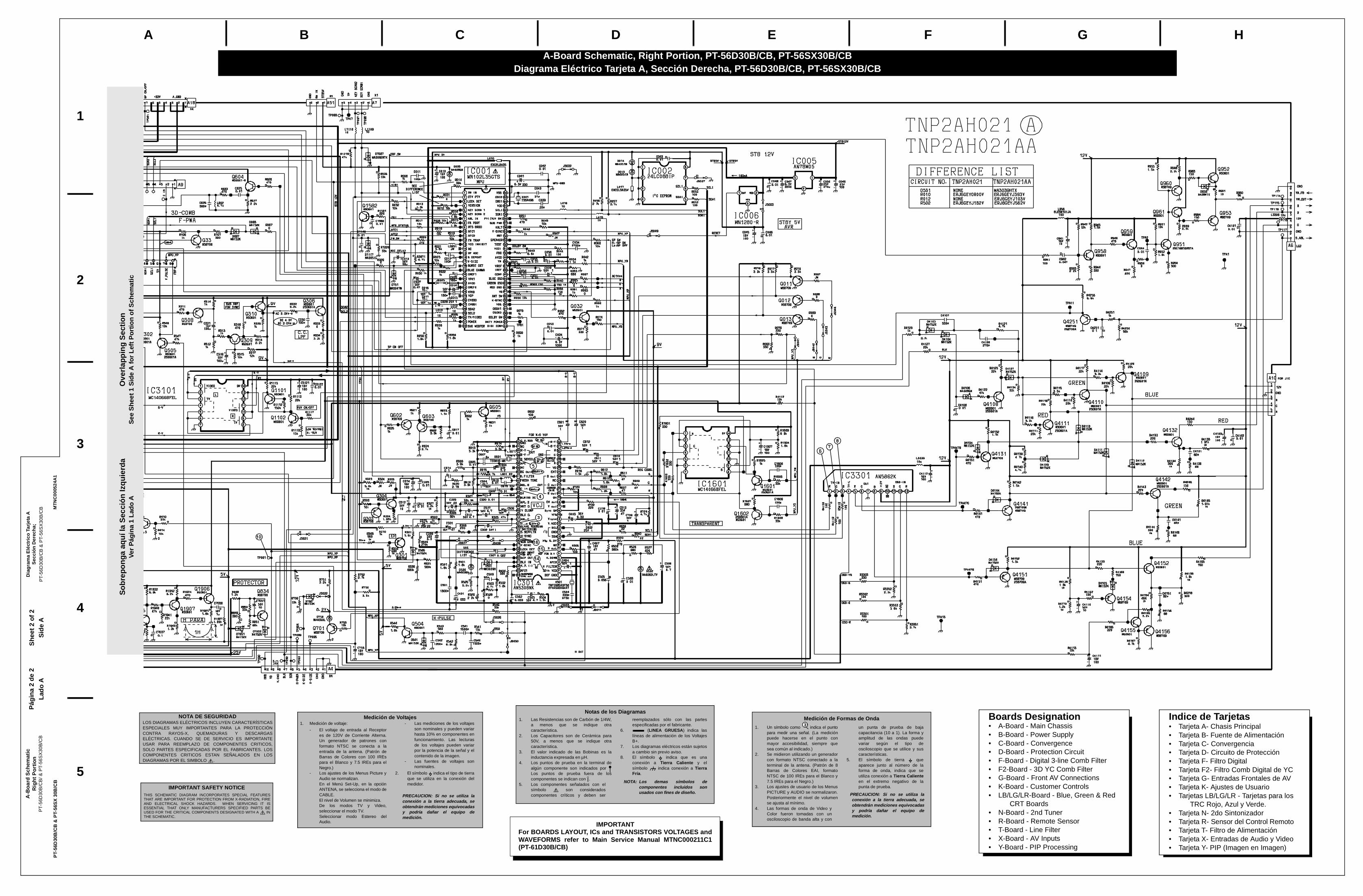
Boards Designation• A-Board - Main Chassis• B-Board - Power Supply• C-Board - Convergence• D-Board - Protection Circuit• F-Board - Digital 3-line Comb Filter• F2-Board - 3D YC Comb Filter• G-Board - Front AV Connections• K-Board - Customer Controls• LB/LG/LR-Board - Blue, Green & Red
CRT Boards• N-Board - 2nd Tuner• R-Board - Remote Sensor• T-Board - Line Filter• X-Board - AV Inputs• Y-Board - PIP Processing
Indice de Tarjetas• Tarjeta A- Chasis Principal• Tarjeta B- Fuente de Alimentación• Tarjeta C- Convergencia• Tarjeta D- Circuito de Protección• Tarjeta F- Filtro Digital• Tarjeta F2- Filtro Comb Digital de YC• Tarjeta G- Entradas Frontales de AV• Tarjeta K- Ajustes de Usuario• Tarjetas LB/LG/LR - Tarjetas para los
TRC Rojo, Azul y Verde.• Tarjeta N- 2do Sintonizador• Tarjeta R- Sensor del Control Remoto• Tarjeta T- Filtro de Alimentación• Tarjeta X- Entradas de Audio y Video• Tarjeta Y- PIP (Imagen en Imagen)
A-B
oar
d S
chem
atic
R
igh
t P
ort
ion
PT-
56D
30B
/CB
/ & P
T-56
SX
30B
/CB
Dia
gra
ma
Elé
ctric
o Ta
rjeta
A
Sec
ción
Der
echa
; P
T-56
D30
B/C
B &
PT-
56S
X30
B/C
B
Pág
ina
2 de
2S
heet
2 o
f 2
IMPORTANTFor BOARDS LAYOUT, ICs and TRANSISTORS VOLTAGES andWAVEFORMS refer to Main Service Manual MTNC000211C1(PT-61D30B/CB)
A-Board Schematic, Right Portion, PT-56D30B/CB, PT-56SX30B/CBDiagrama Eléctrico Tarjeta A, Sección Derecha, PT-56D30B/CB, PT-56SX30B/CB
Foldout Page2a.fm Page 1 Wednesday, July 12, 2000 11:40 AM
Related Documents