PIONEER ELECTRONIC CORPORATION 4-1, Meguro 1-Chome, Meguro-ku, Tokyo 153-8654, Japan PIONEER ELECTRONICS SERVICE INC. P.O.Box 1760, Long Beach, CA 90801-1760 U.S.A. PIONEER ELECTRONIC [EUROPE] N.V. Haven 1087 Keetberglaan 1, 9120 Melsele, Belgium PIONEER ELECTRONICS ASIACENTRE PTE.LTD. 501 Orchard Road, #10-00, Wheelock Place, Singapore 238880 C PIONEER ELECTRONIC CORPORATION 1998 K-ZZU. OCT. 1998 Printed in Japan ORDER NO. CRT2259 MULTI-CD CONTROL HIGH POWER CASSETTE PLAYER WITH FM/AM TUNER KEH-P580 X1M/UC Service Manual CONTENTS 1. SAFETY INFORMATION ............................................2 2. EXPLODED VIEWS AND PARTS LIST ......................2 3. SCHEMATIC DIAGRAM.............................................8 4. PCB CONNECTION DIAGRAM................................22 5. ELECTRICAL PARTS LIST........................................32 6. ADJUSTMENT .........................................................41 7. GENERAL INFORMATION.......................................43 7.1 PARTS ................................................................43 7.1.1 IC ...............................................................43 7.1.2 DISPLAY ...................................................47 7.2DISASSEMBLY ...................................................48 7.3 BLOCK DIAGRAM ..............................................49 8. OPERATIONS AND SPECIFICATIONS ....................50 NOTE: - See the separate manual CX-631(CRT1640) for the cassette mechanism description. - The cassette mechanism assy employed in this model is one of 2L series. - Dolby noise reduction manufactured under license from Dolby Laboratories Licensing Corporation. "Dolby" and the double-D symbol are trademarks of Dolby Laboratories Licensing Corporation. - This service manual does not describe the CD test mode. For the operations in the CD test mode, refer to the CD player's Service Manual. KEH-P5850 X1M/ES KEH-P5800 X1M/UC KEH-P5850/X1M/ES

Welcome message from author
This document is posted to help you gain knowledge. Please leave a comment to let me know what you think about it! Share it to your friends and learn new things together.
Transcript

PIONEER ELECTRONIC CORPORATION 4-1, Meguro 1-Chome, Meguro-ku, Tokyo 153-8654, Japan PIONEER ELECTRONICS SERVICE INC. P.O.Box 1760, Long Beach, CA 90801-1760 U.S.A.PIONEER ELECTRONIC [EUROPE] N.V. Haven 1087 Keetberglaan 1, 9120 Melsele, Belgium PIONEER ELECTRONICS ASIACENTRE PTE.LTD. 501 Orchard Road, #10-00, Wheelock Place, Singapore 238880
C PIONEER ELECTRONIC CORPORATION 1998 K-ZZU. OCT. 1998 Printed in Japan
ORDER NO.
CRT2259
MULTI-CD CONTROL HIGH POWER CASSETTE PLAYER WITH FM/AM TUNER
KEH-P580 X1M/UC
ServiceManual
CONTENTS1. SAFETY INFORMATION............................................22. EXPLODED VIEWS AND PARTS LIST ......................23. SCHEMATIC DIAGRAM.............................................84. PCB CONNECTION DIAGRAM................................225. ELECTRICAL PARTS LIST........................................326. ADJUSTMENT.........................................................41
7. GENERAL INFORMATION.......................................437.1 PARTS ................................................................43
7.1.1 IC ...............................................................437.1.2 DISPLAY ...................................................47
7.2DISASSEMBLY ...................................................487.3BLOCK DIAGRAM ..............................................49
8. OPERATIONS AND SPECIFICATIONS....................50
NOTE:
- See the separate manual CX-631(CRT1640) for the cassette mechanism description.
- The cassette mechanism assy employed in this model is one of 2L series.
- Dolby noise reduction manufactured under license from Dolby Laboratories Licensing Corporation."Dolby" and the double-D symbol are trademarks of Dolby Laboratories Licensing Corporation.
- This service manual does not describe the CD test mode.For the operations in the CD test mode, refer to the CD player's Service Manual.
KEH-P5850 X1M/ES
KEH-P5800 X1M/UC
KEH-P5850/X1M/ES

2
KEH-P580,P5800,P5850
1. SAFETY INFORMATIONUC modelCAUTION
This service manual is intended for qualified service technicians; it is not meant for the casual do-it-yourselfer.Qualified technicians have the necessary test equipment and tools, and have been trained to properly and safely repaircomplex products such as those covered by this manual.Improperly performed repairs can adversely affect the safety and reliability of the product and may void the warranty.If you are not qualified to perform the repair of this product properly and safely; you should not risk trying to do soand refer the repair to a qualified service technician.
WARNING
Lead in solder used in this product is listed by the California Health and Welfare agency as a known reproductivetoxicant which may cause birth defects or other reproductive harm (California Health and Safety Code, Section25249.5). When servicing or handling circuit boards and other components which contain lead in solder, avoidunprotected skin contact with the solder. Also, when soldering do not inhale any smoke or fumes produced.
2. EXPLODED VIEWS AND PARTS LIST2.1 PACKING
36
10
2
9
8
7
54
18
12
16
117
11
15
14
13
19

3
KEH-P580,P5800,P5850
NOTE:- Parts marked by “*”are generally unavailable because they are not in our Master Spare Parts List.
- Screws adjacent to ∇ mark on the product are used for disassembly.
- PACKING SECTION PARTS LIST
Part No.Mark No. Description KEH-P580/X1M/UC KEH-P5800/X1M/UC KEH-P5850/X1M/ES
1 Cord Assy CDE5798 CDE5798 CDE57982 Spring CBH1650 CBH1650 CBH16503 Screw Assy CEA2351 CEA2351 CEA23514 Screw CBA1304 CBA1304 CBA1304
* 5 Polyethylene Bag CEG-127 CEG-127 CEG-127
6 Screw(x4) CRZ50P090FMC CRZ50P090FMC CRZ50P090FMC7 Screw(x4) TRZ50P080FMC TRZ50P080FMC TRZ50P080FMC
* 8 Polyethylene Bag CEG-158 CEG-158 CEG-1589 Handle(x2) CNC5395 CNC5395 CNC5395
10 Bush CNV3930 CNV3930 CNV3930
11 Polyethylene Bag CEG1173 CEG1173 CEG-16212 Battery CEX1030 Not used CEX103013 Carton CHG3555 CHG3554 CHG355614 Contain Box CHL3555 CHL3554 CHL355615 Protector CHP2101 CHP2101 CHP2101
16 Protector CHP2102 CHP2102 CHP210217 Case Assy CXB3520 CXB3520 CXB352018 Remote Control Unit CXB3454 Not used CXB3454
19-1 Owner’s Manual CRD2772 CRD2770 CRD277419-2 Installation Manual CRD2773 CRD2771 CRD2776
* 19-3 Warranty Card CRY1070 Not used Not used
* 19-4 Card Not used ARY1048 Not used19-5 Owner’s Manual Not used Not used CRD2775
- Owner's Manual, Installation ManualModel Part No. LanguageKEH-P580/X1M/UC CRD2772 English, French
CRD2773 English, FrenchKEH-P5800/X1M/UC CRD2770 English, French, Spanish
CRD2771 English, French, SpanishKEH-P5850/X1M/ES CRD2774 English, Spanish, Portuguese(B)
CRD2775 Chinese, ArabicCRD2776 English, Spanish,
Portuguese(B), Chinese, Arabic
4
KEH-P580,P5800,P5850
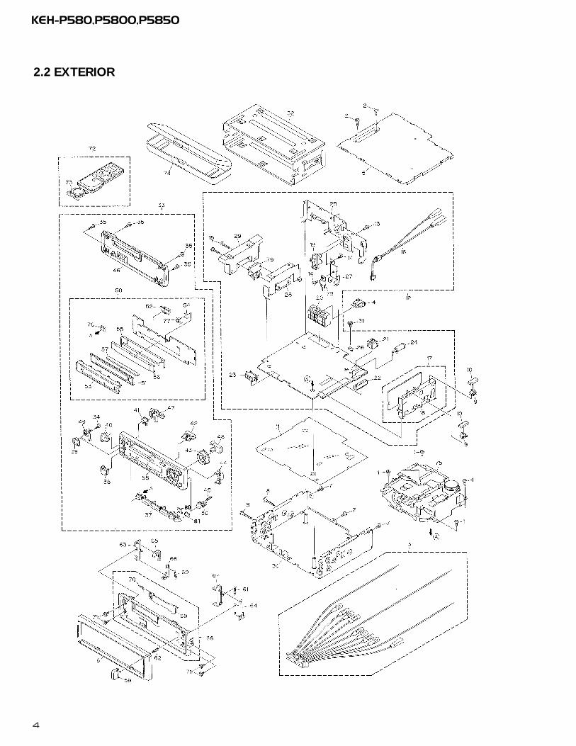
2.2 EXTERIOR

5
KEH-P580,P5800,P5850
1 Screw BSZ26P050FMC2 Screw BSZ30P050FMC3 Cord Assy CDE57984 Fuse(10A) CEK11365 Case CNB2350
6 Panel CNS51377 Screw BSZ30P050FMC8 Screw BSZ30P200FMC9 Holder CNC5704
10 Cushion CNM5210
11 Insulator CNM596312 Tuner Amp Unit See Contrast table(2)13 Screw BPZ26P080FMC14 Screw BSZ26P080FMC15 Screw BSZ26P160FMC
16 Cord CDE575317 FM/AM Tuner Unit See Contrast table(2)18 Holder CNC655419 Pin Jack(CN301) CKB103520 Plug(CN603) CKM1270
21 Connector(CN701) CKS340822 Connector(CN602) CKS356823 Connector(CN601) CKS358124 Antenna Jack(CN402) CKX105625 Panel See Contrast table(2)
26 Holder CNC539927 Holder CNC684528 Holder CNC799629 Heat Sink CNR150530 Chassis Unit CXB3012
31 Screw ISS26P055FUC32 Holder Unit CXB268733 Detach Grille Assy See Contrast table(2)34 Screw BPZ20P060FMC35 Screw BPZ20P100FZK
36 Button(Detach) CAC578937 Button(1-6) CAC579438 Button(-) CAC593039 Button(EQ) CAC613540 Button(+) CAC5783
41 Button(Eject) CAC579342 Button(Display) CAC578843 Button(Cross) CAC578644 Button(A,B) CAC578745 Spring CBH2103
46 Cover CNS513047 Lighting Conductor CNV552548 Housing CNV552649 Housing CNV552850 Keyboard Unit See Contrast table(2)
51 LCD(LCD1901) CAW152652 Connector(CN1901) CKS358053 Holder CNC798154 Spacer CNM504355 Sheet CNM6192
56 Lighting Conductor CNV552457 Connector CNV553158 Grille Unit See Contrast table(2)59 Button CAC483660 Spring CBH1834
61 Spring CBH183562 Spring CBH218263 Bracket CNC613564 Bracket CNC679165 Arm CNV4692
66 Arm CNV469367 Arm CNV472868 Panel Unit CXB302069 Door CAT202670 Spring CBH1838
71 Screw IMS20P030FZK72 Remote Control Unit CXB345473 Cover CNS494874 Case Assy CXB352075 Cassette Mechanism ModuleEXK3690
76 Sheet CNM624377 IC(IC1902) SBX8035-H78 IC(IC302) TDA738479 Transistor(Q904) 2SD239680 Sheet CWM6292
81 Sheet CWM6293
(1) EXTERIOR SECTION PARTS LIST
Mark No. Description Part No. Mark No. Description Part No.

6
KEH-P580,P5800,P5850
2.3 CASSETTE MECHANISM MODULE
(2)CONTRAST TABLEKEH-P580/X1M/UC , KEH-P5800/X1M/UC and KEH-P5850/X1M/ES have the same construction except for the following:
Part No.Mark No. Description KEH-P580/X1M/UC KEH-P5800/X1M/UC KEH-P5850/X1M/ES
12 Tuner Amp Unit CWM6108 CWM6243 CWM624417 FM/AM Tuner Unit CWE1467 CWE1467 CWE148625 Panel CNB2341 CNB2343 CNB234133 Detach Grille Assy CXB3316 CXB3317 CXB331850 Keyboard Unit CWM6254 CWM6255 CWM6256
58 Grille Unit CXB4061 CXB4058 CXB4059

7
KEH-P580,P5800,P5850
Mark No. Description Part No. Mark No. Description Part No.
1 Screw BSZ20P040FMC2 Washer CBF10373 Washer CBF10384 Washer CBG10035 Deck Unit EWM1018
6 Screw EBA10287 Screw EBA10378 Spring EBH15319 Spring EBH1575
10 Plug(CN251) CKS3540
11 Spring EBH151512 Spring EBH158713 Spring EBH151714 Spring EBH151815 Spring EBH1519
16 Spring EBH153717 Cord EDD102018 Photo-interrupter(EGN2,3) EGN100619 Photo-interrupter(EGN1) EGN100520 Roller ENR1031
21 Shaft ELA137322 Pinch Roller ENV151823 Arm ENC148924 Arm ENC139725 Guide ENC1481
26 Holder ENC141727 Lever ENC144828 Arm ENC1488
* 29 Motor EXM103130 Belt ENT1027
31 Gear ENV134732 Collar ENV150833 Gear ENV135034 Flywheel ENV150035 Worm Gear ENV1439
36 Worm Wheel ENV144037 Gear ENR102838 Lever ENV144239 Arm ENV152540 Gathering PCB ENX1037
41 Gathering PCB ENX104242 Switch(S1,S2) ESG100443 Motor Unit(M2) EXA148544 Chassis Unit EXA151145 Pinch Holder ENV1485
46 Pinch Holder ENV148647 Reel Unit EXA154348 Head Base Unit EXA145749 Lever Unit EXA143850 Gear Unit EXA1545
51 Frame Unit EXA145852 Lever Unit EXA143953 Head Assy(HD1) EXA150654 Motor Unit(M1) EXA149055 Washer HBF-179
56 Screw BMZ20P022FMC57 Spring EBH154558 Washer YE20FUC59 Pinch Holder Unit EXA152960 Pinch Holder Unit EXA1528
- CASSETTE MECHANISM MODULE SECTION PARTS LIST

8
KEH-P580,P5800,P5850
A
1 2 3 4
B
C
D
1 2 3 4
3. SCHEMATIC DIAGRAM3.1 OVERALL CONNECTION DIAGRAM(GUIDE PAGE)Note: When ordering service parts, be sure to refer to “EXPLODED VIEWS AND PARTS LIST” or “ELECTRICAL PARTS
LIST”.
A-a A-b
A-a A-b
A-b A-a
Large sizeSCH diagram
Guide page
Detailed page
4R7/
16
ES model
UC model
331(
UC
mo
del
)51
0(E
S m
od
el)
FM/AM TUNER UNIT
TAPE: -9dBs
FM: -15.5dBsAM: -22dBs
For resistors and capacitors in the circuit diagrams, their resistance values orcapacitance values are expressed in codes:
Ex. *Resistors Code Practical value 123 12k ohms 103 10k ohms
*Capacitors Code Practical value 103 0.01uF 101/10 100uF/10V
B
D
KEYBOARD UNITC
DE
CK
UN
IT
A-a
A

9
KEH-P580,P5800,P58505 6 7 8
A
B
C
D
5 6 7 8
KEH-P580/X1M/UCKEH-P5850/X1M/ES
KEH-P580/X1M/UCKEH-P5850/X1M/ES
102
P580 P5800 P5850
TUNER AMP UNIT
CD: +2.2dBs
FM: +9.6dBsAM: -3.1dBsTAPE: -4dBsCD: +10.3dBs
FM: +35.6dBsAM: +29.1dBsTAPE: +22.0dBsCD: +36.3dBs
SYSTEM CONTROLLER
IP-BUS DRIVER
ELECTRONIC VOLUME
POWER AMP
RESET
8V REGULATER
VDD SWITCH
A
IP-BUS
CEK1136
TAPE: -4.2dBs
CN1901
T
332/
16
A
A-b

10
KEH-P580,P5800,P5850
A
1 2 3 4
B
C
D
1 2 3 4
4R7/16
ES
mo
del
UC
mo
del331(UC model)
510(ES model)
KE
H-P
580/
KE
H-P
5850
102
P58
0P
5800
P58
50
FM/A
M T
UN
ER
UN
IT
FM: -
15.5
dB
sA
M: -
22d
Bs
IP-
B
A-a
A-a
A-b

11
KEH-P580,P5800,P58505 6 7 8
A
B
C
D
5 6 7 8
TA
PE
: -9d
Bs
SY
ST
EM
CO
NT
R
For
resi
sto
rs a
nd
cap
acit
ors
in t
he
circ
uit
dia
gra
ms,
th
eir
resi
stan
ce v
alu
es o
rca
pac
itan
ce v
alu
es a
re e
xpre
ssed
in c
od
es:
Ex.
*R
esis
tors
C
od
e
P
ract
ical
val
ue
1
23
12k
oh
ms
1
03
10k
oh
ms
*C
apac
ito
rs
Co
de
P
ract
ical
val
ue
1
03
0.01
uF
1
01/1
0
100u
F/10
V
D
CN
1901
KE
YB
OA
RD
UN
ITC
DECK UNIT
A-a
A-a
A-b

12
KEH-P580,P5800,P5850
A
1 2 3 4
B
C
D
1 2 3 4
-P58
0/X
1M/U
C-P
5850
/X1M
/ES
0
TU
NE
R A
MP
UN
IT
FM: +
9.6d
Bs
AM
: -3.
1dB
sT
AP
E: -
4dB
sC
D: +
10.3
dB
s
FM: +
35.6
dB
sA
M: +
29.1
dB
sT
AP
E: +
22.0
dB
sC
D: +
36.3
dB
s
IP-B
US
DR
IVE
R
ELE
CT
RO
NIC
VO
LUM
E
PO
WE
R A
MP
RE
SE
T
A
CE
K11
36
TA
PE
: -4.
2dB
s
332/16
A-a
A-b
A-b

13
KEH-P580,P5800,P58505 6 7 8
A
B
C
D
5 6 7 8
KE
H-P
580/
X1M
/UC
KE
H-P
5850
/X1M
/ES
CD
: +2.
2dB
s
ON
TR
OLL
ER
8V R
EG
ULA
TE
R
VD
D S
WIT
CH
IP-B
US
A-b
A-a
A-b
14
KEH-P580,P5800,P5850
A
1 2 3 4
B
C
D
1 2 3 4
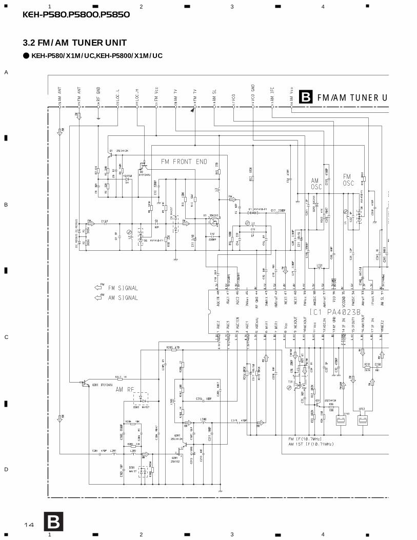
3.2 FM/AM TUNER UNIT- KEH-P580/X1M/UC,KEH-P5800/X1M/UC
B
3
1
2
FM/AM TUNER U
D1
D2
RD
39JS
RD
39JS
R1
R2
2R2M
2R2M
D6
MA
157
B

15
KEH-P580,P5800,P58505 6 7 8
A
B
C
D
5 6 7 8
B
ER UNIT IFC
A

3
1
2
FM/AM TUNER U
D1
D2
RD
39JS
RD
39JS
R1
R2
2R2M
2R2M
D6
MA
157
16
KEH-P580,P5800,P5850
A
1 2 3 4
B
C
D
1 2 3 4
- KEH-P5850/X1M/ES
B
B

ER UNIT IFC
17
KEH-P580,P5800,P58505 6 7 8
A
B
C
D
5 6 7 8
B
A

18
KEH-P580,P5800,P5850
A
1 2 3 4
B
C
D
1 2 3 4
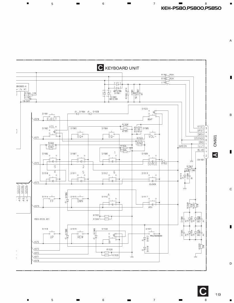
3.3 KEYBOARD UNIT
C
19
KEH-P580,P5800,P58505 6 7 8
A
B
C
D
5 6 7 8
C KEYBOARD UNIT
EDIT
CLOCK
PTY
PAUSE/BSM
C
CN
601
A

20
KEH-P580,P5800,P5850
A
1 2 3 4
B
C
D
1 2 3 4
3.4 CASSETTE MECHANISM MODULE
D
DECK UNIT
MU
TE
CXA2560Q
11121314151617181920
40393837363534333231
30 29 28 27 26 25 24 23 22 21
1 2 3 4 5 6 7 8 9 10
CN602
R256 220
R287
0R0
C273
22/16
R283 0R0
R284 0R0
R282 0R0
C253 330P
C254 330P
C252 330P
C251 330P
R281 0R0
R255 220
C256
R01
R258
1K
VR302CCP1280
33K(B)
R30
1
18K
C31
0R
1
R273 1K
R274 1K
R271 1K
R272 1K
R290 0R0
C403 R068
R403 82K
C402
4700P
C401R33
R40216K
R4014R7K
R32
30R
0
R257
1K
C255
R01
C272 R1
VR301
33K(B) CCP1280
C30
9R
1
C31
310
0P
R38
60R
0
R28
50R
0
HD1HEAD ASSYEXA1506
TEST TAPENCT-150(400Hz, 200nWb/m)
RL
RR
FR
FL
Signal GND
C30
2
R1
C30
2
R1
C30
1
R1
R32
21K
-6dBs(388mV)±1dB A
D
Fwd-R
Fwd-L

21
KEH-P580,P5800,P58505 6 7 8
A
B
C
D
5 6 7 8
FED
PCB UNIT
REEL PCB
SWITCHES:PCB UNIT S1:LOAD SWITCH..........EJECT-PLAY S2:70µs SWITCH............ON-OFFThe underlined indicates the switch position.
R0
068
2K
0216K
1K
R35
11K
R35
21K
R35
31K
R35
41K
R373 0R0
R375 0R0
R35
527
0K
C35
239
00P
R36
218
0
C35
1R
22
C35
3R
01
C35
4R
01
R374 0R0
C356 R01
C355 R1D35
21S
S35
5
M1MOTOR UNIT(MAIN MOTOR)EXA1490
S1 LOAD
ESG1004 S2
ESG1004
70µs
MODESENSE
EGN1EGN1005
EGN2EGN1006FWD ENDSENSE
EGN3EGN1006REV ENDSENSE
M2MOTOR UNIT(SUB MOTOR)EXA1485
Power GND
F
E

22
KEH-P580,P5800,P5850
A
1 2 3 4
B
C
D
1 2 3 4
ACN1901C
CORD ASSY
TUNER AMP UNIT
4. PCB CONNECTION DIAGRAM4.1 TUNER AMP UNIT
NOTE FOR PCB DIAGRAMS1. The parts mounted on this PCB
include all necessary parts forseveral destination.For further information forrespective destinations, be sureto check with the schematicdiagram.
2. Viewpoint of PCB diagrams
CapacitorConnector
P.C.Board Chip Part
SIDE A
SIDE B
A

23
KEH-P580,P5800,P58505 6 7 8
A
B
C
D
5 6 7 8
A
SIDE A
B
CN251D

24
KEH-P580,P5800,P5850
A
1 2 3 4
B
C
D
1 2 3 4
A
A TUNER AMP UNIT

25
KEH-P580,P5800,P58505 6 7 8
A
B
C
D
5 6 7 8
A
SIDE B

26
KEH-P580,P5800,P5850
A
1 2 3 4
B
C
D
1 2 3 4
4.2 FM/AM TUNER UNIT
BSIDE A
B
A
FM/A
M T
UN
ER
UN
IT

27
KEH-P580,P5800,P58501 2 3 4
A
B
C
D
1 2 3 4
B
SIDE B
B
FM/A
M T
UN
ER
UN
IT

KEH-P580,P5800,P5850
A
1 2 3 4
B
C
D
1 2 3 4
CLO
CK
RP
T
TR
AFF
IC IN
FOE
DIT
/BS
M
B
A
65
43
21
SO
UR
CE
VO
L-VO
L+
EQ
-
EQ
+
EJE
CT
4.3 KEYBOARD UNIT
C
CK
EY
BO
AR
D U
NIT
28
SIDE A

29
KEH-P580,P5800,P58501 2 3 4
A
B
C
D
1 2 3 4
C
CK
EY
BO
AR
D U
NIT
CN
601
A
SIDE B

30
KEH-P580,P5800,P5850
A
1 2 3 4
B
C
D
1 2 3 4
4.4 CASSETTE MECHANISM MODULE
D
D
A
HEADASSY
M2 M1
DECK UNIT
CN602
D DECK UNIT
SIDE A
SIDE B
E

31
KEH-P580,P5800,P58501 2 3 4
A
B
C
D
1 2 3 4
Fig. 20
FE
E PCB UNIT
REEL PCB
SIDE A
SIDE B
E
F
LOAD SWS1
70µ SWS2
MODE SENSEEGN1
1
4
7
1 2 3 4 5 6
E PCB UNIT
D CN253
F

32
KEH-P580,P5800,P5850
5. ELECTRICAL PARTS LISTNOTE:- Parts whose parts numbers are omitted are subject to being not supplied.
- The part numbers shown below indicate chip components.Chip Resistor
RS1/_S___J,RS1/__S___JChip Capacitor (except for CQS.....)
CKS....., CCS....., CSZS.....
D 607 Diode 1SS270D 608 Diode 1SS270D 901 Diode HZS7L(C2)D 902 Diode 1SR139-400D 903 Diode 1SR139-400
D 904 Diode HZS7L(A1)D 905 Diode 1SR139-400D 906 Diode HZS6L(B2)D 907 Diode HZS9L(B3)D 908 Diode HZS9L(A2)
D 909 Diode 1SR139-400D 910 Diode 1SR139-400D 912 Diode See Contrast tableD 913 Diode See Contrast tableD 914 LED See Contrast table
L 501 Ferri-Inductor LAU2R2KL 502 Ferri-Inductor LAU2R2KL 601 Ferri-Inductor LAU2R2KL 602 Ferri-Inductor LAU2R2KL 603 Ferri-Inductor LAU2R2K
L 702 Ferri-Inductor LAU2R2KL 901 Choke Coil 600µH CTH1168X 501 Crystal Resonator 7.200MHz CSS1379X 601 Ceramic Resonator 4.194MHz CSS1047
FM/AM Tuner Unit See Contrast table
RESISTORS
R 301 RS1/10S0R0JR 302 RS1/10S0R0JR 310 RS1/10S103JR 313 See Contrast tableR 314 See Contrast table
R 315 See Contrast tableR 317 RS1/10S152JR 318 RS1/10S103JR 319 RS1/10S221JR 320 RS1/10S101J
R 321 RS1/10S223JR 322 RS1/10S153JR 323 RS1/10S103JR 325 RS1/10S821JR 326 RS1/10S821J
R 327 RS1/10S223JR 328 RS1/10S223JR 333 RS1/10S101JR 334 RS1/10S101JR 335 RS1/10S223J
R 336 RS1/10S223JR 337 RD1/4PU102JR 338 RD1/4PU102JR 340 RS1/10S0R0JR 342 RS1/10S0R0J
Unit Number : CWM6108(KEH-P580/X1M/UC)CWM6243(KEH-P5800/X1M/UC)CWM6244(KEH-P5850/X1M/ES)
Unit Name : Tuner Amp Unit
MISCELLANEOUS
IC 301 IC PML003AMIC 302 IC TDA7384IC 501 IC PM2006AIC 601 IC PD4973AIC 602 IC S-80734AN
IC 702 IC CA0008AMIC 901 IC TPD1018FIC 902 IC See Contrast tableQ 306 Transistor DTC124EKQ 307 Transistor 2SC1740S
Q 308 Transistor DTC143TKQ 309 Transistor DTC143TKQ 310 Transistor DTA124EKQ 401 Transistor 2SC2412KQ 505 Transistor DTA124EK
Q 506 Transistor DTC114EKQ 601 Transistor 2SA933SQ 701 Transistor 2SA1037KQ 702 Transistor DTC114EKQ 901 Transistor 2SC1740S
Q 902 Transistor 2SC2412KQ 903 Transistor 2SD2037Q 904 Transistor 2SD2396Q 905 Transistor 2SB1243Q 906 Transistor 2SC1740S
Q 907 Transistor 2SA1048Q 908 Transistor DTC114TKQ 909 Transistor 2SA1674Q 910 Transistor DTC114TKQ 911 Transistor 2SC2412K
Q 912 Transistor See Contrast tableQ 914 Transistor See Contrast tableQ 915 Transistor See Contrast tableQ 920 Transistor DTC114ESQ 921 Transistor DTA124ES
D 301 Diode 1SS270D 302 Diode 1SS270D 401 Diode 1SS270D 402 Diode 1SS270D 601 Diode 1SS270
D 602 Diode 1SS270D 603 Diode 1SS270D 604 Diode 1SS270D 605 Diode 1SS270D 606 Diode 1SS270
=====Circuit Symbol and No.===Part Name Part No.--- ------ ------------------------------------------ -------------------------
=====Circuit Symbol and No.===Part Name Part No.--- ------ ------------------------------------------ -------------------------
A

33
KEH-P580,P5800,P5850
R 401 See Contrast tableR 402 RS1/10S162JR 403 RS1/10S162JR 404 RS1/10S0R0JR 405 See Contrast table
R 406 RS1/10S102JR 407 RD1/4PU222JR 408 RS1/10S222JR 410 RS1/10S102JR 412 RD1/4PU103J
R 413 RS1/10S393JR 417 RS1/10S0R0JR 418 RS1/10S0R0JR 419 RS1/10S0R0JR 502 RS1/10S102J
R 503 RS1/10S222JR 506 RS1/10S182JR 510 RS1/10S0R0JR 511 RS1/10S0R0JR 512 See Contrast table
R 513 RS1/10S102JR 514 RS1/8S0R0JR 515 RS1/10S562JR 517 RS1/10S473JR 518 RS1/10S152J
R 519 RS1/10S472JR 520 RS1/10S222JR 521 RS1/10S822JR 522 RS1/10S392JR 523 RS1/10S0R0J
R 524 RS1/10S562JR 525 RS1/10S222JR 526 RS1/10S392JR 527 RS1/10S392JR 528 RS1/10S472J
R 529 RS1/10S473JR 531 RS1/10S104JR 532 RS1/10S473JR 535 RD1/4PU102JR 536 RS1/10S473J
R 601 RS1/10S124JR 604 RS1/10S473JR 607 RD1/4PU102JR 610 RS1/10S473JR 611 RS1/10S473J
R 612 RS1/10S473JR 613 RS1/10S473JR 614 RS1/8S103JR 615 RS1/10S392JR 616 RD1/4PU222J
R 617 RD1/4PU223JR 618 RD1/4PU222JR 619 RD1/4PU222JR 620 RD1/4PU103JR 621 RS1/10S222J
R 622 RS1/10S222JR 623 RD1/4PU222JR 624 RS1/10S222JR 625 RD1/4PU222JR 626 RD1/4PU222J
R 627 RD1/4PU222JR 628 RD1/4PU222JR 629 RD1/4PU681JR 630 RS1/10S681JR 633 RD1/4PU681J
R 634 RD1/4PU681JR 635 RD1/4PU222JR 636 RS1/10S472JR 637 RS1/10S103JR 638 RD1/4PU222J
R 639 RS1/10S223JR 640 See Contrast tableR 641 RD1/4PU222JR 642 RS1/10S473JR 643 RS1/10S472J
R 644 RS1/10S472JR 645 RS1/10S472JR 647 RS1/10S102JR 648 See Contrast tableR 649 See Contrast table
R 651 RD1/4PU222JR 653 RS1/8S0R0JR 654 RS1/10S0R0JR 655 RS1/10S473JR 716 RS1/10S620J
R 717 RS1/10S101JR 718 RS1/10S101JR 719 RS1/10S473JR 720 RS1/10S473JR 721 RS1/10S102J
R 722 RS1/10S102JR 723 RS1/10S102JR 724 RS1/10S223JR 725 RD1/4PU472JR 726 RS1/10S222J
R 901 RS1/10S473JR 902 RS1/10S223JR 903 RS1/10S223JR 904 RS1/10S473JR 905 RD1/4PU102J
R 906 RD1/4PU473JR 907 RS1/10S473JR 908 RS1/10S472JR 909 RS1/10S332JR 910 RD1/4PU101J
R 911 RS1/10S122JR 912 RS1/10S103JR 913 RS1/10S103JR 914 RS1/10S102JR 915 RS1/10S103J
R 916 RS1/10S103JR 917 RS1/10S0R0JR 918 See Contrast tableR 919 RS1/10S102JR 920 RS1/10S103J
R 921 RS1/10S152JR 922 RS1/10S102JR 923 RS1/10S103JR 924 RS1/10S223JR 930 See Contrast table
R 931 See Contrast tableR 932 See Contrast tableR 933 See Contrast tableR 934 See Contrast tableR 935 See Contrast table
R 936 See Contrast tableR 937 See Contrast tableR 944 RS1/10S152JR 948 RS1/10S0R0JR 949 RS1/8S0R0J
=====Circuit Symbol and No.===Part Name Part No.--- ------ ------------------------------------------ -------------------------
=====Circuit Symbol and No.===Part Name Part No.--- ------ ------------------------------------------ -------------------------

34
KEH-P580,P5800,P5850
CAPACITORS
C 303 CEJA470M10C 304 CEJA100M16C 305 See Contrast tableC 306 See Contrast tableC 308 CKSQYB104K50
C 309 CKSQYB224K16C 310 CKSQYB224K16C 311 CKSQYB224K16C 312 CKSQYB224K16C 313 CEJA4R7M35
C 314 CEJA4R7M35C 315 CEJA330M10C 316 CEJA1R0M50C 317 CEJA100M16C 318 CKSYB105K16
C 319 CKSQYB224K16C 320 CKSQYB224K16C 321 CKSQYB224K16C 322 CKSQYB224K16C 323 CKSQYB104K50
C 324 3300µF/16V CCH1169C 325 CEJA2R2M50C 326 CEJA2R2M50C 327 CEJA1R0M50C 328 CEJA1R0M50
C 329 CEJA1R0M50C 330 CEJA1R0M50C 331 CKSQYB153K50C 332 CKSQYB153K50C 401 CKSQYB473K50
C 402 CKSQYB473K50C 403 CKSQYB223K25C 407 CKSQYB223K50C 408 CCSQSL101J50C 411 CCSQSL101J50
C 413 CKSQYB223K50C 414 CKSQYB103K50C 504 CKSQYB103K50C 505 CKSQYB103K50C 506 See Contrast table
C 507 CEJA220M6R3C 508 CKSQYB102K50C 510 CCSQSL101J50C 511 CKSQYB103K50C 512 CKSQYB103K50
C 513 CKSQYB103K50C 514 CCSQCH150J50C 515 CKSQYB102K50C 516 CCSQCH150J50C 518 CKSQYB103K50
C 519 CEJA220M6R3C 520 CKSQYB103K50C 521 CEJA220M6R3C 522 CKSQYB104K50C 524 CKSQYB103K50
C 525 4.7µF/16V CCH1250C 527 CKLSR473K16C 528 CKSQYB154K16C 530 CEJA220M10C 601 CKSQYB473K50
C 602 CEJA2R2M50C 603 CCSQCH101J50C 604 CCSQCH101J50C 608 CEJA4R7M35C 609 CEJA100M16
C 610 CEJA220M10C 611 CKSQYB223K50C 715 CKSQYB102K50C 716 CKSQYB104K50C 901 CEJA101M10
C 902 CKSQYB473K50C 903 470µF/16V CCH1183C 904 CKSQYB103K50C 905 330µF/10V CCH1181C 906 CKSQYB103K50
C 907 100µF/16V CCH1179C 908 CKSQYB103K50C 910 CKSQYB472K50C 911 See Contrast tableC 912 See Contrast tableC 913 See Contrast tableC 914 See Contrast table
=====Circuit Symbol and No.===Part Name Part No.--- ------ ------------------------------------------ -------------------------
=====Circuit Symbol and No.===Part Name Part No.--- ------ ------------------------------------------ -------------------------

35
KEH-P580,P5800,P5850
Unit Number : CWM6254(KEH-P580/X1M/UC)CWM6255(KEH-P5800/X1M/UC)CWM6256(KEH-P5850/X1M/ES)
Unit Name : Keyboard Unit
MISCELLANEOUS
IC 1901 IC PD6278AIC 1902 IC SBX8035-HD 1901 Chip Diode MA151WKD 1902 Diode MA151WAD 1904 LED CL170PGCD
D 1906 LED CL170PGCDD 1908 LED CL170PGCDD 1909 LED CL170PGCDD 1912 LED CL170PGCDD 1913 LED NSPWF50SB
D 1914 LED NSPWF50SBD 1915 LED NSPWF50SBD 1916 LED NSPWF50SBD 1918 LED CL170PGCDD 1919 LED CL170SBX
D 1920 LED CL170PGCDD 1922 LED CL170PGCDL 1901 Inductor LCTB101K2125X 1901 Ceramic Resonator 4.97MHz CSS1422S 1901 Switch CSG1041
S 1902 Switch CSG1107S 1903 Switch CSG1111S 1904 Switch CSG1111S 1905 Switch CSG1111S 1906 Switch CSG1112
S 1907 Switch CSG1112S 1908 Switch CSG1112S 1909 Switch CSG1112S 1910 Switch CSG1112S 1911 Switch CSG1112
S 1912 Switch CSG1112S 1913 Switch CSG1112S 1914 Switch CSG1041S 1915 Switch CSG1041S 1916 Switch CSG1112
=====Circuit Symbol and No.===Part Name Part No.--- ------ ------------------------------------------ -------------------------
=====Circuit Symbol and No.===Part Name Part No.--- ------ ------------------------------------------ -------------------------
C
CONTRAST TABLE of TUNER AMP UNITKEH-P580/X1M/UC , KEH-P5800/X1M/UC and KEH-P5750/X1M/ES have the same construction except for the following:
Part No.Symbol and Description KEH-P580/X1M/UC KEH-P5800/X1M/UC KEH-P5850/X1M/ESTuner Amp Unit CWM6108 CWM6243 CWM6244FM/AM Tuner Unit CWE1467 CWE1467 CWE1486IC902 IC TPD1018F Not used TPD1018FQ912 Transistor 2SA933S Not used 2SA933SQ914 Transistor DTC124EK Not used DTC124EK
Q915 Transistor 2SC1740S Not used 2SC1740SD912 Diode 1SR139-400 Not used 1SR139-400D913 Diode 1SR139-400 Not used 1SR139-400D914 LED BR4361F Not used BR4361FR313 RS1/10S102J Not used RS1/10S102J
R314 RD1/4PU103J Not used RD1/4PU103JR315 Not used Not used RS1/10S123JR401 Not used Not used RS1/10S182JR405 RS1/10S331J RS1/10S331J RS1/10S510JR512 RS1/10S0R0J RS1/10S0R0J Not used
R640 RD1/4PU103J Not used RD1/4PU103JR648 RS1/10S122J Not used RS1/10S182JR649 RS1/10S272J RS1/10S102J RS1/10S102JR918 RS1/8S0R0J Not used RS1/8S0R0JR930 RS1/10S223J Not used RS1/10S223J
R931 RS1/10S223J Not used RS1/10S223JR932 RS1/10S473J Not used RS1/10S473JR933 RS1/10S103J Not used RS1/10S103JR934 RS1/10S272J Not used RS1/10S272JR935 RS1/10S223J Not used RS1/10S223J
R936 RD1/4PU102J Not used RD1/4PU102JR937 RS1/10S751J Not used RS1/10S751JC305 CKSQYB473K50 Not used CKSQYB473K50C306 CKSQYB473K50 Not used CKSQYB473K50C506 Not used Not used CKSQYB103K50
C911 CKSQYB103K50 Not used CKSQYB103K50C912 CCSQSL101J50 Not used CCSQSL101J50C913 CKSQYB103K50 Not used CKSQYB103K50C914 CKSQYB472K50 Not used CKSQYB472K50

36
KEH-P580,P5800,P5850
S 1917 Switch CSG1112S 1918 Switch CSG1041S 1919 Switch CSG1041S 1920 Switch CSG1107S 1921 Switch CSG1111
S 1922 Switch CSG1107LCD1901 LCD CAW1526
RESISTORS
R 1901 RS1/10S222JR 1902 RS1/10S222JR 1903 RS1/10S472JR 1904 RS1/10S121JR 1905 RS1/8S470J
R 1906 RS1/8S470JR 1907 RS1/10S2R2JR 1908 RS1/10S473JR 1909 RS1/10S473JR 1910 RS1/10S473J
R 1911 RS1/10S473JR 1912 RS1/10S473JR 1913 RS1/10S473JR 1922 RS1/8S821JR 1923 RS1/8S821J
R 1924 RS1/8S821JR 1925 RS1/8S821JR 1926 RS1/8S821JR 1927 RS1/8S821JR 1928 RS1/8S821J
R 1929 RS1/8S821JR 1930 RS1/8S821JR 1931 RS1/8S821JR 1932 RS1/8S821JR 1933 RS1/8S821J
R 1934 RS1/8S821JR 1935 RS1/8S821JR 1939 RS1/10S391JR 1940 RS1/10S511JR 1941 RS1/10S511J
R 1943 RS1/8S621J
CAPACITORS
C 1901 CEH100M6R3C 1902 CKSQYB104K16C 1903 CEH100M6R3C 1904 CKSQYF104Z50C 1905 CKSQYF104Z50
C 1906 CKSQYF104Z50C 1907 CKSQYF104Z50C 1908 CKSRYB104K16
Number : CWE1467(UC model)Unit Name : FM/AM Tuner Unit
MISCELLANEOUS
IC 1 IC PA4023BIC 2 IC PA4024AQ 1 Transistor 2SC2412KQ 2 Transistor DTC124EUQ 3 FET 3SK263
Q 31 Transistor 2SC2412KQ 201 FET 2SK932Q 202 Transistor 2SC2412KQ 203 Transistor DTC124EUD 1 Diode RD39JS
D 2 Diode RD39JSD 4 Diode 1SV250D 5 Diode KV1410-F1D 6 Diode MA157D 7 Diode KV1410-F1
D 8 Diode KV1410-F1D 201 Diode MA157D 202 Diode MA157D 231 Diode SVC253L 2 Coil CTC1133
L 3 Inductor LCTB2R2K2125L 4 Coil CTC1133L 5 Coil CTC1132L 51 Ferri-Inductor LAU150KL 201 Ferri-Inductor LAU4R7K
L 202 Ferri-Inductor LAU330KL 203 Inductor CTF1287L 208 Inductor LAU121KL 231 Inductor LCTA3R3J3225T 31 Coil CTE1117
T 51 Coil CTC1159CF 51 Ceramic Filter CTF1441CF 52 Ceramic Filter CTF1441CF 53 Ceramic Filter CTF1441CF 232 Ceramic Filter CTF1348
X 151 Radiator 918.5Hz CSS1365X 231 Crystal Resonator 10.26MHz CSS1111VR 154 Semi-fixed 150kΩ(B) CCP1213
RESISTORS
R 1 RS1/16S225JR 2 RS1/16S225JR 4 RS1/16S154JR 5 RS1/16S391JR 6 RS1/16S223J
R 7 RS1/16S123JR 8 RS1/16S332JR 9 RS1/16S473JR 10 RS1/16S223JR 11 RS1/16S124J
R 13 RS1/16S563JR 15 RS1/16S271JR 16 RS1/16S104JR 17 RS1/16S332JR 18 RS1/16S332J
R 31 RS1/16S470JR 32 RS1/16S822JR 33 RS1/16S822JR 34 RS1/16S331JR 35 RS1/16S331J
R 51 RS1/16S271JR 52 RS1/16S560JR 55 RS1/16S102JR 56 RS1/16S823JR 61 RS1/16S392J
R 62 RS1/16S273JR 101 RS1/16S272JR 102 RS1/16S682JR 103 RS1/16S333JR 104 RS1/16S334J
R 105 RS1/16S683JR 107 RS1/16S222JR 151 RS1/16S222JR 152 RS1/16S393JR 155 RS1/16S273J
=====Circuit Symbol and No.===Part Name Part No.--- ------ ------------------------------------------ -------------------------
=====Circuit Symbol and No.===Part Name Part No.--- ------ ------------------------------------------ -------------------------
B

37
KEH-P580,P5800,P5850
R 156 RS1/16S243JR 157 RS1/16S203JR 160 RS1/16S222JR 161 RS1/16S563JR 162 RS1/16S105J
R 163 RS1/16S223JR 202 RS1/16S223JR 203 RS1/16S225JR 204 RS1/16S103JR 206 RS1/16S220J
R 207 RS1/16S101JR 208 RS1/16S102JR 209 RS1/16S471JR 214 RS1/16S822JR 215 RS1/16S822J
R 217 RS1/16S102JR 231 RS1/16S272JR 232 RS1/16S473JR 237 RS1/16S103JR 238 RS1/16S104J
R 239 RS1/16S104JR 240 RS1/16S332JR 241 RS1/16S202JR 243 RS1/16S183JR 244 RS1/16S392J
R 247 RS1/16S123J
CAPACITORS
C 1 CCSQCH6R0D50C 2 CCSRCK2R0C50C 4 CCSRCH820J50C 6 CCSRCH820J50C 8 CKSRYB103K25
C 9 CKSQYB104K16C 10 CCSRCKR50C50C 11 CEJA1R0M50C 12 CKSRYB222K50C 13 CKSRYB222K50
C 14 CCSRCH220J50C 15 CCSRCH6R0D50C 16 CCSRCH8R0D50C 17 CKSRYB222K50C 18 CKSRYB103K25
C 19 CKSRYB222K50C 20 CKSRYB222K50C 21 CEJA100M16C 22 CCSRTH9R0D50C 23 CCSRTH120J50
C 24 CCSRCH471J50C 25 CKSRYB103K25C 26 CCSRCH101J50C 31 CKSRYB103K25C 32 CKSQYB472K50
C 33 CCSRCH5R0C50C 34 CKSQYB104K16C 36 CCSRRH201J50C 51 CKSRYB223K25C 52 CKSRYB103K25
C 54 CCSRCH470J50C 55 CKSQYB223K25C 56 CKSQYB104K16C 57 CKSRYB472K50C 58 CEJA330M10
C 59 CKSRYB103K25C 60 CKSRYB102K50C 61 CCSRCH270J50C 62 CKSRYB103K25C 63 CEJAR22M50
C 101 CEJANP100M10C 102 CKSRYB182K50C 103 CKSRYB682K25C 104 CEJA2R2M50C 105 CKSRYB103K25
C 106 CCSRCH151J50C 107 CKSRYB103K25C 151 CKSRYB472K50C 152 CKSQYB104K16C 153 CEJA3R3M50
C 154 CKSQYB104K16C 157 CEJA3R3M50C 158 CKSYB474K16C 159 CEJA220M6R3C 160 CKSQYB104K16
C 161 CKSQYB104K16C 162 CEJA3R3M50C 163 CKSRYB102K50C 170 CCSRCH100D50C 201 CCSRCH471J50
C 202 CCSRCH100D50C 203 CKSRYB332K50C 204 CKSQYB473K16C 205 CKSQYB473K16C 206 CKSQYB104K16
C 207 CCSRCH560J50C 209 CKSQYB104K16C 211 CCSRCH101J50C 212 CEJA470M6R3C 213 CKSRYB103K25
C 216 CCSRCH101J50C 217 CEJA1R5M50C 219 CCSRCH471J50C 220 CKSRYB103K25C 230 CKSRYB103K25
C 231 CCSRCH330J50C 232 CCSRCH150J50C 233 CKSQYB104K16C 234 CEJA330M10C 235 CKSRYB332K50
C 236 CKSQYB473K16C 237 CCSRCH120J50C 239 CKSRYB472K50C 240 CEJAR47M50C 241 CKSQYB104K16
C 242 CEJAR47M50C 243 CEJAR33M50C 244 CKSQYB473K16C 245 CKSRYB333K16C 246 CKSQYB473K16
C 250 CCSRCH471J50
Unit Number : CWE1486(ES model)Unit Name : FM/AM Tuner Unit
MISCELLANEOUS
IC 1 IC PA4023BIC 2 IC PA4024AQ 1 Transistor 2SC2412KQ 2 Transistor DTC124EUQ 3 FET 3SK263
=====Circuit Symbol and No.===Part Name Part No.--- ------ ------------------------------------------ -------------------------
=====Circuit Symbol and No.===Part Name Part No.--- ------ ------------------------------------------ -------------------------
B

Q 31 Transistor 2SC2412KQ 201 FET 2SK932Q 202 Transistor 2SC2412KQ 203 Transistor DTC124EUD 1 Diode RD39JS
D 2 Diode RD39JSD 4 Diode 1SV250D 5 Diode KV1410-F1D 6 Diode MA157D 7 Diode KV1410-F1
D 8 Diode KV1410-F1D 201 Diode MA157D 202 Diode MA157D 231 Diode SVC253L 2 Coil CTC1133
L 3 Inductor LCTB2R2K2125L 4 Coil CTC1133L 5 Coil CTC1132L 6 Inductor LCTBR15K1608L 51 Ferri-Inductor LAU150K
L 201 Ferri-Inductor LAU4R7KL 202 Ferri-Inductor LAU330KL 203 Inductor CTF1287L 208 Inductor LAU121KL 231 Inductor LCTA3R3J3225
T 31 Coil CTE1117T 51 Coil CTC1159CF 51 Ceramic Filter CTF1441CF 52 Ceramic Filter CTF1441CF 53 Ceramic Filter CTF1441
CF 232 Ceramic Filter CTF1348X 151 Radiator 918.5Hz CSS1365X 231 Crystal Resonator 10.26MHz CSS1111VR 154 Semi-fixed 150kΩ(B) CCP1213
RESISTORS
R 1 RS1/16S225JR 2 RS1/16S225JR 4 RS1/16S154JR 5 RS1/16S391JR 6 RS1/16S223J
R 7 RS1/16S123JR 8 RS1/16S332JR 9 RS1/16S473JR 10 RS1/16S223JR 11 RS1/16S124J
R 13 RS1/16S563JR 15 RS1/16S271JR 16 RS1/16S104JR 17 RS1/16S332JR 18 RS1/16S332J
R 31 RS1/16S470JR 32 RS1/16S822JR 33 RS1/16S822JR 34 RS1/16S331JR 35 RS1/16S331J
R 51 RS1/16S271JR 52 RS1/16S560JR 55 RS1/16S102JR 56 RS1/16S823JR 61 RS1/16S392J
R 62 RS1/16S273JR 101 RS1/16S272JR 102 RS1/16S682JR 103 RS1/16S333JR 104 RS1/16S334J
R 105 RS1/16S683JR 107 RS1/16S222JR 151 RS1/16S222JR 152 RS1/16S393JR 155 RS1/16S273J
R 156 RS1/16S243JR 157 RS1/16S203JR 160 RS1/16S222JR 161 RS1/16S563JR 162 RS1/16S105J
R 163 RS1/16S223JR 202 RS1/16S223JR 203 RS1/16S225JR 204 RS1/16S103JR 206 RS1/16S220J
R 207 RS1/16S101JR 208 RS1/16S102JR 209 RS1/16S471JR 214 RS1/16S822JR 215 RS1/16S822J
R 217 RS1/16S102JR 231 RS1/16S272JR 232 RS1/16S473JR 237 RS1/16S103JR 238 RS1/16S104J
R 239 RS1/16S104JR 240 RS1/16S332JR 241 RS1/16S202JR 243 RS1/16S183JR 244 RS1/16S392J
R 247 RS1/16S123J
CAPACITORS
C 1 CCSQCH6R0D50C 2 CCSRCK2R0C50C 4 CCSRCH820J50C 6 CCSRCH820J50C 8 CKSRYB103K25
C 9 CKSQYB104K16C 10 CCSRCKR50C50C 11 CEJA1R0M50C 12 CKSRYB222K50C 13 CKSRYB222K50
C 14 CCSRCH220J50C 15 CCSRCH6R0D50C 16 CCSRCH8R0D50C 17 CKSRYB222K50C 18 CKSRYB103K25
C 19 CKSRYB222K50C 20 CKSRYB222K50C 21 CEJA100M16C 22 CCSRTH9R0D50C 23 CCSRTH120J50
C 24 CCSRCH471J50C 25 CKSRYB103K25C 31 CKSRYB103K25C 32 CKSQYB472K50C 33 CCSRCH5R0C50
C 34 CKSQYB104K16C 36 CCSRRH201J50C 51 CKSRYB223K25C 52 CKSRYB103K25C 54 CCSRCH470J50
38
KEH-P580,P5800,P5850
=====Circuit Symbol and No.===Part Name Part No.--- ------ ------------------------------------------ -------------------------
=====Circuit Symbol and No.===Part Name Part No.--- ------ ------------------------------------------ -------------------------

C 55 CKSQYB223K25C 56 CKSQYB104K16C 57 CKSRYB472K50C 58 CEJA330M10C 59 CKSRYB103K25
C 60 CKSRYB102K50C 61 CCSRCH270J50C 62 CKSRYB103K25C 63 CEJAR22M50C 101 CEJANP100M10
C 102 CKSRYB182K50C 103 CKSRYB682K25C 104 CEJA2R2M50C 105 CKSRYB103K25C 106 CCSRCH151J50
C 107 CKSRYB103K25C 151 CKSRYB472K50C 152 CKSQYB104K16C 153 CEJA3R3M50C 154 CKSQYB104K16
C 157 CEJA3R3M50C 158 CKSYB474K16C 159 CEJA220M6R3C 160 CKSQYB104K16C 161 CKSQYB104K16
C 162 CEJA3R3M50C 163 CKSRYB102K50C 170 CCSRCH100D50C 201 CCSRCH471J50C 202 CCSRCH100D50
C 203 CKSRYB332K50C 204 CKSQYB473K16C 205 CKSQYB473K16C 206 CKSQYB104K16C 207 CCSRCH560J50
C 209 CKSQYB104K16C 211 CCSRCH101J50C 212 CEJA470M6R3C 213 CKSRYB103K25C 216 CCSRCH101J50
C 217 CEJA1R5M50C 219 CCSRCH471J50C 220 CKSRYB103K25C 230 CKSRYB103K25C 231 CCSRCH330J50
C 232 CCSRCH150J50C 233 CKSQYB104K16C 234 CEJA330M10C 235 CKSRYB332K50C 236 CKSQYB473K16
C 237 CCSRCH120J50C 239 CKSRYB472K50C 240 CEJAR47M50C 241 CKSQYB104K16C 242 CEJAR47M50
C 243 CEJAR33M50C 244 CKSQYB473K16C 245 CKSRYB333K16C 246 CKSQYB473K16C 250 CCSRCH471J50
Unit Number : EWM1018Unit Name : Deck Unit
MISCELLANEOUS
IC 251 IC CXA2560QIC 351 IC PA2020AD 352 Diode 1SS355VR 301 Semi-fixed 33kΩ(B) CCP1280VR 302 Semi-fixed 33kΩ(B) CCP1280
RESISTORS
R 255 RS1/16S221JR 256 RS1/16S221JR 257 RS1/16S102JR 258 RS1/16S102JR 271 RS1/16S102J
R 272 RS1/16S102JR 273 RS1/16S102JR 274 RS1/16S102JR 281 RS1/8S0R0JR 282 RS1/8S0R0J
R 283 RS1/8S0R0JR 284 RS1/8S0R0JR 285 RS1/16S0R0JR 286 RS1/16S0R0JR 287 RS1/8S0R0J
R 290 RS1/8S0R0JR 301 RS1/16S183JR 322 RS1/16S102JR 323 RS1/8S0R0JR 351 RS1/16S102J
R 352 RS1/16S102JR 353 RS1/16S102JR 354 RS1/16S102JR 355 RS1/10S274JR 362 RS1/8S181J
R 373 RS1/8S0R0JR 374 RS1/8S0R0JR 375 RS1/8S0R0JR 401 RS1/16S472JR 402 RS1/16S163J
R 403 RS1/16S823J
CAPACITORS
C 251 CKSRYB331K50C 252 CKSRYB331K50C 253 CKSRYB331K50C 254 CKSRYB331K50C 255 CKSRYB103K25
C 256 CKSRYB103K25C 272 CKSQYB104K16C 273 CEJA220M16C 301 CKSYB104K50C 302 CKSYB104K50
C 309 CKSQYB104K16C 310 CKSQYB104K16C 313 CCSQCH101K50C 351 CKSYB224K25C 352 CKSQYB392K50
C 353 CKSQYB103K50C 354 CKSQYB103K50C 355 CKSYB104K50C 356 CKSQYB103K50C 401 CKSQYB334K16
39
KEH-P580,P5800,P5850
D
=====Circuit Symbol and No.===Part Name Part No.--- ------ ------------------------------------------ -------------------------
=====Circuit Symbol and No.===Part Name Part No.--- ------ ------------------------------------------ -------------------------

C 402 CKSQYB472K50C 403 CKSQYB683K16
Unit Number :Unit Name : PCB Unit
S 1 Switch (Load) ESG1004S 2 Switch (70µS) ESG1004EGN 1 Photo-Interrupter EGN1005
Unit Number :Unit Name : Reel PCB
EGN 2 Photo-Interrupter EGN1006EGN 3 Photo-Interrupter EGN1006
Miscellaneous Parts List
M 1 Motor Unit (Main) EXA1490M 2 Motor Unit (Sub) EXA1485HD 1 Head Assy EXA1506
40
KEH-P580,P5800,P5850
E
F
=====Circuit Symbol and No.===Part Name Part No.--- ------ ------------------------------------------ -------------------------

41
KEH-P580,P5800,P5850
FM
/AM
TU
NE
R U
NIT
4Ω
4Ω
Lch +
Lch -
Rch +
Rch -
BACK UP
ACC
GND
+14.4V
GND
AntennaJack
mV Meter (1) Oscilloscope
DC RegulatedPower Supply
TUNER AMP UNIT
50 Ω(75Ω )
FM SSG StereoModulator
50Ω (37.5Ω )Antenna Plug
Dummy Antenna
DE
CK
UN
IT
VR401
DC V Meter(2)
SIDE B
FM/AM TUNER UNIT (TOP VIEW)
T31
T51
C63
T51 CenterMeter
FM/AM TUNER UNIT (BOTTOM VIEW)
Pin1
Pin13
Pin14
Pin 19
Pin26L2
L4
L5
VR154
TC1
DC VMeter(1)
Q402 EMITTER
6. ADJUSTMENT- Connection Diagram
VR302
mVMeter(2)
VR301
L-CHR-CH
Pin2Pin3
CN251
DECK UNIT(BOTTOM VIEW)

42
KEH-P580,P5800,P5850
Modulation M:MONO MOD., 400Hz 30%(22.5kHz Dev.) or 400Hz 100%(75kHz Dev.)S:STEREO MOD., 1kHz, L or R=30%(20.25kHz+7.5kHz Dev.)
NOTE:Before proceeding to further adjustments after switching power ON, let the tuner run for ten minutes to allow the circuits to stabilize.
FM ADJUSTMENT(UC MODEL)
FM SSG Displayed Adjustment Adjustment MethodNo. Frequency(MHz) Level(dBf) Frequency(MHz) Point (Switch Position)
TUN Volt 1 ••••• ••••• 107.9 L5 DC V Meter(1) : 6VIF 2 98.1 M 60—100 98.1 T51 Center Meter : 0ANT Coil 3 98.1 M 5 98.1 L2 mV Meter(1) : MaximumRF Coil 4 98.1 M 5 98.1 L4 mV Meter(1) : MaximumIFT 5 98.1 M 5 98.1 T31 mV Meter(1) : Maximum
(STEREO MODE)ARC 6 98.1 S 40 98.1 VR154 mV Meter(1) : Separation 5dB
(STEREO MODE)
FM ADJUSTMENT(ES MODEL)
FM SSG Displayed Adjustment Adjustment MethodNo. Frequency(MHz) Level(dBf) Frequency(MHz) Point (Switch Position)
TUN Volt 1 ••••• ••••• 108.0 L5 DC V Meter(1) : 6VIF 2 98.1 M 60—100 98.1 T51 Center Meter : 0ANT Coil 3 98.1 M 5 98.1 L2 mV Meter(1) : MaximumRF Coil 4 98.1 M 5 98.1 L4 mV Meter(1) : MaximumIFT 5 98.1 M 5 98.1 T31 mV Meter(1) : Maximum
(STEREO MODE)ARC 6 98.1 S 40 98.1 VR154 mV Meter(1) : Separation 5dB
(STEREO MODE)
DOLBY B NR ADJUSTMENTNo. Test Tape Adjustment Point Adjustment Method
(Switch Position)1 NCT-150 VR301(Lch),VR302(Rch) mV Meter(2) : –6dBs±1.0dB
(400Hz,200nwb/m) (DOLBY NR Switch : OFF)

43
KEH-P580,P5800,P5850
7. GENERAL INFORMATION7.1 PARTS7.1.1 ICCXA2560Q

44
KEH-P580,P5800,P5850
- Pin Functions(PD4973A)Pin No. Pin Name I/O Format Function and Operation
1 ASENBO O C Slave power supply control output2 NC Not used3 ADPW O C A/D converter power output4 AVSS GND5 swvdd O C Grille power supply control output6 st I FM stereo input7 AVREF1 D/A converter standard voltage8 KYDT I Grille MicroComputer data input9 DPDT O C Grille MicroComputer data output
10 NC Not used11 TUNPDI I PLL IC data input12 TUNPDO O C PLL IC data output13 TUNPCK O C PLL IC clock output14 TUNPCE O C PLL IC chip enable output
15,16 NC Not used17 TX O C IP BUS data output
18,19 NC Not used20 DIMMER O C Dimmer select output21 DRELAY O C Detach alarm relay output22 VST O C Strobe pulse output for electronic volume23 VCK O C Clock output for electronic volume24 VDT O C Data output for electronic volume25 LCDPW O C LCD back light power supply control output26 ILMPW O C Illumination power supply control output27 DRSENS I Door open/close sense input28 DRSYS O C Door system select output29 FM O C FM power control output30 AM O C AM power control output31 CM O C Cassette mechanism capstan motor control output32 NR O C DolbyB output33 VSS GND34 SC2 O C Cassette mechanism sub motor control output35 SC1 O C Cassette mechanism sub motor control output36 MSIN I Cassette mechanism MS sense input37 MCMUTE O N Cassette mechanism mute output38 mtlsw I Metal sense input39 dled O N Alarm LED output40 n/R O C Normal reverse output41 PLAY O C Tape MS filter select output42 loadsw I Tape loading input43 POS I Cassette mechanism position sense input44 RES I Cassette mechanism reverse end sense input45 PEE O C Beep tone output46 NES I Cassette mechanism forward end sense input47 NC Not used48 STBY O C Stand-by output
49–52 NC Not used53 SD I SD input 54 mute O C Mute output55 SYSPW O C System power supply control output
56–59 NC Not used60 RESET I Reset input61 RX I IP BUS data input62 NC Not used63 dsens I Grille detach sense input64 TELIN I TEL mute signal input65 asens I ACC power sense input66 bsens I Back up power sense input67 CLKIN I Clock input

45
KEH-P580,P5800,P5850
IC's marked by* are MOS type.Be careful in handling them because they are veryliable to be damaged by electrostatic induction.
Format MeaningC C MOSN N Channel open drain
*PD6278A
16
1732
33
48
49 64
1
Pin No. Pin Name I/O Format Function and Operation68 VDD VDD69 X2 Oscillator output70 X1 Oscillator input71 IC Connect to GND72 XT2 Sub Clock terminal73 TESTIN I Test program mode input74 AVDD A/D converter analog power supply (VDD)75 AVREF0 I A/D converter standard voltage input76 SL I Signal level input77 MODEL0 I Model select input78 MODEL1 I Model select input
79,80 NC Not used
801
20
21 40
41
60
61
*PD4973A

46
KEH-P580,P5800,P5850
- Pin Functions (PD6278A)Pin No. Pin Name I/O Function and Operation
1-5 SEG4-0 O LCD segment output6-9 COM3-0 O LCD common output 10 V3 LCD drive power supply
11-14 KS4-1 O Key strobe output15,16 KD1,2 I Key data input (analogue input)
17 REM I Remote control reception18 RXD I System micro computer UART communication data input19 rst I System reset20 TXD O System micro computer UART communication data output21 MODA GND22 X0 Crystal oscillator connection pin23 X1 Crystal oscillator connection pin24 VSS GND
25,26 KD3,4 I Key data input27,28 KS6,5 O Key strobe output29-55 SEG39-13 O LLCD segment output
56 VCC Power supply57-64 SEG12-5 O LCD segment output
1 2 3 4 5 6 7 8 9 10 11 12 13 14
1516171819202122232425262728
Vref IN1_L IN2_L IN3_L IN4+_L AGND Loud- out_L
SVin_L Front- out_L
Rear- out_L
FIE_L DGNDIN4-_L CLK
VCC IN1_R IN2_R IN3_R IN4+_R AGNDLoud- out_R SVin_R
Front- out_R
Rear- out_R FIE_R STBIN4-_R DATA
Isolator circuit
Primary volume
Anti Alias filter
Treble
Anti radiation filter
Middle Bass
Loudness volume
FIE
Fadervolume
Secondary volume
Zero crossdetect circuit
Primary volume
Anti Alias filter
Middle
Treble
Bass
Isolator circuit
Anti radiation filter
Loudness volume
Zero crossdetect circuit
Fadervolume
Secondary volume
FIE
Digital block
Auto-Zero
Auto-Zero
PML003AM

47
KEH-P580,P5800,P5850
7.1.2 DISPLAY
- CAW1526
CO
MM
ON
SE
GM
EN
T

48
KEH-P580,P5800,P5850
7.2 DISASSEMBLY
- Removing the Tuner Amp Unit(Fig.2)
Removing the two screws.
Removing the three screws.
Removing the screw.
Unbend the tabs at three locationsindicated by arrow until straight.Remove the Tuner Amp Unit.
- Removing the Case(not shown)1.Remove the two screws.2.Remove the Case.
- Removing the Cassette Mechanism Module(not shown)
1.Remove the four screws.2.Disconnect the connector, and then removing the
Cassette Mechanism Module.
- Removing the Panel Unit(Fig.1)
Remove the two screws.
Disengage the stopper at two locationsindicated and remove the Panel Unit.
Fig.1
Fig.2
Panel Unit
Tuner Amp Unit

49
KEH-P580,P5800,P5850
7.3 BLOCK DIAGRAM
BA
D
F
E
C

50
KEH-P580,P5800,P5850
8. OPERATIONS AND SPECIFICATIONS
+ ≠
+ ≠ + ≠
+ ≠ + ≠
+ ≠
Thi
s Pr
oduc
t
Ant
enna
jack
Mul
ti-C
D p
laye
r(s
old
sepa
rate
ly)
To te
rmin
al a
lway
s su
pplie
d w
ith p
ower
rega
rdle
ss o
f ig
nitio
n sw
itch
posi
tion.
To e
lect
ric
term
inal
con
trol
led
by ig
nitio
nsw
itch
(12
V D
C)
ON
/OFF
.
Con
nect
ing
cord
s w
ithR
CA
pin
plu
gs(s
old
sepa
rate
ly)
Blu
e/w
hite
To s
yste
m c
ontr
ol te
rmin
al o
fth
e po
wer
am
p or
Aut
o-an
tenn
are
lay
cont
rol t
erm
inal
.(M
ax. 3
00 m
A 1
2 V
DC
)
Pow
er a
mp
(sol
d se
para
tely
)
To v
ehic
le (
met
al)
body
.
Rea
rsp
eake
r
Fron
tsp
eake
r
Bla
ck (
grou
nd)
Red
Yel
low
Whi
te
Whi
te/b
lack
Gra
y
Gra
y/bl
ack
Gre
en
Gre
en/b
lack
Vio
let
Vio
let/b
lack
See
the
sect
ion
“DFS
Ala
rm In
stal
latio
n”.
Whi
te/y
ello
w
Bro
wn
Rea
r ou
tput
Fuse
Left
Rig
ht
Syst
em r
emot
e co
ntro
l
Fron
tsp
eake
r
Rea
rsp
eake
r
Rea
rsp
eake
rR
ear
spea
ker
Perf
orm
thes
e co
nnec
tions
whe
n us
ing
a di
ffer
ent a
mp
(sol
d se
para
tely
).
With
a 2
spe
aker
sys
tem
, do
not c
onne
ctan
ythi
ng to
the
spea
ker
lead
s th
at a
re n
otco
nnec
ted
to s
peak
ers.
CAU
TIO
N•
Cor
ds f
or th
is p
rodu
ct a
nd th
ose
for
othe
r pr
oduc
ts m
aybe
dif
fere
nt c
olor
s ev
en if
they
hav
e th
e sa
me
func
tion.
Whe
n co
nnec
ting
this
pro
duct
to a
noth
er p
rodu
ct, r
efer
toth
e su
pplie
d In
stal
latio
n m
anua
ls o
f bo
th p
rodu
cts
and
conn
ect c
ords
that
hav
e th
e sa
me
func
tion.

51
KEH-P580,P5800,P5850
Key
Fin
der
Hea
d U
nit
5/∞
/2/3
butto
ns
SOU
RC
E/O
FFbu
tton
+/–
butto
nA
UD
IObu
tton
Det
ach
butto
n
But
tons
1–6
Cas
sette
door
EJE
CT
butto
n
PAU
SE/B
SMbu
tton
RPT
butto
n
CL
OC
Kbu
tton
BA
ND
butto
n
DIS
PLA
Ybu
tton
EQ
butto
n
Bas
ic O
pera
tion
To L
iste
n to
Mus
icT
he f
ollo
win
g ex
plai
ns th
e in
itial
ope
ratio
ns r
equi
red
befo
re y
ou c
an li
sten
to m
usic
.
Not
e:•
Loa
ding
a c
asse
tte in
this
pro
duct
.
1.Se
lect
the
des
ired
sou
rce.
(e.
g. t
uner
)
7H
ead
Uni
tE
ach
pres
s of
the
SOU
RC
E/O
FF b
utto
n se
lect
s th
e de
sire
d so
urce
in th
e fo
llow
ing
orde
r:C
D p
laye
r (o
ne d
isc
only
) =
Tun
er =
Tape
=M
ulti-
CD
pla
yer
=A
UX
7Re
mot
e Co
ntro
ller
Eac
h pr
ess
of th
e bu
tton
sele
cts
the
desi
red
sour
ce in
the
follo
win
g or
der:
TU
NE
R b
utto
n: T
uner
=O
FFTA
PE b
utto
n: T
ape
=A
UX
=O
FFC
D b
utto
n: C
D p
laye
r (o
ne d
isc
only
) =
Mul
ti-C
D p
laye
r =
OFF
Not
e:•
In th
e fo
llow
ing
case
s, th
e so
und
sour
ce w
ill n
ot c
hang
e:*
Whe
n a
prod
uct i
s no
t con
nect
ed to
this
pro
duct
.*
Whe
n no
tape
is s
et in
this
pro
duct
.*
Whe
n no
mag
azin
e is
set
in th
e M
ulti-
CD
pla
yer.
*W
hen
no d
isc
is s
et in
the
CD
pla
yer.
*W
hen
the
AU
X (
exte
rnal
inpu
t) is
set
to O
FF.
2.R
aise
or
low
er t
he v
olum
e.
3.Tu
rn t
he s
ourc
e O
FF.
Hol
d fo
r 1
seco
nd o
r m
ore
Eac
h pr
ess
chan
ges
the
Sour
ce ..
.
8.1 OPERATIONS(ES model)

52
KEH-P580,P5800,P5850
Bas
ic O
pera
tion
of T
uner
Bas
ic O
pera
tion
Man
ual a
nd S
eek
Tuni
ng
•Y
ou c
an s
elec
t th
e tu
ning
met
hod
by c
hang
ing
the
leng
th o
f ti
me
you
pres
s th
e 2
/3bu
tton
.
Man
ual T
unin
g (s
tep
by s
tep)
0.5
seco
nds
or le
ss
Seek
Tun
ing
0.5
seco
nds
or m
ore
Not
e:•
If y
ou c
ontin
ue p
ress
ing
the
butto
n fo
r lo
nger
than
0.5
sec
onds
, you
can
ski
p br
oadc
ast
stat
ions
. See
k T
unin
g st
arts
as
soon
as
you
stop
pre
ssin
g th
e bu
tton.
Not
e:•
“”
ster
eo in
dica
tor
light
s w
hen
a st
ereo
sta
tion
is s
elec
ted.
Pres
et T
unin
g
•Y
ou c
an m
emor
ize
broa
dcas
t st
atio
ns in
but
tons
1 th
roug
h 6
for
easy
, one
-tou
ch s
tati
on r
ecal
l.
Pres
et s
tatio
n re
call
2 se
cond
s or
less
Bro
adca
st s
tatio
n pr
eset
mem
ory
2 se
cond
s or
mor
e
Not
e:•
Up
to 1
8 FM
sta
tions
(6
in F
I(F
M1)
, FII
(FM
2) a
nd F
III
(FM
3))
and
6 A
M s
tatio
ns c
an b
e st
ored
in m
emor
y.•
You
can
als
o us
e th
e 5
or ∞
butto
ns to
rec
all b
road
cast
stat
ions
mem
oriz
ed in
but
tons
1 th
roug
h 6.
Pres
et N
umbe
r Ind
icat
or
Ban
d FI(F
M1)
=FI
I(F
M2)
=
FIII
(FM
3) =
AM
Bas
ic O
pera
tion
of C
asse
tte P
laye
r
Dir
ectio
n Ch
ange
Dir
ectio
n In
dica
tor
Ejec
t Not
e:•
The
Tap
e fu
nctio
n ca
n be
turn
ed O
N/O
FF w
ithth
e ca
sset
te ta
pe r
emai
ning
in th
is p
rodu
ct.
Fast
For
war
d/Re
win
d an
d M
usic
Sea
rch
•E
ach
pres
s of
the
3bu
tton
sel
ects
Fas
t fo
rwar
d or
For
war
d-M
usic
Sear
ch.
FF (
Fast
for
war
d) =
F-M
S (F
orw
ard-
Mus
ic S
earc
h) =
Nor
mal
Pla
ybac
k
•E
ach
pres
s of
the
22bu
tton
sel
ects
Rew
ind
or R
ewin
d-M
usic
Sea
rch.
RE
W (
Rew
ind)
=R
-MS
(Rew
ind-
Mus
ic S
earc
h) =
Nor
mal
Pla
ybac
k
Not
e:•
Fast
for
war
d/R
ewin
d an
d M
usic
Sea
rch
can
be c
ance
led
by p
ress
ing
the
BA
ND
butto
n.
Ban
d In
dica
tor
Freq
uenc
y In
dica
tor
Res
et th
e A
M tu
ning
ste
p fr
om 9
kH
z (t
he f
acto
ry p
rese
t ste
p) to
10
kHz
whe
n us
ing
the
tune
r in
Nor
th, C
entr
al o
r So
uth
Am
eric
a.
Cass
ette
Loa
ding
Slo
t
Met
al In
dica
tor
“MT
L”
indi
cato
r lig
hts
whe
n a
met
al o
r ch
rom
e ta
pe is
inse
rted
.

53
KEH-P580,P5800,P5850
Bas
ic O
pera
tion
of M
ulti-
CD P
laye
r
Dis
c N
umbe
r Sea
rch
(for 6
-Dis
c, 1
2-D
isc
type
s)
•Y
ou c
an s
elec
t di
scs
dire
ctly
wit
h th
e 1
to 6
but
tons
. Jus
t pr
ess
the
num
ber
corr
espo
ndin
g to
the
dis
c yo
u w
ant
to li
sten
to.
Not
e:•
Whe
n a
12-D
isc
Mul
ti-C
D P
laye
r is
con
nect
ed a
nd y
ou w
ant t
o se
lect
dis
c 7
to 1
2, p
ress
the
1 to
6 bu
ttons
for
2 s
econ
ds o
r lo
nger
.
Dis
c N
umbe
r Rou
gh S
earc
h (fo
r 50-
Dis
c ty
pe o
nly)
Thi
s ha
ndy
func
tion
lets
you
sel
ect d
iscs
load
ed in
a 5
0-D
isc
Mul
ti-C
D P
laye
r us
ing
the
1 to
5 b
utto
ns. T
he 5
0 di
scs
are
divi
ded
into
fiv
e bl
ocks
, with
eac
h of
the
1 to
5 b
utto
nsas
sign
ed to
a b
lock
.
•Se
lect
the
des
ired
blo
ck w
ith
the
1 to
5 b
utto
n.
Not
e:•
Aft
er c
ompl
etin
g a
roug
h se
arch
, use
the
5an
d ∞
butto
ns to
sel
ect a
des
ired
dis
c.
Dis
play
ing
Dis
c Ti
tles
•P
ress
the
DIS
PL
AY
but
ton,
to
chan
ge t
he D
isc
Tit
le d
ispl
ay o
f th
e cu
rren
tdi
sc.
Not
e:•
If y
ou s
witc
h di
spla
ys w
hen
disc
title
s ha
ve n
ot b
een
inpu
t, “N
O T
ITL
E”
is d
ispl
ayed
.•
Rep
eat t
he p
rece
ding
ope
ratio
n to
ret
urn
to th
e no
rmal
dis
play
.
Not
e:•
The
mul
ti-C
D p
laye
r m
ay p
erfo
rm a
pre
para
tory
ope
ratio
n, s
uch
as v
erif
ying
the
pres
ence
of
adi
sc o
r re
adin
g di
sc in
form
atio
n, w
hen
the
pow
er is
turn
ed O
N o
r a
new
dis
c is
sel
ecte
d fo
rpl
ayba
ck. “
RE
AD
Y”
is d
ispl
ayed
.•
Whe
n a
mag
azin
e is
load
ed in
to a
50-
Dis
c ty
pe M
ulti-
CD
Pla
yer,
info
rmat
ion
on a
ll th
e di
scs
inth
e m
agaz
ine
is r
ead.
If y
ou s
tart
pla
ying
a d
isc
on a
50-
Dis
c ty
pe M
ulti-
CD
Pla
yer
befo
re r
eadi
ng o
f in
form
atio
n on
all d
iscs
has
bee
n co
mpl
eted
, rea
ding
of
info
rmat
ion
stop
s pa
rt w
ay th
roug
h.•
If th
e m
ulti-
CD
pla
yer
cann
ot o
pera
te p
rope
rly,
an
erro
r m
essa
ge s
uch
as “
ER
RO
R-1
4” is
disp
laye
d. R
efer
to th
e m
ulti-
CD
pla
yer
owne
r’s
man
ual.
•If
ther
e ar
e no
dis
cs in
the
mul
ti-C
D p
laye
r m
agaz
ine,
“N
O D
ISC
” is
dis
play
ed.
•“L
OA
D”
will
be
disp
laye
d in
the
follo
win
g ca
ses:
*If
the
disc
in th
e ex
tra
tray
is s
elec
ted.
*If
the
disc
is m
oved
fro
m th
e ex
tra
tray
to th
e m
agaz
ine.
(Ref
er to
the
50-D
isc
type
mul
ti-C
D p
laye
r ow
ner’
s m
anua
l.)•
You
can
not u
se th
e “E
ject
ing
a Si
ngle
Dis
c”, “
Freq
uenc
y Pl
ay”,
“M
usic
Gro
up P
lay”
or
“AB
CD
isc
Titl
e Se
arch
” fu
nctio
ns w
ith th
is p
rodu
ct.
Bas
ic O
pera
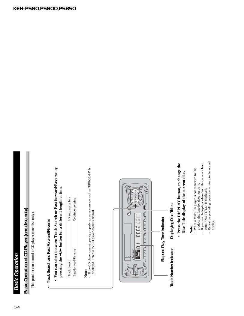
tion
Trac
k Se
arch
and
Fas
t For
war
d/Re
vers
e
•Y
ou c
an s
elec
t be
twee
n T
rack
Sea
rch
or F
ast
forw
ard/
Rev
erse
by
pres
sing
the
2/3
butt
onfo
r a
diff
eren
t le
ngth
of
tim
e.
Tra
ck S
earc
h0.
5 se
cond
s or
less
Fast
for
war
d/R
ever
seC
ontin
ue p
ress
ing
Switc
hing
the
Mul
ti-CD
Pla
yer
Usi
ng a
mul
tiple
con
nect
ion
adap
ter
lets
you
con
nect
up
toth
ree
Mul
ti-C
D p
laye
rs.
M-C
D 1
=M
-CD
2 =
M-C
D 3
(Dis
play
ed f
or a
bout
2 s
econ
ds.)
Elap
sed
Play
Tim
e In
dica
tor
Dis
c Se
arch
Dis
c N
umbe
r Ind
icat
orTr
ack
Num
ber I
ndic
ator
Thi
s pr
oduc
t can
con
trol
one
or
mor
e m
ulti-
CD
pla
yers
. (T
here
are
som
e ty
pes
of M
ulti-
CD
pla
yers
suc
h as
“C
DX
-P63
0S”
whi
ch y
ou c
anno
t con
nect
mor
e th
an o
ne.)
54
KEH-P580,P5800,P5850
Bas
ic O
pera
tion
Bas
ic O
pera
tion
of C
D P
laye
r (on
e di
sc o
nly)
Thi
s pr
oduc
t can
con
trol
a C
D p
laye
r (o
ne d
isc
only
).
Trac
k Se
arch
and
Fas
t For
war
d/Re
vers
e
•Y
ou c
an s
elec
t be
twee
n T
rack
Sea
rch
or F
ast
forw
ard/
Rev
erse
by
pres
sing
the
2/3
butt
on fo
r a
diff
eren
t le
ngth
of
tim
e.
Tra
ck S
earc
h0.
5 se
cond
s or
less
Fast
-for
war
d/R
ever
seC
ontin
ue p
ress
ing
Not
e:•
If th
e C
D p
laye
r ca
nnot
ope
rate
pro
perl
y, a
n er
ror
mes
sage
suc
h as
“E
RR
OR
-14”
isdi
spla
yed.
Ref
er to
the
CD
pla
yer
owne
r’s
man
ual.
Elap
sed
Play
Tim
e In
dica
tor
Trac
k N
umbe
r Ind
icat
orD
ispl
ayin
g D
isc
Title
s
•P
ress
the
DIS
PL
AY
but
ton,
to
chan
ge t
heD
isc
Tit
le d
ispl
ay o
f th
e cu
rren
t di
sc.
Not
e:•
Whe
n a
Mul
ti-C
D p
laye
r is
not
con
nect
ed to
this
prod
uct,
this
fun
ctio
n do
es n
ot w
ork.
•If
you
sw
itch
disp
lays
whe
n di
sc ti
tles
have
not
bee
nin
put,
“NO
TIT
LE
” is
dis
play
ed.
•R
epea
t the
pre
cedi
ng o
pera
tion
to r
etur
n to
the
norm
aldi
spla
y.

55
KEH-P580,P5800,P5850
GeneralPower source .......... 14.4 V DC (10.8 – 15.1 V allowable)Grounding system ........................................ Negative typeMax. current consumption ........................................ 8.5 ADimensions
(DIN) (chassis) ...... 178 (W) × 50 (H) × 155 (D) mm(nose) ............ 188 (W) × 58 (H) × 19 (D) mm
(D) (chassis) ...... 178 (W) × 50 (H) × 160 (D) mm(nose) ............ 170 (W) × 48 (H) × 14 (D) mm
Weight ...................................................................... 1.2 kg
AmplifierContinuous power output is 17 W per channel min. into 4ohms, both channels driven 50 to 15,000 Hz with no morethan 5% THD.Maximum power output ...................................... 40 W × 4Load impedance .......................... 4 Ω (4 – 8 Ω allowable)Preout maximum output
level/output impedance ...................... 2.2 Vp-p/1 kΩEqualizer (3 band equalizer)
(Low) .............................................................. ±12 dB(Mid) .............................................................. ±12 dB(High) .............................................................. ±12 dB
Loudness contour(Low) .................. +3.5 dB (100 Hz), +3 dB (10 kHz)(Mid).................. +10 dB (100 Hz), +6.5 dB (10 kHz)(High).................. +11 dB (100 Hz), +11 dB (10 kHz)
(volume: –30 dB)
Cassette playerTape ........................ Compact cassette tape (C-30 – C-90)Tape speed ...... 4.76 cm/sec.(+0.14cm/sec., -0.05cm/sec.)Fast forward/rewinding time .... Approx. 100 sec. for C-60Wow & flutter .......................................... 0.09% (WRMS)Frequency response .......... Metal: 30 – 19,000 Hz (±3 dB)Stereo separation ...................................................... 45 dBSignal-to-noise ratio
...... Metal: Dolby B NR IN: 67 dB (IEC-A network)Dolby NR OUT: 61 dB (IEC-A network)
FM tunerFrequency range(UCmodel) ..................87.5 – 107.9 MHz
(ESmodel) ........................................ 87.5 – 108 MHzUsable sensitivity .................................................... 11 dBf
(1.0 µV/75 Ω, mono, S/N: 30 dB)50 dB quieting sensitivity .... 16 dBf (1.7 µV/75 Ω, mono)Signal-to-noise ratio ...................... 70 dB (IEC-A network)Distortion .......................... 0.3% (at 65 dBf, 1 kHz, stereo)Frequency response ...................... 30 – 15,000 Hz (±3 dB)Stereo separation .......................... 40 dB (at 65 dBf, 1 kHz)Selectivity(UCmodel) ......................................70dB(2ACA)Three-signal intermodulation(UCmodel)
(desired signal level) ..........................................50dBf(two undesire signal level : 100 dBf)
AM tunerFrequency range ........................ 531 – 1,602 kHz (9 kHz)
(ESmodel) 530 – 1,710 kHz (10 kHz)Usable sensitivity .............................. 18 µV (S/N: 20 dB)Selectivity (ESmodel) ................................ 50 dB (±9 kHz)
50 dB (±10 kHz)
Note:• Specifications and the design are subject to
possible modification without notice due toimprovements.
8.2 SPECIFICATIONS
Related Documents