Orbital Wall Reconstruction with Two-Piece Puzzle 3D Printed Implants: Technical Note Maurice Y. Mommaerts, MD, DMD, PhD, FEBOMFS, FICS, FAACS 1,2 Michael Büttner, MD 1 Herman Vercruysse Jr., MD, MSc 1 Lauri Wauters, MD 1 Maikel Beerens, Ir 3 1 European Face Centre, Universitair Ziekenhuis Brussel, VUB, Brussels, Belgium 2 Orthoface Clinic, Oost-Vlaanderen, Belgium 3 Xilloc Medical B.V, Maastricht, the Netherlands Craniomaxillofac Trauma Reconstruction Address for correspondence Maurice Y. Mommaerts, MD, DMD, PhD, FEBOMFS, FICS, FAACS, European Face Centre, Universitair Ziekenhuis Brussel, VUB, Laarbeeklaan 101, Brussels 1090, Belgium (e-mail: [email protected]). Orbital wall fractures can result in increased orbital volume, tissue herniation into the maxillary sinus, fat atrophy, loss of ligament support, and scar contracture leading to enoph- thalmos and diplopia. 1 Reconstruction of large defects re- mains challenging since anatomical landmarks are lost, particularly the posteromedial orbital bulge and orbital apex. 2 In approximately 8.5% of patients, increased orbital volume remains after treatment with traditional reconstruc- tion techniques. 3 This may be due to treatment by inexperi- enced surgeons, especially when damage involves the posterior orbit, which is particularly difficult to reconstruct. To design implants for orbital reconstruction, rapid proto- type models can be derived from Digital Imaging and Com- munications in Medicine (DICOM) data obtained from the patient’s computed tomography (CT) scan. The model is used to create the implant by mirroring data from the unaffected orbit, and reconstruction is performed with prebent plates. Although this technique is not commonly used, advantages include a true-to-original anatomical repair, 4 restoration of orbital volume, 5 and superior ophthalmological rehabilita- tion when evaluating for binocular single vision and ocular motility. 6 From a surgical point of view, insertion is simplified by the precise fit, and no operating time is wasted in shaping the implant. The orbital floor can be accessed using a transconjunctival approach, which allows exploration of both medial and lateral walls and leaves no scar on the skin. However, extensive defects inevitably call for a larger reconstruction plate, which often requires a transcaruncular or a lateral canthotomy extension of the transconjunctival approach. Transcutaneous approaches, including the subciliary approach (which can be extended laterally), the subtarsal approach, and the infraor- bital approach, all leave a cutaneous scar. To prevent cutane- ous scarring in late primary and secondary reconstruction Keywords ► orbital fractures ► surgery ► computer-assisted ► printing ► three-dimensional Abstract The purpose of this article is to describe a technique for secondary reconstruction of traumatic orbital wall defects using titanium implants that act as three-dimensional (3D) puzzle pieces. We present three cases of large defect reconstruction using implants produced by Xilloc Medical B.V. (Maastricht, the Netherlands) with a 3D printer manufactured by LayerWise (3D Systems; Heverlee, Belgium), and designed using the biomedical engineering software programs ProPlan and 3-Matic (Materialise, Heverlee, Belgium). The smaller size of the implants allowed sequential implantation for the reconstruction of extensive two-wall defects via a limited transconjunctival incision. The precise fit of the implants with regard to the surrounding ledges and each other was confirmed by intraoperative 3D imaging (Mobile C-arm Systems B.V. Pulsera, Philips Medical Systems, Eindhoven, the Netherlands). The patients showed near- complete restoration of orbital volume and ocular motility. However, challenges remain, including traumatic fat atrophy and fibrosis. received January 22, 2015 accepted after revision March 1, 2015 Copyright © 2015 by Thieme Medical Publishers, Inc., 333 Seventh Avenue, New York, NY 10001, USA. Tel: +1(212) 584-4662. DOI http://dx.doi.org/ 10.1055/s-0035-1563392. ISSN 1943-3875. Original Article

Welcome message from author
This document is posted to help you gain knowledge. Please leave a comment to let me know what you think about it! Share it to your friends and learn new things together.
Transcript
Orbital Wall Reconstruction with Two-PiecePuzzle 3D Printed Implants: Technical NoteMaurice Y. Mommaerts, MD, DMD, PhD, FEBOMFS, FICS, FAACS1,2 Michael Büttner, MD1
Herman Vercruysse Jr., MD, MSc1 Lauri Wauters, MD1 Maikel Beerens, Ir3
1European Face Centre, Universitair Ziekenhuis Brussel, VUB, Brussels,Belgium
2Orthoface Clinic, Oost-Vlaanderen, Belgium3Xilloc Medical B.V, Maastricht, the Netherlands
Craniomaxillofac Trauma Reconstruction
Address for correspondence Maurice Y. Mommaerts, MD, DMD, PhD,FEBOMFS, FICS, FAACS, European Face Centre, Universitair ZiekenhuisBrussel, VUB, Laarbeeklaan 101, Brussels 1090, Belgium(e-mail: [email protected]).
Orbital wall fractures can result in increased orbital volume,tissue herniation into the maxillary sinus, fat atrophy, loss ofligament support, and scar contracture leading to enoph-thalmos and diplopia.1 Reconstruction of large defects re-mains challenging since anatomical landmarks are lost,particularly the posteromedial orbital bulge and orbitalapex.2 In approximately 8.5% of patients, increased orbitalvolume remains after treatment with traditional reconstruc-tion techniques.3 This may be due to treatment by inexperi-enced surgeons, especially when damage involves theposterior orbit, which is particularly difficult to reconstruct.
To design implants for orbital reconstruction, rapid proto-type models can be derived from Digital Imaging and Com-munications in Medicine (DICOM) data obtained from thepatient’s computed tomography (CT) scan. The model is usedto create the implant by mirroring data from the unaffectedorbit, and reconstruction is performed with prebent plates.
Although this technique is not commonly used, advantagesinclude a true-to-original anatomical repair,4 restoration oforbital volume,5 and superior ophthalmological rehabilita-tion when evaluating for binocular single vision and ocularmotility.6 From a surgical point of view, insertion is simplifiedby the precise fit, and no operating time is wasted in shapingthe implant.
The orbital floor can be accessed using a transconjunctivalapproach,which allows exploration of bothmedial and lateralwalls and leaves no scar on the skin. However, extensivedefects inevitably call for a larger reconstruction plate, whichoften requires a transcaruncular or a lateral canthotomyextension of the transconjunctival approach. Transcutaneousapproaches, including the subciliary approach (which can beextended laterally), the subtarsal approach, and the infraor-bital approach, all leave a cutaneous scar. To prevent cutane-ous scarring in late primary and secondary reconstruction
Keywords
► orbital fractures► surgery► computer-assisted► printing► three-dimensional
Abstract The purpose of this article is to describe a technique for secondary reconstruction oftraumatic orbital wall defects using titanium implants that act as three-dimensional(3D) puzzle pieces.We present three cases of large defect reconstruction using implantsproduced by Xilloc Medical B.V. (Maastricht, the Netherlands) with a 3D printermanufactured by LayerWise (3D Systems; Heverlee, Belgium), and designed usingthe biomedical engineering software programs ProPlan and 3-Matic (Materialise,Heverlee, Belgium). The smaller size of the implants allowed sequential implantationfor the reconstruction of extensive two-wall defects via a limited transconjunctivalincision. The precise fit of the implants with regard to the surrounding ledges and eachother was confirmed by intraoperative 3D imaging (Mobile C-arm Systems B.V. Pulsera,Philips Medical Systems, Eindhoven, the Netherlands). The patients showed near-complete restoration of orbital volume and ocular motility. However, challenges remain,including traumatic fat atrophy and fibrosis.
receivedJanuary 22, 2015accepted after revisionMarch 1, 2015
Copyright © 2015 by Thieme MedicalPublishers, Inc., 333 Seventh Avenue,New York, NY 10001, USA.Tel: +1(212) 584-4662.
DOI http://dx.doi.org/10.1055/s-0035-1563392.ISSN 1943-3875.
Original Article
and to achieve perfect shape and volume, the three-dimen-sional (3D) puzzle-solving technique was developed.
Technique
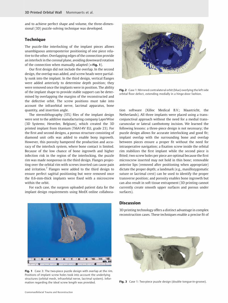
The puzzle-like interlocking of the implant pieces allowsunambiguous anteroposterior positioning of one piece rela-tive to the other. Overlapping edges of the connection providean interlock in the coronal plane, avoidingdownward rotationof the connection when manually adapted (►Fig. 1).
Our first design did not include the overlap. In the seconddesign, the overlap was added, and screw heads were partial-ly sunk into the implant. In the third design, vertical flangeswere added anteriorly to determine depth position; theywere removed once the implants were in position. The abilityof the implant shape to provide stable support can be deter-mined by overlapping the margins of the reconstructed andthe defective orbit. The screw positions must take intoaccount the infraorbital nerve, lacrimal apparatus, bonequantity, and insertion angle.
The stereolithography (STL) files of the implant designwere sent to the additive manufacturing company LayerWise(3D Systems; Heverlee, Belgium), which created the 3Dprinted implant from titanium (Ti6A14V ELI, grade 23). Forthe first and second designs, a porous structure consisting ofdiamond unit cells was added to enable bony ingrowth.However, this porosity hampered the production and accu-racy of the interlock system, where bone contact is limited.Because of the low chance of bone ingrowth and higherinfection risk in the region of the interlocking, the puzzlerim was made nonporous in the third design. Flanges projec-ting over the orbital rim with screws inserted can cause painand irritation.7 Flanges were added to the third design toensure perfect sagittal positioning but were removed oncethe 0.6-mm-thick implants were fixed with a microscrewwithin the orbit.
For each case, the surgeon uploaded patient data for theimplant design requirements using MedX online collabora-
tion software (Xilloc Medical B.V.; Maastricht, theNetherlands). All three implants were placed using a trans-conjunctival approach without the need for a medial trans-caruncular or lateral canthotomy incision. We learned thefollowing lessons: a three-piece design is not necessary; thepuzzle design allows for accurate interlocking and good fit;implant overlap with the surrounding bone and overlapbetween pieces ensure a proper fit without the need forintraoperative navigation; a fixation screw inside the orbitalrim stabilizes the first implant while the second piece isfitted; two screw holes per piece are optimal because the firstmicroscrew inserted may not hold in thin bone; removableanterior lips (removed after positioning when appropriate)dictate the proper depth; a landmark (e.g., maxillozygomaticsuture or lacrimal crest) can be used to identify the propertransverse position; and porosity enables bone ingrowth butcan also result in soft tissue entrapment (3D printing cannotcurrently create smooth upper surfaces and porous undersurfaces).
Discussion
3D printing technology offers a distinct advantage in complexreconstruction cases. These techniques enable a precise fit of
Fig. 1 Case 3: The two-piece puzzle design with overlap at the rim.Positions of implant screw holes took into account the underlyingstructures (orbital mesh, infraorbital nerve, lacrimal system). Infor-mation regarding the ideal screw length was provided.
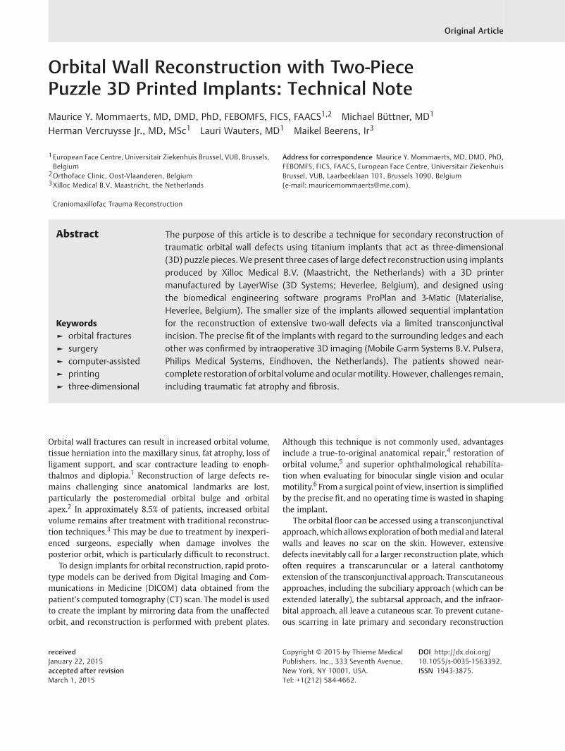
Fig. 2 Case 1: Mirrored contralateral orbit (blue) overlying the left sideorbital floor defect, extending medially in a hinge-door fashion.
Fig. 3 Case 1: Two-piece puzzle design (double tongue-in-groove).
Craniomaxillofacial Trauma and Reconstruction
3D Printed Orbital Wall Mommaerts et al.

the implant, decreasing surgical time because intraoperativemodeling of the implant is unnecessary.
The anatomy of the orbit makes a true-to-original recon-struction challenging. Secondary reconstructions can be evenmore challenging as intraoperative anatomical landmarksmay be lost. The mirroring technique enables digital recon-struction by projection of the unaffected side onto theaffected side. Patient-specific implants can then be createdby using a digital workflow or by manually bending theimplants. Metzger et al described a procedure for producinganatomically adapted mesh, which is bent using a STL tem-plate of the digitally reconstructed orbit.8 Navigation-aidedprocedures guarantee precise intraoperative placement ofthemanually preformedmesh. The usefulness of this strategyin complex orbital trauma was confirmed in a larger patientseries (n ¼ 15) by Bell and Markiewicz.9 In our opinion,adaptation of the titanium plate to a solid model introducessmall inaccuracies caused by the DICOM to STL conversion10
and bigger errors introduced bymanual bending. To avoid thelatter, a complete digital workflow is preferred.
In 2012, Salmi et al described a workflow for 3D modelingand 3D printing of a titanium orbital implant.11 After digitalreconstruction of the affected orbit without mirroring of thecontralateral side, a STL solid model was fabricated using finepolyamide, and a verification model in stainless steel wascreated by selective laser sintering. The 3D modeling of the
orbital implant required the use of two software programs:the shape was determined using the first software programand surface modeling with the second. The implant wascreated with titanium Ti64 ELI mesh (0.4-mm net thickness,3-mm hole) to correct a defect of the orbital floor withextension to the medial wall. Using an infraorbital approach,the implant was positioned without the need for an externalguidance device because of the precise anatomical fit andfixed with two titanium screws. The technique described inthis article uses a single software program for preoperativeplanning and modeling.
Gander et al12 and Rana et al13 described modifications ofthe workflow proposed by Salmi et al.11 A 3D reconstructionof the affected orbit used the mirrored unaffected orbit astemplate. After the digital design, three landmarks werepositioned on the implant to facilitate control of the implantposition by intraoperative navigation, making an externalguidance device or STL solid model with a verification model
Fig. 4 Case 1: Lack of overlap in this first two-piece puzzle implantresulted in insufficient vertical position control between the twoplates.
Fig. 5 Case 2: Overlap between the implants.
Fig. 6 Case 2: Single tongue-in-groove design and reinforcement ofthe anterior border to allow countersinking of the microscrew heads.
Fig. 7 Case 2: Postoperative coronal CT scan, demonstrating near-perfect fit of the implant and symmetrical intraorbital content.
Craniomaxillofacial Trauma and Reconstruction
3D Printed Orbital Wall Mommaerts et al.
unnecessary. We believe that intraoperative navigation willalso become unnecessary because the patient-specific designshould enable a precise fit.
In 2014, Stoor et al presented a case series of 12 orbitalreconstructions (including combined maxillary and orbitaldefects) with Ti6AI4V ELI laser-sintered implants.14 The im-plants were designed using a single software program, withthe size and thickness dependent on the defect (0.5–0.8 mm).Most of the implants were placed through a subciliary inci-sion andfixedwith self-drilling 2 mm screws; positioning didnot require intraoperative navigation. The authors report that16% of procedures resulted inmisfit, probably due to errors indata processing of the thin orbital walls. Incorrect placementof the implant occurred in 24% of the cases, as assessed byoverlapping the preoperative planning and postoperative CTimages. The saving of surgical time was confirmed.
Use of two-piece puzzle 3D printed implants simplifies thesurgical approach. The smaller implants allow for sequentialimplantation via a normal transconjunctival incision. Thetransconjunctival approach appears to have an overall lowcomplication rate (0.3%).15 However, adding a lateral can-thotomy is associated with the highest rate of lower eyelidmalposition and is best avoided.15 Salgarelli et al advocate thesubciliary approach whenwider exposure is needed; howev-er, this approach increases the probability of visible scarring,ectropion, and eyelid malpositioning compared with thetransconjunctival approach.15 Although the transcaruncularapproach leaves no visible scar, potential complications in-clude injury to the globe, eyelid, lacrimal apparatus, inferior
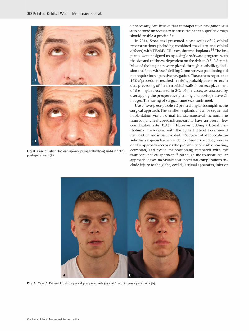
Fig. 8 Case 2: Patient looking upward preoperatively (a) and 4monthspostoperatively (b).
Fig. 9 Case 3: Patient looking upward preoperatively (a) and 1 month postoperatively (b).
Craniomaxillofacial Trauma and Reconstruction
3D Printed Orbital Wall Mommaerts et al.
oblique muscle, medial canthal tendon, trochlea of superioroblique, and ethmoidal vessels.16
Printed patient-specific implants have increased stiffness,preventing deformation during placement. The more rigidstructure of the titanium implant avoids intraoperative bend-ing and loss of shape, which can occur when using the moreflexible traditional prebent mesh plates. In our small series,no intraoperative corrections were necessary for correctadaptation, whereas Gander et al reported an intraoperativecorrection rate of 16.6%.12
Gander et al reported that digital planning required 30 to36 minutes, and the manufacturing process took 4 to6 days.12 However, the main disadvantage of our approachis the planning time,which required approximately 2weeksfor a custom design, followed by 2 to 3 weeks of production
time. In addition, the implant must be sterilized the daybefore surgery. This increased time can be explained by thelearning curve required for the planning and printing of theinterlocking puzzle mechanism. After optimization, thisprocedure will still require 2 days for data upload andimplant design, 1.5 days for implant production, and1 day for shipment according to Xilloc Medical B.V. (Janu-ary 2015), limiting but not excluding the use of thistechnique in primary reconstruction. For the momentbeing, we suggest reserving this technique for complexsecondary reconstruction.
Case Reports
Case 1A 12-year-old boy presented with a left orbital floor defectextending into the medial wall due to a traffic accident thatoccurred 1 month earlier. After rendering of the high-resolutionCT DICOMdata, mirroring was performed usingMimics Innova-tion Suite (Materialise, Heverlee, Belgium), which showed ex-tension of the dislocation into the medial wall (►Fig. 2). Twointerlocking porous pieces were designed for transconjunctivalinsertion (►Fig. 3). The surgery was performed 3 months afterthe accident. Screw position was determined after taking intoaccount infraorbital nerve position and bone thickness. Micro-screws (1.2-mm diameter; Surgi-Tec, Sint-Denijs-Westrem,Belgium)were used for platefixation. The pieces did not overlapvertically, resulting in unfavorable rotational movement aroundthe sagittal axis upon insertion (►Fig. 4). Two months postop-eratively, there was normal ocular motility, no enophthalmos,and no V2 disturbance.
Case 2A 46-year-old man was referred for evaluation of debilitatingdiplopia with enophthalmos, lagophthalmos, and downward
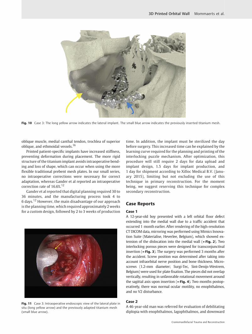
Fig. 10 Case 3: The long yellow arrow indicates the lateral implant. The small blue arrow indicates the previously inserted titanium mesh.
Fig. 11 Case 3: Intraoperative endoscopic view of the lateral plate insitu (long yellow arrow) and the previously adapted titanium mesh(small blue arrow).
Craniomaxillofacial Trauma and Reconstruction
3D Printed Orbital Wall Mommaerts et al.

displacement of the globe caused by trauma that had oc-curred 7 months previously. The mirror image technique wasused to facilitate implant design. Because of the large caudaldislocation in the posterior area, support there was notpossible. However, lateral extension of the borders providedsupport and enabled a proper fit. A single tongue-in-groovestructure guaranteed the reciprocal anteroposterior posi-tions of the pieces, and the overlap provided vertical fit andstability (►Fig. 5). After the screw position was determined,the flanges were made thicker to sink the screw heads(►Fig. 6). The implant was inserted using a transconjunctivalapproach without extensions. Postoperative CT imagesshowed good anatomical reconstruction and restoration oforbital volume (►Fig. 7). Minimal diplopia in extreme up-ward gaze, slight enophthalmos, and lagophthalmos per-sisted because of fibrosis and fat atrophy (►Fig. 8).
Case 3A 28-year-old man was referred with disabling diplopia andsevere globe malposition after two repairs of an impure orbitalfloor fracture using a stock titanium orbital mesh plate(►Fig. 9). He had been hit by a pulley in a work accident.The presence of the previously inserted titaniummesh slightlyhindered implant design because of the scatter effect on CTscan. Mirroring revealed a height difference of 7 mm betweenthe unaffected side and the mesh on the affected side (►Figs.
10–12). The 3D model had to take into account the lower
position of the orbital rim, and the screwpositionwas based onthe amount of remaining bone and positions of the mesh,infraorbital canal, and lacrimal system. The porous implantswere printed with a double tongue-in-groove design (►Figs. 1
and 10). The puzzle-piece design allowed precise fit betweenthe first and second implants (►Fig. 12). Anterior flanges werenot necessary as the shape of the reconstructed infraorbital rimprovided anteroposterior guidance. Slight diplopia in extremeupward gaze and lagophthalmos remained because of previousfibrosis (►Fig. 9).
Conclusion
The two-piece puzzle 3D printed implant appears to be usefulfor reconstruction of extensive orbital wall damage. Thisapproach makes use of a limited surgical access, and theprecise fit greatly decreases operation time. Because ofplanning cost and time, cases should be selected based onreconstruction difficulty and extent of the defect.
References1 Clauser L, Galiè M, Pagliaro F, Tieghi R. Posttraumatic enophthal-
mos: etiology, principles of reconstruction, and correction. JCraniofac Surg 2008;19(2):351–359
2 Hammer B, Kunz C, Schramm A, deRoche R, Prein J. Repair ofcomplex orbital fractures: technical problems, state-of-the-art
Fig. 12 Case 3: Intraoperative 3D imaging using the Pulsera fluoroscopy system. (a) 3D reconstruction and section plane indication. (b) Good fitof the two puzzle pieces (long yellow arrow). Malpositioned mesh (short blue arrow). (c) Good fit of the medial puzzle-piece (long yellow arrow).The titanium mesh was not prebent and was 7 mm too low at the posterior sigmoid bulge (short blue arrow). (d) Axial view of the titanium mesh.The two-piece puzzle implants are visible only where they overlap the infraorbital rim.
Craniomaxillofacial Trauma and Reconstruction
3D Printed Orbital Wall Mommaerts et al.

solutions and future perspectives. Ann Acad Med Singapore 1999;28(5):687–691
3 Hammer B, Prein J. Correction of post-traumatic orbital deformi-ties: operative techniques and review of 26 patients. J Craniomax-illofac Surg 1995;23(2):81–90
4 Schön R, Metzger MC, Zizelmann C, Weyer N, Schmelzeisen R.Individually preformed titanium mesh implants for a true-to-original repair of orbital fractures. Int J Oral Maxillofac Surg2006;35(11):990–995
5 Tang W, Guo L, Long J, et al. Individual design and rapid proto-typing in reconstruction of orbital wall defects. J Oral MaxillofacSurg 2010;68(3):562–570
6 Kozakiewicz M, Elgalal M, Piotr L, Broniarczyk-Loba A, StefanczykL. Treatment with individual orbital wall implants in humans - 1-Year ophthalmologic evaluation. J Craniomaxillofac Surg 2011;39(1):30–36
7 Mustafa SF, Evans PL, Bocca A, Patton DW, Sugar AW, Baxter PW.Customized titanium reconstruction of post-traumatic orbitalwalldefects: a review of 22 cases. Int J Oral Maxillofac Surg 2011;40(12):1357–1362
8 Metzger MC, Schön R, Schulze D, Carvalho C, Gutwald R, Schmel-zeisen R. Individual preformed titanium meshes for orbital frac-tures. Oral Surg Oral Med Oral Pathol Oral Radiol Endod 2006;102(4):442–447
9 Bell RB, Markiewicz MR. Computer-assisted planning, stereolitho-graphic modeling, and intraoperative navigation for complex
orbital reconstruction: a descriptive study in a preliminary cohort.J Oral Maxillofac Surg 2009;67(12):2559–2570
10 Huotilainen E, Jaanimets R, Valášek J, et al. Inaccuracies inadditive manufactured medical skull models caused by theDICOM to STL conversion process. J Craniomaxillofac Surg2014;42(5):e259–e265
11 Salmi M, Tuomi J, Paloheimo KS, et al. Patient-specific reconstruc-tion with 3D modeling and DMLS additive manufacturing. RapidPrototyping J 2012;18:209–214
12 Gander T, Essig H, Metzler P, et al. Patient specific implants (PSI) inreconstruction of orbital floor and wall fractures. J Craniomax-illofac Surg 2015;43(1):126–130
13 RanaM, Gellrich MM, Gellrich NC. Customised reconstruction ofthe orbital wall and engineering of selective laser melting(SLM) core implants. Br J Oral Maxillofac Surg 20115;53(2):208–209
14 Stoor P, Suomalainen A, Lindqvist C, et al. Rapid prototyped patientspecific guiding implants for reconstruction of orbital wall defects.J Craniomaxillofac Surg 2014;42(8):1644–1649
15 Salgarelli AC, Bellini P, Landini B, Multinu A, Consolo U. A compar-ative study of different approaches in the treatment of orbitaltrauma: an experience based on 274 cases. Oral Maxillofac Surg2010;14(1):23–27
16 Edgin WA, Morgan-Marshall A, Fitzsimmons TD. Transcaruncularapproach to medial orbital wall fractures. J Oral Maxillofac Surg2007;65(11):2345–2349
Craniomaxillofacial Trauma and Reconstruction
3D Printed Orbital Wall Mommaerts et al.
Related Documents