STS 86-0302-2A ORBITAL SPACECRAFT CONSUMABLES RESUPPLY SYSTEM (OSCRS) FINAL REPORT Volume II STUDY RESULTS (DRD-10) Prepared for the National Aeronautics and Space Administration Lyndon 8. Johnson Space Center CONTRACT NO. NASS-17584 CDRL DATA ITEM MA-1 023T March 1987 R.Bemis OSCRS Program Manager Rockwell International Space Transportation Systems Division

Welcome message from author
This document is posted to help you gain knowledge. Please leave a comment to let me know what you think about it! Share it to your friends and learn new things together.
Transcript
STS 86-0302-2A
ORBITAL SPACECRAFT CONSUMABLES
RESUPPLY SYSTEM (OSCRS)
FINAL REPORT Volume II
STUDY RESULTS (DRD-10)
Prepared for the
National Aeronautics and Space Administration Lyndon 8. Johnson Space Center
CONTRACT NO. NASS-17584 CDRL DATA ITEM MA-1 023T
March 1987
R.Bemis OSCRS Program Manager
Rockwell International Space Transportation
Systems Division
October 27, 1986
This r e p o r t was prepared by:
G . R. Cox * Under the superv i s ion o f R. Bemis w i t h the assistance o f the OSCRS Engineering, Safe ty and R e l i a b i l i t y team and the Space Transpor ta t ion Systems D i v i s i o n techn ica l s t a f f .
March 1987 Rev is ion A
Technical changes between t h i s Tevis ion and the o r i g i n a l re lease are denoted by a b lack ba r a long the t e x t margin. Table and f i g u r e enhancements f o r l e g i b i l i t y and c o r r e c t i o n o f typographical o r grammatical e r r o r s have n o t been h i g h l i g h t e d w i t h a change bar.
ii
FOREWORD
This f i n a l r e p o r t o f the O r b i t a l Spacecraf t Consumables Resupply System (OSCRS) study was prepared by the Space Transpor ta t ion Systems D i v i s i o n o f Rockwell I n t e r n a t i o n a l f o r the Nat ional Aeronaut ics and Space Admin is t ra t ion , Johnson Space Center, Houston, Texas, i n compliance w i t h the requirements o f Contract NAS9-17584, CDRL No. MA 1 O23T.
I n response w i t h the CDRL i n s t r u c t i o n s , t h i s r e p o r t i s submi t ted i n th ree separate ly bound volumes:
Vol . 1. Execut ive Sumnary
I Vol. 2. Study Resul ts
Vol. 3 Program Cost Est imate
Fu r the r i n fo rma t ion concerning the contents o f t h i s r e p o r t may be obta ined from R. Bemis, Study Program Manager, telephone (213) 922-3805, Downey , Cal i fo rn ia .
6071 c iii
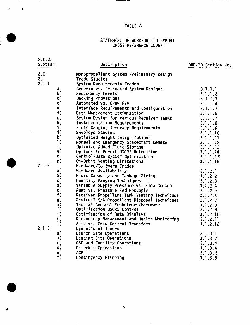
STATEFENT OF k’oBK TASK TO D D 10 REPORT CROSS REFERENCE INDEX
The contract statement-ofrork tasks v u e performed i n general accorbnce w i t h the study plan per STS-86-0109. between the S-0-W subtaeks and the reporting paragraphs of th is document.
Table A provides a croas-reference index
i v
, b
TABLE A
a
P ) 2.1.2
ii 2.1.3
STATEMENT OF WORK/DRD-10 REPORT CROSS REFERENCE INDEX
Desc r i p t i on
Monopropel 1 a n t System Pre l i m i nary Desi gn Trade Studies System Requirements Trades Generic vs. Dedicated System Designs Redundancy Level s Docking Prov is ions Automated vs. Crew EVA I n t e r f a c e Requ i remen t s and Con f i g u r a t i on Data Management Opt im iza t ion System Design f o r Various Receiver Tanks Ins t rumenta t ion Requirements F l u i d Gauging Accuracy Requirements Envelope Studies Opt imized Weight Design Options Normal and Emergency Spacecraf t Demate Optimize Added F1 u i d Storage Options t o Permit OSCRS Relocat ion Contro l /Data System Cpt imiza t ion On-Orbit Vent ing L i m i t a t i o n s Hardware/Software Trades Hardware Avai 1 abi 1 i ty F l u i d Capaci ty and Tankage S i z i n g Quant i t y Gauging Techniques Var iab le Supply Pressure vs. Flow Control Pump vs. Pressure Fed Resupply Receiver P rope l l an t Tank Venting Techniques Resi dual S/C Propel l a n t Disposal Techniques Thermal Contro l Techniques/Hardware Opt imiza t ion OSCRS Contro l Opt im iza t ion o f Data D isp lays Redundancy Management and Heal th Mon i to r ing Auto vs. Crew Contro l Transfers Operat ional Trades Launch S i t e Operat ions Landing S i t e Operat ions GSE and F a c i l i t y Operat ions On-Orbit Operat ions ASE Contingency P lann ing
DRD-10 Sect ion No.
3.1.1.1 3.1.1.2 3.1.1.3 3.1.1.4 3.1 .l. E 3.1.1.6 3.1.1.7 3.1 .I .a 3.1.1.9 3.1.1.10 3.1.1 .ll 3.1.1.1 2 3.1.1.13 3.1.1 -14 3.1.1.1 5 3.1.1.16
3.1.2.1 3.1.2.2 3.1 2 . 3 3.1 2 . 4 3.1.2. f 3.1.2.6 3.1.2.7 3.1.2.8 3.1.2.9 3.1.2.10 3.1.2.11 3.1.2.1 2
3.1.3.1 3.1.3.2 3.1.3.4 3.1.3.4 3.1.3.5 3.1.3.6
V
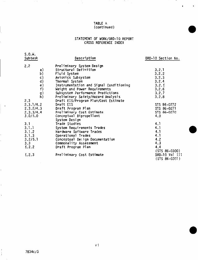
TABLE A (cont inued)
S.O.W. Sub task
2.2 a ) b ) C) d) e ) f ) 9 ) h )
2.3 2.3.1 /4.2 2.3.2/4.3 2.3.3/4.4 3.0/5.0
3.1 3.1.1 3.1.2 3.1.3 3.2/5.1 3.3 5.2.2
5.2.3
STATEMENT OF WORK/DRD-I 0 REPORT CROSS REFERENCE INDEX
Descr i p t i on
P re l i m i nary Sys tern Desi gn S t r u c t u r a l D e f i n i t f o n F l u i d System Avi on i cs Subsystem Thermal System Ins t rumenta t ion and Signal Cond i t ion ing GIei gh t and Power Requirements Sub sys tern Performance Pred ic t ions P re l i m i nary Safety/Hazard Analysi s D r a f t EIS/Program Plan/Cost Estimate D r a f t €IS D r a f t Program Plan Preliminary Cost Estimate Conceptual Bi propel 1 an t System Design Trade Studies System Requirements Trades Hardware Software Trades Operat ional Trades Conceptual Der i gn Documentation Comnonal i t y Assessment D r a f t Program Plan
P re l i m i nary Cost Estimate
DRD-10 Sect ion No.
3.2.1 3.2.2 3.2.3 3.2.4 3.2.5 3.2.6 3.2.7 3.2.8
STS 86-0272 STS 86-0271 STS 86-C27C 4.0
4.1 4.1 4.1 4.1 4.2 4.3 4.4 (STS 86-0300) DRD-10 V O I 111 (STS 86-0301
v i
7834c/3
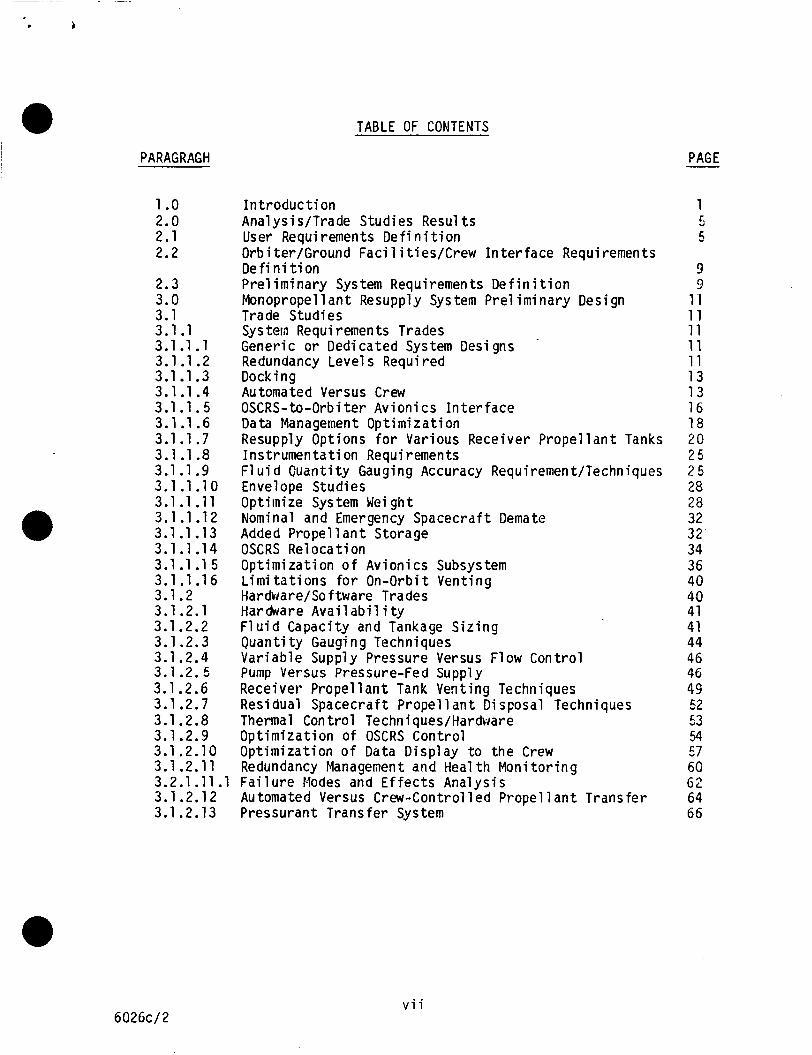
TABLE OF CONTENTS
PARAGRAGH
1 .o 2.0 2.1 2.2
2.3 3.0 3.1 3.1.1 3.1 .l. 1 3.1.1.2 3.1.1.3 3.1.1.4 3.1.1.5 3.1.1.6 3.1.1.7 3.1 -1.8 3.1.1 .9 3.1.1.1 0 3.1.1 .ll 3.1.1.12 3.1.1.13 3.1.1.14 3.1.1 .l 5 3.1.1.16 3.1.2 3.1.2.1 3.1.2.2 3.1.2.3 3.1.2.4 3.1.2.5 3.1.2.6 3.1.2.7 3.1.2.8 3.1.2.9 3.1.2.10 3.1.2.11
I n t r o d u c t i o n Analysis/Trade Studies Resul ts User Requirements D e f i n i t i o n Orb i ter/Ground Faci 1 i ti es/Crew I n t e r face Requirements D e f i n i t i o n P r e l i m i n a r y System Requirements D e f i n i t i o n Monopropel 1 a n t Resupply Sys tem Pre l im inary Design Trade Studies Sys tern Requi remen t s Trades Generic o r Dedicated System Designs Redundancy Level s Required Docking Automated Versus Crew OSCRS-to-Orbi t e r Av ion ics I n t e r f a c e Data Management Opt im iza t ion Resupply Options f o r Various Receiver P r o p e l l a n t Tanks Ins t rumenta t ion Requi rements F1 u i d Ouant i ty Gauging Accuracy Requirement/Techniques Envelope Studies Optimize Sys tem Wei gh t Nominal and Emergency Spacecraf t Demate Added Propel 1 a n t Storage OSCRS Re1 oca t i on Opt imiza t ion o f Av ion ics Subsystem L i m i t a t i o n s f o r On-Orbi t Vent ing HarduarelSoftware Trades Hardware A v a i l a b i l i ty F l u i d Capaci ty and Tankage S i z i n g Q u a n t i t y Gauging Techniques Var iab le Supply Pressure Versus Flow Contro l Pump Versus Pressure-fed Supply Receiver P r o p e l l a n t Tank Venting Techniques Residual Spacecraf t Propel 1 a n t Disposal Techniques Thermal Control Techniques/Hardware Opt imiza t ion o f OSCRS Contro l ODt imizat ion o f Data DisDlav t o t h e Crew Redundancy Management and tieal t h M o n i t o r i n g
3.2.1 .11.1 F a i l u r e Modes and E f f e c t s Ana lys is 3.1.2.12 Automated Versus Crew-Control led P r o p e l l a n t Transfer
PAGE -
1
5
9 9
1 I 11 11 11 11 13 13 16 1 8 20 2 5 2 5 28 28 32 32- 34 36 40 40 41 41 44 46 46 49 52 53 54 57 60 6 2 64
C,
3.1 2 . 1 3 Pressurant Transfer System 66
602Gc/2 v i i
PARAGRAPH
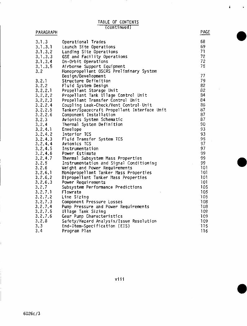
3.1.3 3.1.3.1 3.1.3.2 3.1.3.3 3.1.3.4 3.1.3.5 3.2
3.2.1 3.2.2 3.2.2.1 3.2.2.2 3.2.2.3 3.2.2.4 3.2.2.5 3.2.2.6 3.2.3 3.2.4 3.2.4.1 3.2.4.2 3.2.4.3 3.2.4.4 3.2.4.5 3.2.4.6 3.2.4.7 3.2.5 3.2.6 3.2.6.1 3.2.6.2 3.2.6.3 3.2.7 3.2.7.1 3.2.7.2 3.2.7.3 3.2.7.4 3.2.7.5 3.2.7.6 3.2.8 3.3 3.4
TABLE OF CONTENTS (con ti nued 1
Operat ional Trades Launch S i t e Operations Landing S i t e Operations GSE and F a c i l i t y Operations On-Orbi t Operations A i rborne Support Equipment blonopropel 1 a n t OSCRS Pre l i m i nary System Desi gn/Devel opment S t ruc tu re D e f i n i t i o n F l u i d System Design Propel 1 a n t Storage U n i t P r o p e l l a n t Tank U l lage Contro l U n i t P r o p e l l a n t Trans fer Contro l U n i t Coup1 i n g Leak-Check/Vent Cont ro l - U n i t Tanker/Spacecraft P r o p e l l a n t I n t e r f a c e U n i t Component I n s t a l l a t i o n Av ion ics System Schematic Thermal Sys tem De f i n i ti on Envelope I n t e r i o r TCS F l u i d Trans fer System TCS Av ion ics TCS I ns tr umen t a t i on Power Estimate Thermal Subsysten: Mass P roper t i es Ins t rumenta t ion and Signal Cond i t i on ing Weight and Power Requirements Monopropel 1 a n t Tanker Flass P roper t i es B i propel 1 a n t Tanker Mass P roper t i es Power Requirements Subsystem Performance P r e d i c t i o n s F1 owrate L ine S i z i n g component Pressure Losses Pump Pressure and Power Requirements U l lage Tank S i z i n g Gear Pump C h a r a c t e r i s t i c s Safety/Hazard Ana lys i s / I ssue Resol u t i on End- Item-Speci f i ca t i on ( EIS) Program Plan
PAGE
68 69 71 72 72 75
77 79 02 82 54 84 8G 87 87
90 93 93 95 57 97 99 99 99 101 101 101 101 105 105 105 108 108 109 109 109 115 116
a7
v i i i
6026c/3
TABLE OF CONTENTS (cont inued)
PARAGRAPH
4.0 4.1 4.1.1
4.1.2
4.1.3 4.1.4 4.1.5
4.1.6 4.1.7
4.1.9 4.1.10 4.1 .ll 4.2 4.2.1 4.2.2 4.2.3 4.2.4 4.2.5 4.2.6 4.3 4.4
4.1 .a
PAGE - Conceptual B i propel 1 a n t Sys tern Desi Qn 121 B i p r o p e l l a n t Unique Trade Studies 121 System Design Requiremerits f o r Various F1 u i d Retent ion Devices 121 On-Orbi t Vent ing and Dumping L i m i t a t i o n s f o r
B i p r o p e l l a n t Hardware A v a i l a b i l i t y 127 F l u i d Capaci ty and Tankage S i z i n g 127 B i propel 1 a n t Spacecraf t Propel 1 a n t Tank Vent ing Techniques 129 Thermal Control Techniques/Hardware 130 Opt imiza t ion o f B i p r o p e l l a n t Av ion ics Control 130 Launch S i t e Operat ions 132 Landing S i t e Operations 132 GSE and Faci 1 i ty Operations 134 B i p r o p e l l a n t System Weight and Power Ana lys is 134 Conceptual Desi gn/Documentation 136 S t r u c t u r a l D e f i n i t i o n 137 F1 u i d Sys tern Schema ti c 137 Av i on i cs Sy s tern Schema t i c 139 Thermal System D e f i n i t i o n 139 Ins t rumenta t ion and Signal Cond i t ion ing 139 P r e l im inary Safety/Hazard Analys is 141 Connnonal i ty Assessment 141 D r a f t Program Plan 144
B i p r o p e l l a n t s 122
6026c/4 i x
L i s t O f F i gures
F i gure
1 .o-1 1 .o-2 2.0-1 2.1-1
Page
2 3 6
2.1-2
3.1.1.1 -1 3.1.1.3-1 3.1.1.3-2 3.1.1.3-3 3.1.1 .5-1A 3.1.1.5-1B 3.1.1.5-2
3.1.1.6-1 3.1.1.7-1 3.1.1.7-2 3.1.1.7-3 3.1.1.7-4
3.1.1.9-1 3.1.1.1 0-1 3.1.1.11-1 3.1 .1 .12-1 3.1.1.13-1 3.1.1.1 3-2 3.1.1.13-3 3.1.1.14-1 3.1.1.1 5-1
3.1.1.1 5-3 3.1.2. 5-1 3.1.2.6-1 3.1.2.9-1 3.1.2.9-2 3.1.2.10-1 3.1.2.10-2 3.1.3.1-1 3.1.3.1-2 3.1.3.3-1 3.1.3.3-2 3.1.3.4-1 3.1.3.5-1
3.1.1.1 5-2
OSCRS Master Sctiedul e (OMS-01 ) Hybr id Ear th S torab le P r o p e l l a n t Tanker Concept OSCRS Study Task Flow Diagram Pred ic ted Ear th S torab le P r o p e l l a n t Tanker In-Bay Resupply Engagements by Community Segment Hydrazine (N2H4) Monopropel-lant O r b i t a l Resupply Requirements by Communi ty Segment Hybr id OSCRS Concept FSS Latch/Payl oad Bay Door Clearance CCTV Tracks GRO Grapple Target B e r t h i n g Latch Ass'y Emergency Separat ion OSCRS t o O r b i t e r Av ion ics I n t e r f a c e Power D i s t r i b u t i o n Concept O r b i t e r I n t e r f a c e s Layout o f AFD t o Support OSCRS Operat ions Software Development F1 ow f o r M i s s i on-Unique Modules U1 lage Recompression Resupply Method U1 lage Exchange Resupply Method U1 lage Vent/Repressur izat ion Resupply Method Residual Removal /U11 age Ven t /Repressur i za t i o n Resupply Method F1 u i d Q u a n t i t y Gaging Se lec t ion I n t e r f a c e s Establ i s h General S t r u c t u r e Envelope Dynamic Analys is MSC/NASTRAN Model F1 u i d Transfer Emergency Disconnect Sequence Monopropellant Tanker Growth Added Propel 1 a n t Storage Added P r o p e l l a n t Storage On-Orbi t Relocat ion OSCRS Avion ics System Block Diagram OSCRS FMDM Av ion ics Control Concept GRO Resupply Opt ions Vent ing Techniques OSCRS Control Panel Nominal Operat ing Sequence G R i D Computers and Graphic D isp lay Example OSCRS Caution and Warning OSCRS Processing T i m e l i n e (KSC) OSCRS Processing T i me1 i n e ( VAFB ) Typica l Hand1 i n g GSE Concept Typica l F l u i d/Mechani c a l GSE Concepts Transfer Operat ion Timel i n e MFR/RM'S Modi f i c a t i ons
7
a 12 14 1 4 1 5
176 1 7 A I 19 21 22 22 24
24 27 29 30 33 33 35 35 37 37 39 39 48 50 56 56 59 E9 70 70 73 73 74 76
X
6026c/ 5
L i s t o f F igures Page F i gures
3.2-1 3.2.1-1
3.2.1 -3 3.2.1-4 3.2.2-1 3.2.2-2
3.2.1.2
3.2.2-3 3.2.2-4 3.2.2.6-1 3.2.3-1 3.2.3-2 3.2.3-3 3.2.3-4
3.2.3-6 3.2.4.2-1 3.2.4.2-2 3.2.4.5-1 3.2.7.1-1 3.2,7.6-1 3.4-1
3.2.3.5
3.4-2
3.4-3 4.1 . l - 1 4.1.7-1 4.1.7-2 4.2.2-1 4.2.2-2
4.2.3-1 4.4-1 4.4-2
Monopropel lant OSCRS Tanker Basic S t r u c t u r a l Dimensions Basic S t r u c t u r e Features Simp1 e Shear J o i n t s Longeron-Trunnion/Fi t t i n g S t r u c t u r e Major S t r u c t u r a l Components Basel ine Monopropel lant F1 u i d Subsystem Schematic Schematic o f P r o p e l l a n t Storage and U1 lage Control U n i t Schematic of P r o p e l l a n t Transfer Control U n i t Schematic o f Coup1 i n g Leak/Vent Contro l U n i t Component I n s t a l l a t i o n OSCRS Av ion ics System Block Diagram Av ion ics Control Concept OSCRS FMDM Redundant Measurement Concept OSCRS Caution And Warning Avion ics Component I n s t a l l a t i o n Thermal Control Sys tern Concepts Thermal Subsys tern Schema ti c Temperature Ins t rumenta t ion ( A1 1 Subsys tems ) U1 lage Recompression Sys tem-Pump Fed Sys tern Geer Pump w i t h Motor Cross Sect ion Orbi t a l Spacecraf t Consumables Resupply Sys tern (OSCRS) Nork Breakdown S t r u c t u r e Phase C / D OSCRS Monopropel lant Tanker Phase C/D Program Schedule Task I n t e r a c t i o n Index F l u i d Transfer System Design Opt ions Automated vs. C r e w Control l e d Funct ions B i p r o p e l l a n t Resupply Control Panel Basel ine B i p r o p e l l a n t F l u i d Subsystem Schematic Fuel Basel ine B i p r o p e l l a n t F l u i d Subsystem Schematic - Ox id izer B i p r o p e l l a n t Av ion ics System Block Diagram B i p r o p e l l a n t OSCRS Program WBS OSCRS B i propel 1 a n t Tanker Phase C / D Program Schedule
78 8 0
81 81 8 3
ao
a3
aE; aa 85
89 89 91 91 91 92 94 96 98 1 06 110
117
118 118 i 23 133 133 138
138 140 145 1 4 5
6026c / 6 x i
L i s t o f Tables Tab1 e
2.1-1
2.1-2
3.1.1 . l - 1 3.1.1.11-1 3.1.2.1-1 3.1.2.1-2 3.1.2.1-3 3.1.2.2-1 3.1.2.2-2 3.1.2.4-1
3.1.2.4-2
3.1.2.5-1 3.1.2.6-1 3.1.2.8-1 3.1.2.9-1 3.1.2.10-1 3.1.2.10-2
3.1.2.11-1
3.1.2.11-2 3.1.2.11-3 3.1.2.11-4 3.1.2.13-1 3.1.3.5-1 3.2.4.7 -1 3.2.5-1 3.2.6.1-1 3.2.6.1-2 3.2.6.1-3
3.2.6.2-1 3.2.6.3-1 3.2.7.2-1 3.2.7.3-1 3.2.7.5-1 3.2.8-1 4.1 . l - 1 4.1.2-1 4.1.4-1
4.1.5-1 4.1.6-1 4.1.11-1 4.1 .11-2
Monopropel lant User Quanti t i e s and Resupply Engagements (1990-2002) B i propel 1 a n t User Ouanti t i e s and Resupply Engagements
Pr imary S t r u c t u r e Weight vs. F l u i d C a r r y i n g Capaci ty Conf igura t ion Mei gh t Summary GRO Monopropel 1 a n t Tanker F1 u i d System Component Test Thermal Control Subsystem Equipment L i s t (GRO) Av ion ics Equipment L i s t (GRO Miss ion) Diaphragm P r o p e l l a n t Tank C h a r a c t e r i s t i c s Diaphragm Tank Propel 1 a n t Volume Advantages and Disadvantages o f an E l e c t r o n i c a l l y C o n t r o l l e d Pressure Regulator f o r a P r o p e l l a n t Trans f e r Sys tem Advantages and Disadvantages o f a Var iab le O r i f i c e Flow Control Device f o r a P r o p e l l a n t Trans fer System w i t h a F ixed Pressure Regulator GRO P r o p e l l a n t Resupply System Comparison A Comparison o f Various Vent ing Methods Temperatue Ins t rumenta t ion ( A l l Subsystems) Automated vs. C r e w C o n t r o l l e d Funct ions Advantages o f Graphic Disp lays R e l a t i v e Advantages and Disadvantages o f D i f f e r e n t D i s p l ay Te c h n i que s F a i l u r e Tolerance Requirements E s t a b l i s h Need f o r Redundant Sys tems Redundancy Concept A1 t e r n a t i v e s Selected Redundancy Concept F a i l u r e Tolerance Versus Redundancy Pressurant Trans f e r Opt ions A i rborne Support Equi pment Wei gh t Summary Ins t rumenta t ion Requirements Basel ine (GRO) l a n k e r Mass & C. G. Growth Monopropel 1 a n t Tanker Mass & C. G. Base1 i n e (GRO) Monopropellant Mass P r o p e r t i e s & C. G. Locat ions F u l l y Loaded B i p r o p e l l a n t Tanker Mass & C.G. OSCRS Power Requirements ( Watts ) System Pressure Drops and Plumbing Weights N2H4 Components Pressure Losses Pump Energy Required vs. Ul lage Tank Volume STS Payload Safety Requirements A p p l i c a b i l i t y M a t r i x P o t e n t i a l B i propel 1 a n t Resupply Scenarios P o t e n t i a l Damage t o the O r b i t e r by MMH and NTO B i p r o p e l l a n t Resupply Module P r o p e l l a n t Tank Options, Trans ferab le P r o p e l l a n t Capaci ty A Comparison o f Various Vent ing Methods Temperature Ins t rumenta t ion ( A l l Subsystems) B i p r o p e l l a n t Tanker Mass & C.G. Locat ion Summary B i propel 1 a n t Sys tem Power Requirements
( 1 990-2002 )
Page
7
8 12 30 42 43 43 4 5 45
47
47 48 50 55 & C " 1
Ea
58
61 61 63 63 07 76 100 100 102 102 103
104 104 107 107 11 0 111 123 125
128 7 28 131 135 135
x i i 6026c/7
A
1 .O I n t r o d u c t i o n
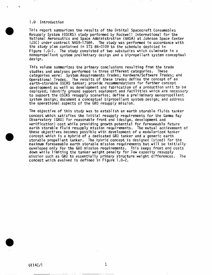
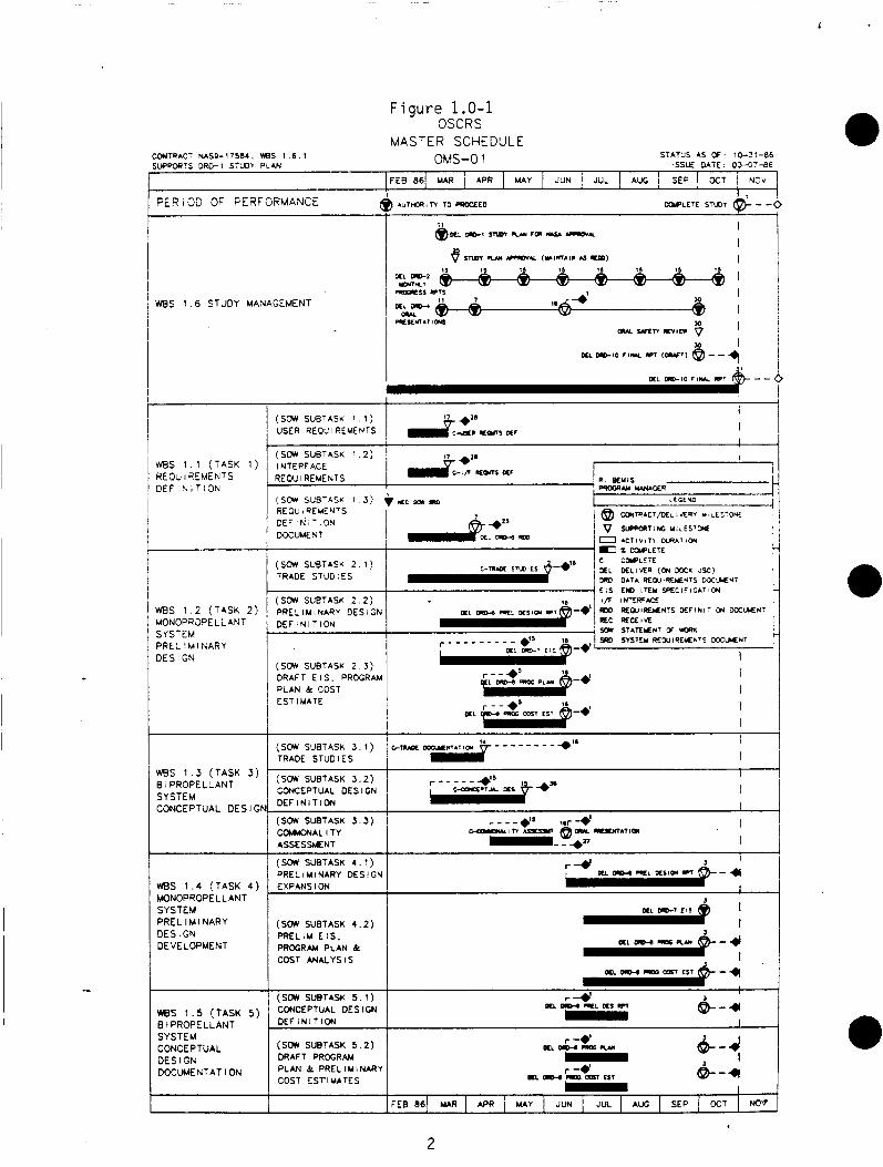
T h i s r e p o r t summarizes t h e r e s u l t s o f t h e O r b i t a l Spacecra f t Consumables Resupply System (OSCRS) s tudy performed by Rockwell I n t e r n a t i o n a l f o r t h e Na t iona l Aeronaut ics and Space Admini s t r a t i o n (NASA) a t Johnson Space Center (JSC) under c o n t r a c t NAS9-17584. The study was performed i n accordance w i t h t h e s tudy p l a n conta ined i n STS 86-0109 t o t h e schedule dep ic ted i n F igu re 1.0-1. nionopropell a n t system p r e l in i inary des ign and a b i p r o p e l l a n t system conceptual design.
The study c o n s i s t e d o f two substudies which cu lmina te i n a
T h i s volunie summarizes t h e pr imary conc lus ions r e s u l t i n g f rom t h e t r a d e s t u d i e s and analyses performed i n t h r e e d i f f e r e n t ca tegor ies . c a t e g o r i e s were: Operat ional Trades. e a r t h - s t o r a b l e OSCRS tanker ; p rov ide recommendations f o r f u r t h e r concept development as w e l l as development and f a b r i c a t i o n o f a p roduc t i on u n i t t o b e deployed; i d e n t i f y ground suppor t equipment and f a c i l i t i e s which a r e necessary t o suppor t t h e OSCKS resupp ly scenar ios ; d e f i n e a p r e l i m i nary monopropel 1 a n t system design; document a conceptual b i p r o p e l l a n t system design; and address t h e opera t i ona l aspects o f t h e GRO resupp ly miss ion.
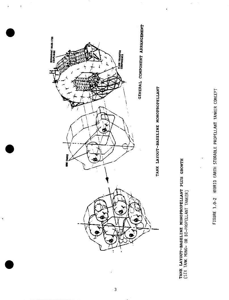
The o b j e c t i v e o f t h i s s tudy was t o e s t a b l i s h an e a r t h s t o r a b l e f l u i d s tanke r concept which s a t i s f i e s t h e i n i t i a l resupp ly requi rements f o r t h e Gama Ray Observatory (GRO) f o r reasonable f r o n t end (des ign, development and v e r i f i c a t i o n ) c o s t w h i l e p r o v i d i n g growth p o t e n t i a l f o r foreseeable f u t u r e e a r t h s t o r a b l e f l u i d resupp ly miss ion requirements. The mutual achievement o f these o b j e c t i v e s becomes p o s s i b l e w i t h development o f a modular ized tanke r concept which i s a h y b r i d o f a dedicated GRO t a n k e r and a gener ic e a r t h s t o r a b l e p r o p e l l a n t tanker . maximum foreseeab le e a r t h s t o r a b l e m iss ion requi rements b u t w i l l be i n i t i a l l y developed o n l y f o r t h e GKO m iss ion requirements. down w h i l e l i m i t i n g t h e tanke r we igh t pena l t y f o r low c a p a c i t y resupp ly m i s s i o n such as GRO t o e s s e n t i a l l y p r imary s t r u c t u r e we igh t d i f f e r e n c e s . The concept which evo lved i s d e f i n e d i n F igu re 1.0-2.
These System Requirememts Trades; Hardware/Software Trades; and
The r e s u l t s o f these t rades d e f i n e t h e concept o f an
The h y b r i d concept i s designed ( s i z e d ) f o r t h e
Th is keeps f r o n t end c o s t s
01 14C/1 1
1
CONCEPTUAL DES I GN
Figure 1.0-1 OSCRS
MASTER SCHEDULE
"-' "" ' '-. I
(SW SUBTASK S.3) CCWKNAL I TY
- - - et' let- -e' , I -,TI UZSn 0- LlCWIllQ
I ASSESWNT D- - *n
FER I 3D OF PEZFORMANCE f
WgS 1 . 4 (TASK 4 ) MONOPROPELLANT
STAT:'S AS O F : 10-2:-86 ISSUE DATE Ot-37-BE OMS-0 1
(SW SUBTASK 4 . 1 ) J I
PRELIMINARY DESiGN r-* K L Dlly W L E S I U ICT p- 4 EXPANSION I
WBS 1 . 6 STUDY MANAGEMENT
(SW SUBTASK 4 .2) PRELIU E l f .
SYSTEM PRELIMINARY DES I GN
K t U b I K L M L N 1 3
D E E I N I T i 3 N
(SW SUBTASK 5 1 )
I X W L E T E ' L L OELIVER (01 DOCK S C ) 1 rW DATA REXIIREIAENTS D S C ' M N T
1 (SOW SUBTASK 2 . 1 ) I TRADE STUDIES
r -Y
I I 4 E I S ElO ITEM SPECIFICATIW
ms 1 . 5 (TASK 5 ) BIPROPELLANT
UtSlbN
CONCEPTUAL DESIGN DEF i N I T i ON
(SW SUBTASK 2 3) DRAFT € I S . PROGRAM PLAN & COST
I ' (SW SUBTASK 3 . 1 ) G-TUOL -niiim - - - - - - - - + l a I TRADE STUDIES 1 A (SW SUBTASK 3 . 2 ) CWXPTUAL DESIGN - . T u X I
nrr I u I T I NI
BiPROPELLANT SYSTEM
2
X z a: E
CL 0 o: e
I I- o: 5
I 0
3
I
2.0 Analys is /Trade Study Resu l t s
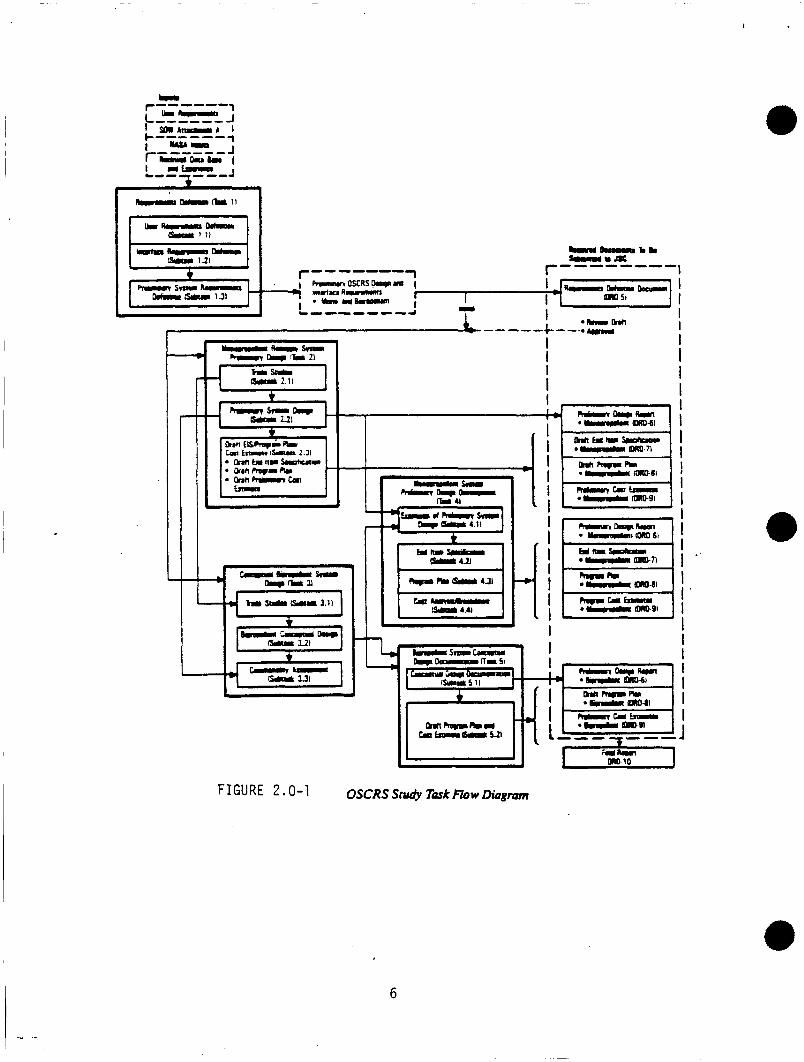
The OSCRS s tudy c o n s i s t e d o f f i v e statement o f work tasks. performed i n accordance w i t h t h e s tudy p l a n conta ined i n STS 86-0109 t o t h e schedule dep ic ted i n F i g u r e 1.0-1. The f i v e s tudy tasks were i n t e r r e l a t e d as shown i n F i g u r e 2.0-1 t o achieve a f i n a l o b j e c t i v e o f d e f i n i n g a c o s t and we igh t e f f e c t i v e e a r t h s t o r a b l e p r o p e l l a n t t anke r which can be used t o resupp ly spacec ra f t i n t o t h e 21s t Century. The f o l l o w i n g d iscuss ions summarize t h e r e s u l t and conc lus ions reached i n each s tudy t a s k phase.
2.1 User Requirements D e f i n i t i o n
These tasks were
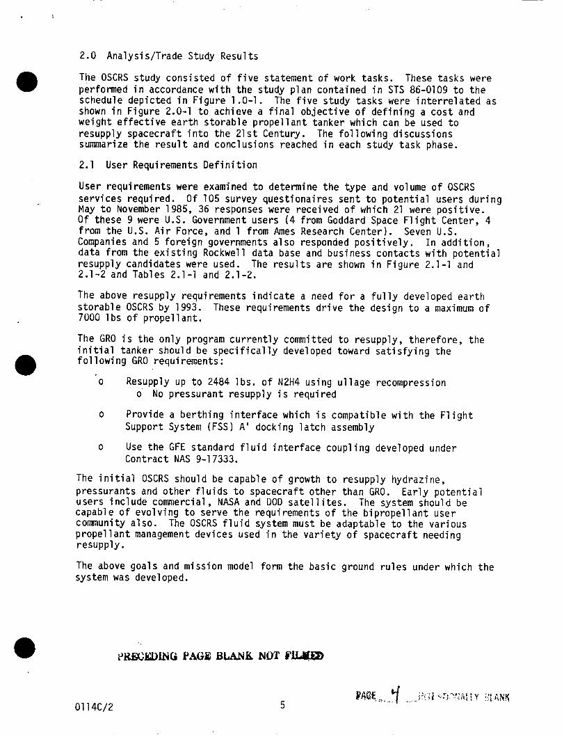
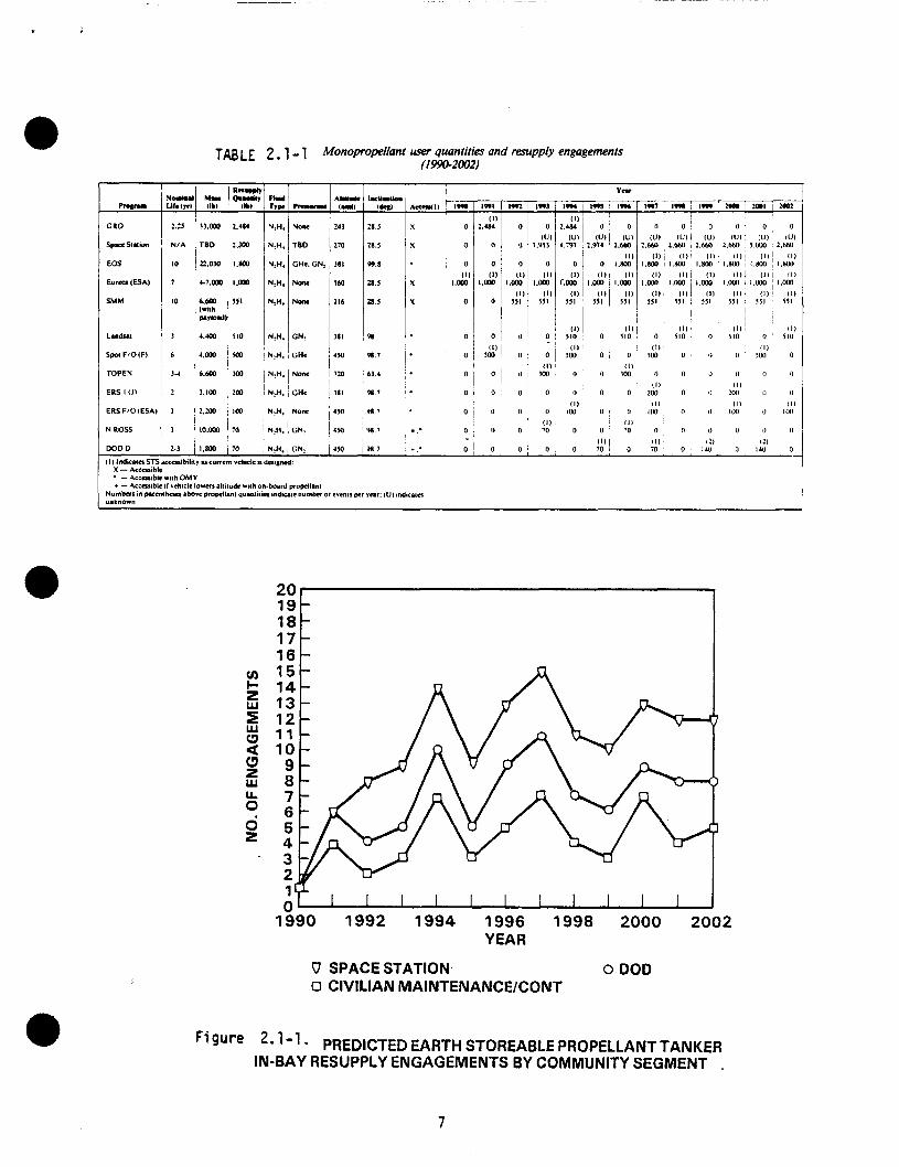
User requi rements were examined t o determine t h e t ype and volume o f OSCKS se rv i ces requ i red . May t o November 1985, 36 responses were rece ived o f which 21 were p o s i t i v e . O f these 9 were U.S. Government users ( 4 from Goddard Space F l i g h t Center, 4 f rom t h e U.S. A i r Force, and 1 f rom Ames Research Center ) . Companies and 5 f o r e i g n governments a1 so responded p o s i t i v e l y . I n a d d i t i o n , da ta f rom t h e e x i s t i n g Rockwell data base and bus iness con tac ts w i t h p o t e n t i a l resupp ly candidates were used. 2.1-2 and Tables 2.1-1 and 2.1-2.
O f 105 survey ques t i ona i res sen t t o p o t e n t i a l users d u r i n g
Seven U.S.
The r e s u l t s a re shown i n F i g u r e 2.1-1 and
The above resupp ly requi rements i n d i c a t e a need f o r a f u l l y developed e a r t h s t o r a b l e OSCRS by 1993. 700G l b s o f p r o p e l l a n t .
These requirements d r i v e t h e des ign t o a maximum o f
The GRO i s t h e o n l y program c u r r e n t l y committed t o resupply , there fore , t h e i n i t i a l t anke r should be s p e c i f i c a l l y developed toward s a t i s f y i n g t h e f o l 1 owing GRO requi rements :
o Resupply up t o 2484 l b s . o f N2H4 us ing u l l a g e recompression
Prov ide a b e r t h i n g i n t e r f a c e which i s compat ib le w i t h t h e F l i g h t Support System (FSS) A ' dock ing l a t c h assembly
Use t h e GFE standard f l u i d i n t e r f a c e c o u p l i n g developed under Cont rac t NAS 9-1 7333.
o No pressu ran t resupp ly i s r e q u i r e d
o
o
The i n i t i a l OSCRS should be capable of growth t o resupp ly hydraz ine, p ressurants and o t h e r f l u i d s t o spacec ra f t o t h e r than GKO. use rs i n c l u d e commercial, NASA and DOD s a t e l l i t e s . capable o f e v o l v i n g t o serve t h e requi rements o f t h e b i p r o p e l l a n t use r community a lso . p r o p e l l a n t management dev ices used i n t h e v a r i e t y o f spacec ra f t needing resupp ly .
The above goa ls and m iss ion model form t h e bas i c ground r u l e s under which t h e system was developed.
E a r l y p o t e n t i a l The system should be
The OSCRS f l u i d system must be adaptable t o t h e va r ious
01 14C/2 5
._ r------ 1 I W'I
6
i
a TAB LE 2.1 - 1 Monopropeliant user quantities and resupply engagements (1990-2002)
I d & ch) 28 5
18.5
99.8
1.5
3 . 5
Po
98.7
61.4
VU.1
98 1
N!H. 1 NOM
N& TED
N,H. CHc.GN:
N,H. Nonc
N,H.
NtH. GN?
N,H. CHe
N:H. NOM
N,H, GHc
NIH. I NOM
241
210
38 I
IM
216
I8 I
4%
720
181
450
4%
NIA
22.030 1.800
c7.m 1.m
6.600 551 W t h p . Y l 0 . d )
4.- I 110
4,000 Ism
'6.600 300
I ~ i m :m
' I
I 2,:m Im
lo.m 10
Ill/ Ill ' Ill ~ Ill 110 , 0 ' 110 , 0 110 0 SI0 L . " h
Spol F/O(F)
TOPEX
ERS-I 11)
111 I 11) I Ill 0 0 1 1001 o i 0 IM 0 0 0 5w 0
I
O i 0 , 0
(1) ' m o o
0 0 0 Ill,
0 la, 0
11) 10 0 0
0 , 0
: 0 0
ERS FlO(ESA)
NROSS 3 I
1 N,H CN:
I ' I 98 7
u) c E a E
0
L w c3
Q
u. 0
2
1
V SPACE STATION 0 DO0 0 CIVILIAN MAINTENANCEKONT
Figure 2- 1-1 PREDICTED EARTH STOREABLE PROPELLANT TANKER IN-BAY RESUPPLY ENGAGEMENTS BY COMMUNITY SEGMENT .
7
1 .
20 19 18 17 16 15 14 13
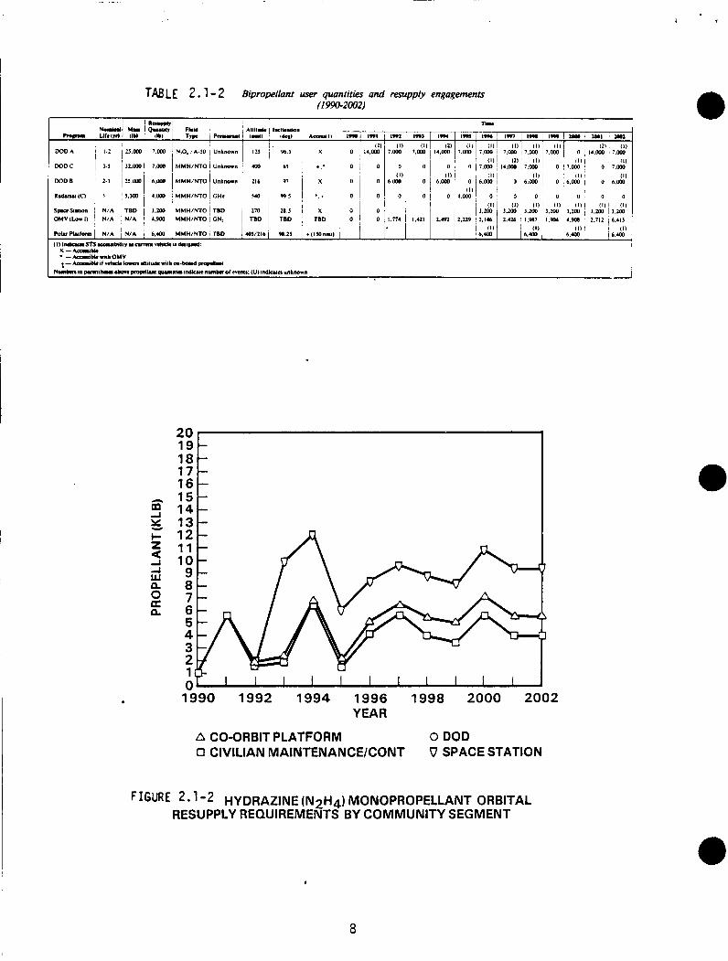
T& LE 2.1 - 2 Bipropellant user quantities and resupply engagements (1990-20021
- - - - - - -
m-0-
DOD A
DOD C
DOD B
R.duul IC1
SpucSl"lo" OMV ( L a 1)
I
TYW I -. n.u j
N.O. iA.50 I Unknown
MMH~NTO i unknown
MMHlNTO Unknown
MMWNTO i CHe
MMHlNTO ! TED MMH/NTO i CN:
12J
yx)
216
54a
210 TBD
MMHlNTO 1 TBD OJ1216
I deuy*d:
B J
6)
97
9 9 5
28 J TED
- A r m y 1 1 I-
X 0
: 0
X 0
*. * 0
X 0 TBD 0
- 1991
I2 I 4 . W
0
0
0
0 0
-
-
i 2 11 10 9 8 7 6 5 4 3 2 1
1990 1992 1994 1996 1998 2000 2002 YEAR
A CO-ORBIT PLATFORM 0 DOD 0 CIVILIAN MAlNTENANCElCONT V SPACE STATION
FIGURE 2 -1 -2 HYDRAZINE ( ~ 2 ~ 4 ) MONOPROPELLANT ORBITAL RESUPPLY REQUIREMENTS BY COMMUNITY SEGMENT
8
2. i! Orbi ter/Ground Fac i 1 i ties/Crew I n t e r f a c e Requirements D e f i n i t i o n
The Orb i te r /g round f a c i l i t y / c r e w i n t e r f a c e requi rements d e f i n i t i o n i s based on t h e r e s u l t s o f t h e va r ious t r a d e s tud ies d iscussed i n paragraph 3.1 and subsequent. The i n t e r f a c e requi rements a r e d e f i n e d i n d e t a i l i n t h e OSCRS End I tem S p e c i f i c a t i o n , pub l i shed as DRD-7 r e p o r t number STS 86-0272.
2.3 P re l im ina ry System Requirements D e f i n i t i o n
The p r e l im ina ry system requi rements d e f i n i t i o n i n t e g r a t e s user requi rements d e f i n i t i o n and Orb i te r /g round f a c i l i t i e s / c r e w i n t e r f a c e d e f i n i t i o n , t o d e f i n e and i d e n t i f y t h e f o l l o w i n g :
o
o
o
The composite s e t o f p r e l i m i n a r y requi rements
Trade s t u d i e s and a n a l y s i s f o r gener ic monopropel lant OSCRS
Trade s t u d i e s and a n a l y s i s f o r gener ic b i p r o p e l l a n t OSCRS
o P re l im ina ry recommendations f o r f u t u r e r e s e r v i c i n g requi rements and i n t e r f a c e c o n t r o l s
o Design requi rements t h a t c o u l d impact system design ( i .e . , l o n g l e a d t imes )
o Spacecra f t elements f o r s tandard i za t i on
o S a t e l l i t e c e r t i f i c a t i o n and des ign requi rements
The r e s u l t s o f t h e p r e l i m i n a r y system requi rements d e f i n i t i o n were documented i n accordance w i t h t h e requi rements o f DRL T-2008 as DRD-5, Requirements D e f i n i t i o n Document (RDD). development o f t h e OSCRS End- I tem-Spec i f i ca t ion d iscussed i n paragraph 3.3 o f t h i s r e p o r t .
The DRD-5 ROD was used as t h e b a s i s f o r t h e
01 14c/3 9
1
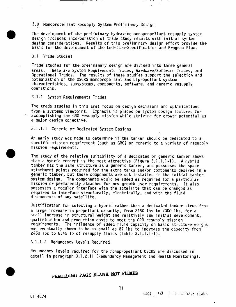
3 .U Monopropel 1 a n t Resupply System Pre l i m i nary Design
The development o f t h e p r e l im ina ry hydraz ine monopropel 1 a n t resupp ly systein des ign i nc ludes i n c o r p o r a t i o n o f t r a d e study r e s u l t s w i t h i n i t i a l system design cons idera t ions . b a s i s f o r t h e development o f t h e End- I tem-Spec i f i ca t ion and Program Plan.
3.1 Trade Stud ies
@ Resu l t s o f t h i s p r e l i m i n a r y des ign e f f o r t p rov ide t h e
Trade s tud ies f o r t h e p r e l i m i n a r y des ign a r e d i v i d e d i n t o t h r e e general areas. These a r e System Requirements Trades , Hardware/Software Trades, and Opera t iona l Trades. The r e s u l t s o f these s tud ies suppor t t t i e s e l e c t i o n and o p t i m i z a t i o n o f t h e OSCRS monopropel lant and b i p r o p e l l a n t system c h a r a c t e r i s t i c s , subsystems, components, sof tware, and gener i c resupp ly opera t ions .
3.1.1 System Requirements Trades
The t r a d e s t u d i e s i n t h i s area focus on des ign dec i s ions and o p t i m i z a t i o n s f rom a systems v iewpo in t . accompl ish ing t h e GRO resupp ly m iss ion w h i l e s t r i v i n g f o r growth p o t e n t i a l as a ma jor des ign o b j e c t i v e .
3.1.1.1
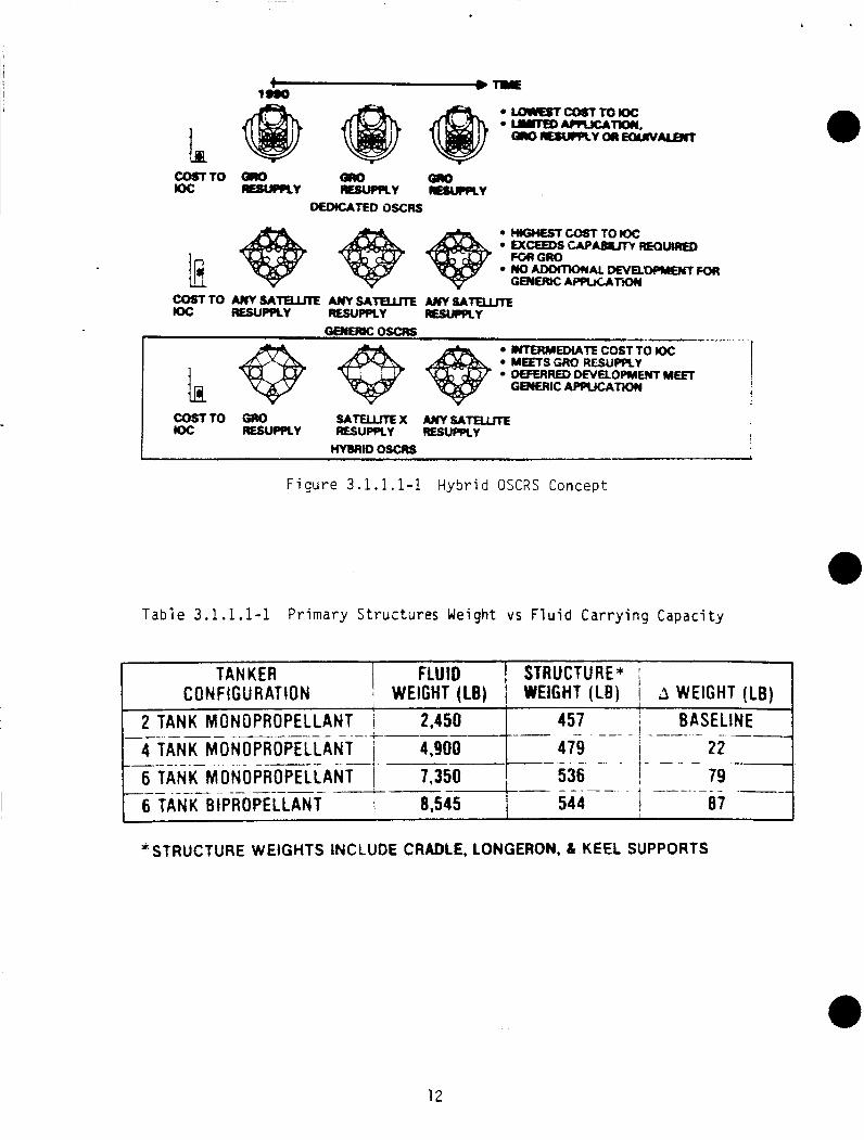
An e a r l y s tudy was made t o determine i f t h e tanke r should be ded ica ted t o a s p e c i f i c m iss ion requi rement (such as GRO) o r gener i c t o a v a r i e t y o f resupp ly m i s s i on r e q u i rement s . The s tudy o f t h e r e l a t i v e s u i t a b i l i t y o f a ded ica ted o r gener ic tanker shows t h a t a h y b r i d concept i s t h e most a t t r a c t i v e (F igu re 3.1.1 .1-1). A h y b r i d t a n k e r has t h e same s t r u c t u r e as a gener ic tanker , and possesses t h e space attachment p o i n t s r e q u i r e d f o r t he e x t r a tanks and/or components d e s i r e d i n a gener ic tanker , b u t these components a r e n o t i n s t a l l e d i n t h e i n i t i a l t anke r system design. The components would be added as r e q u i r e d f o r a p a r t i c u l a r m i s s i o n o r permanently a t tached f o r new growth user requirements. It a l s o possesses a modular i n t e r f a c e w i t h t h e s a t e l l i t e t h a t can be changed as r e q u i r e d t o i n t e r f a c e s t r u c t u r a l l y , e l e c t r i c a l l y , and w i t h t h e f l u i d d isconnects o f any s a t e l l i t e .
J u s t i f i c a t i o n f o r s e l e c t i n g a h y b r i d r a t t i e r than a ded ica ted tanker sterns from a l a r g e inc rease i n p r o p e l l a n t capac i t y , f rom 2450 l b s t o 7000 l b s , f o r a smal l inc rease i n s t r u c t u r a l we igh t and r e l a t i v e l y low i n i t i a l development, q u a l i f i c a t i o n and p roduc t i on c o s t s t o meet t h e GRO resupp ly m iss ion requi rements. The in f l uence o f added f l u i d c a p a c i t y on bas i c s t r u c t u r e we igh t was e v e n t u a l l y shown t o be as small as 87 l b s t o inc rease t h e c a p a c i t y f rom 2450 l b s t o 8545 l b o f resupp ly f l u i d s (Tab le 3.1.1.1-1).
3.1 . 1 .2 Redundancy Level s Required
Emphasis i s p laced on system design fea tu res f o r -
Generic o r Dedicated System Designs
Redundancy 1 eve1 s r e q u i r e d f o r t h e monopropel 1 a n t OSCRS a r e d i scussed i n d e t a i l i n paragraph 3.1.2.11 (Redundancy Management and Hea l th M o n i t o r i n g ) .
11
01 14C/4
L
TANKER FLUID
2 TANK MONOPROPELLANT I 2,450 4 TANK MONOPROPELLANT 1 4,900 6 TANK MONOPROPELLANT 1 7,350 6 TANK BIPROPELLANT I 8,545
C 0 N F I G U RAT ION i WEIGHT (LB)
_ _ _ _ _ _ - _ -- ----?---- --__ - - - - - -*
- - - __ .. __ - __ - - ----
-TO m m OR0 KK: R S U Q R Y
DEMCATED OSCRS
STRUCTURE* WEIGHT (LB) 1 3 WEIGHT (LB) '
457 I I BASELINE I - --- -- - - __
479 I 22 - - I - - - 7 9 536
a7
- _
-- - - . - - - - - 544
! h I
INTERMED1ATE COST TO Kw: MEFTS GRO RESUPPLY MFERRU) ORlELOPMEwT MEET GENWC APPUCATiW i
COST10 GRO SATuLmx AlyTSATuuTr Ioc RESUPPLY RESUPPLY RESUPPCY I - HYBRH)oscRs
F i g u r e 3.1.1.1-1 Hybrid O S C R S Concept
T a b l e 3.1.1.1-1 Primary Structures Weight vs Fluid Carrying Capacity
*STRUCTURE WEIGHTS INCLUDE CRADLE, LONGERON, L KEEL SUPPORTS
12
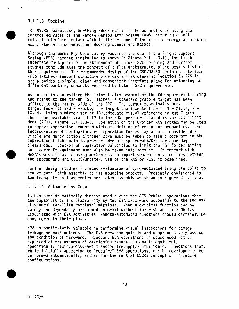
3.1.1.3 Docking
For OSCRS opera t ions , b e r t h i n g (dock ing) i s t o be accomplished us ing t h e c o n t r o l l e d ra tes o f the Remote tdanipu lator System (Rl lS) assur ing a s o f t i n i ti a1 i n t e r f a c e c o n t a c t w i t h 1 i t t l e o r none o f t he k i n e t i c energy absorp t ion associ a ted w i t h convent ional docking speeds and masses.
A1 though the Gamma Ray Observatory r e q u i r e s the use o f t he F1 i g h t Support System (FSS) l a t ches ( i n s t a l l e d as shown i n F igure 3.1.1.3-11, the l a t c h i n t e r f a c e must p rov ide f o r attachment o f f u t u r e S / C b e r t h i n g and f u r t h e r s tud ies conclude t h a t the concept o f a f l a t unobs t ruc ted p lane bes t s a t i s f i e s t h i s requirement. The recommended design o f t he GRO/OSCRS b e r t h i n g i n t e r f a c e (FSS l a t c h e s ) suppor t s t r u c t u r e p rov ides a f l a t p lane a t l o c a t i o n Zo 475.141 and prov ides a simple, c lean and convenient i n t e r f a c e p lane f o r a t t a c h i n g t o d i f f e r e n t b e r t h i n g concepts r e q u i r e d by f u t u r e S/C requirements.
As an a i d i n c o n t r o l l i n g the l a t e r a l displacement o f the GRO spacec ra f t d u r i n g the mating t o the tanker FSS la t ches , a s tandard grapp le t a r g e t has been a f f i x e d t o t h e mat ing s i d e o f the GRO. the t a r g e t face ( Z ) GRO = -76.00; t he t a r g e t s h a f t c e n t e r l i n e i s Y = 21.54, X = 12.44. Using a m i r r o r s e t a t 45O,adequate v i sua l re fe rence i n the Z a x i s shou ld be a v a i l a b l e v i a a CCTV t o the RMS opera tor l o c a t e d i n the a f t f l i g h t deck (AFD), F igu re 3.1.1.3-2. Operat ion o f the O r b i t e r RCS system may be used t o impar t separa t ion momentum w i t h o u t a d d i t i o n o f redundant mechanisms. The i n c o r p o r a t i o n of spr ing- induced separa t ion fo rces may a1 so be considered a v i a b l e emergency o p t i o n a l though ca re must be taken t o assure accuracy i n the separa t ion fl i g h t pa th t o p rov ide adequate spacecra f t /Orb i t e r appendage c learances. on spacec ra f t equipment must a l so be taken i n t o account. NASA's wish t o avo id us ing mechanisms t o impar t separa t i on v e l o c i t i e s between the spacec ra f t and OSCRS/Orbiter, use o f the RMS o r RCS, i s basel ined.
The t a r g e t coord ina tes are:
Contro l o f separa t ion v e l o c i t i e s t o 1 i m i t the "G" f o rces a c t i n g I n concer t w i t h
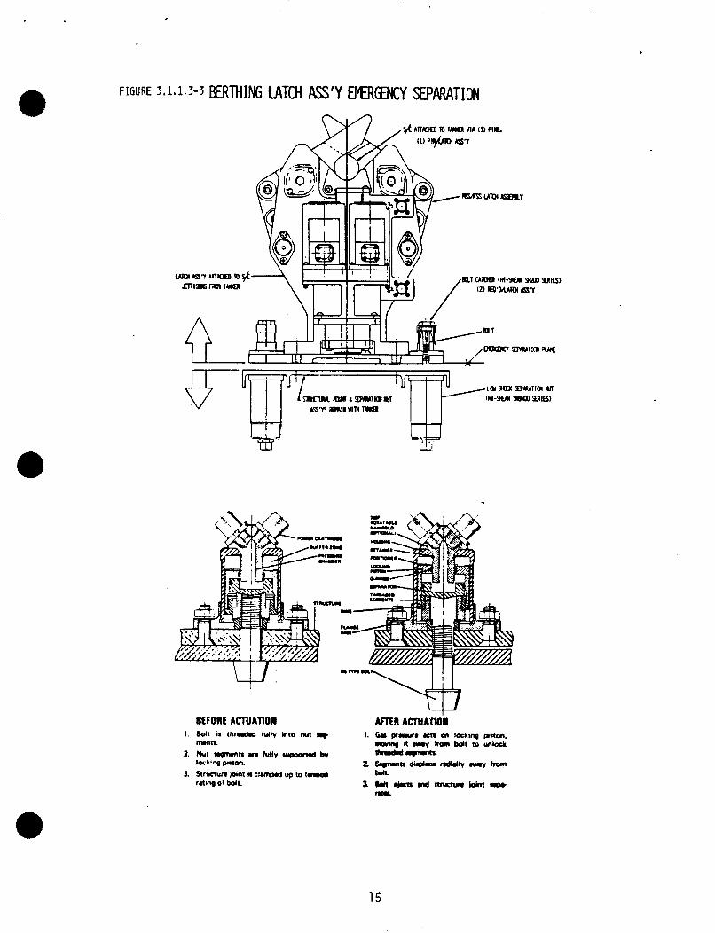
F u r t h e r des ign s tud ies i n c l u d e d e v a l u a t i o n o f pyro-ac tua ted f r a n g i b l e bo1 t s t o secure each l a t c h assembly t o i t s mounting bracket . Present ly env is ioned i s two f r a n g i b l e b o l t assembles pe r l a t c h assembly as shown i n F igu re 3.1.1.3-3.
3.1.1.4 Automated vs Crew
It has been d ramat i ca l l y demonstrated dur ing the STS O r b i t e r o p e r a t i o n s t h a t the c a p a b i l i t i e s and f l e x i b i l i t y by the EVA crew were e s s e n t i a l t o the success of severa l s a t e l l i t e r e t r i e v a l missions. When a c r i t i c a l f u n c t i o n can be s a f e l y and dependably performed o n - o r b i t w i t h o u t the r i s k and t ime delays assoc ia ted w i t h EVA a c t i v i t i e s , remote/autornated f u n c t i o n s shou ld c e r t a i n l y be cons idered i n t h e i r p lace.
EVA i s p a r t i c u l a r l y va luab le i n per forming v i s u a l i nspec t i ons f o r damage, leakage o r ma l func t ions . The EVA crew can q u i c k l y and comprehensively assess the c o n d i t i o n of hardware. expanded a t t he expense o f develop ing remote, automatic equipment, s p e c i f i c a l l y f l u i d / p r e s s u r a n t t r a n s f e r ( resupp ly ) u m b i l i c a l s . Funct ions t h a t , w h i l e i n i t i a l l y appearing t o " r e q u i r e " EVA opera t ions , can be developed t o be performed au tomat i ca l l y , e i t h e r f o r t he i n i t i a l OSCRS concept o r i n f u t u r e conf i g u r a t i ons .
However, EVA opera t ions i n space need n o t be
13
01 14c/5
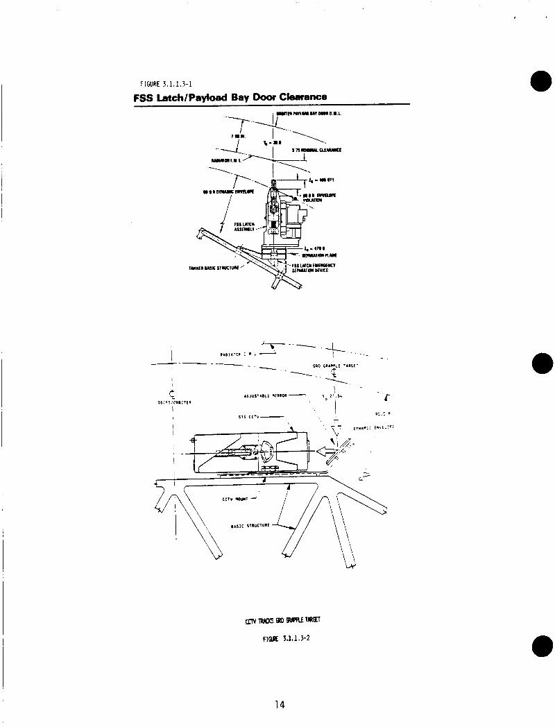
FIGURE 3.1.1 I 3-1
FSS Latch/Payloed Bay Door Clearance
~fT~mrrxSWwreRTTrnCn
FlQK 3.1.1.3-2
14
I=.;$.'
15
Aside from p o s s i b l e crew exposure t o hazardous chemicals d u r i n g p repara t i ons f o r and a f t e r p r o p e l l a n t d e l i v e r y , i t seems t o make the most sense t o l i m i t EVA a c t i v i t i e s t o those f u n c t i o n s t h a t , a f t e r thorough study, mandate t h e presence o f crew members. Where poss ib le , automated f l u i d and gas u m b i l i c a l s should be developed. P a r t i c u l a r l y i n f u t u r e resupply miss ions when t r a n s f e r r i n g b i p r o p e l l a n t s w i l l be requ i red , EVA should be l i m i t e d t o s u p p o r t i v e obse rva t i on and cont ingency e f f o r t s on ly .
Man's proven a b i l i t y i n space t o observe, assess, and improv ise has been proven and needs t o be u t i l i z e d and expanded, b u t n o t extended t o marg ina l o r unduly hazardous opera t i ons t h a t can be automated. Since the NAS9-17333 standard r e f u e l i n g coup1 i n g has been developed f o r t h e r e f u e l i n g o f hyd raz ine f o r t he GRO S/C, and s ince independent t i m e l i n e opera t i ons have been i d e n t i f i e d as w e l l w i t h i n the s i x -hou r t ime l i m i t on E V A ' S ( i n c l u d i n g cont ingency) t h e f i r s t usage o f t he OSCRS should i n c l u d e the EVA a c t i v i t i e s as planned. NASA should i n i t i a t e development o f a remote - automat ic system as d standard ized i n t e r f a c e t o d e l i v e r a l l f u t u r e consumables.
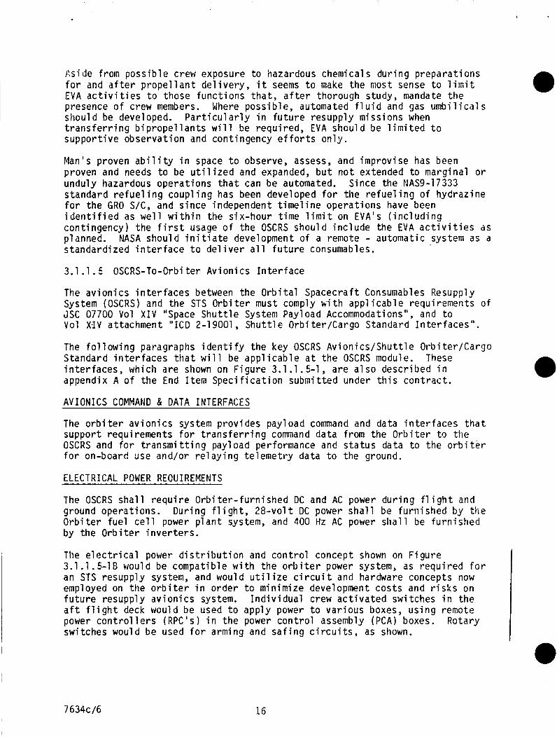
3.1 .l. 5 OSCRS-To-Orbi t e r Av ion i cs I n t e r f a c e
The a v i o n i c s i n t e r f a c e s between the O r b i t a l Spacecraf t Consunables Resupply System (OSCRS) and the STS O r b i t e r must comply k i t h a p p l i c a b l e requirements o f JSC 07700 Vol X I V "Space S h u t t l e System Payload Accommodations", and t o Vol X- IV at tachment " I C D 2-1 9001 , S h u t t l e Orbi ter /Cargo Standard I n t e r f a c e s " .
The f o l l o w i n g paragraphs i d e n t i f y t he key OSCRS A v i o n i c s / S h u t t l e Orb i te r /Cargo Standard i n t e r f a c e s t h a t w i l l be a p p l i c a b l e a t t h e OSCRS module. These i n t e r f a c e s , which a re shown on F igu re 3.1 .l. 5-1 , a r e a l s o desc r ibed i n appendix A o f t h e End I t e m S p e c i f i c a t i o n submi t ted under t h i s c o n t r a c t .
A V I O N I C S COMMAND & DATA INTERFACES
The o r b i t e r a v i o n i c s system p rov ides payload command and data i n t e r f a c e s t h a t suppor t requirements f o r t r a n s f e r r i n g command data from t h e O r b i t e r t o t h e OSCRS and f o r t r a n s m i t t i n g payload performance and s t a t u s data t o the o r b i t e r f o r on-board use and/or r e l a y i n g t e l e m e t r y data t o the ground.
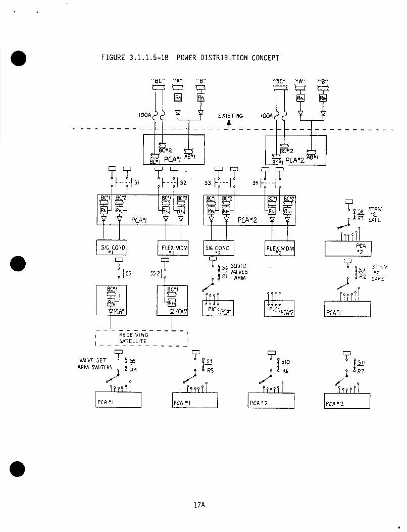
ELECTRICAL POWER REOUIREMENTS
The OSCRS s h a l l r e q u i r e O r b i t e r - f u r n i s h e d DC and AC power d u r i n g f l i g h t and ground operat ions. Dur ing f l i g h t , 2 8 - v o l t DC power s h a l l be f u r n i s h e d by the O r b i t e r f u e l c e l l power p l a n t system, and 1100 Hz AC power s h a l l be f u r n i s h e d by the O r b i t e r i n v e r t e r s .
The e l e c t r i c a l power d i s t r i b u t i o n and c o n t r o l concept shown on F i g u r e 3.1.1.5-16 would be compat ib le w i t h t h e o r b i t e r power system, as r e q u i r e d f o r an STS resupply system, and would u t i l i z e c i r c u i t and hardware concepts now employed on t h e o r b i t e r i n o rde r t o min imize development c o s t s and r i s k s on f u t u r e resupply a v i o n i c s system. I n d i v i d u a l crew a c t i v a t e d switches i n t h e a f t f l i g h t deck would be used t o apply power t o v a r i o u s boxes, u s i n g remote power c o n t r o l l e r s (RPC's) i n t h e power c o n t r o l assembly (PCA) boxes. Rotary switches would be used f o r arming and s a f i n g c i r c u i t s , as shown.
7634c/6 16
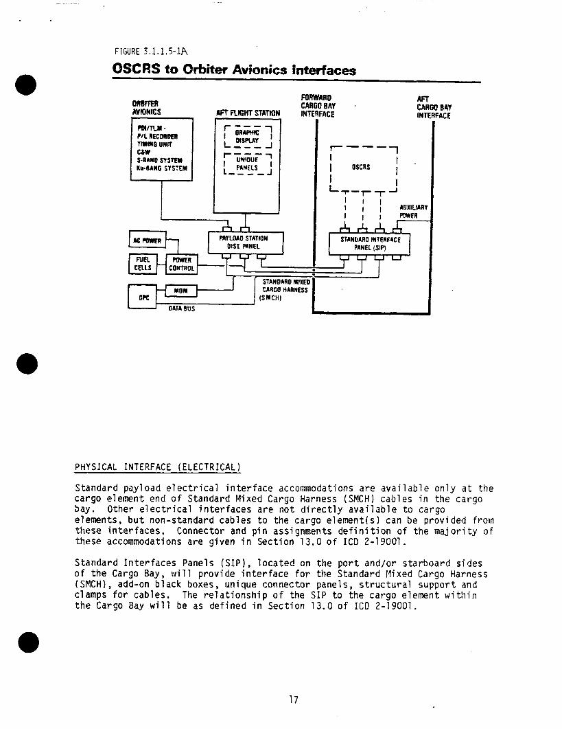
FIGURE ?,.I. 185-1A
OSCRS to Orbiter Avionics fnterfaces
onllm AVIONICS
7--- 1 I I . I OSCRS I I I LY-TT J
1 I l l I I AUXIUARY
A A A I I 1 POWFR
STANOARO INTERFACE PBNEL (SIP)
CELLS CONTROL
STANONID MIXED CARGO HARNESS
I T H " " Y '
(SMCH)
I.-cllh 1-1 PRYLMD STATION
FORWARO CARGO BAY INTERFACE
AFf CARGO BAY INTERFACE
PHYSICAL INTERFACE ( E L E C T R I C A L )
S t anda rd payload electr ical interface accommodations are available only a t the cargo element end of Standard Mixed Cargo Harness (SMCH) cables i n the cargo bay. Other electr ical interfaces are not directly available t o cargo elements, b u t non-standard cables t o the cargo elernent(s) can be provided f rom these interfaces. Connector and p i n assignments definition of the majority of these accommodations are g i v e n i n Section 13.0 of I C D 2-19001.
S tanda rd Interfaces Panels (SIP), located on the port a n d / o r s ta rboard sides o f the Cargo Bay, will provide interface fo r the S tanda rd Mixed Cargo Harness (SMCH) , add-on black boxes, un ique connector panels, structural suppor t and clamps fo r cables. The relationship o f the SIP t o the cargo element w i t h i n the Cargo Bay will be as defined in Section 13.0 of IC@ 2-19001.
17
I
FIGURE 3.1.1.5-16 POWER DISTRIBUTION CONCEPT
'' BC" " A " i5
IOOA /! u EX I ST I NG 4 - - - -
B V t - I
7 - - - I SI ?
s3
PCA'I
FL E ~ ~ M OM]
f 155-1 55-21
P P , j y p 4 1 1 ,
VALVE 5ET AkM SWITC> 1;
0
6
PCA I * PCA"2 T""1 PCA " I p"i PCA " 2
17A
.
A V I O t 4 I C S SUBSYSTEM/COt-lPONENT INTERFACES
O r b i t e r a v i o n i c s se rv i ces t h a t suppor t OSCRS m iss ion requirements f o r on-board c o n t r o l and data handl ing, and f o r command and data exchanges w i t h the ground, i n c l u d e the f o l l o w i n g subsystem and component i n t e r f a c e s . a re i n a d d i t i o n t o those f o r e l e c t r i c a l power and the phys i ca l i n t e r f a c e s presented e l sewhere.
These r e q u i retnents
o Payload Data I n t e r l e a v e r (PDI) o Payload Recorder o Data Bus o Mu1 t ip lexer /Demul t i p l e x e r (MCM) o Caut ion and Warning System o Master T iming U n i t o GPC Software
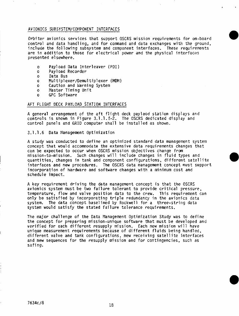
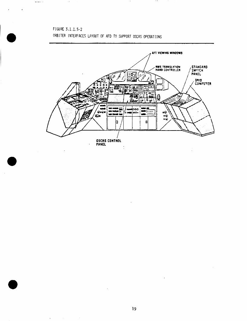
AFT FLIGHT DECK PAYLOAD STATION INTERFACES
A general arrangement o f the a f t f l i g h t deck paylaod s t a t i o n d i s p l a y s and c o n t r o l s i s shown i n F i g u r e 3.1.1.5-2. c o n t r o l panels and G R I D computer s h a l l be i n s t a l l e d as shown.
The OSCRS dedicated d i s p l a y and
3.1.1.6 Data Management Op t im iza t i on
A study was conducted t o d e f i n e an op t im ized s tandard data management system concept t h a t would accommodate the ex tens i ve da ta requirements changes t h a t can be expected t o occur when OSCRS m iss ion o b j e c t i v e s change from mission-to-mission. Such changes w i l l i n c l u d e changes i n f l u i d types and q u a n t i t i e s , changes i n tank and component c o n f i g u r a t i o n s , d i f f e r e n t s a t e l l i t e i n t e r f a c e s and new procedures. i n c o r p o r a t i o n o f hardware and so f tware changes w i t h a miniinurn c o s t and schedule impact.
The OSCRS da ta management concept must suppor t
A key requi rement d r i v i n g t h e data management concept i s t h a t t he OSCRS a v i o n i c s system must be two f a i l u r e t o l e r a n t t o p rov ide c r i t i c a l pressure, temperature, f l o w and va l ve p o s i t i o n data t o the crew. This requi rement can o n l y be s a t i s f i e d by i n c o r p o r a t i n 9 t r i p l e redundancy i n the a v i o n i c s data system. The data concept base l i ned by Rockwell f o r a t h r e e - s t r i n g data system would s a t i s f y the s t a t e d f a i l u r e t o l e r a n c e requirements.
The major chal lenge o f t h e Data tlranagement Op t im iza t i on Study was t o d e f i n e t h e concept f o r p r e p a r i n g mission-unique software t h a t must be developed and v e r i f i e d f o r each d i f f e r e n t resupply mission. Each new m iss ion w i l l have unique measurement requirements because o f d i f f e r e n t f l u i d s b e i n g handled, d i f f e r e n t va l ve and tank c o n f i g u r a t i o n s , new r e c e i v i n g s a t e l l i t e i n t e r f a c e s and new sequences f o r t he resupply m iss ion and f o r cont ingencies, such as s a f i ng.
7634c/8 18
F ! GU RE 3 I 1 I 1 5-2 ORBITER INTERFACES LAYOUT OF AFD T@ SiJPPORT OSCRS OPERATIONS
AFT VlEWlM6 WINDOWS
RMS TRAMSL4TIOI HAND CONTROLLER
OSCRS CONTROL * PANEL
19
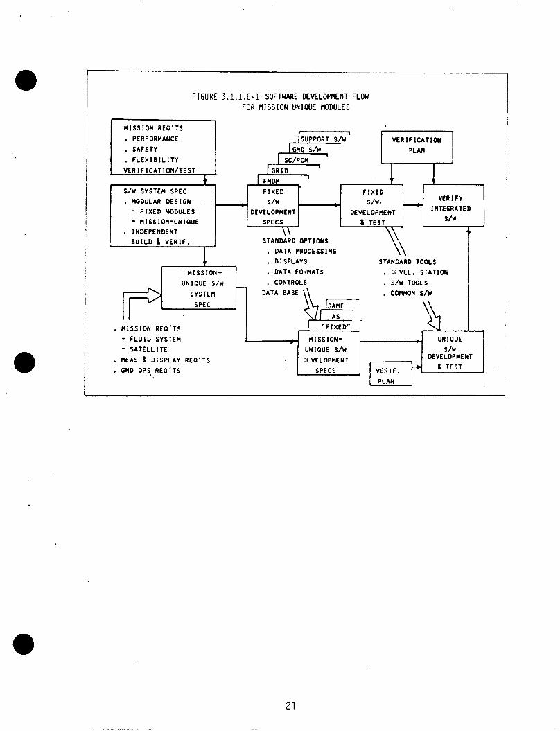
An optimized concept was described in the s tudy t h a t features a modular software design t h a t would permit individual payload contractors/customers t o develop and verify their own mission-unique software t h a t could then be efficiently integrated into the total f l igh t software package fo r a particular resupply mission. T h i s concept i s shown i n Figure 3.1.1.6-1.
The data management requirements significantly affect the avionics and software designs, and the recommendations for the optimized concept defined i n the study must be implemented a t the beginning of the design phase of the OSCRS program to achieve the required objectives.
3.1.1.7 Resupply Options f o r Various Receiver Propellant Tanks
The baseline OSCRS configuration was designed with the primary intent o f resupplying the Gamma Ray Observatory (GRO) with hydrazine. The GRO spacecraft uses a propulsion systern which operates in a blowdown mode s ta r t ing from 400 psia and ending a t 100 psia or less. For a system o f this type, an ullage recompression transfer will be used (see Figure 3.1.1.7-1).
Ullage recompression i s the simplest, and generally most e f f ic ien t method o f resupplying a s a t e l l i t e while on-orbit. Firs t , the propellant transfer coupling i s mated to the sa t e l l i t e , and the installation leak checks are performed. A flow restr ic t ing or i f ice controls i n i t i a l propellant flow i n t o the evacuated l ine u n t i l i t i s f i l l ed to equalized pressure. then opened. the supply t a n k . During this time the pumps are by-passed, and the flowrate i s controlled by a flow restr ic t ing orifice. (or fa i r ly c lose) , the pumps are started and the flow i s cofitinued.
The coupling i s Propellant transfer i s ini t ia ted using the excess pressure in
Once the pressures are equalized
During the transfer, the receiver spacecraft I s propel 1 a n t tank ull age gas temperature will increase due t o "adiabatic" compressive heating effects . A variable flowrate pump will be used t o control the maximum ullage temperature w i t h i n certain bounds as this occurs. Before the maximum allowable temperature is reached (Z 1 %OF), the flowrate i s decreased as required. The flowrate a t t h i s point will be established such t h a t the heat generated by compression i s equal t o the heat absorbed i n t o the receiver propellant t ank by radiation and conduction. This permits the fas tes t possible transfer, while maintaining adequate compression ignition safety margins.
Once the desired quantity of hydrazine has been transferred, the pumps are stopped; and the coup1 i n g closed, purged, leak checked, and disconnected.
Where applicable, this i s the most e f f ic ien t resupply method, since only one commodity need be transferred. Also, this transfer method h a s the advantage o f minimizing the amount of pressurant gas desaturating d u r i n g the f i l l process. The propellant supply tanks will be kept a t low pressure (hydrazine vapor pressure Z 20 ps i a ) d u r i n g ground turnaround and launch. Immediately before the transfer commences, a separate ullage bot t le will be used t o pressurize the propellant t a n k . Since gas saturation o f the propellant th rough the diaphragm i s very slow, the propellant will remain unsaturated throughout the transfer. Some gas w i l l effervesce i n t rans i t through the pump and a t certain flow restr ic t ions, b u t the total volume of free gas transferred t o the receiver tanks ( a f t e r being compressed t o 300 - 400 psia) will be minimal. Since the transferred propellant \vas only saturated t o 23 psia, this small amount of gas will a l l go back into solution.
20 7634c/8
I-
S/W SYSTEM SPEC . MODULAR DESIGN c - F I X E D MODULES - MISSION-UNIQUE
!
I F I X E D F I X E D
s/w s/w- VEA I F Y
s/w DEVELOPMENT DEVELOPMEM - INTEGRATED
SPECS
I
INDEPENDENT
B U I L D 8 V E R I F .
I
\\ 4 ' STANDARD OPTIONS
FIGURE 3.1.1.6-1 SOFTWARE DEVELOPMENT FLOW FOR MISSION-UNIQUE MODULES
UNIQUE S/W
SYSTEM
SPEC
M I S S I O N REO'TS
I PERFORMANCE
, SAFETY . F L E X I B I L I T Y
, CONTROLS , S/W TOOLS
DATA BASE , COMMON S/W
\SAME
I I I SUPPORT S/W V E R I F I C A T I O N
SC/PCM i G R I D I
. M I S S I O N REO'TS
- F L U I D SYSTEM
AS
I "FIXED"
; MISSION- - UNIOUE
4 , DISPLAYS
I M I S S I ON- . DATA FORMATS
- S A T E L L I T E
. MEAS 8 D I S P L A Y REO'TS
GND OPS. REO'TS
.
STANDARD TOOLS . DEVEL. STATION I
UNIQUE S/W s/w DEVELOPMENT
& TEST DEVELOPMENT
SPECS VERIF.
21
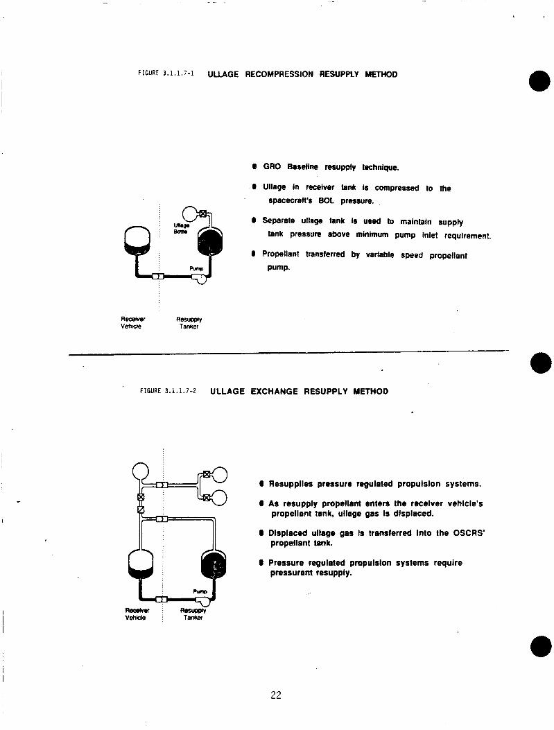
FIGURE 3.1.1.7-1 ULLAGE RECOMPRESSION RESUPPLY METHOD
0 GRO Baseline resupply technlque.
0 Ullage In receiver tank Is compressed to the
spacecraft's BOL pressure.
0 Separate ullage tank is used to maintain supply tank pressure above minimum pump Inlet requlrement.
0 Propellant transferred by variable speed propellant
Pump.
Aecerver Resupply Vehule Tanker
FIGURE 3.1.1.7-2 ULLAGE EXCHANGE RESUPPLY METHOD
0 Resupplles pressure regulated propulslon systems.
0 As resupply propellant enters the recelver vehlcle's propellant tank, ullage gas Is dlsplaced.
0 Dlsplaced ullage gas Is transferred Into the OSCRS'
0 Pressure regulated pmpulslon systems require
propellant tank.
pressurant resupply.
22
A t the present time, a1 1 o f the i d e n t i f i e d monopropel 1 a n t spacecra f t resupply candi dates e i t h e r have a d i aphragm-type propel 1 a n t tank , o r requ i r e u l 1 age recompression. The base1 i ne system w i 11 t h e r e f o r e s a t i s f y a1 1 foreseeable monopropell a n t needs w i t h o u t m o d i f i c a t i o n . When a1 t e r n a t e resupply methods are r e q u i r e d ( w i t h b i p r o p e l l a n t s f o r example) , the system i s e a s i l y adapted w i t h the a d d i t i o n o f s p e c i f i c modules.
e By adding u l l age and pressurant t r a n s f e r modules, u l l age exchange resupply o f pressure r e g u l a t e d systems i s a l s o p o s s i b l e (see F igure 3.1.1.7-2). resupply mode, t h r e e t r a n s f e r coupl ings are requ i red ; one f o r propel1 ant, one f o r pressurant, and one t o t r a n s f e r the u l l a g e . Using u l l a g e exchange, the r e c e i v e r sate1 1 i t e ' s pressurant tank i s f i r s t i sol a ted from the propel 1 a n t tank u l lage. A s f l u i d e n t e r s the r e c e i v e r p r o p e l l a n t tank, u l l a g e gas i s d isp laced o u t the u l l a g e r e t u r n l i n e . Th is d isp laced u l l a g e gas i s thereby t r a n s f e r r e d i n t o the OSCRS p r o p e l l a n t tank. small , s ince the d e l t a pressure i s minimal , and t h e r e i s e s s e n t i a l l y no heat ing o f the r e c e i v e r p r o p e l l a n t tank.
I n t h i s
Pumping energy r e q u i r e d i s very
It should be noted however, t h a t a l i q u i d / g a s separat ion device would be r e q u i r e d i n the s p a c e c r a f t ' s propel 1 a n t tanks w i t h o u t diaphragms. necessary t o p revent propel1 a n t f rom i n a d v e r t a n t l y be ing t r a n s f e r r e d back i n t o the OSCRS through the u l l a g e r e t u r n l i n e . Spacecraf t which use diaphragm propel 1 a n t tanks woul d be candidates f o r u l l age exchange. No o t h e r spacecra f t c u r r e n t l y have t h e g a s / l i q u i d separat ion c a p a b i l i t y .
Th is i s
I n p a r a l l e l w i t h the p r o p e l l a n t loading, pressurant i s a1 so t r a n s f e r r e d t o the spacecraf t . A "cascade" method o f pressurant resupply w i l l be used. See paragraph 3.1 .2.13 (Pressurant Transfer System) f o r more deta i 1 s on pressurant resupply.
U l lage exchange resupply w i l l r e q u i r e more t ime t o complete than u l l a g e recomDression due t o the a d d i t i o n a l oDerat ions t h a t must be Derformed, b u t since' there i s no p r a c t i c a l method o f ' r e t u r n i n g the pressurant i n t h e - u l l a g e t o the pressurant tank, i t i s the p r e f e r r e d resupply mode f o r pressure r e g u l a t e d systems.
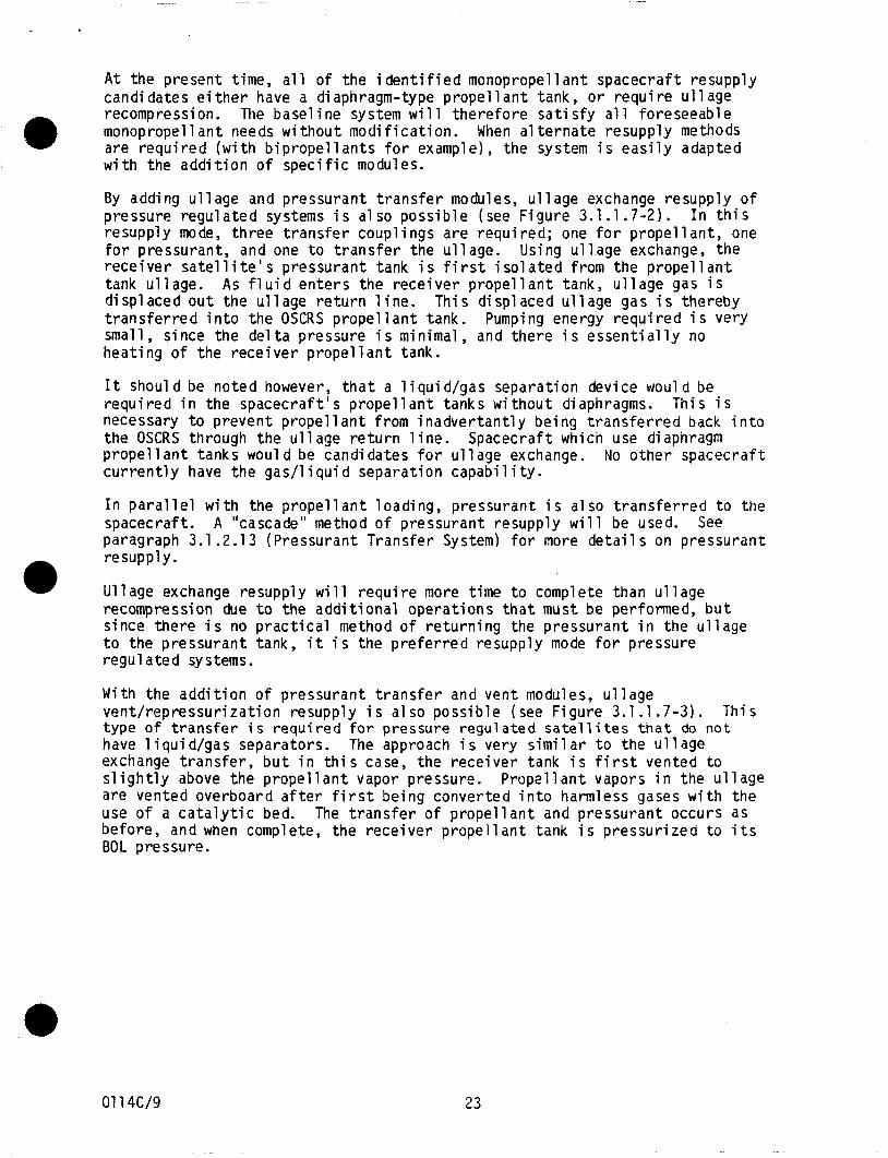
With the a d d i t i o n o f pressurant t r a n s f e r and vent modules, u l l age vent / repressur iza t ion resupply i s a1 so poss ib le (see F igure 3.1.1.7-3). type o f t r a n s f e r i s r e q u i r e d f o r pressure r e g u l a t e d s a t e l l i t e s t h a t do not have l i q u i d / g a s separators. The approach i s very s i m i l a r t o the u l l a g e exchange t r a n s f e r , b u t i n t h i s case, the r e c e i v e r tank i s f i r s t vented t o s l i g h t l y above t h e propel 1 a n t vapor pressure. are vented overboard a f t e r f i r s t be ing conver ted i n t o harmless gases w i t h the use o f a c a t a l y t i c bed. before, and when complete, the r e c e i v e r p r o p e l l a n t tank i s p ressur ized t o i t s BOL pressure.
T h i s
Propel 1 a n t vapors i n the u l l age
The t r a n s f e r o f p r o p e l l a n t and pressurant occurs as
01 14c/9 23
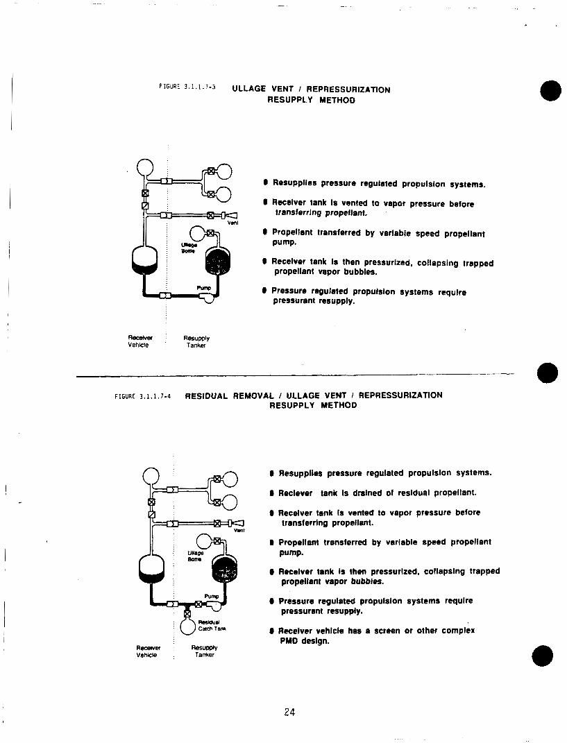
FIGURE 3 . 1 . 1 . 7 - 3 ULLAGE VENT I REPRESSURIZATION RESUPPLY METHOD
W
RWAVW Resu@v Vehlcle Tanker
0 Rerupplles pressure regulated propulsion systems.
0 Recelver tank Is vented to vapor pressure before transferring propellent.
0 Propellant transferred by varlable speed propellant Pump.
0 Recelver tank Is then pressurlzed, collapslng trapped propellant vapor bubbles.
0 Pressure re~guleted propulslon systems require pressurant resupply.
FIGURE 3.1.1.7-4 RESIDUAL REMOVAL / ULLAGE VENT I REPRESSURIZATION RESUPPLY METHOD
0 0 Resupplies pressure regulated propulsion sy
0 Reclever tank Is dralned of reslduei propellant.
0 Recelver tank Is vented to vapor pressure before
0 Propellant transferred by verlable speed propellant
0 Receiver tank Is then pressurlzed, collapslng trapped
0 Pressure regulated propulsion systems require
0 Receiver vehlcle has a screen or other complex
transferring propellant.
pump.
propellant vapor bubbles.
pressurant resupply.
PMD deslgn. Recervef Resupply Vehrle Tanker
24
Some s a t e l l i t e s may r e q u i r e t h a t b e f o r e any t r a n s f e r i s i n i t i a t e d , t h e p r o p e l l a n t r e s i d u a l s be removed from the p r o p e l l a n t t a n k ( s ) . tanks c o u l d be prompted by several f a c t o r s . Lack o f knowledge concern ing f l i g h t r e s i d u a l s c o u l d r e q u i r e d r a i n i n g o f the tank t o e s t a b l i s h a known l e v e l p r i o r t o resupply , o r perhaps a lengthy o n - o r b i t s tay c o u l d cause concern about contaminat ion o f the p r o p e l l a n t . Also, it may n o t be convenient t o v i a i t u n t i l a s a t e l l i t e has complete ly depleted i t s p r o p e l l a n t l o a d t o begin resupply, and l a r g e r e s i d u a l s (perhaps 40%) may s t i l l be on-board. I n t h i s case, l a r g e r e s i d u a l q u a n t i t i e s may need t o be o f f - l o a d e d b e f o r e v e n t i n g can occur. A compl icated p r o p e l l a n t management device (such as a b a f f l e used i n an o x i d i z e r tank) may r e q u i r e complete evacuat ion t o the p r o p e l l a n t vapor pressure t o assure t h a t no bubbles are t rapped i n the b a f f l e s t r u c t u r e .
D r a i n i n g o f the
A r e s i d u a l d r a i n / u l l age vent / repressur iza t ion resupply technique can be used f o r these customers wi th the a d d i t i o n o f a r e s i d u a l d r a i n tank module (see F i g u r e 3.1.1.7-4). P r i o r t o i n i t i a t i o n o f resupply , t h e p r o p e l l a n t tank r e s i d u a l s would be dra ined i n t o a ca tch tank on the OSCRS f o r l a t e r removal d u r i n g ground turnaround a c t i v i t i e s . p r o p e l l a n t c o u l d be f i l t e r e d and r e t u r n e d t o the spacecraf t . With r e s i d u a l propel l a n t removed, t h e t r a n s f e r r e d propel 1 a n t q u a n t i t y (which i s measured by the OSCRS) cou ld be used t o e s t a b l i s h the s p a c e c r a f t ' s base l ine p r o p e l l a n t mass.
I n t h e case o f l a r g e r e s i d u a l s , the
Overa l l , the base1 i n e blowdown pump-fed resupply system chosen i s seen t o p rov ide an e f f i c i e n t resupply system t h a t i s capable o f s e r v i c i n g the GRO; and, w i t h the c a p a b i l i t y t o add pressurant t r a n s f e r , u l l a g e exchange, and r e s i d u a l d r a i n modules as requi red, i s seen t o p rov ide a resupply system t h a t i s capable o f hand1 i n g a l l poss ib le monopropel lant and b i p r o p e l l a n t s a t e l l i t e resupply requirements. A t the same t ime, t h i s system w i l l be o f l i g h t we igh t ( s i n c e modules a r e o n l y added a s ' r e q u i r e d ) , and o f low c o s t ( s i n c e module development and f a b r i c a t i o n are de fer red u n t i l a s p e c i f i c need a r i s e s ) ,
3.1.1.8 Ins t rumenta t ion Requirements
The d i f f e r e n t types and quant i t i e s o f ins t rumenta t ion r e q u i r e d t o safe e f f e c t i v e l y m o n i t o r system s t a t u s f o r general heal th , 1 oading/resupply operat ions, and f a u l t de tec t ion a r e discussed i n d e t a i l i n paragraph 3
3.1.1.9 F1 u i d Quant i ty Gaging Accuracy Requirements/Techniques
The fl u i d gauging accuracy requirements incorpora te i n f l u e n c e s associ a sate1 1 i t e resupply requirements and those associated w i t h the OSCRS design. These i n c l u d e t h e requirements f o r the de terminat ion and c o n t r o l o f the q u a n t i t i e s o f f l u i d s t r a n s f e r r e d d u r i n g a resupply and f o r the deterrn in3t ion o f f l u i d quant i t i e s remain ing i n t h e OSCRS tanker tankage.
Spacecraf t requirement assessments have bracketed the need t o determine t h e quant i t i e s o f N2H4 t r a n s f e r r e d d u r i n g a resupply t o accurac ies rang ing from 1 t o 5 percent. Tanker/spacecraf t i n t e r f a c e pressure accuracy measurement o f 0.5% and/or gas mass t r a n s f e r accuracy o f 2% are the pressurant t r a n s f e r ' s most s t r i n g e n t requirements. The maximum q u a n t i t y o f N2H4 t o be t r a n s f e r r e d i s 7440 pounds ( i n c l u d i n g growth c a p a b i l i t y ) a t f l o w r a t e s rang ing up t o 1 0 gpm.
y and
2.5.
.ed w i t h
7634c/10 25
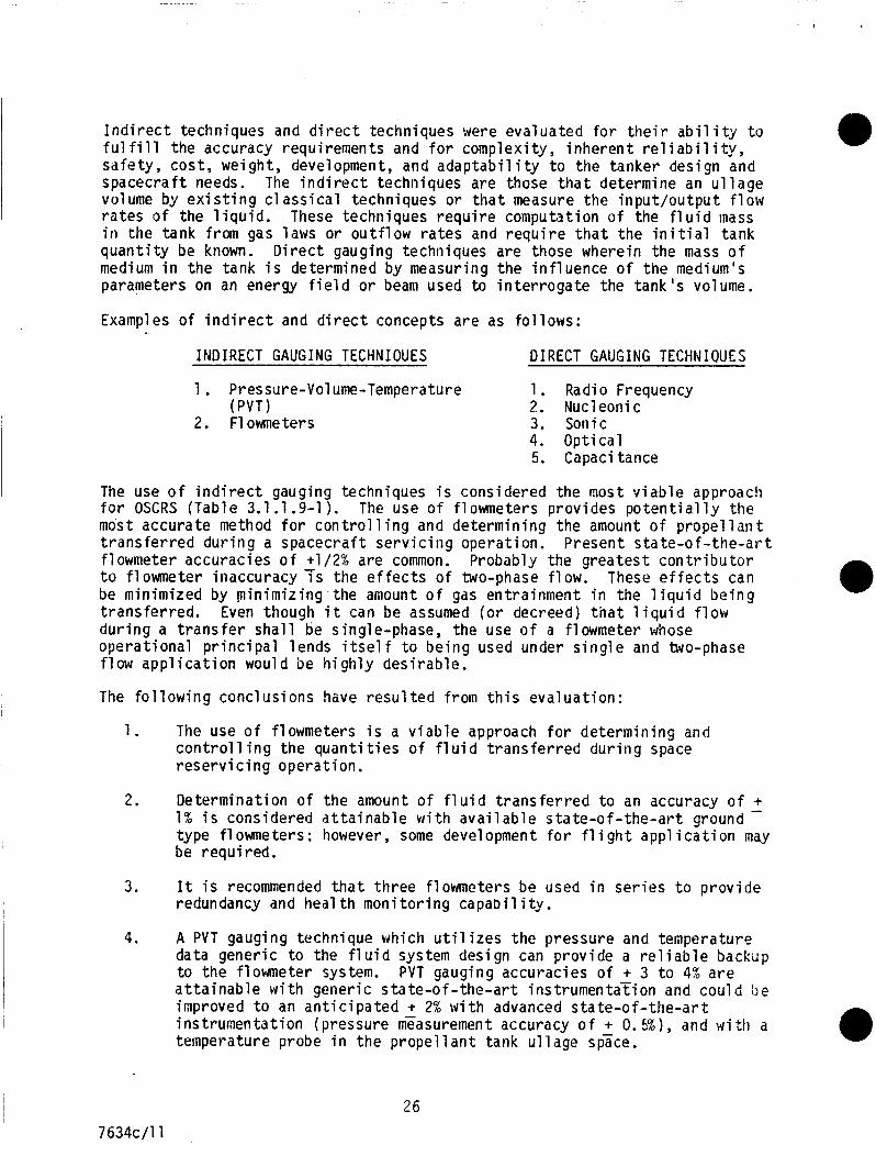
I n d i r e c t techniques and d i r e c t techniques were evaluated f o r t h e i r a b i l i t y t o f u l f i l l the accuracy requirements and f o r complexi ty, i n h e r e n t r e l i a b i l i t y , sa fe ty , cos t , weight, development, and a d a p t a b i l i t y t o the tanker design and spacecra f t needs. The i n d i r e c t techniques are those t h a t determine an u l l a g e volume by e x i s t i n g c l a s s i c a l techniques o r t h a t measure the i n p u t / o u t p u t f l o w r a t e s o f the l i q u i d . These techniques r e q u i r e computation o f the f l u i d mass i n t h e tank from gas laws o r o u t f l o w r a t e s and r e q u i r e t h a t t h e i n i t i a l tank q u a n t i t y be known. D i r e c t gauging techniques are those wherein the mass o f medium i n the tank i s determined by measuring the i n f l u e n c e o f t h e medium's parameters on an energy f i e l d o r beam used t o i n t e r r o g a t e the t a n k ' s volume.
Examples o f i n d i r e c t and d i r e c t concepts a r e as fo l lows:
INDIRECT GAUGING TECHNIOUES DIRECT GAUGING TECHMIQUES
1. Pressure-Volume-Temperature 1. Radio Frequency
2. Flowmeters 3. Sonic (PVT 1 2. Nucleonic
4. O p t i c a l 5. Capacitance
The use o f i n d i r e c t gauging techniques i s considered the most v i a b l e approac!i f o r OSCRS (Table 3.1.1.9-1). The use o f f lowmeters prov ides p o t e n t i a l l y the most accurate method f o r c o n t r o l 1 i n g and determin ing the amount o f propel 1 a n t t r a n s f e r r e d d u r i n g a spacecra f t s e r v i c i n g operat ion. f lowmeter accurac ies o f +1/2% are common. Probably the g r e a t e s t c o n t r i b u t o r t o f l o m e t e r inaccuracy 7 s the e f f e c t s o f two-phase f low. These e f f e c t s can be minimized by min imiz ing the amount o f gas entrainment i n the l i q u i d b e i n g t r a n s f e r r e d . d u r i n g a t r a n s f e r s h a l l be single-phase, the use o f a f lowmeter whose o p e r a t i o n a l p r i n c i p a l lends i t s e l f t o b e i n g used under s i n g l e and two-phase f l o w a p p l i c a t i o n would be h i g h l y d e s i r a b l e .
The f o l l o w i n g conclus ions have r e s u l t e d from t h i s eva lua t ion :
Present s t a t e - o f - t h e - a r t
Even though i t can be assumed ( o r decreed) t h a t l i q u i d f l o w
1. The use o f f lowmeters i s a v i a b l e approach f o r de termin ing and c o n t r o l 1 i n g the quant i t i e s o f f l u i d t r a n s f e r r e d d u r i n g space r e s e r v i c i n g opera t ion .
2. Determinat ion o f the amount o f f l u i d t r a n s f e r r e d t o an accuracy o f + 1% i s considered a t t a i n a b l e w i t h a v a i l a b l e s t a t e - o f - t h e - a r t ground - type f lowmeters; however, some development f o r f l i g h t a p p l i c a t i o n may be requi red.
3 . It i s recommended t h a t t h r e e f lowmeters be used i n s e r i e s t o p r o v i d e redundancy and h e a l t h m o n i t o r i n g c a p a b i l i t y .
4. A PVT gauging technique which u t i l i z e s t h e pressure and temperature data gener ic t o the f l u i d system design can prov ide a r e l i a b l e backup t o the f l o w e t e r system. a t t a i n a b l e w i t h gener ic s t a t e - o f - t h e - a r t instrumentaTion and c o u l d be improved t o an a n t i c i p a t e d + 2% w i t h advanced s t a t e - o f - t h e - a r t ins t rumenta t ion (pressure measurement accuracy o f + 0. 5 % ) , and w i t h a temperature probe i n the propel 1 a n t tank u l l age space.
PVT gauging accurac ies o f + 3 t o 4% a r e
26
7634c/11
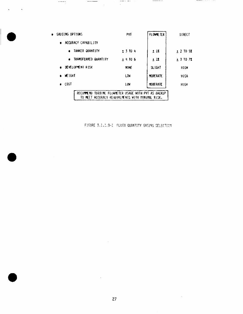
lo 0 W G l N G OPT!ONS
ACCURACY CAPAB I L I TY
PVT FLOW KR UIRECT n 2 2 TO 5%
2 3 TO 7%
SLIGHT H i G H
l lOMRATE H I G H
H iGH
0 TANKER PUANTITY 2 3 T 0 4
0 TRANSFERRED W A N T i TY - + 4 T O 6
DEVELOPMENT R ISK NONE
M I G H T LOW
COST LON
I RECOrmENO TURBIYL FLOWMETLR USAGE WITH PVT AS UACKUP I TO MEET ACCURACY R E W l R t f f N T S WITII l l lN iMAl R I S K ,
F!SURE 3,1.1,9-1 F L U I D QUGNTJTY GASINS SELECTI3'1
27
Based upon the r e s u l t s o f t h i s e v a l u a t i o n i t i s recommended t h a t a t h r e e f lowmeter system be base l ined f o r use i n t h e OSCRS t o determine q u a n t i t i e s o f p r o p e l l a n t t r a n s f e r r e d d u r i n g a r e s e r v i c i n g operat ion. I n a d d i t i o n , i t i s recommended t h a t a PVT gauging system us ing s t a t e - o f - t h e - a r t i n s t r u m e n t a t i o n be used as a backup t o t h e base l ine method.
3.1.1.10 Envelope Studies
The Gamma Ray Observatory (GRO) be ing t h e f i r s t c o m i t t e d user o f an OSCRS resupply has a s i g n i f i c a n t i n f l u e n c e on t h e monopropel lant tanker basel i n e design. e s t a b l i s h e d a bas ic s t r u c t u r a l c o n f i g u r a t i o n c h a r a c t e r i s t i c . 3.1.1 . lo-1 shows t h e major i n t e r f a c e s which i n f l u e n c e d t h e u l t i m a t e s t r u c t u r a l c o n f i g u r a t i o n .
The OSCRS c o n f i g u r a t i o n was e s t a b l i s h e d from p a s t I R & D s tud ies and t h e GRO i n t e r f a c e / r e s u p p l y requirements. A goal was t o e s t a b l i s h a s i n g l e b a s i c s t r u c t u r e c o n f i g u r a t i o n f o r bo th t h e monopropel lant and t h e b i p r o p e l l a n t tankers which i s c o s t and we igh t e f f i c i e n t . f o r a snial 1 we igh t pena l ty (87 1 bs) on t h e basel i ne 2500 1 b monopropel 1 a n t tanker .
Use o f t h e GRO p r o p e l l a n t tanks f o r OSCRS was basel ined and F i g u r e
Th is o b j e c t i v e can be achieved
Two of t h e t h r e e tlEilS/FSS l a t c h assemblies a r e l o c a t e d a t Yo = 18.0. ad jacent payload o u t s i d e envelope matches t h i s Yo l o c a t i o n on OSCRS then an added 10.0 inches must be added t o t h e m a n i f e s t i n g separa t ion o f 24 inches. S ince no b i p r o p e l l a n t b e r t h i n g i n t e r f a c e e x i s t s a t t h i s t ime no judgment can be made as t o whether a g r e a t e r o r smal le r c learance i s r e q u i r e d d u r i n g a mixed cargo m a n i f e s t i n g u s i n g o t h e r than MMS/FSS 1 atches.
Locat ion o f t h e F l i g h t Releasable Grapple F i x t u r e (FRGF) i s i d e n t i c a l on b o t h monopropel lant and b i p r o p e l l a n t tankers. nan i f e s t i ng . The 1 o c a t i o n o f t h e NAS9-17333 f l u i d coup1 i n g on monopropel 1 a n t t a n k e r occupies a space i n t h e upper p o r t s i d e t o match t h e r e f u e l i n g i n t e r f a c e on GRO. es tab l i shed. Consol i d a t i o n o f t h e r e f u e l i n g u m b i l i c a l s t o one s p e c i f i c area of t h e S/C and t a n k e r would be b e n e f i c i a l i n s i m p l i f y i n g the b i p r o p e l l a n t umbil i c a l mechanical / s t r u c t u r a l suppor t system.
I f an
They have no impact on cargo
A b i p r o p e l l a n t r e f u e l i n g in te r face / requ i rement has n o t been
3.1.1 .ll Optimize System Weight
The i n i t i a l s t r u c t u r e s e l e c t i o n was based on a GKO resupply q u a n t i t y o f approximate1 4,300 l b s o f N2H4, s t o r e d i n f o u r GRO-type p r o p e l l a n t tanks
2,450 l b s . Th is l a t t e r q u a n t i t y can be s t o r e d i n two GRO t y p e p r o p e l l a n t tanks. Growth beyond the GRO resupply requirements i s cons idered a major c h a r a c t e r i s t i c o f t h e OSCRS tanker .
niounted i n t Yl e OSCRS. Subsequently, t h e GRO resupply q u a n t i t y was reduced t o
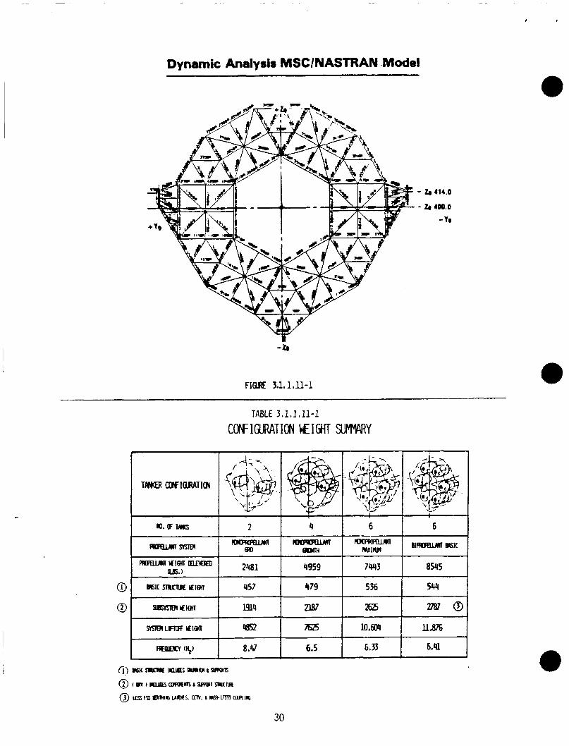
A NASTRAN f i n i t e element model ( F i g u r e 3.1.1.11-1 o f t h e growth c o n f i g u r a t i o n (4,300 l b s o f p r o p e l l a n t ) was developed. e v a l u a t i o n o f t h e s t r u c t u r a l impact ( s t a t i c and dynamic) o f var ious p r o p e l l a n t weight and tankage c o n f i g u r a t i o n s . Both t h e s t a t i c and dynamic (normal modes) analyses were performed u s i n g the MacNeal -Schwendl e r Corporat ion (MSC) program.
Th is p e r m i t t e d quick and e f f i c i e n t
01 14C/12 28
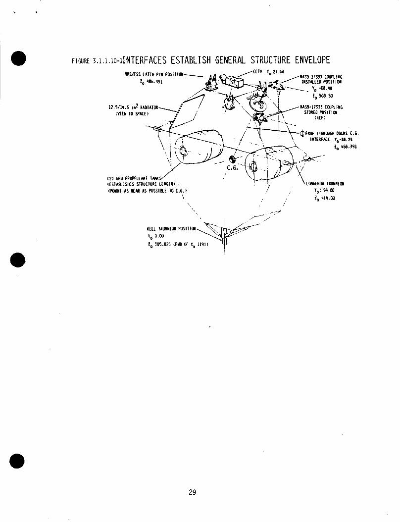
FIGURE ~,~,~Jo-IINTERFACES ESTABLISH GENERAL STRUCTURE ENVELOPE MAS-17133 CWLIIG M S S LATCH P I N POSIIIOW-. INSTKLED WSI!IoII
NAS9-17333 COUPLING (VIEY 10 P A C E )
tOnGEROii lRUMNlC4
zo 4IC.W
(2 ) GRO PROPELLMT TW (CSTAKIMS SlRUClURE LENGTH) (NOUN1 AS NEAR AS POSSIKE TO E.G.)
\ /
. -4 \
\
29
Dynamic Analysis MSClNASTRAN Model
- Zn 114.0
- ZB 400.0
- Y e
-t
F I Q E 3.1.1.11-1 ---- -
TABLE 3.1.1.11-1 COPFIGURATION EIGHT SUMHARY
30
The minimum member s t r e s s s i z i n g was based on an es t imate o f r e a l i s t i c minimum manufactur ing/machinin and hand l ing dimensions. Several heav ie r members were a l s o used f o r pr imary 4 oad paths. With t h e i n i t i a l s i z i n g , a s t a t i c s t r e s s d i s t r i b u t i o n was c a l c u l a t e d , u s i n g MSC/NASTRAN f o r t h e t r a n s i e n t l i f t - o f f and 1 anding cases, which were deemed c r i t i c a l . An e x i s t i n g in-house program was used t o search t h e element member s t resses and p r i n t o u t o n l y those elements t h a t exceed predef ined compression and tens ion s t r e s s a l lowab le l i m i t s . Based on t h e element c ross s e c t i o n and length, column a l lowab les were developed. The column a1 lowables were c a l c u l a t e d us ing s tandard a i r c r a f t a n a l y s i s methods t h a t account f o r t h e i n t e r a c t i o n o f E u l e r column f a i l u r e w i t h l o c a l b u c k l i n g f a i l u r e .
A f t e r an acceptable s t a t i c s t r e s s s i z i n g was establ ished, cons t ra ined n a t u r a l f requencies ( f i r s t e i g h t modes) were c a l c u l a t e d u s i n g t h e MSCINUSTRAN modes ana lys is . The f o u r tank c o n f i g u r a t i o n (4,300 l b s p r o p e l l a n t ) s t r u c t u r e (477 l b s ) a n a l y s i s was performed and a minimum cons t ra ined frequency o f 6.29 Hz was ob ta ined and was considered an acceptable frequency f o r use i n d e f i n i n g bas ic s t r u c t u r a l c ross sec t ions . The minimuni r e q u i r e d cons t ra ined frequency f o r a payload l e s s than 45,000 l b s i s 6.33 Hz (39.75 radians/second). A second r u n was made employing t h e above s t r u c t u r a l c o n f i g u r a t i o n w i t h s i x tanks (6450 l b s ) . The r e s u l t i n g cons t ra ined frequency was 6.11 Hz. A s t a t i c s t r e s s model was r u n and t h e maximum element s t r e s s search conducted. A minimum o f s t r u c t u r a l beef-up was requ i red . S t r u c t u r a l beef-up was made i n t h e area on t h e t r u n n i o n backup s t r u c t u r e and a t h i r d r u n was made. From t h i s r u n t h e frequency was 6.60 f o r a 7 l b increase i n s t r u c t u r e we igh t t o 484 l b s .
U t i l i z i n g t h e four - tank s t r u c t u r e s i z i n g o f 477 pounds, a MSC/NASTRAN model a n a l y s i s produced a frequency of 10.34 Hz i n d i c a t i n g some r e d u c t i o n i n s t r u c t u r a l we igh t was a v a i l a b l e f o r a dedicated two-tank system (base l ine GRO t a n k e r ) .
To prov ide a more accurate we igh t and dynamic response o f t h e a c t u a l proposed t r u n n i o n suppor t s t r u c t u r e , t h e base l ine NASTRAN model was m o d i f i e d i n t h e l o c a l area o f t r u n n i o n and t r u n n i o n backup s t r u c t u r e .
Since t h e s ix - tank c o n f i g u r a t i o n met t h e e s t a b l i s h e d compression and t e n s i o n a l lowables, s e l e c t i v e s t r u c t u r a l beef-up was i n i t i a t e d t o increase the cons t ra ined frequency t o t h e minimum a l lowab le o f 6.33 Hz.
A f t e r severa l i t e r a t i o n s , s u f f i c i e n t s t r u c t u r a l beef -up ( increased member area and p l a t e th ickness) was made i n t h e t r u n n i o n s t r u c t u r e area t o achieve t h e r e q u i r e d cons t ra ined frequency o f 6.33 Hz. The r e s u l t i n g weight o f a s i x tank s t r u c t u r e was 536 l b s . versus 457 l b s f o r t h e b a s e l i n e two tank s t r u c t u r e , o r a d e l t a weight o f 79 l b s . The four - tank c o n f i g u r a t i o n was handled i n a s i m i l a r manner, r e s u l t i n g i n a s t r u c t u r e we igh t o f 479 l b s , a d e l t a we igh t o f 22 l b s . over t h e b a s i c two tank s t r u c t u r e . var ious c o n f i g u r a t i o n s ( i n c l u d i n g a 6 tank b i p r o p e l l a n t s t r u c t u r e ) and prov ides a quick- look a t d e l t a weights.
Table 3.1.1.11-1 compares t h e
31
01 14C/13
3.1.1.1 2 Nominal 81 Emergency S/C Demate
Spacecraf t o n - o r b i t resupply opera t ions r e q u i r e b e r t h i n g t h e spacecra f t t o t h e OSCRS i n t e r f a c e and connect ing t h e f l u i d , gas, and e l e c t r i c a l /av ion ics u m b i l i c a l s , p e r m i t t i n g t h e t r a n s f e r o f consumables t o t h e spacecraf t . I n t h e base1 i n e monopropel lant t a n k e r d e l i v e r y system, a l l u m b i l i c a l connect ions a r e manual ly mated and demated u t i l i z i n g EVA crew a c t i v i t y .
The requirement f o r redundant coupl i n g s (i .e., NAS9-17333) w i l l n e c e s s i t a t e redundant t r a n s f e r l i n e / c o u p l i n g assemblies. cho ice o f u s i n g redundant coupl i n g / l i n e assembles prov ides c l e a r design and o p e r a t i o n a l advantages over a s ing1 e 1 ine , redundant coupl i n g replacement concept :
A t t h i s p o i n t i n t h e des ign t h e
o EVA opera t iona l s a f e t y and s i m p l i c i t y o Lower o v e r a l l c o s t o Maintenance o f a l l e l e c t r i c a l and heater element connect ions
The added requirement o f emergency demate, d u r i n g consumables t r a n s f e r , w i t h o u t b e n e f i t o f EVA a c t i v i t y , adds system design and component complex i ty t o t h e f l u i d u m b i l i c a l i n t e r f a c e .
The emergency separa t ion dev ice shown i n F i g u r e 3.1.1.1 2-1 has been examined i n d e t a i l f o r use w i t h i n t h e tanker s t r u c t u r e . Th is des ign i s more a t t r a c t i v e than one l o c a t e d c l o s e t o the NAS9-17333 coupl ing at tachment on the GRO s ince i t e l i m i n a t e s any requirement f o r remote/automatic re-s towing mechanisms t o r e p o s i t i o n t h e extended t r a n s f e r hose from o u t s i d e of t h e payload bay doors t o t h e v i c i n i t y o f t h e t a n k e r s t r u c t u r e .
Emergency demate a t t h e FSS l a t c h i n t e r f a c e s i s covered i n Sec t ion 3.1.1.3, docking p r o v i s i o n s e
Dur ing an emergency demate, i n t h e event separa t ion f o r c e s necessary, t h e O r b i t e r separa t ion forces.
E l e c t r i c a l /Av ion ics connectors ( f o r use t o s a t i s f y b o t h EVA and emergency demate q u a l i f i e d components.
t h e RMS i s u n a v a i l a b l e t o p r o v i d e t h e RCS system can be used t o p r o v i d e t h e
n t h e spacecra f t u m b i l i c a l i n t e r f a c e ) requirements a r e a v a i l a b l e as
The t o t a l s u b j e c t o f emergency spacecra f t separa t ion deserves more d e t a i l e d techno1 ogy development i n consonance w i t h remote/automatic spacecra f t b e r t h i n g and hookup.
3.1.1.1 3 Added P r o p e l l a n t Storage
As t h e need f o r a d d i t i o n a l o n - o r b i t p r o p e l l a n t increases w i t h t h e m a t u r i t y o f t h e Space S t a t i o n and o t h e r o r b i t a l operat ions, tanker d e l i v e r y c a p a b i l i t y may have t o be increased. maximum o f s i x tanks has been recomnended. Th is growth can be accomplished w i t h a minimum o f r e - q u a l i f i c a t i o n t e s t i n g and l e a s t impact on t h e base l ine system.
A planned growth f rom t h e b a s e l i n e two tank t o a
01 14C/14 32
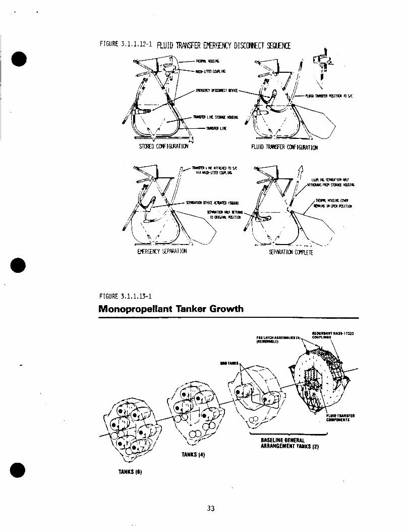
FIGURE 3.1.1,U-1
Monopropellant Tanker Growth
TANKS (6)
33
From t h e se lected basel i n e s t r u c t u r a l arrangement, a simple, l o g i c a l growth i n p r o p e l l a n t l o a d i n g can be accommodated. i d e n t i c a l t o t h e b a s e l i n e c o n f i g u r a t i o n can be i n s t a l l e d i n t h e open chambers incorpora ted i n t o t h e b a s i c c r a d l e s t r u c t u r e . concept i s dep ic ted i n F i g u r e 3.1.1.13-1.
Fuel tanks and pressurant b o t t l e s
Thi s p l anned, s tep growth
Prov is ions incorpora ted i n t h e s t r u c t u r a l arrangement o f t h e basel i n e monopropel lant system r e a d i l y p rov ide f o r p r o p e l l a n t c a p a c i t y growth. Almost no s t r u c t u r a l system we igh t penal ty i s i ncurred. p ressurant b o t t l e s and t h e i r i n s t a l l a t i o n a r e i d e n t i c a l t o those components i n t h e base l ine tanker and can be modular ly added o r removed w i t h minimum scar we igh t impact.
From a b a s e l i n e p r o p e l l a n t l o a d o f s i x tanks f o r near-term space opera t ions a growth t o ( 1 2 ) tanks capable o f c a r r y i n g up t o 18,000 l b s has been developed. Using t h e several elements o f s t r u c t u r e , p r o p e l l a n t tanks, and pressurant b o t t l e s o f t h e b a s e l i n e tanker , var ious c o n f i g u r a t i o n s f o r t h i s growth have been r e v i ewed.
Propel 1 a n t tanks and
Growth o f t h e b i p r o p e l l a n t system f rom t h e s ix - tank b a s e l i n e t o t h e 12-tank system can be r e a d i l y accomplished i n a l o g i c a l e v o l u t i o n . concept developed f o r t h e basel i n e g r e a t l y f a c i l i t a t e s t h i s growth. conceptual approaches have been i d e n t i f i e d f o r f u t u r e eva lua t ion .
A simple, c o s t e f f e c t i v e arrangement has been d e f i n e d t o p rov ide a d d i t i o n a l p r o p e l l a n t ( f o r example, b i p r o p e l l a n t ) . S i x b a s e l i n e f u e l tanks can be i n s t a l l e d i n t h e s i x chambers o f the bas ic monopropel lant tanker s t r u c t u r e and s i x o x i d i z e r tanks can be i n s t a l l e d w i t h "A" frame supports, c a n t i l e v e r e d e x t e r n a l l y t o t h e s t r u c t u r e assembly.
The s t r u c t u r a l Several
Th is c o n f i g u r a t i o n i s shown i n F i g u r e 3.1.1.13-2.
Another expanded p r o p e l l a n t c a p a c i t y scheme u t i l i z e s two n e a r l y i d e n t i c a l s t r u c t u r a l assemblies as shown i n F i g u r e 3.1.1.13-3. The arrangement i n c o r p o r a t e s two bas ic s t r u c t u r e assemblies b o l t e d together t o produce a double- length s t r u c t u r e s i m i l a r t o t h e technique employed by t h e STS Space Lab p a l 1 e t .
3.1.1.14 OSCRS Re loca t ion
To p rov ide t h e maximum m a n i f e s t i n g c a p a b i l i t y , t h e t a n k e r may be r e q u i r e d t o occupy a launch and/or e n t r y payload bay l o c a t i o n o t h e r than t h a t r e q u i r e d t o i n t e r f a c e w i t h a p a r t i c u l a r spacecra f t (S/C) f o r any g iven miss ion. o t h e r payload deployment, t h e tanker may be r e q u i r e d t o be r e l o c a t e d i n t h e bay.
The OSCRS s t r u c t u r a l envelope and l o c a t i o n o f t h e grapp le f i x t u r e were des i ned t o a s s i s t i n o n - o r b i t r e l o c a t i o n so t h a t the number o f payload bay (PLB? r e l o c a t i o n s w i l l n o t be l i m i t e d by RMS excurs ion l i m i t s . L i m i t a t i o n s do r e s u l t from: ( a ) t h e t r u n n i o n center1 ine- to-center1 i n e span chosen c o n s i s t e n t w i t h b r i d g e f i t t i n g l i m i t l oads a t any one X s t a t i o n ( t h e s h o r t e r t h i s span, t h e more r e l o c a t i o n s a v a i l a b l e i f singye b r i d g e f i t t i n g s a r e used) and ( b ) t h e d e c i s i o n o f whether o r n o t t o use dual b r i d g e f i t t i n g s t o suppor t re1 oca t i o n .
A f t e r
01 14C/15 34
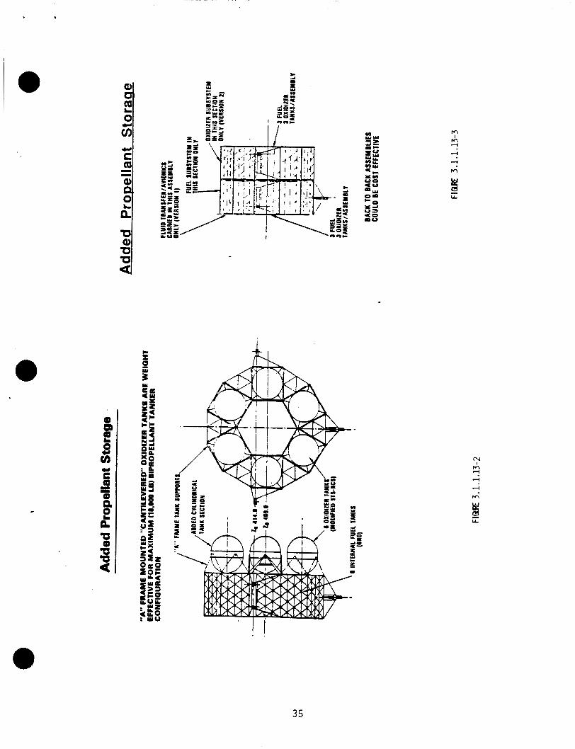
.
a 0) m 0 E 3i
m m 1
l-4
l-4
l-4
m
M
35
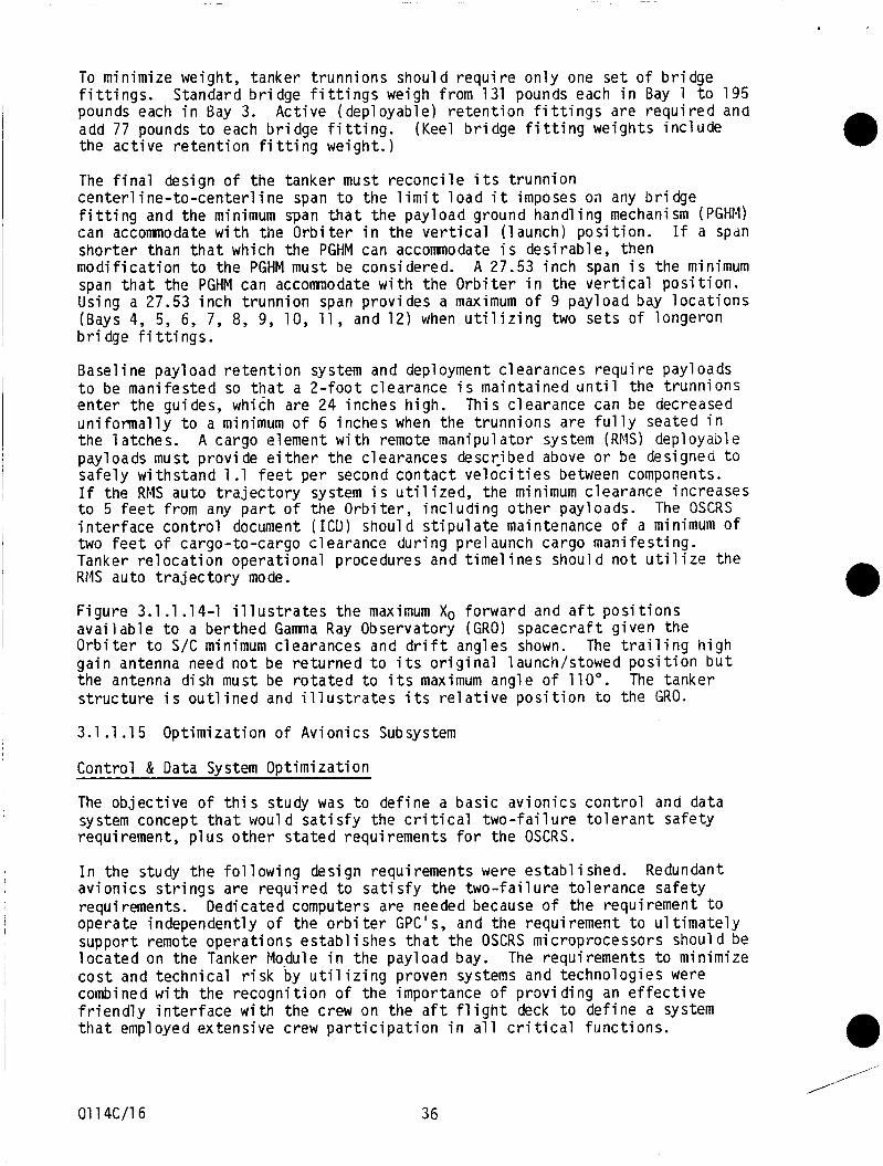
To minimize weight, tanker t runn ions should r e q u i r e o n l y one s e t o f b r i d g e f i t t i n g s . Standard b r i d g e f i t t i n g s weigh from 131 pounds each i n Bay 1 t o 195 pounds each i n Bay 3. Ac t ive (deployable) r e t e n t i o n f i t t i n g s are r e q u i r e d and add 77 pounds t o each b r i d g e f i t t i n g . the a c t i v e r e t e n t i o n f i t t i n g weight.)
(Keel b r i d g e f i t t i n g weights i n c l u d e
The f i n a l design o f t h e tanker must r e c o n c i l e i t s t r u n n i o n c e n t e r l i n e - t o - c e n t e r l i n e span t o the l i m i t l o a d i t imposes on any b r i d g e f i t t i n g and the minimum span t h a t the payload ground handl ing mechanism (PGHM) can accommodate w i t h the O r b i t e r i n the v e r t i c a l ( launch) p o s i t i o n . I f a span shor te r than t h a t which the PGHM can accomnodate i s des i rab le, then m o d i f i c a t i o n t o the PGHM must be considered. A 27.53 i n c h span i s the minimum span t h a t the PGHM can accomnodate w i t h the O r b i t e r i n the v e r t i c a l p o s i t i o n . Using a 27.53 i n c h t r u n n i o n span prov ides a maximum o f 9 payload bay l o c a t i o n s (Bays 4, 5, 6, 7, 8, 9, 10, 11, and 12) when u t i l i z i n g two se ts o f longeron b r i d g e f i t t i n g s .
Base1 i ne payl oad r e t e n t i o n system and deployment c l earances r e q u i r e payl oads t o be mani fested so t h a t a 2 - f o o t c learance i s ma in ta ined u n t i l the t runn ions e n t e r the guides, which are 24 inches high. This c learance can be decreased u n i f o r m a l l y t o a minimum o f 6 inches when the t runn ions are f u l l y seated i n the la tches . A cargo element w i t h remote manipulator system (RMS) deployable payloads must p rov ide e i t h e r the c learances descr ibed above o r be designed t o safe ly w i ths tand 1.1 f e e t per second c o n t a c t v e l o c i t i e s between components. I f the RMS auto t r a j e c t o r y system i s u t i l i z e d , the minimum c learance increases t o 5 f e e t from any p a r t o f the O r b i t e r , i n c l u d i n g o t h e r payloads. i n t e r f a c e c o n t r o l document ( I C D ) shoul d s t i p u l a t e maintenance o f a minimum of two f e e t o f cargo-to-cargo c learance dur ing prelaunch cargo man i fes t ing . Tanker r e l o c a t i o n opera t iona l procedures and t ime1 i n e s shoul d n o t u t i 1 i z e the RMS auto t r a j e c t o r y mode.
The OSCRS
Figure 3.1.1.14-1 i l l u s t r a t e s the maximum Xo fo rward and a f t p o s i t i o n s a v a i l a b l e t o a ber thed Gama Ray Observatory (GRO) spacecra f t g iven the O r b i t e r t o S/C minimum clearances and d r i f t angles shown. The t r a i l i n g h i g h ga in antenna need n o t be r e t u r n e d t o i t s o r i g i n a l launch/stowed p o s i t i o n b u t the antenna d ish must be r o t a t e d t o i t s maximum angle o f 110". s t r u c t u r e i s o u t l i n e d and i l l u s t r a t e s i t s r e l a t i v e p o s i t i o n t o the GRO.
The tanker
3.1 .1 .15 Opt im iza t ion o f Av ion ics Subsystem
Control & Data System Opt imiza t ion
The o b j e c t i v e o f t h i s study was t o de f ine a bas ic a v i o n i c s c o n t r o l and data system concept t h a t woul d s a t i sfy the c r i t i c a l two- fa i 1 u r e to1 e r a n t sa fe ty requirement, p l u s o t h e r s t a t e d requirements f o r the OSCRS.
I n the study the f o l l o w i n g design requirements were establ ished. a v i o n i c s s t r i n g s are r e q u i r e d t o s a t i s f y the t w o - f a i l u r e to le rance sa fe ty requi rements. operate independent ly o f the o r b i t e r G P C ' s , and t h e requirement t o u l t i m a t e l y support remote opera t ions e s t a b l i s h e s t h a t the OSCRS microprocessors shoul d be l o c a t e d on the Tanker Module i n the payload bay. The requirements t o minimize c o s t and techn ica l r i s k by u t i l i z i n g proven systems and technologies were combined w i t h the r e c o g n i t i o n o f the importance o f p r o v i d i n g an e f f e c t i v e f r i e n d l y i n t e r f a c e w i t h the crew on the a f t f l i g h t deck t o de f ine a system t h a t employed extens ive crew p a r t i c i p a t i o n i n a l l c r i t i c a l func t ions .
Redundant
Dedicated computers are needed because o f the requirement t o
0 ,
,,"
01 14C/16 36
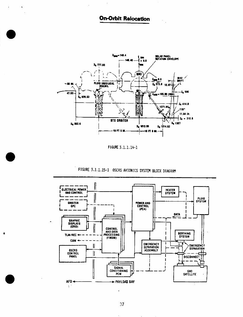
OnQrbit Relocation
FIGURE 3.1,1,15-1 OSCRS AVIONICS SYSTEM BLOCK DIAGRAM
I
PC M SATELLITE
AFO c--- - PAY LOAD BAY
37

The av ion ics system concept de f ined i s shown on F igure 3.1.1.1 5-1 "OSCRS Av ion ics System Block Diagram".
Contro l and Data Processing Requirements Analys is , and FMDM Se lec t ion
A key a n a l y s i s i n the OSCRS a v i o n i c s d e f i n i t i o n s t u d i e s was the i d e n t i f i c a t i o n o f the func t ions t o be performed by the c o n t r o l and data process ing a v i o n i c s l o c a t e d on the OSCRS Tanker Nodule and the d e f i n i t i o n o f proven designs arid systems t h a t would acconpl i s h the r e q u i r e d computat ional and data process ing funct ions.
Host o f the FMDM modules a r e developed and have f l i g h t h i s t o r y . The Decom module i s i n the conceptual design stage b u t i s considered f a i r l y s t r a i g h t forward and w i l l f i t w e l l i n t o the FMDM system w i t h no s i g n i f i c a n t a n t i c i p a t e d problems expected.
The MCV v e r s i o n o f the FMDM (MCV i s the concept adopted f o r OSCRS and f l e w on f l i g n t E l B i n A p r i l o f 1985) conta ined 3% o f PROM and 16K o f RAM. v e r s i o n o f t h e memory module f i t s i n t o t h e same s l o t occupied by t h e above memory and has 8K o f PROM, 24K o f EEPROM and 40K o f RAM. This q u a n t i t y o f memory i s b e l i e v e d t o be s u f f i c i e n t f o r the r e q u i r e d tasks.
Examination o f the requirements c l e a r l y shows t h a t a complex, c a r e f u l l y i n t e g r a t e d system w i l l be r e q u i r e d t o per form the OSCRS c o n t r o l and data process ing func t ions . The necess i ty o f u s i n g e x i s t i n g space-proven systems and components t o minimize development costs and r i s k s on t h e OSCRS program l i m i t s the s e l e c t i o n t o o n l y a few a l t e r n a t i v e s .
The EEPROPI
One design concept t h a t appears t o s a t i s f y t h e f u n c t i o n a l and phys ica l OSCRS requirements, and which i s the concept recommended by t h i s study, i s the Sperry Corp FMDM. The FMDM design i s based on t h e proven O r b i t e r f.IDM's, used on a l l STS f l i g h t s t o date, w i t h no i n - f l i g h t f a i l u r e s . The FMDK, developed s p e c i f i c a l l y t o suppor t O r b i t e r payload operat ions, i s shown i n F igure 3.1.1.15-2.
No o ther a v i o n i c s design concept has been i d e n t i f i e d t h a t prov ides the r e q u i r e d c a p a b i l i t i e s i n a s i n g l e i n t e g r a t e d package, as does the FFIDM. Other a v i o n i c s concepts t h a t c o u l d p o s s i b l y be i n t e g r a t e d i n t o an OSCRS a v i o n i c s system t h a t were evaluated d u r i n g the t rade study were:
o o F a i r c h i l d STACC System, and o ther modular systems
Gulton I n d u s t r i e s T2 C 2 System
Power and Contro l System Analys is
The power and c o n t r o l system a n a l y s i s addressed the requirements f o r developing adequate a v i o n i c s system outpu t commands t o c o n t r o l c r i t i c a l va lves and o ther f l u i d system components t h a t must s a t i s f y t h e t w o - f a i l u r e to le rance s a f e t y requirements.
Two a1 t e r n a t i v e s evaluated f o r s a t i s f y i n g the power and c o n t r o l requirements , which are v i r t u a l l y the same as the requirements imposed on c r i t i c a l STS va lve c o n t r o l c i r c u i t s which must meet t w o - f a i l u r e to le rance requirements, were:
o U t i l i z e c i r c u i t s employing mu1 t i p l e i n d i v i d u a l power a r i v e r c i r c u i t s 0 and diodes t o c o n t r o l each component i n response t o redundant i n p u t commands, as i s done on O r b i t e r c o n t r o l c i r c u i t s
7634c/18 38
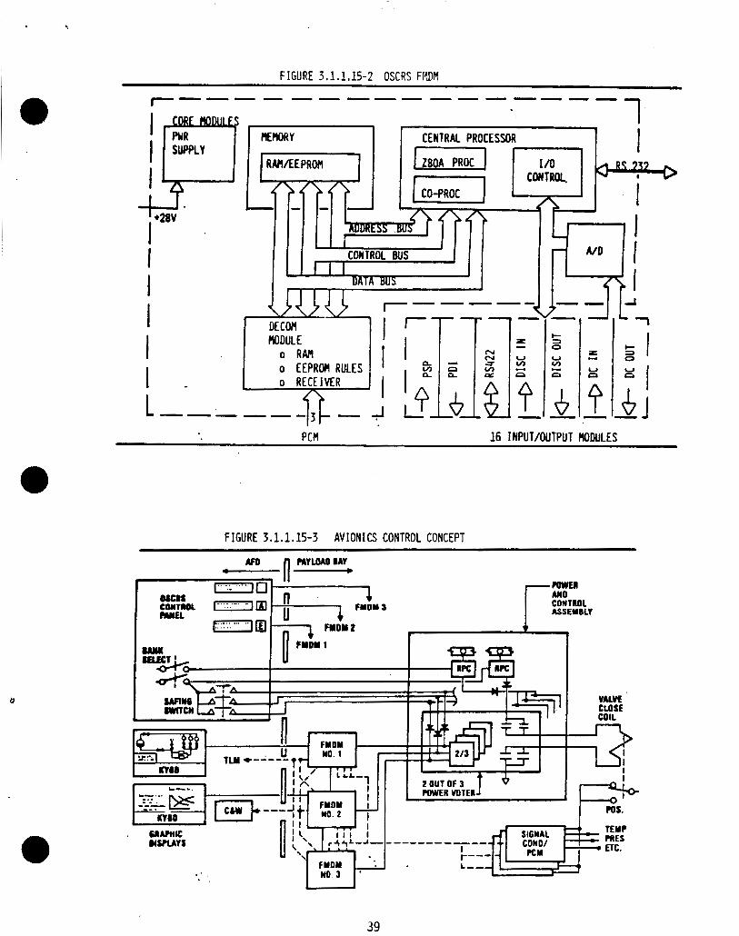
PCM 16 I NPUT/OUTPUT RODULES
FIGURE 3.1,1.15-3 AVIONICS CONTROL CONCEPT
USRAY t
39
o U t i l i z e a 2-out-of-3 power v o t e r module t h a t incorpora tes a l l r e q u i r e d l o g i c and power s w i t c h i n g on a s i n g l e 2- inch by 2- inch module
The 2-out-of-3 power voter , as shown i n F igure 3.1.1.1 5-3 was se lec ted f o r the OSCRS a p p l i c a t i o n . The newly developed Rockwell v o t e r module w i l l p e r m i t a t h r e e t o one r e d u c t i o n i n t h e number o f components requi red, p l u s r e d u c t i o n s i n s i z e and i n c i r c u i t complex i ty over a design us ing the c u r r e n t O r b i t e r c o n t r o l concepts. Th is design i s a d e r i v a t i v e o f the s i n g l e d r i v e r modules c u r r e n t l y used on STS, and has been developed by the same designers.
A c o n t r o l c i r c u i t f o r the c o i l t o c lose a c r i t i c a l va lve i s shown i n F igure 3.1.1.15-3. The redundant low l e v e l commands from the th ree FMCM's are shown as i n p u t s t o t h e l o g i c which, w i t h c o r r e c t inpu ts , a c t i v a t e s power c i r c u i t s t o c lose the valve. Crew a c t i v a t e d switches f o r s e l e c t i n g one group o f va lves t o be powered up, and s a f i n g switches t o bypass the l o g i c and c lose the va lve i n the event o f an a v i o n i c s system f a i l u r e , are a l s o shown.
Because o f the manual sequences r e q u i r e d t o enable each FCIDM, i t w i l l p robably be necessary t o use value p o s i t i o n feedback t o te rmina te c o i l power. (Otherwise command c o u l d be terminated be fore power i s app l ied . ) n a t u r a l l y ( t i m e ) l i m i t a p p l i e d c o i l power. A secondary t imeout may a l s o 5e used t o l i m i t the consequence o f va lue p o s i t i o n feedback f a i l u r e .
The base l ine a v i o n i c s concepts w i l l s a t i s f y the c r i t i c a l OSCRS t w o - f a i l u r e t o l e r a n t s a f e t y requirements w h i l e a1 so s a t i s f y i n g program requirements f o r minimum development c o s t and risk, and s a t i s f y f l e x i b i 1 i ty and growth requirements.
3.1.1.16 L i m i t a t i o n s f o r On-Orbi t Vent ing
This would
P r e s e n t l y de f ined contaminat ion l i m i t a t i o n s are f o r qu iescent opera t ion o f space-based f a c i l i t i e s o r f o r maximum exposure l i m i t a t i o n s o f ground personnel i n a normal working environment. hydraz ine t r a n s f e r must be considered as a s t a r t i n g p o i n t i n v e n t i n g l i m i t a t i o n s u n t i l a c t u a l data i s a v a i l a b l e f o r more r e a l i s t i c l i m i t a t i o n s .
These l i m i t a t i o n s as a p p l i e d t o an o n - o r b i t
Resul ts o f l a b o r a t o r y t e s t s and f l i g h t data s t r o n g l y i n d i c a t e t h a t the v e n t i n g o f hydraz ine through a c a t a l y s t bed ( u s i n g a j u d i c i o u s vent d i r e c t i o n ) w i l l n o t advers ley a f f e c t the o r b i t e r , Space Sta t ion , o r r e c e i v e r veh ic le . Laboratory t e s t s under vacuum c o n d i t i o n s have shown t h a t hydraz ine decomposit ion products do n o t c o l l e c t on sur faces a t temperatures above -5C" F i n the absence o f chemical o r space environmental e f f e c t s such as UV r a d i a t i o n ana s o l a r wind induced p a r t i c l e bombardment. F l i g h t data from two quar tz c r y s t a l microbalance de tec tors (one a t -40°F and the o t h e r a t -150°F) on board t h e SCATHA s a t e l l i t e were analyzed t o determine i f f i r i n g the l i g h t hydrazine motors ( s i x - 0.23 lbm, two - 6.5 lbm) r e s u l t e d i n measurable contaminat ion a t the sensors. No measurable contaminat ion was a t t r i b u t e d t o a m u l t i t u d e o f f i r i n g s o f the SCATHA RCS hydraz ine t h r u s t e r s over a p e r i o d o f 10 mont$s.
I t i s recommended t h a t the r e c e i v e r v e h i c l e s h i e l d s e n s i t i v e c o l d areas ( l e s s than -50°F) d u r i n g the v e n t i n g and t r a n s f e r process. It i s assumed t h a t t h e r e c e i v e r v e h i c l e w i l l move o u t o f the c rea ted molecular ven t c l o u d a f t e r the t r a n s f e r i s complete.
7634c/19 40
.
Two other a1 ternatives were examined for venting propellants from the receiver vehicle: ( a ) Residual containment in waste tanks fo r post-landing disposal , arid ( b ) Cold trap subsystem t o decontaminate vent gas. were rejected in favor of a simpler venting system -- use of a catalyst bed with nonpropulsive vents. waste t a n k volumes necessary ( a b o u t 1 0 times the receiver t a n k volume). A1 ternative ( b 1 was rejected due t o system complexity and the concern t h a t slugs o f propellant would not be removed completely from the vent gas.
B o t h alternatives
AI ternative ( a ) was rejected because of the massive
3.1.2 Hardware/Software Trades
The studies in this area perform design optimization trades on hardware a n d software. These studies resolve design related issues, identify cost and schedule drivers which influence selection of hardware and software designs.
3.1.2.1 Hardware Availability
The assessment o f the hardware required t o sat isfy the OSCRS tanker monopropellant resupply system design requirements had as a goal the use a f previously space qual i f i ed hardware/concepts where possible. avai laoi l i ty l i s t presented i n Tables 3.1.2.1-1 through 3.1.2.1-3 identifies the degree o qual i f i cation or technology s ta tus , the recommended suppl i e r , the quantity required on the baseline tanker (GRO) and the weight and power r eq u i reme n ts where a ppl i cab 1 e.
The hardware
3.1.2.2 Flu d Capacity and Tankage Sizing
The selection of a propellant tank i s an important step i n the design of a low-g propellant transfer system, such as the OSCRS Tanker. In many cases the propellant acquisition device/tank design will constrain the operational capabili t ies o f the transfer system, such as the transfer flowrates a n d system's operating environment. the design o f the res t of the tanker systems, including pressurant subsystem sizing, heater control, power requirements, and structural configuration.
The selection of a t a n k also helps determine
Two state-of-the-art low-g propellant acquisition device ( P A D ) designs were i d e n t i fied a s p o s s i b l e candidates for t h e monopropell a n t hydrazine tanker . These PAD designs are 1 ) dev i ces . surface tension devices, and 2 ) positive expulsion
Due t o the complexity of the screen tank's design, the weight and cost o f a propellant transfer system us ing this type of tank would be higher, i n comparison to less complex t ank designs, such a s surface tension vanes, o r positive expulsion diaphragms. acceleration levels, due t o vernier thruster f i r ings, achieve values as h i g h as 3 x 10⁻⁴ g ' s in the payload bay. Acceleration levels of th is magnitude will not allow the use of large scale vane tanks in the orbiter environment, therefore surface tension devices are n o t appeal ing candidates.
Shuttle Orbiter on-orbit station-keeping
d i ap hr agm. received w propulsion d i a p hra gms
abi l i ty of
The most feasible tank/PAD design fo r the tanker is the positive expulsion Positive expulsion devices, such as the polymeric diaphragm, have
de use throughout the industry in monopropellant hydrazine systems. Examples of hydrazine systems currently employing include the TDRSS and the Space Shuttle Orbiter 's Auxiliary Power . diaphragm tanks to withstand STS launch loads. The major
Both the TDRSS and APU propellant tanks have demonstrated the
7634c/19 41
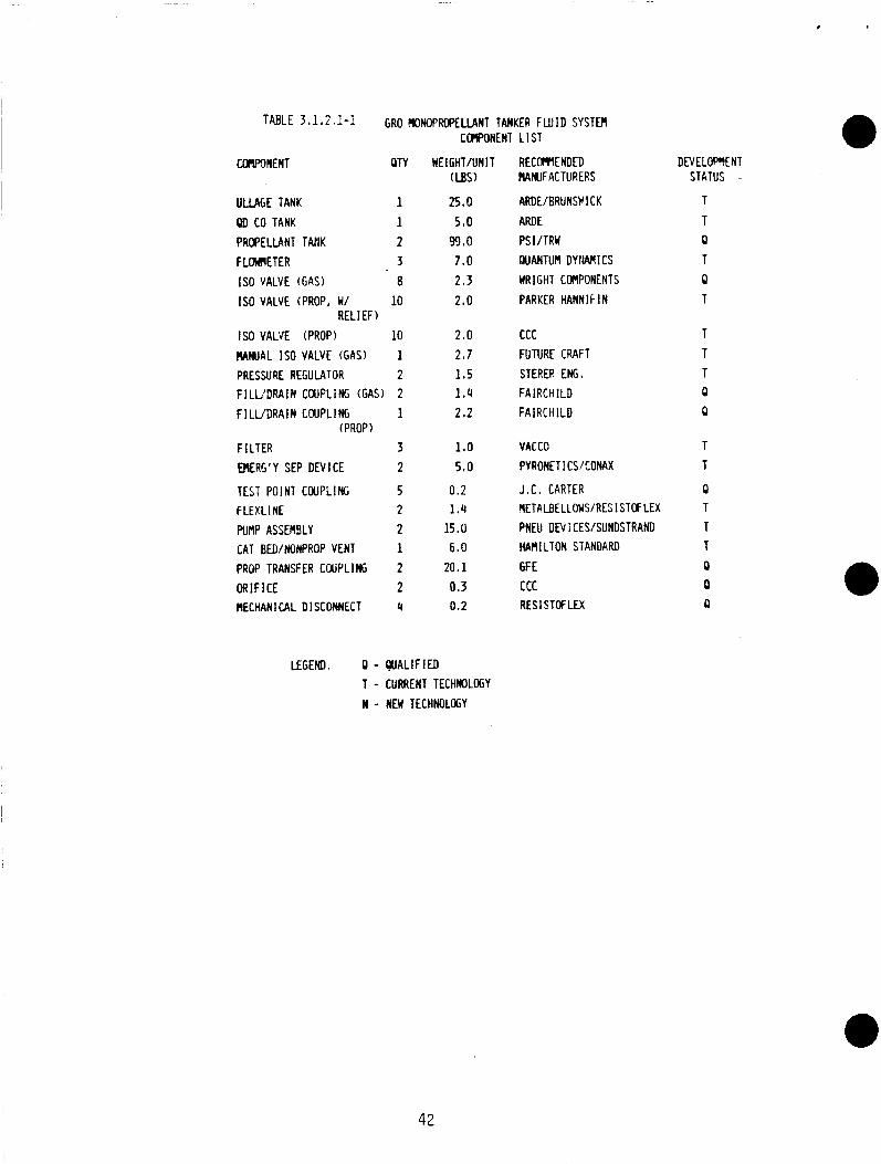
.
CLIIP9NENl OTY WEIGHT/UNIT RECOPWENDED DEVELOPMENT (US) HAAMIFACTURERS STATUS -
ULLAGE TANK 1 OD CO TANK 1 PROPELLANT TAllK 2 FLOCMETER 3
IS0 VALVE (PROP, W/ 10
IS0 VALVE (PROP) 10 R A M A L IS0 VALVE (GAS) 1 PRESSURE REGULATOR 2 F I L L ' D R A I N CWFLING (GAS) 2 F I L V D R A l N C W P L I N G 1
F I LTER 3 M E % ' Y SEP DEV 1 CE 2
IS0 VALVE (GAS) a
RELIEF)
(PROP )
25.0 5.0 99.0 7.0 2.3 2.0
2.0 2.7 1.5 1.4 2.2
1.0 5.0
ARDE/BRUNSFI CK ARDE P S I /TRW QUANTUM DYl lAnlCS HRlGHT CUIPONENTS PARKER HANN I F I N
ccc FUTURE CRAFT STERER ENG. FAIRCHILD FAIRCHILD
VACCO PYRONE11 C S K O N A X
T T
TEST POINT COUPLING 5 0.2 J . C . CARTER 0 F L E X L l NE 2 1.4 METALBELLOWRES I S T W LEX T
W f l P ASSEMBLY 2 15.0 PNEU D N I CES/SUNDSTRAND T CAT BED/NONPROP VENT 1 6.0 HAMILTON STANDARD T PROP TRANSFER COUPLING 2 20.1 GF E 0 O R I F I C E 2 0.3 ccc 0 NECHANI CAL DISCONNECT 4 0.2 RES 1 STOF LEX a
LEGEND: 0 - W A L l F I E D T - CURRENT TECHWLOGY N - NEW TECtlNOLOGY
42
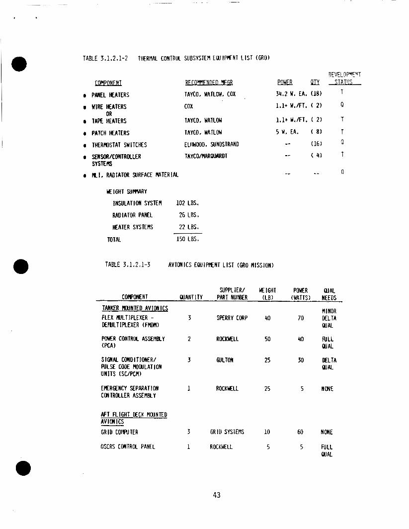
TABLE 3 ,1,2#1-2 TllERMAL CONTRuL SUUSYSTEM ELUIPMCNT L I S T (GRO)
COMPONENT 0 PANEL HEATERS
0 U l R E HEATERS
0 TAPE HEATERS OR
DEVELDPYEYT - eahlEB Q I Y STATIJS T TAYCO, WATLOW. COX 34,2 W . EA. (18)
cox
TAY CO , UATLOU
1,1+ W./FT, ( 2 ) Q
1.1+ W./FT. ( 2 ) T
0 PATCH HEATERS TAYCO, UATLOW 5 W . EA. ( 8 ) T 0 THERMOSTAT SWITCHES ELl lU000, SUNUSTRANO -- (16) Q
0 SEWSOA/CONTROLLER TAYCO/MRQUI\RDT SYSTEHS
0 M I , RADIATOR SURFACE M T E R I A L -- -- Q
M I G H T SUmARY
INSULATION SYSTEM 102 L E ,
RAD [ATOR PANEL 26 LBS.
HEATER SYSTEMS 22 LBS.
T O T N 150 LUS.
TABLE 3 . 1 , 2 * 1 - 3 AVIONICS E W I P E N T L I S T (GRO MISSION)
SUPPLIER/ WE IGHT POWER QJAL CORONENT U A N T I T Y PART NUIlBER ( L B ) (WATTS) NEEDS
MINOR TANKER mXlNTED AVIONICS
FLEX MJLTIPLEXER - 3 SPERRY CORP 40 70 DELTA OEEULTIREXER (FMDfl) Qll AL
POWER CONTROL ASSEflBLY 2 ROCKMLL (PCA)
50 40 R1 LL Gw A L
3 GULTON 25 30 DELTA SIGNAL COIIDITIONER/ PULSE CODE H O W L A T I O N QUAL U N I T S (SC/PCM)
EERGENCY SEPARAT 1 ON 1 ROCKMLL 25 5 NONE CONTROLLER ASSEMBLY
AFT F L I G H T DECK W N T E D A V I a ICs GRID COMRlTER 3 GRID SYSTEflS 10 60 NONE
OSCRS CONTROL PANEL 1 ROCKUELL 5 5 FULL QUAL
43
,
advantages of employing diaphragm tanks in the tanker include: efficiency; independence of expulsion t o spacecraft accelerations; l igh t weight design; and a definite boundary between ul1 age and propel lant.
high expulsion
The baseline monopropellant OSCRS design i s fo r resupply of the GRO with a resupply quantity requirement of 2450 lbm of hydrazine. the design must permit interconnection of mu1 t i ple OSCRS or supplemental propel1 a n t modules t o the primary tanker t o achieve increased propel 1 a n t quantity transfer u p t o 7400 lbm.
For growth capabil i ty,
To maximize the propellant capacity of the propellant t a n k designs identi f iea i n Table 3.1.2.2-1 a minimum tank ullage needs t o be identified fo r these tanks. the propellant t ank ullage volume i s sized too small , thermal expansion of the ullage gas, due to a 2-3 degree r i se in t a n k temperature, could cause the pressure level within the tank t o exceed safe operating l imits. sized to accomnodate a maximum thermal excursion o f +5 psid/deg. F , a t nominal tank operating pressures. of the Shuttle A P U , TDRS, and GRO tanks in the OSCRS applications.
I f
Minimum ullage volume was
Table 3.1.2.2-2 defines the usable propellant capacity
A 2 GRO tank propellant transfer system design would have a propellant resupply capacity o f 2472 lbs o f hydrazine. A propellant resupply system using the TDRS propellant t ank would require 3 tanks (2880 lbs ) t o meet the G R O 2450 l b transfer capacity requirement. A propellant resupply system u s i n g the APU tank would require 7 tanks (2730 l b s ) t o meet the GRO transfer capacity requirement.
Signi ficant parameters in the selection of a preferred propellant transfer subsystem design were system weight and operating pressure. An estimated delta weight analysis of the propellant transfer subsystem designs ( n o t including any structural support weight) reveal s the 2 GRO tank design t o be 1 i ghter than the 3 TDRS t a n k design (by approximately 2 5 l b s ) . I n addition, the operating pressure o f the 3 TDRS t a n k design (339 psia) i s significantly lower t h a n the 2 GRO t a n k design (400 psia). Since the baseline user of the OSCRS vehicle, the Gamma Ray Observatory, operates a t a beginning-of-life pressure of 400 psia, a higher operat ing pressure capability for the tanker propellant transfer subsystem i s considered a significant system design feature. The 7 APU t a n k design i s the least desirable, due to the large number of tanks, high system weight, and low operating pressure.
Based on this evaluation, the 2 GRO diaphragm tank propellant transfer subsystem design i s the best suited for the OSCRS monopropellant tanker.
3.1 2 . 3 Quantity Gauging Techniques
The quantity gauging techniques for OSCRS were evaluated arid discussed in detail in paragraph 3.1.1.9. accurate method for control1 i n g and determining the amount of propellant transferred d u r i n g a spacecraft servicing operation. Turbine flowmeters were selected a s the most accurate system over the broad flowrate range required for OSCRS operations. Three turbine flowmeters used in series will provide fot- redundancy and heal t h monitoring.
The use of flowmeters was determined to provide the most
Quantum Dynamics has developed and suppl ies such a flowmeter for measuring mass flows of cryogenic fluids. This design enables determination of two-phase mass flows t o accuracies of 1/2%. Mass flow determination of the tanker propellants i s considered state-of-the-art for their flowmeter concept.
44 7634c/20
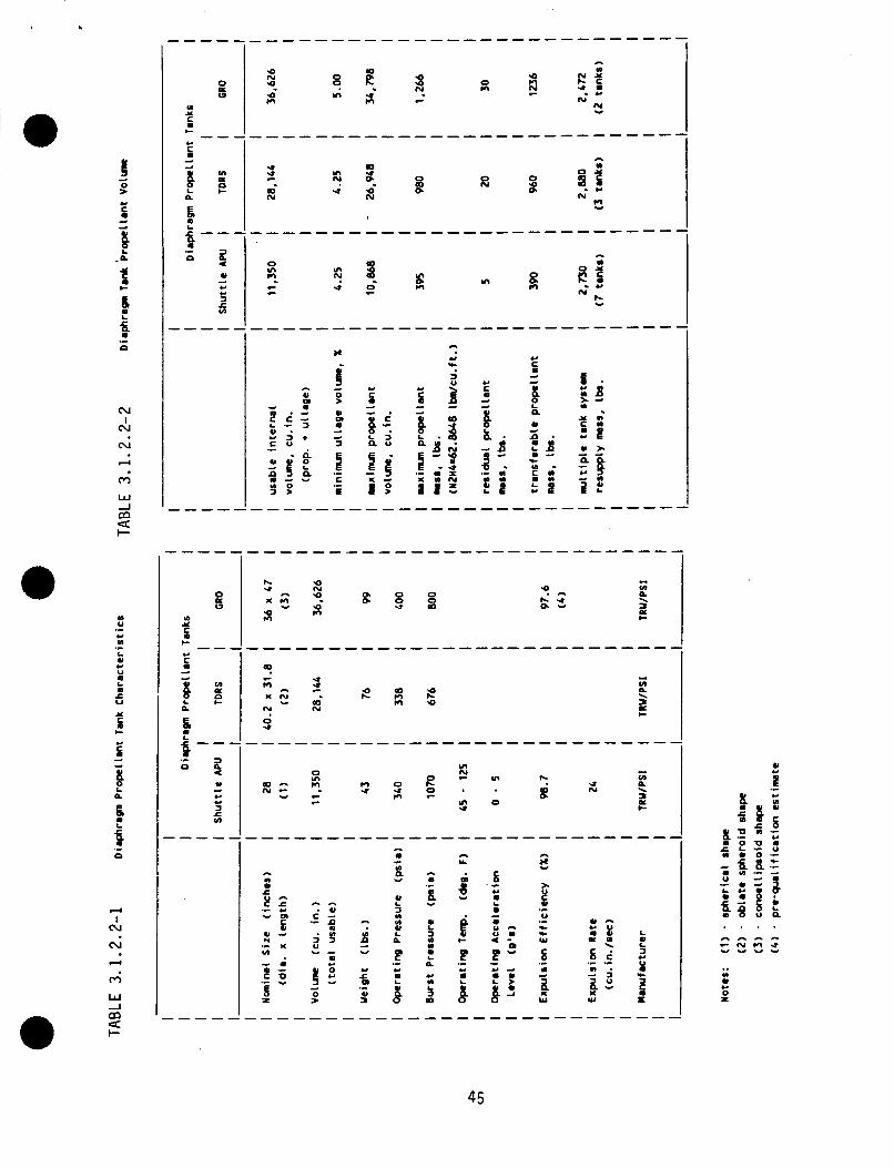
I O
a
0 w. u UI x
5 -- I-
U
5 d
d
a
I i-- .L
o z
Fi u
a
u c U
c u)
d
X
d 5' 0
U a d d
3
I .L
C
E .L
c'
a -
- 5' 0
U s d d
H a z i .L
U C
d d
t b
5 .C
e t
e
i
4 - 6 2
* \ a
2 I-
c o n N - Y
---
0 Y) n
e c
n U
0 s In Y
In U
In
0
h 2 U N
- - U m
E d
0 >
B Y
? .- U m
0 ii
CI m .L
B Y
L a U (D
3 m
P .- U m
B
- - Y
>. E .C
u v. - W
.L
s a .C
a d
W
(D 0
0 X U
45
3.1 2 . 4 Var iab le Supply Pressure vs. Flow Contro l
Th is task compared a p r o p e l l a n t t r a n s f e r system t h a t used an e l e c t r o n i c a l l y c o n t r o l l e d pressure r e g u l a t o r w i t h a f i x e d o r i f i c e , versus a v a r i a b l e o r i f i c e f low c o n t r o l device w i t h a s e t pressure r e g u l a t o r . The e l e c t r o n i c a l l y c o n t r o l l e d pressure r e g u l a t o r was found t o be t h e p r e f e r r e d o p t i o n f o r t h e f o l l o w i n g reasoi is:
1. A v a r i a b l e r e g u l a t o r i s ab le t o d e l i v e r r e l a t i v e l y gas f r e e p r o p e l l a n t t o the r e c e i v e r v e h i c l e as compared t o a v a r i a b l e o r i f i c e f l o w c o n t r o l device. The e f fe rvesced gas volume u s i n g a f l o w c o n t r o l device c o u l d be as h i g h 88 i n 3 ( u s i n g GN2) a t the complet ion o f a 2500 lbm hydraz ine t r a n s f e r . This q u a n t i t y o f pressurant and the t ime r e q u i r e d f o r r e d i s s o l u t i o n a r e n o t acceptable c o n d i t i o n s t o impose on the r e c e i v e r v e h i c l e .
2 . Greater v e r s a t i l i t y o f the v a r i a b l e pressure r e g u l a t e d system can be achieved u s i n g a pump as the f low c o n t r o l device. With a pump, the tanker w i 11 be ab1 e t o per form an " u l l age t r a n s f e r " spacecra f t r e s e r v i c i n g .
3. An e l e c t r o n i ca l l y c o n t r o l 1 ed pressure r e g u l a t o r as a developed technology w i l l a l s o be b e n e f i c i a l f o r a p p l i c a t i o n s i n a p ressurant t r a n s f e r subsystem.
The advantages and disadvantages o f the two s y s t e m a r e summarized i n Tables 3.1.2.4-1 and 3.1.2.4-2.
3.1.2.5 Pump versus Pressure Fed Supply
A t r a d e o f f o f t h e blowdown pump-fed p r o p e l l a n t t r a n s f e r system and t h e pressure-regulated pressure- fed system was performed t o i d e n t i f y t h e b e s t system o p t i o n f o r a 2500 l b hydrazine (N2H4) t r a n s f e r system. The two resupply o p t i o n s are presented i n F i g u r e 3.1 2.5-1. the d e l t a weight , d e l t a cos t , and system comparisons, r e s p e c t i v e l y . F i n a l system s e l e c t i o n was based on the f o l l o w i n g e v a l u a t i o n c r i t e r i a : cos t , s a f e t y , v e r s a t i l i t y , complex i ty , and the a b i l i t y o f t h e system t o accommodate a l l spacecra f t p r o p e l l a n t feed systems.
Table 3.1.2.5-1 presents a we igh t comparison o f t h e two p r o p e l l a n t t r a n s f e r systems f o r the t r a n s f e r o f 2500 l bs . o f hydrazine. The t a b l e inc ludes o n l y the d i f f e r e n c e s between t h e two schematics. Therefore, t h e t o t a l we igh t values are t o be used as comparative values, n o t as t o t a l system values. The l i g h t e s t system i s c l e a r l y the blowdown pump-fed system u s i n g O r b i t e r power. The t o t a l weight i s 62 l b s . compared t o 247 l b s . f o r the pressure- fed system.
I Table 3.1.2.5-1 presents
weight,
The c o s t shown i s n o t the t o t a l system c o s t b u t an est imated d e l t a c o s t between t i e d i f f e r e n c e s i n the system components (based on s u p p l i e r data and s i m i l a r i t y t o S h u t t l e component c o s t s ) . system w i l l c o s t about 1.2 m i l l i o n d o l l a r s more than the blowdown pump-fed system. The major-cost d r i v e r i n t h e pressure- fed system i s t h e l a r g e number o f components t h a t are r e q u i r e d f o r t h i s system.
As can be seen t h e pressure- fed
46 7634c/21
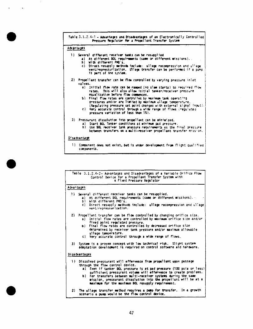
Table 3.1.2.4-1 - A&antrgrs and Disadvanflges o f an E l e c t r o n t c r l l y t o n t r o l l e d Pressure k g u l a t w ta a Propel lant t rans fe r S y s * s
1 Several d i f f e r e n t rece iver W s can be resuppl fed a ) A t d i f f e r e n t Bot, r q u i r a n t s (sue or d i f f e r e n t miss ions) . b ) With d i f f e r e n t PbO's. c ) D i r e c t Tt tupply rpoL f n c l u h : u l l a g r recompression a n t ut1age
vent/repressur izat ion. Ullage Wansfer can be perfocned i f a p;np ts p a r t o f the s y s t n .
2 ) Prope l lan t t rans fer can be fla cont ro l led by vary ing p resswe i n l e t valves.
a ) : n t t i a l fla ra te a n be rrapcd (no slam s t a r t s ) t o r q u ' r r d now ra tes . This w i l l a lso a l l - i n i t i a l %nker/rcceiver p res rd r r equa l iza t ion before fla commces.
h ) F ina l fla ra tes are c a t r o l l e d by mnurinu 'ank operat '?g pressures and/or are 1 i m 2 d by maxima! u l lage tcmpcratdre. (Regulating pressure set point changes w i t h external signal ! n p u t i .
c ) Very accwate cont ro l thrcu# a wide range o f f l m s i v g u : a t e a pressure v a t f a t i o n o f less than 1%) .
Sort BOL Tanker conditions a t mininun pad pressure. Use BOl mceiver tank pressure requirc l r rnts a s the f i n a l 2rcs;i;re between transfers on a u r l t i - m c c i v r r p rope l l an t w m s f e r niss:on.
3 ) Prcssurant d !sso lu t im fn ta p o p l l a n t can be alnlmized. a ) b )
Disadvantage
1 ) Component does not ex is t , bu t I s undcr deve lopent frm fl ight q u a l i f i e a cunponents.
Table 3.1.2.4-2- Advantages and Disadvantages o f a Var iab le O r i f i c e Flow Cont ro l Device f o r a Prope l lan t Transfer System wi th
a F ixed Pressure Regulator
Advantages
1 1 Several d i f f e r e n t rece ive r tanks can be resupplied. a ) A t d i f f e r e n t BOL rquirecaents (sane or d i f f e r e n t o i s s i o n s ) . - b ) U i t h d i f f e r e n t PMD's. c ) D i r e c t r e s o p p l i methods inc lude: ul lage recompression and h i l a 9
ven t / rep ressu r i z r t i on .
2 ) Prope l l an t t r a n s f e r can be flor con t ro l l ed by changing o r i f i c e s ize . a )
b ) F i n a l f l o w r a t e s are c o n t r o l l e d by decreased o r i f i c e s i z e
c ) Very accurate con t ro l throu# a wide range o f flows.
I n i t i a l f l o w ra tes are con t ro l l ed by maximum o r i f i c e s i z e and/or f i x e d p o i n t regu la ted pressure.
determined by rece ive r tank pressure and/or maximum a l lowab le u l l a g e temperaewe.
3 ) System i s a proven concept w i t h lor technical r i s k . adapta t ion developnent i s requ i red on cont ro l sof tware and hardware.
S l i g h t system
D i sa ctvantages
1 ) D isso lved pressurant w i l l effervesce frm prope l l an t upon passage thraugh the f low con t ro l device.
a ) Even i f tanker BOL pressure i s a t pad pressure (100 ps ia o r l e s s s u f f i c i e n t pressurant voluac w i l l ef fervesce to crea te problems.
b ) For t r a n s f e r s bebeen m l t i - r e c e f v s systcms dur ing the same mission. pressurant d i sso lu t i on into the prope l l an t w i l l be a t a u x i u m f o r t he aaxlprm BOL resupply rqu i remen t .
2 ) The u l l a g e t r a n s f e r method requ i res a p u p for t rans fe r . scenar io a p u ~ p would be the fla cont ro l device.
I n a growth
47
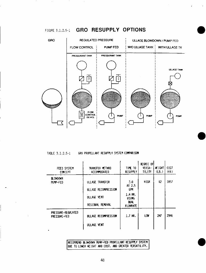
GRO REGULATED PRESSURE ; ULLAGE BLOWDOWN I PUMP FED
FLOW CONTROL i PUMP FED i W/O ULLAGE TANK WITH ULLAGE TK
I
PRESSURINT TANK PRESSURANTTANK : I n
ULLAGE TANM
ro r
i a-1 I
TABLE 3,1,2,5-1 GRO PROPELLANT RESUPPLY SYSTEM COFPARISON
OEGREE Ol MRSA- T I L l l Y
LJE IGHT (LB, 1
COST ( K S 1
FEED SYSTEM CONCEPT
TRANSFER N T H O D ACCOMMODATED
TIE TO RESUPPLY
~~ ~
ULLAGE TRANSFER
ULLAGE RECOMPRESSION
ULLAGE VENT
RES I DUAL REIlOVAL
ULLAGE R E C W R E S S 1011
ULLAGE VENT
BLOWDOWN PU MP-F ED HIGH 62 1857 3.0
AT 2.5 GPM
1.4 HR. USING WAL
FLOWRATE
1.7 HR. PRE SSURE-REGULATED PRESSUHE-FED LOU 247 2946
I RECOflMEND BLOWDOWN R J R - F E D PROPELLANT RESUPPLY SYSTER I DUE TO LOWER HEIGHT AND COST, All0 GREATER VERSATILITY.
The blowdown pump-fed system accomnodates a l l methods of propel1 a n t transfer, i t costs and weighs less ( f o r Orbiter supplied power), and has a greater versatility than the pressure-fed system. Safety considerations rate the t' o systems abou t the same. Disadvantages of the pump-fed system include a sma 1 increase in resupply time and complexity when compared t o the pressure-fed sys tem.
This system evaluation shows t h a t the blowdown pump-fed propel1 a n t transfer system is favored over the pressure-fed propel 1 a n t transfer sys tem. pump-fed system is lower i n cost and weight (with Orbiter power), more versatile, and i t can accommodate a l l methods of resupply.
The
3.1.2.6 Receiver Propellant Tank Venting Techniques
Identified spacecraft requiring hydrazine resupply f i t into two general pressurant sys tern categories . The bl owdown sys tem will be resuppl ied by the mthod of u l l age recompression and therefore no venting is required. I t should be noted t h a t almost a l l hydrazine spacecraft t h a t require resupply from the Orbiter f i t into this category. The second type is a pressure regulated system. Since the pressure of the propellant tank is maintained a t a fixed pressure, resupply can be performed by two methods: ullage exchange or by ullage vent followed by subsequent repressurization ( this will require a pressurant transfer). For ullage exchange no venting is required (Space Station may be a potential candidate due t o s t r i c t contamination l imits) . For ullage vent followed by subsequent repressurization, venting is obviously required. One potential resupply candidate t h a t may f i t into the category i s the Space S t a t i o n .
There are several conceptual methods of ullage venting t h a t can be applied t o hydrazine users as shown in Figure 3.1.2.6-1. Figure 3.1.2.6-la represents a nonpropulsive dumping of unreacted hydrazine vapor/l iquid overboard from either the Orbiter or during a more remote transfer (such as Space S t a t i o n ) . This method is not considered t o be a routine method for ullage venting since the unreacted hydrazine has the potential of damaging the Orbiter, user, and OSCRS over ex,tended periods of time.
The f i r s t sys tern type is a bl owdown sys tem.
The method of venting by non-propulsive vents th rough a catalyst bed is i l lustrated in Figure 3.1.2.6-lb. Hydrazine decomposes primarily i n t o amnonia, nitrogen, and hydrogen gases; a l l o f w h i c h are considerably less corrosive than hydrazine. The q u a n t i t y of hydrazine t h a t i s expected t o be vented is about 3.6 x 10⁻³ l b per cubic f o o t of ullage for a diaphragm t a n k . Safety problems associated with the method of non-propellant venting through a catalyst bed come as an outgrowth of defining the catalyst bed as a thruster. NHB 1700.7A states t h a t for a "10 pounds or less thrust, the minimum safe fir ing distance following deployment is 200 feet from the Orbiter". The major problems t h a t a thruster can cause t o the Orbiter result from impingement and heat damage from a thruster directed toward the Orbiter ( o r s a t e l l i t e ) . OSCRS can be designed so t h a t this shoul d n o t present a problem by selective directional venting and reducing the size of the thruster ( a 0.1 lb thruster i s allowed w i t h i n 30 f t of the Orbiter).
49 01 14C/22
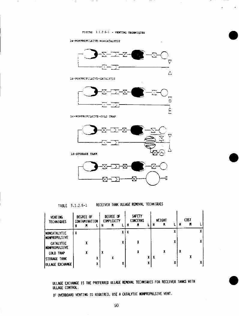
n
SAFETY CONCERNS
I - - L-2 I
t L
lc - WOHPRC F.LS ICT -CC'J .nuP
WE I GHT H f l L H M L
ld-STORAGE TANX
K
X
X
X
TABLE 3,1.2,6-1 RECEIVER TANK ULLAGE REHOVAL TECHNIQUES
x x
VENT I ffi TECHN I QlES
DNCATALYT IC IONPROPULSIVE
CATALYTIC KMPROPULSIVE C W ) TRAP
;TORACE TANK ILLAGE EXCHAffiE
DEGREE OF CONTAdl NATION H M L
X
X
X X X
DEGREE OF COnPLEX I TY in^
X
X
K X
X
X
X
X
X
COST H H L
X X
ULLAGE EXCHANGE IS THE PREFERRED ULLAGE W A L TECHNIQUES FOR RECEIVER TANKS WITH ULIAGE CONTROL,
IF OVERBOARD VENTING IS REWIRED, USE A CATALYTIC WONPROPULSIVE VENT.
50
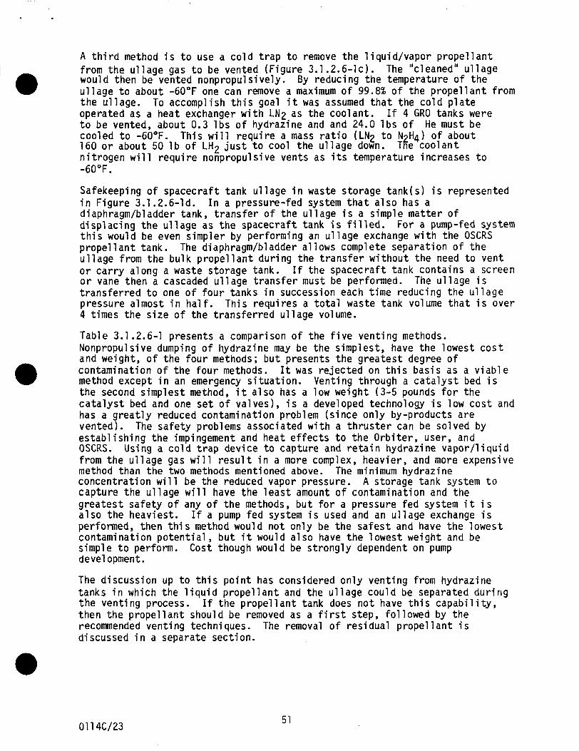
A t h i r d method i s t o use a cold t r a p t o remove the l i q u i d / v a p o r propellant from the ullage gas t o be vented (Figure 3.1.2.6-lc). would then be vented nonpropulsively. ullage t o about -60°F one can remove a maximum of 99.8% of the propellant from the ullage. operated as a heat exchanger w i t h L N 2 as the coolant. t o be vented, about 0.3 l b s of hydrazine and and 24.0 l b s of He must be cooled t o -60°F. 160 or a b o u t 50 l b of L H 2 just t o cool the ullage down. T2e coolant nitrogen will require nonpropul sive vents as i t s temperature increases t o
The "cleaned" ullage By reducing the temperature of the
To accomplish th i s goal i t was assumed that the cold plate
This will require a mass ra t io ( L N 2 t o N H4) of abou t
If 4 GRO tanks were
- 6 O O F .
Safekeeping of spacecraft tank u l 1 age i n waste storage tank( s ) i s represented i n Figure 3.1.2.6-1d. diaphragm/bladder t a n k , transfer of the ullage i s a simple matter of displacing the ullage as the spacecraft tank i s f i l l ed . this would be even simpler by performing an ullage exchange w i t h the OSCRS propel 1 ant t a n k . ullage from the b u l k propellant dur ing the transfer w i t h o u t the need to vent or carry along a waste storage tank. or vane then a cascaded ullage transfer must be performed. transferred t o one of four tanks i n succession each time reducing the ullage pressure almost i n half. 4 times the s ize of the transferred ullage volume.
Table 3.1.2.6-1 presents a comparison of the five venting methods. Nonpropulsive dumping of hydrazine may be the simplest, have the lowest cos t and w e i g h t , of the four methods; b u t presents the greatest degree of contamination of the four methods. method except i n an emergency situation. the second simplest method, i t also has a low weight (3-5 pounds for the catalyst bed and one s e t of valves), i s a developed technology i s low cost and has a greatly reduced contamination problem (since only by-products are vented). establishing the impingement and heat effects t o the Orbiter, user, and OSCRS. from the ullage gas wil l resul t i n a more complex, heavier, and more expensive method than the two methods mentioned above. The m i n i m u m hydrazine concentration will be the reduced vapor pressure. capture the ullage will have the l ea s t amount of contamination and the greatest safety of any of the methods, b u t for a pressure fed system i t i s also the heaviest. I f a pump fed system i s used and an ullage exchange i s performed, then t h i s method would n o t only be the safest and have the lowest contamination potential, b u t i t would also have the lowest weight and be simple t o perform. Cost though would be strongly dependent on pump devel opment.
In a pressure-fed system tha t also has a
For a pump-fed system
The diaphragm/bl adder a1 1 ows compl e t e separation of the
The ullage i s I f the spacecraft t ank contains a screen
T h i s requires a t o t a l waste tank volume t h a t i s over
I t was rejected on t h i s basis a s a viable Venting th rough a catalyst bed i s
The safety problems associated w i t h a thruster can be solved by
Using a cold t r a p device to capture and retain hydrazine vapor/liquid
A storage t a n k system t o
The discussion u p to t h i s point has considered only venting from hydrazine tanks i n which the l i q u i d propellant and the ullage could be separated d u r i n g the venting process. then the propellant should be removed as a f i r s t step, followed by the recommended venting techniques. The removal of residual propel 1 a n t i s discussed i n a separate section.
I f the propellant t a n k does not have this capability,
01 14C/23 51
There are two recomnendations t h a t have been produced by t h i s study.
1 ) Since the spacecra f t w i l l c o n t a i n an u l l a g e t r a n s f e r qu ick d isconnect t o r e t u r n u l l a g e t o the OSCRS tanker f o r d isposal , u l l a g e exchange i s the p r e f e r r e d method f o r diaphragm tanks. a pump-fed propel 1 a n t sys tem.
This i n d i c a t e s a need f o r
2 ) If vent ing i s r e q u i r e d and u l l a g e exchange i s n o t p o s s i b l e then u s i n g a c a t a l y s t bed t o decompose the hydrazine i s the suggested approach.
3.1.2.7 Residual Spacecraf t P r o p e l l a n t Disposal Techniques
The removal o f r e s i d u a l p r o p e l l a n t f rom the spacecra f t may be necessary f o r t h r e e reasons. One reason would be t o enable an accurate p r o p e l l a n t q u a n t i t y determinat ion by f i l l i n g the spacecra f t ' s p r o p e l l a n t tanks f rom the empty s t a t e . The removal o f r e s i d u a l p r o p e l l a n t f rom the spacecra f t w i l l a l l o w t h e q u a n t i t y o f p r o p e l l a n t added t o the spacecra f t t o be accurate ly determined by OSCRS tanker f lowmeters. The second reason f o r removal o f r e s i d u a l p r o p e l l a n t may r e s u l t f r o m contaminated p r o p e l l a n t due t o long- term storage on o r b i t . The l a s t reason occurs when vent ing i s r e q u i r e d and the r e c e i v e r p r o p e l l a n t tank does n o t have a p r o p e l l a n t / u l l a g e separator . The removal o f r e s i d u a l p r o p e l l a n t i n t h i s case would minimize t h e q u a n t i t y o f vented uy-products by removing most l i q u i d p r o p e l l a n t f rom the r e c e i v e r tank before vent ing.
TWO methods o f p r o p e l l a n t d isposal techniques are considered v i a b l e opt ions f o r the tanker. The f i r s t method woul d i n v o l v e the dumping o f r e s i dual p r o p e l l a n t through a nonpropuls ive vent system a f t e r pass ing through a c a t a l y s t bed. The second method woul d i n v o l v e the s to rage o f r e s i dual propel 1 a n t i n s torage tanks o r the tanker propel 1 a n t tanks.
The removal of r e s i d u a l p r o p e l l a n t f r o m the s p a c e c r a f t by dumping through a c a t a l y s t bed may be a v i a b l e o p t i o n i n s p e c i f i c cases, b u t i s n o t cons idered t o be a v i a b l e o p t i o n i n general . of the Space S t a t i o n i s banned i n the q u a n t i t i e s considered as r e s i d u a l prope1lai.t. more. S p e c i f i c cases where vent ing may be al lowed: 1) f o r smal l r e s i d u a l q u a n t i t i e s t r a n s f e r r e d a t the O r b i t e r , 2 ) the removal o f contaminated p r o p e l l a n t a t the O r b i t e r , and 3) the emergency removal o f p r o p e l l a n t .
The vent ing o f by-products i n the v i c i n i t y
The q u a n t i t i e s o f r e s i d u a l hydraz ine may be as h i g h as 200 l b s o r
The second v i a b l e method i s t o s t o r e the r e s i d u a l p r o p e l l a n t i n a s to rage tank ( t h i s inc ludes the tanker p r o p e l l a n t tanks) . The removal o f p r o p e l l a n t f rom a diaphragm/bladder a c q u i s i t i o n tank w i l l p resent no removal problems and w i l l be the b e s t type of tank f o r p r o p e l l a n t removal (most p o t e n t i a l users f i t i n t h i s category) . Hydrazine removal f rom a vane a c q u i s i t i o n device should be as s imp le as f rom a diaphragm tank except t h a t the f l o w r a t e must be t a i l o r e d t o the c a p a b i l i t y o f the vane tank. Removal o f hydraz ine f r o m a screen a c q u i s i t i o n tank w i l l r e q u i r e one more step. The screen must be e i t h e r completely wet o r completely dry f o r an e f f e c t i v e resupply t o occur s i n c e u l l a g e t rapped i n s i d e the channel w i l l l i m i t the a c q u i s i t i o n dev ice 's a b i l i t y t o d e l i v e r gas f r e e p r o p e l l a n t t o the t h r u s t e r s . T'ne removal o f a l l p r o p e l l a n t t o vapor pressure can be accomplished by f i r s t us ing the s torage tank t o remove as much r e s i d u a l p r o p e l l a n t as p o s s i b l e and then vent ing the remaining p r o p e l l a n t through the c a t a l y s t bed. s to rage tank method over the vent ing method i s t h a t the s t o r e d p r o p e l l a n t can be reused i n s p e c i f i c cases t o resupply the spacecraf t .
An advantage t o us ing the
01 14C/24
t
There are three recommendations t h a t have been produced by t h i s study.
1 )
2 )
3)
3.1.2.8
Usage of res idua l storage tanks t o remove and s to re res idua l hydrazine i s the bes t opt ion. contamination o r safety , w i t h small pena l t i es f o r weight and cos t . The res idua l storage tank cou ld be an e x t r a p rope l l an t tank o r a planned volume o f a requ i red p rope l l an t tank.
C a t a l y t i c vent ing o f hydrazine i s a secondary op t i on o f res idua l p rope l l an t removal and disposal . It i s bes t app l ied t o small quant i t i e s o f res idua l p rope l lan t .
It w i l l minimize any problems o f
A pump t r a n s f e r system w i l l a l l ow more v e r s a t i l i t y i n the opt ions of res idual removal and storage.
Therma 1 Control Tech n i ques /Hardware
A comparison o f heater types (i.e., component vs. area) was performed. s tud ies completed under p r o j e c t s 85250 and 85208, p r i o r t o the OSCRS cont rac t , i nd i ca ted t h a t power requ i renients o f i nsul ated component heaters are 1 ower than f o r area heaters, and showed technica l problems associated w i t h each type. Under contract , f u r t h e r i nves t i ga t i on r e l a t i n g t o costs, f e r r y f l i g h t , sa fe ty and o ther issues was conducted. A panel type heater system was se lected on the bas is o f safety, w i t h advantages f o r redundancy, repa i r , i n s t a l l a t i o n , and convenience o f tank changeout as secondary considerat ions. Costs a l so favor panel heaters, although the advantage i s small compared t o program cost .
Analys is of in-bay f e r r y operat ions i nd i ca ted t h a t f o r a monopropellant tanker l ong d is tance f e r r y t ranspor ta t i on i s n o t a r e l i a b l e p o s s i b i l i t y w i thout heat ing o f OSCRS components, which i s present ly n o t poss ib le . from DRFC t o VAFB can be accomplished i f the smal ler f l u i d l i n e s are insu lated. woul d a1 low b e t t e r analys i s o f t h i s m i ss ion phase.
Hot case en t r y and post1 anding condi t ions, p a r t i c u l a r l y f o r NTO, were analyzed under IR&D P ro jec t 8621 0.
I R & D
Transpor tat ion
An improved understanding o f Orb i te r payload bay f e r r y cond i t ions
I t was found t h a t under the worst poss ib le condi t ions, overtemperatures could occur a f t e r landing. under nominal condi t ions. It i s concluded t h a t cond i t ions lead ing t o overtemperatures are u n l i k e l y and can be prevented procedura l ly . of very small l i n e s i s recomnended. It was shown t h a t r e s u l t s f o r NTO are conservat ive f o r hydrazine.
Several s tud ies o f the f l u i d t r a n s f e r coupl ing and l i n e were accomplished. i s recommended t h a t a removable i n s u l a t i o n system, i n s t a l l e d fo l l ow ing coup l ing deployment, be used i n conjunct ion w i t h patch and w i re heaters t o ma in ta in the assembly i n the requ i red temperature range under design and f a i l u r e condi t ions. Based on conservat ive assumptions, a maximum of 21 wat ts peak power should be app l ied t o the coupl ing and about 20 wat ts f o r the f l u i d 1 ine .
This i s a t variance w i t h O r b i t e r f l u i d l i n e experience
I n s u l a t i o n
It
53 01 14C/25
Avion ics thermal c o n t r o l was i n v e s t i g a t e d f o r a v a r y i n g a v i o n i c s h e a t l o a d under IR&D P r o j e c t 86210, f o r a b i p r o p e l l a n t des ign producing 195 wat ts . T h i s a n a l y s i s r e s u l t e d i n a louvered r a d i a t o r design. Under cont rac t , a cont inuous 380 w a t t a v i o n i c s heat l o a d was analyzed. The c o n t r a c t a n a l y s i s more c l o s e l y model s c u r r e n t OSCRS des ign cond i t ions . It was determined t h a t an i n t e r n a l l y and e x t e r n a l l y r a d i a t i n g f l a t panel (nonlouvered) 2 a d i a t o r i s dequate f o r a1 1 f l i g h t cond i t ions . An o u t e r sur face rea o f 12 f t t o 14.3 ft’, w i t h an e f f e c t i v e i n n e r sur face area o f 1 4 f t , i s requi red, depending on f l i g h t cond i t ions .
h
To suppor t OSCRS a v i o n i c s design, temperature i n s t r u m e n t a t i o n ranges were e s t a b l i s h e d f o r each ins t rument l o c a t i o n .
S tud ies o f temperature sensor requirements were c a r r i e d o u t under I R & D P r o j e c t 85208 (monopropellant-1985) and 86210 (b ip rope l lan t -1986) . monopropel lant study was done under c o n t r a c t . about 102 temperature sensors (65 f o r thermal c o n t r o l and 37 f o r o t h e r purposes) a r e requi red. About 155 sensors a r e r e q u i r e d f o r t h e growth design. F o l l o w i n g t h e hardware t e s t and a n a l y s i s program, a p o t e n t i a l r e d u c t i o n o f about 26 sensors ( b a s e l i n e ) t o 31 (g rowth) e x i s t s . Table 3.1.2.8-1 l i s t s t h e i n s t r u m e n t a t i o n a p p l i c a t i o n s .
A f i n a l For t h e monopropel lant OSCRS,
3.1.2.9 Opt im iza t ion o f OSCRS Control
The o b j e c t i v e o f t h i s study was t o develop an op t im ized c o n t r o l system f o r a monopropel lant o r b i t a l consumables resupply system. system d e f i n e d by t h e s tudy f e a t u r e s a user f r i e n d l y manhachine i n t e r f a c e and s a t i s f i e s resupply system f a i l u r e t o l e r a n c e requirements.
The op t im ized c o n t r o l
The f u n c t i o n s t o be c o n t r o l l e d by t h e OSCRS c o n t r o l system were i d e n t i f i e d i n t h e s tudy descr ibed i n 3.1.2.12. Table 3.1.2.9-1 i d e n t i f i e s these f u n c t i o n s and a l s o i n d i c a t e s whether t h e f u n c t i o n s should be c o n t r o l l e d by hardwired comnands f rom t h e O r b i t e r a f t f l i g h t deck o r be c o n t r o l l e d a u t o m a t i c a l l y by t h e F1 ex Mu1 t i p l exer Demul t i p l exer ( FflDM) u n i t s on t h e t a n k e r modul e.
The c o n t r o l concept developed under t h i s study i n c l u d e s a dedicated OSCRS Cont ro l Panel, l o c a t e d on t h e AFD as shown e a r l i e r on F i g u r e 3.1.1.15-1. The G R I D computers, a l s o shown on t h e f i g u r e , operate i n c o n j u n c t i o n w i t h t h e OSCRS Contro l Panel t o p r o v i d e t h e man-machine i n t e r f a c e between t h e crew and t h e OSCKS. The dedicated OSCRS Contro l Panel, shown i n F igure 3.1.2.9-1, p rov ides dedicated swi tches t o c o n t r o l bank se lec t , va lve sa f ing , b e r t h i n g la tches , emergency separa t ion func t ions , and power ON/OFF c o n t r o l o f e l e c t r o n i c s and heaters. The panel a l s o i n c l u d e s t h e Crew Contro l /Status Panel, which prov ides redundant, dedicated c o n t r o l and s t a t u s paths t o each FMDM . A l l automat ic sequences performed on a resupply m i s s i o n w i l l be c o n t r o l l e d by t h e FMDM software. T h i s sof tware w i l l c o n s i s t o f programs f o r a l a r g e number o f sequences, such as opening a valve, t h a t c o u l d e i t h e r be r u n i n d i v i d u a l l y or as a s e r i e s o f events i n a resupply mission. can o n l y be i n i t i a t e d by crew a c t i v a t i o n o f t h e ARM/EXECUTE switches on t h e Crew Control /Status Panel.
These c r i t i c a l FMDM sequences
54 01 14C/26
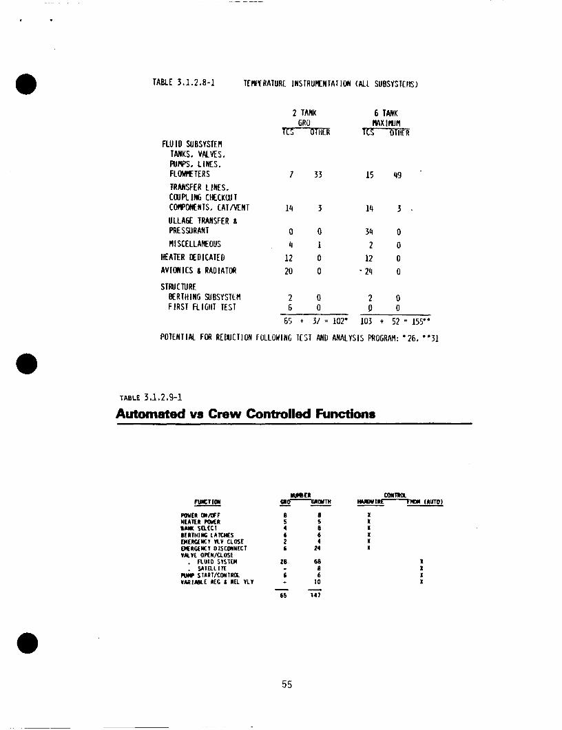
TABLE 3.1.2.8-1 TEMfY RATURL INSTRUMENTAT ION (ALL SUBSYSTENS)
2 TANK 6 TANK r GRO MX IRJM
OTIC R cs m r R FLU I D SUBSVSTEfl
TANKS. VALVES, AIWS, L I L S . F L O I M T E R S 7 33 15 49 TRANSFER L I N E S . COUPLING CHECKWT COROWE N I S , CAT M N T 14 3 14 3 . ULLAGE TRANSFER g PRESSURANT a 0 34 0 MISCELLANEOUS 4 1 2 0
HEATER N D I C A T E D 12 0 12 0 AVIONICS 6 RADIATOR 20 0 - 24 0
STRUCTURE BERTHING SUBSYSTLM 2 0 2 0 F I R S T FLIGliT TEST 6 0 P O
65 + 37 = 102' 103 + 5 2 = 155"
POTENTIAL Foll REUUCTION fULLOWlNG TCST AND ANALYSIS PROGRAM: '26, "31
TABLE 3 .1,2.9-1
Automated vs Crew Controlled Functions
6 6 2 4 6 24
20 68 (I
6 6 - IO
65 1 4 1
- - -
M)(m IWDWtR- (AUTO)
X X I X X X
1 X X I
55
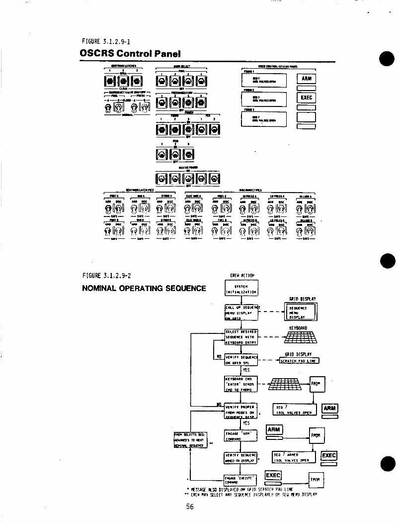
FIGURE 3 I 1.2.9-1
OSCRS Control Panel
FIGURE 3,1,2.9-2 C R W ACTIW
I NOMINAL OPERATING SEQUENCE ~lN1,lllzA,,o,, S Y S l t M
56
Independent FMDM c o n t r o l paths, a long w i t h dedicated feedback Sequence Disp lays, prevents i n a d v e r t e n t a c t u a t i o n o f sequences due t o s ing1 e p o i n t f a i l u r e s i n t h e c o n t r o l system.
Each o f t h e t h r e e FMDM's had a dedicated Sequence D isp lay and Programmable D isp lay Module (PDM) w i t h a t a c t i l e f e e l sw i tch on t h e Cont ro l /S ta tus Panel. The Sequence D isp lay i s a 2 1 i n e by 20 charac ter s c r a t c h pad d i s p l a y . The PDM c o n s i s t s o f a 16 x 35 a r r a y o f l i g h t e m i t t i n g diodes (LED's) which can d i s p l a y any message. The PDM/Switch w i l l be used t o d i s p l a y and generate ARbl and EXECUTE commands. Messages f o r t h e Sequence D isp lay w i l l be c a l l e d up by t h e FMDM by coded commands. The c o n t r o l panel w i l l be used i n c o n j u n c t i o n w i t h two G R I D Compass computers.
The sequence t o be f o l l o w e d by t h e crew t o s e l e c t and execute a resupply sequence i s shown on F i g u r e 3.1.2.9-2. d i s p l a y s and keyboard i n s e l e c t i n g t h e n e x t sequence, and shows t h e crew a c t i o n r e q u i r e d t o v e r i f y t h e proper sequence, arm it, and i n i t i a t e t h e commands t o t h e FMDM's t o execute t h e sequence.
3.1.2.10 Opt imiza t ion o f Data D isp lay t o t h e Crew
The o b j e c t i v e o f t h i s study was t o d e f i n e t h e optimum system f o r p resent ing da ta t o t h e crew d u r i n g an OSCRS resupply miss ion.
A g raph ic d i s p l a y was se lec ted as t h e p r e f e r r e d method o f p r o v i d i n g crew data f o r t h e reasons g i v e n on Table 3.1.2.1 0-1.
Ana lys is o f d i f f e r e n t d i s p l a y technologies, as presented on Table 3.1.2.10-2 r e s u l t e d i n s e l e c t i o n o f an e lec t ro luminescent screen f o r t h e OSCRS graph ic d i s p l a y . An e v a l u a t i o n was conducted t o determine if t h e s i z e o f a v a i l a b l e e lec t ro luminescent (EL) screens, 4 i n . by 8 in. , and t h e p i c t u r e r e s o l u t i o n o f 64 p i x e l s p e r inch, would be adequate f o r t h e OSCRS graphic d i s p l a y requirements. F i g u r e 3.1.2.10-1 shows t h a t t h e e x i s t i n g screens can d i s p l a y on OSCRS f l u i d system schematic i n adequate d e t a i l .
The f i g u r e shows t h e r o l e o f t h e G R I D
The Gr id Systems Compass Computer Model 1139, w i t h a 4 x 8 i n c h e lec t ro luminescent d i sp l ay , meets a1 1 known requirements and i s recommended as t h e graphics d i s p l a y f o r t h e OSCRS. powerful , h igh l y i n t e g r a t e d package whose use w i l l g r e a t l y reduce hardware development r i sks/costs.
The G R I D computer w i t h EL d i s p l a y i s an economical, low r i s k s o l u t i o n f o r an OSCRS a f t crew compartment d i sp lay .
The G r i d Computer i s an extremely
o The D isp lay Memory, D isp lay D r i v e r E l e c t r o n i c s , Computer, Keyboard, and I n t e r f a c e s a r e a compact, f u l l y i n t e g r a t e d package.
The computer uses a most ly standard key t y p e w r i t e r keyboard. o
o The computer can be mounted w i t h Velcro s t r i p s i n a lmost any c o c k p i t 1 o c a t i on.
The G R I D computer i s space-qua l i f ied and has f lown on t h e S h u t t l e as t h e SPOC ( S h u t t l e Por tab le On-Board Computer). on Miss ion 51-B).
The l a r g e screen G R I D was f i r s t f l o w n
01 14C/27 57
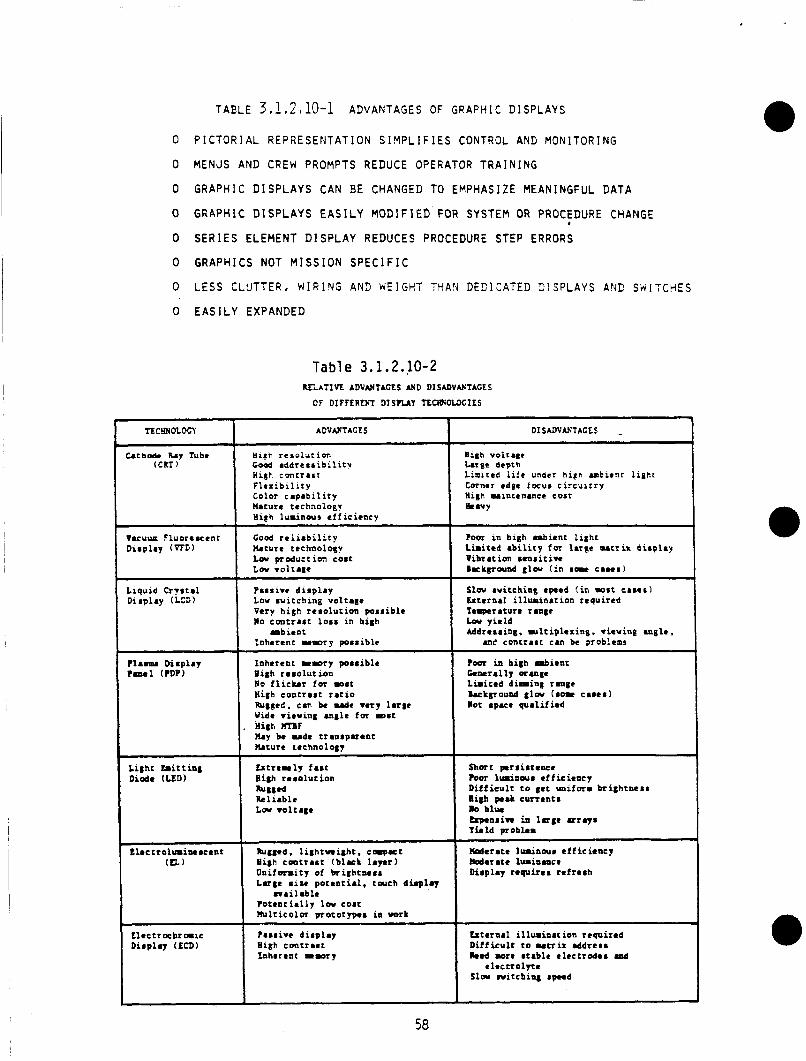
TABLE 3 , 1 , 2 I 10-1 ADVANTAGES OF GRAPH 1 C D1 SPLAYS
~
' t t e r n a l i l l u r i n a c i o n r equ i r ed ' D i f f i c u l t t o mtrix eddreaa ' ked more a t ab le e l e c t r o d e s .nd ' e l e c c r o l ~ e
Slow n i t c b i n g #peed
I
0 PICTORIAL REPRESENTATION SIYPLIFIES CONTROL AND MONITORING
0 MENJS AND CREW PROMPTS REDUCE OPERATOR TRAINING
0 GRAPHIC DISPLAYS CAN BE CHANGED TO EMPHASIZE MEANINGFUL DATA
0 GRAPHIC DISPLAYS EASILY MODIFIED FOR SYSTEM OR PROCEDURE CHANGE
0 SERIES ELEMENT DISPLAY REDUCES PROCEDURE STEP ERRORS
0 GRAPHICS NOT MISSION SPEClFIC
I
0 LESS CLUTTER, WIRlYS AN3 WEIGHT THAV DECltATED 31SPLAYS AVC SNITCHES
0 EASILY EXPANDED
nc!mDLocI ' ADVANTAGES
Cathode k y Tube Hist. r e s c l u c i o n ( C R T ) Good addre sc i b i l i t v
Higt. c m t r a c t F l e x i b i l i t y Color c apab i 1 i c y nature technology H i f h luminous e f f i c i e n c y
!
Table 3.1.2.10-2 RELATIVE ADVANTAGES *D DISADVANTAGES
OF DIFFERENT D T S P U Y TECWOLDGILS
Dirplay ? m a 1 (?DP)
Inherent w w r y p o r r i h l e High r e s o l u t i o n No f l i c k e r for moat High contrast r a t i o h g g r d . c a n be d e very l a r p Wide viewing angle for w a t
b y be u d e tranrpuent %cure technology
. Hi8h WTIIF
Vacuue Fluoremcent Display (WE)
Diaplay (LCD)
Short prrirtencr Four l m i n o u s r f f i c i ency D i f f i c u l t t o get uniform b r i g h t n e s s nigh peak c u r r a n t s lo blue -naive in l a r g e arrays T u l d problem
Good r e l i a b i l i t y b t u r e technology L a productim coa t L a v o l t a g e
I
P a r r i v e d i s p l a y L o u w i t c h i n g vo l t age Very h igh r e a o l u t i o n poss ib l e l o cone raa t l o a s i n high
Inhe ren t u m o r p poaaible r b i e n t
f lec t rolumine .cent (U)
L l e e t r a h r a i c
Pugged. l i g h t w i g h t . c q r t Uigh c a c r a s t (b l ack 1aV.t) O n i f o m i c y of b r i g h t n e a r L a r g e a i m pocan t i a l . touch d b p l q
P o t e n t i a l l y la coat l b l t i c o l m procotypea i n uork
P a r l i v e d i a o l a r
m a i l a b l e
DISADVUTAGES
B i 8 h Volt.#* k r g e depth Limited l i f e under high a m b i e n t l i g h t Corner edge focus c i r c u i r r y High mincenmce cosf tkavy
?om in high ambient l i g h t Limited a b i l i t y f o r large matrix d i s p l a y Vibr a t in r e n r i t i v e a rkg round g lov ( i n a 0 . c caaea)
S l w r v i t c h i n g a p e d ( i n m s t cases) External i l l umina t ion r equ i r ed 1a-r ature range L a y i e l d Addreaaing. u l t i p l e r i n g , viewing ang le ,
UIZ c o n t r a s t can be problems
?om in high d i e m
L i d r e d d i m i n g r m f e kctground g l a ( a m came#) lot rpece q u a l i f i e d
kmLrallY mmae
58
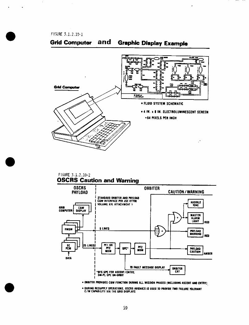
FIGURE 3.1.2.10-1
Grid Computer and Graphic Display Extamdo
FIGURE 3 - 1 2.10-2 OSCRS Caution and Warning
OSCRS ORBITER PAYLOAD I CAUTION / WARNING
I I STANDARD OROlTEl AND PLrLOAD I CLW INTERFACE PER JSC 07700 I VOLUME XlV. ATTACHMENT 1
RED
RED
AMBER
DATA I I I I I 'OFS 6 K FOR ASCENT/ENTRX I SM-PL GPC OM-01011 I
ORBITER PROVIDES CLW FUNCTION DUlfflO ALL MISSION MASES (INCLUDING ASCENT AND ENTRY),
DURING n E s u m v OPERATIONS. oscns AVIONICS IS USED TO m w m E TWO FAiLunE r n i E n u T C / W CAPABILITY VIA THE 6RlO DISPLAYS
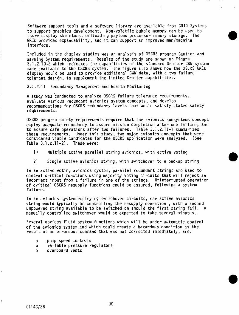
Software support t o o l s and a sof tware l i b r a r y a r e a v a i l a b l e from G R I D Systems t o suppor t graphics development. s t o r e d i spl ay skel etons, o f f 1 oadi ng pay1 oad processor memory storage. G R I D p rov ides expandabi 1 i ty , and i t can suppor t an improved man/machine i n t e r f a c e .
N o n - v o l a t i l e bubble memory can be used t o The
Inc luded i n the d i s p l a y s t u d i e s was an a n a l y s i s o f OSCRS program Caut ion and Warning System requirements. 3.1.2.10-2 which i n d i c a t e s t h e capabi 1 i t i e s o f t h e standard O r b i t e r C&W system made a v a i l a b l e t o t h e OSCRS system. d i s p l a y would be used t o p r o v i d e a d d i t i o n a l C&W data, w i t h a two f a i l u r e to1 e r a n t design, t o suppl ement t h e 1 i m i t e d O r b i t e r capabi 1 i t i e s .
3.1 .2.11 Redundancy Management and Heal t h Moni t o r i ng
A study was conducted t o analyze OSCRS f a i 1 u r e t o 1 erance requirements, eva lua te var ious redundant a v i o n i c s system concepts, and develop recommendations f o r OSCRS redundancy l e v e l s t h a t would s a t i s f y s t a t e d s a f e t y requirements.
OS€RS program s a f e t y requirements r e q u i r e t h a t t h e a v i o n i c s subsystems concept employ adequate redundancy t o assure miss ion complet ion a f t e r one f a i 1 ure, and t o assure sa fe opera t ions a f t e r two f a i l u r e s . Table 3.1.2.11-1 summarizes these requirements. cons idered v i a b l e candidates f o r t h e OSCRS a p p l i c a t i o n were analyzed. Table 3.1.2.11-2). These were:
Resul ts o f t h e study a r e shown on F igure
The f i g u r e a l s o shows how t h e OSCRS G R I D
Under t h i s study, two major a v i o n i c s concepts t h a t were (See
1 ) M u l t i p l e a c t i v e p a r a l l e l s t r i n g av ion ics , w i t h a c t i v e v o t i n g
2) S i n g l e a c t i v e a v i o n i c s s t r i n g , w i t h swi tchover t o a backup s t r i n g
I n an a c t i v e v o t i n g a v i o n i c s system, p a r a l l e l redundant s t r i n g s a r e used t o c o n t r o l c r i t i c a l f u n c t i o n s u s i n g m a j o r i t y v o t i n g c i r c u i t s t h a t w i l l r e j e c t an i n c o r r e c t i n p u t f rom a f a i l u r e i n one o f t h e s t r i n g s . o f c r i t i c a l OSCRS resupp ly f u n c t i o n s c o u l d be assured, f o l l o w i n g a system f a i l ure.
Un in te r rup ted o p e r a t i o n
I n an a v i o n i c s system employing switchover c i r c u i t s , one a c t i v e a v i o n i c s s t r i n g would t y p i c a l l y be c o n t r o l l i n g t h e resupply opera t ion , w i t h a second unpowered s t r i n g a v a i l a b l e t o be switched on should t h e f i r s t s t r i n g f a i l . manual ly c o n t r o l l e d swi tchover woul d be expected t o take several minutes.
Several obvious f l u i d system func t ions which w i l l be under automat ic c o n t r o l o f t h e a v i o n i c s system and which c o u l d c r e a t e a hazardous c o n d i t i o n as t h e r e s u l t o f an erroneous command t h a t was n o t c o r r e c t e d immediately, are:
A
o pump speed c o n t r o l s o o overboard vents
v a r i ab1 e pressure regu l a t o r s
60 01 14C/28
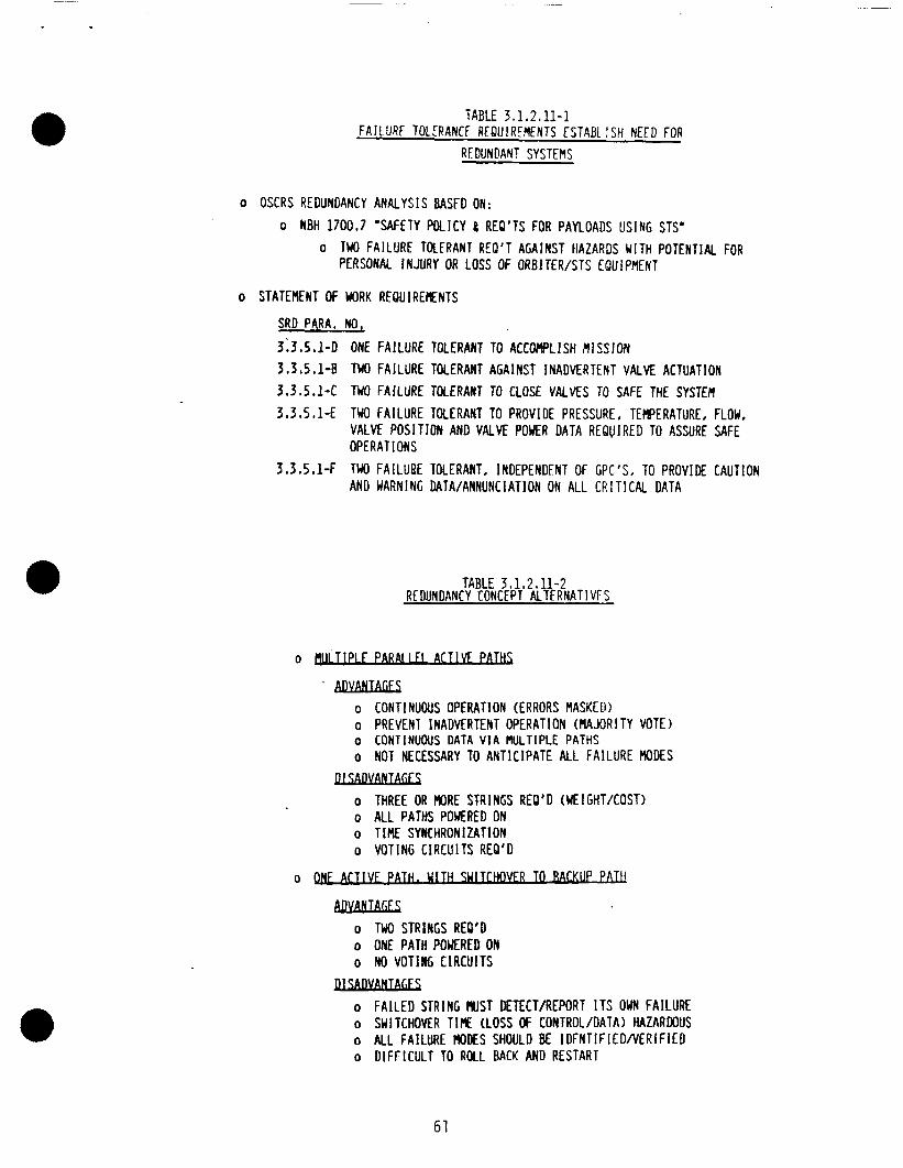
TABLE 3.1.2,11-1 FA JLURF TOLIRANCF REQUlREMfNTS €STABL ! SH NEED FOR
REDUNDANT SYSTEMS
o OSCRS REDUNDANCY ANALYSIS BASFD ON: o NBH 1 7 0 0 , 7 'SAFETY POLICY 8 REO'TS FOR PAYLOADS USING STS'
o TWO FAILURE TOLfRANT REQ'T AGAINST HAZARDS WITH POTENTIAL FOR PERSONAL INJURY OR LOSS OF ORBlT€R/STS EQUIPMENT
o STATEMENT OF WORK REQUIREENTS
SRD PARA. NO,
3 ;3 ,5 .1 -D 3.3,5,1-B
ONE FAILURE TOLERANT TO ACCOMPLISH PllSSlON TWO FAILURE TOLERANT AGAINST INADVERTENT VALVE ACTUATION
3.3.5.1-C 3.3.5.1-E
TWO FAILURE TOLERANT TO CLOSE VALVES TO SAFE THE SYSTEH TWO FAILURE TOLERANT TO PROVIDE PRESSURE, TEMPERATURE, FLOW, VALVE POSITION AND VALVE POWER DATA REQUIRED TO ASSURE SAFE OPERATIONS TWO FAILURE TOLERANT. INDEPENDENT O f GPC'S, TO PROVIDE CAUTION AND WARNING DATA/ANNUNCIATlON ON ALL CRIT ICAL DATA
3 . 3 . 5 . 1 4
TABLE 3 1.2 I 11-2 REDUNDANCY CONCEPT ALTERNATIVFS
0-
.ADVANTAGES o CONTINUOUS OPERATION (ERRORS MASKED) o PREVENT INADVERTENT OPERATION (MAJORITY VOTE) o CONTINUOUS DATA V I A HULTIPLE PATHS o NOT NECESSARY TO ANTICIPATE ALL FAlLURE MODES
o THREE OR MORE STRINGS REO'D (WEIGHT/COST) o ALL PATHS POWERED ON o TIME SYKHRONlZATlON o VOTING CIRCUITS REO'D
Il.uwmm
o ACTIVE P A . U A L U SUIT- I
ADYANTAGES o TWO STRINGS REO'D o ONE PATH POUERED ON o NO VOTlNG CIACUlTS
D1SADYANTALES o F A I L E D STRlNG MIST DETECT/REPORT I T S OWN FAILURE o SWITCHOVER T I E (LOSS OF CONTROL/DATA) HAZAROOUS o ALL FAILURE WDES SHOULD BE I D F N T f F l E D N E R l F l E D o DlFf ICULT TO ROLL BACK AND RESTART
61
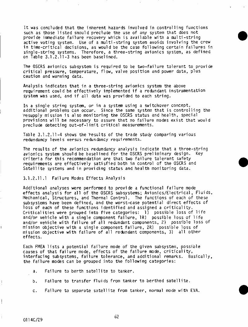
It was concluded t h a t the i n h e r e n t hazards i n v o l v e d i n c o n t r o l l i n g f u n c t i o n s such as those l i s t e d should prec lude the use o f any system t h a t does n o t p r o v i de imnedi a t e f a i l u r e recovery which i s avai 1 ab1 e w i t h a mu1 ti - s t r i n g a c t i v e v o t i n g system. i n t i m e - c r i t i c a l dec is ions, as would be the case f o l l o w i n g c e r t a i n f a i l u r e s i n s i n g l e - s t r i n g systems. on Table 3.1.2.11 -3 has been basel ined.
Use o f a m u l t i - s t r i n g system avoids i n v o l v i n g t h e crew
Therefore, a t h r e e - s t r i n g a v i o n i c s system, as def ined
The OSCRS a v i o n i c s subsystem i s r e q u i r e d t o be t w o - f a i l u r e t o l e r a n t t o p rov ide c r i t i c a l pressure, temperature, f l ow , va l ve p o s i t i o n and power data, p l u s c a u t i o n and warning data.
Ana lys i s i n d i c a t e s t h a t i n a t h r e e - s t r i n g a v i o n i c s system the above requirement c o u l d be e f f e c t i v e l y implemented i f a redundant i n s t r u m e n t a t i o n system was used, and i f a l l data was p r o v i d e d t o each s t r i n g .
I n a s i n g l e s t r i n g system, o r i n a system us ing a swi tchover concept, a d d i t i o n a l problems can occur. Since the same system t h a t i s c o n t r o l l i n g the -resupply m i s s i o n i s a1 so m o n i t o r i n g the OSCRS s t a t u s and hea l th , spec ia l p r o v i s ions w i l l be necessary t o assure t h a t no f a i l u r e modes e x i s t t h a t woul d prec lude d e t e c t i n g out -of -1 i m i t c r i t i c a l measurements.
Table 3.1.2.1 1-4 shows t h e Fesul t s o f t h e t r a d e study comparing v a r i o u s redundancy 1 eve1 s versus redundancy requirements.
The r e s u l t s o f t h e a v i o n i c s redundancy a n a l y s i s i n d i c a t e t h a t a t h r e e - s t r i n g a v i o n i c s system should be b a s e l i n e d f o r t he OSCRS p r e l i m i n a r y design. c r i t e r i a f o r t h i s recommendation a re t h a t two f a i l u r e t o l e r a n t s a f e t y requirements a re e f f e c t i v e l y s a t i s f i e d bo th i n c o n t r o l o f t h e OSCRS and Sate1 1 i t e systems and i n p r o v i d ing s t a t u s and heal t h moni t o r i n g data.
Key
3.1.2.11.1 F a i l u r e Modes E f f e c t s Ana lys i s
A d d i t i o n a l analyses were performed t o p r o v i d e a f u n c t i o n a l f a i l u r e mode e f f e c t s a n a l y s i s f o r a l l o f t h e OSCRS subsystems; A v i o n i c s / E l e c t r i c a l , F l u i d s , Mechanical, S t ruc tu res , and Thermal Con t ro l . The f u n c t i o n s o f each o f these subsystems have been def ined, and the worst-case p o t e n t i a l d i r e c t e f f e c t s of l o s s of each o f these f u n c t i o n s i d e n t i f i e d and assigned a c r i t i c a l i t y . C r i t i c a l i t i e s were grouped i n t o f i v e ca tegor ies : and/or v e h i c l e w i t h a s i n g l e component f a i l u r e , 1R) and/or v e h i c l e w i t h f a i l u r e o f a l l redundant components, 2 )
m iss ion o b j e c t i v e w i t h f a i l u r e o f a l l redundant components, 3) a l l o t h e r e f f e c t s .
1 ) p o s s i b l e l o s s o f l i f e p o s s i b l e l o s s o f l i f e
p o s s i b l e l o s s O f I m i ss ion o b j e c t i v e w i t h a s i n g l e component f a i l u r e , 2R) p o s s i b l e l o s s o f
Each FMEA l i s t s a p o t e n t i a l f a i l u r e mode o f t he g i ven subsystem, poss ib causes o f t h a t f a i l u r e mode, e f f e c t s o f t h e f a i l u r e mode, c r i t i c a l i t y , i n t e r f a c i n g subsystems, f a i l u r e to lerance, and a d d i t i o n a l remarks. Bas t h e f a i l u r e modes can be grouped i n t o the f o l l o w i n g ca tegor ies :
a. F a i l u r e t o b e r t h sate1 1 i t e t o tanker .
b. F a i l u r e t o t r a n s f e r f l u i d s f rom tanke r t o b e r t h e d s a t e l l i t e .
e
c a l l y ,
c . F a i l u r e t o separate s a t e l l i t e from tanker , normal mode w i t h EVA.
I 01 14CI29
62
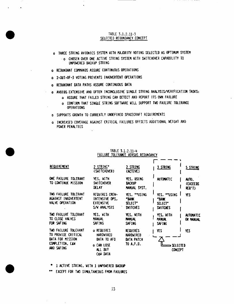
TABLE 3,1.2.11-3 SELFCTED REDUNDANCY CONCEPT
o THREE STRING AVIONICS SYSTEM WITH MAJORITY VOTING SELECTED AS OPTIMUPI SYSTEn . o CHOSEN OVER ONE ACTIVE STRING SYSTEM WITH SWITCHOVER CAPABILITY TO
UNPOWERE D BACKUP STRl NG
o REDUNDANT COtlMANDS ASSURE CONTINUOUS OPERATIONS
o 2-OUT-OF-3 VOTING PREVENTS INADVERTENT OPERATIONS
o REDUNDANT DATA PATHS ASSURE CONTINUOUS DATA
o AVOIDS EXTENSIVE AND OFTEN INCONCLUSIVE' SINGLE STRING ANALYSISNERIFICATION TASKS: o ASSURE THAT FAILED STRING CAN DETECT AND REPORT I T S OWN FAILURE o CONFIRM THAT SINGLE STRING SOFTWARE WILL SUPPORT TWO FAILURE TOLERANCE
OPERATIONS
o SUPPORTS GROWTH TO CURRENTLY UNDEFINED SPACECRAF T REQUIREMENTS
o INCREASED COVERAGE AGAINST CRITlCAL FAILURES OFFSETS ADDITIONAL WElGHT AND POWER PENALTIES
TABLE 3.1,2,11-4 FA lLURf TOLERANCL MRSUS REDUNDANCY
r ---: REOUIREMENT
ONE FAILURE TOLERANT TO CONTINUE MISSION
TWO FAILURE TOLERANT AGAINST INADVERTENT VALVE OPERATION
TU0 FAILURE TOLERANT TO CLOSE VALVES FOR W I N G
TW FAILURE TOLERANT TO PROVIDE CRITICAL DATA FOR MISSION C W L E T 1 ON, LLW AND W I N G
2 STRING' (SUI TCHOVER)
YES, WITH SWl TCHOVER DELAY
INTENSIVE OPS, EXTENSIVE S/w ANALYSIS
YES, WITH MNUAL W I N G
o REWIRES
REOU I RES CREW-
HARDW I RED DATA TO AFD
0 CAN LOSE ALL BUT CLW DATA
2 STRING (ACTIVE)
YES, USING BACKUP W U A L SYST,
YES, "USING 'BANK SELECT' SWITCHES
YES, WITH M U A L W I N G
REOU I RES HARDWIRED DATA PATCH 70 A.F.D.
3 STRING I - 5 STRING - ' A U T W T I C ( AUTO.
' YES, "USING I YES
(EXCEEDS I REO'T)
I
I "BANK I SELECT' I SYlTcHES I
YES. YlTH I AUTWTIC OR MNUK I
I YES
I MNW I WIN6
-J
SELECTED COrrcEPT
I
1 ACTIVE STRING, WITH 1 UNPOUERED WLlP EXCEPT FOR TH) SIMLTANEOUS FMOn FAILURES
d. F a i l u r e t o separate sa te l 1 i t e from tanker, emergency mode w i t h o u t EVA.
e. Damage t o O r b i t e r o r o t h e r payload.
f. Damage t o tanker.
g. Damage t o sa te l 1 i t e o r degraded sa te l 1 i t e performance a f t e r separat ion.
A d e t a i l e d l i s t i n g o f a l l the subsystem f u n c t i o n a l FMEA's i s con ta ined i n STS 86-0298 submi t ted as an attachment t o DRD-6. The purpose o f the FMEA's i s t o p rov ide a system whereby a l l p o t e n t i a l f a i l u r e modes are t racked t o ensure t h a t the proper component redundancy and design margins are prov ided t o meet the requirements o f no s i n g l e f a i l u r e causing l o s s o f mission, and no dual f a i l u r e causing l o s s o f l i f e o r veh ic le .
Pre l i in i nary component 1 eve1 FMEA' s have been generated f o r the f l u i ds subsystem, i n o rder t o p rov ide base l ine i n f o r m a t i o n needed t o suppor t the t r a d e studies. phase C/D o f the c o n t r a c t , component FMEA's w i l l be p r o v i d e d f o r a l l of the sub sy stems .
A l i s t i n g o f these FMEA's i s a l s o prov ided i n STS 86-0298. I n
3.1 .2.12
The o b j e c t i v e o f t h i s study was t o i n v e s t i g a t e the c o n t r o l f u n c t i o n s t o be i n i t i a t e d dur ing an OSCRS p r o p e l l a n t t r a n s f e r miss ion and t o make recomnendations as t o whether the func t ions shoul d be c o n t r o l l e d a u t o m a t i c a l l y o r if they should be i n i t i a t e d e i t h e r s o l e l y by crew a c t i o n s o r by crew a c t i o n s performed i n con junc t ion w i t h an automatic sequence.
Automated Versus Crew-Control led P r o p e l l a n t Transfer
The c r i t i c a l nature o f the OSCRS resupply miss ion d i c t a t e s t h a t manual c o n t r o l s must be prov ided f o r many o f the f u n c t i o n s which c o u l d r e s u l t i n an unsafe c o n d i t i o n i f they e i t h e r were actuated a t the i n c o r r e c t t ime, o r f a i l e d t o actuate a t a l l , because o f a f a i l u r e i n the automat ic c o n t r o l system. Even though the use o f redundant components and redundant c i r c u i t s can prov ide a h i g h degree o f p r o t e c t i o n f rom f a i l u r e s i n an a u t o m a t i c a l l y c o n t r o l l e d system, i t i s s t i l l necessary t o u t i l i z e t h e s k i l l s and i n t e l l i g e n c e o f the crew t o achieve the maximum l e v e l o f sa fe ty .
The study inc luded, f i r s t , the i d e n t i f i c a t i o n o f the f u n c t i o n s t h a t must be c o n t r o l l e d dur ing a resupply mission, and second, an a n a l y s i s o f whether the func t ions should be c o n t r o l l e d by a crew operated switch, o r a u t o m a t i c a l l y , o r by a combination o f both.
The crew c o n t r o l panel s r e f e r r e d t o i n t h i s r e p o r t were de f ined i n the re1 a ted OSCRS study "Opt imizat ion o f OSCRS Control ' I , Sect ion 3.1.2.9.
A major f a c t o r i n f l u e n c i n g the r e s u l t s o f the study was the a r c h i t e c t u r e o f the base1 i n e d a v i o n i c s system. s t r i n g s , p l u s v o t i n g c i r c u i t s , t o s a t i s f y the t w o - f a i l u r e - t o l e r a n t sa fe ty requirement f o r c o n t r o l o f the f l u i d system valves and components. func t ions are c o n t r o l l e d by simultaneous automatic sequences i n the t h r e e FMDM's, i t would n o t be p r a c t i c a l t o p rov ide the crew w i t h i n d i v i d u a l
The a v i o n i c s system employs t h r e e a c t i v e
Since the
64 01 14C/30
hardwired switch c o n t r o l o f the c r i t i c a l f l u i d system components The crew i s provided, however, c o n t r o l over the automatic sequences performed by the FMDM's. No resupply sequence can be i n i t i a t e d w i t h o u t two d i s t i n c t commands, "ARM" and "EXECUTE", being sent t o each FMDM on dedicated c i r c u i t s f rom the crew-operated CONTROL/STATUS panel on the a f t f l i g h t deck. The sa fe ty c r i t i c a l nature o f the OSCRS resupply miss ions w i l l always r e q u i r e a s i g n i f i c a n t amount o f p a r t i c i p a t i o n by a s k i l l e d crew. The one except ion would be a remote resupply miss ion, w i t h the OSCRS opera t ing w i t h a c a r r i e r v e h i c l e such as the O r b i t a l Maneuvering Vehic le (OMV) o u t s i d e the O r b i t e r payload bay. I n t h i s case the sequence ARM and EXECUTE commands would be sent from a ground s t a t i o n v i a an RF l i n k .
Resu l ts o f t h i s study were shown on Table 3.1.2.9-1. d i r e c t c o n t r o l over b lack box power and heater power f u n c t i o n s v i a switches on the OSCRS Control Panel. Crew c o n t r o l o f the bank s e l e c t f u n c t i o n s and the s a t e l l i t e b e r t h i n g l a t c h open and c lose commands woul d a1 so be prov ided by switches on t h e OSCRS Control Panel (F igure 3.1.2.9-1 ) . A1 so shown on Table 3.1.2.9-1 are the number o f c r i t i c a l f l u i d system valve, pump, r e g u l a t o r and r e l i e f va lve f u n c t i o n s t h a t are c o n t r o l l e d by the redundant FMDM's and v o t e r c i r c u i t s discussed i n the p r i o r paragraph. The automat ic sequences c o n t r o l 1 i n g these f u n c t i o n s are i n i t i a t e d by "ARM" and "EXECUTE" swi tch commands from the crew CONTROL/STATUS panel .
The crew would have
The base1 i ne mu1 ti - s t r i n g av i oni c s system p r o v i des automat ic p r o t e c t i o n from c r i t i c a l f a i l u r e s where an i n c o r r e c t command c o u l d r e s u l t i n a hazardous c o n d i t i o n i f immediate c o r r e c t i v e a c t i o n was n o t taken. Obvious examples are excessive pump speed commands, dangerous pressure s e t t i n g s f o r r e g u l a t o r s dnd r e l i e f valves, o r erroneous commands t o open overboard v e n t valves. The crew would n o t be i n v o l v e d i n such t i m e - c r i t i c a l decis ions, and would n o t be respons ib le t o implement c o r r e c t i v e a c t i o n f o l l o w i n g the f i r s t system f a i l u r e , under the b a s e l i n e d a v i o n i c s concept.
It was determined i n the study t h a t the crew must have the c a p a b i l i t y t o "SAFE" the OSC2S system, even i n the event o f a f a i l u r e o f the t n r e e redundant a v i o n i c s s t r i n g s . Th is c a p a b i l i t y , which i s i n c o r p o r a t e d i n the oase l ine Av ion ics system, i s p rov ided by hardwired c i r c u i t s t o operate the "CLOSE" c o i l s t o a l l c r i t i c a l va lves on OSCRS. The emergency va lve "CLOSE" command will be i ssued t o a number, o r bank , o f va lves a t the same t ime. RF up1 i n k commands f o r these f u n c t i o n s would be poss ib le dur ing remote resupply missions.
The Emergency Disconnect f u n c t i o n shown on Table 3.1.2.9-1 s a t i s f i e s the requi rement t o p r o v i de the capabi l i t y t o i n i ti a te an emergency d i sconnect o f the r e c e i v i n g s a t e l l i t e t o p e r m i t separat ion i n an emergency, w i t h o u t EVA support. The base l ine concept u t i l i z e s pyrotechnic devices t o separate a1 1 in te rconnect ing systems. I n compl iance w i t h NASA requirements f o r ordnance systems, the pyrotechnic i n i t i a t o r s w i l l be a c t i v a t e d by Pyrotechnic I n i t i a t o r C o n t r o l l e r s ( P I C ' S ) . Each o f two redundant pyro systems r e q u i r e "ARM" and "FIRE" commands t o the P I C ' S t o i n i t i a t e separat ion o f each disconnect. Because o f the c r i t i c a l na ture o f these f u n c t i o n s they should be a c t i v a t e d by hardwired c i r c u i t s from crew switches on the OSCRS c o n t r o l panel (F igure 3.1.2.9-1). Th is f u n c t i o n i s n o t r e q u i r e d dur ing remote resupply missions.
01 14C/31 65
Performance of the propellant transfer operation w i l l employ two types of control, both direct crew control and automatic sequences ini t ia ted by crew controls. automatic operations d u r i n g remote resupply missions t o be defined i n the future.
The system must have the inherent capability t o support f u l l y
3.1.2.13 Pressurant Transfer System
The three pressure transfer opt ions shown i n Table 3.1 2.13-1 were evaluated.
o Compressor o Hybrid Cascade Compressor o Cascade
Since there was no apparent advantage of the compressor only method of resupply, the discussion here under i s limited t o the comparison of the hybrid and the cascade method. the cost, weight, and heat dissipation disadvantage w i t h a 10/1 compressor ra t io .
The compressor only method i s less appealing due t o
A cascade-compressor hybr id pressurant transfer system's method o f operati on i s as follows: a re opened and pressurant i s transferred t o t h e receiver vehicle u n t i l pressure equal ization occurs. Then the compressor by-pass valve is closed and the compressor is activated t o remove as much pressurant as possible without exceeding the design compression r a t i o and maximum delta pressure. procedure is repeated u n t i l each supply t a n k has transferred i t s pressurant t o the receiver veiii cle. step, thereby reducing the size of each supply presswant tank when compared to a cascade only resupply system w i t h the same operating pressure.
To determine the optimum hybrid system two factors were examined: the hybrid system weight for different compression rat io cases, and 2 ) the hedt t o be dissipated by the system for the different cases. analysis showed that the o p t i m u m compressor wi l l have a compression r a t i o o f l e s s than 3 t o 1 .
The f i r s t supply t a n k isolation and compressor by-pass valves
This
The compressor removes pressurant a f t e r each cascade
1 )
The results of the
The cascade only method involves multiple resupply tanks a t a higher pressure being opened one a t a time t o the receiver t a n k ( s ) u n t i l pressure equalization occurs. The advantages of this method are i t s simple operating procedure, sequential valve openings, and i t s minimal equipment requirements - tanks and isolation valves only. Transfer occurs polytropi cal l y w i t h the spacecraft pressurant tanks heating u p and the tanker pressurant tanks cooling down. A polytropic constant of 1.1 was used i n the analysis t o l imi t the heating a n d cooling e f fec ts as would occur i n an actual transfer. Sufficient pressurant was added to the spacecraft tanks t o sat isfy i t s BOL requirements a f te r cool-down. The results of the analysis indicate that an opt imum system \ J i l l consist of 5 to 6 pressurant tanks i n the resupply vehicle.
A comparison between the cascade pressurant transfer system and a cascade-compressor hybrid pressurant transfer system i s seen i n Table 3.1.2.13-1. There are two major differences between the two systems: 1 ) the cascade only system is operating a t 8000 psia whereas the hybrid system is operating a t 6000 psia, 2 ) the hybrid system i s an active system compared t o the passive cascade system. Both systems have the C a p a b i l i t y t o deliver 20 l b s of GHe a t BOL conditions o f 4000 psia, 70°F.
66 7 634c /32
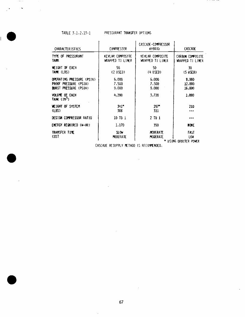
c
TABLE 3 I 1 I 2.13-1
CHARACTER I S T I C S
TYPE OF PRESSURANT TAM
M I G H T OF EACH TANK (LBS)
OPERATING PRESSURE (PSIA) PROOF PRESSURE ( P S I A ) BURST PRESSURE ( P S I A )
WLUkE EACH TANK ( I N 1
M I G H T OF SYSTEM (LBS)
DESIGN COMPRESSOR R A T I O
ENERGY REQUIRED (W-HR)
TRANSFER TIllE COST
PRESSURANT TRANSFER OPT IONS
C NIPRE SSOR
KEVLAH COFIPOSITE WRAPPED 11 LINER
56 ( 2 USED)
6.000 7.500 9.000
4,200
341'
10 TO 1
1,170
SL ow MODERATE
3aa
CASCAOE -COMPRESSOR HYBRID
KE VLAR COMPOS I TE WRAPPED TI L I N E R
50 (4 USED)
6.000 7.500 9,000
3.720
2 9 7 311
2 TO 1
350
MODERATE MODERATE
us
CASCADE
CARBON COWOSITE WRAPPED T I L INER
30 ( 5 USED)
8 .Ooo 12.OOo 16.000
1, aao
210 ---
NONE
FAST LOW
I ORBITER POWER CASCAUE RESUPPLY R T H O D I S RECOMMENDED.
67
The cascade on ly system w i l l r e q u i r e q u a l i f i c a t i o n o f a r e l a t i v e l y new h igh-s t rength carbon f i b e r f i l ament-wound composite f iber /meta l p ressurant tank. Thi s w i 11 a1 1 ow a we igh t savings o f 20-30% over a comparable k e v l ar-49 f i b e r f i lament-wound composite f iber /meta l pressurant tank. The we igh t of a 1880 i n 3 tank i s 30 l b s , w i t h an opera t ing pressure (OP) o f 8000 p s i a and a b u r s t pressure 2 t imes the OP. k e v l a r f i b e r f i lament . It weighs 44 l b s f o r a tank volume o f 3720 i n 3 and a OP of 6000 p s i a ( b u r s t i s 1.5 x OP) . tank i s t h a t the techno1 ogy has been space qual i f i e d on several manned programs i n c l ud ing the s h u t t l e program.
The h y b r i d system i s an a c t i v e system due t o compressor usage t o t r a n s f e r pressurant a f t e r each tank cascade. e x i s t , b u t compressor technology i s we l l es tab l i shed. has the i n h e r e n t p o t e n t i a l f o r f a i l u r e , p revent ing complete pressurant t r a n s f e r . compressor e f f i c i e n c y o f 50%. The heat r e j e c t i o n problem increases by inc reas ing the compression r a t i o o f the compressor, t h i s may necess i ta te the requirements o f a c t i v e thermal c o n t r o l system a t h i g h compression r a t i o s .
The h y b r i d system pressurant tank uses a
The advantage o f us ing a k e v l a r wrapped
A space q u a l i f i e d compressor does n o t As an a c t i v e system i t
There i s a l s o the h e a t r e j e c t i o n problem from an expected
Tota l system weight f o r the cascade on ly pressurant t r a n s f e r system i s 210 l b s which inc ludes the f i v e p ressurant tanks, pressurant , and i s o l a t i o n valves. Tota l system weight f o r the h y b r i d pressurant t r a n s f e r i s 311 l b s ( i n c l u d i n g b a t t e r y weight ) o r 297 l b s w i t h o u t b a t t e r y weight; and t h i s we igh t e s t i m a t e i n c l u d e s f o u r p ressurant tanks, pressurant, i s o l a t i o n valves, and two compressors . The f o l l o w i n g are conclus ions o f the pressurant t r a n s f e r system se lec t ion .
1 ) I n designing a cascade-compressor h y b r i d p ressurant t r a n s f e r systein a compression r a t i o o f l e s s than 3 t o 1 w i l l be optimum. Four o r l e s s pressurant tanks were determined t o be optimum f o r the h y b r i d system.
A comparison between a cascade on ly and a h y b r i d pressurant t r a n s f e r system f a v o r s the. s e l e c t i o n of the cascade o n l y p ressurant t r a n s f e r system because o f i t s lower system we igh t (210 l b s compared t o 297 l b s ) , and reduced system complex i ty ( t h e h y b r i d system i s an a c t i v e system r e q u i r i n g a power source and p o t e n t i a l thermal c o n t r o l ) .
2)
3) The h i g h e r the supply pressure the g r e a t e r the volume and weight e f f i c i e n c y ; t h e r e f o r e i t i s recommended t h a t 8000 p s i a p ressurant tanks be used.
4) It i s recommended t h a t a t l e a s t 6 pressurant tanks be used i n the supply vehi c l e.
3.1.3 Operat ional Trades
The opera t iona l t rade s tud ies and analyses op t im ize the OSCRS design and gener ic miss ion procedures. t ime 1 ines, system turnaround, opera t iona l hand1 i n g complexi t y and cos t , and t o maximize the c o s t e f fec t i veness , safety , and f l e x i b i l i t y o f OSCRS.
The r e s u l t s o f these s tud ies minimize opera t iona l
01 14c/33 68
3.1.3.1 Launch S i t e Operations
Wi th in the scoDe o f the t rade s tud ies Derformed i n eva lua t ing the f a c i l i t i e s c lass i f i e d fo r ' e i t h e r nonhazardous o r hazardous operat ions o f KSC, the comparative serv ices between the f a c i l i t i e s d i d n o t c l e a r l y i d e n t i f y any one f a c i l i t y above the others. Therefore, s t rong considerat ion was given t o i d e n t i f y the f a c i l i t i e s which bes t meet the c r i t e r i a o f an optimum processing f low w i t h the l e a s t impact on Orb i te r turnaround operat ions. An optimum processing f low can be def ined as one i n which the handl ing and moving o f the OSCRS tanker and i t s unique GSE i s kep t a t a minimum. t rade studies, propel 1 an t and pressurant se rv i c ing o f t he OSCRS tanker shoul d take place i n a Hazardous Processing F a c i l i t y (HPF) p r i o r t o be ing t rans fe r red t o the launch pad i n the payload can is te r . launch pad w i l l be an impact on the normal Orb i te r launch schedule.
As determined by the
Any s e r v i c i n g undertaken a t the
The t y p i c a l turnaround processing f low o f an OSCRS tanker (F igure 3.1.3.1 -1 ) w i l l s t a r t a t the Orb i te r Processing F a c i l i t y (OPF) where i t w i l l be safed; removed from the Orb i te r , and i n s t a l l e d i n i t s shipping/handl ing ls torage conta iner f o r t rans fe r t o a HPF. Assuming the optimum turnaround opera t ion wherein the tanker w i l l be processed i n one f a c i l i t y through i t s p rope l l an t and pressurant serv ic ing, the fo l l ow ing t y p i c a l operat ions w i l l be performed: p o s t f l i g h t inspect ion; f l i g h t anomaly i nves t i ga t i on and cor rec t ion ; system maintenance, refurbishment and reconf igura t ion ; subsystem t e s t and system checkout; preparat ion f o r storage ( i f requi red) , and se rv i c ing prope l lan ts and pressurants f o r nex t f l i g h t . Upon leav ing the HPF, the f u l l y loaded OSCRS tanker w i l l be t rans fe r red t o the Ver t i ca l Processing F a c i l i t y (VPF) where, i f required, C I T E t e s t i n g w i l l be performed p r i o r t o the tanker i n s t a l l a t i o n i n t o the payload can is te r f o r t rans fe r t o the launch pad. A t the pad, the can is te r w i l l be ra i sed i n t o the Payload Changeout Room (PCR) on the Rotat ing Service St ruc ture (RSS) and t rans fer red t o the Payload Ground Hand1 i n g Mechanism. A f i n a l p r e - i n s t a l l a t i o n system hea l th check i s made on the OSCRS and then i t i s i n s t a l l e d i n the Orb i te r payload bay. The e l e c t r i c a l i n t e r f a c e connection i s made and v e r i f i e d f o r launch.
The turnaround processing f low o f the OSCRS tanker a t VAFB (F igure 3.1.3.1-2) i s more opt imized than a t KSC i n t h a t a f t e r the tanker i s removed from the Orb i te r i n the Orb i te r Maintenance Checkout Fac i l i t y (OKCF) and deserviced there ( i f requ i red) i t i s i n s t a l l e d i n i t s shipping, handl ing and storage conta iner and t rans fe r red t o the Payload Preparat ion Room ( P P R ) a t the launch s i t e where a l l the processing operat ions are performed, inc lud ing C I T E t e s t i n g (if requi red) , and p rope l l an t and pressurant s e r v i c i n g f o r f l i g h t . completion o f serv ic ing, the OSCRS tanker i s t rans fer red w i t h i n the PPR us ing a strongback and i n s t a l l e d i n the PGHM which i s then t rans fe r red i n t o the mobile ( t racked) PCR. A f t e r a sho r t t rans fe r t o the Launch Nount ( L M ) , the PCR i s mated wi th the Orb i te r and the payload bay doors a re opened. p r e - i n s t a l l a t i o n hea l th check i s made on the OSCRS and then i t i s i n s t a l l e d i n the Orb i te r payload bay. The e l e c t r i c a l i n te r face connection i s made and v e r i f i e d f o r f l i g h t .
Upon
A f i n a l
7534c/34 69
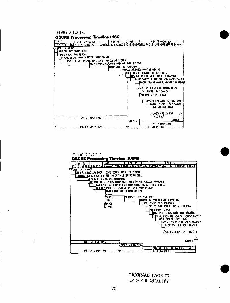
FIGYRE 3.1,3,1-1 OSCRS Rocosm&~a lbndirw (KSCI
I / F H R I F I C A I I M I I
FIGURE 3.1,3,1-2 3SCRS Pmcoulncl Thdh. WAwD
WOllER A I WF PAlLOAD MY W S . WE OPRS. PIEP FOL RERBM
SERVICE OSCRS (as REWIRED)
MIWILMCE/Rf F I B ISH SYSIEIS
SUBSYSlER l E S I X H C K W 1
STImAGf XFER M C R S IO SIRUIGBKI: M L L M I / P R f S S U R A N l Y R V I C 116
- . -. . . .- 39 WYS SCRS 10 XFfR IMR. INSTALL IN WH
X F E R PWw 10 PCR TO LH, MIE Y l l H OABlKR
PBlWSlL MALIH CHECKKLOS DPEW PAYLMU BAY UWylS
QIT
OTUGIMAC P&E IS OF POOR QUALITY
70
3.1.3.2 Landing S i t e Operations
The post landing operat ions f o r a l l normal landings, which inc lude Return t o Landing S i t e (RTLS) and Abort-Once-Around (AOA) iandings, w i l l no t requ i re ariy spec ia l i zed equipment o r techniques t o remove the OSCRS from the Orb i te r payload bay i n the OPF o ther than the OSCRS-unique GSE and standard payload removal and handl ing procedures. The sa fe ty aspect o f removing and handl ing a fu l l y loaded OSCRS tanker, versus one w i t h on ly res idua l p rope l lan ts aboard, w i l l n o t vary too much. A l l o f the handl ing GSE w i l l be designed t o support a weight equiva lent t o t h a t o f a f u l l y loaded b i p r o p e l l a n t tanker ( f l u i d capaci ty o f up t o 8545 l b ) . tanker wh i le it i s s t i l l i n the OPF, such as t o requ i re emergency detanking, there are adequate f a c i l i t i e s i n the OPF t o support t h i s operation.
I
I f a problem were to develop w i t h the OSCRS
A f t e r the OSCRS tanker has been removed from the Orb i te r and i n s t a l l e d i n i t s shipping/handl ing/storage container, i t w i l l be t ranspor ted t o a Hazardous Processing F a c i l i t y (HPF) on a f l a tbed t r a i l e r . requ i red dur ing t h i s r e l a t i v e l y sho r t t r i p .
Mo o ther special equipment i s
Operations a t the HPF w i l l vary depending on the s ta tus o f the OSCRS a t the t ime o f i t s removal from the Orb i ter . I f the OSCRS mission had been f u l l y accomplished, thereby leav ing on ly res idua l p rope l l an t aboard, then the standard p o s t f l i g h t operat ions w i l l take place. These operat ions w i l l i nc lude b u t not be l i m i t e d t o the fo l low ing : (1 ) p o s t f l i g h t inspect ion; ( 2 ) f l i g h t anomaly i n v e s t i g a t i o n and cor rec t ion ( i f any); (3 ) system reconf igura t ion o r refurbishment; ( 4 ) system t e s t and checkout, and (5) preparat ion f o r storage o r se rv i c ing f o r nex t f l i g h t . the OSCRS, the f u l l y loaded OSCRS w i l l have several opt ions ava i l ab le as t o what processing steps w i l l be taken. These opt ions are: ( 1 ) leave the OSCRS tanker loaded and monitor system hea l th us ing OSCRS-unique GSE u n t i l i t s nex t mission; ( 2 ) deservice the OSCRS tanker p rope l l an t and pressurant systems, and ( 3 ) depressurize the h igh pressure tanks wh i le mainta in ing and mon i to r ing the p rope l l an t load. Select ion o f the appropr iate op t ion w i l l be done on a rea l - t ime bas is i n support o f the KSC launch schedule. Based on the op t i on selected, some p o r t i o n or a l l o f the operat ions l i s t e d above w i l l be i n i t i a t e d .
I f the mission was aborted, b u t n o t caused by
Landing a t a contingency land ing s i t e , such as DFRC, w i l l r equ i re add i t i ona l tasks t o be performed on the OSCRS. The tanker cannot remain i n the Orb i te r payload bay dur ing the f e r r y f l i g h t t o KSC due t o po ten t i a l thermal problems associated w i t h the f reez ing temperature (35°F) o f hydrazine o r the diaphragm i n the fue l tanks. Orb i te r payload bay doors strongbacks (GSE) and associated hardware w i l l be shipped t o DFRC along w i t h the OSCRS-unique GSE requ i red t o support the post landing operat ions. the OSCRS tanker w i l l be removed; the p rope l l an t system w i l l be deserviced and the OSCRS tanker w i l l be prepared f o r shipment t o KSC aboard a C5A a i r c r a f t o r another type a i r c r a f t . Upon a r r i v a l a t KSC o r Cape Canaveral A i r Force S ta t i on (CCAFS), the OSCRS tanker w i l l be t ranspor ted t o an HPF, and the post1 anding operat ions associated w i t h a normal l and ing w i l l be implemented.
A f t e r the payload bay doors are opened
7634c/35 7 1
3.1.3.3 GSE and Facility Operations
The approach taken by the trade study i n determining the GSE required to s u p p o r t the OSCRS tanker program, w a s t o evaluate the requirements within each processing element a t the launch site. Based on the handling, checkout and servicing philosophies developed to support the OSCRS tanker design concept, each task was analyzed t o ascertain the most viable GSE approach. A conceptual design requirement was prepared for each item of GSE identified. These requirements were i n turn used as the basis for establishing the design, manufacturing, development, t e s t , delivery schedule and estimated costs of the required GSE. As part of the trade study, the STS program's GSE designs were reviewed t o ascertain which designs, i f any, were feasible f o r use on the OSCRS program. Several STS GSE designs were found to be acceptable either as designed or with some design modifications. items, such as the Tanker Lifting/Handling Sling Set; the Tanker Support Stand, and the Propellant Servicing/Deservicing U n i t (Figure 3.1.3.3-1 and Figure 3.1.3.3-Z), will be designed, fabricated, tested, and delivered i n time t o support the tanker Qualification Test program. the Tanker ShippinglHandl ing/Storage Container and the Tanker Lifting/Handl i n g Sling Set, will be delivered to KSC prior t o delivery of the f l i gh t tanker.
KSC and Cape Canaveral Air Force Sta t ion have a variety of payload processing f ac i l i t i e s i n both the hazardous and nonhazardous categories. Not all of these f ac i l i t i e s are acceptable for use by the OSCRS program. tanker i s a vertical payload, those f ac i l i t i e s hand1 i n g horizontal payloads were eliminated from the trade study's selection process. In selecting the f ac i l i t i e s which best suppor t an optimized turnaround processing flow, strong consideration was given t o a fac i l i ty ' s availability and storage capability. The OSCRS tanker is , by i t s function, considered t o be a hazardous payload. Therefore, i t i s very important t h a t excessive moving/handl ing of the tanker
.,be avoided. all processing operations from inspection th rough servicing can be performed, will greatly reduce the moving/handling of the tanker. A dedicated faci l i ty will provide a home base f o r all OSCRS unique GSE and a storage place for the tanker between missions. Building M7-1410, Cryogenics #2, ideally located in the vicinity of the Cargo Hazardous Servicing Facility (CHSF) and the Vertical Processing Facility ( V P F ) , i s a prime candidate to be the dedicated faci l i ty for the OSCRS program. Selection o f this faci l i ty would eliminate conflict of interest wi t h other program, such t h a t might be encountered in the CHSF or HMF.
Certain OSCRS tanker unique GSE
All GSE i t e m , other than
Since the OSCRS
The use of one f a c i l i Q , dedicated t o the OSCRS program, i n which
3.1.3.4 On-Orbit Operations
A trade s tudy was performed t o develop an on-orbi t operational timeline representative of a typical Extravehicular Activity ( E V A ) i n support of a monopropel 1 a n t tanker transferring consumables t o a berthed spacecraft in the Orbiter payload bay.
The results of this study (see Figure 3.1.3.4-1) indicate t h a t sufficient time is available t o perform a single transfer of hydrazine (NzH4) supported by normal EVA a c t i v i t y . Inclusion of an OSCRS on-orbit relocation significantly extends this timeline.
01 14C/36 72
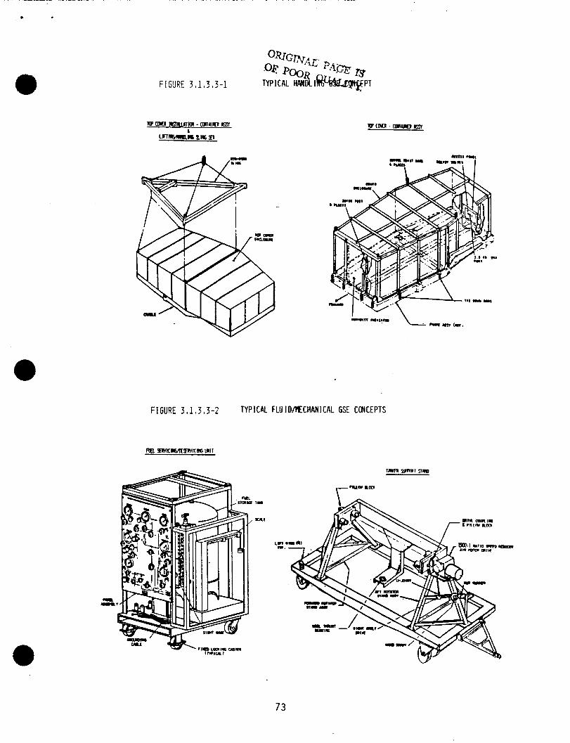
F I SURE 3 I 1.3.3-1
FIGURE 3.1,3,3-2 TYPICAL FLU ID/MECHANICRL GSE CCNCEPTS
RR mc~LmlvI[IIc, Ill11
73
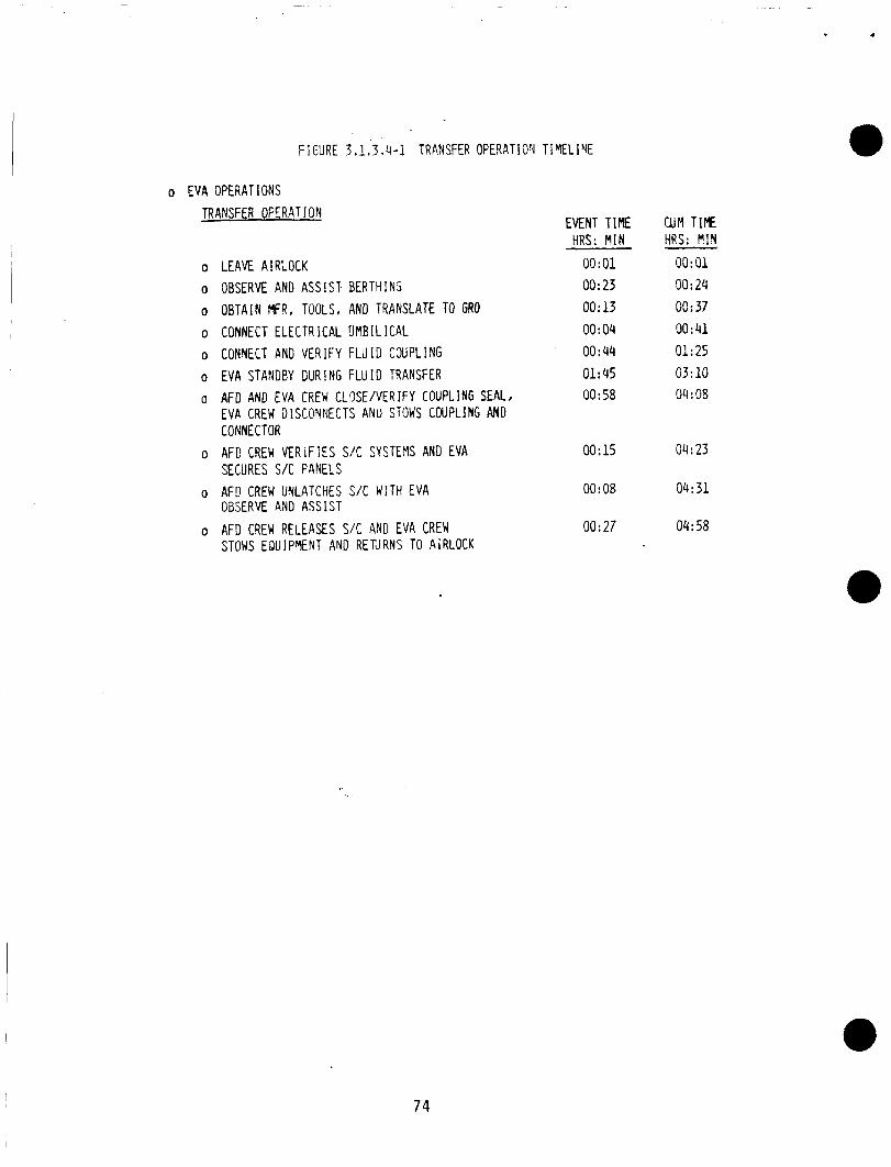
FIGURE 3.1.’!.4-1 TRANSFER OPE4ATIOY TIWELIVE
o EVA OPERATIONS TRANSFER OPERAT ION
0
0
0
0
0
0
0
0
0
0
LEAVE A I RLOCK OBSERVE AND ASSIST BERTHING OBTAIN MFR, TOOLS, AND TRANSLATE TO GRO CONNECT ELECTRICAL UMBILICAL CONNECT AND VERIFY FLUID C N P L I N G EVA STANGEY DURING FLU I D TRANSFER
EVP. CREW DISCONNECTS ANU STOWS CNPLING AND CONNECTOR AFD CREW VERiF IES S/C SYSTEMS AND EVA SECURES S/C PANELS AFE CREW UNLATCHES S/C WITH EVA OBSERVE AND ASSIST AFD CREW RELEASES S I C AND EVA CREW STOWS EQUIPVENT AND RETJRNS TO AIRLOCK
AFD AND EVA CREW CLXE/VERIFY COUPLING SEAL,
EVENT TIME clin T I E HRS: \ I N
00: 01 00: 23 00:13 00: 04 00:44 01: 45 00: 58
00:15
00: 08
00:27
HRS: !!?I
OO:O1 00: 24 00:37 90:41 01: 25 03: 10 04 : 08
04:23
04:31
04:58
74
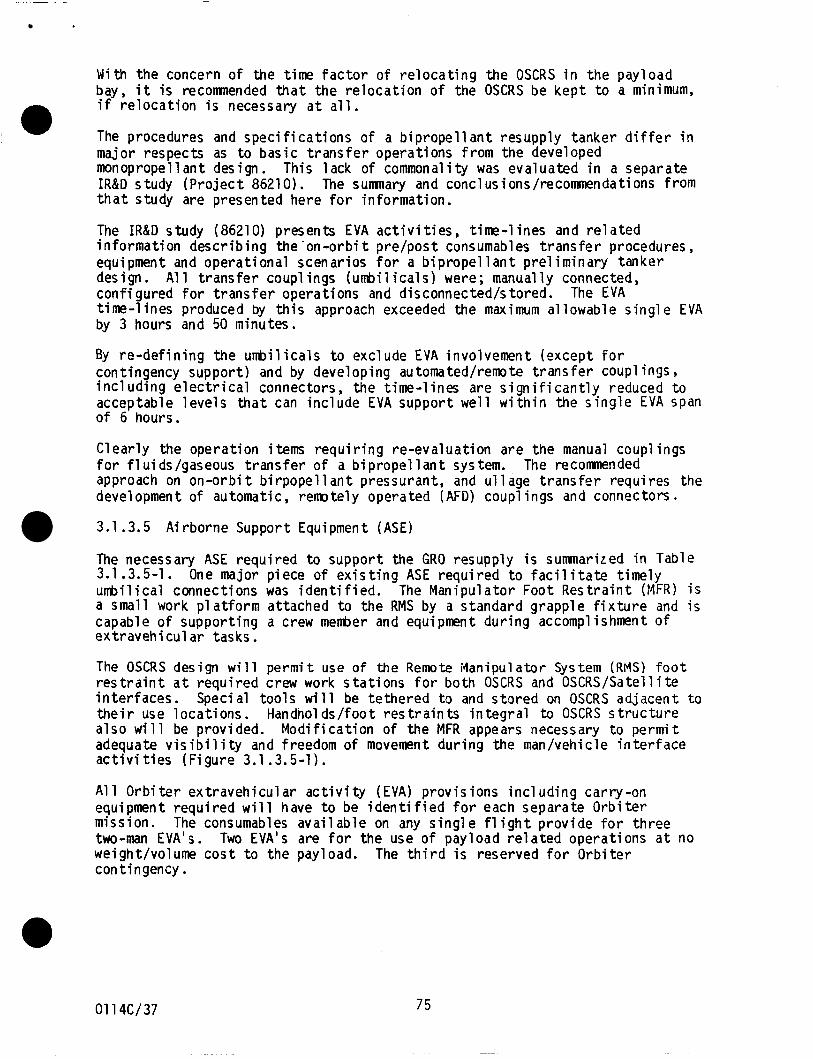
With the concern of the time factor of relocating the OSCRS in the payload bay. i t is recomnended t h a t the relocation of the OSCRS be keDt t o a minimum, if- relocation is necessary a t a l l .
The procedures and specifications of a bipropellant resupply tanker differ i n . . . major respects as to - basic transfer operations from the developed monopropellant design. This lack of commonality was evaluated in a separate IR&D study (Project 86210). The sumnary and conclusions/recommendations from tha t study are presented here f o r information.
The IR&D study (86210) presents EVA act ivi t ies , time-lines and related information describing the -on-orbi t pre/post consumables transfer procedures, equipment and operational scenarios for a bipropellant preliminary tanker design. A1 1 transfer coupl ings (umbilicals) were; manually connected, configured for transfer operations and disconnectedh tored. time-lines produced by this approach exceeded the maximum allowable single EVA by 3 hours and 50 minutes.
The EVA
By re-defining the umbilicals t o exclude EVA involvement (except for contingency support) and by developing automated/remote transfer coupl ings , including electrical connectors, the time-lines are significantly reduced t o acceptable levels t h a t can include EVA suppor t well within the single EVA span of 6 hours.
Clearly the operation items requiring re-evaluation are the manual coupl ings for fluids/gaseous transfer of a bipropellant system. approach on on-orbi t birpopell a n t pressurant, and ullage transfer requires the development o f automatic, remotely operated (AFD) coupl ings and connectors.
The recomnended
3.1.3.5 Airborne Suppor t Equipment (ASE)
The necessary ASE required t o support the GRO resupply is sumnarized in Table 3.1.3.5-1. umbilical connections was identified. The Manipulator Foot Restraint (MFR) i s a small work platform attached t o the RMS by a standard grapple fixture and is capable of supporting a crew menber and equipment during accomplishment of extravehicular tasks.
One major piece of existing ASE required to f ac i l i t a t e timely
The OSCRS design w i l l permit use o f the Remote ivlanipulator System (RMS) f o o t res t ra int a t required crew work stations f o r both OSCRS and OSCRS/Satellite interfaces. Special tools will be tethered t o and stored on OSCRS adjacent t o their use locations. Handnol ds/foot restraints integral to OSCRS structure also will be provided. Modification of the MFR appears necessary t o permit adequate v is ib i l i ty and freedom of movement during the man/uehicle interface activi t ies (Figure 3.1 .3.5-1).
All Orbiter extravehicular activity ( E V A ) provisions including carry-on equipment required will have t o be identified for each separate Orbiter mission. The consumables available on any single f l i gh t provide f o r three two-man EVA's. weight/volume cost t o the payload. contingency .
Two EVA's are for the use of payload related operations a t no The t h i r d is reserved for Orbiter
01 14c/37 75
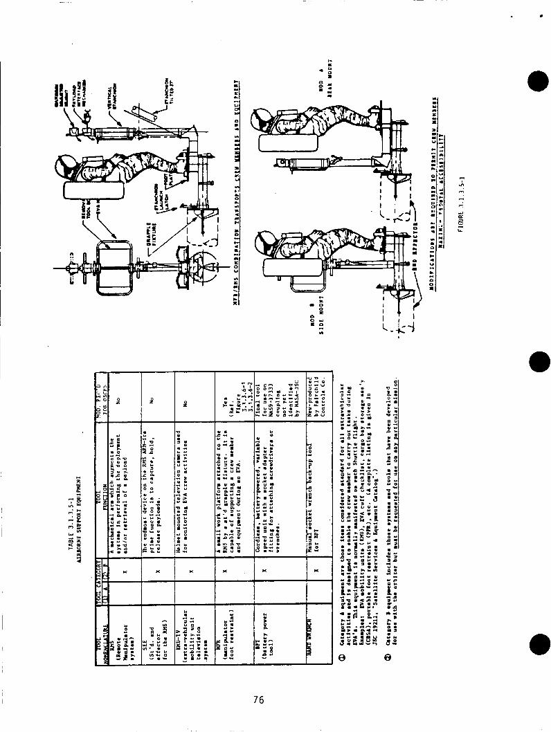
.. U . D m
0 - c v
!: u u u o m
" > m u " I . > u
U P Y L I
Y O Y d O C
O Y
' 0
4 C
:<
o m
a o m e
urn
2:
K
I,
76
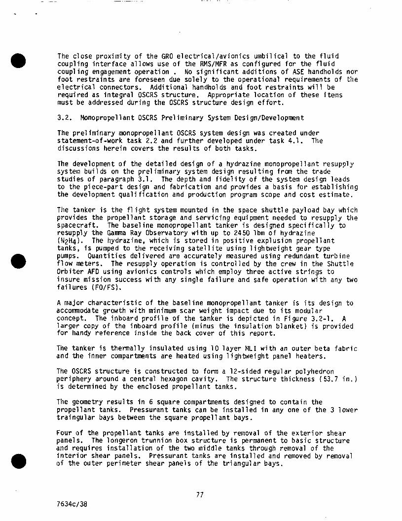
The c lose prox imi ty o f the GRO e l e c t r i c a l / a v i o n i c s umb i l i ca l t o the f l u i d coupl ing i n t e r f a c e a l lows use o f the RMS/MFR as conf igured f o r the f l u i d coup1 i n g engagement operat ion . No s i g n i f i c a n t add i t ions o f ASE handholds nor f o o t r e s t r a i n t s are foreseen due so le l y t o the operat ional requirements o f t h e e l e c t r i c a l connectors. Addi t ional handholds and f o o t r e s t r a i n t s w i l l be requi red as i n t e g r a l OSCRS s t ruc tu re . must be addressed dur ing the OSCRS s t r u c t u r e design e f f o r t .
Appropriate l o c a t i o n o f these i terns
3.2. Monopropellant OSCRS Pre l iminary System Desi gn/Development
The p r e l imiriary monopropellant OSCRS system design was created under statement-of-work task 2.2 and f u r t h e r developed under task 4.1. discussions here in covers the r e s u l t s o f both tasks.
The
The development o f the d e t a i l e d design o f a hydrazine monopropellant resupply system bu i l ds on the pre l im inary system design r e s u l t i n g from the trade s tud ies o f paragraph 3.1. The depth and f i d e l i t y o f the system design leads t o the p iece-par t design and fab r i ca t i on and provides a bas is f o r es tab l i sh ing the development qua l i f i c a t i o n and product ion program scope and cos t estimate.
The tanker i s the f l i g h t system mounted i n the space s h u t t l e payload bay which provides the p rope l l an t storage and se rv i c ing equipment needed to resupply the spacecraft. resupply the Gamma Ray Observatory wi th up t o 2450 lbm of hydrazine (N2H4). tanks, i s pumped t o the rece iv ing s a t e l l i t e us ing l i ghbve igh t gear type pumps. f l o w meters. Orb i te r AFD us ing av ion ics con t ro l s which employ three a c t i v e s t r i n g s t o insure mission success w i t h any s ing le f a i l u r e and safe operat ion w i t h any two f a i l u r e s (FO/FS).
The base1 ine monopropel 1 an t tanker i s designed speci f i ca l ly t o
The hydrazine, which i s s tored i n p o s i t i v e explusion p rope l l an t
Quant i t ies de l i vered are accurate ly measured us ing redundant tu rb ine The resupply operat ion i s c o n t r o l l e d by the crew i n the Shut t le
A major c h a r a c t e r i s t i c o f the basel ine monopropellant tanker i s i t s design t o accommodate growth w i t h minimum scar weight impact due t o i t s modular concept. l a r g e r copy o f the inboard p r o f i l e (ininus the i n s u l a t i o n b lanket ) i s provided f o r handy reference ins ide the back cover o f t h i s repor t .
The inboard p r o f i l e of the tanker i s depicted i n F igure 3.2-1. A
The tanker i s thermal ly insu la ted us ing 10 l a y e r MLI w i t h an ou ter beta f a b r i c and the inner compartments are heated us ing 1 igh twe igh t panel heaters.
The OSCRS s t r u c t u r e i s constructed to form a 12-sided regu la r polyhedron per iphery around a cent ra l hexagon cav i t y . The s t r u c t u r e th ickness (53.7 i n . ) i s determined by the enclosed p rope l l an t tanks.
The geometry r e s u l t s i n 6 square compartments designed t o conta in the p rope l l an t tanks. t r a i n g u l a r bays between the square p rope l l an t bays.
Pressurant tanks can be i n s t a l l e d i n any one o f the 3 lower
Four o f the p rope l l an t tanks are i n s t a l l e d by removal o f the e x t e r i o r shear panels. and requi res i n s t a l l a t i o n o f the two middle tanks through removal o f the i n t e r i o r shear panels. o f the outer per imeter shear panels o f the t r i a n g u l a r bays.
The longeron t runn ion box s t r u c t u r e i s permanent t o bas ic s t ruc tu re
Pressurant tanks are i n s t a l l e d and removed by removal a
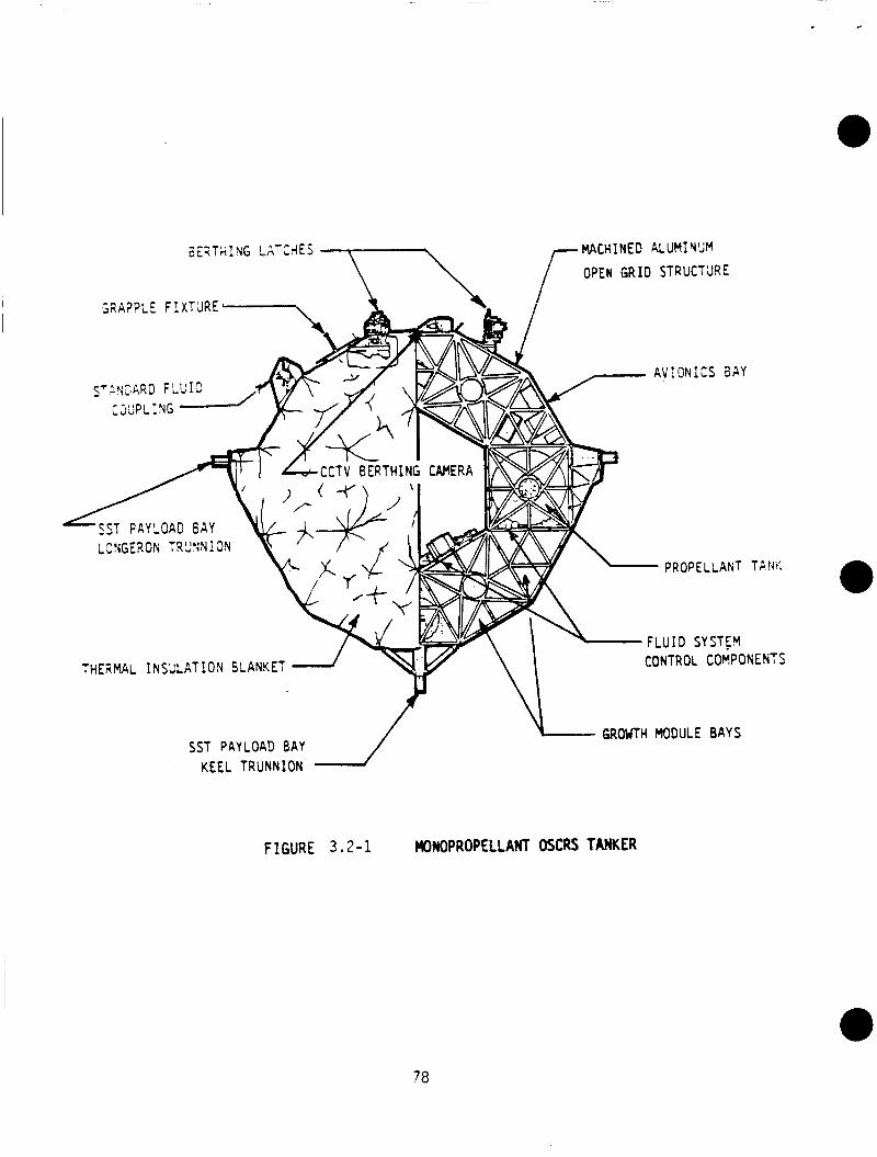
GRAPPLE F 1 XTJRE
ST PAYLOAD Kay 2NGERON T R ' J N N i O N
PROPELLANT T P !dK
, -n\ L - L u I D CONTROL sYsT:Y COMPONENTS THERMAL INSULATION SLANKET
GROUTH MODULE BAYS SST PkYLOAD BAY
KEEL TRUNNION
FlGURE 3.2-1 WNOPROP€LLAHT OSCRS TANKER
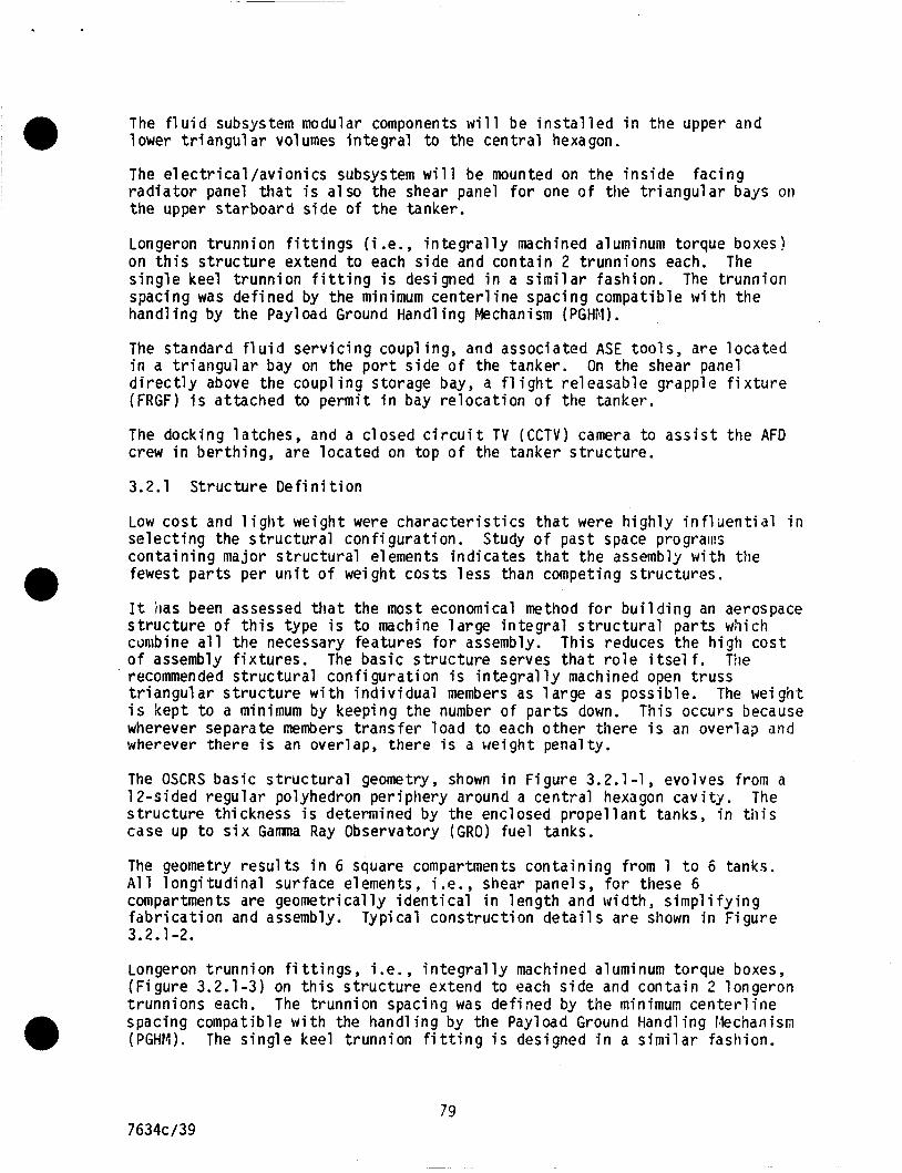
The f l u i d subsystem modular components w i l l be i n s t a l l e d i n the upper and lower t r i a n g u l a r volumes in teg ra l t o the cent ra l hexagon.
The e l e c t r i c a l / a v i o n i c s subsystem w i l l be mounted on the i n s i d e fac ing r a d i a t o r panel t h a t i s a lso the shear panel f o r one o f the t r i a n g u l a r bays on the upper s tarboard s ide o f the tanker.
Longeron t runnion f i t t i n g s (i .e., i n t e g r a l l y machined aluminuni torque boxes! on t h i s s t r u c t u r e extend t o each s ide and conta in 2 t runnions each. The s ing le keel t runn ion f i t t i n g i s designed i n a s i m i l a r fashion. The t runn ion spacing was def ined by the minimum c e n t e r l i n e spacing compatible w i t h the handl i n g by the Pay1 oad Ground Handl i n g Mechanism (PGHM) . The standard f l u i d serv i c i ng coupl i ng, and associated ASE t o o l s , are 1 oca ted i n a t r i a n g u l a r bay on the p o r t s ide o f the tanker. d i r e c t l y above the coupl i n g storage bay, a f l i g h t re leasable grapple f i x t u r e (FRGF) i s at tached t o permi t i n bay re loca t i on o f the tanker.
On the shear panel
The docking la tches, and a c losed c i r c u i t TV ( C C T V ) camera to a s s i s t the AFD crew i n ber th ing, are located on top o f the tanker s t ruc tu re .
3.2.1 S t ruc ture D e f i n i t i o n
Low c o s t and l i g h t weight were cha rac te r i s t i cs t h a t were h igh l y i n f l u e n t i a l i n se lec t i ng the s t r u c t u r a l con f igura t ion . Study o f past space prograins conta in ing major s t ruc tu ra l elements ind ica tes t h a t the assembly w i t h the fewest pa r t s per u n i t o f weight costs l ess than competing s t ruc tu res .
It has been assessed t h a t the most economical method f o r b u i l d i n g an aerospace s t r u c t u r e o f t h i s type i s t o machine l a rge i n t e g r a l s t r u c t u r a l par ts which canibine a l l the necessary features f o r assembly. o f assembly f i x tu res . The basic s t ruc tu re serves t h a t r o l e i t s e l f . The recommended s t ruc tu ra l con f igura t ion i s i n teg ra l l y machined open t russ t r i a n g u l a r s t r u c t u r e w i t h i nd i v idua l members as 1 arge as possible. i s kept t o a minimum by keeping the number o f pa r t s down. wherever separate members t rans fe r load t o each o ther there i s an over lap and wherever there i s an overlap, there i s a weight penal ty.
This reduces the h igh cos t
The weight This occurs because
The OSCRS bas ic s t r u c t u r a l geometry, shown i n F igure 3.2.1-1, evolves from a 12-sided regu la r polyhedron per iphery around a cent ra l hexagon cav i t y . The s t ruc tu re t h i ckness i s determined by the encl osed propel 1 an t tanks, i n til i s case up t o s i x Gama Ray Observatory (GRO) fue l tanks.
The geometry r e s u l t s i n 6 square compartments conta in ing from 1 t o 6 tanks. A l l l ong i tud ina l surface elements, i.e., shear panels, f o r these 6 compartments are geometr ical ly i d e n t i c a l i n leng th and width, s i m p l i f y i n g f a b r i c a t i o n and assembly. Typical cons t ruc t ion d e t a i l s a re shown i n F igure 3.2.1 -2.
Longeron t runnion f i t t i n g s , i.e., i n t e g r a l l y machined aluminum torque boxes, (F igure 3.2.1-3) on t h i s s t ruc tu re extend t o each s ide and conta in 2 longeron t runnions each. The t runnion spacing was def ined by the minimum center1 i n e spacing compatible w i t h the handl i n g by the Payload Ground Handl i n g fkchanism (PGHM). The s ing le keel t runnion f i t t i n g i s designed i n a s i m i l a r fashion.
79 7634c/39
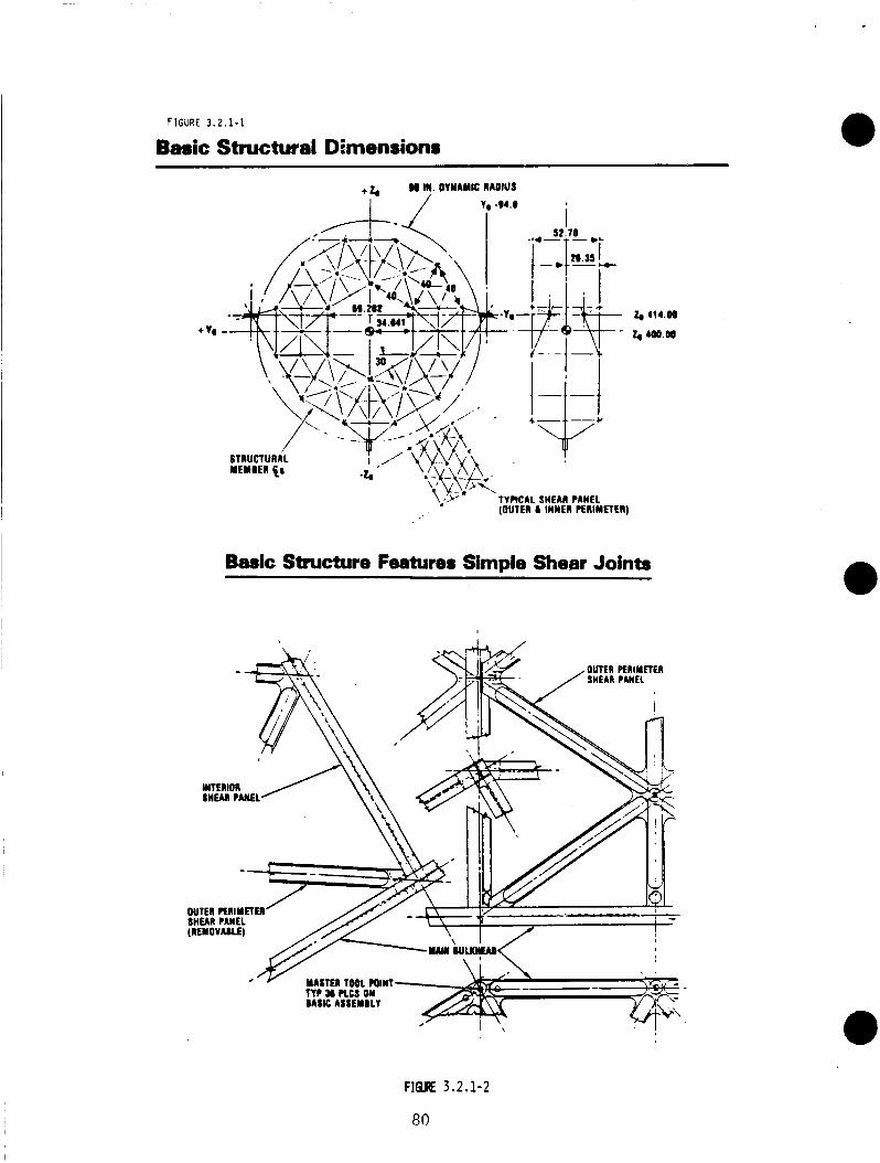
FIGURE 3.2.1-1
Basic Structural Dimensions
+ 4 80 IN. DYNAMIC RADIUS
I / I, -84.0
\,'>' TYPICAL SHEAl PANEL (OUTEI L INNER PERIMETER)
Basic Structure Features Simple Shear Joints
F l Q E 3 .2 .1-2
80
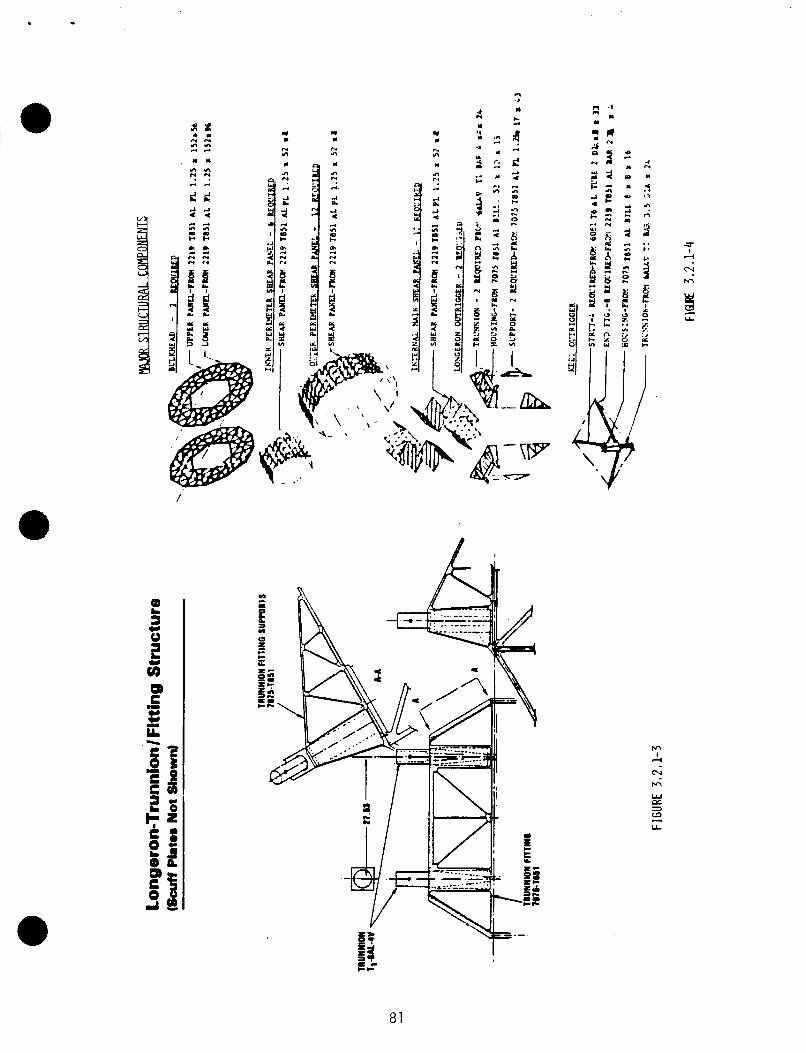
'I L IL
/
* r) L
IY n n n
m 5 N
m
81
For maximum s t i f f n e s s , minimum weight and cost, a l l major s t r u c t u r a l components are machine 2124-T851 ( i f welding i s des i red) or 7075-T7352 aluminum a l l o y . Par ts made from these ma te r ia l s (F igure 3.2.1-4) w i l l be f i n i s h e d t o prov ide p ro tec t i on from corros ion i n accordance w i t h the requirements o f MFSC Spec 2 9 , c lass 11, as a minimum. As requ i red f o r s p e c i f i c l oad i n t e n s i t i e s such as p rope l l an t tank and t runnion reac t ions , machined s t r u t elements are t a i l o r e d f o r the def ined l o a d paths.
Forward and a f t bulkhead frames are m i l l e d i n two pieces each from the l a r g e s t a v a i l a b l e m i l l - r u n p l a t e stock.
3.2.2 F l u i d Subsystem Design
The base l ine f l u i d subsystem design, f o r the monopropellant OSCRS, i s presented i n F igure 3.2.2-1.
Layout o f the f l u i d subsystem schematic d iv ides subsystem components i n t o several convenient u n i t s based on t h e i r func t iona l operat ioas:
1. P rope l l an t Storage Un i t .
2. Prope l lan t Tankage Ul lage Control Un i t .
3. Prope l l an t Transfer Control Uni t .
4. Coup1 i n g Leak-Check/Vent Control Uo i t .
5. Tanker/Spacecraft Propel 1 an t I n te r face Un i t .
3.2.2.1 P rope l l an t Storage U n i t
The p r o p e l l a n t storage u n i t (F igure 3.2.2-2) i s compr sed o f t he CSCRS p rope l l an t tankage and the tank in terconnect man i fo ld hardware. base1 i n e conceptual design o f the monopropel 1 an t resu p l y tanker u t i l i zes two GRO p rope l l an t tanks f o r p rope l l an t storage. GRO tank con f igu ra t i on i s 2472 lbm o f hydrazine. Add i t iona l GRO tanks can be at tached t o the base l ine design; up t o four add i t i ona l tanks, b r i ng ing the resupply capaci ty t o 7416 lbrn o f hydrazine.
The GRO p rope l l an t tank i s conoe l l ipso ida l i n shape; approximately 36 inches i n t e r n a l diameter and 47 inches i n t e r n a l length. Gas-free expuls ion o f p rope l l an t i s achieved us ing an elastomeric diaphragm as the tank p r o p e l l m t a c q u i s i t i o n device. The GRO tank i s designed f o r a maximum opera t i ng pressure o f 400 psid, w i t h a minimum b u r s t c a p a b i l i t y o f 800 psid. tanks, which have been qual i f i ed f o r the GRO sate1 1 i te, wei gh approximately 99 l bs .
Rockwell ' s
The resupply capaci ty o f the two
GRO p rope l l an t
The propel 1 an t tanks are interconnected i n paral 1 e l , w i t h paral 1 e l redundant valves a t each o f the tank ou t l e t s . l a t c h i n g and possess a reverse f l ow pressure re1 i e f capabi l i t y .
Tank i s o l a t i o n valves are magnet ica l ly
Mechanical coup1 ings are u t i l i zed t o a t tach add i t i ona l p rope l l an t tanks t o the tank manifold.
7634c /40 82
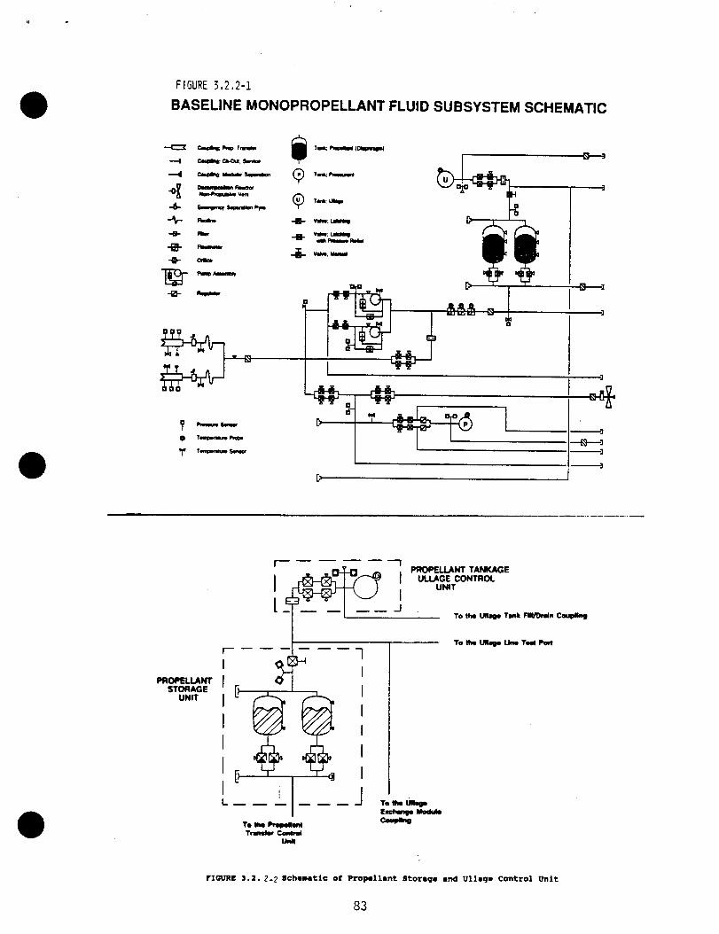
FIGURE 3,2,2-1
BASELINE MONOPROPELLANT FLUID SUBSYSTEM SCHEMATIC
PROPEUHT STORAGE
UNIT
I-
I I I I I I I
7 I I I I I I I
r I m c 3 . 1 . 2 - 2 Schematic of Propollant Storap, and ullaqo Control Unit
83
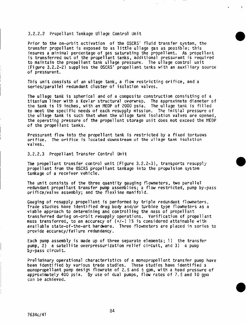
Y
3.2.2.2 P r o p e l l a n t Tankage Ul lage Control U n i t
P r i o r t o the o n - o r b i t a c t i v a t i o n o f the OSCRS' f l u i d t r a n s f e r system, t h e t r a n s f e r p r o p e l l a n t i s exposed t o as l i t t l e u l l a g e gas as poss ib le ; t h i s insures a minimal percentage o f gas s a t u r a t i n g the prope l lan t . As p r o p e l l a n t i s t r a n s f e r r e d o u t o f t h e propel 1 a n t tanks, a d d i t i o n a l pressurant i s r e q u i r e d t o ma in ta in the p r o p e l l a n t tank u l l a g e pressure. ( F i g u r e 3.2.2-2) suppl i e s t h e OSCRS' p r o p e l l a n t tanks w i t h an a u x i l i a r y source o f pressurant.
The u l l a g e c o n t r o l u n i t
Th is u n i t c o n s i s t s o f an u l l a g e tank, a f l o w r e s t r i c t i n g o r i f i c e , and a s e r i e s / p a r a l l e l redundant c l u s t e r o f i s o l a t i o n valves.
The u l l a g e tank i s spher ica l and o f a composite c o n s t r u c t i o n c o n s i s t i n g o f a t i t a n i u m 1 i n e r w i t h a Kevl a r s t r u c t u r a l overwrap. The approximate diameter o f t i l e tank i s 19 inches, w i t h an MEOP o f 2000 ps ia. The u l l a g e tank i s f i l l e d t o meet the s p e c i f i c needs o f each resupply mission. t h e u l l a g e t a n k i s such t h a t when t h e u l l a g e tank i s o l a t i o n va lves a r e opened, the o p e r a t i n g pressure o f the p r o p e l l a n t s torage u n i t does n o t exceed t h e MEOP o f t h e p r o p e l l a n t tanks.
The i n i t i a l pressure o f
Pressurant f l o w i n t o t h e p r o p e l l a n t tank i s r e s t r i c t e d by a f i x e d t o r t u o u s o r i f i c e . The o r i f i c e i s l oca ted downstream o f the u l l a g e tank i s o l a t i o n Val ves.
3.2.2.3 P r o p e l l a n t Transfer Control U n i t
The p r o p e l l a n t t r a n s f e r c o n t r o l u n i t ( F i g u r e 3.2.2-31, t r a n s p o r t s resupp ly p r o p e l l a n t from t h e OSCRS p r o p e l l a n t tankage i n t o the p r o p u l s i o n system tankage o f a r e c e i v e r veh ic le .
The u n i t c o n s i s t s o f t h e t h r e e q u a n t i t y gauging f l owmeters, two para1 1 e l redundant p r o p e l l a n t t r a n s f e r pump assemblies; a f l o w r e s t r i c t e d , pump by-pass o r i f i ce/val ve assembly; and t h e f l ex1 i n e mani fo ld .
Gauging o f resupply p r o p e l l a n t i s performed by t r i p l e redundant f lowmeters. Trade s t u d i e s have i d e n t i f i e d drag body and/or t u r b i n e type f lowmeters as a v i a b l e approach t o determin ing and c o n t r o l l i n g the mass o f p r o p e l l a n t t r a n s f e r r e d d u r i i i g on-orbi t resupp ly operat ions. mass t rans fer red , t o an accuracy o f ( + / - I 1% i s considered a t t a i n a b l e w i t h a v a i l ab le s t a t e - o f - t h e - a r t hardware. p rov ide a c c u r a c y / f a i l ure redundancy.
V e r i f i c a t i o n o f propel 1 a n t
Three f l o t m e t e r s a r e p laced i n s e r i e s t o
Each pump assembly i s made up o f t h r e e separate elements; 1 ) the t r a n s f e r pump, 2 ) a s a t e l l i t e o v e r p r e s s u r i z a t i o n r e l i e f c i r c u i t , and 3 ) a pump by-pass c i r c u i t.
P r e l im inary opera t iona l c h a r a c t e r i s t i c s o f a monopropel 1 a n t t r a n s f e r pump have been i d e n t i f i e d by var ious t rade s tud ies . These s t u d i e s have i d e n t i f i e d a monopropel lant pump design f l o w r a t e o f 2.5 and 5 gpm, w i t h a head pressure o f approx imate ly 400 psia. By use o f dual pumps, f l o w r a t e s o f 7 . 5 and 10 gpn can be achieved.
7634c/41 84
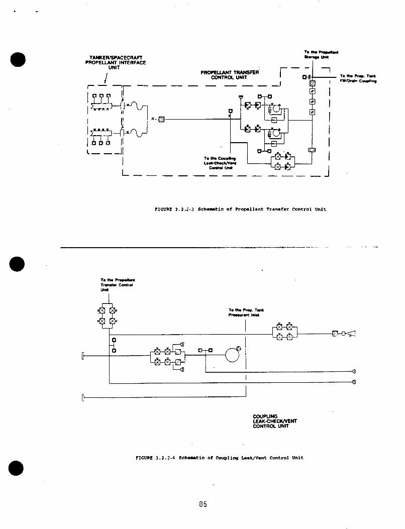
TAWEWSPACECRAfl P R O P E W INTERFACE
UNIT
I r - 7r---
I I I.
FIGURE 3.2.2-3 Schematic of Propel lant T r s n d e r Control Unit
To th. Rop.l(.nt Tra tdu C m h d W
To th. Plop. Talk
COUPUNG LEAK-CHE-HT CONTROL UNIT
FIGURE 3 .1 .2 -4 S c h e n t i c of Coupling L.ek/Vent Control Unit
85
Each pump assembly has a by-pass c i r c u i t , a l l ow ing the t rans fe r o f p rope l l an t , by tak ing advantage o f the p o s i t i v e pressure d i f f e r e n t i a l between the OSCRS p rope l l an t tankage and the rece iver s a t e l l i t e ' s tankage. Prope l lan t backf low i s c o n t r o l l e d by a check valve.
To p r o t e c t the rece ive r s a t e l l i t e ' s propuls ion system from overpressur izat ion, a r e l i e f va lve has been incorporated i n t o each o f the pump assemblies. I n the event t h a t the pump o u t l e t pressure i s greater than the des i red t r a n s f e r pressure, the r e l i e f va lve would r e l i e v e back t o the pump i n l e t .
Is01 a t i o n o f t he pump assembl i e s i s achieved by ser ies redundant magnet ica l l y l a t c h i n g valves, possessing a reverse f low pressure re1 i e f capabi 1 i t y .
The pump by-pass o r i f i c e / v a l v e assembly i s designed t o s lowly f i l l the evacuated coupl i n g mani f o l d, p r i o r t o opening the pump assembly i s o l a t i o n Val ves.
Use o f the by-pass c i r c u i t s b u i l t i n t o each o f t he pump assembl ies , t o f i 11 the evacuated coupl ing manifold, i s n o t recommended. As the pump i s o l a t i o n valves are opened, the pressure d i f f e r e n t i a l between the evacuated coupl i n g man i fo ld and the upstream pressure o f the valves would cause the p r o p e l l a n t e n t e r i n g the man i fo ld t o i n i t i a l l y vaporize. As the p r o p e l l a n t vapors i n the
pump assembly's by-pass c i r c u i t would n o t a l low enough time f o r the heat generated by the recompression t o d iss ipa te . The increas ing temperature i n the mani fo ld would cause the ad iaba t i c detonat ion o f t he t r a n s f e r p rope l l an t . I n s e r t i n g an o r i f i c e upstream o f the pumps would g r e a t l y h inder the performance of the pumps and increase the l eng th o f t he resupply operat ion.
The f l e x l i n e man i fo ld connects the p r o p e l l a n t t r a n s f e r con t ro l u n i t to the t a n k e r / s a t e l l i t e p r o p e l l a n t i n t e r f a c e u n i t . two f l e x l i n e s i s 6 feet . i n t e r f a c e u n i t by the tanker ha1 f o f the emergency separat ion valves.
I mani fo ld are recompressed back t o a l i q u i d , the p rope l l an t f lowra te through
Approximate l eng th o f each o f t he Each f l e x l i n e i s connected t o the p rope l l an t
3.2.2.4 Coupling Leak-Check/Vent Control U n i t
The coup l ing leak-check u n i t (F igure 3.2.2-4) i s designed t o prov ide an EVA operated gas supply (separate from the p r o p e l l a n t t r a n s f e r u n i t ' s pressurant source), f o r f l u i d connection leak checks o f the OSCRS/receiver veh ic le i n t e r face.
The leak check u n i t cons is ts o f a small hel ium b o t t l e , pressure regu la to rs , and several ser ies /para l le1 redundant c l u s t e r s o f i s o l a t i o n valves.
The hel ium b o t t l e i s spher ica l i n shape and made o f t i tan ium. diameter o f the tank i s 8 inches, w i t h an MEOP o f 1000 psia.
The approximate
There are two p a r a l l e l redundant, f i x e d s e t p o i n t pressure regu la to rs between the hel ium tank and the regu la to r i s o l a t i o n valves. reduce the hel ium source pressure t o the des i red working pressure. Pre l im inary analyses o f the operat ion o f the leak-check u n i t , has def ined a nominal r e g u l a t i n g pressure o f 100 ps ia.
The pressure regu la to rs
7634c /42 86
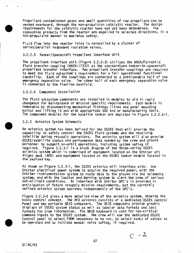
P r o p e l l a n t contaminated gases and small q u a n t i t i e s o f raw p r o p e l l a n t can be vented overboard, through the non-propul s ion c a t a l y t i c reac tor . The design requirements f o r the c a t a l y t i c r e a c t o r have n o t y e t been determined. The combustion products from the r e a c t o r are e x p e l l e d i n se lec ted d i r e c t i o n s , i n a non-propul s ive manner t o maximize safety .
F l u i d f l o w i n t o the r e a c t o r i n l e t i s c o n t r o l l e d by a c l u s t e r of Ser i es/paral l e 1 redundant i sol a t i o n valves.
0
3.2.2.5 Tanker/Spacecraft P r o p e l l a n t I n t e r f a c e U n i t
The p r o p e l l a n t i n t e r f a c e u n i t (F igure 3.2.2-3) u t i l i z e s the NASA/Fairchi ld f l u i d t r a n s f e r coupl i n g (NAS9-17333) as the s tandard ized tanker- to-spacecraf t propel 1 a n t t r a n s f e r i n t e r f a c e . t o meet the f l u i d subsystem's requirement f o r a f a i l opera t iona l f u n c t i o n a l c a p a b i l i t y . emergency separat ion valve. i s connected t o t h e f l ex1 i n e man i fo l d.
Two propel1 a n t t r a n s f e r coupl i n g s are r e q u i r e d
Each o f the coupl i n g s are connected t o a j e t t i sonable ha1 f o f t h e The o t h e r ha1 f o f each emergency separat ion va lve
3.2.2.6 Component I n s t a l 1 a ti on
The f l u i d subsystem components a re i n s t a l l e d i n modules t o a i d i n r a p i d changeout f o r maintenance o r miss ion s p e c i f i c requirements. removable by d isconnect ing mechanical f i t t i n g s (1 i n e s and panel mounting b o l t s ) and l i f t i n g i t o u t w i t h appropr ia te GSE and o r manufactur ing t o o l s . The component modules f o r the base l ine tanker are depic ted i n F igure 3.2.2.6-1.
Each module i s
3.2.3 Av ion ics System Schematic
An a v i o n i c s system has been de f ined f o r the OSCRS t h a t w i l l p rov ide the c a p a b i l i t y t o s a f e l y c o n t r o l the OSCRS f l u i d systems and the r e c e i v i n g s a t e l l i t e dur ing resupply operat ions. OSCRS/satell i t e s t a t u s and performance data needed by the crew and ground personnel t o support on-orbi t operat ions, i n c l u d i n g system s a f i n g i f requi red. F i gure 3.2.3-1 i s a b l o c k d i agram o f the t h r e e - s t r i n g OSCRS a v i o n i c s system which i s comprised o f equipment l o c a t e d on the O r b i t e r a f t f l i g h t deck (AFD) and equipment l o c a t e d on the OSCRS tanker module l o c a t e d i n the pay1 oad bay.
The av ion ics system w i l l a1 so prov ide
A S shown on F igure 3.2.3-1, the OSCRS a v i o n i c s w i l l i n t e r f a c e w i t h : the O r b i t e r e l e c t r i c a l power system t o acqui re the r e q u i r e d power; w i t h the O r b i t e r i n s t r u m e n t a t i o n system t o r o u t e data t o the ground v i a the te lemet ry system; and w i t h the Caution and Warning system t o a l e r t the crew o f ser ious o u t - o f - l i m i t cond i t ions . a n t i c i p a t i o n o f f u t u r e resupply miss ion requirements, b u t the c u r r e n t l y def ined a v i o n i c s system operates independent ly o f the GPC's.
An i n t e r f a c e w i t h O r b i t e r GPC's i s p rov ided i n
F igure 3.2.3-2 g ives a more d e t a i l e d view of the a v i o n i c s system, showing the b a s i c c o n t r o l concept. The AFD a v i o n i c s c o n s i s t s o f a dedicated OSCRS Contro l Panel and two p o r t a b l e G R I D computers. The G R I D computers p rov ide graphic d isp lays o f OSCRS system s t a t u s as we l l as t a b u l a r data formats and t e x t formats f o r crew in fo rmat ion . The GRID keyboard i s used f o r n o n - c r i t i c a l comnand i n p u t s t o the OSCRS system. The crew w i l l use the dedicated OSCRS Contro l panel t o s e l e c t FMDM sequences t o be run, t o s e l e c t banks o f va lves t o be operated and t o i n i t i a t e manual va lve saf ing, i f requi red.
87 01 14c/43
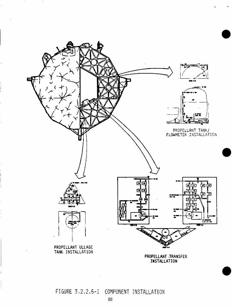
PROPELLANT ULLAGE TANK I NSTAL LAT I ON
PROPELLANT TANK/ FLOWMETER INSTALLATION
I 'I
PROPELLANT .TRANS FER I NSTAl L A T I ON
FIGURE 3 I 2 I 2,6-1 COMPONENT INSTALLATION 88
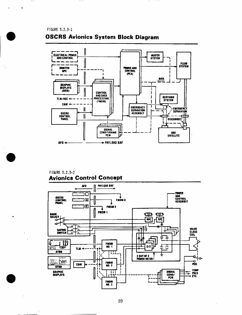
I O FIGURE 3.2,3-1
OSCRS Avionics System Block Diagram
FIGURE 3,2,3-2 Avionics Control Concept
89
The three-string avionics system will u t i l i ze three flex mu1 ti pl exer-demul t i pl exer (FMDM) uni t s , which are a derivative of the proven Orbiter MDM units, for system control and data processing. The FMDM, which incorporates a microprocessor and memory capabili t ies i n t o the existing MDM design, minimizes cost and schedule problems typically associated with developing an integrated avionics system. o f the FMDM.
Figure 3.2.3-3 i s a block diagram
The three-string concept permits the OSCRS resupply mission t o continue a f te r any one system fai l ure and supports safi ng the system af te r two fa i l ures. Adequate data i s provided t o the crew f o r safe control of the system, even af te r two f ai 1 ures.
A new concept included in the avionics system as shown in Figure 3.2.3-2, i s the use of a 2-out-of-3 power voter module. the voter module from the 3 FMDM's, and when any 2 of the 3 inputs are activated, 28 VDC power i s applied t o the valve or other component being controlled. logic and interconnecting wiring required in typical redundant systems.
Input commands are provided t o
The voter modules represent a significant simplification in the
The emergency separation function, shown on Figure 3.2.3-1 , provides the capability t o separate the use of the EVA. Pyrotechnic devices are used t o separate f luid supply l ines , electrical l ines and berthing latches t o permit the sa t e l l i t e and OSCRS t o separate. Controllers ( P I C ' S ) located in the Emergency Separation Controller. The P I C ' S are activated in response t o ARM and FIRE commands from crew-operated switches on the AFD OSCRS Control Panel.
the receiving sa t e l l i t e from the OSCRS tanker without
The pyrotechnic devices are f i red by Pyrotechnic I n i t i a t o r
The instrumentation system uses three integrated Signal Condi tioner/Pul se Code modulation packages to acquire and process OSCRS system data. unit , common signal conditioning c i rcu i t s are used rather t h a n the typical dedicated c i rcu i t s , and the data i s formatted i n t o a PCM stream and routea t o the FMDM's. Three independent data paths are provided, a s shown i n Figure 3.2.3-4, t o assure that adequate data will be avail able t o support safe operations even af te r two system failures.
The capabili t ies of the Orbiter Caution and Warning System are available t o payloads th rough a standard interface, as shown on Figure 3.2.3-5, which shows the OSCRS C&W concept. the crew during ascent and entry, when the G R I D displays would not be available. tolerant C&W data in addition t o the Orbiter C&W data.
I n the SC/PCM
The Orbiter C&W provides OSCRS s ta tus information t o
During resupply operations, OSCRS Avionics provides two fa i lure
The avionics component installation into the tanker i s shown in Figure 3.2.3-6.
3.2.4 Thermal System Definition
The preliminary thermal control system design will support OSCRS operations under a1 1 conditions for any m i ssion duration. required t o optimize the design and t o verify the thermal subsystem capabilities. subparagraphs.
Additional analysi s i s
Specific detai ls of the design are discussed i n the following
01 14c/44
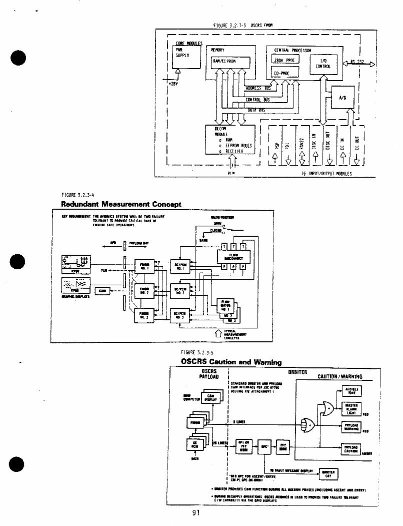
.
a
FIGURE 3.2 .3-5
FIGURE 3 . 2 . 3 - 4
bdundant Measurement Concept
OSCRS C8Uti011 and Warning OSCRS ORBITER
PAYLOAO I CAUTION / WARNING I I l U O U O O M I l E R U WlOlO
I I 1
91
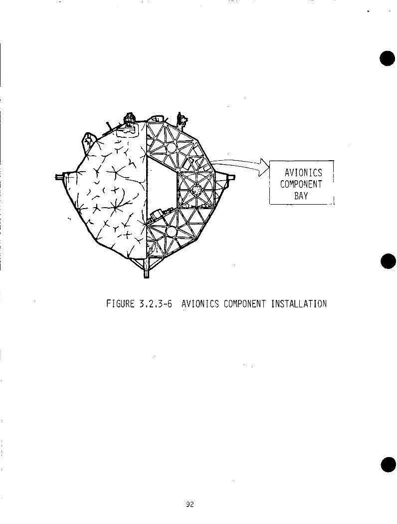
F I G U R E 3,2,3-6 A V I O N I C S COVPONENT I N S T A L L A T I O N
92
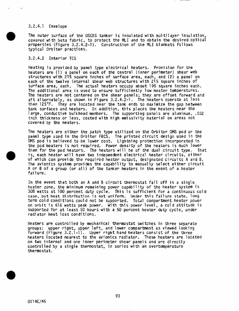
3.2.4.1 Envelope
The ou ter surface o f the OSCRS tanker i s i n s u l a t e d w i t h m u l t i l a y e r i n s u l a t i o n , covered w i t h b e t a fabr ic , t o p r o t e c t the MLI and t o o b t a i n the des i red o p t i c a l p r o p e r t i e s (F igure 3.2.4.2-1). t y p i c a l O r b i t e r p r a c t i c e s .
@ Construct ion o f the MLI b lankets f o l l o w s
3.2.4.2 I n t e r i o r TCS
Heat ing i s p rov ided by panel type e l e c t r i c a l heaters. P r o v i s i o n f o r the heaters are (1 ) a panel on each o f the c e n t r a l ( i n n e r per imeter ) shear web s t r u c t u r e s w i t h 215 square inches o f surface area, each, and (2) a panel on each o f the twelve i n t e r n a l shear web s t r u c t u r e s w i th 215 square inches of surface area, each. The actual heaters occupy about 195 square inches each. The a d d i t i o n a l area i s used t o ensure s u f f i c i e n t l y low heater temperatures. The heaters are n o t centered on the shear panels; they are o f f s e t fo rward and a f t a l t e r n a t e l y , as shown i n F igure 3.2.4.2-1. The heaters operate a t l e s s than 125°F. They are l o c a t e d near the tank ends t o maximize the gap between tank surfaces and heaters . I n a d d i t i o n , t h i s p laces the heaters near the 1 arge, conduct ive bulkhead members. The suppor t ing panels a re aluminum, .032 inch th ickness o r less , coated w i t h h i g h e m i s s i v i t y m a t e r i a l on areas n o t covered by the heaters.
The heaters are e i t h e r t h e patch type u t i l i z e d on the O r b i t e r OMS pod o r the panel type used i n the O r b i t e r FRCS. The p r i n t e d c i r c u i t design used i n the OMS pod i s b e l i e v e d t o be lower cost . L i g h t n i n g p r o t e c t i o n incorpora ted i n the pod heaters i s n o t requi red. Power dens i ty o f the heaters i s much lower than f o r the pod heaters. The heaters w i l l be o f the dual c i r c u i t type. That i s , each heater w i 11 have two independent e l e c t r i c a l heater c i r c u i ts , e i t h e r of which can prov ide the r e q u i r e d heater output , designated c i r c u i t s A and B. The av ion ics system p r o v i des the capabi l i t y t o manually s e l e c t e i t h e r c i r c u i t A o r B o f a group ( o r a l l ) o f the tanker heaters i n the event o f a heater f a i l u r e .
I n the event t h a t both an A and B c i r c u i t thermostat f a i l o f f i n a s i n g l e heater zone, the minimum remaining power c a p a b i l i t y o f the heater system 308 w a t t s a t 100 percent duty cyc le . Th is i s s u f f i c i e n t f o r a cont inuous case , b u t h e a t d i s t r i b u t i o n i s not uniform. Under t h i s f a i l u r e s t a t e , l o
S co l d 9
term c o l d c o n d i t i o n s coul d n o t be supported. Tota l coinpartment heater power on o r b i t i s 616 w a t t s peak power. With t h i s power l e v e l , a c o l d a t t i tude i s supported f o r a t l e a s t 50 hours w i t h a 50 percent heater duty cyc le , under r a d i a t o r h e a t l o s s cond i t ions .
Heaters are c o n t r o l l e d by mechanical thermostat switches i n t h r e e separate groups: fo rward (F igure 3.2.1 -1 1. hea ters l o c a t e d nearest t o the a v i o n i c s r a d i a t o r . These heaters are l o c a t e d on two i n t e r n a l and one i n n e r per imeter shear panels and are d i r e c t l y c o n t r o l l e d by a s i n g l e thermostat, i n s e r i e s w i t h an overtemperature thermostat .
upper r i g h t , upper l e f t , and lower compartment as viewed l o o k i n g Upper r i g h t hand heaters c o n s i s t o f the th ree
01 14c/45 93
FIGURE 3,2,4.2-1
Thermal Control System Concepts
AVIONICS RADIATOR COUPLINGS HAVE INDEPENDENT TCS
ULTILAYER INSULATION
SHEAR PANELS
94
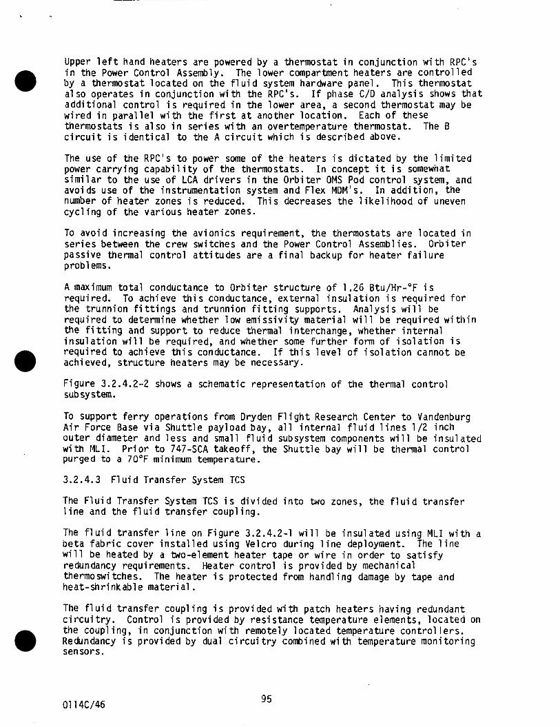
Upper l e f t hand heaters are powered by a thermostat i n con junc t ion w i t h RPC's i n the Power Control Assembly. The lower compartment heaters are c o n t r o l l e d by a thermostat l o c a t e d on the f l u i d system h a r d a r e panel. Th is thermostat a l s o operates i n con junc t ion w i t h the RPC's. a d d i t i o n a l c o n t r o l i s r e q u i r e d i n the lower area, a second thermostat may be w i r e d i n p a r a l l e l w i t h the f i r s t a t another l o c a t i o n . thermostats i s a l s o i n s e r i e s w i t h an overtemperature thermostat . c i r c u i t i s i d e n t i c a l t o the A c i r c u i t which i s descr ibed above.
I f phase C/D a n a l y s i s shows t h a t
Each o f these The B
The use o f the RPC's t o power some o f the heaters i s d i c t a t e d by the l i m i t e d power c a r r y i n g c a p a b i l i t y o f the thermostats. s i m i l a r t o the use o f LCA d r i v e r s i n the O r b i t e r OMS Pod c o n t r o l system, and avoids use o f the ins t rumenta t ion system and Flex MDM's. number of heater zones i s reduced. This decreases the l i k e l i h o o d o f uneven c y c l i n g o f the var ious heater zones.
TO a v o i d inc reas ing the a v i o n i c s requirement, the thermostats a re l o c a t e d i n s e r i e s between the crew switches and the Power Control Assembl i e s . O r b i t e r passive thermal c o n t r o l a t t i t u d e s are a f i n a l backup f o r heater f a i l u r e problems.
I n concept i t i s somewhat
I n a d d i t i o n , the
A maximum t o t a l conductance t o O r b i t e r s t r u c t u r e o f 1.26 Btu/Hr-"F i s requi red. To achieve t h i s conductance, ex te rna l i n s u l a t i o n i s r e q u i r e d f o r the t runn ion f i t t i n g s and t runn ion f i t t i n g supports. Ana lys is w i l l be r e q u i r e d t o determine whether low e m i s s i v i t y m a t e r i a l w i l l be r e q u i r e d w i t h i n the f i t t i n g and support t o reduce thermal interchange, whether i n t e r n a l i n s u l a t i o n w i l l be required, and whether some f u r t h e r form o f i s o l a t i o n i s r e q u i r e d t o achieve t h i s conductance. I f t h i s l e v e l o f i s o l a t i o n cannot be achieved, s t r u c t u r e heaters may be necessary.
F igure 3.2.4.2-2 shows a schematic representa t ion o f t h e thermal c o n t r o l subsystem.
To support f e r r y opera t ions from Dryden F1 i g h t Research Center t o Vandenburg A i r Force Base v i a S h u t t l e payload bay, a l l i n t e r n a l f l u i d l i n e s 1/2 i n c h o u t e r diameter and l e s s and small f l u i d subsystem components w i l l be i n s u l a t e d w i t h MLI. P r i o r t o 747-SCA t a k e o f f , the S h u t t l e bay w i l l be thermal c o n t r o l purged t o a 70°F min imum temperature.
3.2.4.3 F l u i d Trans fer System TCS
The F l u i d Transfer System TCS i s d i v i d e d i n t o two zones, t h e f l u i d t r a n s f e r l i n e and the f l u i d t r a n s f e r coupl ing.
The f l u i d t rans fer l i n e on F igure 3.2.4.2-1 w i l l be i n s u l a t e d us ing MLI w i t h a b e t a f a b r i c cover i n s t a l l e d us ing Velcro dur ing l i n e deployment. w i l l be heated by a two-element heater tape o r w i r e i n o rder t o s a t i s f y redundancy requirements. Heater c o n t r o l i s p rov ided by mechanical thermoswitches. heat-shr inkable m a t e r i a l .
The l i n e
The heater i s p r o t e c t e d from handl ing damage by tape and
The fl u i d t r a n s f e r coupl i n g i s prov ided w i t h patch heaters hav ing redundant c i r c u i t r y . Control i s p rov ided by res is tance temperature elements, l o c a t e d on the coupl ing, i n con junc t ion w i t h remotely l o c a t e d temperature c o n t r o l l e r s . Redundancy i s p rov ided by dual c i r c u i t r y combined w i th temperature m o n i t o r i n g sensors.
01 14C/46 95
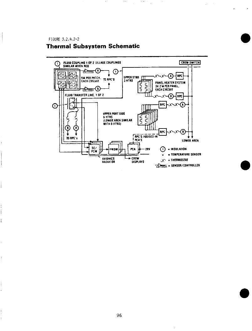
FIGURE 3 # 2 , 4 . 2 - 2
Thermal Subsystem Schematic
FlUiD COUPLIMO 1 OF 2 ULLAGE COUPLINOS 9 SIMILAR NHEN REO
x x THERMOSTAT RADIATOR DISPLAYS = SEMSOR/COMTROLLEC
96
Heaters on systems a r e a c t l v a t e d p r l o r t o deployment, and deac t l va ted f o l l o w i n g stowing, s ince they a re stowed I n a thermal ly c o n t r o l l e d p o r t l o n o f t h e OSCRS. Thermostat ranges a r e set above the OSCRS I n t e r n a l heater temperature range. I n t h l s way, the A and B c l r c u l t s o f each heater may be s e q u e n t i a l l y a c t l v a t e d b r l e f l y , p r l o r t o deployment, as a f u n c t i o n t e s t . Thermal c o n t r o l a t t l t u d e s can a l s o be used as a f l n a l backup w l t h the heaters turned o f f .
F o l l o w l n g deployment and attachment t o the spacecraf t , the m u l t i l a y e r i n s u l a t l o n cover I s placed over the c o u p l l n g - l l n e assembly. The lnsu1at:on I s removed p r l o r t o stowlng o f the assembly. The backup coup l l ng I s covered by an I n s u l a t e d cap w h l l e stowed.
3 . 2 . 4 . 4 Avlonlcs TCS.
The a v l o n l c s system 1 s est lmated t o d l s s l p a t e 380 watts. To remove t h l s heat, a pass lve maln a v l o n l c s r a d l a t o r I s used ( F i g u r e 3.2.4.2-1). The heat d l s s l p a t l n g components ( F l e x H D M ' s , Signal Condltloner/PCH u n i t s and two Power Con t ro l Assemblles) a r e a t tached t o the lnner sur face o f the r a d l a t o r . The remaln lng a v l o n l c s components, l n c l u d l n g the a d d l t l o n a l Power Con t ro l Assemblles used on the growth OSCRS, operate l n t e r m l t t a n t l y and d l s s l p a t e very l i t t l e power. They a r e mounted on I n t e r n a l maln shear panels. Heater l o c a t i o n s a r e ad jus ted where necessary t o prevent overheat lng o f these components.
The r a d l a t o r panel outer su r face I s covered by s l l v e r - t e f l o n m a t e r l a l , as used on the O r b l t e r r a d l a t o r , I n order t o t o l e r a t e so la r exposure. Radlator l ouve rs or thermal shades a r e n o t used. The r a d l a t o r panel, which a c t s as the a v l o n l c s baseplate, I s deslgned w l t h a maxlmum o f 14.7 f t 2 . o f sur face area, and approx lmate ly 14.0 f t 2 o f e f f e c t l v e lnner sur face area, assumlng t h a t some conduct lon i s a v a l l a b l e I n the box m a t e r l a l . P r l o r t o f l l g h t , ' t h e t a d l a t o r area i s p a r t i a l l y I nsu la ted . based on the worst ho t c o n d l t l o n s expected d u r l n g the mlss lon. a r e co-manlfested w l t h OSCRS, as w e l l as the requlrements o f the resupply
sur face u l t h o u t b l o c k l n g areas opposl te the av lon l cs box bases. Thls area supports comblned e a r t h and sun exposure or e a r t h p lus albedo, and r e s u l t s I n r a d l a t o r temperatures s l l g h t l y above t h e OSCRS l n t e r l o r temperature under c o l d c o n d l t l o n s w h l l e p r o v l d l n g the c a p a b l l l t y t o t o l e r a t e moderately h l g h envlronmental h e a t i n g loads. For a severe t o p sun envlronment comblned w l t h e a r t h h e a t l n g a t B = 90 degrees, the su r face area I s Increased t o 13.8 f t * by reduc lng t h e MLI cover lng. Maximum area I s about 14.3 f t 2 .
These c o n d l t l o n s a r e d r l ven by whatever payloads
, candldate and t h e O r b l t e r . A nominal 12.0 f t 2 may be obtalned on the outer
3.2.4.5 Ins t rumen ta t l on
The GRO mlss lon requ l res 102 temperature sensors, w l t h 155 sensors f o r t he growth ve rs lon . O f these, 65 and 103 r e s p e c t l v e l y a re requ l red f o r thermal c o n t r o l purposes, t he o the rs be ing used f o r safety , gauglng, e t c .
*'Sensor d l s t r l b u t l o n Is g lven by Table 3.2.4.5-1.
97
01 1 4 C / 4 7
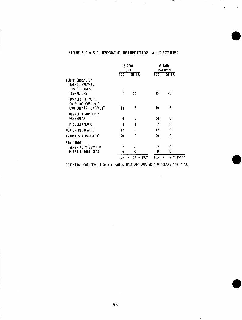
FlGURE 3 . 2 I il, 5-1 TERf'CRATllRE INSTRUKNTAT ION ( A l l . SUBSYSTE#S)
2 TANK 6 TANK MX rrun
f C S OTHER TCS OTllLR --- GRO
FLU I D SUBSYSTEM TANKS. VALVFS. PUIII'S, LINES. F LOWHE TER S 7 33 IS 49 TRANSFER 1 INC S I COUPI. ING CHELKWT COWONE NT S , C A I / M N T 14 3 14 3 U L L A R TRANSFER 8 PRESSMAN1 0 0 34 0 MISCELLANEOUS 4 1 2 0
HEATER OEDICATED 12 0 12 0 A V I O N I C S 8 RADIA!OR 20 0 24 0
STRUCTURE B E R I H I N G 9 J B l j Y S T f M 2 0 2 0 FIRST FLIGIII Esr 6 0 0 0
65 + 37 = 102' 103 + 52 = 155"
POTENTIAL FOR REDUCTION fULLr iWIN6 TFST AND ANACYZIS PAOGRAPI: '26, "31
98
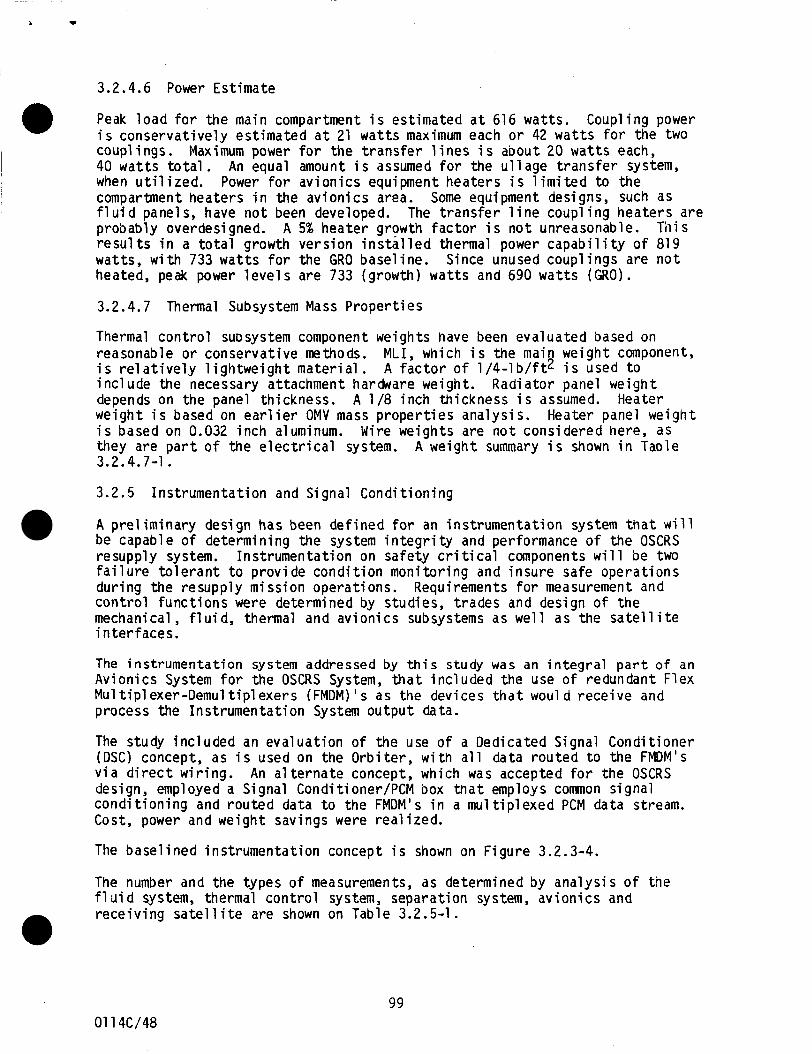
3.2.4.6 Power Estimate
Peak load for the main compartment i s estimated a t 616 watts. i s conservatively estimated a t 21 watts maximum each or 42 wat t s for the two couplings. Maximum power for the transfer l ines i s a b o u t 20 wat t s each, 40 wat ts total . An equal amount i s assumed f o r the ullage transfer system, when uti l ized. compartment heaters in the avionics area. Some equipment designs, such as f luid panels, have n o t been developed. The transfer l ine coupling heaters are probably overdesigned. results i n a total growth version installed thermal power capability of 819 watts, w i t h 733 watts f o r the GRO baseline. Since unused couplings are n o t heated, peak power levels are 733 (growth) wat ts and 690 watts ( G R O ) .
0 Coupling power
Power f o r avionics equipment heaters i s limited t o the
A 5% heater growth factor i s not unreasonable. This
3.2.4.7 Thermal Subsystem Mass Properties
Thermal control subsystem component weights have been evaluated based on reasonable or conservative methods. i s relatively lightweight material. include the necessary attachment hardware weight. Radiator panel weight depends on the panel thickness. A 1/8 inch thickness i s assumed. Heater weight i s based on ear l ie r OMV mass properties analysis. i s based on 0.032 inch aluminum. they are part of the electrical system. A weight summary i s shown in Table
MLI, which i s the main weight component, A factor of 1/4-lb/ft2 i s used t o
Heater panel weight Wire weights are n o t considered here, a s
3.2.4.7-1.
3.2.5 Instrumentation and Signal Conditioning
A preliminary design has been defined for an instrumentation system t h a t will be capable of determining the system integrity and performance of the OSCRS resupply system. Instrumentation on safety cr i t ical components w i l l be two fai lure tolerant t o provide condition monitoring and insure safe operations during the resupply mission operations. control functions were determined by studies, trades and design of the mechanical, f luid, thermal and avionics subsystems a s well as the sa t e l l i t e interfaces.
Requirements f o r measurement and
The instrumentat ion system addressed by t h i s study was an i n t e g r a l p a r t o f an Avionics System f o r the OSCRS System, t h a t included the use of redundant Flex Mu1 t i p 1 exer-Demul tiplexers (FMDM) I s as the devices t h a t woul d receive and process the Instrumentation System o u t p u t data.
The study included an evaluation of the use of a Dedicated Signal Conditioner (DSC) concept, as i s used on the Orbiter, with all d a t a routed t o the FMDM's via direct wiring. An al ternate concept, which was accepted f o r the OSCRS design, employed a Signal Conditioner/PCM box t n a t employs common signal conditioning and routed data t o the FMDM's in a mu1 tiplexed PCM data stream. Cost, power and weight savings were realized.
The baselined instrumentation concept i s shown on Figure 3.2.3-4.
The number and the types of measurements, as determined by analysis of the f lu id system, thermal control system, separation system, avionics and receiving sa t e l l i t e are shown on Table 3..2.5-1.
0
01 14C/48 99
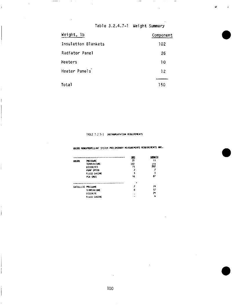
i II
Weiqht, l b
-
Tab1 e 3 2 4.7-1 Wei gh t Summary
- - Insu la t ion 61 ankets
CornDonent
102
Radiator Panel 26
Heaters 1 0
Heater Panel s- 1 2
Total 150
TABLE 3 . 2 . 5 - 1 INSIHWfNTAIlW RLWIREMNIS
OStwS )OPRWELLANI S Y S l C M PRILlMINARV NASWCMNIS REWlRENMlS ARE1
100
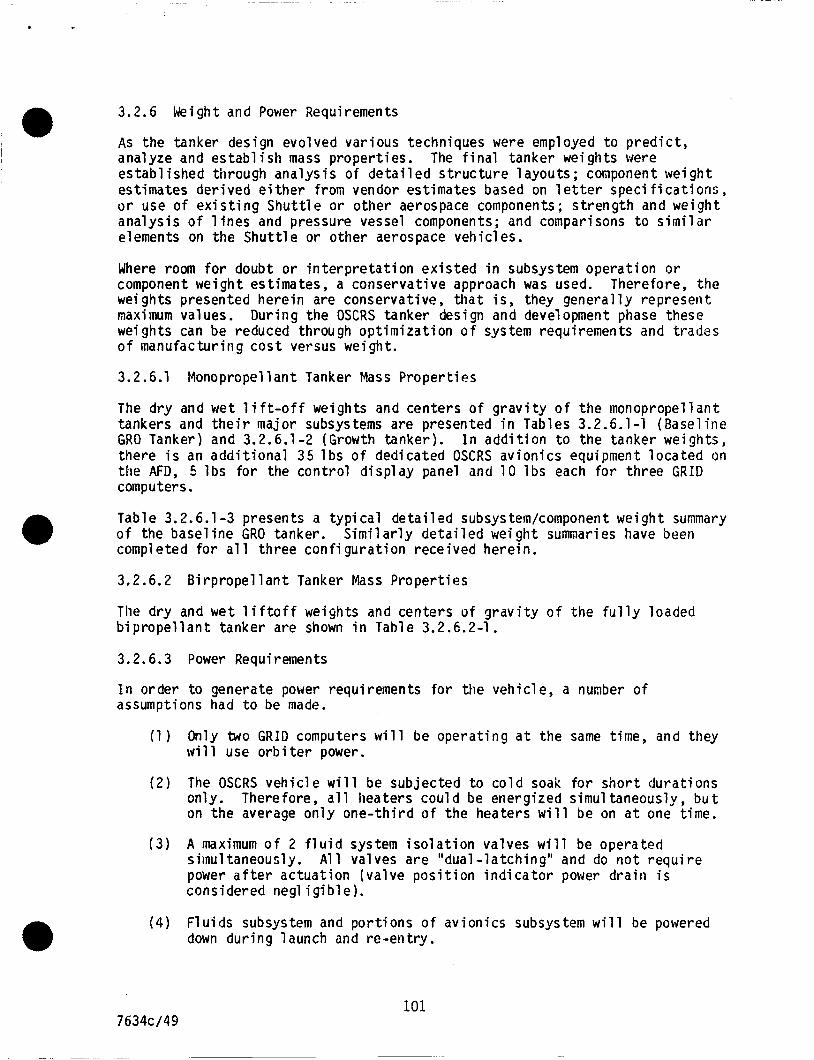
3.2.6 Weight and Power Requirements
As the tanker design evolved var ious techniques were employed t o D r e d i c t , a
. - analyze and e s t a b l i s h mass proper t ies . e s t a b l i s h e d through a n a l y s i s o f d e t a i l e d s t r u c t u r e l a y o u t s ; component we igh t est imates d e r i v e d e i t h e r from vendor est imates based on 1 e t t e r speci f i ca t ions , o r use o f e x i s t i n g S h u t t l e o r o ther aerospace components; s t r e n g t h and weight a n a l y s i s o f l i n e s and pressure vessel components; and comparisons t o s i m i l a r elements on t h e S h u t t l e o r o ther aerospace vehic les.
The ' f i n a l tanker weights bere
Where room f o r doubt o r i n t e r p r e t a t i o n e x i s t e d i n subsystem opera t ion o r component we igh t est imates, a conserva t ive approach was used. Therefore, t h e weights presented h e r e i n are conservat ive, t h a t i s , they g e n e r a l l y represent maximum values. weights can be reduced through o p t i m i z a t i o n o f system requirements and t rades o f manufactur ing c o s t versus weight.
Dur ing t h e OSCRS tanker design and development phase these
3.2.6.1 Monopropel lant Tanker Mass P r o p e r t i e s
The d r y and wet l i f t - o f f weights and centers o f g r a v i t y o f t h e monopropel lant tankers and t h e i r major subsystems are presented i n Tables 3.2.6.1-1 (Base l ine GRO Tanker) and 3.2.6.1-2 (Growth tanker) . I n a d d i t i o n t o the tanker weights, there i s an a d d i t i o n a l 35 l b s o f dedicated OSCRS av ion ics equipment l o c a t e d on the AFD, 5 l b s f o r the c o n t r o l d i s p l a y panel and 1 0 l b s each f o r th ree G R I D computers.
Table 3.2.6.1 -3 presents a t y p i c a l d e t a i l e d subsystem/component we igh t summary o f the b a s e l i n e GRO tanker. completed f o r a1 1 th ree c o n f i g u r a t i o n rece ived here in .
S i m i l a r l y d e t a i l e d weight s u m a r i e s have been
3.2.6.2 B i r p r o p e l l a n t Tanker Mass P r o p e r t i e s
The d r y and wet l i f t o f f weights and centers o f g r a v i t y o f t h e f u l l y loaded b i p r o p e l l a n t tanker are shown i n Table 3.2.6.2-1.
3.2.6.3 Power Requirements
I n order t o generate power requirements f o r the veh ic le , a number o f assumptions had t o be made.
(1 ) Only two G R I D computers w i l l be o p e r a t i n g a t t h e same t ime, and they w i l l use o r b i t e r power.
( 2 ) The OSCRS v e h i c l e w i l l be subjected t o c o l d soak f o r s h o r t dura t ions only. Therefore, a l l heaters cou ld be energ ized simultaneously, b u t on t h e average o n l y o n e - t h i r d o f t h e heaters w i l l be on a t one t ime.
( 3 ) A maximum o f 2 f l u i d system i s o l a t i o n va lves w i l l be operated siinul taneously. power a f t e r a c t u a t i o n ( v a l v e p o s i t i o n i n d i c a t o r power dra i r i i s considered negl i g i b l e ) .
A1 1 va lves a r e "dual - l a t c h i n g " and do n o t r e q u i r e
(4) F l u i d s subsystem and p o r t i o n s o f av ion ics subsystem w i l l be powered down d u r i n g launch and r e - e n t r y .
101 7634c/49
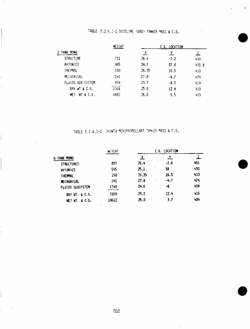
2 TANK !%YO
STPUCXRE AV ! ON I CS THEAWL fIEC%!V I CAL FLUiDS SUE- SY 21EM
DRY r lT 8 C.G. WET WT 8 C . G .
HE I GHT
711 q45 150 241 4'54
2501 4482
-
X 26 .4 2 4 . 7 26.35
-
2 7 . 8 2 3 . 7 2 5 . 6 26.0
C . G . LOCATICN Y 2 - -
-2 .2 400 5 7 , a 431.8 16 .5 410
-4#7 474 -8.3 4!4 1 ? . 4 420 5,s GTJ9
6-TANK MOM STRUCTURES AV ION1 cs T H E M L KCMNI UIL FLUIDS SUBSYSTER
DRY Wl, 6 C.G. WET wT. L C.G.
WF I G H T
893 545 150 241 1340
3169 10612
C.G. LOCATION Y - X -
26.4 -2.0 25.1 58 26,35 16.5 27.8 -4.7 24.0 -6
25.2 12.4 26.0 3.7
1 401 4 30 410 474 408
415 404
102
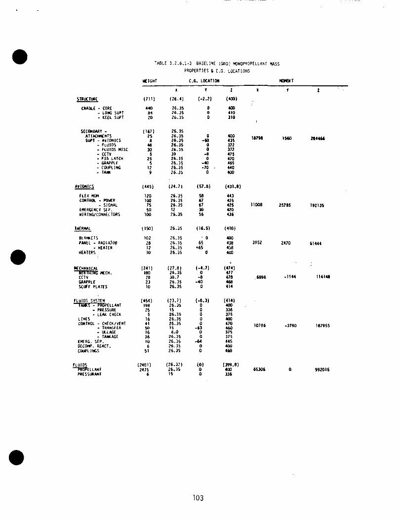
STRRUtTURE
CRADLE - CORE - LONG SUP1 - KEEL S U P 1
SECONDARV - ATTKWENTS SWT - AVIONICS - FLUIOS - FLU105 M I X - CCTV - FSS LATCH - GRAPPLE - C O u P L l f f i - 1AW
AV ION I CS - - SIGNAL
LMERGEN~V SEP. M I A INWCONNECTORS
lHERML - B L A M t T S PAnEL - RADIATOR - HEATER HEATERS
MECHANICAL CYCH.
CCTV MAPPLE SCUFF PLATES
FLUIDS SYSTEM T s - PROPELLANT - PRESSURE - LEAK CHECK
L INES COWTROL - CHECK/YENT - TRANSFER - ULLAGE - TAMAGE E M R C . SEP. O L C W . REACT. COWL INCS
FLUIDS -PA[IPE L L ANT
PRESSURANT
TABLE 3.2 .6 .1 -3 BASELINE (GRO: YONOPQOPELLANT MSS PROPERTIES b C.G. LJCATIONS
Y f IGHT C.G. LOCATION W T
(711)
440 84 20
(167) 25 8 4a 30
5 25
5 12 9
(445)
120 IO0 75 50
100
(150)
102 26 I 2 10
(;;A) 28 23 10
(454) 198 25
5 16 41 50 16 36 IO 6
51
(2401) 2475
6
X
(26.4)
26.35 26.35 26.35
26.35 26.35 26.35 26.35 26.35 39 26.35 26.35 26.35 26.35
(24.7)
26.35 26.35 26.35 12 26.35
26.35
26.35 26.35 26.35 26.35
(27.8) 26.35 3 8 . 7 26.35 26.35
(23.7) 26.35 15 26.35 26.35 26.35 I5 6.0
26.35 26.35 26.35 26.35
( 26. I ? ) 26.35 15
V
(-2.2)
0 0 0
0 -60
0 0
-0 0
-40 - 70 0
(57.8)
58 67 67 30 56
(16.5)
' 0 65
*65 0
(-4.7) 0
-8 -40
0
(-8.3) 0 0 0 0 0
-63 0 0
-64 0 0
0
1
(400)
4al 410 310
400 435 372 372 475 470 465 440 400
(431.8)
443 425 425 420 43 6
(410)
100 438 43% 4uo
';;;I
(%I
478 460 414
336 375 400 470 460 375 375 445 ux) 460
(399.8) 4 m 336
x
I
18798
11008
3952
6696
10786
65306
T
1 S K I
25785
2470
-1144
-3790
204466
192135
61444
114148
187955
0 992016
103
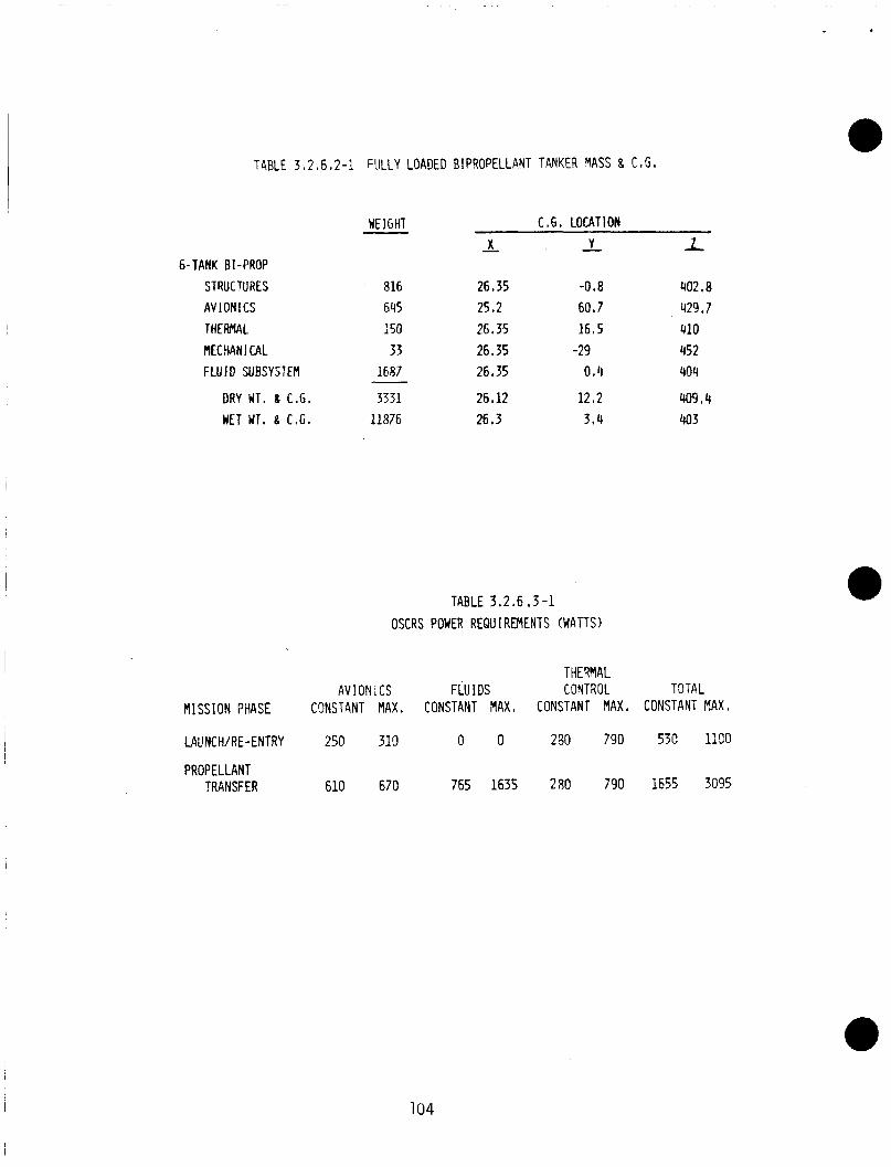
TABLE 3,2,6.2-1 FULLY LOADED BIPROPELLANT TANKER YASS 8 C ,G I
6- TANK BI -PROP STRUCTURES AV ION1 CS THERMAL MECHANICAL FLUID SUBSYSTEM
DRY UT. 8 C . G .
NET Wl. 8 C.G.
WEIGHT X -
C.G. LOCATION
816 645 150 33
1687
3331 11876
26.35 25.2 26.35 26.35 26.35
26.12 26,3
Y - L
-0.8 402.8 60.7 429.7 16,s 410 -29 452 0.4 404
12.2 409,4 3 * 4 403
TABLE 3.2.6.3-1 OSCRS POWER REQUl REMENTS (WATTS)
THERMAL AV I O N i CS FLU I D S CONTROL T 3 i A L
MISSION PHASE CONSTANT MAX, CONSTANT MAX, CONSTANT MAX, CONSTANT MAX I
LAUNCH/ RE - ENTRY 250 310 0 0 230 790 530 1190
PROPELLANT TRANSFER 610 670 765 1635 280 790 1655 3095
104
Using the above assumptions, a preliminary analysis of the OSCRS power requirements was generated, and i s shown in Table 3.2.6.3-1. Constant power drain for all subsystems was estimated to be approximately 1655 watts during propellant transfer. Max power usage ( b o t h propellant pumps operating, all heaters on, al l avionics u p ) was found t o be approximately 3095 watts.
3.2.7 Subsystem Performance Predictions
The objective of t h i s analysis was t o evaluate the performance of the OSCRS Fluid subsystem. To do th is , a micro-g thermal math model, and a zero-g pressure math model were used t o make temperature predictions f o r the receiver and supply tank ullages, perform steady s ta te pressure drop analyses for the f lu id system components, make l ine sizing recomnendations, and perform a pump requirements analysi s.
3.2.7.1 F1 owrate
Pump flowrate was found t o be limited primarily by heat buildup in the receiver t a n k as the ull age vol ume i s compressed. model, i t was determined t h a t the maximum allowable continuous flow rate i s 2.5 gpm (see Figure 3.2.7.1-1).
As can be seen from the figure, the m a x i m u m ullage temperature ( i . e . , " h o t spot") i s a t 150°F a t the completion of the transfer. This p o i n t was chosen as the upper l imit because i t provides a safety margin comfortably below the autoigni t i o n temperature of the N2H4 vapor.
Use of dual flowrates (10.0 gpm a n d 2.5 gpm) i s also possible, as long as the flowrate i s thrott led back when the ullage temperature reaches 150°F. Such a transfer i s shown i n Figure 3.2.7.1-1. Using dual flowrates, the transfer can be completed in j u s t under 1-1 /2 hours, as compared t o 2.0 hours for a straight 2.5 gpm transfer.
Using the thermal math
a The optimum pump design was therefore found t o be one t h a t incorporates dual flowrate capability (2.5 gpm and 5.0 gpm). A 10.0 gpm flow can be achieved w i t h simultaneous pump operation a t the high flowrate setting. r a t i o was chosen over the 10.0/2.5 gpm rat io (4 : l ) because the lower ratio al lows f o r a more e f f i c i e n t design.
3.2.7.2 Line Siz ing
A 2:l gpm
Wi th the m i n i m u m flowrate set a t 2 .5 gpm and the maximum flowrate a t 10.0 gpm, the optimum l ine diameter was then determined. Table 3.2.7.2-1 presents a summary of the pressure losses and delta weights for the var ious l ine sizes under consi deration.
Taking into consideration the pressure drops, system weights, and power requirements for the various l ine sizes, i t appears t h a t the optimum design would use 3/4 in. lines. As compared t o 5/8 i n . l ines , 3/4 in. l ines have pressure restriction 8 psid less a t 10 gpm, and will use less pump energy t o complete a typical mission. A1 so, system start-up and shutdown surge pressures will be lessened, and pump cooling requirements will be lowered. The only drawback i s a 2.0 lbm mass penalty, w h i c h i s fa i r ly minor. Use o f 1 i n . l ines would provide s l ight reductions in pressure drops and power requirements, b u t the additional mass penalty of 5.0 lbm i s n o t worth the very a . minor gains.
105 01 14C/50
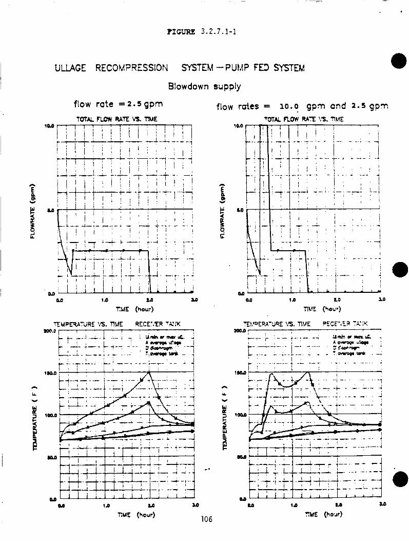
? I G ~ 3 . 2 7 ,1-1
ULLAGE RECOM7RESSION SYSTEM -PUMP FED SYSTEM B!owdown supply
flow rate = 2 5 gprn TQTAL FLOW RATE v3. RME
M 1 0 LD TME (hour)
106 TlME (hour)
flow rates = 10.0 gprn and 2 . 5 gprn TOTAL RATE ?'S. TIA!,!E
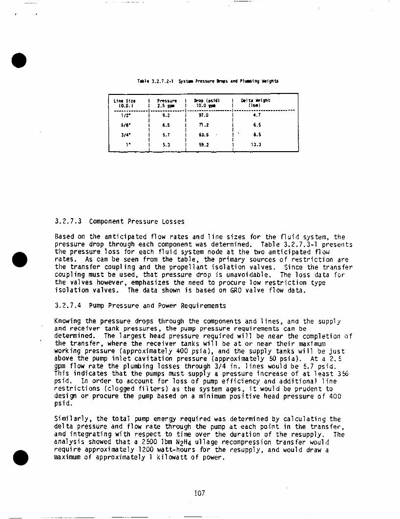
i
T I l r 3.2.7.2-1 S y s u Pressure Drops ad P l u b i n g b i g h t s
3.2.7.3 Component Pressure Losses
Based on the anticipated flow rates a n d l ine sizes for the f l g i d system, the pressure drop through each component was determined. Tab1 e 3.2.7.3-1 preseri t s the pressure loss for each fluid system node a t the bvo anticipated f l m rates. As can be seen from the table, the primary sources o f restriction are the transfer coupling and the propellant isolation valves. Since the transfer coupling must be used, that pressure d rop i s unavoidable. The loss data fclr the valves however, emphasizes the need t o procure low restriction type isolation valves. The data shown i s based on GRO valve flow data.
3 . 2 . 7 . 4 Pump Pressure and Power Requirements
Knowing the pressure drops through the components a n d l ines , and the supply and receiver tank pressures, the pump pressure requirements can be determined. The largest head pressure required will be near the completion o f the transfer, where the receiver tanks will be a t o r near their maximum working pressure (approximately 400 psia) , and the supply tanks will be j u s t above the pump i n l e t cavitation pressure (approximately 50 psia). gpm flow rate the plumbing losses through 3/4 in. l ines would be 5.7 psid. T h i s indicates that the pumps must supply a pressure increase o f a t l ea s t 356 ps id . In order t o account for loss o f pump efficiency and a d d i t i o n a l l ine rest r ic t ions (clogged f i l t e r s ) as the system ages, i t would be prudent to design o r procure the pump based on a minimum positive head pressure o f 400 p s i d .
’
A t a 2 . E
Similarly, the total pump energy required was determined by calculating the delta pressure and flow rate through the pump a t each point i n the transfer, and integrating w i t h respect t o time over the duration of the resupply. The analysis showed t h a t a 2500 lbm N2H4 ullage recompression transfer wouli! require approximately 1200 watt-hours for the resupply, and would draw a maximum of approximately 1 kilowatt o f power.
107
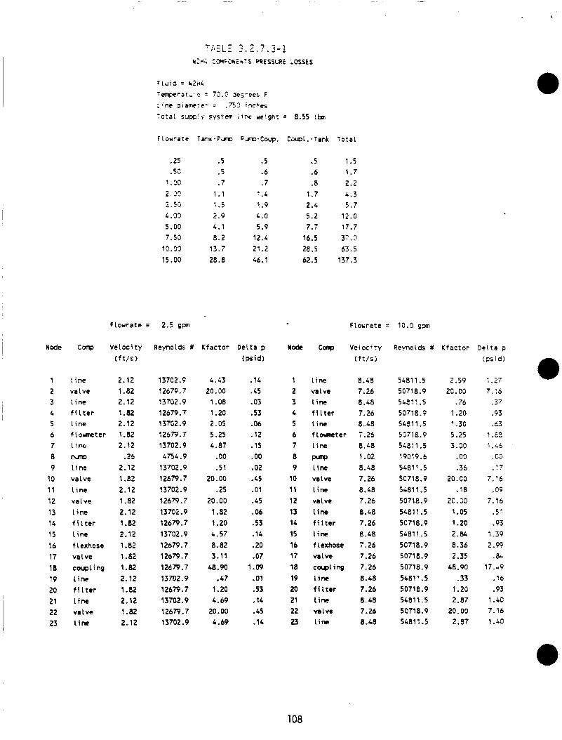
’
I ~ Node
1 2 3 4 5 6 7 8 9 19 1 1 12 13 14 15 16 17 18 19 20 21 22 1 23
I
.25
.55 1 .oo 2.25 z.50 4.03 5.00 7.50 10.90 15.00
Flourate = 2.5 gpri
ine valve 1 ine f i l t e r 1 ine f L o w t e r Line hnp
l i n e va l ve l inc va l ve t ine f i l t e r l i n e f Lcxhosc va 1 ve coupling 1 ine f i l t e r l i n e va l vc Line
( f t / S )
2.12 1.82 2.12 1.82 2.12 1.82 2.12 .26
2.12 1.82 2.12 1.82 2.12 1.82 2-12 1.82 1.82 1.82 2.12 1.82 2.12 1.82 2.12
Reynolds #
137C2.9 12b7F. 7 13702.9 12679.7 137G2.9 726R.7 13702.9 4754.9 13’02.9 12679.7 1 3702.9 12679.7 13702.9 12679.7 13702.9 12679.7 12679.7 12679.7 13702.9 12679.7 13702.9 12679.7 13702.9
.5
. 5
.7 1.1 1.5 2.9 4.1 8.2 13.7 28.8
Kfactor
L.43 20.00 1.08 1.20 2.05 5.25 4.87 . 00 .51
20.00 .25
20.00 1.82 1.20 4.57 8.82 3.11 48.90 .47 1.20 4.69 20.00 4.69
.5
.6
.7 1.4 1 .P 4.0 5.9 12.4 21.2 46.1
Delta p (psid)
.14
.6
.03
.53 -06 .12 .15
. 00
.02
.65
. G1
.45
.06
.53
.14
.20 -07 1.09
.01
.53
.1c
.45
.14
- 5 .6 .8 1.7 2.4 5.2 7.7 16.5 28.5 62.5
Total
1 .5 1.7 2.2 L.3 5.7 12.0 17.7 37.3 63.5 137.3
Flowrate = 10.0 s p
Node Conp Velocitv
1 l ine 2 valve 3 l ine 4 f i l t e r 5 l ine 6 flowncter 7 Line
8 - 9 l ine 10 valve 1 1 l ine 12 valve 13 Line 14 f i l t e r 15 l ine 16 f lexhose 17 v a l w 18 corqling 19 l ine 20 f i l t e r 21 Line 22 valve 23 l ine
( f t / s i
8.48 7.26 8.48 7.26 8.48 7.26 8.L8 1-02 8.48 7.26 8.48 7.26 8.48 7.26 8.48 7.26 7.26 7.26 8.48 7.26 8.48 7.26 0.48
Reynolds #
54811.5 5C718.9 SLe? 1.5 5071 8.9 54811.5 5G718.9 5491 1.5 19019.6 54811.5 5071 8.9 5411.5 50718.9 5481 1.5 5071 8.9 54811 .5 5071 8.9 5071 8.9 50718.9 5481? .5 5071 8.9 5411.5 5071 8.9 5481 I .5
K f ac t or
2.59 20.00
.76 1.20 ’ -30 5.25 3.00 . 00 -36
20.00 .78
20. GO 1.05 1.20 2.84 8.36 2.35 48.90
-33 1.20 2.87 2@ - 00 2.37
D e l t a p
!psis)
1.27 7. :6 .37 .F3 .63
1.e5 5 . i S
. G;l
. !?
7-16 .OF
7.15 .51 .93 1.39 2.99 .&
17.~9 .16 .93 1.40 7.16 1 .LO
108
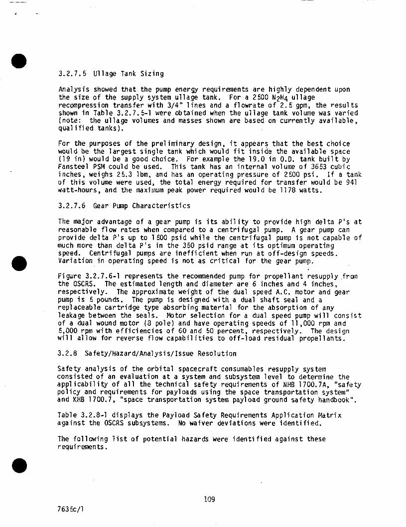
3.2.7.5 Ullage Tank Sizing
Analysis showed t h a t the pump energy requirements are highly dependent upon the size of the supply system ullage tank. recompression transfer with 3/4" l ines and a flowrate o f 2.5 gpm, the resul ts shown in Table 3.2.7.5-1 were obtained when the ullage tank volume was varied (note: the ullage volumes and masses shown are based on currently available, qual i fi ed tanks).
For a 2500 N2H4 ullage
For the purposes of the preliminary design, i t appears that the best choice would be the largest single t a n k which would f i t inside the available space ( 1 9 i n ) would be a good choice. For example the 19.0 in O.D. tank bui l t by Fansteel PSI4 could be used. This tank has an internal volume o f 3653 cubic inches, weighs 25.3 lbm, and has an operating pressure of 2500 psi. of th is volume were used, the total energy required f o r transfer would be 941 watt-hours, and the maximum peak power required would be 1178 watts.
I f a tank
3.2.7.6 Gear Pump Characteristics
The major advantage of a gear pump is i t s ab i l i ty to provide h i g h delta P's a t reasonable flow rates when compared t o a centri fuga1 pump. A gear pump can provide delta P's up t o 1500 psid while the centrifugal pump i s n o t capable o f much more than delta P ' s in the 350 psid range a t i t s optimum operatirig speed. Centrifugal pumps are inefficient when run a t off-design speeds. Variation in operating speed i s n o t as cr i t ical for the gear pump.
Figure 3.2.7.6-1 represents the recommended pump f o r propel1 a n t resupply ,from the OSCRS. The estimated length and diameter are 6 inches a n d 4 inches, respectively. pump i s 5 pounds. rep1 aceable cartridge type absorbing material for the absorption of any leakage between the seals. Motor selection f o r a dual speed pump will consist of a dual wound motor (8 pole) and have operating speeds o f 11,000 rpm and 5,000 rpm with efficiencies o f 60 and 50 percent, respectively. will allow for reverse flow capabili t ies t o off-load residual propellants.
3.2.8 Sa fety/Hazard/Anal ysi s/ Issue Resol ution
The approximate weight of the dual speed A.C. motor and gear The pump is designed with a dual s h a f t seal and a
The design
Safety analysis of the orbital spacecraft consumables resupply system consisted of an evaluation a t a system and subsystem level t o determine the appl icabil i ty of a1 1 the technical safety requirements of NHB 1 7 G O . 7 A , "safety policy and requirements f o r payloads using the space transportation system" and KHB 1700.7, %pace transportation system payload ground safety handbook".
Table 3.2.8-1 displays the Payload Safety Requirements Application Matrix against the OSCRS subsystems. No waiver deviations were identified.
The following l i s t o f potential hazards were identi fied against these requirements.
109 763!3/1
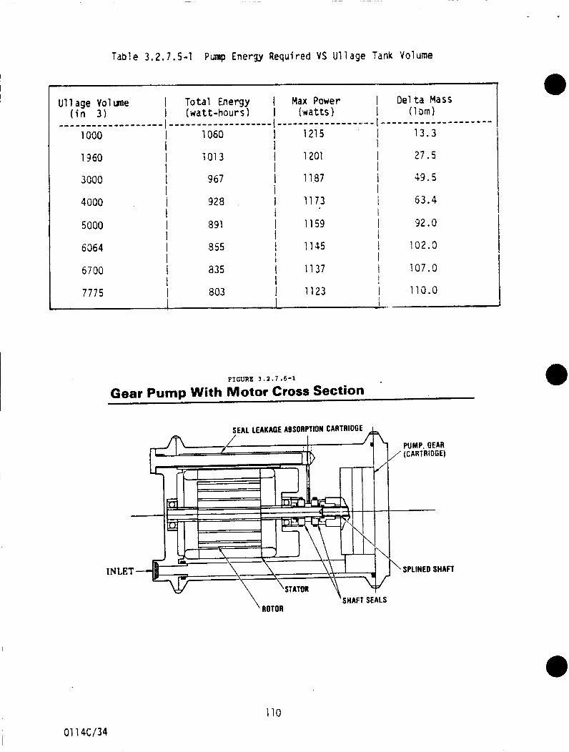
Table 3.2.7.5-1 Pimp Energy Required VS Ul lage Tank Volume
I I U11 age Vol me I Total Energy Max Power I Delta Mass
( i n 3 ) I (watt-hours) I (wat ts) I (1 bm) - - - - - - - - - - - - - - - - - - - I - - - - - - - - - - - - - - - - - - - t - - - - - - ~ - - - - - - - - ~ - - l - - - - - - - - - - - - - - - - - - - -
1000 I 1060 1 1215 I 13 .3 I I
1960 I '101 3 I 1201 I I
I I 3000 I 967 1 1197 I
I 1 I I
4000 I 928 1 1173 I I 1 I
5000 I 891 I 1159 I I I I
6364 I 8 55 i 1155 I I I
5700 I a35 1 1137 I I
i I 7775 I 803 1 11 23 I
I
1 1 .
27 .5
49.5
63.4
32.0
102.0
107.1)
110.0
FIGURE 3 . 2 . 7 .6-1
Gear Pump With Motor Cross Section
SEAL LEAKAGE ABSORPTION CARTRIDGE A
/
I I
I I I
I
01 14c/34
110
PUMP, GEAR (CARTRIDGE)
-~~
SPLINED SHAFT
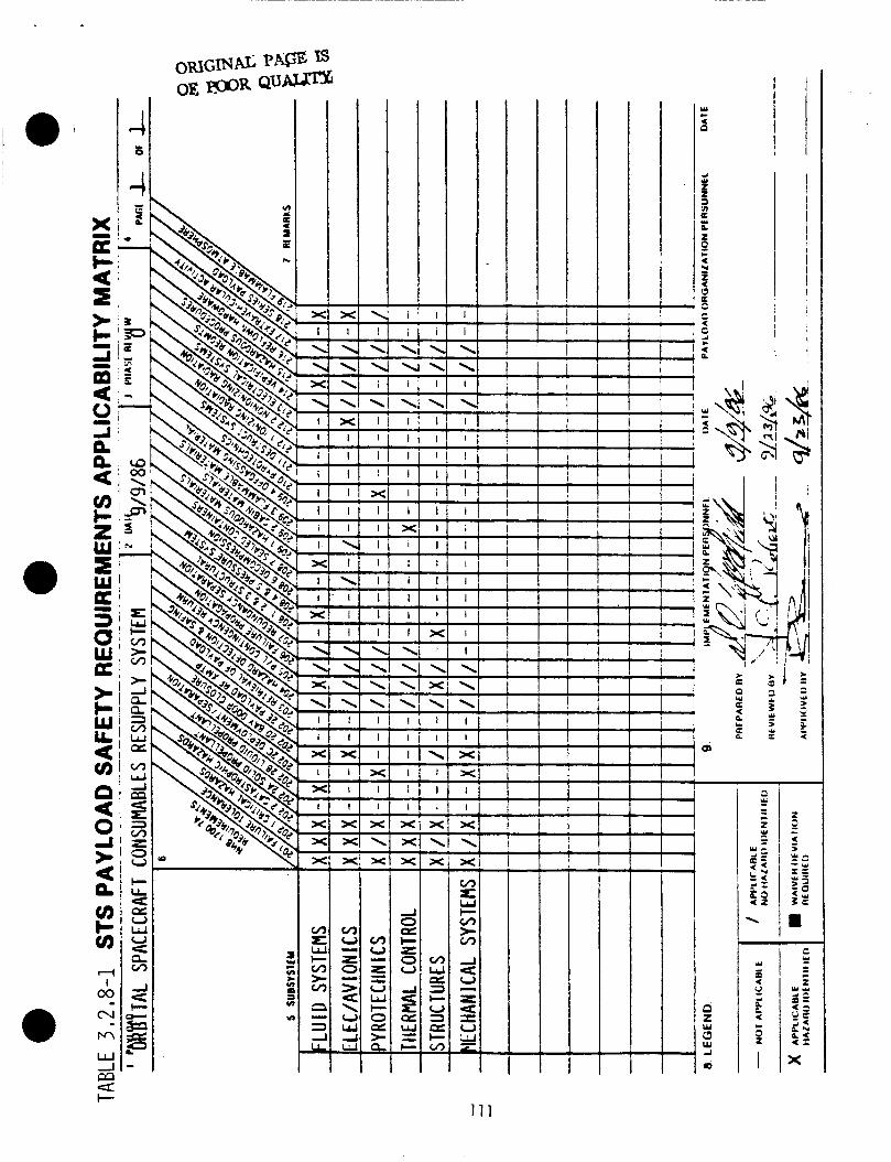
T I
I - - I -
II ti-'
I - I I
I I
I I / !
t 7
i e ua c v)
111
STRUCTURES-POTENTIAL HAZARDS
Personnel I n j u r y
P o t e n t i a l i n j u r y t o ground personnel and p o t e n t i a l l o s s o f l i f e o f EVA crew ( d e p l e t i o n of l i f e support consumables) from c o n t a c t w i t h sharp edges o r p r o t r u s i o n s on s t r u c t u r e .
S t r u c t u r a l Fai 1 u re
F a i l u r e o f the pr imary o r secondary s t r u c t u r e coul d cause c o l 1 i sion w i t h the O r b i t e r l e a d i n g t o l o s s o f O r b i t e r and l i f e .
Loose Components
Improper ly secured components can break loose and become p r o j e c t i l e s which can e n t e r the crew compartment and r e s u l t i n l o s s o f l i f e .
MECHANICAL SYSTEMS-POTENTIAL HAZARDS
Fai 1 u re t o Secure OSCRS A f t e r On-Orbi t Relocat ion
F a i l u r e o f the OSCRS t o be secured a f t e r the o n - o r b i t r e l o c a t i o n c o u l d r e s u l t i n l o s s o f the O r b i t e r e n t r y c a p a b i l i t y .
F a i l u r e o f S a t e l l i t e t o Separate From OSCRS
F a i l u r e o f t h e r e c e i v e r s a t e l l i t e t o separate f rom the OSCRS c o u l d r e s u l t i n i n a b i l i t y t o c l o s e pay load bay doors which i n t u r n w i l l r e s u l t i n the l o s s o f the O r b i t e r e n t r y c a p a b i l i t y .
FLUID SYSTEMS-POTENTIAL HAZARDS
Hy draz i ne Leak age/Spi 1 1 age
The l e a k a g e / s p i l l age o f hydraz ine can contaminate the surrounding s t r u c t u r e and elements l e a d i n g t o a p o t e n t i a l l y t o x i c / f l amnable atmosphere.
Ground Crew Contact With Hydrazine
During ground opera t ions t h e sp i l laye / leakage o f hydraz ine c o u l d r e s u l t i n i n j u r y / i l l n e s s t o ground personnel through s k i n c o n t a c t o r vapor i n h a l a t i o n .
RuDture o f Pressur ized Tanks. Lines. F i t t i n a s . and ComDonents
The r u p t u r e o f p r e s s u r i z e d tanks, l i n e s , f i t t i n g s , and components may cause i n j u r y t o personnel (shrapnel , f l u i d c o n t a c t ) and damage t o the O r b i t e r and o t h e r paylodas.
Adiabat ic ComDression Detonat ion
Opening c l o s i n g o f f l o w c o n t r o l devices may cause a d i a b a t i c compression detonat ion. I
I
I
I 01 16C/2 112
High Pressure Gas ImDinqement on Personnel
Release o r leakage of h i g h pressure gas dur ing ground o r EVA opera t ions c o u l d r e s u l t i n impact o f h i g h v e l o c i t y gas v i i th personnel causing i n j u r y o r i 1 1 ne ss . OverDressur izat ion o f OSCRS Prooe l l a n t Tank
Inadequate OSCRS p r o p e l l a n t tank u l l a g e can l e a d t o pressure l e v e l s w i t h i n the tank exceeding safe opera t ing l i m i t s due t o thermal expansion o f t h e u l l age/propel l ant.
Overpressur izat ion o f Spacecraf t F l u i d Systems
Excessive f l u i d resupply may l e a d t o poss ib le damage/leakage o f r e s u p p l i e d s p a c e c r a f t ' s f l u i d system.
SDacecraft U11 aae Overheatinq
Excessive resupply f l o w r a t e s coul d cause the s p a c e c r a f t ' s propel 1 a n t tank u l l age t o overheat and explode.
EVA Contact With Hydrazine
Leakage o f hydraz ine w h i l e per forming EVA opera t ions can contaminate the EMU and may p o s s i b l y deplete the l i f e support consumables i f c o n t a c t i s w i t h the EMU face s h i e l d causing the s h i e l d t o crack.
On-Orbi t Venting o f Hazardous F l u i ds
OSCRS o n - o r b i t ven t ing o r p r o p e l l a n t s o r o t h e r hazardous f l u i d s can contaminate the O r b i t e r , o t h e r vehic les/payloads, o r the EVA crew l e a d i n g t o an unsafe e n t r y due t o TPS degradation o r i n j u r y / i l l n e s s t o the crew.
F a i l u r e of F l u i d Resupply Lines/Coupl i n g s To Be Disconnected
F a i l u r e o f the f l u i d resupply 1 ines/coupl i n g s t o be disconnected a f t e r the resupply w i l l cause i n t e r f e r e n c e w i t h the c l o s u r e o f the payload bay doors and result in the l o s s o f the Orbiter's entry capability.
Pump Damage /Fr agmen t a ti on
The p r o p e l l a n t resupply pump may become damaged and p o s s i b l y explode which c o u l d cause f u r t h e r damage t o the resupply system, O r b i t e r , and i n j u r e personnel due t o f ragmentat ion/shrapnel . Nonconformance of O r b i t e r ' s Landinq CG and Load L i m i t s
The OSCRS payload may cause the O r b i t e r t o exceed i t s cen ter o f g r a v i t y and l o a d l i m i t s f o r landing.
THERMAL CONTROL-POTENTIAL HAZARDS
ProDel l a n t Tank OvertemDerature
Overtemperature o f loaded propel1 a n t tanks coul d cause excessive tank pressure r e s u l t i n g i n tank f a i l u r e and re lease o f hydrazine.
01 1 6C/3 113
F1 aking Shredding o f Thermal I n s u l a t i o n
F1 aking shredding o f thermal i n s u l a t i o n due t o improper m a t e r i a l s e l e c t i o n may cause contaminat ion i n the pay load bay.
Hydrazine Expansion During Thawing
The f reez ing and subsequent expansion o f hydraz ine dur ing i t s thaw can cause damage o r a r u p t u r e w i t h i n the OSCRS p r o p e l l a n t system.
ELECTRICAL/AVIONICS-POTENTIAL HAZARDS
E l e c t r i c a l Shock Dur ing E l e c t r i c a l Cable Connection
P o t e n t i a l f o r e l e c t r i c a l shock dur ing connect ion o f e l e c t r i c a l cables.
S t a t i c Discharge Dur ing Ber th ing
S t a t i c d i scharge dur ing i n i ti a1 b e r t h i n g o f the r e c e i v e r sate1 1 i t e t o the OSCRS dest roy ing any s e n s i t i v e e l e c t r o n i c s .
S t a t i c D i scharqe Durinq Ground Operat ions/Serv ic inq
S t a t i c discharge dur ing ground opera t ions may be a p o t e n t i a l i g n i t i o n source for a f l amnable atmosphere.
E l e c t r i c a l Cable Dmaae Dur inq On-Orbi t OSCRS Re loca t ion
The o n - o r b i t r e l o c a t i o n o f the OSCRS may damage t h e e l e c t r i c a l cables between the OSCRS and the a f t f l i g h t deck area.
E l e c t r i c a l Shor ts / Ign i t i o n Sources
E l e c t r i c a l w i r e s may become damaged and cause system mal f u n c t i o n s o r p o s s i b l y i g n i t e a flammable atmosphere.
F a i l u r e o f E l e c t r i c a l C o w l i n a To Be Disconnected
F a i l u r e o f the e l e c t r i c a l 1 ines/coupl i n g s t o be disconnected a f t e r the resupply w i l l cause i n t e r f e r e n c e w i t h the c l o s u r e o f the payload bay doors and r e s u l t i n the loss o f the O r b i t e r ' s e n t r y c a p a b i l i t y .
Venting/Expl os ion o f B a t t e r i e s
The use o f b a t t e r i e s on remote resupp l ies can l e a d t o contaminat ion o f surrounding elements due t o vent ing and p o s s i b l e damage/loss of equipment/vehicles due t o the exp los ion p o t e n t i a l o f b a t t e r i e s .
Cont i nuousl v Eneraized ProDel1 a n t Val ve
A con t inuous ly energ ized hydraz ine va lve can cause excessive va lve temperatures l e a d i n g t o detonat ion o f the hydrazine.
01 16C/4 114
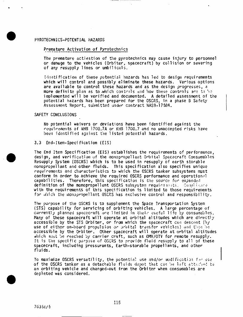
PYROTECHNICS-POTENTIAL HAZARDS
Premature Act ivati on of Pyrote chni cs
The premature activation of the pyrotechnics may cause injiiry to personnel or damage to the vehicles (Orbiter, spacecraft) by coll ision or severing of any resupply l ines or umbilicals.
-------
14?liti fi catiori of these potetitiai iiazards has led to design requirements which will control and possibly eliminate these hazards. Various options are available to control these hazards and as the design progresses, n more de fini tc pl i ln as t o -which coil tmi s sild !how these cor1 t r o l s 3rr! I-:) ):? implemented will be verified and documented. A detailed assessment of tiie poteritial hazards has been prepared for the OSCRS, in a phase B Safety Assessluetit Report, submitted JnGer cantract NAS9-17%4.
L a
SAFETY CONCLUSIONS
No potential waivers or deviations have been identified against the requirements of NH8 1700.7A or KHB 1700.7 and no unaccepted risks have been i den t i f i e4 ?gi i tis t t : ie 1 i s ted po tcri ti a1 hazards.
3 . 3 End-Item-Speci fication (EIS)
The End Item Specification (EIS) establishes the requirements of performance, design, and veri ficljtiori o f the i n o r i o p ~ ~ > p ~ l l a i l t 3r-i)i tal Siiac2craft Consumables Resupply System (OSCRS) which i s t o be used in resupply o f earth storable monopropellant and other fluids. This speci fication a1 so speci f ies unique requirements and characteristics t o which tiie OSCRS tanker subsystems must conform i n order t o achieve the required OSCRS performance and operatiom1 capabil i t i e s . Therefore, this speci f i catiori i s the sodrce for exparideJ definition of the monopropellant OSCRS suhystea requir:? i? t t ; , $) , I ! ) : i .-.,I:-..>
w i t h the requirements of this speci f i cation i s 1 ini ted t o those requirements f w ,hidl tile inowpropellant OSCRS has exclusive control a n d responsibil i t:y.
Tile p'.rrpose of tile OSCRS i s t o supplement the Space Transportation System (STS) capability for servicing of orbiting vehicles. A large percentage o f cirrrently pl anned spdcecraft ;Ir.e 1 imi t c d in t h e i f * t.isefij1 1 i fe by consumables. Many of these spacecraft will operate a t orbital a1 t i tudes which are directly accessible by the STS Orbiter, or f rm which the spdcecraft cdri di?sclmt (by use of e i ther on-board propulsion i)r \ v i J i tal tr.irisfer* v & i i cles ) r l i 1 d t ' i p 2 O 5:: accessible by the Orbi ter . Other spacecraft will operate a t orbital a1 ti tudes d i i c h W A S L :>e reddied by carr ier c r a f t , such as OMV/OTV f o r remote resupply. I t i s t h e specific pi lrp~sc? o F 0SC;iS t o p r o v i d e fluid resupply t o a l l o f these spacecraft, including pressurants, Earth-storable propellants, and other fluids.
To maxiniize OSCRS versatil i t y , the potent-;a: use and/or : f l o d i f i m t i ~ ~ f );- . J L ; ~ ~
of the OSCRS tanker as a detachdble fluids ddpt t h t c d t i ' ) e i . $ f t : ' :a l ! t.1 an orbiting vehicle and changed-out from the Orbiter when consumables are depleted was considered. e
115
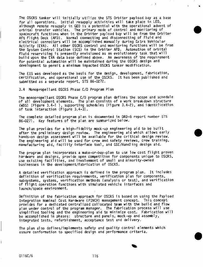
The OSCRS tanker w i l l i n i t i a l l y u t i 1 i z e the STS O r b i t e r payload bay as a base f o r a l l operat ions. I n i t i a l resupply a c t i v i t i e s w i l l take p lace i n LEO, al though remote resupply i n GEO i s a p o t e n t i a l w i t h the operat ional advent o f o r b i t a l t r a n s f e r veh ic les . The pr imary mode o f c o n t r o l and mon i to r ing of spacecraf t f u n c t i o n s when i n the O r b i t e r pay load bay w i l l be from the O r b i t e r A f t F l i g h t Deck (AFD). e l e c t r i c a l connectors w i l l be accomplished manually dur ing E x t r a Veh icu la r A c t i v i t y (EVA) . the System Contro l S t a t i o n (SCS) i n the O r b i t e r AFD. Automation o f o r b i t a l f l u i d r e s e r v i c i n g i s p r e s e n t l y env is ioned as an e v o l u t i o n a r y task t h a t w i l l b u i l d upon the EVA data base de f ined above. f o r p o t e n t i a l automation w i l l be mainta ined dur ing t h e OSCRS design and development t o p e r m i t a minimum impacted OSCRS tanker m o d i f i c a t i o n .
Normal connect ing and d isconnect ing o f f l u i d and
A l l o t h e r OSCRS c o n t r o l and mon i to r ing f u n c t i o n s w i l l be from
An awareness o f the requirement
The E I S was developed as the b a s i s f o r the design, development, f a b r i c a t i o n , c e r t i f i c a t i o n , and opera t iona l use o f the OSCRS. It has been pub l ished and submit ted as a separate r e p o r t , STS 86-0272.
3.4 Monopropellant OSCRS Phase C/D Program Plan
The monopropel lant OSCRS Phase C/D program p l a n de f ines the scope and schedule o f a l l development elements. (WBS) (F igure 3.4-1 ) , suppor t ing schedules (F igure 3.4-2), and i d e n t i f i c a t i o n o f task i n t e r a c t i o n (F igure 3.4-3).
The complete d e t a i l e d program p l an i s documented i n DRD-8 r e p o r t number STS 86-0271 . The p l an p r o v i des f o r a h i g h - f i d e l i t y mock-up engineer ing a i d t o be b u i 1 t a f t e r the p r e l i m i n a r y design review. The engineer ing a i d which a l lows e a r l y hands-on design assessment w i l l be a v a i l a b l e f o r the c r i t i c a l design review. The engineer ing a i d w i l l be used f o r crew and s a f e t y reviews, crew t r a i n i n g , manufactur ing aid, f a c i l i t y i n t e r f a c e t o o l , and GSE/Handl i n g design a id .
The program p l a n incorpora tes a make-or-buy-plan t o use low c o s t f l i g h t proven hardware and designs, p rov ide open compet i t ion f o r components unique t o OSCRS, use e x i s t i n g f a c i l i t i e s , and involvement o f small and minor i ty-owned businesses i n the development / fabr icat ion o f OSCRS.
The p l an c o n s i s t s o f a work breakdown s t r u c t u r e
Key f e a t u r e s o f the p l a n are sumnarired be l ow.
A d e t a i l e d v e r i f i c a t i o n approach i s de f ined i n the program plan. d e f i n i t i o n o f v e r i f i c a t i o n requirements, v e r i f i c a t i o n p l a n f o r components, subsystems, systems, v e r i f i c a t i o n methods ( a n a l y s i s o r t e s t ) , and v e r i f i c a t i o n of fl i g h t opera t ion f u n c t i o n s w i t h s imulated v e h i c l e i n t e r f a c e s and 1 aunch/space environment.
I t i n c l u d e s
D e f i n i t i o n o f the f a b r i c a t i o n approach f o r OSCRS i s based on us ing the Payload I n t e g r a t i o n Nominal Cost Hardware (PINCH) management concept. p rov ides f o r a dedicated c e n t r a l i z e d c o l l o c a t e d team w i t h t h e b u i l d and f l o w p l a n under c o n t r o l o f t h e program manager. The f a b r i c a t i o n process w i l l use s i m p l i f i e d t o o l i n g and the engineer ing a i d t o minimize cost . be accomplished i n phases: i n t e g r a t e d t e s t s , r e f u r b i shment, acceptance t e s t and d e l i v e r y .
The p l a n a1 so defines/implements sa fe ty and q u a l i t y c o n t r o l elements which assure conformat ion t o s p e c i f i e d design and performance c r i t e r i a .
Thi s concept
F a b r i c a t i o n w i l l s t r u c t u r e and panel s, mock-up and assembly,
01 16C/6 116
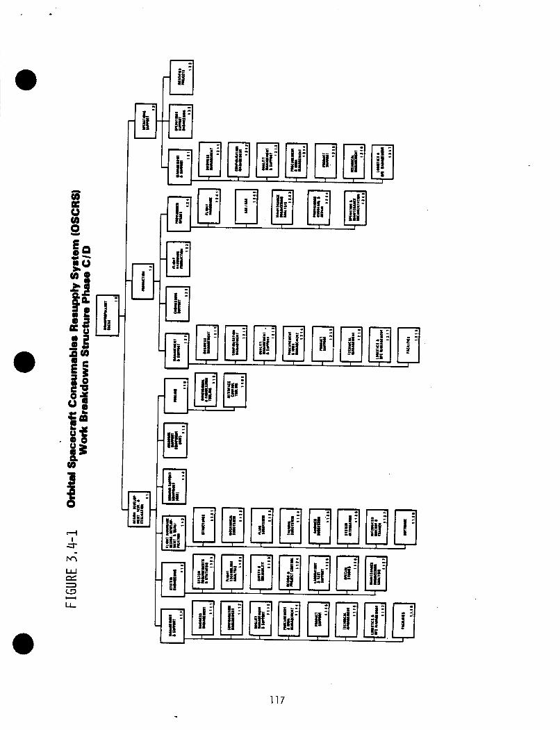
117
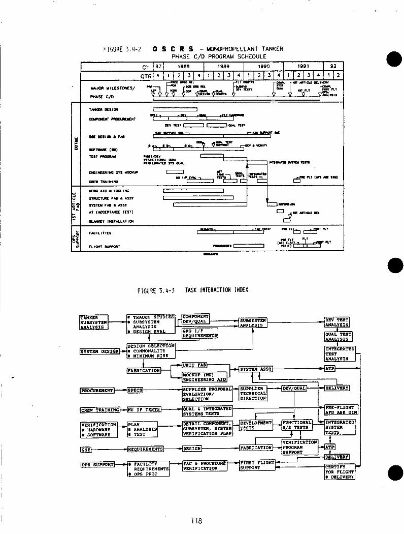
c
fAclLITlLS
FIGURE 3 . 4 - 3 TASK INTERACTION INDEX
@ SOFlWARE
r O R FLIGHT @ DELIVERY
118

.
This Page Intentionally Blank
119
4.0 Conceptual B i p r o p e l l a n t System Design (Study)
The conceptual b i p r o p e l l a n t OSCRS design study prov ides an assessment of the concept and i t s comnonal i ty w i t h the monopropel 1 a n t design. system design i s based on unique b ip rope l l a n t system, hardware/software, and opera t iona l t rade studies. The conceptual b i p r o p e l l a n t design inc ludes a d e f i n i t i o n o f the p o t e n t i a l comnonal i ty areas w i t h the monopropel 1 a n t system design and i d e n t i f i e s any design compromises r e q u i r e d t o achieve commonalites.
0 The b i propel 1 a n t
4.1 B i p r o p e l l a n t Unique Trade Studies
The t rade s tud ies presented i n paragraph 3.1, w h i l e p r i m a r i l y e v a l u a t i n g / d e f i n i n g the monopropel lant system design, a1 so considered b i p r o p e l l a n t system requirements t o the g r e a t e s t e x t e n t poss ib le . s tud ies presented here address the b i p r o p e l l a n t unique areas n o t p r e v i o u s l y eva lua ted and assures the c u r r e n t a p p l i c a b i l i t y o f t h e j o i n t t r a d e s tud ies.
4.1.1 System Design Requirements f o r Various F l u i d Retent ion Devices
The t r a d e
I n determining the b i p r o p e l l a n t OSCRS f l u i d t r a n s f e r subsystem design requirements, the type o f propel 1 a n t acqui s i t i o n device (PAD) be ing used by p o t e n t i a l resupply candidates, were i d e n t i f i e d f o r var ious p r o p e l l a n t t r a n s f e r processes: u l l a g e recompression, u l l a g e exchange, and u l l a g e vent / repressur iza t ion . i d e n t i f i e d t o accommodate the var ious PAD/transfer process combinations.
F1 u i d t r a n s f e r subsystem design o p t i o n s were
These o p t i o n s were evaluated under an I R & D study, P r o j e c t 86210. conclusions, and recomnendations from t h a t study have been excerpted and
The r e s u l t s ,
presented here f o r in fo rmat ion .
Numerous f l u i d t r a n s f e r subsystem designs were i d e n t i f i e d f o r the oi l -orbi t t r a n s f e r o f b i p r o p e l l a n t s . PAD used by r e c e i v e r vehic les, and the p r o p e l l a n t t r a n s f e r process b e s t s i r i ted f o r the r e c e i v e r v e h i c l e ' s p r o p u l s i o n system. be p l a c e d i n one o f f o u r general categor ies: t r a n s f e r subsystem design, p ressurant t r a n s f e r subsystem design, and the f l u i d disposal subsystem design.
The var ious design o p t i o n s depend on the type of
A l l o f the design o p t i o n s can tank/PAD design, p r o p e l l a n t
The s e l e c t i o n o f a tank/PAD design i s an impor tant step i n the low-g b i p r o p e l l a n t t r a n s f e r system. I n many cases the PAD des c o n s t r a i n the opera t iona l capabi l i t i e s o f the t r a n s f e r system; t r a n s f e r f l o w r a t e s and the system's opera t ing environment.
design of a yn w i l l such as the
The propel1 a n t t r a n s f e r subsystem and the pressurant t r a n s f e r ubsystem design d e f i n e the methods i n Nhich p r o p e l l a n t and pressurant are t r a n s f e r r e d from the resupply module t o the r e c e i v e r v e h i c l e s p ropu ls ion system.
I f the disposal o f res idua l p r o p e l l a n t and vent ing o f contaminated u l l a g e gas i s requi red, a f l u i d disposal subsystem would need t o be i n c o r p o r a t e d i n t o t h e resupply module design.
01 16C/7
F i v e PAD op t ions were i d e n t i f i e d a s p o t e n t i a l resupply r e c e i v e r tankage designs: sur face tens ion screens w/o u l l a g e p o s i t i o n i n g , sur face tens ion vanes, polymeric diaphragms, and we1 ded metal be l lows. Even though a n i t r o g e n t e t r o x i d e compat ib le po lymer ic diaphragm does n o t e x i s t , the PAD design was considered as a f u t u r e p o t e n t i a l r e c e i v e r and supply tankage PAD design.
surface tens ion screens w i t h an u l l a g e p o s i t i o n i n g c a p a b i l i t y ,
Several combinations o f r e c e i v e r v e h i c l e PAD designs versus t r a n s f e r processes were analyzed t o i d e n t i f y p o t e n t i a l p r o p e l l a n t t r a n s f e r scenarios. p r o p e l l a n t t r a n s f e r scenar ios were i d e n t i f i e d and are tabu1 a ted i n Table 4.1.1 -1 . The u l l age exchange resupply process, resupp ly ing e i t h e r a vane PAD o r a screen PAD w i t h o u t any u l l a g e c o n t r o l c a p a b i l i t i e s , were n o t cons idered as p o t e n t i a l resupply t r a n s f e r scenario. Since these two PAD designs do n o t have s u f f i c i e n t u l l a g e p o s i t i o n i n g c a p a b i l i t i e s , resupply propel1 a n t coul d unknowingly be t r a n s f e r o u t o f the r e c e i v e r tank ( through the u l l a g e t r a n s f e r tank out1 e t ) back i n t o the resupply tanker.
T h i r t e e n f l u i d t r a n s f e r system designs were i d e n t i f i e d t o accommodate the t h i r t e e n resupply scenarios. reduced the number of the OSCRS's f l u i d t r a n s f e r system designs t o th ree . These t h r e e designs are i l l u s t r a t e d i n F igure 4.1.1-1.
The o p t i o n 1 resupply subsystem design can resupply any type o f PAD, us ing the u l l a g e recompression t r a n s f e r process. The Opt ion 2 design can resupply P A D ' S w i t h u l l a g e p o s i t i o n i n g c a p a b i l i t i e s , us ing the u l l a g e t r a n s f e r process. Opt ion 3 i d e n t i f i e s a resupply subsystem which c o u l d resupply any type o f PAD, us ing the u l l a g e v e n t / r e p r e s s u r i z a t i o n t r a n s f e r process.
T h i r t e e n
Commonality among the subsystem design o p t i o n s
To s a t i s f y the resupply requirements o f a l l the p o t e n t i a l users o f o n - o r b i t p r o p e l l a n t resupply, the f l u i d t r a n s f e r subsystem design o f the OSCRS would need t o accomnodate a l l t h r e e methods o f p r o p e l l a n t resupply . Design Opt ion 1 can o n l y accomnodate u l l a g e recompression resupply m i ssions. Design Opt ions 2 and 3 can a1 so accomnodate u l l age recompression miss ions; however, i n a d d i t i o n t o u l l a g e recompression, the Opt ion 2 design can accomnodate u l l a g e exchange resuppl ies, and Opt ion 3 can accommodate u l l a g e v e n t / r e p r e s s u r i z a t i o n missions.
A s l i g h t m o d i f i c a t i o n t o the Opt ion 3 design (see F igure 4.1.1-1) would p e r m i t the subsystem t o accommodate u l l a g e exchange resupp l ies , i n a d d i t i o n t o the o t h e r two t r a n s f e r methods. 3 design i s the p r e f e r r e d f l u i d t r a n s f e r system design.
4.1.2
Because o f t h i s v e r s a t i l i t y , the m o d i f i e d Opt ion
On-Orbi t Venting and Dumping L i m i t a t i o n s f o r B i p r o p e l l an ts
ON-ORBIT VENTING
On-orbi t vent ing 1 i m i t a t i o n s f o r a conceptual b i p r o p e l l a n t resupply system are based on c u r r e n t contaminat ion 1 i m i t a t i o n s f o r the O r b i t e r , Space S t a t i o n and o ther spacecraf t users. The a p p l i c a t i o n o f these contaminat ion 1 i m i t s and the resu l t s o f m a t e r i a l exposure/compatibi 1 i ty t e s t s were eva lua ted under an I R & D study, P r o j e c t 86210. The r e s u l t s , conclusions, and recommendations f rom t h a t study have been excerpted and are presented here f o r in fo rmat ion .
01 16C/8 122
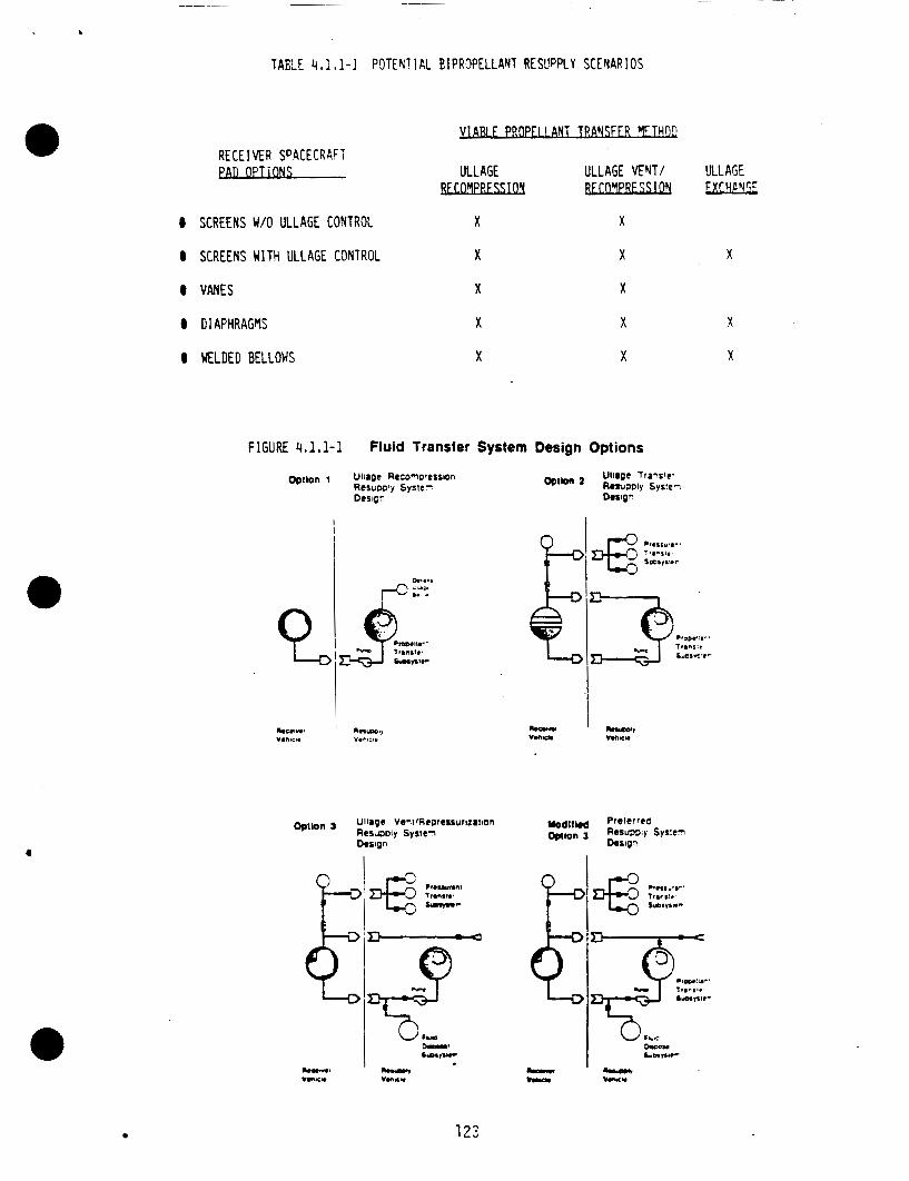
TABLE 4.1.1-1 POTEN!IAL E I P R 9 P E L L A W RESUPPLY SCENARIOS
c
R E C E I M R SPACECRAFT ea0 OPTiONS ULLAGE ULLAGE VENT/ ULLAGE - FXTYF,YC:
0 SCREENS WO ULLAGE CONTROL X X
0 SCREENS U l T H ULLAGE CONTROL X X X
0 VANES X X
0 DIAPHRAGVS X X X
I WELDED BELLOWS X X X
FIGURE 4,l.l-1 Fluid Transfer System Design Options
123
Exposure tes ts of MPlH and NTO t o Orbiter materials has Seen done by Garrard and Houston a t the Physical Chemistry Laboratory. The results of MMH exposure tes t s are discussed in the fo l lowing section. on spacecraft materials i s r a p i d degradation of strength, operations l i f e , and overall safety and re l iab i l i ty . A detailed summary of material affects i s presented i n the bipropellant conceptual design report per STS 86-0299. reported resul ts are from te s t s performed i n atmospheric conditions. How these results re la te to minor propellant exposures due t o venting o r small leaks i n the hard vacuum of space is unknown. are expected to be relatively benign.
Tile compatibility of Teflon FEP f i l m a n d Teflon covered beta cloth was determined by exposure t o l i q u i d MMH f o r 96 hours. material degradation was observed. was also noted t h a t vapor transmission occurred through the cloth, b u t riot 1 i q u i d .
In general, the affect of NTO
The
The suspected effects i n space
No visual evidence o f The fabric was wetted by the &lH and i t
Several t es t s were performed simulating a MMH sp i l l on a g roup ing of t i l e s , a thermal barrier and other samples t o t e s t the t i l e bond strength. the sp i l l t e s t s , the samples were tested fo r bond strength and examined fo r the amount of contamination and damage. Results show that MMH spil lage OII the TPS would be d i f f i c u l t t o decontaminate and can affect the strength of the t i l e bond. A fuel spil l would leave the TPS highly contaminated and very d i f f i c u l t t o clean because of the absorbtion characterist ics of the SIP , f i l l e r b a r , and possibly the t i l e . The Contaminated TPS would have t o be physically removed for decontamination and replacement. Examination of the failed specimens revealed some effect on the adhesive-to-Koropon bond. was no apparent reaction between MMH and SIP or the si l icon adhesive. change i n the t i l e bond strength appears t o be due t o mechanical effects resulting from f l u i d adsorption. B u t i t was noted that the SIP could be easily.peeled from the Koropon a f te r 6 weeks. the degradation of the bond may be time dependent. would be required t o verify this condition.
Following
There Any
There was an indication t h a t However, additional tes t s
An NTO sp i l l t h a t occurred on the pad a t KSC resulted i n the removal, direct or indirect, of over 300 t i l e s i n an area adjacent t o the RCS pod. resu l t of the s p i l l , t es t s were performed of the “splash/soak” type f o r NTO compatibility on materials either i n the spi l l area or adjacent t o i t such that they could have been exposed t o NTO vapor.
As a
OVERBOARD PROPELLANT DUMPING
Table 4.1.2-1 presents the resul t of a bipropellant dump study t h r o u g h the Centaur dump ports. MMH/NTO i n 225 seconds. The analysis indicated t h a t about 80% of the WIH/NTO i s dumped i n the liquid/solid phase w i t h the balance being vapor. surfaces that would be contaminated from a dump through the Centaur dump ports include: 1 ) upper wing and elevon, 2 ) fuselage, a n d 3 ) the lower OMS POD. I t was assumed that the FPJIH/NTO dump would be of suff ic ient d u r a t i o n t o be absorbed i n t o the TPS system to the extent t h a t the structure would be wet.
The analysis examined the dumping o f 9000 pounds of
The
124
763 5c/9
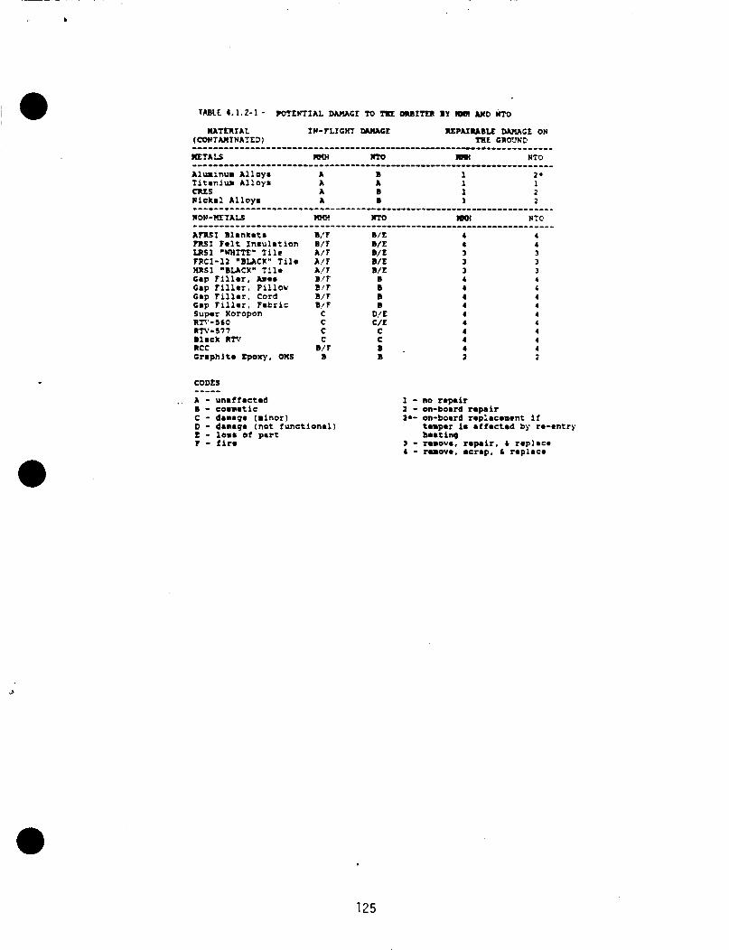
A t R S I Blanket* ?RSI felt Insulation LRSl .WHI?r* lilc TRCI-12 " B U C K " T i l e HRSI " B U C K " T i l e tap Tiller, h a s Gap Tiller, Pillow Gap f i l l e r , Cord Gap T i l l e r , Fatrlc Super Koropon R l T - 5 6 0 nn-s77 Black Rm RCC Graphlte Zp~x)~, OMS
B: F B / f A / f A / f A , l f B/f E!F B/f B/ f
C C C C
B/f B
COOLS ----- _ . A - unaffected
B - coeuetie C - damage (minor) D - damaqe (not functional) t - tome of part t - l i r e
4 4 3 3 3 4 4 4 4 4 4 4 4 4 1
4 4 3 3 3 4 4 4 4 4 4 4 4 4 2
1 - no repair 1 - on-board repair 2.- on-bomrd rephcement if
3 - remove, repair, b replace 4 - remove, mcrap. 6 replace
temper 1. affected by re-entry boating
125
4
The r e s u l t s are tabu la ted i n Table 4.1.2-1, b u t some o f the key r e s u l t s are as f 01 1 ows :
Waterproofing o f the TPS prov ides no p r o t e c t i o n f rom w e t t i n g by e i t h e r MMH o r NTO.
C-9 c o a t i n g on b l ankets w i l l n o t p revent I’.!MH/NTO f l u i d penet ra t ion .
A1 1 gap f i 1 l e r types w i l l absorb 1 i q u i d MMH/NTO.
NTO e n e r g e t i c a l l y a t tacks super Koropon pr imer and S IP .
Absorbed MMH i n b lankets w i l l be benign u n t i l a i r i s encountered. Atmospheric a i r can promote increased temperature and p o t e n t i a l a u t o i g n i t i o n .
concl us ion t o the 9000 1 b b i p r o p e l l an t dump study are:
MMH Dump
A p o t e n t i a l f i r e hazard w i l l e x i s t e i t h e r d u r i n g re -en t ry o r upon landing, when the MMH soaked TPS i n s u l a t i o n i s exposed t o heat and a i r .
The TPS i n s u l a t i o n w i l l probably be f u n c t i o n a l u n t i l a f i r e develops.
Vehicu lar s u r v i v a b i l i t y w i t h a TPS f i r e i s doubt fu l .
NTO Dump
Degradation of the super Koropon pr imer and S I P w i l l occur i n minutes when soaked i n NTO.
The degraded super Koropon pr imer i n t u r n w i l l cause the TPS i n s u l a t i o n adhesive t o debond f rom the s t r u c t u r e . a l s o w i l l cause t i l e l o s s .
TPS l o s s w i l l expose base aluminum 2024 T81 and g r a p h i t e sk ins t o re-ent ry heat ing (600°F m i nimurn) . A burn through on the OMS pod s k i n i s expected, exposing p r o p e l l a n t tanks t o h o t gases.
The degraded S I P
F a i l u r e o f a propel 1 a n t tank i s conceivable.
The i n f o r m a t i o n f rom the phys ica l chemistry l a b and the A&P group i s considered as extreme contaminat ion t e s t i n g , p a r t i c u l a r l y the 9000 l b dump i n 225 seconds, b u t the r e s u l t s do i n d i c a t e some 1 i m i t a t i o n s t h a t can be appl i e d t o the vent ing o f b i p r o p e l l ants.
CONCLUSIONS ABOUT ON-ORBIT VENTING OF BIPROPELLANTS
The conclusions and recommendations o f on o r b i t ven t ing o f b i p r o p e l l a n t s i s presented below.
1 ) B i p r o p e l l a n t s must be e x p e l l e d w i t h minimal p o t e n t i a l o f c o n t a c t w i t h the O r b i t e r , spacecraf t , o r resupply tanker.
01 16C/10 126
For the O r b i t e r , the Centaur dump p o r t s are considered as unacceptable f o r b i p r o p e l l a n t s i n the l i q u i d h o l i d phase. p o t e n t i a l f o r O r b i t e r damage/contamination i s t o o great . But, dump p o r t s t h a t r u n o u t o f t h e a f t f u s e l age may be acceptable; f u r t h e r ana lys is i n t h i s area i s requi red.
I f MMH/NTO must be dumped o u t o f the Centaur dump p o r t s , i t should be i n the vapor phase only .
The
NTO even as a vapor i s considered as a h i g h l y c o r r o s i v e chemical w i t h the c a p a b i l i t y o f damaging the resupply tanker, O r b i t e r , and spacecra f t over extended per iods o f t i m e .
External Contamination o f the resupply tanker o r the O r b i t e r can r e q u i r e extens ive decontamination procedures be fore reuse.
MMH dumped as vapor presents a p o t e n t i a l f i r e hazard on ly if i t i s absorbed i n t o the TPS i n s u l a t i o n i n s u f f i c i e n t q u a n t i t y t o s a t u r a t e the i n s u l a t i o n . This i s n o t an expected problem.
.
There are i n d i c a t i o n s t h a t MMH contaminat ion e f f e c t s are t ime dependent. designed l i f e t i m e .
Thus there i s a concern o f m a t e r i a l f a i l u r e before t h e
B i p r o p e l l a n t Hardware A v a i l a b i l i t y
An assessment o f the a d d i t i o n a l hardware r e q u i r e d f o r a b i p r o p e l l a n t resupply system i d e n t i f i e d s p e c i f i c components. These components requirements were evaluated i n d e t a i l under an IR&D study, P r o j e c t 86210 t o i d e n t i f y hardware avai 1 ab i 1 i t y , weight, power requi red, p o t e n t i a1 suppl i e r and present q u a l i f i c a t i o n s ta tus . conceptual b i p r o p e l l a n t resupply systems.
@ This data i s presented i n DRD-6 (STS 86-0299) f o r the -
4.1.4 F1 u i d Capacity and Tankage S i z i n g
User requirements were examined t o determine the type and volume o f OSCRS serv ices requi red. The b i p r o p e l l a n t users r e s u l t s are tabu1 ated i n Table 2.1-2. These r e s u l t s d r i v e the b i p r o p e l l a n t OSCRS design t o a maximum b i p r o p e l l a n t capaci ty o f 7,000 1 bs .
Rockwell proposes t h a t the s t r u c t u r a l design and dimensions of the b i p r o p e l l a n t OSCRS be the same as i t s monopropellant counterpar t . s t r u c t u r a l geometry evolves f rom a 12-sided polyhedron per iphery around a c e n t r a l hexagon c a v i t y . This geometry r e s u l t s i n s i x , 39 inch-square by 51.7 i n c h long compartments, c o n t a i n i n g 6 p r o p e l l a n t tanks ( 3 f u e l and 3 o x i d i z e r ) .
Several propel1 a n t tanks designs have been i d e n t i f i e d f o r p o t e n t i a l a p p l i c a t i o n i n the b i p r o p e l l a n t OSCRS. The phys ica l and opera t ing c h a r a c t e r i s t i c s of these tank designs are t a b u l a t e d i n Table 4.7.4-7.
The GRO propel 1 a n t tank i s a p o t e n t i a1 b i p r o p e l l a n t OSCRS’ tank candidate. Unfor tunate ly , the e x i s t i n g PAD design cannot be used w i t h the o x i d i z e r . The PAD i s a polymeric diaphragm, which i s n o t compat ib le w i t h Ni t rogen Tetrox ide (NTO). However, the polymeric diaphragms are compat ib le w i t h f u e l s , Monomethyl Hydrazine (MMH) and Aerozine-50 (A-50). The MMH capac i ty o f t h e GRO tank was c a l c u l a t e d t o be 1075 l b s .
The bas ic
0 01 1 6C/11 127
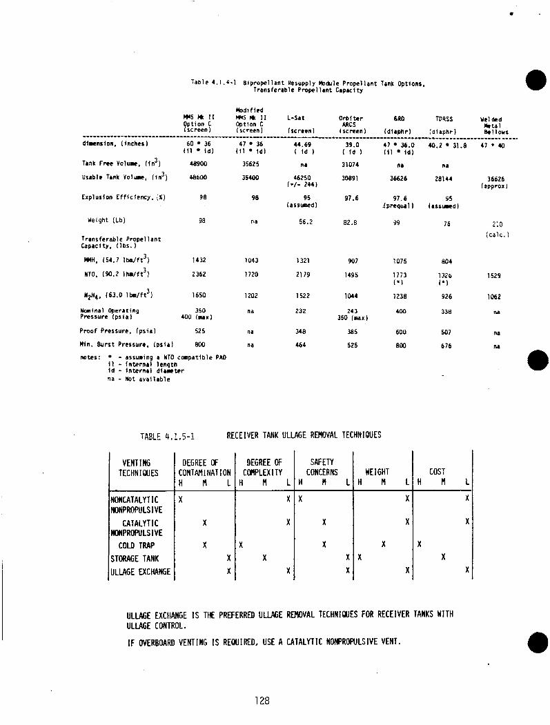
SAFETY CONCERNS
Table 4.1.4-1 Bipropel lant Resupply nDdule Propellant Tank Options, Transferable Propellant Capacity
UE I GHT H M L H M L
dimension, ( inches)
I(
X
X X X
Tr9k Free Volume, ( in3 )
Usable frnk Volume, ( l n 3 )
X
X
X
X X
Explusion E f f l c i ency . ; X )
X
Weigh: (Lb)
x x
Trans ferable Propel 1 an t Capacity, I l b s . )
M”, 154.7 1 h / f t 3 )
NTO. (90.2 1t,.,/ft3)
3 N2H4, (63.0 l b d f t
Nominal Operating Pressure f p s i a )
Proof Pressure, (ps ia )
60 36 111 i d )
48900
48600
98
9a
1432
2 362
1650
350 (00 I N N )
525
Min. Burst Pressure, I p s i a l 800
notes: - assuming a IT0 c m p a t i b l e PA0 11 - In te rna l l eng th i d - In te rna l d i r r t e r na - Not ava i l ab le
47 36 44.69 I f 1 i d ) I i d
35625 nr
35400 46250
98 95
1*/- 244)
(assumed)
na 56.2
1043 1321
1720 21 79
1202 1522
na 232
na 348
na 464
39.0 ( i d
3 1074
30891
91.6
82.8
907
1495
1044
24 3 350 ( m x )
385
525
TABLE 4 I 1 a 5-1 RECEIVER TANK ULLAGE REMOVAL TECHNIQUES
VENT I NG TECHNIQUES
ONCATALY T IC ONPROPULS I V E
CATALYTIC ONPROPULSIVE
COLD TRAP TORAGE TANK L U G E EXCHANGE
DEGREE OF DEGREE OF :ONTAMINATION COMPLEXITY i M L I H M L
47 36.0 (11 i d )
n r
36626
97.6 l p requa l )
39
1075
1773 ( * I
1238
400
600
800
X
X
40.2 31.8 47 * 40
n r
28144 36626 lapprox !
45 ( rSSucled I
76 213 i c a l c . )
804
132b 1529 I*)
926 lo62
338 na
507 na
676 na
cos: H M L
X
X
X X
X
ULLAGE EXCHANGE IS THE PREFERRED ULLAGE REMOVAL TECHNIQUES FOR RECEIVER TANKS M T H ULLAGE CONTROL I
IF OVERBOARD VENTING IS REQUIRED, USE A CATALYTlC NWROPULSIVE VENT.
128
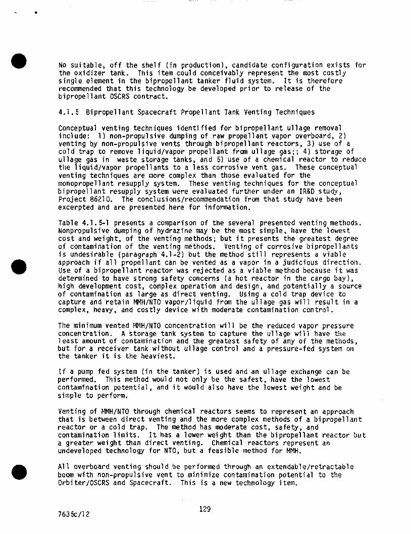
No su i tab le , o f f the s h e l f ( i n product ion), candidate con f igu ra t i on e x i s t s f o r the ox id i ze r tank. s i n g l e element i n the b i p r o p e l l a n t tanker f l u i d system. recommended t h a t t h i s technology be developed p r i o r t o re lease o f the b i p r o p e l l an t OSCRS contract .
This i tem could conceivably represent the most c o s t l y It i s there fore
4.1.5 B ip rope l l an t Spacecraft Prope l lan t Tank Venting Techniques
Conceptual vent ing techniques i d e n t i f i e d f o r b i p r o p e l l a n t u l l age removal inc lude: 1 ) non-propulsive dumping o f raw p rope l l an t vapor overboard, 2) vent ing by non-propulsive vents through b i p r o p e l l a n t reactors , 3 ) use o f a c o l d t r a p t o remove 1 iquid/vapor propel1 ant from u l lage gas; ; 4 ) storage o f u l lage gas i n waste storage tanks, and 5) use o f a chemical reac tor t o reduce t i le 1 i q u i d/vapor propel 1 ants t o a 1 ess cor ros ive vent gas. These conceptual vent ing techniques are nore complex than those evaluated f o r the monopropel 1 an t resupply system. These vent ing techniques f o r the conceptual b i p r o p e l l a n t resupply system were evaluated f u r t h e r under an IR&D study, P ro jec t 8621 0. The conclusions/recommendation from t h a t study have been excerpted and are presented here f o r informat ion.
Table 4.1.5-1 presents a comparison o f the several presented vent ing methods. Nonpropulsive dumping o f hydrazine may be the most simple, have the lowest, c o s t and weight, o f the vent ing methods; bu t i t presents the greatest degree o f contamination o f the vent ing methods. Venting o f cor ros ive b ip rope l l an ts i s undesirable (paragraph 4.1-2) bu t the method s t i l l represents a v iab le approach i f a l l p rope l l an t can be vented as a vapor i n a j ud i c ious d i r e c t i o n . Use o f a b i p r o p e l l a n t reac tor was re jec ted as a v iab le method because i t was determined t o have s t rong safety concerns (a h o t reac tor i n the cargo bay), h igh development cost , complex operat ion and design, and p o t e n t i a l l y a source o f contamination as l a rge as d i r e c t venting. capture and r e t a i n MMH/NTO vapor / l i qu id from the u l l age gas w i l l r e s u l t i n a complex, heavy, and c o s t l y device w i t h moderate contamination con t ro l .
Using a c o l d t rap device t o
The minimum vented MMH/NTO concentrat ion w i l l be the reduced vapor pressure concentration. l e a s t amount o f containination and the greatest safety o f any o f the methods, b u t f o r a rece iver tank wi thout u l l age con t ro l and a pressure-fed system oti the tanker i t i s the heaviest.
A storage tank system t o capture the u l l age w i l l have the
I f a pump fed system ( i n the tanker) i s used and an u l l age exchange can be performed. contaminat ion po ten t i a l , and i t would a l s o have the lowest weight and be simple t o perform.
This method would no t on ly be the safest , have the lowest
Venting of MMH/NTO through chemical reac tors seems t o represent an approach t h a t i s between d i r e c t vent ing and the more complex methods o f a b i p r o p e l l a n t reac to r or a c o l d t rap. contamination l i m i t s . a greater weight than d i r e c t venting. Chemical reactors represent an undeveloped technology f o r NTO, b u t a feas ib le rnethod f o r MMH.
The method has moderate cost , safety , and It has a lower weight than the b i p r o p e l l a n t reac tor b u t
A1 1 overboard vent ing should be performed through an extendable/ re t ractabl e boom w i t h non-propulsive vent t o minimize contamination po ten t i a l t o the Orbiter/OSCRS and Spacecraft. This i s a new technology item.
0
763 k / l 2 129
The conclusions and recomnendations of this section i s presented below.
Since the spacecraft will contain a ullage transfer quick disconnect t o return ullage t o the tanker f o r disposal - ullage exchange i s the preferred method f o r receiver tanks w i t h u l l age control capabil i ty . If venting i s required and the receiver tanks do not have ullage control capability then the residual propellant should be removed t o the tanker t o minimize MMH/NTO disposal problems.
After the residual propellant i s removed then the propellant saturated ullage can be disposed of by one of the suggested methods t h r o u g h a non-propulsive vent which i s removed from the Orbi terhpacecraf t vicinity by a retractable boom.
Development o f small chemical reactors i s recommended t o handle the disposal of the propel 1 a n t saturated u l l age.
H4H disposal can be potentially performed by two types of reactors. One, by using a spontaneous catalyst b u t concentrating on the carbon deactivation problem. Two, by using a nonspontaneous catalyst w i t h a iodine pentoxi de ignitor.
NTO disposal by chemical reactor wi l l require some developmental work t o se lec t an adequate solid fuel reactant.
Thermal Control Techni que/Hardware
There is no significant difference between the bipropellant tanker thermal control system and t h a t developed for the monopropellant tanker, except f o r added thermal instrumentation.
Table 4.1.6-1 shows 185 sensors are required f o r the bipropellant tanker. hundred t h i r t y three (133) sensors are used f o r thermal control and 52 are used for other purposes such as: valve fai lure detection, PVT gauging, etc.
One
4.1.7 Optimization of Bipropellant Avionics Control
The concepts for p r o v i d i n g crew control of a bipropell a n t consumabl es resupply system from the orbiter a f t f l i g h t deck differ from the concepts f o r a monopropellant control system i n several areas, such as:
o A generic bipropellant avionics control system must be more highly automated than a simple monopropellant system i n order t o s u p p o r t eventual remote operations and increased complexity safely.
o The emergency separation system for the bipropellant system i s significantly different from a monopropellant system, since a remote automatic umbilical i s proposed f o r bipropellant designs versus pyrotechnic devices t h a t separate monopropellant f l u i d l ines.
I 01 16C/13 130
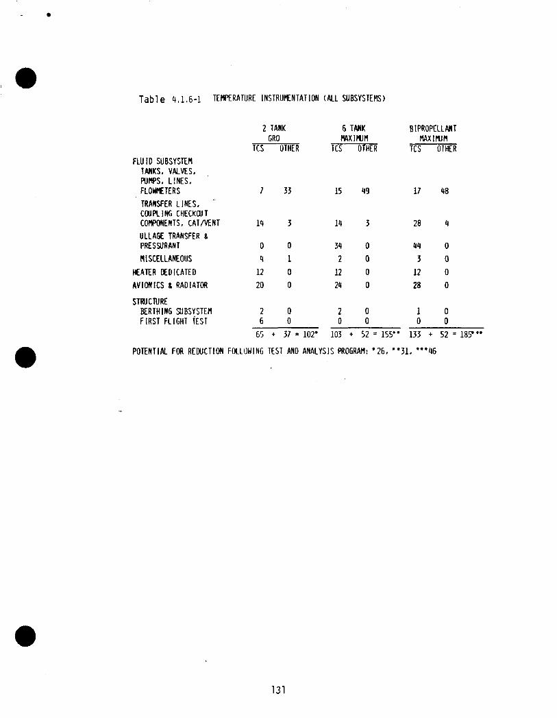
Tab1 e 4,1 ,6-1 TEMPERATURE INSTRUMENTATION (ALL SUBSYSTEtlS)
FLU I D SUBSYSTEM TANKS, VALVES, PUMPS. L I N E S . FLOWHETERS TRANSFER LINES. . COUPLING CHECKWT COMPONENTS, C A T M N T ULLAGE TRANSFER 8 PRESSURANT flISCELLANEOUS
HEATER DEDICATED AVIONICS 8 RADIATOR
STRUCTURE BERTHING SUBSYSTEM F I R S T FLIGHT TEST
2 TANK 6 TANK GRO W IWM
TCS OTHER TCS OTHER
7
14
0 4 12 20
2 6
33 15
3 14
0 34 1 2 0 12 0 24
0 2 0 0
49
3
0 0 0 0
0 0
BIPROPELLMT MXllZlM
TCS OTHER
17
28
44 3 12 28
1 0
48
4
0 0 0 0
0 0
65 + 37 = 102' 103 + 52 = 155" 133 + 52 = 187"
POTENTIAL FOR R E W C T I O N FOLLOWING TEST AND ANALYSIS PROGRAM: '26. "31, "'46
131
The concepts f o r c o n t r o l o f the gener ic b i p r o p e l l a n t av ion ics system were evaluated under in-house I R & D study P r o j e c t 86210. The conclus ion & recomnendations f rom the IR&D study are presented h e r e i n f o r in fo rmat ion .
I
The func t ions t o be c o n t r o l l e d by the b i p r o p e l l a n t resupply av ion ics system are shown i n F igure 4.1.7-1. f o r each o f the f u n c t i o n s l i s t e d and a lso shows whether the f u n c t i o n s are c o n t r o l l e d by hardwire switches on the crew c o n t r o l panel o r are c o n t r o l l e d automati c a l l y by FMDM' s on the tanker module.
The l a y o u t o f the b i p r o p e l l a n t resupply c o n t r o l panel l o c a t e d on the AFD i s shown i n F igure 4.1.7-2. The switches t o p rov ide the prev ious ly i d e n t i f i e d hardwired c o n t r o l f u n c t i o n s are shown on the panel. The panel a lso inc ludes the crew c o n t r o l /s ta tus panel which prov ides redundant dedicated c o n t r o l and s t a t u s paths t o the. FMDM's which c o n t r o l the automatic func t ions .
The t a b l e shows the number o f commands r e q u i r e d
The automatic FMDM sequences which c o n t r o l the b i p r o p e l l a n t system c r i t i c a l o p e r a t i ons can only be i n i ti ated by crew a c t i v a t i o n o f the ARM/EXECUTE switches on the Crew Control /Status Panel. p resent data descr ib ing the planned FMDM sequence t o a s s i s t the crew i n s e l e c t i n g and a c t i v a t i n g sequences.
The two-1 i n e message d isp lays
4.1.8 Launch S i t e Operations
The processing operat ions o f a b i p r o p e l l a n t tanker a t KSC w i l l d i f f e r f r o m those o f t h e OSCRS monopropel lant tanker. i d e n t i f i e d as: (1) types o f p r o p e l l a n t s used; ( 2 ) s a f e t y concerns, (3 ) GSE requirements, and (4 ) process ing schedule. These d i f f e r e n c e s were i n v e s t i g a t e d under an in-house I R & D Study, P r o j e c t 86210.
The main conc lus ion o f t h i s study i s t h a t the f a c i l i t i e s a t bo th KSC and VAFB are capable o f processing a b i p r o p e l l a n t system equa l ly as w e l l as a monopropel 1 a n t system. be exercised, however, the opera t ing personnel are f ami 1 i a r w i t h hand1 i ng both commodities and no unusual problems are foreseen. The process ing schedule of a b i p r o p e l l a n t tanker w i l l i n c l u d e more s e r i a l t i m e operat ions due t o the two p r o p e l l a n t s , thereby lengthen ing the turnaround schedule. Also, the o x i d i z e r s e r v i c i n g opera t ion a t VAFB w i l l be performed i n the PCR a t the Launch Mount p r i o r t o i n s t a l l a t i o n o f the tanker i n t o the payload bay o f the O r b i t e r .
These d i f f e r e n c e s have been
There are a d d i t i o n a l s a f e t y precaut ions t h a t have t o
4.1.9 Landing S i t e Operations
The turnaround processi ng operat ions f o r a b i propel 1 an t tanker a t the 1 andi ng s i t e may d i f f e r f r o m those o f the OSCRS monopropel lant tanker. d i f ferences c o u l d be a t t r i b u t e d t o the f o l l o w i n g : hypergo l i c p r o p e l l a n t s ; (2) e f f e c t on the turnaround processing schedule. The in-house I R & D Study, P r o j e c t 8621 0, i n v e s t i g a t e d the d i f fe rences .
Some of the
the s a f e t y and handl ing concerns, and ( 3 ) t h e (1 ) Use o f the two
i 01 16C/14 132
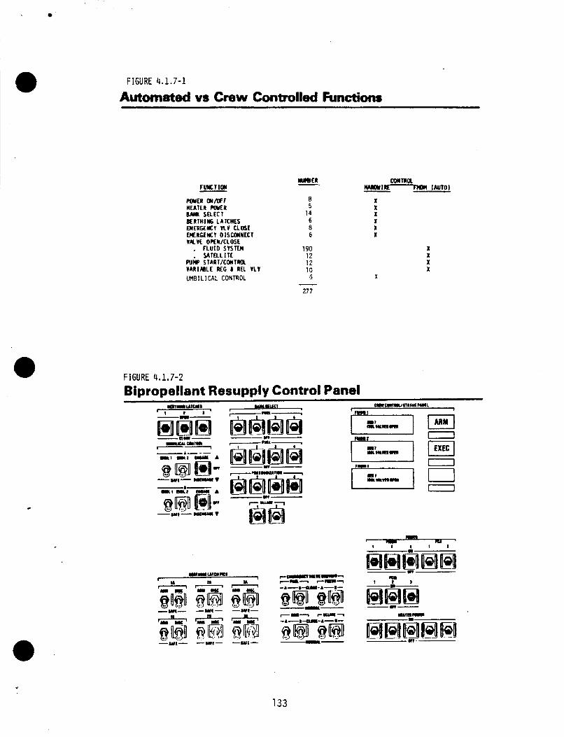
a
FIGURE 4,1.7-1
Automated vs Crew Controlled Functions
FUWCTION - mrn OIMFF
mEnC+tcy nv c L m r
MEATtR POVCR BAUK SrLECI BERTHIM6 LATCHES
OERGrMY DIScOINrcl VMVL OPfN/CLOSE . FLUID SYSTEII
SATELL I TE Pub START/CWTRU VARIMLE REG b REL VLV UMBILICAL CONTROL
8 5
14 6 8 6
190 12 1 2 10 G
277
X
I l I I l
-e- r-1
- ._ -wt- -wI- -wt-
133
The b i p r o p e l l a n t tanker ground processing opera t ions f o l l o w i n g a successful r e s e r v i c i n g miss ion w i l l n o t vary much from those o f a monopropel lant tanker . The storage, handl ing and sa fe ty aspects o f monomethyl hydrazine are the same as f o r hydrazine. f u e l s are the same. Likewise, s i m i l a r , i f n o t i d e n t i c a l GSE can be u t i l i z e d on e i t h e r program. processing opera t ions t o the turnaround t ime and increases the sa fe ty concerns. system which w i l l be s i m i l a r t o t h a t f o r the f u e l system i n concept, b u t u s i n g components compat ib le w i t h the o x i d i z e r .
4.1.10 GSE and F a c i l i t y Operat ions
Therefore, the t e s t i n g , checkout and s e r v i c i n g o f these two
The i n c l u s i o n o f an o x i d i z e r system on the tanker adds
There w i l l be a complete s e t o f GSE r e q u i r e d f o r the o x i d i z e r
The GSE i d e n t i f i e d f o r the OSCRS b i p r o p e l l a n t tanker program may n o t be t o t a l l y usable on the monopropel lant tanker program due t o : two d i f f e r e n t p rope l lan ts ; ( 2 ) the sa fe ty and hand l ing concerns, and (3 ) design c o m p a t i b i l i t y . the same processing f a c i l i t i e s as used w i t h the monopropel lant tanker i s quest ionable due t o : ( 1 ) the use o f a d i f f e r e n t f u e l ; ( 2 ) the a d d i t i o n of an o x i d i z e r system, and ( 3 ) the sa fe ty concerns. These quest iondble i tems were i n v e s t i g a t e d under an in-house I R & D Study, P r o j e c t 86210.
( 1 ) the use of
Also, i n the area of f a c i l i t y opera t ions the use o f a l l
A f t e r rev iewing the conceptual designs f o r the monopropel 1 a n t tanker harial i ng GSE, i t was determined t h a t these designs are d i r e c t l y usable and c o u l d p o s s i b l y be shared on the b i p r o p e l l a n t program, schedule p e r m i t t i n g . It was a l s o determined t h a t w h i l e the p r o p e l l d n t s e r v i c i n g and checkout GSE conceptual designs are adequate f o r the b i p r o p e l l a n t tanker program, a separate s e t o f each w i l l be r e q u i r e d f o r bo th the o x i d i z e r and f u e l systems. There are some unique i tems of GSE t h a t w i l l nave t o be procur red o r f a b r i c a t e d f o r each o f the b i propel 1 a n t systems.
Review o f the KSC f a c i l i t i e s recornended f o r use on the OSCRS (monopropel lant) tanker program has shown t h a t the o n l y f a c i l i t y t h a t i s suspect i s the Hazardous Processing F a c i l i t y . The HPF recommended f o r use as a dedicated OSCRS b i p r o p e l l a n t f a c i l i t y i s Cryogenics # l . c o u l d be made capable o f hand l ing bo th a monopropel lant and a b i p r o p e l l a n t tank e r p rog ram.
T h i s f a c i l i t y , when mod i f ied ,
4.1 .ll B i p r o p e l l a n t System Weight and Power Ana lys is
A sumnary o f the i n d i v i d u a l subsystem weights f o r a maximum growth b i p r o p e l l a n t resupply system i s presented i n Table 4.1 .11-1. Tota l es t imated system masses are 3331 1 bm and 11,876 lbm f o r dry and wet s y s t e m r e s p e c t i v e l y .
I n order t o c a l c u l a t e b i p r o p e l l a n t system power requirements, the f o l l o w i n g assumpti on s were made :
( 1 ) Only two GRID computers w i l l be opera t ing a t t h e same t ime, and they w i l l use o r b i t e r power.
( 2 ) The tanker w i l l o n l y be subjected t o s h o r t d u r a t i o n c o l d soak per iods. b u t on ly an average o f o n e - t h i r d o f the heaters w i l l be i n opera t ion on a time-averaged bas is .
Therefore a1 1 heaters coul d be energ ized simul taneously,
01 1 6C/15 134
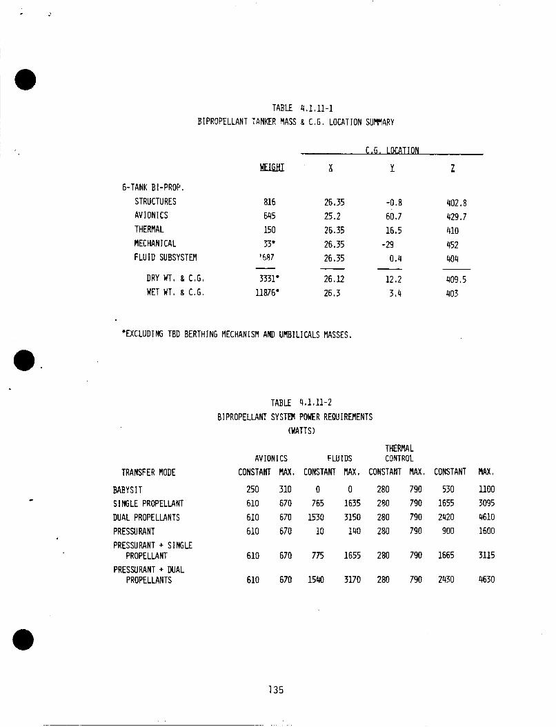
I .
TABLE 4.1.11-1 BIPROPELLANT TANKER MASS 8 C . G , LOCATION SUMMARY
C . G . 1 OcBI lON
"I X Y Z 6-TANK BI-PROP,
STRUCTURES ai6 26.35 -0.8 402.3 AV ION1 CS 645 25.2 60.7 429.7
MECHANICAL 33. 26.35 -29 452 FLUID SUBSYSTEM 1597 26.35 0.4 404
THERMAL 150 26.35 16.5 '110
- DRY WT, 8 C.G. 3331' 26.12 12.2 409.5 WET WT, 8 C . G . iia76* 26.3 3.4 403
'EXCLUDING TBD BERTHING MECHANISM AND UMBILICALS MASSES.
a. TABLE 4.1.11-2
BIPROPELLANT SYSTM POWER REQUIREMENTS (WATTS)
TRANSFER MODE
BABYSI T SINGLE PROPELLANT DUAL PROPELLANTS PRESSURANT PRESSURANT + SINGLE
PROPELLANT PRESSURANT + DUAL
PROPELLANTS
THERMAL AVI ON I CS FMIDS CWTROL
CONSTANT MAX. CONSTANT MAX. CONSTANT MAX. CONSTANT MAX,
250 310 0 0 280 790 530 1100 610 670 765 1635 250 790 1655 3095 610 670 1530 3150 280 790 2420 4610 610 670 10 140 280 790 goo 1600
610 670 775 1655 280 790 1665 3115
135
A maximum of 2 fluid system isolation valves will be operated simultaneously. All valves are "dual-latching" and do not require power a f te r actuation (valve position indicator power d r a i n i s considered negligible).
U1 lage recompression transfer mode is used (resul ts in highest power consumption).
Fuel and oxidizer transfer is sl ightly staggered so t h a t the two systems do not draw maximum power a t the same time.
Number of transfer pumps and electronic regulators i n operation simultaneously i s defined by the transfer mode.
All numbers are based on a maximum resupply mission ( i . e . , 6 propellant tanks and 6 pressurant t anks ) .
Fluids subsystem and portions of avionics subsystem will be powered down d u r i n g launch and re-entry.
Table 4.1.11-2 presents a sumnary of the bipropellant system power requirements. The results indicate that the peak power required t o transfer fuel, oxidizer, and pressurant sirnul taneously would be 4630 watts. power drain fo r the same transfer mode would be s l ight ly under 2500 wat ts .
Continuous
4.2 Conceptual Desi gn/Documentation
The bipropellant OSCRS system design/documentation builds on the monopropel 1 a n t resupply trade studies of paragraph 3.1 supplemented by the unique bipropellant system trade studies of paragraph 4.1. The conceptual bipropellant design implements commonality w i t h the monopropellant OSCRS.
The bi propel lan t tanker concept u t i 1 izes the monopropel lan t tanker s t ructure , and basic avionics and thermal subsystems, and incorporates a bipropellant fluid storage and distribution system i n place o f the high monopropellant hydrazine system. The fluid system also incorporates a h i g h and low pressure pressurant resupply source, a spacecraft ullage transfer system which includes a means of disposing of the propellant contaminated ullage gases, and provisions for receiving spacecraft residual propellants. The s a t e l l i t e specific berthing interfaces are not defined so a space on the +Z ( t o p ) side o f the tanker i s reserved for instal l ing the TBD mechanism. of fluid coupl ing interfaces (8-12 or more) required t o provide redundant interfaces with the receiver bipropellant spacecraft will necessitate development of an automatic umbil ical interface coupl i n g which should be remotely operable.
The large number
Definition of the basic system design and structural concept includes:
o Structural Definition o Fluid Subsystem Design (Schematic) o Avionics Subsystem Design (Schematic) o Thermal Control Subsystem Definition o Assessment of Unique Safety Hazards
136 763 k / l 6
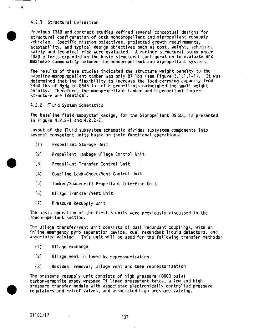
4.2.1 S t r u c t u r a l D e f i n i t i o n
Prev ious IR&D and c o n t r a c t - s t u d i e s de f ined several conceptual designs f o r s t r u c t u r a l c o n f i g u r a t i o n o f b o t h monopropel 1 a n t and b i p r o p e l l a n t resupply vehic les. a d a p t a b i l i t y , and t y p i c a l design o b j e c t i v e s such as cos t , weight, schedule, safety and techn ica l r i s k were evaluated. A f u r t h e r s t r u c t u r a l study under IR&D e f f o r t s expanded on the b a s i c s t r u c t u r a l c o n f i g u r a t i o n t o evaluate and maximize comnonal i ty between t h e monopropel 1 a n t and b i propel 1 a n t systems.
S p e c i f i c miss ion o b j e c t i v e s , p r o j e c t e d growth requirements,
The r e s u l t s o f these s tud ies i n d i c a t e d t h e s t r u c t u r e we igh t pena l ty t o the b a s e l i n e monopropel lant tanker was on ly 87 l b s (see F i g u r e 3.1.1 . l - 1 ) . determined t h a t t h e f l e x i b i l i t y t o increase the l o a d c a r r y i n g capac i ty from 2450 l b s of N2H4 t o 8545 l b s o f b i p r o p e l l a n t s outweighed the small weight pena l ty . Therefore, the monopropel lant tanker and b i p r o p e l l a n t tanker s t r u c t u r e are i dent i ca l .
It was
4.2.2 F l u i d System Schematics
The base l ine f l u i d subsystem design, f o r the b i p r o p e l l a n t OSCRS, i s presented i n F igure 4.2.2-1 and 4.2.2-2.
Layout of the f l u i d subsystem schematic d i v i d e s subsystem components i n t o several convenient u n i t s based on t h e i r f u n c t i o n a l
(1 )
( 2 ) Propel1 a n t Tankage U11 age Control U n i t
( 3 ) P r o p e l l a n t Transfer Contro l U n i t
(4 ) Coup1 i n g Leak-Check/Vent Control U n i t
( 5)
( 6 )
(7 ) Pressure Resupply U n i t
Propel 1 a n t Storage U n i t
Tanker/Spacecraf t Propel 1 a n t I n t e r f a c e Un
U11 age Tran s fer /Vent U n i t
The b a s i c opera t ion o f the f i r s t 5 u n i t s were prev monopropel 1 a n t sect ion.
operat ions:
t
ous ly discussed i n the
The u l l a g e t r a n s f e r / v e n t u n i t c o n s i s t s of dual redundant coupl ings, w i t h an i n l i n e emergency pyro separat ion device, dual redundant 1 i q u i d detectors , and associated va lv ing . Th is u n i t w i l l be used f o r the f o l l o w i n g t r a n s f e r methods:
(1 U11 age exchange
(2 ) Ul lage vent f o l l o w e d by r e p r e s s u r i z a t i o n
( 3 ) Residual removal , u l l age vent and then r e p r e s s u r i z a t i o n
The pressure resupply u n i t c o n s i s t s o f h i g h pressure (8000 p s i a ) carbon-graphi te expoy wrapped T i l i n e d pressurant tanks, a low and h i g h pressure t r a n s f e r module w i t h associ a ted e l e c t r o n i c a l l y c o n t r o l 1 ed pressure r e g u l a t o r s and r e l i e f valves, and associated h i g h pressure va lv ing .
01 16C/17 137
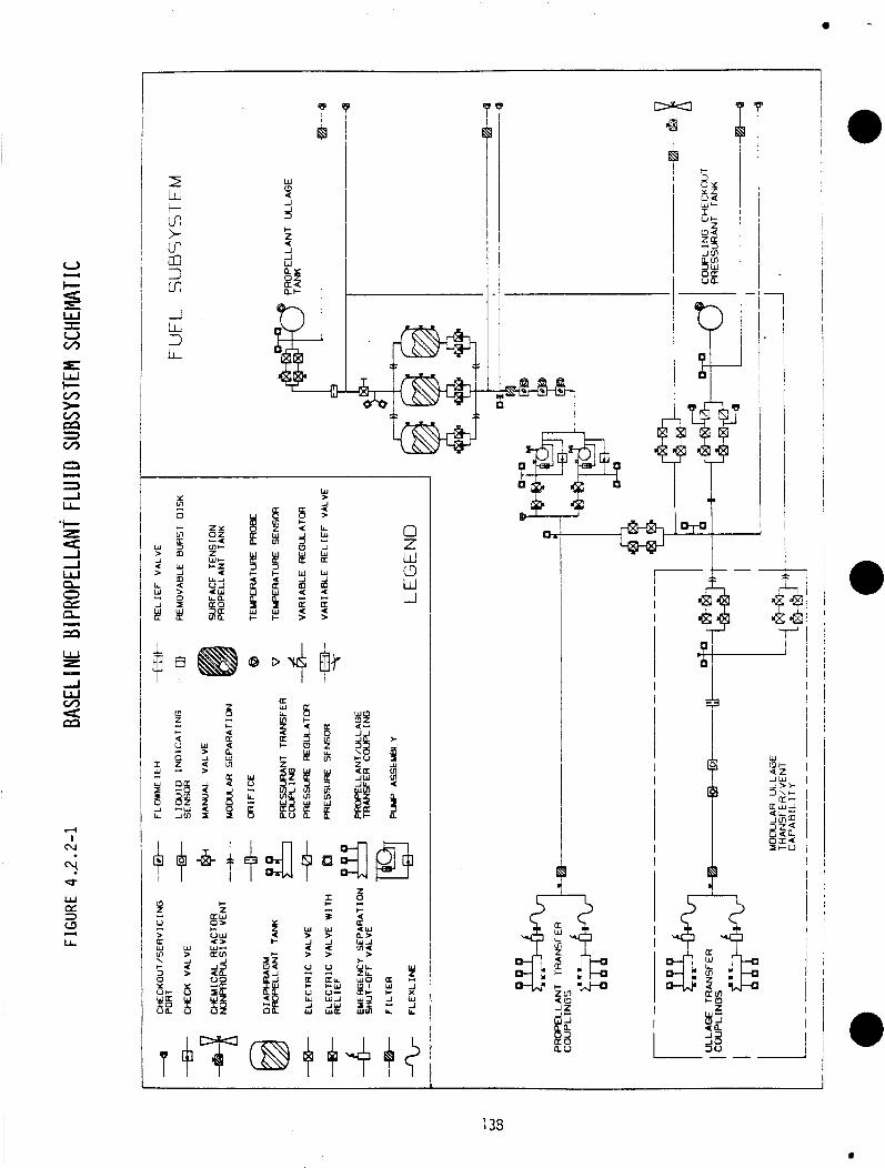
b D 1 1 ' 3 P D 1
I
I
I
L l -
F T m
Y k!
w z - w v) 4 m
4 I
(v
A I- I
3
w > J < >
2 alL t - W V- w A J W w a
t- z a w
O W t- V U < w W-
J 23 40
a m I L L
r_ i: W J ll.
T 9T @ + H f i 133
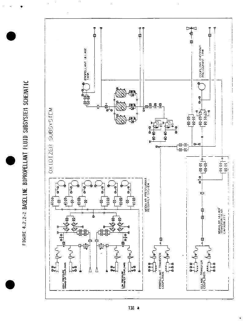
I rn
m L
I
I T cu I
(v
I
I I
I Y
LL
138 a
4.2.3 Av ion ics System Schematic
The d e s c r i p t i o n o f an av ion ics system p r e l i m i n a r y design f o r a b i p r o p e l l a n t OSCRS system would be v i r t u a l l y the same as the d e s c r i p t i o n o f the monopropel lant OSCRS a v i o n i c s system g iven i n 3.2.3.
The gener ic a v i o n i c s system concept was purposefu l l y de f ined t o p rov ide a s i n g l e bas ic design t h a t c o u l d be u t i l i z e d w i t h the basel ined, r e l a t i v e l y simple, GRO resupply m i s s i o n and t h a t woul d support o t h e r monopropell a n t miss ions as we l l as f u t u r e b i p r o p e l l a n t resupply missions, w i t h o u t s i g n i f i c a n t design changes.
A b lock diagram f o r the b i p r o p e l l a n t a v i o n i c s i s shown i n F igure 4.2.3-1. The major d i f f e r e n c e between t h i s diagram and the monopropel lant a v i o n i c s b lock diagram, F igure 3.2.3-1, i s i n the area o f the emergency separat ion system.
I n the base1 i n e d b i p r o p e l l a n t resupply system, an automated u m b i l i c a l assembly would be employed f o r f l u i d and e l e c t r i c a l l i n e s connect ing the tanker nodule t o the r e c e i v i n g sate1 1 i te. separat ion w i t h o u t EVA, t h e r e f o r e the b i p r o p e l l a n t a v i o n i c s system woul d n o t i n c l u d e the pyrotechnic devices f o r emergency separat ion o f f l u i d supply 1 ines and e l e c t r i c a l l i n e s t o the s a t e l l i t e , as had been i n c l u d e d i n the monopropel 1 a n t system design. Emergency di sconnect pyro ' s woul d s t i 11 be r e q u i r e d f o r the b e r t h i n g l a t c h e s however, as shown. number o f P I C ' S i n the Emergency Separat ion C o n t r o l l e r . The number of crew-operated pyro ARM-FIRE switches on the AFD Control Panel are a l s o reduced.
The automated umbi 1 i c a l woul d p e r m i t emergency
This change reduces the
The number of FMDM u n i t s and SCjPCM u n i t s woul d remain the same, th ree of each, i n the b i p r o p e l l a n t a v i o n i c s design. However, requirements t o handle increased numbers of c o n t r o l func t ions and measurements f o r a b i p r o p e l l a n t system would be accommodated by adding modules t o the i n i t i a l box designs. @ The number o f Power Control Assemblies (PCA's) woul d increase i n the b i p r o p e l l a n t a v i o n i c s design. PCA's woul d be requi red. b i p r o p e l l a n t systems and s a t e l l i t e s t o be serviced, and i s l i k e l y h igh . number o f PCA's c o u l d e a s i l y drop t o f o u r as a b e t t e r understanding i s gained of the number o f f u n c t i o n s t o c o n t r o l and measure.
The c u r r e n t conservat ive es t imate i s t h a t s i x
The Th is est imate was made w i t h 1 i t t l e Val i d data on the
The added a v i o n i c s on the tanker would be mounted i n the upper most t r i a n g u l a r bay.
4.2.4 Thermal System D e f i n i t i o n
The p r e l i m i n a r y thermal c o n t r o l system design f o r the monopropel 1 a n t tanker , shown i n F igure 3.2.4.2-1, w i l l support the b i p r o p e l l a n t OSCRS opera t ions under a1 1 c o n d i t i o n s f o r any m i ss ion durat ion. r e q u i r e d t o op t im ize the design and t o v e r i f y the thermal subsystem capabi l i t i e s .
Add i t iona l a n a l y s i s i s
4.2.5 Ins t rumenta t ion and Signal Cond i t ion ing
A conceptual desiqn f o r an ins t rumenta t ion system capable o f determining system i n t e g r i t y and performance o f a b i p r o p e l l a n t resupply system would be v i r t u a l l y the same as f o r the monopropel lant OSCRS tanker.
139 01 16C/18
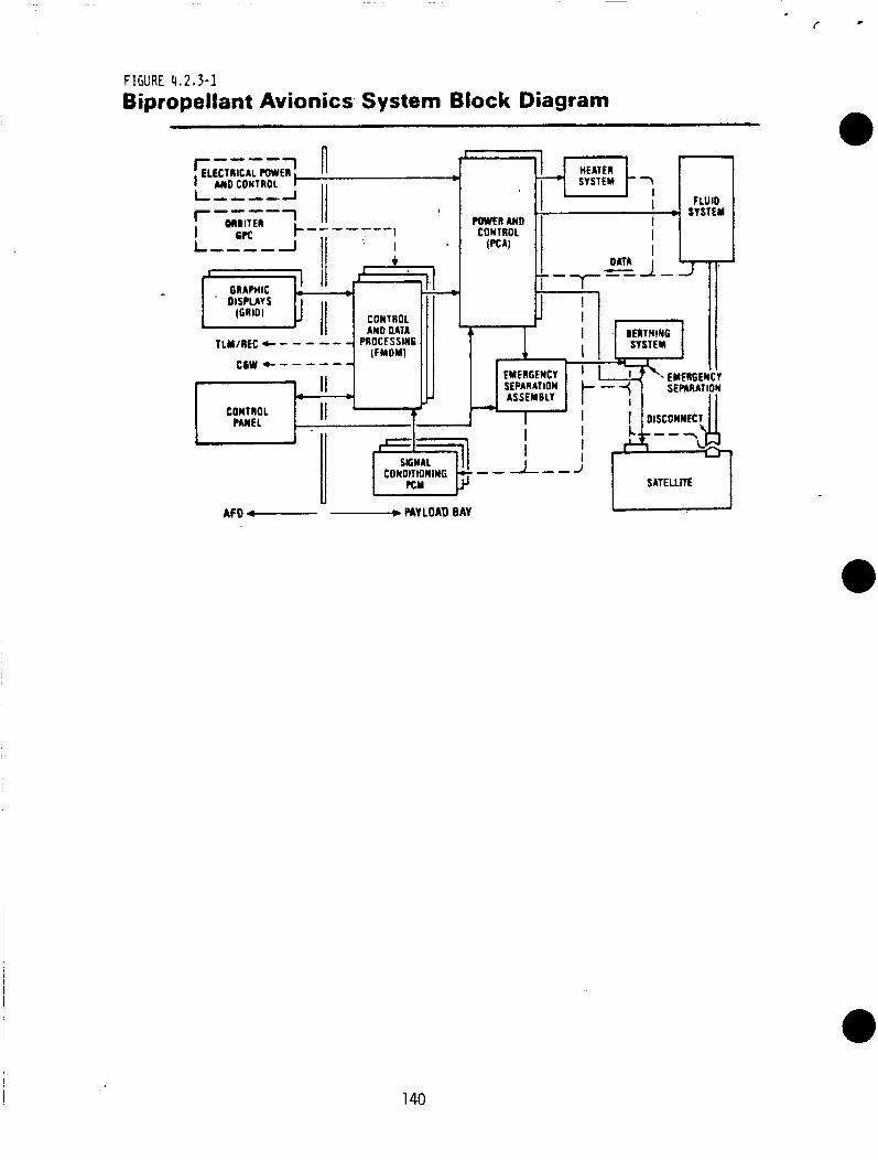
FIGURE 4 , 2 , 3 - 1 Bipropellant Avionics System Block Diagram
U AFD c--- - PAY LOAD BAY
140
The number and types o f measurements would increase f o r a b i p r o p e l l a n t resupply system and w i l l be f u l l y de f ined i n the Phase C/D program.
4.2.6 Pre l im inary Safety/Hazard Ana lys is
The p r e l i m i n a r y hazard ana lys i s o f the OSCRS b i p r o p e l l a n t system design i d e n t i f i e d o n l y those hazards which are unique t o a b i p r o p e l l a n t system ( p r e v i o u s l y i d e n t i f i e d p o t e n t i a l hazards f o r the monopropel lant system a1 SO apply t o the b i p r o p e l l a n t system). From a sa fe ty standpoint , growth from a monopropel lant resupply system t o a b i p r o p e l l a n t system w i l l r e s u l t i n a d d i t i o n a l p o t e n t i a l hazards o n l y i n the f l u i d subsystems. The conceptual b i p r o p e l l a n t design poses no a d d i t i o n a l hazards f o r the o t h e r subsystems ( e l e c t r i c a l /av ion ics, pyrotechnics, thermal c o n t r o l , s t ruc tu res , and mechanical ) . As w i t h the monopropel lant system, no p o t e n t i a l waivers o r d e v i a t i o n s have been i d e n t i f i e d aga ins t t h e requirements o f t h e NHB 1700.7A o r KHB 1700.7 and no unacce t e d r i s k s have been i d e n t i f i e d a g a i n s t the p o t e n t i a l hazards f o r the b i p r o p e l P a n t design.
The f o l l o w i n g are the i d e n t i f i e d p o t e n t i a l hazards which are unique t o a b i p r o p e l l a n t system:
Oxi d i z e r Leakage/Spi 11 age
The leakage/spi 11 age o f o x i d i z e r can corrode the surrounding s t r u c t u r e and elements which can a l s o l e a d t o a p o t e n t i a l l y t o x i c atmosphere.
Unintended Mix o f Fuel and Ox id izer
The unintended mix o f f u e l and o x i d i z e r w i l l r e s u l t i n a f i r e which can p o t e n t i a l l y cause the l o s s o f l i f e , o r b i t e r / v e h i c l e s , and o t h e r payloads.
Aerozi ne-50 E x ~ o sure t o Vacuum 0
Aerozine-50 (A-50) i f exposed t o vacuum can f reeze w i t h i n cause a r u p t u r e o r exp los ion due t o i t s subsequent expans
the system and on dur ing thaw
4.3 Commonal i ty Assessment
The designs t h a t have been determined f o r both the monopropel lant and b i p r o p e l l a n t tanker subsystems have been compared c o n t i n u a l l y throughout v a r i o u s t r a d e s tud ies i n t h e i r s p e c i f i c areas and hardware elements f o r comnonal i ty . STRUCTURE
can ng.
Dur ing the t r a d e s tud ies i n t h e s t r u c t u r a l area i t has been shown t h a t the base1 i n e open t r u s s s a t i s f i e s b o t h monopropel 1 a n t and b i propel 1 a n t tankers and subsystem designs w i t h very small p e n a l t i e s i n we igh t and l a r g e savings i n c o s t and schedules. monopropel 1 a n t and b i p r o p e l l a n t tankers.
As a r e s u l t , the same s t r u c t u r e i s proposed f o r bo th the
141 01 16C/19
MECHANISMS
The NASA NAS9-17333 fuel transfer coup1 ing use will be 1 imi ted t o the monopropellant tanker and a new, remote, and automatic transfer umbilical should be developed for the bipropellant tanker.
The berthing interface ut i l iz ing the FSS latches may well be limited in use t o the baseline monopropell a n t tanker. spacecraft have n o t been defined a t this time. should be developed by the NASA.
I
Berthing interfaces beyond the GRO A generic berthing interface
FLUID SUBSYSTEM
There are three significant differences between a monopropell a n t f lu id subsystem and a bipropellant f luid subsystem. quanti t i e s are 2.8 times greater than the base1 ine monopropel 1 a n t requi rements (7,000 pounds). 3 fue l ) . Secondly, the bipropellant system has two independent propellant storage and feed systems for the fuel and oxidizer. The fuel system can be coimnon/or i dentical, t o the monopropel 1 a n t tanker system. However, the oxidizer components must be cer t i f ied compatible w i t h NTO. Finally, since most bipropell a n t systems have a pressure-regul ated feed system, the u l l age must be disposed o f prior t o or dur ing the propellant resupply and pressurant repl eni shment w i 11 be required, necessitating the need f o r a pressurant transfer system.
The baseline bipropellant
This creates a need for six propellant tanks ( 3 oxidizer and
The bipropellant tanker would be sized t o nominally resupply up t o 7,000 pounds of propellant. fuel tanks and three equally sized oxidizer tanks with surface tension propellant management devices. The fuel flow control system could be the same a s the one used on the monopropellant tanker. system could be different depending on how the spacecraft ullage i s handled.
Most bipropell a n t spacecraft systems operate by a pressure-regul ated feed system. T h i s requires disposing of the ullage p r io r t o o r during the propel 1 a n t resupply. Pressurant repl eni shment i s then required. Di sposal o f the spacecraft tank ull age coul d be accompli shed by several approaches, b u t the key t o all techniques requires a definite means of separating the ullage from the propellant in the spacecraft tanks. To meet this requirement, the spacecraft tanks must contain a liquid-free vent system t h a t allows decreasing the ullage volume by up to 90 percent without expelling the bulk propellant. To achieve this , a unique liquid/gas separator will have to be developed f o r the spacecraft tanks. device (diaphragm or bellows) in the spacecraft tanks.
This could be contained i n three GRO-type diaphragm
The oxidizer f luid control
An alternate would be t o use a positive expul sion
THERMAL CONTROL SUBSYSTEM
I With the exception of the f luid transfer assembly, a l l thermal control designs and components appear comnon between monopropel 1 a n t and bipropell a n t designs. Coup1 ing comnonality will be assessed pending a transfer assembly design.
01 16C/20 142
A V I O N I C S SUBSYSTEM
A h igh degree o f commonality e x i s t s between the monopropellant and b i p r o p e l l a n t av ion ics systems def ined under the OSCRS study. ob jec t i ve i n a l l the av ion ics study tasks was t o de f ine concepts t h a t would support growth w i thout major design changes. were there fore se lected t h a t would support the r e l a t i v e l y simple GRO resupply mission, b u t which could be expanded t o support the s ix- tank monopropellant mr'ssion, o r a b i p r o p e l l a n t resupply mission, through modular add i t ions t o the sys tem.
A major
Components and system concepts
.Three FMDM's would be used f o r a l l OSCRS app l ica t ions . Addi t ional p lug- in modules would be added as the number o f funct ions t o be c o n t r o l l e d and measured increased.
The number o f Power Control Assemblies (PCA's) would increase as add i t iona l c a p a b i l i t y was required. mission, two more o f the i d e n t i c a l u n i t s would be added t o support the monopropellant gravth concept, and tMo more PCA's would be requ i red f o r the b i p r o p e l l a n t resupply missions ( f o r a t o t a l o f s i x ) .
Two i d e n t i c a l PCA's would be used f o r the GRO
Three S i gnal Condi tioner/PCM u n i t s woul d be used - fo r a1 1 OSCRS appl i ca t i o r l s . The se lected design employs a modular concept, however i t i s n o t a p lug- in concept s ince the nodules must be permanently w i red i n place. Therefore, some phys ica l redesign would be requ i red t o increase the number o f modules as OSCRS data requirements increase. .
The same Emersenc.y Seuaration Control Assernblv would be used f o r a l l OSCRS app l i ca t ions . - The n u h e r o f p lug- in pyrotechnic c o n t r o l l e r assemblies (PIC'S) would be changed as OSCRS requirements f o r pyro operated devices changed . The i d e n t i c a l G R I D computers would be used on the a f t f l i g h t deck f o r a l l OSCRS missions.
The dedicated OSCRS crew con t ro l panel would conta in some switches and d isp lays t h a t would be comnon t o a l l OSCRS missions, however, the panels will be d i f f e r e n t . Prov is ions would be made f o r the add i t i on of switches t o con t ro l add i t i ona l resupply funct ions, and f o r de le t i on o f some pyrotechnic con t ro l switches which would be expected t o decrease as fu tu re automatic umbi 1 i cal concepts are introduced.
OSCRS software w i l l employ a modular design concept t o prov ide a h igh l eve l o f commonality f o r a l l resupply missions. Requirements w i l l be imposed t o design the OSCRS software so t h a t c e r t a i n core func t ions are establ ished t h a t w i l l be app l i cab le t o a l l missions and w i l l n o t change. The c a p a b i l i t y w i l l a l so be provided t o develop software modules conta in ing mission-unique con t ro l and data requirements, t h a t w i l l be prepared i n d i v i d u a l l y f o r a p a r t i c u l a r mission and w i l l be in tegra ted w i t h the core sof tware modules p r i o r t o the mission. This concept permits a h igh percentage o f the OSCRS software t o be comoii f o r a l l resupply missions, w i thout change. Changes would be incorporated us ing the mission-unique software modules.
143 7 63 %/21
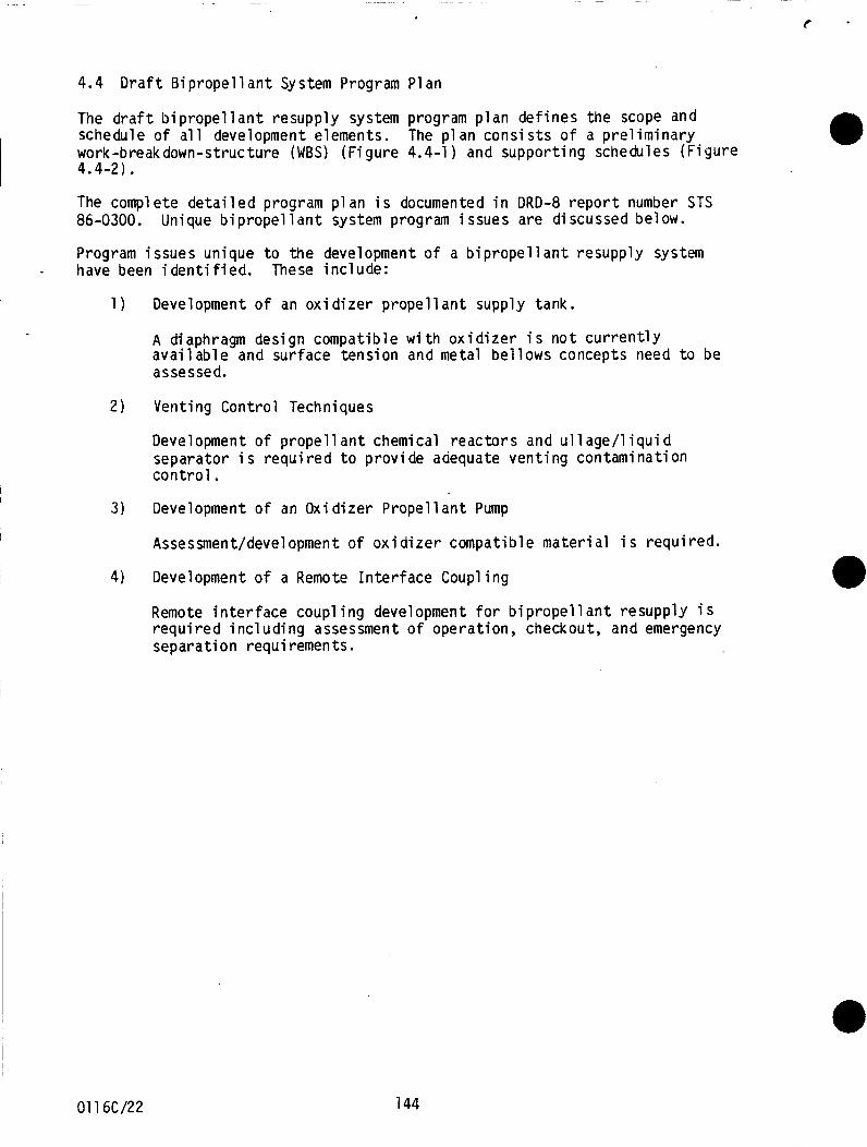
4.4 Draft Bipropellant System Program Plan
The draft bipropellant resupply system program p l a n defines the scope and schedule of all development elements. The plan consists of a preliminary work-breakdown-structure (WBS) (Figure 4.4-1 ) and supporting schedules (Figure 4.4-2).
The compl ete detailed program p l an i s documented in DRD-8 report number STS 86-0300.
Program issues unique t o the development of a bipropellant resupply system
Unique bipropellant system program issues are discussed below.
- have been identified. These include:
1 ) Development of an oxidizer propellant supply t a n k .
A diaphragm design compatible with oxidizer i s n o t currently available and surface tension and metal bellows concepts need t o be assessed.
2 ) Venting Control Techniques
Development of propel1 a n t chemical reactors and ull age/l iqui d separator i s required t o provide adequate venting contamination control.
3) Development of an Oxidizer Propellant Pump
Assessment/development of oxidizer compatible material i s required.
4) Development of a Remote Interface Coupling
Remote interface coup1 ing development for bipropellant resupply i s required including assessment of operation, checkout, and emergency separation requirements.
01 16C/22 144
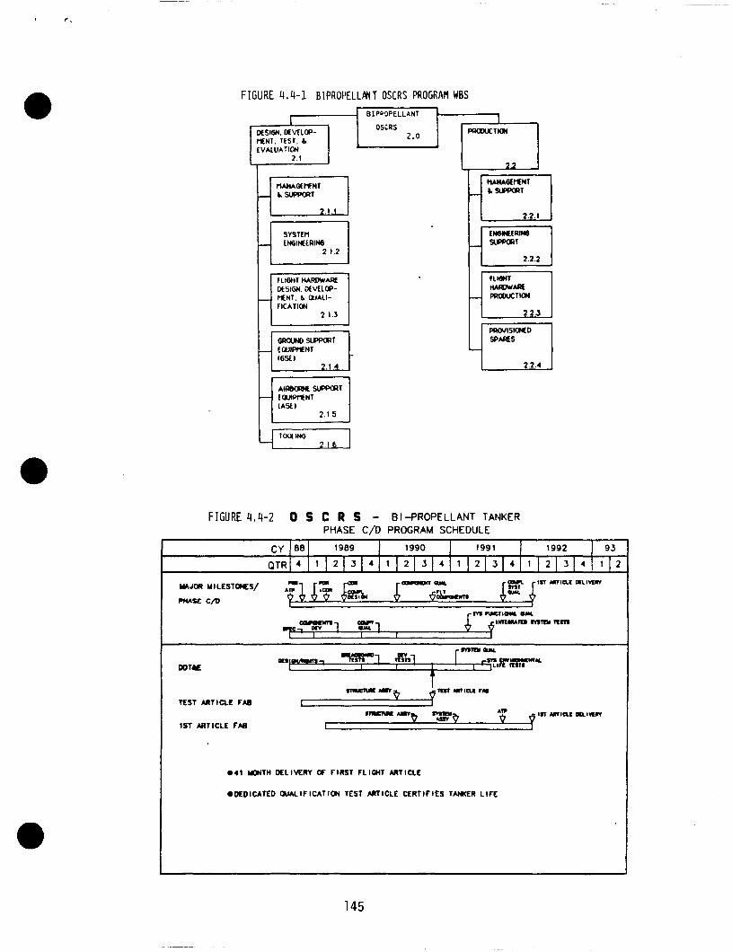
0
a
F I G U R E 4.4-1 BIPROPELLPNT OSCRS PROGRAM WBS
OCstGM. MMLB- MEW. TE5r. L
SYSTt I l LMSIHERW
f LIGMT HAI)(IW*AE
MENT. h WALI- FlCATlOJ
DtSIGM. MVLLW-
F I G U R E 4,4-2 0 S C R S - BI-PROPELLANT TANKER PHASE C/O PROGRAM SCHEDULE
0 4 1 UWTH DELIVERY OF FIRST FLIGHT M T I C L E
.DEDICATED OUALIFICATION TEST ARTICLE CERTIFIES TAmER L IFE
145
Related Documents