Oracle Utilities Meter Data Management/Smart Grid Gateway Administrative User Guide Release 2.2.0.2 E91718-01 January 2018

Welcome message from author
This document is posted to help you gain knowledge. Please leave a comment to let me know what you think about it! Share it to your friends and learn new things together.
Transcript
Oracle UtilitiesMeter Data Management/Smart GridGatewayAdministrative User GuideRelease 2.2.0.2E91718-01
January 2018

2
Oracle Utilities Meter Data Management/Smart Grid Gateway Administrative User Guide
Release 2.2.0.2
E91718-01
January 2018
Documentation build: 1.5.2018 15:25:14 [D1_1515183914000]
Copyright © 2010, 2018, Oracle and/or its affiliates. All rights reserved.
This software and related documentation are provided under a license agreement containing restrictions on use and disclosure and are protected
by intellectual property laws. Except as expressly permitted in your license agreement or allowed by law, you may not use, copy, reproduce,
translate, broadcast, modify, license, transmit, distribute, exhibit, perform, publish, or display any part, in any form, or by any means. Reverse
engineering, disassembly, or decompilation of this software, unless required by law for interoperability, is prohibited.
The information contained herein is subject to change without notice and is not warranted to be error-free. If you find any errors, please report
them to us in writing.
If this is software or related documentation that is delivered to the U.S. Government or anyone licensing it on behalf of the U.S. Government, then
the following notice is applicable:
U.S. GOVERNMENT END USERS: Oracle programs, including any operating system, integrated software, any programs installed on the
hardware, and/or documentation, delivered to U.S. Government end users are "commercial computer software" pursuant to the applicable Federal
Acquisition Regulation and agency-specific supplemental regulations. As such, use, duplication, disclosure, modification, and adaptation of the
programs, including any operating system, integrated software, any programs installed on the hardware, and/or documentation, shall be subject to
license terms and license restrictions applicable to the programs. No other rights are granted to the U.S. Government.
This software or hardware is developed for general use in a variety of information management applications. It is not developed or intended for
use in any inherently dangerous applications, including applications that may create a risk of personal injury. If you use this software or hardware
in dangerous applications, then you shall be responsible to take all appropriate fail-safe, backup, redundancy, and other measures to ensure its
safe use. Oracle Corporation and its affiliates disclaim any liability for any damages caused by use of this software or hardware in dangerous
applications.
Oracle and Java are registered trademarks of Oracle and/or its affiliates. Other names may be trademarks of their respective owners.Intel and Intel
Xeon are trademarks or registered trademarks of Intel Corporation. All SPARC trademarks are used under license and are trademarks or registered
trademarks of SPARC International, Inc. AMD, Opteron, the AMD logo, and the AMD Opteron logo are trademarks or registered trademarks of
Advanced Micro Devices. UNIX is a registered trademark of The Open Group.
This software or hardware and documentation may provide access to or information about content, products, and services from third parties.
Oracle Corporation and its affiliates are not responsible for and expressly disclaim all warranties of any kind with respect to third-party content,
products, and services unless otherwise set forth in an applicable agreement between you and Oracle. Oracle Corporation and its affiliates will not
be responsible for any loss, costs, or damages incurred due to your access to or use of third-party content, products, or services, except as set forth
in an applicable agreement between you and Oracle.
3
ContentsFramework Administrative User Guide.........................................................................................................19
Defining General Options...................................................................................................................................................19Defining Installation Options........................................................................................................................................... 19
Installation Options - Main...........................................................................................................................................19Installation Options - Messages.................................................................................................................................. 20Installation Options - Algorithms................................................................................................................................. 20Installation Options - Accessible Modules.................................................................................................................. 22Installation Options - Installed Products......................................................................................................................22
Support For Different Languages................................................................................................................................... 23User Language............................................................................................................................................................ 23Customer Language.................................................................................................................................................... 24Defining Languages.....................................................................................................................................................24
Defining Countries...........................................................................................................................................................25Country - Main.............................................................................................................................................................25Country - States.......................................................................................................................................................... 26
Defining Currency Codes................................................................................................................................................26Defining Time Zones.......................................................................................................................................................26
Designing Time Zones................................................................................................................................................ 26Setting Up Time Zones............................................................................................................................................... 27Setting Up Seasonal Time Shift..................................................................................................................................27
Defining Geographic Types............................................................................................................................................ 28Defining Work Calendar..................................................................................................................................................28Defining Display Profiles.................................................................................................................................................29
Additional Hijri Date Configuration.............................................................................................................................. 31Defining Phone Types.................................................................................................................................................... 31Setting Up Characteristic Types & Values..................................................................................................................... 31
There Are Four Types Of Characteristics...................................................................................................................31Searching By Characteristic Values............................................................................................................................33Characteristic Type - Main.......................................................................................................................................... 33Characteristic Type - Characteristic Entities............................................................................................................... 34
Setting Up Foreign Key Reference Information............................................................................................................. 34Information Description Is Dynamically Derived..........................................................................................................35Navigation Information Is Dynamically Derived...........................................................................................................35Search Options............................................................................................................................................................ 36Foreign Key Reference - Main....................................................................................................................................36
Defining Feature Configurations..................................................................................................................................... 37Feature Configuration - Main...................................................................................................................................... 38Feature Configuration - Messages..............................................................................................................................38
Defining Master Configurations.......................................................................................................................................38Defining Security & User Options...................................................................................................................................... 39
The Big Picture of Application Security..........................................................................................................................39Application Security..................................................................................................................................................... 39Action Level Security...................................................................................................................................................41Field Level Security..................................................................................................................................................... 41Encryption and Masking.............................................................................................................................................. 42
System Encryption................................................................................................................................................... 42User Interface Masking............................................................................................................................................ 43Application Encryption..............................................................................................................................................47
The Base Package Controls One User, One User Group, And Many Application Services.......................................49Importing Security Configuration from an External Source.........................................................................................49
The Big Picture of Row Security.................................................................................................................................... 50Defining Application Services......................................................................................................................................... 50
Application Service - Main...........................................................................................................................................50Application Service - Application Security...................................................................................................................51
Defining Security Types..................................................................................................................................................51Security Type - Main................................................................................................................................................... 51
Defining User Groups..................................................................................................................................................... 52User Group - Main...................................................................................................................................................... 52

4
User Group - Application Services..............................................................................................................................52User Group - Users.....................................................................................................................................................53
Defining Access Groups................................................................................................................................................. 54Defining Data Access Roles...........................................................................................................................................54
Data Access Role - Main............................................................................................................................................ 54Data Access Role - Access Group............................................................................................................................. 55
Defining Users.................................................................................................................................................................55User Interface Tools...........................................................................................................................................................55
Defining Menu Options................................................................................................................................................... 55Menu - Main................................................................................................................................................................ 55Menu - Menu Items..................................................................................................................................................... 56
The Big Picture of System Messages............................................................................................................................ 58Defining System Messages.........................................................................................................................................58
Message - Main....................................................................................................................................................... 58Message - Details.................................................................................................................................................... 59
The Big Picture of Portals and Zones............................................................................................................................60There Are Three Types of Portals.............................................................................................................................. 60Common Characteristics of All Portals....................................................................................................................... 60
Portals Are Made Up of Zones................................................................................................................................60Configuring Zones for a Portal................................................................................................................................ 60Granting Access to Zones....................................................................................................................................... 61
Common Characteristics of Stand-Alone Portals........................................................................................................62Putting Portals on Menus.........................................................................................................................................62Granting Access to A Portal.................................................................................................................................... 62
Custom Look and Feel Options......................................................................................................................................63User Interface.............................................................................................................................................................. 63UI Map Help................................................................................................................................................................ 63
Setting Up Portals and Zones........................................................................................................................................ 63Defining Zone Types................................................................................................................................................... 63Defining Zones.............................................................................................................................................................65
Zone - Main..............................................................................................................................................................65Zone - Portal............................................................................................................................................................ 66Zone Configuration Topics.......................................................................................................................................66
Defining Context-Sensitive Zones............................................................................................................................... 88Defining Portals........................................................................................................................................................... 88
Portal - Main.............................................................................................................................................................89Portal - Options........................................................................................................................................................ 90
Defining Display Icons.................................................................................................................................................... 90Defining Navigation Keys................................................................................................................................................91
Navigation Key Types................................................................................................................................................. 91Navigation Key vs. Navigation Option.........................................................................................................................91The Flexibility of Navigation Keys...............................................................................................................................91Linking to External Locations...................................................................................................................................... 92Overriding Navigation Keys.........................................................................................................................................92Maintaining Navigation Keys....................................................................................................................................... 92
Defining Navigation Options........................................................................................................................................... 93Navigation Option - Main............................................................................................................................................ 94Navigation Option - Tree.............................................................................................................................................96
Database Tools.................................................................................................................................................................. 96Defining Table Options................................................................................................................................................... 96
Table - Main................................................................................................................................................................ 96Table - Table Field...................................................................................................................................................... 98Table - Constraints...................................................................................................................................................... 99Table - Referred by Constraints................................................................................................................................100
Defining Field Options.................................................................................................................................................. 101Field - Main................................................................................................................................................................101Field - Tables Using Field.........................................................................................................................................102
Defining Maintenance Object Options.......................................................................................................................... 102Maintenance Object - Main....................................................................................................................................... 102Maintenance Object - Options...................................................................................................................................103Maintenance Object - Algorithms.............................................................................................................................. 103Maintenance Object - Maintenance Object Tree...................................................................................................... 105
Defining Valid Values....................................................................................................................................................105Defining Lookup Options........................................................................................................................................... 106
5
Lookup - Main........................................................................................................................................................ 107Defining Extendable Lookups....................................................................................................................................108
Extendable Lookup Advanced Topics....................................................................................................................108The Big Picture Of Audit Trails.................................................................................................................................... 110
Captured Information................................................................................................................................................. 110How Auditing Works.................................................................................................................................................. 110The Audit Trail File....................................................................................................................................................111How To Enable Auditing........................................................................................................................................... 111
Turn On Auditing For a Table............................................................................................................................... 111Specify The Fields and Actions To Be Audited.....................................................................................................112
Audit Queries............................................................................................................................................................. 112Audit Query by User.............................................................................................................................................. 112Audit Query by Table / Field / Key........................................................................................................................113
Bundling.........................................................................................................................................................................114About Bundling.......................................................................................................................................................... 114
Sequencing of Objects in a Bundle....................................................................................................................... 114Recursive Key References.....................................................................................................................................114Owner Flags on Bundled Entities.......................................................................................................................... 115
Configuring Maintenance Objects for Bundling.........................................................................................................115Making Maintenance Objects Eligible for Bundling............................................................................................... 115Adding a Foreign Key Reference.......................................................................................................................... 115Creating a Physical Business Object.....................................................................................................................116Creating a Bundling Add Business Object............................................................................................................ 116Adding the Current Bundle Zone...........................................................................................................................116Adding a Customized Entity Search Query Zone to the Bundle Export Portal......................................................117
Working with Bundles................................................................................................................................................117Creating Export Bundles........................................................................................................................................ 117Creating and Applying Import Bundles.................................................................................................................. 118Editing Export Bundles...........................................................................................................................................119Editing Import Bundles...........................................................................................................................................119
Revision Control............................................................................................................................................................119About Revision Control..............................................................................................................................................120
Turning On Revision Control................................................................................................................................. 120Configuring Maintenance Objects for Revision Control.........................................................................................120
Working with the Revision Control Zones.................................................................................................................121Checking Out an Object.........................................................................................................................................121Checking In an Object........................................................................................................................................... 122Reverting Changes.................................................................................................................................................122Forcing a Check In or Restore.............................................................................................................................. 122Deleting an Object................................................................................................................................................. 123Restoring an Object............................................................................................................................................... 123
Working with the Revision Control Portal................................................................................................................. 123Revision Control Search........................................................................................................................................ 123
Information Lifecycle Management ..............................................................................................................................124The Approach to Implementing Information Lifecycle Management.........................................................................124
Batch Processes.................................................................................................................................................... 125Eligibility Algorithm................................................................................................................................................. 127
Enabling ILM for Supported Maintenance Objects................................................................................................... 127Ongoing ILM Tasks................................................................................................................................................... 128Archived Foreign Keys.............................................................................................................................................. 128
Configuration Tools.......................................................................................................................................................... 129Business Objects.......................................................................................................................................................... 129
The Big Picture of Business Objects........................................................................................................................ 129What Is A Business Object?..................................................................................................................................129Business Object Inheritance.................................................................................................................................. 135Each Business Object Can Have A Different Lifecycle.........................................................................................136BO Algorithm Execution Summary........................................................................................................................ 142Granting Access To Business Objects.................................................................................................................. 143
Defining Business Objects.........................................................................................................................................144Business Object - Main..........................................................................................................................................144Business Object - Schema.................................................................................................................................... 145Business Object - Algorithms.................................................................................................................................146Business Object - Lifecycle....................................................................................................................................147Business Object - Summary.................................................................................................................................. 150
6
Advanced BO Tips and Techniques......................................................................................................................... 150Managing To Do Entries........................................................................................................................................150Submitting a Batch Job..........................................................................................................................................151
Defining Status Reasons...........................................................................................................................................151Business Services.........................................................................................................................................................152
Service Program........................................................................................................................................................ 152Defining Business Services.......................................................................................................................................153
Business Service - Main........................................................................................................................................ 153Business Service - Schema...................................................................................................................................153Useful Services and Business Services................................................................................................................ 154
User Interface (UI) Maps.............................................................................................................................................. 157Defining UI Maps.......................................................................................................................................................159
UI Map - Main........................................................................................................................................................ 159UI Map - Schema...................................................................................................................................................160UI Map Attributes and Functions........................................................................................................................... 161UI Map Standards.................................................................................................................................................. 219
Ensuring Unique Element IDs for UI Maps...............................................................................................................230Maintaining Managed Content......................................................................................................................................231
Managed Content - Main...........................................................................................................................................231Managed Content - Schema..................................................................................................................................... 231
Data Areas.................................................................................................................................................................... 231Defining Data Areas.................................................................................................................................................. 232
Data Area - Main................................................................................................................................................... 232Data Area - Schema.............................................................................................................................................. 233
Advanced Schema Topics............................................................................................................................................ 233Schema Nodes and Attributes.................................................................................................................................. 233UI Hint Syntax........................................................................................................................................................... 252Schema Designer...................................................................................................................................................... 260Schema Viewer..........................................................................................................................................................262
Business Event Log...................................................................................................................................................... 263Miscellaneous Topics....................................................................................................................................................263
Module Configuration.................................................................................................................................................263Menu Item Suppression......................................................................................................................................... 264Menu Suppression................................................................................................................................................. 264Turn Off A Function Module.................................................................................................................................. 264
Global Context Overview...........................................................................................................................................264System Data Naming Convention............................................................................................................................. 265
Base Product System Data....................................................................................................................................265Implementation System Data................................................................................................................................. 265
Referencing URIs...................................................................................................................................................... 266Validation Against a Whitelist................................................................................................................................ 266URI Substitution..................................................................................................................................................... 266
Caching Overview......................................................................................................................................................266Server Cache......................................................................................................................................................... 267Batch Cache...........................................................................................................................................................267Client Cache...........................................................................................................................................................268
Expression Parser..................................................................................................................................................... 268Debug Mode.............................................................................................................................................................. 270System Override Date............................................................................................................................................... 271Advanced Search Options.........................................................................................................................................271
To Do Lists.......................................................................................................................................................................271The Big Picture of To Do Lists.....................................................................................................................................272
To Do Entries Reference A To Do Type.................................................................................................................. 272To Do Entries Reference A Role.............................................................................................................................. 272To Do Entries Can Be Rerouted (Or Suppressed) Based On Message Number..................................................... 273The Priority Of A To Do Entry.................................................................................................................................. 274Working On A To Do Entry.......................................................................................................................................274Launching Scripts When A To Do Is Selected......................................................................................................... 274To Do Entries Have Logs..........................................................................................................................................274How Are To Do Entries Created?.............................................................................................................................275
To Do Entries Created By Background Processes............................................................................................... 275To Do Entries Created By Algorithms................................................................................................................... 276To Do Entries Created Manually........................................................................................................................... 277
The Lifecycle Of A To Do Entry................................................................................................................................278
7
Linking Additional Information To A To Do Entry..................................................................................................... 278Implementing Additional To Do Entry Business Rules............................................................................................. 279To Do Entries May Be Routed Out Of The System................................................................................................. 279Periodically Purging To Do Entries........................................................................................................................... 279
Setting Up To Do Options............................................................................................................................................ 279Installation Options.................................................................................................................................................... 279
To Do Information May Be Formatted By An Algorithm........................................................................................280Set Additional Information Before A To Do Is Created......................................................................................... 280Alerts.......................................................................................................................................................................280Next Assignment Algorithm....................................................................................................................................280
Messages...................................................................................................................................................................280Feature Configuration................................................................................................................................................ 280Defining To Do Roles................................................................................................................................................281
To Do Role - Main................................................................................................................................................. 281To Do Role - To Do Types....................................................................................................................................282
Defining To Do Types............................................................................................................................................... 282To Do Type - Main................................................................................................................................................ 282To Do Type - Roles............................................................................................................................................... 283To Do Type - Sort Keys........................................................................................................................................ 283To Do Type - Drill Keys.........................................................................................................................................283To Do Type - Message Overrides......................................................................................................................... 284To Do Type - To Do Characteristics..................................................................................................................... 284To Do Type - Algorithms....................................................................................................................................... 284
List of System To Do Types..................................................................................................................................... 286Implementing The To Do Entries.............................................................................................................................. 286
Background Processes.....................................................................................................................................................286Understanding Background Processes.........................................................................................................................286
Background Processing Overview.............................................................................................................................287Parallel Background Processes.................................................................................................................................288
Optimal Thread Count............................................................................................................................................288Parameters Supplied To Background Processes..................................................................................................... 289
Indicating a File Path............................................................................................................................................. 291Processing Errors...................................................................................................................................................... 292Error Post-Processing Logic......................................................................................................................................292Post-Processing Logic............................................................................................................................................... 292Timed Batch Processes............................................................................................................................................ 293Monitor Background Processes.................................................................................................................................293Plug-in Driven Background Processes......................................................................................................................294
Processing System Records.................................................................................................................................. 294Uploading Records.................................................................................................................................................296
How to Re-extract Information.................................................................................................................................. 298How to Submit Batch Jobs........................................................................................................................................298How to Track Batch Jobs..........................................................................................................................................298How to Restart Failed Jobs and Processes............................................................................................................. 298Assessing Level of Service....................................................................................................................................... 298System Background Processes.................................................................................................................................299
Defining Batch Controls................................................................................................................................................ 299Batch Control - Algorithms........................................................................................................................................ 301
On-Line Batch Submission........................................................................................................................................... 302Batch Submission Creates a Batch Run.................................................................................................................. 302Jobs Submitted in the Background........................................................................................................................... 303Email Notification....................................................................................................................................................... 303Running Multi-Threaded Processes.......................................................................................................................... 303Batch Jobs May End in Error....................................................................................................................................304Submitting Jobs in the Future................................................................................................................................... 304Lifecycle of a Batch Job Submission........................................................................................................................ 304Granting Access To Batch Submission.....................................................................................................................304Batch Job Submission - Main................................................................................................................................... 305
Tracking Batch Processes............................................................................................................................................ 306Batch Run Tree - Main............................................................................................................................................. 307Batch Run Tree - Run Control..................................................................................................................................307
Service Health Check................................................................................................................................................... 308The Big Picture of Requests........................................................................................................................................ 309
Request Type Defines Parameters........................................................................................................................... 309

8
Previewing and Submitting a Request .....................................................................................................................309To Do Summary Email..............................................................................................................................................310Exploring Request Data Relationships......................................................................................................................310Defining a New Request........................................................................................................................................... 310Setting Up Request Types........................................................................................................................................ 310Maintaining Requests................................................................................................................................................ 311
Defining Algorithms.......................................................................................................................................................... 311The Big Picture Of Algorithms......................................................................................................................................311
Algorithm Type Versus Algorithm..............................................................................................................................312How To Add A New Algorithm..................................................................................................................................312Minimizing The Impact Of Future Upgrades............................................................................................................. 312
Setting Up Algorithm Types..........................................................................................................................................313List of Algorithm Types............................................................................................................................................. 314
Setting Up Algorithms................................................................................................................................................... 314Defining Script Options.................................................................................................................................................... 315
The Big Picture Of Scripts............................................................................................................................................315Scripts Are Business Process-Oriented.................................................................................................................... 315A Script Is Composed Of Steps................................................................................................................................315A Script May Declare Data Areas.............................................................................................................................316Securing Script Execution......................................................................................................................................... 316
The Big Picture Of BPA Scripts................................................................................................................................... 316How To Invoke Scripts.............................................................................................................................................. 317Developing and Debugging Your BPA Scripts..........................................................................................................317Launching A Script From A Menu.............................................................................................................................318Launching A Script When Starting The System....................................................................................................... 318Executing A Script When A To Do Entry Is Selected...............................................................................................319The Big Picture Of Script Eligibility Rules.................................................................................................................320
Script Eligibility Rules Are Not Strictly Enforced................................................................................................... 320You Can Mark A Script As Always Eligible........................................................................................................... 320You Can Mark A Script As Never Eligible.............................................................................................................320Criteria Groups versus Eligibility Criteria............................................................................................................... 320Defining Logical Criteria.........................................................................................................................................321Examples Of Script Eligibility Rules.......................................................................................................................322
The Big Picture Of Server-Based Scripts.....................................................................................................................324Additional Coding Options For Server Scripts.......................................................................................................... 324
Using Groovy Within Scripts.................................................................................................................................. 324Plug-In Scripts........................................................................................................................................................... 325
A Plug-In Script's API............................................................................................................................................ 325Setting Up Plug-In Scripts......................................................................................................................................326
Service Scripts...........................................................................................................................................................327A Service Script's API............................................................................................................................................327Invoking Service Scripts.........................................................................................................................................327
Groovy Library Scripts...............................................................................................................................................327A Groovy Library Script's API................................................................................................................................327Invoking Groovy Library Methods.......................................................................................................................... 327
Debugging Server-Based Scripts.............................................................................................................................. 328Maintaining Scripts........................................................................................................................................................328
Script - Main.............................................................................................................................................................. 328Script - Step...............................................................................................................................................................329
How To Set Up Each Step Type...........................................................................................................................330Additional Topics.................................................................................................................................................... 362
Script - Data Area..................................................................................................................................................... 369Script - Schema.........................................................................................................................................................370Script - Eligibility........................................................................................................................................................ 370
Merging Scripts............................................................................................................................................................. 372Script Merge.............................................................................................................................................................. 373
Maintaining Functions................................................................................................................................................... 375Function - Main..........................................................................................................................................................375Function - Send Fields.............................................................................................................................................. 376Function - Receive Fields..........................................................................................................................................377
Mobile Application............................................................................................................................................................ 377Understanding Mobile Devices..................................................................................................................................... 378
Mobile Platform..........................................................................................................................................................378Mobile Device Terminals (MDT)................................................................................................................................378

9
Registration................................................................................................................................................................ 378Managing Attachments.............................................................................................................................................. 379Device Data Encryption.............................................................................................................................................379
Understanding Mobile Application Files....................................................................................................................... 379Oracle Utilities Mobile Library (OUML)..................................................................................................................... 380Business Logic Resides in Mobile Components.......................................................................................................380Packaged by a Batch Process..................................................................................................................................381Testing....................................................................................................................................................................... 382
Understanding Deployments.........................................................................................................................................384Deployment Types.....................................................................................................................................................385Deployment Parts...................................................................................................................................................... 385Deployment................................................................................................................................................................ 385Out of Date Deployments..........................................................................................................................................386Downloading Deployments........................................................................................................................................ 386Setting Up Deployments............................................................................................................................................386
Mobile Application Versioning.......................................................................................................................................387Configuring Mobile Devices.......................................................................................................................................... 387
Defining MDT Types..................................................................................................................................................387Defining MDTs........................................................................................................................................................... 388
Configuring Deployment Options.................................................................................................................................. 389Defining Deployment Parts........................................................................................................................................389Defining Deployment Types...................................................................................................................................... 389Maintaining Deployments...........................................................................................................................................389Defining Mobile Components.................................................................................................................................... 390
Mobile Application Master Configuration...................................................................................................................... 390Attachments...................................................................................................................................................................... 390
Attachment Overview.................................................................................................................................................... 391Configuring Your System for Attachments................................................................................................................... 391Maintaining Attachments...............................................................................................................................................392
Adding Attachments...................................................................................................................................................393Application Viewer............................................................................................................................................................ 393
Application Viewer Toolbar........................................................................................................................................... 393Data Dictionary Button.............................................................................................................................................. 393Physical and Logical Buttons.................................................................................................................................... 394Collapse Button......................................................................................................................................................... 394Attributes and Schema Button.................................................................................................................................. 394Maintenance Object Button....................................................................................................................................... 394Algorithm Button........................................................................................................................................................ 395Batch Control Button................................................................................................................................................. 395To Do Type Button....................................................................................................................................................395Description and Code Buttons.................................................................................................................................. 395Service XML Button...................................................................................................................................................395Select Service Button................................................................................................................................................ 396Java Docs Button...................................................................................................................................................... 396Groovy Java Docs Button......................................................................................................................................... 396Classic Button............................................................................................................................................................396Preferences Button.................................................................................................................................................... 396Help Button................................................................................................................................................................ 396About Button.............................................................................................................................................................. 397Slider Icon..................................................................................................................................................................397
Data Dictionary..............................................................................................................................................................397Using the Data Dictionary List Panel........................................................................................................................ 397
Primary And Foreign Keys.....................................................................................................................................398Field Descriptions Shown.......................................................................................................................................398
Using the Data Dictionary Detail Panel.................................................................................................................... 398Related Tables View.............................................................................................................................................. 398Table Detail View................................................................................................................................................... 399Column Detail View................................................................................................................................................399
Maintenance Object Viewer..........................................................................................................................................399Using the Maintenance Object List Panel.................................................................................................................400Using the Maintenance Object Detail Panel............................................................................................................. 400
Algorithm Viewer........................................................................................................................................................... 400Using the Algorithm Viewer List Panel..................................................................................................................... 400Using the Algorithm Plug-In Spot Detail Panel.........................................................................................................400
10
Using the Algorithm Type Detail Panel.....................................................................................................................400Using the Algorithm Detail Panel.............................................................................................................................. 401
Batch Control Viewer.................................................................................................................................................... 401Using the Batch Control Viewer List Panel...............................................................................................................401Using the Batch Control Detail Panel....................................................................................................................... 401
To Do Type Viewer.......................................................................................................................................................401Using the To Do Type Viewer List Panel................................................................................................................. 402Using the To Do Type Detail Panel..........................................................................................................................402
Service XML Viewer..................................................................................................................................................... 402Using the Service XML Viewer Overview Panel.......................................................................................................402Using the Service XML Viewer Detail Panel............................................................................................................ 402
Java Docs Viewer......................................................................................................................................................... 403Using the Java Docs Viewer List Panel....................................................................................................................403Using the Java Package Detail Panel...................................................................................................................... 403Using the Java Interface / Class Detail Panel.......................................................................................................... 403
Groovy Java Docs Viewer............................................................................................................................................ 404Application Viewer Preferences.................................................................................................................................... 404Application Viewer Stand-Alone Operation...................................................................................................................404
Stand-Alone Configuration Options........................................................................................................................... 404Example Application Viewer Configuration............................................................................................................... 405
Application Viewer Generation......................................................................................................................................405Reporting and Monitoring Tools.......................................................................................................................................406
Reporting Tool Integration............................................................................................................................................ 406The Big Picture Of Reports.......................................................................................................................................406
Integration with BI Publisher.................................................................................................................................. 406How To Request Reports...................................................................................................................................... 407Viewing Reports..................................................................................................................................................... 408
Configuring The System To Enable Reports............................................................................................................ 408Configuring BI Publisher Reports.......................................................................................................................... 408Defining Reporting Options....................................................................................................................................408Defining Report Definitions.................................................................................................................................... 409
Sample Reports Supplied with the Product.............................................................................................................. 410How to Use a Sample Report Provided with the System......................................................................................410
How To Define A New Report.................................................................................................................................. 411Use a Sample Report as a Starting Point.............................................................................................................411Publishing Reports in BI Publisher........................................................................................................................ 412Designing Your Report Definition.......................................................................................................................... 412
Measuring Performance................................................................................................................................................414About Performance Targets...................................................................................................................................... 414
Performance Target Objects Overview..................................................................................................................415Calculating and Displaying Performance Targets..................................................................................................415Performance Target Metrics and Metric Types..................................................................................................... 416Performance Target Categories and Types.......................................................................................................... 416Performance Targets Define Specific Metrics....................................................................................................... 416Objects Linked to a Performance Target...............................................................................................................417Creating Performance Target Zones..................................................................................................................... 417
Setting Up Performance Target Configuration..........................................................................................................417Performance Target Category Lookup...................................................................................................................417Defining Performance Target Types......................................................................................................................418
Maintaining Performance Targets............................................................................................................................. 418Capturing Statistics....................................................................................................................................................... 418
About Statistics.......................................................................................................................................................... 418Configuring Your System for Statistics..................................................................................................................... 419
Defining and Monitoring Statistics......................................................................................................................... 419External Messages........................................................................................................................................................... 420
Incoming Messages...................................................................................................................................................... 420Inbound Web Services.............................................................................................................................................. 420
About Inbound Web Services................................................................................................................................ 420Configuring Inbound Web Service Options........................................................................................................... 421Deploying Web Services........................................................................................................................................423
Guaranteed Delivery..................................................................................................................................................425Outgoing Messages...................................................................................................................................................... 425
Outbound Messages..................................................................................................................................................425Polling Outbound Messages Using OSB...............................................................................................................426
11
Batch Message Processing....................................................................................................................................426Real Time Messages............................................................................................................................................. 427Designing the System for Outbound Messages.................................................................................................... 428Configuring the System for Outbound Messages..................................................................................................431Managing Outbound Messages............................................................................................................................. 442
Web Service Adapters...............................................................................................................................................443Understanding Web Service Adapters...................................................................................................................443Setting Up Web Service Adapters.........................................................................................................................445
Sending Email............................................................................................................................................................445Web Service Category..................................................................................................................................................445
Defining Web Service Categories............................................................................................................................. 446JMS Message Browser.................................................................................................................................................446Integration Cloud Service Catalog................................................................................................................................447
Web Service Catalog Configuration.......................................................................................................................... 447Web Service Catalog Master Configuration.......................................................................................................... 447Maintaining the Web Service Catalog................................................................................................................... 448
Mobile Remote Messages............................................................................................................................................ 448About Remote Messages.......................................................................................................................................... 448
Messages From A Mobile Device..........................................................................................................................448Messages To A Mobile Device..............................................................................................................................448
Maintaining Remote Messages................................................................................................................................. 449XML Application Integration..........................................................................................................................................449
The Big Picture of XAI.............................................................................................................................................. 449XAI Architecture..................................................................................................................................................... 450XML Background Topics........................................................................................................................................452Inbound Messages................................................................................................................................................. 455Outgoing Messages............................................................................................................................................... 464
Designing Your XAI Environment..............................................................................................................................466Installation...............................................................................................................................................................466Designing XAI Inbound Services........................................................................................................................... 468Designing XML Schemas.......................................................................................................................................468Designing XSL Transformations............................................................................................................................ 469Designing Your Registry Options...........................................................................................................................469Configuring the System for NDS Messages..........................................................................................................476
Schema Editor........................................................................................................................................................... 476Opening the Schema Editor...................................................................................................................................476Schema Editor Window..........................................................................................................................................476Validating a Schema.............................................................................................................................................. 479Registering a Service.............................................................................................................................................480Testing a Schema.................................................................................................................................................. 480System Wide Functions for Schema Editor...........................................................................................................480
Setting Up Your XAI Environment............................................................................................................................ 482Message Class.......................................................................................................................................................482XAI Envelope Handler............................................................................................................................................483Setting Up Your Registry....................................................................................................................................... 483XAI Route Type......................................................................................................................................................491
Running Your XAI Environment................................................................................................................................ 491XAI Staging Control............................................................................................................................................... 491XAI Upload Staging................................................................................................................................................492Uploading XAI Staging Records............................................................................................................................ 493XAI Upload Exception............................................................................................................................................ 495XAI Download Staging........................................................................................................................................... 495XAI Download Exception........................................................................................................................................495
Maintaining Your XAI Environment........................................................................................................................... 496XAI Submission...................................................................................................................................................... 496Additional XAI Tools...............................................................................................................................................496Server Trace...........................................................................................................................................................498
Integrations....................................................................................................................................................................... 500LDAP Integration...........................................................................................................................................................500
LDAP Integration Overview....................................................................................................................................... 501Configuring LDAP Integration .................................................................................................................................. 502
LDAP Mapping....................................................................................................................................................... 503Oracle Identity Manager Integration............................................................................................................................. 505Batch Scheduler Integration..........................................................................................................................................506
12
Data Synchronization.................................................................................................................................................... 507About Data Synchronization......................................................................................................................................507Maintaining Sync Requests.......................................................................................................................................508
Analytics Integration......................................................................................................................................................509About Analytics Integration........................................................................................................................................509Maintaining Bucket Configurations............................................................................................................................ 509ETL Mapping Control................................................................................................................................................ 510
Business Flags..............................................................................................................................................................511About Business Flags................................................................................................................................................511
Standard Name...................................................................................................................................................... 511Business Flag Type Defines Behavior for a Standard Name................................................................................512Business Flag Type Algorithms............................................................................................................................. 512Objects Linked to a Business Flag........................................................................................................................512Impacted Business Process...................................................................................................................................512Dates.......................................................................................................................................................................513Creating Business Flags........................................................................................................................................ 513Confidence..............................................................................................................................................................514
Setting Up Business Flag Configuration................................................................................................................... 514Standard Name Category Characteristic Type...................................................................................................... 514Business Flag Standard Name Lookup................................................................................................................. 515Business Process Lookup......................................................................................................................................515Integration Configuration........................................................................................................................................ 515Defining Business Flag Types............................................................................................................................... 515
Maintaining Business Flags.......................................................................................................................................515Configuration Migration Assistant (CMA).........................................................................................................................516
Understanding CMA......................................................................................................................................................516The CMA Process Flow............................................................................................................................................ 517Migration Assumptions, Restrictions and Recommendations................................................................................... 518
CMA Configuration........................................................................................................................................................521Master Configuration - Migration Assistant............................................................................................................... 521Migration Plans.......................................................................................................................................................... 521
Defining a Migration Plan.......................................................................................................................................521Understanding the BO Filtering Process............................................................................................................... 523Migration Plans for Objects with XML-Embedded Links....................................................................................... 523
Defining a Migration Request....................................................................................................................................524Wholesale and Targeted Migrations......................................................................................................................... 525
Wholesale Migrations............................................................................................................................................. 526Targeted Migrations............................................................................................................................................... 526
Identifying Tables to Exclude From Migrations.........................................................................................................526Configuring Custom Objects for Migration................................................................................................................ 527
The CMA Execution Process........................................................................................................................................528Exporting a Migration................................................................................................................................................ 528
Migration Data Set Export......................................................................................................................................529Export Lifecycle...................................................................................................................................................... 529
Importing and Applying a Migration.......................................................................................................................... 530Import Step.............................................................................................................................................................531Compare Step........................................................................................................................................................ 532Approval Step.........................................................................................................................................................535Apply Step.............................................................................................................................................................. 535Adjusting Data Prior to Comparing........................................................................................................................539Import Process Summary ..................................................................................................................................... 540Cancelling a Data Set............................................................................................................................................545Additional Note Regarding Imports........................................................................................................................545Caching Considerations......................................................................................................................................... 545Maintaining Import Data.........................................................................................................................................545
Running Batch Jobs......................................................................................................................................................547CMA Reference.............................................................................................................................................................548
Framework-Provided Migration Configuration........................................................................................................... 548Configuring Facts............................................................................................................................................................. 550
Fact Is A Generic Entity............................................................................................................................................... 550Fact's Business Object Controls Everything.................................................................................................................550Fact Supports A Log.....................................................................................................................................................551
Cloud Service Foundation................................................................................................................................................551Process Automation Tool..............................................................................................................................................551
13
Creating an Infrastructure Process........................................................................................................................... 552Executing an Infrastructure Process......................................................................................................................... 553Monitoring Infrastructure Process Progress.............................................................................................................. 554
Infrastructure Process Control............................................................................................................................... 554Monitoring a Running Infrastructure Process........................................................................................................ 555Dealing with Exceptions.........................................................................................................................................555
Process Automation Tool Setup................................................................................................................................556Security Setup........................................................................................................................................................ 556Master Configuration Setup................................................................................................................................... 556External Systems and Message Senders..............................................................................................................557
Configuring New Infrastructure Processes................................................................................................................557Configuring a New Infrastructure Process Step Type........................................................................................... 557Configuring a New Infrastructure Process Type....................................................................................................558
CMA Migration Infrastructure Process Types........................................................................................................... 558CMA Accelerator Load (K1-CMA-LOAD)...............................................................................................................559CMA Migration (K1-CMA-MIGRATE).....................................................................................................................559
Integration Configuration (SOA) Infrstructure Process Types...................................................................................560Integration Configuration Migration (K1-INTEG-CONFIG-MIGR).......................................................................... 560
Data Conversion Support for Cloud Implementations..................................................................................................561Data Conversion Overview........................................................................................................................................561
Conversion Steps................................................................................................................................................... 561SQL Loader............................................................................................................................................................ 563Conversion Artifacts............................................................................................................................................... 565
Configuring Conversion............................................................................................................................................. 565Conversion Master Configuration...........................................................................................................................566Conversion Task Types......................................................................................................................................... 566Conversion Artifact Generator................................................................................................................................566Conversion Tasks...................................................................................................................................................567Conversion Batch Controls.................................................................................................................................... 568
Input Data Files......................................................................................................................................................... 570Overview.................................................................................................................................................................570Input Data for a Staging Table.............................................................................................................................. 573Input Data for Maintenance Object........................................................................................................................573Limitations for Input Data.......................................................................................................................................574
Conversion Orchestration.......................................................................................................................................... 574Input and Output File Location.............................................................................................................................. 575Understanding Load Data Process........................................................................................................................575Understanding the Conversion Orchestration Process..........................................................................................577
Security Setup for Conversion.................................................................................................................................. 578Conversion Reconciliation Reports........................................................................................................................... 578
Meter Data Management Functional Overview.......................................................................................... 579Architectural Overview......................................................................................................................................................582Naming Conventions........................................................................................................................................................ 583High Level Functional Areas............................................................................................................................................584Configuration Setup Sequence........................................................................................................................................ 584
Additional Resources................................................................................................................................... 587How to Get Support......................................................................................................................................................... 587Knowledge Base Articles................................................................................................................................................. 587
Important Articles.......................................................................................................................................................... 588Support Hot Topic Emails................................................................................................................................................ 588Embedded Help................................................................................................................................................................588Leveraging Demonstration Data.......................................................................................................................................589Customer User Groups.................................................................................................................................................... 589
Best Practices................................................................................................................................................590Performance Recommendations...................................................................................................................................... 590
Initial Measurement Loading Recommendations..........................................................................................................590VEE Recommendations................................................................................................................................................ 590Usage Transaction Recommendations.........................................................................................................................591User Interface Recommendations................................................................................................................................ 591SQL Recommendations................................................................................................................................................ 592Java Recommendations................................................................................................................................................592
Referencing Master Data by Identifiers........................................................................................................................... 592Understanding Referencing Master Data by Identifiers................................................................................................592
14
Recommendations for Creating a Production Environment.............................................................................................593System-wide Options....................................................................................................................................594
Installation Options - Framework..................................................................................................................................... 594Configuring Installation Options - Framework.............................................................................................................. 594
Feature Configurations..................................................................................................................................................... 595Configuring Feature Configurations.............................................................................................................................. 595
Time Zones.......................................................................................................................................................................596Configuring Time Zones............................................................................................................................................... 596Configuring Multi-time Zone Support............................................................................................................................596
General........................................................................................................................................................... 598Units of Measure.............................................................................................................................................................. 598
Understanding Units of Measure.................................................................................................................................. 598Configuring Units of Measure....................................................................................................................................... 598
Service Quantity Identifiers.............................................................................................................................................. 599Understanding Service Quantity Identifiers.................................................................................................................. 599Configuring Service Quantity Identifiers....................................................................................................................... 599
Time of Use......................................................................................................................................................................599Understanding Time of Use..........................................................................................................................................599Configuring Time of Use...............................................................................................................................................599
Service Types...................................................................................................................................................................600Understanding Service Types.......................................................................................................................................600Configuring Service Types............................................................................................................................................600
Factors.............................................................................................................................................................................. 600Understanding Factors..................................................................................................................................................600Configuring Factors.......................................................................................................................................................601
Markets............................................................................................................................................................................. 601Understanding Markets................................................................................................................................................. 601Configuring Markets...................................................................................................................................................... 602
Market Participants...........................................................................................................................................................602Understanding Market Participants...............................................................................................................................602Configuring Market Participants....................................................................................................................................602
Understanding Processing Methods................................................................................................................................ 603Device............................................................................................................................................................. 606
Command Sets.................................................................................................................................................................606Understanding Command Sets.....................................................................................................................................606Configuring Command Sets..........................................................................................................................................606
Manufacturers................................................................................................................................................................... 607Understanding Manufacturers.......................................................................................................................................607Configuring Manufacturers............................................................................................................................................607
Head End Systems.......................................................................................................................................................... 607Understanding Head End Systems.............................................................................................................................. 607Understanding SGG Adapter Configuration................................................................................................................. 608Configuring Head End Systems................................................................................................................................... 609
Measuring Component Types.......................................................................................................................................... 609Understanding Measuring Component Types.............................................................................................................. 609Configuring Measuring Component Types................................................................................................................... 614
Device Configuration Types............................................................................................................................................. 614Understanding Device Configuration Types................................................................................................................. 614Configuring Device Configuration Types...................................................................................................................... 614
Device Types....................................................................................................................................................................615Understanding Device Types........................................................................................................................................615Configuring Device Types.............................................................................................................................................616
Device Installation.........................................................................................................................................617Service Point Types......................................................................................................................................................... 617
Understanding Service Point Types............................................................................................................................. 617Configuring Service Point Types.................................................................................................................................. 617
Measurement Cycles........................................................................................................................................................618Understanding Measurement Cycles............................................................................................................................618Configuring Measurement Cycles.................................................................................................................................618Measurement Cycle and Bill Determinants.................................................................................................................. 618
Measurement Cycle Schedules........................................................................................................................................619Understanding Measurement Cycle Schedules............................................................................................................619Configuring Measurement Cycle Schedules.................................................................................................................619
15
Measurements................................................................................................................................................621Initial Measurement Data................................................................................................................................................. 621
Configuring the Initial Measurement Algorithms...........................................................................................................621Configuring Measurement Logging...............................................................................................................................622
VEE..................................................................................................................................................................624Exception Types............................................................................................................................................................... 624
Understanding Exception Types................................................................................................................................... 624Configuring Exception Types........................................................................................................................................624
VEE Groups......................................................................................................................................................................625Understanding VEE Groups..........................................................................................................................................625Configuring VEE Groups.............................................................................................................................................. 625
VEE Rules........................................................................................................................................................................ 626Understanding VEE Rules............................................................................................................................................ 626Configuring VEE Rules................................................................................................................................................. 626
Validation VEE Rules................................................................................................................................................ 630Consecutive Interval Check................................................................................................................................... 630Duplicate IMD Check............................................................................................................................................. 633Dynamic Comparison Validation............................................................................................................................ 633Ensure IMD Exists for Sibling MCs....................................................................................................................... 635Final Measurement Replacement.......................................................................................................................... 636High/Low Check..................................................................................................................................................... 639Inactive Measurement Check.................................................................................................................................640Interval Size Validation...........................................................................................................................................642Interval Spike Check.............................................................................................................................................. 643Multiplier Check......................................................................................................................................................643Negative Consumption Check................................................................................................................................643Prolonged Estimation Check..................................................................................................................................644Raise Missing Quantity Exception......................................................................................................................... 645Sum Check.............................................................................................................................................................645Unit of Measure Check.......................................................................................................................................... 645Zero Consumption Check...................................................................................................................................... 646
Estimation VEE Rules............................................................................................................................................... 646Interval Adjustment From Scalar........................................................................................................................... 646Interval Averaging Estimation................................................................................................................................ 647Interval Create Estimation IMD for Gap................................................................................................................ 647Interval Interpolation Estimation.............................................................................................................................649Interval Profile Estimation...................................................................................................................................... 649Scalar Calculation From Interval............................................................................................................................649Scalar Estimation................................................................................................................................................... 650Scalar Profile Estimation........................................................................................................................................650Scalar Proration......................................................................................................................................................651Subtractive Interval Adjustment Rule.....................................................................................................................651
Decision-Making VEE Rules......................................................................................................................................652Exception Handler.................................................................................................................................................. 652Execute VEE Group...............................................................................................................................................652Successful Termination.......................................................................................................................................... 652VEE Group Matrix (Factor).................................................................................................................................... 653
Measuring Component Statistics......................................................................................................................................653Understanding Measuring Component Statistics..........................................................................................................653Configuring Measuring Component Statistics...............................................................................................................655
Usage.............................................................................................................................................................. 657Usage Subscription Types............................................................................................................................................... 657
Understanding Usage Subscription Types................................................................................................................... 657Configuring Usage Subscription Types........................................................................................................................ 657
Integrating Usage Transactions....................................................................................................................................... 658Requesting Usage Transactions from External Systems............................................................................................. 658Processing and Sending Usage Transactions to External Systems............................................................................ 658Generating Usage Transactions in Oracle Utilities Meter Data Management..............................................................660
Usage Transaction Exception Types............................................................................................................................... 660Understanding Usage Transaction Exception Types................................................................................................... 660Configuring Usage Transaction Exception Types........................................................................................................ 660
Usage Calculation Groups............................................................................................................................................... 660Understanding Usage Calculation Groups................................................................................................................... 661
16
Configuring Usage Calculation Groups........................................................................................................................ 661Usage Calculation Rules..................................................................................................................................................661
Understanding Usage Calculation Rules......................................................................................................................661Configuring Usage Calculation Rules...........................................................................................................................662
Pre-Calculation Usage Calculation Rules................................................................................................................. 666Alignment and Delay Usage Calculation Rule.......................................................................................................666Check Existence of Installed Device..................................................................................................................... 667
Calculation Usage Calculation Rules........................................................................................................................ 667Apply Math (Interval Data)..................................................................................................................................... 667Daily Scalar Usage Calculation Rule.....................................................................................................................668Get Interval Data....................................................................................................................................................669Get Item Counts and Consumption....................................................................................................................... 669Get Scalar Details.................................................................................................................................................. 669Get Subtractive Interval Details............................................................................................................................. 670Get TOU Mapped Usage.......................................................................................................................................670Interval Tier Calculation......................................................................................................................................... 671Profile Accumulation...............................................................................................................................................671Round and Adjust Usage.......................................................................................................................................672Vector and Service Quantity Math.........................................................................................................................672
Post-Calculation Usage Calculation Rules................................................................................................................672Usage High/Low Rule............................................................................................................................................ 672Validate Against Tolerance.................................................................................................................................... 673Business Flag Hold................................................................................................................................................ 673
Decision-Making Usage Calculation Rules............................................................................................................... 673Execute Usage Calculation Group.........................................................................................................................674Exception Handler.................................................................................................................................................. 674
Detailed Configuration Examples..................................................................................................................................674Dynamic Option Types.....................................................................................................................................................676
Understanding Dynamic Option Types.........................................................................................................................676Configuring Dynamic Option Types..............................................................................................................................676
Contact Types.................................................................................................................................................................. 676Understanding Contact Types...................................................................................................................................... 676Configuring Contact Types........................................................................................................................................... 676
Bill Cycle...........................................................................................................................................................................677Understanding Bill Cycle...............................................................................................................................................677Configuring Bill Cycle....................................................................................................................................................677
Time of Use Mapping................................................................................................................................... 678Time of Use Groups.........................................................................................................................................................678
Understanding Time of Use Groups.............................................................................................................................678Configuring Time of Use Groups..................................................................................................................................678
Time of Use Map Templates........................................................................................................................................... 679Understanding Time of Use Map Templates................................................................................................................679Configuring Time of Use Map Templates.................................................................................................................... 680
Time of Use Map Types.................................................................................................................................................. 680Understanding Time of Use Map Types...................................................................................................................... 680Configuring Time of Use Map Types........................................................................................................................... 681
About Communications................................................................................................................................682Device Event Types......................................................................................................................................................... 682
Understanding Device Event Types............................................................................................................................. 682Configuring Device Event Types.................................................................................................................................. 684
Activity Types................................................................................................................................................................... 684Understanding Activity Types....................................................................................................................................... 684Configuring Activity Types............................................................................................................................................ 686
Communication Types......................................................................................................................................................687Understanding Communication Types..........................................................................................................................687Configuring Communication Types...............................................................................................................................687
Service Task Types..........................................................................................................................................................688Understanding Service Task Types..............................................................................................................................688Configuring Service Task Types...................................................................................................................................688
Service Order Management..........................................................................................................................689Understanding Service Order Management.....................................................................................................................689Service Order Activities....................................................................................................................................................690
Understanding Service Order Activities........................................................................................................................690

17
Service Order Activity Processing.............................................................................................................................691Service Order Activity Algorithm Types.................................................................................................................... 693
Understanding Service Order Activity Types................................................................................................................698Configuring Service Order Activity Types.....................................................................................................................699
Service Order Field Activities...........................................................................................................................................699Understanding Service Order Field Activities...............................................................................................................699
How Do Service Order Field Activities Work?.......................................................................................................... 700Service Order Field Activity Processing....................................................................................................................701Service Order Field Activity Communication.............................................................................................................705Unrelated Pickup Orders........................................................................................................................................... 708
Understanding Service Order Field Activity Types.......................................................................................................709Configuring Service Order Field Activity Types............................................................................................................709
Field Task Types..............................................................................................................................................................709Understanding Field Task Types..................................................................................................................................710Configuring Field Task Types.......................................................................................................................................710
Service Order Management External Applications.......................................................................................................... 711Data Extracts................................................................................................................................................. 713
Analytics Configuration.....................................................................................................................................................713Consumption Extract Type...............................................................................................................................................714
Understanding Consumption Extract Type...................................................................................................................714Configuring Consumption Extract Type........................................................................................................................714
Additional Independent Modules.................................................................................................................715Aggregation.......................................................................................................................................................................715
Configuring an Out-of-the-box Aggregation..................................................................................................................715Understanding an Example Out-of-the-box Aggregation..............................................................................................715Creating a New Custom Aggregation...........................................................................................................................716
Consumption Synchronization..........................................................................................................................................717Configuring Consumption Synchronization...................................................................................................................717
Dashboards.......................................................................................................................................................................721Configuring the MDM Operational Dashboard............................................................................................................. 721Configuring the Service Order Operational Dashboard................................................................................................721Configuring the Service Order Trends Dashboard.......................................................................................................722
Measurement Reprocessing.............................................................................................................................................722Configuring Measurement Reprocessing......................................................................................................................722
Information Lifecycle Management (ILM).........................................................................................................................723Understanding Information Lifecycle Management (ILM).............................................................................................723Configuring Information Lifecycle Management (ILM)..................................................................................................728
Outage Storm Mode.........................................................................................................................................................730Configuring Outage Storm Mode..................................................................................................................................730Detailed Examples of Outage Storm Mode..................................................................................................................731
Integrations.................................................................................................................................................... 734External Applications........................................................................................................................................................ 734
Understanding External Applications............................................................................................................................ 734Configuring External Applications................................................................................................................................. 735
Business Flags................................................................................................................................................................. 735Understanding Business Flags..................................................................................................................................... 735Configuring Business Flags.......................................................................................................................................... 736
Oracle Utilities Customer Care and Billing...................................................................................................................... 736Overview........................................................................................................................................................................736Configuring Master Data Synchronization.................................................................................................................... 737Configuring the Bill Determinant Interface....................................................................................................................743
Oracle Utilities Operational Device Management............................................................................................................ 745Overview........................................................................................................................................................................745Configuring Master Data Synchronization.................................................................................................................... 746
Oracle Utilities Analytics...................................................................................................................................................747Overview........................................................................................................................................................................747Configuring Extracts......................................................................................................................................................747
Oracle DataRaker.............................................................................................................................................................. 748Business Flag Integration............................................................................................................................................. 748
Configuring Business Flag Integration...................................................................................................................... 748Usage and Event Integration........................................................................................................................................749
Configuring DataRaker Usage and Event Integration...............................................................................................750Oracle Utilities Network Management System................................................................................................................ 751

18
Overview...................................................................................................................................................................... 751Configuring Device Event Notification Suppression..................................................................................................... 752
Oracle Utilities Customer Self Service.............................................................................................................................752Overview........................................................................................................................................................................752Configuring Rate Compare Usage Adjustment Profiles............................................................................................... 754
Oracle Utilities Dataconnect / Opower.............................................................................................................................758Overview........................................................................................................................................................................758Consumption Extract.....................................................................................................................................................759Master Data Extract...................................................................................................................................................... 762Extract Flat File Formats.............................................................................................................................................. 763
Message Formats.............................................................................................................................................................764Data Import - Message Driven Bean Configuration.........................................................................................................764
Overview........................................................................................................................................................................764JMS Configuration.........................................................................................................................................................765Message Driven Bean Configuration............................................................................................................................766Notification Queue Configuration.................................................................................................................................. 767

Oracle Utilities Meter Data Management/Smart Grid Gateway Administrative User Guide • 19
Chapter 1
Framework Administrative User Guide
The topics in this section describe how to administer the Oracle Utilities Application Framework.
Defining General OptionsThis section describes control tables that are used throughout your product.
Defining Installation OptionsThe topics in this section describe the various installation options that control various aspects of the system.
Installation Options - MainSelect Admin > General > Installation Options - Framework to define system wide installation options.
Description of Page
The Environment ID is a unique universal identifier of this instance of the system. When the system is installed, theenvironment id is populated with a six digit random number. While it is highly unlikely that multiple installs of the systemat a given implementation would have the same environment ID, it is the obligation of the implementers to ensure that theenvironment ID is unique across all installed product environments.
System Owner will be Customer Modification.
The Admin Menu Order controls how the various control tables are grouped on Admin.
• If you choose Functional, each control table appears under a menu item that corresponds with its functional area. Note,the menu that is used when this option is chosen is the one identified with a menu type of Admin.
• If you choose Alphabetical, each control table appears under a menu item that corresponds with its first letter, using aRoman alphabet. For example, the Language control table will appear under the L menu item entry.

Oracle Utilities Meter Data Management/Smart Grid Gateway Administrative User Guide • 20
NOTE: The Alphabetical option only supports the Roman alphabet. For languages that do not use the Roman alphabet,the recommendation is to configure the system for the Functional setting.
CAUTION: In order to improve response times, installation options are cached the first time they are used after a webserver is started. If you change the Admin Menu Order and you don't want to wait for the cache to rebuild, you mustclear the cached information so it will be immediately rebuilt using current information. Refer to Caching Overview forinformation on how to clear the system login cache (this is the cache in which installation options are stored).
The Language should be set to the primary language used by the installation. Note that if multiple languages are supported,each user may define their preferred language.
The Currency Code is the default currency code for transactions in the product.
If your product supports effective dated characteristics on any of its objects, define the date to be used as the CharacteristicDefault Date on objects without an implicit start date. The date you enter in this field will default when new characteristicsare added to these objects (and the default date can be overridden by the user).
Active Owner displays the owner of newly added system data (system data is data like algorithm types, zones, To Do types,etc.). This will be Customer Modification unless you are working within a development region.
Country and Time Zone represent the default country and time zone that should be used throughout the application.
CAUTION: In most implementations, the time zone defined here matches the database time zone. However, if there issome reason that the database time zone does not match the installation time zone, an implementation may configurea setting in the properties file to automatically convert data from the database time zone to the time zone defined herewhen displaying dates. Note that when this property setting is defined, changes to the installation time zone will requirethe server and the thread pool workers to be restarted in order for the changes to take effect.
Turn on Seasonal Time Shift if your company requires seasonal time shift information to be defined. Note that this iscurrently only applicable to Oracle Customer Care and Billing > Interval Billing functionality.
Installation Options - MessagesSelect Admin > General > Installation Options - Framework and the Messages tab to review or enter messages that willappear throughout the application when a given event occurs.
The Message collection contains messages that are used in various parts of the system. For each message, define theInstallation Message Type and Installation Message Text. The following table describes the Message Types provided bythe framework product and how they are used in the system. Your specific product may have introduced addition messagetypes.
Message Type How The Message Is UsedCompany Title for Reports This message appears as a title line on the sample reports provided
with the system. Generally it is your company name. It is only usedif you have installed reporting functionality and are using the samplereports (or have designed your reports to use this message).
Installation Options - AlgorithmsSelect Admin > General > Installation Options - Framework and the Algorithms tab to review or enter the algorithmsthat should be evoked when a given event occurs.
The grid contains Algorithms that control important functions in the system. You must define the following for eachalgorithm:
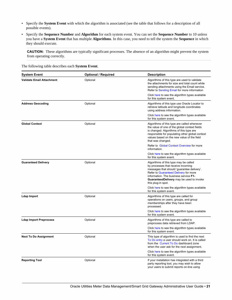
Oracle Utilities Meter Data Management/Smart Grid Gateway Administrative User Guide • 21
• Specify the System Event with which the algorithm is associated (see the table that follows for a description of allpossible events).
• Specify the Sequence Number and Algorithm for each system event. You can set the Sequence Number to 10 unlessyou have a System Event that has multiple Algorithms. In this case, you need to tell the system the Sequence in whichthey should execute.
CAUTION: These algorithms are typically significant processes. The absence of an algorithm might prevent the systemfrom operating correctly.
The following table describes each System Event.
System Event Optional / Required DescriptionValidate Email Attachment Optional Algorithms of this type are used to validate
the attachments for size and total count whilesending attachments using the Email service.Refer to Sending Email for more informationClick here to see the algorithm types availablefor this system event.
Address Geocoding Optional Algorithms of this type use Oracle Locator toretrieve latitude and longitude coordinatesusing address information.Click here to see the algorithm types availablefor this system event.
Global Context Optional Algorithms of this type are called wheneverthe value of one of the global context fieldsis changed. Algorithms of this type areresponsible for populating other global contextvalues based on the new value of the fieldthat was changed.Refer to Global Context Overview for moreinformation.Click here to see the algorithm types availablefor this system event.
Guaranteed Delivery Optional Algorithms of this type may be calledby processes that receive incomingmessages that should ‘guarantee delivery’.Refer to Guaranteed Delivery for moreinformation. The business service F1-GuaranteedDelivery may be used to invokethis plug-in spot.Click here to see the algorithm types availablefor this system event.
Ldap Import Optional Algorithms of this type are called foroperations on users, groups, and groupmemberships after they have beenprocessed.Click here to see the algorithm types availablefor this system event.
Ldap Import Preprocess Optional Algorithms of this type are called topreprocess data retrieved from LDAP.Click here to see the algorithm types availablefor this system event.
Next To Do Assignment Optional This type of algorithm is used to find the next To Do entry a user should work on. It is calledfrom the Current To Do dashboard zonewhen the user ask for the next assignment.Click here to see the algorithm types availablefor this system event.
Reporting Tool Optional If your installation has integrated with a thirdparty reporting tool, you may wish to allowyour users to submit reports on-line using
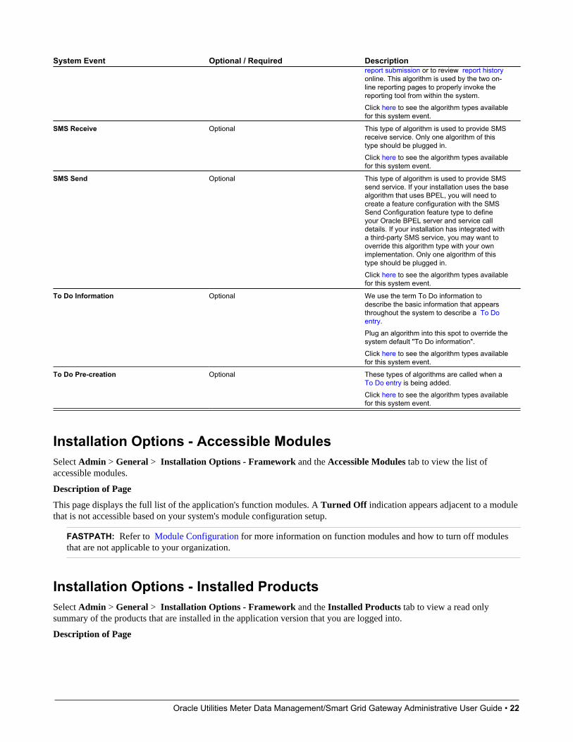
Oracle Utilities Meter Data Management/Smart Grid Gateway Administrative User Guide • 22
System Event Optional / Required Descriptionreport submission or to review report historyonline. This algorithm is used by the two on-line reporting pages to properly invoke thereporting tool from within the system.Click here to see the algorithm types availablefor this system event.
SMS Receive Optional This type of algorithm is used to provide SMSreceive service. Only one algorithm of thistype should be plugged in.Click here to see the algorithm types availablefor this system event.
SMS Send Optional This type of algorithm is used to provide SMSsend service. If your installation uses the basealgorithm that uses BPEL, you will need tocreate a feature configuration with the SMSSend Configuration feature type to defineyour Oracle BPEL server and service calldetails. If your installation has integrated witha third-party SMS service, you may want tooverride this algorithm type with your ownimplementation. Only one algorithm of thistype should be plugged in.Click here to see the algorithm types availablefor this system event.
To Do Information Optional We use the term To Do information todescribe the basic information that appearsthroughout the system to describe a To Doentry.Plug an algorithm into this spot to override thesystem default "To Do information".Click here to see the algorithm types availablefor this system event.
To Do Pre-creation Optional These types of algorithms are called when a To Do entry is being added.Click here to see the algorithm types availablefor this system event.
Installation Options - Accessible ModulesSelect Admin > General > Installation Options - Framework and the Accessible Modules tab to view the list ofaccessible modules.
Description of Page
This page displays the full list of the application's function modules. A Turned Off indication appears adjacent to a modulethat is not accessible based on your system's module configuration setup.
FASTPATH: Refer to Module Configuration for more information on function modules and how to turn off modulesthat are not applicable to your organization.
Installation Options - Installed ProductsSelect Admin > General > Installation Options - Framework and the Installed Products tab to view a read onlysummary of the products that are installed in the application version that you are logged into.
Description of Page
Oracle Utilities Meter Data Management/Smart Grid Gateway Administrative User Guide • 23
The Product Name indicates the name of the "products" that are installed. The collection should include Framework, anentry for your specific product and an entry for Customer Release.
Release ID shows the current release of the application that is installed. This field is used by the system to ensure that thesoftware that executes on your application server is consistent with the release level of the database. If your implementationof the product has developed implementation-specific transactions, you can populate the Release Id for the CustomerRelease entry to define the latest release of implementation-specific logic that has been applied to this environment. In orderfor this to work, your implementation team should populate this field as part of their upgrade scripts.
The Release ID Suffix, Build Number and Patch Number further describe the details of your specific product release.
The Display column indicates the product whose name and release information should be displayed in the title bar. Onlyone product sets this value to Yes.
Owner indicates if this entry is owned by the base package or by your implementation (Customer Modification).
Product Type indicates if the product is a Parallel Application. A parallel application is one that is independent of, anddoes not conflict with, other parallel applications. Multiple parallel applications can be installed in the same database andapplication server.
NOTE: About Information. The information on this tab is used to populate the information displayed in the Aboutinformation for your product.
Support For Different Languages
User LanguageThe system provides support for multiple languages in a single environment. System users can use the system in theirpreferred language, as long as a translation into that language has been provided. A user sees the system in the languagedefined on their user record. If enabled, users can use the Switch Language zone to switch to another supported languagereal time.
NOTE: Normally, setting up the system for another language is an implementation issue, not an administrative setupissue. However, there are several online administrative features that are used to set up a new language, and these aredescribed here.
The following steps are required to support a new language:
1. Define a language code and indicate that it is enabled. For details on this procedure, see Defining Languages.
2. Copy descriptions of all language-enabled tables from an existing translation (e.g., English). The copied values actmerely as placeholders while the strings are translated into the new language. It is necessary to do this as a first step inorder to create records using the new language code created in the previous step. Language-based descriptions can becopied using a supplied batch process, F1–LANG. The batch copies all English labels in the system.
3. Apply the language pack. If the product supplies a language pack with translations for the system metadatadescriptions, follow the instructions provided with the language pack to add the translated text.
4. Translate additional content. Translatable descriptions and labels for implementation data may be updated / enteredin the application. First the user record must be updated to reference the new language. This may be done in one of thefollowing ways:
a. Switch to the new language using the Switch Language zone.
b. If that zone is not available, navigate to the user page, assign the new language code to your User ID, sign out, andsign back in again.
Oracle Utilities Meter Data Management/Smart Grid Gateway Administrative User Guide • 24
Any online functions that you access will use your new language code. You can change the language code for all userswho plan to use/modify the new language.
NOTE: The language pack updates all language entries for base owned system data. If your implementation updatesbase owned labels and descriptions prior to applying the language pack, they will be overwritten. Note that most userfacing labels and messages support defining an Override Label or Override Description. This information is not updatedby the base product and should be utilized if your implementation desires a specific label or description.
Customer LanguageYour specific product may also support capturing the language of a customer. Such that correspondence sent from theproduct may be produced in a language set on a customer record. Refer to your specific product’s documentation for moreinformation about additional language support.
Defining LanguagesYour product may support multiple languages. For example, the field labels, input text, and even outputs and reports can beconfigured to appear in a localized language. A language code for every potential language exists in the system to supplythis information in various languages.
Select Admin > General > Language to define a language.
Description of Page
Enter a unique Language Code. If you are applying a language pack provided by the product, use the language codedesigned by the language pack.
Enter the Description for the language. Typically this should be the name of the language in that language.
Turn on Language Enable if the system should add a row for this language whenever a row is added in another language.For example, if you add a new currency code, the system will create language specific record for each language that hasbeen enabled. You would only enable multiple languages if you have users who work in multiple languages. Languages thatare configured as enabled, appear in the Switch Language dashboard zone. In addition, the login page for the applicationdisplays all the languages that are enabled, allowing the user to toggle the login instructions in that language.
NOTE: The list of enabled languages is captured on the server at startup time. If a new language is enabled, contactyour server administrator to refresh the server in order to see the new language displayed in the login page.
The following two fields control how the contents of grids and search results are sorted by the Java virtual machine (JVM)on your web server:
• The Locale is a string containing three portions:
• ISO language code (lower case, required)
• ISO country code (upper case, optional)
• Variant (optional).
• Underscores separate the various portions, and the variant can include further underscores to designate multiple variants.The specific JVM in use by your particular hardware/OS configuration constrains the available Locales. Validatingthe Locale against the JVM is outside the scope of this transaction. This means you are responsible for choosing validLocales.
The following are examples of valid locales:

Oracle Utilities Meter Data Management/Smart Grid Gateway Administrative User Guide • 25
Locale Commentsen_US American English
en_AU Australian English
pt_BR Brazilian Portuguese
fr_FR_EURO European French
ja_JP Japanese
In addition, the Java collation API can take a Collator Strength parameter. This parameter controls whether, for example,upper and lower-case characters are considered equivalent, or how accented characters are sorted. Valid values for collatorstrength are PRIMARY, SECONDARY, TERTIARY, and IDENTICAL. If you leave this field blank, Java will use itsdefault value for the language. We'd like to stress that the impact of each value depends on the language.
Please see https://docs.oracle.com/javase/7/docs/api/java/text/Collator.html for more information about the collator strengthfor your language.
Display Order indicates if this language is written Left to Right or Right to Left.
Owner indicates if this language is owned by the base package or by your implementation (Customer Modification). Thesystem sets the owner to Customer Modification when you add a language. This information is display-only.
Where Used
Follow this link to open the data dictionary where you can view the tables that reference CI_LANGUAGE.
Note that all administrative control tables and system metadata that contain language-specific columns (e.g., a description)reference a language code.
In addition, other tables may reference the language as a specific column. For example, on the User record you indicate thepreferred language of the user.
Defining CountriesThe topics in this section describe how to maintain countries.
Country - MainTo add or review Country definitions choose Admin > General > Country.
The Main page is used to customize the fields and field descriptions that will be displayed everywhere addresses are usedin the system. This ensures that the all addresses conform to the customary address format and conventions of the particularcountry you have defined.
Description of Page
Enter a unique Country and Description for the country.
The address fields that appear in the Main page are localization options that are used to customize address formats sothat they conform to address requirements around the world. By turning on an address field, you make that field availableeverywhere addresses for this country are used in the system. You can enter your own descriptions for the labels that suffixeach switch; these labels will appear wherever addresses are maintained in the system.
NOTE: For any country where the State switch is checked, the valid states for the country must be entered on theCountry - State tab. When entering address constituents on a record that captures this detail, the value for State isverified against the data in the State table. For any country where there is a component of the address that represents a"state" but your implementation does not want to populate the valid states for that country, choose a different field suchas County for this constituent (and define an appropriate label). When entering address constituents on a record thatcaptures this detail, no validation is done for the County column.
Oracle Utilities Meter Data Management/Smart Grid Gateway Administrative User Guide • 26
Where Used
Follow this link to open the data dictionary where you can view the tables that reference CI_COUNTRY.
Country - StatesTo maintain the states located in a country, choose Admin > Country > Search and navigate to the State page.
Description of PageFor any country where you have enabled the State switch, use the State collection to define the valid states in the Country.
• Enter the standard postal abbreviation for the State or province.
• Enter a Description for this state or province.
Defining Currency CodesThe currency page allows you to define display options related to currency codes that are used by your system. Use Admin> General > Currency to define the currency codes in which financial information is denominated.
Description of Page
Enter a unique Currency and Description for the currency.
Use Currency Symbol to define the character that prefixes currency amounts in the system (e.g., $ for U.S. dollars).
Enter the number of Decimals that will appear in the notation for the currency.
NOTE: Please contact your specific product to verify whether it supports a currency with more than 2 decimals.
The Currency Position indicates whether the currency symbol should be displayed as a Prefix or a Suffix to the currencyamount.
Where Used
Follow this link to open the data dictionary where you can view the tables that reference CI_CURRENCY_CD.
Defining Time ZonesThe following topics describe how to design and set up time zones.
Designing Time ZonesNOTE: Oracle Utilities Customer Care and Billing - Interval Billing applications customers should consult the topicTime Issues (search the Help index for "time issues") for specific information relating to that product's interval billingtime related functionality.
It is recommended that all time sensitive data is stored in the standard time (also called 'physical time') of the base timezone as defined on the installation options. This will prevent any confusion when analyzing data and will ensure that youralgorithms do not have to perform any shifting of data that may be stored in different time zones.
The Time Zone entity is used to define all the time zones where your customers may operate. Each time zone should definean appropriate Time Zone Name. This is a reference to an external source that defines time zones, their relationship toGreenwich Mean Time, whether the time zone follows any shifting for summer / winter time (daylight savings time) andwhen this shift occurs.
Oracle Utilities Meter Data Management/Smart Grid Gateway Administrative User Guide • 27
When designing your time zones, the first thing to determine is the base time zone. You may choose the time zone wherethe company's main office resides. Once this is done you can link the time zone code to the installation option as the basetime zone. Refer to Installation Options - Main for more information.
NOTE: An attribute in the system properties file may be configured to indicate that the DB session time zone shouldbe synchronized with the value defined on the Installation Options. Refer to the Server Administration Guide for moreinformation.
If your company does business beyond your main office's time zone, define the other time zones where you may havecustomers or other systems with which you exchange data. At this point, your specific product may include configurationtables to capture default time zones, for example based on a postal code or geographic location.
NOTE: Date and time in business object schemas. When defining date / time fields in a BO schema, schema attributescan be used to define whether or not data should be stored in standard time for the base time zone or if it should bestored in the standard time of another time zone (related to the data). In addition, schema attributes can be used toindicate if the display of the time should be shifted to represent the "local time". This is used to adjust for seasonal timedifferences. For example, if the data is stored in the appropriate time zone, but currently daylight savings time is beingobserved, the data will be shifted and shown in the "local" time. In addition, if the data is stored in the base time zonebut the data is related to a different time zone, the data will be shown in the time zone appropriate for the data (includingthe appropriate seasonal adjustment). Refer to Schema Nodes and Attributes- Standard Time Considerations for moreinformation.
Setting Up Time ZonesRefer to Designing Time Zones for background information about defining time zones.
Open Admin > General > Time Zone > Search to define the time zones and their relation to the base time.
Description of Page
Enter a unique Time Zone and Description for the time zone.
Select the Time Zone Name from the list of Olson time zone values. This value is a reference to an external definition thatallows the system to know how the time zone relates to Greenwich Mean Time and information about whether the timezone shifts for summer / winter time and when.
Indicate the Shift in Minutes that this time zone differs from the base time zone defined on the Installation Options. This isonly applicable for the Oracle Utility Customer Care and Billing - Interval Billing application.
Indicate the Seasonal Time Shift applicable for this time zone. This is only applicable for the Oracle Utility Customer Careand Billing - Interval Billing application.
Default Time Zone Label and Shifted Time Zone Label are used for data that is sensitive to time zones and time shifting.It indicates whether the data displayed or data to be input is related to the "standard" time or the "shifted" time. Forexample, on a day when clocks are turned back one hour, a time entry of 1:30 a.m. needs to be labeled as either 1:30 a.m.standard time or 1:30 a.m. daylight savings time.
Where Used
Follow this link to open the data dictionary where you can view the tables that reference CI_TIME_ZONE.
Setting Up Seasonal Time ShiftNOTE: The information in this topic applies only to Oracle Utilities Customer Care and Billing - Interval Billingapplications.
Open Admin > General > Seasonal Time Shift > Search to define the seasonal time shift schedule.
Oracle Utilities Meter Data Management/Smart Grid Gateway Administrative User Guide • 28
Description of Page
Enter a unique Seasonal Time Shift code and Description for the seasonal time shift.
The Collection defines the Effective Date/Time (in standard time) that a time zone may shift in and out of standard time.If time is changed from standard time on the effective date/time, enter the Shift in Minutes that the time changes fromstandard time (usually 60). If the time is changed back to standard time on the effective date/time, enter a Shift in Minutesof 0.
Where Used
Follow this link to open the data dictionary where you can view the tables that reference CI_SEAS_TM_SHIFT.
Defining Geographic TypesIf your company uses geographic coordinates for dispatching or geographic information system integration, you need tosetup a geographic (coordinate) type for each type of geographic coordinate you capture on your premises and/or servicepoints (geographic coordinates can be defined on both premises and service points).
To define geographic types, open Admin > Geographic > Geographic Type.
NOTE: Product specific. There is no framework functionality that uses this information. Refer to your specific productdocumentation to verify how this table is used in your specific product. In addition, use the data dictionary link below todetermine if this object is a foreign key on any tables specific to your product.
Description of Page
Enter an easily recognizable Geographic Type code and Description.
Define the algorithm used to validate the Validation Format Algorithm. If an algorithm is specified, the system willvalidate that the geographic location entered on the premise and/or service point for the geographic type is in the format asdefined in the algorithm. If you require validation, you must set up this algorithm in the system.
Click here to see the algorithm types available for this plug-in spot.
Where Used
Follow this link to open the data dictionary where you can view the tables that reference CI_GEO_TYPE.
Defining Work CalendarWorkday calendars are used to ensure system-calculated dates fall on a workday. Select Admin > General > WorkCalendar > Search to define a workday calendar.
Description of Page
The information on this transaction is used to define the days of the week on which your organization works.
Enter a unique Work Calendar and Description.
Turn on (check) the days of the week that are considered normal business days for your organization.
Use the collection to define the Holiday Date, Holiday Start Date, Holiday End Date, and Holiday Name for eachcompany holiday. Holiday Start Date and Holiday End Date define the date and time that the holiday begins and ends. Forexample, your organization might begin a holiday at 5:00 p.m. on the day before the actual holiday.
Where Used
Follow this link to open the data dictionary where you can view the tables that reference CI_CAL_WORK.
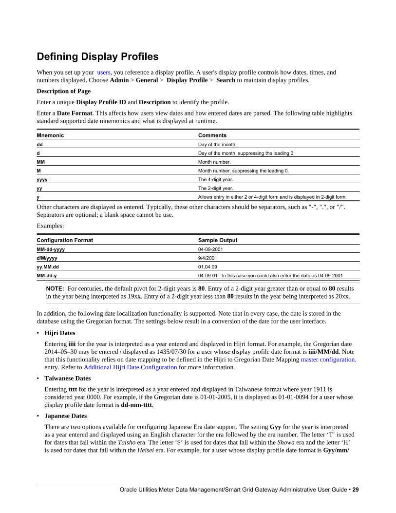
Oracle Utilities Meter Data Management/Smart Grid Gateway Administrative User Guide • 29
Defining Display ProfilesWhen you set up your users, you reference a display profile. A user's display profile controls how dates, times, andnumbers displayed. Choose Admin > General > Display Profile > Search to maintain display profiles.
Description of Page
Enter a unique Display Profile ID and Description to identify the profile.
Enter a Date Format. This affects how users view dates and how entered dates are parsed. The following table highlightsstandard supported date mnemonics and what is displayed at runtime.
Mnemonic Commentsdd Day of the month.
d Day of the month, suppressing the leading 0.
MM Month number.
M Month number, suppressing the leading 0.
yyyy The 4-digit year.
yy The 2-digit year.
y Allows entry in either 2 or 4-digit form and is displayed in 2-digit form.
Other characters are displayed as entered. Typically, these other characters should be separators, such as "-", ".", or "/".Separators are optional; a blank space cannot be use.
Examples:
Configuration Format Sample OutputMM-dd-yyyy 04-09-2001
d/M/yyyy 9/4/2001
yy.MM.dd 01.04.09
MM-dd-y 04-09-01 - In this case you could also enter the date as 04-09-2001
NOTE: For centuries, the default pivot for 2-digit years is 80. Entry of a 2-digit year greater than or equal to 80 resultsin the year being interpreted as 19xx. Entry of a 2-digit year less than 80 results in the year being interpreted as 20xx.
In addition, the following date localization functionality is supported. Note that in every case, the date is stored in thedatabase using the Gregorian format. The settings below result in a conversion of the date for the user interface.
• Hijri Dates
Entering iiii for the year is interpreted as a year entered and displayed in Hijri format. For example, the Gregorian date2014–05–30 may be entered / displayed as 1435/07/30 for a user whose display profile date format is iiii/MM/dd. Notethat this functionality relies on date mapping to be defined in the Hijri to Gregorian Date Mapping master configuration.entry. Refer to Additional Hijri Date Configuration for more information.
• Taiwanese Dates
Entering tttt for the year is interpreted as a year entered and displayed in Taiwanese format where year 1911 isconsidered year 0000. For example, if the Gregorian date is 01-01-2005, it is displayed as 01-01-0094 for a user whosedisplay profile date format is dd-mm-tttt.
• Japanese Dates
There are two options available for configuring Japanese Era date support. The setting Gyy for the year is interpretedas a year entered and displayed using an English character for the era followed by the era number. The letter ‘T’ is usedfor dates that fall within the Taisho era. The letter ‘S’ is used for dates that fall within the Showa era and the letter ‘H’is used for dates that fall within the Heisei era. For example, for a user whose display profile date format is Gyy/mm/
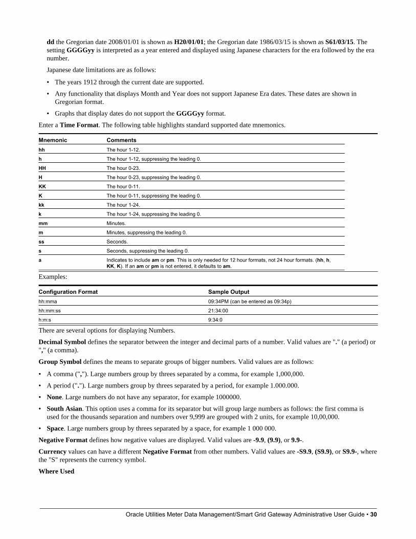
Oracle Utilities Meter Data Management/Smart Grid Gateway Administrative User Guide • 30
dd the Gregorian date 2008/01/01 is shown as H20/01/01; the Gregorian date 1986/03/15 is shown as S61/03/15. Thesetting GGGGyy is interpreted as a year entered and displayed using Japanese characters for the era followed by the eranumber.
Japanese date limitations are as follows:
• The years 1912 through the current date are supported.
• Any functionality that displays Month and Year does not support Japanese Era dates. These dates are shown inGregorian format.
• Graphs that display dates do not support the GGGGyy format.
Enter a Time Format. The following table highlights standard supported date mnemonics.
Mnemonic Commentshh The hour 1-12.
h The hour 1-12, suppressing the leading 0.
HH The hour 0-23.
H The hour 0-23, suppressing the leading 0.
KK The hour 0-11.
K The hour 0-11, suppressing the leading 0.
kk The hour 1-24.
k The hour 1-24, suppressing the leading 0.
mm Minutes.
m Minutes, suppressing the leading 0.
ss Seconds.
s Seconds, suppressing the leading 0.
a Indicates to include am or pm. This is only needed for 12 hour formats, not 24 hour formats. (hh, h,KK, K). If an am or pm is not entered, it defaults to am.
Examples:
Configuration Format Sample Outputhh:mma 09:34PM (can be entered as 09:34p)
hh:mm:ss 21:34:00
h:m:s 9:34:0
There are several options for displaying Numbers.
Decimal Symbol defines the separator between the integer and decimal parts of a number. Valid values are "." (a period) or"," (a comma).
Group Symbol defines the means to separate groups of bigger numbers. Valid values are as follows:
• A comma (","). Large numbers group by threes separated by a comma, for example 1,000,000.
• A period ("."). Large numbers group by threes separated by a period, for example 1.000.000.
• None. Large numbers do not have any separator, for example 1000000.
• South Asian. This option uses a comma for its separator but will group large numbers as follows: the first comma isused for the thousands separation and numbers over 9,999 are grouped with 2 units, for example 10,00,000.
• Space. Large numbers group by threes separated by a space, for example 1 000 000.
Negative Format defines how negative values are displayed. Valid values are -9.9, (9.9), or 9.9-.
Currency values can have a different Negative Format from other numbers. Valid values are -S9.9, (S9.9), or S9.9-, wherethe "S" represents the currency symbol.
Where Used

Oracle Utilities Meter Data Management/Smart Grid Gateway Administrative User Guide • 31
Follow this link to open the data dictionary where you can view the tables that reference CI_DISP_PROF.
Additional Hijri Date ConfigurationFor implementations that wish to support displaying dates according to the Hijri calendar, besides appropriate configurationin the Display Profile, the mapping between the Hijri dates and the Gregorian dates must be entered. This mapping isdefined in the Hijri to Gregorian Date Mappingmaster configuration record.
The mapping record contains a collection of entries for each year in the Islamic calendar.
For each year, clicking the Expand Zone icon shows the mapping collection with the first date of each month of the Hijricalendar. The corresponding date in the Gregorian calendar should be entered for each row.
Defining Phone TypesPhone types define the format for entering and displaying phone numbers.
To add or review phone types, choose Admin > General > Phone Type.
Description of Page
Enter a unique Phone Type and Description for each type of phone number you support.
Select an appropriate Phone Number Format Algorithm for each Phone Type. This algorithm controls the format forentry and display of phone numbers. Click here to see the algorithm types available for this plug-in spot.
Use Phone Type Flag to define if this type of phone number is a Fax number. Defining which phone type is used forfacsimile transmittal is only pertinent if your product supports routing of information via fax. For example, in OracleUtilities Customer Care and Billing, the system may be configured to fax a bill to a customer.
Where Used
Follow this link to open the data dictionary where you can view the tables that reference CI_PHONE_TYPE.
Setting Up Characteristic Types & ValuesMany objects in the system support a collection of Characteristics, which are used to capture additional fields for the objectthat are not already supported by the object’s provided attributes. Each characteristic is associated with a characteristic type,which defines attributes of the field you wish to capture.
All characteristics are captured as a list. However, the user interface for characteristics differ based on the type of page thatis used to maintain the object.
• For portal based pages the business object drives the display and maintenance of an object. For these types of pages, it isrecommended that characteristics are defined as part of the business object schema allowing the user interface to displaythe characteristic as if it is another field. However, the display / maintenance of the characteristic is determined by thebusiness object’s user interface design.
• There are some fixed pages in the system that do not support customization of the user interface. For these objects, thecharacteristics are displayed / maintained as a generic list.
The topics in this section describe how to setup a characteristic type.
There Are Four Types Of CharacteristicsEvery characteristic referenced on an object references a characteristic type. The characteristic type controls the validity ofthe information entered by a user when they enter the characteristic's values. For example, if you have a characteristic type
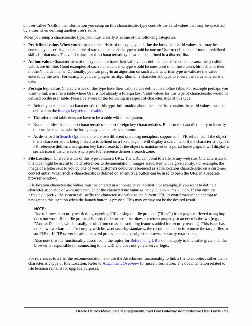
Oracle Utilities Meter Data Management/Smart Grid Gateway Administrative User Guide • 32
on user called "skills", the information you setup on this characteristic type controls the valid values that may be specifiedby a user when defining another user's skills.
When you setup a characteristic type, you must classify it as one of the following categories:
• Predefined value. When you setup a characteristic of this type, you define the individual valid values that may beentered by a user. A good example of such a characteristic type would be one on User to define one or more predefinedskills for that user. The valid values for this characteristic type would be defined in a discreet list.
• Ad hoc value. Characteristics of this type do not have their valid values defined in a discreet list because the possiblevalues are infinite. Good examples of such a characteristic type would be ones used to define a user's birth date or theirmother's maiden name. Optionally, you can plug-in an algorithm on such a characteristic type to validate the valueentered by the user. For example, you can plug-in an algorithm on a characteristic type to ensure the value entered is adate.
• Foreign key value. Characteristics of this type have their valid values defined in another table. For example perhaps youwant to link a user to a table where User is not already a foreign key. Valid values for this type of characteristic would bedefined on the user table. Please be aware of the following in respect of characteristics of this type:
• Before you can create a characteristic of this type, information about the table that contains the valid values must bedefined on the foreign key reference table.
• The referenced table does not have to be a table within the system.
• Not all entities that support characteristics support foreign key characteristics. Refer to the data dictionary to identifythe entities that include the foreign key characteristic columns.
• As described in Search Options, there are two different searching metaphors supported on FK reference. If the objectthat a characteristic is being linked to is defined on a fixed page, it will display a search icon if the characteristic type'sFK reference defines a navigation key based search. If the object is maintained on a portal based page, it will display asearch icon if the characteristic type's FK reference defines a search zone.
• File Location. Characteristics of this type contain a URL. The URL can point to a file or any web site. Characteristics ofthis type might be useful to hold references to documentation / images associated with a given entity. For example, theimage of a letter sent to you by one of your customers could be referenced as a file location characteristic on a customercontact entry. When such a characteristic is defined on an entity, a button can be used to open the URL in a separatebrowser window.
File location characteristic values must be entered in a "non-relative" format. For example, if you want to define acharacteristic value of www.msn.com, enter the characteristic value as http://www.msn.com. If you omit thehttp:// prefix, the system will suffix the characteristic value to the current URL in your browser and attempt tonavigate to this location when the launch button is pressed. This may or may not be the desired result.
NOTE:Due to browser security restrictions, opening URLs using the file protocol ("file://") from pages retrieved using httpdoes not work. If the file protocol is used, the browser either does not return properly or an error is thrown (e.g.,"Access Denied", which usually results from cross site scripting features added for security reasons). This issue hasno known workaround. To comply with browser security standards, the recommendation is to move the target files toan FTP or HTTP server location to avoid protocols that are subject to browser security restrictions.
Also note that the functionality described in the topics for Referencing URIs do not apply to this value given that thebrowser is responsible for connecting to the URI and does not go via server logic.
For references to a file, the recommendation is to use the Attachment functionality to link a file to an object rather than acharacteristic type of File Location. Refer to Attachment Overview for more information. The documentation related tofile location remains for upgrade purposes.

Oracle Utilities Meter Data Management/Smart Grid Gateway Administrative User Guide • 33
Searching By Characteristic ValuesFor certain entities in the system that have characteristics, you may search for a record linked to a given characteristic value.The search may be done in one of the following ways:
• Some base searches provide an option to search for an object by entering Characteristic Type and Characteristic Value.
• Your implementation may define a customized search for an entity by a characteristic value for a specific characteristictype using a query data explorer.
• Your implementation may require a business service to find a record via a given characteristic value. For example,maybe an upload of user information attempts to find the user via an Employee ID, defined as a characteristic.
Not all entities that support characteristics support searching by characteristics. Refer to the data dictionary to identify thecharacteristic collections that include the search characteristic column.
CAUTION: For ad-hoc characteristics, only the first 50 bytes are searchable. For foreign key characteristics, the searchvalue is populated by concatenating the values of each foreign key column to a maximum of 50 bytes.
For the base searches that provide a generic option to search by characteristic type and value, you can restrict thecharacteristic types that can be used to search for an entity. For example, imagine you use a characteristic to define a"jurisdiction" associated with a To Do for reporting purposes. If your company operates within a very small number ofjurisdictions, you wouldn't want to allow searching for a To Do by jurisdiction, as a large number of To Do entries would bereturned.
A flag on the characteristic type allows an administrator to indicate if searching by this characteristic type is allowed or notallowed.
Characteristic Type - MainTo define a characteristic type, open Admin > General > Characteristic Type.
Description of Page
Enter an easily recognizable Characteristic Type and Description for the characteristic type. Owner indicates if thischaracteristic type is owned by the base package or by your implementation (Customer Modification).
CAUTION: Important! If you introduce a new characteristic type, carefully consider its naming convention. Refer toSystem Data Naming Convention for more information.
Use Type of Char Value to classify this characteristic type using one of the following options (refer to There Are FourTypes Of Characteristics for more information):
• Predefined value. Characteristics of this type have their valid values defined in the Characteristic Value scroll, below.For each valid value, enter an easily recognizable Characteristic Value and Description.
• Ad hoc value. Characteristics of this type capture free form text. If you use this option, you can optionally define theValidation Rule used to validate the user-entered characteristic value. Click here to see the algorithm types available forthis plug-in spot.
• File location value. Characteristics of this type contain a URI. The URI can point to a file or any web site. Refer to There Are Four Types Of Characteristics for limitations associated with this type of characteristic value.
• Foreign key reference. Characteristics of this type have their valid values defined in another table. If you choose thisoption, you must use FK Reference to define the table that controls the valid values of this characteristic type. Refer toSetting Up Foreign Key References for more information.
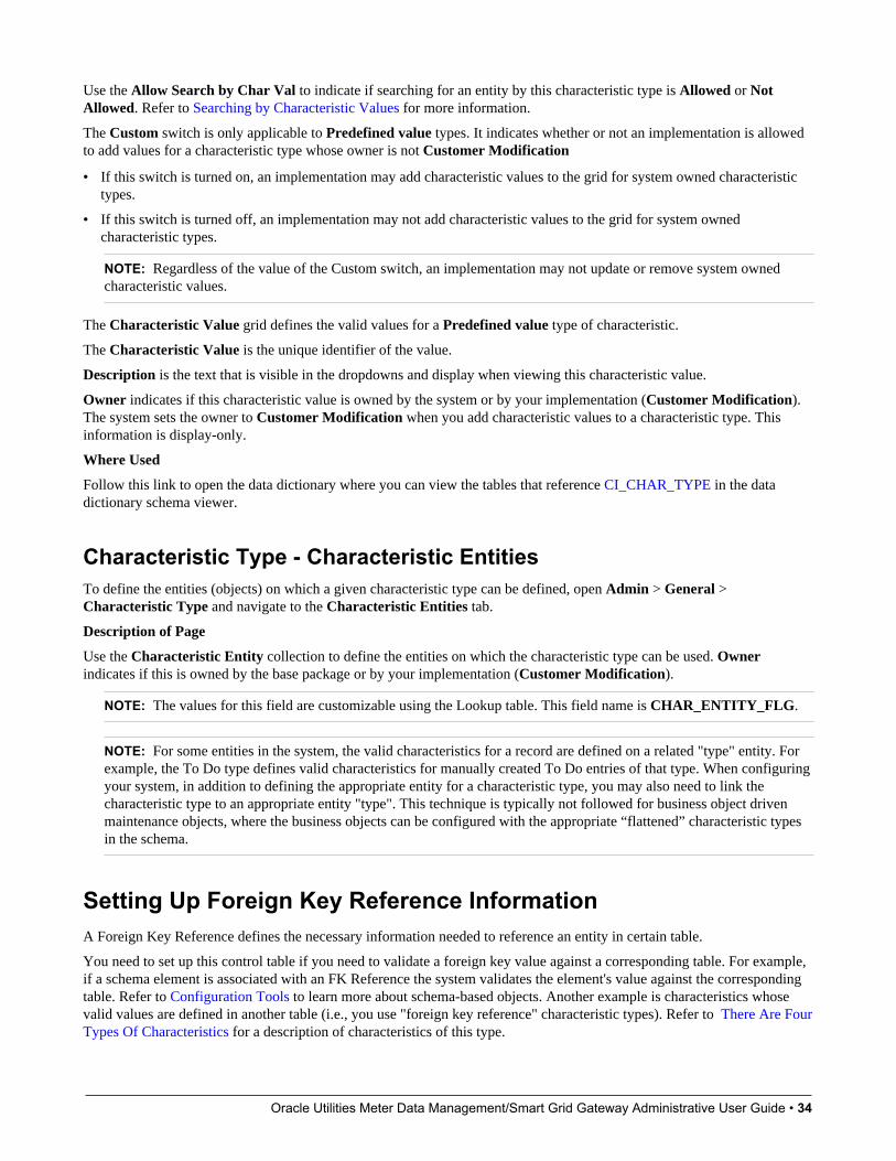
Oracle Utilities Meter Data Management/Smart Grid Gateway Administrative User Guide • 34
Use the Allow Search by Char Val to indicate if searching for an entity by this characteristic type is Allowed or NotAllowed. Refer to Searching by Characteristic Values for more information.
The Custom switch is only applicable to Predefined value types. It indicates whether or not an implementation is allowedto add values for a characteristic type whose owner is not Customer Modification
• If this switch is turned on, an implementation may add characteristic values to the grid for system owned characteristictypes.
• If this switch is turned off, an implementation may not add characteristic values to the grid for system ownedcharacteristic types.
NOTE: Regardless of the value of the Custom switch, an implementation may not update or remove system ownedcharacteristic values.
The Characteristic Value grid defines the valid values for a Predefined value type of characteristic.
The Characteristic Value is the unique identifier of the value.
Description is the text that is visible in the dropdowns and display when viewing this characteristic value.
Owner indicates if this characteristic value is owned by the system or by your implementation (Customer Modification).The system sets the owner to Customer Modification when you add characteristic values to a characteristic type. Thisinformation is display-only.
Where Used
Follow this link to open the data dictionary where you can view the tables that reference CI_CHAR_TYPE in the datadictionary schema viewer.
Characteristic Type - Characteristic EntitiesTo define the entities (objects) on which a given characteristic type can be defined, open Admin > General > Characteristic Type and navigate to the Characteristic Entities tab.
Description of Page
Use the Characteristic Entity collection to define the entities on which the characteristic type can be used. Ownerindicates if this is owned by the base package or by your implementation (Customer Modification).
NOTE: The values for this field are customizable using the Lookup table. This field name is CHAR_ENTITY_FLG.
NOTE: For some entities in the system, the valid characteristics for a record are defined on a related "type" entity. Forexample, the To Do type defines valid characteristics for manually created To Do entries of that type. When configuringyour system, in addition to defining the appropriate entity for a characteristic type, you may also need to link thecharacteristic type to an appropriate entity "type". This technique is typically not followed for business object drivenmaintenance objects, where the business objects can be configured with the appropriate “flattened” characteristic typesin the schema.
Setting Up Foreign Key Reference InformationA Foreign Key Reference defines the necessary information needed to reference an entity in certain table.
You need to set up this control table if you need to validate a foreign key value against a corresponding table. For example,if a schema element is associated with an FK Reference the system validates the element's value against the correspondingtable. Refer to Configuration Tools to learn more about schema-based objects. Another example is characteristics whosevalid values are defined in another table (i.e., you use "foreign key reference" characteristic types). Refer to There Are FourTypes Of Characteristics for a description of characteristics of this type.
Oracle Utilities Meter Data Management/Smart Grid Gateway Administrative User Guide • 35
A FK Reference is used not just for validation purposes. It also used to display the standard information description ofthe reference entity as well as provide navigation information to its maintenance transaction. Info descriptions appearthroughout the UI, for example, whenever an account is displayed on a page, a description of the account appears. Theproduct provides base product FK references for many of its entities as they are used for validation and display of elementsin both fixed page user interfaces as well as portal based user interfaces.
An implementation may also see the need to define a foreign key reference. The following points describe what you shouldknow before you can setup a foreign key reference for a table.
• The physical name of the table. Typically this is the primary table of a maintenance object.
• The program used by default to construct the referenced entity's info description. Refer to Information Description IsDynamically Derived for more information on how this is used.
• The transaction used to maintain the referenced entity. This is where the user navigates to when using the "go to" buttonor hyperlink associated with the entity. Refer to Navigation Information Is Dynamically Derived for more information onhow this is used.
• The name of the search page used to look for a valid entity. Refer to Search Options for more information.
Information Description Is Dynamically DerivedTypically a FK Reference is defined for a maintenance object's primary table. In this case the system dynamically derivesthe standard information associated with a specific referenced entity as follows:
• Attempt to determine the business object associated with the referenced entity. Refer to the Determine BO maintenanceobject algorithm system event for more information. If a business object has been determined, the system lets thebusiness object's Information plug-in, if any, format the description.
• If a business object has not been determined or the business object has no such plug-in, the system lets the maintenanceobject's information plug-in, if any, format the description.
• If the maintenance object has no such plug-in, the system uses the info program specified on the FK Reference to formatthe information.
NOTE: Technical note. The class that returns the information displayed adjacent to the referenced entity is generatedspecifically for use as an info routine. Please speak to your support group if you need to generate such a class.
NOTE: Generic routine. The system provides a generic information routine that returns the description of control tableobjects from its associated language table. By "control table" we mean a table with an associated language table thatcontains a DESCR field. Refer to Defining Table Options for more information on tables and fields. The java class is com.splwg.base.domain.common.foreignKeyReference.DescriptionRetriever.
Navigation Information Is Dynamically DerivedTypically a FK Reference is defined for a maintenance object's primary table. In this case the system dynamically derivesthe actual transaction to navigate to for a given referenced entity as follows:
• Attempt to determine the business object associated with the referenced entity. Refer to the Determine BO maintenanceobject algorithm system event for more information. If a business object has been determined, use the maintenance portaldefined as its Portal Navigation Option business object option.
• If a business object has not been determined or the business object defines no such option, the system uses thetransaction specified on the FK Reference.

Oracle Utilities Meter Data Management/Smart Grid Gateway Administrative User Guide • 36
Search OptionsThe product provides two main metaphors for implementing a user interface. For input fields that are foreign keys, searchoptions are dependent on the metaphor used by the page in question.
• A portal based user interface is a more flexible user interface where an implementation has more options for customizingthe look and feel. The base product uses UI maps or automatic UI rendering to display input fields. Elements that areforeign keys may display a search icon if the FK reference defines a Search Zone.
NOTE: Defining search zones directly. It's possible for elements on a UI map to define a specific search zonedirectly in the HTML, rather than using the search zone defined on an FK reference. Refer to the UI map tips formore information on implementing searches using zones.
• A fixed maintenance page user interface is a page supplied by the base product where only minor enhancements, if any,can be introduced by implementations. The foreign key reference may be used in one of two ways.
• The based product may use an FK reference to define a base element on one of these pages. If a search is available forsuch elements, the FK reference's Search Navigation Key is used to implement the search.
• Entities that support characteristics typically include a generic characteristic collection UI metaphor on these typesof pages. In this metaphor, a foreign key characteristic displays a search icon if the FK Reference has configured aSearch Navigation Key.
NOTE: Not every FK reference provided with the product is configured with both search options. Specifically, objectsthat are maintained in a portal based page typically do not provide a navigation key based search. It means that if linkingthis type of object as a characteristic to an object that is maintained on a fixed page, a search will not be available.
Foreign Key Reference - MainTo setup a foreign key reference, open Admin > Database > FK Reference.
CAUTION: Important! If you introduce a new foreign key reference, carefully consider its naming convention. Refer to System Data Naming Convention for more information.
Description of Page
Enter an easily recognizable FK (foreign key) Reference code and Description for the record.
Enter the name of the Table whose primary key is referenced. After selecting a Table, the columns in the table's primarykey are displayed adjacent to Table PK Sequence.
Use Navigation Option to define the page to which the user will be transferred when they press the go to button orhyperlink associated with the referenced entity. Refer to Navigation Information Is Dynamically Derived for moreinformation on how this is used.
The Info Program Type indicates whether the default program that returns the standard information description is Java orJava (Converted), meaning it was converted into Java.
NOTE: Java (Converted) program types are not applicable to all products.
Use Info Program Name to enter the Java class / program name.
Refer to Information Description Is Dynamically Derived for more information on the info program is used.
Oracle Utilities Meter Data Management/Smart Grid Gateway Administrative User Guide • 37
NOTE: View the source. If the program is shipped with the base package, you can use the adjacent button to displaythe source code of this program in the Java docs viewer.
Use Context Menu Name to specify the context menu that appears to the left of the value.
NOTE: Context Menu Name is not applicable to user interface elements displaying a generic collection using a foreignkey characteristic type. It is only applicable for pages utilizing the foreign key compound element type for fixed pageuser interface and for data displayed in a portal based user interface where the foreign key reference is defined as anattribute for an element. Report parameters that reference foreign key characteristics are an example of a user interfacewhere a context menu is not displayed even if the foreign key reference defines one.
Use Search Zone to define the search zone that opens when a user searches for valid values when the foreign key referenceis configured as an input field on a portal based page. Refer to Search Options for more information.
Use Search Navigation Key to define the search page that will be opened when a user searches for valid values on a userinterface that is a fixed page. Refer to Search Options for more information.
Use Search Type to define the default set of search criteria used by the Search Navigation Key's search page.
Use Search Tooltip to define a label that describes the Search Navigation Key's search page.
NOTE: Search Type and Search Tooltip. These attributes are only applicable to user interface elements utilizingthe foreign key compound element type on fixed page user interfaces. Report parameters that reference foreign keycharacteristics are an example of a user interface where this information is not used even if the foreign key referencedefines them.
Where Used
Follow this link to open the data dictionary where you can view the tables that reference CI_FK_REF.
Defining Feature ConfigurationsSome system features are configured by populating options on a "feature configuration". Because various optionsthroughout the system may be controlled by settings in feature configuration, this section does not document all thedisparate possible options. The topics below simply describe how to use this transaction in a generic way.
For information about specific features:
• Refer to the detailed description of each option type.
• Use the index in the online help and search for ‘feature configuration’ to find any specific topics describing featureoptions in the administration guide.
You can create options to control features that you develop for your implementation. To do this:
• Review the lookup values for the lookup field EXT_SYS_TYP_FLG. If your new option can be logically categorizedwithin an existing feature type, note the lookup value. If your new option warrants a new feature type, add a lookup valueto this lookup field.
• Define the feature's option types. If you have identified an existing feature type to add the options to, find the lookupwith the name xxxx_OPT_TYP_FLG where xxxx is the lookup value of EXT_SYS_TYP_FLG noted above. If youdecided to create a new feature type (by adding a new lookup value to the EXT_SYS_TYP_FLG lookup, you mustcreate a new lookup with the name xxxx_OPT_TYP_FLG where xxxx is the new value you defined above.
• Flush all caches.

Oracle Utilities Meter Data Management/Smart Grid Gateway Administrative User Guide • 38
Feature Configuration - MainTo define your feature configuration, open Admin > General > Feature Configuration.
Description of Page
Enter an easily recognizable Feature Name code.
Indicate the Feature Type for this configuration. For example, if you were setting up the options for the external messages,you'd select External Messages.
NOTE: You can add new Feature Types. Refer to the description of the page above for how you can add FeatureTypes to control features developed for your implementation.
NOTE: Multiple Feature Configurations for a Feature Type. Some Feature Types allow multiple featureconfigurations. The administration documentation for each feature will tell you when this is possible.
The Options grid allows you to configure the feature. To do this, select the Option Type and define its Value. Set theSequence to 1 unless the option may have more than value. Detailed Description may display additional information onthe option type.
NOTE: Each option is documented elsewhere. The administration documentation for each feature describes itsoptions and whether an option supports multiple values. Use the index to look for ‘feature configuration’ to find thevarious types of feature options.
NOTE: You can add new options to base-package features. Your implementation may want to add additional optionsto one of the base-package's feature types. For example, your implementation may have plug-in driven logic that wouldbenefit from a new option. To do this, display the lookup field that holds the desired feature's options. The lookup field'sname is xxxx_OPT_TYP_FLG where xxxx is the identifier of the feature on the EXT_SYS_TYP_FLG lookup value.For example, to add new batch scheduler options, display the lookup field BS_OPT_TYP_FLG.
Feature Configuration - MessagesIf the feature exists to interface with an external system, you can use this page to define the mapping between error andwarning codes in the external system and our system.
Open this page using Admin > General > Feature Configuration and navigate to the Messages tab.
Description of Page
For each message that may be received from an external system, define the Feature Message Category and FeatureMessage Code to identify the message.
A corresponding message must be defined in the system message tables. For each message identify the Message Categoryand Message Number. For each new message, the Message Category defaults to 90000 (because an implementation'smessages should be added into this category or greater so as to avoid collisions during upgrades).
Defining Master ConfigurationsA master configuration is an object that enables an implementation to define configuration for features in the system. It isan alternative to using feature configuration for defining options. A master configuration is defined using a business object.Only one master configuration may exist for a given business object.
Oracle Utilities Meter Data Management/Smart Grid Gateway Administrative User Guide • 39
The product provides one or more master configuration that may be used for configuration. Some examples, of base masterconfiguration business objects are as follows
• Hijri to Gregorian Date Mapping. This allows an implementation that uses Hijri dates to define the mapping betweenthose dates and Gregorian dates.
• ILM Configuration. For implementations that use Information Lifecycle Management, the ILM configuration recorddefines some parameters used by the process.
• Migration Assistant Configuration. For implementations that use the configuration migration assistant (CMA), theconfiguration record defines some parameters used by the process.
For a list of all the master configuration records provided by the product, navigate to the master configuration page in theapplication. To find help topics related to functionality controlled by the master configuration records, use the keyword‘master configuration’ in the index.
To set up a master configuration, open Admin > General > Master Configuration.
The topics in this section describe the base-package zones that appear on the Master Configuration portal.
Master Configuration
The Master Configuration List zone lists every category of master configuration.
The following functions are available:
• If a master configuration record exists for a given master configuration business object, the broadcast icon may be usedto view details information about the adjacent master configuration. In addition, an edit icon is visible to allow a user toupdate the record.
• If a master configuration record does not exist for a given master configuration business object, the add icon is visible toallow a user to define the record.
Master Configuration Details
The Master Configuration Details zone contains display-only information about a master configuration.
This zone appears when a master configuration has been broadcast from the Master Configuration zone.
Please see the zone's help text for information about this zone's fields.
Defining Security & User OptionsThe contents of this section describe how to maintain a user's access rights.
The Big Picture of Application SecurityThe contents of this section provide background information about application security.
Application SecurityThe system restricts access to transactions or explicit services using an application service. The following points highlightwhat may be secured.
• The following points highlight security related to viewing and modifying individual records in the system:
• All maintenance objects define an application service that includes the basic actions available, typically Add,Change, Delete, and Inquire. The base product supplies an application service for every maintenance object. Notethat the application service for the maintenance object is defined on its related service program.
Oracle Utilities Meter Data Management/Smart Grid Gateway Administrative User Guide • 40
• For maintenance objects whose user interface page is not portal-based, the application service also controls whetherthe menu entry appears. If a user doesn't have access to the maintenance object's application service, the menu itemthat corresponds with the application service will not be visible.
• For portal based user interfaces, each main (stand-alone) portal defines an explicit application service with the accessmode Inquire, allowing the user interface to be secured independently of the underlying object security. If a userdoesn't have access to the portal's application service, the menu item that corresponds with the application service willnot be visible. The base product supplies an application service for every portal that is accessible from the menu. Notethat the application service for the portal is defined on its related service program, which is derived via its navigationoption and navigation key.
• Menu items may define an application service / access mode. Typically the security supplied for portals andmaintenance objects provides enough granularity to suppress menu items that a user does not have access to. Linkingan explicit application service / access mode will further suppress the menu item under one of the following scenarios:
• Suppress a menu item if the underlying application security for the transaction does not provide enough finegrained control. For example, imagine your implementation creates a special BPA script to add a To Do Entryand would like users to use the special BPA rather than the base supplied Add dialogue for To Do Entry. Theunderlying security settings for To Do Entry should grant Add access to these users given that the special BPA willstill add a record. To suppress the base Add dialogue, link a special application service and access mode for thebase supplied menu item for To Do Entry Add. Then define a menu entry for the new special BPA for adding.
• Suppress the add option if a user does not have add security for the object. By default the product does notsuppress the add function if a user does not have add access to the object. Rather, the user is prevented fromadding the record at the back-end. If your implementation would like to suppress the menu option, link the object'sapplication service and the Add access mode to the Add menu item.
NOTE: The base product does not typically provide menu items with application services configured.Implementations may add this configuration if one of the above scenarios exist.
• Zones define an application service.
• For zones linked to a portal, if a user doesn't have access to the zone's application service, the zone will not bevisible on the portal. In most cases the zone is delivered with the same application service as its portal. In specialcases, such as the zones on the Dashboard, the product supplies separate application services for each zoneallowing implementations to determine at a more granular level which users should have access to which zones.
• For query zones that are configured on a multi-query zone, if a user doesn't have access to the zone's applicationservice, the zone will not be visible in the dropdown on the multi-query zone. In most cases all zones in a multi-query zone define the same application service as the multi-query zone. The product may supply a specialapplication service for one or more zones in a multi-query zone if the functionality is special to certain markets orjurisdictions and not applicable to all implementations.
• For zones that are used by business services to perform SQL queries, the product supplies a default applicationservice. Security for these zones is not checked by the product as they are used for internal purposes.
• Business objects define an application service. If the business object defines a lifecycle, the application service mustinclude access modes that correspond to each state. In addition, the standard maintenance object access modes ofAdd, Change, Delete and Inquire are included. The base product business objects are supplied with appropriateapplication services. In addition, implementations may override the configured application service if desired.
• Batch controls define an application service which provides the ability to secure submission of individual batchprocesses. The application service must include an access mode of Execute. The base product batch controls aresupplied with appropriate application services. These services will typically have an ID that matches the batch controlID.
• Report Definition records define an application service. The application service must include an access mode ofSubmit / View Report.
Oracle Utilities Meter Data Management/Smart Grid Gateway Administrative User Guide • 41
• The following objects are securable but are typically executed via internal processes. The security is provided to ensurethat any access to the objects from an external source is secured.
• BPA scripts may define an application service with the access mode Execute. The base BPA scripts are typically notconfigured with any application service. An implementation may define one. Note that as mentioned above, a menuitem may also be configured with an application service and access mode. This allows for a BPA that is invoked via amenu entry to be secured in more than one way.
• Business Services and Service Scripts define an application service with the access mode Execute. This is neededfor services that may be executed from an external system, for example via an inbound web service. Base businessservices and service scripts that are linked to an inbound web service are configured with special application service.All other business services and service scripts are delivered with a default application service, which may beoverridden by an implementation.
• Service Programs define an application service. As mentioned above, for Portals and Maintenance Objects, theirapplication service is taken from the related service program. In base, specific application services are released foreach of these types of service programs. All other service programs are typically delivered with a default applicationservice, which may be overridden by an implementation. Note that for service programs linked to a Business Service,the application service on the business service takes precedence when invoking the business service.
Users are granted access to application services via user groups. For example, you may create a user group called SeniorManagement and give it access to senior manager-oriented pages and portals.
• When you grant a user group access to an application service with multiple access modes, you must also define theaccess modes that are allowed. Often the access modes correspond to an action on a user interface. For example, youmay indicate a given user group has inquire-only access to an application service, whereas another user group has add,change, cancel and complete access to the same service. Refer to action level security for more information.
• If the application service has field level security enabled, you must also define the user group's security level for eachsecured field on the transaction.
• And finally, you link individual users to the user groups to which they belong. When you link a user to a user group, thisuser inherits all of the user group's access rights.
Action Level SecurityWhen you grant a user group access to an application service, you must indicate the actions to which they have access.
• For application services that only query the database, there is a single action to which you must provide access - this iscalled Inquire.
• For application services that can modify the database, you must define the actions that the user may perform. At aminimum, most maintenance transactions support Add, Change, and Inquire actions. Additional actions are availabledepending on the application service's functions.
CAUTION: Important! If an application service supports actions that modify the database other than Add, Change, andDelete; you must provide the user with Change access in addition to the other access rights. Consider a transaction thatsupports special actions in addition to Add, Change, and Inquire (e.g., Freeze, Complete, Cancel). If you want to givea user access to any of these special actions, you must also give the user access to the Inquire and Change actions.
Field Level SecuritySometimes transaction and action security is not sufficient. There are situations where you may need to restrict access basedon the values of data. For example, in Oracle Utilities Customer Care and Billing you might want to prevent certain usersfrom completing a bill for more than $10,000. This is referred to as "field level security".
Oracle Utilities Meter Data Management/Smart Grid Gateway Administrative User Guide • 42
Field level security can be complex and idiosyncratic. Implementing field level security always requires some programmingby your implementation group. This programming involves the introduction of the specific field-level logic into therespective application service(s).
NOTE: Field level security logic is added to user exits. Refer to the Public API chapter of the Software DevelopmentKit Developer Guide for more information on how to introduce field-level security logic into an application service'suser exits.
Even though the validation of a user's field-level security rights requires programming, the definition of a user's accessrights is performed using the same transactions used to define transaction / action level security. This is achieved as follows:
• Create a security type for each type of field-level security.
• Define the various access levels for each security type. For example, assume you have some users who can completebills for less than $300, and other users who can complete bills for less than $1,000, and still other users who cancomplete bills for any value. In this scenario, you'd need 3 access levels on this security type:
• Level 1 (lowest): May authorize bills <= $300
• Level 2 (medium): May authorize bills <= $1,000
• Level 3 (highest): May authorize all bills
• Link this security type to each application service where this type of field level security is implemented. This linkage isperformed on the security type transaction.
• Defining each user group's access level for each security type (this is done for each application service on which thesecurity type is applicable).
NOTE:Highest value grants highest security. The system expects the highest authorization level value to represent highestsecurity level. Moreover, authorization level is an alphanumeric field so care should be taken to ensure that it's set upcorrectly.
Encryption and Masking"Encryption" refers to encrypting data stored in the database using an encryption key. There are two different types ofencryption described in the sections below. System encryption refers to columns in the system identified by the productto use encryption. Application encryptions refers to the ability for an implementation to configure fields and element thatshould be encrypted in the database.
"Masking" refers to overwriting all or part of an un-encrypted field value with a masking character. For example, perhapsonly the last 4 digits of a credit card number are visible with the other digits changed to an asterisk. The system providessupport for masking fields on the user interface that may be stored as plain text in the database. In addition, there are caseswhere encrypted fields are shown to the user interface using masked values rather than the encrypted value.
The following sections provide more information about each feature.
System EncryptionThe system automatically encrypts certain fields captured in various option tables or context tables. This is mainly used forpasswords. For example, passwords captured in Message Sender context or password
In addition, batch control supports configuring a security option for parameters that capture sensitive information, such as apassword. Refer to Defining Batch Controls for more information.
It is also possible to enable system encryption using the characteristic type F1-PWD. However, the maintenance objectmust include specific code to enable system encryption for characteristics of this type. In Oracle Utilities Application
Oracle Utilities Meter Data Management/Smart Grid Gateway Administrative User Guide • 43
Framework, the only maintenance object that supports this is extendable lookup. Refer to Extendable Lookup AdvancedTopics for more information.
User Interface MaskingThe functionality described in this section is used to take data that is stored in plain text in the database and mask the valuebefore it is presented to a user (or an external system). This feature includes the ability to allow some users to view the dataunmasked using security configuration. The system allows different masking rules to be applied to different fields. Forexample, a credit card number can be masked differently than a social security number.
The following topics describe how to mask field values.
Identify the Data to be MaskedIdentify the data that is stored as plain text, but should be masked for display to users. For example, imagine that youhave identified that Credit Card Numbers and a person’s federal ID number (for example, in the United States, the SocialSecurity Number or SSN). Each field identified may be displayed and maintained in different user interfaces throughout thesystem, but the masking rules for a given field are probably uniform regardless of where the data is displayed.
Primary keys cannot be masked. A field defined as a unique identifier of a row cannot be configured for masking.Masking a field that is part of the primary key causes a problem when attempting to update the record. This restriction alsoapplies to elements that are part of a "list" in an XML column on a maintenance object. One or more elements in the listmust be defined as a primary identifier of the list. Be sure that primary key elements in the list are not ones that requiremasking.
List members that contain different "types". Consider a page with a list that contains a person's identification numbers.You can set up the system so that a person's social security number has different masking rules than their drivers licensenumber. If your implementation has this type of requirement, the list of masked fields should contain an entry for eachmasking rule.
For each field, if there are some users that may see the data unmasked on one or more of the user interfaces, then securityconfiguration is required. If the value of a field should be masked for all users across all pages in the application, then thesecurity configuration is not needed.
Security ConfigurationDefine a security type for each field with two authorization levels:
• 1 - Can only see the element masked
• 2 - Can only see the element unmasked
Link all of the security types to an application service of your choosing. We recommend linking every masking-orientedsecurity type to a single application service (e.g., CM_MASK) as it makes granting access easier.
For each security type, identify which users can see its data unmasked and which users can only see its data masked. If themasked and unmasked users fit into existing user groups, no additional user groups are necessary. Otherwise, create newuser groups for the masked and unmasked users.
After the user groups for each security type are defined, link each user group to the application service defined above. Whena user group is linked to the application service, you will define the authorization level for each security type linked to theapplication service. If a user group's users should see the security type's field values unmasked, set the authorization level to2; otherwise set it to 1.
NOTE: Flush the cache. Remember that any time you change access rights you should flush the security cache (byentering flushAll.jsp on the URL of the application) if you want the change to take effect immediately.

Oracle Utilities Meter Data Management/Smart Grid Gateway Administrative User Guide • 44
Configure a Masking AlgorithmA data masking algorithm must be created for each combination of masking rules and security type. These algorithmsdetermine if a user has the rights to view a given field unmasked, and, if not, how the field should be masked.
The base package provides the algorithm type F1-MASK whose parameters are designed to handle most masking needs. Ifcertain users may see the data unmasked, parameters capture the application service, security type and authorization leveldefined above used to evaluate this. In addition, parameters allow you to configure how much of the data to mask, whatmasking character to use. Refer to the algorithm type description for more information.
Click here for a list of all the algorithms supplied for this plug-in spot.
Determine How the Fields are DisplayedThe masking configuration differs based on how a field is retrieved for access to the user interface. So for the maskingof one “logical” field (like a person’s SSN), there may be multiple configuration entries required to cover all the accessmethods. Review each user interface where a given field is displayed and create the following categories:
• The field is an element that is retrieved by invoking a business object, a business service, or a service script
• The field is displayed on a fixed maintenance page (and is therefore retrieved by invoking a page service)
• The field is displayed on a fixed search page (and is therefore retrieved by invoking a search service)
• The field is stored as an ad hoc characteristic
Create a Feature Configuration for Each Masked ElementCreate a feature configuration with a Feature Type of Data Masking. An option entry with option type of Field Masking isneeded for every combination of field to mask and the method used to display the data. The value will contain mnemonicsthat reference the appropriate data masking algorithm along with configuration that differs depending on how the field isretrieved for display as described below.
Schema Based Object Field MaskingFor data that is accessed via a schema-based object call and displayed in a UI map, the field to be masked must reference ameta-data field name in its schema definition: field="fld_name", alg="algorithm name"
If the element references an mdField in the schema, that is the field used to identify the masking rule. If there is no mdFieldreference but only a mapField reference, that is the field used to identify the masking rule. For example, if you want to maska credit card number, let's assume that field is defined in the schema is the following:
<creditCard mdField="CCNBR" mapField="EXT_ACCT_ID"/>
In this case, the option value should be field="CCNBR", alg="algorithm name". An option value of field="EXT_ACCT_ID", alg="algorithm name" would not result in masking.
A "where" clause may also be specified. This is useful for data that resides in a list where only data of a certain type needsto be masked: field="fld_name", alg="algorithm name", where="fld_name='value'"
For example, person can have a collection of IDs and only IDs of type 'SSN' (social security number) should be masked. Ifthe person data including its collection of person IDs is displayed on a UI map via a business object call, let's assume thecollection is defined in the following way:
<personIDs type="list" mapChild=CI_PER_ID"> <isPrimaryId mapField="PRIM_SW"/> <idType mapField="ID_TYPE_CD"/> <personIdNumber mapField="PER_ID_NBR"/></personIds>
The option value may look like this: field="PER_ID_NBR", alg="algorithm name", where="ID_TYPE_CD='SSN'"
Please note the following important points for schema based masking:

Oracle Utilities Meter Data Management/Smart Grid Gateway Administrative User Guide • 45
• Limitation of 'where' field Although the main use of a 'where' clause for schema oriented elements is to mask certainelements in a list based on a 'type', it is also possible to mask a single field in the schema based on the value of anotherfield. For example, imagine that a customer submits a registration form that defines an ID type and ID value. Althoughthis data is not in a list, the implementation may still want to only mask the ID value if the ID type is "SSN". Theframework is only able to mask an element in the schema based on a 'where' clause if the element in the 'where' clause isa "sibling" in the schema.
• If the element to be masked is in a list, the element in the 'where' clause must be in the same list.
• If an element to be masked maps to a real column in a table, the element in the 'where' clause must also map to a realcolumn in the table.
• If an element to be masked maps to and XML column in the table as a single element, the element in the 'where'clause must map to the same XML column as a single element.
• Multiple feature option entries for the same field. It's possible that different schemas in the system have a similar typeof data that may be masked based on different conditions. For example, imagine that an implementation has differentschemas that captured or referenced person identifiers in different ways:
• One schema captures a single person ID without any corresponding "type" record and it should always be maskedusing Algorithm CM_SSN_MASK:
<personSSN mapXML=BO_DATA_AREA mdField=PER_ID_NBR/>
• One schema captures a person ID and a corresponding ID Type and it should be masked with Algorithm CM_SSN_MASK if the type is "SSN" and masked with algorithm CM_FEIN_MASK if the type is "FEIN".
<personIdType mapXML=BO_DATA_AREA mdField=ID_TYPE_CD/><personId mapXML=BO_DATA_AREA mdField=PER_ID_NBR/>
• One schema captures a person ID and a corresponding ID Type and it has the same masking rules as the previousschema, but a different field name is used for the ID Type code. (This scenario could happen if for example a differentlabel is desired for ID Type on the user interface for this schema.)
<personIdType mapXML=BO_DATA_AREA mdField=CM_ID_TYPE/><personId mapXML=BO_DATA_AREA mdField=PER_ID_NBR/>
For this scenario, the feature options may look like this:
1. field="PER_ID_NBR", alg="CM_SSN_MASK"
2. field="PER_ID_NBR", alg="CM_SSN_MASK", where="ID_TYPE_CD='SSN'"
3. field="PER_ID_NBR", alg="CM_FEIN_MASK", where="ID_TYPE_CD='FEIN'"
4. field="PER_ID_NBR", alg="CM_SSN_MASK", where="CM_ID_TYPE='SSN'"
5. field="PER_ID_NBR", alg="CM_FEIN_MASK", where="CM_ID_TYPE='FEIN'"
For each schema, the system will first find whether the element applies to any masking option. It will find 5 maskingoptions for the field PER_ID_NBR. Then it will determine if any sibling elements match the 'where' clause.
• If more than one sibling element matches a 'where' clause, a runtime error is issued. For example if a schema has anelement that references "mdField=ID_TYPE_CD" and an element that references "mdField=CM_ID_TYPE", this isan error. Additionally, if multiple elements reference mdField=ID_TYPE_CD", this is an error.
• If one and only one sibling element matches a 'where' clause, the value of the element is compared to the valuesdefined in the 'where' clause. If it finds a match on the value, the appropriate masking algorithm is applied. If nomatch is found (for example, the Person ID Type is "LICENSE") the element is displayed as is.
• If no sibling element matches a 'where' clause and a feature option exists with no 'where' clause (option 1 above), thenthe masking algorithm of the option with no 'where' clause is applied.
• Changing the value in the 'where' clause. If your implementation has some users that are allowed to change recordswhere some data is masked based on a condition, it is recommended to design the user interface to reset the masked
Oracle Utilities Meter Data Management/Smart Grid Gateway Administrative User Guide • 46
value when the value in the 'where' clause changes. For example, if a user is prevented from viewing a person's socialsecurity number, but the user is allowed to make updates to the person's record, changing the value of the Person IDType should reset the Person ID Number. This would ensure that the user does not 'unmask' the social security numberby simply changing the ID Type.
Records Maintained Using Page MaintenanceFor data that is accessed via a page maintenance service call, indicate the table name and the field name where the dataresides: table="table_name", field="fld_name", alg="algorithm name"
For example if the Person record and its collection of identifiers are displayed and maintained using page maintenance, theoption value should be table="CI_PER_ID", field="PER_ID_NBR", alg="algorithm name"
A "where" clause may also be specified: table="table_name", field="fld_name", where="fld_name='value'",alg="algorithm name"
This is useful for data that resides in a child table where only data of a certain type needs to be masked. For the person IDexample, table="CI_PER_ID", field="PER_ID_NBR", alg="algorithm name", where="ID_TYPE_CD='SSN'"
Characteristic DataFor data that is stored as a characteristic, simply indicate the characteristic type: CHAR_TYPE_CD='char type',alg="algorithm name"
This needs to be defined only once regardless of which characteristic entity the char type may reside on. Note that only ad-hoc characteristics are supported.
Masking Fields in Explorer Zones or Info StringsIn explorer zones data is often retrieved using SQL directly from the database. No masking is applied automatically in thiscase. If there is data in the explorer zone results that should be masked, the masking must be applied by calling a businessservice.
Similarly, an MO Info algorithm may not use BO interaction to get data. It may access data using SQL for efficiencypurposes. No masking in applied when retrieving data via SQL. To apply masking to a string prior to including it in an infostring, the masking must be applied by calling a business service.
The system supplies two business services to be called to determine if masking rules apply for a specific field.
• F1-TableFieldMask. Mask a Table field. This business service receives a table name, field name and one or more fieldvalues. If masking applies it returns the masked value.
• F1-SchemaFieldMask. Mask a Schema field. This business service receives a schema name and type, XPath and fieldvalue. If masking applies it returns the masked value.
Search Service ResultsFor data that is displayed on a ‘fixed’ search page, it is retrieved via a search service call. Indicate the search name and theappropriate field to mask along with the masking algorithm. For example: search="SearchServiceName", field="PER_ID_NBR", where="ID_TYPE_CD='SSN'", alg="algorithm name"
To find the name of the search service, launch the search in question, right click in the filter area and choose View Source.Search for ServiceName. The service name is listed there. To find the field name to mask, go back to the search windowand right click on the results area and choose View Source. Look for the Widget Info section and find the field name in theSEARCH RESULTS (do not include the $). Note, the "where" statement can only apply to fields that are also part of thesearch results.
Additional Masking InformationThe following points provide additional information to assist in your masking configuration:
• If the demonstration database includes a Data Masking feature configuration, review the settings because it willprobably contain masking rules that will match your own.

Oracle Utilities Meter Data Management/Smart Grid Gateway Administrative User Guide • 47
• On data input pages, a user might be able to enter or change masked data, such as a bank account number, but not be ableto subsequently see what they added or changed.
• External systems can request information by performing a service call via a web service. Please keep in mind that someweb service requests require data to be masked and some do not. For example, a request from an external system tosynchronize person information needs the person's social security number unmasked; whereas a request from a webself service application to retrieve the same person information for display purposes needs the person's social securitynumber masked. To implement this type of requirement, different users must be associated with each of the requests andthese users must belong to separate user groups with different access rights.
• If a maintenance object (MO) contains a field that holds an XML document and a service call invokes the MO's serviceprogram directly, the system will mask individual XML elements in the field if a Determine BO algorithm has beenplugged into the maintenance object and the element(s) in the respective BO schema have been secured as describedabove.
Application EncryptionThe functionality described in this section allows implementations to configure fields to encrypt when storing it in thedatabase. This functionality is mutually exclusive from the User Interface Masking functionality described in the previoussection. This feature supports encrypting specific elements stored within a CLOB or XML column.
The following points highlight the features of the encryption functionality:
• The encryption key is defined using a keystore, which must be set up in order to use this functionality. For details aboutsetting up the keystore in the system, see the Installation Guide.
• When a field is configured to be encrypted, the encrypted data is stored in a special encryption field that is not the sourcefield (the one exposed to the user on the user interface). The source field captures the data as masked. Because a specialfield is required to support encryption, the product must provide support for that field to be encrypted.
• For encrypted data that must allow searching, the system supports capturing a hash value in a special field. The productmust provide support for this functionality. Besides providing a special field to capture the hash value, base searchfunctionality for that data must also cater for this configuration.
• The system supports encrypting data that is captured as an element within an XML field. If the XML field is provided ina schema owned by the product, then the product must provide specific support for the capture of the encrypted data.
The following sections provide additional information about the support for encryption provided by the framework. Refer tothe security chapter of the administration guide for your particular product for more information.
Encrypting and Masking the DataWhen a product enables encrypting for a given type of data, a special encryption field should be created to capture theencrypted value. Because encrypting is optional, the source field (the one exposed to the user) should not be this specialencrypted field. If encryption is configured, the system will internally populate the encrypted field. The source field will bepopulated with asterisks by default. That way the masked data is what is shown to the user on page rather than the encryptedvalue.
The following points highlight how the system behaves when encryption is configured and when it is not. Assume as anexample, the field is a credit card number. The user views and populates a field with the field name CC_NBR. The tablealso has a second field ENCR_CC_NBR. A user populates the credit card number:
• If encryption is not configured, CC_NBR will be updated with the entered credit card number and ENCR_CC_NBR willbe empty. Note that in this case, an implementation may choose to configure user interface masking.
• If encryption is configured, CC_NBR will be updated with ‘*******************’ and ENCR_CC_NBR will containthe encrypted value. The asterisks for the standard field will fill the full field size up to 50 characters.
If for some reason the standard masking using all asterisks is not desired, the system supports supplying an explicit maskingalgorithm using the same Data Masking plug-in spot used for User Interface Masking.

Oracle Utilities Meter Data Management/Smart Grid Gateway Administrative User Guide • 48
WARNING: Unlike user interface masking, the masking of encrypted fields is not driven by security. The data storedin the source field for all encrypted data should be masked. Be sure not to configure security authorization logic inalgorithms used for this type of masking.
Feature Option ConfigurationCreate a feature configuration with a Feature Type of Encryption. For each source field you are encrypting, enter an optionwith option type of Field Encryption. The value will contain mnemonics that reference the appropriate encryption keyalias defined in the keystore along with configuration related to the field and its table location. Unlike the user interfacedata masking, the configuration for data encryption is related to how the data is stored rather than how it is displayed. Inaddition, each entry may define an explicit masking algorithm to override the default and if supported, may also define ahash field and hash alias.
For data that is stored in a specific column on a table, an explicit field to capture the encrypted value must exist. Indicatethe table name, source field name and encrypted field name along with the alias: table='table_name', field='fld_name',encryptedField='encr_fld_name', alias='alias key'
A "where" clause may also be specified when data resides in a child table and only data of a certain type needs to beencrypted.
Example, table='CI_PER_ID', field='PER_ID_NBR', encryptedField='ENCR_PER_ID_NBR', alias='key alias',where='ID_TYPE_CD='SSN''
For data that is stored in an XML column in a record, the source field to be encrypted must reference a meta-data fieldname in its schema definition along with the element that captures the encrypted data and the alias: field='field_name',encryptedField='encr_field_name', alias='key alias'
The syntax for adding a reference to a masking algorithm is maskAlg='algorithm name' .
The syntax for adding configuration for capturing a hash value for searching purposes is hashAlias='hashAliasKey'hashField='HASH_FLD_NAME'.
The following is an example of configuration that uses all the possible options (specific masking algorithm, where clauseand hash field support):
table='CI_PER_ID', field='PER_ID_NBR', alias='aliasKey', encryptedField='ENCR_PER_ID_NBR',hashAlias='hashAliasKey' hashField='HASH_PER_ID_NBR', where='ID_TYPE_CD=SSN', maskAlg='CM-PERIDMASK'
Searching by an Encrypted ValueIf the product supports a hashed value for an encrypted field for searching purposes, the following points highlight explorerzone configuration for this purpose
• The user filter value should reference the source field and should include an additional encrypt= mnemonic. Forexample
type=STRINGlabel=PER_ID_NBR encrypt=[CI_PER_ID,PER_ID_NBR,ID_TYPE_CD,F1]
Refer to User Filters for more information.
• The SQL should include the hashed value in the WHERE clause. Note that because encryption is optional, a productzone that includes searching by a field eligible for encryption will include finding a match for the filter in the source field(as plain text) or in the hashed field. For example:
WHERE [(F2) (ID.PER_ID_NBR =:F2 OR ID.HASH_PER_ID_NBR = :F2)]
Oracle Utilities Meter Data Management/Smart Grid Gateway Administrative User Guide • 49
Customizing Encryption AlgorithmAlthough the encryption algorithm to use with a given key can be gleaned from the key in the keystore, there is sometimesextra information associated with an algorithm that might need to be used to encrypt or decrypt data.
The system provides a feature configuration option for the Encryption feature type using the option type Algorithm Infothat can be used to adjust the behavior of the encryption.
• You can modify the default mode and padding of the encryption algorithm.
• If a key will be used to digitally sign anything, the signing algorithm can also be specified for the key.
For details about the syntax, refer to the feature option type’s detailed description.
The Base Package Controls One User, One User Group, And ManyApplication ServicesWhen the system is initially installed, the following information is delivered:
• Application services for all secured transactions, maintenance objects, business objects, business services, scripts andzones in the base package.
• A user identified by the user id SYSUSER.
• A user group identified by the user group code ALL_SERVICES. This user group is associated with all supportedapplication services delivered with the base product. This user group is given access to all access modes for allapplication services (i.e., all actions on all transactions).
• The user SYSUSER is linked to the ALL_SERVICES user group. This means that this user has access to alltransactions and all actions.
You cannot change or remove the information delivered for ALL_SERVICES. This information is owned by the basepackage. It is provided so that an "initial user" has access to the entire system and can setup user groups and users as peryour organization's business requirements. It is not recommended to provide your own users with access to the ALL_SERVICES user group. Rather, create user groups that are appropriate for the organization's business requirements anddefine user access to these user groups. If you introduce new transactions, configure them for the appropriate custom usergroups.
In addition, SYSUSER is provided to allow for an initial user to define appropriate users in your implementation. Onceproper administrative users have been defined, it is recommended that SYSUSER is updated to set the User Enable settingto Disabled.
When you receive an upgrade:
• New application services are delivered for the new transactions, business objects, zones introduced in the release. Therelease notes highlights the additions / changes.
• Existing application services are updated with changes in their access modes (e.g., if a new action is added to atransaction, its application service is updated accordingly).
• The ALL_SERVICES user group is updated so it can access the new / changed application services.
• Implementations should review the release notes and determine which user groups created for your implementationshould be updated with the additions, if applicable.
Importing Security Configuration from an External SourceThe product provides support for importing security information from an external source:
Oracle Utilities Meter Data Management/Smart Grid Gateway Administrative User Guide • 50
• If your organization uses Lightweight Directory Access Protocol (LDAP), you can import your existing LDAP usersand groups into the system. Once imported, all user and group functions are available. You can import a user group, or asingle user. You can resynchronize your LDAP users and groups at any time.
FASTPATH: For more information refer to LDAP Integration.
• The system provides an integration with Oracle Identity Manager. When a user is created in the identity managerproduct, its information can automatically be interfaced to the product. Once the user is successfully created in thesystem, all functions are available.
FASTPATH: For more information refer to Oracle Identity Manager Integration.
The Big Picture of Row SecuritySome products allow you to limit a user's access to specific rows. For example, in Oracle Utilities Customer Care andBilling, row level security prevents users without appropriate rights from accessing specific accounts.
A combination of framework configuration and configuration in your edge product is required for row level security. Thefollowing points describe the configuration:
• For each record that should be secured, associate it with an Access Group. Note that if your edge product supports rowlevel security, that product is providing a link between the secure-able record and Access Group. Your access groupsmay be granular and only referenced by one secured record or they may be more broad and be referenced by multiplesecured records that require the same type of security restriction.
• To define which users have access to the secured records, you define a Data Access Role. For each data access role,define which Access Groups the role has security clearance for. An access group may be linked to one or more dataaccess roles. In addition, define the Users that have access rights to these secured records. When you grant a dataaccess role rights to an access group, you are giving all users in the data access role rights to all secured records all thereferenced access groups. A user may belong to many data access roles.
If your edge product supports row level security, it will include logic in the appropriate areas of the system to limit thesecured rows that a user may view or maintain based on this configuration. For example, in Oracle Utilities Customer Careand Billing, throughout the system users are only able to view and maintain information about an account and any of itsdetail if the user is in a Data Access Role for the account’s Access Group (or the account is not linked to an Access Group).
FASTPATH: Refer to your product’s documentation for more information on row level security, if applicable.
Defining Application ServicesAn application service exists for every transaction in the system. Please refer to Application Security for a description ofhow application services are used when you grant user groups access rights transactions.
CAUTION: Important! If you introduce a new application service, carefully consider its naming convention. Refer to System Data Naming Convention for more information.
Application Service - MainSelect Admin > Security > Application Service to define an application service.
Description of Page
Enter a unique Application Service code and Description for the application service.
Oracle Utilities Meter Data Management/Smart Grid Gateway Administrative User Guide • 51
Indicate the application service's various Access Modes (i.e., actions). Refer to Action Level Security for more informationabout the significance of these fields.
Where Used
Follow this link to open the data dictionary where you can view the tables that reference SC_APP_SERVICE.
Application Service - Application SecurityUse the Application Security portal to set up security for an application service.
Open this page using Admin > Security > Application Service, and then navigate to the Application Security tab.
This section describes the available zones on this page.
Application Service Details zone. This zone contains display-only information about the selected application service,including the Access Modes for the application service and its security type.
Secured Objects zone. This zone displays the object (or objects) that are secured by this application service. Refer toApplication Security for details about the types of objects that may be secured.
User Groups Linked zone. This zone lists the user groups that currently have a link to the application service. Note thatexpired links are also included. The following actions are available:
• Click the Description link to navigate to the User Group - Users page for the adjacent user group. This allows you to addor remove users linked to the user group.
• Click Deny Access to remove the selected Application Service’s link to this user group.
User Groups not Linked zone. This zone lists the user groups that do not have a link to the application service. Thefollowing actions are available:
• Click the Description link to navigate to the User Group - Users page for the adjacent user group.
• Click Grant Access to navigate to the User Group - Application Services page for the user group. The page isautomatically positioned at the selected application service allowing you to set the access modes and the expiration date.
Defining Security TypesSecurity types are used to define the types of field level security.
NOTE: Programming is required. You cannot have field level security without introducing logic to user exits. Referto Field Level Security for more information on how security types are used to define field level security.
Security Type - MainSelect Admin > Security > Security Type to define your security types.
Description of Page
Enter a unique Security Type and Description.
Use the Authorization Level grid to define the different authorization levels recognized for this security type. Enter anAuthorization Level Number and its Description.
NOTE: Programming is required. Note that the values that you enter are not interpreted by the system itself, but bythe user exit code used to implement the special security. Check with the developer of the user exit logic for the correctvalues. Refer to Field Level Security for more information on how security types are used to define field level security.
Oracle Utilities Meter Data Management/Smart Grid Gateway Administrative User Guide • 52
Use the Application Services grid to define the application service(s) to which this security type is applicable. If thisapplication service is already associated with user groups, you must update each user group to define their respectivesecurity level. This is performed using User Group - Application Service.
Where Used
Follow this link to open the data dictionary where you can view the tables that reference CI_SC_TYPE.
Defining User GroupsA user group is a group of users who have the same degree of security access. Think of a user group as a "role"; associatedwith a role are:
• The users who play this role
• The application services to which the role's users have access (along with the actions they can execute for each serviceand their field level security authorization levels).
User Group - MainSelect Admin > Security > User Group to view the application services to which a user has access.
CAUTION: Application services may not be changed or removed from the ALL_SERVICES user group. Refer to TheBase Package Controls One User, One User Group, And Many Application Services for an explanation.
Description of Page
Enter a unique User Group code and Description for the user group.
Owner indicates if this user group is owned by the base package or by your implementation (Customer Modification). Thesystem sets the owner to Customer Modification when you add a user group. This information is display-only.
The Application Services grid displays the various application services to which users in this group have access. Pleasenote the following in respect of this grid:
• Use the Application Service search to restrict the application services displayed in the grid. For example, if you onlywant to see application services that start with the word "field", you can enter this word and press enter.
• To add additional application services to this user group, navigate to the User Group - Application Services page andclick the add icon.
• To remove or change this user group's access to an application service, click the go to button adjacent to the respectiveapplication service. This will cause you to be transferred to the User Group - Application Services tab where you shouldclick the - icon to remove the application service from the user group.
• Note, Owner indicates if this user group / application service relationship is owned by the base package or by yourimplementation (Customer Modification). The system sets the owner to Customer Modification when you add anapplication service to the user group. This information is display-only.
Where Used
Follow this link to open the data dictionary where you can view the tables that reference SC_USER_GROUP.
User Group - Application ServicesSelect Admin > Security > User Group and navigate to the Application Services tab to maintain a user group's accessrights to an application service.
Oracle Utilities Meter Data Management/Smart Grid Gateway Administrative User Guide • 53
NOTE: Important! When you grant a user group access rights to an application service, you are actually granting allusers in the user group access rights to the application service.
Description of Page
The Application Service scroll contains the application services to which the User Group has access.
NOTE: You can also use Main page to select the application service for which you wish to change the access privileges.To do this, simply click the go to button adjacent to the respective application service.
To add additional application services to this user group, click the + icon and specify the following:
• Enter the Application Service ID to which the group has access.
• Define the Expiration Date when the group's access to the application service expires.
Define the Access Modes that users in this group have to the Application Service. When a new application service isadded, the system will default all potential Access Modes associate with the Application Service. You need only removethose modes that are not relevant for the User Group. Refer to Action Level Security for more information about accessmodes.
CAUTION: Important! If an application service supports actions that modify the database other than Add, Change, andDelete; you must provide the user with Change access in addition to the other access rights. Consider a transaction thatsupports actions in addition to Add, Change, and Inquire (e.g., Freeze, Complete, Cancel). If you want to give a useraccess to any of these additional actions, you must also give the user access to the Inquire and Change actions.
If you require additional security options, often referred to as "field level" security, then you use Security Type Codeand assign an Authorization Level to each. When a new application service is added, the system will display a messageindicating how many security types are associated with this application service. Use the search to define each SecurityType Code and indicate the appropriate Authorization Level for this user group. Refer to Field Level Security for moreinformation about security types.
User Group - UsersSelect Admin > Security > User Group and navigate to the Users tab to maintain the users in a user group.
Description of Page
The scroll area contains the users who are part of this user group.
NOTE: Keep in mind that when you add a User to a User Group, you are granting this user access to all of theapplication services defined on the Application Services tab.
The following fields are included for each user:
• Enter the User ID of the user.
• Use Expiration Date to define when the user's membership in the group expires.
• Owner will be Customer Modification.
NOTE: You can also add a user to a user group using User - Main.
Oracle Utilities Meter Data Management/Smart Grid Gateway Administrative User Guide • 54
Defining Access GroupsFASTPATH: Refer to The Big Picture of Row Security for a description of how access groups are use to restrict accessto specific objects.
Access groups control which groups of users (referred to as Data Access Roles) have rights to accounts (or other objects)associated with the access group. Select Admin > Security > Access Group to define your access groups.
Description of Page
Enter a unique Access Group code and Description for the data access group.
Use the Data Access Role collection to define the data access roles whose users have access to the access group's accounts(or other objects). Keep in mind that when you add a Data Access Role to an Access Group, you are granting all users whobelong to this role access to all of the accounts (or other objects) linked to the access groups.
NOTE: You can also use Data Access Role - Access Group to maintain a data access role's access groups.
Where Used
Follow this link to open the data dictionary where you can view the tables that reference CI_ACC_GRP.
Defining Data Access RolesFASTPATH: Refer to The Big Picture of Row Security for a description of how access groups are use to restrict accessto specific objects.
The data access role transaction is used to define two things:
• The users who belong to the data access role.
• The access groups whose accounts (or other objects) may be accessed by these users.
Data Access Role - MainSelect Admin > Security > Data Access Role to define the users who belong to a data access role.
Description of Page
Enter a unique Data Access Role code and Description for the data access role.
The scroll area contains the Users who belong to this role. A user's data access roles play a part in determining the accounts(or other objects) whose data they can access.
To add additional users to this data access role, press the add button, , and specify the following:
• Enter the User ID. Keep in mind that when you add a User to a Data Access Role, you are granting this user access toall of the accounts (or other objects) linked to the data access role's access groups.
• Use Expiration Date to define when the user's membership in this data access role expires.
NOTE: Also maintained on the user page. You can also use User - Access Security to maintain a user's membership indata access roles.
Where Used
Oracle Utilities Meter Data Management/Smart Grid Gateway Administrative User Guide • 55
Follow this link to open the data dictionary where you can view the tables that reference CI_DAR.
Data Access Role - Access GroupSelect Admin > Security > Data Access Role and navigate to the Access Groups tab to define the access groups whoseaccounts (or other objects) may be accessed by the users in this data access role.
Description of Page
Use the Access Group collection to define the access groups whose objects can be accessed by this role's users. Keep inmind that when you add an Access Group to a Data Access Role, you are granting all users who belong to this role accessto all of the accounts (or other objects) linked to the access groups.
NOTE: You can also use Access Group - Main to maintain an access group's data access roles.
Defining UsersThe user maintenance transaction is used to define a user's user groups, data access roles, portal preferences, default values,and To Do roles. To access the user maintenance transaction, select Admin > Security > User.
The user maintenance transaction is the same transaction invoked when the user launches Preferences.
User Interface ToolsThis section describes tools that impact many aspects of the user interface.
Defining Menu OptionsThe contents of this section describe how you can add and change menus.
CAUTION: Updating menus requires technical knowledge of the system. This is an implementation and delivery issueand should not be attempted if you do not have previous experience with menus.
NOTE: Security and menus. Refer to Application Security for a discussion of how application security can preventmenu items (or an entire menu) from appearing.
NOTE: Module configuration and menus. Your module configuration can prevent menu items (or an entire menu)from appearing.
Menu - MainThis transaction is used to define / change any menu in the system. Navigate to this page using Admin > System > Menu.
Description of Page
Enter a meaningful, unique Menu Name.
Owner indicates if this menu line is owned by the base product or by your implementation (Customer Modification). Thesystem sets the owner to Customer Modification when you add a menu line. This information is display-only.

Oracle Utilities Meter Data Management/Smart Grid Gateway Administrative User Guide • 56
The Flush Menu button is used to flush the cached menu items so you can see any modified or newly created menus. Referto Caching Overview for more information.
Menu Type defines how the menu is used. You have the following options:
• Admin is one of the menus that appears in the Application Toolbar. It is a special type of menu because adminmenu items can be grouped alphabetically or by functional group. Refer to the description of Admin Menu Order on Installation Options - Framework for more information about admin menu options.
• Context refers to a context menu.
• Main is another menu that appears in the Application Toolbar that is simply titled Menu.
• Page Action Menu defines buttons that appear in the Page Title Area.
• Submenu defines a menu group that appears when an Application Toolbar menu is selected. for the Admin menu, this isonly visible when it's organized functionally.
• Enter User Menu refers to the menu items that appear on the user menu; for example, User Preferences.
Description provides a description of the menu. Note that this is not the text used when displaying a menu option.
Sequence is only enabled for the Main and Admin menu types.
The grid contains a summary of the menu's lines. Besides the standard add and delete icons available in a grid, the followinginformation is displayed:
• Menu Line ID is the unique identifier of the line on the menu. This information is display-only. Before the menu line idis a Go To icon that allows a user to drill into the Menu Items for the displayed menu line.
• Sequence is the relative position of the line on the menu. Note, if two lines have the same Sequence, the systemorganizes the lines alphabetically (based on the Long Label, which is defined on the next tab).
NOTE: An implementation may override the sequence of a base product owned menu line. Also note that thesequence is defined on the menu line language table, allowing for different orders to be used for different languages(or to let the menu be sorted alphabetically in one language and in a specified order in a different one).
• Navigation Option / Submenu contains information about the line's items. If the line's item invokes a submenu, thesubmenu's unique identifier is displayed. If the line's item(s) invoke a transaction, the description of the first item's navigation option is displayed.
• Long Label is the verbiage that appears on the menu line.
• Item Count is the number of menu items on the line.
• Owner indicates if this menu line is owned by the base product or by your implementation (Customer Modification).The system sets the owner to Customer Modification when you add a menu line. This information is display-only.
NOTE: Adding menu lines to base owned menus. An implementation may choose to add custom menu lines alongwith its menu item (or items) to a base owned menu.
Refer to the description of Menu Items for how to add items to a menu line.
Menu - Menu ItemsOnce a menu has lines (these are maintained on the main page), you use this page to maintain a menu line's items.
Each menu line can contain one or two menu items. The line's items control what happens when a user selects an option onthe menu.
There are two types of menu lines that define a single menu item: one type causes a submenu to appear; the other typecauses a transaction or script to be invoked when it's selected.
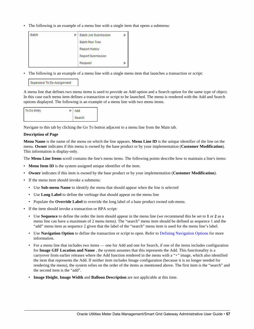
Oracle Utilities Meter Data Management/Smart Grid Gateway Administrative User Guide • 57
• The following is an example of a menu line with a single item that opens a submenu:
• The following is an example of a menu line with a single menu item that launches a transaction or script:
A menu line that defines two menu items is used to provide an Add option and a Search option for the same type of object.In this case each menu item defines a transaction or script to be launched. The menu is rendered with the Add and Searchoptions displayed. The following is an example of a menu line with two menu items.
Navigate to this tab by clicking the Go To button adjacent to a menu line from the Main tab.
Description of Page
Menu Name is the name of the menu on which the line appears. Menu Line ID is the unique identifier of the line on themenu. Owner indicates if this menu is owned by the base product or by your implementation (Customer Modification).This information is display-only.
The Menu Line Items scroll contains the line's menu items. The following points describe how to maintain a line's items:
• Menu Item ID is the system assigned unique identifier of the item.
• Owner indicates if this item is owned by the base product or by your implementation (Customer Modification).
• If the menu item should invoke a submenu:
• Use Sub-menu Name to identify the menu that should appear when the line is selected
• Use Long Label to define the verbiage that should appear on the menu line
• Populate the Override Label to override the long label of a base product owned sub-menu.
• If the item should invoke a transaction or BPA script:
• Use Sequence to define the order the item should appear in the menu line (we recommend this be set to 1 or 2 as amenu line can have a maximum of 2 menu items). The “search” menu item should be defined as sequence 1 and the“add” menu item as sequence 2 given that the label of the “search” menu item is used for the menu line’s label.
• Use Navigation Option to define the transaction or script to open. Refer to Defining Navigation Options for moreinformation.
• For a menu line that includes two items — one for Add and one for Search, if one of the items includes configurationfor Image GIF Location and Name , the system assumes that this represents the Add. This functionality is acarryover from earlier releases where the Add function rendered in the menu with a “+” image, which also identifiedthe item that represents the Add. If neither item includes Image configuration (because it is no longer needed forrendering the menu), the system relies on the order of the items as mentioned above. The first item is the “search” andthe second item is the “add”.
• Image Height, Image Width and Balloon Description are not applicable at this time.
Oracle Utilities Meter Data Management/Smart Grid Gateway Administrative User Guide • 58
• Use the Long Label to define the text to appear on the menu entry. Note that when a menu line defines two menu items,the long label on the search entry is used to build the menu entry text. The label long on the menu line that defines theAdd option is information only.
• The Override Label is provided in case you want to override the base-package's label.
• Use Application Service and Access Mode to easily suppress a menu item for one or more users. Refer to ApplicationSecurity for more information.
The Big Picture of System MessagesAll error, warning and informational messages that are displayed in the system are maintained on the message table. Everymessage is identified by a combination of two fields:
• Message category number. Think of a message category as a library of messages related to a given functional area. Forexample, there is a message category for billing messages and another one for payment messages.
• Message number. A unique number identifies each message within a category.
Every message has two components: a brief text message and a long description. On the Main tab, you can only maintainthe brief message. If you need to update a message's long description, you must display the message on the Details tab.
NOTE: You cannot change the product’s text. If the message is "owned" by the product, you cannot change theproduct’s message or detailed description. If you want your users to see a different message or detailed descriptionother than that supplied by the product, display the message on the Details tab and enter your desired verbiage in the"customer specific" fields (and flush the cache).
Defining System MessagesThe contents of this section describe how to maintain messages that appear throughout the system. An implementation mayintroduce messages used in custom processes or may choose to override the text for messages delivered by the product.
Message - MainSelect Admin > System > Message to maintain a message category and its messages.
Description of Page
To add a new message category, enter a Message Category number and Description.
CAUTION: Message category 80000 or greater must be used to define new messages introduced for a specificimplementation of the system. Changes to other Message Text will be overwritten when you next upgrade. If you wantto make a change to a Message, drill down on the message and specify Customer Specific Message Text. Note that evenfor message categories 80000 and higher, message numbers lower than 1000 are reserved for common base productmessages.
NOTE: Owner indicates if this message category is owned by the base product or by your implementation (CustomerModification). The system sets the owner to Customer Modification when you add a category. This information isdisplay-only.
To update a message, you must first display its Message Category. You can optionally start the message grid at a StartingMessage Number.
To override the message text or detailed description of messages owned by the base product, click on the message's go tobutton. When clicked, the system takes you to the Details tab on which you can enter your implementation's override text.

Oracle Utilities Meter Data Management/Smart Grid Gateway Administrative User Guide • 59
The following points describe how to maintain messages owned by your implementation:
• Click the - button to delete a message.
• Click the + button to add a new message. After clicking this button, enter the following fields:
• Use Message Number to define the unique identifier of the message within the category.
• Use Message Text to define a basic message. You can use the %n notation within the message text to cause field valuesto be substituted into a message. For example, the message text The %1 non-cash deposit for %2 expires on %3 willhave the values of 3 fields merged into it before it is displayed to the user (%1 is the type of non-cash deposit, %2 is thename of the customer, and %3 is the expiration date of the non-cash deposit).
NOTE: The system merges whatever values are supplied to it. Therefore, if a programmer supplies a premiseaddress as the second merge parameter in the above message, this address is merged into the message (rather than thecustomer's name).
• Owner indicates if this message number is owned by the base product or by your implementation (CustomerModification). The system sets the owner to Customer Modification when you add a message. This information isdisplay-only.
• Click the go to button to enter a detailed description of the message. Clicking this button transfers you to the Details tab.
Where Used
Follow this link to open the data dictionary where you can view the tables that reference CI_MSG. In addition, messages areused throughout the system for error messages and other system messages.
Message - DetailsSelect Admin > System > Message and navigate to the Details tab to define detailed information about a message.
NOTE: Drilling in from the Main tab. Rather than scrolling through the messages, you can display a message byclicking the respective go to button in the grid on the main tab.
Description of Page
The Message Collection scroll contains an entry for every message in the grid on the Main tab. It's helpful to categorizemessages into two categories when describing the fields on this page:
• Product messages
• Implementation-specific messages (i.e., a message added to Message Category 80000 or greater)
For product messages, you can use this page as follows:
• If you want to override a message, specify Customer Specific Message Text.
• You are limited to the same substitution values used in the original Message Text. For example, if the original MessageText is The %1 non-cash deposit for %2 expires on %3 and %1 is the type of non-cash deposit, %2 is the name of thecustomer, and %3 is the expiration date of the non-cash deposit; your Customer Specific Message Text is limited to thesame three substitution variables. However, you don't have to use any substitution variable in your message and you canuse the substitution variables in whatever order you please (e.g., %3 can be referenced before %1, and %2 can be left outaltogether).
• If you want to override the detailed description of an error message, specify Customer Specific Description. Note thatthe system does not present detailed descriptions when warnings are shown to users. Therefore, it doesn't make sense toenter this information for a warning message.
For implementation-specific messages, you can use this page as follows:
• Message Text is the same Message Text displayed on the main tab.

Oracle Utilities Meter Data Management/Smart Grid Gateway Administrative User Guide • 60
CAUTION: If both Message Text and Customer Specific Message Text are specified, the system will only display theCustomer Specific Message Text in the dialog presented to the user.
• Use Detailed Description to define additional information about an error message. Note that the system does not presentdetailed descriptions when warnings are shown to users. Therefore, it doesn't make sense to enter this information for awarning message.
CAUTION: If both Detailed Description and Customer Specific Description are specified, the system will onlydisplay the Customer Specific Description in the dialog presented to the user.
The Big Picture of Portals and ZonesA portal is a page that is comprised of one or more information zones. The base product pages are built using either a fixedpage metaphor or using portals and zones. The contents of this section describe general information about portals and zones.
There Are Three Types of PortalsThere are three broad classes of portals:
• Standalone Portal. Standalone portals are separate pages where the main tab of the page is built using a portal. Thesepages are opened using any of the standard methods (e.g., by selecting a menu item, by selecting a favorite link, etc.).Additional tabs for a stand-alone portal may be included using tab page portals.
• Tab Page Portals. These types of portals cannot be attached to a menu. They simply define the zones for a tab oneither a standalone portal or on a “fixed” page. Please contact customer support if you need to add portals to existingtransactions.
• Dashboard Portal. The dashboard portal is a portal that appears in the Dashboard Area on the user’s desktop. Its zonescontain tools and information that exist on the user's desktop regardless of the transaction.
There is only one dashboard portal. This portal and several zones are delivered as part of the base-package. Yourimplementation can add additional zones to this portal. Please contact customer support if you need to add zones to thedashboard portal.
Common Characteristics of All PortalsThe topics that follow describe characteristics common to all types of portals.
Portals Are Made Up of ZonesA portal is a page that contains one or more zones, and each zone contains data of some sort.
All zones reference a Zone Type. The zone type controls the behavior of the zone and the parameters available to configurethe zone.
Configuring Zones for a PortalThe portal includes configuration of how the zones should appear on the portal by default. This includes the followingoptions, all of which may be overridden by an implementation.
• The order in which the zone should appear. An implementation may configure an override sequence to change the orderzones on a base delivered portal.

Oracle Utilities Meter Data Management/Smart Grid Gateway Administrative User Guide • 61
• Whether the zone is visible on the portal. Zones delivered in the base product should be configured to be visible. But animplementation may override this if desired.
• Whether the zone should display initially collapsed or not. A zone’s data is only retrieved when it is expanded. As such,a zone may be configured to be initially collapsed when the data is not needed very often. A user can expand the zonewhen the information is required. Implementations may change the collapsed setting of a base product portal / zone.
FASTPATH: Refer to Zones May Appear Initially Collapsed When a Page Opens for more information.
FASTPATH: Refer to Defining Portals for more information about this configuration.
In addition, the portal includes configuration to indicate whether or not the portal should appear on a user’s portalpreferences. This is typically enabled for a portal that provides disparate information where not all zones are applicable toall users or where users may wish to adjust the order of the zones. An example of a portal enabled for portal preferences isthe Dashboard portal. The user can override zone oriented configuration for the portal:
• Which zones appear on that portal
• The order in which the zones appear
• Whether the zones should be initially collapsed when the portal opens.
• The refresh seconds. This is applicable to zones displaying data that changes often.
An implementation can optionally configure the system to define portal preferences on one or more "template" users. Whena template user is linked to a "real" user, the real user's preferences are inherited from the "template" user and the "real" usercannot change their preferences. Some implementations opt to work this way to enforce a standard look and feel for users inthe same business area.
FASTPATH: Refer to User — Portal Preferences for more information about how users configure their zones.
Granting Access to ZonesAn application service is associated with each zone. A user must be granted access rights to the respective applicationservice in order to see a zone on a portal.
FASTPATH: Refer to The Big Picture Of Application Security for information about granting users access rights to anapplication service.
Please note the following with respect to zone application security:
• For most base product portals, all the zones for all the portals reference the same application service that is used to grantaccess to the main (stand-alone) portal for the page. In other words, if the user has access to the page, then he has accessto all the zones on all portals for the page. There may be exceptions to this rule for certain portals.
• For a base product multi-query zones, typically the individual query zones and the multi-query zone reference the sameapplication service that is used to grant access to the main (stand-alone) portal for the page. However, there may beindividual query zones provided with a unique application service. This may occur when the query option is unusual andnot applicable to all users or even to all implementations. If a user does not have security access to an individual queryzone, that option will not be available in the dropdown.
• For base product portals that are configured to show on portal preferences, it is common that the portal contains differenttypes of zones that may be applicable to different types of users. Typically these types of portals will deliver a uniqueapplication service for each zone so that an implementation may configure which user groups are allowed to view eachzone. For these types of portals, please note the following:
• A user's Portal Preferences page contains a row for a zone regardless of whether the user has access rights to the zone.Because of this, the system displays an indication of the user's access rights to each zone.
Oracle Utilities Meter Data Management/Smart Grid Gateway Administrative User Guide • 62
• If a user's access rights to a zone are revoked, the zone will be suppressed when the user navigates to the respectiveportal.
• Revoking a user's access rights does not change the user's portal preferences (i.e., a user can indicate they want to seea zone even if they don't have access to the zone - such a zone just won't appear when the respective portal appears).
NOTE: If you don't need to use zone security. When defining a zone, an application service is required. For zones thatdon’t require special security, the product provides a “default” application service (F1-DFLTS) that may be used. Theexpectation is that all user groups are granted access to this application service.
Common Characteristics of Stand-Alone PortalsThe topics that follow describe addition characteristics specific to stand-alone portals.
Putting Portals on MenusA stand-alone portal should appear as a menu item on one of your menus. The following points provide how to do this:
• Every stand-alone portal has an associated navigation option. You can see a portal's navigation option on the Portal -Main page.
• To add a portal to a menu, you must add a menu item to the desired menu. This menu item must reference the portal'snavigation option. There are two ways to add a menu item:
• If the portal's navigation option doesn't currently exist on a menu, you can press the Add To Menu button on the Portal -Main page. When you press this button, you will be prompted for the menu. The system will then create a menu item onthis menu that references the portal's navigation option.
• You can always use the Menu page to add, change and delete menu items.
NOTE: No limit. A portal's navigation option can appear on any number of menu items (i.e., you can create severalmenu items that reference the same portal.
NOTE: Favorite links. Your users can set up their preferences to include the portal's navigation option on their FavoriteLinks. This way, they can easily navigate to the portal without going through menus.
Granting Access to A PortalAn application service is associated with each stand-alone portal. A user must be granted access rights to the respectiveapplication service in order to see a portal. Tab portals do not have separate security access. If a user has access to themain stand-alone portal, then the user will have security access to all its tabs. However, as mentioned in Granting Accessto Zones, in some scenarios, the individual zones on the portal may have different security access rights depending on thefunctionality.
FASTPATH: Refer to The Big Picture Of Application Security for information about granting users access rights to anapplication service.
NOTE: Automatically created. When you add a new stand-alone portal, the system automatically creates anapplication service behind the scenes. You'll need to know the name of this application service as this is what you use togrant access to the portal. The name of each stand-alone portal's application service is shown on the portal transaction.
Please note the following in respect of how application security impacts a user's portals:
Oracle Utilities Meter Data Management/Smart Grid Gateway Administrative User Guide • 63
• A user's Portal Preferences page only shows the portals configured to show on user preferences and where they havesecurity access.
• The system's menus only show portals to which a user has security access.
• Users can set up favorite links to all portals, but they must have security rights to the portal's application service in orderto invoke the favorite link.
Custom Look and Feel OptionsThe default look and feel of the application can be customized via feature configuration and cascading style sheets. Thebase product is provided with a Custom Look And Feel Feature Configuration type. You may want to set up a featureconfiguration of this type to define style sheet and UI Map help options.
User InterfaceThe base product allows for the conditional inclusion of custom style sheets into the system style set. Custom styles mayoverride any style provided by the base product. The style sheet may also include new styles for use in customer zonedefinitions. Use the Style Sheet option on the Custom Look And Feel Feature Configuration to define your custom stylesheet.
NOTE: Some styles cannot change if they are part of the HTML code.
CAUTION: Implementers must ensure that the customized user interface is stable and scalable. Changing font,alignment padding, border size, and other user interface parameters may cause presentation problems, like scrollbarsappearing or disappearing, cursors not working as expected, and unanticipated look and feel alterations of some layouts.
UI Map HelpA tool tip can be used to display additional help information to the user. This applies to section elements as well asindividual elements on a map zone or UI Map. Refer to the tips context sensitive zone associated with the UI Map page formore information. The Custom Look And Feel Feature Configuration provides options to control the following:
• Whether UI Map Help functionality is turned on or off. By default it is turned on.
• Override the default help image with a custom image
• The location of the help image, either before or after the element.
FASTPATH: Refer to the feature configuration for a detailed description of each option.
Setting Up Portals and ZonesThe topics in this section describe how to set up portals and zones. Please refer to The Big Picture of Portals and Zones forbackground information.
Defining Zone TypesA Zone Types represents a particular type of zone with a specific behavior. For example, a data explorer zone type is usedto select data using a specific SQL statement and display the data based on parameter configuration. The zone type definesthe Java Class that controls the behavior of the zone and defines the parameters that the Java Class supports. The base
Oracle Utilities Meter Data Management/Smart Grid Gateway Administrative User Guide • 64
product supports many zone types used to build the portal / zone user interface. Implementations may introduce their ownzone types.
NOTE: It is not very common for an implementation to introduce their own zone types.
Select Admin > System > Zone Type to maintain zone types.
Description of Page
Specify an easily recognizable Zone Type code and Description. Use the Detailed Description to describe in detail whatthe zone type does.
CAUTION: When adding new zone types, carefully consider its naming convention. Refer to System Data NamingConvention for more information.
Owner indicates if this zone type is owned by the base product or by your implementation (Customer Modification). Thesystem sets the owner to Customer Modification when you add a zone type. This information is display-only.
Java Class Name is the Java class responsible for building the zone using the parameters defined below.
Two types of parameters are specified when defining a zone type:
• Parameter values that have a Usage of Zone are defined on the zones and control the functionality of each zone governedby the zone type. A Usage value of Zone - Override Allowed indicates that an implementation may override theparameter value for a base zone.
• Parameter values that have a Usage of Zone Type are defined directly on the zone type and control how the zone typeoperates (e.g., the name of the XSL template, the name of the application service). A Usage value of Zone Type -Override Allowed indicates that an implementation may override the parameter value for a base zone type.
The following points describe the fields that are defined for each parameter:
• Sequence defines the relative position of the parameter.
• Parameter Name is the name of the parameter.
• Description is a short description that allows you to easily identify the purpose of the parameter.
• Comments contain information that you must know about the parameter or its implementation. For parameters witha usage of Zone or Zone — Override Allowed, this information is visible to the user when viewing or defining thisparameter for a zone of this type.
• Usage indicates whether the parameter value is defined in a Zone of this type or in the Zone Type. Zone - OverrideAllowed and Zone Type - Override Allowed indicate that override values for the parameters defined in a base zone orbase zone type can be entered.
• Required is checked to indicate that a zone must define a value for the parameter. It is not checked if a value for theparameter is optional. This field is protected if the Usage is Zone Type or Zone Type - Override Allowed.
• Parameter Value is used to define the value of zone type parameters. This field is protected if the Usage is Zone orZone - Override Allowed.
• Owner indicates if this parameter is owned by the base product or by your implementation (Customer Modification).The system sets the owner to Customer Modification when you add a parameter. This information is display-only.
Where Used
Follow this link to open the data dictionary where you can view the tables that reference CI_ZONE_HDL.
Zone Type Parameter CommentsFor the product owned zone type parameters, the parameter’s detailed description provides the detail needed for properlyconfiguring the parameter. For the Action parameters (IMPLEMENTOR_ACTION_n), the parameter description is
Oracle Utilities Meter Data Management/Smart Grid Gateway Administrative User Guide • 65
abbreviated. Additional detail about configuring this parameter may be found in the Zone Action Parameter detailedinformation. The same details apply.
Defining ZonesThe contents of this section describe how to maintain zones.
Zone - MainImplementations may use the zone page to define custom zones. In addition, an implementation may override descriptionsor some parameter values for base product zones.
Select Admin > System > Zone to create or maintain a zone.
Description of Page
Specify an easily recognizable Zone identifier and Description. Note that if this zone appears on a portal, this descriptionacts as the zone title.
Override Description is provided if your implementation wishes to override the description of the value provided by theproduct.
CAUTION: Important! When introducing a new zone, carefully consider its naming convention. Refer to System DataNaming Convention for more information.
Owner indicates if this zone is owned by the base product or by your implementation (Customer Modification). Thesystem sets the owner to Customer Modification when you add a zone. This information is display-only.
Zone Type identifies the zone type that defines how the zone functions.
Application Service is the application service that is used to provide security for the zone. Refer to Granting Access ToZones for more information.
The Width defines if the zone occupies the Full width of the portal or only Half.
NOTE: Zones on the dashboard portal are always the width of the dashboard.
If the zone type supports help text, you can use Zone Help Text to describe the zone to the end-users. Note that for multi-query zones, if the multi-query zone has help text, that is displayed for any zone selected. If the multi-query zone does nothave help text, but the selected zone has help text, the selected zone’s help text is displayed. Please refer to the section onzone help text for more information on how you can use HTML and cascading style sheets to format the help text.
Use Override Zone Help Text to override the product provided help text for this zone.
NOTE: Viewing Your Text. You can press the Test button to see how the help text will look when it's displayed in thezone.
The grid contains the zone's parameter values. The Zone Type controls the list of parameters. The grid contains thefollowing fields:
• Description describes the parameter. This is display-only. Note that if there is a detailed description on the zone typeparameter, an icon appears next to the parameter's description. Click the icon to see details related to the parameter,including tips on how to populate the parameter value.
NOTE: Additional Details for Some Parameters. There are several parameter types that have a lot of detail relatedto the possible configuration that cannot easily fit into the detailed description. Refer to Zone Parameter Details foradditional information about these parameters.
Oracle Utilities Meter Data Management/Smart Grid Gateway Administrative User Guide • 66
• Parameter Value is the value for the parameter.
• Use Override Parameter Value to override the existing value for this parameter. This field is enabled when the relatedzone type parameter value is Zone - Override Allowed, and the zone is owned by the base product.
• Owner indicates if this parameter is owned by the base product or by your implementation (Customer Modification).This information is display-only.
Where Used
Follow this link to open the data dictionary where you can view the tables that reference CI_ZONE.
Zone - PortalSelect Admin > System > Zone and navigate to the Portal tab to define the portals on which a zone appears.
Description of Page
The scroll area contains the portals on which the zone appears.
To add a zone to a portal, press the + button and specify the Portal.
NOTE: Owner indicates if this portal / zone relationship is owned by the base product or by your implementation(Customer Modification). This information is display-only.
NOTE: You can also add a zone to a portal using Portal - Main. Additional configuration about how the zone appears onthe portal is available only on the Portal.
Zone Configuration TopicsThe topics in this section provide additional information related to setting up your zones.
Zone Help TextMost zone types support a button that allows a user to see zone-specific help text, which is defined on the zone page.
You can use HTML tags in the zone help text. The following is an example of help text that contains a variety of HTMLtags:
This zone summarizes <font color=blue><b>revenue</b></font> in 4 periods:<br>
The above would cause the word revenue to be bold and blue:
• <b> and </b> are the HTML tags used to indicate that the surrounded text should be bold
• <font color=blue> and </font> are the HTML tags used to indicate that the surrounded text should be blue.
The following are other useful HTML tags:
• <br> causes a line break in a text string. If you use <br><br> a blank line will appear.
• <I> causes the surrounded text to be italicized
Please refer to an HTML reference manual or website for more examples.
You can also use "spans" to customize the look of the contents of a text string. For example, your text string could be <spanstyle="font-family:Courier; font-size:large; font-weight:bold;">revenue</span>. This would make the word "revenue"appear as large, bold, Courier text. Please refer to a Cascading Style Sheets (CSS) reference manual or website for moreexamples.
The following is an example of help text using a variety of HTML tags:
Oracle Utilities Meter Data Management/Smart Grid Gateway Administrative User Guide • 67
<font FACE="arial" size=2>
This zone summarizes <font color=blue><b>revenue</b></font> in 4 periods:<br>
- The <b>1st period</b> is under your control. You simply select the desired <b>Period</b>, above <i>(you may need toclick the down arrow to expose the filter section)</i><br>
- The <b>2nd period</b> is the period before the 1st period<br>
- The <b>3rd period</b> is the same as the 1st period, but in the previous year<br>
- The <b>4th period</b> is the period before the 3rd period<br>
<br>
The traffic light's color is determined as follows:<br>
- The ratio of the 1st and 3rd period is calculated<br>
- If this value is between 80 and 100, <font color=orange><b>yellow</b></font> is shown<br>
- If this value is < 80, <font color=red><b>red</b></font> is shown<br>
- If this value is > 100, <font color=green><b>green</b></font> is shown<br>
- If the value of the 3rd period is 0, no color is shown<br>
</font>
NOTE: It is possible to associate tool tip help with individual HTML and UI map elements. For more information, seeUI Map Help.
Zone Parameter DetailsFor most zone parameters, the embedded help for the parameter provides the detailed information needed for configuringthe parameter values. For some parameters with very detailed descriptions, the embedded help is abbreviated and moredetail is provided here.
Zone Visibility Service ScriptAll zones support a visibility script that is used to determine if the zone should be displayed to the user or not based onconditions. The script may receive input parameters and is expected to return a Boolean value indicating if the zone shouldbe displayed or not. The embedded help for the Zone Visibility Service Script parameter provides details related to thesyntax.
The following table highlights some service scripts provided by the product that may be used if applicable to your zone'srequirements. This is not an exhaustive list of visibility scripts. There may be others that are specific to a given zone.
Script Code Description CommentsF1-ShldShwZn Zone Visibility - Display Zone in Portal This script simply returns a value of 'true' and
is used when the zone should always appear.
F1-CondShwZn Zone Visibility - Display Zone in PortalConditionally
This is used when the condition for showingthe zone is based on the population of acontext value. This is commonly used whenone zone in the portal should only appearafter a broadcast of a record from anotherzone in the portal.For an example of a zone the uses thisvisibility script, refer to F1-BSFTYPE .
F1-RwCtShwZn Zone Visibility - Based on Row Count This is used when the condition for showingthe zone is based on the existence of one ormore rows that can be determined using SQL.This script accepts a zone code, user filters1 through 25 and hidden filters 1 through 10.
Oracle Utilities Meter Data Management/Smart Grid Gateway Administrative User Guide • 68
Script Code Description CommentsThe script returns an indication of 'true' if atleast one row count is returned by the zone.To use this visibility script, a specific dataexplorer zone must be developed for thespecific use case.For an example of a zone the uses thisvisibility script, refer to F1-MIGRREQEL .
SQL StatementData explorer zones are used to select data to display using one or more SQL statements. The SQL parameters areapplicable to the following zone types
• Info Data Explorer - Single SQL (F1–DE-SINGLE). The parameter has the description SQL Statement.
• Info Data Explorer - Multiple SQLs (F1–DE). The parameters follow the description pattern of SQL Statement x.
• Query Data Explorer - Multiple SQLs (F1–DE-QUERY). The parameters follow the description pattern of SQLStatement x.
NOTE: If your implementation has been configured to restrict the functions that may be used when defining an SQLthen an error is issued at runtime if there are functions found that are not in the whitelist. The whitelist may be viewedusing the View SQL function whitelist link in the Tips zone on the zone maintenance page.
The following table provides a list of SQL substituted keywords that may be used in the SQL Statement parameters inexplorer zones. At execution time, the system determines the database and substitutes the keyword with the databasespecific syntax:
Keyword Description Examples@toCharacter() Converts the input to Character data type. select @toCharacter(batch_cd) as
batchCode from ci_batch_ctrl
@toDate() Converts the input to Date data type. select @toDate(last_update_dttm) aslastUpdateDate from ci_batch_ctrl
@toNumber() Converts the input to Number data type. select @toNumber(next_batch_nbr) from ci_batch_ctrl
@currentDate Fetches the current date.
CAUTION: The Oracle functions SYSDATEand CURRENT_DATE should not be usedbecause they do not properly cater foradjusting dates from the database timezone to the installation time zone, if needed.
select batch_cd, @currentDate as today fromci_batch_ctrl
@currentTimestamp Fetches the current date / time.
CAUTION: The Oracle functionsSYSTIMESTAMP and CURRENT_TIMESTAMP should not be used becausethey do not properly cater for adjusting thedate / time from the database time zone tothe installation time zone, if needed.
select batch_cd from ci_batch_ctrl where last_update_dttm > @currentTimestamp
@concat Combines the result list of two or morecolumns.
select batch_cd @concat next_batch_nbrconcatNbr from ci_batch_ctrl
@substr(string, start) String is the input String that you are trying toget a substring of.Start is the position of the character for theoutput results.
select batch_cd batchCode from ci_batch_ctrlResult: TESTCDselect @substr(batch_cd,3) batchCode fromci_batch_ctrlResult: STCD
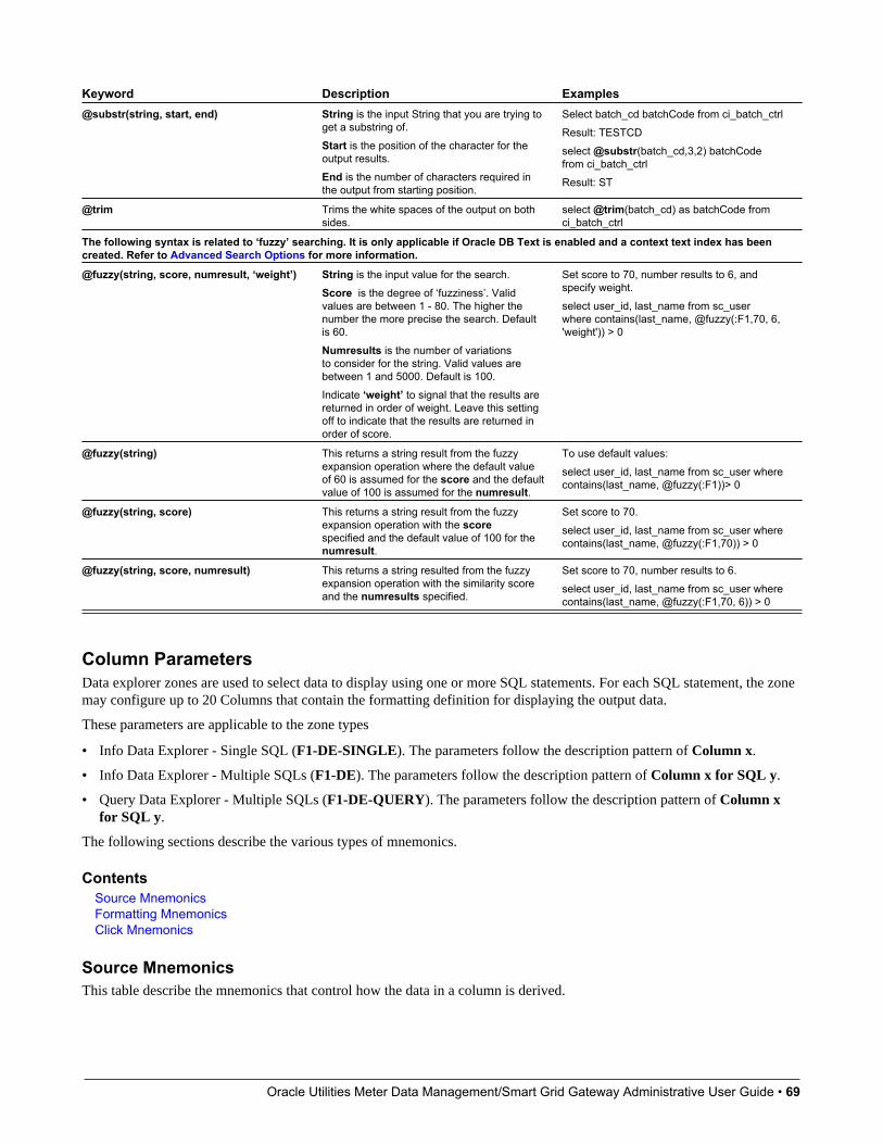
Oracle Utilities Meter Data Management/Smart Grid Gateway Administrative User Guide • 69
Keyword Description Examples@substr(string, start, end) String is the input String that you are trying to
get a substring of.Start is the position of the character for theoutput results.End is the number of characters required inthe output from starting position.
Select batch_cd batchCode from ci_batch_ctrlResult: TESTCDselect @substr(batch_cd,3,2) batchCodefrom ci_batch_ctrlResult: ST
@trim Trims the white spaces of the output on bothsides.
select @trim(batch_cd) as batchCode fromci_batch_ctrl
The following syntax is related to ‘fuzzy’ searching. It is only applicable if Oracle DB Text is enabled and a context text index has beencreated. Refer to Advanced Search Options for more information.
@fuzzy(string, score, numresult, ‘weight’) String is the input value for the search.Score is the degree of ‘fuzziness’. Validvalues are between 1 - 80. The higher thenumber the more precise the search. Defaultis 60.Numresults is the number of variationsto consider for the string. Valid values arebetween 1 and 5000. Default is 100.Indicate ‘weight’ to signal that the results arereturned in order of weight. Leave this settingoff to indicate that the results are returned inorder of score.
Set score to 70, number results to 6, andspecify weight.select user_id, last_name from sc_userwhere contains(last_name, @fuzzy(:F1,70, 6,'weight')) > 0
@fuzzy(string) This returns a string result from the fuzzyexpansion operation where the default valueof 60 is assumed for the score and the defaultvalue of 100 is assumed for the numresult.
To use default values:select user_id, last_name from sc_user wherecontains(last_name, @fuzzy(:F1))> 0
@fuzzy(string, score) This returns a string result from the fuzzyexpansion operation with the scorespecified and the default value of 100 for thenumresult.
Set score to 70.select user_id, last_name from sc_user wherecontains(last_name, @fuzzy(:F1,70)) > 0
@fuzzy(string, score, numresult) This returns a string resulted from the fuzzyexpansion operation with the similarity scoreand the numresults specified.
Set score to 70, number results to 6.select user_id, last_name from sc_user wherecontains(last_name, @fuzzy(:F1,70, 6)) > 0
Column ParametersData explorer zones are used to select data to display using one or more SQL statements. For each SQL statement, the zonemay configure up to 20 Columns that contain the formatting definition for displaying the output data.
These parameters are applicable to the zone types
• Info Data Explorer - Single SQL (F1-DE-SINGLE). The parameters follow the description pattern of Column x.
• Info Data Explorer - Multiple SQLs (F1-DE). The parameters follow the description pattern of Column x for SQL y.
• Query Data Explorer - Multiple SQLs (F1-DE-QUERY). The parameters follow the description pattern of Column xfor SQL y.
The following sections describe the various types of mnemonics.
ContentsSource MnemonicsFormatting MnemonicsClick Mnemonics
Source MnemonicsThis table describe the mnemonics that control how the data in a column is derived.

Oracle Utilities Meter Data Management/Smart Grid Gateway Administrative User Guide • 70
Mnemonic Description Valid Values Comments
SQLCOL Indicates that the source of thecolumn's value comes from a columnin the SQL statement. This typeof column must also reference thesqlcol= mnemonic.
BO Indicates that the source of thecolumn's value comes from a businessobject. This type of column mustalso reference the bo=, input= andoutput= mnemonics to define how tointeract with the business object.
BS Indicates that the source of thecolumn's value comes from a businessservice. This type of column mustalso reference the bs=, input= andoutput= mnemonics to define how tointeract with the business service.
SS Indicates that the source of thecolumn's value comes from a servicescript. This type of column mustalso reference the ss=, input= andoutput= mnemonics to define how tointeract with the service script.
FORMULA Indicates that the source of thiscolumn's value is calculated using aformula. This type of column must alsoreference the formula= mnemonic.
SETFUNC Indicates that the source of thiscolumn's value is calculated using asuperset of values from the rows in theSQL statement. This type of columnmust also reference the setfunc=mnemonic.
ICON Indicates that the source of thiscolumn's value is a display iconreference (meaning that an icon willbe displayed in the column). This typeof column must also reference theicon= mnemonic to define the iconreference.
NOTE: When using this sourcemnemonic, the formattingmnemonictype= is not applicable.
source= Defines how the column's value isderived.
FKREF Indicates that the source of thiscolumn's value is an FK reference(meaning that the FK reference'scontext menu and information stringwill be displayed in the column). This

Oracle Utilities Meter Data Management/Smart Grid Gateway Administrative User Guide • 71
Mnemonic Description Valid Values Commentstype of column must also referencethe fkref= and input= mnemonics todefine how the FK reference is called.
NOTE: When using this sourcemnemonic, the formattingmnemonictype= is not applicable.
SPECIFIED Indicates that the source of thiscolumn's value is specified byconcatenating literals and othercolumn values. This type of columnmust also reference the spec=mnemonic.
MSG Indicates that the source of thiscolumn is a message from themessage table (along with anysubstitution variables). This type ofcolumn must also reference the msg=mnemonic.
COLUMN_NAME Enter the name of a column that isretrieved in the SELECT statement.Note that if the select statement usesan alias for a column, then the aliasshould be referenced here.
sqlcol= Defines the column in the SQLstatement when source=SQLCOL.
x Where x is an integer value thatreferences a column by its relativeposition in the SELECT statement. Forexample, sqlcol=3 would display the3rd column in the SELECT statement).
bo= Defines the business object to invokewhen source=BO.
This mnemonic must be used inconjunction with the input= andoutput= mnemonics to define howinformation is sent to / received fromthe business object.
'Business Object Code'
bs= Defines the business service to invokewhen source=BS.
This mnemonic must be used inconjunction with the input= andoutput= mnemonics to define howinformation is sent to/received from thebusiness service.
'Business Service Code'
ss= Defines the service script to invokewhen source=SS.
This mnemonic must be used inconjunction with the input= andoutput= mnemonics to define how
'Service Script Code'

Oracle Utilities Meter Data Management/Smart Grid Gateway Administrative User Guide • 72
Mnemonic Description Valid Values Commentsinformation is sent to / received fromthe service script.
Cx This means FK reference code isdefined in an earlier column. Forexample, define C1 if column 1 definesthe FK reference value.
COLUMN_NAME This means the FK reference wasretrieved by the SELECT statement.The value should match the namedefined in the SELECT clause.
fkref= Defines the FK reference used toretrieve the column’s information whensource=FKREF.
This mnemonic must be used inconjunction with the input= mnemonicto define how information is sent to theFK reference to build the information.
'FK Reference Code' This means the FK Reference isdefined directly. For example 'F1-ROLE'.
For column references, use the formatCx where x represents the columnnumber.
formula= Defines the formula to use whensource=FORMULA.
Examples:
• formula=C1*.90/C2
• formula=(C1/C2)*100
The formula can contain numericconstants, operators and columnreferences.
Refer to Expression Parser forinformation about the functionssupported.
setfunc= Defines the function to apply tothe rows of a given column whensource=SETFUNC.
function(Cx) Where Cx represents a columnwhose rows should have the functionapplied and the function is one of thefollowing:
• MAX. This derives the maximumvalue of all rows in the column.
• MIN. This derives the minimumvalue of all rows in the column.
• TOT. This derives the sum (totalvalue) of all rows in the column.
• ACC. This derives the cumulativetotal of all rows up to an includingthe current row.
Cx Where Cx represents the value of aprevious column. If the value to pass isin the first column, reference C1.
COLUMN_NAME This means the value to pass in wasretrieved by the SELECT statement.The value should match the namedefined in the SELECT clause.
'literal value' This means a literal value within thesingle quotes should be passed in.
input= This is used to define one or moreinput fields and values passed tobusiness objects, business services,service scripts, and FK references.
The syntax is as follows: [ELEMENT_NAME=ELEMENT_REF ELEMENT_NAME=ELEMENT_REF ...]
In other words, the list of inputvalues is surrounded by squarebrackets separated by a space.Each passed value first defines theELEMENT_NAME, which is the nameof the element / field in the target.ELEMENT_REF is the value passedin. The next column indicates thepossible values for ELEMENT_REF.
userTimeZone This means the current user's timezone should be passed in. This istypically used with the businessservice F1-ShiftDateTime to convertdata in the storage time zone to theuser's time zone for display.
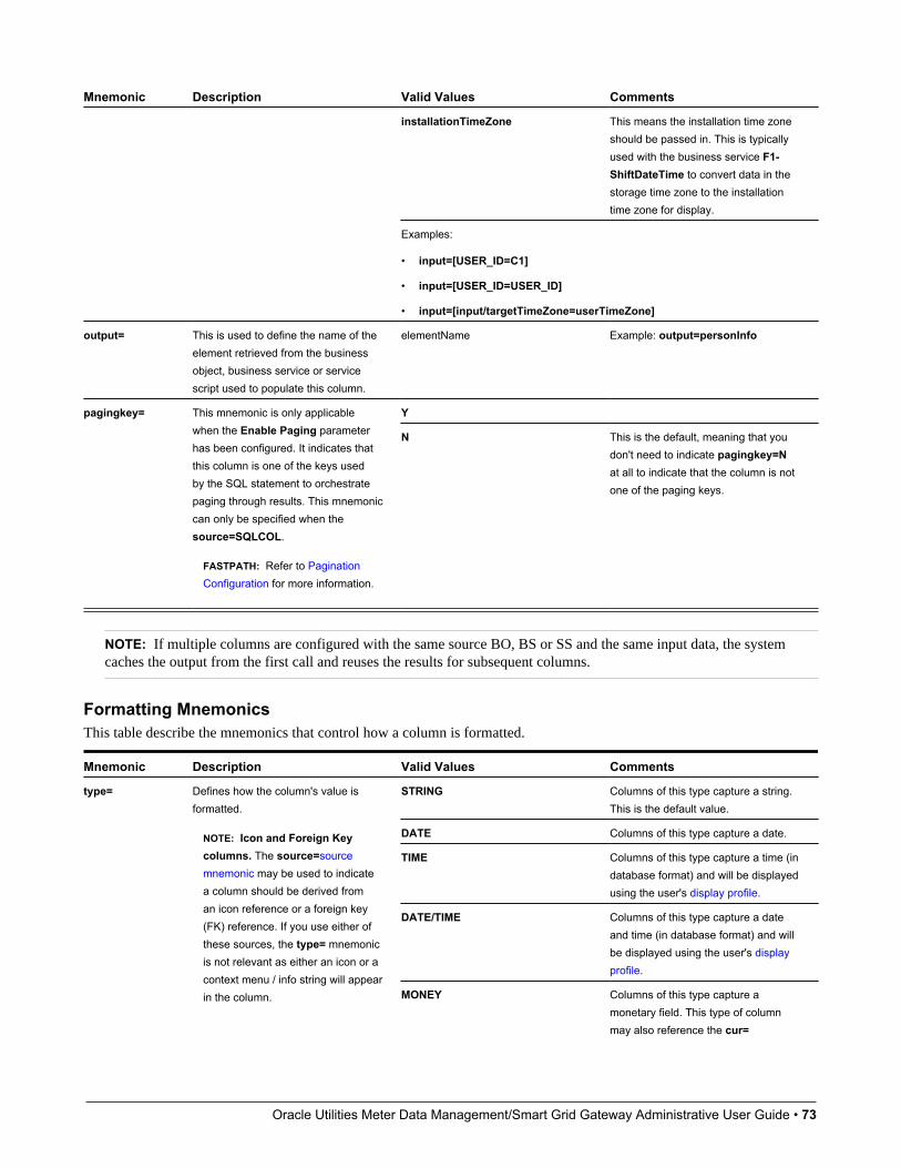
Oracle Utilities Meter Data Management/Smart Grid Gateway Administrative User Guide • 73
Mnemonic Description Valid Values Comments
installationTimeZone This means the installation time zoneshould be passed in. This is typicallyused with the business service F1-ShiftDateTime to convert data in thestorage time zone to the installationtime zone for display.
Examples:
• input=[USER_ID=C1]
• input=[USER_ID=USER_ID]
• input=[input/targetTimeZone=userTimeZone]
output= This is used to define the name of theelement retrieved from the businessobject, business service or servicescript used to populate this column.
elementName Example: output=personInfo
Ypagingkey= This mnemonic is only applicablewhen the Enable Paging parameterhas been configured. It indicates thatthis column is one of the keys usedby the SQL statement to orchestratepaging through results. This mnemoniccan only be specified when thesource=SQLCOL.
FASTPATH: Refer to PaginationConfiguration for more information.
N This is the default, meaning that youdon't need to indicate pagingkey=Nat all to indicate that the column is notone of the paging keys.
NOTE: If multiple columns are configured with the same source BO, BS or SS and the same input data, the systemcaches the output from the first call and reuses the results for subsequent columns.
Formatting MnemonicsThis table describe the mnemonics that control how a column is formatted.
Mnemonic Description Valid Values Comments
STRING Columns of this type capture a string.This is the default value.
DATE Columns of this type capture a date.
TIME Columns of this type capture a time (indatabase format) and will be displayedusing the user's display profile.
DATE/TIME Columns of this type capture a dateand time (in database format) and willbe displayed using the user's displayprofile.
type= Defines how the column's value isformatted.
NOTE: Icon and Foreign Keycolumns. The source=sourcemnemonic may be used to indicatea column should be derived froman icon reference or a foreign key(FK) reference. If you use either ofthese sources, the type= mnemonicis not relevant as either an icon or acontext menu / info string will appearin the column. MONEY Columns of this type capture a
monetary field. This type of columnmay also reference the cur=
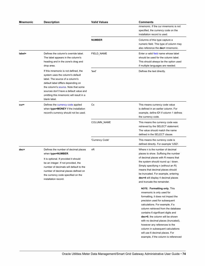
Oracle Utilities Meter Data Management/Smart Grid Gateway Administrative User Guide • 74
Mnemonic Description Valid Values Commentsmnemonic. If the cur mnemonic is notspecified, the currency code on theinstallation record is used.
NUMBER Columns of this type capture anumeric field. This type of column mayalso reference the dec= mnemonic.
FIELD_NAME Enter a valid field name whose labelshould be used for the column label.This should always be the option usedif multiple languages are needed.
label= Defines the column's override label.The label appears in the column'sheading and in the zone's drag anddrop area.
If this mnemonic is not defined, thesystem uses the column's defaultlabel. The source of a column'sdefault label differs depending onthe column's source. Note that somesources don't have a default value andomitting this mnemonic will result in ablank label.
'text' Defines the text directly.
Cx This means currency code valueis defined in an earlier column. Forexample, define C1 if column 1 definesthe currency code.
COLUMN_NAME This means the currency code wasretrieved by the SELECT statement.The value should match the namedefined in the SELECT clause.
cur= Defines the currency code appliedwhen type=MONEY if the installationrecord's currency should not be used.
'Currency Code' This means the currency code isdefined directly. For example 'USD'.
dec= Defines the number of decimal placeswhen type=NUMBER.
It is optional. If provided it shouldbe an integer. If not provided, thenumber of decimals will default to thenumber of decimal places defined onthe currency code specified on theinstallation record.
nR Where n is the number of decimalplaces to show. Suffixing the numberof decimal places with R means thatthe system should round up / down.Simply specifying n (without an R)means that decimal places shouldbe truncated. For example, enteringdec=4 will display 4 decimal placesand truncate the remainder.
NOTE: Formatting only. Thismnemonic is only used forformatting, it does not impact theprecision used for subsequentcalculations. For example, if acolumn retrieved from the databasecontains 6 significant digits anddec=0, the column will be shownwith no decimal places (truncated),however any references to thecolumn in subsequent calculationswill use 6 decimal places. Forexample, if the column is referenced

Oracle Utilities Meter Data Management/Smart Grid Gateway Administrative User Guide • 75
Mnemonic Description Valid Values Commentsin a formula or set function, all 6decimal places will be used.
char= This mnemonic applies specialcharacter(s) to the column's value.
'x[]x' Where x references the literal valueto display and [ ] defines the relativeposition of the characters (before orafter the value).
You need only include the [ ] if youwant to position characters in front ofthe value. For example, char='%' willplace a percent sign after the value. Ifyou want to position the word 'minutes'before a value, enter char='minutes[ ]'. If you want to output a valuelike BUDGET $123.12 (YTD), enterchar='BUDGET [ ] (YTD)'.
truesuppress= This is used to indicate a columnshould not be displayed.
A column would be suppressed if it'sonly defined for use by subsequentcolumns, for example, if there is aformula that derives a column usingtwo other columns. In this scenario,the columns referenced in the formulacan be suppressed.
false This is the default, meaning that youdon't need to indicate suppress=falseat all to indicate that the field shouldbe shown.
truesuppressSearch= This is used to indicate a columnshould not be displayed when thezone is invoked in search mode only.
false This is the default, meaningthat you don't need to indicatesuppressSearch=false at all toindicate that the field should be shown.
truesuppressExport= This is used to indicate a columnshould not be downloaded to Excel. false This is the default, meaning
that you don't need to indicatesuppressExport=false at all toindicate that the field should beincluded in a download.
width= This is used to override the width of acolumn (number of pixels). The defaultvalue is the maximum width of any cellin the column.
n Where n is a number between 0 and999.
NOTE:If there is no available breaking pointin the data, the column will be longerthan the specified number of pixels.
The length of the column's label(which appears in the column'sheading) may also make the widthwider than specified.

Oracle Utilities Meter Data Management/Smart Grid Gateway Administrative User Guide • 76
Mnemonic Description Valid Values Comments
A valid HTML "named" color For example color=red orcolor=yellow.
color= This is used to override the column'stext color.
A valid RGB color model combination For example color=#FF0000 orcolor=#CCCCCC. Note that the # isrequired.
A valid HTML "named" color Similar to the color= mnemonic.bgcolor= This is used to override the column'sbackground color. A valid RGB color model combination Similar to the color= mnemonic.
ASC Indicates that the order is ascending.This is the default meaning that it isnot necessary to indicate order=ASC.
order= Defines the column's default sortorder.
DESC Indicates that the order is descending.
Click MnemonicsThis table describe the mnemonics that define whether a column value may be clicked and if so, what should happen.
Mnemonic Description Valid Values Comments
Cx This means navigation option codeis defined in an earlier column. Forexample, define C1 if column 1defines the navigation option.
COLUMN_NAME This means the navigation optionwas retrieved by the SELECTstatement. The value should matchthe name defined in the SELECTclause.
Example: navopt=MAIN_PORTAL
navopt= Defines the navigation option thatreferences the target transaction orscript when the user clicks a column.
Note, this mnemonic should be usedin conjunction with the context=mnemonic to define what informationis sent to the navigation option'starget transaction.
This mnemonic is ignored ifsource=FKREF because theFK reference code defines thehyperlink's destination.
'Navigation Option Code' This means the navigation optioncode is defined directly. For examplenavopt='userMaint'.
Cx Where Cx represents the value of aprevious column. For example, if thevalue to pass is in the first column,reference C1.
COLUMN_NAME This means the value to pass in wasretrieved by the SELECT statement.The value should match the namedefined in the SELECT clause.
context= This is used to define one or morecontext fields and values passed tothe target navigation option to goalong with the navopt= mnemonic.
The syntax is as follows: [FIELD_NAME=FIELD_REF FIELD_NAME=FIELD_REF ...]
In other words, the list of input valuesis surrounded by square bracketsseparated by a space. Each passedvalue first defines the FIELD_NAME,which is the name of the contextfield in the navigation option. FIELD_REF is the value passed in. The nextcolumn indicates the possible valuesfor FIELD_REF.
'literal value' This means a literal value within thesingle quotes should be passed in.
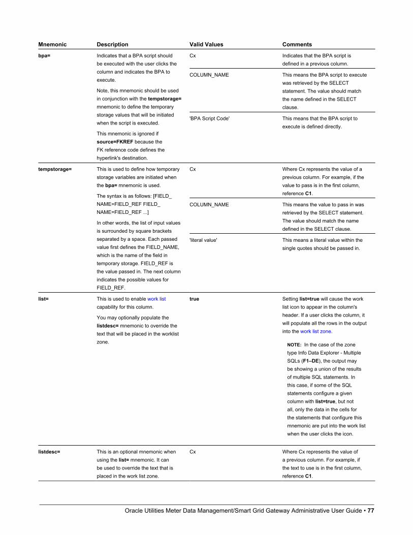
Oracle Utilities Meter Data Management/Smart Grid Gateway Administrative User Guide • 77
Mnemonic Description Valid Values Comments
Cx Indicates that the BPA script isdefined in a previous column.
COLUMN_NAME This means the BPA script to executewas retrieved by the SELECTstatement. The value should matchthe name defined in the SELECTclause.
bpa= Indicates that a BPA script shouldbe executed with the user clicks thecolumn and indicates the BPA toexecute.
Note, this mnemonic should be usedin conjunction with the tempstorage=mnemonic to define the temporarystorage values that will be initiatedwhen the script is executed.
This mnemonic is ignored ifsource=FKREF because theFK reference code defines thehyperlink's destination.
'BPA Script Code' This means that the BPA script toexecute is defined directly.
Cx Where Cx represents the value of aprevious column. For example, if thevalue to pass is in the first column,reference C1.
COLUMN_NAME This means the value to pass in wasretrieved by the SELECT statement.The value should match the namedefined in the SELECT clause.
tempstorage= This is used to define how temporarystorage variables are initiated whenthe bpa= mnemonic is used.
The syntax is as follows: [FIELD_NAME=FIELD_REF FIELD_NAME=FIELD_REF ...]
In other words, the list of input valuesis surrounded by square bracketsseparated by a space. Each passedvalue first defines the FIELD_NAME,which is the name of the field intemporary storage. FIELD_REF isthe value passed in. The next columnindicates the possible values forFIELD_REF.
'literal value' This means a literal value within thesingle quotes should be passed in.
list= This is used to enable work listcapability for this column.
You may optionally populate thelistdesc= mnemonic to override thetext that will be placed in the worklistzone.
true Setting list=true will cause the worklist icon to appear in the column'sheader. If a user clicks the column, itwill populate all the rows in the outputinto the work list zone.
NOTE: In the case of the zonetype Info Data Explorer - MultipleSQLs (F1–DE), the output maybe showing a union of the resultsof multiple SQL statements. Inthis case, if some of the SQLstatements configure a givencolumn with list=true, but notall, only the data in the cells forthe statements that configure thismnemonic are put into the work listwhen the user clicks the icon.
listdesc= This is an optional mnemonic whenusing the list= mnemonic. It canbe used to override the text that isplaced in the work list zone.
Cx Where Cx represents the value ofa previous column. For example, ifthe text to use is in the first column,reference C1.
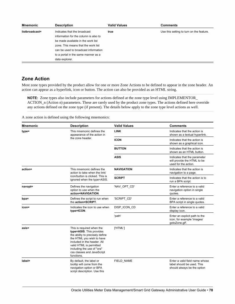
Oracle Utilities Meter Data Management/Smart Grid Gateway Administrative User Guide • 78
Mnemonic Description Valid Values Comments
listbroadcast= Indicates that the broadcastinformation for the column is also tobe made available in the work listzone. This means that the work listcan be used to broadcast informationto a portal in the same manner as adata explorer.
true Use this setting to turn on the feature.
Zone ActionMost zone types provided by the product allow for one or more Zone Actions to be defined to appear in the zone header. Anaction can appear as a hyperlink, icon or button. The action can also be provided as an HTML string.
NOTE: Zone types also include parameters for actions defined at the zone type level using IMPLEMENTOR_ACTION_n (Action n) parameters. These are rarely used by the product zone types. The actions defined here overrideany actions defined on the zone type (if present). The details below apply to the zone type level actions as well.
A zone action is defined using the following mnemonics:
Mnemonic Description Valid Values CommentsLINK Indicates that the action is
shown as a textual hyperlink.
ICON Indicates that the action isshown as a graphical icon.
BUTTON Indicates that the action isshown as an HTML button.
type= This mnemonic defines theappearance of the action inthe zone header.
ASIS Indicates that the parameterwill provide the HTML to beused for the action.
NAVIGATION Indicates that the action isnavigation to a page.
action= This mnemonic defines theaction to take when the link/icon/button is clicked. This isignored when the type=ASIS. SCRIPT Indicates that the action is to
run a BPA script.
navopt= Defines the navigationoption to use when theaction=NAVIGATION.
'NAV_OPT_CD' Enter a reference to a validnavigation option in singlequotes.
bpa= Defines the script to run whenthe action=SCRIPT.
'SCRIPT_CD' Enter a reference to a validBPA script in single quotes.
DISP_ICON_CD Enter a reference to a validdisplay icon.
icon= Indicates the icon to use whentype=ICON.
'path' Enter an explicit path to theicon, for example 'images/gotoZone.gif'.
asis= This is required when thetype=ASIS. This providesthe ability to precisely definethe HTML you wish to haveincluded in the header. Allvalid HTML is permittedincluding the use of "ora"css classes and JavaScriptfunctions.
['HTML']
label= By default, the label ortooltip will come from thenavigation option or BPAscript description. Use this
FIELD_NAME Enter a valid field name whoselabel should be used. Thisshould always be the option
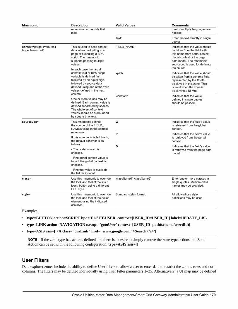
Oracle Utilities Meter Data Management/Smart Grid Gateway Administrative User Guide • 79
Mnemonic Description Valid Values Commentsused if multiple languages areneeded.
mnemonic to override thatlabel.
'text' Enter the text directly in singlequotes.
FIELD_NAME Indicates that the value shouldbe taken from the field withthis name from portal context,global context or the pagedata model. The mnemonicsourceLoc is used for definingthe source.
xpath Indicates that the value shouldbe taken from a schema field,represented by the Xpath,displayed in this zone. Thisis valid when the zone isdisplaying a UI Map.
context=[target1=source1target2=source2]
This is used to pass contextdata when navigating to apage or executing a BPAscript. The mnemonicsupports passing multiplevalues.In each case the targetcontext field or BPA scriptvariable is defined firstfollowed by an equal sign,followed by source datadefined using one of the validvalues defined in the nextcolumn.One or more values may bedefined. Each context value isdefined separated by spaces.The whole set of contextvalues should be surroundedby square brackets.
'constant' Indicates that the valuedefined in single quotesshould be passed.
G Indicates that the field's valueis retrieved from the globalcontext.
P Indicates that the field's valueis retrieved from the portalcontext.
sourceLoc= This mnemonic definesthe source of the FIELD_NAME's value in the contextmnemonic.If this mnemonic is left blank,the default behavior is asfollows:- The portal context ischecked.- If no portal context value isfound, the global context ischecked.- If neither value is available,the field is ignored.
D Indicates that the field's valueis retrieved from the page datamodel.
class= Use this mnemonic to overridethe look and feel of the link /icon / button using a differentCSS style.
'className1' 'className2' Enter one or more classes insingle quotes. Multiple classnames may be provided.
style= Use this mnemonic to overridethe look and feel of the actionelement using the indicatedcss style.
Standard style= format. All allowed css styledefinitions may be used.
Examples:
• type=BUTTON action=SCRIPT bpa='F1-SET-USER' context=[USER_ID=USER_ID] label=UPDATE_LBL
• type=LINK action=NAVIGATION navopt='gotoUser' context=[USER_ID=path(schema/userdId)]
• type=ASIS asis=['<A class="oraLink" href="www.google.com">Search</a>']
NOTE: If the zone type has actions defined and there is a desire to simply remove the zone type actions, the ZoneAction can be set with the following configuration: type=ASIS asis=[]
User FiltersData explorer zones include the ability to define User filters to allow a user to enter data to restrict the zone’s rows and / orcolumns. The filters may be defined individually using User Filter parameters 1–25. Alternatively, a UI map may be defined
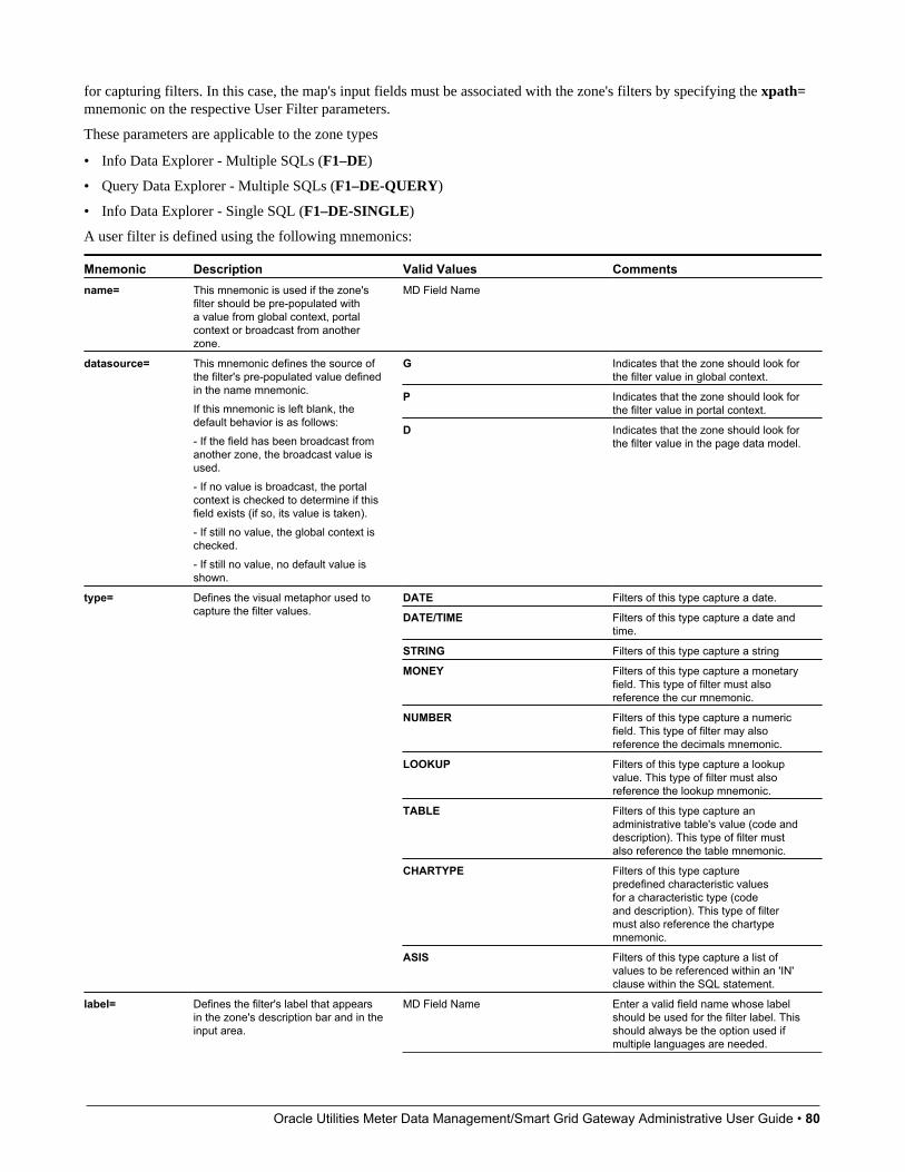
Oracle Utilities Meter Data Management/Smart Grid Gateway Administrative User Guide • 80
for capturing filters. In this case, the map's input fields must be associated with the zone's filters by specifying the xpath=mnemonic on the respective User Filter parameters.
These parameters are applicable to the zone types
• Info Data Explorer - Multiple SQLs (F1–DE)
• Query Data Explorer - Multiple SQLs (F1–DE-QUERY)
• Info Data Explorer - Single SQL (F1–DE-SINGLE)
A user filter is defined using the following mnemonics:
Mnemonic Description Valid Values Commentsname= This mnemonic is used if the zone's
filter should be pre-populated witha value from global context, portalcontext or broadcast from anotherzone.
MD Field Name
G Indicates that the zone should look forthe filter value in global context.
P Indicates that the zone should look forthe filter value in portal context.
datasource= This mnemonic defines the source ofthe filter's pre-populated value definedin the name mnemonic.If this mnemonic is left blank, thedefault behavior is as follows:- If the field has been broadcast fromanother zone, the broadcast value isused.- If no value is broadcast, the portalcontext is checked to determine if thisfield exists (if so, its value is taken).- If still no value, the global context ischecked.- If still no value, no default value isshown.
D Indicates that the zone should look forthe filter value in the page data model.
DATE Filters of this type capture a date.
DATE/TIME Filters of this type capture a date andtime.
STRING Filters of this type capture a string
MONEY Filters of this type capture a monetaryfield. This type of filter must alsoreference the cur mnemonic.
NUMBER Filters of this type capture a numericfield. This type of filter may alsoreference the decimals mnemonic.
LOOKUP Filters of this type capture a lookupvalue. This type of filter must alsoreference the lookup mnemonic.
TABLE Filters of this type capture anadministrative table's value (code anddescription). This type of filter mustalso reference the table mnemonic.
CHARTYPE Filters of this type capturepredefined characteristic valuesfor a characteristic type (codeand description). This type of filtermust also reference the chartypemnemonic.
type= Defines the visual metaphor used tocapture the filter values.
ASIS Filters of this type capture a list ofvalues to be referenced within an 'IN'clause within the SQL statement.
label= Defines the filter's label that appearsin the zone's description bar and in theinput area.
MD Field Name Enter a valid field name whose labelshould be used for the filter label. Thisshould always be the option used ifmultiple languages are needed.
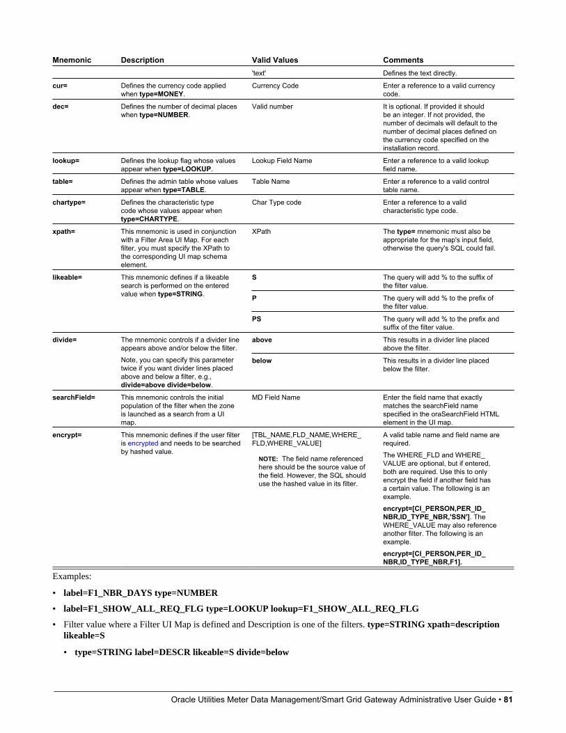
Oracle Utilities Meter Data Management/Smart Grid Gateway Administrative User Guide • 81
Mnemonic Description Valid Values Comments'text' Defines the text directly.
cur= Defines the currency code appliedwhen type=MONEY.
Currency Code Enter a reference to a valid currencycode.
dec= Defines the number of decimal placeswhen type=NUMBER.
Valid number It is optional. If provided it shouldbe an integer. If not provided, thenumber of decimals will default to thenumber of decimal places defined onthe currency code specified on theinstallation record.
lookup= Defines the lookup flag whose valuesappear when type=LOOKUP.
Lookup Field Name Enter a reference to a valid lookupfield name.
table= Defines the admin table whose valuesappear when type=TABLE.
Table Name Enter a reference to a valid controltable name.
chartype= Defines the characteristic typecode whose values appear whentype=CHARTYPE.
Char Type code Enter a reference to a validcharacteristic type code.
xpath= This mnemonic is used in conjunctionwith a Filter Area UI Map. For eachfilter, you must specify the XPath tothe corresponding UI map schemaelement.
XPath The type= mnemonic must also beappropriate for the map's input field,otherwise the query's SQL could fail.
S The query will add % to the suffix ofthe filter value.
P The query will add % to the prefix ofthe filter value.
likeable= This mnemonic defines if a likeablesearch is performed on the enteredvalue when type=STRING.
PS The query will add % to the prefix andsuffix of the filter value.
above This results in a divider line placedabove the filter.
divide= The mnemonic controls if a divider lineappears above and/or below the filter.Note, you can specify this parametertwice if you want divider lines placedabove and below a filter, e.g.,divide=above divide=below.
below This results in a divider line placedbelow the filter.
searchField= This mnemonic controls the initialpopulation of the filter when the zoneis launched as a search from a UImap.
MD Field Name Enter the field name that exactlymatches the searchField namespecified in the oraSearchField HTMLelement in the UI map.
encrypt= This mnemonic defines if the user filteris encrypted and needs to be searchedby hashed value.
[TBL_NAME,FLD_NAME,WHERE_FLD,WHERE_VALUE]
NOTE: The field name referencedhere should be the source value ofthe field. However, the SQL shoulduse the hashed value in its filter.
A valid table name and field name arerequired.The WHERE_FLD and WHERE_VALUE are optional, but if entered,both are required. Use this to onlyencrypt the field if another field hasa certain value. The following is anexample.encrypt=[CI_PERSON,PER_ID_NBR,ID_TYPE_NBR,'SSN']. TheWHERE_VALUE may also referenceanother filter. The following is anexample.encrypt=[CI_PERSON,PER_ID_NBR,ID_TYPE_NBR,F1].
Examples:
• label=F1_NBR_DAYS type=NUMBER
• label=F1_SHOW_ALL_REQ_FLG type=LOOKUP lookup=F1_SHOW_ALL_REQ_FLG
• Filter value where a Filter UI Map is defined and Description is one of the filters. type=STRING xpath=descriptionlikeable=S
• type=STRING label=DESCR likeable=S divide=below

Oracle Utilities Meter Data Management/Smart Grid Gateway Administrative User Guide • 82
• label=REQ_TYPE_CD type=TABLE table=F1_REQ_TYPE
Hidden FiltersData explorer zones include the ability to define Hidden filters to restrict the rows and / or columns that appear in the zone.The following are the potential sources of a hidden filter's value:
• The global area contains the fields whose values are maintained in global context.
• The portal area contains the fields describing the object currently displayed in a portal.
• Other zones on a portal can broadcast information to the portal area, which can then in turn be used by the zone as ahidden filter.
These parameters are applicable to the zone types
• Info Data Explorer - Multiple SQLs (F1–DE)
• Query Data Explorer - Multiple SQLs (F1–DE-QUERY)
• Info Data Explorer - Single SQL (F1–DE-SINGLE)
A hidden filter is defined using the following mnemonics:
Mnemonic Description Valid Values Commentsname= This mnemonic defines the name of
the field that needs to be broadcastfrom other zones or populated inthe portal context
FIELD_NAME
G Indicates that the zone should lookfor the filter value in global context.
P Indicates that the zone should lookfor the filter value in portal context.
datasource= This mnemonic defines the sourceof the hidden filter's value.If this mnemonic is left blank, thedefault behavior is as follows:- If the field has been broadcastfrom another zone, the broadcastvalue is used.- If no value is broadcast, the portalcontext is checked to determine ifthis field exists (if so, its value istaken).- If still no value, the global contextis checked.- If still no value, the zone appearsas per the poprule mnemonic.
D Indicates that the zone should lookfor the filter value in the page datamodel.
R Indicates that a value for the filteris required. The zone will be set tothe "empty state" and the "pleasebroadcast" message will appear inthe zone. This is the default value.
poprule= This mnemonic controls whathappens if the hidden filter is notpresent.
O Indicates that the value is optional.If no value is required, the zone isstill built without that value.
DATE Filters of this type capture a date.
DATE/TIME Filters of this type capture a dateand time.
STRING Filters of this type capture a string
MONEY Filters of this type capture amonetary field. This type of filtermust also reference the curmnemonic.
type= Defines the visual metaphor usedto capture the filter values.
NUMBER Filters of this type capture anumeric field. This type of filter
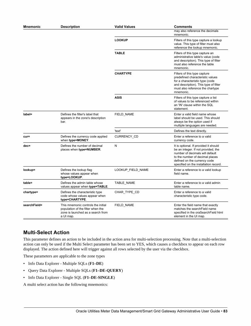
Oracle Utilities Meter Data Management/Smart Grid Gateway Administrative User Guide • 83
Mnemonic Description Valid Values Commentsmay also reference the decimalsmnemonic.
LOOKUP Filters of this type capture a lookupvalue. This type of filter must alsoreference the lookup mnemonic.
TABLE Filters of this type capture anadministrative table's value (codeand description). This type of filtermust also reference the tablemnemonic.
CHARTYPE Filters of this type capturepredefined characteristic valuesfor a characteristic type (codeand description). This type of filtermust also reference the chartypemnemonic.
ASIS Filters of this type capture a listof values to be referenced withinan 'IN' clause within the SQLstatement.
FIELD_NAME Enter a valid field name whoselabel should be used. This shouldalways be the option used ifmultiple languages are needed.
label= Defines the filter's label thatappears in the zone's descriptionbar.
'text' Defines the text directly.
cur= Defines the currency code appliedwhen type=MONEY.
CURRENCY_CD Enter a reference to a validcurrency code.
dec= Defines the number of decimalplaces when type=NUMBER.
N It is optional. If provided it shouldbe an integer. If not provided, thenumber of decimals will defaultto the number of decimal placesdefined on the currency codespecified on the installation record.
lookup= Defines the lookup flagwhose values appear whentype=LOOKUP.
LOOKUP_FIELD_NAME Enter a reference to a valid lookupfield name.
table= Defines the admin table whosevalues appear when type=TABLE.
TABLE_NAME Enter a reference to a valid admintable name.
chartype= Defines the characteristic typecode whose values appear whentype=CHARTYPE.
CHAR_TYPE_CD Enter a reference to a validcharacteristic type code.
searchField= This mnemonic controls the initialpopulation of the filter when thezone is launched as a search froma UI map.
FIELD_NAME Enter the field name that exactlymatches the searchField namespecified in the oraSearchField htmlelement in the UI map.
Multi-Select ActionThis parameter defines an action to be included in the action area for multi-selection processing. Note that a multi-selectionaction can only be used if the Multi Select parameter has been set to YES, which causes a checkbox to appear on each rowdisplayed. The action defined here will trigger against all rows selected by the user via the checkbox.
These parameters are applicable to the zone types
• Info Data Explorer - Multiple SQLs (F1–DE)
• Query Data Explorer - Multiple SQLs (F1–DE-QUERY)
• Info Data Explorer - Single SQL (F1–DE-SINGLE)
A multi select action has the following mnemonics:
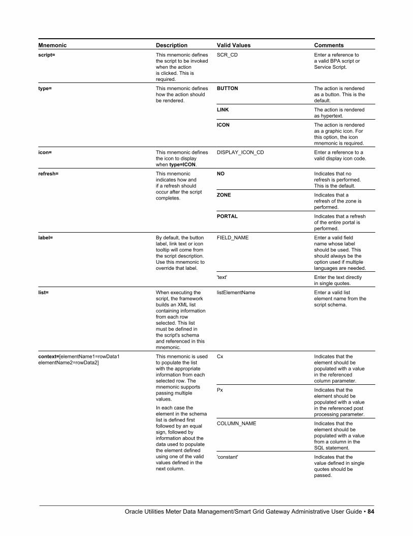
Oracle Utilities Meter Data Management/Smart Grid Gateway Administrative User Guide • 84
Mnemonic Description Valid Values Commentsscript= This mnemonic defines
the script to be invokedwhen the actionis clicked. This isrequired.
SCR_CD Enter a reference toa valid BPA script orService Script.
BUTTON The action is renderedas a button. This is thedefault.
LINK The action is renderedas hypertext.
type= This mnemonic defineshow the action shouldbe rendered.
ICON The action is renderedas a graphic icon. Forthis option, the iconmnemonic is required.
icon= This mnemonic definesthe icon to displaywhen type=ICON.
DISPLAY_ICON_CD Enter a reference to avalid display icon code.
NO Indicates that norefresh is performed.This is the default.
ZONE Indicates that arefresh of the zone isperformed.
refresh= This mnemonicindicates how andif a refresh shouldoccur after the scriptcompletes.
PORTAL Indicates that a refreshof the entire portal isperformed.
FIELD_NAME Enter a valid fieldname whose labelshould be used. Thisshould always be theoption used if multiplelanguages are needed.
label= By default, the buttonlabel, link text or icontooltip will come fromthe script description.Use this mnemonic tooverride that label.
'text' Enter the text directlyin single quotes.
list= When executing thescript, the frameworkbuilds an XML listcontaining informationfrom each rowselected. This listmust be defined inthe script's schemaand referenced in thismnemonic.
listElementName Enter a valid listelement name from thescript schema.
Cx Indicates that theelement should bepopulated with a valuein the referencedcolumn parameter.
Px Indicates that theelement should bepopulated with a valuein the referenced postprocessing parameter.
COLUMN_NAME Indicates that theelement should bepopulated with a valuefrom a column in theSQL statement.
context=[elementName1=rowData1elementName2=rowData2]
This mnemonic is usedto populate the listwith the appropriateinformation from eachselected row. Themnemonic supportspassing multiplevalues.In each case theelement in the schemalist is defined firstfollowed by an equalsign, followed byinformation about thedata used to populatethe element definedusing one of the validvalues defined in thenext column.
'constant' Indicates that thevalue defined in singlequotes should bepassed.

Oracle Utilities Meter Data Management/Smart Grid Gateway Administrative User Guide • 85
Mnemonic Description Valid Values CommentsOne or more valuesmay be defined.Each context valueis defined separatedby spaces. The wholeset of context valuesshould be surroundedby square brackets.Example of a schema:<schema> <accountInfo type="list"> <accountId/> <name/> <amount/> <process/> </accountInfo></schema>
Example of list andcontext mnemonics.list=accountInfocontext=[accountId=ACCT_ID name=C2amount=P3process='O']
class= Use this mnemonic tooverride the look andfeel of the action usinga different CSS style.
'className1' 'className2' Enter one or moreclasses in singlequotes to be appendedto the standardclass(es). Multipleclass names may beprovided.
style= Use this mnemonicto override the lookand feel of the actionelement using theindicated css style.
Standard style= format. All allowed css styledefinitions may beused.
Pagination ConfigurationThe various data explorer zones in the product support the ability to configure pagination so that a user can 'page through' alarge set of results using "previous" and "next" buttons or links.
There are several zone parameters that are impacted when attempting to configure this functionality. The following stepshighlight the configuration.
• The Enable Pagination parameter must be configured to define the basic setup for pagination for the zone. Thisparameter defines whether the "previous" and "next" actions are defined as buttons, links or icons and indicates thelocation of the actions. It also allows an indication as to whether the additional rows are simply appended, rather thanshown in a new "page". Refer to the parameter's embedded help for information about the specific syntax.
• It is recommended that the zone is configured with record count and page information by properly configuring theRecord Count Display parameter. Refer to the parameter's embedded help for information about the specific syntax.
• Configure the Number of Rows to Retrieve for SQL. parameter to define the number of records displayed per page. Ifthis parameter is not specified the value in the Number of Rows to Display parameter is used.
• Configure the key that will be used for paging so that the system can keep track of the 'page break'. The data must besorted by the paging key; as a result, the decision for identifying the paging key must take into account the design forthe zone and the data being displayed. In addition, the paging key must be unique to ensure that the page breaks occurcorrectly. See below for configuration examples.
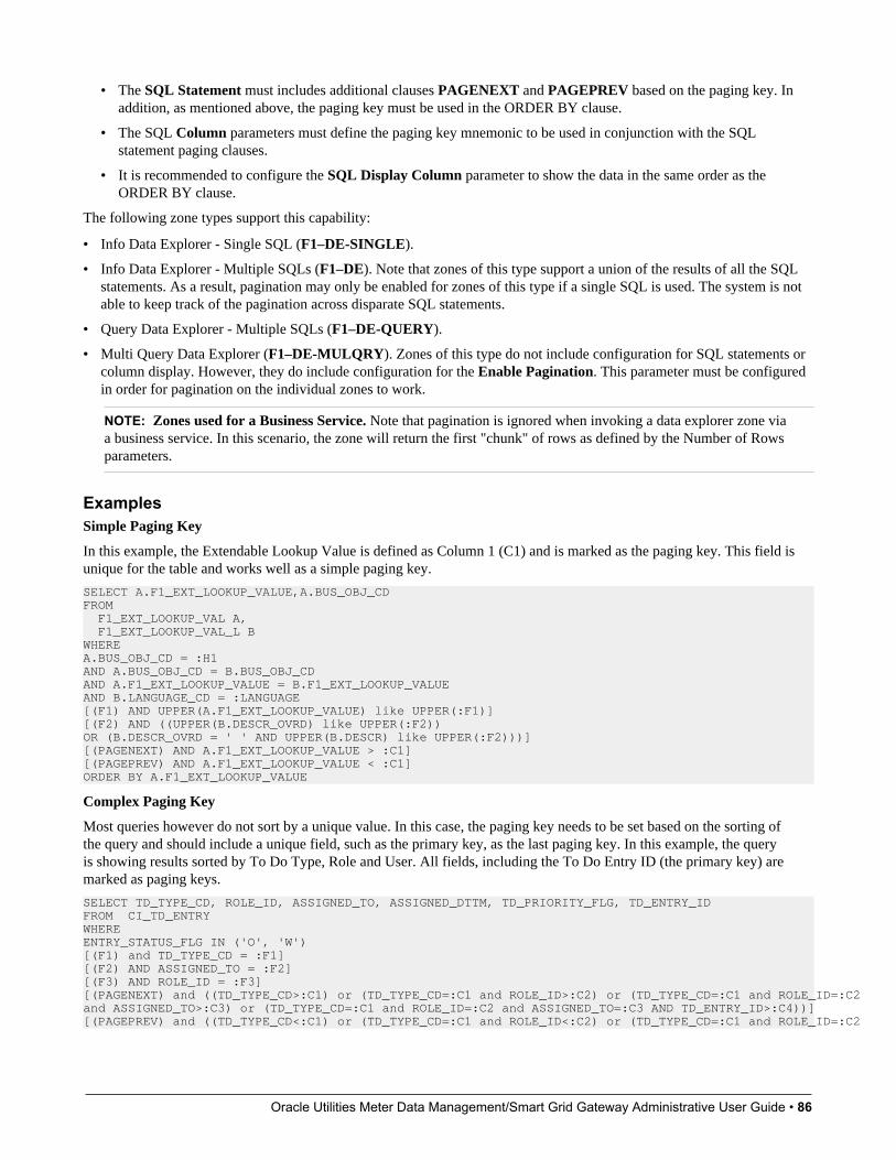
Oracle Utilities Meter Data Management/Smart Grid Gateway Administrative User Guide • 86
• The SQL Statement must includes additional clauses PAGENEXT and PAGEPREV based on the paging key. Inaddition, as mentioned above, the paging key must be used in the ORDER BY clause.
• The SQL Column parameters must define the paging key mnemonic to be used in conjunction with the SQLstatement paging clauses.
• It is recommended to configure the SQL Display Column parameter to show the data in the same order as theORDER BY clause.
The following zone types support this capability:
• Info Data Explorer - Single SQL (F1–DE-SINGLE).
• Info Data Explorer - Multiple SQLs (F1–DE). Note that zones of this type support a union of the results of all the SQLstatements. As a result, pagination may only be enabled for zones of this type if a single SQL is used. The system is notable to keep track of the pagination across disparate SQL statements.
• Query Data Explorer - Multiple SQLs (F1–DE-QUERY).
• Multi Query Data Explorer (F1–DE-MULQRY). Zones of this type do not include configuration for SQL statements orcolumn display. However, they do include configuration for the Enable Pagination. This parameter must be configuredin order for pagination on the individual zones to work.
NOTE: Zones used for a Business Service. Note that pagination is ignored when invoking a data explorer zone viaa business service. In this scenario, the zone will return the first "chunk" of rows as defined by the Number of Rowsparameters.
ExamplesSimple Paging Key
In this example, the Extendable Lookup Value is defined as Column 1 (C1) and is marked as the paging key. This field isunique for the table and works well as a simple paging key.
SELECT A.F1_EXT_LOOKUP_VALUE,A.BUS_OBJ_CDFROM F1_EXT_LOOKUP_VAL A, F1_EXT_LOOKUP_VAL_L BWHERE A.BUS_OBJ_CD = :H1AND A.BUS_OBJ_CD = B.BUS_OBJ_CDAND A.F1_EXT_LOOKUP_VALUE = B.F1_EXT_LOOKUP_VALUEAND B.LANGUAGE_CD = :LANGUAGE[(F1) AND UPPER(A.F1_EXT_LOOKUP_VALUE) like UPPER(:F1)][(F2) AND ((UPPER(B.DESCR_OVRD) like UPPER(:F2))OR (B.DESCR_OVRD = ' ' AND UPPER(B.DESCR) like UPPER(:F2)))][(PAGENEXT) AND A.F1_EXT_LOOKUP_VALUE > :C1][(PAGEPREV) AND A.F1_EXT_LOOKUP_VALUE < :C1]ORDER BY A.F1_EXT_LOOKUP_VALUE
Complex Paging Key
Most queries however do not sort by a unique value. In this case, the paging key needs to be set based on the sorting ofthe query and should include a unique field, such as the primary key, as the last paging key. In this example, the queryis showing results sorted by To Do Type, Role and User. All fields, including the To Do Entry ID (the primary key) aremarked as paging keys.
SELECT TD_TYPE_CD, ROLE_ID, ASSIGNED_TO, ASSIGNED_DTTM, TD_PRIORITY_FLG, TD_ENTRY_IDFROM CI_TD_ENTRYWHERE ENTRY_STATUS_FLG IN ('O', 'W')[(F1) and TD_TYPE_CD = :F1][(F2) AND ASSIGNED_TO = :F2][(F3) AND ROLE_ID = :F3][(PAGENEXT) and ((TD_TYPE_CD>:C1) or (TD_TYPE_CD=:C1 and ROLE_ID>:C2) or (TD_TYPE_CD=:C1 and ROLE_ID=:C2 and ASSIGNED_TO>:C3) or (TD_TYPE_CD=:C1 and ROLE_ID=:C2 and ASSIGNED_TO=:C3 AND TD_ENTRY_ID>:C4))] [(PAGEPREV) and ((TD_TYPE_CD<:C1) or (TD_TYPE_CD=:C1 and ROLE_ID<:C2) or (TD_TYPE_CD=:C1 and ROLE_ID=:C2
Oracle Utilities Meter Data Management/Smart Grid Gateway Administrative User Guide • 87
and ASSIGNED_TO<:C3) or (TD_TYPE_CD=:C1 and ROLE_ID=:C2 and ASSIGNED_TO=:C3 AND TD_ENTRY_ID<:C4))] ORDER BY TD_TYPE_CD, ROLE_ID, ASSIGNED_TO, TD_ENTRY_ID
Use Data Explorer for Derived DataThere are times when a design warrants displaying data in a data explorer zone that is not accessible via SQL. For example,perhaps the data is from another system and it requires a web service call. The JMS Message Browser is another example.
The product provides functionality in the data explorer that allows you to call a script after the user filters are populated butbefore the SQL is executed. The script can retrieve the data as appropriate, store the data in table format so that the SQL canretrieve the data from the table.
The following points provide more detail:
• Create a service script that retrieves the data as needed. This script should store the retrieved data in a temporary table.
• The product provides a table that may be used. It is called F1_GENERIC_GTT (Generic Global Temporary Table).There is a business service — Create Global Temporary Table Records (F1-InsertGTTRecords) that the servicescript may call to insert the records.
• Note that if the data is accessed via a web service call, it may be appropriate to execute the web service in a separatesession using the business service F1-ExecuteScriptInNewSession to trap errors that may be issued by the web servicecall and provide a better error.
• In the data explorer zone use this service script in the zone’s pre-processing script parameter. If any user or hidden filtersshould be passed into the script, the parameter supports mnemonics for this purpose. Refer to the parameter’s embeddedhelp for the supported syntax.
• The SQL for the data explorer should access the temporary table that was populated by the service script.
Configuring Timeline ZonesThis topic highlights information related to configuring a timeline zone. The zone type is F1-TIMELINE. A timelinezone contains one or more "lines" where each line shows when significant events have occurred. The output of each lineis driven by an algorithm configured on a timeline zone. Each algorithm is responsible for retrieving a single type of data.For example, on algorithm may retrieve bills for an account in a given time period whereas another algorithm may retrievepayments for that account for the same time period.
The algorithms to configure for a timeline zone use the Zone — Timeline plug-in spot. Please note the following detailsabout the behavior for algorithms for this plug-in spot.
• The timeline algorithm receives all the global context values currently populated. In addition, it receives a start and enddate from the zone, based on the time period chosen by the user, along with the maximum number of events that can bereasonably display for the chosen time period. The algorithm should use this information to retrieve data for a given typeof transaction related to one or more of the input context values for the provided time period.
• For each event found, the algorithm returns information about the event along with many options that assist the user ingetting more detail about each event or acting on an event.
• Event date
• Primary key of the record (key / value pairs)
• FK Reference. With this information, the timeline zone will display the appropriate info string to display in the zone’sinfo area when clicking on the event. In addition, the FK reference identifies the appropriate navigation option to usewhen a user clicks the info string hypertext to view the record on its maintenance page.
• Background Color and Text Color to use for the event. (Optional). The algorithm may be configured to provide onecolor for all events or it may be configured to return different colors for different events based on other factors such asstatus or priority.
Oracle Utilities Meter Data Management/Smart Grid Gateway Administrative User Guide • 88
• Icon use for the event. (Optional). The algorithm may be configured to provide an icon to display adjacent to theevent.
• BPA script to launch when a user clicks on an event. (Optional). The algorithm may return one or more BPA scriptsthat a user may launch to act on an event. For example, for an event that has a status of Error, perhaps a BPA isprovided to walk a user through resolving the error.
When a script is initiated from a timeline, the system puts the prime key of the event into a field in the page datamodel. The name of the field is the column name(s) of the event's prime key. For example, when a script associatedwith a payment event is kicked off, the system populates a field called PAY_ID with the prime-key of the selectedpayment.
Note that your specific edge application may supply algorithm types for a timeline zone as part of the base product. Clickhere to see the algorithm types available for this plug-in spot. Although algorithm types may be provided, typically theproduct does not deliver algorithms because the parameters for the algorithms are driven by a particular implementation’sbusiness rules and preferences. As a result, the product will also not deliver pre-configured timeline zones. Please refer toyour edge application’s documentation for more information about what timeline algorithm types are delivered, if any andrecommendations for configuration.
Defining Context-Sensitive ZonesA context-sensitive zone allows you to associate a zone with a specific user-interface transaction. A context-sensitive zoneappears at the top of the Dashboard when a user accesses a page for which the zone is specified as the context. For example,when viewing a business object, additional zones are visible that are specific to the business object page.
CAUTION: Make sure that the zone is appropriate for the transaction on which you are specifying it. For example, ifyour zone requires a business object ID as one of its keys, it should not be displayed on the To Do entry transaction.
Select Admin > Context Sensitive Zone to maintain context-sensitive zones.
Description of Page
The Navigation Key is a unique identifier of a tab page within the system. Owner indicates if this navigation key is ownedby the base product or by your implementation (Customer Modification).
CAUTION: Important! When introducing a new context sensitive zone, carefully consider its naming convention. Referto System Data Naming Convention for more information.
The grid contains the list of context-sensitive zones and the sequence in which they appear in the dashboard for the selectednavigation key. The grid contains the following fields:
• Zone is the name of the zone to display in the Dashboard.
• Sequence is the sequence in which the zone is displayed (if multiple context-sensitive zones are defined).
• Owner indicates if this context sensitive zone is owned by the base product or by your implementation (CustomerModification).
Where Used
A context-sensitive zone displays at the top of the Dashboard whenever a user accesses the transaction for with the zone isspecified.
Defining PortalsThis transaction is used to define / change portals. An implementation may define their own portals. In addition, animplementation may override some of the settings for base product provided portals.
Oracle Utilities Meter Data Management/Smart Grid Gateway Administrative User Guide • 89
Portal - MainNavigate to this page using Admin > System > Portal.
Description of Page
Enter a meaningful and unique Portal code and Description. Please be aware that for stand-alone portals, the Description isthe portal's title (i.e., the end-users will see this title whenever they open the portal).
CAUTION: Important! When introducing a new portal, carefully consider its naming convention. Refer to System DataNaming Convention for more information.
Owner indicates if this portal is owned by the base product or by your implementation (Customer Modification). Thesystem sets the owner to Customer Modification when you add a portal. This information is display-only.
Type flag indicates whether the portal is a Standalone Portal, a Tab Page Portal or the Dashboard. Refer to There AreThree Types of Portals for more information.
The following fields are only enabled for Standalone Portals:
• Navigation Option defines the navigation option that is used to navigate to this portal from menus, scripts and yourfavorite links. The navigation option is automatically created when a Standalone Portal is added.
• You'll find an Add To Menu button adjacent. This field is only enabled if the navigation option is not referenced on amenu. When you click this button, a pop-up appears where you define a menu. If you subsequently press OK, a menuitem is added to the selected menu. This menu item references the portal's navigation option. You can reposition themenu item on the menu by navigating to the Menu page.Refer to Putting Portals on Menus for more information.
• Application Services defines the service used to secure this portal. The application service is automatically created whena Standalone Portal is added. Please note that only users with access to this application service will be able to view thisportal and its zones. Refer to Granting Access to A Portal for more information.
• Show on Portal Preferences indicates if a user is allowed to have individual control of the zones on this portal. Theportal will not appear in the accordion on the user's Portal Preferences page if this value is set to No. Note that animplementation may change this value for a product delivered portal.
The grid contains a list of zones that are available in the portal. Click + to add a new zone to the portal. Click - to remove azone from the portal. The grid displays the following fields:
• Zone is the name of the zone as defined on the Zone page.
• Description is a description of the zone as defined on the Zone page.
• Display controls whether or not the zone is visible in the portal. For portals that are configured to Show on PortalPreferences, users may override this value for their view of the portal.
• Initially Collapsed controls whether or not the zone is initially collapsed in the portal. For portals that are configured toShow on Portal Preferences, users may override this value for their view of the portal.
NOTE: Recommendation. It is recommended that zones that have information that is always needed when usersfirst display a portal be set up to be initially collapsed. That way the data in the zone is only built when the userexpands the zone. This improves response times.
• Default Sequence is the default sequence number for the zone within the portal. It does not need to be unique within theportal. Note that a sequence of zero will appear last, not first, in the portal. For portals that are configured to Show onPortal Preferences, users may override this value for their view of the portal.
• Override Sequence can be used by an implementation team to override the Default Sequence value that is set in the baseproduct.

Oracle Utilities Meter Data Management/Smart Grid Gateway Administrative User Guide • 90
• Refresh Seconds defines in seconds how often the zone is automatically refreshed. The minimum valid value is 15. Themaximum valid value is 3600 (1 hour). A value of 0 indicates no automatic refresh. Implementers can change this valueas needed.
• Owner indicates if this portal / zone relationship is owned by the base product or by your implementation (CustomerModification). This information is display-only.
NOTE: Removing zones from a portal. You cannot remove a base product zone from a base product portal. Animplementation may override the Display setting to prevent a zone from displaying on the portal. In addition, you cannotremove a zone if a user has enabled it on their Portal Preferences. To remove a zone from the portal list, first make surethat no user has it enabled in their portal preferences.
Where Used
Follow this link to open the data dictionary where you can view the tables that reference CI_PORTAL.
Portal - OptionsUse this page to maintain a portal's options. Open this page using Admin > System > Portal and then navigate to theOptions page.
Description of Page
The options grid allows you to configure the options that provide additional information related to the portal.
Select the Option Type dropdown to define its Value. Detailed Description may display additional information on theoption type.
Set the Sequence to a unique value within a given option type.
Owner indicates if this is owned by the base product or by your implementation (Customer Modification).
NOTE: You can add new option types. Your implementation may want to add additional portal option types. To dothat, add your new values to the customizable lookup field PORTAL_OPT_FLG.
Defining Display IconsIcons are used to assist users in identifying different types of objects or instructions. A limited number of control tablesallow administrative users to select an icon when they are configuring the system. Select Admin > System > Display IconReference to maintain the population of icons available for selection.
Description of Page
Each icon requires the following information:
• Display Icon is a code that uniquely identifies the icon.
• Icon Type defines how big the icon is (in pixels). The permissible values are: 30 x 21, 21 x 21, and 20 x 14. Note thatonly icons that are 20 x 14 can be used on base product instructions.
• Description contains a brief description of the icon.
• URL describes where the icon is located. Your icons can be located on the product's web server or on an external webserver.
• To add a new icon to the product web server, place it under the /cm/images directory under the DefaultWebApp. Then,in the URL field, specify the relative address of the icon. For example, if the icon's file name is myIcon.gif, the URLwould be /cm/images/myIcon.gif.
• If the icon resides on an external web server, the URL must be fully qualified (for example, http://myWebServer/images/myIcon.gif).

Oracle Utilities Meter Data Management/Smart Grid Gateway Administrative User Guide • 91
• Owner indicates if this icon is owned by the base product or by your implementation (Customer Modification). Thisinformation is display-only.
Where Used
Follow this link to open the data dictionary where you can view the tables that reference CI_DISP_ICON.
Defining Navigation KeysEach location to which a user can navigate (e.g., transactions, tab pages, tab menus, online help links, etc.) is identified by anavigation key. A navigation key is a logical identifier for a URL.
Navigation Key TypesThere are three types of navigation keys:
• System navigation keys define locations where the target for the navigation is a transaction or portal within the system.The navigation keys define the program component that identifies the page to navigate to.
• External navigation keys define a URL that identifies the target location. External URLs can be specified as relativeto the product web server or fully qualified. External navigation keys always launch in a new instance of a browserwindow. Examples of external navigation keys include application viewer links and URLs to external systems.
• Help navigation keys define a online help topic that identifies the specific page within the online help to launch. Helpnavigation keys may be related to a program component when the help is related to a specific page in system.
Navigation Key vs. Navigation OptionThe system has two entities that work in conjunction with each other to specify how navigation works:
• Navigation Key defines a unique location to which a user can navigate. For example, each page in the system has aunique navigation key. Navigation keys can also define locations that are "outside" of the system. For example, you cancreate a navigation key that references an external URL. Think of a navigation key as defining "where to go".
• Navigation Option defines how a page is opened when a user wants to navigate someplace. For example, you mighthave a navigation key that identifies a specific page. This navigation key can then be referenced on two navigationoptions; the first navigation option may allow users to navigate to the page with no context included, while the secondnavigates to the page with context data provided to automatically display information related to that context.
• Please note that a wide variety of options can be defined on a navigation option. In addition to defining if data is passedto the page, it could also define search options. In addition, there are some navigation options that do not reference anavigation key but rather refer to a BPA script that should be launched.
The Flexibility of Navigation KeysNavigation keys provide a great deal of functionality to your users. Use navigation keys to:
• Allow users to navigate to new pages or search programs
• Allow users to transfer to an external system or web page. After setting up this data, your users may be able to access thisexternal URL from a menu, a context menu, their favorite links, etc. Refer to Linking to External Locations for moreinformation.
Refer to the Tool Suite Guide for more information on developing program components.
Oracle Utilities Meter Data Management/Smart Grid Gateway Administrative User Guide • 92
NOTE: Replacing Base-Package Pages or Searches. If your new page or search has been designed to replace amodule in the base-package, the navigation key must indicate that it is overriding an existing navigation key.
Linking to External LocationsIf you want to include links to external systems or locations from within the system, you need to:
• Define a navigation key that specifies the URL of the location. For example, define an external navigation key that as aURL of http://www.oracle.com/.
• Define a navigation option that specifies from where in the system a user can go to your external location. For example,define a navigation option with a usage of Favorites or with a usage of Menu. Your navigation option points to thenavigation key you defined above.
• Add your navigation option to the appropriate location within the system. For example, have users add the navigationoption to their Favorite Links or add the navigation option as an item on a menu.
Overriding Navigation KeysYour implementation may choose to design a program component (e.g., a maintenance transaction or search page) toreplace a component provided by the system. When doing this, the new navigation key must indicate that it is overridingthe system navigation key. As a result, any menu entry or navigation options that reference this overridden navigation keyautomatically navigates to the custom component.
For example, if you have a custom On-line Batch Submission page and would like users to use this page rather than the oneprovided by the system, setting up an override navigation key ensures that if a user chooses to navigate to the On-line BatchSubmission from Menu or a context menu, the user is brought to the custom On-line Batch Submission page.
To create an override navigation key, you need to:
• Define a navigation key using an appropriate naming convention.
• If the Navigation Key Type of the navigation key being overridden is External, specify a Navigation Key Type ofOverride (Other) and define the appropriate URL Component.
• If the Navigation Key Type of navigation key being overridden is System, specify a Navigation Key Type of Override(System) and populate the Program Component ID with your custom program component ID.
• Specify the navigation key that you are overriding in the Overridden Navigation Key field.
Refer to the Tool Suite Guide for more information about developing your own program components.
Maintaining Navigation KeysSelect Admin > System > Navigation Key to maintain navigation keys.
CAUTION: Important! When introducing a new navigation key, carefully consider its naming convention. Refer to System Data Naming Convention for more information.
Description of Page
The Navigation Key is a unique name of the navigation key for internal use.
Owner indicates if this navigation key is owned by the base product or by your implementation (Customer Modification).This information is display-only.
Navigation Key Type includes the following possible values:
• External indicates that the location is specified in the URL Component field.

Oracle Utilities Meter Data Management/Smart Grid Gateway Administrative User Guide • 93
• Help indicates that the navigation key is used to launch online help where the specific help topic is defined in the URLComponent field.
• Override (Other) indicates that the navigation key overrides another navigation key of type External or Help. For thisoption, the name of the navigation key being overridden is populated in the Overridden Navigation Key field.
• Override (System) indicates that the navigation key overrides a system navigation key. For this option, the name of thenavigation key being overridden is populated in the Overridden Navigation Key field.
• System indicates that the navigation key refers to a transaction in the system identified by its program component.
FASTPATH: Refer to Navigation Key Types for more information about navigation key types.
FASTPATH: Refer to Overriding Navigation Keys for more information about settings required to override a systemnavigation key.
Program Component ID is the name of the program component identified by the key (for system navigation keys). Theprogram component ID can also be used to specify the transaction with which an online help link is associated.
Overridden Navigation Key is the name of the navigation key that the current navigation key is overriding (if Override(Other) or Override (System) is selected for the Navigation Key Type). Refer to Overriding Navigation Keys for moreinformation.
URL Component is the specific URL or portion of the URL for the navigation key (external and help navigation keysonly). The URL can be relative to the product web server or fully qualified.
Open Window Options allows you to specify options (e.g., width and height) for opening a browser window for anexternal navigation key. (External navigation keys always launch in a new browser window.) You can use any valid featuresavailable in the Window.open( ) JavaScript method. The string should be formatted the same way that it would be forthe features argument (e.g., height=600,width=800,resizeable=yes,scrollbars=yes,toolbar=no). Refer to a JavaScriptreference book for a complete list of available features.
Application Service is the application service that is used to secure access to transactions associated with Externalnavigation keys. If a user has access to the specified application service, the user can navigate to the URL defined on thenavigation key. Refer to The Big Picture of Application Security for more information.
The grid displays menu items that reference the navigation key (actually, it shows menu items that reference navigationsoptions that, in turn, reference the navigation key).
Where Used
Follow this link to open the data dictionary where you can view the tables that reference CI_MD_NAV.
Defining Navigation OptionsEvery time a user navigates to a transaction, the system retrieves a navigation option to determine which transaction shouldopen. For example:
• A navigation option is associated with every menu item. When a user selects a menu item, the system retrieves therelated navigation option to determine which transaction to open.
• A navigation option is associated with every favorite link. When a user selects a favorite link, the system retrieves therelated navigation option to determine which transaction to open.
• A navigation option is associated with every node in the various trees. When a user clicks a node in a tree, the systemretrieves the related navigation option to determine which transaction to open.
• Etc.
Oracle Utilities Meter Data Management/Smart Grid Gateway Administrative User Guide • 94
Many navigation options are shipped with the base product and cannot be modified as these options support corefunctionality. As part of your implementation, you may add additional navigation options to support your specific businessprocesses.
Navigation options may also be used to launch a BPA script.
The topics in this section describe how to maintain navigation options.
CAUTION: In order to improve response times, navigation options are cached the first time they are used after a webserver is started. If you change a navigation option and you don't want to wait for the cache to rebuild, you must clearthe cached information so it will be immediately rebuilt using current information. A special button has been providedon the Main tab of the navigation option transaction that performs this function. Please refer to Caching Overview forinformation on the various caches.
Navigation Option - MainSelect Admin > System > Navigation Option to maintain a navigation option.
Description of Page
Enter a unique Navigation Option code and Description.
CAUTION: When introducing a new navigation option, carefully consider its naming convention. Refer to System DataNaming Convention for more information.
The Flush System Login Info button is used to flush the cached navigation options so you can use any modified navigationoptions. Refer to Caching Overview for more information.
Owner indicates if this navigation option is owned by the base product or by your implementation (CustomerModification). This field is display-only. The system sets the owner to Customer Modification when you add a navigationoption.
NOTE: You may not change navigation options that are owned by the base product.
Use Navigation Option Type to define if the navigation option navigates to a Transaction, launches a BPA Script oropens an Attachment.
NOTE: The Attachment option type is only applicable to navigation options that are used to launch a file attached to arecord in the Attachment maintenance object.
For navigation option types of script, indicate the Script to launch. You can use the Context Fields at the bottom of thepage if you want to transfer the contents of specific fields to temporary storage variables available to the script. The scriptengine creates temporary storage variables with names that match the Context Field names.
For navigation option types of transaction, define the Target Transaction (navigation key) and optionally a specific TabPage (also a navigation key) if a specific tab on the transaction (other than the Main tab) should be opened when navigatingto that transaction.
NOTE: Finding transaction navigation keys. When populating the Target Transaction and Tab Page you arepopulating an appropriate navigation key. Because the system has a large number of transactions, we recommendusing the "%" metaphor when you search for the transaction identifier. For example, if you want to find the currencymaintenance transaction, enter "%currency" in the search criteria.
The additional information depends on whether the target transaction is a fixed page or a portal-based page:
• For portal-based pages:
• Navigation Mode is not applicable and should just be set to Add Mode.

Oracle Utilities Meter Data Management/Smart Grid Gateway Administrative User Guide • 95
• If navigating to a query portal, by default the query portal will open with the default search option defined. If thenavigation should open a different search option, define the Multi-Query Zone for that query portal and indicate theSub-Query Zone to open by default. Note that for this configuration, it is common to define Context Fields to pre-populate search criteria in the target query zone. When using this configuration, be sure that the target query zone’suser filters are defined to populate data from context.
• For fixed pages:
• Navigation Mode indicates if the Target Transaction should be opened in Add Mode or Change Mode.
• Add Mode should be used if the option is used to navigate to a transaction ready to add a new object. You can use theContext Fields at the bottom of the page if you want to transfer the contents of specific fields to the transaction whenit opens.
• Change Mode is only applicable for fixed pages and should be used if the option is used to navigate to a transactionready to update an object. You have two ways to define the object to be changed:
• Define the name of the fields that make up the unique identifier of the object in the Context Fields (and make sureto turn on Key Field for each such field).
• Define the Search Transaction (navigation key) if you want to open a search window to retrieve an object beforethe target transaction opens. Select the appropriate Search Type to define which search method should be used.The options in the drop down correspond with the sections in the search (where Main is the first section, Alternateis the 2nd section, Alternate 2 is the 3rd section, etc.). You should execute the search window in order to determinewhat each section does.
When you select a Search Type, define appropriate Context Fields so that the system will try to pre-populate thesearch transaction with these field values when the search first opens. Keep in mind that if a search is populatedwith field values the search is automatically triggered and, if only one object is found that matches the searchcriteria, it is selected and the search window closes.
• Search Group is only visible if the Development Tools module is not turned off. It is used to define the correlationbetween fields on the search page and the tab page. You can view a tab page's Search Groups by viewing the HTMLsource and scanning for allFieldPairs.
The Go To Tooltip is used to specify the label associated with the tool tip that appears when hovering over a Go To object.Refer to the Usage grid below.
The Usage grid defines the objects on which this navigation option is used:
• Choose Favorites if the navigation option can be used as a favorite link.
• Choose Menus if the navigation option can be used as a user's home page or as a menu or context menu item.
• Choose Script if the navigation option can be used in a script.
• Choose Foreign Key if the navigation option can be used as a foreign key reference.
• Choose Go To if the navigation option can be used as a "go to" destination ("go to" destinations are used on Go Tobuttons, tree nodes, and hyperlinks).
• If your product supports marketing campaigns, you can choose Campaign if the navigation option can be used as a "postcompletion" transaction on a campaign. For more information refer to that product's documentation for campaigns.
The Context Fields grid contains the names of the fields whose contents will be passed to the Target Transaction orScript or used to launch an Attachment. The system retrieves the values of these fields from the "current" page andtransfers them to the target transaction or to the script's temporary storage. Turn on Key Field for each context field thatmakes up the unique identifier when navigating to a transaction in Change Mode.
NOTE: For an Attachment, the grid should contain the Attachment ID.

Oracle Utilities Meter Data Management/Smart Grid Gateway Administrative User Guide • 96
NOTE: Navigating from a Menu. The standard followed for many base main menu navigation options for fixedtransactions is that navigation options launched from the Menu dropdown are configured with no context.
Where Used
Follow this link to open the data dictionary where you can view the tables that reference CI_NAV_OPT.
Navigation Option - TreeThis page contains a tree that shows how a navigation option is used. Select Admin > System > Navigation Option andnavigate to the Tree tab to view this page.
Description of Page
The tree shows every menu item, favorite link, and tree node that references the navigation option. This information isprovided to make you aware of the ramifications of changing a navigation option.
Database ToolsThis section describes a variety of database tools that are supplied with the your product.
Defining Table OptionsThe topics in this section describe the transaction that allows you to define metadata for the application's tables.
Table - MainNavigate using Admin > Database > Table.
Description of Page
Table Name is the identifier of this table.
Description contains a brief description of the table.
System Table defines if the table includes rows that are owned by the base product.
Enable Referential Integrity defines if the system performs referential integrity validation when rows in this table aredeleted.
Data Group ID is used for internal purposes.
Enable Data Dictionary defines if the table is to be included in the Data Dictionary application viewer.
Table Type defines if the table is an External Table, a View or a physical Table.
Date / Time Data Type defines if the system shows times on this table in Local Legal Time or in Local Standard TimeLocal Legal Time is the time as adjusted for daylight savings / summer time.
Table Classification Type specifies the category of data the table will hold. This is for information purposes only and isnot used by any system processing. Valid values are Admin System Table, Admin Non System Table, Master Table,Transaction Table, and Unclassified.
Table Volume Type specifies the expected amount of data the table will hold. This is for information purposes only andis not used by any system processing. Valid values are High Volume, Low Volume, Medium Volume, and Unclassified.The volume of data in a particular table in the system may differ greatly from one implementation to another based on
Oracle Utilities Meter Data Management/Smart Grid Gateway Administrative User Guide • 97
unique business requirements. The values populated for base product tables are set to volumes that are typical but may notbe true for a given implementation. The value may be updated to reflect the situation for a given implementation.
Audit Table is the name of the table on which this table's audit logs are stored. Refer to The Audit Trail File for moreinformation.
Use Audit Program Type to define if the audit program is written in Java or Java (Converted), meaning it was convertedinto Java.
NOTE: Java (Converted) program types are not applicable to all products.
Audit Program is the name of the program that is executed to store an audit log. Refer to Turn On Auditing For a Table formore information.
NOTE: View the source. If the program is shipped with the base package, you can use the adjacent button to displaythe source code of this program in the Java docs viewer.
Upgrade controls what happens to the rows in this table when the system is upgraded to a new release:
• Keep means that the rows on this table are not touched during an upgrade
• Merge means that the rows on this table are merged with rows owned by the base product
• Refresh means that the rows on this table are deleted and refreshed with rows owned by the base product.
Data Conversion Role controls if / how the table is used by the conversion tool:
• Convert (Retain PK) means that the table's rows are populated from the conversion schema and the prime key in theconversion schema is used when the rows are converted. A new key is not assigned by the system.
• Convert (New PK) means that the table's rows are populated from the conversion schema and the prime key isreassigned by the system during conversion.
• Not Converted means that the table's rows are not managed by the conversion tool.
• View of Production means that the conversion tool uses a view of the table in production when accessing the rows in thetable. This is commonly used for administrative tables.
A Language Table is specified when fields containing descriptions are kept in a child table. The child table keeps aseparate record for each language for which a description is translated.
A Characteristic Entity is populated if this table is used to capture characteristics and indicates the associatedcharacteristic entity lookup value for this table. When defining characteristic types, you indicate the characteristic entitieswhere that characteristic type is applicable / valid.
A Key Table is specified when the prime-key is assigned by the system. This table holds the identity of the prime keysallocated to both live and archived rows.
Type of Key specifies how prime key values are generated when records are added to the table:
• Other means a foreign-system allocates the table's prime-key.
• Sequential means a sequence number is incremented whenever a record is added to the table. The next number in thesequence determines the key value.
• System-generated means a program generates a random key for the record when it is added. If the record's table is thechild of another table, it may inherit a portion of the random number from its parent's key.
• User-defined means the user specifies the key when a record is added.
Inherited Key Prefix Length defines the number of most significant digits used from a parent record's primary key valueto be used as the prefix for a child record's key value. This is only specified when the Type of Key is System-generated andthe high-order values of the table's key is inherited from the parent table.
Oracle Utilities Meter Data Management/Smart Grid Gateway Administrative User Guide • 98
NOTE: In general, randomly generated system keys are used to attempt to evenly distribute records across a full rangeof possible IDs. Batch programs that use multiple threads will typically divide the threads using ID ranges and evenlydistributed keys will help spread out the work. The reason for inherited keys for child records further extends theperformance benefit. When considering partitioning, the recommendation for DBAs is to range partition data basedon the primary key so that different batch threads operate on different partitions which reduces contention for hotblocks. Ideally the number of batch threads will be an exact multiple of the number of partitions. Batch programs thatinsert child data (for example batch Billing creation) also benefit from this design especially when the child tables arepartitioned in the same way. The parent is often the driver of the batch process. If this is multi-threaded, then each threadis processing a set of parent records in a given ID range and all child records are being inserted into the same ID range.
Java Table Name. This field is used to identify the entity/Java class name of the class that represents the table in the Javacode. It should contain a short "camelCased" name to be used as the name of the entity within the system. It must also be avalid Java name, and must be unique across the system. This name is used as follows:
• As the short class name on all classes in the Java hierarchy for the class: the Impl class, the Gen, and the interface.
• In HQL queries, it is used to identify the hibernate entity being selected.
Caching Regime determines if the table’s values should be cached when they are accessed by a batch process. The defaultvalue is Not Cached. You should select Cached for Batch if you know the values in the table will not change during thecourse of a batch job. For example, currency codes will not change during a batch process. Caching a table's values willreduce unnecessary SQL calls and improve performance.
Key Validation determines if and when keys are checked for uniqueness. The default value is Always Check Uniqueness.Select Check Uniqueness Online Only when the database constructs the keys in the table, such as in log tables. SelectNever Perform Uniqueness Checking when you know that the database constructs the keys in the table and that userscannot add rows directly to the table, such as in log parameter tables. This will reduce unnecessary SQL calls and improveperformance.
Help URL is the link to the user documentation that describes this table.
Help Text contains additional information about the table.
Extract for Translation is only visible in a development environment. It indicates whether or not the table includes stringsthat are eligible for product translation.
Translation Context is only visible in a development environment. It is used to provide information to a translator aboutthe nature and purpose of rows in the table.
NOTE: Changes to base owned tables. Only the following attributes of tables that are owned by the product aremodifiable: Audit Table, Audit Program Type, Audit Program, Caching Regime, Key Validation and Table VolumeType.
The grid contains an entry for every field on the table. Drilling down on the field takes you to the Table Field tab whereyou may modify certain attributes. The following fields may also be modified from the grid: Description, Override Label,Audit Delete, Audit Insert and Audit Update. Refer to the Table Field tab for descriptions of these fields.
Table - Table FieldNavigate using Admin > Database > Table and click the Table Field tab.
Description of Page
Field Name is the name of the field. It is followed by its Java Field Name.
Field Help Text displays the help text listed for this field on the Field page, if populated.
Nullable, Required and Validate are for internal use.

Oracle Utilities Meter Data Management/Smart Grid Gateway Administrative User Guide • 99
Turn on Audit Delete if an audit record should be stored for this field when a row is deleted. Refer to How To EnableAuditing for more information.
Turn on Audit Insert if an audit record should be stored for this field when a row is added. Refer to How To EnableAuditing for more information.
Turn on Audit Update if an audit record should be stored for this field when it is changed. Refer to How To EnableAuditing for more information.
The Allow Customization is only applicable if the table is an Admin System Table. It indicates fields that animplementation is allowed to change for a base owned record. Changes to the field value of one of these types of fields byan implementation are maintained when upgrading to a new version of the product.
Standard Time Type is only enabled if the Table indicates that the Date/Time Data Type is Local Standard Time.Each field that represent date/time should define if it uses Logical Standard Time, Physical Standard Time or uses aReferenced Time Zone.
Sequence is a unique sequence of this field with respect to other fields on the table.
The Label column is used to define a special label for this field when it relates to this table if it should be different from thefield’s label. Note that this only impacts the label on a fixed page user interface. Labels on portal based user interfaces donot use this information.
The Override Label is provided if an implementation wants to override the base-product label.
NOTE: If you want the Override Label to be shown in the data dictionary, you must regenerate the data dictionary.
Help Text contains any additional information about the field with respect to its use on this table.
Extract for Translation is only visible in a development environment. For tables marked to extract for translation, eachtranslatable field on the table should indicate Yes.
Translation Context is only visible in a development environment. It is used to provide information to a translator aboutthe nature and purpose of the data in this field on this table.
NOTE: Changes to base owned table / fields. Only the following attributes of table / fields that are owned by theproduct are modifiable: Audit Delete, Audit Insert, Audit Update, Override Label.
Table - ConstraintsSelect Admin > Database > Table and navigate to the Constraints tab to view the constraints defined on the table.
Description of Page
The fields on this page are protected as only the product development group may change them.
This page represents a collection of constraints defined for the table. A constraint is a field (or set of fields) that representsthe unique identifier of a given record stored in the table or a field (or set of fields) that represents a given record'srelationship to another record in the system.
Constraint ID is a unique identifier of the constraint.
Owner indicates if this is owned by the base package or by your implementation (Customer Modification)
Constraint Type Flag defines how the constraint is used in the system:
• Primary Key represents the field or set of fields that represent the unique identifier of a record stored in a table.
• Logical Key represents an alternate unique identifier of a record based on a different set of fields than the Primary key.
• Foreign Key represents a field or set of fields that specifies identifying and non-identifying relationships to other tablesin the application. A foreign key constraint references the primary key constraint of another table.

Oracle Utilities Meter Data Management/Smart Grid Gateway Administrative User Guide • 100
• Conditional Foreign Key represents rare relationships between tables where a single field (or set of fields) mayreference multiple primary key constraints of other tables within the application as a foreign key.
When Enable Referential Integrity is checked, the system validates the integrity of the constraint when a row in the tableis modified.
Referring Constraint Owner indicates if this is owned by the base package or by your implementation (CustomerModification).
Referring Constraint ID is the Primary Key constraint of another table whose records are referenced by records stored inthis table.
Referring Constraint Table displays the table on which the Referring Constraint ID is defined. You can use the adjacentgo-to button to open the table.
Additional Conditional SQL Text is only specified when the constraint is a Conditional Foreign Key. The SQLrepresents the condition under which the foreign key represents a relationship to the referring constraint table.
NOTE: Additional Conditional SQL Syntax. When specifying additional conditional SQL text, all table names areprefixed with a pound (#) sign.
The Constraint Field grid at the bottom of the page is for maintaining the field or set of fields that make up this constraint.
Field is the name of the table's field that is a component of the constraint.
Sequence The rank of the field as a component of the constraint.
The Referring Constraint Field grid at the bottom of the page displays the field or set of fields that make up the Primarykey constraint of the referring constraint.
Field is the name of the table's field that is a component of the referring constraint.
Sequence is the rank of the field as a component of the referring constraint.
Table - Referred by ConstraintsSelect Admin > Database > Table and navigate to the Referred By Constraints tab to view the constraints defined onother tables that reference the Primary Key constraint of this table.
Description of Page
This page is used to display the collection of constraints defined on other tables that reference the table.
Referred By Constraint Id is the unique identifier of the constraint defined on another table.
Referred By Constraint Owner indicates if this constraint is owned by the base package or by your implementation(Customer Modification).
Prime Key Constraint Id is the Primary Key constraint of the current table.
Prime Key Owner indicates if this prime key is owned by the base package or by your implementation (CustomerModification).
Referred By Constraint Table is the table on which Referred By Constraint ID is defined.
When Enable Referential Integrity is checked, the system validates the integrity of the constraint when a row in the tableis modified.
The grid at the bottom of the page displays the Field and Sequence for the fields that make up the constraint defined on theother table.
Oracle Utilities Meter Data Management/Smart Grid Gateway Administrative User Guide • 101
Defining Field OptionsThe topics in this section describe the transaction that can be used to view information about a field and to change the nameof a field on the various pages in the system.
Field - MainOpen this page using Admin > Database > Field.
Description of Page
Field Name uniquely identifies this field.
CAUTION: As described in System Data Naming Convention for most system data tables, the base product follows aspecific naming convention. However, this is not true for the Field table. If you introduce new fields, you must prefixthe field with CM. If you do not do this, there is a possibility that a future release of the application could introduce anew field with the name you allocated.
Owner indicates if this field is owned by the base package or by your implementation (Customer Modification). Thesystem sets the owner to Customer Modification when you add a field.
Base Field indicates that the field inherits some of its definitions from another field.
Data Type indicates if the type of data the field will hold. Valid values are Character, Character Large Object, Date,DateTime, Number, Time, Varchar2 and XML Type. This field is protected if the field refers to a Base Field.
Ext Data Type or Extended Data Type is used to further define the type of data for certain data types. Valid values areCurrency Source, Day of Month, Duration, Money, Month of Year, Flag, Switch and URI. This field is protected if thefield refers to a Base Field.
Precision defines the length of the field. In the case of variable length fields, it is the maximum length possible. For numberfields that include decimal values, the precision includes the decimal values. This field is protected if the field refers to aBase Field.
Scale is only applicable for number fields. It indicates the number of decimal places supported by the field. This field isprotected if the field refers to a Base Field.
Sign is only applicable for numbers. It indicates if the data may contain positive or negative numbers.
Value List is only visible for products that had at one point included COBOL. It defines the copybook that includes the listof valid values for the field.
Description contains the label of the field. This is the label of the field that appears on the various pages on which the fieldis displayed. Note, the field's label can be overridden for a specific table by specifying an Override Label on the table / fieldinformation. However, this override is not used in portal based user interfaces. It is only applicable if the field is displayedon fixed page user interfaces.
Java Field Name is the reference to this field used in Java code.
Override Label is used if an implementation would like to override the label that appear on user interfaces in the system.
CAUTION: For fixed pages, if the field's label is overridden for a specific table, that override takes precedence. In this isthe case the override on the table / field page should be used.
Work Field indicates that the field does not represent a database table column.
Help Text is used to provide field level embedded help to this field. If the field is displayed on a user interface that supportsdisplay of embedded help, this text may be displayed.
Oracle Utilities Meter Data Management/Smart Grid Gateway Administrative User Guide • 102
Use Override Help Text to override the existing embedded help text for this field.
Extract for Translation is only visible in a development environment. It indicates whether or not the field and itsdescription should be included in an extract of translatable strings when doing a product translation. This flag may be set to"No" for work fields whose label is not visible to a user on any user interface.
Translation Context is only visible in a development environment. It is used to provide information to a translator aboutthe use of the field’s label so that an appropriate translation can be provided.
Field - Tables Using FieldSelect Admin > Database > Field and navigate to the Tables Using Field tab to view the tables that contain a field.
Description of Page
The grid on this page contains the Tables that reference the Field. You can use the adjacent go to button to open the TableMaintenance transaction.
Defining Maintenance Object OptionsA maintenance object defines the configuration of a given “entity” in the system. It includes the definition of the tables thattogether capture the physical data for the entity. In addition, the maintenance object includes options that define importantinformation related to the maintenance object that may be accessed for logic throughout the system. Several algorithm plug-in spots are also defined on the maintenance object, allowing for business rules that govern all records for this maintenanceobject.
Many maintenance objects in the system support the use of business objects to further define configuration and businessrules for a given record. Refer to The Big Picture of Business Objects for more information.
Maintenance Object - MainSelect Admin > Database > Maintenance Object to view information about a maintenance object.
Description of Page
Most maintenance objects are provided with the base package. An implementation can introduce custom maintenanceobjects when needed. Most fields may not be changed if owned by the base package.
Enter a unique Maintenance Object name and Description. Owner indicates if this business object is owned by the basepackage or by your implementation (Customer Modification).
IMPORTANT: If you introduce a new maintenance object, carefully consider its naming convention. Refer to SystemData Naming Convention for more information.
Service Name is the name of the internal service associated with the maintenance object.
Click the View XML hyperlink to view the XML document associated with the maintenance object service in the ServiceXML Viewer.
Click the View MO hyperlink to view the definition of the maintenance object in the Maintenance Object Viewer.
The grid displays the following for each table defined under the maintenance object:
• Table is the name of a given table maintained as part of the maintenance object.
• Table Role defines the table's place in the maintenance object hierarchy. Only one Primary table may be specifiedwithin a maintenance object, but the maintenance object may contain many Child tables.

Oracle Utilities Meter Data Management/Smart Grid Gateway Administrative User Guide • 103
• Parent Constraint ID specifies the constraint used to link the table to its parent table within the maintenance objecttable hierarchy.
• Owner indicates if this is owned by the base package or by your implementation (Customer Modification).
Maintenance Object - OptionsUse this page to maintain a maintenance object's options. Open this page using Admin > Database > MaintenanceObject and then navigate to the Options tab.
Description of Page
The options grid allows you to configure the maintenance object to support extensible options.
Select the Option Type drop-down to define its Value. Detailed Description may display additional information on theoption type.
Set the Sequence to 1 unless the option can have more than one value.
Owner indicates if this is owned by the base package or by your implementation (Customer Modification).
NOTE: You can add new option types. Your implementation may want to add additional maintenance option types.For example, your implementation may have plug-in driven logic that would benefit from a new type of option. To dothat, add your new values to the customizable lookup field MAINT_OBJ_OPT_FLG.
Maintenance Object - AlgorithmsUse this page to maintain a maintenance object's algorithms. Open this page using Admin > Database > MaintenanceObject and then navigate to the Algorithms tab.
Description of Page
The Algorithms grid contains algorithms that control important functions for instances of this maintenance object. Youmust define the following for each algorithm:
• Specify the System Event with which the algorithm is associated (see the table that follows for a description of allpossible events).
• Specify the Sequence Number and Algorithm for each system event. You can set the Sequence Number to 10 unlessyou have a System Event that has multiple Algorithms. In this case, you need to tell the system the Sequence in whichthey should execute.
• If the algorithm is implemented as a script, a link to the Script is provided. Refer to Plug-in Scripts for moreinformation.
• Owner indicates if this is owned by the base package or by your implementation (Customer Modification).
The following table describes each System Event.
System Event Optional / Required DescriptionAudit Optional Algorithms of this type are called to notify
of any changes to the maintenance object'sset of tables. These algorithms are invokedjust before the commit at the end of a logicaltransaction. The system keeps track of whatrecords are added or changed in the course ofa transaction and all MO audit algorithms areexecuted in order of when each record wasfirst added or updated.Click here to see the algorithm types availablefor this system event.
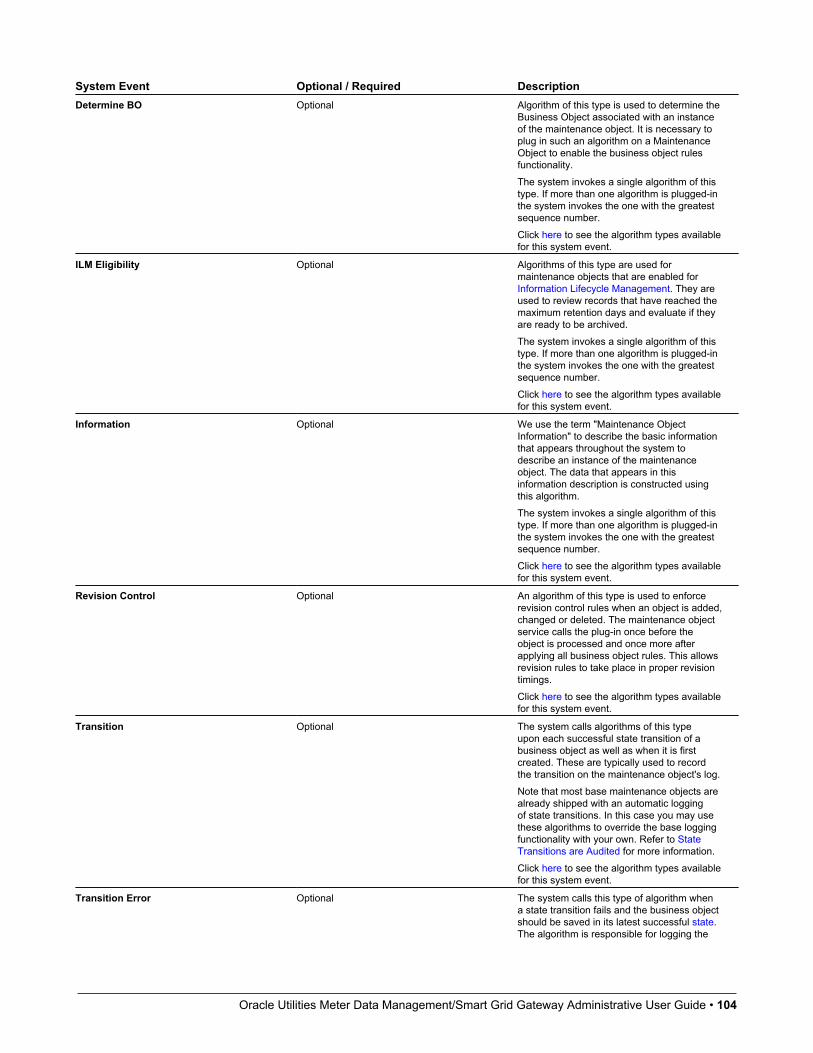
Oracle Utilities Meter Data Management/Smart Grid Gateway Administrative User Guide • 104
System Event Optional / Required DescriptionDetermine BO Optional Algorithm of this type is used to determine the
Business Object associated with an instanceof the maintenance object. It is necessary toplug in such an algorithm on a MaintenanceObject to enable the business object rulesfunctionality.The system invokes a single algorithm of thistype. If more than one algorithm is plugged-inthe system invokes the one with the greatestsequence number.Click here to see the algorithm types availablefor this system event.
ILM Eligibility Optional Algorithms of this type are used formaintenance objects that are enabled forInformation Lifecycle Management. They areused to review records that have reached themaximum retention days and evaluate if theyare ready to be archived.The system invokes a single algorithm of thistype. If more than one algorithm is plugged-inthe system invokes the one with the greatestsequence number.Click here to see the algorithm types availablefor this system event.
Information Optional We use the term "Maintenance ObjectInformation" to describe the basic informationthat appears throughout the system todescribe an instance of the maintenanceobject. The data that appears in thisinformation description is constructed usingthis algorithm.The system invokes a single algorithm of thistype. If more than one algorithm is plugged-inthe system invokes the one with the greatestsequence number.Click here to see the algorithm types availablefor this system event.
Revision Control Optional An algorithm of this type is used to enforcerevision control rules when an object is added,changed or deleted. The maintenance objectservice calls the plug-in once before theobject is processed and once more afterapplying all business object rules. This allowsrevision rules to take place in proper revisiontimings.Click here to see the algorithm types availablefor this system event.
Transition Optional The system calls algorithms of this typeupon each successful state transition of abusiness object as well as when it is firstcreated. These are typically used to recordthe transition on the maintenance object's log.Note that most base maintenance objects arealready shipped with an automatic loggingof state transitions. In this case you may usethese algorithms to override the base loggingfunctionality with your own. Refer to StateTransitions are Audited for more information.Click here to see the algorithm types availablefor this system event.
Transition Error Optional The system calls this type of algorithm whena state transition fails and the business objectshould be saved in its latest successful state.The algorithm is responsible for logging the

Oracle Utilities Meter Data Management/Smart Grid Gateway Administrative User Guide • 105
System Event Optional / Required Descriptiontransition error somewhere, typically on themaintenance object's log.Notice that in this case, the caller does NOTget an error back but rather the call endssuccessfully and the exception is recordedsomewhere, as per the plug-in logic.The system invokes a single algorithm of thistype. If more than one algorithm is plugged-inthe system invokes the one with the greatestsequence number.Click here to see the algorithm types availablefor this system event.
NOTE: You can inactivate algorithms on Maintenance Objects. Your implementation may want to inactivateone or more algorithms plugged into the base maintenance object. To do that, go to the options grid on MaintenanceObject - Options and add a new option, setting the option type to Inactive Algorithm and setting the option value to thealgorithm code.
Maintenance Object - Maintenance Object TreeYou can navigate to the Maintenance Object Tree to see an overview of the tables and table relationships associated withthe maintenance objects.
Description of Page
This page is dedicated to a tree that shows the maintenance object's tables as well as business objects, if you have definedany. You can use this tree to both view high-level information about these objects and to transfer to the respective page inwhich an object is maintained.
Defining Valid ValuesThe product provides several options for defining valid values for a column on a table:
• Lookup
• Extendable Lookup
• Control Table
The following provides more information about the functionality of each of the options available for defining valid valuesfor a column.
LookupThe simplest mechanism for defining valid values for a column on a table is via the Lookup table. This is sometimesreferred to as a “simple” lookup to distinguish it from an extendable lookup (described below). Using the lookup table, youcan define valid values and their descriptions. When choosing a valid value that is defined by a lookup, a dropdown UImetaphor is used.
The following highlights functionality related to lookups:
• Lookups are associated with a Field. The field is defined as a character data type with an extended data type of Flag. Thefield’s label serves as the description for the prompt to select the valid value.
• The lookup code is limited to four characters and must be all uppercase. If there is any functionality where a valid valuein the application must match valid values in an external system, the lookup table may not be the appropriate choice.
• The lookup table does not support additional attributes to be defined for each value. This option is only appropriate whena simple code and description pair is needed.

Oracle Utilities Meter Data Management/Smart Grid Gateway Administrative User Guide • 106
• The product may also use Lookups to define valid values for functionality unrelated to a column on a table. For example,an algorithm plug-in spot may define an input parameter that supports one or more valid values. The plug-in spot maydefine the valid values using a lookup, allowing for a simple way to validate the value supplied when invoking thealgorithm and to document the valid values.
FASTPATH: For more information, refer to Defining Lookup Options.
Extendable LookupThe extendable lookup provides a way of defining valid values for a column with additional capabilities that are notsupported using the Lookup table. When choosing a valid value that is defined by an extendable lookup, a dropdown UImetaphor is used.
The following highlights functionality related to extendable lookups:
• Each Extendable Lookups is defined using a business object.
• A field should be defined for the extendable lookup code. The field defines the label for the lookup code and definesthe size of the lookup code. The size is determined based on the business use case. In addition, there are standard fieldsincluded in all extendable lookups, including a description, detailed description and an override description (so thatimplementations can override the description of base delivered values).
• The extendable lookup may define additional information for each value if warranted by the business requirement. SeeAdditional Attributes for technical information about additional attributes.
FASTPATH: For more information, refer to Defining Extendable Lookups.
Control TableThere may be scenarios where a list of valid values warrants a standalone maintenance object, which is considered anadministrative or control table object. When choosing a valid value that is defined by a control, either a dropdown UImetaphor or a search metaphor is used, depending on how it has been designed.
The following points highlight some reasons why this option may be chosen:
• The records require a lifecycle such that BO status is warranted.
• The additional attributes are sophisticated enough that they warrant their own column definition rather than relying onusing CLOB or flattened characteristic. For example, if a list of information needs to be captured with several attributesin the list and the information in the list needs to be searchable.
In this situation, if a product has provided a control table for this type of functionality, it will be documented fullyin the appropriate functional area. If an implementation determines that a custom control table is warranted, all thestandard functionality for a maintenance object is required: database tables, maintenance object metadata, appropriateJava maintenance classes, portals, zones, etc. Refer to the Software Development Kit for more information. No furtherinformation is provided in this section for this option.
Defining Lookup OptionsLookup fields may be used to define valid values for a column in a table or for other types of values like parameters to analgorithm.
FASTPATH: Refer to Defining Valid Values for some background information.
The base product provides many different lookup fields and their values as part of the product. The following pointshighlight some functionality related to base-package lookups.

Oracle Utilities Meter Data Management/Smart Grid Gateway Administrative User Guide • 107
• Fields that are owned by the product will typically provide base lookup values. Implementations are not permitted toremove base delivered lookup values. Implementations may be able to add custom values to base owned lookups. This iscontrolled with the Custom switch on lookup.
• When the custom switch is unchecked, it means that there is functionality controlled by the base values and animplementation may not extend or customize this functionality. An example of this type of lookup is the Data Typefield on the Field table. The system supports a distinct list of data types and an implementation may not add additionalvalues.
• When the custom switch is checked, it means that there is base functionality supplied for the base values but that animplementation can extend the functionality by supplying their own values. An example of this type of lookup is theAccess Mode on Application Service. The product provides many values for the access mode lookup, representingvarious actions a user may perform. Implementations may add their own values to this lookup. Documentation shouldindicate when functionality may be extended and should highlight the lookup value that can be extended.
CAUTION: Important! If you introduce new lookup values, you must prefix the lookup value code with X or Y. Ifyou do not do this, there is a possibility that a future release of the application could introduce a new lookup valuewith the name you allocated.
• There may be some scenarios where the product supplies a base field and base lookup field with no base lookup valuessupplied. This occurs when the product doesn’t have any base functionality driven by the lookup values. Typically thistype of lookup is for information or categorization purposes. The configuration guide for the functional area associatedwith the lookup should include a configuration step regarding defining values for this type of lookup.
• The description of base delivered values may be overridden by an implementation.
An implementation may also identify the need for defining a new lookup field with its values.
Lookup - MainSelect Admin > Database > Lookup to maintain lookup values.
Description of Page
Field Name is the name of the field whose lookup values are maintained in the grid. If you need to add a new lookup field,you must first add the lookup field here, then navigate to the Field page to create a field with a data type of Character andan extended data type of Flag.
Owner indicates if this lookup field is owned by the base package or by your implementation (Customer Modification).This information is display-only.
Custom switch is used to indicate whether you are allowed to add valid values for a lookup field whose owner is notCustomer Modification.
• If this switch is turned on, you may add new values to the grid for system owned lookup fields.
• If this switch is turned off, you may not add, remove or change any of the values for system owned lookup fields, withthe exception of the override description.
This field is always protected for system owned lookup fields because you may not change a field from customizable tonon-customizable (or vice versa).
Java Field Name indicates the name of the field as it is referenced in Java code.
The grid contains the lookup values for a specific field. The following fields are visible:
Field Value is the unique identifier of the lookup value. If you add a new value, it must begin with an X or Y (in order toallow future upgrades to differentiate between your implementation-specific values and base-package values).
Description is the name of the lookup value that appears on the various transactions in the system
Java Value Name indicates the unique identifier of the lookup value as it is referenced in Java code.
Oracle Utilities Meter Data Management/Smart Grid Gateway Administrative User Guide • 108
Status indicates if the value is Active or Inactive. The system does not allow Inactive values to be used (the reason weallow Inactive values is to support historical data that references a value that is no longer valid).
Detailed Description is the detailed description for a lookup value, which is provided in certain cases.
Override Description is provided if your implementation wishes to override the description of the value provided by theproduct.
NOTE: If you wish the override descriptions of your lookup values to appear in the application viewer, you mustregenerate the data dictionary application viewer background process.
Owner indicates if this lookup value is owned by the base package or by your implementation (Customer Modification).The system sets the owner to Customer Modification when you add lookup values to a field. This information is display-only.
Defining Extendable LookupsExtendable lookups are a way of defining valid values that are more sophisticated than simple lookups.
FASTPATH: Refer to Defining Valid Values for some background information.
The base product provides extendable lookups as part of the product. The following points highlight some functionalityrelated to base-package extendable lookups.
• The base product may supply base extendable lookup values. Implementations are not permitted to remove basedelivered extendable lookup values. It is also possible that implementations may be able to add custom values to baseowned lookups. If an implementation is not permitted to add lookup values to the base extendable lookup, the extendablelookup’s business object will include validation to prevent this. There is no equivalent of the Custom switch that is on thelookup field.
• There may be some scenarios where the product supplies a base extendable lookup with no base lookup valuessupplied. This occurs when the product doesn’t have any base functionality driven by the extendable lookup values. Theconfiguration guide for the functional area associated with the extendable lookup should include a configuration stepregarding defining values for this type of extendable lookup.
• The description of base delivered values may be overridden by an implementation.
Open this page using Admin > General > Extendable Lookup.
You are brought to the Extendable Lookup Query where you need to search for the extendable lookup object (i.e., itsbusiness object).
Once you have found the appropriate extendable lookup, select the value and you are brought to a standard All-in-Oneportal that lists the existing lookup values for the extendable lookup. The standard actions for an All-in-One portal areavailable here.
Extendable Lookup Advanced TopicsThis section provides some addition technical information about extendable lookup attributes
Defining Additional AttributesThe product provides a few different ways to define additional values for an extendable lookup. Some of the methods areonly relevant for base delivered lookup values as they may impact whether or not an implementation can update the values.
The following table highlights the options available and some summary information about what the option provides.
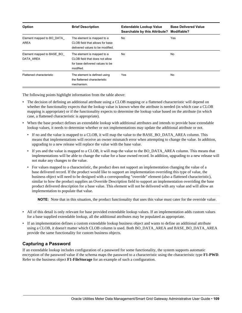
Oracle Utilities Meter Data Management/Smart Grid Gateway Administrative User Guide • 109
Option Brief Description Extendable Lookup ValueSearchable by this Attribute?
Base Delivered ValueModifiable?
Element mapped to BO_DATA_AREA
The element is mapped to aCLOB field that allows for basedelivered values to be modified.
No Yes
Element mapped to BASE_BO_DATA_AREA
The element is mapped to aCLOB field that does not allowfor base delivered values to bemodified.
No No
Flattened characteristic The element is defined usingthe flattened characteristicmechanism.
Yes No
The following points highlight information from the table above:
• The decision of defining an additional attribute using a CLOB mapping or a flattened characteristic will depend onwhether the functionality expects that the lookup value is known when the attribute is needed (in which case a CLOBmapping is appropriate) or if the functionality expects to determine the lookup value based on the attribute (in whichcase, a flattened characteristic is appropriate).
• When the base product defines an extendable lookup with additional attributes and intends to provide base extendablelookup values, it needs to determine whether or not implementations may update the additional attribute or not.
• If no and the value is mapped to a CLOB, it will map the value to the BASE_BO_DATA_AREA column. Thismeans that implementations will receive an owner mismatch error when attempting to change the value. In addition,upgrading to a new release will replace the value with the base value.
• If yes and the value is mapped to a CLOB, it will map the value to the BO_DATA_AREA column. This means thatimplementations will be able to change the value for a base owned record. In addition, upgrading to a new release willnot make any changes to the value.
• For values mapped to a characteristic, the product does not support an implementation changing the value of abase delivered record. If the product would like to support an implementation overriding this type of value, thebusiness object will need to be designed with a corresponding "override" element (also a flattened characteristic),similar to how the product supplies an Override Description field to support an implementation overriding the baseproduct delivered description for a base value. This element will not be delivered with any value and will allow animplementation to populate that value.
NOTE: Note that in this situation, the product functionality that uses this value must cater for the override value.
• All of this detail is only relevant for base provided extendable lookup values. If an implementation adds custom valuesfor a base supplied extendable lookup, all the additional attributes may be populated as appropriate.
• If an implementation defines a custom extendable lookup business object and wants to define an additional attributeusing a CLOB, it doesn't matter which CLOB column is used. Both BO_DATA_AREA and BASE_BO_DATA_AREAprovide the same functionality for custom business objects.
Capturing a PasswordIf an extendable lookup includes configuration of a password for some functionality, the system supports automaticencryption of the password value if the schema maps the password to a characteristic using the characteristic type F1-PWD.Refer to the business object F1-FileStorage for an example of such a configuration.
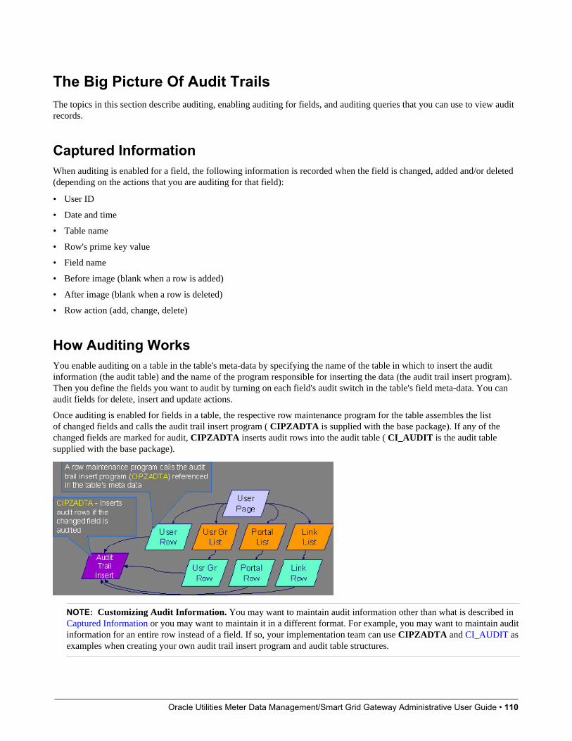
Oracle Utilities Meter Data Management/Smart Grid Gateway Administrative User Guide • 110
The Big Picture Of Audit TrailsThe topics in this section describe auditing, enabling auditing for fields, and auditing queries that you can use to view auditrecords.
Captured InformationWhen auditing is enabled for a field, the following information is recorded when the field is changed, added and/or deleted(depending on the actions that you are auditing for that field):
• User ID
• Date and time
• Table name
• Row's prime key value
• Field name
• Before image (blank when a row is added)
• After image (blank when a row is deleted)
• Row action (add, change, delete)
How Auditing WorksYou enable auditing on a table in the table's meta-data by specifying the name of the table in which to insert the auditinformation (the audit table) and the name of the program responsible for inserting the data (the audit trail insert program).Then you define the fields you want to audit by turning on each field's audit switch in the table's field meta-data. You canaudit fields for delete, insert and update actions.
Once auditing is enabled for fields in a table, the respective row maintenance program for the table assembles the listof changed fields and calls the audit trail insert program ( CIPZADTA is supplied with the base package). If any of thechanged fields are marked for audit, CIPZADTA inserts audit rows into the audit table ( CI_AUDIT is the audit tablesupplied with the base package).
NOTE: Customizing Audit Information. You may want to maintain audit information other than what is described in Captured Information or you may want to maintain it in a different format. For example, you may want to maintain auditinformation for an entire row instead of a field. If so, your implementation team can use CIPZADTA and CI_AUDIT asexamples when creating your own audit trail insert program and audit table structures.
Oracle Utilities Meter Data Management/Smart Grid Gateway Administrative User Guide • 111
The Audit Trail FileAudit log records are inserted in the audit tables you define. The base product contains a single such table (called CI_AUDIT ). However, the audit insert program ( CIPZADTA) is designed to allow you to use multiple audit tables.
If you want to segregate audit information into multiple tables, you must create these tables. Use the following guidelineswhen creating new audit tables (that use the CIPZADTA audit insert program):
• The new audit tables must look identical to the base table ( CI_AUDIT ).
• The new tables must be prefixed with CM (e.g., CM_AUDIT_A, CM_AUDIT_B, etc.).
• The name of the new table must be referenced on the various tables whose changes should be logged in the new table.
NOTE: Interesting fact. It's important to note if you use your own tables (as opposed to using the base package tablecalled CI_AUDIT), the SQL used to insert and access audit trail records (in CIPZADTA) is dynamic. Otherwise, if thebase package's table is used, the SQL is static.
How To Enable AuditingEnabling audits is a two-step process:
• First, you must turn on auditing for a table by specifying an audit table and an audit trail insert program.
• Second, you must specify the fields and actions to be audited for the table.
The following topics describe this process.
Turn On Auditing For a TableIn order to tell the system which fields to audit, you must know the name of the table on which the field is located. Youmust specify the audit table and the audit trail insert program for a table in the table's meta-data.
NOTE: Most of the system's table names are fairly intuitive. For example, the user table is called SC_USER, thenavigation option table is called CI_NAV_OPT, etc. If you cannot find the table using the search facility on the TableMaintenance page, try using the Data Dictionary. If you still cannot find the name of the table, please contact customersupport.
To enable auditing for a table:
• Navigate to the Table maintenance page and find the table associated with the field(s) for which you want to captureaudit information.
• Specify the name of the Audit Table.
NOTE: Specifying the Audit Table. You can use the audit table that comes supplied with the base package ( CI_AUDIT) to audit multiple tables and fields. All the audit logs are combined in a single table ( CI_AUDIT). However,you can also have a separate audit table for each audited table. Refer to The Audit Trail File for more information.
• Specify the name of the Audit Program ( CIPZADTA is the default audit program supplied with the base package).
CAUTION: By default, none of a table's fields are marked for audit. Even though you have enabled auditing for a table,you must still specify the fields and actions on those fields to be audited (see below).

Oracle Utilities Meter Data Management/Smart Grid Gateway Administrative User Guide • 112
Specify The Fields and Actions To Be AuditedThe system only audits actions (insert, update and delete) made to fields that you want audited.
To specify the fields and actions to be audited:
• Navigate to the Table - Table Field maintenance page for a table on which you have enabled auditing.
• For each field you want to audit, specify the actions you want to audit by turning on the Audit Delete, Audit Insert andAudit Update switches as appropriate.
NOTE: Note. You can also turn on the audit switches using the Field grid at the bottom of the Table maintenance page.
CAUTION: Audit Program Caching! The audit program from the table meta-data is read into a program cache on theapplication server whenever the date changes or when the server starts. If you implement new auditing on a table, youraudit trail does not become effective until this program cache is reloaded. In other words, new audits on tables wherethe audit program was not previously specified do not become effective until the next day (or the next restart of theapplication server). However, if you change the fields to be audited for a table where the audit program is already in thecache, your changes are effective immediately.
Audit QueriesThere are two queries that can be used to access the audit information.
Audit Query by UserThis transaction is used to view changes made by a user that are stored on a given Audit Trail File.
CAUTION: The system only audits changes that you've told it to audit. Refer to The Big Picture Of Audit Trails formore information.
Navigate to this page by selecting Admin > Database > Audit Query By User.
Description of Page
To use this transaction:
• Enter the User ID of the user whose changes you wish to view.
• Enter the name of the table on which the audit trail information is stored in Audit Table. Refer to The Audit Trail Filefor more information about this field.
NOTE: Default Note. If only one audit table is used to store audit trail information, that table is defaulted.
• Specify a date and time range in Created between to restrict the records that result from the query.
NOTE: Default Note. The current date is defaulted.
• Click the search button to display all changes recorded on a specific audit table associated with a given user.
Information on this query is initially displayed in reverse chronological order.
The following information is displayed in the grid:
• Row Creation Date is the date and time that the change was made.
Oracle Utilities Meter Data Management/Smart Grid Gateway Administrative User Guide • 113
• Audited Table Name contains the name of the table whose contents were changed.
• Primary Key is the prime key of the row in the Audited Table whose contents where changed.
• Audited Field Name is the name of the field that was changed.
• Audit Action indicates whether the row action was Add, Change or Delete.
• Field Value Before Update contains the content of the field before the change. This column is blank if information wasAdded.
• Field Value After Update contains the content of the field after the change. This column is blank if information wasDeleted.
Audit Query by Table / Field / KeyThis transaction is used to view audited changes made to a given table.
CAUTION: The system only audits changes that you've told it to audit. Refer to The Big Picture Of Audit Trails formore information.
NOTE: Most of the system's table names are fairly intuitive. For example, the user table is called SC_USER, thenavigation option table is called CI_NAV_OPT, etc. If you cannot find the table using the search facility on the TableMaintenance page, try using the Data Dictionary. If you still cannot find the name of the table, please contact customersupport.
This transaction can be used in several different ways:
• You can view all audited changes to a table. To do this, enter the Audited Table Name and leave the other input fieldsblank.
• You can view all audited changes to a given row in a table (e.g., all changes made to a given user). To do this, enter theAudited Table Name and row's prime key (the row's prime key is entered in the field(s) beneath Audited Field Name).
• You can view all audited changes to a given field in a table (e.g., all changes made to all customers' rates). To do this,enter the Audited Table Name and the Audited Field Name.
• You can view all audited changes to a given field on a specific row. To do this, enter the Audited Table Name, theAudited Field Name, and row's prime key (the row's prime key is entered in the field(s) beneath Audited Field Name).
Navigate to this page by selecting Admin > Database > Audit Query By Table/Field/Key.
Description of Page
To use this transaction:
• Enter the name of the table whose changes you wish to view in Audited Table Name.
• If you wish to restrict the audit trail to changes made to a specific field, enter the Audited Field Name.
• If you wish to restrict the audit trail to changes made to a given row, enter the row's prime key (the row's prime key isentered in the field(s) beneath Audited Field Name). These fields are dynamic based on the Audited Table Name.
• Specify a date and time range in Created between to restrict the records that result from the query.
NOTE: The current date is defaulted.
• Click the search button to display all changes made to this data.
Information on this query is initially displayed in reverse chronological order by field.
The following information is displayed in the grid:
• Create Date/Time is the date / time that the change was made.
Oracle Utilities Meter Data Management/Smart Grid Gateway Administrative User Guide • 114
• User Name is the name of the person who changed the information.
• Primary Key is the prime key of the row in the Audited Table whose contents where changed.
• Audited Field Name is the name of the field that was changed.
• Audit Action indicates whether the row action was Add, Change or Delete.
• Value Before Update contains the content of the field before the change. This column is blank if information wasAdded.
• Value After Update contains the content of the field after the change. This column is blank if information was Deleted.
BundlingThe topics in this section describe the bundling features in the application.
About BundlingBundling is the process of grouping entities for export or import from one environment to another.
For example, you might export a set of business objects and service scripts from a development environment and importthem into a QA environment for testing. The group of entities is referred to as a bundle. You create export bundles in thesource environment; you create import bundles in the target environment.
Working with bundles involves the following tasks:
• Configuring entities for bundling if they are not preconfigured
• Creating an export bundle, which contains a list of entities to be exported from the source environment
• Creating an import bundle to import those entities to the target environment
• Applying the import bundle, which adds or updates the bundled entities to the target environment
Sequencing of Objects in a BundleBundle entities are added or updated to the target environment in the sequence defined in the bundle
Typically, the sequence of entities does not matter. However, sequence is important in the following situations:
• Entities that are referenced as foreign keys should be at the top of the sequence, before the entities that reference them.Specify zones last, as they typically contain numerous foreign key references.
• When importing a business object, specify the business object first, then its plug-in scripts, then the algorithms thatreference the scripts, and then the algorithm types that reference the algorithms.
• When importing a portal and its zones, specify the portal first and then its zones.
• When importing a multi-query zone, specify the referenced zones first and then the multi-query zone.
• Always specify algorithms types before algorithms.
You can specify the sequence when you define the export bundle or when you import the bundle to the target environment.
Recursive Key ReferencesRecursive foreign keys result when one object has a foreign key reference to another object that in turn has a foreign keyreference to the first object.

Oracle Utilities Meter Data Management/Smart Grid Gateway Administrative User Guide • 115
For example, a zone has foreign keys to its portals, which have foreign keys to their zones. If the objects you want to bundlehave recursive relationships, you must create a 'bundling add' business object that has only the minimal number of elementsneeded to add the entity. A bundling add business object for a zone contains only the zone code and description, with noreferences to its portals. In the same way, a bundling add business object for a portal defines only its code and description.
When you apply the bundle, the system initially adds the maintenance object based on the elements defined in the bundlingadd business object. Before committing the bundle, the system updates the maintenance object with the complete set ofelements based on its physical business object.
Owner Flags on Bundled EntitiesThe owner flag of the entities in an import bundle must match the owner flag of the target environment.
If you need to import objects that your source environment does not own, you must replace the owner flag in the importbundle with the owner flag of the target environment.
Configuring Maintenance Objects for BundlingAll base package meta-data objects are pre-configured to support bundling. All other objects must be manually configured.
If a base package maintenance object is pre-configured for bundling, the Eligible For Bundling option will be set to "Y" onthe Options tab for the maintenance object.
To configure other objects for bundling, review the configuration tasks below and complete all those that apply:
Configuration Task Scope of TaskMake maintenance objects eligible for bundling All objects to be included in the bundle
Add a foreign key reference All objects to be included in the bundle
Create a physical business object All objects to be included in the bundle
Create a bundling add business object Objects with recursive foreign key references
Add the Current Bundle zone All objects, if you want the Current Bundle zone to appear on themaintenance object's dashboard. This is not required by the bundlingprocess.
Create a custom Entity Search zone and add it to the Bundle Exportportal
All objects, if you want them to be searchable in the Bundle Exportportal. This is not required by the bundling process.
Making Maintenance Objects Eligible for BundlingThe "Eligible For Bundling" maintenance object option must be set to "Y" for all bundled objects.
To make maintenance objects eligible for bundling:
1. Go to the Maintenance Object page and search for the maintenance object.
2. On the Options tab, add a new option with the type Eligible For Bundling.
3. Set the value to "Y" and click Save.
Adding a Foreign Key ReferenceEach maintenance object in a bundle must have a foreign key reference. Bundling zones use the foreign key reference todisplay the standard information string for the maintenance object.
To add a foreign key reference to the maintenance object:
1. Navigate to FK Reference and set up a foreign key reference for the primary table of the maintenance object.

Oracle Utilities Meter Data Management/Smart Grid Gateway Administrative User Guide • 116
2. Navigate to Maintenance Object and search for the maintenance object.
3. On the Option tab, add a new option with the type Foreign Key Reference. The value is the name of the foreign keyreference you just created.
Creating a Physical Business ObjectEach maintenance object in a bundle must have a physical business object. The physical business object's schema representsthe complete physical structure of the maintenance object, and includes elements for all fields in the maintenance object'stables. The bundling process uses this schema to generate the XML for the import bundle.
To create a physical business object for the maintenance object:
1. Navigate to Business Object and specify the maintenance object.
2. Click Generate in the BO Schema dashboard zone to generate a schema that looks like the physical structure of themaintenance object.
3. Save the physical business object.
4. Navigate to Maintenance Object and search for the maintenance object.
5. On the Option tab, add a new option with the type Physical Business Object. The value is the name of the physicalbusiness you just created.
Creating a Bundling Add Business ObjectIf the objects to be bundled have recursive foreign key references, you must create a bundling add business object to avoidproblems with referential integrity.
To create a bundling add business object:
1. Navigate to Business Object and specify the maintenance object.
2. Click Generate in the BO Schema dashboard zone to generate a schema that looks like the physical structure of themaintenance object.
3. Remove all elements that are not essential. Typically, only a code and description are required.
4. Save the physical business object.
5. Navigate to Maintenance Object and search for the maintenance object you want to bundle.
6. On the Option tab, add a new option with the type Bundling Add BO. The value is the name of the bundling addbusiness object you just created.
Adding the Current Bundle ZoneIf you want the Current Bundle zone to appear on the maintenance object's dashboard, you must add the Current Bundlezone as a context-sensitive zone for the maintenance object.
To add the Current Bundle zone to the maintenance object:
1. Navigate to Context Sensitive Zone and search for the navigation key for the maintenance object.
2. Add the Current Bundle zone F1-BNDLCTXT, to that navigation key.

Oracle Utilities Meter Data Management/Smart Grid Gateway Administrative User Guide • 117
Adding a Customized Entity Search Query Zone to the Bundle ExportPortalIf you want the maintenance object to be searchable in the Bundle Export portal, you must first create an entity-specificquery zone to search for the maintenance object. Then you must create a customized entity search zone that references thisnew query zone. Finally, you must add the customized entity search zone to the Bundle Export portal.
To make the maintenance object searchable:
1. Create an entity-specific query zone to search for the maintenance object:
a) Navigate to Zone and search for one of the base query zones, such as the Algorithm Search zone F1-BNALGS.
b) Click the Duplicate button in the page actions toolbar.
c) Enter a name for the new zone.
d) Click Save.
e) Locate the User Filter parameter in the parameter list. Add SQL to search for the maintenance object(s) you want toappear in the zone.
f) Save the query zone.
2. Create a customized entity search zone:
This step only needs to be done once. If you already have a customized search zone in the Bundle Export portal go tostep 3
a) Navigate to Zone and search for the F1-BNDLENTQ Entity Search zone.
b) Duplicate this zone (as described above).
c) Remove any references to base query zones.
3. Add the new entity-specific query zone to the customized entity search zone:
a) Locate the customized entity search zone for your Bundle Export portal. This is the zone created in Step 2.
b) Locate the Query Zone parameter in the parameter list. Add the name of the query zone you created in Step 1.
c) Save the entity search zone.
4. Add the customized entity search zone to the Bundle Export portal:
This step needs to be done only once.
a) Navigate to Portal and search for the Bundle Export portal, F1BNDLEM.
b) In the zone list, add the entity search zone you created in Step 2. (Add the new zone after the base entity searchzone).
c) Save the portal.
Working with BundlesUse the Bundle Export portal to create an export bundle. The export bundle contains a list of entities to be exported fromthe source environment. When you are ready to import the objects, use the Bundle Import portal to import the objects to thetarget environment.
Creating Export BundlesAn export bundle contains a list of entities that can be imported into another environment.

Oracle Utilities Meter Data Management/Smart Grid Gateway Administrative User Guide • 118
To create an export bundle:
1. Log on to the source environment from which objects will be exported.
2. Select Admin > Implementation Tools > Bundle Export > Add.
3. Complete the fields in the Main section to define the bundle's basic properties.
NOTE: You can use the Entities section to add bundle entities now, or save the bundle and then add entities asdescribed in step 5.
4. Click Save to exit the Edit dialog. The export bundle status is set to Pending.
5. While an export bundle is in Pending state, use any of the following methods to add entities to the bundle:
a) Use the Entity Search zone on the Bundle Export portal to search for entities and add them to the bundle. If anentity is already in the bundle, you can remove it.
b) To import entities from a .CSV file, click Edit on the Bundle Export portal, and then click CSV File to Upload. Specify the file name and location of the .CSV file containing the list of entities. Click Submit to upload the file,and then click Save to save the changes.
c) Use the Current Bundle zone in the dashboard of the entity you want to add. (All entities that are configured tosupport bundling display a Current Bundle zone). This zone displays a list of all pending export bundles to whichyou can add the entity.
d) When you check an entity into revision control, specify the export bundle on the Revision Info dialog.
6. When you have added all entities, click Bundle in the Bundle Actions zone on the Bundle Export portal. The exportbundle state is set to Bundled and the Bundle Details zone displays the XML representation of every entity in thebundle.
NOTE: The owner flags of the entities in the bundle must match the owner flag of the bundle itself. If the ownerflags do not match, the system displays a warning message. Click OK to continue or Cancel to abort the bundle.If you click OK, you will need to resolve the owner flag discrepancy before you import the bundle to the targetenvironment.
7. Copy the XML from the Bundle Detail zone to the clipboard (or to a text file). You can now create an import bundleand apply it to the target environment.
NOTE: If you need to make additional changes to the bundle, you must change the bundle state by selecting theBack to Pending button in the Bundle Actions zone.
Creating and Applying Import BundlesImport bundles define a group of entities to be added or updated in the target environment.
Before you create an import bundle, you must have already created an export bundle, added entities, and set the bundle'sstate to Bundled.
To create an import bundle and apply it to the target environment:
1. If you have not already copied the XML from the export bundle, do so now:
a) Select Admin > Implementation Tools > Bundle Export and search for the bundle.
b) Copy the XML from the Bundle Detail zone to the clipboard (or to a text file).
2. Log on to the target environment.
Oracle Utilities Meter Data Management/Smart Grid Gateway Administrative User Guide • 119
3. Select Admin > Implementation Tools > Bundle Import > Add.
4. In the Bundle Actions zone, click Edit XML.
5. Paste the contents of the clipboard (or text file if you created one) into the Bundle Detail zone.
6. Make any necessary changes to the XML and click Save. The status of the import bundle is set to Pending.
NOTE: Use caution when editing the XML to avoid validation errors.
7. To remove entities from the import bundle or change their sequence, click Edit. Enter your changes and click Save toexit the Edit dialog.
8. When you are ready to apply the bundle, click Apply. The import bundle state is set to Applied and the entities areadded or updated in the target environment.
Editing Export BundlesYou can add or remove entities from an export bundle when it is in Pending state. You can also change the sequence ofentities.
To edit to an export bundle that has already been bundled, you must change the bundle state by selecting the Back toPending button on the Bundle Export portal.
To edit a pending export bundle:
1. Open the bundle in edit mode.
2. Click Edit on the Export Bundle portal.
3. Make any necessary changes on the edit dialog and then click Save.
Editing Import BundlesYou can remove entities from an import when it is in Pending state. You can also change the sequence of entities and editthe generated XML.
To edit a pending import bundle:
1. Open the bundle in edit mode.
2. To edit the XML snapshot, click Edit XML. Edit the XML code as needed, then click Save.
NOTE: Use caution when editing the XML to avoid validation errors.
3. To remove entities or change their sequence, click Edit. Make any necessary changes and click Save.
Revision ControlThe topics in this section describe the revision control features in the application.
Oracle Utilities Meter Data Management/Smart Grid Gateway Administrative User Guide • 120
About Revision ControlRevision control is a tool provided for the development phase of a project to allow a user to check out an object that is beingworked on. In addition, it captures the version of the maintenance object when users check in an update, maintaining ahistory of the changes to the object.
If revision control is enabled for an object you must check out the object to change it. While the object is checked out noone else can work on it. You can revert all changes made since checking out an object, reinstate an older version of anobject, recover a deleted object, and force a check in of an object if someone else has it checked out.
NOTE: Revision control does not keep your work separate from the environment. Because the metadata formaintenance objects is in the central database, any changes you make to an object while it is checked out will be visibleto others and may impact their work.
Many of the maintenance objects used as configuration tools are already configured for revision control, but it is turnedoff by default. For example, business objects, algorithms, data areas, UI maps, and scripts are pre-configured for revisioncontrol.
Turning On Revision ControlRevision control is turned off by default for maintenance objects that are configured for revision control.
To turn on revision control:
1. Add the base package Checked Out zone to the Dashboard portal.
a) Navigate to Portal.
b) Search for the portal CI_DASHBOARD.
c) In the zone list for the Dashboard portal, add the zone F1-USRCHKOUT.
2. Set up application security.
For users to have access to revision control, they must belong to a user group that has access to the application serviceF1-OBJREVBOAS.
3. Add the revision control algorithm to the maintenance object that you want to have revision control.
This step must be repeated for each maintenance object that you want to have revision control.
a) Go to the Maintenance Object page and search for the maintenance object that you want to have revision control.
b) On the Algorithms tab of the maintenance object, add the revision control algorithm F1-REVCTL.
Configuring Maintenance Objects for Revision ControlMost configuration tool maintenance objects are pre-configured for revision control. You can configure other maintenanceobjects for revision control, as well.
To configure other objects for revision control:
1. Create a physical business object for the maintenance object.
A physical business object is one that has a schema with elements for all of the fields for the tables in the maintenanceobject. Follow these steps to create a physical business object:
a) Navigate to Business Object and specify the maintenance object.
Oracle Utilities Meter Data Management/Smart Grid Gateway Administrative User Guide • 121
b) Use the BO Schema dashboard zone to generate a schema that looks like the physical structure of the maintenanceobject.
c) Save the physical business object.
d) Go to the Maintenance Object page and search for the maintenance object for which you want to enable revisioncontrol.
e) On the Options tab of the maintenance object add a new option with the type Physical Business Object. The valueis the name of the physical business object that you just created.
2. Add a foreign key reference to the maintenance object.
The revision control zones will display the standard information string for the object based on the foreign key reference.Follow these steps to create a foreign key reference:
a) Navigate to FK Reference and set up a foreign key reference for the primary table of the maintenance object.
b) Go to the Maintenance Object page and search for the maintenance object.
c) On the Options tab of the maintenance object, add a new option with the type Foreign Key Reference. The value isthe name of the foreign key reference that you just created.
3. Add the Revision Control zone to the maintenance object.
a) Navigate to Context Sensitive Zone and search for the navigation key for the maintenance object.
b) Add the Revision Control zone, F1-OBJREVCTL, to that navigation key.
4. Add the revision control algorithm to the maintenance object.
a) Go to the Maintenance Object page and search for the maintenance object that you want to have revision control.
b) On the Algorithms tab of the maintenance object, add the revision control algorithm F1-REVCTL.
Working with the Revision Control ZonesYou use two zones in the dashboard to work with revision controlled objects when revision control is turned on.
The Revision Control zone gives you several options for managing the revision of the currently displayed object. Thiszone also shows when the object was last revised and by whom. This information is linked to the Revision Control Searchportal which lists all of the versions of the object.
Using the Revision Control zone you can:
• Check out an object in order to change it.
• Check in an object so others will be able to work on it.
• Revert the object back to where it was at the last checkout.
• Force a check in of an object that is checked out by someone else. You need special access rights to force a check in.
• Delete an object.
The Checked Out zone lists all of the objects that you currently have checked out. Clicking on an object listed in this zonewill take you to the page for that object. The zone is collapsed if you have no objects checked out.
See Revision Control Search for more information about Check In, Force Check In, and Check Out one or more recordssimultaneously.
Checking Out an ObjectYou must check out a revision controlled object in order to change it.
An object must have revision control turned on before you can check it out.
Oracle Utilities Meter Data Management/Smart Grid Gateway Administrative User Guide • 122
NOTE: When you first create or update an object a dialog box informs you that the object is under revision control. Youcan select OK to check out the object and save your changes, or Cancel to stop the update.
1. Go to the object that you want to work on.
2. Select Check Out in the Revision Control dashboard zone.
Checking In an ObjectYou must check in a revision controlled object in order to create a new version of it. Checking in an object also allowsothers to check it out.
1. Select a link in the Checked Out dashboard zone to go to the object that you want to check in.
2. Select Check In in the Revision Control dashboard zone.
3. Provide details about the version:
• In the External References field state the bug number, enhancement number, or a reason for the revision.
• In the Detailed Description field provide additional details regarding the revision.
• In the Keep Checked Out box specify if you want to keep the object checked out. If you keep the object checked outthen your revision is a new version that you can restore later.
• In the Add To Bundle box specify if the object belongs to a bundle.
4. Select OK to check in the object.
Reverting ChangesReverting changes will undo any changes you made since you checked out an object.
To revert changes:
1. Go to the object that you want to revert.
2. Select Revert in the Revision Control dashboard zone.
3. In the confirmation dialog box select OK to confirm the action or Cancel to return to the object page.
Once reverted, the object can be checked out by another user.
Forcing a Check In or RestoreYou can force a check in if an object is checked out by another user and that person is not available to check it in.
You must have proper access rights to force a check in or restore.
To force a check in or restore:
1. Go to the object that is checked out by another user.
2. Select Force Check In or Force Restore in the Revision Control zone.
The Force Check In option is the same as a regular check in. The Force Restore option checks in the object and restores itto the previously checked in version.

Oracle Utilities Meter Data Management/Smart Grid Gateway Administrative User Guide • 123
Deleting an ObjectIf revision control is turned on for an object, you must use the Revision Control zone to delete it.
The object must be checked in before it can be deleted.
To delete a revision controlled object:
1. Go to the object that you want to delete.
2. Select Delete in the Revision Control zone.
3. Provide details regarding the deletion.
4. Select OK to delete the object.
The system creates a revision record before the object is deleted so that the deleted object can be restored.
Restoring an ObjectYou can restore an older version of either a current object or a deleted object.
An object must be checked in before an older version can be restored.
To restore an object:
1. Go to the Revision History portal for the object.
If the object was deleted you must search for it by going to Admin > Implementation Tools > Revision Control.
2. Select the desired entity by clicking the hyperlink in the Details column.
3. Locate the row in the version history that has the version that you want to restore and click Restore.
4. In the confirmation dialog box select OK to confirm the action or Cancel to return to the object page.
Working with the Revision Control PortalThe Revision Control portal lists information about each version of a revision controlled object.
You can navigate to the Revision Control portal from either a link in the Revision Control dashboard zone or by going toRevision Control portal through Admin.
If you want to find the Revision History entry for an earlier version or deleted object, you must search for the object usingthe Revision Control Search portal. Once you select the desired entry, you can restore a previous version of the objectclicking Restore in the row for the version that you want to restore. You can also see the details of each version by clickingthe broadcast icon for that version.
See Working with Revision Control Zones for more information about tasks that can be performed through RevisionControl.
Revision Control SearchThe Revision Control Search portal allows users to search for entities that have a revision history. The Search Bydropdown provides additional functionality so that users can search for revisions that are associated to theirs or other’s userID. Users can also Check In, Force Check In, or Check Out one or more entities through this portal.
Oracle Utilities Meter Data Management/Smart Grid Gateway Administrative User Guide • 124
Zone Options• Revision History Search allows the user to query for revised entities based on a combination of criteria.
• In the User ID field, enter the user ID that is associated with a revision.
• In the External Reference field, enter an ID from an external system and is associated with a revision.
• In the Maintenance Object dropdown menu, select the Maintenance Object that is associated with a revision. Theoptions in this list are populated by the Maintenance Objects that are active to track revision.
• In the Key 1, Key 2, Key 3, Key 4, Key 5 fields, enter the primary identifier(s) for the revised entity. Typically, theentity only requires a single key, but some entities require more than one (for example, Oracle Utilities Customer Careand Billing SA Type require CIS Division and SA Type).
• In the Status dropdown menu, select the entity status for your search.
• Check In allows the user to search for entities currently checked out to the logged in user ID and a combination ofcriteria. Once the search results are returned, the user has the option to select one or more entities and check them in.
• In the Maintenance Object dropdown menu, select the Maintenance Object that is associated with a revision. Theoptions in this list are populated by the Maintenance Objects that are active to track revision.
• In the Key field, enter the primary identifier(s) for the revised entity.
• Force Check In allows the user to search for entities that are currently checked out by other user IDs (excluding thelogged in user ID) based on a combination of criteria. Once the search results are returned, the user has the option toselect one or more entities and check them in.
• In the Checked Out By User field, enter the user ID that has the entity in a Checked Out status.
• In the Maintenance Object dropdown menu, select the Maintenance Object that is associated with a revision. Theoptions in this list are populated by the Maintenance Objects that are active to track revision.
• In the Key field, enter the primary identifier(s) for the revised entity.
• Check Out allows the user to search for entities currently checked in user ID and a combination of criteria. Once thesearch results are returned, the user has the option to select one or more entities and check them out.
• In the Maintenance Object dropdown menu, select the Maintenance Object that is associated with a revision. Theoptions in this list are populated by the Maintenance Objects that are active to track revision.
• In the Key field, enter the primary identifier(s) for the revised entity.
Please see Working with Revision Control Zones for more information about working with individual entities.
Information Lifecycle ManagementInformation Lifecycle Management (ILM) is designed to address data management issues, with a combination of processesand policies so that the appropriate solution can be applied to each phase of the data’s lifecycle.
Data lifecycle typically refers to the fact that the most recent data is active in the system. As time progresses, the same databecomes old and unused. Older data becomes overhead to the application not only in terms of storage, but also in termsof performance. This older data’s impact can be reduced by using advanced compression techniques, and can be put intoslower and cheaper storage media. Depending on how often it’s accessed, it can be removed from the system to make anoverall savings of cost and performance. The target tables for ILM are transactional tables that have the potential to growand become voluminous over time.
The Approach to Implementing Information Lifecycle ManagementThis section describes the product approach to implementing ILM for its maintenance objects (MOs).
Oracle Utilities Meter Data Management/Smart Grid Gateway Administrative User Guide • 125
NOTE: The term archiving is used to cover any of the possible steps an implementation may take in their datamanagement strategy, including compression, moving to cheaper storage, and removing the data altogether.
Age is the starting point of the ILM product implementation for some of its high volume data. In general "old" records areconsidered eligible to be archived. In the product solution, maintenance objects (MOs) that are enabled for ILM have anILM Date on the primary table and the date is typically set to the record's creation date. (An MO may have special businessrules for setting this date, in which case, a different date may be used to set the initial ILM Date). For implementations thatwant to use ILM to manage the records in the MO, the ILM date is used for defining partitions for the primary table.
There are cases where a record's age is not the only factor in determining whether or not it is eligible to be archived. Theremay be some MOs where an old record is still 'in progress' or 'active' and should not be archived. There may be other MOswhere certain records should never be archived. To evaluate archive eligibility using information other than the ILM Date,the ILM enabled MOs include an ILM Archive switch that is used to explicitly mark records that have been evaluated andshould be archived. This allows DBAs to monitor partitions based on age and the value of this switch to evaluate data thatmay be ready to be archived.
Evaluating records to determine their archive eligibility should still occur on “old” records. The expectation is that a largepercentage of the old records will be eligible for archiving. The small number that may be ineligible could be updated with amore recent ILM date. This may cause the records to move into a different partition and can delay any further evaluation ofthose records until more time has passed.
For each MO enabled for ILM, the product provides a batch process to review “old” records and an ILM eligibilityalgorithm that contains business logic to evaluate the record and mark it eligible for archiving or not. The following sectionsprovide more information about the batch process and algorithm functionality.
Batch ProcessesThere are two main types of batch processes that manage data for ILM in the application: ILM Crawler Initiator andindividual ILM Crawlers (one for each MO that is configured for ILM).
• ILM Crawler Initiator: (F1-ILMIN) - The ILM Crawler Initiator is a driver batch process that starts the individualILM Crawler batch control as defined by the MO’s options.
Restartable: In case of server failure, the ILM Crawler Initiator process can be restarted, which will also restart the ILMCrawler processes.
• ILM Crawler: Each maintenance object that is configured for ILM defines an ILM Crawler. These are child batchprocesses that can be started either by the ILM Crawler Initiator or by a standalone batch submission.
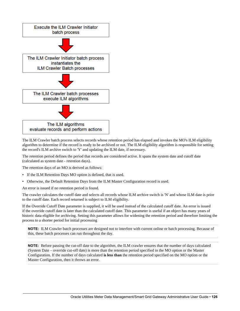
Oracle Utilities Meter Data Management/Smart Grid Gateway Administrative User Guide • 126
The ILM Crawler batch process selects records whose retention period has elapsed and invokes the MO's ILM eligibilityalgorithm to determine if the record is ready to be archived or not. The ILM eligibility algorithm is responsible for settingthe record's ILM archive switch to 'Y' and updating the ILM date, if necessary.
The retention period defines the period that records are considered active. It spans the system date and cutoff date(calculated as system date - retention days).
The retention days of an MO is derived as follows:
• If the ILM Retention Days MO option is defined, that is used.
• Otherwise, the Default Retention Days from the ILM Master Configuration record is used.
An error is issued if no retention period is found.
The crawler calculates the cutoff date and selects all records whose ILM archive switch is 'N' and whose ILM date is priorto the cutoff date. Each record returned is subject to ILM eligibility.
If the Override Cutoff Date parameter is supplied, it will be used instead of the calculated cutoff date. An error is issuedif the override cutoff date is later than the calculated cutoff date. This parameter is useful if an object has many years ofhistoric data eligible for archiving. Setting this parameter allows for widening the retention period and therefore limiting theprocess to a shorter period for initial processing
NOTE: ILM Crawler batch processes are designed not to interfere with current online or batch processing. Because ofthis, these batch processes can run throughout the day.
NOTE: Before passing the cut-off date to the algorithm, the ILM crawler ensures that the number of days calculated(System Date – override cut-off date) is more than the retention period specified in the MO option or the MasterConfiguration. If the number of days calculated is less than the retention period specified on the MO option or theMaster Configuration, then it throws an error.
Oracle Utilities Meter Data Management/Smart Grid Gateway Administrative User Guide • 127
Eligibility AlgorithmAlgorithms are triggered by the ILM batch crawler for the maintenance object. The key responsibility of the ILM algorithmis to determine whether a record can be marked as ready to be archived or not. If a record is determined to be ready forarchive, the algorithm should set the ILM Archive switch to Y. If not, the algorithm leaves the switch set to N and maydecide to update the ILM Date to something more recent (like the System Date) to ensure that the record does not getevaluated again until the future.
This algorithm is plugged into the Maintenance Object — Algorithm collection.
Oracle Utilities Application Framework provides the algorithm ILM Eligibility Based on Status (F1-ILMELIG) tosupport the ILM batch crawler. Refer to the algorithm type description for details about how this algorithm works. If amaintenance object has special business rules that are evaluated to determine the eligibility for ILM, a custom algorithm canbe created and applied by the implementation team.
Enabling ILM for Supported Maintenance ObjectsIn order to enable ILM for one or more maintenance objects, several steps are needed in both the configuration and in thedatabase. This section describes some configuration enabled by default and some steps that must be taken in order to fullyimplement ILM.
There is some configuration enabled by default, but it won’t be used unless ILM is fully configured. Each maintenanceobject that the product has configured for ILM has the following provided out of the box:
• Special Table Columns: Maintenance objects that support ILM include two specific columns: ILM Archive Switch(ILM_ARCH_SW) and ILM Date (ILM_DT).
• Crawler Batch Process: A "crawler" batch process is provided for each maintenance object that supports ILM and it isplugged into the MO as an option. Refer to Batch Processes for more information.
• ILM Eligibility Algorithm: Each maintenance object that is configured for ILM defines an eligibility algorithm thatexecutes the logic to set the ILM Archive switch appropriately. This is plugged in to the MO algorithm collection.
If an implementation decides to implement ILM, there are steps that need to be followed, which are highlighted below.
Create the Master Configuration RecordThe first step when enabling ILM is to create the ILM Configurationmaster configuration record.
The master configuration for ILM Configuration defines global parameters for all ILM eligible maintenance objects. Forexample, the Default Retention Period. In addition, your product may implement additional configuration. Refer to theembedded help for specific details about the information supported for your product's ILM configuration.
In addition, the user interface for this master configuration record displays summary information about all the maintenanceobjects that are configured to use ILM.
Confirm the Maintenance Objects to EnableIn viewing the list of maintenance objects that support ILM in the ILM master configuration page, your implementationmay choose to enable ILM for only a subset of the supported maintenance objects. For example, some of the maintenanceobjects may not be relevant for your implementation. Or perhaps, the functionality provided by the maintenance object isused, but your implementation does not expect a high volume of data.
For each maintenance object that your implementation has confirmed for ILM, the following steps should be taken:
• Determine if the maintenance object should have a different default retention days than the system wide value definedon the master configuration. If so, use the MO option ILM Retention Period in Days to enter an override option for thismaintenance object.
Oracle Utilities Meter Data Management/Smart Grid Gateway Administrative User Guide • 128
• Review the functionality of the ILM Eligibility algorithm provided by the product for this maintenance object. Eachalgorithm may support additional configuration based on business needs. If your organization has special business rulesthat aren't satisfied by the algorithm provided by the product, a custom algorithm may be provided to override the basealgorithm.
For each maintenance object that your implementation does not want to enable for ILM, inactivate the eligibility algorithm.This will ensure that the ILM Crawler Initiator background process does not submit the crawler batch job for themaintenance object in question.
• Go to the Maintenance Object - Algorithm tab for each maintenance object and take note of the ILM Eligibilityalgorithm code.
• Go to the Maintenance Object - Option tab for the same maintenance object and add an option with an option type ofInactivate Algorithm and the value set to the ILM eligibility algorithm noted in the previous step.
Database Administrator TasksIn order to implement ILM for each of the maintenance objects determined above, your database administrator mustperform several steps in the database for the tables related to each MO. The following points are a summary of those steps.More detail can be found in the Information Lifecycle Management section of your product's Database AdministrationGuide.
• Initializing ILM Date: Your existing tables that are enabled for ILM may not have the ILM Date and ILM Archiveswitch initialized on all existing records. When choosing to enable ILM, a first step is to initialize this data based onrecommendations provided in the DBA guide.
• Referential Integrity: The recommended partitioning strategy for child tables in a maintenance object is referentialpartitioning. In order to implement this, database referential integrity features must be enabled.
• Partitioning: This provides a way in which the data can segregate into multiple table partitions and will help in bettermanagement of the lifecycle of the data.
Schedule the ILM Crawler InitiatorThe final step of enabling the system for ILM is to schedule the ILM crawler initiator F1-ILMIN regularly based on yourimplementation’s need. It is recommended to only schedule this batch process once all the required database activities arecomplete.
Ongoing ILM TasksFor an environment where ILM is enabled, besides the periodic execution of the ILM crawler batch processes to review andmark records, your database administrator has ongoing tasks.
The DBA reviews and maintains partitions and identifies partitions that may warrant some type of archiving step. TheInformation Lifecycle Management section of your product's Database Administration Guide provides more information foryour DBA.
Archived Foreign KeysIf your DBA chooses to archive a partition, there may be records in the system that refer to one of the archived records as aforeign key.
When a user attempts to view a record using a hyperlink or drill down mechanism, if the implementation of the navigationuses FK Reference functionality, the system will first check if the record exists. If not, it will display a message to the userindicating that the record has been archived.
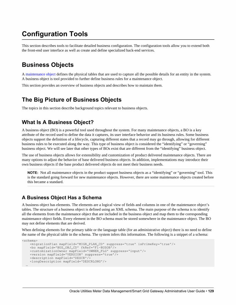
Oracle Utilities Meter Data Management/Smart Grid Gateway Administrative User Guide • 129
Configuration ToolsThis section describes tools to facilitate detailed business configuration. The configuration tools allow you to extend boththe front-end user interface as well as create and define specialized back-end services.
Business ObjectsA maintenance object defines the physical tables that are used to capture all the possible details for an entity in the system.A business object is tool provided to further define business rules for a maintenance object.
This section provides an overview of business objects and describes how to maintain them.
The Big Picture of Business ObjectsThe topics in this section describe background topics relevant to business objects.
What Is A Business Object?A business object (BO) is a powerful tool used throughout the system. For many maintenance objects, a BO is a keyattribute of the record used to define the data it captures, its user interface behavior and its business rules. Some businessobjects support the definition of a lifecycle, capturing different states that a record may go through, allowing for differentbusiness rules to be executed along the way. This type of business object is considered the “identifying” or “governing”business object. We will see later that other types of BOs exist that are different from the “identifying” business object.
The use of business objects allows for extensibility and customization of product delivered maintenance objects. There aremany options to adjust the behavior of base delivered business objects. In addition, implementations may introduce theirown business objects if the base product delivered objects do not meet their business needs.
NOTE: Not all maintenance objects in the product support business objects as a “identifying” or “governing” tool. Thisis the standard going forward for new maintenance objects. However, there are some maintenance objects created beforethis became a standard.
A Business Object Has a SchemaA business object has elements. The elements are a logical view of fields and columns in one of the maintenance object’stables. The structure of a business object is defined using an XML schema. The main purpose of the schema is to identifyall the elements from the maintenance object that are included in the business object and map them to the correspondingmaintenance object fields. Every element in the BO schema must be stored somewhere in the maintenance object. The BOmay not define elements that are derived.
When defining elements for the primary table or the language table (for an administrative object) there is no need to definethe name of the physical table in the schema. The system infers this information. The following is a snippet of a schema:
<schema> <migrationPlan mapField="MIGR_PLAN_CD" suppress="true" isPrimeKey="true"/> <bo mapField="BUS_OBJ_CD" fkRef="F1-BUSOB"/> <customizationOwner mapField="OWNER_FLG" suppress="input"/> <version mapField="VERSION" suppress="true"/> <description mapField="DESCR"/> <longDescription mapField="DESCRLONG"/> …
Oracle Utilities Meter Data Management/Smart Grid Gateway Administrative User Guide • 130
Many maintenance objects have child table collections (e.g., a collection of names for a person, or a collection of personson an account). Depending on the requirements, the business object may define the full collection such that the user willmaintain the information in a grid. However, the schema also supports “flattening” records in a child table so that they canbe treated as if they were singular elements. The following are examples of each:
Example of a child table. This is a snippet of the Instructions collection on the migration plan business object. You can seethat the list attribute defines the child table and all elements within it map to the appropriate column in that table.
<migrationPlanInstruction type="list" mapChild="F1_MIGR_PLAN_INSTR"> <migrationPlan mapField="MIGR_PLAN_CD" suppress="true"/> <sequence mapField="PLAN_INSTR_SEQ" suppress="true"/> <instructionSequence mapField="INSTR_SEQ"/> <instructionType mapField="INSTR_TYPE_FLG"/> <parentInstructionSequence mapField="PARENT_INSTR_SEQ"/> <businessObject mapField="BUS_OBJ_CD" fkRef="F1-BOMO"/>...
Example of a simple “flattened” field. The business object for Status Reason includes an element called Usage, which mapsto a pre-defined characteristic of type F1–SRUSG. The “row” defines which child table is being flattened and the attributesof the row in that child that uniquely identify it.
<usage mdField="STATUS_RSN_USAGE" mapField="CHAR_VAL"> <row mapChild="F1_BUS_OBJ_STATUS_RSN_CHAR"> <CHAR_TYPE_CD is="F1-SRUSG"/> <SEQ_NUM is="1"/> </row> </usage>
Example of a “flattened row”. This business object for Account includes a single row for the Person collection where onlythe “financially responsible, main” customer is defined. The “accountPerson” attribute defines one field from that row(the Person Id) and includes the ‘flattening’ criteria in the “row” information. In addition, a second field from that samerow (“accountRelType”) is defined. Instead of having to repeat the flattening criteria, the “rowRef” attribute identifies theelement that includes the flattening.
<accountPerson mapField="PER_ID"> <row mapChild="CI_ACCT_PER"> <MAIN_CUST_SW is="true"/> <FIN_RESP_SW default="true"/> </row> </accountPerson> <accountRelType mapField="ACCT_REL_TYPE_CD" rowRef="accountPerson" dataType="string"/>
Example of a “flattened list”. The business object for Tax Bill Type includes an list of valid algorithms for “billcompletion”. The Sequence and the Algorithm are presented in a list. The list element identifies the child table and the‘rowFilter’ identifies the information about the list that is common.
<taxBillCompletion type="list" mapChild="C1_TAX_BILL_TYPE_ALG"> <rowFilter suppress="true" private="true"> <TAX_BILL_TYPE_SEVT_FLG is="C1BC"/> </rowFilter> <sequence mapField="SEQ_NUM"/> <algorithm mapField="ALG_CD" fkRef="F1-ALG"/> </taxBillCompletion>
In addition, many maintenance objects support an XML structure field within the entity. These fields may be of data typeCLOB or XML. One or more business object elements may be mapped to the MO's XML structure field. These elementsmay be defined in different logical places in the business object schema based on what makes sense for the business rules.When updating the MO, the system builds a type of XML document that includes all the elements mapped to the XMLstructure and stores it in one column. The following is an example of elements mapped to an XML column:
<filePath mdField="F1_FILE_PATH" mapXML="MST_CONFIG_DATA" required="true"/> <characterEncoding mdField="F1_CHAR_ENCODING" mapXML="MST_CONFIG_DATA"/>
NOTE: If the MO’s XML structure field is of the data type XML, the database will allow searching for records based onthat data, assuming appropriate indexes are defined. If the MO’s XML structure field is of the data type CLOB, indexing

Oracle Utilities Meter Data Management/Smart Grid Gateway Administrative User Guide • 131
or joining to elements in this column via an SQL statement is not typically supported. Note that most MOs are currentlyusing the CLOB data type for the XML structure column, if provided.
Some business objects may have child tables that allow data to be stored in an XML structure field. The schema languagesupports defining elements from those fields in your schema as well.
Besides including information about the physical “mapping” of the element to its appropriate table / field location inthe maintenance object, the schema supports additional syntax to provide the ability to define basic validation and datamanipulation rules, including:
• Identifying the primary key of the record or the primary key of the a row in a list.
• Identifying which elements are required when adding or changing a record.
• Default values when no data is supplied on an Add.
• For elements that are lookup values, the lookup may be specified to validate that the value of the element is a validlookup value.
• For elements that are foreign keys to another table, the FK Reference may be specified to validate the data.
The system will check the validity of the data based on the schema definition obviating the need for any special algorithm tocheck this validation.
In addition, the schema language may include some attributes that are used to auto-render the view of the record on the userinterface, such as the suppress attribute. Refer to BO Defines its User Interface for more information.
NOTE: Refer to Schema Syntax for the complete list of the XML nodes and attributes available to you when youconstruct a schema.
A business object’s schema may include a subset of the fields and tables defined in the maintenance object. There are tworeasons for this:
• The fields or tables may not be applicable to the type of record the business object is governing. For example, a field thatis specific to gas may not be included on a Device business object that is specific to electric meters.
• The information is not maintained through the business object, but rather maintained separately. For example, many BObased maintenance objects include a Log table. The records in the log table are typically not included the BO becausethey are viewed and maintained separately from the business object.
A Business Object May Define Business RulesA business object may define business rules that govern the behavior of entities of this type.
• Simple element-level validation is supported by schema attributes. Note that element-level validation is executed beforeany maintenance object processing. For more sophisticated rules you create Validation algorithms and associate themwith your business object. BO validation algorithms are only executed after "core validation" held in the MO is passed.
• A Pre-Processing algorithm may be used to "massage" a business object's elements prior to any maintenance objectprocessing. For example, although simple element-level defaulting is supported by schema attributes. you may use thistype of algorithm to default element values that are more sophisticated.
• A Post-Processing algorithm may be used to perform additional steps such as creating a To Do Entry or add a log recordas part of the business object logical transaction. These plug-ins are executed after all the validation rules are executed.
• An Audit algorithm may be used to audit changes made to entities of this type.Any time a business entity is added, changed or deleted, the system detects and summarizes the list of changes that tookplace in that transaction and hands it over to Audit plug-ins associated with the business object. These plug-ins areexecuted after all the post-processing rules are executed. It is the responsibility of such algorithms to log the changes ifand where appropriate, for example as a log entry or an entry in an audit trail table or an entry in the business event log

Oracle Utilities Meter Data Management/Smart Grid Gateway Administrative User Guide • 132
By default all elements of the business object are subject to auditing. You can however mark certain elements to beexcluded from the auditing process using the noAudit schema attribute. Marking an element as not auditable will preventit from ever appearing as a changed element in the business object's audit plug-in spot. In addition, if the only elementsthat changed in a BO are ones marked to not audit, the audit algorithm is not even called. Refer to Schema Syntax formore information on this attribute.
Refer to Business Object - Algorithms for more information on the various types of algorithms.
The system applies business object rules (schema based and algorithms) whenever a business object instance is added,changed or deleted. This is only possible when the call is made via the maintenance object service. For example, whenmade via business object interaction ("invoke BO"), the MO's maintenance page or inbound web services that referencethe BO. In addition the system must be able to determine the identifying business object associated with the actual objectbeing processed. If the business object cannot be determined for a maintenance object instance business object rules are notapplied.
NOTE:Pre-Processing is special. The pre-processing algorithm plug-in spot is unique in that it only applies during a BOinteraction. It is executed prior to any maintenance object processing. It means that when performing add, change ordelete via the maintenance object service, the pre-processing plug-in is not executed.
CAUTION: Direct entity updates bypass business rules! As mentioned above, it is the maintenance object service layerthat applies business object rules. Processes that directly update entities not via the maintenance object service bypassany business object rules you may have configured.
FASTPATH: Refer to BO Algorithm Execution Order for a summary of when these algorithms are executed withrespect to lifecycle algorithms.
The plug-in spots described above are available for all business objects and they are executed by the system whenprocessing adds or updates to the business object. It is possible for a specific maintenance object to define a special plug-in spot for business objects of that MO. When this happens, the maintenance object identifies the special algorithm entitylookup value as an MO option: Valid BO System Event, causing the BO Algorithm collection to include that system eventin its list.
A Business Object Defines its User InterfaceOne of the responsibilities of an identifying business object is to define its user interface rules for viewing and maintenanceof its record. The standard implementation for maintaining a business object is that a maintenance portal is used to displaya record. This portal includes a "map" zone that displays the information about the business object. To add or make changesto a record, the user clicks a button that launches a maintenance BPA script which displays a maintenance "map".
The display and maintenance "maps" are driven by the business object. The BO may define a full UI map where all theinformation is displayed based on the map's HTML. Note that for a child BO, the maps may be inherited by a parent BO (orany BO "up the chain").
The standard going forward is to use schema definition and UI Hints to define user interface behavior so that a full UI mapis not needed but rather the HTML is derived. The schema language includes some basic display attributes such as labeland suppress. UI hints provide many additional tags and elements that allow dynamic generation of formatted UI Maps.For more complex behavior in the user interface, for example where javascript is needed, UI map fragments may be definedwithin the schema via UI hints. In this way only complex UI behavior warrants small snippets of javascript and HTML.However the rendering of standard fields can be dynamically rendered. UI map fragments also allow for derived fields to beincluded in the user interface.
A business object schema may include data areas for segments of its schema definition to allow for reusable components. Inthis case the data area would also include schema attributes and UI hints for the elements that it is including.
Oracle Utilities Meter Data Management/Smart Grid Gateway Administrative User Guide • 133
NOTE: Refer to UI Hint Syntax for detailed information about the supported syntax.
As mentioned in Business Object Inheritance, schemas are not inherited on a child business object. As such, when using UIhints for automatic UI rendering, the child BO must define the full schema with all the definitions. A good business objecthierarchy will be designed for reuse meaning that the child BO will include the parent BO schema or alternatively, the BOschemas will include reusable data areas.
Invoking A Business ObjectWe have talked about defining a business object. This section describes how business objects are used throughout thesystem to view, add and update records.
• Various parameters for zones that are used to display data in the system include support for retrieving data by referencinga business object. The zone code will "invoke" the BO, meaning that the record will be retrieved using the referencedBO.
• The system's scripting language includes a step type to "invoke BO". This allows for BPA scripts, service scripts andplug-in scripts to retrieve information and add or update records using BO interaction.
• Inbound web services may reference a business object in its operations collection. This allows external systems to add orupdate records in our product via web service interaction.
Often when configuring a zone or writing a script, the BO to use in the "invoke BO" statement should be the identifyingBO of the record. As such, often the script will include steps prior to the "invoke BO" step to "determine the identifyingBO of the record" and once the identifying BO is found, the script step will invoke that BO. Note that zones and inboundweb services reference a BO directly. In each case, if the BO to use should be dynamic, then the zone / inbound web serviceshould reference a service script that can perform the steps to identify the BO and then invoke that BO.
It should be noted however that the BO used in an "invoke BO" statement (or referenced in an inbound web service) doesnot have to match the identifying BO for the record. Here are some examples of where this may be true:
• A script may only require a subset of elements for a record and not the entire record. In this case, it is better forperformance purposes to define a special BO (sometimes called a "lite" BO or a "mini" BO) that only defines theneeded elements. When the system retrieves the data, it will only access the tables that are included in the BO's schemadefinition. In addition, if there are no elements that map to an XML structure field, the system will skip any parsing ofthat column. Similarly, if a script is updating a subset of elements on a record, it may be beneficial to use a "mini" BO todo the updates.
NOTE: Please note the following with respect to using a mini BO. This BO is only used for its schema. This typeof BO would not define algorithms or a lifecycle. Because the BO is special, it often should not be able to be usedas any record’s identifying BO. To control that, these BOs are often configured to not allow new instances. Refer toDetermine the Identifying BO for more information.
• The maintenance object to be added or updated in a script may not support business objects as "identifying BOs". Forexample, Batch Control maintenance object does not have an identifying BO. However, scripts may still wish to retrievedata (or make updates) to these types of records. An easy way to achieve that goal is to define a business object and use"invoke BO" to access the data.
NOTE: Not all maintenance objects support being maintained through a business object interaction. This is true ina small number of older objects where the underlying maintenance service includes additional functionality besidessimply updating the database tables. These maintenance objects are identified via the MO optionBO Maintenance,set to N.
• Some functionality may be trying to add or update records for a maintenance object in a 'physical' manner and do notwant or need to use the object's identifying BO. Or the MO may not have an identifying BO. For example, revision

Oracle Utilities Meter Data Management/Smart Grid Gateway Administrative User Guide • 134
control takes a snapshot of a record for audit purpose and to be able to restore a previous version. In this case, the systemwants to capture a full "physical" view of the record. To do this, a special "physical" BO may be created that includes all(or most of) the columns and the child tables.
NOTE: Like the mini BO, the physical BO would not define algorithms or a lifecycle and should not be able to beused as any record’s identifying BO. To control that, these BOs are often configured to not allow new instances.Refer to Determine the Identifying BO for more information.
NOTE: To reiterate, the BO referenced in the "invoke BO" statement or referenced in an inbound web service does nothave to match the identifying BO and does not have to be configured to "allow new instances".
Determine the Identifying BOAs mentioned in other topics, the identifying BO is the business object that governs the business rules for a record. This isthe business object that the record will be validated against when any additions or changes are made to the record as longas updates are made via the maintenance service. This includes using "invoke BO" for add or update, using inbound webservice interaction and for access to the maintenance page service (via an old style fixed page or via a business service).
How does the system determine the identifying BO? An algorithm plugged into the maintenance object (the Determine BOplug-in spot) is responsible for this. If the maintenance object is not configured with an algorithm for this plug-in spot, or noBO is found by the algorithm, no BO business rules are applied.
Most maintenance objects in the system capture the record's identifying BO directly on the record. However, it is possibleto define the identifying BO somewhere else. For example, there may be some maintenance objects that are master ortransaction objects with an associated "type" object where the identifying BO is defined on its "type" object. Note thatthe standard Determine BO algorithm plugged into most maintenance objects (F1-STD-DTMBO - Determine StandardBusiness Object) checks for these two conditions.
There may also be cases where a single identifying BO is used for all BOs for a given MO. This may be an option used forsome older maintenance object created prior to the business object functionality when implementations wish to introducecustom business rules that are common for all records of that MO. The product provides a base algorithm type (F1–MOBO- Determine Specific Business Object) that captures the BO as a parameter.
Base Business ObjectsFor each maintenance object (MO) that supports an “identifying” business object, the type of business object provided bythe product depends on the functionality and expected use by implementations. The following are some common patterns.
• There are MOs where the product provides base BOs that implementations may use if applicable for their business rules.In addition, it is expected that implementation will define custom BOs to support their business needs. Good examples ofthis type of MO are any of the various “rule” MOs. For example, calculation rule in Oracle Utilities Customer Care andBilling or the usage rule in Oracle Utilities Meter Data Management or the form rule in Oracle Public Sector RevenueManagement. The product provides business objects for common rules but each implementation could have special rulesthat they need to implement and will need to create custom business objects.
• There are MOs where the product provides base BOs that supply common behavior for an object. Implementations mayfind that supplied the business objects match their business requirements and use the BOs as is. It is expected, howeverthat for many implementations, their business rules will require additional elements to be captured or have special rulesto apply. In this case the base business objects may be extended. This scenario may apply to ‘master’ data objects invarious products such as the Device or Meter or Tax Role.
• There are MOs where the product may deliver a base BO that is not expected to satisfy most implementations becausedifferent jurisdictions or different implementations will typically have their own rules. In this case the base delivered BOcan be used as a template or starting point for custom defined BOs. Some examples of this are Rebate Claim in OracleUtilities Customer Care and Billing or the Appeal object in Oracle Public Sector Revenue Management.

Oracle Utilities Meter Data Management/Smart Grid Gateway Administrative User Guide • 135
• There are MOs where the expectation is that every implementation will have different requirements for the type of datato capture and the product will not supply base BOs that can be used as the “identifying” BO. However, it may supplya “parent” BO that defines the lifecycle and many of the business rules that it expects all records to follow. In thesescenarios, the implementations will create “child” BOs that will serve as the “identifying” BOs and refer to the base“parent” BO for many of its rules through inheritance. Some examples of the are Tax Form in Oracle Public SectorRevenue Management or Activity in Oracle Utilities Mobile Workforce Management.
• There are some scenarios where the base product provides business objects and the expectation is that implementationswill use the business objects as delivered with little or no customization. This is a case where the system used businessobjects to implement product functionality, not because there is an expectation that the implementers will extend thefunctionality, but because the business object model is the favored development tool even for the product. The objectsdelivered for Configuration Migration Assistant are an example.
NOTE: Not all maintenance objects in the product support business objects as a “identifying” or “governing” tool. Thisis the standard going forward for new maintenance objects. However, there are some maintenance objects created beforethis became a standard.
For all maintenance objects, the base product may provide additional BOs that are not meant to be “identifying” BOs, butinstead are provided to support functionality to interact with the MO using the BO as a tool as described in Invoking a BO.
• One or more “mini” or “lite” BOs may be supplied for a maintenance object. This may be found when the product hasfunctionality to retrieve a subset of elements for the maintenance object via scripting or via a user interface.
• A “physical” BO may be supplied. This a BO that typically includes all tables and all fields of the maintenance object inthere “physical” form. In other words, there is no “flattening” of child tables and any XML structure fields are definedas a single field. Physical BOs are used in system processing where the full record needs to be captured as is. Somefunctionality that uses a physical BO includes bundling, revision control and the pre-compare algorithm for CMA toadjust data prior to comparing.
Business Object InheritanceA business object may inherit business rules from another business object by referencing the latter as its parent. A childbusiness object can also have children, and so on. A parent's rules automatically apply to all of its children (no compilation -it's immediate). A child business object can always introduce rules of its own but never remove or bypass an inherited rule.
The following is an illustration of multiple levels of business object inheritance.
Notice how the "Business Customer" business object extends its parent rules to also enforce a credit history check on alltypes of customers associated with its child business objects.
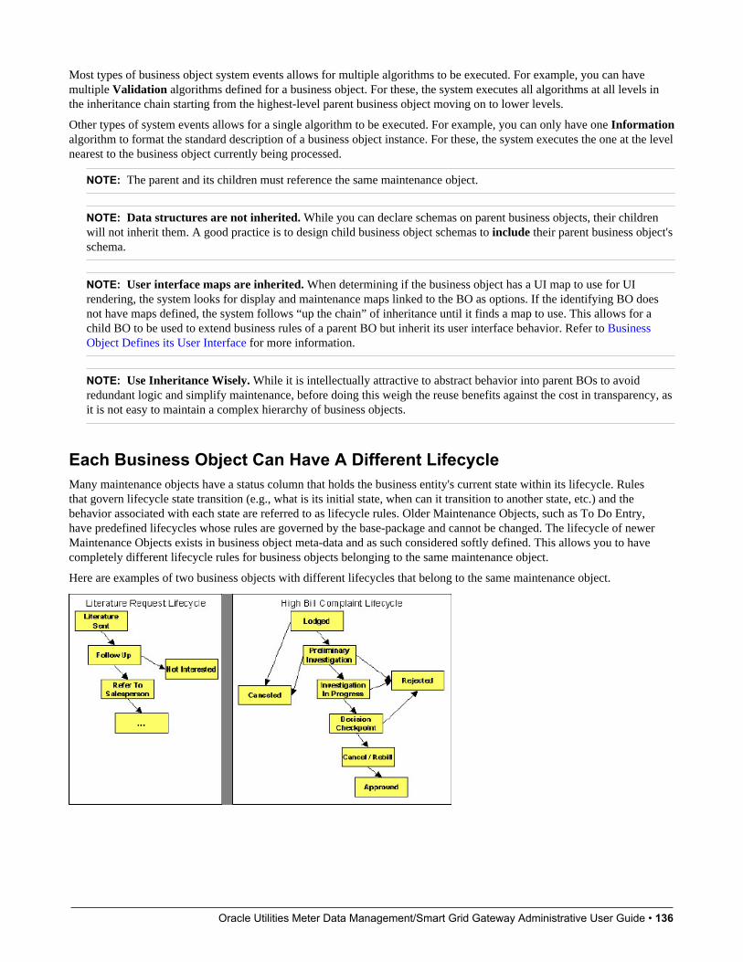
Oracle Utilities Meter Data Management/Smart Grid Gateway Administrative User Guide • 136
Most types of business object system events allows for multiple algorithms to be executed. For example, you can havemultiple Validation algorithms defined for a business object. For these, the system executes all algorithms at all levels inthe inheritance chain starting from the highest-level parent business object moving on to lower levels.
Other types of system events allows for a single algorithm to be executed. For example, you can only have one Informationalgorithm to format the standard description of a business object instance. For these, the system executes the one at the levelnearest to the business object currently being processed.
NOTE: The parent and its children must reference the same maintenance object.
NOTE: Data structures are not inherited. While you can declare schemas on parent business objects, their childrenwill not inherit them. A good practice is to design child business object schemas to include their parent business object'sschema.
NOTE: User interface maps are inherited. When determining if the business object has a UI map to use for UIrendering, the system looks for display and maintenance maps linked to the BO as options. If the identifying BO doesnot have maps defined, the system follows “up the chain” of inheritance until it finds a map to use. This allows for achild BO to be used to extend business rules of a parent BO but inherit its user interface behavior. Refer to BusinessObject Defines its User Interface for more information.
NOTE: Use Inheritance Wisely. While it is intellectually attractive to abstract behavior into parent BOs to avoidredundant logic and simplify maintenance, before doing this weigh the reuse benefits against the cost in transparency, asit is not easy to maintain a complex hierarchy of business objects.
Each Business Object Can Have A Different LifecycleMany maintenance objects have a status column that holds the business entity's current state within its lifecycle. Rulesthat govern lifecycle state transition (e.g., what is its initial state, when can it transition to another state, etc.) and thebehavior associated with each state are referred to as lifecycle rules. Older Maintenance Objects, such as To Do Entry,have predefined lifecycles whose rules are governed by the base-package and cannot be changed. The lifecycle of newerMaintenance Objects exists in business object meta-data and as such considered softly defined. This allows you to havecompletely different lifecycle rules for business objects belonging to the same maintenance object.
Here are examples of two business objects with different lifecycles that belong to the same maintenance object.
Oracle Utilities Meter Data Management/Smart Grid Gateway Administrative User Guide • 137
NOTE: A Maintenance Object supports soft lifecycle rules if it is defined with a Status Field Maintenance Objectoption.
The topics that follow describe important lifecycle oriented concepts.
Valid States versus State Transition RulesThe boxes in the above diagram show the potential valid states a business entity of the above business object can be in. Thelines between the boxes indicate the state transition rules. These rules govern the states it can move to while in a given state.For example, the above diagram indicates a high bill complaint that's in the Lodged state can be either Canceled or movedinto the Preliminary Investigation state.
When you set up a business object, you define both its valid states and the state transition rules.
One Initial State and Multiple Final StatesWhen you set up lifecycle states, you must pick one as the initial state. The initial state is the state assigned to new entitiesassociated with the business object. For example, the above high-bill complaint business object defines an initial state ofLodged, whereas the literature request one defines an initial state of Literature Sent.
You must also define which statuses are considered to be "final". Typically when an entity reaches a "final" state, itslifecycle is considered complete and no further processing is necessary.
NOTE: Allowing An Entity To Be "Reopened". You can set up your state transition rules to allow a business entity tobe "reopened" (i.e., to be moved from a final state to a non-final state). Neither of the above examples allows this, but itis possible if you configure your business object accordingly.
State-Specific Business RulesFor each state in a business object's lifecycle, you can define the following types of business rules.
FASTPATH: Refer to BO Algorithm Execution Order for a summary of when these lifecycle algorithms are executedwith respect to BO level algorithms.
Logic To Take Place When Entering A StateYou can define algorithms that execute before a business entity enters a given state. For example, you could develop analgorithm that requires a cancellation reason before an entity is allowed to enter the Canceled state.
You can also incorporate state auto-transitioning logic within this type of algorithms. Refer to auto-transition for moreinformation.
Also note that when a record is processed by the monitor batch program, by default the BO Post Processing, BO Audit andMO Audit algorithms are not executed. However, it is possible for an enter algorithm to indicate that the other algorithmsshould be executed by the batch process by setting the “force post processing” indicator to true.
Logic To Take Place When Exiting A StateYou can define algorithms that execute when a business entity exists a given state. For example, you could develop analgorithm that clears out error messages when a given entity exits the Error state.
Also note that when a record is processed by the monitor batch program, by default the BO Post Processing, BO Audit andMO Audit algorithms are not executed. However, it is possible for an exit algorithm to indicate that the other algorithmsshould be executed by the batch process by setting the “force post processing” indicator to true.
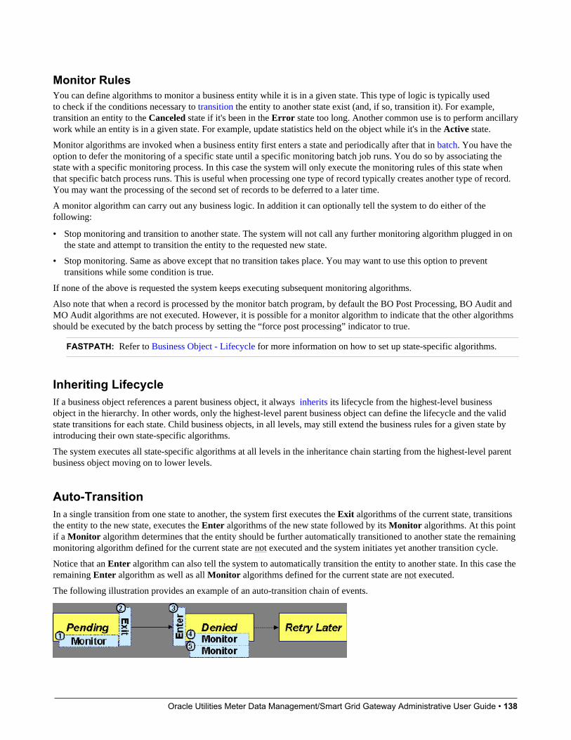
Oracle Utilities Meter Data Management/Smart Grid Gateway Administrative User Guide • 138
Monitor RulesYou can define algorithms to monitor a business entity while it is in a given state. This type of logic is typically usedto check if the conditions necessary to transition the entity to another state exist (and, if so, transition it). For example,transition an entity to the Canceled state if it's been in the Error state too long. Another common use is to perform ancillarywork while an entity is in a given state. For example, update statistics held on the object while it's in the Active state.
Monitor algorithms are invoked when a business entity first enters a state and periodically after that in batch. You have theoption to defer the monitoring of a specific state until a specific monitoring batch job runs. You do so by associating thestate with a specific monitoring process. In this case the system will only execute the monitoring rules of this state whenthat specific batch process runs. This is useful when processing one type of record typically creates another type of record.You may want the processing of the second set of records to be deferred to a later time.
A monitor algorithm can carry out any business logic. In addition it can optionally tell the system to do either of thefollowing:
• Stop monitoring and transition to another state. The system will not call any further monitoring algorithm plugged in onthe state and attempt to transition the entity to the requested new state.
• Stop monitoring. Same as above except that no transition takes place. You may want to use this option to preventtransitions while some condition is true.
If none of the above is requested the system keeps executing subsequent monitoring algorithms.
Also note that when a record is processed by the monitor batch program, by default the BO Post Processing, BO Audit andMO Audit algorithms are not executed. However, it is possible for a monitor algorithm to indicate that the other algorithmsshould be executed by the batch process by setting the “force post processing” indicator to true.
FASTPATH: Refer to Business Object - Lifecycle for more information on how to set up state-specific algorithms.
Inheriting LifecycleIf a business object references a parent business object, it always inherits its lifecycle from the highest-level businessobject in the hierarchy. In other words, only the highest-level parent business object can define the lifecycle and the validstate transitions for each state. Child business objects, in all levels, may still extend the business rules for a given state byintroducing their own state-specific algorithms.
The system executes all state-specific algorithms at all levels in the inheritance chain starting from the highest-level parentbusiness object moving on to lower levels.
Auto-TransitionIn a single transition from one state to another, the system first executes the Exit algorithms of the current state, transitionsthe entity to the new state, executes the Enter algorithms of the new state followed by its Monitor algorithms. At this pointif a Monitor algorithm determines that the entity should be further automatically transitioned to another state the remainingmonitoring algorithm defined for the current state are not executed and the system initiates yet another transition cycle.
Notice that an Enter algorithm can also tell the system to automatically transition the entity to another state. In this case theremaining Enter algorithm as well as all Monitor algorithms defined for the current state are not executed.
The following illustration provides an example of an auto-transition chain of events.
Oracle Utilities Meter Data Management/Smart Grid Gateway Administrative User Guide • 139
In this example a business entity is in a Pending state. While in that state a Monitor algorithm determines to auto-transitionit to the Denied state. At this point the following takes place:
• No further Monitor algorithms of the Pending state are executed
• Pending state Exit algorithms are executed
• The system transitions the entity to the Denied state
• Denied state Enter algorithms are executed. No further auto-transition is requested.
• Denied state Monitor algorithms are executed. No further auto-transition is requested.
Keeping An Entity In Its Last Successful StateBy default, any error encountered while transitioning a business entity from one state to another rolls back all changesleaving the entity in its original state.
When applicable, the Maintenance Object can be configured to always keep an entity in its last successful state rather thanrolling all the way back to the original state. This practice is often referred to as "taking save-points". In case of an error, theentity is rolled back to the last successfully entered state and the error is logged on the maintenance object's log. Notice thatwith this approach no error is returned to the calling process, the error is just logged.
The logic to properly log the error is in a Transition ErrorMaintenance Object plug-in. The system considers amaintenance object to practice "save-points" when such an algorithm is plugged into it.
Even if the maintenance object practices "save-points", in case of an error the system will not keep an entity in the lastsuccessfully entered state if that state is either marked as transitory or one of its Enter algorithms has determined thatthe entity should proceed to a next state. The system will roll back to the first previous state that does not match theseconditions.
Monitoring Batch ProcessesA monitor batch process may be used to transition a business object into its next state by executing the monitor algorithmsassociated with the current state of the entity. The use cases for performing the monitor logic in batch are as follows:
• The record may be waiting for something else to occur before transitioning. The monitor algorithm may be coded todetermine if the condition is satisfied and initiate the transition then. For example perhaps when entering a state, a fieldactivity is generated and the record should exit the state when the field activity is complete. The monitor algorithm cancheck the status of the field activity.
• Perhaps a record is added or updated manually and the next step in the BO lifecycle includes a large amount ofprocessing such that the logic should occur in batch. In this case the BO status is configured with an explicit reference toa batch control (called a “deferred” batch control), which indicates to the system that the monitor algorithms should notbe performed automatically (but should be deferred to batch). Later when the batch process runs, it selects all the recordsto process to progress the records.
NOTE: When a status includes a deferred batch control, it may also be configured to allow a user to manuallytransition the record to the next state rather than waiting for batch. When a user manually transitions a record thatincludes monitor algorithms, those algorithms are not executed.
• Perhaps a record is added or updated in batch, but a subsequent step in the overall lifecycle should be processed later.This may be accomplished by ensuring that the batch control linked to the state to process later does not match the batchcontrol that added or updated the record.
• Monitor processes may also be used to periodically perform some logic related to the record without actuallytransitioning the record.
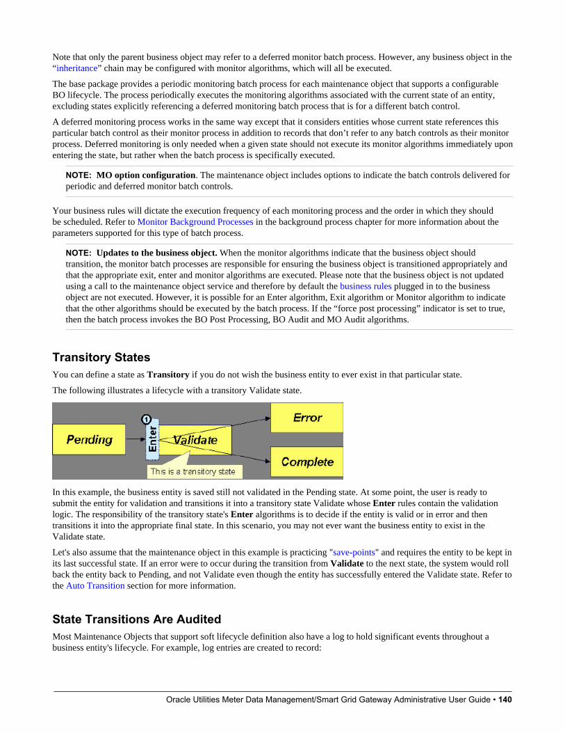
Oracle Utilities Meter Data Management/Smart Grid Gateway Administrative User Guide • 140
Note that only the parent business object may refer to a deferred monitor batch process. However, any business object in the“inheritance” chain may be configured with monitor algorithms, which will all be executed.
The base package provides a periodic monitoring batch process for each maintenance object that supports a configurableBO lifecycle. The process periodically executes the monitoring algorithms associated with the current state of an entity,excluding states explicitly referencing a deferred monitoring batch process that is for a different batch control.
A deferred monitoring process works in the same way except that it considers entities whose current state references thisparticular batch control as their monitor process in addition to records that don’t refer to any batch controls as their monitorprocess. Deferred monitoring is only needed when a given state should not execute its monitor algorithms immediately uponentering the state, but rather when the batch process is specifically executed.
NOTE: MO option configuration. The maintenance object includes options to indicate the batch controls delivered forperiodic and deferred monitor batch controls.
Your business rules will dictate the execution frequency of each monitoring process and the order in which they shouldbe scheduled. Refer to Monitor Background Processes in the background process chapter for more information about theparameters supported for this type of batch process.
NOTE: Updates to the business object. When the monitor algorithms indicate that the business object shouldtransition, the monitor batch processes are responsible for ensuring the business object is transitioned appropriately andthat the appropriate exit, enter and monitor algorithms are executed. Please note that the business object is not updatedusing a call to the maintenance object service and therefore by default the business rules plugged in to the businessobject are not executed. However, it is possible for an Enter algorithm, Exit algorithm or Monitor algorithm to indicatethat the other algorithms should be executed by the batch process. If the “force post processing” indicator is set to true,then the batch process invokes the BO Post Processing, BO Audit and MO Audit algorithms.
Transitory StatesYou can define a state as Transitory if you do not wish the business entity to ever exist in that particular state.
The following illustrates a lifecycle with a transitory Validate state.
In this example, the business entity is saved still not validated in the Pending state. At some point, the user is ready tosubmit the entity for validation and transitions it into a transitory state Validate whose Enter rules contain the validationlogic. The responsibility of the transitory state's Enter algorithms is to decide if the entity is valid or in error and thentransitions it into the appropriate final state. In this scenario, you may not ever want the business entity to exist in theValidate state.
Let's also assume that the maintenance object in this example is practicing "save-points" and requires the entity to be kept inits last successful state. If an error were to occur during the transition from Validate to the next state, the system would rollback the entity back to Pending, and not Validate even though the entity has successfully entered the Validate state. Refer tothe Auto Transition section for more information.
State Transitions Are AuditedMost Maintenance Objects that support soft lifecycle definition also have a log to hold significant events throughout abusiness entity's lifecycle. For example, log entries are created to record:
Oracle Utilities Meter Data Management/Smart Grid Gateway Administrative User Guide • 141
• When the business entity is created (and who created it)
• When its status changes (and who changed it)
• If a transition error occurred (and the error message)
• References to other objects created throughout the entity's lifecycle. For example, if a To Do entry is created as part ofprocessing the entity, the To Do Entry is referenced in the log.
• Manual entries added by a user (think of these as "diary" entries)
When a business entity is first created and when it transitions into a new state the system calls Transition algorithm(s)plugged in on the Maintenance Object to record these events. If the maintenance object supports a log these events can becaptures as log entries.
NOTE: Most base package maintenance objects supporting a log may already provide state transition logging as partof their core logic. In this case you only need to provide a Transition plug-in if you wish to override base logging logicwith your own.
Required Elements Before Entering A StateYou can define additional elements that are required before a business entity can enter a given state. For example, let'sassume that a Cancel Reason must be defined before an object can enter the Canceled state. You do this by indicating thatelement as a Required Element state-specific option on the appropriate state on the business object.
Capturing a Reason for Entering a StateSome business objects support configuring certain states to allow or require a status reason when an object enters the state.The product provides a centralized status reason table that may be used to define the valid BO status reasons for variousbusiness objects and various states. The status reasons are defined using the Status Reason portal.
The following sections provide additional information about the BO status reason functionality.
Maintenance Object Must Support Status ReasonIn order for a business object to use the centralized status reason table to define reasons, the maintenance object must firstsupport the status reason. MOs that support status reason have the following characteristics:
• The primary table includes a column for Status Reason. This represents the status reason for the record’s current status, ifapplicable.
• The log table includes a column for Status Reason. The standard logic for capturing a log record when entering a statealso captures the status reason, if applicable. This allows a user to review the history of the changes in status and thestatus reason captured for a previous state transition, if applicable.
• The maintenance object option collection includes an option that defines the Status Reason field. This setting is a triggerfor business objects of this MO to be able to configure states to allow or require status reason.
Business Object State Indicates if Reasons are ApplicableOnce the MO is configured to support status reason, configuration on the business object is required to indicate the stateswhere a reason is applicable. States may be configured to require status reasons, allow status reasons as optional or notallow status reasons. With this configuration, the framework will automatically get the list of valid reasons for a state thatallows or requires them and then prompt the user for a status reason when a manual state transition occurs for that state. Italso automatically triggers an error if the state requires a status reason and no reason is provided.
NOTE: The status reason configuration on the business object state is customizable. That means that for a productowned business object, an implementation may opt to change the delivered configuration.
Oracle Utilities Meter Data Management/Smart Grid Gateway Administrative User Guide • 142
Status reasons are defined for the parent (or “lifecycle”) business object. All business objects in the hierarchy of the parentbusiness object have the same valid reasons for their states.
The status reason code must be unique for the centralized status reason table. Business object and status are required fields,so it is not possible to share a common reason code (like “Not applicable”) across multiple business objects or states. Ifmultiple BOs / states want to support a reason “Not applicable” then each must define a unique record for it. This pointshould be considered when planning for your status reasons.
Selectable vs. Not SelectableWhen defining a status reason, you may indicate whether it’s Selectable or Not Selectable. When a manual transition isperformed and a user is prompted for a status reason, only the Selectable reasons are presented. The Not Selectable reasonsmay be defined to support transitions that occur via algorithm processing.
NOTE: The Selectable setting is customizable. That means that if a product provides a base owned status reason for abusiness object state, an implementation may opt to change whether it is selectable or not. Careful consideration shouldbe made before changing a base delivered status reason from Not Selectable to Selectable as this may affect baseprovided algorithm functionality that could be relying on the setting of Not Selectable.
Status Reason Business ObjectThe status reason maintenance object, as with many maintenance objects in the product, references a business object used todefine attributes and behavior related to defining status reasons. The framework provides a business object for status reason(F1–BOStatusReason). For the business objects that have states that require a status reason (let’s call these “transactionalBOs”), if there is some special logic required for defining the status reasons, it is possible to define a different status reasonBO. In this situation, the override status reason BO to use for capturing status reasons should be defined as a BO option onthe transactional BO using the Status Reason Business Object option type. If a transactional BO does not define any statusreason BO option, then the F1–BOStatusReason is used when adding a status reason.
Defining a UsageThe base product status reason BO provides the ability to define a “usage” value. This is useful for algorithms that performstate transitions where a status reason is needed and where the algorithm is usable by more than one business object. Inthis case, the status reason to use cannot be provided as a parameter because each business object must define its own setof status reasons for each state. The Usage value can be used instead. Each business object can configure the status reasonto use in the algorithm and set the appropriate usage value. The algorithm can reference the usage value and retrieve thecorrect status reason to use based on the record’s transactional BO.
The status reason business object provided with the framework product (F1–BOStatusReason) supports capturing a usage.The valid usage values are defined in the Status Reason Usage characteristic type.
Alternatives for Defining ReasonsThere may be business objects in the system that capture reasons that are defined somewhere besides the BO status reasontable. For example, some objects may have an explicit administrative table for status reasons. Some objects may use aLookup or an Extendable Lookup to capture reasons. Refer to the business object description for information about howvalid reasons are defined, if applicable.
If a business object supports a reason that is not related to a state transition (such as a creation reason), the BO status reasonwould not be used. One of the alternate methods for defining a reason, described above, would be used.
BO Algorithm Execution SummaryThis table highlights the processing steps that occur when adding or changing a record that is governed by a business object.
Invoke BO
Event Comments

Oracle Utilities Meter Data Management/Smart Grid Gateway Administrative User Guide • 143
BO Pre-processing algorithms executed These algorithms are only executed when Invoke BO is used. Thebusiness object in the Invoke BO is the one whose rules are executed.
MO Processing
Event Comments
Determine if status has changed. The system keeps a note of the new status value but initially proceedswith the old value.
MO Processing. Standard MO processing, including MO validation is executed.
Determine BO algorithm executed. The MO level algorithm is executed to determine the identifying BO.
BO Validation algorithms executed.
BO Status Exit algorithms for the “old” status executed.
Status updated to the new value.
BO Status Enter algorithms for the “new” status executed.
If no error — MO Transition algorithms are executed.
FASTPATH: Refer to State Transitions are Audited for moreinformation.
State transition rules are performed if the status has changed.
If error and there are “save points” the MO Transition Error algorithmsare executed.
FASTPATH: Refer to Keeping An Entity In Its Last Successful Statefor more information.
Otherwise, the error is reported.
BO Status Monitor algorithms are executed. If the record transitions again, the prior step (State transition rule step)is repeated for the new transition.
BO Post-processing algorithms are executed.
BO Audit algorithms are executed. These algorithms are only executed if the system detects a change inelements that are not marked with “no audit”.
NOTE: To emphasize, the steps in the MO Processing table are only executed when the maintenance object service isinvoked. Any add or update initiated by an “invoke BO” statement will invoke the MO service. This is also true for webservice that invoke the business object. The Monitor Batch Process does not invoke the maintenance service. By defaultthe monitor batch process only executes the monitor algorithms and the state transition rules (if the monitor algorithmsindicate that a status change should occur). However, it is possible for an Enter algorithm, Exit algorithm or Monitoralgorithm to indicate that the other algorithms should be executed by the batch process. If the “force post processing”indicator is set to true, then the batch process invokes the BO Post Processing, BO Audit and MO Audit algorithms.
NOTE: For records that do not have a status, the state transition rules and the monitor rules are not applicable.
Granting Access To Business ObjectsEvery business object must reference an application service. When you link a business object to an application service, youare granting all users in the group access to its instances. You can prevent users from transitioning a business object intospecific states by correlating each business object status with each application service action (and then don't give the usergroup rights to the related action).
FASTPATH: Refer to The Big Picture Of Application Security for information about granting users access rights to anapplication service.
The system checks if a user has access rights each time the application is invoked to add, change, delete, read, or transitiona business object. However, if a business object invokes another business object, we assume that access was controlled bythe initial business object invocation and we do not check access for other business objects that it invokes. In other words,access rights are only checked for the initial business object invoked in a service call.
Oracle Utilities Meter Data Management/Smart Grid Gateway Administrative User Guide • 144
In order to apply business object security the system must be able to determine the business object associated with the actualobject being processed. To do that the Maintenance Object itself has to have a Determine BO algorithm plugged in. Ifthis algorithm is not plugged in or it cannot determine the BO on the MO, the system will not invoke any BO rules. If thebusiness object cannot be determined for a maintenance object instance, business object security is not checked. In this casethe system checks the user's access rights using standard maintenance object security.
NOTE: Parent business objects are ignored. If a child business object exists, a user need only have access to the childbusiness object's application service (not to every application service in the business object hierarchy).
Defining Business ObjectsThe topics in this section describe how to maintain business objects.
Note that several context sensitive dashboard zones appear on this page and are visible on all tabs.
• Schema Tips. This zone provides several links to launch help topics related to valid schema syntax and UI Hint syntaxin one click.
• View UI Rendering. This zone provides buttons to view the automatic rendering of the Display map or Input map basedon the attributes defined in the schema, including UI hints.
• Generate Schema. This zone includes a button that can be used to generate a “physical” schema based on themaintenance object definition. The element names are taken from the Java field name for each column. Once generated,adjust the schema as desired.
• Create a BO Algorithm. This zone includes a button to create a script based algorithm related to this business object.You are then prompted for information regarding the plug-in spot (BO or BO Status) and the system event, the name,description, etc. Once all the information is provided, the system creates an algorithm type, algorithm, links thealgorithm to the business object, creates the script and brings you to the script step to start defining the logic for the plug-in script.
• BOs Linked to the MO. This zone displays other business objects for the same maintenance object as the BO currentlydisplayed. You may drill into any of the other BOs by clicking its description.
Business Object - MainUse this page to define basic information about a business object. Open this page using Admin > System > BusinessObject
Description of Page
Enter a unique Business Object name and Description. Use the Detailed Description to describe the purpose of thisbusiness object in detail. Owner indicates if this business object is owned by the base package or by your implementation(Customer Modification).
CAUTION: Important! If you introduce a new business object, carefully consider its naming convention. Refer to System Data Naming Convention for more information.
Enter the Maintenance Object that is used to maintain objects of this type.
Enter a Parent Business Object from which to inherit business rules.
Lifecycle Business Object is only displayed for child business objects, i.e. those that reference a parent business object. Itdisplays the highest-level business object in the inheritance hierarchy. Refer to Inheriting Lifecycle for more information.
Application Service is the application service that is used to provide security for the business object. Refer to GrantingAccess To Business Objects for more information. The application service on the child business object must have the samevalid actions as the application service on the parent business object.

Oracle Utilities Meter Data Management/Smart Grid Gateway Administrative User Guide • 145
Use Instance Control to allow or prevent new entities from referencing the business object. Typically only the identifyingBOs are marked to allow new instances.
Click the View Schema hyperlink to view the business object's expanded schema definition. Doing this opens the schemaviewer window.
Click the View XSD hyperlink to view the business object's expanded schema definition in XSD format.
Click the View MO hyperlink to view the maintenance object in the Maintenance Object Viewer. You may find it useful toleave the application viewer window open while defining your business object schema.
The options grid allows you to configure the business object to support extensible options. Select the Option Type drop-down to define its Value. Detailed Description may display additional information on the option type. Set the Sequence to1 unless the option can have more than one value. Owner indicates if this option is owned by the base package or by yourimplementation (Customer Modification).
NOTE: You can add new options types. Your implementation may want to add additional option types. For example,your implementation may have plug-in driven logic that would benefit from a new option. To do that, add your newvalues to the customizable lookup field BUS_OBJ_OPT_FLG. If you add a new option type for a business option,you must update its maintenance object to declare this new option type. Otherwise, it won't appear on the option typedropdown. You do that by referencing the new option type as a Valid BO Option Typemaintenance object option.
Where Used
Follow this link to open the data dictionary to view the tables that reference F1_BUS_OBJ.
Business Object - SchemaUse this page to maintain a business object's schema. Open this page using Admin > System > Business Object and thennavigate to the Schema tab.
Description of Page
The contents of this section describe the zones that are available on this portal.
The General Information zone displays main attributes of the business object.
Click the View Schema hyperlink to view the business object's expanded schema definition. Doing this opens the schemaviewer window.
Click the View XSD hyperlink to view the business object's expanded schema definition in XSD format.
The Schema Designer zone allows you to edit the business object's schema. The purpose of the schema is to describe thebusiness object's properties and map them to corresponding maintenance object fields.
FASTPATH: Refer to Schema Syntax and UI Hint syntax for a complete list of the XML nodes and attributes availableto you when you construct a schema. Also note that the Schema Tips zone in the dashboard provides links to launchthese help topics directly.
NOTE: Generating a Schema A context sensitive "Generate Schema" zone is associated with this page. The zoneprovides a button that allows the user to generate a basic schema that includes all the fields for all the tables for the BO’smaintenance object.
NOTE: View UI Rendering. A context sensitive "View UI Rendering" zone is associated with this page. The zone isuseful for business objects that define the user interface detail using schema attributes and UI Hints. The buttons allowyou to view the automatically rendered display and input maps.
The Schema Usage Tree zone summarizes all cross-references to this schema. These may be other schemas, scripts, andweb services. For each type of referencing entity, the tree displays a summary node showing a total count of referencing
Oracle Utilities Meter Data Management/Smart Grid Gateway Administrative User Guide • 146
items. The summary node appears if at least one referencing item exists. Expand the node to list the referencing items anduse their description to navigate to their corresponding pages.
Business Object - AlgorithmsUse this page to maintain a business object's algorithms. Open this page using Admin > System > Business Object andthen navigate to the Algorithms tab.
Description of Page
The Algorithms grid contains algorithms that control important functions for entities defined by this business object. Youmust define the following for each algorithm:
• Specify the System Event with which the algorithm is associated (see the table that follows for a description of allpossible events).
• Specify the Sequence Number and Algorithm for each system event. You can set the Sequence Number to 10 unlessyou have a System Event that has multiple Algorithms. In this case, you need to tell the system the Sequence in whichthey should execute.
• If the algorithm is implemented as a script, a link to the Script is provided. Refer to Plug-In Scripts for moreinformation.
• Owner indicates if this is owned by the base package or by your implementation (Customer Modification).
The following table describes each System Event. Refer to A Business Object May Define Business Rules for moreinformation about these system events.
System Event Optional / Required DescriptionAudit Optional Algorithms of this type may be used to audit
certain changes made to business objectinstances.The system hands over to the algorithmsa summary of all the elements that werechanged throughout a specific call to updatean object. Excluded from this processing areelements explicitly marked on the schemaas requiring no audit. For each element itsoriginal value before the change as well as itsnew value are provided.It is the responsibility of the algorithms torecord corresponding audit information.The system invokes all algorithms of thistype defined on the business object'sinheritance hierarchy. Refer to BusinessObject inheritance for more information.Click here to see the algorithm types availablefor this system event.
Information Optional We use the term "Business ObjectInformation" to describe the basic informationthat appears throughout the system todescribe an entity defined by the businessobject. The data that appears in thisinformation description is constructed usingthis algorithm.The system invokes a single algorithm of thistype. If more than one algorithm is plugged-inthe system invokes the one with the greatestsequence number found on the businessobject closest to the current business object inthe inheritance hierarchy. Refer to BusinessObject inheritance for more information.Click here to see the algorithm types availablefor this system event.
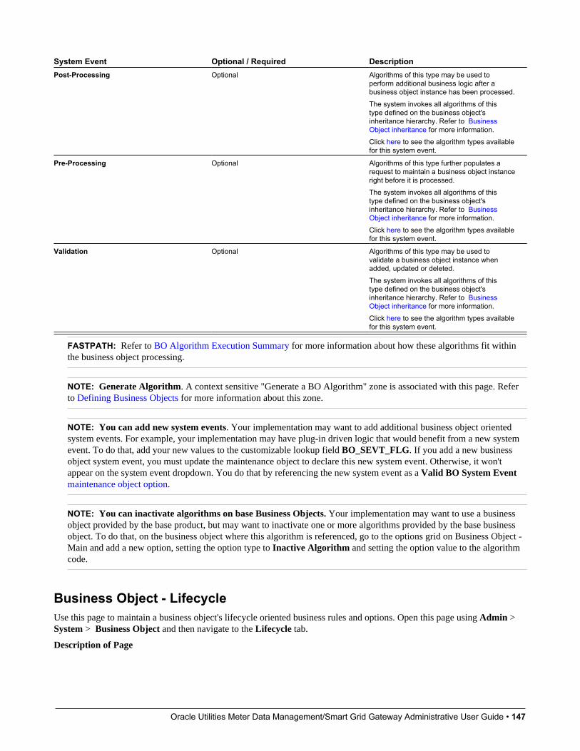
Oracle Utilities Meter Data Management/Smart Grid Gateway Administrative User Guide • 147
System Event Optional / Required DescriptionPost-Processing Optional Algorithms of this type may be used to
perform additional business logic after abusiness object instance has been processed.The system invokes all algorithms of thistype defined on the business object'sinheritance hierarchy. Refer to BusinessObject inheritance for more information.Click here to see the algorithm types availablefor this system event.
Pre-Processing Optional Algorithms of this type further populates arequest to maintain a business object instanceright before it is processed.The system invokes all algorithms of thistype defined on the business object'sinheritance hierarchy. Refer to BusinessObject inheritance for more information.Click here to see the algorithm types availablefor this system event.
Validation Optional Algorithms of this type may be used tovalidate a business object instance whenadded, updated or deleted.The system invokes all algorithms of thistype defined on the business object'sinheritance hierarchy. Refer to BusinessObject inheritance for more information.Click here to see the algorithm types availablefor this system event.
FASTPATH: Refer to BO Algorithm Execution Summary for more information about how these algorithms fit withinthe business object processing.
NOTE: Generate Algorithm. A context sensitive "Generate a BO Algorithm" zone is associated with this page. Referto Defining Business Objects for more information about this zone.
NOTE: You can add new system events. Your implementation may want to add additional business object orientedsystem events. For example, your implementation may have plug-in driven logic that would benefit from a new systemevent. To do that, add your new values to the customizable lookup field BO_SEVT_FLG. If you add a new businessobject system event, you must update the maintenance object to declare this new system event. Otherwise, it won'tappear on the system event dropdown. You do that by referencing the new system event as a Valid BO System Eventmaintenance object option.
NOTE: You can inactivate algorithms on base Business Objects. Your implementation may want to use a businessobject provided by the base product, but may want to inactivate one or more algorithms provided by the base businessobject. To do that, on the business object where this algorithm is referenced, go to the options grid on Business Object -Main and add a new option, setting the option type to Inactive Algorithm and setting the option value to the algorithmcode.
Business Object - LifecycleUse this page to maintain a business object's lifecycle oriented business rules and options. Open this page using Admin >System > Business Object and then navigate to the Lifecycle tab.
Description of Page
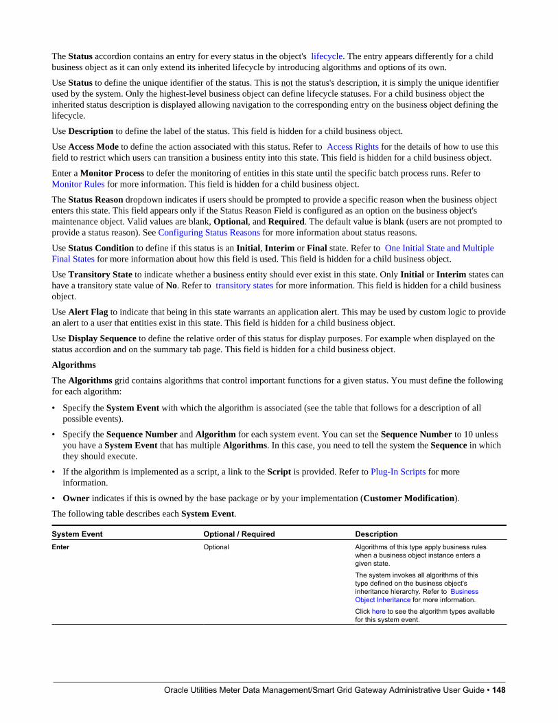
Oracle Utilities Meter Data Management/Smart Grid Gateway Administrative User Guide • 148
The Status accordion contains an entry for every status in the object's lifecycle. The entry appears differently for a childbusiness object as it can only extend its inherited lifecycle by introducing algorithms and options of its own.
Use Status to define the unique identifier of the status. This is not the status's description, it is simply the unique identifierused by the system. Only the highest-level business object can define lifecycle statuses. For a child business object theinherited status description is displayed allowing navigation to the corresponding entry on the business object defining thelifecycle.
Use Description to define the label of the status. This field is hidden for a child business object.
Use Access Mode to define the action associated with this status. Refer to Access Rights for the details of how to use thisfield to restrict which users can transition a business entity into this state. This field is hidden for a child business object.
Enter a Monitor Process to defer the monitoring of entities in this state until the specific batch process runs. Refer toMonitor Rules for more information. This field is hidden for a child business object.
The Status Reason dropdown indicates if users should be prompted to provide a specific reason when the business objectenters this state. This field appears only if the Status Reason Field is configured as an option on the business object'smaintenance object. Valid values are blank, Optional, and Required. The default value is blank (users are not prompted toprovide a status reason). See Configuring Status Reasons for more information about status reasons.
Use Status Condition to define if this status is an Initial, Interim or Final state. Refer to One Initial State and MultipleFinal States for more information about how this field is used. This field is hidden for a child business object.
Use Transitory State to indicate whether a business entity should ever exist in this state. Only Initial or Interim states canhave a transitory state value of No. Refer to transitory states for more information. This field is hidden for a child businessobject.
Use Alert Flag to indicate that being in this state warrants an application alert. This may be used by custom logic to providean alert to a user that entities exist in this state. This field is hidden for a child business object.
Use Display Sequence to define the relative order of this status for display purposes. For example when displayed on thestatus accordion and on the summary tab page. This field is hidden for a child business object.
Algorithms
The Algorithms grid contains algorithms that control important functions for a given status. You must define the followingfor each algorithm:
• Specify the System Event with which the algorithm is associated (see the table that follows for a description of allpossible events).
• Specify the Sequence Number and Algorithm for each system event. You can set the Sequence Number to 10 unlessyou have a System Event that has multiple Algorithms. In this case, you need to tell the system the Sequence in whichthey should execute.
• If the algorithm is implemented as a script, a link to the Script is provided. Refer to Plug-In Scripts for moreinformation.
• Owner indicates if this is owned by the base package or by your implementation (Customer Modification).
The following table describes each System Event.
System Event Optional / Required DescriptionEnter Optional Algorithms of this type apply business rules
when a business object instance enters agiven state.The system invokes all algorithms of thistype defined on the business object'sinheritance hierarchy. Refer to BusinessObject Inheritance for more information.Click here to see the algorithm types availablefor this system event.

Oracle Utilities Meter Data Management/Smart Grid Gateway Administrative User Guide • 149
System Event Optional / Required DescriptionExit Optional Algorithms of this type apply business rules
when a business object instance exits a givenstate.The system invokes all algorithms of thistype defined on the business object'sinheritance hierarchy. Refer to BusinessObject Inheritance for more information.Click here to see the algorithm types availablefor this system event.
Monitor Optional Algorithms of this type monitor a businessobject instance while in a given state.Typically these are used to auto-transition it toanother state.The system invokes all algorithms of thistype defined on the business object'sinheritance hierarchy. Refer to BusinessObject Inheritance for more information.Click here to see the algorithm types availablefor this system event.
FASTPATH: Refer to BO Algorithm Execution Summary for more information about how these algorithms fit withinother business object algorithms.
NOTE: Generate Algorithm. A context sensitive "Generate a BO Algorithm" zone is associated with this page. Referto Defining Business Objects for more information about this zone.
NOTE: You can inactivate status level algorithms on base Business Objects. Your implementation may want to usea business object provided by the base product, but may want to inactivate one or more of the status oriented algorithmsprovided by the base business object. To do that, on the business object and status where this algorithm is referenced, goto the options grid and add a new option, setting the option type to Inactive Algorithm and setting the option value tothe algorithm code.
Next Statuses
Use the Next Statuses grid to define the valid statuses a business entity can transition into while it's in this state. Thissection is hidden for a child business object. Refer to Valid States versus State Transition Rules for more information.Please note the following about this grid:
• Status shows the statuses for the top-level business object, the Status Code, the Lifecycle BO description, and theStatus description for each status.
• Use Action Label to indicate the verbiage to display on the button used to transition to this status.
• Sequence controls the relative order of one status compared to others for display purposes. This information may be usedto control the order in which buttons are presented on a user interface.
• Default controls which next state (if any) is the default one. This information may be used by an Enter or Monitoralgorithm to determine an auto-transition to the default state. It may also be used to also mark the associated button as thedefault one on a user interface.
• Transition Condition may be configured to identify a common transition path from the current state. By associatinga given "next status" with a transition condition value, you can design your auto-transition rules to utilize those flagvalues without specifying a status particular to a given business object. Thus, similar logic may be used across a range ofbusiness objects to transition a business entity into, for example, the next Ok state for its current state. You'll need to addyour values to the customizable lookup field BO_TR_COND_FLG.
• Transition Role controls whether only the System or both System and User have the ability to transition a businessentity into a given "next status".
Oracle Utilities Meter Data Management/Smart Grid Gateway Administrative User Guide • 150
• When you initially set up a business object lifecycle, none of the statuses will reside on the database and thereforeyou can't use the search to define a "next status". We recommend working as follows to facilitate the definition of thisinformation:
• Leave the Next Statuses grid blank when you initially define a business object's statuses
• After all statuses have been saved on the database, update each status to define its Next Statuses (this way, you canuse the search to select the status).
Options
The options grid allows you to configure the business object status to support extensible options. Select the Option Typedrop-down to define its Value. Detailed Description may display additional information on the option type. Set theSequence to 1 unless the option can have more than one value. Owner indicates if this option is owned by the base packageor by your implementation (Customer Modification).
NOTE: You can add new options types. Your implementation may want to add additional option types. For example,your implementation may have plug-in driven logic that would benefit from a new option. To do that, add your newvalues to the customizable lookup field BO_OPT_FLG. If you add a new option type for a status, you must updatethe business object's maintenance object to declare this new option type. Otherwise, it won't appear on the option typedropdown. You do that by referencing the new option type as a Valid BO Status Option Type maintenance objectoption.
Business Object - SummaryThis page summarizes business object information in a high level. Open this page using Admin > System > BusinessObject > Search and then navigate to the Summary tab.
Description of Page
The contents of this section describe the zones that are available on this portal.
The General Information zone displays main attributes of the business object.
Click the View Schema hyperlink to view the business object's expanded schema definition. Doing this opens the schemaviewer window.
Click the View XSD hyperlink to view the business object's expanded schema definition in XSD format.
The Business Object Hierarchy zone displays in a tree view format the hierarchy of child business object associated withthe current business object. It also shows the current business object's immediate parent business object.
For business objects with a lifecycle, the Lifecycle Display zone shows a graphical depiction of the lifecycle. Refer to theembedded help of that zone for more information.
The Options zone summarizes business object and state specific options throughout the inheritance chain.
The Rules zone summarizes business object and state specific rules throughout the inheritance chain.
Advanced BO Tips and TechniquesThe topics in this section describe some advanced tips and techniques for configuring business objects.
Managing To Do EntriesThe product provides several base algorithm types that may be used to manage To Do entries through status changes for agiven record via BO lifecycle plug-ins.

Oracle Utilities Meter Data Management/Smart Grid Gateway Administrative User Guide • 151
Create To Do EntryThe product supplies a BO status Enter algorithm type Generic To Do Creation (F1-TDCREATE) that creates a ToDo entry based on parameter configuration. Refer to the algorithm type description for more information about how itdetermines the To Do type or To Do role and how to populate the appropriate message text onto the To Do. This algorithmmay be used in conjunction with the Retry Logic (below).
If your implementation has a business rule that requires a To Do entry to be created when entering a given BO status andthe logic provided by the algorithm type meets the needs of the business rule, this algorithm type may be used. Createan algorithm for the algorithm type, populate the algorithm parameters according to the business rules and plug the newalgorithm into the appropriate business object status as an Enter algorithm.
Retry LogicThe algorithm type Retry for To Dos (F1-TODORETRY) is supplied for a special use case. It is a BO status monitor plug-in and may be used for a state that is a type of ‘error’ or ‘waiting’ state. It relies on the To Do entry creation logic to seta Retry Frequency. The algorithm transitions to the originating state to retry the logic. The idea is that the condition thatcaused the record to enter the ‘error’ or ‘waiting’ state may be resolved after some period of time has passed, allowing therecord to progress in its lifecycle. Refer to the algorithm type description for more information about its logic.
To use this functionality, create an algorithm for this algorithm type, populate the algorithm parameters according tothe business rules and plug the new algorithm into the appropriate business object status as a Monitor algorithm. Thestate should also have an algorithm for the Generic To Do Creation algorithm type plugged in as an Enter algorithm (orsomething equivalent) that sets the appropriate Retry Frequency.
To Do CompletionIt is common that one or more To Do entries associate with a given record should be completed when exiting a state (if itis not already completed). The system supplies the algorithm type Generic To Do Completion (F1-TODOCOMPL) thatmay be used for this purpose. Note that the algorithm type functionality is not tied to any To Do creation logic. It may beused for any use case where To Do entries should be completed on exiting a state. Refer to the algorithm type descriptionfor more information about its functionality and how to prevent certain To Do entries from being automatically completed.
To use this functionality, create an algorithm for this algorithm type, populate the algorithm parameters according to thebusiness rules and plug the new algorithm into the appropriate business object status as an Exit algorithm.
Submitting a Batch JobThe product provides a base algorithm type that submits a batch job when entering a BO state. This functionality allows for“event driven” batch submission where the event is the lifecycle transition for a certain record.
The algorithm type is Create Batch Job Submission Entry for Batch Control (F1-SCHEDJOB). The batch control codeis a parameter for the algorithm. Refer to the algorithm type description for more information about its logic.
To use this functionality, create an algorithm for this algorithm type, populate the algorithm parameter with the batchcontrol that should be submitted and plug the new algorithm into the appropriate business object status as an Enteralgorithm.
Defining Status ReasonsStatus Reasons are used to provide more information about why a business object transitioned to a given state. The statusreason table provides a centralized place where status reasons can be defined across many different business objects andstates.
NOTE: Refer to Defining Reasons for Entering a State for overview information.
Oracle Utilities Meter Data Management/Smart Grid Gateway Administrative User Guide • 152
If a business object has one or more states that are configured to capture a status reason, you may configure the validreasons by navigating to the status reason portal using Admin > System > Status Reason.
The topics in this section describe the base-package zones that appear on the Status Reason portal.
Business Objects with Status Reason ListThis zone displays the business objects that have one or more status values that allow status reasons to be defined.
Click the broadcast icon to open other zones that contain more information about the business object’s status reasons.
Status ReasonsThe Status Reasons zone contains a list of the existing status reasons for the broadcasted business object.
Business ServicesA business service is used to expose a back-end service so that it may be invoked by a script or a zone or a map to retrieveinformation or perform functions, depending on the related service.
As with the business object, the business service's interface to the internal service is defined using its schema. The schemamaps the business service's elements to the corresponding elements in the internal service program's XML document. Just asa business object can simplify the schema of its maintenance object by only defining elements that it needs and “flattening”entries in a child collection to be defined as a singular element, a business service schema may simplify its service XML ina similar way.
FASTPATH: Refer to Schema Syntax for a complete list of the XML nodes and attributes available to you when youconstruct a schema.
Inbound web services and scripts support interaction with business services. You can also invoke a business service from aJava class.
Service ProgramThis transaction defines services available in the system. These include user interface services as well as stand-aloneservices that perform a specific function. A service may be referenced by a business service. Use this transaction to viewexisting service and introduce a new stand-alone service to be made available to a Business Service.
Select Admin > System > Service Program to maintain service programs.
Description of Page
Service Name is the unique identifier of the service.
CAUTION: Important! When adding new service programs, carefully consider its naming convention. Refer to SystemData Naming Convention for more information.
Owner indicates if this service is owned by the base package or by your implementation (Customer Modification). Thesystem sets the owner to Customer Modification when you add a service. This information is display-only.
Description describes the service.
Application Service is the application service that is used to provide security for the service. If the service is related to amaintenance object, the access modes for the application service should be the standard Add, Change, Delete and Inquire.For other services, the application service should have the Execute access mode.
Service Type indicates whether the service is a Java Based Service or a Java (Converted) Service.

Oracle Utilities Meter Data Management/Smart Grid Gateway Administrative User Guide • 153
This Program Component grid shows the list of program user interface components associated with the service. For astand-alone service, this list is typically not applicable.
Where Used
Follow this link to open the data dictionary where you can view the tables that reference CI_MD_SVC.
Defining Business ServicesThe topics in this section describe how to maintain business services.
Note that several context sensitive dashboard zones appear on this page and are visible on all tabs.
• Schema Tips. This zone provides several links to launch help topics related to valid schema syntax.
• Generate Schema. This zone includes a button that can be used to generate the schema based on the XML of its relatedService. Once generated, adjust the schema as desired.
Business Service - MainUse this page to define basic information about a Business Service. Open this page using Admin > System > BusinessService
Description of Page
Enter a unique Business Service name and Description. Use the Detailed Description to describe the purpose of thisbusiness service in detail. Owner indicates if the business service is owned by the base package or by your implementation(Customer Modification).
CAUTION: Important! If you introduce a new business service, carefully consider its naming convention. Refer toSystem Data Naming Convention for more information.
Enter the internal Service Name being called when this business service is invoked.
Enter the Application Service that is used to provide security for the business service. The application service must have anAccess Mode of Execute.
Click the View Schema to view the business service's expanded schema definition. Doing this opens the schema viewerwindow.
Click the View XSD hyperlink to view the business object's expanded schema definition in XSD format.
Click the View XML hyperlink to view the XML document used to pass data to and from the service in the Service XMLViewer. You may find it useful to leave the application viewer window open while defining your business service schema.
NOTE: XML document may not be viewable. If you create a new service program and do not regenerate theapplication viewer, you will not be able to view its XML document.
Where Used
Follow this link to open the data dictionary to view the tables that reference F1_BUS_SVC.
Business Service - SchemaUse this page to maintain a Business Service's schema and to see where the Business Service is used in the system. Openthis page using Admin > System > Business Service and then navigate to the Schema tab.
Description of Page
The contents of this section describe the zones that are available on this portal.

Oracle Utilities Meter Data Management/Smart Grid Gateway Administrative User Guide • 154
The General Information zone displays main attributes of the business service.
The Schema Designer zone allows you to edit the business service's schema. The purpose of the schema is to map thebusiness service's elements to the corresponding fields of the back-end service program it rides on.
NOTE: Generating a Schema A context sensitive "Generate Schema" zone is associated with this page. The zoneprovides a button that allows the user to generate a basic schema that includes all the elements that are found in theXML of the BS’s service.
FASTPATH: Refer to Schema Syntax for a complete list of the XML nodes and attributes available to you when youconstruct a schema. Also note that the Schema Tips zone in the dashboard provides a link to launch this help topicdirectly.
The Schema Usage Tree zone summarizes all cross-references to this schema. These may be other schemas, scripts, andweb services. For each type of referencing entity, the tree displays a summary node showing a total count of referencingitems. The summary node appears if at least one referencing item exists. Expand the node to list the referencing items anduse their description to navigate to their corresponding pages.
Useful Services and Business ServicesThe following section highlights some business services and services provided by the product that may be useful forimplementations to use.
Data Explorer ServiceThe system provides a mechanism for performing an SQL select statement for use in scripting, Java plug-ins, or via a webservice call. This is done by creating a zone using one of the data explorer zone types where the SQL is defined. Then,create a business service using the Data Explorer service (FWLZDEXP).
NOTE: There are numerous business services delivered with the base product that reference this service that may beused as a template.
The following points highlight how to create your own business service for this service. Note that typically a separatebusiness service exists for each zone.
• Enter a Business Service code and a Description. It is recommended to define the business service code to match thezone code so that it’s easier to manage which business service invokes which zone.
• Select the Service NameFWLZDEXP.
• On the Schema tab, under the <schema> node, enter mapping for the fields that are required for the Data Explorerservice:
• The Zone should be mapped into service field ZONE_CD . Define the zone code as the default value.
• For every user filter defined on the zone, create a schema mapping into the service field Fx_VALUE, where "x" isthe filter number (from the zone parameters).
• For every hidden filter defined on the zone, create a mapping into the service field Hx_VALUE, where "x" is thefilter number (from the zone parameters).
• The search results are returned as a list by the data explorer service. Each column value is in the service field COL_VALUE with an appropriate sequence number (SEQNO). The results can be flattened based on sequence numberallowing for a logical element name to be defined.
• Another useful field is ROW_CNT, which provides the number of rows retrieved by your search.
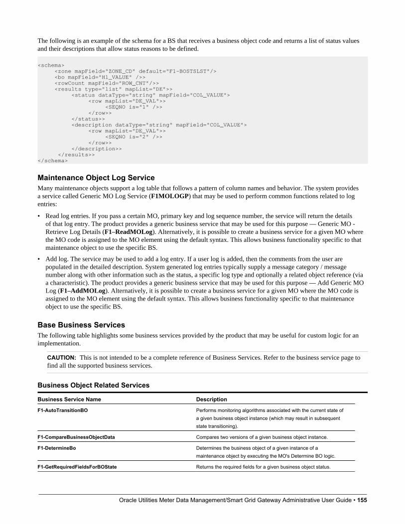
Oracle Utilities Meter Data Management/Smart Grid Gateway Administrative User Guide • 155
The following is an example of the schema for a BS that receives a business object code and returns a list of status valuesand their descriptions that allow status reasons to be defined.
<schema> <zone mapField="ZONE_CD" default="F1-BOSTSLST"/> <bo mapField="H1_VALUE" />> <rowCount mapField="ROW_CNT"/>> <results type="list" mapList="DE">> <status dataType="string" mapField="COL_VALUE"> <row mapList="DE_VAL">> <SEQNO is="1" />> </row>> </status>> <description dataType="string" mapField="COL_VALUE"> <row mapList="DE_VAL">> <SEQNO is="2" />> </row>> </description>> </results>></schema>
Maintenance Object Log ServiceMany maintenance objects support a log table that follows a pattern of column names and behavior. The system providesa service called Generic MO Log Service (F1MOLOGP) that may be used to perform common functions related to logentries:
• Read log entries. If you pass a certain MO, primary key and log sequence number, the service will return the detailsof that log entry. The product provides a generic business service that may be used for this purpose — Generic MO -Retrieve Log Details (F1–ReadMOLog). Alternatively, it is possible to create a business service for a given MO wherethe MO code is assigned to the MO element using the default syntax. This allows business functionality specific to thatmaintenance object to use the specific BS.
• Add log. The service may be used to add a log entry. If a user log is added, then the comments from the user arepopulated in the detailed description. System generated log entries typically supply a message category / messagenumber along with other information such as the status, a specific log type and optionally a related object reference (viaa characteristic). The product provides a generic business service that may be used for this purpose — Add Generic MOLog (F1–AddMOLog). Alternatively, it is possible to create a business service for a given MO where the MO code isassigned to the MO element using the default syntax. This allows business functionality specific to that maintenanceobject to use the specific BS.
Base Business ServicesThe following table highlights some business services provided by the product that may be useful for custom logic for animplementation.
CAUTION: This is not intended to be a complete reference of Business Services. Refer to the business service page tofind all the supported business services.
Business Object Related Services
Business Service Name Description
F1-AutoTransitionBO Performs monitoring algorithms associated with the current state ofa given business object instance (which may result in subsequentstate transitioning).
F1-CompareBusinessObjectData Compares two versions of a given business object instance.
F1-DetermineBo Determines the business object of a given instance of amaintenance object by executing the MO's Determine BO logic.
F1-GetRequiredFieldsForBOState Returns the required fields for a given business object status.

Oracle Utilities Meter Data Management/Smart Grid Gateway Administrative User Guide • 156
Business Service Name Description
F1-RetrieveBOOption Returns BO option values for a given BO and option type.
F1-RetrieveBOStatusOption Returns BO option values for a given BO, status and option type.
F1-RetrieveBOStatusOption Retrieves a list of BOs for a given MO that are accessible for thecurrent user.
F1-RetrieveBoStatusDescription Return the description of a given BO status.
F1-RetrieveBusinessObjectLabel Return the label appropriate for a given path (e.g. element) within aBO schema.
F1-RetrieveNextStates Return a list of next possible states based on the input of a MO andits prime key, or a BO and one of its statuses.
Email Related Services
Business Service Name Description
F1-EmailService Sends an email message in real time.
F1-RetrieveEmailAddress Retrieves the email addresses of users belonging to a To Do Role.
F1-RetrieveEnvironmentURL Retrieves the current environment URL information for theinstallation.
Tools for Maps and Scripting
Business Service Name Description
F1–DateMath Performs various date and time math calculations. Refer to the BSdescription for more details.
F1-DateTimeFormattingService Formats a given date / time based on the user’s display profilesettings.
F1-ExecuteScriptInNewSession Executes a Service Script in a new processing session/transaction.
F1-GetFieldLabel Retrieves the label for a given field.
F1-GetForeignKeyReference Returns foreign key reference information for a given FK Referenceand primary key, including info description, navigation option, andcontext menu.
F1-GetFKReferenceDetails Returns foreign key reference information for a given MO andprimary key, including FK reference code, info description,navigation option, search zone and context menu.
F1-GetLookupDescription Returns lookup description for a lookup field value given the lookupfield name.
F1-GetExtLookUpVal Returns the list of values for a given extendable lookup BO.
F1-GetMonthInYearAbbreviation Returns a 3-character month abbreviation for an input date insystem format.
F1-NumberAmountFormatter Formats a given amount or number based on the user’s displayprofile settings. It also may receive input to adjust the scale andoptionally apply currency settings.
F1-OutmsgDispatcher Dispatches a real-time message giving the user the option ofwhether to persist the message on the database, and whether to

Oracle Utilities Meter Data Management/Smart Grid Gateway Administrative User Guide • 157
Business Service Name Descriptiontrap errors that may take place during the call. Refer to Real TimeMessages for more information.
F1-OutmsgMediator Alternative to F1-OutmsgDispatcher and may be a better optionif the sender does not require an outbound message record to beinstantiated. Refer to Real Time Messages for more information.
F1-RethrowError Issues an application error using the input message category /number / parameters.
F1-RetrieveMODescription Retrieves the description for a maintenance object.
F1-ReturnMessage Returns the expanded message given a message category,number, parameters, and parameter types.
F1-SavePointDispatcher Allows for a service script to be executed where exceptions aretrapped and the transaction is rolled back to a save point set beforethe service script execution.
User Related Services
Business Service Name Comments
F1-CheckApplicationSecurity Checks a user’s security for a given application service / accessmode
F1-CheckUserAuthorization Determine whether a given user is authorized for access based on theinput application service, security code, and authorization level.
F1-DetermineIfUserCanApproveTD Determine if the current user can approve a given To Do.
User Interface (UI) MapsThe User Interface (UI) map holds HTML to be rendered within portal zones and Business Process Assistant (BPA)scripts. UI maps allow your implementation to create input forms and output maps that closely match your customer'sbusiness practices. In other words, the UI Map is designed to facilitate the capture and display of your business objects and business services.
The UI map is a repository for a single HTML document paired with an XML schema where the schema defines the datathat the HTML document displays and/or modifies. The UI Map HTML gives you the ability to craft the display by anymethod that an html document can support, including JavaScript and full CSS functionality.
Configuration tool support for UI Maps hinges around the ability to inject and extract an XML document from the HTML.For more information on the specialized support for HTML and JavaScript functionality refer to UI Map Attributes andFunctions.
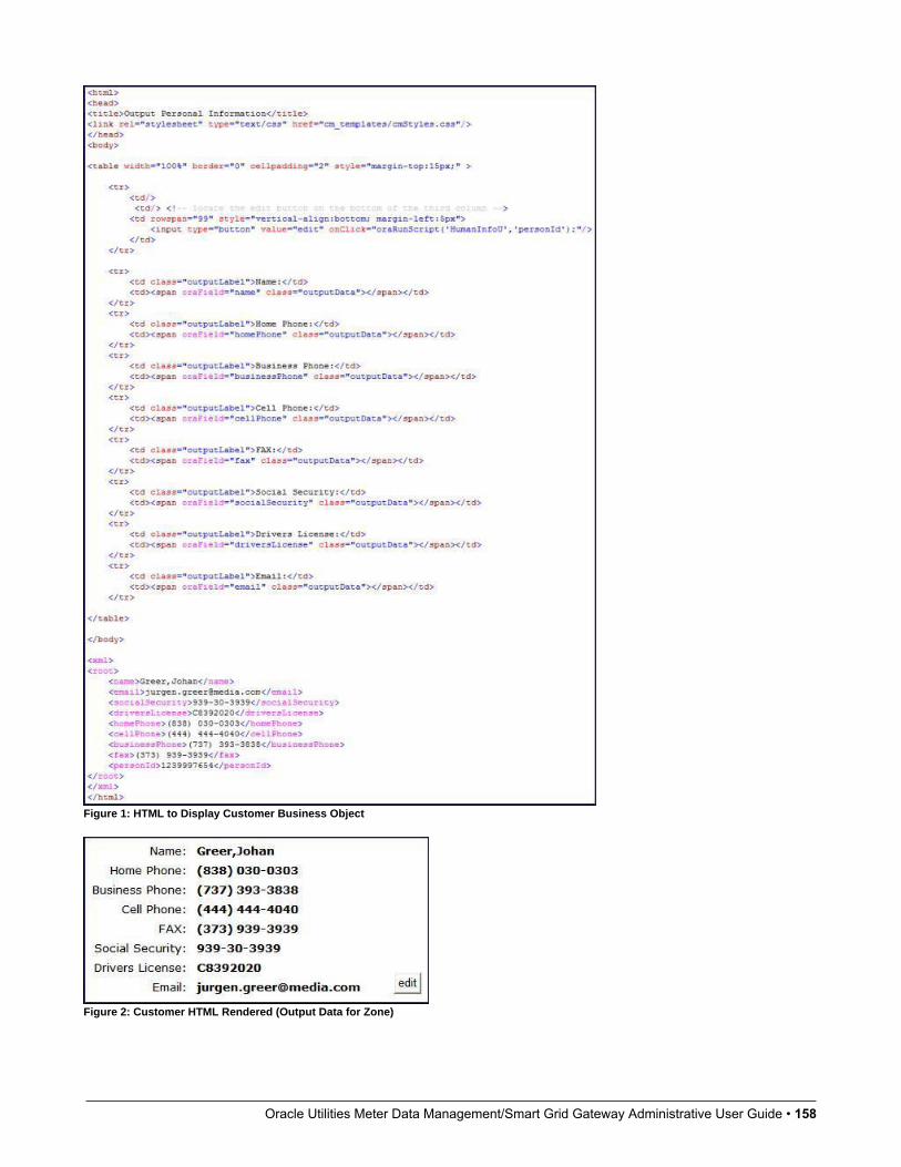
Oracle Utilities Meter Data Management/Smart Grid Gateway Administrative User Guide • 158
Figure 1: HTML to Display Customer Business Object
Figure 2: Customer HTML Rendered (Output Data for Zone)
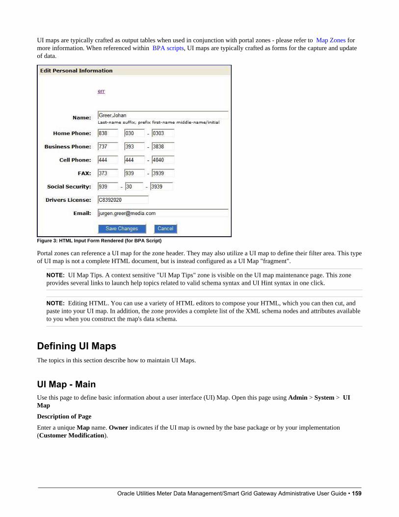
Oracle Utilities Meter Data Management/Smart Grid Gateway Administrative User Guide • 159
UI maps are typically crafted as output tables when used in conjunction with portal zones - please refer to Map Zones formore information. When referenced within BPA scripts, UI maps are typically crafted as forms for the capture and updateof data.
Figure 3: HTML Input Form Rendered (for BPA Script)
Portal zones can reference a UI map for the zone header. They may also utilize a UI map to define their filter area. This typeof UI map is not a complete HTML document, but is instead configured as a UI Map "fragment".
NOTE: UI Map Tips. A context sensitive "UI Map Tips" zone is visible on the UI map maintenance page. This zoneprovides several links to launch help topics related to valid schema syntax and UI Hint syntax in one click.
NOTE: Editing HTML. You can use a variety of HTML editors to compose your HTML, which you can then cut, andpaste into your UI map. In addition, the zone provides a complete list of the XML schema nodes and attributes availableto you when you construct the map's data schema.
Defining UI MapsThe topics in this section describe how to maintain UI Maps.
UI Map - MainUse this page to define basic information about a user interface (UI) Map. Open this page using Admin > System > UIMap
Description of Page
Enter a unique Map name. Owner indicates if the UI map is owned by the base package or by your implementation(Customer Modification).
Oracle Utilities Meter Data Management/Smart Grid Gateway Administrative User Guide • 160
CAUTION: Important! If you introduce a new UI map, carefully consider its naming convention. Refer to System DataNaming Convention for more information.
Use UI Map Type to indicate whether the map is a Complete XHTML Document, Complete HTML Document,XHTML Fragment or an HTML Fragment. The default value is Complete XHTML Document.
Enter a Description. Use the Detailed Description to describe how this map is used in detail.
Click on the View Schema to view the UI map's expanded schema definition. Doing this opens the schema viewer window.
Use the Test UI Map hyperlink to render your HTML in a test window.
NOTE: The Test UI Map hyperlink also exercises the proprietary functionality that binds an XML element with anHTML element so you can get immediate feedback on your HTML syntax.
Where Used
Follow this link to open the data dictionary to view the tables that reference F1_MAP.
UI Map - SchemaUse this page to maintain a UI Map's HTML and schema and to see where the UI Map is used in the system. Open this pageusing Admin > System > UI Map and then navigate to the Schema tab.
Description of Page
The contents of this section describe the zones that are available on this portal.
The General Information zone displays main attributes of the UI Map.
The HTML Editor zone allows you to edit the HTML document of the map.
NOTE: Refer to UI Map Attributes and Functions and UI Map Standards for more information about HTML definitionsyntax. These topics describe good ways to produce simple HTML, however, they are not an HTML reference. Note thatyou can use a variety of HTML editors to compose your HTML, which you can then cut and paste into your UI map.
NOTE: Providing Help. A tool tip can be used to display additional help information to the user. This applies to sectionelements as well as individual elements on a map. Refer to UI Map Attributes and Functions for more information onhow to enable and provide UI map help.
The Schema Designer zone allows you to edit the data schema part of the map. The purpose of the schema is to describethe data elements being displayed by the map.
FASTPATH: Refer to Schema Syntax for a complete list of the XML nodes and attributes available to you when youconstruct a schema. Also note that the UI Map Tips zone in the dashboard provides a link to launch this help topicdirectly.
The Schema Usage Tree zone summarizes all cross-references to this schema. These may be other schemas, scripts, andweb services. For each type of referencing entity, the tree displays a summary node showing a total count of referencingitems. The summary node appears if at least one referencing item exists. Expand the node to list the referencing items anduse their description to navigate to their corresponding pages.
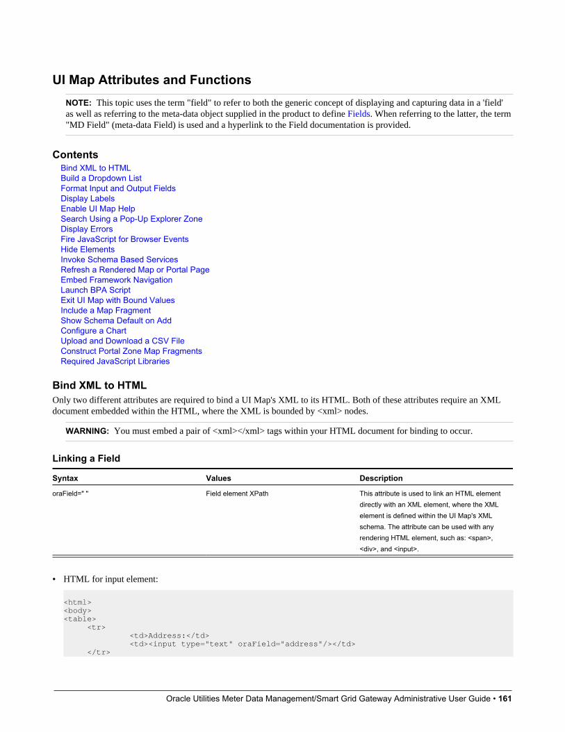
Oracle Utilities Meter Data Management/Smart Grid Gateway Administrative User Guide • 161
UI Map Attributes and FunctionsNOTE: This topic uses the term "field" to refer to both the generic concept of displaying and capturing data in a 'field'as well as referring to the meta-data object supplied in the product to define Fields. When referring to the latter, the term"MD Field" (meta-data Field) is used and a hyperlink to the Field documentation is provided.
ContentsBind XML to HTMLBuild a Dropdown ListFormat Input and Output FieldsDisplay LabelsEnable UI Map HelpSearch Using a Pop-Up Explorer ZoneDisplay ErrorsFire JavaScript for Browser EventsHide ElementsInvoke Schema Based ServicesRefresh a Rendered Map or Portal PageEmbed Framework NavigationLaunch BPA ScriptExit UI Map with Bound ValuesInclude a Map FragmentShow Schema Default on AddConfigure a ChartUpload and Download a CSV FileConstruct Portal Zone Map FragmentsRequired JavaScript Libraries
Bind XML to HTMLOnly two different attributes are required to bind a UI Map's XML to its HTML. Both of these attributes require an XMLdocument embedded within the HTML, where the XML is bounded by <xml> nodes.
WARNING: You must embed a pair of <xml></xml> tags within your HTML document for binding to occur.
Linking a Field
Syntax Values Description
oraField=" " Field element XPath This attribute is used to link an HTML elementdirectly with an XML element, where the XMLelement is defined within the UI Map's XMLschema. The attribute can be used with anyrendering HTML element, such as: <span>,<div>, and <input>.
• HTML for input element:
<html><body><table> <tr> <td>Address:</td> <td><input type="text" oraField="address"/></td> </tr>

Oracle Utilities Meter Data Management/Smart Grid Gateway Administrative User Guide • 162
<tr> <td>City:</td> <td><input type="text" oraField="city"/></td> </tr> <tr> <td>State:</td> <td><input type="text" oraField="state"/></td> </tr> <tr> <td>Zip:</td> <td><input type="text" oraField="zip"/></td> </tr></table></body><xml> <root> <address>123 Main St</address> <city>Alameda</city> <state>CA</state> <zip>94770</zip> </root></xml></html>
Rendered HTML
• HTML for span and div elements:
<html><body> <div oraField="address"></div><span oraField="city"></span><span>,</span><span oraField="state"></span><span oraField="zip"></span><span oraField="country"></span> </body><xml> <root> <address>123 Main St</address> <city>Alameda</city> <state>CA</state> <zip>94770</zip> </root></xml></html>
HTML rendered:
Linking a ListThis attribute is used to link an HTML table with an XML list, where the XML list is defined within the UI Map's XMLschema. The purpose of the element is to trigger the framework to replicate the table's HTML for each occurrence of thelist.

Oracle Utilities Meter Data Management/Smart Grid Gateway Administrative User Guide • 163
Syntax Values Description
oraList=" " List element XPath This attribute is used to link an HTML tablewith an XML list, where the XML list isdefined within the UI Map's XML schema.The purpose of the element is to trigger theframework to replicate the table's HTML foreach occurrence of the list.
NOTE: The oraField attributes embedded within the list must contain XPath navigation relative to the list. See belowfor an example.
<html><head><title>Bind xml list element</title></head><body><table oraList="payment"> <thead> <tr> <th><span>Pay Date</span></th><th><span>Amount</span></th> </tr> <tr/> </thead> <tr> <td> <span oraField="date" oraType="date"></span> </td> <td align="right"> <span oraField="amount" oraType="money"></span> </td> </tr></table></body><xml><root> <payment> <date>2008-01-01</date> <amount>44.28</amount> </payment> <payment> <date>2008-02-01</date> <amount>32.87</amount> </payment> <payment> <date>2008-03-01</date> <amount>21.76</amount> </payment></root></xml></html>
HTML rendered:
Build a Dropdown ListThe following attributes are provided to build an HTML ‘select’ element, also called a dropdown, based on various sources.

Oracle Utilities Meter Data Management/Smart Grid Gateway Administrative User Guide • 164
Source Syntax Values Examples
Lookup oraSelect="lookup: ;" Lookup field ...<td>House Type:</td><td> <select oraField="houseType" oraSelect="lookup:HOUSE_TYPE;"></select></td>
Extendable Lookup oraSelect="lookupBO: ;" BO code ...<td>UI Device Display Type:</td><td> <select oraField="uiDeviceType" oraSelect="lookupBO:F1-DeviceDisplayTypes;"></select></td>
Characteristic Type (pre-defined) oraSelect="charType: ;" Characteristic Type code ...<td>Usage:</td><td> <select oraField="statusReasonUsage" oraSelect="charType:F1-SRUSG;"></select></td>...
Control Table oraSelect="table: ;"
NOTE: This attribute onlyworks with tables that followthe standard control tablestructure where there isa related language tablethat includes that includesthe column DESCR as itsdescription column. Usethe Application Viewer datadictionary to identify tables thatqualify for this functionality.
WARNING: The oraSelectfunction will only work if lessthan 500 values are displayed.
Table name ...<td>Currency: </td><td> <select oraField="currency" oraSelect="table:CI_CURRENCY_CD;"></select></td>...
Page Service oraSelect="service: ;" Page Service name ...<td>Country:</td><td> <select oraField="country" oraSelect="service:CIPTCNTW;"></select></td>...
Embedded List Used to build a select dropdownbased on a list within the map’sXML.oraSelect="valuePath: ;descPath:"
After the valuePath, indicate theXPath of the element that holdsthe values. After the descPath,indicate the XPath of the elementthat holds the descriptions.
<html><body><table summary="" border="0" cellpadding="1" cellspacing="1"> <tr> <td>Select: </td> <td><select oraSelect="valuePath:list/value; descPath:list/desc" oraField="target"></select></td> </tr></table>
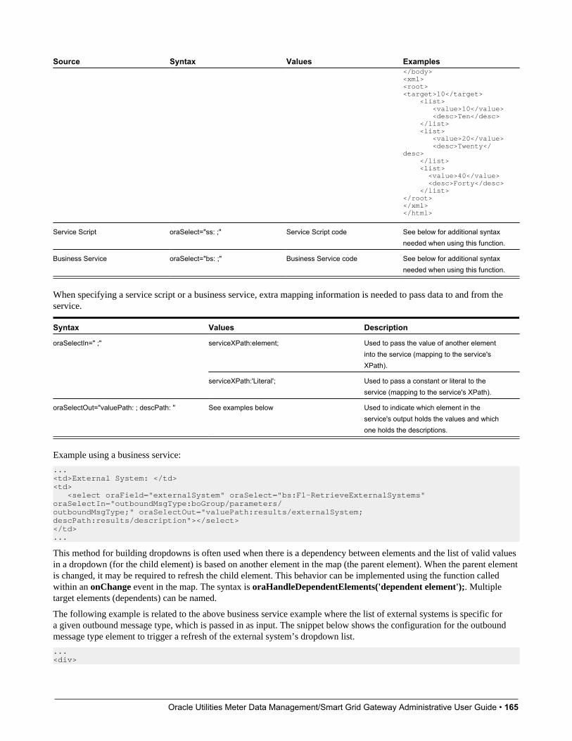
Oracle Utilities Meter Data Management/Smart Grid Gateway Administrative User Guide • 165
Source Syntax Values Examples</body><xml><root><target>10</target> <list> <value>10</value> <desc>Ten</desc> </list> <list> <value>20</value> <desc>Twenty</desc> </list> <list> <value>40</value> <desc>Forty</desc> </list></root></xml></html>
Service Script oraSelect="ss: ;" Service Script code See below for additional syntaxneeded when using this function.
Business Service oraSelect="bs: ;" Business Service code See below for additional syntaxneeded when using this function.
When specifying a service script or a business service, extra mapping information is needed to pass data to and from theservice.
Syntax Values Description
serviceXPath:element; Used to pass the value of another elementinto the service (mapping to the service'sXPath).
oraSelectIn=" ;"
serviceXPath:'Literal'; Used to pass a constant or literal to theservice (mapping to the service's XPath).
oraSelectOut="valuePath: ; descPath: " See examples below Used to indicate which element in theservice's output holds the values and whichone holds the descriptions.
Example using a business service:
...<td>External System: </td><td> <select oraField="externalSystem" oraSelect="bs:F1-RetrieveExternalSystems" oraSelectIn="outboundMsgType:boGroup/parameters/outboundMsgType;" oraSelectOut="valuePath:results/externalSystem; descPath:results/description"></select></td>...
This method for building dropdowns is often used when there is a dependency between elements and the list of valid valuesin a dropdown (for the child element) is based on another element in the map (the parent element). When the parent elementis changed, it may be required to refresh the child element. This behavior can be implemented using the function calledwithin an onChange event in the map. The syntax is oraHandleDependentElements('dependent element');. Multipletarget elements (dependents) can be named.
The following example is related to the above business service example where the list of external systems is specific fora given outbound message type, which is passed in as input. The snippet below shows the configuration for the outboundmessage type element to trigger a refresh of the external system’s dropdown list.
...<div>
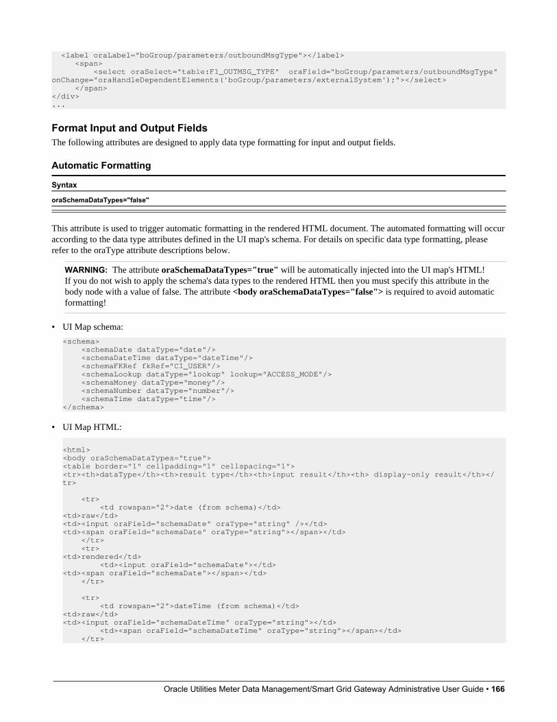
Oracle Utilities Meter Data Management/Smart Grid Gateway Administrative User Guide • 166
<label oraLabel="boGroup/parameters/outboundMsgType"></label> <span> <select oraSelect="table:F1_OUTMSG_TYPE" oraField="boGroup/parameters/outboundMsgType" onChange="oraHandleDependentElements('boGroup/parameters/externalSystem');"></select> </span></div>...
Format Input and Output FieldsThe following attributes are designed to apply data type formatting for input and output fields.
Automatic Formatting
Syntax
oraSchemaDataTypes="false"
This attribute is used to trigger automatic formatting in the rendered HTML document. The automated formatting will occuraccording to the data type attributes defined in the UI map's schema. For details on specific data type formatting, pleaserefer to the oraType attribute descriptions below.
WARNING: The attribute oraSchemaDataTypes="true" will be automatically injected into the UI map's HTML!If you do not wish to apply the schema's data types to the rendered HTML then you must specify this attribute in thebody node with a value of false. The attribute <body oraSchemaDataTypes="false"> is required to avoid automaticformatting!
• UI Map schema:
<schema> <schemaDate dataType="date"/> <schemaDateTime dataType="dateTime"/> <schemaFKRef fkRef="CI_USER"/> <schemaLookup dataType="lookup" lookup="ACCESS_MODE"/> <schemaMoney dataType="money"/> <schemaNumber dataType="number"/> <schemaTime dataType="time"/> </schema>
• UI Map HTML:
<html><body oraSchemaDataTypes="true"><table border="1" cellpadding="1" cellspacing="1"><tr><th>dataType</th><th>result type</th><th>input result</th><th> display-only result</th></tr> <tr> <td rowspan="2">date (from schema)</td><td>raw</td><td><input oraField="schemaDate" oraType="string" /></td><td><span oraField="schemaDate" oraType="string"></span></td> </tr> <tr><td>rendered</td> <td><input oraField="schemaDate"></td><td><span oraField="schemaDate"></span></td> </tr> <tr> <td rowspan="2">dateTime (from schema)</td><td>raw</td><td><input oraField="schemaDateTime" oraType="string"></td> <td><span oraField="schemaDateTime" oraType="string"></span></td> </tr>

Oracle Utilities Meter Data Management/Smart Grid Gateway Administrative User Guide • 167
<tr><td>rendered</td><td><input oraField="schemaDateTime"></td><td><span oraField="schemaDateTime"></span></td> </tr>
<tr> <td rowspan="2">fkRef (from schema)**</td><td>raw</td><td><input oraField="schemaFkRef" oraType="string"></td><td><span oraField="schemaFkRef" oraType="string"></span></td> </tr> <tr><td>rendered</td><td><input oraField="schemaFkRef"></td><td><span oraField="schemaFkRef"></span></td> </tr> <tr> <td rowspan="2">lookup (from schema)</td><td>raw</td><td><input oraField="schemaLookup" oraType="string"></td><td><span oraField="schemaLookup" oraType="string"></span></td> </tr> <tr><td>rendered</td><td><input oraField="schemaLookup"></td><td><span oraField="schemaLookup"></span></td> </tr> <tr> <td rowspan="2">money (from schema)</td><td>raw</td><td><input oraField="schemaMoney" oraType="string"></td><td><span oraField="schemaMoney" oraType="string"></span></td> </tr> <tr><td>rendered</td><td><input oraField="schemaMoney"></td><td><span oraField="schemaMoney"></span></td> </tr> <tr> <td rowspan="2">number (from schema)</td><td>raw</td><td><input oraField="schemaNumber" oraType="string"/></td><td><span oraField="schemaNumber" oraType="string"></span></td> </tr> <tr><td>rendered</td><td><input oraField="schemaNumber"></td><td><span oraField="schemaNumber"></span></td> </tr> <tr> <td rowspan="2">time (from schema)</td><td>raw</td><td><input oraField="schemaTime" oraType="string"></span></td><td><span oraField="schemaTime" oraType="string"></span></td> </tr> <tr><td>rendered</td><td><input oraField="schemaTime"></td><td><span oraField="schemaTime"></span></td> </tr> </table> </body><xml><root><schemaDate>2007-11-02</schemaDate>

Oracle Utilities Meter Data Management/Smart Grid Gateway Administrative User Guide • 168
<schemaDateTime>2007-11-02-23.45.00</schemaDateTime><schemaFkRef>USD</schemaFkRef><schemaLookup>A</schemaLookup><schemaMoney>1000000</schemaMoney><schemaNumber>5661976.11548</schemaNumber><schemaTime>23.45.00</schemaTime></root></xml></html>
HTML rendered.
Date FormattingThis function is used to display a date according to the user's display profile. For input fields, the setting formats the datawhen the user tabs out of the field.
Syntax
oraType="date"
<html><body><table summary="" border="0" cellpadding="1" cellspacing="1"> <tr> <td>Date: </td><td><span oraField="date" oraType="date"></span></td> </tr> <tr> <td>Date: </td><td><input oraField="date" oraType="date"/></td> </tr></table></body><xml><root><date>2008-12-28</date></root></xml>

Oracle Utilities Meter Data Management/Smart Grid Gateway Administrative User Guide • 169
</html>
HTML rendered.
Time FormattingThis function is used to display a time according to the user's display profile. For input fields, the setting formats the datawhen the user tabs out of the field.
Syntax
oraType="time"
<html><body><table summary="" border="0" cellpadding="1" cellspacing="1"> <tr> <td>Time: </td><td><span oraField="time" oraType="time"></span></td> </tr> <tr> <td>Time: </td><td><input oraField="time" oraType="time"/></td> </tr></table></body><xml><root><time>00.28.54.389</time></root></xml></html>
HTML rendered.
Date and Time FormattingThis function is used to display a timestamp according to the user's display profile. If this function is used for an inputelement, it is broken into two pieces, one for date and one for time. Optionally, the time portion of the date time element canbe suppressed using the attribute value 'time:suppress'.
Syntax
oraType="dateTime; time:suppress"
<html><body><table summary="" border="0" cellpadding="1" cellspacing="1"> <tr> <td>Date time: </td> <td><span oraField="dateTime" oraType="dateTime"></span></td> </tr> <tr> <td>Date only: </td> <td><span oraField="dateTime" oraType="dateTime; time:suppress"></span></td> </tr> <tr>

Oracle Utilities Meter Data Management/Smart Grid Gateway Administrative User Guide • 170
<td>Date time: </td> <td><input oraField="dateTime" oraType="dateTime"/></td> </tr> <tr> <td>Date only: </td> <td><input oraField="dateTime" oraType="dateTime; time:suppress"/></td> </tr></table></body><xml><root><dateTime>2009-11-01-00.28.54</dateTime></root></xml></html>
HTML rendered.
Date / Time Formatting with Standard TimeThis true function is used to render a date / time element according to the daylight savings time schedule of the 'base' timezone. The 'base' time zone is specified on the Installation table and represents the database time zone. For input elementswith this setting, all time entered is assumed to correspond with the daylight savings time schedule of the base time zone. Ifa time is entered that cannot be unambiguously translated to standard time, then the user will be required to provide a timezone label to indicate whether daylight savings time, or standard time, has been entered.
Syntax
oraType="dateTime; stdTime:true;"
<html><body><table summary="" border="0" cellpadding="1" cellspacing="1"> <tr> <td>Date time: </td><td><span oraField="dateTime" oraType="dateTime; stdTime:true;"></span></td> </tr> <tr> <td>Date time: </td><td><input oraField="dateTime" oraType="dateTime; stdTime:true;"/></td> </tr></table></body> <xml><root><dateTime>2009-11-01-00.28.54</dateTime></root></xml></html>
HTML rendered.
NOTE: The time zone label is displayed because 1:28 is ambiguous otherwise. Legally, November 1, 2009 1:28 AMoccurs twice because daylight savings time (DST) is removed at 2:00 AM. With the stdTime function time zone labelsare only displayed when required to clarify time overlaps.

Oracle Utilities Meter Data Management/Smart Grid Gateway Administrative User Guide • 171
HTML rendered for the following day.
Date and Time Formatting with Time Zone Reference
Syntax Valid Values Description
oraType="dateTime; stdTimeRef: ;" Reference an XPath after the colon. This function is used to render a date / timeelement according to the daylight savingstime schedule of a time zone whose XPath isreferenced. Note that the time processed isassumed to have been stored in the standardtime of the referenced time zone - so onlydaylight savings time shifting will execute - nottime zone shifting.
oraType="dateTime; displayRef: ;" Reference an XPath after the colon. This function is similar to the stdTimeReffunction, except that this function will executetime zone shifting in addition to daylightsavings time shifting. To use displayRefcorrectly, only associate it with time zoneelements that have been stored in the basetime zone.
For input elements, all time entered is assumed to correspond with the daylight savings time schedule of the referenced timezone. If a time is entered that cannot be unambiguously translated to standard time, then the user will be required to providea time zone label to indicate whether daylight savings time, or standard time, has been entered.
<html><body><table summary="" border="0" cellpadding="1" cellspacing="1"> <tr> <td>Date time: </td> <td><span oraField="dateTime" oraType="dateTime; stdTimeRef:timeZone;"></span></td> </tr> <tr> <td>Date time: </td> <td><input oraField="dateTime" oraType="dateTime; stdTimeRef:timeZone;"/></td> </tr></table></body><xml><root><timeZone>US-EAST</timeZone><dateTime>2009-11-01-00.28.54</dateTime></root></xml></html>
HTML rendered.
NOTE: The time zone label is always displayed for a referenced time zone.

Oracle Utilities Meter Data Management/Smart Grid Gateway Administrative User Guide • 172
HTML rendered for the following day.
Duration Formatting
Syntax
oraType="duration"
This function is used to display time duration. For an input element, the value entered by the user is translated from minutesto hour and minutes as appropriate. For example, an entered value of '90', is converted to '00:01:30' when tabbing out of theinput field.
<html><body><table summary="" border="0" cellpadding="1" cellspacing="1"> <tr> <td>Duration: </td> <td><span oraField="duration" oraType="duration"></span></td> </tr> <tr> <td>Duration: </td> <td><input oraField="duration" oraType="duration"/></td> </tr></table></body><xml><root><duration>90</duration></root></xml></html>
HTML rendered.
Day in Month Formatting
Syntax
oraType="dayInMonth"
This function is used to display a concatenated day and month.
<html><body><table summary="" border="0" cellpadding="1" cellspacing="1"> <tr> <td>Day In Month: </td><td><span oraField="dayMonth" oraType="dayInMonth"></span></td> </tr> <tr> <td>Day In Month: </td><td><input oraField="dayMonth" oraType="dayInMonth"/></td> </tr></table></body><xml><root><dayMonth>0228</dayMonth>

Oracle Utilities Meter Data Management/Smart Grid Gateway Administrative User Guide • 173
</root></xml></html>
HTML rendered.
Month In Year Formatting
Syntax
oraType="monthInYear"
This function is used to display a concatenated month and year.
<html><body><table summary="" border="0" cellpadding="1" cellspacing="1"> <tr> <td>Month In Year: </td><td><span oraField="month" oraType="monthInYear"></span></td> </tr> <tr> <td>Month In Year: </td><td><input oraField="month" oraType="monthInYear"/></td> </tr></table></body><xml><root><month>200811</month></root></xml></html>
HTML rendered.
Monetary FormattingThis function is used to display a number as a monetary amount. See the table for configuration options with respect to thecurrency. For input elements, an error is issued if a non-numeric value is entered.
Syntax Description
oraType="money: " Directly specify a currency code after the colon.
oraType="money;currencyRef: " Reference an XPath (after the colon) for an element that references acurrency code.
oraType="money" If no currency or currency reference is specified, the installationcurrency is used.
NOTE: You must specify a pair of stylesheet references, cisEnabled and cisDisabled, in the map's header for rightalignment. The stylesheet controls how the field will be rendered. If you want to alter the rendering you must overridethe oraMoney style.
<html>
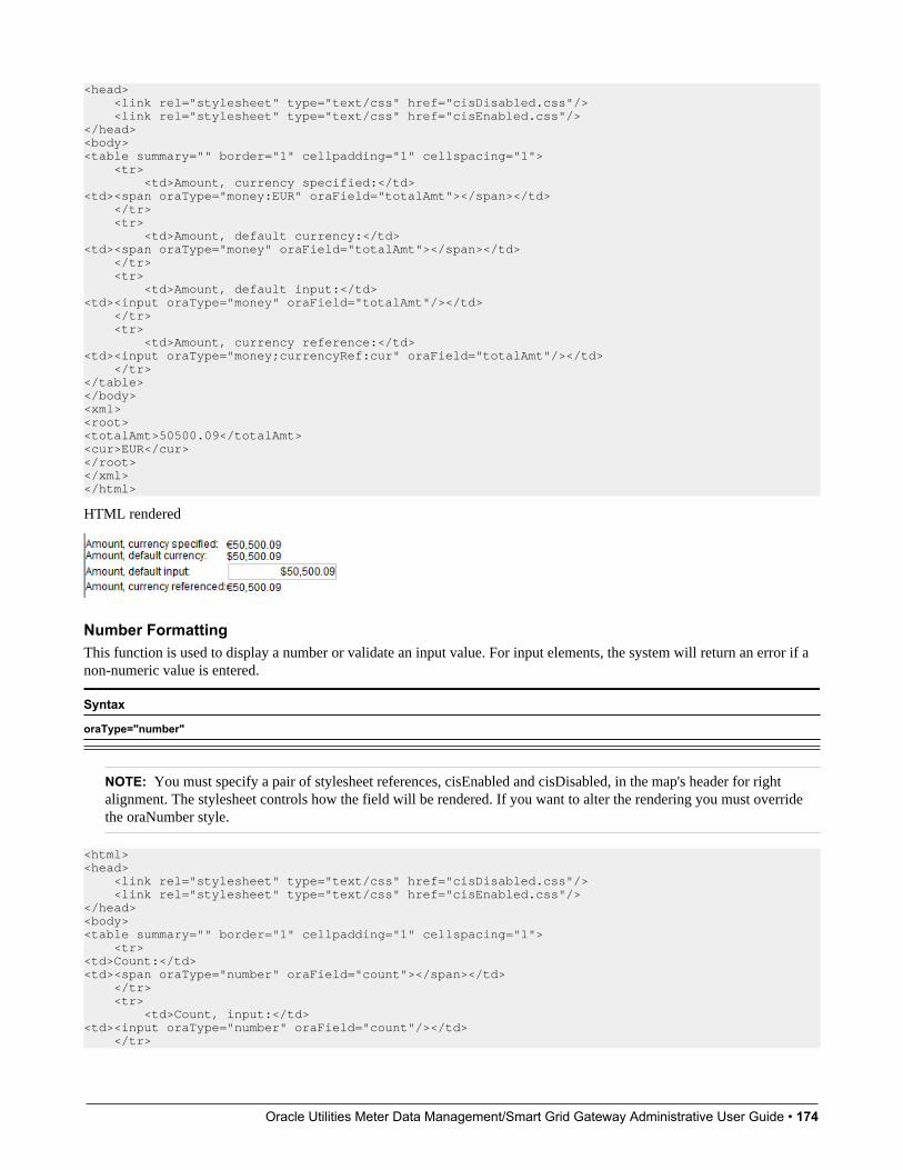
Oracle Utilities Meter Data Management/Smart Grid Gateway Administrative User Guide • 174
<head> <link rel="stylesheet" type="text/css" href="cisDisabled.css"/> <link rel="stylesheet" type="text/css" href="cisEnabled.css"/></head><body><table summary="" border="1" cellpadding="1" cellspacing="1"> <tr> <td>Amount, currency specified:</td><td><span oraType="money:EUR" oraField="totalAmt"></span></td> </tr> <tr> <td>Amount, default currency:</td><td><span oraType="money" oraField="totalAmt"></span></td> </tr> <tr> <td>Amount, default input:</td><td><input oraType="money" oraField="totalAmt"/></td> </tr> <tr> <td>Amount, currency reference:</td><td><input oraType="money;currencyRef:cur" oraField="totalAmt"/></td> </tr></table></body><xml><root><totalAmt>50500.09</totalAmt><cur>EUR</cur></root></xml></html>
HTML rendered
Number FormattingThis function is used to display a number or validate an input value. For input elements, the system will return an error if anon-numeric value is entered.
Syntax
oraType="number"
NOTE: You must specify a pair of stylesheet references, cisEnabled and cisDisabled, in the map's header for rightalignment. The stylesheet controls how the field will be rendered. If you want to alter the rendering you must overridethe oraNumber style.
<html><head> <link rel="stylesheet" type="text/css" href="cisDisabled.css"/> <link rel="stylesheet" type="text/css" href="cisEnabled.css"/></head><body><table summary="" border="1" cellpadding="1" cellspacing="1"> <tr><td>Count:</td><td><span oraType="number" oraField="count"></span></td> </tr> <tr> <td>Count, input:</td><td><input oraType="number" oraField="count"/></td> </tr>
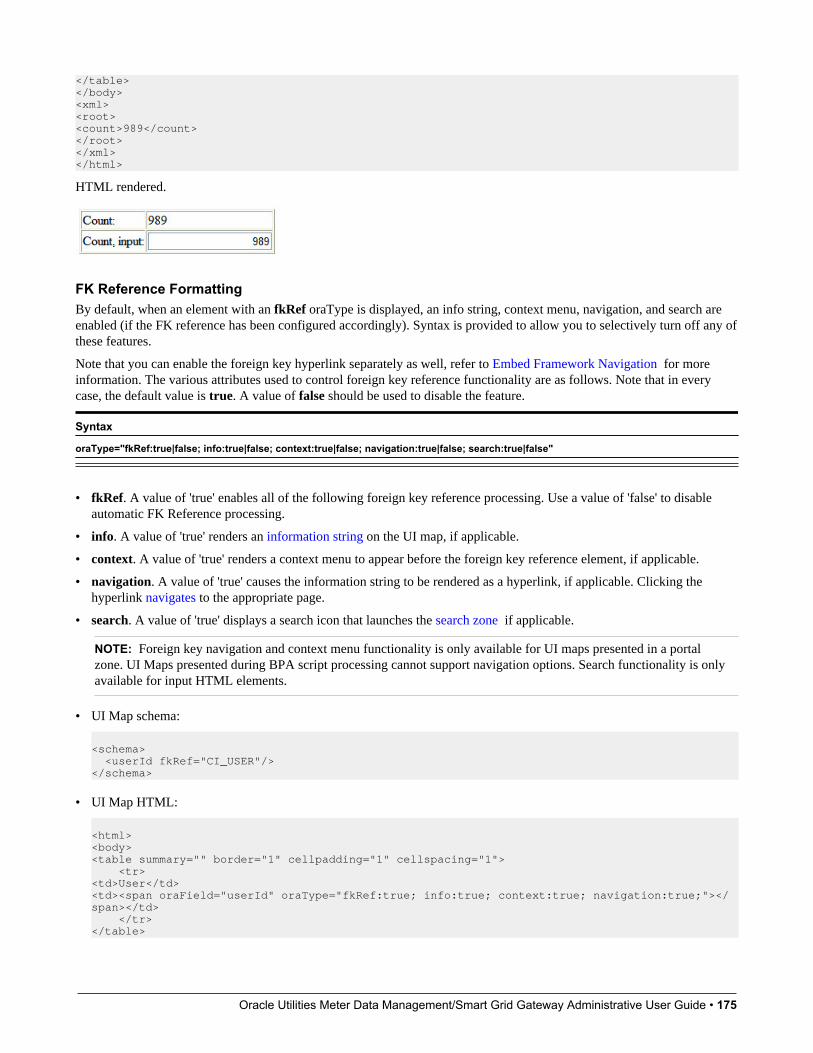
Oracle Utilities Meter Data Management/Smart Grid Gateway Administrative User Guide • 175
</table></body><xml><root><count>989</count></root></xml></html>
HTML rendered.
FK Reference FormattingBy default, when an element with an fkRef oraType is displayed, an info string, context menu, navigation, and search areenabled (if the FK reference has been configured accordingly). Syntax is provided to allow you to selectively turn off any ofthese features.
Note that you can enable the foreign key hyperlink separately as well, refer to Embed Framework Navigation for moreinformation. The various attributes used to control foreign key reference functionality are as follows. Note that in everycase, the default value is true. A value of false should be used to disable the feature.
Syntax
oraType="fkRef:true|false; info:true|false; context:true|false; navigation:true|false; search:true|false"
• fkRef. A value of 'true' enables all of the following foreign key reference processing. Use a value of 'false' to disableautomatic FK Reference processing.
• info. A value of 'true' renders an information string on the UI map, if applicable.
• context. A value of 'true' renders a context menu to appear before the foreign key reference element, if applicable.
• navigation. A value of 'true' causes the information string to be rendered as a hyperlink, if applicable. Clicking thehyperlink navigates to the appropriate page.
• search. A value of 'true' displays a search icon that launches the search zone if applicable.
NOTE: Foreign key navigation and context menu functionality is only available for UI maps presented in a portalzone. UI Maps presented during BPA script processing cannot support navigation options. Search functionality is onlyavailable for input HTML elements.
• UI Map schema:
<schema> <userId fkRef="CI_USER"/></schema>
• UI Map HTML:
<html><body><table summary="" border="1" cellpadding="1" cellspacing="1"> <tr><td>User</td><td><span oraField="userId" oraType="fkRef:true; info:true; context:true; navigation:true;"></span></td> </tr></table>

Oracle Utilities Meter Data Management/Smart Grid Gateway Administrative User Guide • 176
</body><xml><root><userId>CZAAND</userId></root></xml></html>
• HTML rendered.
Lookup FormattingThis function is used to display the description of a lookup value.
Syntax Valid Values
oraType="lookup: " Lookup field name after the colon.
<html><body><table summary="" border="1" cellpadding="1" cellspacing="1"> <tr> <td>Status:</td> <td><span oraField="status" oraType="lookup:BATCH_JOB_STAT_FLG"></span></td> </tr></table></body><xml><root> <status>PD</status></root></xml></html>
HTML rendered.
Extendable Lookup FormattingThis function is used to display the description of an extendable lookup value.
Syntax Valid Values
oraType="lookupBO: " Business Object code name after the colon.
<html><body><table summary="" border="1" cellpadding="1" cellspacing="1"> <tr> <td>Status:</td> <td><span oraField="status" oraType="lookupBO:F1-DeviceDisplayTypes"></span></td> </tr></table></body><xml><root> <status>PD</status></root></xml></html>
HTML rendered.

Oracle Utilities Meter Data Management/Smart Grid Gateway Administrative User Guide • 177
Characteristic Type FormattingThis function is used to display the description of a predefined characteristic value.
Syntax Valid Values
oraType="charType: " Characteristic Type code after the colon.
<html><body><table summary="" border="1" cellpadding="1" cellspacing="1"> <tr> <td>Skill:</td> <td><span oraType="charType:CM-SKILL" oraField="skill"></span></td> </tr></table></body><xml><root> <skill>10</skill></root></xml></html>
HTML rendered.
Control Table FormattingThis function is used to display the description of a control table that has an associated language table.
Syntax Valid Values
oraType="table: " Table code after the colon.
<html><body><table summary="" border="1" cellpadding="1" cellspacing="1"> <tr><td>Currency:</td><td><span oraType="table:CI_CURRENCY_CD" oraField="curr"></span></td> </tr></table></body><xml><root><curr>USD</curr></root></xml></html>
HTML rendered.
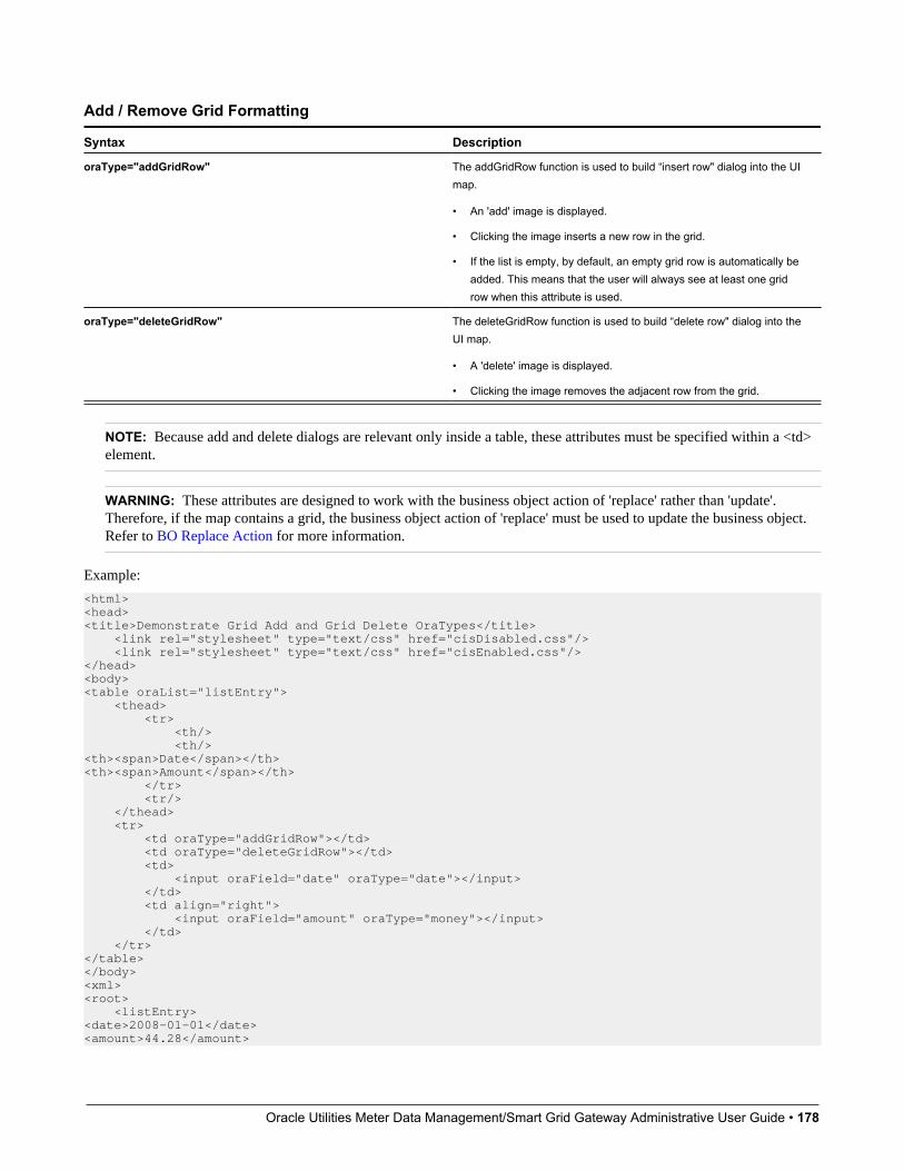
Oracle Utilities Meter Data Management/Smart Grid Gateway Administrative User Guide • 178
Add / Remove Grid Formatting
Syntax Description
oraType="addGridRow" The addGridRow function is used to build “insert row" dialog into the UImap.
• An 'add' image is displayed.
• Clicking the image inserts a new row in the grid.
• If the list is empty, by default, an empty grid row is automatically beadded. This means that the user will always see at least one gridrow when this attribute is used.
oraType="deleteGridRow" The deleteGridRow function is used to build “delete row" dialog into theUI map.
• A 'delete' image is displayed.
• Clicking the image removes the adjacent row from the grid.
NOTE: Because add and delete dialogs are relevant only inside a table, these attributes must be specified within a <td>element.
WARNING: These attributes are designed to work with the business object action of 'replace' rather than 'update'.Therefore, if the map contains a grid, the business object action of 'replace' must be used to update the business object.Refer to BO Replace Action for more information.
Example:
<html><head><title>Demonstrate Grid Add and Grid Delete OraTypes</title> <link rel="stylesheet" type="text/css" href="cisDisabled.css"/> <link rel="stylesheet" type="text/css" href="cisEnabled.css"/></head><body><table oraList="listEntry"> <thead> <tr> <th/> <th/><th><span>Date</span></th><th><span>Amount</span></th> </tr> <tr/> </thead> <tr> <td oraType="addGridRow"></td> <td oraType="deleteGridRow"></td> <td> <input oraField="date" oraType="date"></input> </td> <td align="right"> <input oraField="amount" oraType="money"></input> </td> </tr></table></body><xml><root> <listEntry><date>2008-01-01</date><amount>44.28</amount>
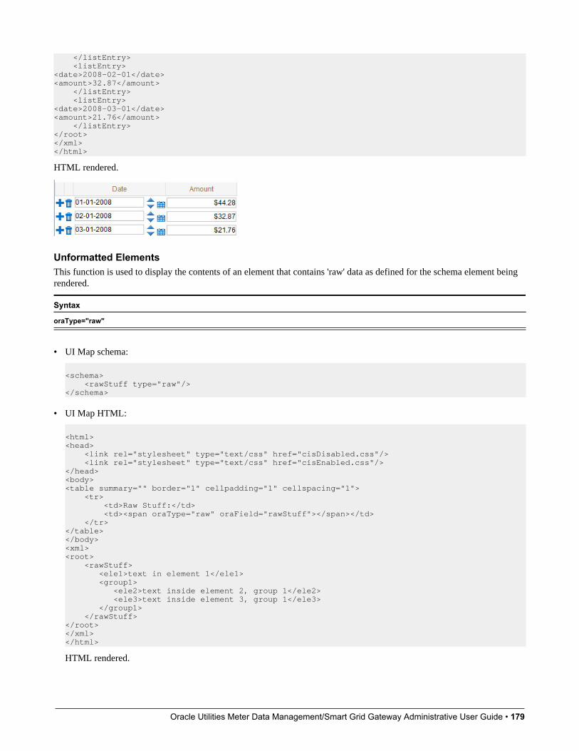
Oracle Utilities Meter Data Management/Smart Grid Gateway Administrative User Guide • 179
</listEntry> <listEntry><date>2008-02-01</date><amount>32.87</amount> </listEntry> <listEntry><date>2008-03-01</date><amount>21.76</amount> </listEntry></root></xml></html>
HTML rendered.
Unformatted ElementsThis function is used to display the contents of an element that contains 'raw' data as defined for the schema element beingrendered.
Syntax
oraType="raw"
• UI Map schema:
<schema> <rawStuff type="raw"/></schema>
• UI Map HTML:
<html><head> <link rel="stylesheet" type="text/css" href="cisDisabled.css"/> <link rel="stylesheet" type="text/css" href="cisEnabled.css"/></head><body><table summary="" border="1" cellpadding="1" cellspacing="1"> <tr> <td>Raw Stuff:</td> <td><span oraType="raw" oraField="rawStuff"></span></td> </tr></table></body><xml><root> <rawStuff> <ele1>text in element 1</ele1> <group1> <ele2>text inside element 2, group 1</ele2> <ele3>text inside element 3, group 1</ele3> </group1> </rawStuff></root></xml></html>
HTML rendered.
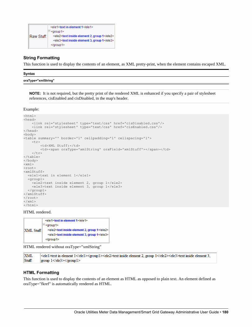
Oracle Utilities Meter Data Management/Smart Grid Gateway Administrative User Guide • 180
String FormattingThis function is used to display the contents of an element, as XML pretty-print, when the element contains escaped XML.
Syntax
oraType="xmlString"
NOTE: It is not required, but the pretty print of the rendered XML is enhanced if you specify a pair of stylesheetreferences, cisEnabled and cisDisabled, in the map's header.
Example:
<html><head> <link rel="stylesheet" type="text/css" href="cisDisabled.css"/> <link rel="stylesheet" type="text/css" href="cisEnabled.css"/></head><body><table summary="" border="1" cellpadding="1" cellspacing="1"> <tr> <td>XML Stuff:</td> <td><span oraType="xmlString" oraField="xmlStuff"></span></td> </tr></table></body><xml><root><xmlStuff> <ele1>text in element 1</ele1> <group1> <ele2>text inside element 2, group 1</ele2> <ele3>text inside element 3, group 1</ele3> </group1></xmlStuff></root></xml></html>
HTML rendered.
HTML rendered without oraType=”xmlString”
HTML FormattingThis function is used to display the contents of an element as HTML as opposed to plain text. An element defined asoraType="fkref" is automatically rendered as HTML.

Oracle Utilities Meter Data Management/Smart Grid Gateway Administrative User Guide • 181
Syntax
oraType="html"
WARNING:To avoid execution of malicious HTML not all HTML tags are supported. The list of supported tags is defined in the"F1-HTMLWhiteList" managed content definition.
If unsupported HTML is detected the entire element is escaped and rendered as plain text. It is therefore recommendedto properly escape any source string that contributes to the final HTML element if it is not expected to contain validHTML. This way only the offending string is escaped and not the entire element.
If the HTML element is composed in scripting refer to the 'escape' function described in the Edit Data Syntax for moreinformation. Use the WebStringUtilities.asHTML java API for escaping text composed in Java.
<html><head> <link rel="stylesheet" type="text/css" href="cisDisabled.css"/> <link rel="stylesheet" type="text/css" href="cisEnabled.css"/></head><body><table summary="" border="0" cellpadding="1" cellspacing="1"> <tr> <td>Info :</td> <td><span oraType="html" oraField="info"></span></td> </tr></table></body><xml><root> <info><b>text in bold</b></info></root></xml></html>
HTML rendered.
HTML rendered without oraType="html"
Display Labels
Derive Label from an ElementThis attribute is used to obtain a language sensitive label for a <span>, <td>, or <input> HTML element.
Syntax Valid Values
oraLabel=" " XPath of an element in the UI map schema. The element mustreference either the mapField=, mdField=, or label= attribute.
NOTE: You can also define a field directly in your HTML for label definition, refer to Deriving Label from a Field formore information.
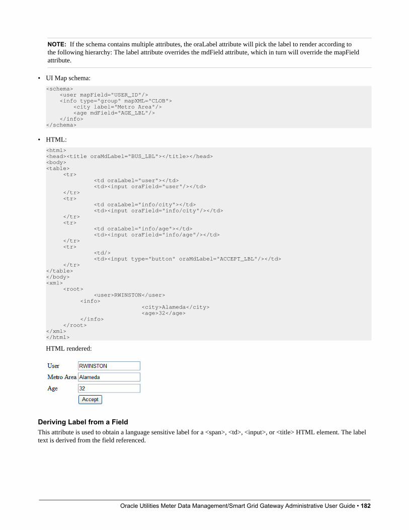
Oracle Utilities Meter Data Management/Smart Grid Gateway Administrative User Guide • 182
NOTE: If the schema contains multiple attributes, the oraLabel attribute will pick the label to render according tothe following hierarchy: The label attribute overrides the mdField attribute, which in turn will override the mapFieldattribute.
• UI Map schema:
<schema> <user mapField="USER_ID"/> <info type="group" mapXML="CLOB"> <city label="Metro Area"/> <age mdField="AGE_LBL"/> </info> </schema>
• HTML:
<html><head><title oraMdLabel="BUS_LBL"></title></head><body><table> <tr> <td oraLabel="user"></td> <td><input oraField="user"/></td> </tr> <tr> <td oraLabel="info/city"></td> <td><input oraField="info/city"/></td> </tr> <tr> <td oraLabel="info/age"></td> <td><input oraField="info/age"/></td> </tr> <tr> <td/> <td><input type="button" oraMdLabel="ACCEPT_LBL"/></td> </tr></table></body><xml> <root> <user>RWINSTON</user> <info> <city>Alameda</city> <age>32</age> </info> </root></xml></html>
HTML rendered:
Deriving Label from a FieldThis attribute is used to obtain a language sensitive label for a <span>, <td>, <input>, or <title> HTML element. The labeltext is derived from the field referenced.

Oracle Utilities Meter Data Management/Smart Grid Gateway Administrative User Guide • 183
Syntax Valid Values
oraMdLabel=" " MD Field code.
NOTE: You can also define labels derived from the map's schema definition, refer to Derive Label from an Element formore information.
• HTML:
<html><head><title oraMdLabel="NOTES_LBL"></title></head><body><table> <tr> <td oraLabel="user"></td> <td><input oraField="user"/></td> </tr> <tr> <td oraLabel="info/city"></td> <td><input oraField="info/city"/></td> </tr> <tr> <td oraLabel="info/age"></td> <td><input oraField="info/age"/></td> </tr> <tr> <td/> <td><input type="button" oraMdLabel="ACCEPT_LBL"/></td> </tr></table></body><xml> <root> <user>RWINSTON</user><info> <city>Alameda</city> <age>32</age></info> </root></xml></html>
HTML rendered:
Enable UI Map HelpThe Display Labels section describes ways to derive the label for an element using an underlying MD Field. In addition,if the same MD field contains help text, the system will automatically generate a tool tip adjacent to the element label.Clicking the tool tip allows the user to view the help text.
It is possible to change the rendering of the tool tip. Refer to Custom Look And Feel Options for more information
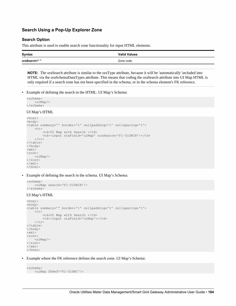
Oracle Utilities Meter Data Management/Smart Grid Gateway Administrative User Guide • 184
Search Using a Pop-Up Explorer Zone
Search OptionThis attribute is used to enable search zone functionality for input HTML elements.
Syntax Valid Values
oraSearch=" " Zone code.
NOTE: The oraSearch attribute is similar to the oraType attribute, because it will be 'automatically' included intoHTML via the oraSchemaDataTypes attribute. This means that coding the oraSearch attribute into UI Map HTML isonly required if a search zone has not been specified in the schema, or in the schema element's FK reference.
• Example of defining the search in the HTML. UI Map’s Schema:
<schema> <uiMap/> </schema>
UI Map’s HTML
<html><body><table summary="" border="1" cellpadding="1" cellspacing="1"> <tr> <td>UI Map with Search </td> <td><input oraField="uiMap" oraSearch="F1-UISRCH"></td> </tr></table></body><xml><root> <uiMap/></root></xml></html>
• Example of defining the search in the schema. UI Map’s Schema:
<schema> <uiMap search="F1-UISRCH"/></schema>
UI Map’s HTML
<html><body><table summary="" border="1" cellpadding="1" cellspacing="1"> <tr> <td>UI Map with Search </td> <td><input oraField="uiMap"></td> </tr></table></body><xml><root> <uiMap/></root></xml></html>
• Example where the FK reference defines the search zone. UI Map’s Schema:
<schema> <uiMap fkRef="F1-UISRC"/>

Oracle Utilities Meter Data Management/Smart Grid Gateway Administrative User Guide • 185
</schema>
UI Map’s HTML
<html><body><table summary="" border="1" cellpadding="1" cellspacing="1"> <tr> <td>UI Map with Search </td> <td><input oraField="uiMap"></td> </tr></table></body><xml><root> <uiMap/></root></xml></html>
In all cases, the HTML rendered is the same.
Initializing Search FieldsThis optional attribute is used to initialize search zone filters. Multiple filters may be initialized. This attribute can only beused in conjunction with the oraSearch attribute.
Syntax Valid Values Field Value Options Comments
No value If you do not specify a fieldvalue, then the value of theinput element containing theoraSearchField attribute will beused.
XPath Indicate the XPath to the schemaelement that contains the value touse.
oraSearchField=" " One or more pairs of field nameand field value separated bycolon. Each pair is separated bya semi-colon.
oraSearchField="fieldName:fieldValue: ..."The field name is used to identifythe zone filter to initialize whenthe search is launched. Thefield name must match the valueof the searchField mnemonicspecified on a search zone userfilter or hidden filter parameter.
'literal' Indicate a literal value to supply.
NOTE: If you do not specify an oraSearchField attribute and the schema element has a search enabled fkRef specified,the framework automatically builds an oraSearchField where the field name is equal to the FK reference's key (MD)fields.
WARNING: The pop-up explorer zone can be invoked one of two ways: By clicking on the search button, or by hittingthe enter key from the field to the left of the button. If you click on the button then no search field information will bepassed to the zone. Search field information is only used to initialize zone filter values when enter is pressed.
Two filter values are initialized as shown in the following example:
<schema> <bo/> <uiMap/></schema>
<html><body>
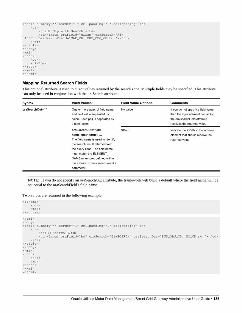
Oracle Utilities Meter Data Management/Smart Grid Gateway Administrative User Guide • 186
<table summary="" border="1" cellpadding="1" cellspacing="1"> <tr> <td>UI Map with Search </td> <td><input oraField="uiMap" oraSearch="F1-UISRCH" oraSearchField="MAP_CD; BUS_OBJ_CD:bo;"></td> </tr></table></body><xml><root> <bo/> <uiMap/></root></xml></html>
Mapping Returned Search FieldsThis optional attribute is used to direct values returned by the search zone. Multiple fields may be specified. This attributecan only be used in conjunction with the oraSearch attribute.
Syntax Valid Values Field Value Options Comments
No value If you do not specify a field value,then the input element containingthe oraSearchField attributereceives the returned value.
oraSearchOut=" " One or more pairs of field nameand field value separated bycolon. Each pair is separated bya semi-colon.
oraSearchOut="fieldname:xpath target; ..."The field name is used to identifythe search result returned fromthe query zone. The field namemust match the ELEMENT_NAME mnemonic defined withinthe explorer zone's search resultsparameter.
XPath Indicate the XPath to the schemaelement that should receive thereturned value.
NOTE: If you do not specify an oraSearchOut attribute, the framework will build a default where the field name will beset equal to the oraSearchField's field name.
Two values are returned in the following example:
<schema> <bo/> <mo/></schema>
<html><body><table summary="" border="1" cellpadding="1" cellspacing="1"> <tr> <td>BO Search </td> <td><input oraField="bo" oraSearch="Z1-BOSRCH" oraSearchOut="BUS_OBJ_CD; MO_CD:mo;"></td> </tr></table></body><xml><root> <bo/> <mo/></root></xml></html>
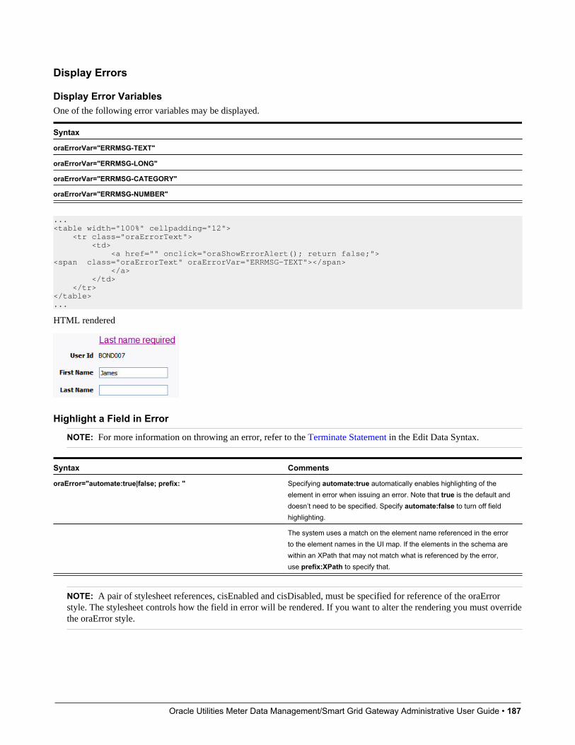
Oracle Utilities Meter Data Management/Smart Grid Gateway Administrative User Guide • 187
Display Errors
Display Error VariablesOne of the following error variables may be displayed.
Syntax
oraErrorVar="ERRMSG-TEXT"
oraErrorVar="ERRMSG-LONG"
oraErrorVar="ERRMSG-CATEGORY"
oraErrorVar="ERRMSG-NUMBER"
...<table width="100%" cellpadding="12"> <tr class="oraErrorText"> <td> <a href="" onclick="oraShowErrorAlert(); return false;"><span class="oraErrorText" oraErrorVar="ERRMSG-TEXT"></span> </a> </td> </tr></table>...
HTML rendered
Highlight a Field in Error
NOTE: For more information on throwing an error, refer to the Terminate Statement in the Edit Data Syntax.
Syntax Comments
oraError="automate:true|false; prefix: " Specifying automate:true automatically enables highlighting of theelement in error when issuing an error. Note that true is the default anddoesn’t need to be specified. Specify automate:false to turn off fieldhighlighting.
The system uses a match on the element name referenced in the errorto the element names in the UI map. If the elements in the schema arewithin an XPath that may not match what is referenced by the error,use prefix:XPath to specify that.
NOTE: A pair of stylesheet references, cisEnabled and cisDisabled, must be specified for reference of the oraErrorstyle. The stylesheet controls how the field in error will be rendered. If you want to alter the rendering you must overridethe oraError style.

Oracle Utilities Meter Data Management/Smart Grid Gateway Administrative User Guide • 188
The following HTML example shows that the elements in the map are defined within a group called boGroup. The elementname returned by the error will not include this group so in order for the field highlighting to work properly the prefix:attribute must indicate the group name.
<html><head> <title>User Zone Input</title> <link rel="stylesheet" type="text/css" href="cisDisabled.css"/> <link rel="stylesheet" type="text/css" href="cisEnabled.css"/></head><body oraError="automate:true; prefix:boGroup"><table width="100%" cellpadding="12"> <tr class="oraErrorText"> <td> <a href="" onclick="oraShowErrorAlert(); return false;"> <span class="oraErrorText" oraErrorVar="ERRMSG-TEXT"></span> </a> </td> </tr></table><table width="100%" border="0" cellpadding="4"> <tr style="padding-top:30px;"> <td align="right" class="label">User Id</td> <td> <span oraField="boGroup/userId" class="normal"/> </td> </tr> <tr> <td align="right" class="label">First Name</td> <td> <input oraField="boGroup/firstName" class="normal"/> </td> </tr> <tr> <td align="right" class="label">Last Name</td> <td> <input oraField="boGroup/lastName" class="normal"/> </td> </tr></table></body> <xml><root><boGroup> <userId>BOND007</userId> <firstName>James</firstName> <lastName></lastName></boGroup></root></xml></html>
HTML rendered, where the error element thrown is equal to 'lastName':
Overriding the Error Element NameIn the rare occasion where the element name returned by the error doesn't match the element name in the map, you can addan explicit attribute to indicate the error element name.

Oracle Utilities Meter Data Management/Smart Grid Gateway Administrative User Guide • 189
Syntax Valid Values Comments
oraErrorElement= "element name" The element name referenced here mustexactly match the name of the error elementassigned when the error was thrown. Morethan one HTML field can be referenced by thesame error element name.
NOTE: A pair of stylesheet references, cisEnabled and cisDisabled, must be specified for reference of the oraErrorstyle. The stylesheet controls how the field in error will be rendered. If you want to alter the rendering you must overridethe oraError style.
This illustrates a scenario where the element name associated with the error differs from the element name on the map.
<html><head> <title>User Zone Input</title> <link rel="stylesheet" type="text/css" href="cisDisabled.css"/> <link rel="stylesheet" type="text/css" href="cisEnabled.css"/></head><body><table width="100%" cellpadding="12"> <tr class="oraErrorText"> <td> <a href="" onclick="oraShowErrorAlert(); return false;"> <span class="oraErrorText" oraErrorVar="ERRMSG-TEXT"></span> </a> </td> </tr></table><table width="100%" border="0" cellpadding="4"> <tr style="padding-top:30px;"> <td align="right" class="label">User Id</td> <td> <span oraField="userId" class="normal"/> </td> </tr> <tr> <td align="right" class="label">First Name</td> <td> <input oraField="firstName" class="normal" oraErrorElement="firstName"/> </td> </tr> <tr> <td align="right" class="label">Last Name</td> <td> <input oraField="familyName" class="normal" oraErrorElement="lastName"/> </td> </tr></table></body> <xml><root> <userId>BOND007</userId> <firstName>James</firstName> <familyName></familyName></root></xml></html>
HTML rendered.

Oracle Utilities Meter Data Management/Smart Grid Gateway Administrative User Guide • 190
Display Error Pop-UpWhen the error text is displayed, this function may be used to pop-up the standard error dialog (which displays moreinformation) when a user clicks the error message.
Syntax
oraShowErrorAlert(); return false;
<html><head> <link rel="stylesheet" type="text/css" href="cisDisabled.css"/> <link rel="stylesheet" type="text/css" href="cisEnabled.css"/></head><body><table width="100%" cellpadding="12"> <tr class="oraErrorText"> <td> <a href="" onclick="oraShowErrorAlert(); return false;"> <span class="oraErrorText" oraErrorVar="ERRMSG-TEXT"></span> </a> </td> </tr></table><table> <tr> <td >Address:</td> <td><input type="text" oraField="address"/></td> </tr> <tr> <td>City:</td> <td><input type="text" oraField="city"/></td> </tr> <tr> <td>State:</td> <td><input type="text" oraField="state"/></td> </tr> <tr> <td>Zip:</td> <td><input type="text" oraField="zip"/></td> </tr> <tr> <td/> <td style="padding-top=15px;"><oraInclude map="F1-SaveCancelButtons"/> </td> </tr></table></body><xml> <root> <address>123 Main St</address> <city>Alameda</city> <state>CA</state> <zip>94770</zip> </root></xml></html>
HTML rendered.
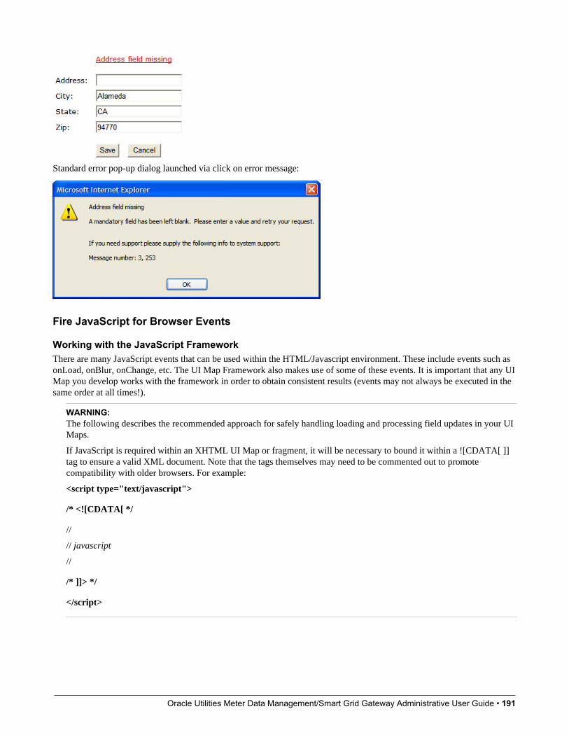
Oracle Utilities Meter Data Management/Smart Grid Gateway Administrative User Guide • 191
Standard error pop-up dialog launched via click on error message:
Fire JavaScript for Browser Events
Working with the JavaScript FrameworkThere are many JavaScript events that can be used within the HTML/Javascript environment. These include events such asonLoad, onBlur, onChange, etc. The UI Map Framework also makes use of some of these events. It is important that any UIMap you develop works with the framework in order to obtain consistent results (events may not always be executed in thesame order at all times!).
WARNING:The following describes the recommended approach for safely handling loading and processing field updates in your UIMaps.
If JavaScript is required within an XHTML UI Map or fragment, it will be necessary to bound it within a ![CDATA[ ]]tag to ensure a valid XML document. Note that the tags themselves may need to be commented out to promotecompatibility with older browsers. For example:
<script type="text/javascript">
/* <![CDATA[ */
//
// javascript
//
/* ]]> */
</script>

Oracle Utilities Meter Data Management/Smart Grid Gateway Administrative User Guide • 192
Element Change Event
Syntax Valid Values
oraChange=" " A JavaScript function.
At the time of UI Map load, if there is an event handler already attached to an HTML element, the framework removes itand attaches a combined event handler. The combined handler calls any framework handler first and then calls the other(custom) handlers.
WARNING: Note that the function must not be used to execute logic that will modify the associated field data valueagain - or an endless loop will occur.
In the following example the oraInvokeBS function is executed when the button is clicked.
<html> <head> <title>oraInvokeBS test</title> </head> <body> <table> <tr> <td>User Id:</td> <td> <input oraField= "xmlGroup/userId"/> <input type="button" value="Search" oraChange="oraInvokeBS('UserSearch','xmlGroup');"/> </td> </tr> <tr> <td/> <td>Search Results</td> </tr> <tr> <td/> <td> <table oraList="xmlGroup/searchList"> <tr> <td><span oraField="userId"></span> </td> </tr> </table> </td> </tr> </table> </body> <xml> <root> <xmlGroup> <userId/> <searchList> <userId></userId> </searchList> </xmlGroup> </root> </xml></html>
Page Load Event
Syntax Valid Values
oraLoad=" " A JavaScript function.
WARNING: When executing oraLoad within a fragment UI map, and you need to execute a JavaScript function duringpage load (where the function invokes a business object, business service, or service script) you can use the special

Oracle Utilities Meter Data Management/Smart Grid Gateway Administrative User Guide • 193
syntax "oraLoad[$SEQUENCEID]". For other special syntax used for map fragments, refer to the Construct a PortalZone Header section.
• In the following example, the oraDisplayNone function is executed during page load:
<html><body><table summary="" border="1" cellpadding="1" cellspacing="1"> <tr> <td oraLoad="oraDisplayNone(item,'userId','')">User Id: </td> <td><span oraField="userId"></span></td> </tr></table></body><xml><root> <userId>SPLAXT</userId></root></xml></html>
• HTML rendered
After Page Load Event
Syntax Valid Values
oraAfterLoad=" " A JavaScript function.
In the following example the oraGetValueFromScript function is executed after page load.
<div>
<label for="boGroup_parameters_externalSystem" oraLabel="boGroup/parameters/externalSystem"> </label> <span> <select oraSelect="bs:F1-RetrieveExternalSystems" class="oraInput" id="boGroup_parameters_externalSystem" oraField="boGroup/parameters/externalSystem" oraSelectOut="valuePath:results/externalSystem; descPath:results/description" oraSelectIn="outboundMsgType:boGroup/parameters/outboundMsgType" oraAfterLoad ="oraGetValueFromScript(document.getElementById('boGroup_parameters_externalSystem');"> </select> </span>
</div>
Hide Elements
Hide Using a FunctionThe system provides a function that is used to hide an HTML element based on the value on another element or basedon the results of a JavaScript function. Note that the first parameter is the string item, which lets the function identify theHTML item being manipulated.
Syntax Valid Values Comments
oraDisplayNone(item ); (item, 'XPath', 'value', 'operator') Used to hide an element based on the valueof another element (referenced using itsXPath). Enter a value of ' ' to interrogate ablank value. By default the operator is '='. This

Oracle Utilities Meter Data Management/Smart Grid Gateway Administrative User Guide • 194
Syntax Valid Values Commentsmay be set instead to another operator suchas '!=', '>', or '<'.
(item, function name,true | false) Used to indicate a JavaScript function, whichmust return a Boolean.
• Example where the User Id label is hidden when no User Id value exists.
<html><body><table summary="" border="1" cellpadding="1" cellspacing="1"> <tr> <td oraLoad="oraDisplayNone(item,'userId','')">User Id: </td> <td><span oraField="userId"></span></td> </tr></table></body><xml><root> <userId></userId></root></xml></html>
• Example where the Save button is hidden when the user does not have security access to the action of change ('C') for theapplication service 'F1-DFLTS'.
<html><body><table summary="" border="1" cellpadding="1" cellspacing="1"> <tr> <td oraLoad="oraDisplayNone(item, oraHasSecurity('F1-DFLTS', 'C'), false );"> <input name="Save" type="button" onclick="oraInvokeBO('CM-IndividualTaxpayer', null, 'replace')"/> </td> </tr></table></body><xml><root> <userId></userId></root></xml></html>
Check User's Security AccessThe system provides two functions to check a user's security access to a given application service and access mode. Theseare commonly used for hiding elements.
Syntax Parameters
'Application Service code'oraHasSecurity( )
'Access Mode'
'Application Service XPath'oraHasSecurityPath('x','y')
'Access Mode XPath'
See the previous section for an example of the oraHasSecurity function. The following shows an example where thestatus button is hidden when the user does not have security access to the access mode 'ACT' of the application service'FORMTST'.
<html>
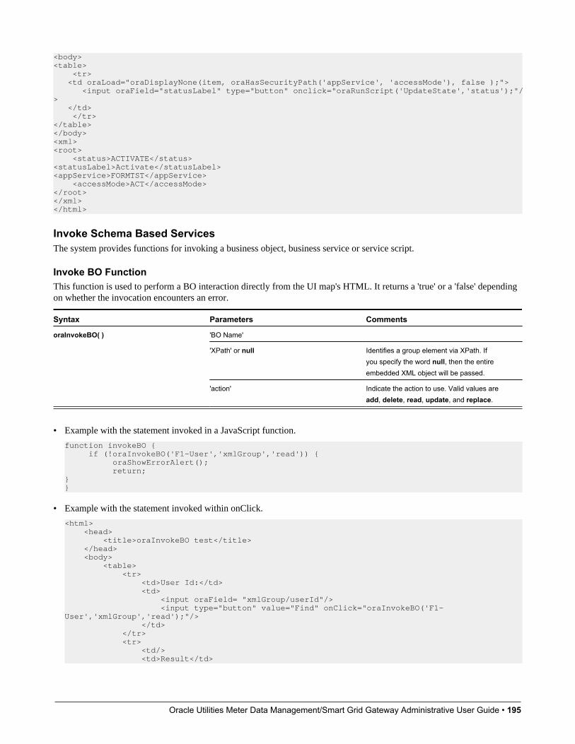
Oracle Utilities Meter Data Management/Smart Grid Gateway Administrative User Guide • 195
<body><table> <tr> <td oraLoad="oraDisplayNone(item, oraHasSecurityPath('appService', 'accessMode'), false );"> <input oraField="statusLabel" type="button" onclick="oraRunScript('UpdateState','status');"/> </td> </tr></table></body><xml><root> <status>ACTIVATE</status><statusLabel>Activate</statusLabel><appService>FORMTST</appService> <accessMode>ACT</accessMode></root></xml></html>
Invoke Schema Based ServicesThe system provides functions for invoking a business object, business service or service script.
Invoke BO FunctionThis function is used to perform a BO interaction directly from the UI map's HTML. It returns a 'true' or a 'false' dependingon whether the invocation encounters an error.
Syntax Parameters Comments
'BO Name'
'XPath' or null Identifies a group element via XPath. Ifyou specify the word null, then the entireembedded XML object will be passed.
oraInvokeBO( )
'action' Indicate the action to use. Valid values areadd, delete, read, update, and replace.
• Example with the statement invoked in a JavaScript function.
function invokeBO { if (!oraInvokeBO('F1-User','xmlGroup','read')) { oraShowErrorAlert(); return;}}
• Example with the statement invoked within onClick.
<html> <head> <title>oraInvokeBO test</title> </head> <body> <table> <tr> <td>User Id:</td> <td> <input oraField= "xmlGroup/userId"/> <input type="button" value="Find" onClick="oraInvokeBO('F1-User','xmlGroup','read');"/> </td> </tr> <tr> <td/> <td>Result</td>
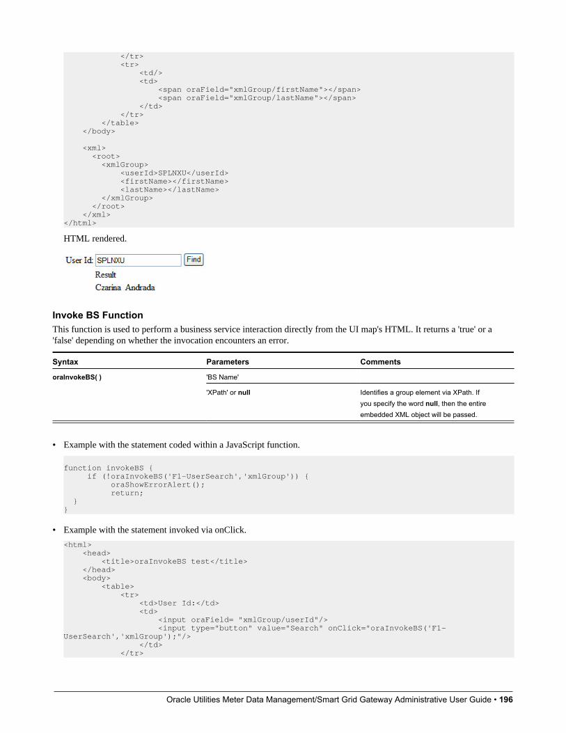
Oracle Utilities Meter Data Management/Smart Grid Gateway Administrative User Guide • 196
</tr> <tr> <td/> <td> <span oraField="xmlGroup/firstName"></span> <span oraField="xmlGroup/lastName"></span> </td> </tr> </table> </body> <xml> <root> <xmlGroup> <userId>SPLNXU</userId> <firstName></firstName> <lastName></lastName> </xmlGroup> </root> </xml></html>
HTML rendered.
Invoke BS FunctionThis function is used to perform a business service interaction directly from the UI map's HTML. It returns a 'true' or a'false' depending on whether the invocation encounters an error.
Syntax Parameters Comments
'BS Name'oraInvokeBS( )
'XPath' or null Identifies a group element via XPath. Ifyou specify the word null, then the entireembedded XML object will be passed.
• Example with the statement coded within a JavaScript function.
function invokeBS { if (!oraInvokeBS('F1-UserSearch','xmlGroup')) { oraShowErrorAlert(); return; }}
• Example with the statement invoked via onClick.
<html> <head> <title>oraInvokeBS test</title> </head> <body> <table> <tr> <td>User Id:</td> <td> <input oraField= "xmlGroup/userId"/> <input type="button" value="Search" onClick="oraInvokeBS('F1-UserSearch','xmlGroup');"/> </td> </tr>
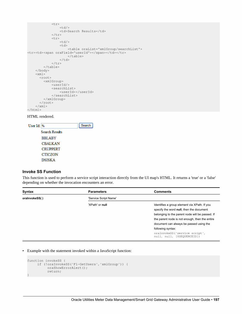
Oracle Utilities Meter Data Management/Smart Grid Gateway Administrative User Guide • 197
<tr> <td/> <td>Search Results</td> </tr> <tr> <td/> <td> <table oraList="xmlGroup/searchList"><tr><td><span oraField="userId"></span></td></tr> </table> </td> </tr> </table> </body> <xml> <root> <xmlGroup> <userId/> <searchList> <userId></userId> </searchList> </xmlGroup> </root> </xml></html>
HTML rendered.
Invoke SS FunctionThis function is used to perform a service script interaction directly from the UI map's HTML. It returns a 'true' or a 'false'depending on whether the invocation encounters an error.
Syntax Parameters Comments
'Service Script Name'oraInvokeSS( )
'XPath' or null Identifies a group element via XPath. If youspecify the word null, then the documentbelonging to the parent node will be passed. Ifthe parent node is not enough, then the entiredocument can always be passed using thefollowing syntax:oraInvokeSS('service script', null, null, [$SEQUENCEID])
• Example with the statement invoked within a JavaScript function:
function invokeSS { if (!oraInvokeSS('F1-GetUsers','xmlGroup')) { oraShowErrorAlert(); return;}
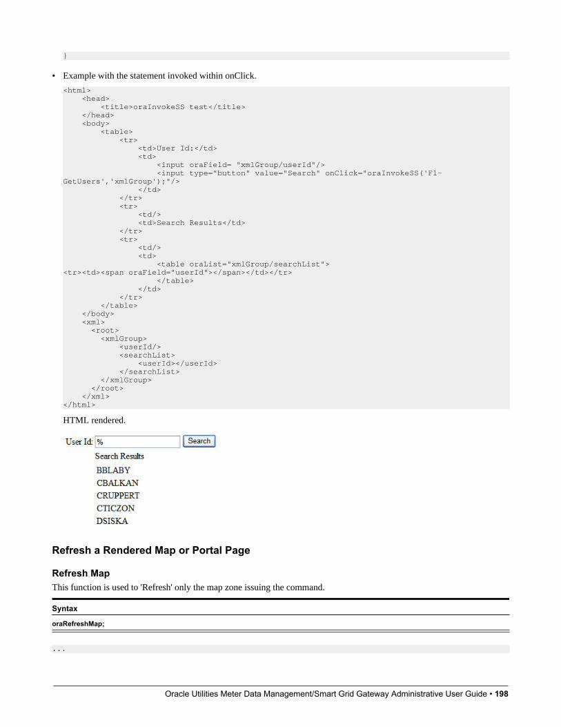
Oracle Utilities Meter Data Management/Smart Grid Gateway Administrative User Guide • 198
}
• Example with the statement invoked within onClick.
<html> <head> <title>oraInvokeSS test</title> </head> <body> <table> <tr> <td>User Id:</td> <td> <input oraField= "xmlGroup/userId"/> <input type="button" value="Search" onClick="oraInvokeSS('F1-GetUsers','xmlGroup');"/> </td> </tr> <tr> <td/> <td>Search Results</td> </tr> <tr> <td/> <td> <table oraList="xmlGroup/searchList"><tr><td><span oraField="userId"></span></td></tr> </table> </td> </tr> </table> </body> <xml> <root> <xmlGroup> <userId/> <searchList> <userId></userId> </searchList> </xmlGroup> </root> </xml></html>
HTML rendered.
Refresh a Rendered Map or Portal Page
Refresh MapThis function is used to 'Refresh' only the map zone issuing the command.
Syntax
oraRefreshMap;
...

Oracle Utilities Meter Data Management/Smart Grid Gateway Administrative User Guide • 199
<tr> <td/> <td><input type="button" onclick="oraRefreshMap();" value="Refresh"/></td> </tr>...
Refresh PageThis function is used to refresh all zones in the portal.
Syntax
oraRefreshPage;
... <tr> <td/> <td><input type="button" onclick="oraRefreshPage();" value="Refresh"/></td> </tr>...
Embed Framework Navigation
Navigate using Navigation OptionThis function is used to navigate to another page using the information defined on a navigation option.
Syntax Parameters
'Navigation Option code'oraNavigate( );
'Key XPath'
WARNING: This function is only intended for a UI map defined within a portal zone. It should not be used within a UImap launched by a BPA script.
The following example exhibits two possible uses of this function: as a URL and as a button. Note that the UI Map schemamust contain a fkRef attribute. Refer to FK Reference Formatting for more information.
<schema> <userId fkRef="CI_USER"/></schema>
<html><body><table summary="" border="1" cellpadding="1" cellspacing="1"> <tr> <td>User Link: </td> <td><a href="" onclick="oraNavigate('userMaint','userId'); return false;"> <span oraField="userId" oraType="fkRef:CI_USER"></span></a> </td> </tr> <tr> <td>User Button: </td> <td><input type="submit" onclick="oraNavigate('userMaint','userId')" value="Go to User"/></td> </tr></table></body><xml><root> <userId>SPLAXT</userId></root></xml></html>
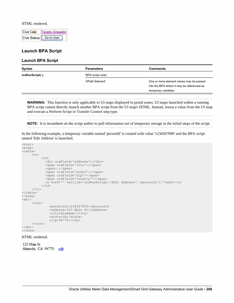
Oracle Utilities Meter Data Management/Smart Grid Gateway Administrative User Guide • 200
HTML rendered.
Launch BPA Script
Launch BPA Script
Syntax Parameters Comments
'BPA script code'.oraRunScript( );
'XPath Element' One or more element values may be passedinto the BPA where it may be referenced astemporary variables.
WARNING: This function is only applicable to UI maps displayed in portal zones. UI maps launched within a runningBPA script cannot directly launch another BPA script from the UI map's HTML. Instead, return a value from the UI mapand execute a Perform Script or Transfer Control step type.
NOTE: It is incumbent on the script author to pull information out of temporary storage in the initial steps of the script.
In the following example, a temporary variable named 'personId' is created with value '1234567890' and the BPA scriptnamed 'Edit Address' is launched.
<html><body><table> <tr> <td> <div oraField="address"></div> <span oraField="city"></span> <span>,</span> <span oraField="state"></span> <span oraField="zip"></span> <span oraField="country"></span> <a href="" onClick="oraRunScript('Edit Address','personId');">edit</a> </td> </tr></table></body><xml> <root> <personId>1234567890</personId> <address>123 Main St</address> <city>Alameda</city> <state>CA</state> <zip>94770</zip> </root></xml></html>
HTML rendered.
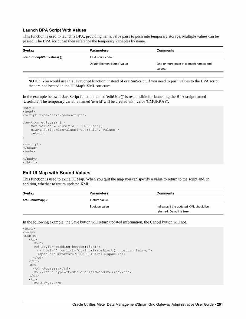
Oracle Utilities Meter Data Management/Smart Grid Gateway Administrative User Guide • 201
Launch BPA Script With ValuesThis function is used to launch a BPA, providing name/value pairs to push into temporary storage. Multiple values can bepassed. The BPA script can then reference the temporary variables by name.
Syntax Parameters Comments
'BPA script code'.oraRunScriptWithValues( );
'XPath Element Name':value One or more pairs of element names andvalues.
NOTE: You would use this JavaScript function, instead of oraRunScript, if you need to push values to the BPA scriptthat are not located in the UI Map's XML structure.
In the example below, a JavaScript function named 'editUser()' is responsible for launching the BPA script named'UserEdit'. The temporary variable named 'userId' will be created with value 'CMURRAY'.
<html><head><script type="text/javascript"> function editUser() { var values = {'userId': 'CMURRAY'}; oraRunScriptWithValues('UserEdit', values); return;} </script></head><body>...</body></html>
Exit UI Map with Bound ValuesThis function is used to exit a UI Map. When you quit the map you can specify a value to return to the script and, inaddition, whether to return updated XML.
Syntax Parameters Comments
'Return Value'oraSubmitMap( );
Boolean value Indicates if the updated XML should bereturned. Default is true.
In the following example, the Save button will return updated information, the Cancel button will not.
<html><body><table> <tr> <td/> <td style="padding-bottom:15px;"> <a href="" onclick="oraShowErrorAlert(); return false;"> <span oraErrorVar="ERRMSG-TEXT"></span></a> </td> </tr> <tr> <td >Address:</td> <td><input type="text" oraField="address"/></td> </tr> <tr> <td>City:</td>
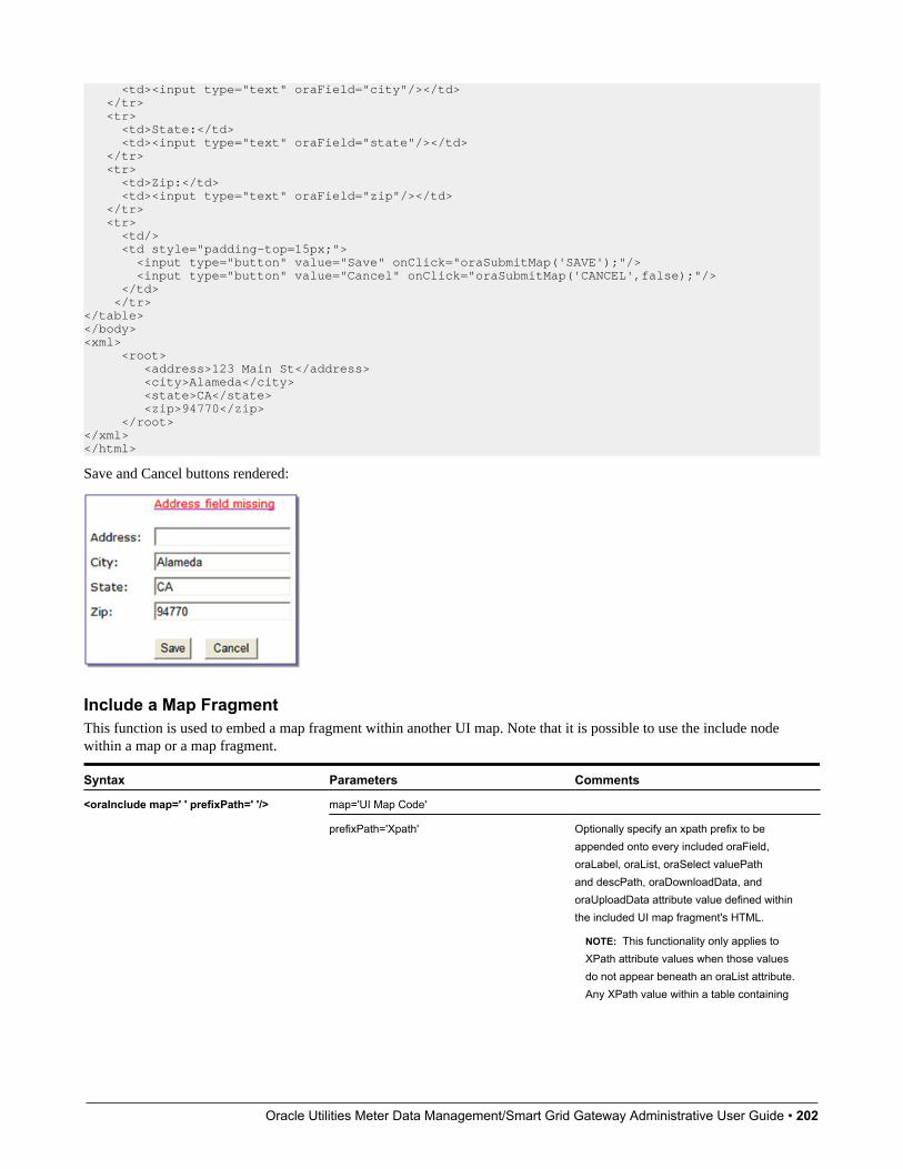
Oracle Utilities Meter Data Management/Smart Grid Gateway Administrative User Guide • 202
<td><input type="text" oraField="city"/></td> </tr> <tr> <td>State:</td> <td><input type="text" oraField="state"/></td> </tr> <tr> <td>Zip:</td> <td><input type="text" oraField="zip"/></td> </tr> <tr> <td/> <td style="padding-top=15px;"> <input type="button" value="Save" onClick="oraSubmitMap('SAVE');"/> <input type="button" value="Cancel" onClick="oraSubmitMap('CANCEL',false);"/> </td> </tr></table></body><xml> <root> <address>123 Main St</address> <city>Alameda</city> <state>CA</state> <zip>94770</zip> </root></xml></html>
Save and Cancel buttons rendered:
Include a Map FragmentThis function is used to embed a map fragment within another UI map. Note that it is possible to use the include nodewithin a map or a map fragment.
Syntax Parameters Comments
map='UI Map Code'<oraInclude map=' ' prefixPath=' '/>
prefixPath='Xpath' Optionally specify an xpath prefix to beappended onto every included oraField,oraLabel, oraList, oraSelect valuePathand descPath, oraDownloadData, andoraUploadData attribute value defined withinthe included UI map fragment's HTML.
NOTE: This functionality only applies toXPath attribute values when those valuesdo not appear beneath an oraList attribute.Any XPath value within a table containing
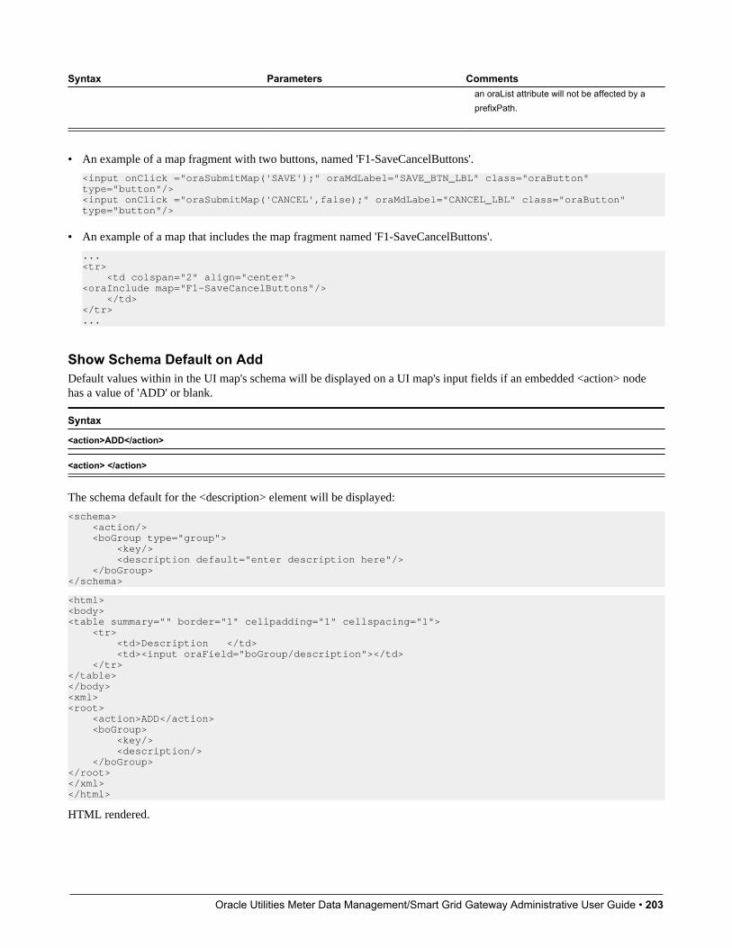
Oracle Utilities Meter Data Management/Smart Grid Gateway Administrative User Guide • 203
Syntax Parameters Commentsan oraList attribute will not be affected by aprefixPath.
• An example of a map fragment with two buttons, named 'F1-SaveCancelButtons'.
<input onClick ="oraSubmitMap('SAVE');" oraMdLabel="SAVE_BTN_LBL" class="oraButton" type="button"/><input onClick ="oraSubmitMap('CANCEL',false);" oraMdLabel="CANCEL_LBL" class="oraButton" type="button"/>
• An example of a map that includes the map fragment named 'F1-SaveCancelButtons'.
...<tr> <td colspan="2" align="center"><oraInclude map="F1-SaveCancelButtons"/> </td></tr>...
Show Schema Default on AddDefault values within in the UI map's schema will be displayed on a UI map's input fields if an embedded <action> nodehas a value of 'ADD' or blank.
Syntax
<action>ADD</action>
<action> </action>
The schema default for the <description> element will be displayed:
<schema> <action/> <boGroup type="group"> <key/> <description default="enter description here"/> </boGroup></schema>
<html><body><table summary="" border="1" cellpadding="1" cellspacing="1"> <tr> <td>Description </td> <td><input oraField="boGroup/description"></td> </tr></table></body><xml><root> <action>ADD</action> <boGroup> <key/> <description/> </boGroup></root></xml></html>
HTML rendered.

Oracle Utilities Meter Data Management/Smart Grid Gateway Administrative User Guide • 204
Configure a ChartThe following HTML attributes are used to configure a graphical representation of an XML list. The designer can controlthe type, size, position, and contents of the chart using the following attributes.
oraChart="type:pie, stacked, cluster, line, area, combo ;"This attribute defines the type of graph to display and its general configuration. The set of configuration parametersavailable for this attribute are as follows:
Parameter Values Description
type: pie
stacked
cluster
line
area
combo
Defines the type of chart to display.
Required
showLegend true
false
Defines if the chart should have a legenddisplayed.
Optional (default is true)
legendPosition left
right
bottom
top
Defines where the legend should appear.
Optional (default is right)
Setting position to left or right willautomatically render it vertically.
Setting position to top or bottom willautomatically render it horizontally.
legendBorder true
false
Defines if the legend should display with aborder around it.
Optional (default is false )
depth true
false
A value of true indicates a 3 dimensionaldepth for the chart.
Optional (default false, which is a 2dimensional chart)
animate true
false
A value of true indicates that the graph shouldanimate when displayed.
Optional (default is true). When using largedata sets, consider disabling animation.
dataCursor on
off
A value of on enables hovering anywhere inthe graph.
Optional (default is off). It is not applicable topie charts.
orientation horizontal Defines the chart orientation. This only appliesto bar, line, area, combo charts.
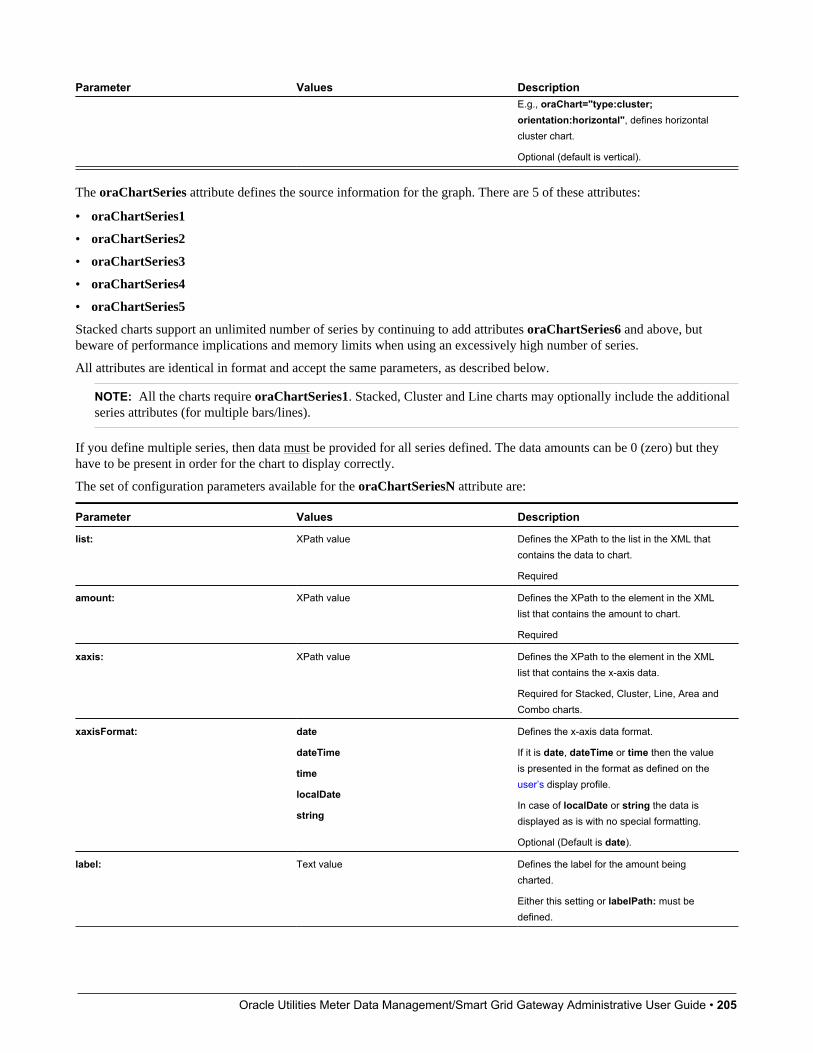
Oracle Utilities Meter Data Management/Smart Grid Gateway Administrative User Guide • 205
Parameter Values DescriptionE.g., oraChart="type:cluster;orientation:horizontal", defines horizontalcluster chart.
Optional (default is vertical).
The oraChartSeries attribute defines the source information for the graph. There are 5 of these attributes:
• oraChartSeries1
• oraChartSeries2
• oraChartSeries3
• oraChartSeries4
• oraChartSeries5
Stacked charts support an unlimited number of series by continuing to add attributes oraChartSeries6 and above, butbeware of performance implications and memory limits when using an excessively high number of series.
All attributes are identical in format and accept the same parameters, as described below.
NOTE: All the charts require oraChartSeries1. Stacked, Cluster and Line charts may optionally include the additionalseries attributes (for multiple bars/lines).
If you define multiple series, then data must be provided for all series defined. The data amounts can be 0 (zero) but theyhave to be present in order for the chart to display correctly.
The set of configuration parameters available for the oraChartSeriesN attribute are:
Parameter Values Description
list: XPath value Defines the XPath to the list in the XML thatcontains the data to chart.
Required
amount: XPath value Defines the XPath to the element in the XMLlist that contains the amount to chart.
Required
xaxis: XPath value Defines the XPath to the element in the XMLlist that contains the x-axis data.
Required for Stacked, Cluster, Line, Area andCombo charts.
xaxisFormat: date
dateTime
time
localDate
string
Defines the x-axis data format.
If it is date, dateTime or time then the valueis presented in the format as defined on theuser’s display profile.
In case of localDate or string the data isdisplayed as is with no special formatting.
Optional (Default is date).
label: Text value Defines the label for the amount beingcharted.
Either this setting or labelPath: must bedefined.

Oracle Utilities Meter Data Management/Smart Grid Gateway Administrative User Guide • 206
Parameter Values Description
labelPath: XPath value Defines the XPath to the element thatprovides the label for the amount beingcharted.
Either this setting or label: must be defined.
currency: A valid Currency code Defines the currency code for the amountbeing charted.
Optional.
currencyPath: XPath value Defines the XPath to the element thatprovides the currency code for the amountbeing charted.
Optional.
hoverText: Text value Defines the hover text for the chart element.
Optional (A default hover text is alwaysavailable.) Ignored if hoverTextPath: isdefined.
The following substitution variables areavailable.
• $label This will be replaced with thelabel text as determined by the label: orlabelPath: setting.
• $amount This will be replaced with theamount text as specified by the amount:setting.
• $axis This will be replaced with the x-axistext.
• $% This will be replaced by thepercentage "slice" of the pie or bar.
• $newline This will be force a line break.
If the hover text defined contains any of theabove values, they will be replaced by theequivalent text prior to being displayed.
Example:
"hoverText:$label$newline$amount"
hoverTextPath: XPath value Defines the XPath to the element thatprovides the hover text for the chart element.
The hover text in the XML can utilize all thesubstitution functionality described above inthe hoverText: description.
Optional.
type: bar
line
area
This attribute is used for the combo charttype only. It defines how each series on thecombo chart should be presented.
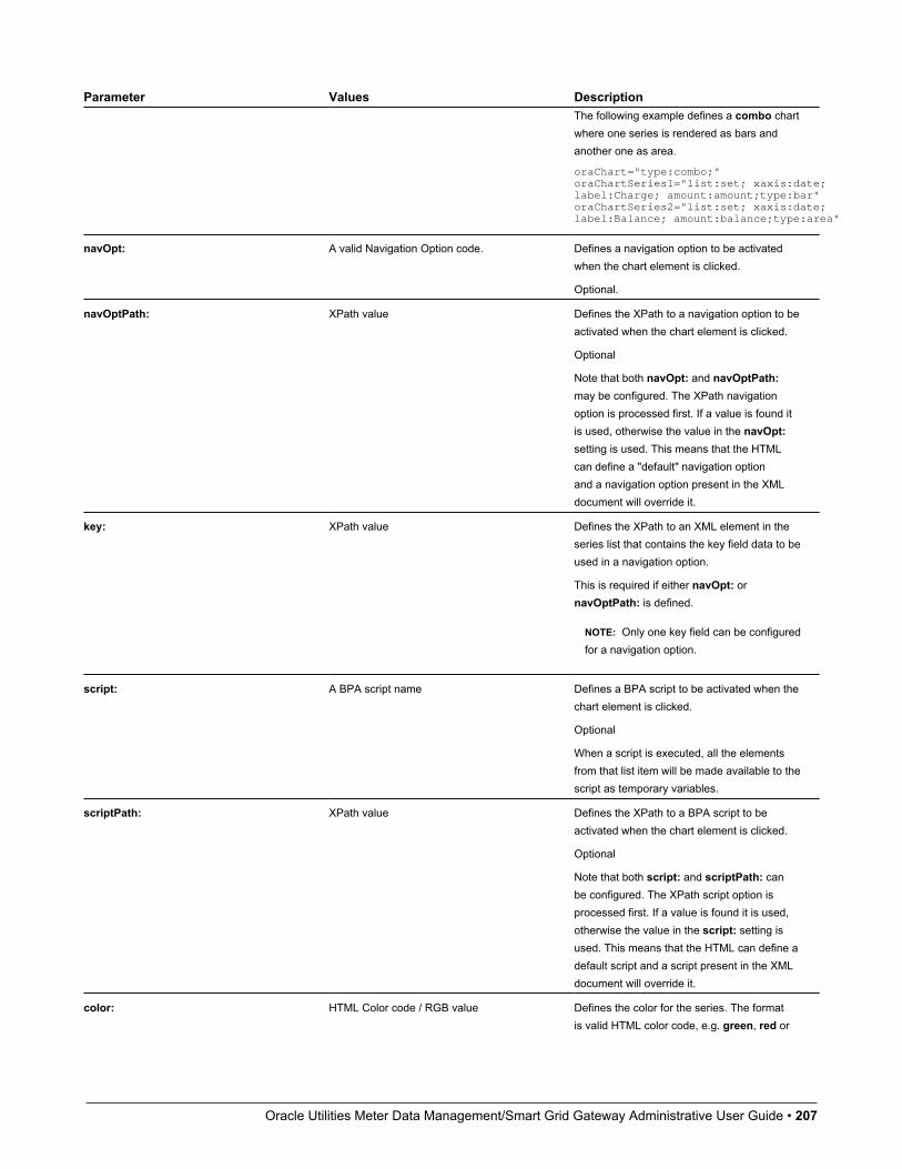
Oracle Utilities Meter Data Management/Smart Grid Gateway Administrative User Guide • 207
Parameter Values DescriptionThe following example defines a combo chartwhere one series is rendered as bars andanother one as area.
oraChart="type:combo;" oraChartSeries1="list:set; xaxis:date; label:Charge; amount:amount;type:bar" oraChartSeries2="list:set; xaxis:date; label:Balance; amount:balance;type:area"
navOpt: A valid Navigation Option code. Defines a navigation option to be activatedwhen the chart element is clicked.
Optional.
navOptPath: XPath value Defines the XPath to a navigation option to beactivated when the chart element is clicked.
Optional
Note that both navOpt: and navOptPath:may be configured. The XPath navigationoption is processed first. If a value is found itis used, otherwise the value in the navOpt:setting is used. This means that the HTMLcan define a "default" navigation optionand a navigation option present in the XMLdocument will override it.
key: XPath value Defines the XPath to an XML element in theseries list that contains the key field data to beused in a navigation option.
This is required if either navOpt: ornavOptPath: is defined.
NOTE: Only one key field can be configuredfor a navigation option.
script: A BPA script name Defines a BPA script to be activated when thechart element is clicked.
Optional
When a script is executed, all the elementsfrom that list item will be made available to thescript as temporary variables.
scriptPath: XPath value Defines the XPath to a BPA script to beactivated when the chart element is clicked.
Optional
Note that both script: and scriptPath: canbe configured. The XPath script option isprocessed first. If a value is found it is used,otherwise the value in the script: setting isused. This means that the HTML can define adefault script and a script present in the XMLdocument will override it.
color: HTML Color code / RGB value Defines the color for the series. The formatis valid HTML color code, e.g. green, red or

Oracle Utilities Meter Data Management/Smart Grid Gateway Administrative User Guide • 208
Parameter Values Descriptionblack. All valid color names are defined in thislink: http://www.w3schools.com/htmL/html_colornames.asp.
Alternatively an RGB format may be used.(FF0000 is red, 00FF00 is green and 0000FFis blue)
Optional (default colors applied)
colorPath: XPath value Defines the XPath to a color for the series.The valid format as described in the color:setting apply.
Optional (default colors applied)
pieColors: HTML color code / RGB values Defines the colors for the pie series. Anynumber of HTML color codes or RGB colorvalues can be specified, separated by spaces.Examples:
pieColors: red green black
pieColors: FF0000 00FF00
Optional (default colors applied if the seriesexceeds the values specified)
oraChartBroadcast="FIELD_NAME:XPath;"A chart configured in a map zone can be set to broadcast portal context. An unlimited number of fields can be broadcast,configured as name/value pairs, as follows:
1. FIELD_NAME: the name of the portal context field to be broadcast.
2. XPath: the XML schema element from the same list item that corresponds to the user selected chart segment andcontains the data value to be broadcast.
Graph Examples• Sample of a pie chart configuration:
<html><head><title>Pie Chart</title></head><body> <div style="width:100%; height:290px;" oraChart="type:pie;" oraChartSeries1="list:set; labelPath:date; amount:amount; " oraChartBroadcast="BILL_ID:billId;"></div> </body> <xml><root> <set><date>05-02-2003</date><amount>163.24</amount><billId>592211649441</billId> </set> <set><date>06-02-2003</date><amount>97.29</amount>
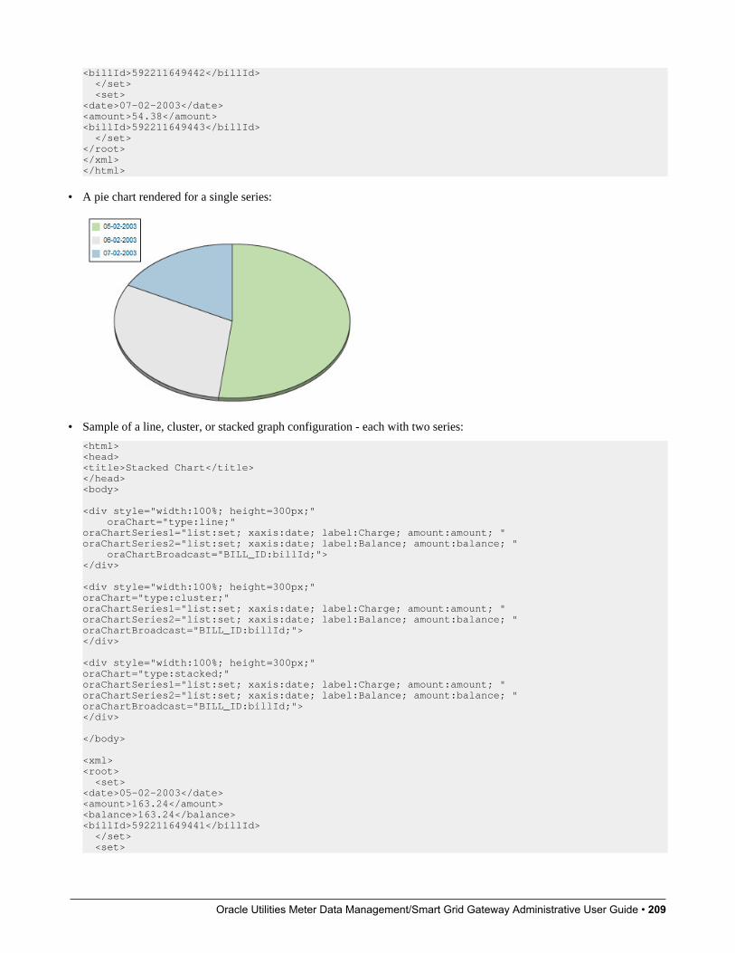
Oracle Utilities Meter Data Management/Smart Grid Gateway Administrative User Guide • 209
<billId>592211649442</billId> </set> <set><date>07-02-2003</date><amount>54.38</amount><billId>592211649443</billId> </set></root></xml></html>
• A pie chart rendered for a single series:
• Sample of a line, cluster, or stacked graph configuration - each with two series:
<html><head><title>Stacked Chart</title></head><body> <div style="width:100%; height=300px;" oraChart="type:line;"oraChartSeries1="list:set; xaxis:date; label:Charge; amount:amount; "oraChartSeries2="list:set; xaxis:date; label:Balance; amount:balance; " oraChartBroadcast="BILL_ID:billId;"></div> <div style="width:100%; height=300px;"oraChart="type:cluster;"oraChartSeries1="list:set; xaxis:date; label:Charge; amount:amount; "oraChartSeries2="list:set; xaxis:date; label:Balance; amount:balance; "oraChartBroadcast="BILL_ID:billId;"></div> <div style="width:100%; height=300px;"oraChart="type:stacked;"oraChartSeries1="list:set; xaxis:date; label:Charge; amount:amount; "oraChartSeries2="list:set; xaxis:date; label:Balance; amount:balance; "oraChartBroadcast="BILL_ID:billId;"></div> </body> <xml><root> <set><date>05-02-2003</date><amount>163.24</amount><balance>163.24</balance><billId>592211649441</billId> </set> <set>

Oracle Utilities Meter Data Management/Smart Grid Gateway Administrative User Guide • 210
<date>06-02-2003</date><amount>97.29</amount><balance>260.53</balance><billId>592211649442</billId> </set> <set><date>07-02-2003</date><amount>54.38</amount><balance>314.91</balance><billId>592211649443</billId> </set></root></xml></html>
• Three types of chart rendered for two series each: line, cluster, and stacked.

Oracle Utilities Meter Data Management/Smart Grid Gateway Administrative User Guide • 211
Upload and Download a CSV FileThe following HTML attributes can be used to manage both an upload and a download between a list defined within themap's schema and a CSV (comma separated value) file.
The syntax is oraUploadData="type:embed;path:list xpath;useLabels:true;showCount:true"

Oracle Utilities Meter Data Management/Smart Grid Gateway Administrative User Guide • 212
Upload configuration requires you to name a CSV file to be uploaded, and an XML list as target. By convention, each CSVrow will create a separate list instance. Each comma-separated field in the file will be uploaded as a separate element in thelist. To embed an upload dialog within a map, the oraUploadData attribute must be associated with a container elementsuch as a div, td, or span.
The optional useLabels:true value indicates that while parsing the upload CSV file, the headers are expected to be labels
NOTE: If you do not specify the useLabels:true value and the XML target element name is "camelCase" then thecorresponding spreadsheet header should be title case with a space between words, e.g.;"Camel Case". Letters andspecial characters are not considered a different word, for example Address1 must be uploaded into the target XMLelement address1.
Specifying the optional showCount:true value will display the number of records uploaded.
CAUTION: If you are using a grid in conjunction with the oraUploadData function, then you must maintain the grid'slist with a 'replace' business object action. Refer to BO Replace Action for more information.
Sample of oraUploadData="embed" within a div element.
<html><head> <title>File Upload</title></head><body> <div oraUploadData="type:embed;path:myList"> </div> </body> <xml><root> <myList><id>838383930</id> <name>Janice Smith</name> </myList> <myList><id>737773730</id> <name>Bill McCollum</name> </myList></root></xml></html>
This file upload dialog will be embedded into the body of the page where the oraUploadData is defined.
oraUploadData="type:popup;path:list xpath;useLabels:true;showOk:true;showCount:true"Upload configuration requires you to name a CSV file to be uploaded, and an XML list as target. By convention, each CSVrow will create a separate list instance. Each comma-separated field in the file will be uploaded as a separate element in thelist. To upload a CSV file using a pop-up dialog, the oraUploadData attribute must be associated with an input element suchas a button, text link, or image.
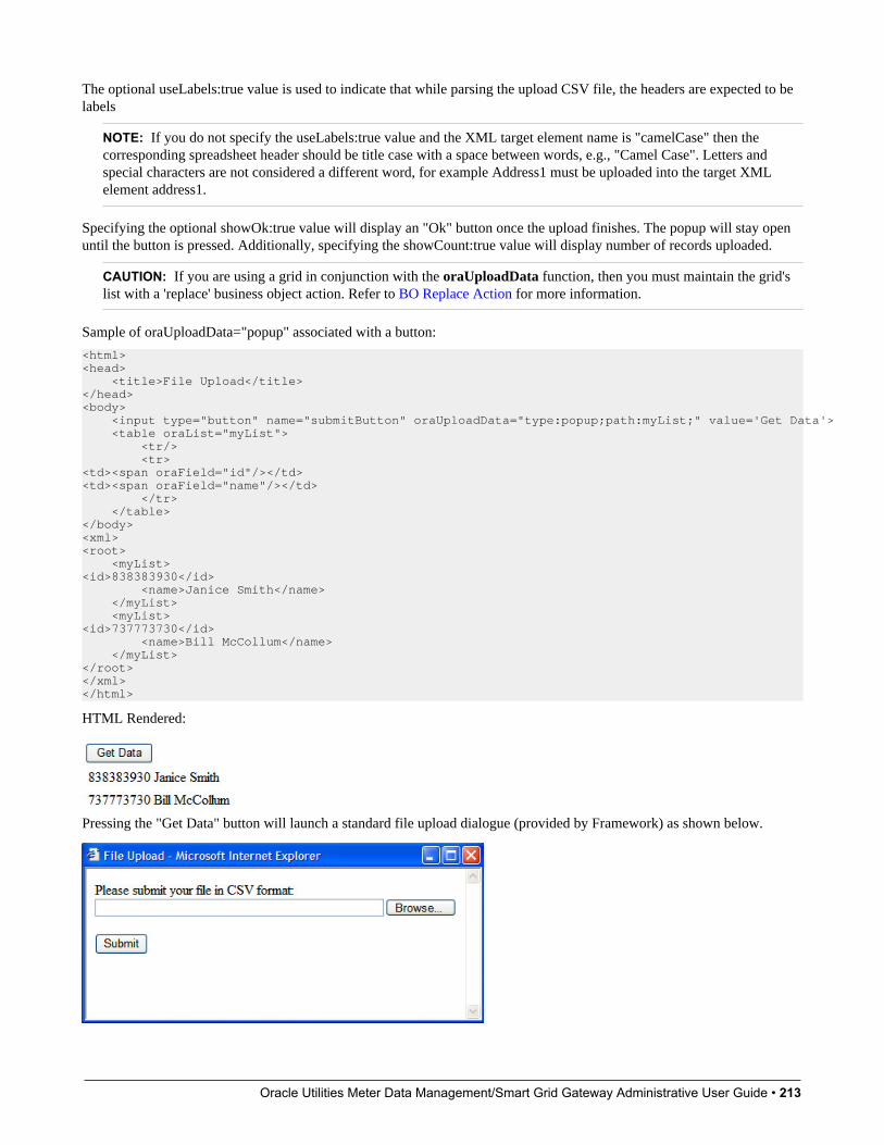
Oracle Utilities Meter Data Management/Smart Grid Gateway Administrative User Guide • 213
The optional useLabels:true value is used to indicate that while parsing the upload CSV file, the headers are expected to belabels
NOTE: If you do not specify the useLabels:true value and the XML target element name is "camelCase" then thecorresponding spreadsheet header should be title case with a space between words, e.g., "Camel Case". Letters andspecial characters are not considered a different word, for example Address1 must be uploaded into the target XMLelement address1.
Specifying the optional showOk:true value will display an "Ok" button once the upload finishes. The popup will stay openuntil the button is pressed. Additionally, specifying the showCount:true value will display number of records uploaded.
CAUTION: If you are using a grid in conjunction with the oraUploadData function, then you must maintain the grid'slist with a 'replace' business object action. Refer to BO Replace Action for more information.
Sample of oraUploadData="popup" associated with a button:
<html><head> <title>File Upload</title></head><body> <input type="button" name="submitButton" oraUploadData="type:popup;path:myList;" value='Get Data'> <table oraList="myList"> <tr/> <tr><td><span oraField="id"/></td><td><span oraField="name"/></td> </tr> </table></body><xml><root> <myList><id>838383930</id> <name>Janice Smith</name> </myList> <myList><id>737773730</id> <name>Bill McCollum</name> </myList></root></xml></html>
HTML Rendered:
Pressing the "Get Data" button will launch a standard file upload dialogue (provided by Framework) as shown below.

Oracle Utilities Meter Data Management/Smart Grid Gateway Administrative User Guide • 214
oraDownloadData="list xpath"Download configuration requires you to name an XML list to be downloaded. By convention, each list instance willrepresent a separate row in the created file. By default every element of the list will be comma separated in the file.
NOTE: The number formatting is based on the user profile setting. For localities where the decimal symbol is a comma,an implementation may configure a property setting (spl.csv.delimiter.useFromDisplayProfile=true) to cause the systemto use a semicolon as the delimiter that separates the elements rather than a comma.
Sample of oraDownloadData.
<html><head><title>File Download</title></head><body><input type="button" name="downloadButton" oraDownloadData="myList" value="Download"/></body><xml><root> <myList> <id>881-990987</id> <name>John Mayweather</name> </myList> <myList> <id>229-765467</id> <name>Anna Mayweather</name> </myList> <myList> <id>943-890432</id> <name>Andrew Brewster</name> </myList></root></xml></html>
HTML Rendered:
Pressing the "Download" button will launch a standard file download dialogue (provided by Framework) as shown below.
A successful download will result in a CSV file:
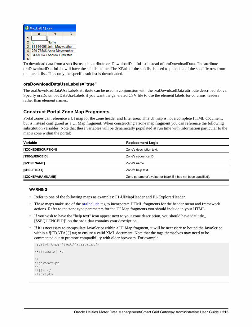
Oracle Utilities Meter Data Management/Smart Grid Gateway Administrative User Guide • 215
To download data from a sub list use the attribute oraDownloadDataInList instead of oraDownloadData. The attributeoraDownloadDataInList will have the sub list name. The XPath of the sub list is used to pick data of the specific row fromthe parent list. Thus only the specific sub list is downloaded.
oraDownloadDataUseLabels="true"The oraDownloadDataUseLabels attribute can be used in conjunction with the oraDownloadData attribute described above.Specify oraDownloadDataUseLabels if you want the generated CSV file to use the element labels for columns headersrather than element names.
Construct Portal Zone Map FragmentsPortal zones can reference a UI map for the zone header and filter area. This UI map is not a complete HTML document,but is instead configured as a UI Map fragment. When constructing a zone map fragment you can reference the followingsubstitution variables. Note that these variables will be dynamically populated at run time with information particular to themap's zone within the portal:
Variable Replacement Logic
[$ZONEDESCRIPTION] Zone's description text.
[$SEQUENCEID] Zone's sequence ID.
[$ZONENAME] Zone's name.
[$HELPTEXT] Zone's help text.
[$ZONEPARAMNAME] Zone parameter's value (or blank if it has not been specified).
WARNING:
• Refer to one of the following maps as examples: F1-UIMapHeader and F1-ExplorerHeader.
• These maps make use of the oraInclude tag to incorporate HTML fragments for the header menu and frameworkactions. Refer to the zone type parameters for the UI Map fragments you should include in your HTML.
• If you wish to have the "help text" icon appear next to your zone description, you should have id="title_[$SEQUENCEID]" on the <td> that contains your description.
• If it is necessary to encapsulate JavaScript within a UI Map fragment, it will be necessary to bound the JavaScriptwithin a ![CDATA[ ]] tag to ensure a valid XML document. Note that the tags themselves may need to becommented out to promote compatibility with older browsers. For example:
<script type="text/javascript">
/*<![CDATA[ */
////javascript///*]]> */</script>

Oracle Utilities Meter Data Management/Smart Grid Gateway Administrative User Guide • 216
NOTE: If you wish to preserve the values of a filter input field, within a filter map fragment, for the framework 'GoBack' and 'Go Forward' functionality, you must associate the input field (text box, select, etc.) with a unique HTML id.Input field values associated with a unique id will be captured in the framework's 'memento'. The 'memento' is used torebuild the input map when the portal zone is navigated to using the 'Go Back' or 'Go Forward' functionality.
NOTE: Many specialized functions exist to manipulate zone behavior, for example:
• oraGetZoneSequence(zoneName). Uses the zone's code to retrieve its sequence number.
• oraIsZoneCollapsed(sequenceId). Uses the zone's sequence to determine if collapsed.
• oraHandleCollapse(seq). Collapse a zone.
• oraHandleExpand(seq,refresh). Expand and/or refresh a zone.
All of these, and many more functions, are located within the JavaScript library userMapSupport.js described below.
NOTE: When executing oraLoad within a fragment UI map, and you need to execute a JavaScript function during pageload (where the function invokes a business object, business service, or service script) you can use the special syntax"oraLoad[$SEQUENCEID]". Refer to the Load Page Event section for more information.
Example of oraLoad[$SEQUENCEID] used within a function:
<script type="text/javascript">function oraLoad[$SEQUENCEID]() {checkRebateClaimStatus();} function checkRebateClaimStatus() { var work = id(''analyticsFilterText[$SEQUENCEID]'',document).cells[0].innerText.split('' ''); var rebateClaimId = work[work.length - 3]; id(''rebateClaimId'', document).value = rebateClaimId;oraInvokeSS(''C1-CheckRCSt'',''checkRebateClaimStatus'', false); var statusIndicator = id(''statusInd'', document).value; if (statusIndicator == ''C1PE'' || statusIndicator == ''C1ID'') { id(''addRebateClaimLine'', document).style.display = ''''; } else {id(''addRebateClaimLine'', document).style.display = ''none''; }}</script>
F1-ExplorerHeader rendered:
Invoking a Business ObjectThe oraInvokeBO function may be used within a portal zone header or zone filter map. It is similar to the commanddescribed in Invoke BO Function which allows for a business object to be invoked within the UI map’s HTML. Refer tothat section for a description of the first three parameters.
Syntax Parameters Comments
'BO Name'
'XPath' or null
'action'
null This must be specified as the fourthargument.
oraInvokeBO( )
[$SEQUENCEID] This must be specified as the fifth argument.

Oracle Utilities Meter Data Management/Smart Grid Gateway Administrative User Guide • 217
Syntax Parameters Comments
true | false Specify true if the fragment is used withina portal zone header. Specify false if thefragment is used with a zone filter map.
Example in a portal zone header:
oraInvokeBO('CM-User','xmlGroup','read', null, [$SEQUENCEID], true)
Invoking a Business ServiceThe oraInvokeBS function may be used within a portal zone header or zone filter map. It is similar to the commanddescribed in Invoke BS Function which allows for a business service to be invoked within the UI map’s HTML. Refer tothat section for a description of the first two parameters.
Syntax Parameters Comments
'BO Name'
'XPath' or null
null This must be specified as the fourthargument.
[$SEQUENCEID] This must be specified as the fifth argument.
oraInvokeBS( )
true | false Specify true if the fragment is used withina portal zone header. Specify false if thefragment is used with a zone filter map.
Example in a portal zone header:
oraInvokeBS('CM-UserSearch','xmlGroup', null, [$SEQUENCEID], true)
Invoking a Service ScriptThe oraInvokeSS function may be used within a portal zone header or zone filter map. It is similar to the commanddescribed in Invoke SS Function which allows for a service script to be invoked within the UI map’s HTML. Refer to thatsection for a description of the first two parameters.
Syntax Parameters Comments
'Service Script Name'
'XPath' or null
null This must be specified as the fourthargument.
[$SEQUENCEID] This must be specified as the fifth argument.
oraInvokeSS( )
true | false Specify true if the fragment is used withina portal zone header. Specify false if thefragment is used with a zone filter map.
Example in a portal zone header:
oraInvokeSS('UserSearch','xmlGroup', null, [$SEQUENCEID], true)
Detecting Unsaved ChangesUse this function to return a Boolean set to true if there are unsaved changes. The system will interrogate the function whenthe user attempts to navigate and issue a warning accordingly. This function is only needed if a UI map is using custom
Oracle Utilities Meter Data Management/Smart Grid Gateway Administrative User Guide • 218
javascript to manage elements such that the system is not able to detect whether changes have been made. Also note that it'sthe responsibility of the UI map javascript to manage the values in the Boolean used for this function.
function hasUnsavedChanges(){ return isDirtyFlag; }
Hiding Portal TabsThe product provides the ability to use JavaScript to hide a tab on the current portal based on some condition using theoraAuthorizeTab JavaScript API. This API accepts a function as a parameter and turns off the tab index indicated.
For example, the UI Map may have a function to turn off one or more tab indexes.:
function overrideTabIndex(index){ if (index == 2) return false; if (index == 3) return false; }
The JavaScript is referenced “on load”:
<body class="oraZoneMap"onLoad="oraAuthorizeTabs(overrideTabIndex);">
Required JavaScript LibrariesAll of the functionality described in this document depends on a pair of JavaScript libraries. If you are writing and executingyour maps entirely within the UI map rendering framework - you do not need to manually insert the following libraries - theframework will insert them for you when the UI Map is rendered.
WARNING: When executing HTML outside of the framework you must include the following references explicitlywithin your HTML. In addition, the tool you use to render the HTML must have access to a physical copy ofprivateUserMapSupport.js for bind support.
src="privateUserMapSupport.js"
Your HTML document must reference this library to execute binding in a stand-alone environment.
WARNING: Referencing functions within this JavaScript library is dangerous - because these functions are owned byframework and they may be changed during version upgrade or via the normal patch process.
<script type="text/javascript" src="privateUserMapSupport.js"></script>
src="userMapSupport.js"
To take advantage of optional toolset features, you must reference this library.
NOTE: You can reference the functions within this JavaScript library to write custom functions within the UI map..
<script type="text/javascript" src="userMapSupport.js"></script>
onload="oraInitializeUserMap();"
To execute binding in a stand-alone environment, you must embed the following onload function into the <body> node.
<body onload="oraInitializeUserMap();">
Oracle Utilities Meter Data Management/Smart Grid Gateway Administrative User Guide • 219
UI Map Standards
ContentsBasic UI Map TemplatesBasic HTML and StylesGrids (Tables of Data)Action ButtonsAvailable StylesUsing OJET
Basic UI Map TemplatesAll UI Maps share the same basic structure regardless of placement (page area, zone, pop-up) or usage (display only, input).
Sample XMLAll information in this document is based upon the following XML structure.
<xml> <root> <address>123 Main St</address> <city>Alameda</city> <state>CA</state> <zip>94770</zip> <contactInformation> <type>Home Phone</type> <number>510-555-2287</number> </contactInformation> <contactInformation> <type>Cell Phone</type> <number>510-555-4285</number> </contactInformation> </root></xml>
Display Only UI Map<html><head> <title oraMdLabel="ADDRESS_LBL"></title> <link rel="stylesheet" type="text/css" href="cisDisabled.css"/> <link rel="stylesheet" type="text/css" href="cisEnabled.css"/></head><body class="oraZoneMap"><table cellspacing="4" width="100%"> <colgroup> <col class="oraLabel oraTableLabel" /> <col class="oraNormal oraTableData" /> </colgroup> <tr> <td oraLabel="address"></td> <td oraField="address"></td> </tr> <tr> <td oraLabel="city"></td> <td oraField="city"></td> </tr> <tr> <td oraLabel="state"></td> <td oraField="state"></td> </tr> <tr> <td class="oraSectionEnd" oraLabel="zip"></td> <td class="oraSectionEnd" oraField="zip"></td> </tr>
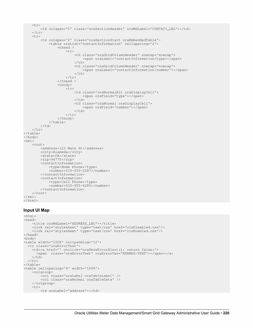
Oracle Utilities Meter Data Management/Smart Grid Gateway Administrative User Guide • 220
<tr> <td colspan="2" class="oraSectionHeader" oraMdLabel="CONTACT_LBL"></td> </tr> <tr> <td colspan="2" class="oraSectionStart oraEmbeddedTable"> <table oraList="contactInformation" cellspacing="2"> <thead > <tr> <th class="oraGridColumnHeader" nowrap="nowrap"> <span oraLabel="contactInformation/type></span> </th> <th class="oraGridColumnHeader" nowrap="nowrap"> <span oraLabel="contactInformation/number"></span> </th> </tr> </thead > <tbody> <tr> <td class="oraNormalAlt oraDisplayCell"> <span oraField="type"></span> </td> <td class="oraNormal oraDisplayCell"> <span oraField="number"></span> </td> </tr> </tbody> </table> </td> </tr></table></body><xml> <root> <address>123 Main St</address> <city>Alameda</city> <state>CA</state> <zip>94770</zip> <contactInformation> <type>Home Phone</type> <number>510-555-2287</number> </contactInformation> <contactInformation> <type>Cell Phone</type> <number>510-555-4285</number> </contactInformation> </root></xml></html>
Input UI Map<html><head> <title oraMdLabel="ADDRESS_LBL"></title> <link rel="stylesheet" type="text/css" href="cisDisabled.css"/> <link rel="stylesheet" type="text/css" href="cisEnabled.css"/></head><body><table width="100%" cellpadding="12"> <tr class="oraErrorText"> <td><a href="" onclick="oraShowErrorAlert(); return false;"> <span class="oraErrorText" oraErrorVar="ERRMSG-TEXT"></span></a> </td> </tr></table><table cellspacing="4" width="100%"> <colgroup> <col class="oraLabel oraTableLabel" /> <col class="oraNormal oraTableData" /> </colgroup> <tr> <td oraLabel="address"></td>
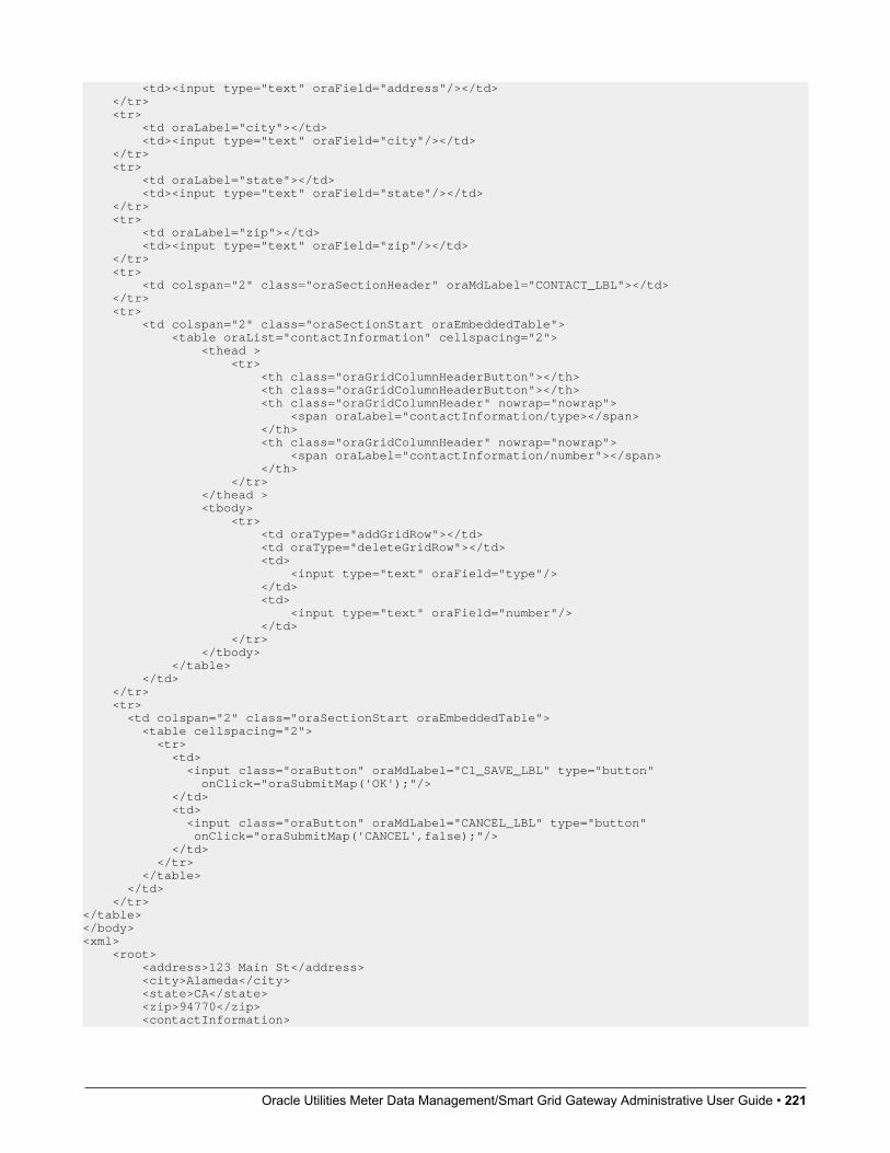
Oracle Utilities Meter Data Management/Smart Grid Gateway Administrative User Guide • 221
<td><input type="text" oraField="address"/></td> </tr> <tr> <td oraLabel="city"></td> <td><input type="text" oraField="city"/></td> </tr> <tr> <td oraLabel="state"></td> <td><input type="text" oraField="state"/></td> </tr> <tr> <td oraLabel="zip"></td> <td><input type="text" oraField="zip"/></td> </tr> <tr> <td colspan="2" class="oraSectionHeader" oraMdLabel="CONTACT_LBL"></td> </tr> <tr> <td colspan="2" class="oraSectionStart oraEmbeddedTable"> <table oraList="contactInformation" cellspacing="2"> <thead > <tr> <th class="oraGridColumnHeaderButton"></th> <th class="oraGridColumnHeaderButton"></th> <th class="oraGridColumnHeader" nowrap="nowrap"> <span oraLabel="contactInformation/type></span> </th> <th class="oraGridColumnHeader" nowrap="nowrap"> <span oraLabel="contactInformation/number"></span> </th> </tr> </thead > <tbody> <tr> <td oraType="addGridRow"></td> <td oraType="deleteGridRow"></td> <td> <input type="text" oraField="type"/> </td> <td> <input type="text" oraField="number"/> </td> </tr> </tbody> </table> </td> </tr> <tr> <td colspan="2" class="oraSectionStart oraEmbeddedTable"> <table cellspacing="2"> <tr> <td> <input class="oraButton" oraMdLabel="C1_SAVE_LBL" type="button" onClick="oraSubmitMap('OK');"/> </td> <td> <input class="oraButton" oraMdLabel="CANCEL_LBL" type="button" onClick="oraSubmitMap('CANCEL',false);"/> </td> </tr> </table> </td> </tr></table></body><xml> <root> <address>123 Main St</address> <city>Alameda</city> <state>CA</state> <zip>94770</zip> <contactInformation>
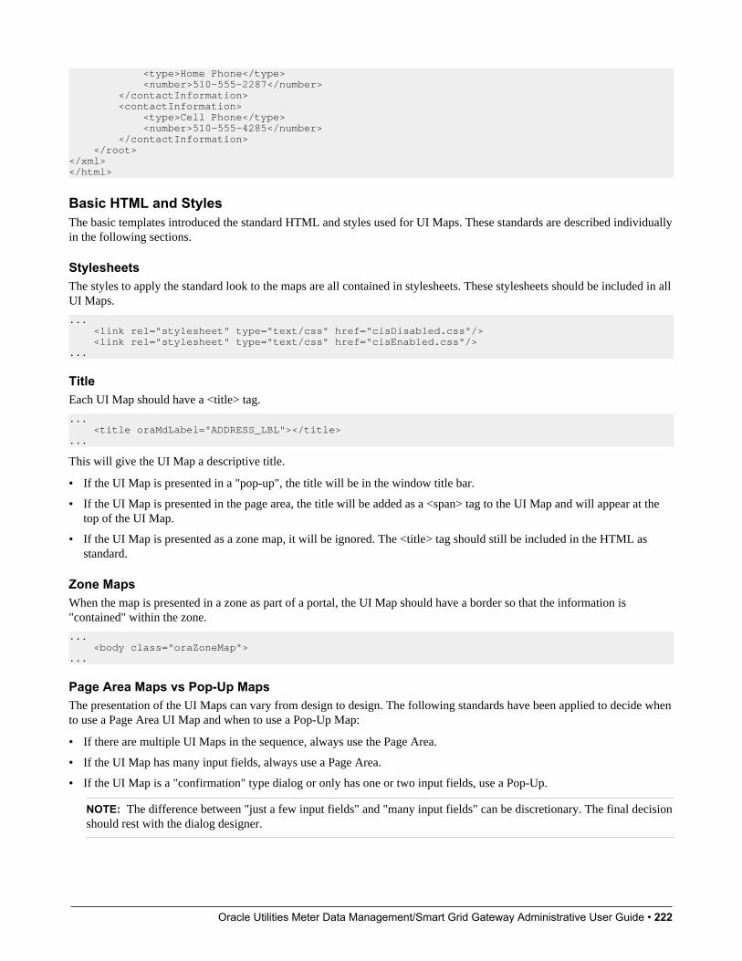
Oracle Utilities Meter Data Management/Smart Grid Gateway Administrative User Guide • 222
<type>Home Phone</type> <number>510-555-2287</number> </contactInformation> <contactInformation> <type>Cell Phone</type> <number>510-555-4285</number> </contactInformation> </root></xml></html>
Basic HTML and StylesThe basic templates introduced the standard HTML and styles used for UI Maps. These standards are described individuallyin the following sections.
StylesheetsThe styles to apply the standard look to the maps are all contained in stylesheets. These stylesheets should be included in allUI Maps.
... <link rel="stylesheet" type="text/css" href="cisDisabled.css"/> <link rel="stylesheet" type="text/css" href="cisEnabled.css"/>...
TitleEach UI Map should have a <title> tag.
... <title oraMdLabel="ADDRESS_LBL"></title>...
This will give the UI Map a descriptive title.
• If the UI Map is presented in a "pop-up", the title will be in the window title bar.
• If the UI Map is presented in the page area, the title will be added as a <span> tag to the UI Map and will appear at thetop of the UI Map.
• If the UI Map is presented as a zone map, it will be ignored. The <title> tag should still be included in the HTML asstandard.
Zone MapsWhen the map is presented in a zone as part of a portal, the UI Map should have a border so that the information is"contained" within the zone.
... <body class="oraZoneMap">...
Page Area Maps vs Pop-Up MapsThe presentation of the UI Maps can vary from design to design. The following standards have been applied to decide whento use a Page Area UI Map and when to use a Pop-Up Map:
• If there are multiple UI Maps in the sequence, always use the Page Area.
• If the UI Map has many input fields, always use a Page Area.
• If the UI Map is a "confirmation" type dialog or only has one or two input fields, use a Pop-Up.
NOTE: The difference between "just a few input fields" and "many input fields" can be discretionary. The final decisionshould rest with the dialog designer.
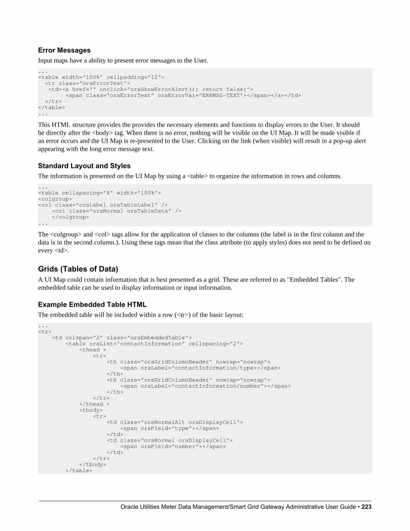
Oracle Utilities Meter Data Management/Smart Grid Gateway Administrative User Guide • 223
Error MessagesInput maps have a ability to present error messages to the User.
...<table width="100%" cellpadding="12"> <tr class="oraErrorText"> <td><a href="" onclick="oraShowErrorAlert(); return false;"> <span class="oraErrorText" oraErrorVar="ERRMSG-TEXT"></span></a></td> </tr></table>...
This HTML structure provides the provides the necessary elements and functions to display errors to the User. It shouldbe directly after the <body> tag. When there is no error, nothing will be visible on the UI Map. It will be made visible ifan error occurs and the UI Map is re-presented to the User. Clicking on the link (when visible) will result in a pop-up alertappearing with the long error message text.
Standard Layout and StylesThe information is presented on the UI Map by using a <table> to organize the information in rows and columns.
... <table cellspacing="4" width="100%"><colgroup><col class="oraLabel oraTableLabel" /> <col class="oraNormal oraTableData" /> </colgroup>...
The <colgroup> and <col> tags allow for the application of classes to the columns (the label is in the first column and thedata is in the second column.). Using these tags mean that the class attribute (to apply styles) does not need to be defined onevery <td>.
Grids (Tables of Data)A UI Map could contain information that is best presented as a grid. These are referred to as "Embedded Tables". Theembedded table can be used to display information or input information.
Example Embedded Table HTMLThe embedded table will be included within a row (<tr>) of the basic layout:
...<tr> <td colspan="2" class="oraEmbeddedTable"> <table oraList="contactInformation" cellspacing="2"> <thead > <tr> <th class="oraGridColumnHeader" nowrap="nowrap"> <span oraLabel="contactInformation/type></span> </th> <th class="oraGridColumnHeader" nowrap="nowrap"> <span oraLabel="contactInformation/number"></span> </th> </tr> </thead > <tbody> <tr> <td class="oraNormalAlt oraDisplayCell"> <span oraField="type"></span> </td> <td class="oraNormal oraDisplayCell"> <span oraField="number"></span> </td> </tr> </tbody> </table>
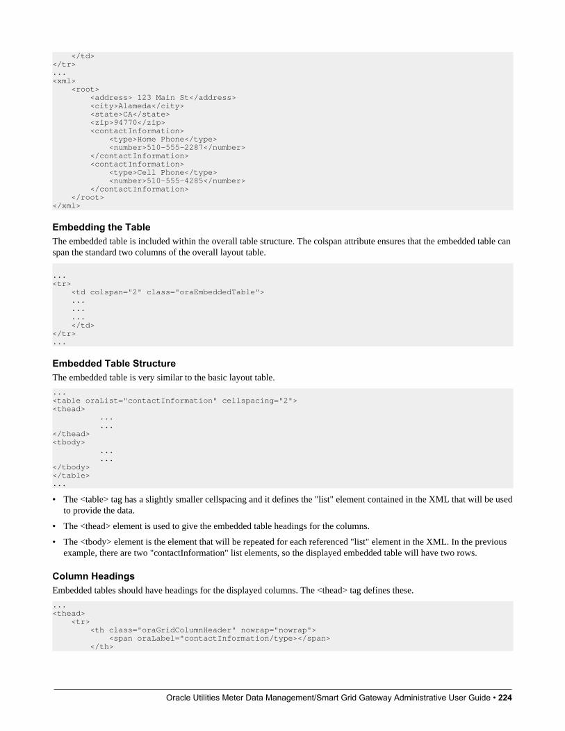
Oracle Utilities Meter Data Management/Smart Grid Gateway Administrative User Guide • 224
</td></tr>...<xml> <root> <address> 123 Main St</address> <city>Alameda</city> <state>CA</state> <zip>94770</zip> <contactInformation> <type>Home Phone</type> <number>510-555-2287</number> </contactInformation> <contactInformation> <type>Cell Phone</type> <number>510-555-4285</number> </contactInformation> </root></xml>
Embedding the TableThe embedded table is included within the overall table structure. The colspan attribute ensures that the embedded table canspan the standard two columns of the overall layout table.
...<tr> <td colspan="2" class="oraEmbeddedTable"> ... ... ... </td></tr>...
Embedded Table StructureThe embedded table is very similar to the basic layout table.
...<table oraList="contactInformation" cellspacing="2"><thead> ... ...</thead><tbody> ... ...</tbody></table>...
• The <table> tag has a slightly smaller cellspacing and it defines the "list" element contained in the XML that will be usedto provide the data.
• The <thead> element is used to give the embedded table headings for the columns.
• The <tbody> element is the element that will be repeated for each referenced "list" element in the XML. In the previousexample, there are two "contactInformation" list elements, so the displayed embedded table will have two rows.
Column HeadingsEmbedded tables should have headings for the displayed columns. The <thead> tag defines these.
...<thead> <tr> <th class="oraGridColumnHeader" nowrap="nowrap"> <span oraLabel="contactInformation/type></span> </th>

Oracle Utilities Meter Data Management/Smart Grid Gateway Administrative User Guide • 225
<th class="oraGridColumnHeader" nowrap="nowrap"> <span oraLabel="contactInformation/number"></span> </th> </tr></thead>...
The "nowrap" attribute prevent the column heading from taking multiples lines. If multiples lines are required, the "nowrap"may be removed.
Input FieldsEmbedded tables may be used for input as well as display only. The framework provides a convenient control to assist inthe creation of editable embedded tables.
...<tr> <td colspan="2" class="oraEmbeddedTable"> <table oraList="contactInformation" cellspacing="2"> <thead > <tr> <th class="oraGridColumnHeaderButton"></th> <th class="oraGridColumnHeaderButton"></th> <th class="oraGridColumnHeader" nowrap="nowrap"> <span oraLabel="contactInformation/type></span> </th> <th class="oraGridColumnHeader" nowrap="nowrap"> <span oraLabel="contactInformation/number"></span> </th> </tr> </thead > <tbody> <tr> <td oraType="addGridRow"></td> <td oraType="deleteGridRow"></td> <td> <input type="text" oraField="type"/> </td> <td> <input type="text" oraField="number"/> </td> </tr> </tbody> </table> </td></tr>...
There are two new columns added to the input embedded table.
• oraType="addGridRow" will add a "+" button to the row. This will allow the User to add an additional row to theexisting grid.
• oraType="deleteGridRow" will add a "-" button to the row. This will allow the User to delete an existing row from thegrid.
NOTE: The <thead> tag also requires these two new columns to be added.
These controls are, as standard, placed at the beginning of the row in the order shown. Either of the controls may be omittedif required (if, for example, Users are not permitted to delete information).
The presence of either of these controls will activate the "empty list" process. This means that if the XML has no data forthe "list" specified, the input grid will display with an empty row ready for the input of new information.
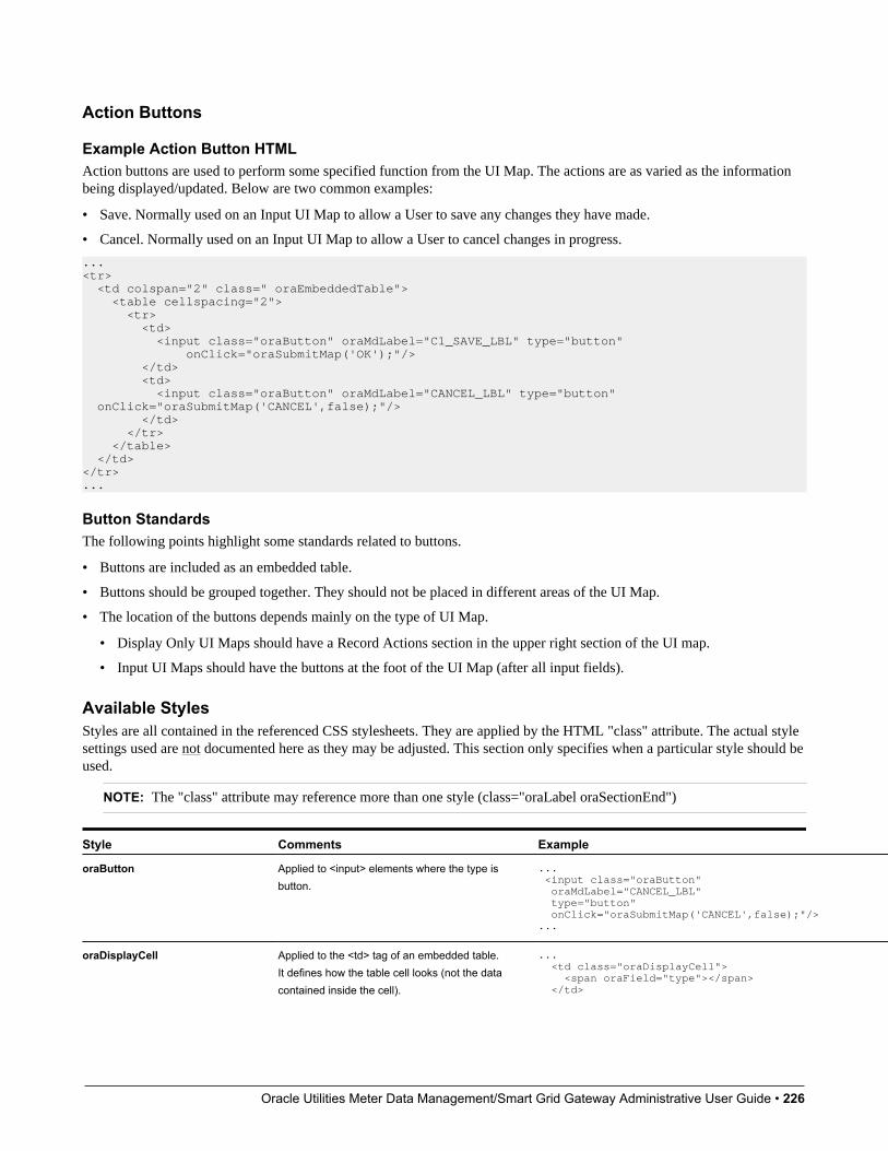
Oracle Utilities Meter Data Management/Smart Grid Gateway Administrative User Guide • 226
Action Buttons
Example Action Button HTMLAction buttons are used to perform some specified function from the UI Map. The actions are as varied as the informationbeing displayed/updated. Below are two common examples:
• Save. Normally used on an Input UI Map to allow a User to save any changes they have made.
• Cancel. Normally used on an Input UI Map to allow a User to cancel changes in progress.
...<tr> <td colspan="2" class=" oraEmbeddedTable"> <table cellspacing="2"> <tr> <td> <input class="oraButton" oraMdLabel="C1_SAVE_LBL" type="button" onClick="oraSubmitMap('OK');"/> </td> <td> <input class="oraButton" oraMdLabel="CANCEL_LBL" type="button" onClick="oraSubmitMap('CANCEL',false);"/> </td> </tr> </table> </td></tr>...
Button StandardsThe following points highlight some standards related to buttons.
• Buttons are included as an embedded table.
• Buttons should be grouped together. They should not be placed in different areas of the UI Map.
• The location of the buttons depends mainly on the type of UI Map.
• Display Only UI Maps should have a Record Actions section in the upper right section of the UI map.
• Input UI Maps should have the buttons at the foot of the UI Map (after all input fields).
Available StylesStyles are all contained in the referenced CSS stylesheets. They are applied by the HTML "class" attribute. The actual stylesettings used are not documented here as they may be adjusted. This section only specifies when a particular style should beused.
NOTE: The "class" attribute may reference more than one style (class="oraLabel oraSectionEnd")
Style Comments Example
oraButton Applied to <input> elements where the type isbutton.
... <input class="oraButton" oraMdLabel="CANCEL_LBL" type="button" onClick="oraSubmitMap('CANCEL',false);"/>...
oraDisplayCell Applied to the <td> tag of an embedded table.It defines how the table cell looks (not the datacontained inside the cell).
... <td class="oraDisplayCell"> <span oraField="type"></span> </td>
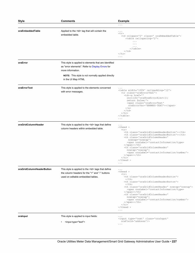
Oracle Utilities Meter Data Management/Smart Grid Gateway Administrative User Guide • 227
Style Comments Example...
oraEmbeddedTable Applied to the <td> tag that will contain theembedded table.
...<tr> <td colspan="2" class=" oraEmbeddedTable"> <table cellspacing="2"> ... ... ... </table> </td></tr>...
oraError This style is applied to elements that are identifiedas "error elements". Refer to Display Errors formore information.
NOTE: This style is not normally applied directlyin the UI Map HTML
oraErrorText This style is applied to the elements concernedwith error messages.
...<table width="100%" cellpadding="12"> <tr class="oraErrorText"> <td><a href="" onclick="oraShowErrorAlert(); return false;"> <span class="oraErrorText" oraErrorVar="ERRMSG-TEXT"></span> </a> </td> </tr></table>...
oraGridColumnHeader This style is applied to the <td> tags that definecolumn headers within embedded table.
...<thead > <tr> <th class="oraGridColumnHeaderButton"></th> <th class="oraGridColumnHeaderButton"></th> <th class="oraGridColumnHeader" nowrap="nowrap"> <span oraLabel="contactInformation/type> </span></th> <th class="oraGridColumnHeader" nowrap="nowrap"> <span oraLabel="contactInformation/number"> </span></th> </tr></thead >...
oraGridColumnHeaderButton This style is applied to the <td> tags that definethe column headers for the "+" and "-" buttonsused on editable embedded tables.
...<thead > <tr> <th class="oraGridColumnHeaderButton"> </th> <th class="oraGridColumnHeaderButton"> </th> <th class="oraGridColumnHeader" nowrap="nowrap"> <span oraLabel="contactInformation/type> </span></th> <th class="oraGridColumnHeader" nowrap="nowrap"> <span oraLabel="contactInformation/number"> </span></th> </tr></thead >...
oraInput This style is applied to input fields:
• <input type="text">
...<input type="text" class="oraInput" oraField="address"/>...
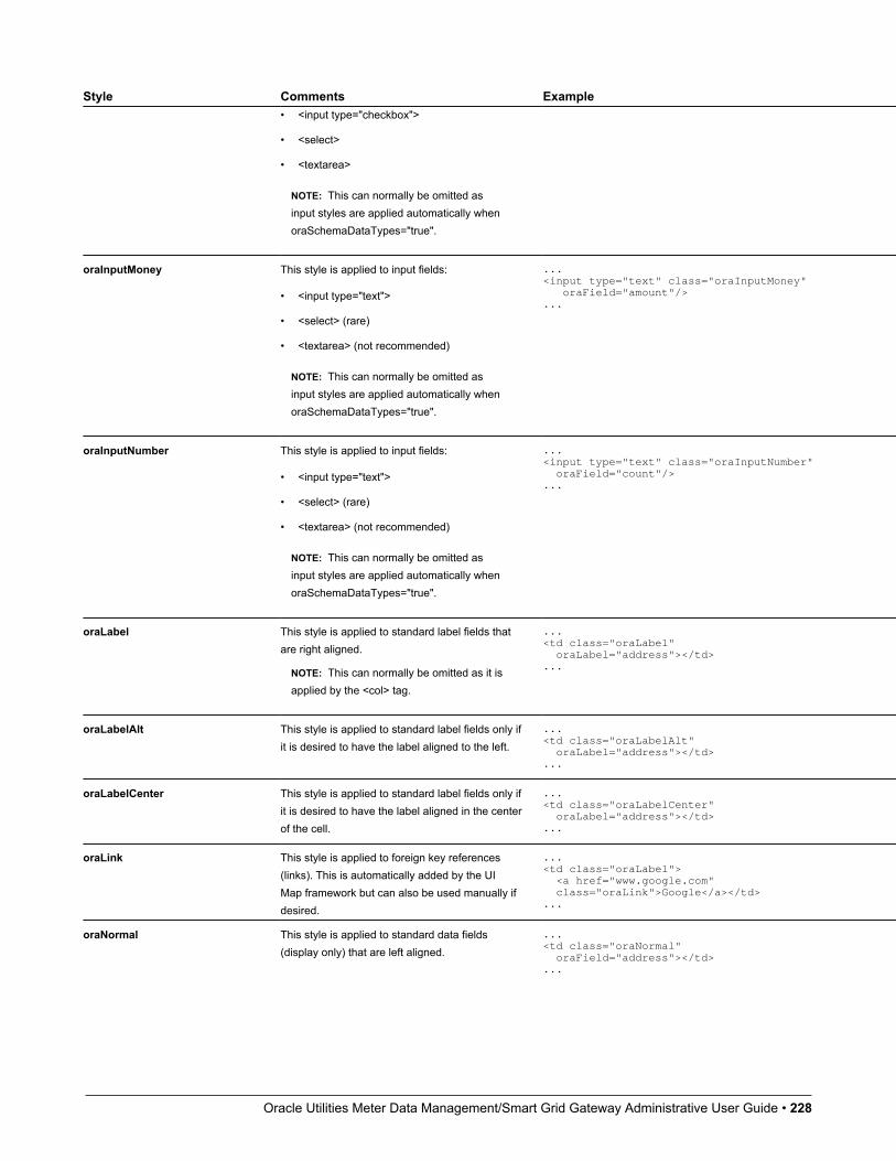
Oracle Utilities Meter Data Management/Smart Grid Gateway Administrative User Guide • 228
Style Comments Example• <input type="checkbox">
• <select>
• <textarea>
NOTE: This can normally be omitted asinput styles are applied automatically whenoraSchemaDataTypes="true".
oraInputMoney This style is applied to input fields:
• <input type="text">
• <select> (rare)
• <textarea> (not recommended)
NOTE: This can normally be omitted asinput styles are applied automatically whenoraSchemaDataTypes="true".
...<input type="text" class="oraInputMoney" oraField="amount"/>...
oraInputNumber This style is applied to input fields:
• <input type="text">
• <select> (rare)
• <textarea> (not recommended)
NOTE: This can normally be omitted asinput styles are applied automatically whenoraSchemaDataTypes="true".
...<input type="text" class="oraInputNumber" oraField="count"/>...
oraLabel This style is applied to standard label fields thatare right aligned.
NOTE: This can normally be omitted as it isapplied by the <col> tag.
...<td class="oraLabel" oraLabel="address"></td>...
oraLabelAlt This style is applied to standard label fields only ifit is desired to have the label aligned to the left.
...<td class="oraLabelAlt" oraLabel="address"></td>...
oraLabelCenter This style is applied to standard label fields only ifit is desired to have the label aligned in the centerof the cell.
...<td class="oraLabelCenter" oraLabel="address"></td>...
oraLink This style is applied to foreign key references(links). This is automatically added by the UIMap framework but can also be used manually ifdesired.
...<td class="oraLabel"> <a href="www.google.com" class="oraLink">Google</a></td>...
oraNormal This style is applied to standard data fields(display only) that are left aligned.
...<td class="oraNormal" oraField="address"></td>...
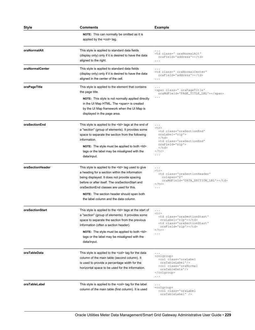
Oracle Utilities Meter Data Management/Smart Grid Gateway Administrative User Guide • 229
Style Comments Example
NOTE: This can normally be omitted as it isapplied by the <col> tag.
oraNormalAlt This style is applied to standard data fields(display only) only if it is desired to have the dataaligned to the right.
...<td class=" oraNormalAlt" oraField="address"></td>...
oraNormalCenter This style is applied to standard data fields(display only) only if it is desired to have the dataaligned in the center of the cell.
...<td class=" oraNormalCenter" oraField="address"></td>...
oraPageTitle This style is applied to the element that containsthe page title.
NOTE: This style is not normally applied directlyin the UI Map HTML. The <span> is createdby the UI Map framework when the UI Map isdisplayed in the page area.
...<span class=" oraPageTitle" oraMdField="PAGE_TITLE_LBL"></span>...
oraSectionEnd This style is applied to the <td> tags at the end ofa "section" (group of elements). It provides somespace to separate the section from the followinginformation.
NOTE: The style must be applied to both <td>tags or the label may be misaligned with thedata/input.
...<tr> <td class="oraSectionEnd" oraLabel="zip"> </td> <td class="oraSectionEnd" oraField="zip"> </td></tr>...
oraSectionHeader This style is applied to the <td> tag used to givea heading for a section within the informationbeing displayed. It does not provide spacingbefore or after itself. The oraSectionStart andoraSectionEnd classes are used for this.
NOTE: The section header should span boththe label column and the data column.
...<tr> <td class="oraSectionHeader" colspan="2" oraMdField="DATA_SECTION_LBL"></td></tr>...
oraSectionStart This style is applied to the <td> tags at the start ofa "section" (group of elements). It provides somespace to separate the section from the previousinformation (often a section header).
NOTE: The style must be applied to both <td>tags or the label may be misaligned with thedata/input.
...<tr> <td class="oraSectionStart" oraLabel="zip"></td> <td class="oraSectionStart" oraField="zip"></td></tr>...
oraTableData This style is applied to the <col> tag for the datacolumn of the main table (second column). Itis used to provide a percentage width for thehorizontal space to be used for the information.
...<colgroup> <col class="oraLabel oraTableLabel"/> <col class="oraNormal oraTableData"/></colgroup>...
oraTableLabel This style is applied to the <col> tag for the labelcolumn of the main table (first column). It is used
...<colgroup> <col class="oraLabel oraTableLabel" />
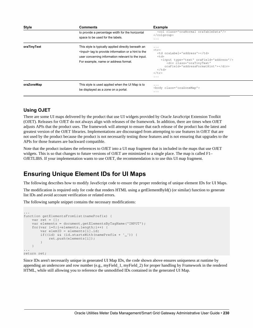
Oracle Utilities Meter Data Management/Smart Grid Gateway Administrative User Guide • 230
Style Comments Exampleto provide a percentage width for the horizontalspace to be used for the labels.
<col class="oraNormal oraTableData"/></colgroup>...
oraTinyText This style is typically applied directly beneath an<input> tag to provide information or a hint to theuser concerning information relevant to the input.For example, name or address format.
...<tr> <td oraLabel="address"></td> <td> <input type="text" oraField="address"/> <div class="oraTinyText" oraField="addressFormatHint"></div> </td></tr>...
oraZoneMap This style is used applied when the UI Map is tobe displayed as a zone on a portal.
...<body class="oraZoneMap">...
Using OJETThere are some UI maps delivered by the product that use UI widgets provided by Oracle JavaScript Extension Toolkit(OJET). Releases for OJET do not always align with releases of the framework. In addition, there are times when OJETadjusts APIs that the product uses. The framework will attempt to ensure that each release of the product has the latest andgreatest version of the OJET libraries. Implementations are discouraged from attempting to use features in OJET that arenot used by the product because the product is not necessarily testing those features and is not ensuring that upgrades to theAPIs for those features are backward compatible.
Note that the product isolates the references to OJET into a UI map fragment that is included in the maps that use OJETwidgets. This is so that changes to future versions of OJET are minimized to a single place. The map is called F1–OJETLIBS. If your implementation wants to use OJET, the recommendation is to use this UI map fragment.
Ensuring Unique Element IDs for UI MapsThe following describes how to modify JavaScript code to ensure the proper rendering of unique element IDs for UI Maps.
The modification is required only for code that renders HTML using a getElementById() (or similar) function to generatelist IDs and avoid account verification or related errors.
The following sample snippet contains the necessary modifications:
...function getElementsFromList(namePrefix) { var ret = []; var elements = document.getElementsByTagName("INPUT"); for(var i=0;i<elements.length;i++) { var elemID = elements[i].id; if((id) && (id.startsWith(namePrefix + '_')) { ret.push(elements[i]); } }...return ret;
Since IDs aren't necessarily unique in generated UI Map IDs, the code shown above ensures uniqueness at runtime byappending an underscore and row number (e.g., myField_1, myField_2) for proper handling by Framework in the renderedHTML, while still allowing you to reference the unmodified IDs contained in the generated UI Map.
Oracle Utilities Meter Data Management/Smart Grid Gateway Administrative User Guide • 231
A switch in the spl.properties file also permits you to disable the generation of unique IDs for elements in a grid (asdescribed below), though, for standards compliance reasons, it is highly recommended that this switch be left at is defaultvalue.
Property Name: spl.runtime.compatibility.uiMapDisableGenerateUniqueHtmlIDsFile Name: spl.properties (under web project in FW)Default Value: falseAccepted Values: true or falseDescription: This property controls the generation of unique IDs for all input elements inside a list. When this value is set to true it disables the generation of unique IDs, thus replicating the old behavior. When this property is set to false or this property is missing it enables the generation of unique IDs, thus enabling the list to be standards-compliant.
Maintaining Managed ContentThe Managed Content maintenance object is used to store content such as XSL files used to create vector charts, JavaScriptinclude files, and CSS files. These files may then be maintained in the same manner as the HTML in UI Maps.
The topics in this section describe the Managed Content portal.
Managed Content - MainThis page is used to define basic information about the content. Open this page using Admin > System > ManagedContent.
Description of Page
Enter a unique name for the content in the Managed Content field.
Owner indicates if the content is owned by the base package or by your implementation.
Use Managed Content Type to indicate the type of content, for example, XSLT or JavaScript.
Enter a Description.
Use the Detailed Description to describe in detail how this map is used.
Managed Content - SchemaThis page is used to create and maintain the managed content. Open this page using Admin > System > Managed Contentand then navigate to the Schema tab.
Description of Page
The General Information zone displays the main attributes of the content. The Editor zone allows you to edit the content.
Data AreasThe data area has no business purpose other than to provide a common schema location for re-used schema structures.It exists solely to help eliminate redundant element declaration. For example, if you have multiple schemas that share acommon structure, you can set up a stand-alone data area schema for the common elements and then include it in each ofthe other schemas.
Be aware that a stand-alone data area can hold elements that are mapped to true fields. For example, you might have 50different types of field activities and all might share a common set of elements to identify where and when the activityshould take place. It would be wise to declare the elements that are common for all in a stand-alone data area and theninclude it in the 50 field activity business objects.

Oracle Utilities Meter Data Management/Smart Grid Gateway Administrative User Guide • 232
It's strongly recommended that you take advantage of stand-alone data areas to avoid redundant data definition!
CAUTION: Dynamic inclusion! When the system renders a schema, all schemas included within it are expandedreal-time. This means that any change you make to a data area will take effect immediately within all schemas it isreferenced within.
NOTE:Schema Tips. The data area page includes a speical Schema Tips zone that provides a link to launch help topics relatedto the Advanced Schema Topics help in one click.
Data areas may be included in a business object that does not define a full UI map for display or input. Rather, it is usingauto-rendering by defining UI attributes in its schema and via UI hints.
NOTE: View UI Rendering. A context sensitive "View UI Rendering" zone appears on this page. It may be used for adata area that is part of a business object that is using auto-rendering for the display and input maps. The buttons allowyou to view the rendered UI for the segment of the schema that is defined by the data area.
Defining Data AreasThe topics in this section describe how to maintain Data Areas.
Data Area - MainUse this page to define basic information about a data area. Open this page using Admin > System > Data Area.
Description of Page
Enter a unique Data Area name and Description. Use the Detailed Description to describe what this data area defines indetail. Owner indicates if the data area is owned by the base package or by your implementation (Customer Modification).
CAUTION: Important! If you introduce a new data area, carefully consider its naming convention. Refer to SystemData Naming Convention for more information.
Click the View Schema to view the data area's expanded schema definition. Doing this opens the schema viewer window.
Click the View XSD hyperlink to view the business object's expanded schema definition in XSD format.
To extend another data area, reference that data area in the Extended Data Area field. By extending a data area you canadd additional elements to a base product data area.
Here's an example of an extended data area:
• The product releases with data area A, which contains elements a, b, and c.
• Your implementation creates data area CM-A, which contains element z, and references data area A as the extended dataarea.
• At run time, everywhere data area A is included it will contain elements a, b, c, and z.
Where Used
Follow this link to open the data dictionary to view the tables that reference F1_DATA_AREA.
Oracle Utilities Meter Data Management/Smart Grid Gateway Administrative User Guide • 233
Data Area - SchemaUse this page to maintain a Data Area's schema and to see where the data area is used in the system. Open this page usingAdmin > System > Data Area and then navigate to the Schema tab.
Description of Page
The contents of this section describe the zones that are available on this portal.
The General Information zone displays the main attributes of the data area.
The Schema Designer zone allows you to edit the data area's schema. The purpose of the schema is to describe the structureand elements of the data area.
FASTPATH: Refer to Schema Syntax and UI Hint syntax for a complete list of the XML nodes and attributes availableto you when you construct a schema. Also note that the Schema Tips zone in the dashboard provides links to launchthese help topics directly.
NOTE: View UI Rendering. A context sensitive "View UI Rendering" zone is associated with this page. The zoneis useful for data areas that are to be included in business objects that define the user interface detail using schemaattributes and UI Hints. The buttons allow you to view the automatically rendered display and input maps.
The Schema Usage Tree zone summarizes all cross-references to this schema. These may be other schemas, scripts, andweb services. For each type of referencing entity, the tree displays a summary node showing a total count of referencingitems. The summary node appears if at least one referencing item exists. Expand the node to list the referencing items anduse their description to navigate to their corresponding pages.
Advanced Schema TopicsThe topics in this section describe some advanced information related to schemas used for business objects, businessservices, service scripts and UI maps.
Schema Nodes and AttributesFor business object definition, the purpose of the schema is to create a link between the schema and a maintenance object.For business service definition you are specifying the link between the schema and a service (either a general service, searchservice, or a maintenance object service). For service script definition, you are defining the API for passing information toand from the script. The following documentation is a complete list of the XML nodes and attributes available to you whenyou construct a schema.

Oracle Utilities Meter Data Management/Smart Grid Gateway Administrative User Guide • 234
ContentsThe Four Element TypesThe Data Type of a Field ElementReferencing Other ElementsStandard Time ConsiderationsThe Mapping AttributesDescriptive AttributesSchema ConstantsDefaulting and System VariablesThe Flattening Nodes and AttributesSearch ZoneExtend Security for Service ScriptOverriding Action for a Business ServiceSpecifying searchBy for a Search ServiceIncluding Other SchemasCompatibility Attributes
The Four Element TypesA schema element can be one of four different structure types. Note that there are two classes of element types: thestructural nodes group and list, and the data containing nodes of field and raw.
Mnemonic Valid Values Description Examples
"field" The field type is the default typefor any element not explicitlylabeled as something other thana field. Therefore, you virtuallynever have to explicitly label anelement as a field. Note that afield element, unlike group orlist, will contain information in itsnodes - rather than other nodes.
"group" The group element is typically astructural element of the schemaonly, in which case it has nomapping.
Note that when grouping severalelements that are all used to mapan XML structure of a CLOB /XML field of a business objectdriven record, the mapping maybe at the group level.
Example where a group is usedto create a structure
<schema> <input type="group" <userId/> </input> <output type="group"> <firstName/> <lastName/> </output></schema>
Example where the groupincludes the mapping:
<parameters type="group" mapXML="BO_DATA_AREA" mdField="F1_TODOSUMEMAIL_PARM_LBL"/> <numberOfDays mdField="F1_NBR_DAYS" required="true"/> <frequency mdField="F1_FREQUENCY"/>
type=
"list" The list node is structural nodelike the group node. The onlydifference is that the list structure
Example of a schema with a list:
<schema> <statesList type="list">
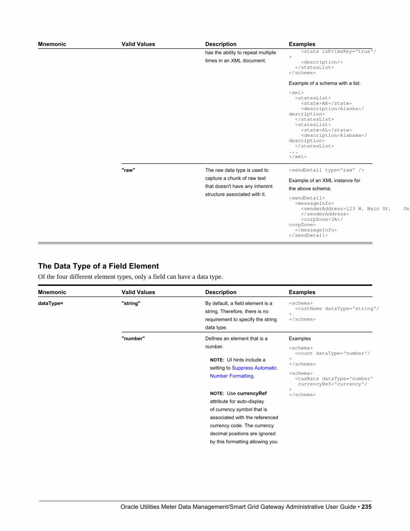
Oracle Utilities Meter Data Management/Smart Grid Gateway Administrative User Guide • 235
Mnemonic Valid Values Description Exampleshas the ability to repeat multipletimes in an XML document.
<state isPrimeKey="true"/> <description/> </statesList></schema>
Example of a schema with a list:
<xml> <statesList> <state>AK</state> <description>Alaska</description> </statesList> <statesList> <state>AL</state> <description>Alabama</description> </statesList>...</xml>
"raw" The raw data type is used tocapture a chunk of raw textthat doesn't have any inherentstructure associated with it.
<sendDetail type="raw" />
Example of an XML instance forthe above schema:
<sendDetail> <messageInfo> <senderAddress>123 W. Main St, Ontario, CA </senderAddress> <corpZone>3A</corpZone> </messageInfo></sendDetail>
The Data Type of a Field ElementOf the four different element types, only a field can have a data type.
Mnemonic Valid Values Description Examples
"string" By default, a field element is astring. Therefore, there is norequirement to specify the stringdata type.
<schema> <custName dataType="string"/></schema>
dataType=
"number" Defines an element that is anumber.
NOTE: UI hints include asetting to Suppress AutomaticNumber Formatting.
NOTE: Use currencyRefattribute for auto-displayof currency symbol that isassociated with the referencedcurrency code. The currencydecimal positions are ignoredby this formatting allowing you
Examples
<schema> <count dataType="number"/></schema>
<schema> <taxRate dataType="number" currencyRef="currency"/></schema>
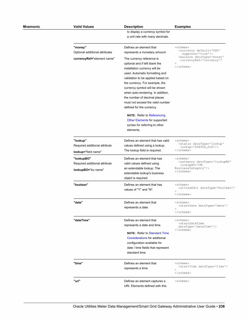
Oracle Utilities Meter Data Management/Smart Grid Gateway Administrative User Guide • 236
Mnemonic Valid Values Description Examplesto display a currency symbol fora unit rate with many decimals.
"money"Optional additional attributes
currencyRef="element name"
Defines an element thatrepresents a monetary amount.
The currency reference isoptional and if left blank theinstallation currency will beused. Automatic formatting andvalidation to be applied based onthe currency. For example, thecurrency symbol will be shownwhen auto-rendering. In addition,the number of decimal placesmust not exceed the valid numberdefined for the currency.
NOTE: Refer to ReferencingOther Elements for supportedsyntax for referring to otherelements.
<schema> <currency default="USD" suppress="true"/> <balance dataType="money" currencyRef="currency"/></schema>
"lookup"Required additional attribute
lookup="field name"
Defines an element that has validvalues defined using a lookup.The lookup field is required.
<schema> <status dataType="lookup" lookup="STATUS_FLG"/></schema>
"lookupBO"Required additional attribute
lookupBO="bo name"
Defines an element that hasvalid values defined usingan extendable lookup. Theextendable lookup's businessobject is required.
<schema> <category dataType="lookupBO" lookupBO="CM-BusinessCategory"/></schema>
"boolean" Defines an element that hasvalues of "Y" and "N".
<schema> <allowsEdit dataType="boolean"/></schema>
"date" Defines an element thatrepresents a date.
<schema> <startDate dataType="date"/></schema>
"dateTime" Defines an element thatrepresents a date and time.
NOTE: Refer to Standard TimeConsiderations for additionalconfiguration available fordate / time fields that representstandard time.
<schema> <startDateTime dataType="dateTime"/></schema>
"time" Defines an element thatrepresents a time.
<schema> <startTime dataType="time"/></schema>
"uri" Defines an element captures aURI. Elements defined with this
<schema>

Oracle Utilities Meter Data Management/Smart Grid Gateway Administrative User Guide • 237
Mnemonic Valid Values Description Examplestype enable the support for URIWhitelist and Substitution asdescribed in Referencing URIs .
<exportDirectory dataType="uri"/></schema>
Referencing Other ElementsThere are several attributes that allow for a reference to another element in the same schema. The supported syntax of theXPath reference is the same in every case. This section provides examples using the default reference attribute (defaultRef).
Reference a sibling element:
<schema> <id mapField="ACCT_ID" required="true"/> <altId defaultRef="id" required="true"/></schema>
Reference an element in a higher group:
<schema> <id mapField="ACCT_ID" required="true"/> <msgInfo type="group" mapXML="XML_FIELD"> <altId defaultRef="../id" required="true"/> </msgInfo></schema>
Reference an element in a lower group:
<schema> <id mapField="ACCT_ID" defaultRef="msgInfo/altId" required="true"/> <msgInfo type="group" mapXML="XML_FIELD"> <altId required="true"/> </msgInfo></schema>
Reference an element in another group:
<schema> <acctInfo type="group"> <id mapField="ACCT_ID" required="true"/> </acctInfo> <msgInfo type="group" mapXML="XML_FIELD"> <altId defaultRef="../acctInfo/altId" required="true"/> </msgInfo></schema>
Standard Time ConsiderationsMost date / time fields represent "legal" time such that if a time zone changes their clocks for winter and summer time, thedate / time field captures the current observed time. However, some date / time fields should always be captured in standardtime to avoid confusion / ambiguity. A good example is a date and time related to detailed interval data.
When defining an element with dataType="dateTime", you may optionally configure stdTime="true" indicating thatdata captured in the element always represents standard time in the 'base' time zone. The 'base' time zone is specified on theInstallation options.
NOTE: If an element is mapped to a table / field with a Standard Time Type of Physical, then stdTime="true" isimplied. Refer to Table / Field for more information.
Example:
<schema> <startTime dataType="Time" stdTime="true"/></schema>
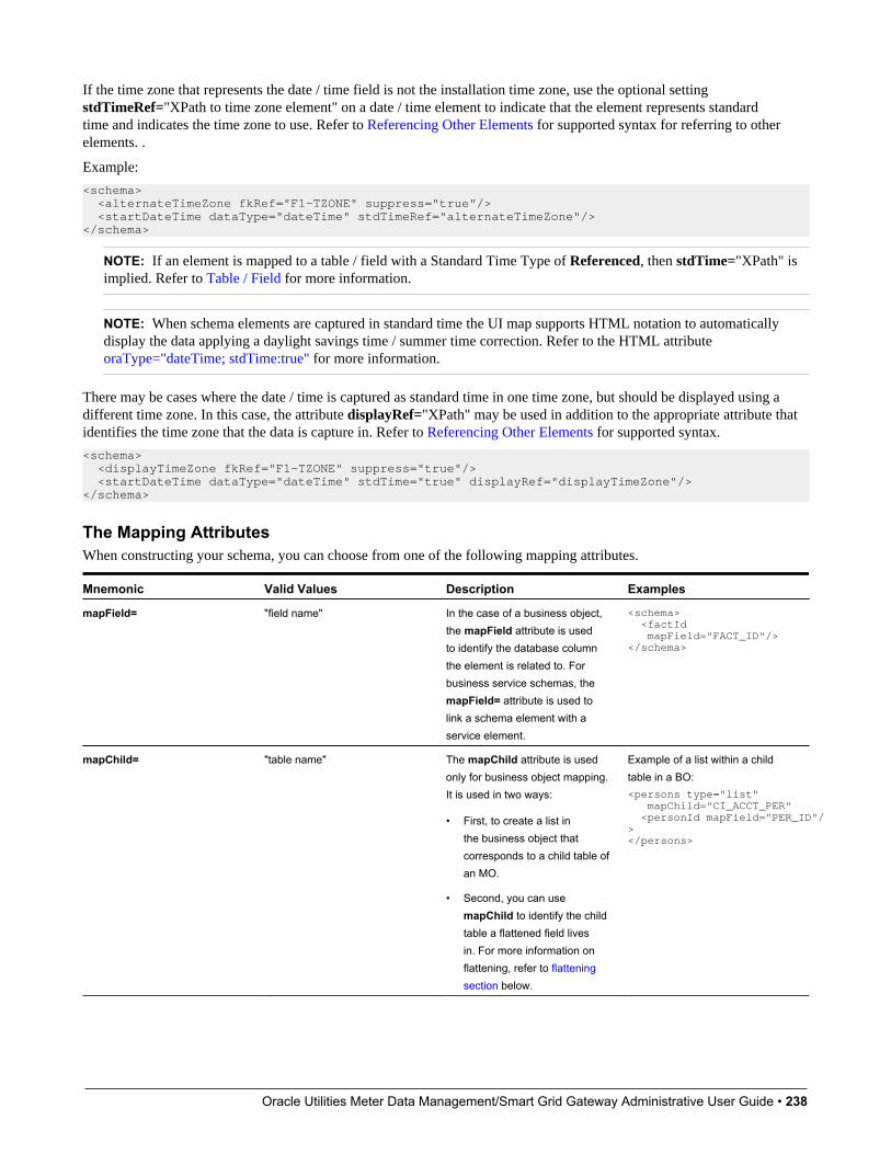
Oracle Utilities Meter Data Management/Smart Grid Gateway Administrative User Guide • 238
If the time zone that represents the date / time field is not the installation time zone, use the optional settingstdTimeRef="XPath to time zone element" on a date / time element to indicate that the element represents standardtime and indicates the time zone to use. Refer to Referencing Other Elements for supported syntax for referring to otherelements. .
Example:
<schema> <alternateTimeZone fkRef="F1-TZONE" suppress="true"/> <startDateTime dataType="dateTime" stdTimeRef="alternateTimeZone"/></schema>
NOTE: If an element is mapped to a table / field with a Standard Time Type of Referenced, then stdTime="XPath" isimplied. Refer to Table / Field for more information.
NOTE: When schema elements are captured in standard time the UI map supports HTML notation to automaticallydisplay the data applying a daylight savings time / summer time correction. Refer to the HTML attributeoraType="dateTime; stdTime:true" for more information.
There may be cases where the date / time is captured as standard time in one time zone, but should be displayed using adifferent time zone. In this case, the attribute displayRef="XPath" may be used in addition to the appropriate attribute thatidentifies the time zone that the data is capture in. Refer to Referencing Other Elements for supported syntax.
<schema> <displayTimeZone fkRef="F1-TZONE" suppress="true"/> <startDateTime dataType="dateTime" stdTime="true" displayRef="displayTimeZone"/></schema>
The Mapping AttributesWhen constructing your schema, you can choose from one of the following mapping attributes.
Mnemonic Valid Values Description Examples
mapField= "field name" In the case of a business object,the mapField attribute is usedto identify the database columnthe element is related to. Forbusiness service schemas, themapField= attribute is used tolink a schema element with aservice element.
<schema> <factId mapField="FACT_ID"/></schema>
mapChild= "table name" The mapChild attribute is usedonly for business object mapping.It is used in two ways:
• First, to create a list inthe business object thatcorresponds to a child table ofan MO.
• Second, you can usemapChild to identify the childtable a flattened field livesin. For more information onflattening, refer to flatteningsection below.
Example of a list within a childtable in a BO:<persons type="list" mapChild="CI_ACCT_PER" <personId mapField="PER_ID"/></persons>

Oracle Utilities Meter Data Management/Smart Grid Gateway Administrative User Guide • 239
Mnemonic Valid Values Description Examples
mapList= "list name" The mapList attribute is usedonly for business servicemapping. It is used in two ways:
• First, to create a list inthe business service thatcorresponds to a list in theservice.
• Second, you can usemapList to identify the listthat a flattened field livesin. For more information onflattening, refer to flatteningsection below.
Example of a list within abusiness service:<selectList type="list" mapList="DE" <value mapField="COL_VALUE"> <row mapList="DE_VAL"> <SEQNO is="2"/> </row> </value> </selectList>
mapXML= "field name" The mapXML attribute is typicallyused to map XML structures intoa large character / XML field ofthe service. Note that when youuse mapXML to map either a listor group structure (type="list" ortype="group") you don't have tomap all the child elements withinthe structure. It is also possibleto map list elements to a largecharacter field associated withthe list child.
<enrollmentRequest type="group" mapXML="CASE_CLOB"> <messageID/> <sender/></enrollmentRequest><enrollmentKey mapXML="CASE_CLOB"/><enrollmentInfo type="list" mapChild="CI_CASE_CHILD"> <sequence mapField="CHILD_SEQ"/> <name mapXML="CASE_CHILD_CLOB"/> <value mapXML="CASE_CHILD_CLOB"/></enrollmentInfo>
isPrimeKey= "true" You must specify a primary keyfor a list defined within a mappedXML element (type="list"mapXML="CLOB"). The primarykey is used by the framework todetermine whether a list elementadd, update or delete is requiredduring a business object update.
NOTE: You do not need tospecify the prime key for abusiness object list mappedto maintenance object list.When a physical list is mapped,the prime key is derived fromexisting physical meta-data.
<questionnaire type="list" mapXML="CASE_CLOB"> <question isPrimeKey="true"/> <answer/></questionnaire>
orderBy= "XPath asc|desc, XPath asc|desc"
By default, a list definedwithin a mapped XML element(type="list" mapXML="CLOB")is sorted by the first element ofthe list. A different sort order maybe specified using the orderByattribute. The attribute valueis a comma separated list of
<questionnaire type="list" orderBy="page/section, page/sequence" mapXML="CASE_CLOB"><question isPrimeKey="true"/><answer/><page type="group"> <section/> <sequence/></page></questionnaire>

Oracle Utilities Meter Data Management/Smart Grid Gateway Administrative User Guide • 240
Mnemonic Valid Values Description Examplesfield XPaths (relative to the listelement) with an optional sortorder (ascending is the default).
NOTE: This is only availablefor lists mapped as XML withinbusiness objects.
Descriptive AttributesThe following attributes can be used to describe a schema element and provide additional configuration related to theelement. Typically, these attributes are useful for field elements only.
Mnemonic Valid Values Description Examples
<!-- comment --> Use this to add a comment to aschema by using special openand close characters: <!-- and -->.
<schema> <!-- This schema is used to capture business information only, please refer to the 'HUMAN' BO for person information --></schema>
description= "text" The description of an elementmay be used to provide aninternal description of the elementto help a reader of the schema tounderstand the business reasonfor the element.
<schema> <active type="boolean" description="active account" label="Active"/></schema>
label= "text" The label of an element is meantto be a short bit of verbiagethat would typically precede theelement in a user interface.
<schema> <active type="boolean" description="active account" label="Active"/></schema>
required= "true" Used to require the existenceof an element during objectinteraction.
NOTE: For included schemas,the required="true" attributeis not processed on businessobject and business serviceschemas when they areincluded within a service scriptschema. This is to support theability of the service script topopulate required elementsbefore an embedded businessobject or business service isinvoked from the service script.
<schema> <logDate mapField="LOG_DT" default="%CurrentDate" required="true" private="true"</schema>
mdField= "field code" The meta-data field attribute isused to associate an elementwith a field's metadata. The fielddefines data type, as well as its
<schema> <active mdField="CM_ACTIVE_SW"/></schema>
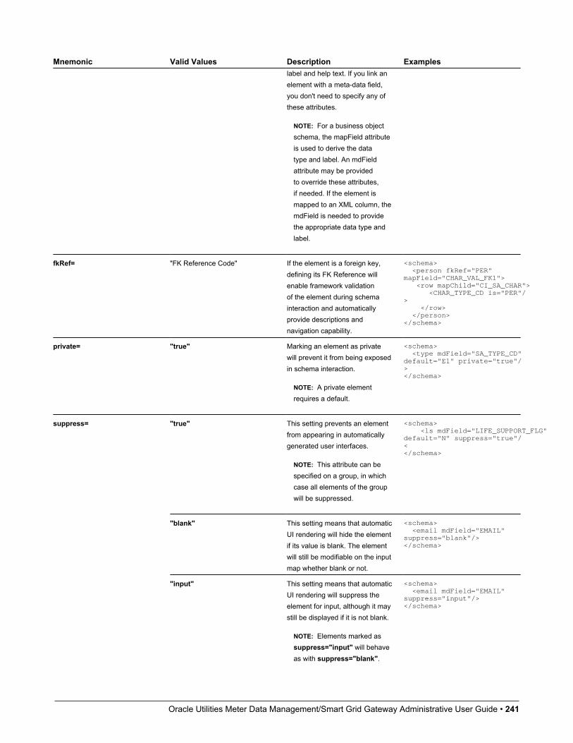
Oracle Utilities Meter Data Management/Smart Grid Gateway Administrative User Guide • 241
Mnemonic Valid Values Description Exampleslabel and help text. If you link anelement with a meta-data field,you don't need to specify any ofthese attributes.
NOTE: For a business objectschema, the mapField attributeis used to derive the datatype and label. An mdFieldattribute may be providedto override these attributes,if needed. If the element ismapped to an XML column, themdField is needed to providethe appropriate data type andlabel.
fkRef= "FK Reference Code" If the element is a foreign key,defining its FK Reference willenable framework validationof the element during schemainteraction and automaticallyprovide descriptions andnavigation capability.
<schema> <person fkRef="PER" mapField="CHAR_VAL_FK1"> <row mapChild="CI_SA_CHAR"> <CHAR_TYPE_CD is="PER"/> </row> </person></schema>
private= "true" Marking an element as privatewill prevent it from being exposedin schema interaction.
NOTE: A private elementrequires a default.
<schema> <type mdField="SA_TYPE_CD" default="E1" private="true"/></schema>
"true" This setting prevents an elementfrom appearing in automaticallygenerated user interfaces.
NOTE: This attribute can bespecified on a group, in whichcase all elements of the groupwill be suppressed.
<schema> <ls mdField="LIFE_SUPPORT_FLG" default="N" suppress="true"/<</schema>
"blank" This setting means that automaticUI rendering will hide the elementif its value is blank. The elementwill still be modifiable on the inputmap whether blank or not.
<schema> <email mdField="EMAIL" suppress="blank"/></schema>
suppress=
"input" This setting means that automaticUI rendering will suppress theelement for input, although it maystill be displayed if it is not blank.
NOTE: Elements marked assuppress="input" will behaveas with suppress="blank".
<schema> <email mdField="EMAIL" suppress="input"/></schema>
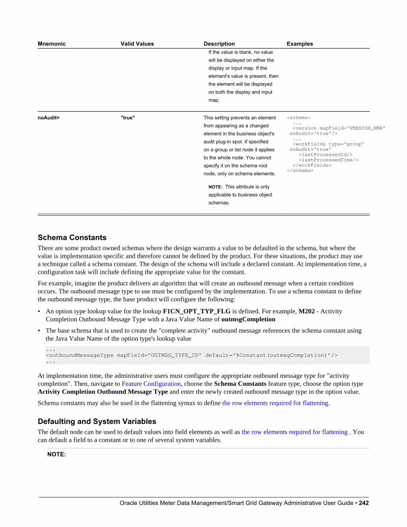
Oracle Utilities Meter Data Management/Smart Grid Gateway Administrative User Guide • 242
Mnemonic Valid Values Description ExamplesIf the value is blank, no valuewill be displayed on either thedisplay or input map. If theelement's value is present, thenthe element will be displayedon both the display and inputmap.
noAudit= "true" This setting prevents an elementfrom appearing as a changedelement in the business object'saudit plug-in spot. If specifiedon a group or list node it appliesto the whole node. You cannotspecify it on the schema rootnode, only on schema elements.
NOTE: This attribute is onlyapplicable to business objectschemas.
<schema> ... <version mapField="VERSION_NBR" noAudit="true"/> ... <workFields type="group" noAudit="true" <lastProcessedId/> <lastProcessedTime/> </workFields></schema>
Schema ConstantsThere are some product owned schemas where the design warrants a value to be defaulted in the schema, but where thevalue is implementation specific and therefore cannot be defined by the product. For these situations, the product may usea technique called a schema constant. The design of the schema will include a declared constant. At implementation time, aconfiguration task will include defining the appropriate value for the constant.
For example, imagine the product delivers an algorithm that will create an outbound message when a certain conditionoccurs. The outbound message type to use must be configured by the implementation. To use a schema constant to definethe outbound message type, the base product will configure the following:
• An option type lookup value for the lookup F1CN_OPT_TYP_FLG is defined. For example, M202 - ActivityCompletion Outbound Message Type with a Java Value Name of outmsgCompletion
• The base schema that is used to create the "complete activity" outbound message references the schema constant usingthe Java Value Name of the option type's lookup value
...<outboundMessageType mapField="OUTMSG_TYPE_CD" default="%Constant(outmsgCompletion)"/>...
At implementation time, the administrative users must configure the appropriate outbound message type for "activitycompletion". Then, navigate to Feature Configuration, choose the Schema Constants feature type, choose the option typeActivity Completion Outbound Message Type and enter the newly created outbound message type in the option value.
Schema constants may also be used in the flattening syntax to define the row elements required for flattening.
Defaulting and System VariablesThe default node can be used to default values into field elements as well as the row elements required for flattening . Youcan default a field to a constant or to one of several system variables.
NOTE:
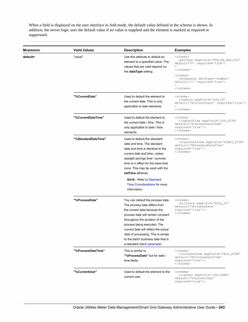
Oracle Utilities Meter Data Management/Smart Grid Gateway Administrative User Guide • 243
When a field is displayed on the user interface in Add mode, the default value defined in the schema is shown. Inaddition, the server logic uses the default value if no value is supplied and the element is marked as required orsuppressed.
Mnemonic Valid Values Description Examples
"value" Use this attribute to default anelement to a specified value. Thevalues that are valid depend onthe dataType setting.
<schema> <perType mapField="PER_OR_BUS_FLG" default="P" required="true"/></schema>
<schema> <frequency dataType="number" default="1" required="true"/></schema>
"%CurrentDate" Used to default the element tothe current date. This is onlyapplicable to date elements.
<schema> <logDate mapField="LOG_DT" default="%CurrentDate" required="true"/></schema>
"%CurrentDateTime" Used to default the element tothe current date / time. This isonly applicable to date / timeelements.
<schema> <logDateTime mapField="LOG_DTTM" default="%CurrentDateTime" required="true"/></schema>
"%StandardDateTime" Used to default the standarddate and time. The standarddate and time is identical to thecurrent date and time, unlessdaylight savings time / summertime is in effect for the base timezone. This may be used with thestdTime attribute.
NOTE: Refer to StandardTime Considerations for moreinformation.
<schema> <startDateTime mapField="START_DTTM" default="%StandardDateTime" required="true"/></schema>
"%ProcessDate" You can default the process date.The process date differs fromthe current date because theprocess date will remain constantthroughout the duration of theprocess being executed. Thecurrent date will reflect the actualdate of processing. This is similarto the batch business date that isa standard batch parameter.
<schema> <billDate mapField="BILL_DT" default="%ProcessDate" required="true"/></schema>
"%ProcessDateTime" This is similar to"%ProcessDate" but for date /time fields.
<schema> <calcDateTime mapField="CALC_DTTM" default="%ProcessDateTime" required="true"/></schema>
default=
"%CurrentUser" Used to default the element to thecurrent user.
<schema> <logUser mapField="LOG_USER" default="%CurrentUser" required="true"/>
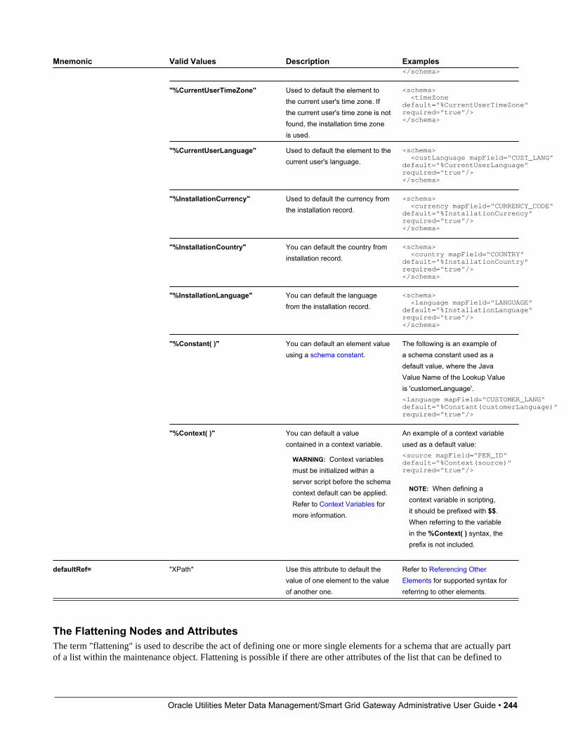
Oracle Utilities Meter Data Management/Smart Grid Gateway Administrative User Guide • 244
Mnemonic Valid Values Description Examples</schema>
"%CurrentUserTimeZone" Used to default the element tothe current user's time zone. Ifthe current user's time zone is notfound, the installation time zoneis used.
<schema> <timeZone default="%CurrentUserTimeZone" required="true"/></schema>
"%CurrentUserLanguage" Used to default the element to thecurrent user's language.
<schema> <custLanguage mapField="CUST_LANG" default="%CurrentUserLanguage" required="true"/></schema>
"%InstallationCurrency" Used to default the currency fromthe installation record.
<schema> <currency mapField="CURRENCY_CODE" default="%InstallationCurrency" required="true"/></schema>
"%InstallationCountry" You can default the country frominstallation record.
<schema> <country mapField="COUNTRY" default="%InstallationCountry" required="true"/></schema>
"%InstallationLanguage" You can default the languagefrom the installation record.
<schema> <language mapField="LANGUAGE" default="%InstallationLanguage" required="true"/></schema>
"%Constant( )" You can default an element valueusing a schema constant.
The following is an example ofa schema constant used as adefault value, where the JavaValue Name of the Lookup Valueis 'customerLanguage'.<language mapField="CUSTOMER_LANG" default="%Constant(customerLanguage)" required="true"/>
"%Context( )" You can default a valuecontained in a context variable.
WARNING: Context variablesmust be initialized within aserver script before the schemacontext default can be applied.Refer to Context Variables formore information.
An example of a context variableused as a default value:<source mapField="PER_ID" default="%Context(source)" required="true"/>
NOTE: When defining acontext variable in scripting,it should be prefixed with $$.When referring to the variablein the %Context( ) syntax, theprefix is not included.
defaultRef= "XPath" Use this attribute to default thevalue of one element to the valueof another one.
Refer to Referencing OtherElements for supported syntax forreferring to other elements.
The Flattening Nodes and AttributesThe term "flattening" is used to describe the act of defining one or more single elements for a schema that are actually partof a list within the maintenance object. Flattening is possible if there are other attributes of the list that can be defined to

Oracle Utilities Meter Data Management/Smart Grid Gateway Administrative User Guide • 245
uniquely describe the element or elements. A common use case for flattening is a characteristic. Rather than defining thecharacteristics of an object using a collection where the user must choose the characteristic type and then define the value,the characteristics are defined as actual elements with the appropriate label already displayed. This technique enables thedesigner of the schema and the user interface to display each separate characteristic in the logical place in the user interfacerather than all lumped together.
NOTE: A flattened element represents a unique row in the database. This row is inserted when the flattened values arecreated. The row is updated when any of the flattened values are changed. The row is deleted when all the flattenedvalues are removed. The behavior of effective dated elements is slightly different - please see Flattening an EffectiveDated List.
NOTE: The flattening feature can also be used to define a list, see Flattened List.
Identifying the List or Child TableWhen flattening a child table, the row node is required to identify the list / child table that the element comes from. Withinthe row node, at least one element must be defined with an is= definition that ensures that the element is a unique row inthe database. It may also define elements or fields in the row that are suppressed and are populated using default valueconfiguration.
• For a business object, the row node defines the child table the flattened field belongs to.
The syntax is <row mapChild="table name">. This example is for the list of persons for an account in the customercare and billing product. One person may be marked as the "main" person. This illustrates how to define an explicitelement for the main person ID to simplify references to that field. It is part of the CI_ACCT_PER child table. Whatmakes it unique is that the MAIN_CUST_SW is true (and only one row may have that value)
<custId mapField="PER_ID" mdField="CM-MainCust"><row mapChild="CI_ACCT_PER"> <MAIN_CUST_SW is="true" /> <ACCT_REL_TYPE_CD default="MAIN" /></row></custId>
NOTE: The above example illustrates that the row node may also define elements within the list that are suppressedand assigned a default value. This syntax is never used to identify a particular row. Note that a default value caneither be a literal string, or a system variable.
• For a business service, the row node identifies the list name the flattened field belongs to.
The syntax is <row mapList="list name">. This example shows two entries from a list being flattened to a field valueand description.
<selectList type="list" mapList="DE"> <value mapField="COL_VALUE"> <row mapList="DE_VAL"> <SEQNO is="2"/> </row> </value> <description mapField="COL_VALUE"> <row mapList="DE_VAL"> <SEQNO is="3"/> </row> </description> </selectList>
Uniquely Identifying the Flattened Field or ListThe is= syntax within a row or rowFilter element is used to uniquely identify the row.

Oracle Utilities Meter Data Management/Smart Grid Gateway Administrative User Guide • 246
Mnemonic Valid Values Description Examples
"value" Use this attribute to reference avalue directly.
<tdTypeCd mapField="CHAR_VAL_FK1"> <row mapChild="F1_EXT_LOOKUP_VAL_CHAR"> <CHAR_TYPE_CD is="CM-TD-TYPE"/> </row></tdTypeCd>
"%Constant( )" You can configure a flattenedelement using a schemaconstant. During a serviceinteraction the value of theschema constant will be used toidentify the flattened element inits child row.
An example of a schemaconstant used in flattening syntaxwhere the Java Value Nameof the Lookup field value is'cmRate'.
<unitRate mapField="CHAR_VAL" dataType="number"> <row mapChild= "F1_EXT_LOOKUP_VAL_CHAR"> <CHAR_TYPE is ="%Constant(cmRate)"/> </row></unitRate>
is=
"%n" The %n substitution value isused to reference a relative listinstance. A relative list instanceis typically used to configure aflattened element for a child tablekeyed by sequence number. Thevalue of n should be a positiveinteger value. During a businessobject read interaction the relativelist instance (position) specifiedby the integer will be returned.
An example with a relativelist instance - where the firstinstance of the row is returned.<schema> <mainPhone mapField="PHONE"> <row mapChild="CI_PER_PHONE"> <PHONE_TYPE_CD is="%Constant(mainPhoneType)"/> <SEQ_NUMis="%1"/> </row> </mainPhone></schema>
FASTPATH: Additional values for is= are used when Flattening an Effective Dated List. Refer to that section for moreinformation.
Flattening a Pre-defined Characteristic TypeIf the flattened field is in a characteristic collection and the characteristic type is a predefined characteristic, automatic UIrendering will generate a dropdown for the list of valid values. For example, the schema below will generate a dropdown forthe Usage element showing the valid values of the Status Reason Usage (F1-SRUSG) characteristic type.
<usage mdField="STATUS_RSN_USAGE" mapField="CHAR_VAL"> <row mapChild="F1_BUS_OBJ_STATUS_RSN_CHAR"> <CHAR_TYPE_CD is="F1-SRUSG"/> <SEQ_NUM is="1"/> </row></usage>
Defining Multiple Elements from the ListWhen attempting to include multiple columns from the same list, the system provide shorthand notation for copying theflattening rules defined on another element so that the flattening rules do not need to be repeated. To do this, the rownode includes the rowRef attribute and it indicates the other element name that defines the mapping information. Thefollowing example illustrates flattening the fields Customer ID and Receives Copy of Bill from the same list of Persons foran Account (where the MAIN_CUST_SW is true ).
<custId mapField="PER_ID"> <row mapChild="CI_ACCT_PER">

Oracle Utilities Meter Data Management/Smart Grid Gateway Administrative User Guide • 247
<MAIN_CUST_SW is="true" /> <ACCT_REL_TYPE_CD default="MAIN" /> </row></custId><copyBill mapField="RECEIVE_COPY_SW" rowRef="custId"/>
Note that the above notation also illustrates that the rowRef may be defined directly in the element's attribute definition.
NOTE: Refer to Referencing Other Elements for supported syntax for referring to other elements.
Flattening Two Layers DeepIf your maintenance object or service has nested lists two layers deep, the system supports flattening and element within aflattened element. This technique also uses the rowRef attribute. The flattening of the second level refers to the flattenedelement of the first level. The following example illustrates flattening a characteristic into an element called legalContactfor the "main" customer. Notice that the legalContact element has two row nodes: one to refer to the flattening informationfor its parent record and one to define its child table
<custId mapField="PER_ID"> <row mapChild="CI_ACCT_PER"> <MAIN_CUST_SW is="true" /> <ACCT_REL_TYPE_CD default="MAIN" /> </row></custId><legalContact mapField="CHAR_VAL_FK1"><row rowRef="custId"> <row mapChild="CI_ACCT_PER_CHAR" > <CHAR_TYPE_CD is="LEGAL" /> </row></row></legalContact>
Note that the above notation also illustrates that the rowRef may be defined as an attribute of a row node rather thandirectly in the element's attribute definition.
Defining a Flattened ListThere are times that a list or child table supports multiple values of the same "type" and these should be presented as a list.To continue with the example above, the list of persons for an account may identify one person as the "main" person. Thisperson has been flattened to a single element (with the account relationship type defaulted and suppressed). To maintainthe other persons related to an account, you can define a list where each row captures the Person Id and the AccountRelationship Type.
Rather than a row node, the flattened list is configured with a rowFilter element. The following schema illustrates thedescribed example. The list node defines the child table. The rowFilter includes the criteria that identify the rows within thetable to include. The elements of the list are defined within the list node outside the rowFilter element.
<custId mapField="PER_ID"> <row mapChild="CI_ACCT_PER"> <MAIN_CUST_SW is="true" /> <ACCT_REL_TYPE_CD default="MAIN" /> </row></custId><miscPersons type="list" mapChild="CI_ACCT_PER"> <rowFilter> <MAIN_CUST_SW is="false" /> </rowFilter> <relType mapField="ACCT_REL_TYPE_CD"/> <personId mapField="PER_ID"/></custId>
Note that the system will validate that if a schema contains flattened single elements and flattened lists from the same childtable, the criteria that defines what makes them unique must be analogous.
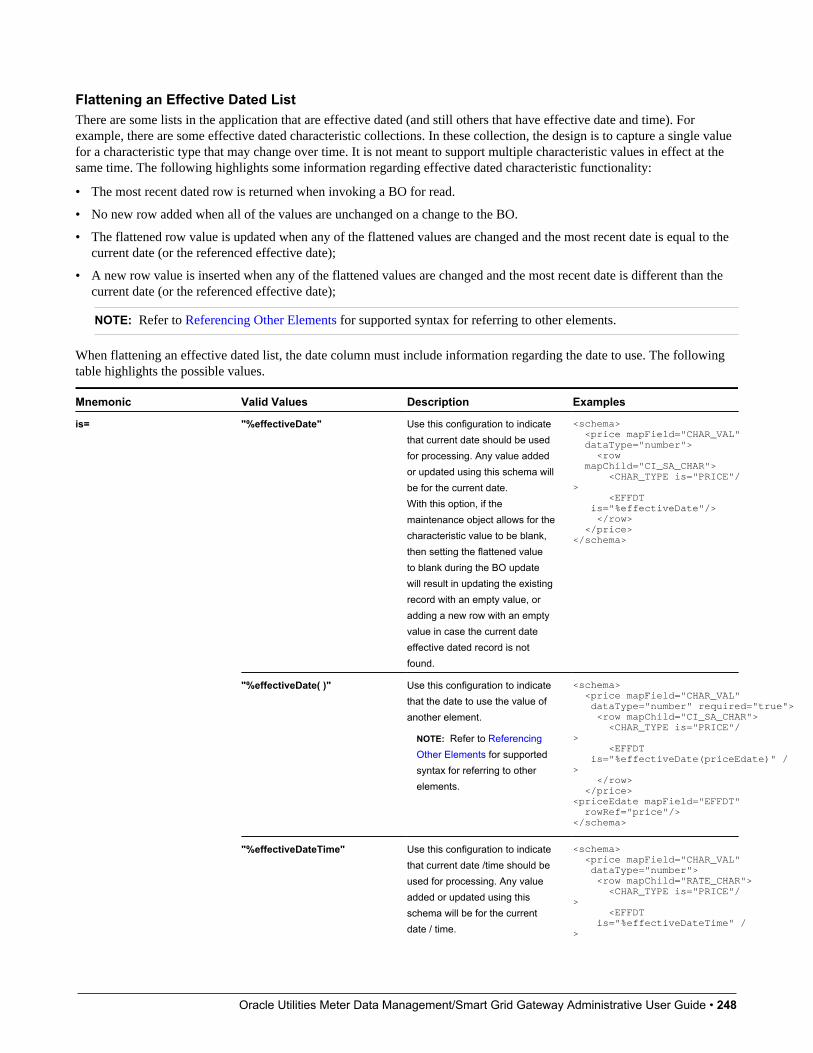
Oracle Utilities Meter Data Management/Smart Grid Gateway Administrative User Guide • 248
Flattening an Effective Dated ListThere are some lists in the application that are effective dated (and still others that have effective date and time). Forexample, there are some effective dated characteristic collections. In these collection, the design is to capture a single valuefor a characteristic type that may change over time. It is not meant to support multiple characteristic values in effect at thesame time. The following highlights some information regarding effective dated characteristic functionality:
• The most recent dated row is returned when invoking a BO for read.
• No new row added when all of the values are unchanged on a change to the BO.
• The flattened row value is updated when any of the flattened values are changed and the most recent date is equal to thecurrent date (or the referenced effective date);
• A new row value is inserted when any of the flattened values are changed and the most recent date is different than thecurrent date (or the referenced effective date);
NOTE: Refer to Referencing Other Elements for supported syntax for referring to other elements.
When flattening an effective dated list, the date column must include information regarding the date to use. The followingtable highlights the possible values.
Mnemonic Valid Values Description Examples
"%effectiveDate" Use this configuration to indicatethat current date should be usedfor processing. Any value addedor updated using this schema willbe for the current date.With this option, if themaintenance object allows for thecharacteristic value to be blank,then setting the flattened valueto blank during the BO updatewill result in updating the existingrecord with an empty value, oradding a new row with an emptyvalue in case the current dateeffective dated record is notfound.
<schema> <price mapField="CHAR_VAL" dataType="number"> <row mapChild="CI_SA_CHAR"> <CHAR_TYPE is="PRICE"/> <EFFDT is="%effectiveDate"/> </row> </price></schema>
"%effectiveDate( )" Use this configuration to indicatethat the date to use the value ofanother element.
NOTE: Refer to ReferencingOther Elements for supportedsyntax for referring to otherelements.
<schema> <price mapField="CHAR_VAL" dataType="number" required="true"> <row mapChild="CI_SA_CHAR"> <CHAR_TYPE is="PRICE"/> <EFFDT is="%effectiveDate(priceEdate)" /> </row> </price><priceEdate mapField="EFFDT" rowRef="price"/></schema>
is=
"%effectiveDateTime" Use this configuration to indicatethat current date /time should beused for processing. Any valueadded or updated using thisschema will be for the currentdate / time.
<schema> <price mapField="CHAR_VAL" dataType="number"> <row mapChild="RATE_CHAR"> <CHAR_TYPE is="PRICE"/> <EFFDT is="%effectiveDateTime" />

Oracle Utilities Meter Data Management/Smart Grid Gateway Administrative User Guide • 249
Mnemonic Valid Values Description Examples </row> </price></schema>
"%effectiveDateTime( )" Use this configuration to indicatethat the date / time to use thevalue of another element.
NOTE: Refer to ReferencingOther Elements for supportedsyntax for referring to otherelements.
<schema> <price mapField="CHAR_VAL" dataType="number"> <row mapChild="RATE_CHAR"> <CHAR_TYPE is="PRICE"/> <EFFDTTM is="%effectiveDateTime(priceEdatetime)"/> </row> </price> <priceEdatetime mapField="EFFDTTM" rowRef="price"/></schema>
Search ZoneA UI Map schema element can be configured to enable an automatic search dialog when the schema is included within amaintenance UI map.
NOTE: Please note that an fkRef can be configured with a search zone. If a schema element has an fkRef but no explicitsearch attributes (as described here) then the fkRef search information will be used in the UI map. In other words, if theschema element already has an fkRef, then these explicit search attributes in the schema are only used to override thefkRef search information.
NOTE: Refer to the UI Map Attributes and Functions for more information on search zone configuration.
search="search zone"The search attribute can be used within a UI map schema and is used to automatically generate the oraSearch UI mapattribute. The search zone is an explorer zone configured as a search.
<person fkRef="PER" search="C1_PSRCH"/>
searchField="search field:element|'literal';"The searchField attribute can only be used in conjunction with the search attribute. The searchField attribute is used to buildthe oraSearchField UI map attribute. The searchField value is used to populate a search zone filter with an initial valuewhen the search zone is launched. The initial value can be a literal also. The searchField value is used to match to the filtermnemonic also named searchField.
Search field: element|'literal'. The search field represents the search zone filter to populate on launch. The element is themap's schema element used to populate the filter. The element is optional, if left blank, it will default to the element that thisattribute is specified on. The searchField also takes 'literal' as input value
NOTE: Multiple filters can be populated within the search zone at launch, but multiple search field pairs must beconstructed within the attribute value. The value specified here will be used to directly build the HTML attributeoraSearchField within the UI map where this schema is specified.
NOTE: Note that the element reference is relative. Refer to Referencing Other Elements for supported syntax forreferring to other elements.
<person fkRef="PER" search="C1_PSRCH" searchField="PERSON; PER_TYPE:personType;"/>
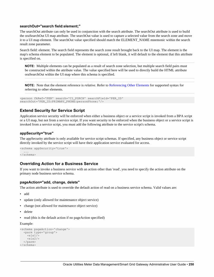
Oracle Utilities Meter Data Management/Smart Grid Gateway Administrative User Guide • 250
searchOut="search field:element;"The searchOut attribute can only be used in conjunction with the search attribute. The searchOut attribute is used to buildthe oraSearchOut UI map attribute. The searchOut value is used to capture a selected value from the search zone and moveit to a UI map element. The searchOut value specified should match the ELEMENT_NAME mnemonic within the searchresult zone parameter.
Search field: element. The search field represents the search zone result brought back to the UI map. The element is themap's schema element to be populated. The element is optional, if left blank, it will default to the element that this attributeis specified on.
NOTE: Multiple elements can be populated as a result of search zone selection, but multiple search field pairs mustbe constructed within the attribute value. The value specified here will be used to directly build the HTML attributeoraSearchOut within the UI map where this schema is specified.
NOTE: Note that the element reference is relative. Refer to Referencing Other Elements for supported syntax forreferring to other elements.
<person fkRef="PER" search="C1_PSRCH" searchField="PER_ID" searchOut="PER_ID;PRIMARY_PHONE:personPhone;"/>
Extend Security for Service ScriptApplication service security will be enforced when either a business object or a service script is invoked from a BPA scriptor a UI map, but not from a service script. If you want security to be enforced when the business object or a service script isinvoked from a service script, you must add the following attribute to the service script's schema.
appSecurity="true"The appSecurity attribute is only available for service script schemas. If specified, any business object or service scriptdirectly invoked by the service script will have their application service evaluated for access.
<schema appSecurity="true"> ...</schema>
Overriding Action for a Business ServiceIf you want to invoke a business service with an action other than 'read', you need to specify the action attribute on theprimary node business service schema.
pageAction="add, change, delete"The action attribute is used to override the default action of read on a business service schema. Valid values are:
• add
• update (only allowed for maintenance object service)
• change (not allowed for maintenance object service)
• delete
• read (this is the default action if no pageAction specified)
Example:
<schema pageAction="change"> <parm type="group"> <ele1/> <ele2/> </parm></schema>
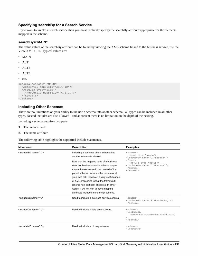
Oracle Utilities Meter Data Management/Smart Grid Gateway Administrative User Guide • 251
Specifying searchBy for a Search ServiceIf you want to invoke a search service then you must explicitly specify the searchBy attribute appropriate for the elementsmapped in the schema.
searchBy="MAIN"The value values of the searchBy attribute can be found by viewing the XML schema linked to the business service, use theView XML URL. Typical values are:
• MAIN
• ALT
• ALT2
• ALT3
• etc.
<schema searchBy="MAIN"> <AccountID mapField="ACCT_ID"/> <Results type="list"> <AccountID mapField="ACCT_ID"/> </Results></schema>
Including Other SchemasThere are no limitations on your ability to include a schema into another schema - all types can be included in all othertypes. Nested includes are also allowed - and at present there is no limitation on the depth of the nesting.
Including a schema requires two parts:
1. The include node
2. The name attribute
The following table highlights the supported include statements.
Mnemonic Description Examples
<includeBO name=" "/> Including a business object schema intoanother schema is allowed.
Note that the mapping rules of a businessobject or business service schema may ormay not make sense in the context of theparent schema. Include other schemas atyour own risk. However, a very useful aspectof XML processing is that the frameworkignores non-pertinent attributes. In otherwords, it will not hurt to have mappingattributes included into a script schema.
<schema> <cust type="group"><includeBO name="C1-Person"/></cust> <spouse type="group"><includeBO name="C1-Person"/></spouse></schema>
<includeBS name=" "/> Used to include a business service schema. <schema><includeBS name="F1-ReadMOLog"/></schema>
<includeDA name=" "/> Used to include a data area schema. <schema><includeDA name="F1CommonSchemaFieldData"/></schema>
<includeMP name=" "/> Used to include a UI map schema. <schema><includeMP

Oracle Utilities Meter Data Management/Smart Grid Gateway Administrative User Guide • 252
Mnemonic Description Examples name="F1-DisplayRecordActions"/></schema>
<includeSS name=" "/> Used to include a service script schema. <schema><includeSS name="F1-ActShowZn"/></schema>
Compatibility AttributesThese attributes were added as part of upgrades from pervious versions of the Framework.
fwRel="2"This attribute has been added to schemas created in Framework 2 as part of a Framework 4 upgrade. New schemas will notneed this attribute. It is not advisable to modify this attribute without understanding the following behavior differences asimproper changes could result in errors:
NOTE: Schemas created in Framework 2 with the fwRel="2" attribute will store any XML mapped fields under groupsas top-level XML elements in the mapXML field. This means that if two or more fields, in different group structures,were to have the same field name, their storage would conflict with one another resulting in errors. The new behavior,without the fwRel="2" attribute, will preserve the group structure and avoid the conflicts.
<schema fwRel="2" ...</schema>
UI Hint Syntax
ContentsWorking ExamplesTechnical NotesFormat an Input Map TitleCreate a SectionInclude a Map FragmentBuild DropdownConditionally Hide ElementsConditionally Protect ElementsTrigger Dependent BehaviorControl Rendering TargetGenerate a Text AreaModify FK Reference DefaultsSuppress Automatic Number FormattingAuto Capitalize the Input Data
Working ExamplesFor working examples of uiHint functionality, refer to the following business objects:
BOs with User Assigned KeysThe following examples illustrate the patterns used to enable uiHints on an object with a user specified key.
• F1-OutcomeStyleLookup. This extendable lookup BO does not require state transition, but does allow duplicate anddelete actions.

Oracle Utilities Meter Data Management/Smart Grid Gateway Administrative User Guide • 253
• F1-TodoSumEmailTyp. This request type illustrates the hints required to support state transition on a display map.
• F1-WebSvc. This web service BO is a good example for management of complex JavaScript requirements. Both displayand input maps have functionality that requires specialized javascript.
BO with System Generated KeyThe following example illustrates the pattern used to enable uiHints on an object with a system generated key.
• F1-GenericAttachment. This attachment BO has a system assigned key, which entails the following special handling:
• F1-AttachmentMain. This is the main section data area contains the elements common to all attachments, includingthe key, bo, and version. Because this data area is used to define the main section of the generated maps, the mainsection of the map can be extended by an implementation via data area extension functionality.
• F1-AttachmentActions. This record actions map contains the standard actions, Edit and Delete, plus custom actionsused only by attachments, View and Upload.
• F1-AttachmentIDFrag. This record information map contains the primary key of the attachment.
Display Map Service ScriptDisplay map service scripts can be fully supported via dynamic HTML generation. However, to help eliminate the needfor a display service script, self-contained uiHint functionality has been developed to write the business object status anddetermine valid state transitions. So the two most common reasons to craft a display service script have been eliminated.
A typical reason to use a display pre-script is if you have an embedded map fragment that contains a business serviceschema. The display service script can be used to invoke the business service. Both the map fragment and the displayservice script must declare the business service schema to support this scenario.
WARNING: The zone used to display the object's map must have a derivation script, like F1-GncDsMpDZ or F1-GenDss, that will invoke a display service script for the business object if it has been defined as a BO option - but notrequire an explicit display map BO option. In addition, the display service script's schema must be enabled for uiHintfunctionality - as the script's schema will be dynamically rendered by the zone - and not the BO schema.
• F1-ExcelSpreadsheet. This attachment BO has a display service script used to manipulate the attachment businessobject before displaying it:
• F1-AttchDtlU. This display map service script's schema has been defined with the uiHint namespace, and will have adisplay map generated for it.
Maintenance Pre-Processing Service ScriptMaintenance pre-processing service scripts can be used with uiHints.
• F1-ExcelSpreadsheet. This attachment BO has a maintenance pre-processing service script used to manipulate theattachment business object before rendering the maintenance map:
• F1-AttchPre. This pre-processing service script's schema mimics a maintenance map schema with embedded boGroupand action elements. It will be invoked before the maintenance map is rendered.
Maintenance Post-Processing Service ScriptMaintenance post-processing service scripts can be used with uiHints.
• F1-ExcelSpreadsheet. This attachment BO has a maintenance post-processing service script used to manipulate theattachment business object after rendering the maintenance map:
• F1-AttchPost. This post-processing service script's schema mimics a maintenance map schema with embedded boGroupand action elements. It will be invoked after the maintenance map is rendered.
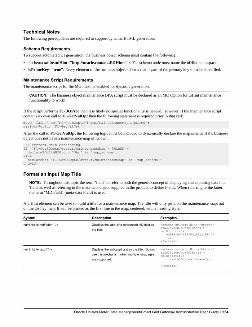
Oracle Utilities Meter Data Management/Smart Grid Gateway Administrative User Guide • 254
Technical NotesThe following prerequisites are required to support dynamic HTML generation:
Schema RequirementsTo support automated UI generation, the business object schema must contain the following:
• <schema xmlns:uiHint="http://oracle.com/ouafUIHints">. The schema node must name the uiHint namespace.
• isPrimeKey="true". Every element of the business object schema that is part of the primary key must be identified.
Maintenance Script RequirementsThe maintenance script for the MO must be enabled for dynamic generation.
CAUTION: The business object maintenance BPA script must be declared as an MO Option for uiHint maintenancefunctionality to work!
If the script performs F1-BOProc then it is likely no special functionality is needed. However, if the maintenance scriptcontains its own call to F1-GetValOpt then the following statement is required prior to that call:
move 'false' to "F1-GetBOOpts/input/maintenanceMapRequired";performScript 'F1-GetValOpt';
After the call to F1-GetValOpt the following logic must be included to dynamically declare the map schema if the businessobject does not have a maintenance map of its own:
// Perform Main Processingif ("F1-GetBOOpts/output/maintenanceMap = $BLANK") declareBOWithBOGroup "$bo" as 'map_schema';else declareMap "F1-GetBOOpts/output/maintenanceMap" as 'map_schema';end-if;
Format an Input Map TitleNOTE: Throughout this topic the term "field" to refer to both the generic concept of displaying and capturing data in a'field' as well as referring to the meta-data object supplied in the product to define Fields. When referring to the latter,the term "MD Field" (meta-data Field) is used.
A uiHint element can be used to build a title for a maintenance map. The title will only print on the maintenance map, noton the display map. It will be printed as the first line in the map, centered, with a heading style.
Syntax Description Examples
<uiHint:title mdField=" "/> Displays the label of a referenced MD field asthe title.
<schema xmlns:uiHint="http://oracle.com/ouafUIHints"><uiHint:title mdField="STATUS_RSN_LBL"/> ...</schema>
<uiHint:title text=" "/> Displays the indicated text as the title. (Do notuse this mechanism when multiple languagesare supported.
<schema xmlns:uiHint="http://oracle.com/ouafUIHints"><uiHint:title text="Status Reason"/> ...</schema>
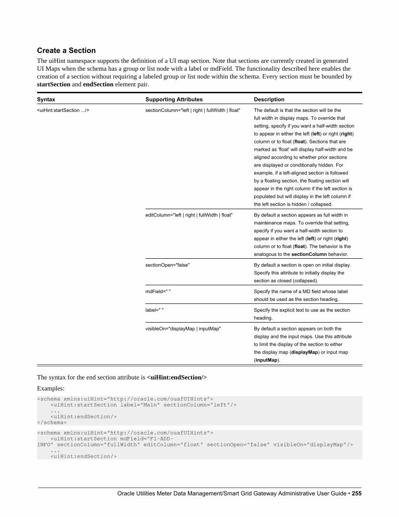
Oracle Utilities Meter Data Management/Smart Grid Gateway Administrative User Guide • 255
Create a SectionThe uiHint namespace supports the definition of a UI map section. Note that sections are currently created in generatedUI Maps when the schema has a group or list node with a label or mdField. The functionality described here enables thecreation of a section without requiring a labeled group or list node within the schema. Every section must be bounded bystartSection and endSection element pair.
Syntax Supporting Attributes Description
sectionColumn="left | right | fullWidth | float" The default is that the section will be thefull width in display maps. To override thatsetting, specify if you want a half-width sectionto appear in either the left (left) or right (right)column or to float (float). Sections that aremarked as 'float' will display half-width and bealigned according to whether prior sectionsare displayed or conditionally hidden. Forexample, if a left-aligned section is followedby a floating section, the floating section willappear in the right column if the left section ispopulated but will display in the left column ifthe left section is hidden / collapsed.
editColumn="left | right | fullWidth | float" By default a section appears as full width inmaintenance maps. To override that setting,specify if you want a half-width section toappear in either the left (left) or right (right)column or to float (float). The behavior is theanalogous to the sectionColumn behavior.
sectionOpen="false" By default a section is open on initial display.Specify this attribute to initially display thesection as closed (collapsed).
mdField=" " Specify the name of a MD field whose labelshould be used as the section heading.
label=" " Specify the explicit text to use as the sectionheading.
<uiHint:startSection .../>
visibleOn="displayMap | inputMap" By default a section appears on both thedisplay and the input maps. Use this attributeto limit the display of the section to eitherthe display map (displayMap) or input map(inputMap).
The syntax for the end section attribute is <uiHint:endSection/>
Examples:
<schema xmlns:uiHint="http://oracle.com/ouafUIHints"> <uiHint:startSection label="Main" sectionColumn="left"/> ... <uiHint:endSection/></schema>
<schema xmlns:uiHint="http://oracle.com/ouafUIHints"> <uiHint:startSection mdField="F1-ADD-INFO" sectionColumn="fullWidth" editColumn="float" sectionOpen="false" visibleOn="displayMap"/> ... <uiHint:endSection/>

Oracle Utilities Meter Data Management/Smart Grid Gateway Administrative User Guide • 256
</schema>
NOTE: The sectionColumn, editColumn and sectionOpen attributes are available for group and list nodes as well.
Include a Map FragmentYou can specify a UI map fragment to inject HTML into a generated map using the includeMap element name. This allowsfor you to support more sophisticated behavior on your user interface. For any element that is included for rendering in themap fragment, be sure to suppress the element in its schema definition, otherwise HTML will automatically be generatedfor the element.
Syntax Supporting Attributes Description
map=" " Specify the name of the map.<uiHint:includeMap .../>
visibleOn="displayMap | inputMap" By default the details from the map fragmentappear on both the display and the inputmaps. Use this attribute to limit the display ofthe section.
Example:
<schema xmlns:uiHint="http://oracle.com/ouafUIHints"> ... <uiHint:includeMap map="StandardActionButtons" visibleOn="displayMap"/> ...</schema>
NOTE: Important note on the map fragment schema: If a map fragment contains a schema, then the fragmentschema structure will be injected into the dynamically generated schema when the business object is rendered for input.Technically, the fragment schema will be inserted after the boGroup structure within the map's schema. This methodmay be used to support the implementation of maintenance pre and post script processing for a business object andoraInvokeBS function calls within embedded JavaScript.
If JavaScript is required within an XHTML UI Map fragment, it is necessary to bound it within a ![CDATA[ ]] tag toensure a valid XML document. Note that the tags themselves may need to be commented out to promote compatibility witholder browsers. For example:
<script type="text/javascript">/* <![CDATA[ */////javascript///* ]]> */</script>
Flush the cache: For performance reasons, the Framework automatically caches business object schemas, data areas, andUI maps. When you update a business object, the cache is automatically flushed. However, if the business object includeseither a data area or embedded UI map fragment, the cache must be manually flushed in order for your changes to berecognized. Refer to Server Cache for more information.
Build A DropdownSyntax is provided to build a dropdown list in an edit map. The dropdown may be built using data returned from a servicescript, a business service or a table.
Syntax Description
uiHint:select="ss: " Specify the name of the service script after the colon.
uiHint:select="bs: " Specify the name of the business service after the colon.

Oracle Utilities Meter Data Management/Smart Grid Gateway Administrative User Guide • 257
Syntax Description
uiHint:select="table: " Specify the name of the table after the colon.
When specifying a service script or a business service, extra mapping information is needed to pass data to and from theservice.
Syntax Values Description
serviceXPath:element Used to pass the value of another elementinto the service (mapping to the service'sXPath).
uiHint:selectIn=" "
serviceXPath:'Literal' Used to pass a constant or literal to theservice (mapping to the service's XPath).
uiHint:selectOut="valuePath: ; descPath: " See examples below. Used to indicate which element in theservice's output holds the values and whichone holds the descriptions.
Examples:
<schema xmlns:uiHint="http://oracle.com/ouafUIHints"> <boStatus mapField="BO_STATUS_CD" uiHint:select="bs:F1-BOStateReasonList" uiHint:selectIn="boStatusBO:boStatusBO" uiHint:selectOut="valuePath:results/status; descPath:results/description"/> ... <algorithm mdField="ALG_CD" uiHint:select="bs:F1-RetrieveSysEvtAlgorithms" uiHint:selectIn="algorithmEntity:'F1AA';" uiHint:selectOut="valuePath:results/algorithm; descPath:results/description"/> ... <outboundMsgType mdField="OUTMSG_TYPE_CD" required="true" fkRef="F1-OMTYP" uiHint:select="table:F1_OUTMSG_TYPE"/></schema>
Conditionally Hide ElementsThe displayNone attribute is used to suppress elements on the map based on conditions.
Syntax Values Description
"'XPath','value','!=' | '='" Used to conditionally hide this elementbased on the value of another element(referenced using its XPath). Enter a value of' ' to interrogate a blank value. By default theoperator is '='. This may be overridden using'!='.
uiHint:displayNone=
"function name, true | false" Used to indicate a JavaScript function, whichmust return a Boolean.
WARNING:Embedded spaces are not supported within the comma separated string values of this attribute.
This setting may be used on group nodes, list nodes, and elements - except for elements within a list. Elements within alist cannot be hidden conditionally.
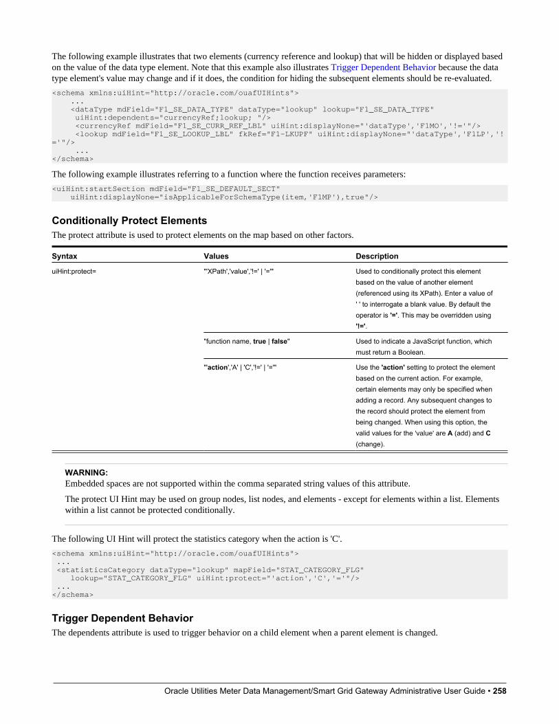
Oracle Utilities Meter Data Management/Smart Grid Gateway Administrative User Guide • 258
The following example illustrates that two elements (currency reference and lookup) that will be hidden or displayed basedon the value of the data type element. Note that this example also illustrates Trigger Dependent Behavior because the datatype element's value may change and if it does, the condition for hiding the subsequent elements should be re-evaluated.
<schema xmlns:uiHint="http://oracle.com/ouafUIHints"> ... <dataType mdField="F1_SE_DATA_TYPE" dataType="lookup" lookup="F1_SE_DATA_TYPE" uiHint:dependents="currencyRef;lookup; "/> <currencyRef mdField="F1_SE_CURR_REF_LBL" uiHint:displayNone="'dataType','F1MO','!='"/> <lookup mdField="F1_SE_LOOKUP_LBL" fkRef="F1-LKUPF" uiHint:displayNone="'dataType','F1LP','!='"/> ...</schema>
The following example illustrates referring to a function where the function receives parameters:
<uiHint:startSection mdField="F1_SE_DEFAULT_SECT" uiHint:displayNone="isApplicableForSchemaType(item,'F1MP'),true"/>
Conditionally Protect ElementsThe protect attribute is used to protect elements on the map based on other factors.
Syntax Values Description
"'XPath','value','!=' | '='" Used to conditionally protect this elementbased on the value of another element(referenced using its XPath). Enter a value of' ' to interrogate a blank value. By default theoperator is '='. This may be overridden using'!='.
"function name, true | false" Used to indicate a JavaScript function, whichmust return a Boolean.
uiHint:protect=
"'action','A' | 'C','!=' | '='" Use the 'action' setting to protect the elementbased on the current action. For example,certain elements may only be specified whenadding a record. Any subsequent changes tothe record should protect the element frombeing changed. When using this option, thevalid values for the 'value' are A (add) and C(change).
WARNING:Embedded spaces are not supported within the comma separated string values of this attribute.
The protect UI Hint may be used on group nodes, list nodes, and elements - except for elements within a list. Elementswithin a list cannot be protected conditionally.
The following UI Hint will protect the statistics category when the action is 'C'.
<schema xmlns:uiHint="http://oracle.com/ouafUIHints"> ... <statisticsCategory dataType="lookup" mapField="STAT_CATEGORY_FLG" lookup="STAT_CATEGORY_FLG" uiHint:protect="'action','C','='"/> ...</schema>
Trigger Dependent BehaviorThe dependents attribute is used to trigger behavior on a child element when a parent element is changed.

Oracle Utilities Meter Data Management/Smart Grid Gateway Administrative User Guide • 259
Syntax Values
uiHint:dependents=" " A list of one or more dependent elements separated by semicolons.
The following example illustrates that the dropdown list of one element is driven by the value of another element. In thisexample, when the Country changes, the list of States to choose from should change to only show the states for the indicatedcountry.
<schema xmlns:uiHint="http://oracle.com/ouafUIHints"> <country label="Country" uiHint:select="table:CI_COUNTRY" uiHint:dependents="state"/> <state label="State" uiHint:select="ss:CM-RetrieveCountryStates" uiHint:selectIn="input/country:country;" uiHint:selectOut="valuePath:output/state/stateCode; descPath:output/state/stateDesc"/> ...</schema>
NOTE:Dependent targets may only name elements, not group or list nodes.
Do not modify the "id" attribute value of dependent and parent element. Data population in dependent is done based onthe "id" attribute value.
Control Rendering TargetBy default all elements that are not suppressed are visible on both the display map and the input map. Use the visibleOnattribute to limit the inclusion of an element to either the display or input map.
Syntax Values
"displayMap"uiHint:visibleOn=
"inputMap"
<schema xmlns:uiHint="http://oracle.com/ouafUIHints"> ... <uiHint:includeMap map="StandardActionButtons" visibleOn="displayMap" ...</schema>
Generate a Text AreaBy default, a standard text box is rendered in an input map for any string element. If the field is larger and you wish to havea bigger text area (with a scroll bar), use the textArea attribute.
Syntax
uiHint:textArea="true"
<schema xmlns:uiHint="http://oracle.com/ouafUIHints"> ... <message label="Message" uiHint:textArea="true"/> ...</schema>
Modify FK Reference DefaultsBy default, when an element with fkRef is displayed, an info string, context menu, navigation, and search are enabled (if theFK reference has been configured accordingly). Syntax is provided to allow you to selectively turn off any of these features.
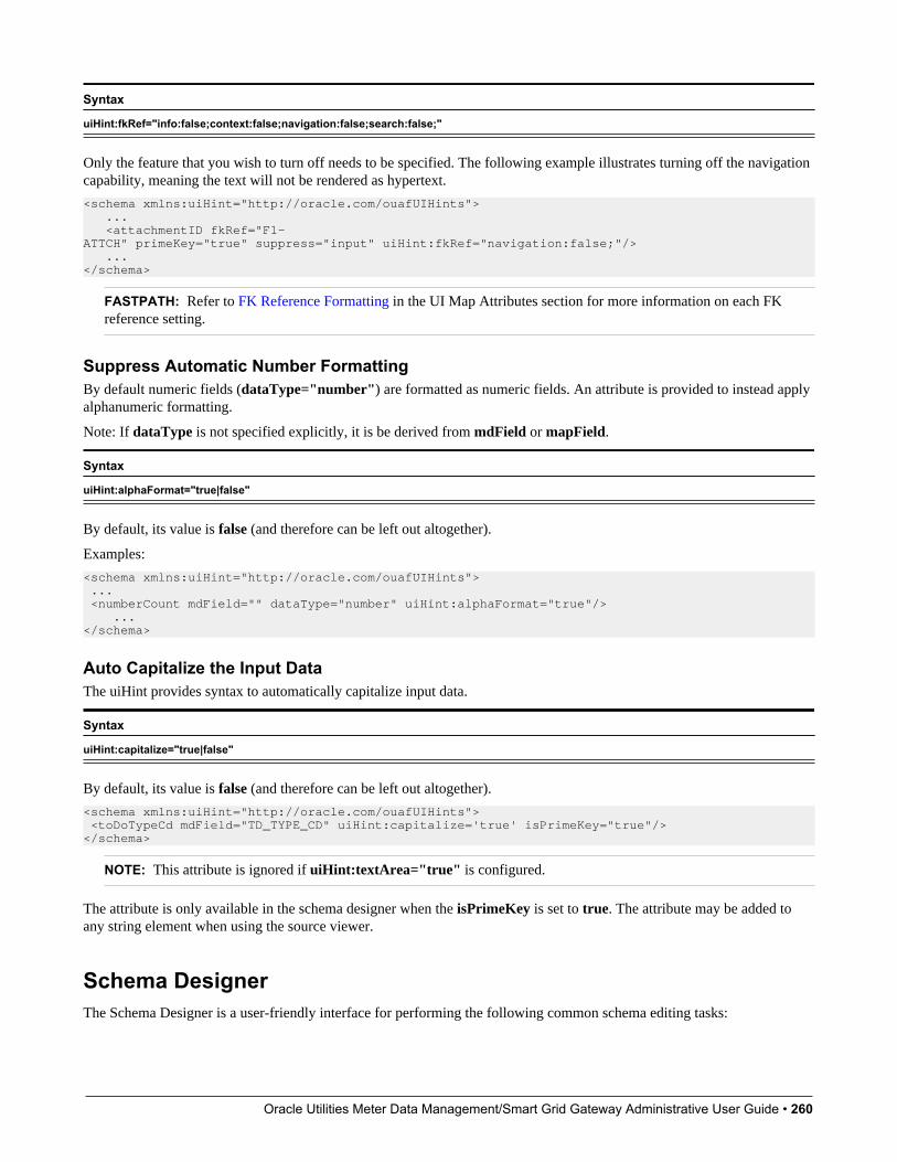
Oracle Utilities Meter Data Management/Smart Grid Gateway Administrative User Guide • 260
Syntax
uiHint:fkRef="info:false;context:false;navigation:false;search:false;"
Only the feature that you wish to turn off needs to be specified. The following example illustrates turning off the navigationcapability, meaning the text will not be rendered as hypertext.
<schema xmlns:uiHint="http://oracle.com/ouafUIHints"> ... <attachmentID fkRef="F1-ATTCH" primeKey="true" suppress="input" uiHint:fkRef="navigation:false;"/> ...</schema>
FASTPATH: Refer to FK Reference Formatting in the UI Map Attributes section for more information on each FKreference setting.
Suppress Automatic Number FormattingBy default numeric fields (dataType="number") are formatted as numeric fields. An attribute is provided to instead applyalphanumeric formatting.
Note: If dataType is not specified explicitly, it is be derived from mdField or mapField.
Syntax
uiHint:alphaFormat="true|false"
By default, its value is false (and therefore can be left out altogether).
Examples:
<schema xmlns:uiHint="http://oracle.com/ouafUIHints"> ... <numberCount mdField="" dataType="number" uiHint:alphaFormat="true"/> ...</schema>
Auto Capitalize the Input DataThe uiHint provides syntax to automatically capitalize input data.
Syntax
uiHint:capitalize="true|false"
By default, its value is false (and therefore can be left out altogether).
<schema xmlns:uiHint="http://oracle.com/ouafUIHints"> <toDoTypeCd mdField="TD_TYPE_CD" uiHint:capitalize='true' isPrimeKey="true"/> </schema>
NOTE: This attribute is ignored if uiHint:textArea="true" is configured.
The attribute is only available in the schema designer when the isPrimeKey is set to true. The attribute may be added toany string element when using the source viewer.
Schema DesignerThe Schema Designer is a user-friendly interface for performing the following common schema editing tasks:
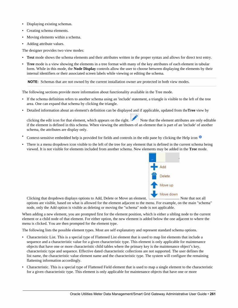
Oracle Utilities Meter Data Management/Smart Grid Gateway Administrative User Guide • 261
• Displaying existing schemas.
• Creating schema elements.
• Moving elements within a schema.
• Adding attribute values.
The designer provides two view modes:
• Text mode shows the schema elements and their attributes written in the proper syntax and allows for direct text entry.
• Tree mode is a view showing the elements in a tree format with many of the key attributes of each element in tabularform. While in this mode, the Node Display controls allow the user to choose between displaying the elements by theirinternal identifiers or their associated screen labels while viewing or editing the schema.
NOTE: Schemas that are not owned by the current installation owner are protected in both view modes.
The following sections provide more information about functionality available in the Tree mode.
• If the schema definition refers to another schema using an 'include' statement, a triangle is visible to the left of the treearea. One can expand that schema by clicking the triangle.
• Detailed information about an element's definition can be displayed and if applicable, updated from theTree view by
clicking the edit icon for that element, which appears on the right. Note that the element attributes are only editableif the element is defined in this schema. When viewing the attributes of an element that is part of an 'include' of anotherschema, the attributes are display only.
• Context-sensitive embedded help is provided for fields and controls in the edit pane by clicking the Help icon
• There is a menu dropdown icon visible to the left of the tree for any element that is defined in the current schema beingviewed. It is not visible for elements included from another schema. New elements may be added in the Tree mode.
Clicking that dropdown displays options to Add, Delete or Move an element. Note that not alloptions are visible, based on what is allowed for the element adjacent to the menu. For example, on the main "schema"node, only the Add option is visible as deleting or moving the "schema" node is not applicable.
When adding a new element, you are prompted first for the element position, which is either a sibling node to the currentelement or a child node of that element. For either option, the new element is added below the one adjacent to where themenu is clicked. You are then prompted for the element type.
The following lists the possible element types. Most are self explanatory and represent standard schema options.
• Characteristic List. This is a special type of Flattened List element that is used to map list elements that include asequence and a characteristic value for a given characteristic type. This element is only applicable for maintenanceobjects that have one or more characteristic child tables where the primary key is the maintenance object’s key,characteristic type and sequence. Effective dated characteristic collections are not supported. The user defines thelist name, the characteristic value element name and the characteristic type. The system will configure the remainingflattening information accordingly.
• Characteristic. This is a special type of Flattened Field element that is used to map a single element to the characteristicfor a given characteristic type. This element is only applicable for maintenance objects that have one or more
Oracle Utilities Meter Data Management/Smart Grid Gateway Administrative User Guide • 262
characteristic child tables where the primary key is the maintenance object’s key, characteristic type and sequence.Effective dated characteristic collections are not supported. The user defines the element name and the characteristictype. The system will configure the remaining flattening information accordingly.
• Comment. This adds a comment to the schema.
• Embedded HTML. This is specific to a schema enabled for UI Hints. It is used to include a UI map fragment.
• Field
• Flattened Field
• Flattened List
• Group
• Include BO Schema
• Include BS Schema
• Include DA Schema
• Include Map Schema
• Include SS Schema
• Input Map Title. This is specific to a schema enabled for UI Hints. It is used to define a title element for the map.
• List
• Nested Flattened Field. This is a flattened field from a child table.
• Raw Element. This element is used to capture text as is. It is typically used to capture an XML structure without anydetails of the definition of the individual nodes.
• Section. This is specific to a schema enabled for UI Hints. It is used to define a section within the map.
• Simple Field. This is a special type of Field element that is used to define an element that is mapped to a column thatsupports data defined in an XML structure. (This is either a column with the character large object data type (CLOB) orthe XML data type).
The Schema Designer is available by choosing the Schema tab on the Business Object, Data Area, UI Map, BusinessService, and Script pages.
Schema ViewerThe schema viewer shows a tree-view presentation of a schema in its expanded form.
The schema illustrates the structure to be used when communicating with the schema's associated object. The followingtakes place when a schema is expanded:
• If the schema definition includes references to other schemas, these references are replaced with the correspondingschema definitions.
• Also, if the schema definition contains private elements, they are omitted from this view.
Clicking on any node on the tree populates the text box on the top with the node's absolute XPath expression. You will findthis feature very useful when writing scripts interacting with schema-based objects. Scripting often involves referencingelements in a schema-based XML document using their absolute XPath expression. You can use this feature on the schemaviewer to obtain the XPath expression for an element and copy it over to your script.
Oracle Utilities Meter Data Management/Smart Grid Gateway Administrative User Guide • 263
Business Event LogBusiness Event Log may be viewed as a tool designed to capture any type of business event worth noting. You configurebusiness objects to represent the various types of events your application calls for. The following type of details may becaptured for each event:
• The business object representing the type of event.
• The date and time the event took place and who initiated it.
• The business entity for which this event is logged.
• Standard application message to describe the event.
• Additional context information that is available at the time of the event and varies for each type of event. The BusinessEvent Log maintenance object supports a standard characteristics collection as well as an XML storage (CLOB) field.The event's business object determines where each piece of information resides. Refer to Business Objects for moreinformation.
One common type of event may be the audit of changes made to sensitive data, for example, tracking an address change.Whenever an entity associated with a business object is added, changed, or deleted the system summarizes the list ofchanges that took place in that transaction and hands them over to Audit business object algorithms to process. You maydesign such an algorithm to audit the changes as business event logs. Refer to a business object may define business rulesfor more information.
You can also allow users to initiate business event logs to capture important notes about a business entity by exposing a BPA Script to invoke the event's corresponding business object.
Bottom line is that any process can create a business event log by invoking the business object representing the appropriatetype of event.
Where Used
Follow this link to open the data dictionary where you can view the tables that reference F1_BUS_EVT_LOG.
Miscellaneous TopicsThe following sections describe miscellaneous system wide topics.
Module ConfigurationThe system provides the ability to simplify the user interface based on functionality areas practiced by your organization.
Menu items and other user interface elements are associated with function modules. By default, all function modules areaccessible. If a function module is not applicable to your business you may turn it off. Refer to Turn Off A FunctionModule for more information on how to turn off a module.
If a function module is made non-accessible, i.e. turned off, its related elements are suppressed from the user interface.In addition the system may validate that related functionality is not accessed. This also means that turning off the wrongmodule may cause any of the following to occur:
• Menu items may not appear. Refer to Menu Item Suppression to better understand how menu item suppression works.
• Entire menus may not appear. Refer to Menu Suppression to better understand how menu suppression works.
• Tabs on pages may not appear.
• Fields may not appear.
• The system may return an error message when you attempt to use a function (indicating the function is turned off).
Oracle Utilities Meter Data Management/Smart Grid Gateway Administrative User Guide • 264
To correct the above situation, simply remove the module from the turned off list thus making it accessible again.
Your module configuration setup is displayed on the installations record.
Menu Item SuppressionThe following points describe how your module configuration can suppress menu items.
• Menu items that are owned by the base product (as opposed to those your implementation adds) are associated with oneor more function modules. If your module configuration has turned off all of the menu item's modules, the menu item issuppressed. If at least one of the modules is accessible, i.e. turned on, the menu item is not suppressed.
• If a menu line doesn't contain any accessible items, the menu line is suppressed.
• If all lines on a menu are suppressed, the menu itself (Menu or Admin menu) is suppressed in the application toolbar.
Menu SuppressionIn addition to the above Menu Item Suppression logic, the following points describe how your module configuration cansuppress an entire menu.
• Menus that are owned by the base product (as opposed to those your implementation adds) are associated with one ormore function modules.
• If your module configuration has turned off all of the menu's modules, the entire menu is suppressed. If at least one ofthe modules is accessible, i.e. turned on, the menu is not suppressed.
Turn Off A Function ModuleThe base package is provided with a Module Configuration Feature Configuration that allows your organization to turn offbase package function modules.
To turn off any of the base package function modules add a Turned Off option to this feature configuration referencing thatmodule. Refer to the MODULE_FLG lookup field for the complete list of the application's function modules.
Any module not referenced on this feature configuration is considered turned on, i.e. accessible. To turn on a module,simply remove its corresponding Turned Off option from this feature configuration.
You may view your module configuration setup on the installation options page.
NOTE: Only one. The system expects only one Module Configuration feature configuration to be defined.
Global Context OverviewThe framework web application provides each product the ability to nominate certain fields to act as a "global context"within the web application. For example, in Oracle Utilities Customer Care and Billing, the global context fields includeAccount ID, Person ID and Premise ID. The values of these fields may be populated as a result of searching or displayingobjects that use these fields in their keys. If you navigate to the Bill page and display a bill, the global context is refreshedwith the Account ID associated with that bill. The global context for Person ID and Premise ID are refreshed with dataassociated with that account.
The fields designated as global context for the product are defined using the lookup F1_UI_CTXT_FLDS_FLG.
Changing the values of the global context typically cause data displayed in zones on the dashboard to be refreshed to showinformation relevant to the current values of these global context fields.

Oracle Utilities Meter Data Management/Smart Grid Gateway Administrative User Guide • 265
When the value of one of the global context fields changes, an algorithm plugged into the installation record is responsiblefor populating the remaining global context values accordingly. Refer to your specific product for more information aboutthe base algorithm that is provided for that product.
System Data Naming ConventionThere are several maintenance objects in the system that include owner flag in one or more of its tables. We refer to the datain these tables as "system data". Some examples of system data tables include Algorithm Type, Batch Control, BusinessObject and Script. Implementations may introduce records to the same tables. The owner flag for records created by animplementation is set to CM (for customer modification), however the owner flag is not part of the primary key for anyof the system data tables. As a result, the base product provides the following guidelines for defining the primary key insystem data tables to avoid any naming conflict.
Base Product System DataFor any table that includes the owner flag, the base product will follow a naming convention for any new data that is ownedby the base product. The primary key for records introduced by the product is prefixed with xn- where xn is the value ofthe owner flag. For example, if a new background process is introduced to the framework product, the batch code name isprefixed with F1-.
NOTE: There are some cases where the hyphen is not included. For example, portal codes omit the hyphen.
For most system data, the remainder of the primary key is all in capital case. An exception is schema oriented records.For business objects, business services, scripts, data areas and UI maps, the product follows the general rule of usingCapitalCase after the product owner prefix. For example, F1-AddToDoEntry is the name of a base product businessservice.
NOTE: Data Explorer Business Services. For business services used to invoke a data explorer zone, it isrecommended to name the Business Service the same name as the related zone rather than defining a differentCapitalCase name for the business service.
Please note that this standard is followed for all new records introduced by the base product. However, there are baseproduct entries in many of these system data tables that were introduced before the naming convention was adopted. Thatdata does not follow the naming convention described above.
NOTE: Schema naming conventions. A context sensitive "Schema Tips" zone is associated with any page where aschema may be defined. The zone provides recommended naming conventions for elements within a schema along witha complete list of the XML nodes and attributes available to you when you construct a schema.
Implementation System DataWhen new system data is introduced for your implementation you must consider the naming convention for the primarykey. The product recommends prefixing records with CM, which is the value of the owner flag in your environment. This isconsistent with the base product naming convention. This convention allows your implementation to use the CM packagingtool in the Software Development Kit as delivered. The extract file provided with the tool selects system data records withan owner flag of CMand with a CM prefix.
NOTE: If you choose not to follow the CM naming convention for your records and you want to use the CM packagingtool, your implementation must customize the extract file to define the appropriate selection criteria for the records to beincluded in the package. Refer to the Software Development Kit documentation for more information.
Oracle Utilities Meter Data Management/Smart Grid Gateway Administrative User Guide • 266
Also note that owner flag may be introduced to an existing table in a new release. When this happens, the CM packagingtool is also updated to include these new system data tables. Your implementation will have existing records in those tablesthat probably do not follow any naming convention. After an upgrade to such a release, if you want to include this data inthe CM packaging tool, you must customize the extract file for the tables in question.
Referencing URIsThere are some configuration objects that require a reference to a URI, including file path URIs. The following sectionshighlight some functionality supported by the product with respect to defining / accessing URIs.
NOTE: In order for the functionality described below to occur, specific APIs must be used by the underlying coderelated to the fields that capture or process the file path or URL information. If you find that there is a URI-related fieldthat does not provide the functionality described here, please contact customer support.
NOTE: For schema elements in a business object that reference a Field with the URI data type or define the elementwith the URI data type configured in the schema will automatically use the appropriate API that validates the value thatmay reference a substitution variable or must be checked against the whitelist if applicable.
Validation Against a WhitelistBased on a property setting, your implementation may be configured to define a whitelist of URIs. If this setting is enabled,the system will issue an error if the URI is not defined in the whitelist. Consult your system administrator to verify if thissetting is enabled or not for your implementation.
FASTPATH: Refer to URI Substitution for information about how defining substitution tokens for URIs using theproperties file technique automatically adds the defined URI to the whitelist.
URI SubstitutionThe system supports the ability to define substitution variables (sometimes referred to as tokens) for all or part of a URIusing the substitution variable properties file. This allows the system administrators to define the proper URI locations in aproperties file whereas the configuration users only need to know the variable name. For example, when defining a locationfor an extract file in an extract batch job, instead of typing a file path of h:\oracle\serverName\1.0.0.0\batch\extract\, thebatch user can enter @FILE_EXTRACT@, assuming there is an entry in the substitution variables file with a name ofFILE_EXTRACT, and a value of h:\oracle\serverName\1.0.0.0\batch\extract\. Another example is that the batch usercould enter @BATCH_FILES@\extract\, assuming that the URI variable for BATCH_FILES is defined as h:\oracle\serverName\1.0.0.0\batch\.
NOTE: The product automatically populates the value of SPLOUTPUT in the properties file so that this may be used inURI configuration. In addition, the product may supply some pre-defined variable names for other common references.As part of this, the 'advanced' menu in the system installation steps may prompt for installers to define the values ofthese pre-defined variables, if desired. Installations may opt to define additional substitution variables for various URIreferences. Refer to the System Administration Guide for more information.
Caching OverviewA great deal of information in the system changes infrequently. In order to avoid accessing the database every time this typeof information is required by an end-user or a batch process, the system maintains a cache of static information on the webserver and in the batch thread pool worker. These are referred to as the “application caches”. Some examples of applicationcaches include
Oracle Utilities Meter Data Management/Smart Grid Gateway Administrative User Guide • 267
• System messages
• Field label and other field information
• Security Information
The framework product provides many specific caches for commonly used (and infrequently changed) data. In addition,specific edge applications may introduce additional caches as appropriate.
Information may also be cached on each user's browser.
The following topics highlight information about refreshing the various caches.
Server CacheThe server cache refers to data that is cached on the web server. An important use of this cache is for users’ online accessto the application. The caches aid in better performance while navigating throughout the system, allowing for data to beaccessed from the cache rather than by always accessing the database. Besides user access to the web server cache, otherfunctionality deployed to the web server uses caches in a similar way. For example, web services are deployed to the webserver and access their own version of the cache.
The contents of the cache are cleared whenever the web server is restarted. This means that fresh values are retrieved fromthe database once users and web services start using the application again.
The product also supplies a flush command that one can issue in the browser's URL to immediately clear the contents of thecache. The command flushAll.jsp flushes every cache.
For example, assume the following:
• the web server and port on which you work is called OU-Production:7500
• you add a new record to a control table and you want it to be available on the appropriate transactions immediately
You would issue the following command in your browser's address bar: http://OU-Production:7500/flushAll.jsp. Noticethat the command replaces the typical cis.jsp that appears after the port number.
If your system has been configured correctly, the flushAll command will submit a request to do a “global” flush of caches(including the web services cache and the thread pool worker cache). This functionality uses a JMS Topic to publish theflush request. Refer to the Server Administration Guide for details on how to configure the JMS topic.
Batch CacheWhen submitting a batch job, the batch component uses a Hibernate data cache to cache administrative data that doesn’tchange very often. The tables whose records are included in this cache are configured using the Caching Regime value ofCached for Batch. Refer to Table - Main for more information. When starting a thread pool worker, data in tables markedas cached is loaded and cached for as long as that thread pool is running.
In addition batch jobs may also access application caches when applicable. When starting a thread pool worker, applicationdata that is cached is loaded and cached for as long as that thread pool is running.
If there is a change in cached data that should be available for the next batch job, the following points highlight how thecache can be refreshed:
• By default the system is configured to automatically refresh the Hibernate cache every 60 seconds. However, animplementation may override the configuration to either change the number of seconds between intervals or to disablethe automatic caching altogether. Application caches used by the batch jobs are not impacted by this refresh.
• Restart the thread pool workers.
• Run the F1–FLUSH (Flush all Caches) background process. This background process will flush the application datacached for all thread pool workers for all thread pools.
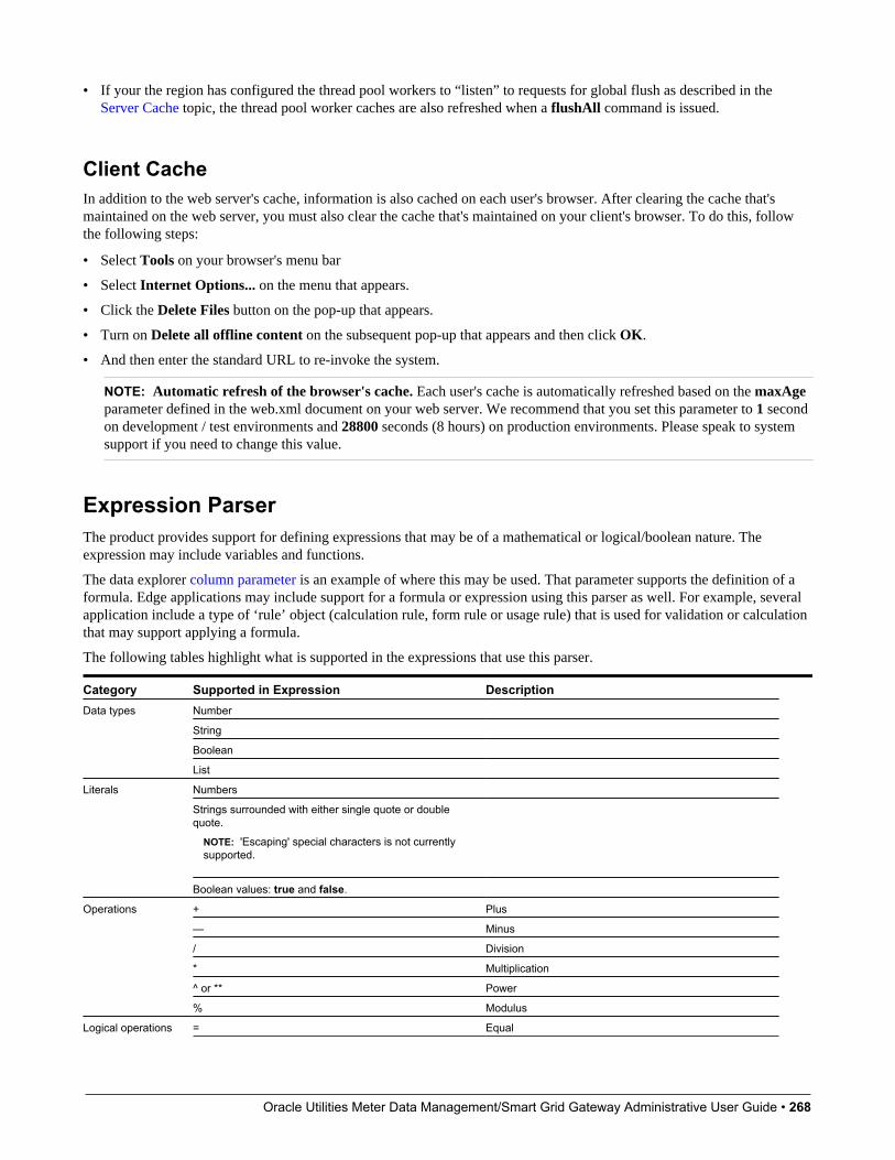
Oracle Utilities Meter Data Management/Smart Grid Gateway Administrative User Guide • 268
• If your the region has configured the thread pool workers to “listen” to requests for global flush as described in theServer Cache topic, the thread pool worker caches are also refreshed when a flushAll command is issued.
Client CacheIn addition to the web server's cache, information is also cached on each user's browser. After clearing the cache that'smaintained on the web server, you must also clear the cache that's maintained on your client's browser. To do this, followthe following steps:
• Select Tools on your browser's menu bar
• Select Internet Options... on the menu that appears.
• Click the Delete Files button on the pop-up that appears.
• Turn on Delete all offline content on the subsequent pop-up that appears and then click OK.
• And then enter the standard URL to re-invoke the system.
NOTE: Automatic refresh of the browser's cache. Each user's cache is automatically refreshed based on the maxAgeparameter defined in the web.xml document on your web server. We recommend that you set this parameter to 1 secondon development / test environments and 28800 seconds (8 hours) on production environments. Please speak to systemsupport if you need to change this value.
Expression ParserThe product provides support for defining expressions that may be of a mathematical or logical/boolean nature. Theexpression may include variables and functions.
The data explorer column parameter is an example of where this may be used. That parameter supports the definition of aformula. Edge applications may include support for a formula or expression using this parser as well. For example, severalapplication include a type of ‘rule’ object (calculation rule, form rule or usage rule) that is used for validation or calculationthat may support applying a formula.
The following tables highlight what is supported in the expressions that use this parser.
Category Supported in Expression DescriptionNumber
String
Boolean
Data types
List
Numbers
Strings surrounded with either single quote or doublequote.
NOTE: 'Escaping' special characters is not currentlysupported.
Literals
Boolean values: true and false.
+ Plus
— Minus
/ Division
* Multiplication
^ or ** Power
Operations
% Modulus
Logical operations = Equal
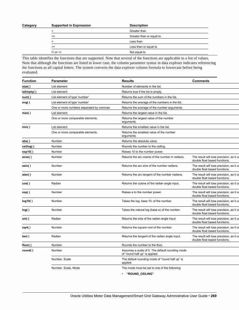
Oracle Utilities Meter Data Management/Smart Grid Gateway Administrative User Guide • 269
Category Supported in Expression Description> Greater than
>= Greater than or equal to
< Less than
<= Less than or equal to
!= or <> Not equal to
This table identifies the functions that are supported. Note that several of the functions are applicable to a list of values.Note that although the functions are listed in lower case, the column parameter syntax in data explorer indicates referencingthe functions as all capital letters. The system converts the data explorer column formula to lowercase before beingevaluated.
Function Parameter Results Commentssize( ) List element Number of elements in the list.
isEmpty( ) List element Returns true if the list is empty.
sum( ) List element of type 'number' Returns the sum of the numbers in the list.
List element of type 'number' Returns the average of the numbers in the list.avg( )
One or more numbers separated by commas Returns the average of the number arguments.
List element Returns the largest value in the list.max( )
One or more comparable elements. Returns the largest value of the numberarguments.
List element Returns the smallest value in the list.min( )
One or more comparable elements. Returns the smallest value of the numberarguments.
abs( ) Number Returns the absolute value.
ceiling( ) Number Rounds the number to the ceiling.
exp10( ) Number Raises 10 to the number power.
acos( ) Number Returns the arc cosine of the number in radians. The result will lose precision, as it uses the system'sdouble float based functions.
asin( ) Number Returns the arc sine of the number radians. The result will lose precision, as it uses the system'sdouble float based functions.
atan( ) Number Returns the arc tangent of the number radians. The result will lose precision, as it uses the system'sdouble float based functions.
cos( ) Radian Returns the cosine of the radian angle input. The result will lose precision, as it uses the system'sdouble float based functions.
exp( ) Number Raises e to the number power. The result will lose precision, as it uses the system'sdouble float based functions.
log10( ) Number Takes the log, base 10, of the number. The result will lose precision, as it uses the system'sdouble float based functions.
log( ) Number Takes the natural log (base e) of the number. The result will lose precision, as it uses the system'sdouble float based functions.
sin( ) Radian Returns the sine of the radian angle input. The result will lose precision, as it uses the system'sdouble float based functions.
sqrt( ) Number Returns the square root of the number. The result will lose precision, as it uses the system'sdouble float based functions.
tan( ) Radian Returns the tangent of the radian angle input. The result will lose precision, as it uses the system'sdouble float based functions.
floor( ) Number Rounds the number to the floor.
Number Assumes a scale of 0. The default rounding modeof “round half up” is applied.
Number, Scale The default rounding mode of “round half up” isapplied.
round( )
Number, Scale, Mode The mode must be set to one of the following:
• “ROUND_CEILING”
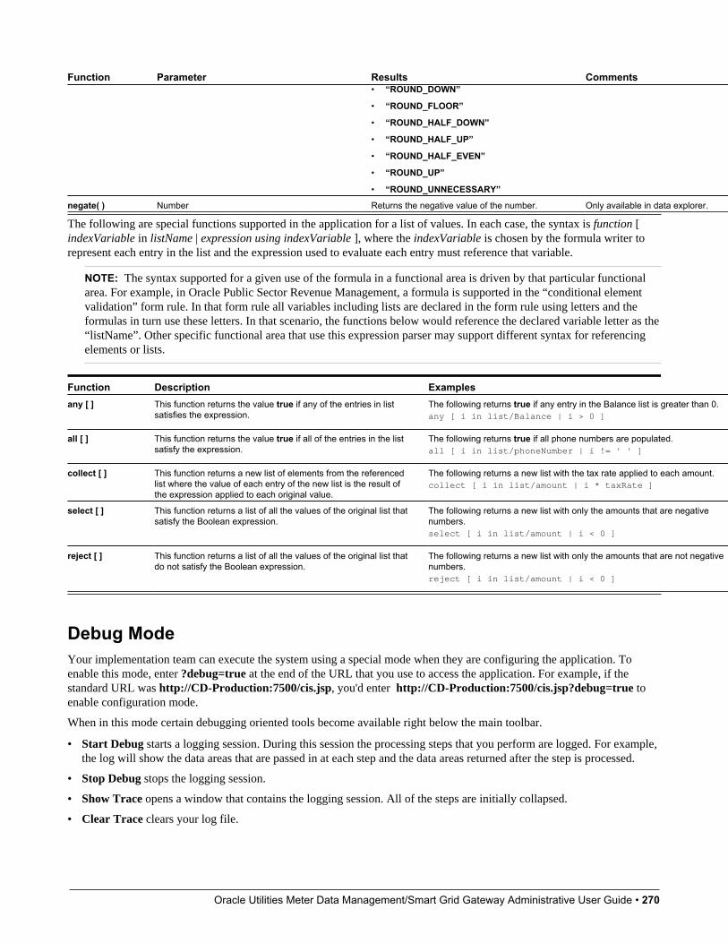
Oracle Utilities Meter Data Management/Smart Grid Gateway Administrative User Guide • 270
Function Parameter Results Comments• “ROUND_DOWN”
• “ROUND_FLOOR”
• “ROUND_HALF_DOWN”
• “ROUND_HALF_UP”
• “ROUND_HALF_EVEN”
• “ROUND_UP”
• “ROUND_UNNECESSARY”
negate( ) Number Returns the negative value of the number. Only available in data explorer.
The following are special functions supported in the application for a list of values. In each case, the syntax is function [indexVariable in listName | expression using indexVariable ], where the indexVariable is chosen by the formula writer torepresent each entry in the list and the expression used to evaluate each entry must reference that variable.
NOTE: The syntax supported for a given use of the formula in a functional area is driven by that particular functionalarea. For example, in Oracle Public Sector Revenue Management, a formula is supported in the “conditional elementvalidation” form rule. In that form rule all variables including lists are declared in the form rule using letters and theformulas in turn use these letters. In that scenario, the functions below would reference the declared variable letter as the“listName”. Other specific functional area that use this expression parser may support different syntax for referencingelements or lists.
Function Description Examplesany [ ] This function returns the value true if any of the entries in list
satisfies the expression.The following returns true if any entry in the Balance list is greater than 0.any [ i in list/Balance | i > 0 ]
all [ ] This function returns the value true if all of the entries in the listsatisfy the expression.
The following returns true if all phone numbers are populated.all [ i in list/phoneNumber | i != ' ' ]
collect [ ] This function returns a new list of elements from the referencedlist where the value of each entry of the new list is the result ofthe expression applied to each original value.
The following returns a new list with the tax rate applied to each amount.collect [ i in list/amount | i * taxRate ]
select [ ] This function returns a list of all the values of the original list thatsatisfy the Boolean expression.
The following returns a new list with only the amounts that are negativenumbers.select [ i in list/amount | i < 0 ]
reject [ ] This function returns a list of all the values of the original list thatdo not satisfy the Boolean expression.
The following returns a new list with only the amounts that are not negativenumbers.reject [ i in list/amount | i < 0 ]
Debug ModeYour implementation team can execute the system using a special mode when they are configuring the application. Toenable this mode, enter ?debug=true at the end of the URL that you use to access the application. For example, if thestandard URL was http://CD-Production:7500/cis.jsp, you'd enter http://CD-Production:7500/cis.jsp?debug=true toenable configuration mode.
When in this mode certain debugging oriented tools become available right below the main toolbar.
• Start Debug starts a logging session. During this session the processing steps that you perform are logged. For example,the log will show the data areas that are passed in at each step and the data areas returned after the step is processed.
• Stop Debug stops the logging session.
• Show Trace opens a window that contains the logging session. All of the steps are initially collapsed.
• Clear Trace clears your log file.
Oracle Utilities Meter Data Management/Smart Grid Gateway Administrative User Guide • 271
• Show User Log allows you to view your own log entries. The number of "tail" entries to view may be specified in theadjacent Log Entries field before clicking the button. Limiting the number of entries to view allows the user to quicklyand easily see only the latest log entries without having to manually scroll to the end of the log.
• Checking the Global Debug indication starts various tracing options.
Other parts of the system may show additional configuration oriented icons when in this mode. For example, explorer zonesmay provide additional tools to assist in debugging zone configuration. These icons are described in the context of wherethey appear.
Also, in debug mode drop down lists in data explorer and UI map zones will contain the code for each item in addition tothe item's display string.
NOTE: Show User Log button is secured. An application service F1USERLOG has been provided for thisfunctionality to allow implementations to restrict user access to this button. Such restriction may be called for inproduction environments.
System Override DateThe system provides a way to override the system date used for online operations. This feature is available if the serveradministrator has enabled it in the environment properties. For instructions on configuring environment properties see theServer Administration Guide. The system date override feature is not recommended for production environments.
Under the General System ConfigurationFeature Configuration, the System Override Date Option Type holds the datethe application will use as the global system date instead of retrieving the same from the database. This feature can beespecially useful in running tests that require the system date to be progressed over a period of time.
The system override date feature is also available at the user level. This is useful when a user wants override the system dateto run tests without affecting the system date for other users in the environment. In order to override the system date for theuser, open the User — Characteristics page, add theSystem Override Date characteristic type with a characteristic value setto the desired date in the YYYY-MM-DD format.
If system override dates are defined at both the feature configuration level and the user level, the date set at the user levelwill take precedence.
Advanced Search OptionsThe product supports fuzzy searching in explorer zone types using the Oracle Text CONTAINS operator.
Refer to the DBA guide for details on setting up the database to support fuzzy searching. Note that there are someimplementations where fuzzy searching will not be possible. For example, it's only available for implementations usingthe Oracle database. Additionally, not all languages are supported. Refer to the Oracle Database documentation for moreinformation about fuzzy searching.
For information about the particular syntax to use in the explorer zones, refer to SQL Statement in the zone parameterdetails section.
To Do ListsCertain events that occur within the system will trigger messages describing work that requires attention. For example, if abill segment has an error, the system generates a To Do message to alert the person responsible for correcting such errors.
Each type of message represents a To Do list. For example, there are To Do lists for bill segment errors, payment errors,customer contact reminder, etc.

Oracle Utilities Meter Data Management/Smart Grid Gateway Administrative User Guide • 272
We refer to each message as a To Do Entry. Each To Do entry is assigned a specific To Do Role. The role defines the userswho may work on the entry. A To Do entry has a To Do log that maintains record of the progress on the To Do entry. Forexample, the To Do log indicates when the To Do entry was created, when it was assigned to a user and to whom it wasassigned, and when and by whom it was completed.
FASTPATH: Refer to To Do Processing for a description of end-user queries and tools assisting in reviewing, assigningand processing To Do entries.
The Big Picture of To Do ListsThe topics below provide more information about To Do configuration.
To Do Entries Reference A To Do TypeEvery To Do entry references a To Do type. The To Do type controls the following functions:
• The To Do list on which the entry appears.
• The page into which a user is taken when they drill down on an entry.
• The message that appears in the user's To Do list. Note this message can be overridden for specific To Do messages byspecifying a different message number in the process that creates the specific To Do entry. For example, the process thatcreates To Do entries associated with bill segments that are in error displays the error message rather than a generic "billsegment is in error" message.
• The To Do list's sort options. Sort options may be used on the To Do list page to sort the entries in a different order. Forexample, when a user looks at the bill segment error To Do list, they have the option of sorting it in error number order,account name order, or in customer class order. Note the default sort order is also defined on To Do type.
• Whether (and how) the To Do entry is downloaded to an external system (e.g., an email system).
• The roles to which an entry may be reassigned.
• The default priority of the To Do list in respect of other To Do lists.
• The To Do list's usage, which indicates whether a To Do of that type may be created manually by a user.
• The algorithms used to perform To Do list specific business rules.
• The characteristics applicable to the To Do list.
To Do Entries Reference A RoleEvery To Do entry references a role. The role defines the users who may be assigned to Open entries.
The permissible roles that may be assigned to a To Do entry are defined on the entry's To Do type. After an entry is created,its role may be changed to any role defined as valid for the entry's To Do type.
An entry's initial role is assigned by the background process or algorithm that creates the entry. Because you can create yourown processes and algorithms, there are an infinite number of ways to default an entry's role. However, the base packageprocesses and algorithms use the following mechanisms to default an entry's role:
• The system checks if an entry's message category / number is suppressed (i.e., not created). If so, the entry is not created.Refer to To Do Entries Can Be Rerouted Or Suppressed Based On Message Number for more information.
• The system checks if an entry's message category / number is rerouted to a specific role. If so, it defaults this role. Referto To Do Entries Can Be Rerouted Or Suppressed Based On Message Number for more information.
Oracle Utilities Meter Data Management/Smart Grid Gateway Administrative User Guide • 273
• Your specific product may introduce additional criteria for assigning a role, for example perhaps important accounts areassigned to a kind of account management group and the account management group includes configuration for specialrole for certain To Do types. Refer to Set Additional Information Before a To Do is Created for more information.
• If a Role wasn't determined in one of the previous steps and a Role is provided by the initiating process, the entry iscreated with that Role.
• If the entry does not have a role after the above takes place, the entry's To Do type's default role is assigned to the entry.
NOTE:At installation time, the system provides a default role assigned to the system To Do types when first installed calledF1_DFLT. This is done to allow testing of the system prior to implementing of appropriate To Do roles for yourorganization. The recommendation is to configure all the To Do Types with appropriate business oriented To Doroles once they are defined.
CAUTION: Important! Most organizations have the notion of a supervisor who is responsible for all entries assigned toa given role. It's important for this user (or users) to be part of all such roles. Refer to To Do Supervisor Functions forinformation about transactions that can be used by supervisors to review and assign work to users.
To Do Entries Can Be Rerouted (Or Suppressed) Based On MessageNumberConsider the To Do type used to highlight bill segments that are in error. To Do entries of this type reference the specificbill segment error number so that the error message can be shown when the Bill Segments in Error To Do list is displayed.
NOTE: Message Category / Message Number. Every error in the system has a unique message category / numbercombination. Refer to The Big Picture of System Messages for more information about message categories andnumbers.
If you want specific types of errors to be routed to specific users, you can indicate such on the To Do type. For example, ifcertain bill segment errors are always resolved by a given rate specialist, you can indicate such on the To Do type. You dothis by updating the To Do type's message overrides. On this page you specify the message category / number of the errorand indicate the To Do role of the user(s) who should work on such errors. Once the To Do type is updated, all new To Doentries of this type that reference the message number are routed to the desired role.
NOTE: Reroute versus suppression. Rather than reroute an entry to a specific role, you can indicate that an entry witha given message number should be suppressed (i.e., not created). You might want to do this if you have a large volumeof certain types of errors and you don't want these to clutter your users' To Do lists.
Obviously, you would only reroute those To Do types that handle many different types of messages. In other words, if theTo Do type already references a specific message category / number rerouting is not applicable.
We do not supply documentation of every possible message that can be handled by a given To Do type. The best way tobuild each To Do type's reroute list is during the pre-production period when you're testing the system. During this period,compile a list of the messages that should be routed to specific roles and add them to the To Do type.
Keep in mind that if a message number / category is not referenced on a To Do type's reroute information, the entry isrouted as described under To Do Entries Reference A Role.
NOTE: Manually created To Do entries cannot be rerouted or suppressed. The rerouting occurs as part of thebatch process or algorithm processing when the To Do is created. The role or user to whom a manual To Do should beassigned is specified when the To Do is created online. A manually created To Do may also be forwarded to anotheruser or role.

Oracle Utilities Meter Data Management/Smart Grid Gateway Administrative User Guide • 274
The Priority Of A To Do EntrySome To Do entries may be more urgent to resolve than others. A To Do entry is associated with a priority levelrepresenting its relative processing order compared to other entries.
Priority level is initially assigned as follows:
• If a Calculate Priority plug-in is defined on the To Do entry's type, the system calls it to determine the entry's priority.You may want to use this method if an entry's priority is based on context or time-based factors. For example, whenpriority takes into consideration account specific attributes. When applicable, you may design a process that triggerspriority recalculation of To Do entries "at will". For example, when priority is reassessed periodically based on factorsexternal to the To Do entry's information. Refer to To Do Type for more information on priority calculation algorithms.
• If a priority value has not been determined by a plug-in, the system defaults a To Do entry's initial priority to the valuespecified on its type.
A user may manually override a To Do entry's priority at any time. Notice that once a To Do entry's priority is overridden,Calculate Priority plug-ins are no longer called so as to not override the value explicitly set by the user.
NOTE: The system does not use priority values to control order of assignment nor processing of To Do entries. Priorityis available to assist your organization with supporting a business practice that ensures higher priority issues are workedon first.
Working On A To Do EntryA user can drill down on a To Do entry. When a user drills down on an entry, the user is transferred to the transactionassociated with the entry. For example, if a user drills down on a bill segment error entry, the user is taken to the BillSegment - Main page. Obviously, the page to which the user is taken differs depending on the type of entry.
It is also possible to configure the To Do type to launch a script when a user drills down on an entry rather than takingthe user to a transaction. The script would walk the user through the steps required to resolve the To Do entry. Refer to Launching Scripts When A To Do Is Selected for more information.
After finishing work on an entry, the user can mark it as Complete. Completed entries do not appear on the To Do listqueries (but they are retained on the database for audit purposes). If the user cannot resolve the problem, the user canforward the To Do to another user.
Launching Scripts When A To Do Is SelectedUsers can complete many To Do entries without assistance. However, you can set up the system to launch a script when auser selects a To Do entry. For example, consider a To Do entry that highlights a bill that's in error due to an invalid mailingaddress. You can set up the system to execute a script when this To Do entry is selected by a user. This script might promptthe user to first correct the customer's default mailing address and then re-complete the bill.
A script is linked to a To Do type based on its message number using the To Do type's message overrides. Refer toExecuting A Script When A To Do Is Selected for more information.
To Do Entries Have LogsEach To Do entry has a To Do log that maintains a record of the To Do's progress in the system. For example, the To Dolog indicates when the To Do entry was created, when it was assigned to a user and to whom it was assigned, and when andby whom it was completed. Users can view the log to see who assigned them a particular To Do and whether any work hasalready been done on the To Do.
Oracle Utilities Meter Data Management/Smart Grid Gateway Administrative User Guide • 275
A log entry is created for all actions that can be taken on a To Do entry. Log entries are created for the following events:
• A To Do entry is created (either by the system or by a user)
• A To Do entry is completed (either by the system or by a user)
• A user takes an open To Do entry
• A supervisor assigns a To Do entry
• A user forwards an entry to another user or role
• A user sends back a To Do to the user who forwarded it
• A user manually adds a log entry to record details about the To Do's progress
• A user manually overrides the To Do entry's priority
FASTPATH: For information about the contents of log entries for each of the events, refer to Log Entry Events.
How Are To Do Entries Created?A To Do Entry may be created in the following ways:
• A background process can create To Do Entries.
• An algorithm can create entries of a given type. Because the use of algorithms is entirely dependent on how youconfigure the control tables, the number of types of such entries is indeterminate.
• A user can create entries of To Do types that have a Manual usage. Refer to To Do Entries Created Manually forinformation about setting up manual To Do types.
For any base product process that includes logic to create a To Do entry, the system supplies a sample To Do type that maybe used. Although the To Do types provided by the product are system data, the following information related to each ToDo type may be customized for an implementation and is not overwritten during an upgrade:
• The creation process. If the To Do is created by a background process where the background process is referenced on aTo Do type. Refer to To Do Entries Created By Background Processes for more information.
• The routing process. Refer to To Do Entries May Be Routed Out of the System for more information.
• The priority. Refer to To Do Type - Main for more information.
• The roles that may be associated with the To Do type. Refer to To Do Entries Reference a Role for more information.
• The message override information. Refer to To Do Entries Can Be Rerouted (Or Suppressed) and Launching ScriptsWhen a To Do Is Selected for more information.
To Do Entries Created By Background ProcessesThere are different types of To Do entries created by background processes:
• To Do entries created by dedicated To Do background processes
• To Do entries created for object-specific errors detected in certain background processes
• To Do entries created based on a specific condition
Dedicated To Do Background ProcessesThere are To Do entries that are created by system background processes whose main purpose is to create To Do entriesbased on a given condition. For these background processes, the To Do Type indicates the creation background process.

Oracle Utilities Meter Data Management/Smart Grid Gateway Administrative User Guide • 276
NOTE: If you don't schedule the background process, the entries will not be created! The To Do entries of thistype will only be created if you have scheduled the associated background process. Therefore, if you want the system toproduce a given entry, schedule the background process.
To Dos Created for Object-Specific Error ConditionsA system background process may create a To Do entry when an error is detected during object-specific processing. Thisis applicable for processes that do not have built in error handling, for example where there is an explicit “error” state orwhere the record has an explicit “exception” record.
For these background processes, the To Do Type must reference the creation background process.
To have the system create To Do entries for some or all of the errors generated by one of these processes, you must do thefollowing:
• If you want the system to generate To Do entries for errors detected by one of the background processes below, go to theappropriate To Do type and populate the creation background process.
• If you want the system to generate To Do entries for some errors for the process, but not for all errors, populate thecreation background process and then proceed to the message overrides tab to suppress certain messages. To this byindicating the message category and message number you want to suppress. Any error that is suppressed is written to thebatch run tree.
The functionality will only create a new To Do entry if there is not already an existing (non-complete) To Do for the sameTo Do type and drill key. It will also check for an existing To Do for a successfully processed record and complete that ToDo.
If you do not populate the creation background process, the errors are written to the batch run tree.
NOTE: Errors received while creating a To Do entry. If the background process cannot successfully create a To Doentry to report an object-specific error, the error is written to the batch run tree along with the error encountered whileattempting to create the To Do entry.
NOTE: System errors are not included. To Do entries are not created for a system error, for example an error relatedto validation of input parameter. These errors are written to the batch run tree. Refer to Processing Errors for moreinformation.
To Dos Created by Background Processes for Specific ConditionsThere are some system background processes that create a To Do entry when the process detects a specific condition thata user should investigate. For each background process, the To Do type is an input parameter to the process. The systemprovides To Do types for each base package background process that may create a To Do entry.
NOTE: No Creation Process. These To Do types do not need (and should not have) a Creation Process specified.
To Do Entries Created By AlgorithmsThere are To Do entries that are created by algorithm types supplied with the base package. The system supplies a To DoType for each of these To Do entries that you may use.
If you want to take advantage of these types of entries for system algorithm types, you must do the following:
• Create an algorithm:
• This algorithm must reference the appropriate Algorithm Type.
Oracle Utilities Meter Data Management/Smart Grid Gateway Administrative User Guide • 277
• These algorithms have a parameter of the To Do Type to be created. You should specify the To Do Type indicated inthe table.
• Plug the algorithm into the respective control table.
To Do Entries Created ManuallyYou must set up manual To Do entry types if you want your users to be able to create To Do entries online. Users maycreate a manual To Do entry as a reminder to themselves to complete a task. Online To Do entries may also be used likeelectronic help tickets in the system. For example, if a user is having a problem starting service, the user can create a To Dothat describes the problem. The To Do can be assigned to a help resolution group that could either resolve the problem orsend the To Do back to the initiating user with information describing how to resolve the problem.
If you want to take advantage of manual To Do entries, create a To Do type and specify the following information.
On the Main tab:
• Set the To Do Type Usage flag to Manual.
• Set the Navigation Option to toDoEntryMaint (To Do entry maintenance).
• Set the Message Category and Message Number to the message you want to be used for To Do entries of this type. Thesystem will populate the message parameter with the Subject. To show only the subject in the To Do’s message, use amessage with “%1” as its text.
On the Roles tab:
• Specify the To Do roles that may be assigned to To Do entries of this type.
• Indicate the To Do role that should be defaulted when you create To Do entries of this type.
On the Sort Keys tab:
When a user adds a manual To Do entry, the system creates an entry with three sort key values. (Sort keys may be used onthe To Do list page to sort the entries in a different order.) The To Do type should be set up to reference the sort keys asfollows:
Sequence Description1 Created by user ID
2 Created by user name
3 Subject
We recommend that the keys have an Ascending sort order and that the Subject is made the default sort key.
NOTE: It is possible to define additional sort keys and use a To Do Post Processing algorithm to populate the values. Inthis case, the base sort keys defined above should still be defined.
On the Drill Keys tab:
When a user adds a manual To Do entry, it is created with a drill key value equal to the To Do entry's ID. When the userclicks the Go To button next to the message in the To Do list, the system uses the drill down application service (defined onthe main tab) and the drill key to display the associated To Do entry.
The To Do type must be set up with a drill key that reference the To Do entry table and the To Do entry ID:
Sequence Table Field
1 CI_TD_ENTRY TD_ENTRY_ID
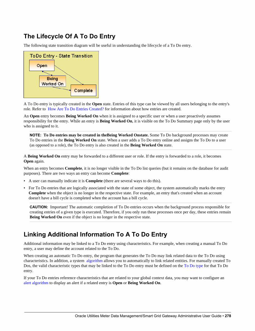
Oracle Utilities Meter Data Management/Smart Grid Gateway Administrative User Guide • 278
The Lifecycle Of A To Do EntryThe following state transition diagram will be useful in understanding the lifecycle of a To Do entry.
A To Do entry is typically created in the Open state. Entries of this type can be viewed by all users belonging to the entry'srole. Refer to How Are To Do Entries Created? for information about how entries are created.
An Open entry becomes Being Worked On when it is assigned to a specific user or when a user proactively assumesresponsibility for the entry. While an entry is Being Worked On, it is visible on the To Do Summary page only by the userwho is assigned to it.
NOTE: To Do entries may be created in theBeing Worked Onstate. Some To Do background processes may createTo Do entries in the Being Worked On state. When a user adds a To Do entry online and assigns the To Do to a user(as opposed to a role), the To Do entry is also created in the Being Worked On state.
A Being Worked On entry may be forwarded to a different user or role. If the entry is forwarded to a role, it becomesOpen again.
When an entry becomes Complete, it is no longer visible in the To Do list queries (but it remains on the database for auditpurposes). There are two ways an entry can become Complete:
• A user can manually indicate it is Complete (there are several ways to do this).
• For To Do entries that are logically associated with the state of some object, the system automatically marks the entryComplete when the object is no longer in the respective state. For example, an entry that's created when an accountdoesn't have a bill cycle is completed when the account has a bill cycle.
CAUTION: Important! The automatic completion of To Do entries occurs when the background process responsible forcreating entries of a given type is executed. Therefore, if you only run these processes once per day, these entries remainBeing Worked On even if the object is no longer in the respective state.
Linking Additional Information To A To Do EntryAdditional information may be linked to a To Do entry using characteristics. For example, when creating a manual To Doentry, a user may define the account related to the To Do.
When creating an automatic To Do entry, the program that generates the To Do may link related data to the To Do usingcharacteristics. In addition, a system algorithm allows you to automatically to link related entities. For manually created ToDos, the valid characteristic types that may be linked to the To Do entry must be defined on the To Do type for that To Doentry.
If your To Do entries reference characteristics that are related to your global context data, you may want to configure analert algorithm to display an alert if a related entry is Open or Being Worked On.
Oracle Utilities Meter Data Management/Smart Grid Gateway Administrative User Guide • 279
Implementing Additional To Do Entry Business RulesIf your business practice calls for additional validation rules or processing steps to take place after a To Do Entry is createdor updated, you may want to take advantage of the To Do Post Processing plug-ins defined on To Do type.
For example, you may want to validate that To Do entries are only assigned to users with the proper skill levels needed toresolve them. Refer to F1-VAL-SKILL for a sample algorithm handling such validation.
To Do Entries May Be Routed Out Of The SystemA To Do type can be configured so that its entries are interfaced to another system.
For example, a given To Do type can be configured to create an email message whenever a new To Do entry is created. Thefollowing points describe how to do this:
• Define the name of the background process responsible for interfacing the new To Do entries to another system on therespective To Do type. The base package contains a batch process called F1-TDEER that can be used for most situations.This batch process invokes the External Routing algorithms defined on each entry's To Do type.
• Plug in an appropriate External Routing algorithm on the respective To Do type. The logic in this type of algorithmperforms the interface efforts for a specific To Do entry. For example, if an email message should be created for a To Doentry, the logic in the algorithm would compose and send the email message(s) for a specific To Do entry.
Click here to see the algorithm types available for this system event.
Periodically Purging To Do EntriesCompleted To Do entries should be periodically purged from the system by executing the F1–TDPG background process.This background process offers you the following choices:
• You can purge all To Do entries older than a given number of days.
• You can purge To Do entries for a specific list of To Do types that are older than a given number of days.
• You can purge all To Do entries except for a specific list of To Do types that are older than a given number of days.
We want to stress that there is no system constraint as to the number of Completed To Do entries that may exist. You canretain these entries for as long as you desire. However, you will eventually end up with a very large number of Completedentries and these entries will cause the various To Do background processes to degrade over time. Therefore, you shouldperiodically purge Completed To Do entries as they exist only to satisfy auditing and reporting needs.
NOTE: Different retention periods for different types of To Do entries. Keep in mind that the purge program allowsyou to retain different types of entries for different periods of time.
Setting Up To Do OptionsThe topics in this section describe how to set up To Do management options.
Installation OptionsThe following section describes configuration setup on the installation options.
Oracle Utilities Meter Data Management/Smart Grid Gateway Administrative User Guide • 280
To Do Information May Be Formatted By An AlgorithmA To Do Information algorithm may be plugged in on the installation record to format the standard To Do informationthat appears throughout the system. This algorithm may be further overridden by a corresponding plug-in on the To DoType.
Set Additional Information Before A To Do Is CreatedA To Do Pre-creation algorithm may be plugged in on the installation record to set additional information for a To Doentry before it is created. Algorithms of this type are used for two common purposes:
• Linking context specific data to the To Do entry using characteristics. For example, Oracle Utilities Customer Careand Billing provides an algorithm that attempts to link a related person, account, premise, service agreement or servicepoint to a To Do entry based on its drill key value. Note, before you can set up this algorithm, you must define thecharacteristic types that you'll use to hold each of these entities. Also note that it is not necessary to define thesecharacteristics as valid characteristic types on the To Do type.
• Overriding the Role of a To Do entry based on specific configuration related to the To Do’s context data. For example,Oracle Utilities Customer Care and Billing provides an algorithm to determine a To Do role based on overrides related tothe account’s account management group or division.
AlertsIf your To Do entries reference characteristics related to your global context data and your product supports dashboardalerts generated by algorithms, you may want configure an algorithm to display an alert if the entry is Open or BeingWorked On for the data currently in context.
Refer to your product’s documentation to determine if these types of alerts are supported.
Next Assignment AlgorithmIf your organization opts to use the next assignment feature supported by the Current To Do dashboard zone, you need toplug-in a Next To Do Assignment algorithm into the installation options to determine the next To Do entry the user shouldwork on. Make sure you provide users with security access rights to the zone's next assignment action.
FASTPATH: Refer to the Current To Do zone for more information.
MessagesYou need only set up new messages if you use algorithms to create To Do entries or prefer different messages than thoseassociated with the base package's To Do types.
Feature ConfigurationThe base package is provided with a generic Activity Queue Management Feature Configuration type. You may wantto set up a feature configuration of this type to define any To Do management related options supporting business rulesspecific to your organization.
For example, the base package provides the following plug-ins to demonstrate a business practice where To Do entries areonly assigned to users with the proper skill levels to work on them.

Oracle Utilities Meter Data Management/Smart Grid Gateway Administrative User Guide • 281
• The base To Do Post Processing To Do Type algorithm F1-VAL-SKILL validates that a user has the necessary skilllevels required to work on a given To Do entry.
• The base Next To Do Assignment installation options algorithm F1-NEXT-ASSG only assigns To Do entries tousers that have the proper skills to work on them. This plug-in is only applicable if your organization practices workdistribution "on demand."
You must set up such an Activity Queue Management feature configuration if you want to use any of the above basepackage plug-ins.
The following points describe the various Option Types provided with the base package:
• Skill. This option provides a reference to a skill category. For example, if you were using characteristics to represent skillcategories then you should reference each characteristic type using this option.
• Override Skill. This option provides an override skill information reference for a specific message. For example, if youwere using a To Do Type characteristic to specify an override skill category and level for a specific message category /number then you would reference this characteristic type using this option.
NOTE: Skill Setup. Refer to the description of the above base package algorithms for further details on how to setupskill level information.
NOTE: More Options. Your implementation may define additional options types. You do this by add new lookupvalues to the lookup field F1QM_OPT_TYP_FLG.
NOTE: Only one. The system expects only one Activity Queue Management feature configuration to be defined.
Defining To Do RolesThis section describes the control table used to maintain To Do roles.
To Do Role - MainThe Main page is used to define basic information about a To Do role.
To maintain this information, select Admin > General > To Do Role.
Description of Page
Enter a unique To Do Role and Description for the To Do role.
The grid contains the ID of each User that may view and work on entries assigned to this role. The First Name and LastName associated with the user is displayed adjacent.
NOTE: System Default Role. The system supplies a default role F1_DFLT linked to each system To Do type. This isdone so that To Do functionality may be tested prior to the creation of appropriate business oriented To Do roles.
Where Used
Follow this link to view the tables that reference CI_ROLE in the data dictionary schema viewer.
In addition, various “type” objects or algorithms may reference a To Do role to use when creating a To Do for a givenbusiness scenario. This is dependent on your specific product.
Oracle Utilities Meter Data Management/Smart Grid Gateway Administrative User Guide • 282
To Do Role - To Do TypesThe To Do Types page defines the To Do types that may be viewed and worked on by users belonging to a given To Dorole.
To maintain this information, select Admin > To Do Role > Search and navigate to the To Do Types page.
Description of Page
Enter the ID of each To Do Type whose entries may be viewed and worked on by the role.
Use As Default is a display-only field that indicates if the role is assigned to newly created entries of this type. You maydefine the default role for a given To Do type on the To Do Type maintenance page.
CAUTION: If you remove a To Do type where this role is the default, you must define a new role as the default for theTo Do type. You do this on the To Do Type maintenance page.
Defining To Do TypesThis section describes the control table used to maintain To Do types.
To Do Type - MainThe Main page is used to define basic information about a To Do type.
FASTPATH: Refer to The Big Picture Of To Do Lists for more information about To Do types and To Do lists ingeneral.
To maintain this information, select Admin > General > To Do Type.
CAUTION: Important! If you introduce a To Do type, carefully consider its naming convention. Refer to System DataNaming Convention for more information.
Description of Page
Enter a unique To Do Type and Description for the To Do type.
Owner indicates if this entry is owned by the base package or by your implementation (Customer Modification).
Use the Detailed Description to provide further details related to the To Do Type.
Enter the default Priority of To Do entries of this type in respect of other To Do types. Refer to The Priority Of A To DoEntry for more information.
For To Do Type Usage, select Automatic if To Dos of this type are created by the system (i.e., a background process oralgorithm). Select Manual if a user can create a To Do of this type online.
Define the Navigation Option for the page into which the user is transferred when drilling down on a To Do entry of thistype.
Use Creation Process to define the background process, if any, that is used to manage (i.e., create and perhaps complete)entries of this type. A Creation Process need only be specified for those To Do types whose entries are created by abackground process. Refer to To Do Entries Created By Background Processes for more information.
Use Routing Process to define the background process that is used to download entries of a given type to an externalsystem, if any. A Routing Process need only be specified for those To Do types whose entries are routed to an externalsystem (e.g., an Email system or an auto-dialer). Refer to To Do Entries May Be Routed Out Of The System for moreinformation.

Oracle Utilities Meter Data Management/Smart Grid Gateway Administrative User Guide • 283
Use Message Category and Message Number to define the message associated with this To Do type's entries. Note:this message will only be used if the process that creates the To Do entry does not supply a specific message number. Forexample, the process that creates To Do entries that highlight bill segments that are in error would not use this message;rather, the entries are marked with the message associated with the bill segment's error.
Use the characteristics collection to define a Characteristic Type and Characteristic Value common to all To Do entriesof this type. You may enter more than one characteristic row for the same characteristic type, each associated with a uniqueSequence number. If not specified, the system defaults it to the next sequence number for the characteristic type.
Where Used
Follow this link to view the tables that reference CI_TD_TYPE in the data dictionary schema viewer.
To Do Type - RolesThe Roles page defines the roles who may view and work on entries of a given To Do type.
To maintain this information, select Admin > To Do Type > Search and navigate to the Roles page.
Description of Page
Enter each To Do Role that may view and work on entries of a given type. Turn on Use as Default if the role should beassigned to newly created entries of this type. Only one role may be defined as the default per To Do type.
FASTPATH: Refer to To Do Entries Reference A Role for more information about roles and To Do entries.
To Do Type - Sort KeysThe Sort Keys page defines the various ways a To Do list's entries may be sorted. For example, when you look at thebill segment error To Do List, you have the option of sorting the entries in error number order, account name order, or incustomer class order.
To maintain this information, select Admin > To Do Type > Search and navigate to the Sort Keys page.
CAUTION: Do not change this information unless you are positive that the process / algorithm that creates entries of agiven type stores this information on the entries.
Description of Page
The following fields display for each sort key.
Sequence is the unique ID of the sort key.
Description is the description of the sort key that appears on the To Do list.
Use as Default indicates the default sort key (the one that is initially used when a user opens a To Do list). Only one sortkey may be defined as the default per To Do type.
Sort Order indicates whether the To Do entries should be sorted in Ascending or Descending order when this sort key isused.
Owner indicates if this entry is owned by the base package or by your implementation (Customer Modification).
To Do Type - Drill KeysThe Drill Keys page defines the keys passed to the application service (defined on the Main page) when you drill down onan entry of a given type.
To maintain this information, select Admin > To Do Type > Search and navigate to the Drill Keys page.

Oracle Utilities Meter Data Management/Smart Grid Gateway Administrative User Guide • 284
CAUTION: Do not change this information unless you are positive that the process / algorithm that creates entries of agiven type stores this information on the entries.
Description of Page
Navigation Option shows the page into which the user is transferred when drilling down on a To Do entry of this type.
The following fields display for each drill key.
Sequence is the unique ID of the drill key.
Table and Field are passed to the application service when you drill down on an entry of a given type.
Owner indicates if this entry is owned by the base package or by your implementation (Customer Modification).
To Do Type - Message OverridesThe Message Overrides page is used if you want To Do entries that reference a given message category / number to berouted to a specific To Do role (or suppressed altogether) or if you want to associate a script to a given message category /number.
FASTPATH: Refer to To Do Entries Reference A Role and To Do Entries Can Be Rerouted Or Suppressed for moreinformation.
To maintain this information, select Admin > To Do Type > Search and navigate to the Message Overrides page.
Description of Page
The following fields display for each override.
Message Category and Number allow the message to be overridden.
Exclude To Do Entry indicates if a To Do entry of this type that references the adjacent Message Category and Numbershould not be created.
Override Role indicates the to do role to which a To Do entry of this type that references the adjacent Message Categoryand Number should be addressed. This field is protected if Exclude To Do Entry is on.
Script indicates the script that should execute when a user drills down on a To Do entry of this type that references theadjacent Message Category and Number. This field is protected if Exclude To Do Entry is on. Refer to Working On ATo Do Entry for more information.
To Do Type - To Do CharacteristicsThe To Do Characteristics page defines characteristics that can be defined for To Do entries of this type. The characteristictypes for characteristics that are linked to the To Do entry as a result of a pre-creation algorithm do not need to be definedhere.
To maintain this information, select Admin > General > To Do Type > Search and navigate to the To DoCharacteristics page.
Turn on the Required switch if the Characteristic Type must be defined on To Do entries of this type.
Enter a Characteristic Value to use as the default for a given Characteristic Type when the Default switch is turned on.Use Sequence to control the order in which characteristics are defaulted.
To Do Type - AlgorithmsThe To Do Algorithms page defines the algorithms that should be executed for a given To Do type.
Oracle Utilities Meter Data Management/Smart Grid Gateway Administrative User Guide • 285
To maintain this information, select Admin > To Do Type > Search and navigate to the Algorithms page.
Description of Page
The grid contains Algorithms that control important To Do functions. If you haven't already done so, you must set up theappropriate algorithms in your system. You must define the following for each algorithm:
• Specify the System Event with which the algorithm is associated (see the table that follows for a description of allpossible events).
• Specify the Sequence Number and Algorithm for each system event. You can set the Sequence Number to 10 unlessyou have a System Event that has multiple Algorithms. In this case, you need to tell the system the Sequence in whichthey should execute.
The following table describes each System Event.
System Event Optional / Required DescriptionCalculate Priority Optional Algorithms of this type may be used to
calculate a To Do entry's priority. They arecalled initially when a To Do entry is createdand each time it gets updated so long asthe To Do entry's priority has not beenmanually overridden. Once overridden, thesealgorithms are not called anymore.Note that it is not the responsibility of thealgorithms to actually update the To Do entrywith the calculated priority value but ratheronly return the calculated value. The systemcarries out the update as necessary.If more than one algorithm is plugged-in thesystem calls them one by one until the first toreturn a calculated priority.Click here to see the algorithm types availablefor this system event.
External Routing Optional Algorithms of this type may be used to route aTo Do entry to an external system.The base package F1-TDEER backgroundprocess invokes the algorithms for every ToDo entry that its type references the processas the Routing Process and that the entrywas not already routed. The backgroundprocess marks an entry as routed by updatingit with the batch control's current run number.If more than one algorithm is plugged-in thebatch process calls them one by one until thefirst to indicate the To Do entry was routed.Click here to see the algorithm types availablefor this system event.
To Do Information Optional We use the term "To Do information" todescribe the basic information that appearsthroughout the system to describe a ToDo entry. The data that appears in "ToDo information" is constructed using thisalgorithm.Plug an algorithm into this spot to override the"To Do information" algorithm on installationoptions or the system default "To Doinformation" if no such algorithm is defined oninstallation options.Click here to see the algorithm types availablefor this system event.
To Do Post-Processing Optional Algorithms of this type may be used tovalidate and/or further process a To Do entrythat has been added or updated.
Oracle Utilities Meter Data Management/Smart Grid Gateway Administrative User Guide • 286
System Event Optional / Required DescriptionClick here to see the algorithm types availablefor this system event.
List of System To Do TypesThe To Do types available to use with the product are found in the To Do Type page. In addition, they may be viewed inthe application viewer's To Do type viewer. If your implementation adds To Do types, you may regenerate the applicationviewer to see your additions reflected there.
Implementing The To Do EntriesTo enable the To Do entries visible in the To Do Type page and application viewer, you must configure the system asfollows:
• Define the To Do roles associated with each To Do type and link the appropriate users to them. Once you have definedthe roles appropriate for your organization's To Do types, remove the reference to this system default role F1_DFLT.Refer to To Do Entries Reference A Role for more information.
• For any To Do Type that is provided for a specific background process, the To Do simply needs to reference theappropriate Creation Background Process. When the background process is scheduled, To Dos are created based onthe logic of the related background process. This applies to To Dos Created for Object-Specific Error Conditions andDedicated To Do Background Processes.
• For any To Do Type that is provided for creation by an algorithm or other process, there may be configuration requiredto populate that To Do type as an algorithm parameter or as an attribute on a control table.
NOTE: Refer to the description of the To Do type for more information.
Background ProcessesThis chapter covers various topics related to background processes. Besides providing an overview of background processfunctionality, the various tools available within the application to define, submit and monitor background processes arecovered.
NOTE: Your specific source application may have additional background process topics. Please refer to thedocumentation section that applies to your source application for more information.
Understanding Background ProcessesThis section describes various topics related to the background processes that perform many important functions throughoutyour product such as:
• Processing To Do Entries
• Monitor processes that select records in a given state to progress them to their next state in their lifecycle
• Processes that purge data
• Processes that extract data
• And many more...
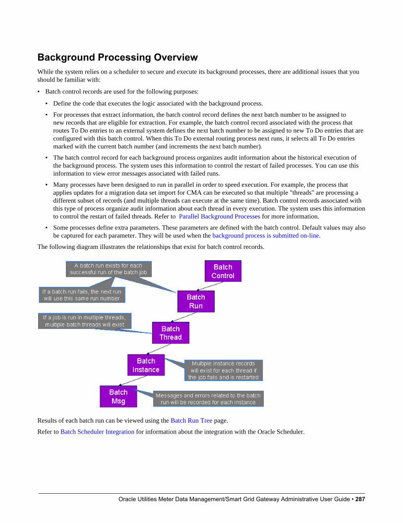
Oracle Utilities Meter Data Management/Smart Grid Gateway Administrative User Guide • 287
Background Processing OverviewWhile the system relies on a scheduler to secure and execute its background processes, there are additional issues that youshould be familiar with:
• Batch control records are used for the following purposes:
• Define the code that executes the logic associated with the background process.
• For processes that extract information, the batch control record defines the next batch number to be assigned tonew records that are eligible for extraction. For example, the batch control record associated with the process thatroutes To Do entries to an external system defines the next batch number to be assigned to new To Do entries that areconfigured with this batch control. When this To Do external routing process next runs, it selects all To Do entriesmarked with the current batch number (and increments the next batch number).
• The batch control record for each background process organizes audit information about the historical execution ofthe background process. The system uses this information to control the restart of failed processes. You can use thisinformation to view error messages associated with failed runs.
• Many processes have been designed to run in parallel in order to speed execution. For example, the process thatapplies updates for a migration data set import for CMA can be executed so that multiple "threads" are processing adifferent subset of records (and multiple threads can execute at the same time). Batch control records associated withthis type of process organize audit information about each thread in every execution. The system uses this informationto control the restart of failed threads. Refer to Parallel Background Processes for more information.
• Some processes define extra parameters. These parameters are defined with the batch control. Default values may alsobe captured for each parameter. They will be used when the background process is submitted on-line.
The following diagram illustrates the relationships that exist for batch control records.
Results of each batch run can be viewed using the Batch Run Tree page.
Refer to Batch Scheduler Integration for information about the integration with the Oracle Scheduler.
Oracle Utilities Meter Data Management/Smart Grid Gateway Administrative User Guide • 288
Parallel Background ProcessesMany processes have been designed to run in parallel in order to speed execution. This is referred to as running the processwith multiple “threads”.
The system provides two strategies for distributing the data to the multiple threads.
• Thread Level SQL Select. This strategy is sometimes referred to as the “thread iterator” strategy. In this strategy, thebatch job uses the primary key to figure out how to evenly distribute key ranges to each thread. Each thread is thenresponsible for selecting the records. In this strategy, the threads should also re-select the data periodically to releasethe cursor, which aids in performance. Note that this strategy is preferred but may only be used under the followingconditions:
• The data from only one maintenance object is being processed.
• The primary key for the maintenance object is a single, numeric system generated key.
NOTE: Parameters may be used to override the low and high id. Refer to Parameters Supplied to BackgroundProcesses for more information.
• Job Level SQL Select. This strategy is sometimes referred to as the “standard commit” strategy. In this strategy, thekeys for the records to be processed by the batch job are all selected first and stored in a temporary table. The batchjob then supplies each thread with a range of keys that it should process. This strategy is used if multiple maintenanceobjects are being processed by the batch job; if the primary key of the maintenance object has multiple parts or if theprimary key is non-numeric.
The multi-threading logic relies on the fact that primary keys for master and transaction data are typically system generatedrandom keys. In addition, if the data is partitioned, it is expected to be partitioned based on the primary key.
NOTE: The detailed description in the metadata for each batch control provided with the system should indicate if itmay be run in parallel. Note that the strategy used is not typically indicated in the detailed description.
NOTE: Overriding the thread ranges. Your implementation has the ability to override the thread ranges if certain datain your system takes longer to process. For example, imagine you have a single account in Oracle Utilities CustomerCare and Billing that has thousands of service agreements (maybe the account for a large corporation or a major city).You may want to set up the thread ranges to put this large account into its own thread and distribute the other accountsto the other threads. To do this, you should create the appropriate batch thread records ahead of time in a status ofThread Ready ( 50) with the key ranges pre-populated. Note that the base product does not provide the ability to addbatch thread records online. If you are interested in more information about this technique, contact Customer Support.
Optimal Thread CountRunning a background process in multiple threads is almost always faster than running it in a single thread. The trick isdetermining the number of threads that is optimal for each process.
NOTE: A good rule of thumb is to have one thread for every 100 MHz of application server CPU available. Forexample if you have four 450 MHz processors available on your application server, you can start with 18 threads tobegin your testing: (450 * 4) / 100 = 18.
This is a rule of thumb because each process is different and is dependent on the data in your database. Also, your hardwareconfiguration (i.e., number of processors, speed of your disk drives, speed of the network between the database server andthe application server) has an impact on the optimal number of threads. Please follow these guidelines to determine theoptimal number of threads for each background process:
Oracle Utilities Meter Data Management/Smart Grid Gateway Administrative User Guide • 289
• Execute the background process using the number of threads dictated by the rule of thumb (described above). During thisexecution, monitor the utilization percentage of your application server, database server and network traffic.
• If you find that your database server has hit 100% utilization, but your application server hasn't one of the following isprobably occurring:
• There may be a problematic SQL statement executing during the process. You must capture a database trace toidentify the problem SQL.
• It is also possible that your commit frequency may be too large. Commit frequency is a parameter supplied to everybackground process. If it is too large, the database's hold queues can start swapping. Refer to Parameters Supplied toBackground Processes for more information about this parameter.
• It is normal if you find that your application server has hit 100% utilization but your database server has not. This isnormal because, in general, all processes are CPU bound and not IO bound. At this point, you should decrease thenumber of threads until just under 100% of the application server utilization is achieved. And this will be the optimalnumber of threads required for this background process.
• If you find that your application server has not hit 100% utilization, you should increase the number of threads untilyou achieve just under 100% utilization on the application server. And remember, the application server should achieve100% utilization before the database server reaches 100% utilization. If this proves not to be true, something is probablywrong with an SQL statement and you must capture an SQL trace to determine the culprit.
Another way to achieve similar results is to start out with a small number of threads and increase the number of threadsuntil you have maximized throughput. The definition of "throughput" may differ for each process but can be generalizedas a simple count of the records processed in the batch run tree. For example, in the Billing background process in OracleUtilities Customer Care and Billing, throughput is the number of bills processed per minute. If you opt to use this method,we recommend you graph a curve of throughput vs. number of threads. The graph should display a curve that is steep at firstbut then flattens as more threads are added. Eventually adding more threads will cause the throughput to decline. Throughthis type of analysis you can determine the optimum number of threads to execute for any given process.
Parameters Supplied To Background ProcessesThis section describes the various types of parameters that are supplied to background processes.
General ParametersThe following information is passed to every background process.
• Batch code. Batch code is the unique identifier of the background process.
• Batch thread number. Thread number is only used for background processes that can be run in multiple parallelthreads. It contains the relative thread number of the process. For example, if the billing process has been set up to run in20 parallel threads, each of the 20 instances receives its relative thread number (1 through 20). Refer to Optimal ThreadCount for Parallel Background Processes for more information.
• Batch thread count. Thread count is only used for background processes that can be run in multiple parallel threads. Itcontains the total number of parallel threads that have been scheduled. For example, if the billing process has been set upto run in 20 parallel threads, each of the 20 instances receives a thread count of 20. Refer to Optimal Thread Count forParallel Background Processes for more information.
• Batch rerun number. Rerun number is only used for background processes that download information that belongs togiven run number. It should only be supplied if you need to download an historical run (rather than the latest run).
• Batch business date. Business date is only used for background processes that use the current date in their processing.For example, a billing process may use the business date to determine which bill cycles should be downloaded. If thisparameter is left blank, the system date is used. If supplied, this date must be in the format YYYY-MM-DD. Note: thisparameter is only used during QA to test how processes behave over time.
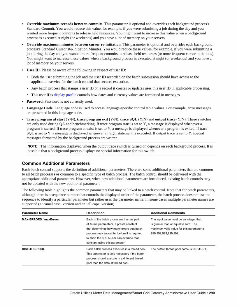
Oracle Utilities Meter Data Management/Smart Grid Gateway Administrative User Guide • 290
• Override maximum records between commits. This parameter is optional and overrides each background process'sStandard Commit. You would reduce this value, for example, if you were submitting a job during the day and youwanted more frequent commits to release held resources. You might want to increase this value when a backgroundprocess is executed at night (or weekends) and you have a lot of memory on your servers.
• Override maximum minutes between cursor re-initiation. This parameter is optional and overrides each backgroundprocess's Standard Cursor Re-Initiation Minutes. You would reduce these values, for example, if you were submitting ajob during the day and you wanted more frequent commits to release held resources (or more frequent cursor initiations).You might want to increase these values when a background process is executed at night (or weekends) and you have alot of memory on your servers.
• User ID. Please be aware of the following in respect of user ID:
• Both the user submitting the job and the user ID recorded on the batch submission should have access to theapplication service for the batch control that secures execution.
• Any batch process that stamps a user ID on a record it creates or updates uses this user ID in applicable processing.
• This user ID's display profile controls how dates and currency values are formatted in messages.
• Password. Password is not currently used.
• Language Code. Language code is used to access language-specific control table values. For example, error messagesare presented in this language code.
• Trace program at start (Y/N), trace program exit (Y/N), trace SQL (Y/N) and output trace (Y/N). These switchesare only used during QA and benchmarking. If trace program start is set to Y, a message is displayed whenever aprogram is started. If trace program at exist is set to Y, a message is displayed whenever a program is exited. If traceSQL is set to Y, a message is displayed whenever an SQL statement is executed. If output trace is set to Y, specialmessages formatted by the background process are written.
NOTE: The information displayed when the output trace switch is turned on depends on each background process. It ispossible that a background process displays no special information for this switch.
Common Additional ParametersEach batch control supports the definition of additional parameters. There are some additional parameters that are commonto all batch processes or common to a specific type of batch process. The batch control should be delivered with theappropriate additional parameters. However, when new additional parameters are introduced, existing batch controls maynot be updated with the new additional parameter.
The following table highlights the common parameters that may be linked to a batch control. Note that for batch parameters,although there is a sequence number that controls the displayed order of the parameter, the batch process does not use thesequence to identify a particular parameter but rather uses the parameter name. In some cases multiple parameter names aresupported (a ‘camel case’ version and an ‘all caps’ version).
Parameter Name Description Additional Comments
MAX-ERRORS / maxErrors Each of the batch processes has, as partof its run parameters, a preset constantthat determines how many errors that batchprocess may encounter before it is requiredto abort the run. A user can override thatconstant using this parameter.
The input value must be an integer thatis greater than or equal to zero. Themaximum valid value for this parameter is999,999,999,999,999.
DIST-THD-POOL Each batch process executes in a thread pool.This parameter is only necessary if the batchprocess should execute in a different threadpool than the default thread pool.
The default thread pool name is DEFAULT.

Oracle Utilities Meter Data Management/Smart Grid Gateway Administrative User Guide • 291
Parameter Name Description Additional Comments
emailMode When the batch job is submitted with anassociated email address, the default logicis to send an email when the job completesregardless of success or failure. Use thisparameter to limit the email based on thestatus of the job when it ends.
Valid Values
• ERROR — send an email only when thejob ends in Error status.
• SUCCESS — send an email only whenthe job ends in successfully.
• ALL — always send an email only whenthe job ends. (This is the default.)
The following parameters are only applicable to jobs that use the Thread Level SQL Select method of distributing work to threads as described inParallel Background Processes.
overrideLowIdValue Specifies a new low id to use in calculatingthe range for a thread. The framework bydefault assumes that the Id is between 0's(e.g. 000000000) and 9's (e.g. 9999999999),but this parameter will override the low value.
The parameter value can be an actualnumber or it can be set to auto. If auto isconfigured, it is set to the lowest current valueon the database table associated with thebackground process.
overrideHighIdValue Specifies a new high id to use in calculatingthe range for a thread. The framework bydefault assumes that the Id is between 0's(e.g. 000000000) and 9's (e.g. 9999999999),but this parameter will override the high value.
The parameter value can be an actualnumber or it can be set to auto. If auto isconfigured, it is set to the highest currentvalue on the database table associated withthe background process.
idRangeOverrideClass Use this parameter to specify a custom classto do thread range calculation. During batchexecution, this override class is instantiatedand the setter methods called to initializethe Ids as required. The low and high gettermethods are called to retrieve the high andlow ids to be used for the run.
The class name specifiedmust implement interfacecom.splwg.base.api.batch.BatchIdRangeOverride.
The following parameters are only applicable to jobs that perform a single commit, for example for extract batch jobs.
numRecordsToFlush This parameter defines how frequently to flushthe Hibernate cache to prevent high heapconsumption and Out Of Memory Errors.
Specific Batch ParametersSome background processes define additional parameters that are specific to their functionality. When a process receivesadditional parameters, they are defined and documented in the batch control entry in the application. They are also visible inthe batch control viewer (part of the application viewer).
Indicating a File PathSome of the system background processes use extra parameters to indicate a File Path and/or File Name for an input file oran output file. For example, most extract processes use File Path and File Name parameter to indicate where to place theoutput file.
When supplying a FILE-PATH variable, the directory specified in the FILE-PATH must already exist and must grantwrite access to the administrator account for the product. You may need to verify a proper location with your systemsadministrator.

Oracle Utilities Meter Data Management/Smart Grid Gateway Administrative User Guide • 292
The syntax of the FILE-PATH depends on the platform used for the product application server. Contact your systemadministrator for verification. For example, if the platform is UNIX, use forward slashes and be sure to put a trailing slash,for example /spltemp/filepath/.
Processing ErrorsWhen a background process detects an error, the error may or may not be related to a specific object that is being processed.For example, if the program finds an error during batch parameter validation, this error is not object-specific. However, ifthe program finds an error while processing a specific bill, this error is object-specific. The system reports errors in one ofthe following ways:
• Errors that are not object-specific are written to the error message log in the Batch Run Tree.
• Some batch processes create entries in an "exception table" for certain object-specific errors. For example, an errordetected in the creation of a bill in Oracle Utilities Customer Care and Billing may be written to the bill exception table.If an error is written to an exception table, it does not appear in the batch run tree. For each exception table, there is anassociated to do entry process that creates a To Do Entry for each error to allow a user to correct the problem on-line.
• For some background processes, errors that do not result in the creation of an exception record may instead generate aTo Do entry directly. For these processes, if you wish the system to directly create a To Do entry, you must configurethe To Do type appropriately. Refer to To Do entry for object-specific errors for information about configuring the ToDo type. If the background process detects an object specific error and you have configured the system to create a To Doentry, the error is not written to the batch run tree. If you have configured your To Do type to not create To Do entries forcertain errors, these errors are written to the batch run tree.
NOTE: Some processes create exceptions and To Do entries. It is possible for a background process to create entriesin an exception table and create To Do entries directly, depending on the error. Consider batch billing in Oracle UtilitiesCustomer Care and Billing; any conditions that cause a bill or bill segment to be created in error status result in arecord added to the bill exception table or the bill segment exception table. However, any object-specific error that is notrelated to a specific bill or bill segment or any error that prevents a bill or bill segment from being created may result ina To Do entry for the object-specific error.
Error Post-Processing LogicThe product supports executing one or more algorithms when a batch process encounters an error that causes execution tostop. This allows for some special processing to occur to handle the failure of the batch job. Algorithms for this plug-in spotreceive the batch control, batch run number, batch processing business date, number of threads and the list of the ad hocparameters of the batch job. The following are some examples of functionality that may be executed when a batch job fails:
• Another object or record that is monitoring the batch job may have its status updated to reflect the batch status.
• An outbound message service may be invoked to perform a task related to the failure.
Note that the units of work for all threads are committed prior to executing the error post-processing logic.
Post-Processing LogicThe product supports executing one or more algorithms after all the threads of a given batch job have completed. Thisallows for some special processing to occur at the end of a batch job. Algorithms for this plug-in spot receive the batchcontrol, batch run number, batch processing business date, number of threads and the list of the ad hoc parameters of thebatch job. The following are some examples of functionality that may be executed at the end of a batch job:
• Another dependent batch job can be kicked off. Note that this use case is only needed when the multiple dependent jobsare not part of a scheduler (which can also detect the successful end of one batch job so as to submit the next job).
• Statistics for the batch run may be analyzed and based on results, a To Do Entry may be sent to an administrator.
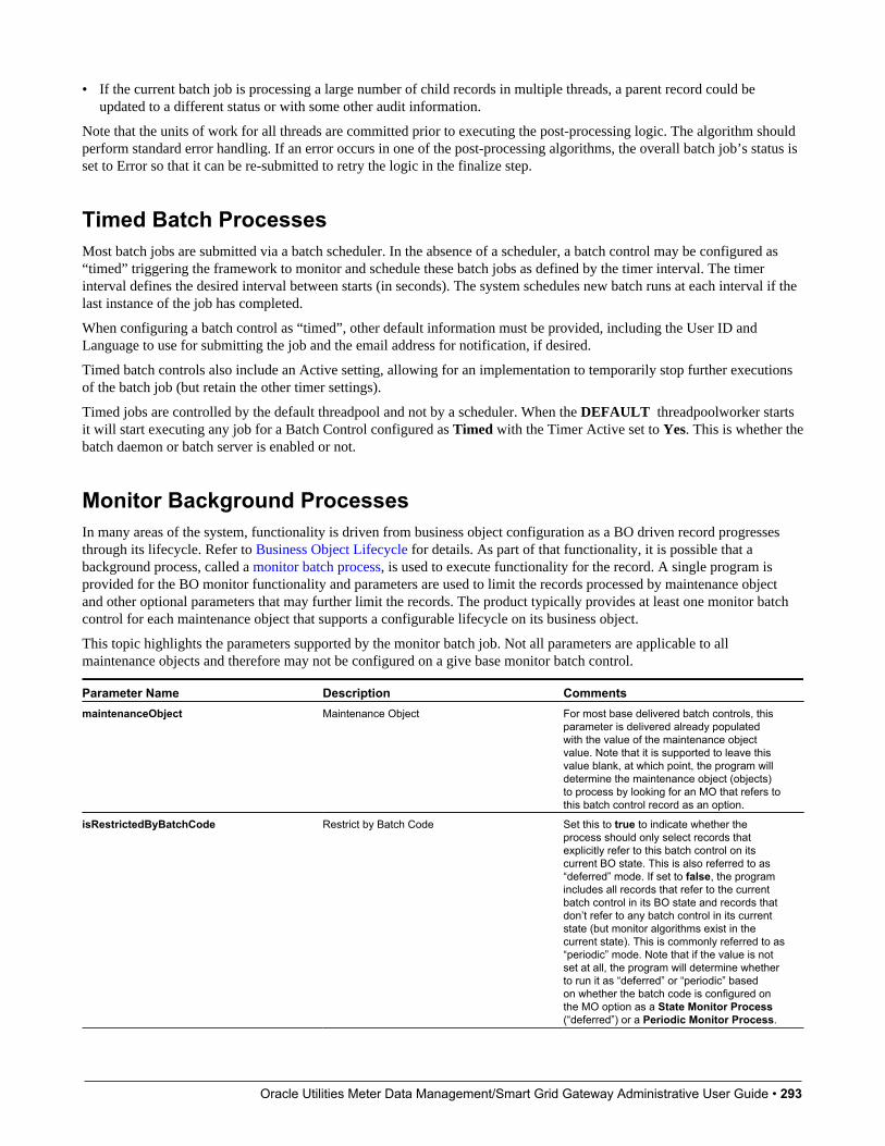
Oracle Utilities Meter Data Management/Smart Grid Gateway Administrative User Guide • 293
• If the current batch job is processing a large number of child records in multiple threads, a parent record could beupdated to a different status or with some other audit information.
Note that the units of work for all threads are committed prior to executing the post-processing logic. The algorithm shouldperform standard error handling. If an error occurs in one of the post-processing algorithms, the overall batch job’s status isset to Error so that it can be re-submitted to retry the logic in the finalize step.
Timed Batch ProcessesMost batch jobs are submitted via a batch scheduler. In the absence of a scheduler, a batch control may be configured as“timed” triggering the framework to monitor and schedule these batch jobs as defined by the timer interval. The timerinterval defines the desired interval between starts (in seconds). The system schedules new batch runs at each interval if thelast instance of the job has completed.
When configuring a batch control as “timed”, other default information must be provided, including the User ID andLanguage to use for submitting the job and the email address for notification, if desired.
Timed batch controls also include an Active setting, allowing for an implementation to temporarily stop further executionsof the batch job (but retain the other timer settings).
Timed jobs are controlled by the default threadpool and not by a scheduler. When the DEFAULT threadpoolworker startsit will start executing any job for a Batch Control configured as Timed with the Timer Active set to Yes. This is whether thebatch daemon or batch server is enabled or not.
Monitor Background ProcessesIn many areas of the system, functionality is driven from business object configuration as a BO driven record progressesthrough its lifecycle. Refer to Business Object Lifecycle for details. As part of that functionality, it is possible that abackground process, called a monitor batch process, is used to execute functionality for the record. A single program isprovided for the BO monitor functionality and parameters are used to limit the records processed by maintenance objectand other optional parameters that may further limit the records. The product typically provides at least one monitor batchcontrol for each maintenance object that supports a configurable lifecycle on its business object.
This topic highlights the parameters supported by the monitor batch job. Not all parameters are applicable to allmaintenance objects and therefore may not be configured on a give base monitor batch control.
Parameter Name Description CommentsmaintenanceObject Maintenance Object For most base delivered batch controls, this
parameter is delivered already populatedwith the value of the maintenance objectvalue. Note that it is supported to leave thisvalue blank, at which point, the program willdetermine the maintenance object (objects)to process by looking for an MO that refers tothis batch control record as an option.
isRestrictedByBatchCode Restrict by Batch Code Set this to true to indicate whether theprocess should only select records thatexplicitly refer to this batch control on itscurrent BO state. This is also referred to as“deferred” mode. If set to false, the programincludes all records that refer to the currentbatch control in its BO state and records thatdon’t refer to any batch control in its currentstate (but monitor algorithms exist in thecurrent state). This is commonly referred to as“periodic” mode. Note that if the value is notset at all, the program will determine whetherto run it as “deferred” or “periodic” basedon whether the batch code is configured onthe MO option as a State Monitor Process (“deferred”) or a Periodic Monitor Process.
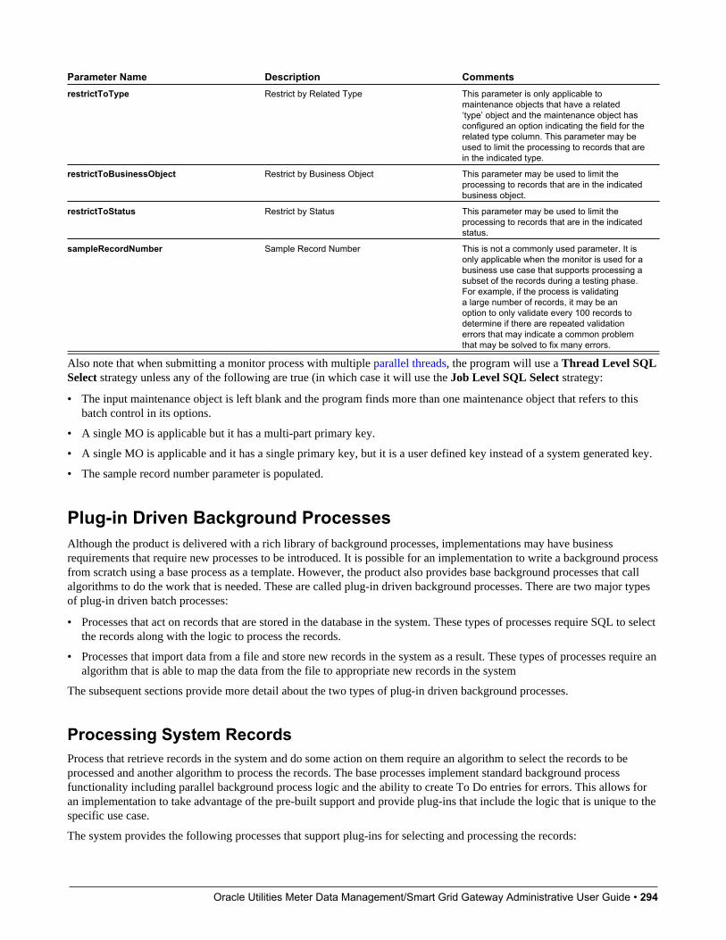
Oracle Utilities Meter Data Management/Smart Grid Gateway Administrative User Guide • 294
Parameter Name Description CommentsrestrictToType Restrict by Related Type This parameter is only applicable to
maintenance objects that have a related‘type’ object and the maintenance object hasconfigured an option indicating the field for therelated type column. This parameter may beused to limit the processing to records that arein the indicated type.
restrictToBusinessObject Restrict by Business Object This parameter may be used to limit theprocessing to records that are in the indicatedbusiness object.
restrictToStatus Restrict by Status This parameter may be used to limit theprocessing to records that are in the indicatedstatus.
sampleRecordNumber Sample Record Number This is not a commonly used parameter. It isonly applicable when the monitor is used for abusiness use case that supports processing asubset of the records during a testing phase.For example, if the process is validatinga large number of records, it may be anoption to only validate every 100 records todetermine if there are repeated validationerrors that may indicate a common problemthat may be solved to fix many errors.
Also note that when submitting a monitor process with multiple parallel threads, the program will use a Thread Level SQLSelect strategy unless any of the following are true (in which case it will use the Job Level SQL Select strategy:
• The input maintenance object is left blank and the program finds more than one maintenance object that refers to thisbatch control in its options.
• A single MO is applicable but it has a multi-part primary key.
• A single MO is applicable and it has a single primary key, but it is a user defined key instead of a system generated key.
• The sample record number parameter is populated.
Plug-in Driven Background ProcessesAlthough the product is delivered with a rich library of background processes, implementations may have businessrequirements that require new processes to be introduced. It is possible for an implementation to write a background processfrom scratch using a base process as a template. However, the product also provides base background processes that callalgorithms to do the work that is needed. These are called plug-in driven background processes. There are two major typesof plug-in driven batch processes:
• Processes that act on records that are stored in the database in the system. These types of processes require SQL to selectthe records along with the logic to process the records.
• Processes that import data from a file and store new records in the system as a result. These types of processes require analgorithm that is able to map the data from the file to appropriate new records in the system
The subsequent sections provide more detail about the two types of plug-in driven background processes.
Processing System RecordsProcess that retrieve records in the system and do some action on them require an algorithm to select the records to beprocessed and another algorithm to process the records. The base processes implement standard background processfunctionality including parallel background process logic and the ability to create To Do entries for errors. This allows foran implementation to take advantage of the pre-built support and provide plug-ins that include the logic that is unique to thespecific use case.
The system provides the following processes that support plug-ins for selecting and processing the records:

Oracle Utilities Meter Data Management/Smart Grid Gateway Administrative User Guide • 295
• Ad-hoc Process. This background process is provided for implementations that have some custom business logic thatneeds to be performed on a group of records. The base batch control Plug-in Driven Generic Template (F1-PDBG) maybe used as a template.
• Extract Process. This background process is provided for implementations that have extract files to produce forintegration with external systems. The process includes parameters to configure the file path and file name for the createdfile along with other parameters to control how the file is formatted. The base batch control Plug-in Driven ExtractTemplate (F1-PDBEX) may be used as a template.
The following sections provide more information about implementing this type of functionality.
Select Records AlgorithmThe first important algorithm to design when implementing a plug-in driven batch process is the Select Records algorithm,plugged in on the batch control page. This algorithm type must define the first parameter as the SQL. The batch job willdirectly access the SQL parameter value in the metadata (rather than invoking the algorithm). All other parameters areavailable for the algorithm to use for its own logic.
In addition, when invoking the algorithm, it must return the strategy to use (Thread Level SQL Select or Job Level SQLSelect. Refer to parallel background processes for more information about the two strategies and when to use each. Whenchoosing the Thread Level SQL Select strategy, the algorithm should return the name of the primary key in the Key Fieldparameter. In addition, the SQL should include a BETWEEN clause that includes the bind variables for the low and highID for the ranges. See below for the bind variable syntax.
If the SQL statement includes variables that are determined at execution time, it must use bind parameters. Bind parametersare referenced in the SQL statement using a colon and a parameter name (for example :parameter). There are somevariables provided by the system that are populated by the batch job at execution time. These have f1. as its prefix.
The system supports the following pre-defined bind parameters:
• :f1.lowID and :f1.highID - these should be used in the BETWEEN clause for the Thread Level SQL Select strategy.The batch job will substitute the appropriate ID range as required.
• :f1.batchCode and :f1.batchNumber - these are common attributes of the batch control that are referenced on a recordfor selection purposes. Note that the batch run number is set according to whether the batch job is a re-run of a previousrun or not.
• :f1.businessDate - the batch job will populate the input batch business date, if populated otherwise the current date.
For any other custom parameters, the Select Records algorithm may return one or more sets of field name / variable name /value where the variable name matches a bind variable in the SQL. The field name provides information about data type andlength that assists the SQL binding logic to properly substitute the values. Note that the variable name cannot start with f1.as its prefix. The batch job will use the value returned by the algorithm to set the bind parameter in the SQL statement.
The plug in spot receives a list of the ad hoc parameters for the batch job as name / value pairs. If the list includesparameters whose values are to be used in selecting records, your algorithm may be used to identify the relevant batchparameter passed as input and populate the field name and output bind variable appropriately.
The product provides a base algorithm type for this plug-in spot that simply defines a parameter for the SQL. It alsoincludes parameters for the strategy and the key field name. This algorithm type may be used by any custom batch processwhere the SQL does not rely on any special bind variables that must be determined. Simply create an algorithm for thealgorithm type and provide the appropriate SQL. Refer to the algorithm type Select Records by Predefined Query (F1-PDB-SR) for more information.
Process Records AlgorithmThe other important algorithm to design when implementing a plug-in driven batch process is the Process Record algorithm,plugged in on the batch control page. This algorithm is called for each record selected for the process. It receives all theinformation that was selected from the Select Records plug-in.
For the ad-hoc processing batch process, algorithms plugged into this spot are responsible for doing the work for eachrecord based on the desired logic.
Oracle Utilities Meter Data Management/Smart Grid Gateway Administrative User Guide • 296
For the extract batch process, algorithms plugged into this spot are responsible for returning the data that should be writtento the file in one or more XML instances along with the schema name(s) that describes the XML instance(s). For XMLoutput format, the batch process will write the XML instance data as returned by the plug-in. For fixed position or CSVoutput format, the batch process will convert the XML instance data to the appropriate format and add it to the file.
Also note that algorithms for this plug-in spot will be passed two Booleans, isFirst and isLast, to indicate if the currentwork unit is the first and/or last for that thread. This allows for the plug-in to do additional work if needed. Note that theisFirst indication is available for both types of batch processes, ad-hoc and extract. However, the isLast indication is onlyapplicable for the file extract batch. For the ad-hoc batch process this value will always be set to false. Extracts will alwaysexecute in a single database transaction. In a single transaction run, any error causes the run to be aborted so that it restartsfrom the beginning when resubmitted. This is done to avoid partial files being written along with inaccurate setting of theisLast element.
The product provides a base algorithm type for this plug-in spot that illustrates the technique to follow when implementingan extract type of plug-in driven background process. Refer to the algorithm type General Process - Sample Process RecordExtract (F1-GENPROCEX) for more information.
Configuring a New ProcessThe following points summarize the steps needed to implement a new background process that act on records in the systemusing plug-ins for the specific functionality:
• Verify the SQL that the background process should execute. Keep in mind that all the data selected in the SQL isavailable to pass to the plug-in that processes the records. If the performance of the background process is important, besure to consult with a DBA when designing the SQL.
• If the SQL does not require any custom variables to substitute at runtime, create an algorithm for the base algorithmtype F1-PDB-SR and configure the SQL. In addition, configure the strategy and the primary key name (for theThread Level SQL Select strategy).
• If the SQL requires custom variables, a new plug-in script must be designed and coded to populate the variable namesand values using the algorithm entity Batch Control - Select Records. Besides defining the variables, the algorithmmust also indicate the strategy and the primary key name (for the Thread Level SQL Select strategy). Define thealgorithm type for the newly created script. The first parameter of the algorithm type must be the SQL as illustrated inthe base algorithm type. Note that the other parameters are available for use by this algorithm type if needed. Definethe algorithm, populating the SQL as appropriate (using the custom variables).
• Design the logic required for each record and create a plug-in script where the algorithm entity is Batch Control -Process Record. Note that the plug-in receives all the information selected in the SQL defined in the Select Recordsplug-in
• For an ad-hoc process, the algorithm should perform whatever process is required based on the business use case.Note that the background process is responsible for committing the records.
• For an extract process, the algorithm is responsible for returning one or more schema instances populated withinformation that should be written to the file. If an existing schema satisfies the output requirements, it may be used.Otherwise, define a data area to indicate the output format of the records as appropriate.
In either case, define the algorithm type and algorithm for the newly created script.
• Create a batch control by duplicating the appropriate base template as per the type of background process needed. Plugin the algorithms created above and configure the parameters as appropriate. Note that you may configure custom adhoc parameters on the batch control if required. Both base and custom batch parameter values are available to the SelectRecords and Process Records plug in algorithms.
Uploading RecordsThe base product provides a background process to upload data from a file. The batch control Plug-in Driven File UploadTemplate (F1-PDUPL) may be used as a template. The process includes parameters to configure the file path and file
Oracle Utilities Meter Data Management/Smart Grid Gateway Administrative User Guide • 297
name for file to upload along with other parameters to control how to handle missing files and how to rename the file onceprocessed. Refer to the description of the batch control and its parameters for more information.
This background process requires an algorithm plugged into the plug-in spot File Upload. This plug-in is called once fora given file. The batch process opens the file and passes to the algorithm the file reader element. The algorithm associatedwith the batch control is responsible for using provided APIs to read the content of the file and store the data in appropriatetable(s) (for example, an appropriate staging table). The base provided process supports uploading multiple files and maybe run mutli-threaded to process multiple files. Each file is processed by one call to the File Upload algorithm and supportsa single commit for the records uploaded in a given file.
NOTE: Plug-in scripts written to implement this type of algorithm must use Groovy as the APIs are not accessible usingthe scripting language. Refer to Additional Coding Options For Server Scripts for more information.
Note that this step in the upload of data is only one part of a typical upload end-to-end process. This step is sometimesreferred to in the product as "Process X". The goal of this step is to get records from a file into database records, withminimal validation and processing. The data should be stored in records that are then processed by a second step (oftenreferred to in the product as the "upload" step, for example "Payment Upload"). The second step, independent of theplug-in driven batch process described here, is responsible for validating the data and should be able to be threaded byindividual records and have proper error handling for individual records. Note that depending on the type of data beinguploaded, the product may already supply appropriate tables that the plug-in driven upload process may populate. Thesecould be staging tables, such as payment upload staging. Or they may be records with business objects that have a lifecycledesigned to handle uploaded data, for example Business Flag. In such cases, the product will typically supply out-of-the-boxbackground processes to validate and further process the data and finalize the upload. If the data to upload does not alreadyhave a base provided staging table, be sure to work with your implementation team to identify an appropriate table to usefor the plug-in driven batch upload. In addition, confirm the design for the second step that is responsible for the detailedvalidation and finalization of the data.
The product supplies sample algorithms to illustrate calling the supplied APIs for processing different types of sourcedata: comma delimited, fixed position and XML. In every case, the sample data supported by the upload uses 'degree day'information to illustrate the process. The system provides sample target records (based on the Fact maintenance object) inorder to illustrate the step to store records based on the input data. Note that only sample plug-in scripts have been provided.No algorithm, algorithm type or batch control is configured to use the sample plug-in scripts. To view the scripts, navigateto the Script page, search for a Script Type of Plug-in Script and Algorithm Entity of Batch Control - File Upload andlook for the 'Sample' scripts.
Note that the sample plug-in scripts provided by the product are supplied to illustrate use of the provided APIs. They shouldnot be considered a template for how to implement a plug-in script for a real use case. The following highlight some pointsto consider when designing a file upload algorithm:
• Error handling / resolution. The sample plug-in scripts do some basic error handling related to the data to illustrateerror handling. However, any errors found in this step require processing of the whole file to stop. As such, this plug-in should only report errors that are not possible to fix, but where the whole file should be rejected. If there are errorsthat can be adjusted in the data, then the recommendation is to not check for those errors at this step. Rather, this plug-in should simply populate the appropriate staging tables and let the next step check for validity. As described above, thenext step should include the ability to mark individual records in error, allowing for users to fix the data and retry.
• Target tables. The sample plug-in scripts use Fact as the target for the resulting insert statements. As mentioned above,the decision of where to store the uploaded data must be carefully considered. There may already be existing tables thatare specific to a given use case. If the data being uploaded does not have existing tables to use, review the product toverify what existing tables may be useful, such as Inbound Sync Request or Service Task. Be sure that the tables chosensupport error handling, either out-of-the box or via designing an appropriate business object with a lifecycle that supportsan error status and the ability to resolve the error. Also note that the Sample Flat File Upload plug-in illustrates a headerrecord / detail record scenario. In this case, the header record is linked to the child record via a CLOB element. This isnot the recommended technique. In a real use case, the header record should be linked to the child record via a separatedatabase column to allow for searching.
Oracle Utilities Meter Data Management/Smart Grid Gateway Administrative User Guide • 298
Configuring a New ProcessThe following points summarize the steps needed to implement a new file upload background process:
• Verify the details of the data in the upload file and map the data to fields in one or more appropriate tables in the system.
• Design the logic required for reading the record details and identifying each record to properly create the insertstatements for storing the data. The sample plug-in scripts provided by the product illustrate using the various APIsavailable for use. Create a plug-in script where the algorithm entity is Batch Control - File Upload. Create anappropriate algorithm type and algorithm for this plug-in script.
• Create a batch control by duplicating the base template. Plug in the algorithm created above and configure the parametersas appropriate. Note that you may configure custom ad hoc parameters on the batch control if required. Both base andcustom batch parameter values are available to the File Upload algorithm.
How to Re-extract InformationIf you need to recreate the records associated with an historical execution of an extract process, you can - simply supply thedesired batch number when you request the batch process.
How to Submit Batch JobsMost batch jobs are submitted via a batch scheduler. Refer to Batch Scheduler Integration for information about theintegration with the Oracle Scheduler.
Batch jobs may be configured as Timed, which means they will automatically be run based on the timer frequency.
In addition, you can manually submit your adhoc background processes or submit a special run for one of your scheduledbackground processes using the online batch job submission page.
How to Track Batch JobsYou can track batch jobs using the batch process pages, which show the execution status of batch processes. For a specifiedbatch control id and run id, the tree shows each thread, the run-instances of each thread, and any messages (informational,warnings, and errors) that might have occurred during the run.
FASTPATH: For more information, refer to Tracking Batch Processes.
How to Restart Failed Jobs and ProcessesEvery process in the system can be easily restarted if it fails (after fixing the cause of the failure). All you have to do isresubmit the failed job; the system handles the restart.
Assessing Level of ServiceFor some background processes, an implementation may wish to supply an algorithm that checks some conditions to assesswhether or not the process is performing as expected. This algorithm could be simply verifying that the batch processis running as frequently as expected. Or it could be used to check the performance of the job to see if it is running asefficiently as expected. Or it could analyze the data processed by the background process to assess whether there may besome problem with the quality of the data.

Oracle Utilities Meter Data Management/Smart Grid Gateway Administrative User Guide • 299
The system provides a Level of Service plug-in spot on batch control to configure the appropriate algorithm for a givenbackground process, if desired. The algorithm is expected to return a value to indicate the ‘level of service’ determinedalong with a message indicating the reason for the value. The following Level of Service values are supported:
• Normal. Indicates that the algorithm did not detect any issues.
• Warning. Indicates that the algorithm found some issues that may or may not indicate a problem.
• Error. Indicates that the algorithm found some issues that should be investigated.
• Disabled. Indicates that the algorithm could not properly execute the level of service logic.
When viewing a batch control record, if there is a level of service algorithm configured, its logic is executed and the resultsare displayed. The level of service is also part of the Health Check service.
System Background ProcessesNOTE: List of system background processes. The list of background processes provided in the base product may beviewed in the application viewer's batch control viewer. In addition if your implementation adds batch control records,you may regenerate the application viewer to see your additions reflected there.
Defining Batch ControlsThe system is delivered with all necessary batch controls. Implementations may define default values for parameters. Inaddition, implementations may define their own background processes.
To view background processes, open Admin > System > Batch Control. Refer to Background Processing Concepts formore information.
CAUTION: Important! If you introduce a new batch process, carefully consider its naming convention. Refer to SystemData Naming Convention for more information.
Description of Page
Enter an easily recognizable Batch Process and Description for each batch process.
Owner indicates if this batch control is owned by the base package or by your implementation (Customer Modification).The system sets the owner to Customer Modification when you add a batch control. This information is display-only.
Use the Detailed Description to describe the functionality of the batch process in detail.
Enter the Application Service that is used to provide security for submission requests for the batch control. The applicationservice must have an Access Mode of Execute. Refer to Granting Access To Batch Submission for more information.
Use Batch Control Type to define the batch process as either Timed or Not Timed. A Timed batch process will beautomatically initialized on a regular basis. A Not Timed process needs to be run manually or through a scheduler.
Use Batch Control Category to categorize the process for documentation purposes. The base values provided are asfollows:
• Ad Hoc. Processes of this type are run on an ad hoc basis, only when needed. For example, if there is a process to do amass cancel / correction of data, it would only be run when a situation occurs requiring this.
• Extract. Extract processes extract information that is interfaced out of the system. Processes of this type typically extractrecords marked with a given run number. If the requester of the process does not supply a specific run number, thesystem assumes that the latest run number should be extracted. If you need to re-extract an historical batch, you simplysupply the respective run number when you request the batch process.
• ILM. Information Lifecycle Management jobs are crawler background processes that are associated with the ILM basedstorage solution.
Oracle Utilities Meter Data Management/Smart Grid Gateway Administrative User Guide • 300
• Monitor. Processes of this type are processes related to business objects with a lifecycle state that defines monitoralgorithms. The monitor process selects records in a given state and executes its algorithms, which may cause therecord to transition to another state or may trigger some other logic to occur. Using configuration, the monitor processmay target only specific records. Refer to Monitoring Batch Processes for more information. Note that these types ofbackground processes can be considered a subset of Process What’s Ready
• Process What’s Ready. Processes of this type create and update records that are “ready” for processing. The definitionof “ready” differs for every process. For example, a payment upload process creates payments for every record that ispending. An overdue event monitor activates pending overdue events that have reached their trigger date.
• Purge. Processes of this type are used to purge historical records from certain objects that generate a large number ofentries and may become unwieldy over time.
• To Do Entry. Processes of this type are used to detect a given situation and create or complete a To Do Entry. Refer toTo Do Entries Created by Background Processes for more information.
• The following categories are related to the data conversion / migration processes, which are not applicable to allproducts:
• Conversion. Processes of this type are dedicated to converting or migrating data from external applications into theproduct.
• Object Validation. Processes of this type are dedicated to validate data within objects for conversion or migrationpurposes.
• Referential Integrity. Processes of this type are dedicated to validate referential integrity within objects forconversion or migration purposes.
NOTE: Additional categories may be introduced by your specific product.
If the batch process is Timed, then the following fields are available:
• Timer Interval is the number of seconds between batch process submissions. The system will start the next run thismany seconds from the start time of the previous run.
• User ID is the ID under which the batch process will run.
• Email Address is the Email address to be used for notification if the batch process fails.
• Timer Active allows you to temporarily switch off the timer while retaining the other settings for the timed job.
• Batch Language is the language associated with the batch process.
Use Program Type to define if the batch process program is written in Java or Java (Converted), meaning that theprogram has been converted into Java.
NOTE: Java (Converted) program types are not applicable to all products.
Use Program Name to define the Java class / program associated with your batch process:
NOTE: View the source. If the program is shipped with the base package, you can use the adjacent button to displaythe source code of this program in the Java docs viewer.
Level of Service shows the output of the level of service algorithm for the batch control. It shows the level of servicelookup value along with a message indicating the reason for the output value. Note that if no level of service algorithm isfound, then the value Disabled is shown with a message indicating that no algorithm is provided for this batch control.
The Last Update Timestamp, Last Update Instance and Next Batch Nbr are used for audit purposes.
Turn on Accumulate All Instances to control how this batch control is displayed in the Batch Run Tree. If checked, therun statistics (i.e., "Records Processed" and "Records in Error") for a thread are to be accumulated from all the instancesof the thread. This would include the original thread instance, as well as any restarted instances. If this is not turned on,only the ending (last) thread instance's statistics are used as the thread's statistics. This may be preferred for certain types of
Oracle Utilities Meter Data Management/Smart Grid Gateway Administrative User Guide • 301
batch processes where the accumulation would create inaccurate thread statistics, such as those that process flat files and,therefore, always start at the beginning, even in the case of a restart.
The following fields are default values that are used when a batch job is submitted for the batch control:
• Use Thread Count to control whether a background process is run single threaded or in multiple parallel threads. Thisvalue defines the total number of threads that have been scheduled.
• Select Trace Program Start if you want a message to be written whenever a program is started.
• Select Trace SQL if you want a message to be written whenever an SQL statement is executed.
• Use Override Nbr Records to Commit to define the default number of records to commit. This is used as the defaultvalue for timed jobs as well as online submission of jobs that are not timed.
• Select Trace Program Exit if you want a message to be written whenever a program is exited.
• Select Trace Output if you want a message to be displayed for special information logged by the background process.
For more information about these fields, see Batch Job Submission - Main
The parameter collection is used to define additional parameters required for a particular background process. The followingfields should be defined for each parameter:
Sequence. Defines the relative position of the parameter.
Parameter Name. The name of the parameter as defined by the background process program.
Description. A description of the parameter.
Detailed Description. A more detailed description of the parameter.
Required. Indicates whether or not this is a required parameter.
Parameter Value. The default value, if applicable. Note that an implementation may define a default value for baseprovided batch controls.
Security. Indicates whether the system should Encrypt the parameter value or not. A value of Encrypt means that theparameter value is stored in the database and written to the log files using encryption. In addition, the parameter is writtento the log files with asterisks. The setting applies to values entered here as well as in the online Batch Submission. If there isno need to secure the parameter value, use the default setting of None.
Owner Indicates if this batch process is owned by the base package or by your implementation (Customer Modification).The system sets the owner to Customer Modification when you add a batch process. This information is display-only.
Batch Control - AlgorithmsUse this page to maintain a batch control's algorithms. Open this page using Admin > System > Batch Control and thennavigate to the Algorithms tab.
Description of Page
The Algorithms grid contains algorithms that control important functions for instances of this batch control. You mustdefine the following for each algorithm:
• Specify the System Event with which the algorithm is associated (see the table that follows for a description of allpossible events).
• Specify the Sequence Number and Algorithm for each system event. You can set the Sequence Number to 10 unlessyou have a System Event that has multiple Algorithms. In this case, you need to tell the system the Sequence in whichthey should execute.
• Owner indicates if this is owned by the base package or by your implementation (Customer Modification).
The following table describes the System Events.
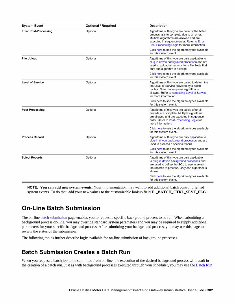
Oracle Utilities Meter Data Management/Smart Grid Gateway Administrative User Guide • 302
System Event Optional / Required DescriptionError Post-Processing Optional Algorithms of this type are called if the batch
process fails to complete due to an error.Multiple algorithms are allowed and areexecuted in sequence order. Refer to ErrorPost-Processing Logic for more information.Click here to see the algorithm types availablefor this system event.
File Upload Optional Algorithms of this type are only applicable toplug-in driven background processes and areused to upload all records for a file. Note thatonly one algorithm is allowed.Click here to see the algorithm types availablefor this system event.
Level of Service Optional Algorithms of this type are called to determinethe Level of Service provided by a batchcontrol. Note that only one algorithm isallowed. Refer to Assessing Level of Servicefor more information.Click here to see the algorithm types availablefor this system event.
Post-Processing Optional Algorithms of this type are called after allthreads are complete. Multiple algorithmsare allowed and are executed in sequenceorder. Refer to Post-Processing Logic formore information.Click here to see the algorithm types availablefor this system event.
Process Record Optional Algorithms of this type are only applicable toplug-in driven background processes and areused to process a specific record.Click here to see the algorithm types availablefor this system event.
Select Records Optional Algorithms of this type are only applicableto plug-in driven background processes andare used to define the SQL to use to selectthe records to process. Only one algorithm isallowed.Click here to see the algorithm types availablefor this system event.
NOTE: You can add new system events. Your implementation may want to add additional batch control orientedsystem events. To do that, add your new values to the customizable lookup field F1_BATCH_CTRL_SEVT_FLG.
On-Line Batch SubmissionThe on-line batch submission page enables you to request a specific background process to be run. When submitting abackground process on-line, you may override standard system parameters and you may be required to supply additionalparameters for your specific background process. After submitting your background process, you may use this page toreview the status of the submission.
The following topics further describe logic available for on-line submission of background processes.
Batch Submission Creates a Batch RunWhen you request a batch job to be submitted from on-line, the execution of the desired background process will result inthe creation of a batch run. Just as with background processes executed through your scheduler, you may use the Batch Run

Oracle Utilities Meter Data Management/Smart Grid Gateway Administrative User Guide • 303
Tree page to view the status of the run, the status of each thread, the run-instances of each thread, and any messages thatmight have occurred during the run.
NOTE: Your on-line submission record is assigned a status value so that you may know whether your job has beensubmitted and whether or not it has ended, however, it will not contain any information about the results of thebackground process itself. You must navigate to the Batch Run Tree page to view this detail.
Jobs Submitted in the BackgroundWhen you save a record on the batch job submission page, the batch job does not get submitted automatically. Rather, itsaves a record in the batch job table. A special background process will periodically check this table for pending records andwill execute the batch job. This background process will update the status of the batch job submission record so that a usercan determine when their job is complete.
NOTE: At installation time, your system administrator will set up this special background process to periodically checkfor pending records in the batch job submission table. Your administrator will define how often the system will look forpending records in this table.
It should be noted that this special background process only submits one pending batch job submission record at a time. Itsubmits a job and waits for it to end before submitting the next pending job.
NOTE: If you request a batch job to be run multi-threaded, the special background process will submit the job asrequested. It will wait for all threads to complete before marking the batch job submission record as ended. Refer to Running Multi-threaded Processes for more information.
Email NotificationIf you wish the system to inform you when the background process completes, you may supply your email address. Theemail you receive will contain details related to the batch job's output; similar to the job results you would see from yourbatch scheduler.
NOTE: This assumes that during the installation process, your system administrator configured the system to enableemail notification. Your administrator may also override the amount of detail included in the email notification.
Running Multi-Threaded ProcessesMany of the system background processes may be run multi-threaded. When submitting a background process on-line,you may also run a multi-threaded process or run a single thread of a multi-threaded process. The fields Thread Count andThread Number on the batch submission page control the multi-threaded process requests:
• To run a multi-threaded process, indicate the number of threads in Thread Count and enter 0 in the Thread Number.
• To run a single thread in a multi-threaded process, indicate the number of threads in Thread Count and indicate theThread Number you would like to run.
• To run a process as a single thread, enter Thread Count = 1 and Thread Number = 1. This will execute the backgroundprocess single-threaded.
NOTE: When running a multi-threaded process, the special background process will wait until all threads are completebefore marking the batch job submission record as Ended.

Oracle Utilities Meter Data Management/Smart Grid Gateway Administrative User Guide • 304
Batch Jobs May End in ErrorIt is possible for your background process to end with an error. When this occurs, your batch job submission record will stillbe marked as Ended. You will need to navigate to the Batch Run Tree page to determine the status of the batch run.
Submitting Jobs in the FutureIf you wish to request a batch job to be submitted in the future, you may do so when creating your batch job submissionrecord by entering a future submission date. The special background process, which looks for pending records in the batchjob submission table, will only submit batch jobs that do not have a future submission date.
Lifecycle of a Batch Job SubmissionThe following diagram illustrates the lifecycle of a batch job submission record.
Pending — Records are created in Pending status. Records in this state are put in a queue to be submitted.
Canceled— Users may cancel a pending record to prevent the batch job from being submitted.
Started— Once a pending record has been submitted for processing, its status will be changed to Started. Records in thisstatus may not be canceled.
Ended— When the batch job has finished processing, its status will be changed to Ended. Note that records in Endedstatus may have ended in error. Refer to Batch Jobs May End in Error for more information.
Granting Access To Batch SubmissionEvery batch control must reference an application service. When you link a batch control to an application service, you aregranting all users in the group the ability to submit the associated batch job for execution.
FASTPATH: Refer to The Big Picture Of Application Security for information about granting users access rights to anapplication service.
When the batch control is added to the batch job table, the system checks if both the user submitting the job and the userID recorded on the batch submission record have access rights. Application security does not apply when viewing a batchcontrol or an associated batch run.

Oracle Utilities Meter Data Management/Smart Grid Gateway Administrative User Guide • 305
NOTE: Base batch controls will be associated with base owned application services by default. Implementations willneed to ensure the appropriate user groups are linked to these application services.
Batch Job Submission - MainThis page allows you to submit a batch job on-line. Navigate to this page using Menu > Tools > Batch Job Submission.
Description of Page
The Batch Job ID is a system generated random number that identifies a particular submission.
To submit a batch job, choose the Batch Code for the process you wish to submit.
NOTE: List of system background processes. The list of background processes provided in the base product may beviewed in the application viewer's batch control viewer.
The following parameters are provided with each background process:
Thread Number is used to control whether a background processes is run single threaded or in multiple parallel threads. Itcontains the relative thread number of the process. For example, if the process has been set up to run in 20 parallel threads,each of the 20 instances receives its relative thread number (1 through 20). Refer to Running Multi-threaded Processes formore information about populating this field.
NOTE: Not all processes may be run multi-threaded. Refer to the description of a batch control to find out if it runsmulti-threaded.
Thread Count is used to control whether a background processes is run single threaded or in multiple parallel threads.It contains the total number of threads that have been scheduled. For example, if the process has been set up to run in 20parallel threads, each of the 20 instances receives a thread count of 20. Refer to Running Multi-threaded Processes for moreinformation about populating this field.
Batch Rerun Number is only used for background processes that download information that belongs to given run number.It should only be supplied if you need to download an historical run (rather than the latest run).
Batch Business Date is only used for background processes that use a date in their processing. In Oracle Utilities CustomerCare and Billing, for example, a billing process can use the business date to determine which bill cycles should bedownloaded. If this parameter is left blank, the system date is used at the time the background process is executed.
NOTE: Saving a record on this page does not submit the batch job immediately. A special background process will runperiodically to find pending records and submit them. Depending on how often the special process checks for pendingrecords and depending on how many other pending records are in the 'queue', there may be a slight lag in submissiontime. If the desired execution date/time is close to midnight, it is possible that your batch job will run on the day afteryou submit it. If you have left the business date blank in this case, keep in mind that your business date would be set tothe day after you submit the job.
Override Nbr Records To Commit and Override Max Timeout Minutes. These parameters are optional and overrideeach background process's Standard Commit Records and Standard Cursor Re-Initiation Minutes. (Each backgroundprocess's Standard Commit Records / Standard Cursor Re-Initiation Minutes should be documented in the detaileddescription of the batch control record). Note that Max Timeout Minutes corresponds to the Cursor Re-initiation Minutes.
FASTPATH: Refer to Parameters Supplied to Background Processes for more information.
User ID is the user ID associated with the run of the background process. Refer to Parameters Supplied to BackgroundProcesses for more information about the significance of the user id.

Oracle Utilities Meter Data Management/Smart Grid Gateway Administrative User Guide • 306
NOTE: This field defaults to the id of the current user.
Password is not currently used.
Language Code is used to access language-specific control table values. For example, error messages are presented in thislanguage code.
If you wish the system to notify you when the batch job is complete, enter your Email ID. Refer to Email Notification formore information.
NOTE: This field defaults to the email address for the current user, if populated on the user record.
The Desired Execution Date/Time defaults to the current date and time. Override this information if you wish thebackground process to be executed at some future date and time. Refer to Submitting Jobs in the Future for moreinformation.
The Batch Job Status indicates the current status of the batch job. Refer to Lifecycle of a Batch Job Submission for moreinformation.
The Program Name associated with the batch control code is displayed.
The following trace parameters may also be supplied to a background process and are only used during QA andbenchmarking.
• Trace Program Start Turn on this switch if you wish a message to be written whenever a program is started.
• Trace Program Exit Turn on this switch if you wish a message to be written whenever a program is exited.
• Trace SQL Turn on this switch if you wish a message to be written whenever an SQL statement is executed.
• Trace Output Turn on this switch if you wish a message to be displayed for special information logged by thebackground process.
NOTE: The information displayed when the trace output switch is turned on depends on each background process. It ispossible that a background process displays no special information for this switch.
NOTE: The location of the output of this trace information is defined by your system administrator at installation time.
If additional parameters have been defined for this background process on the Batch Control page, the Parameter Name,Description, Detailed Description and an indicator of whether or not the parameter is Required are displayed.
If a default parameter value is configured on the batch control configuration, that value is shown and may be overridden.Confirm or enter the appropriate Parameter Value for each parameter. Note that if the parameter value is configured to beEncrypted on the batch control configuration, the value here will be shown encrypted.
Once you have entered all the desired values, Save the record in order to include it in the queue for background processes.
If you wish to duplicate an existing batch job submission record, including all its parameter settings, display the submissionrecord you wish to duplicate and use the Duplicate and Queue button. This will create a new Batch Job Submission entryin pending status. The new submission entry will be displayed.
If you wish to cancel a Pending batch job submission record use the Cancel button. The button is disabled for all otherstatus values.
Tracking Batch ProcessesThe batch process pages show the execution status of batch processes. For a specified batch control id and run id, the treeshows each thread, the run-instances of each thread, and any messages (informational, warnings, and errors) that might haveoccurred during the run. Refer to Defining Batch Controls for more information on how batch control codes are defined.

Oracle Utilities Meter Data Management/Smart Grid Gateway Administrative User Guide • 307
Batch Run Tree - MainThis page allows you to view the status of a specific execution of a batch job. Navigate to this page using Menu > Tools > Batch Run Tree.
Description of Page
Select a Batch Control process and Batch Number to view information and statistics on the batch run's "threads". Thefollowing points should help understand this concept:
• Many batch jobs cannot take advantage of your hardware's processing power when they are run singularly. Rather, you'llfind that a large percentage of the CPU and/or disk drives are idle.
• In order to minimize the amount of idle time (and increase the throughput of your batch processes), we allow you to setup your batch processes so that multiple instances of a given batch job are executed at the same time. For example, inOracle Utilities Customer Care and Billing when you schedule the billing process, you can indicate that multiple parallelinstances should be executed (rather than just one instance). You'd do this so that the processing burden of creating billsfor your customers can be spread over multiple processes.
• We refer to each parallel execution of a batch process as a "thread".
• Statistics and information messages are displayed in respect of each thread. Why? Because each thread is a separateexecution and therefore can start and end at different times.
The tree includes a node that displays the total number of records processed for the batch run, the total number of recordsin error for the batch run and the batch run elapsed time. The elapsed time is the longest elapsed time among the batchthread(s). The message is red if there are any records in error.
If the background process has been enabled to create To Do entries for object specific errors, information about the To Doentries are displayed in the tree. This information is not displayed for each thread, but rather all the To Do entries createdfor the batch run are grouped together. The To Do entries are grouped by their status.
If the application properties file has been configured with the location of the log files and the log files associated with thebatch thread are still available, the links Download stdout and (if applicable) Download stderr are visible. Clicking eitherlink allows you to view or save the log files.
NOTE: Compression. The log files are compressed and include a *.gz extension. Different browsers treat this type offile differently. Some browsers may automatically decompress the file as part of the download and they are viewablein any text viewer by changing the extension to one the text viewer recognizes. However, some browsers download thecompressed file and a user will need to unzip the file prior to viewing.
NOTE: Security Access. The 'download' hyperlinks are only visible for users that have security access to the Downloadaccess mode for the batch run tree application service.
The messages that appear under a thread always show the start and end times of the execution instance. If errors aredetected during the execution of the thread, these error messages may also appear in the tree. Refer to Processing Errors forinformation about the types of errors that appear in the batch run tree.
Batch Run Tree - Run ControlBy default, if a batch process fails, it will restart. This tab allows you to modify the restart status of a failed run.
Navigate to this page using Menu > Tools > Batch Run Tree search for the desired batch control and then navigate to theRun Control page.
Description of Page
Oracle Utilities Meter Data Management/Smart Grid Gateway Administrative User Guide • 308
On the main page, you must select a Batch Control, Batch Number, and Batch Rerun Number to view a tree of the batchrun. On this page, the following information is displayed:
• Last Update Timestamp contains the date and time this batch run last start or last completed.
• Batch Business Date is the business date that was supplied to the background process (this date is used as the "systemdate" by the process).
Run Status indicates the status of the batch run. Valid values are: In Progress, Error, and Complete.
If the Run Status is Error, the system will attempt to restart this run when you attempt to execute the Batch Control.In most situations, this is exactly what you want to happen. However, there are rare situations where you do not want thesystem to execute a given batch run (e.g., if this run is somehow corrupt and you cannot correct the data for whateverreasons). If you want the system to skip the execution of a batch run (and proceed to the next run), turn on Do Not AttemptRestart.
Service Health CheckThe system provides a service that returns an overall assessment of the system’s health. The overall response is expressedusing an HTTP code. The codes supported by the service are defined in the lookup HEALTH_RESPONSE_FLG and areas follows:
• A value of 500 (One or More Critical Functions Degraded) is returned if there is any critical issue detected by theservice.
• A value of 203 (Non-Critical Function Degraded) is returned if no critical issues are found and there is at least one non-critical issue detected by the service.
• Otherwise a value of 200 (All Checks Successful) is returned.
This health check service is accessible through the business service F1–HealthCheck. Also note that the system providesan Inbound Web Service for this business service (also called F1–HealthCheck) allowing external systems to use a webservice to retrieve this information.
In addition, the product provides a portal that allows a user to view the detailed results of the health check service.
Navigate using Admin > System > Health Check to view this portal.
The zone on the portal displays the following:
Overall Response is the HTTP response code returned by the business service as described above.
The grid displays the detail of each individual component checked as part of the system health check. See below for moredetail about what components are checked.
• Health Component indicate the type of health check performed. Currently the system supports Batch Level of Servicecomponent type.
• Health Component Details provides information about the individual entity checked. The information displayed heredepends on the type of health component. If supported by the type of component, the column may be hypertext, allowingthe user to drill into the entity itself.
• Status displays the status returned by the health component check for this individual entity. The information displayedhere depends on the type of health component.
• Status Reason provides more detail about why the individual entity is in the indicated status. The information displayedhere depends on the type of health component.
• Response shows the health check response code assigned to this individual entity’s health check response. It is mappedbased on the status returned by the health component check.
Oracle Utilities Meter Data Management/Smart Grid Gateway Administrative User Guide • 309
Health Component Type DetailsThe details returned by the business service for this portal depends on the health component type. The system supports theBatch Level of Service health component type.
This health component type finds all the batch controls that are configured with a level of service algorithm and invokes thealgorithm for each batch control. The business service populates the output for this health service for each batch control asfollows:
• The Health Component Detail is populated with the Batch Control code and description. In addition, the navigationinformation for being able to drill into the batch control are provided and used to build the column as hypertext.
• The Status is populated with the description of the Level of Service lookup value returned by the level of servicealgorithm for this batch control.
• The Status Reason is populated with the expanded text of the status reason returned by the level of service algorithm forthis batch control.
• The Response is populated based on the value of the Level of Service status. It is set to All Checks Successful (200)when the Level of Service is Normal or Disabled; Non-Critical Function Degraded (203) when the Level of Service isWarning and One or More Critical Functions Degraded (500) when the Level of Service is Error.
The Big Picture of RequestsRequests enable an implementer to design an ad-hoc batch process using the configuration tools.
An example of such a process might be to send an email to a group of users that summarizes the To Do entries that areassigned to them. This is just one example. The request enables many types of diverse processing.
Request Type Defines ParametersFor each type of process that your implementation wants, you must configure a request type to capture the appropriateparameters needed by the process.
Previewing and Submitting a RequestTo submit a new request, go to Menu > Tools > Request in add mode. You must select the appropriate request type andthen enter the desired parameter values, if applicable.
After entering the parameters, the following actions are possible:
• Click Save to submit the request.
• Click Cancel to cancel the request.
• Click Preview to see a sample of records that satisfy the selection criteria for this request. This information is displayedin a separate map. In addition, the map displays the total number of records that will be processed when the request issubmitted. From this map you can click Save to submit the request, Back to adjust the parameters, or Cancel to cancelthe request.
When a request is saved, the job is not immediately submitted for real time processing. The record is saved with the statusPending and a monitor process for this record's business object is responsible for transitioning the record to Complete.
As long as the record is still Pending, it may be edited to adjust the parameters. The preview logic described above may berepeated when editing a record.
The actual work of the request, such as generating an email, is performed when transitioning to Complete (using an enterprocessing algorithm for the business object).
Oracle Utilities Meter Data Management/Smart Grid Gateway Administrative User Guide • 310
To Do Summary EmailThe base product includes a sample request process that sends an email to users that have incomplete To Dos older than aspecified number of days.
The following configuration tasks are required to use this process:
• Define an Outbound Message Type. The business object usually defined for the Outbound Message Type is F1-EmailMessage.
• Define an External System that contains the Outbound Message Type in one of its steps. In the configuration determine ifthe communication is through SOA, batch, or real-time processing method when sending the email notification. Refer toOutbound Messages for more information about configuration needed for the different processing methods.
• Create a Request Type that includes the Outbound Message Type and the corresponding External System.
• Create a Request for the created Request Type.
Exploring Request Data RelationshipsUse the following links to open the application viewer where you can explore the physical tables and data relationshipsbehind the request functionality:
• Click F1-REQ-TYPE to view the request type maintenance object's tables.
• Click F1-REQ to view the request maintenance object's tables.
Defining a New RequestTo design a new ad-hoc batch job that users can submit via Request, first create a new Request Type business object. Thebase product BO for request type, F1-TodoSumEmailTyp, may be used as a sample.
The business object for the request includes the functionality for selecting the records to process, displaying a preview mapfor the user to review, and for performing the actual processing. The base product BO for request, F1-TodoSumEmailReq,may be used as a sample. The following points highlight the important configuration details for this business object:
• Special BO options are available for request BOs to support the Preview Request functionality.
• Request Preview Service Script. This script retrieves the information that is displayed when a user asks for apreview of a request.
• Request Preview Map. This map displays the preview of a request.
• The enter algorithm plugged into the Complete state is responsible for selecting the records that satisfy the criteria andprocessing the records accordingly.
Setting Up Request TypesUse the Request Type portal to define the parameters to capture when submitting a request. Open this page using Admin >General > Request Type.
This topic describes the base-package zones that appear on the Request Type portal.
Request Type List. The Request Type List zone lists every request type. The following functions are available:
• Click a broadcast icon to open other zones that contain more information about the request type.
• Click Add in the zone's title bar to add a new request type.

Oracle Utilities Meter Data Management/Smart Grid Gateway Administrative User Guide • 311
Request Type. The Request Type zone contains display-only information about a request type. This zone appears when arequest type has been broadcast from the Request Type List zone or if this portal is opened via a drill down from anotherpage. The following functions are available:
• Click Edit to start a business process that updates the request type.
• Click Delete to start a business process that deletes the request type.
• Click Deactivate start a business process that deactivates the request type.
• Click Duplicate to start a business process that duplicates the request type.
• State transition buttons are available to transition the request type to an appropriate next state.
Please see the zone's help text for information about this zone's fields.
Maintaining RequestsUse the Request transaction to view and maintain pending or historic requests.
Open this page using Menu > Tools > Request > Search. This topic describes the base-package portals and zones on thispage.
Request Query. Use the query portal to search for an existing request. Once a request is selected, you are brought to themaintenance portal to view and maintain the selected record.
Request Portal. This portal appears when a request has been selected from the Request Query portal. The following base-package zones appear on this portal:
• Actions. This is a standard actions zone.
• Request. The Request zone contains display-only information about a request. Please see the zone's help text forinformation about this zone's fields.
• Request Log. This is a standard log zone.
Defining AlgorithmsIn this section, we describe how to set up the user-defined algorithms that perform many important functions including:
• Validating the format of a phone number entered by a user.
• Validating the format of a latitude/longitude geographic code entered by a user.
• In products that support payment and billing:
• Calculating late payment charges.
• Calculating the recommended deposit amount.
• Constructing your GL account during the interface of financial transactions to your GL
• And many other functions...
The Big Picture Of AlgorithmsMany functions in the system are performed using a user-defined algorithm. For example, when a CSR requests acustomer's recommended deposit amount, the system calls the deposit recommendation algorithm. This algorithm calculatesthe recommended deposit amount and returns it to the caller.
Oracle Utilities Meter Data Management/Smart Grid Gateway Administrative User Guide • 312
NOTE: Algorithm = Plug-in. We use the terms plug-in and algorithm interchangeably throughout this documentation.
So how does the system know which algorithm to call? When you set up the system's control tables, you define whichalgorithm to use for each component-driven function. You do this on the control table that governs each respective function.For example:
• You define the algorithm used to validate a phone number on your phone types.
• You define the algorithm in Oracle Utilities Customer Care and Billing used to calculate late payment charges on eachService Agreement Type that has late payment charges.
• The list goes on...
The topics in this section provide background information about a variety of algorithm issues.
Algorithm Type Versus AlgorithmYou have to differentiate between the type of algorithm and the algorithm itself.
• An Algorithm Type defines the program that is called when an algorithm of this type is executed. It also defines thetypes of parameters that must be supplied to algorithms of this type.
• An Algorithm references an Algorithm Type. It also defines the value of each parameter. It is the algorithm that isreferenced on the various control tables.
FASTPATH: Refer to How to Add A New Algorithm for an example that will further clarify the difference between analgorithm and an algorithm type.
How To Add A New AlgorithmBefore you can add a new algorithm, you must determine if you can use one of the sample algorithm types supplied with thesystem. Refer to List of Algorithm Types for a complete list of algorithm types.
If you can use one of the sample algorithm types, simply add the algorithm and then reference it on the respective controltable. Refer to Setting Up Algorithms for how to do this.
If you have to add a new algorithm type, you may have to involve a programmer. Let's use an example to help clarify whatyou can do versus what a programmer must do. Assume that you require an additional geographic type validation algorithm.To create your own algorithm type you must:
• Write a new program to validate geographic type in the appropriate manner. Alternatively, you may configure a plug-in script to implement the validation rules. The advantage of the latter is that it does not require programming. Refer toplug-in script for more information.
• Create an Algorithm Type called Our Geographic Format (or something appropriate). On this algorithm type,you'd define the name of the program (or the plug-in script) that performs the function. You'd also define the variousparameters required by this type of algorithm.
• After creating the new Algorithm Type, you can reference it on an Algorithm.
• And finally, you'd reference the new Algorithm on the Geographic Type that requires this validation.
Minimizing The Impact Of Future UpgradesThe system has been designed to use algorithms so an implementation can introduce their own logic in a way that's 100%upgradeable (without the need to retrofit logic). The following points describe strong recommendations about how toconstruct new algorithm type programs so that you won't have to make program changes during future upgrades:
Oracle Utilities Meter Data Management/Smart Grid Gateway Administrative User Guide • 313
• Do not alter an algorithm type's hard parameters. For example, you might be tempted to redefine or initialize parametersdefined in an algorithm type's linkage section. Do not do this.
• Follow the naming conventions for the new algorithm type code and your source code, i.e., both the source code and thealgorithm type should be prefixed with "CM". The reason for this naming convention is to make it impossible for a new,base-package algorithm type from overwriting your source code or algorithm type meta-data (we will never develop aprogram or introduce meta-data beginning with CM).
• Avoid using embedded SQL to perform insert/update/delete. Rather, invoke the base-package's object routines orcommon routines.
• Avoid using base messages (outside of common messages, i.e., those with a message number < 1000) as we maydeprecate or change these messages in future releases. The most common problem is caused when an implementationclones a base package algorithm type program because they need to change a few lines of logic. Technically, to be100% upgradeable, you should add new messages in the "90000" or greater category (i.e., the category reserved forimplementation-specific messages) for every message in your new program even though these messages may beduplicates of those in the base package.
Setting Up Algorithm TypesThe system provides many algorithm types to support base product functionality. If you need to introduce a new type ofalgorithm, open Admin > System > Algorithm Type.
FASTPATH: Refer to The Big Picture Of Algorithms for more information.
CAUTION: Important! If you introduce a new algorithm type, carefully consider its naming convention. Refer to System Data Naming Convention for more information.
Description of Page
Enter an easily recognizable Algorithm Type and Description.
Owner indicates if this algorithm type is owned by the base package or by your implementation (Customer Modification).The system sets the owner to Customer Modification when you add an algorithm type. This information is display-only.
Enter a Detailed Description that describes, in detail, what algorithms of this type do.
Use Algorithm Entity to define where algorithms of this type can be "plugged in". If a detailed description about analgorithm entity is available, a small help icon is visible adjacent to the dropdown. Click the icon to view the information.
NOTE: The values for this field are customizable using the lookup table. This field name is ALG_ENTITY_FLG.
Use Program Type to define if the algorithm's program is written using Java, a Plug-In Script, or Java (Converted),meaning the program has been converted to Java.
NOTE: Java (Converted) program types are not applicable to all products.
Use Program Name to define the program to be invoked when algorithms of this type are executed:
• If the Program Type is Java (Converted), enter the name of the converted program.
• If the Program Type is Java, enter the Java class name.
• If the Program Type is Plug-In Script, enter the plug-in script name. Only plug-in scripts defined for the algorithmentity may be used.

Oracle Utilities Meter Data Management/Smart Grid Gateway Administrative User Guide • 314
NOTE: View the source. If the program is shipped with the base package, you can use the adjacent button to displaythe source code of this program in the Java docs viewer. For plug-in scripts, drill into the plug-in script to view thedetails.
Use the Parameter Types grid to define the types of parameters that algorithms of this type use. The following fieldsshould be defined for each parameter:
• Use Sequence to define the relative position of the Parameter.
• Use Parameter to describe the verbiage that appears adjacent to the parameter on the Algorithm page.
• Indicate whether the parameter is Required. This indicator is used when parameters are defined on algorithms thatreference this algorithm type.
• Owner indicates if the parameter for this algorithm type is owned by the base package or by your implementation(Customer Modification). The system sets the owner to Customer Modification when you add an algorithm type withparameters. This information is display-only.
NOTE: When adding a new algorithm type that is for a Java program, the parameters are automatically generated basedon the Java code. Once an algorithm type exists, any additional parameters defined in the Java code should be manuallyadded to the algorithm type. For other program types, algorithm type parameters must be manually defined.
NOTE: When a new algorithm type parameter is added for any program type, existing algorithms for the algorithm typedo not automatically get updated with the new parameter. The algorithms must be manually updated.
Where Used
An Algorithm references an Algorithm Type. Refer to Setting Up Algorithms for more information.
List of Algorithm TypesThe algorithm types available to use with the product may be viewed in the algorithm type page and in the applicationviewer's algorithm viewer. If your implementation adds algorithm types or adds algorithms to reference existing algorithmtypes, you may regenerate the application viewer to see your additions reflected there.
Setting Up AlgorithmsIf you need to introduce a new algorithm, open Admin > System > Algorithm. Refer to The Big Picture Of Algorithmsfor more information.
Description of Page
Enter an easily recognizable Algorithm Code and Description of the algorithm. Owner indicates if this algorithm is ownedby the base package or by your implementation (Customer Modification).
CAUTION: Important! If you introduce a new algorithm, carefully consider its naming convention. Refer to SystemData Naming Convention for more information.
Reference the Algorithm Type associated with this algorithm.
FASTPATH: Refer to Algorithm Type Versus Algorithm for more information about how an algorithm type controlsthe type of parameters associated with an algorithm.
The parameters available for an algorithm are defined on the algorithm type. The system allows a set of parameter valuesto change over time. Use the parameter scroll to view parameter values for a given Effective Date. The Owner of the

Oracle Utilities Meter Data Management/Smart Grid Gateway Administrative User Guide • 315
collection of parameters is displayed. The collection shows the Parameter description, the Sequence and the Value foreach parameter.
NOTE: If the product delivers an algorithm with parameter values defined, an implementation may override the baseprovided parameter values by adding an additional effective dated collection of parameters.
NOTE: If an algorithm is defined and subsequently a new parameter is added to the algorithm type, existing algorithmsfor the algorithm type should be updated as follows: Click the “+” to add a new effective dated entry to the parametercollection. At this point the latest list of parameters for the algorithm type are visible. Configure the parametersaccordingly.
Where Used
Algorithms are plugged in on control tables throughout the system. Each algorithm type’s Algorithm Entity indicates thename of the control table where it is plugged in. The algorithm viewer in the application viewer may also be used to see alist of plug-in spots along with their algorithm types and algorithms.
Defining Script OptionsWe use the term "script" to define processing rules that your implementation sets up to control both front-end and back-endprocessing:
• Rules that control front-end processing are defined using Business Process Assistant (BPA) scripts. For example, yourimplementation could set up a BPA script to guide a user through your organization's payment cancellation process.
• Rules that control back-end processing are defined using Server-based scripts. For example, your implementation couldset up a server-based script to control the processing that executes whenever a given type of adjustment is canceled.
The topics in this section describe how to configure your scripts.
The Big Picture Of ScriptsThis section describes features and functions that are shared by both BPA scripts and server-based scripts.
Scripts Are Business Process-OrientedTo create a script, you must analyze the steps used to implement a given business process. For example, you could create a"stop auto pay" BPA script that:
• Asks the user to select the customer / taxpayer using an appropriate search page
• Asks the user to define the date on which the person would like to stop making automatic payments
• Invokes a server-based script that populates the end-date on the account's latest automatic payment instructions.
After you understand the business process, you can set up a script to mimic these steps. If the business process isstraightforward (e.g., users always perform the same steps), the script configuration will be straightforward. If the businessprocess has several logic branches, the composition of the script may be more challenging.
A Script Is Composed Of StepsA script contains one or more steps. For example, a "stop auto pay" BPA script might have three steps:
• Ask the user to select the customer / taxpayer using an appropriate search page
Oracle Utilities Meter Data Management/Smart Grid Gateway Administrative User Guide • 316
• Ask the customer the date on which they'd like to stop making automatic payments (and default the current date)
• Invoke a server-based script that, in turn, updates the account's auto pay options.
Each step references a step type. The step type controls what happens when a step executes. It might be helpful to think of ascript as a macro and each step as a "line of code" in the macro. Each step's step type controls the function that is executedwhen the step is performed.
FASTPATH: Refer to How To Set Up Each Step Type for a detailed description of all available step types and how toset them up.
A Script May Declare Data AreasBoth BPA and server-based scripts may have one or more data areas:
• If the script contains steps that exchange XML documents, you must declare a data area for each type of XML document.For example, if a BPA script has a step that invokes a service script, the BPA script must declare a data area that holdsthe XML document that is used to pass information to and from the service script.
• You can use a data area as a more definitive way to declare your temporary storage. For example, you can describe yourscript's temporary storage variables using a stand-alone data area schema and associate it with your script.
Various step types involve referencing the script's data areas as well as support the ability to compare and move data to andfrom field elements residing in the data areas.
An Edit Data step supports the syntax to dynamically declare data areas as part of the step itself. This technique eliminatesthe need to statically declare a data area. Refer to Edit Data Syntax for more information on edit data commands andexamples of the use of dynamic data areas.
NOTE: Some server based scripts may not use data areas as means of defining or exchanging data, depending on scripttype and the chosen scripting technique. Refer to The Big Picture Of Server Based Scripts for an overview of serverscripts and their applicable scripting options.
Securing Script ExecutionThe system supports the ability to secure the execution of scripts by associating the script with an Application Service.Refer to The Big Picture of Application Security for more information. Application security is optional for user-invocableBPA scripts. If a script is not associated with an application service, all users may execute the script. Otherwise, only usersthat have Execute access to the application service may execute the script. For service scripts, the application service isrequired.
The Big Picture Of BPA ScriptsFASTPATH: Refer to The Big Picture Of Scripts to better understand the basic concept of scripts.
Users may require instructions in order to perform certain tasks. The business process assistant allows you to set upscripts that step a user through your business processes. For example, you might want to create scripts to help users do thefollowing:
• Add a new person to an existing account
• Set up a customer to pay automatically
• Modify a customer who no longer wants to receive marketing information
• Modify a customer's web password
Oracle Utilities Meter Data Management/Smart Grid Gateway Administrative User Guide • 317
• Record a trouble order
• Merge two accounts into one account
• Fix a bill with an invalid rate
• ... (the list is only limited by your time and imagination)
Users execute these scripts via the business process assistant (BPA). Users can also define their favorite BPA scripts in theiruser preferences. By doing this, a user can execute a script by pressing an accelerator key (Ctrl + Shift + a number).
Don't think of these scripts as merely a training tool. BPA scripts can also reduce the time it takes to perform common tasks.For example, you can write a script that reduces the "number of clicks" required to add a new person to an existing account.
CAUTION: Future upgrade issues. Although we make every effort not to remove fields or tab pages between releases,there may be times when changes made by the base-package will necessitate changes to your scripts. Please refer to therelease notes for a list of any removed fields or tab pages.
CAUTION: Scripts are not a substitute for end-user training. Scripts minimize the steps required to perform commontasks. Unusual problems (e.g., a missing meter exchange) may be difficult to script as there are many different ways toresolve such a problem. However, scripts can point a user in the right direction and reduce the need to memorize obscurebusiness processes.
The topics in this section describe background topics relevant to BPA scripts.
How To Invoke ScriptsRefer to Initiating Scripts for a description of how end-users initiate scripts.
Developing and Debugging Your BPA ScriptsWe recommend considering the approaches outlined below when you construct scripts.
While designing your scripts, determine the most maintainable way to set them up. Rather than creating complex,monolithic scripts, we recommend dividing scripts into smaller sections. For example
• Determine if several scripts have similar steps. If so, set up a script that contains these common steps and invoke it fromthe main scripts using a Perform script step.
• Determine if a large script can be divided into logical sections. If so, set up a small script for each section and create a"master script" to invoke each sub script via a Transfer control step.
For debugging purposes, you may find it helpful to categorize the step types into two groups: those that involve some typeof activity in the script area, and those that don't. The following step types cause activity in the script area: Height, Displaytext, Prompt user, Input data, Input Map, Set focus to a field.
The rest of the step types are procedural and involve no user interaction. There are two techniques you can use to assist indebugging these step types.
• You can instruct the system to display text in the script area.
• You can display an entire data area (or a portion thereof) in the script area by entering %+...+% where ... is the name ofthe node whose element(s) should be displayed.
NOTE: Time saver. When you develop a new BPA script, change your user preferences to include the script as yourfirst "favorite". This way, you can press Ctrl+Shift+1 to invoke the script (eliminating the need to select it from thescript menu).

Oracle Utilities Meter Data Management/Smart Grid Gateway Administrative User Guide • 318
Launching A Script From A MenuYou can create menu items that launch BPA scripts rather than open a page. To do this, create a navigation option thatreferences your script and then add a menu item that references the navigation option.
If the navigation option is referenced on a context menu and the navigation option has a "context field", a temporary storagevariable will be created and populated with the unique identifier of the object in context. For example, if you add a "script"navigation option to the bill context menu and this navigation option has a context field of BILL_ID, the system will createa temporary storage variable called BILL_ID and populate it with the respective bill id when the menu item is selected.
Launching A Script When Starting The SystemYou can set the system to launch a script upon startup.
For example, imagine that through an interactive voice response system, a customer has keyed in their account ID and hasindicated that they would like to stop an automatic payment. At the point when the IVR system determines that the customermust speak to a user, the interface can be configured to launch the application. When launched it passes the script name andaccount ID. It can also pass a navigation option to automatically load the appropriate page (if this information is not part ofthe script).
To do this, parameters are appended to the standard system URL. The following parameters may be supplied:
• script=<scriptname>
• ACCT_ID=<account id>
• location=<navigation option>
Parameters are added to the standard system URL by appending a question mark (?) to the end and then adding the"key=value" pair. If you require more than one parameter, use an ampersand (&) to separate each key=value pair.
For example, the following URLs are possible ways to launch the CM-StopAutoPay script at startup, assuming yourstandard URL for launching the system is http://system-server:1234/cis.jsp:
• http://system-server:1234/cis.jsp?script=CM-StopAutoPay
• http://system-server:1234/cis.jsp?script=CM-StopAutoPay&ACCT_ID=1234512345
• Zoneshttp://system-server:1234/cis.jsp?script=CM-StopAutoPay&ACCT_ID=1234512345&location=accountMaint
It doesn't matter in which order the parameters are provided. The system processes them in the correct order. For example,the following examples are processed by the system in the same way:
• http://system-server:1234/cis.jsp?ACCT_ID=1234512345&script=CM-StopAutoPay&location=accountMaint
• http://system-server:1234/cis.jsp?ACCT_ID=1234512345&location=accountMaint&script=CM-StopAutoPay
These parameters are kept in a common area accessible by any script for the duration of the session. To use theseparameters on a script you may reference the corresponding %PARM-<name> global variables. In this example, after thesystem is launched any script may have access to the above account ID parameter value by means of the %PARM-ACCT_ID global variable. Also note, these parameters are also loaded into temporary storage (to continue the example, there'd alsobe a temporary storage variable called ACCT_ID that holds the passed value).
NOTE: Minimizing the Dashboard. As described in Dashboard Portal, a URL parameter may be used to minimize thedashboard when launching the system, which may be included in the URL when launching the system with a script.

Oracle Utilities Meter Data Management/Smart Grid Gateway Administrative User Guide • 319
Determining the Target Navigation in the ScriptBy default, if a script is provided but the location attribute is not provided, the system navigates to the user's home pageprior to executing the script. If the script itself includes a step to navigate to a target page as one of its initial steps, thenavigation to the home page is unnecessary and may degrade performance. The system supplies an optional attribute toinclude in the URL to bypass the home page: initNav=false.
NOTE: The system still requires a page to be launched for technical reasons. A blank portal with no zones is used forthis purpose. Users may see this portal (called Launching Application) briefly before the navigation initiated by thescript. In addition, this is the portal that the user will remain on if there are any errors in the script or if the script doesnot navigate anywhere.
Navigate to a Given Record’s Maintenance PortalIf your use case is to simply navigate to the maintenance page for a given record and display that record, the script F1-GotoPrtl (Navigate to portal for an MO and key values) may be used. This script is only applicable to records that aregoverned by a business object (and define a navigation option as a BO option). It takes the incoming maintenance objectcode and primary key values, looks up the appropriate portal navigation option from the record's BO, populates keys intothe 'page data model' and navigates to the portal.
The script expects the keys to be passed in using variable names pkValue1 through pkValue5. It is also recommended toinclude the initNav=false attribute. This example navigates to the appropriate Migration Data Set portal for the given ID'sbusiness object.
• http://system-server:1234/cis.jsp?script=F1–GotoPrtl&pkValue1=1234512345&mo=F1–MIGRDS&initNav=false
Executing A Script When A To Do Entry Is SelectedThe system creates To Do entries to highlight tasks that require attention (e.g., records in error). Users can complete manyof these tasks without assistance. However, you can set up the system to automatically launch a script when a user selects aTo Do entry. For example, consider a To Do entry that highlights a bill that's in error due to an invalid mailing address. Youcan set up the system to execute a script when this To Do entry is selected by a user. This script might prompt the user tofirst correct the customer's default mailing address and then re-complete the bill.
The following points provide background information to help you understand how to implement this functionality:
• Every To Do entry references a To Do type and a message category and number. The To Do type defines the category ofthe task (e.g., bill errors). The message number defines the specific issue (e.g., a valid address can't be found.). Refer to The Big Picture of System Messages for more information about message categories and numbers.
• When a user drills down on a To Do entry, either a script launches OR the user is transferred to the transaction associatedwith the entry's To Do type. You control what happens by configuring the To Do type accordingly:
• If you want to launch a script when a user drills down on an entry, you link the script to the To Do type and messagenumber. Keep in mind that you can define a different script for every message (and some To Do types have manydifferent messages).
• If the system doesn't find a script for an entry's To Do type and message number, it transfers the user to the To Dotype's default transaction.
NOTE: How do you find the message numbers? We do not supply documentation of every To Do type's messagenumbers (this list would be impossible to maintain and therefore untrustworthy). The best way to determine whichmessage numbers warrant a script is during pre-production when you're testing the system. During this period, To Doentries will be generated. For those entries that warrant a script, simply display the entry on To Do maintenance. On thispage, you will find the entry's message number adjacent to the description.

Oracle Utilities Meter Data Management/Smart Grid Gateway Administrative User Guide • 320
• These types of scripts invariably need to access data that resides on the selected To Do entry. Refer to How To Use ToDo Fields for the details.
The Big Picture Of Script Eligibility RulesYou can configure eligibility criteria on the scripts to limit the scripts that a user sees in the script search. For example,you could indicate a script should only appear on the script menu if the user belongs to the level 1 customer servicerepresentative group. You may also indicate that a script should only appear if the data a user is viewing has certain criteria.For example, if you are using Oracle Utilities Customer Care and Billing, you can indicate that a script should only appearif the current account's customer class is residential. By doing this, you avoid presenting the user with scripts that aren'tapplicable to the current data in context or the user's role.
The topics in this section describe eligibility rules.
Script Eligibility Rules Are Not Strictly EnforcedThe script search gives a user a choice of seeing all scripts or only scripts that are eligible (given the current data in contextand their user profile). This means that it's possible for a script that isn't eligible for the given context data / user to beexecuted via this search. In other words, the system does not strictly enforce a script's eligibility rules.
It might be more helpful to think of eligibility rules as "highlight conditions". These "highlight conditions" simply controlwhether the script appears in the script search when a user indicates they only want to see eligible scripts.
You Can Mark A Script As Always EligibleIf you don't want to configure eligibility rules, you don't have to. Simply indicate that the script is always eligible.
You Can Mark A Script As Never EligibleIf you have scripts that you do not want a user to select from the script menu, indicate that it is never eligible. An exampleof a script that you wouldn't want a user to select from the menu is one that is launched when a To Do entry is selected.These types of scripts most likely rely on data linked to the selected To Do entry. As a result, a user should only launchscripts of this type from the To Do entry and not from the script menu.
Criteria Groups versus Eligibility CriteriaBefore we provide concrete examples of eligibility criteria, we need to explain two concepts: Criteria Groups and EligibilityCriteria. A script's criteria groups control whether a user is eligible to choose a script. At a high level, it works like this:
• A criteria group has one or more eligibility criteria. A group's criteria control whether the group is considered true orfalse.
• When you create a group, you define what should happen if the group is true or false. You have the following choices:
• The user is eligible to choose the script
• The user is not eligible to choose the script
• The next group should be checked
We'll use the following example from Oracle Utilities Customer Care and Billing to help illustrate these points. Assume ascript is only eligible if:
• The customer has electric service and the user belongs to user group A, B or C
• OR, the customer has gas service and the user belongs to user group X, Y or A

Oracle Utilities Meter Data Management/Smart Grid Gateway Administrative User Guide • 321
This script requires two eligibility groups because it has two distinct conditions:
• IF (Customer has electric service AND (User belongs to user group A, B or C))
• IF (Customer has gas service AND (User belongs to user group X, Y or A))
If either condition is true, the script is eligible.
You would need to set the following criteria groups in order to support this requirement:
Group No. Group Description If Group is True If Group is False
1 Customer has electric serviceand the user belongs to usergroup A, B or C
Eligible Check next group
2 Customer has gas service andthe user belongs to user group X,Y or A
Eligible Ineligible
The following criteria are required for each of the above groups:
Group 1: Customer has electric service and the user belongs to user group A, B or C
Seq Logical Criteria If Eligibility Criteria is True If Eligibility Criteria isFalse
If Insufficient Data
10 Customer has electricservice
Check next condition Group is false Group is false
20 User belongs to usergroup A, B or C
Group is true Group is false Group is false
Group 2: Customer has gas service and the user belongs to user group X, Y or A
Seq Logical Criteria If Eligibility Criteria is True If Eligibility Criteria isFalse
If Insufficient Data
10 Customer has gas service Check next condition Group is false Group is false
20 User belongs to usergroup X, Y or A
Group is true Group is false Group is false
The next section describes how you might configure the specific logical criteria in each of the groups.
Defining Logical CriteriaWhen you set up an eligibility criterion, you must define two things:
• The field to be compared
• The comparison method
You have the following choices in respect of identifying the field to be compared :
• You can execute an algorithm to retrieve a field value from somewhere else in the system.
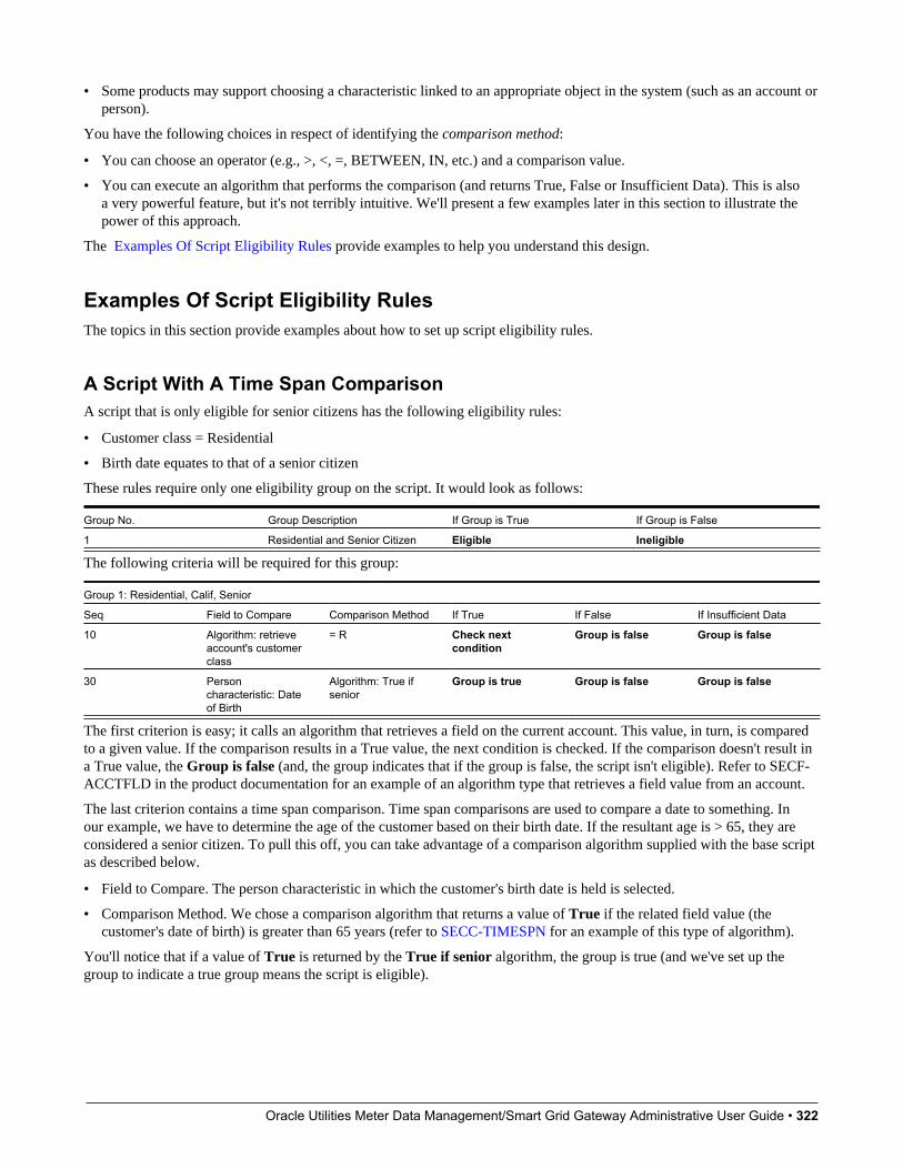
Oracle Utilities Meter Data Management/Smart Grid Gateway Administrative User Guide • 322
• Some products may support choosing a characteristic linked to an appropriate object in the system (such as an account orperson).
You have the following choices in respect of identifying the comparison method:
• You can choose an operator (e.g., >, <, =, BETWEEN, IN, etc.) and a comparison value.
• You can execute an algorithm that performs the comparison (and returns True, False or Insufficient Data). This is alsoa very powerful feature, but it's not terribly intuitive. We'll present a few examples later in this section to illustrate thepower of this approach.
The Examples Of Script Eligibility Rules provide examples to help you understand this design.
Examples Of Script Eligibility RulesThe topics in this section provide examples about how to set up script eligibility rules.
A Script With A Time Span ComparisonA script that is only eligible for senior citizens has the following eligibility rules:
• Customer class = Residential
• Birth date equates to that of a senior citizen
These rules require only one eligibility group on the script. It would look as follows:
Group No. Group Description If Group is True If Group is False
1 Residential and Senior Citizen Eligible Ineligible
The following criteria will be required for this group:
Group 1: Residential, Calif, Senior
Seq Field to Compare Comparison Method If True If False If Insufficient Data
10 Algorithm: retrieveaccount's customerclass
= R Check nextcondition
Group is false Group is false
30 Personcharacteristic: Dateof Birth
Algorithm: True ifsenior
Group is true Group is false Group is false
The first criterion is easy; it calls an algorithm that retrieves a field on the current account. This value, in turn, is comparedto a given value. If the comparison results in a True value, the next condition is checked. If the comparison doesn't result ina True value, the Group is false (and, the group indicates that if the group is false, the script isn't eligible). Refer to SECF-ACCTFLD in the product documentation for an example of an algorithm type that retrieves a field value from an account.
The last criterion contains a time span comparison. Time span comparisons are used to compare a date to something. Inour example, we have to determine the age of the customer based on their birth date. If the resultant age is > 65, they areconsidered a senior citizen. To pull this off, you can take advantage of a comparison algorithm supplied with the base scriptas described below.
• Field to Compare. The person characteristic in which the customer's birth date is held is selected.
• Comparison Method. We chose a comparison algorithm that returns a value of True if the related field value (thecustomer's date of birth) is greater than 65 years (refer to SECC-TIMESPN for an example of this type of algorithm).
You'll notice that if a value of True is returned by the True if senior algorithm, the group is true (and we've set up thegroup to indicate a true group means the script is eligible).
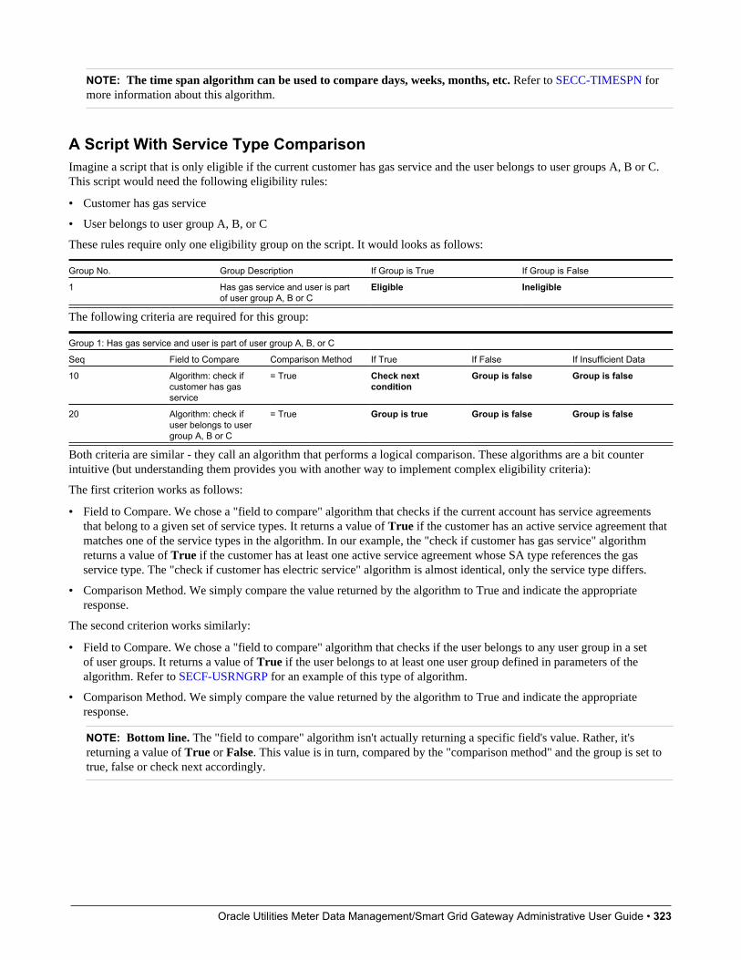
Oracle Utilities Meter Data Management/Smart Grid Gateway Administrative User Guide • 323
NOTE: The time span algorithm can be used to compare days, weeks, months, etc. Refer to SECC-TIMESPN formore information about this algorithm.
A Script With Service Type ComparisonImagine a script that is only eligible if the current customer has gas service and the user belongs to user groups A, B or C.This script would need the following eligibility rules:
• Customer has gas service
• User belongs to user group A, B, or C
These rules require only one eligibility group on the script. It would looks as follows:
Group No. Group Description If Group is True If Group is False
1 Has gas service and user is partof user group A, B or C
Eligible Ineligible
The following criteria are required for this group:
Group 1: Has gas service and user is part of user group A, B, or C
Seq Field to Compare Comparison Method If True If False If Insufficient Data
10 Algorithm: check ifcustomer has gasservice
= True Check nextcondition
Group is false Group is false
20 Algorithm: check ifuser belongs to usergroup A, B or C
= True Group is true Group is false Group is false
Both criteria are similar - they call an algorithm that performs a logical comparison. These algorithms are a bit counterintuitive (but understanding them provides you with another way to implement complex eligibility criteria):
The first criterion works as follows:
• Field to Compare. We chose a "field to compare" algorithm that checks if the current account has service agreementsthat belong to a given set of service types. It returns a value of True if the customer has an active service agreement thatmatches one of the service types in the algorithm. In our example, the "check if customer has gas service" algorithmreturns a value of True if the customer has at least one active service agreement whose SA type references the gasservice type. The "check if customer has electric service" algorithm is almost identical, only the service type differs.
• Comparison Method. We simply compare the value returned by the algorithm to True and indicate the appropriateresponse.
The second criterion works similarly:
• Field to Compare. We chose a "field to compare" algorithm that checks if the user belongs to any user group in a setof user groups. It returns a value of True if the user belongs to at least one user group defined in parameters of thealgorithm. Refer to SECF-USRNGRP for an example of this type of algorithm.
• Comparison Method. We simply compare the value returned by the algorithm to True and indicate the appropriateresponse.
NOTE: Bottom line. The "field to compare" algorithm isn't actually returning a specific field's value. Rather, it'sreturning a value of True or False. This value is in turn, compared by the "comparison method" and the group is set totrue, false or check next accordingly.

Oracle Utilities Meter Data Management/Smart Grid Gateway Administrative User Guide • 324
The Big Picture Of Server-Based ScriptsFASTPATH: Refer to The Big Picture Of Scripts to better understand the basic concept of scripts.
Server-based scripts allow an implementation to configure backend business processes. The system supports three types ofserver-based scripts, Plug-In scripts, Service scripts and Groovy Library scripts.
• Plug-in scripts allow an implementation to develop routines that are executed from the system's various plug-in spots.For example, an implementation could configure a plug-in script that is executed every time an adjustment of a giventype is frozen.
• Service scripts allow an implementation to develop common routines that are invoked from both front-end and back-endservices. For example, an implementation could create a service script that terminates an account's automatic paymentpreferences. This service script could be invoked from a BPA script initiated by an end-user when a customer asks tostop paying automatically, and it could also be executed from a plug-in script if a customer fails to pay their debt on time.Service scripts are typically written using xpath scripting.
• Groovy Library scripts allow an implementation to develop groups of common routines written in the Groovy languagewhich may be invoked from Groovy Member step types.
The topics in this section describe background topics relevant to server-based scripts.
Additional Coding Options For Server ScriptsServer based scripts often perform complex functions best supported by coding in languages with more comprehensivecommand sets than the base script steps. The system supports two common third-party languages for this purpose.
XML Path Language (XPath) is a language for querying and evaluating elements or nodes in an XML document. XPathcommands and expressions can be used directly within Edit Data step types. The script engine version is used to define theapplicable XPath version.
Groovy is an object-oriented, dynamic language for the Java platform. The framework supports the use of Groovywithin server-based scripts to provide restricted and controlled access to Java-like code, particularly for cloud basedimplementations. The following topic provides more information on how to incorporate Groovy code into scripts.
Using Groovy Within ScriptsGroovy code can be incorporated in scripts using the step type Groovy Members. For each script with Groovy code, therewill be a single Groovy class created by concatenating all Groovy Members steps.
For security, the product and third party Java classes available for scripting in Groovy will be restricted. The allowable baseclasses may be viewed via the Groovy JavaDocs feature in the Application Viewer and also via the ‘View Groovy Javadocs’link in the context sensitive Script Tips zone. The list of allowable third party classes can be viewed via the ‘View thirdparty Groovy whitelist’ link in the Script Tips zone.
NOTE: This system supports the use of Groovy for back end processing purposes. It is not intended for user interfaces.Groovy is also not applicable to BPA scripts.
The following describes the two methods for using Groovy.
Using the Scripting EngineIf the script is configured to use a scripting engine version, it can include a mixture of regular and Groovy Members steptypes. The script step types will define the process to be executed. The Groovy Members steps will contain code that can

Oracle Utilities Meter Data Management/Smart Grid Gateway Administrative User Guide • 325
be called from Edit Data step types within the script using the invokeGroovy command. Only Groovy methods that receiveno arguments and return void are supported using this command. Refer to the section on edit data steps for more details.
For scripts using this option, the framework provides a superclass containing methods that support common scriptingactions such as move commands, string evaluation, and methods to invoke business objects, business services and servicescripts. Refer to the Groovy specific JavaDocs for details of the supported methods
Using the Groovy EngineThe system uses an engine version of Groovy to indicate that a script is written entirely in Groovy code and can beprocessed in a similar way to code written in Java. This avoids the need to convert the script to and from XML format andallows the use of code that acts directly on the system objects with consequent performance benefits.
The following script types support the Groovy engine version:
Plug In Scripts
Plug-in Scripts can be configured to use the Groovy engine if they contain only Groovy Members step types. The systemprovides an automatically generated superclass that defines the plug-in spot API. Internally, the Groovy code must conformto the system conventions for Java based algorithm types, including the inclusion of an 'invoke' method that is the plug-inentry point, and the definition of 'soft' parameters using annotations.
Groovy Library Scripts
Groovy Library Scripts provide the ability to create groups of common routines written in Groovy that can be called fromwithin other scripts. Scripts of this type must include a single step type of Groovy Library Interface in which the publiclyavailable methods in the library are listed. The supporting code for those methods is defined in one or more GroovyMembers step types within the library script. The methods defined in the library can accept arguments and return values ofany type. Scripts of this type use the Groovy engine by default and cannot include scripting step types.
Scripts that need to invoke methods from a Groovy library can use the createLibraryScript method provided by the systemto instantiate the library interface.
Importing Groovy ClassesThe system provides the ability to import one or more Groovy classes into a script. This simplifies coding by allowing thoseclasses to be referenced without having to use the fully qualified package name for the class. The list of imports is definedwithin a script using a step type of Groovy Imports. Only the allowable base and third party classes may be imported. Theability to import Groovy classes applies to all script types that support Groovy coding.
NOTE: If your application stack includes classes with the same names as imported classes, the code will still need toreference the full class package name when invoking associated methods to avoid ambiguity.
Plug-In ScriptsNOTE: This section assumes you are familiar with the notion of plug-in spots (algorithm entities) and plug-ins. See TheBig Picture Of Algorithms for more information.
As an alternative to writing a java program for a plug-in spot, the framework supports creating plug-ins using the definedscript steps, Xpath commands, Groovy code or a combination of these three options.
The following topics describe basic concepts related to plug-in scripts.
A Plug-In Script's APILike program-based plug-ins, plug-in scripts:
• Run on the application server
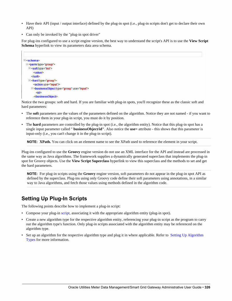
Oracle Utilities Meter Data Management/Smart Grid Gateway Administrative User Guide • 326
• Have their API (input / output interface) defined by the plug-in spot (i.e., plug-in scripts don't get to declare their ownAPI)
• Can only be invoked by the "plug-in spot driver"
For plug-ins configured to use a script engine version, the best way to understand the script's API is to use the View ScriptSchema hyperlink to view its parameters data area schema.
Notice the two groups: soft and hard. If you are familiar with plug-in spots, you'll recognize these as the classic soft andhard parameters:
• The soft parameters are the values of the parameters defined on the algorithm. Notice they are not named - if you want toreference them in your plug-in script, you must do it by position.
• The hard parameters are controlled by the plug-in spot (i.e., the algorithm entity). Notice that this plug-in spot has asingle input parameter called " businessObject/id". Also notice the use= attribute - this shows that this parameter isinput-only (i.e., you can't change it in the plug-in script).
NOTE: XPath. You can click on an element name to see the XPath used to reference the element in your script.
Plug-ins configured to use the Groovy engine version do not use an XML interface for the API and instead are processed inthe same way as Java algorithms. The framework supplies a dynamically generated superclass that implements the plug-inspot for Groovy objects. Use the View Script Superclass hyperlink to view this superclass and the methods to set and getthe hard parameters.
NOTE: For plug-in scripts using the Groovy engine version, soft parameters do not appear in the plug-in spot API asdefined by the superclass. Plug-ins using only Groovy code define their soft parameters using annotations, in a similarway to Java algorithms, and fetch those values using methods defined in the algorithm code.
Setting Up Plug-In ScriptsThe following points describe how to implement a plug-in script:
• Compose your plug-in script, associating it with the appropriate algorithm entity (plug-in spot).
• Create a new algorithm type for the respective algorithm entity, referencing your plug-in script as the program to carryout the algorithm type's function. Only plug-in scripts associated with the algorithm entity may be referenced on thealgorithm type.
• Set up an algorithm for the respective algorithm type and plug it in where applicable. Refer to Setting Up AlgorithmTypes for more information.
Oracle Utilities Meter Data Management/Smart Grid Gateway Administrative User Guide • 327
Service ScriptsBPA scripts run on the client's browser and guide the end-users through business processes. Service scripts run on theapplication server and perform server-based processing for BPA scripts, zones and more. You may want to think of aservice script as a common routine that is set up via scripting (rather than programming).
The following topics describe basic concepts related to service scripts.
A Service Script's APIAs with any common routine, a service script must declare its input / output parameters (i.e., its API). A service script's APIis defined on its schema.
NOTE: Refer to Schema Nodes and Attributes for a complete list of the XML nodes and attributes available to youwhen you construct a schema.
Invoking Service ScriptsAny type of script configured to use a scripting engine version may invoke a service script:
• A BPA script may invoke a service script to perform server-based processing.
• Plug-in scripts may invoke a service script (like a "common routine").
• A service script may call another service script (like a "common routine").
Map zones may be configured to invoke service scripts to obtain the data to be displayed. Refer to Map Zones for moreinformation.
Inbound web services support interaction with service scripts allowing the outside world to interact directly with a servicescript.
You can also invoke a service script from a Java class.
Groovy Library ScriptsJust as service scripts can define common routines written in scripting language, Groovy library scripts are used to definegroups of common components or methods written in Groovy. Groovy library code runs on the application server andperforms server-based processing for scripts that utilize Groovy code.
The following topics describe basic concepts related to Groovy library scripts.
A Groovy Library Script's APIA Groovy library script’s API is composed of one or more public methods whose code is defined in the script’s steps. Thosemethods are defined in a step type of Groovy Library Interface. A Groovy library script must have one (and only one)step of this type.
Invoking Groovy Library MethodsAny type of script that supports the Groovy Members step type may invoke common methods defined in Groovy libraryscripts.
Oracle Utilities Meter Data Management/Smart Grid Gateway Administrative User Guide • 328
Code within a Groovy Members step must create an instance of the Groovy library interface definition to enable theinterface methods to be invoked. Refer to the topic Using Groovy Within Scripts for more information.
Debugging Server-Based ScriptsThe server can create log entries to help you debug your server scripts.
The logs contain a great deal of information including the contents of the referenced data area for Move data, Invokebusiness object, Invoke business service and Invoke service script steps.
Refer to the Debug Mode topic in the Configuration Tools chapter for details of how to execute the application in debugmode.
Maintaining ScriptsThe script maintenance transaction is used to maintain your scripts. The topics in this section describe how to use thistransaction.
FASTPATH: Refer to The Big Picture Of Scripts for more information about scripts.
Script - MainUse this page to define basic information about a script. Open this page using Admin > System > Script.
NOTE: Script Tips. A context sensitive "Script Tips" zone is associated with this page. The zone provides links toEdit Data Syntax and Advanced Schema Topics so that users can quickly access those online help topics to aid inconstructing scripts. In addition, the zone provides links to view the Groovy JavaDocs Viewer and the whitelist of thirdparty Groovy classes so that users can verify the restricted list of classes available for Groovy coding in the script.
Description of Page
Enter a unique Script code and Description for the script. Use the Detailed Description to describe the purpose ofthis script in detail. Owner indicates if the script is owned by the base package or by your implementation (CustomerModification).
CAUTION: Important! If you introduce a new script, carefully consider its naming convention. Refer to System DataNaming Convention for more information.
Script Type indicates if this is a BPA Script, Plug-In Script, Groovy Library Script or Service Script. Refer to The BigPicture Of BPA Scripts and The Big Picture Of Server Based Scripts for more information.
Accessibility Option appears only for BPA scripts. Set this value to Accessible from Script Menu for any script that maybe launched as a stand-alone script. Scripts with this configuration may be linked to a navigation option so that they maybe invoked from a menu and may be configured by a user as a favorite script. Set this value to Not Accessible from ScriptMenu for any script that cannot be launched on its own. For example, any script that is a invoked as a sub-script fromanother script should have this setting. In addition, any script that is designed to be launched from within a specific portalwhere certain data is provided to the script should include this setting.
Enter an Application Service if the execution of the script should be secured. The application service should includeExecute as one of its access modes. Refer to Securing Script Execution for more information. This field does not appear ifthe script type is Groovy Library Script.
Algorithm Entity appears only for plug-in scripts. Use this field to define the algorithm entity into which this script can beplugged in.
Oracle Utilities Meter Data Management/Smart Grid Gateway Administrative User Guide • 329
Business Object appears only for business object related plug-in scripts. Enter the Business Object whose elements are tobe referenced by the plug-in script.
Script Engine Version defines key information affecting the context and execution of the script.
• Script engine version values of 1, 2 and 3 define the version of the XML Path Language (XPath) to be used for thescript. Versions 2 and 3 use the XPath 2 engine supplied by the XQuery team. This is the same engine used inside theOracle database. The current script engine version 3 is a modified version that offers performance improvements withoutimpacting existing version 2 scripts.
The default script engine version is 3.0 for plug-in and service scripts. The default version for BPA scripts is 1.0 ashigher level versions are not applicable.
There are some additional details to note about script engine version 1.0:
• The XPath library used is Jaxen
• For BPA scripts, it uses the browser’s xpath and XML support except for Internet Explorer where the XSXML parseris used.
• Xpath 1 (and even JavaScript) uses floating point arithmetic, which means that adding a collection of numbers withtwo decimal places might end up with a value of 10779.079999999998 instead of 10779.08
• A Script Engine Version value of Groovy indicates that only Groovy Members step types are used in the script andsignals to the system that there is no need to convert the data to and from an XML interface. This allows for greaterefficient in script execution. Only plug-in scripts can select the Groovy engine version.
• The value Framework Version 2.1 Compatibility Mode remains for upgrade purposes. This value should only beapplicable to early versions of BPA scripts using syntax that is incompatible with xpath syntax.
NOTE: The Script Engine Version field does not appear for Groovy Library scripts. The script engine version forthese scripts is set to Groovy by default and cannot be changed.
Click the View Script Schema to view the script's data areas on the schema viewer window. This link does not appear if thescript engine version is Groovy.
Click the View XSD hyperlink to view a script’s schema definition in XSD format. This link only appears if the script typeis BPA Script or Service Script.
The View Script Superclass hyperlink appears only for plug-in scripts using an engine version of Groovy. Click this linkto view the code of the runtime generated superclass for the related plug-in spot’s implementation.
The View Script As Text hyperlink appears for server-based scripts only. Click this link to view the internal scriptingcommands in a separate window.
The tree summarizes the script's steps. You can use the hyperlink to transfer to the Step tab with the corresponding stepdisplayed.
Script - StepUse this page to add or update a script's steps. Open this page using Admin > System > Script and then navigate to theStep tab.
NOTE: Time saver. You can navigate to a step by clicking on the respective node in the tree on the Main tab.
Description of Page
The Steps accordion contains an entry for every step linked to the script. When a script is initially displayed, its steps arecollapsed. To see a step's details, simply click on the step's summary bar. You can re-click the bar to collapse the step'sdetails. Please see accordions for the details of other features you can use to save time.

Oracle Utilities Meter Data Management/Smart Grid Gateway Administrative User Guide • 330
Select the Step Type that corresponds with the step. Refer to How To Set Up Each Step Type for an overview of the steptypes.
CAUTION: The Step Type affects what you can enter on other parts of this page. The remainder of this section isdevoted to those fields that can be entered regardless of Step Type. The subtopics that follow describe those fieldswhose entry is contingent on the Step Type.
Step Sequence defines the relative position of this step in respect of the other steps. The position is important because itdefines the order in which the step is executed. You should only change a Step Sequence if you need to reposition this step.But take care; if you change the Step Sequence and the step is referenced on other steps, you'll have to change all of thereferencing steps.
NOTE: Leave gaps in the sequence numbers. Make sure you leave space between sequence numbers so that youcan add new steps between existing ones in the future. If you run out of space, you can use the Renumber button torenumber all of the steps. This will renumber the script's steps by 10 and change all related references accordingly.
Display Step is only enabled on BPA scripts for step types that typically don't cause information to be displayed in thescript area (i.e., step types like Conditional Branch, Go to a step, Height, etc). If you turn on this switch, informationabout the step is displayed in the script area to help you debug the script.
CAUTION: Remember to turn this switch off when you're ready to let users use this script.
NOTE: If Display Step is turned on and the step has Text, this information will be displayed in the script area. IfDisplay Step is turned on and the step does not have Text, a system-generated messages describing what the step doesis displayed in the script area.
Display Icon controls the icon that prefixes the Text that's displayed in the script area. Using an icon on a step is optional.This field is only applicable to BPA scripts.
Text is the information that displays in the script area when the step executes. You need only define text for steps that causesomething to display in the script area.
FASTPATH: Refer to How To Substitute Variables In Text for a discussion about how to substitute variables in a textstring.
FASTPATH: Refer to How To Use HTML Tags And Spans In Text for a discussion about how to format (with colorsand fonts) the text that appears in the script area.
The other fields on this page are dependent on the Step Type. The topics that follow briefly describe each step type's fieldsand provide additional information about steps.
Click on the View Script Schema hyperlink to view the script's data areas. Doing this opens the schema viewer window.
The View Script As Text hyperlink appears for server-based scripts only. Click this link to view the internal scriptingcommands in a separate window. The presented script syntax is valid within edit data steps.
How To Set Up Each Step TypeThe contents of this section describe how to set up each type of step.

Oracle Utilities Meter Data Management/Smart Grid Gateway Administrative User Guide • 331
Common Step Types To All Script TypesThe contents of this section describe common step types applicable to all script types using a scripting language engineversion.
How To Set Up Conditional Branch StepsConditional branch steps allow you to conditionally jump to a different step based on logical criteria. For example, youcould jump to a different step in a script if the customer is residential as opposed to commercial. In addition, several fieldsare required for Conditional Branch steps:
Compare Field Type and Compare Field Name define the first operand in the comparison. The Field Type defines wherethe field is located. The Field Name defines the name of the field. The following points describe each field type:
• Current To Do Information. Use this field type when the field being compared resides on the current To Do entry.Refer to How To Use To Do Fields for instructions on how to define the appropriate Field Name.
• Data Area. Use this field type when the field being compared is one that you put into one of the scripts data areas inan earlier step. Field Name must reference both a data area structure name as well as the field, for example "parm/charType". Refer to How To Reference Fields In Data Areas for instructions on how to construct the appropriate FieldName.
• Page Data Model. Use this field type when the field being compared resides on one of the tab pages in the object displayarea. Refer to How To Find The Name Of Page Data Model Fields for instructions on how to find the appropriate FieldName.
• Predefined Value. Use this field type when the field being compared is a global variable.
• Temporary Storage. Use this field type when the field being compared is one that you put into temporary storage in anearlier step. The Field Name must be the same as defined in an earlier step.
• User Interface Field. Use this field type when the field being compared resides on the currently displayed tab page.Refer to How To Find The Name Of User Interface Fields for instructions on how to find the appropriate Field Name.
Condition defines the comparison criteria:
• Use >, <, =, >=, <=, <> (not equal) to compare the field using standard logical operators. Enter the comparison valueusing the following fields.
• Use IN to compare the first field to a list of values. Each value is separated by a comma. For example, if a field valuemust equal 1, 3 or 9, you would enter a comparison value of 1,3,9.
• Use BETWEEN to compare the field to a range of values. For example, if a field value must be between 1 and 9, youwould enter a comparison value of 1,9. Note, the comparison is inclusive of the low and high values.
Comparison Field Type, Comparison Field Name and Comparison Value define what you're comparing the firstoperand to. The following points describe each field type:
• Current To Do Information. Use this field type when the comparison value resides on the current To Do entry. Refer toHow To Use To Do Fields for instructions on how to define the appropriate Field Name.
• Data Area. Use this field type when the comparison value resides in one of the scripts data areas. Field Name mustreference both a data area structure name as well as the field, for example "parm/charType". Refer to How To ReferenceFields In Data Areas for instructions on how to construct the appropriate Field Name.
• Page Data Model. Use this field type when the comparison value resides on one of the tab pages in the object displayarea. Refer to How To Find The Name Of Page Data Model Fields for instructions on how to find the appropriate FieldName.
Oracle Utilities Meter Data Management/Smart Grid Gateway Administrative User Guide • 332
• Predefined Value. Use this field type when the field being compared is a constant value defined in the script. When thisfield type is used, use Comparison Value to define the constant value. Refer to How To Use Constants In Scripts forinstructions on how to use constants.
• Temporary Storage. Use this field type when the comparison value is a field that you put into temporary storage in anearlier step. The Field Name must be the same as defined in an earlier step.
• User Interface Field. Use this field type when the comparison value resides on the currently displayed tab page. Refer toHow To Find The Name Of User Interface Fields for instructions on how to find the appropriate Field Name.
NOTE: Conditional field types. The field types Current To Do Information, Page Data Model and User InterfaceField are only applicable to BPA scripts.
The above fields allow you to perform a comparison that results in a value of TRUE or FALSE. The remaining fieldscontrol the step to which control is passed given the value:
• If TRUE, Go to defines the step that is executed if the comparison results in a TRUE value.
• If FALSE, Go to defines the step that is executed if the comparison results in a FALSE value.
NOTE: Numeric Comparison. Comparison of two values may be numeric or textual (left-to-right). Numericcomparison takes place only when values on both side of the comparison are recognized as numeric by the system.Otherwise, textual comparison is used. Fields for Current To Do Information, Data Area, Page Data Model, andUser Interface Field types are explicitly associated with a data type and therefore can be recognized as numeric ornot. This is not the case for fields residing in Temporary Storage or those set as Predefined Values . A TemporaryStorage field is considered numeric if it either holds a numeric value moved to it from an explicitly defined numericvalue (see above) or it is a resultant field of mathematical operation. A Predefined Value field is considered numericif the other field it is compared to is numeric. For example, if a numeric field is compared to a Predefined Value thelatter is considered numeric as well resulting in numeric value comparison. However, if the two fields are defined asPredefined Values the system assumes their values are text strings and therefore applies textual comparison.
How To Set Up Edit Data StepsEdit data steps provide a free format region where you can specify commands to control your script processing.
In general, the syntax available within edit data mimics the commands available within the explicit step types. However,there are a few commands that are available only within edit data. For example, the two structured commands: For, and If.
For server-based scripts, you may find it useful to create a few explicit step types and then use the View Script as Texthyperlink on the Script - Step page to better understand the edit data syntax.
NOTE: Not all BPA step types are supported using the edit data syntax. Refer to the Edit Data Syntax topic below formore information on edit data commands and examples.
Additional field required for Edit data steps:
Enter your scripting commands in the Edit Data Text field. Click the adjacent icon to open a window providing more spacefor defining the edit data step.
Edit Data SyntaxThe topics in this section provide detail of the syntax supported in the edit data step type.
Oracle Utilities Meter Data Management/Smart Grid Gateway Administrative User Guide • 333
ContentsCommentsTemporary VariablesContext VariablesMove StatementGo To StatementConditional Branch StatementIf StatementFor StatementList ProcessingFunctions for Processing a ListDeclare and Invoke Schema Based ObjectsSystem and Global VariablesPerform Script and TransferNavigate StatementInvoke Map StatementDeclare BO with BO GroupGenerate Edit Map StatementsTerminate StatementInvoking Groovy CodeDebugging a BPA Script
CommentsYou can place comments into your script using the double slash notation // in the first two characters of the edit data step.Example:
// // quit with error//if ("not(customer/securityEnabled)")terminate with error (8000, 1001 %1="customer/id" %1='not allowed');end-if;
Temporary VariablesTemporary variables can be declared within all types of scripts. They should be referenced by a leading single dollar sign('$'). However, temporary variables behave differently in the various script types:
• In BPA Scripts temporary variables remain persistent from one BPA script to another (refer to the Perform Script andTransfer Control statements), which means that you can use temporary variables to communicate between BPA scripts.
• Temporary variables cannot be passed from a BPA script to a service or plug-in script. Only data area elements can bepassed between these types of scripts.
• Within service and plug-in scripts, temporary variables remain persistent only for the life of the particular script thatdeclared the variable. This means that temporary variables cannot be passed between plug-in scripts and service scripts,only global variables, context variables and data area elements can be passed between these types of scripts.
Declaring / Initializing / Defaulting Temporary Variables
When using a temporary variable, it should be declared or initialized with an appropriate value before using it. A typicalmethod for declaring a variable is to simply move data to it in a move statement, for example.
move "0" to $index;
FASTPATH: Refer to Move to a Temporary Variable for more information on implicit declaration of a temporaryvariable within a move statement.
For BPA scripts, as mentioned above, temporary variables may be passed from one BPA script to another. As such, it iscommon to reference a temporary variable in a BPA that should have been initialized by a previous BPA. However, if there
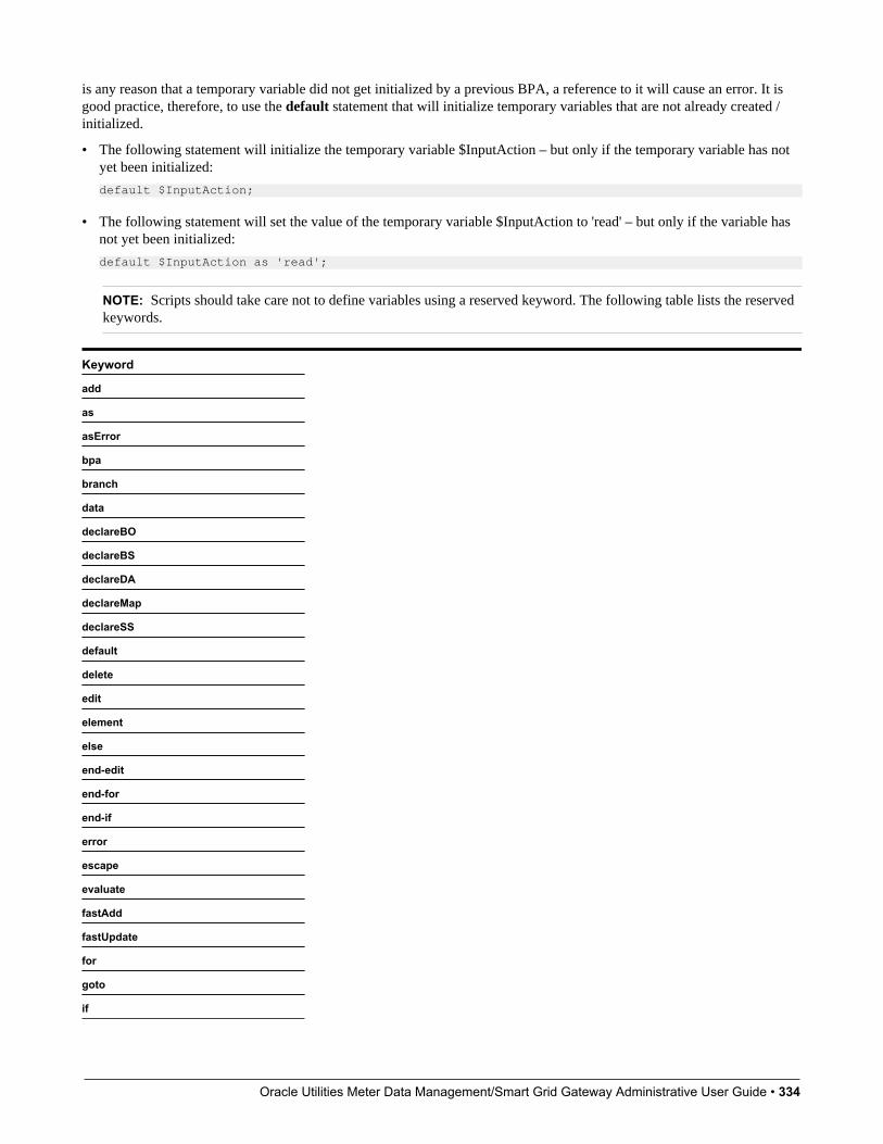
Oracle Utilities Meter Data Management/Smart Grid Gateway Administrative User Guide • 334
is any reason that a temporary variable did not get initialized by a previous BPA, a reference to it will cause an error. It isgood practice, therefore, to use the default statement that will initialize temporary variables that are not already created /initialized.
• The following statement will initialize the temporary variable $InputAction – but only if the temporary variable has notyet been initialized:
default $InputAction;
• The following statement will set the value of the temporary variable $InputAction to 'read' – but only if the variable hasnot yet been initialized:
default $InputAction as 'read';
NOTE: Scripts should take care not to define variables using a reserved keyword. The following table lists the reservedkeywords.
Keyword
add
as
asError
bpa
branch
data
declareBO
declareBS
declareDA
declareMap
declareSS
default
delete
edit
element
else
end-edit
end-for
end-if
error
escape
evaluate
fastAdd
fastUpdate
for
goto
if
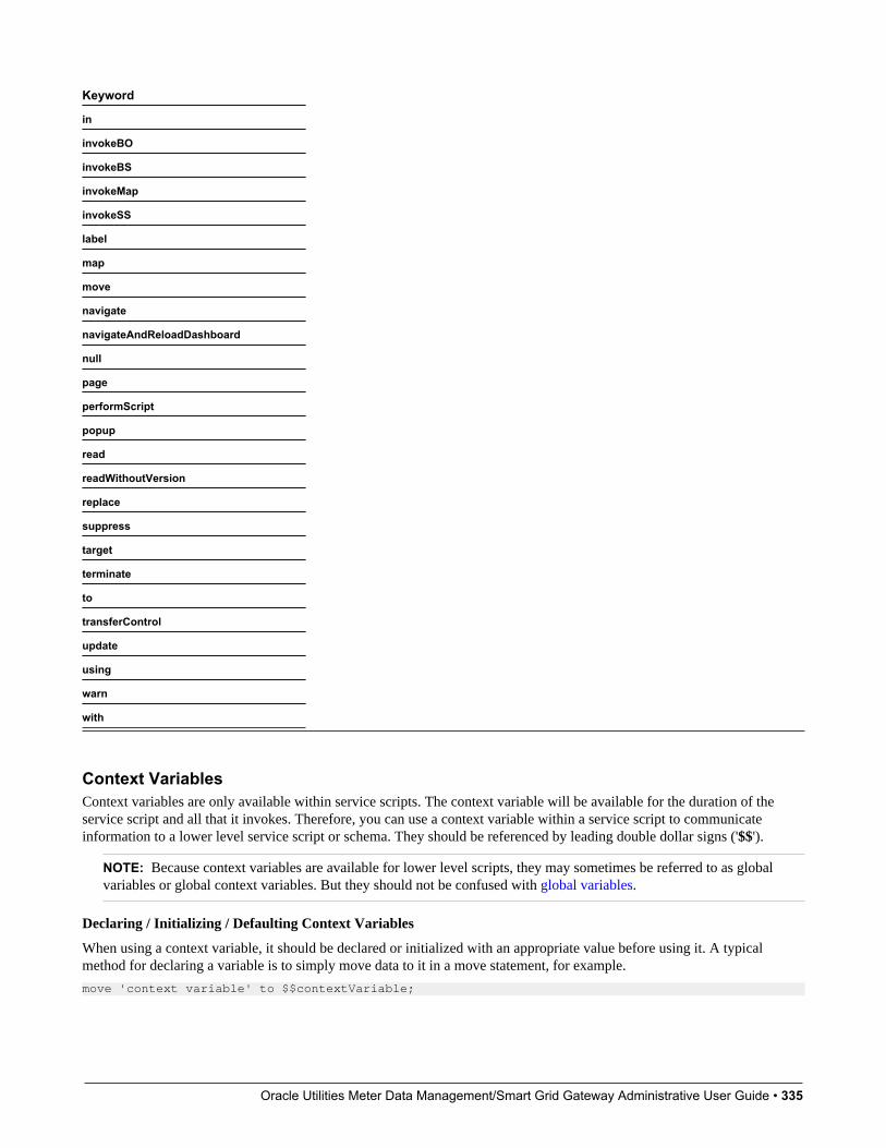
Oracle Utilities Meter Data Management/Smart Grid Gateway Administrative User Guide • 335
Keyword
in
invokeBO
invokeBS
invokeMap
invokeSS
label
map
move
navigate
navigateAndReloadDashboard
null
page
performScript
popup
read
readWithoutVersion
replace
suppress
target
terminate
to
transferControl
update
using
warn
with
Context VariablesContext variables are only available within service scripts. The context variable will be available for the duration of theservice script and all that it invokes. Therefore, you can use a context variable within a service script to communicateinformation to a lower level service script or schema. They should be referenced by leading double dollar signs ('$$').
NOTE: Because context variables are available for lower level scripts, they may sometimes be referred to as globalvariables or global context variables. But they should not be confused with global variables.
Declaring / Initializing / Defaulting Context Variables
When using a context variable, it should be declared or initialized with an appropriate value before using it. A typicalmethod for declaring a variable is to simply move data to it in a move statement, for example.
move 'context variable' to $$contextVariable;
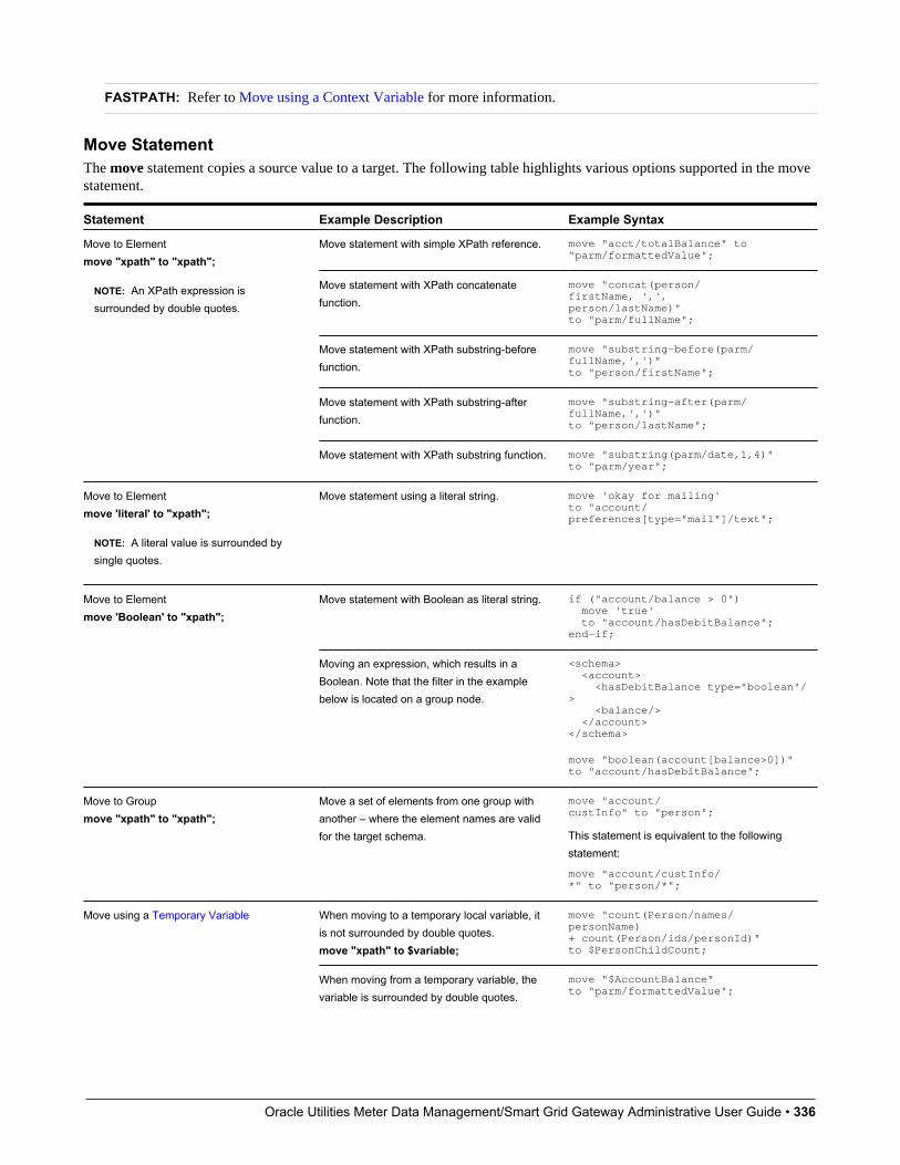
Oracle Utilities Meter Data Management/Smart Grid Gateway Administrative User Guide • 336
FASTPATH: Refer to Move using a Context Variable for more information.
Move StatementThe move statement copies a source value to a target. The following table highlights various options supported in the movestatement.
Statement Example Description Example Syntax
Move statement with simple XPath reference. move "acct/totalBalance" to "parm/formattedValue";
Move statement with XPath concatenatefunction.
move "concat(person/firstName, ',', person/lastName)" to "parm/fullName";
Move statement with XPath substring-beforefunction.
move "substring-before(parm/fullName,',')" to "person/firstName";
Move statement with XPath substring-afterfunction.
move "substring-after(parm/fullName,',')" to "person/lastName";
Move to Elementmove "xpath" to "xpath";
NOTE: An XPath expression issurrounded by double quotes.
Move statement with XPath substring function. move "substring(parm/date,1,4)" to "parm/year";
Move to Elementmove 'literal' to "xpath";
NOTE: A literal value is surrounded bysingle quotes.
Move statement using a literal string. move 'okay for mailing' to "account/preferences[type="mail"]/text";
Move statement with Boolean as literal string. if ("account/balance > 0") move 'true' to "account/hasDebitBalance"; end-if;
Move to Elementmove 'Boolean' to "xpath";
Moving an expression, which results in aBoolean. Note that the filter in the examplebelow is located on a group node.
<schema> <account> <hasDebitBalance type="boolean"/> <balance/> </account></schema>
move "boolean(account[balance>0])" to "account/hasDebitBalance";
Move to Groupmove "xpath" to "xpath";
Move a set of elements from one group withanother – where the element names are validfor the target schema.
move "account/custInfo" to "person";
This statement is equivalent to the followingstatement:
move "account/custInfo/*" to "person/*";
When moving to a temporary local variable, itis not surrounded by double quotes.move "xpath" to $variable;
move "count(Person/names/personName) + count(Person/ids/personId)" to $PersonChildCount;
Move using a Temporary Variable
When moving from a temporary variable, thevariable is surrounded by double quotes.
move "$AccountBalance" to "parm/formattedValue";

Oracle Utilities Meter Data Management/Smart Grid Gateway Administrative User Guide • 337
Statement Example Description Example Syntaxmove "$variable" to “xpath”;
Move using a Context Variable
move "xpath" to $$variable;
move $$variable to “xpath”;
Context variables, source or target, arereferenced without any double quotes.
move 'context value' to $$contextVariable;// // here, we move from a context variable.move $$contextVariable to "MarketMessage/sender";
Move using a Dynamic Locationmove "xpath" | 'literal' toevaluate("xpath" | $variable);
move evaluate("xpath" | $variable) to"xpath" | $variable;
The evaluate statement allows your movesource or target location to be dynamicallyderived from a variable or schema elementlocation.
move 'literal' to evaluate("schemaLocation"); //move "schemaLocation" to evaluate($Variable);
move evaluate("schemaLocation") to $Variable;// move evaluate($Variable) to "schemaLocation";
Move escapemove escape("xpath" | $variable) to"xpath" | $variable;
Move escape is only available for servicescripts and plug-in scripts. The escapestatement scans your source text value forHTML content and escapes it, i.e. replaces anyHTML-like characters with special charactersthat are escaped from HTML rendering. Bydoing so the text would be displayed as plaintext when displayed as part of an HTMLelement.
NOTE: You should only use this functionif the text is to be displayed as part of anHTML element and is suspected to containHTML-like characters or even maliciousHTML that should not be rendered as HTML.If incorrectly displayed using a non HTMLelement, the special escape characters, ifany would be visible as part of your text.Refer to the UI Map Attributes and Functionsfor more information on how to define anelement to display HTML content.
move escape("schemaLocation") to $Variable;// move escape($Variable) to "schemaLocation";
Move nullmove null to "xpath";
You can remove information from the XMLinstance document through the special syntaxof move 'null'. Note that you can specify eithera node name in the XPath expression or agroup name. If you specify a group then thegroup and all child elements will be eliminatedfrom processing.
Remove a node and all of its child nodes:
if ("boolean(customer/securityEnabled)") goto updateInfo;else move null to "customer"; end-if;
Remove all child nodes of a group node withthe suffix '/*'.
if ("boolean(customer/securityEnabled)") move null to "customer/*";end-if;
Go To StatementThe edit data step supports functionality analogous to the Go To step type. The syntax is goto label; where the labelrepresents another location within the edit data text field (identified by this label) or represents another step in the script.
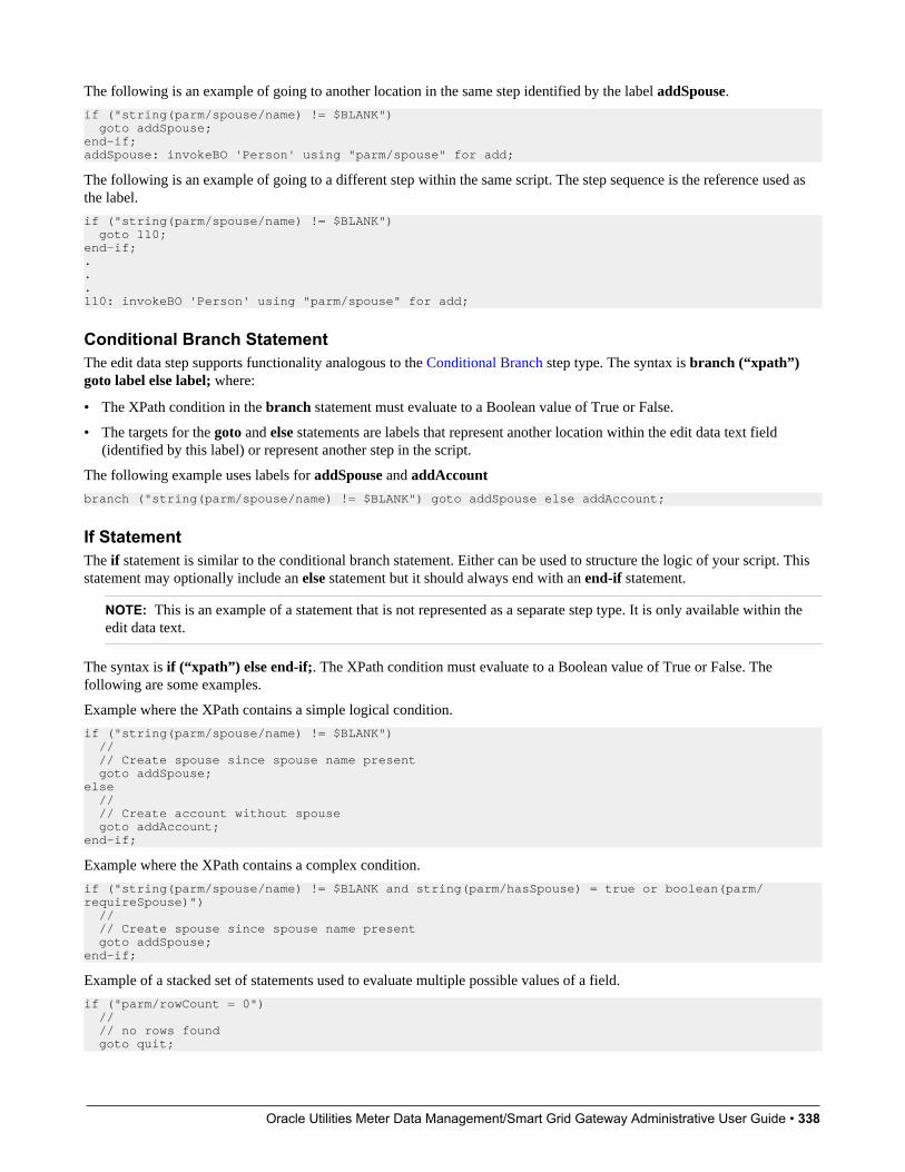
Oracle Utilities Meter Data Management/Smart Grid Gateway Administrative User Guide • 338
The following is an example of going to another location in the same step identified by the label addSpouse.
if ("string(parm/spouse/name) != $BLANK") goto addSpouse;end-if;addSpouse: invokeBO 'Person' using "parm/spouse" for add;
The following is an example of going to a different step within the same script. The step sequence is the reference used asthe label.
if ("string(parm/spouse/name) != $BLANK") goto 110;end-if;...110: invokeBO 'Person' using "parm/spouse" for add;
Conditional Branch StatementThe edit data step supports functionality analogous to the Conditional Branch step type. The syntax is branch (“xpath”)goto label else label; where:
• The XPath condition in the branch statement must evaluate to a Boolean value of True or False.
• The targets for the goto and else statements are labels that represent another location within the edit data text field(identified by this label) or represent another step in the script.
The following example uses labels for addSpouse and addAccount
branch ("string(parm/spouse/name) != $BLANK") goto addSpouse else addAccount;
If StatementThe if statement is similar to the conditional branch statement. Either can be used to structure the logic of your script. Thisstatement may optionally include an else statement but it should always end with an end-if statement.
NOTE: This is an example of a statement that is not represented as a separate step type. It is only available within theedit data text.
The syntax is if (“xpath”) else end-if;. The XPath condition must evaluate to a Boolean value of True or False. Thefollowing are some examples.
Example where the XPath contains a simple logical condition.
if ("string(parm/spouse/name) != $BLANK") // // Create spouse since spouse name present goto addSpouse;else // // Create account without spouse goto addAccount;end-if;
Example where the XPath contains a complex condition.
if ("string(parm/spouse/name) != $BLANK and string(parm/hasSpouse) = true or boolean(parm/requireSpouse)") // // Create spouse since spouse name present goto addSpouse;end-if;
Example of a stacked set of statements used to evaluate multiple possible values of a field.
if ("parm/rowCount = 0") // // no rows found goto quit;
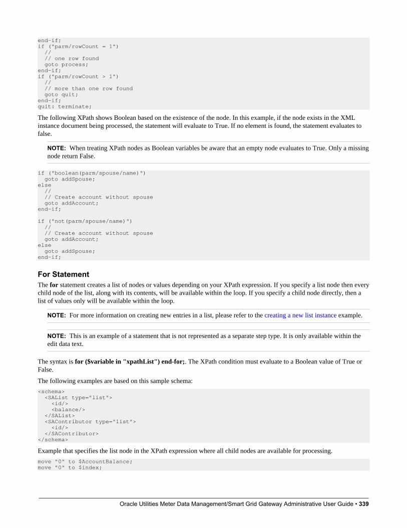
Oracle Utilities Meter Data Management/Smart Grid Gateway Administrative User Guide • 339
end-if;if ("parm/rowCount = 1") // // one row found goto process;end-if;if ("parm/rowCount > 1") // // more than one row found goto quit;end-if;quit: terminate;
The following XPath shows Boolean based on the existence of the node. In this example, if the node exists in the XMLinstance document being processed, the statement will evaluate to True. If no element is found, the statement evaluates tofalse.
NOTE: When treating XPath nodes as Boolean variables be aware that an empty node evaluates to True. Only a missingnode return False.
if ("boolean(parm/spouse/name)") goto addSpouse;else // // Create account without spouse goto addAccount;end-if; if ("not(parm/spouse/name)") // // Create account without spouse goto addAccount;else goto addSpouse;end-if;
For StatementThe for statement creates a list of nodes or values depending on your XPath expression. If you specify a list node then everychild node of the list, along with its contents, will be available within the loop. If you specify a child node directly, then alist of values only will be available within the loop.
NOTE: For more information on creating new entries in a list, please refer to the creating a new list instance example.
NOTE: This is an example of a statement that is not represented as a separate step type. It is only available within theedit data text.
The syntax is for ($variable in "xpathList") end-for;. The XPath condition must evaluate to a Boolean value of True orFalse.
The following examples are based on this sample schema:
<schema> <SAList type="list"> <id/> <balance/> </SAList> <SAContributor type="list"> <id/> </SAContributor></schema>
Example that specifies the list node in the XPath expression where all child nodes are available for processing.
move "0" to $AccountBalance;move "0" to $index;

Oracle Utilities Meter Data Management/Smart Grid Gateway Administrative User Guide • 340
for ($SAList in "SAList") move "$SAList/balance + $AccountBalance" to $AccountBalance; // // keep track of each SA contributing to the balance in the SA Contributor list move "1 + $index" to $index; move "$SAList/id" to "SAContributor[$index]/id";end-for;
Example that specifies a child node within the list node in the XPath expression. Only values of that node are available forprocessing.
move "0" to $AccountBalance;for ($SABalance in "SAList/balance") move "$SABalance + $AccountBalance" to $AccountBalance;end-for;
Example that shows that a filter can be used to limit the rows selected by the for loop.
move "0" to $AccountDebitBalance;for ($SAList in "SAList[Balance>0]") move "$SAList/balance + $AccountDebitBalance" to $AccountDebitBalance;end-for;
Example that shows the use of a filter when specifying child nodes.
move "0" to $AccountCreditBalance;for ($SABalance in "SAList[Balance<0]/balance") move "$SABalance + $AccountCreditBalance" to $AccountCreditBalance; end-for;
List ProcessingThis section provides details about processing lists. The examples in this section reference the following schema:
<schema> <parm type="group"> <name/> </parm> <Person type="group"> <names type="list"> <type/> <name/> </names> </Person></schema>
Referencing a List Element. You can move a value to a particular list instance by referencing an identifying node in thelist within a filter. The syntax is move "xpath" to "xpathList[filter]/element"; Example:
move "parm/name" to "Person/names[type='main']/name";
Creating a New List Instance. A special notation can be used within a move target statement to indicate a new list instanceshould be created. The "+" indicates to the script processor that a new instance of a list should be initiated for the targetelement. The syntax is move "xpath" to "+xpathList"; Example:
move "parm/name" to "Person/+names/name";
Deleting a List Instance. An XML list entry can be deleted from the database by moving an action attribute of 'delete' tothe element name. To cause a database delete of a list entry requires an attribute of action="delete" in the target node and asubsequent update BO interaction. The syntax is move 'delete' to "xpathList@action"); Example:
if ("parm/action = 'd'") move "0" to $index; for ($CCList in "CCList") move "1 + $index" to $index; if ("$CCList/id = parm/id") move 'delete' to "CCList[$index]@action"; goto update; end-if; end-for;end-if;
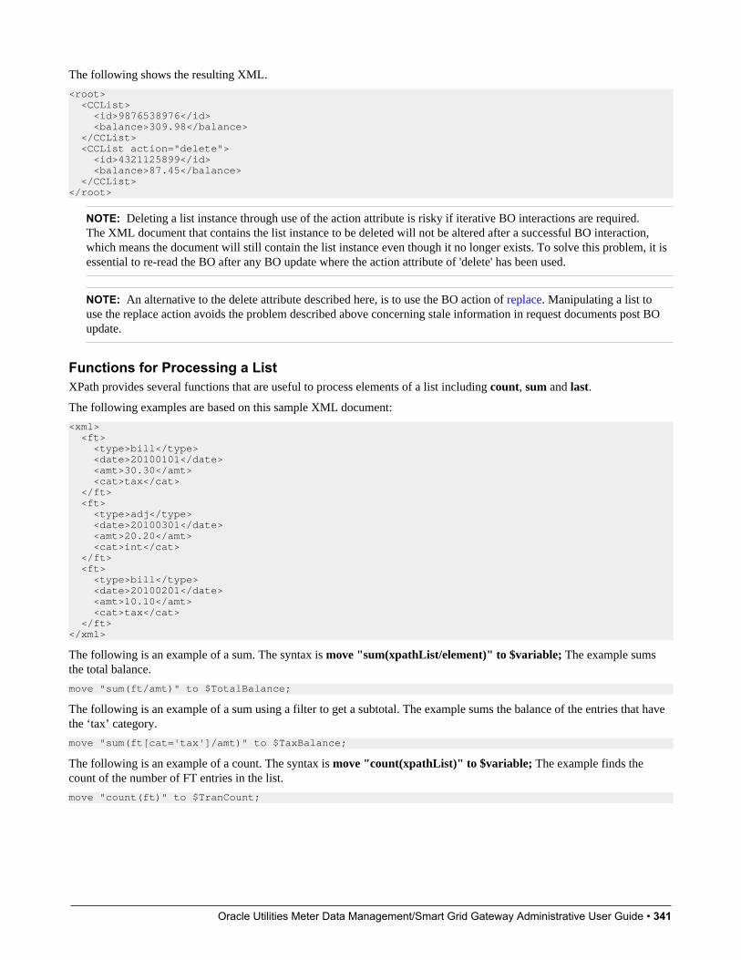
Oracle Utilities Meter Data Management/Smart Grid Gateway Administrative User Guide • 341
The following shows the resulting XML.
<root> <CCList> <id>9876538976</id> <balance>309.98</balance> </CCList> <CCList action="delete"> <id>4321125899</id> <balance>87.45</balance> </CCList></root>
NOTE: Deleting a list instance through use of the action attribute is risky if iterative BO interactions are required.The XML document that contains the list instance to be deleted will not be altered after a successful BO interaction,which means the document will still contain the list instance even though it no longer exists. To solve this problem, it isessential to re-read the BO after any BO update where the action attribute of 'delete' has been used.
NOTE: An alternative to the delete attribute described here, is to use the BO action of replace. Manipulating a list touse the replace action avoids the problem described above concerning stale information in request documents post BOupdate.
Functions for Processing a ListXPath provides several functions that are useful to process elements of a list including count, sum and last.
The following examples are based on this sample XML document:
<xml> <ft> <type>bill</type> <date>20100101</date> <amt>30.30</amt> <cat>tax</cat> </ft> <ft> <type>adj</type> <date>20100301</date> <amt>20.20</amt> <cat>int</cat> </ft> <ft> <type>bill</type> <date>20100201</date> <amt>10.10</amt> <cat>tax</cat> </ft></xml>
The following is an example of a sum. The syntax is move "sum(xpathList/element)" to $variable; The example sumsthe total balance.
move "sum(ft/amt)" to $TotalBalance;
The following is an example of a sum using a filter to get a subtotal. The example sums the balance of the entries that havethe ‘tax’ category.
move "sum(ft[cat='tax']/amt)" to $TaxBalance;
The following is an example of a count. The syntax is move "count(xpathList)" to $variable; The example finds thecount of the number of FT entries in the list.
move "count(ft)" to $TranCount;
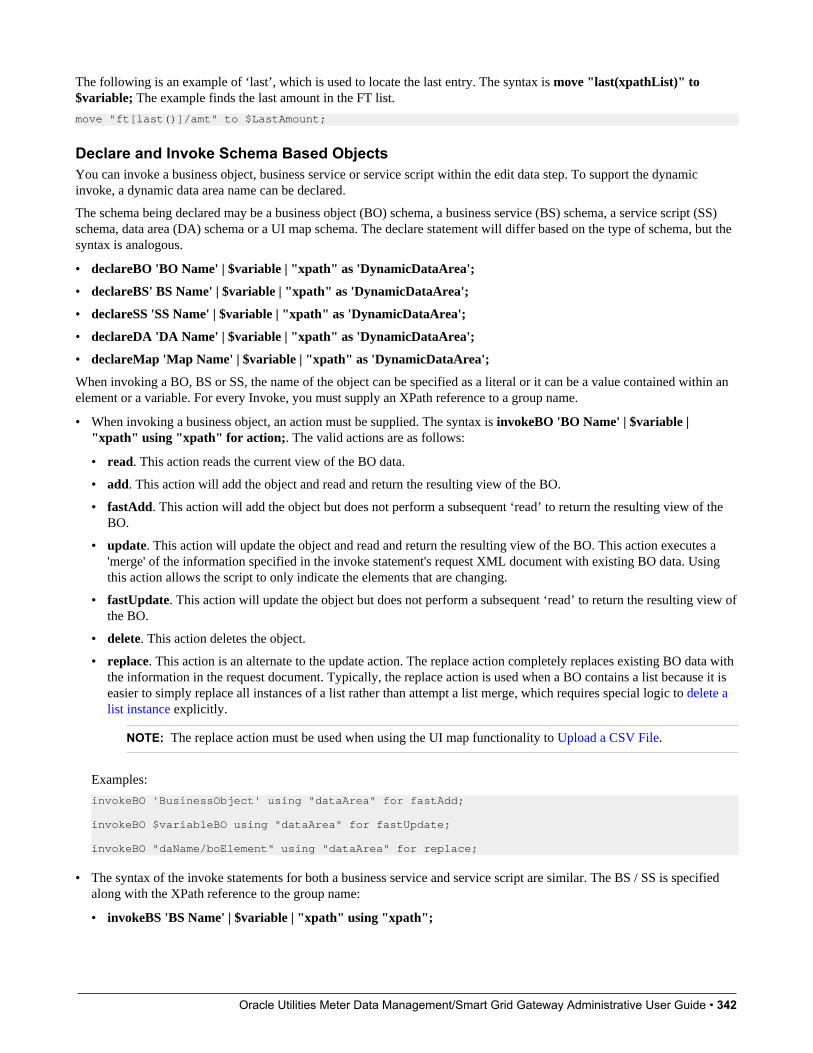
Oracle Utilities Meter Data Management/Smart Grid Gateway Administrative User Guide • 342
The following is an example of ‘last’, which is used to locate the last entry. The syntax is move "last(xpathList)" to$variable; The example finds the last amount in the FT list.
move "ft[last()]/amt" to $LastAmount;
Declare and Invoke Schema Based ObjectsYou can invoke a business object, business service or service script within the edit data step. To support the dynamicinvoke, a dynamic data area name can be declared.
The schema being declared may be a business object (BO) schema, a business service (BS) schema, a service script (SS)schema, data area (DA) schema or a UI map schema. The declare statement will differ based on the type of schema, but thesyntax is analogous.
• declareBO 'BO Name' | $variable | "xpath" as 'DynamicDataArea';
• declareBS' BS Name' | $variable | "xpath" as 'DynamicDataArea';
• declareSS 'SS Name' | $variable | "xpath" as 'DynamicDataArea';
• declareDA 'DA Name' | $variable | "xpath" as 'DynamicDataArea';
• declareMap 'Map Name' | $variable | "xpath" as 'DynamicDataArea';
When invoking a BO, BS or SS, the name of the object can be specified as a literal or it can be a value contained within anelement or a variable. For every Invoke, you must supply an XPath reference to a group name.
• When invoking a business object, an action must be supplied. The syntax is invokeBO 'BO Name' | $variable |"xpath" using "xpath" for action;. The valid actions are as follows:
• read. This action reads the current view of the BO data.
• add. This action will add the object and read and return the resulting view of the BO.
• fastAdd. This action will add the object but does not perform a subsequent ‘read’ to return the resulting view of theBO.
• update. This action will update the object and read and return the resulting view of the BO. This action executes a'merge' of the information specified in the invoke statement's request XML document with existing BO data. Usingthis action allows the script to only indicate the elements that are changing.
• fastUpdate. This action will update the object but does not perform a subsequent ‘read’ to return the resulting view ofthe BO.
• delete. This action deletes the object.
• replace. This action is an alternate to the update action. The replace action completely replaces existing BO data withthe information in the request document. Typically, the replace action is used when a BO contains a list because it iseasier to simply replace all instances of a list rather than attempt a list merge, which requires special logic to delete alist instance explicitly.
NOTE: The replace action must be used when using the UI map functionality to Upload a CSV File.
Examples:
invokeBO 'BusinessObject' using "dataArea" for fastAdd; invokeBO $variableBO using "dataArea" for fastUpdate; invokeBO "daName/boElement" using "dataArea" for replace;
• The syntax of the invoke statements for both a business service and service script are similar. The BS / SS is specifiedalong with the XPath reference to the group name:
• invokeBS 'BS Name' | $variable | "xpath" using "xpath";

Oracle Utilities Meter Data Management/Smart Grid Gateway Administrative User Guide • 343
• invokeSS 'SS Name' | $variable | "xpath" using "xpath";
The examples use the invokeBS statement but the statements are similar for the invokeSS statement.
invokeBS 'BusinessService' using "dataArea"; invokeBS $variableBS using "dataArea"; invokeBS "daName/bsElement" using "dataArea";
Note that for BPA scripting, the invoke statements may also indicate how to handle warnings.
Syntax Description Examples
with warn asError Indicates that a warning should be treatedas an error displayed in the UI map. The textasError is optional.
invokeBO 'BusinessObject' using "dataArea" for add with warn asError;
invokeSS 'ServiceScript' using "dataArea" with warn;
with warn popup Indicates that a warning should be presentedin the standard framework popup. In thisscenario, the user is presented with standardOK and Cancel buttons. If the user clicks OK,it means that the process should continue. Ifthe user clicks Cancel, the processing shoulddiscontinue.
invokeBS "daName/bsElement" using "dataArea" with warn popup;
with warn suppress Indicates that a warning should besuppressed. This is the default if no warningsyntax is added to the invoke statement.
invokeBS "daName/bsElement" using "dataArea" with warn suppress;
invokeSS 'ServiceScript' using "dataArea";
NOTE: For service scripts, all objects invoked from the service script will inherit their warning level. Therefore, if theservice script is invoked with warn, all nested invoke statements will also be invoked with warn.
For BPA scripts, there should also be logic following the invocation to handle errors and warnings (if with warn as popupis used). The system variables $ERROR and $WARNING are provided to interpret the results. $WARNING is set to trueif the user has clicked the Cancel button. Also note that the product provides a BPA Script F1–HandleErr that may be usedto display the error. The following is an example of typical error handling logic.
invokeBO "F1-DetermineBo/output/bo" using "boSchema" for update with warn popup;if ("$WARNING") terminate;end-if;if ("$ERROR") transferControl 'F1-HandleErr';end-if;
System and Global VariablesThe following tables highlight system and global variables available for script writing.
System Variables - All Script Types
The following system variables are available for all script types (service scripts, plug-in scripts, and BPA scripts).
Variable Description Example
$BLANK Represents an empty node. if ("string(parm/spouse/name) != $BLANK") goto addSpouse;end-if;
$CURRENT-DATE Represents the current date.For BPA scripts, this is the browser date.
move "$CURRENT-DATE" to $tempDate;
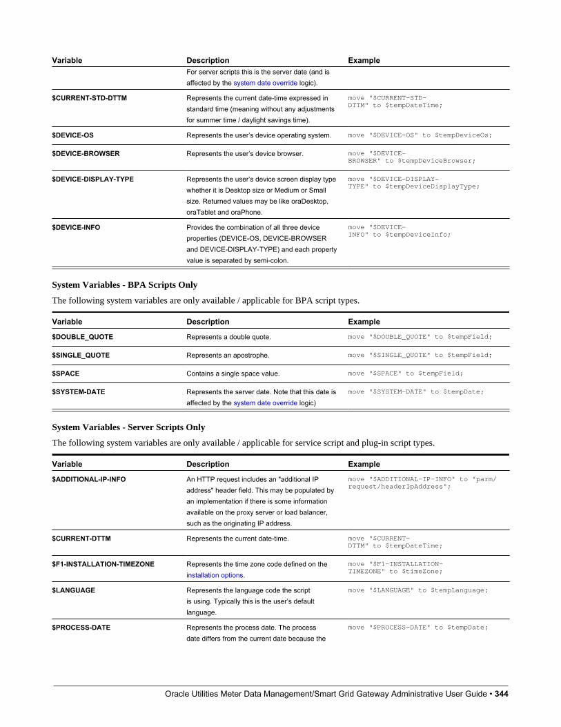
Oracle Utilities Meter Data Management/Smart Grid Gateway Administrative User Guide • 344
Variable Description ExampleFor server scripts this is the server date (and isaffected by the system date override logic).
$CURRENT-STD-DTTM Represents the current date-time expressed instandard time (meaning without any adjustmentsfor summer time / daylight savings time).
move "$CURRENT-STD-DTTM" to $tempDateTime;
$DEVICE-OS Represents the user’s device operating system. move "$DEVICE-OS" to $tempDeviceOs;
$DEVICE-BROWSER Represents the user’s device browser. move "$DEVICE-BROWSER" to $tempDeviceBrowser;
$DEVICE-DISPLAY-TYPE Represents the user’s device screen display typewhether it is Desktop size or Medium or Smallsize. Returned values may be like oraDesktop,oraTablet and oraPhone.
move "$DEVICE-DISPLAY-TYPE" to $tempDeviceDisplayType;
$DEVICE-INFO Provides the combination of all three deviceproperties (DEVICE-OS, DEVICE-BROWSERand DEVICE-DISPLAY-TYPE) and each propertyvalue is separated by semi-colon.
move "$DEVICE-INFO" to $tempDeviceInfo;
System Variables - BPA Scripts Only
The following system variables are only available / applicable for BPA script types.
Variable Description Example
$DOUBLE_QUOTE Represents a double quote. move "$DOUBLE_QUOTE" to $tempField;
$SINGLE_QUOTE Represents an apostrophe. move "$SINGLE_QUOTE" to $tempField;
$SPACE Contains a single space value. move "$SPACE" to $tempField;
$SYSTEM-DATE Represents the server date. Note that this date isaffected by the system date override logic)
move "$SYSTEM-DATE" to $tempDate;
System Variables - Server Scripts Only
The following system variables are only available / applicable for service script and plug-in script types.
Variable Description Example
$ADDITIONAL-IP-INFO An HTTP request includes an "additional IPaddress" header field. This may be populated byan implementation if there is some informationavailable on the proxy server or load balancer,such as the originating IP address.
move "$ADDITIONAL-IP-INFO" to "parm/request/headerIpAddress";
$CURRENT-DTTM Represents the current date-time. move "$CURRENT-DTTM" to $tempDateTime;
$F1-INSTALLATION-TIMEZONE Represents the time zone code defined on theinstallation options.
move "$F1-INSTALLATION-TIMEZONE" to $timeZone;
$LANGUAGE Represents the language code the scriptis using. Typically this is the user’s defaultlanguage.
move "$LANGUAGE" to $tempLanguage;
$PROCESS-DATE Represents the process date. The processdate differs from the current date because the
move "$PROCESS-DATE" to $tempDate;
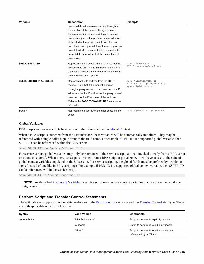
Oracle Utilities Meter Data Management/Smart Grid Gateway Administrative User Guide • 345
Variable Description Exampleprocess date will remain consistent throughoutthe duration of the process being executed.For example, if a service script stores severalbusiness objects – the process date is initializedat the start of the service script execution andeach business object will have the same processdate defaulted. The current date, especially thecurrent date time, will reflect the actual time ofprocessing.
$PROCESS-DTTM Represents the process date-time. Note that theprocess date and time is initialized at the start ofa particular process and will not reflect the exactdate and time of an update.
move "$PROCESS-DTTM" to $tempDateTime;
$REQUESTING-IP-ADDRESS Represents the IP address from the HTTPrequest. Note that if the request is routedthrough a proxy server or load balancer, this IPaddress is be the IP address of the proxy or loadbalancer, not the IP address of the end user.Refer to the $ADDITIONAL-IP-INFO variable forinformation.
move "$REQUESTING-IP-ADDRESS" to "parm/request/systemIpAddress";
$USER Represents the user ID of the user executing thescript.
move "$USER" to $tempUser;
Global Variables
BPA scripts and service scripts have access to the values defined in Global Context.
When a BPA script is launched from the user interface, these variables will be automatically initialized. They may bereferenced with a single dollar sign in front of the field name. For example if PER_ID is a supported global variable, then$PER_ID can be referenced within the BPA script:
move "$PER_ID" to "schema/customerId";
For service scripts, global variables may only be referenced if the service script has been invoked directly from a BPA scriptor a zone on a portal. When a service script is invoked from a BPA script or portal zone, it will have access to the suite ofglobal context variables populated in the UI session. For service scripting, the global fields must be prefixed by two dollarsigns (instead of one like in BPA scripting). For example if PER_ID is a supported global context variable, then $$PER_IDcan be referenced within the service script.
move $$PER_ID to "schema/customerId";
NOTE: As described in Context Variables, a service script may declare context variables that use the same two dollarsign syntax.
Perform Script and Transfer Control StatementsThe edit data step supports functionality analogous to the Perform script step type and the Transfer Control step type. Theseare both applicable only to BPA scripts.
Syntax Valid Values Comments
'BPA Script Name' Script to perform is explicitly provided.
$Variable Script to perform is found in a variable.
performScript
"XPath" Script to perform is found in an element,referenced by its XPath.
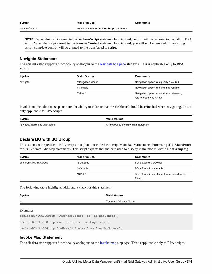
Oracle Utilities Meter Data Management/Smart Grid Gateway Administrative User Guide • 346
Syntax Valid Values Comments
transferControl Analogous to the performScript statement
NOTE: When the script named in the performScript statement has finished, control will be returned to the calling BPAscript. When the script named in the transferControl statement has finished, you will not be returned to the callingscript, complete control will be granted to the transferred to script.
Navigate StatementThe edit data step supports functionality analogous to the Navigate to a page step type. This is applicable only to BPAscripts.
Syntax Valid Values Comments
'Navigation Code' Navigation option is explicitly provided.
$Variable Navigation option is found in a variable.
navigate
"XPath" Navigation option is found in an element,referenced by its XPath.
In addition, the edit data step supports the ability to indicate that the dashboard should be refreshed when navigating. This isonly applicable to BPA scripts.
Syntax Valid Values
navigateAndReloadDashboard Analogous to the navigate statement
Declare BO with BO GroupThis statement is specific to BPA scripts that plan to use the base script Main BO Maintenance Processing (F1–MainProc)for its Generate Edit Map statements. This script expects that the data used to display in the map is within a boGroup tag.
Syntax Valid Values Comments
'BO Name' BO is explicitly provided.
$Variable BO is found in a variable.
declareBOWithBOGroup
"XPath" BO is found in an element, referenced by itsXPath.
The following table highlights additional syntax for this statement.
Syntax Valid Values
as 'Dynamic Schema Name'
Examples:
declareBOWithBOGroup 'BusinessObject' as 'newMapSchema'; declareBOWithBOGroup $variableBO as 'newMapSchema'; declareBOWithBOGroup "daName/boElement" as 'newMapSchema';
Invoke Map StatementThe edit data step supports functionality analogous to the Invoke map step type. This is applicable only to BPA scripts.
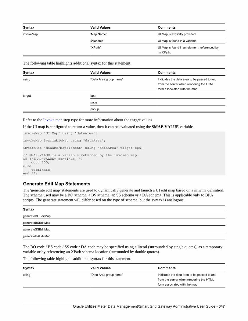
Oracle Utilities Meter Data Management/Smart Grid Gateway Administrative User Guide • 347
Syntax Valid Values Comments
'Map Name' UI Map is explicitly provided.
$Variable UI Map is found in a variable.
invokeMap
"XPath" UI Map is found in an element, referenced byits XPath.
The following table highlights additional syntax for this statement.
Syntax Valid Values Comments
using "Data Area group name" Indicates the data area to be passed to andfrom the server when rendering the HTMLform associated with the map.
bpa
page
target
popup
Refer to the Invoke map step type for more information about the target values.
If the UI map is configured to return a value, then it can be evaluated using the $MAP-VALUE variable.
invokeMap 'UI Map' using "dataArea"; invokeMap $variableMap using "dataArea"; invokeMap "daName/mapElement" using "dataArea" target bpa; // $MAP-VALUE is a variable returned by the invoked map.if ("$MAP-VALUE='continue' ") goto 300;else terminate;end if;
Generate Edit Map StatementsThe 'generate edit map' statements are used to dynamically generate and launch a UI edit map based on a schema definition.The schema used may be a BO schema, a BS schema, an SS schema or a DA schema. This is applicable only to BPAscripts. The generate statement will differ based on the type of schema, but the syntax is analogous.
Syntax
generateBOEditMap
generateBSEditMap
generateSSEditMap
generateDAEditMap
The BO code / BS code / SS code / DA code may be specified using a literal (surrounded by single quotes), as a temporaryvariable or by referencing an XPath schema location (surrounded by double quotes).
The following table highlights additional syntax for this statement.
Syntax Valid Values Comments
using "Data Area group name" Indicates the data area to be passed to andfrom the server when rendering the HTMLform associated with the map.
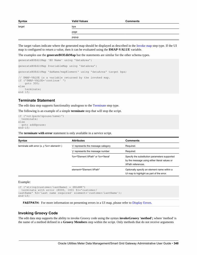
Oracle Utilities Meter Data Management/Smart Grid Gateway Administrative User Guide • 348
Syntax Valid Values Comments
bpa
page
target
popup
The target values indicate where the generated map should be displayed as described in the Invoke map step type. If the UImap is configured to return a value, then it can be evaluated using the $MAP-VALUE variable.
The examples use the generateBOEditMap but the statements are similar for the other schema types.
generateBOEditMap 'BO Name' using "dataArea"; generateBOEditMap $variableMap using "dataArea"; generateBOEditMap "daName/mapElement" using "dataArea" target bpa; // $MAP-VALUE is a variable returned by the invoked map.if ("$MAP-VALUE='continue' ") goto 300;else terminate;end if;
Terminate StatementThe edit data step supports functionality analogous to the Terminate step type.
The following is an example of a simple terminate step that will stop the script.
if ("not(parm/spouse/name)") terminate;else goto addSpouse;end-if;
The terminate with error statement is only available in a service script.
Syntax Attributes Comments
'x' represents the message category Required.
'y' represents the message number Required.
%n="Element XPath" or %n='literal' Specify the substitution parameters supportedby the message using either literal values orXPath references.
terminate with error (x, y %n= element= )
element="Element XPath" Optionally specify an element name within aUI map to highlight as part of the error.
Example:
if ("string(customer/lastName) = $BLANK") terminate with error (8000, 1001 %1="customer/lastName" %2='Last name required' element='customer/lastName');end-if;
FASTPATH: For more information on presenting errors in a UI map, please refer to Display Errors.
Invoking Groovy CodeThe edit data step supports the ability to invoke Groovy code using the syntax invokeGroovy 'method'; where 'method' isthe name of a method defined in a Groovy Members step within the script. Only methods that do not receive arguments

Oracle Utilities Meter Data Management/Smart Grid Gateway Administrative User Guide • 349
and return void can be invoked in this way. However, the method invoked from the edit data step can be supported byadditional Groovy code in other Groovy Members step types.
Example Edit Data step:
invokeGroovy 'invoke';
Example Groovy Members step:
void invoke() { initParms() readBO() initConfig() retrieve() updateBO()}
Debugging a BPA ScriptIf a BPA script has height greater than zero, then selected nodes of the script's data area can be displayed at runtime. TheXML data is displayed during script execution within the BPA script's display area. Specify the XPath of an XML nodefrom any of the BPA script's data areas, between the paired characters: '%+' and '+%'.
For example, the entire contents of the schema group node named 'input', and the specific contents of the schema elementnamed 'output/status' will be displayed in the BPA script's display area. The debug text must be entered into the BPA script'stext area and not within the script's edit data field. Debug text can be declared for any explicit step of the script.
display input: %+input+% , and output status: %+output/status+%
Script Engine Version 2 and Above NotesScripting using the engine version 2 or above requires some extra syntax to take advantage of XPath 2 functionality. Ingeneral, any variable declared will be assumed to be a string. This means, that if you intend to construct a mathematicalstatement then it is necessary to explicitly declare the data type of variables as integers, numbers, or dates.
NOTE: Unless otherwise noted, all XPath examples in this topic are for the Version 1 engine – which means XPath 1.Statements that function using XPath 1 will not necessarily work for XPath 2. This is especially true when executingmath, see below for examples.
Date and Time ArithmeticXPath date/time and interval data types support arithmetic operations ('+', '-', '*' etc.) and functions, which can be used fortime calculations in the same way as '1 + xs:integer(value)' is used for numeric calculations.
Compare time duration:
if ("(xs:dateTime(fn:current-dateTime()) - xs:dateTime($updateDateTimeX)) ge xs:dayTimeDuration(concat('PT', BO/hoursBetweenStatisticsUpdate, 'H'))") goto 60;end-if;
Compare one date to another:
if ("xs:date(parm/endDate) < xs:date(parm/startDate)") terminate with error (11108, 11507 element='endDate');end-if;
Compare a date against today's date:
if ("xs:date(parm/startDate) <= xs:date($CURRENT-DATE)") terminate with error (11108, 11507 element='endDate');end-if;
Calculate the end of month:
// covert to ISOmove "concat($year,'-',$mon2,'-01T00:00:00')" to $monthStart;
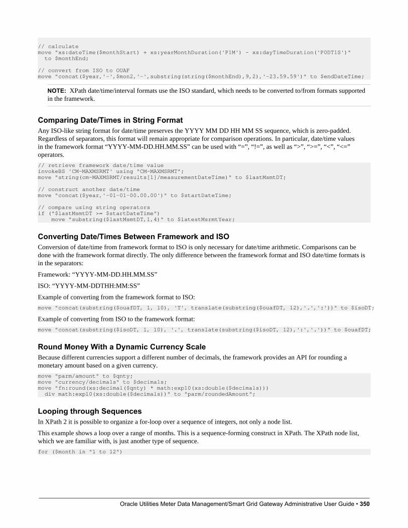
Oracle Utilities Meter Data Management/Smart Grid Gateway Administrative User Guide • 350
// calculatemove "xs:dateTime($monthStart) + xs:yearMonthDuration('P1M') - xs:dayTimeDuration('P0DT1S')" to $monthEnd; // convert from ISO to OUAFmove "concat($year,'-',$mon2,'-',substring(string($monthEnd),9,2),'-23.59.59')" to $endDateTime;
NOTE: XPath date/time/interval formats use the ISO standard, which needs to be converted to/from formats supportedin the framework.
Comparing Date/Times in String FormatAny ISO-like string format for date/time preserves the YYYY MM DD HH MM SS sequence, which is zero-padded.Regardless of separators, this format will remain appropriate for comparison operations. In particular, date/time valuesin the framework format “YYYY-MM-DD.HH.MM.SS” can be used with “=”, “!=”, as well as “>”, “>=”, “<”, “<=”operators.
// retrieve framework date/time valueinvokeBS 'CM-MAXMSRMT' using "CM-MAXMSRMT";move "string(cm-MAXMSRMT/results[1]/measurementDateTime)" to $lastMsmtDT; // construct another date/timemove "concat($year,'-01-01-00.00.00')" to $startDateTime; // compare using string operatorsif ("$lastMsmtDT >= $startDateTime") move "substring($lastMsmtDT,1,4)" to $latestMsrmtYear;
Converting Date/Times Between Framework and ISOConversion of date/time from framework format to ISO is only necessary for date/time arithmetic. Comparisons can bedone with the framework format directly. The only difference between the framework format and ISO date/time formats isin the separators:
Framework: “YYYY-MM-DD.HH.MM.SS”
ISO: “YYYY-MM-DDTHH:MM:SS”
Example of converting from the framework format to ISO:
move "concat(substring($ouafDT, 1, 10), 'T', translate(substring($ouafDT, 12),'.',':'))" to $isoDT;
Example of converting from ISO to the framework format:
move "concat(substring($isoDT, 1, 10), '.', translate(substring($isoDT, 12),':','.'))" to $ouafDT;
Round Money With a Dynamic Currency ScaleBecause different currencies support a different number of decimals, the framework provides an API for rounding amonetary amount based on a given currency.
move "parm/amount" to $qnty;move "currency/decimals" to $decimals;move "fn:round(xs:decimal($qnty) * math:exp10(xs:double($decimals))) div math:exp10(xs:double($decimals))" to "parm/roundedAmount";
Looping through SequencesIn XPath 2 it is possible to organize a for-loop over a sequence of integers, not only a node list.
This example shows a loop over a range of months. This is a sequence-forming construct in XPath. The XPath node list,which we are familiar with, is just another type of sequence.
for ($month in "1 to 12")

Oracle Utilities Meter Data Management/Smart Grid Gateway Administrative User Guide • 351
This example shows a loop over a give range of years in descending order:
for ($year in "fn:reverse(parm/startYear to parm/endYear)") move "concat($year,'-01-01-00.00.00')" to $startDateTime; move "concat($year,'-12-31-23.59.59')" to $endDateTime; ...
This example shows a loop through a node list using ‘index’, so that other node lists can be accessed:
for ($idx in "1 to count(parm/touData/touList)") move "parm/touData/touList[$idx]" to $tou; // access any list with this index
The above syntax can be used as an elegant alternative to maintaining indices separately, for example instead of thefollowing:
move “0” to $idx;for ($item in "parm/touData/touList") move “1 + xs:integer($idx)” to $idx;
String Padding and Decimal FormattingThis is used with specific input formats or output formatting. It is applicable to zero, space and other types of padding.
This example shows prefixing for date/time components, for example producing “2010-01-02” instead of “2010-1-2”.
move "substring(concat('0',string($month)), string-length(string($month)), 2)" to $mon2;
This example shows suffixing for adding decimal zero-padded alignment, for example producing “12.30” and “4.00”instead of “12.3” and “4”. The example performs 3 tasks: rounding to 2 decimals, inserting a period if necessary, and zeropadding.
// round and zero-pad to 2 decimalsmove "$item/amount" to $qty;move "fn:round(xs:double($qty) * 100) div 100" to $qty;move "string($qty)" to $qty;move "concat(substring-before(concat($qty,'.'),'.'),'.',substring(concat(substring-after($qty,'.'),'00'),1,2))" to $qty;
Ternary OperationThis makes a choice between values based on a condition, so that it could be used in a single expression instead of an if/elseblock. It is know in C/C++ as ‘cond ? value1 : value2’ or in BASIC as ‘IFF(cond, value1, value2)’. In XPath the syntax is:"if (cond) then value1 else value2". Note this is not the top-level scripting if-statement block.
In XPath this is an expression, which can be combined with other expressions. In scripting it can be used as:
move "if (string(D1-UnitOfMeasure/measuresPeakQuantity) = 'D1MP') then 'D1MX' else 'D1SM' " to $func;
Pipeline ProcessingIn scripting, it is not easy to create a simple reusable piece of code as there are no local functions, and a separate scriptcall is a coding overhead and requires packing/unpacking parameters. To avoid copying and pasting the same code blockbetween similar script stages, consider ‘pipelining’, which is breaking the overall process into separate top-level steps, someof which could be shared between alternating paths. This is common for parameter preparation and output formatting. Anintermediate result between stages can be stored in a “parm” substructure.
Instead of this code:
if ("type = A") prepare params ... call services for A ... format output ...end-if;if ("type = B") prepare params ... call services for B ... format output ...
Consider this alternative:
prepare params ...
if ("type = A") call services for A ...end-if;if ("type = B") call services for B ...end-if;

Oracle Utilities Meter Data Management/Smart Grid Gateway Administrative User Guide • 352
end-if; format output ...
XPath 2 FunctionsScript engine versions 2 and above support XQuery 1.0 Functions and Operators, and the XQuery 1.0 standard itself withsome minor limitations. Below are the URLs to both specifications. The first link has the functions/operators available touse from XQuery.
• http://www.w3.org/TR/xpath-functions/
• http://www.w3.org/TR/xquery/
The following can only access local file systems. (For other protocols like http they will return an empty sequence):
• fn:doc
• fn:collection
How To Set Up Go To StepsGo to steps allow you to jump to a step other than the next step. Additional fields required for Go To steps:
Next Step defines the step to which the script should jump.
How To Set Up Invoke Business Object StepsInvoke business object steps allow you to interact with a business object in order to obtain or maintain its information.
The following additional fields are required for Invoke business object steps:
Use Warning Level to indicate whether warnings should be suppressed and if not, how they should be presented to theuser. By default, warnings are suppressed. If Warn As Popup is used, the warning is displayed using the standard popupdialog. If Warn As Error is used processing is directed to the If Error, Go To step. This field is only applicable to BPAscripts.
Group Name references the data area to be passed to and from the server when communicating with the Business Object.Indicate the Action to be performed on the object when invoked. Valid values are Add, Delete, Fast Add (No Read), FastUpdate (No Read), Read, Replace, Update.
NOTE: Performance note. The actions Fast Add and Fast Update should be used when the business object's data areadoes not need to be re-read subsequent to the Add or Update action. In other words, the Add and Update actions areequivalent to Fast Add + Read and Fast Update + Read .
The business object call will either be successful or return an error. The next two fields only appear when the call is issuedfrom a BPA script, to determine the step to which control is passed given the outcome of the call.
If Success, Go To defines the step that is executed if the call is successful. This field is only applicable to BPA scripts.
If Error, Go To defines the step that is executed if the call returns on error. Please note that the error information is held in global variables. This field is only applicable to BPA scripts.
NOTE: Error technique. Let's assume a scenario where a business object is invoked from a BPA script and the callreturned an error. If the BPA script is configured to communicate with the user using a UI map, you may find it usefulto invoke the map again to present the error to the user. Alternatively, you may invoke a step that transfers control to ascript that displays the error message information and stops.
Oracle Utilities Meter Data Management/Smart Grid Gateway Administrative User Guide • 353
How To Set Up Invoke Business Service StepsInvoke business service steps allow you to interact with a business service.
The following additional fields are required for Invoke business service steps:
Use Warning Level to indicate whether warnings should be suppressed and if not, how they should be presented to theuser. By default, warnings are suppressed. If Warn As Popup is used, the warning is displayed using the standard popupdialog. If Warn As Error is used processing is directed to the If Error, Go To step. This field is only applicable to BPAscripts.
Group Name references the data area to be passed to and from the server when the Business Service is invoked.
The business service call will either be successful or return an error. The next two fields only appear when the call is issuedfrom a BPA script, to determine the step to which control is passed given the outcome of the call.
If Success, Go To defines the step that is executed if the call is successful. This field is only applicable to BPA scripts.
If Error, Go To defines the step that is executed if the call returns on error. Please note that the error information is held in global variables. This field is only applicable to BPA scripts.
NOTE: Error technique. Let's assume a scenario where a business service is invoked from a BPA script and the callreturned an error. If the BPA script is configured to communicate with the user using a UI map, you may find it usefulto invoke the map again to present the error to the user. Alternatively, you may invoke a step that transfers control to ascript that displays the error message information and stops.
How To Set Up Invoke Service Script StepsInvoke service script steps allow you to execute a service script.
The following additional fields are required for Invoke service script steps:
Use Warning Level to indicate whether warnings should be suppressed and if not, how they should be presented to theuser. By default, warnings are suppressed. If Warn As Popup is used, the warning is displayed using the standard popupdialog. If Warn As Error is used processing is directed to the If Error, Go To step. This field is only applicable to BPAscripts.
Group Name references the data area to be passed to and from the server when the Service Script is invoked.
The service script call will either be successful or return an error. The next two fields only appear when the call is issuedfrom a BPA script to determine the step to which control is passed given the outcome of the call.
If Success, Go To defines the step that is executed if the call is successful. This field is only applicable to BPA scripts.
If Error, Go To defines the step that is executed if the call returns on error. Please note that the error information is held in global variables. This field is only applicable to BPA scripts.
NOTE: Error technique. Let's assume a scenario where a service script is invoked from a BPA script and the callreturned an error. If the BPA script is configured to communicate with the user using a UI map, you may find it usefulto invoke the map again to present the error to the user. Alternatively, you may invoke a step that transfers control to ascript that displays the error message information and stops.
How To Set Up Label StepsLabel steps allow you to describe what the next step(s) are doing. Steps of this type are helpful to the script administratorswhen reviewing or modifying the steps in a script, especially when a script has many steps. When designing a script, thelabel steps enable you to provide a heading for common steps that belong together. The script tree displays steps of this typein a different color (green) so that they stand out from other steps.
Oracle Utilities Meter Data Management/Smart Grid Gateway Administrative User Guide • 354
There are no additional fields for Label steps.
How To Set Up Move Data StepsMove data steps allow you to move data (from a source to a destination). The following additional fields are required forMove data steps:
Source Field Type, Source Field Name and Source Field Value define what you're moving. The following pointsdescribe each field type:
• Context Variable. Use this field type in a plug-in or service script if the source value is a variable initiated in a higherlevel script. This is only applicable to Service Scripts and Plug-in Scripts.
• Current To Do Information. Use this field type when the source value resides on the current To Do entry. Refer toHow To Use To Do Fields for instructions on how to define the appropriate Field Name. This is only applicable to BPAScripts.
• Data Area. Use this field type when the field being compared is one that you put into one of the script's data areas inan earlier step. Field Name must reference both a data area structure name as well as the field, for example "parm/charType". Refer to How To Reference Fields In Data Areas for instructions on how to construct the appropriate FieldName.
• Global Context. Use this field type when the source value is a global context variable. This is only applicable to BPAScripts.
• Page Data Model. Use this field type when the source value resides on any of the tab pages in the object display area(i.e., the source field doesn't have to reside on the currently displayed tab page, it just has to be part of the object that'scurrently displayed). Refer to How To Find The Name Of Page Data Model Fields for instructions on how to find theappropriate Field Name. This is only applicable to BPA Scripts.
• Portal Context. Use this field type when the source value is a variable in the portal context. This is only applicable toBPA Scripts.
• Predefined Value. Use this field type when the source value is a constant value defined in the script. When this fieldtype is used, use Source Field Value to define the constant value. Refer to How To Use Constants In Scripts forinstructions on how to use constants.
NOTE: Concatenating fields together. You can also use Predefined Value if you want to concatenate two fieldstogether. For example, let's say you have a script that merges two persons into a single person. You might want thisscript to change the name of the person being merged out of existence to include the ID of the person remaining. In thisexample, you could enter a Source Field Value of %ONAMEmerged into person %PERID (where ONAME is afield in temporary storage that contains the name of the person being merged out of existence and PERID contains theID of the person being kept). Refer to How To Substitute Variables In Text for a description of how you can substitutefield values to compose the field value.
• Temporary Storage. Use this field type when the source value is a field that you put into temporary storage in an earlierstep. The Field Name must be the same as defined in an earlier step.
• User Interface Field. Use this field type when the source value resides on the currently displayed tab page. Refer to How To Find The Name Of User Interface Fields for instructions on how to find the appropriate Field Name. This isonly applicable to BPA Scripts.
Destination Field Type and Destination Field Name define where the source field will be moved. The Field Type defineswhere the field is located. The Field Name defines the name of the field. The following points describe each field type:
• Context Variable. Use this field type in your plug-in or service script if you use a variable to communicate informationto a lower level service script or schema. This is not applicable to BPA Scripts.
• Data Area. Use this field type when the destination field resides on one of the scripts data areas. Field Name mustreference both a data area structure name as well as the field, for example "parm/charType". Refer to How To ReferenceFields In Data Areas for instructions on how to construct the appropriate Field Name.
Oracle Utilities Meter Data Management/Smart Grid Gateway Administrative User Guide • 355
• Page Data Model. Use this field type when the destination field resides on any of the tab pages in the object display area(i.e., the field populated doesn't have to reside on the currently displayed tab page, it just has to be part of the object that'scurrently displayed). Refer to How To Find The Name Of Page Data Model Fields for instructions on how to find theappropriate Field Name. This is only applicable to BPA Scripts.
• Portal Context. Use this field type when the destination to be updated is in the current portal context. This is onlyapplicable to BPA Scripts.
• Temporary Storage. Use this field type when the destination field resides in temporary storage. Use Field Name toname the field in temporary storage. Use Field Name to name the field in temporary storage. Refer to How To NameTemporary Storage Fields for more information.
• User Interface Field. Use this field type when the destination field resides on the currently displayed tab page. Referto How To Find The Name Of User Interface Fields for instructions on how to find the appropriate Field Name. This isonly applicable to BPA Scripts.
NOTE: Conditional field types. The field types Current To Do Information, Page Data Model and User InterfaceField are only applicable to BPA scripts.
How To Set Up Terminate StepsTerminate steps cause a server-based script to end processing successfully or issue an error.
The following additional fields are required for Terminate steps:
Error indicates whether an error should be thrown or not. If error, Error Data Text must be specified, indicating theerror message and any message substitution parameters. Refer to Edit Data Syntax the actual syntax of initiating an errormessage.
NOTE: The ability to terminate a step in error is only supported for server-based scripts.
Step Types Applicable to BPA Scripts onlyThe contents of this section describe step types that are only applicable to BPA scripts.
How To Set Up Display Text StepsDisplay text steps cause a text string to be displayed in the script area. Steps of this type can be used to provide the userwith guidance when manual actions are necessary. In addition, they can be used to provide confirmation of the completionof tasks.
The information you enter in the Text field is displayed in the script area when the step is executed.
The text string can contain substitution variables and HTML formatting commands. Also note that for debugging purposes,you can display an entire data area (or a portion thereof) by entering %+...+% where ... is the name of the node whoseelement(s) should be displayed.
NOTE: Conditional step type. This step type is only applicable to BPA scripts.
How To Set Up Height StepsHeight steps are used to change the height of the script area to be larger or smaller than the standard size.
The following additional fields are required for Height steps:

Oracle Utilities Meter Data Management/Smart Grid Gateway Administrative User Guide • 356
Script Window Height defines the number of Pixels or the Percentage (according to the Height Unit) that the scriptwindow height should be adjusted. The percentage indicates the percentage of the visible screen area that the script areauses. For example, a percentage value of 100 means that the script area will use the entire area.
NOTE: Standard Number of Pixels. The default number of pixels used by the script area is 75.
NOTE: Adjust script height in the first step. If you want to adjust the height of the script area, it is recommendationto define the height step type as your first step. Otherwise, the script area will open using the standard height and thenreadjust, causing the screen to redisplay.
NOTE: Hide script area. You could use this type of step to set the height to 0 to hide the script area altogether. This isuseful if the script does not require any prompting to the user. For example, perhaps you define a script to take a user toa page and with certain data pre-populated and that is all.
NOTE: Automatically close script area. If you want the script area to close when a script is completed, you coulddefine the final step type with a height of 0.
NOTE: Conditional step type. This step type is only applicable to BPA scripts.
How To Set Up Input Data StepsInput data steps cause the user to be prompted to populate an input field in the script area. The input value can be saved ina field on a page or in temporary storage. A Continue button always appears adjacent to the input field. You may configuresteps of this type to display one or more buttons in addition to the Continue button. For example, you may want to providethe ability for the user to return to a previous step to fix incorrect information. The user may click on any of these buttonswhen ready for the script to continue.
The following additional fields are required for Input Data steps:
Destination Field Type and Destination Field Name define where the input field will be saved. The Field Type defineswhere the field is located. The Field Name defines the name of the field. The following points describe each field type:
• Page Data Model. Use this field type to put the input field into a field that resides on any of the tab pages in the objectdisplay area (i.e., the field populated doesn't have to reside on the currently displayed tab page, it just has to be part of theobject that's currently displayed). Refer to How To Find The Name Of Page Data Model Fields for instructions on howto find the appropriate Field Name.
• Temporary Storage. Use this field type to put the input field into temporary storage. Use Field Name to name the fieldin temporary storage. Refer to How To Name Temporary Storage Fields for more information.
• User Interface Field. Use this field type to put the input field into a field that resides on the currently displayed tab page.Note, if you want to execute underlying default logic, you must populate a User Interface Field. Refer to How To FindThe Name Of User Interface Fields for instructions on how to find the appropriate Field Name.
The Prompt Values grid may be used to define additional buttons. A separate button is displayed in the script area for eachentry in this grid.
• Prompt Text is the verbiage to appear on the button. Refer to How To Substitute Variables In Text for a description ofhow you can substitute field values into the prompts.
• Sequence controls the order of the buttons.
• Next Script Step defines the step to execute if the user clicks the button.
NOTE: Conditional step type. This step type is only applicable to BPA scripts.
Oracle Utilities Meter Data Management/Smart Grid Gateway Administrative User Guide • 357
How To Set Up Invoke Function StepsNOTE: Functions were implemented prior to the introduction of business services (BS), service scripts (SS) andbusiness objects (BO). The functionality is still supported, but the recommendation for implementations going forwardis to use a step that invokes one of the above configuration tool objects in a script rather than defining a function.
Invoke function steps may be used to retrieve or update data independent of the page currently being displayed. Forexample, if you design a script that takes different paths based on the customer's customer class, you could invoke afunction to retrieve the customer's customer class.
FASTPATH: You must set up a function before it can be referenced in a script. Refer to Maintaining Functions for thedetails.
The following additional fields are required for Invoke Function steps:
Function defines the name of the function. The function's Long Description is displayed below.
When a function is invoked, it will either be successful or return an error. The next two fields control the step to whichcontrol is passed given the outcome of the function call:
• If Success, Go to defines the step that is executed if the function is successful.
• If Error, Go to defines the step that is executed if the function returns on error. Refer to How To Use Constants InScripts for a list of the global variables that are populated when a function returns an error.
NOTE: Error technique. If a function returns an error, we recommend that you invoke a step that transfers control to ascript that displays the error message information and stops (note, the error information is held in global variables). Youwould invoke this script via a Transfer Control.
The Send Fields grid defines the fields whose values are sent to the function and whose field value source is not DefinedOn The Function. For example, if the function receives an account ID, you must define the name of the field in the scriptthat holds the account ID.
• Field contains a brief description of the field sent to the function.
• Source Field Type and Mapped Field / Value define the field sent to the function. Refer to the description of SourceField under How To Set Up Move Data Steps for a description of each field type.
• Comments contain information about the field (this is defined on the function).
The Receive Fields grid defines the fields that hold the values returned from the function. For example, if the functionreturns an account's customer class and credit rating, you must set up two fields in this grid.
• Field contains a brief description of the field returned from the function.
• Destination Field Type and Mapped Field define the field returned from the function. Refer to the description ofDestination Field under How To Set Up Move Data Steps for a description of each field type.
• Comments contain information about how the field (this is defined on the function).
NOTE: Conditional step type. This step type is only applicable to BPA scripts.
How To Set Up Invoke Map StepsInvoke map steps are used to invoke a UI Map to display, capture and update data using an HTML form. You mayconfigure steps of this type to display one or more buttons in addition to the Continue button. For example, you may wantto provide the ability for the user to return to a previous step to fix incorrect information. The user may click on any of thesebuttons when ready for the script to continue.

Oracle Utilities Meter Data Management/Smart Grid Gateway Administrative User Guide • 358
The following additional fields are required for Invoke map steps:
Group Name references the data area to be passed to and from the server when rendering the HTML form associated withthe Map.
Use Target Area to designate where the map will be presented.
• Select BPA Zone if the map should be presented within the script area.
• Select Page Area if the map should be presented in the object display area, i.e. the frame typically used to house amaintenance page.
• Select Pop-up Window if the map should be launched in a separate window.
The Returned Values grid contains a row for every button defined on the map.
• Returned Value is the value returned when the user clicks the button.
• Use as Default can only be turned on for one entry in the grid. If this is turned on, this value's Next Script Step will beexecuted if the returned value does not match any other entry in the grid. For example, if the user closes a pop-up (ratherthan clicking a button), the default value will be used.
• Next Script Step defines the step to execute if the user clicks the button.
NOTE: Conditional step type. This step type is only applicable to BPA scripts.
How To Set Up Mathematical Operation StepsMathematical operation steps allow you to perform arithmetic on fields. You can also use this type of step to add andsubtract days from dates. For example, you could calculate a date 7 days in the future and then use this value as thecustomer's next credit review date. The following additional fields are required for Mathematical Operation steps:
Base Field Type and Base Field Name define the field on which the mathematical operation will be performed. The FieldType defines where the field is located. The Field Name defines the name of the field. The following points describe eachfield type:
• Page Data Model. Use this field type when the field resides on any of the tab pages in the object display area. Refer to How To Find The Name Of Page Data Model Fields for instructions on how to find the appropriate Field Name.
• Temporary Storage. Use this field type when the field resides in temporary storage. You must initialize the temporarystorage field with a Move Data step before performing mathematical operations on the field. Refer to How To Set UpMove Data Steps for more information.
• User Interface Field. Use this field type when the field resides on the currently displayed tab page. Refer to How ToFind The Name Of User Interface Fields for instructions on how to find the appropriate Field Name.
Math Operation controls the math function to be applied to the Base Field. You can specify +, -, /, and *. Note, if the basefield is a date, you can only use + or -.
Math Field Type, Math Field Name and Math Field Value define the field that contains the value to be added, subtracted,divided, or multiplied. The following points describe each field type:
• Current To Do Information. Use this field type when the value resides on the current To Do entry. Refer to How ToUse To Do Fields for instructions on how to define the appropriate Field Name.
• Page Data Model. Use this field type when the value resides on any of the tab pages in the object display area. Refer to How To Find The Name Of Page Data Model Fields for instructions on how to find the appropriate Field Name.
• Predefined Value. Use this field type when the value is a constant. When this field type is used, use Source FieldValue to define the constant value. Refer to How To Use Constants In Scripts for more information. Note, if you areperforming arithmetic on a date, the field value must contain the number and type of days/ months/ years. For example,if you want to add 2 years to a date, the source field value would be 2 years.
Oracle Utilities Meter Data Management/Smart Grid Gateway Administrative User Guide • 359
• Temporary Storage. Use this field type when the value is a field that you put into temporary storage in an earlier step.The Field Name must be the same as defined in an earlier step.
• User Interface Field. Use this field type when the value resides in a field on the current tab page. Refer to How To FindThe Name Of User Interface Fields for instructions on how to find the appropriate Field Name.
NOTE: Conditional step type. This step type is only applicable to BPA scripts.
How To Set Up Navigate To A Page StepsNavigate to a page steps cause a new page (or tab within the existing page) to be displayed in the object display area. Stepsof this type are a precursor to doing anything on the page. The following additional field is required for Navigate to a pagesteps:
Navigation Option defines the transaction, tab, access mode (add or change) and any context fields that are passed to thetransaction in change mode. For example, if you want a script to navigate to Person - Characteristics for the current personbeing displayed in the dashboard, you must set up an appropriate navigation option. Refer to Defining Navigation Optionsfor more information.
NOTE: Navigating to a page in update mode. Before you can navigate to a page in change mode, the page data modelmust contain the values to use for the navigation option's context fields. If necessary, you can move values into thepage data model using a Move Data step first. For example, before you can navigate to a page in change mode with anaccount ID in context, you may need to move the desired account ID into the ACCT_ID field in the page data model.The actual field name(s) to use are listed as context fields on the navigation option.
NOTE: Conditional step type. This step type is only applicable to BPA scripts.
How To Set Up Perform Script StepsPerform script steps cause another BPA script to be performed. After the performed script completes, control is returned tothe next step in the original script. You might want to think of the scripts referred to on steps of this type as "subroutines".This functionality allows you to encapsulate common logic in reusable BPA scripts that can be called from other BPAscripts. This simplifies maintenance over the long term.
The following additional field is required for Perform script steps:
Subscript is the name of the script that is performed.
NOTE: Conditional step type. This step type is only applicable to BPA scripts.
How To Set Up Press A Button StepsPress a button steps cause a button or link text to be ‘pressed’ in the object display area, the application toolbar or the pagetitle area. For example, you could use this type of step to add a new row to a person's characteristic (and then you could usea Move Data step to populate the newly added row with a given char type and value). The following additional fields arerequired for Press a button steps:
Button Name is the name of the button to be pressed. This button must reside on the currently displayed tab page (or in theapplication toolbar or page actions toolbar). Refer to How To Find The Name Of A Button for more information.
NOTE: Conditional step type. This step type is only applicable to BPA scripts.
Oracle Utilities Meter Data Management/Smart Grid Gateway Administrative User Guide • 360
How To Set Up Prompt User StepsPrompt user steps cause the user to be presented with a menu of options. The options can be presented using either buttonsor in the contents of a drop down. You can also use steps of this type to pause a script while the user checks somethingout (and when the user is ready to continue with the script, they are instructed to click a prompt button). The followingadditional fields are required for Prompt User steps:
Prompt Type controls if the prompt shown in the script area is in the form of Button(s) or a Dropdown. Note, if you usea Dropdown, a Continue button appears adjacent to the dropdown in the script area when the step executes. The user clicksthe Continue button when they are ready for the script to continue.
The Prompt Values grid contains a row for every value that can be selected by a user. Note, if you use a Prompt Type ofButton(s), a separate button is displayed in the script area for each entry in this grid.
• Prompt Text is the verbiage to appear on the button or in the dropdown entry. Refer to How To Substitute Variables InText for a description of how you can substitute field values into the prompts.
• Sequence controls the order of the buttons or dropdown entries.
• Use As Default can only be turned on for one entry in the grid. If this is turned on for a dropdown entry, this value isdefaulted in the grid. If this is turned on for a button, this button becomes the default (and the user should just have topress Enter (or space) rather than click on it).
• Next Script Step defines the step to execute if the user clicks the button or selects the dropdown value.
NOTE: Conditional step type. This step type is only applicable to BPA scripts.
How To Set Up Set Focus To A Field StepsSet focus to a field steps cause the cursor to be placed in a specific field on a page. A Continue button always appears inthe script area when this type of step executes. The user may click the Continue button when they are ready for the scriptto continue. You may configure steps of this type to display one or more buttons in addition to the Continue button. Forexample, you may want to provide the ability for the user to return to a previous step to fix incorrect information. The usermay click on any of these buttons when ready for the script to continue.
The following additional fields are required for Set focus to a field steps:
Destination Field Name defines the field on which focus should be placed. This field must reside on the currentlydisplayed tab page. Refer to How To Find The Name Of User Interface Fields for instructions on how to find theappropriate Field Name.
The Prompt Values grid may be used to define additional buttons. A separate button is displayed in the script area for eachentry in this grid.
• Prompt Text is the verbiage to appear on the button. Refer to How To Substitute Variables In Text for a description ofhow you can substitute field values into the prompts.
• Sequence controls the order of the buttons.
• Next Script Step defines the step to execute if the user clicks the button.
NOTE: Conditional step type. This step type is only applicable to BPA scripts.
How To Set Up Transfer Control StepsTransfer control steps cause the current BPA script to terminate and the control to pass to another BPA script. You mightwant to construct a BPA script with steps of this type when the script has several potential logic paths and you want tosegregate each logic path into a separate BPA script (for ease of maintenance).

Oracle Utilities Meter Data Management/Smart Grid Gateway Administrative User Guide • 361
The following additional fields are required for Transfer control steps:
Subscript is the name of the script to which control is transferred.
NOTE: Conditional step type. This step type is only applicable to BPA scripts.
Step Types Applicable to Server Based Scripts onlyThe contents of this section describe step types that are only applicable to server based scripts.
How To Set Up Groovy Member StepsGroovy Member steps provide a free format text area where you can enter Groovy code.
Enter a description of the code block in the Text field. Click the adjacent icon to open a window providing more space forentering text.
Enter your code in the Edit Data Text field. Click the adjacent icon to open a window providing more space for editing thecode.
NOTE: While it is possible to set up multiple steps of type Groovy Member the system treats these steps as a singleclass for compilation and execution purposes. Refer to the topic Using Groovy Within Scripts for more information.
How To Set Up Groovy Imports StepsGroovy Imports step types provide a free format text area where you can list the Groovy classes to be imported for use bythe code in Groovy Member steps within the script.
Enter a description of the imports step in the Text field. Click the adjacent icon to open a window providing more space forentering text.
Enter the list of classes to import in the Edit Data Text field using the syntax import ‘class’; where ‘class’ is the fullyqualified package name of the Groovy class. Click the adjacent icon to open a window providing more space for editing thetext.
NOTE: For security, the classes that may be imported are restricted to those allowed by the Framework. Refer to thetopic Using Groovy Within Scripts for more information.
How To Set Up Groovy Library Interface StepsGroovy Library Interface steps are only applicable to Groovy Library Scripts. They provide a free format text areawhere you can list the Groovy methods defined within the script that are available for use by other scripts.
Enter a description of the interface step in the Text field. Click the adjacent icon to open a window providing more spacefor entering text.
Enter the list of interface methods in the Edit Data Text field. Click the adjacent icon to open a window providing morespace for editing the list.
NOTE: Every Groovy Library Script must have one and only one step of type Groovy Library Interface. Thesupporting code for the available methods is defined using one or more Groovy Member steps in the same script. Referto the topic Using Groovy Within Scripts for more information.
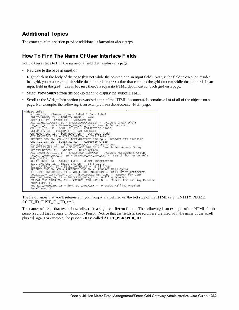
Oracle Utilities Meter Data Management/Smart Grid Gateway Administrative User Guide • 362
Additional TopicsThe contents of this section provide additional information about steps.
How To Find The Name Of User Interface FieldsFollow these steps to find the name of a field that resides on a page:
• Navigate to the page in question.
• Right click in the body of the page (but not while the pointer is in an input field). Note, if the field in question residesin a grid, you must right click while the pointer is in the section that contains the grid (but not while the pointer is in aninput field in the grid) - this is because there's a separate HTML document for each grid on a page.
• Select View Source from the pop-up menu to display the source HTML.
• Scroll to the Widget Info section (towards the top of the HTML document). It contains a list of all of the objects on apage. For example, the following is an example from the Account - Main page:
The field names that you'll reference in your scripts are defined on the left side of the HTML (e.g., ENTITY_NAME,ACCT_ID, CUST_CL_CD, etc.).
The names of fields that reside in scrolls are in a slightly different format. The following is an example of the HTML for thepersons scroll that appears on Account - Person. Notice that the fields in the scroll are prefixed with the name of the scrollplus a $ sign. For example, the person's ID is called ACCT_PER$PER_ID.
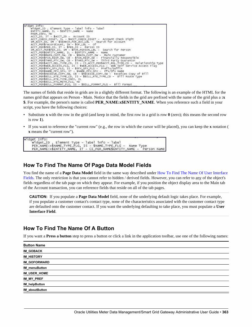
Oracle Utilities Meter Data Management/Smart Grid Gateway Administrative User Guide • 363
The names of fields that reside in grids are in a slightly different format. The following is an example of the HTML for thenames grid that appears on Person - Main. Notice that the fields in the grid are prefixed with the name of the grid plus a :x$. For example, the person's name is called PER_NAME:x$ENTITY_NAME. When you reference such a field in yourscript, you have the following choices:
• Substitute x with the row in the grid (and keep in mind, the first row in a grid is row 0 (zero); this means the second rowis row 1).
• If you want to reference the "current row" (e.g., the row in which the cursor will be placed), you can keep the x notation (x means the "current row").
How To Find The Name Of Page Data Model FieldsYou find the name of a Page Data Model field in the same way described under How To Find The Name Of User InterfaceFields. The only restriction is that you cannot refer to hidden / derived fields. However, you can refer to any of the object'sfields regardless of the tab page on which they appear. For example, if you position the object display area to the Main tabof the Account transaction, you can reference fields that reside on all of the tab pages.
CAUTION: If you populate a Page Data Model field, none of the underlying default logic takes place. For example,if you populate a customer contact's contact type, none of the characteristics associated with the customer contact typeare defaulted onto the customer contact. If you want the underlying defaulting to take place, you must populate a UserInterface Field.
How To Find The Name Of A ButtonIf you want a Press a button step to press a button or click a link in the application toolbar, use one of the following names:
Button NameIM_GOBACK
IM_HISTORY
IM_GOFORWARD
IM_menuButtonIM_USER_HOMEIM_MY_PREFIM_helpButton
IM_aboutButton
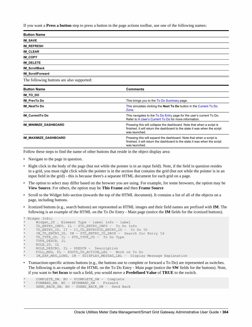
Oracle Utilities Meter Data Management/Smart Grid Gateway Administrative User Guide • 364
If you want a Press a button step to press a button in the page actions toolbar, use one of the following names:
Button NameIM_SAVE
IM_REFRESH
IM_CLEAR
IM_COPYIM_DELETEIM_ScrollBackIM_ScrollForward
The following buttons are also supported:
Button Name CommentsIM_TO_DO
IM_PrevTo Do This brings you to the To Do Summary page.
IM_NextTo Do This simulates clicking the Next To Do button in the Current To DoZone.
IM_CurrentTo Do This navigates to the To Do Entry page for the user’s current To Do.Refer to A User’s Current To Do for more information.
IM_MINIMIZE_DASHBOARD Pressing this will collapse the dashboard. Note that when a script isfinished, it will return the dashboard to the state it was when the scriptwas launched.
IM_MAXIMIZE_DASHBOARD Pressing this will expand the dashboard. Note that when a script isfinished, it will return the dashboard to the state it was when the scriptwas launched.
Follow these steps to find the name of other buttons that reside in the object display area:
• Navigate to the page in question.
• Right click in the body of the page (but not while the pointer is in an input field). Note, if the field in question residesin a grid, you must right click while the pointer is in the section that contains the grid (but not while the pointer is in aninput field in the grid) - this is because there's a separate HTML document for each grid on a page.
• The option to select may differ based on the browser you are using. For example, for some browsers, the option may beView Source. For others, the option may be This Frame and then Frame Source
• Scroll to the Widget Info section (towards the top of the HTML document). It contains a list of all of the objects on apage, including buttons.
• Iconized buttons (e.g., search buttons) are represented as HTML images and their field names are prefixed with IM. Thefollowing is an example of the HTML on the To Do Entry - Main page (notice the IM fields for the iconized buttons).
* Widget Info: * Widget_ID , Element Type - label info - label* TD_ENTRY_INFO, IL - $TD_ENTRY_INFO - To Do Info* TD_ENTRY_ID, IT - CI_TD_ENTRY$TD_ENTRY_ID - To Do ID* IM_TD_ENTRY_ID, IM - $TD_ENTRY_ID_SRCH - Search for Entry Id* TD_TYPE_CD, IL - $TD_TYPE_CD - To Do Type* TYPE_DESCR, IL* ROLE_ID, IL* ROLE_DESCR2, IL - $DESCR - Description* FULL_MSG, PL - $GOTO_TD_ACTION_LBL - Work on To Do* IM_EXP_MSG_LONG, IM - $DISPLAY_MESSAG_LBL - Display Message Explanation
• Transaction-specific actions buttons (e.g., the buttons use to complete or forward a To Do) are represented as switches.The following is an example of the HTML on the To Do Entry - Main page (notice the SW fields for the buttons). Note,if you want to Set focus to such a field, you would move a Predefined Value of TRUE to the switch.
* COMPLETE_SW, BU - $COMPLETE_SW - Complete* FORWARD_SW, BU - $FORWARD_SW - Forward* SEND_BACK_SW, BU - $SEND_BACK_SW - Send Back
Oracle Utilities Meter Data Management/Smart Grid Gateway Administrative User Guide • 365
How To Substitute Variables In TextYou can substitute field values into a step's text string. You do this by prefixing the field name whose value should besubstituted in the string with a %. For example, the message, "On %COMPLETION_DTTM this bill was completed, it'sending balance was %ENDING_BALANCE" contains two substitution variables (the bill's completion date / time and thebill's ending balance).
To substitute the value of an element from a data area you need to reference its XPath location as follows: %=XPath=%. Ifyou want to substitute the whole XML node, not just the value, you need to reference it as follows %+XPath+%.
Only fields linked to the current To Do and fields that reside in temporary storage and global variables can be substitutedinto a text string.
NOTE: You can substitute fields that reside in the User Interface or Page Data Model by first moving them intotemporary storage (using a Move data step).
You can also substitute field values into the verbiage displayed in prompts using the same technique.
How To Use HTML Tags And Spans In Text Strings and PromptsYou can use HTML tags in a step's text string. For example, the word "Continue" will be italicized in the following textstring "Press<i>Continue</i> after you've selected the customer" (the <i> and </i> are the HTML tags used to indicate thatthe surrounded text should be italicized).
The following are other useful HTML tags:
• <br> causes a line break in a text string. If you use <br><br> a blank line will appear.
• <font color=red> text </font> causes the surrounded text to be colored as specified (in this case, red). You can also usehex codes rather than the color name.
Please refer to an HTML reference manual or website for more examples.
You can also use "spans" to customize the look of the contents of a text string. For example, your text string could be "Press<span style="font-family:Courier; font-size:large; font-weight:bold;">Continue</span> after you've selected the customer".This would make the word "Continue" appear as large, bold, Courier text. Please refer to a Cascading Style Sheets (CSS)reference manual or website for more examples.
How To Use Constants In ScriptsSome steps can reference fields called Predefined Values. For example, if you want to compare an input value to the letter"Y", the letter Y would be defined as a Predefined Value's field value.
Special constants are used for fields defined as switches. When you move TRUE to a switch, it turns it on. When you moveFALSE to a switch, it turns it off.
You can use a global variable as a Predefined Value. For example, if you wanted to move the current date to a field, you'dindicate you wanted to move a Predefined Value named %CURRENT_DATE.
How To Use Global VariablesSome explicit steps can reference fields called Predefined Values. In addition to referencing an ad hoc constant value (e.g.,the letter Y), you can also reference a global variable in such a field value. A global variable is used when you want toreference system data.
Note that when using the Edit Data step type, the variable available are slightly different. Refer to Edit Data Syntax fordetails.
Oracle Utilities Meter Data Management/Smart Grid Gateway Administrative User Guide • 366
The following global variables exist for BPA scripts:
Variable Name Comments%PARM-<name> This is the value of a parameter of that name passed in to the
application when launched via the standard system URL. Refer toLaunching A Script When Starting the System for more information onthese parameters.
%PARM-NOT-SET This is to be used to compare against %PARM-< > parameters tocheck if the parameter has been set or not when the application waslaunched. A parameter that has not been set would be consideredequal to this global variable. It is recommended to compare parametersagainst this global variable before using them for the first time.
%BLANK A constant that contains a blank value (no value).
%SPACE A constant that contains a single space value.
%CURRENT-DATE The current date as known by the browser, not the server.
%SYSTEM-DATE The server date. Note that this date is affected by the system dateoverride logic)
%SAVE-REQUIRED A flag that contains an indication of whether the data on a page hasbeen changed (and thus requires saving). You may want to interrogatethis flag to force a user to save their work before executing subsequentsteps. This flag will have a value of TRUE or FALSE.
%NEWLINE A constant that contains a new line character (carriage return). Uponsubstitution, a line break is inserted in the resultant text.
NOTE: This constant does not have the desired effect when theresultant text is HTML. For example, a step's text and prompt strings.This is because HTML ignores special characters such as new lines.Refer to How To Use HTML Tags And Spans In Text to learn how tocause a line break in an HTML text.
To refer to a global context variable, use %FIELD_NAME. For example, if the field SP_ID is in the global context, youmay reference %SP_ID to reference the ID of the service point currently in context. In addition, the following special valuesare supported:
Variable Name Comments%CONTEXT-PERSONID A constant that contains the ID of the current person.
%CONTEXT-ACCOUNTID A constant that contains the ID of the current account.
%CONTEXT-PREMISEID A constant that contains the ID of the current premise.
In addition, if the script is invoking something else via one of the various “Invoke” step types and an error is returned, thefollowing global variables contain information about the error:
Variable Name Comments%ERRMSG-CATEGORY %ERRMSG-NUMBER The unique identifier of the error message number.
%ERRMSG-TEXT The brief description of the error.
%ERRMSG-LONG The complete description of the error.
How To Name Temporary Storage FieldsInput Data and Move Data steps can create fields in temporary storage. You specify the name of the temporary storagefield in the step's Field Name. The name of the field must not begin with % and must not be named the same as the globalvariables. Besides this restriction, you can use any Field Name that's acceptable to JavaScript (i.e., you can name a field intemporary storage almost anything). Keep in mind that field names are case-sensitive.
Oracle Utilities Meter Data Management/Smart Grid Gateway Administrative User Guide • 367
How To Work With DatesBefore we discuss how to work with dates in your scripts, we need to point out that there are two types of date fields: date-only and date-time. Date-only fields only contain a date. Date-time fields contain both a date and a time. The followingtopics describe how to work with dates on the various step types.
NOTE: If you're working with a field that resides on the database (as opposed to a temporary storage field), the databasefield name will tell you what type of date it is: date-only fields are suffixed with DT, and date-time fields are suffixedwith DTTM.
Move DataIf you intend to use a Move data step to populate a date-time field, please be aware of the following:
• If the destination field resides in the page data model, the source field value must be in the format YYYY-MM-DD-HH.MM.SS or YYYY-MM-DD. If the field is in the format YYYY-MM-DD, the time of 12:00 am will be defaulted.
• If the destination field resides in the user interface, you must use two steps if you want to populate both date and time.To explain this, we'll assume the field you want to populate is called EXPIRE_DTTM:
• First, you populate the date portion of the field. To do this, you'd move a date (this value can be in any valid dateformat that a user is allowed to enter) to a field called EXPIRE_DTTM_FWDDTM_P1. In other words, you suffix _FWDDTM_P1 to the field name.
• If you want to populate the time, you'd move the time (again, the field value can be in any format that a user could useto enter a time) to a field called EXPIRE_DTTM_FWDTTM_P2. In other words, you suffix _FWDDTM_P2 to thefield name.
If you intend to use a Move data step to populate a date-only field, please be aware of the following:
• If the destination field resides in the page data model, the source field value must be in the format YYYY-MM-DD.
• If the destination field resides in the user interface, the source field can be in any valid date format that a user is allowedto enter.
NOTE: %CURRENT-DATE. Keep in mind that the global variable%CURRENT-DATE contains the current date andyou can move this to either a page data model, user interface, or temporary storage field. If you move %CURRENT-DATE to a temporary storage fields, it is held in the format YYYY-MM-DD.
Mathematical OperationIf you intend to use a Mathematical operation step to calculate a date, you can reference both date-only and date-timefields. This is because mathematical operations are only performed against the date portion of date-time fields.
Mathematical operations are limited to adding or subtracting days, months and years to / from a date.
NOTE: A useful technique to perform date arithmetic using the current date is to move the globalvariable%CURRENT-DATE to a temporary storage field and then perform the math on this field.
Input DataIf you intend to use an Input data step on a date-time field, please be aware of the following:
• If the field resides in the page data model, the user must enter a value in the format YYYY-MM-DD-HH.MM.SS (andtherefore we do not recommend doing this).

Oracle Utilities Meter Data Management/Smart Grid Gateway Administrative User Guide • 368
• If the field resides in the user interface, you must use two steps if you want to populate both date and time. To explainthis, we'll assume the field you want to populate is called EXPIRE_DTTM:
• First, you populate the date portion of the field. To do this, you'd input the date (this value can be in any valid dateformat that a user is allowed to enter) in a field called EXPIRE_DTTM_FWDDTM_P1. In other words, you suffix _FWDDTM_P1 to the field name.
• If you want to populate the time, you'd input the time (again, the field value can be in any format that a user could useto enter a time) in a field called EXPIRE_DTTM_FWDTTM_P2. In other words, you suffix _FWDDTM_P2 to thefield name.
If you intend to use an Input data step to populate a date-only field, please be aware of the following:
• If the field resides in the page data model, the user must enter a value in the format YYYY-MM-DD (and therefore wedo not recommend doing this).
• If the field resides in the user interface, the user can enter any valid date format.
How To Use To Do FieldsAs described under Executing A Script When A To Do Entry Is Selected, you can set up the system to automatically launcha script when a user selects a To Do entry. These types of scripts invariably need to access data that resides on the selectedTo Do entry. The following points describe the type of information that resides on To Do entries:
• Sort keys. These values define the various ways a To Do list's entries may be sorted. For example, when you look at thebill segment error To Do List, you have the option of sorting the entries in error number order, account name order, or incustomer class order. There is a sort key value for each of these options.
• Message parameters. These values are used when the system finds %n notation within the message text. The %nnotation causes field values to be substituted into a message before it's displayed. For example, the message text The %1non-cash deposit for %2 expires on %3 will have the values of three fields merged into it before it is displayed to theuser (%1 is the type of non-cash deposit, %2 is the name of the customer, and %3 is the expiration date of the non-cashdeposit). Each of these three values is stored as a separate message parameter on the To Do entry.
• Drill keys. These values are the keys passed to the page if a user drilled down on the entry (and the system wasn't set upto launch a script). For example, a To Do entry that has been set up to display an account on the account maintenancepage has a drill key of the respective account ID.
• To Do ID. Every To Do entry has a unique identifier referred to as its To Do ID.
You can access this information in the following types of steps:
• Move Data steps can move any of the above to any data area. For example, you might want to move a To Do entry's drillkey to the page data model so it can be used to navigate to a specific page.
• Conditional Branch steps can perform conditional logic based on any of the above. For example, you can performconditional logic based on a To Do entry's message number (note, message numbers are frequently held in sort keys).
• Mathematical Operation steps can use the above in mathematical operations.
A To Do entry's sort key values are accessed by using a Field Type of Current To Do Information and a Field Name ofSORTKEY[index]. Note, you can find an entry's potential sort keys by displaying the entry's To Do type and navigating tothe Sort Keys tab. If you want to reference the first sort key, use an index value of 1. If you want to use the second sort key,use an index value of 2 (and so on).
A To Do entry's drill key values are accessed by using a Field Type of Current To Do Information and a Field Name ofDRILLKEY[index]. Note, you can find an entry's potential drill keys by displaying the entry's To Do type and navigatingto the Drill Keys tab. If you want to use the first drill key, use an index value of 1. If you want to use the second drill key,use an index value of 2 (and so on).
A To Do entry's message parameters are accessed by using a Field Type of Current To Do Information and a FieldValue of MSGPARM[index]. Note, because a To Do type can have an unlimited number of messages and each messagecan have different parameters, finding an entry's message parameters requires some digging. The easiest way to determine

Oracle Utilities Meter Data Management/Smart Grid Gateway Administrative User Guide • 369
these values is to display the To Do entry on To Do maintenance. On this page, you will find the entry's message category/number adjacent to the description. Once you know these values, display the message category/number on MessageMaintenance. You'll find the message typically contains one or more %n notations (one for each message parameter). Forexample, the message text The %1 non-cash deposit for %2 expires on %3 has three message parameters. You then needto deduce what each of the message parameters are. You do this by comparing the message on the To Do entry with thebase message (it should be fairly intuitive as to what each message parameter is). If we continue using our example, %1 isthe non-cash deposit type, %2 is the account name, and %3 is the expiration date. You can access these in your scripts byusing appropriate index value in MSGPARM[index].
A To Do entry's unique ID is accessed by using a Field Type of Current To Do Information and a Field Value of TD_ENTRY_ID.
In addition, any of the above fields can be substituted into a text string or prompt. Simply prefix the To Do field name witha % as you would fields in temporary storage. For example, assume you want your script to display the following text in thescript area: "ABC Supply does not have a bill cycle" (where ABC Supply is the account's name). If the first sort key linkedto the To Do entry contains the account's name, you'd enter a text string of %SORTKEY[1] does not have a bill cycle.
How To Reference Fields In Data AreasVarious step types involve referencing field elements residing in the script's data areas. To reference an element in a dataarea you need to provide its absolute XPath notation starting from the data area name. For example, use "CaseLogAdd/caseID" to reference a top-level "caseID" element in a script data area called "CaseLogAdd".
You don't have to type in long XPath notions. Use the View Script Schema hyperlink provided on the Script - Step tabpage to launch the script's data areas schema.
Figure 4: Schema Viewer
Doing this opens the schema viewer window where you can:
• Click on the field element you want to reference in your script step. The system automatically populates the text box onthe top with the element's absolute XPath notation.
• Copy the element's XPath notation from the text box to your script.
You can also use the View Data Area, View Service Script Data Area, or View Plug-In Script Data Area links on Script- Data Area to the same effect. These open up the schema viewer for a specific data area respectively.
Script - Data AreaUse this page to define the data areas used to pass information to and from the server or any other data area describing yourtemporary storage. Open this page using Admin > System > Script and then navigate to the Data Area tab.
NOTE: Conditional tab page. This tab page does not appear for Groovy Library scripts or plug-in scripts using theGroovy engine version.
Description of Page
The grid contains the script's data areas declaration. For steps that invoke an object that is associated with a schema, youmust declare the associated schema as a data area for your script. In addition, if you have defined one or more data areas to
Oracle Utilities Meter Data Management/Smart Grid Gateway Administrative User Guide • 370
describe the script's temporary storage, you need to declare them too. The following bullets provide a brief description ofeach field on a script data area:
• Schema Type defines the type of schema describing the data area's element structure.
• The data area's schema is the one associated with the referenced Object. Only objects of the specified Schema Type maybe selected.
• Data Area Name uniquely identifies the data area for referencing purposes. By default, the system assigns a data areawith the associated object name.
• Click on the View Data Area link to view the data area's schema in the schema viewer window.
The View Service Script Data Area link appears for service scripts only. Use this link to view the script's parameters dataarea schema in the schema viewer window.
The View Plug-In Script Data Area link appears only for plug-in scripts using a script engine version. Use this link toview the script's parameters data area schema in the schema viewer window.
FASTPATH: Refer to A Script May Declare Data Areas for more information on data areas.
Script - SchemaUse this page to define the data elements passed to and from a service script. Open this page using Admin > System > Script and then navigate to the Schema tab.
NOTE: Conditional tab page. This tab page only appears for service scripts.
Description of Page
The contents of this section describe the zones that are available on this portal.
The General Information zone displays the script name and description.
The Schema Designer zone allows you to edit the service script's parameters schema. The purpose of the schema is todescribe the input and output parameters used when invoking the script.
NOTE: Refer to Schema Nodes and Attributes for a complete list of the XML nodes and attributes available to youwhen you construct a schema.
The Schema Usage Tree zone summarizes all cross-references to this schema. For each type of referencing entity, the treedisplays a summary node showing a total count of referencing items. The summary node appears if at least one referencingitem exists. Expand the node to list the referencing items and use their description to navigate to their corresponding pages.
Script - EligibilityUse this page to define a script's eligibility rules. Open this page using Admin > System > Script and then navigate to theEligibility tab.
NOTE: Conditional tab page. This tab page only appears for BPA scripts.
Description of Page
Use the Eligibility Option to indicate whether the script is Always Eligible, Never Eligible or to Apply EligibilityCriteria. The remaining fields on the page are only visible if the option is Apply Eligibility Criteria.
Oracle Utilities Meter Data Management/Smart Grid Gateway Administrative User Guide • 371
CAUTION: The following information is not intuitive; we strongly recommend that you follow the guidelines under The Big Picture Of Script Eligibility before attempting to define this information.
The Eligibility Criteria Group scroll contains one entry for each group of eligibility criteria. The following fields may bedefined for each group:
• Use Sort Sequence to control the relative order in which the group is executed when the system determines if the scriptshould appear in the script search.
• Use Description and Long Description to describe the criteria group.
• Use If Group is True to define what should happen if the eligibility criteria (defined in the following grid) return a valueof True.
• Choose Eligible if this script should appear.
• Choose Ineligible if this script should not appear.
• Choose Check Next Group if the next criteria group should be checked.
• Use If Group is False to define what should happen if the eligibility criteria (defined in the following grid) return avalue of False.
• Choose Eligible if this script should appear.
• Choose Ineligible if this script should not appear.
• Choose Check Next Group if the next criteria group should be checked.
The grid that follows contains the script's eligibility criteria. Think of each row as an "if statement" that can result in therelated eligibility group being true or false. For example, you might have a row that indicates the script is eligible if thecurrent account in context belongs to the residential customer class. The following bullets provide a brief description ofeach field on an eligibility criterion. Please refer to Defining Logical Criteria for several examples of how this informationcan be used.
• Use Sort Sequence to control the order in which the criteria are checked.
• Use Criteria Field to define the field to compare:
• Choose Algorithm if you want to compare anything other than a characteristic. Push the adjacent search button toselect the algorithm that is responsible for retrieving the comparison value. Click here to see the algorithm typesavailable for this plug-in spot.
• Some products may also include an option to choose Characteristic. Choosing this option displays adjacent fieldsto define the object on which the characteristic resides and the characteristic type. The objects whose characteristicvalues may be available to choose from depend on your product.
• Use Criteria Comparison to define the method of comparison:
• Choose Algorithm if you want an algorithm to perform the comparison and return a value of True, False orInsufficient Data. Push the adjacent search button to select the algorithm that is responsible for performing thecomparison. Click here to see the algorithm types available for this plug-in spot.
• Choose any other option if you want to compare the Criteria Field using a logical operator. The following options areavailable:
• Use >, <, =, >=, <=, <> (not equal) to compare the Criteria Field using standard logical operators. Enter thecomparison value in the adjacent field.
• Use IN to compare the Criteria Field to a list of values. Each value is separated by a comma. For example, if afield value must equal 1, 3 or 9, you would enter a comparison value of 1,3,9.
• Use BETWEEN to compare the Criteria Field to a range of values. For example, if a field value must be between1 and 9, you would enter a comparison value of 1,9. Note, the comparison is inclusive of the low and high values.
• The next three fields control whether the related logical criteria cause the eligibility group to be considered true or false:

Oracle Utilities Meter Data Management/Smart Grid Gateway Administrative User Guide • 372
• Use If True to control what happens if the related logical criterion returns a value of True. You have the options ofGroup is true, Group is false, or Check next condition. If you indicate Group is true or Group is false, the scriptis judged Ineligible or Eligible based on the values defined above in If Group is False and If Group is True.
• Use If False to control what happens if the related logical criterion returns a value of False. You have the options ofGroup is true, Group is false, or Check next condition. If you indicate Group is true or Group is false, the scriptis judged Ineligible or Eligible based on the values defined above in If Group is False and If Group is True.
• Use If Insufficient Data to control what happens if the related logical criterion returns a value of "Insufficient Data".You have the options of Group is true, Group is false, or Check next condition. If you indicate Group is true orGroup is false, the script is judged Ineligible or Eligible based on the values defined above in If Group is False andIf Group is True.
Merging ScriptsUse the Script Merge page to modify an existing script by copying steps from other scripts. The following points summarizethe many diverse functions available on the Script Merge transaction:
• You can use this transaction to renumber steps (assign them new sequence numbers).
• You can use this transaction to move a step to a different position within a script. When a step is moved, all references tothe step are changed to reflect the new sequence number.
• You can use this transaction to delete a step.
• You can use this transaction to copy steps from other scripts. For example:
• You may want to create a script that is similar to an existing script. Rather than copying all the information from theexisting script and then removing the inapplicable steps, this page may be used to selectively copy steps from theexisting script to the new script.
• You may have scripts that are very similar, but still unique. You can use this transaction to build large scripts fromsmaller scripts. In this scenario, you may choose to create special 'mini' scripts, one for each of the various optionsthat may make a script unique. Then, you could use the script merge page to select and merge the mini scripts that areapplicable for a main script.
NOTE: The target script must exist prior to using this page. If you are creating a new script, you must first create theScript and then navigate to the merge page to copy step information.
NOTE: Duplicate versus Merge. The Script page itself has duplication capability. You would duplicate a script if youwant to a) create a new script and b) populate it with all the steps from an existing script.
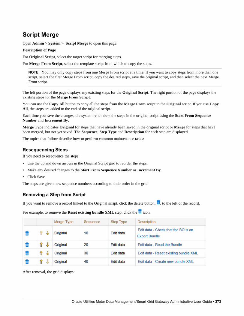
Oracle Utilities Meter Data Management/Smart Grid Gateway Administrative User Guide • 373
Script MergeOpen Admin > System > Script Merge to open this page.
Description of Page
For Original Script, select the target script for merging steps.
For Merge From Script, select the template script from which to copy the steps.
NOTE: You may only copy steps from one Merge From script at a time. If you want to copy steps from more than onescript, select the first Merge From script, copy the desired steps, save the original script, and then select the next MergeFrom script.
The left portion of the page displays any existing steps for the Original Script. The right portion of the page displays theexisting steps for the Merge From Script.
You can use the Copy All button to copy all the steps from the Merge From script to the Original script. If you use CopyAll, the steps are added to the end of the original script.
Each time you save the changes, the system renumbers the steps in the original script using the Start From SequenceNumber and Increment By.
Merge Type indicates Original for steps that have already been saved in the original script or Merge for steps that havebeen merged, but not yet saved. The Sequence, Step Type and Description for each step are displayed.
The topics that follow describe how to perform common maintenance tasks:
Resequencing StepsIf you need to resequence the steps:
• Use the up and down arrows in the Original Script grid to reorder the steps.
• Make any desired changes to the Start From Sequence Number or Increment By.
• Click Save.
The steps are given new sequence numbers according to their order in the grid.
Removing a Step from Script
If you want to remove a record linked to the Original script, click the delete button, , to the left of the record.
For example, to remove the Reset existing bundle XML step, click the icon.
After removal, the grid displays:
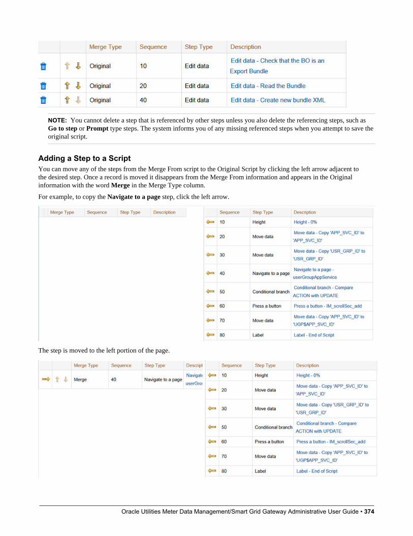
Oracle Utilities Meter Data Management/Smart Grid Gateway Administrative User Guide • 374
NOTE: You cannot delete a step that is referenced by other steps unless you also delete the referencing steps, such asGo to step or Prompt type steps. The system informs you of any missing referenced steps when you attempt to save theoriginal script.
Adding a Step to a ScriptYou can move any of the steps from the Merge From script to the Original Script by clicking the left arrow adjacent tothe desired step. Once a record is moved it disappears from the Merge From information and appears in the Originalinformation with the word Merge in the Merge Type column.
For example, to copy the Navigate to a page step, click the left arrow.
The step is moved to the left portion of the page.

Oracle Utilities Meter Data Management/Smart Grid Gateway Administrative User Guide • 375
NOTE: If you add a step, such as Go to step or Prompt type steps, that references other steps, you must also add thereferenced steps. The step references are updated to use the new sequence numbers when you save the original script.The system informs you of any referenced steps that haven't been added when you attempt to save the original script.
Removing an Uncommitted Step from a Script
Maintaining FunctionsNOTE: Functions were implemented prior to the introduction of business services (BS), service scripts (SS) andbusiness objects (BO). The functionality is still supported, but the recommendation for implementations going forwardis to use one of the above configuration tool objects in a script rather than defining a function. The documentation hasnot been updated throughout this section to highlight where BS, SS or BO could be used to perform the equivalent logic.
Invoke function steps may be used to retrieve or update data independent of the page currently being displayed. Forexample, if you design a script that takes different paths based on the customer's customer class, you could invoke afunction to retrieve the customer's customer class. Doing this is much more efficient than the alternative of transferring tothe account page and retrieving the customer class from the Main page.
An Invoke function step retrieves or updates the relevant data by executing a service (on the server). These types of stepsdo not refer to the service directly. Rather, they reference a "function" and the function, in turn, references the service.
NOTE: Functions are abstractions of services. A function is nothing more than meta-data defining the name of aservice and how to send data to it and retrieve data from it. Functions allow you to define a scriptwriter's interface toservices. They also allow you to simplify a scriptwriter's set up burden as functions can handle the movement of datainto and out of the service's XML document.
The topics in this section describe how to set up a function.
NOTE: You can retrieve data from all base-package objects. If you know the name of the base-package "page"service used to inquire upon an object, you can retrieve the value of any of its fields for use in your scripts. To do this,set up a function that sends the unique identifier of the object to the service and retrieves the desired fields from it.
Function - MainUse this page to define basic information about a function. Open this page using Admin > System > Function.
Oracle Utilities Meter Data Management/Smart Grid Gateway Administrative User Guide • 376
Description of Page
Enter a unique Function code and Description for the function.
Use the Long Description to describe, in detail, what the function does.
Define the Internal Service that the function invokes.
NOTE: In this release, only page services can be invoked.
Click the View XML hyperlink to view the XML document used to pass data to and from the service. Doing this causes theXML document to be displayed in the Application Viewer.
NOTE: XML document may not be viewable. If you create a new page service and do not regenerate the applicationviewer, you will not be able to view its XML document.
The tree summarizes the following:
• The fields sent to the service. You can use the hyperlink to transfer to the Send Fields tab with the corresponding fielddisplayed.
• The fields received from the service. You can use the hyperlink to transfer to the Receive Fields tab with thecorresponding field displayed.
• Scripts that reference the function. You can use the hyperlink to transfer to the script page.
Function - Send FieldsUse this page to add or update the fields sent to the service. Open this page using Admin > System > Function and thennavigate to the Send Fields tab.
NOTE: Displaying a specific field. Rather than scrolling through each field, you can navigate to a field by clickingon the respective node in the tree on the Main tab. Also note, you can use the Alt+right arrow and Alt+left arrowaccelerator keys to quickly display the next and previous entry in the scroll.
NOTE: You're defining the service's input fields. On this tab, you define which fields are populated in the XMLdocument that is sent to the service. Essentially, these are the service's input fields.
Description of Page
Use Sequence to define the order of the Send Fields.
Enter a unique Function Field Name and Description for each field sent to the application service. Feel free to enterComments to describe how the field is used by the service.
Use Field Value Source to define the source of the field value in the XML document sent to the service:
• If the field's value is the same every time the function is invoked, select Defined On The Function. Fields of this typetypically are used to support "hard-coded" input values (so that the scriptwriter doesn't have to populate the field everytime they invoke the function). Enter the "hard-coded" Field Value in the adjacent field.
• If the field's value is supplied by the script, select Supplied By The Invoker. For example, if the function retrieves anaccount's customer class, the script would need to supply the value of the account ID (because a different account ID ispassed each time the function is invoked). Turn on Required if the invoker must supply the field's value (it's possible tohave optional input fields).
Regardless of the Field Value Source, use XML Population Logic to define the XPath expression used to populate thefield's value in the XML document sent to the service.
Oracle Utilities Meter Data Management/Smart Grid Gateway Administrative User Guide • 377
NOTE: Usability suggestion. You populate a field's value in an XML document by specifying the appropriate XPathexpression for each field. Rather than referring to an XPath manual, the system can create the XPath expression for you.To do this, click the adjacent View XML hyperlink. This will display the XML document used to communicate withthe Service defined on the Main page. After the XML document is displayed, click the XPath hyperlink adjacent tothe desired field to see how the XPath expression looks. You can then cut / paste this XPath expression into the XMLPopulation Logic Field.
Function - Receive FieldsUse this page to add or update the fields received from the service. Open this page using Admin > System > Function andthen navigate to the Receive Fields tab.
NOTE: Displaying a specific field. Rather than scrolling through each field, you can navigate to a field by clickingon the respective node in the tree on the Main tab. Also note, you can use the Alt+right arrow and Alt+left arrowaccelerator keys to quickly display the next and previous entry in the scroll.
NOTE: You're defining the application service's output fields. On this tab, you define which fields are populated inthe XML document that is received from the service. Essentially, these are the service's output fields.
Description of Page
Use Sequence to define the order of the Receive Fields.
Enter a unique Function Field Name and Description for each field received from the service. Feel free to enterComments to describe the potential values returned from the service.
Turn on Required if the invoker must use the field.
Regardless of the Field Value Source, use XML Population Logic to define the XPath expression used to retrieve thefield's value from the XML document received from the service.
NOTE: Usability suggestion. You retrieve a field's value in an XML document by specifying the appropriate XPathexpression for the field. Rather than referring to an XPath manual, the system can create the XPath expression for you.To do this, click the adjacent View XML hyperlink. This will display the XML document used to communicate withthe Service defined on the Main page. After the XML document is displayed, click the XPath hyperlink adjacent tothe desired field to see how the XPath expression looks. You can then copy / paste this XPath expression into the XMLPopulation Logic Field.
NOTE: Fields in multiple lists. Note that the XPath expression generated in the application viewer refers to listsusing a generic “list” reference. If a field within the list is unique across the service, the generic list reference issufficient for the XML population logic. However, if the field you are trying to reference is in multiple lists, theXPath must include the list name. Adjust the Application Viewer’s generated XPath by adding the list name, whichcan be found in the overview panel in the Service XML viewer. For example, instead of /pageBody/list/listBody/field[@name=’FIELD_NAME’], the XPath Population Logic must read /pageBody/list[@name=’LIST_NAME’]/listBody/field[@name=’FIELD_NAME’].
Mobile ApplicationThis section describes various entities and aspects involved in the configuration of a mobile application.

Oracle Utilities Meter Data Management/Smart Grid Gateway Administrative User Guide • 378
Understanding Mobile DevicesLaptops, cellular phones, tablets, and other mobile devices may be used to interface with the system via the supportedmobile applications. The mobile application and data reside locally on the mobile device allowing the user to work offlineas needed.
This section describes concepts related to device management administration.
Mobile PlatformThe mobile solution consists of a thin runtime installed on the device, the mobile application files, and metadata. Themobile applications are built using HTML5 and JavaScript on top of the Oracle Utilities Mobile Library (OUML) platform.The application communicates with the server via RESTful Services exposed by the main application.
The mobile applications require metadata (such as lookups, business object definitions and more ) to function. All files forall mobile application reside in a shared location on the server. It is the metadata that controls the behavior and functionalityunique to each mobile application. The metadata package for each mobile application is also known as a deployment.
The URL entered at application startup is the URL used for both communication with the server and locating the mobileapplication HTML5 and JavaScript files. The deployment is downloaded once the user selects which mobile applicationthey will be using.
Refer to Understanding Deployments for more information.
This approach makes it easier to push out applications changes to crews without having to reinstall the application on thedevice. The footprint on the device is kept to the minimal allowing the rest to be downloaded at start time from the server.The thin runtime can be downloaded from the application store and is assumed to be rarely updated. Customers can make asmany changes as they like to the application HTML5 and JavaScript files without having to physically reinstall anything onthe device.
Mobile Device Terminals (MDT)You must create an MDT record for each physical device that will use a mobile application to communicate with the mainserver application. The MDT record has to be uniquely identified by a device tag.
The product provides a replicator tool on the MDT portal that may be used to create many MDT records that share the samedevice tag prefix.
An MDT Type defines attributes common to mobile devices of a certain type such as synchronization settings, attachmentmaximum size, and so on.
RegistrationThe first time a mobile user runs the mobile application, they will be required to register their mobile device.
The system will ask for the MDT Tag and the URL of the server application. The MDT Tag is a unique, user-definedidentifier that is assigned to the device when the MDT record is created on the server application.
As part of the registration process, the system posts the device's unique ID on the MDT record on the server. Variousmobile platforms like iOS, Android, and Windows provide a system level API to get the device's unique hardware ID whichis used as the device's unique ID.
Once the device is registered, the mobile user will be able to log on to the application from that device without furtherprompting.
Oracle Utilities Meter Data Management/Smart Grid Gateway Administrative User Guide • 379
All the platforms return the same ID consistently, except for iOS that assigns a unique ID for the application when it isinstalled. This means that for iOS, the MDT's unique ID changes each time the application is uninstalled and installed again.In this situation, you would need to reset the unique ID stamped on the MDT record after reinstalling the application. Usethe Reset Registration action on the MDT portal to do so.
Managing AttachmentsThe MDT Type may also set a limit for the total size for attachments on mobile devices of that type. When a user attemptsto download an attachment, the system validates that the total size of the download plus what is already on the mobiledevice will not exceed the maximum for the mobile device.
The total size specified should take into account common attachments that are included as part of the mobile applicationdeployment part configuration. These are automatically downloaded along with the mobile application.
Device Data EncryptionYou have the option of enabling or disabling data encryption globally as well as for specific devices.
Use the Data Encryption parameter on the Mobile Configuration (master configuration) record to turn device dataencryption on or off globally.
Each MDT has a data encryption setting which you can set to either use the global default, or turn it on or off for thisdevice.
Understanding Mobile Application FilesThe mobile application consists of the Oracle Utilities Mobile library and application layers responsible for specificbusiness functionality. It uses HTML5 and JavaScript to implement business logic, render the user interface and interactwith mobile device services. RESTful services facilitate communication between the mobile application and the applicationserver.
The following diagram illustrates the mobile application architecture in a high level.
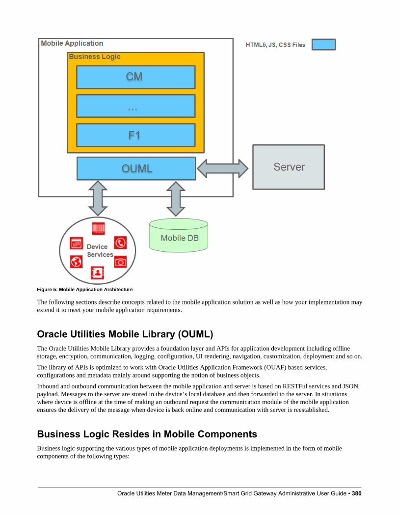
Oracle Utilities Meter Data Management/Smart Grid Gateway Administrative User Guide • 380
Figure 5: Mobile Application Architecture
The following sections describe concepts related to the mobile application solution as well as how your implementation mayextend it to meet your mobile application requirements.
Oracle Utilities Mobile Library (OUML)The Oracle Utilities Mobile Library provides a foundation layer and APIs for application development including offlinestorage, encryption, communication, logging, configuration, UI rendering, navigation, customization, deployment and so on.
The library of APIs is optimized to work with Oracle Utilities Application Framework (OUAF) based services,configurations and metadata mainly around supporting the notion of business objects.
Inbound and outbound communication between the mobile application and server is based on RESTFul services and JSONpayload. Messages to the server are stored in the device’s local database and then forwarded to the server. In situationswhere device is offline at the time of making an outbound request the communication module of the mobile applicationensures the delivery of the message when device is back online and communication with server is reestablished.
Business Logic Resides in Mobile ComponentsBusiness logic supporting the various types of mobile application deployments is implemented in the form of mobilecomponents of the following types:

Oracle Utilities Meter Data Management/Smart Grid Gateway Administrative User Guide • 381
• Standalone pages.
• Business objects.
• Shared components include:
• Business Object Status Enter and Post Processing plug-ins. These implement business rules triggered when abusiness object transitions to a new state in its lifecycle or updated respectively. The same plug-in may be associatedwith multiple business objects.
• Services. A service implements an independent function that can be called from various places in the application.
• UI Sections. These model reusable form sections that can be references on multiple pages.
• A library of common functions. Implements a library of functions that can be shared across the application.
• Message to device. Implements a type of message that is sent from the server to be processed on a mobile device.
• Product Configuration. Defines global settings for the mobile application.
• Themes. Defines swatches and styles for the mobile application.
The following sections describe how mobile components are implemented and used.
Mobile Component OwnershipMobile components are system-owned records stored in a designated maintenance object. The base product is released withall the necessary mobile components needed to support its mobile applications.
You may implement new custom mobile components to meet your organization’s mobile application requirements.
As a rule, only the component’s owner is allowed to change and delete it. However, some types of components allowcustom extensions where custom content may be added to base components. For example, you may customize a base ownedbusiness object mobile component to add more plug-ins when it transitions to a specific state, etc.
Mobile Component EditorMobile components are implemented using a browser-based editor. Use the Mobile Component portal to author custommobile components as well as extend the content of base components.
Packaged by a Batch ProcessThe source of mobile components is stored in the database and as such can me migrated from one environment to anotherusing standard tools such as Bundling and CMA.
The mobile application requires this content (HTML, JavaScript and CSS etc) to be available in the form of files. The BuildMobile Component Package batch process needs to run to generate files based on mobile component content and packagethem into an application bundle file on a shared location on the server. The bundle is downloaded when the application islaunched from the mobile device.
The following illustration shows how mobile components are converted to files and packaged along with the OUML files asthe mobile application bundle.
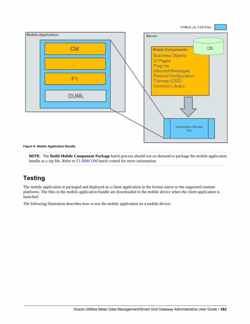
Oracle Utilities Meter Data Management/Smart Grid Gateway Administrative User Guide • 382
Figure 6: Mobile Application Bundle
NOTE: The Build Mobile Component Package batch process should run on demand to package the mobile applicationbundle as a zip file. Refer to F1-BMCOM batch control for more information.
TestingThe mobile application is packaged and deployed as a client application in the format native to the supported runtimeplatforms. The files in the mobile application bundle are downloaded to the mobile device when the client application islaunched.
The following illustration describes how to test the mobile application on a mobile device.
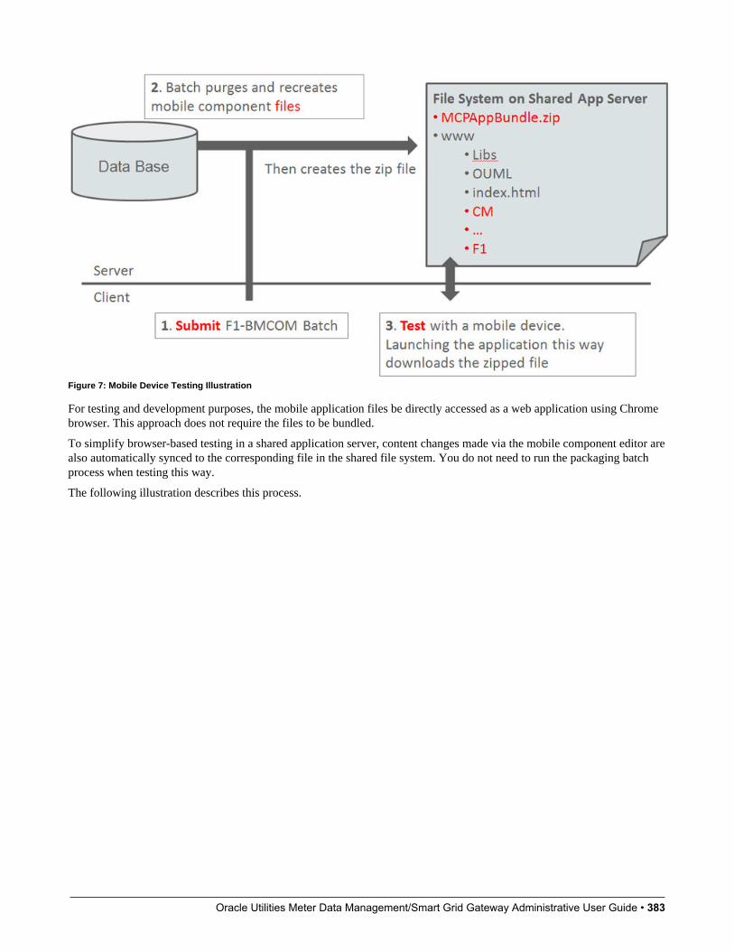
Oracle Utilities Meter Data Management/Smart Grid Gateway Administrative User Guide • 383
Figure 7: Mobile Device Testing Illustration
For testing and development purposes, the mobile application files be directly accessed as a web application using Chromebrowser. This approach does not require the files to be bundled.
To simplify browser-based testing in a shared application server, content changes made via the mobile component editor arealso automatically synced to the corresponding file in the shared file system. You do not need to run the packaging batchprocess when testing this way.
The following illustration describes this process.
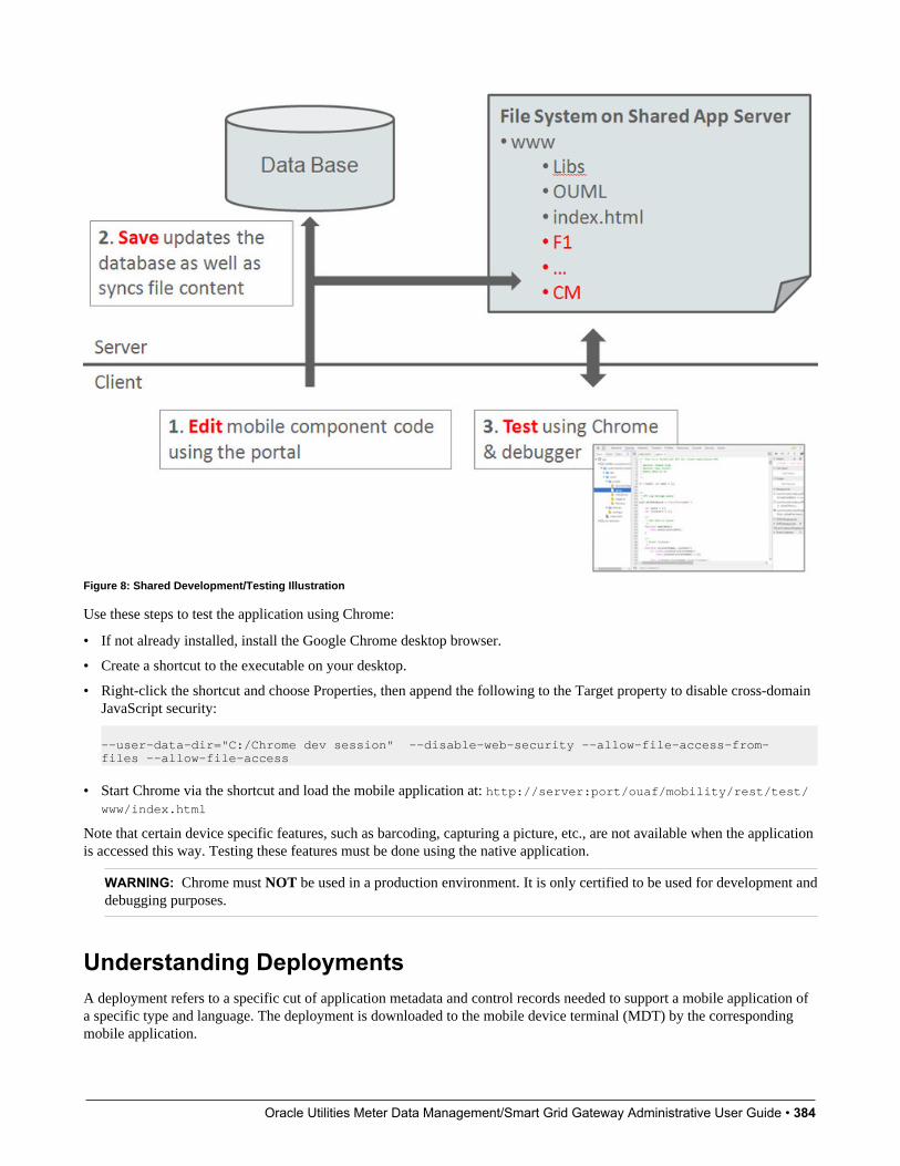
Oracle Utilities Meter Data Management/Smart Grid Gateway Administrative User Guide • 384
Figure 8: Shared Development/Testing Illustration
Use these steps to test the application using Chrome:
• If not already installed, install the Google Chrome desktop browser.
• Create a shortcut to the executable on your desktop.
• Right-click the shortcut and choose Properties, then append the following to the Target property to disable cross-domainJavaScript security:
--user-data-dir="C:/Chrome dev session" --disable-web-security --allow-file-access-from-files --allow-file-access
• Start Chrome via the shortcut and load the mobile application at: http://server:port/ouaf/mobility/rest/test/www/index.html
Note that certain device specific features, such as barcoding, capturing a picture, etc., are not available when the applicationis accessed this way. Testing these features must be done using the native application.
WARNING: Chrome must NOT be used in a production environment. It is only certified to be used for development anddebugging purposes.
Understanding DeploymentsA deployment refers to a specific cut of application metadata and control records needed to support a mobile application ofa specific type and language. The deployment is downloaded to the mobile device terminal (MDT) by the correspondingmobile application.
Oracle Utilities Meter Data Management/Smart Grid Gateway Administrative User Guide • 385
This section describes topics related to managing mobile application deployments.
Deployment TypesA deployment type represents the configuration needed to support an application of a given type. You can configuremultiple types of applications by setting up a deployment type for each.
A deployment type configuration defines the following aspect of the mobile application:
• The application items included in the application, by referencing deployment parts.
• The initial function that starts the business flow on the device when the application is launched.
• The MDT Types compatible to run this type of application.
• The authorized user groups that are allowed to use the mobile application.
• The application message categories used by the mobile application.
Deployment PartsDeployment parts provide a way to create reusable groups of application items. A deployment part is a collection ofapplication components, such as business objects, lookups, task types, and many more that are needed to support the mobileapplication.
The base product provides preconfigured deployment parts that include the base mobile application components. You onlyneed to configure parts to include your custom entities. Make sure to include your custom deployment parts as part of yourdeployment type setup.
Create deployment parts to represent subsets of your custom deployment items based on their type or usage. You shouldshare deployment parts across deployment types when applicable to prevent redundancy and improve management ofdeployment configuration. For example, use a designated deployment part for control data, another for items that arecommon across platforms, another with user interface items for a specific platform etc.
To simplify the collection of items in a deployment part it is recommended that you create an export bundle per deploymentpart so that implementations can add their new or changed items directly to the corresponding bundle using the dashboardzone. Once items are collected, the bundle can be uploaded to the deployment part. You can always maintain itemsmanually on a deployment part.
Consider where attachments must be automatically pushed to the mobile application as pat of the deployment and add themto your deployment parts.
DeploymentA deployment can only be created using the Create Deployment batch process. Once your deployment type setup iscomplete, submit the batch to create a new deployment for your deployment type for a specific language.
Once the batch job runs and the deployment has been created, it has to be manually activated on the deployment portalbefore it can be deployed to any devices.
NOTE: The Create Deployment batch process should run on demand or periodically based on your business needsto avoid situations where out of dates deployments are being used. Refer to F1-DPLOY batch control for moreinformation.

Oracle Utilities Meter Data Management/Smart Grid Gateway Administrative User Guide • 386
Out of Date DeploymentsDeployments become out of date when a new mobile application version is released, the deployment type configurationchanges, or any underlying application component that is part of the configuration changes.
Mobile users are warned at login to their mobile device that they are using an out of date deployment. The user is allowed tocontinue, but is advised to contact their administrator to synchronize their deployment. Refer to Downloading Deploymentsfor more information.
The product provides a batch process that evaluates existing active deployment records and marks those that are out ofdate if it detects any metadata changes. The background process also purges out of date deployments that are older than aspecified number of days.
NOTE: The Deployment Evaluation and Purge batch process should run on demand or periodically based on yourbusiness needs to avoid situations where out of dates deployments are being used. Refer to F1-DPUTD batch control formore information.
Also note that as part of accepting a new product release, all existing deployments are marked as out of date. Newdeployments are required to be created and activated.
When an active deployment is marked out of date, the system creates a To Do entry in order for a user to create a newdeployment as needed. Creating a new deployment for the same deployment type and language automatically closes anyremaining To Do entries reported for out of date deployments for the same configuration.
Downloading DeploymentsOnce a deployment has been activated, it is available for download to mobile devices. When the mobile user logs on to themobile application, the system looks for the most recent version of all active, qualified deployments based on the user's usergroup, language, and MDT type.
If no deployments are found, the system displays an authorization error message and prevents the user from continuing.
If only one deployment is found and it is the same as the one currently deployed, then the deployment is not downloaded.
If only one deployment is found and it is newer than the one currently deployed or there is none currently deployed, then thedeployment is downloaded to the mobile device.
If more than one deployment is found, the user can select the one they want to download.
NOTE: A new deployment will not be downloaded if unprocessed data from a previous shift still exist on the device.The system warns that user of the situation. If the user is authorized to use the deployment currently on the device, itwill be used; otherwise, an authorization error will be displayed
Setting Up DeploymentsThis section summarizes steps involved in configuring your deployment types:
• Review the various types of devices that needs to be supported and set up corresponding MDT types.
• Define MDT records for each mobile device.
• Create deployment parts to represent subsets of your custom deployment items based on their type or usage.
• Set up a deployment type for each type of application you need to support. For example, the product supports a mobileapplication for a crew to work their schedule, and another application for a contractor worker.
• Specify the deployment parts and message categories needed to support the application.
Oracle Utilities Meter Data Management/Smart Grid Gateway Administrative User Guide • 387
• List applicable MDT Types.
• Identify the user groups authorized to use the application and associate them with the deployment type.
• When you have finished defining each deployment type, you need to run the Create Deployment batch process tocreate a deployment for it for each language supported by your company. Refer to F1-DPLOY batch control for moreinformation.
• Activate each deployment.
Mobile Application VersioningThe mobile application communication architecture involves both client side and server side elements. When a deploymentis created on the server, it is marked with the version number of the server side mobile application components that createdit. The same version number is also stamped on the mobile application bundle when generated on the server. The version ofthese elements on the device must match the latest version on the server else errors will occur.
With each new product version, existing deployments stamped with the older version are marked as out of date and existingapplication bundles are deleted. New deployments need to be created and activated and a new application bundle must beregenerated with each product upgrade.
NOTE: The Create Deployment batch process should run to create a new deployment for each mobile application typeand language applicable to your organization. Refer to F1-DPLOY batch control for more information. Once created,each deployment should be activated.
NOTE: In addition, the Build Mobile Component Package background process should run to regenerate the mobileapplication bundle. Refer to F1-BMCOM batch control for more information.
To enforce compatibility, the system validates the mobile application version as follows:
• Only deployments and application bundles that are compatible with the server mobile application version can bedownloaded.
• When the mobile device attempts to connect to the server, the system checks whether or not the mobile applicationversion already on the device is compatible with the mobile application version on the server. If the versions are notcompatible, the device is not allowed to work online and no communication is sent to and from the server. In thissituation, the mobile device must be upgraded to the correct version before it can work online again. If there was dataon the mobile device, the user can continue offline and manually collect any data they need before the mobile device isupgraded.
NOTE: Before the server is upgraded, all users using the mobile application must be allowed to end their worksuccessfully from their mobile devices and logoff. This prevents the incompatible version situation described above.
The About section on the Settings menu option on the mobile device shows the mobile application version number. Thisversion is also stamped on the MDT record on the online mobile device screen.
Configuring Mobile DevicesThe following section describes mobile device configuration options.
Defining MDT TypesThis portal is used to maintain MDT types.

Oracle Utilities Meter Data Management/Smart Grid Gateway Administrative User Guide • 388
Refer to Understanding Mobile Devices for more information.
You can access the portal from theAdmin Menu > Mobile > MDT Type.
The following zones may appear as part of the portal's Main tab page
• MDT Type List. This zone lists all MDT types. Broadcast a record to display the details of the selected deployment part.
• MDT Type. This zone provides information about the selected MDT type.
Where Used
Follow this link to open the data dictionary where you can view the tables that reference F1_MDT_TYPE.
Defining MDTsThis portal is used to display and maintain a mobile data terminal (MDT). You need to define a mobile data terminal(MDT) record for each mobile device that needs to communicate with the system to send and receive work using the mobileapplication.
You can access the portal from theAdmin Menu > Mobile > MDT. You are brought to a query portal with options forsearching for a specific MDT. Once an MDT has been selected you are brought to the maintenance portal to view andmaintain the selected record.
Refer to Understanding Mobile Devices for more information.
The MDT zone on the portal's Main tab page provides information about the mobile device.
The following zones may appear as part of the portal's Log Files tab page:
• Mobile Log Files Search. This zone allows you to search for log files that may have been sent in from the mobile deviceto a designated location on the sever.
• Mobile Log. This zone shows server logging information related to communications made using this mobile device, ifthis feature is enabled from the mobile device.
Replicate MDTsYou may use the Replicate button set up a bulk of MDT records based on the details of the current MDT. This function setsthe device tag for each new MDT to the prefix text you provide and a running sequence number.
Getting the MDT Log FilesLog files are not sent to the server automatically; they are only sent on demand, usually for debugging or tracing purposes.Use the Get Log Files button to send a message to the device to send log files to the server. When the device sends the files,you may use the Log Files tab to view their content.
Changing the Mobile Device Log LevelClick the Set Log Level button to send a request to the device to change the logging level used by the mobile application.Once the mobile device is updated, it sends a response back to the server to update the current log level on the MDT recordto reflect the change.
Reset RegistrationIf this MDT is used by an iOS device and the mobile application was reinstalled on the device, the unique ID has to be resetbefore the MDT can be used again. Click the Reset Registration button to do so.
Refer to Registration for more information.

Oracle Utilities Meter Data Management/Smart Grid Gateway Administrative User Guide • 389
Configuring Deployment OptionsThe following section describes mobile device configuration options.
Defining Deployment PartsThis portal is used to maintain deployment parts. You may upload a predefined bundle when adding or updating adeployment part.
Refer to Understanding Deployments for more information.
You can access the portal from the Admin Menu > Mobile > Deployment Part.
The following zones may appear as part of the portal's Main tab page
• Deployment Part List. This zone lists all deployment parts. Broadcast a record to display the details of the selecteddeployment part.
• Deployment Part. This zone provides information about the selected deployment part.
• Deployment Items. This zone lists the application items included in this deployment part.
• Referenced By Deployment Types. This zone lists the deployment types referencing this deployment part.
CAUTION: Important! If you introduce a new deployment part, carefully consider its naming convention. Refer to System Data Naming Convention for more information.
Where Used
Follow this link to open the data dictionary where you can view the tables that reference F1_DEPLOYMENT_PART.
Defining Deployment TypesA deployment type represents a specific type of mobile application. This portal is used to maintain deployment types.
Refer to Understanding Deployments for more information.
You can access the portal from the Admin Menu > Mobile > Deployment Type.
The following zones may appear as part of the portal's Main tab page
• Deployment Type List. This zone lists all deployment types. Broadcast a record to display the details of the selecteddeployment type.
• Deployment Type. This zone provides information about the selected deployment type. You may use the NewDeployment link to submit the batch process to create a new deployment.
Where Used
Follow this link to open the data dictionary where you can view the tables that reference F1_DEPLOYMENT_TYPE.
Maintaining DeploymentsThis portal is used to view existing deployments and change their status.
NOTE: A deployment has to be activated before it can be downloaded to mobile devices. You can also inactivate adeployment so that it can no longer be deployed.
Oracle Utilities Meter Data Management/Smart Grid Gateway Administrative User Guide • 390
Refer to Understanding Deployments for more information.
You can access the portal from the Admin Menu > Mobile > Deployment. You are brought to a query portal with optionsfor searching for a specific deployment. Once a deployment has been selected you are brought to the maintenance portal toview and maintain the selected record.
The Deployment zone on the portal's Main tab page provides information about the mobile device.
The following zones may appear as part of the portal's Main tab page
• Deployment. This zone provides information about the selected deployment.
• Out of Date Items. This zone lists items that have changed and caused the deployment to become out of date. Expandthe zone to request the system to evaluate the deployment now. If the deployment is out of date, it is marked as such andthe zone lists the out of date items information.
Defining Mobile ComponentsThis portal is used to maintain mobile components. You may use this portal to review the base components as well asextend them or implement new custom mobile components to support your mobile application requirements.
NOTE: You need to run the Build Mobile Component Package background process to include your custom mobilecomponent content as part of the application bundle that is downloaded when the mobile application is launched from amobile device. Refer to F1-BMCOM batch control for more information.
Refer Understanding Mobile Application Files for more information.
You can access the portal from the Admin Menu > Mobile > Mobile Component.
The following zones may appear as part of the portal’s Main tab page:
• Mobile Component. This zone provides general information about the selected mobile component.
• Mobile Component Content Editor. This zone is used to maintain the various contents associated with the selectedmobile component.
CAUTION: Important! If you introduce a new mobile component, carefully consider its naming convention. Refer to System Data Naming Convention for more information.
Where Used
Follow this link to open the data dictionary where you can view the tables that reference F1_MOBILE_COMPONENT.
Mobile Application Master ConfigurationThe Mobile Configuration (master configuration) record defines several system wide settings related to mobile applicationfunctionality. For more information about specific fields in the master configuration, refer to the embedded help.
AttachmentsSome implementations may require that attachments be available from the application. These attachments can be stored inthe Attachment table and then linked to other objects if applicable.
Oracle Utilities Meter Data Management/Smart Grid Gateway Administrative User Guide • 391
Attachment OverviewThe following topics provide additional information regarding attachment functionality.
Attachment TypesThe system supports several different attachment content types, for example:
• PDF Document
• Excel Spreadsheet
• Jpeg Image
• Text Document
The attachment data itself may be text or binary. When storing the data in the application however, it is stored as textinformation only. As a result, the upload of an attachment that is a binary type requires a conversion prior to storing thedata. When viewing the attachment, the data is converted again for display.
Each type of attachment is defined using an attachment business object. The business object includes configuration definingthe supported file extensions, whether the data is binary or not and the content type that represents the type of data for theattachment.
NOTE: To view the attachment business objects provided with the base product, navigate using Admin > BusinessObject > Search and search for business objects related to the Maintenance Object for Attachments (F1-ATCHMT).
Owned AttachmentsAttachments can be either ‘owned’ or ‘common’. An owned attachment is one that is related to a specific record. Forexample, the specific test results for a given device can be uploaded and linked to that device or to its test records. Thesetypes of attachments are typically uploaded and maintained via the object that owns it.
Common AttachmentsCommon attachments are ones that are uploaded independent of any transaction in the system. They can be used forgeneral system or company information. Or they can be linked to more than one transaction. For example, instructions forperforming a certain type of task can be uploaded as an attachment and linked to a task type where those instructions arerelevant. These types of attachments are uploaded and maintained in the central Attachment portal. Objects that may refer tothe attachments may link the attachments via characteristics or some other appropriate mechanism.
Emailing AttachmentsThe system supports a business service that may be used by system processing to send an email. The business service F1-EmailService supports receiving the IDs of one or more attachments as input parameters.
Refer to Sending Email for more information.
Configuring Your System for AttachmentsIn order to link attachments to objects in the system, there may be some configuration or implementation required to supportthe link. It is possible that one or more objects in your product already support attachments out of the box. Consult theproduct documentation for the specific object for confirmation. For objects in the system that do not support attachments outof the box, the following sections provide some guidelines for enabling support for attachments. Contact product support formore information.

Oracle Utilities Meter Data Management/Smart Grid Gateway Administrative User Guide • 392
Supporting Common AttachmentsThe attachments themselves are created / uploaded using the attachment portal. Refer to Maintaining Attachments for moreinformation.
If your implementation has a use case where one or more common attachments may be linked to an object (and the objectdoes not already support this functionality), the object may need to be extended to capture the attachments.
• If the object includes a characteristic collection, this is a recommended way to capture attachments. A characteristic typeshould be defined for each type of attachment. The characteristic type should be a foreign key type and should referencethe Attachment FK reference. The characteristic entity collection should include the object that the common attachmentwill be linked to.
• Most characteristic collections are sequence based characteristics and would support multiple entries for the samecharacteristic types, if multiple attachments are applicable.
• If the object to support the attachments is governed by a business object, the implementation must extend the businessobject to define one or more appropriate elements used to capture the attachments. If only one attachment of a certaintype is allowed, a single flattened characteristic may be used. If multiple attachments of a certain type are allowed, theBO schema may define a “flattened list” exposing the sequence and the characteristic type.
• If the object is maintained on a “fixed page” with a generic characteristic collection, no additional configuration isneeded to allow users to link attachments to that object.
Supporting Owned AttachmentsWhen creating an attachment for a specific record, the attachment itself captures the information about the related record,namely its maintenance object code and its primary key. For these types of attachments, no configuration is needed on therelated business object to capture the attachments, as was the case with common attachments.
However, it is recommended to configure the user interface of the related object so that the owned attachments can beviewed and maintained from that page. To do this, you may use the generic attachment zone provided by the product: F1-ATTCHOWN.
Note that your product may already have support for viewing and maintaining owned attachments on one or more if its basedelivered portals.
Defining a New Attachment TypeAs mentioned, the product provides support for several content types. If your implementation needs to support attachmentsfor a content type not currently supported, create a new business object copying the configuration of an existing attachmentbusiness object.
Configure the following option types for the BO:
• Binary indicates whether the attachment data must be converted from binary format. Binary attachments are stored in thedatabase as text, and are then converted back to the original format when retrieved.
• Content Type represents the browser's mime type of the attachment.
• Supported File Extension specifies the valid file extensions for the content type.
Once the business object is defined, it is ready for use.
Maintaining AttachmentsThis section describes the functionality supported for viewing and maintaining attachments.
Navigate using Admin > General > Attachment. You are brought to a query portal with options for searching forcommon attachments.
Oracle Utilities Meter Data Management/Smart Grid Gateway Administrative User Guide • 393
Once an attachment has been selected, you are brought to the maintenance portal to view and maintain the selected record.
NOTE: The base search options for the attachments query only support searching for common attachments. Ownedattachments may also be viewed on the attachment maintenance portal, but a user may only drill into the attachmentmaintenance from the maintenance portal of the “owning” entity.
The Attachment zone provides basic information about an attachment, including the ability to upload the file and to view anuploaded file.
Adding AttachmentsCommon attachments may be added from the attachments portal (or via the standard menu path). In addition, your productmay support attachments associated with specific records (“entity owned attachments”) which may also provide thecapability to add attachments.
In both cases, when adding an attachment, you are prompted for the file to upload. Once the file is chose, the systemdetermines the appropriate business object to associate with the attachment based on the file extension. Typically one andonly one business object is found at which point you are prompted to provide the Attachment Name. (Your specific productmay also require additional information at this time). Fill in the details and save.
Please note the following:
• If no business object is found for the uploaded file’s file type, an error is issued. This type of file is not currentlysupported as an attachment.
• If multiple business objects are found, the user must choose the appropriate one. This should be rare.
Application ViewerThe Application Viewer allows you to explore meta-data driven relationships and other deliverable files online.
NOTE: Running Stand-Alone. You can also launch the Application Viewer as a stand-alone application (i.e., you donot need to start it from within the system). Refer to Application Viewer Stand-Alone Operation for more informationabout running the Application Viewer as a stand-alone application.
To open the application viewer from within your application, navigate to Admin > Implementation Tools > ApplicationViewer. The application viewer may also be launched from other locations for example when viewing a section of theonline help files that contain hypertext for a table name, clicking on that hypertext brings you to the definition of that tablein the data dictionary.
Application Viewer ToolbarThe Toolbar provides the main controls for using the Application Viewer. Each button is described below.
Data Dictionary Button
The Data Dictionary button switches to the Data Dictionary application.
Oracle Utilities Meter Data Management/Smart Grid Gateway Administrative User Guide • 394
Physical and Logical Buttons
The Physical button changes the display in the List Panel from a logical name view to a physical name view. Note that theTables are subsequently sorted by the physical name and therefore may not be in the same order as the logical name view.Once clicked, this button toggles to the Logical button.
The Logical button changes the display in the List Panel from a physical name view to a logical name view. Note that theTables are subsequently sorted by the logical name and therefore may not be in the same order as the physical name view.Once clicked, this button toggles to the Physical button.
These buttons are only available in the Data Dictionary.
Collapse Button
The Collapse button closes any expanded components on the list panel so that the child items are no longer displayed.
This button is only available in the Data Dictionary viewer.
Attributes and Schema Button
The Attributes button changes the display in the Detail Panel from a related tables view to an attribute view. Once clicked,this button toggles to the Schema button.
The Schema button changes the display in the Detail Panel from an attribute view to a related tables view. Once clicked,this button toggles to the Attributes button. Note that only tables have this view available. Columns are always displayed inan attribute view.
These buttons are only available in the Data Dictionary.
Maintenance Object Button
The Maintenance Object button switches to the Maintenance Object viewer application.

Oracle Utilities Meter Data Management/Smart Grid Gateway Administrative User Guide • 395
Algorithm Button
The Algorithm button switches to the Algorithm viewer application.
Batch Control Button
The Batch Control button switches to the Batch Control viewer application.
To Do Type Button
The To Do Type button switches to the To Do Type viewer application.
Description and Code Buttons
The Description button changes the display in the List Panel to Description (Code) from Code (Description). Note that thelist is subsequently sorted by the description. Once clicked, this button toggles to the Code button.
The Code button changes the display in the List Panel to Code (Description) from Description (Code). Note that the list issubsequently sorted by the Code. Once clicked, this button toggles to the Description button.
These buttons are only available in the Batch Control and To Do Type viewers.
Service XML Button
The Service XML button switches to the Service XML viewer. This button is not available when you are already in theService XML viewer.
You are prompted to enter the name of the service XML file you want to view. The name of the service XML file should beentered without the extension.

Oracle Utilities Meter Data Management/Smart Grid Gateway Administrative User Guide • 396
Select Service Button
The Select Service button loads another service XML file that you specify. This button is only available in the ServiceXML viewer.
You are prompted to enter the name of the service XML file you want to view. The name of the service XML file should beentered without the extension.
Java Docs Button
The Java Docs button switches to the Java Docs viewer.
Groovy Java Docs Button
The Groovy Java Docs button switches to the Groovy Java Docs viewer.
Classic Button
This button is only available in the Java Docs viewer.
The Classic button launches the classic Javadocs viewer on a separate window. If you are more comfortable with that lookyou can use this viewer instead.
Preferences Button
The Preferences button allows you to set optional switches used by the Application Viewer. Refer to Application ViewerPreferences for more information.
Help Button
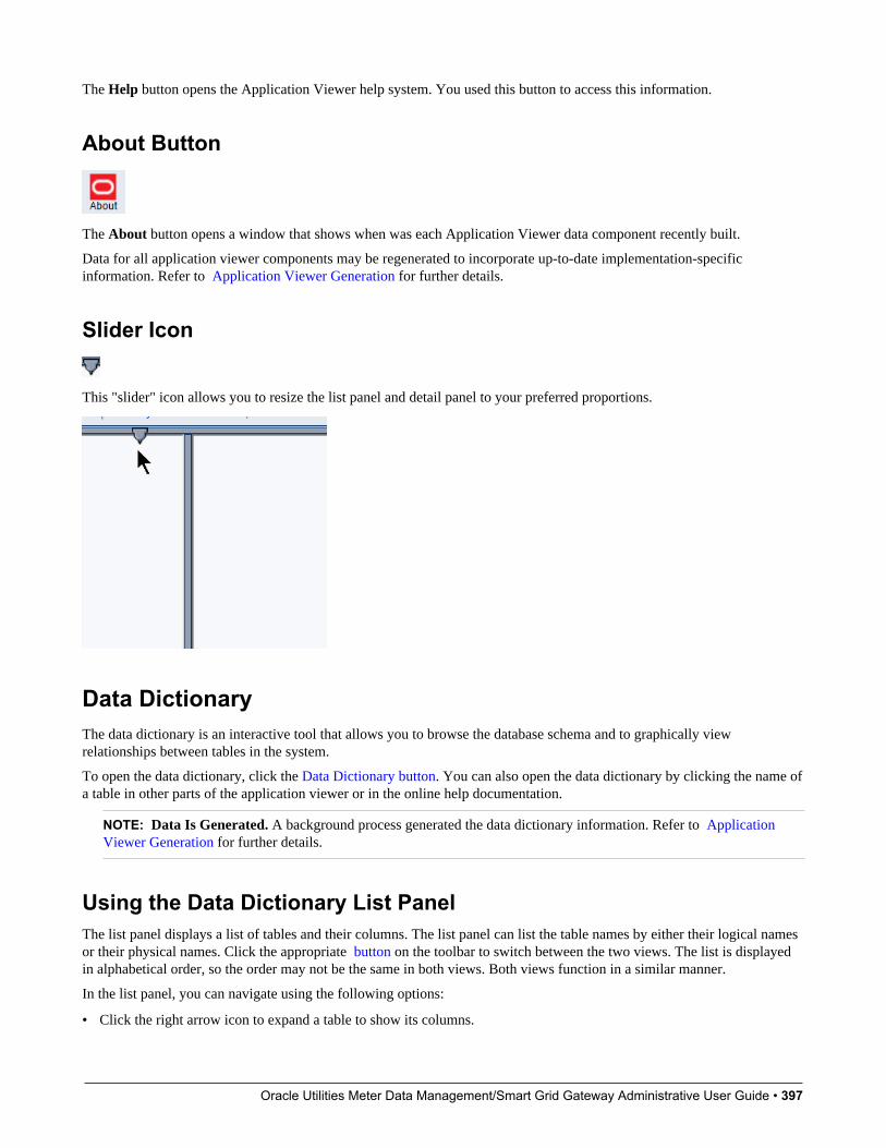
Oracle Utilities Meter Data Management/Smart Grid Gateway Administrative User Guide • 397
The Help button opens the Application Viewer help system. You used this button to access this information.
About Button
The About button opens a window that shows when was each Application Viewer data component recently built.
Data for all application viewer components may be regenerated to incorporate up-to-date implementation-specificinformation. Refer to Application Viewer Generation for further details.
Slider Icon
This "slider" icon allows you to resize the list panel and detail panel to your preferred proportions.
Data DictionaryThe data dictionary is an interactive tool that allows you to browse the database schema and to graphically viewrelationships between tables in the system.
To open the data dictionary, click the Data Dictionary button. You can also open the data dictionary by clicking the name ofa table in other parts of the application viewer or in the online help documentation.
NOTE: Data Is Generated. A background process generated the data dictionary information. Refer to ApplicationViewer Generation for further details.
Using the Data Dictionary List PanelThe list panel displays a list of tables and their columns. The list panel can list the table names by either their logical namesor their physical names. Click the appropriate button on the toolbar to switch between the two views. The list is displayedin alphabetical order, so the order may not be the same in both views. Both views function in a similar manner.
In the list panel, you can navigate using the following options:
• Click the right arrow icon to expand a table to show its columns.
Oracle Utilities Meter Data Management/Smart Grid Gateway Administrative User Guide • 398
• Click the down arrow icon to collapse the column list for a table. Optionally, collapse all column lists by using theCollapse button.
• Click the column name to display information about the column in the detail panel.
• If the detail panel is in related table view, click the table name to view its related tables. If the detail panel is in tabledetail view, click the table name to display its information.
Primary And Foreign KeysThe columns in the list panel may display key information as well as the column name:
• A yellow key indicates that the column is a primary key for the table.
• A light blue key indicates that the column is a foreign key to another table. If you hover the cursor over the icon, the tooltip indicates the foreign table.
• A dark blue key indicates that the column is a conditional foreign key. A conditional foreign key represents rarerelationships between tables where a single field (or set of fields) may reference multiple primary key constraints of othertables within the application as a foreign key.
• A red key indicates that the column is a logical key field. A logical key represents an alternate unique identifier of arecord based on a different set of fields than the primary key.
If you hover your cursor over an icon, the tool tip indicates the key type.
Field Descriptions ShownThe language-specific, logical name of each field is shown adjacent to the physical column name in the data dictionary. Youcan enter an override label for a table / field's to be used throughout the system as the field's logical name. Here too it is theoverride label that is shown.
NOTE: Regenerate. You should regenerate the data dictionary after overriding labels. Refer to Application ViewerGeneration for further details.
Using the Data Dictionary Detail PanelThe Data Dictionary detail panel displays the details of the selected item. There are three main displays for the Detail Panel:
• Related tables view
• Table detail view
• Column detail view
Related Tables ViewThe Related Tables view displays information about the table's parent tables and child tables. Click the Schema button inthe toolbar to switch to related tables view.
In the related tables view, you can navigate using the following options:
• Click the left arrow and right arrow icons to view the related tables for that linked table. The List Panel is automaticallypositioned to the selected table.
• Click the maintenance object icon ( ) to view the table's maintenance object.
Oracle Utilities Meter Data Management/Smart Grid Gateway Administrative User Guide • 399
• If you want to position the List Panel to view the columns for different table click the name of the table for which youwant to view the columns.
Table Detail ViewThe table detail view displays information about the selected table. Click Attributes (in the toolbar) to switch to the tabledetail view.
In the table detail view, you can navigate using the following options:
• If user documentation is available for the table, click the View User Documentation link to read the user documentationthat describes the table's maintenance object.
• If the table has an associated Language Table, click the link to view the Language Table details.
• If there is an associated Maintenance Program, click the link to view the source code for the maintenance program (youare transferred to the Java Docs Viewer).
• If there is an associated Key Table, click the link to view the Key Table details.
Column Detail ViewClick on a column name in the list panel to switch to the column detail view. The Column Detail view displays informationabout the selected column.
In the column detail view, you can navigate using the following options:
• If user documentation is available for the column, click the View User Documentation link to read about the column'srelated maintenance object.
• If the column is a foreign key, click the table name to switch to the Table Detail view for that table.
• If the column has a Value List available (normally only present for a subset of flag and switch fields), click the link toview the source code for the copybook (you are transferred to the Java Docs Viewer).
Lookup ValuesIf the selected column is a lookup field its valid values are also listed. Notice that you can enter an override description for lookup values. In this case the override description is shown.
NOTE: Regenerate. You should regenerate the data dictionary after overriding lookup value descriptions. Refer to Application Viewer Generation for further details.
Maintenance Object ViewerThe maintenance object viewer is an interactive tool that allows you to view a schematic diagram of a maintenance object.A maintenance object is a group of tables that are maintained as a unit.
To open the Maintenance Object Viewer, click the Maint. Object button in the application viewer or click a maintenanceobject icon in the Data Dictionary.
NOTE: Data Is Generated. A background process generated the maintenance object information. Refer to ApplicationViewer Generation for further details.
Oracle Utilities Meter Data Management/Smart Grid Gateway Administrative User Guide • 400
Using the Maintenance Object List PanelThe list panel displays a list of maintenance objects. In the list panel, you can click the maintenance object name to displayinformation about the maintenance object in the detail panel.
Using the Maintenance Object Detail PanelThe Maintenance Object detail panel displays a schematic of the selected maintenance object.
In the detail panel, you can navigate using the following options:
• Click a table name to transfer to the Data Dictionary table detail view for a table. (Click the Maint. Object button in thetoolbar to return to the maintenance object.)
• Click the service XML icon ( ) to view the XML file of the Service Program used to maintain the displayed object.(Click the Maintenance Object button in the toolbar to return to the maintenance object.)
Algorithm ViewerThe algorithm viewer is an interactive tool that allows you to view algorithm types (grouped by their plug-in spot) and theirrelated algorithms.
To open the Algorithm Viewer, click the Algorithm button in the application viewer. The Algorithm viewer may also beopened from certain locations in the online help documentation.
NOTE: Data Is Generated. A background process generates algorithm information. Refer to Application ViewerGeneration for further details.
Using the Algorithm Viewer List PanelThe list panel displays a list of algorithm types and their related algorithms, grouped by their plug-in spot.
In the list panel, you can navigate using the following options:
• Click the algorithm plug-in spot description to display information about the plug-in spot in the detail panel.
• Click the right pointer icon to expand a plug-in spot and view its algorithm types and their related algorithms.
• Click the down pointer icon to collapse the list of algorithm types for a plug-in spot.
• Click the algorithm type name to display information about the algorithm type in the detail panel.
• Click the algorithm name to display information about the algorithm in the detail panel.
Using the Algorithm Plug-In Spot Detail PanelThe Algorithm plug-in spot detail panel displays further information about the selected plug-in spot.
Using the Algorithm Type Detail PanelThe Algorithm Type detail panel displays further information about the selected algorithm type.
In the Algorithm Type detail panel, you can navigate using the following options:
Oracle Utilities Meter Data Management/Smart Grid Gateway Administrative User Guide • 401
• Click on the program name to view its source in the Java docs viewer.
Using the Algorithm Detail PanelThe Algorithm detail panel displays further information about the selected algorithm.
Batch Control ViewerThe batch control viewer is an interactive tool that allows you to view batch controls.
To open the Batch Control Viewer, click the Batch Control button in the application viewer. The Batch Control viewer mayalso be opened from certain locations in the online help documentation.
NOTE: Data Is Generated. A background process generates batch control information. Refer to Application ViewerGeneration for further details.
Using the Batch Control Viewer List PanelThe list panel displays a list of batch controls. The list panel can display the list of batch controls sorted by their codeor sorted by their description. Click the appropriate button on the toolbar to switch between sorting by the code anddescription.
In the list panel, you can click the batch control to display information about the batch control in the detail panel.
NOTE: Not All Batch Controls Included. Note that the insertion and key generation programs for conversion (CIPV*)are not included.
Using the Batch Control Detail PanelThe batch control detail panel displays further information about the selected batch control.
In the batch control detail panel, you can navigate using the following options:
• Click on the program name to view its source in the Java docs viewer.
• If a To Do type references this batch control as its creation or routing process, click on the To Do type to view its detailin the To Do type viewer.
To Do Type ViewerThe to do type viewer is an interactive tool that allows you to view to do types defined in the system.
To open the To Do Type Viewer, click the To Do Type button in the application viewer. The To Do Type viewer may alsobe opened from certain locations in the online help documentation.
NOTE: Data Is Generated. A background process generates To Do type information. Refer to Application ViewerGeneration for further details.
Oracle Utilities Meter Data Management/Smart Grid Gateway Administrative User Guide • 402
Using the To Do Type Viewer List PanelThe list panel displays a list of To Do types. The list panel can display the list of To Do types sorted by their code or sortedby their description. Click the appropriate button on the toolbar to switch between sorting by the code and description.
In the list panel, you can click the To Do type to display information about the To Do type in the detail panel.
Using the To Do Type Detail PanelThe To Do type detail panel displays further information about the selected To Do type.
In the To Do type detail panel, you can navigate using the following options:
• If the To Do type references a creation process or a routing process, click on the batch process to view its detail in thebatch control viewer.
• Click on the table listed in the drill key section to view its detail in the data dictionary.
• Click on the field(s) listed in the drill key section to view its detail in the data dictionary.
Service XML ViewerThe service XML viewer is an interactive tool that allows you to browse the XML files of service programs that execute onthe application server.
You can access the service XML viewer as follows:
• The maintenance object viewer allows you to view the XML file of the maintenance object's service program. Thisfeature is implemented by viewing the maintenance object and then clicking on the Service XML icon.
• When viewing a maintenance object on the Maintenance Object page, clicking the View XML hyperlink causes theservice’s XML document to be displayed in the Service XML Viewer.
• When viewing a business service on the Business Service page, clicking the View XML hyperlink causes the service’sXML document to be displayed in the Service XML Viewer.
• When setting up a Function, you may want to view the XML document used to pass data to and from the service.Clicking the View XML hyperlink causes the XML document to be displayed in the Service XML Viewer.
Using the Service XML Viewer Overview PanelThe overview panel displays a high level nodes and list names structure of the XML document.
In the overview panel, you can click on any node item to position the detail panel to view that item.
Using the Service XML Viewer Detail PanelThe detail panel displays nodes and attributes of the selected XML file.
Click the xpath button to view the XML path that should be used to reference the selected node in the XML document. Thebox at the top of the overview panel changes to display this information.
NOTE: Fields in multiple lists. Note that the generated XPath expression refers to lists using a generic “list” reference.For example: /pageBody/list/listBody/field[@name=’FIELD_NAME’]. If a service has a field that appears in morethan one list, the above XPath may not be sufficient for referencing that field. In this case, references to the XPath

Oracle Utilities Meter Data Management/Smart Grid Gateway Administrative User Guide • 403
should be adjusted to include the list name. The list name is visible in the overview panel. To add the list name, use[@name=’LIST_NAME’]. For example: /pageBody/list[@name=’LIST_NAME’]/listBody/field[@name=’FIELD_NAME’].
Java Docs ViewerThe Java Docs viewer is an interactive tool that allows you to browse Java documentation files (Javadocs) for Java classesthat execute on the application server.
NOTE: Proprietary Java Classes. A small number of Java classes have been suppressed due to their proprietary nature.
NOTE: Classic view. If you are more comfortable using the classic Javadocs viewer you may use the Classic button.
To open the Java Docs viewer from within the application viewer, click the Java Docs button. Additionally, the algorithmviewer and the batch control viewer allows you to view the Javadocs of a program written in Java.
Using the Java Docs Viewer List PanelThe list panel displays a tree of Java packages where each package may be expanded to list the Java interfaces classes itincludes.
In the list panel, you can navigate using the following options:
• Click the right arrow icon to expand a Java package to view the Java interfaces and classes it includes.
• Click the down arrow icon to collapse the list for a Java package. Optionally, collapse all lists by using the Collapsebutton.
• Click the Java interface or class name to display information about it in the detail panel.
The list details panel designates the interfaces and the classes as follows:
• A green dot indicates Java interfaces.
• A blue key indicates Java classes.
If you hover the cursor over the icon, the tool tip indicates whether it's an interface or a class.
Using the Java Package Detail PanelThe package detail panel displays a summary of the various Java classes that are included in the selected Java package.
Click the Java class name to display information about the Java class in the detail panel.
Using the Java Interface / Class Detail PanelThe detail panel displays Java documentation information about the selected Java interface or class.
You can navigate using hyperlinks to other locations in the current detail panel or to view the details of other Javainterfaces / classes.
Oracle Utilities Meter Data Management/Smart Grid Gateway Administrative User Guide • 404
Groovy Java Docs ViewerThe Groovy Java Docs viewer is an interactive tool that allows you to browse Java documentation files (Javadocs) for theJava classes that are accessible to Groovy code within scripts.
NOTE: For system protection, only a subset of the base Java classes are available for use by Groovy code.
To open the Groovy Java Docs viewer from within the application viewer, click the Groovy Java Docs button. You canalso access the viewer via the ‘View Groovy Javadocs’ link in the context sensitive Script Tips zone. Refer to the additionaltopics in the Java Docs Viewer section for details of how to navigate the viewer panels.
Application Viewer PreferencesThis panel displays the Available Languages and allows you to select the language in which the labels and buttons aredisplayed. Select your desired language and click OK.
Application Viewer Stand-Alone OperationYou can run the Application Viewer as a stand-alone application (i.e., you do not need to launch it from the onlineapplication environment). To run it as a stand-alone application, you should copy the Application Viewer files (all files inthe appViewer directory) and the online help files (all files in the help directory) to the server on which you want to run theApplication Viewer.
NOTE: Online Help. If you do not copy the online help files, online help will not be available for the ApplicationViewer, nor will you be able to view business descriptions of the tables' maintenance objects.
To start the application viewer in stand-alone mode, launch the appViewer.html file (located in the appViewer directory).
Stand-Alone Configuration OptionsYou can configure the Application Viewer for stand-alone operation by modifying options in a configuration file. TheApplication Viewer comes with a default configuration file called config_default.xml (located in the appViewer\configdirectory). Create a copy of the default configuration file and rename it to config.xml. Modify the options described in thefollowing table to suit the needs of your installation.
NOTE: Default Configuration. If you do not create the config.xml file, the Application Viewer launches with itsdefault (internal) configuration.
Option DescriptiondefaultLanguage The default language used when the application viewer is started.
Available values are those marked as language enabled on thelanguage page.
defaultView The default view then the application viewer is started. Available valuesinclude:- Data Dictionary
dataDictionary Whether the Data Dictionary is available or not:- Y- N
Oracle Utilities Meter Data Management/Smart Grid Gateway Administrative User Guide • 405
Option DescriptionsourceCode This property is not being used. Simply enter ‘N’.
baseHelpLocation The location of the stand-alone online help in relation to the applicationviewer. Specify the directory structure relative to the location of thedirectory in which the Application Viewer files are located. Note that thisis the directory in which the language subdirectories for the online helpare located. The default location is:../help
appViewerHelp The default help topic that is launched when the Help button is clickedin the Application Viewer. Specify a help file and anchor that is underthe appropriate language directory under the baseHelpLocation. Thedefault is:Framework/Admin/91AppViewer.html#SPLINKApplication_Viewer
Example Application Viewer ConfigurationThe following excerpt shows an example Application Viewer configuration.
<?xml version="1.0" encoding="UTF-8" ?><configuration><option id="defaultLanguage">PTB</option><option id="defaultView">Data Dictionary</option><option id="dataDictionary">Y</option><option id="sourceCode">N</option><option id="baseHelpLocation">../help</option><option id="appViewerHelp">Framework/Admin/91AppViewer.html#SPLINKApplication_Viewer</option></configuration>
Application Viewer GenerationThe Application Viewer is initially delivered with service XML information only.
The other components of the application viewer are generated on site.
• Use the background process F1-AVALG to regenerate algorithm information
• Use the background process F1-AVBT to regenerate batch control information.
• Use the background process F1-AVMO to regenerate maintenance object information
• Use the background process F1-AVTBL to regenerate data dictionary information.
• Use the background process F1-AVTD to regenerate To Do type information.
These processes have been introduced so that you can more easily incorporate your implementation-specific informationinto the application viewer.
To keep the information shown in the application viewer current it is important to execute these background processes afteryou introduce changes to the corresponding system data.
NOTE: Data Generation Is Not Incremental. Each new execution of these processes first deletes existing data (if any)in the corresponding folder before it generates new data.
NOTE: Other Extensions. Service XML may also be extended to include implementation-specific information. Thebase package is provided with special scripts that handle this type of extension. Refer to the Software Development KitUser Guide for further information on application viewer extensions.

Oracle Utilities Meter Data Management/Smart Grid Gateway Administrative User Guide • 406
NOTE: War File. If your application is installed in war file format, each generation of application viewer data rebuildsthe corresponding war file. The web application server then needs to be "bounced" in order to make the newly generateddata available to the application viewer. Please consult your system administrator for assistance.
NOTE: Certain Web Application Servers Are Special. WebSphere and Oracle Application web application serversrequire an additional step in order to make the newly generated data available to the application viewer. These webapplication servers require a rebuild of the application ear file and its redeployment in the web application server. Thisstep is described in the installation document. Please consult your system administrator for further details.
Reporting and Monitoring ToolsThis chapter describes various tools provided in the product to support reporting and monitoring.
Reporting Tool IntegrationThis section describes how to configure your third party reporting tool and how to define your reports in the system toenable users to submit reports online.
The Big Picture Of ReportsThe topics in this section describe the approach for designing and defining your system reports. Note that the productincludes an out-of-the-box integration with BI Publisher. However it is possible to use the reporting objects to integrate witha different third party tool.
Integration with BI PublisherYour DBMS, your product, and BI Publisher can work together to produce reports. You may choose to use a differentreporting tool, but this may not be a trivial effort. This section provides high-level information about some of the businessrequirements that are being solved with the reporting solution.
Multi-Language and Localization SupportThe integration supports a multi-language implementation and supports different localization settings.:
• All labels, headings and messages are defined using field and message meta-data in the application, which supportmultiple languages.
• The appropriate font, size, and layout are based on the requested report and the user's language.
• Dates and numbers are formatted as per the user's display profile.
• Currency based numbers are formatted as per the currency definition from the product
Requesting Reports from The SystemAlthough reports are rendered in your reporting tool, users must be able to request ad-hoc reports from within the system(assuming users have the appropriate security access).
• The prompts for the input parameters must be shown in the user's language
• Users should be able to use the standard search facilities to find parameter values
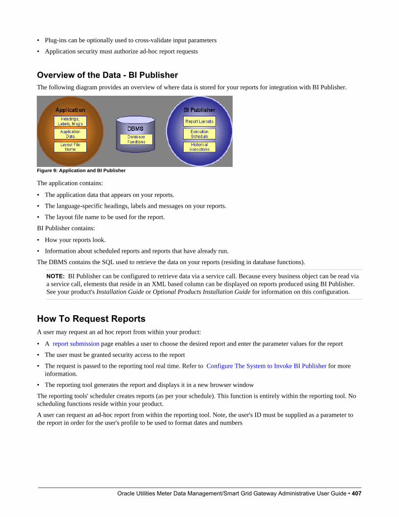
Oracle Utilities Meter Data Management/Smart Grid Gateway Administrative User Guide • 407
• Plug-ins can be optionally used to cross-validate input parameters
• Application security must authorize ad-hoc report requests
Overview of the Data - BI PublisherThe following diagram provides an overview of where data is stored for your reports for integration with BI Publisher.
Figure 9: Application and BI Publisher
The application contains:
• The application data that appears on your reports.
• The language-specific headings, labels and messages on your reports.
• The layout file name to be used for the report.
BI Publisher contains:
• How your reports look.
• Information about scheduled reports and reports that have already run.
The DBMS contains the SQL used to retrieve the data on your reports (residing in database functions).
NOTE: BI Publisher can be configured to retrieve data via a service call. Because every business object can be read viaa service call, elements that reside in an XML based column can be displayed on reports produced using BI Publisher.See your product's Installation Guide or Optional Products Installation Guide for information on this configuration.
How To Request ReportsA user may request an ad hoc report from within your product:
• A report submission page enables a user to choose the desired report and enter the parameter values for the report
• The user must be granted security access to the report
• The request is passed to the reporting tool real time. Refer to Configure The System to Invoke BI Publisher for moreinformation.
• The reporting tool generates the report and displays it in a new browser window
The reporting tools' scheduler creates reports (as per your schedule). This function is entirely within the reporting tool. Noscheduling functions reside within your product.
A user can request an ad-hoc report from within the reporting tool. Note, the user's ID must be supplied as a parameter tothe report in order for the user's profile to be used to format dates and numbers

Oracle Utilities Meter Data Management/Smart Grid Gateway Administrative User Guide • 408
Viewing ReportsAs described above, ad-hoc reports requested from within your product are displayed immediately after they are generatedin a new browser window
If your reporting tools supports it, the Report History page may be configured to open tool’s report execution history pageand request a view of this report.
NOTE: The Report History page currently does not display historical reports for BI Publisher.
Configuring The System To Enable Reports
Configuring BI Publisher ReportsThis section contains topics specific about configuring the product to interoperate with BI Publisher.
Configure the System to Invoke BI Publisher Real-timeThe base product provides an installation algorithm plug-in spot called Reporting Tool. This plug-in spot should contain analgorithm that invokes the third party reporting tool real-time.
For BI Publisher, the system provides an algorithm type called F1-BIPR-INV, which invokes BI Publisher.
These algorithms rely on information defined in the Reporting Options table: the reporting server, reporting folder andthe user name and password for accessing the reporting tool. The values in the reporting options should have been set upwhen the system was installed. Contact your system administrator if there are any problems with the values defined on thereporting options.
To use the algorithm types to invoke BI Publisher, perform the following steps:
• Create an algorithm for the appropriate algorithm type.
• On the installation options, add an entry to the algorithm collection with an algorithm entity of Reporting Tool andindicate the algorithm created in the previous step.
Batch Scheduling in BI PublisherFor many of your reports, you probably want the report to be produced on a regular basis according to a scheduler. Thereporting solution relies on the BI Publisher software to provide the batch scheduler functionality. Refer to BI Publisherdocumentation for details about configuring the batch scheduler.
Defining Reporting OptionsThe reporting options are provided as a mechanism for defining information needed by your reporting solution. The baseproduct uses the reporting options to define information needed to access the reporting tool from within the system using thealgorithm defined on the installation option.
Navigate to this page using Admin > Reporting > Reporting Options.
Description of pageReporting Folder defines the shared folder where reports are stored.
Oracle Utilities Meter Data Management/Smart Grid Gateway Administrative User Guide • 409
Reporting Server defines the URL of the web application where the reporting tool is installed. For example, using BIPublisher, the format is: http://<BI Publisher Server>:<port>.
Reporting Tool User ID is not applicable when integrating with BI Publisher.
Other reporting tools may require a user id to use when logging in.
Reporting Tool Password is not applicable when integrating with BI Publisher.
Other reporting tools may require a password to use when logging in.
NOTE: Customize Options. The reporting options are customizable using the Lookup table. This field name isRPT_OPT_FLG. The reporting options provided with the system are needed to invoke the reporting tool. If yourimplementation requires other information to be defined as reporting options, use the lookup table to define additionalvalues for the reporting option flag.
Where Used
This information is used by the reporting tool algorithm on the installation option to invoke the reporting tool software.
Implementations may use reporting options to record other information needed for their reporting tool.
Defining Report DefinitionsFor each report supplied by your installation, use the report definition page to define various attributes of the report.
Report Definition - MainNavigate to this page using Admin > Reporting > Report Definition.
CAUTION: Important! If you introduce new report definitions, you must prefix the report code with CM. If you do notdo this, there is a slight possibility that a future release of the application could introduce a new system report with thename you allocated.
Description of page
Enter an easily recognizable Report Code and Description for each report. Use the External Reference ID to define theidentifier for this report in your external reporting tool.
Define an application service to enable users to request submission of this report online or to view report history for thisreport. Once you define an application service for each report, use application security to define which users may accessthis report.
NOTE: Access Mode. The access mode for application services related to reports must be set to Submit/View Report.
If you have more than one parameter defined for your report and you wish to perform cross-validation for more than oneparameter, provide an appropriate Validation Algorithm. Click here to see the algorithm types available for this systemevent.
Enter a Long Description to more fully describe the functionality of this report. This information is displayed to the userwhen attempting to submit the report online or when viewing history for this report.
For BI Publisher, if you want to use one of the sample reports provided by the system, but with a different layout, indicatethe layout to use for the report in the Customer Specific Font/ Layout field and BI Publisher uses this information instead.The name for base report layout is <report code>_Base. For example, a base layout for CI_VACANT is named CI_VACANT_Base.

Oracle Utilities Meter Data Management/Smart Grid Gateway Administrative User Guide • 410
Report Definition - LabelsNavigate to this page using Admin > Reporting > Report Definition and go to the Labels tab.
NOTE: Company name and logo. Note the company name used as a title in the sample reports is defined as a messageon the installation options. For information about installing the company logo, refer to your product's Installation Guideor the Optional Products Installation Guide.
Description of Page
In order to provide multi-language capability for each report, the labels used for the report must support multiple languagedefinitions. For each label used by your report, indicate a unique Sequence and the Field used to define the Label. The labeldefined here should be the same label that is defined in your report layout defined in the external reporting tool.
When rendering an image of the report, the external reporting tool retrieves the appropriate label based on the language usedfor the report.
Report Definition - ParametersNavigate to this page using Admin > Reporting > Report Definition and go to the Parameters tab .
Description of Page
The Parameters scroll contains one entry for every parameter defined for the report. The following fields display:
Parameter Code is the identifier of the parameter. This must correspond to the parameter definition in the reporting tool.
Required indicates that a value for the parameter must be defined when submitting the report.
Sort Sequence must match the parameter order defined in the reporting tool's report. It is also used when displaying the listof parameters on the report submission page.
Characteristic Type indicates the characteristic type used to define this parameter.
Default Value is option and if populated is displayed to the user when the report is chosen on the report submission page.
Description is a brief description of the parameter. This description is used when displaying the parameter on the reportsubmission page.
Long Description is a detailed description of the parameter. This description is used on the report submission page whenthe user requests more information for a given parameter.
Sample Reports Supplied with the ProductDepending on your specific product, there may be sample reports provided that your organization may use as they are oras a starting point for creating a new report. The following sections provide an overview of the sample reports along withinstructions on how to use one of the sample reports in your implementation environment.
How to Use a Sample Report Provided with the SystemIf you would like to use any of the sample reports, you need to perform some steps to be able to execute them in animplementation environment. This section walks you through the steps needed.

Oracle Utilities Meter Data Management/Smart Grid Gateway Administrative User Guide • 411
Steps Performed at Installation TimeRefer to the Installation Guide or Optional Products Installation Guide for instructions for setting up and configuring yourproduct and reporting tool to use the sample reports provided with the system. The following steps are described there.
• Setting up the stored procedures used by the sample reports.
• Defining the company title and logo used by the sample reports. Note the company name used as a title in the samplereports is defined as a message on the installation options.
• Defining a user for integration with your product.
• Publishing the sample reports in BI Publisher.
Contact your system administrator to verify that the above steps have occurred.
How To Define A New Report
Use a Sample Report as a Starting Point• Make a copy of the report and save it in an appropriate directory. Prefix the new report name with CM.
• Review the stored procedure(s) used for this report. Refer to the installation guide for information about where the storedprocedures should be defined. If you want to change the data that is being accessed, copy the stored procedure, prefixingthe new stored procedure with CM. Make the appropriate changes in the new version of the stored procedure. Contactyour database administrator to find out the procedure for creating a new stored procedure.
NOTE: Performance considerations. When designing a stored procedure, you must consider the performance of thereport when executed. Consult your database administrator when designing your database access to ensure that all issuesare considered.
NOTE: Defining Messages. The stored procedures provided with the system use messages defined in message category30. If your new stored procedures require new messages, use message category 90000 or greater, which are reserved forimplementations.
• Review the parameters used by the report. Make appropriate changes to the parameters required by the report. Thisaffects how you define your report. Refer to Designing Parameters for more information.
• Determine whether or not you require cross validation for your report parameters. If any cross validation is necessary,you should design an appropriate validation algorithm to be executed when requesting a report in your product. Refer to Designing Validation Algorithms for more information.
NOTE: Cross Validation for On-line Submission Only. The cross validation algorithm is only executed for ad-hocreport submissions via your product. If you submit this report through your reporting tool, this algorithm is not executed.
• Review the labels used by the report. Labels and other verbiage are implemented in the sample reports using a referenceto the field table in the system. This enables the report to be rendered in the appropriate language for the user. For anynew report label you require, you must define a new field entry. Refer to Designing Labels for more information.
• Review the layout of the report and make any desired changes based on your business needs.
When you have finished designing and coding your new report in your reporting tool, you must do the following in orderfor it to be usable:
Oracle Utilities Meter Data Management/Smart Grid Gateway Administrative User Guide • 412
• Publish the report in BI Publisher. Refer to the documentation for this products for details about publishing a report.Refer to Publishing Reports in BI Publisher for configuration information specific to publishing a report for integrationwith your product.
• Define the report. Refer to Designing Your Report Definition for more information.
Publishing Reports in BI PublisherPlease refer to the documentation for BI Publisher for more information about publishing a report in this system. Theremaining topics in this section provide information about settings needed to ensure that the report is accessible using BIPublisher.
BI Publisher Database AccessWhen publishing a report in BI Publisher, you are asked for database logon information. The logon user name and passwordmust be the user name and password that has access to the database functions related to this report in your database.
Verify BI Publisher User Access RightsTo verify the user's access rights to folders in BI Publisher:
• Open the BI Publisher Enterprise Security Center.
• Check that the role for the user has access to the appropriate report folders.
For more information, refer to the "Understanding Users and Roles" section in the Oracle Business Intelligence PublisherUser's Guide.
Designing Your Report DefinitionWhen adding a new report, you must define it in the system to allow users to request ad-hoc reports from on-line and totake advantage of the multi-language provisions in the system. The following topics illustrate the steps to take to correctlyconfigure your report definition.
Designing Main Report Definition ValuesRefer to field description section of the report definition main page for information about defining general informationabout the report.
For the validation algorithm, preliminary steps are required. Refer to Designing Validation Algorithms for moreinformation.
For the application service, preliminary steps are required. Refer to Designing Application Services for more information.
Designing Characteristic TypesThe parameter tab on the report definition page uses characteristic types to define the report parameters. For each reportparameter that you plan to use, you must define a characteristic type.
You do not need a unique characteristic type for each report parameter. For example, if Start Date and End Date areparameters your report, only one Report Date characteristic type needs to be defined. This characteristic type would beused on both date parameters.
Each characteristic type to be used as a report parameter must indicate a characteristic entity of Report.
Oracle Utilities Meter Data Management/Smart Grid Gateway Administrative User Guide • 413
To illustrate the characteristic type definitions, let's look at the sample report Tax Payables Analysis. It needs the followingparameters: From Date, To Date, GL Account Type Characteristic Type and Account Type value.
NOTE: Account Type Parameters. The tax payables report must find general ledger entries that have posted to acertain distribution code. In order to find the appropriate distribution code, the report expects each distribution code tobe defined with a characteristic indicating its GL account type (for example, Revenue, Asset, etc.) The report needs toknow the characteristic type used to define this entry.
To support the required parameters, the following characteristic types are needed.
Char Type Description Type Valid Values Char Entities
CI_DATE Date Parameter Ad-hoc (Uses validation algorithmto validate proper dateentry)
Report
CI_CHTYP Characteristic Type FK Reference CHAR_TYP Report
CI_GLTY GL Account Type Pre-defined A- Asset, E- Expense,LM- Liability/miscellaneous, LT-Liability/taxes, R-Revenue
Distribution Code, Report
Highlights for some of the above settings:
• We have defined a characteristic type for defining a characteristic type. This is to allow the user to indicate which CharType on the Distribution Code is used for the GL account type. This is an FK reference type of characteristic.
• The GL account type characteristic type is referenced on both the Distribution Code entity and the report entity.
Designing ParametersYour report definition parameters collection must define a unique parameter entry for each parameter sent to the reportingtool. The sequence of your parameters must match the sequence defined in your reporting tool.
Continuing with the Tax Payables Analysis report as an example, let's look at the parameter definitions.
Parameter Code Description Char Type Default ValueP_FROM_DT From Date CI_DATE N/A
P_TO_DT To Date CI_DATE N/A
P_CHAR_TYPE Account Type Characteristic CI_CHTYP CI_GLTY
P_TAX_ACCTY_CHAR Account Type Char Value for TaxRelated GL Account
CI_GLTY LT-Liability/taxes
Highlights for some of the above settings:
• The from date and to date parameters use the same characteristic type.
• The characteristic type parameter is defined with a default value pointing to the GL account type characteristic type.
• The GL account type parameter defines the liability/taxes account type as its default value.
NOTE: User Id. The sample reports provided by the system pass the user id as the first parameter passed to thereporting tool. It does not need to be defined in the parameter collection for the report.
Designing Validation AlgorithmsWhen designing your report definition, determine if cross validation should occur for your collection of parameters. In theTax Payables Analysis report, there are two date parameters. Each date parameter uses the characteristic type validationalgorithm to ensure that a valid date is entered. However, perhaps additional validation is needed to ensure that the start dateis prior to the end date. To do this, a validation algorithm must be designed and defined on the report definition.

Oracle Utilities Meter Data Management/Smart Grid Gateway Administrative User Guide • 414
The system provides a sample algorithm RPTV-DT that validates that two separate date parameters do not overlap. Thisalgorithm should be used by the Tax Payables Analysis report.
If you identify additional validation algorithm, create a new algorithm type. Create an algorithm for that algorithm typewith the appropriate parameter values. Plug in the new validation algorithm to the appropriate report definition.
Designing Application ServicesApplication services are required in order to allow a user to submit a report on-line or to view history for a report. Definean application service for each report and define the user groups that should have submit/view access to this report.
Update report definition to reference this application service.
Designing LabelsThe system supports the rendering of a report in the language of the user. In order to support a report in multiple languages,the verbiage used in the report must be defined in a table that supports multiple languages. Some examples of verbiage in areport include the title, the labels and column headings and text such as "End of Report".
The system uses the field table to define its labels.
NOTE: Report Definition. This section assumes that your new report in the reporting tool has followed the standardfollowed in the sample reports and uses references to field names for all verbiage rather than hard-coding text in a singlelanguage.
For each label or other type of verbiage used by your report, define a field to store the text used for the verbiage.
• Navigate to the field page using Admin > System > Field.
• Enter a unique Field Name. This must correspond to the field name used in your report definition in the reporting tooland it must be prefixed with CM.
• Define the Owner as Customer Modification.
• Define the Data Type as Character.
• Precision is a required field, but is not applicable for your report fields. Enter any value here.
• Use the Description to define the text that should appear on the report.
• Check the Work Field switch. This indicates to the system that the field does not represent a field in the database.
Update the report definition to define the fields applicable for this report in the Labels tab.
If your installation supports multiple languages, you must define the description applicable for each supported language.
Measuring PerformanceMany implementations need the ability to track and view the performance of key system processes against a definedtarget level. The framework provides objects to allow an edge product or an implementation to calculate and displayperformance measures against a desired target for one or more use cases. The topics in this section provide informationabout what is supplied in the framework and guidelines for implementing a specific use case for batch processes. Yourspecific product may supply out of the box support for additional use cases. Refer to your product specific documentationfor more information.
About Performance TargetsThe following are examples of use cases that would be well suited for tracking as performance targets:
Oracle Utilities Meter Data Management/Smart Grid Gateway Administrative User Guide • 415
• Track and view the duration of key batch processes, either individually or as a group, and how they relate to a definedtarget.
• Monitor used and free space on a database against critical levels.
• Check the performance of individual user interface zones against a defined performance expectation
• Compare the number of web service requests made to an application against a threshold where performance may be ofconcern.
Framework provides functionality to define and categorize performance targets and link them to objects such as businessservices, zones and portals. This supports the calculation and display of the metrics against desired results.
In addition, Framework supplies out of the box support for batch process performance targets. Individual edge applicationsmay supply more specific functionality for other use cases, if applicable.
Ideally, users should have the ability to view these performance targets on a dashboard that groups related measures.Framework provides the necessary components to achieve this for batch process performance targets.
The following sections highlight functionality supported for performance targets in the framework. Refer to the edgeapplication product documentation for more details of other supported use cases.
Performance Target Objects OverviewThe setup of a performance target involves a unique combination of configuration data and processing logic that calculatesand displays a specific measure.
The framework performance target functionality is supported by a combination of inter-related objects, as shown below.Some of these objects will be generic for use in all performance targets while some are specific to a functional area such asbatch processes.
• Maintenance Objects for capturing performance target types and performance target instances.
• Extendable Lookups to define performance target categories and performance target metrics.
• Business Services to calculate known metrics for a group of performance targets, such as for batch processes.
• UI Maps to interpret the performance calculation results and display them in charts that show the comparison to thetarget.
• A Zone that serves as a template for system duplication to create specific zones related to each performance target. Thezone invokes a business service to perform calculations and display performance measures in the related UI map.
• Business Objects to capture configuration data for a specific performance target instance and its related objects.
• Functionality to create Zone instances for specific performance targets based on the associated template zone.
Each edge application will deliver the following to compliment the objects delivered by the framework:
• Portals to group related performance target zones.
• Specific entries for the performance target category Extendable Lookup .
The following sections describe the combined use of these objects for performance targets in more detail.
Calculating and Displaying Performance TargetsPerformance targets are intended to be displayed in a portal using an explicit object zone. The zone parameters define boththe business service used to calculate the performance metrics and the UI map that displays the results. While an individualperformance target needs to reference a zone with a unique configuration that calculates a particular metric, those zones willbe based on a template zone which defines the core parameters.
Oracle Utilities Meter Data Management/Smart Grid Gateway Administrative User Guide • 416
Framework provides a base Batch Performance Target Metric Template zone (F1-PERFBA) for batch process performancetargets. Refer to this zone and its parameters for more information about the batch performance zone configuration and therelated business service and UI map.
Performance Target Metrics and Metric TypesThe framework supports two types of metrics for performance monitoring:
• Value based metrics are used to record results against a specific numeric target.
• Time based metrics are used to track the results against a specific date and time target.
The list of valid metrics for a given performance target category and its associated performance target types ismaintained using an extendable lookup. Framework uses the base business object Batch Performance Target Metric (F1-BatchPerfTargetMetric) to define batch process metric values. Refer to this lookup for the supported batch processmetrics.
NOTE: While users are not prevented from adding new values to the lookup, the list is not intended to be extendable asnew values will not be recognized by the business service that performs the base batch performance calculation logic.
Your edge product or implementation may supply other extendable lookup business objects for additional performancemeasurement use cases, if applicable.
Performance Target Categories and TypesThere are key configuration details required by all performance targets. These are defined on two related objects.
Performance Target CategoriesTarget categories define the template zone and security setting for a group of performance measures. The list of validcategories is maintained using an extendable lookup.
The framework product supplies the business object Performance Target Category (F1-PerformanceTargetCategory) forthis functionality. Refer to the business object description and configuration for more information.
Performance Target TypesTarget types define the related performance target business object and the display portal for a group of performancemeasures. In addition, a target type references a target category which defines the associated zone details.
The framework product supplies the business object Performance Target Type (F1-PerformanceTargetType) for thisfunctionality. Refer to the business object description and configuration for more information.
The framework does not deliver any standard type or category values for batch processing performance targets. Refer toyour specific edge application products to verify if any standard values are delivered for the batch processes within yourapplications. Edge applications may also supply standard categories and types for additional performance target use cases.
Performance Targets Define Specific MetricsAlthough the types of measures and the business services and UI maps that govern how they are calculated and displayedare defined using separate objects, a performance target record defines the additional configuration needed to measure aspecific metric and compare the result to a desired value.
There are key configuration details required by all performance target instances. These include a reference to the metricbeing measured, the desired target value or time, the desired result for the target and the unique zone by which thisperformance target will be monitored.
Oracle Utilities Meter Data Management/Smart Grid Gateway Administrative User Guide • 417
NOTE: The performance target maintenance object has a direct foreign key link to the extendable lookup businessobject and value that define the performance metric. This is an unusual pattern as extendable lookup values are normallyrecorded only in an object's schema. The pattern has been adopted to allow the description of the metric to be displayedin the performance target maintenance portal.
A given performance target type may require additional details for its calculations. For example, the framework batchprocess performance target defines additional details to restrict the measurement to specific batch processes that haveexecuted within a given time frame. These details are configured on the performance target business object. Refer to theembedded help text on the business objects supplied by the framework and your edge applications for more information.
The performance target type also defines the business object to use when creating the resulting performance target record.
Objects Linked to a Performance TargetSome performance measures such as batch process metrics, derive the data for the calculation from objects within thesystem. The performance target can be linked to one or more related objects to define the specific data sources included inthat target metric. For example, when creating a batch process performance target, the framework supports linking specificbatch codes to the performance target to indicate the group of batch processes that are included in the measure.
The performance target business object may be configured to allow only relevant objects types to be linked to aperformance target record. Refer to the base Batch Performance Target business object (F1-BatchPerformanceTarget) foran example.
Creating Performance Target ZonesOnce a performance target and its objects have been defined, a unique zone needs to be created to display and monitor thespecific target.
The framework functionality for batch performance targets implements the zone creation via the related business objectlifecycle. When a performance target is added, status enter plug-ins are responsible for generating the new zone usingthe template zone and prefix configured on the target category (or the override values) and adding the zone to the portalconfigured on the target type. When a performance target is inactivated, an enter plug in is responsible for removing thezone from the portal.
NOTE: While the template zone associated with the performance target category may be overridden, the zonegeneration algorithm makes certain assumptions about the zone type and parameters. In particular, the logic expects toconfigure a zone parameter that references the performance target code as input to the business service responsible forcalculating the metrics.
Refer to the base Batch Performance Target business object (F1-BatchPerformanceTarget) for details of the lifecycle andthe enter plug-ins responsible for performance target zone creation.
Setting Up Performance Target ConfigurationThe following topics highlight the general configuration steps required to use performance target functionality. Yourparticular product or implementation may supply additional functionality to support specific use cases for performancetargets. Refer to your product’s documentation and the library of business objects supplied for performance target in yoursystem for more information.
Performance Target Category LookupRefer to About Performance Targets for an overview of performance target functionality.
Oracle Utilities Meter Data Management/Smart Grid Gateway Administrative User Guide • 418
Each Performance Target Type is associated with a unique Performance Target Category. The categories are defined as anextendable lookup.
Navigate to the Extendable Lookup portal. Search for and select the Performance Target Category business object. Definevalues that are appropriate to the categories your implementation is assigning for the performance target types in use. Insome cases, an edge application may already have delivered the appropriate performance target category for your use
Refer to the embedded help for more information about configuring this object.
Defining Performance Target TypesRefer to About Performance Targets for an overview of performance target functionality.
To maintain the performance target types applicable to your product or implementation, open Admin > Reports >Performance Target Type.
This is a standard All-in-One portal.
The information captured on the performance target type depends on the business objects supported by your product orimplementation. Refer to the embedded help text for more information.
Where Used
Follow this link to open the data dictionary where you can view the tables that reference F1_PERF_TGT_TYPE.
Maintaining Performance TargetsThis section describes the functionality supported for viewing and maintaining performance targets.
Refer to About Performance Targets for an overview of performance target functionality.
Navigate using Main > Reporting > Performance Target. This is an All-in-One portal and includes the standard List anddisplay zones for a performance target.
For information about the data defined on the performance target, refer to embedded help.
Capturing StatisticsThe product provides objects to allow for an edge product or an implementation to periodically calculate and capturestatistics for one or more use cases. The topics in this section provide information about what is supplied in the frameworkand guidelines for implementing specific use cases.
About StatisticsThere are two objects that work together to capture the statistics related to a given business use case:
• The statistics control record which defines configuration related to capturing statistics. It also defines a category that isused to group similar types of statistics together.
• The statistics snapshot is the record where the actual calculated statistics are captured.
Statistics ControlThe statistics control record whether or not statistics are automatically calculated and how frequently. In addition, you maycontrol the retention policy of snapshot record. You may indicate that only the most recent snapshot is kept or all snapshotrecords are kept or that they are retained for a defined number of days.

Oracle Utilities Meter Data Management/Smart Grid Gateway Administrative User Guide • 419
The system provides a business object for statistics control (F1-Statistics) that is expected to be used for most use cases. Itslifecycle includes the support for periodic capturing of statistics snapshot records as well as on demand capture.
Statistics SnapshotThe statistics snapshot object is the object that is responsible for calculating and capturing the statistics details. A separatebusiness object must be defined for each use case. The schema of the business object defines the details that are captured. Inaddition, it must include an algorithm as an enter plug-in on the Complete state that is responsible for capturing statistics.
The system provides a 'root' business object for statistics snapshot (F1-SnapshotRoot) which includes the lifecycle thatstatistics snapshot business objects should follow. No explicit statistics snapshot use case is provided by the Framework.Your specific product may supply some out of the box support for certain use cases, in which case specific statisticssnapshot business objects are provided. Refer to your product specific documentation for more information.
Viewing / Reporting StatisticsThe product provides the mechanism for defining statistics control and statistics snapshot records and viewing the datain basic format. If your product has provided support for specific use cases, there may also be additional portals usedto display the statistics in a meaningful format. For example, the statistics snapshot may be capturing data that can bepresented in graphical format. Additionally, if multiple historical statistics snapshot records are retained, a zone may bedefined to graph changes over time.
Configuring Your System for StatisticsIf your product provides statistics use cases that you are planning to implement, all that you need to do is configure theappropriate statistics control record and define the appropriate configuration for your business requirements. Refer toDefining and Monitoring Statistics for more information.
If your implementation has identified an additional use case where you would like to capture statistics, the following pointshighlight the steps needed to configure the system to support the use case.
• Determine whether an additional Statistics Category value is needed. This is captured on the statistics category record.Navigate to the Lookup page. Search for and select the STAT_CATEGORY_FLG field. Review the values anddetermine if additional values are needed.
• Define a new statistics snapshot BO. This should be a child BO of the base delivered BO (F1-SnapshotRoot). Itsschema should define elements for the specific information that is captured by the statistics calculations. The schemashould be designed in conjunction with an appropriate Enter Status algorithm for the Complete that calculates thestatistics as appropriate for the business requirement.
• Once the snapshot business object is designed and implemented, configure the appropriate statistics control record.
Defining and Monitoring StatisticsRefer to About Statistics for an overview of the statistics functionality.
To define and maintain statistics control records and view a list of the current snapshot records, open Admin > Reporting >Statistics Control.
This is an All-in-One portal and includes the standard List and display zones for a statistics control.
For information about the data defined on the statistics control, refer to embedded help.
Statistics SnapshotIf there are any Statistics Snapshot records for the statistics control, the Statistics Snapshot List zone displays a list of themost recent records. A user may drill into any of the records to view more detail. You are brought to a maintenance portal

Oracle Utilities Meter Data Management/Smart Grid Gateway Administrative User Guide • 420
where you may view details about the calculated statistics. The information captured will be unique to the particular usecase. Refer to the embedded help for more information.
External MessagesThis section describes mechanisms provided in the product that enable an implementation to configure the system tocommunicate with an external application.
Incoming MessagesThis section provides information about support for incoming messages.
Inbound Web ServicesInbound web service functionality is provided to support receiving web service requests from an external system.
About Inbound Web ServicesThe following topics provide overview information about inbound web services (IWS).
Multiple OperationsAn inbound web service supports the configuration of one or more operation per web service. Each operation defines theschema-based object to invoke to perform the desired function. An operation may refer to a Business Service, a BusinessObject, or a Service Script. If the IWS supports multiple operations, each operation can refer to the same or a completelydifferent schema-based object from other operations within the IWS. In addition, each operation may define a transactiontype, which is essentially an action that is supported by the schema-based object.
By default, Inbound Web Services uses the Schema Name to dictate the Request and Response for the service. The APIcan be overridden with custom formats by specifying Request and Response Schemas with the appropriate Request andResponse XSL to transform into the relevant schema formats.
For business object based operations, when invoking the web service an action is required. This may be passed into theweb service as part of the invocation or alternatively, the action may be defined when configuring the operation using thetransaction type.
NOTE: Using the transaction type Change requires all values to be passed in. Using the transaction type Update allowsthe web service to pass only the primary key and the values to be updated. All other elements will retain their existingvalues.
Annotations Used for SecurityWhen preparing to deploy inbound web services, the security aspects of the service must be decided. The product providesa default security policy that is applied when no other policy is defined: @Policy(uri=”policy:Wssp1.2-2007-Https-BasicAuth.xml”, attachToWsdl=true) which requires HTTP Basic over SSL and a WS-Security Timestamp.
If a different security policy is desired, the following options are available:
• Security policies may be attached to the Inbound Web Service via the Java Enterprise Edition (Java EE) WebApplication Server. This allows for multiple policies to be attached as supported by the Java EE Web Application Server.In order to enable this capability, explicit system configuration is required so that the product does not assume the defaultsecurity policy. See the subsequent bullets for more information.
Oracle Utilities Meter Data Management/Smart Grid Gateway Administrative User Guide • 421
• Define a system wide security policy using a feature configuration option. Find the Feature Configuration record for theExternal Messages feature type. (It may need to be defined if it does not exist). Choose the option type Default securitypolicy and define an appropriate value. If your implementation wishes for the policies to be attached at the Java EE WebApplication Server, define this option type with an option value of <none>.
• Attach a security policy to the IWS via a Web Service Annotation. The base product provides annotation types thatsupport the standard WS-Policy (F1POLICY) and OWSM Security Policy (F1-OWSM). No base annotation is suppliedby the product for either annotation type.
If your implementation wishes for the policy of a particular IWS to be attached at the Java EE Web Application Server,define a special annotation for the F1POLICY annotation type and configure the uri parameter value to <none>.
NOTE: Refer to WebLogic documentation for more information on supported security policies.
NOTE: In order to use the OWSM Policy, additional system configuration is necessary. Contact your systemadministrator to confirm if your implementation supports OWSM.
Inbound Web Service DeploymentAn Inbound Web Service must be deployed to the Java EE Web Application Server in order for it to be available to the WebService Clients to access the system. Refer to Deploying Web Services for more information.
Deploying XAI Inbound Service via IWSFor implementations using XAI inbound services for external messages, the product recommends moving to the inboundweb service mechanism, which uses the Java EE Web Application Server to communicate with the product rather than theXAI servlet.
For XAI inbound services that use the Business Adapter, it is straight forward to move to IWS because the configurationis similar. In both cases, the service is configured to reference a business object, business service or service script. Theassociated WSDL for each record is similar. Changing the interface for the incoming message to use IWS instead of XAIinbound services is similar.
However, for XAI inbound services that use the Core Adapter, these services reference an underlying “page service” in theproduct. For these services, the Request and Response schemas for the XAI inbound service were created using the SchemaEditor. In order to support calling an underlying "page service" in IWS, first a business service must be created to referencethe page service (if one doesn’t already exist). However, the resulting schema for the business service is different fromthe Request and Response schemas related to the XAI inbound service. Moving this functionality to IWS using businessservices requires changes to the format of the incoming messages.
Moving all incoming messages over to use IWS instead of XAI is the product recommendation. However, to aid inimplementations that have many integrations in place using the XAI inbound services that use the Core Adapter (or anyadapter whose message class is BASEADA), the product provides the ability to deploy these types of XAI inbound servicesto the Java EE Web Application Server along with the Inbound Web Services.
To take advantage of this capability, you must define a feature configuration option. Under the External Messages featureconfiguration type, the Support XAI Services via IWS is used to indicate if this feature is supported. Setting the value totrue turns on the feature. If no option is defined for that option type, it is equivalent to setting the value to false.
When the system is configured to support XAI services via IWS, the Inbound Web Service deployment includes XAIinbound services (that are configured with an Adapter that references the BASEADA message class). The deploymentportal will also include a zone showing the deployment status of these XAI Inbound Services.
Configuring Inbound Web Service OptionsThis topic describes the configuration needed for using inbound web services.
Oracle Utilities Meter Data Management/Smart Grid Gateway Administrative User Guide • 422
Technical ConfigurationIn order to use inbound web services, there are tasks a system administrator must perform.
Refer to the Server Administration Guide for technical details of each of these processes.
Maintaining Web Service Annotation TypesThe product provides some base annotation types. Refer to the metadata for more information. If your implementationwishes to define additional annotation types, use the Web Service Annotation Type portal. Open this page using Admin >External Message > Web Service Annotation Type.
You are taken to the query portal where you can search for an existing web service annotation type. Once an annotation typeis selected, you are brought to the maintenance portal to view and maintain the selected record.
NOTE: Use of custom policies should only be considered if the policies supplied by the Java EE Web ApplicationServer are not sufficient for your implementation's needs.
CAUTION: Important! When adding new records, carefully consider the naming convention of the web serviceannotation type code. Refer to System Data Naming Convention for more information.
The Web Service Annotation Type zone provides basic information about the web service annotation type.
Please see the zone's help text for information about this zone's fields.
The system supports the ability for an IWS record to refer to multiple policies. In this situation, the annotation type for thepolicy should include a reference to a parent annotation type so that the system can properly build the array of annotations.
Where Used
Follow this link to open the data dictionary where you can view the tables that reference F1_IWS_ANN_TYPE.
Maintaining Web Service AnnotationsIf your implementation wishes to define annotations, use the Web Service Annotation portal. Open this page using Admin >Integration > Web Service Annotation.
This is a standard All-in-One portal.
CAUTION: Important! When adding new records, carefully consider the naming convention of the web serviceannotation code. Refer to System Data Naming Convention for more information.
Where Used
Follow this link to open the data dictionary where you can view the tables that reference F1_IWS_ANN.
Maintaining Inbound Web ServicesInbound Web Services are used to define a specific message that your implementation will receive from an external systemand provides configuration needed to process the inbound message.
The product provides several inbound web services out of the box. By default, no annotations are defined for the baseinbound web services. You may modify the message options or the annotations for any base IWS record. In addition, youmay define additional IWS records for other incoming messages supported by your implementation.

Oracle Utilities Meter Data Management/Smart Grid Gateway Administrative User Guide • 423
To view an inbound web service, navigate using Admin > Integration > Inbound Web Service. You are brought to aquery portal with options for searching for inbound web services.
Once an inbound web service has been selected, you are brought to the maintenance portal to view and maintain the selectedrecord.
CAUTION: Important! When adding new records, carefully consider the naming convention of the inbound web servicecode. Refer to System Data Naming Convention for more information.
The Inbound Web Service zone displays the configuration information for the record, including its annotations, ifapplicable and its operations.
Note that in addition to standard actions available on this portal, there is also a special Add to Category button in the pageaction area. Click this button to link an inbound web service to one or more web service categories.
Deploying Web ServicesThis topic describes the configuration needed for using inbound web services.
Once an Inbound Web Service is defined it is not automatically available to the Web Service Clients to access the system.The Deployment Status and the Active flag (set to true) indicate whether a Web Service is available or not. The last step isto deploy the Inbound Web Services to the Java EE Web Application Server. This deployment phase has a number of stepsthat are automatically performed when a deployment is initiated:
• The Web Service files are generated and policies are attached.
• The WSDL is generated with appropriate annotations and enumerations.
• The necessary Java stub code to implement the Web Service in the Java EE Web Application Server is generated andcompiled.
• The Web Services are built into a valid Web Application Archive (WAR) file.
• Optionally, the newly created Web Services WAR file is deployed to the Java EE Web Application Server. This can alsobe done manually for clustered deployments, if desired.
There are two methods available for deploying inbound web services:
• Deployment at the command line using the iwsdeploy[.sh] command as outlined in the Server Administration Guide.This method is recommended for native installations and production implementations.
• Deployment using the Inbound Web Service Deployment portal. This method is only supported in development (non-production) environments.
Inbound Web Service Deployment PortalTo use the online Inbound Web Service Deployment portal, navigate using Admin > Integration > Inbound Web ServiceDeployment.
The following sections describe the base zones that are provided on the portal.
Deploy Inbound Web Services
The Deploy Inbound Web Services zone provides information about the last deployment. If the region is a development(non-production) region you may use the Deploy button to deploy or re-deploy inbound web services. All inbound webservices whose Active switch is Yes will be deployed. All whose active switch is No will be undeployed.
NOTE: When an Inbound Web Service is deployed, the value of its service revision field is captured. Certain changesto configuration will require re-deployment to take effect. When any of the following changes occur, the IWS servicerevision value is incremented. This will cause the deployment status to show Needs Deployment.
• Active switch is changed
Oracle Utilities Meter Data Management/Smart Grid Gateway Administrative User Guide • 424
• An Annotation is added or removed
• An Operation is added or removed.
• The Operation Name, Schema Type / Schema Name, Request or Response Schema, Request or Response XSL for anOperation is changed.
NOTE: In addition, if the implementation supports XAI services deployed through IWS, the appropriate XAI inboundservices will also be deployed or undeployed as required.
Deployment Status
The Deployment Status zone displays a list of inbound web services in the product, including the deployment status.
The deployment status is determined by comparing the internal Service Revision field on each IWS against the valuecaptured at the time of deployment.
• Deployed. Indicates that the IWS has been deployed and no changes have been detected to the configuration.
• Needs Deployment. Indicates that the IWS has never been deployed or has been deployed but in the meantime, changeshave been detected to the configuration that require redeployment.
• Undeployed. Indicates that the IWS is marked as inactive and the IWS is not found to be deployed at this time.
• Needs Undeployment. Indicates that the IWS is marked as inactive but the IWS is found to be deployed at this time.
If the IWS has been deployed, the View column will include a WSDL link allowing you to launch a separate window toview the WSDL definition.
Use the broadcast button adjacent to any of the inbound web services listed in the zone to view the details of the IWSrecord. This causes the Inbound Web Service zone to appear. It is the same zone that appears on the Inbound Web Servicemaintenance portal.
XAI Inbound Service Deployment Status
The XAI Inbound Service Deployment Status zone is only visible if the feature configuration option Support XAI Servicesvia IWS is configured on the External Messages feature type or if the system detects that there are XAI inbound servicesthat have been deployed. (The latter condition is checked for the case where an implementation has XAI inbound servicesdeployed and then chooses to discontinue using this functionality. After changing the feature configuration option to false,one more deployment is required to "undeploy" the XAI services.) The zone displays a list of XAI inbound services in theproduct that are related to page services. Refer to Deploying XAI Inbound Service via IWS for more information.
The deployment status is determined by comparing the record’s Version field against the value captured at the time ofdeployment.
• Deployed. Indicates that the XAI inbound service has been deployed and no changes have been detected to theconfiguration.
• Needs Deployment. Indicates that the XAI inbound service has not been deployed or has been deployed but in themeantime, changes have been detected to the configuration.
• Undeployed. Indicates that the XAI inbound service is marked as inactive or the Support XAI Services via IWS is notset to true and the XAI inbound service is not found to be deployed at this time.
• Needs Undeployment. Indicates that the XAI inbound service is marked as inactive or the Support XAI Services viaIWS is not set to true but the XAI inbound service is found to be deployed at this time.
XAI inbound service does not have the equivalent of a Service Revision field that inbound web service has, which is onlyincremented when changes are made to the record that impact deployment. For XAI inbound service, the version number onthe record is used. This field is incremented when any changes are made, even ones that may not impact deployment. As aresult, some XAI Inbound Services may indicate "Needs Deployment" in cases where a redeployment may not be necessary.The recommendation when this occurs is to simply Deploy again to be safe.
Oracle Utilities Meter Data Management/Smart Grid Gateway Administrative User Guide • 425
If the IWS has been deployed, the View column will include a WSDL link allowing you to launch a separate window toview the WSDL definition.
Guaranteed DeliveryThere are alternatives for sending messages to the system besides using inbound web services. An external system may beable to send messages to the system in a generic manner where a new web service does not need to be defined for every newtype of message. These types of messages may provide a payload (the message) and the service script or business service toinvoke. An example of this type of communication is a message sent from a mobile application using RESTful operations.
The external system may have no mechanism for retrying failed messages. For this situation, the product provides analgorithm that may be used to capture incoming messages that should ‘guarantee delivery’. A servlet processing this type ofmessage may invoke the installation algorithm - Guaranteed Delivery, passing the details of the message and an indicationif a response should be returned. The algorithm is responsible for storing the message information in a table so that it can besubsequently processed.
NOTE: The framework does not provide a sample algorithm for this plug-in spot. Your specific product may provide analgorithm and additional support for guaranteeing messages. Refer to your product documentation for more information.
Outgoing Messages"Outgoing messages" is the term used to describe messages that are initiated by our system and sent to an external system.Messages may be sent real time or near real time. The system provides the following mechanisms for communicatingmessages to external systems.
• Outbound Messages. This method allows implementers to use configurable business objects to define the messageformat and to use scripts to build the message. If sent near real-time the message is posted to the outbound message tablewaiting for Oracle Service Bus to poll the records, apply the XSL and route the message. If sent real time, the messagedispatcher routes the message immediately.
• Web Service Adapters. Using a web service adapter, an implementation can consume a WSDL from an external systemand create an “adapter” record that references the URL of the external system and creates appropriate request andresponse data areas to expose the payload information in a format understood by configuration tools. A script may thenbe written to build the request information and initiate a real-time web service call from within the system.
• Send Email. The system supplies a dedicated business service that may be used to send an email real-time from withinthe application.
All these methods are described in more detail in the following sections.
Outbound MessagesOutbound messages provide functionality for routing XML messages to an external system real-time or in near real time.In addition the functionality supports collecting related messages into a batch to then be sent to an external system as aconsolidate XML message.
For each outbound message that your implementation must initiate you define a business object for the outbound messagemaintenance object. Using the business object's schema definition, you define the fields that make up the XML source field.These are the fields that make up the basis for the XML message (prior to any XSL transformation).
Each outbound message requires the definition of its schema by creating a business object whose schema describes theinformation that is provided to the external system. An XSL transformation may then be performed when routing themessage to an external system.
For each external system that may receive this message, you configure the appropriate message XSL and routinginformation.
Oracle Utilities Meter Data Management/Smart Grid Gateway Administrative User Guide • 426
Because the outbound message type is associated with a business object, your implementation can easily create outboundmessage records from a script using the Invoke business objectstep type. Such a script would do the following:
• Determine the appropriate outbound message type and external system based on business rules
• Access the data needed to populate the message detail
• Populate the fields in the schema and use the Invoke business object script step type for the outbound message type'sbusiness object to store the outbound message.
• The resulting outbound message ID is returned to the script and the scriptwriter may choose to design a subsequent stepto store that ID as an audit on the record that initiated this message.
The following topics provide more information about functionality supported by outbound messages.
NOTE: For implementations that continue to use MPL and XAI, there is additional functionality related to outboundmessages. Refer to Outgoing Messages for more information.
Polling Outbound Messages Using OSBIf the outbound message that needs to be sent to an external system can be sent as an asynchronous message (in ‘near realtime’), the process initiating the outbound message should create a record in the outbound message staging table. OracleService Bus (OSB), is the recommended tool to use to process outbound messages in near real-time.
Outbound messages that should be processed by OSB should be configured with a processing method defined as SOA forthe external system / outbound message type. No other information is required for defining outbound message types that areprocessed by OSB.
For the OSB part of the processing, the product provides a custom transport: OUAF Outbound Message that may be used byan implementation to define messages to process and how to process them.
This section provides an overview of steps required to develop OSB integrations for outbound messages created by yourproduct.
Before developing OSB integrations, a developer should be familiar with OSB development such as creating proxy services,business services, and message flow/routing. These terms are defined as follows:
Proxy Service: In OSB, a Proxy Service is the entity that processes a given type of message and routes it to a BusinessService. A separate proxy service should be defined for each type of outbound message. If a given outbound message typemay be routed to different external systems, it is the responsibility of the proxy service to query the external system definedon the outbound message and invoke the appropriate business service (see below). If any transformation is required prior torouting a message to a business service, it is the proxy service’s responsibility to perform the transformation.
Business Service: In OSB, a Business Service is an entity that receives a message from OSB and routes it to the appropriatedestination. This should not be confused with the Business Service object provided in the product in the configuration tools.
FASTPATH: Refer to the whitepaper OSB Integration for more information.
Batch Message ProcessingYour implementation may be required to send messages to the same destination as a single XML file with multiplemessages include. The following points describe this logic:
• The individual messages that should be grouped together must have a processing method of batch on the externalsystem / outbound message type record. The appropriate batch code that is responsible for grouping the messages mustalso be provided.
• A separate "consolidated message" outbound message type should be configured for the external system with aprocessing method of SOA.

Oracle Utilities Meter Data Management/Smart Grid Gateway Administrative User Guide • 427
• When outbound message records are created for the individual messages, the batch code and current batch run numberare stamped on the record.
• When the batch process runs it is responsible for building the XML file that is a collection of the individual messages.This batch process should include the following steps:
• Format appropriate header information for the collection of messages
• Apply the individual message XSL to each message before including the message
• Insert a new outbound message for the external system with the "consolidated message" outbound message type.
• The consolidated message is ready to be processed by Oracle Service Bus.
NOTE: No process provided. The system does not supply any sample batch job that does the above logic.
Real Time MessagesThe system supports the ability to make web service calls, i.e. sending real time messages, to an external system.
The system supports special functionality for sending an Email message real-time. Refer to Sending Email for moreinformation.
For other types of real-time messages, the system also uses outbound message type and external system configuration toformat and route the message. When defining the configuration for real time messages, an additional step is required todefine the mechanism for routing the message using a message sender. The system supports routing messages via HTTP andvia JMS. Note that for HTTP routing, the system also supports sending the message using a JSON format.
Just like near real-time messages, initiating a real-time outbound message may also be done from a script. When a realtime message is added, the system immediately routes it to the external system. If the external system provided a responsemessage back, the system captures the response on the outbound message. If the outbound message type for the externalsystem is associated with a response XSL it is applied to transform the response. In this case the system captures the rawresponse as well on the outbound message. Note that the outbound message BO should be configured to capture a responseXML in its schema.
Any error (that can be trapped) causes the outbound message to be in a state of Error. It is the responsibility of the callingprocess to check upon the state of the outbound message and take a programmatic action. When the outbound message stateis changed back to Pending the message will be retried.
The base package provides two business services: Outbound Message Dispatcher (F1-OutmsgDispatcher) and OutboundMessage Mediator (F1-OutmsgMediator) that further facilitate making web service calls. Both business services aresimilar, allowing the calling script to configure the following behavior (with differences noted):
• Whether or not exceptions encountered while sending the message are trapped. Trapping errors allows the calling scriptto interrogate any errors encountered and take some other programmatic action.
• Whether or not the sent message is persisted as an actual outbound message record.
• If a persisted message is desired, the recommendation is to use the Outbound Message Dispatcher. This businessservice creates the message using standard BO processing, relying on the outbound message logic to route themessage and store the record. The message is routed after the BO pre-processing algorithm and after the record ispersisted but before the BO post-processing and audit plug-ins are executed.
• If the message should not be persisted, then the business service to choose depends on whether you rely on the BOpre-processing algorithm. As mentioned, the Outbound Message Dispatcher creates the outbound message record,relying on the outbound message logic to route the message. If it should not be persisted, it is subsequently deleted. Incontrast the Outbound Message Mediator routes the message explicitly without creating a message record. It is moreefficient for scenarios that don't require persistence. However, it should only be used if the pre-processing algorithmon the outbound message BO is needed. Note that the Outbound Message Mediator also supports persistence, but itdoes so by creating the records without using BO processing. This is not recommended. The Dispatcher is the betteroption if persistence is desired.
Oracle Utilities Meter Data Management/Smart Grid Gateway Administrative User Guide • 428
Refer to the descriptions of the two business services for more information.
Designing the System for Outbound MessagesThe following sections describe the setup required when using outbound messages to communicate with an external system.The configuration walks you through the steps to configure a single external system and all its messages.
Define the Outbound Message Business Object and TypeThe product supplies many outbound message Business Objects along with Outbound Message Types for out of the boxfunctionality.
In addition, implementations may need to define configuration for custom outbound messages. For each outbound messagethat must be sent to an external system, create a business object for the outbound message maintenance object. Using thebusiness object's schema definition, your implementation defines the elements that make up the XML Source field (XML_SOURCE). These are the elements that are the basis for the XML message. XSL transformations may be applied to thisXML source to produce the XML message.
If your integration is real-time and a response is expected, the Outbound Message business object should also map to theXML Response field (XML_RESPONSE).
• You may decide to capture the response as is and define the element as “raw”. For example
<responseDetail mapXML="XML_RESPONSE" type="raw"/>
In this scenario, a Response XSL may or may not be needed.
• Alternatively, if the details of the response are needed, you may define specific elements for the response. For thisoption, depending on how the integration is designed, a Response XSL may be needed to transform the response into theexpected XML format.
Once you have your business object and schema, define an outbound message type for each unique outbound message.
Capturing the Outbound Message ID in the MessageIf your integration would like to use the system generated Outbound Message ID as a unique identifier with the externalsystem, the following configuration is needed:
• Define an element within the XML Source that should be populated with the system generated outbound message.
• Configure a BO Option on the outbound message’s business object using the Option Type Outbound Message IDXPath and set the Option Value to the XPath of the element defined to capture the ID.
NOTE: This functionality is only applicable if the outbound message is persisted.
Support for Dynamic URLsThe product supports the ability to build a dynamic URLs. These are cases where the URL requires information determinedat runtime. This is supported with a combination of BO schema definition, URL configuration and appropriate code whencreating the outbound message. The following points highlight the steps needed to support this functionality.
• When defining the Message Sender’s URL, use the syntax ${pathParms} in the location of the URL where runtimeinformation must be inserted. For example: http://my.server.com:1000/rest/services/${pathParms}
• Include the data area F1-OM-DynamicConfig (Outbound message dynamic configuration) in the schema of the businessobject for the outbound message. This data area includes elements for pathParms and queryParms.
• In the code that creates the outbound message, populate the pathParms and if applicable queryParms elements withthe appropriate information. The system will build the URL by plugging in the pathParms element value followed by aquestion mark, followed by the queryParms element value into the ${pathParms} location in the URL.
Oracle Utilities Meter Data Management/Smart Grid Gateway Administrative User Guide • 429
The following is an example of run time values.
<dynamicConfiguration> <pathParms>job/1234</pathParms> <queryParms>firstName=John&lastName=Doe</queryParms> <dynamicConfigureation>
Add SOAP Header Parameters at RuntimeThe product supports the ability to add SOAP header parameters to an external message at runtime. The following pointshighlight the steps needed to support this functionality.
• Include the data area F1-OM-DynamicConfig (Outbound message dynamic configuration) in the schema of the businessobject for the outbound message. This data area includes the element soapHeaders .
• In the code that creates the outbound message, populate the soapHeaders element with the self contained XML to add tothe SOAP header section of the outgoing SOAP request.
Real-Time Message ConfigurationWhen messages are routed to an external system real-time using the outbound message dispatcher or using the real-timesend email business service. The system supports routing messages using HTTP and routing messages using JMS. Inaddition, there is a special type of message sender used for sending emails. The following sections highlights the supportedreal-time communication and the configuration needed for each.
Email MessagesFor sending emails, the following configuration is needed:
• Define a message sender configured for email. Senders of this type should be configured with the RTEMAILSNDRclass. The sender context is used to configure the connection information for the connecting to the SMTP server.
• This sender may be defined as the default email sender on the message option table. Alternatively, the message sendercan be provided to the business service as input. Refer to Sending Email for more information.
Outbound MessagesFor other outbound messages that are routed using the real-time outbound message dispatcher, a message sender must beconfigured to define how to route the message. The following points highlight more detail related to this configuration.
Determine the communication mechanism prior to configuring the sender.
• When routing the message using JMS, the following configuration must be defined
• Define an appropriate JNDI Server that indicates where the JMS resources are located.
• Define a JMS Connection to define additional configuration needed for the connection.
• Define the JMS Queue or JMS Topic to define the queue or topic to use.
• When communicating using a JSON format, determine the method to use to convert the XML to JSON. The desiredmethod is driven by how the request should be sent.
• If choosing the Base JSON Conversion method, if XSL transformation needs to be applied prior to the conversion toJSON, then the target XML Request Schema must be defined (using a data area) so that the conversion logic knowsthe format of the XML it is converting. The XSL is applied to the outbound message’s XML Source, resulting in thedefined XML Request Schema, which is then converted to JSON. If XSL transformation is not required, then theoutbound message’s XML Source is converted to JSON.
• If the XML source on the outbound message can be converted to JSON using an XSL, then the XSL Transformationmethod may be chosen.
Oracle Utilities Meter Data Management/Smart Grid Gateway Administrative User Guide • 430
• You may also choose to convert the XML Source to JSON via the Standard API Conversion method (using aJettison library). With this method, an XSL may optionally be provided. The conversion will be performed on thetransformed XML.
• For the response, if the outbound message BO defines detailed elements for the XML Response field, then the JSONshould be converted to this format. If your conversion method is Base JSON Conversion, then if the JSON responsecannot be converted directly to the XML Response elements on the outbound message BO, then define a ResponseSchema (data area) that represents the results for the base JSON conversion. In addition, define an XSL that cantransform the response from the converted XML to the XML format expected on the BO. If the conversion methodis Standard API Conversion or XSL Transformation, the standard API is used to convert JSON to XML. An XSLmay be defined to convert the response to the XML Response if needed.
• If the outbound message BO defines a "raw" element to capture the response, then a response schema and XSL arenot necessary. In this case, the system will perform a JSON to XML conversion using the Standard API Conversionmethod (regardless of the conversion method defined) and the result is captured in the XML response.
• For HTTP senders including JSON senders, the system provides support for sending messages secured by OAuthauthentication using Oracle Web Services Manager (OWSM). The system provides a pre-configured set of policies forOAuth (F1-OAUTH) using a special extendable lookup. Note that the values of this policy set defines a specific CSFkey repository that the implementation should use for capturing its CSF keys. In addition, there is a substitution valuedefined for the token URI: @F1_OAUTH2_URI@. Configure the appropriate URI for this implementation as describedin URI Substitution. By default the system does not support additional policy sets to be defined. If your implementationrequires a different policy set, contact support.
Define a message sender configured for each appropriate routing method. The invocation type should be configured asReal-time. For routing via HTTP, use the RTHTTPSNDR - HTTP sender class. For routing via HTTP with SOAP formatautomatically applied, use the SOAPSNDR - HTTP SOAP sender class. For routing via HTTP using JSON format, usethe RTJSONSNDR - JSON sender class. For routing via JMS, use the RTJMSQSNDR - JMS queue sender class orRTJMSTSNDR - JMS topic sender class and configure the JMS Connection and JMS Queue or JMS Topic. Use the sendercontext to configure the required values for connecting to the appropriate destination.
NOTE: Refer to Support for Dynamic URLs for configuration needed to support dynamic URLs when sending anoutbound message. There is specific configuration expected when defining the URL on the Sender in order to supportdynamic URLs.
Configure the external system / outbound message type collection. The processing method defined for the external system /outbound message type must be Real-time.
Define the External System and Configure the MessagesDefine an external system and configure the valid outgoing messages and their method of communication (processingmethod). Refer to Outbound Messages for more information.
Outbound Message Schema ValidationThe outbound messages that are generated by the system should be well formed and valid so that they do not cause anyissues in the external system. To ensure this validity you may configure the system to validate messages before they arerouted to their destination. Note that the validation is applied just before communication with the sender and therefore afterany Request XSL has been applied.
• Define a directory where the valid W3C schemas are located using the Message option Outbound Message SchemaLocation.
• Each external system message must indicate the appropriate W3C schema to use for validation.
You may turn on or off this validation checking using the Message option Schema Validation Flag.
Oracle Utilities Meter Data Management/Smart Grid Gateway Administrative User Guide • 431
Configuring the System for Outbound MessagesThe following sections describe the setup required when using outbound messages to communicate with an external system.
JNDI ServerIf using JMS to communicate outbound messages, define a new JNDI Server. Open Admin > Integration > JNDI Server.
Description of Page
Enter a unique JNDI Server and Description.
Indicate the Provider URL to indicate the location of the JNDI server. A variable may be used in place of all or part of theURL. The variable must be predefined in the substitution variable property file. The value here should enclose the variablename with @. Refer to Referencing URIs for more information.
Indicate the Initial Context Factory, which is a Java class name used by the JNDI server provider to create JNDI contextobjects.
Where Used
Follow this link to open the data dictionary where you can view the tables that reference CI_XAI_JNDI_SVR.
JMS ConnectionTo define a JMS Connection, open Admin > Integration > JMS Connection.
Description of Page
Enter a unique JMS Connection and Description.
Indicate the JNDI Server to be used. Refer to JNDI Server for more information.
Use the JNDI Connection Factory to indicate the lookup keyword in the JNDI server used to locate the JMS connection.
Where Used
Follow this link to open the data dictionary where you can view the tables that reference CI_XAI_JMS_CON.
JMS QueueTo define your JMS Queue values, open Admin > Integration > JMS Queue.
Description of Page
Enter a unique JMS Queue and Description.
Enter the Queue Name as defined in the JNDI server. This is the JNDI lookup name identifying the queue.
Use the Target Client Flag to indicate whether or not the target client is JMS or MQ.
Select the JNDI Server where the queue is defined. Refer to JNDI Server for more information.
Where Used
Follow this link to open the data dictionary where you can view the tables that reference CI_XAI_JMS_Q.
JMS TopicTo define your JMS Topic values, open Admin > Integration > JMS Topic.
Description of Page
Oracle Utilities Meter Data Management/Smart Grid Gateway Administrative User Guide • 432
Enter a unique JMS Topic and Description.
Select the JNDI Server where the topic is defined. Refer to JNDI Server for more information.
Enter the Topic Name as defined in the JNDI server. This is the JNDI lookup name identifying the topic.
Where Used
Follow this link to open the data dictionary where you can view the tables that reference CI_XAI_JMS_TPC.
Message SenderThe topics in this section describe the maintenance of a message sender
Message Sender - MainTo define a new sender, open Admin > Integration > Message Sender.
Description of Page
Enter a unique Message Sender and Description.
Set Invocation Type to Real-time.
NOTE: The invocation type MPL remains in the product for upgrade purposes but is not recommended.
Indicate the Message Class for this sender, which indicates the method used to route the message. The real-time senderclasses are as follows:
Message Class DescriptionRTEMAILSNDR Email sender.
RTHTTPSNDR HTTP sender.
RTJMSQSNDR JMS queue sender.
RTJMSTSNDR JMS topic sender.
RTJSONSNDR HTTP JSON sender.
SOAPSNDR HTTP SOAP sender.
The following sender classes are related to MPL processing and remain in the product for upgrade purposes:
Message Class DescriptionDWNSTGSNDR Download Staging sender.
EMAILSENDER Email sender.
FLATFILESNDR Flat file sender.
HTTPSNDR HTTP sender.
JMSSENDER JMS Queue sender.
OUTMSGSNDR Outbound Message sender.
STGSENDER Staging Upload sender.
TPCSNDR JMS Topic sender.
UPLDERRHNDLR Upload Error Handler.
Indicate whether or not this sender is currently Active.
Indicate whether the MSG Encoding is ANSI message encoding or UTF-8 message encoding.
If the Message Class is one that connects to a JMS Queue or JMS Topic, indicate the appropriate JMS Connection
FASTPATH: Refer to JMS Connection for more information.
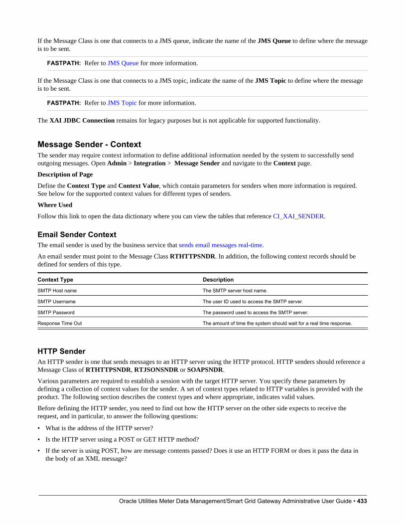
Oracle Utilities Meter Data Management/Smart Grid Gateway Administrative User Guide • 433
If the Message Class is one that connects to a JMS queue, indicate the name of the JMS Queue to define where the messageis to be sent.
FASTPATH: Refer to JMS Queue for more information.
If the Message Class is one that connects to a JMS topic, indicate the name of the JMS Topic to define where the messageis to be sent.
FASTPATH: Refer to JMS Topic for more information.
The XAI JDBC Connection remains for legacy purposes but is not applicable for supported functionality.
Message Sender - ContextThe sender may require context information to define additional information needed by the system to successfully sendoutgoing messages. Open Admin > Integration > Message Sender and navigate to the Context page.
Description of Page
Define the Context Type and Context Value, which contain parameters for senders when more information is required.See below for the supported context values for different types of senders.
Where Used
Follow this link to open the data dictionary where you can view the tables that reference CI_XAI_SENDER.
Email Sender ContextThe email sender is used by the business service that sends email messages real-time.
An email sender must point to the Message Class RTHTTPSNDR. In addition, the following context records should bedefined for senders of this type.
Context Type Description
SMTP Host name The SMTP server host name.
SMTP Username The user ID used to access the SMTP server.
SMTP Password The password used to access the SMTP server.
Response Time Out The amount of time the system should wait for a real time response.
HTTP SenderAn HTTP sender is one that sends messages to an HTTP server using the HTTP protocol. HTTP senders should reference aMessage Class of RTHTTPSNDR, RTJSONSNDR or SOAPSNDR.
Various parameters are required to establish a session with the target HTTP server. You specify these parameters bydefining a collection of context values for the sender. A set of context types related to HTTP variables is provided with theproduct. The following section describes the context types and where appropriate, indicates valid values.
Before defining the HTTP sender, you need to find out how the HTTP server on the other side expects to receive therequest, and in particular, to answer the following questions:
• What is the address of the HTTP server?
• Is the HTTP server using a POST or GET HTTP method?
• If the server is using POST, how are message contents passed? Does it use an HTTP FORM or does it pass the data inthe body of an XML message?
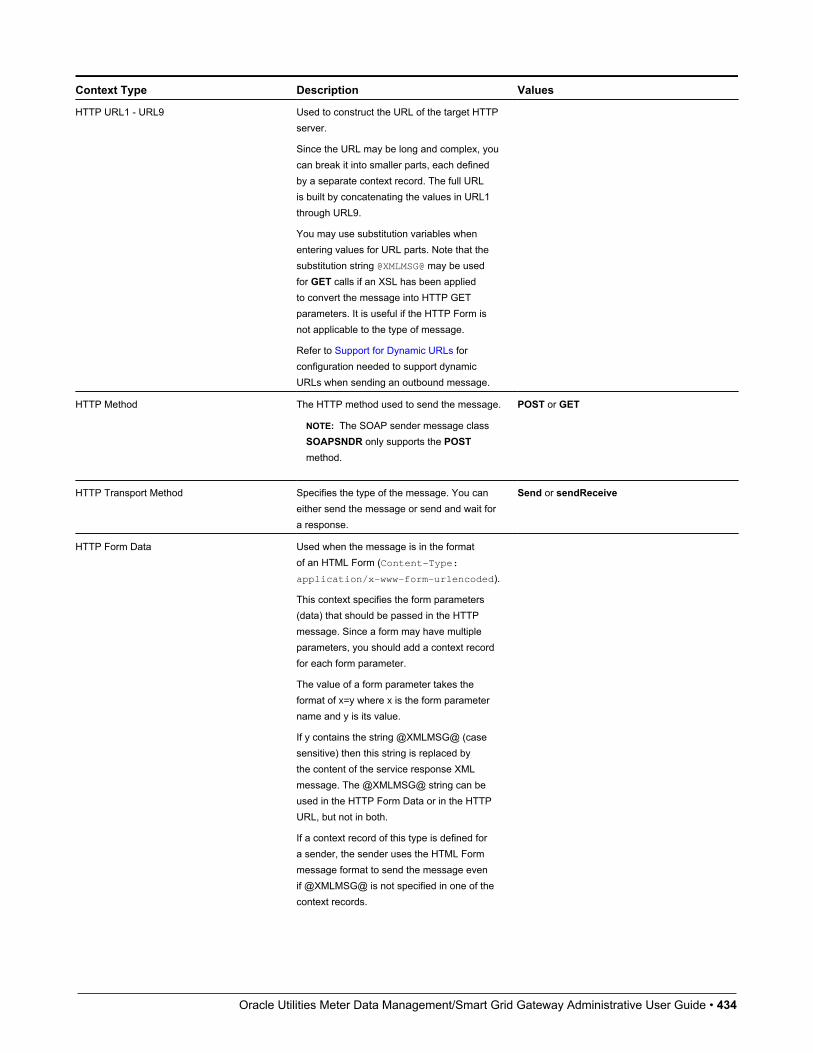
Oracle Utilities Meter Data Management/Smart Grid Gateway Administrative User Guide • 434
Context Type Description Values
HTTP URL1 - URL9 Used to construct the URL of the target HTTPserver.
Since the URL may be long and complex, youcan break it into smaller parts, each definedby a separate context record. The full URLis built by concatenating the values in URL1through URL9.
You may use substitution variables whenentering values for URL parts. Note that thesubstitution string @XMLMSG@ may be usedfor GET calls if an XSL has been appliedto convert the message into HTTP GETparameters. It is useful if the HTTP Form isnot applicable to the type of message.
Refer to Support for Dynamic URLs forconfiguration needed to support dynamicURLs when sending an outbound message.
HTTP Method The HTTP method used to send the message.
NOTE: The SOAP sender message classSOAPSNDR only supports the POSTmethod.
POST or GET
HTTP Transport Method Specifies the type of the message. You caneither send the message or send and wait fora response.
Send or sendReceive
HTTP Form Data Used when the message is in the formatof an HTML Form (Content-Type:application/x-www-form-urlencoded).
This context specifies the form parameters(data) that should be passed in the HTTPmessage. Since a form may have multipleparameters, you should add a context recordfor each form parameter.
The value of a form parameter takes theformat of x=y where x is the form parametername and y is its value.
If y contains the string @XMLMSG@ (casesensitive) then this string is replaced bythe content of the service response XMLmessage. The @XMLMSG@ string can beused in the HTTP Form Data or in the HTTPURL, but not in both.
If a context record of this type is defined fora sender, the sender uses the HTML Formmessage format to send the message evenif @XMLMSG@ is not specified in one of thecontext records.
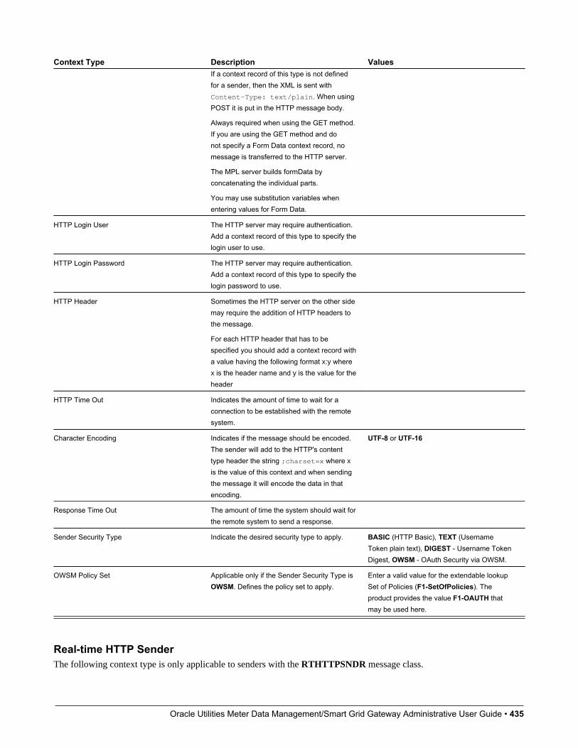
Oracle Utilities Meter Data Management/Smart Grid Gateway Administrative User Guide • 435
Context Type Description ValuesIf a context record of this type is not definedfor a sender, then the XML is sent withContent-Type: text/plain. When usingPOST it is put in the HTTP message body.
Always required when using the GET method.If you are using the GET method and donot specify a Form Data context record, nomessage is transferred to the HTTP server.
The MPL server builds formData byconcatenating the individual parts.
You may use substitution variables whenentering values for Form Data.
HTTP Login User The HTTP server may require authentication.Add a context record of this type to specify thelogin user to use.
HTTP Login Password The HTTP server may require authentication.Add a context record of this type to specify thelogin password to use.
HTTP Header Sometimes the HTTP server on the other sidemay require the addition of HTTP headers tothe message.
For each HTTP header that has to bespecified you should add a context record witha value having the following format x:y wherex is the header name and y is the value for theheader
HTTP Time Out Indicates the amount of time to wait for aconnection to be established with the remotesystem.
Character Encoding Indicates if the message should be encoded.The sender will add to the HTTP's contenttype header the string ;charset=x where xis the value of this context and when sendingthe message it will encode the data in thatencoding.
UTF-8 or UTF-16
Response Time Out The amount of time the system should wait forthe remote system to send a response.
Sender Security Type Indicate the desired security type to apply. BASIC (HTTP Basic), TEXT (UsernameToken plain text), DIGEST - Username TokenDigest, OWSM - OAuth Security via OWSM.
OWSM Policy Set Applicable only if the Sender Security Type isOWSM. Defines the policy set to apply.
Enter a valid value for the extendable lookupSet of Policies (F1-SetOfPolicies). Theproduct provides the value F1-OAUTH thatmay be used here.
Real-time HTTP SenderThe following context type is only applicable to senders with the RTHTTPSNDR message class.

Oracle Utilities Meter Data Management/Smart Grid Gateway Administrative User Guide • 436
Context Type Description
Content Type Populate a value here to override the Content-Type attribute in theHTTP header, which defaults to text/xml.
SOAP SenderA SOAP sender is an HTTP sender that automatically adds support for the SOAP format. For this type of sender (messageclass of SOAPSNDR), besides the context values listed above, the following context entries may also be supplied.
Context Type Description Values
Message Namespace URI Used to indicate a specific namespace to beincluded in messages for this sender. Notethat this value is used only when the ExternalMessage link to this sender is configured witha Namespace Option of Configured onSender.
SOAP Insert Timestamp Indicate whether a timestamp should beadded. Default value is 'N'.
Y or N
SOAP Expiration Delay (in seconds) Indicate an expiration delay to add to thetimestamp. The default value is 60.
NOTE: Refer to Add SOAP Header Parameters at Runtime for information about dynamically including SOAP Headerparameters when sending a message.
JMS SenderA JMS sender is one that sends messages to a JMS queue or JMS topic. JMS senders should reference a Message Class ofRTJMSQSNDR or RTJMSTSNDR, respectively.
The following parameters are used to connect to the JMS resource.
Context Type Description Values
JMS Message Type (Bytes(Y)/Text(N) Indicates whether the data is sent as a bytesmessage or as a text message.
Y or N
JMS User Name Enter the user name to connect to the JMSresource.
JMS User Password Enter the password to use to connect to theJMS resource.
JMS Header If JMS header values are required for themessage, use this context type.
For each JMS header that has to be specified,add a context record with a value having thefollowing format x:y where x is the headername and y is the value.
Defining Outbound Message TypesRefer to Outbound Messages for an overview of this functionality.
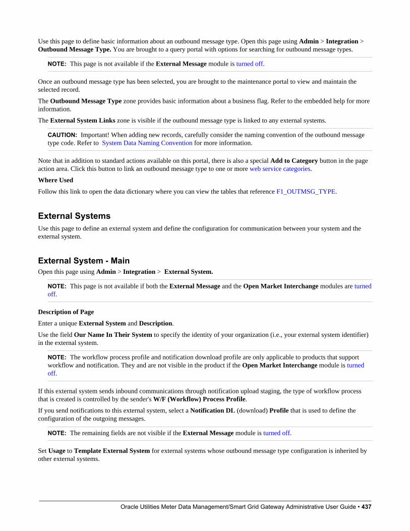
Oracle Utilities Meter Data Management/Smart Grid Gateway Administrative User Guide • 437
Use this page to define basic information about an outbound message type. Open this page using Admin > Integration > Outbound Message Type. You are brought to a query portal with options for searching for outbound message types.
NOTE: This page is not available if the External Message module is turned off.
Once an outbound message type has been selected, you are brought to the maintenance portal to view and maintain theselected record.
The Outbound Message Type zone provides basic information about a business flag. Refer to the embedded help for moreinformation.
The External System Links zone is visible if the outbound message type is linked to any external systems.
CAUTION: Important! When adding new records, carefully consider the naming convention of the outbound messagetype code. Refer to System Data Naming Convention for more information.
Note that in addition to standard actions available on this portal, there is also a special Add to Category button in the pageaction area. Click this button to link an outbound message type to one or more web service categories.
Where Used
Follow this link to open the data dictionary where you can view the tables that reference F1_OUTMSG_TYPE.
External SystemsUse this page to define an external system and define the configuration for communication between your system and theexternal system.
External System - MainOpen this page using Admin > Integration > External System.
NOTE: This page is not available if both the External Message and the Open Market Interchange modules are turnedoff.
Description of Page
Enter a unique External System and Description.
Use the field Our Name In Their System to specify the identity of your organization (i.e., your external system identifier)in the external system.
NOTE: The workflow process profile and notification download profile are only applicable to products that supportworkflow and notification. They and are not visible in the product if the Open Market Interchange module is turnedoff.
If this external system sends inbound communications through notification upload staging, the type of workflow processthat is created is controlled by the sender's W/F (Workflow) Process Profile.
If you send notifications to this external system, select a Notification DL (download) Profile that is used to define theconfiguration of the outgoing messages.
NOTE: The remaining fields are not visible if the External Message module is turned off.
Set Usage to Template External System for external systems whose outbound message type configuration is inherited byother external systems.

Oracle Utilities Meter Data Management/Smart Grid Gateway Administrative User Guide • 438
If the outbound message type configuration should be inherited from a template external system, define the TemplateExternal System. If this field is specified, the outbound message type collection displays the data defined for the templatesystem as display-only.
The Outbound Message Typeaccordion contains an entry for every type of outbound message defined for this externalsystem. For each type of outbound message identify its Outbound Message Type.
Define the Processing Method for messages of this type. Valid values are Batch, Real-time, SOA and XAI.
Define an appropriate Message Sender if the processing method is XAI or Real-time.
Namespace Option is used when your message should include a namespace in the resulting XML. The valid optionare Standard Namespace and Configured on Sender. If the value is Standard Namespace, the system will generate anamespace for the resulting WSDL with the following value: http://ouaf.oracle.com/outbound/AAA_BBB, where AAA isthe external system code and BBB is the outbound message type code. If the value is Configured on Sender, then the valueof the namespace is taken from the sender context with context type Message Namespace URI.
Define an appropriate Batch Control if the processing method is Batch.
If the message sender is one with a message class of RTJSONSNDR, indicate the JSON Conversion Method. The validvalues are Base JSON Conversion, Standard API Conversion and XSL Transformation. Refer to Real Time MessageConfiguration for more information about these methods and the additional configuration that may be applicable.
If the JSON Conversion Method is Base JSON Conversion, the Request Schema is enabled. Populate a data area thatdefines the schema for the XML format to convert the outbound message’s BO schema to prior to performing the JSONconversion. Refer to Real Time Message Configuration for more information.
The Message XSL is the schema used to transform information from the format produced by the system to a formatunderstood by the sender, who receives a message of this type. This is not applicable for Processing Method of SOA.
Enter the file name of the appropriate W3C Schema if you want to validate the message built for outbound messages forthis external system / outbound message type prior to being routed to their destination. Refer to Outbound Message SchemaValidation for more information. This is not applicable for Processing Method of SOA.
If the JSON Conversion Method is Base JSON Conversion, the Response Schema is enabled. Populate a data area thatdefines the schema for the XML format that the JSON message is initially converted to. The XML is then converted to BOXML. Refer to Real Time Message Configuration for more information.
Response XSL will have the same search service as is used for the existing Message XSL field. This field will only bedisplayed when the processing method is Real-time. Refer to Real Time Messages for more information on how it is used.
External System - Template UseIf you are viewing an external system whose usage is a Template External System, use this page to view the other externalsystems that reference this one. Open this page using Admin > Integration > External System and then navigate to theTemplate Use tab.
Description of Page
The tree shows every external system that references this external system as its template.
Message OptionThe Message Option page defines various system settings used by the system when processing external messages.
To define options for your environment, open Admin > Integration > Message Option.
Description of Page
The following options are supported.
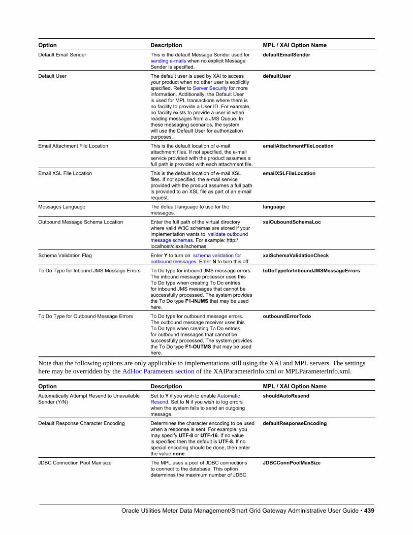
Oracle Utilities Meter Data Management/Smart Grid Gateway Administrative User Guide • 439
Option Description MPL / XAI Option NameDefault Email Sender This is the default Message Sender used for
sending e-mails when no explicit MessageSender is specified.
defaultEmailSender
Default User The default user is used by XAI to accessyour product when no other user is explicitlyspecified. Refer to Server Security for moreinformation. Additionally, the Default Useris used for MPL transactions where there isno facility to provide a User ID. For example,no facility exists to provide a user id whenreading messages from a JMS Queue. Inthese messaging scenarios, the systemwill use the Default User for authorizationpurposes.
defaultUser
Email Attachment File Location This is the default location of e-mailattachment files. If not specified, the e-mailservice provided with the product assumes afull path is provided with each attachment file.
emailAttachmentFileLocation
Email XSL File Location This is the default location of e-mail XSLfiles. If not specified, the e-mail serviceprovided with the product assumes a full pathis provided to an XSL file as part of an e-mailrequest.
emailXSLFileLocation
Messages Language The default language to use for themessages.
language
Outbound Message Schema Location Enter the full path of the virtual directorywhere valid W3C schemas are stored if yourimplementation wants to validate outboundmessage schemas. For example: http:/localhost/cisxai/schemas.
xaiOuboundSchemaLoc
Schema Validation Flag Enter Y to turn on schema validation foroutbound messages. Enter N to turn this off.
xaiSchemaValidationCheck
To Do Type for Inbound JMS Message Errors To Do type for inbound JMS message errors.The inbound message processor uses thisTo Do type when creating To Do entriesfor inbound JMS messages that cannot besuccessfully processed. The system providesthe To Do type F1-INJMS that may be usedhere.
toDoTypeforInboundJMSMessageErrors
To Do Type for Outbound Message Errors To Do type for outbound message errors.The outbound message receiver uses thisTo Do type when creating To Do entriesfor outbound messages that cannot besuccessfully processed. The system providesthe To Do type F1-OUTMS that may be usedhere.
outboundErrorTodo
Note that the following options are only applicable to implementations still using the XAI and MPL servers. The settingshere may be overridden by the AdHoc Parameters section of the XAIParameterInfo.xml or MPLParameterInfo.xml.
Option Description MPL / XAI Option NameAutomatically Attempt Resend to UnavailableSender (Y/N)
Set to Y if you wish to enable AutomaticResend. Set to N if you wish to log errorswhen the system fails to send an outgoingmessage.
shouldAutoResend
Default Response Character Encoding Determines the character encoding to be usedwhen a response is sent. For example, youmay specify UTF-8 or UTF-16. If no valueis specified then the default is UTF-8. If nospecial encoding should be done, then enterthe value none.
defaultResponseEncoding
JDBC Connection Pool Max size The MPL uses a pool of JDBC connectionsto connect to the database. This optiondetermines the maximum number of JDBC
JDBCConnPoolMaxSize
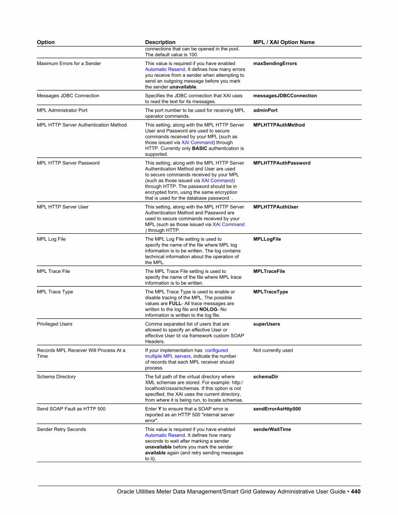
Oracle Utilities Meter Data Management/Smart Grid Gateway Administrative User Guide • 440
Option Description MPL / XAI Option Nameconnections that can be opened in the pool.The default value is 100.
Maximum Errors for a Sender This value is required if you have enabledAutomatic Resend. It defines how many errorsyou receive from a sender when attempting tosend an outgoing message before you markthe sender unavailable.
maxSendingErrors
Messages JDBC Connection Specifies the JDBC connection that XAI usesto read the text for its messages.
messagesJDBCConnection
MPL Administrator Port The port number to be used for receiving MPLoperator commands.
adminPort
MPL HTTP Server Authentication Method This setting, along with the MPL HTTP ServerUser and Password are used to securecommands received by your MPL (such asthose issued via XAI Command) throughHTTP. Currently only BASIC authentication issupported.
MPLHTTPAuthMethod
MPL HTTP Server Password This setting, along with the MPL HTTP ServerAuthentication Method and User are usedto secure commands received by your MPL(such as those issued via XAI Command)through HTTP. The password should be inencrypted form, using the same encryptionthat is used for the database password. .
MPLHTTPAuthPassword
MPL HTTP Server User This setting, along with the MPL HTTP ServerAuthentication Method and Password areused to secure commands received by yourMPL (such as those issued via XAI Command) through HTTP.
MPLHTTPAuthUser
MPL Log File The MPL Log File setting is used tospecify the name of the file where MPL loginformation is to be written. The log containstechnical information about the operation ofthe MPL.
MPLLogFile
MPL Trace File The MPL Trace File setting is used tospecify the name of the file where MPL traceinformation is to be written.
MPLTraceFile
MPL Trace Type The MPL Trace Type is used to enable ordisable tracing of the MPL. The possiblevalues are FULL- All trace messages arewritten to the log file and NOLOG- Noinformation is written to the log file.
MPLTraceType
Privileged Users Comma separated list of users that areallowed to specify an effective User oreffective User Id via framework custom SOAPHeaders.
superUsers
Records MPL Receiver Will Process At aTime
If your implementation has configuredmultiple MPL servers, indicate the numberof records that each MPL receiver shouldprocess.
Not currently used
Schema Directory The full path of the virtual directory whereXML schemas are stored. For example: http:/localhost/cisxai/schemas. If this option is notspecified, the XAI uses the current directory,from where it is being run, to locate schemas.
schemaDir
Send SOAP Fault as HTTP 500 Enter Y to ensure that a SOAP error isreported as an HTTP 500 "internal servererror".
sendErrorAsHttp500
Sender Retry Seconds This value is required if you have enabledAutomatic Resend. It defines how manyseconds to wait after marking a senderunavailable before you mark the senderavailable again (and retry sending messagesto it).
senderWaitTime
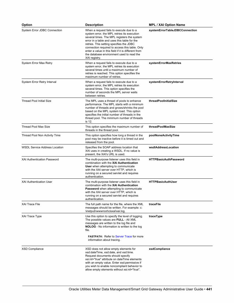
Oracle Utilities Meter Data Management/Smart Grid Gateway Administrative User Guide • 441
Option Description MPL / XAI Option NameSystem Error JDBC Connection When a request fails to execute due to a
system error, the MPL retries its executionseveral times. The MPL registers the systemerror in a table and uses this table for theretries. This setting specifies the JDBCconnection required to access this table. Onlyenter a value in this field if it is different fromthe database environment used to read theXAI registry.
systemErrorTableJDBCConnection
System Error Max Retry When a request fails to execute due to asystem error, the MPL retries its executionseveral times until a maximum number ofretries is reached. This option specifies themaximum number of retries.
systemErrorMaxRetries
System Error Retry Interval When a request fails to execute due to asystem error, the MPL retries its executionseveral times. This option specifies thenumber of seconds the MPL server waitsbetween retries.
systemErrorRetryInterval
Thread Pool Initial Size The MPL uses a thread of pools to enhanceperformance. The MPL starts with a minimumnumber of threads and grows/shrinks the poolbased on the MPL system load. This optionspecifies the initial number of threads in thethread pool. The minimum number of threadsis 12.
threadPoolInitialSize
Thread Pool Max Size This option specifies the maximum number ofthreads in the thread pool.
threadPoolMaxSize
Thread Pool Non Activity Time This option specifies how long a thread in thepool may be inactive before it is timed out andreleased from the pool.
poolNoneActivityTime
WSDL Service Address Location Specifies the SOAP address location thatXAI uses in creating a WSDL. If no value ispresent, the XAI's URL is used.
wsdlAddressLocation
XAI Authentication Password The multi-purpose listener uses this field incombination with the XAI AuthenticationUser when attempting to communicatewith the XAI server over HTTP, which isrunning on a secured servlet and requiresauthentication.
HTTPBasicAuthPassword
XAI Authentication User The multi-purpose listener uses this field incombination with the XAI AuthenticationPassword when attempting to communicatewith the XAI server over HTTP, which isrunning on a secured servlet and requiresauthentication.
HTTPBasicAuthUser
XAI Trace File The full path name for the file, where the XMLmessages should be written. For example: c:\inetpub\wwwroot\cisxai\xai.log.
traceFile
XAI Trace Type Use this option to specify the level of logging.The possible values are FULL - All XMLmessages are written to the log file andNOLOG - No information is written to the logfile.
FASTPATH: Refer to Server Trace for moreinformation about tracing.
traceType
XSD Compliance XSD does not allow empty elements forxsd:dateTime, xsd:date, and xsd:time.Request documents should specifyxsi:nil="true" attribute on dateTime elementswith an empty value. Enter xsd:permissive ifyou wish to enable noncompliant behavior toallow empty elements without xsi:nil="true".
xsdCompliance

Oracle Utilities Meter Data Management/Smart Grid Gateway Administrative User Guide • 442
Option Description MPL / XAI Option NameEnter xsd:strict if it is desired to enforce strictcompliance on dateTime, date, and timeelements. The default value is xsd:strict.
XSL Directory The full path of the virtual directory whereXSL transformation scripts are located. XSLtransformation scripts can be defined for eachservice. By default, this is the same directoryas the schemas directory.
XSLDir
Managing Outbound MessagesUse this page to view information about outbound messages.
Outbound Message - MainOpen this page using Menu > Integration > Outbound Message.
Description of Page
Outbound Message ID is the system-assigned unique identifier of the outbound message. These values only appear afterthe outbound message is added to the database.
The Processing Method indicates whether this record will be processed by a Batch extract process, through the XAI toolor Real-time. The value defined on the external system / outbound message type collection populates this value.
When records are created with a processing method of Batch, the system sets Extract to Can Be Extracted. Change thevalue to Not to be extracted if there is some reason that processing should be held for this record.
For records with a processing method of Batch, Batch Control indicates the process that will extract this record. This valueis populated based on the on the external system / outbound message type's value. Batch Number indicates in which batchrun this record was extracted or will be extracted.
The Retry Count is used by the XAI tool to keep track of how many times the tool tried to process this record and couldnot process the record, resulting in an error.
The Creation Date indicates the date that this record was created.
If the processing method is XAI, Status defines the state of the outbound message record. Refer to Lifecycle of OutboundMessage for more information.
For messages in error status, click Pending to change the status back to pending for reprocessing.
For messages in pending, error, or in progress status, click Cancel to cancel the message and prevent further processing.
Outbound Message - MessageUse this page to view the XML source used to build an outbound message. Open this page using Menu > Integration > Outbound Message and then navigate to the Message tab.
Description of Page
The XML Source is displayed.
If a message XSL is defined on the external system / outbound message type record linked to this outbound message, theShow XML button is enabled. Click this button to view the XML that is a result of applying the Message XSL to the XMLsource.
Oracle Utilities Meter Data Management/Smart Grid Gateway Administrative User Guide • 443
Outbound Message - ResponseUse this page to display the XML response. Open this page using Menu > Integration > Outbound Message and thennavigate to the Response tab.
Description of Page
The XML Response and optionally the XML Raw Response is displayed.
XML Response displays the response data from the system called by the real-time message. If a response XSL is definedon the external system / outbound message type record linked to this outbound message, a transform is performed and theXML Raw Response displays the original, unchanged response.
Web Service AdaptersThe base product provides a configuration object called Web Service Adapter that is used to help build configurationobjects to allow for functionality in the system to initiate a web service call from within the system. A Web Service Adapterprovides the following functionality:
• WSDL (web service description language) import. An implementer can use the WSDL import functionality to read thedetails of a WSDL into the system
• Internal API generation. The system generates internal data areas that have two main purposes: they provide the API forcustom code to define the appropriate input and they provide output data for the web service call using Oracle UtilitiesApplication Framework schema language. In addition, the web service dispatcher uses element mapping defined in thedata areas to transform the internal XML into the structure expected by the external system as described in the WSDL.
• Defines the URL needed to perform the web service call at runtime.
Understanding Web Service AdaptersThe following topics describe the system functionality in more detail.
Importing a WSDLConfiguring a Web Service Adapter starts by identifying the WSDL (the web service description language documentused to define the interface) that will be provided by the external system. The following steps describe the base productfunctionality provided to allow a user to import a WSDL.
• Navigate to the Web Service Adapter page in add mode and select the appropriate base business object.
• Enter a meaningful Web Service Name and appropriate descriptions.
• Provide the URL of the given WSDL.
• Click Import to retrieve the details of the WSDL. The system then parses the WSDL details and populates the WSDLService Name, WSDL Source, WSDL Port, URL and a list of Operations (methods) defined in the WSDL.
• Determine which Operations should be active based on the business requirements for invoking this web service. Activeoperations are those that the implementation is planning to invoke from the system. These require appropriate requestand response data areas generated for them. The following section provides more information about that.
• Specify the appropriate Security Type to configure the type of security to use when invoking this web service.
• Click Save.
At this point, a web service adapter record is created in pending status. The next step is to generate the request and responsedata areas for the operations configured as active.
Oracle Utilities Meter Data Management/Smart Grid Gateway Administrative User Guide • 444
Generating Request and Response Data AreasEach active operation for the web service adapter requires a pair of data areas, request and response, that represent therequest and response XML messages for the operation.
The base product provides steps to generate the data areas as follows:
• As described in the Importing a WSDL section above, the operations listed in the WSDL are generated for the webservice adapter and the implementer should indicate which operation to activate.
• After saving the pending web service adapter, the display lists all the active operations and for each one includes aGenerate button.
• After clicking Generate for an operation, a window appears where the names of the new Request and Response DataAreas may be defined. Click Save to generate the data areas.
The generated data areas provide the API for the implementer to use when implementing the web service call in anappropriate algorithm or service in the system. The data areas contain the appropriate mapping from the elements that theimplementer works within the code that invokes the web services and the WSDL definitions.
To facilitate generating the request and response data areas, the base product invokes a special business service used tocreate the appropriate mapping. The business service is defined as a BO option on the Web Service Adapter business object.This allows an implementation to provide a custom business service to further enhance the request and response mappingwhere appropriate.
NOTE:Generated data areas. It is possible to edit and modify the generated data areas after they are created. An implementercan change element names or remove unneeded elements if desired. Manually changing the generated data areas must bedone only when absolutely necessary. This is because the system is not able to validate manual changes and issues withthe data areas would only be detected at run time.
Activating Web Service AdaptersThe business objects provided by the base package for web service adapters include a simple lifecycle of Pending andActive. Configure the web service adapter and its data areas while in Pending status and activate it when it is ready to beimplemented in the appropriate system functionality.
Invoking Web ServicesTo make a call to a web service using a web service adapter, the system has provided a Web Service Dispatcher businessservice (F1-InvokeWebService) to submit a web service call. The calling program is responsible for retrieving all theinformation to correctly populate the request data required by the web service call before invoking the business service.
NOTE:Refer to the detailed description of the business service for more information.
LimitationsThe following points highlight limitations associated with the types of web services that the system supports:
• It is possible for one WSDL document to contain definitions for several web services. The system currently supportsonly one port or service per WSDL document.
• It is possible for a WSDL to support multiple message patterns. The system currently supports only request / response.
Oracle Utilities Meter Data Management/Smart Grid Gateway Administrative User Guide • 445
Setting Up Web Service AdaptersUse the Web Service Adapter portal to define the configuration needed to communicate with an external system using a webservice call. Open this page using Admin > Integration > Web Service Adapter. You are brought to a query portal withoptions for searching for web service adapters.
Once a web service adapter has been selected, you are brought to the maintenance portal to view and maintain the selectedrecord.
The Web Service Adapter zone provides basic information about the web service annotation type.
Please see the zone's help text for information about this zone's fields.
FASTPATH: Refer to Understanding Web Service Adapters for information about common web service adapterfunctionality.
Sending EmailThe framework provides the ability to initiate an email from within the system. The following topics highlight thefunctionality available.
• Sending email “real time” using a specific business service. The framework provides a business service F1–EmailService that supports sending an email. The schema supports elements for all the information required to createan email real time. It also supports sending attachments. The SMTP information (host, user name and password)may be provided or may be defined on a message sender, that may be provided as input. In addition, the businessservice supports using a default message sender defined as a message option. Review the business service schema forinformation about the input elements.
NOTE: Validating attachments. If a Validate Email Attachment algorithm is plugged into the installation record, it iscalled to validate the attachments supplied, if applicable.
NOTE: Retry setting. An option in the system properties file allows your implementation to configure the numberof times to retry (if any) if the SMTP server is unavailable. Refer to the server administration guide for moreinformation.
• Using an outbound message to send an email. This option allows for different variations as described in OutboundMessages.
• Some emails may be created en masse (for example a large group of emails routed to users for a given set of To Doentries). In this case, the records can be created in the staging table for processing using OSB.
• Messages may still be sent real time using one of two business services described in Real Time Messages. This optionis an alternative to the dedicated email service described above when aspects of the outbound message functionalityare needed, such as the ability to instantiate a record as an audit or to include additional logic via BO plug-ins as partof sending the email.
Web Service CategoryThe product provides the ability to categorize web services that are defined in the system. The term web services refers toOutbound Message Types, Inbound Web Services, and for those implementations where they are applicable, XAI InboundServices.
Oracle Utilities Meter Data Management/Smart Grid Gateway Administrative User Guide • 446
A given web service may be linked to more than one category. The product supplies web service categories and mostbase delivered web services are configured with appropriate categories. Implementations may define new categories andmay link custom web services to base delivered categories or to custom categories. In addition, implementations maylink additional categories to base delivered web services. However, implementations may not remove base delivered webservices from base delivered categories.
If your implementation uses the Integration Cloud Service Catalog, the integration provides the categories for each webservice that is sent to the catalog.
The web service category portal supports adding and removing web services from the category. In addition, the OutboundMessage Type portal and Inbound Web Service portal each provide a page action button to Add to Category.
Defining Web Service CategoriesRefer to Web Service Category for an overview of this functionality.
Use this page to define basic information about a web service category. Open this page using Admin > Integration > WebService Category. You are brought to a query portal with options for searching for web service categories.
NOTE: This page is not available if the External Message module is turned off.
Once a web service category has been selected, you are brought to the maintenance portal to view and maintain the selectedrecord.
The Web Service Category zone provides basic information about a web service category.
CAUTION: Important! When adding new records, carefully consider the naming convention of the web service categorycode. Refer to System Data Naming Convention for more information.
Once a web service category exists, an Add Web Services zone is provided to find and select web services to link to theweb service category.
When viewing a category that already has web services linked to it, they are visible in the zone Included Web Services .This zone allows a user to remove a customer owned web service from the list.
Where Used
Follow this link to open the data dictionary where you can view the tables that reference F1_WEB_CAT.
JMS Message BrowserThe JMS Message Browser portal allows you to select a JMS queue and view messages currently in the queue.
In order for a JMS queue to be available on the portal, a message sender must be defined that is configured for theappropriate JMS queue with the credentials to connect to the queue.
• If your organization sends real-time outgoing messages to a JMS queue, this configuration would exist as per the detailsin Real-Time Message Configuration.
• If inbound web service messages are routed to the system via a JMS queue, no configuration is needed in the system.However, if you would like to view the messages in the queue in the JMS message browser portal, configuration for theJMS queues as described for outgoing messages is required.
Navigate to the portal using Main > Integration > JMS Message Browser.
The JMS Senders zone provides a list of configured message senders eligible for selection.
The JMS Message List zone is visible for the JMS Sender broadcast from the first zone. This zone supports selecting oneor more records to delete from the queue. Use the message selector to limit the results to messages that satisfy the message

Oracle Utilities Meter Data Management/Smart Grid Gateway Administrative User Guide • 447
selector. This uses standard JMS API message selector functionality. Refer to the zone embedded help for information aboutthe supported syntax.
The JMS Message Details zone displays a message broadcast from the list zone.
Integration Cloud Service CatalogIntegration Cloud Service (ICS) is an offering that serves as integration infrastructure for Oracle cloud solutions. Theproduct provides an adapter for ICS to streamline integration between your edge application and ICS.
ICS AdapterThe product provides a web service that ICS can invoke (referred to here as the ICS adapter) to retrieve information aboutavailable web services supported by one or more edge products. The information retrieved by the adapter includes the name,the source system, the WSDL location and namespace.
It is possible that not every web service supported by an edge product is managed by ICS. In order to only include theappropriate web services in the ICS adapter, configuration is needed to identify which web services to include.
The web service catalog is used to identify the records that should be retrieved by the adapter:
• For inbound messages, the system supports both the use of inbound web services and XAI inbound services that aredeployed via IWS. Each IWS or XAI inbound service that should be included in the catalog must be flagged. Note thatonly deployed services are returned to the catalogue.
• For outbound message, the system requires the creation of an External System that includes each outbound message typethat the external system receives. For outbound messages that are integrated through ICS, the external system itself willrepresent ICS. Rather than identifying each outbound message type to include in the catalog, only the external systemneeds to be flagged. The ICS adapter will return web service information for all the outbound message types configuredfor the external system.
FASTPATH: Refer to Maintaining the Web Service Catalog for more information.
Master and Subordinate CatalogsFor installations that support multiple edge products, each with their own list of web services, the system includesfunctionality to allow ICS to make one call to the adapter and receive all the services for all the products. This is handledby nominating one of the edge products as the "master". The "master" receives the ICS adapter request and this productincludes configuration for how to connect to the other products to gather their web service catalog information and merge itwith its own web services.
Web Service Catalog ConfigurationThe topics in this section describe the configuration needed in your edge application to integrate with ICS.
Web Service Catalog Master ConfigurationThe Service Catalog Configuration (master configuration) record defines several system wide settings related tointegrating with the service catalog.
It includes configuration for the WSDL base URL. Note that this element supports the functionality described inReferencing URIs.
This includes defining subordinate servers if the current product is considered the "master". The record supports encryptingthe subordinate server password. To do this, additional configuration is required. You need to define an entry in the'encryption' feature configuration referencing USER_PASSWORD in the field= setting and ENCR_USER_PASSWORD
Oracle Utilities Meter Data Management/Smart Grid Gateway Administrative User Guide • 448
in the encryptedField= setting. Refer to Application Encryption for more information and for additional configurationneeded.
For more information about specific fields in the master configuration, refer to the embedded help.
Maintaining the Web Service CatalogRefer to Integration Cloud Service Catalog for an overview of web service catalog functionality.
To add or remove services that are reported to the ICS catalog, navigate to the portal using Admin > Integration > WebService Catalog.
The Catalog zone provides a list of services that are currently in the catalog. Users may use this zone to remove servicesfrom the catalog.
The Candidate Services zone provides a list of external systems, inbound web services and XAI inbound services (ifapplicable) that are not currently linked to the catalog. Users may use this zone to add services to the catalog.
NOTE: For inbound web services and XAI inbound services, they may be selected for the catalogue at any time.However, only deployed services are returned to the catalogue by the ICS adapter.
Mobile Remote MessagesThis section provides information about the functionality supporting a message exchange with a mobile application.
About Remote MessagesRemote messages are used to send data to and from a mobile device. This section describes the mechanism that allows themain application to send and receive messages to a mobile device.
Messages From A Mobile DeviceAsynchronous messages from the field may be received continually throughout the day. The processing of such messagesensures against data loss by saving the message before processing it. This approach guarantees message delivery despite ofpotential processing errors. Refer to Guaranteed Delivery for more information.
If message processing fails at any time, a To Do entry is created for a user to review and resolve the problem. You can viewthe content of any message, try to reprocess the message as is, or edit the message content and then reprocess.
Some errors may arise due to a temporary situation and may resolve on their own when the system tries to process theerroneous message again by the remote message monitor batch process.
NOTE: It is important to schedule the Remote Message Monitor batch process to retry failed messages periodically.Refer to F1-RMMSG batch control for more information.
Messages To A Mobile DeviceDepending on your mobile application requirements, certain business events triggered by the main application may need tobe communicated to a mobile user’s specific mobile device.
The payload and rules associated with such message are defined using a Message To Devicemobile component. You mayuse the Add Message To Device (F1-AddMessageToDevice) business service to post a message to be processed by amobile device. Refer to the description of this business service for more information.
Oracle Utilities Meter Data Management/Smart Grid Gateway Administrative User Guide • 449
The mobile device periodically polls for queued messages and process them in the order they were posted. You mayconfigure an expiry time on the message’s mobile component. If specified, messages of this type that have not been pickedup by the specified time are automatically discarded by the remote message monitor batch program.
NOTE: It is important to schedule the Remote Message Monitor batch process to expire messages and finalize the stateof processed messages. Refer to F1-RMMSG batch control for more information.
Maintaining Remote MessagesThis portal is used to view a messages sent to and from a mobile device.
Refer to About Remote Messages for more information.
You can access this portal from the Main > Integration > Mobile Remote Message. You are brought to a query portalwith options for searching for a specific remote message. Once a remote message has been selected, you are brought to themaintenance portal to view and maintain the selected record.
The Remote Message zone on the portal's Main tab page provides information about the remote message, including thevarious maintenance actions applicable to its current state.
XML Application IntegrationThis section describes the XML Application Integration (XAI) utility, which enables you to configure your system toreceive information from and to send information to external applications using Extensible Markup Language (XML)documents.
NOTE: The XAI functionality is legacy functionality and not recommended for new implementations. The topics for thefunctionality outlined in the previous sections describe the recommended features for supporting sending and receivingexternal messages. The XAI information remains in the documentation for upgrade purposes.
The Big Picture of XAIThe XML Application Integration (XAI) module provides the tools and infrastructure that businesses require for integratingtheir applications with your product. The integration your product with other systems across organizational boundaries orbusiness is made possible, regardless of the platforms or operating system used. XAI provides an integration platform thatenables the following:
• Integrate with Customer Relationship Management (CRM) systems
• Provide information feeds for web based customer portals
• Fit seamlessly with web based applications
• Facilitate fast implementation of batch interfaces
• Integrate with other XML compliant enterprise applications
XAI exposes system business objects as a set of XML based web services. The service can be invoked via differentmethods, e.g., Hypertext Transfer Protocol (HTTP) or Java Message Service (JMS). Consequently, any application or toolthat can send and receive XML documents can now access the rich set of system business objects. Business-to-Business(B2B) or Business-to-Consumer (B2C) integration with other enterprise applications as well as the setup of web portals ismade very simple and straightforward.
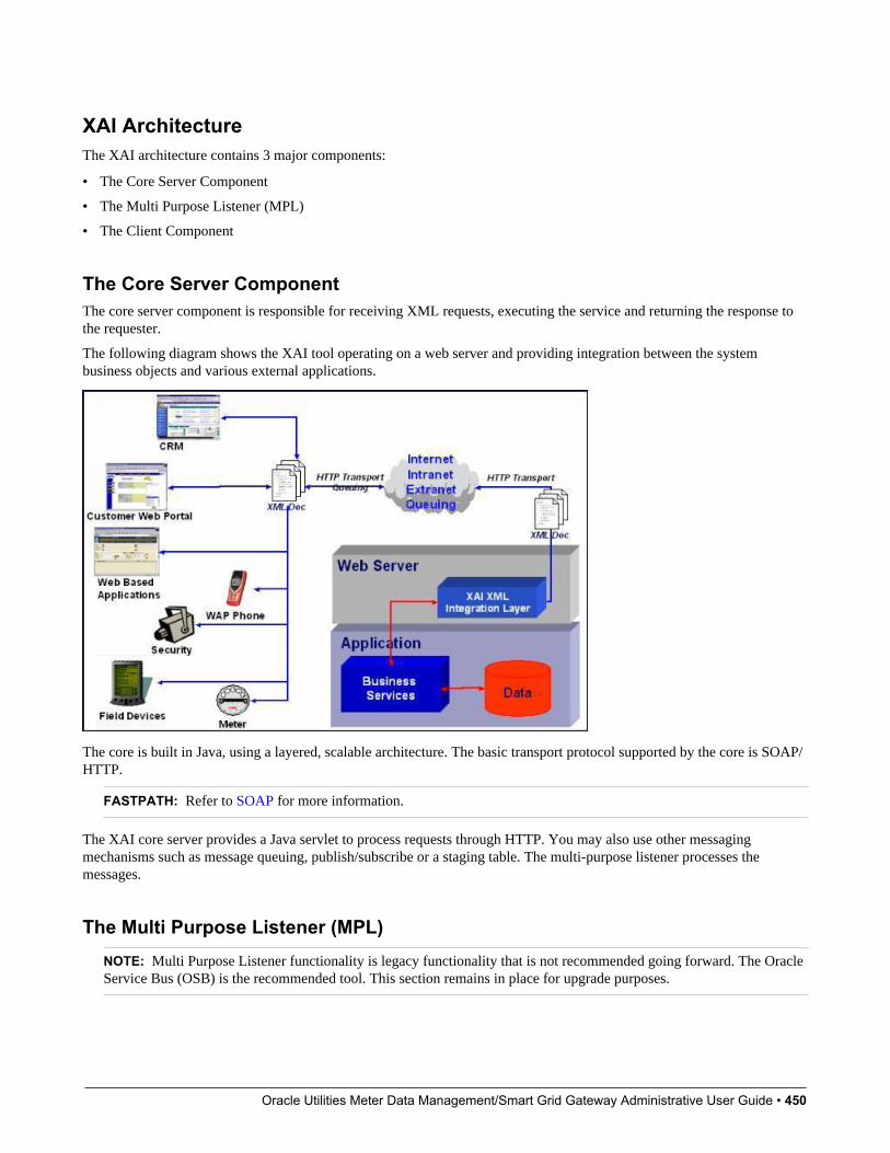
Oracle Utilities Meter Data Management/Smart Grid Gateway Administrative User Guide • 450
XAI ArchitectureThe XAI architecture contains 3 major components:
• The Core Server Component
• The Multi Purpose Listener (MPL)
• The Client Component
The Core Server ComponentThe core server component is responsible for receiving XML requests, executing the service and returning the response tothe requester.
The following diagram shows the XAI tool operating on a web server and providing integration between the systembusiness objects and various external applications.
The core is built in Java, using a layered, scalable architecture. The basic transport protocol supported by the core is SOAP/HTTP.
FASTPATH: Refer to SOAP for more information.
The XAI core server provides a Java servlet to process requests through HTTP. You may also use other messagingmechanisms such as message queuing, publish/subscribe or a staging table. The multi-purpose listener processes themessages.
The Multi Purpose Listener (MPL)NOTE: Multi Purpose Listener functionality is legacy functionality that is not recommended going forward. The OracleService Bus (OSB) is the recommended tool. This section remains in place for upgrade purposes.
Oracle Utilities Meter Data Management/Smart Grid Gateway Administrative User Guide • 451
The Multi Purpose Listener (MPL) is a multi-threaded Java server that constantly reads XML requests from various externaland internal data sources, such as a Java Message Service (JMS) message queue, a JMS topic or system staging tables.
The MPL can be used to process inbound messages (those sent by an external application to invoke a system service),or outgoing messages (those sent by your product to external applications). The MPL uses different receivers to processmessages from different data sources.
A receiver is implemented using 3 distinct layers:
• The Receiving Layer
• The Execution Layer
• The Response Layer
The Receiving LayerThis layer deals with polling various locations to determine if new records, files or incoming requests exist. The variouslocations include:
• Staging tables, including XAI staging control, XAI upload staging, notification download staging (certain products only),and outbound message.
• An external directory that contains a file, for example a comma delimited file or an XML file.
• A JMS queue/topic.
A separate receiver is defined to read requests from each of these locations. When the MPL server starts, it looks for alldefined active receivers in the XAI Receiver table, and for each receiver it starts a thread that constantly fetches messagesfrom the message source.
Once a request message is read, it is passed to an execution thread that implements the execution layer. Each receiverreferences an Executer that is responsible for executing the request.
Configuring Multiple MPL ServersA single MPL server may only run one of each of the above staging table receivers for a given JDBC connection. Toenhance the performance of the processing of the staging tables, you may define multiple MPL servers where each one runsthe active receivers defined in the receiver table.
To ensure that each staging table receiver processes its own set of records in the staging table, the receiver selects a setnumber of records (specified as Message optionNumber of Records an MPL Receiver Will Process At a Time) andmarks those records with the IP address and port number of the MPL.
The Execution LayerThe execution layer sends the XML request to the XAI core server and waits for a response.
NOTE: Currently the only type of executer supported is the XAI servlet running either on an XAI server or locallyunder the MPL. However the architecture allows for executing a request on other execution environments.
The executer is invoked and is passed in an XAI Inbound Service that specifies an XML request schema and an adapter.Adapters tell XAI what to do with a request. The adapters point to a specific Java class that renders a service.
For example you can configure an Adapter to invoke any published application object (by pointing it to the appropriate javaclass). This adapter accesses system objects through the page service. You can think of an adapter as a plug-in component.
Once the executer processes the request and a response is received, it is transferred to the next layer, the response layer.
Oracle Utilities Meter Data Management/Smart Grid Gateway Administrative User Guide • 452
The Response LayerThe response layer is responsible for "responding" to the execution. The responses are handled by invoking an appropriatesender defined on the receiver's response information. Each sender defined in the system knows how to process its response.For example:
• The JMS queue sender and the JMS topic sender post responses to the appropriate queue / topic.
• The staging control sender handles errors received during the execution of the staging control request.
• The upload staging sender updates the status of the upload staging record based on the success or failure of the stagingupload request.
• The download staging sender is a bit unusual because it is helping to build the message being sent (Oracle CustomerCare and Billing only).
NOTE: There are some cases where a response is not applicable. For example, the file scan receiver creates a stagingcontrol record to process a file that exists in a directory. There is no "response" applicable for executing this request.
The XAI Client ComponentThe XAI Client component is the set of online control tables and tools used to manage your XAI environment.
The Schema Editor is a tool used to create and maintain XAI schemas.
FASTPATH: Refer to XAI Schema for more information.
The Registry is a term used to refer to all the tables required to "register" a service in the system. It includes the XAIInbound Service and a set of control tables defining various options.
The Trace Viewer is installed with your XAI client tools and is used to view traces created on the XAI server.
XML Background TopicsThe following section introduces some background information related to XML.
XAI SchemasNOTE: Business Adapter. The BusinessAdapter adapter supports communication to configuration tool objects: business objects, business services and service scripts through their own schema API. When communicating to theseobjects, it is not necessary to create XAI schemas for the schemas associated with the objects. As a result, there is noneed to use the XAI schema editor when defining XAI Inbound Services for this adapter.
At the core of XAI are XML web services based on XML schemas. XML schemas define the structure of XML documentsand are the infrastructure of e-business solutions. They are used to bridge business applications and enable transactionautomation for e-commerce applications. Industry standard schemas document common vocabularies and grammars,enhancing collaboration and standardization. Validating XML processors utilize XML schemas to ensure that the rightinformation is made available to the right user or application.
The system exposes its application objects as XML schemas that define the interface to system services. Every service(e.g., CreatePerson or AccountFinancialHistory) is defined using a pair of schemas: the Request Schema and the ResponseSchema. The request and response schema can be identical.
The Request Schema defines the XML document structure describing the "inputs" for a service.
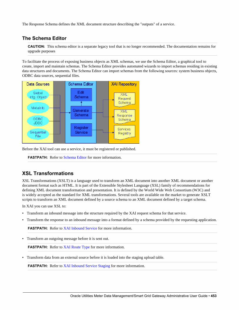
Oracle Utilities Meter Data Management/Smart Grid Gateway Administrative User Guide • 453
The Response Schema defines the XML document structure describing the "outputs" of a service.
The Schema EditorCAUTION: This schema editor is a separate legacy tool that is no longer recommended. The documentation remains forupgrade purposes
To facilitate the process of exposing business objects as XML schemas, we use the Schema Editor, a graphical tool tocreate, import and maintain schemas. The Schema Editor provides automated wizards to import schemas residing in existingdata structures and documents. The Schema Editor can import schemas from the following sources: system business objects,ODBC data sources, sequential files.
Before the XAI tool can use a service, it must be registered or published.
FASTPATH: Refer to Schema Editor for more information.
XSL TransformationsXSL Transformations (XSLT) is a language used to transform an XML document into another XML document or anotherdocument format such as HTML. It is part of the Extensible Stylesheet Language (XSL) family of recommendations fordefining XML document transformation and presentation. It is defined by the World Wide Web Consortium (W3C) andis widely accepted as the standard for XML transformations. Several tools are available on the market to generate XSLTscripts to transform an XML document defined by a source schema to an XML document defined by a target schema.
In XAI you can use XSL to:
• Transform an inbound message into the structure required by the XAI request schema for that service.
• Transform the response to an inbound message into a format defined by a schema provided by the requesting application.
FASTPATH: Refer to XAI Inbound Service for more information.
• Transform an outgoing message before it is sent out.
FASTPATH: Refer to XAI Route Type for more information.
• Transform data from an external source before it is loaded into the staging upload table.
FASTPATH: Refer to XAI Inbound Service Staging for more information.

Oracle Utilities Meter Data Management/Smart Grid Gateway Administrative User Guide • 454
SOAPSOAP stands for Simple Object Access Protocol. The SOAP "Envelope" is the wrapping element of the whole requestdocument that may be used by messages going through the XAI tool.
The following diagram shows a simple XML request using the SOAP standard.
XPATHThe XML Path Language (XPath) is an expression language used by XSLT to access or refer to parts of an XML document.It is part of the XSL recommendations maintained by the W3C. XPath provides the syntax for performing basic queriesupon your XML document data. It works by utilizing the ability to work with XML documents as hierarchically structureddata sets.
In the following XML document, some examples of XPath references are:
• authors/author/name
• authors/*/name
• authors/author[nationality]/name
• authors/author[nationality='Russian']/name
• authors/author[@period="classical"]
In the XAI tool, XPath is used to construct outgoing messages.
Oracle Utilities Meter Data Management/Smart Grid Gateway Administrative User Guide • 455
Server SecurityXAI server security supports the basic HTTP authentication mechanism as well as web service security (WS-Security)to authenticate the user requesting service. When authenticating using WS-Security, the SOAP header contains theauthenticating information.
The base package provides two XAI server URLs, one that uses basic HTTP authentication ('/classicxai') and another thatsupports both methods ('/xaiserver'). Regardless of which authentication method is practiced, it is the latter you shouldexpose as your main XAI server. The main XAI servlet gathers authentication information from the incoming request(HTTP or SOAP header) and further calls the internal ("classic") servlet for processing.
The "classic" XAI server security uses the basic HTTP authentication mechanism to authenticate the user requestingservice. It assumes the requester has been authenticated on the Web server running the XAI servlet using the standardHTTP (or HTTPS) basic authentication mechanism. The authenticated user-id is passed to the application server, which isresponsible for enforcing application security. This requires the system administrator to enable basic authentication for theWeb server running the XAI servlet. To enable HTTP basic authentication, the XAI server '/classicxai' should be defined asa url-pattern in the web resource collection in the web.xml file. When the XAI server is not enabled for basic authentication,it transfers the user-id specified on the Default UserMessage option to the application server.
By default, the system would always attempt to further authenticate using SOAP header information. This is true even ifthe request has already been authenticated via the Web server. Use the Enforce SOAP AuthenticationMessage Optionto override this behavior so that a request that has been authenticated already by the Web server does not require furtherauthentication by the system.
If SOAP authentication information is not provided, the system attempts to authenticate this time using informationon the HTTP header. You can force the system to solely use SOAP authentication using the Attempt ClassicAuthenticationMessage Option.
Currently the system only supports the standard Username Token Profile SOAP authentication method where "Username","Password" and "Encoding" information is used to authenticate the sender's credentials. The following is an example of aUsername Token Profile in a SOAP header:
<SOAP-ENV:Envelope xmlns:SOAP-ENV = "urn:schemas-xmlsoap-org:envelope"><SOAP-ENV:Header xmlns:wsse="http://www.w3.org/2001/XMLSchema-instance"><wsse:Security> <wsse:UsernameToken> <wsse:Username>MYUSERID</wsse:Username><wsse:Password Type="PasswordText">MYPASSWORD</wsse:Password></wsse:UsernameToken> </wsse:Security><SOAPActionVersion>2.0.0</SOAPActionVersion></SOAP-ENV:Header><SOAP-ENV:Body>...</SOAP-ENV:Body></SOAP-ENV:Envelope>
By default both user and password are authenticated. You can use the System Authentication ProfileMessage Option tochange this.
NOTE: Custom authentication. You can override the base package user credentials authentication logic using theSystem Authentication ClassMessage Option.
Inbound MessagesInbound messages are XML messages sent by an external application to invoke a system service. Inbound messages canbe sent one at a time or in batches of several messages in a file. Third party integration points can import web services for

Oracle Utilities Meter Data Management/Smart Grid Gateway Administrative User Guide • 456
inbound service calls. The standard method of doing this is by publishing a WSDL (Web Service Definition Language)definition for each exposed service.
Synchronous Messages
Synchronous service requests are sent using the HTTP protocol to the XAI servlet, which runs under a web applicationserver such as WebLogic.
• The service request XML document must conform to the request schema that defines the service.
• The XAI servlet on the web server receives the service request XML document and based on the service name in thedocument identifies the appropriate XAI Inbound Service. Once the service is identified, the XAI servlet accesses theXAI Inbound Service record to find out the properties of the service.
• Based on the service properties, the XAI module loads the request and response schemas from the schemas repository(and caches them in memory).
• Based on the Adapter referenced by the service, it calls the appropriate adapter. The adapter performs most of the workto service the request.
• The adapter connects to the application server, based on the connection information in the registry control tables.
• It then parses the request document using the request schema.
• Once the request document has been validated, the adapter converts the XML request document into a call to theapplication server.
• The response returned by the application server is then converted into a service response XML document, based on theresponse schema.
• The XML response document is shipped back to the caller over HTTP.
Using HTTP for Synchronous Service ExecutionInvoking a service is not much different from sending a regular HTTP request. Here the HTTP request contains the XML asa parameter. The XAI server handling requests via the HTTP protocol is implemented using a Java servlet running on theweb server.
Microsoft Visual Basic/C Example
Microsoft provides an easy way to send XML requests over HTTP. To send and receive XML data over HTTP, use theMicrosoft XMLHTTP object
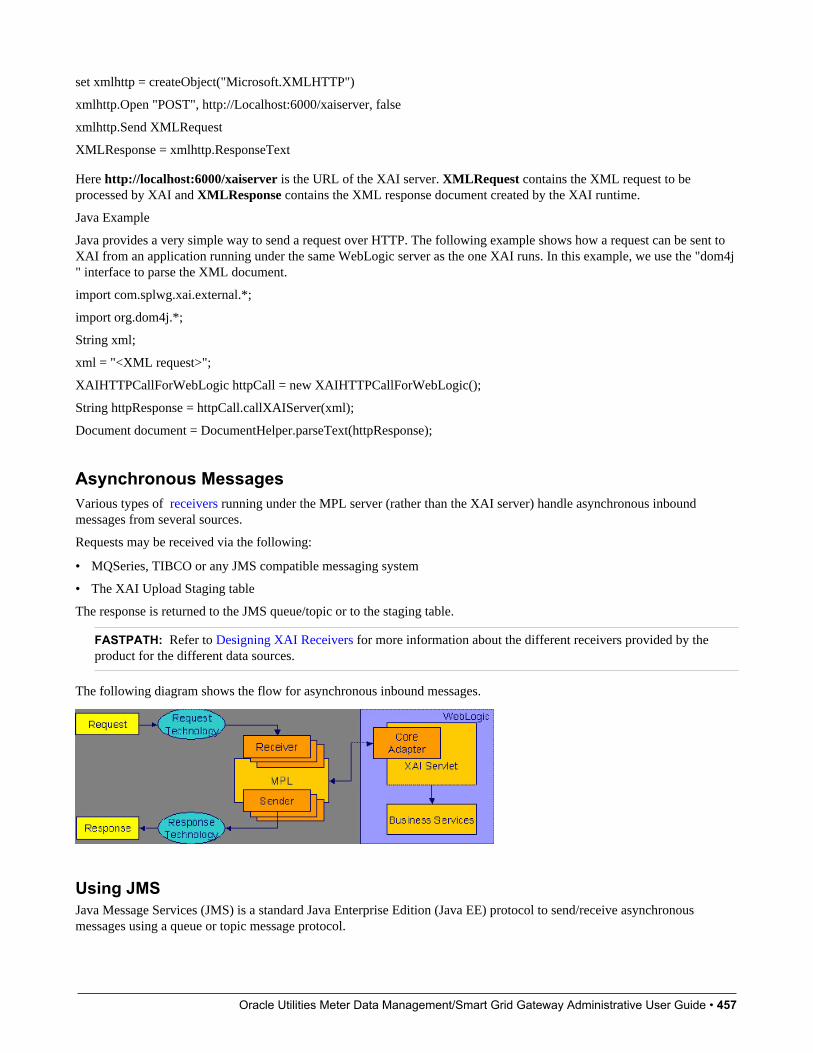
Oracle Utilities Meter Data Management/Smart Grid Gateway Administrative User Guide • 457
set xmlhttp = createObject("Microsoft.XMLHTTP")
xmlhttp.Open "POST", http://Localhost:6000/xaiserver, false
xmlhttp.Send XMLRequest
XMLResponse = xmlhttp.ResponseText
Here http://localhost:6000/xaiserver is the URL of the XAI server. XMLRequest contains the XML request to beprocessed by XAI and XMLResponse contains the XML response document created by the XAI runtime.
Java Example
Java provides a very simple way to send a request over HTTP. The following example shows how a request can be sent toXAI from an application running under the same WebLogic server as the one XAI runs. In this example, we use the "dom4j" interface to parse the XML document.
import com.splwg.xai.external.*;
import org.dom4j.*;
String xml;
xml = "<XML request>";
XAIHTTPCallForWebLogic httpCall = new XAIHTTPCallForWebLogic();
String httpResponse = httpCall.callXAIServer(xml);
Document document = DocumentHelper.parseText(httpResponse);
Asynchronous MessagesVarious types of receivers running under the MPL server (rather than the XAI server) handle asynchronous inboundmessages from several sources.
Requests may be received via the following:
• MQSeries, TIBCO or any JMS compatible messaging system
• The XAI Upload Staging table
The response is returned to the JMS queue/topic or to the staging table.
FASTPATH: Refer to Designing XAI Receivers for more information about the different receivers provided by theproduct for the different data sources.
The following diagram shows the flow for asynchronous inbound messages.
Using JMSJava Message Services (JMS) is a standard Java Enterprise Edition (Java EE) protocol to send/receive asynchronousmessages using a queue or topic message protocol.

Oracle Utilities Meter Data Management/Smart Grid Gateway Administrative User Guide • 458
XML messages may be received and sent via JMS using either a JMS Queue or JMS Topic. In order to access a JMSprovider such as MQSeries, TIBCO or WebLogic, the MPL must first connect to the appropriate server using a JMSConnection.
The following diagram depicts a message sent and received through a JMS Queue.
Using JMS QueuesJMS Queues are used to receive and send messages using the message queue protocol. Products that support this protocolinclude MQSeries.
The following describes events that take place when a JMS queue is used:
• The requester places the XML request message on a JMS queue. The request contains both the XML message and thename for the reply queue.
• The JMS Queue Receiver waits for messages on that queue. When the message arrives it is selected from the queue andexecuted using the adapter for the requested service.
• The XML response message is placed on the reply queue specified in the request. It is the requester's responsibility tofetch the response message from the queue.
The MPL uses a JNDI server to locate the queue resource.
Using JMS TopicsJMS Topics are used to send and receive messages using the publish/subscribe messaging model. Products that support thisprotocol include TIBCO, MQSeries and WebLogic.
The MPL uses a JNDI server to locate the topic resource.
• Define a JMS Topic receiver, listening to a predefined JMS Topic.
• The other application builds an XML message based on the schema defined for that service.
• It sends the XML request to the predefined topic and specifies the reply topic name.
• The MPL reads the message from the Topic, executes the service and returns the response to the reply topic specified inthe inbound message.
Staging UploadThe system provides a staging table, where an interface can store XML requests to perform a service in the system.
Some external systems interfacing with the system are not able to produce XML request messages. Or you may haveexternal systems that produce XML messages but the messages are sent in a batch rather than real time. The systemprovides the capability to read an external data source containing multiple records, map the data to an XML request andstore the request on the XAI upload staging table. These records may be in XML requests, sequential input files or databasetables.

Oracle Utilities Meter Data Management/Smart Grid Gateway Administrative User Guide • 459
The XAI upload staging table may be populated in one of the following ways:
• When a collection of messages in a file or database table must be uploaded, a staging control record should be createdfor each file/database table. The Staging Control Receiver processes each file or database table and creates records in theXAI upload staging table for each message.
• The XML File Receiver creates records directly in the XAI upload staging table. Note, in addition, the XML FileReceiver creates a staging control record to group together these records.
• XAI creates records in the XAI upload staging table for inbound messages in error that are configured to post the error.
• It is possible that when a response to a notification download staging message is received (Oracle Customer Care andBilling only), the response requires some sort of action. If this is the case, the system creates an XAI upload stagingrecord (and an XAI staging control record) for the response.
Staging Upload ReceiverOnce the XML requests are in the staging table, the Staging Upload Receiver reads the requests from the XAI uploadstaging table and invokes the XAI server (via the executer) with the appropriate XAI inbound service. Inbound servicerecords typically point to the core adapter used to invoke system services.
Staging Upload SenderThe staging upload sender handles "responses" to the execution of the message in XAI upload staging. If the executionis successful, the sender updates the status of the upload staging record to complete. If the execution is unsuccessful, thesender updates the status to error and creates a record in the XAI upload exception table.
NOTE: Configuration required. The above explanation assumes that you have correctly configured your uploadstaging receiver to reference the upload staging sender. Refer to Designing Responses for a Receiver for moreinformation.
Staging ControlThe staging control table is used to indicate to XAI that there is a file or table with a collection of records to be uploaded.The special Staging Control Receiver periodically reads the staging control table to process new records.
The XAI staging control table may be populated in one of the following ways:
• To process a specific sequential input file, manually create a staging control record and indicate the location and name ofthe file and the XAI inbound service to use for processing. Use this mechanism to process ad-hoc uploads of files.
• If a file is received periodically, you may define a File Scan Receiver, which periodically checks a given file directoryfor new files. The file scan receiver creates a new staging control record to process this file.
• The XML File Receiver processes a file containing a collection of XML messages to be uploaded. The XML file receivercreates a staging control record and creates records directly into the XML upload table. The staging control record isautomatically set to a status of Complete and is used to group together the XML upload records. Refer to ProcessingStaging Upload Records for a Staging Control for more information.
• To upload records from a database, manually create a staging control record and indicate an appropriate XAI inboundservice, which contains the information needed by the system to access the appropriate table. Use this mechanism toprocess ad-hoc uploads of files.
NOTE: To upload records from a database table, you must create a staging control record. There is no receiver thatperiodically looks for records in a database table.
• Whenever an XAI upload staging record is created, an XAI staging control record is created as well.
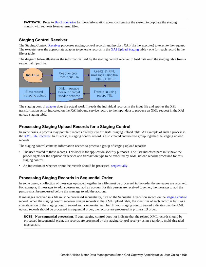
Oracle Utilities Meter Data Management/Smart Grid Gateway Administrative User Guide • 460
FASTPATH: Refer to Batch scenarios for more information about configuring the system to populate the stagingcontrol with requests from external files.
Staging Control ReceiverThe Staging Control Receiver processes staging control records and invokes XAI (via the executer) to execute the request.The executer uses the appropriate adapter to generate records in the XAI Upload Staging table - one for reach record in thefile or table.
The diagram below illustrates the information used by the staging control receiver to load data onto the staging table from asequential input file.
The staging control adapter does the actual work. It reads the individual records in the input file and applies the XSLtransformation script indicated on the XAI inbound service record to the input data to produce an XML request in the XAIupload staging table.
Processing Staging Upload Records for a Staging ControlIn some cases, a process may populate records directly into the XML staging upload table. An example of such a process isthe XML File Receiver. In this case, a staging control record is also created and used to group together the staging uploadrecords.
The staging control contains information needed to process a group of staging upload records:
• The user related to these records. This user is for application security purposes. The user indicated here must have theproper rights for the application service and transaction type to be executed by XML upload records processed for thisstaging control.
• An indication of whether or not the records should be processed sequentially.
Processing Staging Records in Sequential OrderIn some cases, a collection of messages uploaded together in a file must be processed in the order the messages are received.For example, if messages to add a person and add an account for this person are received together, the message to add theperson must be processed before the message to add the account.
If messages received in a file must be processed sequentially, turn on the Sequential Execution switch on the staging controlrecord. When the staging control receiver creates records in the XML upload table, the identifier of each record is built as aconcatenation of the staging control record and a sequential number. If your staging control record indicates that the XMLupload records should be processed in sequential order, the records are processed in primary ID order.
NOTE: Non-sequential processing. If your staging control does not indicate that the related XML records should beprocessed in sequential order, the records are processed by the staging control receiver using a random, multi-threadedmechanism.
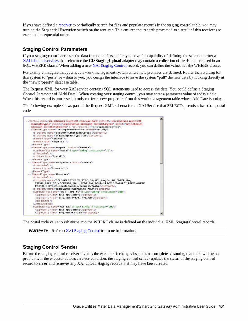
Oracle Utilities Meter Data Management/Smart Grid Gateway Administrative User Guide • 461
If you have defined a receiver to periodically search for files and populate records in the staging control table, you mayturn on the Sequential Execution switch on the receiver. This ensures that records processed as a result of this receiver areexecuted in sequential order.
Staging Control ParametersIf your staging control accesses the data from a database table, you have the capability of defining the selection criteria.XAI inbound services that reference the CISStagingUpload adapter may contain a collection of fields that are used in anSQL WHERE clause. When adding a new XAI Staging Control record, you can define the values for the WHERE clause.
For example, imagine that you have a work management system where new premises are defined. Rather than waiting forthis system to "push" new data to you, you design the interface to have the system "pull" the new data by looking directly atthe "new property" database table.
The Request XML for your XAI service contains SQL statements used to access the data. You could define a StagingControl Parameter of "Add Date". When creating your staging control, you may enter a parameter value of today's date.When this record is processed, it only retrieves new properties from this work management table whose Add Date is today.
The following example shows part of the Request XML schema for an XAI Service that SELECTs premises based on postalcode.
The postal code value to substitute into the WHERE clause is defined on the individual XML Staging Control records.
FASTPATH: Refer to XAI Staging Control for more information.
Staging Control SenderBefore the staging control receiver invokes the executer, it changes its status to complete, assuming that there will be noproblems. If the executer detects an error condition, the staging control sender updates the status of the staging controlrecord to error and removes any XAI upload staging records that may have been created.

Oracle Utilities Meter Data Management/Smart Grid Gateway Administrative User Guide • 462
NOTE: Configuration required. The above explanation assumes that you have correctly configured your stagingcontrol receiver to reference the staging control sender. Refer to Designing Responses for a Receiver for moreinformation.
Inbound Message Error HandlingFor messages that are processed using the staging upload table, application errors that prevent XAI from successfullyprocessing the message cause the staging record to be marked in error and highlighted via a To Do entry.
For messages that are not processed via staging upload, your implementation should consider what should happen toapplication errors. If the origin of the message is able to handle an immediate error returned by XAI, then no specialconfiguration is needed. An example of this is an HTTP call to our system where the originator of the message is waiting fora real-time response.
Otherwise, for messages where errors should not be returned to the originator, but should be highlighted in this systemfor resolution, be sure to mark the Post Error switch on the XAI inbound service. When this switch is turned on and anapplication error is received by XAI when processing the message an XAI upload staging record is created (along with astaging control record) and marked in error.
For example, if a message is received via a JMS queue, application errors that prevent XAI from processing the messageshould not be returned to the queue because there is no logic to route the error to the sending system.
Integration Scenarios
Integration Using an EAI (or Hub)It is possible for your various systems to be integrated with each other using a hub. The hub is implemented using anEnterprise Application Integration (EAI) tool provided by a third party vendor. Most hubs support HTTP and/or JMS andcan work with XML schemas or document type definitions (DTDs).
• XAI services are presented to the EAI tool as schemas or as DTDs, immediately making the system callable from thehub.
• Integration scripts or workflow processes are defined in the EAI tools.
• At run time the hub uses HTTP or JMS to access the system using inbound messages.
• Outgoing messages are used to notify the hub about events occurring in the system. The messages are sent using HTTPor JMS.
Batch ScenariosMessages may be sent in batch files, or may be retrieved from a database. In all cases, the system needs to be able to readthe file and identify each individual message in order to create an XML request that can be processed by the XAI server.Once each individual message is identified, a request is stored on the XAI Staging Upload table for later execution.
XML Message FileIt is possible for you to receive a file containing a collection of XML messages. The system identifies each separatemessage within the file and creates an entry for each message on the XAI upload staging table. It also creates a stagingcontrol record to group together each newly created XAI upload record. This staging control is created in Complete statusand is not processed by the staging control receiver.
Since external applications may send messages in a format unknown to XAI, the system needs a mechanism for identifyingthe messages and mapping them to an XAI service.
Oracle Utilities Meter Data Management/Smart Grid Gateway Administrative User Guide • 463
XAI GroupsFirst the system associates the entire XML file with an XAI Group. You can think of the XAI Group as a categorizationof the collection of messages. For example, you may have a separate XAI Group for each third party who sends you acollection of XML messages.
The system uses an XPath and XPath value to identify the correct XAI Group for the XML file.
Attachments and RulesAfter identifying the appropriate group to which an XML file belongs, the system takes each message in the file and appliesthe appropriate XSL transformation to the message to produce a record on the upload staging table.
To process the messages in a file, the system needs to know how to identify each message in a file containing multiplemessages. A file may use the same root element for each message or different root elements for different types of messages.For each XAI group, you must indicate the root element(s) that identifies a message by defining one or more attachments.Each attachment defines a root element, which tells the system when a new message begins.
Once the system has identified each separate message in the file, it must determine the correct XSL transformation script toapply. Once again the system uses an XPath and XPath value to identify the correct XSL to apply. For each XAI group, youdefine one XAI rule for every possible type of message you may receive in the file. Each XAI rule defines an XPath, XPathvalue and XSL transformation script.
Note you may assign a priority to each of your rules. The rules for more common messages may be assigned a higherpriority. This enhances performance by ensuring that rules for more common messages are processed before rules for lesscommon messages.
NOTE: Include parent elements. If the XML message includes parent elements (such as a transmission id or adate/time) that are needed for any of the separate child messages that are posted to the upload staging table, you canconfigure the appropriate attachment to include parent elements.
FASTPATH: Refer to Designing an XML File Receiver for more information about defining receivers that processXML files.
Sequential Input FileYou may receive messages in a sequential input file, such as a comma-delimited file.
The following steps should be performed when configuring the system to enable data to be uploaded from an input file intothe staging upload table:
1. Create an XML Schema that describes the records in the sequential input file.
2. Create the XSLT transformation that maps a record in the input file to an XML service request in your product.
3. Create an XAI service representing the batch process that loads the input file into the staging table.
4. If desired, create a new file scan receiver, which waits for an input file to appear in a particular directory. (If you do nottake this step, then you need to create a staging control when you want a file to be processed.)
NOTE: Character Encoding. If the file is encoded with a specific character encoding, you may indicate the encodingas part of the file name to be uploaded. If the file name ends with ?enc=?x, where x is the file character encoding, theadapter processes the file accordingly. For example, the file name may be specified as premiseUpload.csv?enc=?UTF-8. If the encoding is not specified as part of the file name and the file is in UTF-16 or UTF-8 with byte order mark,then the adapter can recognize the encoding.
Database FileIt is possible for you to define an interface where inbound messages are retrieved by reading records in a database table.

Oracle Utilities Meter Data Management/Smart Grid Gateway Administrative User Guide • 464
The following steps should be performed when configuring the system to enable data to be uploaded from a database tableinto the staging upload table:
• Create an XML Schema that describes the records in the database table.
• Create the XSLT transformation that maps a record in the database table to an XML service request in your product.
• Create an XAI service representing the process that loads the records from the database table into the staging table.
WSDL CatalogWeb Service Definition Language (WSDL) is a language for describing how to interface with XML-based services. It actsas a "user's manual" for Web services, defining how service providers and requesters communicate with each other aboutWeb services.
The base package provides the ability to publish a WSDL definition for each service exposed as an XAI Inbound Service. Inaddition, it is possible to request a catalog of all the XAI Inbound Services and a link to each WSDL. To view the catalog,launch a new browser session and enter the URL http://$host:$port/XAIApp/xaiserver?WSDL where $host and $portare replaced by the appropriate values for the current environment.
Outgoing MessagesThis section describes outgoing message functionality related to MPL, which is no longer recommended.
• Outbound messages. As described in Outbound Messages, outbound messages are supported for sending outgoingmessages. This functionality includes support that is only related to MPL.
• Notification download staging (NDS) messages. This method is only supported by Oracle Utilities Customer Careand Billing. Using this method near real-time, a record is written to the NDS staging table referencing only key fields.MPL then polls the records, invokes a service to build the message, applies the XSL and routes the message. If sentreal-time, no record is posted to the staging table but rather the message dispatcher routes the message immediately.Refer to Oracle Utilities Customer Care and Billing help, Workflow and Notifications, Notification and XAI for moreinformation.
The following sections describe the outbound messages topics specific to MPL in more detail.
Outbound Message ReceiverThe outbound message receiver processes records in the outbound message table that have a processing method flag equalto XAI and a status of pending and changes the status to in progress. The receiver then retrieves the message XSL and themessage sender defined for the external system / outbound message type.
NOTE: Template external system. If the outbound message's external system references a template external system,the outbound message type configuration for the template external system is used.
It applies the message XSL (if supplied). If the option to validate outbound message schemas is turned on, the schemavalidation is performed.
Refer to Outbound Message Error Handling for information about error handling.
If no errors are received, control is turned over to the outbound message sender for routing.
NOTE: Initialization of receiver. During the initialization of this receiver (for example if there is a problem with MPLand it is restarted) any records that are found to be in progress are changed to pending so that those messages are sentproperly.
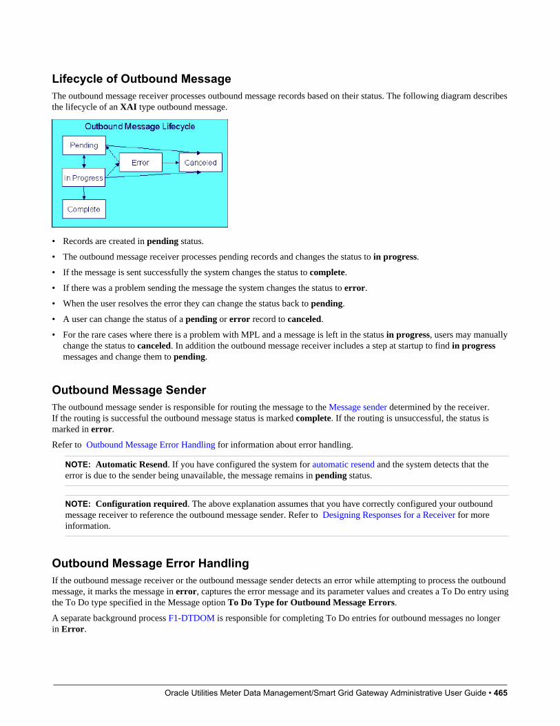
Oracle Utilities Meter Data Management/Smart Grid Gateway Administrative User Guide • 465
Lifecycle of Outbound MessageThe outbound message receiver processes outbound message records based on their status. The following diagram describesthe lifecycle of an XAI type outbound message.
• Records are created in pending status.
• The outbound message receiver processes pending records and changes the status to in progress.
• If the message is sent successfully the system changes the status to complete.
• If there was a problem sending the message the system changes the status to error.
• When the user resolves the error they can change the status back to pending.
• A user can change the status of a pending or error record to canceled.
• For the rare cases where there is a problem with MPL and a message is left in the status in progress, users may manuallychange the status to canceled. In addition the outbound message receiver includes a step at startup to find in progressmessages and change them to pending.
Outbound Message SenderThe outbound message sender is responsible for routing the message to the Message sender determined by the receiver.If the routing is successful the outbound message status is marked complete. If the routing is unsuccessful, the status ismarked in error.
Refer to Outbound Message Error Handling for information about error handling.
NOTE: Automatic Resend. If you have configured the system for automatic resend and the system detects that theerror is due to the sender being unavailable, the message remains in pending status.
NOTE: Configuration required. The above explanation assumes that you have correctly configured your outboundmessage receiver to reference the outbound message sender. Refer to Designing Responses for a Receiver for moreinformation.
Outbound Message Error HandlingIf the outbound message receiver or the outbound message sender detects an error while attempting to process the outboundmessage, it marks the message in error, captures the error message and its parameter values and creates a To Do entry usingthe To Do type specified in the Message option To Do Type for Outbound Message Errors.
A separate background process F1-DTDOM is responsible for completing To Do entries for outbound messages no longerin Error.

Oracle Utilities Meter Data Management/Smart Grid Gateway Administrative User Guide • 466
Automatic ResendIf a system error is received by the MPL when attempting to route the message to a sender, (using the outbound messagemethod or the NDS message method), the system marks the appropriate table in error. This is true even if the reason forthe error is that the connection to the sender is unavailable. When the connection is restored, a user must change the statusof the appropriate record to pending (for outbound messages) or retry (for NDS messages) in order for the message to beresent.
Alternatively, you can configure your system to attempt to automatically resend the message. This section describes thelogic available for auto resend. To enable automatic resend, you must set the flag Automatically Attempt Resending toUnavailable Senders on Message option appropriately.
If an error is received by the MPL when it attempts to invoke a sender and the auto resend option is on, the system does notmark the record in error. It continues to attempt sending messages to the sender until the number of errors has reached apredefined maximum error number (defined as an Message option). When the maximum is reached, the sender is marked asunavailable and an MPL log entry is created. The MPL ignores messages for unavailable senders.
The system tries to resend messages to this sender the moment the sender is reset to be available. The following pointsdescribe how a sender becomes available:
• MPL attempts to retry sending messages to unavailable senders every X minutes, where X is defined on Message option.
• On MPL startup all senders are marked as available
• A user may navigate to the XAI Command page and issue a command MPL Refresh Sender to refresh the cachedinformation for a particular sender
Designing Your XAI EnvironmentThis section guides you through the steps required to design the tables that control your XAI processing.
InstallationThe XAI server is installed with default configuration. This section describes how you may customize the XAI serverconfiguration.
Startup parameters are defined in two parameters files
• The XAIParameterInfo.xml file is used by the XAI HTTP server. This file is found within the XAI directory in the path(...\splapp\xai).
• The MPLParameterInfo.xml file is used by the MPL server. This file is found within the XAI directory in the path (...\splapp\mpl).
Both files store the parameters as XML files with the following elements (sections):
• Source
• ParameterVariables
• AdHocParameters
The XAI Source SectionThe XAI tool accesses XAI registry information through the standard system programs. The <Source> section in theXAIParameterInfo.xml file tells XAI the user ID for accessing the registry information. It contains the followingattributes:

Oracle Utilities Meter Data Management/Smart Grid Gateway Administrative User Guide • 467
Attribute Name Description
Source Type This should be set to CorDaptix, which tells XAI to access the registrythrough the standard access to system programs.
CorDaptixUser The user ID to use when accessing the registry data.
The MPL Source SectionThe <Source> section in the MPLParameterInfo.xml file defines the database connection information used to connectto the database storing the XAI table information. It contains the following attributes:
Attribute Name Description
Source Type Defines the source of the data, for example ORACLE or DB2.
jdbcURL The URL used to connect to the product database. For example: jdbc:oracle:thin:@//server-name:1234/DBNAME
databaseUser The Oracle User Id used to connect to the database.
databaseUserPassword The Oracle password used to connect to the database.
The Parameter Variables SectionWhen defining values for fields in certain control tables in the registry, you may reference substitution variables that pointto the <ParameterVariables> section of the installation files. Substitution variables provide for dynamic substitution ofvalues based on parameters provided at server startup.
To specify a substitution parameter in a string value you enter the name of the substitution parameter enclosed with @.
For example if you have a field in the XAI control tables that should contain the URL for the XAI HTTP servlet, you couldenter the value in the following way: http://@HOST@:@PORT@/xaiserver.
In the parameters section, define the appropriate values for these parameters, for example:
<ParameterVariables><ParameterVariable name="HOST" value="localhost" /><ParameterVariable name="PORT" value="8001" /></ParameterVariables>
At run time, the system builds the URL as http://localhost:8001/xaiserver.
Every substitution parameter is defined using an <ParameterVariable> element with the following attributes:
Attribute Name Description
Name The name of the substitution parameter
Value The value to replace an occurrence of the substitution parameter in anXAI control table field
NOTE: Substitution parameters can only be used for string fields, and not for fields that are foreign keys to otherobjects.
The AdHoc Parameters SectionThe <AdHocParameters> section is used to provide registry definitions that override the existing ones. Unlike the<ParameterVariables> section, a whole registry object definition can be specified in this section. When the XAI serverstarts, it first reads the registry definitions from the database and then it reads the <AdhocParameters> section. If it finds anobject definition in this section, it uses it to replace the one read from the database.
Attribute Name Description
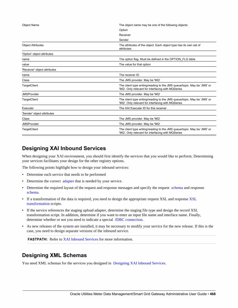
Oracle Utilities Meter Data Management/Smart Grid Gateway Administrative User Guide • 468
Object Name The object name may be one of the following objects:OptionReceiverSender
Object Attributes The attributes of the object. Each object type has its own set ofattributes:
'Option' object attributes
name The option flag. Must be defined in the OPTION_FLG table
value The value for that option
'Receiver' object attributes
name The receiver ID
Class The JMS provider. May be 'MQ'
TargetClient The client type writing/reading to the JMS queue/topic. May be 'JMS' or'MQ'. Only relevant for interfacing with MQSeries
JMSProvider The JMS provider. May be 'MQ'
TargetClient The client type writing/reading to the JMS queue/topic. May be 'JMS' or'MQ'. Only relevant for interfacing with MQSeries
Executer The XAI Executer ID for this receiver
'Sender' object attributes
Class The JMS provider. May be 'MQ'
JMSProvider The JMS provider. May be 'MQ'
TargetClient The client type writing/reading to the JMS queue/topic. May be 'JMS' or'MQ'. Only relevant for interfacing with MQSeries
Designing XAI Inbound ServicesWhen designing your XAI environment, you should first identify the services that you would like to perform. Determiningyour services facilitates your design for the other registry options.
The following points highlight how to design your inbound services:
• Determine each service that needs to be performed
• Determine the correct adapter that is needed by your service.
• Determine the required layout of the request and response messages and specify the request schema and response schema.
• If a transformation of the data is required, you need to design the appropriate request XSL and response XSLtransformation scripts.
• If the service references the staging upload adapter, determine the staging file type and design the record XSLtransformation script. In addition, determine if you want to enter an input file name and interface name. Finally,determine whether or not you need to indicate a special JDBC connection.
• As new releases of the system are installed, it may be necessary to modify your service for the new release. If this is thecase, you need to design separate versions of the inbound service.
FASTPATH: Refer to XAI Inbound Services for more information.
Designing XML SchemasYou need XML schemas for the services you designed in Designing XAI Inbound Services.
Oracle Utilities Meter Data Management/Smart Grid Gateway Administrative User Guide • 469
For each message, identify what service you need to invoke and what action you need to perform. If you have multipleactions that you may need to perform for the same service, you may choose to create a single generic XML schema or youmay choose to create multiple schemas, which are more specific. For generic messages, the transaction type, indicatingthe action to perform would be passed in on the XML request document to indicate what must be done. For more specificmessages, you may be able to indicate the transaction type directly on the schema and it would not need to be overwritten atrun time.
You need to create a response schema for each request schema. It is possible for you to use the same schema for bothfunctions.
FASTPATH: Refer to Schema Editor for more information.
Designing XSL TransformationsYou need an XSL transformation script for each service you designed in Designing XAI Inbound Services, where youdetermined a transformation is necessary. In addition, you need XSLT scripts for your outgoing messages. Each sender,which receives a message, probably requires a transformation of the message into a local format. Refer to OutgoingMessages for more information.
For each message requiring transformation, determine the format used by the external system. In most cases, it is not thesame format recognized by the system. For each case, you must create an XSL transformation, which maps the messageformat from the external format to one expected by your product or from your product format to one expected by theexternal system.
When identifying the required XSL transformations, remember to take into consideration the data that is processed bythe staging control table. This service reads data stored in a file or database table and uses the Record XSL to map theindividual records to an individual service request.
FASTPATH: Refer to XAI Inbound Service for more information.
Designing Your Registry OptionsThe XAI registry is a set of control tables that is used to store service definitions as well as various system informationrequired by the XAI and MPL servers. The following sections describe each table in the registry.
Designing XAI JDBC ConnectionsIf you need to access a database table to process your messages, XAI needs to know the location of the database and howto access it. If the tables are located in the same database used for the system (defined in your Installation), then you do notneed to enter any extra JDBC Connections. If you need to access data that lives in another database, design the additionalJDBC Connections and determine the type of connection and connection information.
FASTPATH: Refer to XAI JDBC Connections for more information about defining XAI JDBC Connections.
Designing XAI FormatsThe Formats section of the registry is used to define data formats. Data formats can be used in schema definitions to specifydata transformations. To determine what data formats you need to define for your XAI environment, you must review theexpected format of data that you will be exchanging and determine whether or not data transformation is required.
The following sections describe the four different types of formats and some guidelines in their use.
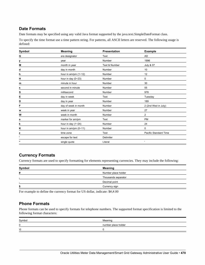
Oracle Utilities Meter Data Management/Smart Grid Gateway Administrative User Guide • 470
Date FormatsDate formats may be specified using any valid Java format supported by the java.text.SimpleDateFormat class.
To specify the time format use a time pattern string. For patterns, all ASCII letters are reserved. The following usage isdefined:
Symbol Meaning Presentation ExampleG era designator Text AD
y year Number 1996
M month in year Text & Number July & 07
d day in month Number 10
h hour in am/pm (1~12) Number 12
H hour in day (0~23) Number 0
m minute in hour Number 30
s second in minute Number 55
S millisecond Number 978
E day in week Text Tuesday
D day in year Number 189
F day of week in month Number 2 (2nd Wed in July)
w week in year Number 27
W week in month Number 2
a marker for am/pm Text PM
k hour in day (1~24) Number 24
K hour in am/pm (0~11) Number 0
z time zone Text Pacific Standard Time
' escape for text Delimiter
'' single quote Literal '
Currency FormatsCurrency formats are used to specify formatting for elements representing currencies. They may include the following:
Symbol Meaning# Number place holder
, Thousands separator
. Decimal point
$ Currency sign
For example to define the currency format for US dollar, indicate: $#,#.00
Phone FormatsPhone formats can be used to specify formats for telephone numbers. The supported format specification is limited to thefollowing format characters:
Symbol Meaning
0 number place holder
\0 0
Oracle Utilities Meter Data Management/Smart Grid Gateway Administrative User Guide • 471
Any other character appearing in the formatting expression is a placeholder for that character. To specify the '0' character,use '\0'.
Phone Format Example: (000) 000-0000
Text FormatsText formats are used to specify formats for character string attributes. The following expressions are supported:
Symbol Meaning
\cUpperCase Translate the string to upper case.
\cLowerCase Translate the string to lower case.
\cProperCase Translate the string to proper case. The first character of every wordis translated to uppercase. The remaining characters are translated tolowercase.
FASTPATH: Refer to XAI Format to define your XAI Formats.
Designing XAI AdaptersThe product provides a set of adapters to process your XML requests. The adapters point to a specific Java class that rendersa service. If you find that you need to use a protocol, which is not supported by the adapters provided, you will need to adda new Message Class (which points to a Java class) and a new XAI Adapter. It is recommended that your implementerscontact customer support. The following adapter classes are provided.
• BUSINESSADA: This is the adapter class that provides access to schema-based objects. This adapter accesses businessobjects, business services and service scripts through their schema API. Services with this adapter need to indicate theschema of the object, which should be invoked. When communicating to these objects, it is not necessary to create XAIschemas for the schemas associated with the objects. XAI is able to directly communicate with these objects using theirexisting schema definitions. As a result, there is no need to use the XAI schema editor when defining XAI InboundServices for this adapter.
• BASEADA: This is the core adapter class that provides access to any published system service. This adapter accessessystem objects through the page server. Services with this adapter need to indicate the object (application service), whichshould be invoked.
• STGUPADA: This staging upload adapter class is used when an extra step is required prior to using a service with thecore adapter. For example, perhaps you need to read a file, which is not in XML format, and convert it to an XML formatrecognized by the system. Services with this type of adapter do not need to indicate an application service but mustindicate information about the file to be converted. Refer to XAI Staging Control for more information.
• XAICMNDADA: This is an internal adapter. It is used to send commands to the XAI Server.
• SIEBELADA: This adapter is no longer supported.
Designing XAI ExecutersThe executer is responsible for executing messages received through a message receiver. The product provides an executer,which uses the XAI server; however the architecture allows for implementing additional execution classes. If you requirea different executer and therefore a different execution class, it is recommended that your implementers contact customersupport.
FASTPATH: Refer to XAI Executer for more information.
Oracle Utilities Meter Data Management/Smart Grid Gateway Administrative User Guide • 472
Designing Message SendersThis section only describes message sender functionality that is only related to the XAI/MPL processing. Refer to messagesender for details about other types of senders that are supported independent of XAI/MPL.
Message senders are responsible for define outgoing message destinations and for " responding" to the XAI executer.
• For NDS messages, the sender to use is defined on the XAI route type for the notification download profile.
• For outbound messages, the sender to use is defined on the external system / outbound message type collection.
• For responding to the XAI executer, the sender to use is defined on the receiver.
For each sender, you must reference an appropriate Message Class. The information in this section describes the senderclasses that are provided with the system.
You must create senders to "respond" to the various staging table receivers in the system.
• Create a sender to be used for "responses" to messages processed by the staging control receiver. You should create onesender, which points to the Message Class UPLDERRHNDLR. Refer to Staging Control Sender for more informationabout this sender.
• Create a sender to be used for "responses" to messages processed by the upload staging receiver. You should create onesender, which points to the Message Class STGSENDER. Refer to Staging Upload Sender for more information aboutthis sender.
• Create a sender to be used for messages processed by the download staging receiver. You should create one sender,which points to the Message Class DWNSTGSNDR. (DWNSTGSNDR is not supported in all products.)
• Create a sender to be used for messages processed by the outbound message receiver. You should create one sender,which points to the Message Class OUTMSGSNDR. Refer to Outbound Message Sender for more information aboutthis sender.
Next, design the senders for "responses" to other receivers, for example the JMS queue receiver or JMS topic receiver.The system provides message classes to use for these senders. Use the class JMSSENDER for a JMS queue sender andTPCSNDR for a JMS topic sender.
Finally, review all your outgoing messages and determine the mechanism for communicating with the target system foreach message.
• For all senders that are used for real time messages, define a context entry with a context type of Response Time Out todefine the amount of time the system should wait for a real time response.
• An HTTP sender is one that sends messages to an HTTP server using the HTTP protocol. For an HTTP sender,reference a message class of HTTPSNDR. In addition, the context described in Message Sender — Context for theRTHTTPSNDR apply to this sender as well.
• An email sender allows for XML messages to be sent as email messages through an SMTP server. It can be used innotification download processes to send a response as an email message. The email sender supports standard emailfunctionality such as "CCs" and attachments. The content of the email message is controlled by the XSL script definedin the XAI route type of the NDS message. The XSL script has access to all context records of the NDS message as wellas the input XAI message that was created by processing the NDS. Reference a message class of EMAILSENDER. Inaddition, the context described in Message Sender — Context for the RTHTTPSNDR apply to this sender as well.
• If you want XML messages to be written to a flat file, use a flat file sender. For example, it can be used in thenotification download process to write a response message to a flat file. Flat file senders should reference a MessageClass of FLATFILESNDR. In addition, the following context records should be defined for senders of this type.
Context Type Description ValuesFlat file output directory Directory in the file system where to write
the file
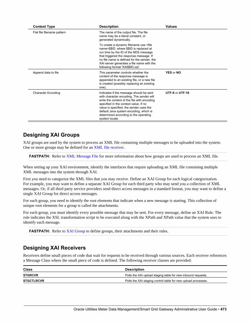
Oracle Utilities Meter Data Management/Smart Grid Gateway Administrative User Guide • 473
Context Type Description ValuesFlat file filename pattern The name of the output file. The file
name may be a literal constant, orgenerated dynamically.To create a dynamic filename use <filename>$$ID, where $$ID is replaced atrun time by the ID of the NDS messagethat triggered the response message. Ifno file name is defined for the sender, theXAI server generates a file name with thefollowing format 'XAI$$ID.xai'.
Append data to file This parameter controls whether thecontent of the response message isappended to an existing file, or a new fileis created (possibly replacing an existingone).
YES or NO
Character Encoding Indicates if the message should be sentwith character encoding. The sender willwrite the content of the file with encodingspecified in the context value. If novalue is specified, the sender uses thedefault Java system encoding, which isdetermined according to the operatingsystem locale.
UTF-8 or UTF-16
Designing XAI GroupsXAI groups are used by the system to process an XML file containing multiple messages to be uploaded into the system.One or more groups may be defined for an XML file receiver.
FASTPATH: Refer to XML Message File for more information about how groups are used to process an XML file.
When setting up your XAI environment, identify the interfaces that require uploading an XML file containing multipleXML messages into the system through XAI.
First you need to categorize the XML files that you may receive. Define an XAI Group for each logical categorization.For example, you may want to define a separate XAI Group for each third party who may send you a collection of XMLmessages. Or, if all third party service providers send direct access messages in a standard format, you may want to define asingle XAI Group for direct access messages.
For each group, you need to identify the root elements that indicate when a new message is starting. This collection ofunique root elements for a group is called the attachments.
For each group, you must identify every possible message that may be sent. For every message, define an XAI Rule. Therule indicates the XSL transformation script to be executed along with the XPath and XPath value that the system uses toidentify each message.
FASTPATH: Refer to XAI Group to define groups, their attachments and their rules.
Designing XAI ReceiversReceivers define small pieces of code that wait for requests to be received through various sources. Each receiver referencesa Message Class where the small piece of code is defined. The following receiver classes are provided:
Class DescriptionSTGRCVR Polls the XAI upload staging table for new inbound requests.
STGCTLRCVR Polls the XAI staging control table for new upload processes.

Oracle Utilities Meter Data Management/Smart Grid Gateway Administrative User Guide • 474
Class DescriptionDWNSTGRCVR Polls the notification download staging table (NDS) for new messages.
(Not available in all products).
OUTMSGRCVR Polls the outbound message table for new messages.
JMSRCVR Receives requests through a message queue that supports the JMSQueue interface, such as IBM MQSeries.
TPCRCVR Receives requests through a publish/subscribe model, such as TIBCO,or any system supporting the JMS Topic interface.
FILESCANRCVR Polls a given directory for files with a given file name pattern.
XMLFILERCVR Polls a given directory for XML files with a given file name pattern.
Multiple receivers may be defined for these receiver classes. For example, the XML file receiver defines the scan directory.If you have multiple directories that contain files to be uploaded, define a receiver for each directory.
All types of receivers reference a Message Class and XAI Executer. If you require a new Message Class or Executerbecause you use a protocol that is not currently supported, it is recommended that your implementers contact customersupport.
Designing Responses for a ReceiverOnce a request has been sent for execution to the XAI server (via the executer), the response layer processes the response.For some receivers, a response may not be applicable. For example, a file scan receiver reads flat files in a given directoryand posts records to the XAI staging control table. Responses are not applicable for this type of receiver.
The response may be conditional on the outcome of the request and may be sent to more than one destination (sender). Todesign your receiver responses, determine the conditions under which a response should be sent for each request processedby each receiver:
• Never send a response
• Send a response if the request was successful
• Send a response if the request was unsuccessful due to a system error
• Send a response if the request was unsuccessful due to an application error
Once you determine when to send a response, you must determine where to send the response. Responses for differentconditions may be sent to different Message Senders or to the same Message Sender.
Designing Receivers that Poll Staging TablesThe following receivers are needed to poll the various system staging tables.
• Create a staging upload receiver that references the Message Class STGRCVR. For responses, All Events shouldreference the staging upload sender.
• Create a staging control receiver that references the Message Class STGCTLRCVR. For responses, All Events shouldreference the staging control sender.
• If your implementation uses the NDS message method of communicating outgoing messages, create a staging downloadreceiver that references the Message Class DWNSTGRCVR. For responses, All Events should reference the downloadstaging sender. NDS messaging is not supported in all products.
• If your implementation uses the outbound message method of communicating outgoing messages, create an outboundmessage receiver that references the Message Class OUTMSGRCVR. For responses, All Events should reference theoutbound message sender.
For all the above receivers, if you need to access multiple environments, simply create receivers for each JDBC connection.Note that you should not add more than one of each of the above receivers pointing to the same JDBC connection. Toimprove performance for a single JDBC connection you may configure multiple MPL servers.

Oracle Utilities Meter Data Management/Smart Grid Gateway Administrative User Guide • 475
NOTE: Sample Data for Initial Install. When first installing the system, records for each of the above receivers areprovided. Your implementation may use these records or remove them and create your own.
Designing a JMS Queue ReceiverIf you need to receive messages through a JMS compatible queue, you need to define a JMS Queue receiver. Whendesigning a JMS Queue receiver you first need to design a JMS Connection and a JMS Queue.
If you would like to post responses back to the JMS queue, you may create a message sender to send the response to theJMS queue.
Designing a JMS Topic ReceiverIf you need to receive messages through a JMS Topic using the publish/subscribe model, you need to define a JMS Topicreceiver, which receives messages published under a specific topic. When designing a JMS Topic receiver you first need todesign a JMS Connection and a JMS Topic.
If you would like to post responses through a JMS Topic using the publish/subscribe model, you may create a messagesender to send the response to the JMS topic.
Designing a File Scan ReceiverThe file scan receiver constantly looks in a given directory for files with a given pattern. When it finds a matching file, itcreates a record in the staging control table to upload the contents of the file into the upload staging table.
When setting up your XAI environment, identify the interfaces that require uploading a file from a directory into the systemthrough XAI. For each unique file, define a file scan receiver. For each receiver record, indicate the Scan Directory, wherenew files will be placed, the Scan File, which is the naming pattern to look for and the XAI Inbound Service to use formapping the data into a system service.
In addition, if you want to specify a character encoding, the following Context record should be defined.
Context Type Description Values
Character Encoding Indicates that the message is characterencoded. When the receiver creates a stagingcontrol entry for a file, it will add ?enc=?x tothe name of the file in the table where x is thevalue of this parameter. Refer to SequentialInput File for more information.
UTF-8 or UTF-16
Designing an XML File ReceiverThe XML file receiver constantly looks in a given directory for XML files with a given pattern. When it finds a matchingfile, it goes through steps to identify each separate message in the file, determine the appropriate XSL transformation andcreate a record in the staging upload table.
FASTPATH: Refer to XML Message File for more information.
When setting up your XAI environment, identify the interfaces, which require uploading an XML file containing multipleXML messages into the system through XAI. For each unique file, define an XML file receiver. For each receiver record,indicate the Scan Directory, where new files will be placed, the Scan File, which is the naming pattern to look for and thecollection of XAI groups. XAI groups are used by the system to identify each separate message in the file and to determinethe appropriate XSL transformation for each message.
Oracle Utilities Meter Data Management/Smart Grid Gateway Administrative User Guide • 476
FASTPATH: Refer to Designing XAI Groups for more information.
Configuring the System for NDS MessagesRefer to the documentation for your product to find out if NDS messaging is supported.
Schema EditorCAUTION: This schema editor is a separate legacy tool that is no longer recommended. The documentation remains forupgrade purposes
The Schema Editor is a Graphical User Interface (GUI) tool to create XML schemas. The tool provides wizards to generateschemas from various sources.
Opening the Schema EditorAfter launching the schema editor, you are asked to connect to a database. On the Connect dialog:
• Select an ODBC data source pointing to the desired database.
• Enter the data source, user ID, password and database owner required to log on to that database.
• Click Connect.
After connecting, the schema editor appears.
Use the File/Open dialogue to select a schema from the schema directory. Refer to The Options Menu for information aboutsetting the default schema directory.
NOTE: When opening a schema, the schema editor validates the schema and any errors are displayed. Refer toValidating a schema for more information.
Schema Editor WindowCAUTION: This schema editor is a separate legacy tool that is no longer recommended. The documentation remains forupgrade purposes
The schema editor allows you to modify individual elements and attributes of a given schema.
Description of Page
Refer to System Wide Functions for Schema Editor for information about the various menu options available for theschema editor.
Service Name Enter the name of the service to be created in the service name text box. This is the name of the first elementunder the Body element in the XML document.
CAUTION: Important! When adding new schemas, carefully consider the naming convention for the Service Name.Refer to System Data Naming Convention for more information.
Adapter The adapter used to process services using this schema.
Internal Service Name If the schema is for an adapter that should invoke a system service, this is the internal name of theservice.
Oracle Utilities Meter Data Management/Smart Grid Gateway Administrative User Guide • 477
Transaction Type Select the transaction type performed by the service. The available values are Read, Add, Change,Update, Delete, List and Search.
NOTE: The difference between Change and Update is that for Change, all field values must be passed in with therequest. Field values that are not passed in to the request are set to null. For Update, you need only pass the primary keyfield values and the values of the fields to be updated. All other fields retain their existing values.
Left Panel
The left panel of the schema editor displays a tree view of the hierarchical elements in the schema. The (+) expands a node,the (-) collapses a node.
Right Panel
The following attributes appear on the right panel of the Schema Editor. Some fields cannot be modified in the schemaeditor. The field description indicates when the field is protected.
Tag Name The XML element tag name. This field is protected, but you may modify this attribute to give the element a self-explanatory name by right-clicking on the element name in the left tree-view.
MetaInfo Name Maps the element to a fully qualified field name in the service, for example PER_ID. This field isprotected.
Internal Type This property is populated automatically when you generate the schema from your product. The valuesfurther define elements and attributes. The values are page, pageBody, list, listHeader, listBody, searchHeader,codeTableDesc, Private. The values of codeTableDesc and Private are used to define special types of attributes.
Private attribute A field that does not exist on the server side, but one that you still want to have in the schema.
Description A description of this field.
Content The element type. This field is only available for elements. Possible values are eltOnly- element may contain onlyother elements and no text, TextOnly- element may only contain text.
Search Type Services, which perform a Search, may allow searching based on different criteria. The values are takenfrom the system meta information when the schema is generated. The possible values are Main, Alternate1, Alternate2,Alternate3, Alternate4, Alternate5 and Alternate6.
NOTE: You would not typically modify this value because it corresponds to a value in the meta information. However,the value is modifiable to accommodate the rare case in which a service may change in a new release. In this scenario,you may prefer to update the schema manually rather than regenerate a new schema for the new version.
Is Part of Primary Key Used to indicate to the XAI server whether or not this field makes up part of the primary key ofthe record. The values are taken from the metadata information when the schema is generated. Value may be true or false.
NOTE: Typically you would not modify this value because it corresponds to a value in the meta data information.However, the value is modifiable to accommodate the rare case where a service may change in a new release. In thisscenario, you may prefer to update the schema manually rather than regenerate a new schema for the new version.
Min Occurs This field is available for elements only and is used for repeating elements. It defines the minimum number ofoccurrences for an element. Value may be 0 or 1.
Schema Max Occurs This field is available for elements only and is used for repeating elements. It defines the maximumnumber of occurrences for an element. Value may be 0, 1 or *.
Limit Number of occurrences This field is available for elements only and is used for repeating elements. If the SchemaMax Occurs field has been set to '*', define the number of max occurrences here.
XML Data Type The data type for the attribute. Possible values are number, string, decimal, date, dateTime, andboolean.
Server Data Type Indicates the data type of this attribute on the server. This field is protected.
Oracle Utilities Meter Data Management/Smart Grid Gateway Administrative User Guide • 478
Service Format The format expected by the service. At runtime, XAI converts the Tag format to the Service Format beforeexecuting the request. Formats are defined in XAI Format.
Tag Format The format used to format an element/attribute in the schemas. Formats are defined in XAI Format.
Min Length Use this property to define the minimum length of the attribute, if applicable.
Max Length Use this property to define the maximum length of the attribute, if applicable.
Precision This is used for decimal attributes to define the maximum number of digits.
Scale This field is used for decimal attributes to define the number of digits at the right of the decimal point.
Required A value of Y indicates that the element must appear in XML document. A value of N indicates that the elementis optional.
Default value Default value to be used for Request schema, when the element is not supplied as part of the XML requestdocument.
Fixed Value Fixed value to be used for Request schema. This value is used regardless of the value supplied in the requestdocument.
Code Table Field This property is used for attributes that are descriptions of a code table, where the description is notautomatically returned by the system service. Use this property to indicate the code whose description should be retrievedby the XAI server.
Code Table Program This property is used for attributes that are descriptions of a code table, where the description isnot automatically returned by the system service. Use this field to indicate the program that XAI should call to access thedescription for the Code Table Field.
Creating a Schema
Usually you do not create schemas from scratch; rather you use Schema Creation Wizards to import existing data structuredefinitions from a variety of data sources:
• System services
• Comma Delimited Files
• Database Extract
• Any XML document
Once a schema is created based on the existing data structure, it is displayed in a TreeView on the left panel. Once theimported schema has been edited, it serves as the basis for creating the request and response schemas. When imported, theschema exposes all fields defined in the service. You may want to remove some attributes/elements from the request orresponse schema.
NOTE: Although the main purpose of the editing process in the creation of the request and response schemas is theelimination of elements, which makes the schema shorter and more understandable, it is not required for processingpurposes. Therefore, if you don't mind that you have not used elements in your schemas, you could stay with oneschema, which serves as both the request and response schema.
1. Save the Schema as a Request schema with an appropriate name, for example PersonInfoRequestSchema.xml
2. To create the Response schema, which is identical to the request schema, use the Save As Response menu option. Thisrenames the top element of the schema to ServiceNameResponse, for example PersonInfoResponse and save the schemaunder a different name i.e. PersonInfoResponseSchema.xml. Note that if the request and response schemas are identicalthen one schema may be used for both and there is no need to create separate schemas.
3. Read in the Request Schema (File/Open) and modify its structure. Depending on the service type, you'll have to modifythe contents of the Request Schema. This is usually required when the service is an "Info" service, which requires veryfew input elements. In such cases you'll delete most of the elements on the schema and only leave the necessary elementsrequired to invoke the service. For example: in the PersonInfo request, you only need the PersonId and the Companyelements in the request schema.
Oracle Utilities Meter Data Management/Smart Grid Gateway Administrative User Guide • 479
4. Read in the Response Schema (File/Open) and Modify its structure. Depending on the service type, you'll want tomodify the contents of the Response Schema. This is usually required when the service is an "Add" or "Delete" service,which returns very few input elements. In such cases you'll delete most of the elements on the response schema and onlyleaves the necessary elements required by the requester of the service.
Adding an Element/Attribute
Usually, you won't have to add element or attributes to a schema. However if the schema already exists and you want to addan element/attribute, you can follow this procedure. Be aware that any element/attribute added here must also exist on thexml metainfo.
• Select the element's node on the TreeView.
• Right click on it and select the 'Add Element' or 'Add Attribute' option in the pop-up menu
• Enter the element/attribute name in the prompt dialog box and click OK.
Removing Elements/Attributes
When generating a schema using one of the wizards, the generated schema may contain information that you do not wantto publish as part of the service, or is not required for a particular service. You can remove elements/attributes from theschema, and though these elements/attributes may still exist on the service they are not seen by the XAI service using thisschema. To remove an element or attribute:
• Select the node to be removed.
• Right click and select "Delete" from the popup menu.
Renaming an Element
To rename an element:
• Select the element's node on the TreeView.
• Right click it and select the Rename option in the pop-up menu
• Enter the new name in the prompt dialog box and click OK.
NOTE: The information in this table is cached by the XAI server and by the MPL server. Changes to values in this tabledo not affect the runtime copy of these servers. Refer to XAI Command for information about refreshing a schema.
Validating a SchemaCAUTION: This schema validation is part of a separate legacy tool that is no longer recommended. The documentationremains for upgrade purposes
Although a schema is validated against the metainfo XML file when it is read into the editor or before it is saved, you canperform the validation at any time while the schema is being edited. To validate a schema, click on the toolbar "Validate"
button . If the schema fails to validate the schema errors dialog is displayed.
When the editor fails to validate a schema against the xml metainfo file, it pops up a dialog that lists the errors found in theschema definition. These errors may be of two types:
• An element or attribute in the schema could not be found in the xml metainfo file. You can click Remove to remove theelement from the schema.
• The data type of an attribute does not match the one defined in the metainfo file. You can click Correct, and the editorfixes the data type so it does match.
The Correct All button can be used to correct all fields that have data types that do not match the one in the XML metainfofile.

Oracle Utilities Meter Data Management/Smart Grid Gateway Administrative User Guide • 480
NOTE: Correcting errors does not save the schema definition into a file. You have to save it manually.
If you Exit without correcting the errors, the schema displays with the mismatch information highlighted in red.
Registering a ServiceBefore a service can be used it must be defined in the XAI Inbound Service table in the XAI registry. A service can beregistered in the XAI registry directly from the schema editor. Go to the menu item 'Register Service' in the 'Schemas'menu. The Register service UI page appears. Fill in the required fields.
NOTE: The registry entry for the service can be later modified using the XAI Inbound Service page.
Testing a SchemaThe XAI schema editor provides a testing option.
NOTE: Testing in your product. You may also test your schemas and your services using XAI Submission.
System Wide Functions for Schema EditorBecause the schema editor is in an application outside of the standard products, this section introduces some generalfunctions related to the application.
Application Standards• The schema editor is a Multiple Document Interface (MDI) windows application. It may contain multiple active
windows. You may jump from one window to the other using the Window menu option.
• The Editor window is always active. Closing the schema editor window quits the application.
• In the Editor window, a splitter bar is available to resize the schema tree view horizontally.
• Actions may be performed using menu items or by clicking on toolbar buttons.
• All messages are displayed on a status bar at the bottom of the screen. Some may also be displayed using message boxes.
The File MenuUse the File menu to open existing schemas and to save a schema to a file.
Connect — Connects to the database.
Open — Loading an existing schema into the editor
You can read an existing schema into the editor.
1. Click on the Open toolbar button or select the File/Open menu option.
2. A file selection dialog is shown. Select the schema file name.
3. The editor first validates the schema against the xml metainfo file. If it fails to validate it shows the Schema ValidationErrors dialog. Refer to Validating a schema for more information.
Save — Save the current schema to a file. Using the current file name.
Oracle Utilities Meter Data Management/Smart Grid Gateway Administrative User Guide • 481
To save a Schema, click on the Save toolbar button, or select the File/Save menu option. When you save a schema, theeditor first attempts to validate the schema. If it fails to validate it against the XML Metainfo file, you are prompted to saveit with inconsistency errors or to return to the editor.
Save As — Save the current schema to a file. Use a different file name.
Save As ResponseSave a copy of the current schema to a file as a response schema. Use a different file name.
The View MenuUse the view menu to perform actions on the Tree View nodes or to view errors. The following menu options are available:
Expand All — Expand all nodes in the Tree View
Collapse All — Collapse all nodes in the Tree View
Expand Branch — Expand the selected node and all the node's children
Search (Ctrl+F) — Find a node with a node name containing a given string
Search Again (F3) — Find the next node with containing the search string
View Schema Errors — Display the Schema Validation Errors dialog.
Web Browser — Display the current schema definition on a web browser page
The Schemas MenuUse the Schemas menu to create, test, validate and register schemas.
• To create schemas from various sources use the Create menu.
• To validate a schema select the Validate option (Ctrl+V).
• To create a sample instance and test the schema, select the Test option (Ctrl+T).
• To create an entry in the service registry for a service represented by the current schema, select the Register Serviceoption (Ctrl+R). Refer to Registering a Service for more information.
The Options MenuAlways Save As W3C — Turn on this option to save schemas in W3C format by default instead of XDR format.
Always Save As DTD — Turn on this option to save schemas in DTD format by default instead of XDR format.
Preferences
The following options may be set on the preferences dialog (Select Options and then Preferences):
• The Default Date Time Format - used for schema date fields
• The default Schema Directory - used to read/save schemas
• The default Metainfo Directory - used to create/validate schemas
• The XAI Servlet URL - used when executing requests from the test schema dialog.
• The Default Account Id - used when generating sample instances of a schema
• Language - used to access language specific data
The Tools MenuSchemas tools can be invoked from the Schema Editor Tools menu.
Oracle Utilities Meter Data Management/Smart Grid Gateway Administrative User Guide • 482
Converting Schemas to a W3C compatible schema — Schemas generated in the Microsoft BizTalk-compatible format(XDR format) may be saved in a format compatible with the October 2000, W3C XML schema standard. To save a schemain a W3C format:
• Select Convert to W3C from the Tools menu. The Convert to W3C dialog box appears.
• Select the schema(s) to be converted. Multiple schemas may be converted in a single step.
• The name of the W3C schema is the same name as the schema but with an ".xsd" file extension, and is saved to the samedirectory as the original schema.
• Click Convert.
Converting Schemas to a DTD — Schemas generated in the Microsoft BizTalk-compatible format (XDR format) may besaved as a DTD.
• Select the Convert to DTD option from the Tools menu. The convert DTD dialog box appears.
• Select the schema(s) to be converted. Note that multiple schemas may be converted in a single step.
• The name of the W3C schema is the same name as the schema but with a ".dtd" file extension, and is saved to the samedirectory as the original schema.
• Click Convert.
Validating multiple schemas — The schema validation tool can be used to validate the correctness of an XAI schemawhen compared to the metainfo xml definition used to generate the schema. For each validated schema, the validationtool scans the list of elements/attributes and compares them with those defined in the XML metainfo file. Select ValidateSchemas in the Tools menu.
• The Validate Schema dialog box appears.
• The left list box is used to select the directory where the schemas to be validated are stored. By default this is theSchema Directory as defined in the preferences.
• On the right, the list of schemas is displayed on a grid.
• Multiple schemas may be validated in a single step.
• To select a schema click on the left button (the first column in the row).
• To select multiple schemas, hold the Ctrl key and select the required schemas.
• Click Validate Schemas.
• The schema grid is updated. When an attribute defined in the schema is missing from the metainfo file or when theproperties of the element do not match defined in the metainfo, a button is displayed at the right of the schema name.Clicking on the edit button loads the schema into the editor and displays the Schema Validation Errors dialog for thatschema. You can correct the schema and save it. Refer to Validating a schema for more information.
Setting Up Your XAI EnvironmentThis section describes the control tables available to administer your XAI environment.
Message ClassThe Message Classes are references to actual Java classes. The Message Class defines the Java class used to implementReceivers, Senders, Adapters and Executers. This information is provided with the system and does not need to be modifiedfor a specific installation.
To view a Message Class, open Admin > XAI > Message Class.
Description of Page
Oracle Utilities Meter Data Management/Smart Grid Gateway Administrative User Guide • 483
The Message Class and Description are unique identifiers of the Message Class. The Class Definition indicates the Javaclass, implementing the adapter, receiver, sender or executer.
Owner indicates if this Message Class is owned by the base package or by your implementation ( CustomerModification). The system sets the owner to Customer Modification when you add a Message Class. This information isdisplay-only.
Where Used
Follow this link to open the data dictionary where you can view the tables that reference CI_XAI_CLASS.
XAI Envelope HandlerTo view your envelope handlers, open Admin > XAI > XAI Envelope Handler. This information is provided with thesystem and does not need to be modified for a specific installation.
Description of Page
Enter a unique XAI Envelope Handler ID and Description.
Indicate whether the Envelope Type is Custom SOAP Envelope, Default (no SOAP environment) or SOAP Envelope.Note that the values of Siebel Integration Message and Siebel VBC are not supported.
When the envelope type is SOAP Envelope, indicate the Envelope URI.
Owner indicates if this XAI envelope handler is owned by the base package or by your implementation (CustomerModification). The system sets the owner to Customer Modification when you add an XAI envelope handler. Thisinformation is display-only.
Setting Up Your RegistryThe following section describes the control tables that are logically considered part of the XAI Registry.
XAI JDBC ConnectionTo view an XAI JDBC Connection, open Admin > XAI > XAI JDBC Connection.
Description of Page
Enter a unique XAI JDBC Connection and Description.
Use the Connection Type to indicate how the JDBC connects to a database. The following connection types are valid:
• Oracle Defined Connection indicates the connection is to an Oracle database through a JNDI entry.
• DB2 Defined Connection indicates the connection is to a DB2 database through a JNDI entry.
• JNDI Defined Connection indicates the connection is using the MQ series classes implementing JMS.
• Determined by parameter file indicates that the connection information should be determined by looking at theparameters defined at Installation.
For connection types of Oracle or DB2, use the JDBC URL to indicate URL of the database connection to be initializedat XAI/MPL startup time. Indicate the Database User and Database Password required for accessing the database. TheJDBC connection URL can either be a Type 2 or a Type 4. For example:
• Type 2: jdbc:oracle:oci8:@CD200ODV
• Type 4: jdbc:oracle:thin:@myhost:1521/ CD200ODV
For a connection type of Determined by parameter file, indicate the parameter substitutions, which should be accessedfrom the parameter file for the JDBC URL, database user and database password, for example, @JDBCURL@,@DBUSER@ and @DBENCPASS@.
Oracle Utilities Meter Data Management/Smart Grid Gateway Administrative User Guide • 484
When the connection type is JNDI, indicate the JNDI Server and the JNDI Data Source name as defined in the JNDI.
Where Used
Follow this link to open the data dictionary where you can view the tables that reference CI_XAI_JDBC_CON.
XAI FormatOpen Admin > XAI > XAI Format to define the various formats.
Description of Page
For each new format, specify a unique XAI Format name and Description.
Indicate whether the Format Type is a Currency formatting string, a Date/Time formatting string, a Phone formattingstring or a Text formatting string.
Finally, indicate the Format Expression, which defines the formatting pattern to be applied.
Owner indicates if this format is owned by the base package or by your implementation ( Customer Modification). Thesystem sets the owner to Customer Modification when you add an XAI format. This information is display-only.
Where Used
Follow this link to open the data dictionary where you can view the tables that reference CI_XAI_FORMAT.
XAI AdapterTo define a new adapter, open Admin > XAI > XAI Adapter.
Description of Page
Indicate a unique Adapter Name and Description.
Indicate the Message Class, which is the name of the Java class, implementing the adapter. The class should be one thatis defined for an adapter. The adapter classes provided with the product are BASEADA- Core Adapter, BUSINESSADA-Business Requests Adapter and XAICMNDADA- XAI Command Adapter. Note that the values SIEBELADA andSTGUPADA are no longer supported.
FASTPATH: Refer to Message Class for more information.
The following fields are not applicable for the BusinessAdapter adapter.
Use the JNDI Server to indicate the name of the WebLogic JNDI server running your product. Refer to JNDI Server formore information.
Indicate the Default User to be passed to your product server when this adapter is executed.
NOTE: If the XML request is sent over an HTTP connection, which has been authenticated, the authenticated User Id ispassed to your product.
The Default Date format and the Default DTTM (date / time) Format specify date and date/time formats to use when aschema does not explicitly indicate formats.
Owner indicates if this XAI adapter is owned by the base package or by your implementation (Customer Modification).The system sets the owner to Customer Modification when you add an XAI adapter. This information is display-only.
Where Used
Follow this link to open the data dictionary where you can view the tables that reference CI_XAI_ADAPTER.

Oracle Utilities Meter Data Management/Smart Grid Gateway Administrative User Guide • 485
XAI ExecuterTo define a new Executer, open Admin > XAI > XAI Executer.
Description of Page
Enter a unique Executer ID and Description.
Indicate the Message Class for this executer. The class should be one that is defined for an executer. The executer classprovided with the product is XAIURLEXEC- XAI Executer.
Indicate the appropriate Executer URL.
Owner indicates if this XAI executer is owned by the base package or by your implementation ( Customer Modification).The system sets the owner to Customer Modification when you add an XAI executer. This information is display-only.
Where Used
Follow this link to open the data dictionary where you can view the tables that reference CI_XAI_EXECUTER.
XAI GroupXAI groups are used to process XML files, which contain a collection of XML messages to be uploaded in batch.
XAI Group - MainTo define your XAI groups, open Admin > XAI > XAI Group.
Description of Page
Enter a unique Group and Description for the XAI Group.
Indicate the Parser used for this group. Possible values are Dom Parser and StAX Parser.
NOTE: Dom Parser reads the full XML document into memory and therefore is not ideal for larger XML documents.
Indicate the XPath and XPath Value, which an XML file receiver uses to identify which group a given XML file belongsto.
• For StAX Parsers the XPath is limited to the root element.
• For Dom Parsers, the XPath supports defining elements at a lower level than the root element.
XAI Group - AttachmentsOpen Admin > XAI > XAI Group and navigate to the Attachments tab to define attachments for your group.
Description of Page
For each entry in the attachments collection, indicate the Sequence and the Root Element. Use Include Elements toindicate if Parent elements should be included along with the current element when applying the XAI rules.
FASTPATH: Refer to XML Message File for more information about how this is used.
XAI Group - RulesOpen Admin > XAI > XAI Group and navigate to the Rules tab to define rules for your group.
Description of Page
Oracle Utilities Meter Data Management/Smart Grid Gateway Administrative User Guide • 486
For each entry in the rules collection, indicate the Sequence, the Priority, the XPath name and XPath Value and the XSLFile Name.
NOTE: Include Parent. If your attachment indicates that Parent elements should be included, be sure that the parentelement is included in the XPath defined here.
FASTPATH: Refer to XML Message File for more information about how this is used.
Where Used
Follow this link to open the data dictionary where you can view the tables that reference CI_XAI_RGRP.
XAI Receivers
XAI Receiver - MainTo define your XAI receivers, open Admin > XAI > XAI Receiver.
Description of Page
Enter a unique Receiver ID and Description for the XAI Receiver.
Indicate the Message Class for this receiver. The class should be one that is defined for a receiver. The receiver classesare DWNSTGRCVR- Download Staging receiver, FILESCANRCVR- Upload Files from a directory, JMSRCVR- JMSQueue receiver, OUTMSGRCVR- Outbound Message receiver, STGCTLRCVR- Staging Control receiver, STGRCVR-Staging Upload Receiver and TPCRCVR- JMS Topic receiver, XMLFILERCVR- XML File receiver.
FASTPATH: For more information, refer to Designing XAI Receivers about different types of receivers.
Indicate whether or not this receiver is currently Active.
Identify the Executer ID. Select the XAILOCAL executer if the Message Class for this receiver is STGCTLRCVR. Selectthe BYPASSXAI executer if the Message Class for this receiver is OUTMSGRCVR. For all other receivers select theXAIURL executer. For more information, refer to XAI Executer.
Indicate whether the MSG Encoding is ANSI message encoding or UTF-8 message encoding.
The Read Interval indicates the number of seconds between read cycles.
Start At Time and Duration are not currently in use.
If the Message Class for this receiver is FILESCANRCVR, STGRCVR, STGCTLRCVR or XMLFILERCVR, indicatethe XAI JDBC Connection.
FASTPATH: Refer to XAI JDBC Connection for more information.
Turn on Sequential Execution if the received requests should be processed in sequential order (instead of multithreaded).If this value is turned on then XAI staging control records created by this receiver are marked for sequential execution.
JMS Information
The following information is only available if the Message Class is JMSRCVR or TPCRCVR.
Indicate the appropriate JMS Connection
FASTPATH: Refer to JMS Connection for more information.
Indicate the appropriate JMS Queue.
Oracle Utilities Meter Data Management/Smart Grid Gateway Administrative User Guide • 487
FASTPATH: Refer to JMS Queue for more information.
Indicate the appropriate and JMS Topic.
FASTPATH: Refer to JMS Topic for more information.
File Information
The following information is only available if the Message Class is FILESCANRCVR or XMLFILERCVR.
Use the Scan Directory to indicate where to look for new files.
In Scan File, indicate the file pattern. All files with names matching the pattern are uploaded into the staging upload table.For each file found, a record in the staging control table is created.
CAUTION: WARNING. MPL expects all files conforming to the Scan File pattern to be complete. If a file is in theprocess of being copied into the scan directory and its name conforms to the naming pattern, MPL still attempts toprocess it and may issue an error for the incomplete file. It is suggested that files first be copied into the scan directorywith a different name that does not conform to the naming pattern, for example filename.xml.inprocess. Once the filecopy/transfer is complete, rename the file to one that conforms to the naming pattern, for example, filename.xml.
The following information is only available if the Message Class is FILESCANRCVR.
Use the XAI In Service Name to indicate how the records in the file are mapped and how they are transformed to match asystem service request structure.
XAI Receiver - ContextOpen Admin > XAI > XAI Receiver and navigate to the Context tab to define context for your receiver.
Description of Page
The Context collection enables you to define a collection of Context Types and Context Values defining. Use thiscollection when you need to store an attribute of a receiver that is not catered for in the current table.
NOTE: The values for the Context Type field are customizable using the Lookup table. This field name is RCVR_CTXT_FLG.
XAI Receiver - ResponseOpen Admin > XAI > XAI Receiver and navigate to the Response tab to define where to send responses to requests madeby this receiver. Refer to Designing Responses for a Receiver for more information.
Description of Page
The response collection enables you to define the destination (Message Sender) where responses to a request may be sentunder various circumstances (Event). The events currently defined with the product are All events, Message executed OK,Application Error, System Error.
NOTE: The values for this field are customizable using the Lookup table. This field name is ON_EVENT_FLG.
XAI Receiver - GroupsOpen Admin > XAI > XAI Receiver and navigate to the Groups tab to the valid XAI groups for an XML file receiver.
Description of Page
This collection is only available if the Message Class is XMLFILERCVR.
Oracle Utilities Meter Data Management/Smart Grid Gateway Administrative User Guide • 488
For each entry in the Group collection, indicate the Priority and the Group. Refer to XAI Groups for more informationabout defining groups.
Where Used
Receivers are used by the XAI server and by the MPL server to process messages sent to the system from various sources.
XAI Inbound ServicesThe XAI Inbound Services section in the registry is the main section of the registry. It is used to define the servicecharacteristics. Basically, a service is defined by an Adapter responsible for executing the service, a pair of XML schemasand connection attributes. The Adapter defines the interface with the target application server, while the schemas define thestructure of the request XML document expected by the service and the structure of the response XML document generatedby the service.
XAI Inbound Service - MainTo update an inbound service, open Admin > XAI > XAI Inbound Service.
CAUTION: Important! When adding new inbound services, carefully consider the naming convention of the XAI InService Name. Refer to System Data Naming Convention for more information.
Description of PageDefine a unique XAI In Service Name. This information is used in the system to identify the service. The service nameis also the first XML element after the <Body> element in the XML request/response document. The system generates aunique XAI Service ID, which serves as the primary key.
Owner indicates if this XAI inbound service is owned by the base package or by your implementation ( CustomerModification). The system sets the owner to Customer Modification when you add an XAI inbound service. Thisinformation is display-only.
Indicate the Adapter, which defines the interface with the target application server.
FASTPATH: Refer to XAI Adapter for more information.
If adapter for this service should invoke a system service, then indicate the appropriate Service Name.
FASTPATH: Refer to Service Program for more information about defining services.
If adapter is the base package Business Adapter then Service Name does not appear. Instead, use Schema Type to indicatethe type of object this service invokes and Schema Name to reference the object to invoke. Using this adapter, you may setup service to invoke business objects, business services and service scripts.
FASTPATH: Refer to Designing XAI Adapters for more information about the Business Adapter.
Web Service Category is visible if the XAI inbound service is linked to one or more web service categories.
Use the Description and Long Description to describe the service.
Check the Active switch if this service is enabled and available for execution. If this switch is unchecked, then the service isdefined in the registry, but not yet available for public use.
Check the Post Error switch to support inbound message error handling for messages that are not processed via the stagingupload table.
Check the Trace switch if you would like the trace to be on for this particular service. If the general trace option is notactivated, you can force a trace for a particular service.
Oracle Utilities Meter Data Management/Smart Grid Gateway Administrative User Guide • 489
FASTPATH: Refer to Server Trace for more information about trace functionality.
When the Debug switch is checked, debug information is generated on the XAI console when this service is executed. Thedebug information can be useful to resolve problems.
Schema Definitions
NOTE: Request Schema and Response Schema are not applicable to services invoking schema-based objects. They donot appear when the Business Adapter is used.
The next two properties define the request and response XML schemas. The schemas were created using the Schema Editorand are SOAP compatible. The schema XML files are expected to be stored in the Schemas Directory on the Web serverrunning the XAI server.
The Request Schema is the XML schema defining the service request. The request sent to the server must adhere to theschema definition.
The Response Schema is the XML schema defining the service response. The response generated by the XAI servercorresponds to the response schema definition.
The same service may perform several actions on a business object. Use the Transaction Type to define the defaultaction performed by a service. The transaction type can be provided when invoking a service, by dynamically specifying atransaction type attribute on the Service element of the XML request. This field may take the following values: Read, Add,Change, Update, Delete, List and Search.
NOTE: The difference between Change and Update is that for Change, all field values must be passed in with therequest. Field values that are not passed in to the request are set to null. For Update, you need only pass the primary keyfield values and the values of the fields to be updated. All other fields retain their existing values.
Services, which perform a Search, may allow searching based on different criteria. When the Transaction Type value isSearch, use the Search Type to define the default search criteria. The possible values are Main, Alternate1, Alternate2,Alternate3, Alternate4, Alternate5 and Alternate6.
NOTE: This is a default definition only and it may be overridden at run time when the service is invoked. To overridethe search type at run time, you should specify the searchType attribute on the Service element of the XML request.
XSL Transformation Definitions
Sometimes, the XML request document does not conform to the request schema, or the response document expected by theservice requestor is not the one generated by the adapter. In such cases the request and/or the response documents must betransformed. The XAI server supports transformation through XSL transformation scripts. Transformation scripts may beapplied to the request before it is passed to the adapter or applied to the response document before it is sent to the servicerequestor.
The Request XSL is the name of the XSL transformation to be applied to the request document before processing it. Thetransformation is usually required when the incoming document does not correspond to the XAI service request schematherefore it has to be transformed before it can be processed by the adapter.
The Response XSL is the name of the XSL transformation to be applied to the response document when the requester of theservice expects the response to have a different XML document structure than the one defined by the response schema forthe service.
Click the WSDL URL hyperlink to launch a separate window that contains the WSDL definition for the inbound service.Note that the server name and port number for the URL are built using a setting in the common properties file using the XAIHTTP Caller URL setting.
NOTE: Refer to WSDL Catalog for information on how to obtain the WSDL catalog for all XAI Inbound Services.
Oracle Utilities Meter Data Management/Smart Grid Gateway Administrative User Guide • 490
XAI Inbound Service - StagingThe staging tab is used to define parameters for services that use the Staging Upload adapter.
FASTPATH: Refer to XAI Upload Staging for more information.
Open Admin > XAI > XAI Inbound Service and navigate to the Staging page to define attributes for your upload stagingadapters.
Description of Page
Indicate the Staging File Type to be processed by the staging upload service. Possible values are Comma Delimited file,Database Extract and Sequential file.
The format of the records in the input file are not in an XML format and do not correspond to an XAI service schema. As aresult, the input record must be transformed into an XML message that conforms to an XAI service request schema. Enterthe Record XSL, which indicates the XSL transformation script used to transform the input record into the appropriateXML message.
For sequential files and Comma delimited files, indicate the Input File Name to be processed.
NOTE: This parameter can be overridden in the Staging Control table when a request to execute such a service ismade.
When the service takes its input from a Database extract, indicate the JDBC Connection used to connect to the databasethat contains the input data.
NOTE: If this value is not populated XAI uses the default JDBC connection, which is the current product database.
FASTPATH: Refer to XAI JDBC Connection for more information about defining these values.
Use the Interface Name to provide a description of the interface being implemented through this service.
XAI Inbound Service - ParametersThis tab enables you to define parameters that are used as selection criteria by the DB Extract staging upload service.
Open Admin > XAI > XAI Inbound Service and navigate to the Parameters page.
Description of Page
The Parameters that were defined under the Request element in the schema are displayed here. They are used to drive theextraction process. This tab only displays the list of parameters. The values for these parameters can later be entered whenthe control record to invoke this service is created.
FASTPATH: Refer to Staging Control Parameters for more information.
Owner indicates if this XAI inbound service is owned by the base package or by your implementation ( CustomerModification). The system sets the owner to Customer Modification when you add an XAI inbound service. Thisinformation is display-only.
Where Used
Follow this link to open the data dictionary where you can view the tables that reference CI_XAI_IN_SVC.

Oracle Utilities Meter Data Management/Smart Grid Gateway Administrative User Guide • 491
NOTE: The information in this table is cached by the XAI server and by the MPL server. Changes to values in this tabledo not affect the runtime copy of these servers. Refer to XAI Command for information about refreshing a service.
XAI Route TypeRefer to the documentation for your product to find out if XAI Route Type is supported.
Running Your XAI EnvironmentNOTE: The XAI functionality is legacy functionality and not recommended for new implementations. This informationremains in the documentation for upgrade purposes. Refer to Incoming Messages and Outgoing Messages forinformation about the recommended features for supporting sending and receiving external messages.
The XML Application Integration (XAI) module provides the tools and infrastructure that businesses require for integratingtheir third-party systems with the application.
This section describes the pages used to manage incoming and outgoing information via the XAI tool.
XAI Staging ControlRefer to Staging Control for more information about the purpose and functionality of this page.
Navigate to this page using Menu > Integration > XAI Staging Control.
Description of Page
The XAI Staging Control ID is a system generated unique identifier of this record.
The XAI Staging Control Status indicates the current state of this record.
Pending This status indicates that this record needs to be processed.
In Progress This status indicates that the background process, which uploads the staging records, is currently processingthis record.
Error This status indicates that the background process found a problem with this record. When the data related to thisrecord has been fixed, change the status back to Pending so that it will be processed again.
Complete This status indicates that this record has been processed.
The Number of Uploaded Records indicates how many XAI staging records related to this staging control record wereuploaded.
The Run Date Time indicates the date and time this record was processed by the upload process.
The User, who created this staging control record, is captured.
If the data to be uploaded is found in a file, indicate the Upload File Name, which should include the directory path and filename.
NOTE: Character Encoding. Refer to Sequential Input File for information about specifying character encoding for afile.
NOTE: Complete File. MPL expects this file to be complete. If the file is in the process of being copied into thedirectory, MPL still attempts to process it and may issue an error for the incomplete file. The staging control recordshould only be created once the complete file is ready for upload.
Oracle Utilities Meter Data Management/Smart Grid Gateway Administrative User Guide • 492
Enter a description of the XAI Interface Name. This is simply information and is not used by the system.
Turn on Sequential Execution if you want the XAI upload staging records related to the staging control record to beprocessed in sequential order (instead of multithreaded).
The XAI Service ID tells the system how to create the XML related to the XAI upload staging record to be created. InOracle Utilities Customer Care and Billing, for example, XAI Services with an adapter type of CISStagingUpload may beindicated here.
FASTPATH: For more information about XAI services, refer to XAI Inbound Service.
Use the Comments to provide free format information related to this staging control record.
The collection of staging control parameters is used to define selection criteria when the staging control is accessing datafrom a database table. The Staging Control Parameter defines the field used in the WHERE clause and XAI StagingControl Parm Value defines the value to be used in the WHERE clause.
Refer to Staging Control Parameters for more information.
The Message collection displays any completion messages for XML requests related to the staging control record.
XAI Upload StagingThe XAI upload page allows you to view the details or to fix errors for a request in the Staging Upload table. This pagedisplays the text of the XML request document linked to the upload.
XAI Upload Staging - MainTo view or modify an XAI upload document, navigate to Menu > Integration > XAI Upload Staging and navigate to themain tab.
Description of Page
The XAI Upload Staging ID is a system assigned identifier of the XAI upload staging record.
The Application Service identifies the internal system service called by the XAI tool to load/update the system data.
NOTE: The upload process does not use this. Rather, the application service is part of the XML Request. This field isused to help in searching for XAI Upload records.
The XAI Staging Control ID related to this XAI upload staging record is displayed.
The status of the upload is indicated by the XAI Upload Staging Status. Values are Pending, In Progress, Complete, andError. If the record is in error, an error is written to the XAI Upload Exception table.
Create Date/Time indicates when the record was posted.
Completion Date/Time indicates when the work was completed.
If this XAI upload staging record is a response to an XAI Download Staging record, information about the relateddownload staging record is displayed.
If there is an error with this record, you will see the error Message associated with this record. The message area issuppressed if there are no problems with the record.
Click the adjacent button to view the long explanation. The long explanation provides information about the cause of theerror (and how to fix it).
The upload staging data appears in the XML Request text box.
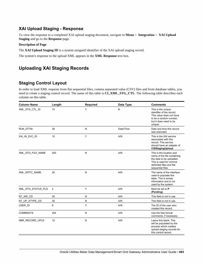
Oracle Utilities Meter Data Management/Smart Grid Gateway Administrative User Guide • 493
XAI Upload Staging - ResponseTo view the response to a completed XAI upload staging document, navigate to Menu > Integration > XAI UploadStaging and go to the Response page.
Description of Page
The XAI Upload Staging ID is a system assigned identifier of the XAI upload staging record.
The system's response to the upload XML appears in the XML Response text box.
Uploading XAI Staging Records
Staging Control LayoutIn order to load XML requests from flat sequential files, comma separated value (CSV) files and from database tables, youneed to create a staging control record. The name of this table is CI_XML_STG_CTL. The following table describes eachcolumn on this table.
Column Name Length Required Data Type CommentsXML_STG_CTL_ID 10 Y N This is the unique
identifier of the record.This value does not haveto be a random number,but it does need to beunique.
RUN_DTTM 26 N Date/Time Date and time this recordwas executed.
XAI_IN_SVC_ID 10 Y A/N This is the XAI serviceassociated with thisrecord. This serviceshould have an adapter ofCISStagingUpload.
XML_STG_FILE_NAME 250 N A/N This is the location andname of the file containingthe data to be uploaded.This is used for commadelimited files and flatsequential files.
XML_INTFC_NAME 30 N A/N The name of the interfaceused to populate thistable. This is simplyinformation and is notused by the system.
XML_STG_STATUS_FLG 2 Y A/N Must be set to P(Pending).
NT_XID_CD 30 N A/N This field is not in use.
NT_UP_XTYPE_CD 30 N A/N This field is not in use.
USER_ID 8 Y A/N The ID of the user whocreated this record.
COMMENTS 254 N A/N Use the free formatcomments, if necessary.
NBR_RECORD_UPLD 10 N A/N Leave this blank. Thiswill be populated by theprocess which createsupload staging records forthis control record.
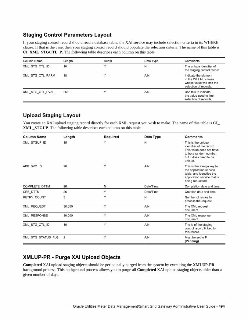
Oracle Utilities Meter Data Management/Smart Grid Gateway Administrative User Guide • 494
Staging Control Parameters LayoutIf your staging control record should read a database table, the XAI service may include selection criteria in its WHEREclause. If that is the case, then your staging control record should populate the selection criteria. The name of this table isCI_XML_STGCTL_P. The following table describes each column on this table.
Column Name Length Req'd Data Type Comments
XML_STG_CTL_ID 10 Y N The unique identifier ofthe staging control record.
XML_STG_CTL_PARM 18 Y A/N Indicate the elementin the WHERE clausewhose value will limit theselection of records.
XML_STG_CTL_PVAL 250 Y A/N Use this to indicatethe value used to limitselection of records.
Upload Staging LayoutYou create an XAI upload staging record directly for each XML request you wish to make. The name of this table is CI_XML_STGUP. The following table describes each column on this table.
Column Name Length Required Data Type CommentsXML_STGUP_ID 15 Y N This is the unique
identifier of the record.This value does not haveto be a random number,but it does need to beunique.
APP_SVC_ID 20 Y A/N This is the foreign key tothe application servicetable, and identifies theapplication service that isbeing requested.
COMPLETE_DTTM 26 N Date/Time Completion date and time.
CRE_DTTM 26 Y Date/Time Creation date and time.
RETRY_COUNT 3 Y N Number of retries toprocess the request.
XML_REQUEST 30,000 Y A/N The XML requestdocument.
XML_RESPONSE 30,000 Y A/N The XML responsedocument.
XML_STG_CTL_ID 10 Y A/N The id of the stagingcontrol record linked tothis record.
XML_STG_STATUS_FLG 2 Y A/N Must be set to P(Pending).
XMLUP-PR - Purge XAI Upload ObjectsCompleted XAI upload staging objects should be periodically purged from the system by executing the XMLUP-PRbackground process. This background process allows you to purge all Completed XAI upload staging objects older than agiven number of days.

Oracle Utilities Meter Data Management/Smart Grid Gateway Administrative User Guide • 495
We want to stress that there is no system constraint as to the number of Completed XAI upload staging objects thatmay exist. You can retain these objects for as long as you desire. However we recommend that you periodically purgeCompleted XAI upload staging objects as they exist only to satisfy auditing and reporting needs.
XAI Upload ExceptionA record is written to the XAI upload exception table for every XAI upload staging record that is in error.
To view the messages associated with the exception records, schedule the TD-XAIUP background process. This processgenerates a To Do entry for every record in the XAI upload exception table.
After correcting the cause of the error, drill into the XAI Upload Staging page and change the status from Error to Pendingand the system will attempt to process the record again.
XAI Download Staging
XAI Download Staging - MainTo view individual XAI download staging records associated with a notification download staging record, open Menu > Integration > XAI Download Staging.
Description of Page
XAI Download Staging displays information about the record.
The Download Staging ID and XAI Route Type are the primary identifiers for this record.
The XAI Download Status is displayed. The values are Pending, Complete, Canceled or Error. When a record is inError, it is displayed on the XAI Download Exception table.
Values from the NDS record associated with this XAI download staging record are displayed including Service Provider,Notification Download Type, NT Download Status Flag, Retry Count and the Context collection.
XAI Download Staging - RequestTo display the XAI Request built by the download staging receiver, open Menu > Integration > XAI Download Staging.
Description of Page
The XML Request built by the download staging receiver is displayed.
XAI Download Staging - ResponseTo display the Response to this request, open Menu > Integration > XAI Download Staging.
Description of Page
The XML Response to this message is displayed.
XAI Download ExceptionA record is written to the XAI download exception table for every XAI download staging record that is in error.
To view the messages associated with the exception records, schedule the TD-XAIDN background process. This processgenerates a To Do entry for every record in the XAI download exception table.
Oracle Utilities Meter Data Management/Smart Grid Gateway Administrative User Guide • 496
Maintaining Your XAI EnvironmentThis section describes various tools provided to enable your XAI administrators to more easily maintain your XAIenvironment.
XAI SubmissionThis page exists for testing purposes. It allows you to create an XML request document and submit it to the system, toensure that the XML has been built correctly.
XAI Submission - MainTo submit an XML document for testing, navigate to Admin > XAI > XAI Submission and navigate to the main tab.
Description of PageThis page is used to test XML schemas, which are defined for the XAI tool. Enter an appropriate XML document in theXML Request field. Typically, you define the XML schema using the schema editor in the XAI application. Then youwould copy and paste the document here, then modify the schema to enter actual data for testing purposes.
When you have entered the document, choose Save to submit this document to the system. Note that this requestinformation is not saved anywhere. It simply calls the system with the appropriate service name and executes the XMLrequest.
Navigate to the Response tab to view the response.
XAI Submission - ResponseTo view the response to a XML document for testing, navigate to the response tab.
Description of Page
After choosing Save on the main tab to submit a test for an XML request, the response to your request is displayed in theXML Response text box.
Additional XAI ToolsThis section introduces some additional tools to help you maintain your XAI environment.
XAI Service ExportThe service export page allows you to export the definition of an XAI Inbound Service to a file. This function may behelpful if you need to copy the definition of this service to a separate environment. To export a service, open Admin > XAI> XAI Service Export.
Description of Page
Upon entry into this page, you are provided with the current list of XAI In bound Services and their Description s. Use theXAI In Service Name search field to find the XAI service that you would like to export.
Use the Export? column to indicate which XAI service(s) you would like to export. Once you have selected your services,choose Save.

Oracle Utilities Meter Data Management/Smart Grid Gateway Administrative User Guide • 497
NOTE: If multiple services are selected, they are exported together into the same output file.
You are presented with the standard File Download dialogue where you can open or save the file.
XAI Service ImportThe service import page allows you to import the definition of an XAI Inbound Service from a file into the XAI servicetable. This function may be helpful if you need to copy in the definition of this service from a separate environment. Toimport a service, open Admin > XAI > XAI Service Import.
Description of Page
Upon initial entry into this page, you are provided with an input field, where you can enter the file name to import. ClickBrowse to search for the desired file in a directory.
Once the file is identified, click Read File, to read in the contents of the file.
NOTE: The format of the file must include tags indicating the column names for XAI Inbound Service table along withthe values of the columns. For an example of how the format should be, simply go to the XAI Service Export page,export a Service and view the format of the resulting file.
Once the file has been read in, the list of XAI services found defined within the file is displayed in the Import grid,identified by their XAI In Service Name and Description. In the Import? column, indicate which services to import.
If a service with this service name already exists in the table, you must check the Overwrite Existing switch in order toindicate that the imported file information should replace the current service. An XAI Inbound Service that is provided aspart of the system (i.e., with an owner of Base Product) may not be overwritten.
Click Save to proceed with the import. If any problems are found, information is displayed in the Message Text column.
XAI CommandUse the XAI Command page to send commands to the XAI and MPL server. To execute a command, open Admin > XAI >XAI Command.
Description of PageThe following operator commands may be sent to the XAI server. For each of these commands, you may check Also Sentto MPL URL, in which case, the command is also sent to the MPL server. You need to indicate the URL of the MPLserver.
Display Registry Use this command to display the current registry information that the XAI instance is running with.
Refresh Code and Description This is related to an attribute in the schema editor where you may indicate that thedescription of a control table code should be returned along with the code itself. This information is kept in cache memoryin the server. As a result, changes made to descriptions have no effect on the runtime server. This command clears the cacheof control table codes and descriptions accessed by the server.
Refresh Registry The registry contents are kept in cache memory in the server. As a result, making changes to the registrycontrol tables has no effect on the runtime server. Use this command to refresh the contents of the registry cache with thenew values in the registry control tables. The command reloads all registry control table data into the server.
Refresh Schema Schema definitions are stored in cache memory on the XAI server. As a result, modifying a schemadefinition has no effect on the runtime server. To refresh schema definitions, use the Refresh Schemas command.
Refresh Service Service definitions are stored in cache memory on the XAI server. As a result, modifying an XAI inboundservice definition has no effect on the runtime server. To refresh service definitions, use the Refresh Service command. Youare prompted to indicate which service to refresh.
Oracle Utilities Meter Data Management/Smart Grid Gateway Administrative User Guide • 498
Refresh XSL XSL Transformation script definitions are stored in cache memory on the XAI server. As a result, modifyingan XSL transformation definition has no effect on the runtime server. To refresh XSL transformation definitions, use theRefresh XSL command.
Trace On Use this command to start the XAI server trace.
Trace Off Use this command to stop the XAI server trace.
XAI Trace Clear Use this command to clear the contents of the trace file.
XAI Trace Swap Use this command to rename the current trace file by appending the date and time to the end. A newtrace file is then created with the name as defined in the Message option page.
The following operator commands can be sent to the MPL server. You must set the URL of the MPL server first.
MPL Refresh Executer Executer definitions are stored in cache memory. As a result, adding or modifying executerdefinitions has no effect on the runtime server. Use this command to refresh executer definitions. You are prompted toindicate the executer to refresh.
MPL Refresh Receiver Receiver definitions are stored in cache memory. As a result, adding or modifying receiverdefinitions has no effect on the runtime server. Use this command to refresh receiver definitions. You are prompted toindicate the receiver to refresh.
MPL Refresh Sender Sender definitions are stored in cache memory. As a result, adding or modifying sender definitionshas no effect on the runtime server. Use this command to refresh sender definitions. You are prompted to indicate the senderto refresh.
MPL Start Receiver Use this command to start a particular receiver. You are prompted to indicate the receiver to start.
MPL Stop Use this command to stop all MPL activity. It stops all receivers and waits for all executers and senders tocomplete.
MPL Stop Receiver Use this command to stop a particular receiver. You are prompted to indicate the receiver to stop.
MPL Trace On Use this command to start the MPL server trace.
MPL Trace Off Use this command to stop the MPL server trace.
When you have chosen the appropriate command and indicated any extra information, click Send Command to send thecommand to the server(s).
If you have sent a command to the XAI Server, then the bottom portion of the screen displays the response in the XAIResponse. If you have sent a command to the MPL Server, then the bottom portion of the screen displays the response inthe MPL Response. If you have sent a command to both servers, the bottom portion of the screen displays both responses.
MPL ExceptionThe MPL Exception table is used by the MPL to keep information about requests that resulted in a system error. These areerrors that occurred inside the MPL. For example, if the MPL fails to send a request to XAI (maybe WebLogic is down),this is a system error, which would be logged in the MPL exception table.
There are errors that are defined recoverable. This means that the MPL will retry the action that failed, according to theparameters it received.
Server TraceThe XAI server traces every request and response. The requests/responses are written to a trace file on the server. The tracefile may be viewed using the Trace Viewer.

Oracle Utilities Meter Data Management/Smart Grid Gateway Administrative User Guide • 499
Starting the TraceThe log starts automatically based on definitions in the Message Options in the traceType and traceFile options. Tomanually start the trace:
• Navigate to Admin > XAI > XAI Command.
• Select the Start Trace command from the command dropdown
• Click Send Command
Stopping the Trace• Navigate to Admin > XAI > XAI Command.
• Select the Stop Trace command from the command dropdown
• Click Send Command
Trace ViewerUse the Trace Viewer utility to view the log file. The Trace Viewer is installed when you install the XAI client tools. It canbe found in the XAI program group under Start/Programs.
Main PageWhen the Trace Viewer starts, select a trace file to view. A trace file may be opened in one of two ways:
• To open a trace file directly from its location on the web application server, use the File, Open HTTP menu item andprovide the appropriate URL.
• To open a trace file on the local/network file system use the File, Open menu item
Description of Page
Once a trace file is opened, it displays a list of all the requests on the left side including the Service Name, the Start Timeand the End Time.
To display the XML contained in the request and response entries for a displayed request, select a request entry.
Filtering Options
Since the trace file may contain a very large number of messages, the trace viewer limits the number of messages that canbe displayed. It does that by displaying messages traced within the last x number of Minutes, Hours or Days.
Use the Max Messages to limit the number of messages displayed.
NOTE: Default Note. By default, the Trace viewer displays the first 200 messages in the trace file.
To view only errors in the trace, check the Show only Errors option.
NOTE: Refresh Display. After changing any of the above filtering options, click the refresh button in order toredisplay the request entries based on the new options.
The First Message Found field indicates the date and time of the earliest entry in the trace file.
Viewing as Text
Oracle Utilities Meter Data Management/Smart Grid Gateway Administrative User Guide • 500
To view the trace file as text rather than viewing each entry in its XML format, use the View, As Text menu option. Thecontents of the trace file are displayed in text format in a separate window.
Statistics PageUse the View, Statistics menu item to view the statistic page, which displays performance statistics about the XAI servicesthat were executed in the XAI trace file.
For each type of XAI Service and transaction type, it displays the following information based on the requests traced in theXAI trace file:
• The Service Name with the transaction type in parentheses
• The Number of calls for this service in the listed trace records
• The Average duration Time (in seconds)
• The Max imum duration Time (in seconds)
• The Min imum duration Time (in seconds)
NOTE: Requests Included in Statistics. Only requests falling in the time selection criteria and listed on the main logviewer are processed for calculating the statistics.
To display a Duration Chart for a particular service, check the Service. A chart such as the one below is displayed.
IntegrationsThis chapter provides high level information about product integrations supported for all products that use Oracle UtilitiesApplication Framework.
LDAP IntegrationOrganizations commonly use a Lightweight Directory Access Protocol (LDAP) security repository as a source of securitycredentials. The system provides support for importing users and groups from an external LDAP repository into the productto populate Users and User Groups in the system. Once imported, all user and group functions are available. You canresynchronize your LDAP users and groups at any time.
NOTE: Import only. The system currently supports importing LDAP information. Exporting users and groups from thesystem to LDAP is not provided.
NOTE: Additional configuration. When importing new users and / or groups, additional configuration is needed inthe base product. For example, after importing a new user group and its users, the user group configuration should beupdated to define the valid application services for the user group. After importing a new user, additional configurationmay be needed on the user such as valid To Do Roles, valid Home Page, etc.
FASTPATH: Refer to Defining Security and User Options for more information about the application security and whatit controls.
This section the functionality provided in the framework application that supports LDAP. Refer to the LDAP Integrationwhite paper for more information about typical steps related to the full integration.

Oracle Utilities Meter Data Management/Smart Grid Gateway Administrative User Guide • 501
LDAP Integration OverviewThis topic provides a high level overview of the integration process.
At a high level, the base product provides a process to import user group and / or user definitions from and LDAPrepository. This is a one way integration.
• When importing a user, if it is not already found in the system, it will be added; otherwise its attributes will be updatedaccording to the imported information.
• When importing a user group, if it is not already found in the system, it will be added; otherwise its attributes will beupdated according to the imported information.
• When importing a user, its user group links will be updated as per the information in the import file. In addition, if thereare any user groups linked to the user that are not found system, they will be added (however, the other users linked tothat group in the LDAP repository will not be added as part of this step).
• When importing a user group, its user links will be updated as per the information in the import file. In addition, if thereare any users linked to the user group that are not found system, they will be added (however, the other user groupslinked to that user in the LDAP repository will not be added as part of this step).
• The import will not cause any deletions of the User or User Group to occur.
A Batch Process Initiates the ImportA batch process is used to initiate the import of information from the LDAP repository. F1–LDAP may be submitted ad hocor may be set up in a scheduler to periodically re-sync the information from the LDAP repository into the application.
The batch process uses parameters to define how to connect to the LDAP repository. In addition, parameters are used toindicate which user or group is being imported.
Adjusting Data to ImportThe system provides several mechanisms for adjusting data that is being added to the system:
• There is an LDAP Import Preprocess algorithm plug-in spot on the installation record. Algorithms plugged in hereare called by the batch process prior to the add or update of any records. It may be used to make adjustments to the databefore doing updates in the application.
• Specifically for creating or updating Users, the F1–IDMUser business object is used to add and create the user. Thestandard BO Preprocessing algorithm plug-in spot may be used to adjust data prior to creation.
• The LDAP mapping file supports some attributes to perform simple modifications to data.
• The transform attribute supports values to truncate values or to convert data to upper case.
• The autoGenerate attribute is specific to the User ID field. Setting this to true will trigger code that willautomatically populate the User ID based on the user’s name. Refer to LDAP Mapping for more information.
Performing Additional Processing After ImportThe system provides a plug-in spot on the installation record called LDAP Import. Algorithms plugged into this spot arecalled after users or user groups have been added or updated. It may be used to perform any extra processing that may needto be executed.
In addition, for any additional processing related to the creation or update of a User, the standard Business Object plug-insmay be used for the F1–IDMUser business object which the LDAP batch process uses to create or update users.
Oracle Utilities Meter Data Management/Smart Grid Gateway Administrative User Guide • 502
Configuring LDAP IntegrationTo interface the LDAP based security repository with the authorization component of the Oracle Utilities ApplicationFramework product the following must be performed:
• The location and port number of the LDAP based security repository must be defined to in the JNDI Server.
• • The LDAP based security repository must be mapped to the Oracle Utilities Application Framework security model.This mapping is expressed as an XML file containing the LDAP query, rules and defaults used in the transformation.
• • The mapping file must be configured on the F1-LDAP batch job.
Define the JNDI ServerThe first step in the configuration process is to define the location of the LDAP based security repository server so that theinterface can connect to the physical attributes of the interface. This is done by creating a JNDI Server.
NOTE: The LDAP server is strictly not a JDNI source but is treated as a JNDI source for the integration.
Enter a reasonable JNDI Server name and description.
Populate the Provider URL using the format ldap://<hostname>:<portnumber> where <hostname> is the host of theLDAP server and <portnumber> is the port used for the interface.
For the Initial Context Factory, the interface uses the standard com.sun.jndi.ldap.LdapCtxFactory provided withjava for the LDAP interface. If your vendor supplies a custom context factory it may be used. Refer to the documentationprovided with your LDAP based security repository for further information.
Define MappingThe critical component of the interface is a file that describes the mapping between the LDAP based security repository andthe system’s security model. This file contains the mapping, rules and queries used by the LDAP batch program to providethe interface. The LDAP batch job includes the reference to the mapping file as a parameter. Refer to LDAP Mapping formore information on defining the mapping file.
Configure LDAP Batch ProcessAt this point, many parameters for the F1–LDAP batch control can be updated with system wide configuration.
• JDNI Server, User and Password may all be configured appropriately. Note that it is recommended that the Securitysetting for the Password be set to Encrypt.
• The LDAP Configuration File should be populated with the name and location of the LDAP Mapping file.
• If the LDAP service has any limitation to the number of objects that may be imported, configure the LDAP Query PageSize parameter to enable querying.
NOTE: Group and User Parameters. The assumption is that the Group or User input parameters are specific to agiven import request and as such would not be populated as part of a configuration step.
NOTE: L2 Cache. The LDAP Import batch process requires the L2 Cache to be disabled since it needs toperform some updates in the outside of the worker threads. Any environment using LDAP Import must setspl.runtime.batch.L2CacheMode=OFF in the threadpoolworker.properties file. It is recommended to run the LDAPimport in its own dedicated threadpoolworker.
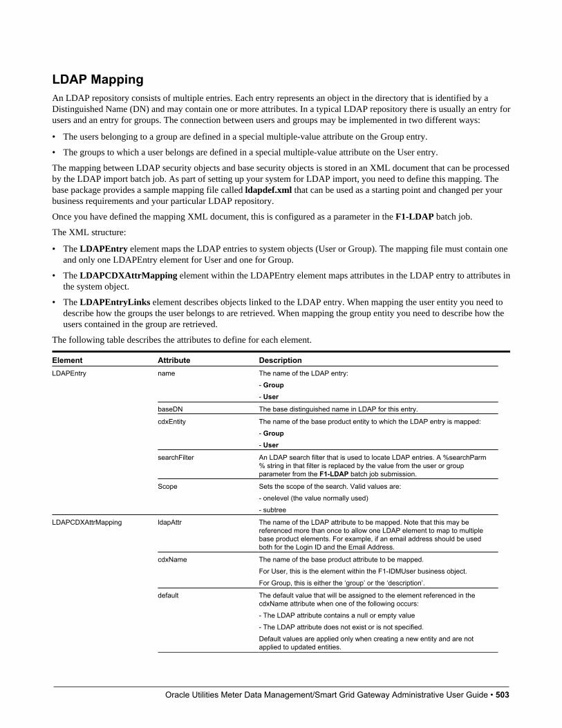
Oracle Utilities Meter Data Management/Smart Grid Gateway Administrative User Guide • 503
LDAP MappingAn LDAP repository consists of multiple entries. Each entry represents an object in the directory that is identified by aDistinguished Name (DN) and may contain one or more attributes. In a typical LDAP repository there is usually an entry forusers and an entry for groups. The connection between users and groups may be implemented in two different ways:
• The users belonging to a group are defined in a special multiple-value attribute on the Group entry.
• The groups to which a user belongs are defined in a special multiple-value attribute on the User entry.
The mapping between LDAP security objects and base security objects is stored in an XML document that can be processedby the LDAP import batch job. As part of setting up your system for LDAP import, you need to define this mapping. Thebase package provides a sample mapping file called ldapdef.xml that can be used as a starting point and changed per yourbusiness requirements and your particular LDAP repository.
Once you have defined the mapping XML document, this is configured as a parameter in the F1-LDAP batch job.
The XML structure:
• The LDAPEntry element maps the LDAP entries to system objects (User or Group). The mapping file must contain oneand only one LDAPEntry element for User and one for Group.
• The LDAPCDXAttrMapping element within the LDAPEntry element maps attributes in the LDAP entry to attributes inthe system object.
• The LDAPEntryLinks element describes objects linked to the LDAP entry. When mapping the user entity you need todescribe how the groups the user belongs to are retrieved. When mapping the group entity you need to describe how theusers contained in the group are retrieved.
The following table describes the attributes to define for each element.
Element Attribute Descriptionname The name of the LDAP entry:
- Group- User
baseDN The base distinguished name in LDAP for this entry.
cdxEntity The name of the base product entity to which the LDAP entry is mapped:- Group- User
searchFilter An LDAP search filter that is used to locate LDAP entries. A %searchParm% string in that filter is replaced by the value from the user or groupparameter from the F1-LDAP batch job submission.
LDAPEntry
Scope Sets the scope of the search. Valid values are:- onelevel (the value normally used)- subtree
ldapAttr The name of the LDAP attribute to be mapped. Note that this may bereferenced more than once to allow one LDAP element to map to multiplebase product elements. For example, if an email address should be usedboth for the Login ID and the Email Address.
cdxName The name of the base product attribute to be mapped.For User, this is the element within the F1-IDMUser business object.For Group, this is either the ‘group’ or the ‘description’.
LDAPCDXAttrMapping
default The default value that will be assigned to the element referenced in thecdxName attribute when one of the following occurs:- The LDAP attribute contains a null or empty value- The LDAP attribute does not exist or is not specified.Default values are applied only when creating a new entity and are notapplied to updated entities.
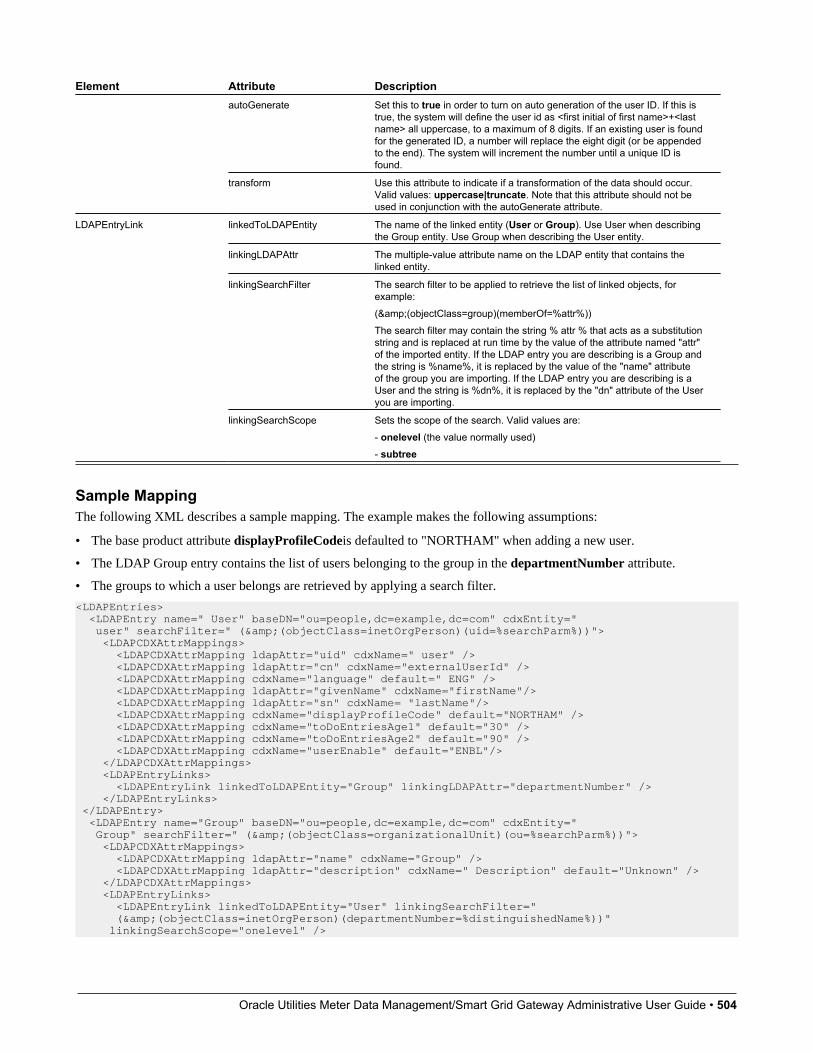
Oracle Utilities Meter Data Management/Smart Grid Gateway Administrative User Guide • 504
Element Attribute DescriptionautoGenerate Set this to true in order to turn on auto generation of the user ID. If this is
true, the system will define the user id as <first initial of first name>+<lastname> all uppercase, to a maximum of 8 digits. If an existing user is foundfor the generated ID, a number will replace the eight digit (or be appendedto the end). The system will increment the number until a unique ID isfound.
transform Use this attribute to indicate if a transformation of the data should occur.Valid values: uppercase|truncate. Note that this attribute should not beused in conjunction with the autoGenerate attribute.
linkedToLDAPEntity The name of the linked entity (User or Group). Use User when describingthe Group entity. Use Group when describing the User entity.
linkingLDAPAttr The multiple-value attribute name on the LDAP entity that contains thelinked entity.
linkingSearchFilter The search filter to be applied to retrieve the list of linked objects, forexample:(&(objectClass=group)(memberOf=%attr%))The search filter may contain the string % attr % that acts as a substitutionstring and is replaced at run time by the value of the attribute named "attr"of the imported entity. If the LDAP entry you are describing is a Group andthe string is %name%, it is replaced by the value of the "name" attributeof the group you are importing. If the LDAP entry you are describing is aUser and the string is %dn%, it is replaced by the "dn" attribute of the Useryou are importing.
LDAPEntryLink
linkingSearchScope Sets the scope of the search. Valid values are:- onelevel (the value normally used)- subtree
Sample MappingThe following XML describes a sample mapping. The example makes the following assumptions:
• The base product attribute displayProfileCodeis defaulted to "NORTHAM" when adding a new user.
• The LDAP Group entry contains the list of users belonging to the group in the departmentNumber attribute.
• The groups to which a user belongs are retrieved by applying a search filter.
<LDAPEntries> <LDAPEntry name=" User" baseDN="ou=people,dc=example,dc=com" cdxEntity=" user" searchFilter=" (&(objectClass=inetOrgPerson)(uid=%searchParm%))"> <LDAPCDXAttrMappings> <LDAPCDXAttrMapping ldapAttr="uid" cdxName=" user" /> <LDAPCDXAttrMapping ldapAttr="cn" cdxName="externalUserId" /> <LDAPCDXAttrMapping cdxName="language" default=" ENG" /> <LDAPCDXAttrMapping ldapAttr="givenName" cdxName="firstName"/> <LDAPCDXAttrMapping ldapAttr="sn" cdxName= "lastName"/> <LDAPCDXAttrMapping cdxName="displayProfileCode" default="NORTHAM" /> <LDAPCDXAttrMapping cdxName="toDoEntriesAge1" default="30" /> <LDAPCDXAttrMapping cdxName="toDoEntriesAge2" default="90" /> <LDAPCDXAttrMapping cdxName="userEnable" default="ENBL"/> </LDAPCDXAttrMappings> <LDAPEntryLinks> <LDAPEntryLink linkedToLDAPEntity="Group" linkingLDAPAttr="departmentNumber" /> </LDAPEntryLinks> </LDAPEntry> <LDAPEntry name="Group" baseDN="ou=people,dc=example,dc=com" cdxEntity=" Group" searchFilter=" (&(objectClass=organizationalUnit)(ou=%searchParm%))"> <LDAPCDXAttrMappings> <LDAPCDXAttrMapping ldapAttr="name" cdxName="Group" /> <LDAPCDXAttrMapping ldapAttr="description" cdxName=" Description" default="Unknown" /> </LDAPCDXAttrMappings> <LDAPEntryLinks> <LDAPEntryLink linkedToLDAPEntity="User" linkingSearchFilter=" (&(objectClass=inetOrgPerson)(departmentNumber=%distinguishedName%))" linkingSearchScope="onelevel" />

Oracle Utilities Meter Data Management/Smart Grid Gateway Administrative User Guide • 505
</LDAPEntryLinks> </LDAPEntry></LDAPEntries>
Oracle Identity Manager IntegrationThe Oracle Identity Manager product allows a site to centralize their user definitions and password rules to manage anddeploy across the enterprise set of products. When an employee joins an organization, changes their name or departs anorganization their security presence across an enterprise must be appropriately managed. Oracle Identity Manager allows forusers to be provision and managed in a central location.
An integration is provided to allow the ability to create, maintain and remove users in the identity management productand sync those changes to the users defined in the application. The following sections provide additional details about theintegration with respect to configuration steps required in an Oracle Utilities Application Framework based product. Formore information about the configuration required in the identity management product, refer to the Identity ManagementSuite Integration white paper.
In order to use this functionality, feature configuration options for the External Messages feature type must be configured.
• Set option type Support SPML Deployment in IWS to true.
• Set option type Default SPML service security policy to an appropriate value per your implementation rules.
Template User FunctionalityThe user object in this product captures configuration used to control access but also preferences. The identify managementproduct allows for extending the configuration to capture user configuration that is specific to this product. However, it doesnot support providing searches or dropdowns to select valid values. For example, to define the user’s Home Page requiresthe reference to a navigation option. To set up your business process such that the home page is configured when definingthe user in the identity management product dictates that the security user types in the correct navigation option reference.
On the other hand, to define a minimal amount of user information in the identity management product may result in atwo step process for defining users: first define them in the identity management product with the basic authenticationdetails and setting system defaults for some important fields, then after submitting the new user to be added to this product,navigate to the user page in this product and fill in all the configuration that is specific to this product.
The product provides support for defining a template user that can facilitate the definition of users and reduce some of thechallenges listed above. The concept is as follows:
• Define a template user for each broad category of users in the system. For example, Oracle Utilities Mobile WorkforceManagement may define the following template users: Dispatcher, Mobile Worker, System Administrator andContractor. Each user would define the typical configuration for users of that type including the home page, the usergroups, the To Do roles, the portal preferences, etc.
• When extending the configuration in the identity manager product, simply map the information that is unique to a userand in addition, define a field for the template user. For example, you may choose to only capture the Name (first andlast), Email address and User IDs for the user along with its Template User (which is mapped to a user characteristic).Additional fields may be included for capture in the identity management product when defining new users as per animplementation’s business needs. For example, if the organization covers multiple time zones, perhaps it is easier todefine the user’s time zone when defining the user in the identity management product.
• When the new user is uploaded to the system, the interface uses the user BO F1–IDMUser to create the user. The BOincludes a preprocessing algorithm that looks for the existence of a template user (sent as a characteristic of type F1-TMUSR). All the information from the template user will be copied onto the new user record except for the informationpassed in from the identity manager. The template user is captured on the newly created user via a characteristic forinformation / audit purposes.
• Once the new user is created, its configuration can now be adjusted, if applicable. Note that the template user is only atool used when adding a user. Updates to the template user will not “ripple” to all the other users that were created basedon this template.
Oracle Utilities Meter Data Management/Smart Grid Gateway Administrative User Guide • 506
Configuring Template UsersBefore configuring template users, all the administrative control tables that are part of User configuration must be defined,including time zones, display profiles, To Do roles, data access roles and user groups.
The next step is to define the user configuration for your system users. During this exercise, you will find that you havebroad categories of users. But you will also see that within a given category of user there may be variations in the userprivileges and preferences. For example, perhaps there are supervisors within the Mobile Worker role that have moresecurity privileges than a typical Mobile Worker. In addition, there may be variations based on the attributes of the usersthemselves. For example, maybe your organization exists in multiple time zones and some of your workers are in one timezone and some are in the other.
At this point your security users that are designing their user provisioning procedures must decide the following:
• What information about a new user will be captured in the identity system (besides the expected information like Name,Email and the User IDs)? For example, for the case of multiple time zones, maybe the best solution is to capture the timezone when defining the user.
What information is defined on the template user and how many template users should be created to reduce the needfor manual steps or additional data captured in the identity management system? In the case of multiple time zones,proliferating the template users to have one set for one time zone and another set for the other time zone may not makesense since this is one field that is different. However it may be reasonable to create additional templates in the case ofstriations in the levels of privileges for workers of a different category. So rather than template users for Dispatcher,Mobile Worker, System Administrator and Contractor, your organization may have template users for Dispatcher,Mobile Worker, Mobile Worker (Supervisor), System Administrator, Contractor (Short Term) and Contractor (LongTerm).
What information is must be configured one the User record in the application after the user is added? If only a smallnumber of users have a variation from other users, it may be that the easiest way to deal with those variations is to simplyupdate those user records manually. Using the above examples:
• If your organization covers 2 time zones but only a small group of people work in one of the time zones whereasthe bulk of the users are in the other time zone, the simplest procedure may be to define the template users for themain time zone and use that for the creation of all users. Then for the small group of users in the separate time zone,navigate to the User page to adjust the time zone after the record is added.
• If only a small number of Mobile Workers are supervisors with separate privileges, rather than defining a specialtemplate user for those type of workers, the simpler procedure may be to use the Mobile Worker template and thennavigate to the User page to add the additional privileges to the supervisor users after the record is added.
To create a template user, navigate using Admin > Security > User.
• Define a User ID that will become the template user reference in the identity management system.
• Be sure to choose a User Type of Template User.
• Define all the information that should be copied onto a new user that references this user as a template user. Note thatBookmarks are not included in the data that is copied from a template user.
NOTE: There is configuration needed in Oracle Identity Management to capture the template user and any otherinformation that the implementation has chosen to define in the identity management product when provisioning a newuser. Refer to the Identity Management Suite Integration white paper for more information.
Batch Scheduler IntegrationThe Oracle Database includes an enterprise wide scheduler to simplify the scheduling of background processes. Thescheduler is implemented by the DBMS_SCHEDULER package. The product provides an integration with the OracleScheduler to facilitate scheduling background processes shipped with the product.
Oracle Utilities Meter Data Management/Smart Grid Gateway Administrative User Guide • 507
At a high level, the integration with the Oracle DBMS Scheduler supports the following entities:
• DBMS Program. A program should be defined for each Batch Control that needs to be scheduled by the DBMSscheduler. A program would typically invoke a batch job, but it could be configured to set certain options instead.
• DBMS Chain. A Chain defines a series of steps with dependency rules between them. A step references a program,with the program performing the actual work for that step. A rule is attached to each step to identify its dependent stepsand the condition for when that step should be executed. For example, in a chain consisting of STEP_A and STEP_B, where STEP_B can only start if STEP_A was successful, the rule for STEP_B to start would specify a condition of"STEP_A SUCCEEDED".
• DBMS Schedule. A predefined frequency for jobs that need to be run periodically, for example, nightly jobs.
• DBMS Job. Defines a plan to perform a specific program or a chain periodically on a specific schedule or ad-hoc.
The product provides a set of business services to maintain these entities as well as submit jobs, manage submissions andreport on past submissions. Refer to business services that start with the prefix "F1-DBMS" for more information.
NOTE: For details on the integration, refer to the Server Administration Guide which contains the API. In addition,refer to the white paper Oracle Scheduler Integration that provides guidelines for using this integration.
Data SynchronizationYour implementation may need to communicate certain data to external systems. This may be part of a data warehousingrequirement or an integration effort. The synchronization process has two main parts. First, the change to the data mustbe detected and captured. Once that is accomplished, the next step is to manage the communication of that change to theexternal systems involved. The changes must be captured in chronological order so as to avoid systems going out of sync.
About Data SynchronizationThe following sections describe general supported functionality in more detail using the logic supplied in the base businessobject F1-SyncRequest. Note that each edge application delivers an appropriate child business object for this BO for eachspecific synch scenario supported in that product. Some of the functionality below is accomplished using configurationon the parent BO delivered by the framework while other functionality may be delivered by the child BO. In addition,there may be more complex use cases supported by your specific product integration. Refer to your specific application’slibrary of Sync Request business object along with the documentation related to your specific product integration for moreinformation.
Capturing the ChangeThe base product uses the Audit plug-in spot on the maintenance object to allow for logic to be performed by the systemwhen a change is detected to a record for that MO. The framework calls the algorithm defined on this plug-in spot inthe event a change to the MO has been detected. Refer to the description of the plug-in spot on Maintenance Object —Algorithms for more information about when this plug-in is called.
The base product provides an change data capture algorithm F1-GCHG-CDCP that may be used by maintenance objects.This algorithm creates a Sync Request record for each changed record, capturing the MO code and the primary key, if itdoesn’t find an existing sync request for the same record (and the same business object) in the initial state. The sync requestbusiness object used is the one defined in the Sync Request BO option on the MO for the record that was changed.
Your specific product may also introduce additional Audit algorithms to cater for more sophisticated examples. Click hereto see the algorithm types available for this system event.
When creating the sync request record, typically the Sync Request BO will have a pre-processing plug-in that captures asnapshot of the record’s data prior to its change. This will be used in subsequent steps to verify that the external systemneeds to be notified of the change.
Oracle Utilities Meter Data Management/Smart Grid Gateway Administrative User Guide • 508
Confirming that a Sync is NeededOnce a sync request is captured, there are several steps performed prior to any information being sent to the external system.
NOTE: This section only highlights key steps. Please refer to the business object configuration, its lifecycle andalgorithms for a thorough picture of the full functionality..
• When a Sync Request record is created, its initial state (Pending) is configured to be processed by a batch monitor.That way, records are added to the sync request table added throughout the day but all are processed together. The MOaudit algorithm ensures that a new synch request is not created if a Pending record already exists for a given MO / PKcombination (for the same business object). However, it is possible that a record for that MO / PK exists in a subsequent“non-final” (such as Awaiting Acknowledgement). This state includes a monitor algorithm to check for that conditionand to skip transitioning if another record exists. This is done to ensure that the existing record is fully processed beforethis new record is processed.
• The next state of the lifecycle is Determine if Sync Needed. This step uses an algorithm to take a snapshot (called the‘final snapshot’) of the data and compare it against the initial snapshot taken when the record was created. Based on thelogic of the algorithm, it may decide to proceed (transition to Send Request or to discontinue (transition to Discarded.
Communicating to the External SystemOnce it is confirmed that the sync should occur, a message must be sent to the external system. The following pointshighlight the basic functionality.
• An algorithm linked to the Send Request state. The expectation is that this algorithm creates an outbound messagethat routes the information to the external system appropriately. The algorithm must determine the external system andoutbound message type to use. Business objects for Sync Request support BO options to define the external system andoutbound message type to use for this algorithm.
• Once the outbound message is triggered, the record transitions to the Awaiting Acknowledgement status. Thisstate is used to hold the sync request from further state transitions until an acknowledgement is received from theexternal system. Note that this step relies on implementation of a response mechanism from the external system. It isrecommended to implement a response as this helps control the chronological flow of information. The product suppliesthe business service F1-UpdateSyncRequest that transitions the sync request to either the next default state (in thiscase the Synchronized state) if a positive acknowledgement is received; or the state associated with the Rejectiontransition condition (in this case the Error state) if a negative acknowledgement is received. In addition, this state maybe configured with a monitor algorithm that detects that a timeout limit has been reached.
• For records that enter the Error state, it is recommended to configure an algorithm that creates a To Do entry to alertsomeone of the problem. Refer to the integration documentation for more information. The state is already preconfiguredwith an algorithm to complete To Dos when exiting the state.
• The final state Synchronized is used to mark the successful synchronizations. However, for more complicated use cases,this state may be used to trigger some additional action. Refer to the documentation for your specific product integrationfor more information.
Maintaining Sync RequestsThe system provides a Sync Request portal that is used to view the in progress or completed sync request records.
The menu location of the portal depends on your specific edge product. It may be in a Data Synchronization menu orperhaps in the Batch menu. You are brought to a query portal with options for searching. The options may differ based onyour specific product.
Once a sync request has been selected, you are brought to the maintenance portal to view and maintain the selected record.
An Actions zone may appear to display specific actions. Alternatively, the actions may be displayed directly in the displayarea of the Sync Request zone.
Oracle Utilities Meter Data Management/Smart Grid Gateway Administrative User Guide • 509
The Sync Request zone provides basic information about the sync request record.
Depending on your specific product additional zones may appear.
Analytics IntegrationThe framework provides several building blocks and tools that the edge applications may use to implement integration withthe Oracle Utilities Analytics product (referred to in this section as the analytics product). The following sections providemore information about this functionality.
About Analytics IntegrationThe following sections describe the type of configuration supported in your product to integrate with the analytics product.Refer to the Oracle Utilities Analytics documentation for more information.
Master ConfigurationEdge applications that include an integration to the analytics product typically include a master configuration record thatcaptures information needed for the extract, load and transformation step, such as extract parameters. These records areprovided by the specific edge products and my be viewed and maintained on the master configuration portal.
Note that your specific edge application may deliver an Analytics Configuration portal that displays the information fromthe master configuration record along with other analytics related configuration.
Bucket ConfigurationThe analytics product provides support for defining a set of ranges, each representing a bucket for which extracted measurescan be grouped and classified under the relevant bucket. The framework product provides support for viewing and definingthe buckets. Refer to Bucket Configuration for more information.
Characteristic MappingThe product provides objects to allow mapping configuration of characteristics in the product to user defined fields ondimensions in the analytics product. Refer to ETL Mapping Control for more information.
Change Data Capture Using Sync RequestDepending on the specific edge application and version you are using, there may be components of the integration that useSync Request for the change data capture step. If that functionality applies to your implementation, the following pointshighlight how to get more information:
• Refer to the administration guide for Oracle Utilities Analytics to confirm if your product integration is using SyncRequest for any change data capture functionality.
• Review the Sync Request Business Objects provided by your product for analytics integration.
• Refer to Data Synchronization for a high level understanding of the process.
Maintaining Bucket ConfigurationsSeveral key performance indicators in the analytics product look at measurement values (for example: the age of an assetor the age of debt) classified into a number of pre-defined groups also known as buckets. The overall metric can then bereported by the different buckets and allow various analyses.
For example, the age of an asset can be classified into the following buckets:
• Less than 6 Months
Oracle Utilities Meter Data Management/Smart Grid Gateway Administrative User Guide • 510
• 6-12 Months
• One Year and Older
The age of debt, also known as arrears can be classified onto the following buckets:
• 0-30 Days
• 30-60 Days
• 60-90 Days
• 90+ Days
The definition of the buckets is extracted to the Business Intelligence data warehouse, to be used as dimensions.
Bucket Definition ConsiderationsEach type of bucket is defined using a bucket configuration Business Object. The bucket definition considerations and/orrules will vary based on the bucket configuration business object used. The business objects available are driven by yourspecific product. For a list of available bucket configurations business objects, navigate to the business object page and viewthe business objects for the Bucket Configuration maintenance object.
Setting Up Bucket ConfigurationsTo maintain the bucket ranges for the bucket configuration(s) applicable to your product, open Admin > AnalyticsConfiguration > Bucket Configuration.
You are taken to the query portal where you can search for an existing bucket configuration. Once a record is selected, youare brought to the maintenance portal to view and maintain the selected record.
NOTE: Your specific product may also include an Analytics Configuration portal that displays the list of existing andpotential bucket configuration records, allowing you to drill into this page to view the record in detail.
The Bucket Configuration zone provides basic information about the bucket configuration.
For more information about the elements supported refer to the zone’s help or to the relevant analytics integrationdocumentation for your product.
ETL Mapping ControlIf your implementation would like to map characteristic data in your application to user defined fields on dimensions in theanalytics product, the ETL mapping control provides configuration to support this.
ETL mapping control relies on configuration in the Allowed Target Dimensions extendable lookup. The extendable lookupis used to define each Target Table in the analytics product that has one or more user defined fields that may be populatedwith characteristic values. It also defines the valid characteristic entities that may act as the source for the characteristicdata.
NOTE: The framework does not provide any values in this lookup, but edge products that support mapping providevalues in this lookup. Please refer to your specific product’s integration chapter and refer to the Oracle UtilitiesAnalytics documentation for more information.
Setting up ETL Mapping ControlUse the ETL mapping control to define how to populate each target table (dimension) and target column (user defined field)by indicating the characteristic entity, characteristic type and for sequence-based characteristic, the sequence number.

Oracle Utilities Meter Data Management/Smart Grid Gateway Administrative User Guide • 511
NOTE: For sequence based characteristics, if the source entity captures multiple characteristic values for a givencharacteristic type, each characteristic type and sequence combination must be mapped to a specific target table andtarget column.
NOTE: Only Adhoc and Pre-defined characteristic types are supported.
To maintain the ETL mapping control records, open Admin > Analytics Configuration > ETL Mapping Control.
This is a standard All-in-One portal.
Refer to the embedded help text for more information.
Business FlagsIt is possible that information detected in one product may be useful or even critical to share with another product. Theframework provides functionality for receiving information from an external system that acts as a type of flag or alertthat may need investigation. This allows any system to store detected business flags in a common way and share thatinformation with one or more other systems.
About Business FlagsThe following is an example of a use case for business flags. Imagine that DataRaker highlights potential theft of service ata certain location. That product may initiate a business flag alert to various products owned by the implementation with arecognized "standard name" for the business flag, such as "TAMPER".
• If Oracle Utilities Meter Data Management receives this business flag, it may initiate a service investigation monitor.
• If Oracle Utilities Mobile Workflow Management receives this business flag, it may initiate a service investigationactivity.
• If Oracle Utilities Customer Care and Billing receives this business flag, it may initiate a hold on billing for that location.
Note that the framework product supplies basic functionality to support logic that is common to all edge applications thatimplement business flag functionality. However it is the individual edge applications that supply more specific functionality(business objects and algorithms) for specific use cases, if applicable.
The following sections highlight functionality supported for business flags in the framework. Refer to the edge applicationproduct documentation for more details for supported use cases.
Standard NameTo ensure that Business Flags are universally understood across all edge applications and to simplify integration eachBusiness Flag will have a Standard Name. This is a name that is used by all the products when sending information to eachother. That way, if DataRaker product sends Oracle Utilities Meter Data Management a "TAMPER" business flag, it shouldresult in the same functionality as when Utilities Customer Care and Billing sends a "TAMPER" business flag.
Business Flag Standard Names are defined using an extendable lookup. In addition to standard extendable lookup fields, thestandard name also references a category. In addition, the lookup supports defining one or more external names, for caseswhere information is communicated from an external system that does not send the expected Standard Name.
The framework does not deliver any standard names or category values. Refer to your specific edge application products toverify if any standard names or categories are delivered. Your implementation may configure appropriate standard namesand categories based on your business rules.
Oracle Utilities Meter Data Management/Smart Grid Gateway Administrative User Guide • 512
Business Flag Type Defines Behavior for a Standard NameAlthough the definition of the business flag standard names should be universally understood by the various integratedproducts that support them, each individual product defines what should occur when a business flag with a given standardname is created. This is configured using a business flag type. Only one active business flag type may exist for a givenstandard name. Business flags that are received from an external system will define the standard name, but will not haveknowledge of the specific business flag types defined. The business flag type is determined based on the standard name.
The business flag type defines the business object to use when creating the resulting business flag record. The businessobject defines the lifecycle of a resulting business flag record.
Business Flag Type AlgorithmsThe business flag type includes support for algorithms. This allows for an implementation to define a common businessobject that may be used for different business flag types (if a common lifecycle is followed) but allow for differentfunctionality to kick in depending on the business flag type.
The product supplies a plug-in spot for Additional Processing that may be invoked by a business flag that enters theAdditional Processing state. Refer to your product’s library of business objects to determine if there is an AdditionalProcessing state that supports calling algorithms on the business flag type.
Click here to see the algorithm types available for this system event.
Objects Linked to a Business FlagThere are two types of links between an object in the system and a given business flag.
Affected EntityEach business flag is associated with a single record in the system that is considered the “affected entity” or the entity thatthe business flag is associated with. The affected entity is defined by the specific business objects designed for the usecases supported by your edge product. For example, many utility base products may configure service point as the affectedentity for its business flag use cases. Each business flag created is linked to a specific service point. Linking a specificentity to each business flag allows for algorithms to trigger functionality for that entity such as an investigation order. Inaddition, algorithms may be implemented in other business process areas that look for the existence of a business flag andact accordingly.
Related ObjectsThe business flag supports linking one or more related objects to a business flag to make it easier to trigger functionality orfor impacted business processes to look for business flags. For example, when creating a business flag for a given servicepoint, it may be useful to link all the accounts that are currently linked to the service point. Then, if an account orientedprocess should check for a business flag, it can look directly for a business flag linked to the account in its related object.
Impacted Business ProcessThe product supplies support for associating one or more impacted business processes to a business flag type. Thisconfiguration is used when functionality for that business process is impacted in some way based on the existence of abusiness flag of a given type. For example, maybe some process is put on hold when a certain type of business flag exists.
Note that configuring a business process on business flag type is not enough to trigger any impact on that business processwhen a business flag exists. There must also be some logic implemented in the business process functionality itself thatknows to look for a business flag for a given record that is configured to impact the business process.
Oracle Utilities Meter Data Management/Smart Grid Gateway Administrative User Guide • 513
The definition of the business process is at the discretion of the edge application that supplies functionality to supportthis. For example, the business process could be defined as something broad such as “billing” or could be something moregranular such as “billing estimation”. The system supplies an extendable lookup to use for configuring the supportedbusiness processes. Refer to the values of the business process extendable lookup in your edge application or to the edgeapplication specific Business Flag documentation for more information about supported business processes.
DatesA business flag supports two dates: a Business Flag Date/Time and a Business Flag End Date/Time
• The business flag date / time is required for all business flags. For some types of business flags only one date is needed.
• For business flags that have a start and end period, the business flag date/time acts as the start date and the other field isthe end date.
For a business flag that has a date range, it may be important for functionality implemented for impacted business processes.How the process treats the date will depend on its functionality.
• For some processes, the business flag is essentially expired after the end date has passed. This applies to impactedprocesses that are only looking at the current status of data in the system. For example, collection processing could beheld if there is a business flag currently in effect (where the current date is within the date range). It would never look athistorical business flags.
• For some processes where historical data may be relevant, a business flag effective during that same historical periodmay impact the process. For example if a business flag denotes an outage event for a given time period, perhapsestimated consumption should never be calculated for that time period.
Note that because business flags have a status, the design for the lifecycle of the business objects for the above effectivedated use cases must carefully consider the states. For business flags that are considered expired after the end date passes,the BO lifecycle may be designed to transition to a final state after that date such that the record is no longer included inactive processing. For business flags that continue to impact processing for a historic period, the BO lifecycle may bedesigned to remain in a non-final state such that it is clear that the record is still applicable.
Creating Business FlagsBusiness flags may be created in a system for one of the following reasons:
• A message is received from an external system that initiates the creation of a business flag. In this case, logic in theexternal system has detected some situation that this product is being alerted about.
• Business logic in this product detects a situation that should be investigated or should act as a flag. In this scenario, theremay not be any integration needed depending on the business rules.
• Business logic in this product detects a situation that another integrated product should be alerted about. In this scenario,the business flag record is used to send out information to the integrated product.
• A user manually creates a business flag based on knowledge of the affected entity. For example, a customer servicerepresentative may create a business flag as a result of contact with the customer.
Creating a Business Flag from a Web ServiceThe system supplies an inbound web service Business Flag Sync Driver (F1-BusinessFlagSync) that may be used foran external system to initiate (or update) a business flag. It references a service script whose ultimate responsibility isto determine the appropriate Business Flag Type, based on the standard name or external standard name, and thereforethe appropriate business object for the new business flag. Because different products may have different logic related tocreating a business flag, the service script calls another service script linked to the maintenance object using the BusinessFlag Sync MO option.
Oracle Utilities Meter Data Management/Smart Grid Gateway Administrative User Guide • 514
The framework does not supply a Business Flag Sync service script, however individual edge applications supply a servicescript based on the use cases it supports out of the box.
NOTE: For products that are continuing to use XAI for external messages, the product also includes an XAI inboundservice for the same Business Flag Sync Driver service script. Note that the product recommendation is to discontinueuse of XAI and use inbound web services instead.
Error HandlingIf there is a problem in trying to create a business flag based on incoming information, the Business Flag Sync Driverservice script creates a special business flag record using the Business Flag Error Business Object. This is also configuredon the maintenance object as an option. The framework product supplies the business object Business Flag Error (F1-BusinessFlagError) for this functionality. Refer to the business object description and configuration for more information.
ConfidenceThere may be use cases where a condition is suspected, but not confirmed. The originating system should be able to assign a"confidence" level to the business flag.
For example, DataRaker through aggregating and analyzing large amounts of data identifies potential revenue protectionissues that need investigation. It triggers business flags with a Suspected confidence.
An application receiving this business flag may adjust the confidence to either Confirmed or Rejected. That update can becommunicated to the other products that received the same business flag.
Note that the application that receives a business flag is responsible for acting on the value based on business rules.
Because a utility implementation may have multiple applications installed that support business flags, the followingguidelines are suggested for designing where the confidence flag should be updated.
• If Oracle Utilities Service Order Management is implemented, it has the responsibility of updating the confidence flagand communicating the update to other products.
• Otherwise, the assumption is that Oracle Utilities Customer Care and Billing owns field work orchestration and that itwill have the responsibility for updating the confidence flag and communicating the update to other products.
No product logic is provided to enforce the above suggestions, however, the business objects supplied by the different edgeapplications will support the recommended implementation.
Business Flag Updates from External SystemWhen the product that is responsible for updating the Confidence flag makes a change, it should initiate an outboundmessage to alert other products. On the receiving side, the same inbound web service and Business Flag Sync service scriptis responsible for the update. Refer to Creating Business Flags for more information.
Setting Up Business Flag ConfigurationThe following topics highlight the general configuration steps required to use business flag functionality. Your specificproduct may supply additional functionality to support specific use cases for business flags. Refer to your specific product’sdocumentation and the library of business objects supplied for Business Flag in your product for more information.
Standard Name Category Characteristic TypeDefine one or more categories for grouping your standard names into logical business groupings.
Navigate to the Characteristic Type page. Search for and select the Business Flag Category characteristic type (F1–BUSFC).
Oracle Utilities Meter Data Management/Smart Grid Gateway Administrative User Guide • 515
Define desired category values and descriptions to be used for the standard names.
Business Flag Standard Name LookupNavigate to the Extendable Lookup portal. Search for and select the Business Flag Standard Name business object.
Define values that are recognized in the external systems that your implementation is receiving business flag details from.
Define a Category for the standard name that is appropriate for your product. Note that the category does not have to be insync with standard name definitions in external products.
Refer to the embedded help for more information about configuring this object.
Business Process LookupIf your specific product supports configuring business processes that may be impacted by the existence of a business flag,they are defined as an extendable lookup.
Navigate to the Extendable Lookup portal. Search for and select the Business Process business object.
Integration ConfigurationThe following points highlight configuration required to support receiving business flag information from an externalsource:
• Define a record for each External System that the product may be receiving business flag records from. This should be avalue known by the external system and provided when new business flags are sent to this product.
When this product should initiate business flag information to be sent to an external system, configure one or moreOutbound Message Type records. For each one, update the External System to configure how each outbound message typeis communicated to the external system.
Defining Business Flag TypesRefer to About Business Flags for an overview of business flag functionality.
To maintain the business flag types applicable to your product, open Admin > Integration > Business Flag Type.
This is a standard All-in-One portal.
The information captured on the business flag type depends on the business objects supported by your product. Refer to theembedded help text for more information.
Where Used
Follow this link to open the data dictionary where you can view the tables that reference F1_BUS_FLG_TYPE.
Maintaining Business FlagsThis section describes the functionality supported for viewing and maintaining business flags.
Refer to About Business Flags for an overview of business flag functionality.
Navigate using Main > Integration > Business Flags. You are brought to a query portal with options for searching forbusiness flags.
Once a business flag record has been selected, you are brought to the maintenance portal to view and maintain the selectedrecord.
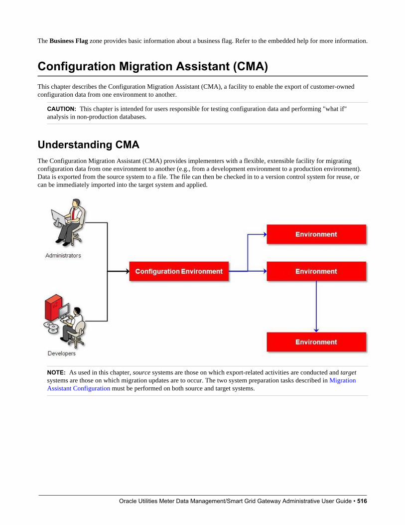
Oracle Utilities Meter Data Management/Smart Grid Gateway Administrative User Guide • 516
The Business Flag zone provides basic information about a business flag. Refer to the embedded help for more information.
Configuration Migration Assistant (CMA)This chapter describes the Configuration Migration Assistant (CMA), a facility to enable the export of customer-ownedconfiguration data from one environment to another.
CAUTION: This chapter is intended for users responsible for testing configuration data and performing "what if"analysis in non-production databases.
Understanding CMAThe Configuration Migration Assistant (CMA) provides implementers with a flexible, extensible facility for migratingconfiguration data from one environment to another (e.g., from a development environment to a production environment).Data is exported from the source system to a file. The file can then be checked in to a version control system for reuse, orcan be immediately imported into the target system and applied.
NOTE: As used in this chapter, source systems are those on which export-related activities are conducted and targetsystems are those on which migration updates are to occur. The two system preparation tasks described in MigrationAssistant Configuration must be performed on both source and target systems.
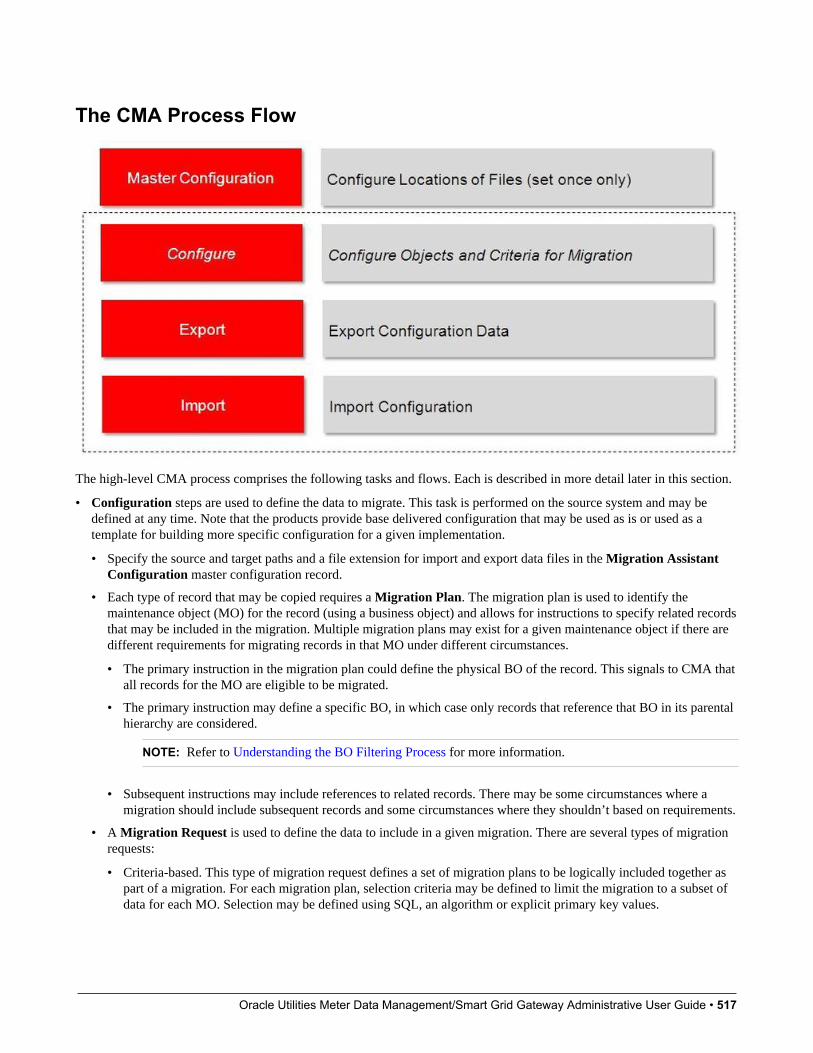
Oracle Utilities Meter Data Management/Smart Grid Gateway Administrative User Guide • 517
The CMA Process Flow
The high-level CMA process comprises the following tasks and flows. Each is described in more detail later in this section.
• Configuration steps are used to define the data to migrate. This task is performed on the source system and may bedefined at any time. Note that the products provide base delivered configuration that may be used as is or used as atemplate for building more specific configuration for a given implementation.
• Specify the source and target paths and a file extension for import and export data files in the Migration AssistantConfiguration master configuration record.
• Each type of record that may be copied requires a Migration Plan. The migration plan is used to identify themaintenance object (MO) for the record (using a business object) and allows for instructions to specify related recordsthat may be included in the migration. Multiple migration plans may exist for a given maintenance object if there aredifferent requirements for migrating records in that MO under different circumstances.
• The primary instruction in the migration plan could define the physical BO of the record. This signals to CMA thatall records for the MO are eligible to be migrated.
• The primary instruction may define a specific BO, in which case only records that reference that BO in its parentalhierarchy are considered.
NOTE: Refer to Understanding the BO Filtering Process for more information.
• Subsequent instructions may include references to related records. There may be some circumstances where amigration should include subsequent records and some circumstances where they shouldn’t based on requirements.
• A Migration Request is used to define the data to include in a given migration. There are several types of migrationrequests:
• Criteria-based. This type of migration request defines a set of migration plans to be logically included together aspart of a migration. For each migration plan, selection criteria may be defined to limit the migration to a subset ofdata for each MO. Selection may be defined using SQL, an algorithm or explicit primary key values.
Oracle Utilities Meter Data Management/Smart Grid Gateway Administrative User Guide • 518
• Entity List. This type of migration request allows the user to choose explicit MO / prime keys. It is meantfor a targeted migration of specific objects. Note that although the user views and maintains MO / PK valueswhen configuring this type of migration request, a migration plan is still used internally for the CMA migrationprocessing.
• Group. This type of migration request points to other migration requests. This allows you to define separatemigration requests that represent logical groupings of migration plan instructions for ease of maintenance, butto combine all the separate migration requests into a single "grouped" migration request for streamlined export /import purposes.
FASTPATH: For more information, refer to CMA Configuration.
• The Export process includes all the steps needed to select records to be exported from the source environment and createthe export file.
• A Migration Data Set Export object is created for a specific migration request.
• The lifecycle of the Migration Data Set Export business object includes algorithms that select the appropriate recordsaccording to the migration request, determine dependencies between records to build groupings of related objects andcreate the export file.
• Because there may be a large volume of data in the export, many of the steps in the lifecycle of the migration data setexport are executed via the Migration Data Set Export Monitor.
FASTPATH: For more information, refer to Exporting a Migration.
• The file created by the export, which is a BINARY file, needs to be transferred from the export directory to the importdirectory. The transfer needs to be done in such a way as to preserve the file structure. Refer to Migration Assumptions,Restrictions and Recommendations for more information.
• The Import processes include all the steps needed to read an imported file, compare the data in the file to the data in thetarget, review the proposed changes and apply the updates. The following is a high level overview of the process.
• A Migration Data Set Import object is created for a given file to import.
• The next step reads the import file and creates Migration Transactions and Migration Objects based on theinformation in the import file. A migration object is created for every maintenance object record to potentially becreated or updated. The migration transaction is a grouping record that groups together related migration objects.
• The next step is for the objects to Compare the data being imported against the data for that record in the targetenvironment. If it is found that the migration object is new or represents a change to the existing record in the targetenvironment, appropriate SQLs are generated. If no changes are found, the object is marked “unchanged” and doesn’tprogress.
• Once all the objects are compared, the user may review the objects for acceptance or rejection.
• When the migration objects are all accepted or rejected, the next step is to apply the objects and update the targetenvironment.
FASTPATH: For more information, refer to Importing and Applying a Migration.
Migration Assumptions, Restrictions and RecommendationsThe following sections describe miscellaneous topics that are important to learn with respect to CMA.
Oracle Utilities Meter Data Management/Smart Grid Gateway Administrative User Guide • 519
Type of Data MigratedCMA is designed to migrate configuration data.
The comparison step of the import process will generate appropriate insert or update SQL statements for the following datafound in the export:
• Configuration data in a maintenance object with no owner flag. This is purely implementation data.
• Configuration data in a maintenance object with owner flag, where the owner is Customer Modification. For example,implementer-specific business objects.
• Configuration data in a maintenance object with owner flag, where the main record is owned by the product but where achild record exists with an owner of Customer Modification. For example, implementer-specific algorithms added to abase owned business object.
• Customizable fields in a record that is owned by the product. For example, the priority of a based owned To Do type.
Data with System Generated Primary KeysThe tool provides support for administrative data with system-generated primary keys. The logic relies on the maintenanceobject to use a method that looks at other attributes of the record (considered a “logical key”) to detect whether the recordbeing migrated already exists in the target region or not. The examples in this section will use the Attachment maintenanceobject as an example. Common attachments are considered administrative data. The attachment MO uses the file name andthe creation date as the “logical key”.
Imagine a common attachment for the "standard rate codes" file exists in a source region with the key 123456789. The tablebelow highlights possible situations at the target region and actions supported in CMA.
Scenario Target Situation Action Comments
1 No matching record Record can be added with key 123456789.
2 Record exists with key 123456789 and logicconfirms that it is also the "standard ratecodes" attachment.
Record can be updated.
3 Record exists with key 123456789, butlogic detects that it is not the "standard ratecodes" attachment.
Record is not updated. An error is issued. The system cannot update this recordbecause it's not the right attachment record.
4 The system detects that another attachmentrecord exists for the "standard rate codes"attachment with a different ID.
Record is not updated. An error is issued. Assumption is that the record was createddirectly in the target or was copied from adifferent source.
The use cases described in scenarios 3 and 4 above would require key mapping to keep track of the id from the source to theid in the target so that any other records from the source that reference this key as a foreign key would be updated as part ofthe migration. This functionality is not supported.
Scenarios 1 and 2 above are supported for maintenance objects that use the method to detect the logical key.
NOTE: If a maintenance object with a system generated key does not supply a method to detect the logical key, CMAwill update an existing record with the same ID. For maintenance objects in the framework that provide this method,refer to Framework Provided Migration Configuration. For your specific edge application, refer to the CMA addendumfor information about support for admin data with system generated keys.
The product recommends that an implementation establishes a migration strategy such that administrative records withsystem generated keys are always created in the same region and always follow a standard migration path for promoting thedata from this source region to other regions. Following this strategy, you would minimize or eliminate the possibility that
Oracle Utilities Meter Data Management/Smart Grid Gateway Administrative User Guide • 520
a record for the same logical key is created in multiple places such that different IDs would be generated as described byscenario 4 above.
MOs with a Mixture of Administration and Non-Administration DataThere are some MOs that contain a mixture of master or transaction data and administrative data. The Attachment is anexample of this. The product supports common attachments and owned attachments. Owned attachments are recordsthat are specific to its owner. The owner could be master or transaction data and its attachments are therefore consideredmaster or transaction data. Owned attachments are not candidates for migration using CMA. Common attachments on theother hand are considered administrative data and may be candidates for migration using CMA. For these use cases, animplementation may follow the suggested strategy of only creating the administrative data in one region so that IDs forcommon attachments are not reused. However, it is reasonable and expected that owned attachments are being created in thetarget region and may receive a system generated key that matches the key of a common attachment from the source region.
To try to minimize this issue, the system includes special logic to be used by any MO that may contain administrative datamixed in with master or transaction data. This special logic generates the key of an administrative record with a zero (0)in the middle of the key and ensures that the keys for master and transaction data do not include a zero in this spot. Formaintenance objects in the framework that use this method, refer to Framework Provided Migration Configuration. For yourspecific edge application, refer to the CMA addendum for information about additional maintenance objects that may be inthis category.
No Record DeletionThe CMA process allows users to define records to copy from a source environment to a target environment. In that way,the import process for the migrated records is able to identify objects to add and objects to change. There is no mechanismfor indicating that records in the target environment should be deleted. The absence of those records in the import is notenough because the migration may be only importing a subset to add or update. If data on the target system must be deleted,users must delete the records in the target accordingly.
Note that CMA does support the deletion of child rows of an object as a result of a comparison. This is only applicable tochild records that are owned by the implementation.
File Transfer ConsiderationsWhen moving the export file between systems, use the binary transfer option of whatever tool you use to move the file sothat line-end characters are not converted from Linux-style to Windows-style or vice versa.
It is recommended to avoid using 'txt' for the export file's extension (defined in the master configuration). That fileextension by default implies a non-binary file and tools that perform file transfer may treat this as a non-binary file unlessexplicitly stated. The recommendation is to define 'cma' as the extension. This is not a recognized file extension and mostfile transfer tools will transfer the file as is.
Note that if the file gets converted, there are two likely outcomes - either a numeric conversion error, or a buffer under-runerror may be received when attempting to import the file.
Multi-Language Environment ConsiderationsIf your implementation uses a language other than English, it means that migrated objects may have multiple language rows(because English is always enabled). There are some important points with respect to multiple languages and CMA:
• As described in User Language, there are steps to follow when supporting an additional language. The steps outlinedin that topic highlight that for system data, translation of the strings may be provided via a language pack provided bythe product or may be the responsibility of your implementation. In either case, this effort is non-trivial and will haveits own established plan. The expectation is that the translation of the system data is applied for each region at yourimplementation site. CMA should not be used to create a new language in a target region.
• For administrative / control data that your implementation develops as part of your project, the expectation is thatdescriptions for your supported language are entered in the region that is considered the source region used to promote
Oracle Utilities Meter Data Management/Smart Grid Gateway Administrative User Guide • 521
changes to regions in the “chain”. For example, control data is entered in a development region and promoted to a testwith the supported language enabled in both regions.
• What if you export data from a region with more languages enabled than your target? This scenario is perhaps a casewhere the source region is a type of test or playpen region where the additional language is enabled for other purposes. Inthis case, if the language code does exist at all in the target region, the import will produce an error given that the code isinvalid. If the language code exists but is not enabled, this will cause the extra language rows to be inserted in the targetregion, but will not cause any issues. They are simply ignored.
• What if you export data from a region with fewer languages enabled than your target? In this situation, the importprocess will only create language rows for the languages that were copied from the source. It will not automaticallycreate language rows in the target as part of the import. For this situation, the recommendation is to run the NewLanguage batch program (F1–LANG) that creates any missing language entries.
CMA ConfigurationThe following sections describe tasks required for CMA configuration.
Master Configuration - Migration AssistantIn both the source environment and the target environment, the system needs to know the location of the export directoryand the import directory along with the expected file suffix. Implementations may define the information explicitly for eachregion using the Migration Assistant Configurationmaster configuration record.
For more information about specific fields in the master configuration, refer to the embedded help.
NOTE: This record can be updated at any time to change details. The new configuration takes effect on all subsequentexports and imports.
Implementations may also rely on the system defaults. If no Migration Assistant Configuration record is found, the systemassumes that there is an entry defined in the system's substitution variable list for F1_CMA_FILES. Further it defaults thevalues as follows:
• Export directory is the value for this variable plus "\export".
• Import directory is the value of this variable plus "\import".
• File suffix is set to cma
Refer to Referencing URIs for more information about the substitution variable list.
Migration PlansA migration plan defines one or more types of objects that are eligible for migration. It is essentially a set of instructionsdescribing how the data to be exported is structured, allowing objects to be migrated together as a logical unit to ensureconsistency and completeness.
The following topics describe defining a migration plan as well as other topics for a migration plan.
Defining a Migration PlanTo view or define a migration plan, navigate using Admin > Implementation Tools > Migration Plan.
Use the Migration Plan Query portal to search for an existing migration plan. Once a migration plan is selected, you arebrought to the maintenance portal to view and maintain the selected record.
Oracle Utilities Meter Data Management/Smart Grid Gateway Administrative User Guide • 522
CAUTION: Important! If you introduce a new migration plan, carefully consider its naming convention. Refer to SystemData Naming Convention for more information.
The following points provide information about defining Instructions for a migration plan.
The Instruction Sequence uniquely identifies the instruction. The recommendation is to use increments of 10 to allowinsertion of other instructions in the future.
Select Primary for the first Instruction Type. All migration plans must contain one and only one primary instruction. Allsubsequent instructions require a Subordinate instruction type. In this case, the Parent Instruction Sequence must beentered. This number, used to maintain the defined relationships in the exported data, must match an instruction sequencenumber at a higher level in the hierarchy.
The instruction Description provides a business description of the instruction.
Select a Business Object (BO) to define the type of object from which data will be derived.
NOTE: Though BOs are specified in each instruction, it's important to understand that each BO is used only for filteringpurposes. The migrated data set comprises the complete contents of the maintenance object that the business objectstructure is defined against. For a more detailed explanation of this, see Understanding the BO Filtering Process.
NOTE: Refer to Identifying Tables to Exclude From Migrations for information about defining child tables to alwaysexclude from a migration.
Traversal Criteria is used to define the relationship between each of the objects in a migration plan. The system providesthree options to define how the child object is connected to the parent object so the system knows how to traverse from oneobject to another. Traversal Criteria Type options are Constraint, SQL and XPath. The following points explain eachoption:
• Constraint allows you to select a table constraint that represents a given record's relationship to another record in thesystem via a foreign key constraint defined in the meta-data. If Constraint is selected, the following additional fields areenabled:
• Constraint ID is a unique identifier for the constraint. The search will show the valid table constraints for the MO ofthe instruction’s BO and the MO of the parent instruction’s BO.
• Constraint Owner is used to define the owner of the constraint. This is populated automatically when selecting aconstraint from the search.
• SQL lets you specify SQL join criteria between the parent instruction’s object and the child object in the SQL TraversalCriteria. The syntax of the the traversal criteria is a WHERE clause (without including the word WHERE). Whenreferring to a field on the parent instruction’s object, use the syntax #PARENT.TABLE_NAME.FIELD_NAME. Whenreferring to a field on the current instruction’s object, use the syntax #THIS.TABLE_NAME.FIELD_NAME. For example,the following statement is used on a migration plan for Business Object, where the parent instruction is the BO andthe subordinate instruction is used to reference the UI Map that is referred to as a BO option with the option type“F1DU”:#PARENT.F1_BUS_OBJ_OPT.BUS_OBJ_OPT_FLG = 'F1DU' AND @trim(#THIS.F1_MAP.MAP_CD) =@trim(#PARENT.F1_BUS_OBJ_OPT.BUS_OBJ_OPT_VAL).
• The XPath option lets you apply syntax in an XPath expression referencing elements in the instructions’referenced business objects. This is entered in the XPath Traversal Criteria. For example, the display mapcollection statement in the SQL example noted above would be written as follows in XPath: #this/mapCd =#parent/businessObjectOption/businessObjectOptionValue AND #parent/businessObjectOption/
businessObjectOptionType = 'F1DU'. This technique allows foreign key references that are mapped inside an XMLcolumn to be referenced.
Oracle Utilities Meter Data Management/Smart Grid Gateway Administrative User Guide • 523
NOTE: The #parent expressions may access elements that are stored in an XML column and described usingmapXML and mdField. However, the #this expressions must refer to fields available in the business object using themapField reference.
Defining Next Migration Plan provides the ability to indicate that in addition to copying the object defined in theinstruction, any additional instructions included in that referenced migration plan will also be included in an export.
The Algorithms grid contains algorithms associated with each instruction. You must define the following for eachalgorithm:
• Specify the System Event with which the algorithm is associated (see the table that follows for a description of allpossible events).
• Specify the Sequence and Algorithm for each system event. You can set the Sequence to 10 unless you have a SystemEvent that has multiple Algorithms. In this case, you need to tell the system the Sequence in which they should execute.
System Event Optional / Required DescriptionPre-Compare Optional Algorithms of this type may be used to adjust
the data after it is moved to the target system.These may only be defined on the primaryinstruction.Refer to Adjusting Imported Data for moreinformation.Click here to see the algorithm types availablefor this system event.
Import Optional Algorithms of this type are no longersupported.
Where Used
Follow this link to open the data dictionary where you can view the tables that reference F1_MIGR_PLAN.
Understanding the BO Filtering ProcessMigration plan instructions require the definition of a business object to provide CMA with information about the recordrelated to the instruction.
If the business object is the physical business object for the maintenance object, then CMA assumes that the instructionapplies to all records that satisfy the traversal criteria. CMA recognizes the physical BO by comparing the BO to the valuedefined in the maintenance object option. If the business object defined is not the physical BO, then CMA will limit therecords in the instruction to those that explicitly reference this BO or reference a child of this BO as its identifying BOvalue. (In other words, this BO must be in the parentage hierarchy of the records to be included in the instruction.)
NOTE: Unlike Bundling, CMA does not use the BO schema to drive what data is copied for a given record. The BOis only used as a filtering mechanism for selecting records. Refer to Identifying Tables to Exclude from Migration forinformation about how to ensure a child table is not included in a migration.
For example, if you define a migration plan for Master Configuration and use the physical business object for the instruction(F1-MstCfgPhysicalBO) then all master configuration records are considered for the instruction. If instead the businessobject you define is Migration Assistant Configuration (F1-MigrationAssistantConfig) then only the record related to thisbusiness object is included in the instruction.
Migration Plans for Objects with XML-Embedded LinksWhen migrating objects where foreign key references are captured in the object's XML based field, subordinate instructionsare needed to define the foreign key references in order for CMA to understand the relationships. This is in contrast to direct
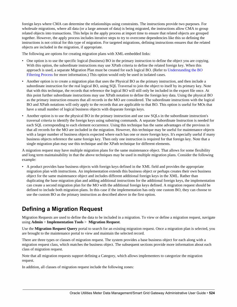
Oracle Utilities Meter Data Management/Smart Grid Gateway Administrative User Guide • 524
foreign keys where CMA can determine the relationships using constraints. The instructions provide two purposes. Forwholesale migrations, where all data (or a large amount of data) is being migrated, the instructions allow CMA to grouprelated objects into transactions. This helps in the apply process at import time to ensure that related objects are groupedtogether. However, the apply process includes iterative steps to try to overcome dependencies like this so defining theinstructions is not critical for this type of migration. For targeted migrations, defining instructions ensures that the relatedobjects are included in the migration, if appropriate.
The following are options for creating migration plans with XML-embedded links:
• One option is to use the specific logical (business) BO in the primary instruction to define the object you are copying.With this option, the subordinate instructions may use XPath criteria to define the related foreign key. When thisapproach is used, a separate Migration Plan must be created for each logical BO. (Refer to Understanding the BOFiltering Process for more information.) This option would only be used in isolated cases.
• Another option is to create a migration plan that uses the Physical BO as the primary instruction, and then include asubordinate instruction for the real logical BO, using SQL Traversal to join the object to itself by its primary key. Notethat with this technique, the records that reference the logical BO will still only be included in the export file once. Atthis point further subordinate instructions may use XPath notation to define the foreign key data. Using the physical BOas the primary instruction ensures that all records in the MO are considered. The subordinate instructions with the logicalBO and XPath notations will only apply to the records that are applicable to that BO. This option is useful for MOs thathave a small number of logical business objects with disparate foreign keys.
• Another option is to use the physical BO in the primary instruction and use raw SQLs in the subordinate instruction'straversal criteria to identify the foreign keys using substring commands. A separate Subordinate Instruction is needed foreach SQL corresponding to each element occurrence. Using this technique has the same advantages of the previous inthat all records for the MO are included in the migration. However, this technique may be useful for maintenance objectswith a larger number of business objects expected where each has one or more foreign keys. It's especially useful if manybusiness objects reference the same foreign key. Then only one instruction is required for that foreign key. Note that asingle migration plan may use this technique and the XPath technique for different elements.
A migration request may have multiple migration plans for the same maintenance object. That allows for some flexibilityand long term maintainability in that the above techniques may be used in multiple migration plans. Consider the followingexample:
• A product provides base business objects with foreign keys defined in the XML field and provides the appropriatemigration plan with instructions. An implementation extends this business object or perhaps creates their own businessobject for the same maintenance object and includes different additional foreign keys in the XML. Rather thanduplicating the base migration plan and adding additional instructions for the additional foreign keys, the implementationcan create a second migration plan for the MO with the additional foreign keys defined. A migration request should bedefined to include both migration plans. In this case if the implementation has only one custom BO, they can choose touse the custom BO as the primary instruction as described above in the first option.
Defining a Migration RequestMigration Requests are used to define the data to be included in a migration. To view or define a migration request, navigateusing Admin > Implementation Tools > Migration Request.
Use the Migration Request Query portal to search for an existing migration request. Once a migration plan is selected, youare brought to the maintenance portal to view and maintain the selected record.
There are three types or classes of migration request. The system provides a base business object for each along with amigration request class, which matches the business object. The subsequent sections provide more information about eachclass of migration request.
Note that all migration requests support defining a Category, which allows implementers to categorize the migrationrequest.
In addition, all classes of migration request include the following zones:

Oracle Utilities Meter Data Management/Smart Grid Gateway Administrative User Guide • 525
• Migration Request This zone contains display-only information about the selected record. Please see the zone's helptext for information about this zone's fields.
• Referencing Migration Requests This zone is only visible if the displayed migration request is included in a Groupmigration request. It lists each group migration request that includes it.
Other zones may appear for specific classes of migration requests. See the following sections for more information.
Where Used
Follow this link to open the data dictionary where you can view the tables that reference F1_MIGR_REQ.
Criteria-basedThis type of migration request defines a set of migration plans to be logically included together as part of a migration. Foreach migration plan, selection criteria is defined to indicate which records for each MO should be included. Selection maybe defined using SQL, an algorithm or explicit primary key values.
• For selection using SQL Statement, refer to the embedded help for examples.
• For selection using Algorithm, the algorithms that are eligible to be plugged in here are those valid for the MigrationRequest - Select system event. Click here to see the algorithm types available for this system event.
• For selection using Specific Keys, the primary key (1 through 5) must be explicitly specified. Multiple rows are allowed.
Entity ListThis type of migration request allows the user to choose explicit MO / prime keys. The MOs that are eligible are thosethat are configured with a Default Migration Plan option. Although the user is managing MO / PKs, the migrationinstructions are still defined with a migration plan. The system maps the migration instructions in a similar way to aCriteria-based migration requests that use a Specific Key selection type. Note however that it will create a separatemigration instruction for each MO / PK combination. It does not try to group all PKs for the same MO / migration underone migration instruction.
For this type of migration request, a user adds a migration request record with its description and other main information.Then, a special zone Add Entities is provided to find and select records based on a selected maintenance object and add tothe migration request. The user is prompted to provide a reference and comments, if desired. If the category selected is onethat requires a reference, then this will be validated.
When maintaining a migration request with existing entities, they are visible in the zone Migration Request Entities . Thiszone allows a user to remove the entity from the list.
GroupThis type of migration request points to other migration requests. This allows you to define separate migration requests thatrepresent logical groupings of migration plan instructions for ease of maintenance, but to combine all the separate migrationrequests into a single "grouped" migration request for streamlined export / import purposes.
The CMA export process will build an extract that includes the union of all the objects that qualify for the export and groupthem together based on their relationships.
Wholesale and Targeted MigrationsThe Configuration Migration Assistant is used for two general types of migrations: wholesale and targeted. The followingsections provide some additional information about these concepts.

Oracle Utilities Meter Data Management/Smart Grid Gateway Administrative User Guide • 526
Wholesale MigrationsWholesale migrations are used when migrating all the configuration and/or administrative data from one environment toanother. For example, a wholesale migration might be used when migrating administrative data from a development or testenvironment to a production environment.
A wholesale migration may be comprised of one or more migration requests that in total include all the administrative datato move. With the ability to group migration requests, the expectation is that implementations follow these guidelines:
• Multiple migration requests using the Criteria-based or Entity List migration request classes are used to groupinformation logically together to allow for more reuse.
• A Group migration request is used for the export. This allows for one data set to export and one data set on the importside, simplifying the process. Note that depending on the amount of data, this may be a large import set to process. Animplementation may find it easier to create multiple migration requests that break down the process into several steps.
You should consider that the framework product provides base migration requests and your specific edge product mayprovide base migration requests as well that may or may not include framework migration plans. Using the productprovided migration requests is beneficial with respect to maintenance. As features are added to the product (including newadministrative maintenance objects), any impact on CMA should be included in the product owned migration requests.If your implementation introduces new custom administrative maintenance objects that should be included in CMA, thencustom migration plans and a custom migration request should be added. Your implementation can build a Group migrationrequest that includes the base migration request and your custom migration requests to have a consolidated export.
Migration plans used in wholesale migrations may be designed to omit subordinate instructions related to explicit foreignkeys that are identified through constraints as they are not needed, assuming that the data they are referring to will also beincluded in the migration.
NOTE: Refer to Framework Provided Migration Objects for information about migration requests provided in theframework product. Refer to your specific product's documentation for information about addition base providedmigration requests.
Targeted MigrationsA targeted migration refers to migrating a specific subset of data from one environment to another. Examples of targetedmigrations include:
• Migration of a new Business objects with its options and algorithms.
• Migration of a new maintenance portal, its zones, and its application service.
• Migration of all outbound message types.
It is expected that the Entity List migration request is used for these types of migrations.
Identifying Tables to Exclude From MigrationsSome maintenance objects that are eligible to be migrated may include child tables that should not be included in themigration. For example, if an object includes log tables, the entries in the log should reflect the actions on the object in thatsystem, and will be different between the source system and the target system. If you have a custom Maintenance Objectthat includes tables you don't wish to migrate (such as a log table), use the Non-Migrated Table option on the MO tospecify this table. All child records for this table will also be ignored during migration.
Another use case to consider is a child "many-to-many" table that connects two administrative objects and exists in themaintenance object of both tables. The child table may be in both MOs for convenience sake, but it may be that one MO isconsidered more of a "driver" object and the other more of a subordinate. If you are doing a targeted migration where you

Oracle Utilities Meter Data Management/Smart Grid Gateway Administrative User Guide • 527
want to copy a subset of objects, you may want to only copy the driver object and its children and their data but not theirchildren. For example, in Oracle Public Sector Revenue Management, a Form Type includes a collection of valid FormChange Reasons and in turn the Form Change Reason refers to its Form Types. If an implementation wants to do a targetedmigration of a form type and include all its related information, including form rules and form change reasons, it does notwant the migration of a form change reason to in turn copy all its form types (and their data).
NOTE: The MO option must be set in both the Source and Target systems for a given MO.
Configuring Custom Objects for MigrationDuring the implementation and extension of the product, new custom administrative maintenance objects may beintroduced. If your implementation would like to migrate records in those maintenance objects using the ConfigurationMigration Assistant, additional steps must be performed, which are highlighted in the following sections.
Physical Business ObjectAs described in Understanding the BO Filtering Process, the migration plan requires a business object for its instruction.The business object is used to identify the records eligible for inclusion in the migration. Assuming your custom tables useone or more “logical” business objects for their processing, your implementation must decide if these business objects areappropriate for use by the migration plans, or if a physical BO is warranted. If so, create an appropriate physical BO.
Review MO Option ConfigurationThe following points highlight maintenance object (MO) configuration that should be reviewed or updated to support CMA:
• If a physical BO was created (above), link it to the MO as an option using the appropriate option type.
• Be sure that your MO defines an appropriate FK Reference and includes an Option on the MO that identifies the FKReference. This is used by various portals and zones for CMA when showing detail about records being imported intothe target region. Also be sure that this FK reference defines an Information program.
• As described in Identifying Tables to Exclude From Migrations, an MO option is used to identify child tables for an MOthat should never be included in a migration. If your custom maintenance object includes a standard Log table, than therecommendation is to list that table as an excluded table. Depending on the specific design of the maintenance object,there may be other child tables to define.
Characteristic Type ConfigurationThe CMA import process will attempt to create a log record for any administrative object that includes a log table. If yourimplementation has introduced any custom administrative tables that you plan to include in a migration request and itincludes a log table, you must, to ensure that the log creation is successful, add your log table as a valid characteristic entityto the characteristic type F1-MGO (Migration Object).
Navigate to Characteristic Type and select the characteristic type F1-MGO. Navigate to the Characteristic Entity tab andadd a row to include the characteristic entity for your custom maintenance object's log table.
Standard CMA ConfigurationCreate one or more migration plans for the new object, depending on the type of data in the maintenance object and thetypes of migrations you envision:
• If you have implemented only one "logical" business object used to define the data in the MO, then a single migrationplan that references the this BO (or the maybe the MO's physical BO) is appropriate.
• If you have implemented more than one "logical" business object, would the data for multiple business objects get copiedtogether? Then perhaps a single migration plan that references the MO's physical BO is appropriate.

Oracle Utilities Meter Data Management/Smart Grid Gateway Administrative User Guide • 528
• Are there additional foreign keys defined using mapXML in the business object(s) for the MO? If so, then it isrecommended to include sub-instructions to define the links. At this point, if multiple "logical" BOs exist, yourimplementation may choose to define all the additional elements in the same migration plan or choose to define separatemigration plans for each logical BO.
• Your implementation may decide to define more than one migration plan for the same type of record based on the typesof migrations you plan to include. For example, you may decide to include a migration plan that copies only the recordsin this maintenance object. You may decide to define another migration plan that copies the records in this MO alongwith related records in another MO (for a special type of migration). Having said that, be sure to design the migrationplan with reuse in mind to minimize maintenance efforts.
In order to support Entity List migration request, a default migration plan must be defined as an option on the maintenanceobject. This should be a single migration plan that supports all types of business objects for the MO.
If your implementation has a template migration request to use for targeted or wholesale migrations, include the newmigration plan(s) as appropriate.
CAUTION: Important! New migration plans and migration requests should follow naming conventions. Refer to SystemData Naming Convention for more information.
The CMA Execution ProcessThe following diagram illustrates a high-level view of the Configuration Migration Assistant execution process. Thesubprocesses illustrated here are described in more detail in the following sections.
Exporting a MigrationThe migration export process begins in the source environment by defining a Migration Data Set Export, which specifiesa defined Migration Request and provides a file name and description for the export file. After the data set is defined andsaved, the Migration Data Set Export Monitor batch job can be submitted generate the export file.

Oracle Utilities Meter Data Management/Smart Grid Gateway Administrative User Guide • 529
The following topics provide more detail about this process.
Migration Data Set ExportTo migrate data from one region to another, define a Migration Data Set Export. This establishes the export file name andidentifies the migration request.
To view an existing migration data set export, navigate using Admin > Implementation Tools > Migration Data SetExport. Use the query criteria to locate the desired data set.
Note that you can also initiate the creation of an export data set from the Migration Request portal using the Export button.
The export requires the name of an existing Migration Request.
Enter a unique File Name for the export. Do not use spaces in the name, and do not enter the file extension or a path. Theoutput location and file extension of the intended export file, which should appear in the Export Directory and File Suffixlabels, are defined as described in the topic Migration Assistant Configuration.
Enter an Export Description to provide information about the purpose of the export. Note that this field is not languageenabled.
The Source Environment Reference is for information purposes. It should be populated with text that provides ameaningful description of the source environment. The default value is the URL of the source environment.
Export LifecycleThe following diagram describes the lifecycle of a Migration Data Set Export (data set).
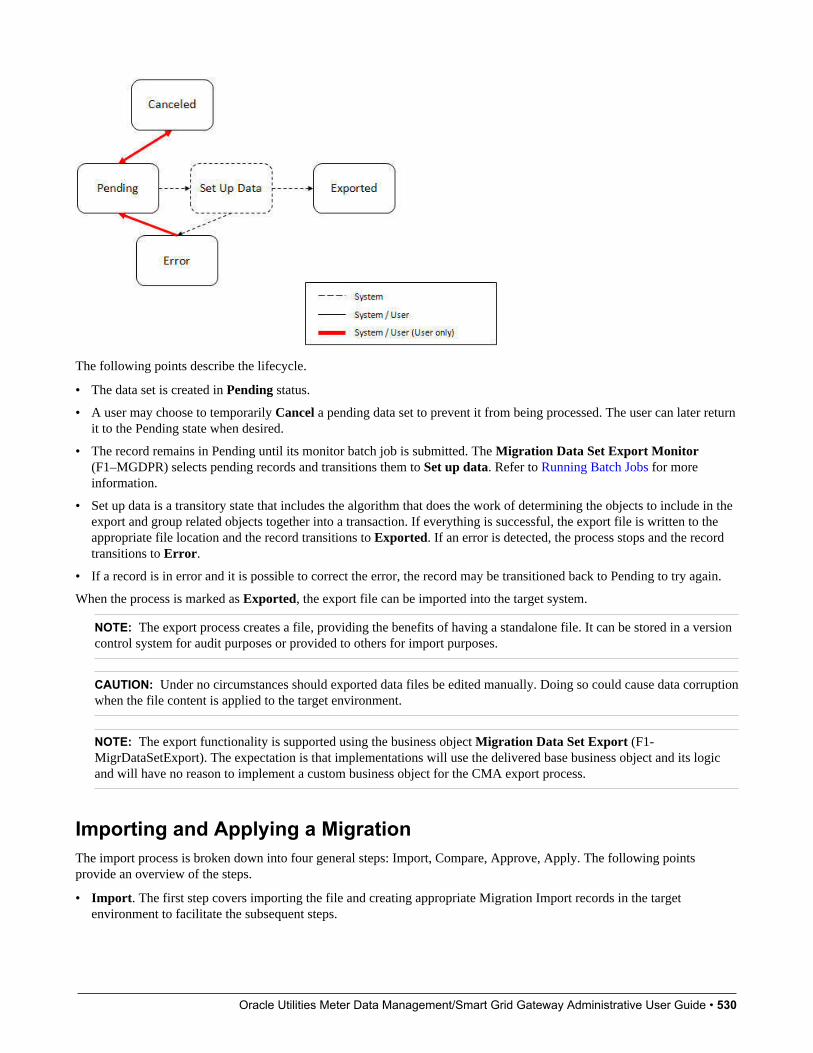
Oracle Utilities Meter Data Management/Smart Grid Gateway Administrative User Guide • 530
The following points describe the lifecycle.
• The data set is created in Pending status.
• A user may choose to temporarily Cancel a pending data set to prevent it from being processed. The user can later returnit to the Pending state when desired.
• The record remains in Pending until its monitor batch job is submitted. The Migration Data Set Export Monitor(F1–MGDPR) selects pending records and transitions them to Set up data. Refer to Running Batch Jobs for moreinformation.
• Set up data is a transitory state that includes the algorithm that does the work of determining the objects to include in theexport and group related objects together into a transaction. If everything is successful, the export file is written to theappropriate file location and the record transitions to Exported. If an error is detected, the process stops and the recordtransitions to Error.
• If a record is in error and it is possible to correct the error, the record may be transitioned back to Pending to try again.
When the process is marked as Exported, the export file can be imported into the target system.
NOTE: The export process creates a file, providing the benefits of having a standalone file. It can be stored in a versioncontrol system for audit purposes or provided to others for import purposes.
CAUTION: Under no circumstances should exported data files be edited manually. Doing so could cause data corruptionwhen the file content is applied to the target environment.
NOTE: The export functionality is supported using the business object Migration Data Set Export (F1-MigrDataSetExport). The expectation is that implementations will use the delivered base business object and its logicand will have no reason to implement a custom business object for the CMA export process.
Importing and Applying a MigrationThe import process is broken down into four general steps: Import, Compare, Approve, Apply. The following pointsprovide an overview of the steps.
• Import. The first step covers importing the file and creating appropriate Migration Import records in the targetenvironment to facilitate the subsequent steps.

Oracle Utilities Meter Data Management/Smart Grid Gateway Administrative User Guide • 531
• Compare. The compare step reviews each object that is in the import file and compares the object in the import againstthe equivalent record in the target environment. The comparison step results in noting which objects are unchanged,which are new (and the appropriate SQL to insert them) and which objects are changed (and the appropriate SQL toupdate them). Based on user configuration at import time, the objects that qualify for the import may be in a state thatrequires review or may be pre-approved.
• Approve. Once the comparison is complete, the user should review the results. There may be records marked for review.All of these records must be approved or rejected before the import can proceed. When the user is satisfied with theresults of the comparison and has completed the review, the import is marked to proceed to the Apply step. Optionally, amigration import may be configured to automatically apply.
• Apply. This is the final step and is the step where the records in the target environment are added or updated. Becauseof potential high volumes of data and because of possible dependencies between records, this step supports two levels ofattempting to apply the records. There is an apply step at the object level and an apply step at the transaction level. Thiswill be described in more detail below.
Import StepThe import process starts with verifying the import directory configured as described in the following topic MasterConfiguration - Migration Assistant and ensuring that the exported file is located in that directory. Then, in the targetenvironment, a Migration Data Set Import record should be created. The user indicates the file name.
In addition, the user decides what the default status should be for resulting objects.
• The Default Status for Add sets the default status for objects that are determined to be new during the importcomparison process. The default is to automatically set new objects to Approved status. Other options are to set any newobjects to Rejected or Needs Review status.
• The Default Status for Change sets the default status for objects that are determined to be changed during the importcomparison process. As with new objects, the default for changed objects is Approved, with Rejected or NeedsReviewoptions available.
The user may also configure the Automatically Apply flag to Yes. This allows for use cases where the migration isrepetitive and has been tested and the user feels that there is no need for manual approval. Note that when configuring thissetting, neither of the Default Status values may be set to Needs Review and at least one must be set to Approved.
The file to import contains a list of all the objects included in the export. Any objects that the export step determined to berelated have been grouped into “transactions”. Once the Migration Data Set Import is created, the next step is for the systemto read in the file and create Migration Transactions and Migration Objects.
The following is a portion of the Migration Data Set Import lifecycle as it pertains to the import step.
The following points describe the lifecycle.
• The data set is created in Pending status.
• The record remains in Pending until its monitor batch job is submitted. The Migration Data Set Import Monitor (F1–MGDIM) selects pending records and transitions them to Ready to Compare. Refer to Import Process Summary andRunning Batch Jobs for more information.

Oracle Utilities Meter Data Management/Smart Grid Gateway Administrative User Guide • 532
The Ready to Compare state has an algorithm that is responsible for reading the related import file and creating themigration transactions and migration objects. The data set remains in this state until the comparison step is complete.
NOTE: A user may choose to Cancel a data set. Refer to Cancelling a Data Set for more information.
The following diagram highlights the relationships of the resulting migration import records.
The migration transaction and migration object each have their own lifecycle that will help manage the subsequent compareand apply steps. At the end of the import step, the status values of the three types of records are as follows:
• Migration Data Set Import is in the Ready to Compare state.
• Migration Transaction is in the Pending state.
• Migration Object is in the Pending state.
NOTE: The import functionality is supported using business objects supplied by the base product. The expectationis that implementations will use the delivered base business objects and their logic and will have no reason toimplement a custom business objects for the CMA import process. The base business objects are Migration Data SetImport (F1-MigrObjectImport), Migration Transaction (F1-MigrTransactionImport) and Migration Object (F1-MigrObjectImport).
Compare StepThe import step results in the creation of one or more migration objects, one for each record selected in the export basedon the export's migration request and its configuration. Related objects are grouped together in migration transactions. Thenext step in the import process is the Comparison step. In this step, the data captured by the import file for each object iscompared to the view of that object in the target environment.
To cater for a possible large volume of objects, the comparison is done via a batch monitor. To aide in performance ofthe process, the monitor is performed on the migration objects so that it can be run multi-threaded. Once the objects arefinished with the comparison, the migration transactions and the migration data set should be updated with an appropriateoverall status before continuing to the next step. As a result, the comparison actually requires three steps: Migration ObjectComparison, Migration Transaction Status Update and Migration Data Set Export Status Update. The steps are explained indetail in the following sections.
NOTE: Refer to Running Batch Jobs for more information about streamlining the various steps in the process.
Migration Object CompareThis is the main step of the comparison. The Migration Object Monitor (F1–MGOPR) selects pending migration objectrecords and transitions them to Comparing. This is a transitory state that includes the algorithm that does the work of
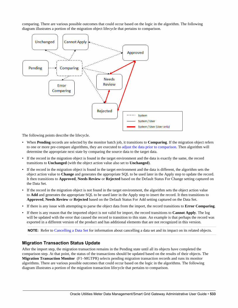
Oracle Utilities Meter Data Management/Smart Grid Gateway Administrative User Guide • 533
comparing. There are various possible outcomes that could occur based on the logic in the algorithm. The followingdiagram illustrates a portion of the migration object lifecycle that pertains to comparison.
The following points describe the lifecycle.
• When Pending records are selected by the monitor batch job, it transitions to Comparing. If the migration object refersto one or more pre-compare algorithms, they are executed to adjust the data prior to comparison. Then algorithm willdetermine the appropriate next state by comparing the source data to the target data.
• If the record in the migration object is found in the target environment and the data is exactly the same, the recordtransitions to Unchanged (with the object action value also set to Unchanged).
• If the record in the migration object is found in the target environment and the data is different, the algorithm sets theobject action value to Change and generates the appropriate SQL to be used later in the Apply step to update the record.It then transitions to Approved, Needs Review or Rejected based on the Default Status For Change setting captured onthe Data Set.
• If the record in the migration object is not found in the target environment, the algorithm sets the object action valueto Add and generates the appropriate SQL to be used later in the Apply step to insert the record. It then transitions toApproved, Needs Review or Rejected based on the Default Status For Add setting captured on the Data Set.
• If there is any issue with attempting to parse the object data from the import, the record transitions to Error Comparing.
• If there is any reason that the imported object is not valid for import, the record transitions to Cannot Apply. The logwill be updated with the error that caused the record to transition to this state. An example is that perhaps the record wasexported in a different version of the product and has additional elements that are not recognized in this version.
NOTE: Refer to Cancelling a Data Set for information about cancelling a data set and its impact on its related objects.
Migration Transaction Status UpdateAfter the import step, the migration transaction remains in the Pending state until all its objects have completed thecomparison step. At that point, the status of the transactions should be updated based on the results of their objects. TheMigration Transaction Monitor (F1–MGTPR) selects pending migration transaction records and runs its monitoralgorithms. There are various possible outcomes that could occur based on the logic in the algorithms. The followingdiagram illustrates a portion of the migration transaction lifecycle that pertains to comparison.

Oracle Utilities Meter Data Management/Smart Grid Gateway Administrative User Guide • 534
The following points describe the lifecycle possible next states after Pending.
• If any related migration object is in the Error Comparing state, the transaction transitions to Error Comparing.
• If all related migration objects are in the Unchanged state, the transaction transitions to Unchanged.
• Otherwise, the transaction transitions to Ready to Apply. This means that at least one object is in an “apply-able” state.
The transaction remains in the Ready to Apply state until a user has approved the data set to move to the Apply step andthe transaction’s related objects have attempted to apply themselves. This is described in more detail below.
NOTE: Refer to Cancelling a Data Set for information about cancelling a data set and its impact on its related objects.
Migration Data Set Import Status UpdateOnce all the objects and all transactions have been updated via the previous two steps, the migration data set export mustbe updated based on the results of their transactions. The Migration Data Set Import Monitor (F1-MGDIM) selectsReady to Compare data sets and runs its monitor algorithms. Note that this is the same monitor process that is used to selectPending data sets. There are various possible outcomes that could occur based on the logic in the algorithms. The followingdiagram illustrates the portion of the migration transaction lifecycle that pertains to comparison.
The following points describe the lifecycle possible next states after Ready to Compare.
• If any related migration transactions is in the Error Comparing state, the data set transitions to Error.
• If all related migration transactions are in the Unchanged state, the data set transitions to Unchanged.

Oracle Utilities Meter Data Management/Smart Grid Gateway Administrative User Guide • 535
• Otherwise, the transaction transitions to Awaiting Approval. This means that there are no errors and at least one objectis in an “apply-able” state.
The data set remains in the Awaiting Approval state until a user decides that the data set and all its records are ready toprogress to the Apply step.
NOTE: A user can choose to cancel a data set at any time while it is in progress. Refer to Cancelling a Data Set for moreinformation.
Approval StepOnce the comparison is complete and the data set transitions to the Awaiting Approval state, a user needs to progress thedata set to Apply Objects to trigger the Apply step. The following points describe steps a user may take during the approvalstep.
• If the data set configuration for the Default State for Add and Change was set to Approved, then any migration objectthat is determined to be eligible for the Apply step will be in the Approved state. In this situation, a user may want toreview the data set and its transactions and objects to see verify that the results make sense. At that time, the user is ableto move an object to Needs Review or Rejected as appropriate.
• If the data set configuration for the Default State for Add and Change was set to Needs Review for either option, theneach migration object in the Needs Review state must be reviewed and the user must either Reject or Approve eachobject before moving to the Apply step.
• If the data set configuration for the Default State for Add and Change was set to Rejected for either option, theassumption is that the rejected records don’t need to be reviewed. But if a user finds a rejected record that shouldn’t berejected, it may be transitioned to Approved (or Needs Review) as appropriate.
Once the user is comfortable with the data set's results and no more objects are in the Needs Review state, the user shouldtransition the record to Apply Objects. This will initiate the Apply step.
Alternatively, if the Automatically Apply flag was set to Yes when creating the import record, the import data set willprogress from Awaiting Approval to Apply Objects. Refer to Import Process Summary for more information.
NOTE: Refer to Maintaining Import Data for details about the pages provided to help the user review a data set and itstransactions and objects to help in the approval step.
NOTE: A user can choose to cancel a data set at any time while it is in progress.
Apply StepThe apply step is the step where records in the target environment are added or updated. Like the comparison step, the applystep is actually multiple steps to optimally handle high volume and dependencies between records as smoothly as possible.
NOTE: Refer to Running Batch Jobs for more information about streamlining the various steps in the process.
Before explaining the apply steps in detail, the following points highlight the type of data that may be included in a givendata set.
1. Records that have no foreign keys and therefore no dependencies on other records. Examples: Message, Display Profile.
2. Records that have foreign keys that may already be in the target. Examples: Algorithms for existing algorithm types, ToDo Roles for existing To Do Types.
3. Records that have foreign keys that are new records but also part of the migration. CMA detected the relationship atexport time and grouped the objects in the same transaction. Example: Script-based Algorithm Type where the script isalso in the migration.
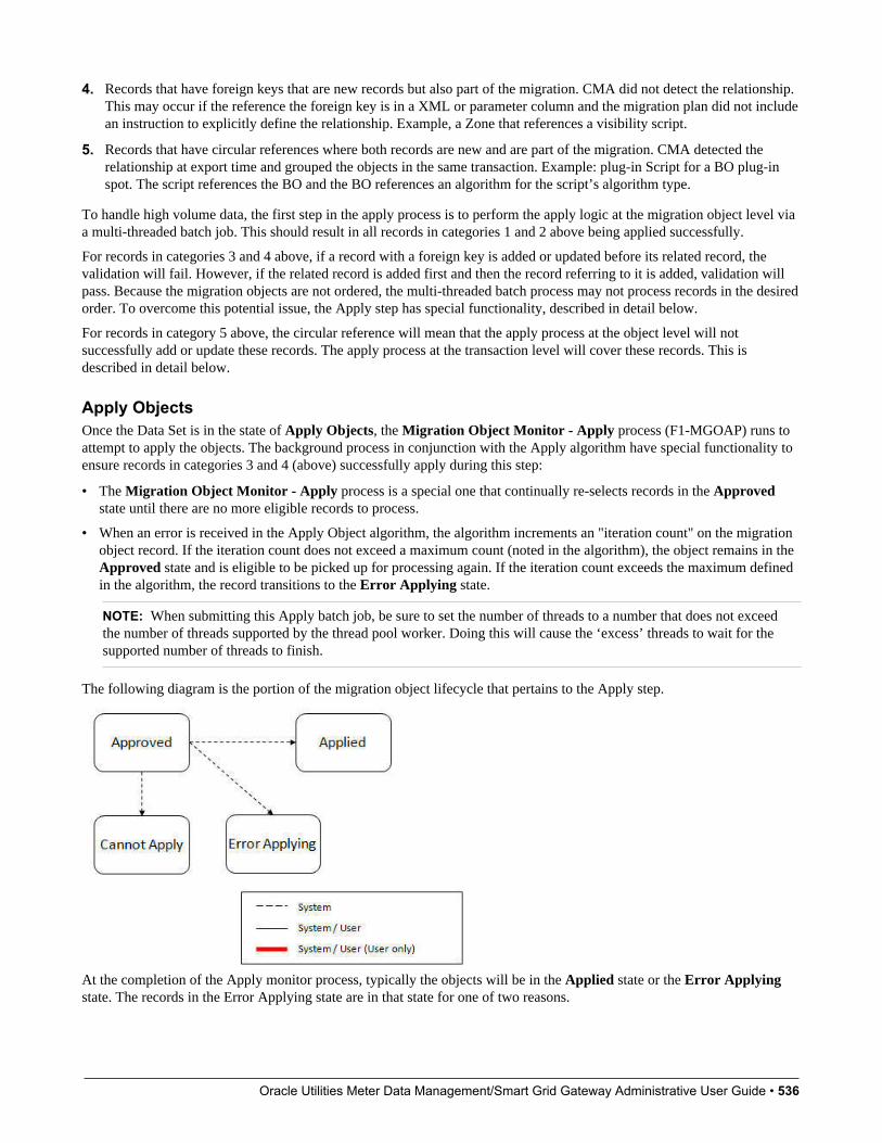
Oracle Utilities Meter Data Management/Smart Grid Gateway Administrative User Guide • 536
4. Records that have foreign keys that are new records but also part of the migration. CMA did not detect the relationship.This may occur if the reference the foreign key is in a XML or parameter column and the migration plan did not includean instruction to explicitly define the relationship. Example, a Zone that references a visibility script.
5. Records that have circular references where both records are new and are part of the migration. CMA detected therelationship at export time and grouped the objects in the same transaction. Example: plug-in Script for a BO plug-inspot. The script references the BO and the BO references an algorithm for the script’s algorithm type.
To handle high volume data, the first step in the apply process is to perform the apply logic at the migration object level viaa multi-threaded batch job. This should result in all records in categories 1 and 2 above being applied successfully.
For records in categories 3 and 4 above, if a record with a foreign key is added or updated before its related record, thevalidation will fail. However, if the related record is added first and then the record referring to it is added, validation willpass. Because the migration objects are not ordered, the multi-threaded batch process may not process records in the desiredorder. To overcome this potential issue, the Apply step has special functionality, described in detail below.
For records in category 5 above, the circular reference will mean that the apply process at the object level will notsuccessfully add or update these records. The apply process at the transaction level will cover these records. This isdescribed in detail below.
Apply ObjectsOnce the Data Set is in the state of Apply Objects, the Migration Object Monitor - Apply process (F1-MGOAP) runs toattempt to apply the objects. The background process in conjunction with the Apply algorithm have special functionality toensure records in categories 3 and 4 (above) successfully apply during this step:
• The Migration Object Monitor - Apply process is a special one that continually re-selects records in the Approvedstate until there are no more eligible records to process.
• When an error is received in the Apply Object algorithm, the algorithm increments an "iteration count" on the migrationobject record. If the iteration count does not exceed a maximum count (noted in the algorithm), the object remains in theApproved state and is eligible to be picked up for processing again. If the iteration count exceeds the maximum definedin the algorithm, the record transitions to the Error Applying state.
NOTE: When submitting this Apply batch job, be sure to set the number of threads to a number that does not exceedthe number of threads supported by the thread pool worker. Doing this will cause the ‘excess’ threads to wait for thesupported number of threads to finish.
The following diagram is the portion of the migration object lifecycle that pertains to the Apply step.
At the completion of the Apply monitor process, typically the objects will be in the Applied state or the Error Applyingstate. The records in the Error Applying state are in that state for one of two reasons.

Oracle Utilities Meter Data Management/Smart Grid Gateway Administrative User Guide • 537
• They are in category 5 described above where the records have a circular reference with another record. For thisscenario, the Apply Transactions step described below should successfully apply the records.
• There is some other error that is unrelated to the records in the current migration. In this case, manual intervention maybe required. Refer to the Resolving Errors section below for more information.
As shown in the diagram, the Apply Objects algorithm may also detect a reason that the object cannot be applied. This mayoccur if the object in the target environment has been updated since the comparison step, making the SQL captured at thatpoint no longer applicable. If this occurs, after the current migration is fully applied, the original file may imported again,and new comparisons can be generated and applied.
Apply TransactionsIdeally, after the Apply Objects step, all the objects are Applied or are in Error Applying due to the "circular reference"situation. The typical next step is to turn over responsibility to the transactions. The migration transactions can then attemptto apply their objects in bulk.
In order to ensure that multiple background processes are not trying to select migration objects to run the Apply step, theTransactions are only eligible to attempt to "apply my objects" if the Data Set is in the Apply Transactions state.
A monitor algorithm (executed by the data set monitor batch process) on the Apply Objects state checks to see if allmigration objects are no longer Approved or the count of records in Error Applying does not exceed a configured limit. Ifso, it automatically transitions the record to the Apply Transactions state.
If the number of objects in Error Applying exceeds a configured limit, the monitor algorithm does not automaticallytransition the record. In that case, a user must determine if the large number of errors can be resolved or manually transitionto Apply Transactions (despite the large number of errors). The Resolving Errors section below describes alternative stepsthat the user may take if there are errors.
Once the Data Set is in the state of Apply Transactions, the Migration Transaction Monitor - Apply process (F1-MGTAP) runs. It attempts to apply the transaction's objects. If no migration objects are in error, the migration transactionsimply transitions to Applied. If any of the migration objects are in Error Applying, the background process and the Applyalgorithm have special functionality to try to overcome dependencies in migrated objects:
• The Apply algorithm selects all migration objects in error and performs all their SQL, then validates all the records. Ifthere are objects in the transaction with circular references, they should pass validation at this point.
• Because there may still be some dependencies across transactions, similar error handling described in the Apply Objectsstep occurs here. When an error is received in the Apply Transaction's Object algorithm for any of the objects in thetransaction, the algorithm increments an "iteration count" on the migration transaction record. If the iteration countdoes not exceed a maximum count (noted in the algorithm), the transaction remains in the Ready to Apply state and iseligible to be picked up for processing again. If the iteration count exceeds the maximum, the record transitions to theError Applying state. Note that if any objects in the transaction are in error, none of the objects are applied. They allremain in error.
• The Migration Transaction Monitor - Apply process is a special one that continually re-selects records in the Ready toApply state until there are no more eligible records to process.
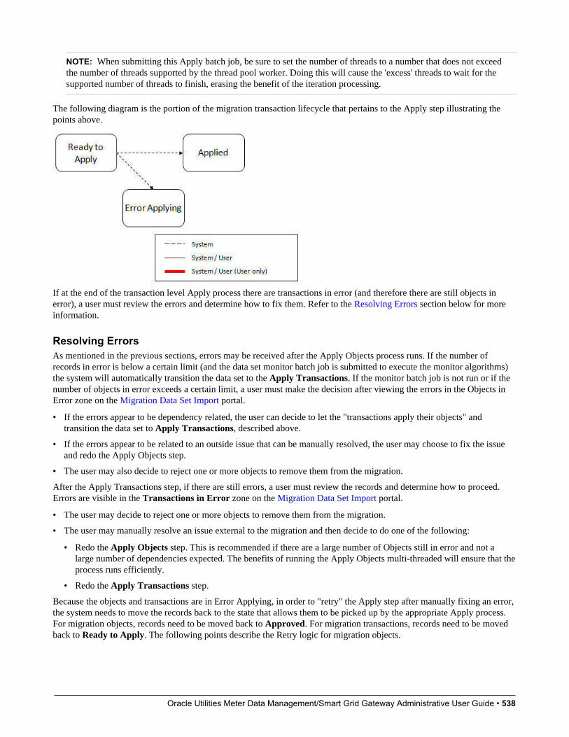
Oracle Utilities Meter Data Management/Smart Grid Gateway Administrative User Guide • 538
NOTE: When submitting this Apply batch job, be sure to set the number of threads to a number that does not exceedthe number of threads supported by the thread pool worker. Doing this will cause the 'excess' threads to wait for thesupported number of threads to finish, erasing the benefit of the iteration processing.
The following diagram is the portion of the migration transaction lifecycle that pertains to the Apply step illustrating thepoints above.
If at the end of the transaction level Apply process there are transactions in error (and therefore there are still objects inerror), a user must review the errors and determine how to fix them. Refer to the Resolving Errors section below for moreinformation.
Resolving ErrorsAs mentioned in the previous sections, errors may be received after the Apply Objects process runs. If the number ofrecords in error is below a certain limit (and the data set monitor batch job is submitted to execute the monitor algorithms)the system will automatically transition the data set to the Apply Transactions. If the monitor batch job is not run or if thenumber of objects in error exceeds a certain limit, a user must make the decision after viewing the errors in the Objects inError zone on the Migration Data Set Import portal.
• If the errors appear to be dependency related, the user can decide to let the "transactions apply their objects" andtransition the data set to Apply Transactions, described above.
• If the errors appear to be related to an outside issue that can be manually resolved, the user may choose to fix the issueand redo the Apply Objects step.
• The user may also decide to reject one or more objects to remove them from the migration.
After the Apply Transactions step, if there are still errors, a user must review the records and determine how to proceed.Errors are visible in the Transactions in Error zone on the Migration Data Set Import portal.
• The user may decide to reject one or more objects to remove them from the migration.
• The user may manually resolve an issue external to the migration and then decide to do one of the following:
• Redo the Apply Objects step. This is recommended if there are a large number of Objects still in error and not alarge number of dependencies expected. The benefits of running the Apply Objects multi-threaded will ensure that theprocess runs efficiently.
• Redo the Apply Transactions step.
Because the objects and transactions are in Error Applying, in order to "retry" the Apply step after manually fixing an error,the system needs to move the records back to the state that allows them to be picked up by the appropriate Apply process.For migration objects, records need to be moved back to Approved. For migration transactions, records need to be movedback to Ready to Apply. The following points describe the Retry logic for migration objects.
Oracle Utilities Meter Data Management/Smart Grid Gateway Administrative User Guide • 539
• If a user decides to Retry Objects (using an action button on the Migration Data Set Import page), the data settransitions to the Retry Objects state. At this point the Migration Object monitor must be run.
• The monitor on the Error Applying state for the objects detects that the data set is in the state of Retry Objects and thattriggers the transition back to Approved.
• The next step is to transition the data set from Retry Objects to Apply Objects. This may be done manually or byrunning the Migration Data Set Import monitor process.
• Now the objects are eligible to be picked up by the object level Apply process.
Analogous logic exists for the migration transactions.
• If a user decides to Retry Transactions (using an action button on the Migration Data Set Import page), the data settransitions to the Retry Transactions state. At this point the Migration Transaction monitor must be run.
• The monitor on the Error Applying state for the transactions detects that the data set is in the state of RetryTransactions and that triggers the transition back to Ready to Apply.
• The next step is to transition the data set from Retry Transactions to Apply Transactions. This may be done manuallyor by running the Migration Data Set Import monitor process.
• Now the transactions are eligible to be picked up by the transaction level Apply process.
The retry logic may also occur when transitioning between the Apply Objects and Apply Transactions depending onwhether or not there are errors. The following scenario highlights this point.
• After the Apply Objectsstep there are objects in Error Applying. The data set transitions to Apply Transactions andthe Apply step is done at the transaction level.
• After the Apply Transactions step there are transactions in Error Applying.
• User chooses to try to apply objects again (by clicking Retry Objects). The steps outlined above for retrying objects arefollowed at this point.
• After the apply objects, user may choose to retry objects again (after fixing errors if applicable).
• At some point the user will transition toApply Transactions again. If there are transactions in Error Applying,the system will automatically transition the data set to Retry Transactions and the steps outlined above for retrytransactions are followed.
Finalize Apply StepOnce all the migration objects for a migration transaction are in a final state (Applied, Rejected or Cannot Apply), themigration transaction transitions to the Applied state. Once all the migration transactions are in the Applied state, theMigration Data Set record transitions to the Completed and the import is complete.
NOTE: To review the full lifecycle for each record, refer to the Business Object - Summary tab in the applicationmetadata for the base business objects Migration Data Set Import (F1-MigrObjectImport), Migration Transaction(F1-MigrTransactionImport) and Migration Object (F1-MigrObjectImport).
Adjusting Data Prior to ComparingSome records may have data that is specific to the environment it is in and won't apply in the target environment. In suchcases, an algorithm plugged into the migration plan primary instruction may be used to adjust the data when importing. Thisalgorithm is executed by the comparison algorithm before any comparison is performed. Algorithms of this system eventreceive the view of the source record (being imported) and the view of the existing record in the target region, if it exists.The data is provided using the physical BO of the migration plan’s maintenance object. The algorithm may make changesand pass a new view of the record that should be used for the comparison. This system event supports multiple algorithmsthat are executed in sequence. Each algorithm receives the original record’s data, the target record’s data (if applicable) andthe ‘new’ view of the data (as populated by previous algorithms, if any). The final ‘new’ view of the data is used for theobject comparison.

Oracle Utilities Meter Data Management/Smart Grid Gateway Administrative User Guide • 540
FASTPATH: Refer to Base Business Objects for more information about physical BOs.
Some examples of records that may require import algorithms.
• Batch Control references its next batch sequence number along with snapshot information like the last run date / time.This information is only relevant with respect to its environment. The instruction for a batch control can include analgorithm to not overwrite the batch sequence number when copying a batch control.
• Some products include administrative objects that reference a master data object. Master data objects are not copied aspart of CMA. An import algorithm may be used to adjust the referenced master data foreign key when importing, forexample to reset it (or not overwrite when updating). If the algorithm knows how to find the appropriate master datarecord to link, that may also be included.
Note that it is possible to use the algorithm to "reset" the source data as a way of indicating that the record should not beimported. For these situations, the migration object comparison step will transition the record to Unchanged and will usean object action value of Canceled. (Note that object action is a simple lookup value. The record is not transitioned to theCanceled BO state as to reserve that status for user initiated cancellations of the object or one of its parent records). Thistechnique not expected to be used often because ideally using appropriate selection criteria at export time should ensure thatthe only records exported are those that should be imported.
NOTE: Legacy ‘Import’ system event. The system originally provided an Import system event / plug-in spot. Thepurpose of algorithms for this plug-in spot were similar in that they were meant to adjust imported data prior to addingor updating. The algorithms were executed in the Apply step. The logic does not allow for easily interacting with therecord using a BO. This makes it difficult to use a plug-in script as the plug-in type. In addition, it is difficult to updateelements in an XML column. The support for the plug-in spot will be removed in a future release. Algorithms to adjustthe data should be using the pre-compare system event.
Import Process SummaryThe following table summarizes the steps required to complete the import process from start to finish. Note that thissection only a summary and assumes that you are familiar with the details described in the previous sections. It highlightswhat steps are manual and what steps are performed by a batch monitor process. For each step, the table highlights theNext Action sequence that would occur. For the Apply steps, there are two parts where multiple next actions are possiblebased on whether there are errors and the user’s decision on how to resolve the error. Refer to Resolving Errors for moreinformation. The possible next actions have the same sequence with a letter following the sequence highlighting the actionto take based on the results of the previous step.
NOTE: When running the Apply batch jobs, be sure to set the number of threads to a number that does not exceed thenumber of threads supported by the thread pool worker.
Also note that a sequence and action marked in bold is considered the “normal path”.
Step Seq Action Manual / Batch Portal - Action Batch Control RecordImpacted -ResultingStatus
Next ActionSequence
10 Create Importrecord
Manual Migration DataSet Import -Add
Migration DataSet Import -Pending
11Import
11 Import file Batch F1-MGDIM -Migration DataSet ImportMonitor
Migration DataSet Import- Ready toCompareMigrationTransaction -Pending
20
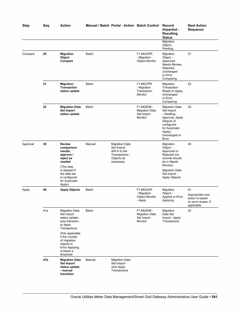
Oracle Utilities Meter Data Management/Smart Grid Gateway Administrative User Guide • 541
Step Seq Action Manual / Batch Portal - Action Batch Control RecordImpacted -ResultingStatus
Next ActionSequence
MigrationObject -Pending
20 MigrationObjectCompare
Batch F1-MGOPR- MigrationObject Monitor
MigrationObject -Approved,Needs Review,Rejected,Unchangedor ErrorComparing
21
21 MigrationTransactionstatus update
Batch F1-MGTPR- MigrationTransactionMonitor
MigrationTransaction -Ready to Apply,Unchangedor ErrorComparing
22
Compare
22 Migration DataSet Importstatus update
Batch F1-MGDIM -Migration DataSet ImportMonitor
Migration DataSet Import- AwaitingApproval, ApplyObjects (ifconfiguredfor AutomaticApply),Unchanged orError
30
Approval 30 Reviewcomparisonresults,approve /reject asneeded(This stepis skipped ifthe data setis configuredfor AutomaticApply)
Manual Migration DataSet Import,drill in to theTransactions /Objects asnecessary.
MigrationObject -Approved orRejected (norecords shouldbe in NeedsReview)Migration DataSet Import -Apply Objects
40
40 Apply Objects Batch F1-MGOAP- MigrationObject Monitor- Apply
MigrationObject -Applied or ErrorApplying
41Appropriate nextaction is basedon error review, ifapplicable.
41a Migration DataSet Importstatus update -auto transitionto ApplyTransactions.Only applicableif the numberof migrationobjects inError Applyingis below athreshold
Batch F1-MGDIM -Migration DataSet ImportMonitor
MigrationData SetImport - ApplyTransactions
42
Apply
41b Migration DataSet Importstatus update- manualtransition
Manual Migration DataSet Import -click ApplyTransactions

Oracle Utilities Meter Data Management/Smart Grid Gateway Administrative User Guide • 542
Step Seq Action Manual / Batch Portal - Action Batch Control RecordImpacted -ResultingStatus
Next ActionSequence
to ApplyTransactions.Occurs if userreviews errorsand determinesthat they maybe resolvedin the ApplyTransactionstep.
System detectsthat all thetransactionsare in theReady toApply stateand proceedsto the ApplyTransactionsstate.
MigrationData SetImport - ApplyTransactions
42
System detectsthat there aretransactionsin the ErrorApplying stateand transitionsinstead tothe RetryTransactionsstate.
MigrationData SetImport - RetryTransactions
45
41c Migration DataSet Importstatus update- manualtransition toRetry Objects.Occurs if userreviews errorsand decides tofix an externalerror and wantsto try the batchlevel Applyagain at theobject level.
Manual Migration DataSet Import- click RetryObjects
Migration DataSet Import -Retry Objects
44
42 ApplyTransactions
Batch F1-MGTAP- MigrationTransactionMonitor - Apply
MigrationTransaction -Applied or ErrorApplyingMigrationObject -Applied or ErrorApplying
43Appropriate nextaction is basedon error review, ifapplicable.
43a MigrationData SetImport statusupdate - autotransition toCompletedApplicable ifall transactionsare Applied
Batch F1-MGDIM -Migration DataSet ImportMonitor
Migration DataSet Import -Completed.
N/A
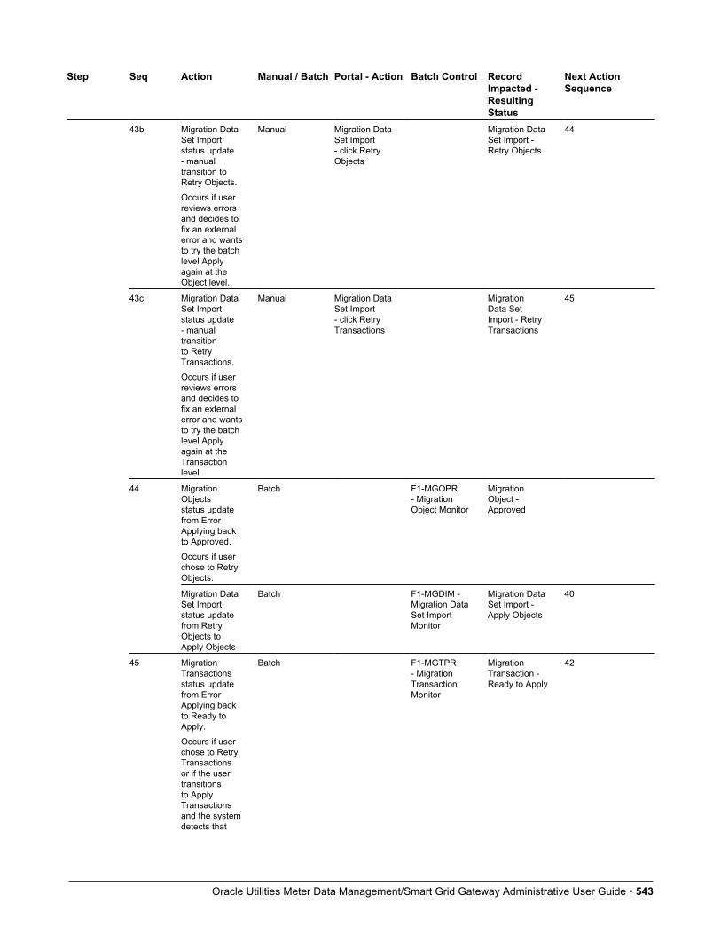
Oracle Utilities Meter Data Management/Smart Grid Gateway Administrative User Guide • 543
Step Seq Action Manual / Batch Portal - Action Batch Control RecordImpacted -ResultingStatus
Next ActionSequence
43b Migration DataSet Importstatus update- manualtransition toRetry Objects.Occurs if userreviews errorsand decides tofix an externalerror and wantsto try the batchlevel Applyagain at theObject level.
Manual Migration DataSet Import- click RetryObjects
Migration DataSet Import -Retry Objects
44
43c Migration DataSet Importstatus update- manualtransitionto RetryTransactions.Occurs if userreviews errorsand decides tofix an externalerror and wantsto try the batchlevel Applyagain at theTransactionlevel.
Manual Migration DataSet Import- click RetryTransactions
MigrationData SetImport - RetryTransactions
45
MigrationObjectsstatus updatefrom ErrorApplying backto Approved.Occurs if userchose to RetryObjects.
Batch F1-MGOPR- MigrationObject Monitor
MigrationObject -Approved
44
Migration DataSet Importstatus updatefrom RetryObjects toApply Objects
Batch F1-MGDIM -Migration DataSet ImportMonitor
Migration DataSet Import -Apply Objects
40
45 MigrationTransactionsstatus updatefrom ErrorApplying backto Ready toApply.Occurs if userchose to RetryTransactionsor if the usertransitionsto ApplyTransactionsand the systemdetects that
Batch F1-MGTPR- MigrationTransactionMonitor
MigrationTransaction -Ready to Apply
42
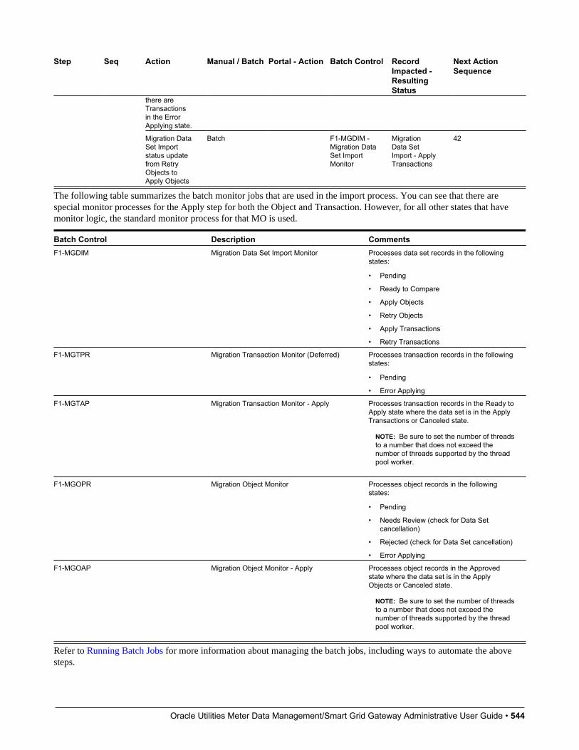
Oracle Utilities Meter Data Management/Smart Grid Gateway Administrative User Guide • 544
Step Seq Action Manual / Batch Portal - Action Batch Control RecordImpacted -ResultingStatus
Next ActionSequence
there areTransactionsin the ErrorApplying state.
Migration DataSet Importstatus updatefrom RetryObjects toApply Objects
Batch F1-MGDIM -Migration DataSet ImportMonitor
MigrationData SetImport - ApplyTransactions
42
The following table summarizes the batch monitor jobs that are used in the import process. You can see that there arespecial monitor processes for the Apply step for both the Object and Transaction. However, for all other states that havemonitor logic, the standard monitor process for that MO is used.
Batch Control Description CommentsF1-MGDIM Migration Data Set Import Monitor Processes data set records in the following
states:
• Pending
• Ready to Compare
• Apply Objects
• Retry Objects
• Apply Transactions
• Retry Transactions
F1-MGTPR Migration Transaction Monitor (Deferred) Processes transaction records in the followingstates:
• Pending
• Error Applying
F1-MGTAP Migration Transaction Monitor - Apply Processes transaction records in the Ready toApply state where the data set is in the ApplyTransactions or Canceled state.
NOTE: Be sure to set the number of threadsto a number that does not exceed thenumber of threads supported by the threadpool worker.
F1-MGOPR Migration Object Monitor Processes object records in the followingstates:
• Pending
• Needs Review (check for Data Setcancellation)
• Rejected (check for Data Set cancellation)
• Error Applying
F1-MGOAP Migration Object Monitor - Apply Processes object records in the Approvedstate where the data set is in the ApplyObjects or Canceled state.
NOTE: Be sure to set the number of threadsto a number that does not exceed thenumber of threads supported by the threadpool worker.
Refer to Running Batch Jobs for more information about managing the batch jobs, including ways to automate the abovesteps.
Oracle Utilities Meter Data Management/Smart Grid Gateway Administrative User Guide • 545
Cancelling a Data SetA user may choose to Cancel a data set to prevent it from being processed at any point during the process.
If related migration transactions or migration objects have already been created, they will not be canceled as part of the dataset getting canceled (due to possible high volumes of related records). They will be canceled the next time an appropriatemonitor batch process runs. The child records checks to see if the data set has been canceled prior to any state transition.
Additional Note Regarding ImportsThe following points describe miscellaneous comments related to Migration Import.
• CMA relies on the fact that database referential integrity constraints are not in place, and that the SQL statements canbe run in any order within the transaction. Any archiving solution that requires referential integrity constraints (suchas Information Lifecycle Management) would not be possible on this data. Given that CMA migrations compriseadministrative data and not transactional data, this should be a reasonable exception.
• The validation that is performed is only via the Page Validate service. BO validation algorithms are not executed. Pagevalidation does not include validation of the business object against the schema (for example, for required fields, fieldsizes, etc.).
• If multiple migration requests are exported at the same time, on the import side, you should consider importing,reviewing, and applying an entire file/data set before moving on to the next one. The reason is that if objects are includedin more than one file, two sets of "inserts" will be generated, but only the first will succeed. The second will cause theobject to transition to "Cannot Apply". If instead you wait until the first file is completed before importing the second,the second data set will not generate any SQL for the object, since it has already been inserted. It's a matter of efficiency:If you first import all files and then try to apply all, you'll have to identify the duplicated object as an error and then markthe object as rejected before applying the transaction. This may also be avoided by using a Group migration request toinclude all objects in one file rather than multiple files.
Caching ConsiderationsBecause CMA updates administrative data that is usually read from a cache, after a successful migration, the target regionnow has new administrative data which needs to be part of various caches. It is recommended to flush the server cache(which will trigger a 'global' flush of the cache). If the thread pool workers in the target region are configured to refreshtheir caches when a global flush is requested, then this is the only step required. If not, then the F1–FLUSH batch jobshould also be submitted to refresh the caches used in batch processing.
FASTPATH: Refer to Caching Overview for more information.
Maintaining Import DataThis section describes the portals provided to add, view and maintain migration import data.
Migration Data Set ImportUse the Migration Data Set Import portal to view and maintain migration data set import records. Refer to Importing andApplying a Migration for an overview of the import process.
Navigate using Admin > Implementation Tools > Migration Data Set Import. You are brought to a query portal withoptions for searching for import data sets. In addition, the query provides an option to specifically search for data sets thathave either objects in error or transactions in error.

Oracle Utilities Meter Data Management/Smart Grid Gateway Administrative User Guide • 546
Once a data set has been selected, you are brought to the maintenance portal to view and maintain the selected record. Thefollowing zones are visible on the main tab:
• Migration Data Set Import. This zone contains display-only information about the selected record. Please see thezone’s help text for information about this zone’s fields.
• Migration Data Set Transactions. This zone is visible once the Import Step has occurred and lists all the transactionsthat are related to the data set. To see more information about a specific migration transaction, click the hypertext for itsID. This brings you to the Migration Transaction portal.
• Migration Data Set Impacted Object Summary. This zone is visible once the Import Step has occurred and lists theobjects that are related to the data set. To see more information about a specific migration object, click the hypertext forits ID. This brings you to the Migration Object portal. A user may choose to update the status of one or more records bychecking the records and clicking Approve, Reject or Needs Review accordingly.
• Migration Data Set Objects in Error. This zone is only visible if there are objects for this data set in a non-finalstatus that have errors. It indicates the error for each object. A user may use this zone to review errors after the monitorbatch job to apply objects completes. Using the error information shown, the user can choose to drill into the record totransition it to Error Applying or choose to manually fix the cause of the errors and click Retry Objects. The user mayalso choose to select one or more records to Reject.
NOTE: Refer to Apply Step for more information about resolving errors.
• Migration Data Set Transactions in Error. This zone is only visible if there are transactions for this data set in anon-final state that have errors. It indicates the error for each transaction. A user may use this zone to review errorsafter the monitor batch job to apply transactions completes. The errors received when attempting to apply objects at thetransaction level may differ from those received when attempting to apply objects at the object level. A transaction log iscreated for each object error received and these exceptions are shown in this zone.
NOTE: Refer to Apply Step for more information about resolving errors.
Migration Transaction PortalThis page appears after drilling into a specific migration transaction from the migration data set portal or from the migrationobject portal.
Refer to Importing and Applying a Migration for an overview of the import process.
The following zones are visible on the main tab:
• Migration Transaction. This zone contains display-only information about the selected record. Please see the zone’shelp text for information about this zone’s fields.
• Migration Transaction Objects. This zone lists the objects that are related to the data set. To see more informationabout a specific migration object, click the hypertext for its ID. This brings you to the Migration Object portal. A usermay choose to update the status of one or more records by checking the records and clicking Approve, Reject or NeedsReview accordingly.
Migration Object PortalThis page appears after drilling into a specific migration object from the migration data set portal or from the migrationtransaction portal.
Refer to Importing and Applying a Migration for an overview of the import process.
The Migration Object zone contains display-only information about the selected record. Please see the zone’s help text forinformation about this zone’s fields.
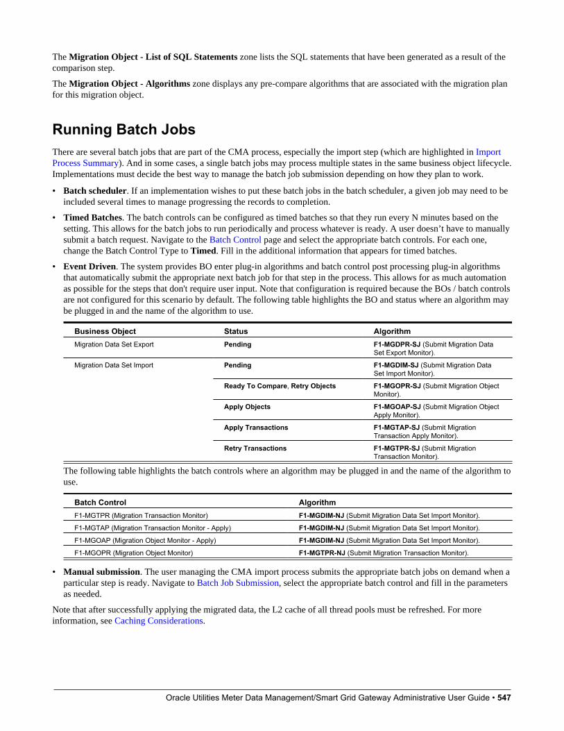
Oracle Utilities Meter Data Management/Smart Grid Gateway Administrative User Guide • 547
The Migration Object - List of SQL Statements zone lists the SQL statements that have been generated as a result of thecomparison step.
The Migration Object - Algorithms zone displays any pre-compare algorithms that are associated with the migration planfor this migration object.
Running Batch JobsThere are several batch jobs that are part of the CMA process, especially the import step (which are highlighted in ImportProcess Summary). And in some cases, a single batch jobs may process multiple states in the same business object lifecycle.Implementations must decide the best way to manage the batch job submission depending on how they plan to work.
• Batch scheduler. If an implementation wishes to put these batch jobs in the batch scheduler, a given job may need to beincluded several times to manage progressing the records to completion.
• Timed Batches. The batch controls can be configured as timed batches so that they run every N minutes based on thesetting. This allows for the batch jobs to run periodically and process whatever is ready. A user doesn’t have to manuallysubmit a batch request. Navigate to the Batch Control page and select the appropriate batch controls. For each one,change the Batch Control Type to Timed. Fill in the additional information that appears for timed batches.
• Event Driven. The system provides BO enter plug-in algorithms and batch control post processing plug-in algorithmsthat automatically submit the appropriate next batch job for that step in the process. This allows for as much automationas possible for the steps that don't require user input. Note that configuration is required because the BOs / batch controlsare not configured for this scenario by default. The following table highlights the BO and status where an algorithm maybe plugged in and the name of the algorithm to use.
Business Object Status AlgorithmMigration Data Set Export Pending F1-MGDPR-SJ (Submit Migration Data
Set Export Monitor).
Pending F1-MGDIM-SJ (Submit Migration DataSet Import Monitor).
Ready To Compare, Retry Objects F1-MGOPR-SJ (Submit Migration ObjectMonitor).
Apply Objects F1-MGOAP-SJ (Submit Migration ObjectApply Monitor).
Apply Transactions F1-MGTAP-SJ (Submit MigrationTransaction Apply Monitor).
Migration Data Set Import
Retry Transactions F1-MGTPR-SJ (Submit MigrationTransaction Monitor).
The following table highlights the batch controls where an algorithm may be plugged in and the name of the algorithm touse.
Batch Control AlgorithmF1-MGTPR (Migration Transaction Monitor) F1-MGDIM-NJ (Submit Migration Data Set Import Monitor).
F1-MGTAP (Migration Transaction Monitor - Apply) F1-MGDIM-NJ (Submit Migration Data Set Import Monitor).
F1-MGOAP (Migration Object Monitor - Apply) F1-MGDIM-NJ (Submit Migration Data Set Import Monitor).
F1-MGOPR (Migration Object Monitor) F1-MGTPR-NJ (Submit Migration Transaction Monitor).
• Manual submission. The user managing the CMA import process submits the appropriate batch jobs on demand when aparticular step is ready. Navigate to Batch Job Submission, select the appropriate batch control and fill in the parametersas needed.
Note that after successfully applying the migrated data, the L2 cache of all thread pools must be refreshed. For moreinformation, see Caching Considerations.
Oracle Utilities Meter Data Management/Smart Grid Gateway Administrative User Guide • 548
CAUTION: Be sure that the Thread Count set when submitting the batch job does not exceed the number supportedby the thread pool. Otherwise the extra threads will wait until the supported number of threads are finished, possiblyresulting in a large number of errors in the Apply steps.
Refer to the parameter descriptions in the batch control metadata for more information about filling in the parameters.
For additional details on submission controls, refer to the topic Batch Job Submission - Main in the Batch Jobs section.
CMA ReferenceThis section provides additional reference information.
Framework-Provided Migration ConfigurationThis topic describes special information relating to migration objects provided for use by CMA in the product. Additionalobjects may be provided by your specific product. Any special information for objects is provided separately in eachproduct's documentation.
The following points highlight some information about Framework-provided migration requests. Navigate to the migrationrequest page in the application to view the details of all provided objects.
• Several base migration requests are supplied to logically group system and administrative tables. For example, there is amigration request for Framework System Configuration F1-SystemConfig where most system configuration objects areincluded. There is another one provided for CMA related configuration objects.
• There are several different security related migration requests that include different combinations of migration plans tosupport multiple possible business requirements related to security migration.
• The system supplies a group migration request F1–FrameworkConfig (Framework Configuration), which includesseveral other migration requests. The expectation is that this migration request includes all the typical objects that areincluded in a wholesale migration. Your specific product may include this migration request into its own group migrationrequest to support a wholesale migration of all the framework and product administrative tables. An implementation maychoose to build a custom group migration request. In this case, review the various migration requests provided by base tosee if any may be included as components for the custom migration request. Then any new migration plans added to thebase migration request in future releases are automatically included in future migrations.
NOTE: Refer to your specific product's CMA documentation for its recommendation on which migration requests to usefor a full migration of framework and product administrative tables.
The following points highlight some information about the Framework-provided migration plans. Navigate to the migrationplan page in the application to view the details of all provided objects.
• Fields and characteristic types are not migrated with an object (like a business object or a data area) unless specificallyindicated.
• The Application Service used by an object is migrated only if it is CM-owned.
• The Batch Control object optionally references a User. If this user does not exist on the target system, CMA cannotapply the requested changes. Also note that when running a batch job, snapshot information is captured on the batchcontrol. Updates like this increment the version number. If a batch control record is part of the migration and thecomparison step has detected a change to the batch control, the Apply step will error out for this batch control if a batchjob is submitted between the compare and apply step.
Oracle Utilities Meter Data Management/Smart Grid Gateway Administrative User Guide • 549
NOTE: CMA batch controls that are part of the import step are executing and as such, the system does not includethese records in a migration. If your implementation changes default parameters for any of the batch controls, therecommendation is to manually make those changes to the target region.
• The base migration plans for MO and BO include instructions to copy option types that use foreign key references torefer to other objects. Note that the data stored in the options are not validated, so defining these instructions is notrequired when doing wholesale migrations. However, including subordinate instructions for foreign key references isuseful for targeted migrations to ensure that the related data is included in the migration. If you add additional MO or BOoption types that use foreign keys and you want to support targeted migrations, you must create custom migration plansand requests for MO and BO, respectively to include these referenced objects in the migration plan. Note that you do notneed to duplicate the instructions in the base migration plans. You may define the additional migration plans to only havethe additional custom option types. When submitting a migration request for MO or BO you must include both the basemigration plans and the custom migration plans in the request.
• For scripts, schema-based objects and zones, the migration plans provided by the product migrate, through constraints,some of the typical associated data with them. However, data specified through alternate formats (such as through EditData steps in scripts, referenced in schemas for schema-based objects, or data from mnemonics in zone parameters, etc.)are not identified and combined in the same transaction. The iterative processing functionality of the import step shouldresolve any timing issues that may result in validation errors for these types of objects.
• There are two migration plans for Scripts. The migration plan F1-ScriptOnly migrates just the script and itsApplication Service (provided the Application Service is CM-owned). The migration plan F1-Script includes mostrelated objects, but does not migrate any objects referenced in the edit data area steps. It does not move the Functionmaintenance object. It may be included in any appropriate custom targeted migration request where scripts and relateddata should be migrated.
• If your implementation includes a Feature Configuration setting for the F1_DBCONINFO entry that will be includedin a migration request, be sure that the import user on the target region has the appropriate security rights to this entry(Administrator access mode for the Feature Configuration application service (CILTWSDP).
• The common attachments in the Attachment maintenance object may be considered administrative data to include ina migration. Because this MO has a system generated key, as described in Migration Assumptions, Restrictions andRecommendations, it uses a logical key of the file name and the creation date to determine if the record exists in thetarget environment. In addition, this MO contains admin data (common attachments) and non-admin data (ownedattachments). To try to minimize the possibility of key “collision”, new common attachments receive a generated keythat includes a zero in the middle whereas owned attachments receive a generated key that does not have a zero in themiddle.
• The Menu maintenance object has a user defined key, however, its menu lines and menu items have system generatedkeys. To avoid the possibility of overriding a menu line or menu item incorrectly, the menu MO will check the menuline’s menu name in the source and target to be sure they match and will check the menu item’s menu line in the sourceand target to be sure they match otherwise an error will be issued in the comparison step.
• For the system messages, the product provides three different migration plans.
• Message Category and its Messages (F1-MessageCategory). This migration plan is included in the F1-SystemConfigmigration request.
• Message Category (F1-MessageCategoryOnly). This migration plan is provided to support a targeted migration wherean implementation has created a custom message category and wants to move it but doesn’t want to move all itsmessages.
• Message (F1-Message). This migration plan is provided to support a targeted migration where only specific messageswithin a message category should be migrated.
• For lookup values, the product provides two different migration plans.
• Lookup Field and its Values (F1-Lookup). This migration plan is included in the F1-SystemConfig migration request.
Oracle Utilities Meter Data Management/Smart Grid Gateway Administrative User Guide • 550
• Lookup Value (F1-LookupValue). This migration plan is provided to support a targeted migration where only specificlookup values within a lookup field should be migrated.
• There are some system data objects where no information in a base delivered record may be modified by animplementation. For these records, the base delivered migration requests include selection criteria to only select CM-owned records (because the base records will always exist in the target region assuming both regions have the samerelease). An example is Algorithm Type. The F1-SystemConfig migration request only includes CM-owned algorithmtypes. However, many system data objects support custom changes to one or more fields, for example the Zone objectallows an implementation to override the zone text or certain parameters. Other system data objects support customadditions to a collection. For example, the Maintenance Object allows an implementation to add algorithms or options.For the migration plans related to these system data objects, all records are included in the base delivered migrationrequests to allow for any customized configuration to be migrated. It means that during the Import / Compare step manybase delivered objects that are not customized will be marked Unchanged.
• Many of the integration related maintenance objects that include references to environment-specific data, such asMessage Senders. This data should be migrated with extreme care. When appropriate, consider taking advantage of URIsubstitution. Refer to Referencing URIs for more information.
Configuring FactsFact is an optional configuration tool for simple workflow-type business messages or tasks. The base package does notprovide a dedicated Fact user interface because fact is generic by design. Implementations configure their own userinterface to visualize the desired custom business process. The topics in this section describe the generic Fact entity andhow it can be customized.
Fact Is A Generic EntityThe Fact maintenance object is a generic entity that can be configured to represent custom entities and support automatedworkflows for a variety of applications. Each fact references a business object to describe the type of entity it is. A statuscolumn on the fact may be used to capture its current state in the processing lifecycle controlled by its business object.
The maintenance object also supports a standard characteristic collection as well as a CLOB element to capture additionalinformation.
Where Used
Follow this link to open the data dictionary where you can view the tables that reference F1_FACT
Fact's Business Object Controls EverythingA fact's business object controls its contents, lifecycle and various other business rules:
• Its schema defines where each piece of information resides on the physical Fact maintenance object.
• If may define a lifecycle for all fact instances of this type to follow. Each fact must exist in a valid state as per itsbusiness object's lifecycle definition.
• It may define validation and other business rules to control the behavior of facts of this type.
FASTPATH: For more information about business objects, refer to The Big Picture of Business Objects.
Oracle Utilities Meter Data Management/Smart Grid Gateway Administrative User Guide • 551
Fact Supports A LogThe Fact maintenance object supports a log. Any significant event related to a Fact may be recorded on its log. The systemautomatically records a log record when the fact is created and when it transitions into a new state. In addition, any customprocess or manual user activity can add log entries.
FASTPATH:
Refer to State Transitions Are Audited for more information on logging.
Cloud Service FoundationThis chapter provides information on how to administer features associated with Oracle Utilities Cloud Service Foundationfunctionality.
NOTE: This chapter does not apply to all implementations. Contact your system administrator to confirm if yourimplementation includes Oracle Utilities Cloud Service Foundation.
Process Automation ToolNOTE: This section does not apply to all implementations. Contact your system administrator to confirm if yourimplementation includes Oracle Utilities Cloud Service Foundation and the Process Automation Tool.
The Process Automation Tool allows customers and implementers to orchestrate and automate a set of infrastructure relatedmulti-step processes. The tool provides the ability to monitor the progress of such process and each of the steps. The toolalso supports user actions at the process and step level.
The process automation tool is made out of the following system entities:
• Infrastructure Process - a Business Object of the Service Task MO.
• Infrastructure Process Step - a Business Object of the Service Task MO.
• Infrastructure Process Type - a Business Object of the Service Task Type MO.
• Infrastructure Process Step Type - a Business Object of the Service Task Type MO.
An Infrastructure Process references a type that includes the steps that are a part of that process. The steps are executedone by one according to their sequence as long as the previous step ended successfully. When a step in a process fails, theprocess will stop and wait for a user to take further actions.
An Infrastructure Process can span up to two product environments. This means that it can invoke and monitor steps in twosystems. This, for example, allows it to orchestrate a configuration migration (using the Configuration Migration Assistant)from one product environment to another. Such a migration can include steps to create the export data on the sourceenvironment, move the export file to the target environment and execute all the import tasks on the target environment, allas a single Infrastructure Process. In this case the Infrastructure Process will be created on the target environment and willpull the configuration from the source environment.
NOTE:This is done in order to ensure that only application users with sufficient security privileges in any system environmentcan create Infrastructure Processes that can update that environment.
Oracle Utilities Meter Data Management/Smart Grid Gateway Administrative User Guide • 552
The rule is that when an Infrastructure Process is created to run processes on two systems, the process will always becreated on the environment with the higher security requirements. For example, if you need to run processes on theDevelopment and Test environments, the infrastructure process will be created and executed from the Test environment(assuming that the Test environment has higher security requirements than the Development environment).
The steps that make an Infrastructure Process reference a step type that governs their behavior. A comprehensive set ofprocess and step types is provided with the product. This set can be extended by implementers as needed.
Creating an Infrastructure ProcessTo create a new process, navigate using Admin > Implementation Tools > Infrastructure Process. Use the InfrastructureProcess Query to search for an existing process. One an Infrastructure Process is selected, you are brought to themaintenance portal to view and maintain the selected record.
The following points provide information about creating a new Infrastructure Process.
Infrastructure Process references an Infrastructure Process Type. When creating a new process you need to select the typethat the process will be based on.
The Name of the process is used for tracking purposes. The name doesn’t have to be unique in the system.
The Process Steps list is read-only and represents the steps that were configured on the Infrastructure Process Type.
NOTE:Changing information on the Infrastructure Process Type, including the steps, will not affect existing InfrastructureProcess records.
The Process Details section represents additional information that is required according to the corresponding process typedefinition.
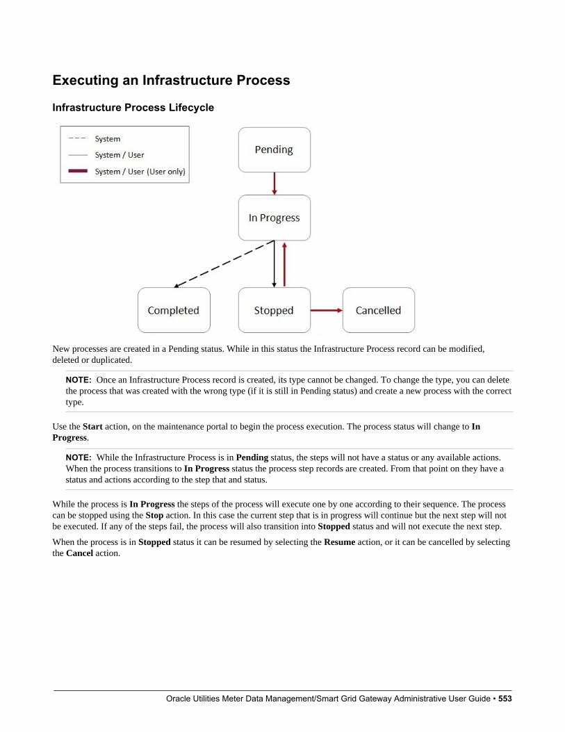
Oracle Utilities Meter Data Management/Smart Grid Gateway Administrative User Guide • 553
Executing an Infrastructure Process
Infrastructure Process Lifecycle
New processes are created in a Pending status. While in this status the Infrastructure Process record can be modified,deleted or duplicated.
NOTE: Once an Infrastructure Process record is created, its type cannot be changed. To change the type, you can deletethe process that was created with the wrong type (if it is still in Pending status) and create a new process with the correcttype.
Use the Start action, on the maintenance portal to begin the process execution. The process status will change to InProgress.
NOTE: While the Infrastructure Process is in Pending status, the steps will not have a status or any available actions.When the process transitions to In Progress status the process step records are created. From that point on they have astatus and actions according to the step that and status.
While the process is In Progress the steps of the process will execute one by one according to their sequence. The processcan be stopped using the Stop action. In this case the current step that is in progress will continue but the next step will notbe executed. If any of the steps fail, the process will also transition into Stopped status and will not execute the next step.
When the process is in Stopped status it can be resumed by selecting the Resume action, or it can be cancelled by selectingthe Cancel action.
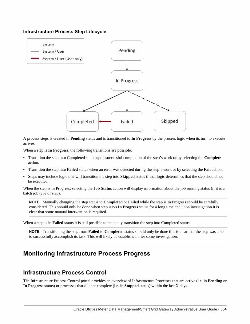
Oracle Utilities Meter Data Management/Smart Grid Gateway Administrative User Guide • 554
Infrastructure Process Step Lifecycle
A process steps is created in Pending status and is transitioned to In Progress by the process logic when its turn to executearrives.
When a step is In Progress, the following transitions are possible:
• Transition the step into Completed status upon successful completion of the step’s work or by selecting the Completeaction.
• Transition the step into Failed status when an error was detected during the step’s work or by selecting the Fail action.
• Steps may include logic that will transition the step into Skipped status if that logic determines that the step should notbe executed.
When the step is In Progress, selecting the Job Status action will display information about the job running status (if it is abatch job type of step).
NOTE: Manually changing the step status to Completed or Failed while the step is In Progress should be carefullyconsidered. This should only be done when step stays In Progress status for a long time and upon investigation it isclear that some manual intervention is required.
When a step is in Failed status it is still possible to manually transition the step into Completed status.
NOTE: Transitioning the step from Failed to Completed status should only be done if it is clear that the step was ableto successfully accomplish its task. This will likely be established after some investigation.
Monitoring Infrastructure Process Progress
Infrastructure Process ControlThe Infrastructure Process Control portal provides an overview of Infrastructure Processes that are active (i.e. in Pending orIn Progress status) or processes that did not complete (i.e. in Stopped status) within the last X days.

Oracle Utilities Meter Data Management/Smart Grid Gateway Administrative User Guide • 555
Navigate to Infrastructure Process Control portal, using Admin > Implementation Tools > Infrastructure ProcessControl.
Available actions on this portal are:
• New Process - creates a new Infrastructure Process
• Environment Setup - directs the user to the master configuration related to the process automation tool
Select any of the processes from the portal lists for more information.
Monitoring a Running Infrastructure ProcessWhen a process is running (in In Progress status), you can monitor its progress by refreshing the page. To configureautomatic page refresh, refer to the User Portal Preferences for this portal.
The Infrastructure Process maintenance portal provides information about the status of the overall process as well as each ofthe steps.
You can also view the details of each individual step including their log for more information or to investigate exceptions.
Dealing with ExceptionsInfrastructure Process steps can be divided into two main categories:
• Steps that start a batch process (job)
• Steps that are not batch process related
In addition, steps can be local or remote. Local steps execute on the same product environment that the process is executingwhile remote steps are executed on a different product environment.
Batch Job Step ExceptionsBatch job steps start a batch job either locally or on a different product environment.
Batch job step in Failed status as a result of a batch job errorWhen a batch process (local or remote) ends with an error, the process step is automatically transitioned to Failed status.
In this case, you should:
1. Ascertain the cause of the job failure (in the local or remote environment).
2. If the issue is temporary or can be fixed, fix it and then rerun the batch job manually using the Batch Job Submissionpage (in the local or remote environment). If the resubmitted job ended successfully, you can transition the process stepto the Completed status and use the Resume action at the process level to continue the process execution.
If the issue cannot be resolved, further investigation is required. In this case the process should remain in Stopped status.
Batch job step in In Progress status while batch job ended with an errorWhen an Infrastructure Process Step that is associated with a batch job stays in In Progress status while the batch job endedwith an error, further investigation is required. One possible cause for that situation could be an error that causes the job tofail and at the same time also prevents the job from communicating its status back to the originating process step.
In this case you should manually transition the step into Failed status and continue your investigation.
NOTE: If you decide to stop the Infrastructure Process altogether (as a result of the exception), it is a good idea to markthe batch job that failed as “Do Not Attempt Restart” in the Batch Run Control for that batch run. This will ensure that

Oracle Utilities Meter Data Management/Smart Grid Gateway Administrative User Guide • 556
the next time the Infrastructure Processes runs, when it gets to that batch process step it will not attempt to resume theexecution that ended with an exception, possibly causing a repeat of the exception.
Batch job step in In Progress status while batch job ended successfullyWhen an Infrastructure Process Step that is associated with a batch job stays in In Progress status while the batch job endedsuccessfully, further investigation is required. In this case, once you ascertained that the job did actually end successfully,you can manually transition the process step into Completed status and use the Resume action at the process level tocontinue its execution.
Non-Batch Step ExceptionsInfrastructure Process Steps that are not associated with batch jobs can experience errors as well and therefore can fail. Asa reminder, the logic for these steps can experience local or remote errors. When such a step fails, information about thefailure can be found in the process step log.
Process Automation Tool SetupThe process automation tool requires the setup of the following components:
• Master Configuration
• External Systems
• Message Senders
In addition, a security setup is required.
The setup itself is done automatically as part of the environment provisioning process. The information in this section isprovided for reference and in case changes in existing setup are required.
Security SetupBefore the process automation tool can be used, the security credentials of the Message Senders, used by the processautomation tool, must be updated.
In order to execute the security setup, navigate using Admin > Implementation Tools > Process Automation SecuritySetup.
The setup script will ask you to provide a User ID, a Password and to indicate whether or not to override the existingsecurity setup.
Please contact your system or security administrator for more information about what User ID should be used forthis setup.
You should select to override existing security setup when you need to update the User ID or the Password on the existingMessages Senders, used by the process automation tool. A common use case will be mandatory periodic password rotationfor the user account that was selected for the setup.
NOTE: At the end of the process, you will be asked to flush all the system cache. This is required in order for theinformation update to take effect.
Master Configuration SetupThe process automation tool relies on master configuration settings in order to identify all the product environments that areavailable to it. The Master Configuration is automatically setup as part of the system provisioning process.
Oracle Utilities Meter Data Management/Smart Grid Gateway Administrative User Guide • 557
This section describes the setup options in case manual changes are needed.
To access the configuration for the process automation tool, navigate using Admin > General > Master Configuration andlook for Process Automation Configuration.
The Main section includes the definition of the Current Environment code and the default file extension for CMA exportfiles.
The Current Environment code is a unique code that is given to each product environment.
The Environment List section describes all the existing product environments and integration (SOA) environment that theprocess automation tool need to interact with, for example, in order to run a process that moves integration configurationfrom one environment to another.
The environment in the list includes the following details:
• Environment: the environment code.
• Product: defined in the Process Automation Product extendable lookup.
• Domain: defined in the Process Automation Domain extendable lookup.
• Migration Source: select “Yes” if you can migrate configuration data from this environment.
NOTE: You should not allow automated migration of configuration from your development environment directly toyour production environment but you would allow migrating from the development to test environments.
• External System: reference to the External System definition that will support communication with the row’senvironment.
• SFTP Alias: this is a name of the SSH file that will be used to support file transfer capabilities between systemenvironment directories.
External Systems and Message SendersThe process automation tool communicates with other product environments (including SOA environments) throughOutbound Messages.
The automated setup for the process automation tool creates a set of Message Senders and External Systems to supportcommunication with other product environments.
Each product environment which is defined on the Process Automation Configuration has a corresponding unique ExternalSystem. Each External System contains the details of all the message types that it supports, the message sender for eachmessage type and additional data if required (for example, message or response XSLs).
Configuring New Infrastructure ProcessesThe process automation tool configuration is essentially a collection of process types and step types that support theautomation of various multi-step processes. A set of Infrastructure Process Types and Infrastructure Process Step Types isprovided with the base product. Customers and implementers can create new process and step types.
This section describes the actions required to configure new Infrastructure Process Type and Infrastructure Process StepType.
Configuring a New Infrastructure Process Step TypeIn order to configure a new step type, navigate using Admin > Implementation Tools > Infrastructure Process StepType. Use the Infrastructure Process Step Type Query to view existing step types.

Oracle Utilities Meter Data Management/Smart Grid Gateway Administrative User Guide • 558
CAUTION: Base product step type names start with “K1” and should not be change. Changing these step types canbreak the process and step types that are provided with the product.
The following points provide information about creating a new Infrastructure Process Step Type.
When creating a new step type, a business object has to be selected first. The Infrastructure Process Step Type BO containsthe information necessary for the Infrastructure Process Step that references that step type. For example, a batch processstep type BO contains information related to the batch code that should be submitted and the parameters that will bepassed to it. You can use existing Infrastructure Process Step Type BOs or create new BOs according to your businessrequirements.
The Related Transaction BO references the Infrastructure Process Step BO. The step BO contains the business logicassociated with the step. For example, a batch process step BO is responsible to submit a batch job with to the informationfrom the step type. You can use existing Infrastructure Process Step BOs or create new BOs according to your businessrequirements.
The Process Step Type Details section represents additional information that is required for this specific step type BO.
Configuring a New Infrastructure Process TypeIn order to configure a new process type, navigate using Admin > Implementation Tools > Infrastructure Process Type.Use the Infrastructure Process Step all-in-one portal to view existing process types.
CAUTION: Base product process type names start with “K1” and should not be change. Changing these process typescan break the base product process types that are provided with the product.
The following points provide information about creating a new Infrastructure Process Type.
When creating a new process type, a business object has to be selected first. The Infrastructure Process Type BO containsinformation necessary for the Infrastructure Process that references that process type. You can use existing InfrastructureProcess Type BOs or create new BOs according to your business requirements.
The Related Transaction BO references the Infrastructure Process BO. The process BO contains the business logicassociated with the process. This includes the orchestration of the process steps. The process BO also contains informationthat is shared by step business logic during the process. For example, a process BO that handles migration of data betweenproduct environments can have a buffer that will hold the information pulled from the source environment using one step sothat another step can use it to push that to the target environment. You can use existing Infrastructure Process BOs or createnew BOs according to your business requirements.
The Process Type Steps section includes a collection of step types. The sequence of steps has to be unique and this will besequence of execution.
CAUTION: When selecting step types for a process type you need to consider the fact that not all step types can be usedon all process types. For example, some steps need to get or save information in the process itself so it can be used byother steps of that process. These types of steps can only work with a certain type of process. Please refer to the detaileddescription in each of the base product provided Infrastructure Process Step Types to see what process types they can bereferenced on.
The Infrastructure Process Type Details section represents additional information that is required for the specific processtype BO.
CMA Migration Infrastructure Process TypesThe following Infrastructure Process Types are provided to support the following configuration migration use cases:
• CMA Accelerator Load - import an exported file created by the Configuration Migration Assistant export process.

Oracle Utilities Meter Data Management/Smart Grid Gateway Administrative User Guide • 559
• CMA Migration - a wholesale or piecemeal configuration migration (using the Configuration Migration Assistant),exporting configuration from a source environment and importing it to a target environment.
CMA Accelerator Load (K1-CMA-LOAD)The K1-CMA-LOAD Infrastructure Process Type supports importing of an exported CMA file.
K1-CMA-LOAD is based on K1-CMAMigrationProcessType Infrastructure Process Type BO and uses the K1-CMAMigration as the Infrastructure Process BO.
The CMA Accelerator Load process type includes all the necessary steps to download an exported CMA file (that wasuploaded to the system via FTP) into the environment that the process is running on (via FTP) and to run all the batchprocesses that are a part of the CMA import.
NOTE: This process type does not include a step for a manual user review. It is assumed that when loading anaccelerator, there shouldn’t be anything to review and the new configuration content is expected to be new for the mostpart or OK to override existing configuration.
Using the CMA Accelerator Load Infrastructure Process TypeIn order to import a CMA export file (e.g. an accelerator), you need to:
• Upload the file to the system via FTP.
• Create a new infrastructure process with the K1-CMA-LOAD Infrastructure Process Type and provide the followingadditional details:
• Name.
• The Process Steps list is for reference only.
• Export filename: specify the CMA export file name that was uploaded to the system. You should specify the fullname including the file extension name.
• User Review Needed: select “Yes” only if you are expecting the CMA file to include data that already exists in thesystem and need to be reviewed before changes are applied.
• Default Status For Add, Default Status For Update are relevant in case you selected to have a user review. In thiscase define the default status of migration data items when imported into the target environment.
• Once the process is saved, you can start it by selecting the Start action.
CMA Migration (K1-CMA-MIGRATE)The K1-CMA-MIGRATE Infrastructure Process Type supports a full or partial migration of configuration data, from aremote environment (the source) to the environment that the process is running on (the target).
NOTE: The configuration migration process is done as a PULL (running on the target environment and pullingdata from the source environment) to make sure that users without security privileges to make changes in a productenvironment “A” won’t be able to run a process from a remote environment “B” that will force changes into “A”.
K1-CMA-MIGRATE is based on K1-CMAMigrationProcessType Infrastructure Process Type BO and uses the K1-CMAMigration as the Infrastructure Process BO.
This configuration migration process type includes all the necessary steps to create an export CMA file from a migrationrequest on the source environment, move the file into the target environment (via FTP) and to run all the import batchprocesses on the target environment to process the file. This process type also includes a step for a manual user review ofthe imported data if needed.
Oracle Utilities Meter Data Management/Smart Grid Gateway Administrative User Guide • 560
Using the CMA Migration Infrastructure Process TypeIn order to migrate configuration data from a remote environment (the source environment) to the current environment (thetarget environment) you need to:
• Create a new infrastructure process with the K1-CMA-MIGRATE Infrastructure Process Type and provide the followingadditional details:
• Name.
• From Environment: select the source environment from which the data will be migrated to the target environment(the current environment). The list of valid environments to choose from is taken from the Process Automation MasterConfiguration. The target environment is always the current environment - the one that this process is created on.
• The Process Steps list is for reference only.
• Migration Request: specify the CMA Migration Request ID that will be used for the migration process. Themigration request should exists on the source environment and will be validated against that environment.
• Export filename: specify the CMA export file name that will be used for the export and import process. You shouldspecify the full name including the file extension name. If you leave this field empty, the system will default the filename according to the migration request ID and the default file extension name.
• User Review Needed: select “Yes” only if you are expecting the CMA file to include data that already exists in thesystem and need to be reviewed before changes are applied.
• Default Status For Add, Default Status For Update are relevant in case you selected to have a user review. In thiscase define the default status of migration data items when imported into the target environment.
• Once the process is saved, you can start it by selecting the Start action.
Integration Configuration (SOA) Infrstructure Process TypesThe K1-INTEG-CONFIG-MIGR Infrastructure Process Type supports the migration of integration configuration data froma source to a target environment for the following configuration types:
• DVM data
• Integration Configuration Properties
The migration is done by using REST APIs that are provided by the integration infrastructure to get and post data.Migration of integration configuration will include a step to get the data from the source environment and then post it to thetarget environment.
Integration Configuration Migration (K1-INTEG-CONFIG-MIGR)K1-INTEG-CONFIG-MIGR is based on K1-IntegConfigMigProcessType Infrastructure Process Type BO and uses the K1-IntegrationConfigMigration as the Infrastructure Process BO.
This migration process type includes all the steps to migrate DVM and Integration Configuration Properties.
Using the Integration Configuration Migration Infrastructure Process TypeIn order to migrate integration configuration data from a remote environment (the source) to the current environment (thetarget) you need to:
• Create a new infrastructure process with the K1-INTEG-CONFIG-MIGR Infrastructure Process Type and provide thefollowing additional details:
• Name.
Oracle Utilities Meter Data Management/Smart Grid Gateway Administrative User Guide • 561
• Product: select the integration product whose configuration you wish to migrate.
• From Environment: select the source environment to migrate the configuration from. The environment should beone of environments of the product that was selected. The list of valid environments to choose from is taken from theProcess Automation Master Configuration according to the product that was selected.
• The target environment is set to the current domain of the product that was selected. For example, if you arecreating a process in the Test environment and you select an integration product “A”, then the target environmentwill be the “A”-Test environment.
• Migrate DVM: select Yes to migrate DVM data. Selecting No will cause the process to skip this step.
• Migrate Configuration File: select Yes to migrate the integration configuration properties file. Selecting No willcause the process to skip this step.
• Once the process is saved, you can start it by selecting the Start action.
Data Conversion Support for Cloud ImplementationsThis chapter provides information and requirements on data conversion in support of Oracle Utilities Cloudimplementations.
NOTE: This section does not apply to all implementations. Contact your system administrator to confirm ifyour implementation includes Oracle Utilities Cloud Service Foundation and Data Conversion Support for cloudimplementations.
Data Conversion OverviewThe ability to covert customer data from legacy systems to OUAF based products is critical for every implementation. Thefollowing chapter describes the overall process, tools and considerations for customer data conversion to SaaS OUAF basedproduct on Oracle Cloud.
Conversion StepsIn general data conversion effort in the cloud is divided into the following steps:
• Prepare for conversion
• Create conversion data files
• Upload conversion data files to the cloud
• Process conversion data files
• Process converted data in cloud application
• Approve converted data for production mode
NOTE:It is important to note that the conversion process is a highly iterative process. All the steps above are likely to be done(completely or partially) multiple times during the conversion process.
For example, customer typically start with a small set of data to convert, they fix issues discovered with that data andthen re-create new data files and proceed to convert them. This can happen many times, each time with either a differentdata sample or bigger and bigger data conversion sets until all the required data has gone through the conversionprocess.
Oracle Utilities Meter Data Management/Smart Grid Gateway Administrative User Guide • 562
Prepare for ConversionPreparing for conversion will typically include the following actions:
• Identify the OUAF product entities (Maintenance Objects) for which data will be converted. Refer the specific OUAFproduct documentation for information about converted entities for that product. Each of the product converted entitieswill have a set of conversion staging tables that will receive the data from your legacy system before they get processedinto the system.
• Generate the conversion artifacts for the product entities you plan to convert data for. This will include, for example, aset of data specification files that describe the format of data required for each file.
• Identify your various sources of data and extraction methods.
Create Conversion Data FilesIn this step you create the set of data conversion files that were identified for the conversion process. You can choose togenerate data files for each staging table or create a smaller set for each converted Maintenance Object.
The data conversion files typically do not include all the data to begin with but start small and grow with every iteration ofthe conversion process until they reach their maximum size at the end.
NOTE: When performing data conversion in the cloud, customers don’t have access to the database staging tables. Datascrubbing and transformation activities has to take place before the data files are generated (in each conversion iteration)so the result of these activities is reflected on the data files that are moved to the cloud to be loaded into the stagingtables.
Upload Data Conversion Files to the CloudSince data conversion files are created locally they have to be uploaded to the cloud environment in order to be processedand loaded into the conversion staging tables.
In this step you can use any sFTP client with the account credentials that were provided at provisioning time to upload allthe files via FTP to the cloud environment.
For more details refer to Input Data Files .
Process Conversion Data FilesAfter uploading the files to the cloud, you should run a set of batch processes that will process the data files using OracleSQL Loader and insert the data to the product conversion staging tables.
The staging table load process also produces output files that provide feedback on the load process.
You can download these output files for review using the same sFTP client you used to upload the data file.
NOTE: The process that imports the data in the files to the staging tables, using Oracle SQL Loader, is using theartifacts that were generated in the “Prepare for Conversion” step.
For more details refer to Understanding Load Data Process .
Process Converted Data in Cloud ApplicationWhen the data intended for conversion (for a conversion iteration) is loaded into the appropriate conversion staging tables,the OUAF application in the cloud can process that data according to the product’s data model, technical and business rules.

Oracle Utilities Meter Data Management/Smart Grid Gateway Administrative User Guide • 563
Refer to the OUAF product specific documentation for further guidelines and information on the specific processes andguidelines related to data conversion.
NOTE:This is one step of the overall iterative process but it is also includes many internal steps, for example:
1. Validation of the data in the conversion staging tables.
2. Generation of the system assigned keys for the converted entities.
3. Migration of the converted data from the staging tables into the actual system tables.
When the processing of the converted data in this iteration is completed, information from the system is used toidentity changes necessary to source data, the extraction process or other activities involved in producing the data to beconverted.
The process can then start over by loading a new set of data into data conversion files, load them to the staging tables inthe cloud and process them once more to get more feedback.
Approve Converted Data for Production ModeWhen the quality and scope of data converted has reached its target, the process can stop. Once the overall data has beenapproved for production mode the conversion process comes to an end. The process of approving the data includes manyactivities, for example:
• Running various reports to compare converted data with legacy data to verify the quantity and quality of the data.
• Running reports and tests in the new application to verify the data and the system’s behavior using that data.
• Manual review of random and key data in the system.
SQL LoaderLoading the data in the data conversion files into the product conversion stating tables is done using Oracle SQL Loader.
Oracle SQL Loader is an Oracle Database Tool that enables mass upload of data from various sources into database tablesin a fast and safe way.
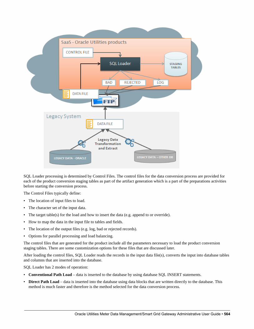
Oracle Utilities Meter Data Management/Smart Grid Gateway Administrative User Guide • 564
SQL Loader processing is determined by Control Files. The control files for the data conversion process are provided foreach of the product conversion staging tables as part of the artifact generation which is a part of the preparations activitiesbefore starting the conversion process.
The Control Files typically define:
• The location of input files to load.
• The character set of the input data.
• The target table(s) for the load and how to insert the data (e.g. append to or override).
• How to map the data in the input file to tables and fields.
• The location of the output files (e.g. log, bad or rejected records).
• Options for parallel processing and load balancing.
The control files that are generated for the product include all the parameters necessary to load the product conversionstaging tables. There are some customization options for these files that are discussed later.
After loading the control files, SQL Loader reads the records in the input data file(s), converts the input into database tablesand columns that are inserted into the database.
SQL Loader has 2 modes of operation:
• Conventional Path Load – data is inserted to the database by using database SQL INSERT statements.
• Direct Path Load – data is inserted into the database using data blocks that are written directly to the database. Thismethod is much faster and therefore is the method selected for the data conversion process.
Oracle Utilities Meter Data Management/Smart Grid Gateway Administrative User Guide • 565
SQL Loader has the ability to deal with multiple data files mapped to multiple tables as well as loading data into CLOBfields.
Using SQL Loader When Processing Conversion Data FilesProcessing of uploaded conversion data files is done via a Batch Process (for each staging table or MO) that does thefollowing:
• Prepare parameters for invoking SQL Loader.
• Invoke SQL Loader for loading one staging table or one MO, using the data files that was uploaded to the cloud (usingsFTP). The data file is processed directly from the sFTP server and is NOT copied to a local directory on the server.
• Archive the input file(s) and upload the results output files to the sFTP server so they can be subsequently downloadedby the customer for review.
Conversion ArtifactsThe base product includes a set of artifacts that support the conversion process. These artifacts are provided on demand(generated as a result of a user request in the system).
The available artifacts are:
• Input Data Specifications
• SQL Loader Control Files
Conversion Input Data SpecificationsThe system will generate a text file with data specification instructions for each of the conversion tables that are supportedby the base product.
The specification files are for reference ONLY and are not used by the system at run time. These files describe the dataformat for each table so that the data specified can be loaded correctly with the Control File that is also generated by thesystem.
For more details refer to Conversion Artifact Generator .
SQL Loader Control FilesThe control files are for internal use and are generated for each of the conversion tables that are supported by the product.These files are used by SQL Loader to interpret and load the data that is provided in the conversion data files.
The control file contains:
• General load parameters and options
• Data field specifications and table-specific load instructions
For more details refer to Conversion Artifact Generator .
Configuring ConversionThe following sections describe the settings and configurations used by various conversion processes.

Oracle Utilities Meter Data Management/Smart Grid Gateway Administrative User Guide • 566
Conversion Master ConfigurationThe Conversion Master Configuration controls generic aspects of legacy data load process. It stores:
• Conversion Task Types. The task types define load parameters for individual tables or maintenance objects.The Master Configuration captures default Conversion Task Types for both table and maintenance object-level loads.
It also allows to setup Override Instructions for tables and maintenance objects that require special processing or dataformatting
• Conversion Artifacts storage options. You can indicate that the snapshot of the generated file(s) should be Stored as anAttachment. If the indicator is set to Y, the Business Object to use for the Attachment has to be specified, otherwise, it isnot required.
Conversion Task TypesTo configure a new conversion task type, navigate using Admin –> Conversion Support –> Conversion Task Type.
The definitions on the conversion task type control the parameters of the data load for the target object: table ormaintenance object.
For the input data files, Conversion Task Types defines:
• Strings to use as data delimiters and enclosing characters. These attributes are referencing the Extendable Lookup valuesfor K1–ConvFileDelimiterLookup and K1–ConvFileEnclosingCharLookup
• Date and DateTime fields’ formats. These attributes are referencing the Extendable Lookup values for K1–ConvLoadDateFormatLookup and K1–ConvLoadDateTimeFmtLookup
• CLOB data extract rules: indicates whether the CLOB data is supplied as part of the input data file or as a separate,secondary file
• Control File Header - a fragment of the control file that contains general load parameters. This is a Foreign Key referenceto the Managed Context entry.
Conversion Task Type also defines the transactional business object for Conversion Task. The algorithms linked to thetransactional business object are responsible for the generation of the Conversion Artifacts: control files and input dataspecifications.
The following Conversion Task Types are pre-configured in the product:
• K1-CNV-TABLE - meant to be used for a single table load. It is referencing a Transactional Conversion Task BusinessObject whose algorithms generate Table Conversion Artifacts
• K1-CNV-MO - meant to be used for a single maintenance object load. It is referencing a Transactional Conversion TaskBusiness Object whose algorithms generate Maintenance Object Conversion Artifacts
• K1-CNV-KEY-TABLE – meant to be used for the Key Tables. Key Tables are index-organized tables (IOT) and assuch cannot be loaded in multiple concurrent sessions of SQL loader. This Task Type is referencing a Control FileHeader (Managed Content) where Parallel Load parameter is set to false
Conversion Artifact GeneratorConversion Artifacts is a set of supporting files used for data upload with SQL Loader. The artifacts are generated based onthe table and maintenance object metadata and the definitions from Conversion Master Configuration and ConfigurationTask Types. Conversion artifacts include SQL Loader control files and input data file specifications.
Input data file specifications provide detailed field-by-field description of the expected data type and format, field order andother instructions. Your implementation may use these specifications to create the legacy data extract.

Oracle Utilities Meter Data Management/Smart Grid Gateway Administrative User Guide • 567
The generator reads Conversion Master Configuration in order to determine the conversion task type associated with thetable or maintenance object.
You can choose to generate artifacts for table-level and/or maintenance object-level load, orfor the entire system or forspecific Table or Maintenance Object:
• Navigate to Admin —> Conversion Support —> Generate Conversion Artifacts.
• Select one of the options:
• Generate All – performs a complete refresh of the conversion artifacts. It deletes existing and creates new ConversionTasks for every table that is marked for conversion in the metadata. It also creates Conversion Task for everyMaintenance Object that includes tables marked for conversion.
• Include All Tables – recreates artifacts for all Tables that are marked for conversion in the metadata
• Table search allows you to select specific target table
• Include All maintenance Objects – recreates artifacts for all Maintenance Objects whose tables are marked forconversion in the metadata
• Maintenance Object search allows you to select specific target Maintenance Object.
NOTE: The process overrides all previously generated artifacts and replaces existing files.
The generator creates Conversion Tasks, one instance per table and/or per maintenance object and creates attachment thatstores the input data file specifications file. The attachment is linked to the Conversion Task as a Related Object.
The regeneration is necessary each time the metadata or conversion configurations are amended.
Conversion Tasks query is provided with the base product.
Accessing the ArtifactsIn order to make the generated input data file specifications available for download, submit the batch process K1-CNVUS.
After successful batch completion, locate the files under corresponding folder. Refer to Input and Output File Location formore details. You can also view the individual specifications by searching for a Conversion Task and exploring the linkedattachment.
NOTE:
• The specification file name for the table is composed as <table name>_spec.txt
• The specification file name for the maintenance object is composed as <maintenance object code>_spec.txt
Conversion TasksThe following sections provide information about Conversion Tasks and generated conversion artifacts.
Conversion Task QueryConversion Task query allows to search by variety of criteria:
• Creating User, Conversion Task Type and Status
• Linked Object – Table or Maintenance Object
• Exact Conversion Task ID
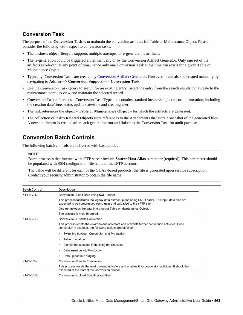
Oracle Utilities Meter Data Management/Smart Grid Gateway Administrative User Guide • 568
Conversion TaskThe purpose of the Conversion Task is to maintain the conversion artifacts for Table or Maintenance Object. Pleaseconsider the following with respect to conversion tasks.
• The business object lifecycle supports multiple attempts to re-generate the artifacts.
• The re-generation could be triggered either manually or by the Conversion Artifact Generator. Only one set of theartifacts is relevant at any point of time, hence only one Conversion Task at the time can exists for a given Table orMaintenance Object.
• Typically, Conversion Tasks are created by Conversion Artifact Generator. However, it can also be created manually bynavigating to Admin—> Conversion Support —> Conversion Task.
• Use the Conversion Task Query to search for an existing entry. Select the entry from the search results to navigate to themaintenance portal to view and maintain the selected record.
• Conversion Task references a Conversion Task Type and contains standard business object record information, includingthe creation date/time, status update date/time and creating user.
• The task references the object – Table or Maintenance Object – for which the artifacts are generated.
• The collection of task’s Related Objects store references to the Attachments that store a snapshot of the generated files.A new attachment is created after each generation run and linked to the Conversion Task for audit purposes.
Conversion Batch ControlsThe following batch controls are delivered with base product:
NOTE:Batch processes that interact with sFTP server include Source Host Alias parameter (required). This parameter shouldbe populated with SSH configuration file name of the sFTP account.
The value will be different for each of the OUAF-based products; the file is generated upon service subscription.Contact your security administrator to obtain the file name.
Batch Control Description
K1-CNVLD Conversion - Load Data using SQL Loader.This process facilitates the legacy data extract upload using SQL Loader. The input data files areexpected to be compressed using gzip and uploaded to the sFTP site.One run uploads the data into a target Table or Maintenance Object.The process is multi-threaded.
K1-CNVDS Conversion - Disable ConversionThis process resets the environment indicators and prevents further conversion activities. Onceconversion is disabled, the following actions are blocked:
• Switching between Conversion and Production
• Table truncation
• Disable Indexes and Rebuilding the Statistics
• Data insertion into Production
• Data upload into staging
K1-CNVEN Conversion - Enable ConversionThis process resets the environment indicators and enables it for conversion activities. It should beexecuted at the start of the Conversion project.
K1-CNVUS Conversion - Upload Specification Files
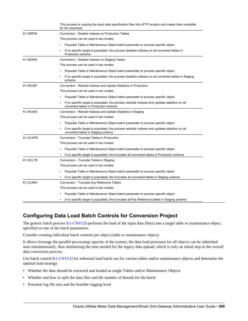
Oracle Utilities Meter Data Management/Smart Grid Gateway Administrative User Guide • 569
This process is copying the input data specification files into sFTP location and makes them availablefor the download
K1-DRPIN Conversion - Disable Indexes on Production TablesThis process can be used in two modes:
• Populate Table or Maintenance Object batch parameter to process specific object
• If no specific target is populated, the process disables indexes on all converted tables inProduction schema
K1-SDSIN Conversion - Disable Indexes on Staging TablesThis process can be used in two modes:
• Populate Table or Maintenance Object batch parameter to process specific object
• If no specific target is populated, the process disables indexes on all converted tables in Stagingschema
K1-RIUSP Conversion - Rebuild Indexes and Update Statistics in ProductionThis process can be used in two modes:
• Populate Table or Maintenance Object batch parameter to process specific object
• If no specific target is populated, the process rebuilds indexes and updates statistics on allconverted tables in Production schema
K1-RIUSS Conversion - Rebuild Indexes and Update Statistics in StagingThis process can be used in two modes:
• Populate Table or Maintenance Object batch parameter to process specific object
• If no specific target is populated, the process rebuilds indexes and updates statistics on allconverted tables in Staging schema
K1-CLNTB Conversion - Truncate Tables in ProductionThis process can be used in two modes:
• Populate Table or Maintenance Object batch parameter to process specific object
• If no specific target is populated, the truncates all converted tables in Production schema
K1-SCLTB Conversion - Truncate Tables in StagingThis process can be used in two modes:
• Populate Table or Maintenance Object batch parameter to process specific object
• If no specific target is populated, the truncates all converted tables in Staging schema
K1-CLNKY Conversion - Truncate Key Reference TablesThis process can be used in two modes:
• Populate Table or Maintenance Object batch parameter to process specific object
• If no specific target is populated, the truncates all Key Reference tables in Staging schema
Configuring Data Load Batch Controls for Conversion ProjectThe generic batch process K1-CNVLD performs the load of the input data file(s) into a target table or maintenance object,specified as one of the batch parameters.
Consider creating individual batch controls per object (table or maintenance object).
It allows leverage the parallel processing capacity of the system; the data load processes for all objects can be submittednear-simultaneously, thus minimizing the time needed for the legacy data upload, which is only an initial step in the overalldata conversion process.
Use batch control K1-CNVLD for rehearsal load batch run for various tables and/or maintenance objects and determine theoptimal load strategy:
• Whether the data should be extracted and loaded as single Tables and/or Maintenance Objects
• Whether and how to split the data files and the number of threads for the batch
• Potential log file size and the feasible logging level

Oracle Utilities Meter Data Management/Smart Grid Gateway Administrative User Guide • 570
Configure data load Batch Controls for each individual Table or Maintenance Object. Pattern the configuration after K1-CNVLD and set the default parameter values:
• Target Table or Maintenance Object:
• File Extension
• Log Level
• Retain Input
• Max Number of Errors
Configure single-threaded batch controls for Key Tables.
Input Data FilesThis section provides information on inputting data files for data conversion.
OverviewThis section provides information on the requirements and details for file upload, loading table, maintenance object, CLOB,layout, data formatting, and so on related to inputting data files for data conversion.
File Creation and UploadThe extract data is expected to be uploaded in compressed form. Use gzip to create compressed input data files.
File Creation
Use your sFTP account to retrieve input data specifications from conversion/reference directory. Create the data extracttext file, using field delimiters, enclosing characters and data formatting according to the specifications.
If the files were created under Windows operating system, it is recommended to remove the carriage return character priorto compression (not applicable for secondary files with CLOB data).
File Compression with gzip
Use gzip utility to compress the file.
• For Windows operating system, download and install gzip utility for Windows. Run the following:
# Navigate to the gzip folder
cd C:\gzip-1.3.12-1-bin\bin
# Run gzip.
# New file will be created in the same directory as the original the input file
gzip -k <full path to the input data file>
# Sample command for the file TABLE_NAME.txt located under
# C/myDataDirectory/:
gzip –k C/myDataDirectory/TABLE_NAME.txt
• For Unix/Linux operating systems, run the following command:
gzip < <inputFile name> > <outputFile name with .gz suffix>
# Sample command for the file TABLE_NAME.txt
Oracle Utilities Meter Data Management/Smart Grid Gateway Administrative User Guide • 571
gzip < TABLE_NAME.txt > TABLE_NAME.txt.gz
Loading Table or Maintenance ObjectThe conversion data upload supports two types of the extract:
• Data extract that contains the data for a single target staging table.
In this case, the upload process inserts records into a single staging table. The input data file consists of similar records,each represents a row in the target table.
• Data extract that contains the data for the group of target staging tables that represent a Maintenance Object.
In this case, the upload process populates all the tables that belong to a maintenance object. The input data file containsmultiple types of records that are inserted into various tables. Each record is prefixed with the table name that is used asrecord type indicator.
Multiple Data FilesThe large volume of the converted data may require the extract to be split into multiple parts.
In this case the multi-part extract for a target staging Table or Maintenance Object is loaded with a multi-threaded batch run.
Sample scenario:10M of the Person records are being converted. The extract file is split into 10 files, PERSON1, PERSON2 PERSON3 etc.,each file contains 1M records. All 10 files are uploaded to sFTP.
Batch process ‘Load Person data’ is submitted with 5 threads; each thread picks up 2 files and uploads the data into stagingtables.
Loading CLOB DataThe CLOB data can be loaded in two ways:
• Extracted as part of the main data file. This method is suitable for the relatively small CLOB data size. Refer toLimitations for more details.
• Extracted into a separate file. This method is suitable for larger CLOB data sizes and also for large volume tables ormaintenance objects. In this scenario, the secondary file has to be uploaded at the same time as the primary data file.
Notes on Secondary Data Files (CLOB Data)Secondary data file is loaded simultaneously with the primary data file. The CLOB data extract should contain exactly thesame number of records as a primary file.
NOTE:When splitting the extract into multiple data files, make sure that the numbers of extracted records in the primary andsecondary files are matching.
It is applicable for both table-level and maintenance-object level load.
Sample Scenario:
Table CI_PER includes CLOB column C1_PER_DATA_AREA.The CLOB field is used to store customer’s resume.
The legacy table contain 10K records and the CLOB data is available for some of the records

Oracle Utilities Meter Data Management/Smart Grid Gateway Administrative User Guide • 572
The primary data file, CI_PREM.csv contains 10K lines, one line per record
The secondary data file, CI_PREM_CLOB, contains 10K records too. The records with the empty CLOB are represented byCLOB delimiter.
Splitting single table data extract with CLOBThe following example illustrates how to split the single table large volume extract correctly if the CLOB data is supplied inthe secondary file:
Assuming the table has 10K records, split into two equal parts. The following files should be created:
• Primary File 1 with 5K records
• Secondary File 1 with 5K CLOB entries
• Primary File 2 with 5K records
• Secondary File 2 with 5K CLOB entries
Splitting maintenance object data extract with CLOBThe following example illustrates how to split the maintenance object large volume extract correctly if the CLOB data issupplied in the secondary file:
Assuming the maintenance object has two tables, one of the tables includes CLOB column and the primary table has 10Krecords. The data supposed to be split into two equal parts. The following files should be created:
• Primary File 1 with 5K records for the primary table and corresponding records for the child table
• Secondary File 1 with CLOB entries corresponding to the table in the Primary File 1
• Primary File 2 with 5K records for the primary table and corresponding records for the child table
• Secondary File 2 with CLOB entries corresponding to the table in the Primary File 2
NOTE:For Maintenance Object-level load consider supplying CLOB data in the primary file, to avoid complicated logic of datasplitting.
Refer to CLOB Data - XML for limitations concerning XML CLOB data
File Layout and Data FormattingThe input data specifications for each table or maintenance object that are subject to conversion specification files areavailable for download. Refer to Input and Output File Location for details.
Specifications are generated based on the metadata and conversion configurations. Configurations control delimiters andenclosing characters and define CLOB data processing rules.
The data extract file is expected to contain one record per each target table row. The data field order in the record has to beexactly the same as it is listed in the specification file.
The specifications contain field-by-field data formatting rules for:

Oracle Utilities Meter Data Management/Smart Grid Gateway Administrative User Guide • 573
• Data type and size
• Date, DateTime and Time formatting
• Special notes on CLOB fields
The fields in the record are expected to be separated by a delimiter character (or string).
The CLOB data in the main record has to be enclosed in the CLOB Delimiter string, for example <clobend>some clobdata<clobend>
For the not-nullable columns with no data, a single space enclosed in the enclosing character (or string) has to be supplied,for example “ “
Enclosing character (or string) can also be used to encapsulate data that includes a field delimiter, for example “Hello,World”
Defining Custom Data Delimiters and Enclosing CharactersThe default configurations are delivered with the base product.
Your entire legacy data or a specific table may require use of a different data delimiter and/or enclosing characters.
• Define new data delimiter string, CLOB delimiter string and/or enclosing string
• Configure Conversion Task Type using newly created delimiters
• Amend Conversion Master Configuration, setting default (for all tables or maintenance objects) or override (for specifictable or maintenance Object) instructions.
• Regenerate Conversion Artifacts
Now you can create data extract according to the newly generated specifications.
Input Data for a Staging TableThe extract for a single table contains delimited data records. Depending on the conversion configuration, the CLOB datashould be supplied either inline or in a separate, secondary file.
Input Data File Names
Input data file names has to follow the rules described in this chapter. The names are key-sensitive.
File Type File Name
Single data file per table, no CLOB File name equal target table name, i.e. CI_PREM
Single data file per table, CLOB data in secondary file Primary file name equal target table name, i.e. CI_PREMSecondary file name composed as target table nameconcatenated with ‘_CLOB’, i.e. CI_PREM_CLOB
Multiple data file per table, no CLOB File name is composed as target table name concatenatedwith file number, i.e. CI_PREM1, CI_PREM2 etc
Multiple data file per table, CLOB data in secondary file Primary file name is composed as target table nameconcatenated with numeric file number, i.e. CI_PREM1, CI_PREM2 etcSecondary file name composed as target table nameconcatenated with ‘_CLOB’ and file number, i.e. CI_PREM_CLOB1, CI_PREM_CLOB2 etc
Input Data for Maintenance ObjectThe extract for a maintenance object contains delimited data records for all tables included in the maintenance object.Depending on the conversion configuration, the CLOB data should be supplied either inline or in a separate, secondary files,
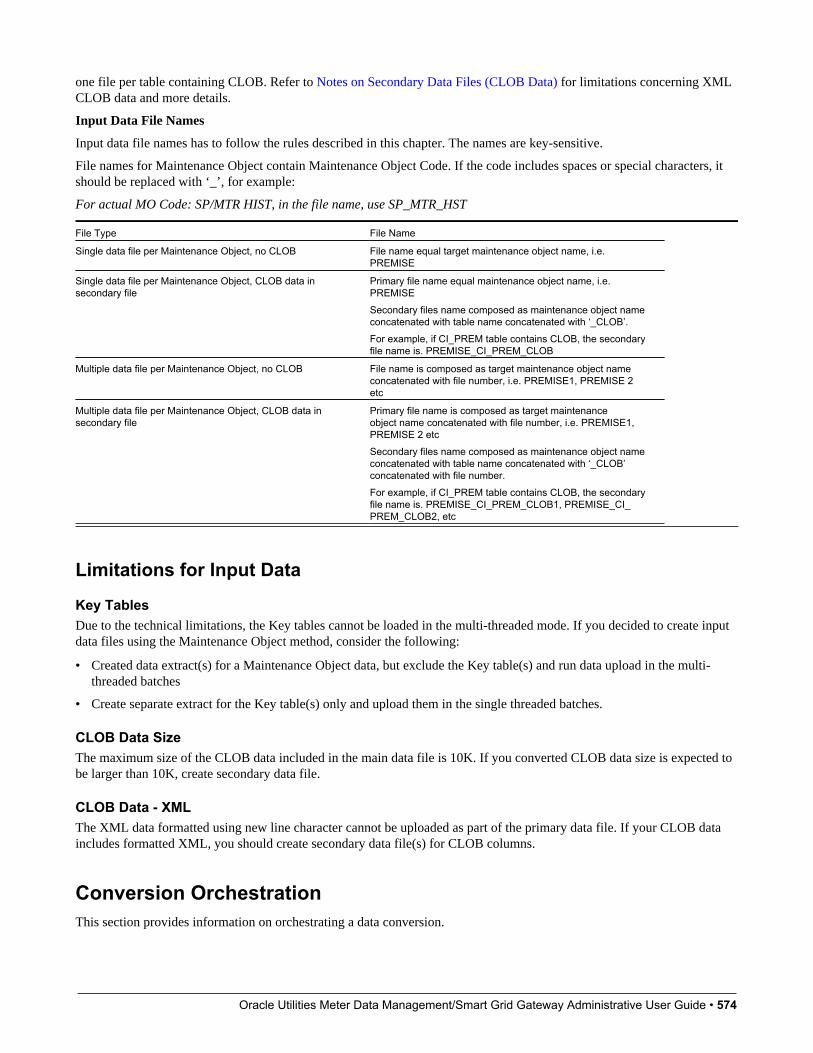
Oracle Utilities Meter Data Management/Smart Grid Gateway Administrative User Guide • 574
one file per table containing CLOB. Refer to Notes on Secondary Data Files (CLOB Data) for limitations concerning XMLCLOB data and more details.
Input Data File Names
Input data file names has to follow the rules described in this chapter. The names are key-sensitive.
File names for Maintenance Object contain Maintenance Object Code. If the code includes spaces or special characters, itshould be replaced with ‘_’, for example:
For actual MO Code: SP/MTR HIST, in the file name, use SP_MTR_HST
File Type File Name
Single data file per Maintenance Object, no CLOB File name equal target maintenance object name, i.e.PREMISE
Single data file per Maintenance Object, CLOB data insecondary file
Primary file name equal maintenance object name, i.e.PREMISESecondary files name composed as maintenance object nameconcatenated with table name concatenated with ‘_CLOB’.For example, if CI_PREM table contains CLOB, the secondaryfile name is. PREMISE_CI_PREM_CLOB
Multiple data file per Maintenance Object, no CLOB File name is composed as target maintenance object nameconcatenated with file number, i.e. PREMISE1, PREMISE 2etc
Multiple data file per Maintenance Object, CLOB data insecondary file
Primary file name is composed as target maintenanceobject name concatenated with file number, i.e. PREMISE1,PREMISE 2 etcSecondary files name composed as maintenance object nameconcatenated with table name concatenated with ‘_CLOB’concatenated with file number.For example, if CI_PREM table contains CLOB, the secondaryfile name is. PREMISE_CI_PREM_CLOB1, PREMISE_CI_PREM_CLOB2, etc
Limitations for Input Data
Key TablesDue to the technical limitations, the Key tables cannot be loaded in the multi-threaded mode. If you decided to create inputdata files using the Maintenance Object method, consider the following:
• Created data extract(s) for a Maintenance Object data, but exclude the Key table(s) and run data upload in the multi-threaded batches
• Create separate extract for the Key table(s) only and upload them in the single threaded batches.
CLOB Data SizeThe maximum size of the CLOB data included in the main data file is 10K. If you converted CLOB data size is expected tobe larger than 10K, create secondary data file.
CLOB Data - XMLThe XML data formatted using new line character cannot be uploaded as part of the primary data file. If your CLOB dataincludes formatted XML, you should create secondary data file(s) for CLOB columns.
Conversion OrchestrationThis section provides information on orchestrating a data conversion.
Oracle Utilities Meter Data Management/Smart Grid Gateway Administrative User Guide • 575
Input and Output File LocationLocations for conversion input and output files on the sFTP server:
• Upload input data files: conversion/upload
• Download the process output: logs, discard and bad files: conversion/download
• Download archived (processed) input data files: conversion/archive
• Download input data specifications: conversion/reference
Understanding Load Data ProcessThe setup of the batch controls that is necessary to support data conversion and legacy data extract upload is described inData Load Batch Controls .
The following sections explain the process of legacy data extract upload with SQL loader.
Load Data Batch Run ParametersThe data upload batch is processing single target object – Table or Maintenance Object. The data extract may be supplied inone or multiple files, created and named according to the Input File instructions for a Staging Table and Maintenance Object.
The process is multi-threaded and optimized for the parallel load.
Using the batch parameters you can control:
• Level of logging
• Data extract retention
• Maximum number of load errors
Multi-ThreadingThe process is threading by dividing the multiple data files between the threads. Each thread in turn, is processing its filesone by one.
The exception is Key Tables. They are index-organized tables and have to be loaded in the single thread, due to the SQLLoader restrictions.
Load Outcome – Log, Bad and Rejected FilesSQL Loader output files are available for download after each run . Refer to Input and Output File Location for details. Toensure file name uniqueness, the output file names are concatenated with the current timestamp.
• Log file contains the information about the run, including number of record processed, errors encountered and otheruseful information. The level of logging is controlled by the batch parameter log .
• Bad and Rejected files contains the records that were rejected by either the SQL Loader or the database.
Oracle Utilities Meter Data Management/Smart Grid Gateway Administrative User Guide • 576
Interrupted LoadThe data load process can be re-started. Once SQL Loader reached the maximum number of errors allowed for the run,it records the position of the last record in error in the log. The restarted load begins pulling the data from the file afterskipping certain number of records.
In order to continue processing interrupted load, perform the following steps:
• Retrieve the log file. Find statement 'Specify SKIP=n when continuing the load.' in the log file.
• Re-upload the input data file to the server
• Submit the batch once again, this time specifying the n as a skip batch parameter
Tables Cleanup and Index MaintenanceThe SQL Loader is running in parallel mode in order to maximize the performance. Therefore the target tables are notemptied prior to the data insertion and it has to be done implicitly, by running corresponding batch jobs.
Indexes are disabled during the data upload. The product provides batch processes that support index disabling/re-buildingand statistics update.
• User batch control K1-SCLTB to truncate tables in Staging area and batch control K1-CLNTB to truncate tables inProduction
• Use batch control K1-SDSIN to disable indexes in Staging area and batch control K1-DRPIN to disable indexes inProduction
• Use batch control K1-CLNKY to truncate Key Reference tables in Staging area
The supported scenarios are:
• Truncate Specific Table or Maintenance Object: In order to truncate the specific table, submit the correspondingbatch job, specifying table parameter. In order to truncate the data that stored in a specific Maintenance Object, submitthe corresponding batch job, specifying maintenanceObject parameter. The process will also disable indexes in thetruncated tables.
NOTE: If the truncated table’s metadata defines a Key table, the Key table gets truncated too.
• Truncate all Converted Tables: In order to truncate all converted tables run the corresponding batch job withoutspecifying table or maintenanceObject parameters. The process will disable indexes and truncate all tables marked forconversion in the metadata.
• Truncate Key Reference Tables for Specific Table or Maintenance Object: In order to truncate Key Referencetable linked to a staging table, submit the corresponding batch job, specifying table parameter. In order to truncate KeyReference tables for a specific Maintenance Object, submit the corresponding batch job, specifying maintenanceObjectparameter.
• Truncate all Key Reference Tables: Submit the corresponding batch job without specifying table ormaintenanceObject parameters to truncate all Key Reference tables.
• Disable Indexes for Specific Table or Maintenance Object: In order to disable indexes for the specific table, submitthe corresponding batch job, specifying table parameter. In order to disable indexes for the specific MaintenanceObject’s tables, submit the corresponding batch job, specifying maintenanceObject parameter.
• Disable Indexes for all converted Tables: In order to disable indexes on all converted tables run the correspondingbatch job without specifying table or maintenanceObject parameters. The process will disable indexes and truncate alltables marked for conversion in the metadata.

Oracle Utilities Meter Data Management/Smart Grid Gateway Administrative User Guide • 577
Load Performance TuningThe data specifics – volumes, structure and other aspects – may justify customizing the default configurations for all orsome tables.
The SQL Loader is processing data according to the Control File. The fragment that contains general load parameters isstored as Managed Content that is referenced on the Conversion Task Type.
You can create new Managed Content, configure the Conversion Task Type and specify the new settings on ConversionMaster Configuration, for all or specific Tables or Maintenance Objects.
Understanding the Conversion Orchestration ProcessThe following sections provide information on general aspects of conversion orchestration.
Enabling ConversionConversion activities are possible as long as conversion is enabled in the environment. The authorized ConversionAdministrator may run the corresponding batch job to enable conversion.
Switching between Staging and Production SchemaIn the environment enabled for conversion, the online application is running against the database schema that containssynonyms pointing to either Staging or Production tables.
The synonyms could be switched by running the corresponding batch job.
The switching is possible only while Conversion is Enabled
Navigate to Admin –> Conversion Support –> Switch Schema to perform the action.
Preparing for ConversionThe preparation steps include evaluating initial conversion configurations provided by the product, customizing theconfigurations if needed, and finally, generating conversion artifacts.
The preparation should be done when the environment is running against Production schema
Conversion DevelopmentThe creation of the legacy data extract and rehearsal of the data load and subsequent conversion data processing is donewhile the environment is running against Staging schema.
Consider creating and scheduling the sequence of the batch processes for both data load and following validation andinsertion.
Include table truncation, index maintenance and statistic updates into batch chains.
Conversion RunFor the mock-up, or dress rehearsal or the actual go-live conversion run you may choose to amend data load batch controlsfor tables/maintenance objects to improve performance:
• Reduce the logging level – set log batch parameter to NOLOG
• Do not retain input data – set retaininput batch parameter to PURGE
Disabling ConversionAfter conversion is completed, the various activities such as table truncation and index maintenance should not be allowed.
Oracle Utilities Meter Data Management/Smart Grid Gateway Administrative User Guide • 578
Upon conversion project completion, switch the schema to Production and request that the authorized ConversionAdministrator run the corresponding batch job to disable Conversion in the environment.
Security Setup for ConversionThe services associated with data conversion are combined into the following user groups
• Conversion Administrators includes the services linked to the most sensitive database operations: enable/disableconversion and switching database synonyms between production and staging schema
• Conversion Development includes the services associated with conversion-related configurations
• Conversion Operations provides access to services associated with data load batch processes. This group could beextended to include services associated with specific table(s) or maintenance object data loads
These user groups are included in the base product. Your implementation may chose to use it as is or create a differentsetup.
Conversion Reconciliation ReportsYour cloud service subscription includes an access to the BI Publisher instance that can be used to create and run datareports against both production and staging tables. Contact your Security Administrator for access information.
Oracle Utilities Meter Data Management/Smart Grid Gateway Administrative User Guide • 579
Chapter 2
Meter Data Management Functional Overview
Oracle Utilities Meter Data Management (MDM) provides functionality for handling large volumes of meter and devicedata that enable increased accuracy, flexibility, and scalability. The following outlines the most crucial business processesthat are enabled within the system:
• Defining meters, meter configurations, service points, and meter installations.
• Loading meter readings and interval data from a head-end system or other source.
• Automatic validation, editing, and estimating measurement data.
• Robust editing capabilities for readings and interval data
• Calculating and publishing bill determinants, and other data, from measurement data to be used in external, down-streamsystems; such as, billing or pricing.
Oracle Utilities Meter Data Management stores a lot of important data; including, meters, service points, customer contacts,and everything in between.

Oracle Utilities Meter Data Management/Smart Grid Gateway Administrative User Guide • 580
Measurement, VEE, and Usage Calculation for Billing
A Device represents a physical meter, communication module, or some other device in the field. A Service Point is the pointwhere service is delivered to a customer and a device can be installed. The Install Event is a record of a specific device thatis installed at a Service Point. A Contact is the customer that is associated with the Usage Subscription.
In order to properly track the way that a device is configured, the Device Configuration keeps a record of which typesof data should be measured for the device. A Measuring Component represents a single channel of data for a device; forexample, a device may have multiple measuring components: one that represents kWh interval data, another that representskWh scalar readings, and a third that registers Voltage interval data.

Oracle Utilities Meter Data Management/Smart Grid Gateway Administrative User Guide • 581
Energy data received from meters is initially stored as Initial Measurement Data (IMD). Once the VEE process is executed,if the data passes then Measurements are created. If the data fails, however, then VEE Exceptions are created.
A Usage Subscription tracks a set of usage calculations that should be performed for a single or multiple Points. In order toperform calculation of usage (often referred to as bill determinants), a Usage Transaction is created through a request fromthe billing system. If any issues are encountered in the usage calculation process, or from a usage transaction validation,then Usage Transaction Exceptions are created.
Service Orders and Remote Commands
An Activity in Oracle Utilities Meter Data Management is a very flexible object that is used for various processes. Two ofthe key processes handled by Activities are:
• Remote Commands involve communicating with a Head End system to perform actions or retrieve data from a meter; forexample, remote connects, remote disconnects, and on-demand reading.
• Service Orders are methods where work can be performed at a Service Point; for example, enabling service, disablingservice, and meter exchanges.
Oracle Utilities Meter Data Management includes the following functional areas:
• Device Management is used by analysts and administrators to manage and define the devices used to record and capturemeter data.
• Device Installation is used by analysts and administrators to manage device installation; including, defining markets andservice providers, service points, contacts, and installation events.

Oracle Utilities Meter Data Management/Smart Grid Gateway Administrative User Guide • 582
• Measurement Data is a normalized way of storing data from a meter that involves some form of measurement (such as,kWh and CCF). Both interval data and scalar readings are held in this common storage location.
• Validation, Editing, and Estimation (VEE) is used by administrators to define validation, editing, and estimation rulesto be applied to measurement data. VEE Exceptions may result from validation or estimation failures and should beworked by analysts through the To Do process.
• 360 Degree Search and View is used by analysts and administrators to search and view data for devices, measuringcomponents, service points, usage subscriptions, and contacts.
• Consumption Sync provides an automatic method to keep interval data and scalar readings in sync with one another.
• Usage Calculation is used by administrators to manage the calculation of usage data and to provide the results of thosecalculations (commonly referred to as bill determinants) to external systems and parties. Usage calculation groups andrules define calculation rules to be applied to measurement data. Usage Transaction Exceptions may result from usagecalculation and should be worked by analysts through the To Do process.
• Device Events provide a view of specific events that have occurred on a meter. These are often unexpected and canindicate an issue with the meter.
• Communication helps track the instances when communication occurs with external systems. This is heavily used totrack remote commands against Head End systems.
• Aggregations are used by analysts and administrators to search, view, and maintain aggregated measurements thatrepresent a summarization of other measurements from a set of devices and/or measuring components.
• Master Data Sync defines the methods that data is automatically synchronized to Oracle Utilities Meter DataManagement from external sources; such as, a CIS and/or Asset Management system.
• Outage Storm Mode is a way for Oracle Utilities Meter Data Management to detect widespread outages and suppressestimation for those meters until normal data communication resumes.
• Dashboards provide high level metrics for Oracle Utilities Meter Data Management operators to monitor operationaltrends as well as overall system health.
• Service Issue Monitor can be setup by administrators to monitor various conditions within Oracle Utilities Meter DataManagement and automatically create a Service Investigative Order, if those conditions are met.
• Service Order Management provides a centralized program for managing the complex interactions required forService Order processing. This area is especially valuable for managing service order processing that involves remotecommunication with a Head End for connects, disconnects, and on-demand readings.
• Information Lifecycle Management is an automated method that administrators can configure to prepare data forarchiving or purging after a defined period of time for the record type.
Architectural OverviewOracle Utilities Meter Data Management is used to maintain information about meters and the service points at which theyare installed. The application provides means of recording measurements and events associated with meters in the field aswell as the ability to compute usage for the recorded measurements.
Oracle Utilities Meter Data Management comprises the following functional areas:
Device Management: the maintenance of physical meters in the field
Device Installation: the maintenance of service points and the installation of meters in the field. This includes the means ofregistering outside systems to Oracle Utilities Meter Data Management for provider/consumer-specific processing of meterevents and activities
Device Communication: the maintenance of communications between Oracle Utilities Meter Data Management and head-end systems, including import of usage and events.

Oracle Utilities Meter Data Management/Smart Grid Gateway Administrative User Guide • 583
Validation, Editing, and Estimation: the maintenance of measurement data and the engine used to validate and modify thatdata as it comes in
Usage Management: the engine that calculates billable usage recorded on devices, applying factors and dividing the usageinto configurable time of use periods
Aggregation: summarization of measurement data for reporting and analysis purposes
Data Synchronization: synchronizing data between Oracle Utilities Meter Data Management and other Oracle Utilitiesapplications (including Oracle Utilities Operational Device Management and Oracle Utilities Customer Care and Billing).
Oracle Utilities DataConnect: extraction of consumption and master data for use in external systems.
Oracle Utilities Meter Data Management is built upon the Oracle Utilities Service and Measurement Data Foundation,a framework that provides shared functionality used by Oracle Utilities Meter Data Management, the Oracle UtilitiesSmart Grid Gateway adapters, and other Oracle Utilities products. Oracle Utilities Meter Data Management and the OracleUtilities Service and Measurement Data Foundation are built atop the Oracle Utilities Application Framework.
Naming ConventionsOracle Utilities Meter Data Management system uses naming conventions to identify and distinguish entities that belong todifferent Oracle applications. These conventions can help you locate entities and understand their context.
Each base product uses a 2-character owner code as a prefix for all its entities. For Oracle Utilities Meter Data Management,these prefixes are as follows:
Product Name Prefix
Oracle Utilities Application Framework F1
Oracle Utilities Service and Measurement Data Foundation D1
Oracle Utilities Meter Data Management D2
Oracle Utilities Smart Grid Gateway for Landys+Gyr D3
Oracle Utilities Smart Grid Gateway for Echelon D4
Oracle Utilities Smart Grid Gateway for MV-90 D5
Oracle Utilities Smart Grid Gateway for Sensus RNI D6
Oracle Utilities Smart Grid Gateway for Silver Springs Networks D7
Oracle Utilities Smart Grid Gateway for Itron OpenWay D8
Oracle Utilities Smart Grid Gateway for Adapter Development Kit DG
Oracle Utilities Customer Self Service WX
Oracle Utilities Meter Data Management Demo Data* DM
*Note: this is not actually a product but rather a set of data that demonstrates Oracle Meter Data Management functionality.
Oracle recommends that you follow these naming conventions and develop your own set of conventions for the entities youcreate. If you create new entities, DO NOT use these prefixes; use the prefix "CM" (or some other unique prefix) to identifyentities that have been customized.
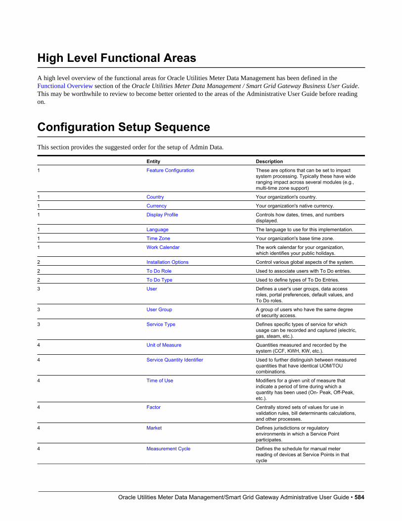
Oracle Utilities Meter Data Management/Smart Grid Gateway Administrative User Guide • 584
High Level Functional AreasA high level overview of the functional areas for Oracle Utilities Meter Data Management has been defined in theFunctional Overview section of the Oracle Utilities Meter Data Management / Smart Grid Gateway Business User Guide.This may be worthwhile to review to become better oriented to the areas of the Administrative User Guide before readingon.
Configuration Setup SequenceThis section provides the suggested order for the setup of Admin Data.
Entity Description
1 Feature Configuration These are options that can be set to impactsystem processing. Typically these have wideranging impact across several modules (e.g.,multi-time zone support)
1 Country Your organization's country.
1 Currency Your organization's native currency.
1 Display Profile Controls how dates, times, and numbersdisplayed.
1 Language The language to use for this implementation.
1 Time Zone Your organization's base time zone.
1 Work Calendar The work calendar for your organization,which identifies your public holidays.
2 Installation Options Control various global aspects of the system.
2 To Do Role Used to associate users with To Do entries.
2 To Do Type Used to define types of To Do Entries.
3 User Defines a user's user groups, data accessroles, portal preferences, default values, andTo Do roles.
3 User Group A group of users who have the same degreeof security access.
3 Service Type Defines specific types of service for whichusage can be recorded and captured (electric,gas, steam, etc.).
4 Unit of Measure Quantities measured and recorded by thesystem (CCF, KWH, KW, etc.).
4 Service Quantity Identifier Used to further distinguish between measuredquantities that have identical UOM/TOUcombinations.
4 Time of Use Modifiers for a given unit of measure thatindicate a period of time during which aquantity has been used (On- Peak, Off-Peak,etc.).
4 Factor Centrally stored sets of values for use invalidation rules, bill determinants calculations,and other processes.
4 Market Defines jurisdictions or regulatoryenvironments in which a Service Pointparticipates.
4 Measurement Cycle Defines the schedule for manual meterreading of devices at Service Points in thatcycle

Oracle Utilities Meter Data Management/Smart Grid Gateway Administrative User Guide • 585
4 Measurement Cycle Schedule Define the dates on which devicesare scheduled to be read for a givenmeasurement cycle.
4 Outbound Message Defines messages sent to external systems.
5 External System Defines External Systems with which OracleUtilities Meter Data Management should beable to communicate.
6 Head End SystemsExternal ApplicationsMarket Participants
External entities that serve various rolesrelative to the application (head-end systems,billing systems, market participants, outagemanagement systems, etc.).
6 Contact Type Defines properties of a class of entities(businesses, persons).
7 Activity Type Defines properties common to a specific typeof activity.
7 Communication Type Define properties common to a specific typeof communication.
7 Service Task Type Defines specific types of tasks performed byexternal users (self-service meter reads, self-service outage notifications, etc.)
7 Dynamic Option Type Defines information common to dynamicoptions of a specific type.
7 Manufacturer Individual companies that makes devices.Manufacturers also reference models.
7 Exception Type Defines properties common to VEEExceptions of a specific type.
8 VEE Group Collections of VEE Rules that are applied toinitial measurement data.
9 VEE Rule Standard and custom VEE Rules that performchecking and/or manipulation of initialmeasurement data.
10 VEE Eligibility Criteria Dictates whether a VEE Rule can executebased on a set of defined criteria.
11 Measuring Component Type Defines the most important properties of ameasuring component.
12 Device Configuration Type Defines properties of Device Configurations ofa given type.
13 Device Type Defines information about a class of devices.
14 Service Point Type Defines specific types of points at whichservice is delivered.
15 TOU Group Used to limit the set of Time Of Uses that areusable in a TOU schedule.
16 TOU Map Template Schedules used for TOU map datageneration.
17 TOU Map Type Define important properties of TOU maps of agiven type.
18 Usage Transaction Exception Type Defines properties common to UsageTransaction Exceptions of a specific type.
18 Usage Calculation Group Collections of usage calculation rules that areapplied to measurement data to calculate billdeterminants for Usage Subscriptions.
19 Usage Calculation Rule Defines rules that perform calculationson measurement data to generate billdeterminants and other values used byexternal systems.
20 Usage Calculation Rule Eligibility Criteria Dictates whether a usage calculation rule canexecute based on a set of defined criteria.
21 Usage Subscription Type Defines collections of properties common to aset of Usage Subscriptions.
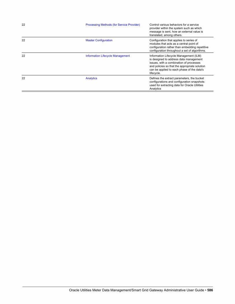
Oracle Utilities Meter Data Management/Smart Grid Gateway Administrative User Guide • 586
22 Processing Methods (for Service Provider) Control various behaviors for a serviceprovider within the system such as whichmessage is sent, how an external value istranslated, among others.
22 Master Configuration Configuration that applies to series ofmodules that acts as a central point ofconfiguration rather than embedding repetitiveconfiguration throughout a set of algorithms.
22 Information Lifecycle Management Information Lifecycle Management (ILM)is designed to address data managementissues, with a combination of processesand policies so that the appropriate solutioncan be applied to each phase of the data'slifecycle.
22 Analytics Defines the extract parameters, the bucketconfigurations and configuration snapshotsused for extracting data for Oracle UtilitiesAnalytics
Oracle Utilities Meter Data Management/Smart Grid Gateway Administrative User Guide • 587
Chapter 3
Additional Resources
How to Get SupportOracle is deeply committed to technical support services for its products. The Oracle Support online portal provides areliable, easy-to-use method for obtaining technical support for Oracle Utilities Meter Data Management. To register as anew user for Oracle Support, go to https://support.oracle.com and follow the steps shown on the screen.
Oracle policies for standard technical support services are available at http://www.oracle.com/us/support/policies/index.html.
Knowledge Base ArticlesOnce you have access to Oracle Support, finding Knowledge Base articles is an easy process.
1. Log in to https://support.oracle.com.
2. Select the Knowledge tab at the top of the Oracle Support portal.
3. Under the Knowledge Base section, type "Oracle Utilities Meter Data Management" as the product.
4. Enter key search topics into the Enter search terms box.
5. Click Search.
The search results will display all knowledge articles stored on Oracle Support related to Oracle Utilities Meter DataManagement for your key topics.
Oracle Utilities Meter Data Management/Smart Grid Gateway Administrative User Guide • 588
Important ArticlesWhile there is a vast library of important Knowledge Base articles on Oracle Support, the list below highlights a few of thekey knowledge articles that should be helpful if you're looking for additional detailed information about Oracle UtilitiesMeter Data Management:
Article Name Knowledge Base Article Number
Information Center: Meter Data Management and Smart Grid GatewayVersion 2
1907636.2
Related Measuring Component Consumption Sync White Paper 1672461.1
Overview and Guidelines for Managing Business Exceptions andErrors(this document was created by the CC&B team but pertains to MDM aswell)
1628358.1
Support Hot Topic EmailsOracle Support provides a way to receive daily or weekly updates on new information posted for Oracle Utilities MeterData Management.
1. Log in to https://support.oracle.com.
2. Select the Settings tab at the top of the Oracle Support portal. (Note: this tab may be hidden for you and may requireclicking a dropdown on the right side of the tabs)
3. Once on the Settings screen, choose the Hot Topics E-mail from the set of options on the left.
4. Under Delivery Options, choose Send With Selected Options.
5. Choose your delivery frequency: either Daily or Weekly.
6. Add content which interests you: there are a number of options available. To subscribe to updates for OracleUtilities Meter Data Management, hit the Add... button under Selected Products. Enter "Oracle Utilities Meter DataManagement" for the Product then choose the types of information for which you'd like to receive an email.
7. Make sure you click Apply at the bottom once you've made all of your selections.
Embedded HelpOracle Utilities Meter Data Management, like all Oracle Utilities Application Framework applications, provides extensiveinternal documentation. For example, detailed descriptions of system objects are included in the objects' maintenanceportals. The lifecycle of each business object is described on the Lifecycle tab and depicted in flow diagrams on theSummary tab. This information is extremely useful for implementers and system administrators.
Embedded help is provided for all non-obvious fields in most portals and zones. If a field has associated help text, aquestion mark icon appears next to the field when the zone is displayed.
Oracle Utilities Meter Data Management/Smart Grid Gateway Administrative User Guide • 589
Leveraging Demonstration DataOne of the best ways to understand Oracle Utilities Meter Data Management is through a thorough review of thedemonstration data (also referred to as "demo data") provided by Oracle. The demo data for Oracle Utilities Meter DataManagement provides the following:
• An overall view of how to implement the product for common needs
• Examples of the productized solutions to solve key utility scenarios
• Some examples of adding "customer modifications" on top of Oracle Utilities Meter Data Management
This demo data can be downloaded along with the Oracle Utilities Meter Data Management. It's recommended that this beinstalled into an isolated environment for reference purposes separate from other development or testing environments.
Once installed, the demo data scenarios can be found in two places within Oracle Utilities Meter Data Management:
• A zone named Demo Scenarios is shown in the right side Dashboard. This provides a quick method to link to the 360Degree View for the specific demo meter.
• An extendable lookup named Demo Scenarios Catalog describes each of the scenarios in detail. This matches thescenarios displayed in the Demo Scenarios zone.
NOTE: Oracle recommends that you do not clone the demonstration environment as a basis for a new productionenvironment. The demonstration environment typically includes transactional data that will be irrelevant to your productionenvironment and can cause unexpected issues if it is not purged correctly. The recommended process is to start a newproduction environment from a new installation and migrate "clean" system data (such as business objects and algorithms)and administrative data (such as sample activity types or other administrative entities) from the demonstration and/or test ordevelopment environments as applicable. Instructions for using these tools are contained in the Bundling and ConfigurationMigration Assistant sections in the Oracle Utilities Application Framework Administrative User Guide.
Customer User GroupsA number of Customer User Groups have been established (one in the United States and others internationally) that arespecific to sharing best practices and learnings about Oracle Utilities Meter Data Management and Oracle Utilities SmartGrid Gateway (SGG). If you're interested in participating in a Customer User Group, contact the appropriate ProductManager.

Oracle Utilities Meter Data Management/Smart Grid Gateway Administrative User Guide • 590
Chapter 4
Best Practices
Performance Recommendations
Initial Measurement Loading Recommendations• In general, keep the number of devices to 1,000 per file for optimum usage and event processing through OSB. A lower
number of devices, per file, will take more time for processing. A higher number of devices, per file, leads to highgrowth in garbage collection leading to waits and results in lower throughput. Please note, the optimum number oftransactions per file may vary by head-end system.
• Initial measurement payloads should have very selective criterion to get to the exact measuring component (MC). In anideal case, it should be the MC identifier along with device serial number. If this is not provided, then the UOM/TOU/SQI configured on the MC type is used to retrieve the exact business object (BO) from the Service Provider which mighthave the same values for multiple channels.
• Populating the raw data section of the IMD record will reduce overall throughput
VEE Recommendations• For the High-Low VEE Rule, the historic pre window should be set as low as possible based on business needs. This rule
has an intensive hit on performance of the Initial Measurement loading process.
• Each VEE Rule included in VEE processing can have an impact on overall performance. The table below summaries therelative costs in terms of performance for several commonly used VEE Rules. Using this table when designing your VEEgroups and rules can help identify potential performance challenges.
• For example, using "Minimal Impact" rules will likely have little to no significant impact on performance, while usingseveral "Moderate Impact" rules could result in performance challenges, and using the High Low Check rule is verylikely to introduce noticeable impacts to VEE processing performance.
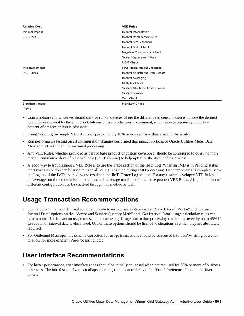
Oracle Utilities Meter Data Management/Smart Grid Gateway Administrative User Guide • 591
Relative Cost VEE Rules
Minimal Impact(0% - 5%)
Interval InterpolationInterval Replacement RuleInterval Size ValidationInterval Spike CheckNegative Consumption CheckScalar Replacement RuleUOM Check
Moderate Impact(5% - 20%)
Final Measurement ValidationInterval Adjustment From ScalarInterval AveragingMultiplier CheckScalar Calculation From IntervalScalar ProrationSum Check
Significant Impact(20%)
High/Low Check
• Consumption sync processes should only be run on devices where the difference in consumption is outside the definedtolerance as dictated by the sum check tolerance. In a production environment, running consumption sync for twopercent of devices or less is advisable.
• Using Scripting for simple VEE Rules is approximately 10% more expensive than a similar Java rule.
• Run performance testing on all configuration changes performed that impact portions of Oracle Utilities Meter DataManagement with high transactional processing.
• Any VEE Rules, whether provided as part of base product or custom developed, should be configured to query no morethan 30 cumulative days of historical data (i.e. High/Low) to help optimize the data loading process
• A good way to troubleshoot a VEE Rule is to use the Trace section of the IMD Log. When an IMD is in Pending status,the Trace On button can be used to trace all VEE Rules fired during IMD processing. Once processing is complete, viewthe Log tab of the IMD and review the results in the IMD Trace Log section. For any custom developed VEE Rules,the average run time should be no longer than the average run time of other base product VEE Rules. Also, the impact ofdifferent configuration can be checked through this method as well.
Usage Transaction Recommendations• Saving derived interval data and sending the data to an external system via the "Save Interval Vector" and "Extract
Interval Data" options on the "Vector and Service Quantity Math" and "Get Interval Data" usage calculation rules canhave a noticeable impact on usage transaction processing. Usage transaction processing can be improved by up to 45% ifextraction of interval data is eliminated. Use of these options should be limited to situations in which they are absolutelyrequired.
• For Outbound Messages, the schema extraction for usage transactions should be converted into a RAW string operationto allow for more efficient Pre-Processing logic.
User Interface Recommendations• For better performance, user interface zones should be initially collapsed when not required for 90% or more of business
processes. The initial state of zones (collapsed or not) can be controlled via the "Portal Preferences" tab on the Userportal.
Oracle Utilities Meter Data Management/Smart Grid Gateway Administrative User Guide • 592
• The number of records returned to the user interface for a zone should be limited to 50 rows when building custom zonesagainst large transactional tables.
• UI Map schemas should be specific to the displayed data. This will make sure that application will not visit all theelements that are not required for display.
• A good way to troubleshoot a screen in the user interface is to go to the Preferences in the top right hand corner ofthe application and choose the Portal Preferences tab. Choose the appropriate portal and set all zones to "InitiallyCollapsed". Next, navigate back to the screen that has performance issues, expand the zones one by one, and measurethe execution time of each zone. This should be an accurate step-by-step representation of the full screen execution. Thistesting is especially important for custom user interfaces.
• For optimal user interface performance, Oracle Utilities Meter Data Management users should ensure their computer setto high performance mode so all CPU resources are used. Also, check if allocating additional memory through yourbrowser's default settings helps improve performance.
SQL Recommendations• Avoid making unbounded SQLs statements with no boundary condition on date columns.
• Reduce CLOB searches and use physical columns wherever possible.
• Implement caching to pre-fetch data instead of issuing multiple SQLs.
Java Recommendations1. For areas where the transactional volume is high (such as Initial Measurement), use Hibernate SQL for non-CLOB
fields whenever possible as opposed to reading entire Business Object. If a CLOB field must be retrieved, then eitherEntity or Lite BO should be used. Reading the full Business Object should be used as the last resort for high volumeareas. This process should be considered for updating data as well when it provides the same functionality as updatingthe Business Object. These methods should only be considered if BO level validations, pre-processing, and post-processing aren't required.
2. For a simple SQL select statement needed in Java (not many joins and no complex logic), using Hibernate SQLprovides a benefit over using a Business Service and a Zone since the entities are cached for Hibernate SQL.
3. "Lite" Business Objects are provided as a way to access the main fields for a BO without pulling back all of theinformation. Retrieving less information will speed up the process for reading the BO.
Referencing Master Data by Identifiers
Understanding Referencing Master Data by IdentifiersThere are many places within admin configuration where direct references to master data can be made. Since master datarelies on system generated keys this configuration often breaks once migrated to a new environment since the masterdata referenced does not exist in the target environment. To alleviate this issue, in each of these instances, a user definedidentifier can be used instead of the system generated keys.
This has an added benefit for installations that support multiple time zones by enabling the identification of the master datato not only search by the user defined identifier but also the time zone of the instance data. This is advantageous because itallows one set of admin configuration to satisfy master data in multiple time zones since things like TOU Maps and profilemeasuring components will be identified at run time using the identifier and time zone.

Oracle Utilities Meter Data Management/Smart Grid Gateway Administrative User Guide • 593
The following types of data can be referenced by an identifier on admin configuration:
• Device: can be referenced by a device identifier type. An example of this can be seen on the Specification Lookup (D1-SpecificationLookup) extendable lookup.
• Measuring Component: can be referenced by a measuring component identifier. When multiple time zone support isenabled the measuring component's time zone will also be evaluated. There are two major patterns for this:
• Profile Factors: The profile factor itself will reference the measuring component by identifier and then the adminconfiguration will point to the profile factor. An example of this is the profile factor list on interval measuring componenttypes.
• Direct Measuring Component references: An example of this is the Final Values Overlay Profile (D1-FinalValuesOverlayProfile) extendable lookup.
• TOU Map: can be referenced by the TOU map template code. The appropriate TOU map is then found by searching forthe appropriate TOU map that references a TOU map type for the supplied TOU map template. When multiple time zonesupport is enabled the TOU map type time zone will also be evaluated. An example of this is the default TOU map thatcan be configured in the display profile of a measuring component type.
During execution the identifier supplied will be used to find the appropriate master data entry. The following validation willoccur:
When multiple time zone support is off: the search must find one and exactly one master data entry for the identifier typeand value.
When multiple time zone support is on: the search must find one and exactly one master data entry for the identifier type,identifier value, and time zone. Note: some installations may want to use master data across time zones, this can still beachieved by supplying one and only one master data entry for the identifier type and value:
When the search fails to find the master data for the identifier type, identifier value, and time zone and there is only oneentry for the identifier type and value that master data will be used (thus allowing one master data entry to be used acrosstime zones)
When the search fails to find the master data for the identifier type, identifier value, and time zone and there are multipleentries for the identifier type and value an error will be encountered.
Recommendations for Creating a Production EnvironmentOracle recommends that you do not clone the demonstration environment as a basis for a new production environment.The demonstration environment typically includes transactional data that will be irrelevant to your production environmentand can cause unexpected issues if it is not purged correctly. The recommended process is to start a new productionenvironment from a new installation and migrate "clean" system data (such as business objects and algorithms) andadministrative data (such as sample activity types or other administrative entities) from the demonstration and/or test ordevelopment environments as applicable.
Your implementation can use bundling and/or the Configuration Migration Assistant to move system and administrativedata. Instructions for using these tools are contained in the Bundling and Configuration Migration Assistant sections in theOracle Utilities Application Framework Administrative User Guide.
Contact Oracle customer support if further assistance is required.
Oracle Utilities Meter Data Management/Smart Grid Gateway Administrative User Guide • 594
Chapter 5
System-wide Options
Installation Options - Framework
Configuring Installation Options - FrameworkInstallation options define the individual applications installed on your system and identify algorithms used to implementcore system functions. These options also define global parameters such as the administrative menu style (alphabetical orfunctional), the country, language, currency code, as well as the base time zone to use for this implementation.
Installation options are stored in the installation record for your system. Use the Installation Options - Framework portal toconfigure these options. This portal is part of the OUAF and is described in detail in the Framework documentation.
Base Time ZoneThe time zone setting of the Installation Options - Framework determines the time zone for all date/times stored within thesystem. Each date/time, based on the configuration of that field, is stored in either standard or legal time within this basetime zone.
Refer to the Glossary of Terms in the Oracle Utilities Meter Data Management / Smart Grid Gateway Business User Guidefor definitions Standard Time and Legal Time
Note: The installation record does not dictate the server time zone, but rather must match it.
Installation AlgorithmsInstallation algorithms implement global system functions and can be customized for each implementation. The basepackage supports the following installation options for Meter Data Management-related system events:
• Geocoding Service: Responsible for geocoding an address (converting an address to a geocode latitude/longitude pair).
• Global Context: Sets global contexts (displayed in the Global Context dashboard zone) based on the value of existingglobal contexts. For example, if the Service Point is specified, this algorithm sets the Device by finding the most recently

Oracle Utilities Meter Data Management/Smart Grid Gateway Administrative User Guide • 595
installed Device on the service point. It then sets the Measuring Component by finding the most effective DeviceConfiguration and retrieving any measuring component linked to it. It then sets the Usage Subscription by finding themost recent active usage subscription linked to the service point. The contact is set by finding the main contact for theusage subscription.
Additional detail on how global context is populated can be found in the detailed description of the D1-GBCTX-DFAlgorithm Type.
• To Do Pre-creation: Associates a To Do entry via characteristic to the related the related Device, Measuring Component,Service Point, Contact, Usage Subscription, Activity Type and Activity based on the drill keys of the To Do entry.
NOTE:Additional detail on how the To Dos are associated to related data can be found in the detailed description of the D1-TDPRCRE algorithm type.
See Installation Options in the Oracle Utilities Application Framework Administrative User Guide for relatedinformation on the installation portal.
Feature Configurations
Configuring Feature ConfigurationsSome of the features in Oracle Utilities Application Framework based applications are configured by populating optionson a "feature configuration". For example, if your implementation uses Oracle Utilities Customer Care and Billing's batchscheduler, you must populate a variety of options on the batch scheduler's feature configuration.
NOTE: Refer to Defining Feature Configurations in the Oracle Utilities Application Framework Administrative UserGuide for additional information.
Oracle Utilities Meter Data Management uses the following types of feature configurations (please note that moreinformation can be found on each of these options by viewing their detailed description in the Feature Configuration portal):
Measurement Data OptionsMeasurement Data Options are used to define behavior related to periodic estimation of initial measurement data, including:
• No of Hours in Past to Retrieve Last Usable Measurement: This option is leveraged by scalar periodic estimationto restrict how far into the past it will search for existing measurements when the last contiguous measurement is beinginitialized on the measuring component. This is to ensure that the first time scalar period estimation is executed on alarge number of measuring components that have not been initialized for periodic estimation the system does not executea large number of unbounded queries into the past which would result in poor performance.
Business Intelligence ConfigurationBusiness intelligence configuration is used to define external data source indicators used when Oracle Utilities MeterData Management is integrated with Oracle Utilities Business Intelligence. External data source indicators allow businessintelligence extracts to properly link the external identifiers to the source external system. The Value of the Data SourceIndicator option should match the Environment ID on the Installation Option of the external system.
General System ConfigurationThis feature configuration is owned by Oracle Utilities Application Framework but there are several important option typesthat have been created specific to Oracle Utilities Meter Data Management:.

Oracle Utilities Meter Data Management/Smart Grid Gateway Administrative User Guide • 596
• Multi Time Zone Support: By default the system assumes an installation operates within a single time zone. In order toenable multiple time zone functionality this option must be defined and set to "D1YS".
• CCB Link URL: this option is used to provide the destination URL for hyperlinking into Oracle Utilities Customer Careand Billing.
• Trace On Flag: can be set to automatically trace any initial measurement being processed. Note: if the initialmeasurement has had trace explicitly turned off then no tracing will occur. This is useful for tracing initial measurementscreated through automated processes where you are unable to set the trace flag directly.
• System Override Date: this option type is provided by OUAF but it is highly useful in testing prior to production. Whenset it will override the system date/time for all users. The format must be entered as: YYYY-MM-DD. For exampleJanuary 1st 2010 would be 2010-01-01.
NOTE:Refer to Configuring Multi-Time Zone Support for additional information on setting up multi-time zone support.
Time Zones
Configuring Time ZonesTo support businesses spanning across multiple time zones, the system stores all date and time information in a singlecommon time zone known as the base time zone or the server time zone. Furthermore, date and time information is storedin either standard time (i.e. independent of any Daylight Savings Time adjustments, if applicable, in that time zone) or legaltime (i.e. shifted according to Daylight Savings Time).
The system also allows data to be entered and displayed in a different time zone in legal time ( i.e. adjusted for DaylightSavings Time, managing the conversion back and forth between the data entry time zone and the storage time zone).
Entities associated with a physical location such as measurements (initial and final), measuring components, deviceconfigurations, devices, installation events, service points, and usage subscriptions are entered and displayed in the specifictime zone where they occur, the entity time zone. The rest of the application uses the base time zone to display date andtime information.
When configuring time zones the following fields are of high importance:
• Time Zone Name: identifies the Olson time zone and as such defines the appropriate offset from Greenwhich MeanTime as well as the schedule for shifting into and out of Daylight Savings Time.
• Default Time Zone Label: will be appended to date times that do not fall within Daylight Savings Time
• Shifted Time Zone Label: will be appended to date times that do fall within Daylight Savings Time
NOTE: The server time zone must be correctly specified on the installation options record for the system to workproperly.
For additional information see Defining Time Zones in the Oracle Utilities Application Framework Administrative UserGuide.
Configuring Multi-time Zone SupportAs a default the system assumes operations are in a single time zone. This has a few high level impacts:

Oracle Utilities Meter Data Management/Smart Grid Gateway Administrative User Guide • 597
• All master data must have a time zone that is equal to the base time zone. As such all master data will have the same timezone and that time zone will be the base time zone
• Certain logical complexities are avoided during high volume processing given the knowledge that all master data timezones are equal to the base time zone.
If your implementation resides within multiple time zones then the Multi Time Zone Support feature configuration must beenabled. Doing so will allow master data to be defined with any time zone configured in the system. It will also enable logicto convert time zones between the master data time zones and the base time zones.
You can access the feature configuration portal from the Admin > General > Feature Configuration.
From the list of results returned select the feature name for the feature type General System Configuration. For the optiontype Multi Time Zone Support supply "D1YS" as the value to turn multiple time zones on.
Refer to Multiple Time Zone Support for information about how functional processing is impacted by multiple time zonesupport.
Oracle Utilities Meter Data Management/Smart Grid Gateway Administrative User Guide • 598
Chapter 6
General
Units of Measure
Understanding Units of MeasureUnits of Measure (UOM) identify quantities measured and recorded, such as KWH, KW, cubic feet, degrees Celsius, etc.UOMs are based on a specific service type.
Important Unit of Measure System EventsUnit of Measure supports the following business object algorithm system events:
• Axis Conversion: this event receives a list of measurements along with a source UOM and interval size and a targetUOM and interval size. It should then perform the necessary actions to convert the source UOM and interval size into thetarget UOM and interval size. Refer to the algorithm Axis Conversion algorithm (D1-AXIS-CONV) as an example.
Configuring Units of MeasureThis portal is used to display and maintain a Unit of Measure.
Refer to Understanding Units of Measure for more information.
You can access the portal from the Admin > General > Unit Of Measure.
The following zones may appear as part of the portal's Main tab page...
• Unit of Measure List: This zone lists all units of measure. Broadcast a record to display the details of the selectedrecord.
• Unit of Measure: This zone provides information about the selected unit of measure.
Oracle Utilities Meter Data Management/Smart Grid Gateway Administrative User Guide • 599
Where UsedFollow this link to open the Application Viewer data dictionary where you can view the tables that reference D1_UOM.
Service Quantity Identifiers
Understanding Service Quantity IdentifiersService Quantity Identifiers (SQI) are used to further distinguish between measured quantities that have identical UOM/TOU combinations, including situations in which the distinguishing identifier of a UOM is not accurately described as aTOU. Some examples include: Generated, Consumed, etc.
SQIs can also be used as a stand-alone representation of a service quantity that is not measured (one that is not properlydescribed as a UOM) within a usage service quantity collection (such as a billing determinant).
Configuring Service Quantity IdentifiersThis portal is used to display and maintain a Service Quantity Identifier.
Refer to Understanding Service Quantity Identifiers for more information.
You can access the portal from the Admin > General > Service Quantity Identifier.
The following zones may appear as part of the portal's Main tab page:
• Service Quantity Identifier List: This zone lists all Service Quantity Identifiers. Broadcast a record to display thedetails of the selected record.
• Service Quantity Identifier: This zone provides information about the selected Service Quantity Identifier.
Where UsedFollow this link to open the data dictionary where you can view the tables that reference D1_SQI.
Time of Use
Understanding Time of UseTime of Use (TOU) periods are modifiers for a given unit of measure that indicate a period of time during which a quantityhas been used, such as On-Peak (meaning during a time when the greatest quantity of some consumable is being used), Off-Peak (meaning during a time when the least amount of some consumable is being used), etc.
Configuring Time of UseThis portal is used to display and maintain a Time of Use.
Refer to Understanding Time of Use for more information.
Oracle Utilities Meter Data Management/Smart Grid Gateway Administrative User Guide • 600
You can access the portal from the Admin > General > Time Of Use.
The following zones may appear as part of the portal's Main tab page:
• Time Of Use List: This zone lists all Time Of Use records. Broadcast a record to display the details of the selectedrecord.
• Time Of Use: This zone provides information about the selected Time Of Use.
Where UsedFollow this link to open the data dictionary where you can view the tables that reference D1_TOU.
Service Types
Understanding Service TypesService Types define specific types of service for which usage can be recorded and captured, such as electric, gas, steam,etc.
Configuring Service TypesThis portal is used to display and maintain a Service Type.
Refer to Understanding Service Types for more information.
You can access the portal from the Admin > General > Service Type.
The following zones may appear as part of the portal's Main tab page:
• Service Type List: This zone lists all Service Type records. Broadcast a record to display the details of the selectedrecord.
• Service Type: This zone provides information about the selected Service Type.
Where UsedFollow this link to open the data dictionary where you can view the tables that reference D1_SVC_TYPE.
Factors
Understanding FactorsFactor are a centrally stored set of values for use in validation rules, bill determinants calculations, and other processes.
A factor can have different values depending upon some definable attribute of a system object, such as customer sizeassociated with a service point. Examples of factors can include minimum and maximum thresholds, loss factors, etc.Classes of factors are defined that can have numeric values (as in the above examples), or values pointing to profilemeasuring components, or VEE groups.
Oracle Utilities Meter Data Management/Smart Grid Gateway Administrative User Guide • 601
A factor's values are effective-dated values - either a number, a profile measuring component, a VEE group, or somecustom-defined value - assigned to a factor and associated to the value of some attribute of a system object. For example,consider a service point that can be classified as residential, commercial, or industrial. The tolerance percentage by which acustomer's consumption can exceed last month's consumption can be based on the service point category.
For this example, factor values for a single factor called "tolerance percentage" could be:
• Residential - 20%
• Commercial - 10%
• Industrial - 5%.
Configuring FactorsThis portal is used to display and maintain Factors and Factor Values.
Refer to Understanding Factors for more information.
Prerequisites: You must define factor characteristic source algorithms, factor characteristic types, and factor characteristicvalues before you can create a factor. Refer to the Oracle Utilities Application Framework online help for more informationabout algorithms, characteristic types, and characteristic values.
You can access the portal from the Admin > General > Factor.
The following zones may appear as part of the portal's Main tab page:
• Factor List: This zone lists all Factor records. Broadcast a record to display the details of the selected record.
• Factor: This zone provides information about the selected Factor.
• Factor Char Value and Factor Value List: This zone lists the characteristic values associated to the Factorcharacteristic. For each characteristic value it will display the related Factor Values. From this zone you can click theFactor Value hyperlink to see the Factor Value in more detail on the Factor Value portal.
Where UsedFollow this link to open the data dictionary where you can view the tables that reference D1_FACTOR.
Markets
Understanding MarketsMarkets define the jurisdictions or regulatory environments in which a service point participates.
Markets also define market relationships for valid service providers and their roles within a market (distributor, etc.).While each service point specifies only one market, a utility may serve more than one market, and different service pointsthroughout the utility's service territory can be linked to different markets.
For each service provider defined for a market, you can also specify a fallback service provider.
Service Providers in Deregulated MarketsSome utilities operate in deregulated markets. In implementations in deregulated markets, the system can send informationto and receive information from a variety of market entities. These entities are defined as service providers.

Oracle Utilities Meter Data Management/Smart Grid Gateway Administrative User Guide • 602
For example, a service point's distribution company and/or energy supply company may subscribe to its consumption, ora service point's meter service provider may send requests to ping the meter that's installed at the service point to verifyconnectivity between the meter and its head-end system.
Different Relationship Types in Different Markets
Each market can define different relationship types between its service providers. A single instance of Oracle Utilities MeterData Management or Oracle Utilities Smart Grid Gateway may have service points in different markets where each markethas different relationship types and service providers. For example:
• In a regulated market the distribution company is the de facto energy supplier and meter service provider.
• Another market might have two relationship types and a single service provider for each relationship:
1. There is a single energy supply company for the entire market
2. There is a single meter service provider for the entire market
Yet a another market might have two relationship types (energy supply and meter service). In this market, there might bemultiple service providers for each relationship type. Each service point can choose any of the relationship type's serviceproviders. If a service point does not declare a specific service provider for a given relationship type, the relationship type's"fallback" service provider is assumed.
Configuring MarketsThis portal is used to display and maintain a Market.
Refer to Understanding Markets for more information.
You can access the portal from the Admin > Market > Market.
The following zones may appear as part of the portal's Main tab page:
• Market List: This zone lists all Market records. Broadcast a record to display the details of the selected record.
• Market: This zone provides information about the selected Market.
Where UsedFollow this link to open the data dictionary where you can view the tables that reference D1_MKT.
Market Participants
Understanding Market ParticipantsMarket Participants are participants in a deregulated environment. Relationships between market participants are defined ina particular market record. Refer to Understanding Markets for more information.
Each market participant can be associated to an external system which is used to define the messages that can be sent to thatservice provider and how each message is sent.
Configuring Market ParticipantsThis portal is used to display and maintain Market Participants.
Refer to Understanding Market Participants for more information.

Oracle Utilities Meter Data Management/Smart Grid Gateway Administrative User Guide • 603
You can access the portal from the Admin > Market > Market Participant.
The following zones may appear as part of the portal's Main tab page:
• Market Participants List: This zone lists all Market Participant records. Broadcast a record to display the details of theselected record.
• Service Provider: This zone provides information about the selected Market Participant.
• Processing Method List: This zone provides the list of processing methods defined for the Market Participant.
• Translation Method List: This zone provides the list of translation methods defined for the Market Participant.
• Inbound BOs Send By Service Provider: This zone lists inbound Business Objects that are sent by this MarketParticipant. The identification is driven by the Business Object having a Business Object Option of type "Sent ByService Provider" that references the current Market Participant.
Where UsedFollow this link to open the data dictionary where you can view the tables that reference D1_SPR.
Understanding Processing MethodsHead end systems, external applications, and market participants can have one or more associated processing methods thatdefine the format or means by which it receives or sends data from or to the application, such as bill determinants, intervaldata, or meter events. Processing methods are also used to define how to create information internal to the applicationsuch as initial measurement data and usage transactions. Processing methods can also be used to define the information anexternal system wishes to subscribe to receive from our application.
At the lowest level processing methods are used to identify an outbound message type, business object, batch control, ormessage category and number.
Each processing method is comprised of a business object that defines what is being mapped as well as how it should bemapped.
Important Processing Method System EventsThe actual logic to determine the appropriate output for a given head end system, external application, or market participantand processing role for a processing method is executed by the following system event:
• Determine Processing Method(s): is a business object algorithm system event that takes in a head end system, externalapplication, or market participant, a processing role, and a list of relevant input data aka related object (e.g. a measuringcomponent, device, etc). For the head end system or external application and the input data it will analyze the selectioncriteria to determine the appropriate output.
How Processing Methods WorkProcessing methods perform two basic tasks:
• They define the criteria for selecting the appropriate output. This can be as simple as providing a single object in returnwithout qualification or in more involved situations it could support determining the appropriate return object based oncharacteristics of the data being processed. This is accomplished through the data structure defined on the processingmethod business object.
• They evaluate the criteria for selecting the appropriate output given a specific head end system, external application,or market participant. This is accomplished through the Determine Processing Method system event on the processingmethod business object.
Each processing method business object can be associated to one or more processing roles. This is done by adding theApplicable Processing Role business object option. It is these processing roles that actually create the association between
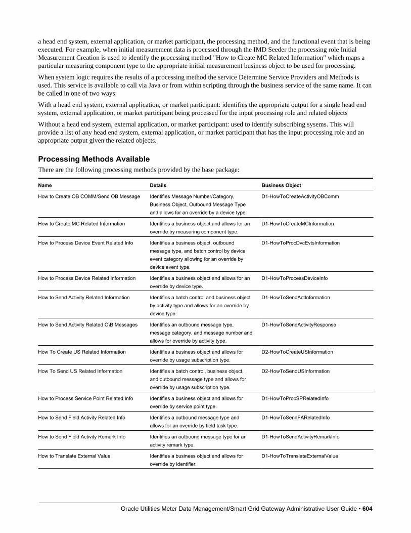
Oracle Utilities Meter Data Management/Smart Grid Gateway Administrative User Guide • 604
a head end system, external application, or market participant, the processing method, and the functional event that is beingexecuted. For example, when initial measurement data is processed through the IMD Seeder the processing role InitialMeasurement Creation is used to identify the processing method "How to Create MC Related Information" which maps aparticular measuring component type to the appropriate initial measurement business object to be used for processing.
When system logic requires the results of a processing method the service Determine Service Providers and Methods isused. This service is available to call via Java or from within scripting through the business service of the same name. It canbe called in one of two ways:
With a head end system, external application, or market participant: identifies the appropriate output for a single head endsystem, external application, or market participant being processed for the input processing role and related objects
Without a head end system, external application, or market participant: used to identify subscribing sysems. This willprovide a list of any head end system, external application, or market participant that has the input processing role and anappropriate output given the related objects.
Processing Methods AvailableThere are the following processing methods provided by the base package:
Name Details Business Object
How to Create OB COMM/Send OB Message Identifies Message Number/Category,Business Object, Outbound Message Typeand allows for an override by a device type.
D1-HowToCreateActivityOBComm
How to Create MC Related Information Identifies a business object and allows for anoverride by measuring component type.
D1-HowToCreateMCInformation
How to Process Device Event Related Info Identifies a business object, outboundmessage type, and batch control by deviceevent category allowing for an override bydevice event type.
D1-HowToProcDvcEvtsInformation
How to Process Device Related Information Identifies a business object and allows for anoverride by device type.
D1-HowToProcessDeviceInfo
How to Send Activity Related Information Identifies a batch control and business objectby activity type and allows for an override bydevice type.
D1-HowToSendActInformation
How to Send Activity Related O\B Messages Identifies an outbound message type,message category, and message number andallows for override by activity type.
D1-HowToSendActivityResponse
How To Create US Related Information Identifies a business object and allows foroverride by usage subscription type.
D2-HowToCreateUSInformation
How To Send US Related Information Identifies a batch control, business object,and outbound message type and allows foroverride by usage subscription type.
D2-HowToSendUSInformation
How to Process Service Point Related Info Identifies a business object and allows foroverride by service point type.
D1-HowToProcSPRelatedInfo
How to Send Field Activity Related Info Identifies a outbound message type andallows for an override by field task type.
D1-HowToSendFARelatedInfo
How to Send Field Activity Remark Info Identifies an outbound message type for anactivity remark type.
D1-HowToSendActivityRemarkInfo
How to Translate External Value Identifies a business object and allows foroverride by identifier.
D1-HowToTranslateExternalValue

Oracle Utilities Meter Data Management/Smart Grid Gateway Administrative User Guide • 605
How to Request Customer Notification Identifies a list of outbound message types. D1-HowToRequestCustomerNotific
How to Process Business Flag Related Info Identifies an outbound message type andallows for an override by business flag type.
D1-HowToProcessBusinessFlagInf
Oracle Utilities Meter Data Management/Smart Grid Gateway Administrative User Guide • 606
Chapter 7
Device
Command Sets
Understanding Command SetsCommand sets are used to define a group of commands that are not eligible for a particular device. For instance, ifCommission or Decommission commands should be considered ineligible for a particular device model, a command setthat references the Device Commission and Device Commission business objects could be created and associated with thatdevice model.
Command sets are specified for individual device models via the Manufacturer portal.
Individual devices of a particular model can be configured to override ineligibility if needed.
Configuring Command SetsThis portal is used to display and maintain a Command Set.
Refer to Understanding Command Sets for more information.
You can access the portal from the Admin > Device > Command Set.
The following zones may appear as part of the portal's Main tab page:
• Command Set List: This zone lists all Command Set records. Broadcast a record to display the details of the selectedrecord.
• Command Set: This zone provides information about the selected Command Set.
Where UsedFollow this link to open the data dictionary where you can view the tables that reference D1_COMMAND_SET.
Oracle Utilities Meter Data Management/Smart Grid Gateway Administrative User Guide • 607
Manufacturers
Understanding ManufacturersManufacturers are the companies that makes devices.
A device's manufacturer is defined as an attribute of the device itself.
Each manufacturer can have zero or more models defined. Models for a single manufacturer can have diverse service types.
• Models can specify an Exclude Command Set that references commands that are not eligible for that model. Refer toUnderstanding Command Sets for more information.
• The Device Command Set Override field indicates if a command set defined by in Exclude Command Set field maybe can be overridden and specified at the device.
Configuring ManufacturersThis portal is used to display and maintain a Manufacturers.
Refer to Understanding Manufacturers for more information.
You can access the portal from the Admin > Device > Manufacturer.
The following zones may appear as part of the portal's Main tab page:
• Manufacturer List: This zone lists all Manufacturer records. Broadcast a record to display the details of the selectedrecord.
• Manufacturer: This zone provides information about the selected Manufacturer.
Where UsedFollow this link to open the data dictionary where you can view the tables that reference D1_MANUFACTURER.
Head End Systems
Understanding Head End SystemsHead end systems are systems that collect measurement data and meter events for eventual submission to the application.Many devices can communicate to the application through a single head-end system, but a utility may have numerous head-end systems through which they communicate with devices.
Head end systems utilize processing methods that specify the type of initial measurement data and device events to createfor devices (and their related measuring components) based on measuring component type. Head end systems also utilizeprocessing methods that specify how smart meter commands are processed.
Refer to Understanding Process Methods for more information about processing methods.

Oracle Utilities Meter Data Management/Smart Grid Gateway Administrative User Guide • 608
Head End Systems Impact Data Import and ExportHead end systems are configured to identify how a particular external system communicates data with Oracle UtilitiesMeter Data Management. This includes:
• The identifier type used to locate devices and measuring components. These are used both on import and export of data.
• The date/time format used in various data imports (i.e. whether or not the date/time format includes time zoneinformation).
Please refer to the embedded help for more information about these fields.
Each head end system can be associated to an external system which is used to define the messages that can be sent to thatservice provider and how each message is sent.
Understanding SGG Adapter ConfigurationThis section describes how to use a head end system’s SGG Adapter Configuration portal.
You can use the SGG Adapter Configuration portal to view configuration information and access configuration componentsfor an SGG adapter head end system.
Note: This portal displays configuration information for head-end systems that reference an SGG Adapter ConfigurationSheet extendable lookup..
To use the configuration information portal for an SGG adapter head end system:
Select Admin > Device > Head End System.
In the Head End system List zone, click the Broadcast icon for the head-end system you wish to view.
Click the SGG Adapter Configuration tab to view the configuration information.
The SGG Adapter Configuration portal contains the following zones:
• SGG Adapter Configuration Tracker: This zone displays the configuration details of the adapter, as defined by theSGG Adapter Configuration Sheet extendable lookup referenced on the head end system. The configuration detailsinclude:
The components required for usage and event processing and command processing. To view more details about thecomponents, you can click the component name to go to the business object for the component. For example, you can clickthe business object "SSN - Connect or Disconnect" to go to the business object portal for the SSN - Connect or Disconnectbusiness object.
Status messages describing the configuration status of components. The following table lists the status messages that maybe displayed and the possible actions you can take:
If the status message is... You can...
Set up this processing method Click the processing role to set up the processing method.
This processing method has been configured Click the processing role to view the configured processing method.
Update your processing method with a communication BO Click the status message to set up the processing method.
Update your external system / outbound message type with anMessage sender
Click the status message to go to the external system.
Update your processing method with an outbound message type Click the status message to set up the processing method.
Add a value to get started Click the status message to go to the extendable lookup.
Values Existing: (number) Click the status message to go to the extendable lookup.
Add a communication type Click the status message to go to the communication type portal.
Add a device event type Click the status message to go to the device event type business objectfor the communication type. This message appears only for Echelontype adapters.

Oracle Utilities Meter Data Management/Smart Grid Gateway Administrative User Guide • 609
Master Configuration has been added Click the status message to view the Master Configuration portal.
Add Master Configuration for this adapter Click the status message to view the Master Configuration portal.
Upload Statistics Aggregators: This zone lists the IMD Upload Statistics Aggregator measuring components associatedwith the head-end system.
Configuring Head End SystemsThis portal is used to display and maintain Head End Systems.
Refer to Understanding Head-End Systems for more information.
You can access the portal from the Admin > Device > Head End System.
The following zones may appear as part of the portal's Main tab page:
• Head End System List: This zone lists all Head End System records. Broadcast a record to display the details of theselected record.
• Service Provider: This zone provides information about the selected Head End System.
• Processing Method List: This zone provides the list of processing methods defined for the Head End System.
• Translation Methods List: This zone provides the list of translation methods defined for the Head End System.
• Inbound BOs Send By Service Provider: This zone lists inbound Business Objects that are sent by this Head EndSystem. The identification is driven by the Business Object having a Business Object Option of type "Sent By ServiceProvider" that references the current Head End System.
Where UsedFollow this link to open the data dictionary where you can view the tables that reference D1_SPR.
Measuring Component Types
Understanding Measuring Component TypesMeasuring component types define the most important properties of a measuring component.
Measuring component types define what a measuring component measures (KWH, temperature, etc.), how regularly itmeasures it, and whether it should be connected to a physical device, or if it's used as a scratchpad measuring componentor an aggregator measuring component. Measuring component types also specify how the measuring component's finalmeasurements should be stored, how the measuring component's user-defined values should be calculated, and specificrules governing validation, editing, and estimation (VEE) for measuring components of the type. In addition, measuringcomponent types define display properties and valid attribute values for measuring components belonging to the type.
The following configurable items are available for most measuring component types:
• Value Identifiers: These store the values of UOM, TOU, and SQI that identify the measured amounts for measuringcomponents of this type. Value identifiers specify the quantities stored on the measurement records for measuringcomponents of this type. Please refer to the Measuring Component Type Value Identifiers topic later in this section formore information.
• Valid VEE Groups: These define the VEE groups considered valid for measuring components of this type. Each groupsupplied here will be available to be selected on measuring components of this type and act as an override to the FallbackVEE Groups.
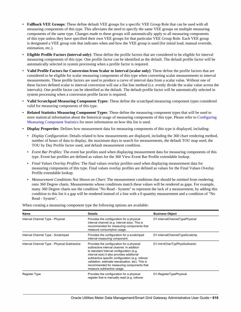
Oracle Utilities Meter Data Management/Smart Grid Gateway Administrative User Guide • 610
• Fallback VEE Groups: These define default VEE groups for a specific VEE Group Role that can be used with allmeasuring components of this type. This alleviates the need to specify the same VEE groups on multiple measuringcomponents of the same type. Changes made to these groups will automatically apply to all measuring componentsof this type unless they have specified their own VEE groups for that particular VEE Group Role. Each VEE groupis designated a VEE group role that indicates when and how the VEE group is used (for initial load, manual override,estimation, etc.).
• Eligible Profile Factors (interval only): These define the profile factors that are considered to be eligible for intervalmeasuring components of this type. One profile factor can be identified as the default. The default profile factor will beautomatically selected in system processing when a profile factor is required.
• Valid Profile Factors for Conversion from Scalar to Interval (scalar only): These define the profile factors that areconsidered to be eligible for scalar measuring components of this type when converting scalar measurements to intervalmeasurements. These profile factors are used to produce a curve of interval data from a scalar value. Without one ofthese factors defined scalar to interval conversion will use a flat line method (i.e. evenly divide the scalar value across theintervals). One profile factor can be identified as the default. The default profile factor will be automatically selected insystem processing when a conversion profile factor is required.
• Valid Scratchpad Measuring Component Types: These define the scratchpad measuring component types consideredvalid for measuring components of this type.
• Related Statistics Measuring Component Types: These define the measuring component types that will be used tostore statistical information about the historical usage of measuring components of this type. Please refer to ConfiguringMeasuring Component Statistics for more information on how this list is used.
• Display Properties: Defines how measurement data for measuring components of this type is displayed, including:
• Display Configuration: Details related to how measurements are displayed, including the 360 chart rendering method,number of hours of data to display, the maximum days to search for measurements, the default TOU map used, theTOU by Day Profile factor used, and default measurement condition.
• Event Bar Profiles: The event bar profiles used when displaying measurement data for measuring components of thistype. Event bar profiles are defined as values for the 360 View Event Bar Profile extendable lookup.
• Final Values Overlay Profiles: The final values overlay profiles used when displaying measurement data formeasuring components of this type. Final values overlay profiles are defined as values for the Final Values OverlayProfile extendable lookup.
• Measurement Conditions Not Shown on Chart: The measurement conditions that should be omitted from renderingonto 360 Degree charts. Measurements whose conditions match these values will be rendered as gaps. For example,many 360 Degree charts use the condition "No Read - System" to represent the lack of a measurement, by adding thiscondition to this list it a gap will be rendered instead of a line with a 0 quantity measurement and a condition of "NoRead - System".
When creating a measuring component type the following options are available:
Name Details Business Object
Interval Channel Type - Physical Provides the configuration for a physicalinterval channel (e.g. interval size). This isrecommended for measuring components thatmeasure consumptive usage.
D1-IntervalChannelTypePhysical
Interval Channel Type - Scratchpad Provides the configuration for a scratchpadinterval measuring component.
D1-IntervalChannelTypeScratchp
Interval Channel Type - Physical Subtractive Provides the configuration for a physicalsubtractive interval channel. In additionto standard interval configuration (e.g.interval size) it also provides additionalsubtractive specific configuration (e.g. rollovervalidation, estimate reevaluation, etc). This isrecommended for measuring components thatmeasure subtractive usage.
D1-IntrvlChanTypPhysSubtractiv
Register Type Provides the configuration for a physicalregister that is manually read (e.g. rollover
D1-RegisterTypePhysical

Oracle Utilities Meter Data Management/Smart Grid Gateway Administrative User Guide • 611
validation). These can be either consumptiveor subtractive but are expected to be readinfrequently (e.g. once a month).
Auto-Read Register Type Provides the configuration for a physicalregister that is automatically read. In additionto the standard register configuration (e.g.rollover validation) it also provides detailsaround the schedule of expected readings(e.g. first daily measurement time andexpected hours between measurements).These can either be consumptive orsubtractive but are expected to be readfrequently (e.g. at least once per day).Note: these measuring component types canalso be used to model interval data that isreceived with a large interval size (e.g. 24hours).
D1-AutoReadRegisterType
Refer to Configuring an Out-of-the-box Aggregation for more information about aggregation configuration
Measuring Component Type Value IdentifiersMeasuring components are configured to measure specific types of quantities this is defined by the list of value identifierson the measuring component type. Up to eleven value identifiers can be specified. The primary measured quantity shouldbe identified using the Value Identifier Type of Measurement. An additional ten derived values can be computed based onthe primary measurement, these are identified with the Value Identifier Type of Value 01 through Value 10. Each valueidentifier is constructed of:
• Unit of Measure: The unit of measure for the quantity being recorded. Examples include kilo-watt hours (kWh), kilo-watts (kW), therms, cubic feet (CCF), temperature (Fahrenheit or Celsius), etc. Refer to Understanding Units of Measurefor more information.
• Time of Use: Modifiers for a given unit of measure that indicate a period of time during which a quantity has beenused, such as On-Peak (meaning during a time when the greatest quantity of some consumable is being used), Off-Peak(meaning during a time when the least amount of some consumable is being used), etc. Refer to Understanding Time ofUse for more information.
• Service Quantity Identifiers: Used to further distinguish between measured quantities that have identical UOM/TOUcombinations, including situations in which the distinguishing identifier of a UOM is not accurately described as a TOU.Generally, SQI is only used when multiple measuring components measure the same thing, but in different ways. Ameter that measures both generation KWH and consumption KWH could use SQIs to differentiate between the two.Refer to Understanding Service Quantity Identifiers for more information.
• Value Derivation Algorithm: Unlike UOM, TOU, and SQI this is not used in the identification of what is measuredbut rather is used to calculate a derived value based on the primary measurement. An algorithm from the list should beselected that contains the appropriate logic for calculating the derived value. This is applicable for those value identifierswith a Value Identifier Type of Value 01 through Value 10. More information on how derived values are calculatedcan be found in the Important Measuring Component Type System Events topic in this chapter. For more functionalinformation about derived values please refer to About Final Measurements.
The combination of UOM, TOU and SQI define what a measuring component measures. TOU and SQI are optional, butUOM must be defined for all value identifiers. For example, consider a meter (as illustrated in the image below) withtwo measuring components, both measuring the same unit of measure (kWh), but each measuring component measuresconsumption in different time of use (TOU) periods (peak and off-peak).

Oracle Utilities Meter Data Management/Smart Grid Gateway Administrative User Guide • 612
Another example might be a meter that records both generated KWH and consumed KWH. This meter would be configuredto measure both UOM and SQI.
Oracle Utilities Meter Data Management/Smart Grid Gateway Administrative User Guide • 613
A measurement is recorded each time a measuring component is read. This means that for a meter with two measuringcomponents that is read once a month, two measurements, one for each measuring component, would be recorded eachmonth.
Important Measuring Component Type System EventsThe measuring component type supports several business object algorithm system events that relate to calculating theconsumption for measuring components of that type:
• Calculate Interval Consumption: receives the interval list and performs any necessary calculations on that interval datato compute consumption. Since interval data is already received as consumption data algorithms for this system event aretypically limited to application of the appropriate multipliers. Refer to the algorithm type Calculate Interval Consumption(D1-IN-CNSUMP) as an example.
• Calculate Scalar Consumption: receives information about the scalar reading and calculates the consumption asappropriate. Algorithms for this event typically support calculating the consumption using a stop and start readingor backing into a reading using consumption and a start reading. Much like the interval counterpart it will apply theappropriate multipliers. Refer to algorithm type Calculate Scalar Consumption (D1-SC-CNSUMP) as an example.
• Calculate Subtractive Interval Consumption: receives the interval list and supporting information (e.g. the startreading for the first interval) and either calculates the consumption by subtracting the interval's reading from the priorinterval's reading or calculates the reading by adding the current interval's consumption to the prior interval's reading.Refer to algorithm type Calculate Subtractive Interval Consumption (D1-SIN-CNSUM) as an example.
• Condition Mapping: receives the details of a single subtractive interval along with the details for its start reading andcomputes the applicable final condition and reading condition. This is leveraged solely for subtractive interval measuringcomponent types. Refer to algorithm type Subtractive Interval - Condition Mapping (D1-SIN-CNMAP) as an example.
These system events are typically called from within initial measurement processing during the initial stages of the initialmeasurement lifecycle (e.g. the Pre VEE status of most initial measurement business objects).
In addition to the measuring component type business object algorithms there is an additional system event provided onmeasuring component type itself:
• Value Derivation: receives details of an initial measurement and an associated final measurement. Using these inputs itcan compute a value derived either from the primary measurement or one of the other derived values. Refer to algorithmtype Derive a quantity using a formula (D1-DERIVAQTY) as an example.
Important Measuring Component System EventsThe measuring component business object that is associated to a given measuring component type supports a special systemevent that is used in the periodic estimation process:
• Periodic Estimation: this system event will scan the measuring component's final measurement history to identifymissing measurements and create either a To Do, or an estimation initial measurement, or both. More detail about thissystem event can be found by visiting the following algorithm types: Refer to algorithm type Create Interval IMD and ToDo Based Upon Install History (D1-CIITBIH) and Auto-Read Scalar Periodic Estimation (D1-ARSPE) as an example.
Measuring Component Business Object Options Drive FunctionalityThe device business object that is associated to a given device type plays an important role in how a device is processed in asystem beyond defining the data associated to that device. Below are a list of business object options that are defined on thedevice business object and their impact on system processing:
• Estimation Initial Measurement Data BO: Is used to identify the appropriate estimation IMD to create.
• Manual Override IMD BO: Is used to identify the appropriate manual override IMD to create.
• System IMD BO: Is used to identify the appropriate system IMD to create.
• Measuring Component Consumption Function: identifies a function that can be executed from any compatiblemeasuring component 360 Degree zone. Each measuring component can support 0 to many of these functions.
Oracle Utilities Meter Data Management/Smart Grid Gateway Administrative User Guide • 614
• Interval Initial Measurement Function: identifies a function that can be executed from any compatible initialmeasurement zone. Each measuring component can support 0 to many of these functions.
More detail about these options can be found by visiting a measuring component business object and inspecting the businessobject options.
Configuring Measuring Component TypesThis portal is used to display and maintain a Measuring Component.
Refer to Understanding Measuring Component Types for more information.
You can access the portal from the Admin > Device > Measuring Component.
The following zones may appear as part of the portal's Main tab page:
• Measuring Component Type: This zone provides information about the selected Measuring Component Type.
Where UsedFollow this link to open the data dictionary where you can view the tables that reference D1_MEASR_COMP_TYPE.
Device Configuration Types
Understanding Device Configuration TypesDevice Configuration types define the measurements a given device can record. It should be noted that the deviceconfiguration type itself does not specify this information but rather the device configuration type will identify the valid listof measuring component types that can be referenced associated to a device.
When creating a new device configuration type there are the following options:
Name Details Business Object
Device Configuration Type This represents configurations for physicalmeters and communication components. Itidentifies a list of valid measuring componentstypes.
D1-DeviceConfigurationType
Item Configuration Type This represents badged items that areinstalled at a particular service point. Giventhe nature of items there are no measuringcomponent types associated to this type.
D1-ItemConfigurationType
Refer to Configuring Consumption Synchronization for more information on how a device configuration type can be set upto synchronize consumption between two related channels of measurement data.
Configuring Device Configuration TypesThis portal is used to display and maintain a Device Configuration Type.
Refer to Understanding Device Configuration Types for more information.
You can access the portal from the Admin > Device > Device Configuration Type.
The following zones may appear as part of the portal's Main tab page:
Oracle Utilities Meter Data Management/Smart Grid Gateway Administrative User Guide • 615
• Device Configuration Type List: This zone lists all Device Configuration Type records. Broadcast a record to displaythe details of the selected record.
• Device Configuration Type: This zone provides information about the selected Device Configuration Type.
Where UsedFollow this link to open the data dictionary where you can view the tables that reference D1_DVC_CFG_TYPE.
Device Types
Understanding Device TypesDevice types define information about a class of devices, including properties that apply to all devices of a type. Propertiesdefined for a device type can be overridden for an individual device
Specifically, device types provide information about:
• How a device can be configured by defining the valid list of device configuration types
• How a device communicates by defining a fallback head end system and a list of valid head end systems.
• How a device records measurement data through the fallback incoming data shift which plays an important role indaylight savings processing. Refer to Daylight Savings Time Support for more information.
• The consumption profile of an item: the unit of measure consumed and method of calculation (profile or straight line)
When creating a new device type there are the following options:
Name Details Business Object
Smart Meter Device Type These devices measure consumptionfor a given service point, support remotecommands, and remote collection ofmeasurement and event data. These devicesare associated to a head end system.
D1-SmartMeterType
Manual Meter Device Type These devices measure consumption for agiven service point but require a visit to theservice point to collect the measurement data.They are not associated to head end systems.
D1-ManualMeterType
Item Device Type These devices represent various itemsthat consume consumption at a constantrate which are not directly metered. Asconsumption is calculated rather thanmeasured so there is no need for anassociation to a head end system. Devices ofthis type can either be created individually for"badged" items or can be listed directly on aservice point for "unbadged items."
D1-ItemType
Communications Component Device Type These devices provide remote collection ofconsumption data measured by a manualmeter to which they are attached. Thesedevices are associated to a head end system.
D1-CommunicationCompMeterType
Device Business Object Options Drive FunctionalityThe device business object that is associated to a given device type plays an important role in how a device is processed in asystem beyond defining the data associated to that device. Below are a list of business object options that are defined on thedevice business object and their impact on system processing:

Oracle Utilities Meter Data Management/Smart Grid Gateway Administrative User Guide • 616
• Device Category: This defines the type of device and correlates to the core device types that are supported (i.e. smartmeter, AMR meter, manual meter, item, or communication component). This value is used by smart meter commands,service order management, and other system processes to make processing decisions.
• Install Event BO: This identifies the appropriate install event business object to use when this device is being installedat a service point. Refer to About Install Events for more information about install events.
• Valid Command Request BO: This identifies the commands that are valid for any device of this type. This option canbe repeated for as many commands as the device supports. Note: the combination of the device and service provider (akahead end) define the true list of available commands by device.
• More detail about these options can be found by visiting a device business object and inspecting the business objectoptions.
Device Type - Service QuantityFor "badged" and "unbadged" items consumption is not directly measured. Instead, for each item type, the average dailyconsumption amount is provided. The commodity represented by the daily consumption amount is defined by the itemtype's unit of measure.
The average daily consumption amount can be effective dated over time to support changes in the consumption profile. Thisis used in conjunction with the item's calculation method to derive the consumed amount per interval.
Refer to Multiple Time Zone Support for additional information on how device type service quantities are impacted bymultiple time zones.
Configuring Device TypesThis portal is used to display and maintain a Device Type.
Refer to Understanding Device Types for more information.
You can access the portal from the Admin > Device > Device Type.
The following zones may appear as part of the portal's Main tab page:
• Device Type List: This zone lists all Device Type records. Broadcast a record to display the details of the selectedrecord.
• Device Type: This zone provides information about the selected Device Type.
• Device Type Service Quantity: This zone displays the list of effective dated service quantities supported by the selectedDevice Type. This applies only to Items.
Where UsedFollow this link to open the data dictionary where you can view the tables that reference D1_DVC_TYPE.
Oracle Utilities Meter Data Management/Smart Grid Gateway Administrative User Guide • 617
Chapter 8
Device Installation
Service Point Types
Understanding Service Point TypesService point types define a specific type of point at which service is delivered.
Specifically, service point types define how the application manages many aspects of the service point's behavior. A servicepoint type may have one or more valid device types defined that limit the types of devices that can be installed at servicepoints of this type.
The "Service Point Category" field defines the types of devices that can be installed at service points of this type. Validvalues include:
• Meter: Indicates that a single meter can be installed at service points of this type.
• Item: Indicates that a single "badged" item can be installed at service points of this type.
• Multi-Item: Indicates that one or more "unbadged" items can be installed at service points of this type.
Configuring Service Point TypesThis portal is used to display and maintain a Service Point Type.
Refer to Understanding Service Point Types for more information.
You can access the portal from the Admin > Device Installation > Service Point Type.
The following zones may appear as part of the portal's Main tab page:
• Service Point Type List: This zone lists all Service Point Type records. Broadcast a record to display the details of theselected record.

Oracle Utilities Meter Data Management/Smart Grid Gateway Administrative User Guide • 618
• Service Point Type: This zone provides information about the selected Service Point Type.
Where UsedFollow this link to open the data dictionary where you can view the tables that reference D1_SP_TYPE.
Measurement Cycles
Understanding Measurement CyclesMeasurement cycles define the schedule for manual meter reading of devices at Service Points in that cycle. Measurementcycles can have one or more associated routes used to collect measurements.
Measurement cycles can also be configured to define when to create usage transactions for Usage Subscriptions associatedto Service Points in the cycle.
For a deeper functional understanding, refer to the About Route Management section of the Oracle Utilities Meter DataManagement / Smart Grid Gateway Business User Guide.
Configuring Measurement CyclesThis portal is used to display and maintain a Measurement Cycle.
Refer to Understanding Measurement Cycles for more information.
You can access the portal from the Admin > Device Installation > Measurement Cycle. You are brought to a query portalwith options for searching. Once your record has been selected you are brought to the maintenance portal to view andmaintain the selected record.
The following zones may appear as part of the portal's Main tab page:
• Measurement Cycle List: This zone lists all Measurement Cycle records. Broadcast a record to display the details of theselected record.
• Measurement Cycle Type: This zone provides information about the selected Measurement Cycle.
• Measurement Cycle Route List: This zone lists the measurement cycle routes related to the measurement cycle.
• Measurement Cycle Schedule List: This zone lists the measurement cycle schedules related to the current measurementcycle.
Where UsedFollow this link to open the data dictionary where you can view the tables that reference D1_MSRMT_CYC.
Measurement Cycle and Bill DeterminantsThe system can be configured to periodically push bill determinants to subscribing systems. In this case, measurementcycles can be configured to define when to create usage transactions for Usage Subscriptions associated to Service Points inthe cycle. Even Service Points whose meters are read automatically may reference measurement cycles.
Creating bill determinants (by creating a usage transaction) is performed by an algorithm on the "Complete" state of the SP/Measurement Cycle Schedule Route business object (similar to creating activities as described above).
Oracle Utilities Meter Data Management/Smart Grid Gateway Administrative User Guide • 619
When the Pending SP/Measurement Cycle Schedule Route records are processed by the D1-PSPSR batch, rather than createa handheld download activity, the algorithm can create a usage transaction (usage transactions are transactions that causebill determinants to be calculated for the Service Point's Usage Subscription).
If the implementation needs to both manually read the meter and push bill determinants, both algorithms would be pluggedin on the SP/Measurement Cycle Schedule Route business object.
Measurement cycle processing is managed by the following three batch processes:
• Create Pending Measurement Cycle Schedule Routes (D1-CMCS): This batch process creates Schedule Routes forMeasurement Cycle Schedules whose schedule selection date is on or before the batch business date. This process is usedif routes have the same schedule each month, quarter, etc. This process simply copies the routes from the MeasurementCycle to the Measurement Cycle Schedule on/after the scheduled selection date.
• Create Pending SP / Measurement Cycle Schedule Route Records (D1-CSPSR): This batch process creates a "SP/Measurement Cycle Schedule Route" transaction for every Service Point in the Measurement Cycle Schedule Route thatis ready for processing.
• Process Pending SP / Measurement Cycle Schedule Route Records (D1-PSPSR): This batch process transitionsthe Pending "SP/Measurement Cycle Schedule Route" transactions to their Complete state. Custom algorithms canbe configured to do any additional necessary work, such as creating a "Meter Read Download" activity. This customalgorithm would be configured as an Enter algorithm on the "Complete" state of the SP/ Measurement Cycle ScheduleRoute business object.
For a deeper functional understanding, refer to the About Route Management section of the Oracle Utilities Meter DataManagement / Smart Grid Gateway Business User Guide.
Measurement Cycle Schedules
Understanding Measurement Cycle SchedulesMeasurement cycle schedules define the dates on which devices are scheduled to be read for a given measurement cycle andthe routes used to collect measurements for the measurement cycle.
For a deeper functional understanding, refer to the About Route Management section of the Oracle Utilities Meter DataManagement / Smart Grid Gateway Business User Guide.
Configuring Measurement Cycle SchedulesThis portal is used to display and maintain a Measurement Cycle Schedule.
Refer to Understanding Measurement Cycle Schedules and Understanding Measurement Cycles for more information.
You can access the portal from the Admin > Device Installation > Measurement Cycle Schedule. You are brought to aquery portal with options for searching. Once your record has been selected you are brought to the maintenance portal toview and maintain the selected record.
The following zones may appear as part of the portal's Main tab page:
• Measurement Cycle Schedule Query: This zone allows you to query for Measurement Cycle Schedules based onMeasurement Cycle and select the desired record.
• Measurement Cycle Type Schedule: This zone provides information about the selected Measurement Cycle Schedule.

Oracle Utilities Meter Data Management/Smart Grid Gateway Administrative User Guide • 620
Where UsedFollow this link to open the data dictionary where you can view the tables that reference D1_MSRMT_CYC_SCHED.
Oracle Utilities Meter Data Management/Smart Grid Gateway Administrative User Guide • 621
Chapter 9
Measurements
Initial Measurement Data
Configuring the Initial Measurement AlgorithmsThe behavior of initial measurement data processing can be adjusted by updating parameters in several key algorithms inthe lifecycle.
NOTE: This is not a list of all algorithms and algorithm parameters that can be customized in the initial measurementprocessing lifecycle. Rather, it is a selection of some of the more impactful parameters.
Initial Measurement Data Seeder Algorithms• Derive Service Provider and Measuring Component (D1-DER-SPRMC):
• Enabling a standalone measuring component search allows initial measurement data to be processed without a deviceidentifier. This is useful when profile or temperature data is loaded through the IMD Seeder and a match must bemade on measuring component identifiers alone.
• If measuring component identifiers can be repeated across measuring components for the same device then the errorfor duplicate measuring components being found can be turned off. This is useful for certain head end systems thatwill have multiple channels with the same channel identifier. When a duplicate is found the search will fall back onother means for identifier the correct measuring component.
• Perform Date/Time Adjustments and Undercount/Overcount Check (D1-DODTTMADJ):
• Undercount validation can be turned off completely or left enabled. When left enabled the automatic filling of gapscan be turned off separately.
• The overcount check can be turned off.
• The automatic adjustment of the individual interval date/times to an interval boundary can be turned on.
Oracle Utilities Meter Data Management/Smart Grid Gateway Administrative User Guide • 622
NOTE:If your implementation receives initial measurement data with date/times that do not include an explicit time zone andthe devices report date/times in standard time, you may need to add the following configuration:
• Navigate to Admin > Integration > Message Option
• In the XAI compliance option, ensure that the following text is provided:xsd:strict:dstGapInStandardTime
This will prevent a date/time reported in standard time that falls on the missing hour of the day Daylight Savings Time isentered from being misinterpreted.
Specific Initial Measurement Data Algorithms• Normalize measurements (overwrite identical existing Measurements) (D1-NORM-IMD):
• When the initial measurement data includes measurements that match exactly with the existing final measurementsthey can either be overwritten or skipped.
• If logging of changes to final measurements is desired then it must be indicated as such in this algorithm. It issuggested to keep this turned off for high volume initial measurement data such as initial load. See ConfiguringMeasurement Logging for more details.
NOTE: Refer to Configuring Consumption Synchronization for additional parameters that can be adjusted on specificinitial measurement data algorithms.
Configuring Measurement LoggingThere are two components to logging changes to final measurements:
• Initial Measurement Finalization: the "normalization" algorithm on a particular initial measurement data businessobject will determine how final measurements are updated. For performance reasons certain types of initial measurementdata (e.g. initial load) are delivered with a final measurement update method that will skip any logging. This can becontrolled by parameters on the algorithm that implements the algorithm type Normalize Measurements for InitialMeasurement Data (D1-NORM-IMD). Specifically the "Create Measurement Log on Update (Y/N)" parameter shouldbe set to "Y". As mentioned creating these logs has a performance impact and it is not recommended for use on initialload.
• Measurement Business Object: there must be an algorithm for the audit system event configured. The base packagedelivers the algorithm type Add Measurement Log Record (D1-AMSRMTLOG). It is this algorithm that actually recordsthe log entries.
Logging User Updates to Manual Initial MeasurementsBy default, manual edits made by users of these zones are not logged on the Log tab. Logging of manual edits to manualinitial measurements can be enabled by adding a logging algorithm on an appropriate lifecycle state of the manual initialmeasurement business objects. The Log User Transaction (D1-LOGUSRTRN) base package algorithm can be used for this.This Enter algorithm is designed to be defined on the Initial state of the manual initial measurement business objects, but itcan also be defined on any (non-transitory) Interim or Final state as well.
To ensure logging of any or all manual edits made to manual initial measurements, this algorithm should be specified onany state in which users will make manual edits. This will most often be the Pending or VEE Ready states, but could alsoinclude the Error, Exception, or Finalized states.

Oracle Utilities Meter Data Management/Smart Grid Gateway Administrative User Guide • 623
CAUTION: When defining this algorithm, the user should exercise caution and determine if previous algorithms inthe sequence within the state contain any form of transitioning logic that may inadvertently cause this algorithm to bebypassed.
Oracle Utilities Meter Data Management/Smart Grid Gateway Administrative User Guide • 624
Chapter 10
VEE
Exception Types
Understanding Exception TypesException Types define the groupings of exceptions for an IMD based on their functional similarity. This provides a way todefine VEE Exceptions in a distinct enough way to understand the root issue that was generated from the VEE Rule.
For a deeper functional understanding of VEE, refer to the About VEE section of the Oracle Utilities Meter DataManagement/Smart Grid Gateway Business User Guide.
Configuring Exception TypesThis portal is used to display and maintain an Exception Type.
Refer to Understanding Exception Types for more information.
You can access the portal from Admin > VEE > Exception Type.
The following zones may appear as part of the portal's Main tab page:
• Exception Type List: displays all of the Exception Types so you can choose the one you want to display in more detail
• Exception Type: shows the specific configuration for the selected Exception Type
There are two different options to use when creating an Exception Type:
Name Details Business Object
VEE Exception This will create a "normal" VEE Exceptionthat is attached to an IMD for tracking ofconditions triggered in the VEE process.
D1-VEEException
Oracle Utilities Meter Data Management/Smart Grid Gateway Administrative User Guide • 625
VEE Exception - Monitor Service Point In addition to tracking the failure in the VEEprocess, this VEE Exception generatesa Service Issue Monitor. This allows forcumulative tracking of VEE Exceptions thatcan be configured to result in a ServiceInvestigative Order (field work) for the ServicePoint.
D2-VEEExceptionServiceMonitor
Where UsedFollow this link to open the data dictionary where you can view the tables that reference D1_EXCP_TYPE.
VEE Groups
Understanding VEE GroupsVEE groups are collections of VEE Rules that are applied to initial measurement data. During the VEE process, the systemexecutes the VEE Rules defined in each VEE group. The rules within a VEE group are defined in a specific sequence,allowing control over the order in which the rules are executed.
VEE groups can be associated to a specific measuring component, or to a measuring component type (or both). VEE groupsassociated with a measuring component type are applied to all measuring components of that type, while those associatedto a specific measuring component are applied only to that measuring component. VEE groups associated to a measuringcomponent override those assigned to a measuring component type.
VEE groups can also be referenced by the Execute VEE Group VEE Rule.
For a deeper functional understanding of VEE, refer to the About VEE section of the Oracle Utilities Meter DataManagement / Smart Grid Gateway Business User Guide.
Configuring VEE GroupsThis portal is used to display and maintain a VEE Group.
Refer to Understanding VEE Groups for more information.
You can access the portal from the Admin > VEE > VEE Group. You are brought to a query portal with options forsearching. Once your record has been selected you are brought to the maintenance portal to view and maintain the selectedrecord.
The following zones may appear as part of the portal's Main tab page:
• VEE Group: Defines basic information about VEE group
• VEE Rules List: lists the VEE Rules belonging to the group
• Referencing VEE Rules List: lists the VEE Rules that reference the group
• Referencing VEE Group Factors List: lists the VEE group factors that reference the group
• Referencing Measuring Component Type List: lists the measuring component types that reference the group
• Referencing Measuring Component List: lists the measuring components that reference the group
Where UsedFollow this link to open the data dictionary where you can view the tables that reference D1_VEE_GRP.
Oracle Utilities Meter Data Management/Smart Grid Gateway Administrative User Guide • 626
VEE Rules
Understanding VEE RulesVEE Rules are standard and custom Validation and Estimation rules that perform checking and/or manipulation of initialmeasurement data. VEE Rules are created for a specific VEE group. For example, if you were configuring two VEE groupsand both included a specific VEE Rule, you would need to create two instances of the VEE Rule, one for each group.
The specific validation and estimation processing performed on initial measurement data is defined in individual VEERules, each performing a specific set of targeted logic. The base product contains many VEE Rules you can use in yourimplementation, but you can also create your own custom VEE Rules.
Some VEE Rules generate VEE Exceptions if the initial measurement data fails the conditions specified for the rule. Otherrules override measurements, changing measurement values as dictated by the rule's parameters. Some rules can both createexceptions and override the measurement as part of a single process. By convention, VEE Rules change the Post-VEEquantities of initial measurement data, but VEE Rules can change anything on an initial measurement.
Every VEE Rule has an effective period. Rules will only be applied if the initial measurement's start date is within the rule'seffective period. For example, an Interval Spike Check rule with a Start Date of 11/15/2010 will only be applied if the startdate of the initial measurement is on or after 11/15/2010.
This allows you to update the specifics of a rule without removing the previous version of the rule. For example, you mightchange the tolerance of an Interval Spike Check rule from 1.2 to 1.5 as of a certain date. However, for initial measurementdata for the period prior to the change, you would want to use the tolerance for the original version of the rule (1.2) insteadof the new tolerance (1.5).
On almost every VEE Rule, the failure of the rule results in a VEE Exception and the Exception Type for the failure can beconfigured on the rule. These Exception Types can also be set to a specific Exception Severity:
• Information: Used to highlight minor issues, but not sufficient to cause the initial measurement data to be put into theexception state. Exceptions of this category can be used to report on the frequency of interesting, but not fatal issues
• Issues: Used to report a problem that will prevent the initial measurement data from being finalized. Multiple "issueexceptions" can be created during VEE processing. If at least one issue exists after all rules have been applied, the initialmeasurement data is transitioned to the exception state
• Terminate: Used to report a severe issue that will cause the VEE process to stop and the initial measurement data to betransitioned immediately to the exception state. Only one terminate exception can be issued (as the first one causes VEEprocessing to stop on an initial measurement data).
For a deeper functional understanding of VEE, refer to the About VEE section of the Oracle Utilities Meter DataManagement / Smart Grid Gateway Business User Guide.
Configuring VEE RulesThis portal is used to display and maintain a VEE Rule. Also, a list of the specific out-of-the-box rules is included below theinstructions for using the portal.
Refer to Understanding VEE Rules, Understanding VEE Groups, and Understanding Exception Types for moreinformation. For a deeper functional understanding of VEE, refer to the About VEE section of the Oracle Utilities MeterData Management / Smart Grid Gateway Business User Guide.
You can access the portal from Admin > VEE > VEE Rule . You are brought to a query portal with options for searching.Once your record has been selected you are brought to the maintenance portal to view and maintain the selected record.
Oracle Utilities Meter Data Management/Smart Grid Gateway Administrative User Guide • 627
The following zones may appear as part of the portal's Main tab page:
• VEE Rule: this zone displays all of the configuration items specific to this instance of a VEE Rule.
• Eligibility Criteria List: this zone displays any VEE Rule Eligibility Criteria that have been setup. These eligibilitycriteria determine conditionally whether the VEE Rule should be executed or not. Use the Add button to create a neweligibility criteria for the rule you're viewing.
Where UsedFollow this link to open the data dictionary where you can view the tables that reference D1_VEE_RULE.
Validation VEE RulesBelow is a list of the validation rules provided as part of base product. For more information on how each rule executes andcan be configured, follow the link provided on the rule.
VEE Rule Name Applicable Data Type(s) Purpose
Consecutive Interval Check Interval This validation rule flags any combinationof consecutive intervals within InitialMeasurement Data based on the values of thedata or the condition codes of the data.
Duplicate IMD Check Interval or Scalar This rule allows for a duplicate IMD to beflagged.
Dynamic Comparison Validation Interval or Scalar This powerful, flexible validation rulecompares measurements to historicalstatistics for the related Service Point. Thesystem will maintain statistics such as thefollowing: sum, min, max, average, median,zero value count, outage count, and standarddeviation. Then you define formulas (noprogramming required) for the comparison ofcurrent measurements to these statistics.
Ensure IMD Exists for Sibling MCs Interval or Scalar This rule validates that an IMD exists for all ofthe other measuring components associatedto the same Device Configuration as thecurrent measuring component, for the sameperiod of time.
Final Measurement Replacement Interval or Scalar This validation rule allows you to definea variety of configuration options todecide if new data should replace existingmeasurements. The options include valuechange thresholds, percentage changethresholds, as well as condition code ranking.
High/Low Check Interval or Scalar This validation rule compares the totalconsumption of the current IMD to historicalvalues. The comparison is normalized basedon average daily usage (ADU). If the currentIMD is too high or too low compared tohistorical data then an exception is thrown.
Inactive Measurement Check Interval or Scalar This validation rule flags any InitialMeasurement Data received on a device that
Oracle Utilities Meter Data Management/Smart Grid Gateway Administrative User Guide • 628
is either disconnected, uninstalled, and/or notconnected to a Usage Subscription.
Interval Size Validation Interval This rule validates that the interval size(in seconds) supplied with the InitialMeasurement is equal to the interval sizedefined on measuring component's type.
Interval Spike Check Interval This rule checks for spikes within an IMD andgenerates an exception if one is found.
Multiplier Check Interval or Scalar This rule validates that the register multipliersupplied with the IMD is equal to the multiplierstored on the measuring component. If not,an exception is created using the registermultiplier exception type and severityconfigured on the rule.
Negative Consumption Check Interval or Scalar This rule flags any IMD where the totalconsumption is negative.
Prolonged Estimation Check Interval or Scalar This validation rule creates an alert when adevice has been estimated for an extendedperiod of time.
Raise Missing Quantity Exception Interval This rule flags any missing interval data.
Sum Check Interval or Scalar This rule is used to compare the differencebetween interval data to scalar data for aperiod of time, or between a set of TOU scalarreads to a "Sum" scalar reading.
Unit of Measure Check Interval or Scalar This rule checks the unit of measure (UOM)passed in with the Initial Measurement againstthe primary unit of measure configured on themeasuring component's type.
Zero Consumption Check Interval or Scalar This rule checks if the total consumption forthe IMD is zero. There is also a check forwhether an outage occurred during the sametime as the zero consumption to provide waysto avoid exceptions in that case.
Estimation VEE RulesBelow is a list of the estimation rules provided as part of base product. For more information on how each rule executes andcan be configured, follow the link provided on the rule.
VEE Rule Name Applicable Data Type(s) Purpose
Interval Adjustment From Scalar Interval This rule performs adjustments to intervalvalues based on the values from theassociated scalar data on the same device.
Interval Averaging Estimation Interval This rule finds historical interval data fromthe same measuring component based ona variety of configuration options to use forestimating any missing data within an IMD.

Oracle Utilities Meter Data Management/Smart Grid Gateway Administrative User Guide • 629
Interval Create Estimation IMD for Gap Interval This estimation rule creates a new EstimationIMD to fill gaps between the interval datareceived from the Head End.
Note: this estimation rule acts differently from
the other rules as it creates a new IMD rather
than filling in missing values in an estimation
IMD created from periodic estimations.
Interval Interpolation Estimation Interval This rule attempts to interpolate gaps withinan IMD using prior and subsequent intervalsas starting points for linear interpolation.
Interval Profile Estimation Interval This rule estimates any missing interval datafor the IMD based on a referenced ProfileFactor.
Scalar Calculation From Interval Scalar This rule performs adjustments to scalarvalues based on the values from theassociated interval data on the same device.
Scalar Estimation Scalar This rule finds historical scalar data fromthe same measuring component based ona variety of configuration options to use forestimating any missing data within an IMD.
Scalar Profile Estimation Scalar This rule estimates any missing scalar datafor the IMD based on a referenced ProfileFactor.
Scalar Proration Scalar This rule prorates the value of a scalarreading that has two valid scalar readings oneither side as boundaries. It will also take intoaccount any related interval data within thesame period to exclude from the calculation.
Subtractive Interval Adjustment Rule Subtractive Interval Adjustment Rule This rule performs adjustments to qualifyinginterval consumption values for subtractiveinterval measuring components based on anadjustment target calculated using a start andstop reading for the period that encapsulatesthe intervals to adjust.
Decision-Making VEE RulesThere are VEE Rules delivered as part of the base product that help with decision-making when executing VEE (listedbelow). For more information on how each rule executes and can be configured, follow the link provided on the rule.
VEE Rule Name Purpose
Exception Handler This rule allows for termination of the VEE process based on aconfigurable set of exceptions being present for the IMD. This rulealso allows a unique To Do Type to be generated based on a group ofexceptions.
Execute VEE Group This rule performs a call to execute a separate VEE Group whichincludes execution of all VEE Rules within that group.
Successful Termination This rule allows VEE to be successfully terminated based on a list ofexceptions.
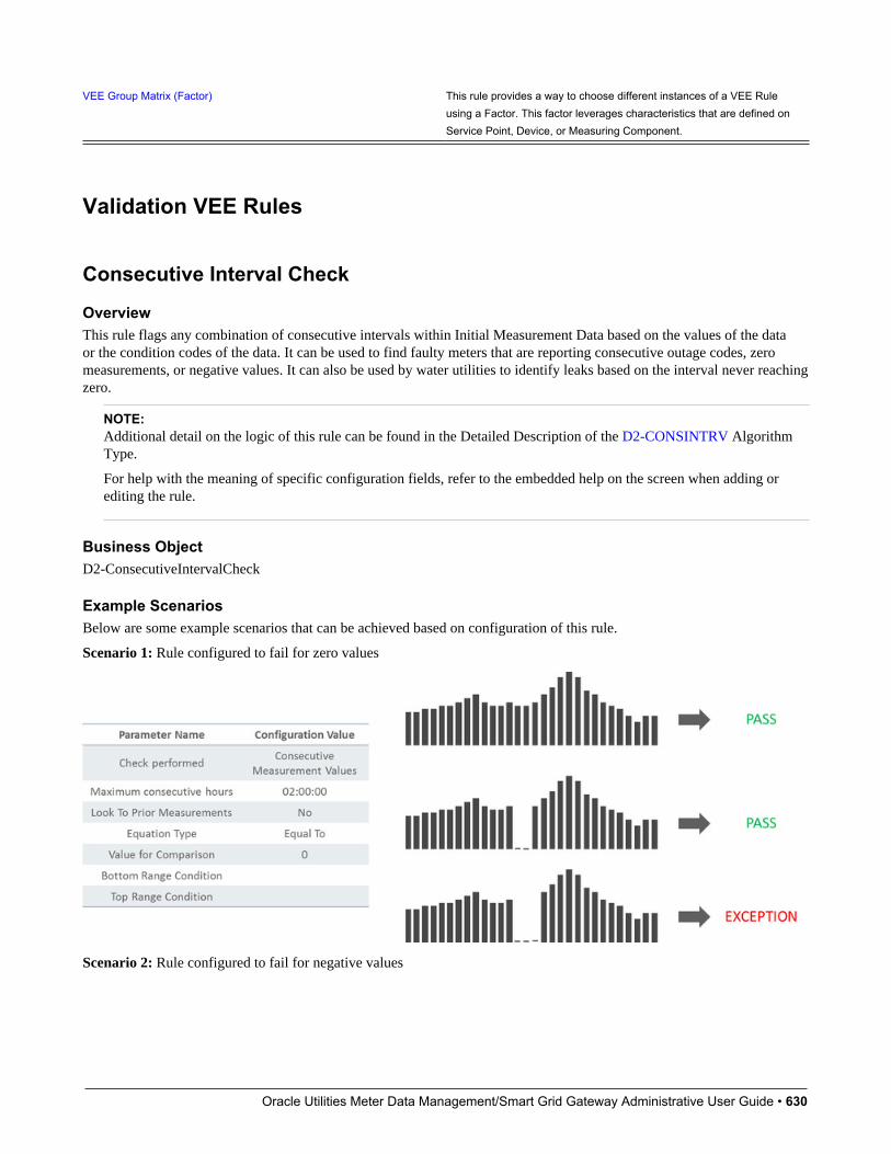
Oracle Utilities Meter Data Management/Smart Grid Gateway Administrative User Guide • 630
VEE Group Matrix (Factor) This rule provides a way to choose different instances of a VEE Ruleusing a Factor. This factor leverages characteristics that are defined onService Point, Device, or Measuring Component.
Validation VEE Rules
Consecutive Interval Check
OverviewThis rule flags any combination of consecutive intervals within Initial Measurement Data based on the values of the dataor the condition codes of the data. It can be used to find faulty meters that are reporting consecutive outage codes, zeromeasurements, or negative values. It can also be used by water utilities to identify leaks based on the interval never reachingzero.
NOTE:Additional detail on the logic of this rule can be found in the Detailed Description of the D2-CONSINTRV AlgorithmType.
For help with the meaning of specific configuration fields, refer to the embedded help on the screen when adding orediting the rule.
Business ObjectD2-ConsecutiveIntervalCheck
Example ScenariosBelow are some example scenarios that can be achieved based on configuration of this rule.
Scenario 1: Rule configured to fail for zero values
Scenario 2: Rule configured to fail for negative values
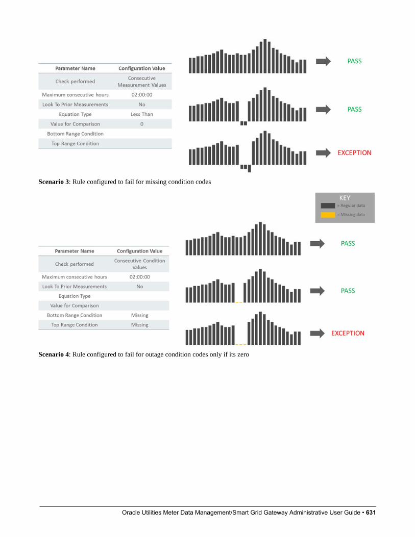
Oracle Utilities Meter Data Management/Smart Grid Gateway Administrative User Guide • 631
Scenario 3: Rule configured to fail for missing condition codes
Scenario 4: Rule configured to fail for outage condition codes only if its zero

Oracle Utilities Meter Data Management/Smart Grid Gateway Administrative User Guide • 632
Scenario 5: Rule configured to fail if a long period of consecutive water values are greater than 0.1
Scenario 6: Look back at prior measurements when the first interval matches criteria

Oracle Utilities Meter Data Management/Smart Grid Gateway Administrative User Guide • 633
Duplicate IMD CheckIf the current Initial Measurement Data (IMD) being validated is determined to be a duplicate of an existing IMD for thesame measuring component, this rule will produce a VEE exception of the type and severity configured on the VEE Rule.The algorithm logic looks for duplicate IMDs using the following criteria:
• associated to the same measuring component as the current IMD
• utilizes the same IMD business object as the current IMD (for example, Initial Load Scalar)
• references the same To Date/Time (ends on the same date) as the current IMD
• exists in a "Finalized" state
• the contents of pre-VEE are identical to the pre-VEE of the current IMD
If any IMDs are found that meet all of the above criteria, the current IMD is deemed to be a duplicate.
NOTE:Additional detail on the logic of this rule can be found in the Detailed Description of the D1-DUPIMDCHK AlgorithmType.
For help with the meaning of specific configuration fields, refer to the embedded help on the screen when adding orediting the rule.
Business ObjectD1-DuplicateIMDCheck
Dynamic Comparison ValidationThis validation rule compares measurements to historical statistics for the related Service Point. The system will maintainstatistics such as the following: sum, min, max, average, median, zero value count, outage count, and standard deviation.Setting up these Measuring Component Statistics is a prerequisite to using the rule.
Users can define formulas (no programming required) for the comparison of current measurements to these statistics. This ispowerful rule will allow utilities to look for unusual usage patterns. For example:
• Lowest/highest usage ever
• Current usage is more than three standard deviations from the mean
• Detect unexpected zero usage
• Detect negative usage while ruling out known cases
• Abnormal usage
• Voltage threshold monitoring
•
NOTE:Additional detail on the logic of this rule can be found in the Detailed Description of the D2-DYNCOMCHK AlgorithmType.
For help with the meaning of specific configuration fields, refer to the embedded help on the screen when adding orediting the rule.
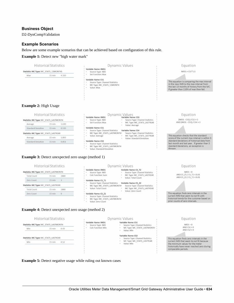
Oracle Utilities Meter Data Management/Smart Grid Gateway Administrative User Guide • 634
Business ObjectD2-DynCompValidation
Example ScenariosBelow are some example scenarios that can be achieved based on configuration of this rule.
Example 1: Detect new "high water mark"
Example 2: High Usage
Example 3: Detect unexpected zero usage (method 1)
Example 4: Detect unexpected zero usage (method 2)
Example 5: Detect negative usage while ruling out known cases
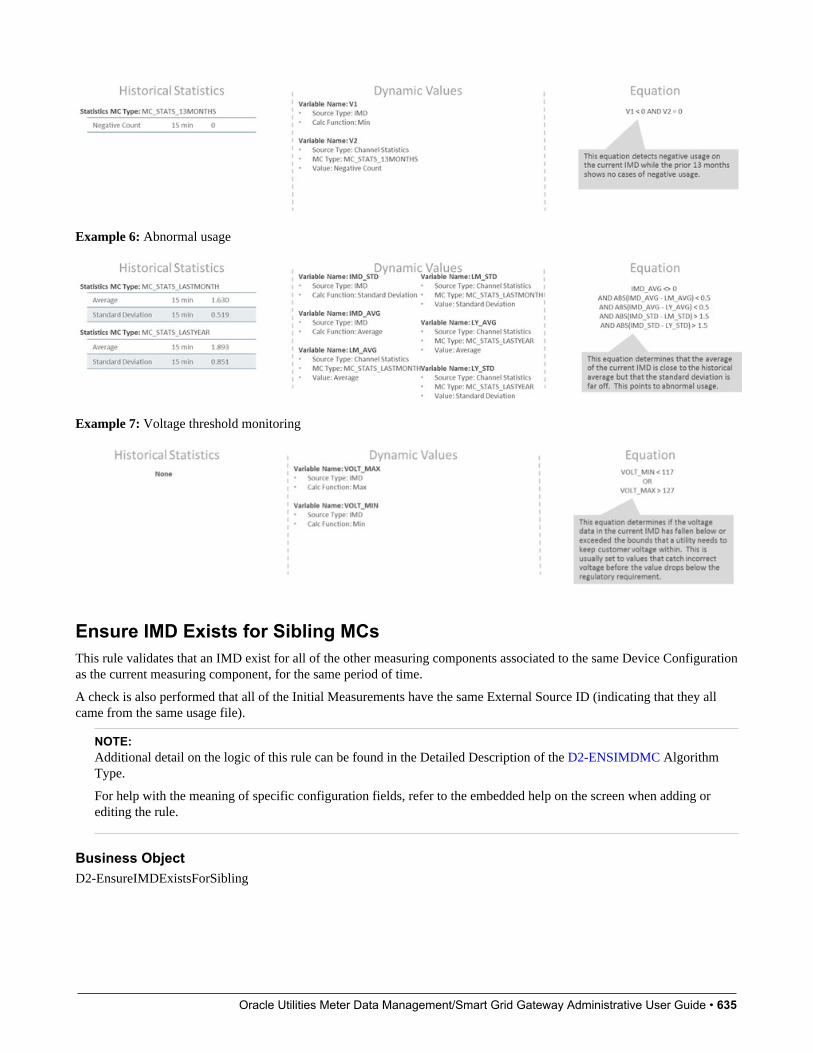
Oracle Utilities Meter Data Management/Smart Grid Gateway Administrative User Guide • 635
Example 6: Abnormal usage
Example 7: Voltage threshold monitoring
Ensure IMD Exists for Sibling MCsThis rule validates that an IMD exist for all of the other measuring components associated to the same Device Configurationas the current measuring component, for the same period of time.
A check is also performed that all of the Initial Measurements have the same External Source ID (indicating that they allcame from the same usage file).
NOTE:Additional detail on the logic of this rule can be found in the Detailed Description of the D2-ENSIMDMC AlgorithmType.
For help with the meaning of specific configuration fields, refer to the embedded help on the screen when adding orediting the rule.
Business ObjectD2-EnsureIMDExistsForSibling
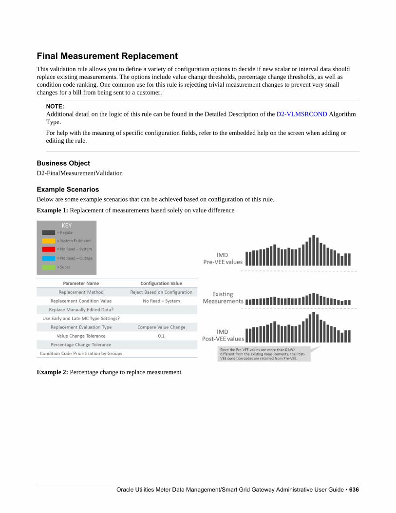
Oracle Utilities Meter Data Management/Smart Grid Gateway Administrative User Guide • 636
Final Measurement ReplacementThis validation rule allows you to define a variety of configuration options to decide if new scalar or interval data shouldreplace existing measurements. The options include value change thresholds, percentage change thresholds, as well ascondition code ranking. One common use for this rule is rejecting trivial measurement changes to prevent very smallchanges for a bill from being sent to a customer.
NOTE:Additional detail on the logic of this rule can be found in the Detailed Description of the D2-VLMSRCOND AlgorithmType.
For help with the meaning of specific configuration fields, refer to the embedded help on the screen when adding orediting the rule.
Business ObjectD2-FinalMeasurementValidation
Example ScenariosBelow are some example scenarios that can be achieved based on configuration of this rule.
Example 1: Replacement of measurements based solely on value difference
Example 2: Percentage change to replace measurement
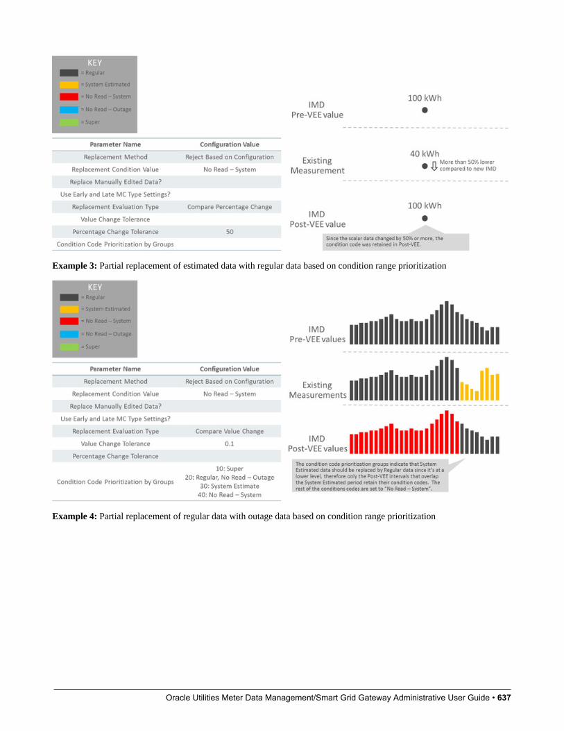
Oracle Utilities Meter Data Management/Smart Grid Gateway Administrative User Guide • 637
Example 3: Partial replacement of estimated data with regular data based on condition range prioritization
Example 4: Partial replacement of regular data with outage data based on condition range prioritization

Oracle Utilities Meter Data Management/Smart Grid Gateway Administrative User Guide • 638
Example 5: Super not replaced by regular (retain a smoothed spike)
Example 6: Prevent replacement of manually edited data
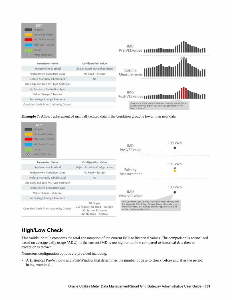
Oracle Utilities Meter Data Management/Smart Grid Gateway Administrative User Guide • 639
Example 7: Allow replacement of manually edited data if the condition group is lower than new data
High/Low CheckThis validation rule compares the total consumption of the current IMD to historical values. The comparison is normalizedbased on average daily usage (ADU). If the current IMD is too high or too low compared to historical data then anexception is thrown.
Numerous configuration options are provided including:
• A Historical Pre-Window and Post-Window that determines the number of days to check before and after the periodbeing examined.
Oracle Utilities Meter Data Management/Smart Grid Gateway Administrative User Guide • 640
• Percentages to control how much of the historical data can be user edited, estimated, or non-normal data.
• What type of historical data to look at first
• What to do when an outage has occurred
NOTE:Additional detail on the logic of this rule can be found in the Detailed Description of the D2-HILO-CHK AlgorithmType.
For help with the meaning of specific configuration fields, refer to the embedded help on the screen when adding orediting the rule.
Business ObjectD2-VEERuleHighLowCheck
Inactive Measurement CheckThis validation rule flags any Initial Measurement Data received on a device that is either disconnected, uninstalled, and/ornot connected to a usage subscription.
• When the 'Check Measurements on Disconnected Device' flag is set to "Yes", the logic will compare the IMDmeasurements total to the threshold configured. If the total measurements are above the threshold, then logic comparesthe IMD dates to two things: 1) On/Off Dates related to the Install Event and 2) the Installation and Removal Dates of theInstall Event. If the On or Off falls within the dates for an interval IMD, then the logic will only sum intervals that fallduring the disconnected periods.
• When the 'Check for Uninstalled Device' flag is set to "Yes", the logic will check for a valid Install Event based on theIMD dates.
• When the 'Check for Missing Usage Subscription' flag is set to "Yes", the logic will check for an active UsageSubscription based on the IMD dates.
NOTE:Additional detail on the logic of this rule can be found in the Detailed Description of the D2-INACTVCHK AlgorithmType.
For help with the meaning of specific configuration fields, refer to the embedded help on the screen when adding orediting the rule.
Business ObjectD2-InactiveMeasurementCheck
Example ScenariosBelow are some example scenarios that can be achieved based on configuration of this rule.
Example 1: Non-zero data during disconnected period
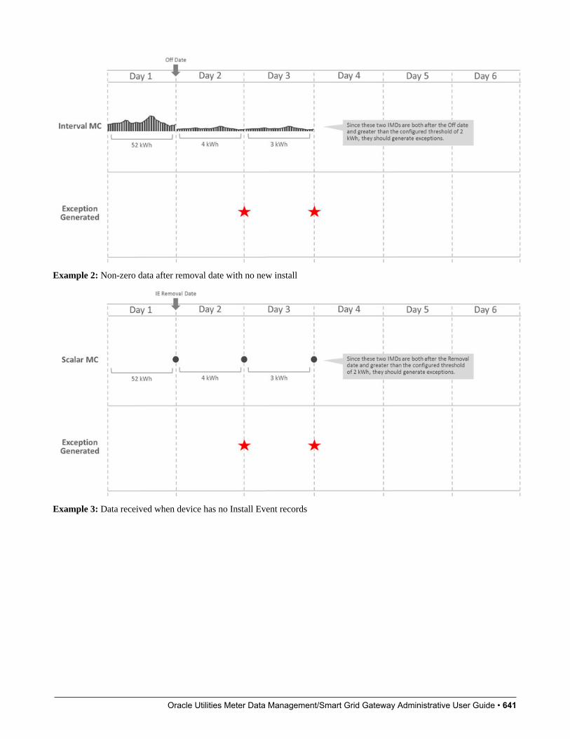
Oracle Utilities Meter Data Management/Smart Grid Gateway Administrative User Guide • 641
Example 2: Non-zero data after removal date with no new install
Example 3: Data received when device has no Install Event records

Oracle Utilities Meter Data Management/Smart Grid Gateway Administrative User Guide • 642
Example 4: Data received when not connected to a Usage Subscription record
Interval Size ValidationThis rule validates that the interval size (in seconds) supplied with the Initial Measurement is equal to the interval sizedefined on measuring component's type.
NOTE:Additional detail on the logic of this rule can be found in the Detailed Description of the D2-INTSIZVAL AlgorithmType.
For help with the meaning of specific configuration fields, refer to the embedded help on the screen when adding orediting the rule.

Oracle Utilities Meter Data Management/Smart Grid Gateway Administrative User Guide • 643
Business ObjectD2-IntervalSizeValidation
Interval Spike CheckThis rule looks for spikes by taking the highest interval and the third-highest interval, and determining the percentdifference between the two. If the percent difference is larger than the tolerance configured on the rule, the algorithm logsan exception of the type and severity configured on the rule.
The rule can be executed in one of two modes (as configured on the rule):
• The spike check is performed for every 24-hour chunk of data in the initial measurement data set
• The spike check is performed for the entire initial measurement data set
NOTE:Additional detail on the logic of this rule can be found in the Detailed Description of the D2-INTSPKCHK AlgorithmType.
For help with the meaning of specific configuration fields, refer to the embedded help on the screen when adding orediting the rule.
Business ObjectD2-IntervalSpikeCheck
Multiplier CheckThis rule validates that the register multiplier supplied with the Initial Measurement is equal to the multiplier stored on themeasuring component.
NOTE:Additional detail on the logic of this rule can be found in the Detailed Description of the D2-REGMULCHK AlgorithmType.
For help with the meaning of specific configuration fields, refer to the embedded help on the screen when adding orediting the rule.
Business ObjectD2-RegisterMultiplierCheck
Negative Consumption CheckThis rule checks if the total consumption of the IMD is less than zero. If the rule encounters negative consumption, anexception will be logged only if the related Measuring Component Type is not configured to "allow negative consumption".
NOTE:Additional detail on the logic of this rule can be found in the Detailed Description of the D2-NCON-CHK AlgorithmType.
For help with the meaning of specific configuration fields, refer to the embedded help on the screen when adding orediting the rule.
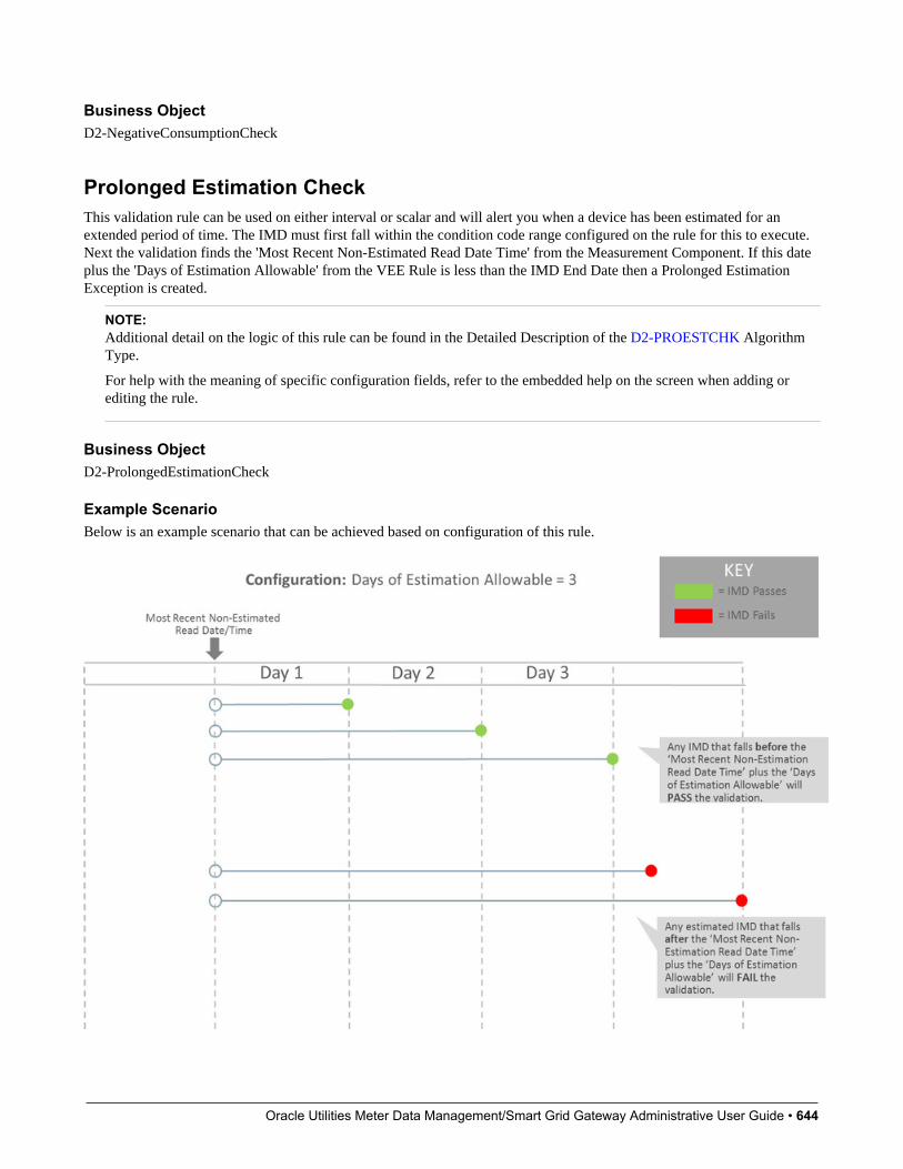
Oracle Utilities Meter Data Management/Smart Grid Gateway Administrative User Guide • 644
Business ObjectD2-NegativeConsumptionCheck
Prolonged Estimation CheckThis validation rule can be used on either interval or scalar and will alert you when a device has been estimated for anextended period of time. The IMD must first fall within the condition code range configured on the rule for this to execute.Next the validation finds the 'Most Recent Non-Estimated Read Date Time' from the Measurement Component. If this dateplus the 'Days of Estimation Allowable' from the VEE Rule is less than the IMD End Date then a Prolonged EstimationException is created.
NOTE:Additional detail on the logic of this rule can be found in the Detailed Description of the D2-PROESTCHK AlgorithmType.
For help with the meaning of specific configuration fields, refer to the embedded help on the screen when adding orediting the rule.
Business ObjectD2-ProlongedEstimationCheck
Example ScenarioBelow is an example scenario that can be achieved based on configuration of this rule.
Oracle Utilities Meter Data Management/Smart Grid Gateway Administrative User Guide • 645
Raise Missing Quantity ExceptionThis rule flags any missing interval data while providing a soft parameter on the algorithm to exclude a condition range ifdesired.
NOTE:Additional detail on the logic of this rule can be found in the Detailed Description of the D2-RAIMISQTY AlgorithmType.
For help with the meaning of specific configuration fields, refer to the embedded help on the screen when adding orediting the rule.
Business ObjectD2-RaiseMissingQuantityExcp
Sum CheckThis rule evaluates whether consumption for the current Initial Measurement Data is within a tolerance of the sum of theconsumption during the same period for any measuring components related to the current one. If the values are not withinthe defined tolerance of each other, and exception is logged.
The rule can be used to evaluate consumption totals for an interval measuring component that has a related scalar measuringcomponent with the same UOM to ensure that the total consumption of the interval measuring component is within atolerance of that of the scalar value. It can also be used to evaluate consumption totals for scalar TOU meters that have a"check" register (for example, three registers that measure ON-PEAK, OFF-PEAK, and SHOULDER, with a fourth checkregister that measures the total consumption).
NOTE:Additional detail on the logic of this rule can be found in the Detailed Description of the D2-SUM-CHK AlgorithmType.
For help with the meaning of specific configuration fields, refer to the embedded help on the screen when adding orediting the rule.
Business ObjectD2-SumCheck
Unit of Measure CheckThis rule checks the unit of measure (UOM) passed in with the Initial Measurement against the primary unit of measureconfigured on the measuring component's type.
NOTE:Additional detail on the logic of this rule can be found in the Detailed Description of the D2-UOMCHK AlgorithmType.
For help with the meaning of specific configuration fields, refer to the embedded help on the screen when adding orediting the rule.

Oracle Utilities Meter Data Management/Smart Grid Gateway Administrative User Guide • 646
Business ObjectD2-UOMCheck
Zero Consumption CheckThis rule checks if the total consumption for the IMD is zero. There is also a check for whether an outage occurred duringthe same time as the zero consumption to provide ways to avoid To Dos by having a different exception type.
NOTE:Additional detail on the logic of this rule can be found in the Detailed Description of the D2-ZEROCNCHK AlgorithmType.
For help with the meaning of specific configuration fields, refer to the embedded help on the screen when adding orediting the rule.
Business ObjectD2-ZeroConsumptionCheck
Estimation VEE Rules
Interval Adjustment From ScalarThis rule adjusts interval Initial Measurement Data based on scalar values using one of two options configured on the VEERule. Both options require that a scalar measuring component be related to the current interval measuring component usingthe Consumption Reference Measuring Component, and that one or more final measurements be present for the relatedmeasuring component between the start and end date/times of the current Initial Measurement Data set.
1. Adjust all intervals. In this case, the scalar consumption provides a value that is then used to proportionally adjust all ofthe intervals in the set. The formula used is (Scalar Consumption / Total Initial Measurement Consumption) * IntervalAmount. If the total of all of the intervals had been equal to zero originally, the rule adjusts all of the intervals to thesame value.
2. Adjust intervals based on condition. For this option, a range of conditions is configured on the VEE Rule, and the ruleadjusts only those intervals with conditions that lie within the configured range. The adjustment is done by applying anadjustment factor to each of the intervals within range.
NOTE:Additional detail on the logic of this rule can be found in the Detailed Description of the D2-INTADJSCA AlgorithmType.
For help with the meaning of specific configuration fields, refer to the embedded help on the screen when adding orediting the rule.
Business ObjectD2-IntervalAdjustmentFrmScalar

Oracle Utilities Meter Data Management/Smart Grid Gateway Administrative User Guide • 647
Interval Averaging EstimationThe algorithm estimates when the current Measuring Component is eligible. Estimation is performed only if all theseconditions are satisfied:
• The Measuring Component is interval.
• The Measuring Component is linked to a Service Point or the VEE Rule's Estimate If Not Attached to SP field is set to"Estimate”.
• The Percentage of Missing Intervals is less than the VEE Rule's Maximum Percentage Missing Intervals Threshold.
The algorithm will compute the Total Accumulated Consumption and the Total Number of Intervals using a variety ofmethods including scanning holidays, similar days of the week, or neighboring days. Once a set of valid comparison daysare found then these are used as the basis of creating estimated intervals for the current IMD.
NOTE:Additional detail on the logic of this rule can be found in the Detailed Description of the D2-INTAVGEST AlgorithmType.
For help with the meaning of specific configuration fields, refer to the embedded help on the screen when adding orediting the rule.
Business ObjectD2-IntervalAveragingEstimation
Interval Create Estimation IMD for GapThis rule is very different from other VEE rules in that it does not examine the current initial measurement but rather looksto see if there are any missing measurements prior to the initial measurement being processed (i.e. a gap exists). If so andthe scenario meets the configured options it will generate an estimation initial measurement to fill in that gap.
This rule is intended to provide more real-time filling of missing measurements as opposed to running periodic estimation.However, it is still expected that periodic estimation will be used in conjunction with this rule such that any gaps that are notfilled in by this rule would eventually be filled in by periodic estimation.
This rule can be configured to perform minimal validation of that gap that is identified and defer to the estimation initialmeasurement to validate against other initial measurements and final measurements that may overlap the gap. Conversely,it can also be configured to validate the gap and exclude any periods where a final measurement or in progress initialmeasurement overlaps the gap's duration.
NOTE:This estimation rule acts differently from the other rules - it creates a new IMD rather than filling in missing values in anestimation IMD created from periodic estimations.
Additional detail on the logic of this rule can be found in the Detailed Description of the D2-CREESTIMD AlgorithmType.
For help with the meaning of specific configuration fields, refer to the embedded help on the screen when adding orediting the rule.
Business ObjectD2-CreateEstimationIMDRule

Oracle Utilities Meter Data Management/Smart Grid Gateway Administrative User Guide • 648
Example ScenariosThe following are sample scenarios that can be achieved based on configuration of this rule.
Example 1: A 4-hour gap exists and the rule is configured to always fill gaps. Maximum hours are set to 4 and the gap fillis set to "always".
Since the maximum hours has not been exceeded and the rule is configured to always fill the gap, a 4-hour estimation IMDis created to fill the gap.
Example 2: A 4-hour gap exists and the rule is configured to always fill gaps. However, the maximum number of hours tofill is 3.
Since the gap is 4 hours long and the maximum hours to gap fill is 3 hours, no estimation has been created. An exceptionwould be created if the rule were configured this way.
Example 3: A non-contiguous gap exists and the rule is configured to "Skip In-Progress IMDs and Final Measurements"with a maximum number of IMDs set to 2.
In this scenario:
• One interval in the 4-hour gap is covered by a final measurement.
Oracle Utilities Meter Data Management/Smart Grid Gateway Administrative User Guide • 649
• One interval in the 4-hour gap is covered by an in-progress IMD.
• Two estimation IMDs are generated one to fill each hour not covered by a final measurement or in-progress IMD.
Interval Interpolation EstimationThis rule attempts to interpolate gaps in Initial Measurement Data sets using prior and subsequent intervals as starting pointsfor linear interpolation. A configuration parameter determines the maximum number of consecutive intervals within a gapbefore that gap can no longer be interpolated.
If a given gap lies at the beginning or end of the Initial Measurement Data set, this algorithm seeks out final measurementsimmediately before or after the set in an attempt to find two reference measurement values for interpolation. In thissituation, assuming that the condition of the measurement retrieved lies in NEITHER of the algorithm parameter ranges youhave configured (the measurement is neither "missing" nor an "outage"), this measurement value is then used as the basisfor interpolation.
In the event that the gap is the entire length of the Initial Measurement Data set (and the VEE Rule is configured such thatthis is not too large of a gap), the routine attempts to find final measurements as described above.
If a valid measurement can be found for only one side of a given gap, the interpolation logic assigns each interval in the gapthe same value - the value of the measurement retrieved. This is referred to as applying a "flat load".
NOTE:Additional detail on the logic of this rule can be found in the Detailed Description of the D2-INTINTEST AlgorithmType.
For help with the meaning of specific configuration fields, refer to the embedded help on the screen when adding orediting the rule.
Business ObjectD2-IntervalInterpolationEst
Interval Profile EstimationThis rule uses a profile measuring component's interval consumption as a source of values to assign to intervals in thecurrent Initial Measurement Data set that are marked "missing" via the interval's condition. If the interval is marked with acondition indicating "outage", the algorithm skips it.
If a measurement is not available for the profile measuring component on the date/time, the interval is left unchanged.
NOTE:Additional detail on the logic of this rule can be found in the Detailed Description of the D2-INTPROEST AlgorithmType.
For help with the meaning of specific configuration fields, refer to the embedded help on the screen when adding orediting the rule.
Business ObjectD2-IntervalProfileEstimation
Scalar Calculation From IntervalThis rule calculates a single consumption amount for a scalar measuring component's Initial Measurement using the totalconsumption for the same date/time range for a related interval measuring component.

Oracle Utilities Meter Data Management/Smart Grid Gateway Administrative User Guide • 650
The scalar value replaces any existing value within the Initial Measurement (in the post-VEE list) and updates the conditionto the value configured on the VEE Rule. This VEE Rule updates the condition to the value defined in "Condition Valuefor High Quality Condition" when the measurement condition value for all underlying interval data and the previous scalarmeasurement (when Evaluate Condition Of Previous Scalar Measurement is configured as "Yes") is greater than or equalto the "Minimum Condition Quality to Override" (If "Minimum Condition Quality to Override" is defined) otherwise itupdates the measurement condition of the Initial Measurement Data to the condition defined in "IMD Created ConditionValue".
NOTE:Additional detail on the logic of this rule can be found in the Detailed Description of the D2-SCACALINT AlgorithmType.
For help with the meaning of specific configuration fields, refer to the embedded help on the screen when adding orediting the rule.
Business ObjectD2-ScalarCalcFromInterval
Scalar EstimationThis rule uses historical data for the same measuring component to derive an estimated value for a scalar InitialMeasurement. Depending upon a VEE Rule configuration parameter, the routine uses historical data from a month agofollowed by a year ago, or vice-versa. If the data for the first historical period turns out to be usable, the second historicalperiod will not be evaluated. Whether historical data qualifies for use in estimation is configured via the rule parameters inconjunction with the below algorithm parameters.
The rule rejects consumption from a historical period as unusable for estimation if too great a portion of the period iscovered by final measurements that are not high-quality. The first pair of parameter values are used when evaluating theacceptable System-Estimated Percentage for historical periods as configured on the VEE Rule. Once an estimated valueis calculated, the routine backs into a reading (which involves backing out multipliers and, if the measuring component issubtractive, adding the result to the prior reading).
An interim High/Low can also be configured on this rule.
NOTE:Additional detail on the logic of this rule can be found in the Detailed Description of the D2-SCALAREST AlgorithmType.
For help with the meaning of specific configuration fields, refer to the embedded help on the screen when adding orediting the rule.
Business ObjectD2-ScalarEstimation
Scalar Profile EstimationThis VEE rule arrives at a scalar estimate by looking at final measurements for a profile measuring component coveringthe same date range as the current Initial Measurement. The profile measuring component to be used as a source ofmeasurement data is defined via a profile factor on the rule. This rule is meant primarily for a configuration in which theprofile measuring components are interval, although the profile could be scalar as well.
If a measurement already exists in the current Initial Measurement with a condition that lies within the ranges specified inthe pairs of algorithm parameters for "system estimate" and "regular", the routine does not attempt to estimate.
Oracle Utilities Meter Data Management/Smart Grid Gateway Administrative User Guide • 651
NOTE:Additional detail on the logic of this rule can be found in the Detailed Description of the D2-SCAPROEST AlgorithmType.
For help with the meaning of specific configuration fields, refer to the embedded help on the screen when adding orediting the rule.
Business ObjectD2-ScalarProfileEstimation
Scalar ProrationThis rule prorates the value of a scalar reading that has two valid scalar readings on either side as boundaries.
If the scalar MC does have a related interval MC and 'Minimum Related Measurement Condition' is defined the algorithmwill take into consideration any intervals during the proration period that meet a minimum condition quality defined by the'Minimum Related Measurement Condition' when performing the proration. This is to keep the prorated scalar estimates insync with any existing interval measurements. To do this the algorithm will augment the total duration and total quantitybeing prorated by the related interval MC's qualifying measurements. For example, take the following scenario:
• Scalar proration is executing for a scalar IMD for 01/01 12:00 AM - 01/02 12:00 AM (24 hours)
• The subsequent measurement is for 150 kWh and has a measurement date/time of 01/04 12:00 AM (72 hours)
• The related interval MC has measurements on 01/03 12:00 AM to 01/04 12:00 AM totally 100 kWh (24 hours)
Therefore the result of the calculation for the scalar IMD from 01/01 12:00 AM to 01/02 12:00 AM would be 25 kWh.Since the interval measurements covered 24 of the 72 total hours of the 150 kWh that would leave 50 kWh to be splitamong the remaining 48 hours. Which leaves 25 kWh for 01/01 12:00 AM to 01/02 12:00 AM and 25 kWh for 01/02 12:00AM to 01/03 12:00 AM.
NOTE:Additional detail on the logic of this rule can be found in the Detailed Description of the D2-SCLRPRORT AlgorithmType.
For help with the meaning of specific configuration fields, refer to the embedded help on the screen when adding orediting the rule.
Business ObjectD2-ScalarProration
Subtractive Interval Adjustment RuleThis rule adjusts qualifying consecutive intervals for a subtractive interval initial measurement (IMD) based on the knownconsumption between a set of actual readings. The readings can either be leveraged from other intervals within the IMD orfrom the final measurements when there are no suitable readings within the IMD. The adjustment is done by applying anadjustment factor to each of the qualifying intervals.
The rule supports adjusting multiple sets of qualifying consecutive intervals by calculating a consumption adjustment targetand adjustment factor specific to each set of consecutive qualifying intervals.
Intervals are considered to be qualified for adjustment based on condition. A range of conditions is configured on the VEERule, and the rule adjusts only those intervals with conditions that lie within the configured range.
NOTE:
Oracle Utilities Meter Data Management/Smart Grid Gateway Administrative User Guide • 652
Additional detail on the logic of this rule can be found in the Detailed Description of the D2-SUBINADJV AlgorithmType.
For help with the meaning of specific configuration fields, refer to the embedded help on the screen when adding orediting the rule.
Business ObjectD2-SubIntAdjustmentVEE
Decision-Making VEE Rules
Exception HandlerThis rule allows you to terminate the VEE process based on a configurable set of exceptions being present for the IMD.This rule also allows a unique To Do Type to be generated based on a group of exceptions.
NOTE:Additional detail on the logic of this rule can be found in the Detailed Description of the D1-AVEER-EEH AlgorithmType.
For help with the meaning of specific configuration fields, refer to the embedded help on the screen when adding orediting the rule.
Business ObjectD1-VEERuleExceptionHandler
Execute VEE GroupMany implementations need to execute a group of validations for any data being received. For example, you might wantto perform device identifier validations, multiplier checks, and UOM checks on all measuring components. One inefficientway to meet this requirement would be to repeat these three rules in multiple VEE groups. However, this solution becomeshard to maintain if changes to the rules are required (or if new "global rules" are introduced) as each group would have to beupdated. Instead of this, you can use the "Execute VEE Group" rule to execute a referenced VEE Group. Using the exampleabove, you could create a group called "Rules for All MCs" that contains a device identifier validations rule, a multipliercheck rule, and a UOM check rule, and then reference the "Rules for All MCs" group in a Execute VEE Group rule.
NOTE:Additional detail on the logic of this rule can be found in the Detailed Description of the D1-AVEER-RFG AlgorithmType.
For help with the meaning of specific configuration fields, refer to the embedded help on the screen when adding orediting the rule.
Business ObjectD1-VEERuleReferredVEEGroup
Successful TerminationThis rule allows VEE to be successfully terminated based on a list of exceptions.

Oracle Utilities Meter Data Management/Smart Grid Gateway Administrative User Guide • 653
NOTE:Additional detail on the logic of this rule can be found in the Detailed Description of the D1-AVEER-EST AlgorithmType.
For help with the meaning of specific configuration fields, refer to the embedded help on the screen when adding orediting the rule.
Business ObjectD1-VEERuleSuccessTermination
VEE Group Matrix (Factor)Another situation likely to occur in many implementations is where specific rules may need to be applied to measurementdata based on specific criteria, such as geography. For example, some geographic territories may have unique VEE Rules inaddition to rules that are applied to all geographic territories. The "VEE Group Matrix (Factor)" rule allows for a Factor todetermine which VEE Rule gets executed based on defined characteristics.
NOTE:Additional detail on the logic of this rule can be found in the Detailed Description of the D1-AVEER-FCT AlgorithmType.
For help with the meaning of specific configuration fields, refer to the embedded help on the screen when adding orediting the rule.
Business ObjectD1-VEERuleGroupFactor
Prerequisite SetupSince the prerequisite setup items for this rule are more involved, the following procedure describes these in detail:
1. Create the Characteristic Type and Values to be used by the factor that will be referenced by the rule.
2. Create the Characteristic Source Algorithm to be used by the factor that will be referenced by the rule.
3. Create the VEE Groups to be associated to the characteristic values.
4. Create the Factor that will be referenced by the rule.
5. Create the Factor Values for the factor, each referencing an effective-dated characteristic value/VEE group pairings.
6. Create the rule, referencing the factor
Measuring Component Statistics
Understanding Measuring Component StatisticsOracle Utilities Meter Data Management provides a way to stage statistics for Measuring Components in order to speed upVEE processing. These statistics are primarily meant for use in conjunction with the Dynamic Comparison Validation VEERule, but could also be generated for other analytics or reporting.
Some of the potential benefits of using Measuring Component Statistics are:

Oracle Utilities Meter Data Management/Smart Grid Gateway Administrative User Guide • 654
• Reduce the data volume for VEE queries by up to 1000 times (this is most beneficial when replacing VEE Rules thatquery historical data such as High/Low)
• Offload heavier processing of historical data to "system downtimes" - potentially nights or weekends
Below is an overview example of how Measuring Component Statistics can be implemented along with the DynamicComparison Validation:
The steps for pre-staging Measuring Component Statistics are detailed below:
1. A Physical Measuring Component is created. The algorithm to trigger the creation of Statistics Measuring Componentsis only set on Interval or Auto-Read Scalar BOs as part of base product.
2. New Statistics Measuring Component are created and linked to the Physical Measuring Component.
3. The Measuring Component Historical Statistics Batch (D1-MCHS) is run based on the schedule you've defined. Thesuggestion is to run this either nightly or on the weekends during quieter times for overall system processing.
4. A measurement is created for the Statistics Measuring Component that holds historical statistics related to the PhysicalMeter for a specific period of time (in this example it's set for 13 months).
The steps for how VEE can take advantage of Measuring Component Statistics are detailed below:
1. IMDs are received from the Head End.
2. The Dynamic Comparison Validation VEE Rule is configured to execute for the meter. This validation uses thehistorical statistics from the Statistics Measuring Component in order to perform its validation logic.
3. An exception and potentially a To Do is generated based on the failure of the VEE rule.
Storage Impact from StatisticsMuch consideration was given to the storage implications when designing Measuring Component Statistics. Below is anoutline of the storage impact to customers who choose to calculate and store Channel Statistics. An example impact to autility with 1 million Physical Meters (each with 4 channels of information) is shown in the far right column:
Area Additional Data in MDM Example Impact

Oracle Utilities Meter Data Management/Smart Grid Gateway Administrative User Guide • 655
(assuming utility has 1 million PhysicalMeters)
Additional MCs
Assumption: Statistics are only configured on
the primary billing channel MC Type for the
majority of your Physical Meters.
1-3 extra MCs per Physical Meter
Assumption: customers will only configure
Statistics on their primary billing channel MC
Type for the majority of their Physical Meters.
1 - 3 million extra MCs
This increases the Measuring Component
table by an extra 25% to 75% from its size
without statistics.
Additional Measurements
If 'Statistics Retention Mode' configured as
"Only Retain Most Recent Record".
1 extra Measurement per Physical Meter 1 - 3 million extra Measurements for the life ofMDM
This data is a minuscule fraction compared to
the overall AMI data footprint.
Additional Measurements
If 'Statistics Retention Mode' configured as
"Retain Historical Records".
1 extra Measurement per Physical Meter perweek
1 - 3 million extra Measurements per week(52-156 million per year)
This data is 0.2-0.5% of the size of the AMI
data collected in that same week.
Configuring Measuring Component StatisticsMeasuring Component TypesIn order to start generating Measuring Component Statistics, two different configurations must occur for MeasuringComponent Types:
• New Measuring Component Types must be configured that leverage the Channel Statistics Type business object. Theseshould be setup as the periods for which Measuring Component Statistics should be calculated. For example, if youwould like to be able to reference both last month, last year, as well as the past 13 months as statistics periods, then 3different Channel Statistics Types must be setup for this. These could be setup as follows:
• "Last Month" Channel Statistics Type:
• Period End Lag Days = 0
• Period Start Lag Days = 30
• "Same Month Last Year" Channel Statistics Type:
• Period End Lag Days = 365
• Period Start Lag Days = 395
• "Prior 13 Months" Channel Statistics Type:
• Period End Lag Days = 0
• Period Start Lag Days = 395
NOTE: it's recommended to set the Statistics Retention Mode to "Only Retain Most Recent Record" on the ChannelStatistics Type to reduce the amount of data being stored in Oracle Utilities Meter Data Management.
• For a Physical Measuring Component Type leveraging either "Interval Channel Type" or "Register - Auto-Read Type",the Related Statistics Measuring Component Types section must be filled in with the appropriate types that should becreated for the Physical Measuring Component.

Oracle Utilities Meter Data Management/Smart Grid Gateway Administrative User Guide • 656
VEE RuleIf you have a desire to leverage Measuring Component Statistics for VEE, the Dynamic Comparison Validation VEE Rulesection should be referenced. A number of detailed examples of how to implement this rule are provided in this section aswell.
Related Batch ControlsThere are a few batches directly involved with Measuring Component Statistics:
• Measuring Component Historical Statistics (D1-MCHS): this batch monitors any active Statistics MeasuringComponents to execute the logic for calculating a new set of historical statistics.
• Statistics Measuring Component Creation (D1-STMCC): this batch is used to create Statistics Measuring Componentson any Physical Measuring Components that were created prior to configuring this module. This is especially useful forexisting customers that want to implement Statistics Measuring Components for all of their devices.
NOTE: Refer to Understanding Measuring Component Statistics for more information.
Oracle Utilities Meter Data Management/Smart Grid Gateway Administrative User Guide • 657
Chapter 11
Usage
Usage Subscription Types
Understanding Usage Subscription TypesUsage Subscription Types define a collection of properties defining a class of Usage Subscriptions. Usage Subscriptiontypes also control valid values for various attributes of Usage Subscriptions.
For a deeper functional understanding, refer to the About Usage Subscriptions or About Usage Calculation sections of theOracle Utilities Meter Data Management / Smart Grid Gateway Business User Guide.
Configuring Usage Subscription TypesThis portal is used to display and maintain a Usage Subscription Type.
Refer to Understanding Usage Subscription Types for more information.
You can access the portal from the Admin > Usage > Usage Subscription Type .
The following zones may appear as part of the portal's Main tab page:
• Usage Subscription Type List: displays all of the Usage Subscription Types so you can choose the one you want todisplay in more detail
• Usage Subscription Type: shows the specific configuration for the selected Usage Subscription Type
The Usage Subscription Type defines a number of lists for "valid" objects that can be used in conjunction with the overallusage calculation process:
• Valid Service Point Types
• Valid Usage Recipients
Oracle Utilities Meter Data Management/Smart Grid Gateway Administrative User Guide • 658
• Valid Usage Calculation Groups
• Valid Dynamic Option Types
Where UsedFollow this link to open the data dictionary where you can view the tables that reference D1_US_TYPE.
Integrating Usage Transactions
Requesting Usage Transactions from External SystemsWhen Oracle Utilities Meter Data Management is deployed with , Oracle Utilities Customer Care and Billing usagetransactions can be created via a request from Oracle Utilities Customer Care and Billing.
To invoke a usage transaction request, Oracle Utilities Customer Care and Billing invokes a Usage Transaction RequestInbound service script which invokes the Usage Transaction Seeder (D2-UsgTranSeeder) business object. This businessobject does the following:
• Determines the usage subscription ID based on an external usage subscription ID
• Determines the appropriate usage transaction business object to create. This uses the "How To Create Usage SubscriptionRelated Information" processing method defined for the "Usage Transaction Creation" processing role on the serviceprovider that represents the external system.
For a deeper functional understanding of Usage Transactions, refer to the About Usage Transactions section.
Processing and Sending Usage Transactions to ExternalSystemsWhen Oracle Utilities Meter Data Management is integrated with a customer information system (such as Oracle UtilitiesCustomer Care and Billing) , usage transaction information, including bill determinants and other data can be sent to thecustomer information system .
Usage transactions are sent to subscribing systems when they enter the "Sent" state. The "Send Usage" (D2-SEND-USG) Enter algorithm on the Sent state of the base package usage transaction business object (D2-UsageTransaction)determines the method used to send the information, based on the Usage Recipient (service provider) defined on the usagetransaction's Usage Subscription. Usage transactions can be sent to service providers via either online real-time processingor periodically via batch processing.
Online Real-Time ProcessingTo set up the service provider to support online real-time notification of usage transactions, do the following:
• Create one or more Outbound Message Types that reference the outbound message business object to be used to sendusage transaction information to the external system. The base package include the following business object for UsageTransaction Outbound Message (D2-UsageTranOutboundMesg).
• Define a Message Sender that will be used to send the message to the external system.
• Add the outbound message type to the service provider's External System and reference the Message sender createdabove.
• Add a processing method to the service provider as follows:
Oracle Utilities Meter Data Management/Smart Grid Gateway Administrative User Guide • 659
• Processing Role: Usage Transaction Notification - Online
• Processing Method: How To Send US Related Information
• Status: Active
• Default Processing Method:
• Outbound Message Type: the outbound message type created above
• Override Processing Method: outbound message types for specific usage subscription types if applicable
For a deeper understanding of integrating usage transactions with a CIS , refer to the Configuring the Bill DeterminantInterface in the Interface section.
Batch ProcessingIf Oracle Utilities Meter Data Management is integrated with a customer information system (such as Oracle UtilitiesCustomer Care and Billing) that requests bill determinants, usage transaction processing should be coordinated with thatbilling system 's billing process.
Requests from a billing system that have been indicated as "batch requests" (such as those produced by Oracle UtilitiesCustomer Care and Billing batch billing process) accumulate in a "calculation deferred" state to be processed specially bythe Usage Transaction Calculate Defer Monitor batch control (D2-UTCD).
To set up the service provider to support periodic batch processing of usage transactions, use a periodic monitor batchcontrol. These batch programs should invoke the business objects that will contain the usage transaction information.The base package includes the following business object for this: Usage Transaction Outbound Message (D2-UsageTranOutboundMesg).
Next, setup the following configuration:
• Add a processing method to the service provider as follows:
• Processing Role: Usage Transaction Notification - Batch
• Processing Method: How To Send US Related Information
• Status: Active
• Default Processing Method:
• Batch Control: the batch control created above
• Override Processing Method: batch controls for specific usage subscription types if applicable
Errors encountered when processing Usage Transactions can be reprocessed with the following batches:
• Reprocessing usage transaction "seeders" in error (D2-UTSED)
• Reprocessing usage transactions in error (D2-UTID)
If unexpected errors occur that leave usage transactions in an unmonitored state, the Usage Transaction Monitor batchcontrol (D2-UT), or one based on this batch control with parameter values tailored to any specific requirements, can be usedto process those usage transactions.
For a deeper functional understanding of Usage Transactions, refer to the About Usage Transactions section of the OracleUtilities Meter Data Management / Smart Grid Gateway Business User Guide.
Oracle Utilities Meter Data Management/Smart Grid Gateway Administrative User Guide • 660
Generating Usage Transactions in Oracle Utilities Meter DataManagementThere may be some cases where Usage Transactions should be generated in Oracle Utilities Meter Data Management ratherthan requested from an external system. Generation of these usage transactions are scheduled around the time when themeter installed on the service point is read.
Base product delivered a batch program that reads all pending measurement cycle schedule routes with selection date onor before the business date and creates as SP measurement cycle schedule route business object instance that stages thecreation of these usage transactions.
For additional details refer to the batch control (D1-CSPSR) and business object (D1-SPMsrmtCycScheduleRoute).
Usage Transaction Exception Types
Understanding Usage Transaction Exception TypesUsage Transaction Exception Types define the groupings of exceptions for a Usage Transaction based on their functionalsimilarity. This provides a way to define Usage Transaction Exceptions in a distinct enough way to understand the rootissue that was generated from the usage calculation rule.
For a deeper functional understanding of Usage Calculation, refer to the About Usage Calculation section of the OracleUtilities Meter Data Management / Smart Grid Gateway Business User Guide.
Configuring Usage Transaction Exception TypesThis portal is used to display and maintain a Usage Transaction Exception Type.
Refer to Understanding Usage Transaction Exception Types for more information.
You can access the portal from the Admin > Usage > Usage Transaction Exception Type .
The following zones may appear as part of the portal's Main tab page:
• Usage Transaction Exception Type List: displays all of the Usage Transaction Exception Types so you can choose theone you want to display in more detail
• Usage Transaction Exception Type: shows the specific configuration for the selected Usage Transaction ExceptionType
Where UsedFollow this link to open the data dictionary where you can view the tables that reference D1_USAGE_EXCP_TYPE.
Usage Calculation Groups

Oracle Utilities Meter Data Management/Smart Grid Gateway Administrative User Guide • 661
Understanding Usage Calculation GroupsUsage calculation groups are collections of usage calculation rules that are used to either calculate bill determinants orvalidate bill determinants. During the usage transaction process, the system executes the usage calculation rules defined inthe usage calculation group referenced on the usage subscription. The rules within a usage calculation group are defined in aspecific sequence, allowing control over the order in which the rules are executed.
Usage calculation groups are associated with specific usage subscriptions and usage subscriptions types (or both). Whenassigned to usage subscriptions, usage calculation groups contain the usage calculation rules to be used to calculate usage /bill determinants. Usage calculation groups associated with usage subscription types are those groups considered valid forusage subscriptions of that type.
Usage calculation groups can also specify a list of device donfiguration types that are considered valid. Usage calculationgroups should only be associated with usage subscriptions for service points related to device configurations of a validdevice configuration type.
Usage calculation groups can also be referenced by the Execute Usage Calculation Group usage calculation rule.
For a deeper functional understanding of usage calculation, refer to the About Usage Calculation section of the OracleUtilities Meter Data Management / Smart Grid Gateway Business User Guide.
Configuring Usage Calculation GroupsThis portal is used to display and maintain a usage calculation group.
Refer to Understanding Usage Calculation Groups for more information.
You can access the portal from You are brought to a query portal with options for searching. Once your record has beenselected you are brought to the maintenance portal to view and maintain the selected record.
The following zones may appear as part of the portal's Main tab page:
• Usage Calculation Group: Defines basic information about usage calculation group
• Usage Calculation Rules List: lists the usage calculation rules belonging to the group
• Referencing Usage Calculation Rules List: lists the usage calculation rules that reference the group
• Referencing Usage Subscription Type List: lists the usage subscription types that reference the group
• Referencing Usage Subscriptions List: lists the usage subscriptions that reference the group
Where UsedFollow this link to open the data dictionary where you can view the tables that reference D1_USG_GRP.
Usage Calculation Rules
Understanding Usage Calculation RulesUsage calculation rules are standard and custom rules that perform calculations on measurement data to generate billdeterminants and other values used by external systems, such as billing systems, customer information systems, etc.Usage calculation rules are created for a specific usage calculation group. For example, if you were configuring two usage
Oracle Utilities Meter Data Management/Smart Grid Gateway Administrative User Guide • 662
calculation groups and both included a specific usage calculation rule, you would need to create two instances of the usagecalculation rule, one for each group.
The base package includes rules that calculate common bill determinants including:
• Scalar reads
• Time-of-use consumption (by applying a time-of-use map to an interval channel)
• Interval curves (either real or derived)
• Virtually anything else that can be calculated from the information in the system
Several usage calculation rules provide a means for defining the manner in which service quantities are rounded duringusage calculations. Service quantity rounding can be defined using the SQ Rounding Details which allow configurationof the method by which quantities are rounded (Up, Down, or Nearest) and the number of decimal positions retained afterrounding.
On almost every usage calculation rule, the failure of the rule results in a usage transaction exception and the UsageTransaction Exception Type for the failure can be configured on the rule. These usage transaction exception types can alsobe set to a specific Exception Severity:
• Information: Used to highlight minor issues, but not sufficient to cause the usage transaction to be put into a failurestate. Exceptions of this category can be used to report on the frequency of interesting, but not fatal issues
• Issues: Used to report a problem that will prevent the usage transaction from being sent. Multiple "issue exceptions"can be created during usage transaction processing. If at least one issue exists after all rules have been applied, the usagetransaction is transitioned to a failure state requiring review and approval.
• Terminate: Used to report a severe issue that will cause the usage calculation process to stop and the usage transactionto be transitioned immediately to a failure state requiring review and approval. Only one terminate exception can beissued (as the first one causes calculation processing to stop on for a Usage Transaction). This should be used for caseswhere manual override / approval isn't accurate. For example, a "Curve Not Continuous" error that says the interval datadoesn't cover the full usage period should always be set to Terminate as an Exception Severity.
For a deeper functional understanding of usage calculation, refer to the About Usage Calculation section of the OracleUtilities Meter Data Management / Smart Grid Gateway Business User Guide.
Configuring Usage Calculation RulesThis portal is used to display and maintain a usage calculation rule.
Refer to Understanding Usage Calculation Rules, Understanding Usage Calculation Groups, and Understanding UsageTransaction Exception Types for more information.
You can access the portal from . You are brought to a query portal with options for searching. Once your record has beenselected you are brought to the maintenance portal to view and maintain the selected record.
The following zones may appear as part of the portal's Main tab page:
• Usage Calculation Rule: Defines the usage calculation rule, including parameters used when executing the rule
• Eligibility Criteria List: Lists the eligibility criteria defined for the rule
Where UsedFollow this link to open the data dictionary where you can view the tables that reference D1_USG_RULE.
Pre-Calculation Usage Calculation RulesThe following is a list of the pre-calculation usage calculation rules provided as part of base product. For more informationon how each rule executes and can be configured, follow the link provided on the rule.
Oracle Utilities Meter Data Management/Smart Grid Gateway Administrative User Guide • 663
Usage Calculation Rule Name Applicable Data Type(s) Purpose
Alignment and Delay Usage Calculation Rule Interval or Scalar This rule can be used to handle two mainneeds:
1) aligns all measuring components fora Usage Subscription to the same date(whether on the same device or separatedevices)
2) delays the usage transaction until the endof the retry window based on
Check Existence of Installed Device Interval or Scalar This rule checks for the existence of a deviceinstalled on the Usage Subscription's ServicePoint for the usage period. In the case ofmulti-items this rule also checks that they areeffective for the usage period.
Calculation Usage Calculation RulesThe following is a list of the calculation usage calculation rules provided as part of base product. For more information onhow each rule executes and can be configured, follow the link provided on the rule.
Usage Calculation Rule Name Applicable Data Type(s) Purpose
Apply Math (Interval Data) Interval This rule is used to perform calculations oninterval data and stores the results in theusage transaction's service quantities. Avariety of options are available on this rulethat include defining the calculation type,variables to use, as well as the equation touse (math functions and expressions).
This rule provides aggregated usage for allselected interval measuring components (filterby TOU, SQI & UOM) associated to a usagesubscription.
This rule can also multiply total usage by afactor using a custom formula.
Daily Scalar Usage Calculation Rule Scalar This rule is used to calculate usage of dailyscalar measuring components installed inthe Service Points associated with a UsageSubscription for the specified usage period.It creates bill determinants by taking thedifference between the beginning and endingreading for the bill period.
This rule can also be used to provide registerreadings by measuring component.
For consumption values, only the beginningand ending readings are exported
This rule supports date breaks (the normalGet Scalar Data rule does not).
Get Interval Data Interval This rule is used to get interval quantitiesfrom interval measuring components installed
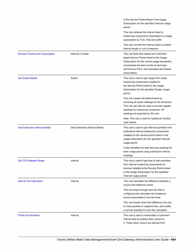
Oracle Utilities Meter Data Management/Smart Grid Gateway Administrative User Guide • 664
in the Service Points linked to the UsageSubscription for the specified 'Interval' usageperiod.
This rule retrieves the interval data formeasuring components associated to a usagesubscription by TOU, SQI and UOM.
This rule converts the interval data to anotherinterval length or unit of measure.
Get Item Counts and Consumption Interval or Scalar This rule finds item-based and multi-item-based Service Points linked to the UsageSubscription for the current usage transaction,summarizes the item counts by item typeand Service Point, and calculates item-basedconsumption.
Get Scalar Details Scalar This rule is used to get usage from scalarmeasuring components installed inthe Service Points linked to the UsageSubscription for the specified 'Scalar' usageperiod.
This rule creates bill determinants bysumming all scalar readings for the bill period.This rule can also be used to provide registerreadings by measuring component. Allreadings are exported by this rule.
Note: This rule is used for traditional monthlyread meters.
Get Subtractive Interval Details Get Subtractive Interval Details This rule is used to get interval quantities fromsubtractive interval measuring componentsinstalled on the service points linked to theusage subscription for the specified 'interval'usage period.
It also identifies the start and stop readings foreach usage period using subtractive intervalreadings.
Get TOU Mapped Usage Interval This rule is used to get time of use quantitiesfrom interval measuring components fordevices installed at the Service Points linkedto the Usage Subscription for the specified'Interval' usage period.
Interval Tier Calculation Interval This rule calculates the difference between asource and reference vector.
This rule loops through each tier that isconfigured and calculates the imbalanceamount associated to that tier level.
This rule breaks down that difference into oneto many positive or negative tiers, and createa service quantity for each tier calculated.
Profile Accumulation Interval This rule is used to manipulate a customer'sinterval data by adding other vectors toit. Those other vectors are derived from
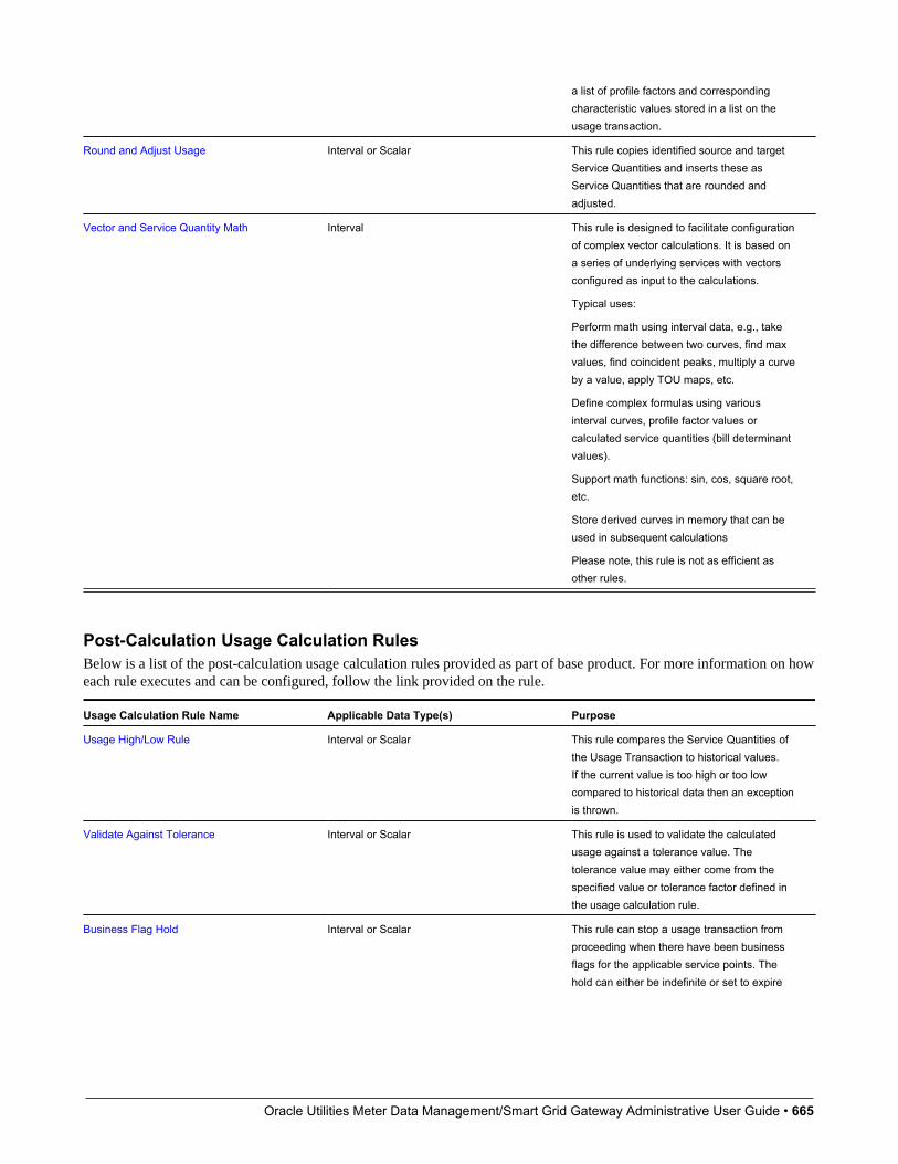
Oracle Utilities Meter Data Management/Smart Grid Gateway Administrative User Guide • 665
a list of profile factors and correspondingcharacteristic values stored in a list on theusage transaction.
Round and Adjust Usage Interval or Scalar This rule copies identified source and targetService Quantities and inserts these asService Quantities that are rounded andadjusted.
Vector and Service Quantity Math Interval This rule is designed to facilitate configurationof complex vector calculations. It is based ona series of underlying services with vectorsconfigured as input to the calculations.
Typical uses:
Perform math using interval data, e.g., takethe difference between two curves, find maxvalues, find coincident peaks, multiply a curveby a value, apply TOU maps, etc.
Define complex formulas using variousinterval curves, profile factor values orcalculated service quantities (bill determinantvalues).
Support math functions: sin, cos, square root,etc.
Store derived curves in memory that can beused in subsequent calculations
Please note, this rule is not as efficient asother rules.
Post-Calculation Usage Calculation RulesBelow is a list of the post-calculation usage calculation rules provided as part of base product. For more information on howeach rule executes and can be configured, follow the link provided on the rule.
Usage Calculation Rule Name Applicable Data Type(s) Purpose
Usage High/Low Rule Interval or Scalar This rule compares the Service Quantities ofthe Usage Transaction to historical values.If the current value is too high or too lowcompared to historical data then an exceptionis thrown.
Validate Against Tolerance Interval or Scalar This rule is used to validate the calculatedusage against a tolerance value. Thetolerance value may either come from thespecified value or tolerance factor defined inthe usage calculation rule.
Business Flag Hold Interval or Scalar This rule can stop a usage transaction fromproceeding when there have been businessflags for the applicable service points. Thehold can either be indefinite or set to expire
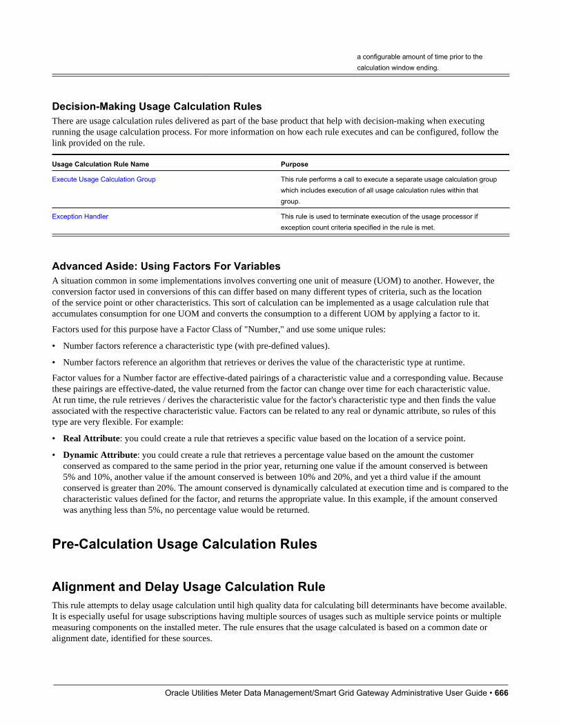
Oracle Utilities Meter Data Management/Smart Grid Gateway Administrative User Guide • 666
a configurable amount of time prior to thecalculation window ending.
Decision-Making Usage Calculation RulesThere are usage calculation rules delivered as part of the base product that help with decision-making when executingrunning the usage calculation process. For more information on how each rule executes and can be configured, follow thelink provided on the rule.
Usage Calculation Rule Name Purpose
Execute Usage Calculation Group This rule performs a call to execute a separate usage calculation groupwhich includes execution of all usage calculation rules within thatgroup.
Exception Handler This rule is used to terminate execution of the usage processor ifexception count criteria specified in the rule is met.
Advanced Aside: Using Factors For VariablesA situation common in some implementations involves converting one unit of measure (UOM) to another. However, theconversion factor used in conversions of this can differ based on many different types of criteria, such as the locationof the service point or other characteristics. This sort of calculation can be implemented as a usage calculation rule thataccumulates consumption for one UOM and converts the consumption to a different UOM by applying a factor to it.
Factors used for this purpose have a Factor Class of "Number," and use some unique rules:
• Number factors reference a characteristic type (with pre-defined values).
• Number factors reference an algorithm that retrieves or derives the value of the characteristic type at runtime.
Factor values for a Number factor are effective-dated pairings of a characteristic value and a corresponding value. Becausethese pairings are effective-dated, the value returned from the factor can change over time for each characteristic value.At run time, the rule retrieves / derives the characteristic value for the factor's characteristic type and then finds the valueassociated with the respective characteristic value. Factors can be related to any real or dynamic attribute, so rules of thistype are very flexible. For example:
• Real Attribute: you could create a rule that retrieves a specific value based on the location of a service point.
• Dynamic Attribute: you could create a rule that retrieves a percentage value based on the amount the customerconserved as compared to the same period in the prior year, returning one value if the amount conserved is between5% and 10%, another value if the amount conserved is between 10% and 20%, and yet a third value if the amountconserved is greater than 20%. The amount conserved is dynamically calculated at execution time and is compared to thecharacteristic values defined for the factor, and returns the appropriate value. In this example, if the amount conservedwas anything less than 5%, no percentage value would be returned.
Pre-Calculation Usage Calculation Rules
Alignment and Delay Usage Calculation RuleThis rule attempts to delay usage calculation until high quality data for calculating bill determinants have become available.It is especially useful for usage subscriptions having multiple sources of usages such as multiple service points or multiplemeasuring components on the installed meter. The rule ensures that the usage calculated is based on a common date oralignment date, identified for these sources.
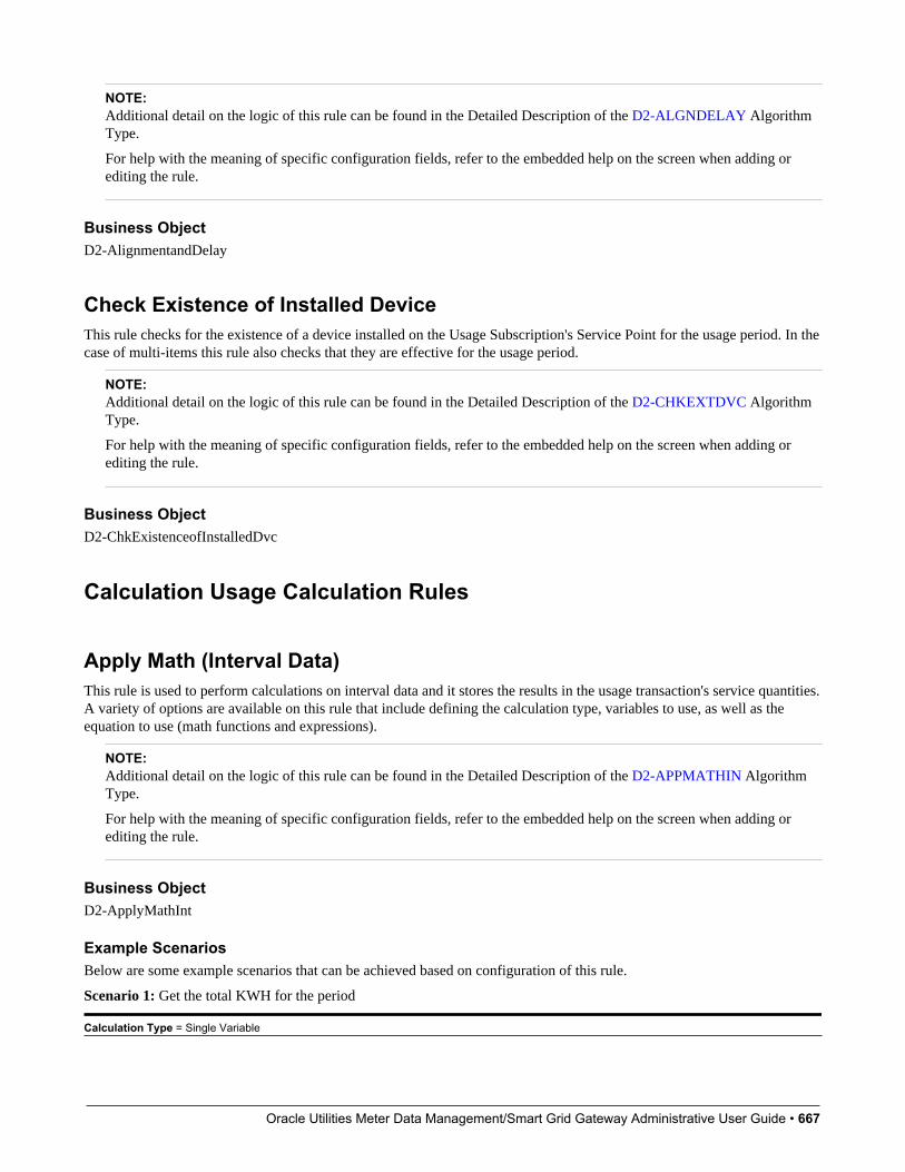
Oracle Utilities Meter Data Management/Smart Grid Gateway Administrative User Guide • 667
NOTE:Additional detail on the logic of this rule can be found in the Detailed Description of the D2-ALGNDELAY AlgorithmType.
For help with the meaning of specific configuration fields, refer to the embedded help on the screen when adding orediting the rule.
Business ObjectD2-AlignmentandDelay
Check Existence of Installed DeviceThis rule checks for the existence of a device installed on the Usage Subscription's Service Point for the usage period. In thecase of multi-items this rule also checks that they are effective for the usage period.
NOTE:Additional detail on the logic of this rule can be found in the Detailed Description of the D2-CHKEXTDVC AlgorithmType.
For help with the meaning of specific configuration fields, refer to the embedded help on the screen when adding orediting the rule.
Business ObjectD2-ChkExistenceofInstalledDvc
Calculation Usage Calculation Rules
Apply Math (Interval Data)This rule is used to perform calculations on interval data and it stores the results in the usage transaction's service quantities.A variety of options are available on this rule that include defining the calculation type, variables to use, as well as theequation to use (math functions and expressions).
NOTE:Additional detail on the logic of this rule can be found in the Detailed Description of the D2-APPMATHIN AlgorithmType.
For help with the meaning of specific configuration fields, refer to the embedded help on the screen when adding orediting the rule.
Business ObjectD2-ApplyMathInt
Example ScenariosBelow are some example scenarios that can be achieved based on configuration of this rule.
Scenario 1: Get the total KWH for the period
Calculation Type = Single Variable
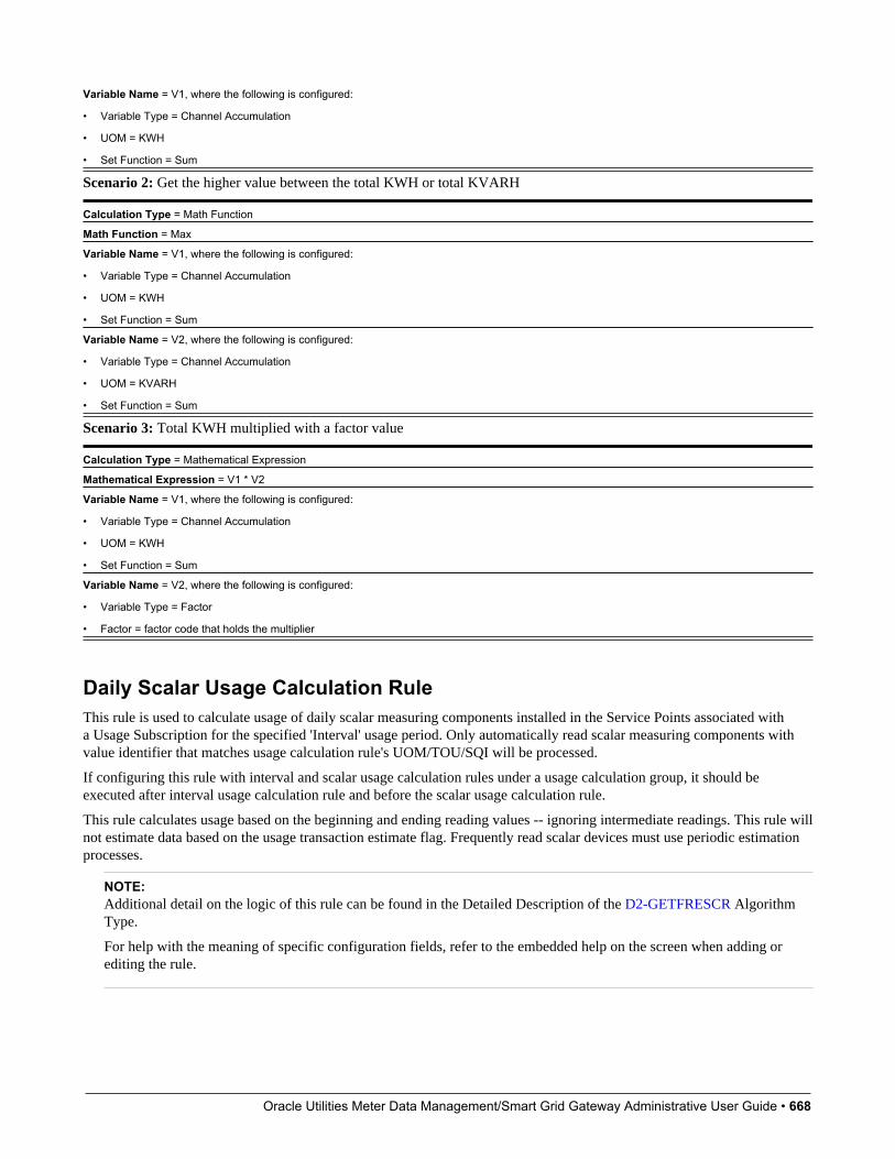
Oracle Utilities Meter Data Management/Smart Grid Gateway Administrative User Guide • 668
Variable Name = V1, where the following is configured:
• Variable Type = Channel Accumulation
• UOM = KWH
• Set Function = Sum
Scenario 2: Get the higher value between the total KWH or total KVARH
Calculation Type = Math Function
Math Function = Max
Variable Name = V1, where the following is configured:
• Variable Type = Channel Accumulation
• UOM = KWH
• Set Function = Sum
Variable Name = V2, where the following is configured:
• Variable Type = Channel Accumulation
• UOM = KVARH
• Set Function = Sum
Scenario 3: Total KWH multiplied with a factor value
Calculation Type = Mathematical Expression
Mathematical Expression = V1 * V2
Variable Name = V1, where the following is configured:
• Variable Type = Channel Accumulation
• UOM = KWH
• Set Function = Sum
Variable Name = V2, where the following is configured:
• Variable Type = Factor
• Factor = factor code that holds the multiplier
Daily Scalar Usage Calculation RuleThis rule is used to calculate usage of daily scalar measuring components installed in the Service Points associated witha Usage Subscription for the specified 'Interval' usage period. Only automatically read scalar measuring components withvalue identifier that matches usage calculation rule's UOM/TOU/SQI will be processed.
If configuring this rule with interval and scalar usage calculation rules under a usage calculation group, it should beexecuted after interval usage calculation rule and before the scalar usage calculation rule.
This rule calculates usage based on the beginning and ending reading values -- ignoring intermediate readings. This rule willnot estimate data based on the usage transaction estimate flag. Frequently read scalar devices must use periodic estimationprocesses.
NOTE:Additional detail on the logic of this rule can be found in the Detailed Description of the D2-GETFRESCR AlgorithmType.
For help with the meaning of specific configuration fields, refer to the embedded help on the screen when adding orediting the rule.

Oracle Utilities Meter Data Management/Smart Grid Gateway Administrative User Guide • 669
Business ObjectD2-CalFrequentlyReadScalar
Get Interval DataThis rule is used to get interval quantities from interval measuring components installed in the service points linked to theusage subscription for the specified 'Interval' usage period. Only measuring components that match the UOM/SQI definedin the usage calculation rule are processed. Measurements within the period are stored in the usage transaction's servicequantities' interval data list. The SQ entry's quantity is calculated based on the Calculate Function defined in the usagecalculation rule. This is done for every entry in the usage period list. Each service quantity recorded by this rule is linked toa service point and measuring component.
By supplying the Axis Conversion parameters on the usage calculation rule, this algorithm will convert the identifiedmeasuring component's consumption into the supplied UOM and interval size prior to storing the consumption into theservice quantity's interval data list.
NOTE:Additional detail on the logic of this rule can be found in the Detailed Description of the D2-GETINTDAT AlgorithmType.
For help with the meaning of specific configuration fields, refer to the embedded help on the screen when adding orediting the rule.
Business ObjectD2-GetIntervalData
Get Item Counts and ConsumptionThis rule finds item-based and multi-item-based Service Points linked to the Usage Subscription for the current usagetransaction, summarizes the item counts by item type and Service Point, and calculates item-based consumption. Once theitem detail entries are created, the rule processes goes through them to create usage period SQs.
NOTE:Additional detail on the logic of this rule can be found in the Detailed Description of the D2-GETITEMCC AlgorithmType.
For help with the meaning of specific configuration fields, refer to the embedded help on the screen when adding orediting the rule.
Business ObjectD2-GetItemCountsConsumption
Get Scalar DetailsThis rule is used to get usage from scalar measuring components installed in the Service Points linked to the UsageSubscription for the specified 'Scalar' usage period. By default all scalar measuring components are processed but if specificUOMs/TOUs/SQIs are defined in the usage calculation rule then only applicable measuring components are processed.Measurements within the period are retrieved. The usage transaction request may indicate whether or not 'Estimate'measurements are allowed.
Oracle Utilities Meter Data Management/Smart Grid Gateway Administrative User Guide • 670
The measurement details are stored in the usage transaction's scalar details. The usage is also stored in the usagetransaction's service quantities unless otherwise specified in the usage calculation rule (using Build Service Quantityindicator).
This rule can be configured to perform measurement quality assessment, which will result in the population of themeasurement quality list with the quantities and corresponding conditions of those measurements (regular, estimated, etc.).
Please note: this rule should not be used with readings occurring daily or more frequently as it will retrieve all of thereadings to store in the Usage Transaction. The Daily Scalar usage calculation rule may be a better option for this use case.
NOTE:Additional detail on the logic of this rule can be found in the Detailed Description of the D2-GETSCALAR AlgorithmType.
For help with the meaning of specific configuration fields, refer to the embedded help on the screen when adding orediting the rule.
Business ObjectD2-GetScalar
Get Subtractive Interval DetailsThis rule is used to calculate the usage for a subtractive interval measuring components. This differs from the Get IntervalData usage calculation rule in that it also retrieves a start and stop reading for each usage period it calculates. The start andstop readings are then used to provide entries into the usage scalar details table which are then made available in the usagetransaction sent to the billing system for bill presentment.
NOTE:Additional detail on the logic of this rule can be found in the Detailed Description of the D2-SUBINTADJ AlgorithmType.
For help with the meaning of specific configuration fields, refer to the embedded help on the screen when adding orediting the rule.
Business ObjectD2-GetSubtractiveInterval
Get TOU Mapped UsageThis rule is used to get time of use quantities from interval measuring components for devices installed at the Service Pointslinked to the Usage Subscription for the specified 'Interval' usage period. Only measuring components that match the UOM/SQI defined in the usage calculation rule instance are processed.
Measurements within the period are mapped to time of use quantities based on the TOU map defined on the usagecalculation rule. If dynamic options are specified in the referenced TOU map and if there are dynamic option events ineffect within the usage period then the TOU map associated with the dynamic option is used for the entire dynamic optionevent period. This calculation is performed for every usage period requested.
The calculated time of use quantities are stored in the usage transaction's service quantities per Service Point and measuringcomponent.
NOTE:Additional detail on the logic of this rule can be found in the Detailed Description of the D2-GETTOUUSG AlgorithmType.

Oracle Utilities Meter Data Management/Smart Grid Gateway Administrative User Guide • 671
For help with the meaning of specific configuration fields, refer to the embedded help on the screen when adding orediting the rule.
Business ObjectD2-GetTOUUsage
Interval Tier CalculationThis rule calculates the difference between a source and reference vector. It then breaks that difference into one to manypositive or negative tiers. For each tier calculated it will create a service quantity with the optional ability to createadditional service quantities for the total of all positive tiers and the total of all negative tiers. This rule will loop througheach tier that is configured and calculate the imbalance amount associated to that tier level.
NOTE:Additional detail on the logic of this rule can be found in the Detailed Description of the D2-GETINTIER AlgorithmType.
For help with the meaning of specific configuration fields, refer to the embedded help on the screen when adding orediting the rule.
Business ObjectD2-IntervalTierCalculation
Profile AccumulationThis rule is used to manipulate a customer's interval data by adding other vectors to it. Those other vectors are derived froma list of profile factors and corresponding characteristic values stored in a list on the usage transaction.
The typical application of this rule is for customer self-service rate compare, in which a self-service user has selected a setof usage adjustments to apply to his/her historical consumption to assess the effect on the amount consumed.
This rule algorithm retrieves the customer's usage (the source UOM) for the usage period using one of two options:
• A channel linked to a Usage Subscription
• A usage transaction service quantity
Then it takes each entry in the usage transaction's profile factor list, finds the profile measuring component for each,retrieves the measurement data for the profile, applies axis conversion to align it to the source UOM and target interval size,and adds it to the source vector. Each profile's data is added progressively to arrive at a final vector. The final vector maythen be TOU-mapped, and the vector itself may be preserved or discarded.
NOTE:Additional detail on the logic of this rule can be found in the Detailed Description of the D2-DYNPRFLAC AlgorithmType.
For help with the meaning of specific configuration fields, refer to the embedded help on the screen when adding orediting the rule.
Business ObjectD2-ProfileAccumulation
Oracle Utilities Meter Data Management/Smart Grid Gateway Administrative User Guide • 672
Round and Adjust UsageThis rule copies identified source and target Service Quantities and inserts these as period Service Quantities that arerounded and adjusted. This rule captures the source and target Service Quantity identifiers, rounding method, and ServiceQuantity bucket to hold the adjustment. The usage calculation rule also has an option to validate the difference between thesource and target service quantities.
NOTE:Additional detail on the logic of this rule can be found in the Detailed Description of the D2-RNDADJUSG AlgorithmType.
For help with the meaning of specific configuration fields, refer to the embedded help on the screen when adding orediting the rule.
Business ObjectD2-RoundAndAdjustUsage
Vector and Service Quantity MathThis rule is designed to facilitate configuration of complex vector and scalar quantity calculations. It is based on a seriesof underlying services, including Axis Conversion, Apply Formula (most importantly), and Apply TOU Map. It can beconfigured to accept as input up to five vectors - where a single vector can represent the combination of all measuringcomponents with linkages to the Usage Subscription with the configured UOM/SQI. It can also accept a list of scalarvariables that can be taken in as factor values, usage transaction service quantities, set functions on a vector, or numericvalues.
Vectors can be combined using a simple formula expression, or using condition formula expressions. Both interval valuesand interval conditions can be referenced. The result is interval-by-interval processing of the vector formula. The resultingfinal vector can be stored, TOU mapped, and/or subjected to a final set function (such as sum or max).
This rule stores service quantities of type "other" - meaning that the service quantities created by this rule do not havelinkages to a specific Service Point or measuring component, given the potentially diverse sources of the data taken as inputby this rule that lead to the final quantity.
NOTE:Additional detail on the logic of this rule can be found in the Detailed Description of the D2-MATH Algorithm Type.
For help with the meaning of specific configuration fields, refer to the embedded help on the screen when adding orediting the rule.
Business ObjectD2-Math
Post-Calculation Usage Calculation Rules
Usage High/Low RuleThis rule is used to validate the current usage against historical usage - previous year usage or previous usage. It ensuresthat any increase or decrease of the current usage relative to historical usage is within a tolerance.

Oracle Utilities Meter Data Management/Smart Grid Gateway Administrative User Guide • 673
NOTE:Additional detail on the logic of this rule can be found in the Detailed Description of the D2-USGHIGLOW AlgorithmType.
For help with the meaning of specific configuration fields, refer to the embedded help on the screen when adding orediting the rule.
Business ObjectD2-UsageHighLowRule
Validate Against ToleranceThis rule is used to validate the calculated usage against a tolerance value. The tolerance value may either come from thespecified value or tolerance factor defined in the usage calculation rule.
NOTE:Additional detail on the logic of this rule can be found in the Detailed Description of the D2-VALUSGTOL AlgorithmType.
For help with the meaning of specific configuration fields, refer to the embedded help on the screen when adding orediting the rule.
Business ObjectD2-ValAgainstTol
Business Flag HoldThis rule can be used to place a hold on a usage transaction until the business flags related to the usage transactions servicepoints can be investigated. The hold can be placed in one of two ways:
• Calculation Window Based: holds will remain until either a user manually bypasses the usage exception error or thecurrent date is within a configurable tolerance of the calculation window end (aka the retry until date time).
• Indefinite: holds require a user to manually bypass the usage exception that is generated.
Defining which business flags should result in a usage transaction is a matter of identifying which business flag types,priorities, and confidences should be included.
NOTE:Additional detail on the logic of this rule can be found in the Detailed Description of the D2-AUR-IBFH algorithm type.
For help with the meaning of specific configuration fields, refer to the embedded help on the screen when adding orediting the rule.
Business ObjectD2-BusinessFlagHold
Decision-Making Usage Calculation Rules
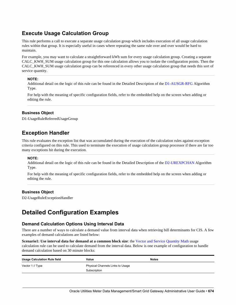
Oracle Utilities Meter Data Management/Smart Grid Gateway Administrative User Guide • 674
Execute Usage Calculation GroupThis rule performs a call to execute a separate usage calculation group which includes execution of all usage calculationrules within that group. It is especially useful in cases where repeating the same rule over and over would be hard tomaintain.
For example, you may want to calculate a straightforward kWh sum for every usage calculation group. Creating a separateCALC_KWH_SUM usage calculation group for this one calculation allows you to isolate the configuration points. Then theCALC_KWH_SUM usage calculation group can be referenced in every other usage calculation group that needs this sort ofservice quantity.
NOTE:Additional detail on the logic of this rule can be found in the Detailed Description of the D1-AUSGR-RFG AlgorithmType.
For help with the meaning of specific configuration fields, refer to the embedded help on the screen when adding orediting the rule.
Business ObjectD1-UsageRuleReferredUsageGroup
Exception HandlerThis rule evaluates the exception list that was accumulated during the execution of the calculation rules against exceptioncriteria configured on this rule. This used to terminate the execution of usage calculation group processor if there are far toomany exceptions hit during the execution.
NOTE:Additional detail on the logic of this rule can be found in the Detailed Description of the D2-UREXPCHAN AlgorithmType.
For help with the meaning of specific configuration fields, refer to the embedded help on the screen when adding orediting the rule.
Business ObjectD2-UsageRuleExceptionHandler
Detailed Configuration ExamplesDemand Calculation Options Using Interval DataThere are a number of ways to calculate a demand value from interval data when retrieving bill determinants for CIS. A fewexamples of demand calculations are listed below:
Scenario1: Use interval data for demand at a common block size: the Vector and Service Quantity Math usagecalculation rule can be used to calculate demand from the interval data. Below is one example of configuration to handledemand calculation based on 30 minute blocks:
Usage Calculation Rule field Value Notes
Vector 1 // Type Physical Channels Links to UsageSubscription

Oracle Utilities Meter Data Management/Smart Grid Gateway Administrative User Guide • 675
Vector 1 // Unit of Measure Kilowatt-Hours Use your own UOM here - this is just asexample.
Vector 1 // Service Quantity Identifier Consumed Use your own SQI here - this is just asexample.
Vector Processing // Common Interval Size 00:30:00 This configuration rolls up all channels(whether 5 minute, 15 minute, or 30 minuteinterval data) into a common interval size.
Vector Processing // Vector Formula Source Simple Vector Formula
Vector Processing // Simple Vector Formula IV1*2 This is multiplying the common 30 minuteinterval size by 2 to achieve an hourly value.
Result // Unit of Measure Kilowatts Use your own UOM here - this is just asexample.
Result // Service Quantity Identifier Consumed Use your own SQI here - this is just asexample.
Result // Insert Primary SQ Entry Yes
Result // SQ Entry Quantity Source Set Function Against Derived Vector
Result // Set Function Against Derived Vector Max This function pulls the max value based onthe configuration in the "Vector Processing"section.
Scenario 2: Use interval data for demand by TOU period: This example is very similar to the last and again leveragesthe Vector and Service Quantity Math usage calculation rule. However, instead of calculating a single demand value for theentire period it will calculate a demand value for each TOU period:
Usage Calculation Rule field Value Notes
Vector 1 // Type Physical Channels Links to UsageSubscription
Vector 1 // Unit of Measure Kilowatt-Hours Use your own UOM here - this is just asexample.
Vector 1 // Service Quantity Identifier Consumed Use your own SQI here - this is just asexample.
Vector Processing // Common Interval Size 00:30:00 This configuration rolls up all channels(whether 5 minute, 15 minute, or 30 minuteinterval data) into a common interval size.
Vector Processing // Vector Formula Source Simple Vector Formula
Vector Processing // Simple Vector Formula IV1*2 This is multiplying the common 30 minuteinterval size by 2 to achieve an hourly value.
Result // Unit of Measure Kilowatts Use your own UOM here - this is just asexample.
Result // Service Quantity Identifier Consumed Use your own SQI here - this is just asexample.
Result // Insert Primary SQ Entry No
Result // Apply TOU Map To Derived Vector Yes
Result // TOU Map (your TOU Map) Select the TOU Map you'd like to apply.
Result // Time Of Use Calculate Function Max This function pulls the max value based onthe configuration in the "Vector Processing"

Oracle Utilities Meter Data Management/Smart Grid Gateway Administrative User Guide • 676
section and then buckets it based on theselected TOU Map.
Dynamic Option Types
Understanding Dynamic Option TypesDynamic option types store information common to dynamic options of a specific type.
Configuring Dynamic Option TypesThis portal is used to display and maintain a Dynamic Option Type.
Refer to Understanding Dynamic Option Types for more information.
You can access the portal from the Admin > Usage > Dynamic Option Type.Admin > Usage > Dynamic Option Type> Search.
The following zones may appear as part of the portal's Main tab page:
• Dynamic Option Type List: displays all of the Dynamic Option Types so you can choose the one you want to display inmore detail
• Dynamic Option Type: shows the specific configuration for the selected Dynamic Option Type
Where UsedFollow this link to open the data dictionary where you can view the tables that reference D1_DYN_OPT_TYPE.
Contact Types
Understanding Contact TypesContact types define the properties of a class of entities (businesses, persons).
Configuring Contact TypesThis portal is used to display and maintain a Contact Type.
Refer to Understanding Contact Types for more information.
You can access the portal from the Admin > Usage > Contact Type.
The following zones may appear as part of the portal's Main tab page:
• Contact Type List: displays all of the Contact Types so you can choose the one you want to display in more detail
• Contact Type: shows the specific configuration for the selected Contact Type
Oracle Utilities Meter Data Management/Smart Grid Gateway Administrative User Guide • 677
Where UsedFollow this link to open the data dictionary where you can view the tables that reference D1_CONTACT_TYPE.
Bill Cycle
Understanding Bill CycleBill cycle identifies window period when a customer is going to be billed and when the bill determinants are going to becalculated.
Configuring Bill CycleThis portal is used to display and maintain a Bill Cycle.
Refer to Understanding Bill Cycle for more information.
You can access the portal from the Admin > Usage > Bill Cycle.
The following zones may appear as part of the portal's Main tab page:
• Bill Cycle List: displays all of the Bill Cycles so you can choose the one you want to display in more detail.
• Bill Cycle: shows the specific configuration for the selected Bill Cycle.
• Bill Cycle List: lists the bill cycle schedules of the current bill cycle.
Where UsedFollow this link to open the data dictionary where you can view the tables that reference D1_BILL_CYC.
Oracle Utilities Meter Data Management/Smart Grid Gateway Administrative User Guide • 678
Chapter 12
Time of Use Mapping
Time of Use Groups
Understanding Time of Use GroupsTime of Use (TOU) Groups are groups of TOUs that are associated to TOU templates that limit the TOUs available for usein a TOU schedule. These TOUs will be available as the default, holiday, and schedule TOUs within the template.
Each TOU in the group is given a priority. The priority is important in a few ways:
• The TOU Overlay 360 Degree zone uses these priorities to decide which TOUs will be rendered as a unique shade andwhich will fall into a category of "other" when the maximum number of distinct TOUs to graph has been reached.
• These priorities are available for use in customized logic. For example,
Configuring Time of Use GroupsThis portal is used to display and maintain a TOU Group.
Refer to Understanding Time of Use Groups for more information.
You can access the portal from the Admin > Usage > TOU Group.
The following zones may appear as part of the portal's Main tab page:
• TOU Group List: This zone lists all TOU Group records. Broadcast a record to display the details of the selected record.
• TOU Group: This zone provides information about the selected TOU Group.
Where UsedFollow this link to open the data dictionary where you can view the tables that reference D1_TOU_GRP.

Oracle Utilities Meter Data Management/Smart Grid Gateway Administrative User Guide • 679
Time of Use Map Templates
Understanding Time of Use Map TemplatesEvery TOU map references a TOU map template that defines the rules for generating TOU data from that TOU map.Specifically, TOU map templates define:
• The TOU group (defines the valid TOU periods for the template) used for the TOU map
• The default TOU period used for periods not explicitly defined. (This means you don't have to specify dates and timesfor all periods. For example, if your default TOU period is "Off Peak" you only need to define dates and days and timesfor On Peak or other TOU periods.)
• The specific date ranges, days of the week, and time periods designated for each TOU period.
The system periodically generates TOU map data for TOU maps by interpreting the rules defined template.
Attributes used to define TOU map templates include the following:
• TOU Group: the TOU group used by the map template Default TOU: the default TOU for the map template (from theTOU Group). This is the TOU used when creating TOU map data for dates not accounted for in the TOU Schedulessection.
• Work Calendar: the work calendar used to identify holidays. On each holiday the Holiday TOU will be used. Foradditional information see Defining Work Calendar in the Oracle Utilities Application Framework Administrative UserGuide.
• Holiday TOU: the TOU used for holidays (from the TOU Group)
• Holiday Template: the TOU map template used for holidays (if applicable)
• Interval Size: the size of the intervals for TOU map data created from the map template, represented ashours:minutes:seconds (HH:MI:SS).
• TOU Schedules: date ranges (including month, day, and time ranges) and which TOUs
Refer to Understanding Referencing Master Data by Identifiers for information on how admin configuration can reference aTOU map by a TOU template to ease migration of data between environments.
TOU Map Template Interval SizeTOU map templates can also specify an interval size (in seconds-per-interval, or SPI). This value specifies the durationof the individual TOU map data records, and also controls the values allowed in the Start and End Times. For example, ifa TOU map template sets the interval size at 15 minutes, Start and End times must be in units of the interval size (10:00,10:15, 10:30, etc.).
A TOU map template can be used to generate TOU map data for TOU maps whose SPI is divisible by the template's SPI.For example, a 60 minute template can be used to generate TOU data for TOU maps with SPIs of 60 minutes, 15 minutes, 5minutes, etc. This means separate map templates are not needed for every SPI.
HolidaysMany utilities categorize consumption on holidays differently than on the day of week on which the holiday falls. Forexample, holiday consumption might be categorized as Off-Peak regardless of the day it falls on. TOU map templates candefine rules for different TOU periods for holidays in two ways. Both options require that the template references a WorkCalendar that identifies each of the holidays throughout the year. In addition they require either:

Oracle Utilities Meter Data Management/Smart Grid Gateway Administrative User Guide • 680
• A Holiday TOU that will be used for each holiday for the duration of that holiday (e.g. Off Peak)
• A Holiday TOU Map Template that defines the TOUs that should be used for holidays that fall during different seasonswithin the year (e.g. Off Peak Summer, Off Peak Winter)
Important Time of Use Template System EventsThe time of use template supports the following business object algorithm system events:
• Derive TOU: receives a date time and determines the TOU code for that date time based on the configuration of the timeof use template schedule. See algorithm type Derive Time Of Use For Date Time (D2-DERTOU-DT) as an example.
Configuring Time of Use Map TemplatesThis portal is used to display and maintain a TOU Map Templates.
Refer to Understanding Time of Use Map Templates for more information.
You can access the portal from the Admin > Usage > TOU Map Template.
The following zones may appear as part of the portal's Main tab page:
• TOU Map Template List: This zone lists all TOU Map Template records. Broadcast a record to display the details ofthe selected record.
• TOU Map Template: This zone provides information about the selected TOU Map Template.
Where UsedFollow this link to open the data dictionary where you can view the tables that reference D1_TOU_MAP_TMPLT.
Time of Use Map Types
Understanding Time of Use Map TypesTOU Map Types define important properties of TOU maps of the type, including the interval size and the valid TOU maptemplates.
Attributes used to define TOU map types include the following:
• Time Zone: the time zone to be used when generating the TOU map data. Refer to Multiple Time Zone Support for moreinformation about how time zones impact TOU map data in multiple time zone environments.
• Interval Size: the size of the intervals for TOU map data created from maps of this type, represented ashours:minutes:seconds (HH:MI:SS). The interval size cannot be larger than the interval size defined on the Default TOUMap Template or any of the Override TOU Map Templates.
• Default TOU Map Template: the default TOU map template used by maps of this type
• Override TOU Map Templates: one or more TOU map templates that can be used as an override on TOU maps of thistype.
TOU Map Type Interval SizeThe SPI of a TOU map must divide evenly into the SPI of any measuring component that uses the map (because the systemjoins the date/time of the measurement to the date/time of the TOU data). This means that it is possible to use a 15 minute

Oracle Utilities Meter Data Management/Smart Grid Gateway Administrative User Guide • 681
TOU map with a 60 minute measuring component. However, it is not OK to have a 60 minute TOU map used with a 15minute measuring component because the join will miss 3 out of 4 measurements.
However, it is important to note that the TOU mapping process is at its most efficient when the measurement data that isbeing mapped is of the same interval size as the TOU schedule it is being mapped against. When there are differences in theinterval size the process must first convert the measurement data into the appropriate interval size for the TOU Map prior toapplying the TOU Map.
This means that for each TOU Map Template you should have sufficient TOU Map Types to cover the various interval sizesthat will be supported by your measurement data. For example, if you have measuring components with interval sizes of 15minutes, 30 minutes, and 60 minutes then for each TOU Map Template there should be TOU Map Types with interval sizesof 15 minutes, 30 minutes, and 60 minutes.
Default and Override TOU Map TemplatesWhile most TOU maps will use the TOU map template defined on the TOU map type, TOU maps also support a fallback/override pattern used in other areas of the system.
• A TOU map's TOU map type defines the default (or "fallback") TOU map template that's used to generate its TOU data.
• A TOU map's type defines the TOU map templates that can be referenced on individual TOU maps to override the"fallback" template.
• An individual TOU map can have an override template. If the TOU map doesn't have an override template, the fallbacktemplate defined on the TOU map type is used to generate the map's TOU data.
Important Time of Use Map System EventsThe TOU Map business object that is associated to a given TOU map type supports a special system event that is used in thegeneration of TOU map data:
• Create TOU Map Data: receives a date range and for that date range it will create the appropriate TOU map data for theTOU map. See algorithm type Create TOU Map Data (D2-CRETMD-CT) as an example.
Configuring Time of Use Map TypesThis portal is used to display and maintain a TOU Map Types.
Refer to Understanding Time of Use Map Types for more information.
You can access the portal from the Admin > Usage > TOU Map Type.
The following zones may appear as part of the portal's Main tab page:
• TOU Map Type List: This zone lists all TOU Group records. Broadcast a record to display the details of the selectedrecord.
• TOU Map Type: This zone provides information about the selected TOU Map Type.
Where UsedFollow this link to open the data dictionary where you can view the tables that reference D1_TOU_MAP_TYPE.

Oracle Utilities Meter Data Management/Smart Grid Gateway Administrative User Guide • 682
Chapter 13
About Communications
Device Event Types
Understanding Device Event TypesDevice EventsDevice event types define properties common to specific types of events.
Device event types represent different types of events that can take place relative to a device. Examples of device eventsinclude power outages, power restoration, tampering alerts, and other events.
Device event types can be defined by the following attributes:
• Standard Event Name: the "standard" name of the event type which is used to. Device vendors may have their ownspecific names for device events. Only a single active device event type may be mapped to a given standard name at anytime.
• Device Event Category: a category (defined as an Extendable Lookup) used to group device event types.
• Reporting Category: a category used to group device event types for reporting purposes.
• Activity Type: the activity type for activities created for device events of this type.
Device Event MappingThe first step to device event type configuration is defining the list of standard event names that will be processed bythe system. This is done by populating the Standard Event Name extendable lookup (D1-StdEventNameLookup). Moreinformation about this extendable lookup can be found in About Device Events.
With the fully defined list of Standard Event Names each head-end specific event name (which is also called anexternal event name) that the system will receive from a given head-end should be mapped to a standard event name.This mapping is configured using a device event mapping extendable lookup. Each head-end system should have
Oracle Utilities Meter Data Management/Smart Grid Gateway Administrative User Guide • 683
its own extendable lookup to define event name mapping in order to prevent possible conflicts between mappings.Each of these business objects should be defined as a child of the parent business object Device Event Mapping (D1-DeviceEventMappingLookup).
For example, head-end systems A and B might both use the same event name, such as the code "1", but this event mightneed to be mapped to "outage" for head-end system A but "tamper" for head-end system B.
The device event mapping extendable lookup business object is configurable. Each Oracle Utilities Smart Grid Gatewayadapter includes a device event mapping lookup business object for the supported head-end system.
Lastly, each device event type is associated to a standard name. This means that as each device event that is received will gothrough the following mapping steps:
1. The head end specific event name is mapped to a standard event name using the head end specific device event mappingextendable lookup
2. The standard event name is mapped to a device event type
3. The device event type is used to select the appropriate device event business object
Device Event - Additional ProcessingCertain device event business objects can be used to update master data as a result of device events received into the system.For example, when a utility's field worker arms a meter, the resulting device event can trigger an update to the device'sarming status in the Oracle Utilities application. This processing is initiated by the Execute - Additional Processing systemevent
algorithm during the Additional Processing status of the business object's lifecycle.
The following base package business objects are configured to execute additional processing:
If a standard device event requires additional processing, the algorithms that execute the processing should be specified inthe Additional Processing Algorithms list on the Standard Event Name extendable lookup for the event. The base packageincludes the additional processing algorithm Arm Meter (D1-ARM-METER).
Only a subset of base package device event business objects are configured to execute additional processing
Description Business Object Name
Device Event Communication Response D1-DeviceEventComResp
Standard Device Event D1-StandardDeviceEvent
If additional processing is required for any business objects not listed above it can easily be added by configuring thealgorithm Executer - Additional Processing System Event (D1-EXTADDPRC) in the Additional Processing status.
Reader RemarksReader remark types define properties common to specific types of reader remarks.
Reader remarks are a type of device event used to capture and/or record specific events or circumstances encountered whena meter reader is manually reading scalar meters. Reader remark types represent the different types of remarks that meterreaders can record. Examples of reader remark types include evidence of tampering, broken seals, damaged meter, dog onpremises, and other notices.
When creating a new device type there are the following options:
Name Details Business Object
Reader Remark Type Provides the configuration for a reader remarktype
D1-ReaderRemarkType
Oracle Utilities Meter Data Management/Smart Grid Gateway Administrative User Guide • 684
Field Activity RemarksField activity remark types define properties common to specific types of field activity remarks.
Field activity remarks are a type of device event used to capture and/or record specific events or circumstances encounteredwhen a field worker is performing field work at a service point. Field activity remarks represent can represent situations thatare found as well as actions that were taken in the field.
When creating a new device type there are the following options:
Name Details Business Object
Device Field Remark Type Provides the configuration for a field activityremark type
D1-DeviceFieldRemarkType
Configuring Device Event TypesThis portal is used to display and maintain a Device Event Type.
Refer to Understanding Device Event Types for more information.
You can access the portal from the Admin > Communication > Device Event Type.
The following zones may appear as part of the portal's Main tab page:
• Device Event Type List: This zone lists all Device Event Type records. Broadcast a record to display the details of theselected record.
• Device Event Type: This zone provides information about the selected Device Event Type.
Where UsedFollow this link to open the data dictionary where you can view the tables that reference D1_DVC_EVT_TYPE.
Activity Types
Understanding Activity TypesActivities are records of a communication or event related to a device, measuring component, service point or other entityin the system. Examples of activities include smart meter command request, field activities, meter read downloads (formanually read meters) or the combined event of a "last gasp" and "power up" message sent by devices when they detectsthey experience an outage.
Each type of activity is assigned to an activity type category, please refer to About Activities for more information about theactivity type categories supported by base product.
Activities Orchestrate CommunicationCertain types of activities such as request orchestrators, field activities, and command requests coordinate a large number ofchild transactions that represent the communication to and from an external application. The below diagram depicts a twoway communication with an external system:
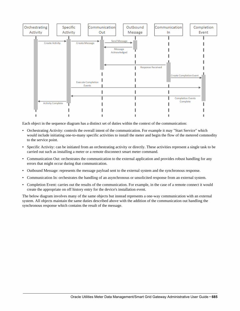
Oracle Utilities Meter Data Management/Smart Grid Gateway Administrative User Guide • 685
Each object in the sequence diagram has a distinct set of duties within the context of the communication:
• Orchestrating Activity: controls the overall intent of the communication. For example it may "Start Service" whichwould include initiating one-to-many specific activities to install the meter and begin the flow of the metered commodityto the service point.
• Specific Activity: can be initiated from an orchestrating activity or directly. These activities represent a single task to becarried out such as installing a meter or a remote disconnect smart meter command.
• Communication Out: orchestrates the communication to the external application and provides robust handling for anyerrors that might occur during that communication.
• Outbound Message: represents the message payload sent to the external system and the synchronous response.
• Communication In: orchestrates the handling of an asynchronous or unsolicited response from an external system.
• Completion Event: carries out the results of the communication. For example, in the case of a remote connect it wouldcreate the appropriate on off history entry for the device's installation event.
The below diagram involves many of the same objects but instead represents a one-way communication with an externalsystem. All objects maintain the same duties described above with the addition of the communication out handling thesynchronous response which contains the result of the message.

Oracle Utilities Meter Data Management/Smart Grid Gateway Administrative User Guide • 686
Important Activity Type System EventsThe activity type supports several business object algorithm system events that relate to calculating the consumption formeasuring components of that type:
• Customer-Device Compatibility: receives information about the activity being analyzed and returns an indication ofwhether the customer and device are compatible. This system event is primarily used in service order management. Seealgorithm type Ensure Device-Usage Calculation Group Compatibility (D2-ENSDVCCMP) as an example.
• Override Device / Task: receives information about the activity such as whether the device is installed at a service point,whether the service point is connected, where it is disconnected (if applicable), and the installation event status override.Based on those inputs it should determine the output device configuration type as well as the field activity businessobject and field task type. This system event is primarily used in service order management. See algorithm type EvaluateSmart Meter Opt-Out for Device Installation (D2-EVSMOPDV) as an example.
Configuring Activity TypesThis portal is used to display and maintain a Activity Type.
Refer to Understanding Activity Types for more information.
You can access the portal from the Admin > Communication > Activity Type.
The following zones may appear as part of the portal's Main tab page:
Oracle Utilities Meter Data Management/Smart Grid Gateway Administrative User Guide • 687
• Activity Type List: This zone works differently than the typical zone that list types in that it displays both those activitytypes that have been configured as well as those activity types that have yet to be configured. Broadcast a record todisplay the details of the selected record.
• Activity Type: This zone provides information about the selected Activity Type
Where UsedFollow this link to open the data dictionary where you can view the tables that reference D1_ACTIVITY_TYPE.
Communication Types
Understanding Communication TypesCommunication types define properties common to a specific type of communication. This single admin object covers bothcommunication in and communication out types.
Communication types include types of communications between an application and an external system such as a head-endsystem or the work management system. These are outbound communications such as smart meter command requests orfield activities as well as inbound communications such as a message response that indicates the results of a request.
Communication types typically provide configuration around exception handling:
• To Do Type and Role: identifies the To Do to be created when an error is encountered
• Retry Frequency: defines how often the communication should be retried. As many errors can be due to connectivitythe ability to retry provides automatic resolution.
• Maximum Retries: provides an upper limit to the number of times a communication can be re-attempted
• Each communication type can have its own unique set of fields, please refer to the embedded help for thatcommunication type for more details on those fields.
Configuring Communication TypesThis portal is used to display and maintain a Communication Type.
Refer to Understanding Communication Types for more information.
You can access the portal from the Admin > Communication > Communication Type.
The following zones may appear as part of the portal's Main tab page:
• Communication Type List: This zone works differently than the typical zone that list types in that it displays both thosecommunication types that have been configured as well as those communication types that have yet to be configured.Broadcast a record to display the details of the selected record.
• Communication Type: This zone provides information about the selected Communication Type
Where UsedFollow this link to open the data dictionary where you can view the tables that reference D1_COMM_TYPE.
Oracle Utilities Meter Data Management/Smart Grid Gateway Administrative User Guide • 688
Service Task Types
Understanding Service Task TypesService tasks types define properties common to specific types of service tasks.
Service task types represent types of tasks that can be performed by users of other Oracle Utilities applications, such OracleUtilities Customer Self Service or Oracle Utilities Network Management System. Examples of service tasks include selfservice meter reads, in which users enter their own meter reads via the Customer Self Service application, and service issuemonitor types used when determining if service investigation is needed for a service point.
When creating a new record, the following options are available:
Name Details Business Object
Service Issue Monitor Type The service issue monitor type defines theparameters for when a service investigativeorder should be created. It can also optionallydefine the completion parameters for thatindicate the investigative order was successfulin its purpose.
D1-ServiceIssueMonitorType
Self-Service Rate Compare Scenario RequestType
A simple description of a rate comparescenario request type.
D2-RateCompareScenarioRqstType
Self-Service Meter Read Task Type Provides the default settings for meter readscreated through self service.
D2-SSMeterReadTaskType
Configuring Service Task TypesThis portal is used to display and maintain a Service Task Type.
Refer to Understanding Service Task Types for more information.
You can access the portal from the Admin > Customer > Service Task Type
The following zones may appear as part of the portal's Main tab page:
• Service Task Type List: This zone lists all Service Task Type records. Broadcast a record to display the details of theselected record.
• Service Task Type: This zone provides information about the selected Service Task Type.
Where UsedFollow this link to open the data dictionary where you can view the tables that reference F1_SVC_TASK_TYPE.

Oracle Utilities Meter Data Management/Smart Grid Gateway Administrative User Guide • 689
Chapter 14
Service Order Management
Understanding Service Order ManagementAt a high level, service order management handles requests for service as follows:
Receive / Create Service Order RequestA service order request is created and/or received. This can be as a result of a customer requesting a change to their servicesuch as enabling or disabling service when moving into or out of a residence, but can also be the result of other businessprocesses, such as a request to cut service due to non-payment.
Regardless of the origin of the request, a service order request is created in a customer information system (CIS) such asOracle Utilities Customer Care and Billing), which in turn is sent to Service Order Management.
Create Service Order ActivityWhen Service Order Management receives the service order request, it creates a service order activity. This activity willmanage and orchestrate any/all other activities needed to fulfill the original service request.
Evaluate Service Point and/or MeterThe service order activity then evaluates the current state of the service point, meter, or item, and determines the appropriateaction(s) to take to fulfill the service request.
Create Activities as Needed / AppropriateBased on the evaluation of the service point/meter/item, the service order activity creates one or more activities as needed.
• Service order field activities involve sending workers into the field to perform service. This can include meterinstallation, meter replacement, and other activities.
• Command activities are smart meter commands used to remotely change the state of the meter. This can include connect,disconnect, checking the device status (ping), or requesting an on-demand reading.

Oracle Utilities Meter Data Management/Smart Grid Gateway Administrative User Guide • 690
Following each of activities, the orchestration activity re-evaluates the state of the service point/ meter/item to determine thenext appropriate action(s) required to fulfill the original service request.
For example, when enabling service at a service point with a smart scalar meter, a typical scenario might involve thefollowing:
1. Service Order Field Activity - Install Meter
2. Command Activity: Commission Device
3. Command Activity: Remote Connect
4. Command Activity: On Demand Read - Scalar
Update Requesting SystemWhen the service order activity determines that everything necessary to satisfy the service order request is ready, the serviceorder activity will inform the requester and complete the original request.
Send Notification to Subscribing SystemsThe service order activity can also be configured to send notifications to other subscribing systems regarding the status ofthe service point/meter/item.
Service Order Activities
Understanding Service Order ActivitiesThis section describes service order activities and how they manage the service order process.
Service order activities coordinate a large number of child transactions that represent the communication to and from anexternal application. The below diagram depicts a service order activity:
Each object in the sequence diagram has a distinct set of duties within the context of the communication:
Oracle Utilities Meter Data Management/Smart Grid Gateway Administrative User Guide • 691
• Orchestrating Activity: controls the overall intent of the communication. For example it may "Enable Service" whichwould include initiating one-to-many specific activities to install the meter and begin the flow of the metered commodityto the service point.
• Specific Activity: can be initiated from an orchestrating activity or directly. These activities represent a single task to becarried out such as installing a meter or a remote disconnect smart meter command.
• Communication Out: orchestrates the communication to the external application and provides robust handling for anyerrors that might occur during that communication.
• Outbound Message: represents the message payload sent to the external system and the synchronous response.
• Communication In: orchestrates the handling of an asynchronous or unsolicited response from an external system.
• Completion Event: carries out the results of the communication. For example, in the case of a remote connect it wouldcreate the appropriate on off history entry for the device's installation event.
The base package provides the following types of service order activities:
• Enable Service: Used to enable service at a service point.
• Disable Service: Used to disable service at a service point.
• Cut for Non-Payment: Used to cut off service at a service point due to non-payment of past due amounts.
• Reconnect Service for Payment: Used to restore service at a service point after receipt of past due payment.
• Exchange Meter: Used to orchestrate the exchange of meters at service point, such as in the event that a customerupgrades their meter.
• Back to Back Service: Used to orchestrate a change of service when the customer at a service point changes (such aswhen owners/tenants change).
Service Order Activity ProcessingTo understand how service order activities manage the service order process, it’s important understand the lifecycle oforchestration activity business objects.
Service Order Orchestration Activity LifecycleAll service order orchestration activity business objects share a common parent business object that defines their lifecycles.This is the Service Point Activity Orchestration business object (D1-SPActivityOrchestration). The table below outlines thelifecycle for this business object.
State Description
Pending The initial state for orchestration activities.
An Enter algorithm sends an acknowledgement to the requesting system.
The activity is transitioned to the next state via a monitor process.
Validate Enter algorithms perform the following:
Validate Activity Type
Validate Service Point
Check for a non-final duplicate service order request activity for the same service point.
Validation Error If the business object fails any of the validations in the Pending state, it enters this state.
Activities in this state can be corrected and retried.
Discarded Activities discarded in other states enter this state.
Enter algorithms perform the following:
Validate that non-final child activities can be discarded without the need for a cancel activity
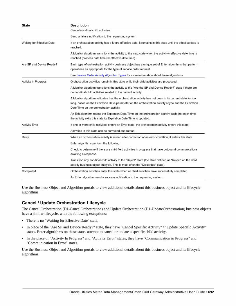
Oracle Utilities Meter Data Management/Smart Grid Gateway Administrative User Guide • 692
State DescriptionCancel non-final child activities
Send a failure notification to the requesting system
Waiting for Effective Date If an orchestration activity has a future effective date, it remains in this state until the effective date isreached.
A Monitor algorithm transitions the activity to the next state when the activity's effective date time isreached (process date time >= effective date time).
Are SP and Device Ready? Each type of orchestration activity business object has a unique set of Enter algorithms that performoperations as appropriate for the type of service order request.
See Service Order Activity Algorithm Types for more information about these algorithms.
Activity in Progress Orchestration activities remain in this state while their child activities are processed.
A Monitor algorithm transitions the activity to the "Are the SP and Device Ready?” state if there areno non-final child activities related to the current activity.
A Monitor algorithm validates that the orchestration activity has not been in its current state for toolong, based on the Expiration Days parameter on the orchestration activity’s type and the ExpirationDate/Time on the orchestration activity
An Exit algorithm resets the Expiration Date/Time on the orchestration activity such that each timethe activity exits this state its Expiration Date/Time is updated.
Activity Error If one or more child activities enters an Error state, the orchestration activity enters this state.
Activities in this state can be corrected and retried.
Retry When an orchestration activity is retried after correction of an error condition, it enters this state.
Enter algorithms perform the following:
Check to determine if there are child field activities in progress that have outbound communicationsawaiting a response.
Transition any non-final child activity to the "Reject" state (the state defined as "Reject" on the childactivity business object lifecycle. This is most often the "Discarded" state).
Completed Orchestration activities enter this state when all child activities have successfully completed.
An Enter algorithm send a success notification to the requesting system.
Use the Business Object and Algorithm portals to view additional details about this business object and its lifecyclealgorithms.
Cancel / Update Orchestration LifecycleThe Cancel Orchestration (D1-CancelOrchestration) and Update Orchestration (D1-UpdateOrchestration) business objectshave a similar lifecycle, with the following exceptions:
• There is no "Waiting for Effective Date" state.
• In place of the "Are SP and Device Ready?” state, they have "Cancel Specific Activity" / "Update Specific Activity"states. Enter algorithms on these states attempt to cancel or update a specific child activity.
• In the place of "Activity In Progress" and "Activity Error" states, they have "Communication in Progress" and"Communication in Error" states.
Use the Business Object and Algorithm portals to view additional details about this business object and its lifecyclealgorithms.
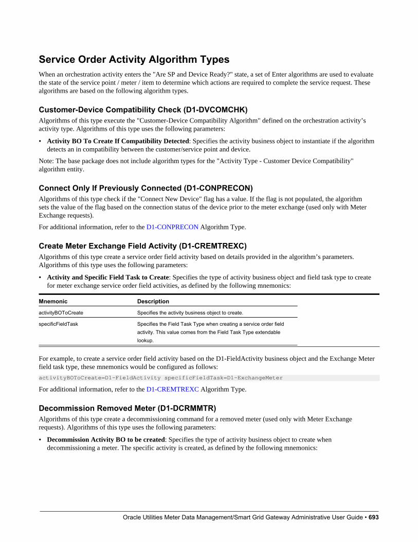
Oracle Utilities Meter Data Management/Smart Grid Gateway Administrative User Guide • 693
Service Order Activity Algorithm TypesWhen an orchestration activity enters the "Are SP and Device Ready?" state, a set of Enter algorithms are used to evaluatethe state of the service point / meter / item to determine which actions are required to complete the service request. Thesealgorithms are based on the following algorithm types.
Customer-Device Compatibility Check (D1-DVCOMCHK)Algorithms of this type execute the "Customer-Device Compatibility Algorithm" defined on the orchestration activity’sactivity type. Algorithms of this type uses the following parameters:
• Activity BO To Create If Compatibility Detected: Specifies the activity business object to instantiate if the algorithmdetects an in compatibility between the customer/service point and device.
Note: The base package does not include algorithm types for the "Activity Type - Customer Device Compatibility"algorithm entity.
Connect Only If Previously Connected (D1-CONPRECON)Algorithms of this type check if the "Connect New Device" flag has a value. If the flag is not populated, the algorithmsets the value of the flag based on the connection status of the device prior to the meter exchange (used only with MeterExchange requests).
For additional information, refer to the D1-CONPRECON Algorithm Type.
Create Meter Exchange Field Activity (D1-CREMTREXC)Algorithms of this type create a service order field activity based on details provided in the algorithm’s parameters.Algorithms of this type uses the following parameters:
• Activity and Specific Field Task to Create: Specifies the type of activity business object and field task type to createfor meter exchange service order field activities, as defined by the following mnemonics:
Mnemonic Description
activityBOToCreate Specifies the activity business object to create.
specificFieldTask Specifies the Field Task Type when creating a service order fieldactivity. This value comes from the Field Task Type extendablelookup.
For example, to create a service order field activity based on the D1-FieldActivity business object and the Exchange Meterfield task type, these mnemonics would be configured as follows:
activityBOToCreate=D1-FieldActivity specificFieldTask=D1-ExchangeMeter
For additional information, refer to the D1-CREMTREXC Algorithm Type.
Decommission Removed Meter (D1-DCRMMTR)Algorithms of this type create a decommissioning command for a removed meter (used only with Meter Exchangerequests). Algorithms of this type uses the following parameters:
• Decommission Activity BO to be created: Specifies the type of activity business object to create whendecommissioning a meter. The specific activity is created, as defined by the following mnemonics:
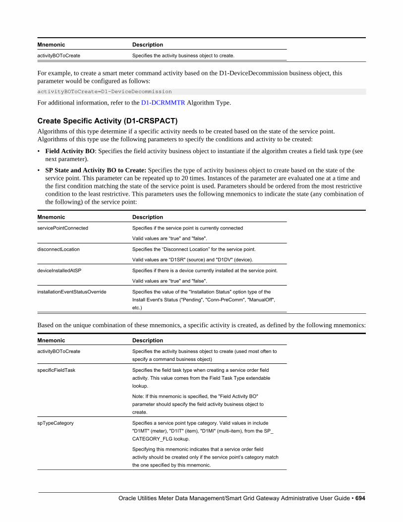
Oracle Utilities Meter Data Management/Smart Grid Gateway Administrative User Guide • 694
Mnemonic Description
activityBOToCreate Specifies the activity business object to create.
For example, to create a smart meter command activity based on the D1-DeviceDecommission business object, thisparameter would be configured as follows:
activityBOToCreate=D1-DeviceDecommission
For additional information, refer to the D1-DCRMMTR Algorithm Type.
Create Specific Activity (D1-CRSPACT)Algorithms of this type determine if a specific activity needs to be created based on the state of the service point.Algorithms of this type use the following parameters to specify the conditions and activity to be created:
• Field Activity BO: Specifies the field activity business object to instantiate if the algorithm creates a field task type (seenext parameter).
• SP State and Activity BO to Create: Specifies the type of activity business object to create based on the state of theservice point. This parameter can be repeated up to 20 times. Instances of the parameter are evaluated one at a time andthe first condition matching the state of the service point is used. Parameters should be ordered from the most restrictivecondition to the least restrictive. This parameters uses the following mnemonics to indicate the state (any combination ofthe following) of the service point:
Mnemonic Description
servicePointConnected Specifies if the service point is currently connected
Valid values are “true" and "false".
disconnectLocation Specifies the “Disconnect Location” for the service point.
Valid values are “D1SR" (source) and "D1DV" (device).
deviceInstalledAtSP Specifies if there is a device currently installed at the service point.
Valid values are “true" and "false".
installationEventStatusOverride Specifies the value of the "Installation Status" option type of theInstall Event's Status ("Pending", "Conn-PreComm", "ManualOff",etc.)
Based on the unique combination of these mnemonics, a specific activity is created, as defined by the following mnemonics:
Mnemonic Description
activityBOToCreate Specifies the activity business object to create (used most often tospecify a command business object)
specificFieldTask Specifies the field task type when creating a service order fieldactivity. This value comes from the Field Task Type extendablelookup.
Note: If this mnemonic is specified, the "Field Activity BO"parameter should specify the field activity business object tocreate.
spTypeCategory Specifies a service point type category. Valid values in include"D1MT" (meter), "D1IT" (item), "D1MI" (multi-item), from the SP_CATEGORY_FLG lookup.
Specifying this mnemonic indicates that a service order fieldactivity should be created only if the service point’s category matchthe one specified by this mnemonic.
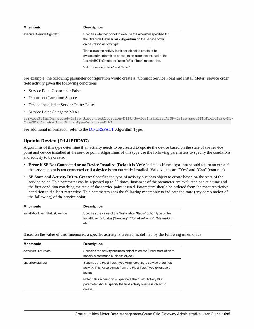
Oracle Utilities Meter Data Management/Smart Grid Gateway Administrative User Guide • 695
Mnemonic Description
executeOverrideAlgorithm Specifies whether or not to execute the algorithm specified forthe Override Device/Task Algorithm on the service orderorchestration activity type.
This allows the activity business object to create to bedynamically determined based on an algorithm instead of the"activityBOToCreate" or "specificFieldTask" mnemonics.
Valid values are “true" and "false".
For example, the following parameter configuration would create a "Connect Service Point and Install Meter" service orderfield activity given the following conditions:
• Service Point Connected: False
• Disconnect Location: Source
• Device Installed at Service Point: False
• Service Point Category: Meter
servicePointConnected=false disconnectLocation=D1SR deviceInstalledAtSP=false specificFieldTask=D1-ConnSPAtSrceAndInstMtr spTypeCategory=D1MT
For additional information, refer to the D1-CRSPACT Algorithm Type.
Update Device (D1-UPDDVC)Algorithms of this type determine if an activity needs to be created to update the device based on the state of the servicepoint and device installed at the service point. Algorithms of this type use the following parameters to specify the conditionsand activity to be created.
• Error if SP Not Connected or no Device Installed (Default is Yes): Indicates if the algorithm should return an error ifthe service point is not connected or if a device is not currently installed. Valid values are "Yes" and "Con" (continue)
• SP State and Activity BO to Create: Specifies the type of activity business object to create based on the state of theservice point. This parameter can be repeated up to 20 times. Instances of the parameter are evaluated one at a time andthe first condition matching the state of the service point is used. Parameters should be ordered from the most restrictivecondition to the least restrictive. This parameters uses the following mnemonic to indicate the state (any combination ofthe following) of the service point:
Mnemonic Description
installationEventStatusOverride Specifies the value of the "Installation Status" option type of theInstall Event's Status ("Pending", "Conn-PreComm", "ManualOff",etc.)
Based on the value of this mnemonic, a specific activity is created, as defined by the following mnemonics:
Mnemonic Description
activityBOToCreate Specifies the activity business object to create (used most often tospecify a command business object)
specificFieldTask Specifies the Field Task Type when creating a service order fieldactivity. This value comes from the Field Task Type extendablelookup.
Note: If this mnemonic is specified, the "Field Activity BO"parameter should specify the field activity business object tocreate.

Oracle Utilities Meter Data Management/Smart Grid Gateway Administrative User Guide • 696
Mnemonic Description
spTypeCategory Specifies a service point type category. Valid values in include"D1MT" (meter), "D1IT" (item), "D1MI" (multi-item), from the SP_CATEGORY_FLG lookup.
Specifying this mnemonic indicates that a service order fieldactivity should be created only if the service point’s category matchthe one specified by this mnemonic.
alternativeFieldTask Specifies an alternative Field Task Type to use when creatinga service order field activity in the event that the device doesnot support the command indicated by the "activityBOToCreate"mnemonic.
Note: If this mnemonic is specified, the "Field Activity BO"parameter should specify the field activity business object tocreate.
A value of 'skip' will continue the evaluation of the algorithm's nextparameter
For example, the following parameter configuration would create a "Turn On Meter" service order field activity given thefollowing conditions:
• Installation Status: Manual Off
• Service Point Category: Meter
installEventStatusOverride=ManualOff specificFieldTask=D1-TurnOnMeter spTypeCategory=D1MT
Other parameters used by algorithms of this type include:
• Field Activity BO: Specifies the field activity business object to instantiate if the algorithm creates a field task type (seeabove parameter).
• XPath of Activity Element controlling Activity creation: Defines an element within the activity business objectschema that can be used to control whether or not this algorithm should create an activity. For example, to specify thatthe value of the "Connect New Device" flag be used to determine whether or not the algorithm should create an activity,this parameter could be set to "connectNewDevice".
• Element value indication that Activity creation should not proceed: Specifies a value for the element defined in the"XPath of Activity Element controlling Activity creation" parameter that would indicate that the algorithm should notcreate an activity. Valid values are based on the element defined for the "XPath of Activity Element controlling Activitycreation" parameter. For example, to specify that an activity should not be created if the "Connect New Device" flag isset to "Do Not Connect / Turn On", this parameter should be set to "D1NC" (from the D1_CONNECT_NEW_DEVICE_FLG lookup).
For additional information, refer to the D1-UPDDVC Algorithm Type.
Remote Turn Off Turn On (D1-REMONOFF)Algorithms of this type remotely turn a device off and on for a Back to Back service request. Algorithms of this type use thefollowing parameters:
• Device Incompatibility Detected Activity BO: Specifies the activity business object the algorithm will look for. If thealgorithm finds an activity of this business object, the algorithm terminates.
• Remote Connect BO: Specifies the activity business object to instantiate when creating a remote connect command.
• Remote Disconnect BO: Specifies the activity business object to instantiate when creating a remote disconnectcommand.
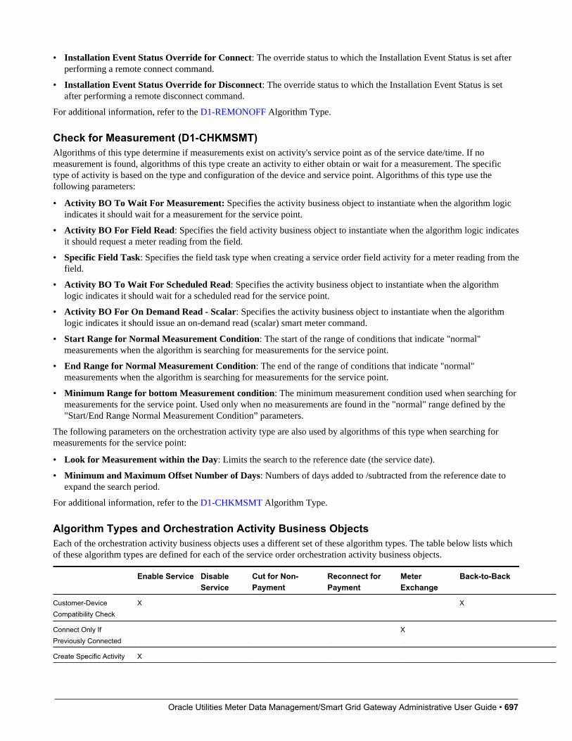
Oracle Utilities Meter Data Management/Smart Grid Gateway Administrative User Guide • 697
• Installation Event Status Override for Connect: The override status to which the Installation Event Status is set afterperforming a remote connect command.
• Installation Event Status Override for Disconnect: The override status to which the Installation Event Status is setafter performing a remote disconnect command.
For additional information, refer to the D1-REMONOFF Algorithm Type.
Check for Measurement (D1-CHKMSMT)Algorithms of this type determine if measurements exist on activity's service point as of the service date/time. If nomeasurement is found, algorithms of this type create an activity to either obtain or wait for a measurement. The specifictype of activity is based on the type and configuration of the device and service point. Algorithms of this type use thefollowing parameters:
• Activity BO To Wait For Measurement: Specifies the activity business object to instantiate when the algorithm logicindicates it should wait for a measurement for the service point.
• Activity BO For Field Read: Specifies the field activity business object to instantiate when the algorithm logic indicatesit should request a meter reading from the field.
• Specific Field Task: Specifies the field task type when creating a service order field activity for a meter reading from thefield.
• Activity BO To Wait For Scheduled Read: Specifies the activity business object to instantiate when the algorithmlogic indicates it should wait for a scheduled read for the service point.
• Activity BO For On Demand Read - Scalar: Specifies the activity business object to instantiate when the algorithmlogic indicates it should issue an on-demand read (scalar) smart meter command.
• Start Range for Normal Measurement Condition: The start of the range of conditions that indicate "normal"measurements when the algorithm is searching for measurements for the service point.
• End Range for Normal Measurement Condition: The end of the range of conditions that indicate "normal"measurements when the algorithm is searching for measurements for the service point.
• Minimum Range for bottom Measurement condition: The minimum measurement condition used when searching formeasurements for the service point. Used only when no measurements are found in the "normal" range defined by the"Start/End Range Normal Measurement Condition” parameters.
The following parameters on the orchestration activity type are also used by algorithms of this type when searching formeasurements for the service point:
• Look for Measurement within the Day: Limits the search to the reference date (the service date).
• Minimum and Maximum Offset Number of Days: Numbers of days added to /subtracted from the reference date toexpand the search period.
For additional information, refer to the D1-CHKMSMT Algorithm Type.
Algorithm Types and Orchestration Activity Business ObjectsEach of the orchestration activity business objects uses a different set of these algorithm types. The table below lists whichof these algorithm types are defined for each of the service order orchestration activity business objects.
Enable Service DisableService
Cut for Non-Payment
Reconnect forPayment
MeterExchange
Back-to-Back
Customer-DeviceCompatibility Check
X X
Connect Only IfPreviously Connected
X
Create Specific Activity X

Oracle Utilities Meter Data Management/Smart Grid Gateway Administrative User Guide • 698
Enable Service DisableService
Cut for Non-Payment
Reconnect forPayment
MeterExchange
Back-to-Back
Create MeterExchange Field Activity
X
Update Device X X X X X X
Remote Turn Off TurnOn
X
DecommissionRemoved Meter
X
Check ForMeasurement:
X X X X
Cancel / Update Orchestration - Algorithm TypesEnter algorithms on the "Cancel Specific Activity" and "Update Specific Activity" states attempt to cancel or update aspecific child activity. These algorithms are based on the following algorithm types.
• Cancel Specific Activity: Algorithms of this type cancel the specific activity (either a service order field activity or asmart meter command) that is associated to the Cancel or Update orchestration activity, based on the current status of thespecific activity.
• Update Specific Activity: Algorithms of this type update the specific activity (either a service order field activity or asmart meter command) that is associated to the Cancel or Update orchestration activity, based on the current status of thespecific activity.
Algorithm Type Algorithm(s)
Cancel Specific Activity (D1-CANSPACT) Cancel Specific Activity (D1-CANSPACT)
Update Specific Activity (D1-UPDSPAC) Update Specific Activity (D1-UPDSPAC)
Use the Algorithm Type and Algorithm portals to view additional details about these algorithms.
Understanding Service Order Activity TypesService order activity types must be configured for each type of service order activity.
Service order activity types are assigned to the following Activity Type Categories:
Service Order Activity Activity Type CategoryBack-to-Back Service Request Orchestration
Cancel Orchestration Orchestration Maintenance
Cut Service for Non-Payment Request Orchestration
Disable Service Request Orchestration
Enable Service Request Orchestration
Exchange Meter Request Orchestration
Reconnect Service for Payment Request Orchestration
Update Orchestration Orchestration Maintenance
Refer to Understanding Activity Types for more information about activity types.

Oracle Utilities Meter Data Management/Smart Grid Gateway Administrative User Guide • 699
Configuring Service Order Activity TypesThe Activity Type portal is used to display and maintain service order activity types.
Refer to Understanding Activity Types for more information.
You can access the portal from the Admin > Communication > Activity Type.
The following zones may appear as part of the portal's Main tab page:
• Activity Type List: This zone works differently than the typical zone that list types in that it displays both those activitytypes that have been configured as well as those activity types that have yet to be configured. Broadcast a record todisplay the details of the selected record.
• Activity Type: This zone provides information about the selected Activity Type
Service Order Management ConfigurationThe following table outlines the activity types that must be configured for the service order activity types supported byService Order Management:
Service Order Activity Activity Type (Business Object)
Enable Service Enable Service (D1–EnableServiceType)
Disable Service Disable Service (D1–DisableServiceType)
Cut Service for Non-Payment Cut Service for Non-Payment (D1-CutServiceForNonPaymentType)
Reconnect Service for Payment Reconnect for Payment (D1–ReconnectForPaymentType)
Meter Exchange Exchange Meter (D1–ExchangeMeterType)
Back-to-Back Service Back-to-Back Service (D1–BackToBackServiceType)
Cancel Orchestration Cancel Orchestration (D1–CancelOrchestrationType)
Update Orchestration Update Orchestration (D1–UpdateOrchestrationType)
The demonstration database contains examples of each of these service order activity types.
Service Order Field Activities
Understanding Service Order Field ActivitiesThis section describes service order field activities and how they communicate with field work management systems such asOracle Utilities Mobile Workforce Management.
Service order field activities are activities that involve sending workers into the field to perform service. This can includemeter installation, meter replacement, and other activities.
Service order field activities send messages to a field work system, which in turn assigns them to crews to be completed inthe field. Service Order Management supports integration with Oracle Utilities Mobile Workforce Management to supportfield activities, but can also integrate with other field work systems if needed.
Oracle Utilities Meter Data Management/Smart Grid Gateway Administrative User Guide • 700
Field Activity InformationAll service order field activities are based on the Field Activity (D1-FieldActivity) business object, and include thefollowing user-accessible information:
• Status: The current status of the service order field activity.
• Service Date/Time: The date and time the service order field activity was created.
• Service Point: The service point associated with the service order field activity.
• Field Task Type: The field task type for the service order field activity. This defines the type of task and otherprocessing details regarding how Service Order Management processes the service order field activity. See Field TaskTypes for more details about field task types.
• Recipient: The field work system service provider to which the service order field activity is sent for scheduling andassignment.
• Device ID: The device related to the service order field activity (if applicable).
• Request Information: Details of the service order request, including requester and external system information.
• Contact Details (or Customer Information): Contact details for the customer associated with the service order request.
• Address Information: The address of the service point associated with the service order field activity.
The field activity business object also contains other information that is populated by algorithms and scripts as the serviceorder field activity is processed by the system.
How Do Service Order Field Activities Work?At a high level, service order field activities work as follows:
Create Field ActivityA service order orchestration activity creates a service order field activity based on the current state of the service point/meter/item.
Retrieve Required DataThe service order field activity uses a set of pre-processing algorithms to derive and populate data needed by the activity,such as the device, service point, address, effective date, and others.
Request Appointment (Optional)If the service order field activity task type specifies that field tasks of this type require an appointment, the service orderfield activity checks for available appointment slots in the field work system and sends a notification to the appointmenthandling system.
Create Outbound CommunicationThe service order field activity creates an outbound communication to send the service order field activity to the field worksystem. The outbound communication gathers the information required by the field work system before being sent. Thisinformation is retrieved by a set of processing scripts defined on the field task type.
Receive Inbound CommunicationWhen the service order field activity has been completed, the field work system sends an inbound communication back toService Order Management.
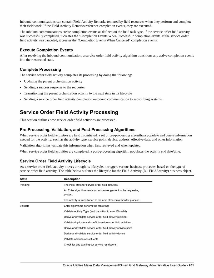
Oracle Utilities Meter Data Management/Smart Grid Gateway Administrative User Guide • 701
Inbound communications can contain Field Activity Remarks (entered by field resources when they perform and completetheir field work. If the Field Activity Remarks reference completion events, they are executed.
The inbound communications create completion events as defined on the field task type. If the service order field activitywas successfully completed, it creates the "Completion Events When Successful" completion events. If the service orderfield activity was canceled, it creates the "Completion Events When Canceled" completion events.
Execute Completion EventsAfter receiving the inbound communication, a service order field activity algorithm transitions any active completion eventsinto their executed state.
Complete ProcessingThe service order field activity completes its processing by doing the following:
• Updating the parent orchestration activity
• Sending a success response to the requester
• Transitioning the parent orchestration activity to the next state in its lifecycle
• Sending a service order field activity completion outbound communication to subscribing systems.
Service Order Field Activity ProcessingThis section outlines how service order field activities are processed.
Pre-Processing, Validation, and Post-Processing AlgorithmsWhen service order field activities are first instantiated, a set of pre-processing algorithms populate and derive informationneeded for the activity, such as the activity type, service point, device, address, effective date, and other information.
Validation algorithms validate this information when first retrieved and when updated.
When service order field activities are completed, a post-processing algorithm populates the activity end date/time:
Service Order Field Activity LifecycleAs a service order field activity moves through its lifecycle, it triggers various business processes based on the type ofservice order field activity. The table below outlines the lifecycle for the Field Activity (D1-FieldActivity) business object.
State Description
Pending The initial state for service order field activities.
An Enter algorithm sends an acknowledgement to the requestingsystem.
The activity is transitioned to the next state via a monitor process.
Validate Enter algorithms perform the following:
Validate Activity Type (and transition to error if invalid)
Derive and validate service order field activity recipient
Validate duplicate and conflict service order field activities
Derive and validate service order field activity service point
Derive and validate service order field activity device
Validate address constituents
Check for any existing cut service restrictions

Oracle Utilities Meter Data Management/Smart Grid Gateway Administrative User Guide • 702
State DescriptionThe activity is transitioned to the next state via a monitor process.
Validation Error If the business object fails any of the validations in the Pending state, itenters this state.
Enter algorithms perform the following:
Create a To Do based on specified To Do Type and To Do Role
Set the "Allow Child to Transition Parent Activity" flag to yes. This allowsthe service order field activity to transition the parent orchestrationactivity if needed.
Activities in this state can be corrected and retried.
Waiting to Request If a service order field activity has a future effective date, it remains inthis state until the effective date is reached.
A Monitor algorithm transitions the activity to the next state when theactivity's effective date time is reached (process date time >= effectivedate time).
An Enter algorithm sets the "Allow Child to Transition Parent ActivityBased On Effective Date" flag to yes. This allows the service order fieldactivity to transition the parent orchestration activity if needed.
Waiting for Appointment If the service order field activity passes its validations and the effectivedate has been reached, the activity enters this state.
Enter algorithms perform the following:
Evaluate if an appointment is required for field tasks of this type. If not,the activity transitions to the "Communication in Progress" state.
Create a To Do if an appointment is necessary but the system is notable to send an appointment request
Set the "Allow Child to Transition Parent Activity" flag to yes. This allowsthe service order field activity to transition the parent orchestrationactivity if needed.
Send a notification to the appointment handling system
Monitor algorithms perform the following:
Verify if an appointment has been supplied
Send a notification to the appointment handling system
The activity is transitioned to the next state via a monitor process.
See Waiting for Appointment for more information about this state.
Communication in Progress Service order field activities enter this state following the "Waiting forAppointment" or "Retry" states.
Enter algorithms perform the following:
Create an outbound communication for the service order field activity(see Communication in Progress for more information)
Set the "Allow Child to Transition Parent Activity" flag to yes. This allowsthe service order field activity to transition the parent orchestrationactivity if needed.
Monitor algorithms perform the following:
Check for existing child communications
Check that the activity hasn’t timed out
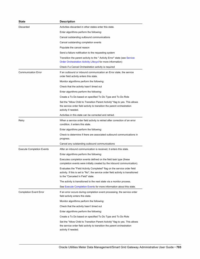
Oracle Utilities Meter Data Management/Smart Grid Gateway Administrative User Guide • 703
State Description
Discarded Activities discarded in other states enter this state.
Enter algorithms perform the following:
Cancel outstanding outbound communications
Cancel outstanding completion events
Populate the cancel reason
Send a failure notification to the requesting system
Transition the parent activity to the " Activity Error" state (see ServiceOrder Orchestration Activity Lifecycl for more information)
Check if a Cancel Orchestration activity is required
Communication Error If an outbound or inbound communication an Error state, the serviceorder field activity enters this state.
Monitor algorithms perform the following:
Check that the activity hasn’t timed out
Enter algorithms perform the following:
Create a To Do based on specified To Do Type and To Do Role
Set the "Allow Child to Transition Parent Activity" flag to yes. This allowsthe service order field activity to transition the parent orchestrationactivity if needed.
Activities in this state can be corrected and retried.
Retry When a service order field activity is retried after correction of an errorcondition, it enters this state.
Enter algorithms perform the following:
Check to determine if there are associated outbound communications inprogress.
Cancel any outstanding outbound communications
Execute Completion Events After an inbound communication is received, it enters this state.
Enter algorithms perform the following:
Executes completion events defined on the field task type (thesecompletion events were initially created by the inbound communication).
Evaluates the "Field Activity Completed" flag on the service order fieldactivity. If this is set to "No", the service order field activity is transitionedto the "Canceled In Field" state.
The activity is transitioned to the next state via a monitor process.
See Execute Completion Events for more information about this state.
Completion Event Error If an error occurs during completion event processing, the service orderfield activity enters this state.
Monitor algorithms perform the following:
Check that the activity hasn’t timed out
Enter algorithms perform the following:
Create a To Do based on specified To Do Type and To Do Role
Set the "Allow Child to Transition Parent Activity" flag to yes. This allowsthe service order field activity to transition the parent orchestrationactivity if needed.
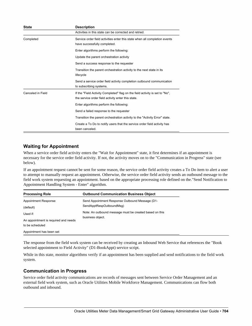
Oracle Utilities Meter Data Management/Smart Grid Gateway Administrative User Guide • 704
State DescriptionActivities in this state can be corrected and retried.
Completed Service order field activities enter this state when all completion eventshave successfully completed.
Enter algorithms perform the following:
Update the parent orchestration activity
Send a success response to the requester
Transition the parent orchestration activity to the next state in itslifecycle
Send a service order field activity completion outbound communicationto subscribing systems.
Canceled in Field If the "Field Activity Completed" flag on the field activity is set to "No",the service order field activity enter this state.
Enter algorithms perform the following:
Send a failed response to the requester
Transition the parent orchestration activity to the "Activity Error" state.
Create a To Do to notify users that the service order field activity hasbeen canceled.
Waiting for AppointmentWhen a service order field activity enters the "Wait for Appointment" state, it first determines if an appointment isnecessary for the service order field activity. If not, the activity moves on to the "Communication in Progress" state (seebelow).
If an appointment request cannot be sent for some reason, the service order field activity creates a To Do item to alert a userto attempt to manually request an appointment. Otherwise, the service order field activity sends an outbound message to thefield work system requesting an appointment. based on the appropriate processing role defined on the."Send Notification toAppointment Handling System - Enter" algorithm.
Processing Role Outbound Communication Business Object
Appointment Response
(default)
Used if:
An appointment is required and needsto be scheduled
Appointment has been set
Send Appointment Response Outbound Message (D1-SendApptRespOutboundMsg)
Note: An outbound message must be created based on thisbusiness object.
The response from the field work system can be received by creating an Inbound Web Service that references the "Bookselected appointment to Field Activity" (D1-BookAppt) service script.
While in this state, monitor algorithms verify if an appointment has been supplied and send notifications to the field worksystem.
Communication in ProgressService order field activity communications are records of messages sent between Service Order Management and anexternal field work system, such as Oracle Utilities Mobile Workforce Management. Communications can flow bothoutbound and inbound.
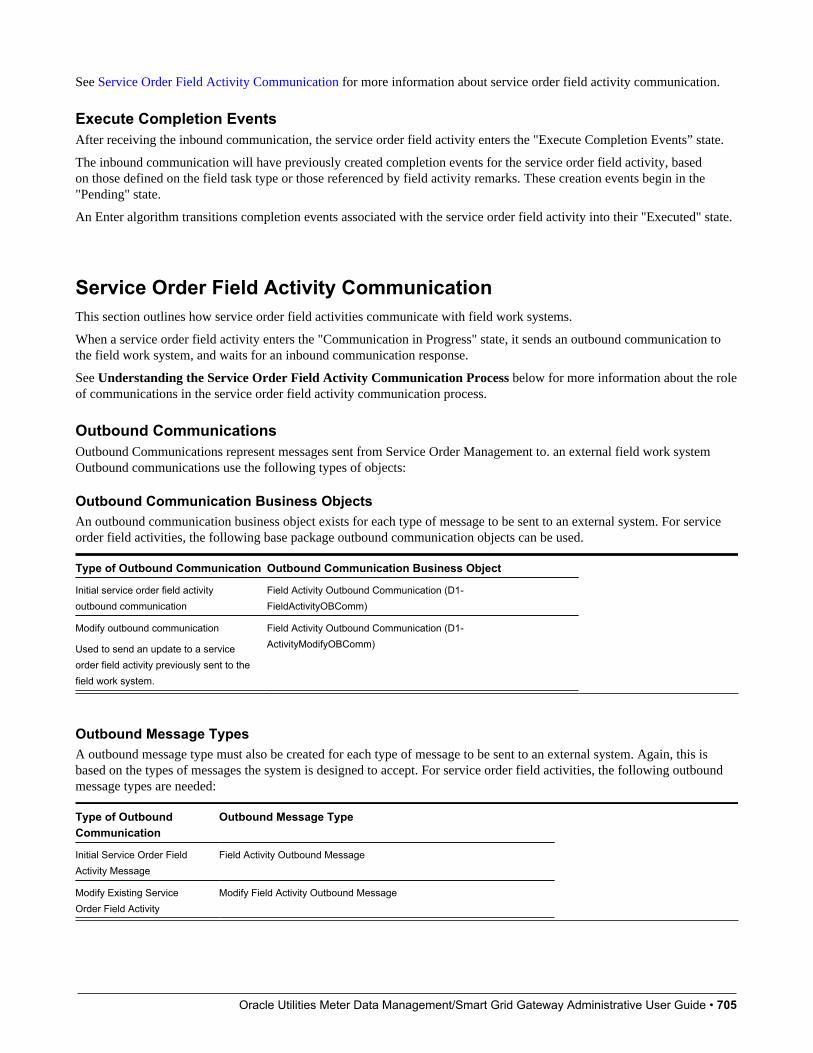
Oracle Utilities Meter Data Management/Smart Grid Gateway Administrative User Guide • 705
See Service Order Field Activity Communication for more information about service order field activity communication.
Execute Completion EventsAfter receiving the inbound communication, the service order field activity enters the "Execute Completion Events” state.
The inbound communication will have previously created completion events for the service order field activity, basedon those defined on the field task type or those referenced by field activity remarks. These creation events begin in the"Pending" state.
An Enter algorithm transitions completion events associated with the service order field activity into their "Executed" state.
Service Order Field Activity CommunicationThis section outlines how service order field activities communicate with field work systems.
When a service order field activity enters the "Communication in Progress" state, it sends an outbound communication tothe field work system, and waits for an inbound communication response.
See Understanding the Service Order Field Activity Communication Process below for more information about the roleof communications in the service order field activity communication process.
Outbound CommunicationsOutbound Communications represent messages sent from Service Order Management to. an external field work systemOutbound communications use the following types of objects:
Outbound Communication Business ObjectsAn outbound communication business object exists for each type of message to be sent to an external system. For serviceorder field activities, the following base package outbound communication objects can be used.
Type of Outbound Communication Outbound Communication Business Object
Initial service order field activityoutbound communication
Field Activity Outbound Communication (D1-FieldActivityOBComm)
Modify outbound communication
Used to send an update to a serviceorder field activity previously sent to thefield work system.
Field Activity Outbound Communication (D1-ActivityModifyOBComm)
Outbound Message TypesA outbound message type must also be created for each type of message to be sent to an external system. Again, this isbased on the types of messages the system is designed to accept. For service order field activities, the following outboundmessage types are needed:
Type of OutboundCommunication
Outbound Message Type
Initial Service Order FieldActivity Message
Field Activity Outbound Message
Modify Existing ServiceOrder Field Activity
Modify Field Activity Outbound Message
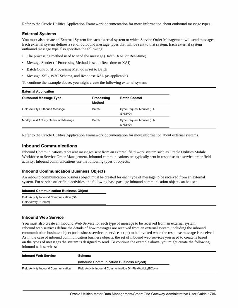
Oracle Utilities Meter Data Management/Smart Grid Gateway Administrative User Guide • 706
Refer to the Oracle Utilities Application Framework documentation for more information about outbound message types.
External SystemsYou must also create an External System for each external system to which Service Order Management will send messages.Each external system defines a set of outbound message types that will be sent to that system. Each external systemoutbound message type also specifies the following:
• The processing method used to send the message (Batch, XAI, or Real-time)
• Message Sender (if Processing Method is set to Real-time or XAI)
• Batch Control (if Processing Method is set to Batch)
• Message XSL, W3C Schema, and Response XSL (as applicable)
To continue the example above, you might create the following external system:
External Application
Outbound Message Type ProcessingMethod
Batch Control
Field Activity Outbound Message Batch Sync Request Monitor (F1-SYNRQ)
Modify Field Activity Outbound Message Batch Sync Request Monitor (F1-SYNRQ)
Refer to the Oracle Utilities Application Framework documentation for more information about external systems.
Inbound CommunicationsInbound Communications represent messages sent from an external field work system such as Oracle Utilities MobileWorkforce to Service Order Management. Inbound communications are typically sent in response to a service order fieldactivity. Inbound communications use the following types of objects:
Inbound Communication Business ObjectsAn inbound communication business object must be created for each type of message to be received from an externalsystem. For service order field activities, the following base package inbound communication object can be used.
Inbound Communication Business Object
Field Activity Inbound Communication (D1-FieldActivityIBComm)
Inbound Web ServiceYou must also create an Inbound Web Service for each type of message to be received from an external system.Inbound web services define the details of how messages are received from an external system, including the inboundcommunication business object (or business service or service script) to be invoked when the response message is received.As in the case of inbound communication business objects, the set of inbound web services you need to create is basedon the types of messages the system is designed to send. To continue the example above, you might create the followinginbound web services:
Inbound Web Service Schema
(Inbound Communication Business Object)
Field Activity Inbound Communication Field Activity Inbound Communication D1-FieldActivityIBComm

Oracle Utilities Meter Data Management/Smart Grid Gateway Administrative User Guide • 707
Refer to the Oracle Utilities Application Framework documentation for more information about Inbound Web Services.
Field Activity RemarksInbound communications can contain activity remarks, which represent notes entered by the field worker as they performand complete their field work. These can be solely informational, or can reference completion events via the "RemarkProcessing" section of the Field Activity Remark Type extendable lookup. This allows information sent with the inboundcommunication to initiate business processing if necessary.
Completion events specified on this extendable lookup are created by the inbound communication, and then executed whenthe service order field activity enters the "Execute Completion Events" state.
Understanding the Service Order Field Activity Communication ProcessThis section provides an overview of the communication process that takes place when a service order field activity isinitiated. For each step in the process, the table below provides a brief description of the processing that takes place, andlists the specific base package objects used by Service Order Management
Note that the process outlined below has been simplified for illustrative purposes, and does not reference every stepperformed in this process.
Step Process Base Package Objects
1. An orchestration activity creates a service orderfield activity as part of its processing.
A service order field activity business object isinstantiated for the command.
Field Activity Business Object: Field Activity (D1-FieldActivity)
2. When the service order field activity enters theCommunication in Progress tate, it creates anoutbound communication.
Outbound Communication Business Object: Field ActivityOutbound Communication
(D1-FieldActivityOBComm)
3. A Enter algorithm on the "Awaiting Response"state of the outbound communication retrievesinformation needed by the outbound messageto be sent to the field work system based onprocessing scripts specified on the field task type.
Enter Algorithm: Populate Send Detail for Field Activity (D1-POPSNDDTL)
4. A Enter algorithm on the "Awaiting Response"state of the outbound communication creates anoutbound message.
Enter Algorithm: Create Outbound Message (D1-COUTMSG)
Note: An outbound message type for this message is notincluded in the base package.
5. The outbound message is sent to middlewarecomponents via an External System and BatchControl.
Middleware components utilize Business ProcessExecution Language (BPEL).
External System: MWM
Batch Control: Sync Request Monitor
(F1-SYNRQ)
6. The middleware converts the outbound messagefrom SOM format into the format used by the fieldwork system, and sends the message to the fieldwork system.
7. When the field work system sends a response,the middleware receives the response messagefrom the field work system, and converts it fromthe format used by the field work system to SOMformat and invokes an Inbound Web Service.
Inbound Web Service: D1-FieldActivityIBComm
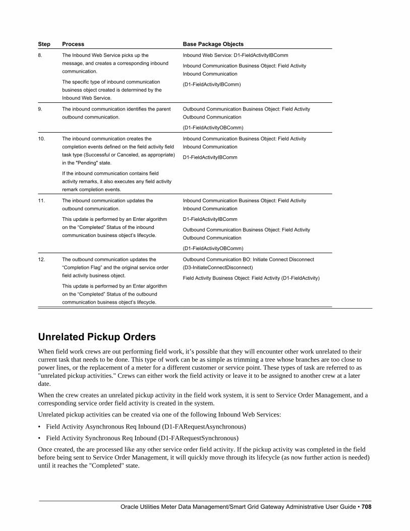
Oracle Utilities Meter Data Management/Smart Grid Gateway Administrative User Guide • 708
Step Process Base Package Objects
8. The Inbound Web Service picks up themessage, and creates a corresponding inboundcommunication.
The specific type of inbound communicationbusiness object created is determined by theInbound Web Service.
Inbound Web Service: D1-FieldActivityIBComm
Inbound Communication Business Object: Field ActivityInbound Communication
(D1-FieldActivityIBComm)
9. The inbound communication identifies the parentoutbound communication.
Outbound Communication Business Object: Field ActivityOutbound Communication
(D1-FieldActivityOBComm)
10. The inbound communication creates thecompletion events defined on the field activity fieldtask type (Successful or Canceled, as appropriate)in the "Pending" state.
If the inbound communication contains fieldactivity remarks, it also executes any field activityremark completion events.
Inbound Communication Business Object: Field ActivityInbound Communication
D1-FieldActivityIBComm
11. The inbound communication updates theoutbound communication.
This update is performed by an Enter algorithmon the “Completed” Status of the inboundcommunication business object’s lifecycle.
Inbound Communication Business Object: Field ActivityInbound Communication
D1-FieldActivityIBComm
Outbound Communication Business Object: Field ActivityOutbound Communication
(D1-FieldActivityOBComm)
12. The outbound communication updates the“Completion Flag” and the original service orderfield activity business object.
This update is performed by an Enter algorithmon the “Completed” Status of the outboundcommunication business object’s lifecycle.
Outbound Communication BO: Initiate Connect Disconnect(D3-InitiateConnectDisconnect)
Field Activity Business Object: Field Activity (D1-FieldActivity)
Unrelated Pickup OrdersWhen field work crews are out performing field work, it’s possible that they will encounter other work unrelated to theircurrent task that needs to be done. This type of work can be as simple as trimming a tree whose branches are too close topower lines, or the replacement of a meter for a different customer or service point. These types of task are referred to as"unrelated pickup activities." Crews can either work the field activity or leave it to be assigned to another crew at a laterdate.
When the crew creates an unrelated pickup activity in the field work system, it is sent to Service Order Management, and acorresponding service order field activity is created in the system.
Unrelated pickup activities can be created via one of the following Inbound Web Services:
• Field Activity Asynchronous Req Inbound (D1-FARequestAsynchronous)
• Field Activity Synchronous Req Inbound (D1-FARequestSynchronous)
Once created, the are processed like any other service order field activity. If the pickup activity was completed in the fieldbefore being sent to Service Order Management, it will quickly move through its lifecycle (as now further action is needed)until it reaches the "Completed" state.
Oracle Utilities Meter Data Management/Smart Grid Gateway Administrative User Guide • 709
Retrieving Service Point InformationIf the unrelated pickup activity is customer-related it will require service point information to be created. This informationcan be queried by the field work crew via the "Field Work Service Point Query" (D1-FieldWorkSPQuery) Inbound webservice.
This service uses set of service point criteria to allow the field crew to search for a service based upon either service pointor device information. The service returns a list of service points that is configurable in length. If the number of resultsis larger than the configured maximum length the service indicates that additional records exist and the crew can requestanother set of results allowing them to identify the proper service point to associate to the activity.
There are times when an unrelated pick-up activity is identified but the field crew is out-of-coverage (i.e. no networkconnection) and they will not be able to immediately verify service point information. In this type of situation, the crew caninput the service point criteria fields and create the activity, which, when imported into Service Order Management, willattempt to identify the service point based upon the information provided. If the service point can be uniquely identifiedeverything should operate as normal. If the service point cannot be uniquely identified then the service order field activity isset to the error state.
Understanding Service Order Field Activity TypesA single service order field activity type must be configured to support communication with external field work systemssuch as Oracle Utilities Module Workforce Management. Service order activity types are assigned to the “Field Activity”Activity Type Category.
Refer to Understanding Activity Types for more information about activity types.
Configuring Service Order Field Activity TypesThe Activity Type portal is used to display and maintain service order field activity types.
Refer to Understanding Activity Types for more information.
You can access the portal from the Admin > Communication > Activity Type.
The following zones may appear as part of the portal's Main tab page:
• Activity Type List: This zone works differently than the typical zone that list types in that it displays both those activitytypes that have been configured as well as those activity types that have yet to be configured. Broadcast a record todisplay the details of the selected record.
• Activity Type: This zone provides information about the selected Activity Type
Service Order Management ConfigurationThe following table outlines the activity types that must be configured for the service order field activity type supported byService Order Management:
Field Activity Activity Type (Business Object)
Field Activity Field Activity (D1–FieldActivityType)
The demonstration database contains examples of each of these service order activity types.
Field Task Types

Oracle Utilities Meter Data Management/Smart Grid Gateway Administrative User Guide • 710
Understanding Field Task TypesA service order field activity’s field task type defines details about the type of task to be performed and how the system willprocess the activity.
Field Task Type InformationField task types are values for the Field Task Type (D1-FieldTaskTypeLookup) extendable lookup. Each field task typevalue includes the following information:
• Routing: Indicates if field tasks of this type can only be performed at a service point. Valid values are "SP Required" and"Pass-Through".
• Appointment Option: Indicates if an appointment (via a mobile workforce application) is required or applicable to fieldtasks of this type. Valid values are "Not Applicable", "Optional", and "Required".
• Completion Events When Successful: One or more completion events that are executed upon successful completion offield tasks of this type.
• Completion Events When Canceled: One or more completion events that are executed upon cancellation of field tasksof this type.
• Duplicate Task Type Information: Defines processing rules for handling potential duplicate field tasks, including:
• Allow Duplicates: Specifies whether or not duplicate field tasks are allowed
• Duplicate Threshold: A number of hours used to determine if a newly instantiated field task type should beconsidered a duplicate.
• Field Task Types: A list of one or more field task types that are considered to be duplicates of the field task type
• Conflict Task Type Information: Defines processing rules for handling potentially conflicting field tasks, including:
• Allow Conflicts: Specifies whether or not conflicting field tasks are allowed
• Conflict Threshold: A number of hours used to determine if a newly instantiated field task type should be considereda conflict.
• Field Task Types: A list of one or more field task types that are considered to conflict with the field task type
• Processing Scripts: Defines one or more processing scripts to extract supplemental information needed by the mobileworkforce application to schedule field tasks of this
Configuring Field Task TypesField task types are configured using the extendable lookup portal.
You can access the extendable lookup portal from the Admin > General > Extendable Lookup.
Use the Extendable Lookup Search zone to search for and select the Field Task Type (D1-FieldTaskTypeLookup)extendable lookup.
The following zones may appear as part of the portal's Main tab page:
• Extendable Lookup List: This zone displays a list of values for the Field Task Type extendable lookup.
• Extendable Lookup List: This zone provides information about the selected value.
Service Order Management ConfigurationThe following table outlines the field task types that must be configured to support each of the service order activity typessupported by Service Order Management:
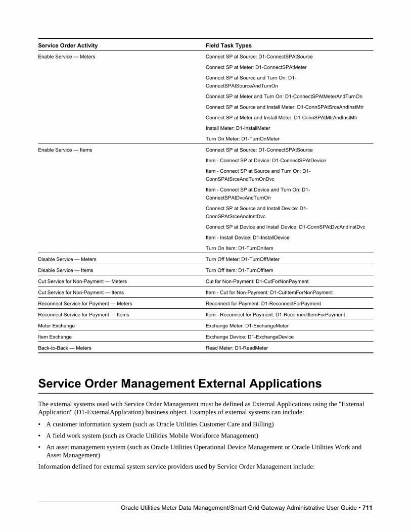
Oracle Utilities Meter Data Management/Smart Grid Gateway Administrative User Guide • 711
Service Order Activity Field Task Types
Enable Service — Meters Connect SP at Source: D1-ConnectSPAtSource
Connect SP at Meter: D1-ConnectSPAtMeter
Connect SP at Source and Turn On: D1-ConnectSPAtSourceAndTurnOn
Connect SP at Meter and Turn On: D1-ConnectSPAtMeterAndTurnOn
Connect SP at Source and Install Meter: D1-ConnSPAtSrceAndInstMtr
Connect SP at Meter and Install Meter: D1-ConnSPAtMtrAndInstMtr
Install Meter: D1-InstallMeter
Turn On Meter: D1-TurnOnMeter
Enable Service — Items Connect SP at Source: D1-ConnectSPAtSource
Item - Connect SP at Device: D1-ConnectSPAtDevice
Item - Connect SP at Source and Turn On: D1-ConnSPAtSrceAndTurnOnDvc
Item - Connect SP at Device and Turn On: D1-ConnectSPAtDvcAndTurnOn
Connect SP at Source and Install Device: D1-ConnSPAtSrceAndInstDvc
Connect SP at Device and Install Device: D1-ConnSPAtDvcAndInstDvc
Item - Install Device: D1-InstallDevice
Turn On Item: D1-TurnOnItem
Disable Service — Meters Turn Off Meter: D1-TurnOffMeter
Disable Service — Items Turn Off Item: D1-TurnOffItem
Cut Service for Non-Payment — Meters Cut for Non-Payment: D1-CutForNonPayment
Cut Service for Non-Payment — Items Item - Cut for Non-Payment: D1-CutItemForNonPayment
Reconnect Service for Payment — Meters Reconnect for Payment: D1-ReconnectForPayment
Reconnect Service for Payment — Items Item - Reconnect for Payment: D1-ReconnectItemForPayment
Meter Exchange Exchange Meter: D1-ExchangeMeter
Item Exchange Exchange Device: D1-ExchangeDevice
Back-to-Back — Meters Read Meter: D1-ReadMeter
Service Order Management External ApplicationsThe external systems used with Service Order Management must be defined as External Applications using the "ExternalApplication" (D1-ExternalApplication) business object. Examples of external systems can include:
• A customer information system (such as Oracle Utilities Customer Care and Billing)
• A field work system (such as Oracle Utilities Mobile Workforce Management)
• An asset management system (such as Oracle Utilities Operational Device Management or Oracle Utilities Work andAsset Management)
Information defined for external system service providers used by Service Order Management include:

Oracle Utilities Meter Data Management/Smart Grid Gateway Administrative User Guide • 712
• Our Name/ID in Their System: This is the value that the field work system uses to identify our system.
• Utility Device ID Type: This is the Device ID Type that will be used when communicating with the external applicationand it will be the assumed Device ID Type for any device identifiers sent from the external application.
• Utility Service Point ID Type: This is the Service Point ID Type that will be used when communicating with theexternal application and it will be the assumed Service Point ID Type for any service point identifiers sent from theexternal application.
Refer to Understanding External Applications and Configuring External Applications for more information about externalapplications.
Processing RolesThe external application’s processing roles define how data relevant to the field work system is sent and/or created.
Field work service providers can use the following processing roles:
• Activity Notification: Used to send notifications to subscribing and/or requesting systems about the status oforchestration and/or service order field activities.
• Appointment Request: Used to send a request for an appointment to the field work system.
• Cancelation Activity: Used to send notifications to requesting systems when canceling orchestration and/or serviceorder field activities.
• Collection Details: Used to retrieve details about collections processing (used with "Cut Service for Non-Payment" and"Restore Service for Payment" orchestration activities).
• Customer Contact: Used to send a contact to a customer regarding a service request
• Field Activity: Used to send a service order field activity to the field work system.
• Field Activity Completion: Used to send a notification regarding completion of a service order field activity.
• Interim Status Update: Used to send updates regarding the status of orchestration and service order field activities torequesting systems.
• Meter Exchange Mapping: Used to define how to define different types of meter exchanges based specific roles anddevice configurations. This can provide context to field crews to help ensure they install the correct type of device anddevice configuration when exchanging a meter.
• Response - Appointment: Used to send a request for an appointment to the field work system.
• Response - Fail: Used to send a response to an external system when Service Order Management fails to respond.
• Response - Missed Appointment: Used to send a response to the field work system when notification of a missedappointment is received.
• Response - Negative Acknowledgement: Used to send a negative acknowledgement response to an external system inthe event that a request is rejected.
• Response - Received: Used to send a response to an external system to acknowledge receipt of a request.
• Response - Success: Used to send a response to an external system when Service Order Management successfullyprocesses a request.
• Send Field Activity Remark: Used to send a service order field activity remark to a subscribing system
• Update Activity: Used to send notifications to requesting systems when updating orchestration and/or service order fieldactivities.
Oracle Utilities Meter Data Management/Smart Grid Gateway Administrative User Guide • 713
Chapter 15
Data Extracts
Analytics ConfigurationThis portal provides a bird's eye view of the configuration information for Oracle Utilities Analytics. It provides links andguidelines for the areas that need configuration to successfully run the extract transfer and load processes from OracleUtilities Analytics.
Refer to the Oracle Utilities Analytics Administration Guide for more information.
You can access the portal from the Admin > Analytics Configuration > Analytics Configuration.
The following zones may appear as part of the portal's Main tab page
• Bucket Configuration List. This zone lists bucket configurations to set up.
• BI-Related Business Objects Information. This zone lists additional control entities to set up.
The following zones may appear as part of the portal's OWB-Based ETL tab page
• Outbound Sync BOs and Algorithm List. This zone lists business objects and algorithms involved in the extractprocess.
• BI-Oriented Extendable Lookup. This zone lists extendable lookups to set.
• External Data Source Indicators List. This zone lists the external identifiers of the various sources for your analyticsdata.
Note: Service Point business objects can make use of the following System Events:
• Service Point Snapshot: This system event defines the algorithm used to create a snapshot of the Service Point for usewith Oracle Utilities Analytics. The Algorithm Entity for available algorithms is "SP (BO) - Snapshot."
• Usage Snapshot: This system event defines the algorithm used to create a usage snapshot of the Service Point for usewith Oracle Utilities Analytics. The Algorithm Entity for available algorithms is "SP (BO) - Usage Snapshot."
Oracle Utilities Meter Data Management/Smart Grid Gateway Administrative User Guide • 714
• Unreported Usage Analysis Snapshot: This system event defines the algorithm used to create a snapshot of the ServicePoint's consumption since the last usage transaction for use with Oracle Utilities Analytics. The Algorithm Entity foravailable algorithms is "SP (BO) - Unreported Usage Analysis Snapshot."
• SP VEE Exception Snapshot: This system event defines the algorithm used to create a snapshot of VEE exceptions forthe Service Point for use with Oracle Utilities Analytics. The Algorithm Entity for available algorithms is "SP (BO) -VEE Exception Snapshot."
Consumption Extract Type
Understanding Consumption Extract TypeThe Consumption Extract Type controls which service point's measurements are extracted for Oracle Utilities DataConnect,what type of measurement is extracted, and how the measurements are grouped into TOU periods (if preferred).
The Consumption Extract Type also controls the request type used for creating Consumption Extract Requests of this type,how frequent automated requests are created for incremental extract, the batch jobs that are triggered for extracting data andthe algorithms that extract, format, and write the data that is extracted.
Refer to the Oracle Utilities DataConnect integration section for more details on how this object is specifically put into use.
Configuring Consumption Extract TypeThis portal is used to display and maintain a Consumption Extract Type.
Refer to Understanding Consumption Extract Types for more information.
You can access the portal from the Admin > Integration > Consumption Extract Type.
The following zones may appear as part of the portal's Main tab page:
• Consumption Extract Type List: displays all of the Consumption Extract Types so you can choose the one you want todisplay in more detail
• Consumption Extract Type: shows the specific configuration for the selected Consumption Extract Type
Where UsedFollow this link to open the data dictionary where you can view the tables that reference D1_CONS_EXT_TYPE.

Oracle Utilities Meter Data Management/Smart Grid Gateway Administrative User Guide • 715
Chapter 16
Additional Independent Modules
Aggregation
Configuring an Out-of-the-box AggregationAggregation calculations should be run on an as needed basis. This can include running the following batches:
• Scanning for new aggregation dimension (D1-ADS): This process is applicable if the system is configured to useaggregation dimension scanners to detect new aggregation dimensions (such as a service point referencing a newtransformer for which an aggregator measuring component doesn't currently exist)
• Performing aggregation calculations (D2-AGG): this batch handles the summarization of measurement values in order tocreate aggregated measurements.
Note that aggregation calculations should precede usage transaction processing if aggregated values serves as input to thecalculation of bill determinants.
Refer to the About Aggregations section of the Oracle Utilities Meter Data Management/Smart Grid Gateway BusinessUser Guide for more information on this functionality. Refer to Aggregation Measuring Component Types for informationon Measuring Component Types provided for aggregation.
Understanding an Example Out-of-the-box AggregationThe Oracle Utilities Meter Data Management base package includes an aggregation that aggregates measurement quantitiesfor constituent measuring components based on postal code and service type dimensions. The table below outlines the typesof objects used in this aggregation, based on the steps outlined above), and the specific objects for each type.
Dependency Order Object Type Base Package Example
1 Aggregator Measuring Component BusinessObject
D2-Aggregator (Aggregator - Postal andService Type)
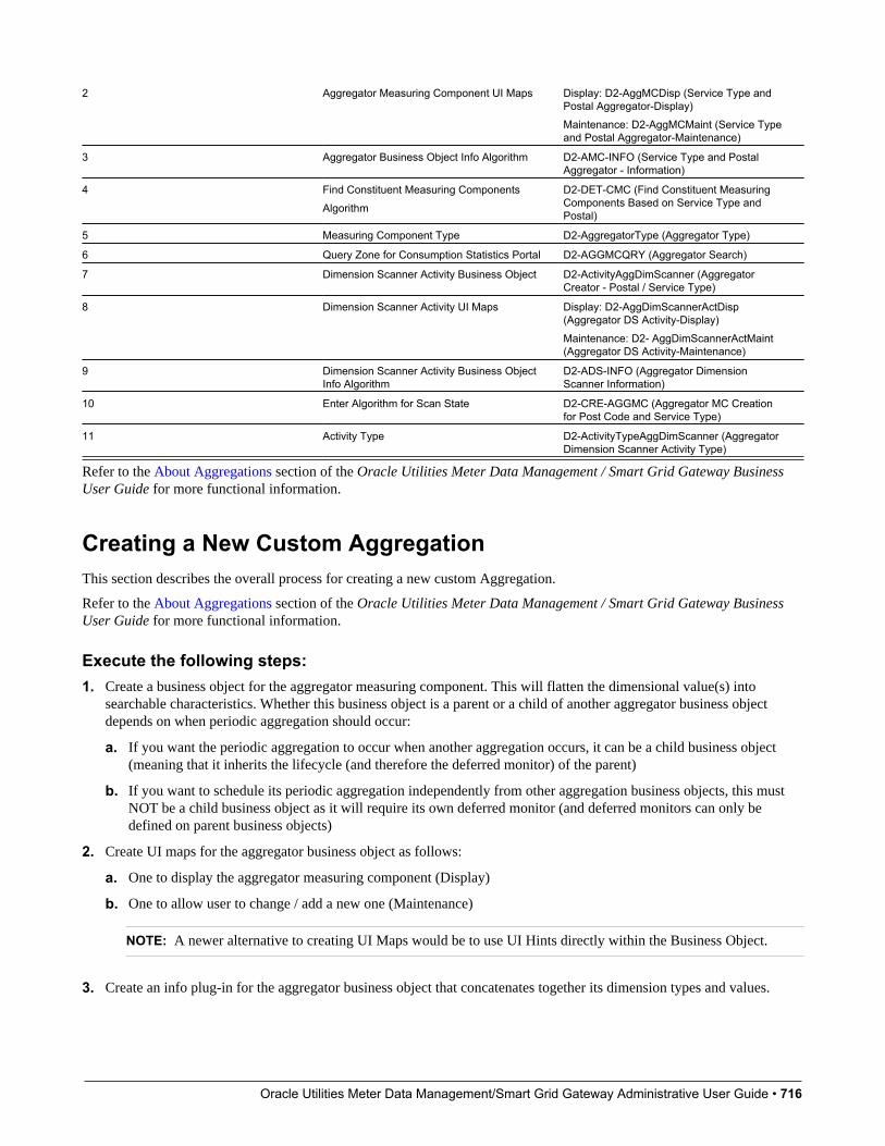
Oracle Utilities Meter Data Management/Smart Grid Gateway Administrative User Guide • 716
2 Aggregator Measuring Component UI Maps Display: D2-AggMCDisp (Service Type andPostal Aggregator-Display)Maintenance: D2-AggMCMaint (Service Typeand Postal Aggregator-Maintenance)
3 Aggregator Business Object Info Algorithm D2-AMC-INFO (Service Type and PostalAggregator - Information)
4 Find Constituent Measuring ComponentsAlgorithm
D2-DET-CMC (Find Constituent MeasuringComponents Based on Service Type andPostal)
5 Measuring Component Type D2-AggregatorType (Aggregator Type)
6 Query Zone for Consumption Statistics Portal D2-AGGMCQRY (Aggregator Search)
7 Dimension Scanner Activity Business Object D2-ActivityAggDimScanner (AggregatorCreator - Postal / Service Type)
8 Dimension Scanner Activity UI Maps Display: D2-AggDimScannerActDisp(Aggregator DS Activity-Display)Maintenance: D2- AggDimScannerActMaint(Aggregator DS Activity-Maintenance)
9 Dimension Scanner Activity Business ObjectInfo Algorithm
D2-ADS-INFO (Aggregator DimensionScanner Information)
10 Enter Algorithm for Scan State D2-CRE-AGGMC (Aggregator MC Creationfor Post Code and Service Type)
11 Activity Type D2-ActivityTypeAggDimScanner (AggregatorDimension Scanner Activity Type)
Refer to the About Aggregations section of the Oracle Utilities Meter Data Management / Smart Grid Gateway BusinessUser Guide for more functional information.
Creating a New Custom AggregationThis section describes the overall process for creating a new custom Aggregation.
Refer to the About Aggregations section of the Oracle Utilities Meter Data Management / Smart Grid Gateway BusinessUser Guide for more functional information.
Execute the following steps:1. Create a business object for the aggregator measuring component. This will flatten the dimensional value(s) into
searchable characteristics. Whether this business object is a parent or a child of another aggregator business objectdepends on when periodic aggregation should occur:
a. If you want the periodic aggregation to occur when another aggregation occurs, it can be a child business object(meaning that it inherits the lifecycle (and therefore the deferred monitor) of the parent)
b. If you want to schedule its periodic aggregation independently from other aggregation business objects, this mustNOT be a child business object as it will require its own deferred monitor (and deferred monitors can only bedefined on parent business objects)
2. Create UI maps for the aggregator business object as follows:
a. One to display the aggregator measuring component (Display)
b. One to allow user to change / add a new one (Maintenance)
NOTE: A newer alternative to creating UI Maps would be to use UI Hints directly within the Business Object.
3. Create an info plug-in for the aggregator business object that concatenates together its dimension types and values.
Oracle Utilities Meter Data Management/Smart Grid Gateway Administrative User Guide • 717
4. Create a "Find Constituent Measuring Components" algorithm and plug it on the aggregator business object. This willbe passed the aggregator measuring component and the from and to date/times. It will insert the constituent measuringcomponent IDs and the respective from / to date-time of each onto a temporary table.
5. Create a measuring component type instance and reference the new aggregator measuring component business object(as well as the types of constituent measuring component types that should be aggregated).
6. Create a query zone for Consumption Statistics search to allow users to find the aggregator measuring component.
Optional steps:
1. Create a business object for the dimension scanner activity. This should be a child business object of the base packagedimension scanner business object.
2. Create UI maps for the activity business object, as follows:
a. One to display the dimension scanner activity (Display).
b. One to allow users to change/add a new one (Maintenance).
NOTE: A newer alternative to creating UI Maps would be to use UI Hints directly within the Business Object.
3. Create an info plug-in that will describe what it scans.
4. Create an Enter algorithm on the Scan state that finds distinct combinations of the dimensional values and creates newaggregator measuring components when new ones are detected.
NOTE: You can reuse the base package deferred monitor batch control called Aggregation Dimension ScannerMonitor (D1-ADS).
Consumption Synchronization
Configuring Consumption SynchronizationNOTE: Refer to Introduction to Consumption Sync for additional functional information about how consumptionsynchronization works.
Keeping consumption synchronized between two measuring components that meter the same quantity but at differentfrequencies is a complicated task. As such the configuration for this process is diffuse and requires settings across severalkey areas of the system to be aligned. This section will help guide you through the process of configuring consumptionsynchronization.
The consumption synchronization process is really a collection of processes within Oracle Utilities Meter Data Managementthat all work together to ensure that quantities between related channels remain consistent:
• Estimation VEE Rules: several rules align consumption between related channels. These rules allow estimations tobe refined based on higher quality measurements from a related channel. These rules are core to the consumptionsynchronization process. In simple scenarios where a few intervals are missing for an interval measuring componentthese rules are all that are necessary for synchronization with the related channel (note: it requires that the relatedchannels data for that same time period has already been processed through to final measurements). For moreinformation on these rules please visit the following sections:
• Interval Adjustment from Scalar
Oracle Utilities Meter Data Management/Smart Grid Gateway Administrative User Guide • 718
• Scalar Calculation from Interval
• Scalar Proration
• Sum Check
• Final Measurement Validation
NOTE: Refer to About IMD Estimations for more information about these rules
• Periodic Estimation: both the interval and scalar variations of periodic estimation play an important role in consumptionsynchronization by ensuring that both channels of data are without gaps. In simple scenarios where one channel ismissing data and the other is not periodic estimation is all that is require to produce synchronized consumption. It isimportant to note that this process itself does not perform estimations but rather it is responsible for creating estimationinitial measurements to trigger the estimation VEE rules.
• Consumption Synchronization Activities: these activities work to fix alignment issues that occur when data for therelated channels are processed out of order or when there are complex outage scenarios. These activities are createdwhen higher quality data is received for one channel and the related channel has measurements that are eligible to berecalculated and adjusted to align the total consumption for the period across the two channels. It is important to note thatthis process itself does not perform estimations but rather it is responsible for creating estimation initial measurements totrigger the estimation VEE rules.
Device Configuration TypeAs a default the system will not generate consumption synch activities for related measuring components. Turning onconsumption synchronization activities is done through a few key fields on the device configuration type:
• Keep Consumption Reference MC in Sync: defines if the related MCs should be kept in sync. It can be configuredto provide a one way synchronization from primary to secondary or a two way synchronization between primary andsecondary.
• Minimum Condition to Sync Primary MC: when the secondary measuring component can initiate synchronization ofthe primary this provides an ability to limit those situations to when the incoming data is of a minimum quality.
• Sum Check VEE Exception Type: provides further ability to limit initiation of synchronization. When configuredthe synchronization activities will only be created when the initial measurement being processed encounters a VEEexception of the type configured. More specifically, a sum check VEE exception which will indicate that the twochannels are out of synch by a minimum tolerance amount. This can be used to avoid synchronization either when thereis no difference between the channels or when there is only a small difference between the channels.
NOTE: Additional detail about these fields can be found in the embedded help for the device configuration type.
Register Auto-Read Measuring Component TypeThe configuration available for the register auto-read measuring component type has an indirect impact on the consumptionsynchronization process. This configuration is primarily intended to allow for a register to re-evaluate previously createdestimations when new more accurate readings are received even when no related measuring components exist. Wherethis has impact to the consumption synchronization process is that when a new scalar reading is received after a period ofestimation it will result in the time period for that new initial measurement being expanded into the past. This is because anyestimates prior to this new higher quality initial measurement will be logically removed and the start reading for the initialmeasurement will in turn be the last non-estimated measurement prior to the initial measurement. This creates an initialmeasurement that spans the entire period for which estimations exist and as a result when a consumption synchronizationactivity is generated it will result in that same period of time being re-evaluated on the related measuring component.
This functionality is controlled by a few key fields on the register auto-read measuring component type:
• Ignore Estimates as IMD Start Reading: controls whether estimates directly previous to newly received incominginitial measurement should be logically removed when that newly received initial measurement data is non-estimated.

Oracle Utilities Meter Data Management/Smart Grid Gateway Administrative User Guide • 719
• Flag Future Estimates as Do Not Use: controls whether estimates that come directly after newly received incominginitial measurements should be logically removed when that newly received initial measurement data is non-estimated
• Actuals or Corrections Initial Re-Estimation: works in tandem with the above two fields. When either scenario resultsin measurements being logically removed this field, when turned on, will reset the last contiguous measurement date/time for the measuring component making it eligible once more for periodic estimation. With the end result being thatthose estimated measurements that were removed would recreated as new estimates.
Measuring ComponentsIn order for consumption synchronization to work it must know that two measuring components are related in a waythat indicates they are measuring the same consumption. This is achieved by configuring the "Consumption ReferenceMeasuring Component" field on the measuring component.
Not only does this establish the relationship but it also establishes which measuring component is considered to be primaryand which is considered to be secondary.
A measuring component is considered to be secondary when it holds the relationship to the Consumption Check MeasuringComponent (the primary measuring component).
For example, consider the following related measuring components.
• Scalar Measuring Component: ER-SM-007 / 1 / Electric kWh Daily
• Interval Measuring Component: ER-SM-007 / 2 / Electric kWh 60min
If the scalar measuring component is the primary measuring component, it does NOT specify a "Consumption ReferenceMeasuring Component", and the interval measuring component specifies the scalar measuring component as the"Consumption Reference Measuring Component".
If the interval measuring component is the primary measuring component, it does NOT specify a "Consumption ReferenceMeasuring Component", and the scalar measuring component specifies the interval measuring component as the"Consumption Reference Measuring Component".
It is important to note that pending initial measurements for the secondary measuring component are processed by the D1-IMD batch process after the initial measurements for the primary measuring component. This ensures that the primarymeasuring component's final measurements will be available to the secondary measuring component's initial measurementsVEE process to provide better quality estimations and validations.
Initial Load and Manual Initial Measurement AlgorithmsKey to the consumption synchronization process are the algorithms that reside on initial load and manual initialmeasurements for both scalar and interval measuring components. These algorithms contain logic to identify finalmeasurements on a related channel that are consumption synchronization eligible (typically estimated).
These algorithms allow definition of:
• The consumption synchronization activity created
• The condition range that defines consumption synchronization eligible final measurements
Please refer to the algorithm type descriptions for more information:
Algorithm Type Description Where used
D1-UPD-DTMC Update Latest Measurement Date/Time onMC with Consumption Sync
D1-InitialLoadIMDInterval
D1-ManualIMDInterval
D1-UDTSCMCRE Update Latest Measurement Date/Time onScalar MC with Consumption Sync
D1-InitialLoadIMDScalar
D1-ManualIMDScalar
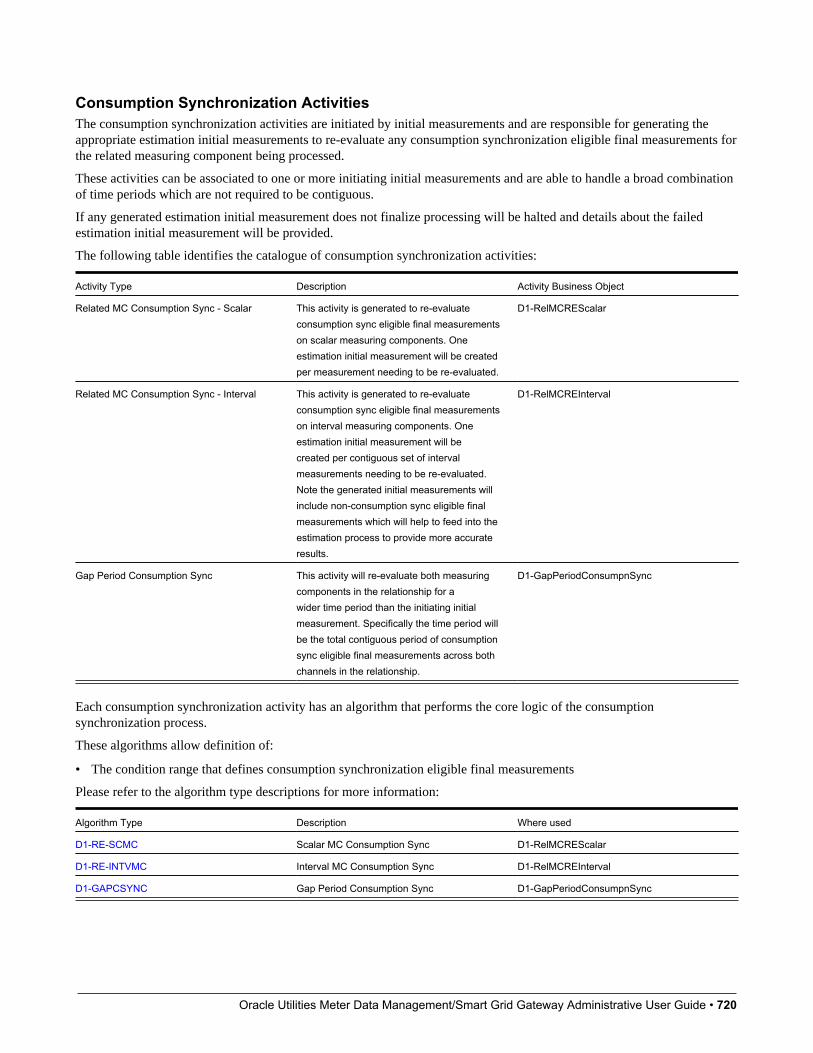
Oracle Utilities Meter Data Management/Smart Grid Gateway Administrative User Guide • 720
Consumption Synchronization ActivitiesThe consumption synchronization activities are initiated by initial measurements and are responsible for generating theappropriate estimation initial measurements to re-evaluate any consumption synchronization eligible final measurements forthe related measuring component being processed.
These activities can be associated to one or more initiating initial measurements and are able to handle a broad combinationof time periods which are not required to be contiguous.
If any generated estimation initial measurement does not finalize processing will be halted and details about the failedestimation initial measurement will be provided.
The following table identifies the catalogue of consumption synchronization activities:
Activity Type Description Activity Business Object
Related MC Consumption Sync - Scalar This activity is generated to re-evaluateconsumption sync eligible final measurementson scalar measuring components. Oneestimation initial measurement will be createdper measurement needing to be re-evaluated.
D1-RelMCREScalar
Related MC Consumption Sync - Interval This activity is generated to re-evaluateconsumption sync eligible final measurementson interval measuring components. Oneestimation initial measurement will becreated per contiguous set of intervalmeasurements needing to be re-evaluated.Note the generated initial measurements willinclude non-consumption sync eligible finalmeasurements which will help to feed into theestimation process to provide more accurateresults.
D1-RelMCREInterval
Gap Period Consumption Sync This activity will re-evaluate both measuringcomponents in the relationship for awider time period than the initiating initialmeasurement. Specifically the time period willbe the total contiguous period of consumptionsync eligible final measurements across bothchannels in the relationship.
D1-GapPeriodConsumpnSync
Each consumption synchronization activity has an algorithm that performs the core logic of the consumptionsynchronization process.
These algorithms allow definition of:
• The condition range that defines consumption synchronization eligible final measurements
Please refer to the algorithm type descriptions for more information:
Algorithm Type Description Where used
D1-RE-SCMC Scalar MC Consumption Sync D1-RelMCREScalar
D1-RE-INTVMC Interval MC Consumption Sync D1-RelMCREInterval
D1-GAPCSYNC Gap Period Consumption Sync D1-GapPeriodConsumpnSync
Oracle Utilities Meter Data Management/Smart Grid Gateway Administrative User Guide • 721
Periodic EstimationThe algorithm that initiates periodic estimation which is plugged in to the Smart Meter device business object has a keyconfiguration setting related to consumption synchronization:
• MC Type to Process First: determines whether interval or scalar measuring components should be estimated first. Thisshould be set to process whichever measuring component type is considered to be primary first.
Please refer to the algorithm type description for more information:
Algorithm Type Description Where used
D1-PERESTM Periodic Estimation D1-SmartMeter
Related Batch ControlsThere are a few batches involved with Consumption Synchronization:
• Related MC Consumption Sync (D1-RMCRE): this processes any pending consumption synchronization activities.
• Related MC Consumption Sync - Retry Act (D1-RMCRR): this retries any consumption synchronization activitiesthat fail to the Issue Detected state.
Dashboards
Configuring the MDM Operational DashboardThis section describes the process for configuring the MDM Operational Dashboard.
Refer to the Using the MDM Operational Dashboard section of the Oracle Utilities Meter Data Management/Smart GridGateway Business User Guide for a information on this functionality.
Configuration for the MDM Operational Dashboard is performed by adding or changing a Master Configuration. You canaccess the portal from the Admin > General > Master Configuration.
Once the Master Configuration search screen returns, configure both the MDM Operational Dashboard Configurationrecord. Use the Add button beside the record to configure for the first time. If a record has already been added, then clickthe Edit button instead. Use the embedded help to guide you through the meaning of each configuration field.
This dashboard also leverages a method of pre-staging data known as Statistics Snapshots. Refer to the FrameworkAdministrative User Guide for more information on Statistics Snapshots. For additional information see About Statistics inthe Oracle Utilities Application Framework Administrative User Guide.
A method for tracking Performance Targets (also known as Service Level Agreements) is available within the MDMOperational Dashboard as well. To understand how to set up Performance Targets, refer to About Performance Targets inthe Oracle Utilities Application Framework Administrative User Guide. The Performance Targets you configure will thenbe leveraged on the Batch Performance and/or Database tabs of the MDM Operational Dashboard.
Configuring the Service Order Operational DashboardThis section describes the process for configuring the Service Order Operational Dashboard.
Refer to the Using the Service Order Operational Dashboard section of the Oracle Utilities Meter Data Management /Smart Grid Gateway Business User Guide for more functional information.

Oracle Utilities Meter Data Management/Smart Grid Gateway Administrative User Guide • 722
Configuration for the Service Order Operational Dashboard is performed by adding or changing a Master Configuration.You can access the portal from the Admin > General > Master Configuration.
Once the Master Configuration search screen returns, locate the Service Order Management Master Configurationrecord. Use the Add button beside the record to configure for the first time. If a record has already been added, thenclick the Edit button instead. The Chart Options section is the primary area for adding configuration that will affect thedashboard. Use the embedded help to guide you through the meaning of each configuration field.
Configuring the Service Order Trends DashboardThis section describes the process for configuring the Service Order Trends Dashboard.
Refer to the Using the Service Order Trends Dashboard section of the Oracle Utilities Meter Data Management / SmartGrid Gateway Business User Guide for more functional information.
Configuration for the Service Order Trends Dashboard is performed by adding or changing a Master Configuration. Youcan access the portal from the Admin > General > Master Configuration.
Once the Master Configuration search screen returns, locate the Service Order Management Master Configurationrecord. Use the Add button beside the record to configure for the first time. If a record has already been added, thenclick the Edit button instead. The Chart Options section is the primary area for adding configuration that will affect thedashboard. Use the embedded help to guide you through the meaning of each configuration field.
Measurement Reprocessing
Configuring Measurement ReprocessingThis section describes the process for configuring Measurement Reprocessing.
Refer to the About Measurement Reprocessing section of the Oracle Utilities Meter Data Management / Smart GridGateway Business User Guide for more functional information.
Activity Type ConfigurationConfiguration for Measurement Reprocessing is performed by adding or changing an Activity Type. You can access theportal from the Admin > Communication > Activity Type.
Once the Activity Type search screen returns, locate the following records:
• Measurement Reprocess Activity - Interval: this Activity Type handles measurement reprocessing for intervalMeasuring Components.
• Measurement Reprocess Activity - Scalar: this Activity Type handles measurement reprocessing for scalar MeasuringComponents.
Use the Add button beside the record to configure for the first time. If a record has already been added, then click the Editbutton instead. Use the embedded help to guide you through the meaning of each configuration field. By adding theseActivity Types you are activating the process within Oracle Utilities Meter Data Management that will monitor changes toeither the Measuring Component multiplier changes or Install Event installation constant. If either of these attributes changefor a device, then a new Activity will be created that attempts to reprocess the measurements for the affected period.
Related Batch ControlsThere are a few batches involved with Measurement Reprocessing:
Oracle Utilities Meter Data Management/Smart Grid Gateway Administrative User Guide • 723
• Measurement Reprocessing Monitor (D1-MRAC): this processes any new Measurement Reprocessing activities thatare created.
• Measurement Reprocessing - Retry Monitor (D1-MRER): this retries any Measurement Reprocessing activities thatfail to the Issue Detected state.
Information Lifecycle Management (ILM)
Understanding Information Lifecycle Management (ILM)Information Lifecycle Management (ILM) is a separately licensable component of Oracle Utilities Meter Data Managementthat works in tandem with Oracle database feature of the same name.
For further background on the overall ILM process see the Information Lifecycle Management chapter of the OracleUtilities Application Framework Administrative User Guide.
This section provides an overview of the components used by the Information Lifecycle Management functionality,including:
• ILM-Enabled Maintenance Objects: Single Retention Period
• ILM-Enabled Maintenance Objects: Multiple Retention Periods
• Adjusting Eligibility of Non-Final Transactions
• Archive Eligibility Hierarchy
• Multiple Retention Period Eligibility Crawling Strategies
Refer to the Information Lifecycle Management chapter of the Oracle Utilities Application Framework Administrative UserGuide for general information about how ILM works with OUAF applications.
ILM-Enabled Maintenance Objects: Single Retention PeriodsThe majority of Maintenance Objects support a single retention period. They can either inherit the system wide retentiondays that are configured on the ILM Configuration master configuration or they can have a retention period specified via theMaintenance Object option ILM Retention Period in Days.
For these objects either the Maintenance Object specific retention period or the system wide retention period will apply toall transactions.
ILM-Enabled Maintenance Objects: Multiple Retention PeriodsFor several Maintenance Objects the retention period may vary based on the type of transaction. For example, initialmeasurement data for non-billed units of measure such as voltage might be archived much more rapidly than measurementsthat feed into the production of billing determinants.
These maintenance objects are differentiated from the single retention period maintenance objects in a few ways:
• The primary table for the entity has an additional column Retention Period (RETENTION_PERIOD) that captures theretention period in days for each transaction. This value is populated based on the ILM Configuration - MDM masterconfiguration.
• There is additional configuration available on the ILM Configuration -MDM master configuration to define multipleretention periods by maintenance object specific criteria
• Initial Measurement Data: retention periods can be specified by type of IMD (Interval vs Scalar), and primary UOM ofthe measuring component
• Device Events: retention periods can be specified by device event type category
Oracle Utilities Meter Data Management/Smart Grid Gateway Administrative User Guide • 724
• Activities: retention periods can be specified by activity type category
• There is a special ILM Crawler batch that supports crawling transactions by their specific retention periods
• A combination of each transactions ILM Date and Retention Period are considered when identifying records to evaluatefor eligibility. Refer to batch controls ILM Crawler - Device Event (D1-DECRL), ILM Crawler - IMD (D1-IMDCL), orILM Crawler - Activity (D1-ACTCR) for more details.
• There is an additional maintenance object option ILM Date Partition Months which feeds into the ILM Crawler batch todelay processing until all records on a partition would be eligible. This is explained later in this section under the headerMultiple Retention Period Eligibility Crawling Strategies.
Adjusting Eligibility of Non-Final TransactionsAs delivered Oracle Utilities Meter Data Management maintenance objects allow non-final transactions to be eligible forarchive. This is a logical approach when transactional data has a very long retention period (e.g. 3 year old non-final InitialMeasurement Data is unlikely to have relevance and in many circumstances shouldn't be finalized).
If non-final transactions should not be eligible for archive this can be controlled at either the Maintenance Object (MO) orBusiness Object (BO) level:
• MO - ILM Restrict By Status (Y/N): Setting this to "Y" opts into the ability to restrict archiving by status, this isrequired to be set for either of the MO or BO level restrictions to be considered. To enforce the status it requires thateither the ILM Restrict By BO Final Status (Y/N) or ILM Final Status Field Value options be configured as well.
• MO - ILM Restrict By BO Final Status (Y/N): Setting this to "Y" indicates the transactions for the MO must be in afinal status to be eligible for ILM. A status is considered to be final based on the BO lifecycle configuration. This canbe overridden by the BO option Final Status Required for Archive (Y/N). This is only applicable for an MO that ismaintained by business objects.
• BO - Final Status Required for Archive (Y/N): Setting this to "Y" indicates the transactions for this particular BOmust be in a final status. This setting overrides the MO level ILM Restrict By BO Final Status (Y/N).
The following table helps to illustrate how these three settings impact whether a given transaction must be in a final status:
• MO: ILM Restrict By Status • MO: ILM Restrict By BO FinalStatus
• BO: Final Status Required forArchive
• Final Status Required forEligibility?
• N • Y • Y • N
• N • Y • N • N
• N • N • Y • N
• Y • N • N • N
• Y • Y • N • N
• Y • Y • Y • Y
• Y • N • Y • Y
• Y • Y • Not Provided • Y
• Y • N • Not Provided • N
NOTE: There are a few MOs that do not support the BO level setting. To best understand how these fields areinterpreted for an MO refer to the detailed description of the algorithm plugged into the ILM Eligibility system event for
Oracle Utilities Meter Data Management/Smart Grid Gateway Administrative User Guide • 725
the MO. For example, the generic ILM Eligibility Based on Status (F1-ILMELIG) algorithm does not support the BOlevel override option.
Archive Eligibility HierarchyThe table below summarizes details of the eligibility algorithms for each maintenance object supported by ILM. Informationon this table includes:
• Cascaded By: Indicates how archiving for transactions for the maintenance object is initiated. For example, device eventscan be archived by themselves or as part of a related activity.
• ILM Date Computation: Indicates the type(s) of transactions that impact the calculation of the ILM Date for transactionsfor the maintenance object. "Itself" indicates that the ILM date is not impacted by other transactions.
• Specific Eligibility Considerations: Indicates specific considerations used by the eligibility algorithm.
• Cascaded Transactions: Indicates other transactions that are archived when transactions for the maintenance object arearchived. For example, VEE exceptions are archived with initial measurements.
Maintenance Object Cascaded By ILM Date Computation Specific EligibilityConsiderations
Cascaded Transactions
Initial Measurement Create date VEE Exceptions must beeligible
Associated Related MCSynchronization activitymust be complete
VEE Exceptions
VEE Exception Initial Measurement Earlier of related InitialMeasurement or VEEException Create Date
Related Service IssueMonitor must be complete
Usage Transaction The latest create datefor all related usagetransactions
All related usagetransactions must beeligible for archiving
Related UsageTransactions
Device Event Activity Create date
Superseded by pairedevent create date if earlier(where applicable)
Related paired eventsmust be eligible
Related service issuemonitor must be complete
Related activity must becomplete
Activity Parent activity Create date
Superseded Deviceevent, child activity, orcompletion event createdate supersede (whereapplicable)
Cascaded transactionsmust be eligible
Command requests mustnot be associated to anon-final service issuemonitor
Command requests mustnot be associated to aninstall event on off historyentry
Child activities
Device events
Outboundcommunications
Inbound communications
Completion events
Outbound Communication Activity Create Date
Superseded by initiatingactivity's create date(where applicable)
Inbound communication

Oracle Utilities Meter Data Management/Smart Grid Gateway Administrative User Guide • 726
Inbound Communication Outbound Communication Create date
Superseded by initiatingoutbound communicationcreate date (whereapplicable)
Device events
Proactive Archive Eligibility for Transactional DataSome types of transaction data, including Device Events, Initial Measurement Data, and Usage Transactions can beanalyzed for archive eligibility as they are received rather than waiting until their retention period has expired. This meansthat these records are judged ready to be archived as they are created and do not need to be read, analyzed, and updatedduring the ILM crawling process. This greatly reduces the number of records to be crawled at the end of the retention periodand shortens the window of time required for ILM crawling. This section outlines how the ILM Archive switch (ILM_ARCH_SW) is set to “Y” (Yes) for records of these types as part of their initial processing.
• Device Events:
• The ILM Archive switch is set to “Y” for device events that meet the following criteria:
• No service issue monitors were created for the device event
• The device event is not a paired device event
• The ILM Archive switch is set to “Y” for device events via the following algorithms:
• Create Service Issue Monitor from Device Event (D1-DVCEVTSIM)
• Create Service Issue Monitor from Device Event for Paired Event (D1-PRDVEVSIM)
• Initial Measurement Data:
• The ILM Archive switch is set to “Y” by default for initial measurements (this is a different approach than the otherrecord types).
• The ILM Archive switch is set to “N” for initial measurements that meet the following criteria:
• A consumption synchronization activity has been created for the initial measurement
• A service issue monitor initiated from a VEE exception related to the initial measurement
• The ILM Archive switch is set to “N” for initial measurements that meet the above criteria via the followingalgorithms:
• Update Latest Measurement Date/Time on Scalar MC with Consumption Sync (D1-UDTSCMCRE)
• Update Latest Measurement Date/Time on MC with Consumption Sync (D1-UPD-DTMC)
• Create Service Issue Monitor from VEE Exception (D2-VEEEXCSIM)
• Usage Transactions:
• The ILM Archive switch is set to “Y” when a usage transaction enters the “Sent” or “Discarded” state (or the“Calculated” or “Discarded” states for a sub-usage transaction ) via the following algorithms:
• Send Usage (D2–SEND-USG)
• Set ILM Switch to ‘Y’ (D1-SETILMSWY)
Multiple Retention Period Eligibility Crawling StrategiesWhen multiple retention periods are defined for a maintenance object each record will have its retention period written tothe database at the time of record creation. This retention period is then used to identify when the record will be ready foreligibility evaluation (aka crawling).

Oracle Utilities Meter Data Management/Smart Grid Gateway Administrative User Guide • 727
NOTE: As specified in the Oracle Utilities Meter Data Management Database Administrator's Guide each uniqueretention period for the maintenance object will be a sub-partition within a given ILM date partition.
The system supports two methodologies for doing so:
• Evaluate Individual Records:
• This is our default approach
• This is the standard approach to evaluating ILM retention for all maintenance objects with a single retention period
• The ILM date for each record will be compared against the current date less the retention period for that type of record.Simply stated, any records older than the retention period will be evaluated for eligibility.
• In this option we will process a portion of a partition each day and only once we had processed the entire partition wouldthe DBA be able to take an archiving action on the partition
• This results in many visits to the partition to determine eligibility
• The image below illustrates how the evaluate individual records method will crawl one day of records on a partitionand sub-partition each day until the retention period for the last day of the partition had expired. All records would thenbe archived together when the last day of the partition was marked as eligible. This results in daily processing of smallamounts of records but frequent visits to the partition.
• Evaluate the Entire Partition
• This option will be enabled by configuring the ILM Date Partition Months in the maintenance object options
• In this option all records on a ILM date partition retention period sub-partition will be evaluated at the same time.
• For example, for a monthly partitioning strategy in the month of January we would not evaluate any records in theJanuary partition until January 31st had reached the end of its retention period.
• This means that we would evaluate the 1st through the 31st all at one time
• This option should typically result in a single visit to the partition to determine eligibility
•• The image below illustrates how the evaluate entire partition method will only crawl records from a given partition and
sub-partition when all records on that partition are eligible to be evaluated. Therefore, when the last day of the partition isready to be evaluated the entire partition will be evaluated. This results in periodic processing with, and in many cases, asingle visit to the partition for ILM purposes.
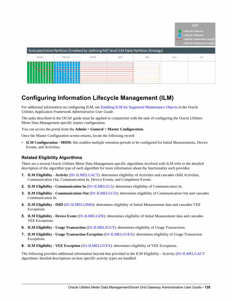
Oracle Utilities Meter Data Management/Smart Grid Gateway Administrative User Guide • 728
Configuring Information Lifecycle Management (ILM)For additional information on configuring ILM, see Enabling ILM for Supported Maintenance Objects in the OracleUtilities Application Framework Administrative User Guide.
The tasks described in the OUAF guide must be applied in conjunction with the task of configuring the Oracle UtilitiesMeter Data Management specific master configuration.
You can access the portal from the Admin > General > Master Configuration.
Once the Master Configuration screen returns, locate the following record:
• ILM Configuration - MDM: this enables multiple retention periods to be configured for Initial Measurements, DeviceEvents, and Activities.
Related Eligibility AlgorithmsThere are a several Oracle Utilities Meter Data Management specific algorithms involved with ILM refer to the detaileddescription of the algorithm type of each algorithm for more information about the functionality each provides:
1. ILM Eligibility - Activity (D1-ILMELGACT): determines eligibility of Activities and cascades child Activities,Communication Out, Communication In, Device Events, and Completion Events.
2. ILM Eligibility - Communication In (D1-ILMELGCI): determines eligibility of Communication In.
3. ILM Eligibility - Communication Out (D1-ILMELGCO): determines eligibility of Communication Out and cascadesCommunication In.
4. ILM Eligibility - IMD (D1-ILMELGIMD): determines eligibility of Initial Measurement data and cascades VEEExceptions.
5. ILM Eligibility - Device Event (D1-ILMELGDE): determines eligibility of Initial Measurement data and cascadesVEE Exceptions.
6. ILM Eligibility - Usage Transaction (D1-ILMELIGUT): determines eligibility of Usage Transactions.
7. ILM Eligibility - Usage Transaction Exception (D1-ILMELGUEX): determines eligibility of Usage TransactionExceptions.
8. ILM Eligibility - VEE Exception (D1-ILMELGVEX): determines eligibility of VEE Exceptions.
The following provides additional information beyond that provided in the ILM Eligibility - Activity (D1-ILMELGACTalgorithms' detailed descriptions on how specific activity types are handled:
Oracle Utilities Meter Data Management/Smart Grid Gateway Administrative User Guide • 729
• Request Orchestration Activities: Request orchestrations also archive any child activities that were created, and thosechild activities archive any child activities or data (completion events, device events, etc.).
• Field Activities / Command Activities: Field activities and command request activities are archived either as part of arequest orchestration or by themselves. When a field activity/command request is archived, it also archives any of thefollowing child transactions:
• Update/Cancel Orchestrators
• Communication Out
• Communication In
• Completion Event
• Non-Dispatchable Activities: Non-Dispatchable activities archived either as part of a request orchestration or bythemselves. When a non-dispatchable activity is archived it also archives child completion events.
• Orchestration Maintenance Activities: Orchestration Maintenance activities are only archived by themselves if they donot have a related activity. When an orchestration maintenance activity is archived it also archives any of the followingchild transactions:
• Communication Out
• Communication In
• Device Event Activities: Presently device event activities are limited to outages which have an initiating and an endingdevice event. These types of activities cannot be archived until their related device events are either archived or ready toarchive. However the device events do not have to wait for the activity to archive so the device events are not updatedwith the activity's ILM date.
• Bulk Activities: Bulk Activities are comprised of the Bulk Header and the Bulk Request/Response, and depending onhow the header was created there will be one header to many bulk requests/responses. The Bulk Header will only beeligible for archive if all related Bulk Request activities are also eligible for archiving. All related bulk activities arearchived together. Bulk activities also generate one-to-many command request activities. Those individual commandactivities are archived separately.
• Payload Statistics Activities: Payload Statistics activities can either be the Payload Summary record or the PayloadStatistic record. Eligibility is based on the Payload Statistics activity, which is only be eligible for archiving if all therelated Payload Summary and Payload Error activities are also eligible for archiving. These activities are only archivedby themselves if they do not have a related activity. Otherwise both the payload statistics and the payload summaryactivities are archived at the same time.
• Extract Request Activities: These activities are used to request data from the head-end system on a periodic basis. Extract
request activities should be in a final state prior to being archived.
• Other Activities: Other types of activities can be archived provided they do not require any special logic for handlingfor archiving purposes, such as checking for related data. These activity types can archive without checking relatedtransactions:
• Consumption Sync
• Dimension Scanner
• Error Activity
• Measurement Quantity (deprecated)
• Meter Read Download Activity
• Suppression
• Usage Transaction Correction Processor

Oracle Utilities Meter Data Management/Smart Grid Gateway Administrative User Guide • 730
In the event that your implementation uses custom activity types that require special handling, a custom algorithm should becreated and added prior to the base package algorithm to preemptively handle the activity type category.
Related Batch ControlsThere are a several Oracle Utilities Meter Data Management specific batch controls involved with ILM:
1. ILM Crawler - Activity (D1-ACTCR): identifies and executes eligibility evaluation for Activities. This batch controlsupports multiple retention periods.
2. ILM Crawler - Communication In (D1-CICRL): identifies and executes eligibility evaluation for Communication In.
3. ILM Crawler - Communication Out (D1-COCRL): identifies and executes eligibility evaluation for CommunicationOut.
4. ILM Crawler - Device Event (D1-DECRL): identifies and executes eligibility evaluation for Device Events.
5. ILM Crawler - IMD (D1-IMDCL): identifies and executes eligibility evaluation for Initial Measurement Data. Thisbatch control supports multiple retention periods.
6. ILM Crawler - Usage Transaction Exception (D1-UEXCL):identifies and executes eligibility evaluation for UsageTransaction Exceptions.
7. ILM Crawler - Usage Transaction (D1-UTCRL): Identifies and executes eligibility evaluation for UsageTransactions.
8. ILM Crawler - VEE Exception (D1-VEXCL):Identifies and executes eligibility evaluation for VEE Exceptions.
For additional details see the Batch Processes section the Oracle Utilities Application Framework Administrative UserGuide.
Outage Storm Mode
Configuring Outage Storm ModeThis section describes the process for configuring Outage Storm Mode.
NOTE: Refer to the About Outage Storm Mode section of the Oracle Utilities Meter Data Management/Smart GridGateway Business User Guide for more functional information.
Master Configuration settingsConfiguration for Outage Storm Mode is performed by adding or changing a Master Configuration. You can access theportal from the Admin > General > Master Configuration.
Once the Master Configuration search screen returns, locate the MDM Master Configuration. Use the Add buttonbeside the record to configure for the first time. If a record has already been added, then click the Edit button instead. TheEstimation Eligibility For Widespread Outages section is the primary section that needs to be configured for OutageStorm Mode to be enabled. Use the embedded help to guide you through the meaning of each configuration field.
Setup Meter Communication Tracking AggregationAs part of Outage Storm Mode, aggregations are performed to determine the percentage of meter communication that hasoccurred for an area. The following configuration supports this:
1. Access the portal for Measuring Component Type through Admin > Device > Measuring Component Type.Add a new Measuring Component Type using the Meter Communication Tracking Aggregator Type (D2-

Oracle Utilities Meter Data Management/Smart Grid Gateway Administrative User Guide • 731
MtrCommTrckngAggregatorType) business object. Follow the embedded help provided for each section. Two areaslisted below are crucial to preparing for this specific aggregation:
a. When selecting a Measuring Component Business Object for this record, choose the Meter CommunicationTracking Aggregator Business Object.
b. For the Value Identifiers, there are a few metrics that are can be defined as listed on the D2-AGG-MCTMAlgorithm Type:
a. Read Percentage
b. Count of Received Measuring Components
c. Count of Total Measuring Components
2. Access the portal for Activity Type through Admin > Communication > Activity Type. Add a new record for the MeterCommunication Tracking Dimension Scanner Activity Type.
3. Access the portal for Activity through Main > Communication > Activity. Add a new record for the Activity Type youdefined in the prior step.
Standard Event Name ConfigurationIf there is a desire to indicate that a widespread outage has ended for a device when it receives certain device events, theStandard Event Name Extendable Lookup can be used for this. You can access the portal from the Admin > General >Extendable Lookup.
Any Device Event that should close out Estimation Suppression Activities must be configured with the "End EstimationSuppression" algorithm (D2-EN-ESTSUP) in the Additional Processing Algorithms section. This is often configured for"Power Up" events to indicate that normal power flow has resumed for the meter.
Related Batch ControlsThere are a few batches directly involved with Outage Storm Mode:
• Dimension Scanner (D1-ADS): monitors the "Meter Communication Tracking Dimension Scanner" business object.New Aggregator Measuring Components will be created for every applicable Service Type, Postal Code, and Head Endin the system.
• Aggregation Monitor (D2-AGG): runs to execute the logic for the "Meter Communication Tracking Aggregator"Measuring Component. This logic will aggregate all meters for the defined Service Type, Postal Code, and HeadEnd. Once the read percentage is found for that day then a measurement will be created for the Aggregator MeasuringComponent.
• Estimation Suppression Monitor (D1-ESTSU): This batch monitors the Estimation Suppression activities forprocessing. This batch should be scheduled to run regularly so it can clean up Suppression Activities if they have ended.
• Widespread Outage (D2-WSO): This batch queries the Meter Communication Tracking Aggregators to determineif any have experienced a widespread outage. For any actively in outage mode, then the batch will find all relatedService Points and execute the logic on the algorithm plugged into the BO system event of "Estimation Suppression". It'srecommended that D2-WSO be scheduled shortly after aggregation D2-AGG.
Detailed Examples of Outage Storm ModeScenario 1: Meter is marked estimation ineligible then received metered data with outageeventsThe following configuration settings should be assumed for this example:
Master Config option Value

Oracle Utilities Meter Data Management/Smart Grid Gateway Administrative User Guide • 732
Check Widespread Outages Yes
Read Percentage Days to Examine 7
Percent Drop From Norm - Estimation Ineligible 30.0%
Minimum Device Count For Ineligibility 100
Days Before Becoming Ineligible 0
Fill Missing Data With Zero No
Days Before Filling Zero
Maximum Estimation Ineligibility Days 3
Percent Within Norm - Resume Estimation 5.0%
Diagram:
Explanation for diagram:
1. The meter was communicating consistently but then a widespread outage occurs in the same postal code so the meterhas an estimation suppression created.
2. Two events are received...a Power Down event and a Power Up event. Also, Regular usage data is received from themeter. The reception of non-estimated data marks the meter as eligible for estimation again.
3. Oracle Utilities Meter Data Management estimates data and takes the two events into account. Intervals marked asoutage and filled with zeros are created during the outage period by the D1-SMMTR batch.
Scenario 2: Meter is marked estimation ineligible, is filled with zeros, then receives actualdataThe following configuration settings should be assumed for this example:

Oracle Utilities Meter Data Management/Smart Grid Gateway Administrative User Guide • 733
Master Config option Value
Check Widespread Outages Yes
Read Percentage Days to Examine 7
Percent Drop From Norm - Estimation Ineligible 30.0%
Minimum Device Count For Ineligibility 100
Days Before Becoming Ineligible 0
Fill Missing Data With Zero Yes
Days Before Filling Zero 0
Maximum Estimation Ineligibility Days 3
Percent Within Norm - Resume Estimation 5.0%
Diagram:
Explanation for diagram:
1. The meter loses communication and periodic estimation fills in outage intervals.
2. The meter reestablishes communication and sends in the latest readings and interval data.
3. Oracle Utilities Meter Data Management creates new data that's synchronized to fall in line with the new data from themeter by the Consumption Sync batch. This data replaces the outage measurements as it balances out to the scalar andinterval data.

Oracle Utilities Meter Data Management/Smart Grid Gateway Administrative User Guide • 734
Chapter 17
Integrations
External Applications
Understanding External ApplicationsExternal applications are applications and systems that are external to the Oracle Utilities meter data products, and caninclude customer information systems such as Oracle Utilities Customer Care and Billing, outage management systems suchas Oracle Utilities Network Management System, or other types of applications.
External system service providers utilize processing methods to specify how the system sends and creates data used by thetwo applications. For example, when Oracle Utilities Meter Data Management is integrated with Oracle Utilities CustomerCare and Billing, an external system representing Oracle Utilities Customer Care and Billing would specify how usagerequests are received and processed by Oracle Utilities Meter Data Management.
Refer to Understanding Process Methods for more information about processing methods.
External Applications Impact Data Import and ExportExternal Applications are configured to identify how a particular external system communicates data with Oracle UtilitiesMeter Data Management. This includes:
• The identifier type used to locate devices and measuring components. These are used both on import and export of data.
• The date/time format used in various data imports (i.e. whether or not the date/time format includes time zoneinformation).
Please refer to the embedded help for more information about these fields.
Each external application can be associated to an external system which is used to define the messages that can be sent tothat service provider and how each message is sent.
Oracle Utilities Meter Data Management/Smart Grid Gateway Administrative User Guide • 735
Configuring External ApplicationsThis portal is used to display and maintain External Applications.
Refer to Understanding External Applications for more information.
You can access the portal from the Admin > Integration > External Application.
The following zones may appear as part of the portal's Main tab page:
• External Applications List: This zone lists all External Application records. Broadcast a record to display the details ofthe selected record.
• Service Provider: This zone provides information about the selected External Application.
• Processing Method List: This zone provides the list of processing methods defined for the External Application.
• Translation Method List: This zone provides the list of translation methods defined for the External Application.
• Inbound BOs Send By Service Provider: This zone lists inbound Business Objects that are sent by this ExternalApplication. The identification is driven by the Business Object having a Business Object Option of type "Sent ByService Provider" that references the current External Application.
Where UsedFollow this link to open the data dictionary where you can view the tables that reference D1_SPR.
Business Flags
Understanding Business FlagsThis product has implemented business flags that represent situations that exist at a customer's service point that are sharedacross external applications; such as, Oracle DataRaker, Oracle Utilities Mobile Workforce Management. The situationsthat a business flag can represent ranges from critical knowledge that requires manual analysis for resolution to purelyinformational notifications.
This sharing of information allows users of each system to quickly understand the status of a service point as it relates tosituations that users of the system would benefit from. For example, the analytics system (Oracle DataRaker) may identifypotential theft situations that should be investigated prior to sending any usage transactions.
The subsequent sections describe business flag functionality that is specific to the service point business flag asimplemented by this product.
When creating a new device type there are the following options:
Name Details Business Object
Service Point Business Flag Type Provides configuration for business flagsassociated to a service point. This type offersan ability to hold a business flag for manualanalysis.
D1-SPBusinessFlagType
Service Point Monitor Business Flag Type Provides configuration for business flagsthat should initiate service issue monitorsand convey results of a field activity to theintended subscribers.
D1-SPMonitorBusinessFlagType
Refer to About Business Flags in the Oracle Utilities Framework Administration User Guide for detailed information aboutthe components of business flags.

Oracle Utilities Meter Data Management/Smart Grid Gateway Administrative User Guide • 736
Important Business Flag Business Object OptionsBelow are a list of business object options that are defined on the business flag business object associated to a givenbusiness flag type:
• Valid Action: identifies a BPA script that can be used to guide the user though an action that can be taken on a businessflag. Note: this option should be paired with a business object lifecycle option of "Execution of Valid Actions Permitted"with a value of "true" for any lifecycle status that should support the execution of valid actions.
More detail about these options can be found by visiting a measuring component business object and inspecting the businessobject options.
Field Activities can Determine Business Flag ConfidenceWhen a business flag results in a field activity being issued and a field team is sent to investigate the service point the resultof that field activity investigation will determine the confidence of the business flag. This is done through the field remarksleft by the field team. The field activity remarks can either be defined as confirming the business flag or rejecting it. Byselecting the appropriate field activity remark the field team will conclude the investigation into the business flag and thefinal confidence will be updated as appropriate.
For those field activity remarks that should either confirm or reject the business flag the Business Flag Confidence Updatealgorithm type should be provided for the field activity remark - activation plug-in spot.
Refer to algorithm type Assign Business Flag Final Confidence (D1-ABFFC) for additional details.
Configuring Business FlagsFor information on configuring business flags, see Business Flag Integration Configuration in the Oracle UtilitiesApplication Framework Administrative User Guide.
Oracle Utilities Customer Care and Billing
OverviewThis section provides an overview of how Oracle Utilities Meter Data Management supports integrations with a customerinformation system. In an integration between Oracle Utilities Meter Data Management (MDM) and a customer informationsystem such as Oracle Utilities Customer Care and Billing (CC&B):
• Oracle Utilities Meter Data Management is typically the "system of record" for meter-related data, including meterrecords, meter configurations, validation, editing, and estimation (VEE) rules, bill determinant calculation rules, usagedata, and calculated bill determinants.
• Oracle Utilities Customer Care and Billing (the customer information system) is typically the "system of record" foraccount related and service point-related data, including the rates and tariffs used to calculate bills for each account andcustomer.
Given this breakdown of data between the two systems, any integration between them must account for the passage of databetween the two to ensure that each system can accurately perform its business functions.
Oracle Utilities Meter Data Management/Smart Grid Gateway Administrative User Guide • 737
Configuring Master Data SynchronizationIn most integrations with Oracle Utilities Customer Care and Billing (or other CIS), Oracle Utilities Meter DataManagement is not used as the system of record for account, customer, or service point-related data. Synchronizing this databetween the two systems ensures that all account, customer, and service point-related data in Oracle Utilities Meter DataManagement is correct and up to date before usage transaction calculations are performed. This synchronization processis supported through a set of business objects, master configurations, batch controls, and pre-configured Inbound WebServices.
• Initial Synchronization Requests: Initial synchronization requests are used when initially setting up Oracle UtilitiesMeter Data Management. They facilitate import of data that creates devices, device configurations, measuringcomponents, service points, install events, contacts, and usage subscriptions in Oracle Utilities Meter Data Managementbased on corresponding data in Oracle Utilities Customer Care and Billing.
• Ongoing Synchronization Requests: Ongoing synchronization requests are used when updating existing data inOracle Utilities Meter Data Management based on changes in corresponding data in Oracle Utilities Customer Care andBilling. Ongoing synchronization requests can be used to update contacts, devices, device configurations, measuringcomponents, install events, service points, and usage subscriptions.
• Composite Synchronization Requests: Composite synchronization requests are requests that contain synchronizationrequests for multiple types of data within a single request. For example, a composite request could contain requeststo update device, device configuration, measuring component, and install event data. This supports situations wheremultiple types of data must be updated based on a single change in Oracle Utilities Customer Care and Billing.
Master ConfigurationThe following master configurations are used in Oracle Utilities Meter Data Management to configure the sync processbetween CIS and MDM:
Master Configuration Name / Description
Master Data Synchronization Configuration Lists all foreign key references that need resolution. Each one shouldreference the view that contains the external key / production keycross-reference. For entities that undergo both the initial and theongoing sync, two views are specified. For entities that undergo theongoing sync, an external system / ID type mapping is specified tocater for entities that might be synchronizing from more than oneexternal system.
Seeder Sync Request Master Configuration Lists the maintenance objects (device, device configuration, etc.) thatrequire synchronization. Each references the synchronization businessobject that needs to be instantiated when processing a synchronizationrequest for that maintenance object. For maintenance objects thatundergo both initial and the ongoing synchronization, two businessobjects are specified.
Inbound Data Synchronization Business ObjectsThe integration between Oracle Utilities Meter Data Management and Oracle Utilities Customer Care and Billing uses thefollowing inbound (to Oracle Utilities Mater Data Management) synchronization business objects:
Object Name Business Object Description
Device Config Composite Sync Request D1-CompositeSyncRequestDC A composite synchronization request thathandles syncing in Device Configuration
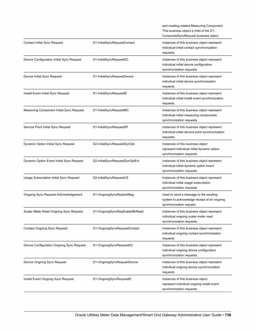
Oracle Utilities Meter Data Management/Smart Grid Gateway Administrative User Guide • 738
and creating related Measuring Component.This business object a child of the D1-CompositeSyncRequest business object.
Contact Initial Sync Request D1-InitialSyncRequestContact Instances of this business object representindividual initial contact synchronizationrequests.
Device Configuration Initial Sync Request D1-InitialSyncRequestDC Instances of this business object representindividual initial device configurationsynchronization requests.
Device Initial Sync Request D1-InitialSyncRequestDevice Instances of this business object representindividual initial device synchronizationrequests.
Install Event Initial Sync Request D1-InitialSyncRequestIE Instances of this business object representindividual initial install event synchronizationrequests.
Measuring Component Initial Sync Request D1-InitialSyncRequestMC Instances of this business object representindividual initial measuring componentssynchronization requests.
Service Point Initial Sync Request D1-InitialSyncRequestSP Instances of this business object representindividual initial service point synchronizationrequests.
Dynamic Option Initial Sync Request D2-InitialSyncRequestDynOpt Instances of this business objectrepresent individual initial dynamic optionsynchronization requests.
Dynamic Option Event Initial Sync Request D2-InitialSyncRequestDynOptEvt Instances of this business object representindividual initial dynamic option eventsynchronization requests.
Usage Subscription Initial Sync Request D2-InitialSyncRequestUS Instances of this business object representindividual initial usage subscriptionsynchronization requests.
Ongoing Sync Request Acknowledgement D1-OngoingSyncReqAckMsg Used to send a message to the sendingsystem to acknowledge receipt of an ongoingsynchronization request.
Scalar Meter Read Ongoing Sync Request D1-OngoingSyncReqScalarMtrRead Instances of this business object representindividual ongoing scalar meter readsynchronization requests.
Contact Ongoing Sync Request D1-OngoingSyncRequestContact Instances of this business object representindividual ongoing contact synchronizationrequests.
Device Configuration Ongoing Sync Request D1-OngoingSyncRequestDC Instances of this business object representindividual ongoing device configurationsynchronization requests.
Device Ongoing Sync Request D1-OngoingSyncRequestDevice Instances of this business object representindividual ongoing device synchronizationrequests.
Install Event Ongoing Sync Request D1-OngoingSyncRequestIE Instances of this business objectrepresent individual ongoing install eventsynchronization requests.

Oracle Utilities Meter Data Management/Smart Grid Gateway Administrative User Guide • 739
Measuring Component Ongoing SyncRequest
D1-OngoingSyncRequestMC Instances of this business object representindividual ongoing measuring componentsynchronization requests.
Service Point Ongoing Sync Request D1-OngoingSyncRequestSP Instances of this business objectrepresent individual ongoing service pointsynchronization requests.
Dynamic Option Ongoing Sync Request D2- OngoingSyncRequestDynOpt Instances of this business object representindividual ongoing dynamic optionsynchronization requests.
Dynamic Option Event Ongoing Sync Request D2- OngoingSyncRequestDynOptEvt Instances of this business object representindividual ongoing dynamic option eventsynchronization requests.
Usage Subscription Ongoing Sync Request D2-OngoingSyncRequestUS Instances of this business object representindividual ongoing usage subscriptionsynchronization requests.
Sync Request Seeder D1-SyncRequestSeeder Used to identify the appropriatesynchronization business object to createwhen processing synchronization requests.
Contact Synchronization Add D1-SynchronizationAddContact Used when adding a new contact as a resultof a synchronization request.
Device Configuration Synchronization Add D1-SynchronizationAddDC Used when adding a new device configurationas a result of a synchronization request.
Device Synchronization Add D1-SynchronizationAddDevice Used when adding a new device as a result ofa synchronization request.
Install Event Synchronization Add D1-SynchronizationAddIE Used when adding a new install event as aresult of a synchronization request.
Measuring Component Synchronization Add D1-SynchronizationAddMC Used when adding a new measuringcomponent as a result of a synchronizationrequest.
Service Point Synchronization Add D1-SynchronizationAddSP Used when adding a new service point as aresult of a synchronization request.
Usage Subscription Synchronization Add D2-SynchronizationAddUS Used when adding a new usage subscriptionas a result of a synchronization request.
Batch ControlsBatch controls perform processing for initial synchronization requests such as allocating keys to data, resolving foreignkeys, and loading data (instantiating business objects representing entities such devices, measuring components, etc.).
"Initial Sync Request - Resolve Keys XXX" batch controls invoke a generic maintenance object transition process toinvoke the "Resolve Keys - Initial Sync" algorithm for synchronization requests of the appropriate type. Parameters used by"resolve keys" batch controls include:
• Maintenance Object: (Required) the maintenance object (device, device configuration, etc.) to be processed. This mustbe set to the Sync Request maintenance object for the batch control (device for device synchronization requests, servicepoint for service point synchronization requests, etc.)
• Restrict By Batch Code: Restricts processing to synchronization requests whose current state is linked to this batchcode.
• Restrict By Business Object: Restricts processing to synchronization requests linked to this business object.
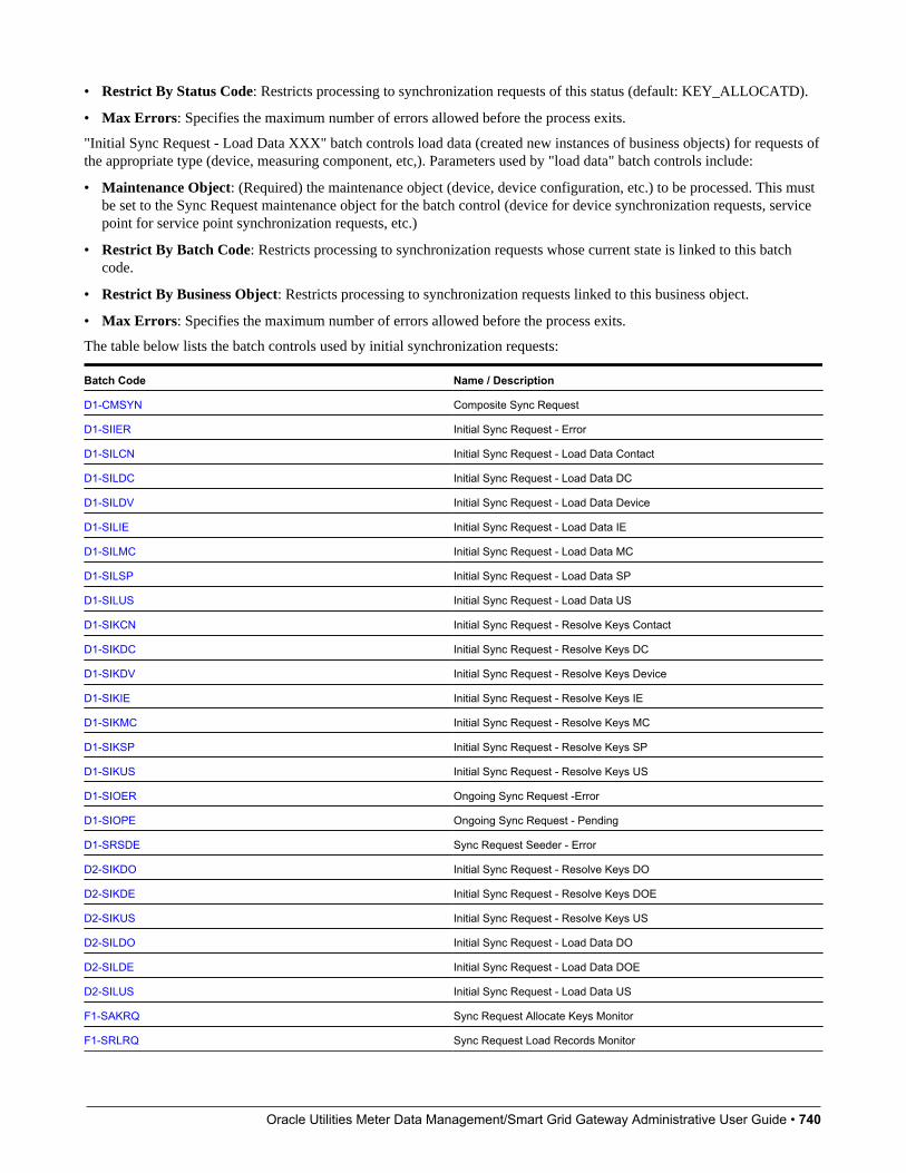
Oracle Utilities Meter Data Management/Smart Grid Gateway Administrative User Guide • 740
• Restrict By Status Code: Restricts processing to synchronization requests of this status (default: KEY_ALLOCATD).
• Max Errors: Specifies the maximum number of errors allowed before the process exits.
"Initial Sync Request - Load Data XXX" batch controls load data (created new instances of business objects) for requests ofthe appropriate type (device, measuring component, etc,). Parameters used by "load data" batch controls include:
• Maintenance Object: (Required) the maintenance object (device, device configuration, etc.) to be processed. This mustbe set to the Sync Request maintenance object for the batch control (device for device synchronization requests, servicepoint for service point synchronization requests, etc.)
• Restrict By Batch Code: Restricts processing to synchronization requests whose current state is linked to this batchcode.
• Restrict By Business Object: Restricts processing to synchronization requests linked to this business object.
• Max Errors: Specifies the maximum number of errors allowed before the process exits.
The table below lists the batch controls used by initial synchronization requests:
Batch Code Name / Description
D1-CMSYN Composite Sync Request
D1-SIIER Initial Sync Request - Error
D1-SILCN Initial Sync Request - Load Data Contact
D1-SILDC Initial Sync Request - Load Data DC
D1-SILDV Initial Sync Request - Load Data Device
D1-SILIE Initial Sync Request - Load Data IE
D1-SILMC Initial Sync Request - Load Data MC
D1-SILSP Initial Sync Request - Load Data SP
D1-SILUS Initial Sync Request - Load Data US
D1-SIKCN Initial Sync Request - Resolve Keys Contact
D1-SIKDC Initial Sync Request - Resolve Keys DC
D1-SIKDV Initial Sync Request - Resolve Keys Device
D1-SIKIE Initial Sync Request - Resolve Keys IE
D1-SIKMC Initial Sync Request - Resolve Keys MC
D1-SIKSP Initial Sync Request - Resolve Keys SP
D1-SIKUS Initial Sync Request - Resolve Keys US
D1-SIOER Ongoing Sync Request -Error
D1-SIOPE Ongoing Sync Request - Pending
D1-SRSDE Sync Request Seeder - Error
D2-SIKDO Initial Sync Request - Resolve Keys DO
D2-SIKDE Initial Sync Request - Resolve Keys DOE
D2-SIKUS Initial Sync Request - Resolve Keys US
D2-SILDO Initial Sync Request - Load Data DO
D2-SILDE Initial Sync Request - Load Data DOE
D2-SILUS Initial Sync Request - Load Data US
F1-SAKRQ Sync Request Allocate Keys Monitor
F1-SRLRQ Sync Request Load Records Monitor

Oracle Utilities Meter Data Management/Smart Grid Gateway Administrative User Guide • 741
F1-SYNRQ Sync Request Monitor Process
F1-SYSRQ Sync Request Sampling Monitor (Deferred)
Batch Control SchedulingThe following table specifies the order in which the batch controls on the Initial Sync Request BO life cycle should beexecuted. The first row identifies the maintenance object for which the synchronization request is intended and the firstcolumn specifies the type of process.
Contact UsageSubscription
ServicePoint
InstallEvent
DeviceConfiguration
Device MeasuringComponent
DynamicOption
DynamicOptionEvent
Transformation /SchemaValidationJob
1 1 1 1 1 1 1 1 1
KeyAllocationJob
2 2 2 2 2 2 2 2 2
ForeignKeyResolution /BOValidationJob
(dependenton ALLKeyAllocationJobsfinishing)
3 8 3 6 3 3 6 3 5
Load Job 4 9 5 7 5 4 7 4 6
Note that before the Key Resolution job is run, all the Key Allocation Jobs need to finish. This ensures that all foreign keyreferences can be subsequently resolved.
Some business object-level validation is dependent on other entities being completely loaded first. The sequence numbersabove allow for this. For example, usage subscriptions business object validation is dependent on service points existing;Install Event business object validation is dependent on both service points and devices existing.
Inbound Web ServicesInbound web services are used to facilitate invoking the Sync Request Seeder business object by the middlewarecomponents upon receipt of a synchronization request.
The table below lists the pre-configured Inbound Web Services used to process synchronization requests sent from OracleUtilities Customer Care and Billing.
Inbound Web Service Description Schema Name
D1-SyncRequestInbound Sync Request Inbound D1-SyncRequestSeeder (BO)
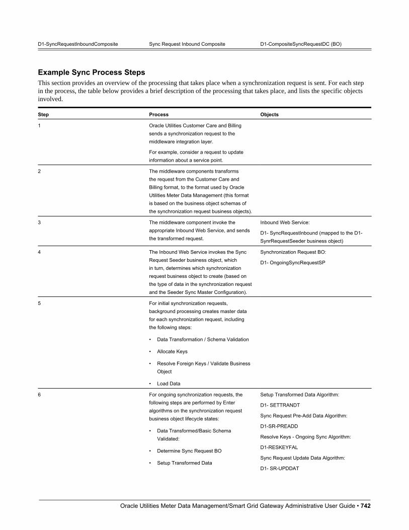
Oracle Utilities Meter Data Management/Smart Grid Gateway Administrative User Guide • 742
D1-SyncRequestInboundComposite Sync Request Inbound Composite D1-CompositeSyncRequestDC (BO)
Example Sync Process StepsThis section provides an overview of the processing that takes place when a synchronization request is sent. For each stepin the process, the table below provides a brief description of the processing that takes place, and lists the specific objectsinvolved.
Step Process Objects
1 Oracle Utilities Customer Care and Billingsends a synchronization request to themiddleware integration layer.
For example, consider a request to updateinformation about a service point.
2 The middleware components transformsthe request from the Customer Care andBilling format, to the format used by OracleUtilities Meter Data Management (this formatis based on the business object schemas ofthe synchronization request business objects).
3 The middleware component invoke theappropriate Inbound Web Service, and sendsthe transformed request.
Inbound Web Service:
D1- SyncRequestInbound (mapped to the D1-SynrRequestSeeder business object)
4 The Inbound Web Service invokes the SyncRequest Seeder business object, whichin turn, determines which synchronizationrequest business object to create (based onthe type of data in the synchronization requestand the Seeder Sync Master Configuration).
Synchronization Request BO:
D1- OngoingSyncRequestSP
5 For initial synchronization requests,background processing creates master datafor each synchronization request, includingthe following steps:
• Data Transformation / Schema Validation
• Allocate Keys
• Resolve Foreign Keys / Validate BusinessObject
• Load Data
6 For ongoing synchronization requests, thefollowing steps are performed by Enteralgorithms on the synchronization requestbusiness object lifecycle states:
• Data Transformed/Basic SchemaValidated:
• Determine Sync Request BO
• Setup Transformed Data
Setup Transformed Data Algorithm:
D1- SETTRANDT
Sync Request Pre-Add Data Algorithm:
D1-SR-PREADD
Resolve Keys - Ongoing Sync Algorithm:
D1-RESKEYFAL
Sync Request Update Data Algorithm:
D1- SR-UPDDAT
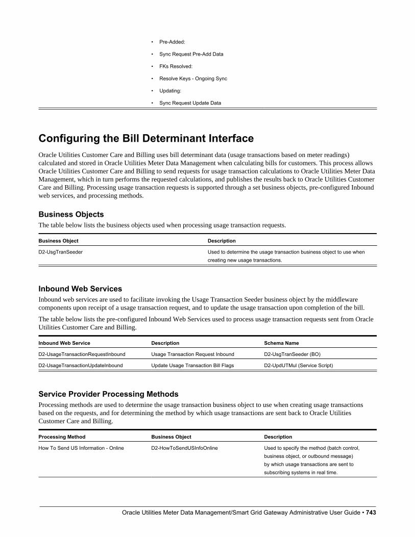
Oracle Utilities Meter Data Management/Smart Grid Gateway Administrative User Guide • 743
• Pre-Added:
• Sync Request Pre-Add Data
• FKs Resolved:
• Resolve Keys - Ongoing Sync
• Updating:
• Sync Request Update Data
Configuring the Bill Determinant InterfaceOracle Utilities Customer Care and Billing uses bill determinant data (usage transactions based on meter readings)calculated and stored in Oracle Utilities Meter Data Management when calculating bills for customers. This process allowsOracle Utilities Customer Care and Billing to send requests for usage transaction calculations to Oracle Utilities Meter DataManagement, which in turn performs the requested calculations, and publishes the results back to Oracle Utilities CustomerCare and Billing. Processing usage transaction requests is supported through a set business objects, pre-configured Inboundweb services, and processing methods.
Business ObjectsThe table below lists the business objects used when processing usage transaction requests.
Business Object Description
D2-UsgTranSeeder Used to determine the usage transaction business object to use whencreating new usage transactions.
Inbound Web ServicesInbound web services are used to facilitate invoking the Usage Transaction Seeder business object by the middlewarecomponents upon receipt of a usage transaction request, and to update the usage transaction upon completion of the bill.
The table below lists the pre-configured Inbound Web Services used to process usage transaction requests sent from OracleUtilities Customer Care and Billing.
Inbound Web Service Description Schema Name
D2-UsageTransactionRequestInbound Usage Transaction Request Inbound D2-UsgTranSeeder (BO)
D2-UsageTransactionUpdateInbound Update Usage Transaction Bill Flags D2-UpdUTMul (Service Script)
Service Provider Processing MethodsProcessing methods are used to determine the usage transaction business object to use when creating usage transactionsbased on the requests, and for determining the method by which usage transactions are sent back to Oracle UtilitiesCustomer Care and Billing.
Processing Method Business Object Description
How To Send US Information - Online D2-HowToSendUSInfoOnline Used to specify the method (batch control,business object, or outbound message)by which usage transactions are sent tosubscribing systems in real time.

Oracle Utilities Meter Data Management/Smart Grid Gateway Administrative User Guide • 744
How To Send US Related Information D2-HowToSendUSInformation How To Send US Related Information Usedto specify the method (batch control, businessobject, or outbound message) by which usagetransactions are sent to subscribing systems.
How To Create US Related Information D2-HowToCreateUSInformation Used to determine the type of usagetransaction business object to create.
How To Send US Related Information Batch D2-HowToSendUSInfoBatch Used to specify the method (batch control,business object, or outbound message)by which usage transactions are sent tosubscribing systems via batch processing.
Example Bill Determinant Process StepsThis section provides an overview of the processing that takes place when a usage transaction request is sent. For each stepin the process, the table below provides a brief description of the processing that takes place, and lists the specific objectsinvolved.
Step Process Objects
1 Oracle Utilities Customer Care and Billingsends a usage transaction request to themiddleware integration layer.
2 The middleware components transformsthe request from the Customer Care andBilling format, to the format used by OracleUtilities Meter Data Management (this formatis based on the business object schemas ofthe synchronization request business objects).
3 The middleware component invoke theappropriate Inbound Web Service, and sendsthe transformed request.
Inbound Web Service:
D2- UsageTransactionRequestInbound(mapped to the D2-UsgTranSeeder businessobject)
4 The Inbound Web Service invokes the UsageTransaction Seeder business object. Thisbusiness object:
• Determines the usage subscription IDbased on an external usage subscriptionID
• Determines the appropriate usagetransaction business object to create
Processing Method:
D2- HowToCreateUSInformation (HowTo Create Usage Subscription RelatedInformation)
5 The usage transaction determines the usagecalculation group(s) to use when calculatingusage. These are retrieved from the usagesubscription (with a fallback to the usagesubscription type).
This base package logic can be overriddenby specifying an algorithm in the UsageCalculation Group Determination OverrideAlgorithm field on the usage subscriptiontype. If an algorithm is specified in this field,
Oracle Utilities Meter Data Management/Smart Grid Gateway Administrative User Guide • 745
its logic overrides the existing method ofdetermining the usage calculation group.
A base package algorithm (D2-DRVUSGGRP)is provided that can be used here. Thisalgorithm uses the CCB Rate Scheduleextendable lookup used to map the rateschedules in Oracle Utilities CustomerCare and Billing to usage calculationgroups. The algorithm's logic looks for acombination of rate history list entries on theusage subscription and the type of deviceconfiguration installed during the bill period todetermine the usage calculation group(s) touse for bill determinants calculation.
6 The usage transaction business objectcalculates usage based on the date rangeprovided in the request.
7 If the usage transaction has a sub usagetransactions, it checks the status of each.
8 If the usage transaction is configured torequire an approval, a To Do Entry is created.
9 The usage transaction then sends the usagetransaction to any subscribing systems.
Processing Method:
D2- HowToSendUSInformation (How To SendUS Related Information)
10 Upon completion of the bill, Oracle UtilitiesCustomer Care and Billing invokes aninbound web service to update the "Used onBill" and/or "Linked to Frozen Bill Segment"fields as appropriate to indicate if the usagetransaction was used on a bill.
Inbound Web Service:
D2-UsageTransactionUpdateInbound
(Update Usage Transaction Bill Flags)
Oracle Utilities Operational Device Management
OverviewThis section provides an overview of how Oracle Utilities Meter Data Management supports integrations with OracleUtilities Operational Device Management. In an integration between Oracle Utilities Meter Data Management and OracleUtilities Operational Device Management:
• Oracle Utilities Meter Data Management is typically considered the "system of record" for service points (assetlocations), contacts, and device installation information (install events)
• Oracle Utilities Operational Device Management is typically considered the "system of record" for assets (devices)
Given this breakdown of data between the two systems, any integration between them must account for the passage of databetween the two to ensure that each system can accurately perform its business functions. The integration between OracleUtilities Meter Data Management and Oracle Utilities Operational Device Management is based on data synchronizationbetween the two systems.
Oracle Utilities Meter Data Management/Smart Grid Gateway Administrative User Guide • 746
Configuring Master Data SynchronizationThe specific data synchronization flows supported between Oracle Utilities Meter Data Management (MDM) and OracleUtilities Operational Device Management (ODM) include the following:
• Asset-Device Synchronization: As new assets are created or changed in ODM, corresponding devices must be createdor changed in MDM
• Service Point/Contact - Asset Location/Contact: As Service Points and/or Contacts are created or changed in MDM,corresponding Asset Locations and Contacts must be created or changed in ODM
• Install Events- Asset Location/Disposition: As devices are installed/removed in MDM, corresponding changes to anasset's Disposition (location and status) must be made in ODM
This synchronization process is supported through a set of business objects, master configurations, batch controls, and pre-configured Inbound Web Services. Refer to the Oracle Utilities Integration for Device Operations Implementation Guidefor more information about this integration and the data synchronization processes used by this integration.
Master ConfigurationThe following master configurations are used to configure the sync process between MDM and ODM:
Master Configuration Name / Description
Master Data Synchronization Configuration Lists all foreign key references that need resolution. Each one shouldreference the view that contains the external key / production keycross-reference. For entities that undergo both the initial and theongoing sync, two views are specified. For entities that undergo theongoing sync, an external system / ID type mapping is specified tocater for entities that might be synchronizing from more than oneexternal system.
Seeder Sync Request Master Configuration Lists the maintenance objects (device, device configuration, etc.) thatrequire synchronization. Each references the synchronization businessobject that needs to be instantiated when processing a synchronizationrequest for that maintenance object. For maintenance objects thatundergo both initial and the ongoing synchronization, two businessobjects are specified.
ODM Integration Master Configuration Specifies the external system used to represent Oracle UtilitiesOperational Management, and the URL for the Oracle UtilitiesOperational Management application.
Also specifies the outbound message types used to sendsynchronization requests to Oracle Utilities Operational Management.
Inbound Data Synchronization Business ObjectsThe integration between Oracle Utilities Meter Data Management and Oracle Utilities Operational Device Managementuses the following inbound (to Oracle Utilities Mater Data Management) synchronization business objects:
Object Name Business Object Description
Device Ongoing Sync Request D1-OngoingSyncRequestDevice Used to synchronize devices in Oracle UtilitiesMater Data Management based on assets
Oracle Utilities Meter Data Management/Smart Grid Gateway Administrative User Guide • 747
created/updates in Oracle Utilities OperationalDevice Management.
Outbound Data Synchronization Business ObjectsThe integration between Oracle Utilities Meter Data Management and Oracle Utilities Operational Device Managementuses the following outbound (from Oracle Utilities Mater Data Management) synchronization business objects (based on theF1-SYNC REQ maintenance object)
Object Name Business Object Description
ODM Sync Request D1-ODMContactSyncRequest Used to synchronize contacts in OracleUtilities Operational Device Managementbased on contacts created/updated in OracleUtilities Meter Data Management
ODM Install Event Sync Request D1-ODMInstallEventSyncRequest Used to synchronize asset location/dispositionin Oracle Utilities Operational DeviceManagement based on install events created/updated in Oracle Utilities Meter DataManagement
ODM SP Sync Request D1-ODMSPSyncRequest Used to synchronize asset locations in OracleUtilities Operational Device Managementbased on service points created/updated inOracle Utilities Meter Data Management
Oracle Utilities Analytics
OverviewOracle Utilities Meter Data Management can also be integrated with Oracle Utilities Analytics (OUA) to allow users toview analytic data based on usage, events, and other data tracked in Oracle Utilities Meter Data Management.
Oracle Utilities Meter Data Management Analytics comprises the following products:
• Oracle Utilities Meter Data Analytics: dashboards, dashboard pages, and analytics used to view usage, event, and otherdata from Oracle Utilities Meter Data Management
• Oracle Utilities Meter Data Management Extractors and Schema: the star schema and extract programs used byOracle Utilities Meter Data Analytics.
Configuring ExtractsOracle Utilities Meter Data Management includes the following components used when integrating with Oracle UtilitiesAnalytics:
Master ConfigurationThe following master configurations are used to configure the sync process between MDM and OUA:

Oracle Utilities Meter Data Management/Smart Grid Gateway Administrative User Guide • 748
Master Configuration Description
Analytics Master Configuration - ODI-Based This master configuration is primarily used to configure the informationthat will be used in the extraction of data for business intelligence whenusing the Oracle Data Integrator extract, transform, and load (ETL)process.
Batch Controls
Batch Code Name / Description
D1-SPSDL Service Point Snapshot Download
D2-DUGDL Usage Subscription Usage Calculation Group Download
D2-MVREF Materialized View Refresh
D2-USGDL Service Point Usage Snapshot Download
D2-UUSDL SP Unreported Usage Snapshot Download
D2-VEEDL SP VEE Exception Snapshot Download
Refer to the following documentation for more information about Oracle Utilities Analytics:
Oracle Utilities Extractors and Schema for Oracle Utilities Meter Data Management Data Mapping Guide
Oracle Utilities Analytics Dashboards for Meter Data Analytics Metric Reference Guide
Oracle Utilities Analytics Admin Guide
Oracle DataRakerThis section describes integrations with Oracle DataRaker.
Business Flag IntegrationWith the business flag integration with Oracle DataRaker:
• Either Oracle Utilities Meter Data Management or Oracle DataRaker can initiate a business flag
• Oracle Utilities Meter Data Management can notify Oracle DataRaker of a change in status of a business flag:
• if a business flag in error has been discarded
• if a business flag's confidence has been updated
• with the results of field work initiated by a business flag
For additional details see About Business Flags in the Oracle Utilities Application Framework Administrative User Guide.
Configuring Business Flag IntegrationOracle Utilities Meter Data Management includes the following components used when integrating with Oracle DataRaker:
Master ConfigurationThe following master configurations are used to configure the sync process between MDM and Oracle DataRaker:

Oracle Utilities Meter Data Management/Smart Grid Gateway Administrative User Guide • 749
Master Configuration Description
DataRaker Integration Master Configuration This master configuration is used to enable deep linking into OracleDataRaker. Multiple URL patterns are supported with an ability toprovide substitution variables to satisfy the URL parameters (e.g."&searchTech="). This also provides a mapping between OracleUtilities Meter Data Management service types and the OracleDataRaker point types.
Service Provider Processing MethodsThe following processing methods should be associated to the service provider configured for Oracle DataRaker:
Processing Role Description
Business Flag Confidence Change This role will identify the appropriate message to send when a businessflag confidence has been changed (e.g. from Suspected to Confirmed).When not configured no message will be sent.
Business Flag Discarded Notification This role will identify the appropriate message to send when a businessflag has been discarded. When not configured no message will be sent.
Business Flag Field Work Details This role will identify the appropriate message to send when a businessflag has completed that initiated field work. When not configured nomessage will be sent.
Business Flag Added Notification This role will identify the appropriate message to send when abusiness flag has been created from within Oracle Utilities Meter DataManagement. When not configured no message will be sent.
Extendable LookupsThe following extendable lookups should be reviewed for Oracle DataRaker:
Extendable Lookup Description
Business Flag Standard Name If Oracle DataRaker will be communicating business flags using a non-standard name provide an entry in the Valid External Name with thenon-standard name for each standard name communicated by OracleDataRaker.
Usage and Event IntegrationOracle Utilities Smart Grid Gateway adapters can be configured to publish initial measurement and device event datafor use in Oracle DataRaker or other external systems. Published data is posted to a user-defined directory that OracleDataRaker can monitor for import.
Initial measurement and device event data is published in the “native” data format (the format of the initial measurementand device event seeder business objects). This format includes normalized unit of measure, condition, and device eventcodes. See the Oracle Utilities Smart Grid Gateway Adapter Development Kit Administrative User Guide for more detailsabout this format.
Oracle Utilities Meter Data Management/Smart Grid Gateway Administrative User Guide • 750
NOTE: Initial measurement data published via this feature is published prior to VEE processing. In addition, filteringcan NOT be applied to initial measurement or device event data published via this feature.
Configuring DataRaker Usage and Event IntegrationOracle Utilities Smart Grid Gateway adapters use OSB and BPEL components when publishing initial measurement anddevice event data for integration with Oracle DataRaker.
OSB ProjectsThe following “CM” Oracle Service Bus projects are used to configure the integration between SGG and Oracle DataRaker:
Adapter OSB Projects
Landis+Gyr SGG-D3-USAGE-CM (used to publish usage)
SGG-D3-EVENT-CM (used to publish device events)
NES SGG-D4-USAGE-CM (used to publish usage)
SGG-D4-EVENT-CM (used to publish device events)
MV90 SGG-D5-USAGE-CM (used to publish usage)
Sensus SGG-D6-USAGE-CM (used to publish usage)
SGG-D6-EVENT-CM (used to publish device events)
Silver Spring Networks SGG-D7-SSNXML-CM (used to publish usage)
SGG-D7-CSV-CM (used to publish device events)
Itron OpenWay SGG-D8-ITRONXML-CM (used to publish usage)
SGG-D8-EXCEPTION-CM (used to publish device events)
Adapter Development Kit SGG-DG-SEEDER-CM (used to publish usage and device events)
The following components provided with these projects are used in publishing measurement data and device events toOracle DataRaker:
• The DataRakerBusinessService business service is used to send data to a pre-configured JMS queue (defined as anEndpoint URI), from which the data will be published. This business service is specified in the EnvironmentSettings.xqfile (see below).
• The DataRakerServiceAccount service account is used to define and maintain the user name and password needed toaccess the JMS queue defined in the DataRakerBusinessService business service.
Enabling Data PublishingPublishing initial measurement and device event data is enabled by referencing a publisher business service(DataRakerBusinessService) in the publishServices/service element in the EnvironmentSettings.xq files provided with theOSB projects listed above as follows:<publishServices> <service>[publisherBusinessService]</service></publishServices>
BPEL CompositesThe SGGDRIntegration BPEL composite handles publishing the data to Oracle DataRaker or other systems.
Oracle Utilities Meter Data Management/Smart Grid Gateway Administrative User Guide • 751
Configuring Publishing OutputThe following parameters can be used to configure details of how the data is provided to Oracle DataRaker, including thedirectory where files are posted for Oracle DataRaker to consume, number of records per file, polling frequency, etc. Theseparameters are defined during installation. See the Oracle Utilities Smart Grid Gateway Installation Guide for more detailsabout defining values for these parameters.
Parameter Description Default Value
SGG_DR_INT_QUEUE JNDI name of queue to publish SGGpayloads.
This is the JMS queue defined in theDataRakerBusinessService businessservice. This should NOT be changed.
DataRakerQueue
SOA_DR_PUBLISH_SIZE The number of records (SGG payloads) toaccumulate in a published file.
100
SOA_DR_FILE_SIZE The maximum file size for the accumulated(SGG payloads) file in kilobytes.
524288
SOA_DR_ELAPSED_TIME The period of time in second which, whenexceeded, causes a new outgoing file to becreated.
600
SOA_DR_POLLING_FREQ The polling frequency in seconds of thestaging directory for new files.
60
SOA_DR_STAGING_DIR Mount point/directory for the staging directoryfor accumulated SGG payload files.
This is used internally and should NOT bechanged.
/spl/sploutput/staging
SOA_DR_INTEGRATION_DIR Mount point/directory from which OracleDataRaker will consume the converted XMLfiles.
/spl/sploutput/int
Oracle Utilities Network Management System
OverviewThis section provides an overview of how Oracle Utilities Meter Data Management supports integrations with OracleUtilities Network Management System. In an integration between Oracle Utilities Meter Data Management and OracleUtilities Network Management System:
• Oracle Utilities Smart Grid Gateway can notify Oracle Utilities Network Management Systems of device events thathave been received (e.g. last gasp and power up).
• Oracle Utilities Network Management Systems can request:
• Oracle Utilities Smart Grid Gateway to perform various smart meter commands for a device or list of devices (e.g.device status check)
• Oracle Utilities Smart Grid Gateway to suppress device event notifications for a certain set of device event types.
Oracle Utilities Meter Data Management/Smart Grid Gateway Administrative User Guide • 752
Configuring Device Event Notification SuppressionOracle Utilities Meter Data Management includes the following components used when integrating with Oracle UtilitiesNetwork Management Systems:
Service Provider Processing MethodsThe following processing methods should be associated to the service provider configured for Oracle Utilities NetworkManagement System:
Processing Role Description
Bulk Response This role will identify the appropriate message to send with the resultsof a bulk command execution. For example, this would be used if alarge list of devices had been supplied to execute device status checkin order to verify outage status.
Response - Success This role will identify the appropriate message to send for a successfulsmart meter command
Send Device Event This role sets up the subscription for device events that Oracle UtilitiesNetwork Management System has interest in.
Suppression Notification This role identifies the appropriate message to send when a notificationhas been set or removed.
Activity TypesThe following processing activity types should be configured:
Activity Type Description
Bulk Request Header Configuration for the bulk request header activity type which is used inmaking smart meter command requests for a list of meters.
Bulk Response Configuration for the bulk response activity type which organizes theresponse for bulk requests.
Device Event Notification Suppression Identifies the device event categories and types that are subject tosuppression.
Oracle Utilities Customer Self Service
OverviewOracle Utilities Meter Data Management can be integrated with Oracle Utilities Customer Self Service (OUCSS) to allowutility customers to:
• View their usage data
• Create self-service meter readings (i.e. submit their own meter readings)

Oracle Utilities Meter Data Management/Smart Grid Gateway Administrative User Guide • 753
• Perform rate comparisons (via integration between CC&B and MDM)
Master ConfigurationThe following master configurations are used to configure the sync process between MDM and OUCSS:
Master Configuration Description
Self Service Master Configuration This master configuration is used for general configuration related tothe MDM to OUCSS interface. This includes a variety of configurationincluding: temperature source, rate comparison, supported usagecalculation groups, etc.
Supporting Oracle Utilities Meter Data Management ServicesOracle Utilities Meter Data Management provides the following services used by Oracle Utilities Customer Self Service:
Service Name Description Logic Inbound Web Service
Create Self-Service Meter Read Allows users to submit their ownmeter reads via the CustomerSelf Service application.
Service Script:
WX-CrSSMRead
WX-CreateSelfServiceMeterRead
Get Scalar ConsumptionSummary
Retrieves consumption data fordisplay in the Customer SelfService application.
Service Script:
WX-GetSCsum
WX-GetScalarConsumptionSummary
Get Usage Overview Retrieves an overview of acustomer's usage for a user-specified duration for displayin the Customer Self Serviceapplication
Service Script:
WX-GetUsgOVw
WX-GetUsageOverview
Multiple Account TOU Usagesby Service Request Type
Uses the Get Usage Detailsservice to retrieve usage fora list of accounts for displayin the Customer Self Serviceapplication. Each account'susage is summarized by servicetype, UOM and SQI.
Service Script:
WX-MulAccTOU
WX-MultipleAccountTOUUsagesByServiceType
Multiple Account Usages byService Request Type
Uses the Get Usage Detailsservice to retrieve usage fora list of accounts for displayin the Customer Self Serviceapplication. Each account'susage is summarized by servicetype, UOM and SQI.
Service Script:
WX-MulAccCmp
WX-MultipleAccountUsagesByServiceType
Multiple Account UsageDownload Request
Uses the Get Usage Detailsservice to retrieve usage fora list of accounts (by usagesubscription) for display inthe Customer Self Serviceapplication.
Service Script:
WX-MulAccUsg
WX-MultipleAccountUsagesDownload
Get Usage Details Retrieves usage details for acustomer for a user-specifictime period (year, month, day)
Business Service:
WX-RETWSSTOUMapping
WX-RETWSSTOUMappingService

Oracle Utilities Meter Data Management/Smart Grid Gateway Administrative User Guide • 754
for display in the Customer SelfService application
Usage Adjustment Retrieval Retrieves usage adjustmenttypes based on a user-specifiedrate schedule. Used by the RateCompare feature of the CustomerSelf Service application.
Service Script:
WX-RetUsgAdj
WX-RetUsgAdj
OR
WX-UsageAdjustmentRetrieval
These services are based on the service scripts and business services noted above, and are invoked via the correspondingInbound Web Services.
Refer to the Oracle Utilities Customer Self Service Implementation Guide for more information about integrating OracleUtilities Meter Data Management with Oracle Utilities Customer Self Service.
Configuring Rate Compare Usage Adjustment ProfilesThis section describes the steps involved in setting up usage adjustment profiles in Oracle Utilities Meter Data Managementfor use with the Rate Compare feature in Oracle Utilities Customer Self- Service.
This section provides an overview of the steps involved in setting up usage adjustment profiles. The sections that followprovide additional details and examples for each type of data that must be configured.
1. Create a characteristic type and values for each type of usage adjustment to be made available for rate comparisonpurposes. For example, if you wanted to allow adjustments for installation of solar panels, use of an energy-efficientappliance, or use of an electric vehicle, you would create three characteristic types (one for each type of adjustment),and values for each option within each type (each type of appliance or electric vehicle supported).
2. Create profile (stand-alone) measuring components that correspond to each characteristic type value.
3. Create profile data for each measuring component. This is interval data that represents the impact of the usageadjustment on a customer's consumption.
4. Create a profile factor for each usage adjustment type.
5. Create factor values for each factor. These values correspond to the characteristic type value, and link characteristic typevalues to profile measuring components.
6. Create one (or more) Profile Accumulation usage calculation rules that will apply the usage adjustment profile to thecustomer's interval consumption when calculating usage for the rate comparison request.
7. Create entries in the CCB Rate Schedule extendable lookup to associate the usage calculation group that contains the"Profile Accumulation" usage calculation rule to a rate schedule in Oracle Utilities Customer Care and Billing.
8. Create entries in the Usage Adjustment Types extendable lookup for each usage adjustment type.
9. Set up the Rate Compare Configuration section of the Self-Service Master Configuration to link usage adjustmentfactors and usage adjustment types to rate schedules Oracle Utilities Customer Care and Billing (defined in the CCBRate Schedule extendable lookup).
Characteristic TypesCreate a characteristic type and values for each type of usage adjustment you wish to make available to customer self-service users. For example, to create a usage adjustment profile for use of an electric vehicle, you would create an "electricvehicle" characteristic type and define values for each type of electric vehicle users can select.
Example Characteristic Type:
• Characteristic Type: ELEC_VEH
• Description: Electric Vehicles
Oracle Utilities Meter Data Management/Smart Grid Gateway Administrative User Guide • 755
• Type of Char Value: Predefined Value
• Characteristic Values:
Characteristic Value Description
LEAF Nissan Leaf
TESLA Tesla Model S
VOLT Chevrolet Volt
Profile Measuring ComponentsCreate profile measuring components for each characteristic type value. These measuring components will be used to storeprofile data for each type of usage adjustment.
Note: The base package does not include stand-alone measuring component/measuring component type business objects,but the demonstration database contains "Standalone Interval" and "Standalone Interval Measuring Component Type"business objects that can be used to create profile measuring components and types.
Example Profile Measuring Component Type:
• Measuring Component Type: KWH-PROFILE
• Description: KWH Profile
• Measuring Component Business Object: Standalone Interval (demo)
• Measurement Business Object: Measurement
• Service Type: Electric
• Allow Negative Consumption: Allowed
• Consumptive / Subtractive: Consumptive
• Seconds Per Interval: 01:00:00
• Value Identifiers:
• Value Identifier Type: Measurement
• Short-Hand Description: kWh
• UOM: Kilowatt-Hours
Example "Nissan Leaf" Profile Measuring Component:
• Measuring Component Type: KWH Profile
• Number of Digits Left: 5
• Number of Digits Right: 5
• Time Zone: US Pacific Time
• Status: Active
• How To Use: Additive
• External ID: Nissan Leaf
Example "Tesla Model S" Profile Measuring Component:
• Measuring Component Type: KWH Profile
• Number of Digits Left: 5

Oracle Utilities Meter Data Management/Smart Grid Gateway Administrative User Guide • 756
• Number of Digits Right: 5
• Time Zone: US Pacific Time
• Status: Active
• How To Use: Additive
• External ID: Tesla Model S
Example "Chevrolet Volt" Profile Measuring Component:
• Measuring Component Type: KWH Profile
• Number of Digits Left: 5
• Number of Digits Right: 5
• Time Zone: US Pacific Time
• Status: Active
• How To Use: Additive
• External ID: Chevrolet Volt
Profile DataCreate profile data for each profile measuring component. This data represents the impact of the usage adjustment on acustomer's consumption.
Note that this profile data can (and often will) include negative interval values to represent the difference in consumptionapplicable for the usage adjustment type. For example, if an energy- efficient electric clothes dryer uses an average of 30kilowatt hours less per month than an average electric clothes dryer, profile data for that appliance might be a "straight line"hourly profile (a profile in which all intervals are of the same value) in which each value equals "0.042" (30 kWh per monthdivided by an average of 720 hours per month).
Factors / Factor ValuesCreate a profile factor for each usage adjustment type. This factor should use the "Factor Characteristic Source N/A Algorithm" to derive the appropriate characteristic type value based on the factor value, and should reference thecharacteristic type created earlier.
Example Electric Vehicle Factor:
• Factor: ELECTRIC_VEHICLE
• Description: Electric Vehicle
• Factor Class: Profile
• Characteristic Source Algorithm: Factor Characteristic Source N/A Algorithm
• Factor Characteristic Type: Electric Vehicle
Example "Nissan Leaf" Factor Value
• Factor: Electric Vehicle
• Factor Characteristic Type: Electric Vehicle
• Factor Characteristic Value: LEAF
• Effective Date/Time: 01-01-2014 12:00:00AM
• Profile: Nissan Leaf, KWH Profile
Example "Tesla Model S" Factor Value
Oracle Utilities Meter Data Management/Smart Grid Gateway Administrative User Guide • 757
• Factor: Electric Vehicle
• Factor Characteristic Type: Electric Vehicle
• Factor Characteristic Value: LEAF
• Effective Date/Time: 01-01-2014 12:00:00AM
• Profile: Tesla Model S, KWH - 60 Minutes
Example "Chevrolet Volt" Factor Value
• Factor: Electric Vehicle
• Factor Characteristic Type: Electric Vehicle
• Factor Characteristic Value: LEAF
• Effective Date/Time: 01-01-2014 12:00:00AM
• Profile: Chevrolet Volt / KWH - 60 Minutes
Profile Accumulation Usage Calculation Group and RuleCreate a usage calculation group that contains a "Profile Accumulation" usage calculation rule. This rule will calculateusage by accumulating historical usage with profile data. based on a selected profile factor value.
Note: Profile Accumulation rules should use eligibility criteria to ensure they are only executed when the "CalculationMode" on the usage transaction is set to "Hypothetical Calculation" (D2HC).
Example: Profile Accumulation Usage Calculation Rule
• Usage Calculation Group: Electric Residential Interval KWH
• Usage Calculation Rule: KWH_PROFILE_ACCUMULATION
• Sequence: 10
• Description: KWH Profile Accumulation
• Category: Usage Calculation
• Vector Source Configuration:
• Vector Type: Channels Linked to Usage Subscription
• Unit of Measure: Kilowatt-Hours
• Time of Use:
• Service Quantity Identifier:
• Target SPI: 01:00:00
• Result Processing Configuration:
• Apply TOU Map to Derived Vector: Yes
• TOU Map: Summer / Winter, 15 minute interval
• Result Storage Configuration:
• Insert Primary SQ Entry: Yes
• Save Derived Vector: No
• Service Quantity Identifier:
• Extract Interval Data: No
Oracle Utilities Meter Data Management/Smart Grid Gateway Administrative User Guide • 758
CC&B Rate Schedule Extendable LookupCreate an entry in the "CCB Rate Schedule" extendable lookup to associate the usage calculation group that contains the"Profile Accumulation" usage calculation rule to an applicable rate schedule in Oracle Utilities Customer Care and Billing.
Example CCB Rate Schedule extendable lookup:
• Rate: E-INT-RES
• Description: Electric Residential Interval Rate
• Default Usage Calculation Group: Electric Residential Interval KWH (E-INT-RES)
Usage Adjustment Types Extendable LookupCreate an entry in the "Usage Adjustment Type" extendable lookup for each type of usage adjustment that will be availableto customer self-service users. These entries are used in the Rate Compare Configuration section of the Self-Service MasterConfiguration (see below).
Example Electric Vehicle entry:
• Usage Adjustment Type: ELEC_VEHICLE
• Description: Purchase of Electric Vehicle
• Override Description: Purchase of Electric Vehicle
• External Reference ID: Purchase of Electric Vehicle
Self-Service Master Configuration - Rate Compare ConfigurationConfigure the "Rate Compare Configuration" section of the Self-Service Master Configuration to associate usageadjustment factors and usage adjustment types with an applicable rate schedule in Oracle Utilities Customer Care andBilling (defined in the CCB Rate Schedule extendable lookup).
Example Self-Service Master Configuration:
• Factor Characteristic Type Indicating No Value Variation: N/A
• External Reference Factor Value Characteristic Type: External Reference ID
• Minimum Days of Usage Adjustment Data: 2
• Rate / Usage Adjustments:
• Rate: Electric Residential - Interval KWH
• Usage Adjustments:
• Usage Adjustment Factor: Electric Vehicle
• Usage Adjustment Type: Purchase of Electric Vehicle
Oracle Utilities Dataconnect / Opower
OverviewOracle Utilities DataConnect facilitates extraction of data from Oracle Utilities Meter Data Management for use in externalapplications such as analytics applications and energy management systems. This section describes how Oracle UtilitiesDataConnect works and how to implement and configure the system to support data extract processing.
Oracle Utilities Meter Data Management/Smart Grid Gateway Administrative User Guide • 759
Oracle Utilities DataConnect can be used to extract two types of data:
• Measurement data for service points based on the Service Point Types defined for a Consumption Extract Type. Whenextracting usage measurement data, Oracle Utilities DataConnect extracts both interval measurement data as well asfrequently read scalar usage data (which is converted into interval measurements during the extraction process).
• Individual service points and install events (based on Service Point Types defined in an extract algorithm).
The extraction processes used for each type of data are separate, but extracted data can be correlated in external systemsthrough service point data included in each type of extract. All data extracts contain the following data elements that can beused for this correlation:
• Service Point ID: The service point ID in Oracle Utilities Meter Data Management
• CIS Service Point ID: The ID used for the service in a customer information system (CIS) such as Oracle UtilitiesCustomer Care and Billing
External systems receiving data extracted from Oracle Utilities DataConnect can use either (or both) of these IDs toassociate extract measurement data to extracted master data.
Consumption ExtractWhen sending interval measurement usage data to an external system, both historical and current data needs to be extracted.Historical data can be extracted as part of an initial load process, and only needs to be provided during initial setup of theintegration. Historical data should include data history for all active service points for a specified historical period. Currentdata should be extracted on a regular ongoing (or incremental) basis. However, in addition to sending current data, anyhistorical corrections received by the system should be extracted as well.
Extract RequestsThere are several types of consumption extract requests:
• Initial Load: Initial load extract requests are created and submitted manually via the Consumption Extract Requestportal. Consumption extract requests are based on a specified Consumption Extract Type (see below) and extraction daterange. An initial load request must be created and submitted for each consumption extract type defined in the system.
• Incremental / Ongoing (Current Data): Incremental / ongoing extract requests can be manually created, but moreoften will be created via a batch process. The "Create Daily Consumption Extract Requests" batch control scansactive consumption extract types and creates a request for each one that has Frequency of "Automated Daily." Ad-hocincremental requests can be created and submitted manually if needed.
• Historical Correction: Historical correction extracts are created via batch process. Algorithms on the Finalized stateof the initial measurement and measurement business objects determine if a finalized initial measurement or rederivedvalues are historical corrections. These algorithms create records which are evaluated by a batch process which extractsthe measurements for the related initial measurements.
Consumption Extract TypeConsumption Extract Types define the specific parameters used when processing a consumption extract request.Consumption Extract Types control the service point type, type of measurement, and how the measurements are groupedinto TOU periods if applicable. Consumption extract types also define the algorithm and batch processes to use whenextracting data for different types of requests (initial load, incremental, and historical).
There are two consumption extract type business objects provided with the base package:
• Consumption Extract Type (D2-ConsumptionExtractType): This business object retrieves interval data and converts itto a specified Target UOM and Interval Size. This business object does not support TOU mapping.
Oracle Utilities Meter Data Management/Smart Grid Gateway Administrative User Guide • 760
• Consumption Extract Type with TOU Mapping (D2-ConsumptionExtractTypeTOU): This business object retrievesinterval data, converts it to a specified Target UOM and Interval Size, and maps it to a specific TOU map prior toextraction.
Historical Versus Current DataThe "Extract Through Date/Time" field on the Consumption Extract Type is used to differentiate between current data(the most recently extracted data) and historical corrections, and is set to the last date on which data was extracted for thatextract type. For example, if data is extracted on June 1, 2015, the "Extract Through Date/Time" would be set to "June 1,2015 12:00AM." If/when data is extracted the next day, "Extract Through Date/Time" would be updated to "June 2, 201512:00AM."
When evaluating data for extract:
• Interval data is considered current if its measurement date time is after the "Extract Through Date/Time".
• Interval data is considered a historical correction if its measurement date time is on or before the "Extract Through Date/Time".
Historical data changes to an initial measurement can be detected when it enters the Finalized state. If the initialmeasurement is determined to be for a historical period by comparing its end date/time against the "Extracted ThroughDate/Time" on the Consumption Extract Type, a general process record will be written for the initial measurement so thatmeasurements for it can be extracted. In addition, re-derived values on final measurements can also trigger the creation of ageneral process record for related initial measurements.
The following algorithms are used in this process:
• The "Create General Process Record if IMD is Historical Correction" algorithm is used to determine if a finalizedinitial measurement data is a historical correction. If it is, the algorithm creates a general process record for the initialmeasurement. This algorithm is provided in the base package, but not specified on initial measurement business objectsby default. This algorithm should be defined as an Enter algorithm on the Finalized state of the initial measurementbusiness objects.
• The "Create General Process Record for Re-derived Values" algorithm creates general process records for initialmeasurements associated with re-derived values. Processing will proceed as if a historical correction came in throughan initial measurement. This algorithm is provided in the base package, but not specified on measurement businessobject by default. This algorithm should be defined as an Enter algorithm on the Re-derive state of the final measurementbusiness object.
Consumption Extract RequestsInitial load and ongoing consumption extracts are created via Consumption Extract Requests. While extracts of thesetypes can be created via adhoc submission of a batch job, requests are the preferred method for these types of consumptionextracts.
The consumption extract request business object lifecycle includes logic that maintains and updates the "Extraction ThroughDate/Time" field on Consumption Extract Types, which is used to determine if daily requests should be created by the"Create Daily Consumption Extract Requests" batch control, and detect historical corrections.
A single business object is provided in the base package for consumption extract requests:
• Consumption Request for DataConnect (D2-IntervalDataExtRepository): This business object contains theinformation and lifecycle responsible for submitting the extract job, monitoring the run until it's finished, and thenupdating the Consumption Extract Type's "Extract Through Date/Time" on the Consumption Extract Type. This businessobject is based on the Request (F1-REQ) maintenance object.
The consumption extract process uses a set of base package algorithms to extract and format the interval data for export.These algorithms are specified in the '"Algorithms" section on the Consumption Extract Type as appropriate. Thesealgorithms can be configured to allow for extraction of data for frequently-read scalar measuring components as well asinterval measuring components. Frequently-read scalar measuring components are defined as scalar measuring componentswhose Read Method is set to "Automatic Read." When extracting measurements for frequently-read scalar measuring
Oracle Utilities Meter Data Management/Smart Grid Gateway Administrative User Guide • 761
components, scalar measurements are converted to interval measurements as part of the extraction process. This conversionuses the profile associated with the measuring component type. If no profile can be found, the interval data uses a flat lineprofile.
Initial Load / Incremental / Ongoing Requests: the following algorithms are used to extract and format interval data forinitial load and incremental / ongoing requests:
• Extract Initial Load/Ongoing Consumption for DataConnect (D2-IDEXTPRD): This algorithm retrieves a servicepoint's consumption for a given period and writes the results to a flat file.
• Extract Initial/Ongoing Consumption and Apply TOU Map for DataConnect (D2-IDEXTPTOU): This algorithmretrieves a service point's consumption for a given period, applies a TOU Map to the consumption, and writes the resultsto a flat file.
Historical Corrections: the following algorithms are used to extract and format interval data for historical correctionrequests:
• Extract Historical Correction Consumption for DataConnect (D2-IDEXTIMD): This algorithm retrieves historicalcorrection consumption for a service point and writes the results to a flat file.
• Extract Historical Corrections and Apply TOU Map for DataConnect (D2-IDEXTITOU): This algorithm retrieveshistorical correction consumption for a service point, applies a TOU map to the consumption, and writes the results to aflat file.
Batch ControlsThe consumption extraction process uses a set of base package batch controls to extract and format the interval data forexport.
• Create Daily Consumption Extract Requests (D2-CRERQ): This batch process scans for active Consumption ExtractTypes, and for each one that has Frequency of Automated Daily creates a pending request. This process should bescheduled to run daily (or at another regular interval).
The following sample batch controls are provided to extract and format interval data. Unique batch controls of each ofthese is required for each consumption extract type. You should create custom versions of the above batch controls for eachconsumption extract type in your implementation. Extract type-specific versions of these batch controls should be specifiedin the "Batch Control" section on the Consumption Extract Type as appropriate.
• Initial Load/Ongoing Consumption Extract (D2-IDEPD): This batch process extracts interval data for a specifiedperiod. This batch control uses the "Initial Load/Ongoing Extract Algorithm" defined on the Consumption Extract Type.
• Historical Corrections Consumption Extract (D2-IDEHC): This batch process extracts interval data for historicalcorrections. This batch control uses the "Historical Corrections Extract Algorithm" defined on the Consumption ExtractType.
Use the Batch Control portal for more information about these batch controls. The extract batch controls contain parametersthat can be used to specify details (including path and file name for this file.) for a delimited flat file containing extracteddata.
Example Setup StepsSetting up consumption extracts involves the following steps:
1. Create Consumption Request Types: you should create a consumption request type for each unique type of requestrequired by your implementation.
2. Create Consumption Extract Types: you should create a consumption extract type for each unique combination ofoutput details (target UOM, target interval size, TOU map/template) and measurement selection criteria.
3. Add the "Create General Process Record if IMD is Historical Correction" historical correction algorithm as an Enteralgorithm on the Finalized state of the initial measurement business objects.
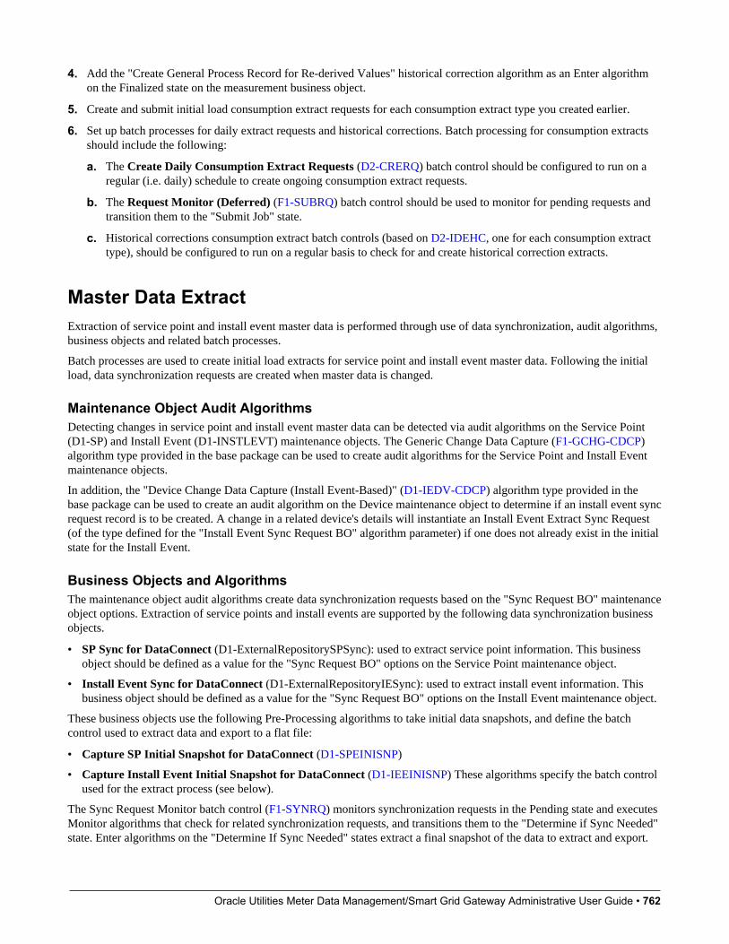
Oracle Utilities Meter Data Management/Smart Grid Gateway Administrative User Guide • 762
4. Add the "Create General Process Record for Re-derived Values" historical correction algorithm as an Enter algorithmon the Finalized state on the measurement business object.
5. Create and submit initial load consumption extract requests for each consumption extract type you created earlier.
6. Set up batch processes for daily extract requests and historical corrections. Batch processing for consumption extractsshould include the following:
a. The Create Daily Consumption Extract Requests (D2-CRERQ) batch control should be configured to run on aregular (i.e. daily) schedule to create ongoing consumption extract requests.
b. The Request Monitor (Deferred) (F1-SUBRQ) batch control should be used to monitor for pending requests andtransition them to the "Submit Job" state.
c. Historical corrections consumption extract batch controls (based on D2-IDEHC, one for each consumption extracttype), should be configured to run on a regular basis to check for and create historical correction extracts.
Master Data ExtractExtraction of service point and install event master data is performed through use of data synchronization, audit algorithms,business objects and related batch processes.
Batch processes are used to create initial load extracts for service point and install event master data. Following the initialload, data synchronization requests are created when master data is changed.
Maintenance Object Audit AlgorithmsDetecting changes in service point and install event master data can be detected via audit algorithms on the Service Point(D1-SP) and Install Event (D1-INSTLEVT) maintenance objects. The Generic Change Data Capture (F1-GCHG-CDCP)algorithm type provided in the base package can be used to create audit algorithms for the Service Point and Install Eventmaintenance objects.
In addition, the "Device Change Data Capture (Install Event-Based)" (D1-IEDV-CDCP) algorithm type provided in thebase package can be used to create an audit algorithm on the Device maintenance object to determine if an install event syncrequest record is to be created. A change in a related device's details will instantiate an Install Event Extract Sync Request(of the type defined for the "Install Event Sync Request BO" algorithm parameter) if one does not already exist in the initialstate for the Install Event.
Business Objects and AlgorithmsThe maintenance object audit algorithms create data synchronization requests based on the "Sync Request BO" maintenanceobject options. Extraction of service points and install events are supported by the following data synchronization businessobjects.
• SP Sync for DataConnect (D1-ExternalRepositorySPSync): used to extract service point information. This businessobject should be defined as a value for the "Sync Request BO" options on the Service Point maintenance object.
• Install Event Sync for DataConnect (D1-ExternalRepositoryIESync): used to extract install event information. Thisbusiness object should be defined as a value for the "Sync Request BO" options on the Install Event maintenance object.
These business objects use the following Pre-Processing algorithms to take initial data snapshots, and define the batchcontrol used to extract data and export to a flat file:
• Capture SP Initial Snapshot for DataConnect (D1-SPEINISNP)
• Capture Install Event Initial Snapshot for DataConnect (D1-IEEINISNP) These algorithms specify the batch controlused for the extract process (see below).
The Sync Request Monitor batch control (F1-SYNRQ) monitors synchronization requests in the Pending state and executesMonitor algorithms that check for related synchronization requests, and transitions them to the "Determine if Sync Needed"state. Enter algorithms on the "Determine If Sync Needed" states extract a final snapshot of the data to extract and export.

Oracle Utilities Meter Data Management/Smart Grid Gateway Administrative User Guide • 763
• Capture SP Final Snapshot for DataConnect (D1-SPEFNISNP)
• Capture Install Event Final Snapshot for DataConnect (D1-IEEFNISNP)
The "Prepare Delimited Extract Data" Enter algorithm (D1-PRPEXTDTA) on the "Send Request" state prepares the datafor extraction, and creates a general process record for the synchronization request (based on the batch control definedby the pre-processing algorithm). Note that this algorithm is defined on the "Send Request" state of the Generic Sync forDataConnect (D1-ParentExternalRepositorySyn) parent business object.
Batch ControlsThe master data extraction process uses a set of batch processes to create data synchronization requests and extract files.The following batch processes are used to create initial synchronization requests:
• SP Initial Load for DataConnect (D1-SPEIL): This batch control creates initial synchronization requests for servicepoints.
• Install Event Initial Load for DataConnect (D1-IEEIL): This batch control creates initial synchronization requests forinstall events.
These batch processes should be run to create initial load data synchronization requests based on the "Sync forDataConnect" business objects. The following batch processes are used to create extract files from synchronization requests.
• SP Extract for DataConnect (D1-SPESR): This batch control creates extract file(s) that contain service pointinformation.
• Install Event Extract for DataConnect (D1-IEESR): This batch control creates extract file(s) that contain install eventinformation.
These batch controls are defined as values for the "Batch Control for Extract" algorithm parameters on the Pre-Processingalgorithms on the "Sync for DataConnect" business objects (see above).
Use the Batch Control portal for more information about these batch controls. The extract batch controls contain parametersthat can be used to specify details (including path and file name) for a delimited flat file containing extracted data.
Example Setup StepsSetting up master data extracts involves the following steps:
1. Add audit algorithms on the Service Point and Install Event maintenance objects.
2. Add the DataConnect synchronization request business objects as "Sync Request BO" options on the Service Point andInstall Event maintenance objects.
3. Add the "Install Event's Device Change Data Capture" algorithm as an audit algorithm on the Device maintenanceobject.
4. Execute initial load batch processes for service points and install events.
5. Once the initial load synchronization has been executed, changes to service points, install events, or related devices willtrigger the creation of new synchronization requests and resulting extraction files.
Extract Flat File FormatsThe data included in each file is based on a specific Data Area. For each Data Area, this section provides a table thatlists the name and corresponding schema element and metadata field for each data element extracted by the Data Area.Reference the Data Areas below to see the details for the fields included in each output.
Process Description Data Area
Consumption Extract Snapshot The Consumption Extract Snapshot data areais used for interval consumption extract.
D2-IntervalDataExtRepoSnapshot
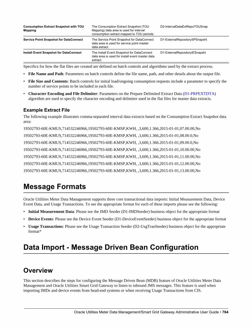
Oracle Utilities Meter Data Management/Smart Grid Gateway Administrative User Guide • 764
Consumption Extract Snapshot with TOUMapping
The Consumption Extract Snapshot (TOUMapping) data area is used for intervalconsumption extract mapped to TOU periods.
D2-IntervalDataExtRepoTOUSnap
Service Point Snapshot for DataConnect The Service Point Snapshot for DataConnectdata area is used for service point masterdata extract.
D1-ExternalRepositorySPSnapsht
Install Event Snapshot for DataConnect The Install Event Snapshot for DataConnectdata area is used for install event master dataextract.
D1-ExternalRepositoryIESnapsht
Specifics for how the flat files are created are defined on batch controls and algorithms used by the extract process.
• File Name and Path: Parameters on batch controls define the file name, path, and other details about the output file.
• File Size and Contents: Batch controls for initial load/ongoing consumption requests include a parameter to specify thenumber of service points to be included in each file.
• Character Encoding and File Delimiter: Parameters on the Prepare Delimited Extract Data (D1-PRPEXTDTA)algorithm are used to specify the character encoding and delimiter used in the flat files for master data extracts.
Example Extract FileThe following example illustrates comma-separated interval data extracts based on the Consumption Extract Snapshot dataarea:
19502793-60E-KMUS,714532246966,19502793-60E-KMSP,KWH, ,3,600,1.366,2015-01-01,07.00.00,No
19502793-60E-KMUS,714532246966,19502793-60E-KMSP,KWH, ,3,600,1.366,2015-01-01,08.00.0,No
19502793-60E-KMUS,714532246966,19502793-60E-KMSP,KWH, ,3,600,1.366.2015-01-01,09.00.0,No
19502793-60E-KMUS,714532246966,19502793-60E-KMSP,KWH, ,3,600,1.366,2015-01-01,10.00.00,No
19502793-60E-KMUS,714532246966,19502793-60E-KMSP,KWH, ,3,600,1.366,2015-01-01,11.00.00,No
19502793-60E-KMUS,714532246966,19502793-60E-KMSP,KWH, ,3,600,1.366,2015-01-01,12.00.00,No
19502793-60E-KMUS,714532246966,19502793-60E-KMSP,KWH, ,3,600,1.366,2015-01-01,13.00.00,No
Message FormatsOracle Utilities Meter Data Management supports three core transactional data imports: Initial Measurement Data, DeviceEvent Data, and Usage Transactions. To see the appropriate format for each of these imports please see the following:
• Initial Measurement Data: Please see the IMD Seeder (D1-IMDSeeder) business object for the appropriate format
• Device Events: Please see the Device Event Seeder (D1-DeviceEventSeeder) business object for the appropriate format
• Usage Transactions: Please see the Usage Transaction Seeder (D2-UsgTranSeeder) business object for the appropriateformat*
Data Import - Message Driven Bean Configuration
OverviewThis section describes the steps for configuring the Message Driven Bean (MDB) feature of Oracle Utilities Meter DataManagement and Oracle Utilities Smart Grid Gateway to listen to inbound JMS messages. This feature is used whenimporting IMDs and device events from head-end systems or when receiving Usage Transactions from CIS.

Oracle Utilities Meter Data Management/Smart Grid Gateway Administrative User Guide • 765
JMS ConfigurationJMS configuration involves setting up JMS queues which will received inbound usage readings and device events. The JMSqueues need to be created first on the application server where the OSB component is deployed. This server is referred to asremote server in the sections below. In the following section the JMS queue on the remote server is assumed to be createdwith the name DestinationQueueWatch-CM.
Note: The JMS changes described in the following sections are not persistent during patches or upgrades. They will need tobe re-created after applying any patches or upgrades to Oracle Utilities Smart Grid Gateway. It is recommended to keep abackup of the $SPLEBASE/splapp/config.xml file.
Create a new JMS ModuleLog in to the Oracle Utilities Smart Grid Gateway Weblogic console and create a JMS Module with an appropriate name.Specify the following values for this JMS module:
• Name: the name of JMS module. For example, JMSModule-CM
• Target: the name of the target server where the Oracle Utilities Smart Grid Gateway application is running. This shouldbe specified as myserver.
Create a Foreign JMS ServerCreate a Foreign JMS server under the JMS module created in the above step. Specify the following values for this foreignJMS server:
• Name: Name of the foreign server. For example, JMSFAServer-CM
• Target: This should be specified as myserver
• JNDI Initial Context Factory: This should be specified as weblogic.jndi.WLInitialContextFactory
• JNDI Connection URL: The URL of the server where OSB is deployed. For example: t3://osbserver:7001
• JNDI Properties Credential: Password for the OSB server user.
• JNDI Properties: The java.naming.security.principal additional property should be specified and set to the OSB serveruser. For example, java.naming.security.principal=weblogic
Create a Foreign DestinationCreate a Foreign destination for each remote queue. Specify the following values for this foreign destination:
• Name: Name of foreign destination. For instance, DestinationQueue-CM
• Local JNDI Name: Local JNDI name for the foreign JMS queue. For example, ForeignDestinationQueue-CM
• Remote JNDI Name: JNDI name of the queue on the remote server. For example, DestinationQueueWatch-CM
Create a Remote Connection FactoryCreate a remote connection factory for the foreign JMS server. Specify the following values for this remote connectionfactory:
• Name: Name of remote connection factory. For example, DestinationQueueConnectionFactory-CM
• Local JNDI Name: Local JNDI name for the Remote Connection Factory. For example,ForegnDestinationQueueConnectionFactory-CM
• Remote JNDI Name: JNDI name of the JMS Connection Factory on the remote server. For example,weblogic.jms.XAConnectionFactory
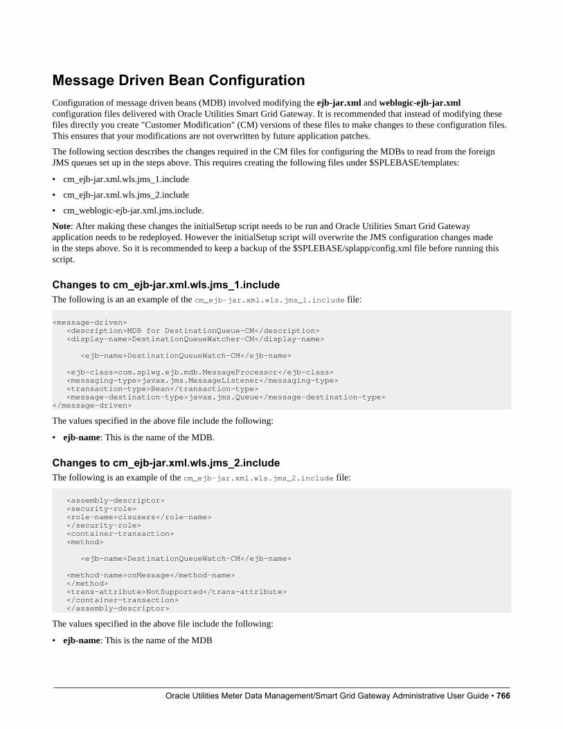
Oracle Utilities Meter Data Management/Smart Grid Gateway Administrative User Guide • 766
Message Driven Bean ConfigurationConfiguration of message driven beans (MDB) involved modifying the ejb-jar.xml and weblogic-ejb-jar.xmlconfiguration files delivered with Oracle Utilities Smart Grid Gateway. It is recommended that instead of modifying thesefiles directly you create "Customer Modification" (CM) versions of these files to make changes to these configuration files.This ensures that your modifications are not overwritten by future application patches.
The following section describes the changes required in the CM files for configuring the MDBs to read from the foreignJMS queues set up in the steps above. This requires creating the following files under $SPLEBASE/templates:
• cm_ejb-jar.xml.wls.jms_1.include
• cm_ejb-jar.xml.wls.jms_2.include
• cm_weblogic-ejb-jar.xml.jms.include.
Note: After making these changes the initialSetup script needs to be run and Oracle Utilities Smart Grid Gatewayapplication needs to be redeployed. However the initialSetup script will overwrite the JMS configuration changes madein the steps above. So it is recommended to keep a backup of the $SPLEBASE/splapp/config.xml file before running thisscript.
Changes to cm_ejb-jar.xml.wls.jms_1.includeThe following is an an example of the cm_ejb-jar.xml.wls.jms_1.include file:
<message-driven> <description>MDB for DestinationQueue-CM</description> <display-name>DestinationQueueWatcher-CM</display-name> <ejb-name>DestinationQueueWatch-CM</ejb-name> <ejb-class>com.splwg.ejb.mdb.MessageProcessor</ejb-class> <messaging-type>javax.jms.MessageListener</messaging-type> <transaction-type>Bean</transaction-type> <message-destination-type>javax.jms.Queue</message-destination-type></message-driven>
The values specified in the above file include the following:
• ejb-name: This is the name of the MDB.
Changes to cm_ejb-jar.xml.wls.jms_2.includeThe following is an example of the cm_ejb-jar.xml.wls.jms_2.include file:
<assembly-descriptor> <security-role> <role-name>cisusers</role-name> </security-role> <container-transaction> <method> <ejb-name>DestinationQueueWatch-CM</ejb-name>
<method-name>onMessage</method-name> </method> <trans-attribute>NotSupported</trans-attribute> </container-transaction> </assembly-descriptor>
The values specified in the above file include the following:
• ejb-name: This is the name of the MDB

Oracle Utilities Meter Data Management/Smart Grid Gateway Administrative User Guide • 767
Changes to cm_ejb-jar.xml.wls.jms_2.includeThe following is an example of the cm_weblogic-ejb-jar.xml.jms.include file:
<weblogic-enterprise-bean> <ejb-name>DestinationQueueWatch-CM</ejb-name> <message-driven-descriptor> <pool> <max-beans-in-free-pool>5</max-beans-in-free-pool> <initial-beans-in-free-pool>1</initial-beans-in-free-pool> </pool> <destination-jndi-name>ForeignDestinationQueue-CM</destination-jndi-name> <connection-factory-jndi-name>ForeignConnectionFactory-CM</connection- factory-jndi-name> </message-driven-descriptor> </weblogic-enterprise-bean>
The values specified in the above file include the following:
• ejb-name: This should be the name of the MDB as specified in ejb-jar.xml
• destination-jndi-name: This should be the JNDI name of the foreign destination as provided in JMS module ' Foreignserver ' Foreign destination ' Local JNDI name.
• connection-factory-jndi-name: This should be the JNDI name of the connection factory as provided in JMS module 'Foreign server ' Remote Connection Factory ' Local JNDI name.
Notification Queue ConfigurationPayload statistics and payload summary records must be submitted sequentially in order for them to be processed correctly.To prevent them from being processed at the same time, you should set the number of notification queue polling threads to1. Follow these steps to configure the number of notification queue threads:
1. Log in to the WebLogic Server Administration Console.
2. Under Helpful Tools, click Configure Applications.
3. Click on SPLService.
4. Click on the NotificationQueue link. for the EJB that you want to configure.
5. Go to the Configuration tab.
6. In the Change Center, click Lock & Edit.
7. Specify the new value of polling threads in Max Beans in Free Pool.
8. Click Save.
9. Click Release Configuration.
10. Restart the OUAF WebLogic instance.
Related Documents