OptiX RTN 980 Radio Transm OptiX RTN 980 Radio Transm V100R003 IDU Quick Installation Guide OptiX RTN 980 无线传输系统 OptiX RTN 980 无线传输系统 IDU 快速安装指南(室内) Issue: 04 Date: 2011-10-30 文档版本:04 发布日期:2011-10-30 HUAWEI TECHNOLOGIES CO., LTD. mission System mission System e (Indoor) 统 V100R003 统 V100R003

Welcome message from author
This document is posted to help you gain knowledge. Please leave a comment to let me know what you think about it! Share it to your friends and learn new things together.
Transcript
OptiX RTN 980 Radio TransmOptiX RTN 980 Radio TransmV100R003IDU Quick Installation Guide
OptiX RTN 980 无线传输系统OptiX RTN 980 无线传输系统IDU 快速安装指南(室内)
Issue: 04Date: 2011-10-30
文档版本:04发布日期:2011-10-30
HUAWEI TECHNOLOGIES CO., LTD.
mission Systemmission System
e (Indoor)
统 V100R003统 V100R003

Huawei Technologies Co., Ltd. provides customers with comprehensive technical support and service. For any assistance, please contact our local office or company headquarters.
Huawei Technologies Co., Ltd.Address: Huawei Industrial Base
Bantian, Longgang
Shenzhen 518129
People's Republic of China
Website: http://www.huawei.com
Email: [email protected]
No part of this document may be reproduced or transmitted in any form or by any means without prior written consent of Huawei Technologies Co., Ltd.
Copyright © Huawei Technologies Co., Ltd. 2011. All rights reserved.
Trademarks and Permissions
and other Huawei trademarks are trademarks of Huawei Technologies Co., Ltd. All other trademarks and trade names mentioned in this document are the property of their respective holders.
Notice The information in this document is subject to change without notice. Every effort has been made in the preparation of this document to ensure accuracy of the contents, but all statements, information, and recommendations in this document do not constitute the warranty of any kind, express or implied.
Huawei Technologies Proprietary
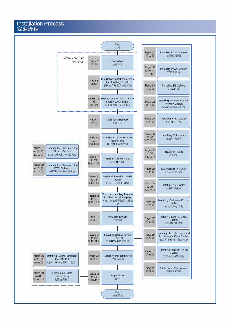
Installation Process安装流程
S
Before You Start安装准备 Prec
注
Page 2第2页
Instructions for Hand
单板操作规
Page 3第3页
单板操作规第3页
Precautions Toggle L纽子开关
Pages 4 to 6
第4-6页
Tools fo安
Page 7第7页
Installing the Chassis in the 19-Inch Cabinet
在19英寸机柜中安装机盒
Pages 11 to 12 第11-12页
安第7页
IntroductionEqu
RTN 98
Pages 8 to 10
第8-10页
Installing安装
Pages 11 to 13
第11 13页Installing the Chassis in the ETSI Cabinet
在ETSI机柜中安装机盒
Pages 12 to 13 第12-13页
安装第11-13页
Pages 13 to 14
第13-14页
Optional: InP
可选:安
Pages 15 to 16
第15 16页
Optional: InBrackets f
可选:安装
Installi安
Page 16第16页
Installing RT
安装RTN
Pages 17 to 29
第17 29页
第15-16页
安装RTN第17-29页
Checking 安装
Page 35第35页
AppPages 36 to 41
第36 41页
Installing Power Cables for the C3 PDU
安装C3PDU电源线(选配)
Pages 36 to 38 第36-38页
Assembling Cable Connectors电缆接头制作
Pages 39 to 41
第39-41页
安
第36-41页电缆接头制作第39 41页
Start
Installing PGND Cables安装保护地线
Page 17 第17页
Installing Power Cables安装电源线
Pages 18 to 19 第18-19页
1 C19
cautions意事项
and Precautions dling Boards规范及注意事项
开始
Installing Ethernet Service Network Cables
安装以太网业务网线
Page 20 第20页
Installing XPIC Cables安装XPIC电缆
Page 20 第20页
Installing E1 Cables安装E1电缆
Page 19 第19页
规范及注意事项
for Handling the Lever Switch操作注意事项
or Installation装工具
Installing Fibers安装光纤
Pages 23 to 24
第23-24页
Installing IF Jumpers安装中频跳线
Pages 21 to 22
第21-22页
装工具
to the RTN 980 uipment80设备介绍
the RTN 980RTN 980
Installing Orderwire Phone Page 25
nstalling the E1 Panel安装E1 Panel
Installing STM-1e Cables安装STM-1e电缆
Page 24 第24页
Installing NM Cables安装网管电缆
Pages 24 to 25
第24-25页
stalling Transfer for IF Jumpers中频跳线转接支
Cables安装公务电话线
Page 25 第25页
Installing External Clock Cables
安装外时钟电缆
Page 26 第26页
Installing Asynchronous and Synchronous Data Cables安装异步和同步数据电缆
Page 27 第27页
ing Boards装单板
Cables for the TN 980N 980的线缆
架
Installing External Alarm Cables
安装外接告警电缆
Page 28 第28页
N 980的线缆
the Installation装后检查
pendixes附录
Cable Layout Effectiveness线缆布放效果图
Page 29 第29页
End装结束
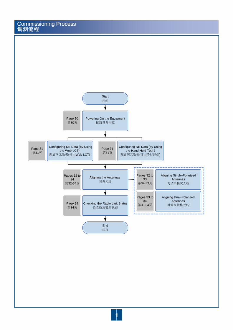
Commissioning Process 调测流程
Start开始
Powering On the Equip接通设备电源
Page 30第30页
Page 31第31页
Configuring NE Data (by Using the Web LCT)
配置网元数据(使用Web LCT)
Page 31第31页
Aligning the Antenn对调天线
Pages 32 to 34
第32-34页
Checking the Radio LinkPage 34 Checking the Radio Link检查微波链路状态
Page 34第34页
End结束
11
pment
Configuring NE Data (by Using the Hand-Held Tool )
配置网元数据(使用手持终端)
nas
k Status
Aligning Dual-Polarized Antennas
对调双极化天线
Pages 33 to 34
第33 34页
Aligning Single-Polarized Antennas
对调单极化天线
Pages 32 to 33
第32-33页
k Status态
对调双极化天线第33-34页
11
Precautions注意事项
This document provides quick guidelines for hardw本文档用于为设备硬件安装提供简明快捷的操作指
This document does not describe pre-delivery assonsite installation.本文档对于出厂前已完成的安装操作不进行介绍,
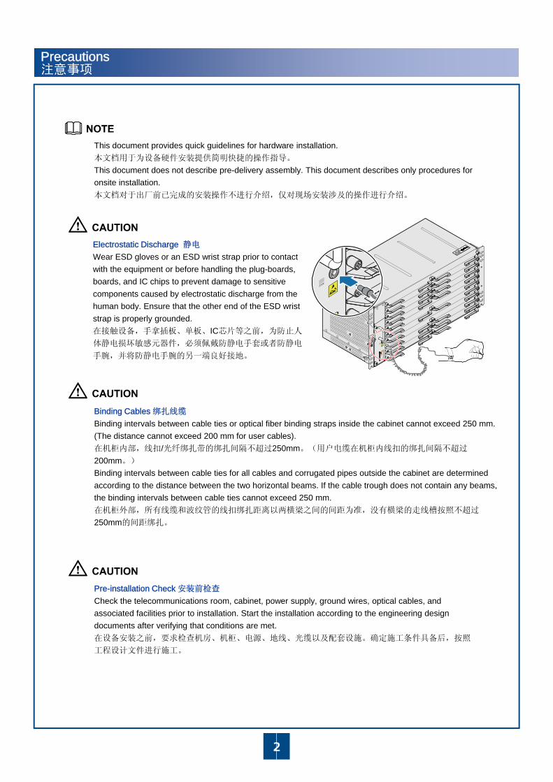
Electrostatic Discharge 静电
Wear ESD gloves or an ESD wrist strap prior to cowith the equipment or before handling the plug-boboards, and IC chips to prevent damage to sensiticomponents caused by electrostatic discharge frocomponents caused by electrostatic discharge frohuman body. Ensure that the other end of the ESDstrap is properly grounded.在接触设备,手拿插板、单板、IC芯片等之前,为
体静电损坏敏感元器件,必须佩戴防静电手套或者
手腕,并将防静电手腕的另一端良好接地。
Binding Cables 绑扎线缆
Binding intervals between cable ties or optical fibe(The distance cannot exceed 200 mm for user cab在机柜内部,线扣/光纤绑扎带的绑扎间隔不超过2200mm。)
Binding intervals between cable ties for all cables according to the distance between the two horizonaccording to the distance between the two horizonthe binding intervals between cable ties cannot ex在机柜外部,所有线缆和波纹管的线扣绑扎距离以
250mm的间距绑扎。
Pre-installation Check 安装前检查
Check the telecommunications room, cabinet, powassociated facilities prior to installation. Start the idocuments after verifying that conditions are met.在设备安装之前,要求检查机房、机柜、电源、地
工程设计文件进行施工。
2
ware installation. 指导。
sembly. This document describes only procedures for
仅对现场安装涉及的操作进行介绍。
ontact ards, ve m them the D wrist
防止人
防静电
er binding straps inside the cabinet cannot exceed 250 mm. bles).50mm。(用户电缆在机柜内线扣的绑扎间隔不超过
and corrugated pipes outside the cabinet are determined ntal beams If the cable trough does not contain any beamsntal beams. If the cable trough does not contain any beams, xceed 250 mm.
以两横梁之间的间距为准,没有横梁的走线槽按照不超过
wer supply, ground wires, optical cables, and nstallation according to the engineering design
地线、光缆以及配套设施。确定施工条件具备后,按照
2
Instructions and Precautions for Handling单板操作规范及注意事项
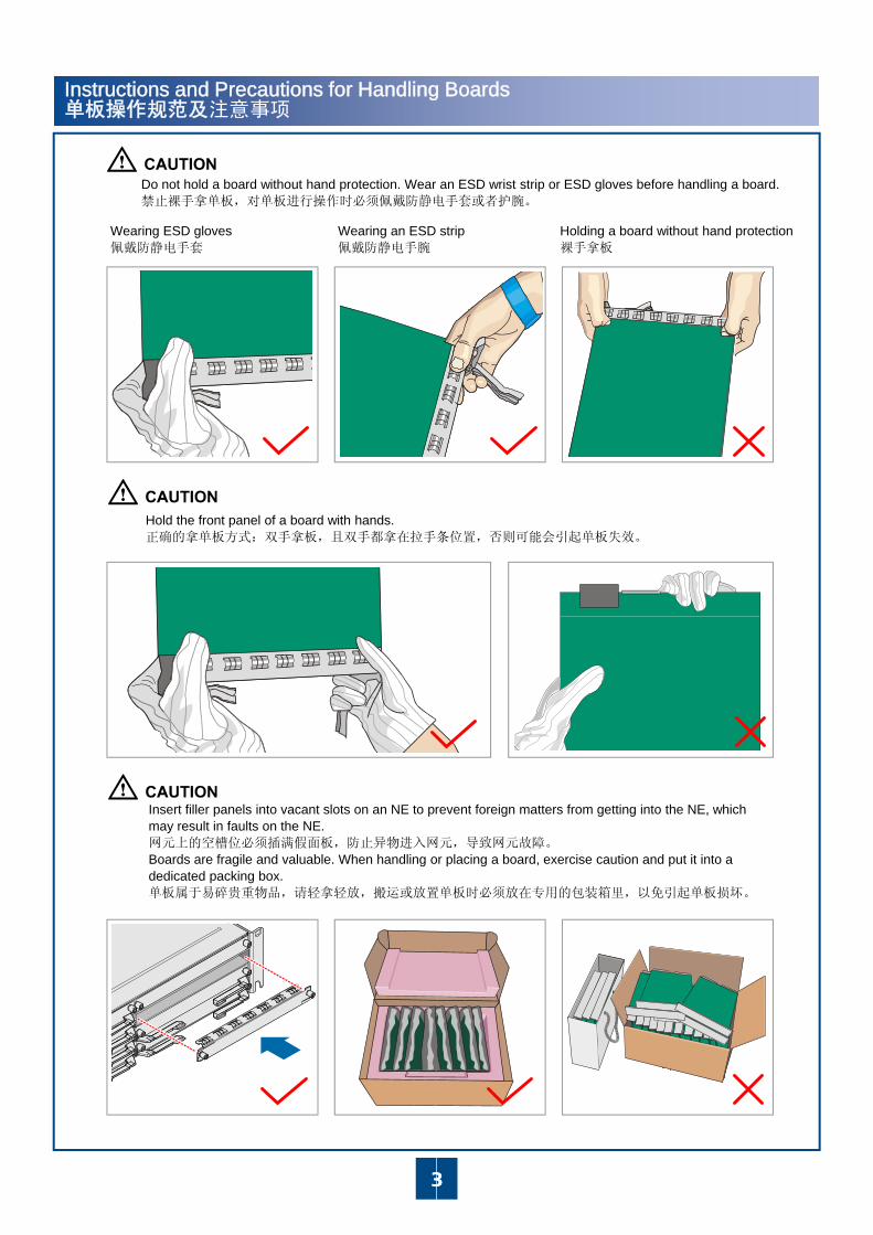
Do not hold a board without hand protection. Wear 禁止裸手拿单板,对单板进行操作时必须佩戴防静电
Wearing ESD gloves佩戴防静电手套
Wearing an ESD 佩戴防静电手腕
Hold the front panel of a board with hands. 正确的拿单板方式:双手拿板,且双手都拿在拉手
Insert filler panels into vacant slots on an NE to prmay result in faults on the NE.网元上的空槽位必须插满假面板,防止异物进入网
Boards are fragile and valuable. When handling odedicated packing box.单板属于易碎贵重物品,请轻拿轻放,搬运或放置
33
g Boards
an ESD wrist strip or ESD gloves before handling a board. 电手套或者护腕。
Holding a board without hand protection裸手拿板
strip
条位置,否则可能会引起单板失效。
revent foreign matters from getting into the NE, which
网元,导致网元故障。
or placing a board, exercise caution and put it into a
置单板时必须放在专用的包装箱里,以免引起单板损坏。
33
Precautions for Handling the Toggle Leve纽子开关操作注意事项
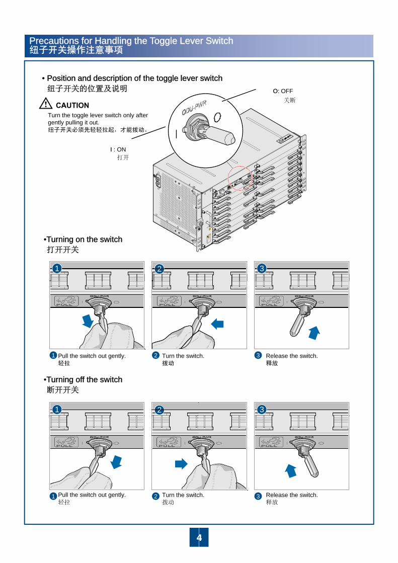
• Position and description of the toggle lever纽子开关的位置及说明
Turn the toggle lever switch only after gently pulling it out.纽子开关必须先轻轻拉起,才能拨动。
• Position and description of the toggle lever
打开
I : ON
1 2
打开开关
•Turning on the switch
1 2
1 2
断开开关
•Turning off the switch
Pull the switch out gently.轻拉
Turn the switc拨动
44
1 2Pull the switch out gently.轻拉
Turn the switc拨动
er Switch
switch
关断
switchO: OFF
3
3
3
ch. Release the switch.释放
44
3ch. Release the switch.释放
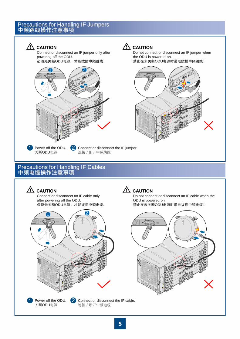
Precautions for Handling IF Jumpers 中频跳线操作注意事项
Connect or disconnect an IF jumper only after powering off the ODU.必须先关断ODU电源,才能拔插中频跳线。
21
Power off the ODU.关断ODU电源
Connect or disconnect the连接/断开中频跳线
Precautions for Handling IF Cables
Connect or disconnect an IF cable only after powering off the ODU.必须先关断ODU电源,才能拔插中频电缆。
g中频电缆操作注意事项
21
55
Power off the ODU.关断ODU电源
Connect or disconnect the连接/断开中频电缆
Do not connect or disconnect an IF jumper when the ODU is powered on.禁止在未关断ODU电源时带电拔插中频跳线!
IF jumper.
Do not connect or disconnect an IF cable when the ODU is powered on.禁止在未关断ODU电源时带电拔插中频电缆!
55
IF cable.
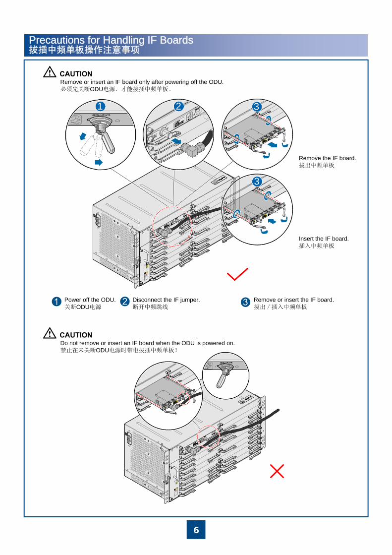
Precautions for Handling IF Boards拔插中频单板操作注意事项
Remove or insert an IF board only after powering off必须先关断ODU电源,才能拔插中频单板。
21
Power off the ODU.关断ODU电源
Disconnect the IF jumpe断开中频跳线
Do not remove or insert an IF board when the ODUDo not remove or insert an IF board when the ODU 禁止在未关断ODU电源时带电拔插中频单板!
66
f the ODU.
3
Remove the IF board.拔出中频单板
3
Insert the IF board.插入中频单板
er. Remove or insert the IF board.拔出/插入中频单板
is powered onis powered on.
66

Tools for Installation安装工具
Long measuring tape长卷尺
Phillips sc十字螺
Level水平尺
Socket wrench成套套筒
Torque wrench 力矩扳手
Hex 内六角
Wire stripper剥线钳
RJ45 crimping tool 网线钳
Diagona斜口
Combination pliers 钢丝钳
Bayonet wrench呆扳手
Fi锉
Utility 裁纸Hammer drill
冲击钻Marker划线笔
Lad梯
ESD gloves防静电手套
ESD wrist strap防静电腕带
7
Binding strap光纤绑扎带
Insulatio电器绝缘
Vacuum cleaner吸尘器
crewdriver螺丝刀
Flat-head screwdriver一字螺丝刀
Adjustable wrench活动扳手
COAX crimping tool压线钳
key 角扳手
Wire clippers 断线钳
al pliers口钳
Cold press pliers冷压钳
Needle-nose pliers 尖嘴钳
Heat gun热风枪
Multimeter万用表
ile锉刀
knife纸刀 Claw hammer
羊角锤Antistatic gloves
安装手套
dder梯子
Electric iron电烙铁
Impact tool 打线刀
7
Network cable tester 网线测试仪
Coax stripper同轴电缆剥线器
on tape缘胶带
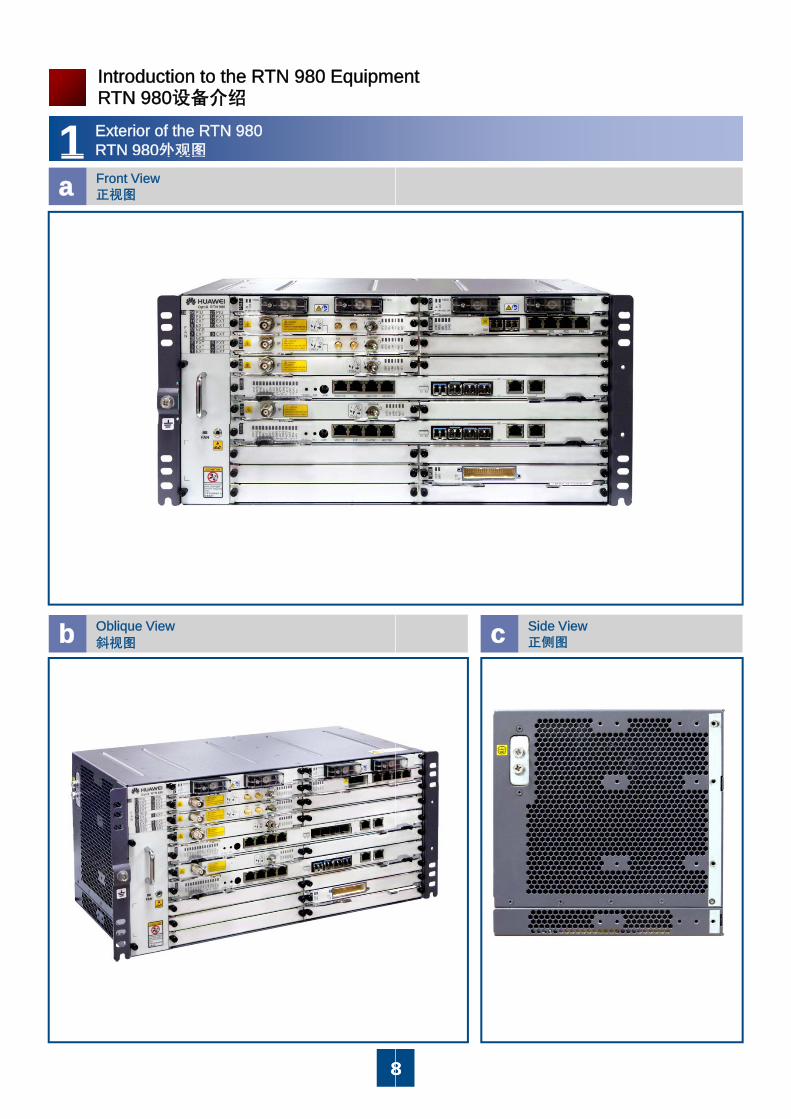
1 Exterior of the RTN 980RTN 980外观图
Introduction to the RTN 980 EquipmeRTN 980设备介绍
Front View正视图a
1 外观图
Oblique View斜视图b
88
ent
Side View正侧图c
88
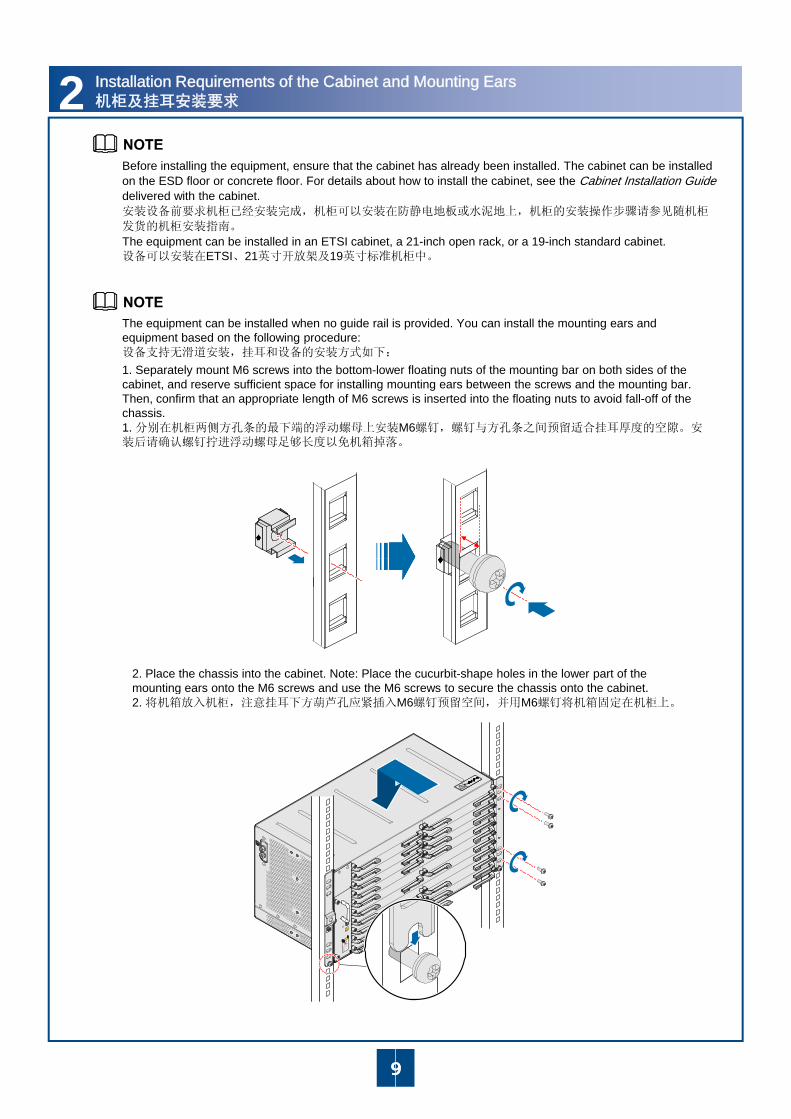
2 Installation Requirements of the Cabinet an机柜及挂耳安装要求
Before installing the equipment, ensure that the cabon the ESD floor or concrete floor. For details about delivered with the cabinet.安装设备前要求机柜已经安装完成,机柜可以安装在
发货的机柜安装指南。
The equipment can be installed in an ETSI cabinet, 设备可以安装在ETSI、21英寸开放架及19英寸标准机
1. Separately mount M6 screws into the bottom-lowecabinet, and reserve sufficient space for installing mThen, confirm that an appropriate length of M6 screwchassis.1 分别在机柜两侧方孔条的最下端的浮动螺母上安装
The equipment can be installed when no guide rail isequipment based on the following procedure: 设备支持无滑道安装,挂耳和设备的安装方式如下:
1. 分别在机柜两侧方孔条的最下端的浮动螺母上安装装后请确认螺钉拧进浮动螺母足够长度以免机箱掉落
2. Place the chassis into the cabinet. Note: Place tmounting ears onto the M6 screws and use the M6g2. 将机箱放入机柜,注意挂耳下方葫芦孔应紧插入
99
nd Mounting Ears
inet has already been installed. The cabinet can be installed how to install the cabinet, see the Cabinet Installation Guide
在防静电地板或水泥地上,机柜的安装操作步骤请参见随机柜
a 21-inch open rack, or a 19-inch standard cabinet.机柜中。
er floating nuts of the mounting bar on both sides of the mounting ears between the screws and the mounting bar.
ws is inserted into the floating nuts to avoid fall-off of the
装M6螺钉 螺钉与方孔条之间预留适合挂耳厚度的空隙 安
s provided. You can install the mounting ears and
装M6螺钉,螺钉与方孔条之间预留适合挂耳厚度的空隙。安落。
the cucurbit-shape holes in the lower part of the 6 screws to secure the chassis onto the cabinet.
入M6螺钉预留空间,并用M6螺钉将机箱固定在机柜上。
99
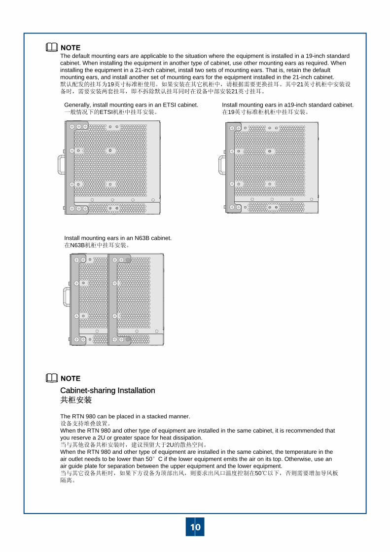
The default mounting ears are applicable to the situacabinet. When installing the equipment in another tyinstalling the equipment in a 21-inch cabinet, install tmounting ears and install another set of mounting emounting ears, and install another set of mounting e默认配发的挂耳为19英寸标准柜使用。如果安装在其备时,需要安装两套挂耳,即不拆除默认挂耳同时在
Generally, install mounting ears in an ETSI cabine一般情况下的ETSI机柜中挂耳安装。
Install mounting ears in an N63B cabinet.在N63B机柜中挂耳安装。
Cabinet-sharing Installation共柜安装
The RTN 980 can be placed in a stacked manner.设备支持堆叠放置。When the RTN 980 and other type of equipment areyou reserve a 2U or greater space for heat dissipatio当与其他设备共柜安装时,建议预留大于2U的散热空When the RTN 980 and other type of equipment areair outlet needs to be lower than 50°C if the lower eair guide plate for separation between the upper equ当与其它设备共柜时,如果下方设备为顶部出风,则
11
当与其它设备共柜时,如果下方设备为顶部出风,则隔离。
ation where the equipment is installed in a 19-inch standard ype of cabinet, use other mounting ears as required. When two sets of mounting ears. That is, retain the default
ears for the equipment installed in the 21 inch cabinetears for the equipment installed in the 21-inch cabinet.其它机柜中,请根据需要更换挂耳。其中21英寸机柜中安装设在设备中部安装21英寸挂耳。
t. Install mounting ears in a19-inch standard cabinet.在19英寸标准柜机柜中挂耳安装。
e installed in the same cabinet, it is recommended that on.空间。e installed in the same cabinet, the temperature in the equipment emits the air on its top. Otherwise, use an uipment and the lower equipment.
则要求出风口温度控制在50℃以下,否则需要增加导风板
00
则要求出风口温度控制在50℃以下,否则需要增加导风板
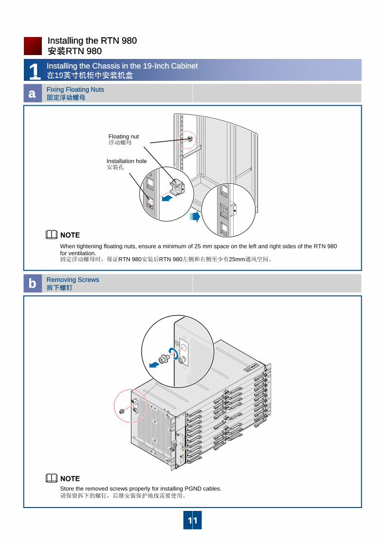
1 Installing the Chassis in the 19-Inch Cabine在19英寸机柜中安装机盒
Installing the RTN 980 安装RTN 980
1 在19英寸机柜中安装机盒
Floating nut浮动螺母
Fixing Floating Nuts固定浮动螺母a
Installation hole安装孔
浮动螺母
When tightening floating nuts, ensure a minimum offor ventilation.固定浮动螺母时,保证RTN 980安装后RTN 980左侧
Removing Screws拆下螺钉b
11
Store the removed screws properly for installing PG请保留拆下的螺钉,后继安装保护地线需要使用。
et
f 25 mm space on the left and right sides of the RTN 980
侧和右侧至少有25mm通风空间。
11
GND cables.
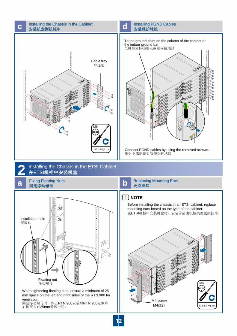
Installing the Chassis in the Cabinet安装机盒到机柜中c
Cable tray导线架
M6
2 Installing the Chassis in the ETSI Cabinet
30±3 Kgf.cm
M6
a2 Installing the Chassis in the ETSI Cabinet
在ETSI机柜中安装机盒
Fixing Floating Nuts固定浮动螺母
Installation hole安装孔
Floating nut浮动螺母
11
When tightening floating nuts, ensure a minimum of 25 mm space on the left and right sides of the RTN 980 for ventilation.固定浮动螺母时,保证RTN 980安装后RTN 980左侧和右侧至少有25mm通风空间。
Installing PGND Cables安装保护地线d
To the ground point on the column of the cabinet or the indoor ground bar至机柜立柱接地点或室内接地排至机柜立柱接地点或室内接地排
Connect PGND cables by using the removed screws. 用拆下来的螺钉安装保护地线
Before installing the chassis in an ETSI cabinet, replace ti b d th t f th bi t
Replacing Mounting Ears更换挂耳b
mounting ears based on the type of the cabinet.在ETSI机柜中安装机盒时,安装前需由机柜类型更换挂耳。
M4
22
M4 screw M4螺钉 12±1.2 Kgf.cm
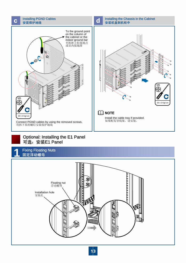
c Installing PGND Cables安装保护地线
To the ground point on the column of the cabinet or thethe cabinet or the indoor ground bar至机柜立柱接地点或室内接地排
M6
Connect PGND cables by using the removed screws. 用拆下来的螺钉安装保护地线
30±3 Kgf.cm
1 Fixing Floating Nuts固定浮动螺母
Optional: Installing the E1 Panel可选:安装E1 Panel
Floating nut浮动螺母
Installation hole安装孔安装孔
11
d Installing the Chassis in the Cabinet安装机盒到机柜中
M6
30±3 Kgf.cm
Install the cable tray if provided.如果配发导线架,请安装。
33
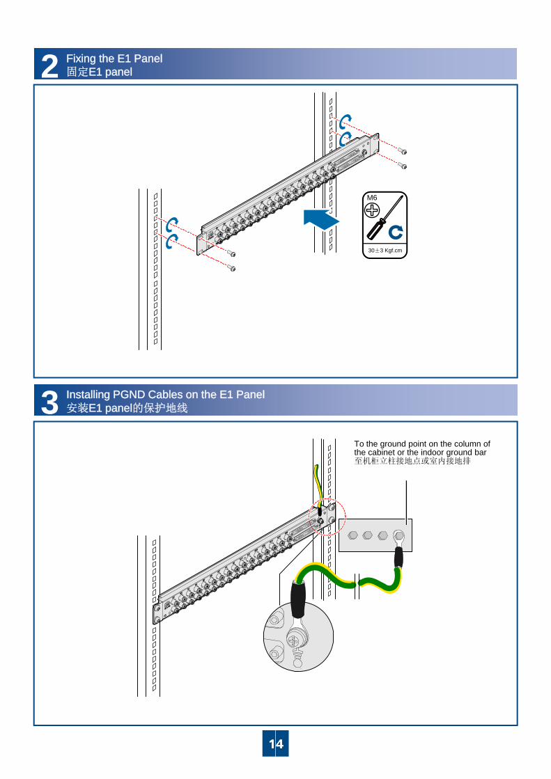
2 Fixing the E1 Panel固定E1 panel
3 Installing PGND Cables on the E1 Panel安装E1 panel的保护地线
11
M6
30±3 Kgf.cm
To the ground point on the column of the cabinet or the indoor ground bar至机柜立柱接地点或室内接地排
44
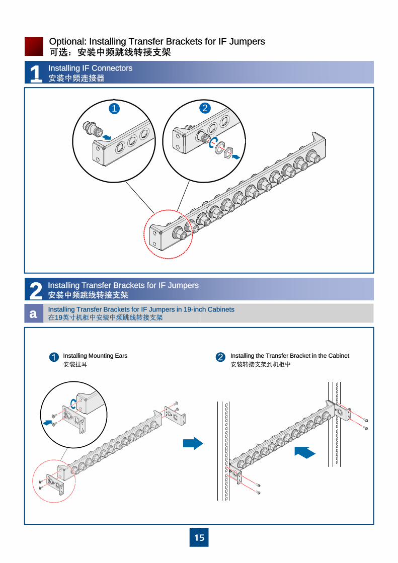
Optional: Installing Transfer Brackets可选:安装中频跳线转接支架
1 Installing IF Connectors安装中频连接器
1
1 安装中频连接器
2 Installing Transfer Brackets for IF Jumpers安装中频跳线转接支架
Installing Transfer Brackets for IF Jumpers in 19-inc在19英寸机柜中安装中频跳线转接支架a
Installing Mounting Ears安装挂耳
1
s for IF Jumpers
2
ch Cabinets
Installing the Transfer Bracket in the Cabinet安装转接支架到机柜中
5
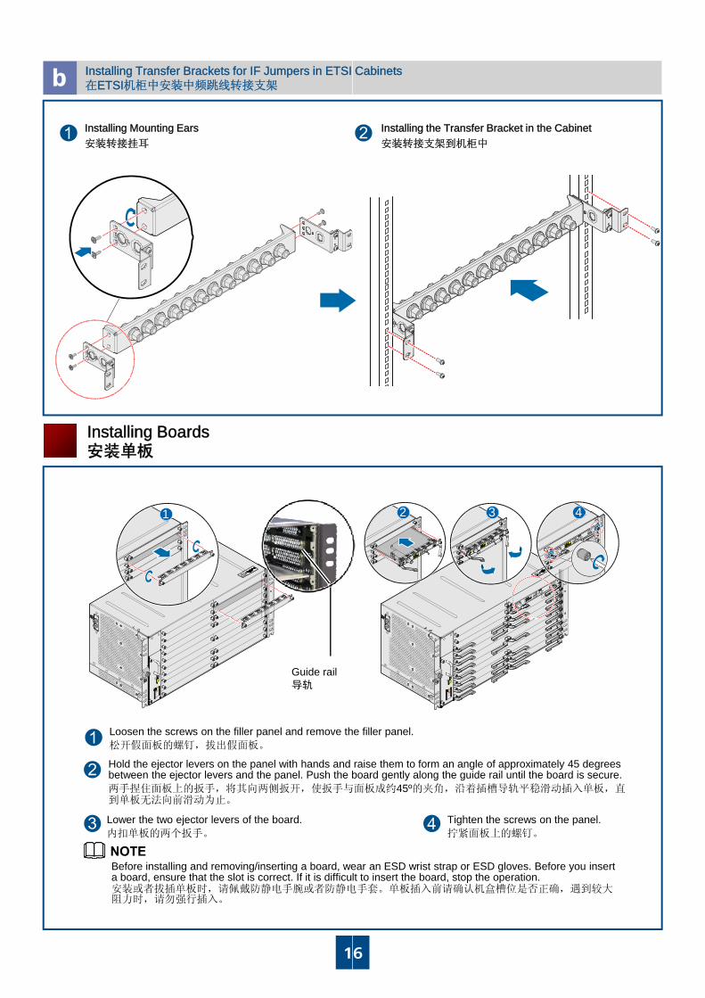
Installing Transfer Brackets for IF Jumpers in ETSI 在ETSI机柜中安装中频跳线转接支架b
Installing Mounting Ears安装转接挂耳安装转接挂耳
Installing Boards安装单板
1
Loosen the screws on the filler panel and remove th
Guide rail导轨
松开假面板的螺钉,拔出假面板。
Hold the ejector levers on the panel with hands and between the ejector levers and the panel. Push the b两手捏住面板上的扳手,将其向两侧扳开,使扳手与到单板无法向前滑动为止。
Lower the two ejector levers of the board.内扣单板的两个扳手。
1
Before installing and removing/inserting a board, wea board, ensure that the slot is correct. If it is difficul安装或者拔插单板时,请佩戴防静电手腕或者防静电阻力时,请勿强行插入。
Cabinets
Installing the Transfer Bracket in the Cabinet安装转接支架到机柜中安装转接支架到机柜中
2 3 4
he filler panel.
raise them to form an angle of approximately 45 degrees board gently along the guide rail until the board is secure.
与面板成约45º的夹角,沿着插槽导轨平稳滑动插入单板,直
Tighten the screws on the panel.拧紧面板上的螺钉。
6
ear an ESD wrist strap or ESD gloves. Before you insert lt to insert the board, stop the operation.
电手套。单板插入前请确认机盒槽位是否正确,遇到较大
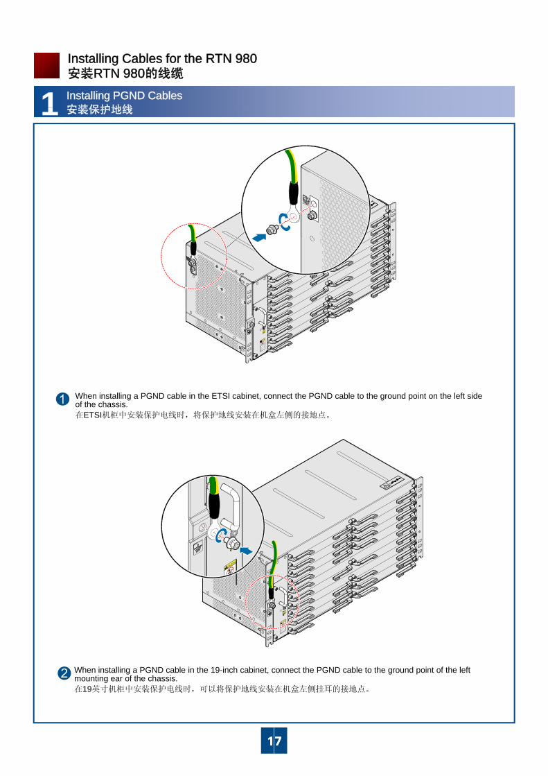
Installing Cables for the RTN 980安装RTN 980的线缆
1 Installing PGND Cables安装保护地线1 安装保护地线
When installing a PGND cable in the ETSI cabinet, conof the chassis.在ETSI机柜中安装保护电线时,将保护地线安装在机盒
Wh i lli PGND bl i h 19 i h bi
11
When installing a PGND cable in the 19-inch cabinet, cmounting ear of the chassis.在19英寸机柜中安装保护电线时,可以将保护地线安装
nnect the PGND cable to the ground point on the left side
盒左侧的接地点。
h PGND bl h d i f h l f
77
connect the PGND cable to the ground point of the left
在机盒左侧挂耳的接地点。
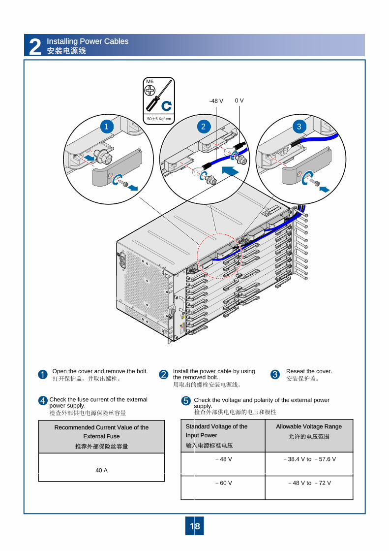
2 Installing Power Cables安装电源线
150±5 Kgf.cm
M6
Check the fuse current of the external power supply.
Cs
Open the cover and remove the bolt.打开保护盖,并取出螺栓。
Install ththe remo用取出的
power supply.检查外部供电电源保险丝容量
s检
Recommended Current Value of the External Fuse
推荐外部保险丝容量
40 A
StaInpu
输入
1
2 3
0 V-48 V
Check the voltage and polarity of the external power supply.
e power cable by using oved bolt.的螺栓安装电源线。
Reseat the cover.安装保护盖。
supply.检查外部供电电源的电压和极性
ndard Voltage of the ut Power
入电源标准电压
Allowable Voltage Range
允许的电压范围
–48 V –38.4 V to –57.6 V
8
–60 V –48 V to –72 V
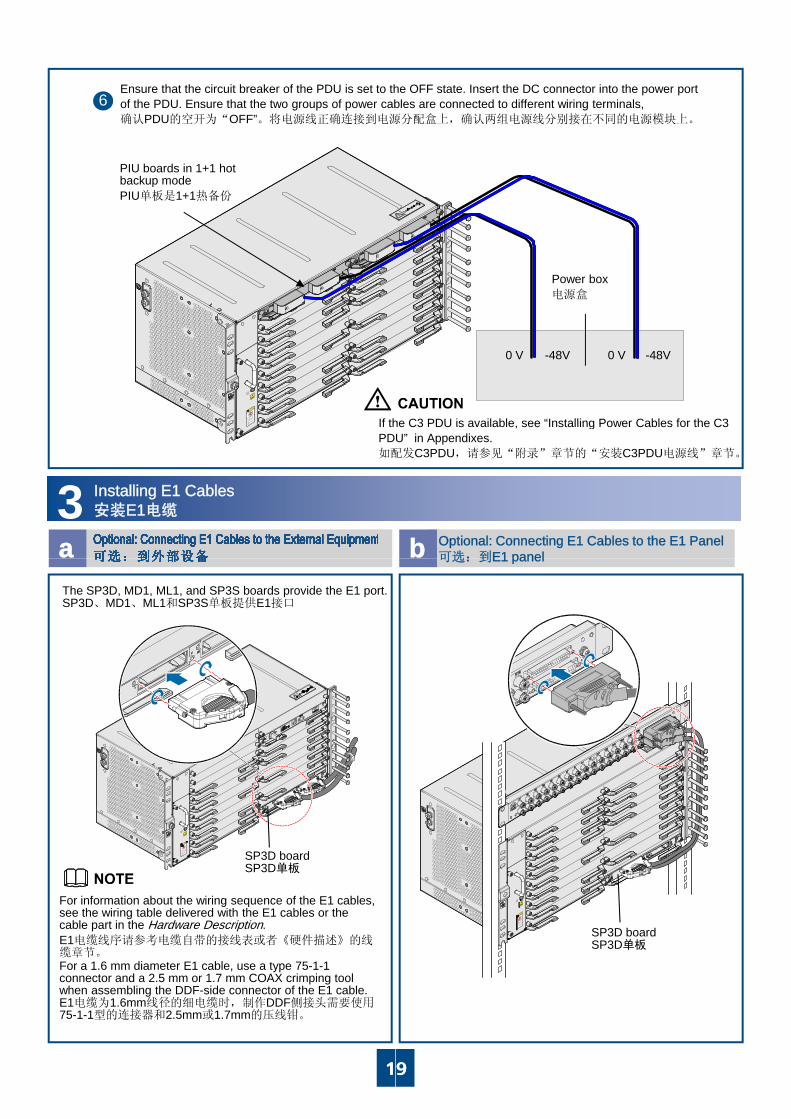
Ensure that the circuit breaker of the PDU is set to thof the PDU. Ensure that the two groups of power cab确认PDU的空开为“OFF”。将电源线正确连接到电源
6
PIU boards in 1+1 hot backup modePIU单板是1+1热备份
If th
3 Installing E1 Cables安装E1电缆
a
If thPD如配
The SP3D, MD1, ML1, and SP3S boards provide the E1 port.SP3D、MD1、ML1和SP3S单板提供E1接口
For information about the wiring sequence of the E1 cables, see the wiring table delivered with the E1 cables or the cable part in the Hardware Description.E1电缆线序请参考电缆自带的接线表或者《硬件描述》的线缆章节。F 1 6 di t E1 bl t 75 1 1
SP3D boardSP3D单板
11
For a 1.6 mm diameter E1 cable, use a type 75-1-1 connector and a 2.5 mm or 1.7 mm COAX crimping tool when assembling the DDF-side connector of the E1 cable.E1电缆为1.6mm线径的细电缆时,制作DDF侧接头需要使用75-1-1型的连接器和2.5mm或1.7mm的压线钳。
he OFF state. Insert the DC connector into the power port bles are connected to different wiring terminals, 源分配盒上,确认两组电源线分别接在不同的电源模块上。
Power box电源盒
-48V0 V -48V0 V
电源盒
he C3 PDU is available see “Installing Power Cables for the C3
Optional: Connecting E1 Cables to the E1 Panel可选:到E1 panelb
he C3 PDU is available, see Installing Power Cables for the C3 U” in Appendixes. 配发C3PDU,请参见“附录”章节的“安装C3PDU电源线”章节。
可选:到E1 panel
SP3D boardSP3D单板
99
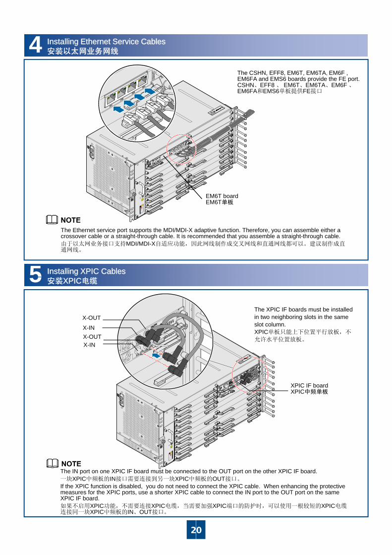
4 Installing Ethernet Service Cables安装以太网业务网线
5 Installing XPIC Cables安
The Ethernet service port supports the MDI/MDI-X acrossover cable or a straight-through cable. It is reco由于以太网业务接口支持MDI/MDI-X自适应功能,因通网线。
5 安装XPIC电缆
X-IN
X-OUT
X INX-OUTX-IN
The IN port on one XPIC IF board must be connecte块XPIC中频板的IN接口需要连接到另 块XPIC中频
22
一块XPIC中频板的IN接口需要连接到另一块XPIC中频
If the XPIC function is disabled, you do not need to measures for the XPIC ports, use a shorter XPIC caXPIC IF board.如果不启用XPIC功能,不需要连接XPIC电缆,当需要连接同一块XPIC中频板的IN、OUT接口。
The CSHN, EFF8, EM6T, EM6TA, EM6F , EM6FA d EMS6 b d id th FE tEM6FA and EMS6 boards provide the FE port.CSHN、EFF8 、 EM6T、EM6TA、EM6F 、EM6FA和EMS6单板提供FE接口
EM6T boardEM6T单板
adaptive function. Therefore, you can assemble either a ommended that you assemble a straight-through cable.
因此网线制作成交叉网线和直通网线都可以。建议制作成直
The XPIC IF boards must be installed in two neighboring slots in the same slot column.XPIC单板只能上下位置平行放板,不
允许水平位置放板。
XPIC IF boardXPIC中频单板
ed to the OUT port on the other XPIC IF board.频板的OUT接口
00
频板的OUT接口。
connect the XPIC cable. When enhancing the protective able to connect the IN port to the OUT port on the same
要加强XPIC端口的防护时,可以使用一根较短的XPIC电缆
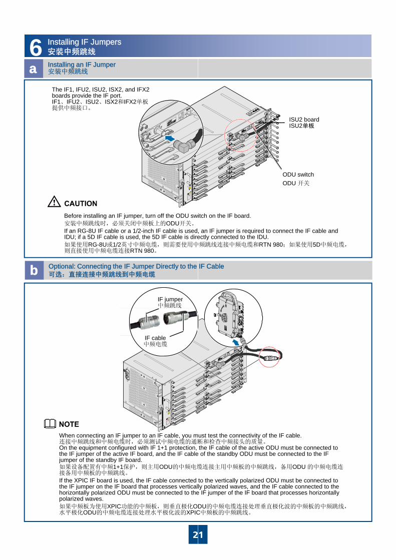
6 Installing IF Jumpers安装中频跳线
Installing an IF Jumper安装中频跳线a
The IF1, IFU2, ISU2, ISX2, and IFX2 boards provide the IF port.IF1、IFU2、ISU2、ISX2和IFX2单板提供中频接口。
Before installing an IF jumper, turn off the ODU sw安装中频跳线时,必须关闭中频板上的ODU开关。
If an RG-8U IF cable or a 1/2-inch IF cable is used,IDU; if a 5D IF cable is used, the 5D IF cable is dire如果使用RG-8U或1/2英寸中频电缆,则需要使用中则直接使用中频电缆连接RTN 980。
Optional: Connecting the IF Jumper Directly to the 可选:直接连接中频跳线到中频电缆b
IF jumper中频跳线
IF cable中频电缆
When connecting an IF jumper to an IF cable, you m连接中频跳线和中频电缆时,必须测试中频电缆的通断On the equipment configured with IF 1+1 protection, the IF jumper of the active IF board, and the IF cablejumper of the standby IF board.如果设备配置有中频1+1保护,则主用ODU的中频电缆接备用中频板的中频跳线。
If the XPIC IF board is used the IF cable connected
22
If the XPIC IF board is used, the IF cable connected the IF jumper on the IF board that processes verticalhorizontally polarized ODU must be connected to thepolarized waves.如果中频板为使用XPIC功能的中频板,则垂直极化O水平极化ODU的中频电缆连接处理水平极化波的XPIC
ISU2 boardISU2单板
ODU switchODU 开关
itch on the IF board.
, an IF jumper is required to connect the IF cable and ectly connected to the IDU.
中频跳线连接中频电缆和RTN 980;如果使用5D中频电缆,
IF Cable
ust test the connectivity of the IF cable.断和检查中频接头的质量。the IF cable of the active ODU must be connected to
e of the standby ODU must be connected to the IF
缆连接主用中频板的中频跳线,备用ODU 的中频电缆连
to the vertically polarized ODU must be connected to
11
to the vertically polarized ODU must be connected to ly polarized waves, and the IF cable connected to the
e IF jumper of the IF board that processes horizontally
DU的中频电缆连接处理垂直极化波的中频板的中频跳线,C中频板的中频跳线。
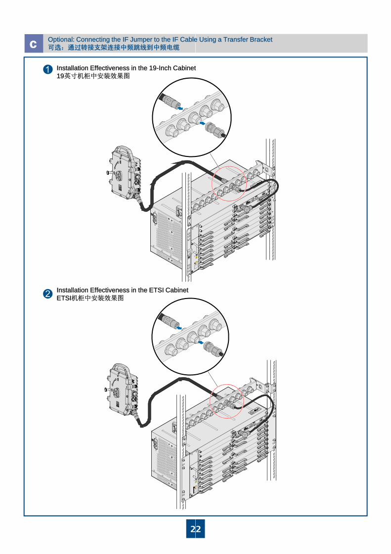
Optional: Connecting the IF Jumper to the IF Cable可选:通过转接支架连接中频跳线到中频电缆c
Installation Effectiveness in the 19-Inch Cabinet19英寸机柜中安装效果图19英寸机柜中安装效果图
Installation Effectiveness in the ETSI CabinetETSI机柜中安装效果图
2
e Using a Transfer Bracket
t
2
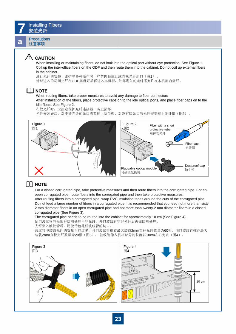
7 Installing Fibers安装光纤
Precautions注意事项a
When installing or maintaining fibers, do not look intoCoil up the inter-office fibers on the ODF and then roin the cabinet. 进行光纤的安装、维护等各种操作时,严禁肉眼靠近
外部进入的局间光纤在ODF架盘好后再进入本机柜,
When routing fibers, take proper measures to avoid After installation of the fibers, place protective caps oidle fibers. See Figure 2. 布放光纤时,应注意保护光纤连接器,防止损坏。
光纤安装好后,对不插光纤的光口需要插上防尘帽,
Figure 1图图1
For a closed corrugated pipe, take protective measuropen corrugated pipe, route fibers into the corrugatedAfter routing fibers into a corrugated pipe, wrap PVC Do not feed a large number of fibers in a corrugated p2 di t fib i t d i d2 mm diameter fibers in an open corrugated pipe andcorrugated pipe (See Figure 3).The corrugated pipe needs to be routed into the cabin闭口波纹管应先做好防割处理再穿光纤,开口波纹管穿
光纤穿入波纹管后,用胶带包扎好波纹管的切口。
波纹管中装载光纤的数量不能过多,开口波纹管推荐最
装载2mm直径光纤数量为20根(图3), 波纹管伸入机
Figure 3Figure 3图3
22
o the optical port without eye protection. See Figure 1.oute them into the cabinet. Do not coil up external fibers
或直视光纤出口(图1) 。
外部进入的光纤不允许在本机柜内盘纤。
any damage to fiber connectorson to the idle optical ports, and place fiber caps on to the
对没有接光口的光纤需要套上光纤帽(图2) 。
Figure 2图
Fiber with a short
Fiber cap光纤帽
Dustproof cap
图2 protective tube短护套光纤
Pluggable optical module可插拔光模块
p p防尘帽
res and then route fibers into the corrugated pipe. For an d pipe and then take protective measures. insulation tapes around the cuts of the corrugated pipe.pipe. It is recommended that you feed not more than sixty
d t th t t 2 di t fib i l dd not more than twenty 2 mm diameter fibers in a closed
net for approximately 10 cm (See Figure 4).穿好光纤后再做防割处理。
最大装载2mm直径光纤数量为60根,闭口波纹管推荐最大
机柜部分的长度以10cm左右为宜(图4)。
Figure 4
10 cm
Figure 4图4
33
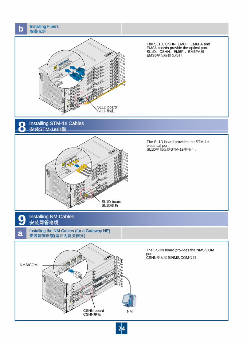
Installing Fibers安装光纤b
SL1D boardSL1D单板
8 Installing STM-1e Cables安装STM-1e电缆8 安装STM 1e电缆
SL1D boardSL1D单板
9 Installing NM Cables安装网管电缆
Installing the NM Cables (for a Gateway NE)安装网管电缆(网元为网关网元)a
NMS/COM
22
CSHN boardCSHN单板
The SL1D, CSHN, EM6F , EM6FA and EMS6 boards provide the optical portEMS6 boards provide the optical port.SL1D、CSHN、EM6F 、EM6FA和EMS6单板提供光接口
The SL1D board provides the STM-1e electrical port.SL1D单板提供STM-1e电接口。
The CSHN board provides the NMS/COM portport.CSHN单板提供NMS/COM接口
44
NM
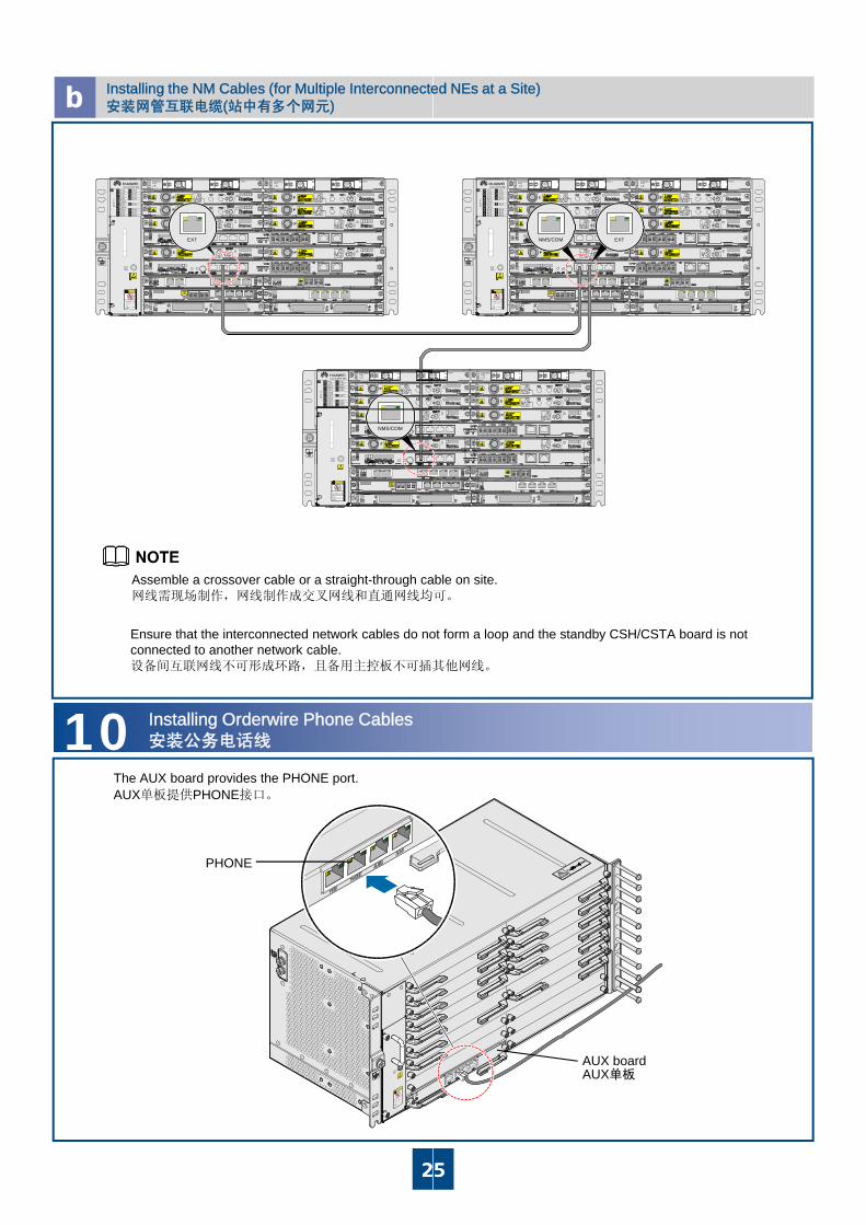
Installing the NM Cables (for Multiple Interconnecte安装网管互联电缆(站中有多个网元)b
MD
1
EXT
NMS/COM
Assemble a crossover cable or a straight-through ca网线需现场制作,网线制作成交叉网线和直通网线均
MD
1
10 Installing Orderwire Phone Cables 安装公务电话线
Ensure that the interconnected network cables do noconnected to another network cable.设备间互联网线不可形成环路,且备用主控板不可插其
PHONE
The AUX board provides the PHONE port.AUX单板提供PHONE接口。
22
ed NEs at a Site)
MD
1
EXTNMS/COM
able on site. 可。
ot form a loop and the standby CSH/CSTA board is not
其他网线。
55
AUX boardAUX单板
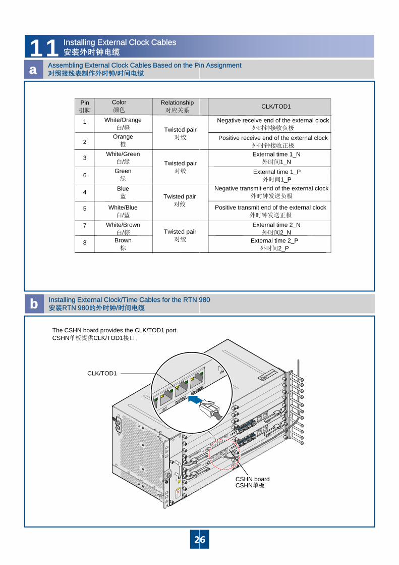
11 Installing External Clock Cables安装外时钟电缆
Assembling External Clock Cables Based on the Pi对照接线表制作外时钟/时间电缆a
Pin引脚
Color颜色
Relationship对应关系
White/Orange白/橙
Orange橙
1
2
Twisted pair对绞
橙
White/Green白/绿Green绿
Blue蓝
White/Blue白/蓝
3
6
4
5
Twisted pair对绞
Twisted pair对绞
白/蓝White/Brown
白/棕Brown棕
7
8
Twisted pair对绞
Installing External Clock/Time Cables for the RTN 9安装RTN 980的外时钟/时间电缆b
The CSHN board provides the CLK/TOD1 port.CSHN单板提供CLK/TOD1接口。
CLK/TOD1
22
in Assignment
CLK/TOD1
Negative receive end of the external clock外时钟接收负极
Positive receive end of the external clock外时钟接收正极
Positive transmit end of the external clock外时钟发送正极
Negative transmit end of the external clock外时钟发送负极
外时钟接收正极
External time 1_P外时间1_P
External time 1_N外时间1_N
外时钟发送正极
External time 2_N外时间2_N
External time 2_P外时间2_P
980
CSHN boardCSHN单板
66
CSHN单板
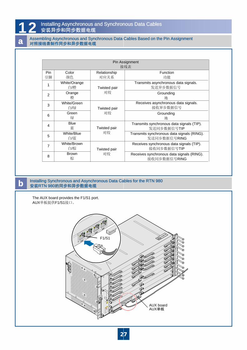
12 Installing Asynchronous and Synchron安装异步和同步数据电缆
Assembling Asynchronous and Synchronous Data 对照接线表制作同步和异步数据电缆a
Pin As接
Pin引脚
Color颜色
Relationship对应关系
White/Orange白/橙
1Twisted pair
对绞Orange橙
White/Green白/绿Green绿
Blue蓝
White/Bl e
2
3
6
4
对绞
Twisted pair对绞
Twisted pair对绞White/Blue
白/蓝White/Brown
白/棕Brown棕
5
7
8
对绞
Twisted pair对绞
Installing Synchronous and Asynchronous Data Ca安装RTN 980的同步和异步数据电缆b
The AUX board provides the F1/S1 port.AUX单板提供F1/S1接口。
F1/S1
22
nous Data Cables
Cables Based on the Pin Assignment
signment接线表
Function功能
Transmits asynchronous data signals.发送异步数据信号
Transmits synchronous data signals (TIP).发送同步数据信号TIP
T it h d t i l (RING)
Grounding地
Receives asynchronous data signals.接收异步数据信号
Grounding地
Receives synchronous data signals (TIP).接收同步数据信号TIP
Receives synchronous data signals (RING).接收同步数据信号RING
Transmits synchronous data signals (RING).发送同步数据信号RING
ables for the RTN 980
77
AUX boardAUX单板
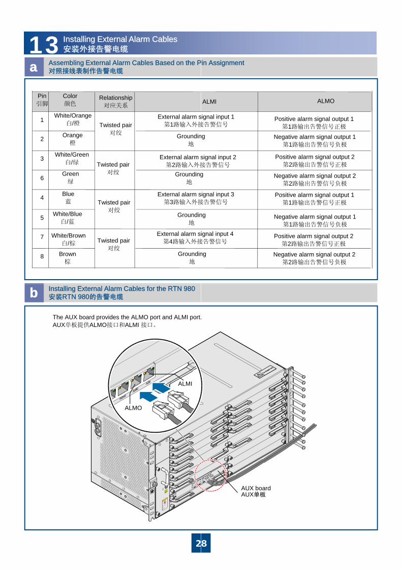
Assembling External Alarm Cables Based on the P对照接线表制作告警电缆a
13 Installing External Alarm Cables安装外接告警电缆
Pin引脚
Color颜色
Relationship对应关系
White/Orange白/橙
Orange橙
1
2
Twisted pair对绞
External alarm s第1路输入外接
Groundin地
White/Green白/绿
Green绿
Blue蓝
White/Blue
3
6
4
5
Twisted pair对绞
External alarm s第3路输入外接
Grounding地
External alarm s第2路输入外接
Twisted pair对绞
GroundinWhite/Blue白/蓝
White/Brown白/棕
Brown棕
5
7
8
Groundin地
Twisted pair对绞
Groundin地
External alarm si第4路输入外接
Installing External Alarm Cables for the RTN 980安装RTN 980的告警电缆b
The AUX board provides the ALMO port and ALMI port.AUX单板提供ALMO接口和ALMI 接口。
ALMI
ALMO
22
Pin Assignment
ALMI
signal input 1接告警信号
ng
Positive alarm signal output 1第1路输出告警信号正极
Negative alarm signal output 1第1路输出告警信号负极
ALMO
signal input 3接告警信号
g
signal input 2接告警信号
ng
Positive alarm signal output 2第2路输出告警信号正极
Negative alarm signal output 2第2路输出告警信号负极
Positive alarm signal output 1第1路输出告警信号正极
Negative alarm signal output 1ng
ng
ignal input 4接告警信号
Negative alarm signal output 1第1路输出告警信号负极
Positive alarm signal output 2第2路输出告警信号正极
Negative alarm signal output 2第2路输出告警信号负极
.
AUX board
88
AUX boardAUX单板
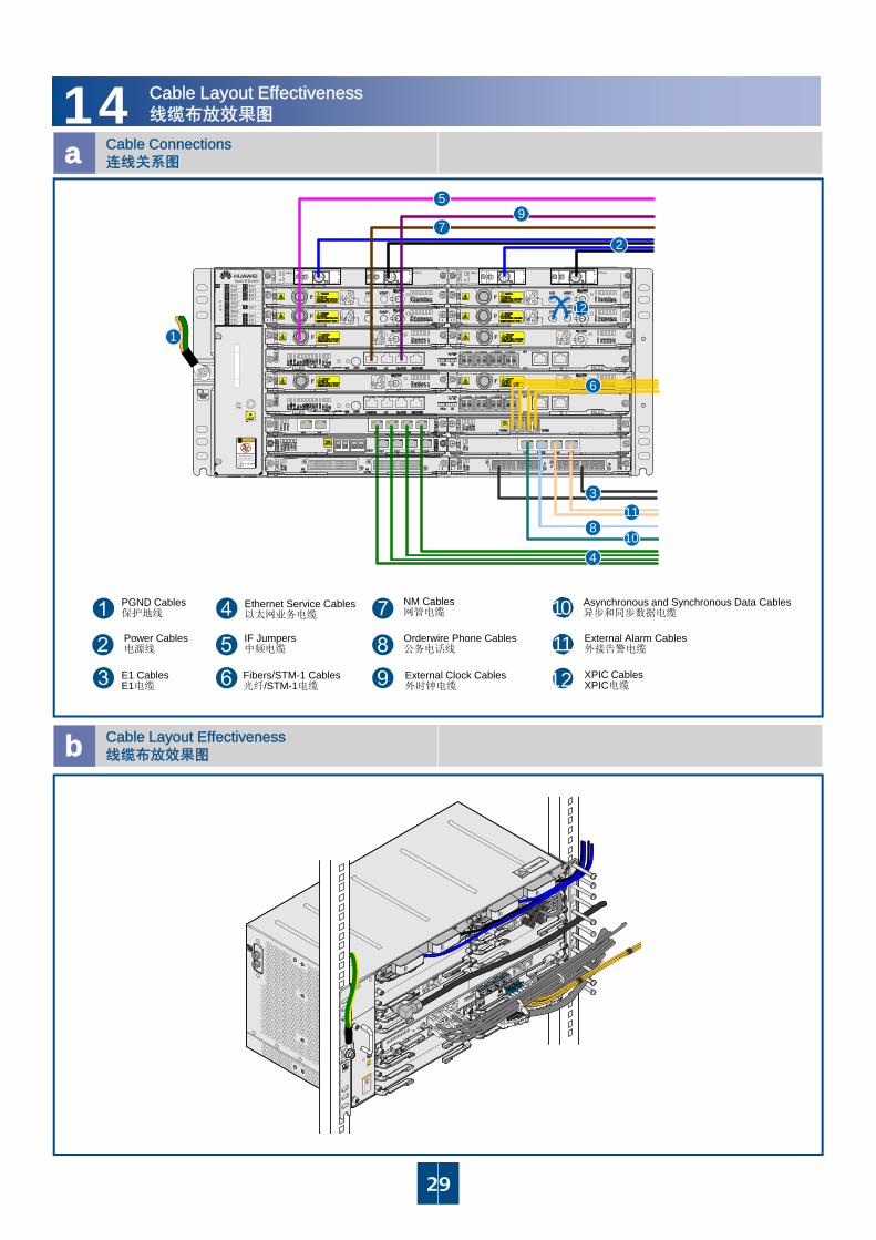
Cable Connections连线关系图a
14 Cable Layout Effectiveness线缆布放效果图
MD
1
1
PGND Cables保护地线
NM Cab网管电缆
Ethernet Service Cables以太网业务电缆
Cable Layout Effectiveness线缆布放效果图b
Power Cables电源线
E1 CablesE1电缆
Orderwi公务电话
IF Jumpers中频电缆
Fibers/STM-1 Cables光纤/STM-1电缆
Externa外时钟电
2
2
5
79
12
6
3
4
810
11
10bles缆
Asynchronous and Synchronous Data Cables异步和同步数据电缆
11ire Phone Cables话线
External Alarm Cables外接告警电缆
al Clock Cables电缆 12 XPIC Cables
XPIC电缆
9
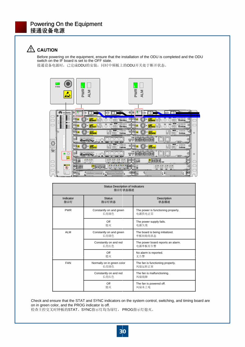
Powering On the Equipment接通设备电源
FANR M
Before powering on the equipment, ensure that the inswitch on the IF board is set to the OFF state.接通设备电源时,已完成ODU的安装,同时中频板上
PW
RA
LM
PW
RA
LM
D1
M
Status Descrip指示灯
Indicator指示灯
Status指示灯状态
PWR Constantly on and gree长亮绿色长亮绿色
Off熄灭
ALM Constantly on and gree长亮绿色
Constantly on and red长亮红色
Off熄灭熄灭
FAN Normally on in green col长亮绿色
Constantly on and red长亮红色
Off熄灭
33
Check and ensure that the STAT and SYNC indicators oon in green color, and the PROG indicator is off.检查主控交叉时钟板的STAT、SYNC指示灯均为绿灯, P
R M
nstallation of the ODU is completed and the ODU
上的ODU开关处于断开状态。
PW
RA
LM
PW
RA
LM
ption of Indicators状态描述
Description状态描述
n The power is functioning properly.电源供电正常电源供电正常
The power supply fails.电源失效
n The board is being initialized.单板初始化状态
The power board reports an alarm.电源单板有告警
No alarm is reported.无告警无告警
or The fan is functioning properly.风扇运转正常
The fan is malfunctioning.风扇故障
The fan is powered off.风扇未上电
00
on the system control, switching, and timing board are
PROG指示灯熄灭。
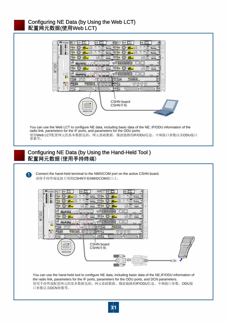
Configuring NE Data (by Using the W配置网元数据(使用Web LCT)
MD
1
NMS/COM
CSCS
You can use the Web LCT to configure NE data, includiradio link, parameters for the IF ports, and parameters f使用Web LCT配置网元的基本数据包括:网元基础数据、参数等。
Configuring NE Data (by Using the H配置网元数据(使用手持终端)配置网元数据(使用手持终端)
Connect the hand-held terminal to the NMS/COM p请将手持终端连接主用的CSHN单板NMS/COM接口
MD
1
You can use the hand-held tool to configure NE data,
NMS/COM
CSHN boardCSHN单板
33
gthe radio link, parameters for the IF ports, parameters使用手持终端配置网元的基本数据包括:网元基础数据
口参数以及DCN参数等。
Web LCT)
SHN boardSHN单板
ing basic data of the NE, IF/ODU information of the for the ODU ports.、微波链路的IF/ODU信息、中频接口参数以及ODU接口
Hand-Held Tool )
ort on the active CSHN board.上。
including basic data of the NE,IF/ODU information of
11
gs for the ODU ports, and DCN parameters.据、微波链路的IF/ODU信息、中频接口参数、ODU接
Aligning Antennas对调天线
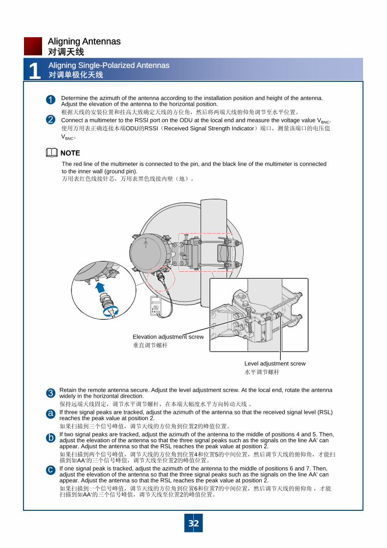
1 Aligning Single-Polarized Antennas对调单极化天线1 对调单极化天线
Determine the azimuth of the antenna according to Adjust the elevation of the antenna to the horizontal根据天线的安装位置和挂高大致确定天线的方位角,
Connect a multimeter to the RSSI port on the ODU 使用万用表正确连接本端ODU的RSSI(Received SVBNC。
The red line of the multimeter is connected to the pto the inner wall (ground pin).万用表红色线接针芯,万用表黑色线接内壁(地)。
Elevation adjustment scj垂直调节螺杆
Retain the remote antenna secure. Adjust the level awidely in the horizontal direction.保持远端天线固定,调节水平调节螺杆,在本端大幅
a
b
c
保持远端天线固定,调节水平调节螺杆,在本端大幅
If three signal peaks are tracked, adjust the azimuth reaches the peak value at position 2.如果扫描到三个信号峰值,调节天线的方位角到位置
If two signal peaks are tracked, adjust the azimuth oadjust the elevation of the antenna so that the three appear. Adjust the antenna so that the RSL reaches如果扫描到两个信号峰值,调节天线的方位角到位置描到如AA‘的三个信号峰值,调节天线至位置2的峰值
If one signal peak is tracked, adjust the azimuth of th
33
c g p , jadjust the elevation of the antenna so that the three appear. Adjust the antenna so that the RSL reaches如果扫描到一个信号峰值,调节天线的方位角到位置扫描到如AA‘的三个信号峰值,调节天线至位置2的峰
the installation position and height of the antenna. l position. 然后将两端天线俯仰角调节至水平位置。
at the local end and measure the voltage value VBNC.Signal Strength Indicator)端口,测量该端口的电压值
in, and the black line of the multimeter is connected
crew
Level adjustment screw水平调节螺杆
adjustment screw. At the local end, rotate the antenna
幅度水平方向转动天线 。幅度水平方向转动天线 。
of the antenna so that the received signal level (RSL)
置2的峰值位置。
of the antenna to the middle of positions 4 and 5. Then, signal peaks such as the signals on the line AA' can
s the peak value at position 2.置4和位置5的中间位置,然后调节天线的俯仰角,才能扫值位置。
he antenna to the middle of positions 6 and 7. Then,
22
p ,signal peaks such as the signals on the line AA' can
s the peak value at position 2.置6和位置7的中间位置,然后调节天线的俯仰角 ,才能峰值位置。
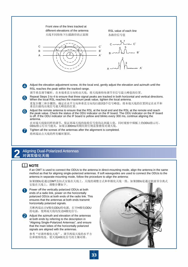
Front view of the lines tracked atdifferent elevations of the antenna天线不同仰角下扫描路径的正面图
A
B
C
24
6 7
1 3
5
Adjust the elevation adjustment screw. At the local RSL reaches the peak within the tracked range.调节垂直调节螺杆,在本端垂直方向转动天线,将天
Repeat Steps 3 to 4 to ensure that three signal peaWhen the local RSL reaches the maximum peak va重复步骤三和步骤四,确定在水平方向和垂直方向均垂直扫描均出现信号最大峰值的位置。
Adjust the remote antenna to ensure that the RSL athe peak value. Check the status of the ODU indicais off. If the ODU indicator on the IF board is yellow antenna.在对端天线做同样的调节,保证两端天线的接收信号ODU指示灯应当熄灭,如果以300ms周期闪黄灯则需
Tighten all the screws of the antennas after the alig将两端站点天线的所有螺丝紧固
2 Aligning Dual-Polarized Antennas对调双极化天线
将两端站点天线的所有螺丝紧固。
Power off the vertically polarized ODUs at both ends of a radio link, power on the horizontally polarized ODUs at both ends of the radio link. This
If an OMT is used to connect the ODUs to the antenmethod as that for aligning single-polarized antennaantenna in separate-mounting mode, follow the proc如果ODU是通过OMT直扣式安装在天线上,天线的调安装在天线上,调整步骤如下。
pensures that the antennas at both ends transmit horizontally polarized signals. 关断两端站点V极化ODU的电源,打开H极化ODU的电源,使两端天线均发送H极化信号。
Adjust the azimuth and elevation of the antennas at both ends by referring to the description in “Aligning Single-Polarized Antennas”, and ensure that the main lobes of the horizontally polarized signals are aligned with the antennas
33
signals are aligned with the antennas.参考“对调单极化天线”,调节两端天线的水平方位和俯仰角度,使天线H极化信号的主瓣对准。
RSL value of each line各路径信号值
31
2
B
7
4 5
6
A
B'
A'
C'C
A'
B'C'
A
end, gently adjust the elevation and azimuth until the
天线俯仰角调节至信号最大峰值的位置。
ks are tracked in both horizontal and vertical directions. alue, tighten the local antenna.均扫描到3个信号峰值,将本端天线的位置固定在水平和
at the local end and the RSL at the remote end reach ator on the IF board. The ODU indicator on the IF board
and blinks every 300 ms, continue aligning the
号值均达到最大值,同时观察中频板上的ODU指示灯,需要继续对调天线。
nment is completed.
nna in direct-mounting mode, align the antenna in the same as. If soft waveguides are used to connect the ODUs to the cedure to align the antenna: 调整方式和单极化天线一致,如果ODU是通过软波导分离式
33
Use a multimeter to measure the RSL (P1) on the end. 使用万用表在本端H极化ODU的RSSI端口测试电平
Power on the vertically polarized ODU at the localPower on the vertically polarized ODU at the local RSSI port of the vertically polarized ODU. Releaseboom gently until the RSL reaches the minimum vacannot be less than 30 dB. Record the current ang打开本端V极化ODU的电源,将万用表移到天线V极块,将馈源在小范围内轻微转动, 使当前V极化的接极化鉴别率XPD1(XPD1=P1-P2)应不小于30dB。Power off the horizontally polarized ODUs at both epolarized ODUs at both ends of the radio link. Adju
f “ Sends by referring to the description in “Aligning Sinlobes of the vertically polarized signals are aligned 关断两端站点H极化ODU的电源,打开V极化ODU的平方位和俯仰角度,使天线V极化信号的主瓣对准。
Refer to Steps 3 and 4 to ensure that the calculatedB. Record the current angle (D2) of the feed boom参考步骤三和步骤四,V极化与H极化的交叉极化鉴馈源角度D2。R t St 1 t 6 t dj t th f d b tl
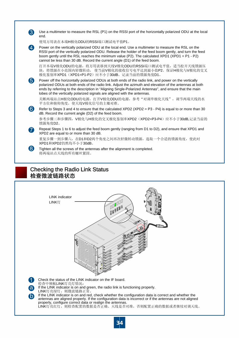
Checking the Radio Link Status
Repeat Steps 1 to 6 to adjust the feed boom gentlyXPD2 are equal to or more than 30 dB.重复步骤一到步骤六,在D1和D2两个角度之间再次XPD1和XPD2仍然均不小于30dB。Tighten all the screws of the antennas after the alig将两端站点天线的所有螺丝紧固。
Checking the Radio Link Status 检查微波链路状态
LINK indicatorLINK灯
Check the status of the LINK indicator on the IF boa检查中频板LINK灯亮灯情况:If the LINK indicator is on and green, the radio link iLINK灯亮绿灯 则微波链路正常
a
33
LINK灯亮绿灯,则微波链路正常。If the LINK indicator is on and red, check whether thantennas are aligned properly. If the configuration dproperly, configure correct data or realign the antenLINK灯亮红灯,则检查配置的数据是否正确、天线是
b
RSSI port of the horizontally polarized ODU at the local
值P1。end Use a multimeter to measure the RSL on theend. Use a multimeter to measure the RSL on the
e the holder of the feed boom gently, and turn the feed alue (P2). The calculated XPD1 (XPD1 = P1 - P2) le (D1) of the feed boom.
极化ODU的RSSI端口测试电平值,适当松开天线馈源压接收信号电平达到最小值P2。保证H极化与V极化的交叉记录当前的馈源角度D1。
ends of the radio link, and power on the vertically ust the azimuth and elevation of the antennas at both
”gle-Polarized Antennas”, and ensure that the main with the antennas.
的电源,参考“对调单极化天线”,调节两端天线的水
d XPD2 (XPD2 = P3 - P4) is equal to or more than 30 m.
鉴别率XPD2(XPD2=P3-P4)应不小于30dB,记录当前的
( i f D1 t D2) d th t XPD1 dy (ranging from D1 to D2), and ensure that XPD1 and
次轻微转动馈源,选取一个合适的馈源角度,使此时
gnment is completed.
ard.
is functioning properly.
44
he configuration data is correct and whether the data is incorrect or if the antennas are not aligned nnas.是否对准,否则配置正确的数据或者继续对调天线。
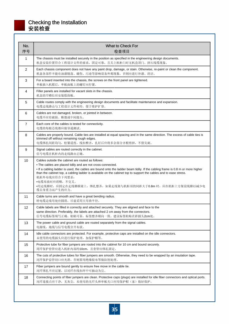
Checking the Installation安装检查
N Wh tNo.序号
What检
1 The chassis must be installed securely in the position as s机盒安装位置符合工程设计文件的要求,固定可靠,且关上
2 Each chassis component does not have any paint drop, d机盒各部件不能有油漆脱落、碰伤、污迹等影响设备外观现
3 For a board inserted into the chassis, the screws on the fr单板插入机箱后 单板面板上的螺钉应拧紧单板插入机箱后,单板面板上的螺钉应拧紧。
4 Filler panels are installed for vacant slots in the chassis.机盒的空槽位应安装假面板。
5 Cable routes comply with the engineering design docume电缆走线路由与工程设计文件相符,便于维护扩容。
6 Cables are not damaged, broken, or jointed in between.电缆不应有破损、断裂或中间接头。
7 E h f th bl i t t d f ti it7 Each core of the cables is tested for connectivity.电缆的每根芯线都应做导通测试。
8 Cables are properly bound. Cable ties are installed at equtrimmed off without remaining rough edges.电缆绑扎间距均 ,松紧适度,线扣整齐,扎好后应将多余
9 Signal cables are routed correctly in the cabinet.信号电缆在机柜内的走线路由正确。
10 Cables outside the cabinet are routed as follows:• The cables are placed tidily and are not cross-connected• If a cabling ladder is used, the cables are bound onto ththan the cabinet top, a cabling ladder is available on the c机柜外布线应符合下列要求:
•电缆布放时应理顺,不交叉。
•用走线梯时,应固定在走线梯横梁上,绑扎整齐,如果走线缆自身重力而产生的应力。
11 Cable turns are smooth and have a great bending radius.转电缆走线弯处应圆滑 尽量采用大弯曲半径转电缆走线弯处应圆滑,尽量采用大弯曲半径。
12 Cable labels are filled in correctly and attached securely. same direction. Preferably, the labels are attached 2 cm a信号电缆标签填写正确、粘贴可靠,标签整齐朝向一致。建
13 The power cable and ground cable are routed separately 电源线、地线与信号电缆分开布放。
14 Idle cable connectors are protected. For example, protect未使用的电缆插头应进行保护处理,加保护帽等。
15 Protective tube for fiber jumpers are routed into the cabin尾纤保护套管应进入机柜内部约10cm,且套管应绑扎固定
16 The cuts of protective tubes for fiber jumpers are smooth.尾纤保护套管切口应光滑,否则要用绝缘胶布等做防割处理
17 Fiber jumpers are bound gently to ensure free move in the尾纤绑扎不应过紧,以尾纤在线扣环中可抽动为宜。
18 Connecting points of fiber jumpers are clean. Protective c
3
18 g p j p尾纤连接点应干净,无灰尘,未使用的光纤头和单板光口应
t t Ch k Ft to Check For检查项目
specified in the engineering design documents.上机柜门时无机盒顶门、挤压线缆现象。
damage, or stain. Otherwise, re-paint or clean the component.现象,否则应进行补漆、清洁。
ront panel are tightened.
ents and facilitate maintenance and expansion.
ual spacing and in the same direction. The excess of cable ties is
余部分齐根剪掉,不留尖刺。
d.e ladder beam tidily. If the cabling frame is 0.8 m or more highercabinet top to support the cables and to ease stress.
线架与机柜顶的间距大于0.8m 时,应在机柜上方架设线梯以减少电
.
They are aligned and face to theaway from the connectors.建议标签粘贴在距插头2cm处。
from the signal cables.
tive caps are installed on the idle connectors.
et for 10 cm and bound securely.。
. Otherwise, they need to be wrapped by an insulation tape.理。
e cable tie.
caps (plugs) are installed for idle fiber connectors and optical ports.
5
p (p g ) p p应用保护帽(塞)做好保护。
Appendixes附录
1 Installing Power Cables for the C3 PDU安装C3PDU电源线(选配)1 安装 电源线(选配)
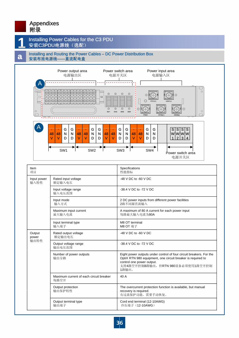
Installing and Routing the Power Cables – DC Pow安装布放电源线——直流配电盒a
Power output area电源输出区
Power swit电源开
A
G G G G GA
Item
-48V
-48V
GND
GND
-48V
-48V
GND
GND
-48V
-48V
GND
SW1 SW2 SW
A
Item项目
Input power输入特性
Rated input voltage 额定输入电压
Input voltage range 输入电压范围
Input mode输入方式
Maximum input current 最大输入电流
Input terminal type 输入端子
Output power输出特性
Rated output voltage额定输出电压
Output voltage range 输出电压范围
Number of power outputs 输出分路
Maximum current of each circuit breaker每路空开
Output protection 输出保护特性
3
输出保护特性
Output terminal type 输出端子
wer Distribution Box
tch area关区
Power input area电源输入区
G G G G S S S S
Specifications
GND
GND
-48V
-48V
GND
GND
SW1
SW2
SW3
SW4
W3 SW4Power switch area
电源开关区
Specifications性能指标
-48 V DC to -60 V DC
-38.4 V DC to -72 V DC
2 DC power inputs from different power facilities2路不同源直流输入
A maximum of 80 A current for each power input每路最大输入电流为80A
M8 OT terminalM8 OT 端子
-48 V DC to -60 V DC
-38.4 V DC to -72 V DC
Eight power outputs under control of four circuit breakers. For the OptiX RTN 980 equipment, one circuit breaker is required to control one power output.支持4路空开控制8路输出,但RTN 980设备必须使用1路空开控制1路输出。
40 A
The overcurrent protection function is available, but manual recovery is required
6
recovery is required. 有过流保护功能,需要手动恢复。
Cord end terminal (12-10AWG)冷压端子(12-10AWG)
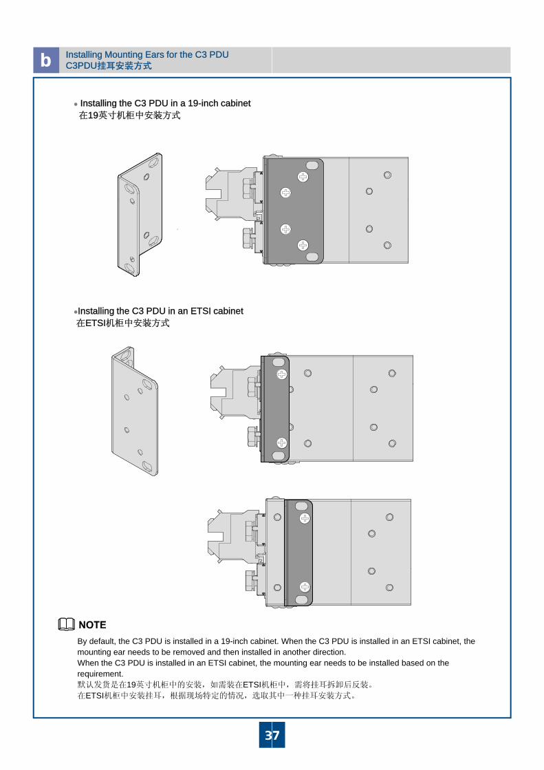
Installing Mounting Ears for the C3 PDU C3PDU挂耳安装方式b
Installing the C3 PDU in a 19-inch cabinetg在19英寸机柜中安装方式
Installing the C3 PDU in an ETSI cabinet在ETSI机柜中安装方式
By default, the C3 PDU is installed in a 19-inch cabinemounting ear needs to be removed and then installed When the C3 PDU is installed in an ETSI cabinet the
33
When the C3 PDU is installed in an ETSI cabinet, the requirement. 默认发货是在19英寸机柜中的安装,如需装在ETSI机柜
在ETSI机柜中安装挂耳,根据现场特定的情况,选取其
et. When the C3 PDU is installed in an ETSI cabinet, the in another direction.mounting ear needs to be installed based on the
77
mounting ear needs to be installed based on the
柜中,需将挂耳拆卸后反装。
其中一种挂耳安装方式。
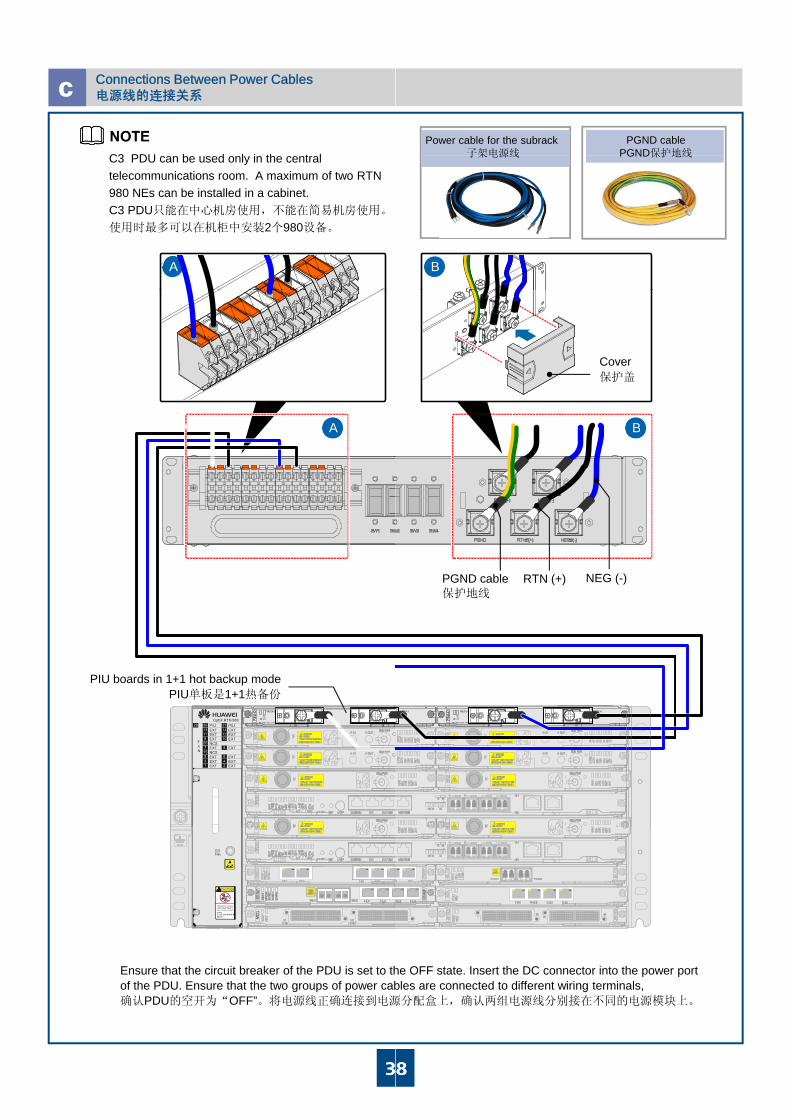
Connections Between Power Cables 电源线的连接关系c
C3 PDU b d l i th t l
A
C3 PDU can be used only in the central telecommunications room. A maximum of two RTN 980 NEs can be installed in a cabinet. C3 PDU只能在中心机房使用,不能在简易机房使用。
使用时最多可以在机柜中安装2个980设备。
AA
PIU boards in 1+1 hot backup modePIU单板是1+1热备份PIU单板是1+1热备份
MD
1
33
Ensure that the circuit breaker of the PDU is set to thof the PDU. Ensure that the two groups of power cab确认PDU的空开为“OFF”。将电源线正确连接到电源
PGND cablePGND保护地线
Power cable for the subrack子架电源线
B
PGND保护地线子架电源线
B
Cover保护盖
B
RTN (+) NEG (-)PGND cable 保护地线
88
he OFF state. Insert the DC connector into the power port bles are connected to different wiring terminals, 源分配盒上,确认两组电源线分别接在不同的电源模块上。
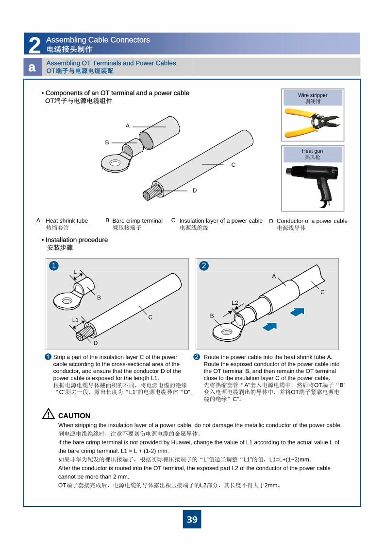
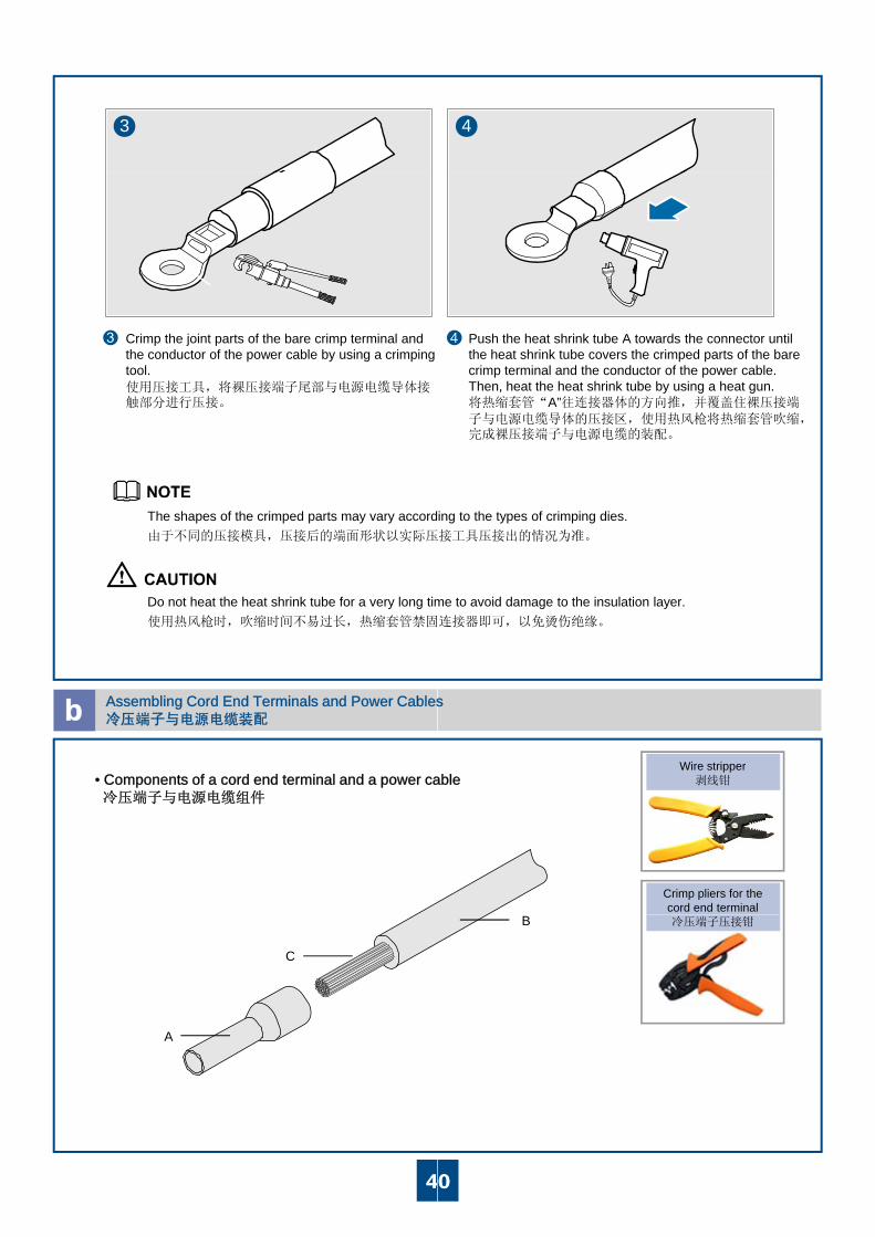
2 Assembling Cable Connectors电缆接头制作
Assembling OT Terminals and Power CablesOT端子与电源电缆装配a
• Components of an OT terminal and a power cable OT端子与电源电缆组件
A
BB
1
• Installation procedure安装步骤
Heat shrink tube热缩套管
Bare crimp terminal裸压接端子
Insula电源线
A B C
L
B
C
L
L1
Strip a part of the insulation layer C of the power cable according to the cross-sectional area of the conductor, and ensure that the conductor D of the power cable is exposed for the length L1.根据电源电缆导体截面积的不同,将电源电缆的绝缘“C”剥去一段,露出长度为“L1”的电源电缆导体“D”。
D
When stripping the insulation layer of a power cable,剥电源电缆绝缘时,注意不要划伤电源电缆的金属导
If the bare crimp terminal is not provided by Huawei, the bare crimp terminal. L1 = L + (1-2) mm.如果非华为配发的裸压接端子,根据实际裸压接端子
After the conductor is routed into the OT terminal the
33
After the conductor is routed into the OT terminal, thecannot be more than 2 mm.OT端子套接完成后,电源电缆的导体露出裸压接端子
Wire stripper剥线钳
Heat gun热风枪
C
D
2
ation layer of a power cable线绝缘
Conductor of a power cable电源线导体
D
A
C
B
L2
。
Route the power cable into the heat shrink tube A. Route the exposed conductor of the power cable into the OT terminal B, and then remain the OT terminal close to the insulation layer C of the power cable. 先将热缩套管“A”套入电源电缆中,然后将OT端子“B”套入电源电缆剥出的导体中,并将OT端子紧靠电源电缆的绝缘”C”。
, do not damage the metallic conductor of the power cable.体。
change the value of L1 according to the actual value L of
的“L”值适当调整“L1”的值,L1=L+(1~2)mm。
e exposed part L2 of the conductor of the power cable
99
e exposed part L2 of the conductor of the power cable
子的L2部分,其长度不得大于2mm。
3
Crimp the joint parts of the bare crimp terminal and the conductor of the power cable by using a crimping tool. 使用压接工具,将裸压接端子尾部与电源电缆导体接触部分进行压接。
The shapes of the crimped parts may vary accord由于不同的压接模具,压接后的端面形状以实际压
Do not heat the heat shrink tube for a very long tim使用热风枪时 吹缩时间不易过长 热缩套管禁固使用热风枪时,吹缩时间不易过长,热缩套管禁固
Assembling Cord End Terminals and Power Cables冷压端子与电源电缆装配b
• Components of a cord end terminal and a power ca冷压端子与电源电缆组件
C
A
44
4
Push the heat shrink tube A towards the connector until the heat shrink tube covers the crimped parts of the bare crimp terminal and the conductor of the power cable. Then, heat the heat shrink tube by using a heat gun.将热缩套管“A”往连接器体的方向推,并覆盖住裸压接端
子与电源电缆导体的压接区,使用热风枪将热缩套管吹缩,完成裸压接端子与电源电缆的装配。
ing to the types of crimping dies.压接工具压接出的情况为准。
me to avoid damage to the insulation layer.连接器即可 以免烫伤绝缘连接器即可,以免烫伤绝缘。
Wire stripper
s
able
Crimp pliers for the cord end terminal
Wire stripper剥线钳
冷压端子压接钳B
00
1
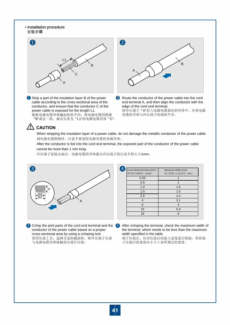
• Installation procedure安装步骤
C
A
L1B
Strip a part of the insulation layer B of the power cable according to the cross-sectional area of the conductor, and ensure that the conductor C of the power cable is exposed for the length L1.根据电源电缆导体截面积的不同,将电源电缆的绝缘“B”剥去一段,露出长度为“L1”的电源电缆导体“C”。
When stripping the insulation layer of a power cable剥电源电缆绝缘时,注意不要划伤电源电缆的金属导
After the conductor is fed into the cord end terminalcannot be more than 1 mm long.冷压端子套接完成后,电源电缆的导体露出冷压端子
3
A
H
W2W1
Crimp the joint parts of the cord end terminal and the conductor of the power cable based on a proper cross-sectional area by using a crimping tool. 使用压接工具,选择合适的截面积,将冷压端子头部
A
3
与电源电缆导体接触部分进行压接。
44
2
A
B
Route the conductor of the power cable into the cord end terminal A, and then align the conductor with the edge of the cord end terminal.将冷压端子“A”套入电源电缆剥出的导体中,并使电源电缆的导体与冷压端子的端面平齐。
e, do not damage the metallic conductor of the power cable.导体。
l, the exposed part of the conductor of the power cable
子的长度不得大于1mm。
4
0.250.51.01.5
11
1.51.5
2.54
2.43.1
管状端子截面积(mm2)
端子的最大压接宽度(mm)
Cross-Sectional Area (mm2)管状端子截面积(mm2)
Maximum Width (mm)端子的最大压接宽度(mm)
4 3.16 4
1016
5.36
After crimping the terminal, check the maximum width of the terminal, which needs to be less than the maximum width specified in the table.端子压接后,应对压接后的最大宽度进行检验,管状端
4
子压接后的宽度应小于上表所规定的宽度。
11

HHUAWEI TECHNOLOGIES CO., LTD.Huawei Industrial Base Bantian Longgang
华为技术有限公司深圳市龙岗区坂田华为总部办公楼
Huawei Industrial Base Bantian Longgang Shenzhen 518129
People’s Republic of Chinawww.huawei.com
深圳市龙岗区坂田华为总部办公楼邮编:518129
www.huawei.com
Related Documents