MULTI-LINE 2 DESCRIPTION OF OPTIONS • Description of options • Data tables • Parameter tables Document no.: 4189340442Y Options H2 and H9 Modbus communication

Welcome message from author
This document is posted to help you gain knowledge. Please leave a comment to let me know what you think about it! Share it to your friends and learn new things together.
Transcript

MULTI-LINE 2 DESCRIPTION OF OPTIONS
• Description of options
• Data tables
• Parameter tables
Document no.: 4189340442Y
Options H2 and H9 Modbus communication

Multi-line 2 Options H2 and H9, Modbus communication
DEIF A/S Page 2 of 203
This description of options covers the following products:
AGC-3 SW version 3.6x.x or later
AGC 100 SW version 4.0x.x or later
GPC-3/GPU-3 Hydro SW version 3.1x.x or later
GPU-3/PPU-3 SW version 3.08.x or later
PPM-3 SW version 3.0x.x or later
Multi-line 2 Options H2 and H9, Modbus communication
DEIF A/S Page 3 of 203
Table of contents
1. WARNINGS AND LEGAL INFORMATION ........................................................................... 4
LEGAL INFORMATION AND RESPONSIBILITY .................................................................................... 4 ELECTROSTATIC DISCHARGE AWARENESS ..................................................................................... 4 SAFETY ISSUES ............................................................................................................................ 4 DEFINITIONS ................................................................................................................................ 4
2. DESCRIPTION OF OPTION .................................................................................................. 5
OPTION H2 .................................................................................................................................. 5 TERMINAL DESCRIPTION AGC/GPC/GPU/PPM/PPU .................................................................... 5 TERMINAL DESCRIPTION AGC 200 ................................................................................................ 5 TERMINAL DESCRIPTION AGC 100 ................................................................................................ 5 HARDWARE SETTINGS .................................................................................................................. 5 OPTION H9 .................................................................................................................................. 6 TERMINAL DESCRIPTION ............................................................................................................... 6 HARDWARE SETTINGS .................................................................................................................. 6 WIRING ....................................................................................................................................... 6
3. FUNCTIONAL DESCRIPTION .............................................................................................. 7
GSM COMMUNICATION ................................................................................................................. 7 EXTERNAL COMMUNICATION CONTROL .......................................................................................... 8
4. PARAMETERS .................................................................................................................... 10
5. DATA TABLES .................................................................................................................... 11
CONFIGURABLE AREA (READ ONLY) (FUNCTION CODE 04H) .......................................................... 11 MEASUREMENT TABLE (READ ONLY) (FUNCTION CODE 04H) ......................................................... 43 ALARM AND STATUS TABLE (READ ONLY) (FUNCTION CODE 04H) ................................................... 63 POWER MANAGEMENT ALARM AND STATUS TABLE (READ ONLY) (FUNCTION CODE 04H) ............... 125 CONTROL REGISTER TABLE READ (03H)/WRITE(10H) ................................................................. 157 COMMAND FLAGS TABLE (WRITE ONLY) (FUNCTION CODE 0FH) ................................................... 167 COMMAND FLAGS TABLE (READ ONLY) (FUNCTION CODE 01FH) .................................................. 174 STATUS FLAGS TABLE (READ ONLY) (FUNCTION CODE 02H) ........................................................ 175 DIGITAL INPUT TABLE (READ ONLY 02H) ..................................................................................... 179 DIGITAL OUTPUT TABLE (READ ONLY 02H) ................................................................................. 187
6. PARAMETER SETTING .................................................................................................... 193
PARAMETER READING AND WRITING .......................................................................................... 193 PARAMETER ADDRESSES .......................................................................................................... 198

Multi-line 2 Options H2 and H9, Modbus communication
DEIF A/S Page 4 of 203
1. Warnings and legal information
Legal information and responsibility
DEIF takes no responsibility for installation or operation of the generator set. If there is any doubt
about how to install or operate the generator set controlled by the unit, the company responsible
for the installation or the operation of the set must be contacted.
Electrostatic discharge awareness
Sufficient care must be taken to protect the terminals against static discharges during the
installation. Once the unit is installed and connected, these precautions are no longer necessary.
Safety issues
Installing the unit implies work with dangerous currents and voltages. Therefore, the installation
should only be carried out by authorised personnel who understand the risks involved in working
with live electrical equipment.
Definitions
Throughout this document a number of notes and warnings will be presented. To ensure that these
are noticed, they will be highlighted in order to separate them from the general text.
Notes
Warnings
The notes provide general information which will be helpful for the reader to
bear in mind.
The warnings indicate a potentially dangerous situation which could result in
death, personal injury or damaged equipment, if certain guidelines are not
followed.
Be aware of the hazardous live currents and voltages. Do not touch any AC
measurement inputs as this could lead to injury or death.
The units are not to be opened by unauthorised personnel. If opened anyway, the
warranty will be lost.
Multi-line 2 Options H2 and H9, Modbus communication
DEIF A/S Page 5 of 203
2. Description of option
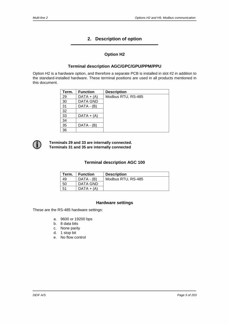
Option H2
Terminal description AGC/GPC/GPU/PPM/PPU
Option H2 is a hardware option, and therefore a separate PCB is installed in slot #2 in addition to
the standard-installed hardware. These terminal positions are used in all products mentioned in
this document.
Term. Function Description
29 DATA + (A) Modbus RTU, RS-485
30 DATA GND
31 DATA - (B)
32
33 DATA + (A)
34
35 DATA - (B)
36
Terminal description AGC 100
Term. Function Description
49 DATA - (B) Modbus RTU, RS-485
50 DATA GND
51 DATA + (A)
Hardware settings
These are the RS-485 hardware settings:
a. 9600 or 19200 bps
b. 8 data bits
c. None parity
d. 1 stop bit
e. No flow control
Terminals 29 and 33 are internally connected.
Terminals 31 and 35 are internally connected
Multi-line 2 Options H2 and H9, Modbus communication
DEIF A/S Page 6 of 203
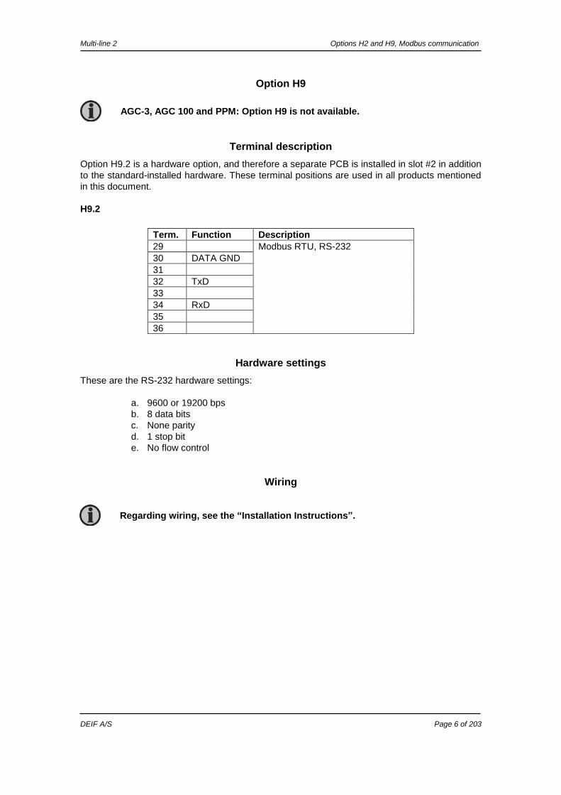
Option H9
Terminal description
Option H9.2 is a hardware option, and therefore a separate PCB is installed in slot #2 in addition
to the standard-installed hardware. These terminal positions are used in all products mentioned
in this document.
H9.2
Term. Function Description
29 Modbus RTU, RS-232
30 DATA GND
31
32 TxD
33
34 RxD
35
36
Hardware settings
These are the RS-232 hardware settings:
a. 9600 or 19200 bps
b. 8 data bits
c. None parity
d. 1 stop bit
e. No flow control
Wiring
Regarding wiring, see the “Installation Instructions”.
AGC-3, AGC 100 and PPM: Option H9 is not available.
Multi-line 2 Options H2 and H9, Modbus communication
DEIF A/S Page 7 of 203
3. Functional description
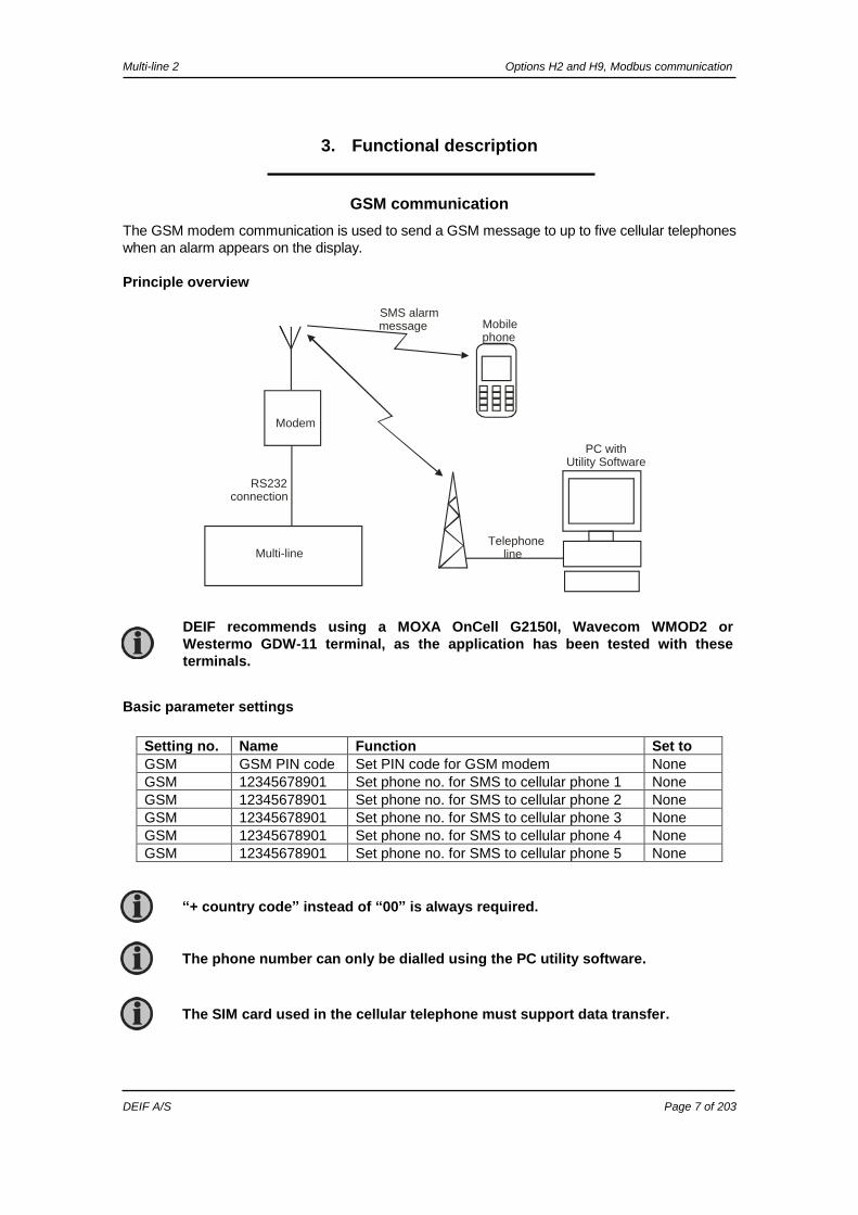
GSM communication
The GSM modem communication is used to send a GSM message to up to five cellular telephones
when an alarm appears on the display.
Principle overview
Multi-line
Modem
Mobilephone
SMS alarmmessage
Telephoneline
PC with Utility Software
RS232connection
Basic parameter settings
Setting no. Name Function Set to
GSM GSM PIN code Set PIN code for GSM modem None
GSM 12345678901 Set phone no. for SMS to cellular phone 1 None
GSM 12345678901 Set phone no. for SMS to cellular phone 2 None
GSM 12345678901 Set phone no. for SMS to cellular phone 3 None
GSM 12345678901 Set phone no. for SMS to cellular phone 4 None
GSM 12345678901 Set phone no. for SMS to cellular phone 5 None
DEIF recommends using a MOXA OnCell G2150I, Wavecom WMOD2 or
Westermo GDW-11 terminal, as the application has been tested with these
terminals.
“+ country code” instead of “00” is always required.
The phone number can only be dialled using the PC utility software.
The SIM card used in the cellular telephone must support data transfer.

Multi-line 2 Options H2 and H9, Modbus communication
DEIF A/S Page 8 of 203
PIN code configuration
After each auxiliary supply power up, the unit will send the required PIN code to the modem if this is
necessary. The PIN code is adjusted in the PC utility software.
USW communication
It is possible to communicate with the unit via the PC utility software. The purpose is to be able to
remote-monitor and control the genset application.
Serial connection
Setup
The Modbus protocol type can be changed from RTU to ASCII in menu 7510. This menu can only
be reached using the JUMP push-button. When set to 1, the ASCII protocol type is used, and the
unit will allow for the slower modem communication.
Safety
If communication fails, the unit will operate according to the received data. For example, if only half
of the parameter file has been downloaded when the communication is interrupted, the unit will use
this actual data.
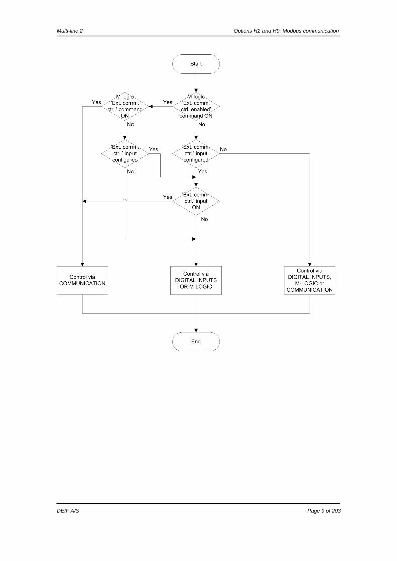
External communication control
With the serial communication, it is possible to control which commands the unit should accept.
The possibilities are described below.
Commands accepted
from
Description Setup required
Digital inputs
M-Logic
External communication
The unit will accept commands
from digital inputs, M-Logic and
external communication.
Default (no setup required).
Digital inputs
M-Logic
Commands from digital inputs
and M-Logic are accepted.
Digital input function ”Ext. comm. ctrl.” configured
and input OFF
OR
M-Logic command ”Ext. comm. ctrl. enabled” ON.
External communication Only commands from external
communication are accepted
Digital input function ”Ext. comm. ctrl.” configured
and input ON
OR
M-Logic commands ”Ext. comm. ctrl. enabled”
and ”Ext. comm. ctrl.” ON.
Because of the RS-232 communication, the GSM function is only available with
option H9.2 or option J5 for AGC 100.
It is possible to remote-control the genset from the PC utility software if a
modem is used. Take precautions that it is safe to remote-operate the genset
to avoid personal injury or death.
”Alarm inhibit” and ”Alarm acknowledge” commands from external
communication are always accepted.
Only valid for GPU-3, GPU-3 Hydro, PPU-3 and GPC-3.
Multi-line 2 Options H2 and H9, Modbus communication
DEIF A/S Page 9 of 203

Multi-line 2 Options H2 and H9, Modbus communication
DEIF A/S Page 10 of 203
4. Parameters
The options H2 and H9 relate to the parameters 7500-7520.
For further information, see the separate parameter list for the Multi-line unit in question:
AGC-3 Document no. 4189340705
AGC 100 Document no. 4189340764
GPC-3/GPU-3 Hydro Document no. 4189340580
GPU-3/PPU-3 Document no. 4189340581
PPM-3 Document no. 4189340672
Multi-line 2 Option H2 and H9, Modbus communication
DEIF A/S Page 11 of 203
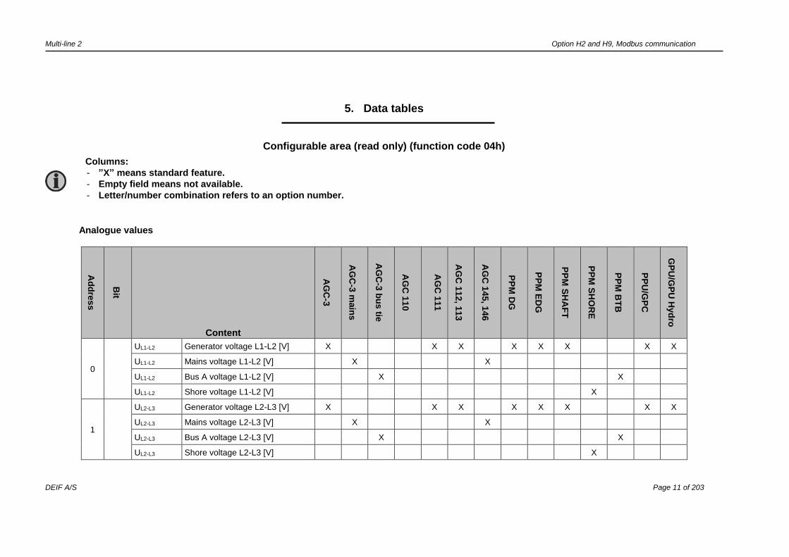
5. Data tables
Configurable area (read only) (function code 04h)
Analogue values
Ad
dre
ss
Bit
Content
AG
C-3
AG
C-3
main
s
AG
C-3
bu
s tie
AG
C 1
10
AG
C 1
11
AG
C 1
12, 1
13
AG
C 1
45, 1
46
PP
M D
G
PP
M E
DG
PP
M S
HA
FT
PP
M S
HO
RE
PP
M B
TB
PP
U/G
PC
GP
U/G
PU
Hyd
ro
0
UL1-L2 Generator voltage L1-L2 [V] X X X X X X X X
UL1-L2 Mains voltage L1-L2 [V] X X
UL1-L2 Bus A voltage L1-L2 [V] X X
UL1-L2 Shore voltage L1-L2 [V] X
1
UL2-L3 Generator voltage L2-L3 [V] X X X X X X X X
UL2-L3 Mains voltage L2-L3 [V] X X
UL2-L3 Bus A voltage L2-L3 [V] X X
UL2-L3 Shore voltage L2-L3 [V] X
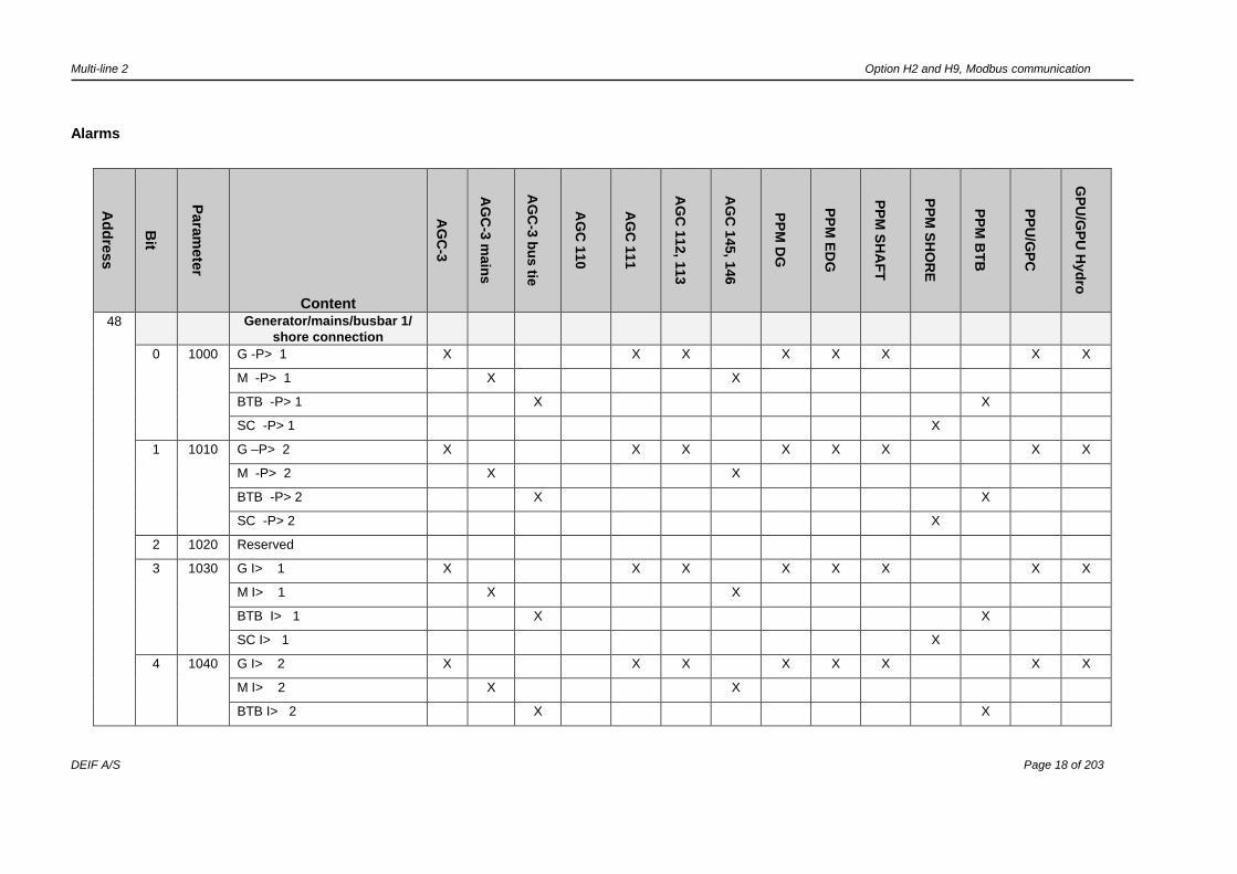
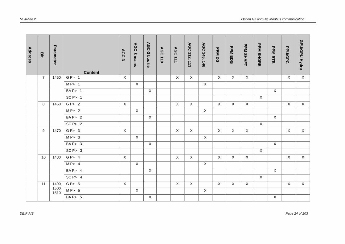
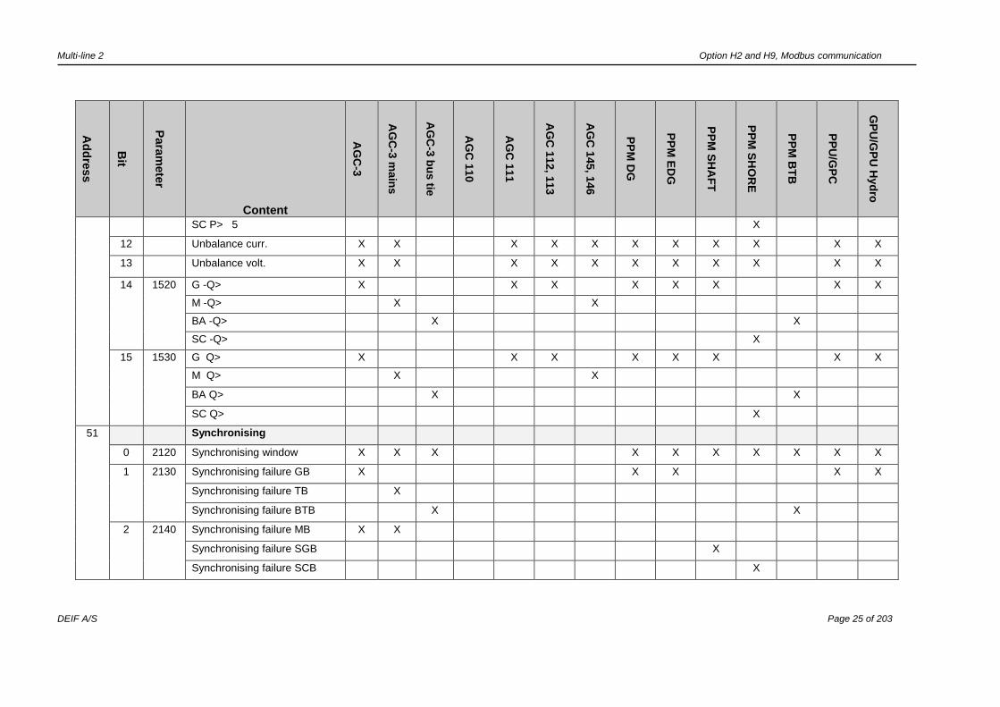
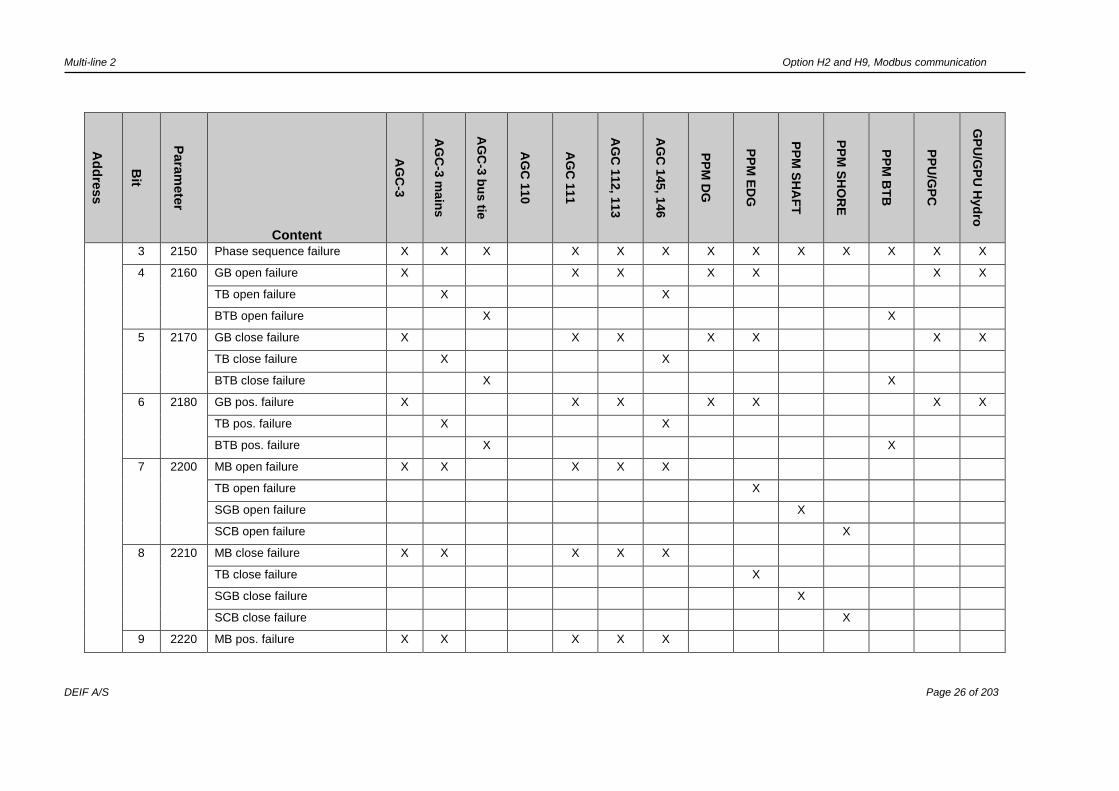
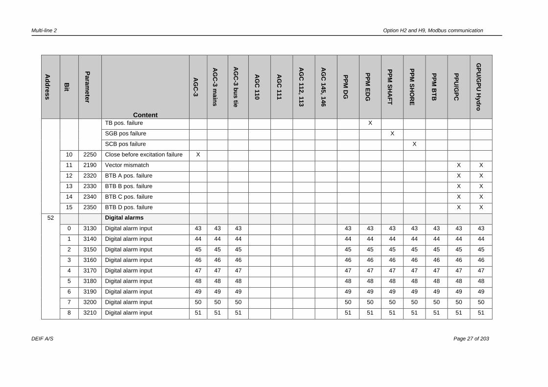
Columns:
- ”X” means standard feature.
- Empty field means not available.
- Letter/number combination refers to an option number.

Multi-line 2 Option H2 and H9, Modbus communication
DEIF A/S Page 12 of 203
Ad
dre
ss
Bit
Content
AG
C-3
AG
C-3
main
s
AG
C-3
bu
s tie
AG
C 1
10
AG
C 1
11
AG
C 1
12, 1
13
AG
C 1
45, 1
46
PP
M D
G
PP
M E
DG
PP
M S
HA
FT
PP
M S
HO
RE
PP
M B
TB
PP
U/G
PC
GP
U/G
PU
Hyd
ro
2
UL3-L1 Generator voltage L3-L1 [V] X X X X X X X X
UL3-L1 Mains voltage L3-L1 [V] X X
UL3-L1 Bus A voltage L3-L1 [V] X X
UL3-L1 Shore voltage L3-L1 [V] X
3
UL1-N Generator voltage L1-N [V] X X X X X X X X
UL1-N Mains voltage L1-N [V] X X
UL1-N Bus A voltage L1-N [V] X X
UL1-N Shore voltage L1-N [V] X
4
UL2-N Generator voltage L2-N [V] X X X X X X X X
UL2-N Mains voltage L2-N [V] X X
UL2-N Bus A voltage L2-N [V] X X
UL2-N Shore voltage L2-N [V] X
5
UL3-N Generator voltage L3-N [V] X X X X X X X X
UL3-N Mains voltage L3-N [V] X X
UL3-N Bus A voltage L3-N [V] X X
UL3-N Shore voltage L3-N [V] X
6
fL1 Generator f L1 [Hz/100] X X X X X X X X
fL1 Mains f L1 [Hz/100] X X
fL1 Bus A f L1 [Hz/100] X X

Multi-line 2 Option H2 and H9, Modbus communication
DEIF A/S Page 13 of 203
Ad
dre
ss
Bit
Content
AG
C-3
AG
C-3
main
s
AG
C-3
bu
s tie
AG
C 1
10
AG
C 1
11
AG
C 1
12, 1
13
AG
C 1
45, 1
46
PP
M D
G
PP
M E
DG
PP
M S
HA
FT
PP
M S
HO
RE
PP
M B
TB
PP
U/G
PC
GP
U/G
PU
Hyd
ro
fL1 Shore f L1 [Hz/100] X
7
IL1 Generator current L1 [A] X X X X X X X X
IL1 Mains current L1 [A] X X
IL1 Bus current L1 [A] X X
IL1 Shore current L1 [A] X
8
IL2 Generator current L2 [A] X X X X X X X X
IL2 Mains current L2 [A] X X
IL2 Bus current L2 [A] X X
IL2 Shore current L2 [A] X
9
IL3 Generator current L3 [A] X X X X X X X X
IL3 Mains current L3 [A] X X
IL3 Bus current L3 [A] X X
IL3 Shore current L3 [A] X
10
PGEN Generator power [kW] X X X X X X X X
PMAINS Mains power [kW] X X
PBA Bus power [kW] X X
PSC Shore power [kW] X
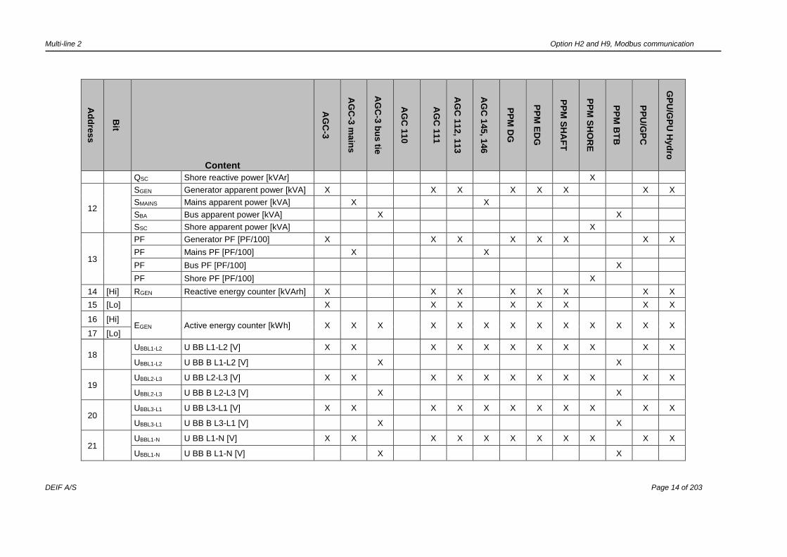
11
QGEN Generator reactive power [kVAr] X X X X X X X X
QMAINS Mains reactive power [kVAr] X X
QBA Bus reactive power [kVAr] X X
Multi-line 2 Option H2 and H9, Modbus communication
DEIF A/S Page 14 of 203
Ad
dre
ss
Bit
Content
AG
C-3
AG
C-3
main
s
AG
C-3
bu
s tie
AG
C 1
10
AG
C 1
11
AG
C 1
12, 1
13
AG
C 1
45, 1
46
PP
M D
G
PP
M E
DG
PP
M S
HA
FT
PP
M S
HO
RE
PP
M B
TB
PP
U/G
PC
GP
U/G
PU
Hyd
ro
QSC Shore reactive power [kVAr] X
12
SGEN Generator apparent power [kVA] X X X X X X X X
SMAINS Mains apparent power [kVA] X X
SBA Bus apparent power [kVA] X X
SSC Shore apparent power [kVA] X
13
PF Generator PF [PF/100] X X X X X X X X
PF Mains PF [PF/100] X X
PF Bus PF [PF/100] X
PF Shore PF [PF/100] X
14 [Hi] RGEN Reactive energy counter [kVArh] X X X X X X X X
15 [Lo] X X X X X X X X
16 [Hi] EGEN Active energy counter [kWh] X X X X X X X X X X X X X
17 [Lo]
18
UBBL1-L2 U BB L1-L2 [V] X X X X X X X X X X X
UBBL1-L2 U BB B L1-L2 [V] X X
19
UBBL2-L3 U BB L2-L3 [V] X X X X X X X X X X X
UBBL2-L3 U BB B L2-L3 [V] X X
20
UBBL3-L1 U BB L3-L1 [V] X X X X X X X X X X X
UBBL3-L1 U BB B L3-L1 [V] X X
21
UBBL1-N U BB L1-N [V] X X X X X X X X X X X
UBBL1-N U BB B L1-N [V] X X
Multi-line 2 Option H2 and H9, Modbus communication
DEIF A/S Page 15 of 203
Ad
dre
ss
Bit
Content
AG
C-3
AG
C-3
main
s
AG
C-3
bu
s tie
AG
C 1
10
AG
C 1
11
AG
C 1
12, 1
13
AG
C 1
45, 1
46
PP
M D
G
PP
M E
DG
PP
M S
HA
FT
PP
M S
HO
RE
PP
M B
TB
PP
U/G
PC
GP
U/G
PU
Hyd
ro
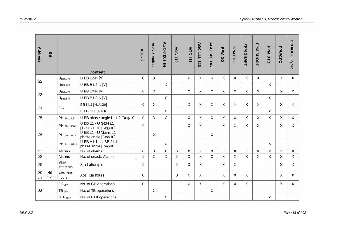
22
UBBL2-N U BB L2-N [V] X X X X X X X X X X X
UBBL2-N U BB B L2-N [V] X X
23
UBBL3-N U BB L3-N [V] X X X X X X X X X X X
UBBL3-N U BB B L3-N [V] X X
24
FBB BB f L1 [Hz/100] X X X X X X X X X X X
BB B f L1 [Hz/100] X X
25 PHIBBL1-L2 U BB phase angle L1-L2 [Deg/10] X X X X X X X X X X X X X
26
PHIBBL1-DGL1 U BB L1 - U GEN L1
phase angle [Deg/10] X X X X X X X X X
PHIBBL1-ML1 U BB L1 - U Mains L1
phase angle [Deg/10] X X
PHIBAL1-BBL1 U BB A L1 - U BB 2 L1
phase angle [Deg/10] X X
27 Alarms No. of alarms X X X X X X X X X X X X X X
28 Alarms No. of unack. Alarms X X X X X X X X X X X X X X
29 Start
attempts Start attempts X X X X X X
X X
30 [Hi] Abs. run.
hours Abs. run hours X X X X X X X
X X
31 [Lo]
32
GBoper No. of GB operations X X X X X X X X
TBoper No. of TB operations X X
BTBoper No. of BTB operations X X

Multi-line 2 Option H2 and H9, Modbus communication
DEIF A/S Page 16 of 203
Ad
dre
ss
Bit
Content
AG
C-3
AG
C-3
main
s
AG
C-3
bu
s tie
AG
C 1
10
AG
C 1
11
AG
C 1
12, 1
13
AG
C 1
45, 1
46
PP
M D
G
PP
M E
DG
PP
M S
HA
FT
PP
M S
HO
RE
PP
M B
TB
PP
U/G
PC
GP
U/G
PU
Hyd
ro
SCBoper No. of SCB operations X
33 MBoper No. of MB operations X X X X X X
TBoper No. of TB operations X
34 USUPPLY DC supply term. 1-2 [V/10] X X X X X X X X X X X X X X
35 USUPPLY M4 DC supply term. 98-99 [V/10] X X X X X X X X X
36 RPM RPM X X X X X X X X X X
37
Multi-input 102 unscaled X X X X X X X X X X
Multi-input 46 unscaled
Multi-input 6 unscaled X X X X
38
Multi-input 105 unscaled X X X X X X X X X X
Multi-input 47 unscaled
Multi-input 7 unscaled X X X X
39
Multi-input 108 unscaled X X X X X X X X X X
Multi-input 48 unscaled
Multi-input 8 unscaled X X X X
40 Control register address 0 X X X X X X X X X X X X X X
41 Control register address 1 X X X X X X X X X X X X X X
42 Control register address 2 X X X X X X X X X X X X X X
43 Control register address 3 X X X X X X X X X X X X X X
44 Control register address 4 X X X X X X X X X X X X X X
45 Control register address 5 X X X X X X X X X X X X X X
46 Control register address 6 X X X X X X X X X X X X

Multi-line 2 Option H2 and H9, Modbus communication
DEIF A/S Page 17 of 203
Ad
dre
ss
Bit
Content
AG
C-3
AG
C-3
main
s
AG
C-3
bu
s tie
AG
C 1
10
AG
C 1
11
AG
C 1
12, 1
13
AG
C 1
45, 1
46
PP
M D
G
PP
M E
DG
PP
M S
HA
FT
PP
M S
HO
RE
PP
M B
TB
PP
U/G
PC
GP
U/G
PU
Hyd
ro
0 SWBD mode X X
1 Fixed frequency X X
2 Fixed P X
3 P load sharing X
4 Frequency droop X
5 Ext. GOV setpoint X X
6 Fixed voltage X X
7 Fixed Q X
8 Fixed PF X
9 Q load sharing X
10 Voltage droop X
11 Ext. AVR setpoint X X
12 Remote X X
13 Local X X
14 Deload X X
15 Start sync./control X X
47 Control register address 7 X X X X X X X X X X X X X X
Multi-line 2 Option H2 and H9, Modbus communication
DEIF A/S Page 18 of 203
Alarms
Ad
dre
ss
Bit
Para
mete
r
Content
AG
C-3
AG
C-3
main
s
AG
C-3
bu
s tie
AG
C 1
10
AG
C 1
11
AG
C 1
12, 1
13
AG
C 1
45, 1
46
PP
M D
G
PP
M E
DG
PP
M S
HA
FT
PP
M S
HO
RE
PP
M B
TB
PP
U/G
PC
GP
U/G
PU
Hyd
ro
48
Generator/mains/busbar 1/
shore connection
0 1000 G -P> 1 X X X X X X X X
M -P> 1 X X
BTB -P> 1 X X
SC -P> 1 X
1 1010 G –P> 2 X X X X X X X X
M -P> 2 X X
BTB -P> 2 X X
SC -P> 2 X
2 1020 Reserved
3 1030 G I> 1 X X X X X X X X
M I> 1 X X
BTB I> 1 X X
SC I> 1 X
4 1040 G I> 2 X X X X X X X X
M I> 2 X X
BTB I> 2 X X
Multi-line 2 Option H2 and H9, Modbus communication
DEIF A/S Page 19 of 203
Ad
dre
ss
Bit
Para
mete
r
Content
AG
C-3
AG
C-3
main
s
AG
C-3
bu
s tie
AG
C 1
10
AG
C 1
11
AG
C 1
12, 1
13
AG
C 1
45, 1
46
PP
M D
G
PP
M E
DG
PP
M S
HA
FT
PP
M S
HO
RE
PP
M B
TB
PP
U/G
PC
GP
U/G
PU
Hyd
ro
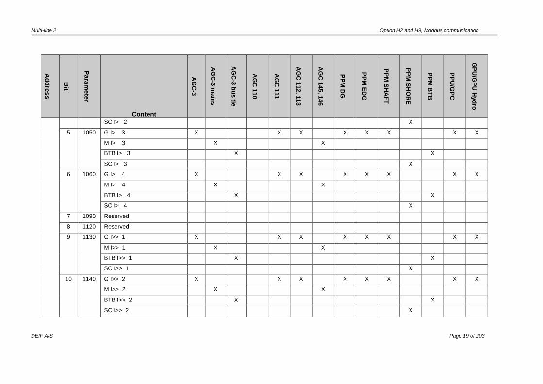
SC I> 2 X
5 1050 G I> 3 X X X X X X X X
M I> 3 X X
BTB I> 3 X X
SC I> 3 X
6 1060 G I> 4 X X X X X X X X
M I> 4 X X
BTB I> 4 X X
SC I> 4 X
7 1090 Reserved
8 1120 Reserved
9 1130 G I>> 1 X X X X X X X X
M I>> 1 X X
BTB I>> 1 X X
SC I>> 1 X
10 1140 G I>> 2 X X X X X X X X
M I>> 2 X X
BTB I>> 2 X X
SC I>> 2 X

Multi-line 2 Option H2 and H9, Modbus communication
DEIF A/S Page 20 of 203
Ad
dre
ss
Bit
Para
mete
r
Content
AG
C-3
AG
C-3
main
s
AG
C-3
bu
s tie
AG
C 1
10
AG
C 1
11
AG
C 1
12, 1
13
AG
C 1
45, 1
46
PP
M D
G
PP
M E
DG
PP
M S
HA
FT
PP
M S
HO
RE
PP
M B
TB
PP
U/G
PC
GP
U/G
PU
Hyd
ro
11 1150 G U> 1 X X X X X X X X
M U> 1 X X
BB-A U> 1 X X
SC U> 1 X
12 1160 G U> 2 X X X X X X X X
M U> 2 X X
BB-A U> 2 X X
SC U> 2 X
13 1170 G U< 1 X X X X X X X X
M U< 1 X X
BB-A U< 1 X X
SC U< 1 X
14 1180 G U< 2 X X X X X X X X
M U< 2 X X
BB-A U< 2 X X
SC U< 2 X
15 1190 G U< 3 X X X X X X X X
M U< 3 X X
BB-A U< 3 X X

Multi-line 2 Option H2 and H9, Modbus communication
DEIF A/S Page 21 of 203
Ad
dre
ss
Bit
Para
mete
r
Content
AG
C-3
AG
C-3
main
s
AG
C-3
bu
s tie
AG
C 1
10
AG
C 1
11
AG
C 1
12, 1
13
AG
C 1
45, 1
46
PP
M D
G
PP
M E
DG
PP
M S
HA
FT
PP
M S
HO
RE
PP
M B
TB
PP
U/G
PC
GP
U/G
PU
Hyd
ro
SC U< 3 X
49 0 1210 G f> 1 X X X X X X X X
M f> 1 X X
B1 f> 1 X X
SC f> 1 X
1 1220 G f> 2 X X X X X X X X
M f> 2 X X
BB-A f> 2 X X
SC f> 2 X
2 1230 G f> 3 X X X X X X X X
M f> 3 X X
BB-A f> 3 X X
SC f> 3 X
3 1240 G f< 1 X X X X X X X X X
M f< 1 X X
BB-A f < 1 X X
4 1250 G f< 2 X X X X X X X X
M f< 2 X X
BB-A f< 2 X X
Multi-line 2 Option H2 and H9, Modbus communication
DEIF A/S Page 22 of 203
Ad
dre
ss
Bit
Para
mete
r
Content
AG
C-3
AG
C-3
main
s
AG
C-3
bu
s tie
AG
C 1
10
AG
C 1
11
AG
C 1
12, 1
13
AG
C 1
45, 1
46
PP
M D
G
PP
M E
DG
PP
M S
HA
FT
PP
M S
HO
RE
PP
M B
TB
PP
U/G
PC
GP
U/G
PU
Hyd
ro
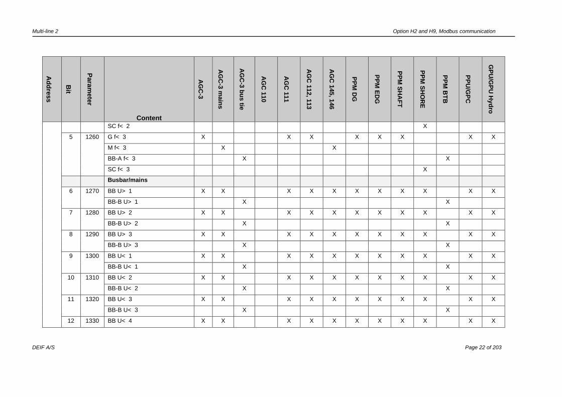
SC f< 2 X
5 1260 G f< 3 X X X X X X X X
M f< 3 X X
BB-A f< 3 X X
SC f< 3 X
Busbar/mains
6 1270 BB U> 1 X X X X X X X X X X X
BB-B U> 1 X X
7 1280 BB U> 2 X X X X X X X X X X X
BB-B U> 2 X X
8 1290 BB U> 3 X X X X X X X X X X X
BB-B U> 3 X X
9 1300 BB U< 1 X X X X X X X X X X X
BB-B U< 1 X X
10 1310 BB U< 2 X X X X X X X X X X X
BB-B U< 2 X X
11 1320 BB U< 3 X X X X X X X X X X X
BB-B U< 3 X X
12 1330 BB U< 4 X X X X X X X X X X X
Multi-line 2 Option H2 and H9, Modbus communication
DEIF A/S Page 23 of 203
Ad
dre
ss
Bit
Para
mete
r
Content
AG
C-3
AG
C-3
main
s
AG
C-3
bu
s tie
AG
C 1
10
AG
C 1
11
AG
C 1
12, 1
13
AG
C 1
45, 1
46
PP
M D
G
PP
M E
DG
PP
M S
HA
FT
PP
M S
HO
RE
PP
M B
TB
PP
U/G
PC
GP
U/G
PU
Hyd
ro
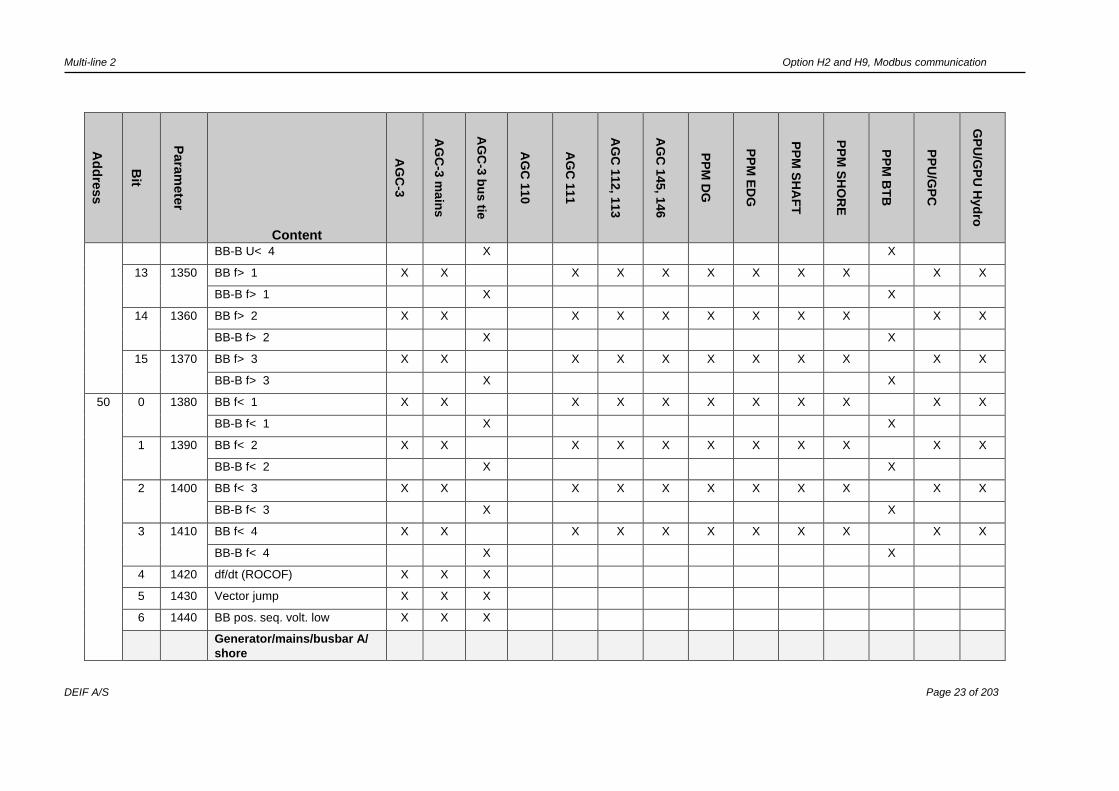
BB-B U< 4 X X
13 1350 BB f> 1 X X X X X X X X X X X
BB-B f> 1 X X
14 1360 BB f> 2 X X X X X X X X X X X
BB-B f> 2 X X
15 1370 BB f> 3 X X X X X X X X X X X
BB-B f> 3 X X
50 0 1380 BB f< 1 X X X X X X X X X X X
BB-B f< 1 X X
1 1390 BB f< 2 X X X X X X X X X X X
BB-B f< 2 X X
2 1400 BB f< 3 X X X X X X X X X X X
BB-B f< 3 X X
3 1410 BB f< 4 X X X X X X X X X X X
BB-B f< 4 X X
4 1420 df/dt (ROCOF) X X X
5 1430 Vector jump X X X
6 1440 BB pos. seq. volt. low X X X
Generator/mains/busbar A/
shore
Multi-line 2 Option H2 and H9, Modbus communication
DEIF A/S Page 24 of 203
Ad
dre
ss
Bit
Para
mete
r
Content
AG
C-3
AG
C-3
main
s
AG
C-3
bu
s tie
AG
C 1
10
AG
C 1
11
AG
C 1
12, 1
13
AG
C 1
45, 1
46
PP
M D
G
PP
M E
DG
PP
M S
HA
FT
PP
M S
HO
RE
PP
M B
TB
PP
U/G
PC
GP
U/G
PU
Hyd
ro
7 1450 G P> 1 X X X X X X X X
M P> 1 X X
BA P> 1 X X
SC P> 1 X
8 1460 G P> 2 X X X X X X X X
M P> 2 X X
BA P> 2 X X
SC P> 2 X
9 1470 G P> 3 X X X X X X X X
M P> 3 X X
BA P> 3 X X
SC P> 3 X
10 1480 G P> 4 X X X X X X X X
M P> 4 X X
BA P> 4 X X
SC P> 4 X
11 1490
1500
1510
G P> 5 X X X X X X X X
M P> 5 X X
BA P> 5 X X
Multi-line 2 Option H2 and H9, Modbus communication
DEIF A/S Page 25 of 203
Ad
dre
ss
Bit
Para
mete
r
Content
AG
C-3
AG
C-3
main
s
AG
C-3
bu
s tie
AG
C 1
10
AG
C 1
11
AG
C 1
12, 1
13
AG
C 1
45, 1
46
PP
M D
G
PP
M E
DG
PP
M S
HA
FT
PP
M S
HO
RE
PP
M B
TB
PP
U/G
PC
GP
U/G
PU
Hyd
ro
SC P> 5 X
12 Unbalance curr. X X X X X X X X X X X
13 Unbalance volt. X X X X X X X X X X X
14 1520 G -Q> X X X X X X X X
M -Q> X X
BA -Q> X X
SC -Q> X
15 1530 G Q> X X X X X X X X
M Q> X X
BA Q> X X
SC Q> X
51 Synchronising
0 2120 Synchronising window X X X X X X X X X X
1 2130 Synchronising failure GB X X X X X
Synchronising failure TB X
Synchronising failure BTB X X
2 2140 Synchronising failure MB X X
Synchronising failure SGB X
Synchronising failure SCB X
Multi-line 2 Option H2 and H9, Modbus communication
DEIF A/S Page 26 of 203
Ad
dre
ss
Bit
Para
mete
r
Content
AG
C-3
AG
C-3
main
s
AG
C-3
bu
s tie
AG
C 1
10
AG
C 1
11
AG
C 1
12, 1
13
AG
C 1
45, 1
46
PP
M D
G
PP
M E
DG
PP
M S
HA
FT
PP
M S
HO
RE
PP
M B
TB
PP
U/G
PC
GP
U/G
PU
Hyd
ro
3 2150 Phase sequence failure X X X X X X X X X X X X X
4 2160 GB open failure X X X X X X X
TB open failure X X
BTB open failure X X
5 2170 GB close failure X X X X X X X
TB close failure X X
BTB close failure X X
6 2180 GB pos. failure X X X X X X X
TB pos. failure X X
BTB pos. failure X X
7 2200 MB open failure X X X X X
TB open failure X
SGB open failure X
SCB open failure X
8 2210 MB close failure X X X X X
TB close failure X
SGB close failure X
SCB close failure X
9 2220 MB pos. failure X X X X X
Multi-line 2 Option H2 and H9, Modbus communication
DEIF A/S Page 27 of 203
Ad
dre
ss
Bit
Para
mete
r
Content
AG
C-3
AG
C-3
main
s
AG
C-3
bu
s tie
AG
C 1
10
AG
C 1
11
AG
C 1
12, 1
13
AG
C 1
45, 1
46
PP
M D
G
PP
M E
DG
PP
M S
HA
FT
PP
M S
HO
RE
PP
M B
TB
PP
U/G
PC
GP
U/G
PU
Hyd
ro
TB pos. failure X
SGB pos failure X
SCB pos failure X
10 2250 Close before excitation failure X
11 2190 Vector mismatch X X
12 2320 BTB A pos. failure X X
13 2330 BTB B pos. failure X X
14 2340 BTB C pos. failure X X
15 2350 BTB D pos. failure X X
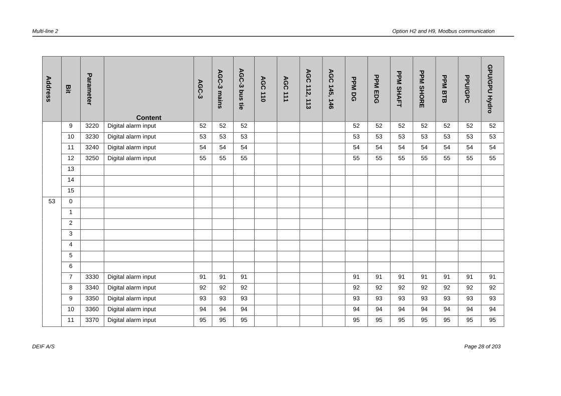
52 Digital alarms
0 3130 Digital alarm input 43 43 43 43 43 43 43 43 43 43
1 3140 Digital alarm input 44 44 44 44 44 44 44 44 44 44
2 3150 Digital alarm input 45 45 45 45 45 45 45 45 45 45
3 3160 Digital alarm input 46 46 46 46 46 46 46 46 46 46
4 3170 Digital alarm input 47 47 47 47 47 47 47 47 47 47
5 3180 Digital alarm input 48 48 48 48 48 48 48 48 48 48
6 3190 Digital alarm input 49 49 49 49 49 49 49 49 49 49
7 3200 Digital alarm input 50 50 50 50 50 50 50 50 50 50
8 3210 Digital alarm input 51 51 51 51 51 51 51 51 51 51
Multi-line 2 Option H2 and H9, Modbus communication
DEIF A/S Page 28 of 203
Ad
dre
ss
Bit
Para
mete
r
Content
AG
C-3
AG
C-3
main
s
AG
C-3
bu
s tie
AG
C 1
10
AG
C 1
11
AG
C 1
12, 1
13
AG
C 1
45, 1
46
PP
M D
G
PP
M E
DG
PP
M S
HA
FT
PP
M S
HO
RE
PP
M B
TB
PP
U/G
PC
GP
U/G
PU
Hyd
ro
9 3220 Digital alarm input 52 52 52 52 52 52 52 52 52 52
10 3230 Digital alarm input 53 53 53 53 53 53 53 53 53 53
11 3240 Digital alarm input 54 54 54 54 54 54 54 54 54 54
12 3250 Digital alarm input 55 55 55 55 55 55 55 55 55 55
13
14
15
53 0
1
2
3
4
5
6
7 3330 Digital alarm input 91 91 91 91 91 91 91 91 91 91
8 3340 Digital alarm input 92 92 92 92 92 92 92 92 92 92
9 3350 Digital alarm input 93 93 93 93 93 93 93 93 93 93
10 3360 Digital alarm input 94 94 94 94 94 94 94 94 94 94
11 3370 Digital alarm input 95 95 95 95 95 95 95 95 95 95
Multi-line 2 Option H2 and H9, Modbus communication
DEIF A/S Page 29 of 203
Ad
dre
ss
Bit
Para
mete
r
Content
AG
C-3
AG
C-3
main
s
AG
C-3
bu
s tie
AG
C 1
10
AG
C 1
11
AG
C 1
12, 1
13
AG
C 1
45, 1
46
PP
M D
G
PP
M E
DG
PP
M S
HA
FT
PP
M S
HO
RE
PP
M B
TB
PP
U/G
PC
GP
U/G
PU
Hyd
ro
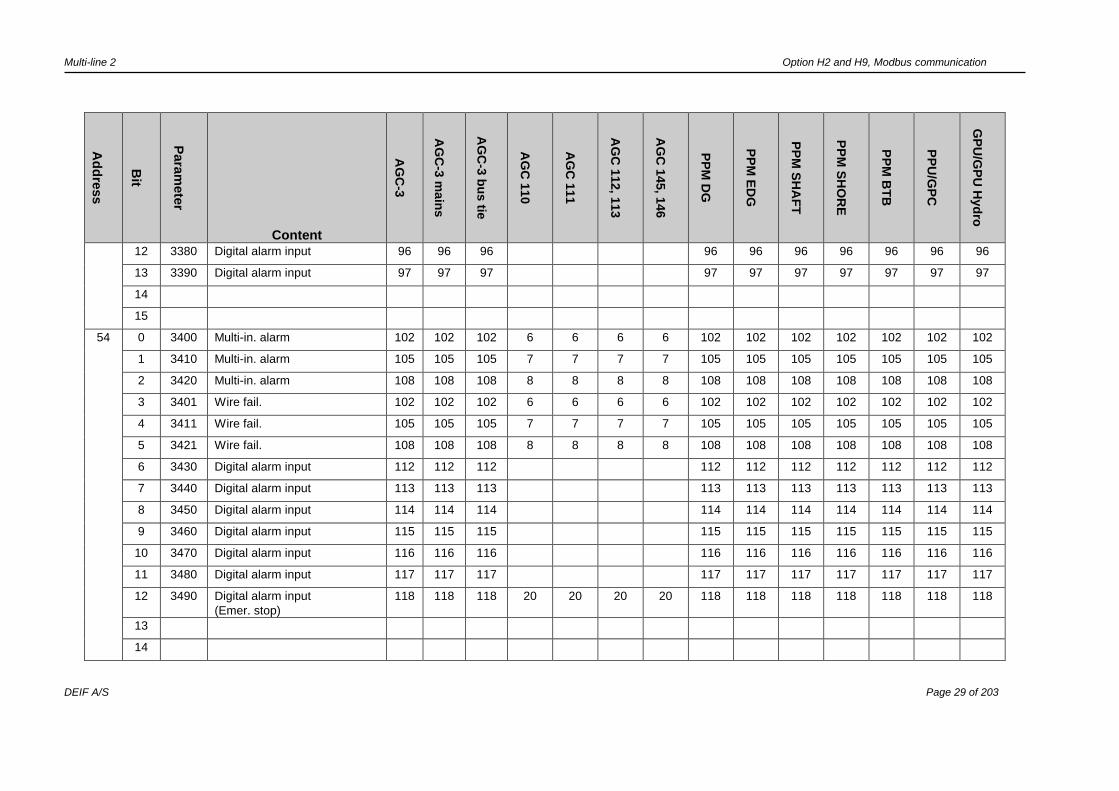
12 3380 Digital alarm input 96 96 96 96 96 96 96 96 96 96
13 3390 Digital alarm input 97 97 97 97 97 97 97 97 97 97
14
15
54 0 3400 Multi-in. alarm 102 102 102 6 6 6 6 102 102 102 102 102 102 102
1 3410 Multi-in. alarm 105 105 105 7 7 7 7 105 105 105 105 105 105 105
2 3420 Multi-in. alarm 108 108 108 8 8 8 8 108 108 108 108 108 108 108
3 3401 Wire fail. 102 102 102 6 6 6 6 102 102 102 102 102 102 102
4 3411 Wire fail. 105 105 105 7 7 7 7 105 105 105 105 105 105 105
5 3421 Wire fail. 108 108 108 8 8 8 8 108 108 108 108 108 108 108
6 3430 Digital alarm input 112 112 112 112 112 112 112 112 112 112
7 3440 Digital alarm input 113 113 113 113 113 113 113 113 113 113
8 3450 Digital alarm input 114 114 114 114 114 114 114 114 114 114
9 3460 Digital alarm input 115 115 115 115 115 115 115 115 115 115
10 3470 Digital alarm input 116 116 116 116 116 116 116 116 116 116
11 3480 Digital alarm input 117 117 117 117 117 117 117 117 117 117
12 3490 Digital alarm input
(Emer. stop)
118 118 118 20 20 20 20 118 118 118 118 118 118 118
13
14
Multi-line 2 Option H2 and H9, Modbus communication
DEIF A/S Page 30 of 203
Ad
dre
ss
Bit
Para
mete
r
Content
AG
C-3
AG
C-3
main
s
AG
C-3
bu
s tie
AG
C 1
10
AG
C 1
11
AG
C 1
12, 1
13
AG
C 1
45, 1
46
PP
M D
G
PP
M E
DG
PP
M S
HA
FT
PP
M S
HO
RE
PP
M B
TB
PP
U/G
PC
GP
U/G
PU
Hyd
ro
15
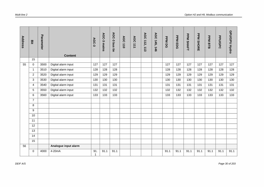
55 0 3500 Digital alarm input 127 127 127 127 127 127 127 127 127 127
1 3510 Digital alarm input 128 128 128 128 128 128 128 128 128 128
2 3520 Digital alarm input 129 129 129 129 129 129 129 129 129 129
3 3530 Digital alarm input 130 130 130 130 130 130 130 130 130 130
4 3540 Digital alarm input 131 131 131 131 131 131 131 131 131 131
5 3550 Digital alarm input 132 132 132 132 132 132 132 132 132 132
6 3560 Digital alarm input 133 133 133 133 133 133 133 133 133 133
7
8
9
10
11
12
13
14
15
56 Analogue input alarm
0 4000 4-20mA 91.
1
91.1 91.1 91.1 91.1 91.1 91.1 91.1 91.1 91.1

Multi-line 2 Option H2 and H9, Modbus communication
DEIF A/S Page 31 of 203
Ad
dre
ss
Bit
Para
mete
r
Content
AG
C-3
AG
C-3
main
s
AG
C-3
bu
s tie
AG
C 1
10
AG
C 1
11
AG
C 1
12, 1
13
AG
C 1
45, 1
46
PP
M D
G
PP
M E
DG
PP
M S
HA
FT
PP
M S
HO
RE
PP
M B
TB
PP
U/G
PC
GP
U/G
PU
Hyd
ro
1 4010 4-20mA 91.
2
91.2 91.2 91.2 91.2 91.2 91.2 91.2 91.2 91.2
2 4020 Wire failure analogue 91 91 91 91 91 91 91 91 91 91
3 4030 4-20mA 93.
1
93.1 93.1 93.1 93.1 93.1 93.1 93.1 93.1 93.1
4 4040 4-20mA 93.
2
93.2 93.2 93.2 93.2 93.2 93.2 93.2 93.2 93.2
5 4050 Wire failure analogue 93 93 93 93 93 93 93 93 93 93
6 4060 4-20mA 95.
1
95.1 95.1 95.1 95.1 95.1 95.1 95.1 95.1 95.1
7 4070 4-20mA 95.
2
95.2 95.2 95.2 95.2 95.2 95.2 95.2 95.2 95.2
8 4080 Wire failure analogue 95 95 95 95 95 95 95 95 95 95
9 4090 4-20mA 97.
1
97.1 97.1 97.1 97.1 97.1 97.1 97.1 97.1 97.1
10 4100 4-20mA 97.
2
97.2 97.2 97.2 97.2 97.2 97.2 97.2 97.2 97.2
11 4110 Wire failure analogue 97 97 97 97 97 97 97 97 97 97
12
13
14
15
57 Multi-functional input
0 4120 4-20mA 102.1 102.1 102.1 6.1 6.1 6.1 6.1 102.1 102.1 102.1 102.1 102.1 102.1 102.1
Multi-line 2 Option H2 and H9, Modbus communication
DEIF A/S Page 32 of 203
Ad
dre
ss
Bit
Para
mete
r
Content
AG
C-3
AG
C-3
main
s
AG
C-3
bu
s tie
AG
C 1
10
AG
C 1
11
AG
C 1
12, 1
13
AG
C 1
45, 1
46
PP
M D
G
PP
M E
DG
PP
M S
HA
FT
PP
M S
HO
RE
PP
M B
TB
PP
U/G
PC
GP
U/G
PU
Hyd
ro
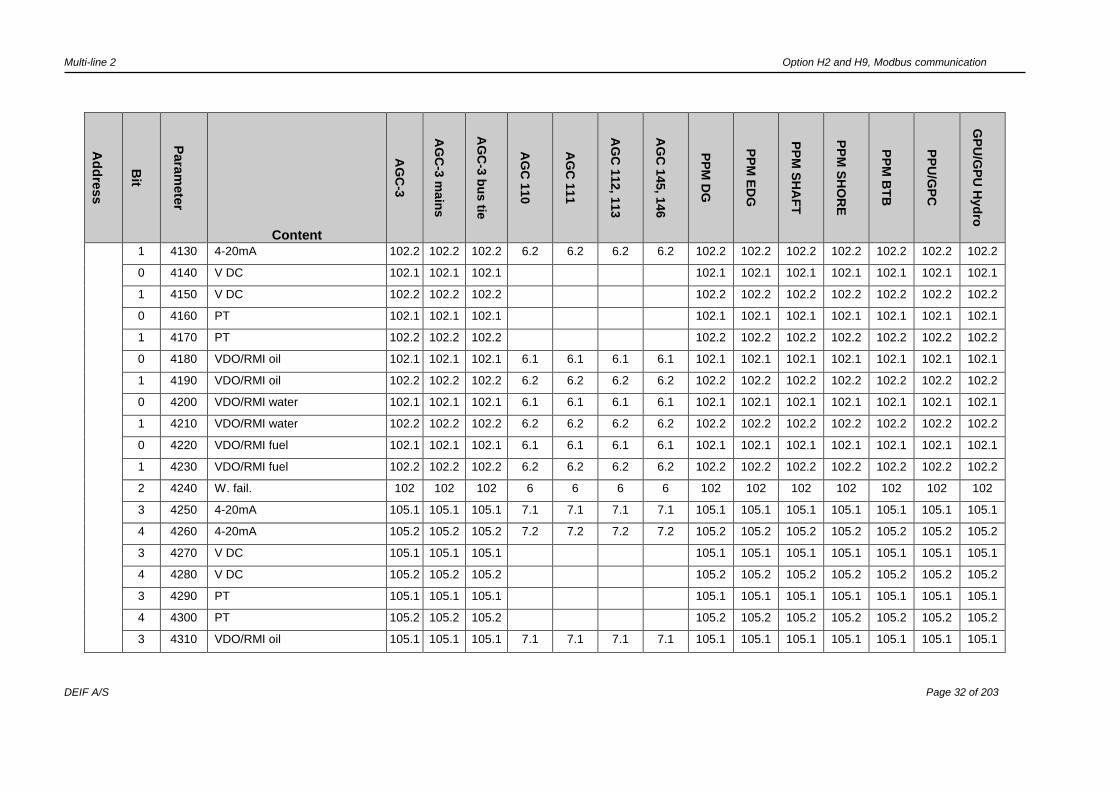
1 4130 4-20mA 102.2 102.2 102.2 6.2 6.2 6.2 6.2 102.2 102.2 102.2 102.2 102.2 102.2 102.2
0 4140 V DC 102.1 102.1 102.1 102.1 102.1 102.1 102.1 102.1 102.1 102.1
1 4150 V DC 102.2 102.2 102.2 102.2 102.2 102.2 102.2 102.2 102.2 102.2
0 4160 PT 102.1 102.1 102.1 102.1 102.1 102.1 102.1 102.1 102.1 102.1
1 4170 PT 102.2 102.2 102.2 102.2 102.2 102.2 102.2 102.2 102.2 102.2
0 4180 VDO/RMI oil 102.1 102.1 102.1 6.1 6.1 6.1 6.1 102.1 102.1 102.1 102.1 102.1 102.1 102.1
1 4190 VDO/RMI oil 102.2 102.2 102.2 6.2 6.2 6.2 6.2 102.2 102.2 102.2 102.2 102.2 102.2 102.2
0 4200 VDO/RMI water 102.1 102.1 102.1 6.1 6.1 6.1 6.1 102.1 102.1 102.1 102.1 102.1 102.1 102.1
1 4210 VDO/RMI water 102.2 102.2 102.2 6.2 6.2 6.2 6.2 102.2 102.2 102.2 102.2 102.2 102.2 102.2
0 4220 VDO/RMI fuel 102.1 102.1 102.1 6.1 6.1 6.1 6.1 102.1 102.1 102.1 102.1 102.1 102.1 102.1
1 4230 VDO/RMI fuel 102.2 102.2 102.2 6.2 6.2 6.2 6.2 102.2 102.2 102.2 102.2 102.2 102.2 102.2
2 4240 W. fail. 102 102 102 6 6 6 6 102 102 102 102 102 102 102
3 4250 4-20mA 105.1 105.1 105.1 7.1 7.1 7.1 7.1 105.1 105.1 105.1 105.1 105.1 105.1 105.1
4 4260 4-20mA 105.2 105.2 105.2 7.2 7.2 7.2 7.2 105.2 105.2 105.2 105.2 105.2 105.2 105.2
3 4270 V DC 105.1 105.1 105.1 105.1 105.1 105.1 105.1 105.1 105.1 105.1
4 4280 V DC 105.2 105.2 105.2 105.2 105.2 105.2 105.2 105.2 105.2 105.2
3 4290 PT 105.1 105.1 105.1 105.1 105.1 105.1 105.1 105.1 105.1 105.1
4 4300 PT 105.2 105.2 105.2 105.2 105.2 105.2 105.2 105.2 105.2 105.2
3 4310 VDO/RMI oil 105.1 105.1 105.1 7.1 7.1 7.1 7.1 105.1 105.1 105.1 105.1 105.1 105.1 105.1
Multi-line 2 Option H2 and H9, Modbus communication
DEIF A/S Page 33 of 203
Ad
dre
ss
Bit
Para
mete
r
Content
AG
C-3
AG
C-3
main
s
AG
C-3
bu
s tie
AG
C 1
10
AG
C 1
11
AG
C 1
12, 1
13
AG
C 1
45, 1
46
PP
M D
G
PP
M E
DG
PP
M S
HA
FT
PP
M S
HO
RE
PP
M B
TB
PP
U/G
PC
GP
U/G
PU
Hyd
ro
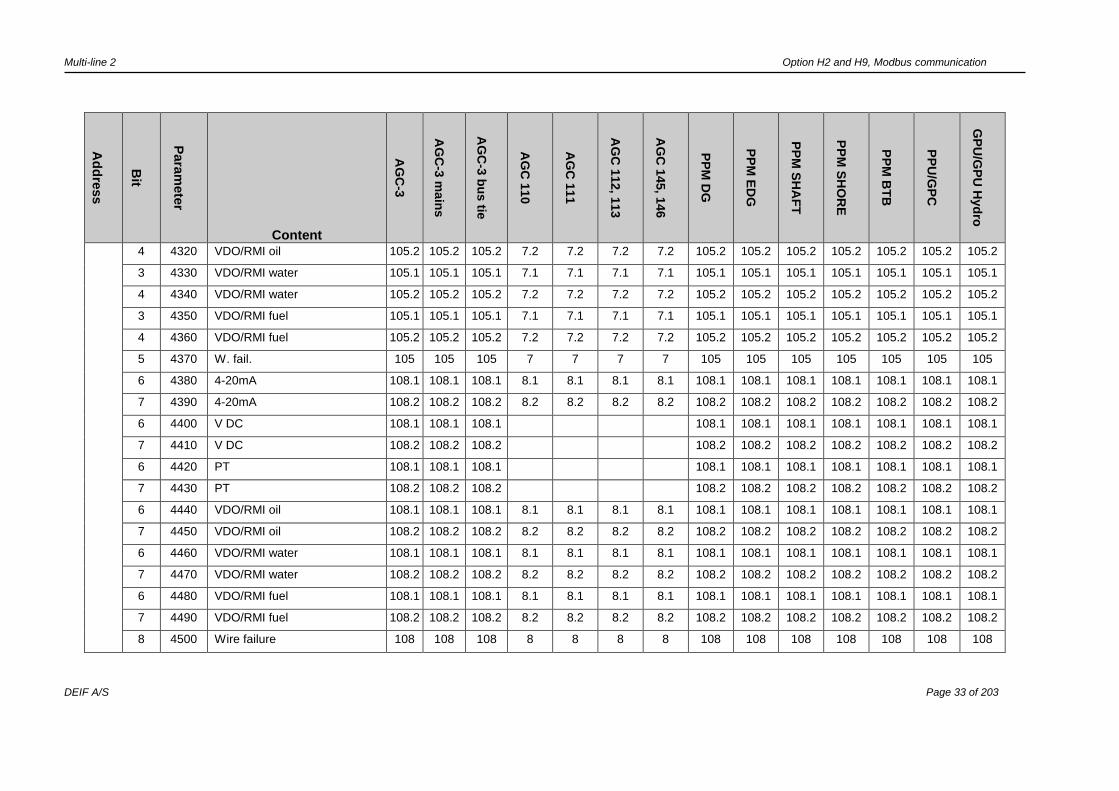
4 4320 VDO/RMI oil 105.2 105.2 105.2 7.2 7.2 7.2 7.2 105.2 105.2 105.2 105.2 105.2 105.2 105.2
3 4330 VDO/RMI water 105.1 105.1 105.1 7.1 7.1 7.1 7.1 105.1 105.1 105.1 105.1 105.1 105.1 105.1
4 4340 VDO/RMI water 105.2 105.2 105.2 7.2 7.2 7.2 7.2 105.2 105.2 105.2 105.2 105.2 105.2 105.2
3 4350 VDO/RMI fuel 105.1 105.1 105.1 7.1 7.1 7.1 7.1 105.1 105.1 105.1 105.1 105.1 105.1 105.1
4 4360 VDO/RMI fuel 105.2 105.2 105.2 7.2 7.2 7.2 7.2 105.2 105.2 105.2 105.2 105.2 105.2 105.2
5 4370 W. fail. 105 105 105 7 7 7 7 105 105 105 105 105 105 105
6 4380 4-20mA 108.1 108.1 108.1 8.1 8.1 8.1 8.1 108.1 108.1 108.1 108.1 108.1 108.1 108.1
7 4390 4-20mA 108.2 108.2 108.2 8.2 8.2 8.2 8.2 108.2 108.2 108.2 108.2 108.2 108.2 108.2
6 4400 V DC 108.1 108.1 108.1 108.1 108.1 108.1 108.1 108.1 108.1 108.1
7 4410 V DC 108.2 108.2 108.2 108.2 108.2 108.2 108.2 108.2 108.2 108.2
6 4420 PT 108.1 108.1 108.1 108.1 108.1 108.1 108.1 108.1 108.1 108.1
7 4430 PT 108.2 108.2 108.2 108.2 108.2 108.2 108.2 108.2 108.2 108.2
6 4440 VDO/RMI oil 108.1 108.1 108.1 8.1 8.1 8.1 8.1 108.1 108.1 108.1 108.1 108.1 108.1 108.1
7 4450 VDO/RMI oil 108.2 108.2 108.2 8.2 8.2 8.2 8.2 108.2 108.2 108.2 108.2 108.2 108.2 108.2
6 4460 VDO/RMI water 108.1 108.1 108.1 8.1 8.1 8.1 8.1 108.1 108.1 108.1 108.1 108.1 108.1 108.1
7 4470 VDO/RMI water 108.2 108.2 108.2 8.2 8.2 8.2 8.2 108.2 108.2 108.2 108.2 108.2 108.2 108.2
6 4480 VDO/RMI fuel 108.1 108.1 108.1 8.1 8.1 8.1 8.1 108.1 108.1 108.1 108.1 108.1 108.1 108.1
7 4490 VDO/RMI fuel 108.2 108.2 108.2 8.2 8.2 8.2 8.2 108.2 108.2 108.2 108.2 108.2 108.2 108.2
8 4500 Wire failure 108 108 108 8 8 8 8 108 108 108 108 108 108 108
Multi-line 2 Option H2 and H9, Modbus communication
DEIF A/S Page 34 of 203
Ad
dre
ss
Bit
Para
mete
r
Content
AG
C-3
AG
C-3
main
s
AG
C-3
bu
s tie
AG
C 1
10
AG
C 1
11
AG
C 1
12, 1
13
AG
C 1
45, 1
46
PP
M D
G
PP
M E
DG
PP
M S
HA
FT
PP
M S
HO
RE
PP
M B
TB
PP
U/G
PC
GP
U/G
PU
Hyd
ro
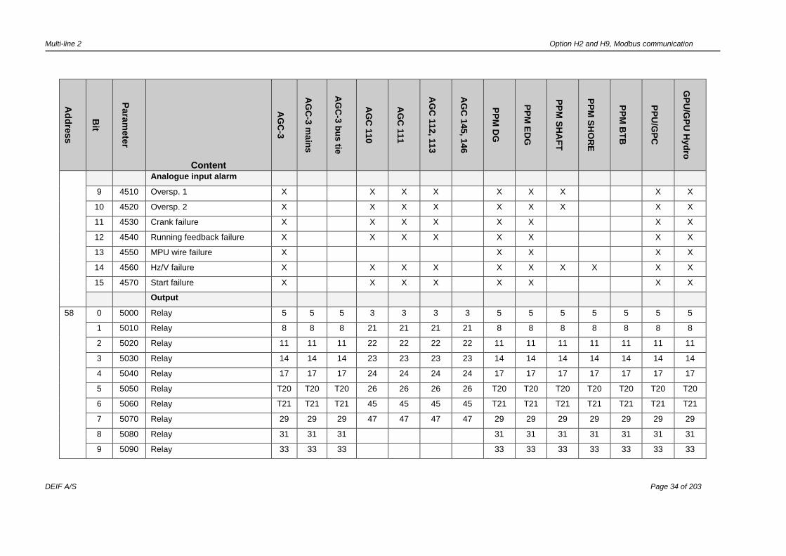
Analogue input alarm
9 4510 Oversp. 1 X X X X X X X X X
10 4520 Oversp. 2 X X X X X X X X X
11 4530 Crank failure X X X X X X X X
12 4540 Running feedback failure X X X X X X X X
13 4550 MPU wire failure X X X X X
14 4560 Hz/V failure X X X X X X X X X X
15 4570 Start failure X X X X X X X X
Output
58 0 5000 Relay 5 5 5 3 3 3 3 5 5 5 5 5 5 5
1 5010 Relay 8 8 8 21 21 21 21 8 8 8 8 8 8 8
2 5020 Relay 11 11 11 22 22 22 22 11 11 11 11 11 11 11
3 5030 Relay 14 14 14 23 23 23 23 14 14 14 14 14 14 14
4 5040 Relay 17 17 17 24 24 24 24 17 17 17 17 17 17 17
5 5050 Relay T20 T20 T20 26 26 26 26 T20 T20 T20 T20 T20 T20 T20
6 5060 Relay T21 T21 T21 45 45 45 45 T21 T21 T21 T21 T21 T21 T21
7 5070 Relay 29 29 29 47 47 47 47 29 29 29 29 29 29 29
8 5080 Relay 31 31 31 31 31 31 31 31 31 31
9 5090 Relay 33 33 33 33 33 33 33 33 33 33
Multi-line 2 Option H2 and H9, Modbus communication
DEIF A/S Page 35 of 203
Ad
dre
ss
Bit
Para
mete
r
Content
AG
C-3
AG
C-3
main
s
AG
C-3
bu
s tie
AG
C 1
10
AG
C 1
11
AG
C 1
12, 1
13
AG
C 1
45, 1
46
PP
M D
G
PP
M E
DG
PP
M S
HA
FT
PP
M S
HO
RE
PP
M B
TB
PP
U/G
PC
GP
U/G
PU
Hyd
ro
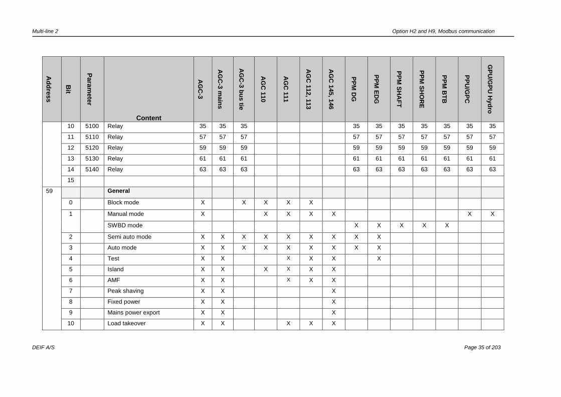
10 5100 Relay 35 35 35 35 35 35 35 35 35 35
11 5110 Relay 57 57 57 57 57 57 57 57 57 57
12 5120 Relay 59 59 59 59 59 59 59 59 59 59
13 5130 Relay 61 61 61 61 61 61 61 61 61 61
14 5140 Relay 63 63 63 63 63 63 63 63 63 63
15
59 General
0 Block mode X X X X X
1 Manual mode X X X X X X X
SWBD mode X X X X X
2 Semi auto mode X X X X X X X X X
3 Auto mode X X X X X X X X X
4 Test X X X X X X
5 Island X X X X X X
6 AMF X X X X X
7 Peak shaving X X X
8 Fixed power X X X
9 Mains power export X X X
10 Load takeover X X X X X

Multi-line 2 Option H2 and H9, Modbus communication
DEIF A/S Page 36 of 203
Ad
dre
ss
Bit
Para
mete
r
Content
AG
C-3
AG
C-3
main
s
AG
C-3
bu
s tie
AG
C 1
10
AG
C 1
11
AG
C 1
12, 1
13
AG
C 1
45, 1
46
PP
M D
G
PP
M E
DG
PP
M S
HA
FT
PP
M S
HO
RE
PP
M B
TB
PP
U/G
PC
GP
U/G
PU
Hyd
ro
11 Power management X X
Genset group X
12 DG supply X X
13 SG/SC supply X X
14 Reserved
15 AMF active X X X X X
60 EIC alarm
0 7570 Communication error X X X X X X X X X X X
1 7580 Warning X X X X X X X X X
2 7590 Shutdown X X X X X X X X X
3 7600 Overspeed X X X X X X X X X
4 7610 Cool water temp. high 1 X X X X X X X X X
5 7620 Cool water temp. high 2 X X X X X X X X X
6 7630 Oil pressure low 1 X X X X X X X X X
7 7640 Oil pressure low 2 X X X X X X X X X
8 7650 Oil temp. 1 X X X X X X X X X
9 7660 Oil temp. 2 X X X X X X X X X
10 7670 Coolant level 1 X X X X X X
11 7680 Coolant level 2 X X X X X X
Multi-line 2 Option H2 and H9, Modbus communication
DEIF A/S Page 37 of 203
Ad
dre
ss
Bit
Para
mete
r
Content
AG
C-3
AG
C-3
main
s
AG
C-3
bu
s tie
AG
C 1
10
AG
C 1
11
AG
C 1
12, 1
13
AG
C 1
45, 1
46
PP
M D
G
PP
M E
DG
PP
M S
HA
FT
PP
M S
HO
RE
PP
M B
TB
PP
U/G
PC
GP
U/G
PU
Hyd
ro
12
13
14
15
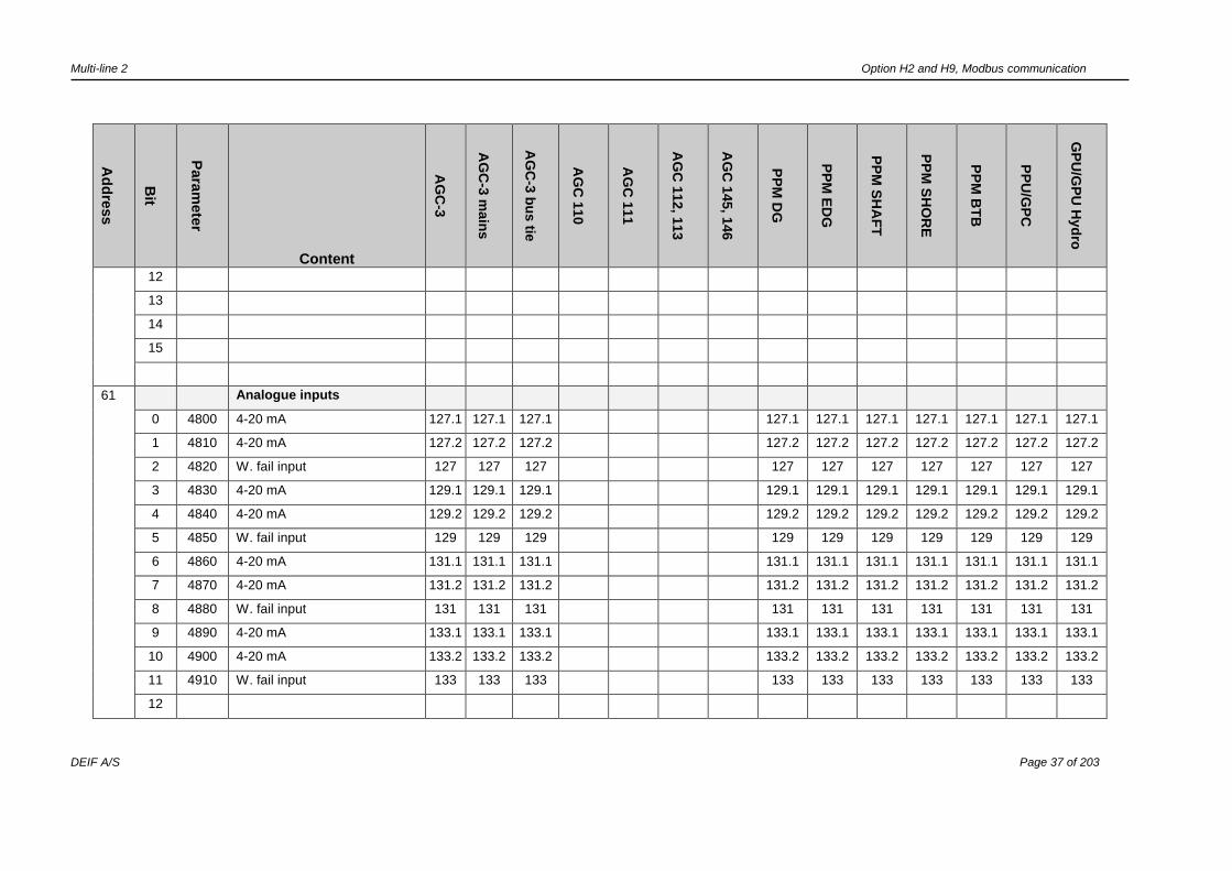
61 Analogue inputs
0 4800 4-20 mA 127.1 127.1 127.1 127.1 127.1 127.1 127.1 127.1 127.1 127.1
1 4810 4-20 mA 127.2 127.2 127.2 127.2 127.2 127.2 127.2 127.2 127.2 127.2
2 4820 W. fail input 127 127 127 127 127 127 127 127 127 127
3 4830 4-20 mA 129.1 129.1 129.1 129.1 129.1 129.1 129.1 129.1 129.1 129.1
4 4840 4-20 mA 129.2 129.2 129.2 129.2 129.2 129.2 129.2 129.2 129.2 129.2
5 4850 W. fail input 129 129 129 129 129 129 129 129 129 129
6 4860 4-20 mA 131.1 131.1 131.1 131.1 131.1 131.1 131.1 131.1 131.1 131.1
7 4870 4-20 mA 131.2 131.2 131.2 131.2 131.2 131.2 131.2 131.2 131.2 131.2
8 4880 W. fail input 131 131 131 131 131 131 131 131 131 131
9 4890 4-20 mA 133.1 133.1 133.1 133.1 133.1 133.1 133.1 133.1 133.1 133.1
10 4900 4-20 mA 133.2 133.2 133.2 133.2 133.2 133.2 133.2 133.2 133.2 133.2
11 4910 W. fail input 133 133 133 133 133 133 133 133 133 133
12
Multi-line 2 Option H2 and H9, Modbus communication
DEIF A/S Page 38 of 203
Ad
dre
ss
Bit
Para
mete
r
Content
AG
C-3
AG
C-3
main
s
AG
C-3
bu
s tie
AG
C 1
10
AG
C 1
11
AG
C 1
12, 1
13
AG
C 1
45, 1
46
PP
M D
G
PP
M E
DG
PP
M S
HA
FT
PP
M S
HO
RE
PP
M B
TB
PP
U/G
PC
GP
U/G
PU
Hyd
ro
13
14
15
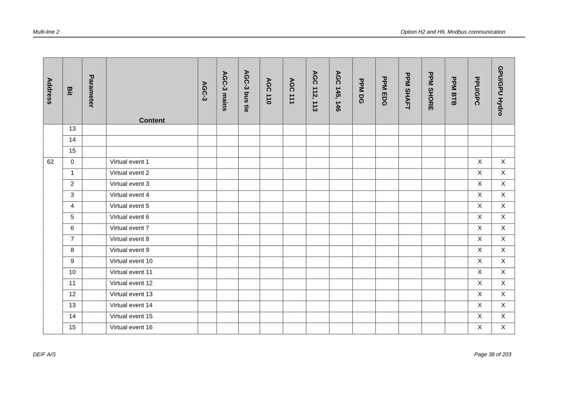
62 0 Virtual event 1 X X
1 Virtual event 2 X X
2 Virtual event 3 X X
3 Virtual event 4 X X
4 Virtual event 5 X X
5 Virtual event 6 X X
6 Virtual event 7 X X
7 Virtual event 8 X X
8 Virtual event 9 X X
9 Virtual event 10 X X
10 Virtual event 11 X X
11 Virtual event 12 X X
12 Virtual event 13 X X
13 Virtual event 14 X X
14 Virtual event 15 X X
15 Virtual event 16 X X
Multi-line 2 Option H2 and H9, Modbus communication
DEIF A/S Page 39 of 203
Ad
dre
ss
Bit
Para
mete
r
Content
AG
C-3
AG
C-3
main
s
AG
C-3
bu
s tie
AG
C 1
10
AG
C 1
11
AG
C 1
12, 1
13
AG
C 1
45, 1
46
PP
M D
G
PP
M E
DG
PP
M S
HA
FT
PP
M S
HO
RE
PP
M B
TB
PP
U/G
PC
GP
U/G
PU
Hyd
ro
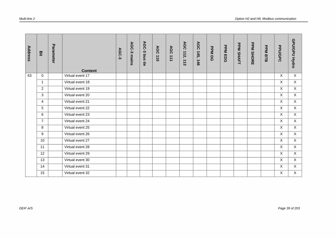
63 0 Virtual event 17 X X
1 Virtual event 18 X X
2 Virtual event 19 X X
3 Virtual event 20 X X
4 Virtual event 21 X X
5 Virtual event 22 X X
6 Virtual event 23 X X
7 Virtual event 24 X X
8 Virtual event 25 X X
9 Virtual event 26 X X
10 Virtual event 27 X X
11 Virtual event 28 X X
12 Virtual event 29 X X
13 Virtual event 30 X X
14 Virtual event 31 X X
15 Virtual event 32 X X

Multi-line 2 Option H2 and H9, Modbus communication
DEIF A/S Page 40 of 203
*Multi-input – unscaled values
A short description of the unscaled values and how to interpret these according to the input type selected is made in this document.
The unscaled values have a full range of 0 to 1023 bit.
4-20 mA
0 mA: 0 bit
4 mA: 170 bit
20 mA: 853 bit
25 mA: 1023 bit
Linearity between the unscaled value and the scaled value yields.
0-40 V DC
0 V DC: 0 bit
40 V DC: 925 bit
Linearity between the unscaled value and the scaled value yields.
Pt100
Linearity between the unscaled value and the input resistance yields according to the following equation:
Ω = (x + 509) * 100/771
x: Unscaled value.
Ω: PT resistance value.
Multi-line 2 Option H2 and H9, Modbus communication
DEIF A/S Page 41 of 203
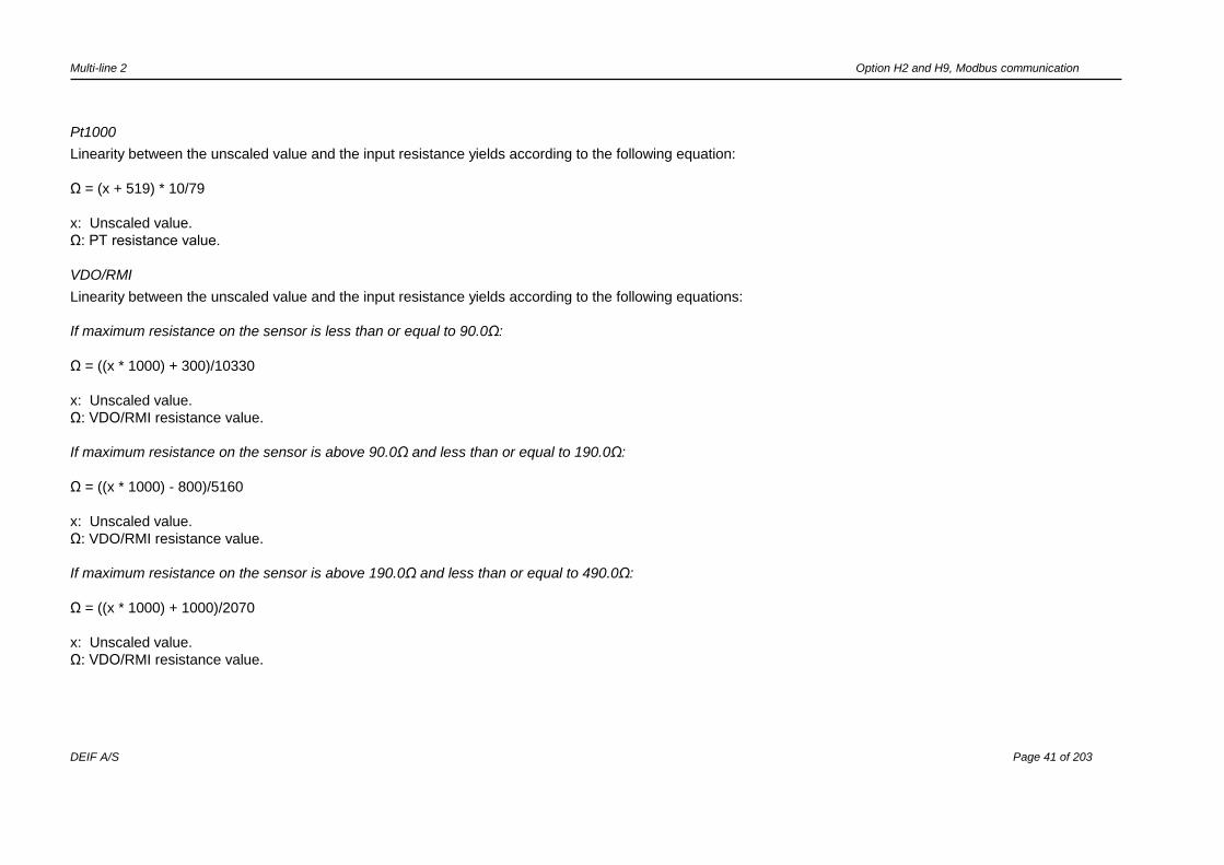
Pt1000
Linearity between the unscaled value and the input resistance yields according to the following equation:
Ω = (x + 519) * 10/79
x: Unscaled value.
Ω: PT resistance value.
VDO/RMI
Linearity between the unscaled value and the input resistance yields according to the following equations:
If maximum resistance on the sensor is less than or equal to 90.0Ω:
Ω = ((x * 1000) + 300)/10330
x: Unscaled value.
Ω: VDO/RMI resistance value.
If maximum resistance on the sensor is above 90.0Ω and less than or equal to 190.0Ω:
Ω = ((x * 1000) - 800)/5160
x: Unscaled value.
Ω: VDO/RMI resistance value.
If maximum resistance on the sensor is above 190.0Ω and less than or equal to 490.0Ω:
Ω = ((x * 1000) + 1000)/2070
x: Unscaled value.
Ω: VDO/RMI resistance value.
Multi-line 2 Option H2 and H9, Modbus communication
DEIF A/S Page 42 of 203
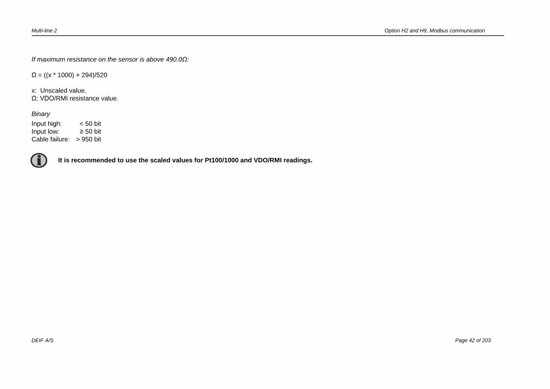
If maximum resistance on the sensor is above 490.0Ω:
Ω = ((x * 1000) + 294)/520
x: Unscaled value.
Ω: VDO/RMI resistance value.
Binary
Input high: < 50 bit
Input low: ≥ 50 bit
Cable failure: > 950 bit
It is recommended to use the scaled values for Pt100/1000 and VDO/RMI readings.

Multi-line 2 Option H2 and H9, Modbus communication
DEIF A/S Page 43 of 203
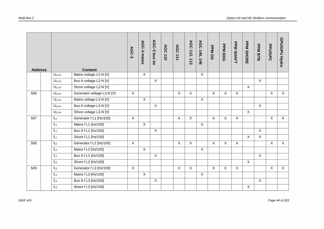
Measurement table (read only) (function code 04h)
Address Content
AG
C-3
AG
C-3
main
s
AG
C-3
bu
s tie
AG
C 1
10
AG
C 1
11
AG
C 1
12. 1
13
AG
C 1
45, 1
46
PP
M D
G
PP
M E
DG
PP
M S
HA
FT
PP
M S
HO
RE
PP
M B
TB
PP
U/G
PC
GP
U/G
PU
Hyd
ro
501 UL1-L2 Generator voltage L1-L2 [V] X X X X X X X X
UL1-L2 Mains voltage L1-L2 [V] X X
UL1-L2 Bus A voltage L1-L2 [V] X X
UL1-L2 Shore voltage L1-L2 [V] X
502
UL2-L3 Generator voltage L2-L3 [V] X X X X X X X X
UL2-L3 Mains voltage L2-L3 [V] X X
UL2-L3 Bus A voltage L2-L3 [V] X X
UL2-L3 Shore voltage L2-L3 [V] X
503
UL3-L1 Generator voltage L3-L1 [V] X X X X X X X X
UL3-L1 Mains voltage L3-L1 [V] X X
UL3-L1 Bus A voltage L3-L1 [V] X X
UL3-L1 Shore voltage L3-L1 [V] X
504
UL1-N Generator voltage L1-N [V] X X X X X X X X
UL1-N Mains voltage L1-N [V] X X
UL1-N Bus A voltage L1-N [V] X X
UL1-N Shore voltage L1-N [V] X
505 UL2-N Generator voltage L2-N [V] X X X X X X X X
Multi-line 2 Option H2 and H9, Modbus communication
DEIF A/S Page 44 of 203
Address Content
AG
C-3
AG
C-3
main
s
AG
C-3
bu
s tie
AG
C 1
10
AG
C 1
11
AG
C 1
12. 1
13
AG
C 1
45, 1
46
PP
M D
G
PP
M E
DG
PP
M S
HA
FT
PP
M S
HO
RE
PP
M B
TB
PP
U/G
PC
GP
U/G
PU
Hyd
ro
UL2-N Mains voltage L2-N [V] X X
UL2-N Bus A voltage L2-N [V] X X
UL2-N Shore voltage L2-N [V] X
506
UL3-N Generator voltage L3-N [V] X X X X X X X X
UL3-N Mains voltage L3-N [V] X X
UL3-N Bus A voltage L3-N [V] X X
UL3-N Shore voltage L3-N [V] X
507
fL1 Generator f L1 [Hz/100] X X X X X X X X
fL1 Mains f L1 [Hz/100] X X
fL1 Bus A f L1 [Hz/100] X X
fL1 Shore f L1 [Hz/100] X X
508
fL2 Generator f L2 [Hz/100] X X X X X X X X
fL2 Mains f L2 [Hz/100] X X
fL2 Bus A f L2 [Hz/100] X X
fL2 Shore f L2 [Hz/100] X
509
fL3 Generator f L3 [Hz/100] X X X X X X X X
fL3 Mains f L3 [Hz/100] X X
fL3 Bus A f L3 [Hz/100] X X
fL3 Shore f L3 [Hz/100] X
Multi-line 2 Option H2 and H9, Modbus communication
DEIF A/S Page 45 of 203
Address Content
AG
C-3
AG
C-3
main
s
AG
C-3
bu
s tie
AG
C 1
10
AG
C 1
11
AG
C 1
12. 1
13
AG
C 1
45, 1
46
PP
M D
G
PP
M E
DG
PP
M S
HA
FT
PP
M S
HO
RE
PP
M B
TB
PP
U/G
PC
GP
U/G
PU
Hyd
ro
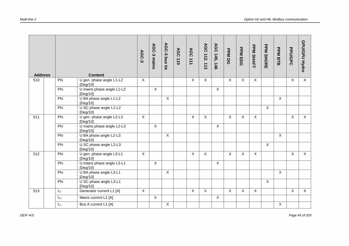
510
Phi U gen. phase angle L1-L2
[Deg/10]
X X X X X X X X
Phi U mains phase angle L1-L2
[Deg/10]
X X
Phi U BA phase angle L1-L2
[Deg/10]
X X
Phi U SC phase angle L1-L2
[Deg/10]
X
511
Phi U gen. phase angle L2-L3
[Deg/10]
X X X X X X X X
Phi U mains phase angle L2-L3
[Deg/10]
X X
Phi U BA phase angle L2-L3
[Deg/10]
X X
Phi U SC phase angle L2-L3
[Deg/10]
X
512
Phi U gen. phase angle L3-L1
[Deg/10]
X X X X X X X X
Phi U mains phase angle L3-L1
[Deg/10]
X X
Phi U BA phase angle L3-L1
[Deg/10]
X X
Phi U SC phase angle L3-L1
[Deg/10]
X
513
IL1 Generator current L1 [A] X X X X X X X X
IL1 Mains current L1 [A] X X
IL1 Bus A current L1 [A] X X

Multi-line 2 Option H2 and H9, Modbus communication
DEIF A/S Page 46 of 203
Address Content
AG
C-3
AG
C-3
main
s
AG
C-3
bu
s tie
AG
C 1
10
AG
C 1
11
AG
C 1
12. 1
13
AG
C 1
45, 1
46
PP
M D
G
PP
M E
DG
PP
M S
HA
FT
PP
M S
HO
RE
PP
M B
TB
PP
U/G
PC
GP
U/G
PU
Hyd
ro
IL1 Shore current L1 [A] X
514
IL2 Generator current L2 [A] X X X X X X X X
IL2 Mains current L2 [A] X X
IL2 Bus A current L2 [A] X X
IL2 Shore current L2 [A] X
515
IL3 Generator current L3 [A] X X X X X X X X
IL3 Mains current L3 [A] X X
IL3 Bus A current L3 [A] X X
IL3 Shore current L3 [A] X
516
PGEN L1 Generator power L1 [kW] X X X X X X X X
PMAINS L1 Mains power L1 [kW] X X
PBA L1 Bus A power L1 [kW] X X
PSC L1 Bus A power L1 [kW] X
517
PGEN L2 Generator power L2 [kW] X X X X X X X X
PMAINS L2 Mains power L2 [kW] X X
PBA L2 Bus A power L2 [kW] X X
PSC L2 Bus A power L2 [kW] X
518
PGEN L3 Generator power L3 [kW] X X X X X X X X
PMAINS L3 Mains power L3 [kW] X X
PBA L3 Bus A power L3 [kW] X X

Multi-line 2 Option H2 and H9, Modbus communication
DEIF A/S Page 47 of 203
Address Content
AG
C-3
AG
C-3
main
s
AG
C-3
bu
s tie
AG
C 1
10
AG
C 1
11
AG
C 1
12. 1
13
AG
C 1
45, 1
46
PP
M D
G
PP
M E
DG
PP
M S
HA
FT
PP
M S
HO
RE
PP
M B
TB
PP
U/G
PC
GP
U/G
PU
Hyd
ro
PSC L3 Bus A power L3 [kW] X
519
PGEN Generator power [kW] X X X X X X X X X
PMAINS Mains power [kW] X X
PBA Bus A power [kW] X
PSC Shore power [kW] X
520 QGEN L1 Generator reactive power L1
[kVAr]
X X X X X X X X X
QMAINS L1 Mains reactive power L1 [kVAr] X X
QBA L1 Bus A reactive power L1 [kVAr]
QSC L1 Bus A reactive power L1 [kVAr] X
521 QGEN L2 Generator reactive power L2
[kVAr]
X X X X X X X X X
QMAINS L2 Mains reactive power L2 [kVAr] X X
QBA L2 Bus A reactive power L2 [kVAr]
QSC L2 Bus A reactive power L2 [kVAr] X
522 QGEN L3 Generator reactive power L3
[kVAr]
X X X X X X X X X
QMAINS L3 Mains reactive power L3 [kVAr] X X
QBA L3 Bus A reactive power L3 [kVAr]
QSC L3 Bus A reactive power L3 [kVAr] X
523
QGEN Generator reactive power [kVAr] X X X X X X X X X
QMAINS Mains reactive power [kVAr] X X X
QBA Bus A reactive power [kVar] X
QSC Shore reactive power [kVAr] X
Multi-line 2 Option H2 and H9, Modbus communication
DEIF A/S Page 48 of 203
Address Content
AG
C-3
AG
C-3
main
s
AG
C-3
bu
s tie
AG
C 1
10
AG
C 1
11
AG
C 1
12. 1
13
AG
C 1
45, 1
46
PP
M D
G
PP
M E
DG
PP
M S
HA
FT
PP
M S
HO
RE
PP
M B
TB
PP
U/G
PC
GP
U/G
PU
Hyd
ro
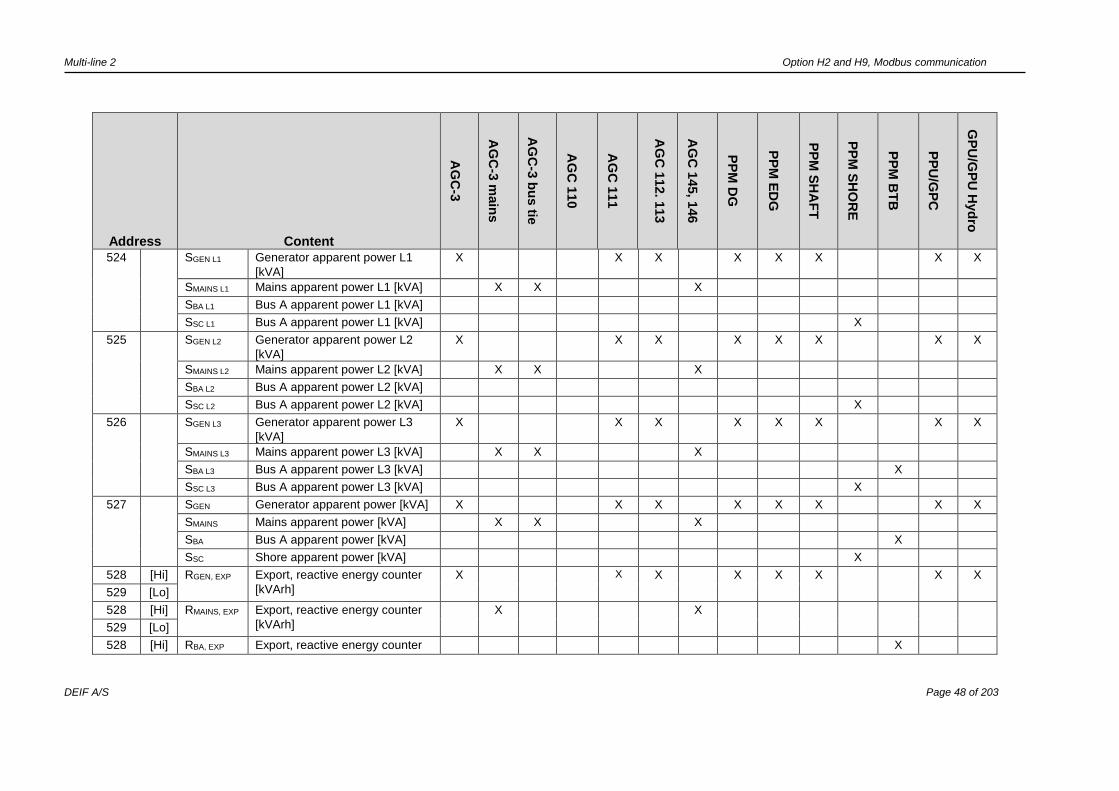
524
SGEN L1 Generator apparent power L1
[kVA]
X X X X X X X X
SMAINS L1 Mains apparent power L1 [kVA] X X X
SBA L1 Bus A apparent power L1 [kVA]
SSC L1 Bus A apparent power L1 [kVA] X
525
SGEN L2 Generator apparent power L2
[kVA]
X X X X X X X X
SMAINS L2 Mains apparent power L2 [kVA] X X X
SBA L2 Bus A apparent power L2 [kVA]
SSC L2 Bus A apparent power L2 [kVA] X
526
SGEN L3 Generator apparent power L3
[kVA]
X X X X X X X X
SMAINS L3 Mains apparent power L3 [kVA] X X X
SBA L3 Bus A apparent power L3 [kVA] X
SSC L3 Bus A apparent power L3 [kVA] X
527
SGEN Generator apparent power [kVA] X X X X X X X X
SMAINS Mains apparent power [kVA] X X X
SBA Bus A apparent power [kVA] X
SSC Shore apparent power [kVA] X
528 [Hi] RGEN, EXP Export, reactive energy counter
[kVArh]
X X X X X
X
X X
529 [Lo]
528 [Hi] RMAINS, EXP Export, reactive energy counter
[kVArh]
X X
529 [Lo]
528 [Hi] RBA, EXP Export, reactive energy counter X
Multi-line 2 Option H2 and H9, Modbus communication
DEIF A/S Page 49 of 203
Address Content
AG
C-3
AG
C-3
main
s
AG
C-3
bu
s tie
AG
C 1
10
AG
C 1
11
AG
C 1
12. 1
13
AG
C 1
45, 1
46
PP
M D
G
PP
M E
DG
PP
M S
HA
FT
PP
M S
HO
RE
PP
M B
TB
PP
U/G
PC
GP
U/G
PU
Hyd
ro
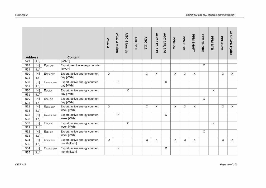
529 [Lo] [kVArh]
528 [Hi] RSC, EXP Export, reactive energy counter
[kVArh]
X
529 [Lo]
530 [Hi] EGEN, EXP Export, active energy counter,
day [kWh]
X X X X X
X
X X
531 [Lo]
530 [Hi] EMAINS, EXP Export, active energy counter,
day [kWh]
X X
531 [Lo]
530 [Hi] EBA, EXP Export, active energy counter,
day [kWh]
X
X
531 [Lo]
530 [Hi] ESC, EXP Export, active energy counter,
day [kWh]
X
531 [Lo]
532 [Hi] EGEN, EXP Export, active energy counter,
week [kWh]
X X X X X
X
X X
533 [Lo]
532 [Hi] EMAINS, EXP Export, active energy counter,
week [kWh]
X X
533 [Lo]
532 [Hi] EBA, EXP Export, active energy counter,
week [kWh]
X
X
533 [Lo]
532 [Hi] ESC, EXP Export, active energy counter,
week [kWh]
X
533 [Lo]
534 [Hi] EGEN, EXP Export, active energy counter,
month [kWh]
X X X X X
X
X
X
535 [Lo]
534 [Hi] EMAINS, EXP Export, active energy counter,
month [kWh]
X X
535 [Lo]

Multi-line 2 Option H2 and H9, Modbus communication
DEIF A/S Page 50 of 203
Address Content
AG
C-3
AG
C-3
main
s
AG
C-3
bu
s tie
AG
C 1
10
AG
C 1
11
AG
C 1
12. 1
13
AG
C 1
45, 1
46
PP
M D
G
PP
M E
DG
PP
M S
HA
FT
PP
M S
HO
RE
PP
M B
TB
PP
U/G
PC
GP
U/G
PU
Hyd
ro
534 [Hi] EBA, EXP Export, active energy counter,
month [kWh]
X
X
535 [Lo]
534 [Hi] ESC, EXP Export, active energy counter,
month [kWh]
X
535 [Lo]
536 [Hi] EGEN, EXP Export, active energy counter,
total [kWh]
X X X X X
X
X
X
537 [Lo]
536 [Hi] EMAINS, EXP Export, active energy counter,
total [kWh]
X X
537 [Lo]
536 [Hi] EBA, EXP Export, active energy counter,
total [kWh]
X
X
537 [Lo]
536 [Hi] ESC, EXP Export, active energy counter,
total [kWh]
X
537 [Lo]
538
PF Generator PF [PF/100] X X X X X X X X
PF Mains PF [PF/100] X X
PF Bus A PF [PF/100] X X
PF Shore PF [PF/100] X
539 UBBL1-L2 U BB L1-L2 [V] X X X X X X X X X X X X
540 UBBL2-L3 U BB L2-L3 [V] X X X X X X X X X X X X
541 UBBL3-L1 U BB L3-L1 [V] X X X X X X X X X X X X
542 UBBL1-N U BB L1-N [V] X X X X X X X X X X X X
543 UBBL2-N U BB L2-N [V] X X X X X X X X X X X X
544 UBBL3-N U BB L3-N [V] X X X X X X X X X X X X

Multi-line 2 Option H2 and H9, Modbus communication
DEIF A/S Page 51 of 203
Address Content
AG
C-3
AG
C-3
main
s
AG
C-3
bu
s tie
AG
C 1
10
AG
C 1
11
AG
C 1
12. 1
13
AG
C 1
45, 1
46
PP
M D
G
PP
M E
DG
PP
M S
HA
FT
PP
M S
HO
RE
PP
M B
TB
PP
U/G
PC
GP
U/G
PU
Hyd
ro
545 FBB BB FL1 [Hz/100] X X X X X X X X X X X X X
546 FBB f BB L2 [Hz/100] X X X X X X X X X X
547 FBB f BB L3 [Hz/100] X X X X X X X X X X
548 PHIBBL1-L2 U BB phase angle L1-L2
[Deg/10]
X X X X X X X X X X X X X
549 PHIBBL2-L3 U BB phase angle L2-L3
[Deg/10]
X X X X X X X X X X
550 PHIBBL3-L1 U BB phase angle L3-L1
[Deg/10]
X X X X X X X X X X
551 PHIBBL1-
DGL1
U BB L1 - U GEN L1
phase angle [Deg/10]
X X X X X X X X
PHIBBL1-
ML1
U BB L1 - U Mains L1
phase angle [Deg/10]
X X
PHIBAL1-
BBL1
U BB A L1 - U BB B L1
phase angle [Deg/10]
X X
PHISCL1-
BBL1
U BB A L1 - U BB B L1
phase angle [Deg/10]
X
552 PHIBBL2-
DGL2
U BB L2 - U GEN L2
phase angle [Deg/10]
X X X X X
X
PHIBBL2-
MAINSL2
U BB L2 - U mains L2
phase angle [Deg/10]
X
PHIBBL2-
BAL2
U BB L2 - U bus A L2
phase angle [Deg/10]
X X
PHISCL2-
BAL2
U BB L2 - U bus A L2
phase angle [Deg/10]
X
553 PHIBBL3-
DGL3
U BB L3 - U GEN L3
phase angle [Deg/10]
X X X X X
X

Multi-line 2 Option H2 and H9, Modbus communication
DEIF A/S Page 52 of 203
Address Content
AG
C-3
AG
C-3
main
s
AG
C-3
bu
s tie
AG
C 1
10
AG
C 1
11
AG
C 1
12. 1
13
AG
C 1
45, 1
46
PP
M D
G
PP
M E
DG
PP
M S
HA
FT
PP
M S
HO
RE
PP
M B
TB
PP
U/G
PC
GP
U/G
PU
Hyd
ro
PHIBBL3-
MAINSL3
U BB L3 - U mains L3
phase angle [Deg/10]
X
PHIBBL3-
BAL3
U BB L3 - U bus A L3
phase angle [Deg/10]
X X
PHISCL3-
BAL3
U BB L3 - U bus A L3
phase angle [Deg/10]
X
554 [Hi] Abs. run.
hours
Absolute. run hours X X X X
X
X
X
X
555 [Lo]
556 [Hi] Rel. run.
hours
Relative. run hours X X X X
X
X
557 [Lo]
558 Alarms No. of alarms X X X X X X X X X X X X X X
559 Alarms No. of unack. alarms X X X X X X X X X X X X X X
560 Alarms No. of active acknowledged
alarms
X X X X X X X X X X X X X X
561 Run. min. Running min. counter, shutdown
override
X X X X X X
562 Run.
hours
Running hour counter, shutdown
override
X X X X X X
563
GBoper No. of GB operations X X X X X X X
TBoper No. of TB operations X X
BTBoper No. of BTB operations X X
564 MBoper No. of MB operations X X X X X X
TBoper No. of TB operations X
SGBoper No. of SGB operations X
Multi-line 2 Option H2 and H9, Modbus communication
DEIF A/S Page 53 of 203
Address Content
AG
C-3
AG
C-3
main
s
AG
C-3
bu
s tie
AG
C 1
10
AG
C 1
11
AG
C 1
12. 1
13
AG
C 1
45, 1
46
PP
M D
G
PP
M E
DG
PP
M S
HA
FT
PP
M S
HO
RE
PP
M B
TB
PP
U/G
PC
GP
U/G
PU
Hyd
ro
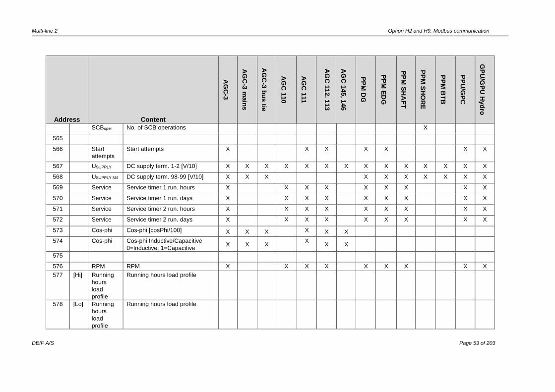
SCBoper No. of SCB operations X
565
566 Start
attempts
Start attempts X X X X X X X
567 USUPPLY DC supply term. 1-2 [V/10] X X X X X X X X X X X X X X
568 USUPPLY M4 DC supply term. 98-99 [V/10] X X X X X X X X X X
569 Service Service timer 1 run. hours X X X X X X X X X
570 Service Service timer 1 run. days X X X X X X X X X
571 Service Service timer 2 run. hours X X X X X X X X X
572 Service Service timer 2 run. days X X X X X X X X X
573 Cos-phi Cos-phi [cosPhi/100] X X X X X X
574 Cos-phi Cos-phi Inductive/Capacitive
0=Inductive, 1=Capacitive X X X
X X X
575
576 RPM RPM X X X X X X X X X
577 [Hi] Running
hours
load
profile
Running hours load profile
578 [Lo] Running
hours
load
profile
Running hours load profile
Multi-line 2 Option H2 and H9, Modbus communication
DEIF A/S Page 54 of 203
Address Content
AG
C-3
AG
C-3
main
s
AG
C-3
bu
s tie
AG
C 1
10
AG
C 1
11
AG
C 1
12. 1
13
AG
C 1
45, 1
46
PP
M D
G
PP
M E
DG
PP
M S
HA
FT
PP
M S
HO
RE
PP
M B
TB
PP
U/G
PC
GP
U/G
PU
Hyd
ro
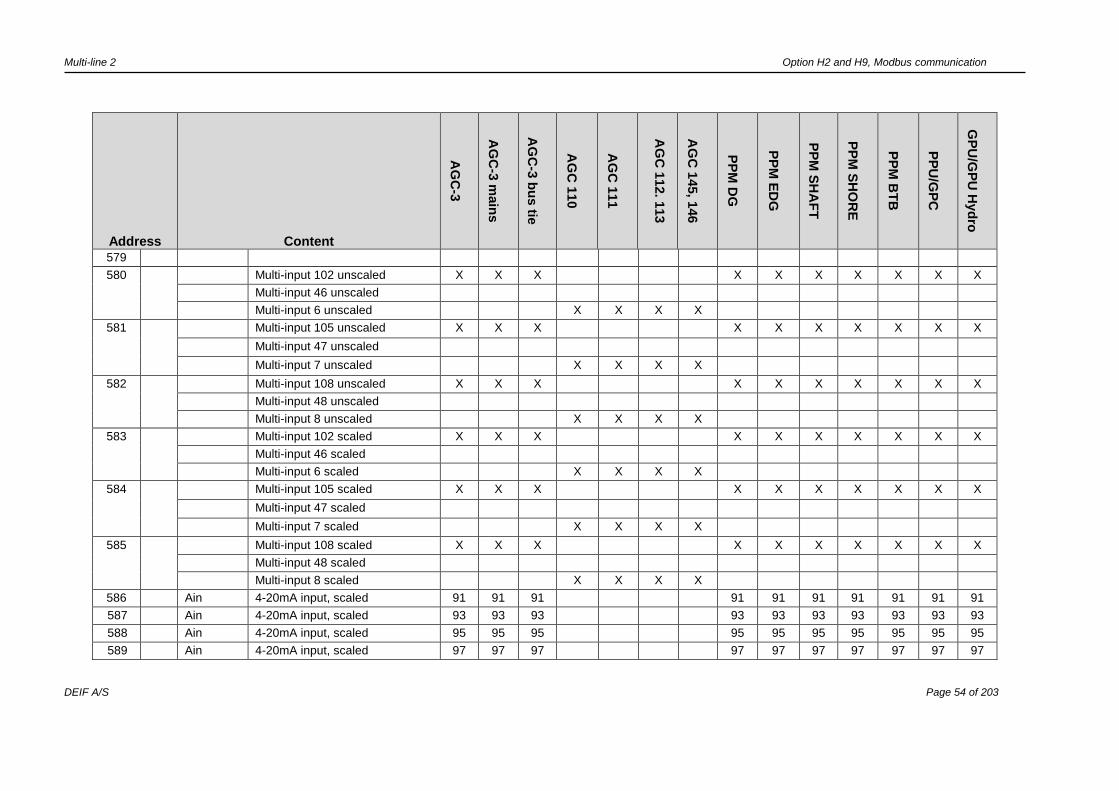
579
580 Multi-input 102 unscaled X X X X X X X X X X
Multi-input 46 unscaled
Multi-input 6 unscaled X X X X
581 Multi-input 105 unscaled X X X X X X X X X X
Multi-input 47 unscaled
Multi-input 7 unscaled X X X X
582 Multi-input 108 unscaled X X X X X X X X X X
Multi-input 48 unscaled
Multi-input 8 unscaled X X X X
583 Multi-input 102 scaled X X X X X X X X X X
Multi-input 46 scaled
Multi-input 6 scaled X X X X
584 Multi-input 105 scaled X X X X X X X X X X
Multi-input 47 scaled
Multi-input 7 scaled X X X X
585 Multi-input 108 scaled X X X X X X X X X X
Multi-input 48 scaled
Multi-input 8 scaled X X X X
586 Ain 4-20mA input, scaled 91 91 91 91 91 91 91 91 91 91
587 Ain 4-20mA input, scaled 93 93 93 93 93 93 93 93 93 93
588 Ain 4-20mA input, scaled 95 95 95 95 95 95 95 95 95 95
589 Ain 4-20mA input, scaled 97 97 97 97 97 97 97 97 97 97
Multi-line 2 Option H2 and H9, Modbus communication
DEIF A/S Page 55 of 203
Address Content
AG
C-3
AG
C-3
main
s
AG
C-3
bu
s tie
AG
C 1
10
AG
C 1
11
AG
C 1
12. 1
13
AG
C 1
45, 1
46
PP
M D
G
PP
M E
DG
PP
M S
HA
FT
PP
M S
HO
RE
PP
M B
TB
PP
U/G
PC
GP
U/G
PU
Hyd
ro
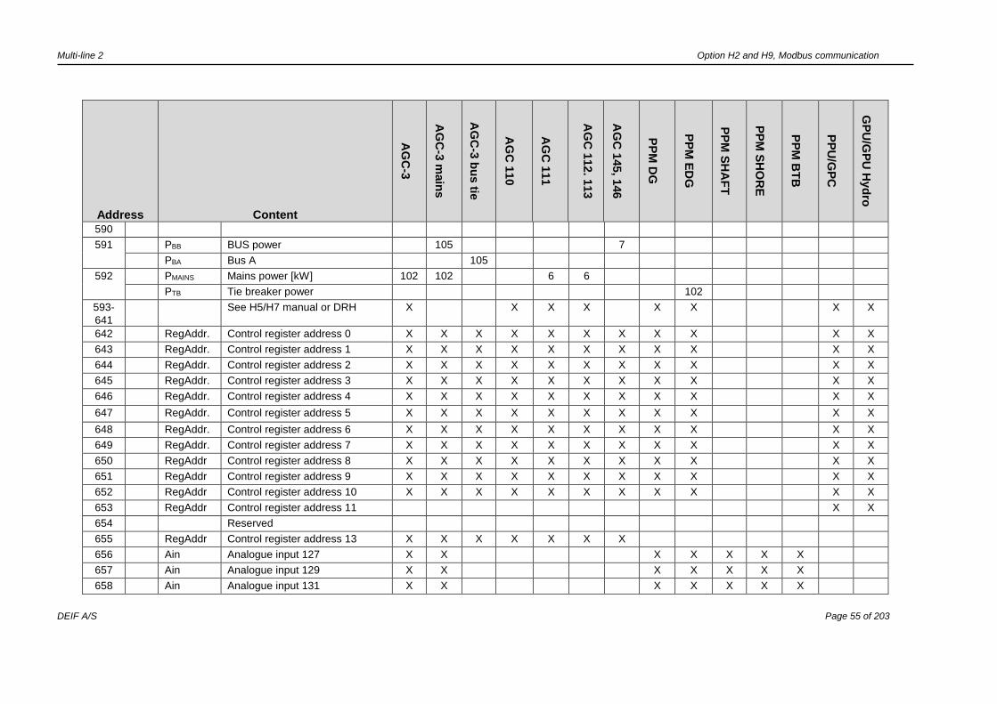
590
591 PBB BUS power 105 7
PBA Bus A 105
592 PMAINS Mains power [kW] 102 102 6 6
PTB Tie breaker power 102
593-
641
See H5/H7 manual or DRH X X X X X X X X
642 RegAddr. Control register address 0 X X X X X X X X X X X
643 RegAddr. Control register address 1 X X X X X X X X X X X
644 RegAddr. Control register address 2 X X X X X X X X X X X
645 RegAddr. Control register address 3 X X X X X X X X X X X
646 RegAddr. Control register address 4 X X X X X X X X X X X
647 RegAddr. Control register address 5 X X X X X X X X X X X
648 RegAddr. Control register address 6 X X X X X X X X X X X
649 RegAddr. Control register address 7 X X X X X X X X X X X
650 RegAddr Control register address 8 X X X X X X X X X X X
651 RegAddr Control register address 9 X X X X X X X X X X X
652 RegAddr Control register address 10 X X X X X X X X X X X
653 RegAddr Control register address 11 X X
654 Reserved
655 RegAddr Control register address 13 X X X X X X X
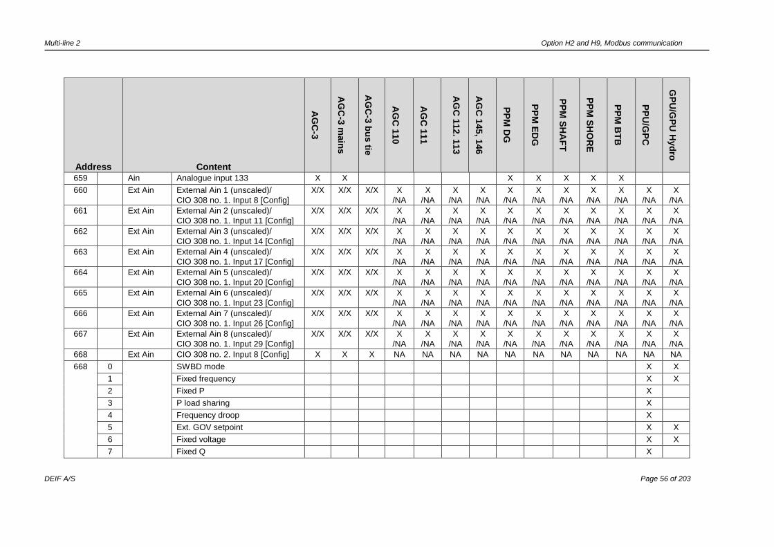
656 Ain Analogue input 127 X X X X X X X
657 Ain Analogue input 129 X X X X X X X
658 Ain Analogue input 131 X X X X X X X
Multi-line 2 Option H2 and H9, Modbus communication
DEIF A/S Page 56 of 203
Address Content
AG
C-3
AG
C-3
main
s
AG
C-3
bu
s tie
AG
C 1
10
AG
C 1
11
AG
C 1
12. 1
13
AG
C 1
45, 1
46
PP
M D
G
PP
M E
DG
PP
M S
HA
FT
PP
M S
HO
RE
PP
M B
TB
PP
U/G
PC
GP
U/G
PU
Hyd
ro
659 Ain Analogue input 133 X X X X X X X
660 Ext Ain External Ain 1 (unscaled)/
CIO 308 no. 1. Input 8 [Config]
X/X X/X X/X X
/NA
X
/NA
X
/NA
X
/NA
X
/NA
X
/NA
X
/NA
X
/NA
X
/NA
X
/NA
X
/NA
661 Ext Ain External Ain 2 (unscaled)/
CIO 308 no. 1. Input 11 [Config]
X/X X/X X/X X
/NA
X
/NA
X
/NA
X
/NA
X
/NA
X
/NA
X
/NA
X
/NA
X
/NA
X
/NA
X
/NA
662 Ext Ain External Ain 3 (unscaled)/
CIO 308 no. 1. Input 14 [Config]
X/X X/X X/X X
/NA
X
/NA
X
/NA
X
/NA
X
/NA
X
/NA
X
/NA
X
/NA
X
/NA
X
/NA
X
/NA
663 Ext Ain External Ain 4 (unscaled)/
CIO 308 no. 1. Input 17 [Config]
X/X X/X X/X X
/NA
X
/NA
X
/NA
X
/NA
X
/NA
X
/NA
X
/NA
X
/NA
X
/NA
X
/NA
X
/NA
664 Ext Ain External Ain 5 (unscaled)/
CIO 308 no. 1. Input 20 [Config]
X/X X/X X/X X
/NA
X
/NA
X
/NA
X
/NA
X
/NA
X
/NA
X
/NA
X
/NA
X
/NA
X
/NA
X
/NA
665 Ext Ain External Ain 6 (unscaled)/
CIO 308 no. 1. Input 23 [Config]
X/X X/X X/X X
/NA
X
/NA
X
/NA
X
/NA
X
/NA
X
/NA
X
/NA
X
/NA
X
/NA
X
/NA
X
/NA
666 Ext Ain External Ain 7 (unscaled)/
CIO 308 no. 1. Input 26 [Config]
X/X X/X X/X X
/NA
X
/NA
X
/NA
X
/NA
X
/NA
X
/NA
X
/NA
X
/NA
X
/NA
X
/NA
X
/NA
667 Ext Ain External Ain 8 (unscaled)/
CIO 308 no. 1. Input 29 [Config]
X/X X/X X/X X
/NA
X
/NA
X
/NA
X
/NA
X
/NA
X
/NA
X
/NA
X
/NA
X
/NA
X
/NA
X
/NA
668 Ext Ain CIO 308 no. 2. Input 8 [Config] X X X NA NA NA NA NA NA NA NA NA NA NA
668 0 SWBD mode X X
1 Fixed frequency X X
2 Fixed P X
3 P load sharing X
4 Frequency droop X
5 Ext. GOV setpoint X X
6 Fixed voltage X X
7 Fixed Q X

Multi-line 2 Option H2 and H9, Modbus communication
DEIF A/S Page 57 of 203
Address Content
AG
C-3
AG
C-3
main
s
AG
C-3
bu
s tie
AG
C 1
10
AG
C 1
11
AG
C 1
12. 1
13
AG
C 1
45, 1
46
PP
M D
G
PP
M E
DG
PP
M S
HA
FT
PP
M S
HO
RE
PP
M B
TB
PP
U/G
PC
GP
U/G
PU
Hyd
ro
8 Fixed PF X
9 Q load sharing X
10 Voltage droop X
11 Ext. AVR setpoint X X
12 Remote X X
13 Local X X
14 Deload X X
15 Start sync./control X X
669 Ext Ain CIO 308 no. 2. Input 11 [Config] X X X NA NA NA NA NA NA NA NA NA NA NA
670 Ext Ain CIO 308 no. 2. Input 14 [Config] X X X NA NA NA NA NA NA NA NA NA NA NA
671 Ext Ain CIO 308 no. 2. Input 17 [Config] X X X NA NA NA NA NA NA NA NA NA NA NA
672 Ext Ain CIO 308 no. 2. Input 20 [Config] X X X NA NA NA NA NA NA NA NA NA NA NA
673 Ext Ain CIO 308 no. 2. Input 23 [Config] X X X NA NA NA NA NA NA NA NA NA NA NA
674 Ext Ain CIO 308 no. 2. Input 26 [Config] X X X NA NA NA NA NA NA NA NA NA NA NA
675 Ext Ain CIO 308 no. 2. Input 29 [Config] X X X NA NA NA NA NA NA NA NA NA NA NA
676 Ext Ain CIO 308 no. 3. Input 8 [Config] X X X NA NA NA NA NA NA NA NA NA NA NA
677 Ext Ain CIO 308 no. 3. Input 11 [Config] X X X NA NA NA NA NA NA NA NA NA NA NA
678 Ext Ain CIO 308 no. 3. Input 14 [Config] X X X NA NA NA NA NA NA NA NA NA NA NA
679 Ext Ain CIO 308 no. 3. Input 17 [Config] X X X NA NA NA NA NA NA NA NA NA NA NA
680 Ext Ain CIO 308 no. 3. Input 20 [Config] X X X NA NA NA NA NA NA NA NA NA NA NA
681 Ext Ain CIO 308 no. 3. Input 23 [Config] X X X NA NA NA NA NA NA NA NA NA NA NA
682 Ext Ain CIO 308 no. 3. Input 26 [Config] X X X NA NA NA NA NA NA NA NA NA NA NA
683 Ext Ain CIO 308 no. 3. Input 29 [Config] X X X NA NA NA NA NA NA NA NA NA NA NA
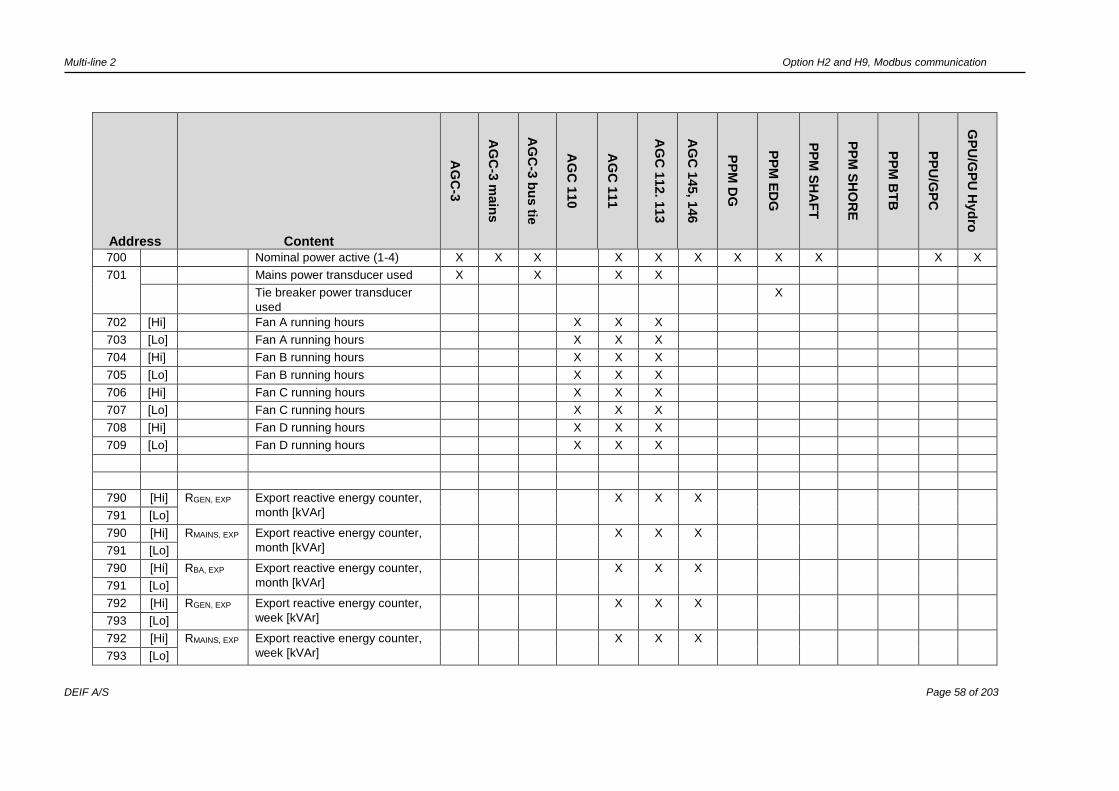
Multi-line 2 Option H2 and H9, Modbus communication
DEIF A/S Page 58 of 203
Address Content
AG
C-3
AG
C-3
main
s
AG
C-3
bu
s tie
AG
C 1
10
AG
C 1
11
AG
C 1
12. 1
13
AG
C 1
45, 1
46
PP
M D
G
PP
M E
DG
PP
M S
HA
FT
PP
M S
HO
RE
PP
M B
TB
PP
U/G
PC
GP
U/G
PU
Hyd
ro
700 Nominal power active (1-4) X X X X X X X X X X X
701 Mains power transducer used X X X X
Tie breaker power transducer
used
X
702 [Hi] Fan A running hours X X X
703 [Lo] Fan A running hours X X X
704 [Hi] Fan B running hours X X X
705 [Lo] Fan B running hours X X X
706 [Hi] Fan C running hours X X X
707 [Lo] Fan C running hours X X X
708 [Hi] Fan D running hours X X X
709 [Lo] Fan D running hours X X X
790 [Hi] RGEN, EXP Export reactive energy counter,
month [kVAr]
X X X
791 [Lo]
790 [Hi] RMAINS, EXP Export reactive energy counter,
month [kVAr]
X X X
791 [Lo]
790 [Hi] RBA, EXP Export reactive energy counter,
month [kVAr]
X X X
791 [Lo]
792 [Hi] RGEN, EXP Export reactive energy counter,
week [kVAr]
X X X
793 [Lo]
792 [Hi] RMAINS, EXP Export reactive energy counter,
week [kVAr]
X X X
793 [Lo]
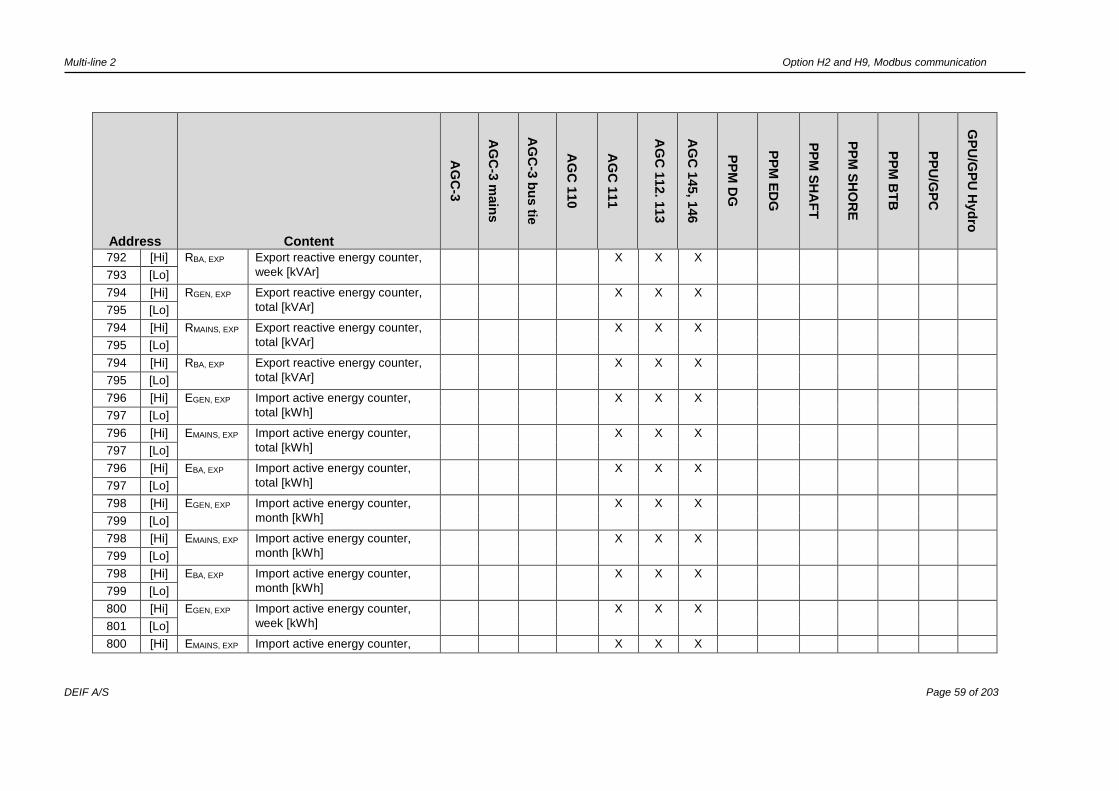
Multi-line 2 Option H2 and H9, Modbus communication
DEIF A/S Page 59 of 203
Address Content
AG
C-3
AG
C-3
main
s
AG
C-3
bu
s tie
AG
C 1
10
AG
C 1
11
AG
C 1
12. 1
13
AG
C 1
45, 1
46
PP
M D
G
PP
M E
DG
PP
M S
HA
FT
PP
M S
HO
RE
PP
M B
TB
PP
U/G
PC
GP
U/G
PU
Hyd
ro
792 [Hi] RBA, EXP Export reactive energy counter,
week [kVAr]
X X X
793 [Lo]
794 [Hi] RGEN, EXP Export reactive energy counter,
total [kVAr]
X X
X
795 [Lo]
794 [Hi] RMAINS, EXP Export reactive energy counter,
total [kVAr]
X X
X
795 [Lo]
794 [Hi] RBA, EXP Export reactive energy counter,
total [kVAr]
X X
X
795 [Lo]
796 [Hi] EGEN, EXP Import active energy counter,
total [kWh]
X X
X
797 [Lo]
796 [Hi] EMAINS, EXP Import active energy counter,
total [kWh]
X X
X
797 [Lo]
796 [Hi] EBA, EXP Import active energy counter,
total [kWh]
X X
X
797 [Lo]
798 [Hi] EGEN, EXP Import active energy counter,
month [kWh]
X X
X
799 [Lo]
798 [Hi] EMAINS, EXP Import active energy counter,
month [kWh]
X X
X
799 [Lo]
798 [Hi] EBA, EXP Import active energy counter,
month [kWh]
X X X
799 [Lo]
800 [Hi] EGEN, EXP Import active energy counter,
week [kWh]
X X X
801 [Lo]
800 [Hi] EMAINS, EXP Import active energy counter, X X X
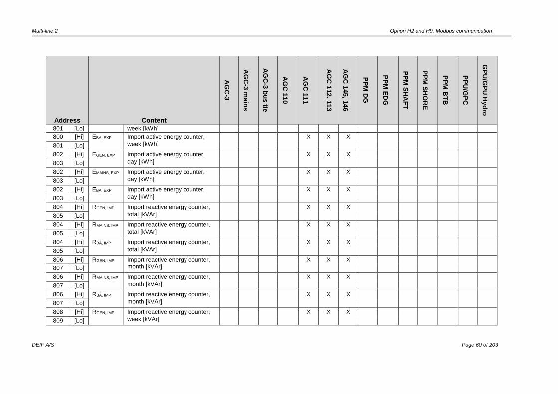
Multi-line 2 Option H2 and H9, Modbus communication
DEIF A/S Page 60 of 203
Address Content
AG
C-3
AG
C-3
main
s
AG
C-3
bu
s tie
AG
C 1
10
AG
C 1
11
AG
C 1
12. 1
13
AG
C 1
45, 1
46
PP
M D
G
PP
M E
DG
PP
M S
HA
FT
PP
M S
HO
RE
PP
M B
TB
PP
U/G
PC
GP
U/G
PU
Hyd
ro
801 [Lo] week [kWh]
800 [Hi] EBA, EXP Import active energy counter,
week [kWh]
X X X
801 [Lo]
802 [Hi] EGEN, EXP Import active energy counter,
day [kWh]
X X X
803 [Lo]
802 [Hi] EMAINS, EXP Import active energy counter,
day [kWh]
X X X
803 [Lo]
802 [Hi] EBA, EXP Import active energy counter,
day [kWh]
X X X
803 [Lo]
804 [Hi] RGEN, IMP Import reactive energy counter,
total [kVAr]
X X X
805 [Lo]
804 [Hi] RMAINS, IMP Import reactive energy counter,
total [kVAr]
X X X
805 [Lo]
804 [Hi] RBA, IMP Import reactive energy counter,
total [kVAr]
X X X
805 [Lo]
806 [Hi] RGEN, IMP Import reactive energy counter,
month [kVAr]
X X X
807 [Lo]
806 [Hi] RMAINS, IMP Import reactive energy counter,
month [kVAr]
X X X
807 [Lo]
806 [Hi] RBA, IMP Import reactive energy counter,
month [kVAr]
X X X
807 [Lo]
808 [Hi] RGEN, IMP Import reactive energy counter,
week [kVAr]
X X X
809 [Lo]
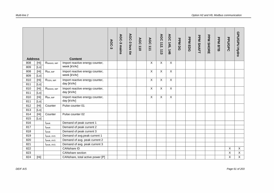
Multi-line 2 Option H2 and H9, Modbus communication
DEIF A/S Page 61 of 203
Address Content
AG
C-3
AG
C-3
main
s
AG
C-3
bu
s tie
AG
C 1
10
AG
C 1
11
AG
C 1
12. 1
13
AG
C 1
45, 1
46
PP
M D
G
PP
M E
DG
PP
M S
HA
FT
PP
M S
HO
RE
PP
M B
TB
PP
U/G
PC
GP
U/G
PU
Hyd
ro
808 [Hi] RMAINS, IMP Import reactive energy counter,
week [kVAr]
X X X
809 [Lo]
808 [Hi] RBA, IMP Import reactive energy counter,
week [kVAr]
X X X
809 [Lo]
810 [Hi] RGEN, IMP Import reactive energy counter,
day [kVAr]
X X X
811 [Lo]
810 [Hi] RMAINS, IMP Import reactive energy counter,
day [kVAr]
X X X
811 [Lo]
810 [Hi] RBA, IMP Import reactive energy counter,
day [kVAr]
X X X
811 [Lo]
812 [Hi] Counter Pulse counter 01
813 [Lo]
814 [Hi] Counter Pulse counter 02
815 [Lo]
816 Ipeak Demand of peak current 1
817 Ipeak Demand of peak current 2
818 Ipeak Demand of peak current 3
819 Ipeak, AVG Demand of avg.peak current 1
820 Ipeak, AVG Demand of avg. peak current 2
821 Ipeak, AVG Demand of avg. peak current 3
822 CANshare ID X X
823 CANshare section X X
824 [Hi] CANshare, total active power [P] X X

Multi-line 2 Option H2 and H9, Modbus communication
DEIF A/S Page 62 of 203
Address Content
AG
C-3
AG
C-3
main
s
AG
C-3
bu
s tie
AG
C 1
10
AG
C 1
11
AG
C 1
12. 1
13
AG
C 1
45, 1
46
PP
M D
G
PP
M E
DG
PP
M S
HA
FT
PP
M S
HO
RE
PP
M B
TB
PP
U/G
PC
GP
U/G
PU
Hyd
ro
825 [Lo] CANshare, total active power [P] X X
826 [Hi] CANshare, total reactive power
[Q]
X X
827 [Lo] CANshare, total reactive power
[Q]
X X
830 Run Day Running hour Day/Min. X X X
831 Run Day Running hour Day/Hour X X X
832 Run
Week
Running hour Week/Min. X X X
833 Run
Week
Running hour Week/Hour X X X
834 Run Hour Running hour Month/Min. X X X
835 Run Hour Running hour Month/Hour X X X
850-
999
See H5/H7 manual or DRH X X X X X X X X X
It is not possible to use both CIO and other external I/O types (Beckhoff/Axiomatic) on a controller.
CIO and other external Ain share the addresses 660 through 667.
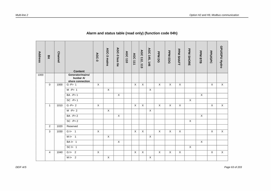
Multi-line 2 Option H2 and H9, Modbus communication
DEIF A/S Page 63 of 203
Alarm and status table (read only) (function code 04h)
Ad
dre
ss
Bit
Ch
an
ne
l
Content
AG
C-3
AG
C-3
ma
ins
AG
C-3
bu
s tie
AG
C 1
10
AG
C 1
11
AG
C 1
12
, 11
3
AG
C 1
45
, 14
6
PP
M D
G
PP
M E
DG
PP
M S
HA
FT
PP
M S
HO
RE
PP
M B
TB
PP
U/G
PC
GP
U/G
PU
Hyd
ro
1000
Generator/mains/
busbar A/
shore connection
0 1000 G -P> 1 X X X X X X X X
M -P> 1 X X
BA -P> 1 X X
SC -P> 1 X
1 1010 G -P> 2 X X X X X X X X
M -P> 2 X X
BA -P> 2 X X
SC -P> 2 X
2 1020 Reserved
3 1030 G I> 1 X X X X X X X X
M I> 1 X X
BA I> 1 X X
SC I> 1 X
4 1040 G I> 2 X X X X X X X X
M I> 2 X X

Multi-line 2 Option H2 and H9, Modbus communication
DEIF A/S Page 64 of 203
Ad
dre
ss
Bit
Ch
an
ne
l
Content
AG
C-3
AG
C-3
ma
ins
AG
C-3
bu
s tie
AG
C 1
10
AG
C 1
11
AG
C 1
12
, 11
3
AG
C 1
45
, 14
6
PP
M D
G
PP
M E
DG
PP
M S
HA
FT
PP
M S
HO
RE
PP
M B
TB
PP
U/G
PC
GP
U/G
PU
Hyd
ro
BA I> 2 X X
SC I> 2 X
5 1050 G I> 3 X X X X X X X X
M I> 3 X X
BA I> 3 X X
SC I> 3 X
6 1060 G I> 4 X X X X X X X X
M I> 4 X X
BA I> 4 X X
SC I> 4 X
7 1080 G I> inv. X X X X
M I> inv. X
BA I> inv.
7 1090 G I> inv. X X
M I> inv.
BA I> inv. X
8 1110 G Iv> X X X X X X X X X X
9 1130 G I>> 1 X X X X X X X X
M I>> 1 X X
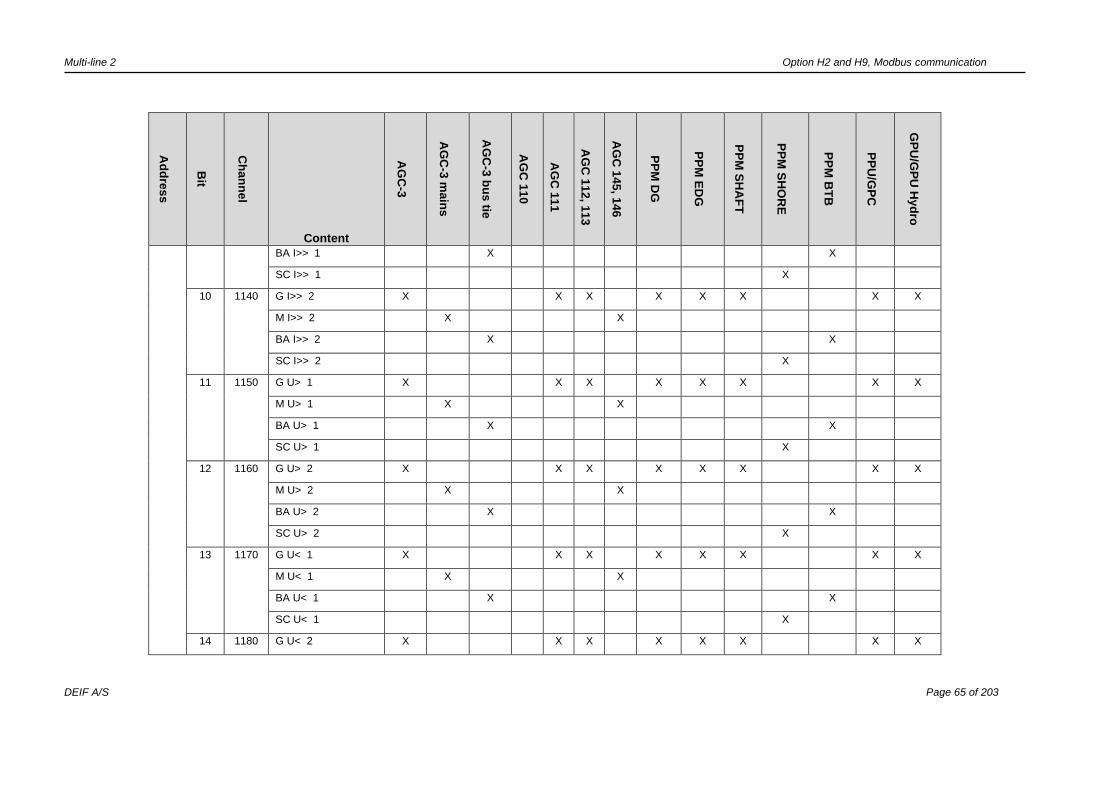
Multi-line 2 Option H2 and H9, Modbus communication
DEIF A/S Page 65 of 203
Ad
dre
ss
Bit
Ch
an
ne
l
Content
AG
C-3
AG
C-3
ma
ins
AG
C-3
bu
s tie
AG
C 1
10
AG
C 1
11
AG
C 1
12
, 11
3
AG
C 1
45
, 14
6
PP
M D
G
PP
M E
DG
PP
M S
HA
FT
PP
M S
HO
RE
PP
M B
TB
PP
U/G
PC
GP
U/G
PU
Hyd
ro
BA I>> 1 X X
SC I>> 1 X
10 1140 G I>> 2 X X X X X X X X
M I>> 2 X X
BA I>> 2 X X
SC I>> 2 X
11 1150 G U> 1 X X X X X X X X
M U> 1 X X
BA U> 1 X X
SC U> 1 X
12 1160 G U> 2 X X X X X X X X
M U> 2 X X
BA U> 2 X X
SC U> 2 X
13 1170 G U< 1 X X X X X X X X
M U< 1 X X
BA U< 1 X X
SC U< 1 X
14 1180 G U< 2 X X X X X X X X

Multi-line 2 Option H2 and H9, Modbus communication
DEIF A/S Page 66 of 203
Ad
dre
ss
Bit
Ch
an
ne
l
Content
AG
C-3
AG
C-3
ma
ins
AG
C-3
bu
s tie
AG
C 1
10
AG
C 1
11
AG
C 1
12
, 11
3
AG
C 1
45
, 14
6
PP
M D
G
PP
M E
DG
PP
M S
HA
FT
PP
M S
HO
RE
PP
M B
TB
PP
U/G
PC
GP
U/G
PU
Hyd
ro
M U< 2 X X
BA U< 2 X X
SC U< 2 X
15 1190 G U< 3 X X X X X X X X
M U< 3 X X
BA U< 3 X X
SC U< 3 X
1001 0 1210 G f> 1 X X X X X X X X
M f> 1 X X
BA f> 1 X X
BA f> 1 X
1 1220 G f> 2 X X X X X X X X
M f> 2 X X
BA f> 2 X X
SC f> 2 X
2 1230 G f> 3 X X X X X X X X
M f> 3 X X
BA f> 3 X X
SC f> 3 X

Multi-line 2 Option H2 and H9, Modbus communication
DEIF A/S Page 67 of 203
Ad
dre
ss
Bit
Ch
an
ne
l
Content
AG
C-3
AG
C-3
ma
ins
AG
C-3
bu
s tie
AG
C 1
10
AG
C 1
11
AG
C 1
12
, 11
3
AG
C 1
45
, 14
6
PP
M D
G
PP
M E
DG
PP
M S
HA
FT
PP
M S
HO
RE
PP
M B
TB
PP
U/G
PC
GP
U/G
PU
Hyd
ro
3 1240 G f< 1 X X X X X X X X X
M f< 1 X X
BA f < 1 X X
4 1250 G f< 2 X X X X X X X X
M f< 2 X X
BA f< 2 X X
SC f< 2 X
5 1260 G f< 3 X X X X X X X X
M f< 3 X X
BA f< 3 X X
SC f< 3 X
BB/mains
6 1270 BB U> 1 X X X X X X X X X X X X X
7 1280 BB U> 2 X X X X X X X X X X X X X
8 1290 BB U> 3 X X X X X X X X X X X X X
9 1300 BB U< 1 X X X X X X X X X X X X X
10 1310 BB U< 2 X X X X X X X X X X X X X
11 1320 BB U< 3 X X X X X X X X X X X X X
12 1330 BB U< 4 X X X X X X X X X X X X X
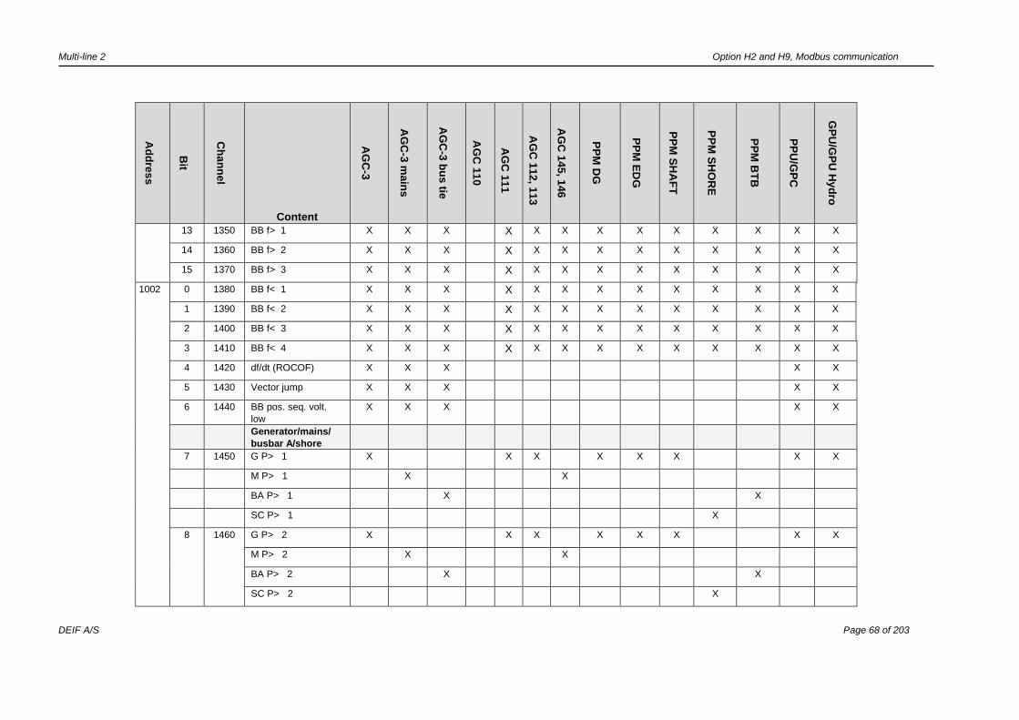
Multi-line 2 Option H2 and H9, Modbus communication
DEIF A/S Page 68 of 203
Ad
dre
ss
Bit
Ch
an
ne
l
Content
AG
C-3
AG
C-3
ma
ins
AG
C-3
bu
s tie
AG
C 1
10
AG
C 1
11
AG
C 1
12
, 11
3
AG
C 1
45
, 14
6
PP
M D
G
PP
M E
DG
PP
M S
HA
FT
PP
M S
HO
RE
PP
M B
TB
PP
U/G
PC
GP
U/G
PU
Hyd
ro
13 1350 BB f> 1 X X X X X X X X X X X X X
14 1360 BB f> 2 X X X X X X X X X X X X X
15 1370 BB f> 3 X X X X X X X X X X X X X
1002 0 1380 BB f< 1 X X X X X X X X X X X X X
1 1390 BB f< 2 X X X X X X X X X X X X X
2 1400 BB f< 3 X X X X X X X X X X X X X
3 1410 BB f< 4 X X X X X X X X X X X X X
4 1420 df/dt (ROCOF) X X X X X
5 1430 Vector jump X X X X X
6 1440 BB pos. seq. volt.
low
X X X X X
Generator/mains/
busbar A/shore
7 1450 G P> 1 X X X X X X X X
M P> 1 X X
BA P> 1 X X
SC P> 1 X
8 1460 G P> 2 X X X X X X X X
M P> 2 X X
BA P> 2 X X
SC P> 2 X
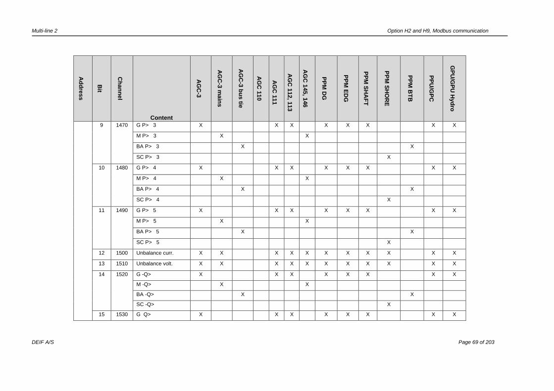
Multi-line 2 Option H2 and H9, Modbus communication
DEIF A/S Page 69 of 203
Ad
dre
ss
Bit
Ch
an
ne
l
Content
AG
C-3
AG
C-3
ma
ins
AG
C-3
bu
s tie
AG
C 1
10
AG
C 1
11
AG
C 1
12
, 11
3
AG
C 1
45
, 14
6
PP
M D
G
PP
M E
DG
PP
M S
HA
FT
PP
M S
HO
RE
PP
M B
TB
PP
U/G
PC
GP
U/G
PU
Hyd
ro
9 1470 G P> 3 X X X X X X X X
M P> 3 X X
BA P> 3 X X
SC P> 3 X
10 1480 G P> 4 X X X X X X X X
M P> 4 X X
BA P> 4 X X
SC P> 4 X
11 1490 G P> 5 X X X X X X X X
M P> 5 X X
BA P> 5 X X
SC P> 5 X
12 1500 Unbalance curr. X X X X X X X X X X X
13 1510 Unbalance volt. X X X X X X X X X X X
14 1520 G -Q> X X X X X X X X
M -Q> X X
BA -Q> X X
SC -Q> X
15 1530 G Q> X X X X X X X X
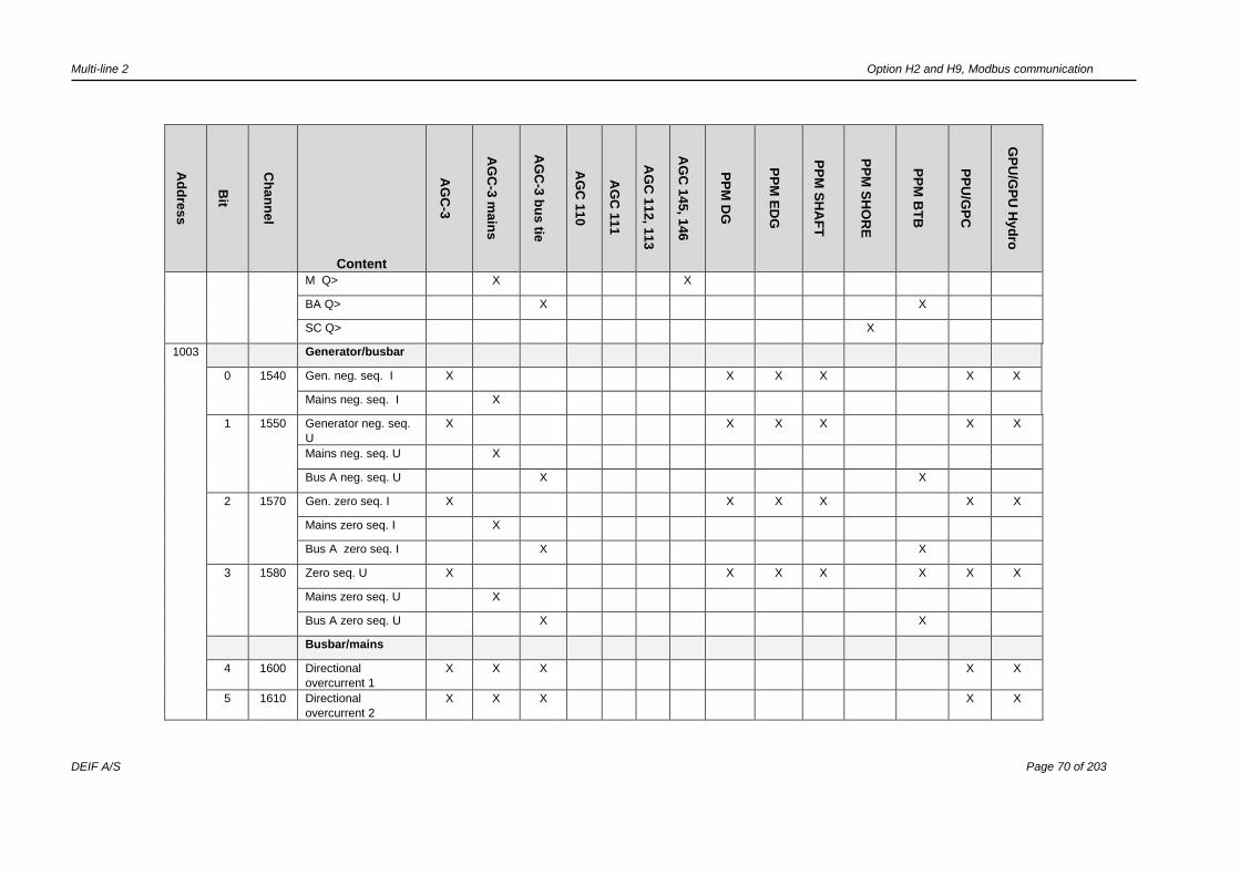
Multi-line 2 Option H2 and H9, Modbus communication
DEIF A/S Page 70 of 203
Ad
dre
ss
Bit
Ch
an
ne
l
Content
AG
C-3
AG
C-3
ma
ins
AG
C-3
bu
s tie
AG
C 1
10
AG
C 1
11
AG
C 1
12
, 11
3
AG
C 1
45
, 14
6
PP
M D
G
PP
M E
DG
PP
M S
HA
FT
PP
M S
HO
RE
PP
M B
TB
PP
U/G
PC
GP
U/G
PU
Hyd
ro
M Q> X X
BA Q> X X
SC Q> X
1003 Generator/busbar
0 1540 Gen. neg. seq. I X X X X X X
Mains neg. seq. I X
1 1550 Generator neg. seq.
U
X X X X X X
Mains neg. seq. U X
Bus A neg. seq. U X X
2 1570 Gen. zero seq. I X X X X X X
Mains zero seq. I X
Bus A zero seq. I X X
3 1580 Zero seq. U X X X X X X X
Mains zero seq. U X
Bus A zero seq. U X X
Busbar/mains
4 1600 Directional
overcurrent 1
X X X X X
5 1610 Directional
overcurrent 2
X X X X X

Multi-line 2 Option H2 and H9, Modbus communication
DEIF A/S Page 71 of 203
Ad
dre
ss
Bit
Ch
an
ne
l
Content
AG
C-3
AG
C-3
ma
ins
AG
C-3
bu
s tie
AG
C 1
10
AG
C 1
11
AG
C 1
12
, 11
3
AG
C 1
45
, 14
6
PP
M D
G
PP
M E
DG
PP
M S
HA
FT
PP
M S
HO
RE
PP
M B
TB
PP
U/G
PC
GP
U/G
PU
Hyd
ro
6 1620 BB unbalance U X X X X X X X X X X X X X
7 1800 NEL 1 I> X X X X X X X X
8 1810 NEL 2 I> X X X X X X X X
9 1820 NEL 3 I> X X X X X X X X
10 1830 NEL 1 BB f< X X X X X X X X
11 1840 NEL 2 BB f< X X X X X X X X
12 1850 NEL 3 BB f< X X X X X X X X
13 1860 NEL 1 P> X X X X X X X X
14 1870 NEL 2 P> X X X X X X X X
15 1880 NEL 3 P> X X X X X X X X
1004 0 1890 NEL 1 P>> X X X X X X X X
1 1900 NEL 2 P>> X X X X X X X X
2 1910 NEL 3 P>> X X X X X X X X
3 1930 DG/SG max. parallel
time
X
4 1940 DG/SC max. parallel
time
X
5 1950 EDG/MSB max.
parallel time
X
6 1960 Uq< 1 X X X X X
7 1970 Uq< 2 X X X X X

Multi-line 2 Option H2 and H9, Modbus communication
DEIF A/S Page 72 of 203
Ad
dre
ss
Bit
Ch
an
ne
l
Content
AG
C-3
AG
C-3
ma
ins
AG
C-3
bu
s tie
AG
C 1
10
AG
C 1
11
AG
C 1
12
, 11
3
AG
C 1
45
, 14
6
PP
M D
G
PP
M E
DG
PP
M S
HA
FT
PP
M S
HO
RE
PP
M B
TB
PP
U/G
PC
GP
U/G
PU
Hyd
ro
8 1980 GB ext. trip X* X X
9 1980 MB ext. trip X*
10 1650 Ut< 1 monitoring
active
X X
11 1660 Ut< 1 X X
12 1690 Ut< 2 monitoring
active
X X
13 1700 Ut< 2 X X
14 1760 G P dep. Q< X X
15 1790 G P dep. Q> X X
1005 Synchronising
0 2120 Synchronising
window
X X X X X X X X X X
1 2130 Synchronising failure
GB
X X X X X
Synchronising failure
TB
X
Synchronising failure
BTB
X X
2 2140 Synchronising failure
MB
X X
Synchronising failure
SGB
X
Synchronising failure
SCB
X
Synchronising failure
TB
X

Multi-line 2 Option H2 and H9, Modbus communication
DEIF A/S Page 73 of 203
Ad
dre
ss
Bit
Ch
an
ne
l
Content
AG
C-3
AG
C-3
ma
ins
AG
C-3
bu
s tie
AG
C 1
10
AG
C 1
11
AG
C 1
12
, 11
3
AG
C 1
45
, 14
6
PP
M D
G
PP
M E
DG
PP
M S
HA
FT
PP
M S
HO
RE
PP
M B
TB
PP
U/G
PC
GP
U/G
PU
Hyd
ro
3 2150 Phase seq. failure X X X X X X X X X X X X X
4 2160 GB open failure X X X X X X X
TB open failure X X
BTB open failure X X
5 2170 GB close failure X X X X X X X
TB close failure X X
BTB close failure X X
6 2180 GB pos. failure X X X X X X X
TB pos. failure X X
BTB pos. failure X X
7 2200 MB open failure X X X X X
SGB open failure X
SCB open failure X
TB open failure X
8 2210 MB close failure X X X X X
SGB close failure X
SCB close failure X
TB close failure X
9 2220 MB pos. failure X X X X X
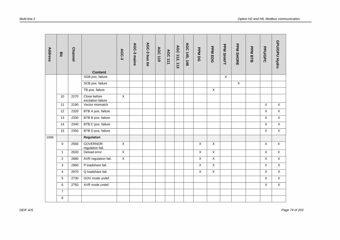
Multi-line 2 Option H2 and H9, Modbus communication
DEIF A/S Page 74 of 203
Ad
dre
ss
Bit
Ch
an
ne
l
Content
AG
C-3
AG
C-3
ma
ins
AG
C-3
bu
s tie
AG
C 1
10
AG
C 1
11
AG
C 1
12
, 11
3
AG
C 1
45
, 14
6
PP
M D
G
PP
M E
DG
PP
M S
HA
FT
PP
M S
HO
RE
PP
M B
TB
PP
U/G
PC
GP
U/G
PU
Hyd
ro
SGB pos. failure X
SCB pos. failure X
TB pos. failure X
10 2270 Close before
excitation failure
X
11 2190 Vector mismatch X X
12 2320 BTB A pos. failure X X
13 2330 BTB B pos. failure X X
14 2340 BTB C pos. failure X X
15 2350 BTB D pos. failure X X
1006 Regulation
0 2560 GOVERNOR
regulation fail.
X X X X X
1 2630 Deload error X X X X X
2 2680 AVR regulation fail. X X X X X
3 2960 P loadshare fail. X X X X
4 2970 Q loadshare fail. X X X X
5 2730 GOV mode undef. X X
6 2750 AVR mode undef. X X
7
8

Multi-line 2 Option H2 and H9, Modbus communication
DEIF A/S Page 75 of 203
Ad
dre
ss
Bit
Ch
an
ne
l
Content
AG
C-3
AG
C-3
ma
ins
AG
C-3
bu
s tie
AG
C 1
10
AG
C 1
11
AG
C 1
12
, 11
3
AG
C 1
45
, 14
6
PP
M D
G
PP
M E
DG
PP
M S
HA
FT
PP
M S
HO
RE
PP
M B
TB
PP
U/G
PC
GP
U/G
PU
Hyd
ro
9
10
11
12
13
14
15
1007 Digital alarms
0 3000 Digital alarm input 23 23 23 10 10 10 10 23 23 23 23 23 23 23
1 3010 Digital alarm input 24 24 24 11 11 11 11 24 24 24 24 24 24 24
2 3020 Digital alarm input 25 25 25 12 12 12 12 25 25 25 25 25 25 25
3 3030 Digital alarm input 26 26 26 13 13 13 13 26 26 26 26 26 26 26
4 3040 Digital alarm input 27 27 27 14 14 14 14 27 27 27 27 27 27 27
5 3050 Digital alarm input 15 15 15 15
6 3060 Digital alarm input 29 29 29 29 29 29 29 29 29 29
7 3070 Digital alarm input 30 30 30 30 30 30 30 30 30 30
8 3080 Digital alarm input 31 31 31 31 31 31 31 31 31 31
9 3090 Digital alarm input 32 32 32 32 32 32 32 32 32 32
10 3100 Digital alarm input 33 33 33 33 33 33 33 33 33 33
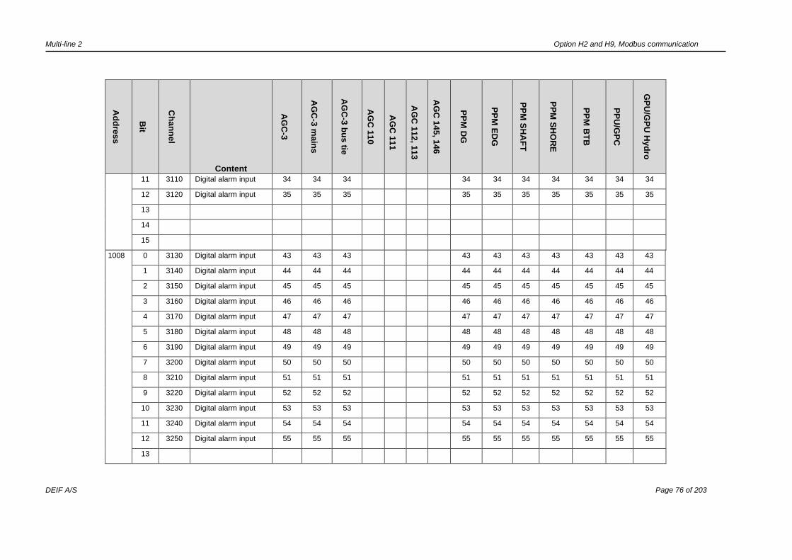
Multi-line 2 Option H2 and H9, Modbus communication
DEIF A/S Page 76 of 203
Ad
dre
ss
Bit
Ch
an
ne
l
Content
AG
C-3
AG
C-3
ma
ins
AG
C-3
bu
s tie
AG
C 1
10
AG
C 1
11
AG
C 1
12
, 11
3
AG
C 1
45
, 14
6
PP
M D
G
PP
M E
DG
PP
M S
HA
FT
PP
M S
HO
RE
PP
M B
TB
PP
U/G
PC
GP
U/G
PU
Hyd
ro
11 3110 Digital alarm input 34 34 34 34 34 34 34 34 34 34
12 3120 Digital alarm input 35 35 35 35 35 35 35 35 35 35
13
14
15
1008 0 3130 Digital alarm input 43 43 43 43 43 43 43 43 43 43
1 3140 Digital alarm input 44 44 44 44 44 44 44 44 44 44
2 3150 Digital alarm input 45 45 45 45 45 45 45 45 45 45
3 3160 Digital alarm input 46 46 46 46 46 46 46 46 46 46
4 3170 Digital alarm input 47 47 47 47 47 47 47 47 47 47
5 3180 Digital alarm input 48 48 48 48 48 48 48 48 48 48
6 3190 Digital alarm input 49 49 49 49 49 49 49 49 49 49
7 3200 Digital alarm input 50 50 50 50 50 50 50 50 50 50
8 3210 Digital alarm input 51 51 51 51 51 51 51 51 51 51
9 3220 Digital alarm input 52 52 52 52 52 52 52 52 52 52
10 3230 Digital alarm input 53 53 53 53 53 53 53 53 53 53
11 3240 Digital alarm input 54 54 54 54 54 54 54 54 54 54
12 3250 Digital alarm input 55 55 55 55 55 55 55 55 55 55
13

Multi-line 2 Option H2 and H9, Modbus communication
DEIF A/S Page 77 of 203
Ad
dre
ss
Bit
Ch
an
ne
l
Content
AG
C-3
AG
C-3
ma
ins
AG
C-3
bu
s tie
AG
C 1
10
AG
C 1
11
AG
C 1
12
, 11
3
AG
C 1
45
, 14
6
PP
M D
G
PP
M E
DG
PP
M S
HA
FT
PP
M S
HO
RE
PP
M B
TB
PP
U/G
PC
GP
U/G
PU
Hyd
ro
14
15
1009 0 3260 Digital alarm input 65 65 65 65 65 65 65 65 65 65
1 3270 Digital alarm input 66 66 66 66 66 66 66 66 66 66
2 3280 Digital alarm input 67 67 67 67 67 67 67 67 67 67
3 3290 Digital alarm input 68 68 68 68 68 68 68 68 68 68
4 3300 Digital alarm input 69 69 69 69 69 69 69 69 69 69
5 3310 Digital alarm input 70 70 70 70 70 70 70 70 70 70
6 3320 Digital alarm input 71 71 71 71 71 71 71 71 71 71
7 3330 Digital alarm input 91 91 91 91 91 91 91 91 91 91
8 3340 Digital alarm input 92 92 92 92 92 92 92 92 92 92
9 3350 Digital alarm input 93 93 93 93 93 93 93 93 93 93
10 3360 Digital alarm input 94 94 94 94 94 94 94 94 94 94
11 3370 Digital alarm input 95 95 95 95 95 95 95 95 95 95
12 3380 Digital alarm input 96 96 96 96 96 96 96 96 96 96
13 3390 Digital alarm input 97 97 97 97 97 97 97 97 97 97
14
15
1010 0 3400 Multi-in. alarm 102 102 102 6 6 6 6 102 102 102 102 102 102 102
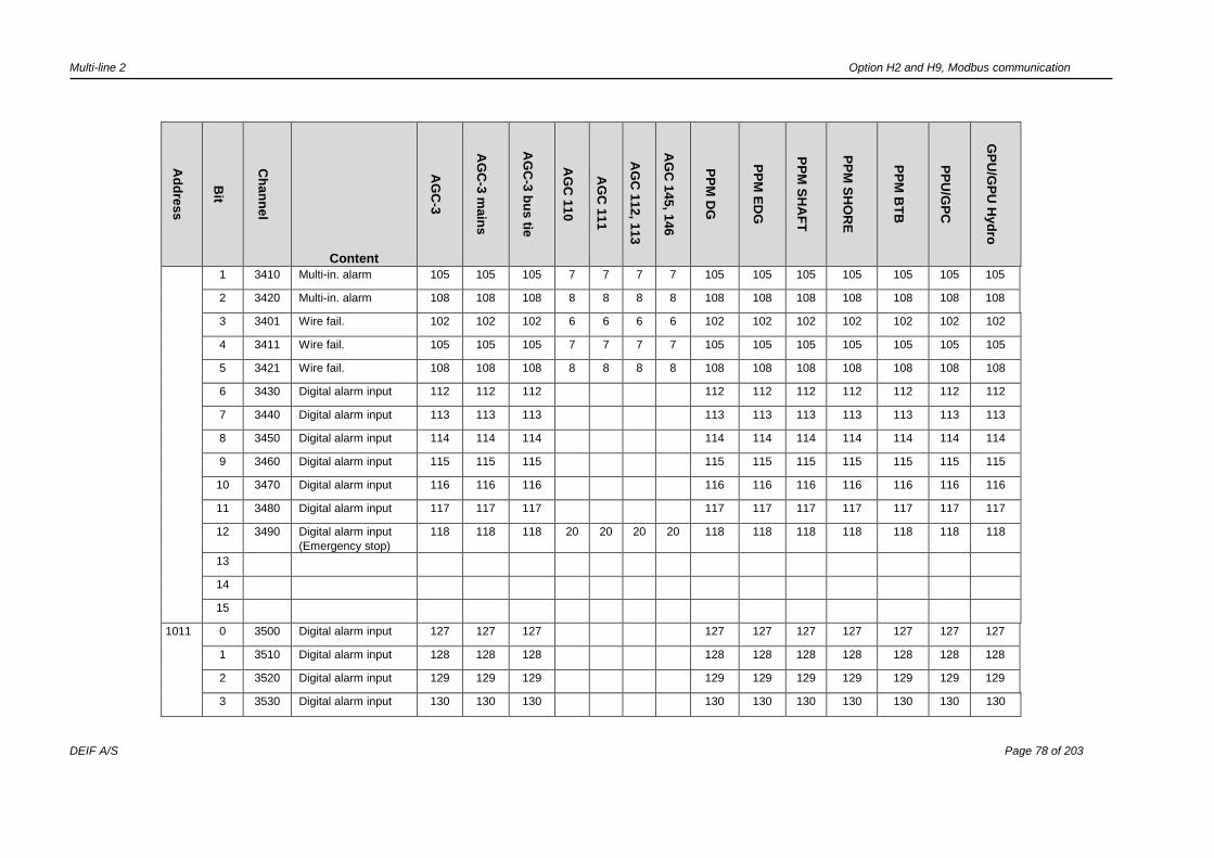
Multi-line 2 Option H2 and H9, Modbus communication
DEIF A/S Page 78 of 203
Ad
dre
ss
Bit
Ch
an
ne
l
Content
AG
C-3
AG
C-3
ma
ins
AG
C-3
bu
s tie
AG
C 1
10
AG
C 1
11
AG
C 1
12
, 11
3
AG
C 1
45
, 14
6
PP
M D
G
PP
M E
DG
PP
M S
HA
FT
PP
M S
HO
RE
PP
M B
TB
PP
U/G
PC
GP
U/G
PU
Hyd
ro
1 3410 Multi-in. alarm 105 105 105 7 7 7 7 105 105 105 105 105 105 105
2 3420 Multi-in. alarm 108 108 108 8 8 8 8 108 108 108 108 108 108 108
3 3401 Wire fail. 102 102 102 6 6 6 6 102 102 102 102 102 102 102
4 3411 Wire fail. 105 105 105 7 7 7 7 105 105 105 105 105 105 105
5 3421 Wire fail. 108 108 108 8 8 8 8 108 108 108 108 108 108 108
6 3430 Digital alarm input 112 112 112 112 112 112 112 112 112 112
7 3440 Digital alarm input 113 113 113 113 113 113 113 113 113 113
8 3450 Digital alarm input 114 114 114 114 114 114 114 114 114 114
9 3460 Digital alarm input 115 115 115 115 115 115 115 115 115 115
10 3470 Digital alarm input 116 116 116 116 116 116 116 116 116 116
11 3480 Digital alarm input 117 117 117 117 117 117 117 117 117 117
12 3490 Digital alarm input
(Emergency stop)
118 118 118 20 20 20 20 118 118 118 118 118 118 118
13
14
15
1011 0 3500 Digital alarm input 127 127 127 127 127 127 127 127 127 127
1 3510 Digital alarm input 128 128 128 128 128 128 128 128 128 128
2 3520 Digital alarm input 129 129 129 129 129 129 129 129 129 129
3 3530 Digital alarm input 130 130 130 130 130 130 130 130 130 130
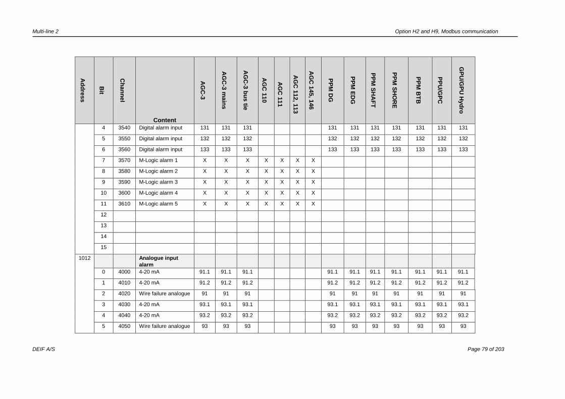
Multi-line 2 Option H2 and H9, Modbus communication
DEIF A/S Page 79 of 203
Ad
dre
ss
Bit
Ch
an
ne
l
Content
AG
C-3
AG
C-3
ma
ins
AG
C-3
bu
s tie
AG
C 1
10
AG
C 1
11
AG
C 1
12
, 11
3
AG
C 1
45
, 14
6
PP
M D
G
PP
M E
DG
PP
M S
HA
FT
PP
M S
HO
RE
PP
M B
TB
PP
U/G
PC
GP
U/G
PU
Hyd
ro
4 3540 Digital alarm input 131 131 131 131 131 131 131 131 131 131
5 3550 Digital alarm input 132 132 132 132 132 132 132 132 132 132
6 3560 Digital alarm input 133 133 133 133 133 133 133 133 133 133
7 3570 M-Logic alarm 1 X X X X X X X
8 3580 M-Logic alarm 2 X X X X X X X
9 3590 M-Logic alarm 3 X X X X X X X
10 3600 M-Logic alarm 4 X X X X X X X
11 3610 M-Logic alarm 5 X X X X X X X
12
13
14
15
1012 Analogue input
alarm
0 4000 4-20 mA 91.1 91.1 91.1 91.1 91.1 91.1 91.1 91.1 91.1 91.1
1 4010 4-20 mA 91.2 91.2 91.2 91.2 91.2 91.2 91.2 91.2 91.2 91.2
2 4020 Wire failure analogue 91 91 91 91 91 91 91 91 91 91
3 4030 4-20 mA 93.1 93.1 93.1 93.1 93.1 93.1 93.1 93.1 93.1 93.1
4 4040 4-20 mA 93.2 93.2 93.2 93.2 93.2 93.2 93.2 93.2 93.2 93.2
5 4050 Wire failure analogue 93 93 93 93 93 93 93 93 93 93

Multi-line 2 Option H2 and H9, Modbus communication
DEIF A/S Page 80 of 203
Ad
dre
ss
Bit
Ch
an
ne
l
Content
AG
C-3
AG
C-3
ma
ins
AG
C-3
bu
s tie
AG
C 1
10
AG
C 1
11
AG
C 1
12
, 11
3
AG
C 1
45
, 14
6
PP
M D
G
PP
M E
DG
PP
M S
HA
FT
PP
M S
HO
RE
PP
M B
TB
PP
U/G
PC
GP
U/G
PU
Hyd
ro
6 4060 4-20 mA 95.1 95.1 95.1 95.1 95.1 95.1 95.1 95.1 95.1 95.1
7 4070 4-20 mA 95.2 95.2 95.2 95.2 95.2 95.2 95.2 95.2 95.2 95.2
8 4080 Wire failure analogue 95 95 95 95 95 95 95 95 95 95
9 4090 4-20 mA 97.1 97.1 97.1 97.1 97.1 97.1 97.1 97.1 97.1 97.1
10 4100 4-20 mA 97.2 97.2 97.2 97.2 97.2 97.2 97.2 97.2 97.2 97.2
11 4110 Wire failure analogue 97 97 97 97 97 97 97 97 97 97
12
13
14
15
1013 Multi-functional
input
0 4120 4-20 mA 102.1 102.1 102.1 6.1 6.1 6.1 6.1 102.1 102.1 102.
1
102.1 102.1 102.
1
102.1
1 4130 4-20 mA 102.2 102.2 102.2 6.2 6.2 6.2 6.2 102.2 102.2 102.
2
102.2 102.2 102.
2
102.2
0 4140 V DC 102.1 102.1 102.1 102.1 102.1 102.
1
102.1 102.1 102.
1
102.1
1 4150 V DC 102.2 102.2 102.2 102.2 102.2 102.
2
102.2 102.2 102.
2
102.2
0 4160 Pt 102.1 102.1 102.1 102.1 102.1 102.
1
102.1 102.1 102.
1
102.1
1 4170 Pt 102.2 102.2 102.2 102.2 102.2 102.
2
102.2 102.2 102.
2
102.2
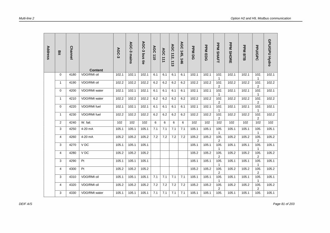
Multi-line 2 Option H2 and H9, Modbus communication
DEIF A/S Page 81 of 203
Ad
dre
ss
Bit
Ch
an
ne
l
Content
AG
C-3
AG
C-3
ma
ins
AG
C-3
bu
s tie
AG
C 1
10
AG
C 1
11
AG
C 1
12
, 11
3
AG
C 1
45
, 14
6
PP
M D
G
PP
M E
DG
PP
M S
HA
FT
PP
M S
HO
RE
PP
M B
TB
PP
U/G
PC
GP
U/G
PU
Hyd
ro
0 4180 VDO/RMI oil 102.1 102.1 102.1 6.1 6.1 6.1 6.1 102.1 102.1 102.
1
102.1 102.1 102.
1
102.1
1 4190 VDO/RMI oil 102.2 102.2 102.2 6.2 6.2 6.2 6.2 102.2 102.2 102.
2
102.2 102.2 102.
2
102.2
0 4200 VDO/RMI water 102.1 102.1 102.1 6.1 6.1 6.1 6.1 102.1 102.1 102.
1
102.1 102.1 102.
1
102.1
1 4210 VDO/RMI water 102.2 102.2 102.2 6.2 6.2 6.2 6.2 102.2 102.2 102.
2
102.2 102.2 102.
2
102.2
0 4220 VDO/RMI fuel 102.1 102.1 102.1 6.1 6.1 6.1 6.1 102.1 102.1 102.
1
102.1 102.1 102.
1
102.1
1 4230 VDO/RMI fuel 102.2 102.2 102.2 6.2 6.2 6.2 6.2 102.2 102.2 102.
2
102.2 102.2 102.
2
102.2
2 4240 W. fail. 102 102 102 6 6 6 6 102 102 102 102 102 102 102
3 4250 4-20 mA 105.1 105.1 105.1 7.1 7.1 7.1 7.1 105.1 105.1 105.
1
105.1 105.1 105.
1
105.1
4 4260 4-20 mA 105.2 105.2 105.2 7.2 7.2 7.2 7.2 105.2 105.2 105.
2
105.2 105.2 105.
2
105.2
3 4270 V DC 105.1 105.1 105.1 105.1 105.1 105.
1
105.1 105.1 105.
1
105.1
4 4280 V DC 105.2 105.2 105.2 105.2 105.2 105.
2
105.2 105.2 105.
2
105.2
3 4290 Pt 105.1 105.1 105.1 105.1 105.1 105.
1
105.1 105.1 105.
1
105.1
4 4300 Pt 105.2 105.2 105.2 105.2 105.2 105.
2
105.2 105.2 105.
2
105.2
3 4310 VDO/RMI oil 105.1 105.1 105.1 7.1 7.1 7.1 7.1 105.1 105.1 105.
1
105.1 105.1 105.
1
105.1
4 4320 VDO/RMI oil 105.2 105.2 105.2 7.2 7.2 7.2 7.2 105.2 105.2 105.
2
105.2 105.2 105.
2
105.2
3 4330 VDO/RMI water 105.1 105.1 105.1 7.1 7.1 7.1 7.1 105.1 105.1 105. 105.1 105.1 105. 105.1
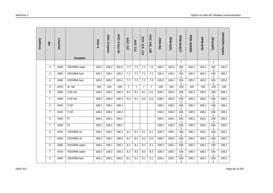
Multi-line 2 Option H2 and H9, Modbus communication
DEIF A/S Page 82 of 203
Ad
dre
ss
Bit
Ch
an
ne
l
Content
AG
C-3
AG
C-3
ma
ins
AG
C-3
bu
s tie
AG
C 1
10
AG
C 1
11
AG
C 1
12
, 11
3
AG
C 1
45
, 14
6
PP
M D
G
PP
M E
DG
PP
M S
HA
FT
PP
M S
HO
RE
PP
M B
TB
PP
U/G
PC
GP
U/G
PU
Hyd
ro
1 1
4 4340 VDO/RMI water 105.2 105.2 105.2 7.2 7.2 7.2 7.2 105.2 105.2 105.
2
105.2 105.2 105.
2
105.2
3 4350 VDO/RMI fuel 105.1 105.1 105.1 7.1 7.1 7.1 7.1 105.1 105.1 105.
1
105.1 105.1 105.
1
105.1
4 4360 VDO/RMI fuel 105.2 105.2 105.2 7.2 7.2 7.2 7.2 105.2 105.2 105.
2
105.2 105.2 105.
2
105.2
5 4370 W. fail. 105 105 105 7 7 7 7 105 105 105 105 105 105 105
6 4380 4-20 mA 108.1 108.1 108.1 8.1 8.1 8.1 8.1 108.1 108.1 108.
1
108.1 108.1 108.
1
108.1
7 4390 4-20 mA 108.2 108.2 108.2 8.2 8.2 8.2 8.2 108.2 108.2 108.
2
108.2 108.2 108.
2
108.2
6 4400 V DC 108.1 108.1 108.1 108.1 108.1 108.
1
108.1 108.1 108.
1
108.1
7 4410 V DC 108.2 108.2 108.2 108.2 108.2 108.
2
108.2 108.2 108.
2
108.2
6 4420 Pt 108.1 108.1 108.1 108.1 108.1 108.
1
108.1 108.1 108.
1
108.1
7 4430 Pt 108.2 108.2 108.2 108.2 108.2 108.
2
108.2 108.2 108.
2
108.2
6 4440 VDO/RMI oil 108.1 108.1 108.1 8.1 8.1 8.1 8.1 108.1 108.1 108.
1
108.1 108.1 108.
1
108.1
7 4450 VDO/RMI oil 108.2 108.2 108.2 8.2 8.2 8.2 8.2 108.2 108.2 108.
2
108.2 108.2 108.
2
108.2
6 4460 VDO/RMI water 108.1 108.1 108.1 8.1 8.1 8.1 8.1 108.1 108.1 108.
1
108.1 108.1 108.
1
108.1
7 4470 VDO/RMI water 108.2 108.2 108.2 8.2 8.2 8.2 8.2 108.2 108.2 108.
2
108.2 108.2 108.
2
108.2
6 4480 VDO/RMI fuel 108.1 108.1 108.1 8.1 8.1 8.1 8.1 108.1 108.1 108.
1
108.1 108.1 108.
1
108.1

Multi-line 2 Option H2 and H9, Modbus communication
DEIF A/S Page 83 of 203
Ad
dre
ss
Bit
Ch
an
ne
l
Content
AG
C-3
AG
C-3
ma
ins
AG
C-3
bu
s tie
AG
C 1
10
AG
C 1
11
AG
C 1
12
, 11
3
AG
C 1
45
, 14
6
PP
M D
G
PP
M E
DG
PP
M S
HA
FT
PP
M S
HO
RE
PP
M B
TB
PP
U/G
PC
GP
U/G
PU
Hyd
ro
7 4490 VDO/RMI fuel 108.2 108.2 108.2 8.2 8.2 8.2 8.2 108.2 108.2 108.
2
108.2 108.2 108.
2
108.2
8 4500 W. fail. 108 108 108 8 8 8 8 108 108 108 108 108 108 108
Analogue input
alarm
9 4510 Overspeed 1 X X X X X X X X X
10 4520 Overspeed 2 X X X X X X X X X
11 4530 Crank failure X X X X X X X X
12 4540 Running feedback
failure
X X X X X X X X X
13 4550 MPU wire failure X X X X X X X X X
14 4560 Hz/V failure X X X X X X X X X X
15 4570 Start failure X X X X X X X X
1014 0 4580 Stop failure X X X X X X X X
1 4960 U< aux. term. 1 1 1 1 1 1 1 1 1 1 1 1 1 1
2 4970 U> aux. term. 1 1 1 1 1 1 1 1 1 1 1 1 1 1
3 4980 U< aux. term. 98 98 98 98 98 98 98 98 98 98
4 4990 U> aux. term. 98 98 98 98 98 98 98 98 98 98
5 4590 Underspeed 1 X X X X X X
6
7
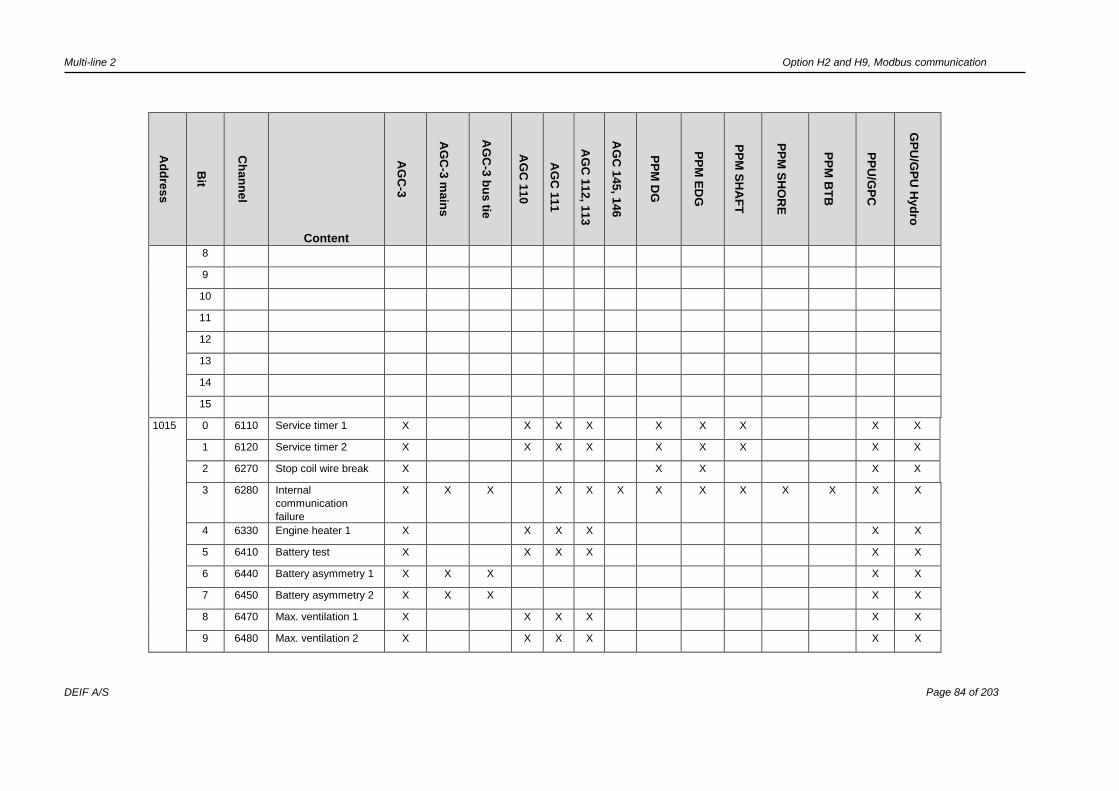
Multi-line 2 Option H2 and H9, Modbus communication
DEIF A/S Page 84 of 203
Ad
dre
ss
Bit
Ch
an
ne
l
Content
AG
C-3
AG
C-3
ma
ins
AG
C-3
bu
s tie
AG
C 1
10
AG
C 1
11
AG
C 1
12
, 11
3
AG
C 1
45
, 14
6
PP
M D
G
PP
M E
DG
PP
M S
HA
FT
PP
M S
HO
RE
PP
M B
TB
PP
U/G
PC
GP
U/G
PU
Hyd
ro
8
9
10
11
12
13
14
15
1015 0 6110 Service timer 1 X X X X X X X X X
1 6120 Service timer 2 X X X X X X X X X
2 6270 Stop coil wire break X X X X X
3 6280 Internal
communication
failure
X X X X X X X X X X X X X
4 6330 Engine heater 1 X X X X X X
5 6410 Battery test X X X X X X
6 6440 Battery asymmetry 1 X X X X X
7 6450 Battery asymmetry 2 X X X X X
8 6470 Max. ventilation 1 X X X X X X
9 6480 Max. ventilation 2 X X X X X X
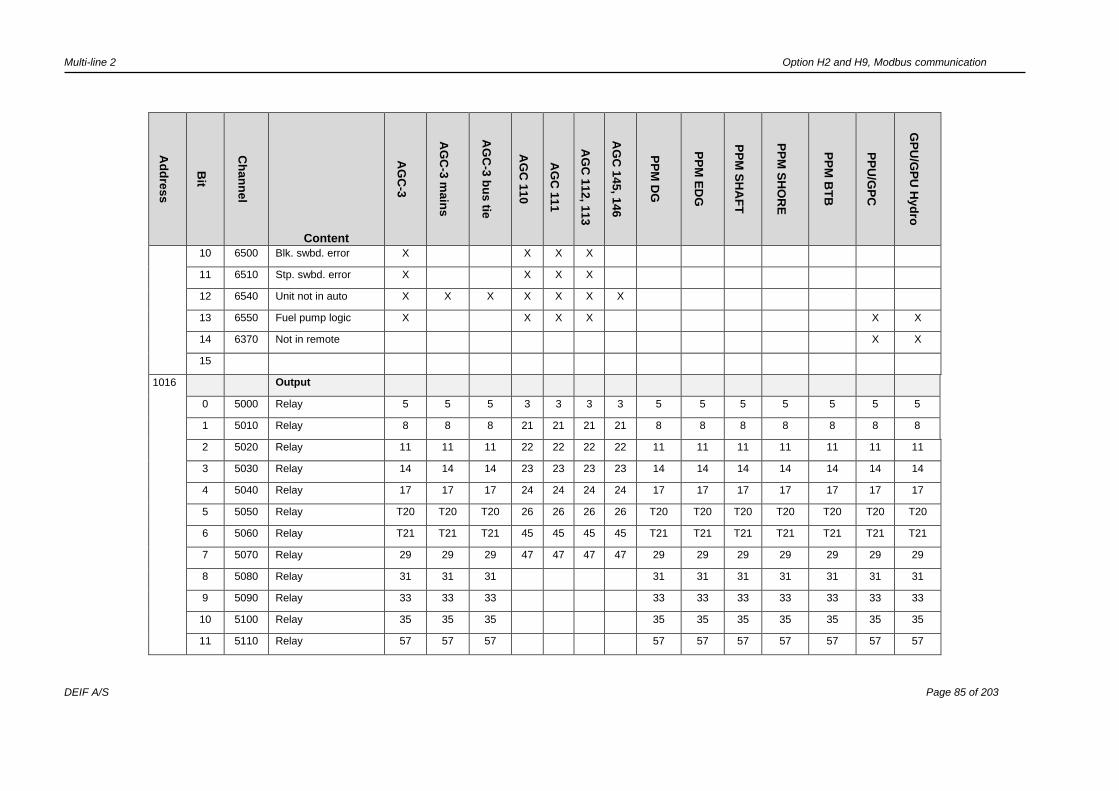
Multi-line 2 Option H2 and H9, Modbus communication
DEIF A/S Page 85 of 203
Ad
dre
ss
Bit
Ch
an
ne
l
Content
AG
C-3
AG
C-3
ma
ins
AG
C-3
bu
s tie
AG
C 1
10
AG
C 1
11
AG
C 1
12
, 11
3
AG
C 1
45
, 14
6
PP
M D
G
PP
M E
DG
PP
M S
HA
FT
PP
M S
HO
RE
PP
M B
TB
PP
U/G
PC
GP
U/G
PU
Hyd
ro
10 6500 Blk. swbd. error X X X X
11 6510 Stp. swbd. error X X X X
12 6540 Unit not in auto X X X X X X X
13 6550 Fuel pump logic X X X X X X
14 6370 Not in remote X X
15
1016 Output
0 5000 Relay 5 5 5 3 3 3 3 5 5 5 5 5 5 5
1 5010 Relay 8 8 8 21 21 21 21 8 8 8 8 8 8 8
2 5020 Relay 11 11 11 22 22 22 22 11 11 11 11 11 11 11
3 5030 Relay 14 14 14 23 23 23 23 14 14 14 14 14 14 14
4 5040 Relay 17 17 17 24 24 24 24 17 17 17 17 17 17 17
5 5050 Relay T20 T20 T20 26 26 26 26 T20 T20 T20 T20 T20 T20 T20
6 5060 Relay T21 T21 T21 45 45 45 45 T21 T21 T21 T21 T21 T21 T21
7 5070 Relay 29 29 29 47 47 47 47 29 29 29 29 29 29 29
8 5080 Relay 31 31 31 31 31 31 31 31 31 31
9 5090 Relay 33 33 33 33 33 33 33 33 33 33
10 5100 Relay 35 35 35 35 35 35 35 35 35 35
11 5110 Relay 57 57 57 57 57 57 57 57 57 57
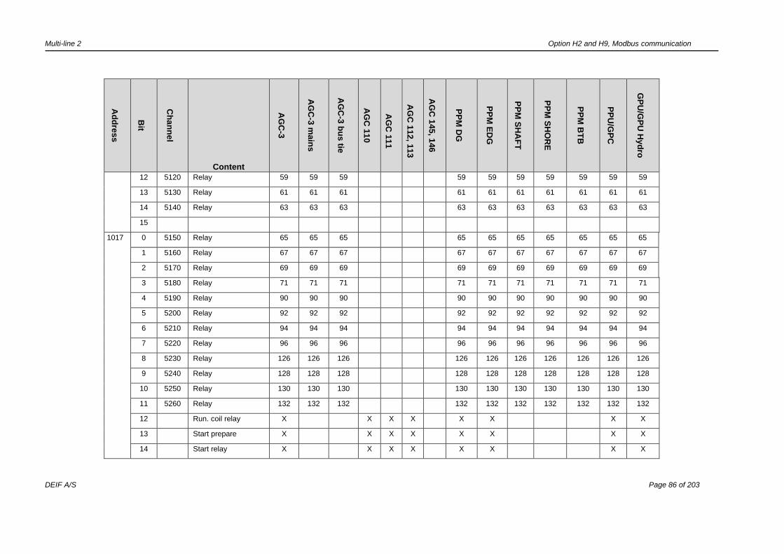
Multi-line 2 Option H2 and H9, Modbus communication
DEIF A/S Page 86 of 203
Ad
dre
ss
Bit
Ch
an
ne
l
Content
AG
C-3
AG
C-3
ma
ins
AG
C-3
bu
s tie
AG
C 1
10
AG
C 1
11
AG
C 1
12
, 11
3
AG
C 1
45
, 14
6
PP
M D
G
PP
M E
DG
PP
M S
HA
FT
PP
M S
HO
RE
PP
M B
TB
PP
U/G
PC
GP
U/G
PU
Hyd
ro
12 5120 Relay 59 59 59 59 59 59 59 59 59 59
13 5130 Relay 61 61 61 61 61 61 61 61 61 61
14 5140 Relay 63 63 63 63 63 63 63 63 63 63
15
1017 0 5150 Relay 65 65 65 65 65 65 65 65 65 65
1 5160 Relay 67 67 67 67 67 67 67 67 67 67
2 5170 Relay 69 69 69 69 69 69 69 69 69 69
3 5180 Relay 71 71 71 71 71 71 71 71 71 71
4 5190 Relay 90 90 90 90 90 90 90 90 90 90
5 5200 Relay 92 92 92 92 92 92 92 92 92 92
6 5210 Relay 94 94 94 94 94 94 94 94 94 94
7 5220 Relay 96 96 96 96 96 96 96 96 96 96
8 5230 Relay 126 126 126 126 126 126 126 126 126 126
9 5240 Relay 128 128 128 128 128 128 128 128 128 128
10 5250 Relay 130 130 130 130 130 130 130 130 130 130
11 5260 Relay 132 132 132 132 132 132 132 132 132 132
12 Run. coil relay X X X X X X X X
13 Start prepare X X X X X X X X
14 Start relay X X X X X X X X
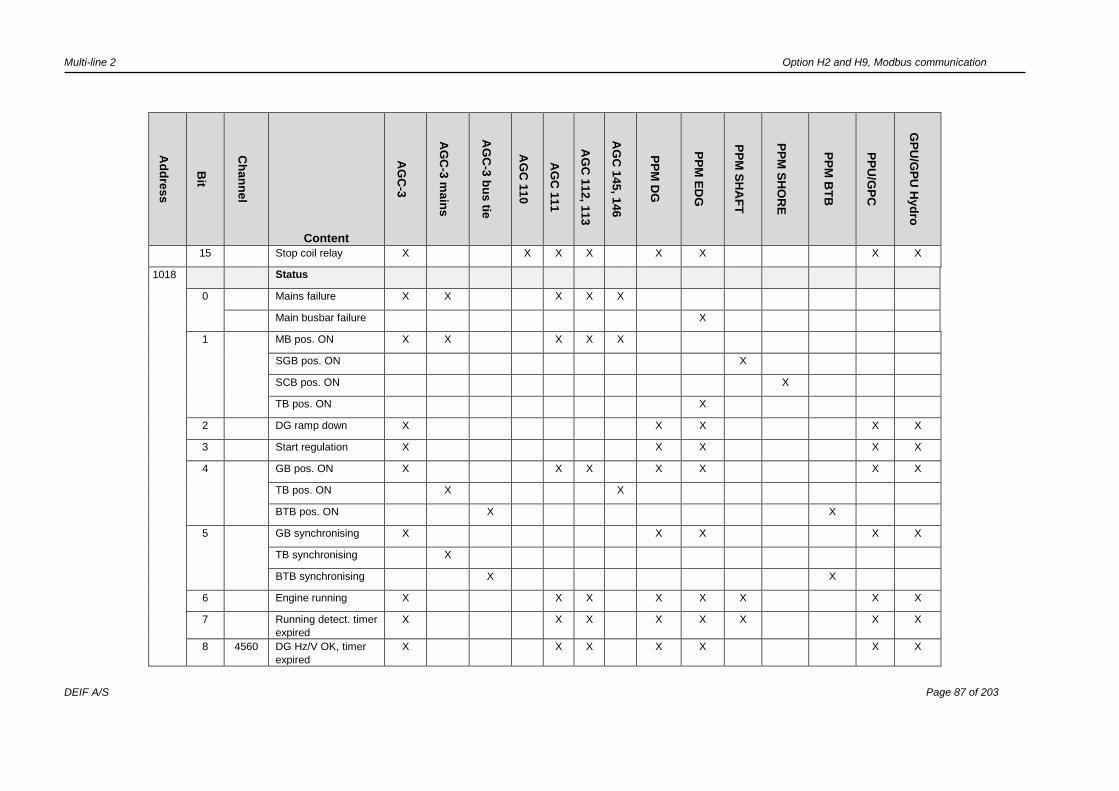
Multi-line 2 Option H2 and H9, Modbus communication
DEIF A/S Page 87 of 203
Ad
dre
ss
Bit
Ch
an
ne
l
Content
AG
C-3
AG
C-3
ma
ins
AG
C-3
bu
s tie
AG
C 1
10
AG
C 1
11
AG
C 1
12
, 11
3
AG
C 1
45
, 14
6
PP
M D
G
PP
M E
DG
PP
M S
HA
FT
PP
M S
HO
RE
PP
M B
TB
PP
U/G
PC
GP
U/G
PU
Hyd
ro
15 Stop coil relay X X X X X X X X
1018 Status
0 Mains failure X X X X X
Main busbar failure X
1 MB pos. ON X X X X X
SGB pos. ON X
SCB pos. ON X
TB pos. ON X
2 DG ramp down X X X X X
3 Start regulation X X X X X
4 GB pos. ON X X X X X X X
TB pos. ON X X
BTB pos. ON X X
5 GB synchronising X X X X X
TB synchronising X
BTB synchronising X X
6 Engine running X X X X X X X X
7 Running detect. timer
expired
X X X X X X X X
8 4560 DG Hz/V OK, timer
expired
X X X X X X X

Multi-line 2 Option H2 and H9, Modbus communication
DEIF A/S Page 88 of 203
Ad
dre
ss
Bit
Ch
an
ne
l
Content
AG
C-3
AG
C-3
ma
ins
AG
C-3
bu
s tie
AG
C 1
10
AG
C 1
11
AG
C 1
12
, 11
3
AG
C 1
45
, 14
6
PP
M D
G
PP
M E
DG
PP
M S
HA
FT
PP
M S
HO
RE
PP
M B
TB
PP
U/G
PC
GP
U/G
PU
Hyd
ro
9 6410 Battery test X X X X X
10 Printing log X X X
11 GB position OFF X X X X X X X
TB position OFF X X
BTB position OFF X X
12 MB position OFF X X X X X
SGB position OFF X
SCB position OFF X
TB position OFF X
13 BB Hz/V OK X X X X X X X X X X X X X X
14 MB synchronising X
15
1019 General/Modes
0 Block mode X X X X X
1 Manual mode X X X X X
SWBD mode X X X X X
2 Semi auto mode X X X X X X X X X
3 Auto mode X X X X X X X X X
4 Test X X X X X X

Multi-line 2 Option H2 and H9, Modbus communication
DEIF A/S Page 89 of 203
Ad
dre
ss
Bit
Ch
an
ne
l
Content
AG
C-3
AG
C-3
ma
ins
AG
C-3
bu
s tie
AG
C 1
10
AG
C 1
11
AG
C 1
12
, 11
3
AG
C 1
45
, 14
6
PP
M D
G
PP
M E
DG
PP
M S
HA
FT
PP
M S
HO
RE
PP
M B
TB
PP
U/G
PC
GP
U/G
PU
Hyd
ro
5 Island X X X X X
6 AMF X X X X X
7 Peak shaving X X X
8 Fixed power X X X X
9 Mains power export X X X
10 Load takeover X X X X X
11 Power management X X
Genset group X
12 DG supply X X
13 SG/SC suppl X X
14 Reserved
15 AMF active X X X X X
1020-
1024
See H5/H7 manual
or DRH
X X X X X X X X
1025 Reserved
1026-
1028
See H5/H7 manual
or DRH
X X X X X X X X

Multi-line 2 Option H2 and H9, Modbus communication
DEIF A/S Page 90 of 203
Ad
dre
ss
Bit
Ch
an
nel
Function
AG
C-3
AG
C-3
main
s
AG
C-3
bu
s tie
AG
C 1
10
AG
C 1
11
AG
C 1
12, 1
13
AG
C 1
45, 1
46
PP
M D
G
PP
M E
DG
PP
M S
HA
FT
PP
M S
HO
RE
PP
M B
TB
GP
C/P
PU
GP
U/G
PU
Hyd
ro
1031
Internal
communications
0 7860 CAN ID missing X X
1 CAN 1 missing ID 1 1 1 1 1 1 1 1 1
2 CAN 1 missing ID 2 2 2 2 2 2 2 2 2
3 CAN 1 missing ID 3 3 3 3 3 3 3 3 3
4 CAN 1 missing ID 4 4 4 4 4 4 4 4 4
5 CAN 1 missing ID 5 5 5 5 5 5 5 5 5
6 CAN 1 missing ID 6 6 6 6 6 6 6 6 6
7 CAN 1 missing ID 7 7 7 7 7 7 7 7 7
8 CAN 1 missing ID 8 8 8 8 8 8 8 8 8
9 CAN 1 missing ID 9 9 9 9 9 9 9 9 9
10 CAN 1 missing ID 10 10 10 10 10 10 10 10 10
11 CAN 1 missing ID 11 11 11 11 11 11 11 11 11
12 CAN 1 missing ID 12 12 12 12 12 12 12 12 12
13 CAN 1 missing ID 13 13 13 13 13 13 13 13 13
14 CAN 1 missing ID 14 14 14 14 14 14 14 14 14
15 CAN 1 missing ID 15 15 15 15 15 15 15 15 15
1032 0 CAN 1 missing ID 16 16 16 16 16 16 16 16 16
1
2 CAN 2 missing ID 1 1 1 1 1 1 1 1 1
3 CAN 2 missing ID 2 2 2 2 2 2 2 2 2
4 CAN 2 missing ID 3 3 3 3 3 3 3 3 3
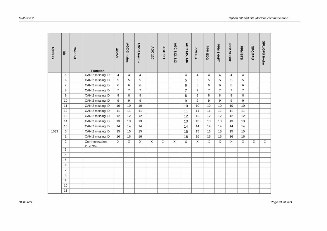
Multi-line 2 Option H2 and H9, Modbus communication
DEIF A/S Page 91 of 203
Ad
dre
ss
Bit
Ch
an
nel
Function
AG
C-3
AG
C-3
main
s
AG
C-3
bu
s tie
AG
C 1
10
AG
C 1
11
AG
C 1
12, 1
13
AG
C 1
45, 1
46
PP
M D
G
PP
M E
DG
PP
M S
HA
FT
PP
M S
HO
RE
PP
M B
TB
GP
C/P
PU
GP
U/G
PU
Hyd
ro
5 CAN 2 missing ID 4 4 4 4 4 4 4 4 4
6 CAN 2 missing ID 5 5 5 5 5 5 5 5 5
7 CAN 2 missing ID 6 6 6 6 6 6 6 6 6
8 CAN 2 missing ID 7 7 7 7 7 7 7 7 7
9 CAN 2 missing ID 8 8 8 8 8 8 8 8 8
10 CAN 2 missing ID 9 9 9 9 9 9 9 9 9
11 CAN 2 missing ID 10 10 10 10 10 10 10 10 10
12 CAN 2 missing ID 11 11 11 11 11 11 11 11 11
13 CAN 2 missing ID 12 12 12 12 12 12 12 12 12
14 CAN 2 missing ID 13 13 13 13 13 13 13 13 13
15 CAN 2 missing ID 14 14 14 14 14 14 14 14 14
1033 0 CAN 2 missing ID 15 15 15 15 15 15 15 15 15
1 CAN 2 missing ID 16 16 16 16 16 16 16 16 16
2 Communication
error ext.
X X X X X X X X X X X X X X
3
4
5
6
7
8
9
10
11

Multi-line 2 Option H2 and H9, Modbus communication
DEIF A/S Page 92 of 203
Ad
dre
ss
Bit
Ch
an
nel
Function
AG
C-3
AG
C-3
main
s
AG
C-3
bu
s tie
AG
C 1
10
AG
C 1
11
AG
C 1
12, 1
13
AG
C 1
45, 1
46
PP
M D
G
PP
M E
DG
PP
M S
HA
FT
PP
M S
HO
RE
PP
M B
TB
GP
C/P
PU
GP
U/G
PU
Hyd
ro
12
13
14
15
1034 0
1 Ext. comm. error
ID
1 1 1 1 1 1 1 1 1
2 Ext. comm. error
ID
2 2 2 2 2 2 2 2 2
3 Ext. comm. error
ID
3 3 3 3 3 3 3 3 3
4 Ext. comm. error
ID
4 4 4 4 4 4 4 4 4
5 Ext. comm. error
ID
5 5 5 5 5 5 5 5 5
6 Ext. comm. error
ID
6 6 6 6 6 6 6 6 6
7 Ext. comm. error
ID
7 7 7 7 7 7 7 7 7
8 Ext. comm. error
ID
8 8 8 8 8 8 8 8 8
9 Ext. comm. error
ID
9 9 9 9 9 9 9 9 9
10 Ext. comm. error
ID
10 10 10 10 10 10 10 10 10
11 Ext. comm. error
ID
11 11 11 11 11 11 11 11 11
12 Ext. comm. error
ID
12 12 12 12 12 12 12 12 12
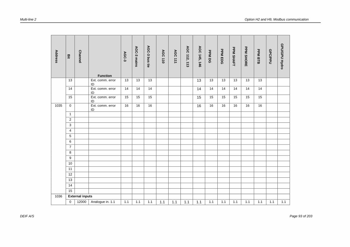
Multi-line 2 Option H2 and H9, Modbus communication
DEIF A/S Page 93 of 203
Ad
dre
ss
Bit
Ch
an
nel
Function
AG
C-3
AG
C-3
main
s
AG
C-3
bu
s tie
AG
C 1
10
AG
C 1
11
AG
C 1
12, 1
13
AG
C 1
45, 1
46
PP
M D
G
PP
M E
DG
PP
M S
HA
FT
PP
M S
HO
RE
PP
M B
TB
GP
C/P
PU
GP
U/G
PU
Hyd
ro
13 Ext. comm. error
ID
13 13 13 13 13 13 13 13 13
14 Ext. comm. error
ID
14 14 14 14 14 14 14 14 14
15 Ext. comm. error
ID
15 15 15 15 15 15 15 15 15
1035 0 Ext. comm. error
ID
16 16 16 16 16 16 16 16 16
1
2
3
4
5
6
7
8
9
10
11
12
13
14
15
1036 External inputs
0 12000 Analogue in. 1.1 1.1 1.1 1.1 1.1 1.1 1.1 1.1 1.1 1.1 1.1 1.1 1.1 1.1 1.1
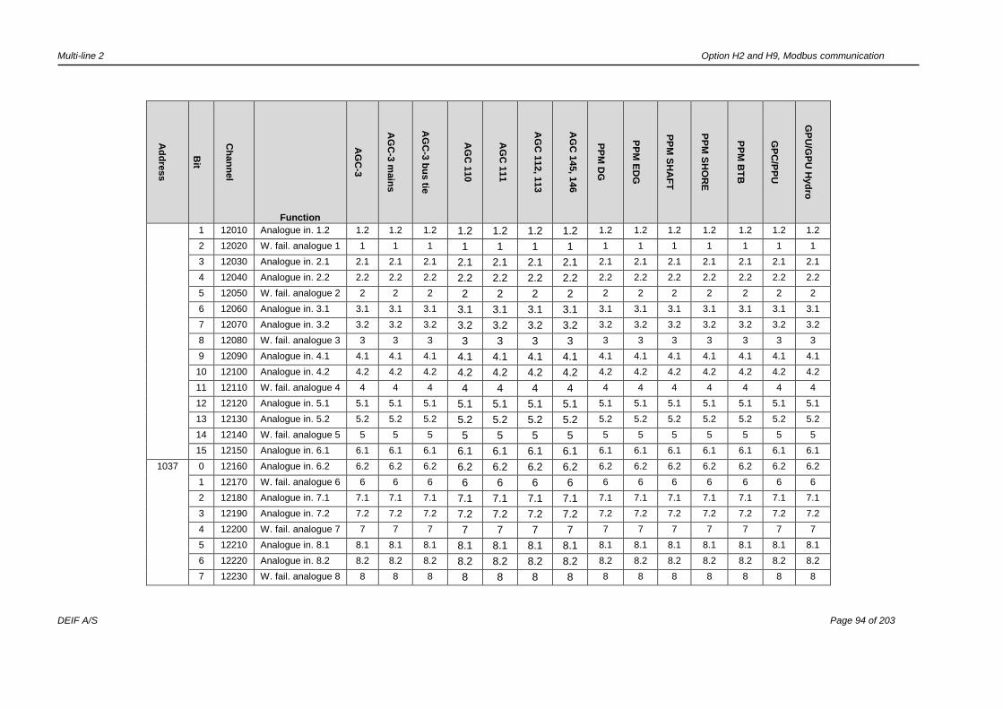
Multi-line 2 Option H2 and H9, Modbus communication
DEIF A/S Page 94 of 203
Ad
dre
ss
Bit
Ch
an
nel
Function
AG
C-3
AG
C-3
main
s
AG
C-3
bu
s tie
AG
C 1
10
AG
C 1
11
AG
C 1
12, 1
13
AG
C 1
45, 1
46
PP
M D
G
PP
M E
DG
PP
M S
HA
FT
PP
M S
HO
RE
PP
M B
TB
GP
C/P
PU
GP
U/G
PU
Hyd
ro
1 12010 Analogue in. 1.2 1.2 1.2 1.2 1.2 1.2 1.2 1.2 1.2 1.2 1.2 1.2 1.2 1.2 1.2
2 12020 W. fail. analogue 1 1 1 1 1 1 1 1 1 1 1 1 1 1 1
3 12030 Analogue in. 2.1 2.1 2.1 2.1 2.1 2.1 2.1 2.1 2.1 2.1 2.1 2.1 2.1 2.1 2.1
4 12040 Analogue in. 2.2 2.2 2.2 2.2 2.2 2.2 2.2 2.2 2.2 2.2 2.2 2.2 2.2 2.2 2.2
5 12050 W. fail. analogue 2 2 2 2 2 2 2 2 2 2 2 2 2 2 2
6 12060 Analogue in. 3.1 3.1 3.1 3.1 3.1 3.1 3.1 3.1 3.1 3.1 3.1 3.1 3.1 3.1 3.1
7 12070 Analogue in. 3.2 3.2 3.2 3.2 3.2 3.2 3.2 3.2 3.2 3.2 3.2 3.2 3.2 3.2 3.2
8 12080 W. fail. analogue 3 3 3 3 3 3 3 3 3 3 3 3 3 3 3
9 12090 Analogue in. 4.1 4.1 4.1 4.1 4.1 4.1 4.1 4.1 4.1 4.1 4.1 4.1 4.1 4.1 4.1
10 12100 Analogue in. 4.2 4.2 4.2 4.2 4.2 4.2 4.2 4.2 4.2 4.2 4.2 4.2 4.2 4.2 4.2
11 12110 W. fail. analogue 4 4 4 4 4 4 4 4 4 4 4 4 4 4 4
12 12120 Analogue in. 5.1 5.1 5.1 5.1 5.1 5.1 5.1 5.1 5.1 5.1 5.1 5.1 5.1 5.1 5.1
13 12130 Analogue in. 5.2 5.2 5.2 5.2 5.2 5.2 5.2 5.2 5.2 5.2 5.2 5.2 5.2 5.2 5.2
14 12140 W. fail. analogue 5 5 5 5 5 5 5 5 5 5 5 5 5 5 5
15 12150 Analogue in. 6.1 6.1 6.1 6.1 6.1 6.1 6.1 6.1 6.1 6.1 6.1 6.1 6.1 6.1 6.1
1037 0 12160 Analogue in. 6.2 6.2 6.2 6.2 6.2 6.2 6.2 6.2 6.2 6.2 6.2 6.2 6.2 6.2 6.2
1 12170 W. fail. analogue 6 6 6 6 6 6 6 6 6 6 6 6 6 6 6
2 12180 Analogue in. 7.1 7.1 7.1 7.1 7.1 7.1 7.1 7.1 7.1 7.1 7.1 7.1 7.1 7.1 7.1
3 12190 Analogue in. 7.2 7.2 7.2 7.2 7.2 7.2 7.2 7.2 7.2 7.2 7.2 7.2 7.2 7.2 7.2
4 12200 W. fail. analogue 7 7 7 7 7 7 7 7 7 7 7 7 7 7 7
5 12210 Analogue in. 8.1 8.1 8.1 8.1 8.1 8.1 8.1 8.1 8.1 8.1 8.1 8.1 8.1 8.1 8.1
6 12220 Analogue in. 8.2 8.2 8.2 8.2 8.2 8.2 8.2 8.2 8.2 8.2 8.2 8.2 8.2 8.2 8.2
7 12230 W. fail. analogue 8 8 8 8 8 8 8 8 8 8 8 8 8 8 8

Multi-line 2 Option H2 and H9, Modbus communication
DEIF A/S Page 95 of 203
Ad
dre
ss
Bit
Ch
an
nel
Function
AG
C-3
AG
C-3
main
s
AG
C-3
bu
s tie
AG
C 1
10
AG
C 1
11
AG
C 1
12, 1
13
AG
C 1
45, 1
46
PP
M D
G
PP
M E
DG
PP
M S
HA
FT
PP
M S
HO
RE
PP
M B
TB
GP
C/P
PU
GP
U/G
PU
Hyd
ro
8
9
10
11
12
13
14
15
1038 0 12540 External digital
input
1 1 1 1 1 1 1 1 1 1 1 1 1 1
1 12550 External digital
input
2 2 2 2 2 2 2 2 2 2 2 2 2 2
2 12560 External digital
input
3 3 3 3 3 3 3 3 3 3 3 3 3 3
3 12570 External digital
input
4 4 4 4 4 4 4 4 4 4 4 4 4 4
4 12580 External digital
input
5 5 5 5 5 5 5 5 5 5 5 5 5 5
5 12590 External digital
input
6 6 6 6 6 6 6 6 6 6 6 6 6 6
6 12600 External digital
input
7 7 7 7 7 7 7 7 7 7 7 7 7 7
7 12610 External digital
input
8 8 8 8 8 8 8 8 8 8 8 8 8 8
8 12620 External digital
input
9 9 9 9 9 9 9 9 9 9 9 9 9 9
9 12630 External digital
input
10 10 10 10 10 10 10 10 10 10 10 10 10 10
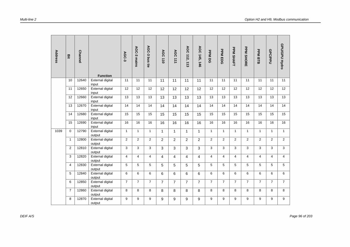
Multi-line 2 Option H2 and H9, Modbus communication
DEIF A/S Page 96 of 203
Ad
dre
ss
Bit
Ch
an
nel
Function
AG
C-3
AG
C-3
main
s
AG
C-3
bu
s tie
AG
C 1
10
AG
C 1
11
AG
C 1
12, 1
13
AG
C 1
45, 1
46
PP
M D
G
PP
M E
DG
PP
M S
HA
FT
PP
M S
HO
RE
PP
M B
TB
GP
C/P
PU
GP
U/G
PU
Hyd
ro
10 12640 External digital
input
11 11 11 11 11 11 11 11 11 11 11 11 11 11
11 12650 External digital
input
12 12 12 12 12 12 12 12 12 12 12 12 12 12
12 12660 External digital
input
13 13 13 13 13 13 13 13 13 13 13 13 13 13
13 12670 External digital
input
14 14 14 14 14 14 14 14 14 14 14 14 14 14
14 12680 External digital
input
15 15 15 15 15 15 15 15 15 15 15 15 15 15
15 12690 External digital
input
16 16 16 16 16 16 16 16 16 16 16 16 16 16
1039 0 12790 External digital
output
1 1 1 1 1 1 1 1 1 1 1 1 1 1
1 12800 External digital
output
2 2 2 2 2 2 2 2 2 2 2 2 2 2
2 12810 External digital
output
3 3 3 3 3 3 3 3 3 3 3 3 3 3
3 12820 External digital
output
4 4 4 4 4 4 4 4 4 4 4 4 4 4
4 12830 External digital
output
5 5 5 5 5 5 5 5 5 5 5 5 5 5
5 12840 External digital
output
6 6 6 6 6 6 6 6 6 6 6 6 6 6
6 12850 External digital
output
7 7 7 7 7 7 7 7 7 7 7 7 7 7
7 12860 External digital
output
8 8 8 8 8 8 8 8 8 8 8 8 8 8
8 12870 External digital
output
9 9 9 9 9 9 9 9 9 9 9 9 9 9
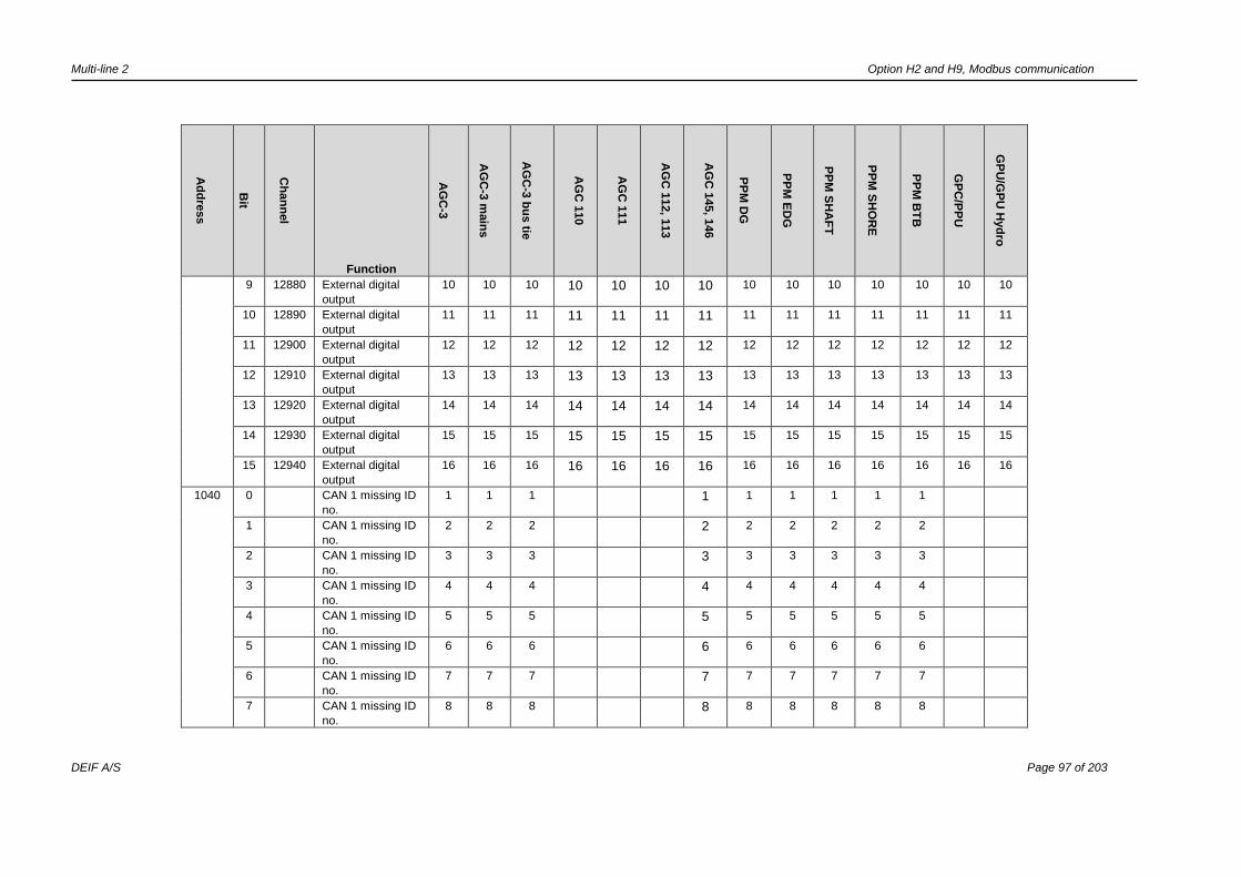
Multi-line 2 Option H2 and H9, Modbus communication
DEIF A/S Page 97 of 203
Ad
dre
ss
Bit
Ch
an
nel
Function
AG
C-3
AG
C-3
main
s
AG
C-3
bu
s tie
AG
C 1
10
AG
C 1
11
AG
C 1
12, 1
13
AG
C 1
45, 1
46
PP
M D
G
PP
M E
DG
PP
M S
HA
FT
PP
M S
HO
RE
PP
M B
TB
GP
C/P
PU
GP
U/G
PU
Hyd
ro
9 12880 External digital
output
10 10 10 10 10 10 10 10 10 10 10 10 10 10
10 12890 External digital
output
11 11 11 11 11 11 11 11 11 11 11 11 11 11
11 12900 External digital
output
12 12 12 12 12 12 12 12 12 12 12 12 12 12
12 12910 External digital
output
13 13 13 13 13 13 13 13 13 13 13 13 13 13
13 12920 External digital
output
14 14 14 14 14 14 14 14 14 14 14 14 14 14
14 12930 External digital
output
15 15 15 15 15 15 15 15 15 15 15 15 15 15
15 12940 External digital
output
16 16 16 16 16 16 16 16 16 16 16 16 16 16
1040 0 CAN 1 missing ID
no.
1 1 1 1 1 1 1 1 1
1 CAN 1 missing ID
no.
2 2 2 2 2 2 2 2 2
2 CAN 1 missing ID
no.
3 3 3 3 3 3 3 3 3
3 CAN 1 missing ID
no.
4 4 4 4 4 4 4 4 4
4 CAN 1 missing ID
no.
5 5 5 5 5 5 5 5 5
5 CAN 1 missing ID
no.
6 6 6 6 6 6 6 6 6
6 CAN 1 missing ID
no.
7 7 7 7 7 7 7 7 7
7 CAN 1 missing ID
no.
8 8 8 8 8 8 8 8 8

Multi-line 2 Option H2 and H9, Modbus communication
DEIF A/S Page 98 of 203
Ad
dre
ss
Bit
Ch
an
nel
Function
AG
C-3
AG
C-3
main
s
AG
C-3
bu
s tie
AG
C 1
10
AG
C 1
11
AG
C 1
12, 1
13
AG
C 1
45, 1
46
PP
M D
G
PP
M E
DG
PP
M S
HA
FT
PP
M S
HO
RE
PP
M B
TB
GP
C/P
PU
GP
U/G
PU
Hyd
ro
8 CAN 1 missing ID
no.
9 9 9 9 9 9 9 9 9
9 CAN 1 missing ID
no.
10 10 10 10 10 10 10 10 10
10 CAN 1 missing ID
no.
11 11 11 11 11 11 11 11 11
11 CAN 1 missing ID
no.
12 12 12 12 12 12 12 12 12
12 CAN 1 missing ID
no.
13 13 13 13 13 13 13 13 13
13 CAN 1 missing ID
no.
14 14 14 14 14 14 14 14 14
14 CAN 1 missing ID
no.
15 15 15 15 15 15 15 15 15
15 CAN 1 missing ID
no.
16 16 16 16 16 16 16 16 16
1041 0 CAN 1 missing ID
no.
17 17 17 17 17 17 17 17 17
1 CAN 1 missing ID
no.
18 18 18 18 18 18 18 18 18
2 CAN 1 missing ID
no.
19 19 19 19 19 19 19 19 19
3 CAN 1 missing ID
no.
20 20 20 20 20 20 20 20 20
4 CAN 1 missing ID
no.
21 21 21 21 21 21 21 21 21
5 CAN 1 missing ID
no.
22 22 22 22 22 22 22 22 22
6 CAN 1 missing ID
no.
23 23 23 23 23 23 23 23 23

Multi-line 2 Option H2 and H9, Modbus communication
DEIF A/S Page 99 of 203
Ad
dre
ss
Bit
Ch
an
nel
Function
AG
C-3
AG
C-3
main
s
AG
C-3
bu
s tie
AG
C 1
10
AG
C 1
11
AG
C 1
12, 1
13
AG
C 1
45, 1
46
PP
M D
G
PP
M E
DG
PP
M S
HA
FT
PP
M S
HO
RE
PP
M B
TB
GP
C/P
PU
GP
U/G
PU
Hyd
ro
7 CAN 1 missing ID
no.
24 24 24 24 24 24 24 24 24
8 CAN 1 missing ID
no.
25 25 25 25 25 25 25 25 25
9 CAN 1 missing ID
no.
26 26 26 26 26 26 26 26 26
10 CAN 1 missing ID
no.
27 27 27 27 27 27 27 27 27
11 CAN 1 missing ID
no.
28 28 28 28 28 28 28 28 28
12 CAN 1 missing ID
no.
29 29 29 29 29 29 29 29 29
13 CAN 1 missing ID
no.
30 30 30 30 30 30 30 30 30
14 CAN 1 missing ID
no.
31 31 31 31 31 31 31 31 31
15 CAN 1 missing ID
no.
32 32 32 32 32 32 32 32 32
1042 0 CAN 1 missing ID
no.
33 33 33 33 33 33 33 33 33
1 CAN 1 missing ID
no.
34 34 34 34 34 34 34 34 34
2 CAN 1 missing ID
no.
35 35 35 35 35 35 35 35 35
3 CAN 1 missing ID
no.
36 36 36 36 36 36 36 36 36
4 CAN 1 missing ID
no.
37 37 37 37 37 37 37 37 37
5 CAN 1 missing ID
no.
38 38 38 38 38 38 38 38 38
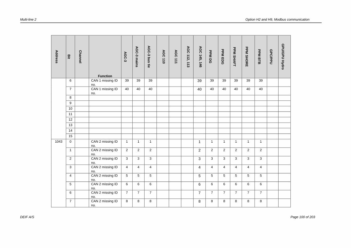
Multi-line 2 Option H2 and H9, Modbus communication
DEIF A/S Page 100 of 203
Ad
dre
ss
Bit
Ch
an
nel
Function
AG
C-3
AG
C-3
main
s
AG
C-3
bu
s tie
AG
C 1
10
AG
C 1
11
AG
C 1
12, 1
13
AG
C 1
45, 1
46
PP
M D
G
PP
M E
DG
PP
M S
HA
FT
PP
M S
HO
RE
PP
M B
TB
GP
C/P
PU
GP
U/G
PU
Hyd
ro
6 CAN 1 missing ID
no.
39 39 39 39 39 39 39 39 39
7 CAN 1 missing ID
no.
40 40 40 40 40 40 40 40 40
8
9
10
11
12
13
14
15
1043 0 CAN 2 missing ID
no.
1 1 1 1 1 1 1 1 1
1 CAN 2 missing ID
no.
2 2 2 2 2 2 2 2 2
2 CAN 2 missing ID
no.
3 3 3 3 3 3 3 3 3
3 CAN 2 missing ID
no.
4 4 4 4 4 4 4 4 4
4 CAN 2 missing ID
no.
5 5 5 5 5 5 5 5 5
5 CAN 2 missing ID
no.
6 6 6 6 6 6 6 6 6
6 CAN 2 missing ID
no.
7 7 7 7 7 7 7 7 7
7 CAN 2 missing ID
no.
8 8 8 8 8 8 8 8 8

Multi-line 2 Option H2 and H9, Modbus communication
DEIF A/S Page 101 of 203
Ad
dre
ss
Bit
Ch
an
nel
Function
AG
C-3
AG
C-3
main
s
AG
C-3
bu
s tie
AG
C 1
10
AG
C 1
11
AG
C 1
12, 1
13
AG
C 1
45, 1
46
PP
M D
G
PP
M E
DG
PP
M S
HA
FT
PP
M S
HO
RE
PP
M B
TB
GP
C/P
PU
GP
U/G
PU
Hyd
ro
8 CAN 2 missing ID
no.
9 9 9 9 9 9 9 9 9
9 CAN 2 missing ID
no.
10 10 10 10 10 10 10 10 10
10 CAN 2 missing ID
no.
11 11 11 11 11 11 11 11 11
11 CAN 2 missing ID
no.
12 12 12 12 12 12 12 12 12
12 CAN 2 missing ID
no.
13 13 13 13 13 13 13 13 13
13 CAN 2 missing ID
no.
14 14 14 14 14 14 14 14 14
14 CAN 2 missing ID
no.
15 15 15 15 15 15 15 15 15
15 CAN 2 missing ID
no.
16 16 16 16 16 16 16 16 16
1044 0 CAN 2 missing ID
no.
17 17 17 17 17 17 17 17 17
1 CAN 2 missing ID
no.
18 18 18 18 18 18 18 18 18
2 CAN 2 missing ID
no.
19 19 19 19 19 19 19 19 19
3 CAN 2 missing ID
no.
20 20 20 20 20 20 20 20 20
4 CAN 2 missing ID
no.
21 21 21 21 21 21 21 21 21
5 CAN 2 missing ID
no.
22 22 22 22 22 22 22 22 22
6 CAN 2 missing ID
no.
23 23 23 23 23 23 23 23 23
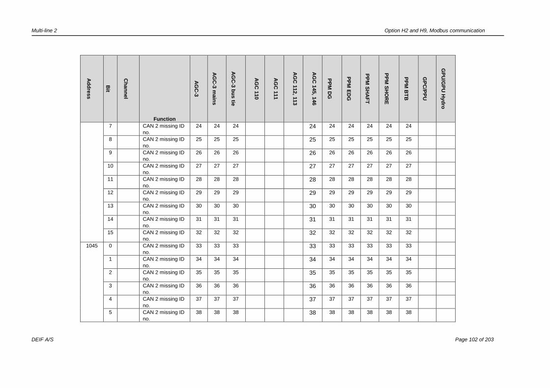
Multi-line 2 Option H2 and H9, Modbus communication
DEIF A/S Page 102 of 203
Ad
dre
ss
Bit
Ch
an
nel
Function
AG
C-3
AG
C-3
main
s
AG
C-3
bu
s tie
AG
C 1
10
AG
C 1
11
AG
C 1
12, 1
13
AG
C 1
45, 1
46
PP
M D
G
PP
M E
DG
PP
M S
HA
FT
PP
M S
HO
RE
PP
M B
TB
GP
C/P
PU
GP
U/G
PU
Hyd
ro
7 CAN 2 missing ID
no.
24 24 24 24 24 24 24 24 24
8 CAN 2 missing ID
no.
25 25 25 25 25 25 25 25 25
9 CAN 2 missing ID
no.
26 26 26 26 26 26 26 26 26
10 CAN 2 missing ID
no.
27 27 27 27 27 27 27 27 27
11 CAN 2 missing ID
no.
28 28 28 28 28 28 28 28 28
12 CAN 2 missing ID
no.
29 29 29 29 29 29 29 29 29
13 CAN 2 missing ID
no.
30 30 30 30 30 30 30 30 30
14 CAN 2 missing ID
no.
31 31 31 31 31 31 31 31 31
15 CAN 2 missing ID
no.
32 32 32 32 32 32 32 32 32
1045 0 CAN 2 missing ID
no.
33 33 33 33 33 33 33 33 33
1 CAN 2 missing ID
no.
34 34 34 34 34 34 34 34 34
2 CAN 2 missing ID
no.
35 35 35 35 35 35 35 35 35
3 CAN 2 missing ID
no.
36 36 36 36 36 36 36 36 36
4 CAN 2 missing ID
no.
37 37 37 37 37 37 37 37 37
5 CAN 2 missing ID
no.
38 38 38 38 38 38 38 38 38

Multi-line 2 Option H2 and H9, Modbus communication
DEIF A/S Page 103 of 203
Ad
dre
ss
Bit
Ch
an
nel
Function
AG
C-3
AG
C-3
main
s
AG
C-3
bu
s tie
AG
C 1
10
AG
C 1
11
AG
C 1
12, 1
13
AG
C 1
45, 1
46
PP
M D
G
PP
M E
DG
PP
M S
HA
FT
PP
M S
HO
RE
PP
M B
TB
GP
C/P
PU
GP
U/G
PU
Hyd
ro
6 CAN 2 missing ID
no.
39 39 39 39 39 39 39 39 39
7 CAN 2 missing ID
no.
40 40 40 40 40 40 40 40 40
8
9
10
11
12
13
14
15
1046 0 4800 4-20 mA alarm no. 127.1 127.1 127.1 127.1 127.1 127.1 127.1 127.1 127.1 127.1
1 4810 4-20 mA alarm no. 127.2 127.2 127.2 127.2 127.2 127.2 127.2 127.2 127.2 127.2
2 4820 Wire fail analogue
input
127 127 127 127 127 127 127 127 127 127
3 4830 4-20 mA alarm no. 129.1 129.1 129.1 129.1 129.1 129.1 129.1 129.1 129.1 129.1
4 4840 4-20 mA alarm no. 129.2 129.2 129.2 129.2 129.2 129.2 129.2 129.2 129.2 129.2
5 4850 Wire fail analogue
input
129 129 129 129 129 129 129 129 129 129
6 4860 4-20 mA alarm no. 131.1 131.1 131.1 131.1 131.1 131.1 131.1 131.1 131.1 131.1
7 4870 4-20 mA alarm no. 131.2 131.2 131.2 131.2 131.2 131.2 131.2 131.2 131.2 131.2
8 4880 Wire fail analogue
input
131 131 131 131 131 131 131 131 131 131
9 4890 4-20 mA alarm no. 133.1 133.1 133.1 133.1 133.1 133.1 133.1 133.1 133.1 133.1
10 4900 4-20 mA alarm no. 133.2 133.2 133.2 133.2 133.2 133.2 133.2 133.2 133.2 133.2
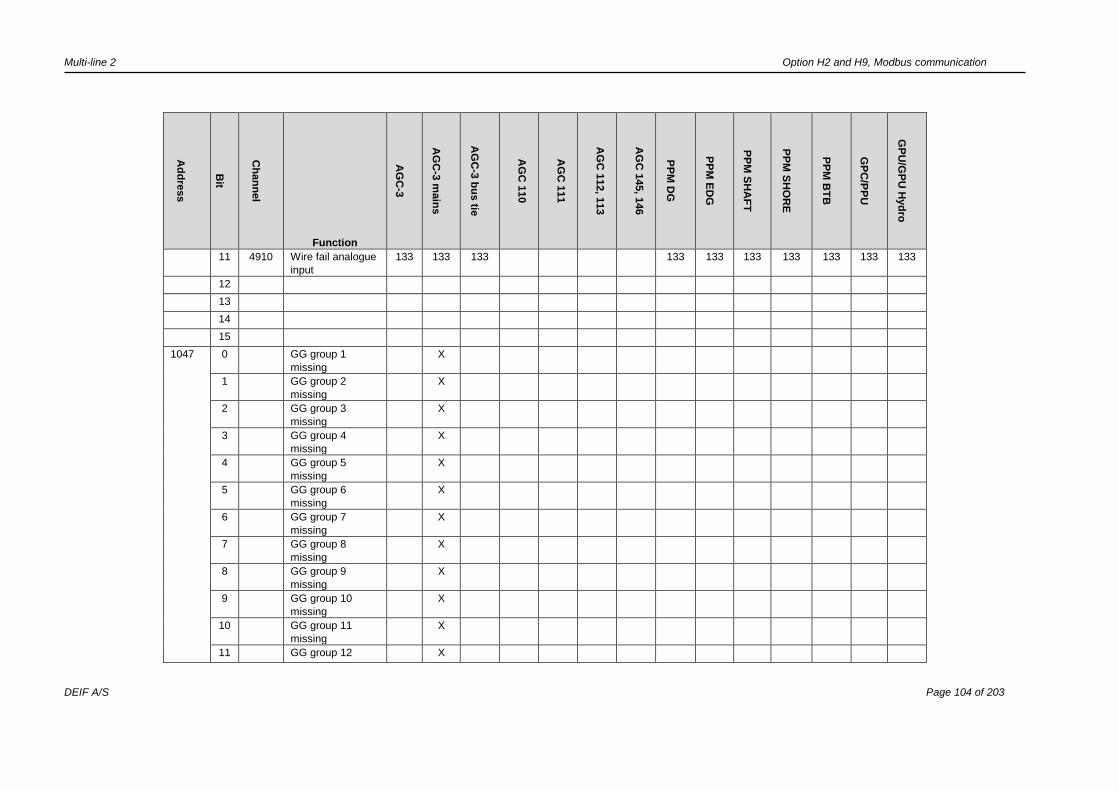
Multi-line 2 Option H2 and H9, Modbus communication
DEIF A/S Page 104 of 203
Ad
dre
ss
Bit
Ch
an
nel
Function
AG
C-3
AG
C-3
main
s
AG
C-3
bu
s tie
AG
C 1
10
AG
C 1
11
AG
C 1
12, 1
13
AG
C 1
45, 1
46
PP
M D
G
PP
M E
DG
PP
M S
HA
FT
PP
M S
HO
RE
PP
M B
TB
GP
C/P
PU
GP
U/G
PU
Hyd
ro
11 4910 Wire fail analogue
input
133 133 133 133 133 133 133 133 133 133
12
13
14
15
1047 0 GG group 1
missing
X
1 GG group 2
missing
X
2 GG group 3
missing
X
3 GG group 4
missing
X
4 GG group 5
missing
X
5 GG group 6
missing
X
6 GG group 7
missing
X
7 GG group 8
missing
X
8 GG group 9
missing
X
9 GG group 10
missing
X
10 GG group 11
missing
X
11 GG group 12 X

Multi-line 2 Option H2 and H9, Modbus communication
DEIF A/S Page 105 of 203
Ad
dre
ss
Bit
Ch
an
nel
Function
AG
C-3
AG
C-3
main
s
AG
C-3
bu
s tie
AG
C 1
10
AG
C 1
11
AG
C 1
12, 1
13
AG
C 1
45, 1
46
PP
M D
G
PP
M E
DG
PP
M S
HA
FT
PP
M S
HO
RE
PP
M B
TB
GP
C/P
PU
GP
U/G
PU
Hyd
ro
missing
12 GG group 13
missing
X
13 GG group 14
missing
X
14 GG group 15
missing
X
15 GG group 16
missing
X
1048 0 GG mains 17
missing
X
1 GG mains 18
missing
X
2 GG mains 19
missing
X
3 GG mains 20
missing
X
4 GG mains 21
missing
X
5 GG mains 22
missing
X
6 GG mains 23
missing
X
7 GG mains 24
missing
X
8 GG mains 25
missing
X
9 GG mains 26
missing
X
10 GG mains 27 X

Multi-line 2 Option H2 and H9, Modbus communication
DEIF A/S Page 106 of 203
Ad
dre
ss
Bit
Ch
an
nel
Function
AG
C-3
AG
C-3
main
s
AG
C-3
bu
s tie
AG
C 1
10
AG
C 1
11
AG
C 1
12, 1
13
AG
C 1
45, 1
46
PP
M D
G
PP
M E
DG
PP
M S
HA
FT
PP
M S
HO
RE
PP
M B
TB
GP
C/P
PU
GP
U/G
PU
Hyd
ro
missing
11 GG mains 28
missing
X
12 GG mains 29
missing
X
13 GG mains 30
missing
X
14 GG mains 31
missing
X
15 GG mains 32
missing
X
1049 Reserved
1050 Reserved
1051 0 Virtual event 1 X X X X X X X X X X X X X X
1 Virtual event 2 X X X X X X X X X X X X X X
2 Virtual event 3 X X X X X X X X X X X X X X
3 Virtual event 4 X X X X X X X X X X X X X X
4 Virtual event 5 X X X X X X X X X X X X X X
5 Virtual event 6 X X X X X X X X X X X X X X
6 Virtual event 7 X X X X X X X X X X X X X X
7 Virtual event 8 X X X X X X X X X X X X X X
8 Virtual event 9 X X X X X X X X X X X X X X
9 Virtual event 10 X X X X X X X X X X X X X X
10 Virtual event 11 X X X X X X X X X X X X X X
11 Virtual event 12 X X X X X X X X X X X X X X
12 Virtual event 13 X X X X X X X X X X X X X X
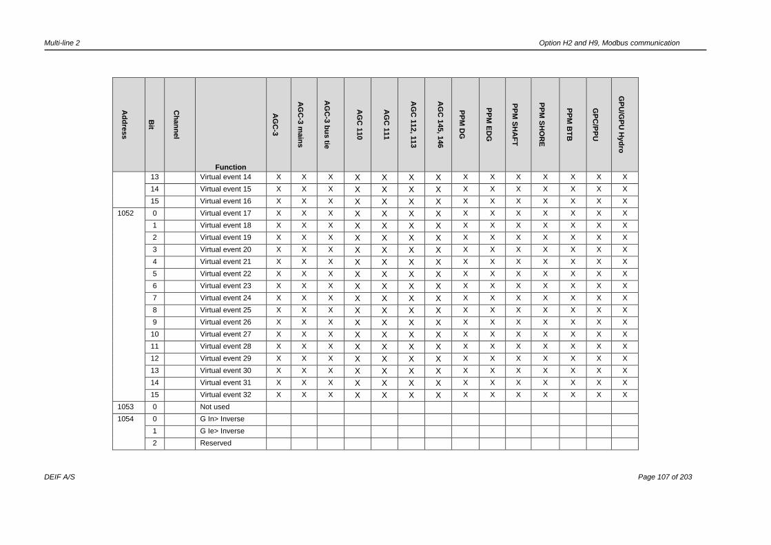
Multi-line 2 Option H2 and H9, Modbus communication
DEIF A/S Page 107 of 203
Ad
dre
ss
Bit
Ch
an
nel
Function
AG
C-3
AG
C-3
main
s
AG
C-3
bu
s tie
AG
C 1
10
AG
C 1
11
AG
C 1
12, 1
13
AG
C 1
45, 1
46
PP
M D
G
PP
M E
DG
PP
M S
HA
FT
PP
M S
HO
RE
PP
M B
TB
GP
C/P
PU
GP
U/G
PU
Hyd
ro
13 Virtual event 14 X X X X X X X X X X X X X X
14 Virtual event 15 X X X X X X X X X X X X X X
15 Virtual event 16 X X X X X X X X X X X X X X
1052 0 Virtual event 17 X X X X X X X X X X X X X X
1 Virtual event 18 X X X X X X X X X X X X X X
2 Virtual event 19 X X X X X X X X X X X X X X
3 Virtual event 20 X X X X X X X X X X X X X X
4 Virtual event 21 X X X X X X X X X X X X X X
5 Virtual event 22 X X X X X X X X X X X X X X
6 Virtual event 23 X X X X X X X X X X X X X X
7 Virtual event 24 X X X X X X X X X X X X X X
8 Virtual event 25 X X X X X X X X X X X X X X
9 Virtual event 26 X X X X X X X X X X X X X X
10 Virtual event 27 X X X X X X X X X X X X X X
11 Virtual event 28 X X X X X X X X X X X X X X
12 Virtual event 29 X X X X X X X X X X X X X X
13 Virtual event 30 X X X X X X X X X X X X X X
14 Virtual event 31 X X X X X X X X X X X X X X
15 Virtual event 32 X X X X X X X X X X X X X X
1053 0 Not used
1054 0 G In> Inverse
1 G Ie> Inverse
2 Reserved
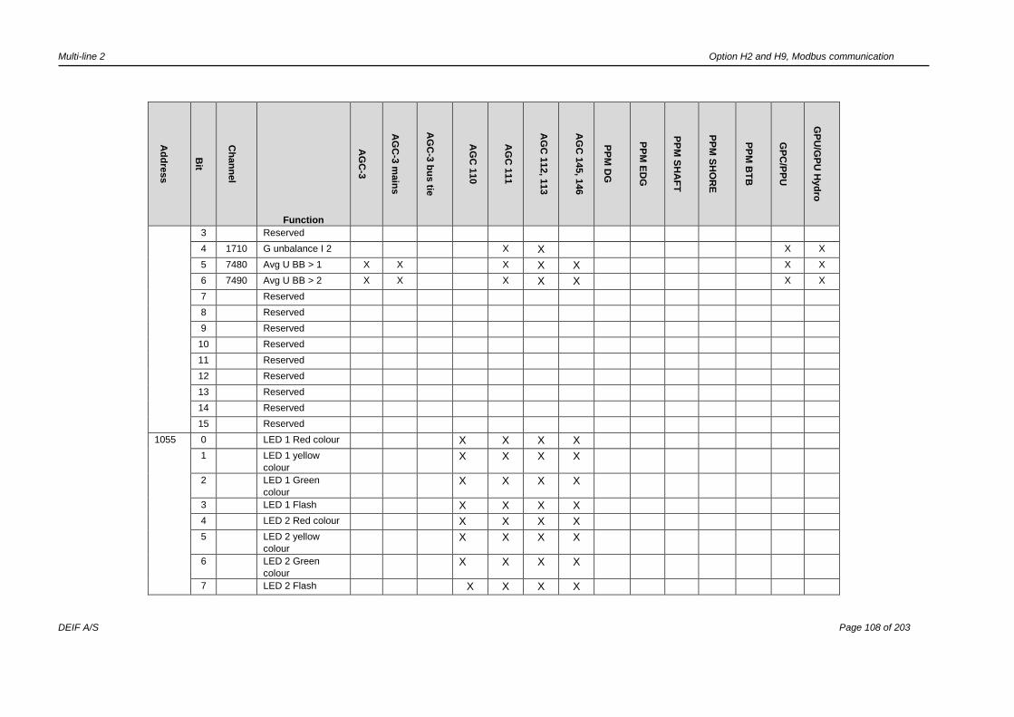
Multi-line 2 Option H2 and H9, Modbus communication
DEIF A/S Page 108 of 203
Ad
dre
ss
Bit
Ch
an
nel
Function
AG
C-3
AG
C-3
main
s
AG
C-3
bu
s tie
AG
C 1
10
AG
C 1
11
AG
C 1
12, 1
13
AG
C 1
45, 1
46
PP
M D
G
PP
M E
DG
PP
M S
HA
FT
PP
M S
HO
RE
PP
M B
TB
GP
C/P
PU
GP
U/G
PU
Hyd
ro
3 Reserved
4 1710 G unbalance I 2 X X X X
5 7480 Avg U BB > 1 X X X X X X X
6 7490 Avg U BB > 2 X X X X X X X
7 Reserved
8 Reserved
9 Reserved
10 Reserved
11 Reserved
12 Reserved
13 Reserved
14 Reserved
15 Reserved
1055 0 LED 1 Red colour X X X X
1 LED 1 yellow
colour
X X X X
2 LED 1 Green
colour
X X X X
3 LED 1 Flash X X X X
4 LED 2 Red colour X X X X
5 LED 2 yellow
colour
X X X X
6 LED 2 Green
colour
X X X X
7 LED 2 Flash X X X X

Multi-line 2 Option H2 and H9, Modbus communication
DEIF A/S Page 109 of 203
Ad
dre
ss
Bit
Ch
an
nel
Function
AG
C-3
AG
C-3
main
s
AG
C-3
bu
s tie
AG
C 1
10
AG
C 1
11
AG
C 1
12, 1
13
AG
C 1
45, 1
46
PP
M D
G
PP
M E
DG
PP
M S
HA
FT
PP
M S
HO
RE
PP
M B
TB
GP
C/P
PU
GP
U/G
PU
Hyd
ro
8 LED 3 Red colour X X X X
9 LED 3 yellow
colour
X X X X
10 LED 3 Green
colour
X X X X
11 LED 3 Flash X X X X
12 LED 4 Red colour X X X X
13 LED 4 yellow
colour
X X X X
14 LED 4 Green
colour
X X X X
15 LED 4 Flash X X X X
1056 0 Digital input 97 X X
1 Digital input 96 X X
2 Digital input 95 X X
3 Digital input 94 X X
4 Digital input 93 X X
5 Digital input 92 X X
6 Digital input 91 X X
7 Digital input 133 X X
8 Digital input 132 X X
9 Digital input 131 X X
10 Digital input 130 X X
11 Digital input 129 X X
12 Digital input 128 X X
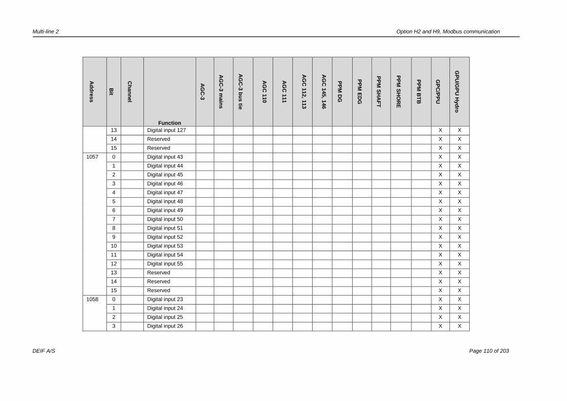
Multi-line 2 Option H2 and H9, Modbus communication
DEIF A/S Page 110 of 203
Ad
dre
ss
Bit
Ch
an
nel
Function
AG
C-3
AG
C-3
main
s
AG
C-3
bu
s tie
AG
C 1
10
AG
C 1
11
AG
C 1
12, 1
13
AG
C 1
45, 1
46
PP
M D
G
PP
M E
DG
PP
M S
HA
FT
PP
M S
HO
RE
PP
M B
TB
GP
C/P
PU
GP
U/G
PU
Hyd
ro
13 Digital input 127 X X
14 Reserved X X
15 Reserved X X
1057 0 Digital input 43 X X
1 Digital input 44 X X
2 Digital input 45 X X
3 Digital input 46 X X
4 Digital input 47 X X
5 Digital input 48 X X
6 Digital input 49 X X
7 Digital input 50 X X
8 Digital input 51 X X
9 Digital input 52 X X
10 Digital input 53 X X
11 Digital input 54 X X
12 Digital input 55 X X
13 Reserved X X
14 Reserved X X
15 Reserved X X
1058 0 Digital input 23 X X
1 Digital input 24 X X
2 Digital input 25 X X
3 Digital input 26 X X

Multi-line 2 Option H2 and H9, Modbus communication
DEIF A/S Page 111 of 203
Ad
dre
ss
Bit
Ch
an
nel
Function
AG
C-3
AG
C-3
main
s
AG
C-3
bu
s tie
AG
C 1
10
AG
C 1
11
AG
C 1
12, 1
13
AG
C 1
45, 1
46
PP
M D
G
PP
M E
DG
PP
M S
HA
FT
PP
M S
HO
RE
PP
M B
TB
GP
C/P
PU
GP
U/G
PU
Hyd
ro
4 Digital input 27 X X
5 Digital input 118
(Emergency stop) X X
6 Digital input 117 X X
7 Digital input 116 X X
8 Digital input 115 X X
9 Digital input 114 X X
10 Digital input 113 X X
11 Digital input 112 X X
12 Digital input 123 X X
13 Multi input 108 X X
14 Multi input 105 X X
15 Multi input 102 X X
1059 0 Relay 65 X X
1 Relay 67 X X
2 Relay 69 X X
3 Relay 71 X X
4 Relay 132 X X
5 Relay 130 X X
6 Relay 128 X X
7 Relay 126 X X
8 Relay 96 X X
9 Relay 94 X X
10 Relay 92 X X

Multi-line 2 Option H2 and H9, Modbus communication
DEIF A/S Page 112 of 203
Ad
dre
ss
Bit
Ch
an
nel
Function
AG
C-3
AG
C-3
main
s
AG
C-3
bu
s tie
AG
C 1
10
AG
C 1
11
AG
C 1
12, 1
13
AG
C 1
45, 1
46
PP
M D
G
PP
M E
DG
PP
M S
HA
FT
PP
M S
HO
RE
PP
M B
TB
GP
C/P
PU
GP
U/G
PU
Hyd
ro
11 Relay 90 X X
12 Relay 57 X X
13 Relay 59 X X
14 Relay 61 X X
15 Relay 63 X X
1060 0 Relay 5 X X
1 Relay 8 X X
2 Relay 11 X X
3 Relay 14 X X
4 Relay 17 X X
5 Relay T20 X X
6 Relay T21 X X
7 Relay 29 X X
8 Relay 31 X X
9 Relay 33 X X
10 Relay 35 X X
11 Run coil X X
12 Start prepare X X
13 Start relay X X
14 Stop coil X X
15 Reserved X X
1067 0 Power limit value1 X**
1 Power limit value2 X**

Multi-line 2 Option H2 and H9, Modbus communication
DEIF A/S Page 113 of 203
Ad
dre
ss
Bit
Ch
an
nel
Function
AG
C-3
AG
C-3
main
s
AG
C-3
bu
s tie
AG
C 1
10
AG
C 1
11
AG
C 1
12, 1
13
AG
C 1
45, 1
46
PP
M D
G
PP
M E
DG
PP
M S
HA
FT
PP
M S
HO
RE
PP
M B
TB
GP
C/P
PU
GP
U/G
PU
Hyd
ro
2 Power limit value3 X**
3 Power limit value4 X**
1071 Blackout Unit X
1072 Blackout Section X
1073 Blackout System X
1074 Blackout Emer-
gency busbar
X
1075 P% X
1076 Q% X
1077 S% X
Bits 3, 7, 11 and 15 only have significance when one of the colour indication bits is high. When bit 3, 7, 11 or 15
is “0”, then the LED is on solid, and when bit 3, 7, 11 or 15 is “1”, the LED is flashing.
Columns marked with ** only apply to GPC.
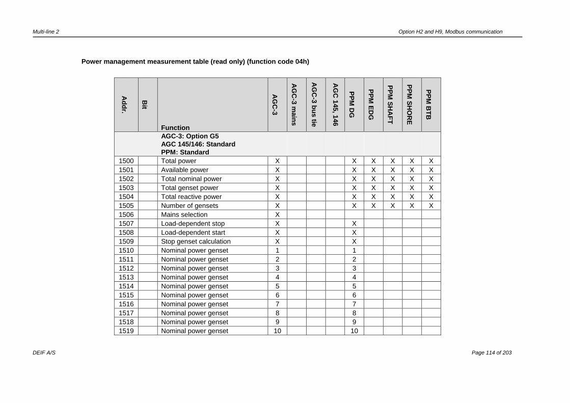
Multi-line 2 Option H2 and H9, Modbus communication
DEIF A/S Page 114 of 203
Power management measurement table (read only) (function code 04h)
Ad
dr.
Bit
Function
AG
C-3
AG
C-3
main
s
AG
C-3
bu
s tie
AG
C 1
45, 1
46
PP
M D
G
PP
M E
DG
PP
M S
HA
FT
PP
M S
HO
RE
PP
M B
TB
AGC-3: Option G5
AGC 145/146: Standard
PPM: Standard
1500 Total power X X X X X X
1501 Available power X X X X X X
1502 Total nominal power X X X X X X
1503 Total genset power X X X X X X
1504 Total reactive power X X X X X X
1505 Number of gensets X X X X X X
1506 Mains selection X
1507 Load-dependent stop X X
1508 Load-dependent start X X
1509 Stop genset calculation X X
1510 Nominal power genset 1 1
1511 Nominal power genset 2 2
1512 Nominal power genset 3 3
1513 Nominal power genset 4 4
1514 Nominal power genset 5 5
1515 Nominal power genset 6 6
1516 Nominal power genset 7 7
1517 Nominal power genset 8 8
1518 Nominal power genset 9 9
1519 Nominal power genset 10 10
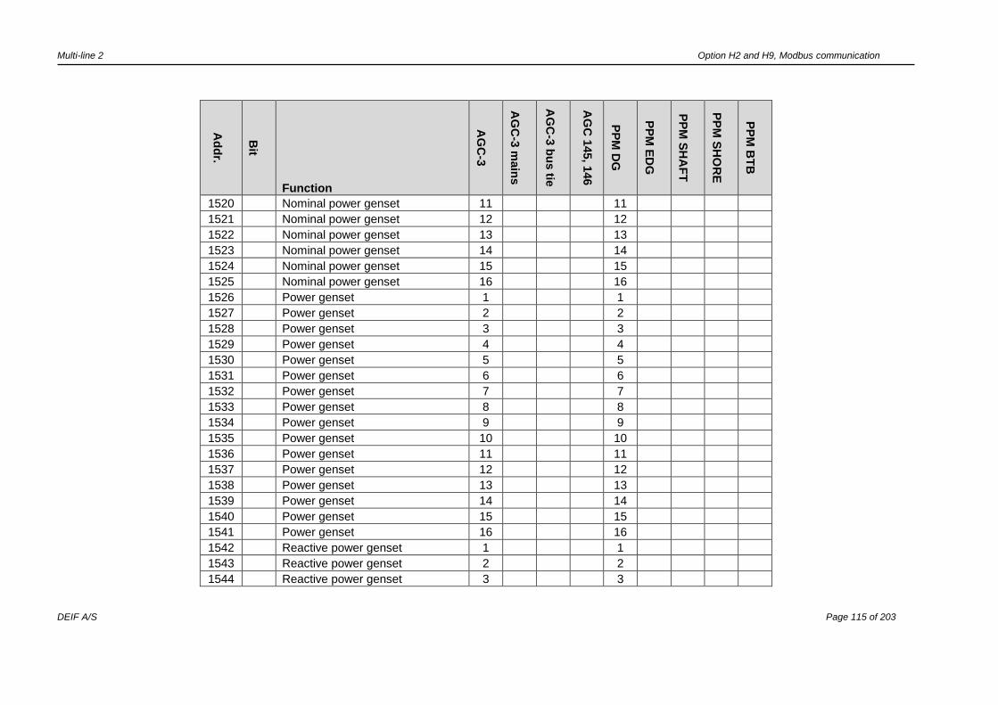
Multi-line 2 Option H2 and H9, Modbus communication
DEIF A/S Page 115 of 203
Ad
dr.
Bit
Function
AG
C-3
AG
C-3
main
s
AG
C-3
bu
s tie
AG
C 1
45, 1
46
PP
M D
G
PP
M E
DG
PP
M S
HA
FT
PP
M S
HO
RE
PP
M B
TB
1520 Nominal power genset 11 11
1521 Nominal power genset 12 12
1522 Nominal power genset 13 13
1523 Nominal power genset 14 14
1524 Nominal power genset 15 15
1525 Nominal power genset 16 16
1526 Power genset 1 1
1527 Power genset 2 2
1528 Power genset 3 3
1529 Power genset 4 4
1530 Power genset 5 5
1531 Power genset 6 6
1532 Power genset 7 7
1533 Power genset 8 8
1534 Power genset 9 9
1535 Power genset 10 10
1536 Power genset 11 11
1537 Power genset 12 12
1538 Power genset 13 13
1539 Power genset 14 14
1540 Power genset 15 15
1541 Power genset 16 16
1542 Reactive power genset 1 1
1543 Reactive power genset 2 2
1544 Reactive power genset 3 3

Multi-line 2 Option H2 and H9, Modbus communication
DEIF A/S Page 116 of 203
Ad
dr.
Bit
Function
AG
C-3
AG
C-3
main
s
AG
C-3
bu
s tie
AG
C 1
45, 1
46
PP
M D
G
PP
M E
DG
PP
M S
HA
FT
PP
M S
HO
RE
PP
M B
TB
1545 Reactive power genset 4 4
1546 Reactive power genset 5 5
1547 Reactive power genset 6 6
1548 Reactive power genset 7 7
1549 Reactive power genset 8 8
1550 Reactive power genset 9 9
1551 Reactive power genset 10 10
1552 Reactive power genset 11 11
1553 Reactive power genset 12 12
1554 Reactive power genset 13 13
1555 Reactive power genset 14 14
1556 Reactive power genset 15 15
1557 Reactive power genset 16 16
1558
1559
1560 Power, mains 1A X
1561 Power, mains 1B X
1562 Power, mains 2A X
1563 Power, mains 2B X
1564
1565 Reactive power mains 1A X
1566 Reactive power mains 1B X
1567 Reactive power mains 2A X
1568 Reactive power mains 2B X
1569 Power mains 17 X

Multi-line 2 Option H2 and H9, Modbus communication
DEIF A/S Page 117 of 203
Ad
dr.
Bit
Function
AG
C-3
AG
C-3
main
s
AG
C-3
bu
s tie
AG
C 1
45, 1
46
PP
M D
G
PP
M E
DG
PP
M S
HA
FT
PP
M S
HO
RE
PP
M B
TB
Power shaft 17 X
Power shore 17 X
1570
Power mains 18 X
Power shaft 18 X
Power shore 18 X
1571
Power mains 19 X
Power shaft 19 X
Power shore 19 X
1572
Power mains 20 X
Power shaft 20 X
Power shore 20 X
1573 Power mains 21 X
1574 Power mains 22 X
1575 Power mains 23 X
1576 Power mains 24 X
1577 Power mains 25 X
1578 Power mains 26 X
1579 Power mains 27 X
1580 Power mains 28 X
1581 Power mains 29 X
1582 Power mains 30 X
1583 Power mains 31 X
1584 Power mains 32 X
1585 Reactive power mains 17 X
Reactive power shaft 17 X
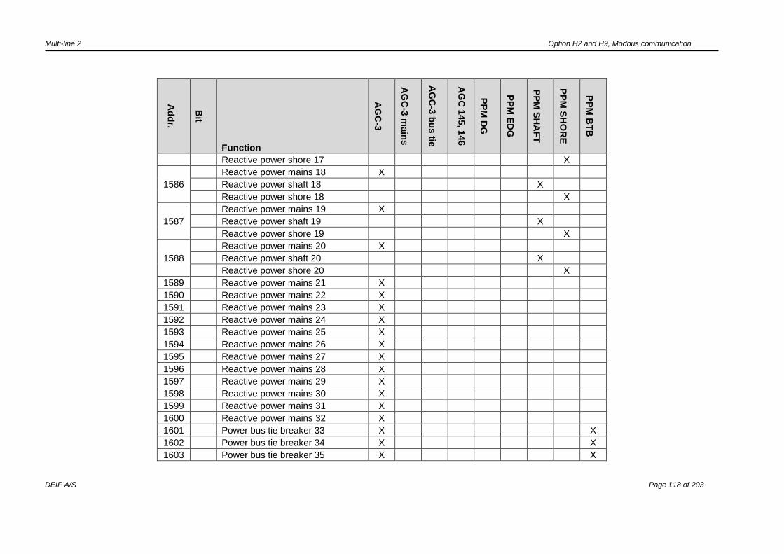
Multi-line 2 Option H2 and H9, Modbus communication
DEIF A/S Page 118 of 203
Ad
dr.
Bit
Function
AG
C-3
AG
C-3
main
s
AG
C-3
bu
s tie
AG
C 1
45, 1
46
PP
M D
G
PP
M E
DG
PP
M S
HA
FT
PP
M S
HO
RE
PP
M B
TB
Reactive power shore 17 X
1586
Reactive power mains 18 X
Reactive power shaft 18 X
Reactive power shore 18 X
1587
Reactive power mains 19 X
Reactive power shaft 19 X
Reactive power shore 19 X
1588
Reactive power mains 20 X
Reactive power shaft 20 X
Reactive power shore 20 X
1589 Reactive power mains 21 X
1590 Reactive power mains 22 X
1591 Reactive power mains 23 X
1592 Reactive power mains 24 X
1593 Reactive power mains 25 X
1594 Reactive power mains 26 X
1595 Reactive power mains 27 X
1596 Reactive power mains 28 X
1597 Reactive power mains 29 X
1598 Reactive power mains 30 X
1599 Reactive power mains 31 X
1600 Reactive power mains 32 X
1601 Power bus tie breaker 33 X X
1602 Power bus tie breaker 34 X X
1603 Power bus tie breaker 35 X X
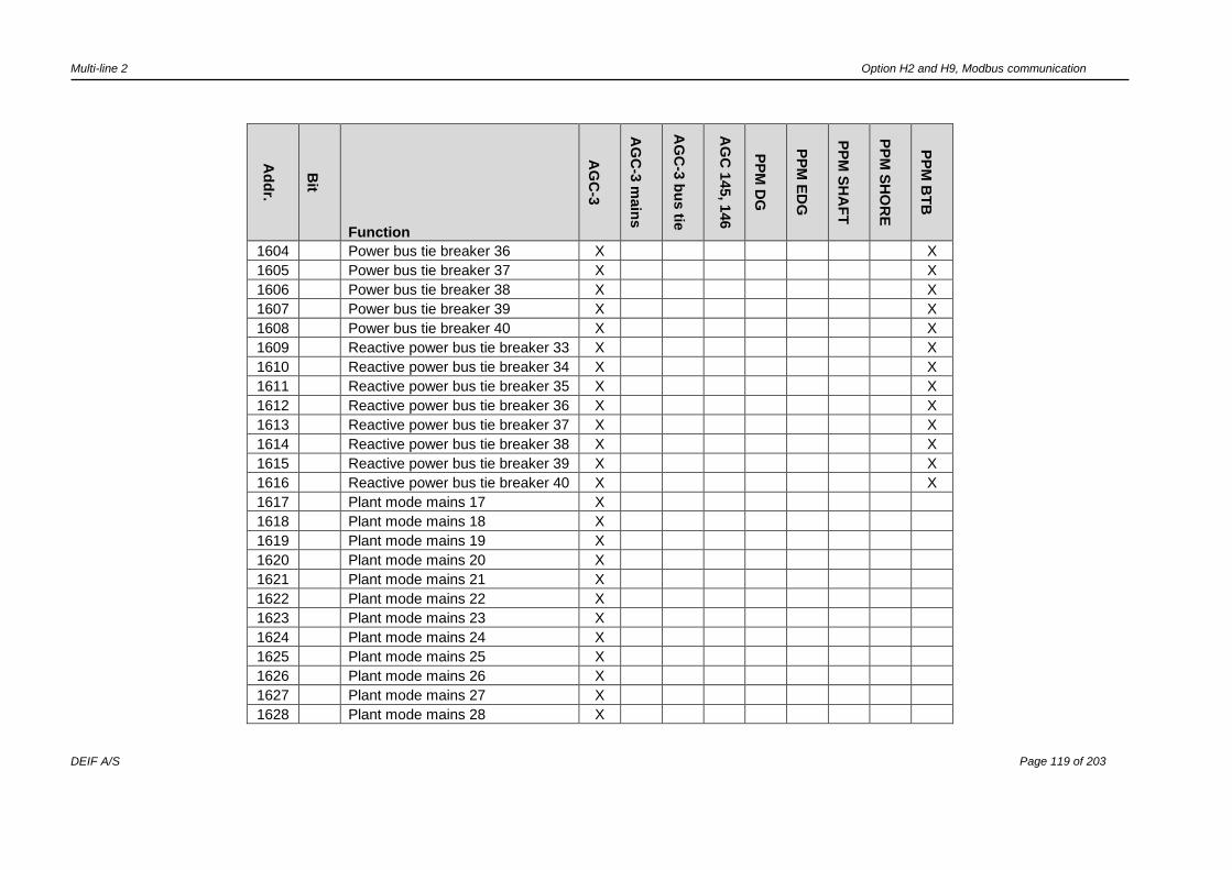
Multi-line 2 Option H2 and H9, Modbus communication
DEIF A/S Page 119 of 203
Ad
dr.
Bit
Function
AG
C-3
AG
C-3
main
s
AG
C-3
bu
s tie
AG
C 1
45, 1
46
PP
M D
G
PP
M E
DG
PP
M S
HA
FT
PP
M S
HO
RE
PP
M B
TB
1604 Power bus tie breaker 36 X X
1605 Power bus tie breaker 37 X X
1606 Power bus tie breaker 38 X X
1607 Power bus tie breaker 39 X X
1608 Power bus tie breaker 40 X X
1609 Reactive power bus tie breaker 33 X X
1610 Reactive power bus tie breaker 34 X X
1611 Reactive power bus tie breaker 35 X X
1612 Reactive power bus tie breaker 36 X X
1613 Reactive power bus tie breaker 37 X X
1614 Reactive power bus tie breaker 38 X X
1615 Reactive power bus tie breaker 39 X X
1616 Reactive power bus tie breaker 40 X X
1617 Plant mode mains 17 X
1618 Plant mode mains 18 X
1619 Plant mode mains 19 X
1620 Plant mode mains 20 X
1621 Plant mode mains 21 X
1622 Plant mode mains 22 X
1623 Plant mode mains 23 X
1624 Plant mode mains 24 X
1625 Plant mode mains 25 X
1626 Plant mode mains 26 X
1627 Plant mode mains 27 X
1628 Plant mode mains 28 X
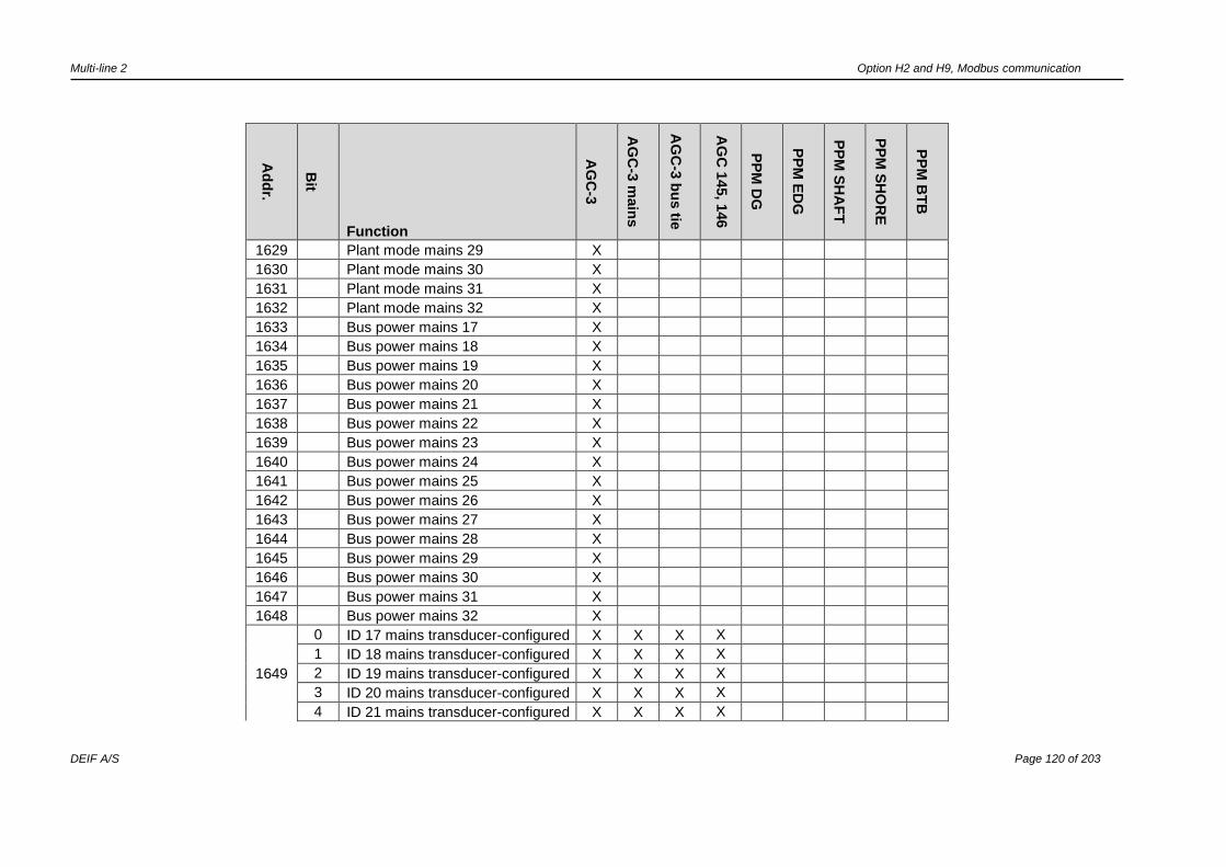
Multi-line 2 Option H2 and H9, Modbus communication
DEIF A/S Page 120 of 203
Ad
dr.
Bit
Function
AG
C-3
AG
C-3
main
s
AG
C-3
bu
s tie
AG
C 1
45, 1
46
PP
M D
G
PP
M E
DG
PP
M S
HA
FT
PP
M S
HO
RE
PP
M B
TB
1629 Plant mode mains 29 X
1630 Plant mode mains 30 X
1631 Plant mode mains 31 X
1632 Plant mode mains 32 X
1633 Bus power mains 17 X
1634 Bus power mains 18 X
1635 Bus power mains 19 X
1636 Bus power mains 20 X
1637 Bus power mains 21 X
1638 Bus power mains 22 X
1639 Bus power mains 23 X
1640 Bus power mains 24 X
1641 Bus power mains 25 X
1642 Bus power mains 26 X
1643 Bus power mains 27 X
1644 Bus power mains 28 X
1645 Bus power mains 29 X
1646 Bus power mains 30 X
1647 Bus power mains 31 X
1648 Bus power mains 32 X
1649
0 ID 17 mains transducer-configured X X X X
1 ID 18 mains transducer-configured X X X X
2 ID 19 mains transducer-configured X X X X
3 ID 20 mains transducer-configured X X X X
4 ID 21 mains transducer-configured X X X X

Multi-line 2 Option H2 and H9, Modbus communication
DEIF A/S Page 121 of 203
Ad
dr.
Bit
Function
AG
C-3
AG
C-3
main
s
AG
C-3
bu
s tie
AG
C 1
45, 1
46
PP
M D
G
PP
M E
DG
PP
M S
HA
FT
PP
M S
HO
RE
PP
M B
TB
5 ID 22 mains transducer-configured X X X X
6 ID 23 mains transducer-configured X X X X
7 ID 24 mains transducer-configured X X X X
8 ID 25 mains transducer-configured X X X X
9 ID 26 mains transducer-configured X X X X
10 ID 27 mains transducer-configured X X X X
11 ID 28 mains transducer-configured X X X X
12 ID 29 mains transducer-configured X X X X
13 ID 30 mains transducer-configured X X X X
14 ID 31 mains transducer-configured X X X X
15 ID 32 mains transducer-configured X X X X
1650
0 ID 17 TB transducer-configured X X X X
1 ID 18 TB transducer-configured X X X X
2 ID 19 TB transducer-configured X X X X
3 ID 20 TB transducer-configured X X X X
4 ID 21 TB transducer-configured X X X X
5 ID 22 TB transducer-configured X X X X
6 ID 23 TB transducer-configured X X X X
7 ID 24 TB transducer-configured X X X X
8 ID 25 TB transducer-configured X X X X
9 ID 26 TB transducer-configured X X X X
10 ID 27 TB transducer-configured X X X X
11 ID 28 TB transducer-configured X X X X
12 ID 29 TB transducer-configured X X X X
13 ID 30 TB transducer-configured X X X X

Multi-line 2 Option H2 and H9, Modbus communication
DEIF A/S Page 122 of 203
Ad
dr.
Bit
Function
AG
C-3
AG
C-3
main
s
AG
C-3
bu
s tie
AG
C 1
45, 1
46
PP
M D
G
PP
M E
DG
PP
M S
HA
FT
PP
M S
HO
RE
PP
M B
TB
14 ID 31 TB transducer-configured X X X X
15 ID 32 TB transducer-configured X X X X
1651
0 ID 33 BTB transducer-configured X X X
1 ID 34 BTB transducer-configured X X X
2 ID 35 BTB transducer-configured X X X
3 ID 36 BTB transducer-configured X X X
4 ID 37 BTB transducer-configured X X X
5 ID 38 BTB transducer-configured X X X
6 ID 39 BTB transducer-configured X X X
7 ID 40 BTB transducer-configured X X X
1652
0 ID 33 BTB controlled X X X
1 ID 34 BTB controlled X X X
2 ID 35 BTB controlled X X X
3 ID 36 BTB controlled X X X
4 ID 37 BTB controlled X X X
5 ID 38 BTB controlled X X X
6 ID 39 BTB controlled X X X
7 ID 40 BTB controlled X X X
1653 ID 17 nominal power X X X X
1654 ID 18 nominal power X X X X
1655 ID 19 nominal power X X X X
1656 ID 20 nominal power X X X X
1657 ID 21 nominal power X X X X
1658 ID 22 nominal power X X X X
1659 ID 23 nominal power X X X X

Multi-line 2 Option H2 and H9, Modbus communication
DEIF A/S Page 123 of 203
Ad
dr.
Bit
Function
AG
C-3
AG
C-3
main
s
AG
C-3
bu
s tie
AG
C 1
45, 1
46
PP
M D
G
PP
M E
DG
PP
M S
HA
FT
PP
M S
HO
RE
PP
M B
TB
1660 ID 24 nominal power X X X X
1661 ID 25 nominal power X X X X
1662 ID 26 nominal power X X X X
1663 ID 27 nominal power X X X X
1664 ID 28 nominal power X X X X
1665 ID 29 nominal power X X X X
1666 ID 30 nominal power X X X X
1667 ID 31 nominal power X X X X
1668 ID 32 nominal power X X X X
1669
0 ID 1 Transducer-configured
1 ID 2 Transducer-configured
2 ID 3 Transducer-configured
3 ID 4 Transducer-configured
4 ID 5 Transducer-configured
5 ID 6 Transducer-configured
6 ID 7 Transducer-configured
7 ID 8 Transducer-configured
8 ID 9 Transducer-configured
9 ID 10 Transducer-configured
10 ID 11 Transducer-configured
11 ID 12 Transducer-configured
12 ID 13 Transducer-configured
13 ID 14 Transducer-configured
14 ID 15 Transducer-configured
15 ID 16 Transducer-configured

Multi-line 2 Option H2 and H9, Modbus communication
DEIF A/S Page 124 of 203
Ad
dr.
Bit
Function
AG
C-3
AG
C-3
main
s
AG
C-3
bu
s tie
AG
C 1
45, 1
46
PP
M D
G
PP
M E
DG
PP
M S
HA
FT
PP
M S
HO
RE
PP
M B
TB
1670 ID 1 Transducer-measured value
1671 ID 2 Transducer- measured value
1672 ID 3 Transducer-measured value
1673 ID 4 Transducer-measured value
1674 ID 5 Transducer-measured value
1675 ID 6 Transducer-measured value
1676 ID 7 Transducer-measured value
1677 ID 8 Transducer-measured value
1678 ID 9 Transducer-measured value
1679 ID 10 Transducer-measured value
1680 ID 11Transducer-measured value
1681 ID 12 Transducer-measured value
1682 ID 13 Transducer-measured value
1683 ID 14 Transducer-measured value
1684 ID 15 Transducer-measured value
1685 ID 16 Transducer-measured value
1690 Plant total DG P X X X X X
1691 HC1 consumed P X X X
1692 HC2 consumed P X X X
1693 HC3 consumed P X X X
1694 HC4 consumed P X X X
1649-
1699 Reserved

Multi-line 2 Option H2 and H9, Modbus communication
DEIF A/S Page 125 of 203
Power management alarm and status table (read only) (function code 04h)
Ad
dr.
Bit
Function
AG
C-3
AG
C-3
main
s
AG
C-3
bu
s tie
AG
C 1
45, 1
46
PP
M D
G
PP
M E
DG
PP
M S
HA
FT
PP
M S
HO
RE
PP
M B
TB
AGC-3: Option G5
AGC 145, 146: Standard
PPM: Standard
1700
0 TB available X
Shore unit available X
1 Mains unit available X
SG unit available X
2 Any MB pos. ON X
Any SGB/SCB pos ON X X
3 Any MB pos. OFF X
Any SGB/SCB pos OFF X X
4
TB pos. ON (Mains Command
Unit) X
SCB pos ON X
5
TB pos. OFF (Mains Command
Unit) X
SCB pos OFF X
6 Any GB pos. ON X X X X
Any GB pos ON on Main BB
7 Any GB pos. OFF X X X X
Any GB pos OFF on Main BB
8 Any TB pos. ON X X
9 Any TB pos. OFF X X
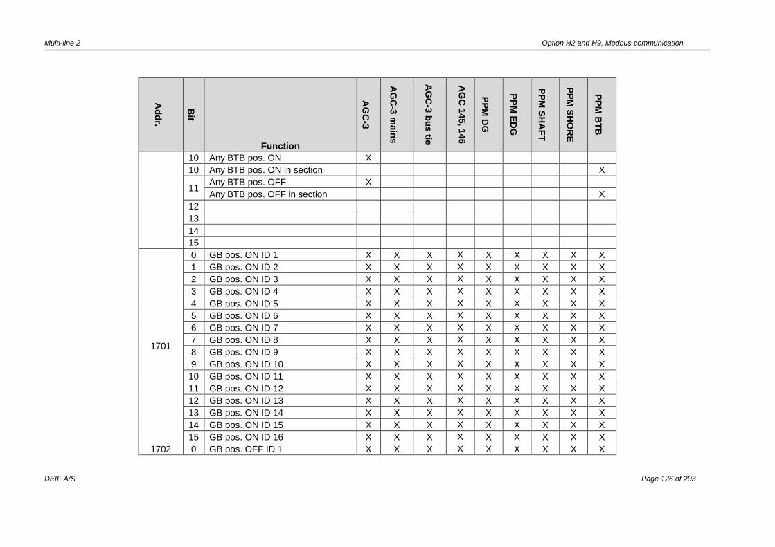
Multi-line 2 Option H2 and H9, Modbus communication
DEIF A/S Page 126 of 203
Ad
dr.
Bit
Function
AG
C-3
AG
C-3
main
s
AG
C-3
bu
s tie
AG
C 1
45, 1
46
PP
M D
G
PP
M E
DG
PP
M S
HA
FT
PP
M S
HO
RE
PP
M B
TB
10 Any BTB pos. ON X
10 Any BTB pos. ON in section X
11 Any BTB pos. OFF X
Any BTB pos. OFF in section X
12
13
14
15
1701
0 GB pos. ON ID 1 X X X X X X X X X
1 GB pos. ON ID 2 X X X X X X X X X
2 GB pos. ON ID 3 X X X X X X X X X
3 GB pos. ON ID 4 X X X X X X X X X
4 GB pos. ON ID 5 X X X X X X X X X
5 GB pos. ON ID 6 X X X X X X X X X
6 GB pos. ON ID 7 X X X X X X X X X
7 GB pos. ON ID 8 X X X X X X X X X
8 GB pos. ON ID 9 X X X X X X X X X
9 GB pos. ON ID 10 X X X X X X X X X
10 GB pos. ON ID 11 X X X X X X X X X
11 GB pos. ON ID 12 X X X X X X X X X
12 GB pos. ON ID 13 X X X X X X X X X
13 GB pos. ON ID 14 X X X X X X X X X
14 GB pos. ON ID 15 X X X X X X X X X
15 GB pos. ON ID 16 X X X X X X X X X
1702 0 GB pos. OFF ID 1 X X X X X X X X X

Multi-line 2 Option H2 and H9, Modbus communication
DEIF A/S Page 127 of 203
Ad
dr.
Bit
Function
AG
C-3
AG
C-3
main
s
AG
C-3
bu
s tie
AG
C 1
45, 1
46
PP
M D
G
PP
M E
DG
PP
M S
HA
FT
PP
M S
HO
RE
PP
M B
TB
1 GB pos. OFF ID 2 X X X X X X X X X
2 GB pos. OFF ID 3 X X X X X X X X X
3 GB pos. OFF ID 4 X X X X X X X X X
4 GB pos. OFF ID 5 X X X X X X X X X
5 GB pos. OFF ID 6 X X X X X X X X X
6 GB pos. OFF ID 7 X X X X X X X X X
7 GB pos. OFF ID 8 X X X X X X X X X
8 GB pos. OFF ID 9 X X X X X X X X X
9 GB pos. OFF ID 10 X X X X X X X X X
10 GB pos. OFF ID 11 X X X X X X X X X
11 GB pos. OFF ID 12 X X X X X X X X X
12 GB pos. OFF ID 13 X X X X X X X X X
13 GB pos. OFF ID 14 X X X X X X X X X
14 GB pos. OFF ID 15 X X X X X X X X X
15 GB pos. OFF ID 16 X X X X X X X X X
1703
0 DG Hz/V OK, ID 1 X X X X X X X X X
1 DG Hz/V OK, ID 2 X X X X X X X X X
2 DG Hz/V OK, ID 3 X X X X X X X X X
3 DG Hz/V OK, ID 4 X X X X X X X X X
4 DG Hz/V OK, ID 5 X X X X X X X X X
5 DG Hz/V OK, ID 6 X X X X X X X X X
6 DG Hz/V OK, ID 7 X X X X X X X X X
7 DG Hz/V OK, ID 8 X X X X X X X X X
8 DG Hz/V OK, ID 9 X X X X X X X X X
9 DG Hz/V OK, ID10 X X X X X X X X X
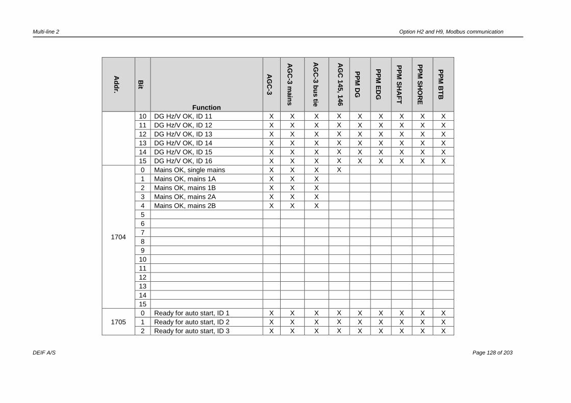
Multi-line 2 Option H2 and H9, Modbus communication
DEIF A/S Page 128 of 203
Ad
dr.
Bit
Function
AG
C-3
AG
C-3
main
s
AG
C-3
bu
s tie
AG
C 1
45, 1
46
PP
M D
G
PP
M E
DG
PP
M S
HA
FT
PP
M S
HO
RE
PP
M B
TB
10 DG Hz/V OK, ID 11 X X X X X X X X X
11 DG Hz/V OK, ID 12 X X X X X X X X X
12 DG Hz/V OK, ID 13 X X X X X X X X X
13 DG Hz/V OK, ID 14 X X X X X X X X X
14 DG Hz/V OK, ID 15 X X X X X X X X X
15 DG Hz/V OK, ID 16 X X X X X X X X X
1704
0 Mains OK, single mains X X X X
1 Mains OK, mains 1A X X X
2 Mains OK, mains 1B X X X
3 Mains OK, mains 2A X X X
4 Mains OK, mains 2B X X X
5
6
7
8
9
10
11
12
13
14
15
1705
0 Ready for auto start, ID 1 X X X X X X X X X
1 Ready for auto start, ID 2 X X X X X X X X X
2 Ready for auto start, ID 3 X X X X X X X X X

Multi-line 2 Option H2 and H9, Modbus communication
DEIF A/S Page 129 of 203
Ad
dr.
Bit
Function
AG
C-3
AG
C-3
main
s
AG
C-3
bu
s tie
AG
C 1
45, 1
46
PP
M D
G
PP
M E
DG
PP
M S
HA
FT
PP
M S
HO
RE
PP
M B
TB
3 Ready for auto start, ID 4 X X X X X X X X X
4 Ready for auto start, ID 5 X X X X X X X X X
5 Ready for auto start, ID 6 X X X X X X X X X
6 Ready for auto start, ID 7 X X X X X X X X X
7 Ready for auto start, ID 8 X X X X X X X X X
8 Ready for auto start, ID 9 X X X X X X X X X
9 Ready for auto start, ID 10 X X X X X X X X X
10 Ready for auto start, ID 11 X X X X X X X X X
11 Ready for auto start, ID 12 X X X X X X X X X
12 Ready for auto start, ID 13 X X X X X X X X X
13 Ready for auto start, ID 14 X X X X X X X X X
14 Ready for auto start, ID 15 X X X X X X X X X
15 Ready for auto start, ID 16 X X X X X X X X X
1706
0 Mains not in semi, single mains X X X X
1 Mains not in semi, mains 1A X X X
2 Mains not in semi, mains 1B X X X
3 Mains not in semi, mains 2A X X X
4 Mains not in semi, mains 2B X X X
5
6
7
8
9
10
11
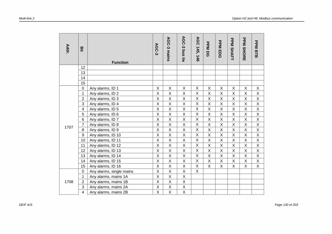
Multi-line 2 Option H2 and H9, Modbus communication
DEIF A/S Page 130 of 203
Ad
dr.
Bit
Function
AG
C-3
AG
C-3
main
s
AG
C-3
bu
s tie
AG
C 1
45, 1
46
PP
M D
G
PP
M E
DG
PP
M S
HA
FT
PP
M S
HO
RE
PP
M B
TB
12
13
14
15
1707
0 Any alarms, ID 1 X X X X X X X X X
1 Any alarms, ID 2 X X X X X X X X X
2 Any alarms, ID 3 X X X X X X X X X
3 Any alarms, ID 4 X X X X X X X X X
4 Any alarms, ID 5 X X X X X X X X X
5 Any alarms, ID 6 X X X X X X X X X
6 Any alarms, ID 7 X X X X X X X X X
7 Any alarms, ID 8 X X X X X X X X X
8 Any alarms, ID 9 X X X X X X X X X
9 Any alarms, ID 10 X X X X X X X X X
10 Any alarms, ID 11 X X X X X X X X X
11 Any alarms, ID 12 X X X X X X X X X
12 Any alarms, ID 13 X X X X X X X X X
13 Any alarms, ID 14 X X X X X X X X X
14 Any alarms, ID 15 X X X X X X X X X
15 Any alarms, ID 16 X X X X X X X X X
1708
0 Any alarms, single mains X X X X
1 Any alarms, mains 1A X X X
2 Any alarms, mains 1B X X X
3 Any alarms, mains 2A X X X
4 Any alarms, mains 2B X X X

Multi-line 2 Option H2 and H9, Modbus communication
DEIF A/S Page 131 of 203
Ad
dr.
Bit
Function
AG
C-3
AG
C-3
main
s
AG
C-3
bu
s tie
AG
C 1
45, 1
46
PP
M D
G
PP
M E
DG
PP
M S
HA
FT
PP
M S
HO
RE
PP
M B
TB
5
6
7
8
9
10
11
12
13
14
15
1709
0 Engine running, ID 1 X X X X X X X X X
1 Engine running, ID 2 X X X X X X X X X
2 Engine running, ID 3 X X X X X X X X X
3 Engine running, ID 4 X X X X X X X X X
4 Engine running, ID 5 X X X X X X X X X
5 Engine running, ID 6 X X X X X X X X X
6 Engine running, ID 7 X X X X X X X X X
7 Engine running, ID 8 X X X X X X X X X
8 Engine running, ID 9 X X X X X X X X X
9 Engine running, ID 10 X X X X X X X X X
10 Engine running, ID 11 X X X X X X X X X
11 Engine running, ID 12 X X X X X X X X X
12 Engine running, ID 13 X X X X X X X X X
13 Engine running, ID 14 X X X X X X X X X
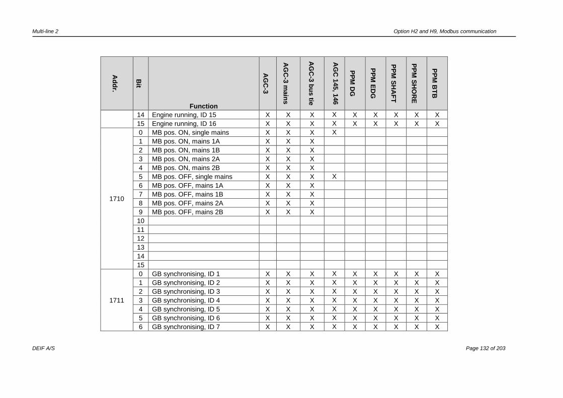
Multi-line 2 Option H2 and H9, Modbus communication
DEIF A/S Page 132 of 203
Ad
dr.
Bit
Function
AG
C-3
AG
C-3
main
s
AG
C-3
bu
s tie
AG
C 1
45, 1
46
PP
M D
G
PP
M E
DG
PP
M S
HA
FT
PP
M S
HO
RE
PP
M B
TB
14 Engine running, ID 15 X X X X X X X X X
15 Engine running, ID 16 X X X X X X X X X
1710
0 MB pos. ON, single mains X X X X
1 MB pos. ON, mains 1A X X X
2 MB pos. ON, mains 1B X X X
3 MB pos. ON, mains 2A X X X
4 MB pos. ON, mains 2B X X X
5 MB pos. OFF, single mains X X X X
6 MB pos. OFF, mains 1A X X X
7 MB pos. OFF, mains 1B X X X
8 MB pos. OFF, mains 2A X X X
9 MB pos. OFF, mains 2B X X X
10
11
12
13
14
15
1711
0 GB synchronising, ID 1 X X X X X X X X X
1 GB synchronising, ID 2 X X X X X X X X X
2 GB synchronising, ID 3 X X X X X X X X X
3 GB synchronising, ID 4 X X X X X X X X X
4 GB synchronising, ID 5 X X X X X X X X X
5 GB synchronising, ID 6 X X X X X X X X X
6 GB synchronising, ID 7 X X X X X X X X X

Multi-line 2 Option H2 and H9, Modbus communication
DEIF A/S Page 133 of 203
Ad
dr.
Bit
Function
AG
C-3
AG
C-3
main
s
AG
C-3
bu
s tie
AG
C 1
45, 1
46
PP
M D
G
PP
M E
DG
PP
M S
HA
FT
PP
M S
HO
RE
PP
M B
TB
7 GB synchronising, ID 8 X X X X X X X X X
8 GB synchronising, ID 9 X X X X X X X X X
9 GB synchronising, ID 10 X X X X X X X X X
10 GB synchronising, ID 11 X X X X X X X X X
11 GB synchronising, ID 12 X X X X X X X X X
12 GB synchronising, ID 13 X X X X X X X X X
13 GB synchronising, ID 14 X X X X X X X X X
14 GB synchronising, ID 15 X X X X X X X X X
15 GB synchronising, ID 16 X X X X X X X X X
1712
0
Mains OK, ID 17 X X X X
Shaft OK, ID 17 X X X X X
Shore OK, ID 17 X X X X X
1
Mains OK, ID 18 X X X X
Shaft OK, ID 18 X X X X X
Shore OK, ID 18 X X X X X
2
Mains OK, ID 19 X X X X
Shaft OK, ID 19 X X X X X
Shore OK, ID 19 X X X X X
3
Mains OK, ID 20 X X X X
Shaft OK, ID 20 X X X X X
Shore OK, ID 20 X X X X X
4 Mains OK, ID 21 X X X X
5 Mains OK, ID 22 X X X X
6 Mains OK, ID 23 X X X X
7 Mains OK, ID 24 X X X X

Multi-line 2 Option H2 and H9, Modbus communication
DEIF A/S Page 134 of 203
Ad
dr.
Bit
Function
AG
C-3
AG
C-3
main
s
AG
C-3
bu
s tie
AG
C 1
45, 1
46
PP
M D
G
PP
M E
DG
PP
M S
HA
FT
PP
M S
HO
RE
PP
M B
TB
8 Mains OK, ID 25 X X X X
9 Mains OK, ID 26 X X X X
10 Mains OK, ID 27 X X X X
11 Mains OK, ID 28 X X X X
12 Mains OK, ID 29 X X X X
13 Mains OK, ID 30 X X X X
14 Mains OK, ID 31 X X X X
15 Mains OK, ID 32 X X X X
1713
0 Mains not in semi 17 X X X X
1 Mains not in semi 18 X X X X
2 Mains not in semi 19 X X X X
3 Mains not in semi 20 X X X X
4 Mains not in semi 21 X X X X
5 Mains not in semi 22 X X X X
6 Mains not in semi 23 X X X X
7 Mains not in semi 24 X X X X
8 Mains not in semi 25 X X X X
9 Mains not in semi 26 X X X X
10 Mains not in semi 27 X X X X
11 Mains not in semi 28 X X X X
12 Mains not in semi 29 X X X X
13 Mains not in semi 30 X X X X
14 Mains not in semi 31 X X X X
15 Mains not in semi 32 X X X X
1714 0 Any alarms, mains ID 17 X X X X

Multi-line 2 Option H2 and H9, Modbus communication
DEIF A/S Page 135 of 203
Ad
dr.
Bit
Function
AG
C-3
AG
C-3
main
s
AG
C-3
bu
s tie
AG
C 1
45, 1
46
PP
M D
G
PP
M E
DG
PP
M S
HA
FT
PP
M S
HO
RE
PP
M B
TB
Any alarms, Shaft ID 17 X X X X X
Any alarms, Shore ID 17 X X X X X
1
Any alarms, mains ID 18 X X X X
Any alarms, Shaft ID 18 X X X X X
Any alarms, Shore ID 18 X X X X X
2
Any alarms, mains ID 19 X X X X
Any alarms, Shaft ID 19 X X X X X
Any alarms, Shore ID 19 X X X X X
3
Any alarms, mains ID 20 X X X X
Any alarms, Shaft ID 20 X X X X X
Any alarms, Shore ID 20 X X X X X
4 Any alarms, mains ID 21 X X X X
5 Any alarms, mains ID 22 X X X X
6 Any alarms, mains ID 23 X X X X
7 Any alarms, mains ID 24 X X X X
8 Any alarms, mains ID 25 X X X X
9 Any alarms, mains ID 26 X X X X
10 Any alarms, mains ID 27 X X X X
11 Any alarms, mains ID 28 X X X X
12 Any alarms, mains ID 29 X X X X
13 Any alarms, mains ID 30 X X X X
14 Any alarms, mains ID 31 X X X X
15 Any alarms, mains ID 32 X X X X
1715 0 MB pos. ON, ID 17 X X X X
SGB/SCB ON, ID 17 X X X X X

Multi-line 2 Option H2 and H9, Modbus communication
DEIF A/S Page 136 of 203
Ad
dr.
Bit
Function
AG
C-3
AG
C-3
main
s
AG
C-3
bu
s tie
AG
C 1
45, 1
46
PP
M D
G
PP
M E
DG
PP
M S
HA
FT
PP
M S
HO
RE
PP
M B
TB
1 MB pos. ON, ID 18 X X X X
SGB ON, ID 18 X X X X X X X X
2 MB pos. ON, ID 19 X X X X
SGB/SCB ON, ID 19 X X X X X X X X
3 MB pos. ON, ID 20 X X X X
SGB/SCB ON, ID 20 X X X X X X X X
4 MB pos. ON, ID 21 X X X X
5 MB pos. ON, ID 22 X X X X
6 MB pos. ON, ID 23 X X X X
7 MB pos. ON, ID 24 X X X X
8 MB pos. ON, ID 25 X X X X
9 MB pos. ON, ID 26 X X X X
10 MB pos. ON, ID 27 X X X X
11 MB pos. ON, ID 28 X X X X
12 MB pos. ON, ID 29 X X X X
13 MB pos. ON, ID 30 X X X X
14 MB pos. ON, ID 31 X X X X
15 MB pos. ON, ID 32 X X X X
1716
0 MB pos. OFF, ID 17 X X X X
SGB/SCB pos OFF, ID 17 X X X X X
1 MB pos. OFF, ID 18 X X X X
SGB/SCB pos OFF, ID 18 X X X X X
2 MB pos. OFF, ID 19 X X X X
SGB/SCB pos OFF, ID 19 X X X X X
3 MB pos. OFF, ID 20 X X X X

Multi-line 2 Option H2 and H9, Modbus communication
DEIF A/S Page 137 of 203
Ad
dr.
Bit
Function
AG
C-3
AG
C-3
main
s
AG
C-3
bu
s tie
AG
C 1
45, 1
46
PP
M D
G
PP
M E
DG
PP
M S
HA
FT
PP
M S
HO
RE
PP
M B
TB
4 MB pos. OFF, ID 21 X X X X
5 MB pos. OFF, ID 22 X X X X
6 MB pos. OFF, ID 23 X X X X
7 MB pos. OFF, ID 24 X X X X
8 MB pos. OFF, ID 25 X X X X
9 MB pos. OFF, ID 26 X X X X
10 MB pos. OFF, ID 27 X X X X
11 MB pos. OFF, ID 28 X X X X
12 MB pos. OFF, ID 29 X X X X
13 MB pos. OFF, ID 30 X X X X
14 MB pos. OFF, ID 31 X X X X
15 MB pos. OFF, ID 32 X X X X
1717
0 Mains failure, ID 17 X X X X
1 Mains failure, ID 18 X X X X
2 Mains failure, ID 19 X X X X
3 Mains failure, ID 20 X X X X
4 Mains failure, ID 21 X X X X
5 Mains failure, ID 22 X X X X
6 Mains failure, ID 23 X X X X
7 Mains failure, ID 24 X X X X
8 Mains failure, ID 25 X X X X
9 Mains failure, ID 26 X X X X
10 Mains failure, ID 27 X X X X
11 Mains failure, ID 28 X X X X
12 Mains failure, ID 29 X X X X

Multi-line 2 Option H2 and H9, Modbus communication
DEIF A/S Page 138 of 203
Ad
dr.
Bit
Function
AG
C-3
AG
C-3
main
s
AG
C-3
bu
s tie
AG
C 1
45, 1
46
PP
M D
G
PP
M E
DG
PP
M S
HA
FT
PP
M S
HO
RE
PP
M B
TB
13 Mains failure, ID 30 X X X X
14 Mains failure, ID 31 X X X X
15 Mains failure, ID 32 X X X X
1718
0 MB synchronising, ID 17 X X X X
SGB/SCB synchronising, ID 17 X X X X X
1 MB synchronising, ID 18 X X X X
SGB/SCB synchronising, ID 18 X X X X X
2 MB synchronising, ID 19 X X X X
SGB/SCB synchronising, ID 19 X X X X X
3 MB synchronising, ID 20 X X X X
SGB/SCB synchronising, ID 20 X X X X X
4 MB synchronising, ID 21 X X X X
5 MB synchronising, ID 22 X X X X
6 MB synchronising, ID 23 X X X X
7 MB synchronising, ID 24 X X X X
8 MB synchronising, ID 25 X X X X
9 MB synchronising, ID 26 X X X X
10 MB synchronising, ID 27 X X X X
11 MB synchronising, ID 28 X X X X
12 MB synchronising, ID 29 X X X X
13 MB synchronising, ID 30 X X X X
14 MB synchronising, ID 31 X X X X
15 MB synchronising, ID 32 X X X X
1719 0 TB pos. ON, ID 17 X X X X
1 TB pos. ON, ID 18 X X X X
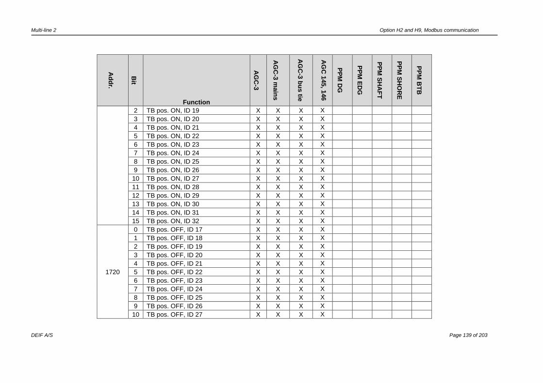
Multi-line 2 Option H2 and H9, Modbus communication
DEIF A/S Page 139 of 203
Ad
dr.
Bit
Function
AG
C-3
AG
C-3
main
s
AG
C-3
bu
s tie
AG
C 1
45, 1
46
PP
M D
G
PP
M E
DG
PP
M S
HA
FT
PP
M S
HO
RE
PP
M B
TB
2 TB pos. ON, ID 19 X X X X
3 TB pos. ON, ID 20 X X X X
4 TB pos. ON, ID 21 X X X X
5 TB pos. ON, ID 22 X X X X
6 TB pos. ON, ID 23 X X X X
7 TB pos. ON, ID 24 X X X X
8 TB pos. ON, ID 25 X X X X
9 TB pos. ON, ID 26 X X X X
10 TB pos. ON, ID 27 X X X X
11 TB pos. ON, ID 28 X X X X
12 TB pos. ON, ID 29 X X X X
13 TB pos. ON, ID 30 X X X X
14 TB pos. ON, ID 31 X X X X
15 TB pos. ON, ID 32 X X X X
1720
0 TB pos. OFF, ID 17 X X X X
1 TB pos. OFF, ID 18 X X X X
2 TB pos. OFF, ID 19 X X X X
3 TB pos. OFF, ID 20 X X X X
4 TB pos. OFF, ID 21 X X X X
5 TB pos. OFF, ID 22 X X X X
6 TB pos. OFF, ID 23 X X X X
7 TB pos. OFF, ID 24 X X X X
8 TB pos. OFF, ID 25 X X X X
9 TB pos. OFF, ID 26 X X X X
10 TB pos. OFF, ID 27 X X X X

Multi-line 2 Option H2 and H9, Modbus communication
DEIF A/S Page 140 of 203
Ad
dr.
Bit
Function
AG
C-3
AG
C-3
main
s
AG
C-3
bu
s tie
AG
C 1
45, 1
46
PP
M D
G
PP
M E
DG
PP
M S
HA
FT
PP
M S
HO
RE
PP
M B
TB
11 TB pos. OFF, ID 28 X X X X
12 TB pos. OFF, ID 29 X X X X
13 TB pos. OFF, ID 30 X X X X
14 TB pos. OFF, ID 31 X X X X
15 TB pos. OFF, ID 32 X X X X
1721
0 TB synchronising, ID 17 X X X X
1 TB synchronising, ID 18 X X X X
2 TB synchronising, ID 19 X X X X
3 TB synchronising, ID 20 X X X X
4 TB synchronising, ID 21 X X X X
5 TB synchronising, ID 22 X X X X
6 TB synchronising, ID 23 X X X X
7 TB synchronising, ID 24 X X X X
8 TB synchronising, ID 25 X X X X
9 TB synchronising, ID 26 X X X X
10 TB synchronising, ID 27 X X X X
11 TB synchronising, ID 28 X X X X
12 TB synchronising, ID 29 X X X X
13 TB synchronising, ID 30 X X X X
14 TB synchronising, ID 31 X X X X
15 TB synchronising, ID 32 X X X X
1722
0 Any alarms, BTB ID 33 X X X X X X X X X
1 Any alarms, BTB ID 34 X X X X X X X X X
2 Any alarms, BTB ID 35 X X X X X X X X X
3 Any alarms, BTB ID 36 X X X X X X X X X

Multi-line 2 Option H2 and H9, Modbus communication
DEIF A/S Page 141 of 203
Ad
dr.
Bit
Function
AG
C-3
AG
C-3
main
s
AG
C-3
bu
s tie
AG
C 1
45, 1
46
PP
M D
G
PP
M E
DG
PP
M S
HA
FT
PP
M S
HO
RE
PP
M B
TB
4 Any alarms, BTB ID 37 X X X X X X X X X
5 Any alarms, BTB ID 38 X X X X X X X X X
6 Any alarms, BTB ID 39 X X X X X X X X X
7 Any alarms, BTB ID 40 X X X X X X X X X
8
9
10
11
12
13
14
15
1723
0 BTB pos. ON, ID 33 X X X X X X X X X
1 BTB pos. ON, ID 34 X X X X X X X X X
2 BTB pos. ON, ID 35 X X X X X X X X X
3 BTB pos. ON, ID 36 X X X X X X X X X
4 BTB pos. ON, ID 37 X X X X X X X X X
5 BTB pos. ON, ID 38 X X X X X X X X X
6 BTB pos. ON, ID 39 X X X X X X X X X
7 BTB pos. ON, ID 40 X X X X X X X X X
8
9
10
11
12

Multi-line 2 Option H2 and H9, Modbus communication
DEIF A/S Page 142 of 203
Ad
dr.
Bit
Function
AG
C-3
AG
C-3
main
s
AG
C-3
bu
s tie
AG
C 1
45, 1
46
PP
M D
G
PP
M E
DG
PP
M S
HA
FT
PP
M S
HO
RE
PP
M B
TB
13
14
15
1724
0 BTB pos. OFF, ID 33 X X X X X X X X X
1 BTB pos. OFF, ID 34 X X X X X X X X X
2 BTB pos. OFF, ID 35 X X X X X X X X X
3 BTB pos. OFF, ID 36 X X X X X X X X X
4 BTB pos. OFF, ID 37 X X X X X X X X X
5 BTB pos. OFF, ID 38 X X X X X X X X X
6 BTB pos. OFF, ID 39 X X X X X X X X X
7 BTB pos. OFF, ID 40 X X X X X X X X X
8
9
10
11
12
13
14
15
1725
0 BTB synchronising, ID 33 X X X X X X X X X
1 BTB synchronising, ID 34 X X X X X X X X X
2 BTB synchronising, ID 35 X X X X X X X X X
3 BTB synchronising, ID 36 X X X X X X X X X
4 BTB synchronising, ID 37 X X X X X X X X X
5 BTB synchronising, ID 38 X X X X X X X X X
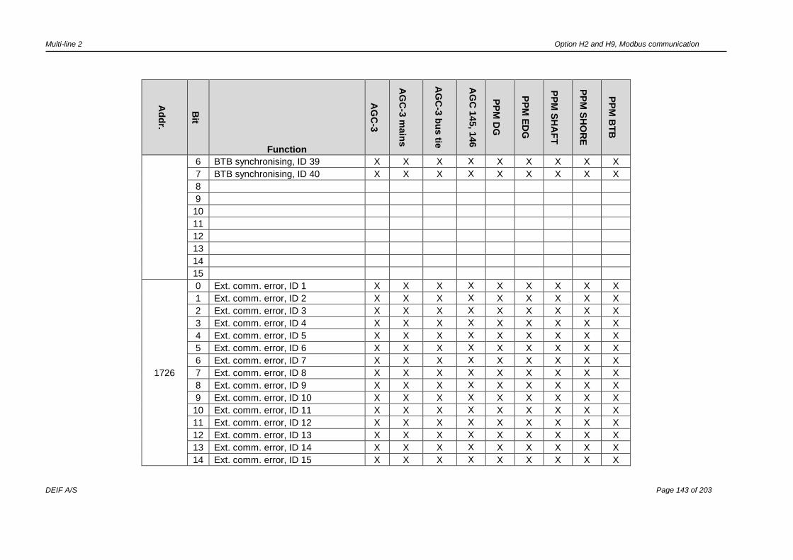
Multi-line 2 Option H2 and H9, Modbus communication
DEIF A/S Page 143 of 203
Ad
dr.
Bit
Function
AG
C-3
AG
C-3
main
s
AG
C-3
bu
s tie
AG
C 1
45, 1
46
PP
M D
G
PP
M E
DG
PP
M S
HA
FT
PP
M S
HO
RE
PP
M B
TB
6 BTB synchronising, ID 39 X X X X X X X X X
7 BTB synchronising, ID 40 X X X X X X X X X
8
9
10
11
12
13
14
15
1726
0 Ext. comm. error, ID 1 X X X X X X X X X
1 Ext. comm. error, ID 2 X X X X X X X X X
2 Ext. comm. error, ID 3 X X X X X X X X X
3 Ext. comm. error, ID 4 X X X X X X X X X
4 Ext. comm. error, ID 5 X X X X X X X X X
5 Ext. comm. error, ID 6 X X X X X X X X X
6 Ext. comm. error, ID 7 X X X X X X X X X
7 Ext. comm. error, ID 8 X X X X X X X X X
8 Ext. comm. error, ID 9 X X X X X X X X X
9 Ext. comm. error, ID 10 X X X X X X X X X
10 Ext. comm. error, ID 11 X X X X X X X X X
11 Ext. comm. error, ID 12 X X X X X X X X X
12 Ext. comm. error, ID 13 X X X X X X X X X
13 Ext. comm. error, ID 14 X X X X X X X X X
14 Ext. comm. error, ID 15 X X X X X X X X X

Multi-line 2 Option H2 and H9, Modbus communication
DEIF A/S Page 144 of 203
Ad
dr.
Bit
Function
AG
C-3
AG
C-3
main
s
AG
C-3
bu
s tie
AG
C 1
45, 1
46
PP
M D
G
PP
M E
DG
PP
M S
HA
FT
PP
M S
HO
RE
PP
M B
TB
15 Ext. comm. error, ID 16 X X X X X X X X X
1727
0 Ext. comm. error, ID 17 X X X X X X X X X
1 Ext. comm. error, ID 18 X X X X X X X X X
2 Ext. comm. error, ID 19 X X X X X X X X X
3 Ext. comm. error, ID 20 X X X X X X X X X
4 Ext. comm. error, ID 21 X X X X X X X X X
5 Ext. comm. error, ID 22 X X X X X X X X X
6 Ext. comm. error, ID 23 X X X X X X X X X
7 Ext. comm. error, ID 24 X X X X X X X X X
8 Ext. comm. error, ID 25 X X X X X X X X X
9 Ext. comm. error, ID 26 X X X X X X X X X
10 Ext. comm. error, ID 27 X X X X X X X X X
11 Ext. comm. error, ID 28 X X X X X X X X X
12 Ext. comm. error, ID 29 X X X X X X X X X
13 Ext. comm. error, ID 30 X X X X X X X X X
14 Ext. comm. error, ID 31 X X X X X X X X X
15 Ext. comm. error, ID 32 X X X X X X X X X
1728
0 Ext. comm. error, ID 33 X X X X X X X X X
1 Ext. comm. error, ID 34 X X X X X X X X X
2 Ext. comm. error, ID 35 X X X X X X X X X
3 Ext. comm. error, ID 36 X X X X X X X X X
4 Ext. comm. error, ID 37 X X X X X X X X X
5 Ext. comm. error, ID 38 X X X X X X X X X
6 Ext. comm. error, ID 39 X X X X X X X X X
7 Ext. comm. error, ID 40 X X X X X X X X X

Multi-line 2 Option H2 and H9, Modbus communication
DEIF A/S Page 145 of 203
Ad
dr.
Bit
Function
AG
C-3
AG
C-3
main
s
AG
C-3
bu
s tie
AG
C 1
45, 1
46
PP
M D
G
PP
M E
DG
PP
M S
HA
FT
PP
M S
HO
RE
PP
M B
TB
8
9
10
11
12
13
14
15
1729
0 EDG TB pos. ON, ID 1 X X X X X
1 EDG TB pos. ON, ID 2 X X X X X
2 EDG TB pos. ON, ID 3 X X X X X
3 EDG TB pos. ON, ID 4 X X X X X
4 EDG TB pos. ON, ID 5 X X X X X
5 EDG TB pos. ON, ID 6 X X X X X
6 EDG TB pos. ON, ID 7 X X X X X
7 EDG TB pos. ON, ID 8 X X X X X
8 EDG TB pos. ON, ID 9 X X X X X
9 EDG TB pos. ON, ID 10 X X X X X
10 EDG TB pos. ON, ID 11 X X X X X
11 EDG TB pos. ON, ID 12 X X X X X
12 EDG TB pos. ON, ID 13 X X X X X
13 EDG TB pos. ON, ID 14 X X X X X
14 EDG TB pos. ON, ID 15 X X X X X
15 EDG TB pos. ON, ID 16 X X X X X
1730 0 EDG TB pos. OFF, ID 1 X X X X X

Multi-line 2 Option H2 and H9, Modbus communication
DEIF A/S Page 146 of 203
Ad
dr.
Bit
Function
AG
C-3
AG
C-3
main
s
AG
C-3
bu
s tie
AG
C 1
45, 1
46
PP
M D
G
PP
M E
DG
PP
M S
HA
FT
PP
M S
HO
RE
PP
M B
TB
1 EDG TB pos. OFF, ID 2 X X X X X
2 EDG TB pos. OFF, ID 3 X X X X X
3 EDG TB pos. OFF, ID 4 X X X X X
4 EDG TB pos. OFF, ID 5 X X X X X
5 EDG TB pos. OFF, ID 6 X X X X X
6 EDG TB pos. OFF, ID 7 X X X X X
7 EDG TB pos. OFF, ID 8 X X X X X
8 EDG TB pos. OFF, ID 9 X X X X X
9 EDG TB pos. OFF, ID 10 X X X X X
10 EDG TB pos. OFF, ID 11 X X X X X
11 EDG TB pos. OFF, ID 12 X X X X X
12 EDG TB pos. OFF, ID 13 X X X X X
13 EDG TB pos. OFF, ID 14 X X X X X
14 EDG TB pos. OFF, ID 15 X X X X X
15 EDG TB pos. OFF, ID 16 X X X X X
1731
0 Shaft/shore running ID 17 X X X X X
1 Shaft/shore running ID 18 X X X X X
2 Shaft/shore running ID 19 X X X X X
3 Shaft/shore running ID 20 X X X X
4
5
6
7
8
9
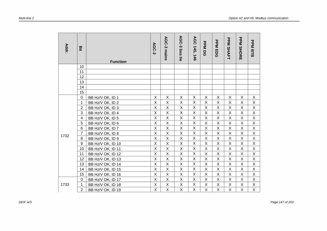
Multi-line 2 Option H2 and H9, Modbus communication
DEIF A/S Page 147 of 203
Ad
dr.
Bit
Function
AG
C-3
AG
C-3
main
s
AG
C-3
bu
s tie
AG
C 1
45, 1
46
PP
M D
G
PP
M E
DG
PP
M S
HA
FT
PP
M S
HO
RE
PP
M B
TB
10
11
12
13
14
15
1732
0 BB Hz/V OK, ID 1 X X X X X X X X X
1 BB Hz/V OK, ID 2 X X X X X X X X X
2 BB Hz/V OK, ID 3 X X X X X X X X X
3 BB Hz/V OK, ID 4 X X X X X X X X X
4 BB Hz/V OK, ID 5 X X X X X X X X X
5 BB Hz/V OK, ID 6 X X X X X X X X X
6 BB Hz/V OK, ID 7 X X X X X X X X X
7 BB Hz/V OK, ID 8 X X X X X X X X X
8 BB Hz/V OK, ID 9 X X X X X X X X X
9 BB Hz/V OK, ID 10 X X X X X X X X X
10 BB Hz/V OK, ID 11 X X X X X X X X X
11 BB Hz/V OK, ID 12 X X X X X X X X X
12 BB Hz/V OK, ID 13 X X X X X X X X X
13 BB Hz/V OK, ID 14 X X X X X X X X X
14 BB Hz/V OK, ID 15 X X X X X X X X X
15 BB Hz/V OK, ID 16 X X X X X X X X X
1733
0 BB Hz/V OK, ID 17 X X X X X X X X X
1 BB Hz/V OK, ID 18 X X X X X X X X X
2 BB Hz/V OK, ID 19 X X X X X X X X X
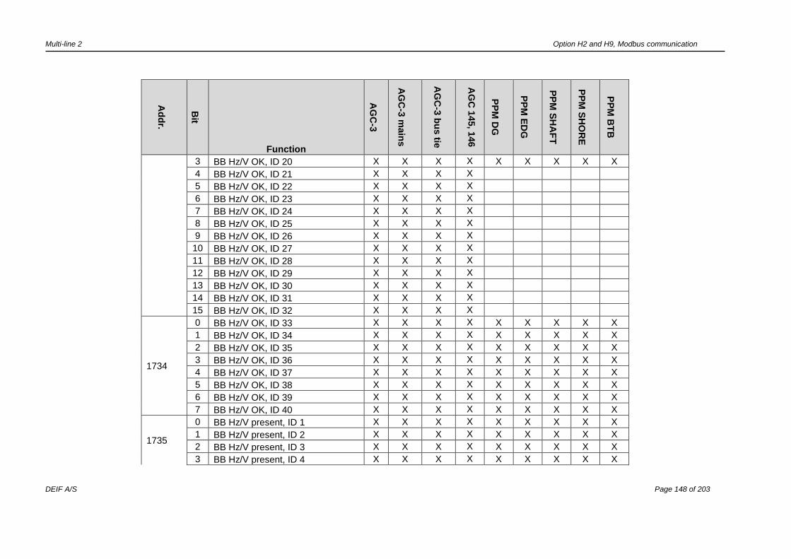
Multi-line 2 Option H2 and H9, Modbus communication
DEIF A/S Page 148 of 203
Ad
dr.
Bit
Function
AG
C-3
AG
C-3
main
s
AG
C-3
bu
s tie
AG
C 1
45, 1
46
PP
M D
G
PP
M E
DG
PP
M S
HA
FT
PP
M S
HO
RE
PP
M B
TB
3 BB Hz/V OK, ID 20 X X X X X X X X X
4 BB Hz/V OK, ID 21 X X X X
5 BB Hz/V OK, ID 22 X X X X
6 BB Hz/V OK, ID 23 X X X X
7 BB Hz/V OK, ID 24 X X X X
8 BB Hz/V OK, ID 25 X X X X
9 BB Hz/V OK, ID 26 X X X X
10 BB Hz/V OK, ID 27 X X X X
11 BB Hz/V OK, ID 28 X X X X
12 BB Hz/V OK, ID 29 X X X X
13 BB Hz/V OK, ID 30 X X X X
14 BB Hz/V OK, ID 31 X X X X
15 BB Hz/V OK, ID 32 X X X X
1734
0 BB Hz/V OK, ID 33 X X X X X X X X X
1 BB Hz/V OK, ID 34 X X X X X X X X X
2 BB Hz/V OK, ID 35 X X X X X X X X X
3 BB Hz/V OK, ID 36 X X X X X X X X X
4 BB Hz/V OK, ID 37 X X X X X X X X X
5 BB Hz/V OK, ID 38 X X X X X X X X X
6 BB Hz/V OK, ID 39 X X X X X X X X X
7 BB Hz/V OK, ID 40 X X X X X X X X X
1735
0 BB Hz/V present, ID 1 X X X X X X X X X
1 BB Hz/V present, ID 2 X X X X X X X X X
2 BB Hz/V present, ID 3 X X X X X X X X X
3 BB Hz/V present, ID 4 X X X X X X X X X

Multi-line 2 Option H2 and H9, Modbus communication
DEIF A/S Page 149 of 203
Ad
dr.
Bit
Function
AG
C-3
AG
C-3
main
s
AG
C-3
bu
s tie
AG
C 1
45, 1
46
PP
M D
G
PP
M E
DG
PP
M S
HA
FT
PP
M S
HO
RE
PP
M B
TB
4 BB Hz/V present, ID 5 X X X X X X X X X
5 BB Hz/V present, ID 6 X X X X X X X X X
6 BB Hz/V present, ID 7 X X X X X X X X X
7 BB Hz/V present, ID 8 X X X X X X X X X
8 BB Hz/V present, ID 9 X X X X X X X X X
9 BB Hz/V present, ID 10 X X X X X X X X X
10 BB Hz/V present, ID 11 X X X X X X X X X
11 BB Hz/V present, ID 12 X X X X X X X X X
12 BB Hz/V present, ID 13 X X X X X X X X X
13 BB Hz/V present, ID 14 X X X X X X X X X
14 BB Hz/V present, ID 15 X X X X X X X X X
15 BB Hz/V present, ID 16 X X X X X X X X X
1736
0 BB Hz/V present, ID 17 X X X X X X X X X
1 BB Hz/V present, ID 18 X X X X X X X X X
2 BB Hz/V present, ID 19 X X X X X X X X X
3 BB Hz/V present, ID 20 X X X X X X X X X
4 BB Hz/V present, ID 21 X X X X
5 BB Hz/V present, ID 22 X X X X
6 BB Hz/V present, ID 23 X X X X
7 BB Hz/V present, ID 24 X X X X
8 BB Hz/V present, ID 25 X X X X
9 BB Hz/V present, ID 26 X X X X
10 BB Hz/V present, ID 27 X X X X
11 BB Hz/V present, ID 28 X X X X
12 BB Hz/V present, ID 29 X X X X

Multi-line 2 Option H2 and H9, Modbus communication
DEIF A/S Page 150 of 203
Ad
dr.
Bit
Function
AG
C-3
AG
C-3
main
s
AG
C-3
bu
s tie
AG
C 1
45, 1
46
PP
M D
G
PP
M E
DG
PP
M S
HA
FT
PP
M S
HO
RE
PP
M B
TB
13 BB Hz/V present, ID 30 X X X X
14 BB Hz/V present, ID 31 X X X X
15 BB Hz/V present, ID 32 X X X X
1737
0 BB Hz/V present, ID 33 X X X X X X X X
1 BB Hz/V present, ID 34 X X X X X X X X
2 BB Hz/V present, ID 35 X X X X X X X X
3 BB Hz/V present, ID 36 X X X X X X X X
4 BB Hz/V present, ID 37 X X X X X X X X
5 BB Hz/V present, ID 38 X X X X X X X X
6 BB Hz/V present, ID 39 X X X X X X X X
7 BB Hz/V present, ID 40 X X X X X X X X
1738
0 BA Hz/V OK, ID 32 X X X X X X X X
1 BA Hz/V OK, ID 33 X X X X X X X X
2 BA Hz/V OK, ID 34 X X X X X X X X
3 BA Hz/V OK, ID 35 X X X X X X X X
4 BA Hz/V OK, ID 36 X X X X X X X X
5 BA Hz/V OK, ID 37 X X X X X X X X
6 BA Hz/V OK, ID 38 X X X X X X X X
7 BA Hz/V OK, ID 39 X X X X X X X X
1739
0
BA Hz/V present, ID 1 X X X X X
Mains present, ID 1 X X
DG Hz/V present, ID 1 X
1
BA Hz/V present, ID 2 X X X X X
Mains present, ID 2 X X
DG Hz/V present, ID 2 X
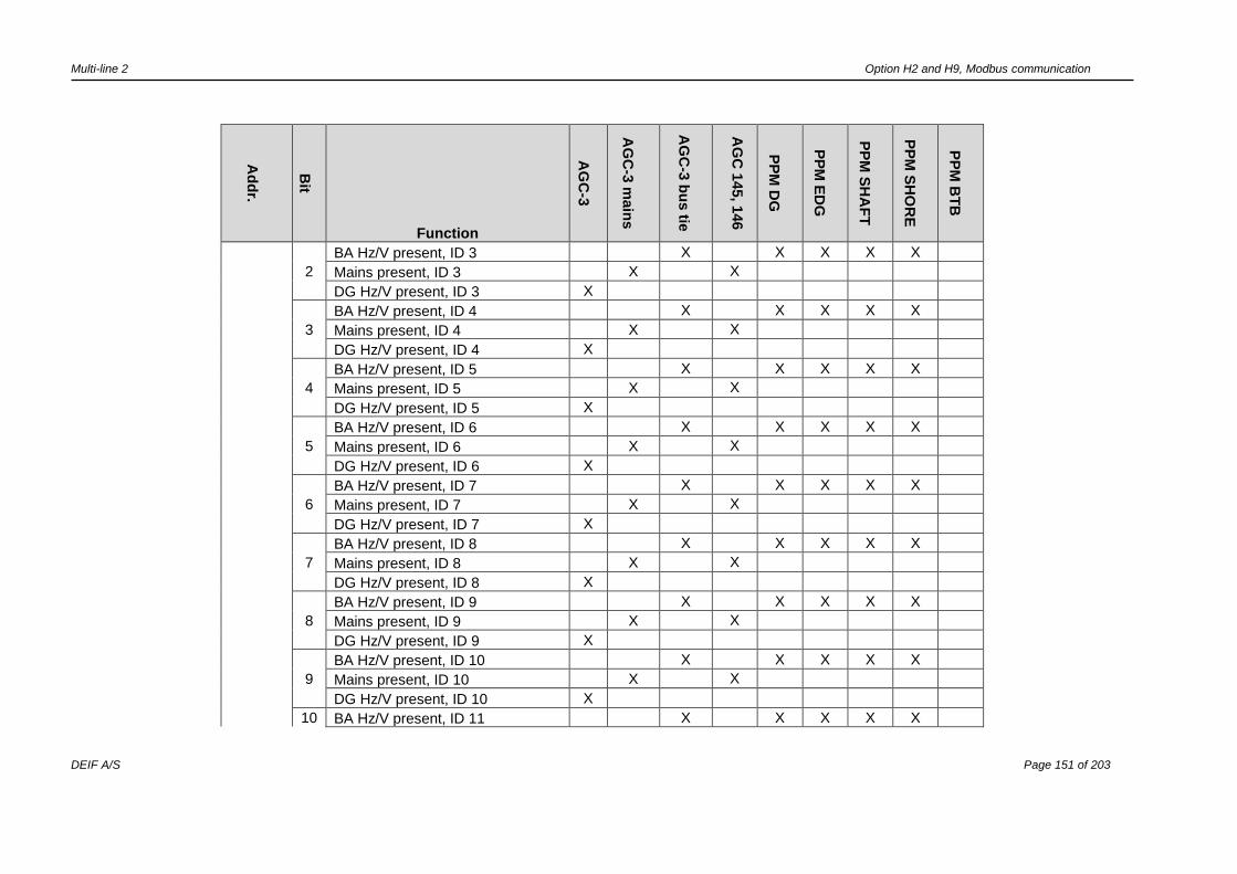
Multi-line 2 Option H2 and H9, Modbus communication
DEIF A/S Page 151 of 203
Ad
dr.
Bit
Function
AG
C-3
AG
C-3
main
s
AG
C-3
bu
s tie
AG
C 1
45, 1
46
PP
M D
G
PP
M E
DG
PP
M S
HA
FT
PP
M S
HO
RE
PP
M B
TB
2
BA Hz/V present, ID 3 X X X X X
Mains present, ID 3 X X
DG Hz/V present, ID 3 X
3
BA Hz/V present, ID 4 X X X X X
Mains present, ID 4 X X
DG Hz/V present, ID 4 X
4
BA Hz/V present, ID 5 X X X X X
Mains present, ID 5 X X
DG Hz/V present, ID 5 X
5
BA Hz/V present, ID 6 X X X X X
Mains present, ID 6 X X
DG Hz/V present, ID 6 X
6
BA Hz/V present, ID 7 X X X X X
Mains present, ID 7 X X
DG Hz/V present, ID 7 X
7
BA Hz/V present, ID 8 X X X X X
Mains present, ID 8 X X
DG Hz/V present, ID 8 X
8
BA Hz/V present, ID 9 X X X X X
Mains present, ID 9 X X
DG Hz/V present, ID 9 X
9
BA Hz/V present, ID 10 X X X X X
Mains present, ID 10 X X
DG Hz/V present, ID 10 X
10 BA Hz/V present, ID 11 X X X X X

Multi-line 2 Option H2 and H9, Modbus communication
DEIF A/S Page 152 of 203
Ad
dr.
Bit
Function
AG
C-3
AG
C-3
main
s
AG
C-3
bu
s tie
AG
C 1
45, 1
46
PP
M D
G
PP
M E
DG
PP
M S
HA
FT
PP
M S
HO
RE
PP
M B
TB
Mains present, ID 11 X X
DG Hz/V present, ID 11 X
11
BA Hz/V present, ID 12 X X X X X
Mains present, ID 12 X X
DG Hz/V present, ID 12 X
12
BA Hz/V present, ID 13 X X X X X
Mains present, ID 13 X X
DG Hz/V present, ID 13 X
13
BA Hz/V present, ID 14 X X X X X
Mains present, ID 14 X X
DG Hz/V present, ID 14 X
14
BA Hz/V present, ID 15 X X X X X
Mains present, ID 15 X X
DG Hz/V present, ID 15 X
15
BA Hz/V present, ID 16 X X X X X
Mains present, ID 16 X X
DG Hz/V present, ID 16 X
1740
0
BA Hz/V present, ID 17 X X X X X
Mains present, ID 17 X X
DG Hz/V present, ID 17 X
1
BA Hz/V present, ID 18 X X X X X
Mains present, ID 18 X X
DG Hz/V present, ID 18 X
2 BA Hz/V present, ID 19 X X X X X
Mains present, ID 19 X X
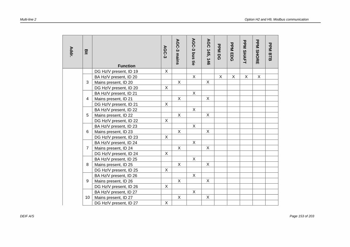
Multi-line 2 Option H2 and H9, Modbus communication
DEIF A/S Page 153 of 203
Ad
dr.
Bit
Function
AG
C-3
AG
C-3
main
s
AG
C-3
bu
s tie
AG
C 1
45, 1
46
PP
M D
G
PP
M E
DG
PP
M S
HA
FT
PP
M S
HO
RE
PP
M B
TB
DG Hz/V present, ID 19 X
3
BA Hz/V present, ID 20 X X X X X
Mains present, ID 20 X X
DG Hz/V present, ID 20 X
4
BA Hz/V present, ID 21 X
Mains present, ID 21 X X
DG Hz/V present, ID 21 X
5
BA Hz/V present, ID 22 X
Mains present, ID 22 X X
DG Hz/V present, ID 22 X
6
BA Hz/V present, ID 23 X
Mains present, ID 23 X X
DG Hz/V present, ID 23 X
7
BA Hz/V present, ID 24 X
Mains present, ID 24 X X
DG Hz/V present, ID 24 X
8
BA Hz/V present, ID 25 X
Mains present, ID 25 X X
DG Hz/V present, ID 25 X
9
BA Hz/V present, ID 26 X
Mains present, ID 26 X X
DG Hz/V present, ID 26 X
10
BA Hz/V present, ID 27 X
Mains present, ID 27 X X
DG Hz/V present, ID 27 X

Multi-line 2 Option H2 and H9, Modbus communication
DEIF A/S Page 154 of 203
Ad
dr.
Bit
Function
AG
C-3
AG
C-3
main
s
AG
C-3
bu
s tie
AG
C 1
45, 1
46
PP
M D
G
PP
M E
DG
PP
M S
HA
FT
PP
M S
HO
RE
PP
M B
TB
11
BA Hz/V present, ID 28 X
Mains present, ID 28 X X
DG Hz/V present, ID 28 X
12
BA Hz/V present, ID 29 X
Mains present, ID 29 X X
DG Hz/V present, ID 29 X
13
BA Hz/V present, ID 30 X
Mains present, ID 30 X X
DG Hz/V present, ID 30 X
14
BA Hz/V present, ID 31 X
Mains present, ID 31 X X
DG Hz/V present, ID 31 X
15
BA Hz/V present, ID 32 X
Mains present, ID 32 X X
DG Hz/V present, ID 32 X
1741
0
BA Hz/V present, ID 33 X X X X X X
Mains present, ID 33 X X
DG Hz/V present, ID 33 X
1
BA Hz/V present, ID 34 X X X X X X
Mains present, ID 34 X X
DG Hz/V present, ID 34 X
2
BA Hz/V present, ID 35 X X X X X X
Mains present, ID 35 X X
DG Hz/V present, ID 35 X
3 BA Hz/V present, ID 36 X X X X X X
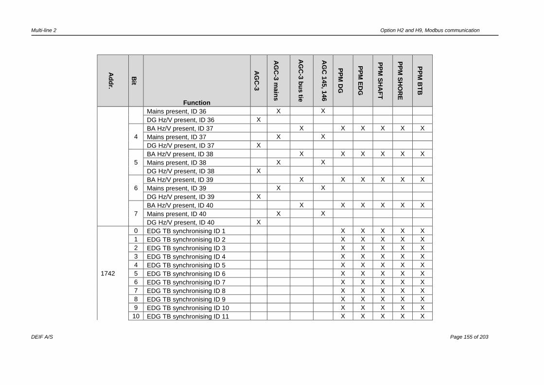
Multi-line 2 Option H2 and H9, Modbus communication
DEIF A/S Page 155 of 203
Ad
dr.
Bit
Function
AG
C-3
AG
C-3
main
s
AG
C-3
bu
s tie
AG
C 1
45, 1
46
PP
M D
G
PP
M E
DG
PP
M S
HA
FT
PP
M S
HO
RE
PP
M B
TB
Mains present, ID 36 X X
DG Hz/V present, ID 36 X
4
BA Hz/V present, ID 37 X X X X X X
Mains present, ID 37 X X
DG Hz/V present, ID 37 X
5
BA Hz/V present, ID 38 X X X X X X
Mains present, ID 38 X X
DG Hz/V present, ID 38 X
6
BA Hz/V present, ID 39 X X X X X X
Mains present, ID 39 X X
DG Hz/V present, ID 39 X
7
BA Hz/V present, ID 40 X X X X X X
Mains present, ID 40 X X
DG Hz/V present, ID 40 X
1742
0 EDG TB synchronising ID 1 X X X X X
1 EDG TB synchronising ID 2 X X X X X
2 EDG TB synchronising ID 3 X X X X X
3 EDG TB synchronising ID 4 X X X X X
4 EDG TB synchronising ID 5 X X X X X
5 EDG TB synchronising ID 6 X X X X X
6 EDG TB synchronising ID 7 X X X X X
7 EDG TB synchronising ID 8 X X X X X
8 EDG TB synchronising ID 9 X X X X X
9 EDG TB synchronising ID 10 X X X X X
10 EDG TB synchronising ID 11 X X X X X

Multi-line 2 Option H2 and H9, Modbus communication
DEIF A/S Page 156 of 203
Ad
dr.
Bit
Function
AG
C-3
AG
C-3
main
s
AG
C-3
bu
s tie
AG
C 1
45, 1
46
PP
M D
G
PP
M E
DG
PP
M S
HA
FT
PP
M S
HO
RE
PP
M B
TB
11 EDG TB synchronising ID 12 X X X X X
12 EDG TB synchronising ID 13 X X X X X
13 EDG TB synchronising ID 14 X X X X X
14 EDG TB synchronising ID 15 X X X X X
15 EDG TB synchronising ID 16 X X X X X
1743-
1999 Reserved

Multi-line 2 Option H2 and H9, Modbus communication
DEIF A/S Page 157 of 203
Control register table read (03h)/write(10h)
Ad
dre
ss
Content Description
AG
C-3
AG
C-3
main
s
AG
C-3
bu
s tie
AG
C 1
10
AG
C 1
11
AG
C 1
12, 1
13
AG
C 1
45, 1
46
PP
M D
G
PP
M E
DG
PP
M S
HA
FT
PP
M S
HO
RE
PP
M B
TB
PP
U/G
PC
GP
U/G
PU
Hyd
ro
0
Power
regulator
setpoint
0...100% of nominal power.
Activated in menu 7501 X X
X X X X
1
cosPhi
regulator
setpoint
60...100 stated as cosPhi
value/100. The value 100
means cosPhi = 1.
Activated in menu 7504
X
X X X X
2
Reactive
power
regulator
setpoint
+/-100% of nominal power. A
negative value means
capacitive reactive power,
and a positive value means
inductive reactive power.
Activated in menu 7505
X
X X X X
3
Frequency
regulator
setpoint
+/-100% corresponding to +/-
10.0% of nominal frequency.
Activated in menu 7502
X
X X X X
4
Voltage
regulator
setpoint
+/-100% corresponding to +/-
10.0% of nominal voltage.
Activated in menu 7503
X
X X X X
5
Control
command
Bit 0
This bit must be 1
when writing the
command word. If
the bit is 0, the
control command is
ignored.
X X X X X X X X X X X X X X
Bit 1 Remote start X X X X X X X X X
Control commands must only be used to send a command. They cannot be used to monitor bit status.

Multi-line 2 Option H2 and H9, Modbus communication
DEIF A/S Page 158 of 203
Ad
dre
ss
Content Description
AG
C-3
AG
C-3
main
s
AG
C-3
bu
s tie
AG
C 1
10
AG
C 1
11
AG
C 1
12, 1
13
AG
C 1
45, 1
46
PP
M D
G
PP
M E
DG
PP
M S
HA
FT
PP
M S
HO
RE
PP
M B
TB
PP
U/G
PC
GP
U/G
PU
Hyd
ro
Bit 2 Remote GB ON X X X X X X X X
Bit 2 Remote TB ON X X
Bit 3 Remote GB OFF X X X X X X X X
Bit 3 Remote TB OFF X X
Bit 4 Remote stop X X X X X X X X X
Bit 5 Reset analogue
regulation outputs X X X X X X
Bit 6 Start + sync. (semi) X X
Bit 7 Alarm inhibit 1 X X X X X X X X X X X X X X
Bit 8 Alarm inhibit 2 X X X X X X X X X X X X X X
Bit 9 Alarm inhibit 3 X X X X X X X X X X X X X X
Bit 10
Alarm ack. This bit
is automatically
reset
X X X X X X X X X X X X X X
Bit 11 Nominal setting 1 X X X X X X X X X X X X X
Bit 12 Nominal setting 2 X X X X X X X X X X X X X
Bit 13 Nominal setting 3 X X X X X X X X
Bit 14 Nominal setting 4 X X X X X X X X
Bit 15 Deload (semi) X X
6
Control
command
Bit 0
This bit must be 1
when writing the
command word. If
the bit is 0, the
X X X X X X X X X X X X X X

Multi-line 2 Option H2 and H9, Modbus communication
DEIF A/S Page 159 of 203
Ad
dre
ss
Content Description
AG
C-3
AG
C-3
main
s
AG
C-3
bu
s tie
AG
C 1
10
AG
C 1
11
AG
C 1
12, 1
13
AG
C 1
45, 1
46
PP
M D
G
PP
M E
DG
PP
M S
HA
FT
PP
M S
HO
RE
PP
M B
TB
PP
U/G
PC
GP
U/G
PU
Hyd
ro
control command is
ignored.
Bit 1 Island X X X X X X X
DG supply X X X
Bit 2
Automatic mains
failure (AMF) X X X X X X
SG supply X X X
Bit 3 Peak shaving X X X X
SHORE supply X X X
Bit 4 Fixed power X X X X X X
Bit 5
Mains power export
(MPE) X X X X
SPLIT X
Bit 6
Load takeover
(LTO) X X X X X X
Connect to DG
supply X
Bit 7 Connect to SG
supply X
Bit 8 Connect to SHORE
supply X
Bit 9 MB/SG/SC/EDG-TB
ON X X X X
Bit 10 MB/SG/SC/EDG-TB
OFF X X X X
Bit 11 Auto start/stop X X X X X X X
Bit 12 Manual mode X X X X X X X X
Bit 13 Auto mode X X X X X X X X X

Multi-line 2 Option H2 and H9, Modbus communication
DEIF A/S Page 160 of 203
Ad
dre
ss
Content Description
AG
C-3
AG
C-3
main
s
AG
C-3
bu
s tie
AG
C 1
10
AG
C 1
11
AG
C 1
12, 1
13
AG
C 1
45, 1
46
PP
M D
G
PP
M E
DG
PP
M S
HA
FT
PP
M S
HO
RE
PP
M B
TB
PP
U/G
PC
GP
U/G
PU
Hyd
ro
Bit 14 Semi-auto mode X X X X X X X X X
Bit 15 Test mode X X X X X X X
7
Bit 0 This bit must be 1
when writing the
command word. If
the bit is 0, the
control command is
ignored.
X X X X
X X X X X X X X X
Bit 1 External frequency
control X
X X
Bit 2 External voltage
control X
X X
Bit 3 External power
control X X
X X
Bit 4 External reactive
power control X
X X
Bit 5 External power
factor control X
X X
Bit 6 Capacitive cosPhi X X X
Bit 7 Base load X X
Bit 8 1. priority X X X
Bit 9 Application 1 X X X X X X X X X X X
Bit 10 Application 2 X X X X X X X X X X X
Bit 11 Application 3 X X X X X X X X X X X
Bit 12 Application 4 X X X X X X X X X X X
Bit 13 Battery test X X X X
Bit 14 Event printer X X
Bit 15 Synchronise clock X X X X X X X X X X X
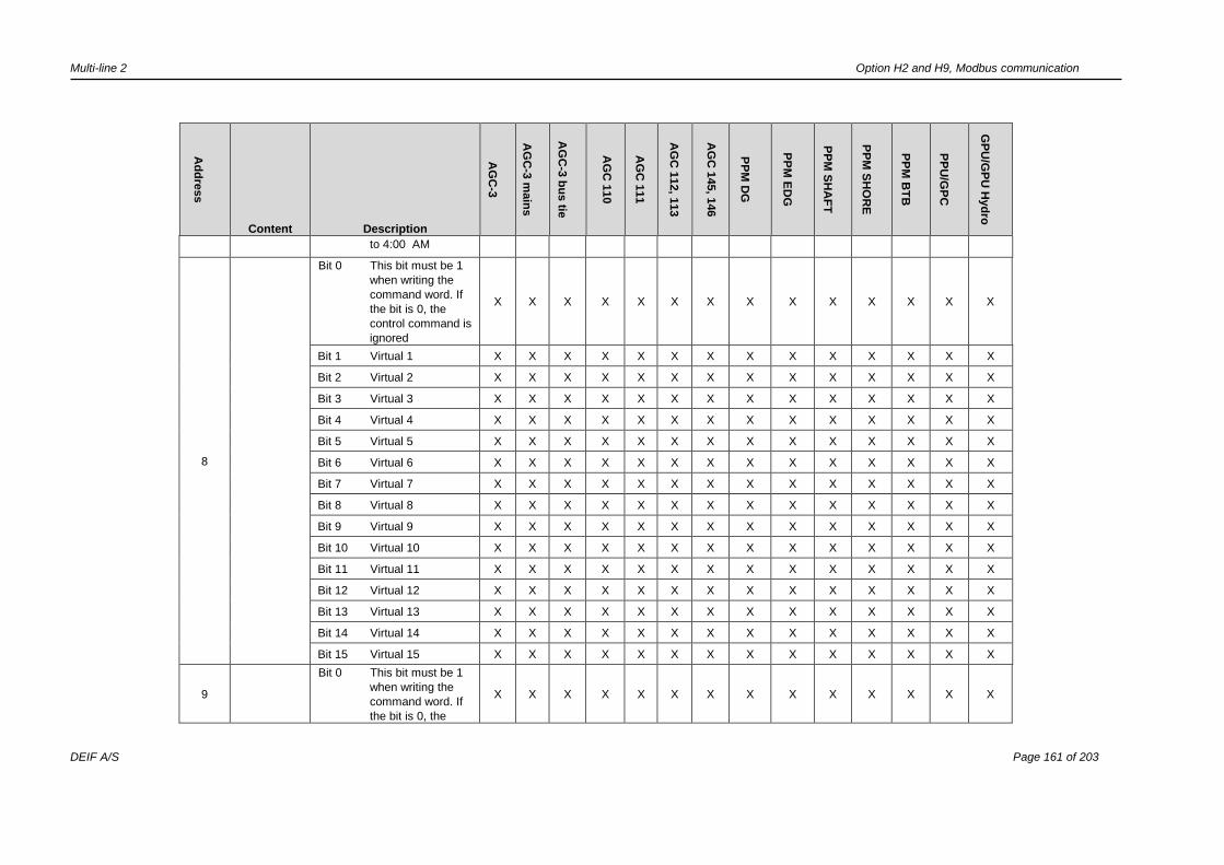
Multi-line 2 Option H2 and H9, Modbus communication
DEIF A/S Page 161 of 203
Ad
dre
ss
Content Description
AG
C-3
AG
C-3
main
s
AG
C-3
bu
s tie
AG
C 1
10
AG
C 1
11
AG
C 1
12, 1
13
AG
C 1
45, 1
46
PP
M D
G
PP
M E
DG
PP
M S
HA
FT
PP
M S
HO
RE
PP
M B
TB
PP
U/G
PC
GP
U/G
PU
Hyd
ro
to 4:00 AM
8
Bit 0 This bit must be 1
when writing the
command word. If
the bit is 0, the
control command is
ignored
X X X X X X X X X X X X X X
Bit 1 Virtual 1 X X X X X X X X X X X X X X
Bit 2 Virtual 2 X X X X X X X X X X X X X X
Bit 3 Virtual 3 X X X X X X X X X X X X X X
Bit 4 Virtual 4 X X X X X X X X X X X X X X
Bit 5 Virtual 5 X X X X X X X X X X X X X X
Bit 6 Virtual 6 X X X X X X X X X X X X X X
Bit 7 Virtual 7 X X X X X X X X X X X X X X
Bit 8 Virtual 8 X X X X X X X X X X X X X X
Bit 9 Virtual 9 X X X X X X X X X X X X X X
Bit 10 Virtual 10 X X X X X X X X X X X X X X
Bit 11 Virtual 11 X X X X X X X X X X X X X X
Bit 12 Virtual 12 X X X X X X X X X X X X X X
Bit 13 Virtual 13 X X X X X X X X X X X X X X
Bit 14 Virtual 14 X X X X X X X X X X X X X X
Bit 15 Virtual 15 X X X X X X X X X X X X X X
9
Bit 0 This bit must be 1
when writing the
command word. If
the bit is 0, the
X X X X X X X X X X X X X X

Multi-line 2 Option H2 and H9, Modbus communication
DEIF A/S Page 162 of 203
Ad
dre
ss
Content Description
AG
C-3
AG
C-3
main
s
AG
C-3
bu
s tie
AG
C 1
10
AG
C 1
11
AG
C 1
12, 1
13
AG
C 1
45, 1
46
PP
M D
G
PP
M E
DG
PP
M S
HA
FT
PP
M S
HO
RE
PP
M B
TB
PP
U/G
PC
GP
U/G
PU
Hyd
ro
control command is
ignored.
Bit 1 Virtual 16 X X X X X X X X X X X X X X
Bit 2 Virtual 17 X X X X X X X X X X X X X X
Bit 3 Virtual 18 X X X X X X X X X X X X X X
Bit 4 Virtual 19 X X X X X X X X X X X X X X
Bit 5 Virtual 20 X X X X X X X X X X X X X X
Bit 6 Virtual 21 X X X X X X X X X X X X X X
Bit 7 Virtual 22 X X X X X X X X X X X X X X
Bit 8 Virtual 23 X X X X X X X X X X X X X X
Bit 9 Virtual 24 X X X X X X X X X X X X X X
Bit 10 Virtual 25 X X X X X X X X X X X X X X
Bit 11 Virtual 26 X X X X X X X X X X X X X X
Bit 12 Virtual 27 X X X X X X X X X X X X X X
Bit 13 Virtual 28 X X X X X X X X X X X X X X
Bit 14 Virtual 29 X X X X X X X X X X X X X X
Bit 15 Virtual 30 X X X X X X X X X X X X X X
10
Bit 0 This bit must be 1
when writing the
command word. If
the bit is 0, the
control command is
ignored.
X X X X X X X X X X X X X X
Bit 1 Virtual 31 X X X X X X X X X X X X X X
Bit 2 Virtual 32 X X X X X X X X X X X X X X
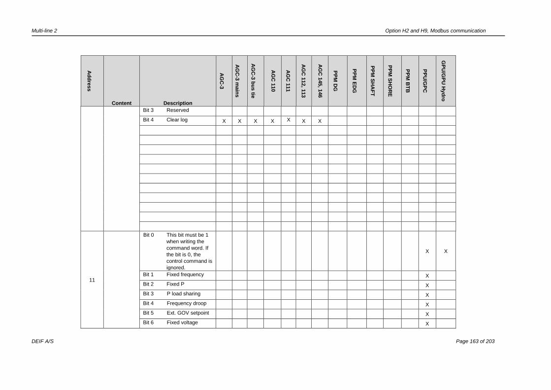
Multi-line 2 Option H2 and H9, Modbus communication
DEIF A/S Page 163 of 203
Ad
dre
ss
Content Description
AG
C-3
AG
C-3
main
s
AG
C-3
bu
s tie
AG
C 1
10
AG
C 1
11
AG
C 1
12, 1
13
AG
C 1
45, 1
46
PP
M D
G
PP
M E
DG
PP
M S
HA
FT
PP
M S
HO
RE
PP
M B
TB
PP
U/G
PC
GP
U/G
PU
Hyd
ro
Bit 3 Reserved
Bit 4 Clear log X X X X X X X
11
Bit 0 This bit must be 1
when writing the
command word. If
the bit is 0, the
control command is
ignored.
X X
Bit 1 Fixed frequency X
Bit 2 Fixed P X
Bit 3 P load sharing X
Bit 4 Frequency droop X
Bit 5 Ext. GOV setpoint X
Bit 6 Fixed voltage X

Multi-line 2 Option H2 and H9, Modbus communication
DEIF A/S Page 164 of 203
Ad
dre
ss
Content Description
AG
C-3
AG
C-3
main
s
AG
C-3
bu
s tie
AG
C 1
10
AG
C 1
11
AG
C 1
12, 1
13
AG
C 1
45, 1
46
PP
M D
G
PP
M E
DG
PP
M S
HA
FT
PP
M S
HO
RE
PP
M B
TB
PP
U/G
PC
GP
U/G
PU
Hyd
ro
Bit 7 Fixed Q X
Bit 8 Fixed PF X
Bit 9 Q load sharing X
Bit 10 Voltage droop X
Bit 11 Ext. AVR setpoint X
Bit 12 Remote X X
Bit 13 Local X X
Bit 14 Deload X X
Bit 15 Start sync./control X X
12
Bit 0 This bit must be 1
when writing the
command word. If
the bit is 0, the
control command is
ignored.
X X
Bit 1 Manual GOV up X X
Bit 2 Manual GOV down X X
Bit 3 Manual AVR up X X
Bit 4 Manual AVR down X X
Bit 5 Activate CANshare
section 1
X X
Bit 6 Activate CANshare
section 2
X X
Bit 7 Activate CANshare
section 3
X X
Bit 8 Activate CANshare
section 4
X X

Multi-line 2 Option H2 and H9, Modbus communication
DEIF A/S Page 165 of 203
Ad
dre
ss
Content Description
AG
C-3
AG
C-3
main
s
AG
C-3
bu
s tie
AG
C 1
10
AG
C 1
11
AG
C 1
12, 1
13
AG
C 1
45, 1
46
PP
M D
G
PP
M E
DG
PP
M S
HA
FT
PP
M S
HO
RE
PP
M B
TB
PP
U/G
PC
GP
U/G
PU
Hyd
ro
Bit 9 Activate CANshare
section 5
X X
Bit 10 Reserved
Bit 11 Reserved
Bit 12 Reserved
Bit 13 Reserved
Bit 14 Reserved
Bit 15 Reserved
13
Bit 0 This bit must be 1
when writing the
command word. If
the bit is 0, the
control command is
ignored.
X
Bit 1 Enable external
frequency
control
X
Bit 2 Disable external
frequency control X
Bit 3 Enable external
voltage control X
Bit 4 Disable external
voltage control X
Bit 5 Enable external
power control X
Bit 6 Disable external
power control X
Bit 7 Enable external
VAr control X
Bit 8 Disable external X
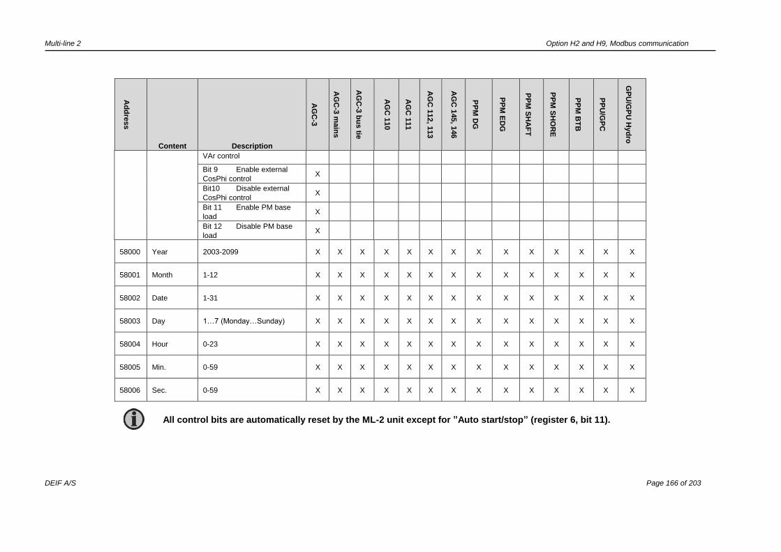
Multi-line 2 Option H2 and H9, Modbus communication
DEIF A/S Page 166 of 203
Ad
dre
ss
Content Description
AG
C-3
AG
C-3
main
s
AG
C-3
bu
s tie
AG
C 1
10
AG
C 1
11
AG
C 1
12, 1
13
AG
C 1
45, 1
46
PP
M D
G
PP
M E
DG
PP
M S
HA
FT
PP
M S
HO
RE
PP
M B
TB
PP
U/G
PC
GP
U/G
PU
Hyd
ro
VAr control
Bit 9 Enable external
CosPhi control X
Bit10 Disable external
CosPhi control X
Bit 11 Enable PM base
load X
Bit 12 Disable PM base
load X
58000 Year 2003-2099 X X X X X X X X X X X X X X
58001 Month 1-12 X X X X X X X X X X X X X X
58002 Date 1-31 X X X X X X X X X X X X X X
58003 Day 1…7 (Monday…Sunday) X X X X X X X X X X X X X X
58004 Hour 0-23 X X X X X X X X X X X X X X
58005 Min. 0-59 X X X X X X X X X X X X X X
58006 Sec. 0-59 X X X X X X X X X X X X X X
All control bits are automatically reset by the ML-2 unit except for ”Auto start/stop” (register 6, bit 11).
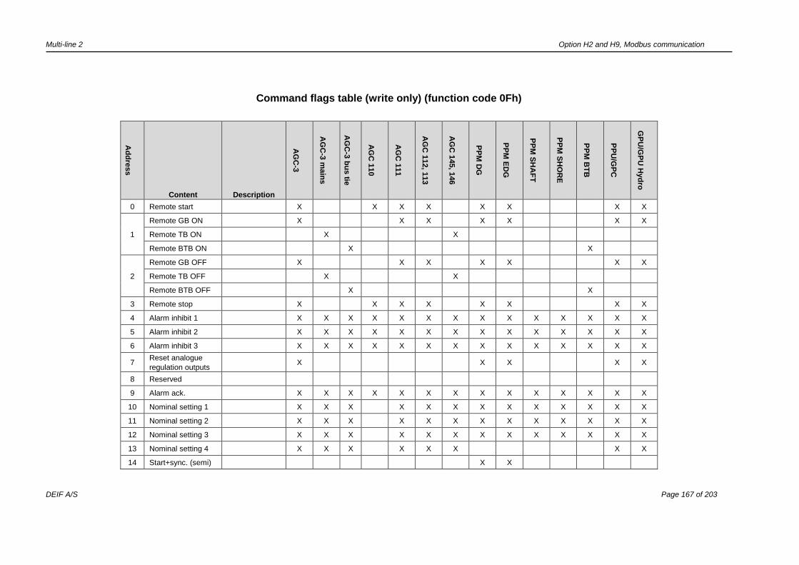
Multi-line 2 Option H2 and H9, Modbus communication
DEIF A/S Page 167 of 203
Command flags table (write only) (function code 0Fh)
Ad
dre
ss
Content Description
AG
C-3
AG
C-3
main
s
AG
C-3
bu
s tie
AG
C 1
10
AG
C 1
11
AG
C 1
12, 1
13
AG
C 1
45, 1
46
PP
M D
G
PP
M E
DG
PP
M S
HA
FT
PP
M S
HO
RE
PP
M B
TB
PP
U/G
PC
GP
U/G
PU
Hyd
ro
0 Remote start X X X X X X X X
1
Remote GB ON X X X X X X X
Remote TB ON X X
Remote BTB ON X X
2
Remote GB OFF X X X X X X X
Remote TB OFF X X
Remote BTB OFF X X
3 Remote stop X X X X X X X X
4 Alarm inhibit 1 X X X X X X X X X X X X X X
5 Alarm inhibit 2 X X X X X X X X X X X X X X
6 Alarm inhibit 3 X X X X X X X X X X X X X X
7 Reset analogue
regulation outputs
X X X X X
8 Reserved
9 Alarm ack. X X X X X X X X X X X X X X
10 Nominal setting 1 X X X X X X X X X X X X X
11 Nominal setting 2 X X X X X X X X X X X X X
12 Nominal setting 3 X X X X X X X X X X X X X
13 Nominal setting 4 X X X X X X X X
14 Start+sync. (semi) X X
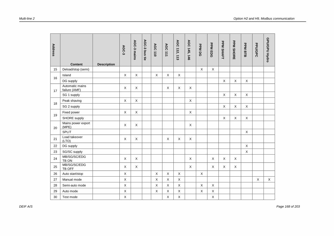
Multi-line 2 Option H2 and H9, Modbus communication
DEIF A/S Page 168 of 203
Ad
dre
ss
Content Description
AG
C-3
AG
C-3
main
s
AG
C-3
bu
s tie
AG
C 1
10
AG
C 1
11
AG
C 1
12, 1
13
AG
C 1
45, 1
46
PP
M D
G
PP
M E
DG
PP
M S
HA
FT
PP
M S
HO
RE
PP
M B
TB
PP
U/G
PC
GP
U/G
PU
Hyd
ro
15 Deload/stop (semi) X X
16 Island X X X X X
DG supply X X X
17
Automatic mains
failure (AMF)
X X X X X
SG 1 supply X X X
18 Peak shaving X X X
SG 2 supply X X X
19 Fixed power X X X
SHORE supply X X X
20
Mains power export
(MPE)
X X X
SPLIT X
21 Load takeover
(LTO)
X X X X X
22 DG supply X
23 SG/SC supply X
24 MB/SG/SC/EDG
TB ON
X X X X X X
25 MB/SG/SC/EDG
TB OFF
X X X X X X
26 Auto start/stop X X X X X
27 Manual mode X X X X X X
28 Semi-auto mode X X X X X X
29 Auto mode X X X X X X
30 Test mode X X X X

Multi-line 2 Option H2 and H9, Modbus communication
DEIF A/S Page 169 of 203
Ad
dre
ss
Content Description
AG
C-3
AG
C-3
main
s
AG
C-3
bu
s tie
AG
C 1
10
AG
C 1
11
AG
C 1
12, 1
13
AG
C 1
45, 1
46
PP
M D
G
PP
M E
DG
PP
M S
HA
FT
PP
M S
HO
RE
PP
M B
TB
PP
U/G
PC
GP
U/G
PU
Hyd
ro
31 External frequency
control
X
X X
32 External voltage
control
X
X X
33 External power
control
X
X X
34 External reactive
power control
X
X X
35 External cosPhi
control
X
X X
36 Capacitive cosPhi X X X
37 Base load X X
38 1. priority X X X
39 Reserved
40 Application 1 X X X X X X X X X X X
41 Application 2 X X X X X X X X X X X
42 Application 3 X X X X X X X X X X X
43 Application 4 X X X X X X X X X X X
44 Battery test X X X X X
45 Event printer X X X
46 Synchronise clock
to 4:00 a.m.
X X X X X X X X X X X
47 Reserved
48 Virtual event 1 X X X X X X X X X X X X X X
49 Virtual event 2 X X X X X X X X X X X X X X
50 Virtual event 3 X X X X X X X X X X X X X X
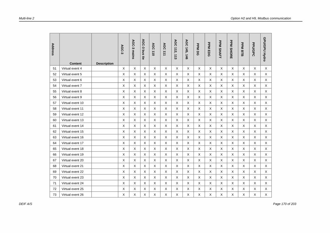
Multi-line 2 Option H2 and H9, Modbus communication
DEIF A/S Page 170 of 203
Ad
dre
ss
Content Description
AG
C-3
AG
C-3
main
s
AG
C-3
bu
s tie
AG
C 1
10
AG
C 1
11
AG
C 1
12, 1
13
AG
C 1
45, 1
46
PP
M D
G
PP
M E
DG
PP
M S
HA
FT
PP
M S
HO
RE
PP
M B
TB
PP
U/G
PC
GP
U/G
PU
Hyd
ro
51 Virtual event 4 X X X X X X X X X X X X X X
52 Virtual event 5 X X X X X X X X X X X X X X
53 Virtual event 6 X X X X X X X X X X X X X X
54 Virtual event 7 X X X X X X X X X X X X X X
55 Virtual event 8 X X X X X X X X X X X X X X
56 Virtual event 9 X X X X X X X X X X X X X X
57 Virtual event 10 X X X X X X X X X X X X X X
58 Virtual event 11 X X X X X X X X X X X X X X
59 Virtual event 12 X X X X X X X X X X X X X X
60 Virtual event 13 X X X X X X X X X X X X X X
61 Virtual event 14 X X X X X X X X X X X X X X
62 Virtual event 15 X X X X X X X X X X X X X X
63 Virtual event 16 X X X X X X X X X X X X X X
64 Virtual event 17 X X X X X X X X X X X X X X
65 Virtual event 18 X X X X X X X X X X X X X X
66 Virtual event 19 X X X X X X X X X X X X X X
67 Virtual event 20 X X X X X X X X X X X X X X
68 Virtual event 21 X X X X X X X X X X X X X X
69 Virtual event 22 X X X X X X X X X X X X X X
70 Virtual event 23 X X X X X X X X X X X X X X
71 Virtual event 24 X X X X X X X X X X X X X X
72 Virtual event 25 X X X X X X X X X X X X X X
73 Virtual event 26 X X X X X X X X X X X X X X

Multi-line 2 Option H2 and H9, Modbus communication
DEIF A/S Page 171 of 203
Ad
dre
ss
Content Description
AG
C-3
AG
C-3
main
s
AG
C-3
bu
s tie
AG
C 1
10
AG
C 1
11
AG
C 1
12, 1
13
AG
C 1
45, 1
46
PP
M D
G
PP
M E
DG
PP
M S
HA
FT
PP
M S
HO
RE
PP
M B
TB
PP
U/G
PC
GP
U/G
PU
Hyd
ro
74 Virtual event 27 X X X X X X X X X X X X X X
75 Virtual event 28 X X X X X X X X X X X X X X
76 Virtual event 29 X X X X X X X X X X X X X X
77 Virtual event 30 X X X X X X X X X X X X X X
78 Virtual event 31 X X X X X X X X X X X X X X
79 Virtual event 32 X X X X X X X X X X X X X X
80 Fixed frequency X
81 Fixed P X
82 P load sharing X
83 Frequency droop X
84 Ext. GOV setpoint X
85 Fixed voltage X
86 Fixed Q X
87 Fixed PF X
88 Q load sharing X
89 Voltage droop X
90 Ext. AVR setpoint X
91 Remote X X
92 Local X X
93 Deload X X
94 Start sync./control X X
95 Reserved
96 Manual GOV up X X
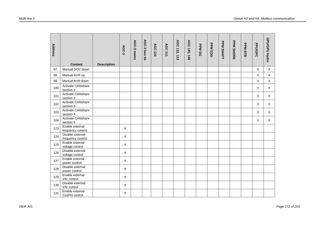
Multi-line 2 Option H2 and H9, Modbus communication
DEIF A/S Page 172 of 203
Ad
dre
ss
Content Description
AG
C-3
AG
C-3
main
s
AG
C-3
bu
s tie
AG
C 1
10
AG
C 1
11
AG
C 1
12, 1
13
AG
C 1
45, 1
46
PP
M D
G
PP
M E
DG
PP
M S
HA
FT
PP
M S
HO
RE
PP
M B
TB
PP
U/G
PC
GP
U/G
PU
Hyd
ro
97 Manual GOV down X X
98 Manual AVR up X X
99 Manual AVR down X X
100 Activate CANshare
section 1
X X
101 Activate CANshare
section 2
X X
102 Activate CANshare
section 3
X X
103 Activate CANshare
section 4
X X
104 Activate CANshare
section 5
X X
123 Enable external
frequency control
X
124 Disable external
frequency control
X
125 Enable external
voltage control
X
126 Disable external
voltage control
X
127 Enable external
power control
X
128 Disable external
power control
X
129 Enable external
VAr control
X
130 Disable external
VAr control
X
131 Enable external
CosPhi control
X
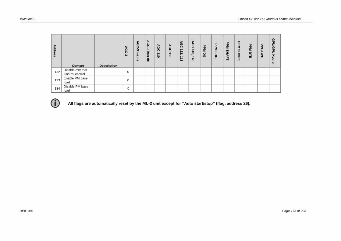
Multi-line 2 Option H2 and H9, Modbus communication
DEIF A/S Page 173 of 203
Ad
dre
ss
Content Description
AG
C-3
AG
C-3
main
s
AG
C-3
bu
s tie
AG
C 1
10
AG
C 1
11
AG
C 1
12, 1
13
AG
C 1
45, 1
46
PP
M D
G
PP
M E
DG
PP
M S
HA
FT
PP
M S
HO
RE
PP
M B
TB
PP
U/G
PC
GP
U/G
PU
Hyd
ro
132 Disable external
CosPhi control
X
133 Enable PM base
load
X
134 Disable PM base
load
X
All flags are automatically reset by the ML-2 unit except for ”Auto start/stop” (flag, address 26).

Multi-line 2 Option H2 and H9, Modbus communication
DEIF A/S Page 174 of 203
Command flags table (read only) (function code 01Fh)
Ad
dre
ss
Content Description
AG
C-3
AG
C-3
main
s
AG
C-3
bu
s tie
AG
C 1
10
AG
C 1
11
AG
C 1
12, 1
13
AG
C 1
45, 1
46
PP
M D
G
PP
M E
DG
PP
M S
HA
FT
PP
M S
HO
RE
PP
M B
TB
PP
U/G
PC
GP
U/G
PU
Hyd
ro
142 HC1 Request X X
143 HC2 Request X X
144 HC3 Request X X
145 HC4 Request X X
146 HC1 Fixed load
Feedback
X X
147 HC2 Fixed load
Feedback
X X
148 HC3 Fixed load
Feedback
X X
149 HC4 Fixed load
Feedback
X X

Multi-line 2 Option H2 and H9, Modbus communication
DEIF A/S Page 175 of 203
Status flags table (read only) (function code 02h)
Ad
dre
ss
Content
AG
C-3
AG
C-3
main
s
AG
C-3
bu
s tie
AG
C 1
10
AG
C 1
11
AG
C 1
12, 1
13
AG
C 1
45, 1
46
PP
M D
G
PP
M E
DG
PP
M S
HA
FT
PP
M S
HO
RE
PP
M B
TB
PP
U/G
PC
GP
U/G
PU
Hyd
ro
0
GB position ON X X X X X X X
TB position ON X X
BTB position ON X X
1
MB position ON X X X X X
SGB position ON X
SCB position ON X
EDG-TB position ON X
2 Reserved
3 Running X X X X X X X X X
4 Generator
voltage/frequency OK X X X X X X X X X
5 Mains failure/main
busbar failure X X X X X X
6 Block mode X X X X X
7 Manual mode X X X X X X
SWBD control X X X X X
8 Semi-auto mode X X X X X X
9 Auto mode X X X X X X
10 Test mode X X X X X X X
11 Remote X X
12 Local X X
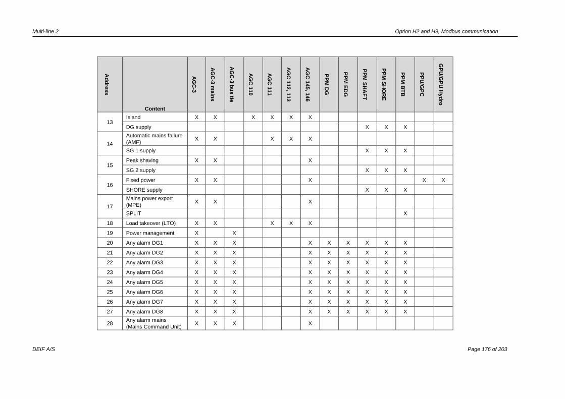
Multi-line 2 Option H2 and H9, Modbus communication
DEIF A/S Page 176 of 203
Ad
dre
ss
Content
AG
C-3
AG
C-3
main
s
AG
C-3
bu
s tie
AG
C 1
10
AG
C 1
11
AG
C 1
12, 1
13
AG
C 1
45, 1
46
PP
M D
G
PP
M E
DG
PP
M S
HA
FT
PP
M S
HO
RE
PP
M B
TB
PP
U/G
PC
GP
U/G
PU
Hyd
ro 13
Island X X X X X X
DG supply X X X
14
Automatic mains failure
(AMF) X X X X X
SG 1 supply X X X
15 Peak shaving X X X
SG 2 supply X X X
16 Fixed power X X X X X
SHORE supply X X X
17
Mains power export
(MPE) X X X
SPLIT X
18 Load takeover (LTO) X X X X X
19 Power management X X
20 Any alarm DG1 X X X X X X X X X
21 Any alarm DG2 X X X X X X X X X
22 Any alarm DG3 X X X X X X X X X
23 Any alarm DG4 X X X X X X X X X
24 Any alarm DG5 X X X X X X X X X
25 Any alarm DG6 X X X X X X X X X
26 Any alarm DG7 X X X X X X X X X
27 Any alarm DG8 X X X X X X X X X
28 Any alarm mains
(Mains Command Unit) X X X X
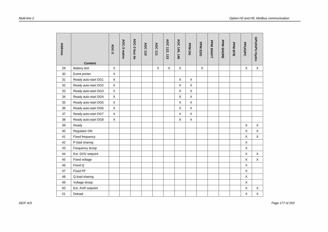
Multi-line 2 Option H2 and H9, Modbus communication
DEIF A/S Page 177 of 203
Ad
dre
ss
Content
AG
C-3
AG
C-3
main
s
AG
C-3
bu
s tie
AG
C 1
10
AG
C 1
11
AG
C 1
12, 1
13
AG
C 1
45, 1
46
PP
M D
G
PP
M E
DG
PP
M S
HA
FT
PP
M S
HO
RE
PP
M B
TB
PP
U/G
PC
GP
U/G
PU
Hyd
ro
29 Battery test X X X X X X X
30 Event printer X
31 Ready auto-start DG1 X X X
32 Ready auto-start DG2 X X X
33 Ready auto-start DG3 X X X
34 Ready auto-start DG4 X X X
35 Ready auto-start DG5 X X X
36 Ready auto-start DG6 X X X
37 Ready auto-start DG7 X X X
38 Ready auto-start DG8 X X X
39 Ready X X
40 Regulator ON X X
41 Fixed frequency X X
42 P load sharing X
43 Frequency droop X
44 Ext. GOV setpoint X X
45 Fixed voltage X X
46 Fixed Q X
47 Fixed PF X
48 Q load sharing X
49 Voltage droop X
50 Ext. AVR setpoint X X
51 Deload X X

Multi-line 2 Option H2 and H9, Modbus communication
DEIF A/S Page 178 of 203
Ad
dre
ss
Content
AG
C-3
AG
C-3
main
s
AG
C-3
bu
s tie
AG
C 1
10
AG
C 1
11
AG
C 1
12, 1
13
AG
C 1
45, 1
46
PP
M D
G
PP
M E
DG
PP
M S
HA
FT
PP
M S
HO
RE
PP
M B
TB
PP
U/G
PC
GP
U/G
PU
Hyd
ro
52 Start sync./control X X
53 Mains sync. inhibit X X X X
54 Any mains sync. inhibit X X
55 G7 any mains sync.
inhibit X X
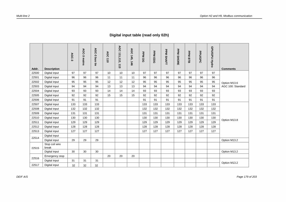
Multi-line 2 Option H2 and H9, Modbus communication
DEIF A/S Page 179 of 203
Digital input table (read only 02h)
Addr. Description
AG
C-3
AG
C-3
main
s
AG
C-3
bu
s tie
AG
C 1
10
AG
C 1
11,1
12, 1
13
AG
C 1
45, 1
46
PP
M D
G
PP
M E
DG
PP
M S
HA
FT
PP
M S
HO
RE
PP
M B
TB
PP
U/G
PC
GP
U/G
PU
Hyd
ro
Comments
22500 Digital input 97 97 97 10 10 10 97 97 97 97 97 97 97
Option M13.6
AGC 100: Standard
22501 Digital input 96 96 96 11 11 11 96 96 96 96 96 96 96
22502 Digital input 95 95 95 12 12 12 95 95 95 95 95 95 95
22503 Digital input 94 94 94 13 13 13 94 94 94 94 94 94 94
22504 Digital input 93 93 93 14 14 14 93 93 93 93 93 93 93
22505 Digital input 92 92 92 15 15 15 92 92 92 92 92 92 92
22506 Digital input 91 91 91 91 91 91 91 91 91 91
22507 Digital input 133 133 133 133 133 133 133 133 133 133
Option M13.8
22508 Digital input 132 132 132 132 132 132 132 132 132 132
22509 Digital input 131 131 131 131 131 131 131 131 131 131
22510 Digital input 130 130 130 130 130 130 130 130 130 130
22511 Digital input 129 129 129 129 129 129 129 129 129 129
22512 Digital input 128 128 128 128 128 128 128 128 128 128
22513 Digital input 127 127 127 127 127 127 127 127 127 127
22514 Digital input
Digital input 29 29 29 Option M13.2
22515
Stop coil wire
break
Digital input 30 30 30 Option M13.2
22516 Emergency stop 20 20 20
Digital input 31 31 31 Option M13.2
22517 Digital input 32 32 32

Multi-line 2 Option H2 and H9, Modbus communication
DEIF A/S Page 180 of 203
Addr. Description
AG
C-3
AG
C-3
main
s
AG
C-3
bu
s tie
AG
C 1
10
AG
C 1
11,1
12, 1
13
AG
C 1
45, 1
46
PP
M D
G
PP
M E
DG
PP
M S
HA
FT
PP
M S
HO
RE
PP
M B
TB
PP
U/G
PC
GP
U/G
PU
Hyd
ro
Comments
22518 Digital input 33 33 33
22519 Digital input 34 34 34
22520 Digital input 35 35 35
22521
22522
22523
22524
22525
22526
22527
22528 Digital input 43 43 43 43 43 43 43 43 43 43
AGC/GPU: Option
M12
PPM/PPU/GPC:
Standard
22529 Digital input 44 44 44 44 44 44 44 44 44 44
22530 Digital input 45 45 45 45 45 45 45 45 45 45
22531 Digital input 46 46 46 46 46 46 46 46 46 46
22532 Digital input 47 47 47 47 47 47 47 47 47 47
22533 Digital input 48 48 48 48 48 48 48 48 48 48
22534 Digital input 49 49 49 49 49 49 49 49 49 49
22535 Digital input 50 50 50 50 50 50 50 50 50 50
22536 Digital input 51 51 51 51 51 51 51 51 51 51
22537 Digital input 52 52 52 52 52 52 52 52 52 52
22538 Digital input 53 53 53 53 53 53 53 53 53 53
22539 Digital input 54 54 54 54 54 54 54 54 54 54
22540 Digital input 55 55 55 55 55 55 55 55 55 55
22541 Digital input 23 23 23 23 23 23 23 23 23 23 Standard
22542 Digital input 24 24 24 24 24 24 24 24 24 24
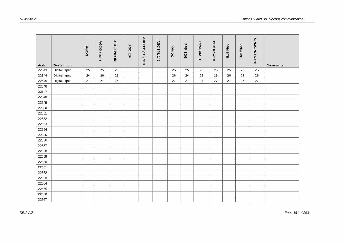
Multi-line 2 Option H2 and H9, Modbus communication
DEIF A/S Page 181 of 203
Addr. Description
AG
C-3
AG
C-3
main
s
AG
C-3
bu
s tie
AG
C 1
10
AG
C 1
11,1
12, 1
13
AG
C 1
45, 1
46
PP
M D
G
PP
M E
DG
PP
M S
HA
FT
PP
M S
HO
RE
PP
M B
TB
PP
U/G
PC
GP
U/G
PU
Hyd
ro
Comments
22543 Digital input 25 25 25 25 25 25 25 25 25 25
22544 Digital input 26 26 26 26 26 26 26 26 26 26
22545 Digital input 27 27 27 27 27 27 27 27 27 27
22546
22547
22548
22549
22550
22551
22552
22553
22554
22555
22556
22557
22558
22559
22560
22561
22562
22563
22564
22565
22566
22567

Multi-line 2 Option H2 and H9, Modbus communication
DEIF A/S Page 182 of 203
Addr. Description
AG
C-3
AG
C-3
main
s
AG
C-3
bu
s tie
AG
C 1
10
AG
C 1
11,1
12, 1
13
AG
C 1
45, 1
46
PP
M D
G
PP
M E
DG
PP
M S
HA
FT
PP
M S
HO
RE
PP
M B
TB
PP
U/G
PC
GP
U/G
PU
Hyd
ro
Comments
22568
22569
22570
22571
22572
22573
22574
22575
22576
22577
22578
22579
22580
22581
22582
22583 Digital input
(emer. stop) 118 118 118 118 118 118 118 118 118 118
AGC/PPM: Standard
PPU/GPC/GPU:
Option M4
22584 Digital input 117 117 117 117 117 117 117 117 117 117
22585 Digital input 116 116 116 116 116 116 116 116 116 116
22586 Digital input 115 115 115 115 115 115 115 115 115 115
22587 Digital input 114 114 114 114 114 114 114 114 114 114
22588 Digital input 113 113 113 113 113 113 113 113 113 113
22589 Digital input 112 112 112 112 112 112 112 112 112 112
22590 Stop coil superv.
(M4) 123 123 123 123 123 123 123 123 123 123
22591 Multi-func. input 108 108 108 8 8 8 108 108 108 108 108 108 108

Multi-line 2 Option H2 and H9, Modbus communication
DEIF A/S Page 183 of 203
Addr. Description
AG
C-3
AG
C-3
main
s
AG
C-3
bu
s tie
AG
C 1
10
AG
C 1
11,1
12, 1
13
AG
C 1
45, 1
46
PP
M D
G
PP
M E
DG
PP
M S
HA
FT
PP
M S
HO
RE
PP
M B
TB
PP
U/G
PC
GP
U/G
PU
Hyd
ro
Comments
22592 Multi-func. input 105 105 105 7 7 7 105 105 105 105 105 105 105
22593 Multi-func. input 102 102 102 6 6 6 102 102 102 102 102 102 102
22594
External digital
input/CIO 116
no. 1. Input 10
1/0 1/10 1/10 1/NA 1/NA 1/NA 1/NA 1/NA 1/NA 1/NA 1/NA 1/NA 1/NA
Option H8.
It is not possible to
use both CIO and
other external I/O
types
(Beckhoff/Axiomatic)
on a controller.
External DIs share
the addresses
22594 through
22609.
The CIO modules
are only available
when using AGC-4
and/or AGC 200
series.
22595
External digital
input/CIO 116
no. 1. Input 11
2/11 2/11 2/11 2/NA 2/NA 2/NA 2/NA 2/NA 2/NA 2/NA 2/NA 2/NA 2/NA
22596
External digital
input/CIO 116
no. 1. Input 12
3/2 3/12 3/12 3/NA 3/NA 3/NA 3/NA 3/NA 3/NA 3/NA 3/NA 3/NA 3/NA
22597
External digital
input/CIO 116
no. 1. Input 13
4/3 4/13 4/13 4/NA 4/NA 4/NA 4/NA 4/NA 4/NA 4/NA 4/NA 4/NA 4/NA
22598
External digital
input/CIO 116
no. 1. Input 14
5/14 5/14 5/14 5/NA 5/NA 5/NA 5/NA 5/NA 5/NA 5/NA 5/NA 5/NA 5/NA
22599
External digital
input/CIO 116
no. 1. Input 15
6/15 6/15 6/15 6/NA 6/NA 6/NA 6/NA 6/NA 6/NA 6/NA 6/NA 6/NA 6/NA
22600
External digital
input/CIO 116
no. 1. Input 16
7/16 7/16 7/16 7/NA 7/NA 7/NA 7/NA 7/NA 7/NA 7/NA 7/NA 7/NA 7/NA
22601
External digital
input/CIO 116
no. 1. Input 17
8/17 8/17 8/17 8/NA 8/NA 8/NA 8/NA 8/NA 8/NA 8/NA 8/NA 8/NA 8/NA
22602
External digital
input/CIO 116
no. 1. Input 19
9/19 9/19 9/19 9/NA 9/NA 9/NA 9/NA 9/NA 9/NA 9/NA 9/NA 9/NA 9/NA
22603
External digital
input/CIO 116
no. 1. Input 20
10/20 10/20 10/20 10/NA 10/NA 10/NA 10/
NA
10/
NA 10/NA
10/
NA
10/
NA
10/
NA 10/NA
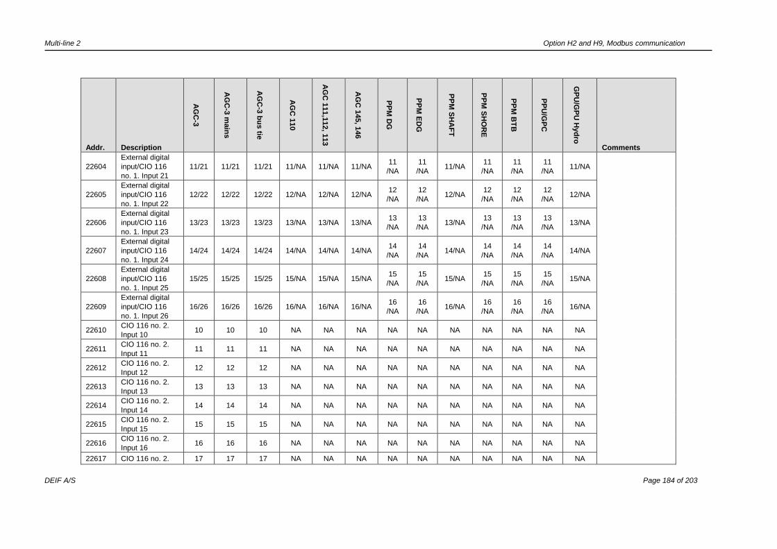
Multi-line 2 Option H2 and H9, Modbus communication
DEIF A/S Page 184 of 203
Addr. Description
AG
C-3
AG
C-3
main
s
AG
C-3
bu
s tie
AG
C 1
10
AG
C 1
11,1
12, 1
13
AG
C 1
45, 1
46
PP
M D
G
PP
M E
DG
PP
M S
HA
FT
PP
M S
HO
RE
PP
M B
TB
PP
U/G
PC
GP
U/G
PU
Hyd
ro
Comments
22604
External digital
input/CIO 116
no. 1. Input 21
11/21 11/21 11/21 11/NA 11/NA 11/NA 11
/NA
11
/NA 11/NA
11
/NA
11
/NA
11
/NA 11/NA
22605
External digital
input/CIO 116
no. 1. Input 22
12/22 12/22 12/22 12/NA 12/NA 12/NA 12
/NA
12
/NA 12/NA
12
/NA
12
/NA
12
/NA 12/NA
22606
External digital
input/CIO 116
no. 1. Input 23
13/23 13/23 13/23 13/NA 13/NA 13/NA 13
/NA
13
/NA 13/NA
13
/NA
13
/NA
13
/NA 13/NA
22607
External digital
input/CIO 116
no. 1. Input 24
14/24 14/24 14/24 14/NA 14/NA 14/NA 14
/NA
14
/NA 14/NA
14
/NA
14
/NA
14
/NA 14/NA
22608
External digital
input/CIO 116
no. 1. Input 25
15/25 15/25 15/25 15/NA 15/NA 15/NA 15
/NA
15
/NA 15/NA
15
/NA
15
/NA
15
/NA 15/NA
22609
External digital
input/CIO 116
no. 1. Input 26
16/26 16/26 16/26 16/NA 16/NA 16/NA 16
/NA
16
/NA 16/NA
16
/NA
16
/NA
16
/NA 16/NA
22610 CIO 116 no. 2.
Input 10 10 10 10 NA NA NA NA NA NA NA NA NA NA
22611 CIO 116 no. 2.
Input 11 11 11 11 NA NA NA NA NA NA NA NA NA NA
22612 CIO 116 no. 2.
Input 12 12 12 12 NA NA NA NA NA NA NA NA NA NA
22613 CIO 116 no. 2.
Input 13 13 13 13 NA NA NA NA NA NA NA NA NA NA
22614 CIO 116 no. 2.
Input 14 14 14 14 NA NA NA NA NA NA NA NA NA NA
22615 CIO 116 no. 2.
Input 15 15 15 15 NA NA NA NA NA NA NA NA NA NA
22616 CIO 116 no. 2.
Input 16 16 16 16 NA NA NA NA NA NA NA NA NA NA
22617 CIO 116 no. 2. 17 17 17 NA NA NA NA NA NA NA NA NA NA

Multi-line 2 Option H2 and H9, Modbus communication
DEIF A/S Page 185 of 203
Addr. Description
AG
C-3
AG
C-3
main
s
AG
C-3
bu
s tie
AG
C 1
10
AG
C 1
11,1
12, 1
13
AG
C 1
45, 1
46
PP
M D
G
PP
M E
DG
PP
M S
HA
FT
PP
M S
HO
RE
PP
M B
TB
PP
U/G
PC
GP
U/G
PU
Hyd
ro
Comments
Input 17
22618 CIO 116 no. 2.
Input 19 19 19 19 NA NA NA NA NA NA NA NA NA NA
22619 CIO 116 no. 2.
Input 20 20 20 20 NA NA NA NA NA NA NA NA NA NA
22620 CIO 116 no. 2.
Input 21 21 21 21 NA NA NA NA NA NA NA NA NA NA
22621 CIO 116 no. 2.
Input 22 22 22 22 NA NA NA NA NA NA NA NA NA NA
22622 CIO 116 no. 2.
Input 23 23 23 23 NA NA NA NA NA NA NA NA NA NA
22623 CIO 116 no. 2.
Input 24 24 24 24 NA NA NA NA NA NA NA NA NA NA
22624 CIO 116 no. 2.
Input 25 25 25 25 NA NA NA NA NA NA NA NA NA NA
22625 CIO 116 no. 2.
Input 26 26 26 26 NA NA NA NA NA NA NA NA NA NA
22626 CIO 116 no. 3.
Input 10 10 10 10 NA NA NA NA NA NA NA NA NA NA
22627 CIO 116 no. 3.
Input 11 11 11 11 NA NA NA NA NA NA NA NA NA NA
22628 CIO 116 no. 3.
Input 12 12 12 12 NA NA NA NA NA NA NA NA NA NA
22629 CIO 116 no. 3.
Input 13 13 13 13 NA NA NA NA NA NA NA NA NA NA
22630 CIO 116 no. 3.
Input 14 14 14 14 NA NA NA NA NA NA NA NA NA NA
22631 CIO 116 no. 3.
Input 15 15 15 15 NA NA NA NA NA NA NA NA NA NA
22632 CIO 116 no. 3.
Input 16 16 16 16 NA NA NA NA NA NA NA NA NA NA
22633 CIO 116 no. 3. 17 17 17 NA NA NA NA NA NA NA NA NA NA

Multi-line 2 Option H2 and H9, Modbus communication
DEIF A/S Page 186 of 203
Addr. Description
AG
C-3
AG
C-3
main
s
AG
C-3
bu
s tie
AG
C 1
10
AG
C 1
11,1
12, 1
13
AG
C 1
45, 1
46
PP
M D
G
PP
M E
DG
PP
M S
HA
FT
PP
M S
HO
RE
PP
M B
TB
PP
U/G
PC
GP
U/G
PU
Hyd
ro
Comments
Input 17
22634 CIO 116 no. 3.
Input 19 19 19 19 NA NA NA NA NA NA NA NA NA NA
22635 CIO 116 no. 3.
Input 20 20 20 20 NA NA NA NA NA NA NA NA NA NA
22636 CIO 116 no. 3.
Input 21 21 21 21 NA NA NA NA NA NA NA NA NA NA
22637 CIO 116 no. 3.
Input 22 22 22 22 NA NA NA NA NA NA NA NA NA NA
22638 CIO 116 no. 3.
Input 23 23 23 23 NA NA NA NA NA NA NA NA NA NA
22639 CIO 116 no. 3.
Input 24 24 24 24 NA NA NA NA NA NA NA NA NA NA
22640 CIO 116 no. 3.
Input 25 25 25 25 NA NA NA NA NA NA NA NA NA NA
22641 CIO 116 no. 3.
Input 26 26 26 26 NA NA NA NA NA NA NA NA NA NA
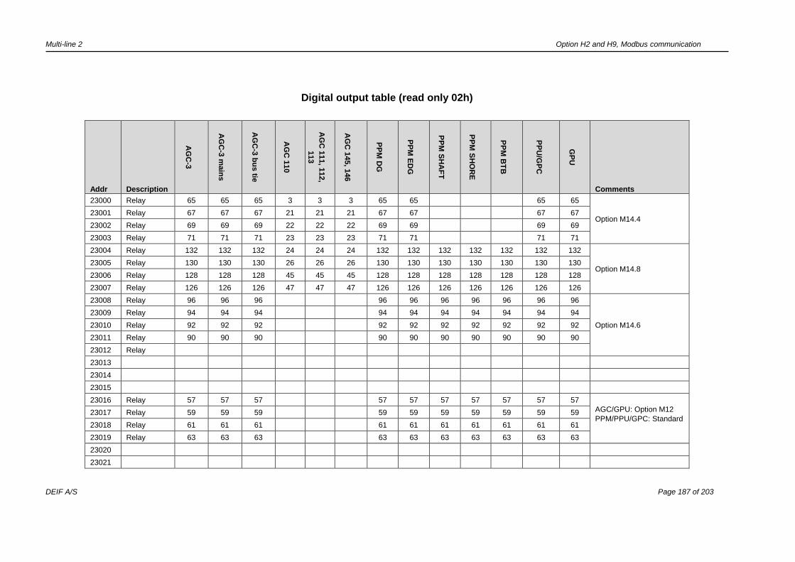
Multi-line 2 Option H2 and H9, Modbus communication
DEIF A/S Page 187 of 203
Digital output table (read only 02h)
Addr Description
AG
C-3
AG
C-3
main
s
AG
C-3
bu
s tie
AG
C 1
10
AG
C 1
11, 1
12,
113
AG
C 1
45, 1
46
PP
M D
G
PP
M E
DG
PP
M S
HA
FT
PP
M S
HO
RE
PP
M B
TB
PP
U/G
PC
GP
U
Comments
23000 Relay 65 65 65 3 3 3 65 65 65 65
Option M14.4 23001 Relay 67 67 67 21 21 21 67 67 67 67
23002 Relay 69 69 69 22 22 22 69 69 69 69
23003 Relay 71 71 71 23 23 23 71 71 71 71
23004 Relay 132 132 132 24 24 24 132 132 132 132 132 132 132
Option M14.8 23005 Relay 130 130 130 26 26 26 130 130 130 130 130 130 130
23006 Relay 128 128 128 45 45 45 128 128 128 128 128 128 128
23007 Relay 126 126 126 47 47 47 126 126 126 126 126 126 126
23008 Relay 96 96 96 96 96 96 96 96 96 96
Option M14.6
23009 Relay 94 94 94 94 94 94 94 94 94 94
23010 Relay 92 92 92 92 92 92 92 92 92 92
23011 Relay 90 90 90 90 90 90 90 90 90 90
23012 Relay
23013
23014
23015
23016 Relay 57 57 57 57 57 57 57 57 57 57
AGC/GPU: Option M12
PPM/PPU/GPC: Standard
23017 Relay 59 59 59 59 59 59 59 59 59 59
23018 Relay 61 61 61 61 61 61 61 61 61 61
23019 Relay 63 63 63 63 63 63 63 63 63 63
23020
23021
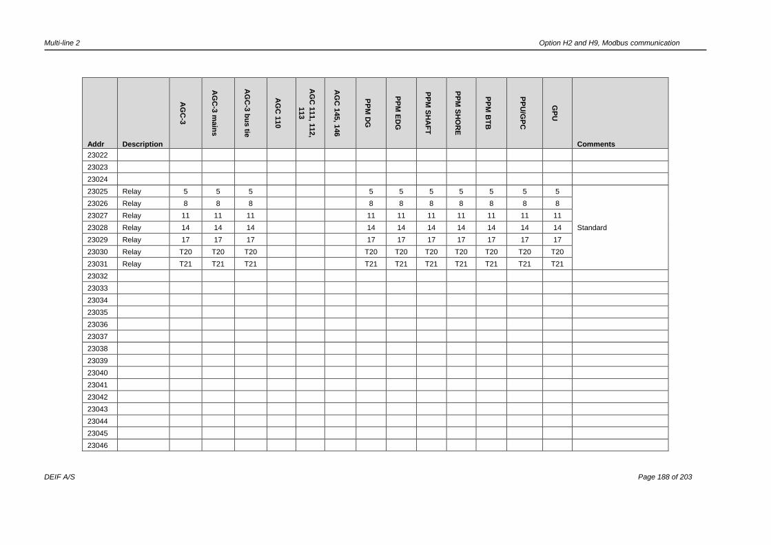
Multi-line 2 Option H2 and H9, Modbus communication
DEIF A/S Page 188 of 203
Addr Description
AG
C-3
AG
C-3
main
s
AG
C-3
bu
s tie
AG
C 1
10
AG
C 1
11, 1
12,
113
AG
C 1
45, 1
46
PP
M D
G
PP
M E
DG
PP
M S
HA
FT
PP
M S
HO
RE
PP
M B
TB
PP
U/G
PC
GP
U
Comments
23022
23023
23024
23025 Relay 5 5 5 5 5 5 5 5 5 5
Standard
23026 Relay 8 8 8 8 8 8 8 8 8 8
23027 Relay 11 11 11 11 11 11 11 11 11 11
23028 Relay 14 14 14 14 14 14 14 14 14 14
23029 Relay 17 17 17 17 17 17 17 17 17 17
23030 Relay T20 T20 T20 T20 T20 T20 T20 T20 T20 T20
23031 Relay T21 T21 T21 T21 T21 T21 T21 T21 T21 T21
23032
23033
23034
23035
23036
23037
23038
23039
23040
23041
23042
23043
23044
23045
23046
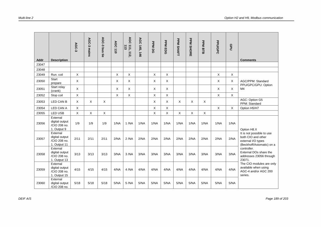
Multi-line 2 Option H2 and H9, Modbus communication
DEIF A/S Page 189 of 203
Addr Description
AG
C-3
AG
C-3
main
s
AG
C-3
bu
s tie
AG
C 1
10
AG
C 1
11, 1
12,
113
AG
C 1
45, 1
46
PP
M D
G
PP
M E
DG
PP
M S
HA
FT
PP
M S
HO
RE
PP
M B
TB
PP
U/G
PC
GP
U
Comments
23047
23048
23049 Run. coil X X X X X X X
AGC/PPM: Standard
PPU/GPC/GPU: Option
M4
23050 Start
prepare X X X X X X X
23051 Start relay
(crank) X X X X X X X
23052 Stop coil X X X X X X X
23053 LED CAN B X X X X X X X X AGC: Option G5
PPM: Standard
23054 LED CAN A X X X X X Option H5/H7
23055 LED USB X X X X X X X X
23056
External
digital output
/CIO 208 no.
1. Output 9
1/9 1/9 1/9 1/NA 1 /NA 1/NA 1/NA 1/NA 1/NA 1/NA 1/NA 1/NA 1/NA
Option H8.X
It is not possible to use
both CIO and other
external I/O types
(Beckhoff/Axiomatic) on a
controller.
External DOs share the
addresses 23056 through
23071.
The CIO modules are only
available when using
AGC-4 and/or AGC 200
series.
23057
External
digital output
/CIO 208 no.
1. Output 11
2/11 2/11 2/11 2/NA 2 /NA 2/NA 2/NA 2/NA 2/NA 2/NA 2/NA 2/NA 2/NA
23058
External
digital output
/CIO 208 no.
1. Output 13
3/13 3/13 3/13 3/NA 3 /NA 3/NA 3/NA 3/NA 3/NA 3/NA 3/NA 3/NA 3/NA
23059
External
digital output
/CIO 208 no.
1. Output 15
4/15 4/15 4/15 4/NA 4 /NA 4/NA 4/NA 4/NA 4/NA 4/NA 4/NA 4/NA 4/NA
23060
External
digital output
/CIO 208 no.
5/18 5/18 5/18 5/NA 5 /NA 5/NA 5/NA 5/NA 5/NA 5/NA 5/NA 5/NA 5/NA
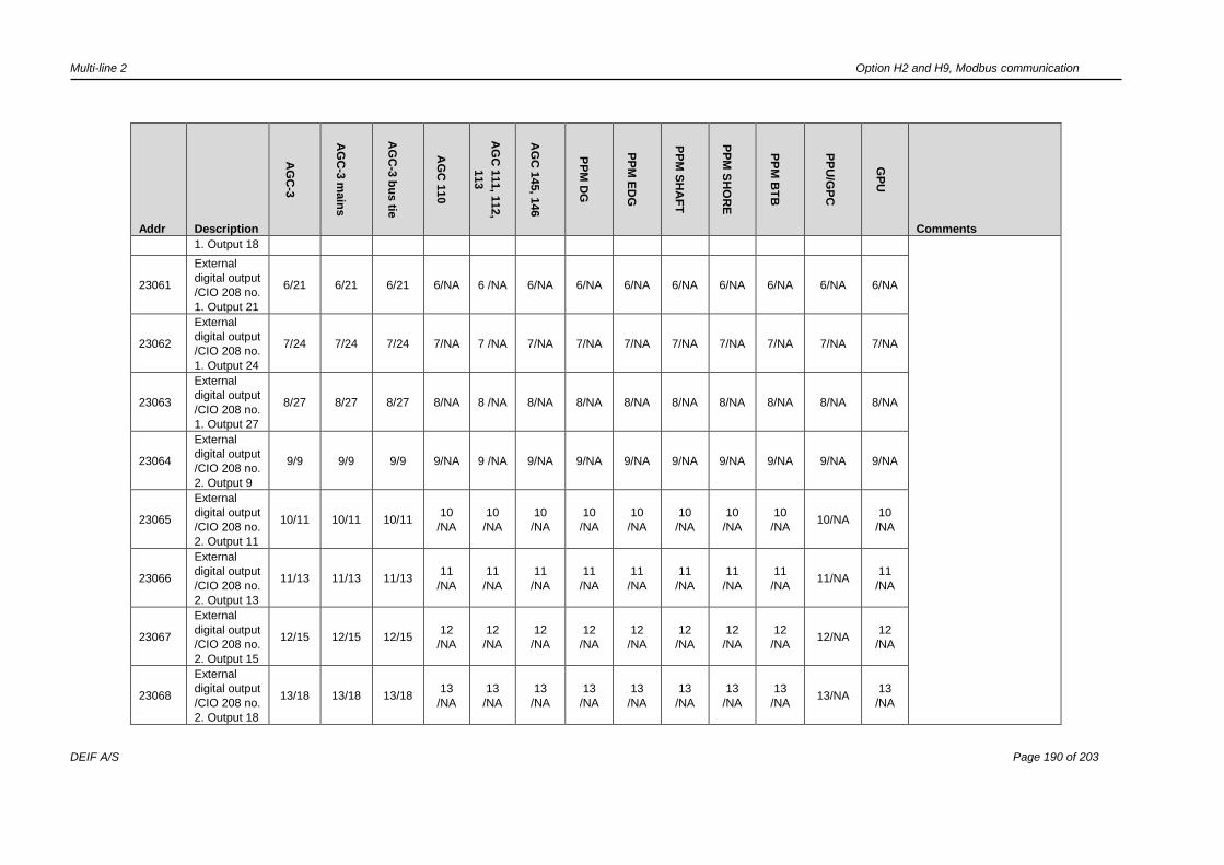
Multi-line 2 Option H2 and H9, Modbus communication
DEIF A/S Page 190 of 203
Addr Description
AG
C-3
AG
C-3
main
s
AG
C-3
bu
s tie
AG
C 1
10
AG
C 1
11, 1
12,
113
AG
C 1
45, 1
46
PP
M D
G
PP
M E
DG
PP
M S
HA
FT
PP
M S
HO
RE
PP
M B
TB
PP
U/G
PC
GP
U
Comments
1. Output 18
23061
External
digital output
/CIO 208 no.
1. Output 21
6/21 6/21 6/21 6/NA 6 /NA 6/NA 6/NA 6/NA 6/NA 6/NA 6/NA 6/NA 6/NA
23062
External
digital output
/CIO 208 no.
1. Output 24
7/24 7/24 7/24 7/NA 7 /NA 7/NA 7/NA 7/NA 7/NA 7/NA 7/NA 7/NA 7/NA
23063
External
digital output
/CIO 208 no.
1. Output 27
8/27 8/27 8/27 8/NA 8 /NA 8/NA 8/NA 8/NA 8/NA 8/NA 8/NA 8/NA 8/NA
23064
External
digital output
/CIO 208 no.
2. Output 9
9/9 9/9 9/9 9/NA 9 /NA 9/NA 9/NA 9/NA 9/NA 9/NA 9/NA 9/NA 9/NA
23065
External
digital output
/CIO 208 no.
2. Output 11
10/11 10/11 10/11 10
/NA
10
/NA
10
/NA
10
/NA
10
/NA
10
/NA
10
/NA
10
/NA 10/NA
10
/NA
23066
External
digital output
/CIO 208 no.
2. Output 13
11/13 11/13 11/13 11
/NA
11
/NA
11
/NA
11
/NA
11
/NA
11
/NA
11
/NA
11
/NA 11/NA
11
/NA
23067
External
digital output
/CIO 208 no.
2. Output 15
12/15 12/15 12/15 12
/NA
12
/NA
12
/NA
12
/NA
12
/NA
12
/NA
12
/NA
12
/NA 12/NA
12
/NA
23068
External
digital output
/CIO 208 no.
2. Output 18
13/18 13/18 13/18 13
/NA
13
/NA
13
/NA
13
/NA
13
/NA
13
/NA
13
/NA
13
/NA 13/NA
13
/NA
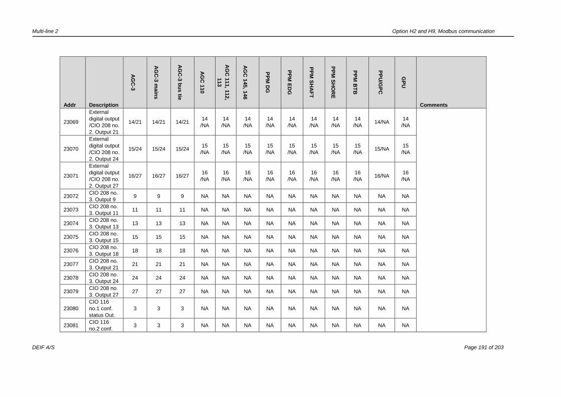
Multi-line 2 Option H2 and H9, Modbus communication
DEIF A/S Page 191 of 203
Addr Description
AG
C-3
AG
C-3
main
s
AG
C-3
bu
s tie
AG
C 1
10
AG
C 1
11, 1
12,
113
AG
C 1
45, 1
46
PP
M D
G
PP
M E
DG
PP
M S
HA
FT
PP
M S
HO
RE
PP
M B
TB
PP
U/G
PC
GP
U
Comments
23069
External
digital output
/CIO 208 no.
2. Output 21
14/21 14/21 14/21 14
/NA
14
/NA
14
/NA
14
/NA
14
/NA
14
/NA
14
/NA
14
/NA 14/NA
14
/NA
23070
External
digital output
/CIO 208 no.
2. Output 24
15/24 15/24 15/24 15
/NA
15
/NA
15
/NA
15
/NA
15
/NA
15
/NA
15
/NA
15
/NA 15/NA
15
/NA
23071
External
digital output
/CIO 208 no.
2. Output 27
16/27 16/27 16/27 16
/NA
16
/NA
16
/NA
16
/NA
16
/NA
16
/NA
16
/NA
16
/NA 16/NA
16
/NA
23072 CIO 208 no.
3. Output 9 9 9 9 NA NA NA NA NA NA NA NA NA NA
23073 CIO 208 no.
3. Output 11 11 11 11 NA NA NA NA NA NA NA NA NA NA
23074 CIO 208 no.
3. Output 13 13 13 13 NA NA NA NA NA NA NA NA NA NA
23075 CIO 208 no.
3. Output 15 15 15 15 NA NA NA NA NA NA NA NA NA NA
23076 CIO 208 no.
3. Output 18 18 18 18 NA NA NA NA NA NA NA NA NA NA
23077 CIO 208 no.
3. Output 21 21 21 21 NA NA NA NA NA NA NA NA NA NA
23078 CIO 208 no.
3. Output 24 24 24 24 NA NA NA NA NA NA NA NA NA NA
23079 CIO 208 no.
3. Output 27 27 27 27 NA NA NA NA NA NA NA NA NA NA
23080
CIO 116
no.1 conf.
status Out.
3 3 3 NA NA NA NA NA NA NA NA NA NA
23081 CIO 116
no.2 conf. 3 3 3 NA NA NA NA NA NA NA NA NA NA
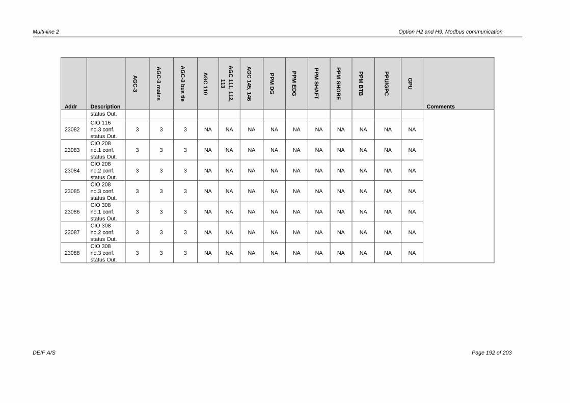
Multi-line 2 Option H2 and H9, Modbus communication
DEIF A/S Page 192 of 203
Addr Description
AG
C-3
AG
C-3
main
s
AG
C-3
bu
s tie
AG
C 1
10
AG
C 1
11, 1
12,
113
AG
C 1
45, 1
46
PP
M D
G
PP
M E
DG
PP
M S
HA
FT
PP
M S
HO
RE
PP
M B
TB
PP
U/G
PC
GP
U
Comments
status Out.
23082
CIO 116
no.3 conf.
status Out.
3 3 3 NA NA NA NA NA NA NA NA NA NA
23083
CIO 208
no.1 conf.
status Out.
3 3 3 NA NA NA NA NA NA NA NA NA NA
23084
CIO 208
no.2 conf.
status Out.
3 3 3 NA NA NA NA NA NA NA NA NA NA
23085
CIO 208
no.3 conf.
status Out.
3 3 3 NA NA NA NA NA NA NA NA NA NA
23086
CIO 308
no.1 conf.
status Out.
3 3 3 NA NA NA NA NA NA NA NA NA NA
23087
CIO 308
no.2 conf.
status Out.
3 3 3 NA NA NA NA NA NA NA NA NA NA
23088
CIO 308
no.3 conf.
status Out.
3 3 3 NA NA NA NA NA NA NA NA NA NA
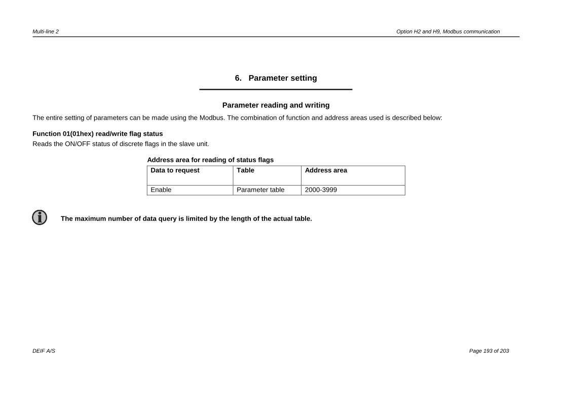
Multi-line 2 Option H2 and H9, Modbus communication
DEIF A/S Page 193 of 203
6. Parameter setting
Parameter reading and writing
The entire setting of parameters can be made using the Modbus. The combination of function and address areas used is described below:
Function 01(01hex) read/write flag status
Reads the ON/OFF status of discrete flags in the slave unit.
Address area for reading of status flags
Data to request Table Address area
Enable Parameter table 2000-3999
The maximum number of data query is limited by the length of the actual table.
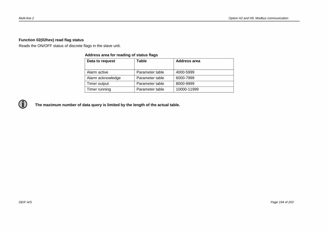
Multi-line 2 Option H2 and H9, Modbus communication
DEIF A/S Page 194 of 203
Function 02(02hex) read flag status
Reads the ON/OFF status of discrete flags in the slave unit.
Address area for reading of status flags
Data to request Table Address area
Alarm active Parameter table 4000-5999
Alarm acknowledge Parameter table 6000-7999
Timer output Parameter table 8000-9999
Timer running Parameter table 10000-11999
The maximum number of data query is limited by the length of the actual table.

Multi-line 2 Option H2 and H9, Modbus communication
DEIF A/S Page 195 of 203
Function 03(03hex) read registers
Reads the binary of registers in the slave unit.
Address area for reading of registers
Data to request Table Address area
Timers used Parameter table 2000-3999
Values used Parameter table 4000-5999
Values minimum Parameter table 6000-7999
Values maximum Parameter table 8000-9999
Output a Parameter table 10000-11999
Output b Parameter table 12000-13999
Fail class used Parameter table 14000-15999
Enable Parameter table 16000-17999
Inhibit Parameter table 18000-19999
The maximum number of data query is limited by the length of the actual table.
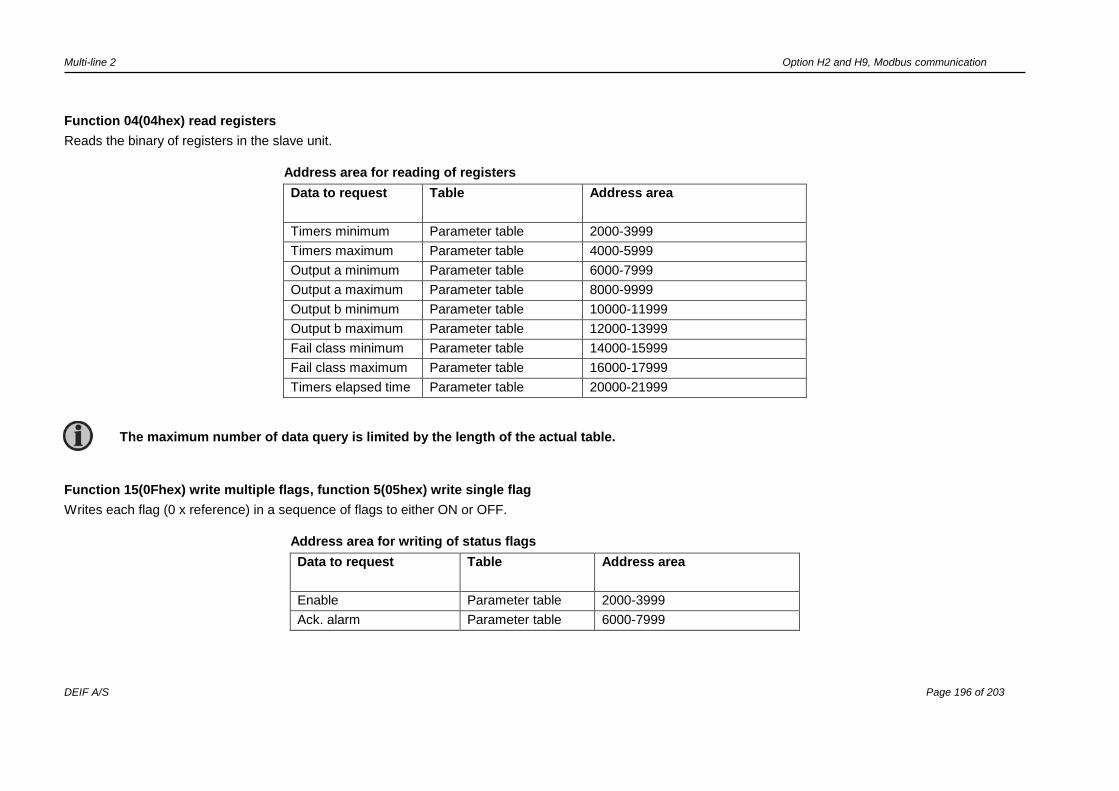
Multi-line 2 Option H2 and H9, Modbus communication
DEIF A/S Page 196 of 203
Function 04(04hex) read registers
Reads the binary of registers in the slave unit.
Address area for reading of registers
Data to request Table Address area
Timers minimum Parameter table 2000-3999
Timers maximum Parameter table 4000-5999
Output a minimum Parameter table 6000-7999
Output a maximum Parameter table 8000-9999
Output b minimum Parameter table 10000-11999
Output b maximum Parameter table 12000-13999
Fail class minimum Parameter table 14000-15999
Fail class maximum Parameter table 16000-17999
Timers elapsed time Parameter table 20000-21999
Function 15(0Fhex) write multiple flags, function 5(05hex) write single flag
Writes each flag (0 x reference) in a sequence of flags to either ON or OFF.
Address area for writing of status flags
Data to request Table Address area
Enable Parameter table 2000-3999
Ack. alarm Parameter table 6000-7999
The maximum number of data query is limited by the length of the actual table.
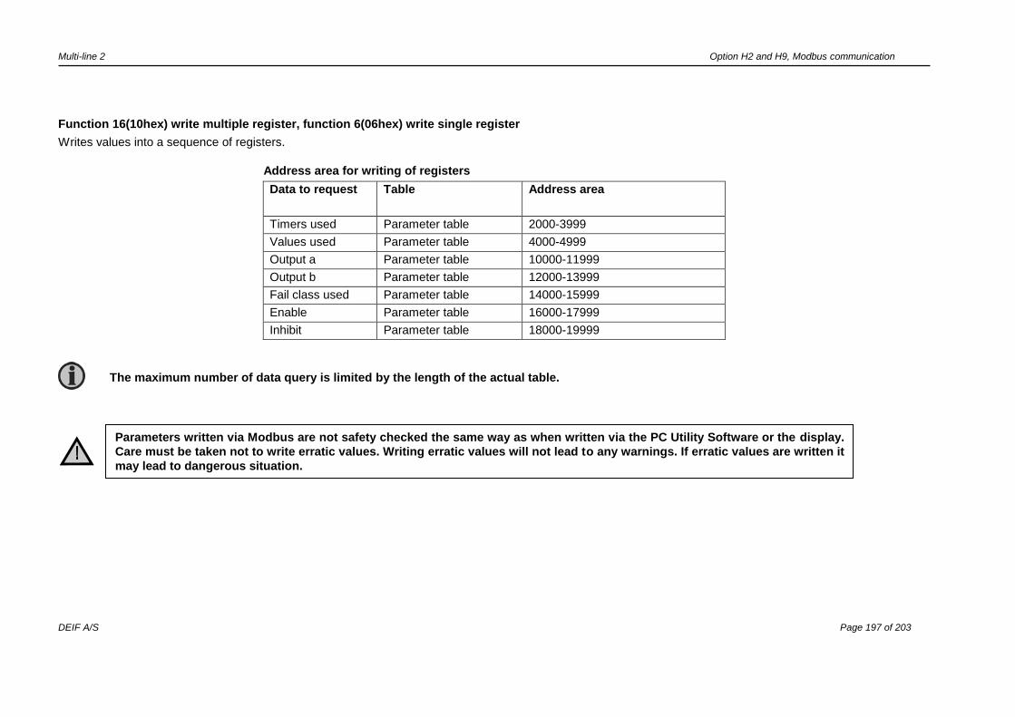
Multi-line 2 Option H2 and H9, Modbus communication
DEIF A/S Page 197 of 203
Function 16(10hex) write multiple register, function 6(06hex) write single register
Writes values into a sequence of registers.
Address area for writing of registers
Data to request Table Address area
Timers used Parameter table 2000-3999
Values used Parameter table 4000-4999
Output a Parameter table 10000-11999
Output b Parameter table 12000-13999
Fail class used Parameter table 14000-15999
Enable Parameter table 16000-17999
Inhibit Parameter table 18000-19999
The maximum number of data query is limited by the length of the actual table.
Parameters written via Modbus are not safety checked the same way as when written via the PC Utility Software or the display.
Care must be taken not to write erratic values. Writing erratic values will not lead to any warnings. If erratic values are written it
may lead to dangerous situation.
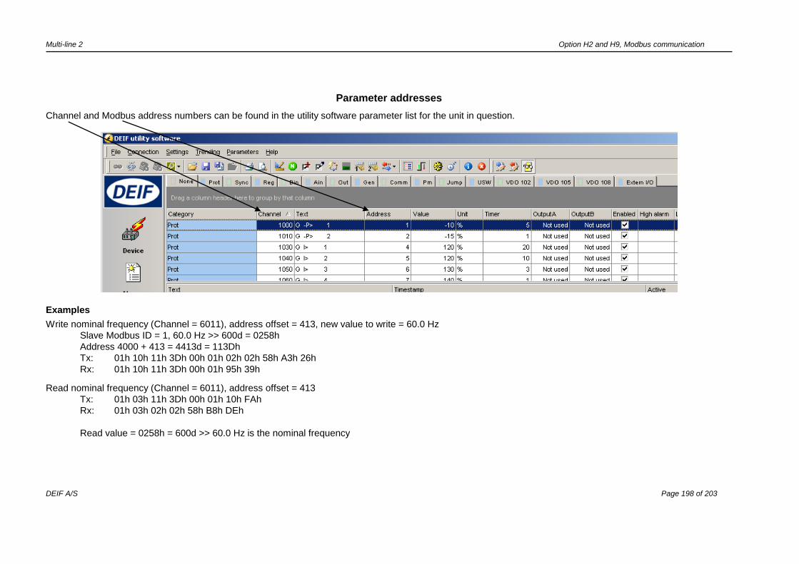
Multi-line 2 Option H2 and H9, Modbus communication
DEIF A/S Page 198 of 203
Parameter addresses
Channel and Modbus address numbers can be found in the utility software parameter list for the unit in question.
Examples
Write nominal frequency (Channel = 6011), address offset = 413, new value to write = 60.0 Hz
Slave Modbus ID = 1, 60.0 Hz >> 600d = 0258h
Address 4000 + 413 = 4413d = 113Dh
Tx: 01h 10h 11h 3Dh 00h 01h 02h 02h 58h A3h 26h
Rx: 01h 10h 11h 3Dh 00h 01h 95h 39h
Read nominal frequency (Channel = 6011), address offset = 413
Tx: 01h 03h 11h 3Dh 00h 01h 10h FAh
Rx: 01h 03h 02h 02h 58h B8h DEh
Read value = 0258h = 600d >> 60.0 Hz is the nominal frequency
Multi-line 2 Option H2 and H9, Modbus communication
DEIF A/S Page 199 of 203
Modbus address offset for alarms on CIO modules
The Modbus offset addresses related to the CIO modules are not listed in the USW like all other offset. The tables in the following pages show the CIO modules’
Modbus offset addresses. The procedure for reading/writing in Modbus is still the same as previously described.
The CIO modules are only available when using AGC-4 and/or AGC 200 series.
It is only possible to access these as read-only values. Configuration must be done using the USW.

Multi-line 2 Option H2 and H9, Modbus communication
DEIF A/S Page 200 of 203
Modbus alarm offset addresses for CIO 116
Description Address offset
Description Address offset
CIO 116 no. 1. Input 10 1047 CIO 116 no. 2. Input 16 1200
CIO 116 no. 1. Input 11 1048 CIO 116 no. 2. Input 17 1237
CIO 116 no. 1. Input 12 1049 CIO 116 no. 2. Input 19 1238
CIO 116 no. 1. Input 13 1050 CIO 116 no. 2. Input 20 1257
CIO 116 no. 1. Input 14 1051 CIO 116 no. 2. Input 21 1260
CIO 116 no. 1. Input 15 1052 CIO 116 no. 2. Input 22 1261
CIO 116 no. 1. Input 16 1053 CIO 116 no. 2. Input 23 1264
CIO 116 no. 1. Input 17 1054 CIO 116 no. 2. Input 24 1266
CIO 116 no. 1. Input 19 1055 CIO 116 no. 2. Input 25 1267
CIO 116 no. 1. Input 20 1056 CIO 116 no. 2. Input 26 1272
CIO 116 no. 1. Input 21 1057 CIO 116 no. 3. Input 10 1296
CIO 116 no. 1. Input 22 1058 CIO 116 no. 3. Input 11 1316
CIO 116 no. 1. Input 23 1059 CIO 116 no. 3. Input 12 1323
CIO 116 no. 1. Input 24 1060 CIO 116 no. 3. Input 13 1324
CIO 116 no. 1. Input 25 1061 CIO 116 no. 3. Input 14 1325
CIO 116 no. 1. Input 26 1062 CIO 116 no. 3. Input 15 1327
CIO 116 no. 2. Input 10 1194 CIO 116 no. 3. Input 16 1328
CIO 116 no. 2. Input 11 1195 CIO 116 no. 3. Input 17 1329
CIO 116 no. 2. Input 12 1196 CIO 116 no. 3. Input 19 1330
CIO 116 no. 2. Input 13 1197 CIO 116 no. 3. Input 20 1331
CIO 116 no. 2. Input 14 1198 CIO 116 no. 3. Input 21 1332
CIO 116 no. 2. Input 15 1199 CIO 116 no. 3. Input 22 1333

Multi-line 2 Option H2 and H9, Modbus communication
DEIF A/S Page 201 of 203
Description Address offset
Description Address offset
CIO 116 no. 3. Input 23 1334 CIO 116 no. 1 missing 957
CIO 116 no. 3. Input 24 1362 CIO 116 no. 2 missing 958
CIO 116 no. 3. Input 25 1363 CIO 116 no. 3 missing 959
CIO 116 no. 3. Input 26 1364
Modbus alarm offset addresses for CIO 208
Description Address offset
CIO 208 no. 1 missing 960
CIO 208 no. 2 missing 961
CIO 208 no. 3 missing 962
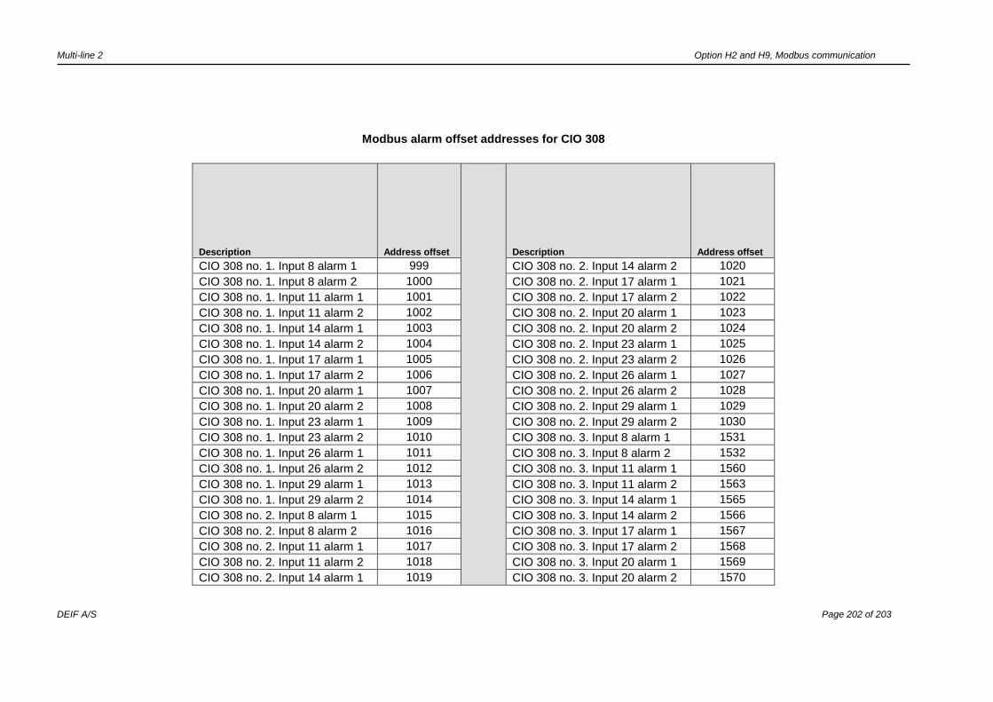
Multi-line 2 Option H2 and H9, Modbus communication
DEIF A/S Page 202 of 203
Modbus alarm offset addresses for CIO 308
Description Address offset
Description Address offset
CIO 308 no. 1. Input 8 alarm 1 999 CIO 308 no. 2. Input 14 alarm 2 1020
CIO 308 no. 1. Input 8 alarm 2 1000 CIO 308 no. 2. Input 17 alarm 1 1021
CIO 308 no. 1. Input 11 alarm 1 1001 CIO 308 no. 2. Input 17 alarm 2 1022
CIO 308 no. 1. Input 11 alarm 2 1002 CIO 308 no. 2. Input 20 alarm 1 1023
CIO 308 no. 1. Input 14 alarm 1 1003 CIO 308 no. 2. Input 20 alarm 2 1024
CIO 308 no. 1. Input 14 alarm 2 1004 CIO 308 no. 2. Input 23 alarm 1 1025
CIO 308 no. 1. Input 17 alarm 1 1005 CIO 308 no. 2. Input 23 alarm 2 1026
CIO 308 no. 1. Input 17 alarm 2 1006 CIO 308 no. 2. Input 26 alarm 1 1027
CIO 308 no. 1. Input 20 alarm 1 1007 CIO 308 no. 2. Input 26 alarm 2 1028
CIO 308 no. 1. Input 20 alarm 2 1008 CIO 308 no. 2. Input 29 alarm 1 1029
CIO 308 no. 1. Input 23 alarm 1 1009 CIO 308 no. 2. Input 29 alarm 2 1030
CIO 308 no. 1. Input 23 alarm 2 1010 CIO 308 no. 3. Input 8 alarm 1 1531
CIO 308 no. 1. Input 26 alarm 1 1011 CIO 308 no. 3. Input 8 alarm 2 1532
CIO 308 no. 1. Input 26 alarm 2 1012 CIO 308 no. 3. Input 11 alarm 1 1560
CIO 308 no. 1. Input 29 alarm 1 1013 CIO 308 no. 3. Input 11 alarm 2 1563
CIO 308 no. 1. Input 29 alarm 2 1014 CIO 308 no. 3. Input 14 alarm 1 1565
CIO 308 no. 2. Input 8 alarm 1 1015 CIO 308 no. 3. Input 14 alarm 2 1566
CIO 308 no. 2. Input 8 alarm 2 1016 CIO 308 no. 3. Input 17 alarm 1 1567
CIO 308 no. 2. Input 11 alarm 1 1017 CIO 308 no. 3. Input 17 alarm 2 1568
CIO 308 no. 2. Input 11 alarm 2 1018 CIO 308 no. 3. Input 20 alarm 1 1569
CIO 308 no. 2. Input 14 alarm 1 1019 CIO 308 no. 3. Input 20 alarm 2 1570

Multi-line 2 Option H2 and H9, Modbus communication
DEIF A/S Page 203 of 203
Description Address offset
Description Address offset
CIO 308 no. 3. Input 23 alarm 1 1571 CIO 308 no. 2. Input 8 wire fail 1039
CIO 308 no. 3. Input 23 alarm 2 1572 CIO 308 no. 2. Input 11 wire fail 1040
CIO 308 no. 3. Input 26 alarm 1 1573 CIO 308 no. 2. Input 14 wire fail 1041
CIO 308 no. 3. Input 26 alarm 2 1574 CIO 308 no. 2. Input 17 wire fail 1042
CIO 308 no. 3. Input 29 alarm 1 1575 CIO 308 no. 2. Input 20 wire fail 1043
CIO 308 no. 3. Input 29 alarm 2 1576 CIO 308 no. 2. Input 23 wire fail 1044
CIO 308 No. 1 missing 963 CIO 308 no. 2. Input 26 wire fail 1045
CIO 308 No. 2 missing 964 CIO 308 no. 2. Input 29 wire fail 1046
CIO 308 No. 3 missing 965 CIO 308 no. 3. Input 8 wire fail 1083
CIO 308 no. 1. Input 8 wire fail 1031 CIO 308 no. 3. Input 11 wire fail 1085
CIO 308 no. 1. Input 11 wire fail 1032 CIO 308 no. 3. Input 14 wire fail 1086
CIO 308 no. 1. Input 14 wire fail 1033 CIO 308 no. 3. Input 17 wire fail 1110
CIO 308 no. 1. Input 17 wire fail 1034 CIO 308 no. 3. Input 20 wire fail 1391
CIO 308 no. 1. Input 20 wire fail 1035 CIO 308 no. 3. Input 23 wire fail 1392
CIO 308 no. 1. Input 23 wire fail 1036 CIO 308 no. 3. Input 26 wire fail 1427
CIO 308 no. 1. Input 26 wire fail 1037 CIO 308 no. 3. Input 29 wire fail 1529
CIO 308 no. 1. Input 29 wire fail 1038
DEIF A/S reserves the right to change any of the above.
Related Documents