PAGE 1 OF 3 Optimus 2 Installation Guide for LCA-SB NOTE: Electrical connections must be performed by a qualified, licensed electrician. NOTE: Lockout and tagout power to pole before installing fixture. CAUTION, risk of electric shock Per IEC TR 62778, luminaire should be positioned so that prolonged staring into luminaire at a distance of 0.319 m is not expected. Round Light Pole Installations 1. Slipfitter: Connect exposed fixture wire to power wire. Install luminaire on light pole and tighten M8 screws. Adjust luminaire angle (-90° ~ 90°). 2. Photocell: Insert light sensor into photocell socket and rotate into place. Connect exposed fixture wire to power wire. Install fixture on light pole and tighten M8 screws. Adjust fixture angle (-90° ~ 90°). 3. Motion sensor: Insert light sensor into photocell socket and rotate into place. Connect exposed fixture wire to power wire. Install fixture on light pole and tighten M8 screws. Insert motion sensor into socket and rotate into place. Adjust fixture angle (-90° ~ 90°). Photocell Motion sensor Square Light Pole Installations 1. Straight arm: Open pole cap. Open fixture cover. Push all wire through fixture hole and align installation hole of fixture to installation hole of lamp hole. Fasten screws. Connect exposed luminaire wire to power wire. 2. Photocell: Insert light sensor into socket and rotate into place. Open pole cap. Open fixture cover. Push all wire through fixture hole and align fixture and installation location on pole. Fasten screws. Connect exposed luminaire wire to power wire. 3. Motion sensor: Open pole cap. Open fixture cover. Push all wire through fixture hole and align fixture and installation location on pole. Fasten screws. Insert motion sensor into socket and rotate into place. Connect exposed fixture wire to power wire. Pole cap Pole cap Photocell Motion sensor Pole cap

Welcome message from author
This document is posted to help you gain knowledge. Please leave a comment to let me know what you think about it! Share it to your friends and learn new things together.
Transcript

PAGE 1 OF 3
Optimus 2Installation Guide for LCA-SB
NOTE: Electrical connections must be performed by a qualified, licensed electrician.
NOTE: Lockout and tagout power to pole before installing fixture.
CAUTION, risk of electric shock
Per IEC TR 62778, luminaire should be positioned so that prolonged staring into luminaire at a distance of 0.319 m is not expected.
Round Light Pole Installations
1. Slipfitter: Connect exposed fixture wire to power wire. Install luminaire on light pole and tighten M8 screws. Adjust luminaire angle (-90° ~ 90°).
2. Photocell: Insert light sensor into photocell socket and rotate into place. Connect exposed fixture wire to power wire. Install fixture on light pole and tighten M8 screws. Adjust fixture angle (-90° ~ 90°).
3. Motion sensor: Insert light sensor into photocell socket and rotate into place. Connect exposed fixture wire to power wire. Install fixture on light pole and tighten M8 screws. Insert motion sensor into socket and rotate into place. Adjust fixture angle (-90° ~ 90°).
Photocell
Motion sensor
Square Light Pole Installations
1. Straight arm: Open pole cap. Open fixture cover. Push all wire through fixture hole and align installation hole of fixture to installation hole of lamp hole. Fasten screws. Connect exposed luminaire wire to power wire.
2. Photocell: Insert light sensor into socket and rotate into place. Open pole cap. Open fixture cover. Push all wire through fixture hole and align fixture and installation location on pole. Fasten screws. Connect exposed luminaire wire to power wire.
3. Motion sensor: Open pole cap. Open fixture cover. Push all wire through fixture hole and align fixture and installation location on pole. Fasten screws. Insert motion sensor into socket and rotate into place. Connect exposed fixture wire to power wire.
Pole cap
Pole cap
Photocell
Motion sensor
Pole cap

PAGE 2 OF 3
Optimus 2Installation Guide for LCA-SB
Trunnion Installations
1. Connect exposed fixture wire to power wire. Adjust luminaire angle (-90° ~ 90°). Install luminaire and tighten M8 screws.
2. Photocell: Insert light sensor into photocell socket and rotate into place. Connect exposed fixture wire to power wire. Adjust fixture angle (-90° ~ 90°). Install luminaire and tighten M8 screws.
3. Motion sensor: Connect exposed fixture wire to power wire. Insert motion sensor into socket and rotate into place. Adjust fixture angle (-90° ~ 90°). Insert motion sensor into socket and rotate into place. Install fixture and tighten M8 screws.
Photocell
Motion sensor
1. Adjustable arm: Open pole cap. Open fixture cover. Push all wire through fixture hole and align fixture and installation location on pole. Fasten screws. Connect exposed luminaire wire to power wire. Adjust fixture angle (-90° ~ 90°).
2. Photocell: Insert light sensor into photocell socket and rotate into place. Open pole cap. Open fixture cover. Push all wire through fixture hole and align fixture and installation location on pole. Fasten screws. Connect exposed luminaire wire to power wire. Adjust fixture angle (-90° ~ 90°).
3. Motion sensor: Open pole cap. Open fixture cover. Push all wire through fixture hole and align fixture and installation location on pole. Fasten screws. Insert motion sensor into socket and rotate into place. Connect exposed luminaire wire to power wire. Adjust fixture angle (-90° ~ 90°).
Pole cap
Pole cap
Photocell
Motion sensor
Pole cap
PAGE 3 OF 3
Optimus 2Installation Guide for LCA-SB
Customer service and technical support888.747.4LED (888.747.4533)SloanLED.com • [email protected]
Europe: Customer service and technical support+31 88 12 44 900 SloanLED.com • [email protected]
P/N 402506 Rev B 2020-03-23
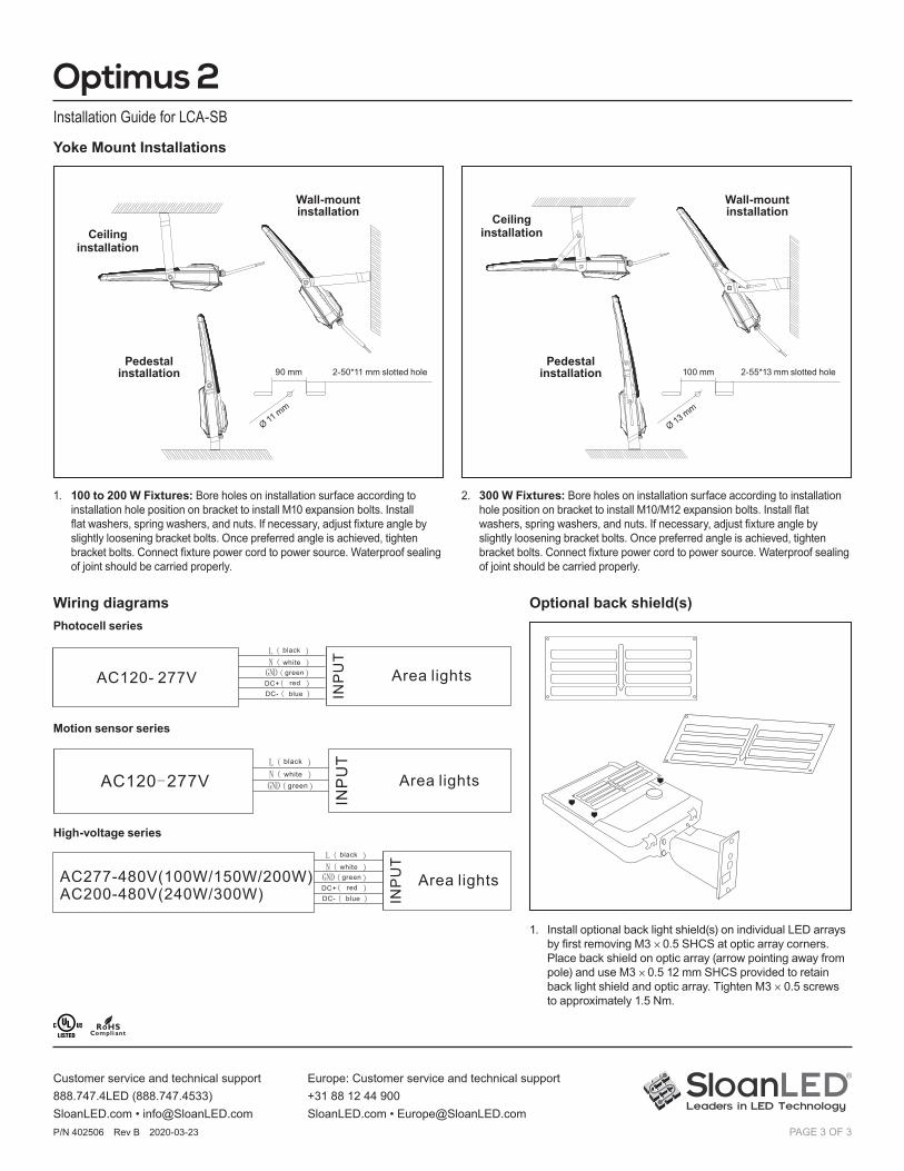
Yoke Mount Installations
1. 100 to 200 W Fixtures: Bore holes on installation surface according to installation hole position on bracket to install M10 expansion bolts. Install flat washers, spring washers, and nuts. If necessary, adjust fixture angle by slightly loosening bracket bolts. Once preferred angle is achieved, tighten bracket bolts. Connect fixture power cord to power source. Waterproof sealing of joint should be carried properly.
2. 300 W Fixtures: Bore holes on installation surface according to installation hole position on bracket to install M10/M12 expansion bolts. Install flat washers, spring washers, and nuts. If necessary, adjust fixture angle by slightly loosening bracket bolts. Once preferred angle is achieved, tighten bracket bolts. Connect fixture power cord to power source. Waterproof sealing of joint should be carried properly.
Pedestal installation
Pedestal installation
Wall-mount installation
Wall-mount installationCeiling
installationCeiling installation
Ø 11 mm
Ø 13 mm
90 mm 100 mm2-50*11 mm slotted hole 2-55*13 mm slotted hole
Wiring diagramsPhotocell series
Motion sensor series
black
white
red Area lightsAC120- 277V greenDC+
blueDC-
High-voltage series:
black
white
red Area lightsAC277-480V(100W/150W/200W)AC200-480V(240W/300W)
greenDC+
blueDC-
black
whitegreen Area lights
Motion Sensor series:
AC120-277V
black
white
red Area lightsAC120- 277V greenDC+
blueDC-
High-voltage series:
black
white
red Area lightsAC277-480V(100W/150W/200W)AC200-480V(240W/300W)
greenDC+
blueDC-
black
whitegreen Area lights
Motion Sensor series:
AC120-277V
black
white
red Area lightsAC120- 277V greenDC+
blueDC-
High-voltage series:
black
white
red Area lightsAC277-480V(100W/150W/200W)AC200-480V(240W/300W)
greenDC+
blueDC-
black
whitegreen Area lights
Motion Sensor series:
AC120-277V
High-voltage series
1. Install optional back light shield(s) on individual LED arrays by first removing M3 × 0.5 SHCS at optic array corners. Place back shield on optic array (arrow pointing away from pole) and use M3 × 0.5 12 mm SHCS provided to retain back light shield and optic array. Tighten M3 × 0.5 screws to approximately 1.5 Nm.
Optional back shield(s)
Related Documents


![SUNIVA OPTIMUS SERIES MONOCRYSTALLINE SOLAR …suniva.com/documents/[SAMD_0051] Suniva Optimus 72...SUNIVA OPTIMUS® SERIES MONOCRYSTALLINE SOLAR MODULES ENGINEERING EXCELLENCE Built](https://static.cupdf.com/doc/110x72/5e5dfc0a8c38203c032420d1/suniva-optimus-series-monocrystalline-solar-samd0051-suniva-optimus-72-suniva.jpg)