Struct Multidisc Optim (2012) 45:377–399 DOI 10.1007/s00158-011-0675-2 RESEARCH PAPER Optimum topology design of various geometrically nonlinear latticed domes using improved harmony search method Serdar Çarba¸ s · Mehmet P. Saka Received: 9 March 2010 / Revised: 10 May 2011 / Accepted: 20 May 2011 / Published online: 29 June 2011 c Springer-Verlag 2011 Abstract Domes are elegant and economical structures used in covering large areas. They are built in various forms. According to their form, they are given special names such as lamella, network, and geodesic domes. In this paper, optimum topological design algorithm is presented that determines the optimum number of rings, the opti- mum height of crown and tubular section designations for the member groups of these domes. The design algorithm developed has a routine that generates the data required for the geometry of these domes automatically. The minimum weight of each dome is taken as the objective function. The design constraints are implemented according to the provi- sion of LRFD-AISC (Load and Resistance Factor Design– American Institute of Steel Constitution). The optimum topological design problem that considers these constraints turns out to be discrete programming problem. Improved harmony search algorithm is suggested to determine its optimum solution. The design algorithm also considers the geometric nonlinearity of these dome structures. Design examples are presented to demonstrate the effectiveness and robustness of the design optimization algorithm developed. Keywords Optimum structural design · Harmony search algorithm · Stochastic search technique · Lamella domes · Network domes · Geodesic domes S. Çarba¸ s(B ) · M. P. Saka Department of Engineering Sciences, Middle East Technical University, 06531 Ankara, Turkey e-mail: [email protected] 1 Introduction Covering large areas without intermediate supports has always been a challenging task for structural engineers. Domes have provided economical solution to this problem throughout the history. One of the unique features of the historical monumental buildings such as palaces, churches and mosques is that they possess a dome that covers the hall of congregation. The spherical structure of a dome does not only provide elegant appearance but also offer one of the most efficient interior atmospheres for human residence because air and energy are allowed to circulate without obstruction. The historical domes were constructed using wood, stone and bricks which results in having heavy structures. Great majority of today’s domes are built by intercon- necting steel elements, usually tubular steel sections, to each other using moment resisting connections. These ele- gant structures are called latticed domes and they are quite light compare to historical ones. The latticed domes are given special names depending on the form in which steel elements are connected to each other. Among the recent applications, the well known ones are lamella domes, net- work domes, and geodesic domes. Latticed domes can easily resist large concentrated or live loads due to the fact that the effect of these loads is rapidly dispersed through- out the interconnecting members; generating primarily axial forces. Consequently, this results in substantial saving of material and yields economical structure. This is proba- bly the main reason why domes are unrivalled structures in covering large areas all over the world. The basic parameters that define the geometry of a latticed dome are the total number of rings and height of crown, once its diameter is specified. It is possible to generate three dimensional shape of a latticed dome

Welcome message from author
This document is posted to help you gain knowledge. Please leave a comment to let me know what you think about it! Share it to your friends and learn new things together.
Transcript
Struct Multidisc Optim (2012) 45:377–399DOI 10.1007/s00158-011-0675-2
RESEARCH PAPER
Optimum topology design of various geometrically nonlinearlatticed domes using improved harmony search method
Serdar Çarbas · Mehmet P. Saka
Received: 9 March 2010 / Revised: 10 May 2011 / Accepted: 20 May 2011 / Published online: 29 June 2011c© Springer-Verlag 2011
Abstract Domes are elegant and economical structuresused in covering large areas. They are built in variousforms. According to their form, they are given special namessuch as lamella, network, and geodesic domes. In thispaper, optimum topological design algorithm is presentedthat determines the optimum number of rings, the opti-mum height of crown and tubular section designations forthe member groups of these domes. The design algorithmdeveloped has a routine that generates the data required forthe geometry of these domes automatically. The minimumweight of each dome is taken as the objective function. Thedesign constraints are implemented according to the provi-sion of LRFD-AISC (Load and Resistance Factor Design–American Institute of Steel Constitution). The optimumtopological design problem that considers these constraintsturns out to be discrete programming problem. Improvedharmony search algorithm is suggested to determine itsoptimum solution. The design algorithm also considers thegeometric nonlinearity of these dome structures. Designexamples are presented to demonstrate the effectiveness androbustness of the design optimization algorithm developed.
Keywords Optimum structural design · Harmony searchalgorithm · Stochastic search technique · Lamella domes ·Network domes · Geodesic domes
S. Çarbas (B) · M. P. SakaDepartment of Engineering Sciences,Middle East Technical University,06531 Ankara, Turkeye-mail: [email protected]
1 Introduction
Covering large areas without intermediate supports hasalways been a challenging task for structural engineers.Domes have provided economical solution to this problemthroughout the history. One of the unique features of thehistorical monumental buildings such as palaces, churchesand mosques is that they possess a dome that covers thehall of congregation. The spherical structure of a domedoes not only provide elegant appearance but also offerone of the most efficient interior atmospheres for humanresidence because air and energy are allowed to circulatewithout obstruction. The historical domes were constructedusing wood, stone and bricks which results in having heavystructures.
Great majority of today’s domes are built by intercon-necting steel elements, usually tubular steel sections, toeach other using moment resisting connections. These ele-gant structures are called latticed domes and they are quitelight compare to historical ones. The latticed domes aregiven special names depending on the form in which steelelements are connected to each other. Among the recentapplications, the well known ones are lamella domes, net-work domes, and geodesic domes. Latticed domes caneasily resist large concentrated or live loads due to the factthat the effect of these loads is rapidly dispersed through-out the interconnecting members; generating primarily axialforces. Consequently, this results in substantial saving ofmaterial and yields economical structure. This is proba-bly the main reason why domes are unrivalled structures incovering large areas all over the world.
The basic parameters that define the geometry of alatticed dome are the total number of rings and heightof crown, once its diameter is specified. It is possibleto generate three dimensional shape of a latticed dome
378 S. Çarbas, M.P. Saka
automatically, if the total number of rings and height of itscrown is given. Consequently, optimum topological designof latticed domes necessitates treatments of these param-eters as design variables. The design constraints that areto be considered in the formulation of the design problemcan be implemented according to one of the current designcodes. Hence, in general the optimum design algorithm tobe developed is expected to select tubular sections for domemembers from the available list such that the provisions ofthe design code adopted are satisfied while the weight orcost of the dome is the minimum. This turns out to be acombinatorial optimization problem.
It is reported that meta-heuristic optimization techniquesemerged recently is quite effective in obtaining the solu-tion of such problems (Saka 2007a). The basic idea behindthese techniques is to simulate a natural phenomenon suchas survival of fittest and swarm intelligence into a numer-ical optimization. Harmony search method is one of therecent additions to meta-heuristic optimization algorithms.This approach simulates the musical performance processthat takes place when a musician searches for a better stateof harmony into a numerical optimization procedure. Jazzimprovisation seeks to find musically pleasing harmonysimilar to the optimum design process which seeks to findoptimum solution. The pitch of each musical instrumentdetermines the aesthetic quality just as the objective func-tion value is determined by the set of values assigned toeach design variable. Harmony search algorithm is firstsuggested and applied to optimum design of water net-work distribution by Geem et al. (2001, 2002) and Geem(2006, 2010c). Utilization of a stochastic derivative on thegrounds of the population density of multiple elite solu-tion vectors while seeking a new vector, instead of usinga calculus-based derivative of single solution vector consti-tutes the base of the theoretical background of the harmonysearch algorithm (Geem 2008). The algorithm has attracteda lot of attention due to its simplicity and efficiency andit is widely applied in various fields of engineering (Geem2009a, 2010a, b, c). Harmony search method is also usedto obtain the solution of optimum structural design prob-lem with continuous and discrete variables (Lee and Geem2004, 2005; Geem et al. 2005; Erdal and Saka 2006; Sakaand Erdal 2009; Hasançebi et al. 2009a). There are vari-ous ways for handling the constraints in the metaheuristicalgorithms. Some of these are mentioned in the above refer-ences. One other kind of constraint handling method is usedby Kaveh and Talatahari (2009).
Modelling of braced domes as rigidly connected threedimensional structures yields more realistic representationof their behaviour. Members in a braced dome are sub-jected to bending as well as axial forces. Furthermore, dueto the slenderness of the members the bending momentsaffect the axial stiffness of these members. As a result, the
behaviour of braced domes turns out to be nonlinear and itis important that the geometric nonlinearity is consideredin finding the response of a latticed dome under appliedloads. It is also important that instability check should becarried out during the geometric nonlinear analysis in orderto make sure that latticed dome does not lose its stability atany stage during the design process (Makowshi 1984; Loon1994; Jung et al. 1994; Levy and Spillers 1995; Montro2006). Some of the algorithms developed for the optimumdesign of braced domes accommodated the nonlinear elas-tic behaviour (Majid 1972; Coates et al. 1972; Saka andUlker 1992). It is shown that consideration of nonlinearbehaviour in the optimum design of structures does not onlyprovide more realistic results, it is also produces lighterstructures (Saka and Hayalioglu 1991; Saka and Kameshki1998, 1999; Kameshki and Saka 2001, 2003; Ebenau et al.2003).
The design optimization of geometrically nonlineargeodesic domes is carried out recently where the designalgorithm developed determines the optimum height of thecrown as well as the optimum tubular steel sections for itsmembers using genetic algorithm (Saka 2007b). In Saka(2007c) optimum topology design of linear elastic geodesicdomes is presented. The design algorithm determines theoptimum number of rings, the optimum height of crown,and tubular sections for the geodesic domes. The opti-mum topology design algorithm based on the hybrid BigBang-Big Crunch optimization method is presented forthe Schwedler and Ribbed domes in Kaveh and Talatahari(2010a). A comparative study is carried out for the opti-mum design of different types of single layer latticed domesin Kaveh and Talatahari (2010b). In this study, numberof metaheuristic algorithms such as the particle swarmoptimizer, ant colony optimization, harmony search, BigBang–Big Crunch, and charged system search are used todetermine the optimum design of various latticed domes andperformance of each algorithm is compared. It is reportedthat the Schwedler dome is found to have the most eco-nomical configuration. In Kaveh and Talatahari (2011) theoptimum geometry and topology design of geodesic domesis obtained by using charged system search (CSS). Thisnew metaheuristic algorithm is originated by the first authorand it makes use of laws from electrostatics and Newtonianmechanics. The algorithm initiates the search in a designspace by considering a number of charged particles and con-tinues the search by providing a good balance between theexploration and the exploitation paradigms. It is shown thatconsiderable improvement can be obtained by this way inthe efficiency of this metaheuristic algorithm.
In this study optimum topological design algorithm isdeveloped for geometrically nonlinear lamella, network,and geodesic domes. The design algorithm treats the totalmember of rings, the height of the crown, and tubular steel
Optimum topology design of various geometrically nonlinear latticed domes 379
section designations for dome members as design variables.The design constraints are implemented from LRFD-AISC(Load and Resistance Factor Design—American Institute ofSteel Constitution) (Manual of Steel Construction 1991).The classical harmony search method is improved byincluding some new strategies and then used to determinethe solution of optimum design problem. The design exam-ples considered to demonstrate the effectiveness and robust-ness of the improvements suggested in the harmony searchtechnique. The novelty of this study lies in the improvementsuggested for the classical harmony search method and thet-test carried out to find out whether this improvement is tobe accepted or rejected as well as the types of the latticeddomes such as lamella and network domes selected for theoptimum topology design problem.
2 Data automation for the geometry of lamellaand network domes
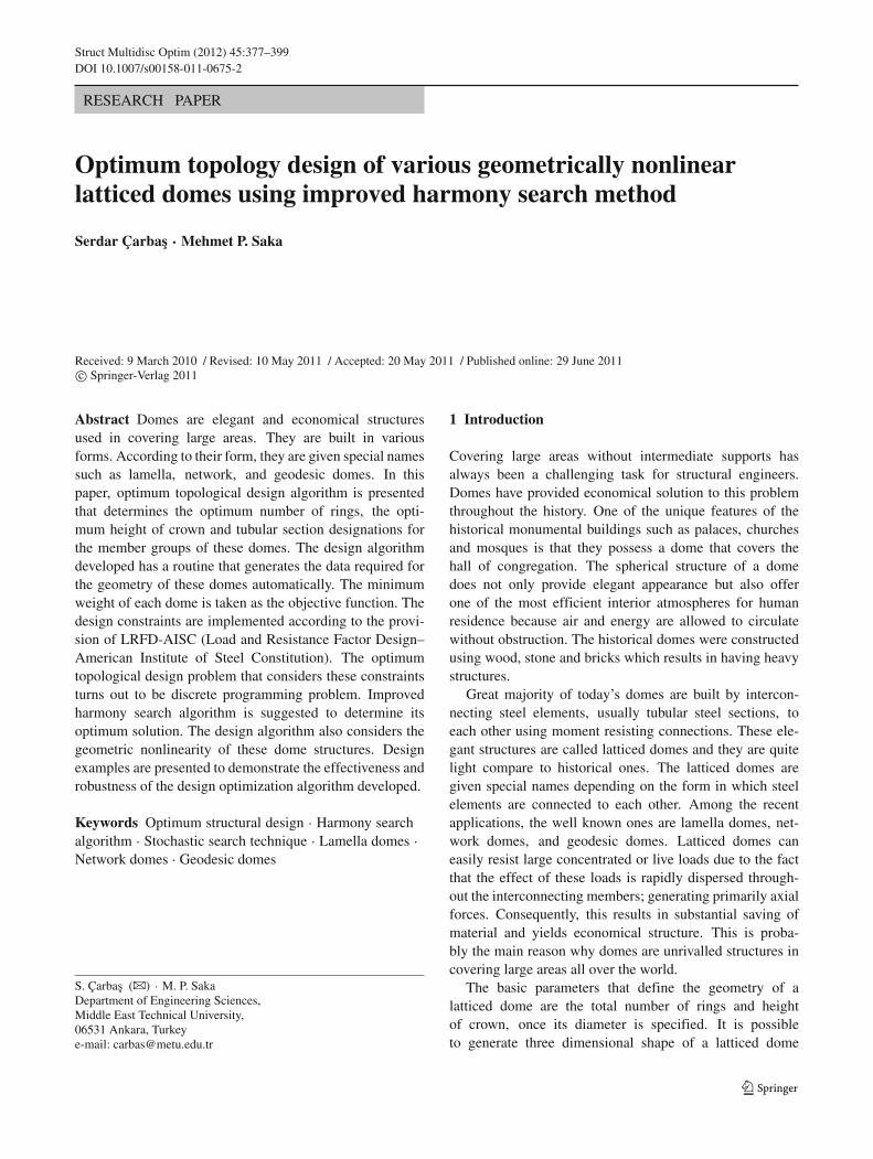
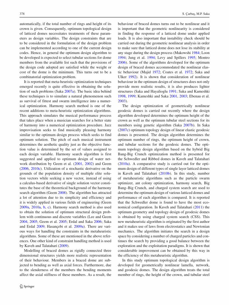
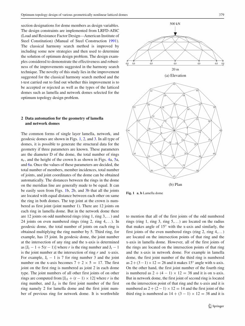
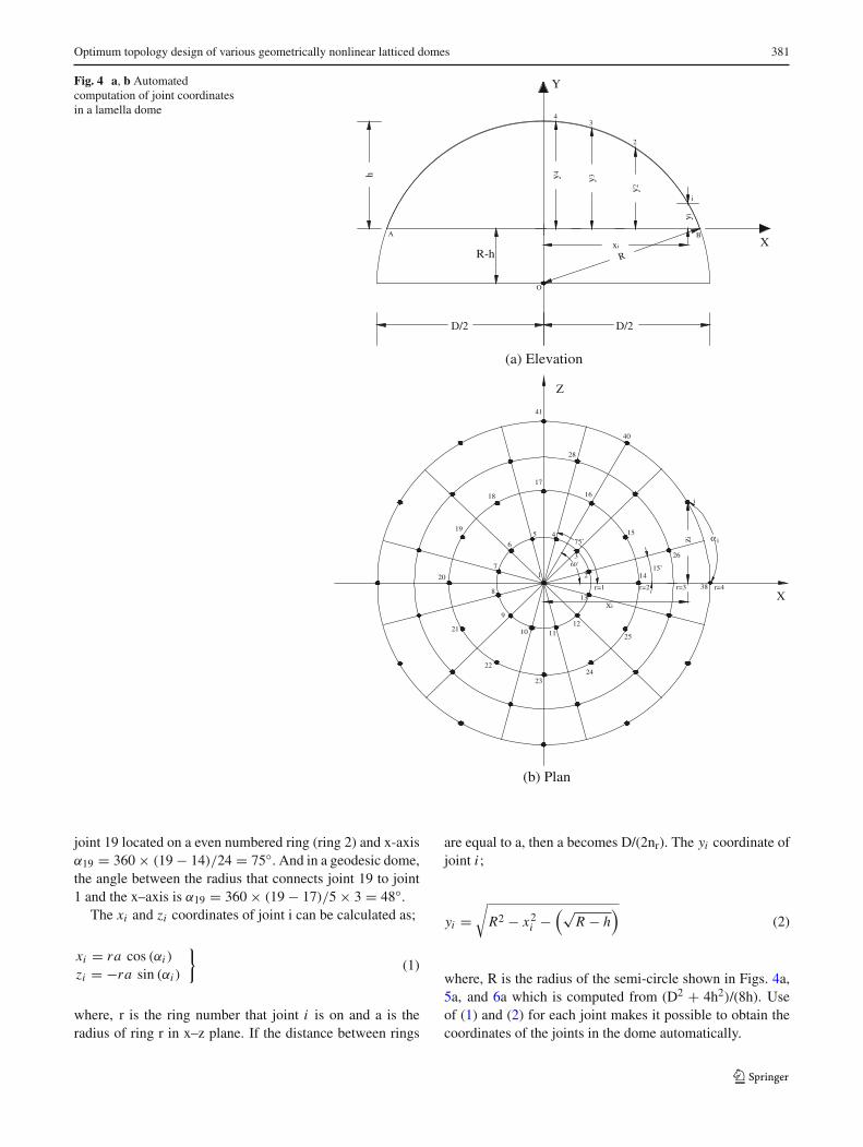
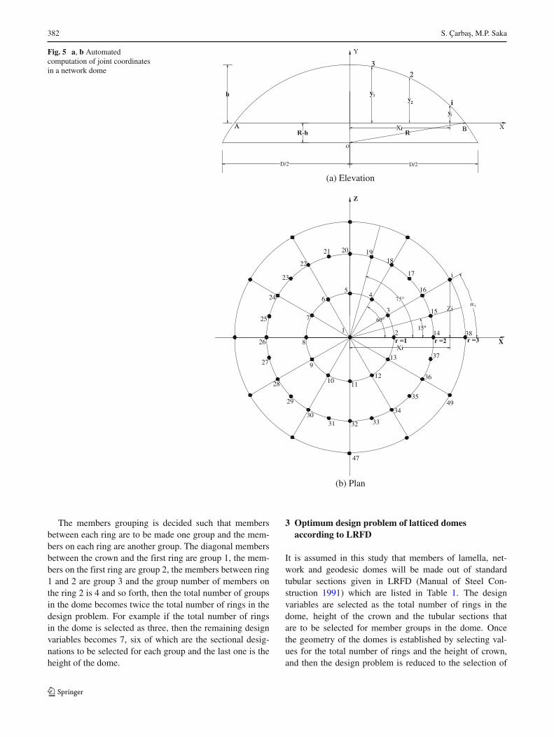
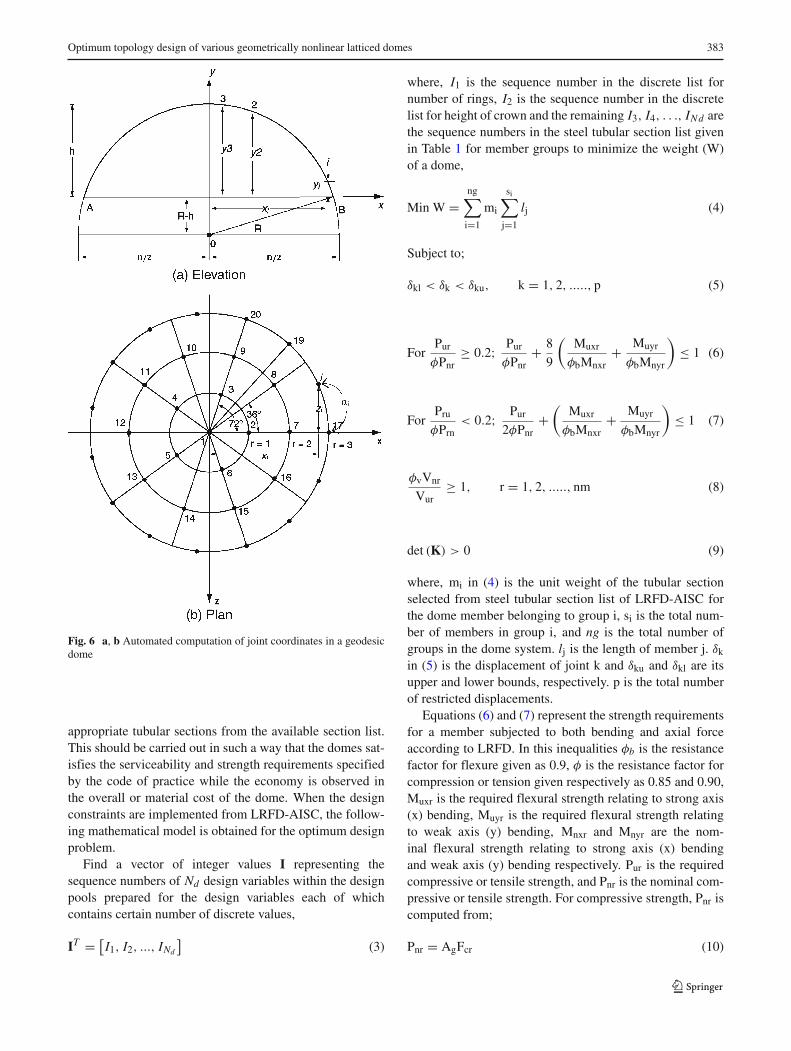
The common forms of single layer lamella, network, andgeodesic domes are shown in Figs. 1, 2, and 3. In all type ofdomes, it is possible to generate the structural data for thegeometry if three parameters are known. These parametersare the diameter D of the dome, the total number of ringsnr , and the height of the crown h as shown in Figs. 4a, 5a,and 6a. Once the values of these parameters are decided, thetotal number of members, member incidences, total numberof joints, and joint coordinates of the dome can be obtainedautomatically. The distances between the rings in the domeon the meridian line are generally made to be equal. It canbe easily seen from Figs. 1b, 2b, and 3b that all the jointsare located with equal distance between each other on samethe ring in both domes. The top joint at the crown is num-bered as first joint (joint number 1). There are 12 joints oneach ring in lamella dome. But in the network dome thereare 12 joints on odd numbered rings (ring 1, ring 3,. . . ) and24 joints on even numbered rings (ring 2, ring 4,. . . ). Ingeodesic dome, the total number of joints on each ring isobtained multiplying the ring number by 5. Third ring, forexample, has 15 joint. In geodesic dome, the joint numberat the intersection of any ring and the x-axis is determinedas [Jr − 1 + 5(r − 1)] where r is the ring number and Jr − 1is the joint number at the intersection of ring r and x-axis.For example, Jr − 1 is 7 for ring number 3 and the jointnumber on the x-axis becomes 7 + 2 × 5 = 17. The firstjoint on the first ring is numbered as joint 2 in each dometype. The joint numbers of all other first joints of on otherrings are computed from [Jr1 + (r − 1) × 12] where r is thering number, and Jr1 is the first joint number of the firstring namely 2 for lamella dome and the first joint num-ber of previous ring for network dome. It is worthwhile
(b) Plan
1 2
3
456
7
8
9
10 1112
1314
15
16
1718
19
20
21
22
2324
25
26
27
2829
30
31
32
33
34 35
36
37
38
39
40
41
42
43
44
45
46
47
48
49
500 kN
(a) Elevation
20 m
Fig. 1 a, b Lamella dome
to mention that all of the first joints of the odd numberedrings (ring 1, ring 3, ring 5,. . . ) are located on the radiusthat makes angle of 15◦ with the x-axis and similarly, thefirst joints of the even numbered rings (ring 2, ring 4,. . . )are located on the intersection points of that ring and thex-axis in lamella dome. However, all of the first joints ofthe rings are located on the intersection points of that ringand the x-axis in network dome. For example in lamelladome, the first joint number of the third ring is numberedas 2+ (3−1)×12 = 26 and it makes 15◦ angle with x-axis.On the other hand, the first joint number of the fourth ringis numbered as 2 + (4 − 1) × 12 = 38 and it is on x-axis.But in network dome, the first joint of second ring is locatedon the intersection point of that ring and the x-axis and it isnumbered as 2 + (2 − 1) × 12 = 14 and the first joint of thethird ring is numbered as 14 + (3 − 1) × 12 = 38 and it is
380 S. Çarbas, M.P. Saka
500kN
20m
(a) Elevation
(b) Plan
Fig. 2 a, b Network dome
also on x-axis. Every other joint on rings is numbered in aregular sequence. Member incidences are arranged in simi-lar manner. First member is taken as one and connects joint1 to joint 2 for each dome type which makes angle of 15◦with x-axis in lamella dome and is on the x-axis in networkand geodesic domes. The other 11 members connect joint1 to joints 3, 4, 5, 6, 7, 8, 9, 10, 11, 12, 13 in lamella andnetwork domes and the other four members connect joint 1to joints 3, 4, 5 and 6 in geodesic dome. This is followedby the members that connect joints on the ring as 2–3, 3–4,4–5, 5–6, 6–2 in geodesic dome and in lamella and networkdomes 2–3, 3–4, 4–5, 5–6, 6–7, 7–8, 8–9, 9–10, 10–11,11–12, 12–13, 13–2. This process is repeated for each ringand member incidences for all the members in the domesare determined and stored in an array.
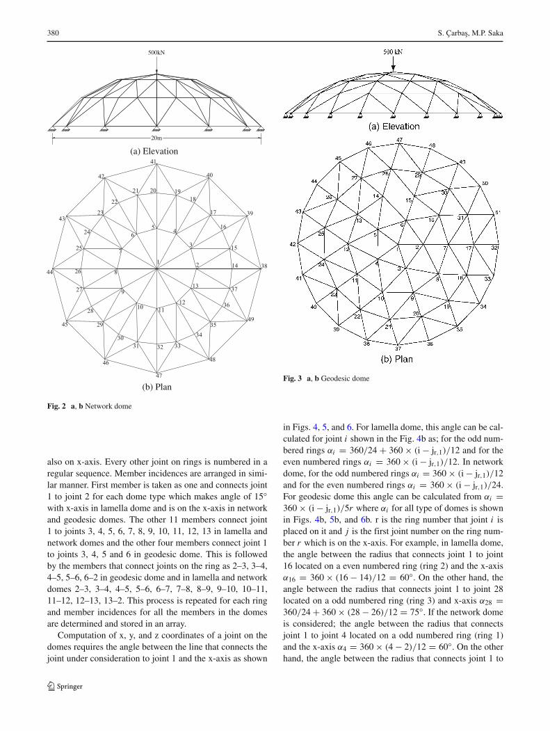
Computation of x, y, and z coordinates of a joint on thedomes requires the angle between the line that connects thejoint under consideration to joint 1 and the x-axis as shown
Fig. 3 a, b Geodesic dome
in Figs. 4, 5, and 6. For lamella dome, this angle can be cal-culated for joint i shown in the Fig. 4b as; for the odd num-bered rings αi = 360/24 + 360 × (i − jr,1)/12 and for theeven numbered rings αi = 360 × (i − jr,1)/12. In networkdome, for the odd numbered rings αi = 360 × (i − jr,1)/12and for the even numbered rings αi = 360 × (i − jr,1)/24.For geodesic dome this angle can be calculated from αi =360 × (i − jr,1)/5r where αi for all type of domes is shownin Figs. 4b, 5b, and 6b. r is the ring number that joint i isplaced on it and j is the first joint number on the ring num-ber r which is on the x-axis. For example, in lamella dome,the angle between the radius that connects joint 1 to joint16 located on a even numbered ring (ring 2) and the x-axisα16 = 360 × (16 − 14)/12 = 60◦. On the other hand, theangle between the radius that connects joint 1 to joint 28located on a odd numbered ring (ring 3) and x-axis α28 =360/24 + 360 × (28 − 26)/12 = 75◦. If the network domeis considered; the angle between the radius that connectsjoint 1 to joint 4 located on a odd numbered ring (ring 1)and the x-axis α4 = 360 × (4 − 2)/12 = 60◦. On the otherhand, the angle between the radius that connects joint 1 to
Optimum topology design of various geometrically nonlinear latticed domes 381
Fig. 4 a, b Automatedcomputation of joint coordinatesin a lamella dome
(b) Plan
1 2
3
45
6
7
8
9
10 1112
13
14
15
16
17
18
19
20
21
22
2324
25
26
28
38
40
41
X
Z
60˚
75˚
Xi
r=1 r=2 r=3 r=4
i
i
X
O
A B
43
2
Y
(a) Elevation
R
y4 y3
y2
xi
yi
h
zi
15˚
R-h
α i
D/2 D/2
joint 19 located on a even numbered ring (ring 2) and x-axisα19 = 360 × (19 − 14)/24 = 75◦. And in a geodesic dome,the angle between the radius that connects joint 19 to joint1 and the x–axis is α19 = 360 × (19 − 17)/5 × 3 = 48◦.
The xi and zi coordinates of joint i can be calculated as;
xi = ra cos (αi )
zi = −ra sin (αi )
}(1)
where, r is the ring number that joint i is on and a is theradius of ring r in x–z plane. If the distance between rings
are equal to a, then a becomes D/(2nr). The yi coordinate ofjoint i ;
yi =√
R2 − x2i −
(√R − h
)(2)
where, R is the radius of the semi-circle shown in Figs. 4a,5a, and 6a which is computed from (D2 + 4h2)/(8h). Useof (1) and (2) for each joint makes it possible to obtain thecoordinates of the joints in the dome automatically.
382 S. Çarbas, M.P. Saka
Fig. 5 a, b Automatedcomputation of joint coordinatesin a network dome
2
3
45
6
7
8
9
10 1112
13
14
15
16
17
18192021
22
23
24
25
26
27
28
29
3031 32 33
34
35
36
37
47
X
i
(b) Plan
α i
(a) Elevation
D/2 D/2
2
The members grouping is decided such that membersbetween each ring are to be made one group and the mem-bers on each ring are another group. The diagonal membersbetween the crown and the first ring are group 1, the mem-bers on the first ring are group 2, the members between ring1 and 2 are group 3 and the group number of members onthe ring 2 is 4 and so forth, then the total number of groupsin the dome becomes twice the total number of rings in thedesign problem. For example if the total number of ringsin the dome is selected as three, then the remaining designvariables becomes 7, six of which are the sectional desig-nations to be selected for each group and the last one is theheight of the dome.
3 Optimum design problem of latticed domesaccording to LRFD
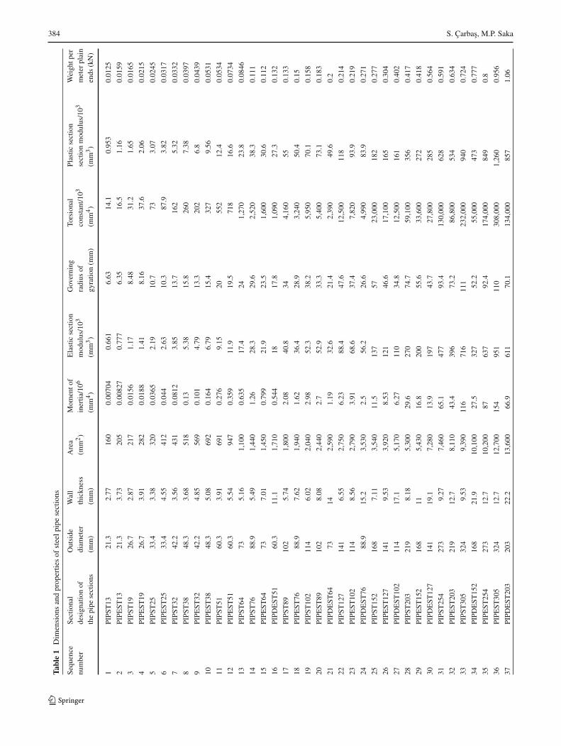
It is assumed in this study that members of lamella, net-work and geodesic domes will be made out of standardtubular sections given in LRFD (Manual of Steel Con-struction 1991) which are listed in Table 1. The designvariables are selected as the total number of rings in thedome, height of the crown and the tubular sections thatare to be selected for member groups in the dome. Oncethe geometry of the domes is established by selecting val-ues for the total number of rings and the height of crown,and then the design problem is reduced to the selection of
Optimum topology design of various geometrically nonlinear latticed domes 383
Fig. 6 a, b Automated computation of joint coordinates in a geodesicdome
appropriate tubular sections from the available section list.This should be carried out in such a way that the domes sat-isfies the serviceability and strength requirements specifiedby the code of practice while the economy is observed inthe overall or material cost of the dome. When the designconstraints are implemented from LRFD-AISC, the follow-ing mathematical model is obtained for the optimum designproblem.
Find a vector of integer values I representing thesequence numbers of Nd design variables within the designpools prepared for the design variables each of whichcontains certain number of discrete values,
IT = [I1, I2, ..., INd
](3)
where, I1 is the sequence number in the discrete list fornumber of rings, I2 is the sequence number in the discretelist for height of crown and the remaining I3, I4, . . ., INd arethe sequence numbers in the steel tubular section list givenin Table 1 for member groups to minimize the weight (W)of a dome,
Min W =ng∑
i=1
mi
si∑j=1
lj (4)
Subject to;
δkl < δk < δku, k = 1, 2, ....., p (5)
ForPur
φPnr≥ 0.2; Pur
φPnr+ 8
9
(Muxr
φbMnxr+ Muyr
φbMnyr
)≤ 1 (6)
ForPru
φPrn< 0.2; Pur
2φPnr+
(Muxr
φbMnxr+ Muyr
φbMnyr
)≤ 1 (7)
φvVnr
Vur≥ 1, r = 1, 2, ....., nm (8)
det (K) > 0 (9)
where, mi in (4) is the unit weight of the tubular sectionselected from steel tubular section list of LRFD-AISC forthe dome member belonging to group i, si is the total num-ber of members in group i, and ng is the total number ofgroups in the dome system. lj is the length of member j. δk
in (5) is the displacement of joint k and δku and δkl are itsupper and lower bounds, respectively. p is the total numberof restricted displacements.
Equations (6) and (7) represent the strength requirementsfor a member subjected to both bending and axial forceaccording to LRFD. In this inequalities φb is the resistancefactor for flexure given as 0.9, φ is the resistance factor forcompression or tension given respectively as 0.85 and 0.90,Muxr is the required flexural strength relating to strong axis(x) bending, Muyr is the required flexural strength relatingto weak axis (y) bending, Mnxr and Mnyr are the nom-inal flexural strength relating to strong axis (x) bendingand weak axis (y) bending respectively. Pur is the requiredcompressive or tensile strength, and Pnr is the nominal com-pressive or tensile strength. For compressive strength, Pnr iscomputed from;
Pnr = AgFcr (10)
384 S. Çarbas, M.P. Saka
Tabl
e1
Dim
ensi
ons
and
prop
ertie
sof
stee
lpip
ese
ctio
ns
Sequ
ence
Sect
iona
lO
utsi
deW
all
Are
aM
omen
tof
Ela
stic
sect
ion
Gov
erni
ngTo
rsio
nal
Plas
ticse
ctio
nW
eigh
tper
num
ber
desi
gnat
ion
ofdi
amet
erth
ickn
ess
(mm
2)
iner
tia/1
06m
odul
us/1
03ra
dius
ofco
nsta
nt/1
03se
ctio
nm
odul
us/1
03m
eter
plai
nth
epi
pese
ctio
ns(m
m)
(mm
)(m
m4)
(mm
3)
gyra
tion
(mm
)(m
m4)
(mm
3)
ends
(kN
)
1PI
PST
1321
.32.
7716
00.
0070
40.
661
6.63
14.1
0.95
30.
0125
2PI
PEST
1321
.33.
7320
50.
0082
70.
777
6.35
16.5
1.16
0.01
59
3PI
PST
1926
.72.
8721
70.
0156
1.17
8.48
31.2
1.65
0.01
65
4PI
PEST
1926
.73.
9128
20.
0188
1.41
8.16
37.6
2.06
0.02
15
5PI
PST
2533
.43.
3832
00.
0365
2.19
10.7
733.
070.
0245
6PI
PEST
2533
.44.
5541
20.
044
2.63
10.3
87.9
3.82
0.03
17
7PI
PST
3242
.23.
5643
10.
0812
3.85
13.7
162
5.32
0.03
32
8PI
PST
3848
.33.
6851
80.
135.
3815
.826
07.
380.
0397
9PI
PEST
3242
.24.
8556
90.
101
4.79
13.3
202
6.8
0.04
39
10PI
PEST
3848
.35.
0869
20.
164
6.79
15.4
327
9.56
0.05
31
11PI
PST
5160
.33.
9169
10.
276
9.15
2055
212
.40.
0534
12PI
PEST
5160
.35.
5494
70.
359
11.9
19.5
718
16.6
0.07
34
13PI
PST
6473
5.16
1,10
00.
635
17.4
241,
270
23.8
0.08
46
14PI
PST
7688
.95.
491,
440
1.26
28.3
29.6
2,52
038
.30.
111
15PI
PEST
6473
7.01
1,45
00.
799
21.9
23.5
1,60
030
.60.
112
16PI
PDE
ST51
60.3
11.1
1,71
00.
544
1817
.81,
090
27.3
0.13
2
17PI
PST
8910
25.
741,
800
2.08
40.8
344,
160
550.
133
18PI
PEST
7688
.97.
621,
940
1.62
36.4
28.9
3,24
050
.40.
15
19PI
PST
102
114
6.02
2,04
02.
9852
.338
.25,
950
70.1
0.15
8
20PI
PEST
8910
28.
082,
440
2.7
52.9
33.3
5,40
073
.10.
183
21PI
PDE
ST64
7314
2,59
01.
1932
.621
.42,
390
49.6
0.2
22PI
PST
127
141
6.55
2,75
06.
2388
.447
.612
,500
118
0.21
4
23PI
PEST
102
114
8.56
2,79
03.
9168
.637
.47,
820
93.9
0.21
9
24PI
PDE
ST76
88.9
15.2
3,53
02.
556
.226
.64,
990
83.9
0.27
1
25PI
PST
152
168
7.11
3,54
011
.513
757
23,0
0018
20.
277
26PI
PEST
127
141
9.53
3,92
08.
5312
146
.617
,100
165
0.30
4
27PI
PDE
ST10
211
417
.15,
170
6.27
110
34.8
12,5
0016
10.
402
28PI
PST
203
219
8.18
5,30
029
.627
074
.759
,100
356
0.41
7
29PI
PEST
152
168
115,
430
16.8
200
55.6
33,6
0027
20.
418
30PI
PDE
ST12
714
119
.17,
280
13.9
197
43.7
27,8
0028
50.
564
31PI
PST
254
273
9.27
7,46
065
.147
793
.413
0,00
062
80.
591
32PI
PEST
203
219
12.7
8,11
043
.439
673
.286
,800
534
0.63
4
33PI
PST
305
324
9.53
9,39
011
671
611
123
2,00
094
00.
724
34PI
PDE
ST15
216
821
.910
,100
27.5
327
52.2
55,0
0047
30.
777
35PI
PEST
254
273
12.7
10,2
0087
637
92.4
174,
000
849
0.8
36PI
PEST
305
324
12.7
12,7
0015
495
111
030
8,00
01,
260
0.95
6
37PI
PDE
ST20
320
322
.213
,600
66.9
611
70.1
134,
000
857
1.06
Optimum topology design of various geometrically nonlinear latticed domes 385
where, Fcr is calculated as in the following;
For λc ≤ 1.5 Fcr =(
0.658λ2c
)Fy (11)
For λc > 1.5 Fcr
[0.877
λ2c
]Fy (12)
where, in (10) Ag is the gross area of a lamella, network orgeodesic domes’ member, and Fcr is found from (11) or (12)in which Fy is the specified yield stress taken as 250 MPaand λc is obtained from;
λc = Kl
rπ
√Fy
E(13)
where, K is the effective length factor taken as 1, l is thelength of a dome member, r is governing radius of gyra-tion about the axis of buckling, and E is the modulus ofelasticity.
For tensile strength, Pnr is computed from;
Pnr = AgFy (14)
where, Fy is the specified minimum yield stress and Ag isthe gross area of a lamella, network or geodesic domes’member.
Equation (8) represents the shear strength requirement inload and resistance factor design according to LRFD. In thisinequality φv represents the resistance factor for shear givenas 0.9, Vnr is the nominal strength in shear and Vur is thefactored service load shear for member r.
The algorithm developed in this study randomly selectsset of pipe sections for the member groups from the pipesections list. With these sections geometrically nonlinearanalysis is carried out under the given loading as explainedin detail in Section 5. If during this analysis or at theend of the analysis if determinant of the stiffness matrix(det(K) in (9)) of the latticed dome turns negative, thisset of sections are rejected and a new set is selected.However if at the end of the nonlinear analysis the deter-minant remains positive then program takes the memberend forces from the nonlinear analysis and goes and checkswhether the strength and displacement constraints are sat-isfied. If any of these constraints is not satisfied this setonce more is rejected and a new set is randomly generated.The algorithm continues generating set of sections until allthe constraints are satisfied. This feasible solution is keptin the harmony memory matrix. The strength constraintsthemselves do not have any ability to detect the overallinstability.
4 Improved Harmony Search (IHS) method
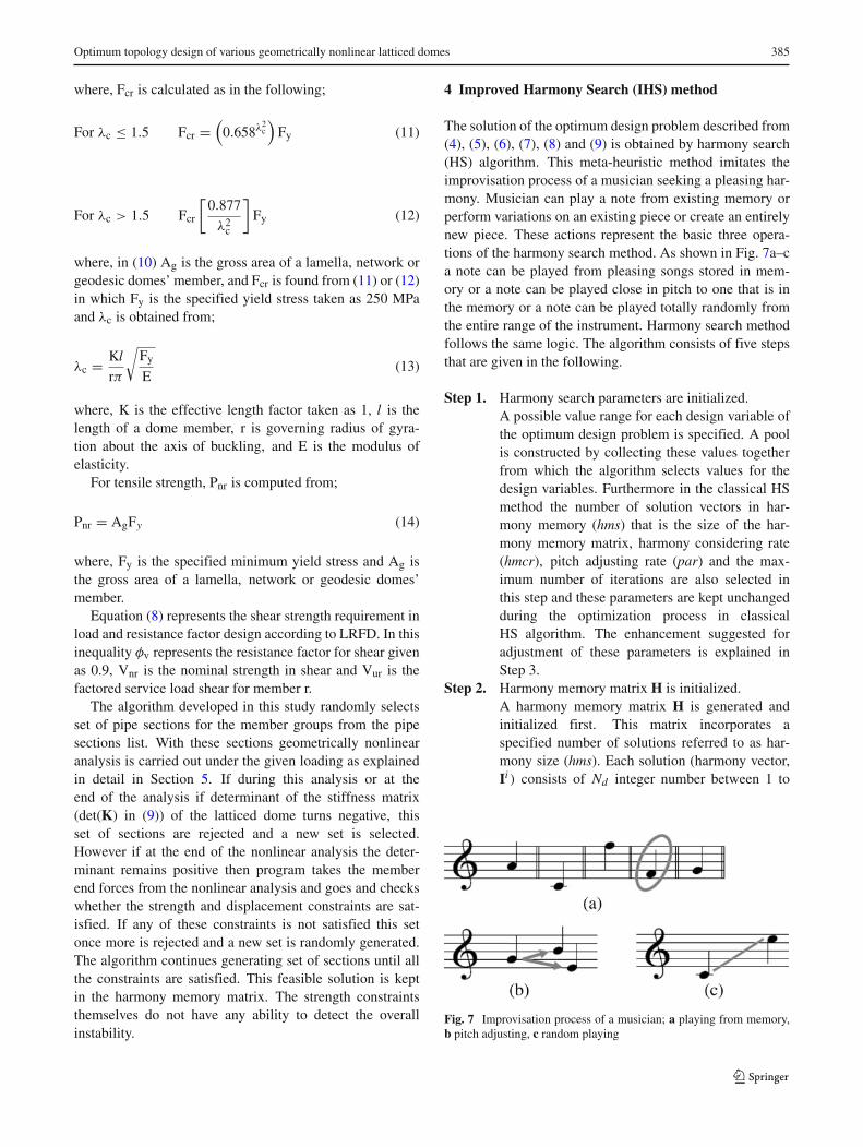
The solution of the optimum design problem described from(4), (5), (6), (7), (8) and (9) is obtained by harmony search(HS) algorithm. This meta-heuristic method imitates theimprovisation process of a musician seeking a pleasing har-mony. Musician can play a note from existing memory orperform variations on an existing piece or create an entirelynew piece. These actions represent the basic three opera-tions of the harmony search method. As shown in Fig. 7a–ca note can be played from pleasing songs stored in mem-ory or a note can be played close in pitch to one that is inthe memory or a note can be played totally randomly fromthe entire range of the instrument. Harmony search methodfollows the same logic. The algorithm consists of five stepsthat are given in the following.
Step 1. Harmony search parameters are initialized.A possible value range for each design variable ofthe optimum design problem is specified. A poolis constructed by collecting these values togetherfrom which the algorithm selects values for thedesign variables. Furthermore in the classical HSmethod the number of solution vectors in har-mony memory (hms) that is the size of the har-mony memory matrix, harmony considering rate(hmcr), pitch adjusting rate (par) and the max-imum number of iterations are also selected inthis step and these parameters are kept unchangedduring the optimization process in classicalHS algorithm. The enhancement suggested foradjustment of these parameters is explained inStep 3.
Step 2. Harmony memory matrix H is initialized.A harmony memory matrix H is generated andinitialized first. This matrix incorporates aspecified number of solutions referred to as har-mony size (hms). Each solution (harmony vector,Ii ) consists of Nd integer number between 1 to
Fig. 7 Improvisation process of a musician; a playing from memory,b pitch adjusting, c random playing
386 S. Çarbas, M.P. Saka
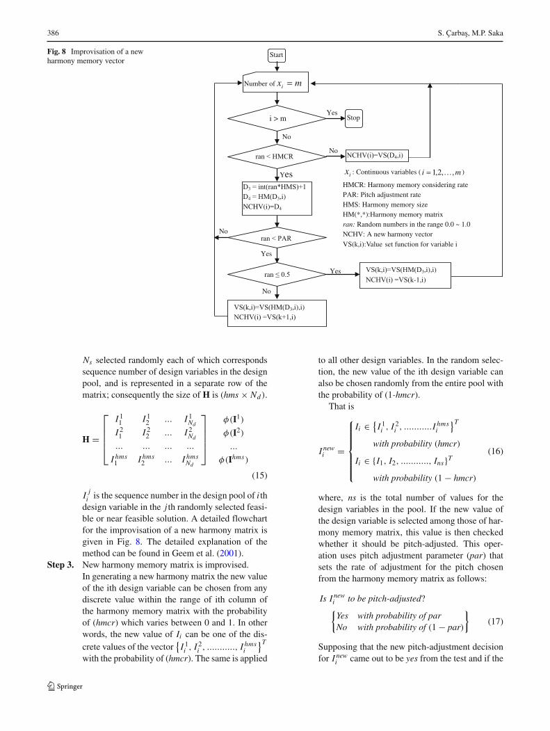
Fig. 8 Improvisation of a newharmony memory vector
No
Start
Number of mxi
Stop i > m
D3
D4 3,i)
NCHV(i) 4
4,i)
ran
3,i),i)
3,i),i)
-1,i)
ix : Continuous variables ( mi ,,2,1 )
HMCR: Harmony memory considering ratePAR: Pitch adjustment rate HMS: Harmony memory sizeHM(*,*):Harmony memory matrix ran: Random numbers in the range 0.0 ~ 1.0NCHV: A new harmony vector
VS(k,i):Value set function for variable i
Yes
Yes
Yes
No
Yes
No
No
Ns selected randomly each of which correspondssequence number of design variables in the designpool, and is represented in a separate row of thematrix; consequently the size of H is (hms × Nd).
H =
⎡⎢⎢⎢⎣
I 11 I 1
2 ... I 1Nd
I 21 I 2
2 ... I 2Nd
... ... ... ...
I hms1 I hms
2 ... I hmsNd
⎤⎥⎥⎥⎦
φ(I1)
φ(I2)
...
φ(Ihms)
(15)
I ji is the sequence number in the design pool of i th
design variable in the j th randomly selected feasi-ble or near feasible solution. A detailed flowchartfor the improvisation of a new harmony matrix isgiven in Fig. 8. The detailed explanation of themethod can be found in Geem et al. (2001).
Step 3. New harmony memory matrix is improvised.In generating a new harmony matrix the new valueof the ith design variable can be chosen from anydiscrete value within the range of ith column ofthe harmony memory matrix with the probabilityof (hmcr) which varies between 0 and 1. In otherwords, the new value of Ii can be one of the dis-crete values of the vector
{I 1i , I 2
i , ..........., I hmsi
}T
with the probability of (hmcr). The same is applied
to all other design variables. In the random selec-tion, the new value of the ith design variable canalso be chosen randomly from the entire pool withthe probability of (1-hmcr).
That is
I newi =
⎧⎪⎪⎪⎪⎪⎨⎪⎪⎪⎪⎪⎩
Ii ∈ {I 1i , I 2
i , ...........I hmsi
}T
with probability (hmcr)
Ii ∈ {I1, I2, ..........., Ins}T
with probability (1 − hmcr)
(16)
where, ns is the total number of values for thedesign variables in the pool. If the new value ofthe design variable is selected among those of har-mony memory matrix, this value is then checkedwhether it should be pitch-adjusted. This oper-ation uses pitch adjustment parameter (par) thatsets the rate of adjustment for the pitch chosenfrom the harmony memory matrix as follows:
Is I newi to be pitch-adjusted?{Yes with probability of parNo with probability of (1 − par)
}(17)
Supposing that the new pitch-adjustment decisionfor I new
i came out to be yes from the test and if the
Optimum topology design of various geometrically nonlinear latticed domes 387
value selected for I newi from the harmony mem-
ory is the kth element in the general discrete set,then the neighbouring value k +1 or k −1 is takenfor new I new
i . This operation prevents stagnationand improves the harmony memory for diversitywith a greater changing of reaching the globaloptimum.
4.1 Proposed strategy for hmcr and par
In classical harmony search method the parameters hmcrand par are selected prior to the application of the methodand they are kept constant until the end of the iterations.The numerical applications have shown that the selectionof values for hmcr and par is problem dependent and theinitial values selected affect the performance of the algo-rithm. Hence, in order to determine the optimum solutionit is necessary to solve the optimization problem severaltimes with different values of these parameters and selectthe solution with minimum weight. It is apparent that suchapplication devaluates the efficiency of the algorithm. Inorder to overcome this discrepancy, numbers of improve-ments are suggested in the literature. Mahdavi et al. (2007)have proposed an improved harmony search algorithm thatuses variable par and bw in improvisation step where bwis an arbitrary distance bandwidth. But Taherinejad (2009)has mentioned that current changes in Mahdavi et al. (2007)are not adequate at all and has proposed a new functionwhich could help the algorithm to explore vast search spacewhile focusing well on local and global optimums. Later,Omran and Mahdavi (2008) have used the concepts fromswarm intelligence to enhance the performance of harmonysearch method. They called this new version of HS, global-best harmony search (GHS). Geem (2009b) has proved thatGHS was good only for small-sized problem by testingthis method with 454-variable real-world water networkdesign problem. Geem and Roper (2010) have comparedfive different harmony search algorithms that consider con-tinuous variables inherently for the hydrologic parametercalibration. Hasançebi et al. (2009b) suggested adaptive har-mony search method where hmcr and par are adjusted bythe algorithm itself automatically using probabilistic sam-pling of control parameters. Hence the algorithm tunes theseparameters to advantageous values online during search. Inthis study, different strategies are proposed for hmcr andpar. par is updated using the concept suggested by Coelhoand Bernert (2009) as follows:
par(i) = parmin + (parmax − parmin).degree(i) (18)
where, par(i) is the pitch adjusting rate for generationi , parmin is the minimum adjusting rate, parmax is the
maximum adjusting rate, and i is the generation num-ber. The degree is updated according to the followingexpression:
degree(i) = (HCostmax(i) − HCostmean)
(HCostmax(i) − HCostmin(i))(19)
where, HCostmax(i) and HCostmin(i) are the maximum andminimum function objective values in generation i , respec-tively; HCostmean is the mean of objective function value ofthe harmony memory.
The improvisation of hmcr is carried out using thefollowing expression;
hmcr(i) = hmcrmax − (hmcrmax − hmcrmin).degree(i) (20)
where, hmcr(i) is the harmony memory considering ratefor generation i , hmcrmax is the maximum considering rate,hmcrmin is the minimum considering rate, and i is thegeneration number.
Constraint handling Once the new harmony vector I newi
is obtained using the above-mentioned rules, it is thenchecked whether it violates problem constraints. If the newharmony vector is severely infeasible, it is discarded. If itis slightly infeasible, it is included in the harmony memorymatrix. In this way the violated harmony vector which maybe infeasible slightly in one or more constraints is used asa base in the pitch adjustment operation to provide a newharmony vector that may be feasible. This is carried out byusing larger error values such as 0.08 initially for the accept-ability of the new design vectors and reduces this valuegradually during the design cycles and use finally an errorvalue of 0.001 towards the end of iterations. This adaptiveerror strategy is found quite effective in handling the designconstraints in large design problems.
Step 4. Harmony Memory matrix is updated. After select-ing the new values for each design variable theobjective function value is calculated for the newharmony vector. If this value is better than theworst harmony vector in the harmony matrix, itis then included in the matrix while the worst oneis taken out of the matrix. The harmony memorymatrix is then sorted in descending order by theobjective function value.
Step 5. Steps 3 and 4 are repeated until the termination cri-terion which is the pre-selected maximum numberof cycles is reached. This number is selected largeenough such that within this number of designcycles no further improvement is observed in theobjective function.
388 S. Çarbas, M.P. Saka
5 Considering geometric nonlinearity in latticed domes
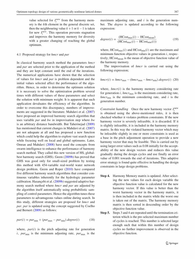
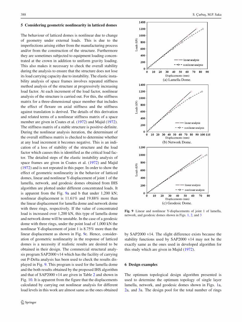
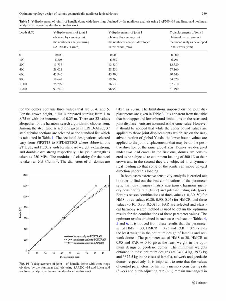
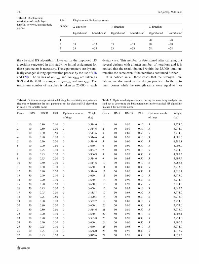
The behaviour of latticed domes is nonlinear due to changeof geometry under external loads. This is due to theimperfections arising either from the manufacturing processand/or from the construction of the structure. Furthermorethey are sometimes subjected to equipment loading concen-trated at the crown in addition to uniform gravity loading.This also makes it necessary to check the overall stabilityduring the analysis to ensure that the structure does not loseits load carrying capacity due to instability. The elastic insta-bility analysis of space frames involves repeated stiffnessmethod analysis of the structure at progressively increasingload factor. At each increment of the load factor, nonlinearanalysis of the structure is carried out. For this, the stiffnessmatrix for a three-dimensional space member that includesthe effect of flexure on axial stiffness and the stiffnessagainst translation is derived. The details of this derivationand related terms of a nonlinear stiffness matrix of a spacemember are given in Coates et al. (1972) and Majid (1972).The stiffness matrix of a stable structure is positive-definite.During the nonlinear analysis iteration, the determinant ofthe overall stiffness matrix is checked to determine whetherat any load increment it becomes negative. This is an indi-cation of a loss of stability of the structure and the loadfactor which causes this is identified as the critical load fac-tor. The detailed steps of the elastic instability analysis ofspace frames are given in Coates et al. (1972) and Majid(1972) and is not repeated in this paper. In order to show theeffect of geometric nonlinearity in the behavior of latticeddomes, linear and nonlinear Y-displacement of joint 1 of thelamella, network, and geodesic domes obtained from IHSalgorithm are plotted under different concentrated loads. Itis apparent from the Fig. 9a and b that under 1,200 kN;nonlinear displacement is 11.61% and 19.88% more thanthe linear displacement for lamella dome and network domewith three rings, respectively. If the value of concentratedload is increased over 1,200 kN, this type of lamella domeand network dome will be unstable. In the case of a geodesicdome with three rings, under the point load of 1,000 kN thenonlinear Y-displacement of joint 1 is 8.75% more than thelinear displacement as shown in Fig. 9c. Hence, consider-ation of geometric nonlinearity in the response of latticeddomes is a necessity if realistic results are desired to beobtained in their design. The commercial structural analy-sis program SAP2000 v14 which has the facility of carryingout P-Delta analysis has been used to check the results dis-played in Fig. 9. This program is used for the lamella domeand the both results obtained by the proposed IHS algorithmand that of SAP2000 v14 are given in Table 2 and shown inFig. 10. It is apparent from the figure that the displacementscalculated by carrying out nonlinear analysis for differentload levels in this work are almost same as the ones obtained
(a) Lamella Dome.
(b) Network Dome.
(c) Geodesic Dome.
Fig. 9 Linear and nonlinear Y-displacements of joint 1 of lamella,network, and geodesic domes shown in Figs. 1, 2, and 3
by SAP2000 v14. The slight difference exists because thestability functions used by SAP2000 v14 may not be theexactly same as the ones used in developed algorithm forthis study which are given in Majid (1972).
6 Design examples
The optimum topological design algorithm presented isused to determine the optimum topology of single layerlamella, network, and geodesic domes shown in Figs. 1a,2a, and 3a. The design pool for the total number of rings
Optimum topology design of various geometrically nonlinear latticed domes 389
Table 2 Y-displacement of joint 1 of lamella dome with three rings obtained by the nonlinear analysis using SAP200 v14 and linear and nonlinearanalysis by the routine developed in this work
Loads (kN) Y-displacements of joint 1 Y-displacements of joint 1 Y-displacements of joint 1
obtained by carrying out obtained by carrying out obtained by carrying out
the nonlinear analysis using the nonlinear analysis developed the linear analysis developed
SAP2000 v14 (mm) in this work (mm) in this work (mm)
0 0.000 0.000 0.000
100 6.805 6.852 6.791
200 13.737 13.830 13.580
400 28.021 28.230 27.160
600 42.946 43.300 40.740
800 58.642 59.260 54.320
1,000 75.299 76.530 67.910
1,200 93.242 96.950 81.490
for the domes contains three values that are 3, 4, and 5.For the crown height, a list is prepared starting from 1 to8.75 m with the increment of 0.25 m. There are 32 valuesaltogether for the harmony search algorithm to choose from.Among the steel tubular sections given in LRFD-AISC, 37steel tubular sections are selected as the standard list whichis tabulated in Table 1. The sectional designations selectedvary from PIPST13 to PIPDEST203 where abbreviationsST, EST, and DEST stands for standard weight, extra strong,and double-extra strong respectively. The yield strength istaken as 250 MPa. The modulus of elasticity for the steelis taken as 205 kN/mm2. The diameters of all domes are
Fig. 10 Y-displacement of joint 1 of lamella dome with three ringsobtained by the nonlinear analysis using SAP200 v14 and linear andnonlinear analysis by the routine developed in this work
taken as 20 m. The limitations imposed on the joint dis-placements are given in Table 3. It is apparent from the tablethat both upper and lower bound limitations on the restrictedjoint displacements are assumed as the same value. Howeverit should be noticed that while the upper bound values areapplied to those joint displacements which are on the neg-ative direction of global Y-axis, the lower bound values areapplied to the joint displacements that may be on the posi-tive direction of the same global axis. Domes are designedunder two load cases. In the first one, domes are consid-ered to be subjected to equipment loading of 500 kN at theircrown and in the second they are subjected to unsymmet-rical loading so that some of the joints can move upwarddirection under this loading.
In both cases extensive sensitivity analysis is carried outin order to find out the best combinations of the parametersets; harmony memory matrix size (hms), harmony mem-ory considering rate (hmcr) and pitch-adjusting rate (par).For this reason combinations of three values (10, 30, 50) forHMS, three values (0.80, 0.90, 0.95) for HMCR, and threevalues (0.10, 0.30, 0.50) for PAR are selected and classi-cal harmony search method is used to obtain the optimumresults for the combinations of these parameter values. Theoptimum results obtained in each case are listed in Tables 4,5 and 6. It is noticed from these results that the parameterset of HMS = 30, HMCR = 0.95 and PAR = 0.50 yieldsthe least weight in the optimum design of lamella and net-work domes. The parameter set of HMS = 30, HMCR =0.95 and PAR = 0.30 gives the least weight in the opti-mum design of geodesic domes. The minimum weightsobtained in these optimum designs are 3490.4 kg, 3973 kgand 3672.5 kg in the cases of lamella, network and geodesicdomes respectively. It is important to note that the valuesof control parameters for harmony memory considering rate(hmcr) and pitch-adjusting rate (par) remain unchanged in
390 S. Çarbas, M.P. Saka
Table 3 Displacementrestrictions of single layerlamella, network, and geodesicdomes
Joint Displacement limitations (mm)
number X-direction Y-direction Z-direction
Upperbound Lowerbound Upperbound Lowerbound Upperbound Lowerbound
1 − − − − 28 −28
2 33 −33 33 −33 28 −28
3 33 −33 33 −33 28 −28
the classical HS algorithm. However, in the improved HSalgorithm suggested in this study, no initial assignment forthese parameters is necessary. These parameters are dynam-ically changed during optimization process by the use of (18and (20). The values of parmax and hmcrmax are taken as0.99 and the 0.01 is assigned to parmin and hmcrmin. Themaximum number of searches is taken as 25,000 in each
Table 4 Optimum designs obtained during the sensitivity analysis car-ried out to determine the best parameter set for classical HS algorithmin case 1 for lamella dome
Cases HMS HMCR PAR Optimum number Weight
of rings (kg)
1 10 0.80 0.10 5 3,514.6
2 10 0.80 0.30 3 3,514.6
3 10 0.80 0.50 3 3,514.6
4 10 0.90 0.10 3 3,514.6
5 10 0.90 0.30 3 3,514.6
6 10 0.90 0.50 3 3,660.1
7 10 0.95 0.10 4 3,864.7
8 10 0.95 0.30 3 3,906.9
9 10 0.95 0.50 3 3,514.6
10 30 0.80 0.10 3 3,514.6
11 30 0.80 0.30 3 3,660.1
12 30 0.80 0.50 3 3,514.6
13 30 0.90 0.10 3 3,660.1
14 30 0.90 0.30 3 3,660.1
15 30 0.90 0.50 3 3,660.1
16 30 0.95 0.10 3 3,660.1
17 30 0.95 0.30 5 3,885.7
18 30 0.95 0.50 3 3,490.4
19 50 0.80 0.10 3 3,532.7
20 50 0.80 0.30 3 3,660.1
21 50 0.80 0.50 3 3,514.6
22 50 0.90 0.10 3 3,660.1
23 50 0.90 0.30 3 3,583.8
24 50 0.90 0.50 3 3,660.1
25 50 0.95 0.10 3 3,660.1
26 50 0.95 0.30 3 3,656.0
27 50 0.95 0.50 4 3,849.6
design case. This number is determined after carrying outseveral designs with a larger number of iterations and it isnoticed that the result obtained within the 25,000 iterationsremains the same even if the iterations continued further.
It is noticed in all these cases that the strength limi-tations are dominant in the design problem. In the opti-mum domes while the strength ratios were equal to 1 or
Table 5 Optimum designs obtained during the sensitivity analysis car-ried out to determine the best parameter set for classical HS algorithmin case 1 for network dome
Cases HMS HMCR PAR Optimum number Weight
of rings (kg)
1 10 0.80 0.10 5 3,974.0
2 10 0.80 0.30 5 3,974.0
3 10 0.80 0.50 5 3,974.0
4 10 0.90 0.10 3 4,086.6
5 10 0.90 0.30 5 4,386.8
6 10 0.90 0.50 5 4,005.0
7 10 0.95 0.10 5 3,974.0
8 10 0.95 0.30 5 4,387.3
9 10 0.95 0.50 5 3,997.9
10 30 0.80 0.10 5 3,968.4
11 30 0.80 0.30 5 3,973.0
12 30 0.80 0.50 5 4,016.1
13 30 0.90 0.10 5 3,973.0
14 30 0.90 0.30 5 3,974.0
15 30 0.90 0.50 5 3,974.0
16 30 0.95 0.10 3 4,045.3
17 30 0.95 0.30 5 3,974.0
18 30 0.95 0.50 5 3,973.0
19 50 0.80 0.10 5 3,974.0
20 50 0.80 0.30 5 3,973.0
21 50 0.80 0.50 5 3,973.0
22 50 0.90 0.10 5 4,003.1
23 50 0.90 0.30 5 3,974.0
24 50 0.90 0.50 5 3,990.5
25 50 0.95 0.10 5 3,974.0
26 50 0.95 0.30 5 4,072.9
27 50 0.95 0.50 3 4,039.3
Optimum topology design of various geometrically nonlinear latticed domes 391
Table 6 Optimum designs obtained during the sensitivity analysis car-ried out to determine the best parameter set for classical HS algorithmin case 1 for geodesic dome
Cases HMS HMCR PAR Optimum number Weight
of rings (kg)
1 10 0.80 0.10 5 3,704.8
2 10 0.80 0.30 5 3,677.9
3 10 0.80 0.50 3 3,796.2
4 10 0.90 0.10 5 3,692.1
5 10 0.90 0.30 5 3,672.5
6 10 0.90 0.50 5 3,771.9
7 10 0.95 0.10 3 3,751.8
8 10 0.95 0.30 5 3,851.1
9 10 0.95 0.50 5 3,771.9
10 30 0.80 0.10 5 3,672.5
11 30 0.80 0.30 5 3,699.2
12 30 0.80 0.50 5 3,672.5
13 30 0.90 0.10 5 3,692.1
14 30 0.90 0.30 5 3,672.5
15 30 0.90 0.50 5 3,692.1
16 30 0.95 0.10 5 3,692.1
17 30 0.95 0.30 5 3,672.5
18 30 0.95 0.50 5 3,734.1
19 50 0.80 0.10 5 3,672.5
20 50 0.80 0.30 5 3,692.1
21 50 0.80 0.50 5 3,698.3
22 50 0.90 0.10 5 3,672.5
23 50 0.90 0.30 5 3,692.1
24 50 0.90 0.50 3 3,751.8
25 50 0.95 0.10 5 3,672.5
26 50 0.95 0.30 5 3,692.1
27 50 0.95 0.50 5 3,692.1
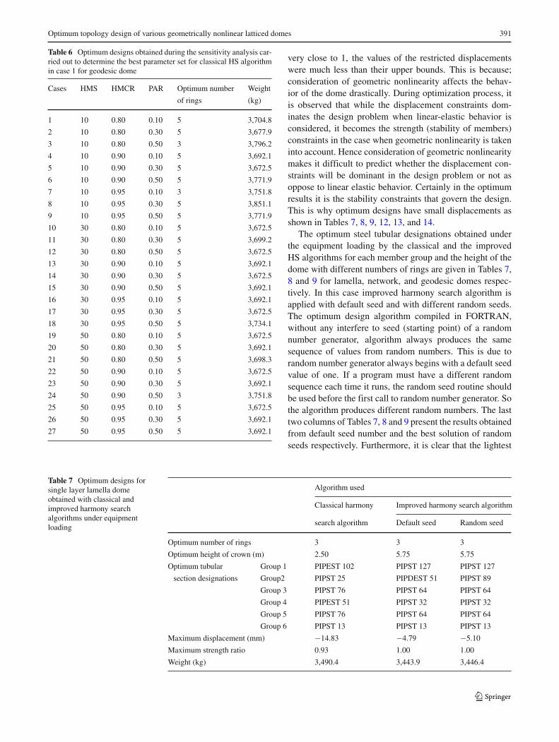
very close to 1, the values of the restricted displacementswere much less than their upper bounds. This is because;consideration of geometric nonlinearity affects the behav-ior of the dome drastically. During optimization process, itis observed that while the displacement constraints dom-inates the design problem when linear-elastic behavior isconsidered, it becomes the strength (stability of members)constraints in the case when geometric nonlinearity is takeninto account. Hence consideration of geometric nonlinearitymakes it difficult to predict whether the displacement con-straints will be dominant in the design problem or not asoppose to linear elastic behavior. Certainly in the optimumresults it is the stability constraints that govern the design.This is why optimum designs have small displacements asshown in Tables 7, 8, 9, 12, 13, and 14.
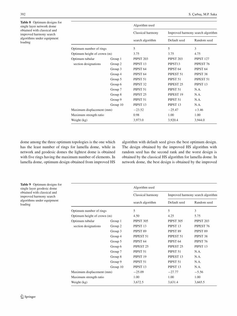
The optimum steel tubular designations obtained underthe equipment loading by the classical and the improvedHS algorithms for each member group and the height of thedome with different numbers of rings are given in Tables 7,8 and 9 for lamella, network, and geodesic domes respec-tively. In this case improved harmony search algorithm isapplied with default seed and with different random seeds.The optimum design algorithm compiled in FORTRAN,without any interfere to seed (starting point) of a randomnumber generator, algorithm always produces the samesequence of values from random numbers. This is due torandom number generator always begins with a default seedvalue of one. If a program must have a different randomsequence each time it runs, the random seed routine shouldbe used before the first call to random number generator. Sothe algorithm produces different random numbers. The lasttwo columns of Tables 7, 8 and 9 present the results obtainedfrom default seed number and the best solution of randomseeds respectively. Furthermore, it is clear that the lightest
Table 7 Optimum designs forsingle layer lamella domeobtained with classical andimproved harmony searchalgorithms under equipmentloading
Algorithm used
Classical harmony Improved harmony search algorithm
search algorithm Default seed Random seed
Optimum number of rings 3 3 3
Optimum height of crown (m) 2.50 5.75 5.75
Optimum tubular Group 1 PIPEST 102 PIPST 127 PIPST 127
section designations Group2 PIPST 25 PIPDEST 51 PIPST 89
Group 3 PIPST 76 PIPST 64 PIPST 64
Group 4 PIPEST 51 PIPST 32 PIPST 32
Group 5 PIPST 76 PIPST 64 PIPST 64
Group 6 PIPST 13 PIPST 13 PIPST 13
Maximum displacement (mm) −14.83 −4.79 −5.10
Maximum strength ratio 0.93 1.00 1.00
Weight (kg) 3,490.4 3,443.9 3,446.4
392 S. Çarbas, M.P. Saka
Table 8 Optimum designs forsingle layer network domeobtained with classical andimproved harmony searchalgorithms under equipmentloading
Algorithm used
Classical harmony Improved harmony search algorithm
search algorithm Default seed Random seed
Optimum number of rings 5 5 3
Optimum height of crown (m) 3.75 3.75 4.75
Optimum tubular Group 1 PIPST 203 PIPST 203 PIPST 127
section designations Group 2 PIPST 13 PIPST13 PIPEST 76
Group 3 PIPST 64 PIPST 64 PIPST 64
Group 4 PIPST 64 PIPEST 51 PIPST 38
Group 5 PIPST 51 PIPST 51 PIPEST 51
Group 6 PIPST 32 PIPEST 25 PIPST 13
Group 7 PIPST 51 PIPST 51 N.A.
Group 8 PIPST 25 PIPEST 19 N.A.
Group 9 PIPST 51 PIPST 51 N.A.
Group 10 PIPST 13 PIPST 13 N.A.
Maximum displacement (mm) −23.52 −25.47 +3.46
Maximum strength ratio 0.98 1.00 1.00
Weight (kg) 3,973.0 3,920.4 3,944.0
dome among the three optimum topologies is the one whichhas the least number of rings for lamella dome, while innetwork and geodesic domes the lightest dome is obtainedwith five rings having the maximum number of elements. Inlamella dome, optimum design obtained from improved HS
algorithm with default seed gives the best optimum design.The design obtained by the improved HS algorithm withrandom seed has the second rank and the worst design isobtained by the classical HS algorithm for lamella dome. Innetwork dome, the best design is obtained by the improved
Table 9 Optimum designs forsingle layer geodesic domeobtained with classical andimproved harmony searchalgorithms under equipmentloading
Algorithm used
Classical harmony Improved harmony search algorithm
search algorithm Default seed Random seed
Optimum number of rings 5 5 3
Optimum height of crown (m) 4.50 4.25 5.75
Optimum tubular Group 1 PIPST 305 PIPST 305 PIPST 203
section designations Group 2 PIPST 13 PIPST 13 PIPEST 76
Group 3 PIPST 89 PIPST 89 PIPST 89
Group 4 PIPEST 51 PIPEST 51 PIPST 38
Group 5 PIPST 64 PIPST 64 PIPST 76
Group 6 PIPEST 25 PIPEST 25 PIPST 13
Group 7 PIPST 51 PIPST 51 N.A.
Group 8 PIPST 19 PIPEST 13 N.A.
Group 9 PIPST 51 PIPST 51 N.A.
Group 10 PIPST 13 PIPST 13 N.A.
Maximum displacement (mm) −25.09 −27.77 −5.56
Maximum strength ratio 1.00 1.00 1.00
Weight (kg) 3,672.5 3,631.4 3,665.5
Optimum topology design of various geometrically nonlinear latticed domes 393
5.75 m5.06 m
3.06 m
5.50 m
4.55 m
2.97 m1.64 m
4.75 m3.95 m
5.13 m4.03 m
2.29 m
(a) (b) (c)
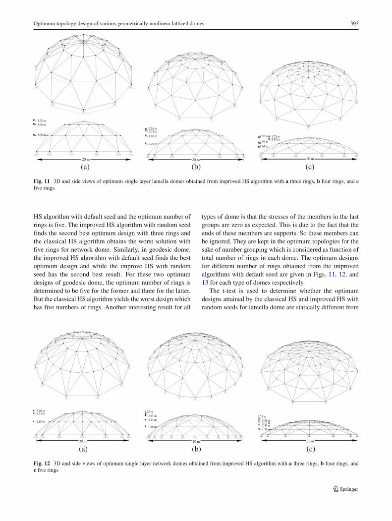
Fig. 11 3D and side views of optimum single layer lamella domes obtained from improved HS algorithm with a three rings, b four rings, and cfive rings
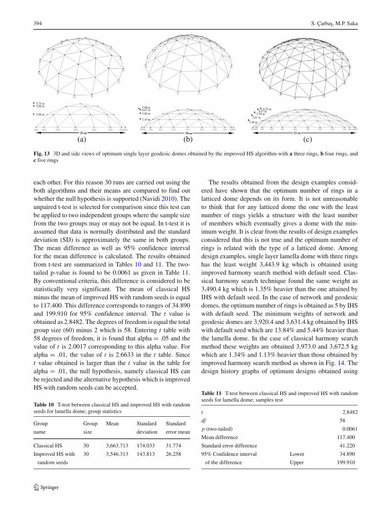
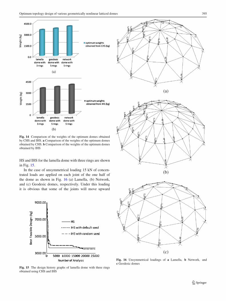
HS algorithm with default seed and the optimum number ofrings is five. The improved HS algorithm with random seedfinds the second best optimum design with three rings andthe classical HS algorithm obtains the worst solution withfive rings for network dome. Similarly, in geodesic dome,the improved HS algorithm with default seed finds the bestoptimum design and while the improve HS with randomseed has the second best result. For these two optimumdesigns of geodesic dome, the optimum number of rings isdetermined to be five for the former and three for the latter.But the classical HS algorithm yields the worst design whichhas five numbers of rings. Another interesting result for all
types of dome is that the stresses of the members in the lastgroups are zero as expected. This is due to the fact that theends of these members are supports. So these members canbe ignored. They are kept in the optimum topologies for thesake of number grouping which is considered as function oftotal number of rings in each dome. The optimum designsfor different number of rings obtained from the improvedalgorithms with default seed are given in Figs. 11, 12, and13 for each type of domes respectively.
The t-test is used to determine whether the optimumdesigns attained by the classical HS and improved HS withrandom seeds for lamella dome are statically different from
5.00 m 4.25 m3.97 m3.14 m
1.80 m
4.41 m
2.69 m
3.75 m3.59 m3.13 m2.36 m1.31 m
(a) (b) (c)
Fig. 12 3D and side views of optimum single layer network domes obtained from improved HS algorithm with a three rings, b four rings, andc five rings
394 S. Çarbas, M.P. Saka
5.75 m5.06 m
3.06 m
5.00 m4.67 m3.68 m
2.10 m
4.25 m4.07 m
3.54 m2.67 m
1.48 m
(a) (b) (c)
Fig. 13 3D and side views of optimum single layer geodesic domes obtained by the improved HS algorithm with a three rings, b four rings, andc five rings
each other. For this reason 30 runs are carried out using theboth algorithms and their means are compared to find outwhether the null hypothesis is supported (Navidi 2010). Theunpaired t-test is selected for comparison since this test canbe applied to two independent groups where the sample sizefrom the two groups may or may not be equal. In t-test it isassumed that data is normally distributed and the standarddeviation (SD) is approximately the same in both groups.The mean difference as well as 95% confidence intervalfor the mean difference is calculated. The results obtainedfrom t-test are summarized in Tables 10 and 11. The two-tailed p-value is found to be 0.0061 as given in Table 11.By conventional criteria, this difference is considered to bestatistically very significant. The mean of classical HSminus the mean of improved HS with random seeds is equalto 117.400. This difference corresponds to ranges of 34.890and 199.910 for 95% confidence interval. The t value isobtained as 2.8482. The degrees of freedom is equal the totalgroup size (60) minus 2 which is 58. Entering t table with58 degrees of freedom, it is found that alpha = .05 and thevalue of t is 2.0017 corresponding to this alpha value. Foralpha = .01, the value of t is 2.6633 in the t table. Sincet value obtained is larger than the t value in the table foralpha = .01, the null hypothesis, namely classical HS canbe rejected and the alternative hypothesis which is improvedHS with random seeds can be accepted.
Table 10 T-test between classical HS and improved HS with randomseeds for lamella dome; group statistics
Group Group Mean Standard Standard
name size deviation error mean
Classical HS 30 3,663.713 174.033 31.774
Improved HS with 30 3,546.313 143.813 26.258
random seeds
The results obtained from the design examples consid-ered have shown that the optimum number of rings in alatticed dome depends on its form. It is not unreasonableto think that for any latticed dome the one with the leastnumber of rings yields a structure with the least numberof members which eventually gives a dome with the min-imum weight. It is clear from the results of design examplesconsidered that this is not true and the optimum number ofrings is related with the type of a latticed dome. Amongdesign examples, single layer lamella dome with three ringshas the least weight 3,443.9 kg which is obtained usingimproved harmony search method with default seed. Clas-sical harmony search technique found the same weight as3,490.4 kg which is 1.35% heavier than the one attained byIHS with default seed. In the case of network and geodesicdomes, the optimum number of rings is obtained as 5 by IHSwith default seed. The minimum weights of network andgeodesic domes are 3,920.4 and 3,631.4 kg obtained by IHSwith default seed which are 13.84% and 5.44% heavier thanthe lamella dome. In the case of classical harmony searchmethod these weights are obtained 3,973.0 and 3,672.5 kgwhich are 1.34% and 1.13% heavier than those obtained byimproved harmony search method as shown in Fig. 14. Thedesign history graphs of optimum designs obtained using
Table 11 T-test between classical HS and improved HS with randomseeds for lamella dome; samples test
t 2.8482
df 58
p (two-tailed) 0.0061
Mean difference 117.400
Standard error difference 41.220
95% Confidence interval Lower 34.890
of the difference Upper 199.910
Optimum topology design of various geometrically nonlinear latticed domes 395
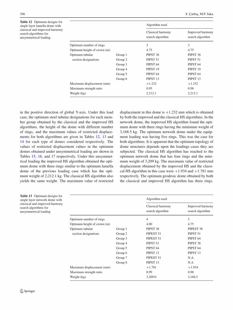
(a)
(b)
Fig. 14 Comparison of the weights of the optimum domes obtainedby CHS and IHS. a Comparison of the weights of the optimum domesobtained by CHS. b Comparison of the weights of the optimum domesobtained by IHS
HS and IHS for the lamella dome with three rings are shownin Fig. 15.
In the case of unsymmetrical loading 15 kN of concen-trated loads are applied on each joint of the one half ofthe dome as shown in Fig. 16 (a) Lamella, (b) Network,and (c) Geodesic domes, respectively. Under this loadingit is obvious that some of the joints will move upward
Fig. 15 The design history graphs of lamella dome with three ringsobtained using CHS and IHS
(b)
(c)
Fig. 16 Unsymmetrical loadings of a Lamella, b Network, andc Geodesic domes
396 S. Çarbas, M.P. Saka
Table 12 Optimum designs forsingle layer lamella dome withclassical and improved harmonysearch algorithms forunsymmetrical loading
Algorithm used
Classical harmony Improved harmony
search algorithm search algorithm
Optimum number of rings 3 3
Optimum height of crown (m) 4.75 4.75
Optimum tubular Group 1 PIPST 38 PIPST 38
section designations Group 2 PIPST 51 PIPST 51
Group 3 PIPST 64 PIPST 64
Group 4 PIPST 19 PIPST 19
Group 5 PIPST 64 PIPST 64
Group 6 PIPST 13 PIPST 13
Maximum displacement (mm) +1.232 +1.232
Maximum strength ratio 0.95 0.98
Weight (kg) 2,212.1 2,212.1
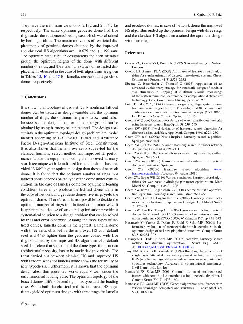
in the positive direction of global Y-axis. Under this loadcase, the optimum steel tubular designations for each mem-ber group obtained by the classical and the improved HSalgorithms, the height of the dome with different numberof rings, and the maximum values of restricted displace-ments for both algorithms are given in Tables 12, 13 and14 for each type of domes considered respectively. Thevalues of restricted displacement values in the optimumdomes obtained under unsymmetrical loading are shown inTables 15, 16, and 17 respectively. Under this unsymmet-rical loading the improved HS algorithm obtained the opti-mum dome with three rings similar to the optimum lamelladome of the previous loading case which has the opti-mum weight of 2,212.1 kg. The classical HS algorithm alsoyields the same weight. The maximum value of restricted
displacement in this dome is +1.232 mm which is obtainedby both the improved and the classical HS algorithms. In thenetwork dome, the improved HS algorithm found the opti-mum dome with three rings having the minimum weight of3,168.5 kg. The optimum network dome under the equip-ment loading was having five rings. This was the case forboth algorithms. It is apparent that the optimum topology ofdome structures depends upon the loadings cases they aresubjected. The classical HS algorithm has reached to theoptimum network dome that has four rings and the mini-mum weight of 3,209 kg. The maximum value of restricteddisplacement obtained by the improved HS and the classi-cal HS algorithm in this case were +1.934 and +1.781 mmrespectively. The optimum geodesic dome obtained by boththe classical and improved HS algorithm has three rings.
Table 13 Optimum designs forsingle layer network dome withclassical and improved harmonysearch algorithms forunsymmetrical loading
Algorithm used
Classical harmony Improved harmony
search algorithm search algorithm
Optimum number of rings 4 3
Optimum height of crown (m) 4.00 4.75
Optimum tubular Group 1 PIPST 38 PIPEST 38
section designations Group 2 PIPEST 51 PIPST 51
Group 3 PIPEST 51 PIPST 64
Group 4 PIPST 51 PIPST 38
Group 5 PIPST 64 PIPST 64
Group 6 PIPST 13 PIPST 13
Group 7 PIPEST 51 N.A.
Group 8 PIPST 13 N.A
Maximum displacement (mm) +1.781 +1.934
Maximum strength ratio 0.99 0.98
Weight (kg) 3,209.0 3,168.5
Optimum topology design of various geometrically nonlinear latticed domes 397
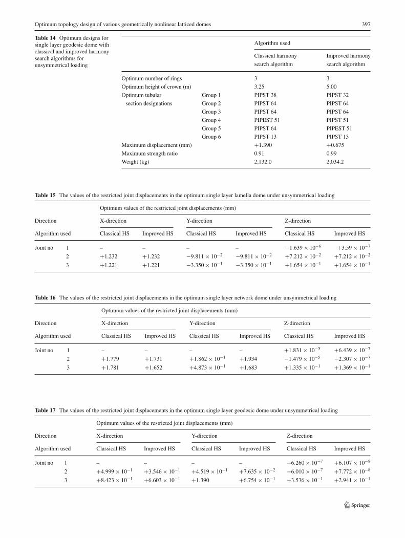
Table 14 Optimum designs forsingle layer geodesic dome withclassical and improved harmonysearch algorithms forunsymmetrical loading
Algorithm used
Classical harmony Improved harmony
search algorithm search algorithm
Optimum number of rings 3 3
Optimum height of crown (m) 3.25 5.00
Optimum tubular Group 1 PIPST 38 PIPST 32
section designations Group 2 PIPST 64 PIPST 64
Group 3 PIPST 64 PIPST 64
Group 4 PIPEST 51 PIPST 51
Group 5 PIPST 64 PIPEST 51
Group 6 PIPST 13 PIPST 13
Maximum displacement (mm) +1.390 +0.675
Maximum strength ratio 0.91 0.99
Weight (kg) 2,132.0 2,034.2
Table 15 The values of the restricted joint displacements in the optimum single layer lamella dome under unsymmetrical loading
Optimum values of the restricted joint displacements (mm)
Direction X-direction Y-direction Z-direction
Algorithm used Classical HS Improved HS Classical HS Improved HS Classical HS Improved HS
Joint no 1 – – – – −1.639 × 10⁻⁶ +3.59 × 10⁻⁷
2 +1.232 +1.232 −9.811 × 10⁻² −9.811 × 10⁻² +7.212 × 10⁻² +7.212 × 10⁻²
3 +1.221 +1.221 −3.350 × 10⁻¹ −3.350 × 10⁻¹ +1.654 × 10⁻¹ +1.654 × 10⁻¹
Table 16 The values of the restricted joint displacements in the optimum single layer network dome under unsymmetrical loading
Optimum values of the restricted joint displacements (mm)
Direction X-direction Y-direction Z-direction
Algorithm used Classical HS Improved HS Classical HS Improved HS Classical HS Improved HS
Joint no 1 – – – – +1.831 × 10⁻⁵ +6.439 × 10⁻⁷
2 +1.779 +1.731 +1.862 × 10⁻¹ +1.934 −1.479 × 10⁻⁵ −2.307 × 10⁻⁷
3 +1.781 +1.652 +4.873 × 10⁻¹ +1.683 +1.335 × 10⁻¹ +1.369 × 10⁻¹
Table 17 The values of the restricted joint displacements in the optimum single layer geodesic dome under unsymmetrical loading
Optimum values of the restricted joint displacements (mm)
Direction X-direction Y-direction Z-direction
Algorithm used Classical HS Improved HS Classical HS Improved HS Classical HS Improved HS
Joint no 1 – – – – +6.260 × 10⁻⁷ +6.107 × 10⁻⁸
2 +4.999 × 10⁻¹ +3.546 × 10⁻¹ +4.519 × 10⁻¹ +7.635 × 10⁻² −6.010 × 10⁻⁷ +7.772 × 10⁻⁸
3 +8.423 × 10⁻¹ +6.603 × 10⁻¹ +1.390 +6.754 × 10⁻¹ +3.536 × 10⁻¹ +2.941 × 10⁻¹
398 S. Çarbas, M.P. Saka
They have the minimum weights of 2,132 and 2,034.2 kgrespectively. The same optimum geodesic dome had fiverings under the equipments loading case which was obtainedby both algorithms. The maximum values of restricted dis-placements of geodesic domes obtained by the improvedand classical HS algorithms are +0.675 and +1.390 mm.The optimum steel tubular designations for each membergroup, the optimum heights of the dome with differentnumber of rings, and the maximum values of restricted dis-placements obtained in the case of both algorithms are givenin Tables 15, 16 and 17 for lamella, network, and geodesicdomes respectively.
7 Conclusions
It is shown that topology of geometrically nonlinear latticeddomes can be treated as design variable and the optimumnumber of rings, the optimum height of crown and tubu-lar steel section designations for its member groups can beobtained by using harmony search method. The design con-straints in the optimum topology design problem are imple-mented according to LRFD-AISC (Load and ResistanceFactor Design–American Institute of Steel Constitution).It is also shown that the improvements suggested for theclassical harmony search method has improved its perfor-mance. Under the equipment loading the improved harmonysearch technique with default seed for lamella dome has pro-vided 13.84% lighter optimum design than those of networkdome. It is found that the optimum number of rings in alatticed dome depends on the type of the dome under consid-eration. In the case of lamella dome for equipment loadingcondition, three rings produce the lightest dome while inthe case of network and geodesic domes five rings yield theoptimum dome. Therefore, it is not possible to decide theoptimum number of rings in a latticed dome intuitively. Itis apparent that the use of structural optimization provides asystematical solution to a design problem that can be solvedby trial and error otherwise. Among the three types of lat-ticed domes, lamella dome is the lightest. Lamella domewith three rings obtained by the improved HS with defaultseed is 5.44% lighter than the geodesic domes with fiverings obtained by the improved HS algorithm with defaultseed. It is clear that selection of the dome type, if it is not anarchitectural necessity, has to be made design variable. Thet-test carried out between classical HS and improved HSwith random seeds for lamella dome shows the reliability ofnew hypothesis. Furthermore, it is shown that the optimumdesign algorithm presented works equally well under theunsymmetrical loading case. The optimum topology of thebraced domes differs depending on its type and the loadingcase. While both the classical and the improved HS algo-rithms yielded optimum designs with three rings for lamella
and geodesic domes, in case of network dome the improvedHS algorithm ended up the optimum design with three ringsand the classical HS algorithm attained the optimum designwith four rings.
References
Coates RC, Coutie MG, Kong FK (1972) Structural analysis. Nelson,London
Coelho LS, Bernert DLA (2009) An improved harmony search algo-rithm for synchronization of discrete-time chaotic systems Chaos.Solitons and Fractals 41(5):2526–2532
Ebenau C, Rottsvhafer J, Thierauf G (2003) Application of anadvanced evolutionary strategy for automatic design of modularsteel structures. In: Topping BHV, Bittnar Z (eds) Proceedingsof the sixth international conference on computational structurestechnology. Civil-Comp Press, Stirling, paper no: 97
Erdal F, Saka MP (2006) Optimum design of grillage systems usingharmony search algorithm. In: Proceedings of 8th internationalconference on computational structures technology (CST 2006),Las Palmas de Gran Canaria, Spain, pp 12–15
Geem ZW (2006) Optimal cost design of water distribution networksusing harmony search. Eng Optim 38:259–280
Geem ZW (2008) Novel derivative of harmony search algorithm fordiscrete design variables. Appl Math Comput 199(1):223–230
Geem ZW (ed) (2009a) Music-inspired harmony search algorithm.Springer, New York
Geem ZW (2009b) Particle-swarm harmony search for water networkdesign. Eng Optim 41(4):297–311
Geem ZW (ed) (2010a) Recent advances in harmony search algorithm.Springer, New York
Geem ZW (ed) (2010b) Harmony search algorithms for structuraldesign optimization. Springer
Geem ZW (2010c) Harmony search algorithm. www.harmonysearch.info. Accessed 04 August 2010
Geem ZW, Roper WE (2010) Various continuous harmony search algo-rithms for web-based hydrologic parameter optimization. MathModel Sci Comput 1(3):231–226
Geem ZW, Kim JH, Loganathan GV (2001) A new heuristic optimiza-tion algorithm; harmony search. Simulation 76:60–68
Geem ZW, Kim JH, Loganathan GV (2002) Harmony search opti-mization: application to pipe network design. Int J Model Simul22:125–133
Geem ZW, Lee KS, Tseng CL (2005) Harmony search for structuraldesign. In: Proceedings of 2005 genetic and evolutionary compu-tation conference (GECCO-2005), Washington DC, pp 651–652
Hasançebi O, Çarbas S, Dogan E, Erdal F, Saka MP (2009a) Per-formance evaluation of metaheuristic search techniques in theoptimum design of real size pin jointed structures. Comput Struct87(5–6):284–302
Hasançebi O, Erdal F, Saka MP (2009b) Adaptive harmony searchmethod for structural optimization. J Struct Eng, ASCE.doi:10.1061/(ASCE)ST.1943-541X.0000128
Jung HM, Known YH, Yamada M (1994) Buckling characteristics ofsingle layer latticed domes and equipment loading. In: ToppingBHV (ed) Proceedings of the second conference on computationalstructures technology. Advances in computational mechanics.Civil-Comp Ltd., London
Kameshki ES, Saka MP (2001) Optimum design of nonlinear steelframes with semi-rigid connections using a genetic algorithm. JComput Struct 79(17):1593–1604
Kameshki ES, Saka MP (2003) Genetic algorithms steel frames withvarious semi-rigid computers and structures. J Constr Steel Res59(1):109–134
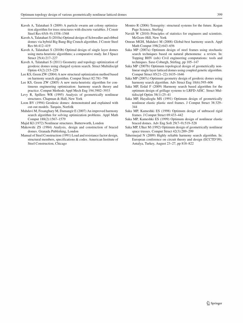
Optimum topology design of various geometrically nonlinear latticed domes 399
Kaveh A, Talatahari S (2009) A particle swarm ant colony optimiza-tion algorithm for truss structures with discrete variables. J ConstrSteel Res 65(8–9):1558–1568
Kaveh A, Talatahari S (2010a) Optimal design of Schwedler and ribbeddomes via hybrid Big Bang-Big Crunch algorithm. J Constr SteelRes 66:412–419
Kaveh A, Talatahari S (2010b) Optimal design of single layer domesusing meta-heuristic algorithms; a comparative study. Int J SpaceStruct 25(4):217–227
Kaveh A, Talatahari S (2011) Geometry and topology optimization ofgeodesic domes using charged system search. Struct MultidisciplOptim 43(2):215–229
Lee KS, Geem ZW (2004) A new structural optimization method basedon harmony search algorithm. Comput Struct 82:781–798
Lee KS, Geem ZW (2005) A new meta-heuristic algorithm for con-tinuous engineering optimization: harmony search theory andpractice. Comput Methods Appl Mech Eng 194:3902–3933
Levy R, Spillers WR (1995) Analysis of geometrically nonlinearstructures. Chapman & Hall, New York
Loon BV (1994) Geodesic domes: demonstrated and explained withcut-out models. Tarquin, Norfolk
Mahdavi M, Fesanghary M, Damangir E (2007) An improved harmonysearch algorithm for solving optimization problems. Appl MathComput 188(2):1567–1579
Majid KI (1972) Nonlinear structures. Butterworth, LondonMakowshi ZS (1984) Analysis, design and construction of braced
domes. Granada Publishing, LondonManual of Steel Construction (1991) Load and resistance factor design,
structural members, specifications & codes. American Institute ofSteel Construction, Chicago
Montro R (2006) Tensegrity: structural systems for the future. KoganPage Science, Sterling
Navidi W (2010) Principles of statistics for engineers and scientists.McGraw-Hill, New York
Omran MGH, Mahdavi M (2008) Global-best harmony search. ApplMath Comput 198(2):643–656
Saka MP (2007a) Optimum design of steel frames using stochasticsearch techniques based on natural phenomena: a review. In:Topping BHV (eds) Civil engineering computations: tools andtechniques. Saxe-Coburgh, Stirling, pp 105–147
Saka MP (2007b) Optimum topological design of geometrically non-linear single layer latticed domes using coupled genetic algorithm.Comput Struct 85(21–22):1635–1646
Saka MP (2007c) Optimum geometry design of geodesic domes usingharmony search algorithm. Adv Struct Eng 10(6):595–606
Saka MP, Erdal F (2009) Harmony search based algorithm for theoptimum design of grillage systems to LRFD-AISC. Struct Mul-tidiscipl Optim 38(1):25–41
Saka MP, Hayalioglu MS (1991) Optimum design of geometricallynonlinear elastic plastic steel frames. J Comput Struct 38:329–344
Saka MP, Kameshki ES (1998) Optimum design of unbraced rigidframes. J Comput Struct 69:433–442
Saka MP, Kameshki ES (1999) Optimum design of nonlinear elasticbraced domes. Adv Eng Soft 29(7–9):519–528
Saka MP, Ulker M (1992) Optimum design of geometrically nonlinearspace trusses. Comput Struct 42(3):289–299
Taherinejad N (2009) Highly reliable harmony search algorithm. In:European conference on circuit theory and design (ECCTD’09),Antalya, Turkey, August 23–27, pp 818–822
Related Documents