Proceedings World Geothermal Congress 2015 Melbourne, Australia, 19-25 April 2015 1 Optimum Hydraulics Design and Operation for Extended-Reach and Horizontal Geothermal Drilling Shigemi Naganawa Frontier Research Center for Energy and Resources, The University of Tokyo, 7-3-1 Hongo, Bunkyo-ku, Tokyo 113-8656 Japan [email protected] Keywords: extended-reach and horizontal drilling, hole cleaning, ECD management, borehole stability, managed pressure drilling ABSTRACT Directional wells for geothermal resource exploitation are expected to enable environmental-friendly, cost-saving developments by means of aggregation of well site drilling and production facilities, which are based outside nature conservation areas. Directional wells are also expected to enhance steam productivity through greater penetration of high-temperature hydrothermal reservoirs. Particularly in enhanced geothermal systems (EGS), to economically extract heat from the reservoirs, directional drilling technology is indispensable for high-quality fracture creations and effective fracture penetrations of production wells. However, in geothermal drilling with subnormal pressure formations and many lost circulation zones, low-density and low-viscosity drilling fluids are usually used which are disadvantageous for obtaining good hole cleaning. Increasing the flow rate in order to compensate the poor hole cleaning may, however, increase the equivalent circulating density (ECD) more rapidly in extended-reach and horizontal wells than in vertical wells. In this paper, information from experimental measurements, numerical simulation, and analysis of field pressure while drilling (PWD) data are summarized, and the optimum hydraulics design and operation for cost- saving, and safe extended-reach and horizontal geothermal drilling are discussed. In the discussion, what the differences of cuttings transport and ECD behaviors between oilwell and geothermal drillings are, and how we can avoid hole cleaning, lost circulation and borehole instability problems are focused on. 1. INTRODUCTION Directional drilling technology is now popular in the oil and gas industry because extended-reach and horizontal wells improve well productivity. In geothermal resource development, directional wells are also expected to enable environmental-friendly, cost-saving developments through the ability to place drilling and production facilities outside nature conservation areas, and greater and more effective penetration of high-temperature hydrothermal reservoirs. Particularly in enhanced geothermal systems (EGS), to economically extract heat from the reservoirs, directional drilling technology is indispensable for high-quality fracture creations and effective fracture penetrations by production wells. However, few applications of long extended-reach and horizontal drilling in geothermal reservoirs have been recorded so far. Figure 1: The difference of ECD behaviors between extended-reach well (left) and vertical well (right) with the same vertical depths. One of the key issues in extended-reach and horizontal drilling applications for geothermal development is the hydraulics design and operation. In geothermal drilling with subnormal pressure formations and many lost circulation zones, low-density and low- viscosity drilling fluids are usually used; these are, however, disadvantageous for obtaining good hole cleaning. An increase in the flow rate to compensate for this may, however, increase the equivalent circulating density (ECD) more rapidly in extended-reach and horizontal wells than in vertical wells, as shown in Figure 1. This generates a potential risk of lost circulation and borehole

Welcome message from author
This document is posted to help you gain knowledge. Please leave a comment to let me know what you think about it! Share it to your friends and learn new things together.
Transcript

Proceedings World Geothermal Congress 2015
Melbourne, Australia, 19-25 April 2015
1
Optimum Hydraulics Design and Operation for Extended-Reach and Horizontal
Geothermal Drilling
Shigemi Naganawa
Frontier Research Center for Energy and Resources, The University of Tokyo, 7-3-1 Hongo, Bunkyo-ku, Tokyo 113-8656 Japan
Keywords: extended-reach and horizontal drilling, hole cleaning, ECD management, borehole stability, managed pressure drilling
ABSTRACT
Directional wells for geothermal resource exploitation are expected to enable environmental-friendly, cost-saving developments by
means of aggregation of well site drilling and production facilities, which are based outside nature conservation areas. Directional
wells are also expected to enhance steam productivity through greater penetration of high-temperature hydrothermal reservoirs.
Particularly in enhanced geothermal systems (EGS), to economically extract heat from the reservoirs, directional drilling
technology is indispensable for high-quality fracture creations and effective fracture penetrations of production wells. However, in
geothermal drilling with subnormal pressure formations and many lost circulation zones, low-density and low-viscosity drilling
fluids are usually used which are disadvantageous for obtaining good hole cleaning. Increasing the flow rate in order to compensate
the poor hole cleaning may, however, increase the equivalent circulating density (ECD) more rapidly in extended-reach and
horizontal wells than in vertical wells. In this paper, information from experimental measurements, numerical simulation, and
analysis of field pressure while drilling (PWD) data are summarized, and the optimum hydraulics design and operation for cost-
saving, and safe extended-reach and horizontal geothermal drilling are discussed. In the discussion, what the differences of cuttings
transport and ECD behaviors between oilwell and geothermal drillings are, and how we can avoid hole cleaning, lost circulation
and borehole instability problems are focused on.
1. INTRODUCTION
Directional drilling technology is now popular in the oil and gas industry because extended-reach and horizontal wells improve well
productivity. In geothermal resource development, directional wells are also expected to enable environmental-friendly, cost-saving
developments through the ability to place drilling and production facilities outside nature conservation areas, and greater and more
effective penetration of high-temperature hydrothermal reservoirs. Particularly in enhanced geothermal systems (EGS), to
economically extract heat from the reservoirs, directional drilling technology is indispensable for high-quality fracture creations and
effective fracture penetrations by production wells. However, few applications of long extended-reach and horizontal drilling in
geothermal reservoirs have been recorded so far.
Figure 1: The difference of ECD behaviors between extended-reach well (left) and vertical well (right) with the same
vertical depths.
One of the key issues in extended-reach and horizontal drilling applications for geothermal development is the hydraulics design
and operation. In geothermal drilling with subnormal pressure formations and many lost circulation zones, low-density and low-
viscosity drilling fluids are usually used; these are, however, disadvantageous for obtaining good hole cleaning. An increase in the
flow rate to compensate for this may, however, increase the equivalent circulating density (ECD) more rapidly in extended-reach
and horizontal wells than in vertical wells, as shown in Figure 1. This generates a potential risk of lost circulation and borehole

Naganawa
2
instability. Implementation of an effective hole cleaning method and appropriate maintenance of the ECD are much more difficult
to achieve in geothermal wells than in oil and gas wells.
The author’s research group has conducted numerous experiments. The group has also undertaken modeling and numerical
simulation studies, and has analyzed field pressure while drilling (PWD) data for over 10 years. Based on the information obtained
from these studies, optimum hydraulics design and operation for cost-saving, safe extended-reach and horizontal geothermal
drilling are discussed. In the discussion, what the differences of cuttings transport and ECD behaviors between oilwell and
geothermal drillings are, and how we can avoid hole cleaning, lost circulation and borehole instability problems are focused on.
2. CUTTINGS TRANSPORT AND ECD MANAGEMENT IN EXTENDED-REACH WELLS
2.1 Cuttings Transport Experiments
The large-scale flow loop experimental apparatus, known as the Cuttings Transport Flow Loop System (CTFLS), was first
constructed in 1998 in the Japan Oil, Gas and Metals National Corporation (JOGMEC) Test Field through a collaborative research
project on highly inclined underbalanced drilling operations between the University of Tokyo and JOGMEC. After some
improvements in the apparatus, quantitative measurements of cuttings accumulation in the flow loop annulus became possible
enabling of versatile study of cuttings transport in extended-reach drilling.
The CTFLS has a 9-m long test section simulating a borehole annulus that consists of a 5-in. outer casing and a 2.063-in. drill pipe.
The middle section of the outer casing that is approximately 7-m is composed of transparent acrylic resin to enable visual
observation of the cuttings flow behavior in the annulus. The test section can be set to an arbitrary angle anywhere between vertical
(0°) and horizontal (90°) in increments of 15°.
By using the CTFLS, drilling conditions with an arbitrary rate of penetration can be reproduced by controlling the feed rate of
cuttings into the test section annulus. As shown in Figure 2, cuttings are fed and mixed into the fluid flow line at the inlet of the test
section by operating a screw feeder at a given rate. Cuttings discharged from the outlet of the test section are separated from the
drilling fluid at the shaker screen and conveyed to the reservoir hopper. The weights of both the cuttings feed hopper and the
reservoir hopper are continuously measured using the respective load cells to calculate the weight of the cuttings accumulated in the
test section annulus. In addition, frictional pressure losses per unit length are measured using a differential pressure sensor.
Figure 2: The cuttings transport flow loop system (CTFLS) experimental apparatus in the JOGMEC Test Field.
We have studied cuttings transport behavior in extended-reach geothermal well drilling using the CTFLS (Naganawa, 2013;
Naganawa and Okabe, 2013). An example of experimental results is shown in Figure 3. The primary result obtained is that the
frictional pressure losses are unexpectedly large at low flow rates for water compared to a more viscous bentonite mud, particularly
at medium to high hole inclination angle, although the cuttings concentrations in the annulus were lower in the low flow rate region.
The reason for these high frictional pressure losses can be explained by considering the drilling fluid and cuttings flow regimes. In
the case of water, fluid flow is turbulent at the flow rates usually observed in the wellbore annulus, and the cuttings are dynamically
transported to form dunes also in a turbulent manner. These moving dunes may result in a much larger frictional pressure loss.
Although the frictional pressure losses in the absence of cuttings is smaller in the case of water than for a viscous bentonite mud, as
might be expected, the increase of the ECD in extended-reach and horizontal wells indicate that cuttings will be accumulated in the
wellbore annulus to a significant degree.
2.2 Modeling and Simulator Development
A transient cuttings transport (TCT) simulator was also developed as a part of the collaborative research project and improvements
continued subsequent to the projects end. The TCT simulator predicts the transient behaviors of cuttings bed height, suspended
cuttings concentration, phase velocities, and annular pressure from the surface to the bottomhole for extended-reach wells with a
complex trajectory (Naganawa and Nomura, 2006).

Naganawa
3
Figure 3: Experimental results of cuttings volume concentration in the annulus and frictional pressure loss measurements
contrasted with cuttings flow regimes with water (left) and low-viscosity bentonite mud (right) as drilling fluids.
Figure 4: Schematic of the two-layer model description for the transient cuttings transport simulator.
Naganawa
4
The mathematical model of the simulator is described as a two-layer model, which handles transient 1D solid-liquid two-phase flow
in the wellbore annulus, as shown in Figure 4. The basic equations include mass and momentum conservations for each phase in the
upper suspended fluid layer and lower cuttings deposit layer. To close the basic equations mathematically, a set of constitutive
equations derived from consideration of the cuttings deposition and re-entrainment relationships between the layers. The model
parameters in the constitutive equations such as friction factors, and cuttings deposition and re-entrainment rates were evaluated
and determined by matching the calculated data with the data obtained from the flow loop experiments described above, as well as
the pressure while drilling (PWD) data obtained from a geothermal well in Japan (Naganawa and Okabe, 2014).
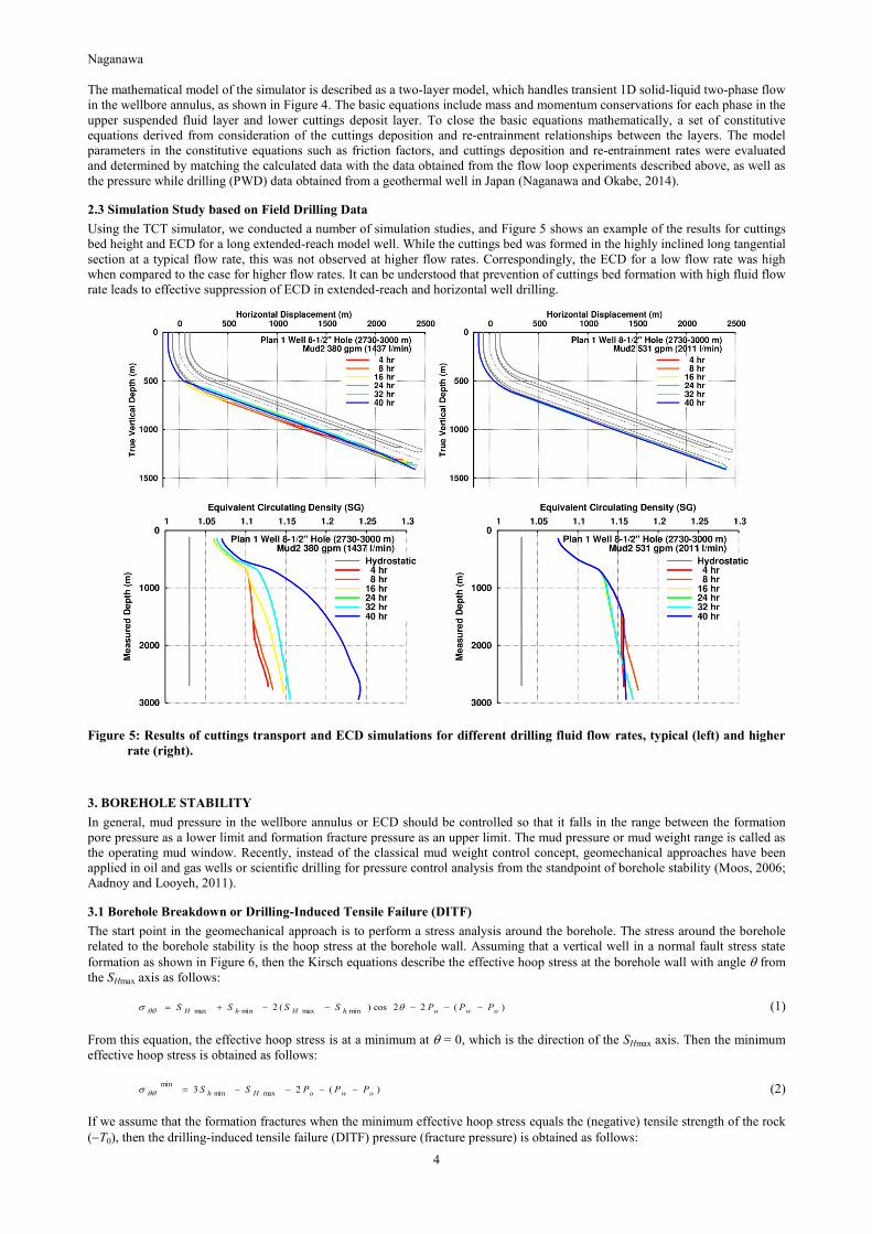
2.3 Simulation Study based on Field Drilling Data
Using the TCT simulator, we conducted a number of simulation studies, and Figure 5 shows an example of the results for cuttings
bed height and ECD for a long extended-reach model well. While the cuttings bed was formed in the highly inclined long tangential
section at a typical flow rate, this was not observed at higher flow rates. Correspondingly, the ECD for a low flow rate was high
when compared to the case for higher flow rates. It can be understood that prevention of cuttings bed formation with high fluid flow
rate leads to effective suppression of ECD in extended-reach and horizontal well drilling.
Figure 5: Results of cuttings transport and ECD simulations for different drilling fluid flow rates, typical (left) and higher
rate (right).
3. BOREHOLE STABILITY
In general, mud pressure in the wellbore annulus or ECD should be controlled so that it falls in the range between the formation
pore pressure as a lower limit and formation fracture pressure as an upper limit. The mud pressure or mud weight range is called as
the operating mud window. Recently, instead of the classical mud weight control concept, geomechanical approaches have been
applied in oil and gas wells or scientific drilling for pressure control analysis from the standpoint of borehole stability (Moos, 2006;
Aadnoy and Looyeh, 2011).
3.1 Borehole Breakdown or Drilling-Induced Tensile Failure (DITF)
The start point in the geomechanical approach is to perform a stress analysis around the borehole. The stress around the borehole
related to the borehole stability is the hoop stress at the borehole wall. Assuming that a vertical well in a normal fault stress state
formation as shown in Figure 6, then the Kirsch equations describe the effective hoop stress at the borehole wall with angle from
the SHmax axis as follows:
)(22cos)(2 minmaxminmax owohHhH PPPSSSS (1)
From this equation, the effective hoop stress is at a minimum at = 0, which is the direction of the SHmax axis. Then the minimum
effective hoop stress is obtained as follows:
)(23 maxmin
min
owoHh PPPSS (2)
If we assume that the formation fractures when the minimum effective hoop stress equals the (negative) tensile strength of the rock
(T0), then the drilling-induced tensile failure (DITF) pressure (fracture pressure) is obtained as follows:

Naganawa
5
0maxmin3 TPSSP oHhwf (3)
In highly permeable zones or naturally fractured zones, pore pressure readily balances with mud pressure, which means Po = Pw,
then Pwf reduces to
2
3 0maxmin TSSP
Hh
wf
(4)
At mud pressures higher than the DITF pressure, borehole fracturing occurs and propagates in the direction of SHmax.
Figure 6: Two modes of borehole failures observed around a vertical well which determine the operating mud window.
3.2 Borehole Breakout or Collapse
In the same manner, from equation (1), the effective hoop stress is maximum at = /2, which is the direction of the Shmin axis. The
maximum effective hoop stress is then given by
)(23 minmax
max
owohH PPPSS (5)
If we assume that formation breakout occurs when the maximum effective hoop stress is equal to the uniaxial compressive strength
of the rock (UCS Po), then
sin1
cos233 minmaxminmax
cSSUCSSSP hHhHwb (6)
The uniaxial (or unconfined) compressive strength, UCS is derived based on the Mohr-Coulomb failure criterion which is defined
as
tan c (7)
where c is the cohesion and is angle of internal friction.
At mud pressures lower than the breakout pressure, borehole breakout occures in the direction of Shmin.
3.3 Operating Mud Window from the Aspect of Borehole Stability
From the above discussion, the optimal operating mud window for borehole stability is
ffwfwwboPPPPP Pressure Fracture~ Pressure DITF PressureBreakout PressurePore (8)
where Pff is the classical formation fracture pressure or formation breakdown pressure. The formation breakdown pressure can be
obtained through an extended leakoff test (XLOT) usually conducted after casing cementing operations to evaluate cement integrity
at the casing shoe, and the breakdown pressure may be greater than the DITF pressure in many situations.
The concept of an operating mud window from the standpoint of borehole stability is illustrated in Figure 7, combined with casing
set depths. In general, a borehole is more unstable in directional wells than in vertical wells because of the difference between the
minimum and maximum stresses perpendicular to the well axis being greater due to the effect of the overburden pressure. As the
operating mud window in extended-reach and horizontal geothermal wells is considered to be narrower than for oilwells, borehole
stability studies using stress analysis based on geomechanics and in-situ horizontal stress measurement through XLOT should be
minhS
)(23 maxmin
min
owoHh PPPSS
)(23 minmax
max
owohH PPPSS
maxHS
wP
oP
Tensile Fracture
Collapse (Breakout)
Minimum Effective Hoop Stress
Maximum Horizontal Stress
Minimum Horizontal Stress
maxHS
minhS
Maximum Effective Hoop Stress

Naganawa
6
carefully conducted during drilling operations, as well as in the well planning phase. XLOT is also effective in determination of the
horizontal stresses.
Figure 7: Safer operating mud window in consideration of borehole breakout and drilling-induced tensile fracture.
4. PRESSURE MANAGEMENT UNDER SIMULTANEOUS OCCURRENCE OF LOST CIRCULATION AND GAS
KICK
In many geothermal fields, formation pressure is normal or subnormal. In addition, typical geothermal fields are located in volcanic
areas. Thus, volcanic gases such as hydrogen sulfide (H2S) or carbon dioxide (CO2) are often observed to be entrained in the
drilling fluid returned to surface. This formation fluid influx into the wellbore is called a kick. A gas kick can rapidly escalate into a
blowout if appropriate well control procedures are not executed. However, in geothermal wells with subnormal formation pressure,
high density drilling fluids for prevention of gas influx into the well annulus cannot be used in many cases because of the risk of
fracturing the formation or of severe lost circulation.
This type of drilling problem is experienced in practice, for example in a geothermal exploration well drilled in 1995 in the
Kakkonda field, northern territory of Japan (Saito et al., 1998). This drilling operation may have observed the world’s highest
bottomhole temperature record at over 500°C. In these conditions, by performing continuous drilling fluid circulation every one
drill pipe stand with a top drive system, combined with a surface mud cooling system (TDS cooling method), successful reduction
of the bottomhole temperature, down to approximately 160°C, was achieved. However, 28% of the total drilling period (97 days out
of the 340 days) was spent on undertaking lost circulation measures. The worst thing was that subnormal pressure and lost
circulation posed a barrier to well control to prevent toxic H2S gas influx at 3,642 m, and consequently, further drilling to the
planned total depth had to be abandoned.
The possible sequence in which H2S gas kick leads to a surface or underground blowout due to failure in well control operation in
the worst case scenario is illustrated in Figure 8. Lost circulation reduces the mud column height and the bottomhole pressure,
inducing the gas kick and leading to the surface or underground blowout.
Figure 8: Possible sequence in which an H2S gas kick leads to a surface or underground blowout due to the failure in well
control operation.

Naganawa
7
A possible mechanism for the simultaneous occurrence of lost circulation and gas kick can be explained by the depth vs. pressure
graph as shown in Figure 9. Under narrow operating mud window condition, although the hydrostatic mud pressure at bottomhole
may be lower than the formation pore pressure or borehole breakout pressure which causes a gas kick, the mud circulating pressure
is higher than the hydrostatic pressure and possibly exceeds the formation fracture pressure, as expressed in equation (4), in the
shallower, naturally fractured lost circulation zone. As already stated, the ECD readily increases in highly inclined long tangential
sections. In addition, the possibility of severe ECD fluctuations in various drilling operations was reported in a previous study
(Naganawa and Okatsu, 2008).
Figure 9: Possible mechanism of simultaneous occurrence of lost circulation and gas kick.
The managed pressure drilling (MPD) method is sometimes applied to wells with a narrow mud window in oil and gas well
development. Typical MPD methodologies are the constant bottomhole pressure (CBHP) method and pressurized mud cap drilling.
As shown in Figure 10, in normal MPD methods, including CBHP and pressurized mud cap drilling, using a rotating control device
(RCD) at the well head, a backpressure is applied at the surface to the annulus.
Figure 10: Typical MPD variations used in oil and gas development.
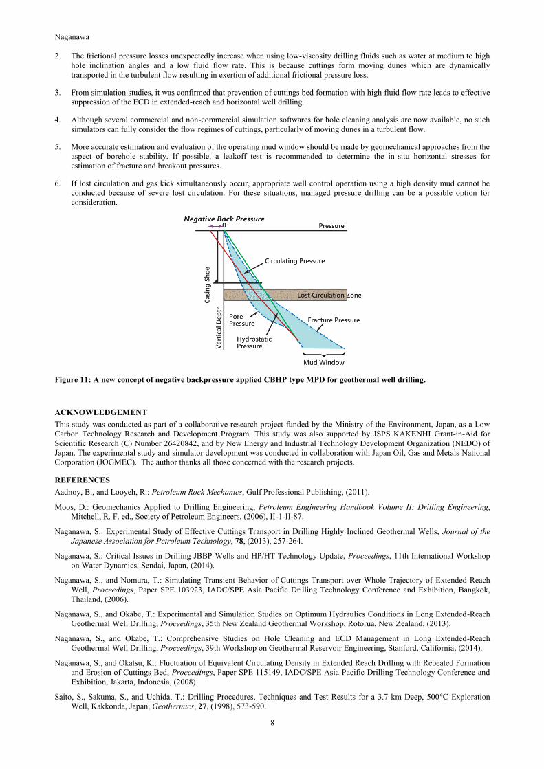
For pressure management during the simultaneous occurrence of lost circulation and gas kick, as presented in Figure 9, MPD is a
possible option. However, under such conditions, the backpressure to be applied may be negative, as shown in Figure 11
(Naganawa, 2014). As this is not a normal MPD operation, whether and how existing MPD equipments can handle the negative
backpressure may require further investigations.
5. CONCLUSION AND RECOMMENDATIONS
1. During extended-reach and horizontal well drilling, the equivalent circulating density (ECD) may readily increase in highly
inclined long tangential hole sections, which makes it difficult to implement both effective hole cleaning and appropriate ECD
management.
Naganawa
8
2. The frictional pressure losses unexpectedly increase when using low-viscosity drilling fluids such as water at medium to high
hole inclination angles and a low fluid flow rate. This is because cuttings form moving dunes which are dynamically
transported in the turbulent flow resulting in exertion of additional frictional pressure loss.
3. From simulation studies, it was confirmed that prevention of cuttings bed formation with high fluid flow rate leads to effective
suppression of the ECD in extended-reach and horizontal well drilling.
4. Although several commercial and non-commercial simulation softwares for hole cleaning analysis are now available, no such
simulators can fully consider the flow regimes of cuttings, particularly of moving dunes in a turbulent flow.
5. More accurate estimation and evaluation of the operating mud window should be made by geomechanical approaches from the
aspect of borehole stability. If possible, a leakoff test is recommended to determine the in-situ horizontal stresses for
estimation of fracture and breakout pressures.
6. If lost circulation and gas kick simultaneously occur, appropriate well control operation using a high density mud cannot be
conducted because of severe lost circulation. For these situations, managed pressure drilling can be a possible option for
consideration.
Figure 11: A new concept of negative backpressure applied CBHP type MPD for geothermal well drilling.
ACKNOWLEDGEMENT
This study was conducted as part of a collaborative research project funded by the Ministry of the Environment, Japan, as a Low
Carbon Technology Research and Development Program. This study was also supported by JSPS KAKENHI Grant-in-Aid for
Scientific Research (C) Number 26420842, and by New Energy and Industrial Technology Development Organization (NEDO) of
Japan. The experimental study and simulator development was conducted in collaboration with Japan Oil, Gas and Metals National
Corporation (JOGMEC). The author thanks all those concerned with the research projects.
REFERENCES
Aadnoy, B., and Looyeh, R.: Petroleum Rock Mechanics, Gulf Professional Publishing, (2011).
Moos, D.: Geomechanics Applied to Drilling Engineering, Petroleum Engineering Handbook Volume II: Drilling Engineering,
Mitchell, R. F. ed., Society of Petroleum Engineers, (2006), II-1-II-87.
Naganawa, S.: Experimental Study of Effective Cuttings Transport in Drilling Highly Inclined Geothermal Wells, Journal of the
Japanese Association for Petroleum Technology, 78, (2013), 257-264.
Naganawa, S.: Critical Issues in Drilling JBBP Wells and HP/HT Technology Update, Proceedings, 11th International Workshop
on Water Dynamics, Sendai, Japan, (2014).
Naganawa, S., and Nomura, T.: Simulating Transient Behavior of Cuttings Transport over Whole Trajectory of Extended Reach
Well, Proceedings, Paper SPE 103923, IADC/SPE Asia Pacific Drilling Technology Conference and Exhibition, Bangkok,
Thailand, (2006).
Naganawa, S., and Okabe, T.: Experimental and Simulation Studies on Optimum Hydraulics Conditions in Long Extended-Reach
Geothermal Well Drilling, Proceedings, 35th New Zealand Geothermal Workshop, Rotorua, New Zealand, (2013).
Naganawa, S., and Okabe, T.: Comprehensive Studies on Hole Cleaning and ECD Management in Long Extended-Reach
Geothermal Well Drilling, Proceedings, 39th Workshop on Geothermal Reservoir Engineering, Stanford, California, (2014).
Naganawa, S., and Okatsu, K.: Fluctuation of Equivalent Circulating Density in Extended Reach Drilling with Repeated Formation
and Erosion of Cuttings Bed, Proceedings, Paper SPE 115149, IADC/SPE Asia Pacific Drilling Technology Conference and
Exhibition, Jakarta, Indonesia, (2008).
Saito, S., Sakuma, S., and Uchida, T.: Drilling Procedures, Techniques and Test Results for a 3.7 km Deep, 500°C Exploration
Well, Kakkonda, Japan, Geothermics, 27, (1998), 573-590.
Related Documents