OPTIMIZING TRANSMISSION FOR WIRELESS VIDEO STREAMING Mei-Hsuan Lu A DISSERTATION Submitted to the Department of Electrical and Computer Engineering of Carnegie Mellon University in partial fulfillment of the requirements for the degree of DOCTOR OF PHILOSOPHY July 2009 Committee: Prof. Tsuhan Chen, Advisor Prof. Peter Steenkiste, Advisor Prof. Ragunathan Rajkumar Dr. M. Reha Civanlar (Ozyegin University)

Welcome message from author
This document is posted to help you gain knowledge. Please leave a comment to let me know what you think about it! Share it to your friends and learn new things together.
Transcript
OPTIMIZING TRANSMISSION FOR WIRELESS VIDEO STREAMING
Mei-Hsuan Lu
A DISSERTATION
Submitted to the Department of Electrical and Computer Engineeringof Carnegie Mellon University
in partial fulfillment ofthe requirements for the degree of
DOCTOR OF PHILOSOPHY
July 2009
Committee:Prof. Tsuhan Chen, AdvisorProf. Peter Steenkiste, AdvisorProf. Ragunathan RajkumarDr. M. Reha Civanlar (Ozyegin University)

Copyright c©July 2009
Mei-Hsuan Lu
All rights reserved
ii
ABSTRACT
With advances in wireless networking technologies, wireless multimedia transmission has
grown dramatically in recent years. The simplicity, flexibility, and low up-front costs of such
systems have not only enabled mobility support for existing multimedia applications but
also stimulated the development of new wireless multimedia services. Despite having many
advantages, wireless multimedia services, particularly video services, also pose a number of
challenges that have prevented them from reaching their full potential. In this thesis, we
propose a novel framework that (1) efficiently uses available wireless resources by means of
cross-layer design in intermediate nodes, wireless relays, and end systems and (2) opportunis-
tically optimizes wireless resource use by leveraging path diversity with agile path selection
to support wireless video transmission.
The proposed solution consists of two building blocks: PRO and TAR. PRO (Protocol
for Retransmitting Opportunistically) is an efficient opportunistic retransmission protocol
residing in the MAC layer. Opportunistic retransmission employs overhearing nodes, if
any, distributed in physical space to function as relays that opportunistically retransmit
failed packets on behalf of the source. Relays with better connectivity to the destination
have a higher chance of delivering packets successfully than the source does, thereby result-
ing in a more efficient use of the channel. TAR (Time-based Adaptive Retransmission) is
a MAC-centric cross-layer strategy that leverages application-level information to improve
MAC (re)transmission. As the name suggests, TAR dynamically determines whether to
(re)transmit or discard a packet based on the retransmission deadline of the packet assigned
by the video server regardless of how many trials have been issued for the packet. TAR
significantly reduces the number of late packets and avoids using scarce wireless bandwidth
to retransmit useless packets. The ultimate solution, PROTAR is a seamless combination of
PRO and TAR that further pushes the performance envelope.
To illustrate the efficacy of the proposed solutions, analytical results, testbed experimen-
iii
tal results, real-world experimental results, and user studies of subjective video quality for
a wide range of wireless scenarios are conducted. The evaluation results consistently show
that PRO and TAR can contribute individually. Moreover, PROTAR provides further per-
formance gain in network throughput and visual quality, especially in contended channels,
under fading, or with user mobility.

iv
ACKNOWLEDGMENTS
I always feel I am so lucky to have two advisors who guide me in my Ph.D studies.
They are like two parents in a child’s growth, both of whom are unreplaceable. Professor
Tsuhan Chen as my advisor was a source of inspiration and ideas. His extremely successful
professional life has been a strong motivating factor in pursuit of my Ph.D. From him, I’ve
learned that good research is not about intricate equations that only few can digest but simple
yet effective solutions that everyone can appreciate. Tsuhan is not only a great advisor but
also a caring mentor during my Ph.D. His strong dedication, amazing energy, warmth, and
generosity will continue to be the source of inspiration to me. I am also extremely grateful
to my co-advisor, Professor Peter Steenkiste, without whom this dissertation will not be
possible. Peter is knowledgeable, patient, kind, and responsible. I can discuss a broad range
of problems with him, ranging from big picture questions to possible causes of a bug. From
him, I learned not only research methodologies but also speaking and writing skills that I
will continue to benefit from in my future career. It is Peter’s kind encouragements and
insightful directions that helped me overcome various barriers during my thesis research.
I would also like to thank other members in my thesis committee – Professor Ragunathan
Rajkumar and Dr. M. Reha Civanlar, for their valuable feedback and suggestions that helped
me to improve the overall quality of this thesis. Special thanks to Professor Ozan Tonguz
who is always helpful. I also want to thank former AMP members Deepak Turaga, Trista
Chen, and Ta-Chien Lin for their assistance in my research and future career plan. It was a
great pleasure knowing you.
This thesis was supported in part by the Institute for Information Industry (III), HP
Labs, the International Collaboration for Advancing Security Technology (iCAST), and an
NSF grant. I am grateful to these sponsors for their support.
I would like to thank other members in Tsuhan’s group, David Liu, Kate Shim, Wende
Zhang, Qi Wu, Wei Yu, Kevin Chang, Andrew Gallagher, Devi Parikh, Congcong Li, Dhruv

v
Batra, and Yimeng Zhang, who provided feedback on my thesis and presentations. I would
also like to thank fellow students in Peter’s group, Glenn Judd, Xiaohui Wang, Fahad Dogar,
Xi Liu, Kaushik Lakshminarayanan, George Nychis, and Kevin Borris. In particular, I would
like to thank Xiaohui Wang, for her help on setting up emulation-based experiments during
the later stage of my thesis work. I would also like to thank all the good friends I made
in Pittsburgh, Yu-Hsiang Bosco Chiu, Juhua Liu, Hsin-Mu Tsai, Frank Wang, Ting-Fang
Yen, Chen-Ling Chou, Hung-Chih Lai, Yen-Tzu Lin, Mike Kuo, Lena Kim, and Cheng-Yuan
Wen for adding the element of fun in my Ph.D. life. Most of them also help me on tedious
user studies for video quality assessment. Many thanks to Hsin-Mu Tsai for his help on
OPNET-related problems. I want to thank my best friend, Anli Su, for her support and
accompany over these years.
Finally, I want to thank my family, my parents, my sister, and my brother. It is their
love, encouragements, and support that enable me to focus on my research and help tide me
through several rough patches. This thesis is dedicated to my parents.

vi
Contents
Chapter 1: Introduction 1
1.1 Challenges with Video Transmission . . . . . . . . . . . . . . . . . . . . . . . . . . . 2
1.1.1 Strict Timing Constraints . . . . . . . . . . . . . . . . . . . . . . . . . . . . . 2
1.1.2 High Bandwidth Demand . . . . . . . . . . . . . . . . . . . . . . . . . . . . . 2
1.1.3 Need for Unequal Error Protection . . . . . . . . . . . . . . . . . . . . . . . . 3
1.2 Challenges with Wireless Communication . . . . . . . . . . . . . . . . . . . . . . . . 3
1.2.1 Multi-path Fading and Shadowing . . . . . . . . . . . . . . . . . . . . . . . . 3
1.2.2 Limited Bandwidth . . . . . . . . . . . . . . . . . . . . . . . . . . . . . . . . 4
1.2.3 Interference . . . . . . . . . . . . . . . . . . . . . . . . . . . . . . . . . . . . . 4
1.2.4 User Mobility . . . . . . . . . . . . . . . . . . . . . . . . . . . . . . . . . . . . 4
1.3 Related Work . . . . . . . . . . . . . . . . . . . . . . . . . . . . . . . . . . . . . . . . 6
1.4 Scope of the Thesis . . . . . . . . . . . . . . . . . . . . . . . . . . . . . . . . . . . . . 14
1.4.1 Wireless Networking Environment . . . . . . . . . . . . . . . . . . . . . . . . 14
1.4.2 Video Streaming Applications . . . . . . . . . . . . . . . . . . . . . . . . . . . 14
1.5 Proposed Solutions . . . . . . . . . . . . . . . . . . . . . . . . . . . . . . . . . . . . . 15
1.5.1 Opportunistic Retransmission . . . . . . . . . . . . . . . . . . . . . . . . . . . 16
1.5.2 Time-based Adaptive Retransmission . . . . . . . . . . . . . . . . . . . . . . 17
1.5.3 Time-based Opportunistic Retransmission . . . . . . . . . . . . . . . . . . . . 17
1.6 Thesis Statement . . . . . . . . . . . . . . . . . . . . . . . . . . . . . . . . . . . . . . 18
1.7 Contributions . . . . . . . . . . . . . . . . . . . . . . . . . . . . . . . . . . . . . . . . 18

vii
1.8 Thesis Organization . . . . . . . . . . . . . . . . . . . . . . . . . . . . . . . . . . . . 19
Chapter 2: Opportunistic Retransmission 21
2.1 Basic Concept . . . . . . . . . . . . . . . . . . . . . . . . . . . . . . . . . . . . . . . . 21
2.2 Related Work . . . . . . . . . . . . . . . . . . . . . . . . . . . . . . . . . . . . . . . . 22
2.3 Analysis . . . . . . . . . . . . . . . . . . . . . . . . . . . . . . . . . . . . . . . . . . . 24
2.4 Protocol Design . . . . . . . . . . . . . . . . . . . . . . . . . . . . . . . . . . . . . . . 29
2.4.1 Link Quality Estimation . . . . . . . . . . . . . . . . . . . . . . . . . . . . . . 31
2.4.2 Relay Qualification . . . . . . . . . . . . . . . . . . . . . . . . . . . . . . . . . 33
2.4.3 Relay Selection . . . . . . . . . . . . . . . . . . . . . . . . . . . . . . . . . . . 35
2.4.4 Relay Prioritization . . . . . . . . . . . . . . . . . . . . . . . . . . . . . . . . 38
2.4.5 Retransmission . . . . . . . . . . . . . . . . . . . . . . . . . . . . . . . . . . . 38
2.4.6 Dynamic Switching between PRO and Mesh Networking . . . . . . . . . . . . 40
2.5 Network-Specific Issues . . . . . . . . . . . . . . . . . . . . . . . . . . . . . . . . . . . 40
2.5.1 Collision Avoidance . . . . . . . . . . . . . . . . . . . . . . . . . . . . . . . . 40
2.5.2 Fairness . . . . . . . . . . . . . . . . . . . . . . . . . . . . . . . . . . . . . . . 45
2.5.3 Incentive to Relay . . . . . . . . . . . . . . . . . . . . . . . . . . . . . . . . . 49
2.5.4 Hidden Terminal Effect . . . . . . . . . . . . . . . . . . . . . . . . . . . . . . 50
2.5.5 Multi-rate PRO . . . . . . . . . . . . . . . . . . . . . . . . . . . . . . . . . . . 51
2.6 Performance Evaluation . . . . . . . . . . . . . . . . . . . . . . . . . . . . . . . . . . 53
2.6.1 Testbed Experimental Results . . . . . . . . . . . . . . . . . . . . . . . . . . . 54
2.6.2 Real-world Experiment Results . . . . . . . . . . . . . . . . . . . . . . . . . . 64
2.7 Summary . . . . . . . . . . . . . . . . . . . . . . . . . . . . . . . . . . . . . . . . . . 72
Chapter 3: Time-based Adaptive Retransmission 73
3.1 Basic Concept . . . . . . . . . . . . . . . . . . . . . . . . . . . . . . . . . . . . . . . . 73
3.2 Related Work . . . . . . . . . . . . . . . . . . . . . . . . . . . . . . . . . . . . . . . . 75
3.3 Analysis . . . . . . . . . . . . . . . . . . . . . . . . . . . . . . . . . . . . . . . . . . . 76
3.4 Protocol Design . . . . . . . . . . . . . . . . . . . . . . . . . . . . . . . . . . . . . . . 81

viii
3.4.1 Assuring Standard Channel Access Behavior . . . . . . . . . . . . . . . . . . 82
3.4.2 Retrieving Retransmission Deadlines . . . . . . . . . . . . . . . . . . . . . . . 84
3.5 Assigning Retransmission Deadlines . . . . . . . . . . . . . . . . . . . . . . . . . . . 85
3.6 Performance Evaluation . . . . . . . . . . . . . . . . . . . . . . . . . . . . . . . . . . 87
3.6.1 Testbed Experimental Results . . . . . . . . . . . . . . . . . . . . . . . . . . . 87
3.6.2 Real-world Experiment Results . . . . . . . . . . . . . . . . . . . . . . . . . . 94
3.7 Summary . . . . . . . . . . . . . . . . . . . . . . . . . . . . . . . . . . . . . . . . . . 95
Chapter 4: Time-based Opportunistic Retransmission 99
4.1 Basic Concept . . . . . . . . . . . . . . . . . . . . . . . . . . . . . . . . . . . . . . . . 99
4.2 Analysis . . . . . . . . . . . . . . . . . . . . . . . . . . . . . . . . . . . . . . . . . . . 100
4.3 Protocol Design . . . . . . . . . . . . . . . . . . . . . . . . . . . . . . . . . . . . . . . 100
4.3.1 Retransmission from Relays . . . . . . . . . . . . . . . . . . . . . . . . . . . . 101
4.3.2 Retrieving Retransmission Deadlines . . . . . . . . . . . . . . . . . . . . . . . 102
4.4 Performance Evaluation . . . . . . . . . . . . . . . . . . . . . . . . . . . . . . . . . . 103
4.4.1 Testbed PSNR Results . . . . . . . . . . . . . . . . . . . . . . . . . . . . . . . 104
4.4.2 Real-World PSNR Results . . . . . . . . . . . . . . . . . . . . . . . . . . . . . 105
4.4.3 User Studies . . . . . . . . . . . . . . . . . . . . . . . . . . . . . . . . . . . . 106
4.5 Summary . . . . . . . . . . . . . . . . . . . . . . . . . . . . . . . . . . . . . . . . . . 111
Chapter 5: Implementation 112
5.1 Background . . . . . . . . . . . . . . . . . . . . . . . . . . . . . . . . . . . . . . . . . 112
5.2 Related Work . . . . . . . . . . . . . . . . . . . . . . . . . . . . . . . . . . . . . . . . 114
5.3 Design . . . . . . . . . . . . . . . . . . . . . . . . . . . . . . . . . . . . . . . . . . . . 114
5.4 Challenges and Solutions . . . . . . . . . . . . . . . . . . . . . . . . . . . . . . . . . . 117
5.4.1 Supporting Precise Scheduling . . . . . . . . . . . . . . . . . . . . . . . . . . 118
5.4.2 Handling Dependent Transmissions . . . . . . . . . . . . . . . . . . . . . . . . 119
5.4.3 Determining the State of Use of the Channel . . . . . . . . . . . . . . . . . . 121
5.5 Precision of FlexMAC . . . . . . . . . . . . . . . . . . . . . . . . . . . . . . . . . . . 122

ix
5.5.1 Timing Precision . . . . . . . . . . . . . . . . . . . . . . . . . . . . . . . . . . 123
5.5.2 Throughput . . . . . . . . . . . . . . . . . . . . . . . . . . . . . . . . . . . . . 125
5.5.3 Coexistence with Hardware MAC and Software MAC . . . . . . . . . . . . . 126
5.5.4 Hidden Terminal Effect . . . . . . . . . . . . . . . . . . . . . . . . . . . . . . 126
5.6 Protocol Implementation Details . . . . . . . . . . . . . . . . . . . . . . . . . . . . . 128
5.6.1 Protocol for Retransmitting Opportunistically (PRO) . . . . . . . . . . . . . 129
5.6.2 Time-based Adaptive Retransmission (TAR) . . . . . . . . . . . . . . . . . . 129
5.6.3 Time-based Opportunistic Retransmission (PROTAR) . . . . . . . . . . . . . 130
5.7 Summary . . . . . . . . . . . . . . . . . . . . . . . . . . . . . . . . . . . . . . . . . . 130
Chapter 6: Conclusions and Future Work 131
6.1 Contribution . . . . . . . . . . . . . . . . . . . . . . . . . . . . . . . . . . . . . . . . 131
6.2 Future Work . . . . . . . . . . . . . . . . . . . . . . . . . . . . . . . . . . . . . . . . 134
6.2.1 Sophisticated Multi-rate Opportunistic Retransmission . . . . . . . . . . . . . 134
6.2.2 Opportunistic Retransmission with Networking Coding . . . . . . . . . . . . 134
6.2.3 Cooperative Application-Layer Relaying . . . . . . . . . . . . . . . . . . . . . 135
Chapter A: Review of the IEEE 802.11 Standard 149
A.1 Basic Channel Access . . . . . . . . . . . . . . . . . . . . . . . . . . . . . . . . . . . 149
A.2 Error Recovery and Retry Limit . . . . . . . . . . . . . . . . . . . . . . . . . . . . . 151
A.3 Rate Adaptation . . . . . . . . . . . . . . . . . . . . . . . . . . . . . . . . . . . . . . 152

x
List of Figures
1.1 Related work categories: overview . . . . . . . . . . . . . . . . . . . . . . . . . . . . 5
2.1 A four-node network with link error rates shown along the edges of the graph . . . . 22
2.2 State transition diagram of a four-node network . . . . . . . . . . . . . . . . . . . . . 26
2.3 Network with an 8× 8 square grid topology . . . . . . . . . . . . . . . . . . . . . . . 28
2.4 Comparison of packet loss rates of an 8× 8 square grid topology . . . . . . . . . . . 28
2.5 Protocol flowchart of PRO . . . . . . . . . . . . . . . . . . . . . . . . . . . . . . . . . 29
2.6 Measurement results of packet delivery ratio and RSSI . . . . . . . . . . . . . . . . . 32
2.7 Periodic Broadcast Message Format . . . . . . . . . . . . . . . . . . . . . . . . . . . 36
2.8 Relay collision probability . . . . . . . . . . . . . . . . . . . . . . . . . . . . . . . . . 43
2.9 Successful retransmission probability . . . . . . . . . . . . . . . . . . . . . . . . . . . 44
2.10 Backoff intervals distribution from multiple relays . . . . . . . . . . . . . . . . . . . . 47
2.11 Non-uniform backoff intervals distribution of individual relays . . . . . . . . . . . . . 47
2.12 Impact on fairness . . . . . . . . . . . . . . . . . . . . . . . . . . . . . . . . . . . . . 48
2.13 Number of eligible relays and expected number of active eligible relay . . . . . . . . 49
2.14 Illustration of table lookup in multi-rate PRO . . . . . . . . . . . . . . . . . . . . . . 52
2.15 Static scenario topology . . . . . . . . . . . . . . . . . . . . . . . . . . . . . . . . . . 54
2.16 UDP throughput over different source-destination distances . . . . . . . . . . . . . . 55
2.17 UDP throughput . . . . . . . . . . . . . . . . . . . . . . . . . . . . . . . . . . . . . . 57
2.18 Successful retransmission ratio . . . . . . . . . . . . . . . . . . . . . . . . . . . . . . 57
2.19 Per-relay retransmission rates . . . . . . . . . . . . . . . . . . . . . . . . . . . . . . . 59

xi
2.20 Percentage of opportunistic retransmissions . . . . . . . . . . . . . . . . . . . . . . . 59
2.21 Mobile scenario test topology . . . . . . . . . . . . . . . . . . . . . . . . . . . . . . . 60
2.22 Throughput result of the mobile scenario . . . . . . . . . . . . . . . . . . . . . . . . 60
2.23 Fairness comparison . . . . . . . . . . . . . . . . . . . . . . . . . . . . . . . . . . . . 62
2.24 Experimental floor plan of the office building scenario . . . . . . . . . . . . . . . . . 64
2.25 Snapshot of the office building experiment setup . . . . . . . . . . . . . . . . . . . . 65
2.26 Throughput CDF results of single source/destination pair in an office building . . . 66
2.27 Throughput CDF results of concurrent source/destination pairs in an office building 66
2.28 Experimental floor plan of the student lounge . . . . . . . . . . . . . . . . . . . . . . 67
2.29 Snapshot of the student lounge experiment setup . . . . . . . . . . . . . . . . . . . . 68
2.30 Throughput CDF results of single source/destination pair in a student lounge . . . . 69
2.31 Throughput CDF of single session scenario in an office building (802.11g) . . . . . . 71
2.32 Throughput CDF of concurrent session scenario in an office building (802.11g) . . . 71
2.33 Throughput CDF of single session scenario in a student lounge (802.11g) . . . . . . . 71
3.1 Example of packet transmission outcomes . . . . . . . . . . . . . . . . . . . . . . . . 77
3.2 802.11 optimal retry limit as a function of µ/λ with variable packet error rates . . . 80
3.3 Loss rate comparison of TAR and 802.11 . . . . . . . . . . . . . . . . . . . . . . . . . 81
3.4 Protocol operation of TAR . . . . . . . . . . . . . . . . . . . . . . . . . . . . . . . . 81
3.5 TAR preserves equal channel access behavior as the 802.11 . . . . . . . . . . . . . . 83
3.6 Overview of the 802.11 protocol . . . . . . . . . . . . . . . . . . . . . . . . . . . . . . 85
3.7 Testbed topology used for studying the 802.11 retransmission issues . . . . . . . . . 87
3.8 Statistics of packets generated from emu-5 in the general scenario . . . . . . . . . . . 88
3.9 Topology of a simple scenario . . . . . . . . . . . . . . . . . . . . . . . . . . . . . . . 90
3.10 Topology of a mobile user scenario scneario . . . . . . . . . . . . . . . . . . . . . . . 90
3.11 Topology of a congested scenario . . . . . . . . . . . . . . . . . . . . . . . . . . . . . 90
3.12 Single session dynamic environment result . . . . . . . . . . . . . . . . . . . . . . . . 93
3.13 Real-world test topology . . . . . . . . . . . . . . . . . . . . . . . . . . . . . . . . . . 93
3.14 Distribution of valid, late and lost packets . . . . . . . . . . . . . . . . . . . . . . . . 96

xii
3.15 Real-world results for unequal error protection . . . . . . . . . . . . . . . . . . . . . 97
3.16 Real-world result of PSNR values . . . . . . . . . . . . . . . . . . . . . . . . . . . . . 98
4.1 Loss rate comparison of an N ×N square grid topology . . . . . . . . . . . . . . . . 101
4.2 System diagram of PROTAR . . . . . . . . . . . . . . . . . . . . . . . . . . . . . . . 102
4.3 802.11 MAC frame with time to relay (TTR) field . . . . . . . . . . . . . . . . . . . 103
4.4 Single session result . . . . . . . . . . . . . . . . . . . . . . . . . . . . . . . . . . . . 107
4.5 Concurrent session result . . . . . . . . . . . . . . . . . . . . . . . . . . . . . . . . . 108
4.6 Single session mobile client result . . . . . . . . . . . . . . . . . . . . . . . . . . . . . 109
4.7 Single session dynamic environment result . . . . . . . . . . . . . . . . . . . . . . . . 110
5.1 System Diagram of FlexMAC . . . . . . . . . . . . . . . . . . . . . . . . . . . . . . . 115
5.2 Timing of a transmission (ignoring propagation delay) . . . . . . . . . . . . . . . . . 118
5.3 Histogram of bus delay . . . . . . . . . . . . . . . . . . . . . . . . . . . . . . . . . . . 120
5.4 Histogram of interrupt latency in transmitting packets . . . . . . . . . . . . . . . . . 120
5.5 Histogram of interrupt latency in receiving packets . . . . . . . . . . . . . . . . . . . 120
5.6 Inter-frame timing . . . . . . . . . . . . . . . . . . . . . . . . . . . . . . . . . . . . . 122
5.7 CDF of timing error . . . . . . . . . . . . . . . . . . . . . . . . . . . . . . . . . . . . 124
5.8 Collision Ratio . . . . . . . . . . . . . . . . . . . . . . . . . . . . . . . . . . . . . . . 127
5.9 Share of bandwidth in a mixed scenario . . . . . . . . . . . . . . . . . . . . . . . . . 127
5.10 Histogram of backoff interval . . . . . . . . . . . . . . . . . . . . . . . . . . . . . . . 127
6.1 Example of networking coding . . . . . . . . . . . . . . . . . . . . . . . . . . . . . . . 135
A.1 The 802.11 basic channel access . . . . . . . . . . . . . . . . . . . . . . . . . . . . . . 150
A.2 Exponential increase of contention window [1] . . . . . . . . . . . . . . . . . . . . . . 151
A.3 Overview of the 802.11 protocol . . . . . . . . . . . . . . . . . . . . . . . . . . . . . . 152
xiii
List of Tables
2.1 System states of the four-node network (N = 4) in Figure 2.1 . . . . . . . . . . . . . 25
2.2 Overall collision probabilities . . . . . . . . . . . . . . . . . . . . . . . . . . . . . . . 58
2.3 On-line calibration result (offset to the default threshold) . . . . . . . . . . . . . . . 58
3.1 Testbed results of packet ratios . . . . . . . . . . . . . . . . . . . . . . . . . . . . . . 91
3.2 Testbed results of PSNR values . . . . . . . . . . . . . . . . . . . . . . . . . . . . . . 92
4.1 Testbed objective visual quality results . . . . . . . . . . . . . . . . . . . . . . . . . . 105
4.2 Real-world objective visual quality results . . . . . . . . . . . . . . . . . . . . . . . . 105
4.3 Attributes of visual quality scale . . . . . . . . . . . . . . . . . . . . . . . . . . . . . 106
4.4 Summary of performance over different real-world scenarios . . . . . . . . . . . . . . 111
5.1 Throughput results . . . . . . . . . . . . . . . . . . . . . . . . . . . . . . . . . . . . . 125
5.2 Hidden terminal results . . . . . . . . . . . . . . . . . . . . . . . . . . . . . . . . . . 126

1
Chapter 1
Introduction
With advances in wireless networking technologies, wireless multimedia transmission has grown
dramatically in recent years. The simplicity, flexibility, and low up-front costs of such systems have
not only enabled mobility support for existing multimedia applications but also stimulated the
development of new wireless multimedia services. Some representative examples include: (1) Video
telephony using portable wireless devices has become an appealing type of telecommunication;
(2) Video streaming of news and movie clips to mobile phones is now widely available; (3) A
wireless local area network (WLAN) can connect various audiovisual entertainment devices in a
home; and (4) Real-time audiovisual communication over wireless ad-hoc networks can direct and
supervise paramedics in providing life-support services in search-and-rescue and other disaster-
recovery operations. There are also applications of enterprise multimedia, community healthcare,
interactive gaming, remote teaching and training, augmented reality and many more that seem to
be announced on an almost daily basis. There is no doubt that wireless multimedia services have
become an essential part of our daily lives and will continue to pervade.
Despite having unleashed a plethora of new multimedia applications, wireless multimedia ser-
vices, particularly video services, continue to pose a number of challenges that have prevented
them from reaching their full potential. These challenges involve two aspects. First, video data
have specific service requirements that need to be fulfilled by the network. Second, the wireless
medium is a challenging environment for providing quality of service. The unique characteristics
1.1. CHALLENGES WITH VIDEO TRANSMISSION 2
of video data and wireless channels make wireless video transmission a difficult problem. In the
following two sections, we elaborate on each challenge in detail.
1.1 Challenges with Video Transmission
The service requirements of video applications differ significantly from those of the elastic ap-
plications (e-mail, Web, remote login, file sharing, etc.). Video applications have several unique
properties that are key to good performance:
1.1.1 Strict Timing Constraints
Most video applications are delay sensitive. For video telephony, gaming, or interactive video
applications, packets that incur a sender-to-receiver delay of more than a few hundred milliseconds
are essentially useless. Transmitting late packets whose timing constraints are violated wastes
bandwidth because late arrivals carry useless information, or at best, they are useful for concealing
errors in subsequent frames. What is worse, in a bandwidth-limited environment, sending late
packets can delay the transmissions of subsequent valid packets and potentially create more late
arrivals. Meeting timing constraints of video data is especially challenging over best-effort networks
which exhibit unpredictable delay, available bandwidth, or loss rates.
1.1.2 High Bandwidth Demand
Many video applications are bandwidth hungry. This is particularly true with the exploding de-
mand for applications like IPTV, gaming and business multimedia which use high quality video
displays. For example, a standard definition (SD) video stream typically runs at 3.75 megabits
per second (Mbps), while a high definition (HD) stream runs at 15 Mbps or more under MPEG-
2 encoding [2]. The high bandwidth demand makes video streaming over networks with limited
bandwidth a challenging problem.

1.2. CHALLENGES WITH WIRELESS COMMUNICATION 3
1.1.3 Need for Unequal Error Protection
One of the most powerful techniques for compressing video is inter-frame coding. Inter-frame coding
uses one or more earlier or later frames (reference frames) in a sequence to compress the current
frame. When the current frame contains areas where nothing has moved in the reference frame,
the system simply issues a short command that copies that part of the reference frame, into the
current one. Inter-frame coding is very efficient because subsequent video frames typically exhibit
high correlations.
Despite high compression efficiency, inter-frame coding also makes video data vulnerable to
losses. For inter-frame coded video streams, packet losses can result in different levels of degradation
in video quality. Specifically, loss in a reference frame is critical because it causes error propagation
across a sequence of video frames that are inter-coded with respect to the reference frame. As such,
video applications typically require unequal error protection for different types of video frames,
which is not supported by most wireless networks.
1.2 Challenges with Wireless Communication
Wireless networks have several important advantages over wired counterparts including ease of
deployment and support for mobile users. However, wireless communication also involves a number
of challenges. These challenges, coupled with the unique characteristics of video data, amplify the
difficulty of video transmission. In the following, we highlight some of the main challenges in
wireless networking and discuss their impact on video communication.
1.2.1 Multi-path Fading and Shadowing
Multi-path fading and shadowing are common wireless effects. Multi-path fading is due to multi-
path propagation: signals from different paths add constructively or destructively. This occurs
when, e.g., people moving around between the transmitter and the receiver. Multi-path fading
results in rapid fluctuation of signal amplitude within the order of a wavelength. Shadowing, on
the other hand, occurs over a relatively large time scale. It is caused by obstacles between the
1.2. CHALLENGES WITH WIRELESS COMMUNICATION 4
transmitter and the receiver that attenuate signal power through absorption, reflection, scattering,
and diffraction. The presence of multi-path fading and shadowing results in time-varying channel
conditions and location-dependent packet erasures. This presence complicates the provision of
delay and bandwidth requirements for video applications.
1.2.2 Limited Bandwidth
Today’s wired networks can easily support bandwidths of multi-Gbps. However, wireless networks
are more limited in capacity. The 802.11 products are advertised as having a data rate of 54
Mbps. However, “protection” mechanisms such as binary exponential backoff, rate adaptation, and
protocol overheads cut the throughput 50% or more. As indicated in [3], the actual throughput of
802.11a and 802.11g is up to 27 Mbps and 24 Mbps. In addition, owing to backward compatibility
with 802.11b, 802.11g is encumbered with legacy issues that reduce throughput by an additional
∼21%. Moreover, the actual bandwidth available to individual users can even be much lower due to
the shared nature of the wireless medium. This low bandwidth environment poses a great obstacle
for providing video services with high bandwidth requirements.
1.2.3 Interference
The wireless medium is essentially shared among multiple nodes, and hence, signals that arrive at
a receiver from other concurrent transmissions, albeit attenuated, constitute interference for the
receiver. Interference is a common effect in WLANs because they operate in the unlicensed 2.4/5
GHz ISM frequency band. WLAN devices share bandwidth with other devices, e.g. Bluetooth
peripheral devices, spread-spectrum cordless phones, or microwave ovens. Interference affects the
quality of a wireless link and, consequently, its error rate and achievable capacity.
1.2.4 User Mobility
User mobility is one of the obvious advantages of wireless networking. Wireless network users can
move around within a broad coverage area and still be connected to the network. In spite of its

1.2. CHALLENGES WITH WIRELESS COMMUNICATION 5
End host End host
Application layer
tion
End host
Application layer
tion
End host
Transport layer
Network layer
ayer
inte
rac Transport layer
Network layer
ayer
inte
rac
MAC layerCro
ss la
MAC layerCro
ss la
(a) End-to-End view
End host End hostIntermediate node
Application layer
tion
End host
Application layer
tion
End hostIntermediate node
Application layer
Transport layer
Network layer
ayer
inte
rac Transport layer
Network layer
ayer
inte
rac
Network layer
Transport layer
erNetwork
MAC layerCro
ss la
MAC layerCro
ss la
MAC layer
Cro
ss la
yeLevel
Wired backhaul Wireless access network
(b) End-to-Intermediate-to-End view
Figure 1.1: Related work categories: overview
advantages, however, user mobility also introduces a number of challenges in wireless communica-
tion [4]. The main problem is that channel conditions between the transmitter and the receiver
fluctuate due to topology or location changes. At times, users may not be within the coverage
area of a network, making the network unavailable to them. This problem impairs the provision of
continuous video playback.
In summary, transmitting delay-sensitive, bandwidth-hungry, and inter-frame coded video data
over the time-varying, error-prone, and low-bandwidth wireless medium is a difficult problem. Many
papers proposed various solutions to address one or several of the previously mentioned challenges.
In the next section, we present recent related work and discuss its strengths and weakness.
1.3. RELATED WORK 6
1.3 Related Work
There exists an extensive body of literature proposing different solutions addressing the challenges
of wireless video transmission. Generally, we can classify these research efforts in five categories: (1)
at the application level in end hosts, (2) across multiple layers in end hosts, (3) at the application
level with the aid of intermediate nodes, (4) across multiple layers in intermediate nodes, and (5) via
the exploitation of path diversity. Categories (1) and (2) are end-to-end solutions (Figure 1.1(a))
whereas (3), (4) and (5) involve the support from intermediate nodes (Figure 1.1(b)). In the
following, we elaborate on each of them.
Application Level in End Hosts
Solutions in this category work in the application layer in end hosts (video servers and video
clients) [5, 6, 7, 8, 9, 10, 11, 12, 13, 14, 15]. Some of these solutions assume knowledge of network
statistics to facilitate error control and bandwidth adaptation. These statistics can be measured
by the application or obtained from lower layers when available.
Error-resilience coding is one of the most representative application level solutions. In recent
video coding standards, error-resilient encoding and decoding strategies have been considered as an
important feature. For example, slice-structured coding, reference picture selection, data partition-
ing, and reversible variable-length coding are widely used error-resilience coding techniques [5, 6].
Coding with error-resilience capabilities yields a bitstream that is less vulnerable to channel er-
rors, but it comes at a price of transmitting more bits. It is therefore important to establish a
balance between error resilience and compression efficiency so as to maximize wireless transmission
performance.
For pre-coded videos without error-resilience capabilities embedded, error control for video data
may exploit error detection and retransmission (ARQ, Automatic Repeat reQuest) [7]1. The desti-
nation sends an acknowledgement (ACK) back to the source to indicate successful reception. If the
sender does not receive an ACK after a timeout, it retransmits the packet until it receives an ACK
1Most video applications use UDP because reliable data transfer is not absolutely critical for the ap-plication’s success and video transmission generally reacts very poorly to TCP’s congestion control. Thus,reliability is directly built in the application itself.

1.3. RELATED WORK 7
or exceeds a predefined number of retransmissions. If there is no feedback channel or the sender-to-
receiver delay is significant, forward error correction (FEC) coding is an alternative approach. In
systems that discard the whole MAC frame in error, video applications apply FEC encoding across
video packets using an interleaver. The resulting parity packets are then transmitted together with
the video packets to improve the error correction process at the receiver. To offer unequal error
protection, FEC codes with different error correction capabilities are applied to different layers of a
scalable-coded videos stream. In [15], Chen and Chen proposed a novel solution to allocate parity
bits more efficiently by taking the rate-distortion properties of video data into account. Contrary
to ARQ that trades delay for bandwidth efficiency, FEC trades bandwidth for latency to improve
the loss rate by alleviating late arrivals [8]. Hybrid ARQ (HARQ) is proposed as a scheme that
combines the reliability and fixed delay advantage of FEC with the conservative bandwidth use of
ARQ [9].
In addition to bit errors, wireless networks are hampered by bandwidth variation. Changes in
available bandwidth cause quality degradation, resulting in occasional to total service interruption.
Existing bandwidth adaptation techniques exploit video coding characteristics to achieve graceful
change in video quality. For instance, error-resilience transcoding converts a video bitstream into
a more resilient one that conforms to the available bandwidth by manipulating temporal, spatial,
and SNR trade-offs on-the-fly [10]. This technique can better utilize the available bit budget but
tends to be computationally expensive. A cheaper alternative for adapting transmit rates in re-
sponse to channel dynamics is selective dropping. This scheme drops bidirectional-predicted frames
(B-frames) first, predicted frames (P-frames) next, and intra-coded frames (I-frames) last [11]. For
pre-encoded videos, it is also possible to create multiple bitstreams with different bandwidth re-
quirements and select the most appropriate bitstream at run time based on channel quality [12].
Furthermore, when content-level information is available, video applications can apply region-of-
interest (ROI) scalable coding schemes and prioritize video contents of the most interest to end
users [13]. The basic concept behind these bandwidth adaptation methods is to give precedence to
important video data when bandwidth is insufficient to maximize received video quality.
Application-layer approaches are self-contained as they do not assume the support of lower

1.3. RELATED WORK 8
layers. Application-layer approaches are widely applicable over both wired or wireless network-
ing systems. However, performing optimization in the application level alone may only achieve
suboptimal performance. This is because:
• The resource management, adaptation, and protection strategies available in the lower layers
(physical (PHY) layer, media access control (MAC) layer, and network/transport layers) are
devised without explicitly considering the specific characteristics of video data [16].
• Video applications do not consider the mechanisms provided by the lower layers for error
protection, scheduling, resource management, and so on [17].
In the following subsection, we present recent research work along the line of cross-layer opti-
mization.
Multiple Layers in End Hosts
In recent years, researchers have proposed the idea of cross-layer design to combat the challenges
of wireless video transmission [18, 19, 20, 16, 21, 22, 23]. In this design, upper layers exchange in-
formation with lower layers such that operational modes and adaptation parameters is configured
to optimize system-wide performance. For example, routing protocols can avoid links experiencing
long latencies for transmitting delay-sensitive video data. While the conventional layered architec-
ture reduces network design complexity, multiple layers may replicate protection strategies, causing
unnecessary overheads. It is believed that a cross-layer design benefits video transmission over wire-
less networks with rapidly-varying channels and scarce resources.
Research on cross-layer optimization made significant progress since the year 2000. In [19], Shan
and Zakhor presented an adaptation mechanism in which an application layer packet is decomposed
exactly into an integer number of equal-sized radio link protocol (RLP) packets. FEC codes are
applied within an application packet at the RLP packet level rather than across different application
packets. This reduces delay at the receiver compared with application level FEC solutions. In [20],
Li and van der Schaar proposed a heuristic for determining the optimal MAC retry limit that
minimizes errors due to sending buffer overflow and link erasures. The proposed solution is extended

1.3. RELATED WORK 9
to provide unequal error protection over different layers in a scalable coded video stream by adapting
different MAC retry-limit settings. In [16], van der Schaar et. al devised a strategy that jointly
considers MAC retransmission, application-layer forward error correction, scalable coding, and
adaptive packetization across different protocol layers to maximize end-to-end video quality [16].
Moreover, Touraga et. al formulated a cross-layer optimization strategy as a M -class classification
problem where M is the number of available protocol parameter settings [22]. A thorough study
of recent work in cross-layer optimization can be found in [24].
Cross-layer approaches that jointly optimize the overall system promise better performance than
single-layer methods, particularly for wireless systems that have tight interdependence between
layers. However, performance gain can come with a price in system complexity after breaking up
the layered structure. Moreover, unbridled cross-layer designs can lead to spaghetti design, which
can stifle further innovation and be difficult to maintain. Caution needs to be exercised to avoid,
e.g. loops that create negative effects on system performance [25].
Application Level Support with the Aid of Intermediate Nodes
To this point, we have presented contributions in end-to-end mechanisms. Recently researchers
have found that adding application-aware intelligence into the network is an effective solution in
improving application level quality [26, 27, 28, 29, 30, 31, 32, 33, 34, 35]. As opposed to end-to-end
approaches, employing intermediate nodes that understand the semantics of video data is more
responsive to network dynamics.
Many papers proposed solutions that use media-aware intermediates to assist wireless video
transmission. Example approaches include: (1) intermediate transcoders that convert the bit-
streams into a more suitable format according to current channel conditions [26], (2) intermediate
rate shapers that truncate a bitstream according to network conditions of each link on the path
between the video server and the video client [27], and (3) intermediate proxies that cache popular
streams [28]. These solutions can also be combined to obtain additional gains. The use of inter-
mediates was originally proposed to improve video transmission over the Internet, but it is also
suitable for wireless video transport as wireless networks are heterogeneous in nature.

1.3. RELATED WORK 10
Similar to application-level solutions in end hosts, application-level support in intermediate
nodes does not assume any help from the network, so it is applicable in different types of networks.
Nevertheless, performance can be further improved by applying a cross-layer design in intermediate
nodes. In the following subsection, we present recent work on multiple layer support in intermediate
nodes.
Multiple Layer Support in Intermediate Nodes
Solutions in multi-layer support in intermediate nodes involve collaboration across protocol layers
in end systems and in intermediate nodes. The application layer in end hosts exchanges information
with lower layers in intermediate nodes such that operational modes and adaptation parameters are
configured to optimize end-to-end performance. This extension of cross-layer design in end systems
alone can provide significant improvements in decoded video quality.
Solutions in this category introduce media-aware intelligence in the base station of a cellular
network [30, 32, 36], in the access point of an infrastructure WLAN [37, 38], or in the wireless
routers in a mesh network [39]. Specifically, intermediate nodes allocate network-level transmission
and buffering resources to packets according to their importance to the decoded video quality. One
type of such technique applies prioritization over different types of video packets. High priority
packets are granted more transmission opportunists and are less likely to be dropped due to buffer
overflow. For example, in [30], Chakravorty et. al associated different retry limits and error
correction configurations with packets of different perceptual importance in the radio link layer
in cellular networks. This practice grants important frames that contribute more to receiving
quality better protection against errors. A similar technique is also used in [29]. In [40], Ou et. al
used a selective dropping strategy for wireless access in vehicle environments (WAVE) to prioritize
reference frames (I frames) when it is not possible to transmit all packets due to limited dwelling
time, heavy load, or difficult channel conditions.
Priority-based methods offer coarse-level service differentiation among packets. To achieve fine-
grained resource allocation, sophisticated scheduling methods at the packet level are employed.
Such methods assume that side information about video stream structures is available on interme-

1.3. RELATED WORK 11
diate nodes. This information is then used for scheduling and buffer management. For example,
in [36], Liebl et al. proposed a joint radio link buffer management and scheduling scheme for wireless
video streaming based on a rate-distortion model proposed in [41]. The scheduler searches for an
optimal combination of scheduling and dropping strategies for different end-to-end streaming op-
tions based on the importance of each packet. The computation of packet importance considers the
transmission history of dependent packets. This scheme is later enhanced with fairness provision-
ing among heterogenous sessions in [32]. In [42], Pahalawatta et. al formulated error concealment
strategies, channel quality estimation, and distortion information into a utility function which is
used by a gradient-based scheduler to make network-level transmission decisions in wireless base
stations.
In brief, multiple layer support in intermediate nodes can lead to further improvements in system
efficiency and individual quality. This type of technique is especially useful when an intermediate
node lies on the interface between two heterogenous networks, for example between wired backhaul
and wireless access networks. Similar to applying a cross-layer design in end systems, breaking up
the layered structure in intermediate nodes also increases system complexity, which may not always
be acceptable or feasible.
Through the Exploitation of Path Diversity
The contributions discussed so far focus on maximizing the efficient use of available resources along
a predetermined path. There is an alternative type of solution that uses additional or alternate
resources to improve wireless video transmission by means of path diversity. Specifically, path
diversity exploits multiple paths between end hosts such that the end-to-end application sees a
virtual average path, which exhibits a smaller variability in quality than any of the individual
paths. In wireless environments, errors and delays are mostly path dependent, so path diversity is
an effective technique for improving wireless communication.
For low-latency video communication, path diversity, coupled with careful co-design of video
coding and packetization, has been demonstrated to be very powerful in combating losses [39,
43, 44, 45, 46]. A path diversity system may use multiple paths at the same time [39, 44, 46] or

1.3. RELATED WORK 12
switch between them (site selection) [45, 47]. Path diversity allows traffic dispersion, improves fault
tolerance and enables link recovery for data delivery.
An important problem in path diversity is path selection. Most path diversity work assumes
the set of paths is given, which may not always be the case. In [48], Wei and Zakhor showed
that path selection is an NP hard problem, and to approximate the optimum, they presented a
heuristic multipath selection framework for streaming video over wireless ad-hoc networks. This
technique selects two node-disjoint paths with minimum concurrent packet losses by taking into
account their interference. Murthy et. al later improved the heuristics using different metrics for
multipath computation when different coding schemes are used [49].
Existing path diversity and path selection techniques have several shortcomings. First, they
overlook the potential impact on other legacy flows. For instance, when video quality is improved
by transmitting packets over two or more paths, the performance of other data flows is likely to
degrade due to increased interference. It is therefore important to understand how path diversity
techniques affect the rest of the network. Unfortunately, this issue is rarely considered in the
literature. Second, existing path selection algorithms only consider two paths. While this constraint
reduces the complexity of the problem, it also limits the potential gain from path diversity. Third,
paths are established in advance of packet transmission. Because path quality may change over
time, such proactive path selection is not agile enough to deal with channel dynamics.
Improving on Earlier Work
The above discussion suggests a cross-layer, multi-path design for wireless video transmission.
Moreover, the design should consist of agility, practicality, low overhead, and transparency to the
rest of the network.
Cross-layer design is a promising technique in optimizing resource efficiency. It is particularly
useful for wireless video communication where the application has unique service requirements
for networks that only have sparse resources. The efficacy of cross-layer design largely depends
on the knowledge of wireless network conditions. For wireless networks with dynamic channels,
cross-layer approaches have been extended from within end systems to across end systems and

1.3. RELATED WORK 13
intermediate nodes in order to achieve faster response to network dynamics. To attain more agility,
the extension can be extended to all the nodes on the end-to-end path, including wireless relays
between intermediate nodes and destination end hosts.
When the scope of cross-layer communication extends from a single system to multiple network
entities, the inter-layer communication mechanism needs to be carefully reconsidered. While an
optimal yet complex form of cross-layer collaboration is possible in a single system, it may not
work for two communicating layers that reside in physically different entities. The communication
cost and complexity in intermediate nodes and wireless relays can easily undo the gain of cross-
layer optimization. These issues need to be kept in mind when applying a cross-layer design across
multiple network entities. Unfortunately, prior work does not explicitly take these issues into
consideration.
Path diversity is a powerful technique for wireless networking. It is commonly known that the
broadcast nature of wireless transmission has posed several problems, for example, interference,
collisions, and limited bandwidth due to spectrum sharing. Path diversity, however, leverages this
unfavored property to overcome errors. Path diversity is especially useful for real-time streaming
applications because it reduces the impact of route breakage and link errors, allowing graceful
degradation in video quality. Recently, many path diversity techniques have been proposed in the
context of wireless mesh/ad hoc networks but little consideration has been given in infrastructure
networks. This is probably because wireless nodes in an infrastructure network communicate di-
rectly so the use of multiple paths is obscure. Nonetheless, we argue that infrastructure networks
can still benefit from path diversity to improve retransmission efficiency.
The above discussion leads us to the proposition of a customized retransmission framework
for infrastructure wireless networks. The mechanism is performed across protocol layers in end
systems, intermediate nodes, and wireless relays via multiple paths between the intermediate and
the destination end system(s) with moderate complexity. The mechanism involves an efficient
and effective mechanism to convey application-level information from end systems to network-level
operational entities. In the following sections, we will give more details about the proposed solution.
But before that, let us first define the scope of this thesis.

1.4. SCOPE OF THE THESIS 14
1.4 Scope of the Thesis
The topic of wireless video transmission is very broad. In the previous section, we have addressed
a number of issues in prior work and pointed out several directions for further improvement. Based
on that, this thesis proposes solutions that run across end hosts and network entities along the
end-to-end path(s). The proposed approaches can be applied in a range of wireless technologies.
In the following subsection, we describe the common features of these networks. The requirement
for video applications in support of the proposed solutions is presented afterward.
1.4.1 Wireless Networking Environment
This thesis considers wireless networks that have the following properties:
• Intermediate nodes and destinations are within one-hop transmission range of each other
although the link delivery probability may be low.
• Retransmission and feedback are used for error control.
These properties are very common in wireless networking technologies, for example, 802.11
wireless LANs [1], 802.11 wireless distribution systems (WDS) [1] and 802.11p wireless access
in vehicular environments (WAVE) [50]. For mesh networks such as ad hoc wireless networks
and 802.15.4 wireless PANs (Zigbee) [51], our solutions can be applied over each hop in a multi-
hop transmission. For illustration purposes, this thesis considers the IEEE 802.11 WLAN as the
underlying wireless technology [1]. Appendix A will provide a brief review of the IEEE 802.11
protocol.
1.4.2 Video Streaming Applications
To support the proposed network-level solutions, we assume the video applications can communicate
with the MAC layer via information sharing. With application-level information, the MAC layer (in
the end system or in the intermediate nodes) operates in a way that maximizes user-perceived video

1.5. PROPOSED SOLUTIONS 15
quality. The video application may support error resilience coding or adaptive packet scheduling
to improve smooth playback on the video client side like most public streaming software [52, 53].
1.5 Proposed Solutions
We propose a novel network-level framework that (1) efficiently uses available wireless resources
by means of cross-layer design in intermediate nodes and in end systems and (2) opportunistically
optimizes wireless resource use by leveraging path diversity with agile path selection. We summarize
the main differences between our solution and prior work as follows:
• Practicability: We avoid complex cross-layer algorithms. Specifically, we combine temporal
and perceptual importance of video data into a single metric which is then used in the network
level for application-aware resource allocation. The use of a single metric allows cross-layer
optimization while preserving application abstraction in lower layers. This quality allows
immediate implementation in today’s commodity hardware.
• Agility: We adopt an agile path selection protocol for multipath transmission. Specifically,
paths are not predetermined but constructed opportunistically in the run time. Opportunistic
path selection has a number of advantages: First, it potentially allows the use of all possible
paths rather than limiting to several predetermined ones. Second, it rapidly adapts to the
best strategy when channel conditions change while proactive methods follow a strategy
based on average performance [16, 44]. This advantage is especially useful in time-varying,
rapidly-changing wireless environments.
• Transparency: Our solutions offer transparency to legacy nodes in the network. That is,
the adoption of our solutions do not affect short-term or long-term performance of legacy
traffic in the network. Prior work focuses on performance improvement for a single video
session (or a set of sessions) but overlooks the potential impact on the rest of the network.
For example, transmitting packets over multiple paths may lead to a different bandwidth
distribution over other single-path flows, leading to unfairness across flows [43, 44]. Our

1.5. PROPOSED SOLUTIONS 16
solutions consider transparency in the protocol design.
In the following sections, we discuss the basic idea and design challenges of the proposed so-
lutions. We first describe an agile path diversity technique. We then describe a light-weight
cross-layer design. Finally, we present the ultimate solution that seamlessly combines the two.
Detailed descriptions of protocol operations will be presented in later chapters.
1.5.1 Opportunistic Retransmission
Opportunistic retransmission increases individual wireless transmission efficiency by exploiting path
diversity with agile path selection [54, 55]. The scheme employs overhearing nodes, if any, dis-
tributed in physical space to function as relays that retransmit packets in error on behalf of the
source [54]. Relays with better connectivity to the destination have a higher chance of delivering
packets successfully than the source does, thereby resulting in a more efficient use of the channel.
The rationale is the fact that in wireless networks, errors are often path or location dependent, so
transmissions that fail over one path may succeed over another path. Opportunistic retransmis-
sion exploits the benefit of multi-hop transmission but in contrast to traditional mesh networking
solutions, no routing overhead is involved.
We have designed an efficient opportunistic retransmission protocol (PRO, Protocol for Re-
transmitting Opportunistically) for 802.11-like networks. The protocol design involves two main
challenges. First, it requires an effective measure of link quality to decide whether a node is suitable
to serve as a relay. This metric must accurately reflect channel conditions in fast changing wireless
environments. Second, it requires efficient coordination of the retransmission process given that
there may be many candidate relays. The protocol needs to ensure the best relay that overheard
the transmission forwards the packet while avoiding simultaneous retransmission attempts that can
lead to duplicates or collisions.
PRO can be applied to any type of wireless network with retransmission. For illustration
purposes, this thesis considers an 802.11 WLAN environment. PRO includes several advantages.
First, the protocol increases individual throughput as well as network capacity in 802.11 WLANs,
which benefits video applications with high bandwidth demands. Second, the protocol leverages the

1.5. PROPOSED SOLUTIONS 17
standard 802.11 operations to achieve various protocol functions so it involves low overhead. Third,
the protocol behaves reactively so it allows the use of the most suitable relay at any given time.
Last, the protocol makes least impact on legacy 802.11 flows by enforcing the protocol operations
transparent to the rest of the network. These properties make PRO an attractive solution over
existing approaches. A detailed description of PRO is provided in Chapter 2.
1.5.2 Time-based Adaptive Retransmission
Time-based Adaptive Retransmission (TAR) is a MAC-centric cross-layer mechanism that leverages
application-level information to improve MAC (re)transmission [24]. As the name suggests, TAR
dynamically determines whether to (re)transmit or discard a packet based on the retransmission
deadline of the packet assigned by the video server regardless of how many trials have been issued
for the packet [38, 37]. Unlike existing count-based retransmission strategies that adopt a fixed
retry limit, TAR dynamically adapts the maximum number of transmissions of a packet based on
current channel conditions and video characteristics. This significantly reduces the number of late
packets [29].
For illustration purposes, this thesis considers a TAR-enabled 802.11 MAC protocol. Our design
includes the following advantages. First, the protocol assigns transmission resources in terms
of application-specific requirements. Second, the protocol is easy to implement in commodity
hardware because it preserves the FIFO queueing discipline in the link layer, while other time-
based approaches tend to adopt a complicated scheduling algorithm [20, 32]. Third, the protocol
ensures that the time-based operation does not change the standard channel access behavior, so
it preserves long-term fairness as well as short-term collision avoidance. These properties make
TAR an attractive solution over existing approaches. A detailed description of TAR is provided in
Chapter 3.
1.5.3 Time-based Opportunistic Retransmission
TAR and PRO can individually improve the performance of wireless video applications. The
combined solution, time-based opportunistic retransmission (PROTAR) that jointly draws on the

1.6. THESIS STATEMENT 18
strength of TAR and PRO can further push the performance envelop [56]. PROTAR enables cross-
layer optimization in multi-path transmission through time-based relaying. The main challenge in
combining TAR and PRO is to guarantee consistent use of retransmission deadlines across multiple
relays given that the clock of individual relays may not be synchronized. This operation must have
low overhead so the gain of time-based retransmission is not compromised. We will show that
PROTAR provides significant performance improvement in both objective and perceptive quality
via extensive testbed and real-world experiments. A detailed description of PROTAR is given
in Chapter 4. Implementation details of PRO, TAR, and PROTAR on commodity hardware are
presented in Chapter 5.
1.6 Thesis Statement
Time-based opportunistic retransmission is an efficient protocol for improving performance of wire-
less video streaming. The protocol offers application awareness to collaborative relays that re-
transmit on behalf of the source to increase wireless transmission efficiency. The two building
blocks, a time-based transmission strategy and an opportunistic retransmission protocol, are self-
contained and they can work and contribute individually. Time-based opportunistic retransmission
can be easily implemented using commodity hardware. This solution significantly improves video
streaming quality over a wide range of wireless networks.
1.7 Contributions
This thesis makes the following technical contributions:
Design, Development and Evaluation of Time-based Adaptive Retransmission: We
present a time-based adaptive retransmission strategy for sending delay-sensitive data over wireless
networks, as well as an implementation of the protocol. We conduct extensive testbed and real-
world experiments to evaluate protocol performance.
Design, Development and Evaluation of Opportunistic Retransmission: We present
an opportunistic retransmission protocol for increasing individual throughput and overall network

1.8. THESIS ORGANIZATION 19
capacity, as well as an implementation of the protocol. We conduct extensive testbed and real-
world experiments to demonstrate the efficacy of the protocol. The protocol is shown to offer
significant gains in heavily loaded, fading channels or with user mobility. A preliminary multi-
rate opportunistic retransmission protocol that integrates rate adaptation [57] into opportunistic
retransmission is also presented.
Design, Development and Evaluation of Time-based Opportunistic Retransmission:
We present a powerful solution that seamlessly combines time-based adaptive retransmission and
opportunistic retransmission to further push the performance envelope, as well as an implementa-
tion of the protocol.
Probabilistic Analysis of the Proposed Protocols: In addition to protocol design and de-
velopment, we present a probabilistic analysis for time-based adaptive retransmission, opportunistic
retransmission, as well as time-based opportunistic retransmission.
Extensive User Studies of Subjective Video Quality: We present extensive user studies
of subjective video quality in addition to objective performance evaluation. The user studies are
performed for diverse wireless environments in order to understand the effectiveness of the proposed
solutions in different deployment scenarios.
Host-based Software Development Platform for 802.11-like Protocols: Finally, we
develop a flexible development and evaluation platform (called FlexMAC) for 802.11-like protocols
using commodity hardware. FlexMAC allows customization of functions such as backoff, retrans-
mission, and packet timing on a commodity platform. These functions are typically not accessible
to the public research community. FlexMAC is a useful tool for researchers who study protocol
features embedded in 802.11-like protocols.
1.8 Thesis Organization
This thesis proceeds as follows. In Chapter 2, we present opportunistic retransmission, including
the basic concept, analysis, protocol design, and evaluation results both on a testbed and in the
real world. In Chapter 3, we present time-based adaptive retransmission. In Chapter 4, we present

1.8. THESIS ORGANIZATION 20
time-based opportunistic retransmission that combines opportunistic retransmission and time-based
adaptive retransmission. In Chapter 5, we present the protocol development platform, FlexMAC,
a software MAC framework that enables implementation of the proposed protocols in the host.
Finally, we present conclusion remarks and discuss future work in Chapter 6.
21
Chapter 2
Opportunistic Retransmission
Video applications have high throughput requirements, even in compressed form. Many consumer
applications, for example, High-Definition TV (HDTV), require transmission bit rates of several
Mbps. In this chapter, we take a closer look at opportunistic retransmission, a novel link-layer
multi-path transmission protocol that increases individual throughput as well as overall capacity
of wireless networks. We begin by describing the basic concept of opportunistic retransmission
and compare it with related work that falls in the context of opportunistic communication. We
then present an analysis to quantify the potential gain of opportunistic retransmission. We present
an efficient opportunistic retransmission protocol, followed by a discussion of several issues ad-
dressed in the protocol design. We present experimental results for PRO-enabled 802.11 WLANs
to demonstrate the effectiveness of the proposed schemes. Finally, we summarize this chapter.
2.1 Basic Concept
Opportunistic retransmission leverages the fact that in the wireless environment, broadcast is free
(from the sender’s perspective) and that errors are mostly location dependent [54, 55]. Hence, if
the intended recipient does not receive the packet, other nodes may be able to receive the packet
and then become a candidate sender for that packet. With multiple candidate senders distributed
in space, the chance that at least one of these available senders succeeds in transmitting the packet

2.2. RELATED WORK 22
2
3
0.20.75
0.5 0.5
0.8
0.4
source destination0
1
Figure 2.1: A four-node network with link error rates shown along the edges of the graph.In this network, node 0 is the source, node 3 is the destination, and node 1 and node 2 arecandidate relays.
is increased. Consider the network in Figure 2.1 in which node 0 is the source and node 3 is the
destination. Due to the broadcast nature of the wireless medium, transmissions from node 0 to
node 3 may be overheard by node 1 and/or node 2. When a transmission from node 0 to node 3 fails
but that packet is overheard by node 1, it may be beneficial to use node 1 to retransmit on behalf of
node 0 because node 1 has a higher chance of successfully delivering the packet. The same scenario
also applies when node 2 overheard the packet. When both nodes overheard the packet, node 2
is more suitable than node 1 to function as a relay. Opportunistic retransmission takes advantage
of packet reception outcomes that are inherently random and unpredictable by postponing the
selection of a relay until the time that a retransmission is needed. This agile approach allows the
use of the best strategy given current channel conditions while conventional relaying-based methods
only operate according to average performance.
2.2 Related Work
The concept of opportunistic communication has been applied in several contexts. Opportunistic
retransmission takes advantage of packet reception outcomes that are random and unpredictable,
similar to techniques such as opportunistic routing or opportunistic relaying. There are however
significant differences:
Opportunistic routing in multi-hop wireless networks [54, 58, 59] improves the performance of
static predetermined routes, by determining the route as the packet moves through the network

2.2. RELATED WORK 23
based on which nodes receive each transmission. The actual forwarding is done by the node clos-
est to the destination. While opportunistic retransmission and opportunistic routing bear some
similarity (i.e. exploiting multiple paths between the source and the destination), they are very
different approaches. First, opportunistic retransmission applies to infrastructure mode networks,
so it is more generally applicable. Second, opportunistic routing requires a separate mechanism to
propagate route information. Third, opportunistic routing is forced to use broadcast transmissions
in order to enable receptions at multiple routers because it operates in the network layer. This
constraint raises two issues. One, broadcasts messages are transmitted with basic rates in the link
layer, which can be overly conservative when destinations are nearby. Two, additional gains of
combining rate adaptation are not available. In contrast, opportunistic retransmission is a link
layer technique, so it automatically avoids these overheads. Finally, opportunistic retransmission
does not affect (or may even decrease) packet latency and packet delivery order, while opportunis-
tic routing often does increase latency and generate out-of-order deliveries in order to spread out
scheduling and routing overheads. The increased delay is a problem for interactive applications.
Recently, opportunistic relaying has been proposed as a practical scheme for cooperative diver-
sity, in view of the fact that practical space-time codes for cooperative relay channels are still an
open and challenging area of research [60, 61]. opportunistic relaying relies on a set of cooperating
relays which are willing to forward received information toward the destination. The challenge is
to develop a protocol that selects the most appropriate relay to forward information toward the re-
ceiver. The scheme can be either digital relaying (decode and forward) or analog relaying (amplify
and forward).
Opportunistic retransmission only uses relays that can fully decode the packets. From a func-
tional perspective, opportunistic retransmission can be categorized as a light-weight, decode-and-
forward opportunistic relaying mechanism. It however differs from opportunistic relaying in two
aspects. First, in PRO, the destination does not combine the signals from the source and the relay,
but tries to decode the information using either the direct signal or the relayed signal (in case that
the direct signal is not decodable). This sacrifices some achievable rates but avoids the cost of ad-
ditional receive hardware, so it is easy to deploy. Second, existing opportunistic relaying protocols

2.3. ANALYSIS 24
require RTS/CTS handshake to assess instantaneous link condition and/or to carry the feedback
of relay selection results [60]. RTS/CTS handshake is rarely used because of its inefficiency in
terms of extra bandwidth and delay. PRO avoids such overhead by using the RSSI history and by
leveraging channel reciprocity for link quality estimation as will be explained later in this chapter.
2.3 Analysis
We now study the analytical performance of opportunistic retransmission. For simplicity, the follow-
ing analysis assumes zero overhead and error free feedback. With the assumption of a memoryless
packet erasure channel such that packets are dropped independently with a constant probability,
we can model opportunistic retransmission as a discrete-time Markov chain with time-homogeneous
transition probabilities. Consider an N -node network with source labeled as 0, destination labeled
as N − 1, and N − 2 candidate relays labeled as 1, 2, · · · , N − 2. Let Pmn denote the link error rate
from node m to node n. The system state S = (bin bN−1bN−2 · · · b1) where bi = {0, 1} is defined
as an (N − 1)-bit number with the n-th bit bn representing the packet reception state of node n (1
is successful reception and 0 is a miss). For example, the four-node network in Figure 2.1 contains
a source (node 0), a destination (node 3), and two relays (node 2 and node 3). State 1 = (bin
001) represents node 1 has received the packet but node 2 and node 3 have not. State 2 = (bin
010) represents node 2 has received the packet but node 1 and node 3 have not. States with the
left-most bit bN−1 set indicate successful deliveries to the destination and to simplify the model,
they are grouped into one single state, state 2N−2. Table 2.1 shows the system states of the network
in Figure 2.1. The resulting model is then a (2N−2 + 1)-state Markov chain.
The system starts at state 0 when the source is ready to send a new packet. Every state
transition is a (re)transmission of the packet. The (re)transmission process terminates at state
2N−2 which indicates the destination has successfully received the packet. Hence the goal of this
analysis is to find the expected number of state transitions going from the initial state 0 to the
sink state 2N−2, that is, the average number of (re)transmissions needed to successfully deliver a
packet.

2.3. ANALYSIS 25
Binary Packet Reception StateState Expression Node 1 Node 2 Node 3
0 000 no no no1 001 yes no no2 010 no yes no3 011 no yes yes4 1** * * yes
Table 2.1: System states of the four-node network (N = 4) in Figure 2.1
Let A = [a(i+1)(j+1)]i=0,1,··· ,2N−2:j=0,1,··· ,2N−2 be the transition probability matrix in which
a(i+1)(j+1) is the transition probability from state i to state j. In the ideal case, the best re-
lay for retransmitting a packet should be the one with the strongest connectivity to the des-
tination among the current receiving nodes. Without loss of generality, we assume nodes la-
beled with a higher number have a smaller link error rate with respect to the destination (i.e.
P0(N−1) ≥ P1(N−1) ≥ · · · ≥ P(N−2)(N−1)). This means that the highest-numbered node out of the
set of receiving nodes is the best relay which should be chosen to retransmit the packet. For a
particular state, this is the node corresponding to the left-most 1 in the binary representation of
the state. Let LMO(i) be a function that returns the position of the left-most 1 in the binary
representation of state i (LMO(0) , 0). Denote the binary representation of state i and state j as
(bin bi,N−1bi,N−2 · · · bi,1) and (bin bj,N−1bj,N−2 · · · bj,1) respectively. We can then write a(i+1)(j+1)
as
a(i+1)(j+1) =
1− PLMO(i)(N−1) if j = 2N−2,
ΠN−1n=1 f(bi,n, bj,n,LMO(i), n) otherwise.
(2.1)
The top case in (2.1) corresponds to a transition to the sink state. In this case, the state transition
probability only involves the probability of successful reception by the destination. Whether other
relays receive the packet or not after this transmission is not a concern since the packet is successfully
delivered. The bottom case in (2.1) corresponds to a transition to states other than the sink state.
In this case, the transition probability must account for the change of packet reception states of
all the nodes. The function f(u, v, s, r) (u, v ∈ {0, 1} and s, r ∈ {1, 2, · · · , N − 1}) returns the
probability that node r’s packet reception state changes from u to v after a transmission from node

2.3. ANALYSIS 26
OR: State Transition Matrix (Revised)
030201 PPP
4
1312 PP 1
03P
030201 PPP
13P
1 32
030201 PPP030201 PPP
0312 PP2321 PP
2321 PP23P
23P
23P0
⎥⎥⎥⎥⎥⎥
⎦
⎤
⎢⎢⎢⎢⎢⎢
⎣
⎡
=
100000000000
23231303
2323211312030201
2321030201
1312030201
030201
PPPPPPPPPPPP
PPPPPPPPPP
PPP
A
Notation: pp −=1
Assume smaller numbered nodes locate closer to the destination, i.e.
231303 PPP <<
Figure 2.2: State transition diagram of the four-node network in Figure 2.1
s, namely
f(u, v, s, r) =
Psr if u = 0, v = 0,
1− Psr if u = 0, v = 1,
1 if u = 1, v = 1,
0 if u = 1, v = 0.
(2.2)
As an example, the transition probability matrix of the four-node network is
A =
P 01P 02P 03P01P 02P 03P 01P02P 03P01P02P 03 P03
0 P 12P 13 0 P12P 13 P13
0 0 P 21P 23 P21P 23 P23
0 0 0 P 23 P23
0 0 0 0 1
(2.3)
where Pmn , 1− Pmn. The corresponding state transition diagram is depicted in Figure 2.2
With the initial state probability π(0) = [1 0 · · · 0], we can then iteratively obtain the k-th
step state probability as π(k) = π(0)Ak. The k-th step state probability represents the likelihood
of all possible packet reception states for a packet after k transmissions. We are interested in the
probability of the sink state, i.e. state 2N−2, in the k-th step which corresponds to the probability
of successfully delivering a packet with k or fewer transmissions. Let X be the random variable

2.3. ANALYSIS 27
representing the number of transmissions needed to successfully deliver a packet. We then get
π(k)
2N−2 = Pr(X ≤ k) (2.4)
which is the cumulative distribution function (CDF) of X. Thus the average number of transmis-
sions needed to deliver a packet by opportunistic retransmission can be obtained as
E[X] =∞∑
k=1
k · (Pr(X ≤ k)− Pr(X ≤ k − 1)) =∞∑
k=1
k · (π(k)
2N−2 − π(k−1)
2N−2 ). (2.5)
If we view the source and relays jointly as a sending system and the network as a transmission
system that connects the sending system to the destination, the packet error rate (i.e., the reciprocal
of the number of transmissions associated with the packet) can be written as
Pe = 1− 1E[X]
. (2.6)
Next we consider a mesh network-based approach for performance comparison. Mesh network-
based approaches use the least-cost multi-hop path to forward packets. Thus the optimal multi-hop
path has the minimum number of transmissions, that is,
TX∗mesh net = min
l(∑`∈l
1P`
) (2.7)
where ` is a composing link in a path l and P` is the link delivery rate. The overall packet error
rate for mesh networking is then
Pe = 1− 1TX∗
mesh net
. (2.8)
Using the above analysis, we compare opportunistic retransmission with the mesh network-
based approach and the direct communication. Consider an N × N square grid topology (see
Figure 2.3 for an 8 × 8 example). The vertexes represent nodes in the network where the source
and the destination are the middle points of the left and right edges, respectively. The distance of
source and destination is N grid units. We associate a network with no relay with N = 1 (i.e., only

2.3. ANALYSIS 28
0 0.25 0.5 0.75 10
0.25
0.5
0.75
1
source destination
Figure 2.3: Network with an 8× 8 square grid topology.
0.4
0.5
0.6
0.7
0.8
0.9
1
0 1 2 3 4 5Network density (log2N)
Pac
ket L
oss
Rat
e
Opport. Retx Mesh NetDirect Comm.
Figure 2.4: Comparison of packet error rates of an N ×N square grid topology withvaried node densities (defined as log2 N)

2.4. PROTOCOL DESIGN 29
Monitor LQ from all overheard
packets
Per nodeLQ history
Overhear a failed data packet
Yes
Relay the packet based on
prioritization
Retransmission
Periodically advertise local LQ
to the network
Background
Decide the set of eligible relays
Receive LQ info from other relays
Am I a qualified
relay?
Am Ian eligible
relay?
Yes
Figure 2.5: Protocol flowchart of PRO
the source and the destination are present in the network). Assume link error rate Pij from node i
to node j is a function of node distance dij with path loss exponent 1.6. We define Pij as
Pij(dij) = 1− Psd
dij1.6 (2.9)
where dij is the node distance in grid units and Psd is the link error rate from the source to the
destination. Figure 2.4 shows the analytical comparison results for square grid topologies with dif-
ferent N . The source-destination link error rate, Psd is 0.75. The figure indicates that opportunistic
retransmission outperforms the optimal mesh network-based approach which in turn outperforms
direct communication. Moreover, while the performance eventually saturates, opportunistic re-
transmission exhibits increased gains as more nodes are present.
2.4 Protocol Design
The analysis presented in the previous section demonstrates the theoretical gain of opportunistic
retransmission when protocol overheads are neglected. To investigate the effectiveness of oppor-

2.4. PROTOCOL DESIGN 30
tunistic retransmission in practice, we have designed and developed an efficient opportunistic re-
transmission protocol (PRO, Protocol for Retransmission Opportunistically). Figure 2.5 gives an
overview of PRO. In the background, candidate relays continuously monitor the link quality with
respect to the source(s) and the destination(s). The channel quality to the destination shows how
likely the node can successfully (re)transmit packets to the destination. The channel quality to the
source indicates how often the node is likely to overhear packets from the source, i.e. how often
the node will be in a position to function as a relay to the destination. Each node locally decides
whether it is a qualified relay for a source-destination pair based on a threshold for the quality of
the channel to the destination. Qualified relays advertise their link quality with respect to both
the source and the destination through periodic broadcasts.
By collecting periodic link quality broadcasts, each qualified relay independently constructs a
global map of the connectivity between qualified relays, the source, and the destination. Using this
information, each qualified relay then decides whether it is an eligible relay for a destination. Only
eligible relays are allowed to retransmit after a failed transmission. Clearly, the selection process
should result in a set of eligible relays that is large enough so there is a high likelihood that one
of them overhears the source. On the other hand, including too many relays can be harmful for
several reasons. First, using too many relays can potentially increase contention in the network
which may result in more collisions. Second, having poorer relays retransmit prevents (or delays)
retransmission by better relays, thus reducing the success rate for retransmissions.
When eligible relays overhear a data packet without followed by an corresponding ACK1, they
participate in the retransmission of the packet. For random access wireless networks like 802.11
WLANs, the opportunistic retransmission process leverages the standard random access procedure.
This is the same as retransmitting a local packet. Relays stop the retransmission when they overhear
an acknowledgement that confirms a successful reception by the receiver. To give precedence to
relays with better connectivity to the destination, eligible relays choose the size of initial contention
window based on their priority i.e. their rank in terms of how effective they are among all eligible
1In the 802.11 standard, destinations send an ACK message after successfully receiving a data packet in aSIFS interval to indicate a successful reception. So sources (and relays) can conjecture a failed transmissionfrom a missing ACK.
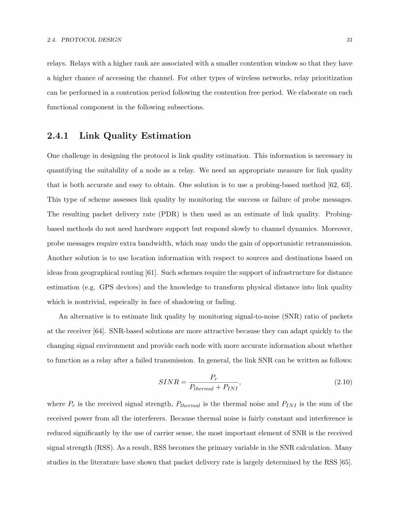
2.4. PROTOCOL DESIGN 31
relays. Relays with a higher rank are associated with a smaller contention window so that they have
a higher chance of accessing the channel. For other types of wireless networks, relay prioritization
can be performed in a contention period following the contention free period. We elaborate on each
functional component in the following subsections.
2.4.1 Link Quality Estimation
One challenge in designing the protocol is link quality estimation. This information is necessary in
quantifying the suitability of a node as a relay. We need an appropriate measure for link quality
that is both accurate and easy to obtain. One solution is to use a probing-based method [62, 63].
This type of scheme assesses link quality by monitoring the success or failure of probe messages.
The resulting packet delivery rate (PDR) is then used as an estimate of link quality. Probing-
based methods do not need hardware support but respond slowly to channel dynamics. Moreover,
probe messages require extra bandwidth, which may undo the gain of opportunistic retransmission.
Another solution is to use location information with respect to sources and destinations based on
ideas from geographical routing [61]. Such schemes require the support of infrastructure for distance
estimation (e.g. GPS devices) and the knowledge to transform physical distance into link quality
which is nontrivial, espeically in face of shadowing or fading.
An alternative is to estimate link quality by monitoring signal-to-noise (SNR) ratio of packets
at the receiver [64]. SNR-based solutions are more attractive because they can adapt quickly to the
changing signal environment and provide each node with more accurate information about whether
to function as a relay after a failed transmission. In general, the link SNR can be written as follows:
SINR =Pr
Pthermal + PINI, (2.10)
where Pr is the received signal strength, Pthermal is the thermal noise and PINI is the sum of the
received power from all the interferers. Because thermal noise is fairly constant and interference is
reduced significantly by the use of carrier sense, the most important element of SNR is the received
signal strength (RSS). As a result, RSS becomes the primary variable in the SNR calculation. Many
studies in the literature have shown that packet delivery rate is largely determined by the RSS [65].

2.4. PROTOCOL DESIGN 32
1472 bytes
0
0.2
0.4
0.6
0.8
1
4 6 8 10 12 14 16
RSSI
Pac
ket D
eliv
ery
Rat
io
Pair 1Pair 2
(a) 1472 bytes
1024 bytes
0
0.2
0.4
0.6
0.8
1
4 6 8 10 12 14 16
RSSI
Pac
ket D
eliv
ery
Rat
io
Pair 1Pair 2
(b) 1024 bytes
512 bytes
0
0.2
0.4
0.6
0.8
1
4 6 8 10 12 14 16
RSSI
Pac
ket D
eliv
ery
Rat
io
Pair 1Pair 2
(c) 512 bytes
16 bytes
0
0.2
0.4
0.6
0.8
1
4 6 8 10 12 14 16
RSSI
Pac
ket D
eliv
ery
Rat
io
Pair 1Pair 2
(d) 16 bytes
Figure 2.6: Measurement results of packet delivery ratio and RSSI with transmit rate equalto 11 Mbps for different packet sizes.
This is especially true in indoor environment where multi-path effects are mitigated by dynamic
equalizers in wireless network cards.
In practice, RSS can be estimated using the Received Signal Strength Indicator (RSSI) [66],
which is reported by almost all modern wireless cards. To understand how RSSI corresponds to
PDR, we use the CMU wireless emulator [67] to collect measurements of PDR for different sized
UDP packets (1472, 1024, 512, and 16 bytes) as a function of signal strength. The test nodes
are equipped with wireless cards using the Atheros AR5212 chipset. To collect unbiased results,
we turned off the exponential backoff process by configuring the minimal and maximal contention
window size to 1. The path loss between the transmitter and the receiver is changed from 90 dB

2.4. PROTOCOL DESIGN 33
to 110 dB with a step size of 0.5 dB. For a particular loss value, we collected average RSSI and
PDR over 1000 packets and repeated the test 10 times. Figure 2.6 shows the measurement results
of average PDR and RSSI for two transmitter/receiver pairs (out of 10 pairs in total). The other
eight pairs exhibit similar behavior. We make the following observations based on these results:
1. PDR as function a of RSSI is somewhat noisy, in particular for 16-byte UDP packets. How-
ever, there is still strong correlation between RSSI and PDR.
2. There is a RSSI high threshold (Thh), above which packets are nearly always received.
3. For different hardware, PDR-RSSI relationship exhibits a similar shape with a shift of 2 ∼ 4
dB. With channel reciprocity, forward link quality can be predicted by reverse link conditions
if the amount of shift is known.
Similar observations are also made in other papers [66]. These results suggests that RSSI is not a
perfect measure for PDR, but as we will show later it suffices for our needs. PRO does not require
a very accurate measure of link quality because link quality is used to help select and prioritize
a reasonable set of relays from a larger pool, and small changes in quality should not affect this
process. In the next subsection, we describe how we leverage the above observations to design an
efficient opportunistic retransmission protocol.
In practice, channel conditions vary with time. To predict the current RSSI, PRO uses the
RSSI history of packets with the time-aware prediction algorithm proposed in [57]. This approach
improves exponential weighted moving average (EWMA) by weighing recent samples more and
filtering out sharp transient fades that last for only a single packet.
2.4.2 Relay Qualification
Using too many or poor relays can hurt performance since it increases the probability of collisions
while offering limited opportunistic gains. To filter out poor relays early, candidate nodes must
pass a qualification process by comparing the RSSI with respect to the destination with threshold
Thh. Qualified relays periodically broadcast their link quality with respect to the source and

2.4. PROTOCOL DESIGN 34
the destination to the network. This information is then used for relay selection, which will be
elaborated in Section 2.4.3.
The qualification process involves one challenge: using the reverse link condition to predict
forward link quality is imprecise if links are asymmetric. Unfortunately, conveying RSSI information
from the destination to the relay using e.g. RTS/CTS handshake [64, 68] introduces relatively high
overheads that can easily undo any performance benefits. PRO avoids such overheads by leveraging
channel reciprocity coupled with on-line threshold calibration according to observed performance.
Initially, relays assume a default Thh of 10 dB (the average value from our offline measurements).
At run time, each relay records the transmission results - success or failure - after each transmission
from itself to the destination. The value of Thh is incremented by 1 if the packet delivery rate
over 100 transmissions is lower than 0.75 and it is decremented by 1 if the packet delivery rate
is equal to 1. As this threshold may vary from receiver to receiver, each transmitter maintains a
Thh for each receiver that it is communicating with and updates these thresholds independently.
Algorithm 1 gives the pseudo code for the on-line calibration process.
Algorithm 1 CalibratingHighThreshold(T )
Require: New transmission result X(= {success, failure})1: n ⇐ n + 12: if X = success then3: k ⇐ k + 14: end if5: if n ≥ 100 then6: if k/n < 0.75 then7: Thh ⇐ Thh + 18: else9: if k/n ≤ 1 then
10: Thh ⇐ Thh − 111: end if12: end if13: n ⇐ 014: k ⇐ 015: end if
The above solution is based on the observation made in Section 2.4.1, which suggests that
PDR-RSSI plots of different sized packets across different source-destination pairs have a similar

2.4. PROTOCOL DESIGN 35
shape. Note that our calibration process does not need to consider the reason for the packet losses,
making it agile to deal with various conditions. For example, if packet losses are due to a jammer on
the path between the relay and the destination, then the calibration process gradually increments
Thh, making the relay less and less likely to pass the relay qualification process. The calibration
process resets Thh to the default value if no transmission to the destination occurs during the
past 30 minutes to compensate for threshold adjustment due to the environment, not due to card
characteristics.
2.4.3 Relay Selection
Relay selection finds the best set of relay(s) among all candidates to retransmit packets in error. Ef-
fective relay selection should increase the probability of successful retransmission while minimizing
collisions and duplicate packets. To assure that overhead does not overwhelm gains, PRO uses a
distributed relay selection algorithm. Each qualified relay runs the algorithm to find a set of eligible
relays out of all the qualified relays based on their link quality with respect to the source and the
destination. A qualified relay then identifies itself as an eligible relay if it falls into the selected
set. Upon a failed transmission, eligible relays that overheard the packet attempt to transmit the
packet. Eligible relays are prioritized based on their relaying performance. This is achieved by
using a smaller contention window for high priority relays.
In the subsequent subsection, we elaborate on how relays share link quality information with
each other and how the relay selection algorithm works. The details of relay prioritization will be
addressed in Section 2.4.4.
Sharing Link Quality via Periodic Broadcasts
The relay selection algorithm considers the link quality to the source and the destination of all the
qualified relays. This information is collected by periodic broadcasts from all the qualified relays.
Figure 2.7 shows the message format of periodic broadcasts when a relay is serving K source-
destination pairs that involve N nodes. The message length is linear with the number of nodes and
source-destination pairs in service but the overhead is relatively small as compared to data packets.

2.4. PROTOCOL DESIGN 36
Frame control
Dur-ation
Address1
Address 2
Address 3 Seq. Address
4Check-
sumPeriodic Broadcast
Message Body
Bytes 2 2 6 6 6 2 6 4
control ation 1 2 3 4 sumMessage Body
N d 1 N d NP i 1 P i 1 P i K P i K
Bytes 1 1 1 1 1 2 2
Node1LQ … NodeN
LQPair1
Src_IDPair1
Dst_IDPairK
Src_IDPairK
Dst_ID… 0x0
Figure 2.7: Periodic Broadcast Message Format. The Src/Dst ID is the index in the linkquality (LQ) list appended after the termination symbol 0x0. The link quality of a node canbe either packet reception ratio in percentage (if the field starts with a leading one) or RSSI(if the field starts with a zero).
The periodic broadcast frequency is 1 second in our implementation. This value is borrowed from
the default HELLO message interval used in AODV [69]. Relays can further reduce the broadcast
overhead by adapting the broadcast frequency based on how fast the channel conditions change.
They can also suppress broadcasts when the chance of becoming an eligible relay is low.
The link quality to the destination is predicted using the time-based EWMA with on-line
calibration (offset with the difference between the default and calibrated Thh). The link quality
to the source is the packet reception rate in percentage, which is obtained by keeping track of
sequence numbers in packets originated from the source. According to the 802.11 specification,
sequence numbers are incremented by 1 for each packet. Thus packet losses are detectable from
a gap in sequence numbers. A node may qualify to relay for multiple sessions, so the broadcast
messages should contain information for all the sessions that it is participating in.
When a qualified relay later fails the qualification process (the predicted RSSI falls below Thh or
the relay does not hear the destination for 2 seconds), it stops broadcasting link quality information
for that destination. Other relays exclude this relay from the relay selection process if they do not
hear its broadcasts for 2 seconds.
Selecting Eligible Relays
The relay selection algorithm is designed using the following guidelines:
• Relays with better connectivity to the destination are favored because they have a higher

2.4. PROTOCOL DESIGN 37
chance to successfully transmit the packet.
• Relays with better connectivity to the source are favored because they have a high likelihood
to overhear the source and offer opportunistic gains.
• The resulting set must be large enough so there is a high likelihood that at least one of
them overhears the source and on the other hand, small enough to minimize collisions while
creating sufficient retransmission opportunities.
The algorithm works as follows. The selection starts with the node that has the highest RSSI
with respect to the destination and continues adding the next higher node until the probability of
having one of the selected relays hear the source is large enough, i.e. larger than a threshold Thr.
Since source packet reception rates are used to select the right number of participating nodes, the
estimation does not have to be very accurate. Experimental results in Section 2.6 show that our
relay selection algorithm works very well. The psuedo code for the algorithm is given in Algorithm 2.
Algorithm 2 RelaySelection(Q)
Require: All qualified relays QEnsure: All eligible relays R1: Initialize Q to the set of all qualified relays2: R ⇐ ∅3: p ⇐ 14: Rank Q according to the RSSI with respect to the destination. Break tie according to
the RSSI with respect to the source.5: while Q is not empty do6: Pick the highest ranked q in Q7: Insert q to R and delete q from Q8: Retrieve the source packet reception ratio αq of q9: p ⇐ p · (1− αq)
10: if 1− p > Thr then11: return R12: end if13: end while

2.4. PROTOCOL DESIGN 38
2.4.4 Relay Prioritization
At run time, there may be multiple eligible relays overhearing a failed transmission. Performance
can be further improved by giving precedence to relays with high RSSI with respect to the desti-
nation. A straightforward solution is to have relays sending feedback and collecting feedback after
each failed transmission. Based on the feedback, the current best relay can be identified and that
relay is responsible for transmitting the packet [60, 70]. Using feedback has two problems. First, it
requires scheduling among relays to decide who sends feedback when, which introduces additional
complexity. Second, the overhead of distributing feedback for every failed transmission can be
considerable.
To reduce overhead, PRO avoids using feedback on a per-transmission basis and instead lever-
ages the standard random backoff procedure to prioritize the relays. The 802.11 standard provides
several mechanisms for achieving this, e.g. by managing the minimal and maximal contention
window size (CWmin and CWmax), backoff increasing factor, interframe space, and backoff time
distribution [71]. For example, 802.11e EDCA [72] performs prioritization by manipulating inter-
frame space or/and contention window size. In our current implementation, effective relays are
prioritized by a smaller CWmin, but other parameters can be considered. Note that the source
behaves as an eligible relay after a failed transmission. That is, it uses a CWmin determined by
the above scheme for retransmissions.
2.4.5 Retransmission
Relays detect failed transmissions through the lack of an ACK. Eligible relays that overheard the
packet then contend to retransmit the packet using the contention window assigned in the relay
prioritization procedure. If the retransmission fails again, relays double the size of contention
windows, select new backoff intervals, and contend again for the channel. The process on each
relay is the same as retransmitting a local packet. Therefore, retransmissions for a packet are
not necessary from a single relay. When the first retransmission fails again, it is likely that new
eligible relays overhear the packet and join the attempt for the second retransmission (i.e., these
relays did not overhear the initial transmission from the source). Newly-joined relays use initial

2.4. PROTOCOL DESIGN 39
contention windows to contend the channel so they will have a higher chance to transmit. We
allow this prejudice because newly-joined relays tend to be further from the source and closer to
the destination.
In our current implementation, relays that have pending local packets do not participate in
relaying. This practice is based on the assumption that nodes are willing to support others only
when they have spare resources to do so. In the future, we will explore different policies that have
nodes act as relays even if they have packets pending. Such policies are useful in e.g., scenarios
with concurrent sessions as we will see in Section 2.6.2.
Relays terminate the retransmission process in response to the following events:
• An ACK frame destined for the source is overheard, since it implies successful reception.
• The retry limit is reached after several unsuccessful transmissions. This is similar to dropping
a local packet that has been retransmitted too many times except that the retry count includes
retransmissions from all the relays.
• A new data packet (i.e. the packet stamped with a larger sequence number) originated from
the source is overheard. This means that either the source has discarded the current packet,
or the packet was successfully received but this relay missed the ACK. In either case, the
relay should stop retransmitting the packet.
• The relay overhears first an ACK and then a retransmission of the packet. This means that
the packet was received successfully, but either a relay or the source did not hear the ACK.
The relay should stop retransmitting the duplicate packet and re-acknowledge it.
In the last case, we need a way of reliably re-acknowledging the packet. The obvious solution,
sending another ACK, does not work: if multiple relays detect the unnecessary retransmission, it
will lead to systematic collisions of the ACKs. Instead, they send a “null” data packet, i.e. the
original data packet with the payload stripped and replaced with acknowledgement information.
Since null packets are transmitted as data packets (i.e. use backoff), we avoid systematic collisions.
Note that when the unnecessary retransmission was sent by the source, this approach effectively
corresponds to retransmission of the ACK.

2.5. NETWORK-SPECIFIC ISSUES 40
When destinations are not within the communication range of the sources, frequent retrans-
mission of ACKs may occur. In that case, it may be more efficient to employ the mesh network
based approach (i.e. sources first send packets to a relay which then forwards them to the des-
tination) as there will be little opportunistic gain (see Section 2.6.2 for experimental results of
such phenomenon). In the subsequent subsection, we present an example source-driven design that
supports dynamic switching between PRO and the mesh network based approach.
2.4.6 Dynamic Switching between PRO and Mesh Networking
In response to frequent relaying of ACKs, the source switches to the mesh networking mode and
notifies relays by marking a flag in the packets. The relay selection algorithm, instead of deciding
a set of relays, finds the best relay to function as the forwarder in a distributed fashion. The best
relay must have a high likelihood of overhearing the transmission from the source as well as a high
probability of successfully forwarding packets to the destination. The forwarder generates an ACK
after successful reception of a packet from the source and forwards the packet to the destination.
The source switches back to the opportunistic retransmission mode later after it starts overhearing
traffic from the destination.
2.5 Network-Specific Issues
In this section we discuss a number of network-specific issues, in particularly, 802.11-based wireless
networks. They are all evaluated in Section 2.6.
2.5.1 Collision Avoidance
The main overhead of PRO is an increased probability of collisions due to transmissions from mul-
tiple relays. Collision avoidance has been partly addressed in the design of PRO’s relay selection
algorithm. The choice of threshold Thr implicitly limits how many eligible relays are selected.
Larger Thr grants more relays, which increases opportunistic gains but potentially creates more
collisions. To understand this tradeoff, this section presents an analytical study of collision proba-

2.5. NETWORK-SPECIFIC ISSUES 41
bilities as a function of Thr. The analytical results are then used for selecting a proper Thr. The
study considers an 802.11-like wireless networking environment.
Consider N qualified relays. For simplicity, assume these relays have an equal probability of
hearing the source, denoted as α. Moreover, consider a single priority class that allows all relays to
contend for the channel with the same uniform distribution [0, CW − 1]. This corresponds to the
worse case where the contention level is maximal. The probability function f(x) and the cumulative
mass function F (x) =∑
x f(x) are
f(x) =1
CWand F (x) =
x + 1CW
where x ∈ {0, 1, 2, · · · , CW − 1}. (2.11)
According to the relay selection algorithm, n out of N relays are identified as eligible relays. Given
Thr, n can be derived by
n = arg mini{1− (1− α)i ≥ Thr} = dlog1−α (1− Thr)e. (2.12)
Upon a failed transmission, a subset of eligible relays overhears the packet and contends for the
channel to retransmit the packet. Denote the subset size as k (k ≤ n). Collisions occur when
the lowest-numbered backoff slot selected by the k relays is associated with two or more relays.
Equivalently, the collision probability is one minus the probability that the lowest-numbered backoff
slot is only associated with one relay:
Pr(collision | k overhearing relays) = 1− Pr(successful retx | k overhearing relays)
= 1− k
CW−1∑x=0
f(x)(1− F (x))k−1. (2.13)
According to the law of total probability, we can derive
Pr(collision) =n∑
k=2
Pr(collision | k overhearing relays) · Pr(k overhearing relays)
=n∑
k=2
(1− k
CW−1∑x=0
f(x)(1− F (x))k−1)·
(n
k
)αk(1− α)n−k. (2.14)

2.5. NETWORK-SPECIFIC ISSUES 42
Substituting (2.11) into (2.14), we then obtain the collision probability.
Figure 2.8 shows the collision probability as a function of Thr. The stairwise shape is due to
the constraint that the number of relays must be an integer. As expected, collision probabilities
grow as Thr increases. Large Thr allows more eligible relays to participate but potentially creates
more collisions. Using a larger CWmin reduces the impact of collisions but it comes with a cost of
increased delay, which translates to another form of overhead.
For a particular CWmin, the choice of Thr should address the tradeoff between the overhead
of collision and the gain of opportunistic retransmission. This tradeoff can be quantified as the
probability of successful retransmission (relaying). To see that, assume all eligible relays have
perfect connectivity to the destination. Then the successful retransmission probability can be
written as
Pr(successful retx) =n∑
k=1
Pr(successful retx | k overhearing relays) · Pr(k overhearing relays)
=n∑
k=1
(1− Pr(collision | k overhearing relays)) · 1 · Pr(k overhearing relays)
=n∑
k=1
Pr(k overhearing relays)−
n∑k=1
Pr(collision | k overhearing relays) · Pr(k overhearing relays)
= (1− (1− α)n)− Pr(collision) (2.15)
where (1 − (1 − α)n) is the probability that at least one eligible relay overhears the packet (so
some relay(s) will participate in the retransmission of the packet). This probability represents
how likely relays participate in retransmission of a failed packet, which corresponds to the gain
of opportunistic retransmission. Therefore, the optimal Thr is chosen to maximize the successful
retransmission probability.
Figure 2.9 shows the successful retransmission probability as a function of Thr. The optimal
Thr for CW = 32 and CW = 16 falls at 0.98 and 0.96, respectively. The figure also shows that the
sensitivity of Thr increases as the source packet reception rate α decreases. The analytical results
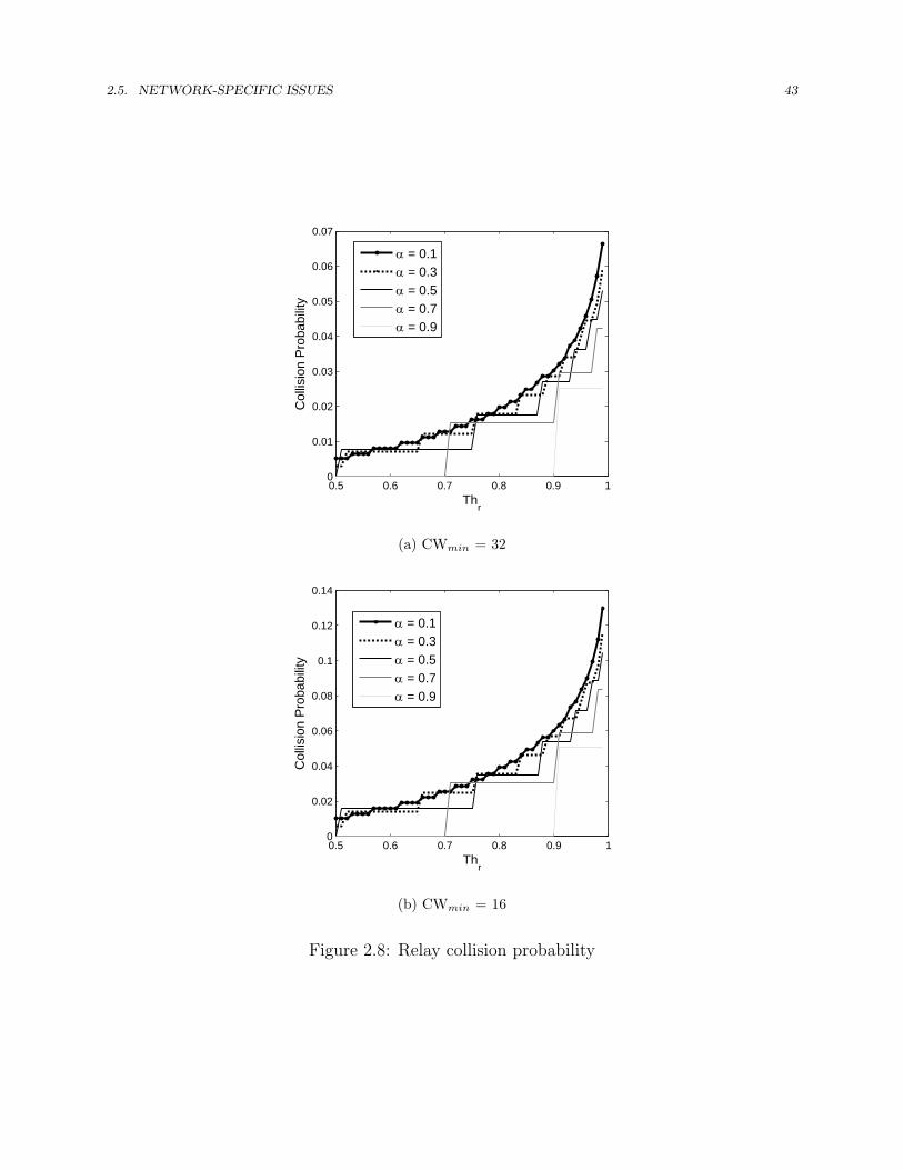
2.5. NETWORK-SPECIFIC ISSUES 43
0.5 0.6 0.7 0.8 0.9 10
0.01
0.02
0.03
0.04
0.05
0.06
0.07
Thr
Col
lisio
n P
roba
bilit
y
α = 0.1α = 0.3α = 0.5α = 0.7α = 0.9
(a) CWmin = 32
0.5 0.6 0.7 0.8 0.9 10
0.02
0.04
0.06
0.08
0.1
0.12
0.14
Thr
Col
lisio
n P
roba
bilit
y
α = 0.1α = 0.3α = 0.5α = 0.7α = 0.9
(b) CWmin = 16
Figure 2.8: Relay collision probability

2.5. NETWORK-SPECIFIC ISSUES 44
0.5 0.6 0.7 0.8 0.9 10.5
0.55
0.6
0.65
0.7
0.75
0.8
0.85
0.9
0.95
1
Thr
Suc
cess
ful R
etra
nsm
issi
on P
roba
bilit
y
α = 0.1α = 0.3α = 0.5α = 0.7α = 0.9
(a) CWmin = 32
0.5 0.6 0.7 0.8 0.9 10.5
0.55
0.6
0.65
0.7
0.75
0.8
0.85
0.9
0.95
1
Thr
Suc
cess
ful R
etra
nsm
issi
on P
roba
bilit
y
α = 0.1α = 0.3α = 0.5α = 0.7α = 0.9
(b) CWmin = 16
Figure 2.9: Successful retransmission probability

2.5. NETWORK-SPECIFIC ISSUES 45
of the simplified scenario provide a guideline for selecting a proper Thr. In Section 2.6.1, we will
show experimental results of collision probabilities when Thr = 0.9 is used. The use of this slightly
conservative threshold is helpful in alleviating collisions in real-world environments when nodes
incorrectly identify themselves as eligible relays due to missing periodic broadcasts, for example,
when relays are hidden from each other (see Section 2.5.4). As we will see, the experimental results
indicate that our algorithm performs very well.
The above analysis assumes perfect relay-destination channels, which does not always hold.
When the first retransmission fails and the second retransmission is needed, more relays may par-
ticipate in the contention process because relays that missed the initial transmission but overheard
the first retransmission are then eligible to transmit. This phenomenon continues until the packet
is successfully delivered or discarded due to too many trials. We do not consider second or later
retransmissions in the above analysis because (1) the use of binary exponential backoff should limit
(even reduce) the increase of contention level and (2) the relay qualification process only allows
good relays to participate, significantly reducing the probability of failed retransmission.
2.5.2 Fairness
The 802.11 exponential backoff procedure offers not only short-term collision avoidance but also
long-term fairness across multiple stations. However, as multiple relays can retransmit on behalf of
a single source, the joint channel access behavior is no longer uniform. This results in unfairness
across flows with different numbers of relays. Figure 2.10 shows the probability functions of backoff
intervals from multiple relays that attempt to retransmit the same packet individually with a
uniform distribution individually in a range of [0, 31]. The figure indicates unfairness across flows
with different numbers of relays - the more relays participate, the higher the probability that a flow
wins the channel over others, and therefore the higher the throughput will be.
Fairness is a policy question and different policies are possible. For example, one policy might be
that it is acceptable to give priority to relayed transmissions, because opportunistic retransmission
can improve network efficiency. Another policy is to force equal channel access probabilities across
all flows. A particular fairness policy can be achieved by tuning the backoff distribution. One

2.5. NETWORK-SPECIFIC ISSUES 46
example is the use of larger initial contention windows when relaying, as we already mentioned
earlier. The initial contention window can also be tuned based on the number of eligible relays.
An even more aggressive solution is to have relays use non-uniform distributions for selecting slots
in the contention window. This makes it possible to have the joint behavior of the relays appear
as that of a single legacy 802.11 node (i.e. a node that uses a uniform distribution to select a
slot in the contention window). Figure 2.11 shows the probability functions of backoff intervals of
individual relays that collectively yield a uniform backoff distribution in a range of [0, 31]. We have
not explored these more advanced techniques, but we present an analytical study of the impact
on fairness in this section. We also present experimental evaluation on how the size of the initial
contention window used for retransmission affects performance and fairness in Section 2.6.1.
We consider fairness as equal channel access chance across flows as adopted in 802.11. For
simplicity, we assume identical transmit rates and fixed contention window sizes. We quantify
the impact on fairness to a legacy node as the ratio of the expected number of backoff slots of a
PRO-enabled node to that of a legacy node. This quantity reflects the long-term bandwidth share
between two flows. The 802.11 standard assures equal channel access which corresponds to a ratio
of 1.
Following (2.11), the expected number of backoff slots of an 802.11 station with no support of
relaying is
E(backoff slots of 802.11) =CW−1∑
x=0
xf(x) =CW − 1
2(2.16)
In the presence of k active eligible relays, the backoff interval is the minimum among the k relays,
which can be written as
Y = min{X1, X2, · · · , Xk}.
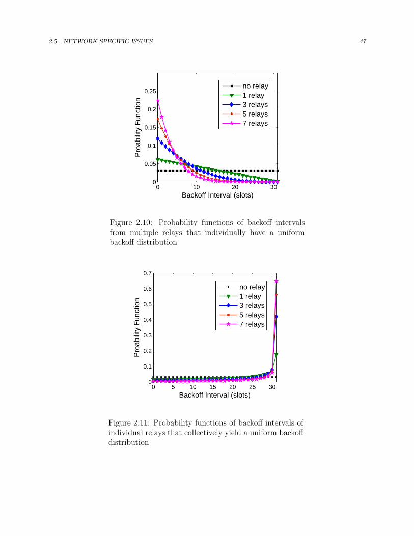
2.5. NETWORK-SPECIFIC ISSUES 47
0 10 20 300
0.05
0.1
0.15
0.2
0.25
Backoff Interval (slots)
Pro
abilit
y Fu
nctio
n
no relay1 relay3 relays5 relays7 relays
Figure 2.10: Probability functions of backoff intervalsfrom multiple relays that individually have a uniformbackoff distribution
0 5 10 15 20 25 300
0.1
0.2
0.3
0.4
0.5
0.6
0.7
Backoff Interval (slots)
Pro
abilit
y Fu
nctio
n
no relay1 relay3 relays5 relays7 relays
Figure 2.11: Probability functions of backoff intervals ofindividual relays that collectively yield a uniform backoffdistribution

2.5. NETWORK-SPECIFIC ISSUES 48
1 3 5 7 90.1
0.2
0.3
0.4
0.5
0.6
0.7
0.8
0.9
1
number of active eligible relays (k)
Rat
io o
f exp
ecte
d ba
ckof
f slo
ts
Figure 2.12: Impact on fairness
The cumulative mass function of Y , G(y) can be derived by
G(y) = Pr(Y ≤ y)
= 1− Pr(Y > y)
= 1− Pr(X1 > y,X2 > y, · · · , Xn > y)
= 1− Pr(X1 > y)Pr(X2 > y) · · ·Pr(Xm > y)
= 1− (1− F (y))m
= 1− (1− y + 1CW
)m. (2.17)
Thus the expected number of backoff slots in the presence of relays can be written as
E(backoff slots of PRO) =CW−1∑
y=0
y(G(y)−G(y − 1))
=CW−1∑
y=0
y((1− y
CW)m − (1− y + 1
CW)m). (2.18)
Figure 2.12 plots the ratios of the expected number of backoff slots of a legacy 802.11 flow to
a flow with the support of a variable number of relays. It confirms that unfairness grows as more

2.5. NETWORK-SPECIFIC ISSUES 49
0.5 0.6 0.7 0.8 0.9 10
10
20
30
40
50
Thr
Num
ber o
f rel
ays
eligible relaysactive eligible relays
(a) α = 0.1
0.5 0.6 0.7 0.8 0.9 10
1
2
3
4
5
Thr
Num
ber o
f rel
ays
eligible relaysactive eligible relays
(b) α = 0.9
Figure 2.13: Number of eligible relays and expected number of active eligible relay
relays contend the channel. In PRO, the impact of unfairness is reduced by avoiding too many
relays. As shown in Figure 2.13, the expected number of eligible relays that overhear a packet in
error is fewer than 5 over different settings. The impact of fairness could be further reduced with
a small Thr at the expense of reduced opportunistic gain.
The above analysis assumes the use of identical transmit rates and fixed contention window
sizes (no binary exponential backoff). In practice, the binary exponential backoff results in unequal
channel access distribution across flows with good and poor channel conditions. Moreover, the
802.11 rate adaptation also changes the share of transmission time when different transmit rates are
used. These factors complicate the provision of fairness. In Section 2.6.1, we present experimental
results of the bandwidth distribution between an 802.11 flow over a poor channel and a flow with
the support of PRO when binary exponential backoff and rate adaptation are enabled.
2.5.3 Incentive to Relay
As opportunistic retransmission departs from the traditional but less effective deterministic, mesh
network-based communication, nodes in such networks may have less incentive to follow protocols

2.5. NETWORK-SPECIFIC ISSUES 50
and contribute [73]. This is especially true when battery use is a main concern since overhearing
and relaying consume extra energy. If every node behaves selfishly, no opportunistic gain can be
achieved.
The problem of cooperation in wireless networks has received a lot of attention in recent years.
The solutions can be categorized into two classes: credit-based approaches [73] and reputation-
based approaches [74]. The former approaches reward relays to encourage participation. The
latter approaches utilize reputation in routing and/or enforcing punishment. The reputation-based
approaches are less suitable for opportunistic communication because identifying misbehaving nodes
is difficult when transmission paths are not pre-constructed. It is easy to combine PRO with a
credit-based approaches to encourage relaying based on the number of relayed transmissions. The
actual design of incentive schemes is outside of the scope of this thesis.
2.5.4 Hidden Terminal Effect
The relay selection algorithm selects a set of eligible relays that hear both the source and the
destination, but it does not guarantee that eligible relays can hear each other. The participation
of hidden relays increases the collision probability.
When hidden relays can still communicate in base rates, they are able to collect periodic broad-
casts and perform relay selection correctly. The relay selection algorithm limits the number of
eligible relays, which mitigates collisions (as discussed in Section 2.5.1). When relays are com-
pletely hidden from each other, they are not able to share periodic broadcasts. With incomplete
link quality information, the distributed relay selection may include too many qualified relays. This
issue can be resolved by modifying the periodic broadcasting mechanism. For example, sources can
be made responsible for collecting the broadcast messages and notifying relays of the global connec-
tivity map. Because relays and sources are within the communication range, this method assures
that each relay receives correct link quality information.
IEEE 802.11 uses RTS/CTS handshake to partly overcome the hidden terminal problem.
RTS/CTS is not a complete solution and may decrease throughput even further. In PRO, choosing
a slightly conservative Thr help mitigate the impact of collisions (see Section 2.5.1). Further, the
2.5. NETWORK-SPECIFIC ISSUES 51
on-line calibration process gradually filters out hidden relays by increasing the qualification thresh-
old after too many failed transmissions. Note that this process works on a much larger time-scale
and much more gradually than the core opportunistic retransmission process. In Section 2.6.2, we
show that PRO deals with hidden terminal better than the mesh network based approach via the
exploitation of relay diversity.
2.5.5 Multi-rate PRO
Current 802.11 provides multi-rate capabilities that allow a sender to change the bit rate adaptively,
depending on the quality of the link to the recipient. The idea of common rate adaptation algorithms
is to minimize packet error rate by lowering bitrates. In other words, rate adaptation trades longer
transmit time for higher packet success rates. Opportunistic retransmission adopts a different
philosophy: the source and relays continue using higher transmit rates and use relaying to improve
the success rate of retransmissions. Hence, opportunistic retransmission trades more transmissions
for longer packet transmission time. This leads to the following question: upon a failed transmission,
should the sender reduce the transmit rate or should it rely on relaying to combat errors?
Whether rate adaptation or opportunistic retransmission should be used is a difficult ques-
tion. It depends on how well rate adaptation performs, e.g. how quickly it adapts to changes in
the environment, and how well relays are in a position to support opportunistic retransmission.
Current rate adaptation algorithms are dominated by probe-based approaches. While probe-based
approaches are simple and easy to implement, many studies have shown that they perform poorly
in dynamic environments [66, 68, 75]. Thus, recent efforts have been made to use signal strength
measurements to help select the transmission rate [57, 64, 66]. In Section 2.6, we compare PRO with
two rate adaptation algorithms, SampleRate [76] and CHARM [57]. The former is a probe-based
method provided with the Madwifi driver and the latter is a SNR-based solution. Our experiment
results show that in practical 802.11b scenarios PRO outperforms 802.11 with rate adaptation.
It is however important to explore how rate adaptation and opportunistic retransmission can
be combined, since both techniques have limitations. For example, no rate adaptation algorithm
can completely eliminate packet losses and relaying can help reduce the cost of packet errors;

2.5. NETWORK-SPECIFIC ISSUES 52
54 Mbps48 Mbps36 Mbps24 Mbps18 Mbps12 Mbps
11 Mbps
9 Mbps
5.5 Mbps2 Mbps1 Mbps
6 Mbps
Default Thresh. for 54Mbps
source:
RSSI
Default Thresh. for 36MbpsDefault Thresh. for 18MbpsRSSI
18M 36M 54M
18M 36M 54Mrelays:
Figure 2.14: Illustration of table lookup in multi-rate PRO
relaying is likely to be more important in very dynamic channels. Opportunistic retransmission on
the other hand can only be effective when good relays are available, so rate adaptation remains
important, especially for protocols such as 802.11g, in which 12 transmit rates (including the four
rates specified in 802.11b) are supported and the radio range of the highest rate (54Mbps) is fairly
short. Integrating rate adaptation and opportunistic retransmission is however a complex research
problem. The reason is that, in general, rate selection on the source, rate selection on the eligible
relays, and the PRO algorithms for the selection and prioritization of eligible relays all depend on
each other, resulting in a huge search space. Channel dynamics combined with the high cost of
coordination further complicate the design of an efficient integrated solution.
As a first step, we combined PRO with the CHARM rate adaptation algorithm. Our multi-rate
PRO is a minimal integration in the sense that we purposely minimized the changes to the PRO
and CHARM algorithms. In multi-rate PRO, the source and relays rely on the regular CHARM
algorithm to select transmission rates. CHARM uses a rate selection table that lists the minimum
required RSSI threshold for each transmit rate. This table is built offline based on general card
characteristics and calibrated online to deal with card differences and link asymmetry. Transmitters
use channel reciprocity to estimate the received signal strength at the receiver, similar to PRO,
and then use table look up to determine the transmit rate to use. For simplicity, multi-rate PRO
eliminates the threshold calibration component of CHARM. Instead, it avoids errors caused by per-
card differences and link asymmetry by only using three out of the possible twelve rates (18, 36,
and 54 Mbps). Upon a transmission failure, multi-rate PRO executes the PRO protocol described
in the previous section.
Multi-rate PRO changes the original CHARM and PRO protocols in only two ways. First, we
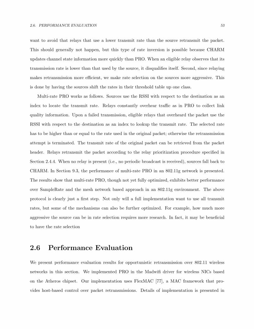
2.6. PERFORMANCE EVALUATION 53
want to avoid that relays that use a lower transmit rate than the source retransmit the packet.
This should generally not happen, but this type of rate inversion is possible because CHARM
updates channel state information more quickly than PRO. When an eligible relay observes that its
transmission rate is lower than that used by the source, it disqualifies itself. Second, since relaying
makes retransmission more efficient, we make rate selection on the sources more aggressive. This
is done by having the sources shift the rates in their threshold table up one class.
Multi-rate PRO works as follows. Sources use the RSSI with respect to the destination as an
index to locate the transmit rate. Relays constantly overhear traffic as in PRO to collect link
quality information. Upon a failed transmission, eligible relays that overheard the packet use the
RSSI with respect to the destination as an index to lookup the transmit rate. The selected rate
has to be higher than or equal to the rate used in the original packet; otherwise the retransmission
attempt is terminated. The transmit rate of the original packet can be retrieved from the packet
header. Relays retransmit the packet according to the relay prioritization procedure specified in
Section 2.4.4. When no relay is present (i.e., no periodic broadcast is received), sources fall back to
CHARM. In Section 9.3, the performance of multi-rate PRO in an 802.11g network is presented.
The results show that multi-rate PRO, though not yet fully optimized, exhibits better performance
over SampleRate and the mesh network based approach in an 802.11g environment. The above
protocol is clearly just a first step. Not only will a full implementation want to use all transmit
rates, but some of the mechanisms can also be further optimized. For example, how much more
aggressive the source can be in rate selection requires more research. In fact, it may be beneficial
to have the rate selection
2.6 Performance Evaluation
We present performance evaluation results for opportunistic retransmission over 802.11 wireless
networks in this section. We implemented PRO in the Madwifi driver for wireless NICs based
on the Atheros chipset. Our implementation uses FlexMAC [77], a MAC framework that pro-
vides host-based control over packet retransmissions. Details of implementation is presented in

2.6. PERFORMANCE EVALUATION 54
Section 5.6.1. We evaluated PRO in both a controlled testbed and in the real world. The con-
trolled experiments use the CMU wireless network emulator [67], which supports realistic and fully
controllable and repeatable wireless experiments. The emulator testbed uses real wireless devices
(laptops) but instead of having the devices communicate through the uncontrolled ether, the RF
signals transmitted by the devices are sent through an FPGA to model various wireless effects. The
emulation-based experiments are useful in studying microscopic behavior of the protocol. The real
world experiments are conducted in diverse indoor environments. These experiments automatically
account for all effects that are naturally present in deployed wireless networks, e.g. interference,
noise, multi-path fading, and shadowing.
2.6.1 Testbed Experimental Results
In the following tests, the source constantly sends back-to-back UDP packets to the destination.
The UDP packets are 1472 bytes each. We ran each test for 3 minutes before starting collecting the
statistics to allow the run-time calibration process to converge. Each test iterates five runs, each
of which lasts one minute and the median results are presented. Experimental results given in this
section were done using 802.11b (instead of 802.11b/g) due to the limitation of timing accuracy of
the testbed. In Section 2.6.2, we will present some results for 802.11g.
1 2 3 4 5
120m
20mS D
Figure 2.15: Static scenario topology
Static Scenario
We first consider three static scenarios. Initially, the distance between the source and the destination
is 120 meters. Five relays are uniformly placed between the source and the destination as shown
in Figure 2.15. A log distance large scale path loss model is used with a path loss exponent of 3.
The description of each scenario is as follows:

2.6. PERFORMANCE EVALUATION 55
• freespace is the default scenario as described above. This scenario is similar to an outdoor
urban environment.
• fading k0 adds a Ricean fading envelop with K = 0 to the log distance mode. This scenario
exhibits severe fading.
• fading k5 adds a Ricean fading envelop with K = 5 to the log distance, where fading is less
severe.
In order to differentiate collisions from errors, we also add a monitor node in the network. The
monitor node is manually configured to have perfect link quality with the other nodes. Thus, packet
losses observed by the monitor node must be caused by collisions.
In the following experiments, sources use a CWmin of 32 slots for initial transmissions. Eligible
relays select CWmin based on their priority. The highest two relays use a CWmin of 32 slots, the
next two use 64 slots, and the remaining use 128 slots. The periodic broadcast interval is 1 second.
The threshold Thr is 0.9.
50 60 70 80 90 100 110 1200
1
2
3
4
5
6
source-destination distance (m)
Thro
ughp
ut (M
bps)
fading_k0(802.11)faidng_k0(PRO)freespace(802.11)freespace(PRO)
Figure 2.16: UDP throughput over different source-destination distances
Overall performance: To understand under what range PRO is effective, we consider two
extreme scenarios, freespace and fading k0. During the experiments, we change the location of the
destination and measure the throughput with different source-destination distances. Figure 2.16
shows the result for PRO and 802.11 (no rate adaptation). In both scenarios, PRO improves

2.6. PERFORMANCE EVALUATION 56
performance in poor channels but it does not harm the performance in good channel conditions.
The figure also shows a wider range of improvement in faded channels. A fading environment offers
higher diversity due to rapid changes in signal strength. When a node is in deep fading, the channel
condition of another node may grow high. Opportunistic retransmission therefore benefits more in
such dynamic networks.
Next we perform evaluation for the three scenarios and compare five mechanisms: 1) 802.11 with
rate adaption off (none); 2) 802.11 with CHARM (CHARM); 3) 802.11 with SampleRate (Sam-
pleRate); 4) the mesh network based approach that forwards packets along the highest throughput
multi-hop path using the highest transmit rate (mesh); and 5) an artificially created optimal case
of PRO that involves a single relay with perfect link quality to both the source and the destination
(PRO optimal). The last case corresponds to the optimal performance PRO may achieve.
Figure 2.17 shows the throughput results. In freespace, PRO and CHARM perform equally
well and they both outperform SampleRate. However, the difference is not significant. In such a
static environment, PRO performs close to the optimal case as the protocol gradually converges
to the best operating point. In fading k0 and fading k5, PRO performs the best while SampleRate
and CHARM are not able to predict the channel precisely under severe small-scale fading. The
slow response results from two problems. First, senders continue to use a low rate when link
quality goes up. Second, senders suffer packet losses because they cannot hit the most appropriate
rate promptly. This is observable in Figure 2.18. The retransmission success rates of CHARM
and SampleRate drop significantly in high-fading environments. In PRO, individual relays also
make imprecise prediction under small-scale fading, especially with the use of a 1-second broadcast
interval. This value is apparently too large for instantaneous link quality sharing. However, the
multi-relay diversity makes PRO less sensitive to imperfect prediction and thus more robust against
channel dynamics. This is why PRO can still maintain a relatively higher retransmission success
rate as opposed to the two rate adaptation techniques. The mesh network based scheme relies on
a single relay to forward packets, which leads to poor performance when the relay is experiencing
deep fading. Overall, 802.11 with rate adaption off has the poorest retransmission efficiency.
To investigate the impact of concurrent transmissions from multiple relays, Table 2.2 shows

2.6. PERFORMANCE EVALUATION 57
0
0.5
1
1.5
2
2.5
3
3.5
4
4.5
5
freespace fading_k5 fading_k0
UD
P T
hrou
ghpu
t (M
bsp)
PRO optimalPROCHARMSampleRatemeshnone
Figure 2.17: UDP throughput
0
0.1
0.2
0.3
0.4
0.5
0.6
0.7
0.8
0.9
1
freespace fading_k5 fading_k0
Suc
cess
ful R
etra
nsm
issi
on R
ate
PRO optimalPROCHARMSampleRatemeshnone
Figure 2.18: Successful retransmission ratio

2.6. PERFORMANCE EVALUATION 58
the collision probability over all the relays. The number of collided packets are calculated by
subtracting the number of transmissions recorded by relays from the number of transmissions from
relays captured by the monitor node. These results indicate that collision probabilities are fairly
low across all scenarios (< 0.5%). This suggests our choice of threshold Thr used in relay selection
is fairly good across scenarios with different degrees of channel fading. The relay selection algorithm
is very effective in preserving the gain while minimizing the overhead. These results are consistent
with analytical results shown in Figure 2.4.
Scenario Collisions (%)freespace 0.43fading k5 0.37fading k0 0.29
Table 2.2: Overall collision probabilities
Per-relay performance: To gain better insight of individual retransmission activities, Fig-
ure 2.19 shows successful retransmission rates for the six transmitters. Relay IDs are assigned
based on their proximity to the destination (see Figure 2.15). Due to a smaller path loss, relays
that are closer to the destination have a higher success rate so they transmit first. On the other
hand, closer relays are farther from the source so they overhear packets less frequently and hence
transmit relatively fewer packets. These two factors jointly result in a peak in the opportunistic
retransmission distribution on relay4 in Figure 2.20. The peak can be calculated given the statistics
of channel conditions among the relays, the source, and the destination. These results indicate that
the relay prioritization procedure effectively prioritizes better relays.
The figure also indicates the effect of on-line threshold calibration. In Figure 2.19, we see the
distribution of transmissions skews toward the closer relays as the effect of channel fading becomes
Relay ID 1 2 3 4 5freespace 2 0 0 0 0fading k5 1 4 0 0 0fading k0 5 5 0 0 0
Table 2.3: On-line calibration result (offset to the default threshold)
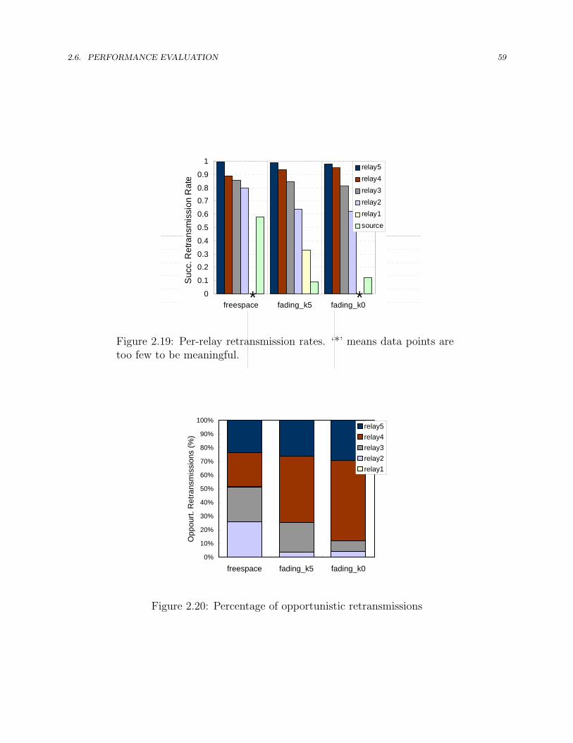
2.6. PERFORMANCE EVALUATION 59
0
0.1
0.2
0.3
0.4
0.5
0.6
0.7
0.8
0.9
1
freespace fading_k5 fading_k0
Suc
c. R
etra
nsm
issi
on R
ate
relay5relay4relay3relay2relay1source
* *
0
0.1
0.20.3
0.4
0.5
0.6
0.70.8
0.9
1
freespace fading_k5 fading_k0
Suc
c. R
etra
nsm
issi
on R
ate
relay5relay4relay3relay2relay1source
* *
Figure 2.19: Per-relay retransmission rates. ‘*’ means data points aretoo few to be meaningful.
0%
10%
20%
30%
40%
50%
60%
70%
80%
90%
100%
freespace fading_k5 fading_k0
Opp
ourt.
Ret
rans
mis
sion
s (%
)
relay5relay4relay3relay2relay1
Figure 2.20: Percentage of opportunistic retransmissions

2.6. PERFORMANCE EVALUATION 60
nodew6
nodew1
nodew3
nodew7
nodew2
nodew5nodew4
Figure 2.21: Mobile scenario test topology
Time Mbps
1001 4.4
2006 4.5
3007 5.1
4008 5.1
5009 4.9
6010 4.8
7016 2.6
8018 3.8
9022 3.6
10025 1.5
11026 3.3
12035 1.9
13036 1.8
14038 2
15039 2.3
16085 2
17118 1.1
18211 1.3
19217 1.1
20943 0.5
21946 1.3
22951 1.2
24014 1.3
25018 0.8
26027 1.6
27029 1.7
28030 1.7
29083 2.2
30411 0.9
31414 2.2
32424 1.7
33425 1.3
34547 0.7
35548 0.9
36552 2
37554 0.8
39663 0.2
40666 1.6
41937 0.9
43049 0.5
45839 0.2
47060 0.3
49311 0.1
0
1
2
3
4
5
6
0 10000 20000 30000 40000 50000 60000
Time (msec)
Thro
ughp
ut (M
bps)
PROSampleCharm
Average Throughput:PRO: 1.5 MbpsSample: 0.92 MbpsCharm: 0.95 Mbps
0
1
2
3
4
5
6
0 10000 20000 30000 40000 50000 60000
Time (msec)
Thro
ughp
ut (M
bps)
PROCHARMSample
Average Throughput:PRO: 1.5 MbpsSample: 0.92 MbpsCHARM: 0.95 Mbps
Figure 2.22: Throughput result of the mo-bile scenario
more pronounced. This is because on-line calibration process gradually increases threshold Thh
for remote relays that perform poorly under highly faded channels. To illustrate this, Table 2.3
shows the calibration result for each relay (offset to the default threshold 10). In the current
implementation, we limit the maximal calibration amount to 5 dB. The result shows that threshold
values for remote relays are raised high particularly in cases with large channel fading.
Mobile Scenario
Next we conduct evaluation in a mobile scenario. As shown in Figure 2.21, this scenario consists of
a source (nodew1), a mobile destination (nodew2), and five relays that are distributed in the test
area. The destination navigates a route at a speed of 5 m/s in a clockwise fashion. The channel
model is log distance with path loss exponent = 3.3. Ricean fading with K = 3 is used. The
scenario involves nodes that participate in (when the destination moves into the radio range of
the node) or withdraw from (when the destination moves out of the radio range of the node) the
relaying over time. Both large-scale and small-scale fading are present in this environment.
Figure 2.22 plots the trace of throughput. It shows that PRO outperforms CHARM and
SampleRate for the most of the trace. During 50-58 second, the destination node moves to (50, 0)

2.6. PERFORMANCE EVALUATION 61
where the destination is not within the communication range of the source. At this point, little
opportunistic gain is available so PRO performs less efficiently. Nevertheless, on average PRO
outperforms rate adaptation by 50% in this particular scenario. Note that the current system is
optimized for slow-moving nodes (e.g. people walking with handheld devices). If users move too
fast, the protocol will not work well because of the one-second periodic broadcast interval. An
alternative solution is to use an adaptive policy that adjusts the interval online in accordance with
the variation in channel condition. Based on the sampling theorem [78], the periodic broadcast
frequency must be at least twice as large as the highest frequency of channel condition change,
which is a function of node speed, fading degree and path loss.
Note that these results do not represent an exhaustive study of mobile scenarios. One can easily
create a scenario in which PRO offers little or no benefit, for example, when no or only poor relays
are present. However, the results in Figure 2.22 indicate that in the presence of good relays, PRO
can adapt quickly to a changing topology; hence a higher throughput is achievable. An extension
of PRO that supports dynamic switching (Section 2.4.6) and multi-rate relaying (Section 2.5.5) can
be more effective in dealing with mobile sources, relays, and destinations. We will investigate such
a more powerful solution in the future.
Fairness
To understand how PRO affects fairness, we conducted experiments in which PRO and legacy 802.11
stations coexist in the network. To isolate the impact of relaying, we do not use rate adaption in the
802.11 stations, unless otherwise noted. The first scenario includes two source-destination pairs,
one using PRO and the other 802.11; the distance between source and destination is 130 meters
for each pair. The channel model is log distance with a path loss exponent of 3 and Ricean fading
with K = 0 is used. We place the two sources close to each other so they defer as a result of carrier
sense. For PRO, five relays are uniformly placed between the source and the destination. To study
the impact of the numbers of relays, we add relays one by one, starting with the one closest to the
source.
Figure 2.23(a) shows the throughput result. Overall, as more relays participate, PRO sees

2.6. PERFORMANCE EVALUATION 62
fairness
PRO 802.11 (Flestrong 802 sum PRO
indvidual 2 2.29 2.38 0 2.29
no relay concurrent 1.33 1.36 0 2.69 1.33
1 relay PRO + 1 re 1.82 1.18 0 3 1.39 1.82
2 relays PRO + 2 re 2.8 0.79 0 3.59 0.61 2.8 0.59 3.08 0.64
3 relays PRO + 3 re 3 0.68 0 3.68 0.58 3 0.68 3 0.45
5 relays PRO + 5 re 3.13 0.62 0 3.75 0.198083 0.56 3.13 0.68 2.95
5 conserv rPRO + 5 re 2.13 1.14 0 3.27 1.14 2.13 1.01 2.34 0.96
legacy 802concurrent 0 0.7 4.19 4.89 #DIV/0! 0
**: conservative using BOFF_POLICY2
*: in concurrent, we reduce PRO src/dst distance to study 802.11 unfairness
discussion:
1. skew (unfairness) of PRO saturate at roughly 1:5
2. however, 802.11 legacy has a skew of 1:6, give the same weak session 0
0.5
1
1.5
2
2.5
3
3.5
4
4.5
5
no re
lay
1 rela
y
2 rela
ys
3 rela
ys
5 rela
ys
5 con
serv
relay
s
legac
y 802
.11
Thro
ughp
ut (M
bps)
PRO802.11 (strong flow)802.11 (poor flow)
(a) PRO vs. poor 802.11 flow
PRO 802.11 strong 802.11
indvidual 2 nodes 0
no relay concurrent 0.85 4.53 0
1 relay PRO + 1 re 1 3.95 0
2 relays PRO + 2 re 1.26 3.49 0
3 relays PRO + 3 re 1.4 3.2 0
5 relays PRO + 5 re 1.55 3 0
SampleRatPRO + 5 re 0.79 2.83 0
legacy 802concurrent 0 0.7 4.19
0
1
2
3
4
5
6
no re
lay
1 rela
y
2 rela
ys
3 rela
ys
5 rela
ys
Sample
Rate
Thro
ughp
ut (M
bps)
PRO802.11 (strong flow)
(b) PRO vs. strong 802.11 flow
Figure 2.23: Fairness comparison
an increase in throughput but the throughput of the 802.11 station decreases. Since the increase
observed by PRO is distinctly higher than the throughput drop for the 802.11 node, network
capacity increases. As discussed in Section 2.5, this “unfair” phenomenon is due to the non-
uniform channel access behavior with multiple relays. The unfairness can be reduced by increasing
the contention window size for relays. For example, we tried a conservative policy by using 32 slots
for the best relay (instead of the best two relays), 64 slots for the next relay (instead of the third and
fourth best relays), and 128 slots for the rest. The “5 conserv relays” bar in Figure 2.23(a) shows
that this strategy reduces the unfairness, although there is also a drop in aggregate throughput. If
fairness is a major concern, we can further increase CWmin or strictly limit the number of relays.
Note though that 802.11 is not a fair protocol due to its binary exponential backoff process: sessions
that experience packet losses will constantly contend for the channel with larger contention windows.
To illustrate this, we conducted an experiment that includes two 802.11 source-destination pairs,
one with perfect channel conditions and another with a poor channel that experiences constant
packet loss. We manipulated the source-destination distances such that the poor session sees a
2.6. PERFORMANCE EVALUATION 63
throughput equal to the 802.11 session in the 5-relay case. The rightmost bar in Figure 2.23(a)
shows that there is extreme unfairness.
We next consider a heterogeneous scenario where the two flows have different source-destination
distances: one is 100 meters and the other is 50 meters. The distant pair uses PRO while the close
pair uses 802.11 over a nearly errorfree channel. The rest of the experimental setup remains the
same. Figure 2.23(b) shows the throughput result. In contrast to the equi-distant experiment,
network capacity decreases with the number of relays: PRO sees an increase in throughput, but
throughput of the 802.11 station decreases. In all cases, the increase observed by PRO is lower
than the throughput drop for the 802.11 pair. PRO increases the successful retransmission ra-
tio of the distant source-destination pair, resulting in a relatively smaller backoff interval and a
better chance to gain channel access. However, the more frequent transmissions from the distant
source-destination pair also reduces efficiency, thereby reducing aggregate throughput. In fact, this
phenomenon also exists in 802.11 rate adaptation. To show this, we configure the remote pair to
run 802.11 with SampleRate. The result is shown in the rightmost bar in Figure 2.23(b). We see
that rate adaptation exhibits the same tradeoff: improving link quality for poor sessions increases
fairness but reduces aggregate network capacity. Note that both the individual and aggregate
throughputs are lower with SampleRate than with PRO.
The results in this section show that PRO can indeed create unfairness relative to legacy 802.11
nodes, but that we can control the degree of unfairness through the selection of CWmin used by
the relays. Our results also suggest that the degree of unfairness introduced by PRO is no worse
than what is already present in 802.11 networks.
Before we end this subsection, it is worth to mention that Figure 2.23(b) also reveals that PRO
offers more benefit than SampleRate in a contending environment. When five relays are present,
PRO increases throughput over SampleRate by 200%. This degree of improvement is greater than
that in the non-contending environment shown in Figure 2.17.
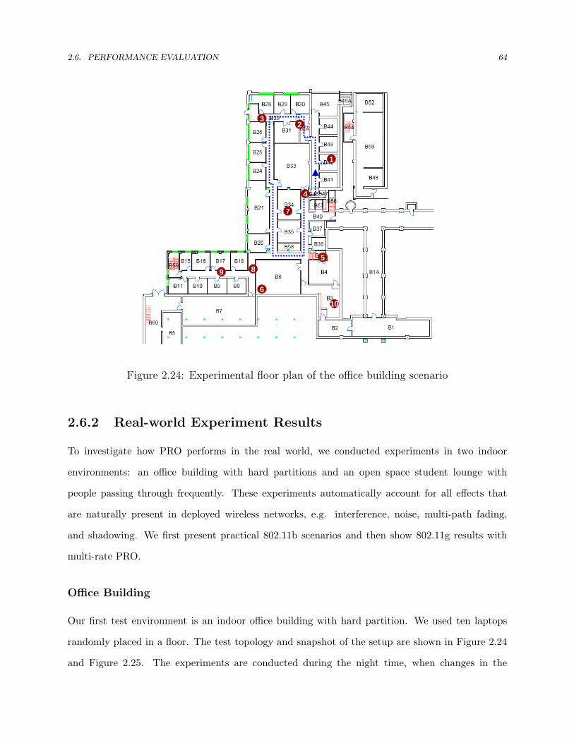
2.6. PERFORMANCE EVALUATION 64
1
23
5
10
6
9
7
8
4
Figure 2.24: Experimental floor plan of the office building scenario
2.6.2 Real-world Experiment Results
To investigate how PRO performs in the real world, we conducted experiments in two indoor
environments: an office building with hard partitions and an open space student lounge with
people passing through frequently. These experiments automatically account for all effects that
are naturally present in deployed wireless networks, e.g. interference, noise, multi-path fading,
and shadowing. We first present practical 802.11b scenarios and then show 802.11g results with
multi-rate PRO.
Office Building
Our first test environment is an indoor office building with hard partition. We used ten laptops
randomly placed in a floor. The test topology and snapshot of the setup are shown in Figure 2.24
and Figure 2.25. The experiments are conducted during the night time, when changes in the
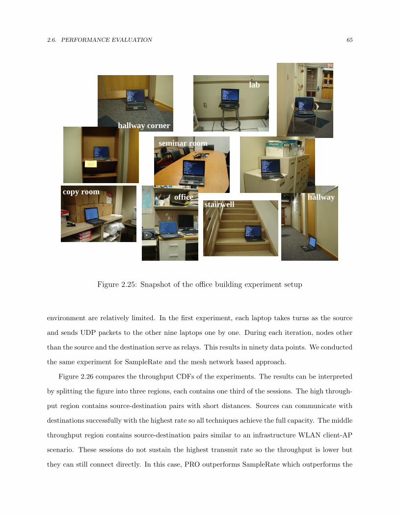
2.6. PERFORMANCE EVALUATION 65
1
lab
office hallway
seminar room
copy room
hallway corner
stairwell
Figure 2.25: Snapshot of the office building experiment setup
environment are relatively limited. In the first experiment, each laptop takes turns as the source
and sends UDP packets to the other nine laptops one by one. During each iteration, nodes other
than the source and the destination serve as relays. This results in ninety data points. We conducted
the same experiment for SampleRate and the mesh network based approach.
Figure 2.26 compares the throughput CDFs of the experiments. The results can be interpreted
by splitting the figure into three regions, each contains one third of the sessions. The high through-
put region contains source-destination pairs with short distances. Sources can communicate with
destinations successfully with the highest rate so all techniques achieve the full capacity. The middle
throughput region contains source-destination pairs similar to an infrastructure WLAN client-AP
scenario. These sessions do not sustain the highest transmit rate so the throughput is lower but
they can still connect directly. In this case, PRO outperforms SampleRate which outperforms the

2.6. PERFORMANCE EVALUATION 66
0
0.1
0.2
0.3
0.4
0.5
0.6
0.7
0.8
0.9
1
0 2 4 6
Throughput (Mbps)
Cum
ulat
ive
Frac
tion
of N
ode
Pai
rs PROSampleRatemesh
Figure 2.26: Throughput CDF results of single source/destination pair in an office building
0
0.1
0.2
0.3
0.4
0.5
0.6
0.7
0.8
0.9
1
0 2 4 6
Throughput (Mbps)
Cum
ulat
ive
Frac
tion
of N
ode
Pai
rs
PROSampleRatemesh
Figure 2.27: Throughput CDF results of concurrent source/destination pairs in an officebuilding
mesh network based approach. These results are consistent with the emulator results in fading
with a large K factor. The low throughput region contains sessions of distant sources and des-
tinations, most of which are out of each other’s communication range. In this case, SampleRate
performs the worst because even the lowest transmit rate does not connect the nodes. PRO’s ca-
pability to relay ACK messages helps in connecting out-of-range nodes, but it relies on detecting

2.6. PERFORMANCE EVALUATION 67
UC
8
10
1
2
3
7
4
5
6
9
Figure 2.28: Experimental floor plan of the student lounge
duplicate transmissions from the source to identify missing ACKs, which involves more overheads
than the mesh network based method. Nonetheless, PRO is more robust against relay outage or
link quality change since the actual relay is determined on-the-fly. In this scenario, the support of
dynamic switching between PRO and the mesh network based approach described in Section 2.4.6
is beneficial.
In the second experiment, we evaluated PRO with concurrent flows. Three source-destination
pairs are randomly chosen every one minute and the test lasts 15 minutes to generate 45 data points.
Note that with concurrent transmissions a relay may serve for multiple source-destination pairs,
and destinations may serve as relays for other source-destination pairs. Again, we repeated the
same experiment for SampleRate and the mesh network based approach. Figure 2.27 compares the
throughput CDFs of them. The extremely poor performance of SampleRate has two causes. First,
SampleRate sometimes misjudges collisions as errors in a contending environment, which yields
an overly conservative selection of rates. This phenomenon becomes more severe with the hidden
terminal effect, which occurs in some concurrent sessions in our testbed. Second, 802.11 provides
equal channel access probabilities across contending stations. When rate adaption is used, poor
sessions that use a low transmit rate consume disproportionately more time than good sessions,
which results in inefficient use of the channel. PRO and the mesh network based approach only use

2.6. PERFORMANCE EVALUATION 68
1
44
Figure 2.29: Snapshot of the student lounge experiment setup
the highest rate so good sessions are not penalized. Moreover, in this scenario, PRO consistently
outperforms the mesh network based approach. We found this is due to the hidden terminal effect.
When senders are hidden from each other and receivers are close enough (or there is a common
receiver), collisions degrade the performance of the mesh network significantly. PRO alleviates the
impact of hidden terminals for two reasons. First, when two sources are hidden from each other and
their transmissions keep colliding at a relay (or two close relays), other relays can still successfully
transmit the packet. Second, when two relays are hidden from each other and their transmissions
collide at two close destinations, the on-line calibration process gradually filters out relays that are
hidden terminals (as poor relays). The hidden terminal effect does not occur in the single session
case.
When more active sessions are present, fewer idle relays are available (i.e., in the current protocol
design, nodes only participate in relaying when no local packet is waiting for transmission). This
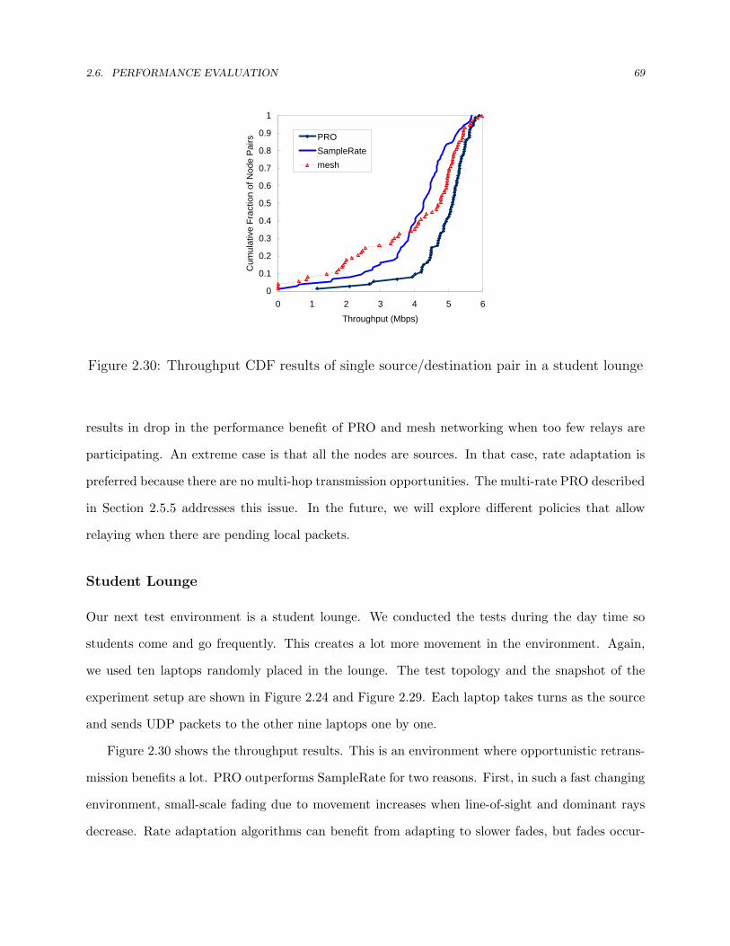
2.6. PERFORMANCE EVALUATION 69
0
0.1
0.2
0.3
0.4
0.5
0.6
0.7
0.8
0.9
1
0 1 2 3 4 5 6
Throughput (Mbps)
Cum
ulat
ive
Frac
tion
of N
ode
Pai
rs PROSampleRatemesh
Figure 2.30: Throughput CDF results of single source/destination pair in a student lounge
results in drop in the performance benefit of PRO and mesh networking when too few relays are
participating. An extreme case is that all the nodes are sources. In that case, rate adaptation is
preferred because there are no multi-hop transmission opportunities. The multi-rate PRO described
in Section 2.5.5 addresses this issue. In the future, we will explore different policies that allow
relaying when there are pending local packets.
Student Lounge
Our next test environment is a student lounge. We conducted the tests during the day time so
students come and go frequently. This creates a lot more movement in the environment. Again,
we used ten laptops randomly placed in the lounge. The test topology and the snapshot of the
experiment setup are shown in Figure 2.24 and Figure 2.29. Each laptop takes turns as the source
and sends UDP packets to the other nine laptops one by one.
Figure 2.30 shows the throughput results. This is an environment where opportunistic retrans-
mission benefits a lot. PRO outperforms SampleRate for two reasons. First, in such a fast changing
environment, small-scale fading due to movement increases when line-of-sight and dominant rays
decrease. Rate adaptation algorithms can benefit from adapting to slower fades, but fades occur-

2.6. PERFORMANCE EVALUATION 70
ring on a very small timescale make them unlikely to be able to adapt successfully. As mentioned
earlier, PRO does not need very accurate prediction of link quality, which makes it more robust
against small-scale fading. These results are consistent with emulation testbed results in channel
fading with a small K factor. Second, similar to the concurrent session scenario, rate adaptation
algorithms sometimes misjudge collisions as errors in a highly contending environment, resulting in
inefficient use of the channel. PRO also outperforms the mesh network based approach for the vast
majority because this environment has few out-of-range nodes. These results are also consistent
with analytical results shown in Figure 2.4.
The measurements in two different buildings reflect PRO’s performance in channel fading with
different K factors, which are consistent with the emulation testbed results. The standard definition
of K is the ratio of signal power in the dominant component over the scattered power. To generalize
the measurement results to other buildings, one can derive K of a particular wireless environment
using the RSS to its standard deviation [57]. The derived K factor can then be used as an index
of performance in emulation testbed results.
The measurements also reveal PRO’s performance in channels with different traffic levels. The
office building scenario was performed during the night time when there is relatively little back-
ground traffic while the student lounge scenario involves more competing traffic. Compared with
Figure 2.26, PRO offers more benefit in a high contending environment. These results are consistent
with the emulation testbed results shown in Figures 2.17 and 2.23(b).
802.11g with Multi-rate PRO
Finally, we presented evaluation results for 802.11g scenarios with multi-rate PRO. We developed
the multi-rate PRO algorithm described in Section 2.5.5 which leverages CHARM to select the right
transmit rate. Our implementation is built upon FlexMAC’s “flexible mode”, which allows the use
of 802.11g transmit rates with 802.11b interframe space [77]. This is equivalent to an 802.11g
station operating in the mixed 802.11b/g mode (See Chapter 5 for more detail). We conducted
experiments in the same real-world environments with the same setup as the 802.11b scenarios
presented earlier in this section. Figure 2.31, Figure 2.32, and Figure 2.33 show the experimental

2.6. PERFORMANCE EVALUATION 71
0
0.1
0.2
0.3
0.4
0.5
0.6
0.7
0.8
0.9
1
0 5 10 15 20
Throughput (Mbps)
Cum
ulat
ive
Frac
tion
of N
ode
Pai
rs
PROSampleRatemesh-54Mmesh-36Mmesh-18M
Figure 2.31: Throughput CDF of single session scenario in an office building (802.11g)
0
0.1
0.2
0.3
0.4
0.5
0.6
0.7
0.8
0.9
1
0 5 10 15
Throughput (Mbps)
Cum
ulat
ive
Frac
tion
of N
ode
Pai
rs
PROSampleRatemesh-18Mmesh-36Mmesh-54M
Figure 2.32: Throughput CDF of concurrent session scenario in an office building(802.11g)
0
0.1
0.2
0.3
0.4
0.5
0.6
0.7
0.8
0.9
1
0 5 10 15
Throughput (Mbps)
Cum
ulat
ive
Frac
tion
of N
ode
Pai
rs
PROSampleRatemesh-54Mmesh-36Mmesh-18M
Figure 2.33: Throughput CDF of single session scenario in a student lounge (802.11g)

2.7. SUMMARY 72
results for a single session, concurrent sessions in the office building, and a single session in the
student lounge, respectively. Similar to the 802.11b results, multi-rate PRO, though not yet fully
optimized, outperforms SampleRate and the mesh network based approach in contended and faded
channels when few out-of-range nodes are present.
2.7 Summary
Opportunistic retransmission offers an effective means to improve individual throughput as well
as overall network capacity in wireless networks by exploiting overhearing relays to retransmit on
behalf of the source upon failed transmissions. In this chapter, we presented an efficient, agile
opportunistic retransmission protocol, PRO that offers transparency to legacy flows. We began by
describing the basic concept of opportunistic retransmission and highlighting the key properties
of PRO. In Section 2.3, we presented an analysis to quantify the potential gain of opportunistic
retransmission. In Section 2.4, We presented the design details of PRO for 802.11-like networks.
Discussion of network-specific issues were elaborated in Section 2.5. In Section 2.6, we presented
experimental results for PRO-enabled 802.11 WLANs and existing techniques to demonstrate the
effectiveness of the proposed schemes, on both a controlled testbed and in the real world. Exper-
imental results show that PRO boosts throughput in various wireless environments, especially in
contended channels, under fading, or with user mobility.

73
Chapter 3
Time-based Adaptive Retransmission
Video communication is subject to deadlines so delay requirements are important [79]. In this
chapter, we present Time-based Adaptive Retransmission (TAR), a simple yet effective solution for
meeting timing constraints in video transmission over wireless networks. We begin by presenting
the basic concept of time-based adaptive retransmission, followed by a discussion of related work in
the literature. We then present an analytical comparison for TAR and 802.11-like retransmission
strategies. We present the protocol design of TAR that addresses the challenge of fairness across
flows with or without the support of TAR. We then present performance evaluation results both
on a testbed and in the real world. Finally, we summarize this chapter.
We focus on intermediate-to-end scenarios in this chapter (i.e. no support from wireless relays
between the intermediate node and the destination end host). We will present how to extend
the scope of TAR from intermediates only to all participating network entities along the path(s)
between the intermediate and the destination end host in Chapter 4.
3.1 Basic Concept
Today’s wireless technologies recommend a simple retransmission mechanism: a failed packet is
retransmitted several times until a predetermined, fixed retry limit is reached [1]. While such a
count-based strategy works well for data applications, it is not suitable for delay-sensitive video

3.1. BASIC CONCEPT 74
streaming applications. Excessive retransmission of late packets not only wastes bandwidth in
useless transmission but also delays the transmission of valid packets, potentially creating more
late packets in a bandwidth-limited environment [80]. TAR is a MAC-centric cross-layer strategy
that is designed to tackle this issue [38, 37]. Specifically, a TAR-enabled MAC adaptively decides
whether to discard or (re)send a packet based on a retransmission deadline attached to that packet.
The retransmission deadline is passed down from the application along with the packet. Section 3.5
describes how to assign retransmission deadlines in detail. The packet is (re)transmitted if the
current time is smaller than the retransmission deadline; otherwise it is discarded regardless of how
many retries have been issued. Therefore, the exact retry limit is not determined a priori but is
dynamically adapted to network conditions and video traffic characteristics. This strategy has the
following attractive properties for wireless video transmission:
• Adaptation to traffic activities and channel conditions: The random backoff period in a clear,
light-loaded channel and a noisy, heavily loaded channel can be quite different [37]. Therefore,
it is difficult to operate at the optimal point using a count-based retransmission strategy. TAR
adaptively determines the transmission decision based on retransmission deadlines such that
valid packets are protected with more transmission opportunities while useless packets are
directly dropped at the sender without wasting network bandwidth.
• Automatic indirect unequal error protection (UEP): The inter-frame coding property of video
data results in differences in the importance of various types of frames. To maximize user-
perceived quality, stronger protection should be applied to more important video packets
than to the other ones. Through careful assignment of retransmission deadlines based on
both temporal and perceptual importance of video packets, the system can provide unequal
error protection for different types of packets. Specifically, a far off deadline corresponding
to more retries (and hence, stronger protection against transmission errors) is assigned to
more important packets (e.g., I frame packets and base layer packets) while a closer deadline,
and thus fewer retries, is assigned to less important ones (e.g., B frame packets and high
enhancement layer packets).

3.2. RELATED WORK 75
• Equal channel access opportunity: TAR maintains the same 802.11 channel access opportunity
by mimicking the transmission behavior of the conventional 802.11 protocol. Specifically, the
contention window size is adjusted based on the conventional 802.11 protocol so that the
time-based retransmission behavior is transparent to other stations. This property assures
equal channel access opportunities for TAR and non-TAR stations.
3.2 Related Work
Many solutions have been proposed to employ cross-layer support to improve end-to-end perfor-
mance. As opposed to application-level approaches, cross-layer designs configure operational modes
and protocol parameters jointly such that application-level performance is maximized. There is a
considerable amount of research work on cross-layer optimization. In [29] and [30], different retry
limits are associated with different priorities in the radio link layer of cellular networks. Important
frames are associated with high priority so they are granted with more retransmissions. In [20],
Li and van der Schaar proposed a real-time retry limit adaptation algorithm to trace the optimal
MAC-layer retry limit over WLANs. The proposed scheme also provides unequal error protection
to layered video streams by adapting different retry limits. For more sophisticated scheduling,
Bucciol et al. proposed a metric that jointly considers perceptual and temporal importance. This
metric is then used by the link layer to drive the packet-selection process at each retransmission
opportunity [31]. In [32], Liebl et al. proposed deadline-aware scheduling for video streams over
a wireless shared channel. By incorporating side information about the video stream structure
and the future channel behavior, the proposed algorithm can achieve a fairer distribution of video
quality among all users. There is also a lot of research in rate-distortion optimized scheduling based
on [41].
Like prior work, TAR leverages cross-layer collaboration between the application and the MAC
layer to maximize end-to-end video quality. There are however three differences. First, TAR
adopts a retransmission deadline, which can represent not only temporal relationship but both
temporal and perceptual importance of packets, for MAC-level transmission scheduling. The use of

3.3. ANALYSIS 76
a unified metric allows cross-layer optimization while preserving application abstraction. Second,
TAR adopts a simple FIFO queueing discipline, which allows easy implementation in the link layer.
Third, TAR offers transparency to the remaining network by preserving the standard channel access
behavior. This property preserves long-term fairness as well as short-term collision avoidance.
3.3 Analysis
In this section, we study the performance of TAR and 802.11-like count-based retransmission strate-
gies analytically. We show that TAR adaptively achieves the best retransmission strategy without
the requirement of channel information and traffic statistics.
In delay-sensitive wireless video applications, there are two causes of packet loss: link packet
erasures (i.e., packets dropped by senders after too many retries), and late arrivals (i.e., packets
missed transmission deadlines due to incurred delay). Late arrivals can be mitigated by introducing
long startup delay at the receiver. However, this does not work for video streams with hard latency
constraints (e.g. interactive video or when the receiver has limited buffer space). To simplify the
analysis, we assume video is generated at a constant frame rate. The deadline of a video frame
is one inter-frame interval after that frame is generated. We further assume a video frame is
packetized into one MAC packet with equal transmission time. Let λ be the packet arrival rate
(packets/seconds). The packet arrival time of packet i can be written as A(i) = i/λ and the
deadline of packet i is D(i) = (i + 1)/λ. Let µ be the service rate of the link (packets/second)
and Pe be the link error rate. If we assume that the wireless link is a memoryless packet erasure
channel such that packets are dropped independently with a constant probability, then the number
of transmissions for successfully delivering a packet is a geometric random variable:
s(TAR)k = (1− Pe)P k−1
e . (3.1)
In TAR, packet i is discarded when the sender cannot deliver it before the deadline D(i) so
ideally there is no late arrival at the destination. This also implies that the transmission of packet
i + 1 will start at the time it arrives in the system, independent of transmission outcomes of

3.3. ANALYSIS 77
A(0) A(1) A(2) A(3) A(4)
D(0) D(1) D(2) D(3)
Time
z0 z1 z2 z3 z4
late packet
0 0 0 0 0 1 1 1 1 1 1 1 2 2 2 2 2 2 3 3 3 4 4 4 4 4
A(0) A(1) A(2) A(3) A(4)
D(0) D(1) D(2) D(3)
Time0 0 0 0 0 1 1 1 1 1 2 2 3 3 3 4 4 4 4 4
packet discarded after expiration of deadline
(a) Time-based adaptive retransmission
A(0) A(1) A(2) A(3) A(4)
D(0) D(1) D(2) D(3)
Time
z0 z1 z2 z3 z4
late packet
0 0 0 0 0 1 1 1 1 1 1 1 2 2 2 2 2 2 3 3 3 4 4 4 4 4
A(0) A(1) A(2) A(3) A(4)
D(0) D(1) D(2) D(3)
Time0 0 0 0 0 1 1 1 1 1 2 2 3 3 3 4 4 4 4 4
packet discarded after expiration of deadline
(b) 802.11 count-based strategy (retry limit = 7)
Figure 3.1: Example of packet transmission outcomes. The gray and white boxes representsuccessful and failed transmissions respectively. The number inside a box is packet ID. Giventhe same channel condition, TAR makes four successful deliveries (packets 0, 2, 3 and 4)with four transmissions while 802.11 makes three deliveries (packet 0, 3 and 4) with fivetransmissions.
the previous packets (i.e. A(i + 1) = D(i)). Figure 3.1(a) shows an example of TAR’s packet
transmission. Given constant packet arrival rate and link service rate, the maximum number of
transmissions before a packet misses the deadline (and is discarded) is bµ/λc. Thus the packet loss
probability of TAR, occurring when the workload of retransmission exceeds the link capacity can
be calculated as
p(TAR)loss =
∞∑k=bµ/λc+1
s(TAR)k = P
bµλc
e . (3.2)
For 802.11-like retransmission strategies, packets are retransmitted until a fixed retry limit R
is reached regardless of the expiration of deadlines. The probability distribution of the number of

3.3. ANALYSIS 78
transmissions for a packet is then written as
s(802.11)k =
(1− Pe)P k−1e if 1 ≤ k ≤ R,
PRe if k = R + 1,
0 otherwise.
(3.3)
In this case, packet losses are caused by either packet erasures (the retry limit is too small) or late
arrivals (the retry limit is too large). The link packet erasure probability (i.e. the packet drop rate
after R unsuccessful retries) is given by
p(802.11)error = PR+1
e . (3.4)
To obtain the probability of late arrivals, let us consider a newly arrived packet i. The packet
faces two conditions: (A) the system immediately starts the transmission of packet i if the trans-
mission of packet i−1 has already finished (either successfully delivered or discarded after the retry
limit is reached); (B) the system postpones the transmission of packet i until the completion of
packet i−1 if the transmission of packet i−1 has not finished yet. This means that the transmission
outcome of a packet is now dependent on that of the previous packets. Figure 3.1(b) illustrates an
example of 802.11’s packet transmission, in which packets 0, 1 and 4 see condition (A) and packets
2 and 3 see condition (B).
Analyzing a system with memory is generally difficult. Fortunately, we see here the memory
structure of the system is statistically describable. Every time the system finishes the transmission
of a packet before the deadline, transmissions of future packets are independent of the past (i.e.
transmission of the next packet will start at the packet arrival time). This means we can simply
study the system behavior between two consecutive packets whose transmissions are finished before
the deadlines, or equivalently, we study the statistics of a burst of late packets.
Let Zi denote the number of transmissions for packet i, which is an i.i.d process with probability
distribution given in (3.3). Call packet i a valid packet if its transmission is finished before D(i);
otherwise a late packet. Consider, for now, that packet 0 is a valid packet. Then the probability of

3.3. ANALYSIS 79
packet 1 being also a valid packet (i.e. the burst length β of late packets is 0) is
Pr(β = 0) = Pr(Z1 ≤ bµ/λc). (3.5)
The probability of packet 1 being a late packet but packet 2 being a valid packet (i.e. the burst
length of late packets is 1) is
Pr(β = 1) = Pr(Z1 > bµ/λc, Z1 + Z2 ≤ b2µ/λc). (3.6)
Likewise, the probability of consecutive K late packets is
Pr(β = K) = Pr(Z1 > bµ/λc, Z1 + Z2 > b2µ/λc, · · · , Z1 + Z2 + · · ·+ ZK > bKµ/λc,
Z1 + Z2 + · · ·+ ZK+1 ≤ b(K + 1)µ/λc). (3.7)
Substituting (3.3) into (3.7), we have
Pr(β = K) =R+1∑
z1=bµλc+1
R+1∑z2=max{b2µ
λc+1−z1,1}
· · ·R+1∑
zK=max{bK µλc+1−(z1+z2+···+zK−1),1}
min{b(K+1)µλc−(z1+z2+···+zK),R+1}∑zK+1=1
(s(802.11)z1
s(802.11)z2
· · · s(802.11)zK+1
). (3.8)
Thus, the average burst length can be obtained by
E[β] =∞∑
k=1
k · Pr(β = k). (3.9)
Recall that the system memory is reset at the occurrence of a valid packet. So the system can be
described as a valid packet followed by a burst of β late packets. We can then derive the probability
of late packets as
p(802.11)late =
E[β]E[β] + 1
. (3.10)

3.3. ANALYSIS 80
0
1
2
3
4
5
6
0 2 4 6 8 10 12
Optimal Retry Limit
μ/λ
Pe = 0.75Pe = 0.5
Figure 3.2: 802.11 optimal retry limit as a function of µ/λ with variable packet error rates
Finally, combining (3.4) and (3.10), the overall loss rate for 802.11’s count-based strategy is
p(802.11)loss = p(802.11)
error + (1− p(802.11)error )p(802.11)
late . (3.11)
Figure 3.2 shows the 802.11 optimal retry limit as a function of λ/µ with variable packet error
rates. We see that there is a broad range of optimal retry limits. In practice the optimal retry limit
is hard to obtain because wireless channel conditions and video traffic characteristics change over
time, requiring constant updating of the retry limit for each source-destination pair. TAR does
not require any knowledge of underlying channel conditions nor traffic characteristics, making it a
more promising solution than a count-based strategy. Even when the optimal retry limit is always
available, a count-based retransmission strategy still has its limitation. Figure 3.3 compares the
overall loss rates of TAR and 802.11 with µλ = 4, Pe = 0.75. The figure shows a tradeoff between
packet erasures and late arrivals in 802.11: a large retry limit mitigates packet erasures but it may
create more late packets; on the other hand, a small retry limit alleviates late arrivals but it is
prone to errors. While an 802.11-like strategy can be penalized by a poor choice of retry limit,
TAR can automatically achieve the best retransmission strategy.

3.4. PROTOCOL DESIGN 81
mu2lambda = 4, Pe = 0.75
Pe^(R+1)
802.11 R Perror Plate ploss
0 0.75 0 0.75
1 0.5625 0 0.5625
2 0.421875 0 0.421875
3 0.316406 0 0.316406
4 0.237305 0.396863691 0.539991
5 0.177979 0.470899471 0.565068
6 0.133484 0.5 0.566742
7 0.100113
8 0.075085
TAR 3 0.3164
Pe
d 1/d PRO Mesh
1 1 0.75 0.75
0.5 2 0.4974 0.6214
0.25 4 0.47 0.6214
0.0625 8 0.465 0.6214
0.047619 16 0.46 0.6214
0.015625 32 0.46 0.6214
perfect rela 0.4286
0
0.1
0.2
0.3
0.4
0.5
0.6
0.7
0.8
0 1 2 3 4 5 6Retry Limit
Loss
Rat
e
retry limit too largeretry limit too small
p loss(TAR)
p error(802.11)
p late(802.11)
p loss(802.11)
0.3
0.4
0.5
0.6
0.7
0.8
Series1
Series2
Figure 3.3: Loss rate comparison of TAR and 802.11
Time-based Adaptive RetransmissionRandom access procedure
NoBin Exp D?
Random access procedure
Yes
Backoff D?
do boff :=
do_boff := FALSENew packet
No
Transmit success?YesYes
D?
D
channel busyor do_boff = TRUE
do_boFALSE
No Donedo_boff := TRUE
Figure 3.4: Protocol operation of TAR
3.4 Protocol Design
The protocol operation of TAR is depicted in Figure 3.4. TAR adaptively decides whether to
discard or (re)send a packet based on a retransmission deadline D attached to that packet. The
retransmission deadline is assigned by the application layer according to the application’s specific
requirements for the transmitted media data, and it is used by the MAC layer to decide when to stop
the retransmission process for each packet. Before initiating the transmission of a packet, the MAC

3.4. PROTOCOL DESIGN 82
checks whether the retransmission deadline of the packet has elapsed and if this is the case, discards
the packet directly. For random access wireless networks, the MAC transmits a valid packet after
the backoff procedure if the retransmission deadline is still smaller than the current time; otherwise
it discards the packet. If the transmission fails, the time-based retransmission procedure continues
until either the packet is successfully delivered to the destination or the retransmission deadline is
elapsed.
A TAR-enabled MAC persistently retransmits a packet as long as the retransmission deadline
is greater than the current time. Therefore, it is likely that the MAC discards a packet before the
retry limit R is reached or continues retransmitting a packet after R is exceeded. For random access
networks, this results in a non standard channel access behavior because the random backoff interval
is a function of the number of transmissions associated with a packet. In the next subsection, we
describe how TAR resolves this issue. We use the 802.11 exponential random backoff as an example.
3.4.1 Assuring Standard Channel Access Behavior
The 802.11 exponential backoff procedure offers not only short-term collision avoidance but also
long-term fairness across multiple stations. This is achieved by using the same rule for updating
contention window sizes among all sending stations. The contention window size is reset to the ini-
tial value after the MAC finishes the transmission of a packet (i.e. when the packet is successfully
delivered or discarded after the retry limit is reached). Because TAR modifies the retransmis-
sion philosophy, the resulting channel access behavior also changes. This potentially yields unfair
bandwidth distribution among TAR-enabled stations and legacy stations.
Fairness is a policy question and different policies are possible. Our goal is to maintain the
802.11-level fairness, that is, to preserve the same channel access behavior as a legacy 802.11 station.
To achieve this, TAR updates the contention window size by mimicking the transmission behavior of
a legacy 802.11 station. Specifically, when a packet is discarded due to deadline expiration, a TAR-
enabled MAC does not reset the contention window size immediately; the contention window is only
reset after a successful transmission or when the number of unsuccessful transmissions after the last
reset reaches the retry limit. On the other hand, when a packet is retransmitted after the retry limit

3.4. PROTOCOL DESIGN 83
n DIFSInitial
attempt
n DIFS2nd retry
n DIFS4th retry
6th retry
n DIFS1st retry
n DIFS3rd retry
5th retry n DIFS
n DIFS …
n DIFSInitial
Attempt
n DIFS2nd retry
n+1 DIFS
n DIFS1st retry
n+1 DIFS
3rd retry
n+1 DIFS
n+1 DIFS
Initialattempt
2nd retry
1st retry
…
Figure 3.5: TAR preserves equal channel access behavior as the 802.11
is reached, a TAR-enabled MAC resets the contention window size for the next retransmission of
the packet. From other stations’ perspective, a TAR-enabled station behaves exactly the same as a
standard 802.11 station. Figure 3.5 shows example operations of TAR when the relevant retry limit
is four. In the left-hand example, the retransmission deadline of packet n has not elapsed after four
unsuccessful retransmissions. At the fifth retry, the contention window size is reset, mimicking the
behavior as if packet n is discarded after the retry limit is reached and packet n+1 is subsequently
transmitted. In the right-hand example, the retransmission deadline of packet n has elapsed after
the second retransmission before the total number of retransmission reaches four. For packet n+1,
the MAC does not reset the contention window size until after the first retransmission of the packet,
that is, when the total number of unsuccessful transmissions sum up to four. This corresponds to
the case that a packet suffers consecutive unsuccessful retransmissions and gets discarded after the
retry limit is reached. This way, the operation of TAR is transparent to legacy 802.111 stations in
the network. Algorithm 3 gives the procedure of how a TAR-enabled MAC updates the contention
window size. This operation provides equal channel access behavior for TAR and non-TAR stations.
In Section 3.6.1, evaluation results of transparency will be presented.

3.4. PROTOCOL DESIGN 84
Algorithm 3 UpdateContentionWindowSize(X)
Require: New transmission result X = {success, failure} and Retry Limit R1: if X = success or r = R then2: CW ⇐ CWmin
3: r ⇐ 04: else5: if CW < CWmax then6: CW ⇐ CW · 27: end if8: r ⇐ r + 19: end if
10: return CW
3.4.2 Retrieving Retransmission Deadlines
There are several ways of retrieving retransmission deadlines in the MAC layer in an intermediate
node. We now present a method similar to how router vendors overcome the connectivity problems
in video conferencing that are presented by firewalls and NAT servers [81]. Specifically, the MAC
continuously examines video packets via the transport source and destination port numbers. These
are the first four bytes in the TCP/UDP header, or equivalently, the twenty-forth to twenty-eighth
bytes in the payload of an 802.11 MAC frame. The port numbers reserved for video sessions can be
negotiated via an out-of-band protocol. When a video packet is identified, the MAC retrieves the
retransmission deadline by offsetting the packet. For example, when RTP is used to encapsulate
video data, the timestamp field in the RTP header automatically represents the retransmission
deadline. The MAC can then find the retransmission deadline by offsetting the timestamp field in
the RTP header. For synchronization purposes, the server application uses NTP to generate RTP
timestamps [82]. NTP provides a means for clock synchronization among computer systems. If the
server application picks initial timestamp values randomly, additional efforts for synchronization
between the server application and the MAC in the intermediate node will be needed. Note that
the synchronization is only needed for the first packet when a video session is newly established.
The retransmission deadlines of the following packets can be derived from the timestamp difference
with respect to the first packet. New video sessions can be detected via a new SSRC identifier in
the RTP header [83].

3.5. ASSIGNING RETRANSMISSION DEADLINES 85
• Differential dropping in the DiffServ Assured Forwarding (Green, Yellow & Red)
• Video applications mark their packets
Wireless Loss Estimation (Background: DiffServ)
Drop Red packets
Drop Red + Yellow packets
Rarely drop Green packets
I B P B P
Increasing Congestion
I B P B P
GoP GoP
Figure 3.6: Structure of a group of pictures (GoP)
3.5 Assigning Retransmission Deadlines
TAR adopts application-assigned retransmission deadlines to guide the MAC transmission pro-
cess. The assignment of retransmission deadline is not performed by TAR. For completeness, this
section discuss possible strategies for assigning retransmission deadlines. Other methods can be
used based on application-specific requirements.
The retransmission deadline is a metric that quantifies the timing stringency of video packets.
In fact, this metric can represent not only temporal importance but also perceptual importance
of a packet. That is, retransmission deadlines not only indicate how fast a packet approaches
its playback deadline but also reflect how important a packet is in terms of its contribution to
user-perceived quality. In the literature, there are many proposals that describe how to combine
temporal and perceptual importance into a unified metric. For example, Bucciol et. al introduced
a weight factor to control the relative importance of the perceptual and temporal terms of the
formula in [31]. In the rest of this section, we present a simple method to determine retransmission
deadlines for pre-encoded video data. This method is also used for performance evaluation in
Section 3.6.
Consider the typical video encoding structure shown in Figure 3.6. The repeated pattern of
a leading I (intra-coded) frame followed by optional P (predicted) and B (bidirectional predicted)
frames is known as a Group of Pictures (GOP). I frames are constructed without reference to
any other frames. I frames are larger than the other types of frames because they contain all the
3.5. ASSIGNING RETRANSMISSION DEADLINES 86
information needed to reconstruct a frame. P frames are predicted from past frames. Only the
difference between the previous frame and the P frame is transmitted. Because of the temporal
redundancy, P frames contain much less data than I frames. Finally, B frames contain only the
information that cannot be derived from previous and future frames. B frames are typically the
smallest frames.
While reducing temporal redundancy significantly increases the compression ratio, it also causes
the problem of error propagation. That is, packet loss of a reference frame will propagate across
multiple frames which are inter-coded with respect to the reference frame. Therefore, receiving an
inter-coded frame is useless if its corresponding reference frame is lost. The goal of our solution is
to prioritize those important reference frames by giving them a later retransmission deadline.
Denote packet (i, n) as the i-th packet in GoP n. The retransmission deadline, Di,n of packet
(i, n) is assigned by the video server according to the following rule
Di,n = t1,n (3.12)
where t1,n is the playback schedule of the leading I frame in GoP n. That is,
t1,n = B + nθ (3.13)
where B is the receiver startup delay and θ is the GoP period. The rationale behind (3.12) is
that in a GoP, early frames are directly or indirectly referenced by later frames. When an early
frame is lost, the reception of a later frame is not very useful since there is no reference for motion
compensation. Therefore, if the transmission of the leading I frame fails after t1,n, the remaining
packets in the same GoP are purged in order to save bandwidth in transmitting useful information.
This method assumes each GoP contributes equally, which may not always be true. However, it
works sufficiently well as will be shown in the next section.

3.6. PERFORMANCE EVALUATION 87
Figure 3.7: Testbed topology used for studying the 802.11 retransmission issues
3.6 Performance Evaluation
We have implemented TAR in the Madwifi driver for wireless NICs based on the Atheros chipset.
Again, FlexMAC is used as the development platform (see Section 5.6.2 for implementation details).
We evaluate TAR in both a controlled testbed and in the real world. In the following subsections,
we present the evaluation results.
3.6.1 Testbed Experimental Results
The controlled experiments use the CMU wireless network emulator [67]. In this subsection, we
first demonstrate the challenge with video transmission over 802.11 wireless networks. We then
show visual quality results for TAR and 802.11 in different testbed scenarios.
Understanding the 802.11 Issues
In this experiment, we study the transmission latency induced in an 802.11b wireless network. The
test topology is shown in Figure 3.7, where emu-3, emu-5, and emu-9 simultaneously run iperf UDP
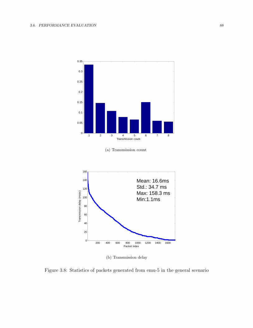
3.6. PERFORMANCE EVALUATION 88
200 400 600 800 1000 1200 1400 16000
20
40
60
80
100
120
140
160
Packet index
Tran
smis
sion
del
ay (m
sec)
Mean: 16.6ms Std.: 20.2 msMax: 273.4 msMin:1.1ms
1 2 3 4 5 6 7 80
0.05
0.1
0.15
0.2
0.25
0.3
0.35
Transmission count
(a) Transmission count
200 400 600 800 1000 1200 1400 16000
20
40
60
80
100
120
140
160
Packet index
Tran
smis
sion
del
ay (m
sec)
Mean: 16.6ms Std.: 34.7 msMax: 158.3 msMin:1.1ms
1 2 3 4 5 6 7 80
0.05
0.1
0.15
0.2
0.25
0.3
0.35
Transmission count
(b) Transmission delay
Figure 3.8: Statistics of packets generated from emu-5 in the general scenario

3.6. PERFORMANCE EVALUATION 89
tests to emu-4, emu-6, and emu-10 for one minute [84]. The UDP packet size is 1400 bytes. Madwifi
0.9.1 is used throughout all the tests. We use emu-7 operating in the monitor mode as a sniffer for
emu-5. This is achieved by configuring emu-7 to have a perfect channel exclusively with emu-5 so
that emu-7 only captures packets of interest.
By post-processing emu-7’s monitoring results, we plot the statistics of transmission count and
transmission latency of packets generated by emu-5 in Figure 3.8. Transmission counts are the
number of transmissions (initial attempts and retransmissions) for a single packet and transmission
delay is the total time needed in delivering a packet, including transmit time, inter-frame space,
and backoff deference of all transmissions associated with the packet. The result indicates that
transmission delays fluctuate by two orders of magnitude. This results in a large delay jitter for
video frames which are typically composed of several MAC-layer packets. Delay jitter is a problem
because the receiver must receive/decode/display frames at a constant rate, and any late frame
resulting from the delay jitter can produce problems in the reconstructed video, e.g. jerks in the
video. The result shows that the 802.11 wireless network is inherently a challenging environment.
The count-based retransmission strategy does not suffice for delay-sensitive video data.
Visual Quality Result
We now evaluate an implementation of TAR in the Madwifi driver. We consider three different
scenarios. The first is a simple scenario with only the video server and the video client in the
network. This scenario was used mainly for debugging our TAR implementation (Figure 3.9). The
second scenario is a mobile-user scenario with the video server and the video client moving at
a velocity of 10 m/s based on a predefined route in a 100x100 square meter area (Figure 3.10).
Ricean fading with K = 3 was used. The third scenario is a congested network in which six stations
contend with the video server and the client (Figure 3.11). Each contending station sends out a
1KB ping packet at a rate of 10 Hz. In the tests, emu-5 and emu-6 serve as the video server
and client, respectively. The video client drops late frames and displays the video according to
its original coding rate without stretching or shrinking interframe intervals. The test sequence is
stefan in CIF format, encoded with 30 frames per second and 15 frames per GOP (composed of
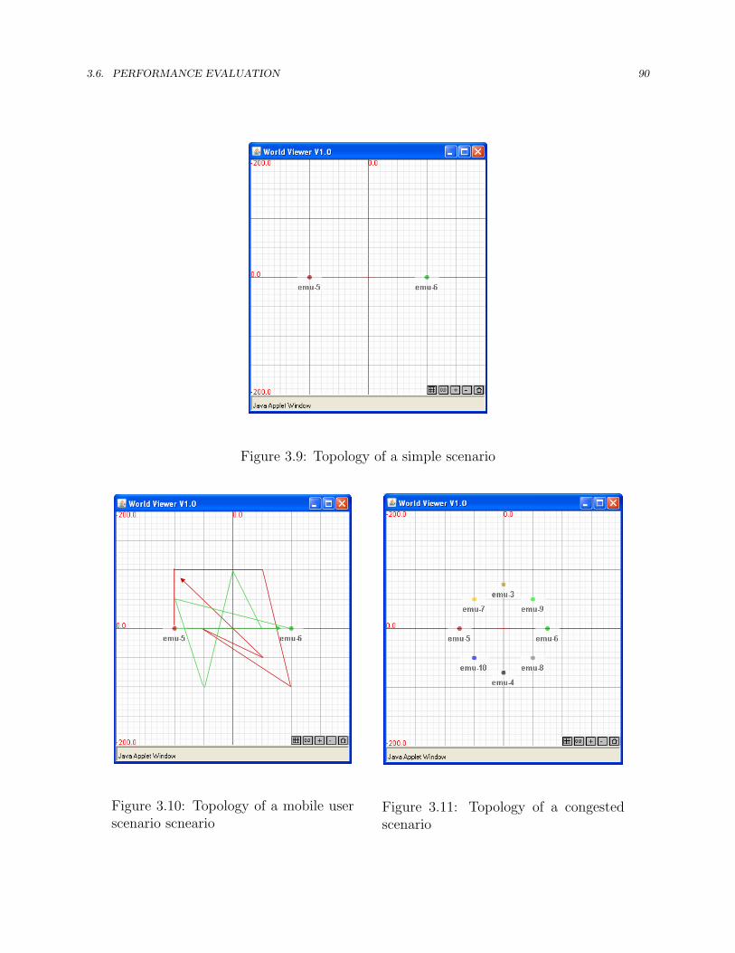
3.6. PERFORMANCE EVALUATION 90
Figure 3.9: Topology of a simple scenario
Figure 3.10: Topology of a mobile userscenario scneario
Figure 3.11: Topology of a congestedscenario

3.6. PERFORMANCE EVALUATION 91
802.11 Valid Late LostI frame packets 85% 9% 6%P frame packets 78% 19% 3%Total packets 79% 18% 3%TAR Eligible Late LostI frame packets 100% 0 0%P frame packets 88% 0 12%Total packets 90% 0 10%
(a) Simple
802.11 Valid Late LostI frame packets 45% 32% 23%P frame packets 50% 25% 25%Total packets 50% 26% 24%TAR Eligible Late LostI frame packets 92% 0 8%P frame packets 54% 0 46%Total packets 59% 0 41%
(b) Mobile-user
802.11 Valid Late LostI frame packets 7% 66% 27%P frame packets 5% 56% 39%Total packets 5% 57% 38%TAR Eligible Late LostI frame packets 99% 0 1%P frame packets 46% 0 54%Total packets 52% 0 48%
(c) Congested-network
Table 3.1: Testbed results of packet ratios
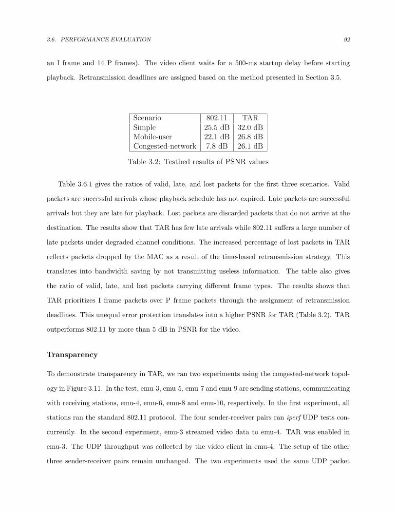
3.6. PERFORMANCE EVALUATION 92
an I frame and 14 P frames). The video client waits for a 500-ms startup delay before starting
playback. Retransmission deadlines are assigned based on the method presented in Section 3.5.
Scenario 802.11 TARSimple 25.5 dB 32.0 dBMobile-user 22.1 dB 26.8 dBCongested-network 7.8 dB 26.1 dB
Table 3.2: Testbed results of PSNR values
Table 3.6.1 gives the ratios of valid, late, and lost packets for the first three scenarios. Valid
packets are successful arrivals whose playback schedule has not expired. Late packets are successful
arrivals but they are late for playback. Lost packets are discarded packets that do not arrive at the
destination. The results show that TAR has few late arrivals while 802.11 suffers a large number of
late packets under degraded channel conditions. The increased percentage of lost packets in TAR
reflects packets dropped by the MAC as a result of the time-based retransmission strategy. This
translates into bandwidth saving by not transmitting useless information. The table also gives
the ratio of valid, late, and lost packets carrying different frame types. The results shows that
TAR prioritizes I frame packets over P frame packets through the assignment of retransmission
deadlines. This unequal error protection translates into a higher PSNR for TAR (Table 3.2). TAR
outperforms 802.11 by more than 5 dB in PSNR for the video.
Transparency
To demonstrate transparency in TAR, we ran two experiments using the congested-network topol-
ogy in Figure 3.11. In the test, emu-3, emu-5, emu-7 and emu-9 are sending stations, communicating
with receiving stations, emu-4, emu-6, emu-8 and emu-10, respectively. In the first experiment, all
stations ran the standard 802.11 protocol. The four sender-receiver pairs ran iperf UDP tests con-
currently. In the second experiment, emu-3 streamed video data to emu-4. TAR was enabled in
emu-3. The UDP throughput was collected by the video client in emu-4. The setup of the other
three sender-receiver pairs remain unchanged. The two experiments used the same UDP packet

3.6. PERFORMANCE EVALUATION 93
0.7
0.8
0.9
Mbp
s)
0 4
0.5
0.6
0.7
0.8
0.9
ughp
ut (M
bps)
S i h 802 11
0.2
0.3
0.4
0.5
0.6
0.7
0.8
0.9
UDP Th
roughp
ut (M
bps)
Straight 802.11
TAR + 802.11
0
0.1
0.2
0.3
0.4
0.5
0.6
0.7
0.8
0.9
UDP Th
roughp
ut (M
bps)
Straight 802.11
TAR + 802.11
0
0.1
0.2
0.3
0.4
0.5
0.6
0.7
0.8
0.9
(emu‐3, emu‐4) (emu‐5, emu‐6) (emu‐7, emu‐8) (emu‐9, emu‐10)
UDP Th
roughp
ut (M
bps)
(Sender, Receiver) pair
Straight 802.11
TAR + 802.11
0
0.1
0.2
0.3
0.4
0.5
0.6
0.7
0.8
0.9
(emu‐3, emu‐4) (emu‐5, emu‐6) (emu‐7, emu‐8) (emu‐9, emu‐10)
UDP Th
roughp
ut (M
bps)
(Sender, Receiver) pair
Straight 802.11
TAR + 802.11
Figure 3.12: UDP throughputs of multiple sender-receiver pairs
size (1024 bytes) for video transmission and iperf tests. We ran both experiments for one minute.
Figure 3.12 shows the average throughput results. We see that the two experiments exhibit similar
UDP throughput distribution, implying that TAR is transparent to the reset of the network.
video client
video server
Contending station
Figure 3.13: Real-world test topology

3.6. PERFORMANCE EVALUATION 94
3.6.2 Real-world Experiment Results
To investigate how TAR performs in the real world, we conducted experiments in an indoor en-
vironment. A TAR-enabled wireless station is associated with an 802.11b access point (AP). The
video server ran on the wireless client and the video client ran on the AP. The video coding and
transmission parameters are identical to those used in the testbed experiments. In addition to the
server-client pair, there was another wireless station that injects contending traffic (using broadcast
pings) into the network. Figure 3.13 shows the experimental topology.
We evaluate three techniques: (1) 802.11 (retry limit = 7), (2) TAR, and (3) an application-
driven mechanism proposed in [85]. This scheme supports adaptive packet dropping and scheduling
with application-level retransmissions and acknowledgement.
Per-Packet Delivery Results
Figure 3.14 shows the distribution of valid, late and lost packets. The results show that the
802.11 perform the poorest because it adopts an excessive retry limit. While 802.11 creates no late
packet (due to a sufficiently large retry limit), a huge portion of the arrivals are late packets. The
application-driven approach performs better than 802.11 because the packet scheduler prioritizes
packets with tight timing constraints and high perceptual importance. However, the relatively
slower response still creates some late arrivals. Among all, TAR performs the best because it reacts
to channel dynamics more promptly. No late arrival is recorded in TAR.
Unequal Error Protection
Figure 3.15 shows packet loss ratios for video frames in a GoP. The x axis means the location of
the frame relative to the leading I frame (0 corresponds to I frames, 1 corresponds to the first
P frames, and so on). The error propagation capability reduces in later frames in a GoP. The
results indicate that both TAR and the application-driven approach offer unequal error protection.
However, TAR protects reference frames better because it reacts faster to channel dynamics. The
application-driven method may over or under estimate the transmission delay so it occasionally
drops packets early or creates late arrivals.

3.7. SUMMARY 95
Visual Quality Result
Finally, Figure 3.16 shows the PSNR results in the received video. Without retry limit adaptation,
802.11 has continuous late arrivals due to accumulated delay. The application-driven approach
avoids the effect of accumulated delay but the relatively slower response results in frequent PSNR
drops. TAR constantly maintains a relatively high PSNR throughout in the test period. The
average PSNR values for TAR, the application-driven method, and 802.11 are 31.5 dB, 28.9 dB
and 16.2 dB. The fluctuating patterns in the figures are caused by error concealment and repeated
video contents (The 1-minute video sequence is created by concatenating 6 copies of a 10-second
video clip). The real-world experimental results are consistent with the testbed results.
3.7 Summary
In this chapter, we presented Time-based Adaptive Retransmission (TAR) for wireless video trans-
mission. Instead of adopting a static, predefined retry limit like the majority of wireless protocols
do, TAR dynamically determines whether to (re)transmit or discard a packet based on the re-
transmission deadline, assigned by the video application to enable cross-layer optimization while
preserving application abstraction in the MAC layer. We began by presenting the basic concept of
time-based adaptive retransmission in Section 3.1, followed by discussion of recent related work. In
Section 3.3, we presented an analytical comparison for TAR and 802.11-like retransmission strate-
gies to illustrate theoretical gain of TAR. In Section 3.4, we presented the protocol design of TAR
that addresses the challenge of fairness across flows with or without the support of TAR. In Sec-
tion 3.6, we presented performance evaluation results both on a testbed and in the real world.
Experimental results showed that TAR outperforms the application-level solution and MAC-level
count-based strategy in terms of packet loss, channel utilization, and user-perceived visual quality.

3.7. SUMMARY 96
0 1000 2000 3000 4000 5000 6000 7000 8000 9000 10000 11000 12000 13000 14000Packet Index
valid packet late packet lost packet
(a) 802.11
0 1000 2000 3000 4000 5000 6000 7000 8000 9000 10000 11000 12000 13000 14000
Packet Index
valid packet late packet lost packet
(b) Application-driven method [85]
0 1000 2000 3000 4000 5000 6000 7000 8000 9000 10000 11000 12000 13000 14000
Packet Index
valid packet late packet lost packet
(c) TAR
Figure 3.14: Distribution of valid, late and lost packets
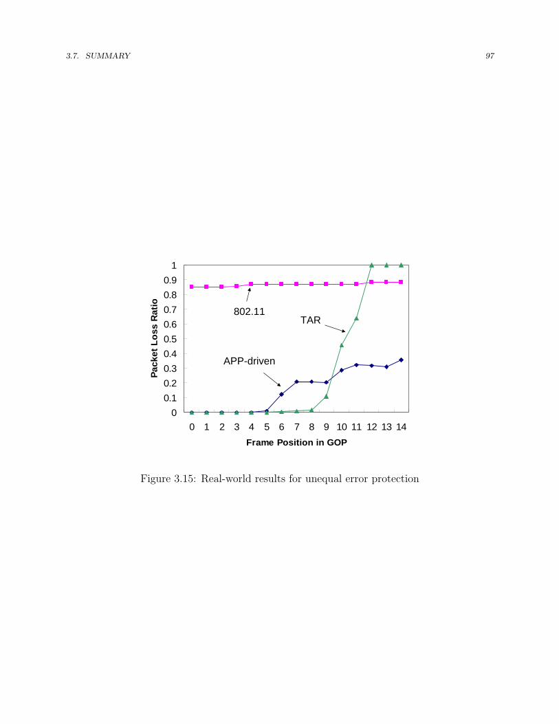
3.7. SUMMARY 97
00.10.20.30.40.50.60.70.80.9
1
0 1 2 3 4 5 6 7 8 9 10 11 12 13 14Frame Position in GOP
Pack
et L
oss
Rat
io
CARNon-CARZakhor*
802.11
APP-driven
TAR
Figure 3.15: Real-world results for unequal error protection

3.7. SUMMARY 98PSNR or the Y component
0
5
10
15
20
25
30
35
40
1 162 323 484 645 806 967 1128 1289 1450 1611 1772Frame Index
PSN
R (d
B)
802.11
(a) 802.11PSNR or the Y component
0
5
10
15
20
25
30
35
40
1 172 343 514 685 856 1027 1198 1369 1540 1711Frame Index
PSN
R (d
B)
App-driven
(b) The application-driven approach [85]PSNR or the Y component
0
5
10
15
20
25
30
35
40
1 162 323 484 645 806 967 1128 1289 1450 1611 1772Frame Index
PSN
R (d
B)
TAR
(c) TAR
Figure 3.16: Real-world result of PSNR values

99
Chapter 4
Time-based Opportunistic
Retransmission
Having seen the virtues of PRO and TAR, an obvious next step is to combine them so as to
maximize the gain. This chapter presents time-based opportunistic retransmission (PROTAR)
that jointly draws on the strength of TAR and PRO [47]. We begin by describing the basic concept
of PROTAR. We then present a probabilistic analysis of PROTAR, building on the analysis of TAR
and PRO. We elaborate on the protocol design of PROTAR with a focus on how to integrate TAR
into PRO. We then present evaluation results for PROTAR using both PSNR-based measurement
studies and extensive user studies both on a testbed and in the real world. Finally, we summarize
this chapter.
4.1 Basic Concept
Time-based opportunistic retransmission integrates time-based retransmission into the framework
of opportunistic retransmission. Before retransmitting a failed packet, eligible relays check whether
the retransmission deadline has elapsed, and if so, they discard the packet immediately. Time-based
opportunistic retransmission avoids the relaying of late packets that are useless to the destination.
Combining TAR and PRO to achieve PROTAR is however a nontrivial task. One challenge is

4.2. ANALYSIS 100
that it needs consistent use of deadlines across multiple relays, given that the clocks of relays may
not be synchronized. This operation must be low overhead so the gain of time-based relaying is
not compromised. In Section 4.3, we will elaborate on protocol details of PROTAR, including how
we resolve the problem of retransmission deadline distribution. Before doing so, we first present
related work and an analysis for PROTAR.
4.2 Analysis
We present performance analysis from the video application’s perspective in this section. The
packet loss probability of PROTAR can be quantified by substituting (2.6) into (3.2). Similarly,
the packet loss probability of PRO is obtained by substituting (2.6) into (3.11) and the packet loss
probability of mesh networking is obtained by substituting (2.8) into (3.11).
Figure 4.1 gives the analytical comparison results of an N ×N square grid topology (see Fig-
ure 2.3 for an 8 × 8 example). We follow the same setup as used in Section 2.3. The default
long retry limit (= 4) in the 802.11 specification is used for the count-based strategies [1]. The
results indicate that though the rationale behind the improvement differs, TAR and PRO both
reduce the overall loss rates. PROTAR combines the gain of TAR and PRO so it achieves the best
performance.
4.3 Protocol Design
PROTAR is designed to draw on the strength of both TAR and PRO [47]. The source, as specified
in TAR, transmits a packet based on the retransmission deadline carried in the packet. Upon a
failed transmission, if the retransmission deadline has not expired, the current best relay, selected
by PRO, is responsible for retransmitting the packet. This time-based opportunistic retransmission
process continues until either the packet is delivered successfully or the retransmission deadline has
elapsed. If no relay is present or willing to participate, PROTAR automatically falls back to TAR.
Figure 5.1 shows the system diagram of PROTAR. We focus on the key components that directly
relate to the operation of PROTAR. The design of PRO used for data traffic can be found in

4.3. PROTOCOL DESIGN 101
overall loss rate
log2(1/d) PROTAR PRO with retryMesh with retry limit = 3
no relay 0 0.3164 0.539990764 0.539991
1 0.0612 0.127449242 0.323749
2 0.0488 0.100988038 0.323749
3 0.0468 0.099181822 0.323749
4 0.0448 0.096834346 0.323749
5 0.0448 0.096834346 0.323749
0
0.1
0.2
0.3
1 2 3 4 5 6
0
0.1
0.2
0.3
0.4
0.5
0.6
0.7
0.8
0 1 2 3 4 5Network density (-log2δ)
Ove
rall
Loss
Rat
e (P
loss
)
PROTAR
PRO (retry limit = 4)
Mesh (retry limit = 4)
TAR
802.11(retry lmit = 4)
0
0.1
0.2
0.3
0.4
0.5
0.6
0.7
0.8
0 1 2 3 4 5Network density (√N)
Ove
rall
Loss
Rat
e (P
loss
)
PROTAR
PRO (retry limit = 4)
Mesh (retry limit = 4)
TAR
802.11(retry lmit = 4)
Figure 4.1: Loss rate comparison of a N ×N square grid topology in Figure 2.3 with variednode densities (defined as
√N)
Chapter 2.
PROTAR integrates TAR into PRO, which involves the following changes to PRO.
4.3.1 Retransmission from Relays
In the original design of PRO, relays retransmit a failed packet until either the packet is successfully
delivered, discarded by the source or dropped after the retry limit is reached (see Section 2.4.6).
For PROTAR, the criteria when relays terminate retransmission are slightly changed. Specifically,
retransmissions from relays follow the principle of TAR. Relays stop the retransmission process in
response to the following events:
• An ACK frame destined for the source is overheard. This implies successful reception.
• The retransmission deadline of the packet has elapsed. We will describe how relays retrieve
the retransmission deadline in the next subsection.
• A new data packet (i.e. the packet stamped with a larger sequence control number) originated
from the source is overheard.
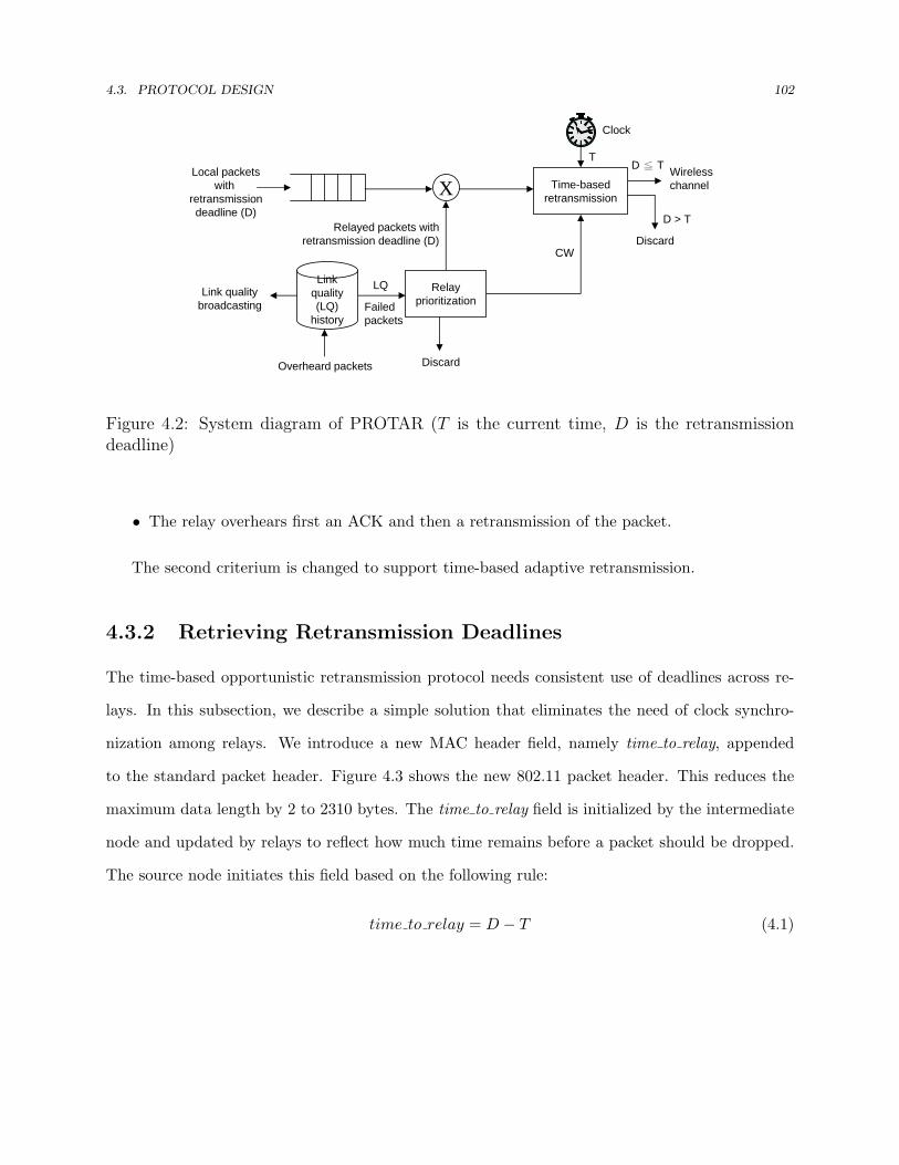
4.3. PROTOCOL DESIGN 102
X
Link quality (LQ)
history
Relay prioritization
Discard
Time-based retransmission
Discard
Wirelesschannel
Local packetswith
retransmissiondeadline (D)
Overheard packets
Link qualitybroadcasting
Clock
Relayed packets withretransmission deadline (D)
D > T
D ≦ T T
LQ
Failedpackets
CW
Figure 4.2: System diagram of PROTAR (T is the current time, D is the retransmissiondeadline)
• The relay overhears first an ACK and then a retransmission of the packet.
The second criterium is changed to support time-based adaptive retransmission.
4.3.2 Retrieving Retransmission Deadlines
The time-based opportunistic retransmission protocol needs consistent use of deadlines across re-
lays. In this subsection, we describe a simple solution that eliminates the need of clock synchro-
nization among relays. We introduce a new MAC header field, namely time to relay, appended
to the standard packet header. Figure 4.3 shows the new 802.11 packet header. This reduces the
maximum data length by 2 to 2310 bytes. The time to relay field is initialized by the intermediate
node and updated by relays to reflect how much time remains before a packet should be dropped.
The source node initiates this field based on the following rule:
time to relay = D − T (4.1)

4.4. PERFORMANCE EVALUATION 103
where D is the retransmission deadline and T is the time that the packet is sent on the air. When
a relay overhears a packet, it reconstructs the retransmission deadline of that packet by:
D = R + time to relay − duration (4.2)
where R is the packet receive time and duration is the value of time needed to transmit the packet.
Relays may retransmit a packet as long as the retransmission deadline is larger than the current
time. Before sending a packet, relays update the time to relay field based on (4.1) so that receivers
of the packet can correctly reconstruct the retransmission deadline.
Figure 4.3: 802.11 MAC frame with time to relay (TTR) field
4.4 Performance Evaluation
In this section, we present visual performance results for PROTAR, based on both objective mea-
surements and user studies. We have implemented PROTAR in the Madwifi driver for wireless
NICs based on the Atheros chipset. Again, FlexMAC is used as the development platform for
PROTAR (see Section 5.6.3 for implementation details). We evaluate five transmission techniques:
(1) 802.11, (2) TAR, (3) PRO, (4) PROTAR, and (5) Mesh in both a controlled testbed and in
the real world. For 802.11 and TAR, SampleRate is used for rate adaptation. For Mesh, PRO,
and PROTAR, the highest transmit rate (i.e. 11 Mbps in 802.11b) is always used. The retry limit
is 5 for the count-based retransmission techniques, 802.11, Mesh, and PRO. PRO and PROTAR
follow the same settings of CWmin in Section 2.6.1 for relay prioritization. Mesh uses relays on
the highest-throughput multi-hop path. This is determined by running an exhaustive search for

4.4. PERFORMANCE EVALUATION 104
all possible paths before starting the experiments. We first present PSNR results for different
transmission techniques. We then present subjective evaluation results based on user studies.
4.4.1 Testbed PSNR Results
The test sequence is stefan, encoded in MPEG-4 CIF format at 15 frames/second and 15 frames/GoP
with quantization step size 4. The video application assigns retransmission deadlines according to
the rule in Section 3.5 to offer unequal error protection [38, 37]. With the FIFO queueing discipline,
inter-coded frames will not be transmitted until after the successful deliveries of reference frames.
The source sends UDP encapsulated video packets at the encoding rate. The destination collects a
packet trace that records the received packets. The information contained in the trace is then used
to calculate the distortion of the associated video. For lost packets (either due to erasures or late
arrivals), an error concealment scheme is used: missing blocks are copied from the last correctly
decoded frame.
The testbed scenario contains seven nodes: source, destination, and five relays. The distance
between the source (video server) and the destination (video client) is initialized to 100 meters. Five
relays are uniformly placed between the source and the destination (adjacent relays are spaced at
16.7 meters). The propagation model is log distance path loss with path loss exponent = 2.8. Ricean
fading with K = 3 is added. The retry limit is 5 for the count-based retransmission techniques
which is the optimal setting that yields the highest average PSNR.
The experimental results are given in Table 4.1. With TAR, the system experiences many
fewer late arrivals which leads to better video quality than 802.11 that adopts a fixed retry limit.
In addition, the maximum playback freezing period is bounded by one GoP period (< 1 second)
due to the assignment of equal retransmission deadlines for packets in a GoP. Exploiting relays
boosts the performance further as it increases throughput for video transmission. The results also
indicate the benefit of opportunistically taking advantage of successful deliveries via the direct path
in multi-hop transmissions as we see that PRO outperforms Mesh. Overall, PROTAR achieves the
best performance. These results are consistent with the real-world evaluation results, which we
present in the next subsection.
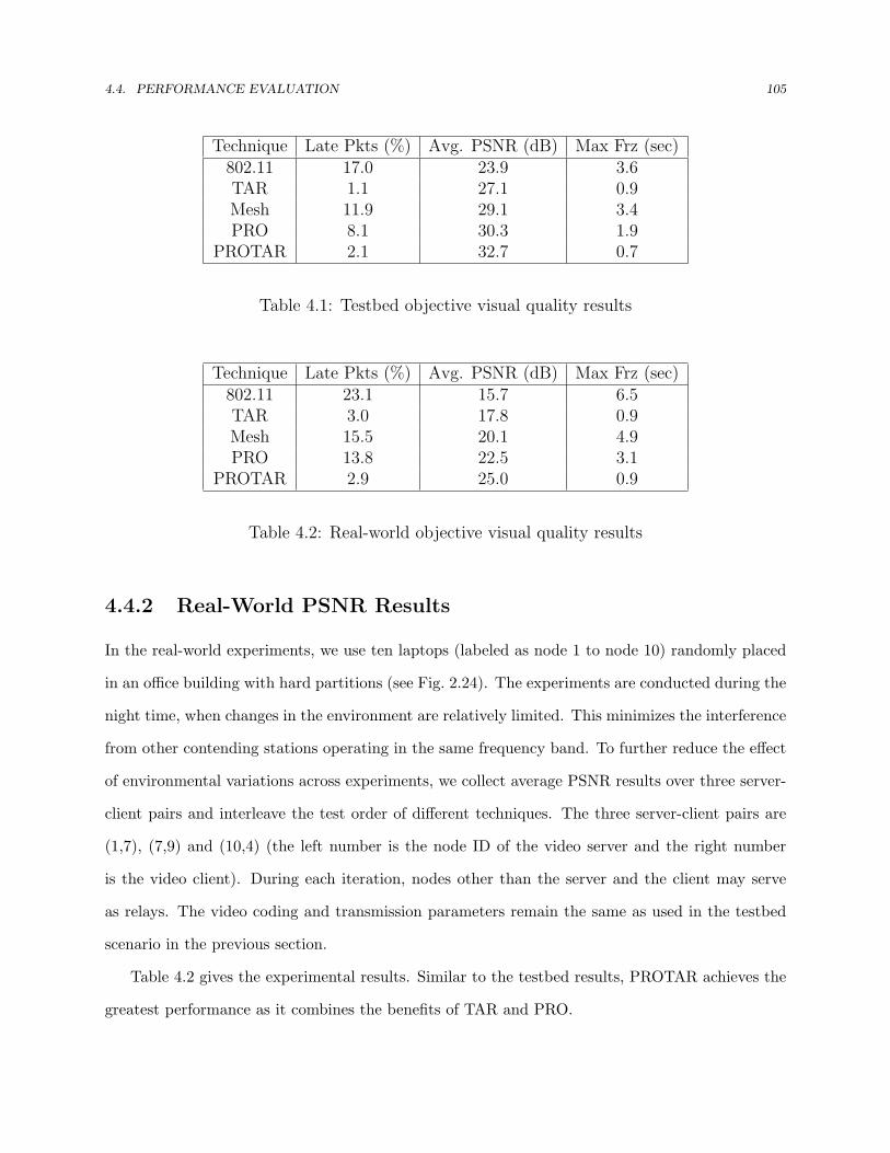
4.4. PERFORMANCE EVALUATION 105
Technique Late Pkts (%) Avg. PSNR (dB) Max Frz (sec)802.11 17.0 23.9 3.6TAR 1.1 27.1 0.9Mesh 11.9 29.1 3.4PRO 8.1 30.3 1.9
PROTAR 2.1 32.7 0.7
Table 4.1: Testbed objective visual quality results
Technique Late Pkts (%) Avg. PSNR (dB) Max Frz (sec)802.11 23.1 15.7 6.5TAR 3.0 17.8 0.9Mesh 15.5 20.1 4.9PRO 13.8 22.5 3.1
PROTAR 2.9 25.0 0.9
Table 4.2: Real-world objective visual quality results
4.4.2 Real-World PSNR Results
In the real-world experiments, we use ten laptops (labeled as node 1 to node 10) randomly placed
in an office building with hard partitions (see Fig. 2.24). The experiments are conducted during the
night time, when changes in the environment are relatively limited. This minimizes the interference
from other contending stations operating in the same frequency band. To further reduce the effect
of environmental variations across experiments, we collect average PSNR results over three server-
client pairs and interleave the test order of different techniques. The three server-client pairs are
(1,7), (7,9) and (10,4) (the left number is the node ID of the video server and the right number
is the video client). During each iteration, nodes other than the server and the client may serve
as relays. The video coding and transmission parameters remain the same as used in the testbed
scenario in the previous section.
Table 4.2 gives the experimental results. Similar to the testbed results, PROTAR achieves the
greatest performance as it combines the benefits of TAR and PRO.

4.4. PERFORMANCE EVALUATION 106
Scale Quality Impairment PSNR Frz Freq5 Excellent Imperceptible 29.5 04 Good Perceptible but not annoying 27.8 03 Fair Slight annoying 23.6 02 Poor Annoying 20.6 0.251 Bad Very annoying 16.1 0.5
Table 4.3: Attributes of visual quality scale. The freezing frequency is defined as the ratioof completely failed frames and the total frames.
4.4.3 User Studies
To obtain objective evaluation results, we set up visual experiments according to the CCIR Rec-
ommendation 500-4 [86]. We conduct performance evaluation using a public streaming server and
media player over various realistic scenarios in the real world [52]. The video server and client
are configured to support a 2-second startup buffer to smooth out delay jitters. The test video
sequences are encoded in MPEG-4 CIF format with 15 frames/sec and 15 frames/GoP. The encod-
ing pattern is IBBPBBPBBPBBPBB. Unless otherwise mentioned, a quantization step size of 4 is
used for all test sequences. Eleven test sequences are used to capture videos with different motion
activities (see Table 4.4 for average bit rates of these sequences).
The video server uses UDP/RTP streaming to transmit video packets. RTP [83] encapsulates
video data into 1400-byte UDP packets. TAR is applied to every RTP packet which can be identified
through pre-configured UDP port numbers. The network driver on the intermediate node detects
a newly-established RTP session via a new synchronization source identifier (SSRC) and it uses
the timestamp field in the RTP header and the knowledge of startup buffering delay to calculate
the retransmission deadline. Relays reconstruct retransmission deadlines based on the procedure
described in Section 4.3.1.
In the subjective tests, assessors grade visual quality for test sequences collected under differ-
ent transmission techniques. The visual quality scale is a subjective assessment metric which is
expressed as a single number in the range from 1 to 5, where 1 is the lowest perceived quality,
and 5 is the highest. Before conducting the subjective tests, a calibration procedure is performed

4.4. PERFORMANCE EVALUATION 107
0
1
2
3
4
5
6
News Hallway Container Foreman City Crew Bus Football Harbour Stefan MobileSequence Name
Vis
ual Q
ualit
y
802.11 TAR Mesh PRO PROTAR
Figure 4.4: Result of video quality for the single session scenario
to mitigate perceptual variations among assessors: each assessor is presented with five video clips,
labeled from scale 1 to 5. The five video clips are created with different degrees of artifacts (i.e.
frame freezes, motion-jitter, blockiness, and variation in visual quality). Table 4.3 shows the at-
tributes of the five pre-rated video clips. During the evaluation, assessors view the test sequences
in the original CIF format and vote the sequences following the scoring principle advised in the
calibration phase. Voting with a decimal fraction is allowed. Each iteration lasts 60 seconds. The
actual technique in use is hidden from the assessors and the order of these techniques is randomized
to avoid expectation of a trend in the visual quality. Each sequence is rated by five assessors. Note
that small differences in the results do not matter because of the limited number of assessors.
Single Session
Our first scenario is a singe video session. The setup is the same as the real-world experiments in
the objective tests (see Section 4.4.2). Figure 4.4 shows the average visual quality over the three
server-client pairs. The performance difference becomes obvious as the video bit rate increases. For
the most part, TAR outperforms 802.11 and PRO outperforms Mesh which outperforms 802.11.
The performance between TAR and PRO is sequence dependent. Nevertheless, PROTAR always
gives the greatest performance. These results are generally consistent with the objective test results.

4.4. PERFORMANCE EVALUATION 108
0
1
2
3
4
5
6
News Hallway Container Foreman City Crew Bus Football Harbour Stefan MobileSequence Name
Vis
ual Q
ualit
y
802.11 TAR Mesh PRO PROTAR
(a) Average visual quality of the highest-rated session
0
1
2
3
4
5
6
News Hallway Container Foreman City Crew Bus Football Harbour Stefan MobileSequence Name
Vis
ual Q
ualit
y
802.11 TAR Mesh PRO TARPRO
(b) Average visual quality of the lowest-rated session
Figure 4.5: Result of video quality for the concurrent session scenario
Concurrent Sessions
Next we study a scenario with multiple concurrent sessions. The three server-client pairs used
in the single session case are now running concurrently. To sustain multiple concurrent streams,
test sequences with quantization step size 8 are used. The rest of the coding parameters and
experimental settings remain the same as in the single session case.
Figure 4.5 shows the average video quality for the highest-rated and the lowest-rated session.
Similar to the single session results, TAR outperforms 802.11 and PRO outperforms Mesh. Among

4.4. PERFORMANCE EVALUATION 109
0
1
2
3
4
5
6
News Hallway Container Foreman City Crew Bus Football Harbour Stefan MobileSequence Name
Vis
ual Q
ualit
y
802.11 TAR Mesh PRO PROTAR
Figure 4.6: Result of video quality for the single session scenario with mobile client
all, PROTAR performs the best. Moreover, we observe that the relay-based methods, PRO, Mesh,
and PROTAR usually outperform the non-relay methods, TAR and 802.11 in this scenario. After
further investigation, we found the following reasons jointly lead to this outcome. First, through-
put improvement due to relaying becomes more obvious when multiple sessions are running con-
currently. Second, for 802.11 and TAR, rate adaptation occasionally misinterprets collisions to
poor link quality and unnecessarily reduces the transmit rate, which leads to inefficient use of the
channel [57]. Third, rate adaptation under an equal channel access policy results in dispropor-
tional transmission time which penalizes flows with high transmit rates [87]. In Figure A.1(a), the
quality degradation in TAR and 802.11 is a result of this. Nonetheless, TAR is still useful but the
achievable performance is limited by the aforementioned phenomenon.
Single Session with a Mobile Client
In this scenario, node 1 serves as the video server, streaming video data to a mobile client. The video
client is moving along the hallway with a walking speed of about 1.5 m/sec. The trajectory is shown
as the dashed line in Figure 2.24. Figure 4.6 shows the average visual quality result. Differing from
the stationary scenarios, 802.11 performs extremely poorly over all the video sequences, even in cases
of low-bit rate videos. We found that the reason is that the video client sometimes passed through
an out-of-reach region where it can hardly connect to the video server (e.g. a spot near room B20 in

4.4. PERFORMANCE EVALUATION 110
0
1
2
3
4
5
6
News Hallway Container Foreman City Crew Bus Football Harbour Stefan MobileSequence Name
Vis
ual Q
ualit
y
802.11 TAR Mesh PRO PROTAR
Figure 4.7: Result of video quality for the single session scenario in a dynamic environment
Figure 2.24). During the out-of-reach period, the 802.11 MAC discards packets after reaching the
retry limit so video playback freezes. However, with TAR, failed packets are persistently retried as
long as the retransmission deadline has not elapsed. This is why TAR performs significantly better
than 802.11. We also observe that relays help connect out-of-reach nodes, and the agility of PRO
leads to a better performance over Mesh. Again, PROTAR achieves the best performance among
all.
Single Session in a Dynamic Environment
Our final scenario is an open space student lounge with ten randomly placed laptops (see Fig-
ure 2.28). The tests are conducted during the day time so students come and go frequently. This
creates a lot more movement in the environment. Three server-client pairs, (6,10), (8,6) and (3,7)
run separately. The results are averaged over three server-client pairs to reduce environmental
variation across experiments.
Figure 4.7 shows the average visual quality result. In comparison with the office building
scenario, PRO significantly outperforms TAR and 802.11 across all the test sequences, including
the low-bit rate videos. This suggests that PRO is very useful in such a dynamic environment.
Again, when relays are not available, the adoption of TAR is still helpful. Among all, PROTAR
achieves the best performance.
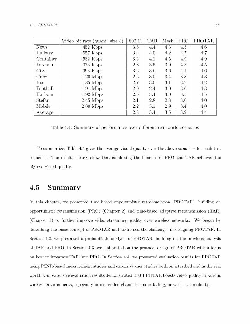
4.5. SUMMARY 111
Video bit rate (quant. size 4) 802.11 TAR Mesh PRO PROTARNews 452 Kbps 3.8 4.4 4.3 4.3 4.6Hallway 557 Kbps 3.4 4.0 4.2 4.7 4.7Container 582 Kbps 3.2 4.1 4.5 4.9 4.9Foreman 973 Kbps 2.8 3.5 3.9 4.3 4.5City 993 Kbps 3.2 3.6 3.6 4.1 4.6Crew 1.20 Mbps 2.6 3.0 3.4 3.8 4.3Bus 1.85 Mbps 2.7 3.0 3.1 3.7 4.2Football 1.91 Mbps 2.0 2.4 3.0 3.6 4.3Harbour 1.92 Mbps 2.6 3.4 3.0 3.5 4.5Stefan 2.45 Mbps 2.1 2.8 2.8 3.0 4.0Mobile 2.80 Mbps 2.2 3.1 2.9 3.4 4.0Average 2.8 3.4 3.5 3.9 4.4
Table 4.4: Summary of performance over different real-world scenarios
To summarize, Table 4.4 gives the average visual quality over the above scenarios for each test
sequence. The results clearly show that combining the benefits of PRO and TAR achieves the
highest visual quality.
4.5 Summary
In this chapter, we presented time-based opportunistic retransmission (PROTAR), building on
opportunistic retransmission (PRO) (Chapter 2) and time-based adaptive retransmission (TAR)
(Chapter 3) to further improve video streaming quality over wireless networks. We began by
describing the basic concept of PROTAR and addressed the challenges in designing PROTAR. In
Section 4.2, we presented a probabilistic analysis of PROTAR, building on the previous analysis
of TAR and PRO. In Section 4.3, we elaborated on the protocol design of PROTAR with a focus
on how to integrate TAR into PRO. In Section 4.4, we presented evaluation results for PROTAR
using PSNR-based measurement studies and extensive user studies both on a testbed and in the real
world. Our extensive evaluation results demonstrated that PROTAR boosts video quality in various
wireless environments, especially in contended channels, under fading, or with user mobility.

112
Chapter 5
Implementation
This chapter presents implementations details of TAR, PRO, and PROTAR. This is a challenging
task because most protocol-related operations, e.g. adaptive transmission, reside in the hardware
which is not generally accessible. To implement the proposed protocols, we developed a host-based
protocol development platform, FlexMAC, for wireless NICs based on the Atheros chipset [77].
FlexMAC offers a number of controls in the host that are useful for developing and evaluating
CSMA-like protocols. In the remainder of this chapter, we first examine FlexMAC in a general
context. We begin by introducing the background of FlexMAC, followed by discussion of related
work. We then elaborate on the design details. We present main design challenges and solutions.
We demonstrate the precision of FlexMAC by comparing it with an 802.11 hardware MAC. Finally,
we describe how we leverage FlexMAC to implement PRO, TAR, and PROTAR in the host, followed
by a summary of this chapter.
5.1 Background
Developing and evaluating wireless protocols is challenging because it requires flexible wireless net-
work hardware, which is not commonly available. To this end, developers have embraced simulation
to support their work. Simulation is widely used but it often lacks physical layer accuracy, which
can lead to incorrect conclusions [88]. This is especially true if the behavior or performance of the

5.1. BACKGROUND 113
protocol or system feature under study is very sensitive to physical layer effects.
To attain experimental realism while preserving flexibility, some researchers have turned to
Software Defined Radios (SDR) [89]. SDRs are fully programmable, but they also offer a number
of challenges for protocol developers. For networking researchers, the learning curve for SDR
platforms is still quite steep. Moreover, the processing and bus transfer delays inherent to SDRs
present unique challenges for MAC protocol development [90] and building standard compliant
protocols (such as 802.11) on SDRs remains difficult. Finally, SDRs are still quite expensive,
making it difficult to run large scale experiments. So while SDRs are a promising technology, they
are not a good solution for all styles of protocol research.
To conduct realistic wireless experiments, an alternative is to use commodity hardware as an
inexpensive platform for prototyping wireless MAC protocols [91, 92, 93]. Commodity hardware
typically only provides partial control over the MAC and PHY layers, but for certain classes of
protocols this is sufficient and very useful [93]. Moreover, with rapid advance in computing tech-
nologies, i.e. faster PCs and higher speed I/O buses, it is increasingly possible to move more
functionality, including more time-critical functions, from the network interface card to the host.
This suggests that commodity hardware can be an appealing option in certain circumstances.
In this chapter, we present FlexMAC, a flexible software platform for developing and evaluating
CSMA protocols. FlexMAC uses a commodity 802.11a/b/g wireless card with a chipset manu-
factured by the Atheros Corporation along with the open-source Madwifi driver [94]. FlexMAC
allows flexible host-based implementations of retransmission, backoff, and timing of transmissions
for 802.11-like protocols. Because the implementation leverages standard 802.11 hardware, it is
relatively easy to have the protocols coexist or even interoperate with 802.11. If interoperability
can be sacrificed, it is likely to make even more radical changes, e.g. allowing the host to generate
acknowledgements. Such a platform is useful because 802.11 is still an active research area and it
can be used to evaluate protocol features that are not necessarily specific to 802.11 such as TAR,
PRO, and PROTAR. There is ample scope for improvement in areas like quality of service, fairness,
performance, etc.

5.2. RELATED WORK 114
5.2 Related Work
In terms of host-based platforms, SoftMAC [91] and MadMAC [92] are the most similar work in
the literature. They also adopt the Atheros chipset along with the Madwifi driver, so they bear
some resemblance to the methodology used in FlexMAC. SoftMAC and MadMAC try to broaden
the range of MAC protocols that can be supported by turning the platform into a generic testbed.
They have successfully shown that, in addition to CSMA protocols, they can use 802.11 hardware
to build non-CSMA protocols such as TDMA or MultiMAC [93]. However, it is not clear how
the performance of a SoftMAC/MadMAC-based system compares to a hardware implementation
because little information about timing is revealed. Our work identifies and measures the bus delay
and interrupt latency, and adopts the idea of polling and spin wait to achieve precise timing. Unlike
prior work, we focus on 802.11-style protocols, i.e. various variants of CSMA. Specifically, we allow
flexible host-based implementations of retransmission, backoff, and timing of transmissions. Such
a platform is useful because 802.11 is still an active research area and it can be used to evaluate
protocol features that are not necessarily specific to 802.11. There is ample scope for improvement
in areas like quality of service, fairness, performance, etc.
Besides host-based platforms, there are other tools used for wireless network evaluation, for
example, testbeds, simulation, trace-driven analysis, and modeling. All of them have different
limitations and advantages.
5.3 Design
FlexMAC offers a number of controls in the host that facilitate a variety of wireless MAC protocol
research. Examples of the types of research that FlexMAC can support include user-defined backoff
mechanisms to boost throughput [95], to reduce collisions [96], to provide differentiated services [97],
to perform fairness provisioning [87] or to detect/isolate selfish nodes [98] in both ad hoc and
infrastructure networks. FlexMAC allows the use of flexible retransmission policies that users
can adapt based on different needs, such as unequal error protection for streaming media [20], or
adaptive FEC coding to deal with channel dynamics [16]. Furthermore, if interoperability with

5.3. DESIGN 115
Network (socket)
Frame Dispatcher
TXController
Frame Scheduler
ISR
WNIC (retry/backoff off and promiscuous mode)
Host
packet pool
HW
System Diagram
frame sentframe rcvd
data packets
NAV
control packets (flexible mode)
Figure 5.1: System Diagram of FlexMAC
802.11 is not a must, FlexMAC is able to make more radical changes (in the ACK response,
RTS/CTS exchange, etc.), which is useful in, for example, rate adaption policies that rely on
modified RTS/CTS to carry link quality information [68]. From a high-level perspective, FlexMAC
supports the following features on a per-packet basis:
• User-defined backoff procedures.
• Adaptive retransmission (allow users to adapt the retry count as well as make changes in
retried packets).
• Timing of transmissions.
• Transactions of control messages if interoperability with 802.11 can be sacrificed.
• Traffic monitoring and capturing.
FlexMAC uses a commodity 802.11a/b/g networking card with a chipset manufactured by the
Atheros Corporation along with the open-source Madwifi driver [94]. Our design of FlexMAC
leverages the flexibility of Atheros hardware to build customized features on top of it. Specifically,
we move several hardware-based functions to the host and offer users the opportunity to replace

5.3. DESIGN 116
these functions based on their needs. With the rapid advance in computing technologies, hosts can
perform some tasks that were previously done in hardware.
Figure 5.1 shows the system diagram of FlexMAC. We configure the hardware to run in the
promiscuous mode. This forces the hardware to pass all the packets, including control messages
(e.g. ACK) as well as those that are not destined for the station itself, to the host. Running in the
promiscuous mode allows the host to perform virtual carrier sense as well as carry out transactions
of control messages. A more detailed description is presented in Section 5.4.
FlexMAC provides two operational modes. The first is an “interoperable” mode that uses the
802.11 IFS. FlexMAC systems operating in this mode can potentially interoperate with 802.11
stations. In the interoperable mode, retransmission and backoff processes are moved to the host so
they must be disabled in the hardware. This can be easily achieved by setting the retry limit to zero
and the minimal and maximal contention window size to one [91, 92]. The second is a “flexible”
mode, which uses larger inter-frame spacings. This makes it possible for the host to support the
transaction of control messages such as ACK response or RTS/CTS exchange. FlexMAC systems
operating in the flexible mode are not interoperable with 802.11 stations (due to larger IFS), but
they respect each other so they can coexist in the same frequency band. In the flexible mode, we
have to disable the automatic generation of control messages in hardware. Fortunately, Atheros
hardware allows us to do so using its on-chip configuration registers.
In the host, three modules are added on top of the original Madwifi driver. The transmission
controller prepares the next packet to be transmitted, which can be either a retransmission of the
previous packet, an initial attempt of the head-of-line packet in the packet pool, or a control message
in the flexible mode, depending on the logic of the protocol. The transmission controller posts the
transmission request to the frame scheduler and waits for the completion of the transmission. The
transmission controller allows at most one packet in the hardware queue and instead keeps a queue
on the host to buffer incoming packets from the kernel.
The frame scheduler is responsible for delivering data packets to the hardware based on the
schedule of transmissions specified by the transmission controller. If backoff freezing is required,
the frame scheduler delays the transmission when the channel is sensed busy. This operation is

5.4. CHALLENGES AND SOLUTIONS 117
important to CSMA protocols with collision avoidance. We will describe how the frame scheduler
preforms precise scheduling in the next section.
The frame dispatcher sends packets that are destined for the station itself to the kernel, as in
the original Madwifi driver. When operating in the flexible mode, it passes the control messages
to the transmission controller so it can respond to them properly. For every received packet, the
frame dispatcher retrieves NAV (Network Access Vector) information from the packet header and
passes the information to the frame scheduler. The NAV is a value that indicates to a station the
amount of time that remains before the medium will become available. Even if the medium does
not appear to be busy based on physical carrier sense, the station cannot transmit during this time
interval. The frame scheduler may need to adjust the scheduling of transmission based on the NAV
values.
Overall, the implementation of FlexMAC involves three challenges. First, the frame scheduler
has to enforce precise scheduling of transmissions. This is hard since the communication time
between the host and NIC is not negligible. Second, for dependent transmissions, the transmission
controller has to accommodate the interrupt latency of the current transmission before it can make
a decision about the next transmission. Finally, the host needs to obtain channel busy information
(e.g. for backoff freezing). We elaborate on our solutions in the next section.
5.4 Challenges and Solutions
Supporting precise scheduling in the host involves two challenges. First, Linux is inherently not
a real-time operating system. On most platforms, the basic scheduling quantum of kernel timers
(jiffies) is ten milliseconds. This is not sufficient to support precise scheduling in most cases. Second,
the scheduling must compensate for bus delay, which involves time needed to move a packet between
the host’s memory and SRAM on the NIC and processing overheads in the hardware.

5.4. CHALLENGES AND SOLUTIONS 118
AIR
HW
HOSTPacket posted to the HW
Packet arrived at HW
Packet sent to the air
Interrupt of TX statust0
t1t2
t6
AIR
HW
HOST
Transmitter
Receiver
Packet arrived at HW
Packet arrived at driver
Packet sent to the kernel
t3
t5t7
ACK sent to the air
ACK arrived at HW
t4transmission time
t3
Figure 5.2: Timing of a transmission (ignoring propagation delay)
5.4.1 Supporting Precise Scheduling
For timing in Linux, the frame scheduler invokes a timer tasklet whenever a scheduling of a trans-
mission is requested. The timer tasklet continuously polls the Time Synchronization Function
(TSF) counter on the NIC to decide whether the schedule of the transmission is due. The TSF
clock has microsecond precision. The timer tasklet constantly reschedules itself so that it does not
block the execution of other time critical tasks. When the schedule of a transmission is approach-
ing, the timer tasklet employs spin waits to assure the preciseness of timing. Our evaluation shows
that using register polling has very good performance, although the resulting scheduling still has
some jitter (see Section 5.5.1). Such a busy polling method trades computation overhead for timing
precision. Fortunately, as we will show later, existing computer technologies can accommodate this
overhead in the host. The complexity-precision tradeoff is the main difference between the host-
based and hardware-based implementation. Currently we are investigating whether we can use the
realtime kernel patches to support microsecond precision [99].
Figure 5.2 illustrates the timing of a transmission. If we want to support precise scheduling, the
driver must schedule a transmission ahead to compensate for bus delay (t2−t0). To assess bus delay,
we obtain t0 by recording the value of TSF clock right before the packet is posted to the hardware.
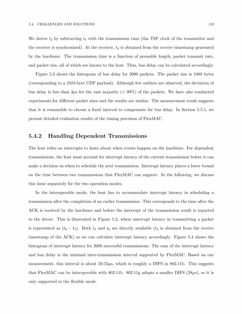
5.4. CHALLENGES AND SOLUTIONS 119
We derive t2 by subtracting t4 with the transmission time (the TSF clock of the transmitter and
the receiver is synchronized). At the receiver, t4 is obtained from the receive timestamp generated
by the hardware. The transmission time is a function of preamble length, packet transmit rate,
and packet size, all of which are known to the host. Thus, bus delay can be calculated accordingly.
Figure 5.3 shows the histogram of bus delay for 2000 packets. The packet size is 1088 bytes
(corresponding to a 1024-byte UDP payload). Although few outliers are observed, the deviation of
bus delay is less than 3µs for the vast majority (> 99%) of the packets. We have also conducted
experiments for different packet sizes and the results are similar. The measurement result suggests
that it is reasonable to choose a fixed interval to compensate for bus delay. In Section 5.5.1, we
present detailed evaluation results of the timing precision of FlexMAC.
5.4.2 Handling Dependent Transmissions
The host relies on interrupts to learn about when events happen on the hardware. For dependent
transmissions, the host must account for interrupt latency of the current transmission before it can
make a decision on when to schedule the next transmission. Interrupt latency places a lower bound
on the time between two transmissions that FlexMAC can support. In the following, we discuss
this issue separately for the two operation modes.
In the interoperable mode, the host has to accommodate interrupt latency in scheduling a
transmission after the completion of an earlier transmission. This corresponds to the time after the
ACK is received by the hardware and before the interrupt of the transmission result is reported
to the driver. This is illustrated in Figure 5.2, where interrupt latency in transmitting a packet
is represented as (t6 − t4). Both t4 and t6 are directly available (t4 is obtained from the receive
timestamp of the ACK) so we can calculate interrupt latency accordingly. Figure 5.4 shows the
histogram of interrupt latency for 2000 successful transmissions. The sum of the interrupt latency
and bus delay is the minimal inter-transmission interval supported by FlexMAC. Based on our
measurement, this interval is about 50-55µs, which is roughly a DIFS in 802.11b. This suggests
that FlexMAC can be interoperable with 802.11b. 802.11g adopts a smaller DIFS (28µs), so it is
only supported in the flexible mode.
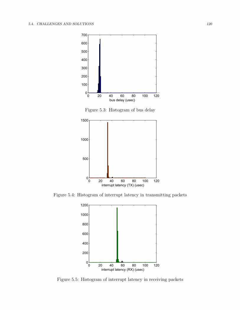
5.4. CHALLENGES AND SOLUTIONS 120
0 20 40 60 80 100 1200
100
200
300
400
500
600
700
bus delay (usec)
Figure 5.3: Histogram of bus delay
0 20 40 60 80 100 1200
500
1000
1500
interrupt latency (TX) (usec)
Figure 5.4: Histogram of interrupt latency in transmitting packets
0 20 40 60 80 100 1200
200
400
600
800
1000
1200
interrupt latency (RX) (usec)
Figure 5.5: Histogram of interrupt latency in receiving packets

5.4. CHALLENGES AND SOLUTIONS 121
In the flexible mode, FlexMAC also handles transactions of control messages. The host has to
deal with interrupt latency in receiving packets, which refers to the time after a request message
(e.g. data packets or RTS messages) is received by the hardware and before the interrupt of the
reception of that message is reported to the driver. The host has to accommodate this latency
before it can properly respond to the message. In Figure 5.2, the interrupt latency of reporting the
reception of a data packet is (t5−t3). Again, we measured this quantity and we show the histogram
of the results in Figure 5.5. The interrupt latency together with the bus delay are the minimal
response interval supported by FlexMAC. Based on our measurement, this interval is about 70µs.
This value is larger than a SIFS (10µs) so FlexMAC systems operating in the flexible mode can
not interoperate with 802.11 stations. However, they respect each other so they can still coexist in
the same frequency band.
5.4.3 Determining the State of Use of the Channel
The 802.11 standard requires sending stations to freeze the backoff decrement process when the
medium is sensed busy, indicated by physical carrier sense or virtual carrier sense. For virtual
carrier sensing, the implementation is straightforward since the NAV information is carried in the
packet header which we have full access to when the card is running in the promiscuous mode. We
can easily adjust the transmission schedule by the amount specified in the NAV.
The implementation of physical carrier sense relies on support from the hardware. Fortunately,
we found that Atheros hardware exports information of channel assessment results via its on-chip
registers [100]. Inside the frame scheduler module, the timer tasklet polls the corresponding register
continuously to acquire the current state of the channel. It increments the transmission schedule
with the amount of the busy period and resynchronizes the slot boundary once the channel state
changes from busy to idle. In Section 5.5, we present evaluation result in various contending
scenarios. The results show that backoff freezing is properly performed.

5.5. PRECISION OF FLEXMAC 122
5.5 Precision of FlexMAC
This section studies the precision of FlexMAC by comparing its performance for a host-based
802.11b implementation (SW MAC) with the hardware-based implementation (HW MAC). The
purpose of the evaluation is to quantify the performance difference between the two. To collect
reliable results, we perform experiments on the CMU wireless network emulator [67]. On the
emulator, we include a monitor node to collect statistics of traffic in the network. The channel
between the monitor node and test nodes has low path loss so the monitor can overhear all traffic
without errors. The monitor node runs a sniffer process that records a tuple for each packet it
overhears into a log file. The tuple includes source address, destination address, sequence number,
hardware-generated receive timestamp, packet size, transmit rate, and preamble length. The log
file is used offline to generate results about timing precision.
To do a fair comparison, we switched off Atheros proprietary performance enhancement features
in the Madwifi driver. We set the retry limit to 7, the minimal and maximal contention window
size to 31 and 1023, unless otherwise specified. The RTS/CTS exchange and rate adaptation are
disabled.
DIFS DATA
backoff periodACK
DATA
SIF
S
DIFS DATA
residualbackoff period
ACK
channel busy
(a)
DIFS DATA
backoff periodACK
DATA
SIF
S
DIFS DATA
residualbackoff period
ACK
channel busy
DIFS
(b)
Figure 5.6: Inter-frame timing (a) in a clear channel and (b) with contention traffic

5.5. PRECISION OF FLEXMAC 123
5.5.1 Timing Precision
We start with a simple scenario that includes three wireless stations: sender, monitor and receiver
in a clear channel. The sending station continuously sends back-to-back UDP packets to the
destination for one minute. The size of the UDP packets is 1024 bytes.
Ideally, the use of a clear channel results in no collisions and no errors. Hence, consecutive
transmissions (including the ACK) are spaced out with a DIFS plus the backoff interval drawn
from a uniform distribution ranging from zero to the size of the initial contention window (see
Figure 5.6(a)). To simplify the offline analysis, SW MAC uses a constant backoff interval of 16
time slots for every transmission. This means that the inter-frame interval should be fixed at 370µs
(802.11b) if perfect timing is fulfilled. The HW MAC does not allow us to change the backoff
distribution. Hence the possible inter-frame intervals range from 50µs to 670µs in 20µs intervals.
We simply use the value that is closest to the measurement as the correct value for the HW MAC.
To evaluate timing precision, we compare the inter-frame interval obtained from the log file
collected by the monitor node with the theoretic value. The experimental inter-frame interval can
be derived using the receive timestamp of consecutive transmissions and the transmission time. The
transmission time is a function of preamble length, packet size, and preamble length, which are all
recorded in the log file. Since the timestamp is generated by the hardware with one-microsecond
precision, the measurement error is ≤ 2µs.
Figure 5.7(a)-(b) shows the cumulative distribution function (CDF) of timing error (difference
between the experimental and theoretical results). The SW MAC, though it is less accurate than
the HW MAC, represents a reasonably good precision. More than 90% of the transmissions have
a timing error ≤ 2µs. Moreover, near 99.5% of the transmissions have an error below 20µs. This
suggests that the resulting timing precision of SW MAC is sufficient for 802.11b, which adopts a
slot time of 20µs.
Now we consider a more realistic scenario which includes a contending station. This station
continuously broadcasts UDP traffic to the network. The contending traffic forces the sending
station to freeze the backoff decrement process when the channel is busy (see Figure 5.6(b)). This
scenario helps us to verify our implementation of backoff freezing described in Section 5.4.3.
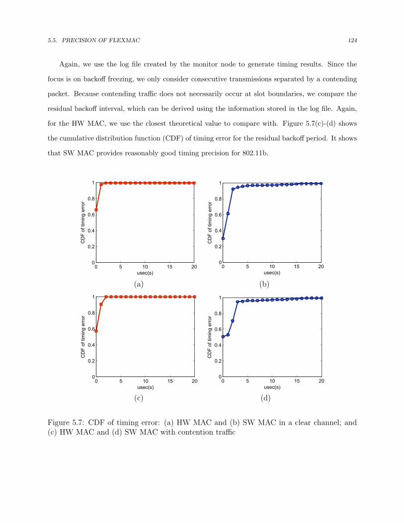
5.5. PRECISION OF FLEXMAC 124
Again, we use the log file created by the monitor node to generate timing results. Since the
focus is on backoff freezing, we only consider consecutive transmissions separated by a contending
packet. Because contending traffic does not necessarily occur at slot boundaries, we compare the
residual backoff interval, which can be derived using the information stored in the log file. Again,
for the HW MAC, we use the closest theoretical value to compare with. Figure 5.7(c)-(d) shows
the cumulative distribution function (CDF) of timing error for the residual backoff period. It shows
that SW MAC provides reasonably good timing precision for 802.11b.
0 5 10 15 200
0.2
0.4
0.6
0.8
1
usec(s)
CD
F of
tim
ing
erro
r
0 5 10 15 200
0.2
0.4
0.6
0.8
1
usec(s)
CD
F of
tim
ing
erro
r
(a) (b)
0 5 10 15 200
0.2
0.4
0.6
0.8
1
usec(s)
CD
F of
tim
ing
erro
r
0 5 10 15 200
0.2
0.4
0.6
0.8
1
usec(s)
CD
F of
tim
ing
erro
r
(c) (d)
Figure 5.7: CDF of timing error: (a) HW MAC and (b) SW MAC in a clear channel; and(c) HW MAC and (d) SW MAC with contention traffic

5.5. PRECISION OF FLEXMAC 125
SW MAC HW MACsession mean(Mbps) std(Kbps) mean(Mbps) std(Kbps)1 2.10 32.1 2.09 28.82 2.05 35.1 2.09 21.23 2.15 26.4 2.12 24.2total 6.29 6.30
(a) UDP Throughput
SW MAC HW MACsession mean(Mbps) std(Kbps) mean(Mbps) std(Kbps)1 1.93 61.3 1.95 41.02 1.97 38.2 1.96 32.53 2.01 47.9 1.97 29.7total 5.91 5.88
(b) TCP Throughput
Table 5.1: Throughput results
5.5.2 Throughput
To gain a better understanding of how SW MAC performs in practice, we now consider high level
performance metrics. The backoff parameters of the SW MAC are restored to the default values.
Ideally, the SW and HW-based implementations should behave similarly. First, we compare TCP
and UDP throughput for both implementations. Throughput is a useful metric that indicates
whether the host can accommodate the computational requirement while maintaining performance
comparable to the hardware. We use the benchmark utility iperf to measure throughput in a multi-
session scenario: three sending stations communicate with the other three receiving stations using
UDP or TCP connections in a clear channel. Each iperf run generates throughput results over a
10-sec time windows. Each run lasts for 10 minutes.
Table 5.1 shows the UDP and TCP throughput result. In general, SW MAC performs very
close to HW MAC, although SW MAC has a slightly higher deviation, particularly for TCP.
Nevertheless, the deviation is not considerable. We have conducted the same experiments with
different combinations of senders and receivers. All the results are similar.

5.5. PRECISION OF FLEXMAC 126
SW MAC HW MACTotal Throughput (Mbps) 4.79 4.03Num. of total TXs 4329 4898Num. of failed TXs 1404 2421Packet Error Rate (%) 32.4 49.4
Table 5.2: Hidden terminal results
Using an emulated clear channel, we assume failed transmissions are due to collisions. Collision
ratio is a useful metric that reveals how good the backoff process is implemented. Figure 5.8 shows
the result with different numbers of concurrent sessions. Again, SW MAC performs very close to
HW MAC. Overall, TCP has a higher collision ratio than UDP because TCP is bidirectional (all
stations are active transmitters).
5.5.3 Coexistence with Hardware MAC and Software MAC
Now we look at a mixed scenario in which three sender-receiver pairs coexist: one pair uses SW
MAC and the other two pairs use HW MAC. Figure 5.9 shows the result of bandwidth sharing
across the three sessions. Overall, HW MAC and SW MAC have similar performance, although
the SW MAC session obtains a slightly smaller share of the bandwidth than the two HW MAC
sessions, especially in the case of TCP. This unfairness is a result of the use of busy polling by
the SW MAC, which does not always offer perfect timing of scheduling as HW MAC does. When
the scheduler delays the scheduling of a transmission, other stations may seize the channel. This
phenomenon becomes more evident in TCP because TCP’s conservative behavior penalizes the
imprecise scheduling more. The throughput loss for the SW MAC session is about 3% of the
bandwidth in TCP.
5.5.4 Hidden Terminal Effect
We end this section with a study of a hidden terminal scenario. In this situation, a sender transmits
to a receiver which can hear a third node (the hidden terminal). However, the transmitter and the
hidden terminal cannot hear each other. This causes collisions at the receiver when the transmitter

5.5. PRECISION OF FLEXMAC 127
0
2
4
6
8
10
12
14
16
18
TCP UDP TCP UDP TCP UDP
1 session 2 sessions 3 sessions
Pac
ket C
ollis
ion
Rat
io (%
)
HW MAC
SW MAC
Figure 5.8: Collision Ratio
33.65 35.06
33.8 34.89
32.56 30.05
0
20
40
60
80
100
UDP TCP
Sha
re o
f BW
(%)
Session 1 (HW) Session 2 (HW) Session 3 (SW)
Figure 5.9: Share of bandwidth in a mixedscenario
Figure 5.10: Histogram of backoff interval
5.6. PROTOCOL IMPLEMENTATION DETAILS 128
and the hidden terminal transmit simultaneously. In this experiment, we ran iperf UDP tests from
the transmitter and the hidden terminal to the receiver simultaneously. We create the hidden
terminal effect by manually increasing path loss between the transmitter and the hidden terminal
such that they can rarely hear each other. We use a clear channel for the connections between the
transmitter and the receiver and between the hidden terminal and the receiver.
Table 5.2 shows the result. The hidden terminal effect is observable from a huge increase in the
packet error rate (PER) even though the path between sender and receiver is clear. Interestingly,
SW MAC achieves a higher throughput than HW MAC. After investigating several possible causes,
we found that the reason is that the Atheros hardware does not conform to the 802.11 standard.
According to [101], if no physical carrier or virtual carrier is detected at the time a retry is scheduled,
Madwifi considers the medium to be free and the sending station retransmits without incurring an
exponential backoff. This implementation used by HW MAC issues retransmissions more quickly,
but it also results in a higher chance of collision. This is especially the case in hidden terminal
scenarios, because the carrier sense process misjudges the medium as uncontended. This results in
poor performance of HW MAC.
To confirm the above analysis, we collected inter-frame intervals for HW MAC using the monitor
node. Figure 5.10 shows the histogram of inter-frame intervals. There are 32 peaks, implying the
contention window size is fixed at 31.
The results shown in this section suggest that FlexMAC is a promising platform for developing
and evaluating 802.11-like protocols. In the next section, we present how we leverage FlexMAC to
implement PRO, TAR, and PROTAR.
5.6 Protocol Implementation Details
We end this chapter by describing how to use FlexMAC for implementing protocols proposed in
this thesis. Readers may refer to [77] for other examples of protocols implemented using FlexMAC:

5.6. PROTOCOL IMPLEMENTATION DETAILS 129
5.6.1 Protocol for Retransmitting Opportunistically (PRO)
Previously, experimentally evaluating a relaying system like PRO would require the use of an SDR-
like solution. Using FlexMAC, we can design and test the protocol in a much easier way. The
implementation of PRO uses the following features offered by FlexMAC:
• Traffic monitoring and sniffering (for relay qualification and relay selection)
• Timing of transmissions (for relay prioritization)
• Adaptive retransmission (for opportunistic retransmission)
Using the feature of traffic monitoring and sniffering, the host collects RSSI statistics from
packets it overhears and detects failed transmissions when it does not hear the corresponding ACK
after a timeout. If the host is an eligible relay, it schedules the transmission of the packet at a
proper time based on its priority; otherwise the packet is discarded. Using the feature of adaptive
retransmission, eligible relays are able to drop out of the contention of a packet once they find the
packet has already been delivered successfully.
5.6.2 Time-based Adaptive Retransmission (TAR)
Using FlexMAC, we can design and test TAR in an easier way. The implementation of TAR uses
the following features offered by FlexMAC:
• Adaptive retransmission (for time-based retransmission)
• Timing of transmissions (for mimicking the standard channel access behavior)
Using the feature of adaptive retransmission, the MAC is able to schedule and issue retrans-
missions if the retransmission deadline of the packet is smaller than the current time, or terminate
retransmission attempts after the retransmission deadline has elapsed. Moreover, the feature of
timing of transmission guarantees packets are transmitted following the standard channel access
behavior.

5.7. SUMMARY 130
5.6.3 Time-based Opportunistic Retransmission (PROTAR)
The implementation of PROTAR is a combination of implementations of PRO and TAR as de-
scribed above.
5.7 Summary
In this chapter, we presented FlexMAC, a wireless protocol development and evaluation platform
based on commodity hardware. FlexMAC targets CSMA wireless protocols and allows customiza-
tion of functions such as backoff, retransmission, packet timing, packet monitoring and sniffering.
We began by discussion of current methodologies for developing and evaluating wireless protocols
that raise the need for a low-cost, flexible, and realistic alternative. In Section 5.3, we elaborated
on the design details of FlexMAC. In Section 5.4, we presented main challenges and solutions in
achieving the host-based design. In Section 5.5, we demonstrated the precision of FlexMAC by com-
paring it with an 802.11 hardware MAC. In Section 5.6, we described how we leverage FlexMAC
to implement PRO, TAR, and PROTAR in the host.

131
Chapter 6
Conclusions and Future Work
Wireless video services have become an essential part of our daily lives, but they also pose a number
of challenges. The specific service requirements of video data and the inherent difficulties of wireless
networking have made wireless video transmission a difficult problem. This thesis proposed Time-
based Opportunistic Retransmission to address the challenges. The proposed solution includes
two building blocks. First, opportunistic retransmission (PRO) employs overhearing nodes, if any,
distributed in physical space to function as relays that retransmit packets in error on behalf of the
source. Second, time-based adaptive retransmission (TAR) leverages application-level information
to avoid the transmission of useless information in the MAC layer. The ultimate solution, PROTAR,
combines the strength of TAR and PRO to further push the performance envelope. In this chapter,
we first provide a detailed description of contributions of this thesis, and then discuss future work
that can be built upon the results of this thesis.
6.1 Contribution
Design, Development and Evaluation of Opportunistic Retransmission
We proposed opportunistic retransmission and designed an opportunistic retransmission protocol
(PRO) that increases individual throughput as well as overall network capacity. Our protocol design
addresses the problems of how nodes coordinate and how nodes assess their suitability to function

6.1. CONTRIBUTION 132
as a relay in an efficient way. Moreover, we pointed out the tradeoff between cross-session fairness
and network-wide throughput. This tradeoff is rarely addressed in cooperative communication-
related work. We also presented an extension of PRO that includes multi-rate capabilities in most
wireless technologies. We found that multi-rate PRO is useful in 802.11g wireless networks where
the highest transmit rate has limited communication range.
To study the efficacy of PRO, we developed the protocol for 802.11 WLANs in commodity
hardware. We conducted a number of testbed and real-world experiments to evaluate PRO in
various scenarios, including a singe session, concurrent sessions, and mobile users. The results
indicate significant gains of PRO in heavily loaded, fading channels or with user mobility. In ad-
dition to performance evaluation, we also studied the issue of fairness across PRO-enabled and
legacy sessions. We found that PRO is actually a fairer and more efficient technique than the rate
adaptation-enabled 802.11. The performance of the preliminary multi-rate opportunistic retrans-
mission protocol that integrates CHARM and PRO was also studied.
Design, Development and Evaluation of Time-based Adaptive Retransmission
We proposed a time-based adaptive retransmission strategy and designed a time-based adaptive
retransmission protocol (TAR) for transmitting delay-sensitive data over wireless networks. We
highlighted the importance of transparency which is often overlooked in prior work and included it
in the protocol design of TAR. We presented a means for assigning retransmission deadlines that
offer unequal error protection. Moreover, we extended the notion of retransmission deadlines from a
temporal metric to a unified indicator that embraces both the perceptual and temporal importance
of video data.
To study the efficacy of TAR, we developed the protocol for 802.11 WLANs in commodity
hardware. In the evaluation, we first studied the transmission behavior of the 802.11 WLAN which
indicates a need for TAR. We then conducted a number of testbed and real-world experiments
to evaluate TAR in various scenarios. We found that TAR responds to channel dynamics more
promptly than 802.11 and application-driven approaches, which leads to a higher visual quality on
the video client side.

6.1. CONTRIBUTION 133
Design, Development and Evaluation of Time-based Opportunistic Retransmis-
sion
We proposed PROTAR that combines time-based adaptive retransmission and opportunistic re-
transmission to further push the performance envelope. The resulting technique is a seamless
integration of the two protocols. To distribute retransmission deadlines from the intermediate node
to wireless relays, we introduced a new header field, time to relay that reflects how much time re-
mains before a packet should be dropped. This eliminates the need of clock synchronization among
relays.
Probabilistic Analysis of the Proposed Protocols
In addition to experimental evaluations, we presented a probabilistic analytical framework for
802.11, TAR, PRO, PROTAR, and a mesh network-based approach that employs relays on the
least-cost path. Our analytical model considers the impact of late arrivals in quantifying video
quality at the video client for different transmission techniques. The analytical results showed that
TAR and PRO outperform 802.11 and mesh networking respectively and PROTAR performs the
best among all. We showed that the analytical results, the emulation testbed results, and the
real-world experimental results are all consistent.
Extensive Experimental Evaluation and User Studies of Subjective Video Quality
In addition to network-wide performance studies, we also conducted extensive user studies to un-
derstand how TAR, PRO, and PROTAR perform from end users’ perspective in practical scenarios.
The evaluation results show that the proposed solutions outperform 802.11 and mesh networking
in variable environments, especially with concurrent sessions and in faded channels.
Host-based Software Development Platform for 802.11-like Protocols
Finally, we developed a flexible development and evaluation platform (FlexMAC) for 802.11-style
protocols using commodity hardware. FlexMAC allows customization of functions such as backoff,
retransmission, and packet timing on a commodity platform which are typically not accessible to

6.2. FUTURE WORK 134
the public research community. We showed that FlexMAC performs equally precisely as an 802.11b
hardware MAC.
6.2 Future Work
6.2.1 Sophisticated Multi-rate Opportunistic Retransmission
In Section 2.5.5, we have presented a preliminary multi-rate PRO protocol to demonstrate the
potential benefit of combining PRO and rata adaptation. While the preliminary multi-rate PRO
exhibits improved performance, further gains can be obtained by a more flexible and more sophis-
ticated design. For example, sources may use a transmit rate higher than that selected by the rate
adaptation algorithm and exploit good relays to retransmit with very high rates when an initial
transmission does not get through. Moreover, the advanced multi-rate PRO does not need to be
built upon CHARM. Other newly proposed rate adaptation protocols (e.g [64] and [102]) may be
considered.
6.2.2 Opportunistic Retransmission with Networking Coding
Network coding is a new paradigm that allows nodes to create and forward “combinations” of
incoming messages, which has been shown to increase throughput [103]. Network coding brings the
main novelty of allowing “processing” of messages at each hop in the network. Each relay is allowed
to mix incoming messages and then to forward the combined packets towards the destination nodes.
The encoding ensures that any destination node can receive with high probability with enough
combinations to recover the original messages.
When the two parties in communication have information to exchange (e.g. a video telephony
scenario), network coding can be employed in combination with opportunistic retransmission to
acquire additional gains. As an example, consider a toy scenario in Figure 6.1 in which two sources
A and B want to exchange information packets, a and b. In the current design, R serves as a relay
for A and B individually. That is, R treats a and b as packets from two independent flows. With
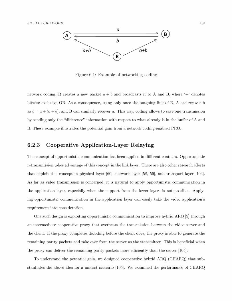
6.2. FUTURE WORK 135
A Ba
b
Ra+b a+b
Figure 6.1: Example of networking coding
network coding, R creates a new packet a + b and broadcasts it to A and B, where ‘+’ denotes
bitwise exclusive OR. As a consequence, using only once the outgoing link of R, A can recover b
as b = a + (a + b), and B can similarly recover a. This way, coding allows to save one transmission
by sending only the “difference” information with respect to what already is in the buffer of A and
B. These example illustrates the potential gain from a network coding-enabled PRO.
6.2.3 Cooperative Application-Layer Relaying
The concept of opportunistic communication has been applied in different contexts. Opportunistic
retransmission takes advantage of this concept in the link layer. There are also other research efforts
that exploit this concept in physical layer [60], network layer [58, 59], and transport layer [104].
As far as video transmission is concerned, it is natural to apply opportunistic communication in
the application layer, especially when the support from the lower layers is not possible. Apply-
ing opportunistic communication in the application layer can easily take the video application’s
requirement into consideration.
One such design is exploiting opportunistic communication to improve hybrid ARQ [9] through
an intermediate cooperative proxy that overhears the transmission between the video server and
the client. If the proxy completes decoding before the client does, the proxy is able to generate the
remaining parity packets and take over from the server as the transmitter. This is beneficial when
the proxy can deliver the remaining parity packets more efficiently than the server [105].
To understand the potential gain, we designed cooperative hybrid ARQ (CHARQ) that sub-
stantiates the above idea for a unicast scenario [105]. We examined the performance of CHARQ

6.2. FUTURE WORK 136
using simulation and found that CHARQ is a promising technique in improving efficiency as well
as reducing delay. In the future, extensive experiments will be needed to assess the efficacy of
CHARQ in diverse real world environments. Moreover, CHARQ can be extended to support mul-
ticast scenarios.
BIBLIOGRAPHY 137
Bibliography
[1] “Part 11: Wireless LAN Medium Access Control (MAC) and Physical Layer (PHY) Specifi-
cations, Ref. ISO/IEC 8802- 11:1999(E), IEEE Std. 802.11-1999,” 1999.
[2] D. E. Smith, “IP TV Bandwidth Demand: Multicast and Channel Surfing,” in Proc. IEEE
Conf. on Computer Commun. (INFOCOM), (Anchorage , Alaska), May 2007.
[3] Wireless Networking in the Developing World: A practical guide to planning and building
low-cost telecommunications infrastructure (2nd ed.). Orlando, FL, USA: Hacker Friendly
LLC., 2007. http://wndw.net/pdf/wndw2-en/wndw2-ebook.pdf.
[4] T. F. L. Porta, T. F. Sabnani, and R. D. Gitlin, “Challenges for Nomadic Computing: Mo-
bility Management and Wireless Communications,” ACM Journal of Nomadic Computing,
no. 1, 1996.
[5] D. Turaga and T. Chen, “Fundamentals of Video Compression: H.263 as an Example,” in A
Book Chapter in Compressed Video over Networks, (New York, NY, USA), Marcel Dekker,
Inc., January 2000.
[6] M. van der Schaar and P. A. Chou, “Error-Resilient Coding and Decoding Strategies,” in A
Book Chapter in Multimedia over IP and Wireless Networks: Compression, Networking, and
Systems, Chapter 1, (Orlando, FL, USA), Academic Press, Inc., 2007.
[7] S. Lin and D. J. Costello, Error Control Coding, Second Edition. Prentice Hall, 2004.

BIBLIOGRAPHY 138
[8] F. Borgonovo and A. Capone, “Efficiency of Error-Control Schemes for Real-Time Wireless
Applications on the Gilbert Channel,” IEEE Trans. Veh. Technol., pp. 246–258, January
2005.
[9] A. Majumdar, D. G. Sachs, I. V. Kozintsev, K. Ramchandran, and M. M. Yeung, “Multicast
and Unicast Real-Time Video Streaming over Wireless LANs,” IEEE Trans. Circuits and
Systems for Video Tech., pp. 524–534, June 2002.
[10] A. Vetro, C. Christopoulos, and H. Sun, “Video Transcoding Architectures and Techniques:
An Overview,” IEEE Signal Processing Magazine, pp. 18–29, March 2003.
[11] K. Sripanidkulchai and T. Chen, “Network-Adaptive Video Coding and Transmission,” in
SPIE Visual Communications and Image Processing, (San Jose, California), January 1999.
[12] X. Sun, F. Wu, S. Li, W. Gao, and Y.-Q. Zhang, “Seamless Switching of Scalable Video
Bitstreams for Efficient Streaming,” IEEE Trans. Multimedia, pp. 291–303, April 2004.
[13] Q. Chen, L. Song, X. Yang, X. Wu, and W. Zhang, “Robust Region-of-Interest Scalable
Coding with Leaky Prediction in H.264/AVC,” in IEEE Workshop on Signal Processing
Systems (SiPS), October 2007.
[14] F. I. L. P. Kondi and A. K. Katsaggelos, “Joint Source-Channel Coding for Motion-
Compensated DCT-based SNR Scalable Video,” IEEE Transactions on Image Processing,
pp. 1043–1052, September 2002.
[15] T. P.-C. Chen and T. Chen, “Fine-Grained Rate Shaping for Video Streaming over Wireless
Networks,” in IEEE International Conference on Acoustics, Speech, and Signal Processing
(ICASSP), (Hong Kong, China), pp. 688–691, April 2003.
[16] M. van der Schaar, S. Krishnamachari, S. Choi, and X. Xu, “Adaptive Cross-Layer Protection
Strategies for Robust Scalable Video Transmission Over 802.11 WLANs,” IEEE J. Select.
Areas Commun., vol. 21, pp. 1752–1763, December 2003.

BIBLIOGRAPHY 139
[17] P. Bucciol, E. Masala, E. Filippi, and J. C. DeMartin, “Advances in Channel-Adaptive Video
Streaming,” Wireless Communications and Mobile Computing, vol. 2, pp. 549–552, September
2002.
[18] E. Setton, T. Yoo, X. Zhu, A. Goldsmith, and B. Girod, “Cross-layer Design of Ad Hoc Net-
works for Real-Time Video Streaming,” IEEE Wireless Communications Magazine, pp. 59–
65, August 2005.
[19] Y. Shan and A. Zakhor, “Cross Layer Techniques for Adaptive Video Streaming Over Wire-
less Networks,” in Proc. IEEE Intern. Conf. on Multimedia and Expo (ICME), (Lausanne,
Switzerland), August 2002.
[20] Q. Li and M. van der Schaar, “Providing Adaptive QoS to Layered Video Over Wireless
Local Area Networks Through Real-Time Retry Limit Adaptation,” IEEE Trans. Multimedia,
vol. 6, pp. 278–290, April 2004.
[21] W. Kumwilaisak, Y. T. Hou, Q. Zjang, W. Zhu, C.-C. J. Kuo, , and Y.-Q. Zhang, “A Cross-
Layer Quality-of-Service Mapping Architecture for Video Delivery in Wireless Networks,”
IEEE J. Select. Areas Commun., pp. 1685–1698, December 2003.
[22] M. van der Schaar, D. S. Turaga, and R. Wong, “Classification-Based System For Cross-Layer
Optimized Wireless Video Transmission,” IEEE Trans. Multimedia, vol. 8, pp. 1082–1095,
October 2006.
[23] S. Khan, Y. Peng, E. Steinbach, M. Sgroi, and W. W. Kellerer, “Application-Driven Cross-
Layer Optimization for Video Streaming over Wireless Networks,” IEEE Communication
Magazine, vol. 4, pp. 122–130, January 2006.
[24] M. van der Schaar, “Cross-Layer Wireless Multimedia,” in A Book Chapter in Multimedia
over IP and Wireless Networks: Compression, Networking, and Systems, Chapter 1, (Or-
lando, FL, USA), Academic Press, Inc., 2007.
[25] D. V. Kawadia, V. Kawadia, and P. R. Kumar, “A Cautionary Perspective on Cross Layer,”
IEEE Wireless Communication Magazine, vol. 12, pp. 3–11, 2005.

BIBLIOGRAPHY 140
[26] B. Shen, S.-J. Lee, and S. Basu, “Caching Strategies in Transcoding-Enabled Proxy Systems
for Streaming Media Distribution Networks,” IEEE Trans. Multimedia, vol. 6, pp. 375–386,
April 2004.
[27] T. P.-C. Chen, “Error-Resilient Rate Shaping for Video Streaming over Pacet-Loss Nnet-
works,” in PhD Thesis, May 2003.
[28] J. Liu, X. Chu, and J. Xu, “Proxy Cache Management for Fine-Grained Scalable Video
Streaming,” in Proc. IEEE Conf. on Computer Commun. (INFOCOM), (Hong Kong, China),
March 2004.
[29] H. Liu, W. Zhang, and J. C. S. Yu, “A Client-Driven Scalable Cross-layer Retransmission
Scheme for 3G Video Streaming,” in Proc. IEEE Intern. Conf. on Multimedia and Expo
(ICME), (Amsterdam, the Netherlands), July 2005.
[30] R. Chakravorty, S. Banerjee, and S. Ganguly, “MobiStream: Error-resilient Video Streaming
in Wireless WANs Using Virtual Channels,” in Proc. IEEE Conf. on Computer Commun.
(INFOCOM), (Barcelona, Spain), April 2006.
[31] P. Bucciol, E. Masala, E. Filippi, and J. C. DeMartin, “Cross-Layer Perceptual ARQ for
Video Communications over 802.11e Wireless Networks,” Advances in Multimedia, vol. 2007,
January 2007.
[32] G. Liebl, M. Kalman, and B. Girod, “Deadline-aware scheduling for wireless video stream-
ing,” in Proc. IEEE Intern. Conf. on Multimedia and Expo (ICME), (Amsterdam, the Nether-
lands), July 2005.
[33] Y. He, I. Lee, X. Gu, and L. Guan, “Centralized Peer-to-Peer Video Streaming Over Hybrid
Wireless Network,” in Proc. IEEE Intern. Conf. on Multimedia and Expo (ICME), (Amster-
dam, the Netherlands), 2005.
[34] M.-F. Leung and S.-H. G. Chan, “Broadcast-Based Peer-to-Peer Collaborative Video Stream-
ing Among Mobiles,” IEEE Trans. on Broadcasting, vol. 53, pp. 350–361, March 2007.

BIBLIOGRAPHY 141
[35] M. Lu, Y.-H. B. Chiu, and T. Chen, “Classification-based Relay Selection for Wireless Video
Streaming,” in Proc. IEEE Intern. Conf. on Multimedia and Expo (ICME), (Cancun, Mex-
ico), June 2009.
[36] G. Liebl, H. Jenkac, T. Stockhammer, and C. Buchner, “Joint buffer management and
scheduling for wireless video streaming,” in IEEE International Conference on Networking,
(Reunion, France), April 2005.
[37] M. Lu, P. Steenkiste, and T. Chen, “A Time-based Adaptive Retry Strategy for Video Stream-
ing in 802.11 WLANs,” Wireless Communications and Mobile Computing, Special Issue on
Video Communications for 4G Wireless Systems, vol. 7, pp. 187–203, February 2007.
[38] M. Lu, P. Steenkiste, and T. Chen, “Video Streaming over 802.11 WLAN with Content-aware
Adaptive Retry,” in Proc. IEEE Intern. Conf. on Multimedia and Expo (ICME), (Amsterdam,
the Netherlands), July 2005.
[39] Y. Andreopoulos, N. Mastronarde, and M. van der Schaar, “Cross-Layer Optimized Video
Streaming Over Wireless Multihop Mesh Networks,” IEEE J. Select. Areas Commun., vol. 24,
pp. 2104–2115, October 2006.
[40] S. Ou, K. Yang, H.-H. Chen, and A. Galis, “A Selective Downlink Scheduling Algorithm
to Enhance Quality of VOD Services for WAVE Networks,” EUROSIP Journal on Wireless
Communications and Networking, no. 478157, 2009.
[41] P. A. Chou and Z. Miao, “Rate-Distortion Optimized Streaming of Packetized Media,” IEEE
Trans. Multimedia, pp. 390–404, April 2006.
[42] P. Pahalawatta, R. Berry, T. Pappas, and A. Katsaggelos, “Content-Aware Resource Alloca-
tion and Packet Scheduling for Video Transmission over Wireless Networks,” IEEE J. Select.
Areas Commun., May 2007.
[43] Y. Wang, A. Reibman, and S. Lin, “Multiple Description Coding for Video Delivery,” Pro-
ceedings of the IEEE, pp. 57–70, January 2005.

BIBLIOGRAPHY 142
[44] S. Mao, S. Lin, S. S. Panwar, Y. Wang, and E. Celebi, “Video Transport over Ad Hoc
Networks: Multistream Coding with Multipath Transport,” IEEE J. Select. Areas Commun.,
no. 10, pp. 1721–1737, 2003.
[45] A. K. Miu, J. Apostolopoulos, W.-T. Tan, and M. Trott, “Low-Latency Wireless Video Over
802.11 Networks Using Path Diversity,” in Proc. IEEE Intern. Conf. on Multimedia and Expo
(ICME), (Baltimore, Maryland), July 2003.
[46] S. Shankar and M. van der Schaar, “Performance Analysis of Video Transmission over IEEE
802.11a/e WLANs,” vol. 55, pp. 2346–2362, July 2007.
[47] M. Lu, P. Steenkiste, and T. Chen, “Time-aware Oppourtunistic Relay for Video Streaming
over WLANs,” in Proc. IEEE Intern. Conf. on Multimedia and Expo (ICME), (Toronto,
Canada), July 2007.
[48] W. Wei and A. Zakhor, “Path selection for multi-path streaming in wireless ad-hoc networks,”
in Proc. IEEE Intern. Conf. on Image Processing (ICIP), (Atlanta, Georgia), January 2006.
[49] S. Murthy, P. Hegde, V. Parameswaran, B. Li, and A. Sen, “Improved Path Selection Al-
gorithms for Multipath Video Streaming in Wireless Ad-Hoc Networks,” in IEEE Military
Communications Conference (MILCOM), (Orlando, florida), October 2007.
[50] “Part 11: Wireless LAN Medium Access Control (MAC) and Physical Layer (PHY) specifica-
tions Amendment 7: Wireless Access in Vehicular Environments, IEEE Draft Std. 802.11p,”
2008.
[51] “Part 15.4: Wireless Medium Access Control (MAC) and Physical Layer (PHY) Specifications
for Low-Rate Wireless Personal Area Networks (WPANs), IEEE Std. 802.15.4-2006,” 2006.
[52] “VLC Media Player.” Website: http://www.videolan.org/vlc/.
[53] “Darwin Streaming Server.”
Website: http://developer.apple.com/opensource/server/streaming/index.html.

BIBLIOGRAPHY 143
[54] M. Lu, P. Steenkiste, and T. Chen, “Video Transmission Over Wireless Multihop Networks
Using Opportunistic Routing,” in Packet Video Workshop (PV2007), (Lausanne, Switzer-
land), November 2007.
[55] M. Lu, P. Steenkiste, and T. Chen, “Design, Implementation and Evaluation of an Efficient
Opportunistic Retransmission Protocol,” in Proc. ACM Intern. Conf. on Mobile Comput.
and Networking (MOBICOM), (Beijing, China), September 2009.
[56] M. Lu, P. Steenkiste, and T. Chen, “Robust Wireless Video Streaming Using Hybrid Spa-
tial/Temporal Retransmission,” submitted to IEEE Journal on Selected Areas in Communi-
cation, Special Issue on Wireless Video Transmission, 2009.
[57] G. Judd, X. Wang, and P. Steenkiste, “Efficient Channel-Aware Rate Adaptation in Dynamic
Environments,” in Proc. ACM Intern. Conf. on Mobile Systems, Applications, and Services
(MOBISYS), (Breckenridge, Colorado), June 2008.
[58] S. Biswas and R. Morris, “ExOR: Opportunistic Multi-Hop Routing for Wireless Networks,”
in Proc. ACM Conference of the Special Interest Group on Data Communication (SIG-
COMM), (Philadelphia, Pennsylvania), August 2005.
[59] S. Chachulski, M. Jennings, S. Katti, and D. Katabi, “Trading Structure for Randomness in
Wireless Opportunistic Routing,” in Proc. ACM Conference of the Special Interest Group on
Data Communication (SIGCOMM), (Kyoto, Japan), August 2007.
[60] A. Bletsas, A. Khisti, D. Reed, and A. Lippman, “A Simple Cooperative Diversity Method
Based On Network Path Selection,” IEEE J. Select. Areas Commun., vol. 24, pp. 659–672,
March 2006.
[61] B. Zhao and M. C. Valenti, “Practical Relay Networks: a Generalization of Hybrid-ARQ,”
IEEE J. Select. Areas Commun., vol. 23, pp. 7–18, January 2005.
[62] D. D. Couto, D. Aguayo, J. Bicket, and R. Morris, “A High-Throughput Path Metric for
Multi-Hop Wireless Routing,” in Proc. ACM Intern. Conf. on Mobile Comput. and Network-
ing (MOBICOM), (San Diego, California), September 2003.
BIBLIOGRAPHY 144
[63] R. Draves, J. Padhye, and B. Zill, “Routing in Multi-Radio, Multi-Hop Wireless Mesh Net-
works,” in Proc. ACM Intern. Conf. on Mobile Comput. and Networking (MOBICOM),
(Philadelphia, Pennsylvania), September 2004.
[64] J. Camp and E. Knightly, “Modulation Rate Adaptation in Urban and Vehicular Envi-
ronments: Cross-Layer Implementation and Experimental Evaluation,” in Proc. ACM In-
tern. Conf. on Mobile Comput. and Networking (MOBICOM), (San Francisco, CA), Septem-
ber 2008.
[65] G. Judd and P. Steenkiste, “Characterizing 802.11 Wireless Link Behavior,” Wireless Net-
works, Springer Netherlands, pp. 7–18, June 2008.
[66] J. Zhang, K. Tan, J. Zhao, H. Wu, and Y. Zhang, “A Practical SNR-guided Rate Adapta-
tion,” in Proc. IEEE Intern. Conf. on Computer Commun. (INFOCOM) (mini-symposium),
(Phoenix, Arizona), 2008.
[67] G. Judd and P. Steenkiste, “Using Emulation to Understand and Improve Wireless Networks
and Applications,” in Proc. Symposium on Networked Systems Design & Implementation
(NSDI), (Boston, Massachusetts), May 2005.
[68] N. V. G. Holland and P. Bahl, “A Rate Adaptive MAC Protocol for Multi-Hop Wireless
Networks,” in Proc. ACM Intern. Conf. on Mobile Comput. and Networking (MOBICOM),
(Rome, Italy), September 2001.
[69] C. Perkins, E. Belding-Royer, and S. Das, RFC 3561 Ad hoc On-Demand Distance Vector
(AODV) Routing, July 2003.
[70] C. K. Lo, W. Heath, and S. Vishwanath, “Opportunistic Relay Selection with Limited Feed-
back,” in Proc. IEEE Vehicular Tech. Conf. (VTC), (Dublin, Ireland), September 2007.
[71] A. Bletsas, A. Khisti, D. Reed, and A. Lippman, “A QoS-enabled MAC Architecture for Pri-
oritized Service in IEEE 802.11 WLANs,” in Proc. IEEE Global Telecommun. Conf. (GLOBE-
COM), (San Francisco, California), December 2003.

BIBLIOGRAPHY 145
[72] “Wireless Medium Access Control (MAC) and Physical Lsyer (PHY) specification: Medium
Access Control (MAC) Quality of Service (QoS) Enhancements, IEEE Std. 802.11e-2005,”
2005.
[73] F. Wu, T. Chen, S. Zhong, L. E. Li, and Y. R. Yang, “Incentive-Compatible Opportunis-
tic Routing for Wireless Networks,” in Proc. ACM Intern. Conf. on Mobile Comput. and
Networking (MOBICOM), (San Francisco, California),), September 2008.
[74] Q. He, D. Wu, and P. Khosla, “SORI: A Secure and Objective Reputation-based Incen-
tive Scheme for Ad-hoc Networks,” in In IEEE Wireless Communications and Neworking
Conference (WCNC 2004), pp. 825–830, 2004.
[75] A. Jardosh, K. Ramachandran, K. Almeroth, and E. Belding-Royer, “Understanding Conges-
tion in IEEE 802.11b Wireless Networks,” in Proc. ACM SIGCOMM/USENIX IMC, 2005.
[76] J. C. Bicket, “Bit-rate Selection in Wireless Networks,” Master’s thesis, Massachusetts In-
stitute of Technology, February 2005.
[77] M. Lu, P. Steenkiste, and T. Chen, “Using Commodity Hardware Platform to Develop and
Evaluate CSMA Protocols,” in The Third ACM International Workshop on Wireless Net-
work Testbeds, Experimental Evaluation and Characterization (WiNTECH), (San Francisco,
California), September 2008.
[78] E. T. Whittaker, “On the Functions Which are Represented by the Expansions of the Inter-
polation Theory,” Proc. Royal Soc. Edinburgh Sec. A, pp. 181–194, 1915.
[79] F. Borko, ed., Handbook of Internet and multimedia: systems and applications. Boca Raton,
FL, USA: CRC Press, Inc., 1999.
[80] S. G. Sitharaman and K. M. Anantharaman, “Impact of Retransmission Delays on Multilayer
Video Streaming over IEEE 802.1le Wireless Networks,” in Proc. Intern. Conf. on Commun.
System software and Middleware (COMSWARE), (Bangalore, India), January 2007.

BIBLIOGRAPHY 146
[81] G. Daugherty, “Traversing Firewalls with Video over IP:Issues and Solutions (white paper),”
in Visual Communications, August 2003.
[82] D. L. Mills, RFC 1305 Network Time Protocol (Version 3) Specification, Implementation,
March 1992.
[83] H. Schulzrinne, S. Casner, R. Frederick, and V. Jacobson, RFC 3550 RTP: A Transport
Protocol for Real-Time Applications, July 2003.
[84] “Iperf Bandwidth Measurement Tool.” Website: http://sourceforge.net/projects/madwifi/.
[85] S. Kang and A. Zakhor, “Packet Scheduling Algorithm for Wireless Video Streaming,” in
Packet Video Workshop, April 2002.
[86] “Method for the Subjective Assessment of the Quality of Television Pictures,” 1990. CCIR
Recommendation 500-4.
[87] B. Sadeghi, V. Kanodia, A. Sabharwal, and E. Knightly, “Opportunistic Media Access for
Multirate Ad Hoc Networks,” in Proc. ACM Intern. Conf. on Mobile Comput. and Networking
(MOBICOM), (Atlanta, Georgia), September 2002.
[88] D. Kotz, C. Newport, R. S. Gray, J. Liu, Y. Yuan, and C. Elliott, “Experimental evaluation
of wireless simulation assumptions,” in Proc. ACM Intern. Conf. on Modeling, Analysis and
Simulation of Wireless and Mobile Systems (MSWiM), (Venice, Italy), October 2004.
[89] T. Shono, Y. Shirato, H. Shiba, and K. Uehar, “IEEE 802.11 Wireless Lan Implemented on
Software Defined Radio with Hybrid Programmable Architecture,” in IEEE Trans. Wireless
Commun., vol. 4, pp. 2299–2308, September 2005.
[90] M. Cummings, “Software Defined Radio,” John Wiley & Sons, March 2004.
[91] M. Neufeld, J. Fifield, C. Doerr, A. Sheth, , and D. Grunwald, “Softmac - Flexible Wireless
Research Platform,” in Proc. 4th ACM Workshop on Hot Topics in Networks (HotNets IV),
(College Park, Maryland), November 2005.

BIBLIOGRAPHY 147
[92] A. Sharma, M. Tiwari, and H. Zheng, “Madmac: Building a Reconfigurable Radio Testbed
Using Commodity 802.11 Hardware,” in Proc. of IEEE SECON-WSDR, (Reston, Virginia),
September 2006.
[93] C. Doerr and M. Neufeld and J. Fifield and T. Weingart and D. Sicker and D. Grunwald,
“Multimac - an adaptive mac framework for dynamic radio networking,” in Proc. of DySPAN,
(Baltimore, Maryland), November 2005.
[94] Multiband Atheros Driver for WiFi, “MADWIFI.” Website:
http://sourceforge.net/projects/iperf.
[95] G. Zhou, C. Huang, T. Yan, T. He, J. A. Stankovic, and T. F. Abdelzaher, “MMSN: Multi-
Frequency Media Access Control for Wireless Sensor Networks,” in Proc. IEEE Conf. on
Computer Commun. (INFOCOM), (Barcelona, Spain), April 2006.
[96] C.-H. Yeh, “A Collision-Controlled MAC Protocol for Mobile Ad Hoc Networks and Multihop
Wireless LANs,” in Proc. IEEE Global Telecommun. Conf. (GLOBECOM), (Dallas , Texas),
June 2004.
[97] Y. Li, K.-P. Long, W.-L. Zhao, F.-R. Yang, and Q.-B. Chen, “Ds-rwbo: A Novel Service
Differentiated Backoff Algorithm for IEEE 802.11 DCF,” in Proc. IEEE International Conf.
on Commun. (ICC), (Seoul , Korea), May 2005.
[98] L. Guang, C. Assi, and A. Benslimane, “Enhancing IEEE 802.11 Random Backoff in Selfish
Environments,” Proc. IEEE Vehicular Tech. Conf. (VTC), vol. 57, pp. 1806–1822, May 2008.
[99] “Linux Real Time Kernel Patch.” Website: http://www.kernel.org/pub/linux/kernel/projects/rt/.
[100] Multiband Atheros Driver for WiFi Open Hardware Abstration Layer, “MADWIFI Open-
HAL.” Website: http://madwifi.org/wiki/OpenHAL/.
[101] “MADWIFI Ticket #852.” Website: http://madwifi.org/ticket/852/.

BIBLIOGRAPHY 148
[102] S. Wong, H. Yang, S. Lu, and V. Bharghavan, “Robust Rate Adaptation for 802.11 Wireless
Networks,” in Proc. ACM Intern. Conf. on Mobile Comput. and Networking (MOBICOM),
(Los Angeles, California),), September 2006.
[103] R. Ahlswede, N. Cai, S.-Y. R. Li, and R. Yeung, “Network Information Flow,” IEEE Trans-
actions on Information Theory, pp. 1204–1216, July 2000.
[104] F. R. Dogar, A. Phanishayee, H. Pucha, O. Ruwase, and D. G. Andersen, “Ditto: a system for
opportunistic caching in multi-hop wireless networks,” in Proc. ACM Intern. Conf. on Mobile
Comput. and Networking (MOBICOM), (San Francisco, California),), September 2008.
[105] M. Lu, P. Steenkiste, and T. Chen, “CHARQ: Cooperative Hybrid ARQ for Wireless Video
Streaming,” in Proc. IEEE Intern. Conf. on Multimedia and Expo (ICME), (Cancun, Mex-
ico), June 2009.

149
Appendix A
Review of the IEEE 802.11 Standard
In this appendix, we present several basic features of the IEEE 802.11 protocol [1], as this standard
is used throughout this thesis to illustrate the proposed solutions. We focus on MAC functions
that are directly relevant to the design of PRO, TAR, and PROTAR.
A.1 Basic Channel Access
The 802.11 MAC includes two operational modes: distributed coordination function (DCF) and
point coordination function (PCF). The DCF mode shall be implemented in all stations, for use
within both ad hoc and infrastructure modes. This thesis focuses on DCF MAC only because PCF
is rarely used in practice. In the rest of the thesis, 802.11 MAC is referred to 802.11 MAC running
in DCF mode.
The fundamental access method of the IEEE 802.11 MAC is known as carrier sense multiple
access with collision avoidance (CSMA/CA), which provides a standard Ethernet-like contention-
based service. Figure A.1 illustrates the 802.11 basic channel access method. For a station to
transmit, it shall sense the medium to determine if another station is transmitting. If the medium
is determined to be idle, the transmission may proceed. The CSMA/CA distributed algorithm
mandates that a gap of a minimum specified duration exists between contiguous frame sequences
(distributed interframe space, DIFS). A sending station shall ensure that the medium is idle for

A.1. BASIC CHANNEL ACCESS 150
busy DATA… ACK
Time
DIFS
Other stations buffer and defer packets
Backoff slots
…
SIFS DIFS
busy DATA…Time
DIFS
Other stations buffer and defer packets
Backoff slots
…
EIFS
Backoff before retransmission
Backoff before sending the next packet
(a) Successful Transaction
busy DATA… ACK
Time
DIFS
Other stations buffer and defer packets
Backoff slots
…
SIFS DIFS
busy DATA…Time
DIFS
Other stations buffer and defer packets
Backoff slots
…
EIFS
Backoff before retransmission
Backoff before sending the next packet
(b) Failed Transaction
Figure A.1: The 802.11 basic channel access
this required duration before attempting to transmit. If the medium is determined to be busy, the
station shall defer until the end of the current transmission. After deferral, or prior to attempting to
transmit again immediately after a successful transmission, the station shall select a random backoff
interval and shall decrement the backoff interval counter while the medium is idle. The backoff time
is a random number that is uniformly distributed in a range, called the contention window (CW).
The backoff procedure is designed to reduce the collision probability between multiple stations
accessing a medium, at the point where collisions would most likely occur.
The successful reception of packets requires the receiving STA to respond with an acknowledge-
ment (ACK) frame within in a specified period (short interframe space, SIFS). Lack of reception
of an expected ACK frame after a SIFS indicates to the source station that an error has occurred.
Though the probability is relatively low, it is likely that the destination station has received the
packet correctly, but the corresponding ACK is lost. After an interval that enables the processing
of frames reported to be erroneous by the PHY layer (extended interframe space, EIFS), the source
station may retransmit a failed packet. The retransmission follows the same channel access method
as the initial transmission.

A.2. ERROR RECOVERY AND RETRY LIMIT 151
Figure A.2: Exponential increase of contention window [1]
A.2 Error Recovery and Retry Limit
Figure A.3 shows the overview of 802.11 channel access operations. When an error is detected, the
sending station may resend the packet. Each packet has a singe retry counter associated with it.
Packet retry counts begin at zero and are incremented when a frame transmission fails. Similar to
the Ethernet protocol, the 802.11 standard adopts a binary exponential backoff procedure. The size
of contention window doubles with every attempt to transmit that is deferred, until a predetermined,
fixed retry limit is reached. The use of binary exponential backoff is built upon the assumption
that errors are mainly due to collisions (i.e. concurrent transmissions from multiple stations). The
exponential increase of contention window size reduces the probability that two stations select equal
backoff time and collide accordingly. Figure A.2 illustrates an example of exponential increase of
contention window.
Retry counts are reset to zero when an ACK is received after a successful (re)transmission or
when retry counts have reached the retry limit. In the latter case, the packet is discarded, and its
loss is reported to higher-layer protocols.

A.3. RATE ADAPTATION 152
802.11
Transmit success?
No
Yes
NoBin Exp Backoff r ≦ R?
Done
channel busy
New packetr++
r:=0
Yes
Figure A.3: Overview of the 802.11 protocol where r is the retry count and R is the retrylimit.
A.3 Rate Adaptation
Most 802.11 PHYs have multiple data transfer rate capabilities that allow implementations to
perform dynamic rate switching with the objective of improving performance based on current
channel conditions. The 802.11b PHY supports four transmission rates (1, 2, 5.5 and 11 Mbps), the
802.11a PHY offers eight rates (6, 9, 12, 18, 24, 36, 48 and 54 Mbps), and the 802.11g PHY supports
all the twelve rate. The standard defines a set of basic rates that are mandated to be supported
by stations. Control messages (e.g., RTS/CTS messages, ACK responses) are transmitted at basic
rates. Data packets may be transmitted at any rate as long as the rate is supported by both the
transmitter and the receiver. The algorithm for performing rate switching is beyond the scope of
the 802.11 standard and it continues to be an active research topic. Representative rate adaptation
algorithms include [57, 64, 68, 66, 76].
Related Documents


![Mining Streaming and Temporal Data: from Representation to ... · data stream mining problems such as online classification, online clustering[Zhang et al., 2014], online optimizing](https://static.cupdf.com/doc/110x72/5d5a72b888c9936a538b5da3/mining-streaming-and-temporal-data-from-representation-to-data-stream-mining.jpg)