Proceedings of the Annual Stability Conference Structural Stability Research Council Grapevine, Texas, April 18-21, 2012 Optimizing cross frame plan orientation in a horizontally curved steel bridge – is it worth it? M. Sharafbayani 1 , D.G. Linzell, P.E., Ph.D. 2 Abstract Unlike straight bridges where cross frames are considered “secondary members”, the interaction of bending and torsion in horizontally curved bridges renders these components primary load carrying members. The effect of curvature on behavior has been understood to be more critical during the construction of these structures due to a lack of a large, hardened, concrete deck that helps to stiffen and stabilize the entire system. Therefore, cross frames play a more important role in providing stability to the girders, helping to restrain lateral torsional buckling and to resist lateral loads in curved bridges during construction. This work examines the effects of using what is termed skewed bracing on the behavior of horizontally curved I-girder bridges having non- skewed abutments during construction. For this, the performance of this bracing system is compared against that for more common type of bracing for horizontally curved bridges, bracing oriented normal to girder web, using three-dimensional, nonlinear finite element analysis. The main objective of this research is to examine optimizing bracing plan orientation in horizontally curved, I-girder, bridges to maintain geometric control and acceptable stress levels during construction while concurrently possibly reducing the number of required intermediate braces. Studies completed on a single-span bridge having small radius of curvature indicated better load sharing between the girders during construction when skewed bracing was used. As a result, exterior girder deformations and rotations, which generally are the largest, decreased when compared against those in a bridge having normal bracing. 1. Introduction Horizontally curved, steel, I-girder bridges can offer an economical solution for highway system crossings where roadway alignment and geometry require a smooth, curved transition across the bridge and limited space is available for interior piers. Due to the curved geometry, the centerline of the girder webs at sections away from the end supports in each span are not collinear with a cord between the supports. Resulting eccentricities induce torsional moments which, in turn, cause out of plane deformations and rotations in the girder cross sections. 1 Graduate Research Assistant, Department of Civil and Environmental Engineering, Pennsylvania State University, University Park, PA 16802, <[email protected]> 2 Shaw Professor, Director, Protective Technology Center, Department of Civil and Environmental Engineering, Pennsylvania State University, University Park, PA 16802, <[email protected] >

Welcome message from author
This document is posted to help you gain knowledge. Please leave a comment to let me know what you think about it! Share it to your friends and learn new things together.
Transcript
Proceedings of the Annual Stability Conference
Structural Stability Research Council Grapevine, Texas, April 18-21, 2012
Optimizing cross frame plan orientation in a horizontally curved steel bridge – is it worth it?
M. Sharafbayani1, D.G. Linzell, P.E., Ph.D. 2
Abstract Unlike straight bridges where cross frames are considered “secondary members”, the interaction of bending and torsion in horizontally curved bridges renders these components primary load carrying members. The effect of curvature on behavior has been understood to be more critical during the construction of these structures due to a lack of a large, hardened, concrete deck that helps to stiffen and stabilize the entire system. Therefore, cross frames play a more important role in providing stability to the girders, helping to restrain lateral torsional buckling and to resist lateral loads in curved bridges during construction. This work examines the effects of using what is termed skewed bracing on the behavior of horizontally curved I-girder bridges having non-skewed abutments during construction. For this, the performance of this bracing system is compared against that for more common type of bracing for horizontally curved bridges, bracing oriented normal to girder web, using three-dimensional, nonlinear finite element analysis. The main objective of this research is to examine optimizing bracing plan orientation in horizontally curved, I-girder, bridges to maintain geometric control and acceptable stress levels during construction while concurrently possibly reducing the number of required intermediate braces. Studies completed on a single-span bridge having small radius of curvature indicated better load sharing between the girders during construction when skewed bracing was used. As a result, exterior girder deformations and rotations, which generally are the largest, decreased when compared against those in a bridge having normal bracing. 1. Introduction Horizontally curved, steel, I-girder bridges can offer an economical solution for highway system crossings where roadway alignment and geometry require a smooth, curved transition across the bridge and limited space is available for interior piers. Due to the curved geometry, the centerline of the girder webs at sections away from the end supports in each span are not collinear with a cord between the supports. Resulting eccentricities induce torsional moments which, in turn, cause out of plane deformations and rotations in the girder cross sections.
1 Graduate Research Assistant, Department of Civil and Environmental Engineering, Pennsylvania State University, University Park, PA 16802, <[email protected]> 2 Shaw Professor, Director, Protective Technology Center, Department of Civil and Environmental Engineering, Pennsylvania State University, University Park, PA 16802, <[email protected] >
2
A critical phase for stability of the steel girders often occurs during construction in the absence of a hardened concrete deck that helps to stiffen and stabilize the entire system. During construction, cross frames and diaphragms play a main role in providing stability to the girders and help to maintain geometric and stress control while concurrently resisting lateral loads. Unpredicted construction deformations or stresses caused by the curved girder geometry can result in premature yielding and fit up issues at girder splices or between girder and bracing members. These problems can result in unexpected and costly construction delays. To better understand horizontally curved, plate girder bridge construction behavior and to explore methods that would mitigate the likelihood of construction issues, several research projects have been completed in the United States. In 1969 the Federal Highway Administration (FHWA) conducted a research project, the Consortium of University Research Teams (CURT) Project, which involved several laboratory experiments and analytical studies to investigate the behavior of curved bridges at different stages of construction (Mozer and Culver 1970: Mozer et al. 1971 and 1973; Brennan 1970, 1971 and 1974; Brennan and Mandel 1979). Another large scale research project examining the behavior of horizontally curved bridges during construction was initiated by FHWA in 1993; the Curved Steel Bridge Research Project (CSBRP). The CSBRP project was conducted in three main phases that studied: (1) the behavior of curved bridges during erection; (2) the strength of bridge components; and (3) the behavior of a composite curved bridge. Studies completed for the first phase examined several erection methods and different shoring scenarios to study girder construction response with results largely published by Linzell (1999), Zureick et al. (2000) and Linzell et al. (2004). Later construction studies examined the effects of erection sequencing on induced stresses and deformations, provided improved design guidelines and examined the capability of analysis tools to effectively predict bridge response (Linzell et al. 2004; White and Grubb 2005). The component strength phase focused on the ultimate strength and the associated behavior of steel I-girder components subjected to uniform major axis bending, major axis bending combined with high shear and high shear with relatively low major axis bending (Zureick et al. 2000; Hartmann 2005). The final phase of the CSBRP also involved full scale experimental examination of a single-span horizontally curved composite I-girder bridge with the major objective being the examination of system and component behavior under non-composite dead load (Change 2006), composite live load and ultimate loading (Jung 2006). Additional research has been completed that addressed other issues pertaining horizontally curved bridge construction behavior. Bell (2004), Nevling (2008) and Linzell and Shura (2010) investigated the effects of various erection procedures on girder response. They found that paired girder erection, which involves first placing a pairs of girder segments having the lowest radius (inner) and interconnected with cross frames on bridge supports, can result in smaller displacements and rotations in the completed superstructure than other studied erection schemes. The effects of temporary shoring locations on the behavior of horizontally curved bridges during construction were investigated by Chavel and Earls (2006a), Stith et. al (2009) and optimal locations to place shoring towers to maintain “no-load” and web plumb conditions in the bridges were proposed. The importance of achieving a web plumb condition in the girders of horizontally curved bridges during construction was addressed in literature by Chavel and Earls (2006b) and Howell and Earls (2007). In addition, proper lifting techniques for curved girders
3
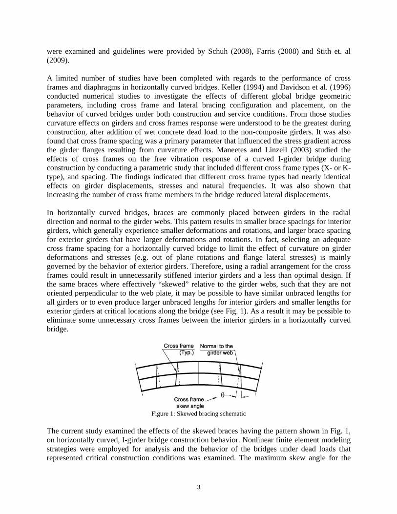
were examined and guidelines were provided by Schuh (2008), Farris (2008) and Stith et. al (2009). A limited number of studies have been completed with regards to the performance of cross frames and diaphragms in horizontally curved bridges. Keller (1994) and Davidson et al. (1996) conducted numerical studies to investigate the effects of different global bridge geometric parameters, including cross frame and lateral bracing configuration and placement, on the behavior of curved bridges under both construction and service conditions. From those studies curvature effects on girders and cross frames response were understood to be the greatest during construction, after addition of wet concrete dead load to the non-composite girders. It was also found that cross frame spacing was a primary parameter that influenced the stress gradient across the girder flanges resulting from curvature effects. Maneetes and Linzell (2003) studied the effects of cross frames on the free vibration response of a curved I-girder bridge during construction by conducting a parametric study that included different cross frame types (X- or K-type), and spacing. The findings indicated that different cross frame types had nearly identical effects on girder displacements, stresses and natural frequencies. It was also shown that increasing the number of cross frame members in the bridge reduced lateral displacements. In horizontally curved bridges, braces are commonly placed between girders in the radial direction and normal to the girder webs. This pattern results in smaller brace spacings for interior girders, which generally experience smaller deformations and rotations, and larger brace spacing for exterior girders that have larger deformations and rotations. In fact, selecting an adequate cross frame spacing for a horizontally curved bridge to limit the effect of curvature on girder deformations and stresses (e.g. out of plane rotations and flange lateral stresses) is mainly governed by the behavior of exterior girders. Therefore, using a radial arrangement for the cross frames could result in unnecessarily stiffened interior girders and a less than optimal design. If the same braces where effectively “skewed” relative to the girder webs, such that they are not oriented perpendicular to the web plate, it may be possible to have similar unbraced lengths for all girders or to even produce larger unbraced lengths for interior girders and smaller lengths for exterior girders at critical locations along the bridge (see Fig. 1). As a result it may be possible to eliminate some unnecessary cross frames between the interior girders in a horizontally curved bridge.
Figure 1: Skewed bracing schematic
The current study examined the effects of the skewed braces having the pattern shown in Fig. 1, on horizontally curved, I-girder bridge construction behavior. Nonlinear finite element modeling strategies were employed for analysis and the behavior of the bridges under dead loads that represented critical construction conditions was examined. The maximum skew angle for the
4
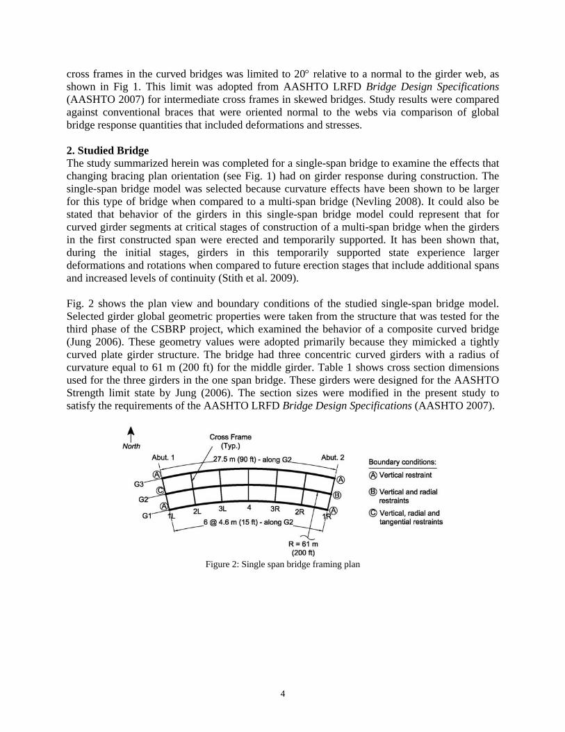
cross frames in the curved bridges was limited to 20 relative to a normal to the girder web, as shown in Fig 1. This limit was adopted from AASHTO LRFD Bridge Design Specifications (AASHTO 2007) for intermediate cross frames in skewed bridges. Study results were compared against conventional braces that were oriented normal to the webs via comparison of global bridge response quantities that included deformations and stresses. 2. Studied Bridge The study summarized herein was completed for a single-span bridge to examine the effects that changing bracing plan orientation (see Fig. 1) had on girder response during construction. The single-span bridge model was selected because curvature effects have been shown to be larger for this type of bridge when compared to a multi-span bridge (Nevling 2008). It could also be stated that behavior of the girders in this single-span bridge model could represent that for curved girder segments at critical stages of construction of a multi-span bridge when the girders in the first constructed span were erected and temporarily supported. It has been shown that, during the initial stages, girders in this temporarily supported state experience larger deformations and rotations when compared to future erection stages that include additional spans and increased levels of continuity (Stith et al. 2009). Fig. 2 shows the plan view and boundary conditions of the studied single-span bridge model. Selected girder global geometric properties were taken from the structure that was tested for the third phase of the CSBRP project, which examined the behavior of a composite curved bridge (Jung 2006). These geometry values were adopted primarily because they mimicked a tightly curved plate girder structure. The bridge had three concentric curved girders with a radius of curvature equal to 61 m (200 ft) for the middle girder. Table 1 shows cross section dimensions used for the three girders in the one span bridge. These girders were designed for the AASHTO Strength limit state by Jung (2006). The section sizes were modified in the present study to satisfy the requirements of the AASHTO LRFD Bridge Design Specifications (AASHTO 2007).
Figure 2: Single span bridge framing plan
5
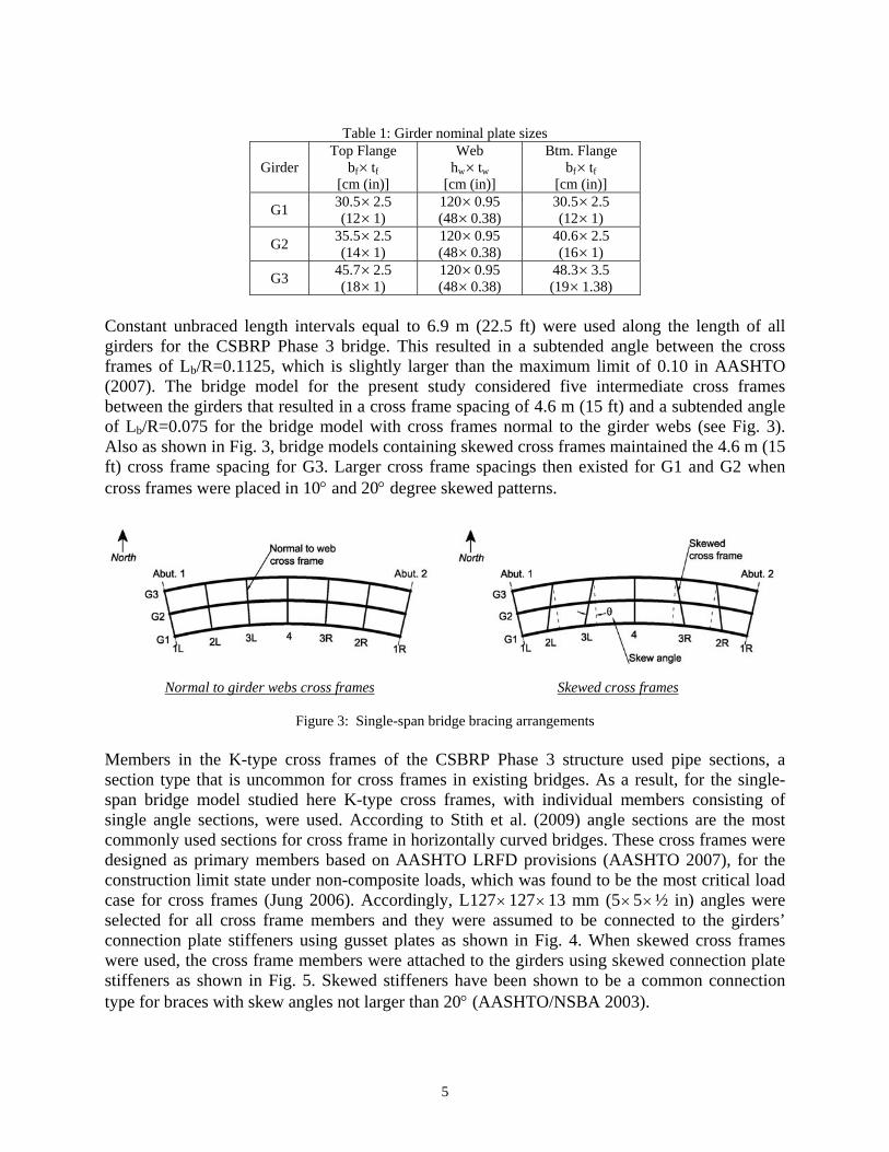
Table 1: Girder nominal plate sizes
Girder Top Flange
bf tf [cm (in)]
Web hw tw
[cm (in)]
Btm. Flange bf tf
[cm (in)]
G1 30.5 2.5 (12 1)
120 0.95 (48 0.38)
30.5 2.5 (12 1)
G2 35.5 2.5 (14 1)
120 0.95 (48 0.38)
40.6 2.5 (16 1)
G3 45.7 2.5 (18 1)
120 0.95 (48 0.38)
48.3 3.5 (19 1.38)
Constant unbraced length intervals equal to 6.9 m (22.5 ft) were used along the length of all girders for the CSBRP Phase 3 bridge. This resulted in a subtended angle between the cross frames of Lb/R=0.1125, which is slightly larger than the maximum limit of 0.10 in AASHTO (2007). The bridge model for the present study considered five intermediate cross frames between the girders that resulted in a cross frame spacing of 4.6 m (15 ft) and a subtended angle of Lb/R=0.075 for the bridge model with cross frames normal to the girder webs (see Fig. 3). Also as shown in Fig. 3, bridge models containing skewed cross frames maintained the 4.6 m (15 ft) cross frame spacing for G3. Larger cross frame spacings then existed for G1 and G2 when cross frames were placed in 10 and 20 degree skewed patterns.
Normal to girder webs cross frames Skewed cross frames
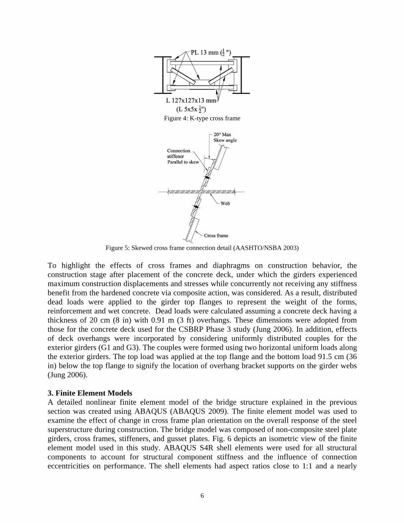
Figure 3: Single-span bridge bracing arrangements Members in the K-type cross frames of the CSBRP Phase 3 structure used pipe sections, a section type that is uncommon for cross frames in existing bridges. As a result, for the single-span bridge model studied here K-type cross frames, with individual members consisting of single angle sections, were used. According to Stith et al. (2009) angle sections are the most commonly used sections for cross frame in horizontally curved bridges. These cross frames were designed as primary members based on AASHTO LRFD provisions (AASHTO 2007), for the construction limit state under non-composite loads, which was found to be the most critical load case for cross frames (Jung 2006). Accordingly, L127 127 13 mm (5 5½ in) angles were selected for all cross frame members and they were assumed to be connected to the girders’ connection plate stiffeners using gusset plates as shown in Fig. 4. When skewed cross frames were used, the cross frame members were attached to the girders using skewed connection plate stiffeners as shown in Fig. 5. Skewed stiffeners have been shown to be a common connection type for braces with skew angles not larger than 20 (AASHTO/NSBA 2003).
6
Figure 4: K-type cross frame
Figure 5: Skewed cross frame connection detail (AASHTO/NSBA 2003)
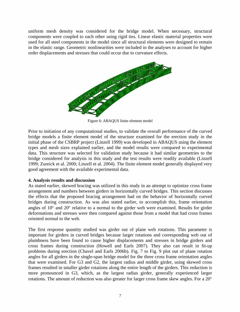
To highlight the effects of cross frames and diaphragms on construction behavior, the construction stage after placement of the concrete deck, under which the girders experienced maximum construction displacements and stresses while concurrently not receiving any stiffness benefit from the hardened concrete via composite action, was considered. As a result, distributed dead loads were applied to the girder top flanges to represent the weight of the forms, reinforcement and wet concrete. Dead loads were calculated assuming a concrete deck having a thickness of 20 cm (8 in) with 0.91 m (3 ft) overhangs. These dimensions were adopted from those for the concrete deck used for the CSBRP Phase 3 study (Jung 2006). In addition, effects of deck overhangs were incorporated by considering uniformly distributed couples for the exterior girders (G1 and G3). The couples were formed using two horizontal uniform loads along the exterior girders. The top load was applied at the top flange and the bottom load 91.5 cm (36 in) below the top flange to signify the location of overhang bracket supports on the girder webs (Jung 2006). 3. Finite Element Models A detailed nonlinear finite element model of the bridge structure explained in the previous section was created using ABAQUS (ABAQUS 2009). The finite element model was used to examine the effect of change in cross frame plan orientation on the overall response of the steel superstructure during construction. The bridge model was composed of non-composite steel plate girders, cross frames, stiffeners, and gusset plates. Fig. 6 depicts an isometric view of the finite element model used in this study. ABAQUS S4R shell elements were used for all structural components to account for structural component stiffness and the influence of connection eccentricities on performance. The shell elements had aspect ratios close to 1:1 and a nearly
7
uniform mesh density was considered for the bridge model. When necessary, structural components were coupled to each other using rigid ties. Linear elastic material properties were used for all steel components in the model since all structural elements were designed to remain in the elastic range. Geometric nonlinearities were included in the analyses to account for higher order displacements and stresses that could occur due to curvature effects.
Figure 6: ABAQUS finite element model
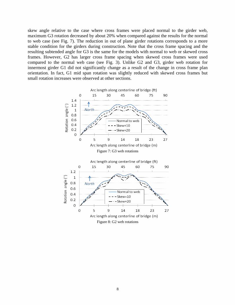
Prior to initiation of any computational studies, to validate the overall performance of the curved bridge models a finite element model of the structure examined for the erection study in the initial phase of the CSBRP project (Linzell 1999) was developed in ABAQUS using the element types and mesh sizes explained earlier, and the model results were compared to experimental data. This structure was selected for validation study because it had similar geometries to the bridge considered for analysis in this study and the test results were readily available (Linzell 1999; Zureick et al. 2000; Linzell et al. 2004). The finite element model generally displayed very good agreement with the available experimental data. 4. Analysis results and discussion As stated earlier, skewed bracing was utilized in this study in an attempt to optimize cross frame arrangement and numbers between girders in horizontally curved bridges. This section discusses the effects that the proposed bracing arrangement had on the behavior of horizontally curved bridges during construction. As was also stated earlier, to accomplish this, frame orientation angles of 10 and 20 relative to a normal to the girder web were examined. Results for girder deformations and stresses were then compared against those from a model that had cross frames oriented normal to the web. The first response quantity studied was girder out of plane web rotations. This parameter is important for girders in curved bridges because larger rotations and corresponding web out of plumbness have been found to cause higher displacements and stresses in bridge girders and cross frames during construction (Howell and Earls 2007). They also can result in fit-up problems during erection (Chavel and Earls 2006b). Fig. 7 to Fig. 9 plot out of plane rotation angles for all girders in the single-span bridge model for the three cross frame orientation angles that were examined. For G3 and G2, the largest radius and middle girder, using skewed cross frames resulted in smaller girder rotations along the entire length of the girders. This reduction is more pronounced in G3, which, as the largest radius girder, generally experienced larger rotations. The amount of reduction was also greater for larger cross frame skew angles. For a 20
8
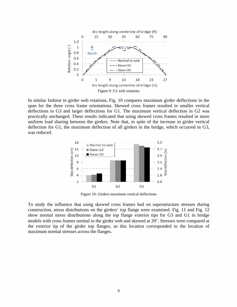
skew angle relative to the case where cross frames were placed normal to the girder web, maximum G3 rotation decreased by about 20% when compared against the results for the normal to web case (see Fig. 7). The reduction in out of plane girder rotations corresponds to a more stable condition for the girders during construction. Note that the cross frame spacing and the resulting subtended angle for G3 is the same for the models with normal to web or skewed cross frames. However, G2 has larger cross frame spacing when skewed cross frames were used compared to the normal web case (see Fig. 3). Unlike G2 and G3, girder web rotation for innermost girder G1 did not significantly change as a result of the change in cross frame plan orientation. In fact, G1 mid span rotation was slightly reduced with skewed cross frames but small rotation increases were observed at other sections.
Figure 7: G3 web rotations
Figure 8: G2 web rotations
9
Figure 9: G1 web rotations
In similar fashion to girder web rotations, Fig. 10 compares maximum girder deflections in the span for the three cross frame orientations. Skewed cross frames resulted in smaller vertical deflections in G3 and larger deflections for G1. The maximum vertical deflection in G2 was practically unchanged. These results indicated that using skewed cross frames resulted in more uniform load sharing between the girders. Note that, in spite of the increase in girder vertical deflection for G1, the maximum deflection of all girders in the bridge, which occurred in G3, was reduced.
Figure 10: Girders maximum vertical deflections
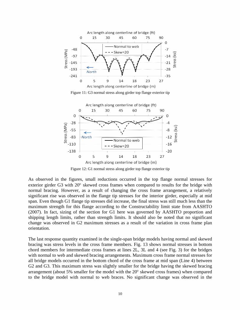
To study the influence that using skewed cross frames had on superstructure stresses during construction, stress distributions on the girders’ top flange were examined. Fig. 11 and Fig. 12 show normal stress distributions along the top flange exterior tips for G3 and G1 in bridge models with cross frames normal to the girder web and skewed at 20. Stresses were compared at the exterior tip of the girder top flanges, as this location corresponded to the location of maximum normal stresses across the flanges.
10
Figure 11: G3 normal stress along girder top flange exterior tip
Figure 12: G1 normal stress along girder top flange exterior tip
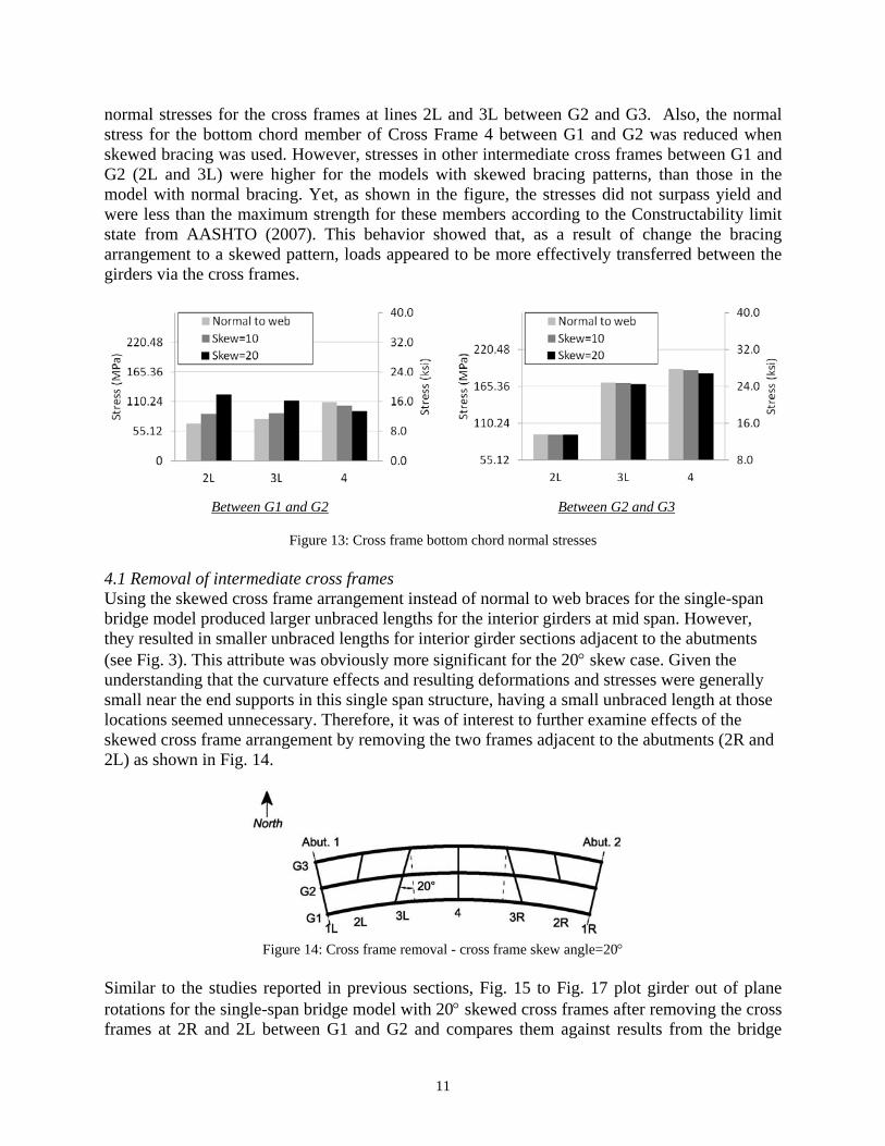
As observed in the figures, small reductions occurred in the top flange normal stresses for exterior girder G3 with 20 skewed cross frames when compared to results for the bridge with normal bracing. However, as a result of changing the cross frame arrangement, a relatively significant rise was observed in the flange tip stresses for the interior girder, especially at mid span. Even though G1 flange tip stresses did increase, the final stress was still much less than the maximum strength for this flange according to the Constructability limit state from AASHTO (2007). In fact, sizing of the section for G1 here was governed by AASHTO proportion and shipping length limits, rather than strength limits. It should also be noted that no significant change was observed in G2 maximum stresses as a result of the variation in cross frame plan orientation. The last response quantity examined in the single-span bridge models having normal and skewed bracing was stress levels in the cross frame members. Fig. 13 shows normal stresses in bottom chord members for intermediate cross frames at lines 2L, 3L and 4 (see Fig. 3) for the bridges with normal to web and skewed bracing arrangements. Maximum cross frame normal stresses for all bridge models occurred in the bottom chord of the cross frame at mid span (Line 4) between G2 and G3. This maximum stress was slightly smaller for the bridge having the skewed bracing arrangement (about 5% smaller for the model with the 20 skewed cross frames) when compared to the bridge model with normal to web braces. No significant change was observed in the
11
normal stresses for the cross frames at lines 2L and 3L between G2 and G3. Also, the normal stress for the bottom chord member of Cross Frame 4 between G1 and G2 was reduced when skewed bracing was used. However, stresses in other intermediate cross frames between G1 and G2 (2L and 3L) were higher for the models with skewed bracing patterns, than those in the model with normal bracing. Yet, as shown in the figure, the stresses did not surpass yield and were less than the maximum strength for these members according to the Constructability limit state from AASHTO (2007). This behavior showed that, as a result of change the bracing arrangement to a skewed pattern, loads appeared to be more effectively transferred between the girders via the cross frames.
Between G1 and G2 Between G2 and G3
Figure 13: Cross frame bottom chord normal stresses 4.1 Removal of intermediate cross frames Using the skewed cross frame arrangement instead of normal to web braces for the single-span bridge model produced larger unbraced lengths for the interior girders at mid span. However, they resulted in smaller unbraced lengths for interior girder sections adjacent to the abutments (see Fig. 3). This attribute was obviously more significant for the 20 skew case. Given the understanding that the curvature effects and resulting deformations and stresses were generally small near the end supports in this single span structure, having a small unbraced length at those locations seemed unnecessary. Therefore, it was of interest to further examine effects of the skewed cross frame arrangement by removing the two frames adjacent to the abutments (2R and 2L) as shown in Fig. 14.
Figure 14: Cross frame removal - cross frame skew angle=20
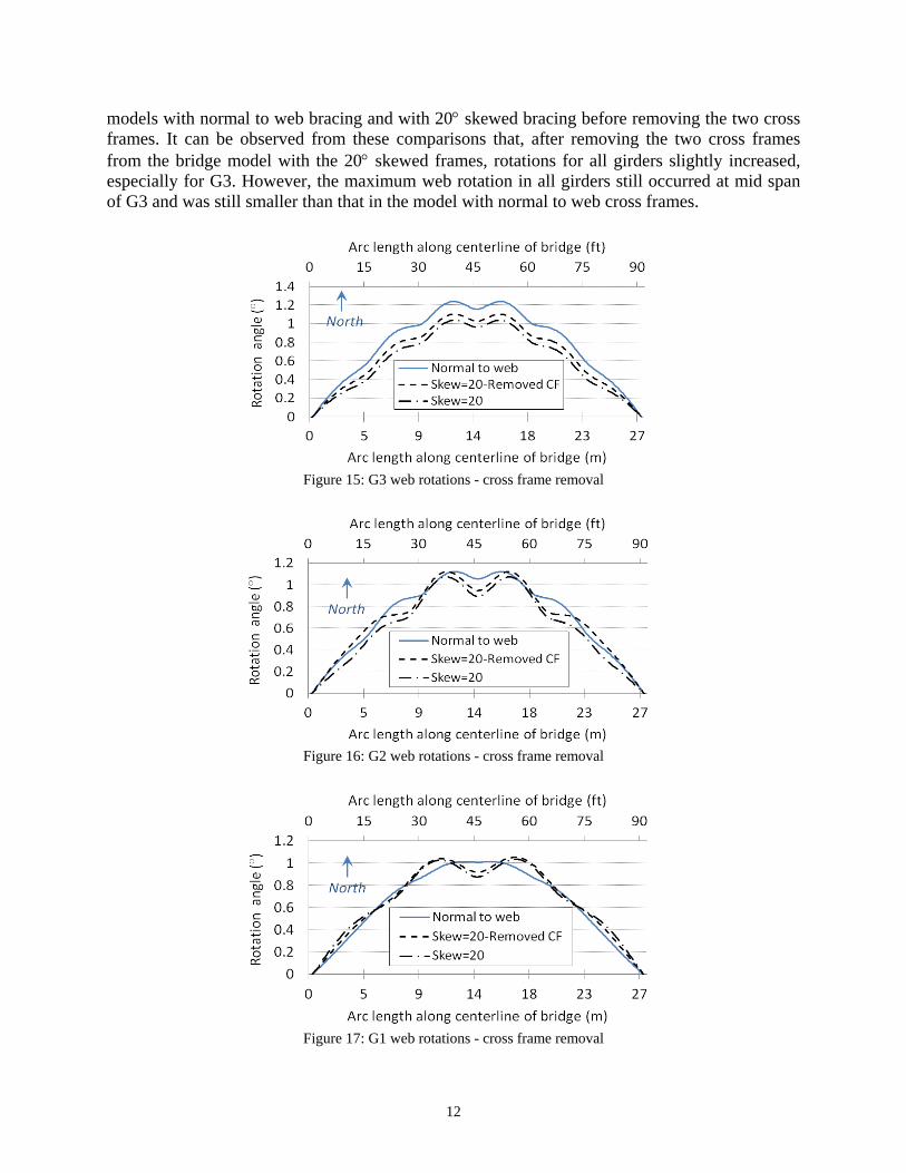
Similar to the studies reported in previous sections, Fig. 15 to Fig. 17 plot girder out of plane rotations for the single-span bridge model with 20 skewed cross frames after removing the cross frames at 2R and 2L between G1 and G2 and compares them against results from the bridge
12
models with normal to web bracing and with 20 skewed bracing before removing the two cross frames. It can be observed from these comparisons that, after removing the two cross frames from the bridge model with the 20 skewed frames, rotations for all girders slightly increased, especially for G3. However, the maximum web rotation in all girders still occurred at mid span of G3 and was still smaller than that in the model with normal to web cross frames.
Figure 15: G3 web rotations - cross frame removal
Figure 16: G2 web rotations - cross frame removal
Figure 17: G1 web rotations - cross frame removal
13
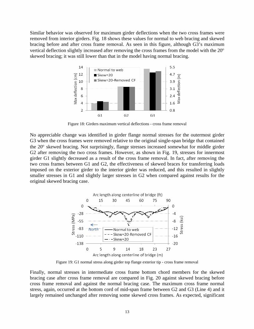
Similar behavior was observed for maximum girder deflections when the two cross frames were removed from interior girders. Fig. 18 shows these values for normal to web bracing and skewed bracing before and after cross frame removal. As seen in this figure, although G3’s maximum vertical deflection slightly increased after removing the cross frames from the model with the 20 skewed bracing; it was still lower than that in the model having normal bracing.
Figure 18: Girders maximum vertical deflections - cross frame removal
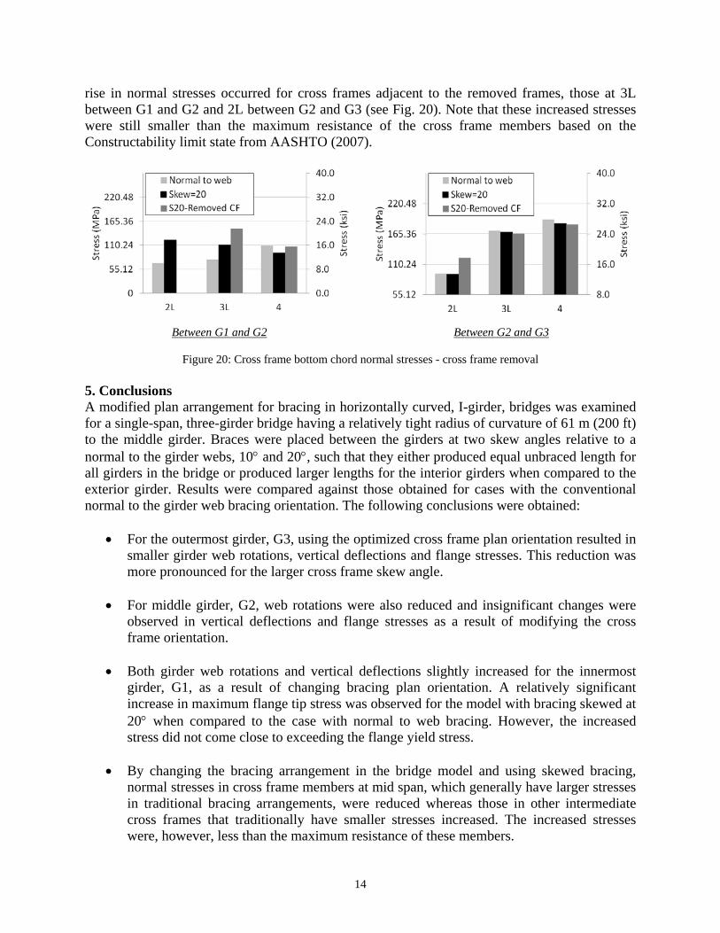
No appreciable change was identified in girder flange normal stresses for the outermost girder G3 when the cross frames were removed relative to the original single-span bridge that contained the 20 skewed bracing. Not surprisingly, flange stresses increased somewhat for middle girder G2 after removing the two cross frames. However, as shown in Fig. 19, stresses for innermost girder G1 slightly decreased as a result of the cross frame removal. In fact, after removing the two cross frames between G1 and G2, the effectiveness of skewed braces for transferring loads imposed on the exterior girder to the interior girder was reduced, and this resulted in slightly smaller stresses in G1 and slightly larger stresses in G2 when compared against results for the original skewed bracing case.
Figure 19: G1 normal stress along girder top flange exterior tip - cross frame removal
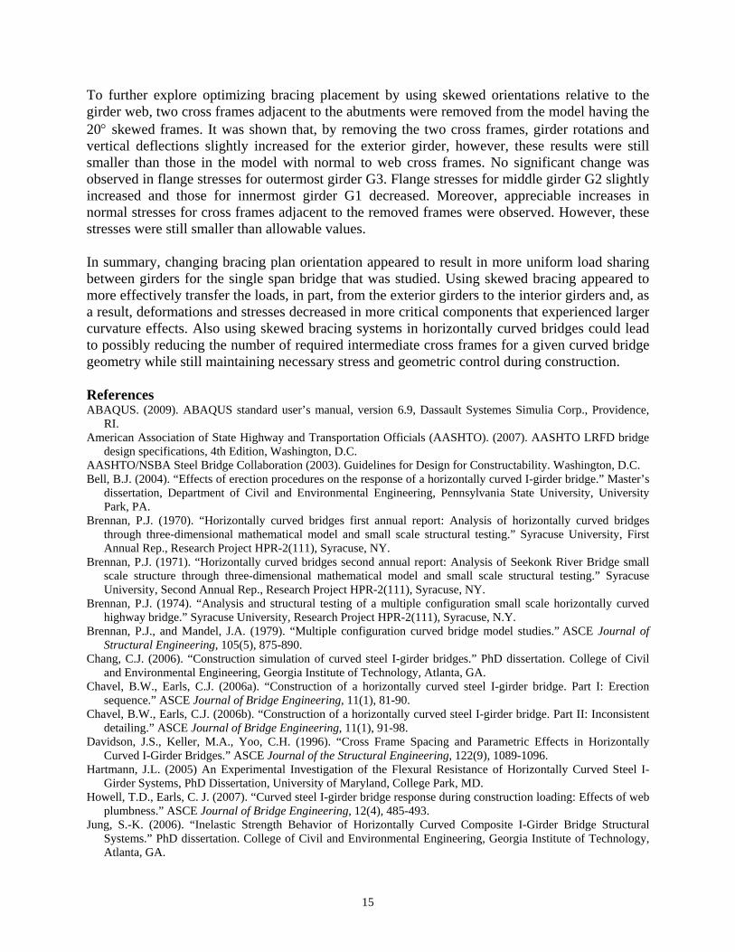
Finally, normal stresses in intermediate cross frame bottom chord members for the skewed bracing case after cross frame removal are compared in Fig. 20 against skewed bracing before cross frame removal and against the normal bracing case. The maximum cross frame normal stress, again, occurred at the bottom cord of mid-span frame between G2 and G3 (Line 4) and it largely remained unchanged after removing some skewed cross frames. As expected, significant
14
rise in normal stresses occurred for cross frames adjacent to the removed frames, those at 3L between G1 and G2 and 2L between G2 and G3 (see Fig. 20). Note that these increased stresses were still smaller than the maximum resistance of the cross frame members based on the Constructability limit state from AASHTO (2007).
Between G1 and G2 Between G2 and G3
Figure 20: Cross frame bottom chord normal stresses - cross frame removal 5. Conclusions A modified plan arrangement for bracing in horizontally curved, I-girder, bridges was examined for a single-span, three-girder bridge having a relatively tight radius of curvature of 61 m (200 ft) to the middle girder. Braces were placed between the girders at two skew angles relative to a normal to the girder webs, 10 and 20, such that they either produced equal unbraced length for all girders in the bridge or produced larger lengths for the interior girders when compared to the exterior girder. Results were compared against those obtained for cases with the conventional normal to the girder web bracing orientation. The following conclusions were obtained:
For the outermost girder, G3, using the optimized cross frame plan orientation resulted in smaller girder web rotations, vertical deflections and flange stresses. This reduction was more pronounced for the larger cross frame skew angle.
For middle girder, G2, web rotations were also reduced and insignificant changes were
observed in vertical deflections and flange stresses as a result of modifying the cross frame orientation.
Both girder web rotations and vertical deflections slightly increased for the innermost
girder, G1, as a result of changing bracing plan orientation. A relatively significant increase in maximum flange tip stress was observed for the model with bracing skewed at 20 when compared to the case with normal to web bracing. However, the increased stress did not come close to exceeding the flange yield stress.
By changing the bracing arrangement in the bridge model and using skewed bracing,
normal stresses in cross frame members at mid span, which generally have larger stresses in traditional bracing arrangements, were reduced whereas those in other intermediate cross frames that traditionally have smaller stresses increased. The increased stresses were, however, less than the maximum resistance of these members.
15
To further explore optimizing bracing placement by using skewed orientations relative to the girder web, two cross frames adjacent to the abutments were removed from the model having the 20 skewed frames. It was shown that, by removing the two cross frames, girder rotations and vertical deflections slightly increased for the exterior girder, however, these results were still smaller than those in the model with normal to web cross frames. No significant change was observed in flange stresses for outermost girder G3. Flange stresses for middle girder G2 slightly increased and those for innermost girder G1 decreased. Moreover, appreciable increases in normal stresses for cross frames adjacent to the removed frames were observed. However, these stresses were still smaller than allowable values. In summary, changing bracing plan orientation appeared to result in more uniform load sharing between girders for the single span bridge that was studied. Using skewed bracing appeared to more effectively transfer the loads, in part, from the exterior girders to the interior girders and, as a result, deformations and stresses decreased in more critical components that experienced larger curvature effects. Also using skewed bracing systems in horizontally curved bridges could lead to possibly reducing the number of required intermediate cross frames for a given curved bridge geometry while still maintaining necessary stress and geometric control during construction. References ABAQUS. (2009). ABAQUS standard user’s manual, version 6.9, Dassault Systemes Simulia Corp., Providence,
RI. American Association of State Highway and Transportation Officials (AASHTO). (2007). AASHTO LRFD bridge
design specifications, 4th Edition, Washington, D.C. AASHTO/NSBA Steel Bridge Collaboration (2003). Guidelines for Design for Constructability. Washington, D.C. Bell, B.J. (2004). “Effects of erection procedures on the response of a horizontally curved I-girder bridge.” Master’s
dissertation, Department of Civil and Environmental Engineering, Pennsylvania State University, University Park, PA.
Brennan, P.J. (1970). “Horizontally curved bridges first annual report: Analysis of horizontally curved bridges through three-dimensional mathematical model and small scale structural testing.” Syracuse University, First Annual Rep., Research Project HPR-2(111), Syracuse, NY.
Brennan, P.J. (1971). “Horizontally curved bridges second annual report: Analysis of Seekonk River Bridge small scale structure through three-dimensional mathematical model and small scale structural testing.” Syracuse University, Second Annual Rep., Research Project HPR-2(111), Syracuse, NY.
Brennan, P.J. (1974). “Analysis and structural testing of a multiple configuration small scale horizontally curved highway bridge.” Syracuse University, Research Project HPR-2(111), Syracuse, N.Y.
Brennan, P.J., and Mandel, J.A. (1979). “Multiple configuration curved bridge model studies.” ASCE Journal of Structural Engineering, 105(5), 875-890.
Chang, C.J. (2006). “Construction simulation of curved steel I-girder bridges.” PhD dissertation. College of Civil and Environmental Engineering, Georgia Institute of Technology, Atlanta, GA.
Chavel, B.W., Earls, C.J. (2006a). “Construction of a horizontally curved steel I-girder bridge. Part I: Erection sequence.” ASCE Journal of Bridge Engineering, 11(1), 81-90.
Chavel, B.W., Earls, C.J. (2006b). “Construction of a horizontally curved steel I-girder bridge. Part II: Inconsistent detailing.” ASCE Journal of Bridge Engineering, 11(1), 91-98.
Davidson, J.S., Keller, M.A., Yoo, C.H. (1996). “Cross Frame Spacing and Parametric Effects in Horizontally Curved I-Girder Bridges.” ASCE Journal of the Structural Engineering, 122(9), 1089-1096.
Hartmann, J.L. (2005) An Experimental Investigation of the Flexural Resistance of Horizontally Curved Steel I-Girder Systems, PhD Dissertation, University of Maryland, College Park, MD.
Howell, T.D., Earls, C. J. (2007). “Curved steel I-girder bridge response during construction loading: Effects of web plumbness.” ASCE Journal of Bridge Engineering, 12(4), 485-493.
Jung, S.-K. (2006). “Inelastic Strength Behavior of Horizontally Curved Composite I-Girder Bridge Structural Systems.” PhD dissertation. College of Civil and Environmental Engineering, Georgia Institute of Technology, Atlanta, GA.
16
Keller, M.A. (1994). “Parametric Study of Horizontally Curved I-girder Systems including lateral bracing Effects”. M.S. Thesis, Auburn University, Auburn, AL.
Linzell, D.G. (1999). “Studies of a full-scale horizontally curved steel I-girder bridge system under self-weight.” PhD thesis, School of Civil and Environmental Engineering, Georgia Institute of Technology, Atlanta.
Linzell, D.G., Leon, R.T., Zureick, A. (2004). “Experimental and analytical studies of horizontally curved steel I-girder bridge during erection.” ASCE Journal of Bridge Engineering, 9(6), 521-530.
Linzell, D.G., Shura, J.F. (2010). “Erection behavior and grillage model accuracy for a large radius curved bridge.” Journal of Constructional Steel Research, 66 (3), 342-350.
Maneetes, H., Linzell, D.G. (2003). “Cross-frame and Lateral Bracing Influence on Curved Steel Bridge Free Vibration Response.” Journal of Constructional Steel Research, 59, 1101 -1117.
Mozer, J., Cook, J., Culver, C. (1973). “Horizontally curved highway bridges–Stability of curved plate girders.” Carnegie Mellon Univ., Rep. No. P3, Research Project HPR-2(111), Pittsburgh, PA.
Mozer, J., and Culver, C. (1970). “Horizontally curved highway bridges–Stability of curved plate girders.” Carnegie Mellon Univ., Rep. No. P1, Research Project HPR-2(111), Pittsburgh, PA.
Mozer, J., Ohlson, R., and Culver, C. (1971). “Horizontally curved highway bridges–Stability of curved plate girders.” Carnegie Mellon Univ., Rep. No. P2, Research Project HPR-2(111), Pittsburgh, PA.
Nevling D. (2008). “Development of Guidelines for Erection Procedure for Horizontally Curved Steel I-Girder Bridges Through Analysis of A Parametric Group of Bridges” PhD Dissertation, The Pennsylvania State University, University Park, PA.
Schuh, A.C. (2008). “Behavior of horizontally curved steel I-girders during lifting.” Master’s dissertation, Department of Civil Architectural and Environmental Engineering, University of Texas at Austin, Austin, TX.
Stith, J., Schuh, A., Farris, J. F., Petruzzi, B., Helwig, T., Williamson, E., Frank, K., Engelhardt, M., and Kim, H. J. (2009). “Guidance for erection and construction of curved I-girder bridges.” Rep. No. FHWA/TX-10/0-5574-1, Center for Transportation Research at the University of Texas at Austin, Austin, TX.
White, D.W., and Grubb, A. (2005). “Unified resistance equations for design of curved and tangent steel bridge I-girders.” Transportation Research Record, CD 11-S, 121–128.
Zureick, A., Linzell, D.G., Leon, R.T., and Burrell, J. (2000). “Curved steel I-girder bridges: Experimental and analytical studies.” Engineering Structures, 22(2), 180-190.
Related Documents