May 2012 Altera Corporation WP-01162-1.2 White Paper Subscribe © 2012 Altera Corporation. All rights reserved. ALTERA, ARRIA, CYCLONE, HARDCOPY, MAX, MEGACORE, NIOS, QUARTUS and STRATIX words and logos are trademarks of Altera Corporation and registered in the U.S. Patent and Trademark Office and in other countries. All other words and logos identified as trademarks or service marks are the property of their respective holders as described at www.altera.com/common/legal.html. Altera warrants performance of its semiconductor products to current specifications in accordance with Altera's standard warranty, but reserves the right to make changes to any products and services at any time without notice. Altera assumes no responsibility or liability arising out of the application or use of any information, product, or service described herein except as expressly agreed to in writing by Altera. Altera customers are advised to obtain the latest version of device specifications before relying on any published information and before placing orders for products or services. 101 Innovation Drive San Jose, CA 95134 www.altera.com Feedback Optimize Motor Control Designs with an Integrated FPGA Design Flow This white paper describes a recommended design flow that leverages Altera ® FPGAs’ adaptability, variable-precision digital signal processing (DSP), and integrated system-level design tools for motor control designs. Designers of industrial motor-driven equipment can take advantage of the performance, integration, and efficiency benefits of this design flow. Introduction Industrial motor-driven equipment accounts for more than two-thirds of industrial energy consumption, making their efficient electrical operation a vital component in factory expenses. The replacement of traditional drives with variable speed drives (VSDs) in motor-driven systems provides significant efficiencies that can translate to up to 40% in energy savings. Altera’s FPGA architectures provide effective platforms for VSD systems because of the following flexibility, performance, integration, and design flow advantages, illustrated in Figure 1. ■ Performance scaling—Achieve higher performance and efficiency on different types of motors through parallelism and scalability of functionality. ■ Design integration—Integrate an embedded processor, encoder interfacing, DSP motion control algorithms, and industrial networking in a single device. Figure 1. Optimized Motor Control FPGA Design Flow Model Algorithm MATLAB/Simulink ● Model System ● Develop Algorithm DSP Builder Optimize Implementation ● Optimize Algorithm ● Logic Folding ● Floating and Fixed Point ● DSP Block HDL Output SOPC Builder/Qsys Integrate ● System Integration ● Embedded Processors ● Networking and Interface IP Compile Design ● HDL Synthesis ● Fitting ● Program File Generation Quartus II FPGA Chip Placement

Welcome message from author
This document is posted to help you gain knowledge. Please leave a comment to let me know what you think about it! Share it to your friends and learn new things together.
Transcript
May 2012 Altera Corporation
WP-01162-1.2
© 2012 Altera Corporation. AlQUARTUS and STRATIX worTrademark Office and in otheof their respective holders as dsemiconductor products to curchanges to any products and sapplication or use of any inforAltera customers are advised tand before placing orders for p
101 Innovation DriveSan Jose, CA 95134www.altera.com
Optimize Motor Control Designs with anIntegrated FPGA Design Flow
White Paper
This white paper describes a recommended design flow that leverages Altera® FPGAs’ adaptability, variable-precision digital signal processing (DSP), and integrated system-level design tools for motor control designs. Designers of industrial motor-driven equipment can take advantage of the performance, integration, and efficiency benefits of this design flow.
IntroductionIndustrial motor-driven equipment accounts for more than two-thirds of industrial energy consumption, making their efficient electrical operation a vital component in factory expenses. The replacement of traditional drives with variable speed drives (VSDs) in motor-driven systems provides significant efficiencies that can translate to up to 40% in energy savings. Altera’s FPGA architectures provide effective platforms for VSD systems because of the following flexibility, performance, integration, and design flow advantages, illustrated in Figure 1.
■ Performance scaling—Achieve higher performance and efficiency on different types of motors through parallelism and scalability of functionality.
■ Design integration—Integrate an embedded processor, encoder interfacing, DSP motion control algorithms, and industrial networking in a single device.
Figure 1. Optimized Motor Control FPGA Design Flow
Model Algorithm
MATLAB/Simulink● Model System● Develop Algorithm
DSP Builder
Optimize Implementation
● Optimize Algorithm● Logic Folding● Floating and Fixed Point● DSP Block HDL Output
SOPC Builder/Qsys
Integrate
● System Integration● Embedded Processors● Networking and Interface IP
Compile Design
● HDL Synthesis● Fitting● Program File Generation
Quartus II
FPGA
Chip Placement
Subscribe
l rights reserved. ALTERA, ARRIA, CYCLONE, HARDCOPY, MAX, MEGACORE, NIOS, ds and logos are trademarks of Altera Corporation and registered in the U.S. Patent and r countries. All other words and logos identified as trademarks or service marks are the property escribed at www.altera.com/common/legal.html. Altera warrants performance of its rent specifications in accordance with Altera's standard warranty, but reserves the right to make ervices at any time without notice. Altera assumes no responsibility or liability arising out of the mation, product, or service described herein except as expressly agreed to in writing by Altera. o obtain the latest version of device specifications before relying on any published information roducts or services.
Feedback
Performance Scaling and Integration Advantages Page 2
■ Design flexibility—Reuse intellectual property (IP) and take advantage of variable-precision DSP blocks. Use fixed- or floating-point precision for any part of the control path.
■ Deterministic latency—Implement motor algorithms and deterministic operations in hardware.
■ Powerful streamlined tools—Use a modeling tool such as Simulink, combined with Altera’s DSP Builder, and a versatile integration tool in Qsys or SOPC Builder to optimize the full motor system in a low-cost FPGA. Although it is common to use off-the-shelf microcontroller units (MCUs) or DSP blocks to implement processing and control loops that monitor load and adjust position, velocity, and other drive aspects, MCUs are limited by their lack of scalability and performance. These deficiencies are most evident in systems of increasingly complex algorithms with high millions-of-instructions-per-second (MIPS) processing requirements. In addition, writing algorithms in software does not translate easily to hardware-optimized system requirements.
Similarly, while high-end DSP blocks typically have the power to handle motor control computations, they are not ideal in a system that simultaneously incorporates time-precise operations with task-oriented operations, such as memory interfacing, signal interfacing and filtering, and supporting an Industrial Ethernet protocol standard.
Performance Scaling and Integration AdvantagesMany off-the-shelf MCUs or DSP blockss have the basic elements for general-purpose drive operations. However, these devices have fixed memory, narrow analog range, a fixed channel for pulse-width modulation (PWM), and limited support for multi-axis systems. Next-generation drives that require more performance and improved motor efficiencies require a platform that provides performance scaling capabilities that correspond with the processing and DSP requirements, while simultaneously providing the flexibility to integrate and optimize the system.
FPGAs can easily scale performance based on the application requirements. Designers can embed multiple processors or use the flexible DSP capabilities in the FPGA, and then leverage additional logic, custom instructions, or one of the many supported industrial networking protocols. Altera FPGAs enable designers to implement multiple embedded processors to control each subsystem independently. The parallel nature of Altera FPGAs supports integration of most motor control system building blocks. For example, Altera’s Nios® II embedded processor (32-bit RISC soft processor) can control all of the various interfaces and sensors and encoders. Designers can then use variable-precision, floating-point DSP blocks to perform field-oriented control (FOC) or other math-intensive algorithms.
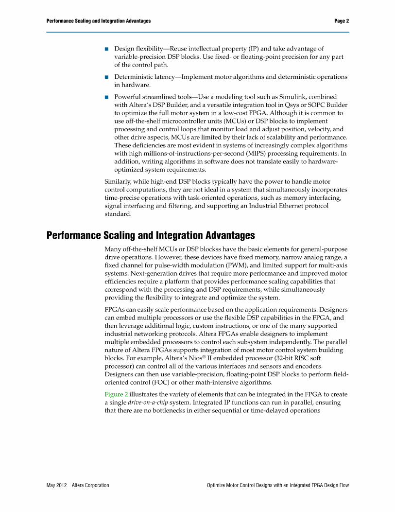
Figure 2 illustrates the variety of elements that can be integrated in the FPGA to create a single drive-on-a-chip system. Integrated IP functions can run in parallel, ensuring that there are no bottlenecks in either sequential or time-delayed operations
May 2012 Altera Corporation Optimize Motor Control Designs with an Integrated FPGA Design Flow
Handling Complex Math Algorithms Page 3
This design flow supports integration of useful IP, including the following:
■ Position feedback—Encoders with high-precision position feedback, such as EnDAT, Hiperface, and BiSS, allow 10X faster speed and position data.
■ IGBT control—Use insulated gate bipolar transistors (IGBTs) to switch the high voltages required to drive AC motors. Use space vector modulation (SVM) in the gate input of the IGBTs to generate the sinusoidal voltage wave necessary to drive the motor. The IGBTs can be of 2-level or 3-level varieties.
■ ADC interface—Interface with an external analogue-to-digital converter (ADC) to measure current feedback from the motor. Sigma-delta (ΣΔ) ADCs are easier to opto-isolate from high drive voltages, have lower noise, and support sampling of their outputs by the FPGA to give fast and accurate readings.
■ Networking interface—Implement real-time protocols in the FPGA to accommodate the Industrial Ethernet protocol standards required for the application, such as Ethernet/IP, PROFINET IO/IRT, and EtherCAT. Industrial Ethernet is becoming a more common feature in industrial drives.
The proliferation of these DSP-based motor control functions, communications, and interface standards make FPGAs an ideal platform for industrial motor drives.
Handling Complex Math AlgorithmsDrive technologies vary widely, depending on the motor type and the application. For example, a drive that controls pumps and fans has different requirements and feedback mechanisms from those that control CNC machines or packaging equipment. The data gathered from these encoders and sensors is fed back to the control system for use in math algorithms to determine the correct voltage level for the target system load and torque requirements.
Figure 2. FOC Model Including Complex Math Algorithms
DSP Builder SOPC Builder
Nios II Processor
Motion Control DSP
PHY
PWM
Industrial EthernetIndustrialEthernet
IGBTControl I/F
ADC I/F
PositionEncoder I/F
Motor
Encoder
∑∆ A/DConverters
PowerStage
May 2012 Altera Corporation Optimize Motor Control Designs with an Integrated FPGA Design Flow
Handling Complex Math Algorithms Page 4
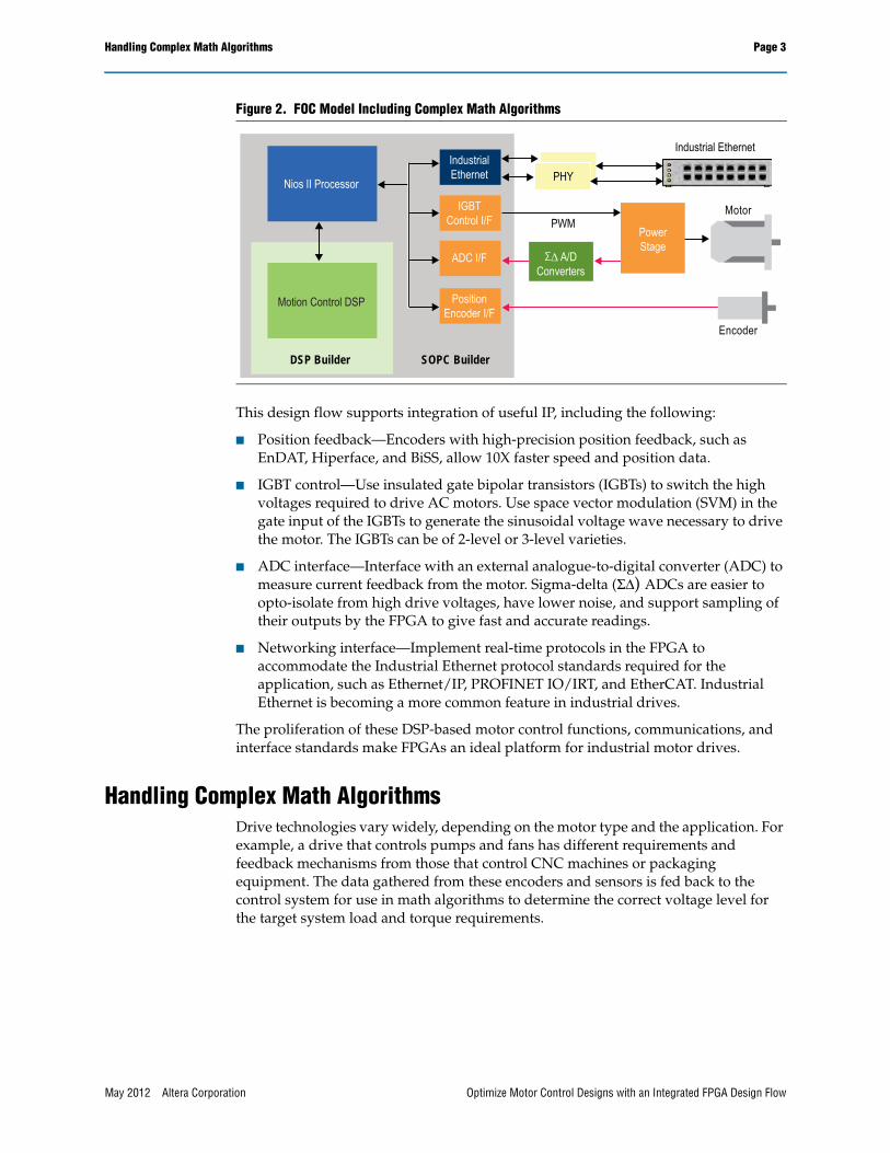
For example, the commonly used permanent magnet synchronous motor (PMSM) uses a math-intensive FOC, also known as vector control, as part of the control loop algorithm. The FOC is useful in industrial servo motors that require precise torque control. FOC techniques help to reduce motor size, cost, and power consumption. The FOC provides improved speed and torque control by metering precise voltage levels and corresponding motor speed to provide a constant torque even with varying load. In addition, the FOC reduces torque ripple and electromagnetic interference. However, this math model is fairly complex, as shown in Figure 3, and running the algorithm at a very high speed requires significant computing power.
FOC involves controlling the motor’s sinusoidal 3-phase currents in real time to create a smoothly rotating magnetic flux pattern, where the frequency of rotation corresponds to the frequency of the sine waves. The technique controls the amplitude of the current vector to maintain its position at 90 degrees with respect to the rotor magnet flux axis (“quadrature” current). This allows designers to control torque while keeping the direct current component (0 degrees) at zero. The algorithm involves the following steps:
1. Convert the 3-phase feedback current inputs and the rotor position from the encoder into quadrature and direct current components using Clarke and Park transforms.
2. Use these current components as the inputs to two proportional and integral (PI) controllers running in parallel to limit the direct current to zero and the quadrature current to the desired torque.
3. Convert the direct and quadrature current outputs from the PI controllers back to 3-phase currents with inverse Clarke and Park transforms.
Figure 3. FOC Model
FOC Algorithm Optimized in an FPGA
PositionRequest Position
PI ControlSpeed
PI Control TorquePI Control
Flux PIControl
InversePark
Transform
InverseClarke
TransformPWM Inverter Motor
CurrentFeedback
ADC
PositionSensor
(Encoder)Speed
Position
Position Feedback
ClarkeTransform
ParkTransform
FPGA
ADCInterface
EncoderInterface
ω
Vq Vα Va
Vd Vβ
Vb
Vc
Iq
Id
Iα
Iβ
Ia
Ib
May 2012 Altera Corporation Optimize Motor Control Designs with an Integrated FPGA Design Flow
Leverage Powerful Development Tools Page 5
Altera FPGAs, with the industry’s first variable-precision DSP block, provide the flexibility to choose the precision level that exactly matches the requirements, and also supports single- or double-precision floating-point types. These factors make the DSP block an ideal choice for implementing FOC loops and other complex math algorithms. The integrated DSP block—a feature in many of Altera’s 28-nm FPGA architectures—allows configuration of each block at compile time in either 18-bit or high-precision mode.
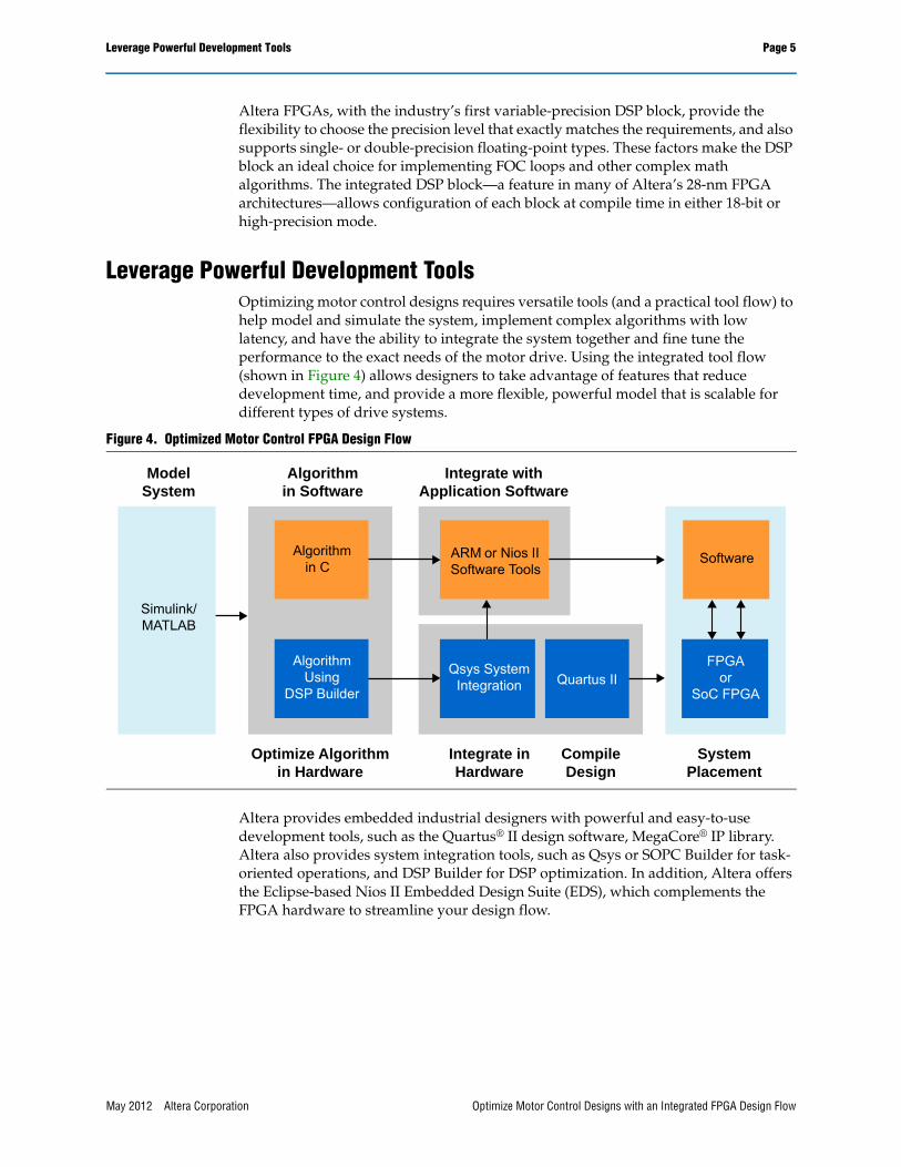
Leverage Powerful Development ToolsOptimizing motor control designs requires versatile tools (and a practical tool flow) to help model and simulate the system, implement complex algorithms with low latency, and have the ability to integrate the system together and fine tune the performance to the exact needs of the motor drive. Using the integrated tool flow (shown in Figure 4) allows designers to take advantage of features that reduce development time, and provide a more flexible, powerful model that is scalable for different types of drive systems.
Altera provides embedded industrial designers with powerful and easy-to-use development tools, such as the Quartus® II design software, MegaCore® IP library. Altera also provides system integration tools, such as Qsys or SOPC Builder for task-oriented operations, and DSP Builder for DSP optimization. In addition, Altera offers the Eclipse-based Nios II Embedded Design Suite (EDS), which complements the FPGA hardware to streamline your design flow.
Figure 4. Optimized Motor Control FPGA Design Flow
ModelSystem
Algorithmin Software
Optimize Algorithmin Hardware
Simulink/MATLAB
Integrate inHardware
CompileDesign
Integrate withApplication Software
SystemPlacement
Software
Quartus II
ARM or Nios IISoftware Tools
FPGAor
SoC FPGA
Algorithmin C
AlgorithmUsing
DSP Builder
Qsys SystemIntegration
May 2012 Altera Corporation Optimize Motor Control Designs with an Integrated FPGA Design Flow
Leverage Powerful Development Tools Page 6
Nios II Embedded Design SuiteAltera provides powerful and easy-to-use embedded development tools, such as the Eclipse-based Nios II EDS, the Nios II embedded processor, and support for standard operating systems (OSs) and real-time operating systems (RTOSs) from a number of popular vendors. The Nios II EDS supports instantiation of multiple general-purpose 32-bit RISC soft processors. These processors are capable of performance of up to 340 MIPS (Dhrystones 2.1), and can run independently with their own custom instruction set, data path, and address spaces.
Qsys and SOPC Builder System Integration ToolsAltera’s Quartus II development software includes the latest Qsys (and legacy SOPC Builder) system integration tools. These tools help designers to define and generate a complete system on a chip (SoC) by automating the task of integrating hardware components. Rather than using traditional design methods to define and connect HDL modules manually, both Qsys and SOPC Builder help you define system components in a GUI and then generate the interconnect logic automatically. These tools generate HDL files that define all components of the system, and a top-level HDL file that connects all the components together. These tools generate either Verilog HDL or VHDL.
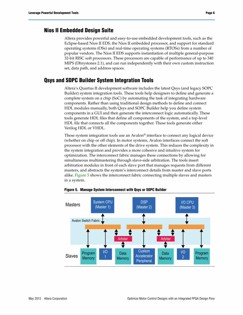
These system integration tools use an Avalon® interface to connect any logical device (whether on chip or off chip). In motor systems, Avalon interfaces connect the soft processor with the other elements of the drive system. This reduces the complexity in the system integration and provides a more cohesive and intuitive system for optimization. The interconnect fabric manages these connections by allowing for simultaneous multimastering through slave-side arbitration. The tools insert arbitration modules in front of each slave port that manages requests from different masters, and abstracts the system’s interconnect details from master and slave ports alike. Figure 5 shows the interconnect fabric connecting multiple slaves and masters in a system.
Figure 5. Manage System Interconnect with Qsys or SOPC Builder
System CPU(Master 1)
DSP(Master 2)
I/O CPU(Master 3)
Avalon Switch Fabric
Arbiter
Slaves
Masters
ProgramMemory
ProgramMemory
I/O1
I/O2
DataMemory
Arbiter
DataMemory
CustomAcceleratorPeripheral
May 2012 Altera Corporation Optimize Motor Control Designs with an Integrated FPGA Design Flow
Leverage Powerful Development Tools Page 7
Altera’s system integration and embedded development tools help designers quickly build the interfaces that connect a processor to a hardware-accelerated motor control algorithm designed in DSP Builder.
DSP Builder and MATLAB/SimulinkMotor control system designers can take advantage of DSP capabilities in FPGAs for high-speed, math-intensive motor control algorithms. Altera provides DSP Builder to shorten DSP design cycles by helping designers create a hardware representation of a DSP design in an algorithm-friendly development environment. DSP Builder integrates the algorithm development, simulation, and verification capabilities of MathWorks’s MATLAB® and Simulink® system-level design tools with Altera’s Quartus II software and third-party synthesis and simulation tools. You can combine Simulink blocks with DSP Builder blocks and IP blocks to verify system-level specifications and perform simulation.
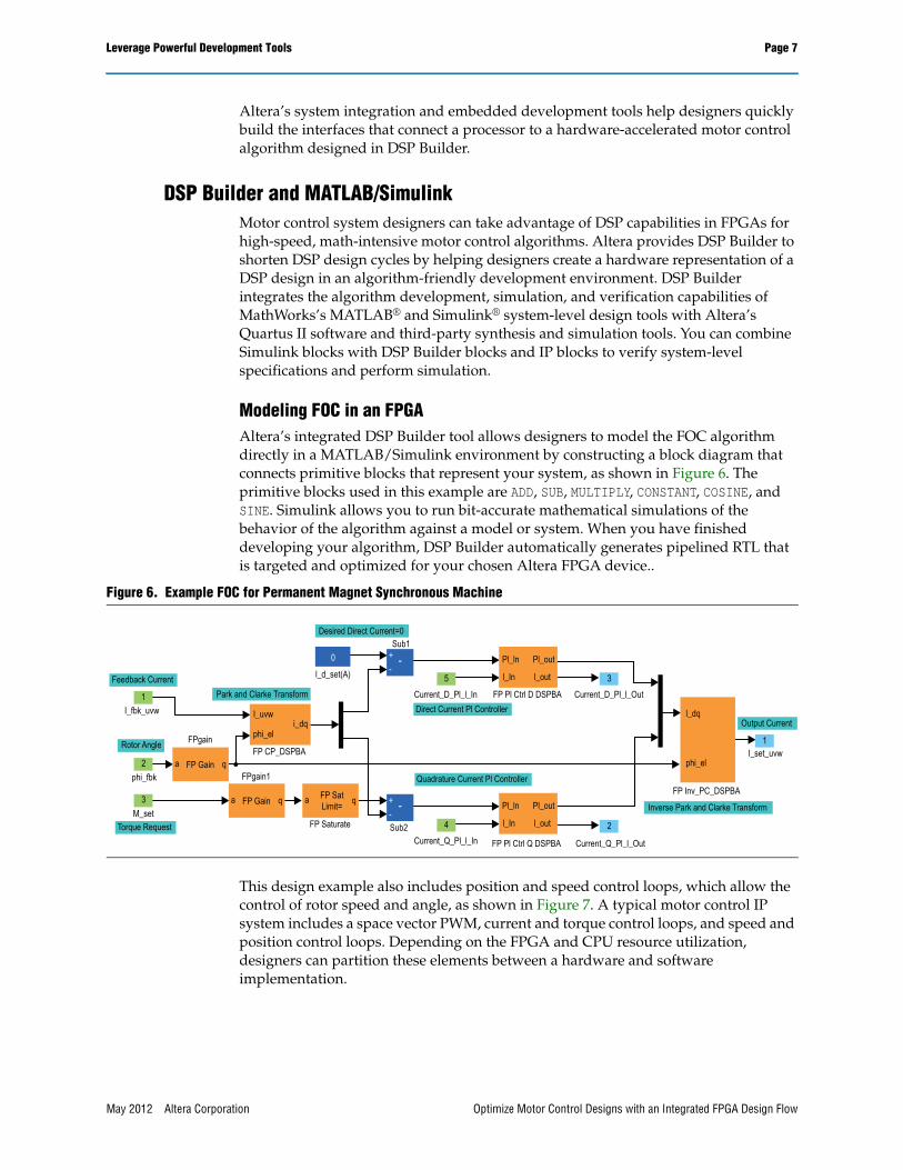
Modeling FOC in an FPGAAltera’s integrated DSP Builder tool allows designers to model the FOC algorithm directly in a MATLAB/Simulink environment by constructing a block diagram that connects primitive blocks that represent your system, as shown in Figure 6. The primitive blocks used in this example are ADD, SUB, MULTIPLY, CONSTANT, COSINE, and SINE. Simulink allows you to run bit-accurate mathematical simulations of the behavior of the algorithm against a model or system. When you have finished developing your algorithm, DSP Builder automatically generates pipelined RTL that is targeted and optimized for your chosen Altera FPGA device..
This design example also includes position and speed control loops, which allow the control of rotor speed and angle, as shown in Figure 7. A typical motor control IP system includes a space vector PWM, current and torque control loops, and speed and position control loops. Depending on the FPGA and CPU resource utilization, designers can partition these elements between a hardware and software implementation.
Figure 6. Example FOC for Permanent Magnet Synchronous Machine
2
l_In
Pl_ln Pl_out
l_out
1
Feedback Current
+-
-
+-
-
Park and Clarke Transform
I_fbk_uvw
Rotor Angle
2
5
3
phi_fbk
M_setTorque Request
FP Gain qa
FP Gain qa qa
I_uvw
phi_el
phi_el
i_dq
FPgain1
FPgainFP CP_DSPBA
l_d_set(A)
0
Desired Direct Current=0
Sub2
Sub1
Current_D_Pl_l_In
l_In
Pl_ln Pl_out
l_out4Current_Q_Pl_l_In
Current_D_Pl_l_Out
Current_Q_Pl_l_OutFP Pl Ctrl Q DSPBA
FP Pl Ctrl D DSPBA3
l_dq
FP SatLimit=
FP Saturate
FP Inv_PC_DSPBA
Inverse Park and Clarke Transform
Output Current
l_set_uvw1
Direct Current Pl Controller
Quadrature Current Pl Controller
May 2012 Altera Corporation Optimize Motor Control Designs with an Integrated FPGA Design Flow

Leverage Powerful Development Tools Page 8
Note:
(1) The PI controllers used require a feedback path to allow the integral portion to be calculated. This path is external to the DSP Builder model and is implemented by connecting the I_out port to the corresponding I_in port within the testbench and the generated VHDL.
A typical legacy design flow includes creating a model of the electrical and motor system, developing the algorithm through simulation, and then writing the C code that implements the algorithm to run on the DSP block. This design flow has the following important drawbacks.
■ Algorithm modeling is often carried out with floating point and subsequently translated to fixed point for implementation on the DSP block. The floating-to-fixed conversion was previously a manual process in which scaling and overflow protection are complicated.
■ C code implementation must be re-verified against the model.
■ Increasing the algorithm run-time performance requires the following additional steps:
a. Hand-optimize the C code for better performance.
b. Upgrade to a faster, more expensive DSP block.
c. Run the algorithm in parallel (if possible) on more than one DSP block.
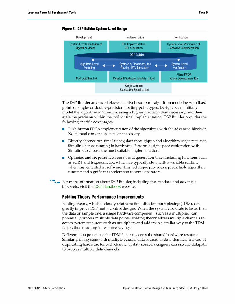
Designers can optimize an FPGA-based DSP system design with DSP Builder. DSP Builder performs optimizations such as pipelining and resource sharing to produce an efficient RTL representation. You can combine existing MATLAB functions and Simulink blocks with Altera DSP Builder blocks and other IP cores to link system-level design and implementation with DSP algorithm development, as shown in Figure 8. DSP Builder allows system, algorithm, and hardware designers to share a common development platform.
Figure 7. Position, Speed, FOC Controller for Permanent Magnet Synchronous Machine
6Position Request
8
7
12
Position Pl_l_In
Rotor Position
Previous Rotor PositionPosition To Speed
fpPos2SpeedDSPBA
Position
Prev PositionSpeed
Position PI ControllerfpPICtrlDSPBA1l_In
Pl_ln Pl_out
l_out
l_In
Pl_ln Pl_out
l_out
Position_Pl_l_Out7
3
Speed Request
4
Enable Speed Control Input
6
d0
d1
Mux6
d0
d1
Mux
1Speed Request Out
+-
-
+-
-Sub
9Speed_PI_I_In
fpPICtrlDSPBASpeed PI Controller
6Speed_Pl_l_Out
Torque Request
Torque Request Out
Torque (Nm)1
2Enable Torque
Mux1Mux
2
Feedback Current
5l_fbk_uvw
10
11
Current_Q_Pl_l_In
Current_D_Pl_l_In
l_fbk_uvw
phi_fbk
M_set
Current_Q_Pl_l_InCurrent_Q_Pl_l_Out
Current_Q_Pl_l_Out
Current_D_Pl_l_OutCurrent_D_Pl_l_OutCurrent_D_Pl_l_In
I_set_uvw
fpCurCtrlDSPBAField Oriented Control Controller
3
4
5
I_set_uvw
Output Current
May 2012 Altera Corporation Optimize Motor Control Designs with an Integrated FPGA Design Flow
Leverage Powerful Development Tools Page 9
The DSP Builder advanced blockset natively supports algorithm modeling with fixed-point, or single- or double-precision floating-point types. Designers can initially model the algorithm in Simulink using a higher precision than necessary, and then scale the precision within the tool for final implementation. DSP Builder provides the following specific advantages:
■ Push-button FPGA implementation of the algorithms with the advanced blockset. No manual conversion steps are necessary.
■ Directly observe run-time latency, data throughput, and algorithm usage results in Simulink before running in hardware. Perform design space exploration with Simulink to choose the most suitable implementation.
■ Optimize and fix primitive operators at generation time, including functions such as SQRT and trigonometric, which are typically slow with a variable runtime when implemented in software. This technique provides a predictable algorithm runtime and significant acceleration to some operators.
f For more information about DSP Builder, including the standard and advanced blocksets, visit the DSP Handbook website.
Folding Theory Performance ImprovementsFolding theory, which is closely related to time-division multiplexing (TDM), can greatly improve DSP motor control designs. When the system clock rate is faster than the data or sample rate, a single hardware component (such as a multiplier) can potentially process multiple data points. Folding theory allows multiple channels to access system resources such as multipliers and adders in a similar way to the TDM factor, thus resulting in resource savings.
Different data points use the TDM factor to access the shared hardware resource. Similarly, in a system with multiple parallel data sources or data channels, instead of duplicating hardware for each channel or data source, designers can use one datapath to process multiple data channels.
Figure 8. DSP Builder System-Level Design
System-Level Simulation ofAlgorithm Model
RTL ImplementationRTL Simulation
System-Level Verification ofHardware Implementation
DSP Builder
Algorithm-LevelModeling
Synthesis, Placement, andRouting, RTL Simulation
System-LevelVerification
MATLAB/Simulink Quartus II Software, ModelSim Tool Altera FPGA
Altera Development Kits
Single SimulinkExecutable Specification
Development Implementation Verification
May 2012 Altera Corporation Optimize Motor Control Designs with an Integrated FPGA Design Flow
Page 10 Benchmarking the FOC Algorithm
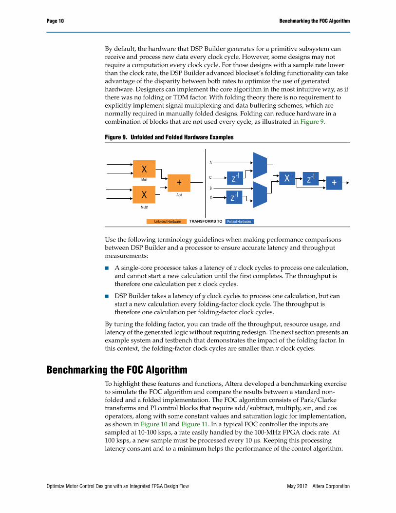
By default, the hardware that DSP Builder generates for a primitive subsystem can receive and process new data every clock cycle. However, some designs may not require a computation every clock cycle. For those designs with a sample rate lower than the clock rate, the DSP Builder advanced blockset’s folding functionality can take advantage of the disparity between both rates to optimize the use of generated hardware. Designers can implement the core algorithm in the most intuitive way, as if there was no folding or TDM factor. With folding theory there is no requirement to explicitly implement signal multiplexing and data buffering schemes, which are normally required in manually folded designs. Folding can reduce hardware in a combination of blocks that are not used every cycle, as illustrated in Figure 9.
Use the following terminology guidelines when making performance comparisons between DSP Builder and a processor to ensure accurate latency and throughput measurements:
■ A single-core processor takes a latency of x clock cycles to process one calculation, and cannot start a new calculation until the first completes. The throughput is therefore one calculation per x clock cycles.
■ DSP Builder takes a latency of y clock cycles to process one calculation, but can start a new calculation every folding-factor clock cycle. The throughput is therefore one calculation per folding-factor clock cycles.
By tuning the folding factor, you can trade off the throughput, resource usage, and latency of the generated logic without requiring redesign. The next section presents an example system and testbench that demonstrates the impact of the folding factor. In this context, the folding-factor clock cycles are smaller than x clock cycles.
Benchmarking the FOC AlgorithmTo highlight these features and functions, Altera developed a benchmarking exercise to simulate the FOC algorithm and compare the results between a standard non-folded and a folded implementation. The FOC algorithm consists of Park/Clarke transforms and PI control blocks that require add/subtract, multiply, sin, and cos operators, along with some constant values and saturation logic for implementation, as shown in Figure 10 and Figure 11. In a typical FOC controller the inputs are sampled at 10-100 ksps, a rate easily handled by the 100-MHz FPGA clock rate. At 100 ksps, a new sample must be processed every 10 μs. Keeping this processing latency constant and to a minimum helps the performance of the control algorithm.
Figure 9. Unfolded and Folded Hardware Examples
Mult
Unfolded Hardware Folded Hardware
X
X+
Mult1
Add
Z-1
Z-1
Z-1 +XC
D
A
B
TRANSFORMS TO
Optimize Motor Control Designs with an Integrated FPGA Design Flow May 2012 Altera Corporation
Benchmarking the FOC Algorithm Page 11
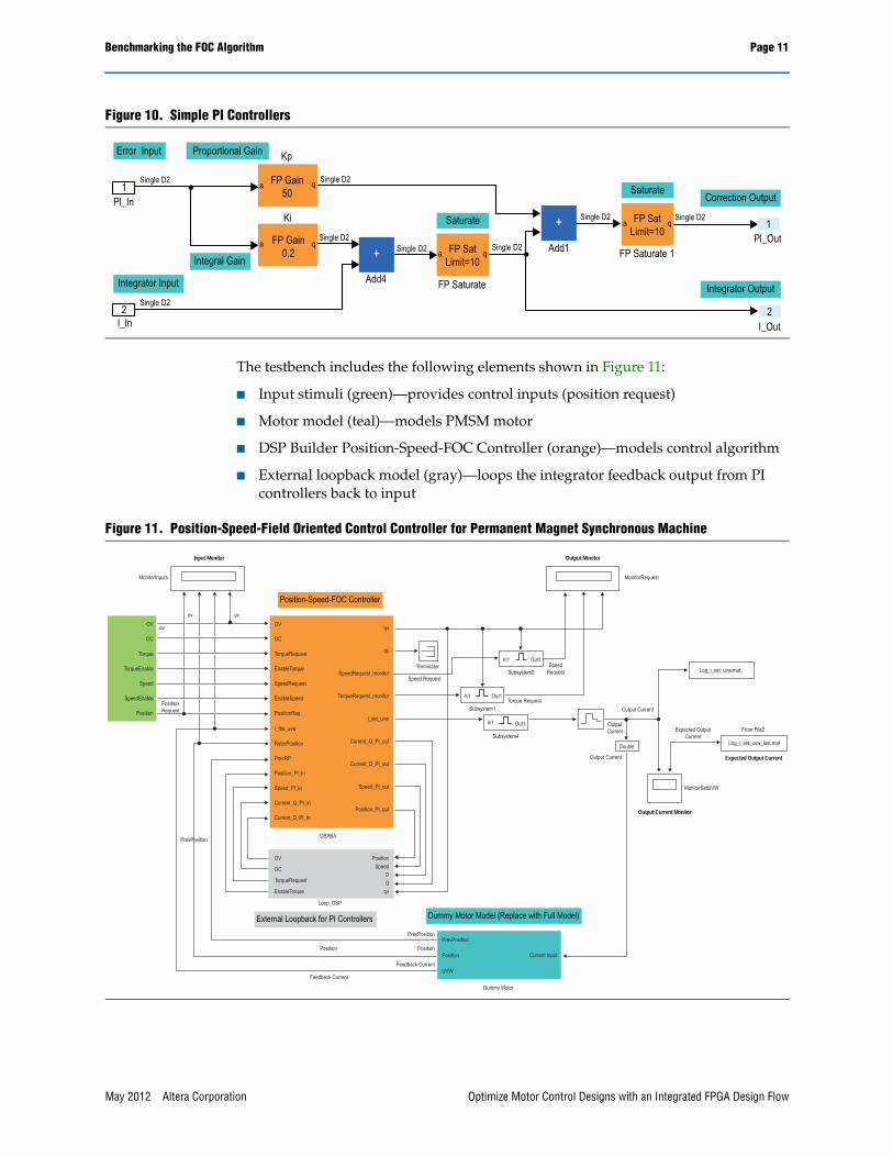
The testbench includes the following elements shown in Figure 11:
■ Input stimuli (green)—provides control inputs (position request)
■ Motor model (teal)—models PMSM motor
■ DSP Builder Position-Speed-FOC Controller (orange)—models control algorithm
■ External loopback model (gray)—loops the integrator feedback output from PI controllers back to input
Figure 10. Simple PI Controllers
Error Input
Single D21
Pl_In
Integral Gain
Proportional Gain Kp
a q
aa
FP Gain50
FP Gain0.2
Ki
Single D2
Single D2Single D2
Single D2
Single D2
Single D2
Integrator Input
2Single D2
l_In
Add4 FP Saturate
Saturate
Saturate
FP SatLimit=10
a qFP SatLimit=10
Add1 FP Saturate 1
Correction Output
Integrator Output
1
2
Pl_Out
I_Out
+
+
Figure 11. Position-Speed-Field Oriented Control Controller for Permanent Magnet Synchronous Machine
OV
Torque
TorqueEnable
Speed
SpeedEnable
Position
DSPBA
MonitorInputs
ovov
ov
PositionRequest
Output Current Monitor
Expected Output Current
Input Monitor
MonitorRequest
Output Monitor
Loop_CSP
PrevPosition
PrevPosition
PositionPosition
Feedback Current
Feedback Current
OC
OV
TorqueRequest
EnableTorque
SpeedRequest
EnableSpeed
PositionReq
OC
OV
TorqueRequest
EnableTorque
OC
Position
QD
qv
Speed
Dummy Motor
PrevPosition
UVW
Position Current Input
I_fbk_uvw
PrevRP
Position_Pl_In
Speed_Pl_In
Current_Q_PI_In
Current_D_PI_In
RotorPosition
qv
SpeedRequest_monitor
In1 Out1
TorqueRequest_monitor
i_set_uvw
Current_Q_PI_out
Current_D_PI_out
qc
Terminator
Speed RequestSubsystem2 Log_i_set_uvw.mat
Log_i_set_uvw_last.mat
From File2Expected OutputCurrent
Double
MonitorSetUVW
Output Current
Output Current
OutputCurrent
SpeedRequest
Torque RequestSubsystem1
Speed_PI_out
Position_PI_out
In1
In1
Out1
Subsystem4
Out1
Dummy Motor Model (Replace with Full Model)
Position-Speed-FOC Controller
External Loopback for PI Controllers
May 2012 Altera Corporation Optimize Motor Control Designs with an Integrated FPGA Design Flow

Page 12 Benchmarking the FOC Algorithm
Design Tuning with DSP BuilderDesigners can control key system parameters from MATLAB workspace variables, allowing tuning of the design in the following scripted ways:
■ Folding factor—Allows sweep of latency, throughput, and resource usage trade-offs to find the implementation sweet spot
■ Fixed-point arithmetic precision—Observe the effect of tuning precision at different stages in the algorithm, for algorithm performance and resource usage
■ Algorithm tuning—Simulate the actual algorithm against a physical model of the plant (motor) and tune parameters for PID controllers, filters, and observers at the modeling stage
Benchmark ResultsThe following section details the algorithm benchmarking results achieved through modeling in Simulink using single-precision floating-point and fixed-point types implemented in a Cyclone® IV device. The results indicate that the design example meets the required 100-MHz clock rate, resource usage, and algorithm latency requirements.
1 After a successful compilation in the Quartus II software , designers can obtain accurate resource information by clicking on the Quartus block link in the Simulink diagram.
1 Typically a design that does not require the high dynamic range afforded by floating point is implemented in fixed point. However, floating point avoids arithmetic overflow during algorithm development and tuning.
By default, DSP Builder creates a fully pipelined VHDL representation that can accept new input values every clock cycle. The result obtained for this “unfolded” configuration was then compared to a “fully folded” configuration.
The results in Table 1, illustrated in Figure 12, show the significant reduction in the operator count as a result of the folding factor, which allows use of a lower density Cyclone IV device. In addition, the latency increase remains acceptable for the algorithm. The speed of the control loop is the algorithm latency, plus the settling time. At 5 μs, the results are 200K loops (or PWM outputs) a second, well within the required specification.
Table 1. Folding Factor Advantage
Specification No Folding Folding Factor 100X
Addsub blocks 22 1
Multiplier blocks 22 1
Sin blocks 4 1
Maximum throughput 100 Msps 1 Msps
Optimize Motor Control Designs with an Integrated FPGA Design Flow May 2012 Altera Corporation
Benchmarking the FOC Algorithm Page 13
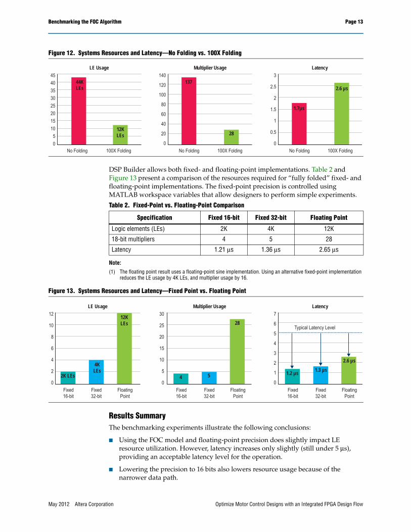
DSP Builder allows both fixed- and floating-point implementations. Table 2 and Figure 13 present a comparison of the resources required for “fully folded” fixed- and floating-point implementations. The fixed-point precision is controlled using MATLAB workspace variables that allow designers to perform simple experiments.
Note:
(1) The floating point result uses a floating-point sine implementation. Using an alternative fixed-point implementation reduces the LE usage by 4K LEs, and multiplier usage by 16.
Results SummaryThe benchmarking experiments illustrate the following conclusions:
■ Using the FOC model and floating-point precision does slightly impact LE resource utilization. However, latency increases only slightly (still under 5 μs), providing an acceptable latency level for the operation.
■ Lowering the precision to 16 bits also lowers resource usage because of the narrower data path.
Figure 12. Systems Resources and Latency—No Folding vs. 100X Folding
454035302520151050
No Folding 100X Folding
44KLEs
12KLEs
LE Usage140
120
100
80
60
40
20
0No Folding 100X Folding
137
28
Multiplier Usage3
2.5
2
1.5
1
0.5
0No Folding 100X Folding
1.7µs
2.6 µs
Latency
Table 2. Fixed-Point vs. Floating-Point Comparison
Specification Fixed 16-bit Fixed 32-bit Floating Point
Logic elements (LEs) 2K 4K 12K
18-bit multipliers 4 5 28
Latency 1.21 μs 1.36 μs 2.65 μs
Figure 13. Systems Resources and Latency—Fixed Point vs. Floating Point
12
10
8
6
4
2
0
30
25
20
15
10
5
0Fixed16-bit
Fixed32-bit
FloatingPoint
2K LEs
4KLEs
12KLEs
LE Usage Multiplier Usage7
6
5
4
3
2
1
0
Latency
Typical Latency Level
Fixed16-bit
Fixed32-bit
FloatingPoint
Fixed16-bit
Fixed32-bit
FloatingPoint
1.2 µs 1.3 µs
2.6 µs
4 5
28
May 2012 Altera Corporation Optimize Motor Control Designs with an Integrated FPGA Design Flow
Page 14 Conclusion
■ The folding factor provides optimized hardware resources while still allowing 1-Msps throughput. This allows real-time processing of up to 10 channels of the 100-ksps FOC algorithm.
ConclusionToday’s modern MCUs and DSP blocks are being pushed beyond their performance ranges in next-generation motor control systems. Designers require the flexibility to fine-tune motor control algorithms to reduce cost and power. Off-the-shelf DSP solutions have limited fixed-point or floating-point capabilities that do not accommodate other components required to drive the system.
Conversely, Altera FPGAs allow integration of components, such as a processor that can manage the overall operation, flexible interfacing to easily connect to customized subsystems, and an optimized design flow that simplifies the complex motor control loops and algorithms in parallel. A motor system is a combination of various fast control loops, timed output pulse frequencies, as well as multisensor interfacing and filtering. Altera FPGAs inherent parallel processing capabilities and high-performance variable-precision DSP blocks reduce bottlenecks and provide an optimal solution for motor control systems.
In addition to these inherent FPGA advantages, Altera provides the optimal design methodology. Using MathWorks Simulink/MATLAB tools for modeling, Altera’s DSP Builder for motor algorithm optimization, Qsys or SOPC Builder for system integration, and the Quartus II software for design synthesis and fitting represents a comprehensive and integrated design methodology that can tackle the most complex drive systems.
Further Information■ Altera in Industrial
www.altera.com/end-markets/industrial/ind-index.html
■ DSP Builder Handbook:www.altera.com/literature/technology/dsp/lit-dsp.jsp
■ White Paper: Lowering the Total Cost of Ownership in Industrial Applicationswww.altera.com/literature/wp/wp-01122-tco-industrial.pdf
■ White Paper: A Flexible Solution for Industrial Ethernetwww.altera.com/literature/wp/wp-01037.pdf
■ White Paper: Developing Functionally Safe Systems with TÜV-Qualified FPGAswww.altera.com/literature/wp/wp-01123-functional-safety.pdf
■ Webcast: “Achieve Lower Total Cost of Ownership for Industrial Designs”www.altera.com/education/webcasts/all/wc-2010-lower-tco-for-industrial-designs.html
■ Video: “3 Ways to Quickly Adapt to Changing Ethernet Protocols”www.altera.com/education/webcasts/videos/videos-adapt-to-changing-ethernet-protocols.html
■ More Industrial Webcasts and Videos:www.altera.com/servlets/webcasts/search?endmarket=industrial
Optimize Motor Control Designs with an Integrated FPGA Design Flow May 2012 Altera Corporation
Acknowledgements Page 15
Acknowledgements■ Kevin Smith, Sr. Member of Technical Staff, Altera Corporation
■ Wil Florentino, Sr. Technical Marketing Manager, Altera Corporation
■ Jason Chiang, Sr. Technical Marketing Manager, Altera Corporation
■ Stefano J. Zammattio, Product Manager, Altera Corporation
About AlteraAs the programmable logic pioneer, Altera delivers innovative technologies that system designers can count on to rapidly and cost effectively innovate, differentiate, and win in their markets. With our fabless business model, we can focus on developing technologically advanced FPGAs, CPLDs, and HardCopy® ASICs.
Using an Altera industrial-grade FPGA as a coprocessor or SoC brings flexibility to industrial applications. Providing a single, highly integrated platform for multiple industrial products, an Altera FPGA can substantially reduce development time and risk. Altera FPGAs offer the following advantages:
■ Design integration through hard IP blocks, embedded processors, transceivers, and other functions-to increase application functionality and lower total costs
■ Reprogrammability, even in the field, to support evolving Industrial Ethernet protocols and changing design requirements
■ Performance scaling via embedded processors, custom instructions, and DSP blocks
■ Obsolescence protection, plus a migration path to future FPGA families, which supports the long life cycles of industrial equipment
■ Familiar tools, use familiar, powerful, and integrated tools to simplify design and software development, IP integration, and debugging.
Document Revision HistoryTable 3 shows the revision history for this document.
Table 3. Document Revision History
Date Version Changes
May 2012 1.2 ■ Minor text and formatting edits.
July 2011 1.1 ■ Minor text edits.
April 2011 1.0 Initial release.
May 2012 Altera Corporation Optimize Motor Control Designs with an Integrated FPGA Design Flow
Related Documents