IJAPRR International Peer Reviewed Refereed Journal, Vol II, Issue III, p.n. 25-36, 2015 Page 25 International Journal of Allied Practice, Research and Review Website: www.ijaprr.com (ISSN 2350-1294) Optimization of Turbine Housing using CAE to Enhance the Life Vishwas M and Vinyas M 1 Assistant Professor, Department of Industrial Engineering and Management, Siddaganga Institute of Technology, Tumkur, Karnataka, India 2 M.Tech (Machine Design), UBDTCE, Davangere, Karnataka, India ABSTRACT - The aerospace industry is at the forefront of technological innovation, both at product level and manufacturing and support levels. It is essential to maintain the competitive edge for the companies by developing innovative designs. Design innovation alone does not guarantee market success but the product needs to satisfy customer expectations. To achieve this, aerospace industries must develop new ideas based on sound engineering fundamentals and rely on computer based tools such as CAD, CAE to evaluate and refine designs as quickly and accurately as possible.. Due to fierce competition, it is necessary to shorten development cycle and improve the performance of the products i.e. turbine housings, turbochargers, compressors etc. In an effort to shorten the product development cycle, manufacturers have to re-orient the design process itself so that analysis is performed much earlier in product development. Computer Aided Engineering (CAE) technique can be employed to achieve this. The overall life of the turbine housing can be enhanced by reducing the stresses at the critical region, which is the tongue/chin region of the housing where the complex thermal load acts. An attempt can be made to analyze and reduce the stresses acting near the tongue region of the turbine housing of the turbocharger by modifying the design at the tongue region or by using an alternative material KEYWORDS: Computer Aided Design (CAD), Computer Aided Engineering (CAE), Product Development, Upfront CAE, Finite Element Analysis (FEA), Turbine Housing 1. INTRODUCTION 1.1 INTRODUCTION TO TURBOCHARGER A turbocharger, or turbo, is a gas compressor that is used for forced induction of an internal combustion engine. A form of supercharger, the turbocharger increases the density of air entering the engine to create more power. A turbocharger has the compressor powered by a turbine which is driven by the engine's own exhaust gases rather than direct mechanical drive. This allows a turbocharger to achieve

Welcome message from author
This document is posted to help you gain knowledge. Please leave a comment to let me know what you think about it! Share it to your friends and learn new things together.
Transcript
IJAPRR International Peer Reviewed Refereed Journal, Vol II, Issue III, p.n. 25-36, 2015 Page 25
International Journal of Allied Practice, Research and Review Website: www.ijaprr.com (ISSN 2350-1294)
Optimization of Turbine Housing using CAE to
Enhance the Life
Vishwas M and Vinyas M 1 Assistant Professor, Department of Industrial Engineering and Management,
Siddaganga Institute of Technology, Tumkur, Karnataka, India 2 M.Tech (Machine Design), UBDTCE, Davangere, Karnataka, India
ABSTRACT - The aerospace industry is at the forefront of technological innovation, both at product level and
manufacturing and support levels. It is essential to maintain the competitive edge for the companies by developing
innovative designs. Design innovation alone does not guarantee market success but the product needs to satisfy customer
expectations. To achieve this, aerospace industries must develop new ideas based on sound engineering fundamentals and
rely on computer based tools such as CAD, CAE to evaluate and refine designs as quickly and accurately as possible..
Due to fierce competition, it is necessary to shorten development cycle and improve the performance of the products i.e.
turbine housings, turbochargers, compressors etc. In an effort to shorten the product development cycle, manufacturers
have to re-orient the design process itself so that analysis is performed much earlier in product development. Computer
Aided Engineering (CAE) technique can be employed to achieve this.
The overall life of the turbine housing can be enhanced by reducing the stresses at the critical region, which is the
tongue/chin region of the housing where the complex thermal load acts. An attempt can be made to analyze and reduce
the stresses acting near the tongue region of the turbine housing of the turbocharger by modifying the design at the
tongue region or by using an alternative material
KEYWORDS: Computer Aided Design (CAD), Computer Aided Engineering (CAE), Product Development, Upfront CAE,
Finite Element Analysis (FEA), Turbine Housing
1. INTRODUCTION
1.1 INTRODUCTION TO TURBOCHARGER
A turbocharger, or turbo, is a gas compressor that is used for forced induction of an internal
combustion engine. A form of supercharger, the turbocharger increases the density of air entering the
engine to create more power. A turbocharger has the compressor powered by a turbine which is driven by
the engine's own exhaust gases rather than direct mechanical drive. This allows a turbocharger to achieve
IJAPRR International Peer Reviewed Refereed Journal, Vol II, Issue III, p.n. 25-36, 2015 Page 26
a higher degree of efficiency than other types of forced induction compressors which are more vulnerable
to parasitic loss.
A turbocharger is a small radial fan pump driven by the energy of the exhaust gases of an engine. A
turbocharger consists of a turbine and a compressor on a shared shaft. The turbine converts exhaust heat
and pressure to rotational force, which is in turn used to drive the compressor. The compressor draws in
ambient air and pumps it in to the intake manifold at increased pressure, resulting in a greater mass of air
entering the cylinders on each intake stroke.
To avoid detonation and physical damage, the pressure in the cylinder must not go too high. To
prevent this, the intake pressure must be controlled by venting excess gas. The control function is
performed by a waste gate, which routes some of the exhaust flow away from the turbine. This regulates
air pressure in the intake manifold.
II. METHODOLOGY
To realize the objectives, the following methodology was adopted:
Detailed study was carried out to understand:
a) The working of turbocharger and turbine of the turbocharger.
b) The importance of turbine housing in a turbocharger.
c) The reason behind the criticality of the tongue region.
The turbine housing model provided by CAD team was meshed using Hypermesh software as a
prerequisite for analysis. The cleaning / quality check for meshed model, refining the mesh at
tongue region to get accurate result and conversion of 2D to 3D meshed model was carried out.
The meshed turbine housing model was imported to ANSYS to analyze for determining the
maximum vonmises stress developed.
The maximum vonmises stress developed during the analysis of initial design of turbine housing
was compared with the yield stress (YS) of the material used to check whether the design is safe
or not.
Based on the outcome, the design modifications, if any were suggested to the CAD team of the
company.
After the suggested modifications were incorporated, the turbine housing model was reanalyzed.
The maximum vonmises stress developed in redesigned turbine housing was checked for design
compatibility.
Based on the outcome of maximum vonmises stress criterion applied to modified design of turbine
housing, further modifications were suggested if necessary, for reanalysis.
IJAPRR International Peer Reviewed Refereed Journal, Vol II, Issue III, p.n. 25-36, 2015 Page 27
III. MESHING DATA
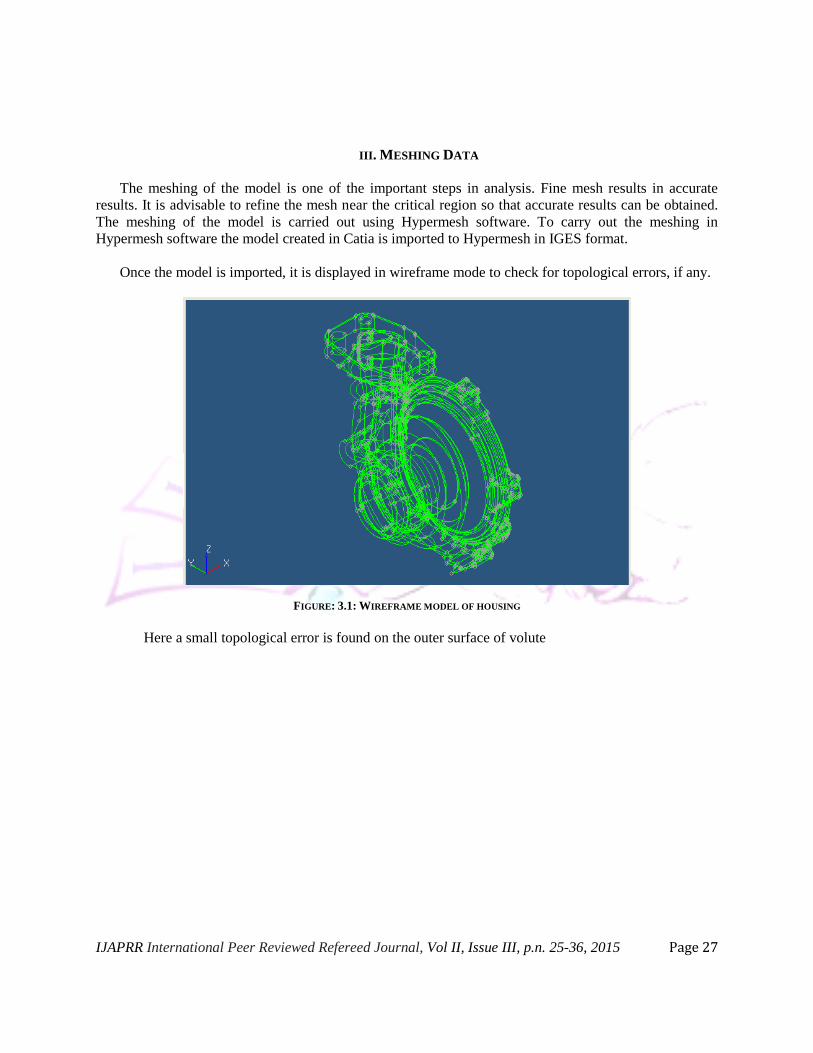
The meshing of the model is one of the important steps in analysis. Fine mesh results in accurate
results. It is advisable to refine the mesh near the critical region so that accurate results can be obtained.
The meshing of the model is carried out using Hypermesh software. To carry out the meshing in
Hypermesh software the model created in Catia is imported to Hypermesh in IGES format.
Once the model is imported, it is displayed in wireframe mode to check for topological errors, if any.
FIGURE: 3.1: WIREFRAME MODEL OF HOUSING
Here a small topological error is found on the outer surface of volute
IJAPRR International Peer Reviewed Refereed Journal, Vol II, Issue III, p.n. 25-36, 2015 Page 28
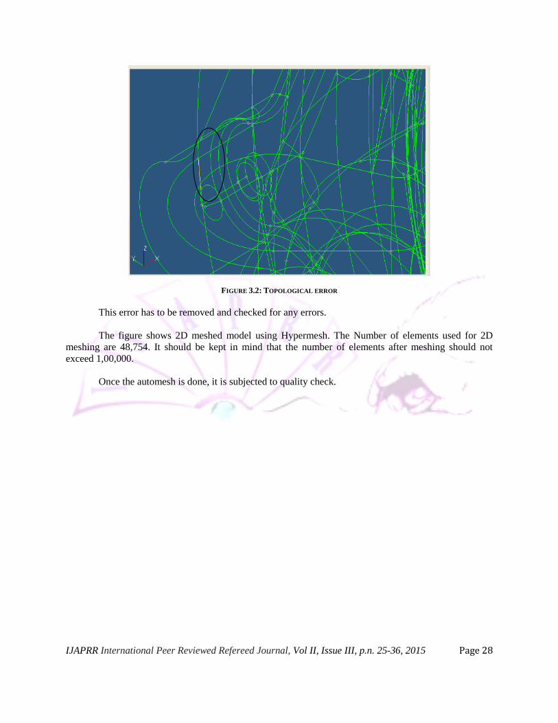
FIGURE 3.2: TOPOLOGICAL ERROR
This error has to be removed and checked for any errors.
The figure shows 2D meshed model using Hypermesh. The Number of elements used for 2D
meshing are 48,754. It should be kept in mind that the number of elements after meshing should not
exceed 1,00,000.
Once the automesh is done, it is subjected to quality check.
IJAPRR International Peer Reviewed Refereed Journal, Vol II, Issue III, p.n. 25-36, 2015 Page 29
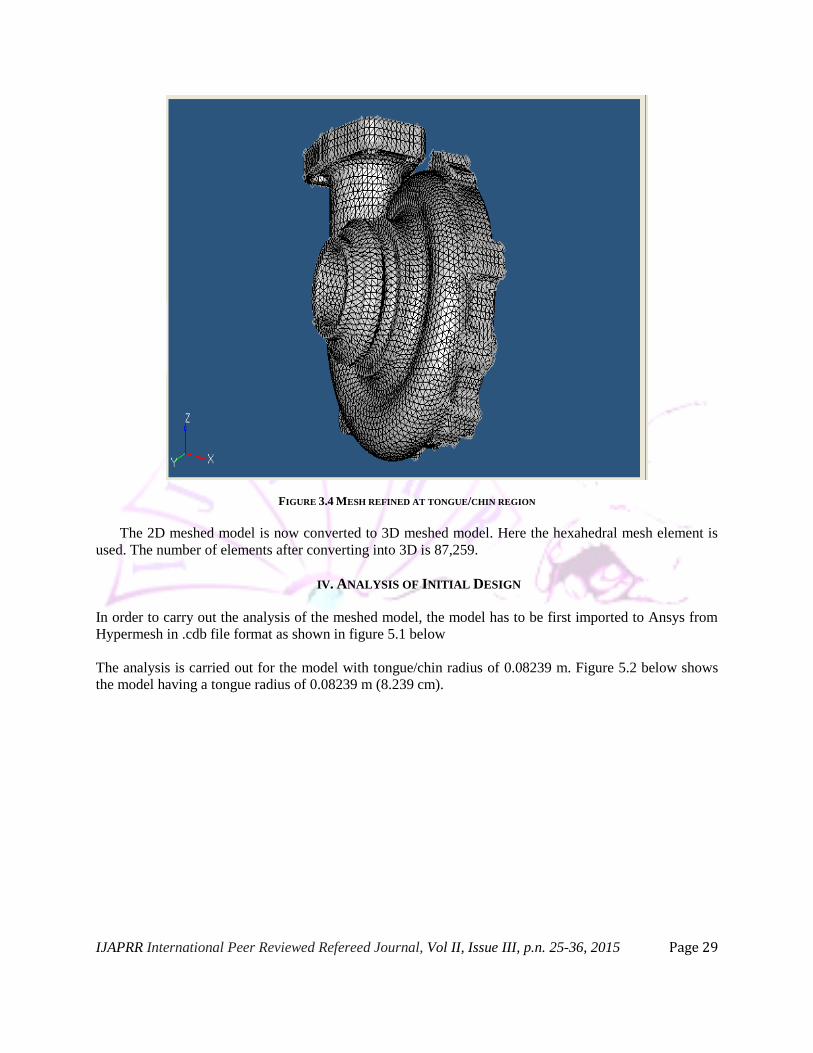
FIGURE 3.4 MESH REFINED AT TONGUE/CHIN REGION
The 2D meshed model is now converted to 3D meshed model. Here the hexahedral mesh element is
used. The number of elements after converting into 3D is 87,259.
IV. ANALYSIS OF INITIAL DESIGN
In order to carry out the analysis of the meshed model, the model has to be first imported to Ansys from
Hypermesh in .cdb file format as shown in figure 5.1 below
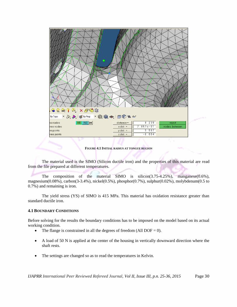
The analysis is carried out for the model with tongue/chin radius of 0.08239 m. Figure 5.2 below shows
the model having a tongue radius of 0.08239 m (8.239 cm).
IJAPRR International Peer Reviewed Refereed Journal, Vol II, Issue III, p.n. 25-36, 2015 Page 30
FIGURE 4.1 INITIAL RADIUS AT TONGUE REGION
The material used is the SIMO (Silicon ductile iron) and the properties of this material are read
from the file prepared at different temperatures.
The composition of the material SIMO is silicon(3.75-4.25%), manganese(0.6%),
magnesium(0.08%), carbon(3-3.4%), nickel(0.5%), phosphor(0.7%), sulphur(0.02%), molybdenum(0.5 to
0.7%) and remaining is iron.
The yield stress (YS) of SIMO is 415 MPa. This material has oxidation resistance greater than
standard ductile iron.
4.1 BOUNDARY CONDITIONS
Before solving for the results the boundary conditions has to be imposed on the model based on its actual
working condition.
The flange is constrained in all the degrees of freedom (All DOF = 0).
A load of 50 N is applied at the center of the housing in vertically downward direction where the
shaft rests.
The settings are changed so as to read the temperatures in Kelvin.
IJAPRR International Peer Reviewed Refereed Journal, Vol II, Issue III, p.n. 25-36, 2015 Page 31
The thermal boundary conditions are applied at different regions of housing based on the
temperature distribution, higher temperature starting from inlet and then gradually decreasing
towards the end.
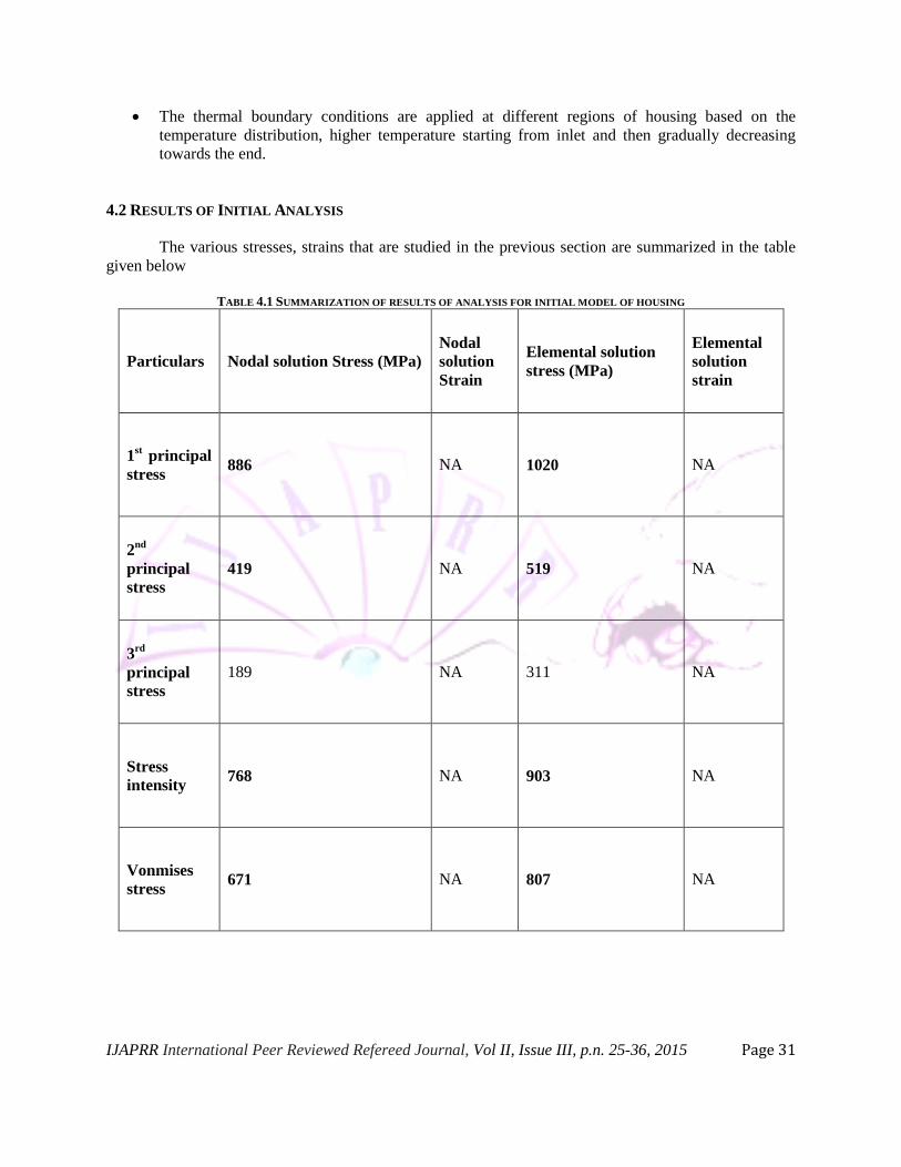
4.2 RESULTS OF INITIAL ANALYSIS
The various stresses, strains that are studied in the previous section are summarized in the table
given below
TABLE 4.1 SUMMARIZATION OF RESULTS OF ANALYSIS FOR INITIAL MODEL OF HOUSING
Particulars Nodal solution Stress (MPa)
Nodal
solution
Strain
Elemental solution
stress (MPa)
Elemental
solution
strain
1st principal
stress 886 NA 1020 NA
2nd
principal
stress
419 NA 519 NA
3rd
principal
stress
189 NA 311 NA
Stress
intensity 768 NA 903 NA
Vonmises
stress 671 NA 807 NA
IJAPRR International Peer Reviewed Refereed Journal, Vol II, Issue III, p.n. 25-36, 2015 Page 32
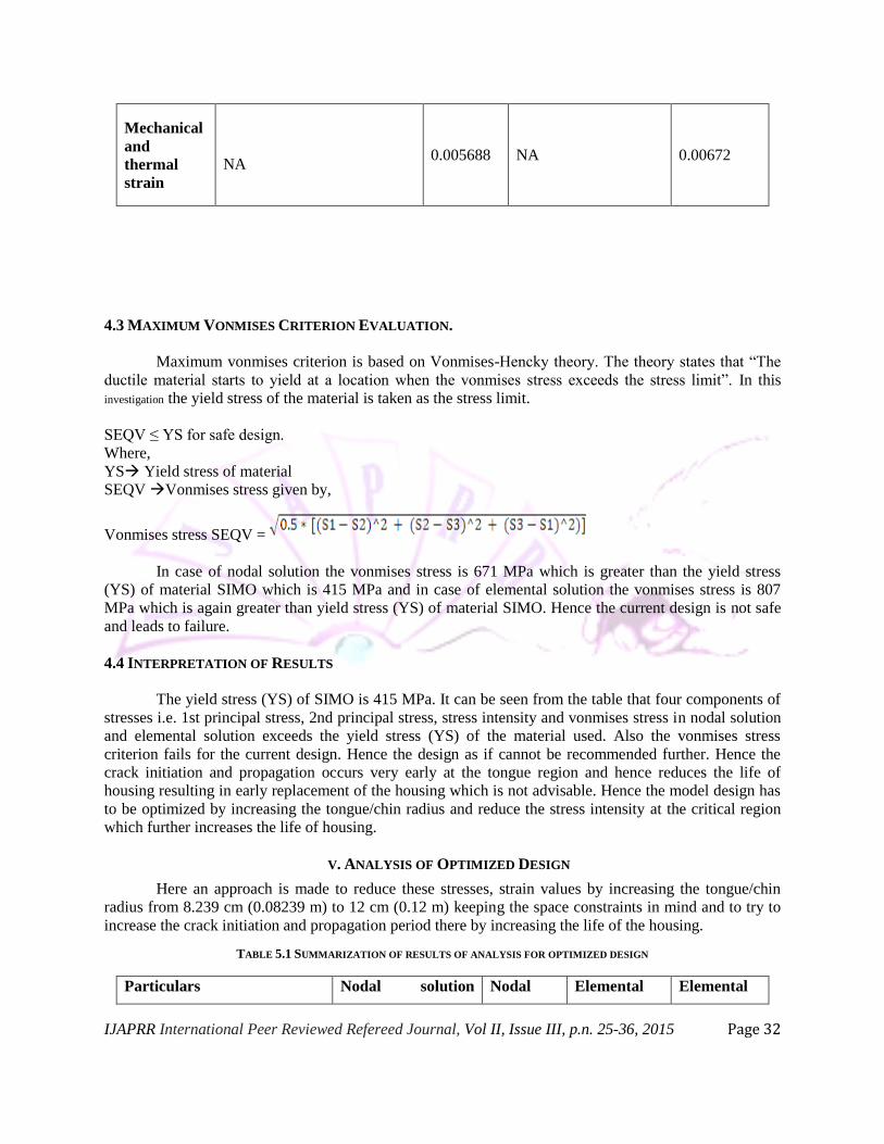
Mechanical
and
thermal
strain
NA 0.005688 NA 0.00672
4.3 MAXIMUM VONMISES CRITERION EVALUATION.
Maximum vonmises criterion is based on Vonmises-Hencky theory. The theory states that “The
ductile material starts to yield at a location when the vonmises stress exceeds the stress limit”. In this
investigation the yield stress of the material is taken as the stress limit.
SEQV ≤ YS for safe design.
Where,
YS Yield stress of material
SEQV Vonmises stress given by,
Vonmises stress SEQV =
In case of nodal solution the vonmises stress is 671 MPa which is greater than the yield stress
(YS) of material SIMO which is 415 MPa and in case of elemental solution the vonmises stress is 807
MPa which is again greater than yield stress (YS) of material SIMO. Hence the current design is not safe
and leads to failure.
4.4 INTERPRETATION OF RESULTS
The yield stress (YS) of SIMO is 415 MPa. It can be seen from the table that four components of
stresses i.e. 1st principal stress, 2nd principal stress, stress intensity and vonmises stress in nodal solution
and elemental solution exceeds the yield stress (YS) of the material used. Also the vonmises stress
criterion fails for the current design. Hence the design as if cannot be recommended further. Hence the
crack initiation and propagation occurs very early at the tongue region and hence reduces the life of
housing resulting in early replacement of the housing which is not advisable. Hence the model design has
to be optimized by increasing the tongue/chin radius and reduce the stress intensity at the critical region
which further increases the life of housing.
V. ANALYSIS OF OPTIMIZED DESIGN
Here an approach is made to reduce these stresses, strain values by increasing the tongue/chin
radius from 8.239 cm (0.08239 m) to 12 cm (0.12 m) keeping the space constraints in mind and to try to
increase the crack initiation and propagation period there by increasing the life of the housing.
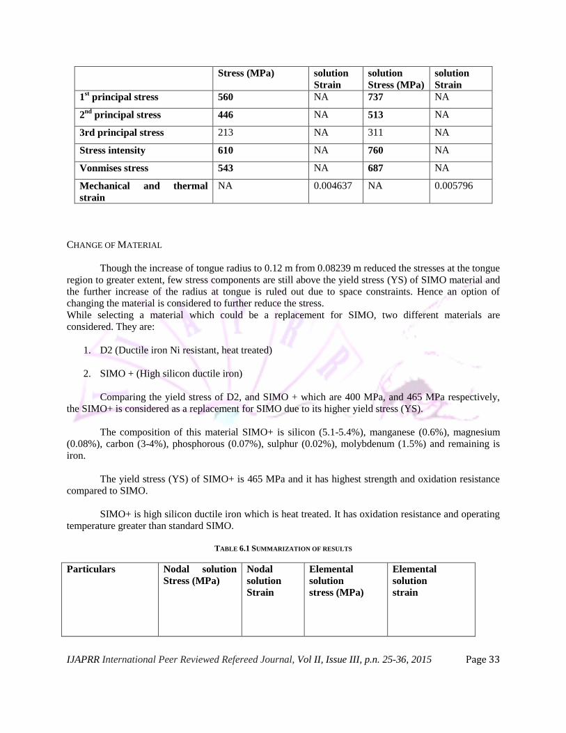
TABLE 5.1 SUMMARIZATION OF RESULTS OF ANALYSIS FOR OPTIMIZED DESIGN
Particulars Nodal solution Nodal Elemental Elemental
IJAPRR International Peer Reviewed Refereed Journal, Vol II, Issue III, p.n. 25-36, 2015 Page 33
Stress (MPa) solution
Strain
solution
Stress (MPa)
solution
Strain
1st principal stress 560 NA 737 NA
2nd
principal stress 446 NA 513 NA
3rd principal stress 213 NA 311 NA
Stress intensity 610 NA 760 NA
Vonmises stress 543 NA 687 NA
Mechanical and thermal
strain
NA 0.004637 NA 0.005796
CHANGE OF MATERIAL
Though the increase of tongue radius to 0.12 m from 0.08239 m reduced the stresses at the tongue
region to greater extent, few stress components are still above the yield stress (YS) of SIMO material and
the further increase of the radius at tongue is ruled out due to space constraints. Hence an option of
changing the material is considered to further reduce the stress.
While selecting a material which could be a replacement for SIMO, two different materials are
considered. They are:
1. D2 (Ductile iron Ni resistant, heat treated)
2. SIMO + (High silicon ductile iron)
Comparing the yield stress of D2, and SIMO + which are 400 MPa, and 465 MPa respectively,
the SIMO+ is considered as a replacement for SIMO due to its higher yield stress (YS).
The composition of this material SIMO+ is silicon (5.1-5.4%), manganese (0.6%), magnesium
(0.08%), carbon (3-4%), phosphorous (0.07%), sulphur (0.02%), molybdenum (1.5%) and remaining is
iron.
The yield stress (YS) of SIMO+ is 465 MPa and it has highest strength and oxidation resistance
compared to SIMO.
SIMO+ is high silicon ductile iron which is heat treated. It has oxidation resistance and operating
temperature greater than standard SIMO.
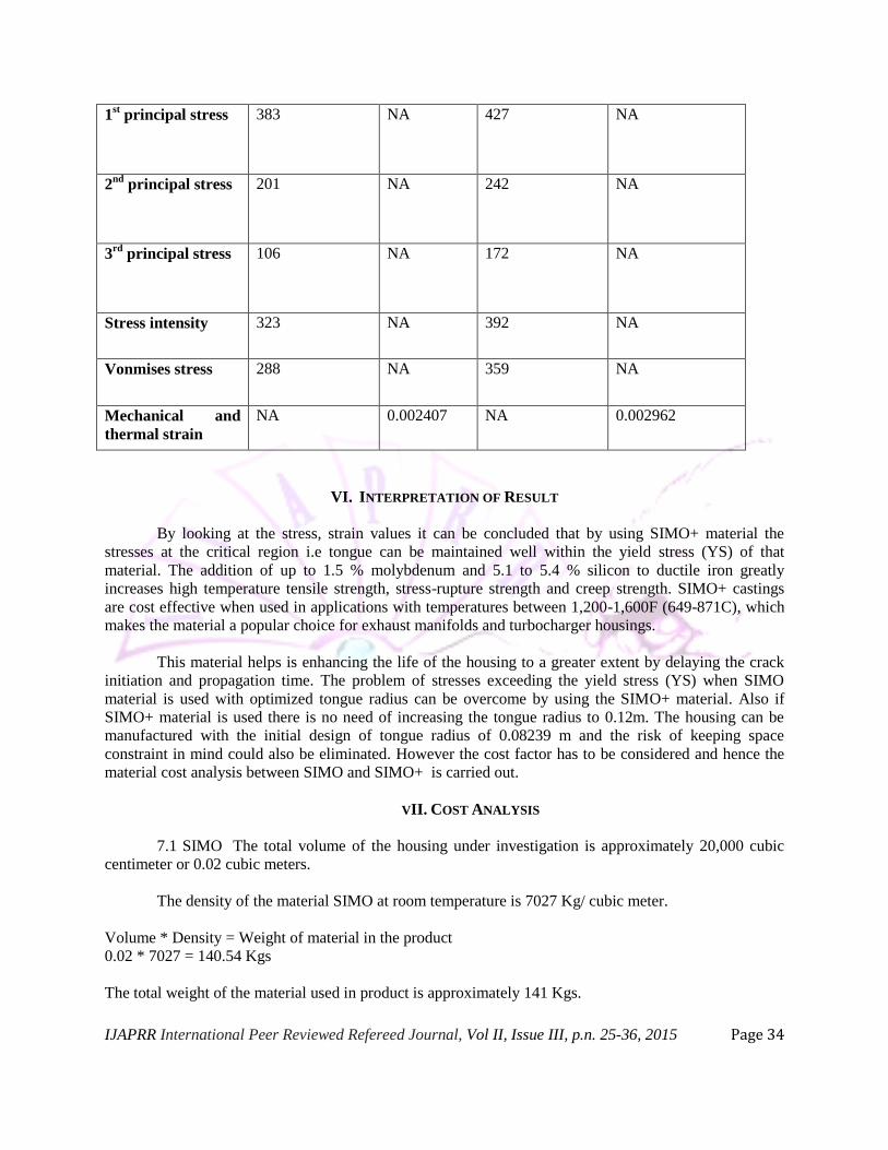
TABLE 6.1 SUMMARIZATION OF RESULTS
Particulars Nodal solution
Stress (MPa)
Nodal
solution
Strain
Elemental
solution
stress (MPa)
Elemental
solution
strain
IJAPRR International Peer Reviewed Refereed Journal, Vol II, Issue III, p.n. 25-36, 2015 Page 34
1st principal stress 383 NA 427 NA
2nd
principal stress 201 NA 242 NA
3rd
principal stress 106 NA 172 NA
Stress intensity 323 NA 392 NA
Vonmises stress 288 NA 359 NA
Mechanical and
thermal strain
NA 0.002407 NA 0.002962
VI. INTERPRETATION OF RESULT
By looking at the stress, strain values it can be concluded that by using SIMO+ material the
stresses at the critical region i.e tongue can be maintained well within the yield stress (YS) of that
material. The addition of up to 1.5 % molybdenum and 5.1 to 5.4 % silicon to ductile iron greatly
increases high temperature tensile strength, stress-rupture strength and creep strength. SIMO+ castings
are cost effective when used in applications with temperatures between 1,200-1,600F (649-871C), which
makes the material a popular choice for exhaust manifolds and turbocharger housings.
This material helps is enhancing the life of the housing to a greater extent by delaying the crack
initiation and propagation time. The problem of stresses exceeding the yield stress (YS) when SIMO
material is used with optimized tongue radius can be overcome by using the SIMO+ material. Also if
SIMO+ material is used there is no need of increasing the tongue radius to 0.12m. The housing can be
manufactured with the initial design of tongue radius of 0.08239 m and the risk of keeping space
constraint in mind could also be eliminated. However the cost factor has to be considered and hence the
material cost analysis between SIMO and SIMO+ is carried out.
VII. COST ANALYSIS
7.1 SIMO The total volume of the housing under investigation is approximately 20,000 cubic
centimeter or 0.02 cubic meters.
The density of the material SIMO at room temperature is 7027 Kg/ cubic meter.
Volume * Density = Weight of material in the product
0.02 * 7027 = 140.54 Kgs
The total weight of the material used in product is approximately 141 Kgs.
IJAPRR International Peer Reviewed Refereed Journal, Vol II, Issue III, p.n. 25-36, 2015 Page 35
The market price of SIMO per Kg is approximately rupees 125 /-.
Total material cost incurred for the product (Rc) = Total weight of material used in product * Cost of
material per Kg. = 141*125 = Rs 17,625
7.2 SIMO+
The total volume of the housing under investigation is approximately 20,000 cubic centimeter or 0.02
cubic meters.
The density of the material SIMO+ at room temperature is 7010 Kg/ cubic meter. The market price of
SIMO+ per Kg is approximately rupees 175 /-. Hence the total material cost = Rupees 24,675/-
VIII. CONCLUSIONS
The following are the major conclusions drawn based on the results obtained from analyzing the
turbine housing of a turbocharger using ANSYS software:
Detailed study about the working of turbocharger and the turbine housing showed that the tongue
region in the turbine housing is the critical area where complex thermal load acts since the tongue
region is subjected to repeated heating and cooling cycles.
The repeated expansion and contraction of housing at tongue region renders it prone to thermal
fatigue cracking. High thermal stresses are developed at tongue region and as a result, the inlet
duct tends to unwind from volute.
The analysis of initial design of turbine housing indicated that the stresses developed at tongue
region are high. The maximum vonmises stress developed at tongue region is 671 MPa in case of
nodal solution and 807 MPa in case of elemental solution. This is greater than the yield stress of
415 MPa corresponding to material SIMO that is used. Hence the maximum vonmises criterion
fails. Thus the design is considered unsafe.
Since the initial design along with material SIMO proved to be unsafe, the design modification
has been carried out by CAD team based on the suggestion given. The tongue radius is increased
by 45% from 0.08239m to 0.12m.
The redesigned turbine housing model is reanalyzed and results are obtained. It was observed that
though the increase in tongue radius helped in reducing the stresses developed, the maximum
vonmises criterion fails again. The maximum vonmises stress developed was found to be 543
MPa for nodal solution and 687 MPa for elemental solution which is still greater than yield stress
of 415 MPa corresponding to material SIMO. Thus rendering the unsafe.
Further increase in tongue radius is ruled out owing to space constraints.
Since further increase in tongue radius is ruled out, it is suggested to change the material of
housing. The material SIMO is replaced by SIMO+ which has higher temperature withstanding
ability due to addition of silicon and molybdenum and has higher yield stress of 465 MPa.
IJAPRR International Peer Reviewed Refereed Journal, Vol II, Issue III, p.n. 25-36, 2015 Page 36
The model is reanalyzed with initial design having a tongue radius of 0.08239m and with new
material SIMO+ to obtain pertinent results. The maximum vonmises stress developed is 288 MPa
in case of nodal solution and 359 MPa in case of elemental solution. This is found to be less than
yield stress of material SIMO+ which is 465 MPa. Thus it is concluded that the design is safe
provided SIMO+ is used for manufacturing the housing.
IX. REFERENCES
1. Karl T. Ulrich, Steven D. Eppinger and Anita goyal. “Product design and development”. 4th edition, McGrawhill
publications.
2. Lucjan Witek, Daniel Musili Ngii, Tadeusz Kowalski. “Thermal fatigue problems of turbine casing”. Fatigue of
aircraft structures. Vol. 1 (2009) 205-211.
3. John Martin Allport, Georgina Chiu, Robert Martin. “Turbine housing for a turbocharger”. Publication no. US
7,798,774 B2. September 21, 2010.
4. A.K. Chitale and R.C Gupta. “Product design and manufacturing” PHI publications, 4th edition.
5. Diaa M. Hosny, Torrance, CA (US). “Turbine housing for high exhaust temperature”. Publication no. US
6,709,235 B2. March 23, 2004.
6. Norman Davey. “The gas turbine – development and engineering”. Wexford college press. 2003
Related Documents