FACULTY OF MECHANICAL ENGINEERING DEPARTMENT OF MECHANICAL AND INDUSTRIAL ENGINEERING MET70LT Kristjan Jagomann OPTIMIZATION OF THE TANK ROTATING MACHINE IN ESTANC AS MAHUTITE PÖÖRAMISE SEADME OPTIMEERIMINE ETTEVÕTTES ESTANC AS Author applies for degree of Master of Technical Sciences (M.Sc.) Tallinn 2016

Welcome message from author
This document is posted to help you gain knowledge. Please leave a comment to let me know what you think about it! Share it to your friends and learn new things together.
Transcript

FACULTY OF MECHANICAL ENGINEERING
DEPARTMENT OF MECHANICAL AND INDUSTRIAL ENGINEERING
MET70LT
Kristjan Jagomann
OPTIMIZATION OF THE TANK ROTATING MACHINE
IN ESTANC AS
MAHUTITE PÖÖRAMISE SEADME OPTIMEERIMINE
ETTEVÕTTES ESTANC AS
Author applies for degree of Master of Technical Sciences (M.Sc.)
Tallinn 2016

Author's Declaration
I have written the Master’s thesis independently.
All works and major viewpoints of the other authors, data from other sources of
literature and elsewhere used for writing this paper have been referenced.
Master's thesis is completed under .......................................................... supervision
“.......”....................201….. Author .............................. signature
Master's thesis is in accordance with terms and requirements
“.......”....................201…. Supervisor …......................................... signature.
Accepted for defence
.............................................................. chairman of defence commission
“.......”....................201… . ............................. signature
Master's Thesis task
2015 /2016 academic year 2nd semester Student: Kristjan Jagomann, 132578MADMM Field of study Design & Engineering Supervisor: Associate Prof. Kristo Karjust (Director of Department Of Machinery, TUT) Consultant(s): Master's Thesis topic (in Estonian and English languages): Mahutite pööramise seadme optimeerimine ettevõttes Estanc AS Optimization of the tank rotating machine in Estanc AS Tasks and timeframe for their completion:
Nr Task description Completion date
1 Collect background data of rotating tanks in manufacturing phase
February 2016
2 Study the tank production related information based on selected company
March 2016
3 Research and comparison of the existing products on the market
March 2016
4 Setting the requirements and development of the concept
April-May 2016
Design and Engineering problems to be solved: The objective of the Master’s Thesis is to analyse company current products related with the tank rotating equipment by covering both economical and technical aspects. The objective is to give input requirements and optimizes the equipment, which fulfils the company’s needs. Defence application submitted to deanery not later than 20.05.2016 Student: Kristjan Jagomann /signature/ 20.05.2016 Supervisor: Associate Prof. Kristo Karjust /signature/ 20.05.2016 Phone +372 620 3260 E-mail: [email protected]
4
Table of contents
Master's Thesis task ....................................................................................................... 3
Table of contents ............................................................................................................ 4
List of figures ................................................................................................................. 6
List of tables ................................................................................................................... 8
Acknowledgment ........................................................................................................... 9
1 Introduction ............................................................................................................ 10
1.1 Goals and objectives ....................................................................................... 10
1.2 Methodology ................................................................................................... 11
2 Overview of the company ...................................................................................... 14
2.1 Company introduction .................................................................................... 14
2.1.1 Organizational structure ........................................................................... 15
2.1.2 Production capacity .................................................................................. 17
2.1.3 Examples of produced equipment ............................................................ 18
2.2 Tank manufacturing process ........................................................................... 21
3 Rotator positioning and aligning analyse ............................................................... 24
3.1 Carrying capacity determination ..................................................................... 24
3.2 Alignment analysis.......................................................................................... 26
3.3 Stability analysis ............................................................................................. 29
3.4 Cylindrical section assembly .......................................................................... 32
3.5 Conclusion ...................................................................................................... 33
4 Equipment research and analysis ........................................................................... 35
4.1 Available equipment ....................................................................................... 36
4.1.1 Self-aligning rotating machine ................................................................. 36
4.1.2 Conventional rotating machine ................................................................ 38
4.1.3 Fit-up rotators........................................................................................... 40
4.1.4 Traversing rotators ................................................................................... 42
4.1.5 Sling type rotator...................................................................................... 44
4.2 Equipment component analyse ....................................................................... 46
5
4.3 Requirements for tank rotating equipment ..................................................... 49
5 Optimization of the tank rotating machine ............................................................ 50
5.1 The existing equipment ................................................................................... 51
5.2 Equipment division to key components .......................................................... 52
5.3 General Morphological Analysis .................................................................... 53
5.4 Concept review ............................................................................................... 56
5.4.1 Solution 1 ................................................................................................. 56
5.4.2 Solution 2 ................................................................................................. 57
5.4.3 Solution 3 ................................................................................................. 58
5.4.4 Evaluation matrix ..................................................................................... 59
5.5 The main frame improvement ......................................................................... 60
5.6 The roller brackets improvement .................................................................... 67
5.7 Economic calculation ...................................................................................... 71
6 Further developments............................................................................................. 75
7 Summary ................................................................................................................ 76
8 Kokkuvõte .............................................................................................................. 78
9 Reference ............................................................................................................... 80
Annex ........................................................................................................................... 82
Annex 1 – Selected bearings .................................................................................... 82
Annex 2 – Material quantities by the details ........................................................... 84
Annex 3 – Operation time ........................................................................................ 86
Annex 4 – Drawings ................................................................................................ 89

6
List of figures
Figure 1.1 The design process [1] ................................................................................ 11
Figure 2.1 Company logo ............................................................................................ 14
Figure 2.2 Geographical locations of sales offices ...................................................... 15
Figure 2.3 The structure of the main processes ........................................................... 16
Figure 2.4 Estanc AS production building in Jüri Technopark, Estonia ..................... 17
Figure 2.5 Example of produced equipment ................................................................ 19
Figure 2.6 Example of produced equipment ................................................................ 20
Figure 2.7 Tank manufacturing cycle .......................................................................... 23
Figure 3.1 Vessel weight distribution .......................................................................... 25
Figure 3.2 Proper setup for rotator alignment .............................................................. 26
Figure 3.3 Common placements of misaligned rotators .............................................. 27
Figure 3.4 Driver and idler unit parallelism alignment check ..................................... 28
Figure 3.5 Distance between rollers ............................................................................. 29
Figure 3.6 Centre of gravity within the width and length of the roller spacing area ... 30
Figure 3.7 Overturning instability................................................................................ 31
Figure 3.8 Workpiece with multiple cylindrical shells ................................................ 32
Figure 4.1 Types of rotators on market ........................................................................ 35
Figure 4.2 Working principle of self-aligning rotator ................................................. 36
Figure 4.3 Self-aligning fixed rotator Bode drive & idler model SAR1200 [9] .......... 37
Figure 4.4 Working principle of conventional rotator ................................................. 38
Figure 4.5 Conventional adjustable rotator ESAB CD-30 [11] ................................... 39
Figure 4.6 Working principle of fit-up rotator ............................................................. 40
Figure 4.7 Fit-up rotator ESAB FIR 35 [12]................................................................ 41
Figure 4.8 Working principle of traversing rotator ...................................................... 42
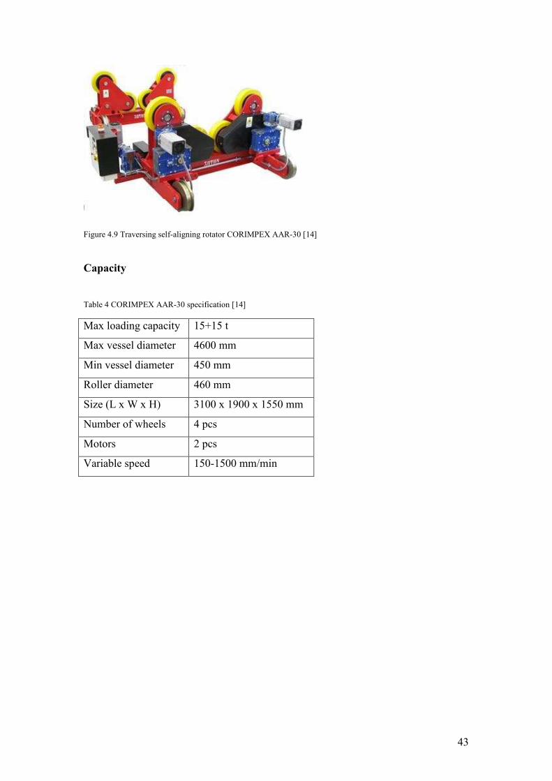
Figure 4.9 Traversing self-aligning rotator CORIMPEX AAR-30 [14] ...................... 43
Figure 4.10 Working principle of sling type rotator .................................................... 44
Figure 4.11 Sling type rotator Koike Trac-Tred T4 [15] ............................................. 45
Figure 5.1 The self-aligning rotator that is use at the company................................... 51
Figure 5.2 Solution 1.................................................................................................... 56
Figure 5.3 Solution 2.................................................................................................... 57
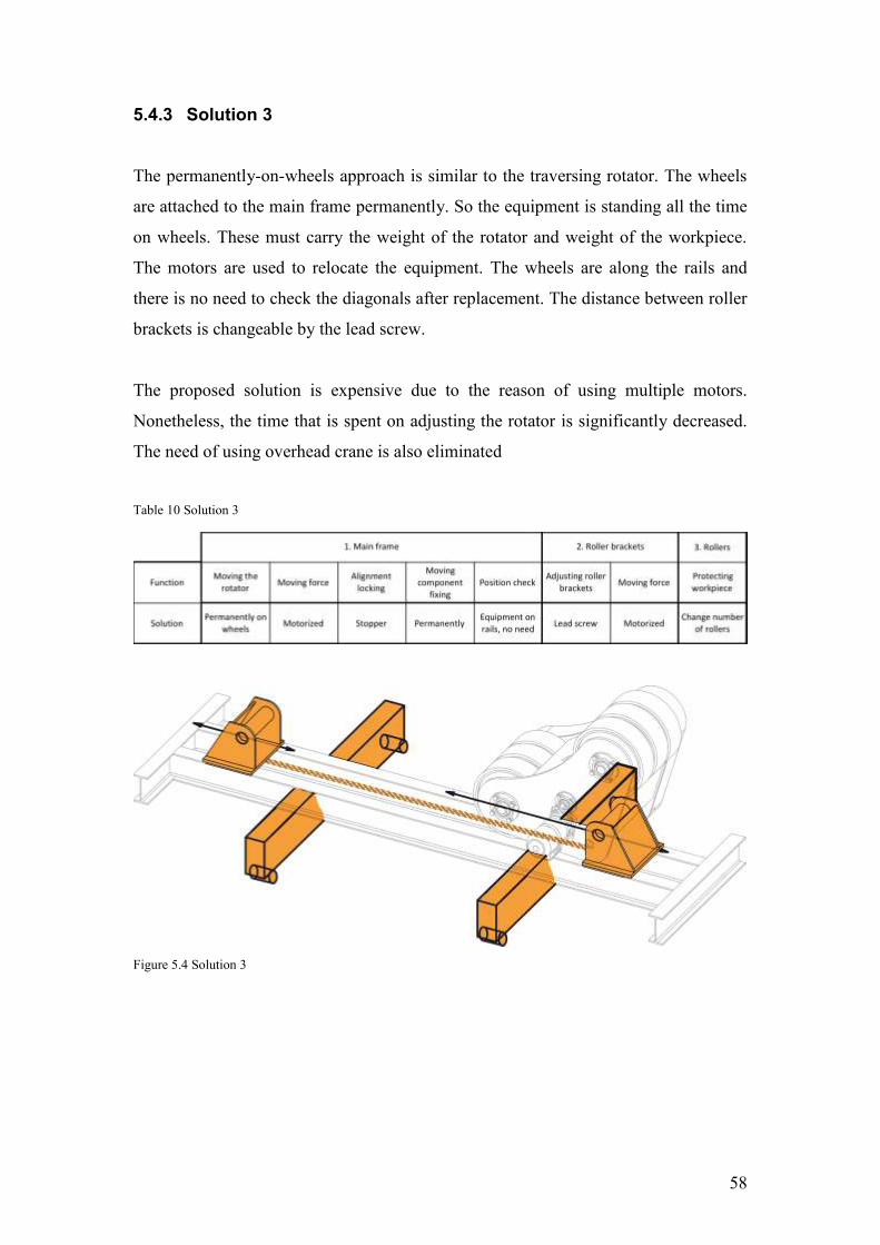
Figure 5.4 Solution 3.................................................................................................... 58

7
Figure 5.5 Main frame improvement ........................................................................... 60
Figure 5.6 Eccentric shaft ............................................................................................ 61
Figure 5.7 Wheel kinematic diagram ........................................................................... 61
Figure 5.8 Wheel locking mechanism ......................................................................... 63
Figure 5.9 Eccentric shaft bearing scheme and applied forces .................................... 66
Figure 5.10 Roller bracket improvement ..................................................................... 67
Figure 5.11 Meshing of the model ............................................................................... 68
Figure 5.12 The boundary conditions .......................................................................... 69
Figure 5.13 Von Mises stress result ............................................................................. 69
Figure 5.14 Total deformation ..................................................................................... 70

8
List of tables
Table 1 Bode driver & idler model SAR1200 specification [9] .................................. 37
Table 2 ESAB CD-30 specification [11] ..................................................................... 39
Table 3 ESAB FIR 35 specification [12] ..................................................................... 41
Table 4 CORIMPEX AAR-30 specification [14] ........................................................ 43
Table 5 Koike Trac-Tred T4 specification [15] ........................................................... 45
Table 6 Table of work parameters ............................................................................... 48
Table 7 Morphological Matrix for possible solutions.................................................. 53
Table 8 Solution 1 ........................................................................................................ 56
Table 9 Solution 2 ........................................................................................................ 57
Table 10 Solution 3 ...................................................................................................... 58
Table 11 Evaluation matrix .......................................................................................... 59
Table 12 The cost of raw material ............................................................................... 71
Table 13 The cost of fasteners ..................................................................................... 72
Table 14 The cost of ready-made products .................................................................. 72
Table 15 Manufacturing cost ....................................................................................... 73
Table 16 Overhead costs .............................................................................................. 73
Table 17 The cost price of the rollers .......................................................................... 74
Table 18 Plate material quantities by the details ......................................................... 84
Table 19 Profile material quantities by the details ....................................................... 85
Table 20 Plasma cutting machine operating time ........................................................ 86
Table 21 Rolling machine operating time .................................................................... 86
Table 22 Welding operating time ................................................................................ 87
Table 23 Machining center operating time .................................................................. 87
Table 24 Band saw operating time ............................................................................... 88

9
Acknowledgment
I would emphasize knowledge base what I have obtained during the master program.
The methods and tools gained through the studies provide the knowledge how to
approach the case in structural terms.
I wish to express my gratitude to the people that supported with their knowledge and
experiences during the process. I would thank supervisor Kristo Karjust for guidance.
Also I would thank quality and development manager Tõnis Tuuder, production
manager Alik Gerasimjak for providing primary data and consultation and other
fellow colleagues.

10
1 Introduction
The initial input for this thesis comes from company called AS Estanc. This company
has rapidly expanded over few years. Due to a new production building, there is a
need for a new tank rotating equipment. The equipment effectiveness is taken into
consideration by example of the existing equipment to increase productivity and meet
the company’s needs. The company has experience with other similar products on
market and is familiar with their strengths and weaknesses.
The overview of the company and a closer look to the tank manufacturing process are
given on the first half of the paper. This phase introduce the importance of the tank
rotating equipment and restrict the scope of the paper. Following, the usage of the
rotator and preparation steps is taken into focus. The bottlenecks are highlighted and
analysed. The attention is also given to already existing products.
The second half of the paper includes the different solution generation, evaluation and
detailed designing by support of various design tools and scoring charts. The strength
calculations and economic calculations are done to validate the design from the
engineering approach.
1.1 Goals and objectives
The expected outcome of this paper is to provide suggestions for improvements of the
existing tank rotating equipment. The concept takes into consideration the aspects of
the specific field production and the company’s needs. The design is focused on the
feasibility of construction based on company’s production capability. Attention is also
given to the main aspects of the tank manufacturing process: such as preparation work,
assembling, including the support activities and jigs, final inspection and cost related
topic.
The objective of the thesis is to improve current equipment that fulfils the company’s
needs and its feasibility to manufacture in-house in both aspects – economical and
production capability.

11
1.2 Methodology
As an engineer, it is easy to deviate from one’s path without having a structured plan
to follow. There is no defined way of solving a problem, but there are generic steps
that should be taken to move toward to desired goal. Haik and Shahin [1] suggest
engineering students can be daunted by the varied sources of new information they
are exposed to during their studies. Also, without guidelines or structure they struggle
to organise information without a clear starting point and finishing line. Therefore,
using the proven design process model is essential [Figure 1.1].
Figure 1.1 The design process [1]

12
The French design model is named after the British author Michael Joseph French [2]
and shown on Figure 1.1. The block diagram shows the design process. Each step
within the model has a number of headings that should be considered at each phase.
The circles on the figure represent different phases. Each step should contain a
number of headings within the model. The rectangles represent work in progress. The
model is drawn as a Flow Diagram to emphasise the progression of the process; one
stage requiring completion for moving to the next.
Analysis of the problem
The process begins with the observation of a market need. Usually this part consists
of identifying the need, and the need is then analysed, which leads to an unambiguous
problem statement. This takes the form of a list of requirements that the product must
fulfil.
The analysis of the problem is a small but an important part of the overall process.
The output is a statement of the problem, which consists of three elements:
x Statement of the design problem.
x Limitations placed upon the solution, e.g. codes of practice, statutory
requirements, customer standards, date of completion.
x The criterion of excellence to be worked to.
Conceptual design
“It is the phase where engineering science, practical knowledge, production methods,
and commercial aspects need to be brought together, and where the most important
decisions are taken.” (M. J. French, 1999).
During this phase, several concepts are generated. It is recommended that a designer
produce several exclusively alternative ideas. Each concept represents a set of
physical principles for solving the problem. These concepts are transformed into a
more concrete representation to allow evaluation and comparison. The concepts are
evaluated and one or more are chosen to form the basis of the final solution.

13
Embodiment of Schemes
Embodiment of schemes phase, “schemes are worked up in a greater detail and, if
there is more than one, a final choice between them is made. The end product is
usually a set of general arrangement drawings. There is (or should be) a great deal of
feedback from this phase to the conceptual design phase.” This is the most time
consuming phase, in which the calculations and complete Finite Element Analysis are
made, as well as the changes in the previous phases. Hence, the feedback loop in the
model leads to reorganization, recalculation etc. of the whole phase.
Detailing
“This is the last phase, in which a very large number of small but essential points
remain to be decided. The quality of this work must be good, otherwise delay and
expense or even failure will be incurred: computers are already reducing the drudgery
of this skilled and patient work and reducing the chance of errors, and will do so
increasingly.” (M. J. French, 1999).
14
2 Overview of the company
2.1 Company introduction
AS Estanc [3] is a leader in manufacturing tanks in Estonia. The main products are
pressurized, non-pressurized, process and fuel tanks. The company’s mission is to
provide professional solutions for the storage and distribution system of industrial
liquids and gases. It is based on project-centred production that offers technical
engineering solutions for the client’s needs – form the initial design to installation of
completed product.
Figure 2.1 Company logo
The company was established in 1992 as a joint company with Finnish and Estonian
owners. The initial name was Estonia-Tanc AS, which was replaced with current
name, Estanc, purely for simplicity. The company started from scratch – it is not
emerge from any pre-existing companies in Estonia. Initially, the company only did
sheet preparation work for vessels, and then began to manufacture simple vessels and
metal constructions as their product range began to expand. Since 1996, the company
is based 100% on Estonian capital. Eventually, Estanc’s production and offices
moved to its current location in Männiku. AS Estanc exports its products all over the
world – from Europe to Asia and United States – and has sales offices in Estonia,
Finland and Sweden [Figure 2.2]. The majority of Estanc’s products are exported
abroad.

15
Figure 2.2 Geographical locations of sales offices
2.1.1 Organizational structure
Planning and controlling of production processes is key to ensuring that production
moves smoothly at the desired level. AS Estanc develops and implements their
management system according to the ISO standard and their own practices. The main
process focuses on the satisfied customer and it includes sub-processes: sales,
purchase, storage, manufacturing, product testing and delivery. The main process
backing support processes are: product development, human assets, infrastructure and
equipment maintenance, working environment, measuring and monitoring, rejected
product management and data analysis.
Sale’s main task is to determine customer needs and product requirements, which
provides a basis to conduct product risk analysis. The purchase sub-process includes
material related topics and verifies outsourcing details. The manufacturing, product
testing and delivery processes are explained in details on next chapter

16
Figure 2.3 The structure of the main processes

17
2.1.2 Production capacity
The company has expanded in the past few years. In 2012, AS Estanc opened a new
production building which is around 8 000 m2 in Jüri Technopark to allow the firm to
manufacture more complex process tanks and heat exchangers with the same quality
and competence level. The building location was chosen based on the good
infrastructure. More than 140 skilled workers, including the office staff, work in both
production buildings. All welders have certifications and workshops are equipped
with welding equipment, half of which are not older than five years. There are two
departments in the production building: Carbon Steel workshop (CS) and Stainless
Steel workshop (SS).
Figure 2.4 Estanc AS production building in Jüri Technopark, Estonia
The carbon steel workshop is able to handle products weighting up to 100 t. The
maximum size of the manufactured product is limited by the size of the production
building door. Therefore, the size of the products cannot be more than 7 m of a
diameter and length up to 60 m. The workshop floor is equipped with rails, which
provides the opportunity to implement a traversing system. The carbon steel
workshop also includes top loaded shot blasting and painting chamber. The chamber
size is 24 x 7 x 7 m. The stainless steel workshop lifting capacity goes up to 60 t. The
size of the manufactured product is also limited by the size of the door that is same –
7 m in diameter and length up to 60 m. Stainless steel workshop includes an acid
pickling chamber.

18
2.1.3 Examples of produced equipment
Between 2014 and 2015, the company successfully completed more than 350
different projects for the container market weighing from 0.5 to 120 tons. A pressure
vessel is container designed to hold gases or liquids at a pressure different from the
ambient pressure. The difference of the pressure is dangerous, and has been known to
cause fatal accidents. The other important sector is fuel and other dangerous fluids
tanks. The quality requirements are high due to the huge impact on the environment
and human health if the above-mentioned tanks fail. Therefore, the market of pressure
vessels and tanks set the highest inspection demands for designing and manufacturing
of a container.
Estanc product range includes:
x Pressure vessels: feed water tanks, ammonia tank, steam accumulators,
pressurized water tanks, compressed air tanks, columns, other pressurized
tanks.
x Fuel tanks: underground double-walled tanks, on-ground tanks
x Heat exchangers: shell and tube heat exchangers, air preheaters
x Non pressure tanks: scrubbers, blow-down tanks, other non-pressure tanks
x Other products: chimney, piping
x Services: boring machine, insulation, installation,
x Tank head: manufacturing, selling

19
Figure 2.5 Example of produced equipment
Feed water tank weight 76.5t; length 21.5m; diameter 4.5m; Finland
Chimney; weight 25.5t; length 37m; diameter 1.9m
Heat exchanger; weight 23.1t; length 6.1m; diameter 1.8m
Condensing tower; weight 82t; length 33.6m; diameter 4.3m; Estonia
Chimney; weight 5.4t; length 27m; diameter 1m

20
Figure 2.6 Example of produced equipment
Reactor Dump Tank; weight 82.5 t; length 14.6m; diameter 4.5m; Finland
Feed water tank insulated; weight 22.5t; length 13m; diameter 3.3m Scrubber; weight 16.6t; length 9.8m; diameter 3.8m
Scrubber; weight 10.8t; length 10.4m; diameter 3.5m

21
2.2 Tank manufacturing process
The product manager plans and controls the process of manufacturing so that process
moves smoothly at the required quality level. Meanwhile, one must keep balance
between the cost and quality objectives [4]. “Process control has two purposes: first,
to ensure that operations are performed according to plan, and second, to continuously
monitor and evaluate the production plan to see if modifications can be devised to
better meet cost, quality, delivery, flexibility, or other objectives.” (W. K. Holstein,
2013). Manufacturing is based on the available equipment and resources. The
company is established in-house rules and agreements to manage the production
department. The manufacturing process consists of the following steps (Figure 2.7):
x Detail preparation
x Assembly and welding
x Inspection
x Surface treatment, finishing
Process starts when the approved drawings are delivered to the production department.
Concurrently, the raw material, ready-made, and semi-finished products are ordered
and delivered to the stock. The raw material heat number is used to identify and track
material movement in the workshop. It is required for final documentation, which
proves that suitable materials are used and meets the requirements for specific project.
The first phase is preparation of the details and ordered details for assembly. It begins
with cleaning (shot blasting, pressure washing) the material. The shell material is cut
to the dimensions using guillotine shears. The edge preparation for shell material is
done due to welding reasons. Final step is rolling the shell to the desired diameter.
This phase also covers the other detail preparations: pipes and other profiles are cut to
the length according to the specification. It also includes pipe connection preparations:
thrilling holes, flange and pipe welding and bevelling. Other details are cut to the
right shape using the plasma-cutting machine. Details that needs after cutting
mechanical treatment are done in this phase. The pre-inspection is done before details
are handed over to the assembly phase. It is required to eliminate discrepancy details

22
and minimize the mistakes beforehand. At this stage replacing or re-producing the
discovered discrepancies are low costs and not time-consuming operations compared
with other stages.
Second phase is the core phase of the tank manufacturing. Cylindrical sections are
assembled and tank heads are installed. In this phase the tank stands most of the time
on the rotator machine until the assembling is done. Therefore supportive activities
and jigs cannot be underestimated to keep the process run smoothly. Production
workers need to rotate the tank to the corresponding angle to cut the openings for pipe
connections and for welding purposes. The reinforcement pads, brackets, lifting eyes,
brackets and other details are installed. Final step is post-weld heat treatment. It is
method for reducing and redistributing the stresses, which is caused during the
welding.
Inspection is required to detect any discrepancy between required quality and reality.
The Notified Body (NoBo)[5] must approve projects that require technical, design
and manufacturing examination. Pressure vessels, tanks and other products follow the
specific project requirements and corresponding country regulations or international
standards according to the manufacturing phase. This phase also includes hydrostatic
pressure testing. NoBo issue the declaration of Conformity that gives the right to label
the product with the CE mark [6].
Final phase is surface treatment and finishing. The surface treatment (shot blasting,
acid pickling, painting) is done in this phase according to the customer needs and
wish- Finally the surface treatment report is created. The finished product is packed
and delivered to the customer.

23
Figure 2.7 Tank manufacturing cycle

24
3 Rotator positioning and aligning analyse
This chapter takes into a focus the assembly and welding phase. The manufacturing
cycle is divided into different phases and it is described on previous section.
Retroactively are analysed three different projects, which are finished and delivered to
the customer. These projects represent the cross-section of different types of product
nomenclature. The projects are chosen correspondingly to the weight, diameter and
the eccentricity of the vessel. The outcome of this is to detect and expose the
bottleneck and time-consuming activities considering the use of tank rotating
equipment in the manufacturing process. Therefore, a deeper look is taken at the
assembly and welding phase where the rotators functionality and usability plays an
important role.
The various steps must be done beforehand. The assembling starts with the
preparation of the workshop floor and determining some of the key factors of specific
project. Previously the manufacturing resource planning is needed to reserve
workshop floor, planning the production workers and materials for the specific project.
Also the production timetable is generated.
3.1 Carrying capacity determination
The tank rotator set typically includes driver and idler unit. The driver unit supports
the vessel from one end and idler unit the other end. The driver unit transfers the
rotational movement to the workpiece and the idler merely supports the workpiece.
Each rotator has a maximum load capacity which cannot be exceeded. Therefore, it is
necessary to determine the maximum weight of the specific vessel to choose the
amount of rotators needed. The load of the symmetrical vessel can be equally divided
to each roller bracket. Figure 3.1 shows a single set of rotator supporting the
cylindrical shell with the centre of gravity is on the centre of rotation axis. The
number of idler units is added if the rotator loading capacity is not enough to carry the
vessel total weight [7].

25
Figure 3.1 Vessel weight distribution
The placement of each of the turning roller unit is in relation to the workpiece nozzles
and other pipe connection locations that must be taken into consideration before
lifting the cylindrical shell onto the rotators. The rotator placement on the workshop
floor must be positioned so that the rollers do not interact with any openings,
connections or stiffening rings. It is necessary that rollers are in contact with the
surface of the entire cylindrical shell perimeter and does not interact with the two
cylindrical section circumferential welds. The workpiece and rollers should be
checked during each operation for unobstructed rotation and inspected for
interference from protruding parts. Any nozzle or other connections assembled during
the assembly phase that can potentially be on the rollers requires the readjustment of
the rotator.
Besides the rotator carrying capacity, the cylindrical shell thickness must be taken
into consideration. It has been observed that the thin-walled cylindrical shells are
more likely to get damaged on the rotators. The outer surface gets dents and leaves a
trail during assembly. If the roller wheels are narrow and the contact surface between
shell and roller wheel is small, then the weight of the shell presses a dent into the
shell’s surface. The other potential situation for dents occurs when the cylindrical
shell is placed on the rotators. It is practically impossible for a crane operator to lower
a shell so that the weight of the workpiece is transferred equally and smoothly to all
the rotator wheels simultaneously. However, it does not occur on thick-walled
cylindrical shell.

26
3.2 Alignment analysis
Previous project leftovers and trash are cleaned from the floor. The rotating machines,
both driver and idler unit, are lifted to place using the overhead cranes. Then the
alignment of the rotators becomes important. Each added idler unit increase the
probability of misaligning the rotators. The one set of rotators is best combination to
align the rotators compared to three or more sets of drivers and idlers used. The
rotators must be on a flat, hard, level floor and are not bolted to the ground. Also
rotators must be placed so that the rollers axes are parallel to the vessel centreline
(Figure 3.2). These factors are important for aligning the rotators to prevent the rollers
making a helix contact angle with the vessel surface. Helical contact between the
roller and the vessel causes spiral movement of the workpiece that leads to
overturning the vessel from the rotators. This condition is also referred as “end
creep”[7].
Figure 3.2 Proper setup for rotator alignment

27
The common placements of misaligned rotators are shown on Figure 3.3 that causes
end creep. Having an incorrect rotator position cause numerous problems – the rollers
scrub the workpiece surface and leaves a trail. The weight of the vessel is unevenly
balanced on rollers, which damage rollers. Possible rotator misalignment situations
that cause end creep are shown on Figure 3.3. The driver and idler unit are not parallel
to each other. In other words the rollers axle are not parallel to the vessel centreline
(Figure 3.3, a). The driver and idler unit are parallel to vessel centreline but driver and
idler unit central axis are not on the same line (Figure 3.3, b). The floor is uneven so
that the rotator rollers are on different level (Figure 3.3, c).
Figure 3.3 Common placements of misaligned rotators

28
Avoiding the previously described end creep conditions is crucial for smoother and
safer manufacturing. It also avoids later readjustments of the rotator set, which can
cause malfunctions of the device. Common practice to check the parallelism between
driver and idler unit (X = Y, Figure 3.4) is checking the diagonals. Also in practise it
is the quickest way to ensure that two rotator units are parallel to each other. The
diagonal distance is measured from one corner of the driver roller axle to the opposite
corner of the idler roller axle (Figure 3.4, distance A and B). Both diagonal
measurements must be equal length for the rollers to be parallel (therefore A = B). If
not then the adjustment is needed. This method assumes that the rotators wheels axles
are parallel to each other.
Figure 3.4 Driver and idler unit parallelism alignment check

29
3.3 Stability analysis
Before lifting the cylindrical shell to the rotator, the distance between the rollers
needs to be clarified. The distance between rollers (length c, Figure 3.5) is important
for supporting the workpiece and preventing workpiece becoming unstable and
overturning from the rotator. The distance between rollers is in direct relation with the
diameter of the workpiece. There are different types of rotators on the market -
conventional and self-aligning rotators. These are more explained in the next chapter -
Equipment research and analysis. The bigger the vessel diameter is, the greater
distance between rollers is required. Therefore, the angle between two lines extended
from the centre of the workpiece to the centre of each rotator roller axle is used (angle
a, Figure 3.5). This angle is also referred as the “included angle” [7]. Figure 3.5
shows a balanced symmetrical load workpiece, where the centre of gravity is on the
same line as the vessel rotation axis. The recommended included angle is between 30
degrees and 60 degrees [8]. A greater included angle can provide more stability of the
workpiece, but additional torque is required to rotate the workpiece. Similarly a
smaller included angle requires less torque to rotate the workpiece but the stability of
the workpiece can become an obstacle.
Figure 3.5 Distance between rollers

30
According to the observation, it is uncommon for the centre of gravity to be on the
same line as the rotation axis. Vessels usually include connections, inspection
manholes or other protruding parts. This affects the centre of gravity of the vessel and
places it off from the vessel rotation axle. If the centre of gravity of the vessel exceeds
the width or length of the rotator set spacing area, then overturning stability must be
taken into consideration (Figure 3.6, hatched area). If the centre of gravity is close to
the edge, then production workers can easily move the centre of gravity location by
just leaning against the workpiece or assembling inside the vessel. It could be enough
for the workpiece to become unstable. When an eccentric load or unbalanced weight
is outside of the spacing area then it causes the workpiece to overturn horizontally or
longitudinally as shown on Figure 3.7.
Figure 3.6 Centre of gravity within the width and length of the roller spacing area

31
Figure 3.7 Overturning instability
An eccentric load requires more traction to keep the rollers from slipping. It has been
reported in small (less than 1 meter of diameter) vessel production where protruding
manholes or other connections are on the same side of the vessel. Widening the
rotator rollers can be used to provide greater traction. It also brings the greater torque
requirement for rotating the workpiece. The further the centre of gravity of the load is
from the workpiece rotation axis, the greater torque is needed to rotate the workpiece.
Greater torque could stall the driver unit. The offset counterweights are added to the
eccentric workpiece to prevent the workpiece from overturning and reducing the
amount of total workpiece imbalance. Alternatively, widening the rotator roller
spacing can overcome the condition.

32
3.4 Cylindrical section assembly
A workpiece (i.e. chimney, columns) often has more than one cylindrical section thus
requiring one driver unit and two or more idler units to support the workpiece (Figure
3.8). A driver and idler unit supports the first cylindrical section and two idler units
support the second workpiece. The first two sections are aligned and tack welded. The
circularity is checked before circumferential welding. Rotator equipment ensures
smoother welds. Circumferential welding is done by having the cylindrical shell
rotated on the rotator. Then the idler units are moved to the new location for another
cylindrical shell. As the workpiece gets longer, then every added rotator unit is
another source of misalignment [7]. Alternatively, a fit-up rotator is used for this step
in the assembly and welding phase.
Figure 3.8 Workpiece with multiple cylindrical shells
The next step after putting the cylindrical shell together is to mark the shell for nozzle,
bracket and stiffening ring locations, as well as cutting opening, preparing the edges
and inserting the reinforcement pad and nozzle. The workpiece is rotated to the
desired angle, which gives to the welder good position for marking and welding the
protruding parts. In the next steps the rotators importance relies on the jig level,
whose main function is to rotate the workpiece to the desired angle. The vessel is
assembled and handed over for inspection and surface treatment.

33
3.5 Conclusion
There are various preparation steps to take before the cylindrical sector is finally lifted
to the rotators. It starts with planning the workshop floor according to the size of the
workpiece. The alignment of the rotator is next important step in the assembly and
welding phase, as well as the basis for assembling the rest of the vessel. Therefore,
care is taken with measuring out the diagonals and checking the placement of the
rotators. Selecting the rotators must also not be overlooked. Suitable rotators are
selected by the diameter and weight of the vessel and also the centre of gravity is
taken into consideration.
Observation and interviews indicate that some bottlenecks do occur. Aligning the
rotator is one of the most time-consuming activities in the preparation of the assembly
and welding phase. Also, the readjustment of the driver and idler unit is occasionally
needed due to various reasons – most likely because cylindrical workpiece protruding
parts may be in the way of the roller’s wheels. If the need appears during the middle
of the assembling phase, then it is difficult to ensure the alignment of the rotator. The
driver and idler unit both weight a considerable amount, requiring the use of overhead
cranes to move them.
The workshop practices to handle these types of situations include the following steps:
First, the workpiece is lifted up with the overhead crane from the side where the
alignment of the rotator unit is needed. Second, the production worker uses a lever or
a crowbar to adjust the rotator to the desired position using force. Finally, the
workpiece is lowered to the rotator. Readjustment using this method is toilsome and
more difficult to ensure the rotators are parallel. Also, the overhead crane is used to
lift up the workpiece.
The other outcome is the use of the overhead crane: the overhead cranes are essential
for moving heavy object inside the production building. They are used to move the
raw material, semi-finished products, and workpieces around the workshop floor. A
production outage may occur when the overhead crane is needed to align or readjust
the rotators but is already in use for other projects. The readjustment of the rotator is

34
sometimes needed due to miscalculations of the rotator placement, and aligning the
rotators on the workshop floor takes between 30 to 60 minutes. This is on the
assumption that the overhead crane is available and later readjustments are excluded.
It has been observed that cylindrical shells become damaged during the assembly and
welding phase on the rotators. The outer surface of the shell gets dents when the shell
is placed to the rotators. It is practically impossible to lower the vessel smoothly onto
the rotator so that the load simultaneously contacts all the rollers at once. In actual use,
a workpiece hits one roller wheel first before the load is divided equally on all other
rollers. There is also the narrow roller wheel, which is in contact with the workpiece
and increases the pressure on the workpiece surface. The dents occur where the roller
contacts the vessel. A narrow roller wheel is important when the workpiece has
several protruding parts on its surface which are close to one another.
The other issue that rises when the workpiece is lowered onto the rotators is the self-
aligning rotators used by the company. This issue is more common when working
with larger diameter shells (>5m). The rollers do not align automatically when the
workpiece is lowered into place. In that situation, only the upper roller wheels touch
the workpiece. Manual adjustments are required on the rollers before lowering the
workpiece to ensure that both upper and lower rollers touch the workpiece.
The diameter of the cylindrical shell varies depending on the project. The stability of
the workpiece and maximum use of the rotators should be taken into further
development.

35
4 Equipment research and analysis
It is necessary to carry out research to identify different types of tank rotating
machines that are available on the market. The tank rotating machines are referred to
as welding rotators, roller beds, turning rolls or tank rotators. The market of rotators is
wide, and various companies produce different types of machines. Welding rotators
nominally come in sets or pairs consisting of a powered rotator (driver unit) and an
idle rotator (idler unit). The further research is mainly grouped by the type of the
rotator wheel and presented average technical and economical parameters. The main
parameters and specification is obtained from the manufacturing company sites and
direct communication with vendors. These machines are examined and evaluated by
the product’s various aspects.
There are several possibilities to categorize the types of rotators. One possible way is
to divide rotators into main groups according the rotator wheel type – Conventional
and self-aligning rotators (Figure 4.1). The subgroups are divided according to the
type of the centreline – fixed or adjustable. Finally, the extra value added of the
rotator. These added values could be represented in both types of rotators. The
differences are explained in details on next sections.
Figure 4.1 Types of rotators on market

36
4.1 Available equipment
4.1.1 Self-aligning rotating machine
Self-aligning rotators are mainly used in pressure vessel and tank manufacturing
companies where the product diameter varies. The roller bracket assembly has two
separate rollers, which are attached to the swing. The swing is hinged to the main
frame that gives the freedom to rotate around its axis. Self-aligning rotator adjusts the
swing angle by itself to the workpiece without the need for manual pre-adjustment.
This ensures the item being worked remains central to the rotator frames and
eliminates the need to adjust the welding head. Also, a bigger diameter – up to 6m –
and irrespective of roundness or irregularity of shells, can be accommodated without
need for any adjustment from a worker.
First, the rotators are placed using the lifting device on to the workshop floor
according to the length of the shell. Ensuring the rotator units are parallel is crucial.
Common practice is to measure the diagonals between drive and idler unit. Finally the
worker places the shell on to the rotator.
Working principle
One possible solution is introduced on Figure 4.2. It is one motor synchronized driver
system. The motors output is transferred to the both roller brackets via worm drive
method. Gear drive, or optionally the chain drive, is used to transfer rotational
movement power to the rollers, which is in contact with the workpiece.
Figure 4.2 Working principle of self-aligning rotator

37
Figure 4.3 Self-aligning fixed rotator Bode drive & idler model SAR1200 [9]9
Capacity
Table 1 Bode driver & idler model SAR1200 specification [9]
Max loading capacity 20+20 t
Max vessel diameter 5200 mm
Min vessel diameter 450 mm
Roller diameter 457 mm
Size (L x W x H) 3050 x 1000 x 1035 mm
Number of wheels 4 pcs
Motors 1 pcs
Variable speed 100 – 1500 mm/min

38
4.1.2 Conventional rotating machine
The construction of these types of machines have roller bracket assembly on both
sides of the main frame. Compared to previous types of machine, the brackets are
bolted on the main frame. The main frame is drilled on top faces of the roller bracket
to provide accurate alignment and to secure the rollers. Therefore, both brackets have
to be moved manually by the worker as the workpiece diameter changes. Powered
rotators have two motors on both roller brackets to output higher torque for smoother
rotation. Alternatively, there are also roller brackets with the lead screw that allows
for sliding the roller brackets over the main frame equally in both directions. These
are referred also as self-centering rotators or screw-adjustable rotators [10].
Similar to the self-aligning rotators, units need to place on to the workshop floor
according to the length of the shell. Besides dimensioning the diagonals of two units,
workers must also manually adjust the roller brackets according to the shell diameter.
Working principle
It is two motor synchronized drivers system, where both roller brackets are connected
to independent motors. The output power is transferred to the rollers by the same
methods as described on self-aligning rotators by either gear or chain drive methods.
Figure 4.4 Working principle of conventional rotator

39
Figure 4.5 Conventional adjustable rotator ESAB CD-30 [11]11
Capacity
Table 2 ESAB CD-30 specification [11]
Max loading capacity 15+15 t
Max vessel diameter 6000 mm
Min vessel diameter 500 mm
Roller diameter 520 mm
Size (L x W x H) 3920 x 765 x 892 mm
Number of wheels 2 pcs
Motors 2 pcs
Variable speed 125-1250 mm/min

40
4.1.3 Fit-up rotators
A workpiece has often more than one section. Fit-up rotators are used for assembling
two similar or different diameter cylindrical sections together by tack welding. It is
mainly used on wind towers, chimneys and generally in series productions where
there is a need for assembling many cylindrical workpieces together. Fit-up rotators
are specially designed to rotate, align and support two sections of the shells. The
aligning feature reduces the handling and adjusting time. The construction of this type
could be same as the conventional or self-aligning rotating machines with the extra
feature added.
Working principle
The powered rotator is placed under one end of one cylindrical section and an idler
rotator is placed under the opposite end of the other section. The two fit-up rotators
are placed to the closer end of the both cylindrical sections. Moving the both fit-up
brackets vertically (bringing the rollers closer or moving them apart) raises or lowers
the cylindrical sectors. Moving one bracket shifts the shell left or right. Rollers are
driven by the hydraulic cylinders to adjust and match the cylinders axis with the other.
The tack welding and further adjusting is done for proper alignment. Finally the full
circumferential welding is done.
Figure 4.6 Working principle of fit-up rotator

41
Figure 4.7 Fit-up rotator ESAB FIR 35 [12]12
Capacity
Table 3 ESAB FIR 35 specification [12]
Max loading capacity 35 t
Max vessel diameter 5000 mm
Min vessel diameter 2200 mm
Roller diameter 300 mm
Size (L x W x H) 2330 x 1600 x 1150 mm
Number of wheels 4 pcs
Motors -
Variable speed -

42
4.1.4 Traversing rotators
The traversing rotators range is to carry vessels of various lengths and to allow for
longitudinal movement of the workpiece. Both types - self-aligning and conventional
rotators are available on the market. The weight of the shell produces enough traction
on the rotator’s rollers to maintain the distance between driver and idler rollers when
the vessel is moved longitudinally. Traversing rotators are mainly used together with
fit-up and welding manipulators as a complex production line in the cylindrical sector
assembling phase. The advance of the traversing rotators compared to other rotators is
eliminating the need to use the lifting devices. Workpiece can be transported from one
workstation to another by the traversing system. It can save several material-handling
lifts of a vessel during the manufacturing. Therefore, the production could increase
and provide safer material movement along the workshop floor.
Working principle
The driver and idler rotators are both installed on a rail-mounted car. The extra
planning and preparation is required beforehand in the workshop floor to take into use
the traversing rotators. The rails need to be installed to the workshop floor. The car
wheels travel along the rails smoothly if the track is accurately aligned, flat, straight
and levelled. Majority of the traversing rotators are designed to operate on standard
1435 mm gauge track [13].
Figure 4.8 Working principle of traversing rotator
43
Figure 4.9 Traversing self-aligning rotator CORIMPEX AAR-30 [14]14
Capacity
Table 4 CORIMPEX AAR-30 specification [14]
Max loading capacity 15+15 t
Max vessel diameter 4600 mm
Min vessel diameter 450 mm
Roller diameter 460 mm
Size (L x W x H) 3100 x 1900 x 1550 mm
Number of wheels 4 pcs
Motors 2 pcs
Variable speed 150-1500 mm/min

44
4.1.5 Sling type rotator
A chain or sling is used to handle thin walled vessels or precious surface cylindrical
workpieces. This type of rotators is used mainly in milk coolers, silos production and
it becomes great help in producing elliptically shaped workpieces. The sling provides
more supportive surface on the workpiece while rotating compared to other rotator
types. That provides extra supportive surface for the workpiece to prevent damage to
its surface i.e. wrinkling or denting the outer surface of thin walled workpieces. The
workpiece can be rotated only in one direction according to the chain location.
Working principle
Sling type rotators can be used on a common main frame. The workpiece must be
placed on the rotator carefully. Sling type rotator chain adopts the shape of the
workpiece that provide an extra supportive surface. It is one motor powered driver
system. The chain transmits mechanical rotation from the motor side roller to the
other roller.
Figure 4.10 Working principle of sling type rotator

45
Figure 4.11 Sling type rotator Koike Trac-Tred T4 [15]15
Capacity
Table 5 Koike Trac-Tred T4 specification [15]
Max loading capacity 10.8 + 10.8 t
Max vessel diameter 6100 mm
Min vessel diameter 4800 mm
Roller diameter -
Size (L x W x H) 3660 x 1070 x 960 mm
Number of wheels 2 pcs
Motors 1 pcs
Variable speed 40 – 1880 mm/min
KOIKE ARONSON, INC. / RANSOME
TRSeriesTrac-Tred Turning Rolls
Feat ures
Precision Rotation of Thin Walled Vessels
Koike Aronson Ransome’s Trac-Tred Turning rolls provide the solutionfor safely turning thin walled or precious surfaced cylindrical pieces withoutmarring, wrinkling or indenting the vessel. The patented Trac-Tred systemallows for steady, precise rotation of vessels from 4’ to 20’, with capacitiesup to 24,000 Lbs.
Various materials for pads
NEMA 12 Electricals
Thin walled vessels
Low voltage hand controlpendants
50:1 Variable speed drives
PAGE 28
Standard hand pendant provided with all models
Optional foot switch controls available
Specifications T1(Single Strand)
T2(Double Strand)
T3(Triple Strand)
T4(4 Strand)
Load Cap. Lbs. 6,000 12,000 18,000 24,000
Speed, IPMTractive Pull, Lbs.
Std. Dia. Range
80 -1.6 IPM1,000
4' - 10' Dia.
80 -1.6 IPM1,000
6' - 12' Dia.
74 -1.5 IPM2,000
16' - 20' Dia.
74 -1.5 IPM3,000
16' - 20' Dia.

46
4.2 Equipment component analyse
The equipment research reveals that many different types, parameters and
combinations of rotators exist in the market. To get full picture of the possible
machines and variable combinations on the market, categorisation was done, based
upon the type of rotator wheel: self-aligning rotator or conventional rotator. The
subcategory determines if the rotator centreline is fixed or adjustable (see Figure 4.1).
Also the different added value is listed in the category. All above-mentioned
equipment have their strengths and weaknesses. The choice of the suitable type of
equipment depends heavily on the workpiece parameters (weight, diameter etc.) and
process is performed (See Table 6).
Self-aligning rotators
The result of the market research shows that the self-aligning rotators are
manufactured mainly as a fixed centreline. This sets the limit of the maximum and
minimum diameter of the workpiece. It does not require any adjustment of the roller
brackets for fitting different size of the workpieces. Nevertheless, it has been noticed
that working with bigger diameter workpieces then self-aligning roller brackets
requires third party intervention. The maximum loading capacity varies on different
types of rotators, as well as the maximum and minimum workpiece diameter, number
of rollers various etc. The self-aligning rotators are available both type - as a
traversing or stand-alone.
Conventional rotators
There are mainly two types of conventional rotators available on the market – fixed
and adjustable centreline. Adjustable centreline conventional rotators need manually
adjustment by the worker. In addition, there are also motorized types available but the
adjustment is still needed beforehand to lower the workpiece. Also, in addition to the
previously mentioned sling-type rotators should be also marked. It is designed
especially for the thin-walled workpieces. The contact area is bigger compared to
other types. The workpieces are fully supported under the lower part of the workpiece

47
via belt or chain. The author does not have personal experience with this type of
rotator, but according to the desktop study, it seems rather unstable for rotating
different size of vessels. Further research and cooperation with the vendor is needed.
The restriction sets the small range of cylindrical shell diameter which is suitable for
sling type rotators.
Most used equipment type is adjustable centreline with various values added. The
typical adjustable rotator brackets are bolted to main frame. Like all represented
options, this type of rotators has disadvantages. The roller brackets have to be
manually positioned across the frame to suit the diameter of the workpiece. It requires
a production worker to find the parameters of the vessel and position the brackets
distance according to the diameter of the workpiece beforehand.

48
Tabl
e 6
Tabl
e of
wor
k pa
ram
eter
s

49
4.3 Requirements for tank rotating equipment
Different types of equipment positive aspects, usability and restrictions are taken into
consideration, which is the outcome of the equipment component research. The needs
and demands of the company are also taken into consideration – the design of the
current equipment should remain and changes in the design should be done as little as
possible but as much as needed. The side objective for the company is to implement
the improvements to other already produced equipment, as well. The decision is made
to improve the next batch of tank rotator equipment based on the result of the
previous study. The components that should be pointed out and used in the further
development:
x Alignment of the rotator
The time spent on aligning the rotators.
x Overhead crane
Reduce the usage of the overhead crane in any mean related with the
rotators.
x The range of the rotator usability
Maximize the usage of the rollers on different projects. The range of
the workpiece diameters is increased, which suits with rotator
equipment and consider the matter of the bigger cylindrical diameter
workpieces.
x Workpiece outer surface
Prevent the workpiece outer surface to get dents caused by the rotators.

50
5 Optimization of the tank rotating machine
The problem discussed in the thesis does not assume to generate a conceptually new
solution. Rather, it is focused on developing suitable solutions to one specific
company, which takes into consideration the needs and competence of the company.
The components that are used in the development of the existing equipment are new
for the company, but are not inventions. It is focused to maximize the benefits of the
equipment and minimize the efforts, which is related with operating with the
equipment.
Five years ago, the company has produced one batch of the rotators by itself.
Difficulties and setbacks appeared in the production and early stage of the testing, due
to a variety of reasons: mainly due to lack of the knowledge, bad quality of the
assembly or detailed drawings, outdated technical information and the lack of
availability of the ready-made products. It is out of this thesis scope, but the author is
responsible for, besides the development, to update technical information according to
the availability of the ready-made products (such as bearings, motor-reducer etc.) and
to ensure that selected components fit to each other. Also, the assembly and detailed
drawings are drawn upon the major focus of eliminating the previous production
difficulties and defaults.
As previously mentioned, the production volumes are increased and therefore, there is
a need for new set of rotators. The existing rotators are reviewed and modernized. The
following development of the rotators takes into consideration the above-mentioned
bottlenecks, which occurred by the time and usage of the equipment and external
circumstances.
The SolidWorks 3D [16] modelling software is used to generate preliminary isometric
views and detailed drawings.

51
5.1 The existing equipment
The equipment that is currently in use at the company is shown below (Figure 5.1). It
is a typical self-aligning rotator with fixed centreline that is described on chapter 4.1.1.
The difference is the number of rollers the equipment uses. It has double set of rollers
on both brackets. That increases the contact surface with the workpiece to distribute
the load more evenly.
Equipment uses two 0.37kW motors for both roller brackets. The main frame is from
two parts that are bolted together. The maximum loading capacity is 12.5 t + 12.5 t
and the maximum vessel diameter is 4800 mm, minimum 540 mm. Roller diameter is
410 mm and width of the roller is 150 mm. Variable speed 150 - 1120 mm/min,
weight 1025 + 820 kg.
Figure 5.1 The self-aligning rotator that is use at the company
5°
5°
5° 5°
2000 10
00
104
0
Main frame
Roller brackets
Rollers
C
D
E
H GA B
FB FG
FD
FD
C
D
E H
G
A
B
FB FG
FGFB
B
A
G
H
ED
C
C
D
E
H GA B
FB FG
FD
Stopper: wheel tube
Stopper: Main frame
REVISIONS
REV. DESCRIPTION DATE DESIGNER
5°
5°
5° 5°
Title:
Project:ROLLER BED (DRIVER)
ESTANC AS ORIGW15123.000.01rev.1Drawing no.
Quantity: Weight:Designed by: Checked by:
J. LehtmeApproved by - date:Remark:
Scale:1:10(A1)
Date: Working no.W15123128.10.2015
Sheet: 1/15 896.5 kg All sharp edges and corners R2
K. JagomannK. Jagomann

52
5.2 Equipment division to key components
Efficient optimization and design presumption is to specify different components on
the rotator. Therefore, according to the outcome of the study, the existing rotator is
divided into three different components, which are taken into further development.
The components are examined separately and the solutions are proposed for each
component. Nevertheless, the equipment’s different components must be compatible
with each other and form a complete solution. The key components are (Figure 5.1):
x Main frame
x Roller brackets
x Rollers
The final equipment is still a tank rotating machine, but according to the previous
experience, it is better to divide these into separate key components. The order of the
key components for further development is chosen according to the importance of the
need and the influence to the overall design. The above-mentioned list is taken as a
base for further development.
The main frame is most suitable component to provide ideas for speed up the
alignment of the rotators. The design of the main frame must fulfil the need to
decrease the time that is spent on aligning the rotators. The change in the main frame
design determines the other key components design and sets limits for other
components development. The roller brackets are taken into focus to maximize the
usage range of the rotator. The changes in the main frame design have the most effect
on the roller bracket design. Therefore, it is necessary to ensure the components are
compatible with each other. The roller, which is not the most important but a still
needed component in the further development point of view. The change in the design
of the previous key components does not affect so much the roller design but cannot
be overlooked.

53
5.3 General Morphological Analysis
The morphological analysis is a solution by combining design alternatives. This
allows combining design options at the sub-function level to come up with suitable
solution for improving the existing equipment [1]. The equipment is divided into key
components, which is the base to create the morphological matrix. The functions are
categorized based on the key components and the matrix is filled with different
potential solutions. The provided solutions are randomly placed in the matrix.
Therefore, the overall compatibility of the equipment components must be ensured
before moving to detailing. The morphological matrix is generated and evaluated with
the most suitable features according to the requirements (Table 7). Each function is
analysed and the most suitable option is selected.
Table 7 Morphological Matrix for possible solutions

54
1. Main Frame
The main frame is divided into sub-category by different functions. Moving the
rotator for alignment purposes is important function of this category. The outcome of
the morphological matrix reveals different solutions between to choose suitable
approach. An option where rotator is permanently on wheels requires equipment to be
on the wheels while it is in the working conditions (workpiece is lowered to the
rotator). The wheels are required to bear the rotator weight and in additionally the
workpiece weight. Option where the rotator is lifted to place is described and
analysed in previous sections. Another option is to use the wheels when the rotator is
set to the place. After the rotator is aligned then the wheels are removed.
The next function in the category is the moving force - the source or method how the
rotator is transported from one point to another. One option is to manually move the
rotator. It could be any form of movement where the effort of the production worker
is involved. The other solution could be usage of the extra equipment. This involves a
wide range of external resource to move the equipment.. Also other solution is to use
motors that move the rotator to desired place.
Another function related to the main frame is the alignment component locking. It
becomes important when the wheels or other movement are used for aligning the
rotator. The alignment locking prevents the rotator to move away from the desired
position when the workpiece is lowered onto the rotator. One option is to use stoppers,
which are commonly used in furniture industry. These are typically attached directly
to the wheel. The other option assumes that rotator does not stand on the wheels. The
main frame is the stopper; the weight of the rotator prevents any movement. Finally,
the external stopper can be used. These are any kind stand-alone stoppers, similar to
chocks.
The one side request is to use developing solution to other existing rotators as well.
Therefore the component fixing to the frame is taken into observation. The moving
component could be easily just fixed permanently to the frame. The temporary fixing
solution idea is to detach when the alignment is done. Finally, the bolting option is
mixture of the two previous solutions.

55
The importance of the position check is described on previous chapter and cannot be
overlooked. One of the most common solutions is to check the diagonals manually by
the production worker. The position check is not required when there is a rotator on a
traversing system. Only the distance between the two rotators is measured and
parallelism is ensured by the traversing system. Other option is to mark the parallel
lines on the production floor. It requires a one-time effort but later maintenance or
marking again is required.
2. Roller brackets
The distance between the roller brackets is in direct relationship with the range of
different workpiece diameter. The main function is adjusting distance between the
roller brackets. One possible solution is to use intermediate parts to extend the frame
and therefore distance between roller brackets. Other solution is to make the roller
brackets removable. The roller brackets are independent units and could be removed
from the main frame. Finally, the lead screw is one possible solution. The both roller
brackets are attached to the lead screw and the distance between brackets is
changeable via the screw.
The moving force for adjusting the roller brackets is also taken into focus. The
possible solutions are similar to moving the main frame. These are: manually by the
worker, use motors or some extra equipment to lift to the desired place the roller
brackets.
3. Rollers
The rollers’ importance is related to the protection of the workpiece from dents. One
possible solution could be wider or narrower width of the roller. Wider rollers
increase the contact area with the shell and decrease the pressure on the workpiece
surface. Other solution could be adding more rollers to brackets. In other words use
double or triple rollers on the brackets. Finally, the current solution is used.

56
5.4 Concept review
5.4.1 Solution 1
The manual forklift is used to move the rotator to desirable place (Figure 5.2). The
corresponding holes are made in the main frame that provides access for forklift to
raise the main frame. Nevertheless, an adjustment check is still needed. The
intermediate part is used to change length between rotator brackets. The bolt
connection between main frame and intermediate part requires additional preparation
by production worker
The presented solution is low-cost and easily adaptable to already produced rotator.
The time spent on aligning the rotator is estimated to be same as using the overhead
crane.
Table 8 Solution 1
Figure 5.2 Solution 1

57
5.4.2 Solution 2
The temporary on wheels approach is a good choice for moving the main frame
(Figure 5.3). The wheels are used only then, when the main frame is relocated to other
place. The wheels are manually lowered to the ground by moving the handle bar. This
causes the main frame to rise from the ground and it is movable. The distance
between roller brackets is convertible by moving one of the brackets on the main
frame. The bracket is fixed to the main frame with bolts.
A temporary on wheels solution decreases the time that is spent on adjusting the
rotator and it eliminates the need to check the diagonals between the rotators. The
wheels must only carry the weight of the rotator.
Table 9 Solution 2
Figure 5.3 Solution 2
58
5.4.3 Solution 3
The permanently-on-wheels approach is similar to the traversing rotator. The wheels
are attached to the main frame permanently. So the equipment is standing all the time
on wheels. These must carry the weight of the rotator and weight of the workpiece.
The motors are used to relocate the equipment. The wheels are along the rails and
there is no need to check the diagonals after replacement. The distance between roller
brackets is changeable by the lead screw.
The proposed solution is expensive due to the reason of using multiple motors.
Nonetheless, the time that is spent on adjusting the rotator is significantly decreased.
The need of using overhead crane is also eliminated
Table 10 Solution 3
Figure 5.4 Solution 3

59
5.4.4 Evaluation matrix
The proposed solutions for different key components vary by the principal idea. Each
of them affects the design of the current equipment. The proposed solutions have
positive and negative aspects, which are taken into consideration. The evaluation
matrix (Table 11) is used to select the solution to go further. The relevant criteria are
selected based on the importance in terms of the previously mentioned needs. On the
same basis, weighting of each criterion is carried out and assigned. Between 8
selected criteria 1,00 points is shared. Subsequently, the rating of each concept with
respect to each criterion is carried out by people of different fields of work from the
company. With a result of 3,85 out of possible 5,00 points the concept 2 is selected to
work further with.
Table 11 Evaluation matrix
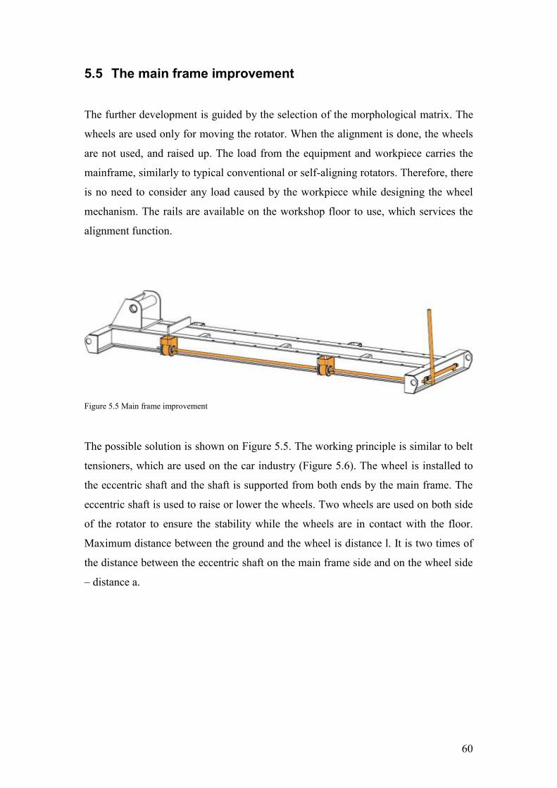
60
5.5 The main frame improvement
The further development is guided by the selection of the morphological matrix. The
wheels are used only for moving the rotator. When the alignment is done, the wheels
are not used, and raised up. The load from the equipment and workpiece carries the
mainframe, similarly to typical conventional or self-aligning rotators. Therefore, there
is no need to consider any load caused by the workpiece while designing the wheel
mechanism. The rails are available on the workshop floor to use, which services the
alignment function.
Figure 5.5 Main frame improvement
The possible solution is shown on Figure 5.5. The working principle is similar to belt
tensioners, which are used on the car industry (Figure 5.6). The wheel is installed to
the eccentric shaft and the shaft is supported from both ends by the main frame. The
eccentric shaft is used to raise or lower the wheels. Two wheels are used on both side
of the rotator to ensure the stability while the wheels are in contact with the floor.
Maximum distance between the ground and the wheel is distance l. It is two times of
the distance between the eccentric shaft on the main frame side and on the wheel side
– distance a.

61
Figure 5.6 Eccentric shaft
The required force, that exceeds the rotator its own weight for raising the rotator, is
given by the wheel and axel method. The mechanical advantage of this is the ratio of
the distances from the fulcrum to the applied loads. The length of the handle bar is in
direct relationship with the distance between the wheel and shaft axis. The bigger
distance between two axles of the eccentric shaft is, the longer handle bar is needed.
Therefore the distance between the ground and the shaft axis is chosen so that it lifts
up the rotator from the ground with small reserve.
Figure 5.7 Wheel kinematic diagram
l= 2
x a
a
l =
2 x
a a
a
pcs$PRPSHEET:{Material}s=$PRPSHEET:{Thickness}
B)
A)
REVISIONS
REV. DESCRIPTION DATE DESIGNER
l= 2
x a
a
l =
2 x
a a
a
Title:
Project:rev.0
Drawing no.
Quantity: Weight:Designed by: Checked by: Approved by - date:
Remark:Scale:2:1(A1)
Date: Working no.8.04.2016
Sheet: 1/1 kg All sharp edges R1
5°
5°
5° 5°
C
D
E
H GA B
FB FG
FD
FD
C
D
E H
G
A
B
FB FG
FGFB
B
A
G
H
ED
C
C
D
H GA B
FB FG
FD
Stopper: wheel tube
Stopper: Main frame
E
REVISIONS
REV. DESCRIPTION DATE DESIGNER
5°
5°
5° 5°
Title:
Project:ROLLER BED (DRIVER)
ESTANC AS L2W15123.000.01rev.1Drawing no.
Quantity: Weight:Designed by: Checked by:
J. LehtmeApproved by - date:Remark:
Scale:1:10(A1)
Date: Working no.W15123128.10.2015
Sheet: 1/15 667.0 kg All sharp edges and corners R2
K. JagomannK. Jagomann

62
Movement analyse
The rotator wheels are lifted or lowered manually by the production worker.
Therefore, it is necessary to get an overview of the forces that applies to the
mechanism and determine the handle bar length that is needed to lift up the rotator.
The assumption is made that the weight of the rotator is equally divided to all four
wheels. There are no exceptional situations where only one or two wheel must carry
the rotator weight.
Therefore load that applies to one wheel:
𝐹𝑇 = 11000 𝑁 – total weight of the rotator
𝐹𝑤 =𝐹𝑇
4 =11000
4 = 2750 𝑁 ( 5.1 )
𝐹𝑊 – load that applies to one wheel (N)
The critical situation is shown on the simplified kinematic diagram (Figure 5.7). In
represented situation, the torque is maximum that is caused by the equipment weight.
The 3D model is generated concurrently with the kinematic diagram to specify the
needed dimensions.
Load that applies to one side of the rotator
𝐹𝐵 = 𝐹𝐺 = 2 ∙ 𝐹𝑊 = 2 ∙ 2750 = 5500 𝑁 ( 5.2 )
𝐹𝐵, 𝐹𝐺 – load that applies to one side of the rotator (N)
The torque that is generated at the current situation:
𝐴𝐵 = 𝐻𝐺 = 10 𝑚𝑚 = 0,01 𝑚 – distance between the wheel and shaft axis
𝐹𝐷 = 200 𝑁 – generated force by human [17]
𝑇𝐴 = 𝑇𝐻 = 𝐹𝐵 ∙ 𝐴𝐵 = 5500 ∙ 0,01 = 55 𝑁𝑚 ( 5.3 )
TA, TH – generated torque (Nm)
The required length for the handlebar:
𝐴𝐷 =𝑇𝐴 + 𝑇𝐻
𝐹𝐷=
55 + 55200 = 0,55 𝑚 = 550 𝑚𝑚
( 5.4 )
𝐴𝐷 – handlebar distance (mm)

63
Locking mechanism
The wheels need to be locked on desired positions (Figure 5.8 position 1: wheels are
carrying the rotator load; position 2: wheels are lifted and the main frame carries the
load). The wheel locking mechanism is resolved by tilting the eccentric shaft out from
the vertical position for both positions. The weight of the rotator (position 1) or
weight of the wheels (position 2) that are tilted away from the vertical line generates
the circular motion which needs to be fixed. Therefore, the stopper is necessary to
prevent the eccentric shaft from making the full turn around its axle and fix the
wheels at the desired position. The biggest load is applied on position 1, while the
wheels carry the weight of the rotator. The stopper in this case is the main frame; the
inner surface of the UPE-profile is used to prevent further movement. The stopper for
other position is tube that connects the wheels.
Figure 5.8 Wheel locking mechanism; Position 1: Wheel is lowered to floor; Position 2: wheel is lifted up

64
Strength calculation
The section with the biggest loads are applied is the critical section. The assumption is
made that the section is where the wheel tube is connected to the handle bar. At this
point, torque is generated from all four wheels and loads are biggest. Two unknown
parameters in one operation are not possible to calculate. Therefore, additional data is
needed and the wheel tube is selected based on the experience. Strength calculations
are made to check if the selected tube withstands the loads. The selected tube that
connects eccentric shafts is D21,3 x 2,6.
𝐷𝑡 = 21,3 𝑚𝑚 – outer diameter of tube
𝑑𝑡 = 16,1 𝑚𝑚 – inner diameter of tube
𝜏𝑚𝑎𝑥 =𝑇𝐴 + 𝑇𝐻
𝑊0=
(55 + 55) ∙ 103
1277,4 = 86,1 𝑀𝑃𝑎 ( 5.5 )
𝑊0 =𝜋 ∙ 𝐷3
16 ∙ [1 − (𝑑𝑡
𝐷𝑡)
4
] =𝜋 ∙ 21,33
16 ∙ [1 − (16,121,3)
4] = 1277,4 𝑚𝑚3
( 5.6 )
𝑊0 – polar moment of inertia (mm3)
The material is S235, therefore the yield limit is 𝑅𝑒𝐻 = 235 𝑀𝑃𝑎
𝜏𝑦 = 0,6 ∙ 𝑅𝑒𝐻 = 0,6 ∙ 235 = 141 𝑀𝑃𝑎 ( 5.7 )
𝜏𝑦 – allowable shear stress (MPa)
Safety factor:
𝑆 =𝜏𝑦
𝜏𝑚𝑎𝑥=
14186,1 = 1,6
( 5.8 )
𝑆 – safety factor
Bearing selection
Selecting the suitable bearings is crucial to carry the rotator weight. The load that
applies to the bearings must not exceed the allowable dynamic or static load. The
selection is based on the SKF catalogue [18]. That sets limits to the bearing inner
diameter and overall selection that is available on the market. The Figure 5.9
illustrates the bearing scheme. The equipment is used indoors mainly; therefore the

65
working conditions are close to the room temperature. The load that applies to the
bearing:
𝐹𝑏𝑟 =𝐹𝑊
2 =2750
2 = 1375 𝑁 = 1,375 𝑘𝑁 ( 5.9 )
𝐹𝑏𝑟 – bearing load (N)
Selected bearings are SKF 6202-2RSH – 𝐶 = 8,1 𝑘𝑁 and 𝐶0 = 3,8 𝑘𝑁;
SKF 62207-2RS1 – 𝐶 = 25,5 𝑘𝑁 and 𝐶0 = 15,3 𝑘𝑁 (Annex I).
Eccentric shaft double-check calculation
The selected bearings set limits on the eccentric shaft diameter. It is necessary to
double-check the loads that eccentric shaft must carry is necessary. The Figure 5.9
shows the loads that apply to the shaft. The diameter of the eccentric shaft on the
main frame side is 15 mm and on the wheel side is 35mm. The loads are chosen from
the centre of the bearings. Check the loads in the dangerous cross-section.
𝑙 = 22 𝑚𝑚 – distance between main frame and wheel bearings
𝑑𝑠 = 15 𝑚𝑚 – shaft diameter on the main frame side
𝜎 =𝑀𝑊 =
30,2 ∙ 103
331,2 = 91,2𝑀 𝑃𝑎 ( 5.10 )
𝑀 = 𝐹𝑏𝑟 ∙ 𝑙 = 1375 ∙ 0,022 = 30,2 𝑁𝑚 ( 5.11 )
𝑊 =𝜋 ∙ 𝑑𝑠
3
32 =𝜋 ∙ 153
32 = 331,2 𝑚𝑚3 ( 5.12 )
The torque that is generated from one side of two wheel is previously calculated on
equation ( 5.3 ):
𝜏𝑠 =𝑇𝐴
𝑊0=
55 ∙ 103
662,3 = 83,1 𝑀𝑃𝑎 ( 5.13 )
𝑊0 =𝜋 ∙ 𝑑𝑠
3
16 =𝜋 ∙ 153
16 = 662,3 𝑚𝑚3 ( 5.14 )
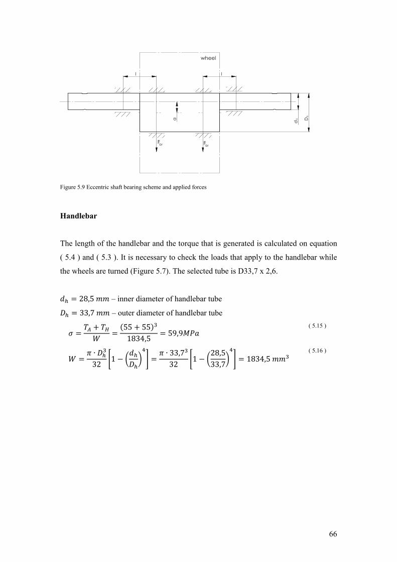
66
Figure 5.9 Eccentric shaft bearing scheme and applied forces
Handlebar
The length of the handlebar and the torque that is generated is calculated on equation
( 5.4 ) and ( 5.3 ). It is necessary to check the loads that apply to the handlebar while
the wheels are turned (Figure 5.7). The selected tube is D33,7 x 2,6.
𝑑ℎ = 28,5 𝑚𝑚 – inner diameter of handlebar tube
𝐷ℎ = 33,7 𝑚𝑚 – outer diameter of handlebar tube
𝜎 =𝑇𝐴 + 𝑇𝐻
𝑊 =(55 + 55)3
1834,5 = 59,9𝑀𝑃𝑎 ( 5.15 )
𝑊 =𝜋 ∙ 𝐷ℎ
3
32 [1 − (𝑑ℎ
𝐷ℎ)
4
] =𝜋 ∙ 33,73
32 [1 − (28,533,7)
4
] = 1834,5 𝑚𝑚3 ( 5.16 )
a
d D
l
l
s
s
Fbr Fbr
pcsS235JRs=
wheel
REVISIONS
REV. DESCRIPTION DATE DESIGNER
Title:
Project:SHAFT
W15123.162 rev.0Drawing no.
Quantity: Weight:Designed by: Checked by: Approved by - date:
Remark:Scale:1:1(A1)
Date: Working no.17.04.2016
Sheet: 1/10.73 kg All sharp edges R1

67
5.6 The roller brackets improvement
The roller bracket design is changed according to the result of the morphological
matrix. The main frame is extended and holes are created on top of the frame for the
fixing reason. One of the roller brackets design is changed so that the bracket is
movable (Figure 5.10) along the frame. The bracket is fixed to the main frame by
bolting or optionally with split pins. The distance within the roller bracket moves on
the main frame is chosen virtually by testing different size of workpieces in 3d model.
Also the included angle and size of the production door sets the limits for the
workpiece. The self-aligning roller does not require to change the distance between
the roller brackets. The rotator could work within wide range of workpiece diameter.
The distance adjusting is needed if the workpiece diameter is in one or other edge of
the diameter. The roller brackets is moved manually by lifting device.
Figure 5.10 Roller bracket improvement
Strength calculation
The calculation is made to check any deformation while the roller bracket is moved.
The changes in the design influence only the lower part of the brackets. The strength
calculation is made only for lifting and moving the roller bracket because the design
change does not affect the parts that carry the roller and workpiece. The shape and
thickness of the side plates are taken from the initial design. The shape of the roller
bracket is complicated to hand calculate it. The finite element analysis method is used
to find out the loads and stresses impact the roller bracket. The Ansys strength
calculation software is used to calculate the stresses.
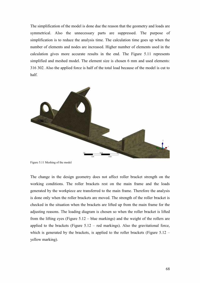
68
The simplification of the model is done due the reason that the geometry and loads are
symmetrical. Also the unnecessary parts are suppressed. The purpose of
simplification is to reduce the analysis time. The calculation time goes up when the
number of elements and nodes are increased. Higher number of elements used in the
calculation gives more accurate results in the end. The Figure 5.11 represents
simplified and meshed model. The element size is chosen 6 mm and used elements:
316 302. Also the applied force is half of the total load because of the model is cut to
half.
Figure 5.11 Meshing of the model
The change in the design geometry does not affect roller bracket strength on the
working conditions. The roller brackets rest on the main frame and the loads
generated by the workpiece are transferred to the main frame. Therefore the analysis
is done only when the roller brackets are moved. The strength of the roller bracket is
checked in the situation when the brackets are lifted up from the main frame for the
adjusting reasons. The loading diagram is chosen so when the roller bracket is lifted
from the lifting eyes (Figure 5.12 – blue markings) and the weight of the rollers are
applied to the brackets (Figure 5.12 – red markings). Also the gravitational force,
which is generated by the brackets, is applied to the roller brackets (Figure 5.12 –
yellow marking).
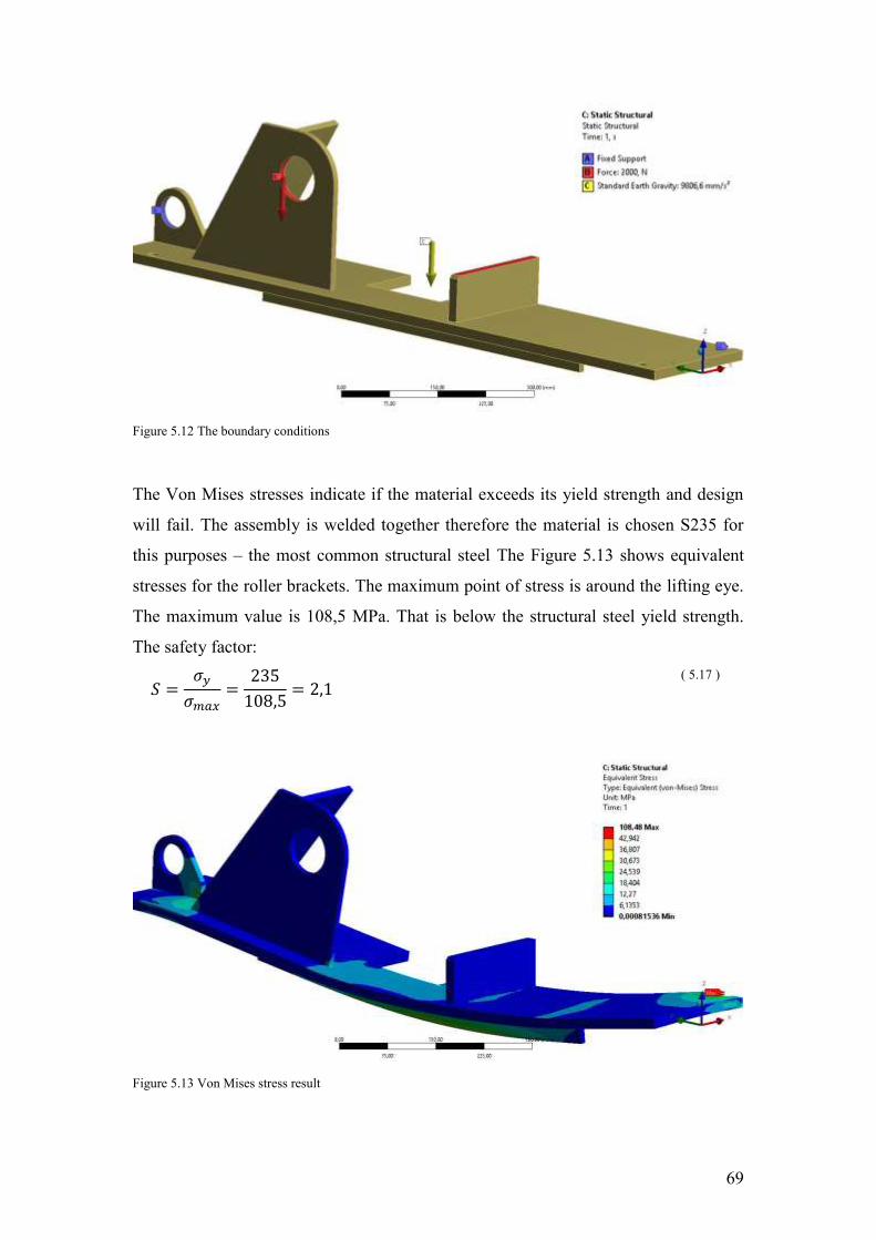
69
Figure 5.12 The boundary conditions
The Von Mises stresses indicate if the material exceeds its yield strength and design
will fail. The assembly is welded together therefore the material is chosen S235 for
this purposes – the most common structural steel The Figure 5.13 shows equivalent
stresses for the roller brackets. The maximum point of stress is around the lifting eye.
The maximum value is 108,5 MPa. That is below the structural steel yield strength.
The safety factor:
𝑆 =𝜎𝑦
𝜎𝑚𝑎𝑥=
235108,5 = 2,1
( 5.17 )
Figure 5.13 Von Mises stress result

70
The Figure 5.14 shows total deformation of the brackets. The maximum deformation
is 0,3 mm and it is located in the middle of the bracket plate. There is an elastic
deformation – if the load is removed then it recovers the initial shape.
Figure 5.14 Total deformation
The figures above show that the desired design is safe to work under the given loads.
The charts presented on the figures also shows that there is space for optimization in
order to save material. It is not done due to desire to keep the different material usage
low in the design. So it is possible to minimize the leftovers and get the effective
usage of the metal plate. Therefore the bracket plate’s thicknesses are chosen
according to the materials that are used in the design already. The Ansys strength
calculation is used to check if the design with given plate thicknesses will fail or not
under given loads.

71
5.7 Economic calculation
The cost price of the product is calculated on the basis of a 1 set of rotators. A set of
rotators includes 1 driver and 1 idler unit. The cost price forming factors are broken
down:
x Material cost
x Manufacturing cost
x Overhead cost
x Total cost
Material cost
The total need of the raw materials is grouped together by the thickness of the plate
and size of the profile on Table 12. The fixings are grouped together on Table 13 and
ready-made products on Table 14. The detailed bill of material table is shown in
section: Annex 2 – Material quantities by the details.
Table 12 The cost of raw material

72
Table 13 The cost of fasteners
Table 14 The cost of ready-made products
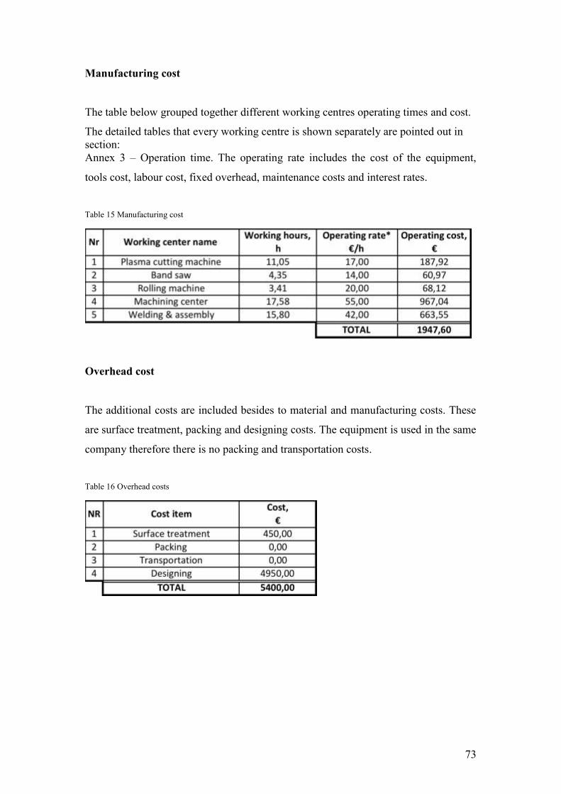
73
Manufacturing cost
The table below grouped together different working centres operating times and cost.
The detailed tables that every working centre is shown separately are pointed out in section: Annex 3 – Operation time. The operating rate includes the cost of the equipment,
tools cost, labour cost, fixed overhead, maintenance costs and interest rates.
Table 15 Manufacturing cost
Overhead cost
The additional costs are included besides to material and manufacturing costs. These
are surface treatment, packing and designing costs. The equipment is used in the same
company therefore there is no packing and transportation costs.
Table 16 Overhead costs

74
Total cost
The total cost consists all the costs that are related with the rotators. These are raw
material, fasteners and ready-made products cost, in addition manufacturing and
overhead costs.
Table 17 The cost price of the rollers
75
6 Further developments
The above-mentioned improvement and implementation of the existing rotator is a
step forward to maximize the usage of the roller bed and meet the company’s needs.
Even so, it is still necessary to build a life-scale and fully functioning prototype. One
side is the theoretical solution on the paper that fulfils the requirements. The other
side is the experience gained from working daily with the equipment. These two
aspects could be different and should not be underestimated, as well as testing the
equipment with full loads to ensure the safety of the rotator.
The movable roller bracket provides a greater range of different workpiece diameters
to work with. At the same time, the wiring is exposed to lacerations. The greatest risk
of damaging the wiring comes while moving the roller brackets to the desired position.
This situation will be tested with the prototype, and if it turns out that this going to be
a problem, then the appropriate measures are taken into action.
The rollers are another possible development. The current solution did not change the
roller design, and the width of the roller is kept the same. Increasing the width of the
roller decreases the chance that the outer surface of the workpiece will be dented. It
also increases the chances that wider rollers could be in the way of the protruding
parts.
Optionally, one could investigate further and redesign the rollers to increase the load
capacity for heavier tanks. It will be put on the agenda when the need arises.

76
7 Summary
The aim of this paper is to provide suggestions for improvements of the existing tank
rotating equipment. The subject is underscored by the company Estanc AS, which
brings attention to the need for the new rotators. The company has expanded rapidly
over the past few years, which increased the need for new equipment. The paper is
focused more on generating technical solutions to an actual problem from an
engineering point of view, rather than design. Despite that, the methods and tools
gained through the studies of the D&E curriculum provide the knowledge to identify,
define and solve a problem in a structural way.
The first part of the work is focused on the tank manufacturing process and gives a
brief overview of the company. The process is taken into pieces and different phases
are studied to get the full picture of the manufacturing process. In general, the process
is divided into four different phases: Detail preparation, when the materials are cut to
the required length, shells are rolled and edge preparation are done; Assembly and
welding phase is the core of the tank manufacturing process during which, the tank is
assembled together and connections are welded; Inspection phase, when it is
important to detect any discrepancy between reality and the required quality; and the
final phase, the surface treatment and finishing during which the tank is cleaned,
painted if needed, packed, and delivered to the customer.
A deeper look is taken into assembly and welding phase. This phase reveals several
steps that must be done before the workpiece can be lowered to the rotators and
assembling may begin. Parallel spacing between two rotators must be ensured, as well
as the distance between the two rotators, because the slightest misalignment leads to
the workpiece overturning from the rotator. Manually adjusting the rotators with the
help of the overhead crane is time consuming, and pushing the rotators with lever
damages the equipment. One of the bottlenecks in the process is the availability of the
overhead crane, which could lead to a loss of time. Also, it is noted that the
cylindrical shells get damaged during the assembly and welding phase. The damage is
more noticeable on thinner workpieces with bigger diameters. A narrow roller wheel
presses the dents into to the outer surface of the shell.

77
Further steps focused on finding existing solutions available on the current market
and analysing their capabilities. Economic and technical aspects of the equipment
offered by the enterprise showed that the equipment currently available in the market
is unable to fully provide effective solutions. The components that are taken into
further development are generated.
The second half of the paper is focused on generating suitable solutions. Three
solutions are generated and analysed with the help of the morphological matrix. The
temporary on wheels and the independent roller brackets solution is chosen to be
examined in greater detail. Furthermore, the wheel motion is studied and strength
analyse is done for different components. The wheel solution provides the chance to
implement the solution for already-made equipment. The suitable profile and
components are selected during this phase.
Finally, economic calculations are done and the cost price is calculated for one set of
the rotators – one driver unit and one idler unit.

78
8 Kokkuvõte
Käesoleva töö eesmärk on pakkuda parandusettepanekuid olemasolevale mahuti
pööramise seadmele. Teema on esilekerkinud tulenevalt ettevõtte Estanc AS
vajadusest uute pööritajate järgi. Ettevõte on viimase paari aasta jooksul kiiresti
arenenud ning kasvanud on vajadus uute seadmete järele. Antud töös on keskendutud
tehnilise lahenduse väljatöötamisele olemasolevale probleemile läbi insenertehnilise
vaatenurga. Sellest hoolimata on D&E õppekaval omandatud meetodid ja
töövahendid andnud teadmised fikseerida, kirjeldada ja lahendada probleemi
struktureeritud viisil.
Esimene osa tööst on fokusseeritud mahuti tootmisprotsessist ning ettevõttest ülevaate
andmisele. Tootmisprotsess on jagatud osadeks ning erinevaid etappe on uuritud, et
omandada täielikku ülevaadet tootmisest. Üldjoontes on protsess jagatud neljaks
erinevaks etapiks – Detailide ettevalmistus, milles materjal on lõigatud mõõtu, kestad
on valtsitud ning servade faasimine on tehtud; Koostamise-keevitamise etapp on
mahuti tootmisprotsessi tuum, milles kestad on koostatud ning ühendused on
keevitatud; Toote kontrolli etapis on oluline avastada igasugune erinevus toote nõutud
kvaliteedi ning tegelikkuse vahel; Viimane etapp on pinnatöötlus, milles mahuti
puhastatakse, vajadusel värvitakse, pakitakse ja toote toimetamine kliendile.
Põhjalikumalt on vaatluse alla võetud koostamise-keevitamise etapp. Selgus, et enne
kui kest tõstetakse pööritajate peale ja on võimalik koostama hakata, peab mitu
erinevat ettevalmistavat sammu tegema. Kahe või enama pööritaja vahel peab olema
tagatud paralleelsus, nagu ka nende omavaheline kaugus. Väiksemgi vastuolu võib
viia olukorrani, milles kest pööritajate pealt maha keerab. Sildkraana abiga, mis on
ajakulukas meetod, on pööritajad paika seatud. Pööritaja paika seadmisel kasutatakse
lisaks ka kangimeetodit, mis kahjustab seadet. Üks kitsaskohtadest on seadme
sõltuvus sildkraana kättesaadavuseset, selle hõivatus võib viia tootmisseisakuni.
Samuti on täheldatud, et silindrilistele kestadele tekivad mõlgid koostamise-
keevitamise etapis. See puudutab rohkem õhukeseseinalisi ja suurema läbimõõduga
kestasid, kuna kitsam rull vajutab mõlgi kestapinnale.

79
Järgnevas osas on vaatluse alla võetud turul olemasolevad tooted ning analüüsitud
nende võimekust. Tootjate poolt pakutud seadmete majanduslikud ja tehnilised
aspektid näitavad, et ollakse võimetud pakkuma efektiivset lahendust antud
probleemile. Edasiarendamisele minevate komponentide nõuete kirjeldus on
genereeritud.
Teine pool tööst on fokusseeritud sobivate lahenduste leidmisele. Morfoloogilise
maatriksi abiga on genereeritud ning analüüsitud kolme lahendust. Ajutiselt ratastel
ning sõltumatu rulliraamid on valitud lahenduseks, millega edasi töötatakse. Ratta
süsteemi on uuritud ning tehtud on tugevusarvutused erinevatele komponentidele.
Ajutiselt ratastel töötavat lahendust on võimalik ülekanda ka olemasolevatele
pööritajatele. Selle etapi tulemusel on sobivad profiilid ning komponendid valitud.
Viimases osas on teostatud majanduslikud arvutused. Toote omahind on arvutatud
ühe paari pööritajate jaoks – üks vedav seade ja üks veetav seade.

80
9 Reference
1 Y. Haik, T. M. M. Shashin, Engineering Design Process
Stamfordt, CT: Cengage Learning, 2011
2 M. J. French, Conceptual Design For Engineers, Third Edition
London: Springer London, 1999
3 AS Estanc [WWW]
www.estanc.eu (26.02.2016)
4 Production management. Industrial engineering [WWW]
http://www.britannica.com/topic/production-management (3.03.2016)
5 Notified bodies. European Commission [WWW]
http://ec.europa.eu/growth/single-market/goods/building-blocks/notified-
bodies/index_en.htm (2.03.2016)
6 “What does the CE marking on a prduct indicate?” European Commission [WWW]
http://ec.europa.eu/growth/single-market/ce-marking/ (5.03.2016)
7 American Welding Society, The practical Reference Guide to Positioning
New York: American Welding Society, 2008
8 American Welding Society, Welding Handbook, Ninth Edition
New York: American Welding Society, 2001
9 Bode, Model SAR1200 specification [WWW]
http://www.bode.co.uk/ (4.03.2016)
10 SHRI- RAM TRANSMISSINS, Self-centering rotators [WWW]
http://www.shriramtransmissions.com/self-centering-rotators.html (6.03.2016)
11 ESAB, Model CD-60 specification [WWW]
http://esabsp.esab.net/files/Fact%20sheets/Welding%20Automation/XA00144320.pdf
(4.03.2016)
12 ESAB, FIR 35 specification [WWW]
http://esabsp.esab.net/files/Fact%20sheets/Welding%20Automation/XA00144520.pdf
(7.03.2016)
13 Standard gauge [WWW]
https://en.wikipedia.org/wiki/Standard_gauge (11.03.16)
14 Corimpex AAR-60 specification [WWWW]
http://www.corimpex.biz/webapp/files/CORIMPEX/contents/aa0156200e61d25147e0

81
39c253068cd8/ROTATORI_AAR_en.pdf (7.03.2016)
15 Koike Aronson, Inc Trac-Tred T4 specification [WWW]
http://www.koike.com/trac-tred (17.0302016)
16 Dassault Systems, SolidWorks Corporation [WWW]
http://www.solidworks.com/ (4.04.2016)
17 P. Põdra, Tugevusanalüüsi alused. Mõningate probleemide kokkuvõtlik käsitlus,
TTÜ, 2004
18 SKF Group [WWW] http://www.skf.com/group/splash/index.html (16.04.16)
Related Documents