Optimization of the Pumping Capacity of Centrifugal Pumps Based on System Analysis Motsi Ephrey Matlakala 1* and Daramy Vandi Von Kallon 1 1 Department of Mechanical and Industrial Engineering Technology, University of Johannesburg, South Africa * Corresponding author email: [email protected] Abstract. The pumping capacity is the maximum flow rate through a pump at its design capacity. In the process of pumping water and other fluids, pumping capacity is required to accurately size pumping systems, determine friction head losses, construct a system curve and select a pump and motor. Failure to choose the right pump size for pumping system, improper installation and pump operation results into higher consumption of energy. The insufficient pumping capacity affects the plant’s operations such as maintenance cost, downtime, loss of production and increase in operating cost. In this study variation of the impeller diameter is used to calculate the new pump curve to improve the pumping capacity. The pumping system is analysed to determine the pumping capacity of the pump. Computational fluid dynamic (CFD) simulations are carried out to determine the performance of the pump and analyses the pumping system to achieve the pumping capacity. Results show that enhanced pumping capacity is achieved at a given impeller design with a specific shift in the pump curve. It is recommended that the pumping capacity can be optimized through trimming of impeller. Trimming of the impeller improves pump efficiency and increases the performance of the pump. In addition, the pumping capacity can also be optimized through the system analysis by adjusting the diameter of the pipes and throttling of the valves. Optimization of the pumping capacity helps with running the pumping system efficiently. Keywords: Pumping Capacity, System Analysis, Computational Fluid Dynamics, Cost, Impeller, Pump Efficiency. © The Authors, published by EDP Sciences. This is an open access article distributed under the terms of the Creative Commons Attribution License 4.0 (http://creativecommons.org/licenses/by/4.0/). MATEC Web of Conferences 347, 00024 (2021) SACAM2020 https://doi.org/10.1051/matecconf/202134700024

Welcome message from author
This document is posted to help you gain knowledge. Please leave a comment to let me know what you think about it! Share it to your friends and learn new things together.
Transcript
Optimization of the Pumping Capacity of Centrifugal Pumps Based on System Analysis
Motsi Ephrey Matlakala1* and Daramy Vandi Von Kallon1
1Department of Mechanical and Industrial Engineering Technology, University of
Johannesburg, South Africa
*Corresponding author email: [email protected]
Abstract. The pumping capacity is the maximum flow rate through a pump
at its design capacity. In the process of pumping water and other fluids,
pumping capacity is required to accurately size pumping systems, determine
friction head losses, construct a system curve and select a pump and motor.
Failure to choose the right pump size for pumping system, improper
installation and pump operation results into higher consumption of energy.
The insufficient pumping capacity affects the plant’s operations such as
maintenance cost, downtime, loss of production and increase in operating
cost. In this study variation of the impeller diameter is used to calculate the
new pump curve to improve the pumping capacity. The pumping system is
analysed to determine the pumping capacity of the pump. Computational
fluid dynamic (CFD) simulations are carried out to determine the
performance of the pump and analyses the pumping system to achieve the
pumping capacity. Results show that enhanced pumping capacity is
achieved at a given impeller design with a specific shift in the pump curve.
It is recommended that the pumping capacity can be optimized through
trimming of impeller. Trimming of the impeller improves pump efficiency
and increases the performance of the pump. In addition, the pumping
capacity can also be optimized through the system analysis by adjusting the
diameter of the pipes and throttling of the valves. Optimization of the
pumping capacity helps with running the pumping system efficiently.
Keywords: Pumping Capacity, System Analysis, Computational Fluid Dynamics, Cost, Impeller,
Pump Efficiency.
© The Authors, published by EDP Sciences. This is an open access article distributed under the terms of the Creative Commons Attribution License 4.0 (http://creativecommons.org/licenses/by/4.0/).
MATEC Web of Conferences 347, 00024 (2021) SACAM2020
https://doi.org/10.1051/matecconf/202134700024
1. Introduction
Sizing of pumping systems are difficult since the pumps must fit the pumping systems, as a
result, it affects the installation, maintenance, and operations of centrifugal pumps and
pumping systems. Centrifugal pumps contain two main parts: an impeller (rotor) that rotates
at speeds of the motor and imparts centrifugal forces to the production fluid and diffuser
(stator) the fixed part that guides the flow to the discharge [1, 2]. Optimization of pumping
capacity is carried out through system analysis which involves process analysis, engineering
design, maintenance, cost analysis, risk and viability analysis. The impeller of a centrifugal
pump regulates performance of pump and determines pumping capacity of the centrifugal
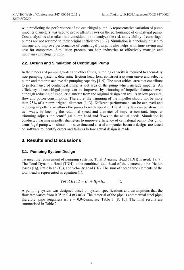
pump [3]. Figure 1 shows layout of centrifugal pump with two major components, impeller
and volute.
Figure 1. Centrifugal Pump [2]
The design of the impeller diameter has a major effect on the pump efficiency, an entirely
new pump can be designed by just modifying the impeller. The pumping capacity is the
maximum flow rate through a pump at its design capacity [4, 5]. The speed and diameter of
the impeller determine the head or pressure head that the pump can generate [3]. A typical
failure mode of centrifugal pumps is caused by the difficulty of installation, operation and
maintenance of the pump. The challenge of implementing proper maintenance plans for the
pumping system affects the efficiency of the pump. The centrifugal pump efficiency can drop
below 5% of required operation duty point, consuming more energy and cost a company
more than usual [6]. In the present study we have identified that companies find it challenging
to design, install, operate and maintain centrifugal pump of which it affects the efficiency of
centrifugal pump. The aim of the paper is to carry out an investigation with the aim to
improve the efficiency and reliability of centrifugal pumps through better design of impeller,
installation, operation and maintenance practices. This paper present affinity laws to help
with predicting the performance of a centrifugal pump and to determine whether a change in
the impeller design is a limiting factor. The parameters of the pumping system are considered
to establish the operating points of centrifugal pumps.
2. Methodology
2.1. Conceptualization
A multiple method was used to identify potential causes of centrifugal pump failure and
dropping of efficiency of the pump. A review of grey and white literature was undertaken to
identify the challenges of installation, operation and maintenance of centrifugal pump.
System analysis of centrifugal pumps is done through engineering design where specification
for the pump is provided based on the pumping system. Affinity laws are presented to help
2
MATEC Web of Conferences 347, 00024 (2021) SACAM2020
https://doi.org/10.1051/matecconf/202134700024
with predicting the performance of the centrifugal pump. A representative variation of pump
impeller diameters was used to prove affinity laws on the performance of centrifugal pump.
Cost analysis is also taken into consideration to analyze the risk and viability if centrifugal
pumps are not restored to their original efficiency [6, 7]. Simulation is a technique used to
manage and improve performance of centrifugal pump. It also helps with time saving and
cost for companies. Simulation process can help industries to effectively manage and
maintain centrifugal pumps.
2.2. Design and Simulation of Centrifugal Pump
In the process of pumping water and other fluids, pumping capacity is required to accurately
size pumping systems, determine friction head loss, construct a system curve and select a
pump and motor to achieve the pumping capacity [4, 5]. The most critical area that contribute
to performance of centrifugal pump is wet area of the pump which include impeller. An
efficiency of centrifugal pump can be improved by trimming of impeller diameter even
although reducing of impeller diameter from the original design can results in low pressure,
flow and power consumption. Therefore, the trimming of the impeller should not be more
than 75% of a pump original diameter [1, 3]. Different performance can be achieved and
reducing impeller size allows the pump to reach specific. The affinity law can be shown in
two ways, by keeping the rotational speed and diameter of impeller constant. Impeller
trimming adjusts the centrifugal pump head and flows to the actual needs. Simulation is
conducted varying impeller diameters to improve efficiency of centrifugal pump. Design of
centrifugal pump with simulation save time and cost of companies because designs are tested
on software to identify errors and failures before actual design is made.
3. Results and Discussions
3.1. Pumping System Design
To meet the requirement of pumping systems, Total Dynamic Head (TDH) is used. [8, 9].
The Total Dynamic Head (TDH) is the combined total head of the elements, pipe friction
losses (Hf), static head (Hs), and velocity head (Hv). The sum of these three elements of the
total head is represented in equation (1):
𝑇𝑜𝑡𝑎𝑙 𝐻𝑒𝑎𝑑 = 𝐻𝑠 + 𝐻𝑓+𝐻𝑣 (1)
A pumping system was designed based on system specifications and assumptions that the
flow rate varies from 0.05 to 0.4 m3 m3/s. The material of the pipe is commercial steel pipe;
therefore, pipe roughness is, 𝜀 = 0.045mm, see Table 1 [8, 10]. The final results are
summarised in Table 2.
3
MATEC Web of Conferences 347, 00024 (2021) SACAM2020
https://doi.org/10.1051/matecconf/202134700024
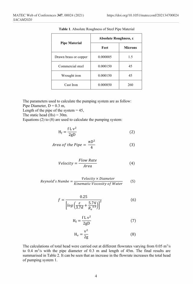
Table 1. Absolute Roughness of Steel Pipe Material
Pipe Material
Absolute Roughness, ε
Feet Microns
Drawn brass or copper 0.000005 1.5
Commercial steel 0.000150 45
Wrought iron 0.000150 45
Cast Iron 0.000850 260
The parameters used to calculate the pumping system are as follow:
Pipe Diameter, D = 0.3 m,
Length of the pipe of the system = 45,
The static head (Hs) = 30m.
Equations (2) to (8) are used to calculate the pumping system:
Hf =f L v2
2gD (2)
𝐴𝑟𝑒𝑎 𝑜𝑓 𝑡ℎ𝑒 𝑃𝑖𝑝𝑒 = 𝜋𝐷2
4 (3)
𝑉𝑒𝑙𝑜𝑐𝑖𝑡𝑦 =𝐹𝑙𝑜𝑤 𝑅𝑎𝑡𝑒
𝐴𝑟𝑒𝑎 (4)
𝑅𝑒𝑦𝑛𝑜𝑙𝑑′𝑠 𝑁𝑢𝑚𝑏𝑒 =𝑉𝑒𝑙𝑜𝑐𝑖𝑡𝑦 × 𝐷𝑖𝑎𝑚𝑒𝑡𝑒𝑟
𝐾𝑖𝑛𝑒𝑚𝑎𝑡𝑖𝑐 𝑉𝑖𝑠𝑐𝑜𝑠𝑖𝑡𝑦 𝑜𝑓 𝑊𝑎𝑡𝑒𝑟 (5)
𝑓 =0.25
[𝑙𝑜𝑔 (𝜀
3.7𝑑+
5.74
𝑅𝑒0.9)]
2 (6)
Hf =f L v2
2gD (7)
Hv =v2
2g (8)
The calculations of total head were carried out at different flowrates varying from 0.05 m3/s
to 0.4 m3/s with the pipe diameter of 0.3 m and length of 45m. The final results are
summarised in Table 2. It can be seen that an increase in the flowrate increases the total head
of pumping system 1.
4
MATEC Web of Conferences 347, 00024 (2021) SACAM2020
https://doi.org/10.1051/matecconf/202134700024
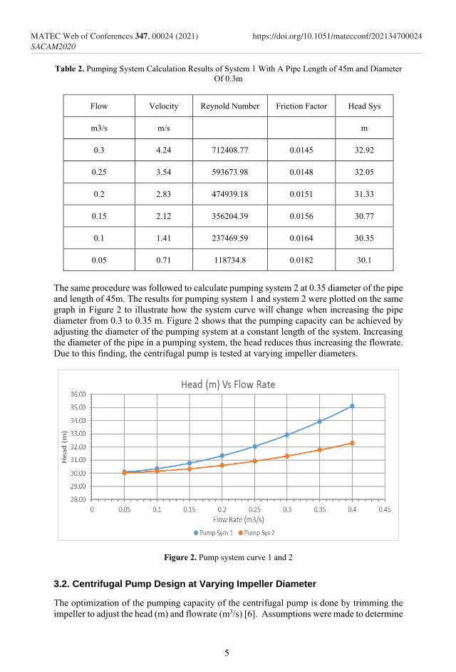
Table 2. Pumping System Calculation Results of System 1 With A Pipe Length of 45m and Diameter
Of 0.3m
Flow Velocity Reynold Number Friction Factor Head Sys
m3/s m/s m
0.3 4.24 712408.77 0.0145 32.92
0.25 3.54 593673.98 0.0148 32.05
0.2 2.83 474939.18 0.0151 31.33
0.15 2.12 356204.39 0.0156 30.77
0.1 1.41 237469.59 0.0164 30.35
0.05 0.71 118734.8 0.0182 30.1
The same procedure was followed to calculate pumping system 2 at 0.35 diameter of the pipe
and length of 45m. The results for pumping system 1 and system 2 were plotted on the same
graph in Figure 2 to illustrate how the system curve will change when increasing the pipe
diameter from 0.3 to 0.35 m. Figure 2 shows that the pumping capacity can be achieved by
adjusting the diameter of the pumping system at a constant length of the system. Increasing
the diameter of the pipe in a pumping system, the head reduces thus increasing the flowrate.
Due to this finding, the centrifugal pump is tested at varying impeller diameters.
Figure 2. Pump system curve 1 and 2
3.2. Centrifugal Pump Design at Varying Impeller Diameter
The optimization of the pumping capacity of the centrifugal pump is done by trimming the
impeller to adjust the head (m) and flowrate (m3/s) [6]. Assumptions were made to determine
5
MATEC Web of Conferences 347, 00024 (2021) SACAM2020
https://doi.org/10.1051/matecconf/202134700024

the effect of the impeller diameter on the pumping capacity of the centrifugal pump. Impeller
diameters of 350mm, 344mm and 338mm were used to do the calculations. The pump
specification to suit the existing pumping system design with the impeller diameter of 350mm
at the flowrate varying 0.05 m3/s to 0.4 m3/s are shown in Table 3.
3.2.1 Affinity Laws for centrifugal pumps
Affinity laws only apply to radial and axial pumps [3, 11]. The formulas applied for affinity
laws in constant impeller diameter and constant rotational speed are represented in equations
(9) and (10):
𝑄1
𝑄2=
𝐷1
𝐷2
𝐻1
𝐻2= (
𝐷1
𝐷2)
2
𝑃1
𝑃2= (
𝐷1
𝐷2)
3
(9)
𝑄1
𝑄2=
𝑛1
𝑛2
𝐻1
𝐻2= (
𝑛1
𝑛2)
2
𝑃1
𝑃2= (
𝑛1
𝑛2)
3
(10)
Table 3. Pump Specifications
Flow Total Heat Water Power
m3/s M kW
0.4 31.36 123.07
0.35 31.8 109.19
0.3 32.18 94.71
0.25 32.5 79.71
0.2 32.76 64.28
0.15 32.97 48.51
0.1 33.11 32.49
0.05 33.2 16.29
The impeller diameters are varied from D0 as the original and two other values D1 and D2 as
variations from D0. The specifications of the pump (Table 1) is at the original impeller
diameter of 350 mm. The head and flowrate of the centrifugal pump was calculated varying
discharge flowrate, see the calculation summary of the result in Table 4.
6
MATEC Web of Conferences 347, 00024 (2021) SACAM2020
https://doi.org/10.1051/matecconf/202134700024
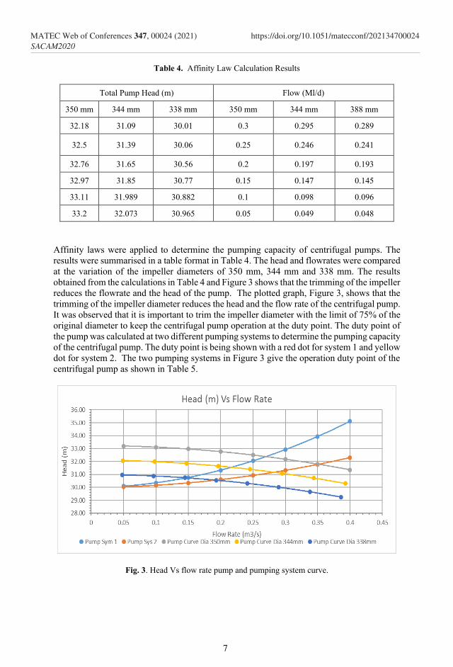
Table 4. Affinity Law Calculation Results
Total Pump Head (m) Flow (Ml/d)
350 mm 344 mm 338 mm 350 mm 344 mm 388 mm
32.18 31.09 30.01 0.3 0.295 0.289
32.5 31.39 30.06 0.25 0.246 0.241
32.76 31.65 30.56 0.2 0.197 0.193
32.97 31.85 30.77 0.15 0.147 0.145
33.11 31.989 30.882 0.1 0.098 0.096
33.2 32.073 30.965 0.05 0.049 0.048
Affinity laws were applied to determine the pumping capacity of centrifugal pumps. The
results were summarised in a table format in Table 4. The head and flowrates were compared
at the variation of the impeller diameters of 350 mm, 344 mm and 338 mm. The results
obtained from the calculations in Table 4 and Figure 3 shows that the trimming of the impeller
reduces the flowrate and the head of the pump. The plotted graph, Figure 3, shows that the
trimming of the impeller diameter reduces the head and the flow rate of the centrifugal pump.
It was observed that it is important to trim the impeller diameter with the limit of 75% of the
original diameter to keep the centrifugal pump operation at the duty point. The duty point of
the pump was calculated at two different pumping systems to determine the pumping capacity
of the centrifugal pump. The duty point is being shown with a red dot for system 1 and yellow
dot for system 2. The two pumping systems in Figure 3 give the operation duty point of the
centrifugal pump as shown in Table 5.
Fig. 3. Head Vs flow rate pump and pumping system curve.
7
MATEC Web of Conferences 347, 00024 (2021) SACAM2020
https://doi.org/10.1051/matecconf/202134700024
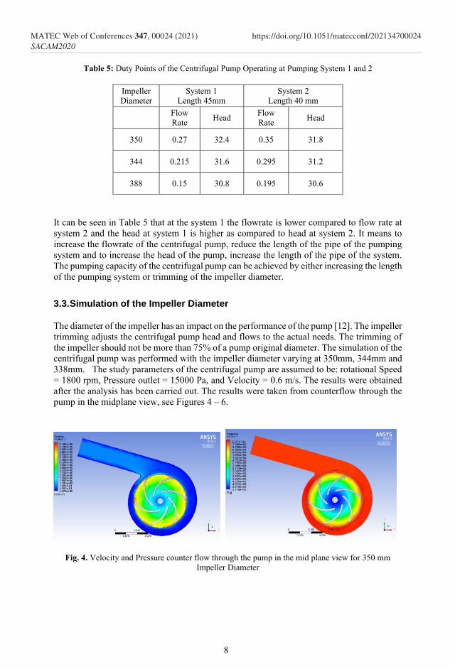
Table 5: Duty Points of the Centrifugal Pump Operating at Pumping System 1 and 2
Impeller
Diameter
System 1
Length 45mm
System 2
Length 40 mm
Flow
Rate Head
Flow
Rate Head
350 0.27 32.4 0.35 31.8
344 0.215 31.6 0.295 31.2
388 0.15 30.8 0.195 30.6
It can be seen in Table 5 that at the system 1 the flowrate is lower compared to flow rate at
system 2 and the head at system 1 is higher as compared to head at system 2. It means to
increase the flowrate of the centrifugal pump, reduce the length of the pipe of the pumping
system and to increase the head of the pump, increase the length of the pipe of the system.
The pumping capacity of the centrifugal pump can be achieved by either increasing the length
of the pumping system or trimming of the impeller diameter.
3.3. Simulation of the Impeller Diameter
The diameter of the impeller has an impact on the performance of the pump [12]. The impeller
trimming adjusts the centrifugal pump head and flows to the actual needs. The trimming of
the impeller should not be more than 75% of a pump original diameter. The simulation of the
centrifugal pump was performed with the impeller diameter varying at 350mm, 344mm and
338mm. The study parameters of the centrifugal pump are assumed to be: rotational Speed
= 1800 rpm, Pressure outlet = 15000 Pa, and Velocity = 0.6 m/s. The results were obtained
after the analysis has been carried out. The results were taken from counterflow through the
pump in the midplane view, see Figures 4 – 6.
Fig. 4. Velocity and Pressure counter flow through the pump in the mid plane view for 350 mm
Impeller Diameter
8
MATEC Web of Conferences 347, 00024 (2021) SACAM2020
https://doi.org/10.1051/matecconf/202134700024
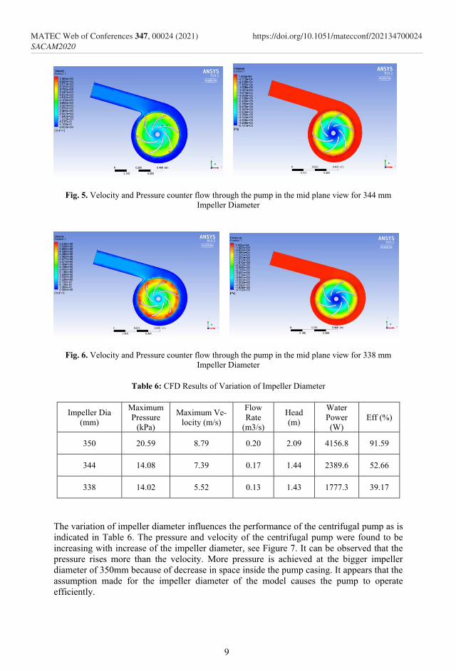
Fig. 5. Velocity and Pressure counter flow through the pump in the mid plane view for 344 mm
Impeller Diameter
Fig. 6. Velocity and Pressure counter flow through the pump in the mid plane view for 338 mm
Impeller Diameter
Table 6: CFD Results of Variation of Impeller Diameter
Impeller Dia
(mm)
Maximum
Pressure
(kPa)
Maximum Ve-
locity (m/s)
Flow
Rate
(m3/s)
Head
(m)
Water
Power
(W)
Eff (%)
350 20.59 8.79 0.20 2.09 4156.8 91.59
344 14.08 7.39 0.17 1.44 2389.6 52.66
338 14.02 5.52 0.13 1.43 1777.3 39.17
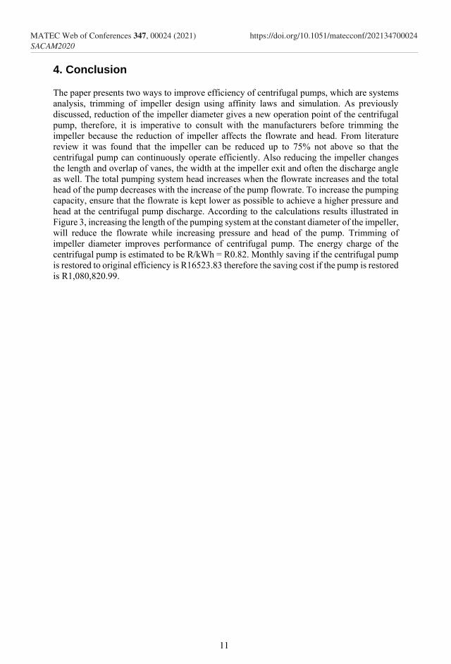
The variation of impeller diameter influences the performance of the centrifugal pump as is
indicated in Table 6. The pressure and velocity of the centrifugal pump were found to be
increasing with increase of the impeller diameter, see Figure 7. It can be observed that the
pressure rises more than the velocity. More pressure is achieved at the bigger impeller
diameter of 350mm because of decrease in space inside the pump casing. It appears that the
assumption made for the impeller diameter of the model causes the pump to operate
efficiently.
9
MATEC Web of Conferences 347, 00024 (2021) SACAM2020
https://doi.org/10.1051/matecconf/202134700024
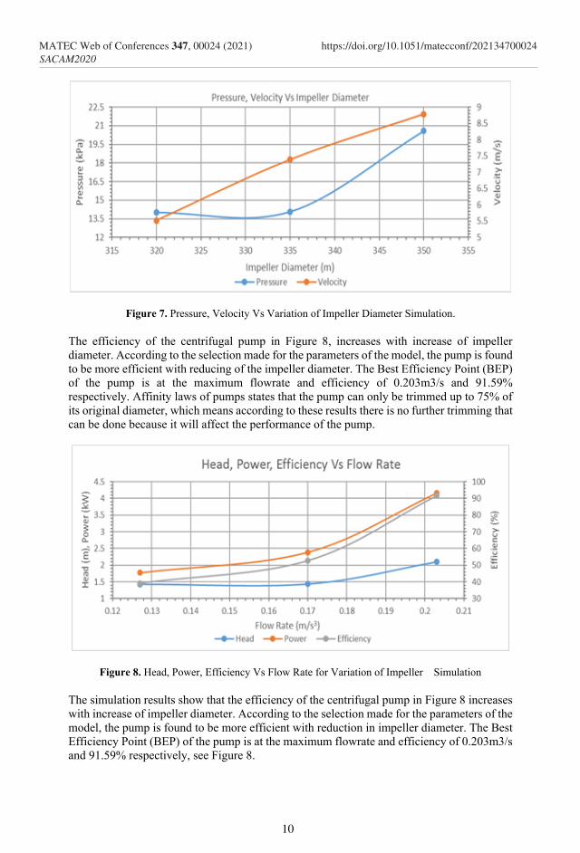
Figure 7. Pressure, Velocity Vs Variation of Impeller Diameter Simulation.
The efficiency of the centrifugal pump in Figure 8, increases with increase of impeller
diameter. According to the selection made for the parameters of the model, the pump is found
to be more efficient with reducing of the impeller diameter. The Best Efficiency Point (BEP)
of the pump is at the maximum flowrate and efficiency of 0.203m3/s and 91.59%
respectively. Affinity laws of pumps states that the pump can only be trimmed up to 75% of
its original diameter, which means according to these results there is no further trimming that
can be done because it will affect the performance of the pump.
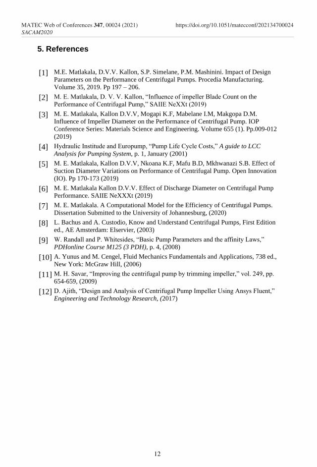
Figure 8. Head, Power, Efficiency Vs Flow Rate for Variation of Impeller Simulation
The simulation results show that the efficiency of the centrifugal pump in Figure 8 increases
with increase of impeller diameter. According to the selection made for the parameters of the
model, the pump is found to be more efficient with reduction in impeller diameter. The Best
Efficiency Point (BEP) of the pump is at the maximum flowrate and efficiency of 0.203m3/s
and 91.59% respectively, see Figure 8.
10
MATEC Web of Conferences 347, 00024 (2021) SACAM2020
https://doi.org/10.1051/matecconf/202134700024
4. Conclusion
The paper presents two ways to improve efficiency of centrifugal pumps, which are systems
analysis, trimming of impeller design using affinity laws and simulation. As previously
discussed, reduction of the impeller diameter gives a new operation point of the centrifugal
pump, therefore, it is imperative to consult with the manufacturers before trimming the
impeller because the reduction of impeller affects the flowrate and head. From literature
review it was found that the impeller can be reduced up to 75% not above so that the
centrifugal pump can continuously operate efficiently. Also reducing the impeller changes
the length and overlap of vanes, the width at the impeller exit and often the discharge angle
as well. The total pumping system head increases when the flowrate increases and the total
head of the pump decreases with the increase of the pump flowrate. To increase the pumping
capacity, ensure that the flowrate is kept lower as possible to achieve a higher pressure and
head at the centrifugal pump discharge. According to the calculations results illustrated in
Figure 3, increasing the length of the pumping system at the constant diameter of the impeller,
will reduce the flowrate while increasing pressure and head of the pump. Trimming of
impeller diameter improves performance of centrifugal pump. The energy charge of the
centrifugal pump is estimated to be R/kWh = R0.82. Monthly saving if the centrifugal pump
is restored to original efficiency is R16523.83 therefore the saving cost if the pump is restored
is R1,080,820.99.
11
MATEC Web of Conferences 347, 00024 (2021) SACAM2020
https://doi.org/10.1051/matecconf/202134700024
5. References
[1] M.E. Matlakala, D.V.V. Kallon, S.P. Simelane, P.M. Mashinini. Impact of Design
Parameters on the Performance of Centrifugal Pumps. Procedia Manufacturing.
Volume 35, 2019. Pp 197 – 206.
[2] M. E. Matlakala, D. V. V. Kallon, “Influence of impeller Blade Count on the
Performance of Centrifugal Pump,” SAIIE NeXXt (2019)
[3] M. E. Matlakala, Kallon D.V.V, Mogapi K.F, Mabelane I.M, Makgopa D.M.
Influence of Impeller Diameter on the Performance of Centrifugal Pump. IOP
Conference Series: Materials Science and Engineering. Volume 655 (1). Pp.009-012
(2019)
[4] Hydraulic Institude and Europump, “Pump Life Cycle Costs,” A guide to LCC
Analysis for Pumping System, p. 1, January (2001)
[5] M. E. Matlakala, Kallon D.V.V, Nkoana K.F, Mafu B.D, Mkhwanazi S.B. Effect of
Suction Diameter Variations on Performance of Centrifugal Pump. Open Innovation
(IO). Pp 170-173 (2019)
[6] M. E. Matlakala Kallon D.V.V. Effect of Discharge Diameter on Centrifugal Pump
Performance. SAIIE NeXXXt (2019)
[7] M. E. Matlakala. A Computational Model for the Efficiency of Centrifugal Pumps.
Dissertation Submitted to the University of Johannesburg, (2020)
[8] L. Bachus and A. Custodio, Know and Understand Centrifugal Pumps, First Edition
ed., AE Amsterdam: Elservier, (2003)
[9] W. Randall and P. Whitesides, “Basic Pump Parameters and the affinity Laws,”
PDHonline Course M125 (3 PDH), p. 4, (2008)
[10] A. Yunus and M. Cengel, Fluid Mechanics Fundamentals and Applications, 738 ed.,
New York: McGraw Hill, (2006)
[11] M. H. Savar, “Improving the centrifugal pump by trimming impeller,” vol. 249, pp.
654-659, (2009)
[12] D. Ajith, “Design and Analysis of Centrifugal Pump Impeller Using Ansys Fluent,”
Engineering and Technology Research, (2017)
12
MATEC Web of Conferences 347, 00024 (2021) SACAM2020
https://doi.org/10.1051/matecconf/202134700024
Related Documents