The University of Tulsa Petroleum Reservoir Exploitation Projects Optimization of the CO 2 Huff-n-Puff Process in an Unconventional Reservoir Using a Machine Learning Proxy Azad Almasov, Mustafa Onur, and Albert Reynolds 4 th BIENNIAL CO 2 FOR EOR AS CCUS CONFERENCE 25 - 27 September 2019

Welcome message from author
This document is posted to help you gain knowledge. Please leave a comment to let me know what you think about it! Share it to your friends and learn new things together.
Transcript

The University of TulsaPetroleum Reservoir Exploitation Projects
Optimization of the CO2 Huff-n-Puff Process in anUnconventional Reservoir Using a Machine
Learning Proxy
Azad Almasov, Mustafa Onur, and Albert Reynolds
4th BIENNIAL CO2 FOR EOR AS CCUS CONFERENCE25 - 27 September 2019
Outline
Introduction
Objectives
Transport Mechanisms of CO2
NPV Formulation
LS-SVR Proxy
Optimization of Well-Control Variables
Conclusions
A. Almasov, M. Onur, A. Reynolds Optimization of the CO2 Huff-n-Puff Process Sep 26, 2019 (2/30)
Introduction
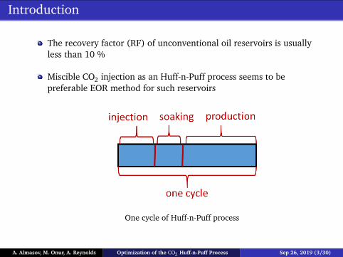
The recovery factor (RF) of unconventional oil reservoirs is usuallyless than 10 %
Miscible CO2 injection as an Huff-n-Puff process seems to bepreferable EOR method for such reservoirs
One cycle of Huff-n-Puff process
A. Almasov, M. Onur, A. Reynolds Optimization of the CO2 Huff-n-Puff Process Sep 26, 2019 (3/30)

Introduction: CO2 Huff-n-Puff
CO2 Huff-n-Puff is a cyclic miscible CO2 EOR method
Purpose: lower viscosity and density of oil; maintain pressure
In this study, reservoir type: unconventional tight-oil or shale-oil;Injected gas: CO2
A. Almasov, M. Onur, A. Reynolds Optimization of the CO2 Huff-n-Puff Process Sep 26, 2019 (4/30)

Transport Mechanisms in Unconventional Reservoirs
Hydrodynamic dispersionConvectionMulticomponent adsorption-Langmuir Model. Normally, only theadsorption of light components (e.g. C1, C2, N2, CO2) is significant
∂
∂ t
(1−φ)ρswis +φNp∑
j=1
ρ jS jwi j
!
+∇ ·
Np∑
j=1
ρ jwi juj −φρ jS jKij∇wi j
!
= 0
where
(Kx x)i j =(Dx x)i j
τ+αl ju
2x j +αt j(u2
y j + u2z j)
φS j |uj|
and
(Kx y)i j =(αl j −αt j)ux juy j
φS j |uj|
where l refers longitudinal direction, t - any direction perpendicular to direction lLake et al. (2014).
A. Almasov, M. Onur, A. Reynolds Optimization of the CO2 Huff-n-Puff Process Sep 26, 2019 (5/30)

Modeling: Transport Mechanisms in CMG-GEM
We need to achieve miscibility for molecular diffusion of CO2
We define molecular diffusion of CO2 in oil phase (in our casesDCO2,oil= 0.0008 cm2/sec)
Non-Darcy flow can be included using different type of correlations(When a general correlation is used, it includes, porosity, saturationpermeability dependent flow of each phase)
A. Almasov, M. Onur, A. Reynolds Optimization of the CO2 Huff-n-Puff Process Sep 26, 2019 (6/30)

Modeling: Case Study (CMG-GEM) (SPE 169575):Composition-Bakken Shale-Oil
Primary (production fluid) and secondary (injection fluid, CO2) aremodelled in CMG-WinProp commercial fluid package
Peng-Robinson EOS model is used
MCMMP = 4,875 psi; FCMMP=10,000 psi, pi=8,000 psi, Ti=240 ◦F
MCM mechanism is: vaporizing and condensing combined gas drive
CO2 is injected at supercritical conditions
Mass percentage of each element in primary (reservoir) fluid and secondary(injected) fluid.
A. Almasov, M. Onur, A. Reynolds Optimization of the CO2 Huff-n-Puff Process Sep 26, 2019 (7/30)

Modeling: Case Study (CMG-GEM) (SPE 169575):Reservoir
Grid: uniform Cartesian; fracture: LS-LR (logarithmicallyspaced-locally refined) grid is used
Hydraulic fracture is modeled using CMG-planar fracture
No geomechanical effects are considered
(a) 3D grid (b) Areal grid, top view
A. Almasov, M. Onur, A. Reynolds Optimization of the CO2 Huff-n-Puff Process Sep 26, 2019 (8/30)

Modeling: Case Study (CMG-GEM) (SPE 169575):Reservoir
Table: Reservoir parameters for CO2 Huff-n-Puff process.
Parameter Value Unit
The model dimensions 340x1300x40 ftInitial reservoir pressure 8000 psiReservoir temperature 240 ◦FInitial water saturation 0.2 fractionTotal compressibility 1e-6 1/psiMatrix permeability 50 to 5000 nDMatrix porosity 0.08 fractionSpace between fractures 80 ftFracture conductivity 50 mD-ftFracture permeability 5 DFracture half-length 350 ftFracture height 40 ft
A. Almasov, M. Onur, A. Reynolds Optimization of the CO2 Huff-n-Puff Process Sep 26, 2019 (9/30)

Importance of Diffusion
(a) end of injection of 1st cycle (DIFF) (b) end of soaking of 1st cycle (DIFF)
(c) end of injection of 1st cycle(NONDIFF)
(d) end of soaking of 1st cycle(NONDIFF)
A. Almasov, M. Onur, A. Reynolds Optimization of the CO2 Huff-n-Puff Process Sep 26, 2019 (10/30)
Life-cycle Production Optimization: NPV Formulation
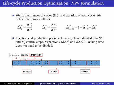
We fix the number of cycles (Nc), and duration of each cycle. Wedefine fractions as follows:
Ó∆tnp =∆tn
p
∆tnÓ∆t
ni =∆tn
i
∆tnÓ∆t
nsoak = 1−Ó∆t
np −Ó∆t
ni
Injection and production periods of each cycle are divided into N ni
and N np control steps, respectively (δ∆tn
p and δ∆tni ). Soaking time
does not need to be divided.
A. Almasov, M. Onur, A. Reynolds Optimization of the CO2 Huff-n-Puff Process Sep 26, 2019 (11/30)
Objective Function: NPV
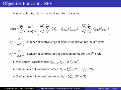
n is cycle, and Nc is the total number of cycles.
J(u) =Nc∑
n=1
∆tn
(1+ b)tn
365
Ó∆tnp
N np
N np
∑
j=1
(rno qn
o, j − cnCO2,pqn
CO2,p, j)−Ó∆t
ni
N ni
N ni
∑
j=1
(cnCO2,i q
nCO2,i, j)
N np =
∆tnp
δ∆tnp
- number of control steps of production period for the nth cycle
N ni =
∆tni
δ∆tni
- number of control steps of injection period for the nth cycle
Well control variables (u): qnCO2,i, j , pn
wf , j , Ó∆tnp, Ó∆t
ni
Total number of control variables: Nu =∑Nc
n=1(Nni + N n
p ) + 2Nc
Total number of control time steps: Nt =∑Nc
n=1(Nni + N n
p )
A. Almasov, M. Onur, A. Reynolds Optimization of the CO2 Huff-n-Puff Process Sep 26, 2019 (12/30)

Constraints
Constraints used in optimization procedure are:
0.3≤Ó∆tnp ≤ 1 and
1−Ó∆tnp
2≤Ó∆t
ni ≤ 1−Ó∆t
np
Bound constraints for production BHP (psi) and injection rate(MSCF/Day) are:
1500< pbh < 2400 and 20< qi < 60
A. Almasov, M. Onur, A. Reynolds Optimization of the CO2 Huff-n-Puff Process Sep 26, 2019 (13/30)
LS-SVR Proxy
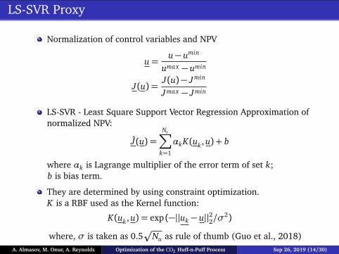
Normalization of control variables and NPV
u=u− umin
umax − umin
J(u) =J(u)− Jmin
Jmax − Jmin
LS-SVR - Least Square Support Vector Regression Approximation ofnormalized NPV:
J(u) =Ns∑
k=1
αkK(uk, u) + b
where αk is Lagrange multiplier of the error term of set k;b is bias term.
They are determined by using constraint optimization.K is a RBF used as the Kernel function:
K(uk, u) = exp (−||uk − u||22/σ2)
where, σ is taken as 0.5p
Nu as rule of thumb (Guo et al., 2018)A. Almasov, M. Onur, A. Reynolds Optimization of the CO2 Huff-n-Puff Process Sep 26, 2019 (14/30)
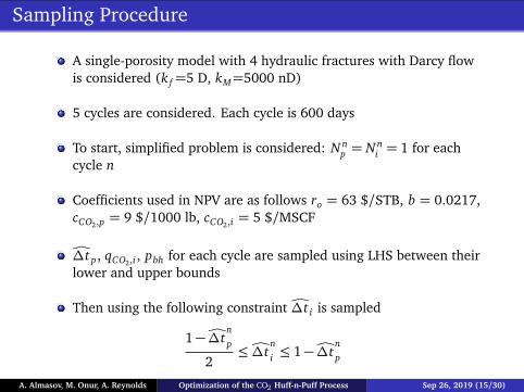
Sampling Procedure
A single-porosity model with 4 hydraulic fractures with Darcy flowis considered (k f=5 D, kM=5000 nD)
5 cycles are considered. Each cycle is 600 days
To start, simplified problem is considered: N np = N n
i = 1 for eachcycle n
Coefficients used in NPV are as follows ro = 63 $/STB, b = 0.0217,cCO2,p = 9 $/1000 lb, cCO2,i = 5 $/MSCF
Ó∆t p, qCO2,i , pbh for each cycle are sampled using LHS between theirlower and upper bounds
Then using the following constraint Ó∆t i is sampled
1−Ó∆tnp
2≤Ó∆t
ni ≤ 1−Ó∆t
np
A. Almasov, M. Onur, A. Reynolds Optimization of the CO2 Huff-n-Puff Process Sep 26, 2019 (15/30)
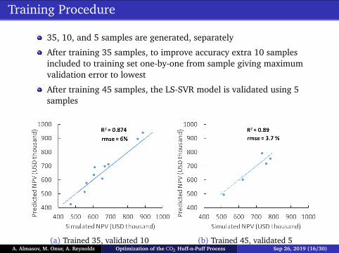
Training Procedure
35, 10, and 5 samples are generated, separately
After training 35 samples, to improve accuracy extra 10 samplesincluded to training set one-by-one from sample giving maximumvalidation error to lowest
After training 45 samples, the LS-SVR model is validated using 5samples
(a) Trained 35, validated 10 (b) Trained 45, validated 5A. Almasov, M. Onur, A. Reynolds Optimization of the CO2 Huff-n-Puff Process Sep 26, 2019 (16/30)

Optimization Procedure
The sequential quadratic programming (SQP) algorithm is used.Analytical gradients of the LS-SVR model are provided
Results of iterative sampling
A. Almasov, M. Onur, A. Reynolds Optimization of the CO2 Huff-n-Puff Process Sep 26, 2019 (17/30)

Optimization Results
Well-control variables of initial and optimum cases
A. Almasov, M. Onur, A. Reynolds Optimization of the CO2 Huff-n-Puff Process Sep 26, 2019 (18/30)

Optimization Results
A. Almasov, M. Onur, A. Reynolds Optimization of the CO2 Huff-n-Puff Process Sep 26, 2019 (19/30)

Conclusions
With good training strategy, LS-SVR model can predict NPV due toCO2 Huff-n-Puff process
This LS-SVR model can be used in maximization process, accuratelyand efficiently
Training strategy affects optimization
Molecular diffusion was found to be important
Duration of soaking period was found to be important
A. Almasov, M. Onur, A. Reynolds Optimization of the CO2 Huff-n-Puff Process Sep 26, 2019 (20/30)

Acknowledgements
Companies supporting The University of Tulsa Petroleum ReservoirExploitation Projects (TUPREP)
A. Almasov, M. Onur, A. Reynolds Optimization of the CO2 Huff-n-Puff Process Sep 26, 2019 (21/30)

Why Huff-n-Puff and Why CO2 In Unconventional OilReservoirs?
Applicable in reservoirs with nanopores
It can extract oil from nanoscale matrix through molecular diffusion
Abundant CO2 from different sources; ecologically is also favourableto inject underground
Miscibility should be achieved
A. Almasov, M. Onur, A. Reynolds Optimization of the CO2 Huff-n-Puff Process Sep 26, 2019 (22/30)
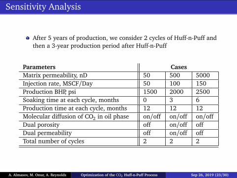
Sensitivity Analysis
After 5 years of production, we consider 2 cycles of Huff-n-Puff andthen a 3-year production period after Huff-n-Puff
Parameters CasesMatrix permeability, nD 50 500 5000Injection rate, MSCF/Day 50 100 150Production BHP, psi 1500 2000 2500Soaking time at each cycle, months 0 3 6Production time at each cycle, months 12 12 12Molecular diffusion of CO2 in oil phase on/off on/off on/offDual porosity off on/off offDual permeability off on/off offTotal number of cycles 2 2 2
A. Almasov, M. Onur, A. Reynolds Optimization of the CO2 Huff-n-Puff Process Sep 26, 2019 (23/30)

Sensitivity Analysis: Matrix Permeability-Single Porosity
qCO2,i=100 MSCF/Daypbh=2000 psi∆t i=6 months∆tsoak=3 months
(a) Diffusion (b) Non-Diffusion
A. Almasov, M. Onur, A. Reynolds Optimization of the CO2 Huff-n-Puff Process Sep 26, 2019 (24/30)

Sensitivity Analysis: Injection Rate-Single Porosity
kM=50 nDpbh =2000 psi∆t i=6 months∆tsoak=3 months
(a) Diffusion (b) Non-Diffusion
A. Almasov, M. Onur, A. Reynolds Optimization of the CO2 Huff-n-Puff Process Sep 26, 2019 (25/30)

Sensitivity Analysis: Duration of Soaking Period-SinglePorosity
kM=50 nDqCO2,i=100 MSCF/Daypbh=2000 psi∆t i=6 months
(a) Diffusion (b) Non-Diffusion
A. Almasov, M. Onur, A. Reynolds Optimization of the CO2 Huff-n-Puff Process Sep 26, 2019 (26/30)
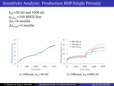
Sensitivity Analysis: Production BHP-Single Porosity
kM=50 nD and 5000 nDqCO2,i=100 MSCF/Day∆t i=6 months∆tsoak=3 months
(a) Diffusion, kM=50 nD (b) Diffusion, kM=5000 nD
A. Almasov, M. Onur, A. Reynolds Optimization of the CO2 Huff-n-Puff Process Sep 26, 2019 (27/30)
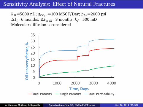
Sensitivity Analysis: Effect of Natural Fractures
kM=5000 nD; qCO2,i=100 MSCF/Day; pbh=2000 psi∆t i=6 months; ∆tsoak=3 months; k f=500 mDMolecular diffusion is considered
A. Almasov, M. Onur, A. Reynolds Optimization of the CO2 Huff-n-Puff Process Sep 26, 2019 (28/30)

Summary of Sensitivity Results
Molecular diffusion of CO2 in oil phase plays important role inHuff-n-Puff performance
In natural fractured reservoirs, we need to inject more CO2, and fora longer time to be able to achieve miscibility
We see benefits of soaking period in diffusion case
Increasing injection rate increases RF
Increasing matrix permeability increases RF
Production BHP does not seem to influence RF very low permeablereservoir since diffusion is more dominant than convection
A. Almasov, M. Onur, A. Reynolds Optimization of the CO2 Huff-n-Puff Process Sep 26, 2019 (29/30)

Optimization Procedure
The sequential quadratic programming (SQP) algorithm is used.Analytical gradients of the LS-SVR model are provided
Usually after 4 iterations, we reach maximum
Different initial guesses yield the same NPV value
Training affects optimization results
Simulator and LS-SVR outputs at the optimum are close around 3%relative error
A. Almasov, M. Onur, A. Reynolds Optimization of the CO2 Huff-n-Puff Process Sep 26, 2019 (30/30)
Related Documents