Arab J Sci Eng (2016) 41:4563–4572 DOI 10.1007/s13369-016-2172-9 RESEARCH ARTICLE - MECHANICAL ENGINEERING Optimization of Mechanical Properties of Friction Stir Spot Welded Joints for Dissimilar Aluminum Alloys (AA2024-T3 and AA 5754-H114) Muna Khethier Abbass 1 · Sabah Khamass Hussein 2 · Ahmed Adnan Khudhair 2 Received: 26 November 2015 / Accepted: 18 April 2016 / Published online: 19 May 2016 © The Author(s) 2016. This article is published with open access at Springerlink.com Abstract In this work, friction stir spot welding (FSSW) was performed for dissimilar aluminum alloys (AA2024-T3 and AA5754-H114) sheets of 2 mm thick at different tool rotational speeds (800, 1000 and 1250 rpm), plunging times (30, 60 and 90 s) and tool pin profile or geometry (threaded cylindrical with flute, tapered cylindrical and straight cylin- drical). Process parameters were optimized by using Taguchi technique and depending on design of experiment (DOE), and data analysis based on the Taguchi method is performed by utilizing the Minitab 17 to estimate the significant fac- tors of the FSSW and main effects using few experimental tests only. It was found that maximum shear force was (2860 N) obtained at best welding process parameters: 800 rpm of rotation speed, 60 s of plunging time and taper cylindrical pin which are obtained from the DOE. Pareto chart of the stan- dardized effects of tensile shear results showed that the pin profile was the most effective parameter than other welding parameters (rotation speed and plunging time). Also it was found that the contribution percentage was 61.5 % for pin profile followed by tool rotation speed 20.1 % and plunging time 18.4 %. Keywords Friction stir spot welding · Shear force · Dissimilar Al-alloys · Taguchi technique B Muna Khethier Abbass [email protected] Sabah Khamass Hussein [email protected] Ahmed Adnan Khudhair [email protected] 1 Department of Production Engineering and Metallurgy, University of Technology, Baghdad, Iraq 2 Engineering Technical College- Baghdad, Middle Technical University, Baghdad, Iraq 1 Introduction Friction stir welding (FSW) was developed by TWI in 1991 [1]. It has been widely used in the aerospace, shipbuild- ing, automobile industries and in many applications because of many of its advantages over the conventional welding tech- niques, some of which include very low distortion, no fumes, porosity or spatter, no consumables (no filler wire), no spe- cial surface treatment and no shielding gas requirements [2]. Friction stir spot welding (FSSW) is a very useful variant of the conventional friction stir welding (FSW), which shows great potential to be a replacement of single-point joining processes like resistance spot welding and riveting, and it has wider applications in aerospace, aviation and automo- bile fields [3, 4]. A number of studies have been conducted on friction stir spot welding (FSSW) between similar and dissimilar aluminum alloys and with other metals over the years as follows: Merzoug et al. [5] conducted experiments of friction stir spot welding on AA6060-T5 using a tool steel of type X210 and the rotational speed in range from 1000 to 2000 rpm and tool feed 16–25 mm/min. They found that the tensile shear force was 5 KN at using 16 mm/min and 1000 rpm compared to 1.98 KN for 25 mm/min and 2000 rpm. The microhardness reaches maximum value they moved away from the nugget zone. Aval et al. [6] investigated the microstructures and mechanical properties in dissimilar friction stir welding of AA5086-O and AA6061-T6 using thermomechanical model and experimental observations. They found that the hardness in AA5086 side mainly depends on recrystallization and gen- eration of fine grains in the weld nugget, whereas hardness in the AA6061 side varies with the size, volume fraction and distribution of precipitates in the weld line and adjacent heat-affected zone as well as the aging period after welding. 123

Welcome message from author
This document is posted to help you gain knowledge. Please leave a comment to let me know what you think about it! Share it to your friends and learn new things together.
Transcript
Arab J Sci Eng (2016) 41:4563–4572DOI 10.1007/s13369-016-2172-9
RESEARCH ARTICLE - MECHANICAL ENGINEERING
Optimization of Mechanical Properties of Friction Stir SpotWelded Joints for Dissimilar Aluminum Alloys(AA2024-T3 and AA 5754-H114)
Muna Khethier Abbass1 · Sabah Khamass Hussein2 · Ahmed Adnan Khudhair2
Received: 26 November 2015 / Accepted: 18 April 2016 / Published online: 19 May 2016© The Author(s) 2016. This article is published with open access at Springerlink.com
Abstract In this work, friction stir spot welding (FSSW)was performed for dissimilar aluminum alloys (AA2024-T3and AA5754-H114) sheets of 2mm thick at different toolrotational speeds (800, 1000 and 1250 rpm), plunging times(30, 60 and 90s) and tool pin profile or geometry (threadedcylindrical with flute, tapered cylindrical and straight cylin-drical). Process parameters were optimized by using Taguchitechnique and depending on design of experiment (DOE),and data analysis based on the Taguchi method is performedby utilizing the Minitab 17 to estimate the significant fac-tors of the FSSW and main effects using few experimentaltests only. It was found that maximum shear force was (2860N) obtained at best welding process parameters: 800 rpm ofrotation speed, 60 s of plunging time and taper cylindrical pinwhich are obtained from the DOE. Pareto chart of the stan-dardized effects of tensile shear results showed that the pinprofile was the most effective parameter than other weldingparameters (rotation speed and plunging time). Also it wasfound that the contribution percentage was 61.5% for pinprofile followed by tool rotation speed 20.1% and plungingtime 18.4%.
Keywords Friction stir spot welding · Shear force ·Dissimilar Al-alloys · Taguchi techniqueB Muna Khethier Abbass
Sabah Khamass [email protected]
Ahmed Adnan [email protected]
1 Department of Production Engineering and Metallurgy,University of Technology, Baghdad, Iraq
2 Engineering Technical College- Baghdad, Middle TechnicalUniversity, Baghdad, Iraq
1 Introduction
Friction stir welding (FSW) was developed by TWI in1991 [1]. It has been widely used in the aerospace, shipbuild-ing, automobile industries and in many applications becauseofmany of its advantages over the conventionalwelding tech-niques, some of which include very low distortion, no fumes,porosity or spatter, no consumables (no filler wire), no spe-cial surface treatment and no shielding gas requirements [2].Friction stir spot welding (FSSW) is a very useful variant ofthe conventional friction stir welding (FSW), which showsgreat potential to be a replacement of single-point joiningprocesses like resistance spot welding and riveting, and ithas wider applications in aerospace, aviation and automo-bile fields [3,4]. A number of studies have been conductedon friction stir spot welding (FSSW) between similar anddissimilar aluminum alloys and with other metals over theyears as follows:
Merzoug et al. [5] conducted experiments of friction stirspot welding on AA6060-T5 using a tool steel of type X210and the rotational speed in range from 1000 to 2000 rpm andtool feed 16–25mm/min. They found that the tensile shearforce was 5 KN at using 16mm/min and 1000 rpm comparedto 1.98KN for 25mm/min and 2000 rpm. Themicrohardnessreaches maximum value they moved away from the nuggetzone. Aval et al. [6] investigated the microstructures andmechanical properties in dissimilar friction stir welding ofAA5086-O and AA6061-T6 using thermomechanical modeland experimental observations. They found that the hardnessinAA5086 sidemainly depends on recrystallization and gen-eration of fine grains in the weld nugget, whereas hardnessin the AA6061 side varies with the size, volume fractionand distribution of precipitates in the weld line and adjacentheat-affected zone as well as the aging period after welding.
123
4564 Arab J Sci Eng (2016) 41:4563–4572
Table 1 Chemical composition of Al-alloys AA2024T3 and AA5754-H114
Element wt% Si Fe Cu Mn Mg Cr Ni Zn Ti V Other Al
AA5457-H114 0.005 0.280 0.038 0.358 2.97 0.046 0.005 0.016 0.015 0.013 0.0327 Bal.
AA2024-T3 0.126 0.280 4.37 0.593 1.27 0.0013 0.0099 0.166 0.0167 0.01 – Bal.
Table 2 Mechanical propertiesof Al-alloys used in this study
Alloys Yield strength (MPa) Tensile strength (MPa) Elongation %
AA2024-T3 345 450 22
AA5754-H114 191 248 18
Krishna et al. [7] used the Taguchi experimental designtechnique to determine the optimum friction stir weldingparameters for dissimilar Al2024-T6 and Al6351-T6 alloys.Effect of FSWprocess parameters such as tool rotation speed,welding speed and axial force on tensile strength was eval-uated. A mathematical model based on nonlinear regressionwas developed to establish relation between welding para-meters and tensile strength. From ANOVA, it is found thatthe speed of tool rotational, speed of welding and force ofaxial have 67.31, 13.7 and 14.5% contribution, respectively.Kulekci [8] used friction stir spot welding to joint aluminumalloy plates (EN AW5005) with a thickness of 1.5mm withusing tool of hardness 52 HRC. They used different para-meters of tool rotation (1500 and 2000 rpm), dwell time (5and 10s) and the tool pin height (2.2 and 2.6mm). Theyfound that the increase in tool rotation speed increases thetensile shear strength in a limited range of “ FSSW joints”and the increase in the tool pin height increases the tensileshear strength. Effect of tool pin height on the tensile shearstrength was greater than dwelling time and tool rotation.
Vanita and Kadlag [9] applied friction stir welding suc-cessfully for AA6082-T6 aluminum alloy sheet of 6.5mmthickness by CNC milling machine. Taper cylindrical toolwith three flutes gave the best weld joint among other toolswhich made of “HSS” for the friction stir welding. Experi-mentswere conducted byvarying rotational speed, transversespeed and constant welding depth using “L9 orthogonalarray” of “Taguchi method.” This work aims at optimizingprocess parameters to achieve high tensile strength. Theyfound that the optimum process parameters are 1400 rpm ofrotational speed, 20mm/min of traverse speed and 5mm ofwelding depth (constant), respectively, which was leading tohigher tensile strength.
Abbass et al. [10] performed friction stir spot welding(FSSW) of an aluminum alloy AA2024T3 sheet to com-mercial pure copper sheet of 2mm thick at different toolrotational speeds (800,1000 and 1250 rpm), plunging times(30, 60 and 90 s) and tool pin profile or geometry (Threadedcylindrical with flute, Tapered cylindrical and straight cylin-drical). Process parameters were optimized by using Taguchi
technique and depending on design of experiment (DOE).They found that maximum shear force was obtained at opti-mum welding parameters: 1250 rpm rotation speed, 90 splunging time and straight cylindrical pin profile which areobtained from the analysis of response optimizer. Pareto chartthe standardized effects of tensile shear results showed thatthe plunging timewas themost effective parameter than otherwelding parameters (rotation speed and pin profile).
From literature reviews as mentioned above, very lim-ited researches or studies focused about the FSSW processof different Al-alloys (heat treatable with non-heat treat-able); therefore, in this work more details are presented. Theobjective of this work is to optimize the FSSW parametersdepending on mechanical properties (tensile shear force andmicrohardness) of spot welded joints by using Taguchi tech-nique and depending on design of experiment of dissimilaraluminum alloys (AA2024-T3 and AA 5754-H114).
2 Experimental Work
2.1 Materials Used
In this study, 2-mm-thick aluminum alloys AA2024-T3 andAA57454-H114were used as basematerials. Chemical com-position analysis of alloys was done using spectrometerinstrument ARL in COSQC laborites as shown in Table 1.Tensile testwas carried out to determine themechanical prop-erties of base metals according to ASTM standard E8M−09for sub-size specimen as shown in Table 2.
2.2 FSSW Procedure
FSSW process was performed by using vertical universalmillingmachine type (DECKELFP4MNC-Germany) to fab-ricate overlap welded joints where the AA2024T3 sheet wasupper sheet and AA5754-H114 was lower sheet. Addition-ally, proper backing sheets were used to obtain the desiredlap spot joints. The work pieces have a 25 × 25mm2 overlaparea. During FSSW, the friction between the shoulder pin and
123
Arab J Sci Eng (2016) 41:4563–4572 4565
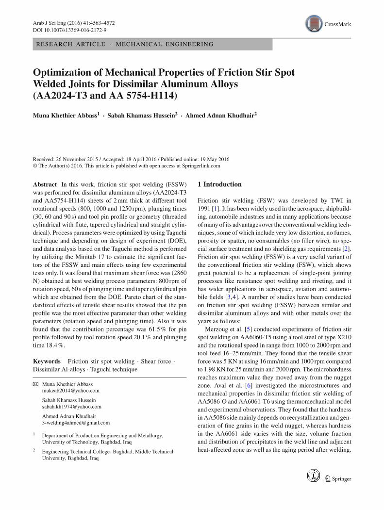
Fig. 1 FSSW tool profile and pin size used in this study a Threadedcylindrical with flute (ThC), b Tapered cylindrical (TC), straight cylin-drical (SC)
Fig. 2 The design and dimensions of overlap work pieces to be spotwelded
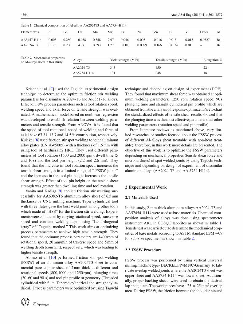
the work pieces generatesmost of the heat energy for joining.The tools used in welding operations were machined fromhigh speed tool steel which has hardness of 54 HRC. Threetools pin profiles (threaded cylindrical with flute, taperedcylindrical and straight cylindrical) were used to fabricatethe joints in this study as shown in Fig. 1. The alignmentand dimensions of overlap work pieces to be spot weldedindicated in Fig. 2. The friction stir spot welding (FSSW)process consists of three stages or steps: plunging, stirringand retracting (drawing out) as shown in Fig. 3 [5].
2.3 Tensile Shear Test
Tensile shear strength was performed on a spot welded spec-imen with 189mm length, 25mm width and 2mm thick.Welded lap shear specimens were tested on an Instronmachine, TGM—France machine Model (03M3818.1) at aconstant crosshead speed of 5mm/min with maximum load100 KN. For lap shear tensile test, the spot welded speci-mens of dissimilar metals (Al2024-T3 and AA5754-H114)were gripped with using shims of thickness equal to thatof the specimens. The maximum shear load was recoded atfracture point during the test for each FSSW specimen.
Fig. 3 Schematic illustration steps of friction stir spot welding process[5]
2.4 Microstructure Examination
Microstructure examination was carried out on cross sec-tion of spot welded specimen of dissimilar and base alloysusing optical microscope type (OPTIKA-ITALY) providedwith computer. A specimen preparation was made includ-ing wet grinding process with using SiC paper in differentgrits of 320, 500, 800, 1000, 1200 and 2000, and then pol-ishing process was performed with using 10 µm diamondpast and lubricant and then alumina solution with 3.0 µmwith special cloth to obtain polished surface. To examine themicrostructure of specimen, etching process was done usingetching solution which consists of (1ml HF+99 ml distilledwater) for twoAl-alloys.Macrostructure of cross sectionwasobtained to study welding zones of joint at optimumweldingconditions.
2.5 Hardness Test
Vickers hardness test was performed on the cross section ofthe spot welded sample, with applied load of 200g for 15 sby usingVickers hardness device.Microhardnesswas carriedout in nugget (stir) zone, TMAZ, HAZ, hook zone and basemetals of AA2024T3 and AA5754-H114, and 12 readings ofHV values were taken in each sample to have more accuracy.
3 Results and Discussion
3.1 Tensile Shear Results
Table 3 shows the shear force for specimens of friction stirspotwelded formed fromAA2024-T3 toAA5754-H114. Themaximumshear force is found for specimenNo. 8with valuesof (2870 N). However, the minimum shear force is found inspecimen No. 5 with a value (490N).
3.2 Macro- and Microstructure Examination
Macro- and microstructural examinations were achieved toinvestigate the welding characteristics. Due to high pressure
123

4566 Arab J Sci Eng (2016) 41:4563–4572
Table 3 Tensile shear forcevalues (AA2024-T3 toAA5754-H114
Experiment No. N (rpm) t (s) PF Tensile shear force (Mean) N
1 800 30 SC 960
2 800 60 TC 2860
3 800 90 ThC 660
4 1000 30 TC 1780
5 1000 60 ThC 490
6 1000 90 SC 2630
7 1250 30 ThC 1130
8 1250 60 SC 2840
9 1250 90 TC 1970
Fig. 4 Macrostructure of the cross section of the spot joint of(AA2024-T3 to AA5757-H114)
and large plastic deformation, the upper and the lower sheetsare compressed together to form an effective joint.
Figure 4 shows macrostructure of the cross section of thespot joint (FSSW) of (AA2024-T3 to AA5754-H114) whichwas welded at best welding parameters. It was seen thereare five zones that have different characteristics includingthe base Metal (BM), the heat-affected zone (HAZ), thermo-mechanically affected zone (TMAZ), the stir zone (SZ) andthe hook on both sides of spot joint. The hooks formed dueto the shearing action, and this action propagates to a depthinversely proportional to the yield strength of the weldedmaterials.
The hook is a characteristic feature of friction stir spotwelds in lap configuration where there is a formation of a
geometrical defect originating at the interface of the twowelded sheets [11]. Figure 5 shows the microstructures ofthe cross section of FSSW joint of (AA2024T3 to AA5754-H114) which was welded at best welding parameters.
3.3 Hook Characteristics
The plastic flow of upper and lower sheets during the spotwelding process leads to hooks formation. The high pressureexerted by the rotation pin in addition to the high temperatureresulted from friction between the rotating pin and the uppersheet. All these factors resulted in plastic flow of the mattingsheets, because the flow of sheet material is constrained bythe setup of the proposed tool. So the sheets forced to flowto the weaker place, which is in this case the lower sheet(AA5754-H114), because this sheet is softened more thanthe upper sheet (AA2024T3), so that all the hooks in thisspot welding process are directed upward to the upper sheetas shown in Fig. 6.
3.4 Hardness Results
Figure 7 shows the Vickers hardness profile across sectionof spot weld of (AA2024-T3 to AA5754-H114) at 12 dif-
Fig. 5 The microstructures of the cross section of FSSW joint of (AA2024T3 to AA5754-H114). a) At ×100, b at ×400
123
Arab J Sci Eng (2016) 41:4563–4572 4567
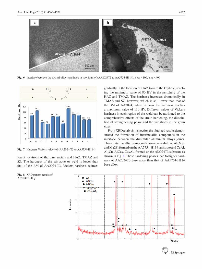
Fig. 6 Interface between the two Al-alloys and hook in spot joint of (AA2024T3 to AA5754-H114). a At ×100, b at ×400
Fig. 7 Hardness Vickers values of (AA2024-T3 to AA5754-H114)
ferent locations of the base metals and HAZ, TMAZ andSZ. The hardness of the stir zone or weld is lower thanthat of the BM of AA2024-T3. Vickers hardness reduces
gradually in the location of HAZ toward the keyhole, reach-ing the minimum value of 80 HV in the periphery of theHAZ and TMAZ. The hardness increases dramatically inTMAZ and SZ, however, which is still lower than that ofthe BM of AA2024, while in hook the hardness reachesa maximum value of 110 HV. Different values of Vickershardness in each region of the weld can be attributed to thecomprehensive effects of the strain-hardening, the dissolu-tion of strengthening phase and the variations in the grainsizes.
FromXRDanalysis inspection theobtained results demon-strated the formation of intermetallic compounds in theinterface between the dissimilar aluminum alloys joints.These intermetallic compounds were revealed as Al3Mg2andMg2Si formedon theAA5754-H114 substrate andCuAl,Al2Cu, AlCu4, Cu9Al4 formed on the Al2024T3 substrate asshown in Fig. 8. These hardening phases lead to higher hard-ness of AA2024T3 base alloy than that of AA5754-H114base alloy.
Fig. 8 XRD pattern results ofAl2024T3 alloy
123
4568 Arab J Sci Eng (2016) 41:4563–4572
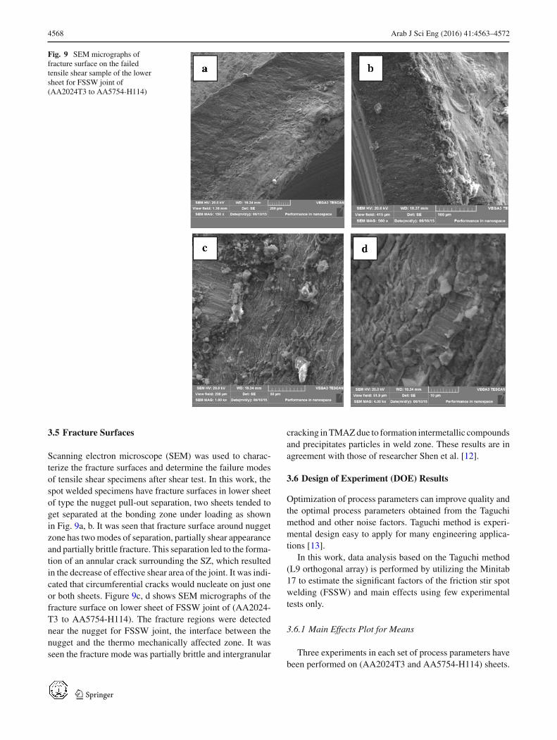
Fig. 9 SEM micrographs offracture surface on the failedtensile shear sample of the lowersheet for FSSW joint of(AA2024T3 to AA5754-H114)
3.5 Fracture Surfaces
Scanning electron microscope (SEM) was used to charac-terize the fracture surfaces and determine the failure modesof tensile shear specimens after shear test. In this work, thespot welded specimens have fracture surfaces in lower sheetof type the nugget pull-out separation, two sheets tended toget separated at the bonding zone under loading as shownin Fig. 9a, b. It was seen that fracture surface around nuggetzone has twomodes of separation, partially shear appearanceand partially brittle fracture. This separation led to the forma-tion of an annular crack surrounding the SZ, which resultedin the decrease of effective shear area of the joint. It was indi-cated that circumferential cracks would nucleate on just oneor both sheets. Figure 9c, d shows SEM micrographs of thefracture surface on lower sheet of FSSW joint of (AA2024-T3 to AA5754-H114). The fracture regions were detectednear the nugget for FSSW joint, the interface between thenugget and the thermo mechanically affected zone. It wasseen the fracture mode was partially brittle and intergranular
cracking inTMAZdue to formation intermetallic compoundsand precipitates particles in weld zone. These results are inagreement with those of researcher Shen et al. [12].
3.6 Design of Experiment (DOE) Results
Optimization of process parameters can improve quality andthe optimal process parameters obtained from the Taguchimethod and other noise factors. Taguchi method is experi-mental design easy to apply for many engineering applica-tions [13].
In this work, data analysis based on the Taguchi method(L9 orthogonal array) is performed by utilizing the Minitab17 to estimate the significant factors of the friction stir spotwelding (FSSW) and main effects using few experimentaltests only.
3.6.1 Main Effects Plot for Means
Three experiments in each set of process parameters havebeen performed on (AA2024T3 and AA5754-H114) sheets.
123
Arab J Sci Eng (2016) 41:4563–4572 4569
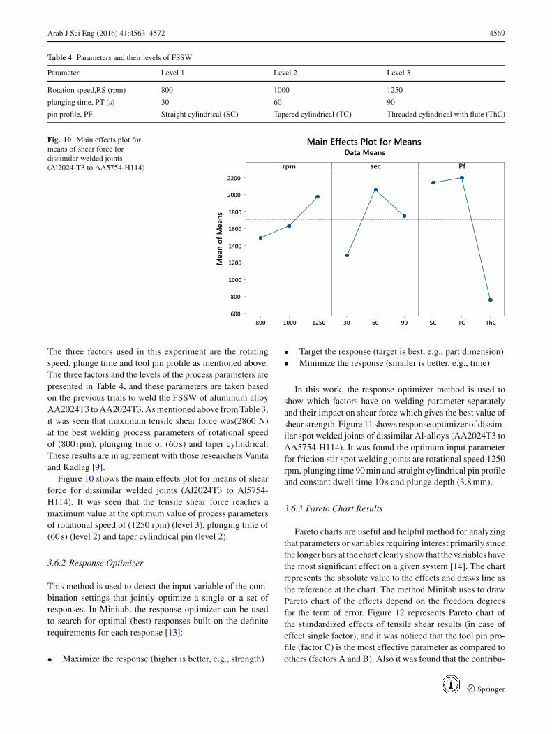
Table 4 Parameters and their levels of FSSW
Parameter Level 1 Level 2 Level 3
Rotation speed,RS (rpm) 800 1000 1250
plunging time, PT (s) 30 60 90
pin profile, PF Straight cylindrical (SC) Tapered cylindrical (TC) Threaded cylindrical with flute (ThC)
Fig. 10 Main effects plot formeans of shear force fordissimilar welded joints(Al2024-T3 to AA5754-H114)
12501000800
2200
2000
1800
1600
1400
1200
1000
800
600906030 ThCTCSC
rpm
Mea
n of
Mea
ns
sec Pf
Main Effects Plot for MeansData Means
The three factors used in this experiment are the rotatingspeed, plunge time and tool pin profile as mentioned above.The three factors and the levels of the process parameters arepresented in Table 4, and these parameters are taken basedon the previous trials to weld the FSSW of aluminum alloyAA2024T3 toAA2024T3.Asmentioned above fromTable 3,it was seen that maximum tensile shear force was(2860 N)at the best welding process parameters of rotational speedof (800 rpm), plunging time of (60 s) and taper cylindrical.These results are in agreement with those researchers Vanitaand Kadlag [9].
Figure 10 shows the main effects plot for means of shearforce for dissimilar welded joints (Al2024T3 to Al5754-H114). It was seen that the tensile shear force reaches amaximum value at the optimum value of process parametersof rotational speed of (1250 rpm) (level 3), plunging time of(60 s) (level 2) and taper cylindrical pin (level 2).
3.6.2 Response Optimizer
This method is used to detect the input variable of the com-bination settings that jointly optimize a single or a set ofresponses. In Minitab, the response optimizer can be usedto search for optimal (best) responses built on the definiterequirements for each response [13]:
• Maximize the response (higher is better, e.g., strength)
• Target the response (target is best, e.g., part dimension)• Minimize the response (smaller is better, e.g., time)
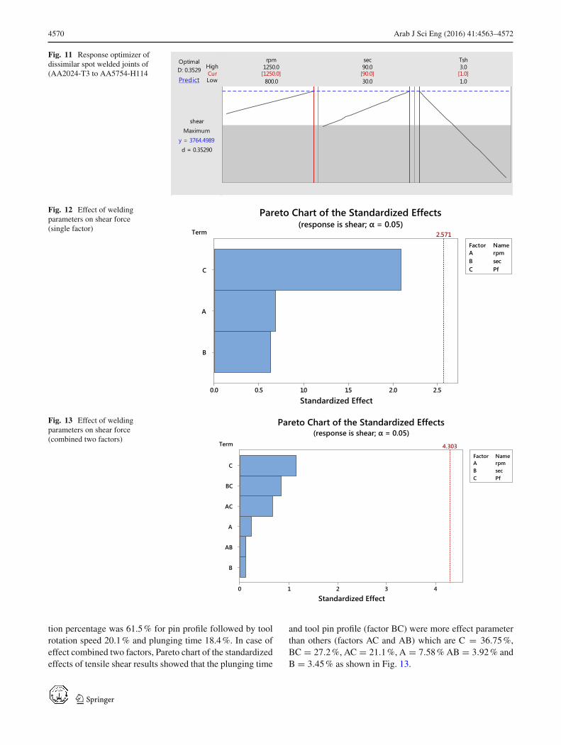
In this work, the response optimizer method is used toshow which factors have on welding parameter separatelyand their impact on shear force which gives the best value ofshear strength. Figure 11 shows responseoptimizer of dissim-ilar spot welded joints of dissimilar Al-alloys (AA2024T3 toAA5754-H114). It was found the optimum input parameterfor friction stir spot welding joints are rotational speed 1250rpm, plunging time 90min and straight cylindrical pin profileand constant dwell time 10s and plunge depth (3.8mm).
3.6.3 Pareto Chart Results
Pareto charts are useful and helpful method for analyzingthat parameters or variables requiring interest primarily sincethe longer bars at the chart clearly show that the variables havethe most significant effect on a given system [14]. The chartrepresents the absolute value to the effects and draws line asthe reference at the chart. The method Minitab uses to drawPareto chart of the effects depend on the freedom degreesfor the term of error. Figure 12 represents Pareto chart ofthe standardized effects of tensile shear results (in case ofeffect single factor), and it was noticed that the tool pin pro-file (factor C) is the most effective parameter as compared toothers (factors A and B). Also it was found that the contribu-
123
4570 Arab J Sci Eng (2016) 41:4563–4572
Fig. 11 Response optimizer ofdissimilar spot welded joints of(AA2024-T3 to AA5754-H114 Cur
High
Low
D: 0.3529Optimal
Predict
d = 0.35290
Maximumshear
y = 3764.4989
1.0
3.0
30.0
90.0
800.0
1250.0sec Tshrpm
[1250.0] [90.0] [1.0]
Fig. 12 Effect of weldingparameters on shear force(single factor) Term
B
A
C
2.52.01.51.00.50.0
A rpmB secC Pf
Factor Name
Standardized Effect
2.571
Pareto Chart of the Standardized Effects(response is shear; α = 0.05)
Fig. 13 Effect of weldingparameters on shear force(combined two factors)
Term
B
AB
A
AC
BC
C
43210
A rpmB secC Pf
Factor Name
Standardized Effect
4.303
Pareto Chart of the Standardized Effects(response is shear; α = 0.05)
tion percentage was 61.5% for pin profile followed by toolrotation speed 20.1% and plunging time 18.4%. In case ofeffect combined two factors, Pareto chart of the standardizedeffects of tensile shear results showed that the plunging time
and tool pin profile (factor BC) were more effect parameterthan others (factors AC and AB) which are C = 36.75%,BC = 27.2%, AC = 21.1%, A = 7.58% AB = 3.92% andB = 3.45% as shown in Fig. 13.
123
Arab J Sci Eng (2016) 41:4563–4572 4571
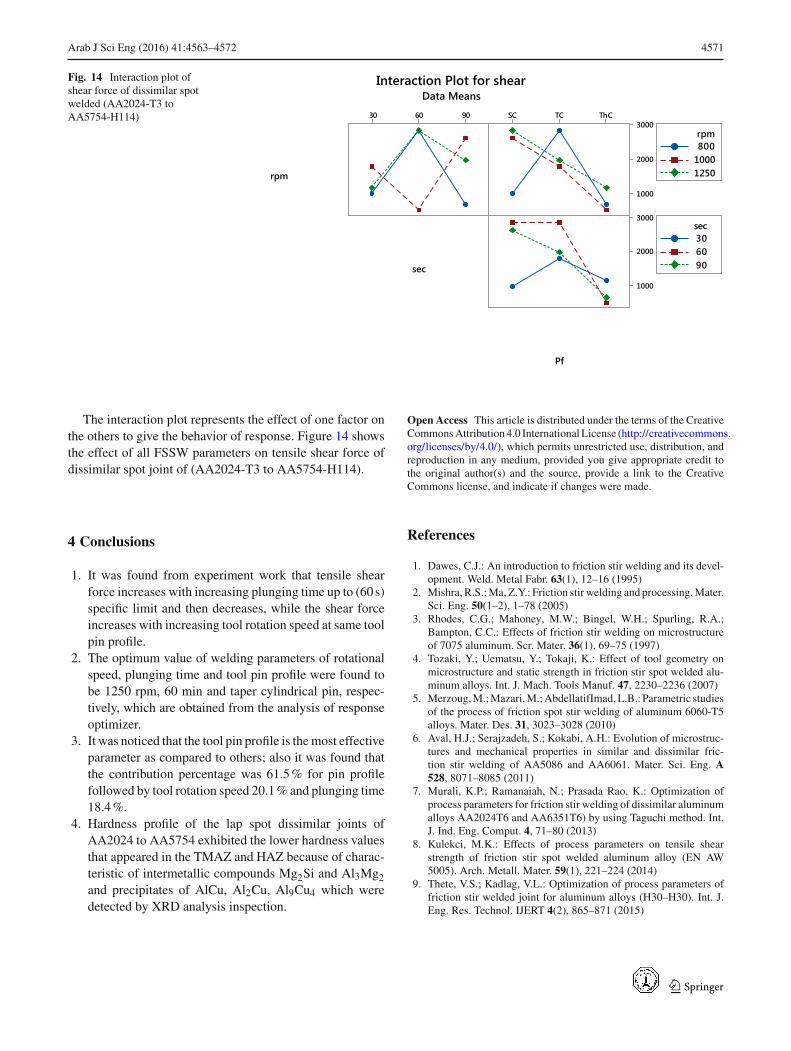
Fig. 14 Interaction plot ofshear force of dissimilar spotwelded (AA2024-T3 toAA5754-H114) 906030 ThCTCSC
3000
2000
1000
3000
2000
1000
rpm
sec
Pf
80010001250
rpm
306090
sec
Interaction Plot for shearData Means
The interaction plot represents the effect of one factor onthe others to give the behavior of response. Figure 14 showsthe effect of all FSSW parameters on tensile shear force ofdissimilar spot joint of (AA2024-T3 to AA5754-H114).
4 Conclusions
1. It was found from experiment work that tensile shearforce increases with increasing plunging time up to (60 s)specific limit and then decreases, while the shear forceincreases with increasing tool rotation speed at same toolpin profile.
2. The optimum value of welding parameters of rotationalspeed, plunging time and tool pin profile were found tobe 1250 rpm, 60 min and taper cylindrical pin, respec-tively, which are obtained from the analysis of responseoptimizer.
3. It was noticed that the tool pin profile is themost effectiveparameter as compared to others; also it was found thatthe contribution percentage was 61.5% for pin profilefollowed by tool rotation speed 20.1% and plunging time18.4%.
4. Hardness profile of the lap spot dissimilar joints ofAA2024 to AA5754 exhibited the lower hardness valuesthat appeared in the TMAZ and HAZ because of charac-teristic of intermetallic compounds Mg2Si and Al3Mg2and precipitates of AlCu, Al2Cu, Al9Cu4 which weredetected by XRD analysis inspection.
Open Access This article is distributed under the terms of the CreativeCommonsAttribution4.0 InternationalLicense (http://creativecommons.org/licenses/by/4.0/), which permits unrestricted use, distribution, andreproduction in any medium, provided you give appropriate credit tothe original author(s) and the source, provide a link to the CreativeCommons license, and indicate if changes were made.
References
1. Dawes, C.J.: An introduction to friction stir welding and its devel-opment. Weld. Metal Fabr. 63(1), 12–16 (1995)
2. Mishra, R.S.;Ma, Z.Y.: Friction stir welding and processing.Mater.Sci. Eng. 50(1–2), 1–78 (2005)
3. Rhodes, C.G.; Mahoney, M.W.; Bingel, W.H.; Spurling, R.A.;Bampton, C.C.: Effects of friction stir welding on microstructureof 7075 aluminum. Scr. Mater. 36(1), 69–75 (1997)
4. Tozaki, Y.; Uematsu, Y.; Tokaji, K.: Effect of tool geometry onmicrostructure and static strength in friction stir spot welded alu-minum alloys. Int. J. Mach. Tools Manuf. 47, 2230–2236 (2007)
5. Merzoug,M.;Mazari,M.;AbdellatifImad,L.B.: Parametric studiesof the process of friction spot stir welding of aluminum 6060-T5alloys. Mater. Des. 31, 3023–3028 (2010)
6. Aval, H.J.; Serajzadeh, S.; Kokabi, A.H.: Evolution of microstruc-tures and mechanical properties in similar and dissimilar fric-tion stir welding of AA5086 and AA6061. Mater. Sci. Eng. A528, 8071–8085 (2011)
7. Murali, K.P.; Ramanaiah, N.; Prasada Rao, K.: Optimization ofprocess parameters for friction stir welding of dissimilar aluminumalloys AA2024T6 and AA6351T6) by using Taguchi method. Int.J. Ind. Eng. Comput. 4, 71–80 (2013)
8. Kulekci, M.K.: Effects of process parameters on tensile shearstrength of friction stir spot welded aluminum alloy (EN AW5005). Arch. Metall. Mater. 59(1), 221–224 (2014)
9. Thete, V.S.; Kadlag, V.L.: Optimization of process parameters offriction stir welded joint for aluminum alloys (H30–H30). Int. J.Eng. Res. Technol. IJERT 4(2), 865–871 (2015)
123
4572 Arab J Sci Eng (2016) 41:4563–4572
10. Abbass, M.K.; Hussein, S.K.; Kudair, A.A.: Optimization of fric-tion stir spot welding parameters of dissimilar welded joints ofaluminum alloy (AA 2024T3) with pure copper sheets. Int. J. Eng.Sci. Res IJESRT 4(12), 514–526 (2015)
11. Badarinarayan, H.; Yang, Q.; Zhu, S.: Effect of tool geometry onstatic strength of friction stir spot-welded aluminum alloy. Int. J.Mach. Tools Manuf. 49, 142–148 (2009)
12. Shen, Z.; Yang, X.; Zhang, Z.; Cui, L.; Yin, Y.: Mechanical prop-erties and failure mechanisms of friction stir spot welds of AA6061-T4 sheets. Mater. Des. 49, 181–191 (2013)
13. Minitab 17 Program guides and Help (2014)14. Richard, N.M.: How to use minitab: design of experiments,
pp. 1–38 (2014)
123
Related Documents