© CADFEM 2015 Optimization of a Dual Band Antenna using `Statistics on Structures` Marc Vidal, Sebastian Wolff, Christian Römelsberger 1

Welcome message from author
This document is posted to help you gain knowledge. Please leave a comment to let me know what you think about it! Share it to your friends and learn new things together.
Transcript

Titelmasterformat durch Klicken bearbeiten
© CADFEM 2015
Optimization of a Dual Band Antenna
using `Statistics on Structures`
Marc Vidal, Sebastian Wolff, Christian Römelsberger
1

© CADFEM 2015
Internet of Things and Antennas
2
• Number of connected devices
growing rapidly
• ca. 30,000,000,000 devices by 2020!
• Automotive, Households, Industrial,
Consumer, Communications, …
• Wearable and mobile devices
wirelessly connected

© CADFEM 2015
Challenges in Antenna Design
3
• Communication of wireless devices
through various frequency bands
using different technologies and
standards
• NFC
• WLAN
• Bluetooth
• ZigBee
• …
• Wearable and mobile devices should
be small
• Save space by using multiple band
antennas
Source: Wikipedia:
Nicolas Sadoc, Nick Pitsas, CSIRO

© CADFEM 2015 4
Engineering Task:
Design antenna structure that works at
the given frequency bands and fits into
a given small space!

© CADFEM 2015
HFSS – High Frequency Structure Simulator
• 3D Field Solver
• 3D Finite Element Method (FEM)
• Boundary Integral (IE)
• Mesh Process: Adaptive
• Advanced Boundary Types
• Radiation and Perfectly Matched Layers
• Symmetry, Finite Conductivity, Infinite Planes, RLC, and Layered Impedance
• Advanced Material Types
• Frequency dependent
• Anisotropic
• Post Processing and Report Type
• SYZ parameters
• Field display
• Near Field/Far Field
5

© CADFEM 2015
Simulation Model – Dual Band Slot Antenna
6
• Need to move minima of return loss
to the right frequencies
• Make 5.8GHz minimum deeper
FR4 Substrate
Slot
GND plane
Microstrip feed
on the back side

© CADFEM 2015 7
• Which parameter shall be taken for a manual variation?
Simulation Model – Dual Band Slot Antenna
lf
wf 50Ω
ws
hs
w1
w2
gap1
gap2
dd
dd
gap1 gap2
ws w2 hs w1
© CADFEM 2015
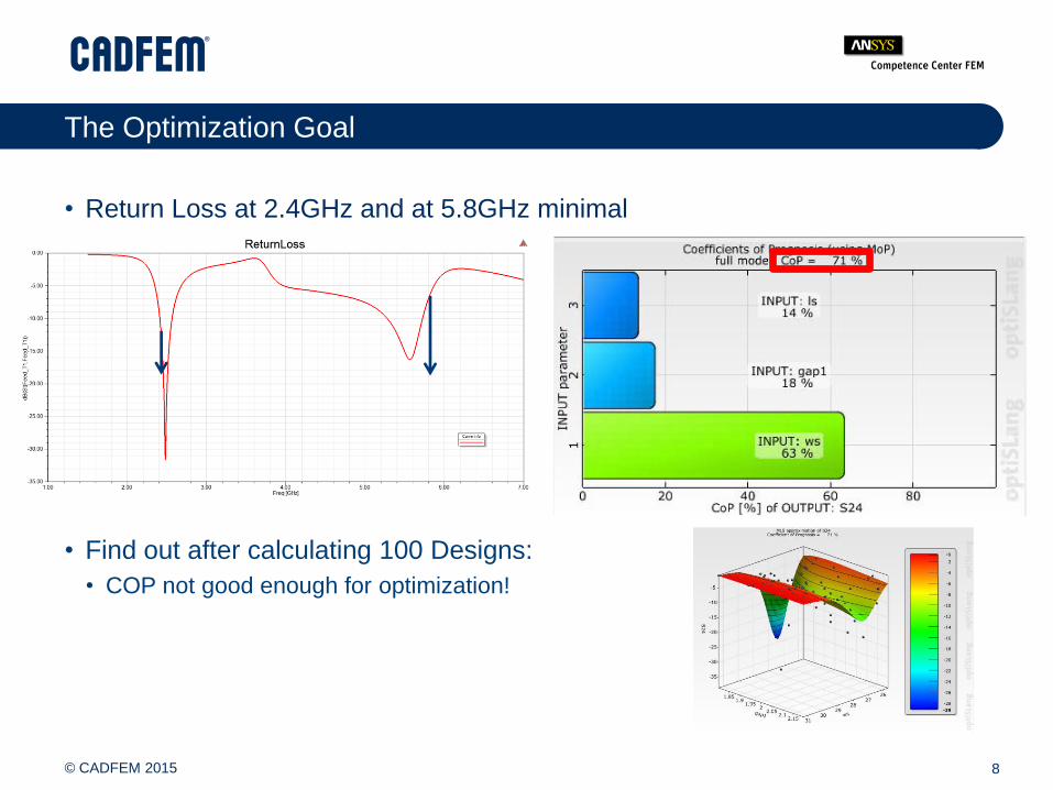
The Optimization Goal
8
• Return Loss at 2.4GHz and at 5.8GHz minimal
• Find out after calculating 100 Designs:
• COP not good enough for optimization!
© CADFEM 2015
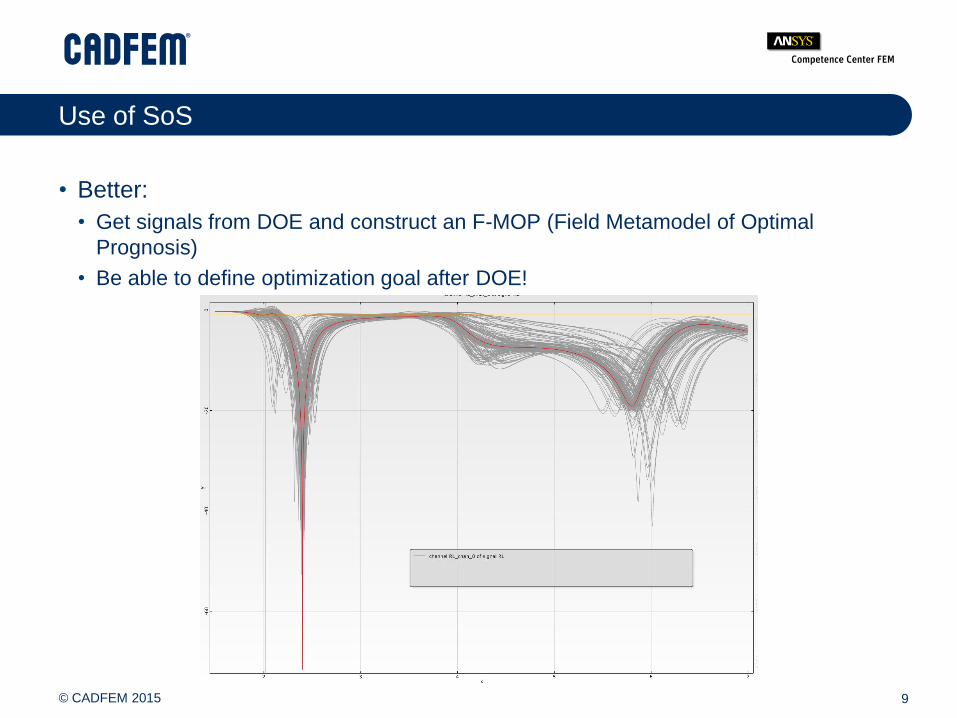
Use of SoS
9
• Better:
• Get signals from DOE and construct an F-MOP (Field Metamodel of Optimal
Prognosis)
• Be able to define optimization goal after DOE!

© CADFEM 2015
Field Meta Model
10
• Expand a signal in terms of ‘shape functions’
• ‘Shape functions’ are determined from the DOE of signals in order to capture
the most important characteristics of the signals
• ‘Regular’ MOP for the expansion coefficients z1, z2, z3,…
≈ *z1+ *z2+ *z3+ *z4+… +
Mean value of DOE
at each frequency

© CADFEM 2015
Field Meta Model
11
Determine
‘shape functions’
Calculate MOP
for coefficients
Reassemble
signals

© CADFEM 2015
Plan / Workflow
12
DOE
(optiSLang) SoS
Optimization
(optiSLang)
Validation
(HFSS)
Signals
F-MOP
for
Signals
Better
Design
•Fully
automated
sampling
•‘Shape
Functions’ for
signals
•F-MOP
•F-CoP
•Decide on
optimization
goal
•Use F-MOP as
raw data

© CADFEM 2015
F-CoP
13
• Bad F-CoP for return loss
Due to dB-Scale of
The Return Loss
(Singularity)
Bad explainability due
to little variation and little
correlation in frequency domain
combined with nonlinear effects
Good F-CoP

© CADFEM 2015
F-CoP
14
• But Return Loss is expressible in terms of complex S-parameters
• With good F-CoP for the S-parameters

© CADFEM 2015
Reformulation of the Optimization Goal
15
• Extract positions and values of the
minima of a given signal
(from F-MOP)
• Optimization Goal:
• Minimize Max(Min24,Min58)
• Constraints:
• Pos24=2.4
• Pos58=5.8
Pos24 Pos58
Min24
Min58
Range 1 Range 2

© CADFEM 2015
Optimization using ARSM on F-MOP
16
MOP for
Coefficients zi
Use ‘shape functions’
to generate F-MOP
Extract scalar
quantities as
optimization goals

© CADFEM 2015
Optimization
17
• Good agreement between F-MOP and calculated Return Loss
Validation

© CADFEM 2015
Best Design
18

© CADFEM 2015
Summary
19
• Good quality of prognosis for full
signals (e.g. Return Loss) using F-
MOP:
• No new simulations
• Possibility for plausibility checks of
solutions before validation using FE-
analysis
• Discover new possibilities (e.g. third
frequency band)
• CoP for signals over frequency (F-
CoP)
• Explain Relations
• Advantage for the engineer:
• Can define optimization goals after
DOE has been done and signals have
been understood.
• Generate F-MOP once and then look at
behavior of signals under optimization.
• No re-evaluation of DOE
F-CoP

© CADFEM 2015
CADFEM – Simulation is more than Software
20
PRODUCTS
Software und IT Solutions
SERVICES
Advice, Support, Engineering
KNOW-HOW
Transfer of knowledge
CADFEM in D, A, CH
• 1985 founded
• 2,300 customers
• 12 locations
• 185 employees (worldwide > 250)
Related Documents


