Welcome message from author
This document is posted to help you gain knowledge. Please leave a comment to let me know what you think about it! Share it to your friends and learn new things together.
Transcript

This document contains a post-print version of the paper
Optimization-based estimator for the contour and movement of heavyplates in hot rolling
authored by F. Schausberger, A. Steinboeck, and A. Kugi
and published in Journal of Process Control.
The content of this post-print version is identical to the published paper but without the publisher's �nal layout orcopy editing. Please, scroll down for the article.
Cite this article as:
F. Schausberger, A. Steinboeck, and A. Kugi, �Optimization-based estimator for the contour and movement of heavyplates in hot rolling�, Journal of Process Control, vol. 29, pp. 23�32, 2015, issn: 0959-1524. doi: 10.1016/j.
jprocont.2015.03.006
BibTex entry:
@article{Schausberger15a,
author = "F. Schausberger and A. Steinboeck and A. Kugi",
title = "Optimization-based estimator for the contour and movement of heavy plates in hot rolling ",
journal = "Journal of Process Control",
volume = "29",
pages = "23 - 32",
year = "2015",
issn = "0959-1524",
doi = "10.1016/j.jprocont.2015.03.006",
url = "http://www.sciencedirect.com/science/article/pii/S0959152415000529"
}
Link to original paper:
http://dx.doi.org/10.1016/j.jprocont.2015.03.006
http://www.sciencedirect.com/science/article/pii/S0959152415000529
Read more ACIN papers or get this document:
http://www.acin.tuwien.ac.at/literature
Contact:
Automation and Control Institute (ACIN) Internet: www.acin.tuwien.ac.atVienna University of Technology E-mail: [email protected]
Gusshausstrasse 27-29/E376 Phone: +43 1 58801 376011040 Vienna, Austria Fax: +43 1 58801 37699
Copyright notice:
This is the authors' version of a work that was accepted for publication in Journal of Process Control. Changes resulting from the publishing
process, such as peer review, editing, corrections, structural formatting, and other quality control mechanisms may not be re�ected in this
document. Changes may have been made to this work since it was submitted for publication. A de�nitive version was subsequently
published in F. Schausberger, A. Steinboeck, and A. Kugi, �Optimization-based estimator for the contour and movement of heavy plates
in hot rolling�, Journal of Process Control, vol. 29, pp. 23�32, 2015, issn: 0959-1524. doi: 10.1016/j.jprocont.2015.03.006

Optimization-based estimator for the contour and movement of heavy plates inhot rolling
F. Schausberger∗, A. Steinboeck, A. Kugi
Automation and Control Institute, Vienna University of Technology, Gußhausstraße 27–29, 1040 Vienna, Austria
Abstract
This paper deals with the estimation of the contour of heavy plates during the hot rolling process. Asymmetricrolling conditions lead to a non-rectangular contour. The reasons for this effect, e.g., temperature gradients or non-homogeneous input thickness profiles, are hard to predict in a real rolling mill. Hence, feedforward compensation ofthese disturbances is difficult, whereas feedback control could be a suitable means for improving the plate contour.Feedback control essentially requires the actual contour of the plate, which has to be measured or estimated inreal-time. The method presented in this paper suggests to capture an image sequence of the plate by means of athermographic measurement device. In the considered application, an image sequence is required because the wholeplate contour cannot be captured by a single image. An optimization-based algorithm takes into account the imagedata and the restrictions of the plate movement in the rolling gap and uses this information to estimate the actualplate contour. In addition, the algorithm estimates the angular velocity and the speed of the plate. Measurement datafrom a heavy plate mill is used to validate the effectiveness of the proposed method.
Keywords: Plate contour measurement, Heavy plate mill, Unconstrained optimization, Moving horizon stateestimation, Moving horizon parameter estimation, Model-based estimator, Image stitching, Snaking
1. Introduction
1.1. Measurement of the plate contourIn heavy plate mills, the thickness of the incoming steel
slabs is successively reduced to the desired final platethickness in several rolling passes at the mill stands. Amajor quality criterion of the final product is the shapeof the resulting contour, i.e. the shape of the plate fromthe top view. Ideally, this contour is rectangular to max-imize the usable area of the plate. A deviation from thedesired contour with respect to the vertical axis of theplate is called camber (cf. Fig. 1). This may be causedby asymmetric rolling conditions, e.g., temperature gra-dients of the plate or non-homogeneous input thicknessprofiles. Minimizing the deviation from the desired platecontour is one main objective of the rolling process.
An important aspect in the design of measures to pre-vent the generation of shape defects is the detection ofthe actual plate contour. A precise knowledge of the con-tour (longitudinal boundaries and shape of the head andtail end) can be used to optimize the adjustment of therolling mill to reduce the camber. Simply measuring the
∗Corresponding author. Tel.: +43 1 58801 376231, fax: +43 1 588019376231.
Email addresses: [email protected] (F.Schausberger), [email protected] (A. Steinboeck),[email protected] (A. Kugi)
Figure 1: Sketched rolling mill with roller tables and rolled plate withcamber.
whole plate contour at once, e.g., by means of edge de-tection of an image of the plate, is not possible in theconsidered application due to the following reasons:
• The contour of the plate is partly covered by plantcomponents.
• The measurement should be performed duringrolling in real-time.
• The length to width ratio of long plates is very dif-ferent from the aspect ratio of common cameras.
Preprint submitted to Journal of Process Control July 2, 2015
Post-print version of the article: F. Schausberger, A. Steinboeck, and A. Kugi, �Optimization-based estimator for the contour and movement
of heavy plates in hot rolling�, Journal of Process Control, vol. 29, pp. 23�32, 2015, issn: 0959-1524. doi: 10.1016/j.jprocont.2015.03.006
The content of this post-print version is identical to the published paper but without the publisher's �nal layout or copy editing.

Furthermore, the measurement of the contour shouldbe carried out as near as possible to the rolling gap be-cause:
• Short plates should also be captured.
• The time delay between the generation of a camberand its measurement should be kept to a minimum.
Therefore, the detection of camber must be conductedduring the rolling pass itself and close to the rolling mill.At this position, the harsh environment may deterioratethe accuracy and robustness of measurements. Also thelateral and rotational movement of the plate, which is ig-nored in many published contour estimation procedures,makes contour detection difficult. In case of pure longi-tudinal movement, the contour could be obtained by sim-ple integration of the plate velocity leading to the plateposition and using measurement signals gathered at aspatially fixed position. Under real rolling conditions,this approach is infeasible because the plate is clampedin the rolling gap so that it may also rotate in additionto its main longitudinal motion (cf. Fig. 2). The possi-
measurement devicesmill roll
late
ral
dir
ecti
on
longitudinaldirection
rotation
Figure 2: Measurement setup providing insufficient data for the es-timation of the longitudinal boundaries of the plate. The solid linerepresents a rotating plate with camber. A rectangular plate with purelongitudinal movement is shown as dashed lines. Both contours maylead to the same signals of the measurement devices, which are locatedat a spatially fixed position.
ble rotation of the plate during the rolling process alsocomplicates the detection of the contour.
1.2. Existing solutions
The use of three devices to measure the lateral posi-tion of the plate downstream the mill is discussed in [1].Based on these measurements, a polynomial represen-tation of the actual plate profile is estimated and usedfor feedback control to reduce the occurring camber bymodifying the output thickness wedge.
Soaring computer performance enabled the usage ofimage processing techniques as proposed in [2], wherethree 2D-CCD cameras capture neighboring areas of theplate. In this camera configuration, the acute angle be-tween the plate surface and the optical axis of the camerarequires a precise calibration of the camera to accuratelyreconstruct the real image. After this preprocessing step,
a customized edge detection routine is employed to esti-mate the edge of the plate. The detected edges of neigh-boring images are joined based on the longitudinal speedof the plate and to ensure C1-continuity of the estimatedplate edges. A very similar approach using just one cam-era to estimate the centerline of the plate is discussed in[3].
Also in strip rolling, 2D-cameras are used to track thelateral position of the strip during the rolling process.Carruthers-Watt et al. (cf. [4]) used measurements fromseveral cameras between the mill stands to determine thelateral position of the strip in the finishing train of a hotstrip mill. The edge is identified as maximum of the gra-dient of the intensity of the image in the lateral directionand parameterized using Bezier curves. A similar mea-surement setup and a mathematical model of the lateralposition of the strip for steering control is discussed in[5]. In fact, an H2 controller that is robust against hetero-geneous properties of the different rolled products wasdesigned using the tilts of several mill stands as controlinputs.
An algorithm tailored to the stitching of several imagesof the plate was developed in [6], [7], and [8]. Commonfeature points are identified on two consecutive imagesto determine the displacement between the images. Theyare captured by a CCD camera. Ollikkala et al. (cf. [9])used a very similar approach. However, in this solutionthe inclined viewing angle of the CCD-camera requires aperspective correction of the recorded images. After thisimage rectification step, an edge detection algorithm isused to extract the boundaries of the plate.
1.3. Motivation and objectives of this workThe existing solutions for the detection of the plate
contour are mainly based on adequate image process-ing. In most published works in this field, neither lat-eral nor rotational movements of the plate are consid-ered. The knowledge of the restrictions of the movementof the plate during the rolling process is also not takeninto account, which may lead to reduced accuracy of thecontour estimation.
Additionally, the angular velocity is linked with thelateral movement (snaking) of the plate in the rolling gap.This movement may lead to an eccentric position of theplate in the lateral direction. Because of the resultingasymmetric loading of the rolls, the knowledge of theevolution of the lateral position of the plate is also vitalfor the necessary adjustment of the rolling gap actuators.
Furthermore, the estimation of the longitudinal speedof the plate, which is required for the detection of thecontour, is not covered in many works. Usually, thespeed of the plate is calculated using a mathematicalmodel (forward slip model) and measurements of the an-gular velocity of the rolls of the mill, see, e.g., [10]. Thisin general results in an error prone speed of the platedue to inaccuracies of the slip model and therefore inan additional error of the estimated contour. Hence, a
2
Post-print version of the article: F. Schausberger, A. Steinboeck, and A. Kugi, �Optimization-based estimator for the contour and movement
of heavy plates in hot rolling�, Journal of Process Control, vol. 29, pp. 23�32, 2015, issn: 0959-1524. doi: 10.1016/j.jprocont.2015.03.006
The content of this post-print version is identical to the published paper but without the publisher's �nal layout or copy editing.

method to determine the plate velocity more accuratelyseems favorable in terms of the contour detection.
All these facts were the motivation to develop a newmethod to estimate the contour of heavy plates in hotrolling. The current work aims at:
• Accurate and robust estimation of the contour (lon-gitudinal and lateral edges).
• Investigation of the influence and estimation of themovement of the plate (rotational and lateral mo-tion).
• Precise estimation of the longitudinal speed of theplate.
The estimation of the plate contour has to respect sev-eral constrains:
• Harsh environment near the rolling gap.
• Real-time implementation of the contour detectionalgorithm.
• Small time delay between the generation and esti-mation of the plate contour.
The presented aspects and requirements make the con-tour detection a challenging task in terms of acquisitionand processing of measurement data. This paper gives,in contrast to common image processing methods, anobserver based approach utilizing the knowledge of themodel for the estimation of the plate contour. The pro-posed method is tailored to the use in control algorithms.
1.4. Structure of the paperThe paper is organized as follows: Section 2 presents
the mathematical model used for the description of themovement of the plate boundary. An optimization-basedalgorithm for the estimation of the contour of the plate isgiven in Section 3. The next Section, Section 4, containssome methods to improve the basic contour detection al-gorithm of Section 3. The recording and processing ofimage data are discussed in more detail in Section 5. Thefeasibility of the proposed approach is demonstrated inSection 6 by measurement results of a downstream con-tour measurement device in a heavy plate mill. Section7 contains a short summary and gives an outlook on fur-ther research activities.
2. Mathematical model of the movement of the plateboundary
The exit velocity of the plate leaving the rolling gapmay be non-uniform along the lateral direction. This isbecause the plate can experience rotations with respectto its vertical axis in addition to the main longitudinalmotion, as observed in [11]. The measured boundaryposition is thus a superposition of the plate contour
and the plate movement. To analyze these effects, amathematical model of the movement of the plate andthe resulting measurement signal of the contour of theplate is deduced in this section. In the sequel, only onelongitudinal edge of the plate is considered, however,the presented algorithm can be analogously applied tothe second longitudinal edge.
mill rollmeasurement line
vPL
vL
ω
ξML
ηML
pL(ξPL)
ϕ
∆ξ
∆η
ξPLηPL
ζPL
ξ
η
ζ
rL
r
′L
PL
Figure 3: Top view of the rolling process with geometric parameteriza-tion of the plate contour.
A schematic representation of the mill roll and therolled plate is shown in Fig. 3. The origin of a fixed globalcoordinate frame (ξ, η, ζ) with base vectors eξ , eη and eζ
is located at the lateral center of the mill roll. At ξ = 0,the plate moves out of the rolling gap with the velocityvPL, which is assumed to be constant but unknown.
Moreover, the velocity in the direction η at ξ = 0 is de-noted by vL. Although vL is zero because the material isclamped in the rolling gap, it will be taken into accountin the mathematical model. The reason to introduce thisvelocity is that misalignments of the camera as shown inFig. 4 may be present. The plate is still clamped in therolling gap and the velocity v of the plate is thereforeperpendicular to the axis of the mill roll. Because of themisalignment of the camera and the rolls, this velocity in-duces a longitudinal and lateral velocity component vPLand vL in the (ξ, η, ζ) coordinate frame. The non-zerolateral velocity vL results in a reduced accuracy of theestimated contour if not considered in the mathematicalmodel. Due to the assembling situation of the camera,a small but constant misalignment has to be expected.Moreover, the rolls of the mill may exhibit a small time-dependent rotation about the ζ-axis, which also leads toan angular misalignment according to Fig. 4.
Furthermore, the plate contour is assumed to be con-stant after leaving the rolling gap. Let ω be the angularvelocity of the plate about the axis ζ. A second localcoordinate frame (index PL) that is fixed to the plate isused for parameterizing the longitudinal boundary by a
3
Post-print version of the article: F. Schausberger, A. Steinboeck, and A. Kugi, �Optimization-based estimator for the contour and movement
of heavy plates in hot rolling�, Journal of Process Control, vol. 29, pp. 23�32, 2015, issn: 0959-1524. doi: 10.1016/j.jprocont.2015.03.006
The content of this post-print version is identical to the published paper but without the publisher's �nal layout or copy editing.

field of view (FOV) of the camera
ξ
η
ζ
vPL
vL
v
Figure 4: Angular misalignment of the camera and the rolls.
polynomial with degree NL
pL(ξPL) =NL
∑i=0
cL,iξiPL, (1)
with so far unknown coefficients cL,i. The origin of thecoordinate frame (ξPL, ηPL, ζPL) is shifted by (∆ξ, ∆η, 0)and rotated by the angle ϕ about the axis ζ with respectto the coordinate frame (ξ, η, ζ). Hence, the nonlineardynamical model of the plate movement reads as
ddt
∆ξ∆ηϕ
=
vPL −ω∆ηω∆ξ + vL
ω
, (2)
with state vector x =[∆ξ ∆η ϕ
]T and inputs vPL,vL(t) and ω(t).
The current position of a point PL(ξL, ηL) on the longi-tudinal boundary in the local coordinate frame is writtenin vector representation as
r′L =
[ξL(t) pL(ξL(t))
]T , (3)
starting from the origin of the plate-fixed coordinateframe. The same point can be described in the globalcoordinate frame with the vector
rL =[ξML ηML(t)
]T ,
where (ξML, ηML(t)) refer to measurement results at themeasurement line, see Fig. 3. These measurements areobtained from edge detection algorithms within bitmapsof the plate, which are captured by an infrared 2D-CCDcamera mounted behind the rolling mill. A detailed de-scription of the measurement setup is given in Section5. It should be noted that ξML does not vary with timein contrast to ηML(t). This is because the measurementdevice has a fixed position and orientation in the globalcoordinate frame. An alternative representation of (3) isgiven by
r′L =
[ξL(t)ηL(t)
]= Aζ(ϕ(t))
[ξML − ∆ξ(t)
ηML(t)− ∆η(t)
], (4)
where the rotation matrix Aζ(ϕ(t)) is defined in the form
Aζ(ϕ(t)) =[
cos(ϕ(t)) sin(ϕ(t))− sin(ϕ(t)) cos(ϕ(t))
].
Similar to (1), the head end of the plate is parameterizedby the polynomial
pH(ηPL) =NH
∑i=0
cH,iηiPL, (5)
with the degree NH and the polynomial coefficientscH,i, i = 0, . . . , NH . Hence, a point PH(ξH , ηH) on thehead end may be written in vector representation as
r′H =
[pH(ηH(t)) ηH(t)
]T
using (5) or as
r′H =
[ξH(t)ηH(t)
]= Aζ(ϕ(t))
[ξMH(t)− ∆ξ(t)
ηMH − ∆η(t)
](6)
in the local coordinate frame using measurements(ξMH(t), ηMH) of the head end. In contrast to the mea-surements of the longitudinal boundaries, for the headend, the longitudinal coordinate ξMH(t) varies with timeand ηMH is constant. This is because of the spatially fixedmeasurement lines in the longitudinal direction used forthe head end.
Note that (4) and (6) also depend on the states x of (2).
3. Optimization-based contour detection
The challenging task of determining the boundary ofthe plate also includes the estimation of the states and in-puts of the system (2). An Extended Kalman Filter (EKF),see, e.g., [12], may be used to estimate the states of thesystem. But the large number of measurements (morethan 1000) obtained by the infrared camera makes thereal-time usage in the considered application much moredifficult due to the resulting extensive computational ef-fort. Optimization-based state estimation serves as an-other option. An overview of this topic can be found in[13]. Because such methods are able to simultaneouslyestimate both parameters and states, an optimization-based approach is developed to determine the contourand the movement of the plate (angular velocity, lateraland longitudinal speed of the plate) based on the mea-surement signals.
3.1. Formulation of the optimization-based contour detectionThe optimization-based detection of the contour of the
plate can be divided into three parts. First, the coeffi-cients of the polynomial (5) are calculated when the headof the plate is in the camera’s field of view (FOV) for thefirst time. In the second part, the head end of the plate isstill in the FOV, which enables the estimation of the lon-gitudinal speed of the plate. When the head end of theplate is no longer in the FOV (third part), the plate speedis held constant for the remaining length of the plate.
4
Post-print version of the article: F. Schausberger, A. Steinboeck, and A. Kugi, �Optimization-based estimator for the contour and movement
of heavy plates in hot rolling�, Journal of Process Control, vol. 29, pp. 23�32, 2015, issn: 0959-1524. doi: 10.1016/j.jprocont.2015.03.006
The content of this post-print version is identical to the published paper but without the publisher's �nal layout or copy editing.

3.1.1. Parameterization of the head endThe contour detection starts when the head end of the
plate appears in the FOV for the first time and the timet is set to zero, i.e. t = 0. Then, the initial state of (2) ischosen as
x(0) = x0 =[ξML,1 0 0
]T , (7)
with ξML,1 representing the longitudinal position of theleft-most measurement line of the FOV in the global co-ordinate frame. At this time step, the coefficients of thepolynomial parameterization of the head end (5) are cal-culated once by minimizing the longitudinal offset
eH(x(t), t; pH) = pH(ηH(t))− ξH(t) (8)
between measured points at the head end (ξMH(t), ηMH)and their representation (6) in the least-squares sense
minpH ∈ RNH+1
MH
∑j=1
e2H(x0, 0; pH),
with the coefficient vector
pH =[cH,0 cH,1 . . . cH,NH
]T
and MH as the number of used rows of the camera.
3.1.2. Optimization problem with a head end in the FOVBecause the head end of the plate is in the FOV, vPL can
be estimated by minimizing the longitudinal offset (8)using the determined coefficient vector pH from Section3.1.1.
A convenient method for determining the unknownpolynomial coefficients cL,i of the longitudinal boundaryis to minimize the lateral offset eL(x(t), t; pL) between ameasured boundary point (ξML, ηML(t)) and its repre-sentation (3) during a certain time period. At the time t,this error is defined as
eL(x(t), t; pL) = pL(ξL(t))− ηL(t), (9)
with the coefficient vector
pL =[cL,0 cL,1 . . . cL,NL
]T (10)
of the boundary polynomial (1).Remember that vPL was assumed to be unknown but
constant. To find the unknowns ω(t), vL(t), pL and vPL,a dynamic optimization problem has to be solved, whichis formulated in the plate-fixed coordinate frame. In or-der to obtain a static optimization problem, (2) is dis-cretized using a fixed sampling time Ts. Based on theassumptions ω(t) = ωk and vL(t) = vL,k during a sam-pling interval tk ≤ t < tk + Ts, the solution x of (2) canbe calculated analytically. This yields the discrete-time
system
xk+1 =
∆ξk cos(ωkTs)− ∆ηk sin(ωkTs)∆ξk sin(ωkTs) + ∆ηk cos(ωkTs)
ϕk + ωkTs
+vPLωk
sin(ωkTs)1− cos(ωkTs)
0
+
vL,k
ωk
cos(ωkTs)− 1sin(ωkTs)
0
= f(xk, ωk, vPL, vL,k), (11)
with the state xk = x(kTs) =[∆ξk ∆ηk ϕk
]T, k ∈N0.Hence, the static optimization problem can be formu-
lated as
minω ∈ RN
vL ∈ RN
pL ∈ RNL+1
vPL
N
∑k=0
ML
∑j=1
e2L,j,k(xk; pL) +
N
∑k=0
MH
∑j=1
e2H,j,k(xk)
︸ ︷︷ ︸J
(12a)
subject to xk+1 = f(xk, ωk, vPL, vL,k) (12b)
with the abbreviations
eL,j,k(xk; pL)
= pL
((ξML,j − ∆ξk) cos(ϕk) + (ηML,j,k − ∆ηk) sin(ϕk)︸ ︷︷ ︸
ξL,j,k
)
−[(ηML,j,k − ∆ηk) cos(ϕk)− (ξML,j − ∆ξk) sin(ϕk)︸ ︷︷ ︸
ηL,j,k
].
and
eH,j,k(xk)
= pH
((ηMH,j − ∆ηk) cos(ϕk)− (ξMH,j,k − ∆ξk) sin(ϕk)︸ ︷︷ ︸
ηH,j,k
)
−[(ξMH,j,k − ∆ξk) cos(ϕk) + (ηMH,j − ∆ηk) sin(ϕk)︸ ︷︷ ︸
ξH,j,k
].
The optimization variables are the vector of the angularvelocities ω =
[ω0 ω1 . . . ωN−1
]T, the vector of the
lateral velocities vL =[vL,0 vL,1 . . . vL,N−1
]T, the co-efficient vector pL and the speed of the plate vPL. ML isthe number of used columns of the measurement device.If no measurement (ξML,j, ηML,j,k) is available for a cer-tain time step k and measurement line j, eL,j,k(xk; pL) isset to zero. Similarly, eH,j,k(xk) vanishes if no head endof the plate is in the FOV at t = kTs. The considered timeperiod ranges from t = 0 to t = NTs, i.e., there are N + 1sampling points and the optimization involves N valuesof ωk and vL,k.
5
Post-print version of the article: F. Schausberger, A. Steinboeck, and A. Kugi, �Optimization-based estimator for the contour and movement
of heavy plates in hot rolling�, Journal of Process Control, vol. 29, pp. 23�32, 2015, issn: 0959-1524. doi: 10.1016/j.jprocont.2015.03.006
The content of this post-print version is identical to the published paper but without the publisher's �nal layout or copy editing.

Remark: Measuring the plate contour at just one fixedlocation ξML provides insufficient information to iden-tify the contour polynomial and the movement of theplate. To extract and separate this information, at leasttwo measurement lines (NL ≥ 2) at significantly differ-ent positions ξML,j must be provided. However, a largernumber of measurements improves the robustness of theestimation as noise and fluctuating errors are suppressedby averaging.
3.1.3. Optimization problem without a head end in the FOVIn Section 4, a receding horizon approach for the pre-
sented optimization-based algorithm will be discussed.For this, measurement sets of the boundary of the platewithout any head end may occur. Such measurementsets do not allow the estimation of the longitudinal speedof the plate with the presented approach. Hence, the es-timated speed of the plate obtained from the last opti-mization with a head end in the FOV, see Section 3.1.2,is used by assuming vPL = const. for the remaining partof the plate. Furthermore, the optimization problem (12)simplifies to
minω ∈ RN
vL ∈ RN
pL ∈ RNL+1
N
∑k=0
ML
∑j=1
e2L,j,k(xk; pL) (13a)
subject to xk+1 = f(xk, ωk, vPL, vL,k). (13b)
3.2. Numerical solution of the optimization problem
Suitable algorithms for solving the static optimiza-tion problems (12) and (13) are, for instance, the steep-est descent method [14], the conjugate gradient method[15], the quasi-Newton method [16], the Newton method[17], the trust-region method [14], and the Gauss-Newtonmethod [14]. For the given problem, the quasi-Newtonmethod proved useful due its superlinear convergencerate (cf. [14]) and the fact that it requires only the eval-uation of the cost function J and its gradient in everyiteration. The gradient may be calculated by numericaldifferentiation of the cost function. For the given opti-mization problem, the gradient is calculated analytically.Compared to the use of numerical differentiation, thisleads to a faster convergence of the optimization algo-rithm as well as to a more accurate solution (cf. [18]).
The gradient of the cost function J with respect to ω,vL, pL, and vPL is detailed in Appendix A. In the sequel,the numerical solution of the optimization problem (12)is discussed. However, the presented approach can beanalogously applied to the optimization problem (13) byomitting the optimization variable vPL. For a compactnotation, all optimization variables are arranged in the
vector
w =
ωvLpLvPL
=
[w0 w1 . . . w2N+NL+1
]T .
According to [16], the quasi-Newton method using theBFGS-formula to update the estimate of the inverseHessian H−1 proceeds as follows:
Step 0: Initialize the estimated inverse Hessian H−10
and calculate the initial gradient g0 = ∇J(w0)for the initial guess w0.
Step 1: Compute the search direction dl = −H−1l gl
with gl = ∇J(wl).
Step 2: Perform a line search, i.e. solveminαl≥0
J(wl + αldl) and compute the update
wl+1 = wl + αldl .
Step 3: Check if any termination criterion (maximumnumber of iterations, convergence) is fulfilled.If yes, stop here.
Step 4: Update H−1l in the form
H−1l+1 =
(I− dl qT
lqT
l dl
)H−1
l
(I− ql dT
lqT
l dl
)+
dldTl
qTl dl
αl
with ql = gl+1 − gl .
Step 5: Start again at Step 1.
A crucial point for the convergence rate of the quasi-Newton method is the choice of the initial guess H−1
0(cf. [14]). The used cost function can be written in theform J = eTe. In the vector e, the lateral offsets eL,j,k,j = 1, . . . , ML and k = 0, . . . , N, and the longitudinaloffsets eH,j,k, j = 1, . . . , MH and k = 0, . . . , N, from (12a)are consecutively arranged. The specific order of theseoffsets in the vector e is arbitrary. Let the Jacobian J of ewith respect to w be denoted as
J(w) = (∇e)T .
Hence, the Hessian of J(w) can be written as
∇2 J(w) = 2JTJ + 2Γ,
with Γ =[Γq,n
]and
Γq,n =N
∑k=0
ML
∑j=1
eL,j,k∂2eL,j,k
∂wq∂wn+
N
∑k=0
MH
∑j=1
eH,j,k∂2eH,j,k
∂wq∂wn
∀q, n ∈ {0, 1, . . . , 2N + NL + 1}.
6
Post-print version of the article: F. Schausberger, A. Steinboeck, and A. Kugi, �Optimization-based estimator for the contour and movement
of heavy plates in hot rolling�, Journal of Process Control, vol. 29, pp. 23�32, 2015, issn: 0959-1524. doi: 10.1016/j.jprocont.2015.03.006
The content of this post-print version is identical to the published paper but without the publisher's �nal layout or copy editing.

This motivates the initial guess
H−10 =
(2JT(w0)J(w0)
)−1. (14)
H−10 is a positive definite approximation of the inverse of
the Hessian if Γ (second order derivatives) is negligible.The expression
(2JT(wl)J(wl)
)−1 could also be usedas an approximation of the inverse Hessian in every iter-ation of the optimization problem. This choice would re-sult in the Gauss-Newton method (cf. [14]). Despite thefact that only very few iterations are necessary for thismethod to converge for the given problem, the extensivecomputational effort of (14) leads to larger total optimiza-tion times than the proposed quasi-Newton method.
In step 2, a line search based on a quadratic interpola-tion of the cost function
J (wl + αldl) ≈ a0 + a1αl + a2α2l (15)
with coefficients ai, i = 1, 2, 3, is performed. The poly-nomial coefficients a0, a1 and a2 can be computed in theform
a0 = J0, a1 = J′0, a2 = J1 − J0 − J′0,
where
J0 = J(wl), J1 = J(wl + dl)
and
J′0 =dJ (wl + αldl)
dαl
∣∣∣∣αl=0
= dTl gl .
The optimal step length α∗l that minimizes the right-hand-side of (15) therefore takes the form
α∗l =12
J′0J0 + J′0 − J1
.
Three different termination criteria are used to checkif the solution is acceptable:
• The gradient is sufficiently small, i.e., ‖gl‖∞ <γg(1 + ‖g0‖∞
)with the tuning parameter γg > 0.
• The step size is sufficiently small, i.e., |wl+1 −wl | <γx
([1 . . . 1
]T+ |wl+1|
)with the parameter γx >
0.
• The achieved decrease of the cost function value Jalong the current search direction is smaller thanthe constant γJ > 0, i.e., J(wl+1) − J(wl+1 +α∗l+1dl+1) < γJ .
Properly chosen values for γg, γx and γJ ensure both, asufficiently accurate optimization result and a low num-ber of iterations.
4. Receding horizon approach
With the proposed method, the contour is estimatedbased on the whole measurement set in one go after theplate has left the rolling gap. This global approach hastwo drawbacks:
1. There is a large number of optimization variables,which increases with the number of images used,leading to large computing times when solving (12).
2. The contour information is only available after theroll pass has finished. Thus, the contour informationcannot be utilized for feedback control.
These problems are avoided if the optimization routineis applied to overlapping sections along the plate. Such areceding horizon approach reduces the number of opti-mization variables and provides almost real-time contourinformation.
field of view (FOV) of the camera
field of view (FOV) of the camera
ξ
ξ
ηη
η
ζ
ζ
lmin
Figure 5: Receding horizon approach for the proposed contour detec-tion method.
The beginning of the optimization procedure is out-lined in Fig. 5, where the plate is shown at 2 differenttimes. At any time, the field of view (FOV) of the 2D-camera remains the same. As indicated in the upperpart of Fig. 5, the first optimization starts at t = 0 whenthe plate length in the FOV exceeds a lower bound lmin.The starting point of the optimization at the boundary ofthe plate is marked with a cross, while the end point ismarked with a circle. As the plate leaves the rolling gapwith the speed vPL, the starting points (crosses) movethrough the FOV, i.e., they are fixed to the corner pointsof the plate. The end points (circles), however, are spa-tially fixed. Hence, they move along the boundary andthe number of optimization variables increases. This con-tinues until the maximum number N of images used in
7
Post-print version of the article: F. Schausberger, A. Steinboeck, and A. Kugi, �Optimization-based estimator for the contour and movement
of heavy plates in hot rolling�, Journal of Process Control, vol. 29, pp. 23�32, 2015, issn: 0959-1524. doi: 10.1016/j.jprocont.2015.03.006
The content of this post-print version is identical to the published paper but without the publisher's �nal layout or copy editing.
one optimization horizon is reached. From this time on-wards, the dimension of the optimization problem doesnot change anymore. Therefore, for every additional cap-tured image, the oldest image in the used measurementset is discarded.
As indicated in the lower part of Fig. 5, the optimiza-tion regions are overlapping. In this case, the estimatedboundary from the first optimization is shown in green.Without this spatial overlap, discontinuities at the junc-tion of the optimization regions may occur. Neverthe-less, a small but negligible deviation between the result-ing contours of subsequent optimizations is present. It isdefined that the overlapping part of the result from themost recent optimization overwrites the result from theprevious run. In case of the example from Fig. 5, theresulting longitudinal boundaries after the first move ofthe optimization horizon consist of the part of the greenline between the red and green cross and the red line.
The previous run is taken as initial guess for the actualone. A reasonable add-on of the algorithm is to estimatealso the head- and tail-contour to obtain the whole plateboundary.
Remark: With increasing plate length, also ∆ξk in-creases. Especially when using boundary polynomialspL with a high degree NL and for ∆ξk � 1, the Hes-sian ∇2 J(w) and therefore the optimization problem be-come ill-conditioned. This property may be challengingin terms of the numerical solution of the optimizationproblem. An easy countermeasure is to regularly shiftthe plate-fixed local coordinate frame (ξPL, ηPL, ζPL) to anew position closer to the FOV and to reset the rotationof the coordinate frame to zero. Then, the estimated con-tour consists of different polynomials belonging to therespective optimization region. The parameters, whichdefine the displacements and the rotations of the coordi-nate frame, have to be stored so that the whole contourcan be assembled at the end of the rolling pass.
5. Recording and processing of image data
The proposed optimization algorithm requires mea-surement pairs (ξML,j, ηML,j,k), j = 1, . . . , ML and k =0, . . . , N, to estimate the plate contour. For the estimationof the speed of the plate, measurements (ξMH,j,k, ηMH,j),j = 1, . . . , MH and k = 0, . . . , N, from the head end of theplate are required. One possible measurement principleis to extract the actual plate boundary from a 2D-imagethat is taken by an infrared CCD camera mounted abovethe plate. It is thus natural to select a sampling time Tsthat equals the frame rate of the camera. The advantageof using a 2D-camera instead of a line scan device is thatseveral measurement lines (depending on the camera res-olution) are concurrently recorded. Furthermore, a sin-gle 2D-camera is cheaper than several line scan devices.Compared to a standard color 2D-CCD array, infrared
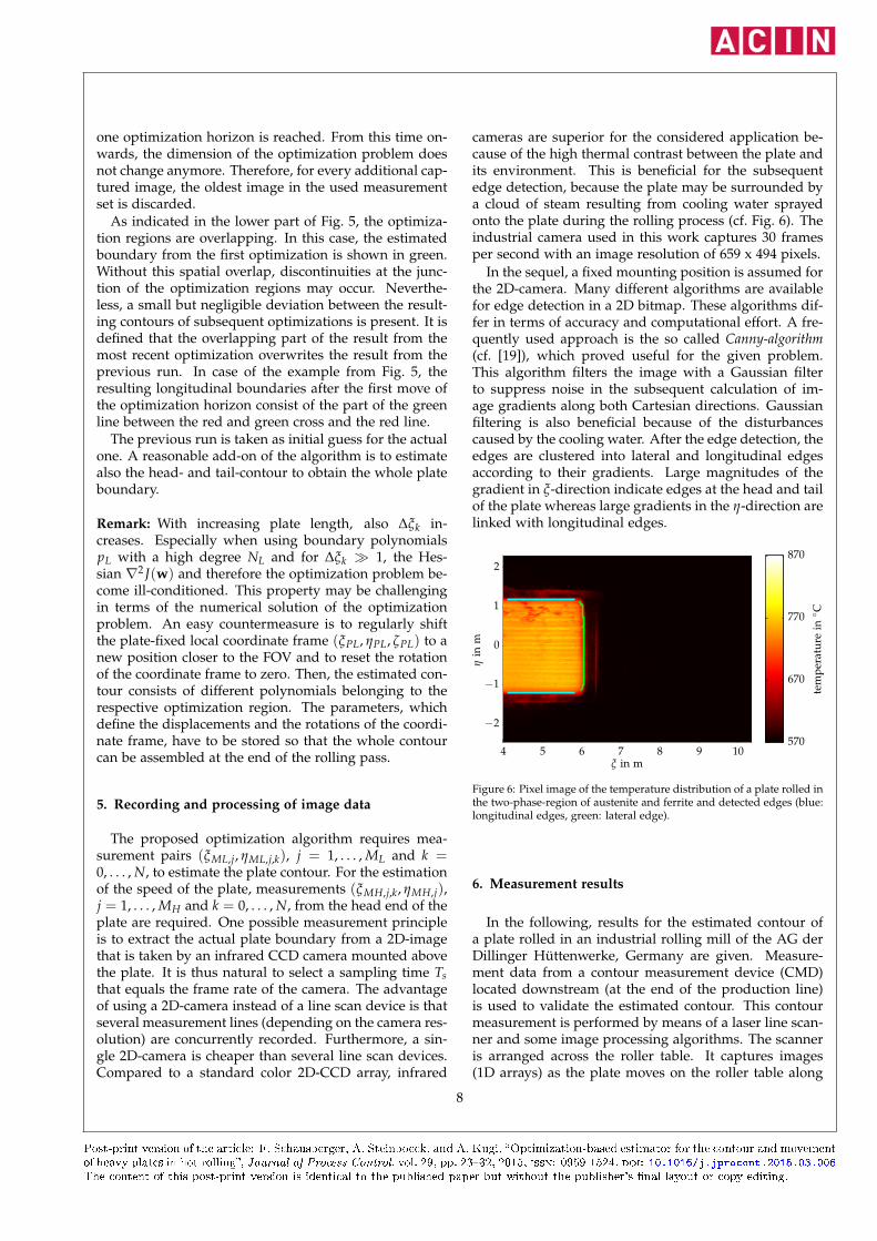
cameras are superior for the considered application be-cause of the high thermal contrast between the plate andits environment. This is beneficial for the subsequentedge detection, because the plate may be surrounded bya cloud of steam resulting from cooling water sprayedonto the plate during the rolling process (cf. Fig. 6). Theindustrial camera used in this work captures 30 framesper second with an image resolution of 659 x 494 pixels.
In the sequel, a fixed mounting position is assumed forthe 2D-camera. Many different algorithms are availablefor edge detection in a 2D bitmap. These algorithms dif-fer in terms of accuracy and computational effort. A fre-quently used approach is the so called Canny-algorithm(cf. [19]), which proved useful for the given problem.This algorithm filters the image with a Gaussian filterto suppress noise in the subsequent calculation of im-age gradients along both Cartesian directions. Gaussianfiltering is also beneficial because of the disturbancescaused by the cooling water. After the edge detection, theedges are clustered into lateral and longitudinal edgesaccording to their gradients. Large magnitudes of thegradient in ξ-direction indicate edges at the head and tailof the plate whereas large gradients in the η-direction arelinked with longitudinal edges.
tem
per
atu
rein
◦ C
ηin
m
ξ in m4 5 6 7 8 9 10
−2
−1
0
1
2
570
670
770
870
Figure 6: Pixel image of the temperature distribution of a plate rolled inthe two-phase-region of austenite and ferrite and detected edges (blue:longitudinal edges, green: lateral edge).
6. Measurement results
In the following, results for the estimated contour ofa plate rolled in an industrial rolling mill of the AG derDillinger Huttenwerke, Germany are given. Measure-ment data from a contour measurement device (CMD)located downstream (at the end of the production line)is used to validate the estimated contour. This contourmeasurement is performed by means of a laser line scan-ner and some image processing algorithms. The scanneris arranged across the roller table. It captures images(1D arrays) as the plate moves on the roller table along
8
Post-print version of the article: F. Schausberger, A. Steinboeck, and A. Kugi, �Optimization-based estimator for the contour and movement
of heavy plates in hot rolling�, Journal of Process Control, vol. 29, pp. 23�32, 2015, issn: 0959-1524. doi: 10.1016/j.jprocont.2015.03.006
The content of this post-print version is identical to the published paper but without the publisher's �nal layout or copy editing.
a strictly straight path (no rotation of the plate). The im-age frames are joined by software to generate a full 2Dpicture of the plate contour.
The optimization problem (12) was implemented inC++. The used infrared 2D-CCD camera was installedat the finishing mill of Aktiengesellschaft der DillingerHuttenwerke. The camera is mounted 25 m above thepass-line level at the ceiling of the plant building. Thisisolates the camera from oscillations and harsh condi-tions (heat, dust, cooling water) near the rolling process.Using a 25 mm lens, a spatial resolution of 9.6 mm/pixelis achieved. By considering both longitudinal edges ofthe plate, the optimization variable w reads as
w =[ωT vT
L pTL,le f t pT
L,right vPL
]T
with the coefficient vectors pL,le f t and pL,right (cf. (1)and (10)) of the boundary polynomials for the left andthe right longitudinal boundary, respectively. The initialguess w0 is chosen as ω0 = vL,0 = 0 and vPL,0 = 3 m/s(common rolling speed). The first entries of pL,le f t andpL,right (constant terms of the polynomials) are set to themean values of the respective edge in the first detectedimage. All other elements of pL,le f t and pL,right are ini-tially set to 0.
A crucial parameter for the estimation accuracy is thechosen length N of the optimization horizon. A largervalue of N results in a smoother estimated contour due toaveraging. Smaller horizons induce more noise in the de-tected contour. Clearly, N also controls the time neededfor solving the optimization problem. The actual choiceof N is therefore a tradeoff between a sufficiently smoothcontour and a reasonable computing time. For the con-sidered measurement configuration, N = 10 proved tobe a good compromise. The remaining parameters usedfor the contour detection are shown in Tab. 1. With theseparameters, it takes less than 25 ms (Standard PC with i7-2600 @ 3.4 GHz processor and 16 GB RAM) to solve theoptimization problem (12) for one optimization horizon.This facilitates contour detection in real-time.
Table 1: Parameters used for the computations.
Parameter Value Unit
NL 3
NH 4
N 10
ML 659
MH 100
Ts 1/30 s
lmin 3 m
ξML,1 4 m
γg 10−10
γx 10−8
γJ 10−3
estimated
measured
yin
m
x in m
0 5 10 15 20 25 30 35 40−1.5
−1.35
−1.2
1.2
1.35
1.5
(a) Measured and estimated contour.
ϕ∆η
ϕin
◦
∆ξ in m
∆η
inm
0 ξML,1 10 20 30 40−0.25
0
0.25
0.5
0.75
1
−0.05
0
0.05
0.1
0.15
0.2
(b) Position and orientation of the plate-fixed coordinateframe.
vL
inm
/s
∆ξ in m0 10 20 30 40
−0.1
−0.05
0
0.05
0.1
ξML,1
(c) Lateral velocity vL of the plate.
vPL = const.
vP
Lin
m/
s
∆ξ in m0 10 20 30 40
3
3.1
3.2
3.3
ξML,1
(d) Longitudinal velocity vPL of the rolled plate.
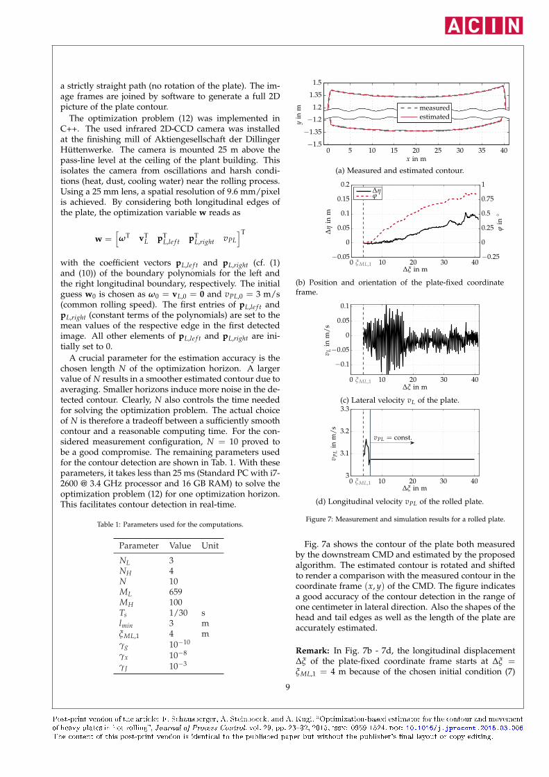
Figure 7: Measurement and simulation results for a rolled plate.
Fig. 7a shows the contour of the plate both measuredby the downstream CMD and estimated by the proposedalgorithm. The estimated contour is rotated and shiftedto render a comparison with the measured contour in thecoordinate frame (x, y) of the CMD. The figure indicatesa good accuracy of the contour detection in the range ofone centimeter in lateral direction. Also the shapes of thehead and tail edges as well as the length of the plate areaccurately estimated.
Remark: In Fig. 7b - 7d, the longitudinal displacement∆ξ of the plate-fixed coordinate frame starts at ∆ξ =ξML,1 = 4 m because of the chosen initial condition (7)
9
Post-print version of the article: F. Schausberger, A. Steinboeck, and A. Kugi, �Optimization-based estimator for the contour and movement
of heavy plates in hot rolling�, Journal of Process Control, vol. 29, pp. 23�32, 2015, issn: 0959-1524. doi: 10.1016/j.jprocont.2015.03.006
The content of this post-print version is identical to the published paper but without the publisher's �nal layout or copy editing.

and the parameters of the used measurement setup (cf.Tab. 1).
Fig. 7b shows the movement of the plate in form ofthe position and orientation of the plate-fixed coordinateframe. In Fig. 7c, the estimated velocity vL in lateral di-rection is shown. Although there are oscillations present,they are not disturbing the estimation of the contour.This is because the lateral deviations resulting from theseoscillations are very small, i.e. they are less than half acentimeter and therefore less than half of the width of apixel. They are caused, e.g., by vibrations of the camerain lateral direction.
Furthermore, the estimated velocity vPL of the plate isshown in Fig. 7d. As mentioned in Section 3.1, vPL canonly be estimated as long as the head of the plate is inthe FOV of the camera. Therefore, a constant plate speedis assumed for the remaining part of the plate. The accu-rately estimated length of the plate indicates that the es-timated velocity agrees well with its real (average) value.
Although only the contour of one representative plateis shown in this paper, similar results have been observedfor randomly chosen plates rolled over a period of sev-eral weeks.
Additionally, the convergence properties for a singleoptimization horizon of the proposed optimization ap-proach are analyzed. To prevent the optimization frompremature termination, the termination criteria are tem-porarily set to γg = γx = γJ = 0. In Fig. 8, the decreaseof the cost function J in every iteration is shown. Thecost value converges within only 5 iterations to the mag-nitude of the machine precision (≈ 2.26 · 10−16). Whenusing the parameters from Tab. 1, the convergence cri-teria would have been already fulfilled after the seconditeration. This shows that the convergence properties ofthis algorithm are quite good. An important prerequi-site for this behavior is the initial choice of the Hessianaccording to (14).
iteration l
J(w
l)−
J(w
l+1)
1 3 5 7 9 11
10−16
10−11
10−6
10−1
Figure 8: Decrease of J (wl) as a function of the iteration l.
7. Conclusions and outlook
In this work, an optimization-based algorithm for real-time estimation of the contour of hot rolled plates duringthe rolling pass was developed. It uses a mathematicalmodel of the movement of the plate and top-view images
of the plate captured by an infrared camera. The modelconsiders the restrictions of the lateral movement of theplate in the rolling gap. Additionally to the contour, theangular movement and the velocity of the plate are esti-mated. An approach to correct angular misalignmentsof the camera was also presented. The resulting un-bounded optimization problem is solved numerically us-ing the quasi-Newton method. Furthermore, a recedinghorizon approach is proposed which renders the methodsuitable for real-time applications.
The results of the proposed algorithm were comparedwith measurements from a contour measurement devicelocated downstream at the finishing mill of the AG derDillinger Huttenwerke in Germany. The comparison in-dicates a good accuracy of the contour detection withdeviations less than one centimeter. Even the velocity ofthe plate and the edges at the head and tail are accuratelyestimated.
It is planned to use the developed contour estimationsystem as a basis for the design of model predictive con-trol algorithm that reduces the occurring camber. To thisend, a model linking the deformation in the rolling gapwith the resulting plate contour, see, e.g., [20], will beused to calculate the required control inputs to the rollingmill.
Acknowledgements
The authors gratefully acknowledge the financial sup-port and the realization of the measurements by Ak-tiengesellschaft der Dillinger Huttenwerke, Germany.The second author gratefully acknowledges financialsupport provided by the Austrian Academy of Sciencesin the form of an APART-fellowship at the Automationand Control Institute of Vienna University of Technology.
Appendix A
The gradient of (12) with respect to the angular veloc-ities ωr, r = 0, . . . , N − 1 takes the form
ddωr
J (w)
= 2N
∑k=0
ML
∑j=1
eL,j,kd
dωreL,j,k + 2
N
∑k=0
MH
∑j=1
eH,j,kd
dωreH,j,k,
with
ddωr
eL,j,k =∂pL
(ξL,j,k
)
∂ξL,j,k
dξL,j,k
dωr−
dηL,j,k
dωr(16)
and
ddωr
eH,j,k =∂pH
(ηH,j,k
)
∂ηH,j,k
dηH,j,k
dωr−
dξH,j,k
dωr(17)
10
Post-print version of the article: F. Schausberger, A. Steinboeck, and A. Kugi, �Optimization-based estimator for the contour and movement
of heavy plates in hot rolling�, Journal of Process Control, vol. 29, pp. 23�32, 2015, issn: 0959-1524. doi: 10.1016/j.jprocont.2015.03.006
The content of this post-print version is identical to the published paper but without the publisher's �nal layout or copy editing.

according to (9) and (8), respectively.The additional derivatives used in (16) can be calcu-
lated as
∂pL
(ξL,j,k
)
∂ξL,j,k= cL,1 + 2cL,2ξL,j,k + . . . + NLcL,NL ξNL−1
L,j,k ,
(18a)dξL,j,k
dωr= −(ξML,j − ∆ξk) sin(ϕk)
dϕkdωr
+ (ηML,j,k − ∆ηk) cos(ϕk)dϕkdωr
− cos(ϕk)d∆ξkdωr
− sin(ϕk)d∆ηkdωr
(18b)
and
dηL,j,k
dωr= −(ηML,j,k − ∆ηk) sin(ϕk)
dϕkdωr
− (ξML,j − ∆ξk) cos(ϕk)dϕkdωr
− cos(ϕk)d∆ηkdωr
+ sin(ϕk)d∆ξkdωr
. (18c)
The derivatives utilized in (17) may be obtained by ex-changing pL with pH , NL with NH , cL,i with cH,i and ξL,j,kwith ηH,j,k in (18a). Moreover, ξL,j,k has to be replaced byξH,j,k, ηL,j,k by ηH,j,k, ξML,j by ξMH,j,k and ηML,j,k by ηMH,jin (18b) and (18c), respectively.
Based on (11), the derivatives dxkdωr
can be recursivelycomputed in the form
dxkdωr
=
0 if r ≥ k∂f(xr ,ωr ,vPL ,vL,r)
∂ωr+
∂f(xr ,ωr ,vPL ,vL,r)∂xr
dxrdωr
if r = k− 1∂f(xk−1,ωk−1,vPL ,vL,k−1)
∂xk−1
dxk−1dωr
if r < k− 1,
with
∂f(xr, ωr, vPL, vL,r)
∂ωr
= Ts
−∆ξr sin(ωr)− ∆ηr cos(ωr) +vPLωr
cos(ωr)
− vPLω2
r Tssin(ωr)− vL,r
ωrsin(ωr)− vL,r
ω2r Ts
(cos(ωr)− 1)
∆ξr cos(ωr)− ∆ηr sin(ωr) +vPLωr
sin(ωr)
− vPLω2
r Ts(1− cos(ωr)) +
vL,rωr
cos(ωr)− vL,rω2
r Tssin(ωr)
1
and
∂f(xr, ωr, vPL, vL,r)
∂xr=
cos(ωr) − sin(ωr) 0sin(ωr) cos(ωr) 0
0 0 1
, (19)
where the abbreviation ωr = ωrTs was used.
The gradient of (12) with respect to vL,r reads as
ddvL,r
J (w)
= 2N
∑k=0
ML
∑j=1
eL,j,kd
dvL,reL,j,k + 2
N
∑k=0
MH
∑j=1
eH,j,kd
dvL,reH,j,k,
with
ddvL,r
eL,j,k =∂pL
(ξL,j,k
)
∂ξL,j,k
dξL,j,k
dvL,r−
dηL,j,k
dvL,r
and
ddvL,r
eH,j,k =∂pH
(ηH,j,k
)
∂ηH,j,k
dηH,j,k
dvL,r−
dξH,j,k
dvL,r.
Again the expressions
dξL,j,k
dvL,r=
dξH,j,k
dvL,r= − cos(ϕk)
d∆ξkdvL,r
− sin(ϕk)d∆ηkdvL,r
and
dηL,j,k
dvL,r=
dηH,j,k
dvL,r= − cos(ϕk)
d∆ηkdvL,r
+ sin(ϕk)d∆ξkdvL,r
are recursively given by
dxkdvL,r
=
0 if r ≥ k∂f(xr ,ωr ,vPL ,vL,r)
∂vL,r+
∂f(xr ,ωr ,vPL ,vL,r)∂xr
dxrdvL,r
if r = k− 1∂f(xk−1,ωk−1,vPL ,vL,k−1)
∂xk−1
dxk−1dvL,r
if r < k− 1
using (19) and
∂f(xr, ωr, vPL, vL,r)
∂vL,r=
cos(ωrTs)−1ωr
sin(ωrTs)ωr0
.
The gradient of the cost function J(w) with respect tothe parameter vector pL yields
ddpL
J (w)
= 2N
∑k=0
ML
∑j=1
eL,j,k
[1 ξL,j,k ξ2
L,j,k . . . ξNLL,j,k
].
The gradient with respect to vPL reads as
ddvPL
J (w)
= 2N
∑k=0
ML
∑j=1
eL,j,kd
dvPLeL,j,k + 2
N
∑k=0
MH
∑j=1
eH,j,kd
dvPLeH,j,k,
11
Post-print version of the article: F. Schausberger, A. Steinboeck, and A. Kugi, �Optimization-based estimator for the contour and movement
of heavy plates in hot rolling�, Journal of Process Control, vol. 29, pp. 23�32, 2015, issn: 0959-1524. doi: 10.1016/j.jprocont.2015.03.006
The content of this post-print version is identical to the published paper but without the publisher's �nal layout or copy editing.

with
ddvPL
eL,j,k =∂pL
(ξL,j,k
)
∂ξL,j,k
dξL,j,k
dvPL−
dηL,j,k
dvPL
and
ddvPL
eH,j,k =∂pH
(ηH,j,k
)
∂ηH,j,k
dηH,j,k
dvPL−
dξH,j,k
dvPL.
Furthermore, it is necessary to calculate
dξL,j,k
dvPL=
dξH,j,k
dvPL= − cos(ϕk)
d∆ξkdvPL
− sin(ϕk)d∆ηkdvPL
and
dηL,j,k
dvPL=
dηH,j,k
dvPL= − cos(ϕk)
d∆ηkdvPL
+ sin(ϕk)d∆ξkdvPL
with recursively computing
dxkdvPL
=
0 if k = 0
sin(ωk−1Ts)ωk−1
1−cos(ωk−1Ts)ωk−1
0
+
∂f(xk−1,ωk−1,vPL ,vL,k−1)∂xk−1
dxk−1dvPL
if k > 0
using (19).[1] Y. Tanaka, K. Omori, T. Miyake, K. Nishizaki, M. Inoue, and
S. Tezuka. Camber control techniques in plate rolling. TechnicalReport 16, Kawasaki Steel, June 1987.
[2] R. C. Gonzalez, R. Valdes, and J. A. Cancelas. Vision based mea-surement system to quantify straightness defect in steel sheets.9th International Conference on Computer Analysis of Images andPatterns, pages 427–434, Warsaw, Poland, September 2001.
[3] R. J. Montague, J. Watton, and K. J. Brown. A machine visionmeasurement of slab camber in hot strip rolling. J. Mater. Process.Technol., 168:172–180, 2005.
[4] B. N. Carruthers-Watt, Y. Xue, and A. J. Morris. A vision basedsystem for strip tracking measurement in the finishing train of ahot strip mill. Proceedings of the 2010 IEEE ICMA, pages 1115–1120, Xi’an, China, August 2010.
[5] I. Malloci, J. Daafouz, C. Iung, R. Bonidal, and P. Szczepanski.Robust steering control of hot strip milling. IEEE Trans. on ControlSystems Technol., 18(4):908–917, 2010.
[6] J. W. Yoo, N. W. Kong, J. Song, and P. G. Park. Camber detec-tion algorithm using the image stitching technique in hot-rollingprocess. International Conference Robotics, pages 74–77, Phuket,Thailand, November 2010.
[7] J. Lee, N. Kong, J. Yoo, and P. Park. A fast image stitching algo-rithm in the endless hot rolling process. 11th International Con-ference on Control, Automation and Systems, pages 1264–1268,Gyeonggi-do, Korea, October 2011.
[8] N. W. Kong, J. W. Yoo, J. S. Lee, S. W. Yun, J. Bae, and P. G.Park. Vision-based camber measurement system in the endlesshot rolling process. Opt. Eng., 50(10):107202–1–107202–10, 2011.
[9] A. Ollikkala, T. Kananen, A. Makynen, M. Holappa, E. Torppa,and T. Harvala. A single camera system for camber measurementin hot strip rolling. Rolling 2013 - 9th International Rolling Confer-ence and the 6th European Rolling Conference, Venice, Italy, June2013.
[10] T. Kiefer and A. Kugi. An analytical approach for modelling asym-metrical hot rolling of heavy plates. Math. and Comput. Model. ofDyn. Syst., 14(3):249–267, 2008.
[11] T. Ishikawa, Y. Tozawa, and J. Nishizawa. Fundamental study onsnaking in strip rolling. Trans. Iron Steel Inst. Jpn., 28(6):485–490,1988.
[12] D. Dochain. State and parameter estimation in chemical and bio-chemical processes: A tutorial. J. Process Control, 13(8):801–818,2003.
[13] J. B. Rawlings and L. Ji. Optim.-based state estimation: Currentstatus and some new results. J. Process Control, 22:1439–1444, 2012.
[14] J. Nocedal and S. J. Wright. Numerical Optimization. Springer Seriesin Operations Research. Springer, New York, 2nd edition, 2006.
[15] E. Polak. Computational Methods in Optimization: A Unified Ap-proach. Academic Press, New York, 1971.
[16] C. T. Kelley and E. W. Sachs. Quasi-newton methods and un-constrained optimal control problems. SIAM J. Control Optim.,25:1503–1516, 1987.
[17] D. P. Bertsekas. Nonlinear Programming. Athena Scientific, Bel-mont, Massachusetts, 2nd edition, 1999.
[18] C. T. Kelley. Iterative methods in optimization. Frontiers in AppliedMathematics. SIAM, Philadelphia, 2nd edition, 1999.
[19] J. Canny. A computational approach to edge detection. IEEE Trans.on Pattern Anal. and Mach. Intell., 8:679–698, 1986.
[20] F. Schausberger, A. Steinboeck, and A. Kugi. Mathematical mod-eling of the contour evolution of heavy plates in hot rolling. Appl.Math. Modell., in Press, 2015.
12
Post-print version of the article: F. Schausberger, A. Steinboeck, and A. Kugi, �Optimization-based estimator for the contour and movement
of heavy plates in hot rolling�, Journal of Process Control, vol. 29, pp. 23�32, 2015, issn: 0959-1524. doi: 10.1016/j.jprocont.2015.03.006
The content of this post-print version is identical to the published paper but without the publisher's �nal layout or copy editing.
Related Documents


![VALUE€¦ · Contour Drawing [Project One] Contour Drawing. Contour Line: In drawing, is an outline sketch of an object. [Project One]: Layered Contour Drawing The purpose of contour](https://static.cupdf.com/doc/110x72/60363a1e4c7d150c4824002e/value-contour-drawing-project-one-contour-drawing-contour-line-in-drawing-is.jpg)