Journal of Marine Science and Engineering Article Optimisation of a Diesel-Electric Ship Propulsion and Power Generation System Using a Genetic Algorithm Raphael Zaccone 1, * , Ugo Campora 2 and Michele Martelli 1 Citation: Zaccone, R.; Campora, U.; Martelli, M. Optimisation of a Diesel–Electric Ship Propulsion and Power Generation System Using a Genetic Algorithm. J. Mar. Sci. Eng. 2021, 9, 587. https://doi.org/ 10.3390/jmse9060587 Academic Editor: Mohamed Benbouzid Received: 12 May 2021 Accepted: 26 May 2021 Published: 28 May 2021 Publisher’s Note: MDPI stays neutral with regard to jurisdictional claims in published maps and institutional affil- iations. Copyright: © 2021 by the authors. Licensee MDPI, Basel, Switzerland. This article is an open access article distributed under the terms and conditions of the Creative Commons Attribution (CC BY) license (https:// creativecommons.org/licenses/by/ 4.0/). 1 DITEN—Department of Naval Architecture, Electrical, Electronic and Telecommunications Engineering, Polytechnic School, University of Genoa, 16145 Genoa, Italy; [email protected] 2 DIME—Department of Mechanical, Energy, Management and Transportation Engineering, Polytechnic School, University of Genoa, 16145 Genoa, Italy; [email protected] * Correspondence: [email protected] Abstract: In recent decades, the design of ship propulsion systems has been focusing on energy efficiency and low pollutant emissions. In this framework, diesel–electric propulsion has become a standard for many ship types and has proven its worth for flexible propulsion design and manage- ment. This paper presents an approach to the optimal design of diesel–electric propulsion systems, minimising the fuel consumption while meeting the power and speed requirements. A genetic algorithm performs the optimisation, used to determine the number and type of engines installed on-board and the engines’ design speed and power, selecting within a dataset of four-stroke diesel engines. The same algorithm is then adapted and applied to determine the optimal load sharing strat- egy in off-design conditions, taking advantage of the high flexibility of the diesel–electric propulsion plants. In order to apply the algorithm, the propulsion layout design is formulated as an optimisation problem, translating the system requirements into a cost function and a set of linear and non-linear constraints. Eventually, the method is applied to a case study vessel: first, the optimal diesel–electric propulsion plants are determined, then the optimal off-design load sharing and working conditions are computed. AC and DC network solutions are compared and critically discussed in both design and off-design conditions. Keywords: ship propulsion; ship design; genetic algorithm; optimisation; electric propulsion; energy efficiency 1. Introduction Traditional ship propulsion systems mainly rely on thermal engines, such as diesel engines [1,2] or gas turbines [3], mechanically connected to either fixed or controllable pitch propellers, most of the time through a reduction gear. This propulsion plant lay- out has several clear advantages, such as being based on simple and well-consolidated technologies [4], ensuring reliability and safety. Moreover, it relies on a small number of efficient energy transformations, ensuring a relatively high overall propulsion efficiency when operating in design conditions [5,6]. The latter makes traditional propulsion the most proficient choice for those marine units characterised by relatively narrow operating profiles, i.e., those ships that steam most of the time at their design speed. Combined propulsion plants [7–10] coupled with controllable pitch propellers can match the operat- ing requirements of ships that require more flexible profiles, for instance, ferries that steam at a different speed in winter or summer season or for navy vessels. In recent decades, diesel–electric propulsion [11,12] has grown as a good competitor for ship propulsion, bringing some additional benefits to operating flexibility and reduced footprint emission [13]. This type of propulsion system has some drawbacks due to additional energy transformations that affect the overall efficiency at maximum speed [14]. On the other hand, the benefits in terms of layout flexibility are straightforward. No shaft-line neither gearbox needs to be installed, allowing the machines to be allocated J. Mar. Sci. Eng. 2021, 9, 587. https://doi.org/10.3390/jmse9060587 https://www.mdpi.com/journal/jmse

Welcome message from author
This document is posted to help you gain knowledge. Please leave a comment to let me know what you think about it! Share it to your friends and learn new things together.
Transcript
Journal of
Marine Science and Engineering
Article
Optimisation of a Diesel-Electric Ship Propulsion and PowerGeneration System Using a Genetic Algorithm
Raphael Zaccone 1,* , Ugo Campora 2 and Michele Martelli 1
�����������������
Citation: Zaccone, R.; Campora, U.;
Martelli, M. Optimisation of a
Diesel–Electric Ship Propulsion and
Power Generation System Using a
Genetic Algorithm. J. Mar. Sci. Eng.
2021, 9, 587. https://doi.org/
10.3390/jmse9060587
Academic Editor: Mohamed
Benbouzid
Received: 12 May 2021
Accepted: 26 May 2021
Published: 28 May 2021
Publisher’s Note: MDPI stays neutral
with regard to jurisdictional claims in
published maps and institutional affil-
iations.
Copyright: © 2021 by the authors.
Licensee MDPI, Basel, Switzerland.
This article is an open access article
distributed under the terms and
conditions of the Creative Commons
Attribution (CC BY) license (https://
creativecommons.org/licenses/by/
4.0/).
1 DITEN—Department of Naval Architecture, Electrical, Electronic and Telecommunications Engineering,Polytechnic School, University of Genoa, 16145 Genoa, Italy; [email protected]
2 DIME—Department of Mechanical, Energy, Management and Transportation Engineering,Polytechnic School, University of Genoa, 16145 Genoa, Italy; [email protected]
* Correspondence: [email protected]
Abstract: In recent decades, the design of ship propulsion systems has been focusing on energyefficiency and low pollutant emissions. In this framework, diesel–electric propulsion has become astandard for many ship types and has proven its worth for flexible propulsion design and manage-ment. This paper presents an approach to the optimal design of diesel–electric propulsion systems,minimising the fuel consumption while meeting the power and speed requirements. A geneticalgorithm performs the optimisation, used to determine the number and type of engines installedon-board and the engines’ design speed and power, selecting within a dataset of four-stroke dieselengines. The same algorithm is then adapted and applied to determine the optimal load sharing strat-egy in off-design conditions, taking advantage of the high flexibility of the diesel–electric propulsionplants. In order to apply the algorithm, the propulsion layout design is formulated as an optimisationproblem, translating the system requirements into a cost function and a set of linear and non-linearconstraints. Eventually, the method is applied to a case study vessel: first, the optimal diesel–electricpropulsion plants are determined, then the optimal off-design load sharing and working conditionsare computed. AC and DC network solutions are compared and critically discussed in both designand off-design conditions.
Keywords: ship propulsion; ship design; genetic algorithm; optimisation; electric propulsion;energy efficiency
1. Introduction
Traditional ship propulsion systems mainly rely on thermal engines, such as dieselengines [1,2] or gas turbines [3], mechanically connected to either fixed or controllablepitch propellers, most of the time through a reduction gear. This propulsion plant lay-out has several clear advantages, such as being based on simple and well-consolidatedtechnologies [4], ensuring reliability and safety. Moreover, it relies on a small number ofefficient energy transformations, ensuring a relatively high overall propulsion efficiencywhen operating in design conditions [5,6]. The latter makes traditional propulsion themost proficient choice for those marine units characterised by relatively narrow operatingprofiles, i.e., those ships that steam most of the time at their design speed. Combinedpropulsion plants [7–10] coupled with controllable pitch propellers can match the operat-ing requirements of ships that require more flexible profiles, for instance, ferries that steamat a different speed in winter or summer season or for navy vessels.
In recent decades, diesel–electric propulsion [11,12] has grown as a good competitorfor ship propulsion, bringing some additional benefits to operating flexibility and reducedfootprint emission [13]. This type of propulsion system has some drawbacks due toadditional energy transformations that affect the overall efficiency at maximum speed [14].
On the other hand, the benefits in terms of layout flexibility are straightforward. Noshaft-line neither gearbox needs to be installed, allowing the machines to be allocated
J. Mar. Sci. Eng. 2021, 9, 587. https://doi.org/10.3390/jmse9060587 https://www.mdpi.com/journal/jmse
J. Mar. Sci. Eng. 2021, 9, 587 2 of 14
more efficiently in the available spaces, reducing the vessel’s acoustic signature and noiseirradiation. Moreover, there is no mechanical link between the power generation and thepropeller shaft, allowing more flexible control of both engines’ and propellers’ revolutionspeeds. Eventually, the power demand can be shared between the diesel generators(D/G) with more degrees of freedom, ship safety and availability benefit, and machineryredundancy. These aspects pushed ship designers to consider diesel–electric propulsionfor passenger ships, navy ships, and various special units.
The possibility to maintain the D/G in optimal operating conditions makes diesel–electric propulsion an effective solution to meet the strict pollution regulations enforcednowadays by the International Maritime Organisation (IMO) [15,16]. In other words, adiesel–electric propulsion architecture is one of the state-of-the-art responses to the designof energy-efficient and environmentally friendly ships [17].
Diesel–electric propulsion is also installed more and more on yachts and pleasurecrafts as well, with a constant increase in new diesel–electric designs [18,19]. This is also dueto the r improved environmental awareness [20], the greater comfort that a flexible diesel–electric propulsion system allows in terms of noise and vibrations during navigation [21],and the potential of saving fuel [22].
A significant improvement to the efficiency of diesel–electric propulsion systemsis due to the recent introduction of variable revolution speed generators [23], allowingthe diesel engines to work in their optimal efficiency conditions. This type of enginecontrol logic is coupled with direct current (DC) distribution in order not to constrain thealternators to produced energy at a fixed distribution frequency, as opposed to alternatecurrent (AC) distribution [24–26].
The operating and layout flexibility of diesel–electric propulsion systems allows manydegrees of freedom in the design phase compared to traditional propulsion. However, itis not straightforward to take advantage of those degrees of freedom in the design phase;traditional approaches usually reduce the number of design choices to consider, compareand evaluate to a manageable number. The application of more advanced computationalapproaches can consider and compare unconventional system layouts during the designphase and select the most promising solutions and compare them in a refinement phase.
This paper aims to present a method for the optimal design of diesel–electric shippropulsion systems, based on parametric modelling of the system layout and performance,which is optimised using a genetic algorithm [27,28]. Compared to other local minimisa-tion algorithms [29], a genetic algorithm has interesting features that suit the presentedapplication: it allows one to efficiently deal with categorical or integer variables and non-differentiable cost functions, as it does not require to compute derivatives, and it is a globaloptimisation algorithm, so it is unlikely to get trapped in local minima of the cost function.For this reason, genetic algorithms find various applications in many industrial areaswhen it is required to deal with the selection of multiple variables affecting one complexsystem. Examples are the selection of a diesel engine’s optimal working parameters [30],the parameter selection of a combined cycle [31], or the optimal allocation of photovoltaicsystems to maximise the performance of an electric microgrid [32]. The optimisation of ageothermic plant design shown in [33] is particularly relevant to the present work, as itperforms a two-stage optimisation, separating the design phase from the computation ofthe optimal operating parameters. Moreover, relevant applications to many aspects of shipdesign can be found in [34–36].
In the presented application, the algorithm is used to select the optimal type, numberand design working conditions for the diesel generators to minimise the fuel consump-tion of the propulsion system at design speed. Moreover, the same approach is usedto select the optimal plant operating mode and load sharing between the generators inoff-design conditions.
The design method is applied to a case study pleasure craft, selecting the optimalpropulsion layout using data of different marine diesel engines: some assumptions of thesystem layout are first made, then the cost function and constraints are formalised based
J. Mar. Sci. Eng. 2021, 9, 587 3 of 14
on ship propulsion theory [37]. The proposed method is used to select optimal layouts intwo configurations, characterised by variable speed and constant speed controlled dieselgenerators, coupled with DC and AC distribution networks, respectively, at the samedesign speed. Next, the optimal propulsion load sharing in off-design conditions, i.e., atlower speeds, is computed. Results are compared and critically discussed both in designand off-design conditions to show the potential of the proposed approach.
2. Diesel–Electric Propulsion System Schemes
In the proposed approach, a diesel–electric system is considered for power generationand propulsion. The three main aspects to take into account when considering a diesel–electric system as a candidate for ship propulsion are:
• Propulsion power demand and the electric load required for auxiliary services arecomparable, the efficiency gap to mechanical propulsion might not be an issue;
• The operating flexibility might be an advantage for those ship types that have verydifferent operating profiles, characterised by, for example, very different ship speeds;
• The layout flexibility might come in handy when considering a ship with limitedspaces on-board or when the low noise level is a design criterion.
Ships that match the above-described requirements, and are thus usually powered bydiesel–electric systems, are, for instance, passenger or cruise ships and some navy ships orpleasure crafts.
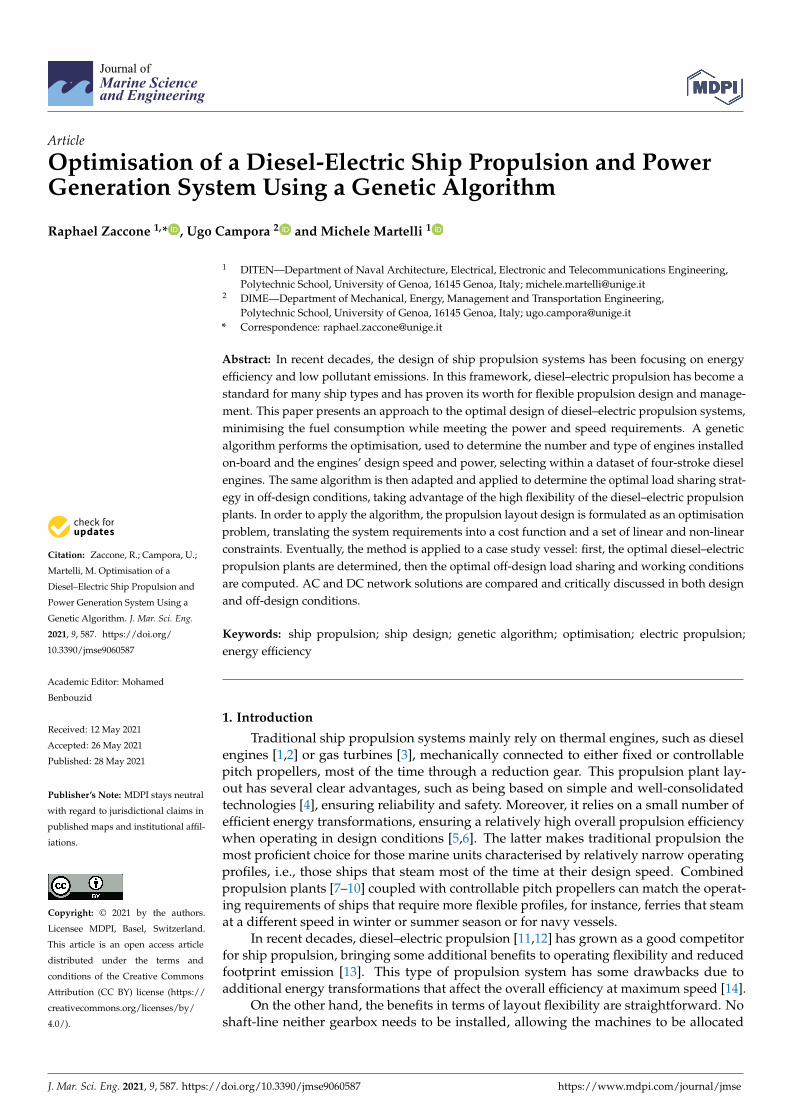
Figure 1 presents two alternative diesel–electric plant layouts considered in thisstudy. Figure 1a represents a typical diesel–electric propulsion system with an AC powerdistribution network: the diesel engines produce the alternate current through alternatorsand are connected to an AC network at constant voltage and frequency. As a consequence,diesel engines need to work at a constant revolution speed to maintain the networkfrequency. Figure 1b shows an alternative layout using a DC distribution network (DC-link): this approach requires several DC/AC and AC/DC converters with their associatedenergy losses, yet it has some advantages. As the frequency is not an issue, the D/G controlis only focused on the voltage, and the diesel generators can operate in optimal workingconditions at partial loads. In addition, DC distribution is not affected by most of the maintypical alternate current issues, such as reactive current losses or harmonic distortions [24].
The standard layout for diesel–electric generation and propulsion of ships featuressome diesel engines of the same size, mainly for construction and maintenance convenience,as the same engines share the same spare parts. In the present study, the aim is to removethis constraint, allowing the plant to include engines of different sizes to maximise theplant’s efficiency in design conditions.
Engine 1
Engine 2
Engine NAux. serv.
Engines
A
A
A
M
M
(a)
Engine 1
Engine 2
Engine NAux. serv.
Engines
A
A
A
M
M
(b)
Figure 1. Generation and propulsion system layout types: AC distribution network, constantrevolution speed D/G (a) and DC distribution network, variable revolution speed D/G (b).
3. Plant Optimisation
The purpose of this study is to perform the propulsion system design using an opti-misation approach. The design problem is formulated as an optimisation problem, and agenetic algorithm is used to find the solution, i.e., to find the minimum fuel consumptionlayout at design conditions. As a second step, the same optimisation approach, with slight
J. Mar. Sci. Eng. 2021, 9, 587 4 of 14
modifications, is applied to determine the optimal working configuration (load sharingand engine working points) of the obtained layouts in off-design conditions, i.e., partialloads. Two alternative plant types are considered, designed and compared: AC and DCdistribution. In the first plant type, represented in Figure 1a, the revolution speed of thediesel engines is constrained by the network frequency, while in the second (Figure 1b),diesel engines can be controlled at variable speeds.
In the design phase, the algorithm can select the number and type of diesel enginesthat are part of the propulsion plant, choosing between a number (four in this study,but the database could be reasonably enlarged) of diesel engines of different sizes andperformance features. Moreover, the algorithm selects the optimal power of each enginefor AC architecture and optimal power and revolution speed in DC configurations. In thetwo cases, the ship’s design speed is guaranteed while minimising the fuel consumption.
In the off-design phase, the propulsion system is already selected: the algorithm canselect the number of operating engines and their working points (power and, if possible,i.e., in DC configuration, revolution speed) in order to minimise the fuel consumption whileproviding sufficient power to sustain both the required off-design speed and hotel-load.
In summary:
• The algorithm is expected to select the number and type of diesel engines to installon-board;
• Moreover, the algorithm is expected to select the power output of each engine if thenetwork distribution is AC, the power output and revolution speed if the distributionis DC;
• The selected solution layout should minimise the total fuel mass flow rate;• The selected solution should ensure the ship reaches the expected speed;• To sightly simplify the problem, engines of the same type are assumed to operate in
the same conditions (power and revolution speed).
Thus, two alternative problems can be formulated, the first describing the AC powergeneration plant with constant revolution speed controlled generators, the second describ-ing the DC plant with variable speed controlled generators. The following subsectionsdescribe all the aspects of the problem formulation, from the genetic encoding, i.e., theparametrisation of the problem, to the set up of the cost function and constraints, based onthe steady-state modelling of the ship’s propulsion system.
3.1. Genetic Encoding
The crucial point when using a genetic approach to solve optimisation problems is thedefinition of the so-called genetic encoding. Let NDG be the number of diesel generatormodels available in the dataset, each one in number Ni, with power Pi and revolutionspeed ni, and i = {1, 2, ..., NDG} identifying the engine model. The encoding in the case ofvariable speed controlled engines takes the following form:
X = {Ni, ni, Pi} (1)
In a similar way, the genetic encoding of a solution in case the engines are controlledat constant revolution speed with AC distribution is the following:
X = {Ni, Pi}, ni = ndesi (2)
where ndesi indicates the nominal revolution speed of the ith engine model.
The total electric power provided if a solution X is selected is expressed by the follow-ing relationships, respectively, in case of DC and AC distribution:
Pel(X) =NDG
∑i=1
NiPiηgen,iηACDC,i (3)
J. Mar. Sci. Eng. 2021, 9, 587 5 of 14
Pel(X) =NDG
∑i=1
NiPiηgen,i (4)
where ηgen,i is the efficiency of the ith alternate current generator, and ηACDC,i is theefficiency of the ith AC/DC converter, installed only with DC distribution.
3.2. Cost Function
The solution ranking after each generation in a genetic algorithm is performed usinga cost function. In the presented application, the optimisation aims to minimise the totalfuel mass flow rate of the power generation plant; thus, the following function is tobe minimised:
f (X = Ni, ni, Pi) =NDG
∑i=1
NiPiSFOCi(ni, Pi) (5)
where SFOCi(n, P) represents the engine load diagram, providing the specific fuel con-sumption at a given revolution speed and power, implemented in the form of a function,such as using a response surface, and the measurement units in proper accordance.
3.3. Constraints
The definition of the constraints is a crucial passage in the presented approach in orderto obtain a reasonable result. First, the bounds of the solutions need to be defined:
{0, ni,min, Pi,min} ≤ {Ni, ni, Pi} ≤ {Ni,max, ni,max, Pi,max} (6)
The number of engines for each type is required to be non-negative and less than amaximum value. The power and revolution speed boundaries are related to each of theengine models. Note that this framework can be applied both to design and off-designoptimisations, setting proper boundaries of the maximum number of running engines,while, in the design phase, the number of engines on-board is to be defined, between zeroand a reasonable maximum value, the off-design optimisation aims to determine thenumber of running engines in a given off-design condition, between zero and the numberof engines on-board.
The next step is the formalisation of the required speed in the form of a non-linearconstraint. In particular, the generated power Pel needs to be sufficient to ensure the ship’sspeed V(X). If there are np propellers, the thrust T required to each propeller is given bythe following equation:
T =Rt
np(1− t)(7)
where Rt is the ship’s resistance and t is the thrust deduction factor.The power required by the electric propulsion motors is described by the following
equations, referring to DC and AC distribution, respectively:
PEPM =(1− w)VT
ηoηrηsηEPMηDCAC(8)
PEPM =(1− w)VTηoηrηsηEPM
(9)
where w is the wake fraction, etar and ηs are the relative rotational efficiency and themechanical transmission efficiency, respectively, ηo is the propeller open water efficiency,ηEPM and ηDCAC are the efficiencies of the electric propulsion motor and the DC/ACconverter, respectively. Note that t, w, etar depend on the ship’s speed, and ηo depends onthe propeller’s working conditions [21].
Note that:
• The selected propulsion layout is such that the propeller’s revolution speed is me-chanically independent of the engines’, as there is no gearbox;

J. Mar. Sci. Eng. 2021, 9, 587 6 of 14
• The propeller is modelled using the open-water diagrams and is assumed to have afixed pitch.
The speed constraint is described by the following inequality:
Pel(X) ≥ npPEPM + Paux (10)
where Paux the power required to satisfy the auxiliary services. Note that this should be anequality constraint: the power provided by the generation system in its working conditionsshould instantly match the power load. However, inequality is needed because someof the variables are integer numbers, and the solver cannot deal with integer variablesand equality constraints at the same time. Moreover, only the lower bound of the powercan be constrained because higher power leads to higher fuel consumption, and theoptimisation will naturally lead to the lowest possible installed power that allows satisfyingthe speed constraint.
3.4. Optimisation Problem
The following optimisation problem, combining Equations (5), (6) and (10), needs tobe solved to determine the optimal propulsion plant configuration:
min{Ni ,ni ,Pi}
NDG
∑i=1
NiPiSFOCi(ni, Pi)
s.t. :
ni,min ≤ ni ≤ ni,max
Pi,min ≤ Pi ≤ Pi,max(ni)
Pel ≥ npPEPM + Paux
(11)
4. Case Study Ship
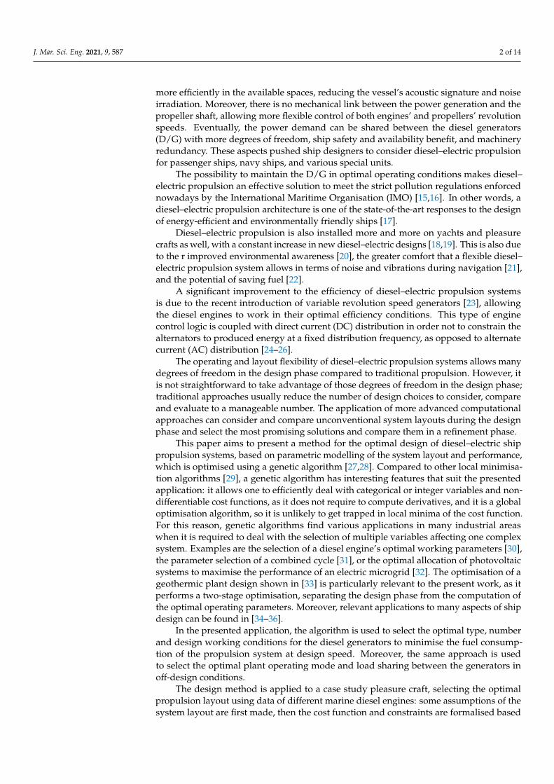
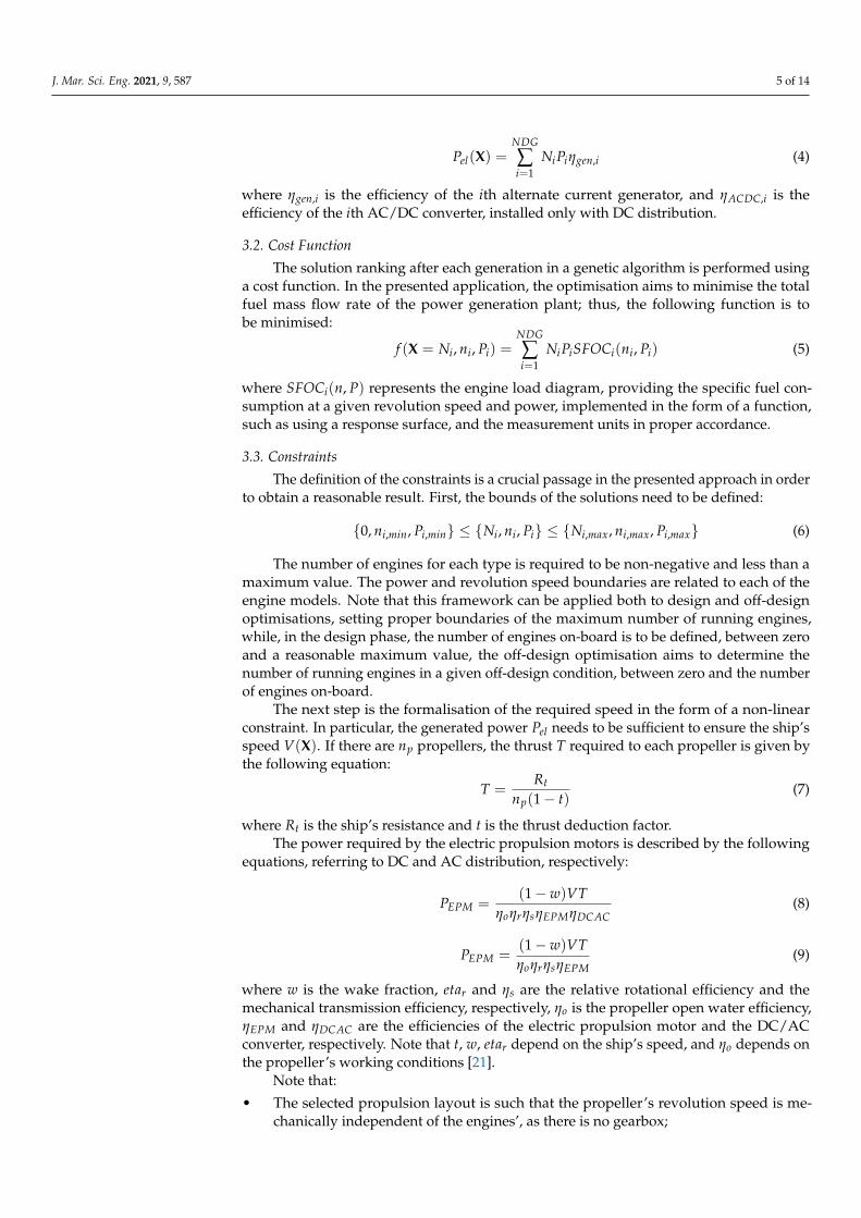
In order to test the proposed methodology, pleasure craft, whose main data arepresented in Table 1, is considered as a case study. The ship is initially equipped by aconventional propulsion plant, composed of two four-stroke diesel engines that drivetwo fixed pitch propellers via independent shaft lines and gearboxes, while the electricload is provided by diesel generators. This type of propulsion system is particularlyefficient for merchant ships, where no particular flexibility is required. In this study,the original propulsion plant is replaced by two alternative diesel–electric propulsionsystems presented in Figure 1 and discussed earlier in this paper. The reason to considera diesel–electric system for such an application is that the operating profile of a pleasurecraft might include multiple speeds and low speeds for a relevant amount of time. Thus, itis reasonable to suppose that, in the future, electric or hybrid propulsion will be widelyadopted in the pleasure craft field, similarly to other ship types that share similar operatingrequirements. Moreover, electric propulsion allows the implementation of zero-emissionsystems (for example, including batteries), which might reduce the craft’s environmentalimpact. The two-shaft propulsion system is required to match the brake power per shaftcurve presented in Figure 2.
Table 1. Main data of the case study vessel.
Length between perpendiculars, Lpp 55.400 mMoulded breadth, B 12.500 mMoulded Depth at weather deck, D 6.000 mMean Scantling Draft, T 3.400 mOriginal propulsion engines: 2 × diesel engines 2525 kW @ 1900 RPMOriginal gen-set 2 × 200 ekW + 1 × 148 ekWHotel electrical load 194 kW
J. Mar. Sci. Eng. 2021, 9, 587 7 of 14
9 10 11 12 13 14 15 16 17 18
Speed [kN]
200
400
600
800
1000
1200
1400
1600
1800
2000
2200
PB
pe
r sh
aft
[kW
]
Figure 2. Vessel’s estimated brake power per shaft.
4.1. Engine Models
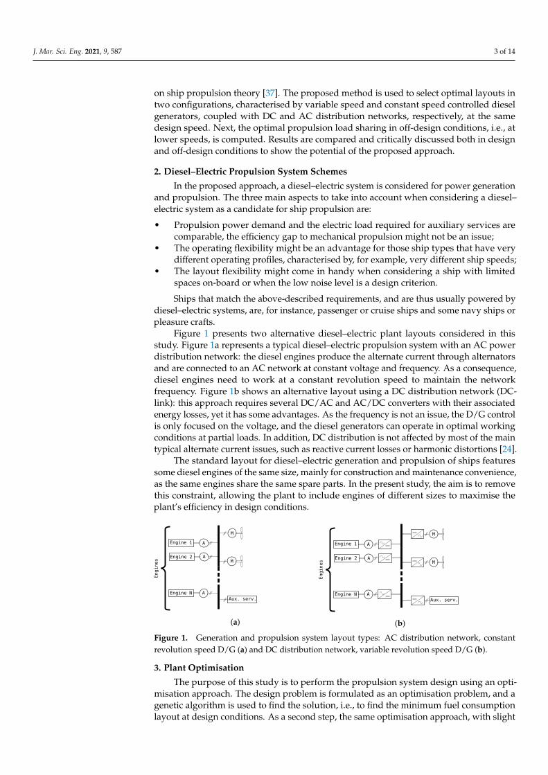
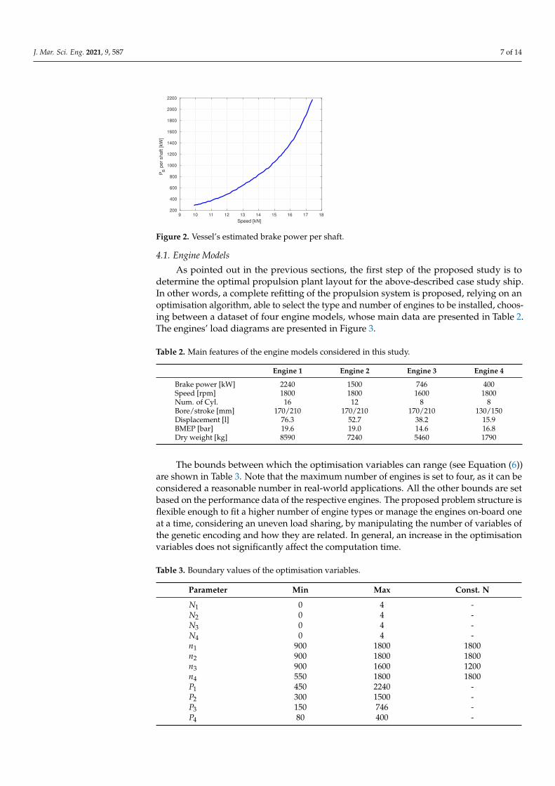
As pointed out in the previous sections, the first step of the proposed study is todetermine the optimal propulsion plant layout for the above-described case study ship.In other words, a complete refitting of the propulsion system is proposed, relying on anoptimisation algorithm, able to select the type and number of engines to be installed, choos-ing between a dataset of four engine models, whose main data are presented in Table 2.The engines’ load diagrams are presented in Figure 3.
Table 2. Main features of the engine models considered in this study.
Engine 1 Engine 2 Engine 3 Engine 4
Brake power [kW] 2240 1500 746 400Speed [rpm] 1800 1800 1600 1800Num. of Cyl. 16 12 8 8Bore/stroke [mm] 170/210 170/210 170/210 130/150Displacement [l] 76.3 52.7 38.2 15.9BMEP [bar] 19.6 19.0 14.6 16.8Dry weight [kg] 8590 7240 5460 1790
The bounds between which the optimisation variables can range (see Equation (6))are shown in Table 3. Note that the maximum number of engines is set to four, as it can beconsidered a reasonable number in real-world applications. All the other bounds are setbased on the performance data of the respective engines. The proposed problem structure isflexible enough to fit a higher number of engine types or manage the engines on-board oneat a time, considering an uneven load sharing, by manipulating the number of variables ofthe genetic encoding and how they are related. In general, an increase in the optimisationvariables does not significantly affect the computation time.
Table 3. Boundary values of the optimisation variables.
Parameter Min Max Const. N
N1 0 4 -N2 0 4 -N3 0 4 -N4 0 4 -n1 900 1800 1800n2 900 1800 1800n3 900 1600 1200n4 550 1800 1800P1 450 2240 -P2 300 1500 -P3 150 746 -P4 80 400 -
J. Mar. Sci. Eng. 2021, 9, 587 8 of 14
400 600 800 1000 1200 1400 1600 1800
N [rpm]
0
500
1000
1500
2000
2500
Pow
er
[kW
]
200
250
300
350
400
450
SF
OC
[g
/kW
h]
(a)
400 600 800 1000 1200 1400 1600 1800
N [rpm]
0
500
1000
1500
Pow
er
[kW
]
200
250
300
350
400
450
SF
OC
[g
/kW
h]
(b)
400 600 800 1000 1200 1400 1600
N [rpm]
0
100
200
300
400
500
600
700
800
Pow
er
[kW
]
200
250
300
350
400
450
SF
OC
[g/k
Wh]
(c)
400 600 800 1000 1200 1400 1600 1800
N [rpm]
0
50
100
150
200
250
300
350
400
Pow
er
[kW
]
200
250
300
350
400
450
SF
OC
[g/k
Wh]
(d)
Figure 3. Load diagrams of the engines considered in the study: (a) Engine 1; (b) Engine 2;(c) Engine 3; (d) Engine 4.
4.2. Electrical Components
In order to perform a realistic performance prediction, i.e., to properly evaluate eachsolution’s cost function, the electric efficiencies need to be assumed. Reasonable efficiencyvalue ranges are listed in Table 4, the higher the component’s size (i.e., power), the higherthe efficiency.
Table 4. Typical efficiencies of the electric machines and conversion devices.
Component Efficiency
Electric motors and alternators 0.95–0.97DC/AC and AC/DC converters 0.99DC/DC and AC/AC converters 0.96–0.98
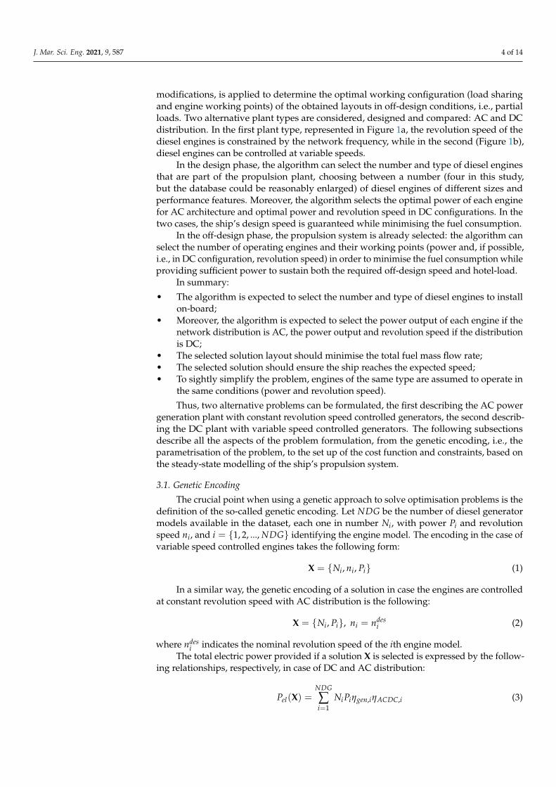
5. Results5.1. Design Condition
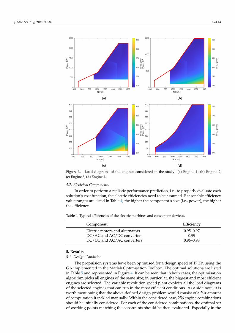
The propulsion systems have been optimised for a design speed of 17 Kn using theGA implemented in the Matlab Optimisation Toolbox. The optimal solutions are listedin Table 5 and represented in Figure 4. It can be seen that in both cases, the optimisationalgorithm picks all engines of the same size; in particular, the biggest and most efficientengines are selected. The variable revolution speed plant exploits all the load diagramsof the selected engines that can run in the most efficient conditions. As a side note, it isworth mentioning that the above-defined design problem would consist of a fair amountof computation if tackled manually. Within the considered case, 256 engine combinationsshould be initially considered. For each of the considered combinations, the optimal setof working points matching the constraints should be then evaluated. Especially in the
J. Mar. Sci. Eng. 2021, 9, 587 9 of 14
variable D/G speed case, this would result in a significant amount of computation thatmight be handled by, for instance, discretising each engine’s load diagram and using abrute force approach to evaluate all the possible working point combinations.
Table 5. Optimal solutions at design condition of 17 Kn.
Const. N Var. N
N1 2 0N2 0 3N3 0 0N4 0 0n1 1800 -n2 - 1540n3 - -n4 - -P1 2099 -P2 - 1428P3 - -P4 - -
f.c. 840 kgh 835 kg
h
5.2. Off-Design Conditions
The design optimisation procedure assessed the engine type, number and optimalworking point in design conditions, set to 17 Kn in the presented case study. As a furtherstep, optimal off-design configurations working points can be determined with the samealgorithm at lower speeds; in particular, the range between 10 Kn and the design speed of17 Kn has been investigated. For each propulsion system, the off-design optimal configu-ration is computed using the same optimisation approach, selecting the number of dieselgenerators running and their working point. For each propulsion plant, two alternativeoff-design power management strategies are considered and compared. The first option isthe most widely adopted and is based on an even load sharing between the generators,while, in the second case, the generators are allowed to run with unevenly shared loads. Itis worth mentioning that, while the constant speed and even load sharing optimality prob-lems might be handled manually, the complexity increase due to the variable speed andthe further addition of uneven load sharing justify the adoption of the proposed approach.
400 600 800 1000 1200 1400 1600 1800
N [rpm]
0
400
800
1200
1600
2000
2400
Pow
er
[kW
]
D/G config.: 2 0 0 0
Fuel cons.: 839.6 [Kg/h]
Eng. 1
Eng. 2
Eng. 3
Eng. 4
(a)
400 600 800 1000 1200 1400 1600 1800
N [rpm]
0
400
800
1200
1600
2000
2400
Pow
er
[kW
]
D/G config.: 0 3 0 0
Fuel cons.: 831.2 [Kg/h]
Eng. 1
Eng. 2
Eng. 3
Eng. 4
(b)
Figure 4. Solutions: constant speed D/G (a) and variable speed D/G (b).
J. Mar. Sci. Eng. 2021, 9, 587 10 of 14
10 11 12 13 14 15 16 171
1.5
2N
D/G
10 11 12 13 14 15 16 17
1000
1500
2000
PB
[kW
]
10 11 12 13 14 15 16 17
Speed [Kn]
1799
1800
1801
N [rp
m]
(a) Const. N
10 11 12 13 14 15 16 171
2
3
N D
/G
10 11 12 13 14 15 16 17
1000
1200
1400
PB
[kW
]
10 11 12 13 14 15 16 17
Speed [Kn]
1200
1400
1600
N [rp
m]
(b) Var. N
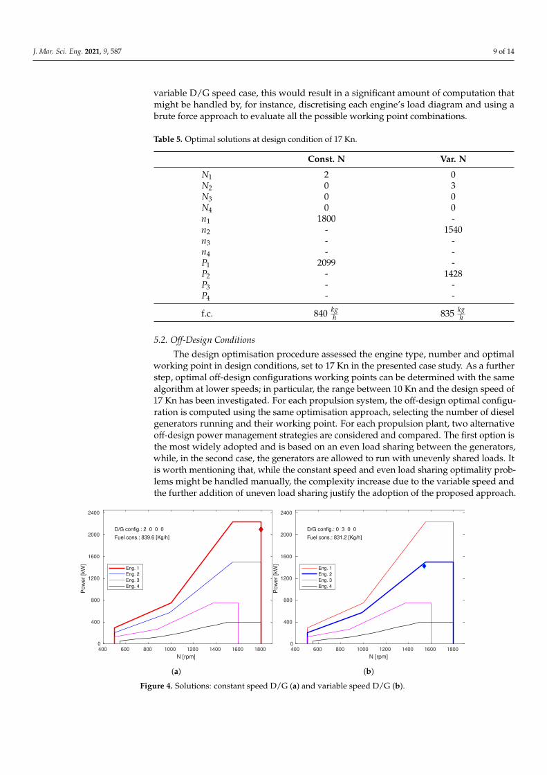
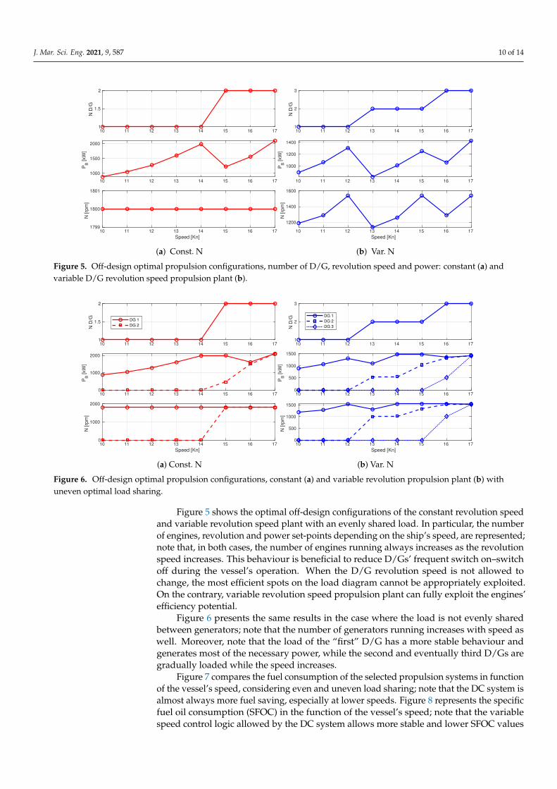
Figure 5. Off-design optimal propulsion configurations, number of D/G, revolution speed and power: constant (a) andvariable D/G revolution speed propulsion plant (b).
10 11 12 13 14 15 16 171
1.5
2
N D
/G
10 11 12 13 14 15 16 170
1000
2000
PB
[kW
]
DG 1
DG 2
10 11 12 13 14 15 16 17
Speed [Kn]
0
1000
2000
N [rp
m]
(a) Const. N
10 11 12 13 14 15 16 171
2
3
N D
/G
10 11 12 13 14 15 16 170
500
1000
1500
PB
[kW
]
DG 1
DG 2
DG 3
10 11 12 13 14 15 16 17
Speed [Kn]
0
500
1000
1500
N [rp
m]
(b) Var. N
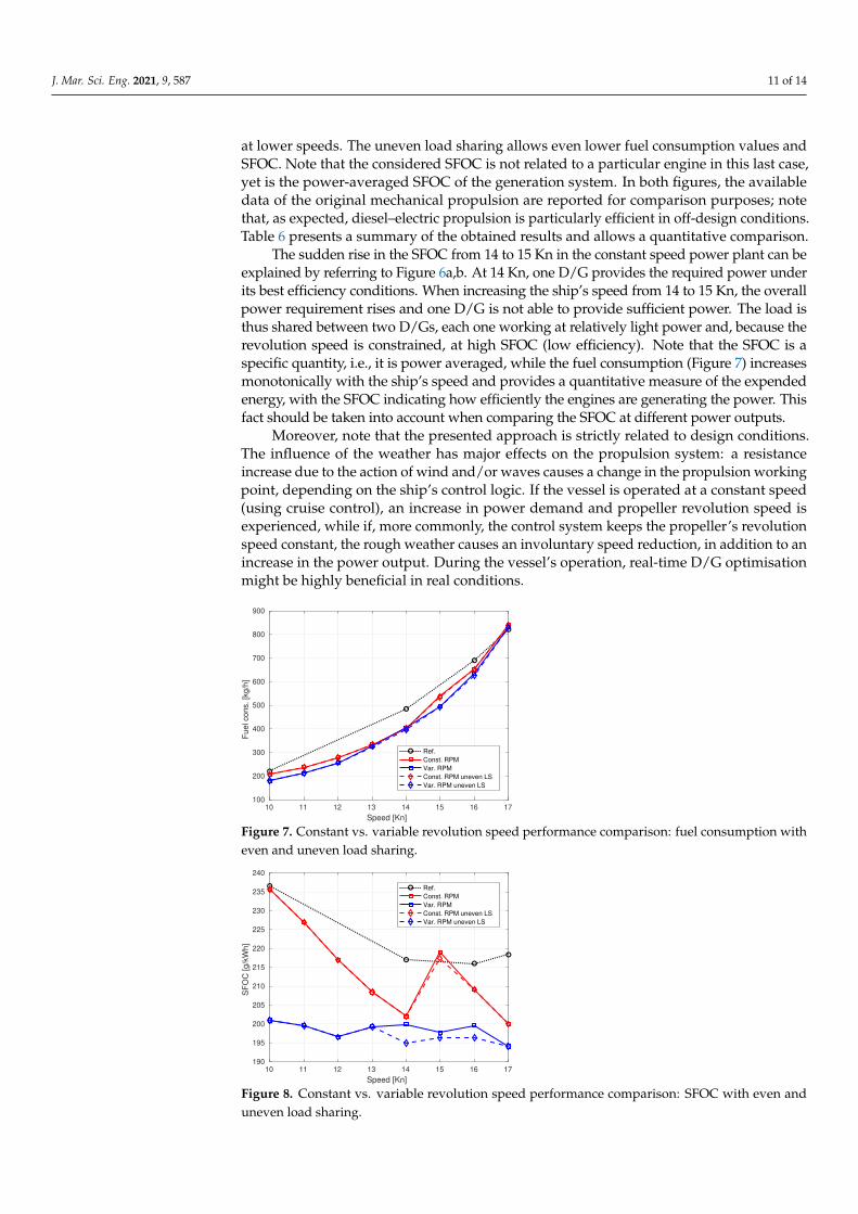
Figure 6. Off-design optimal propulsion configurations, constant (a) and variable revolution propulsion plant (b) withuneven optimal load sharing.
Figure 5 shows the optimal off-design configurations of the constant revolution speedand variable revolution speed plant with an evenly shared load. In particular, the numberof engines, revolution and power set-points depending on the ship’s speed, are represented;note that, in both cases, the number of engines running always increases as the revolutionspeed increases. This behaviour is beneficial to reduce D/Gs’ frequent switch on–switchoff during the vessel’s operation. When the D/G revolution speed is not allowed tochange, the most efficient spots on the load diagram cannot be appropriately exploited.On the contrary, variable revolution speed propulsion plant can fully exploit the engines’efficiency potential.
Figure 6 presents the same results in the case where the load is not evenly sharedbetween generators; note that the number of generators running increases with speed aswell. Moreover, note that the load of the “first” D/G has a more stable behaviour andgenerates most of the necessary power, while the second and eventually third D/Gs aregradually loaded while the speed increases.
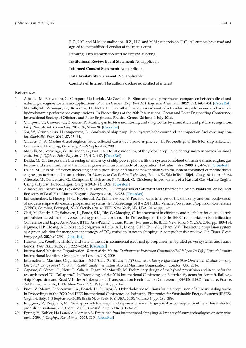
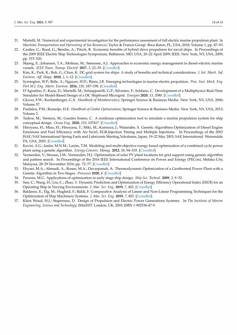
Figure 7 compares the fuel consumption of the selected propulsion systems in functionof the vessel’s speed, considering even and uneven load sharing; note that the DC system isalmost always more fuel saving, especially at lower speeds. Figure 8 represents the specificfuel oil consumption (SFOC) in the function of the vessel’s speed; note that the variablespeed control logic allowed by the DC system allows more stable and lower SFOC values
J. Mar. Sci. Eng. 2021, 9, 587 11 of 14
at lower speeds. The uneven load sharing allows even lower fuel consumption values andSFOC. Note that the considered SFOC is not related to a particular engine in this last case,yet is the power-averaged SFOC of the generation system. In both figures, the availabledata of the original mechanical propulsion are reported for comparison purposes; notethat, as expected, diesel–electric propulsion is particularly efficient in off-design conditions.Table 6 presents a summary of the obtained results and allows a quantitative comparison.
The sudden rise in the SFOC from 14 to 15 Kn in the constant speed power plant can beexplained by referring to Figure 6a,b. At 14 Kn, one D/G provides the required power underits best efficiency conditions. When increasing the ship’s speed from 14 to 15 Kn, the overallpower requirement rises and one D/G is not able to provide sufficient power. The load isthus shared between two D/Gs, each one working at relatively light power and, because therevolution speed is constrained, at high SFOC (low efficiency). Note that the SFOC is aspecific quantity, i.e., it is power averaged, while the fuel consumption (Figure 7) increasesmonotonically with the ship’s speed and provides a quantitative measure of the expendedenergy, with the SFOC indicating how efficiently the engines are generating the power. Thisfact should be taken into account when comparing the SFOC at different power outputs.
Moreover, note that the presented approach is strictly related to design conditions.The influence of the weather has major effects on the propulsion system: a resistanceincrease due to the action of wind and/or waves causes a change in the propulsion workingpoint, depending on the ship’s control logic. If the vessel is operated at a constant speed(using cruise control), an increase in power demand and propeller revolution speed isexperienced, while if, more commonly, the control system keeps the propeller’s revolutionspeed constant, the rough weather causes an involuntary speed reduction, in addition to anincrease in the power output. During the vessel’s operation, real-time D/G optimisationmight be highly beneficial in real conditions.
10 11 12 13 14 15 16 17
Speed [Kn]
100
200
300
400
500
600
700
800
900
Fu
el co
ns.
[kg
/h]
Ref.
Const. RPM
Var. RPM
Const. RPM uneven LS
Var. RPM uneven LS
Figure 7. Constant vs. variable revolution speed performance comparison: fuel consumption witheven and uneven load sharing.
10 11 12 13 14 15 16 17
Speed [Kn]
190
195
200
205
210
215
220
225
230
235
240
SF
OC
[g
/kW
h]
Ref.
Const. RPM
Var. RPM
Const. RPM uneven LS
Var. RPM uneven LS
Figure 8. Constant vs. variable revolution speed performance comparison: SFOC with even anduneven load sharing.

J. Mar. Sci. Eng. 2021, 9, 587 12 of 14
Table 6. Quantitative performance comparison.
Speed [Kn] 10 11 12 13 14 15 16 17
D/G running
Const. spd. 1 1 1 1 1 2 2 2Var. spd. 1 1 1 2 2 2 3 3
Fuel cons. [kg/h]
Ref. plant 220 - - - 484 - 690 821Const. spd. even 206.7 237.0 277.4 333.8 400.7 537.8 652.6 839.6Const. spd. uneven 206.7 237.0 277.4 333.8 400.7 533.9 652.5 839.6Var. spd. even 179.9 212.7 256.4 325.8 404.7 495.6 635.6 831.2Var. spd. uneven 179.9 212.7 256.4 325.6 394.6 492.1 625.7 831.2
SFOC [g/kWh]
Ref. plant 236 - - - 217 - 216 218Const. spd. even 236 227 217 208 202 219 209 200Const. spd. uneven 236 227 217 208 202 217 209 200Var. spd. even 201 200 197 199 200 198 200 194Var. spd. uneven 201 200 197 199 195 196 196 194
6. Conclusions
In this paper, an optimisation procedure has been presented, oriented to the optimaldesign of a diesel–electric ship propulsion system. In particular, a genetic algorithm hasbeen used to design the optimal layout of a diesel–electric propulsion plant, includingdiesel generators of various sizes either with an AC or DC power distribution network.The same approach with slight variations is then applied to find the optimal load sharingstrategy in several off-design conditions. The proposed method is applied to a case studyvessel; specifically, a pleasure craft is considered. The comparison has been discussed indetail, including the original propulsion plant data as a reference.
DC distribution coupled with variable speed generator control is highly beneficial forvessels that have operating requirements that are very demanding in terms of flexibility.The variable revolution speed control of the diesel engines allows the DC systems to keepmore stable SFOC values depending on the vessel’s speed, as the engines’ working pointcan be optimised further if compared to the constant revolution speed control approach.In particular, diesel–electric propulsion systems allow great flexibility, and optimal de-sign and off-design configurations can be achieved by numeric optimisation, allowingmaximisation of propulsive efficiency in the whole vessel’s speed operating range.
Numeric optimisation is an effective way to manage highly under-determined prob-lems such as propulsion system layout design or optimal load sharing determination,and the results obtained are auspicious. The proposed approach comes in handy forpropulsion plant designers, allowing them to manage high numbers of alternative optionsand combinations in a reasonable amount of time. When increasing the complexity of theproblem, an exhaustive brute force analysis employing standard methods is not feasible.
It should be noted that the proposed approach is based on two sequential steps: first,the optimal layout to reach the design speed with all the engines running is determined,then the optimal load sharing in off-design conditions is computed, considering the propul-sion system obtained in the design phase. In the future development of the proposedapproach, these two steps are supposed to be nested to compute the optimal propulsionsystem design to match a given operating profile with two or more different design speeds.
Author Contributions: Conceptualisation, R.Z., U.C. and M.M.; methodology, R.Z.; software, R.Z.;validation, M.M.; formal analysis, R.Z. and M.M.; investigation, R.Z. and U.C.; resources, U.C.; datacuration, R.Z.; writing—original draft preparation, R.Z., U.C. and M.M.; writing—review and editing,
J. Mar. Sci. Eng. 2021, 9, 587 13 of 14
R.Z., U.C. and M.M.; visualisation, R.Z., U.C. and M.M.; supervision, U.C.; All authors have read andagreed to the published version of the manuscript.
Funding: This research received no external funding.
Institutional Review Board Statement: Not applicable
Informed Consent Statement: Not applicable
Data Availability Statement: Not applicable
Conflicts of Interest: The authors declare no conflict of interest.
References1. Altosole, M.; Benvenuto, G.; Campora, U.; Laviola, M.; Zaccone, R. Simulation and performance comparison between diesel and
natural gas engines for marine applications. Proc. Inst. Mech. Eng. Part M J. Eng. Marit. Environ. 2017, 231, 690–704. [CrossRef]2. Martelli, M.; Vernengo, G.; Bruzzone, D.; Notti, E. Overall efficiency assessment of a trawler propulsion system based on
hydrodynamic performance computations. In Proceedings of the 26th International Ocean and Polar Engineering Conference,International Society of Offshore and Polar Engineers, Rhodes, Greece, 26 June–1 July 2016.
3. Campora, U.; Cravero, C.; Zaccone, R. Marine gas turbine monitoring and diagnostics by simulation and pattern recognition.Int. J. Nav. Archit. Ocean Eng. 2018, 10, 617–628. [CrossRef]
4. Shi, W.; Grimmelius, H.; Stapersma, D. Analysis of ship propulsion system behaviour and the impact on fuel consumption.Int. Shipbuild. Prog. 2010, 57, 35–64.
5. Clausen, N.B. Marine diesel engines: How efficient can a two-stroke engine be. In Proceedings of the STG Ship EfficiencyConference, Hamburg, Germany, 28–29 September, 2009.
6. Martelli, M.; Vernengo, G.; Bruzzone, D.; Notti, E. Holistic modeling of the global propulsion energy index in waves for smallcraft. Int. J. Offshore Polar Eng. 2017, 27, 442–447. [CrossRef]
7. Dzida, M. On the possible increasing of efficiency of ship power plant with the system combined of marine diesel engine, gasturbine and steam turbine, at the main engine-steam turbine mode of cooperation. Pol. Marit. Res. 2009, 16, 47–52. [CrossRef]
8. Dzida, M. Possible efficiency increasing of ship propulsion and marine power plant with the system combined of marine dieselengine, gas turbine and steam turbine. In Advances in Gas Turbine Technology; Benini, E., Ed.; InTech: Rijeka, Italy, 2011; pp. 45–68.
9. Altosole, M.; Benvenuto, G.; Campora, U.; Silvestro, F.; Terlizzi, G. Efficiency Improvement of a Natural Gas Marine EngineUsing a Hybrid Turbocharger. Energies 2018, 11, 1924. [CrossRef]
10. Altosole, M.; Benvenuto, G.; Zaccone, R.; Campora, U. Comparison of Saturated and Superheated Steam Plants for Waste-HeatRecovery of Dual-Fuel Marine Engines. Energies 2020, 13, 985. [CrossRef]
11. Bolvashenkov, I.; Herzog, H.G.; Rubinraut, A.; Romanovskiy, V. Possible ways to improve the efficiency and competitivenessof modern ships with electric propulsion systems. In Proceedings of the 2014 IEEE Vehicle Power and Propulsion Conference(VPPC), Coimbra, Portugal, 27–30 October 2014; IEEE: New York, NY, USA, 2014; pp. 1–9.
12. Chai, M.; Reddy, B.D.; Sobrayen, L.; Panda, S.K.; Die, W.; Xiaoqing, C. Improvement in efficiency and reliability for diesel-electricpropulsion based marine vessels using genetic algorithm. In Proceedings of the 2016 IEEE Transportation ElectrificationConference and Expo, Asia-Pacific (ITEC Asia-Pacific), Busan, Korea, 1–4 June 2016; IEEE: New York, NY, USA, 2016; pp. 180–184.
13. Nguyen, H.P.; Hoang, A.T.; Nizetic, S.; Nguyen, X.P.; Le, A.T.; Luong, C.N.; Chu, V.D.; Pham, V.V. The electric propulsion systemas a green solution for management strategy of CO2 emission in ocean shipping: A comprehensive review. Int. Trans. Electr.Energy Syst. 2020, e12580. [CrossRef]
14. Hansen, J.F.; Wendt, F. History and state of the art in commercial electric ship propulsion, integrated power systems, and futuretrends. Proc. IEEE 2015, 103, 2229–2242. [CrossRef]
15. International Maritime Organization. Report of the Marine Environment Protection Committee (MEPC) on Its Fifty-Seventh Session;International Maritime Organization: London, UK, 2008.
16. International Maritime Organization. IMO Train the Trainer (TTT) Course on Energy Efficiency Ship Operation. Module 2—ShipEnergy Efficiency Regulations and Related Guidelines; International Maritime Organization: London, UK, 2016.
17. Capasso, C.; Veneri, O.; Notti, E.; Sala, A.; Figari, M.; Martelli, M. Preliminary design of the hybrid propulsion architecture for theresearch vessel “G. Dallaporta”. In Proceedings of the 2016 International Conference on Electrical Systems for Aircraft, Railway,Ship Propulsion and Road Vehicles & International Transportation Electrification Conference (ESARS-ITEC), Toulouse, France,2–4 November 2016; IEEE: New York, NY, USA, 2016; pp. 1–6.
18. Bucci, V.; Mauro, F.; Vicenzutti, A.; Bosich, D.; Sulligoi, G. Hybrid-electric solutions for the propulsion of a luxury sailing yacht.In Proceedings of the 2020 2nd IEEE International Conference on Industrial Electronics for Sustainable Energy Systems (IESES),Cagliari, Italy, 1–3 September 2020; IEEE: New York, NY, USA, 2020; Volume 1, pp. 280–286.
19. Ruggiero, V.; Ruggiero, M. New approach to design and representation of large yacht as consequence of new diesel electricpropulsion systems. Int. J. Adv. Mech. Automob. Emg. 2016, 3, 123–128.
20. Eyring, V.; Köhler, H.; Lauer, A.; Lemper, B. Emissions from international shipping: 2. Impact of future technologies on scenariosuntil 2050. J. Geophys. Res. Atmos. 2005, 110. [CrossRef]
J. Mar. Sci. Eng. 2021, 9, 587 14 of 14
21. Martelli, M. Numerical and experimental investigation for the performance assessment of full electric marine propulsion plant. InMaritime Transportation and Harvesting of Sea Resources; Taylor & Francis Group: Boca Raton, FL, USA; 2018; Volume 1, pp. 87–93.
22. Castles, G.; Reed, G.; Bendre, A.; Pitsch, R. Economic benefits of hybrid drive propulsion for naval ships. In Proceedings ofthe 2009 IEEE Electric Ship Technologies Symposium, Baltimore, MD, USA, 20–22 April 2009; IEEE: New York, NY, USA, 2009;pp. 515–520.
23. Skjong, E.; Johansen, T.A.; Molinas, M.; Sørensen, A.J. Approaches to economic energy management in diesel–electric marinevessels. IEEE Trans. Transp. Electrif. 2017, 3, 22–35. [CrossRef]
24. Kim, K.; Park, K.; Roh, G.; Chun, K. DC-grid system for ships: A study of benefits and technical considerations. J. Int. Marit. Saf.Environ. Aff. Shipp. 2018, 2, 1–12. [CrossRef]
25. Symington, W.P.; Belle, A.; Nguyen, H.D.; Binns, J.R. Emerging technologies in marine electric propulsion. Proc. Inst. Mech. Eng.Part M J. Eng. Marit. Environ. 2016, 230, 187–198. [CrossRef]
26. D’Agostino, F.; Kaza, D.; Martelli, M.; Schiapparelli, G.P.; Silvestro, F.; Soldano, C. Development of a Multiphysics Real-TimeSimulator for Model-Based Design of a DC Shipboard Microgrid. Energies 2020, 13, 3580. [CrossRef]
27. Glover, F.W.; Kochenberger, G.A. Handbook of Metaheuristics; Springer Science & Business Media: New York, NY, USA, 2006;Volume 57.
28. Pardalos, P.M.; Romeijn, H.E. Handbook of Global Optimization; Springer Science & Business Media: New York, NY, USA, 2013;Volume 2.
29. Tadros, M.; Ventura, M.; Guedes Soares, C. A nonlinear optimization tool to simulate a marine propulsion system for shipconceptual design. Ocean Eng. 2020, 210, 107417. [CrossRef]
30. Hiroyasu, H.; Miao, H.; Hiroyasu, T.; Miki, M.; Kamiura, J.; Watanabe, S. Genetic Algorithms Optimization of Diesel EngineEmissions and Fuel Efficiency with Air Swirl, EGR,Injection Timing and Multiple Injections. In Proceedings of the 2003JSAE/SAE International Spring Fuels and Lubricants Meeting,Yokohama, Japan, 19–22 May 2003; SAE International: WarrendalePA, USA, 2003. [CrossRef]
31. Kaviri, A.G.; Jaafar, M.N.M.; Lazim, T.M. Modeling and multi-objective exergy based optimization of a combined cycle powerplant using a genetic algorithm. Energy Convers. Manag. 2012, 58, 94–103. [CrossRef]
32. Vermeulen, V.; Strauss, J.M.; Vermeulen, H.J. Optimisation of solar PV plant locations for grid support using genetic algorithmand pattern search. In Proceedings of the 2016 IEEE International Conference on Power and Energy (PECon), Melaka City,Malaysia, 28–29 November 2016; pp. 72–77. [CrossRef]
33. Ehyaei, M.A.; Ahmadi, A.; Rosen, M.A.; Davarpanah, A. Thermodynamic Optimization of a Geothermal Power Plant with aGenetic Algorithm in Two Stages. Processes 2020, 8. [CrossRef]
34. Parsons, M.G. Applications of optimization in early stage ship design. Ship Sci. Technol. 2009, 3, 9–32.35. Sun, C.; Wang, H.; Liu, C.; Zhao, Y. Dynamic Prediction and Optimization of Energy Efficiency Operational Index (EEOI) for an
Operating Ship in Varying Environments. J. Mar. Sci. Eng. 2019, 7, 402. [CrossRef]36. Baldasso, E.; Elg, M.; Haglind, F.; Baldi, F. Comparative Analysis of Linear and Non-Linear Programming Techniques for the
Optimization of Ship Machinery Systems. J. Mar. Sci. Eng. 2019, 7, 403. [CrossRef]37. Klein Woud, H.J.; Stapersma, D. Design of Propulsion and Electric Power Generations Systems. In The Institute of Marine
Engineering, Science and Technology; IMarEST: London, UK, 2003; ISBN 1-902536-47-9.
Related Documents