CORONARY INTERVENTIONS 934 EXPERIMENTAL RESEARCH EuroIntervention 2014;10:934-941 published online ahead of print February 2014 DOI: 10.4244/EIJV10I8A160 © Europa Digital & Publishing 2014. All rights reserved. *Corresponding author: Department of Cardiovascular Medicine, Heart Center, New Yukuhashi Hospital, 1411, Dojoji, Yukuhashi, 822-0034, Japan. E-mail: [email protected] Optimal kissing balloon inflation after single-stent deployment in a coronary bifurcation model Yoshinobu Murasato 1 *, MD, PhD; Kiyotaka Iwasaki 2 , PhD; Tadashi Yamamoto 2 , MD; Takanobu Yagi 2 , PhD; Yutaka Hikichi 2,3 , MD, PhD; Yasunori Suematsu 1 , MD; Tomohiko Yamamoto 1 , MD 1. Department of Cardiovascular Medicine, Heart Center, New Yukuhashi Hospital, Yukuhashi, Japan; 2. Cooperative Major in Advanced Biomedical Sciences, Graduate School of Advanced Science and Engineering, Waseda University, Tokyo, Japan; 3. Cardiovascular Division, Department of Internal Medicine, Saga University, Saga, Japan This paper also includes accompanying supplementary data published online at: http://www.pcronline.com/eurointervention/79th_issue/160 Abstract Aims: To define the optimal kissing balloon inflation (KBI) after single-stent deployment in a coronary bifur- cation model. Methods and results: We deployed stents in main vessels (MV) followed by KBI in various conditions and compared the stent configurations. A) KBI at the operator’s discretion vs. under the guidelines of mini- mal balloon overlapping (MBO). Various stent configurations were observed after the former option, whereas similar maximal dilation points were observed under the MBO guidelines. B) Long balloon overlapping (LBO) vs. MBO with proximal MV dilated by a large balloon. The proximal MV was dilated to an ideal round shape with MBO versus an oval shape with LBO. C) Two-link vs. 3-link stents. Although the 2-link stent was advantageous to open the side branch, it incurred a risk of overdilatation of the proximal struts, whereas the 3-link stent preserved its structure. Computed simulations of coronary flow were analysed in the following left main coronary models: circle with a diameter of 4 and 5.5 mm, ellipse with longitudinal direction and tilt position. They revealed that the overdilated side was exposed to low shear stress regardless of its shape. Conclusions: Optimal KBI can be achieved with MBO and proximal dilatation by an optimally sized balloon. KEYWORDS • coronary bifurcation • coronary flow • drug-eluting stent SUBMITTED ON 14/04/2013 - REVISION RECEIVED ON 13/10/2013 - ACCEPTED ON 30/10/2013

Welcome message from author
This document is posted to help you gain knowledge. Please leave a comment to let me know what you think about it! Share it to your friends and learn new things together.
Transcript
CORONARY INTERVENT IONS
934
E X P E R I M E N TA L R E S E A R C H
EuroIntervention 20
14
;10
:934-941 pu
blish
ed on
line ah
ead of p
rint February 2
014
D
OI: 10.4
24
4/E
IJV10
I8A
16
0
© Europa Digital & Publishing 2014. All rights reserved.
*Corresponding author: Department of Cardiovascular Medicine, Heart Center, New Yukuhashi Hospital, 1411, Dojoji, Yukuhashi, 822-0034, Japan. E-mail: [email protected]
Optimal kissing balloon inflation after single-stent deployment in a coronary bifurcation modelYoshinobu Murasato1*, MD, PhD; Kiyotaka Iwasaki2, PhD; Tadashi Yamamoto2, MD; Takanobu Yagi2, PhD; Yutaka Hikichi2,3, MD, PhD; Yasunori Suematsu1, MD; Tomohiko Yamamoto1, MD
1. Department of Cardiovascular Medicine, Heart Center, New Yukuhashi Hospital, Yukuhashi, Japan; 2. Cooperative Major in Advanced Biomedical Sciences, Graduate School of Advanced Science and Engineering, Waseda University, Tokyo, Japan; 3. Cardiovascular Division, Department of Internal Medicine, Saga University, Saga, Japan
This paper also includes accompanying supplementary data published online at: http://www.pcronline.com/eurointervention/79th_issue/160
AbstractAims: To define the optimal kissing balloon inflation (KBI) after single-stent deployment in a coronary bifur-cation model.
Methods and results: We deployed stents in main vessels (MV) followed by KBI in various conditions and compared the stent configurations. A) KBI at the operator’s discretion vs. under the guidelines of mini-mal balloon overlapping (MBO). Various stent configurations were observed after the former option, whereas similar maximal dilation points were observed under the MBO guidelines. B) Long balloon overlapping (LBO) vs. MBO with proximal MV dilated by a large balloon. The proximal MV was dilated to an ideal round shape with MBO versus an oval shape with LBO. C) Two-link vs. 3-link stents. Although the 2-link stent was advantageous to open the side branch, it incurred a risk of overdilatation of the proximal struts, whereas the 3-link stent preserved its structure. Computed simulations of coronary flow were analysed in the following left main coronary models: circle with a diameter of 4 and 5.5 mm, ellipse with longitudinal direction and tilt position. They revealed that the overdilated side was exposed to low shear stress regardless of its shape.
Conclusions: Optimal KBI can be achieved with MBO and proximal dilatation by an optimally sized balloon.
KEYWORDS
• coronary bifurcation
• coronary flow• drug-eluting stent
SUBMITTED ON 14/04/2013 - REVISION RECEIVED ON 13/10/2013 - ACCEPTED ON 30/10/2013
935
Optimal kissing balloon inflation in bifurcationEuroIntervention 2
01
4;1
0:934-941
AbbreviationsDES drug-eluting stentLBO long balloon overlappingKBI kissing balloon inflationMACE major adverse cardiac eventsMBO minimal balloon overlappingMFCT microfocus x-ray computed tomographyMV main vesselSB side branch
IntroductionDespite the use of drug-eluting stents (DES), coronary bifurcation lesions remain associated with high rates of restenosis and stent thrombosis1,2. The deployment of stents in both the main vessel (MV) and the side branch (SB) with a view to covering the entire lesion conferred no benefit compared with the deployment of a sin-gle stent in the MV3,4. Therefore, a provisional stent strategy has been recommended as first-line treatment5. However, the indica-tions and SB characteristics, including degree of stenosis, perfusion area, size, and flow disturbance, remain controversial.
Kissing balloon inflation (KBI) has been advocated for the man-agement of bifurcation lesions6 in order to: 1) preserve the access to the SB; 2) prevent its narrowing and restenosis; 3) widen the lumen of the proximal MV; 4) optimise the stent apposition; and 5) mini-mise the stent deformation. While the efficacy of KBI as a means of limiting restenosis of the SB in dual stent deployment has been demonstrated conclusively7-9, its effect on the rates of major adverse cardiac events (MACE) when a single stent is deployed has recently been questioned. The Nordic-Baltic III trial, in which patients undergoing deployment of a single stent in the MV were randomly assigned to final KBI versus no KBI, observed identical 2.9% MACE rates in both study groups10. In the Korean Coronary Bifurcation Stenting (COBIS) Registry, KBI was associated with a higher MACE rate (8.7%) than no KBI (4.7%)11.
In a study comparing fractional flow reserve versus quan-titative coronary angiography, the angiographic severity of the jailed SB was often overestimated, as a FFR <0.75 was observed in only 27% of SB with >75% angiographic stenosis12. Therefore, overtreatment of the SB is thought to be one of the explanations for the adverse consequences of KBI. However, in both the Nordic-Baltic III trial and the COBIS Registry, numeri-cally higher rates of restenosis in the MV in the KBI group were observed compared to the non-KBI group, whereas there were lower rates in the SB10,11. In addition, oval stent deformation in the proximal MV is induced by KBI13, which does not obey the natural vascular branching law and symmetric property. Thus, the adverse effects of KBI are not explained only by overtreat-ment of SB, but also by disturbances in the MV.
To clarify the effects of KBI on the MV, we studied the defor-mation of stents implanted by crossover stenting followed by KBI in a bifurcation phantom model, using microfocus x-ray computed tomography (MFCT) with a superior resolution14,15. We also per-formed a computer-based analysis of the coronary flow in the
deformed stents in order to clarify the benefit of proximal optimisa-tion of the proximal MV after KBI.
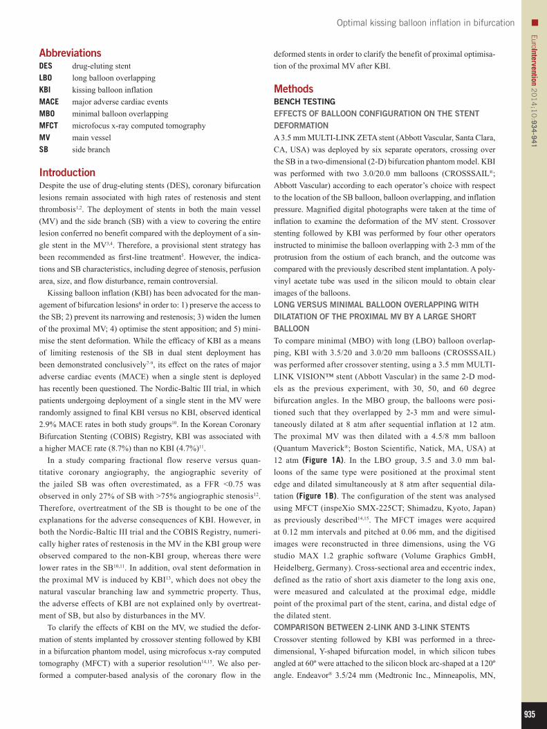
MethodsBENCH TESTINGEFFECTS OF BALLOON CONFIGURATION ON THE STENT DEFORMATIONA 3.5 mm MULTI-LINK ZETA stent (Abbott Vascular, Santa Clara, CA, USA) was deployed by six separate operators, crossing over the SB in a two-dimensional (2-D) bifurcation phantom model. KBI was performed with two 3.0/20.0 mm balloons (CROSSSAIL®; Abbott Vascular) according to each operator’s choice with respect to the location of the SB balloon, balloon overlapping, and inflation pressure. Magnified digital photographs were taken at the time of inflation to examine the deformation of the MV stent. Crossover stenting followed by KBI was performed by four other operators instructed to minimise the balloon overlapping with 2-3 mm of the protrusion from the ostium of each branch, and the outcome was compared with the previously described stent implantation. A poly-vinyl acetate tube was used in the silicon mould to obtain clear images of the balloons.LONG VERSUS MINIMAL BALLOON OVERLAPPING WITH DILATATION OF THE PROXIMAL MV BY A LARGE SHORT BALLOONTo compare minimal (MBO) with long (LBO) balloon overlap-ping, KBI with 3.5/20 and 3.0/20 mm balloons (CROSSSAIL) was performed after crossover stenting, using a 3.5 mm MULTI-LINK VISION™ stent (Abbott Vascular) in the same 2-D mod-els as the previous experiment, with 30, 50, and 60 degree bifurcation angles. In the MBO group, the balloons were posi-tioned such that they overlapped by 2-3 mm and were simul-taneously dilated at 8 atm after sequential inflation at 12 atm. The proximal MV was then dilated with a 4.5/8 mm balloon (Quantum Maverick®; Boston Scientific, Natick, MA, USA) at 12 atm (Figure 1A). In the LBO group, 3.5 and 3.0 mm bal-loons of the same type were positioned at the proximal stent edge and dilated simultaneously at 8 atm after sequential dila-tation (Figure 1B). The configuration of the stent was analysed using MFCT (inspeXio SMX-225CT; Shimadzu, Kyoto, Japan) as previously described14,15. The MFCT images were acquired at 0.12 mm intervals and pitched at 0.06 mm, and the digitised images were reconstructed in three dimensions, using the VG studio MAX 1.2 graphic software (Volume Graphics GmbH, Heidelberg, Germany). Cross-sectional area and eccentric index, defined as the ratio of short axis diameter to the long axis one, were measured and calculated at the proximal edge, middle point of the proximal part of the stent, carina, and distal edge of the dilated stent.COMPARISON BETWEEN 2-LINK AND 3-LINK STENTSCrossover stenting followed by KBI was performed in a three-dimensional, Y-shaped bifurcation model, in which silicon tubes angled at 60º were attached to the silicon block arc-shaped at a 120º angle. Endeavor® 3.5/24 mm (Medtronic Inc., Minneapolis, MN,
936
EuroIntervention 20
14
;10
:934-941
USA) and MULTI-LINK ZETA 3.5/28 mm (Abbott Vascular) stents were used as representatives of 2-link and 3-link stents, respec-tively. In the KBI, 3.5/20 mm and 3.0/20 mm balloons (Ryujin™ Plus; Terumo, Tokyo, Japan) were simultaneously dilated at 8 atm, after sequential balloon dilatation at 12 atm, with their proximal segments placed in the proximal edge of the stent. The stent con-figuration was analysed, using MFCT.
COMPUTER-BASED ANALYSIS OF THE CORONARY FLOWThe effect of proximal overdilatation by KBI on the coronary flow dynamics in the left main (LM) coronary artery bifurcation was
Figure 1. Bench comparisons of minimal (MBO) versus long (LBO) balloon overlapping during KBI. A) MBO. a) Location of 3.5 and 3.0 mm balloons in the bifurcation model, where a 3.5 mm stent was deployed in the MV; b) simultaneous inflation; c) proximal MV dilation with a 4.5/8 mm balloon. B) LBO. a) Location of 3.5 and 3.0 mm balloons; b) simultaneous inflation.
analysed in the computational flow dynamics. The LM bifurcation model included: A) a 15 mm long LM coronary artery, B) a left ante-rior descending artery with a diameter of 3.5 mm, and C) a circumflex artery with a diameter of 3.0 mm, with these two vessels bifurcated at an angle of 120º. The simulated LM artery was connected to the aorta with a radius of 5 mm, the simulated systolic flow was 40% of the diastolic flow and the direction of forward flow was in the opposite direction to the diastolic flow. The coronary flow was simulated by a finite volume method, using the ANSYS CFX12.0 software pack-age (Cybernet Systems, Tokyo, Japan). Peak systolic and diastolic flow velocity were measured in the LM coronary artery under the following conditions: A) circle with a diameter of 4 mm, B) circle with a diameter of 5.5 mm, C) ellipse with long and short diameters of 5.5 and 4 mm, respectively, with its long axis in a longitudinal direction (ellipse - lon-gitude), and D) ellipse with the same dimension as in C, with its long axis in the tilt position (ellipse - tilt).
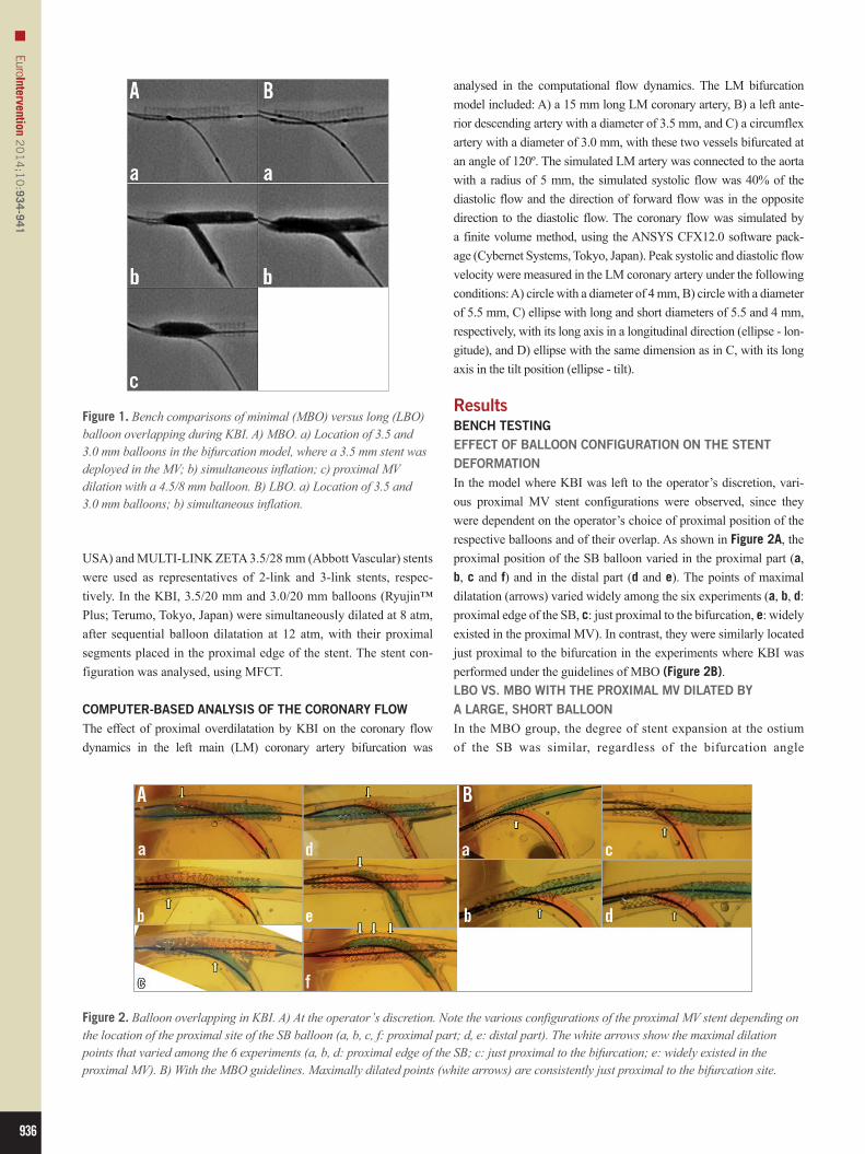
ResultsBENCH TESTINGEFFECT OF BALLOON CONFIGURATION ON THE STENT DEFORMATIONIn the model where KBI was left to the operator’s discretion, vari-ous proximal MV stent configurations were observed, since they were dependent on the operator’s choice of proximal position of the respective balloons and of their overlap. As shown in Figure 2A, the proximal position of the SB balloon varied in the proximal part (a, b, c and f) and in the distal part (d and e). The points of maximal dilatation (arrows) varied widely among the six experiments (a, b, d: proximal edge of the SB, c: just proximal to the bifurcation, e: widely existed in the proximal MV). In contrast, they were similarly located just proximal to the bifurcation in the experiments where KBI was performed under the guidelines of MBO (Figure 2B).LBO VS. MBO WITH THE PROXIMAL MV DILATED BY A LARGE, SHORT BALLOONIn the MBO group, the degree of stent expansion at the ostium of the SB was similar, regardless of the bifurcation angle
Figure 2. Balloon overlapping in KBI. A) At the operator’s discretion. Note the various configurations of the proximal MV stent depending on the location of the proximal site of the SB balloon (a, b, c, f: proximal part; d, e: distal part). The white arrows show the maximal dilation points that varied among the 6 experiments (a, b, d: proximal edge of the SB; c: just proximal to the bifurcation; e: widely existed in the proximal MV). B) With the MBO guidelines. Maximally dilated points (white arrows) are consistently just proximal to the bifurcation site.
937
Optimal kissing balloon inflation in bifurcationEuroIntervention 2
01
4;1
0:934-941
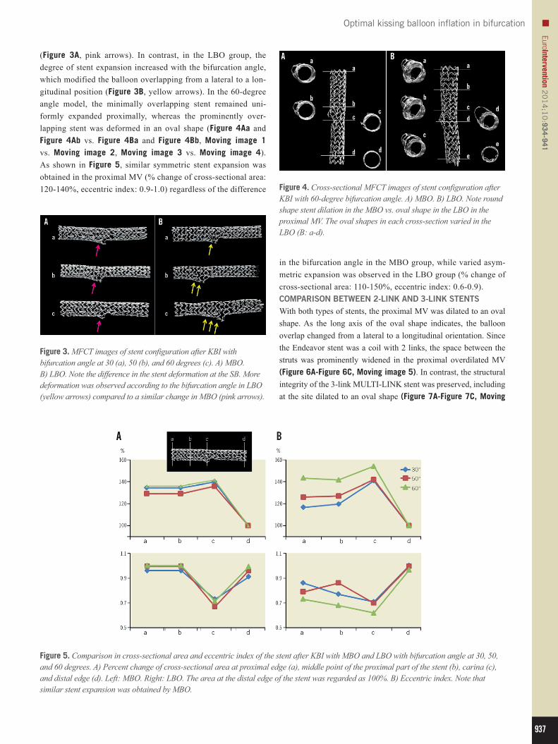
(Figure 3A, pink arrows). In contrast, in the LBO group, the degree of stent expansion increased with the bifurcation angle, which modified the balloon overlapping from a lateral to a lon-gitudinal position (Figure 3B, yellow arrows). In the 60-degree angle model, the minimally overlapping stent remained uni-formly expanded proximally, whereas the prominently over-lapping stent was deformed in an oval shape (Figure 4Aa and Figure 4Ab vs. Figure 4Ba and Figure 4Bb, Moving image 1 vs. Moving image 2, Moving image 3 vs. Moving image 4). As shown in Figure 5, similar symmetric stent expansion was obtained in the proximal MV (% change of cross-sectional area: 120-140%, eccentric index: 0.9-1.0) regardless of the difference
Figure 5. Comparison in cross-sectional area and eccentric index of the stent after KBI with MBO and LBO with bifurcation angle at 30, 50, and 60 degrees. A) Percent change of cross-sectional area at proximal edge (a), middle point of the proximal part of the stent (b), carina (c), and distal edge (d). Left: MBO. Right: LBO. The area at the distal edge of the stent was regarded as 100%. B) Eccentric index. Note that similar stent expansion was obtained by MBO.
Figure 3. MFCT images of stent configuration after KBI with bifurcation angle at 30 (a), 50 (b), and 60 degrees (c). A) MBO. B) LBO. Note the difference in the stent deformation at the SB. More deformation was observed according to the bifurcation angle in LBO (yellow arrows) compared to a similar change in MBO (pink arrows).
Figure 4. Cross-sectional MFCT images of stent configuration after KBI with 60-degree bifurcation angle. A) MBO. B) LBO. Note round shape stent dilation in the MBO vs. oval shape in the LBO in the proximal MV. The oval shapes in each cross-section varied in the LBO (B: a-d).
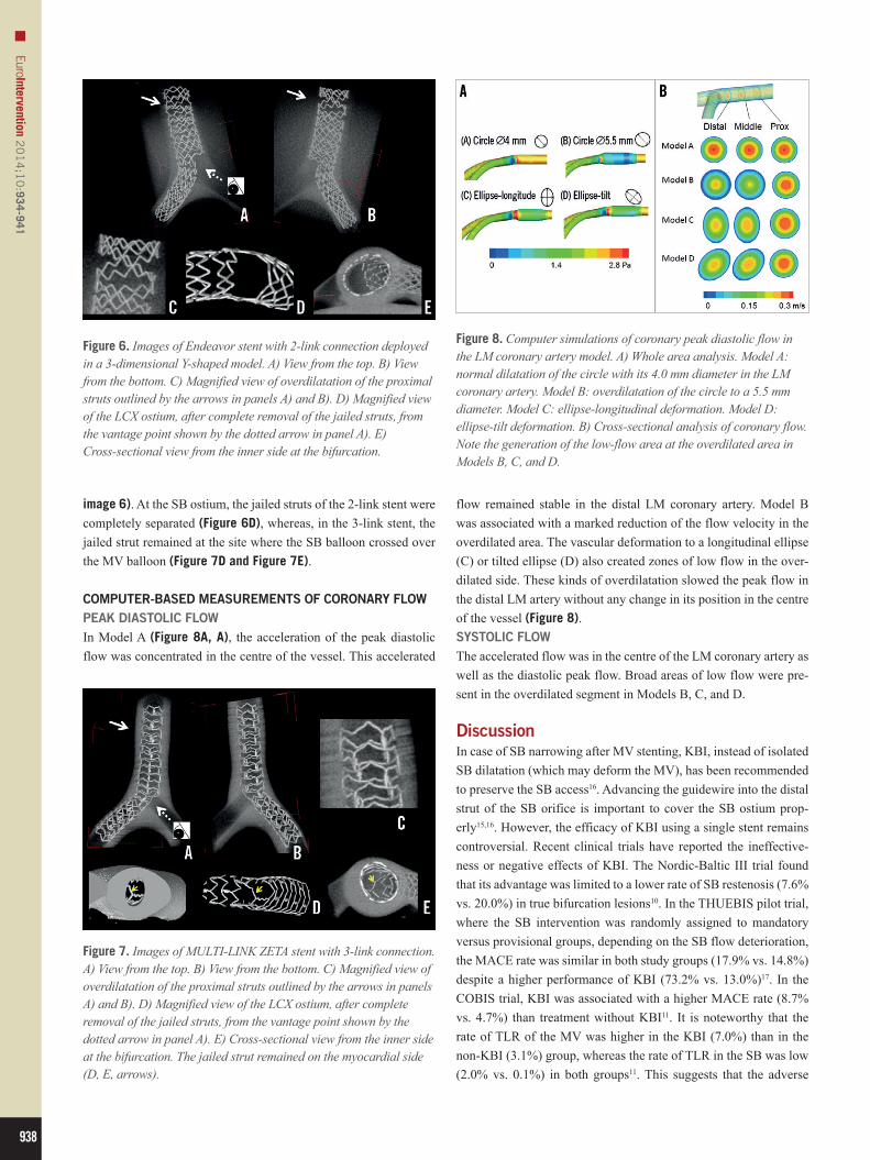
in the bifurcation angle in the MBO group, while varied asym-metric expansion was observed in the LBO group (% change of cross-sectional area: 110-150%, eccentric index: 0.6-0.9).COMPARISON BETWEEN 2-LINK AND 3-LINK STENTSWith both types of stents, the proximal MV was dilated to an oval shape. As the long axis of the oval shape indicates, the balloon overlap changed from a lateral to a longitudinal orientation. Since the Endeavor stent was a coil with 2 links, the space between the struts was prominently widened in the proximal overdilated MV (Figure 6A-Figure 6C, Moving image 5). In contrast, the structural integrity of the 3-link MULTI-LINK stent was preserved, including at the site dilated to an oval shape (Figure 7A-Figure 7C, Moving
938
EuroIntervention 20
14
;10
:934-941
Figure 6. Images of Endeavor stent with 2-link connection deployed in a 3-dimensional Y-shaped model. A) View from the top. B) View from the bottom. C) Magnified view of overdilatation of the proximal struts outlined by the arrows in panels A) and B). D) Magnified view of the LCX ostium, after complete removal of the jailed struts, from the vantage point shown by the dotted arrow in panel A). E) Cross-sectional view from the inner side at the bifurcation.
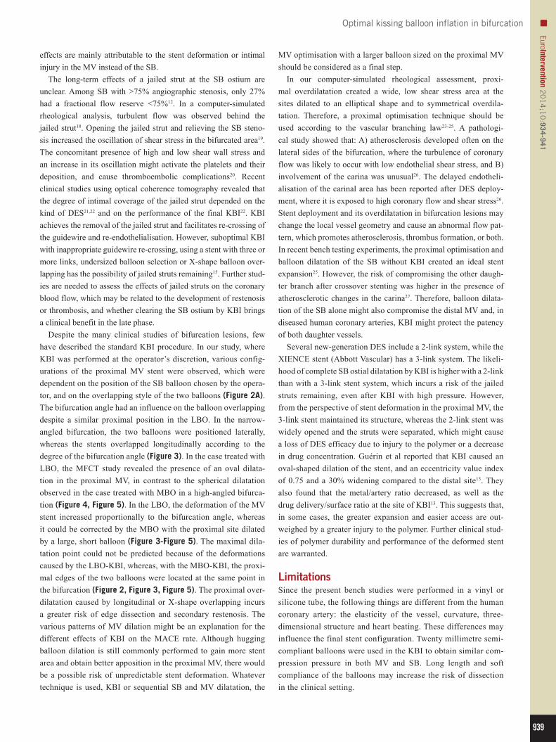
Figure 8. Computer simulations of coronary peak diastolic flow in the LM coronary artery model. A) Whole area analysis. Model A: normal dilatation of the circle with its 4.0 mm diameter in the LM coronary artery. Model B: overdilatation of the circle to a 5.5 mm diameter. Model C: ellipse-longitudinal deformation. Model D: ellipse-tilt deformation. B) Cross-sectional analysis of coronary flow. Note the generation of the low-flow area at the overdilated area in Models B, C, and D.
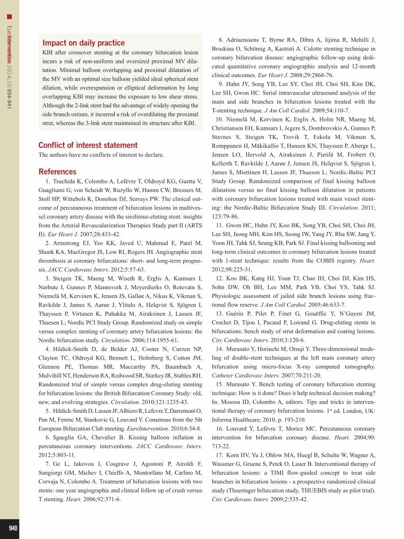
Figure 7. Images of MULTI-LINK ZETA stent with 3-link connection. A) View from the top. B) View from the bottom. C) Magnified view of overdilatation of the proximal struts outlined by the arrows in panels A) and B). D) Magnified view of the LCX ostium, after complete removal of the jailed struts, from the vantage point shown by the dotted arrow in panel A). E) Cross-sectional view from the inner side at the bifurcation. The jailed strut remained on the myocardial side (D, E, arrows).
image 6). At the SB ostium, the jailed struts of the 2-link stent were completely separated (Figure 6D), whereas, in the 3-link stent, the jailed strut remained at the site where the SB balloon crossed over the MV balloon (Figure 7D and Figure 7E).
COMPUTER-BASED MEASUREMENTS OF CORONARY FLOWPEAK DIASTOLIC FLOWIn Model A (Figure 8A, A), the acceleration of the peak diastolic flow was concentrated in the centre of the vessel. This accelerated
flow remained stable in the distal LM coronary artery. Model B was associated with a marked reduction of the flow velocity in the overdilated area. The vascular deformation to a longitudinal ellipse (C) or tilted ellipse (D) also created zones of low flow in the over-dilated side. These kinds of overdilatation slowed the peak flow in the distal LM artery without any change in its position in the centre of the vessel (Figure 8).SYSTOLIC FLOWThe accelerated flow was in the centre of the LM coronary artery as well as the diastolic peak flow. Broad areas of low flow were pre-sent in the overdilated segment in Models B, C, and D.
DiscussionIn case of SB narrowing after MV stenting, KBI, instead of isolated SB dilatation (which may deform the MV), has been recommended to preserve the SB access16. Advancing the guidewire into the distal strut of the SB orifice is important to cover the SB ostium prop-erly15,16. However, the efficacy of KBI using a single stent remains controversial. Recent clinical trials have reported the ineffective-ness or negative effects of KBI. The Nordic-Baltic III trial found that its advantage was limited to a lower rate of SB restenosis (7.6% vs. 20.0%) in true bifurcation lesions10. In the THUEBIS pilot trial, where the SB intervention was randomly assigned to mandatory versus provisional groups, depending on the SB flow deterioration, the MACE rate was similar in both study groups (17.9% vs. 14.8%) despite a higher performance of KBI (73.2% vs. 13.0%)17. In the COBIS trial, KBI was associated with a higher MACE rate (8.7% vs. 4.7%) than treatment without KBI11. It is noteworthy that the rate of TLR of the MV was higher in the KBI (7.0%) than in the non-KBI (3.1%) group, whereas the rate of TLR in the SB was low (2.0% vs. 0.1%) in both groups11. This suggests that the adverse
939
Optimal kissing balloon inflation in bifurcationEuroIntervention 2
01
4;1
0:934-941
effects are mainly attributable to the stent deformation or intimal injury in the MV instead of the SB.
The long-term effects of a jailed strut at the SB ostium are unclear. Among SB with >75% angiographic stenosis, only 27% had a fractional flow reserve <75%12. In a computer-simulated rheological analysis, turbulent flow was observed behind the jailed strut18. Opening the jailed strut and relieving the SB steno-sis increased the oscillation of shear stress in the bifurcated area19. The concomitant presence of high and low shear wall stress and an increase in its oscillation might activate the platelets and their deposition, and cause thromboembolic complications20. Recent clinical studies using optical coherence tomography revealed that the degree of intimal coverage of the jailed strut depended on the kind of DES21,22 and on the performance of the final KBI22. KBI achieves the removal of the jailed strut and facilitates re-crossing of the guidewire and re-endothelialisation. However, suboptimal KBI with inappropriate guidewire re-crossing, using a stent with three or more links, undersized balloon selection or X-shape balloon over-lapping has the possibility of jailed struts remaining15. Further stud-ies are needed to assess the effects of jailed struts on the coronary blood flow, which may be related to the development of restenosis or thrombosis, and whether clearing the SB ostium by KBI brings a clinical benefit in the late phase.
Despite the many clinical studies of bifurcation lesions, few have described the standard KBI procedure. In our study, where KBI was performed at the operator’s discretion, various config-urations of the proximal MV stent were observed, which were dependent on the position of the SB balloon chosen by the opera-tor, and on the overlapping style of the two balloons (Figure 2A). The bifurcation angle had an influence on the balloon overlapping despite a similar proximal position in the LBO. In the narrow-angled bifurcation, the two balloons were positioned laterally, whereas the stents overlapped longitudinally according to the degree of the bifurcation angle (Figure 3). In the case treated with LBO, the MFCT study revealed the presence of an oval dilata-tion in the proximal MV, in contrast to the spherical dilatation observed in the case treated with MBO in a high-angled bifurca-tion (Figure 4, Figure 5). In the LBO, the deformation of the MV stent increased proportionally to the bifurcation angle, whereas it could be corrected by the MBO with the proximal site dilated by a large, short balloon (Figure 3-Figure 5). The maximal dila-tation point could not be predicted because of the deformations caused by the LBO-KBI, whereas, with the MBO-KBI, the proxi-mal edges of the two balloons were located at the same point in the bifurcation (Figure 2, Figure 3, Figure 5). The proximal over-dilatation caused by longitudinal or X-shape overlapping incurs a greater risk of edge dissection and secondary restenosis. The various patterns of MV dilation might be an explanation for the different effects of KBI on the MACE rate. Although hugging balloon dilation is still commonly performed to gain more stent area and obtain better apposition in the proximal MV, there would be a possible risk of unpredictable stent deformation. Whatever technique is used, KBI or sequential SB and MV dilatation, the
MV optimisation with a larger balloon sized on the proximal MV should be considered as a final step.
In our computer-simulated rheological assessment, proxi-mal overdilatation created a wide, low shear stress area at the sites dilated to an elliptical shape and to symmetrical overdila-tation. Therefore, a proximal optimisation technique should be used according to the vascular branching law23-25. A pathologi-cal study showed that: A) atherosclerosis developed often on the lateral sides of the bifurcation, where the turbulence of coronary flow was likely to occur with low endothelial shear stress, and B) involvement of the carina was unusual26. The delayed endotheli-alisation of the carinal area has been reported after DES deploy-ment, where it is exposed to high coronary flow and shear stress26. Stent deployment and its overdilatation in bifurcation lesions may change the local vessel geometry and cause an abnormal flow pat-tern, which promotes atherosclerosis, thrombus formation, or both. In recent bench testing experiments, the proximal optimisation and balloon dilatation of the SB without KBI created an ideal stent expansion25. However, the risk of compromising the other daugh-ter branch after crossover stenting was higher in the presence of atherosclerotic changes in the carina27. Therefore, balloon dilata-tion of the SB alone might also compromise the distal MV and, in diseased human coronary arteries, KBI might protect the patency of both daughter vessels.
Several new-generation DES include a 2-link system, while the XIENCE stent (Abbott Vascular) has a 3-link system. The likeli-hood of complete SB ostial dilatation by KBI is higher with a 2-link than with a 3-link stent system, which incurs a risk of the jailed struts remaining, even after KBI with high pressure. However, from the perspective of stent deformation in the proximal MV, the 3-link stent maintained its structure, whereas the 2-link stent was widely opened and the struts were separated, which might cause a loss of DES efficacy due to injury to the polymer or a decrease in drug concentration. Guérin et al reported that KBI caused an oval-shaped dilation of the stent, and an eccentricity value index of 0.75 and a 30% widening compared to the distal site13. They also found that the metal/artery ratio decreased, as well as the drug delivery/surface ratio at the site of KBI13. This suggests that, in some cases, the greater expansion and easier access are out-weighed by a greater injury to the polymer. Further clinical stud-ies of polymer durability and performance of the deformed stent are warranted.
LimitationsSince the present bench studies were performed in a vinyl or silicone tube, the following things are different from the human coronary artery: the elasticity of the vessel, curvature, three-dimensional structure and heart beating. These differences may influence the final stent configuration. Twenty millimetre semi-compliant balloons were used in the KBI to obtain similar com-pression pressure in both MV and SB. Long length and soft compliance of the balloons may increase the risk of dissection in the clinical setting.
940
EuroIntervention 20
14
;10
:934-941
Impact on daily practiceKBI after crossover stenting at the coronary bifurcation lesion incurs a risk of non-uniform and oversized proximal MV dila-tation. Minimal balloon overlapping and proximal dilatation of the MV with an optimal size balloon yielded ideal spherical stent dilation, while overexpansion or elliptical deformation by long overlapping KBI may increase the exposure to low shear stress. Although the 2-link stent had the advantage of widely opening the side branch ostium, it incurred a risk of overdilating the proximal strut, whereas the 3-link stent maintained its structure after KBI.
Conflict of interest statementThe authors have no conflicts of interest to declare.
References 1. Tsuchida K, Colombo A, Lefèvre T, Oldroyd KG, Guetta V, Guagliumi G, von Scheidt W, Ruzyllo W, Hamm CW, Bressers M, Stoll HP, Wittebols K, Donohoe DJ, Serruys PW. The clinical out-come of percutaneous treatment of bifurcation lesions in multives-sel coronary artery disease with the sirolimus-eluting stent: insights from the Arterial Revascularization Therapies Study part II (ARTS II). Eur Heart J. 2007;28:433-42. 2. Armstrong EJ, Yeo KK, Javed U, Mahmud E, Patel M, Shunk KA, MacGregor JS, Low RI, Rogers JH. Angiographic stent thrombosis at coronary bifurcations: short- and long-term progno-sis. JACC Cardiovasc Interv. 2012;5:57-63. 3. Steigen TK, Maeng M, Wiseth R, Erglis A, Kumsars I, Narbute I, Gunnes P, Mannsverk J, Meyerdierks O, Rotevatn S, Niemelä M, Kervinen K, Jensen JS, Galløe A, Nikus K, Vikman S, Ravkilde J, James S, Aarøe J, Ylitalo A, Helqvist S, Sjögren I, Thayssen P, Virtanen K, Puhakka M, Airaksinen J, Lassen JF, Thuesen L; Nordic PCI Study Group. Randomized study on simple versus complex stenting of coronary artery bifurcation lesions: the Nordic bifurcation study. Circulation. 2006;114:1955-61. 4. Hildick-Smith D, de Belder AJ, Cooter N, Curzen NP, Clayton TC, Oldroyd KG, Bennett L, Holmberg S, Cotton JM, Glennon PE, Thomas MR, Maccarthy PA, Baumbach A, Mulvihill NT, Henderson RA, Redwood SR, Starkey IR, Stables RH. Randomized trial of simple versus complex drug-eluting stenting for bifurcation lesions: the British Bifurcation Coronary Study: old, new, and evolving strategies. Circulation. 2010;121:1235-43. 5. Hildick-Smith D, Lassen JF, Albiero R, Lefevre T, Darremont O, Pan M, Ferenc M, Stankovic G, Louvard Y. Consensus from the 5th European Bifurcation Club meeting. EuroIntervention. 2010;6:34-8. 6. Sgueglia GA, Chevalier B. Kissing balloon inflation in percutaneous coronary interventions. JACC Cardiovasc Interv. 2012;5:803-11. 7. Ge L, Iakovou I, Cosgrave J, Agostoni P, Airoldi F, Sangiorgi GM, Michev I, Chieffo A, Montorfano M, Carlino M, Corvaja N, Colombo A. Treatment of bifurcation lesions with two stents: one year angiographic and clinical follow up of crush versus T stenting. Heart. 2006;92:371-6.
8. Adriaenssens T, Byrne RA, Dibra A, Iijima R, Mehilli J, Bruskina O, Schömig A, Kastrati A. Culotte stenting technique in coronary bifurcation disease: angiographic follow-up using dedi-cated quantitative coronary angiographic analysis and 12-month clinical outcomes. Eur Heart J. 2008;29:2868-76. 9. Hahn JY, Song YB, Lee SY, Choi JH, Choi SH, Kim DK, Lee SH, Gwon HC. Serial intravascular ultrasound analysis of the main and side branches in bifurcation lesions treated with the T-stenting technique. J Am Coll Cardiol. 2009;54:110-7. 10. Niemelä M, Kervinen K, Erglis A, Holm NR, Maeng M, Christiansen EH, Kumsars I, Jegere S, Dombrovskis A, Gunnes P, Stavnes S, Steigen TK, Trovik T, Eskola M, Vikman S, Romppanen H, Mäkikallio T, Hansen KN, Thayssen P, Aberge L, Jensen LO, Hervold A, Airaksinen J, Pietilä M, Frobert O, Kellerth T, Ravkilde J, Aarøe J, Jensen JS, Helqvist S, Sjögren I, James S, Miettinen H, Lassen JF, Thuesen L; Nordic-Baltic PCI Study Group. Randomized comparison of final kissing balloon dilatation versus no final kissing balloon dilatation in patients with coronary bifurcation lesions treated with main vessel stent-ing: the Nordic-Baltic Bifurcation Study III. Circulation. 2011; 123:79-86. 11. Gwon HC, Hahn JY, Koo BK, Song YB, Choi SH, Choi JH, Lee SH, Jeong MH, Kim HS, Seong IW, Yang JY, Rha SW, Jang Y, Yoon JH, Tahk SJ, Seung KB, Park SJ. Final kissing ballooning and long-term clinical outcomes in coronary bifurcation lesions treated with 1-stent technique: results from the COBIS registry. Heart. 2012;98:225-31. 12. Koo BK, Kang HJ, Youn TJ, Chae IH, Choi DJ, Kim HS, Sohn DW, Oh BH, Lee MM, Park YB, Choi YS, Tahk SJ. Physiologic assessment of jailed side branch lesions using frac-tional flow reserve. J Am Coll Cardiol. 2005;46:633-7. 13. Guérin P, Pilet P, Finet G, Gouëffic Y, N’Guyen JM, Crochet D, Tijou I, Pacaud P, Loirand G. Drug-eluting stents in bifurcations: bench study of strut deformation and coating lesions. Circ Cardiovasc Interv. 2010;3:120-6. 14. Murasato Y, Horiuchi M, Otsuji Y. Three-dimensional mode-ling of double-stent techniques at the left main coronary artery bifurcation using micro-focus X-ray computed tomography. Catheter Cardiovasc Interv. 2007;70:211-20. 15. Murasato Y. Bench testing of coronary bifurcation stenting technique: How is it done? Does it help technical decision making? In: Moussa ID, Colombo A, editors. Tips and tricks in interven-tional therapy of coronary bifurcation lesions. 1st ed. London, UK: Informa Healthcare; 2010. p. 193-210. 16. Louvard Y, Lefèvre T, Morice MC. Percutaneous coronary intervention for bifurcation coronary disease. Heart. 2004;90: 713-22. 17. Korn HV, Yu J, Ohlow MA, Huegl B, Schulte W, Wagner A, Wassmer G, Gruene S, Petek O, Lauer B. Interventional therapy of bifurcation lesions: a TIMI flow-guided concept to treat side branches in bifurcation lesions - a prospective randomized clinical study (Thueringer bifurcation study, THUEBIS study as pilot trial). Circ Cardiovasc Interv. 2009;2:535-42.
941
Optimal kissing balloon inflation in bifurcationEuroIntervention 2
01
4;1
0:934-941
18. Deplano V, Bertolotti C, Barragan P. Three-dimensional numerical simulations of physiological flows in a stented coronary bifurcation. Med Biol Eng Comput. 2004;42:650-9. 19. Katritsis DG, Theodorakakos A, Pantos I, Gavaises M, Karcanias N, Efstathopoulos EP. Flow patterns at stented coronary bifurcations: computational fluid dynamics analysis. Circ Cardiovasc Interv. 2012;5:530-9. 20. Nesbitt WS, Mangin P, Salem HH, Jackson SP. The impact of blood rheology on the molecular and cellular events underlying arterial thrombosis. J Mol Med (Berl). 2006;84:989-95. 21. Kyono H, Guagliumi G, Sirbu V, Rosenthal N, Tahara S, Musumeci G, Trivisonno A, Bezerra HG, Costa MA. Optical coher-ence tomography (OCT) strut-level analysis of drug-eluting stents (DES) in human coronary bifurcations. EuroIntervention. 2010;6:69-77. 22. Hariki H, Shinke T, Otake H, Shite J, Nakagawa M, Inoue T, Osue T, Iwasaki M, Taniguchi Y, Nishio R, Hiranuma N, Kinutani H, Konishi A, Hirata KI. Potential benefit of final-kissing inflation after single stenting for the treatment of bifurcation lesions: insight from OCT observations. Circ J. 2013;77:1193-201. 23. Lefèvre T, Darremont O, Albiero R. Provisional side branch stenting for the treatment of bifurcation lesions. EuroIntervention. 2010;6:J65-71. 24. Mortier P, De Beule M, Dubini G, Hikichi Y, Murasato Y, Ormiston JA. Coronary bifurcation stenting: insights from in vitro and virtual bench testing. EuroIntervention. 2010;6:J53-60.
25. Foin N, Torii R, Mortier P, De Beule M, Viceconte N, Chan PH, Davies JE, Xu XY, Krams R, Di Mario C. Kissing balloon or sequen-tial dilation of the side branch and main vessel for provisional stent-ing of bifurcations: lessons from micro-computed tomography and computational simulations. JACC Cardiovasc Interv. 2012;5: 47-56. 26. Nakazawa G, Yazdani SK, Finn AV, Vorpahl M, Kolodgie FD, Virmani R. Pathological findings at bifurcation lesions: the impact of flow distribution on atherosclerosis and arterial healing after stent implantation. J Am Coll Cardiol. 2010;55:1679-87. 27. Goto Y, Kawasaki T, Koga N, Tanaka H, Koga H, Orita Y, Ikeda S, Shintani Y, Kajiwara M, Fukuyama T. Plaque distribution patterns in left main trunk bifurcations: prediction of branch vessel compromise by multidetector row computed topography after percu-taneous coronary intervention. EuroIntervention. 2012;8:708-16.
Online data supplementMoving image 1. MFCT movie of the stent after MBO-KBI with 60-degree bifurcation angle.Moving image 2. MFCT movie of the stent after LBO-KBI with 60-degree bifurcation angle.Moving image 3. Axial view of the stent after MBO-KBI.Moving image 4. Axial view of the stent after LBO-KBI.Moving image 5. MFCT movie of Endeavor stent with 2-link con-nection deployed in a 3-dimensional Y-shaped model.Moving image 6. MFCT movie of MULTI-LINK ZETA stent with 3-link connection.
Related Documents