1 Optimal Design of Jacket Supporting Structures for Offshore Wind Turbines Optimal Design of Jacket Supporting Structures for Offshore Wind Turbines Using CBO and ECBO Algorithms Ali Kaveh 1* , Sepehr Sabeti 2 Received 28 October 2017; Revised 06 November 2017; Accepted 13 November 2017 1 Centre of Excellence for Fundamental Studies in Structural Engineering, School of Civil Engineering, Iran University of Science and Technology, Narmak, Tehran-16, Iran 2 School of Civil Engineering, Iran University of Science and Technology, Narmak, Tehran-16, Iran * Corresponding author, email: [email protected] OnlineFirst (2017) paper 11651 https://doi.org/10.3311/PPci.11651 Creative Commons Attribution b research article P P Periodica Polytechnica Civil Engineering Abstract Structural optimization of offshore wind turbines is a tedi- ous task due to the complexity of the problem. However, in this article, this problem is tackled using two meta-heuristic algorithms - Colliding Bodies Optimization (CBO) and its enhanced version (ECBO) - for a jacket supporting structure. The OC4 reference jacket is chosen as a case study to validate the methods utilized in this research. The jacket supporting structure is modeled in MATLAB and its optimal design is per- formed while both Ultimate Limit State (ULS) and frequency constraints are considered. In the present study, it is presumed that both wind and wave phenomena act in the same horizon- tal direction. As a result, all resultant forces and moments will act in-plane and the substructure can therefore be modeled in 2D space. Considerable weight reduction is obtained during the optimization process while fulfilling all constraints. Keywords offshore wind turbines, jacket supporting structures, Col- liding Bodies Optimization, structural design optimization, meta-heuristic algorithm 1 Introduction The population of the world has been outstandingly increas- ing, which means that reliance on fossil fuel resources may be further exacerbating some of the prominent environmental issues such as global warming. Renewable energies, more spe- cifically wind energy, are surmised as one of the best substi- tutes for fossil fuels in generating electricity; hence, offshore wind energy has been recipient of many attentions in recent years [1]. Offshore regions abound with numerous appropriate spots in which wind farms can be hosted. Aside from acces- sibility to higher wind velocity, offshore wind farms may omit both noise and visual pollutions, by which onshore wind farms deficiencies have been always pointed out. In addition, although substantial land occupancy of onshore wind farms has been a noticeable barrier in engrossing new investments, this is no longer a problem in offshore wind industry. The aforementioned advantage of offshore wind farms has resulted in a noteworthy reduction in required capitals, which has cre- ated new perspectives in this industry [1]. Bottom-fixed and floating substructures are currently the dominating structural systems in offshore wind industry. Monopiles, which belong to the former category, are the domi- neering structural system. Simplicity in both manufacturing and design processes may justify their popularity [2]. When moving to deeper offshore areas striving to reach higher wind potentials, these substructures are no longer applicable due to the harsher environment of such regions. In these occasions, frame substructures such as jackets are presumed to be more effectual. Not only are these structural systems able to stand harsher environments, but they also are capable of bearing the weight of larger wind turbines; thus, frame substructures are currently playing a more prominent role in offshore wind indus- try than previous years [2]. Tripod and jacket substructures are usually recognized as the best options in offshore wind indus- try. These structures have been extensively utilized in oil and gas industry; consequently, this acquaintance has resulted in a great enhancement when designing offshore wind turbines [2]. As size and dimension of structures expand, structural optimization becomes more crucial. Especially for large

Welcome message from author
This document is posted to help you gain knowledge. Please leave a comment to let me know what you think about it! Share it to your friends and learn new things together.
Transcript

1Optimal Design of Jacket Supporting Structures for Offshore Wind Turbines
Optimal Design of Jacket Supporting Structures for Offshore Wind Turbines Using CBO and ECBO Algorithms
Ali Kaveh1*, Sepehr Sabeti2
Received 28 October 2017; Revised 06 November 2017; Accepted 13 November 2017
1 Centre of Excellence for Fundamental Studies in Structural Engineering, School of Civil Engineering, Iran University of Science and Technology, Narmak, Tehran-16, Iran
2 School of Civil Engineering, Iran University of Science and Technology, Narmak, Tehran-16, Iran
* Corresponding author, e mail: [email protected]
OnlineFirst (2017) paper 11651https://doi.org/10.3311/PPci.11651
Creative Commons Attribution b
research article
PPPeriodica PolytechnicaCivil Engineering
Abstract Structural optimization of offshore wind turbines is a tedi-ous task due to the complexity of the problem. However, in this article, this problem is tackled using two meta-heuristic algorithms - Colliding Bodies Optimization (CBO) and its enhanced version (ECBO) - for a jacket supporting structure. The OC4 reference jacket is chosen as a case study to validate the methods utilized in this research. The jacket supporting structure is modeled in MATLAB and its optimal design is per-formed while both Ultimate Limit State (ULS) and frequency constraints are considered. In the present study, it is presumed that both wind and wave phenomena act in the same horizon-tal direction. As a result, all resultant forces and moments will act in-plane and the substructure can therefore be modeled in 2D space. Considerable weight reduction is obtained during the optimization process while fulfilling all constraints.
Keywords offshore wind turbines, jacket supporting structures, Col-liding Bodies Optimization, structural design optimization, meta-heuristic algorithm
1 IntroductionThe population of the world has been outstandingly increas-
ing, which means that reliance on fossil fuel resources may be further exacerbating some of the prominent environmental issues such as global warming. Renewable energies, more spe-cifically wind energy, are surmised as one of the best substi-tutes for fossil fuels in generating electricity; hence, offshore wind energy has been recipient of many attentions in recent years [1]. Offshore regions abound with numerous appropriate spots in which wind farms can be hosted. Aside from acces-sibility to higher wind velocity, offshore wind farms may omit both noise and visual pollutions, by which onshore wind farms deficiencies have been always pointed out. In addition, although substantial land occupancy of onshore wind farms has been a noticeable barrier in engrossing new investments, this is no longer a problem in offshore wind industry. The aforementioned advantage of offshore wind farms has resulted in a noteworthy reduction in required capitals, which has cre-ated new perspectives in this industry [1].
Bottom-fixed and floating substructures are currently the dominating structural systems in offshore wind industry. Monopiles, which belong to the former category, are the domi-neering structural system. Simplicity in both manufacturing and design processes may justify their popularity [2]. When moving to deeper offshore areas striving to reach higher wind potentials, these substructures are no longer applicable due to the harsher environment of such regions. In these occasions, frame substructures such as jackets are presumed to be more effectual. Not only are these structural systems able to stand harsher environments, but they also are capable of bearing the weight of larger wind turbines; thus, frame substructures are currently playing a more prominent role in offshore wind indus-try than previous years [2]. Tripod and jacket substructures are usually recognized as the best options in offshore wind indus-try. These structures have been extensively utilized in oil and gas industry; consequently, this acquaintance has resulted in a great enhancement when designing offshore wind turbines [2].
As size and dimension of structures expand, structural optimization becomes more crucial. Especially for large
2 Period. Polytech. Civil Eng. A. Kaveh, S. Sabeti
structures, such as offshore wind turbines, design optimiza-tion is considered as an indispensable task. This task has been pursued by several researchers. To name a few, following arti-cles can be mentioned:
Uys et al. explored the optimal design of an onshore mono-pile turbine under a number of buckling constraints using a zeroth order search algorithm [3]. Chen and Yang et al. adopt the Particle Swarm Optimization (PSO) algorithm to optimize both shape and size of the lattice partition in a wind turbine tower with lattice-tubular hybrid substructure [4]. Genetic Algorithm (GA) was employed by Thiry et al. to explore the optimal design of an offshore monopile wind turbine when considering Fatigue Limit State (FLS), Ultimate Limit State (ULS) and frequency constraints [5]. Long et al. investigated characteristics of tripod and jacket substructures for offshore wind turbines under ULS conditions [6]. Their results are fur-ther expanded considering FLS conditions complying with design standards by Long and Moe [7]. Zwick et al. then pre-sented a new concept in offshore wind industry known as full-height lattice offshore wind turbine. Its optimal design under both FLS and ULS constraints were then investigated using an iterative optimization approach [8]. Zwick and Muskulus pre-sented a method for simplified fatigue load assessments based on statistical regression models [9]. In addition, Chew et al. utilized Sequential Quadratic Programming (SQP) optimizer for performing the optimal design of the OC4 reference jacket with both ULS, FLS and frequency constraints being consid-ered [10]. Oest et al. investigated the optimal design of jacket substructures for large offshore wind turbines using analyti-cal gradients and a Sequential Linear Programming optimizer while FLS, ULS and frequency constraints were taken into consideration [11].
Nevertheless, this research utilizes two efficient meta-heu-ristic algorithms for the investigation of the optimal design of jacket supporting structures. In fact, many such algorithms have recently been established mimicking natural phenomena, sharing simplicity in implementation and less time-consump-tion as their distinct advantages [12], and have been applied in solving various engineering problems [13–16]. Colliding Bod-ies Optimization (CBO) and its enhanced version (ECBO) are the utilized algorithms in this study. Colliding Bodies Optimi-zation is a population-based meta-heuristic algorithm, which attempts to mimic governing laws in collision between bodies [17]. The main features of the aforementioned algorithm are parameter independency and its simple formulation. Enhanced Colliding Bodies Optimization (ECBO), developed by Kaveh and Ilchi-Ghazaan, utilizes a memory in order to enhance the CBO performance by saving some historically best solutions, which results in better performance in escaping from local minima without any increase in the computational cost [18].
Perceivably, this research attempts to utilize the aforemen-tioned meta-heuristic algorithms in structural optimization
of a jacket supporting structure for an offshore wind turbine. To do so, firstly the structure is modeled using Finite Element Method in MATLAB. The mentioned algorithms are then utilized attempting to select the lightest structural members while all structural constraints, including both Ultimate Limit State and frequency constraints, are fully satisfied. Afterward, the efficiency of the proposed algorithms are demonstrated employing a case study. The OC4 reference jacket (Offshore Code Comparison Collaboration Continuation) is the design example in this research, which bears the weight of a NREL 5-MW reference wind turbine.
For the sake of simplicity, it is assumed that wave and wind effects are in the same plane, which gives the advantage of modeling and analyzing the entire structure in 2D space (Fig. 1) [19]. After analyzing, designing and optimizing the design example in 2D space, results are expanded to 3D space, where the three dimensional real structure is re-created based on the obtained results, and the weight of the optimized structure is determined, indicating an outstanding weight reduction while fulfilling all constraints. Considering the aforementioned facts, outcomes of this research would be fruitful in pre-liminary stages of designing such structures and conducting appropriate comparisons.
Fig. 1 In-plane winds and waves actions [19]
2 Configuration of the OC4 Reference Jacket As mentioned, seeking higher wind velocity in offshore
regions has led us toward utilizing frame substructures, by which larger wind turbines can be placed in harsher environ-ments of such regions; thus, this research is conducted in order to explore the optimal design of jacket supporting structures. Note that only the optimal design of this part of the offshore wind turbine structure is investigated in this study.
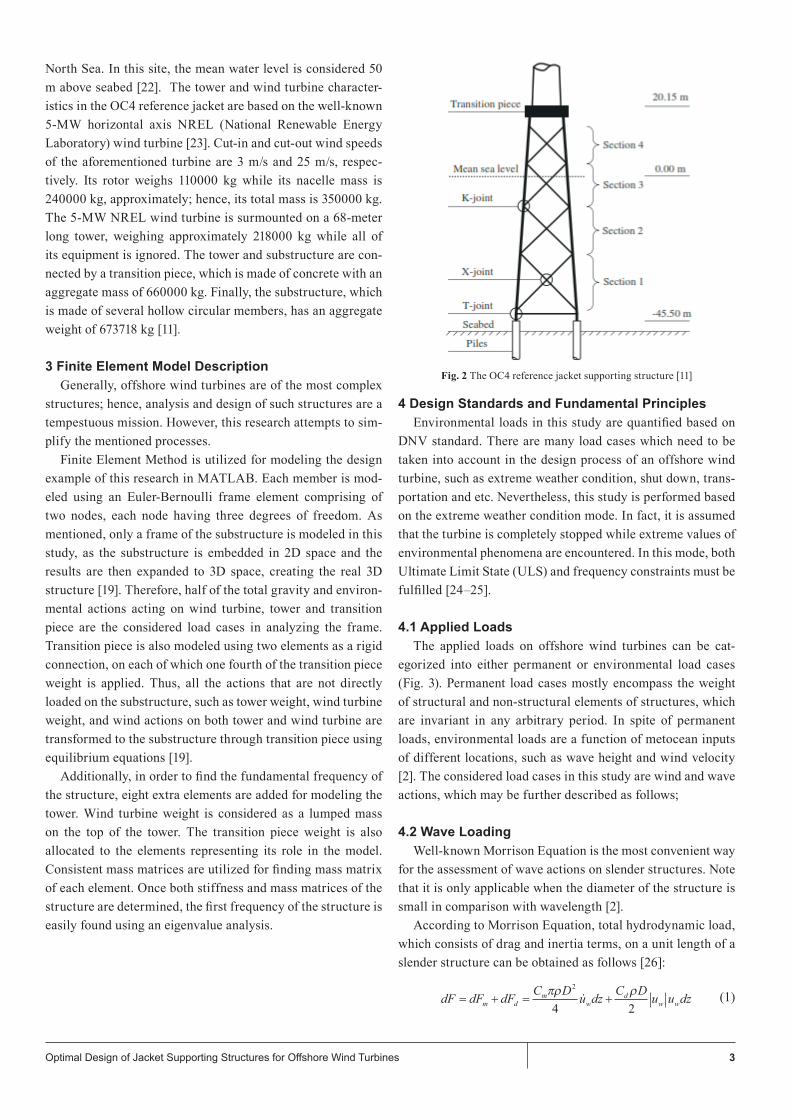
This research is performed based on the OC4 reference jacket characteristics (Fig. 2) [20–21]. This offshore wind tur-bine is presumed to be located at K13 deep-water site in the
3Optimal Design of Jacket Supporting Structures for Offshore Wind Turbines
North Sea. In this site, the mean water level is considered 50 m above seabed [22]. The tower and wind turbine character-istics in the OC4 reference jacket are based on the well-known 5-MW horizontal axis NREL (National Renewable Energy Laboratory) wind turbine [23]. Cut-in and cut-out wind speeds of the aforementioned turbine are 3 m/s and 25 m/s, respec-tively. Its rotor weighs 110000 kg while its nacelle mass is 240000 kg, approximately; hence, its total mass is 350000 kg. The 5-MW NREL wind turbine is surmounted on a 68-meter long tower, weighing approximately 218000 kg while all of its equipment is ignored. The tower and substructure are con-nected by a transition piece, which is made of concrete with an aggregate mass of 660000 kg. Finally, the substructure, which is made of several hollow circular members, has an aggregate weight of 673718 kg [11].
3 Finite Element Model Description Generally, offshore wind turbines are of the most complex
structures; hence, analysis and design of such structures are a tempestuous mission. However, this research attempts to sim-plify the mentioned processes.
Finite Element Method is utilized for modeling the design example of this research in MATLAB. Each member is mod-eled using an Euler-Bernoulli frame element comprising of two nodes, each node having three degrees of freedom. As mentioned, only a frame of the substructure is modeled in this study, as the substructure is embedded in 2D space and the results are then expanded to 3D space, creating the real 3D structure [19]. Therefore, half of the total gravity and environ-mental actions acting on wind turbine, tower and transition piece are the considered load cases in analyzing the frame. Transition piece is also modeled using two elements as a rigid connection, on each of which one fourth of the transition piece weight is applied. Thus, all the actions that are not directly loaded on the substructure, such as tower weight, wind turbine weight, and wind actions on both tower and wind turbine are transformed to the substructure through transition piece using equilibrium equations [19].
Additionally, in order to find the fundamental frequency of the structure, eight extra elements are added for modeling the tower. Wind turbine weight is considered as a lumped mass on the top of the tower. The transition piece weight is also allocated to the elements representing its role in the model. Consistent mass matrices are utilized for finding mass matrix of each element. Once both stiffness and mass matrices of the structure are determined, the first frequency of the structure is easily found using an eigenvalue analysis.
Fig. 2 The OC4 reference jacket supporting structure [11]
4 Design Standards and Fundamental Principles Environmental loads in this study are quantified based on
DNV standard. There are many load cases which need to be taken into account in the design process of an offshore wind turbine, such as extreme weather condition, shut down, trans-portation and etc. Nevertheless, this study is performed based on the extreme weather condition mode. In fact, it is assumed that the turbine is completely stopped while extreme values of environmental phenomena are encountered. In this mode, both Ultimate Limit State (ULS) and frequency constraints must be fulfilled [24–25].
4.1 Applied Loads
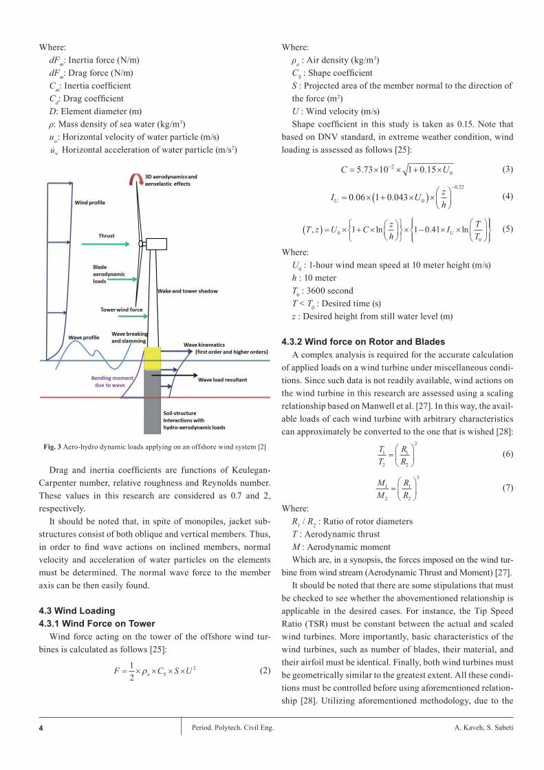
The applied loads on offshore wind turbines can be cat-egorized into either permanent or environmental load cases (Fig. 3). Permanent load cases mostly encompass the weight of structural and non-structural elements of structures, which are invariant in any arbitrary period. In spite of permanent loads, environmental loads are a function of metocean inputs of different locations, such as wave height and wind velocity [2]. The considered load cases in this study are wind and wave actions, which may be further described as follows;
4.2 Wave Loading
Well-known Morrison Equation is the most convenient way for the assessment of wave actions on slender structures. Note that it is only applicable when the diameter of the structure is small in comparison with wavelength [2].
According to Morrison Equation, total hydrodynamic load, which consists of drag and inertia terms, on a unit length of a slender structure can be obtained as follows [26]:
dF dF dF C D u dz C D u u dzm dm
wd
w w= + = +πρ ρ2
4 2
(1)
4 Period. Polytech. Civil Eng. A. Kaveh, S. Sabeti
Where:dFm: Inertia force (N/m)dFm: Drag force (N/m)Cm: Inertia coefficientCd: Drag coefficientD: Element diameter (m)ρ: Mass density of sea water (kg/m3)uw: Horizontal velocity of water particle (m/s)uw Horizontal acceleration of water particle (m/s2)
Fig. 3 Aero-hydro dynamic loads applying on an offshore wind system [2]
Drag and inertia coefficients are functions of Keulegan-Carpenter number, relative roughness and Reynolds number. These values in this research are considered as 0.7 and 2, respectively.
It should be noted that, in spite of monopiles, jacket sub-structures consist of both oblique and vertical members. Thus, in order to find wave actions on inclined members, normal velocity and acceleration of water particles on the elements must be determined. The normal wave force to the member axis can be then easily found.
4.3 Wind Loading 4.3.1 Wind Force on Tower
Wind force acting on the tower of the offshore wind tur-bines is calculated as follows [25]:
Where: ρa : Air density (kg/m3)CS : Shape coefficient S : Projected area of the member normal to the direction ofthe force (m2)U : Wind velocity (m/s)Shape coefficient in this study is taken as 0.15. Note that
based on DNV standard, in extreme weather condition, wind loading is assessed as follows [25]:
Where: U0 : 1-hour wind mean speed at 10 meter height (m/s)h : 10 meterT0 : 3600 second T < T0 : Desired time (s)z : Desired height from still water level (m)
4.3.2 Wind force on Rotor and Blades A complex analysis is required for the accurate calculation
of applied loads on a wind turbine under miscellaneous condi-tions. Since such data is not readily available, wind actions on the wind turbine in this research are assessed using a scaling relationship based on Manwell et al. [27]. In this way, the avail-able loads of each wind turbine with arbitrary characteristics can approximately be converted to the one that is wished [28]:
Where: R1 / R2 : Ratio of rotor diameters T : Aerodynamic thrust M : Aerodynamic moment Which are, in a synopsis, the forces imposed on the wind tur-
bine from wind stream (Aerodynamic Thrust and Moment) [27].It should be noted that there are some stipulations that must
be checked to see whether the abovementioned relationship is applicable in the desired cases. For instance, the Tip Speed Ratio (TSR) must be constant between the actual and scaled wind turbines. More importantly, basic characteristics of the wind turbines, such as number of blades, their material, and their airfoil must be identical. Finally, both wind turbines must be geometrically similar to the greatest extent. All these condi-tions must be controlled before using aforementioned relation-ship [28]. Utilizing aforementioned methodology, due to the
F C S Ua S= × × × ×1
2
2ρ
C U= × × + ×−5 73 10 1 0 15
2
0. .
I U zhU = × + ×( )×
−
0 06 1 0 0430
0 22
. .
.
T z U C zh
I TTU, ln . ln( ) = × + ×
× − × ×
0
0
1 1 0 41
TT
RR
1
2
1
2
2
=
MM
RR
1
2
1
2
3
=
(2)
(3)
(4)
(5)
(6)
(7)
5Optimal Design of Jacket Supporting Structures for Offshore Wind Turbines
lack of information, however, aerodynamic thrust and moment of the 5-MW NREL wind turbine can be approximately deter-mined according to what is presented in Leite [29], which are the foundations of further calculations.
4.4 Load CombinationsFollowing load combinations must be considered for evalu-
ating Ultimate Limit State constraints in offshore wind tur-bines based on DNV 2014 [25]:
First load combination: dead load (containing self-weight of the whole structure including tower, substructure together with the weight of wind turbine multiplied by a coefficient equal to 1.25) + wind load (consisting of imposed wind load on tower, substructure and turbine multiplied by a coefficient equal to 0.7) + wave load (multiplied by a coefficient equal to 0.7).
Second load combination: dead load (containing self-weight of the whole structure including tower, substructure together with the weight of wind turbine multiplied by a coefficient equal to 1) + wind load (consisting of imposed wind load on tower, substructure and turbine multiplied by a coefficient equal to 1.35) + wave load (multiplied by a coefficient equal to 1.35).
5 The Structural Optimization ProblemA typical structural optimization problem can be stated as
follows [12]:
In the abovementioned formulas, X is the vector of design variables with n unknowns, and gi is the ith constraint from m inequality constraints. Constraint violations in this study are handled using well-known penalty approach. In this methodol-ogy, Mer(X) is the merit function, f(x) is the cost function, and fpenalty(X) takes constraint violations into account. Following penalty function is used for changing a constrained problem into an unconstrained one in this research:
ε1 and ε2 in the abovementioned penalty function are cho-sen in a way that a suitable balance dominates exploration and exploitation rates within search space in the algorithms, which are taken one and 3 in the present study, respectively.
5.1 Design VariablesIn this study, both diameter and thickness of each member
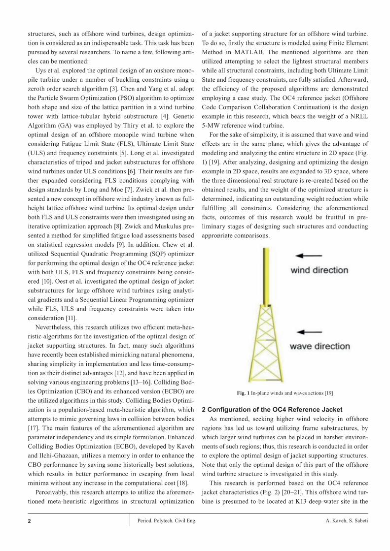
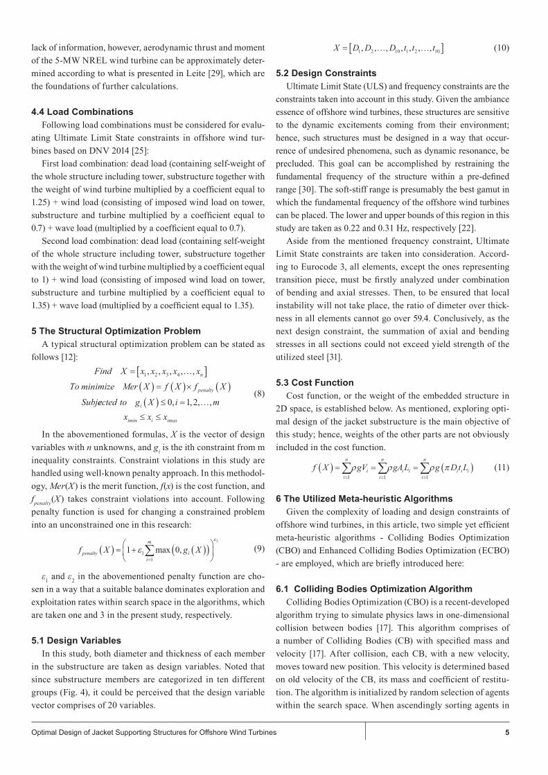
in the substructure are taken as design variables. Noted that since substructure members are categorized in ten different groups (Fig. 4), it could be perceived that the design variable vector comprises of 20 variables.
5.2 Design ConstraintsUltimate Limit State (ULS) and frequency constraints are the
constraints taken into account in this study. Given the ambiance essence of offshore wind turbines, these structures are sensitive to the dynamic excitements coming from their environment; hence, such structures must be designed in a way that occur-rence of undesired phenomena, such as dynamic resonance, be precluded. This goal can be accomplished by restraining the fundamental frequency of the structure within a pre-defined range [30]. The soft-stiff range is presumably the best gamut in which the fundamental frequency of the offshore wind turbines can be placed. The lower and upper bounds of this region in this study are taken as 0.22 and 0.31 Hz, respectively [22].
Aside from the mentioned frequency constraint, Ultimate Limit State constraints are taken into consideration. Accord-ing to Eurocode 3, all elements, except the ones representing transition piece, must be firstly analyzed under combination of bending and axial stresses. Then, to be ensured that local instability will not take place, the ratio of dimeter over thick-ness in all elements cannot go over 59.4. Conclusively, as the next design constraint, the summation of axial and bending stresses in all sections could not exceed yield strength of the utilized steel [31].
5.3 Cost Function
Cost function, or the weight of the embedded structure in 2D space, is established below. As mentioned, exploring opti-mal design of the jacket substructure is the main objective of this study; hence, weights of the other parts are not obviously included in the cost function.
6 The Utilized Meta-heuristic AlgorithmsGiven the complexity of loading and design constraints of
offshore wind turbines, in this article, two simple yet efficient meta-heuristic algorithms - Colliding Bodies Optimization (CBO) and Enhanced Colliding Bodies Optimization (ECBO) - are employed, which are briefly introduced here:
6.1 Colliding Bodies Optimization AlgorithmColliding Bodies Optimization (CBO) is a recent-developed
algorithm trying to simulate physics laws in one-dimensional collision between bodies [17]. This algorithm comprises of a number of Colliding Bodies (CB) with specified mass and velocity [17]. After collision, each CB, with a new velocity, moves toward new position. This velocity is determined based on old velocity of the CB, its mass and coefficient of restitu-tion. The algorithm is initialized by random selection of agents within the search space. When ascendingly sorting agents in
Find X x x x x x
To mize Mer X f X f X
Subj
n
penalty
= …[ ]( ) = ( )× ( )1 2 3 4, , , , ,
i
eected to g X i mx x x
i
imin i imax
( ) ≤ = …
≤ ≤
0 1 2, , , ,
min
f X g Xpenaltyi
m
i( ) = + ( )( )
=∑1 01
1
2
εε
max ,
X D D D t t t= … …[ ]1 2 10 1 2 10, , , , , , ,
f X gV gAL g D t Li
n
ii
n
i ii
n
i i i( ) = = = ( )= = =∑ ∑ ∑
1 1 1
ρ ρ ρ π
(8)
(9)
(10)
(11)
6 Period. Polytech. Civil Eng. A. Kaveh, S. Sabeti
accordance with the values of cost function, CBs are broken into two equal categories named stationary and moving cat-egories [17]. The velocity of good agents is considered equal to zero. The members of moving category then move toward stationary ones in a way that the better and worse CBs collide together. The mentioned process results in enhancing mov-ing CBs positions simultaneously with forcing stationary CBs toward better locations. Velocity of the CBs before collision is considered as the value of change in the body position [17].
Then, momentum and energy conservation laws are utilized for assessing the velocity of each body after collision [17]:
In the abovementioned formulas, vi and v'i are the velocities of the ith CB before and after collision, respectively. The mass of each CB can be obtained using following equation [17]:
In the abovementioned formula, fit(i) is in fact the value of objective function for the ith agent. It can be inferred that larger and lighter masses are carried by better and worse CBs, respectively. Coefficient of restitution (ε) is defined as the ratio of separation velocity of two agents after collision over approach velocity of two agents before collision. This number is employed attempting to control the rate of exploration and exploitation in the algorithm, which is defined as follows [17]:
Where iter and itermax are the current iteration number and the maximum number of iterations, respectively. New posi-tion of CBs can conclusively be gained using following for-mulas [17]:
Optimization process is terminated when reaching a prede-fined criterion such as maximum number of iterations.
Fig. 4 Design variables with grey elements not being optimized
6.2 Enhanced Colliding Bodies Optimization Algorithm
To improve the CBO performance, Enhanced Colliding Bodies Optimization is developed utilizing memory in order to save some best-so-far CBs, which results in improving solu-tions when consuming less time. In addition, a mechanism is defined to randomly alter some components of CBs to afford a chance for the CBs to escape from local minima, and preclude probable premature convergence. This algorithm is mentioned as follows [18]:
Level 1: Initialization Step 1: The initial positions of all colliding bodies are ran-
domly determined within the search space.Level 2: SearchStep 1: Each CB is assigned a mass value based on Eq. 14.Step 2: Colliding Memory (CM) is then utilized to save a
number of historically best vectors and their corresponding val-ues (related mass and objective function values). Solution vectors that are saved in CM are added to the population, and the same number of the current worst CBs are discharged from the popula-tion, consequently. Afterward, CBs are sorted based on their cor-responding objective function values in an increasing order.
Step 3: CBs are divided into two equal groups: (i) stationary group, and (ii) moving group.
Step 4: The velocities of CBs are calculated using Eq. 12. Step 5: The velocities of both stationary and moving bodies
after collision are then calculated using Eq. 13.
v i nv x x i n n n
i
i i i n
= = …= − = + + …−
0 1 2
1 2 2
, , , ,
, , ,
vm m vm m
i n
vm m vm m
ii n i n i n
i i n
ii i n i
i i
' , , ,
'
=+( )+
= …
=−( )+
+ + +
+
−
+
ε
ε
1 2
nn
i n n n= + + …1 2 2, , ,
ε = −1 iteritermax
x x rand vx x rand v
inew
i i
inew
i n i
= + ′
′= +−
i = 1, 2, ..., ni = n +1, n +2, ..., 2n
mfit k
fit i
k nk
i
n=
( )
( )
= …
=∑
1
11 2 2
1
, , ,
(12)
(13)
(14)
(15)
(16)
7Optimal Design of Jacket Supporting Structures for Offshore Wind Turbines
Step 6: Eq. 16 determines the new position of each CB after collision.
Step 7: In order to escape from local minima, a parameter called Pro is defined within (0,1), specifying whether a com-ponent of each CB must be changed or not. For each colliding body, Pro is compared with rni (i = 1,2,…, n), which is a ran-dom number uniformly distributed within (0,1). If rni is less than Pro, one design variable of ith CB is selected in random and its value is regenerated. In order to protect the structure of CBs, only one dimension is altered.
7 ResultsThis study is conducted to demonstrate how meta-heuristic
algorithms can be utilized in performing structural design optimization of jacket substructures for offshore wind tur-bines. The OC4 reference jacket is adopted as a case study. Based on an engineering assumption, it is presumed that the environmental loads, including wave and wind loads, act in a same plane; hence, the structure can be modeled and analyzed in 2D space. Hereupon, a frame of the jacket substructure is modeled in MATLAB based on Finite Element Method prin-ciples, and then the resulted are utilized in re-creation of real 3D structure. Environmental inputs, such as wave height and wind velocity, are indicated in Table 1. The jacket substruc-ture is assumed to be made of a steel with following structural properties ( fy = 355 MPa, E = 2 × 10⁵ MPa, ρ = 7885 kg/m3). Mass density of seawater is considered (ρ = 1025 kg/m3) while this number for air is taken (ρ = 1.225 kg/m3).
7.1 Hydrodynamic LoadingTo assess hydrodynamic loads, it is assumed that both drag
and inertia terms of Morrison Equation simultaneously take place, while all the hydrodynamic actions are calculated in the phase angle equal to zero.
For the sake of simplicity, wave load on the substructure members is considered as a uniformly distributed load. Its value is obtained averaging the hydrodynamic loads acting on the start and end nodes of each member.
Table 1 Simplified load cases used in the case study [32]
Significant wave height (m) 9.4
Wave period (s) 13.7
Water depth (m) 50
1-hour mean wind speed at hub height (m/s) 42.73
7.2 Aerodynamic Loading
Same procedure as hydrodynamic load calculation is car-ried out for finding wind loads on both tower and substructure elements. The thrust and aerodynamic moment acting on the wind turbine in the stopped mode are provided in Table 2.
Table 2 Aerodynamic forces imposed on the structure
Total Force (kN) 696.96
Total Moment (kN.m) 74.30
7.3 Optimization Results Optimal design of the OC4 reference jacket in this study
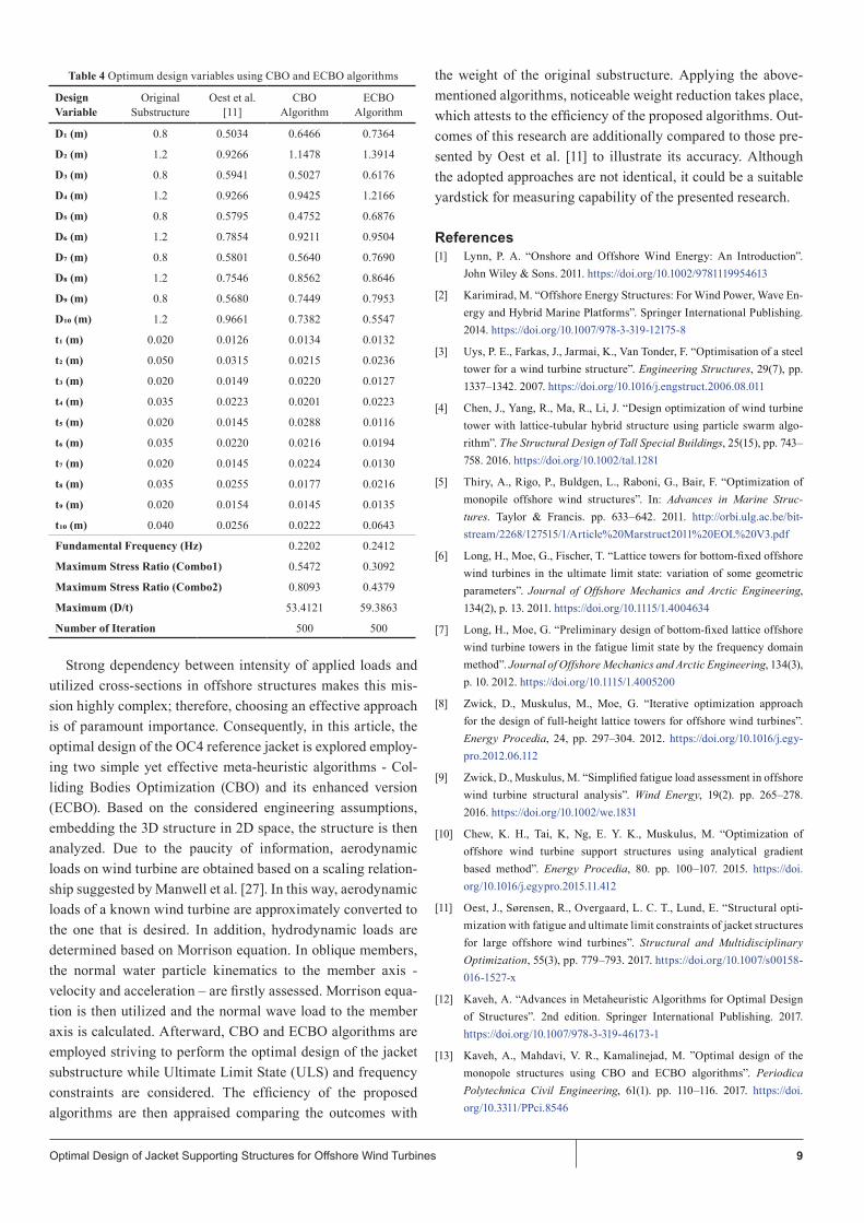
is investigated using CBO and ECBO algorithms. This opti-mization problem deals with 20 design variables, which are diameters and thicknesses of substructure elements, which are categorized in ten design groups. Fifty colliding bodies in 500 iterations are employed to be searching for the optimal design of the problem. To indicate the accuracy of the proposed algo-rithms, the outcomes of this research are compared to those of Oest et al. [11] even though the adopted approaches are not quite identical. This comparison can be a suitable yardstick for illustrating both capability and accuracy of the proposed algorithms.
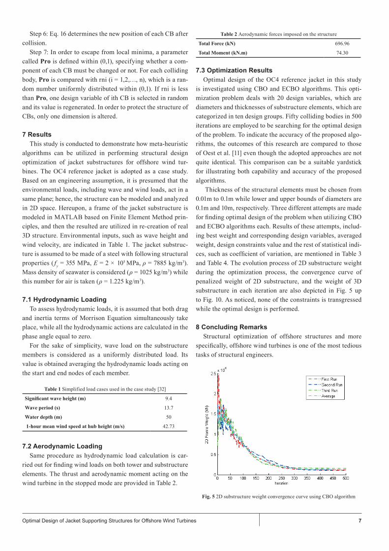
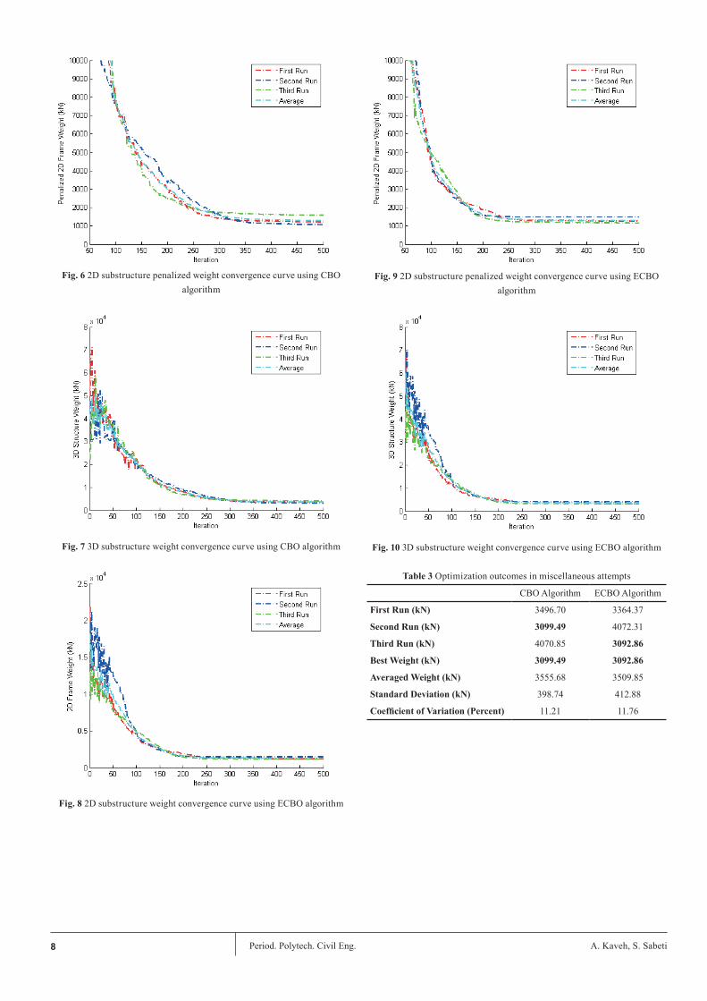
Thickness of the structural elements must be chosen from 0.01m to 0.1m while lower and upper bounds of diameters are 0.1m and 10m, respectively. Three different attempts are made for finding optimal design of the problem when utilizing CBO and ECBO algorithms each. Results of these attempts, includ-ing best weight and corresponding design variables, averaged weight, design constraints value and the rest of statistical indi-ces, such as coefficient of variation, are mentioned in Table 3 and Table 4. The evolution process of 2D substructure weight during the optimization process, the convergence curve of penalized weight of 2D substructure, and the weight of 3D substructure in each iteration are also depicted in Fig. 5 up to Fig. 10. As noticed, none of the constraints is transgressed while the optimal design is performed.
8 Concluding Remarks Structural optimization of offshore structures and more
specifically, offshore wind turbines is one of the most tedious tasks of structural engineers.
Fig. 5 2D substructure weight convergence curve using CBO algorithm
8 Period. Polytech. Civil Eng. A. Kaveh, S. Sabeti
Fig. 6 2D substructure penalized weight convergence curve using CBO algorithm
Fig. 7 3D substructure weight convergence curve using CBO algorithm
Fig. 8 2D substructure weight convergence curve using ECBO algorithm
Fig. 9 2D substructure penalized weight convergence curve using ECBO algorithm
Fig. 10 3D substructure weight convergence curve using ECBO algorithm
Table 3 Optimization outcomes in miscellaneous attempts
CBO Algorithm ECBO Algorithm
First Run (kN) 3496.70 3364.37
Second Run (kN) 3099.49 4072.31
Third Run (kN) 4070.85 3092.86
Best Weight (kN) 3099.49 3092.86
Averaged Weight (kN) 3555.68 3509.85
Standard Deviation (kN) 398.74 412.88
Coefficient of Variation (Percent) 11.21 11.76
9Optimal Design of Jacket Supporting Structures for Offshore Wind Turbines
Table 4 Optimum design variables using CBO and ECBO algorithms
Design Variable
Original Substructure
Oest et al. [11]
CBO Algorithm
ECBO Algorithm
D1 (m) 0.8 0.5034 0.6466 0.7364
D2 (m) 1.2 0.9266 1.1478 1.3914
D3 (m) 0.8 0.5941 0.5027 0.6176
D4 (m) 1.2 0.9266 0.9425 1.2166
D5 (m) 0.8 0.5795 0.4752 0.6876
D6 (m) 1.2 0.7854 0.9211 0.9504
D7 (m) 0.8 0.5801 0.5640 0.7690
D8 (m) 1.2 0.7546 0.8562 0.8646
D9 (m) 0.8 0.5680 0.7449 0.7953
D10 (m) 1.2 0.9661 0.7382 0.5547
t1 (m) 0.020 0.0126 0.0134 0.0132
t2 (m) 0.050 0.0315 0.0215 0.0236
t3 (m) 0.020 0.0149 0.0220 0.0127
t4 (m) 0.035 0.0223 0.0201 0.0223
t5 (m) 0.020 0.0145 0.0288 0.0116
t6 (m) 0.035 0.0220 0.0216 0.0194
t7 (m) 0.020 0.0145 0.0224 0.0130
t8 (m) 0.035 0.0255 0.0177 0.0216
t9 (m) 0.020 0.0154 0.0145 0.0135
t10 (m) 0.040 0.0256 0.0222 0.0643
Fundamental Frequency (Hz) 0.2202 0.2412
Maximum Stress Ratio (Combo1) 0.5472 0.3092
Maximum Stress Ratio (Combo2) 0.8093 0.4379
Maximum (D/t) 53.4121 59.3863
Number of Iteration 500 500
Strong dependency between intensity of applied loads and utilized cross-sections in offshore structures makes this mis-sion highly complex; therefore, choosing an effective approach is of paramount importance. Consequently, in this article, the optimal design of the OC4 reference jacket is explored employ-ing two simple yet effective meta-heuristic algorithms - Col-liding Bodies Optimization (CBO) and its enhanced version (ECBO). Based on the considered engineering assumptions, embedding the 3D structure in 2D space, the structure is then analyzed. Due to the paucity of information, aerodynamic loads on wind turbine are obtained based on a scaling relation-ship suggested by Manwell et al. [27]. In this way, aerodynamic loads of a known wind turbine are approximately converted to the one that is desired. In addition, hydrodynamic loads are determined based on Morrison equation. In oblique members, the normal water particle kinematics to the member axis - velocity and acceleration – are firstly assessed. Morrison equa-tion is then utilized and the normal wave load to the member axis is calculated. Afterward, CBO and ECBO algorithms are employed striving to perform the optimal design of the jacket substructure while Ultimate Limit State (ULS) and frequency constraints are considered. The efficiency of the proposed algorithms are then appraised comparing the outcomes with
the weight of the original substructure. Applying the above-mentioned algorithms, noticeable weight reduction takes place, which attests to the efficiency of the proposed algorithms. Out-comes of this research are additionally compared to those pre-sented by Oest et al. [11] to illustrate its accuracy. Although the adopted approaches are not identical, it could be a suitable yardstick for measuring capability of the presented research.
References[1] Lynn, P. A. “Onshore and Offshore Wind Energy: An Introduction”.
John Wiley & Sons. 2011. https://doi.org/10.1002/9781119954613
[2] Karimirad, M. “Offshore Energy Structures: For Wind Power, Wave En-ergy and Hybrid Marine Platforms”. Springer International Publishing. 2014. https://doi.org/10.1007/978-3-319-12175-8
[3] Uys, P. E., Farkas, J., Jarmai, K., Van Tonder, F. “Optimisation of a steel tower for a wind turbine structure”. Engineering Structures, 29(7), pp. 1337–1342. 2007. https://doi.org/10.1016/j.engstruct.2006.08.011
[4] Chen, J., Yang, R., Ma, R., Li, J. “Design optimization of wind turbine tower with lattice-tubular hybrid structure using particle swarm algo-rithm”. The Structural Design of Tall Special Buildings, 25(15), pp. 743–758. 2016. https://doi.org/10.1002/tal.1281
[5] Thiry, A., Rigo, P., Buldgen, L., Raboni, G., Bair, F. “Optimization of monopile offshore wind structures”. In: Advances in Marine Struc-tures. Taylor & Francis. pp. 633–642. 2011. http://orbi.ulg.ac.be/bit-stream/2268/127515/1/Article%20Marstruct2011%20EOL%20V3.pdf
[6] Long, H., Moe, G., Fischer, T. “Lattice towers for bottom-fixed offshore wind turbines in the ultimate limit state: variation of some geometric parameters”. Journal of Offshore Mechanics and Arctic Engineering, 134(2), p. 13. 2011. https://doi.org/10.1115/1.4004634
[7] Long, H., Moe, G. “Preliminary design of bottom-fixed lattice offshore wind turbine towers in the fatigue limit state by the frequency domain method”. Journal of Offshore Mechanics and Arctic Engineering, 134(3), p. 10. 2012. https://doi.org/10.1115/1.4005200
[8] Zwick, D., Muskulus, M., Moe, G. “Iterative optimization approach for the design of full-height lattice towers for offshore wind turbines”. Energy Procedia, 24, pp. 297–304. 2012. https://doi.org/10.1016/j.egy-pro.2012.06.112
[9] Zwick, D., Muskulus, M. “Simplified fatigue load assessment in offshore wind turbine structural analysis”. Wind Energy, 19(2). pp. 265–278. 2016. https://doi.org/10.1002/we.1831
[10] Chew, K. H., Tai, K, Ng, E. Y. K., Muskulus, M. “Optimization of offshore wind turbine support structures using analytical gradient based method”. Energy Procedia, 80. pp. 100–107. 2015. https://doi.org/10.1016/j.egypro.2015.11.412
[11] Oest, J., Sørensen, R., Overgaard, L. C. T., Lund, E. “Structural opti-mization with fatigue and ultimate limit constraints of jacket structures for large offshore wind turbines”. Structural and Multidisciplinary Optimization, 55(3), pp. 779–793. 2017. https://doi.org/10.1007/s00158-016-1527-x
[12] Kaveh, A. “Advances in Metaheuristic Algorithms for Optimal Design of Structures”. 2nd edition. Springer International Publishing. 2017. https://doi.org/10.1007/978-3-319-46173-1
[13] Kaveh, A., Mahdavi, V. R., Kamalinejad, M. ”Optimal design of the monopole structures using CBO and ECBO algorithms”. Periodica Polytechnica Civil Engineering, 61(1). pp. 110–116. 2017. https://doi.org/10.3311/PPci.8546
10 Period. Polytech. Civil Eng. A. Kaveh, S. Sabeti
[14] Kaveh, A., Khanzadi, M., Alipour, M., Rajabi Naraky, M. “CBO and CSS algorithms for resource allocation and time-cost trade-off”. Period-ica Polytechnica Civil Engineering, 59(3). pp. 361–371. 2015. https://doi.org/10.3311/PPci.7788
[15] Csébfalvi, A. “A hybrid meta-heuristic method for continuous engineer-ing optimization”. Periodica Polytechnica Civil Engineering, 53(2), pp. 93–100. 2009. https://doi.org/10.3311/pp.ci.2009-2.05
[16] Csébfalvi, A. “A new theoretical approach for robust truss optimization with uncertain load directions”. Mechanics Based Design of Structures and Machines, 42 (4). pp. 442–453. 2014. http://dx.doi.org/10.1080/15397734.2014.880064
[17] Kaveh, A., Mahdavi, V. R. “Colliding Bodies Optimization: Extensions and Applications”. Springer International Publishing. 2015. https.//doi.org/10.1007/978-3-319-19659-6
[18] Kaveh, A., Ghazaan, M. I. “Enhanced colliding bodies algorithm for truss optimization with frequency constraints”. Computing in Civil Engineer-ing, 29(6). 2014. https://doi.org/10.1061/(ASCE)CP.1943-5487.0000445
[19] Chen, I.W., Wong, B.L., Lin, Y.H., Chau, S.W., Huang, H.H. “Design and analysis of jacket substructures for offshore wind turbines”. Energies, 9(4). pp. 264. 2016. https://pdfs.semanticscholar.org/fa39/0170049b-21594c70d7d50ca5c52bd718b346.pdf
[20] Vorpahl, F., Kaufer, D., Popko, W. “Description of a basic model of the “Upwind reference jacket” for code comparison in the OC4 project un-der IEA Wind Annex 30”. Tech. Rep. Institute for Wind Energy and En-ergy Systems Technology. 2011.
[21] Popko, Wojciech, et al. “Offshore Code Comparison Collaboration Continuation (OC4), Phase 1-Results of Coupled Simulations of an Offshore Wind Turbine with Jacket Support Structure”. The Twen-ty-second International Offshore and Polar Engineering Conference. International Society of Offshore and Polar Engineers. Jun. 17–22, Rhodes, Greece, 2012. http://citeseerx.ist.psu.edu/viewdoc/download?-doi=10.1.1.433.6695&rep=rep1&type=pdf
[22] Fischer, T., De Vries, W., Schmidt, B. “UpWind Design Basis”. Tech. Rep. 2010.
[23] Jonkman, J., Butterfield, S., Musial, W., Scott, G. “Definition of a 5-MW reference wind turbine for offshore system development”. Tech. Rep. 2009. https://www.nrel.gov/docs/fy09osti/38060.pdf
[24] DNV-DS-J102. “Design and manufacture of wind turbine blades, off-shore and onshore wind turbines”. Det Norske Veritas, Høvik. 2010. https://rules.dnvgl.com/docs/pdf/DNV/codes/docs/2010-11/DS-J102.pdf
[25] DNV-OS-J101: “Design of offshore wind turbine structures”. Det Norske Veritas, Høvik. 2014. https://rules.dnvgl.com/docs/pdf/DNV/codes/docs/2014-05/Os-J101.pdf
[26] Morison, J. R., O’Brien, M. P., Johnson, J., Schaaf, S. “The force exerted by surface waves on piles”. Petroleum Transactions, 189. 1950.
[27] Manwell, J. F., McGowan, J. G., Rogers, A. L. “Wind Energy Explained: Theory, Design and Application”. John Wiley & Sons. 2010.
[28] Gencturk, B., Attar, A., Tort, C. “Selection of an optimal lattice wind turbine tower for a seismic region based on the Cost of Energy”. KSCE Journal of Civil Engineering, 19(7). pp. 2179–2190. 2015. https://doi.org/10.1007/s12205-014-1428-8
[29] Leite, O. B. “Review of design procedures for monopile offshore wind structures”. Master Thesis. University of Porto. 2015.
[30] Muskulus, M., Schafhirt, S. “Design optimization of wind turbine sup-port structures - a review”. Journal of Ocean and Wind Energy, 1(1). pp. 12–22. 2014. https://pdfs.semanticscholar.org/de0a/5887eee4d-568662ef7ff7a4fed761616fb5f.pdf
[31] Eurocode 3: “Design of steel structures – Part 1–1: General rules and rules for buildings”. European Committee for Standardization. 2010.
[32] Chew, K. H., Tai, K, Ng, E. Y. K., Muskulus, M. “Optimization of offshore wind turbine support structures using analytical gradient based method”. Energy Procedia, 80, pp. 100–107. 2015. https://doi.org/10.1016/j.egypro.2015.11.412
Related Documents