Journal of Mechanics of Materials and Structures OPTIMAL BUCKLING DESIGN OF ANISOTROPIC RINGS/LONG CYLINDERS UNDER EXTERNAL PRESSURE Karam Y. Maalawi Volume 3, Nº 4 April 2008 mathematical sciences publishers

Welcome message from author
This document is posted to help you gain knowledge. Please leave a comment to let me know what you think about it! Share it to your friends and learn new things together.
Transcript
Journal of
Mechanics ofMaterials and Structures
OPTIMAL BUCKLING DESIGN OF ANISOTROPIC RINGS/LONGCYLINDERS UNDER EXTERNAL PRESSURE
Karam Y. Maalawi
Volume 3, Nº 4 April 2008
mathematical sciences publishers
JOURNAL OF MECHANICS OF MATERIALS AND STRUCTURESVol. 3, No. 4, 2008
OPTIMAL BUCKLING DESIGN OF ANISOTROPIC RINGS/LONG CYLINDERSUNDER EXTERNAL PRESSURE
KARAM Y. MAALAWI
Structural buckling failure due to high external hydrostatic pressure is a major consideration in designingrings and long cylindrical shell-type structures. This paper presents a direct approach for enhancingbuckling stability limits of thin-walled rings/long cylinders that are fabricated from multiangle fibrouslaminated composite lay-ups. The mathematical formulation employs the classical lamination theory forcalculating the critical buckling pressure, where an analytical solution that accounts for the effective axialand flexural stiffness separately as well as the inclusion of the coupling stiffness terms is presented. Theassociated design optimization problem of maximizing the critical buckling pressure has been formulatedin a standard nonlinear mathematical programming problem with the design variables encompassing thefiber orientation angles and the ply thicknesses as well. The physical and mechanical properties of thecomposite material are taken as preassigned parameters. The proposed model deals with dimensionlessquantities in order to be valid for thin shells having different thickness-to-radius ratios. Useful designcharts are given for several types of anisotropic rings/long cylinders showing the functional dependenceof the buckling pressure on the selected design variables. Excellent results have been obtained for casesof filament wound rings/long cylinders fabricated from three different types of materials: E-glass/vinyl-ester, graphite/epoxy and S-glass/epoxy. It was shown that significant improvement in the overall stabil-ity level can be attained as compared with a baseline shell design. In fact, the developed methodologyhas been proved to be a useful design tool for selecting an optimal stacking sequence of a thin-walledanisotropic ring/long cylinder having arbitrary thickness-to-radius ratio.
1. Introduction
Many mechanical and structural elements made of fiber reinforced composites are increasingly utilizedin aerospace, marine and civil engineering applications [Vinson 1992; Daniel and Ishai 2006]. Themost important benefits from using such advanced materials in the various structural types are the at-tainment of high stiffness-to-weight ratio and long fatigue life. One common application is the designof composite cylindrical shells under the action of external hydrostatic pressure, which might causecollapse by buckling instability [Simitses 1996; Sridharan and Kasagi 1997]. Examples are the under-ground and underwater pipelines, rocket motor casing, boiler tubes subjected to external steam pressure,and reinforced submarine structures. The composite cylindrical vessels for underwater applications[Davies and Chauchot 1999] are intended to operate at high external hydrostatic pressure (sometimesup to 60 MPa). For deep-submersible long-unstiffened vessels, the hulls are generally realized usingmultilayered, cross-ply, composite cylinders obtained following the filament winding process [Graham1995]. On the other hand, previous numerical and experimental studies have shown that failure due to
Keywords: buckling instability, structural optimization, fibrous composite, laminated ring/cylindrical shell, externalhydrostatic pressure.
775
776 KARAM Y. MAALAWI
structural buckling is also a major risk factor for thin laminated cylindrical shells. Anastasiadis andSimitses [1993] studied the buckling of long laminated cylindrical shells under external radial pressureusing higher order deformation theory. Their formulation, however, was restricted to symmetric lay-upswith respect to the mid-surface, to eliminate the coupling terms, as well as constant-directional pressure.More conservative results for a true fluid pressure were given by Rasheed and Yousif [2001; 2005] whoapplied standard energy formulation to derive the kinematics and equilibrium equations and the classicallamination theory to express the needed constitutive equations. They developed a powerful generalizedclosed form analytical formula for calculating stability limits of thin anisotropic rings/long cylinderssubject to hydrostatic pressure. Another refined treatment of the inplane buckling of rings was given byHodges [1999] and Hodges and Harursampath [2002]. Formulation was based on a nonlinear theory forstretching and bending of anisotropic beams having constant initial curvature in their plane of symmetrywith the only restriction of small strain in the prebuckling state.
Considering next structural optimization, several papers appeared on the topic of buckling and sta-bility optimization. Maalawi [2002] presented a piecewise structural model for buckling optimizationof elastic columns under mass equality constraint. He showed that the most effective design variablesthat have a bearing on buckling optimization are the cross sectional area, radius of gyration and lengthof each segment composing the column. Another work by Maalawi and El Chazly [2002] dealt withboth stability and dynamic optimization of multielement beam type structures. They formulated theassociated optimization problems in a standard mathematical programming solved by the interior penaltyfunction technique. More recently, Librescu and Maalawi [2007] considered optimization of aeroelasticstability of composite wings. They applied the concept of material grading with the implementationof both continuous and piecewise structural models. For fibrous laminated composite structures, theoptimization of ply angles and thicknesses could allow the properties of the laminate to be tailored toa specific application. ZitzEvancih [1985] applied NASA buckling equations for the optimization oforthotropic cylinders against buckling. Balanced symmetric plies, consisting of 0◦, ±45◦ and 90◦ fiberorientations, were used to construct the laminates. The relative volume ratio of the laminates to each otherand the stacking sequence were used as the optimization design variables. Chattopadhyay and Ferreira[1993] performed a study to investigate the maximum buckling load of a cylinder subject to ply stressconstraints using material and geometric design variables. A closed form shell equation was utilized forthe buckling load calculation. Laminates were constrained to be symmetric, and the number of plies wasincluded in the design variables. Results for graphite/epoxy, glass/epoxy and Kevlar/epoxy models werefound using the computer code CONMIN. Considering optimization of underwater cylindrical vessels,Tanguy et al. [2002] dealt with the optimal design of deep submarine vehicles. They developed a geneticalgorithm procedure coupled with an analytical model to determine the laminate stacking sequences thatmaximize the critical external buckling pressure. They also showed that the measured buckling pressuresfor glass/epoxy and carbon/epoxy cylinders appear to be in good agreement with numerical results anddemonstrated the gains due to the optimized laminations.
The aim of the present study is to achieve enhanced stability limits of anisotropic ring/long cylindricalshell structures subjected to hydrostatic external pressure. Based on the analytical buckling model devel-oped by Rasheed and Yousif [2005], a useful optimization tool has been built for designing efficient con-figurations with improved buckling stability. This allows the search for the stacking sequences that maxi-mize the buckling pressure and at the same time takes into account the manufacturing requirements. The
OPTIMAL BUCKLING DESIGN OF ANISOTROPIC RINGS/LONG CYLINDERS. . . 777
corresponding increases in the buckling pressures calculated with respect to a baseline design have beenevaluated for several configurations, including cases of orthotropic, filament wound rings/long cylindersfabricated from three different types of composite materials, namely E-glass/vinyl-ester, graphite/epoxyand S-glass/epoxy. It is assumed that the volume fractions of the constituent materials of the compositestructure remain constant during optimization, so that the total structural mass is held at its referencevalue corresponding to the baseline design. The final results demonstrated the usefulness of the givenmethodology in attaining substantial improvement in the overall stability level of thin-walled anisotropicrings/long cylinders having arbitrary thickness-radius ratio, which is a major contribution of this paper.
2. Structural analysis
In this section, the basic structural analysis of multiangle laminated composite lay-ups that are widelyused in filament wound rings/long cylinders are considered. In order to restrict the time of calculation toacceptable values for the developed optimization tool, the analytical formulation shall be based on thederivation in two fruitful papers by Rasheed and Yousif [2001; 2005], which are based on the assumptionof small hoop strain and rotation of circumferential elements. Such an approach provides good sensitiv-ity to lamination parameters, and allows the search for the needed optimal stacking sequences, whichmaximize the buckling pressure in a reasonable computational time.
Following the standard procedures of the classical lamination theory [Soden et al. 1998; Reddy2004], the matrix equation, which relates the resultant, distributed forces (Nxx , Nss, Nxs) and moments(Mxx ,Mss,Mxs) to the strains (ε0
xx , ε0ss, γ
0xa) and curvatures (κxx , κss, κxs) at the middle surface of the
shell structure, can be written as
Nxx
Nss
Nxs
Mxx
Mss
Mxs
=
A11 A12 A16 B11 B12 B16
A12 A22 A26 B12 B22 B26
A16 A26 A66 B16 B26 B66
B11 B12 B16 D11 D12 D16
B12 B22 B26 D12 D22 D26
B16 B26 B66 D16 D26 D66
ε0xxε0
ssγ 0
xsκxx
κss
κxs
, (1)
where (x, s, z) are the axial, tangential and radial coordinates, respectively, and the matrix elements(Ai j , Bi j , Di j ) are called the extensional, coupling and bending stiffness coefficients, respectively. Theyare all defined in Appendix A, along with the necessary kinematical relations and constitutive equationsutilized in deriving (1). Actually, the kinematical relations follow the same expressions derived for thinisotropic rings [Brush and Almroth 1975; Simitses 1976]. Both cases of laminated composite ringsand long cylindrical shells are considered. It was shown by Rasheed and Yousif [2005] that the onlysignificant strain components in both cases are the hoop strain ε0
ss and the circumferential curvature κss
of the mid-surface; see Appendix A. The reduced form of (1) for the two cases was shown to be(Nss
Mss
)=
(Aani Bani
Bani Dani
) (ε0
ssκss
). (2)
In the case of thin rings the axial and shear forces (Nxx , Nxs) must vanish along the free edges. Thebending and twisting moments (Mxx ,Mxs) may also be neglected. Therefore, the first, third, fourth and
778 KARAM Y. MAALAWI
sixth rows of (1) are solved for the strains and curvatures in terms of (ε0ss, κss) to give the following
matrix relation
S1
ε0
xxγ 0
xsκxx
κxs
= −S2
(ε0
ssκss
),
or ε0
xxγ 0
xsκxx
κxs
= −S−11 S2
(ε0
ssκss
), (3)
where
S1 =
A11 A16 B11 B16
A16 A66 B16 B66
B11 B16 D11 D16
B16 B66 D16 D66
, and S2 =
A12 B12
A26 B26
B12 D12
B26 D26
.
Substituting (3) back into (1), we can show that(Aani Bani
Bani Dani
)ring
=
(A22 B22
B22 D22
)− ST
2 S−11 S2. (4)
For the case of a long cylinder, the out-of-plane displacements are restrained, that is,
ε0xx = γ 0
xs = κxs = 0.
Therefore, the only strains to be taken into considerations are the in-plane hoop strain ε0ss and the cir-
cumferential curvature κss . Accordingly, the reduced matrix of (2) takes the following form(Aani Bani
Bani Dani
)cylinder
=
(A22 B22
B22 D22
). (5)
3. Analytical buckling model
The governing differential equations of anisotropic rings/long cylinders subjected to external pressureare similar to those of the isotropic case [Brush and Almroth 1975; Simitses 1976].
They are cast in the following:
M ′
ss + R(N ′
ss −βNss)= βpR2,
M ′′
ss − R(Nss + (βNss)
′+ p(w0 + v′
0))= pR2,
(6)
where the prime denotes differentiation with respect to angular position ϕ, and
β =1R(v 0 −w′
0).
Definitions of other parameters are given in Appendix A. Rasheed and Yousif [2001; 2005] presented twosolutions for (6): one for the prebuckled state and the other termed as the bifurcation solution obtained
OPTIMAL BUCKLING DESIGN OF ANISOTROPIC RINGS/LONG CYLINDERS. . . 779
�
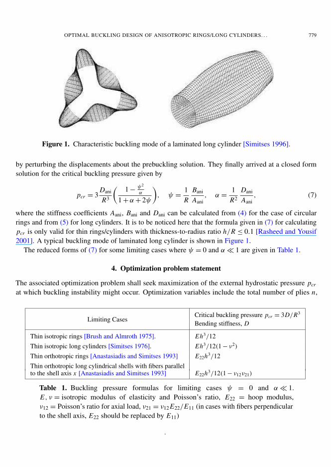
Figure 1. Characteristic buckling mode of a laminated long cylinder [Simitses 1996].
by perturbing the displacements about the prebuckling solution. They finally arrived at a closed formsolution for the critical buckling pressure given by
pcr = 3Dani
R3
(1 −
ψ2
α
1 +α+ 2ψ
), ψ =
1R
Bani
Aani, α =
1R2
Dani
Aani, (7)
where the stiffness coefficients Aani, Bani and Dani can be calculated from (4) for the case of circularrings and from (5) for long cylinders. It is to be noticed here that the formula given in (7) for calculatingpcr is only valid for thin rings/cylinders with thickness-to-radius ratio h/R ≤ 0.1 [Rasheed and Yousif2001]. A typical buckling mode of laminated long cylinder is shown in Figure 1.
The reduced forms of (7) for some limiting cases where ψ = 0 and α � 1 are given in Table 1.
4. Optimization problem statement
The associated optimization problem shall seek maximization of the external hydrostatic pressure pcr
at which buckling instability might occur. Optimization variables include the total number of plies n,
Limiting CasesCritical buckling pressure pcr = 3D/R3
Bending stiffness, D
Thin isotropic rings [Brush and Almroth 1975]. Eh3/12Thin isotropic long cylinders [Simitses 1976]. Eh3/12(1 − ν2)
Thin orthotropic rings [Anastasiadis and Simitses 1993] E22h3/12Thin orthotropic long cylindrical shells with fibers parallelto the shell axis x [Anastasiadis and Simitses 1993] E22h3/12(1 − ν12ν21)
Table 1. Buckling pressure formulas for limiting cases ψ = 0 and α � 1.E, ν = isotropic modulus of elasticity and Poisson’s ratio, E22 = hoop modulus,ν12 = Poisson’s ratio for axial load, ν21 = ν12 E22/E11 (in cases with fibers perpendicularto the shell axis, E22 should be replaced by E11)
.
780 KARAM Y. MAALAWI
thickness hk and fiber orientation angle θk of the individual k-th ply. Side constraints are always imposedon the design variables for geometrical, manufacturing or logical reasons to avoid having unrealistic oddshaped optimum designs.
4A. Definition of the baseline design. It is convenient first to normalize all variables and parameterswith respect to a baseline design, which has been selected to be a unidirectional orthotropic laminatedring/long cylinder with the fibers parallel to the shell axis x . Optimized shell designs shall have thesame material properties, mean radius R and total shell thickness h of the baseline design. Therefore,the preassigned parameters, which are not subject to change in the optimization process, ought to be thetype of material of construction, mean radius and total thickness of the shell.
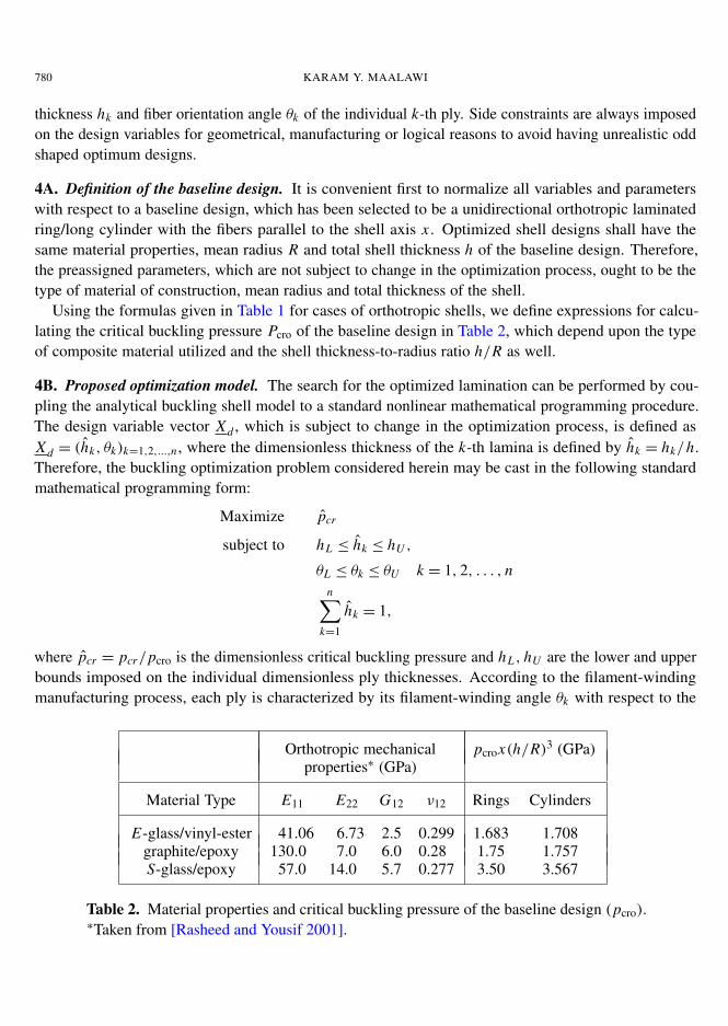
Using the formulas given in Table 1 for cases of orthotropic shells, we define expressions for calcu-lating the critical buckling pressure Pcro of the baseline design in Table 2, which depend upon the typeof composite material utilized and the shell thickness-to-radius ratio h/R as well.
4B. Proposed optimization model. The search for the optimized lamination can be performed by cou-pling the analytical buckling shell model to a standard nonlinear mathematical programming procedure.The design variable vector Xd , which is subject to change in the optimization process, is defined asXd = (hk, θk)k=1,2,...,n , where the dimensionless thickness of the k-th lamina is defined by hk = hk/h.Therefore, the buckling optimization problem considered herein may be cast in the following standardmathematical programming form:
Maximize pcr
subject to hL ≤ hk ≤ hU ,
θL ≤ θk ≤ θU k = 1, 2, . . . , nn∑
k=1
hk = 1,
where pcr = pcr/pcro is the dimensionless critical buckling pressure and hL , hU are the lower and upperbounds imposed on the individual dimensionless ply thicknesses. According to the filament-windingmanufacturing process, each ply is characterized by its filament-winding angle θk with respect to the
Orthotropic mechanical pcrox(h/R)3 (GPa)properties∗ (GPa)
Material Type E11 E22 G12 ν12 Rings Cylinders
E-glass/vinyl-ester 41.06 6.73 2.5 0.299 1.683 1.708graphite/epoxy 130.0 7.0 6.0 0.28 1.75 1.757S-glass/epoxy 57.0 14.0 5.7 0.277 3.50 3.567
Table 2. Material properties and critical buckling pressure of the baseline design (pcro).∗Taken from [Rasheed and Yousif 2001].
OPTIMAL BUCKLING DESIGN OF ANISOTROPIC RINGS/LONG CYLINDERS. . . 781
cylinder axis x . The stacking sequence is denoted by [θ1/θ2/ · · · /θn], where the angles are given indegrees, starting from the outer surface of the shell. In addition, in a real-world manufacturing process,the filament-winding angles θk must be chosen from a limited range of allowable lower (θL) and upper(θU ) values according to technology references. It is important to mention here that the volume fractionsof the constituent materials of the composite structure are assumed not to significantly change duringoptimization, so that the total structural mass remains constant at its reference value of the baselinedesign. The effect of changing the volume fractions is now under study by the author, where the conceptof material grading will be considered [Librescu and Maalawi 2007].
This optimization problem may be thought as a search in a 2n-dimensional space for a point corre-sponding to the maximum value of the objective function such that it lies within the region bounded bysubspaces representing the constraint functions [Vanderplaats 1994; Venkataraman 2002]. The usefulnessand efficiency of penalty methods (see Appendix B) for solving this kind of optimization problems havebeen explored intensively in the literature [Maalawi and El Chazly 2002]. The constraints are takeninto account indirectly by transforming the constrained problem into a series of unconstrained problems.Several software packages are available now for solving mathematical programming problems. TheMATLAB optimization toolbox [Venkataraman 2002] offers routines that implement the interior penaltyfunction method, which has a wide applicability in many engineering applications, via a built-in functionnamed “fminsearch”.
5. Results and discussions
The given approach discussed in previous sections shall be applied here to several cases of study ofthin-walled anisotropic rings/long cylinders subjected to external hydrostatic pressure. The materials ofconstruction are chosen to be E-glass/vinyl-ester, graphite/epoxy and S-glass/epoxy. The functional be-havior of the candidate objective function, as represented by maximization of the dimensionless bucklingpressure pcr , is thoroughly investigated in order to see how it is changed with the optimization variablesin the selected design space. The final optimum designs recommended by the model will directly dependon the mathematical form and behavior of the objective function.
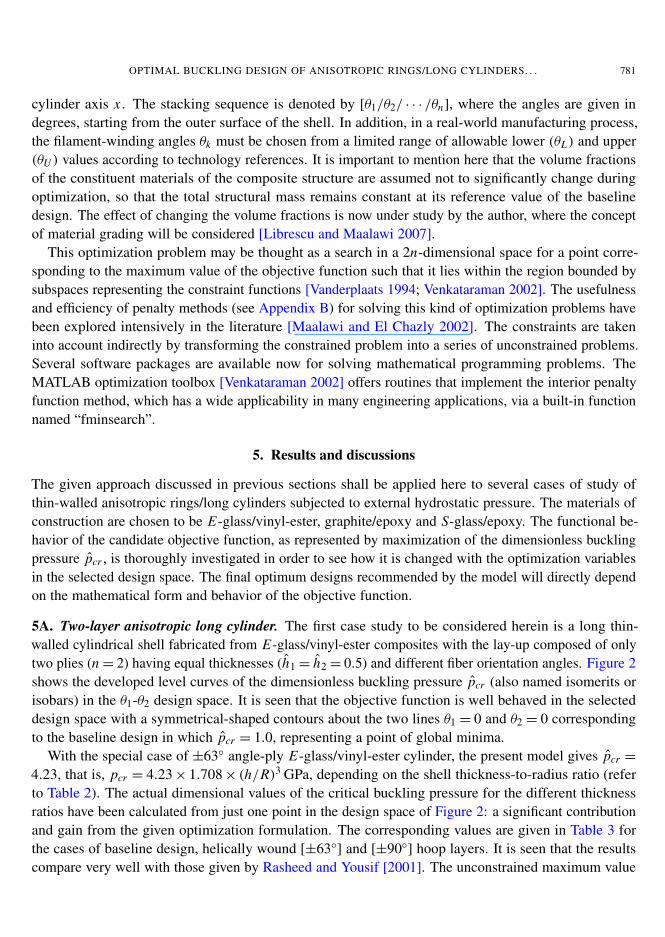
5A. Two-layer anisotropic long cylinder. The first case study to be considered herein is a long thin-walled cylindrical shell fabricated from E-glass/vinyl-ester composites with the lay-up composed of onlytwo plies (n = 2) having equal thicknesses (h1 = h2 = 0.5) and different fiber orientation angles. Figure 2shows the developed level curves of the dimensionless buckling pressure pcr (also named isomerits orisobars) in the θ1-θ2 design space. It is seen that the objective function is well behaved in the selecteddesign space with a symmetrical-shaped contours about the two lines θ1 = 0 and θ2 = 0 correspondingto the baseline design in which pcr = 1.0, representing a point of global minima.
With the special case of ±63◦ angle-ply E-glass/vinyl-ester cylinder, the present model gives pcr =
4.23, that is, pcr = 4.23 × 1.708 × (h/R)3 GPa, depending on the shell thickness-to-radius ratio (referto Table 2). The actual dimensional values of the critical buckling pressure for the different thicknessratios have been calculated from just one point in the design space of Figure 2: a significant contributionand gain from the given optimization formulation. The corresponding values are given in Table 3 forthe cases of baseline design, helically wound [±63◦
] and [±90◦] hoop layers. It is seen that the results
compare very well with those given by Rasheed and Yousif [2001]. The unconstrained maximum value
782 KARAM Y. MAALAWI�
�
�
�
�
�
�
�
�
�
�
�
������������
���������������
��
Figure 2. Dimensionless buckling pressure pcr in the [θ1/θ2] design space. Two-plycylinder made of E-glass/vinyl-ester (h1 = h2 = 0.5).
of the critical buckling pressure occurs at any one of the corners of Figure 2 corresponding to the fourdesign points [θ1/θ2] = [±90◦/± 90◦
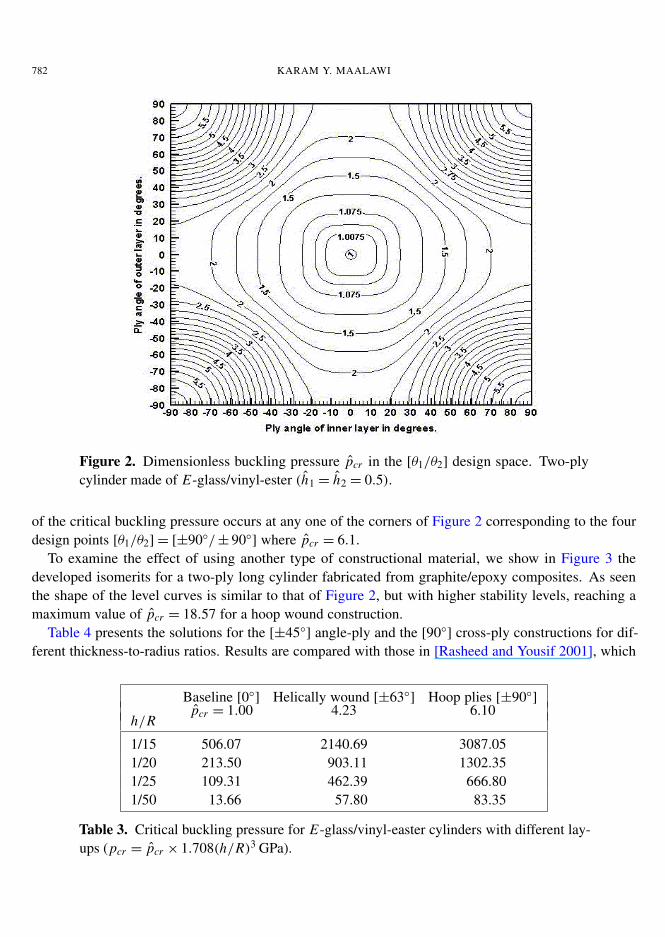
] where pcr = 6.1.To examine the effect of using another type of constructional material, we show in Figure 3 the
developed isomerits for a two-ply long cylinder fabricated from graphite/epoxy composites. As seenthe shape of the level curves is similar to that of Figure 2, but with higher stability levels, reaching amaximum value of pcr = 18.57 for a hoop wound construction.
Table 4 presents the solutions for the [±45◦] angle-ply and the [90◦
] cross-ply constructions for dif-ferent thickness-to-radius ratios. Results are compared with those in [Rasheed and Yousif 2001], which
Baseline [0◦] Helically wound [±63◦
] Hoop plies [±90◦]
pcr = 1.00 4.23 6.10h/R
1/15 506.07 2140.69 3087.051/20 213.50 903.11 1302.351/25 109.31 462.39 666.801/50 13.66 57.80 83.35
Table 3. Critical buckling pressure for E-glass/vinyl-easter cylinders with different lay-ups (pcr = pcr × 1.708(h/R)3 GPa).
OPTIMAL BUCKLING DESIGN OF ANISOTROPIC RINGS/LONG CYLINDERS. . . 783�
�
�
�
�
�
�
�
�
�
�
�
�
�
�
�
�
�
�
Figure 3. pcr -isomerits for a graphite/epoxy, two-layer cylinder in [θ1/θ2] design space(h1 = h2 = 0.5).
were based on the assumption that adjacent [±θ ] layers are merged together with the stiffness coefficientstaken as average values from the (+θ) and (−θ) plies. These solutions are also valid for lay-ups [0◦
3]s ,[90◦
3]s , [45◦
2/− 45◦
2]s and [45◦/− 45◦/45◦/− 45◦]s , which were numbered 1, 8, 20 and 21 in the papers
by Anastasiadis and Simitses [1993] and Rasheed and Yousif [2001].The case of a helically wound lay-up construction [+θ/− θ ] with unequal play thicknesses h1 and
h2, such that their sum is held fixed at a value of unity, has also been investigated. Computer solutionshave shown that no significant change in the resulting values of the critical buckling pressure can beremarked in spite of the wide change in the ply thicknesses. This is a natural expected result since
Baseline [0◦] Helically wound [±45◦
] Hoop plies [±90◦]
pcr = 1.00 5.9 18.57h/R
1/15 520.59 3071.50 9667.401/50 14.06 82.93 261.021/120 1.02 5.99 18.88
Table 4. Critical buckling pressure for graphite/epoxy cylinders with different lay-ups(pcr = pcr × 1.757(h/R)3 GPa).
784 KARAM Y. MAALAWI
�
�
�
�
�
�
�
�
�
�
�
�
�
�
�
Figure 4. pcr - isomerits for three-ply graphite/epoxy cylinder [θ1/θ2/θ1].
the stiffness coefficients Aani, Bani and Dani remain unchanged for such lay-up construction. Also, itshould be mentioned here that the optimal buckling pressure for a cylinder having stacking sequence[+θ1/− θ1/+ θ2/− θ2] is identical to that obtained before for stacking sequence [θ1/θ2], as given inFigures 2 and 3.
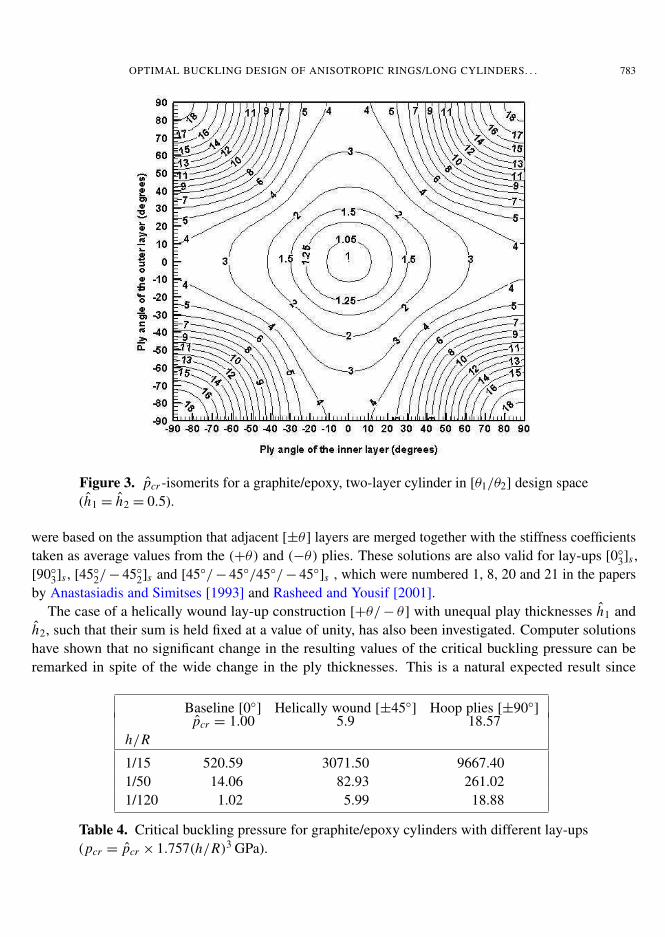
5B. Three-layer anisotropic long cylinder. Figure 4 shows the developed isomerits for a cylinder con-structed from three equally-thicked layers with stacking sequence denoted by [θ1/θ2/θ1]. The samebehavior can be observed as before, but with slight flattening in the θ2-direction. The contours are fullysymmetrical about the mid-point corresponding to the minimal baseline value of unity. Two distinctzones can be seen: the closed middle one containing the global minima, and the open one covering thetwo ranges θ1 < −30◦ and θ1 > 30◦ in which the critical buckling pressure is not much affected byvariation in the ply angle θ2.
Other computational results for cross-ply lamination are given in Table 5, where substantial increasein the critical bucking pressure by changing the ply angles can be observed. Similar solutions wereobtained for the stacking sequences [0◦
2/90◦]s and [90◦
2/0◦]s , which corresponds to lay-up numbers 2
and 7 considered by Anastasiadis and Simitses [1993].
5C. Four-layer sandwiched anisotropic cylinder. The same graphite/epoxy cylinder is reconsideredhere with changing the stacking sequence to become ±20◦ equal-thickness layers sandwiched in betweenouter and inner 90◦ hoop layers with unequal thicknesses h2 = h3, h1 6= h4, such that the thickness equality
OPTIMAL BUCKLING DESIGN OF ANISOTROPIC RINGS/LONG CYLINDERS. . . 785
�
�
�
�
�
�
�
�
�
�
�
�
�
�
�
�
�
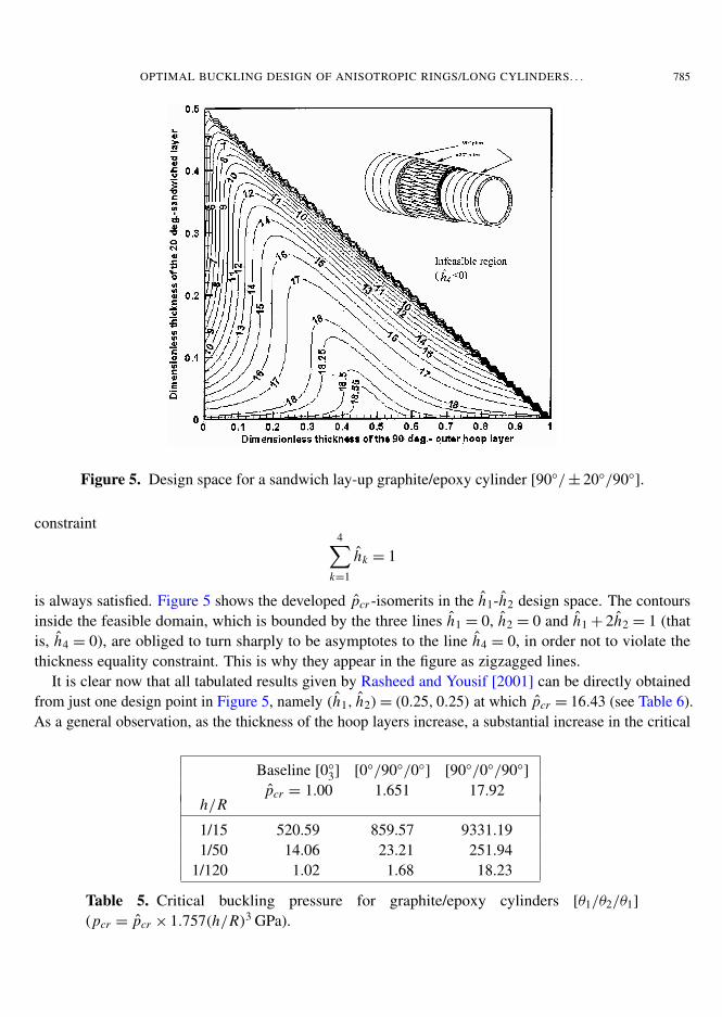
Figure 5. Design space for a sandwich lay-up graphite/epoxy cylinder [90◦/± 20◦/90◦].
constraint4∑
k=1
hk = 1
is always satisfied. Figure 5 shows the developed pcr -isomerits in the h1-h2 design space. The contoursinside the feasible domain, which is bounded by the three lines h1 = 0, h2 = 0 and h1 + 2h2 = 1 (thatis, h4 = 0), are obliged to turn sharply to be asymptotes to the line h4 = 0, in order not to violate thethickness equality constraint. This is why they appear in the figure as zigzagged lines.
It is clear now that all tabulated results given by Rasheed and Yousif [2001] can be directly obtainedfrom just one design point in Figure 5, namely (h1, h2)= (0.25, 0.25) at which pcr = 16.43 (see Table 6).As a general observation, as the thickness of the hoop layers increase, a substantial increase in the critical
Baseline [0◦
3] [0◦/90◦/0◦] [90◦/0◦/90◦
]
pcr = 1.00 1.651 17.92h/R
1/15 520.59 859.57 9331.191/50 14.06 23.21 251.94
1/120 1.02 1.68 18.23
Table 5. Critical buckling pressure for graphite/epoxy cylinders [θ1/θ2/θ1]
(pcr = pcr × 1.757(h/R)3 GPa).
786 KARAM Y. MAALAWI
�
�
�
�
�
�
�
�
�
�
�
�
�
�
�
�
�
��
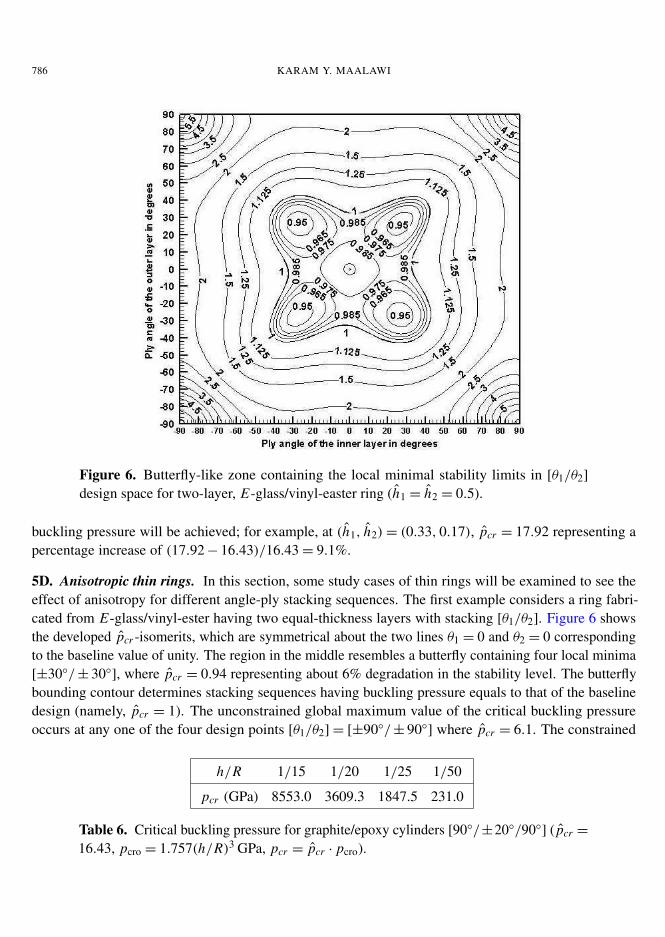
Figure 6. Butterfly-like zone containing the local minimal stability limits in [θ1/θ2]
design space for two-layer, E-glass/vinyl-easter ring (h1 = h2 = 0.5).
buckling pressure will be achieved; for example, at (h1, h2)= (0.33, 0.17), pcr = 17.92 representing apercentage increase of (17.92 − 16.43)/16.43 = 9.1%.
5D. Anisotropic thin rings. In this section, some study cases of thin rings will be examined to see theeffect of anisotropy for different angle-ply stacking sequences. The first example considers a ring fabri-cated from E-glass/vinyl-ester having two equal-thickness layers with stacking [θ1/θ2]. Figure 6 showsthe developed pcr -isomerits, which are symmetrical about the two lines θ1 = 0 and θ2 = 0 correspondingto the baseline value of unity. The region in the middle resembles a butterfly containing four local minima[±30◦/± 30◦
], where pcr = 0.94 representing about 6% degradation in the stability level. The butterflybounding contour determines stacking sequences having buckling pressure equals to that of the baselinedesign (namely, pcr = 1). The unconstrained global maximum value of the critical buckling pressureoccurs at any one of the four design points [θ1/θ2] = [±90◦/± 90◦
] where pcr = 6.1. The constrained
h/R 1/15 1/20 1/25 1/50
pcr (GPa) 8553.0 3609.3 1847.5 231.0
Table 6. Critical buckling pressure for graphite/epoxy cylinders [90◦/±20◦/90◦] ( pcr =
16.43, pcro = 1.757(h/R)3 GPa, pcr = pcr · pcro).
OPTIMAL BUCKLING DESIGN OF ANISOTROPIC RINGS/LONG CYLINDERS. . . 787
[+63◦] [+63◦/− 63◦
] [+63◦/− 63◦]3 [+63◦/− 63◦
]∞pcr = 1.754 2.166 3.134 3.234
h/R
1/20 369.00 455.67 659.32 680.351/50 23.62 29.16 42.20 43.541/100 2.95 3.65 5.27 5.44
Table 7. Critical buckling pressure for E-glass/vinyl-easter thin rings (pcr = pcr × 1.683(h/R)3 GPa).
solutions for the special case of ±63◦ angle-ply, which was considered by Rasheed and Yousif [2005],are summarized in Table 7, including also the extreme cases of full anisotropy represented by the lay-upwith only [+63◦
] plies for the entire thickness and the fully orthotropic lamination consisting of manytoo thin alternating balanced plies [+63◦/− 63◦
], which produce the highest possible buckling capacity.A last example considers a thin ring fabricated from S-glass/epoxy with the mechanical properties
given in Table 2. The lay-up consists of three [+45◦/− 45◦] balanced plies, each with equal thickness,
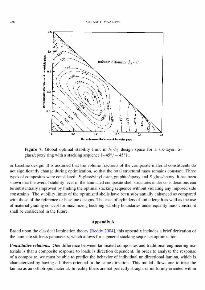
that is, [hk/hk]k=1,2,3 where hk is the thickness of a single lamina. Figure 7 depicts the developed pcr -isomerits in the h1-h2 design space. As seen, the feasible domain is bounded by the three straight linesh1 = 0, h2 = 0 and h1 + h2 = 0.5, where an infinite number of level curves are obliged to turn to be tangentto the latter one in order not to violate the thickness equality constraint. The global optimal solution hasshown to be of equal ply thickness: hk = 0.167, k = 1, 2, 3, where pcr = 1.2593. The calculateddimensional value of the maximum buckling pressure is given in Table 8 for different thickness to radiusratios.
6. Conclusions
In this paper, a practical approach for enhancing the buckling stability limits of thin-walled anisotropicrings/long cylinders has been developed. The formulation of an optimal lamination design against buck-ling has been thoroughly investigated, where useful design charts are given for several types of anisotropicrings/long cylinders showing the functional dependence of the critical buckling pressure on the stackingsequence and ply thickness as well. An analytical buckling model has been implemented, which providesgood sensitivity to lamination parameters, allowing the search for the needed optimal stacking sequencesin an acceptable computational time. The proposed model deals with dimensionless quantities in orderto be applicable for handling thin shells having arbitrary thickness-to-radius ratios, which is a majorcontribution of this work. Results have indicated that the optimized laminations induce significant in-creases, always exceeding several tens of percent, of the buckling pressures with respect to the reference
h/R 1/15 1/20 1/25 1/50 1/100
pcr (KPa) 1305.94 550.94 282.1 35.26 4.41
Table 8. Maximum buckling pressure for S-glass/epoxy rings [+45◦/− 45◦]3 ( pcr =
1.2593, pcro = 3.5(h/R)3 GPa, pcr = pcr · pcro).
788 KARAM Y. MAALAWI
�
�
�
�
�
�
Figure 7. Global optimal stability limit in h1-h2 design space for a six-layer, S-glass/epoxy ring with a stacking sequence [+45◦/− 45◦
]3.
or baseline design. It is assumed that the volume fractions of the composite material constituents donot significantly change during optimization, so that the total structural mass remains constant. Threetypes of composites were considered: E-glass/vinyl-ester, graphite/epoxy and S-glass/epoxy. It has beenshown that the overall stability level of the laminated composite shell structures under considerations canbe substantially improved by finding the optimal stacking sequence without violating any imposed sideconstraints. The stability limits of the optimized shells have been substantially enhanced as comparedwith those of the reference or baseline designs. The case of cylinders of finite length as well as the useof material grading concept for maximizing buckling stability boundaries under equality mass constraintshall be considered in the future.
Appendix A
Based upon the classical lamination theory [Reddy 2004], this appendix includes a brief derivation ofthe laminate stiffness parameters, which allows for a general stacking sequence optimization.
Constitutive relations. One difference between laminated composites and traditional engineering ma-terials is that a composite response to loads is direction dependent. In order to analyze the responseof a composite, we must be able to predict the behavior of individual unidirectional lamina, which ischaracterized by having all fibers oriented in the same direction. This model allows one to treat thelamina as an orthotropic material. In reality fibers are not perfectly straight or uniformly oriented within
OPTIMAL BUCKLING DESIGN OF ANISOTROPIC RINGS/LONG CYLINDERS. . . 789
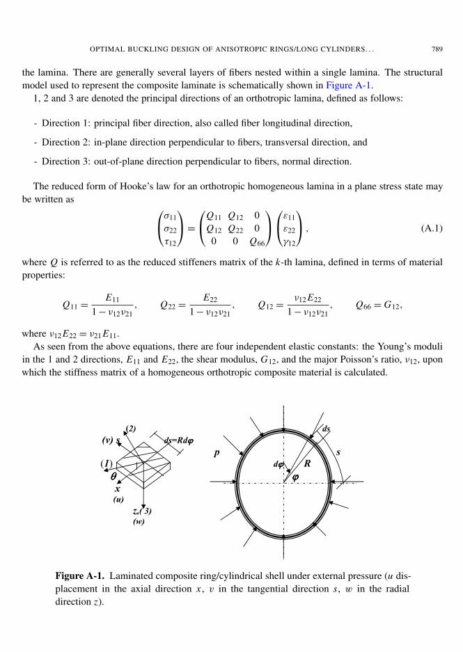
the lamina. There are generally several layers of fibers nested within a single lamina. The structuralmodel used to represent the composite laminate is schematically shown in Figure A-1.
1, 2 and 3 are denoted the principal directions of an orthotropic lamina, defined as follows:
- Direction 1: principal fiber direction, also called fiber longitudinal direction,
- Direction 2: in-plane direction perpendicular to fibers, transversal direction, and
- Direction 3: out-of-plane direction perpendicular to fibers, normal direction.
The reduced form of Hooke’s law for an orthotropic homogeneous lamina in a plane stress state maybe written as σ11
σ22
τ12
=
Q11 Q12 0Q12 Q22 00 0 Q66
ε11
ε22
γ12
, (A.1)
where Q is referred to as the reduced stiffeners matrix of the k-th lamina, defined in terms of materialproperties:
Q11 =E11
1 − ν12ν21, Q22 =
E22
1 − ν12ν21, Q12 =
ν12 E22
1 − ν12ν21, Q66 = G12,
where ν12 E22 = ν21 E11.As seen from the above equations, there are four independent elastic constants: the Young’s moduli
in the 1 and 2 directions, E11 and E22, the shear modulus, G12, and the major Poisson’s ratio, ν12, uponwhich the stiffness matrix of a homogeneous orthotropic composite material is calculated.
�
�
�
� ������ �������������������������������������������������������������������
� ������������������������������� �
�����������������������������������������������������������������������������������������������
����������������������������������������������������������������������������������������������������������
� ������� ��������������������������������
� �� �� � �� �
� ������� �� ���� � �
�
�
��
Figure A-1. Laminated composite ring/cylindrical shell under external pressure (u dis-placement in the axial direction x , v in the tangential direction s, w in the radialdirection z).
790 KARAM Y. MAALAWI
For a generally orthotropic material, (A.1) must be transformed to reflect rotated fiber orientationangles. The following matrix relation reflects this transformation [Daniel and Ishai 2006]:
σxx
σss
τxs
=
Q11 Q12 Q16Q12 Q22 Q26Q16 Q26 Q66
εxx
εss
γxs
. (A.2)
The elements of the k-th lamina stiffness matrix Q, which is now referred to the reference axes of thecylindrical shell (x, s, z), are given by
Q11 = U1 + U2 cos 2θ + U3 cos 4θ, Q22 = U1 − U2 cos 2θ + U3 cos 4θ,
Q12 = U4 − U3 cos 4θ, Q16 = 0.5 U2 sin 2θ + U3 sin 4θ,
Q26 = 0.5 U2 sin 2θ − U3 sin 4θ, Q66 = 0.5 (U1 − U4)− U3 cos 4θ,
where the invariant terms Ui are solely function of the material properties. They are defined by thefollowing expressions [Reddy 2004]:
U1 = 0.125 (3Q11 + 3Q22 + 2Q12 + 4Q66), U2 = 0.5 (Q11 − Q22),
U3 = 0.125 (Q11 + Q22 − 2Q12 − 4Q66), U4 = 0.125 (Q11 + Q22 + 6Q12 − 4Q66).
For classical lamination theory, it is assumed that n layers of material are perfectly bonded together, withinfinitely thin, nonshear deformable boundaries. Using Kirchoff plate theory [Simitses 1976], whichassumes that the in-plane displacements vary linearly through the thickness of the laminate, the displace-ments of a material point distance z from the middle surface are
u(x, s, z)= u0(x, s)− z∂w0
∂x,
v(x, s, z)= v 0(x, s)− z(∂w0
∂s−v 0
R
),
(s ∼= Rϕ,
zR
� 1),
w(x, s, z)= w0(x, s),
where u0(x, s), v 0(x, s) and w0(x, s) are the displacements of a generic point (x, s) on the shell middlesurface (z = 0) in x, s and z directions, respectively.
The strain-displacement relations in terms of the middle surface strains and shell curvatures are givenin the following:
εxx = ε0xx + zκxx ,
εss = ε0ss + zκss,
γxs = γ 0xs + zκxs,
or
εxx
εss
γxs
=
ε0xxε0
ssγ 0
xs
+ z
κxx
κss
κxs
, (A.3)
OPTIMAL BUCKLING DESIGN OF ANISOTROPIC RINGS/LONG CYLINDERS. . . 791
where the middle surface strains and curvatures are [Brush and Almroth 1975]
ε0xx =
∂u0
∂x,
ε0ss =
∂v 0
∂s+w0
R+
12
(∂w0
∂s−v 0
R
)2,
γ 0xs =
∂u0
∂s+∂v 0
∂x,
κxx = −∂2w0
∂x2 ,
κss = −∂
∂s
(∂w0
∂s−v 0
R
),
κxs = 2∂
∂x
(∂w0
∂s−v 0
R
).
Substituting for the total strains from (A.3) into (A.2) we haveσxx
σss
τxs
k
=
Q11 Q12 Q16Q12 Q22 Q26Q16 Q26 Q66
k
ε0xxε0
ssγ 0
xs
+ z
κxx
κss
κxs
. (A.4)
The resultant forces and moments per unit length applied at the middle surface are defined by theintegrals
Forces:
Nxx
Nss
Nxs
=
∫ h/2
−h/2
σxx
σss
τxs
dz =
n∑k=1
∫ zk
zk−1
σxx
σss
τxs
dz , (A.5)
Moments:
Mxx
Mss
Mxs
=
∫ h/2
−h/2
σxx
σss
τxs
zdz =
n∑k=1
∫ zk
zk−1
σxx
σss
τxs
zdz. (A.6)
Substituting for the stress-strain relationships of (A.4) into (A.5) and (A.6), we get
Nxx
Nss
Nxs
Mxx
Mss
Mxs
=
A11 A12 A16 B11 B12 B16
A12 A22 A26 B12 B22 B26
A16 A26 A66 B16 B26 B66
B11 B12 B16 D11 D12 D16
B12 B22 B26 D12 D22 D26
B16 B26 B66 D16 D26 D66
ε0xxε0
ssγ 0
xsκxx
κss
κxs
,
where Ai j are called the extensional stiffnesses given by Ai j =
n∑k=1
(Qi j )k(zk − zk−1). Bi j are called thebending-extensional stiffnesses given by
Bi j =12
n∑k=1
(Qi j )k(z2k − z2
k−1) .
Di j are called the bending stiffnesses
Di j =13
n∑k=1
(Qi j )k(z3k − z3
k−1),
where n is the number of different plies in the stacking sequence.
792 KARAM Y. MAALAWI
Appendix B: The interior penalty function technique
In this method the original objective function F(Ex) is augmented with terms, called penalty terms, suchthat as Ex approaches a constraint surface one term increases indefinitely. Since the algorithm seeks tominimize the value of the objective function, it will try not to penetrate any constraint surface. Thus allconstraints are taken into consideration by representing them by penalty terms in the objective functionexpression. The most commonly used interior penalty function [Vanderplaats 1994] is cast in the form
8(Ex, r)= F(Ex)− rM∑
j=1
1G j (Ex)
,
where8(Ex, r) is the modified objective function, G j (Ex) is the j -th constraint function and r is a multiplier.A sequence of unconstrained minimization problems is solved with successively decreasing values of r .The MATLAB optimization toolbox [Venkataraman 2002] offers routines that implement the interiorpenalty function method via a built-in function named fminsearch.
Acknowledgment
The author wishes to thank Professor Hayder Rasheed of the Department of Civil Engineering, KansasState University, for his valuable scientific discussions and help.
References
[Anastasiadis and Simitses 1993] J. S. Anastasiadis and G. J. Simitses, “Buckling of pressure-loaded, long, shear deformablecylindrical laminated shells”, Compos. Struct. 23:3 (1993), 221–231.
[Brush and Almroth 1975] D. O. Brush and B. O. Almroth, Buckling of bars, plates and shells, McGraw-Hill, New York, 1975.
[Chattopadhyay and Ferreira 1993] A. Chattopadhyay and J. Ferreira, “Design sensitivity and optimization of composite cylin-ders”, Compos. Eng. 3 (1993), 169–179.
[Daniel and Ishai 2006] I. M. Daniel and O. Ishai, Engineering mechanics of composite materials, 2nd ed., Oxford University,New York, 2006.
[Davies and Chauchot 1999] P. Davies and P. Chauchot, Composites for marine applications –Part 2: underwater structures,Kluwer Academic, Dordrecht, 1999.
[Graham 1995] D. Graham, “Composite pressure hulls for deep ocean submersibles”, Compos. Struct. 32:1-4 (1995), 331–343.
[Hodges 1999] D. H. Hodges, “Non-linear inplane deformation and buckling of rings and high arches”, Int. J. Nonlinear Mech.34:4 (1999), 723–737.
[Hodges and Harursampath 2002] D. H. Hodges and D. Harursampath, “Inplane buckling of anisotropic rings”, in Proceedingsof the 15th ASCE Engineering Mechanics Division Conference (New York), Columbia University, New York, June 2–5 2002.
[Librescu and Maalawi 2007] L. Librescu and K. Y. Maalawi, “Material grading for improved aeroelastic stability in compositewings”, J. Mech. Mater. Struct. 2:7 (2007), 1381–1394.
[Maalawi 2002] K. Y. Maalawi, “Buckling optimization of flexible columns”, Int. J. Solids Struct. 39:23 (2002), 5865–5876.
[Maalawi and El Chazly 2002] K. Y. Maalawi and N. M. El Chazly, “Global optimization of multi-element beam-type struc-tures”, in The 2nd international conference on advances in structural engineering and mechanics, ASEM02 (Busan, SouthKorea), August 21–23 2002.
[Rasheed and Yousif 2001] H. A. Rasheed and O. H. Yousif, “Buckling of thin laminated orthotropic composite rings/longcylinders under external pressure”, Int. J. Struct. Stab. Dyn. 1:4 (2001), 485–507.
OPTIMAL BUCKLING DESIGN OF ANISOTROPIC RINGS/LONG CYLINDERS. . . 793
[Rasheed and Yousif 2005] H. A. Rasheed and O. H. Yousif, “Stability of anisotropic laminated rings and long cylinderssubjected to external hydrostatic pressure”, J. Aerospace Eng. 18:3 (2005), 129–138.
[Reddy 2004] J. N. Reddy, Mechanics of laminated composite plates and shells: theory and analysis, 2nd ed., CRC Press,Boca Raton, 2004.
[Simitses 1976] G. J. Simitses, An introduction to the elastic stability of structures, Prentice-Hall, Englewood Cliffs, N.J., 1976.
[Simitses 1996] G. J. Simitses, “Buckling of moderately thick laminated cylindrical shells: a review”, Compos. Part B Eng.27:6 (1996), 581–587.
[Soden et al. 1998] P. D. Soden, M. J. Hinton, and A. S. Kaddour, “Lamina properties, lay-up configurations and loadingconditions for a range of fibre-reinforced composite laminates”, Compos. Sci. Technol. 58:7 (1998), 1011–1022.
[Sridharan and Kasagi 1997] S. Sridharan and A. Kasagi, “On the buckling and collapse of moderately thick composite cylin-ders under hydrostatic pressure”, Compos. Part B Eng. 28:5-6 (1997), 583–596.
[Tanguy et al. 2002] M. Tanguy, P. Mariusz, G. Bernard, and C. Pierre, “Optimal laminations of thin underwater compositecylindrical vessels”, Compos. Struct. 58:4 (2002), 529–537.
[Vanderplaats 1994] G. Vanderplaats, Numerical optimization techniques for engineering design: with applications, McGraw-Hill, New York, 1994.
[Venkataraman 2002] P. Venkataraman, Applied optimization with MATLAB programming, Wiley, New York, 2002.
[Vinson 1992] J. R. Vinson, The behavior of shells composed of isotropic and composite materials, Kluwer Academic, Dor-drecht, 1992.
[ZitzEvancih 1985] L. D. ZitzEvancih, “Designing graphite cylinders to resist buckling”, AIAA J. 85 (1985), 1101. Also,AIAA/SAE/ASME/ASEE 21st Joint Propulsion Conference, Monterey, CA: July 8–10, 1985.
Received 7 Oct 2007. Revised 21 Jan 2008. Accepted 22 Jan 2008.
KARAM Y. MAALAWI: [email protected] of Mechanical Engineering, National Research Center, 12622 Dokki, Cairo, Egyptwww.nrc.sci.eg
Related Documents