Effective edge node configuration for video transport over Optical Burst Switched networks F. Espina n , D. Morato, M. Izal, E. Magaña Public University of Navarre, Campus de Arrosadía s/n, E-31006 Pamplona, Spain article info Article history: Received 2 July 2012 Received in revised form 7 March 2013 Accepted 8 March 2013 Available online 22 March 2013 Keywords: Optical Burst Switching Bursty losses Video quality metrics Traffic Engineering Video multiplexation abstract This paper considers digital video transport over Optical Burst Switched networks where burst losses cause data loss from one or more adjacent video frames. Analytical approximations for the frame losses and video playback interruptions are derived and validated using simulations. Both parameters require a very limited and static amount of data about the video on the user side and some quality of service metrics about the network to quantify the quality of the received video. The results take into account the strong dependency in the video traffic structure due to the coding mechanisms. The critical effect of video coding parameters is also revealed. The paper also presents a Traffic Engineering procedure to select the best parameters for the edge node and the video codec to meet a given video quality level on the user side. & 2013 Elsevier B.V. All rights reserved. 1. Introduction Internet video was 40% of consumer Internet traffic in 2011 and it is expected to rise to more than 60% by the end of 2015 [1]. Therefore, high-speed optical switching back- bones will be necessary for video content delivery [2,3]. Video traffic is bursty. It generates large periodic data bursts (inter-frame time T if ). An Optical Circuit Switching (OCS) technology is no efficient for the individual trans- port of video frames due to the cost of creating and destroying the optical path for each one. Therefore, the path would last for the whole video duration, including the periods of time when the source does not generate traffic, resulting in an inefficient use of the optical bandwidth. The biggest problems of Optical Packet Switching (OPS) are the lack of optical RAM, needed for buffering packets during contention periods, and the need of very high switching rates. These needs are amplified in the case of bursty traffic like video, where the number of short optical packets competing for the same backbone network resources can vary significantly. Optical Burst Switching (OBS) is an intermediate solu- tion. In OBS, electronic packets are aggregated into large bursts and these bursts are routed and switched through the optical network as independent optical packets. The optical path is established for each burst using one way reservation, lessening the burden of circuit establishment times, and there is no need of very high switching rates as the optical packets are large. There are various proposals of hybrid switching archi- tectures [2,4,5] that can be used to transport video traffic instead of using ‘standard’ OBS. Some of these proposals combine OBS with other switching technologies and they can use the results and conclusions from this paper to improve the received video quality. For example, in an OCS þ OBS hybrid network like HOS [6], the video usually will be transported by OCS to ensure perfect delivery. When the OCS network does not have a source–destina- tion path available or when the available path does not have enough bandwidth, the whole video flow should be Contents lists available at SciVerse ScienceDirect journal homepage: www.elsevier.com/locate/osn Optical Switching and Networking 1573-4277/$ - see front matter & 2013 Elsevier B.V. All rights reserved. http://dx.doi.org/10.1016/j.osn.2013.03.003 n Corresponding author. Tel.: þ34 948 166033. E-mail addresses: [email protected] (F. Espina), [email protected] (D. Morato), [email protected] (M. Izal), [email protected] (E. Magaña). Optical Switching and Networking 10 (2013) 327–342

Welcome message from author
This document is posted to help you gain knowledge. Please leave a comment to let me know what you think about it! Share it to your friends and learn new things together.
Transcript
Contents lists available at SciVerse ScienceDirect
Optical Switching and Networking
Optical Switching and Networking 10 (2013) 327–342
1573-42http://d
n CorrE-m
daniel.meduardo
journal homepage: www.elsevier.com/locate/osn
Effective edge node configuration for video transport overOptical Burst Switched networks
F. Espina n, D. Morato, M. Izal, E. MagañaPublic University of Navarre, Campus de Arrosadía s/n, E-31006 Pamplona, Spain
a r t i c l e i n f o
Article history:Received 2 July 2012Received in revised form7 March 2013Accepted 8 March 2013Available online 22 March 2013
Keywords:Optical Burst SwitchingBursty lossesVideo quality metricsTraffic EngineeringVideo multiplexation
77/$ - see front matter & 2013 Elsevier B.V.x.doi.org/10.1016/j.osn.2013.03.003
esponding author. Tel.: þ34 948 166033.ail addresses: [email protected] (F. [email protected] (D. Morato), [email protected]@unavarra.es (E. Magaña).
a b s t r a c t
This paper considers digital video transport over Optical Burst Switched networks whereburst losses cause data loss from one or more adjacent video frames. Analyticalapproximations for the frame losses and video playback interruptions are derived andvalidated using simulations. Both parameters require a very limited and static amount ofdata about the video on the user side and some quality of service metrics about thenetwork to quantify the quality of the received video. The results take into accountthe strong dependency in the video traffic structure due to the coding mechanisms. Thecritical effect of video coding parameters is also revealed. The paper also presents a TrafficEngineering procedure to select the best parameters for the edge node and the videocodec to meet a given video quality level on the user side.
& 2013 Elsevier B.V. All rights reserved.
1. Introduction
Internet video was 40% of consumer Internet traffic in2011 and it is expected to rise to more than 60% by the endof 2015 [1]. Therefore, high-speed optical switching back-bones will be necessary for video content delivery [2,3].
Video traffic is bursty. It generates large periodic databursts (inter-frame time Tif). An Optical Circuit Switching(OCS) technology is no efficient for the individual trans-port of video frames due to the cost of creating anddestroying the optical path for each one. Therefore, thepath would last for the whole video duration, includingthe periods of time when the source does not generatetraffic, resulting in an inefficient use of the opticalbandwidth.
The biggest problems of Optical Packet Switching (OPS)are the lack of optical RAM, needed for buffering packetsduring contention periods, and the need of very high
All rights reserved.
pina),unavarra.es (M. Izal),
switching rates. These needs are amplified in the case ofbursty traffic like video, where the number of short opticalpackets competing for the same backbone network resourcescan vary significantly.
Optical Burst Switching (OBS) is an intermediate solu-tion. In OBS, electronic packets are aggregated into largebursts and these bursts are routed and switched throughthe optical network as independent optical packets. Theoptical path is established for each burst using one wayreservation, lessening the burden of circuit establishmenttimes, and there is no need of very high switching rates asthe optical packets are large.
There are various proposals of hybrid switching archi-tectures [2,4,5] that can be used to transport video trafficinstead of using ‘standard’ OBS. Some of these proposalscombine OBS with other switching technologies and theycan use the results and conclusions from this paper toimprove the received video quality. For example, in anOCSþOBS hybrid network like HOS [6], the video usuallywill be transported by OCS to ensure perfect delivery.When the OCS network does not have a source–destina-tion path available or when the available path does nothave enough bandwidth, the whole video flow should be

F. Espina et al. / Optical Switching and Networking 10 (2013) 327–342328
discarded or the OBS network should be used for itstransport. In this case, the results from this paper can beused to compute the received video quality depending onthe OBS network configuration or to choose the OBSparameters to obtain a minimum acceptable video quality.
An Optical Burst Switched (OBS) network [7] is con-sidered in this paper because of the potential it offers forthe core of future ISP networks. Edge nodes to an OBSnetwork aggregate input traffic into bursts. The mostfrequently used OBS burst formation mechanism (a.k.a.burstifiers) in the literature is timer-based [8]. A timer ofvalue Tout is started on the arrival of a packet to an emptyburst formation queue. When the timer expires, the burstis scheduled for transmission on the output port. Thesebursts use an all-optical data plane from the ingress toegress node where they are disassembled into their con-tained packets.
For efficient network transport, video flows are com-pressed, mainly using encoders from the MPEG family [9]or proprietary (but similar in concept) encoders [10].Given the widespread use of these encoders throughoutthe industry and reaching millions of user devices, theywill most likely remain popular for the foreseeable future.
The coding process in MPEG standards takes advantageof similarities in frames close in time to produce smallercompressed frames. Therefore, the decoding process formost video frames requires previously decoded frames,and the loss of one frame prevents the correct decoding ofthe following frames [11]. The packet aggregation proce-dure used on OBS creates bursts that could often containpackets from several contiguous video frames, thereforeproducing bursty losses of packets and frames in the videoflow. The loss of a few consecutive frames could create alarge gap in video playback, presenting a serious negativeimpact on the quality experienced by the user.
A video provider needs to be able to observe and reactquickly to these quality problems, optimally before theuser perceives them. The concept of Quality of Experience(QoE) emerged from this identified need. ITU-T definesQoE [12] as “The overall acceptability of an application orservice, as perceived subjectively by the end-user”. QoEincludes all the end-to-end system effects (e.g., client,terminal, network, services infrastructure), and the overallacceptability may be influenced by the user's expectationsand context.
Subjective quality metrics are concerned with how videois perceived by a user. Metric tests are expensive in termsof time (preparation and running) and human resourcesbecause they must collect user opinions on video quality.Objective quality metrics are mathematical models thatapproximate the results of subjective quality assessmentbut are based on metrics that can be measured objectivelyand automatically evaluated by a computer program.
Objective quality metrics are categorized based onthe availability of the original video signal [13]. In fullreference (FR) metrics, the entire original video signal isavailable. In reduced reference (RR) metrics, only some ofthe information of the original video is available. In noreference (NR) metrics, the original video is completelyunavailable. The signal received by the user is assumed tobe available for the three metrics.
FR metrics require the original and the received videoto be available together at some point. RR metrics requirethe computation and centralization of some structuralparameters from the original and the received video.NR metrics can be computed at the user side based onlyon the received video. Therefore, NR metrics are theeasiest to implement and use for Traffic Engineering in areal video distribution network. This paper analyses twoNR metrics mathematically and by simulation.
Popular NR metrics are based on network losses andtheir effects on the decoding procedure. Due to thebufferless nature of the OBS optical switches, output portcontention results in drops of bursts. The proportion oflost packets is a Quality of Service (QoS) metric about thetransport network, but according to the definition givenabove, it cannot be considered a QoE metric. The propor-tion of lost frames, named the Frame Loss Ratio (FLR), iscloser to what is expected of a QoE metric but is rather aQoS on the application level metric because it does notinclude the frames that are not lost but have not been ableto be decoded and displayed to the user. The proportion offrames that could not be decoded and displayed can beconsidered a QoE metric [14]. This proportion is called theFrame Starvation Ratio (FSR) and its complementary, theDecodable Frame Rate (Q), was proposed in [15]. It wasassumed that direct frame losses are mutually indepen-dent, but this assumption cannot be taken in networkscenarios with bursty losses, where usually more than oneadjacent frame is lost with high probability.
User perception is affected not only by the number ofnon-displayed frames but also by their grouping in time.This grouping is reflected in the length of the videoplayback interruptions or cuts. Experimental measure-ments [16] have shown that video playback interruptionsof 200 ms are certainly visible to the user. Even video cutsof only 80 ms may be visible. OBS losses are bursty, so cutsof that length or larger can be frequently generated.Therefore, it is important to analytically describe therelationship between the OBS parameters (e.g., timer,multiplexation level) and the video playback interruptionlengths.
The experimental measurements in [16] showed thatusers seem to be more annoyed by several short videoplayback interruptions than by one single video playbackinterruption of the same duration, and they are moreannoyed when the video playback interruptions are ofdifferent lengths than when they are of the same duration.Therefore, both the number of non-displayed frames andthe video playback interruption lengths must be taken intoaccount for video quality evaluation.
In this paper, quality metrics that depend on networkparameters are analytically derived for network scenarioswith bursty losses. The results allow simple quality pre-diction for the design and tuning of video distributionnetworks. Previous works have studied the transport ofvideo over OBS networks [17–19], but none of them havederived analytically the relationship between the networkOBS parameters (e.g., timer, loss ratio) and the degradationof video quality.
The rest of the paper is organized as follows. Section 2introduces the two proposed network scenarios for the

F. Espina et al. / Optical Switching and Networking 10 (2013) 327–342 329
transport of video over an OBS network without and withthe multiplexation of videos. Section 3 introduces someimportant parameters of encoded video. Sections 4 and 5present the analytical study of the two proposed scenarios.Section 6 presents the validation of these analyticalequations. Section 7 shows the contribution of some codecparameters to the quality degradation caused by the net-work. Section 8 presents a Traffic Engineering procedurefor tuning the burstification process to meet a givenquality level. Finally, Section 9 concludes this paper.
2. Network scenario
Video servers usually send all packets from a frameback-to-back. These packets will arrive at the edge nodeburstifier at approximately the same time. In an OBSnetwork with timer-based burstifiers, if a packet from aframe gets into a burst, we assume that the rest of thepackets from the frame do so as well. Therefore, by usinga timer-based burstifier, bursts will contain one or morewhole frames. Inside the OBS network, due to the buffer-less nature of the optical switches, output port contentionresults in the drop of bursts. The loss of one of these bursts(due to output port contention or bit errors) results in anumber of lost and non-decodable video frames.
Fig. 1 shows the scenarios under study. In the firstscenario, each video flow uses an independent burstifiernot shared with other videos. Several frames from thesame video could be aggregated into the same burst. In thesecond scenario, all the video flows from the same ingressnode that address the same egress point are aggregatedinto the same burst formation buffer with timer Tout.
The analytical results presented in this paper also applyto any other network technology where video frame lossescould take place in bursts. For example, Digital VideoBroadcasting-Handheld (DVB-H) [20] technology can pre-sent this behaviour. DVB-H is a technical specification forbringing broadcast services to battery-powered handhelddevices. In DVB-H, data packets are transmitted as burstsin small time slots at the channel bit rate (greater than theoriginal flow bit rate). A timer-based burstification processsimilar to the one used on OBS could be employed. Thus,the results for lost frames and video playback interrup-tions obtained for OBS will be valid for a DVB-H environ-ment with this burstification process.
Fig. 1. OBS network scenario under study: timer-based burstifiers withone or more video flows.
3. Video codification
MPEG is standardized in a joint effort by ISO and ITU.MPEG does not standardize the encoder/decoder, but itstandardizes the encoded video bit stream that the enco-der/decoder exchanges.
The MPEG standards define three types of video frames[21]: intra-coded frames (I-frames), inter-coded or pre-dicted frames (P-frames) and bidirectional coded frames(B-frames). I-frames can be decoded on their own. P- andB-frames hold only the changes in the image from thereference frames, thus improving the video compressionrates. P-frames have only one reference frame, the pre-vious I- or P-frame. In MPEG-2 Part 2 (H.262) [22], MPEG-4Part 2 [23] and MPEG-4 Part 10 (MPEG-4 AVC or H.264)[24], B-frames have two reference frames, the previous I-or P-frame and the following one of either type. Optionally,B-frames from H.264 can have up to 16 reference frames,located before or after the B-frame, and even B-frames canbe reference frames for other B-frames.
In this paper, videos that have “classic” B-frames will bestudied, i.e., B-frames depending only on the previous andfollowing I- or P-frames of either type.
I-, P- and B-frames are grouped into GoPs (Groups ofPictures). A GoP is a sequence of frames beginning with anI-frame up to the frame before the next I-frame. The GoPstructure is the pattern of I-, P- and B-frames used insideevery GoP. A regular GoP structure is usually described asGxBy, where x is the number of frames in the GoP and y isthe number of contiguous B-frames. For example, the GoPstructure could be G12B2 or IBBPBBPBBPBB. A GoP hasGP ¼ ⌊ðx−1Þ=ðyþ1Þ⌋ P-frames and GB ¼ x−1−GP B-framesdivided into blocks of y frames. Different GoP sizes andstructures, and even changes of the GoP structure in astream, are possible. However, the GoP structure is typi-cally not changed for the duration of a video.
Video frames are usually fragmented into several IPpackets due to their sizes. The loss of a portion of a framedue to network packet drops could have a lesser or greatereffect on the decoding process. In the OBS scenarioanalysed in this paper, all the packets from a frame areaggregated into a single burst. Therefore, there are nopartial frame losses, i.e., either the whole frame is lost ornothing is lost.
The event of not being able to decode a frame affectsother frames that are related by the interdependency ofthe GoP structure. The adopted criterion in this paper isthat a frame cannot be decoded if any of the frames itdepends on are non-decodable [14,15]. Because the MPEGstandard does not define a specific encoder/decoder beha-viour, the adopted criterion presents a worst case scenario.Better decoding results could be obtained in a real imple-mentation, but they would have a strong dependency onthe ad hoc techniques used by the specific decoder.
As an example, Fig. 2 (left) shows a G10B2 GoPstructure with a non-decodable P-frame due to networkpacket losses. In the right side of the figure, all the framesthat could not be decoded due to that loss are marked withdashed lines. The loss of a P-frame triggers the impossi-bility to decode all the following frames in the GoP and theB-frames previous to it and after another I- or P-frame.

F. Espina et al. / Optical Switching and Networking 10 (2013) 327–342330
The FLR is defined as Fl=F , where Fl is the number of lostframes from a video in the network and F is the referencetotal number of frames (see Table 1 for the notation usedin the paper). The FSR is defined as Fnd=F , where Fnd is thenumber of frames that could not be decoded due to lossesand inter-frame dependencies. Clearly, FSR≥FLR becauseFnd≥Fl.
CL is the average video playback interruption length oraverage cut length, measured in frames. CF is the averagenumber of cuts per frame. Both CL and CF account for non-decodable frames due to losses and inter-frame depen-dencies. Clearly, CL ¼ Fnd=ðF � CF Þ.
FSR, CL and CF are NR quality parameters, as noinformation from the original video is needed to computetheir values.
4. Network scenario with one video per burstifier
The scenario in which each burstifier aggregates trafficfrom one single video flow was partially studied in [25],but only suggestions about how to obtain values for FLR,
Table 1Notation.
Variable Definition
GxBy Regular GoP structure (x: nGP Number of P-frames in a GoGB Number of B-frames in a GoF Total number of frames in aFl Number of lost frames fromFnd Number of non-decoded fraTif Inter-frame timeTout Timer valueFb Number of frames per bursb Total number of burstsbl Number of lost burstsp Burst loss ratio at the netwFLR Frame Loss RatioFSR Frame Starvation RatioCL Average cut length, measurCF Average number of cuts per
Fbnd½T� Average number of non-dec
Cb½T� Average number of cuts perN Average number of multipleP½Fb� Probability that a video conFb Average number of frames
Tminout
Minimum Tout that satisfies
Tmin,mulout
Minimum Tout that satisfies
Toutmax Maximum Tout that satisfies
bs Burst sizeVR Average bitrate of a videobmaxs
Maximum burst sizeNmax Maximum number of video
Fig. 2. Example of inter-frame dependence in a GoP.
FSR and CL were provided. In this paper, an algebraic andsystematic method to compute FLR, FSR and CL isdemonstrated.
Optical buffering in the OBS core nodes can be imple-mented using fibre delay lines, but it is usually non-existent or scarce. Therefore, burst losses in the corenetwork will be the result of output port contention thatcould not be solved by the core node. In this paper, thenetwork is modelled as a single element including theeffect of interfering traffic to the video flow using burstloss ratio p (independent burst losses). This assumption iscommon in OBS because the losses in the core network areless correlated than in a packet switched network due toits bufferless nature [8].
As the network losses are modelled by an independentburst loss ratio p, the bursts from different burstifiers donot interfere with each other. Therefore, without loss ofgenerality, a network with only one burstifier and onevideo can be studied. In the analytical derivation, weignore events of more than one loss per GoP as they areof order p2, where p will be assumed to be small at thenetwork operating point (less than 10−2 for any usefulnetwork). In the following sections, the validity of thisapproximation will be checked.
4.1. Analysis of losses (FLR and FSR derivation)
The burst formation process creates b bursts from avideo stream. bl is the number of lost bursts, Fb ¼ ⌈Tout=Tif ⌉is the number of frames per burst and Fbnd½Tout � is the
umber of frames in the GoP; y: number of contiguous B-frames)P: ⌊ðx−1Þ=ðyþ1Þ⌋P: x−1−GP
videoa videomes in a video flow
t: ⌈Tout=Tif ⌉
ork
ed in framesframeoded frames due to the loss of a burst from a burstifier with timer T
lost burst from a burstifier with timer Txed video flowstributes to a burst with Fb frames when N videos are multiplexedof a video flow inside a burst when N videos are multiplexedthe CF constraint for Traffic Engineering
the CF constraint for Traffic Engineering when videos are multiplexed
the CL constraint for Traffic Engineering (with or without multiplexing)
flows allowed to be multiplexed into a burstifier

Table 2
Average number of frames that cannot be decoded (Fbnd) for different GxByGoP structures (the GoP type is in parentheses).
Fb G12B2 (open) G12B10 (closed) G16B7 (open) G16B14 (closed)
1 3.83 2.75 3.25 2.812 7.33 4.50 6.37 4.623 10.50 6.16 9.37 6.374 11.50 7.75 12.25 8.065 12.50 9.25 15.00 9.686 13.50 10.66 17.62 11.257 14.50 12.00 20.12 12.758 15.50 13.25 22.50 14.189 16.50 14.41 23.50 15.56
10 17.50 15.50 24.50 16.8711 18.50 16.50 25.50 18.1212 19.50 17.50 26.50 19.31
F. Espina et al. / Optical Switching and Networking 10 (2013) 327–342 331
average number of frames that cannot be decoded due to theloss of a burst containing Fb consecutive frames. Rememberthat Tout is the burst formation timer value, Tif is the inter-frame time, and GxBy is the typical structure of aregular GoP.
It was shown in [25] that the FLR is the same as theburst loss ratio p (1). The FSR depends on the FLR, theinter-frame time Tif, the GoP structure, and the burstifiertimer Tout (2):
FLR¼ FlF
¼ blFbb Fb
¼ blb
¼ p ð1Þ
FSR¼ FndF
¼ Fbnd½Tout �blbFb
¼ Fbnd½Tout �Fb
p¼ Fbnd½Tout �Fb
FLR ð2Þ
Fbnd½Tout � is computed as the average of the Fbnd½j; Tout �values:
Fbnd½Tout � ¼ 1x
∑x
j ¼ 1Fbnd½j; Tout � ð3Þ
Fbnd½j; Tout � is defined as the number of frames that couldnot be decoded when a burst of Fb frames is lost.j represents the position in the GoP of the first frame inthe dropped burst.
A GoP has only one I-frame, and it is always the firstframe (j¼1), but the position of the P- and B-framesdepends on the type of regular GoP, whether open orclosed, and the transmission order of the frames. There-fore, the computation of Fbnd½j; Tout � will be different foropen and closed GoPs.
In an open GoP, the last B-frames depend on theI-frame from the next GoP, as, for example, in G12B2 orIBBPBBPBBPBB. In a closed GoP, there is no dependencewith frames out of the GoP. A closed GoP ends with a P-frame, as, for example, in G9B3 or IBBBPBBBP.
A GoP structure such as IBBPBBPBBPBB or IBBBPBBBP isshown in presentation order, i.e., the order in which theframes will be shown to the user. However, becauseB-frames require the previous and the following I- orP-frame to be processed, the coding/decoding order willbe different. The coding order will be IbbPBBPBBPBBiBB fora G12B2 GoP structure, where the frames in lower-casecorrespond to frames from the previous or the next GoP,showing that it is an open GoP. The coding order will beIPBBBPBBB for a G9B3 GoP structure.
The transmission order usually corresponds to thecoding/decoding order. This ordering decides whichframes are lost when a burst is dropped. In this paper,the GoP structure will always be considered in coding/decoding order. Eq. (4) represents the position j of eachframe in a GoP in transmission order for both open (z¼1)and closed (z¼0) GoPs, where i¼ 0…GP and k¼ 0…y.
j¼ 1þ iðyþ1Þþk−ð1−zÞ y−⌊1− iGP
⌋ðy−kÞ !
:
I-frame if k¼ 0 and i¼ 0P-frame if k¼ 0 and i40B-frame if fz¼ 1, k40 and ∀ig
or fz¼ 0, k40 and i40g
8>>>><>>>>:
ð4Þ
The loss of a burst started by an I-frame (j¼1) willcause the whole GoP to not be decoded, and in the case ofopen GoPs, even the last B-frame block from the previousGoP will be useless. Eq. (5) provides Fbnd½j¼ 1; Tout � for openand closed GoPs.
Fbnd½j¼ 1; Tout � ¼ x⌈ Tout
xTif⌉þzy ð5Þ
The loss of a P-frame makes decoding all the followingframes impossible in the GoP. Thus, the number of framesthat could not be decoded when a P-frame started burst islost will depend on which P-frame in the GoP startedthe burst.
If the ith P-frame of a GoP is lost, it will always causex−iðyþ1Þþy frames to not be decoded. If Tout is largeenough to reach the I-frame from the next GoP, then allframes from the next GoP will not be decoded.
Eq. (6) provides Fbnd½j; Tout � for the case of a loss startedby a P-frame for open and closed GoPs.
Fbnd½j; Tout � ¼ ⌈ Toutþðj−1ÞTif
xTif⌉x−ðj−1Þþzy ð6Þ
The loss of a B-frame does not affect any other frames.As the timer Tout gets larger, more frames will fall insidethe lost burst whose first frame is a B-frame. Eventually, anI-frame (if the frames are from the last B-frame block) or aP-frame (otherwise) will be lost too. This scenario willcause other non-dropped frames to fail to be decoded aswell. For the kth B-frame from a B-frame block, thisscenario happens when Tout4 ðy−kþ1ÞTif .
Eq. (7) provides Fbnd½j; Tout � for the case of a loss startedby a B-frame for open and closed GoPs, whereTP ¼ Tout−ðy−kþ1ÞTif and TI ¼ Toutþðj−1ÞTif−xTif .
Fbnd½j; Tout � ¼
⌈Tout
Tif⌉ if
Tout
Tif≤ðy−kþ1Þ
y−kþ1þFbndjþð2−zÞy
yþ1; TP
� �if
Tout
Tif4ðy−kþ1Þ
and jox−y
y−kþ1þFbnd½j¼ 1; TI � ifTout
Tif4ðy−kþ1Þ
and j4x−y
8>>>>>>>>>>>>><>>>>>>>>>>>>>:
ð7Þ

Table 3Average cut length CL, measured in frames, for different GxBy GoPstructures (the GoP type is in parentheses).
Fb G12B2 (open) G12B10 (closed) G16B7 (open) G16B14 (closed)
1 3.83 2.75 3.25 2.812 5.50 4.15 5.66 4.353 6.30 5.28 7.50 5.664 6.90 6.20 8.90 6.785 7.50 6.93 10.00 7.75
F. Espina et al. / Optical Switching and Networking 10 (2013) 327–342332
Table 2 shows the analytical values of the averagenumber of frames that cannot be decoded (Fbnd) fordifferent GxBy GoP structures.
Combining (5)–(7) through (3) and (4), the FSR isobtained as
FSR¼ x⌈ Tout
xTif⌉þzyþ ∑
x
j ¼ 2Fbnd½j; Tout �
!FLRxFb
ð8Þ
6 8.10 7.52 10.84 8.577 8.70 8.00 11.50 9.278 9.30 8.36 12.00 9.869 9.90 8.65 12.53 10.37
10 10.50 8.85 13.06 10.8011 11.10 9.00 13.60 11.1512 11.70 9.54 14.13 11.44
4.2. Analysis of video playback interruptions (CL and CFderivation)
Cb½Tout � is defined as the average number of cuts per lostburst. Video playback interruptions or cuts must be under-stood as experienced by the user; therefore, they must bemeasured from the presentation order of the videos, notthe transmission order, where the bursty losses take place.The average number of cuts per frame CF ¼ Cb½Tout �bl=F ,where bl is the number of lost bursts. The average videoplayback interruption length can be expressed (9) as theratio of Fbnd½Tout � and Cb½Tout �:
CL ¼FndF � CF
¼ Fbnd½Tout �blF � Cb½Tout �bl=F
¼ Fbnd½Tout �Cb½Tout �
ð9Þ
Cb½j; Tout � is defined as the number of cuts producedwhen a burst of Fb frames is lost, where the first frame inthe burst is the jth frame from the GoP. Cb½Tout � iscomputed (10) as the average of Cb½j; Tout �:
Cb½Tout � ¼1x
∑x
j ¼ 1Cb½j; Tout � ð10Þ
The computation of Cb½j; Tout � could be different foropen and closed GoPs.
The loss of a burst started by an I-frame will cause thewhole GoP to not be decoded, creating a single cut. In thecase of an open GoP, the last B-frames from the previousGoP will be part of the same single cut when considered inpresentation order.
The loss of a burst that is started by a P-frame makesdecoding all the following frames impossible in the GoP.Because all these frames are consecutive, both in transmis-sion and presentation order, only one cut is generated. IfTout is large enough to reach the I-frame from the next GoP,then all the frames from the next GoP will not be decoded.Again, all these frames are consecutive and result in onlyone cut.
The loss of a burst started by a B-frame and containingonly B-frames creates only one cut. When the burstformation timer is large enough to reach an I- or P-frame,two cuts are generated. This scenario is due to an I- or P-frame, out of the burst, whose position in presentationorder falls between lost frames. The threshold for thisevent is Tout4 ðyþ1−kÞTif , where k is the position of thefirst frame in the lost burst relative to the B-frame block.For example, suppose a B-frame block has two frames(k¼ 1…2). The first frame of the block (k¼1) needs a timerTout greater than twice the Tif to reach the frame outsidethe B-frame block, i.e., Tout4ð2þ1−1ÞTif . However, the
second frame in the block only needs a timer Tout greaterthan Tif, Tout4 ð2þ1−2ÞTif .
Eq. (11) provides Cb½j; Tout � of a B-frame for open andclosed GoPs.
Cb½j; Tout � ¼2 if k40 and Tout4ðyþ1−kÞTif and
fopen GoP or fclosed GoP and i40gg1 otherwise
8><>:
ð11ÞCombining (10) and (11), the average number of cuts
per lost burst is obtained (12). The expression is valid forboth open (z¼1) and closed GoPs (z¼0).
Cb½Tout � ¼1þGPþGB
y ∑yk ¼ 1Cb½j¼ 2−zþk; Tout �
x
¼1þ⌊ x−1
yþ1⌋þx−1−⌊ x−1yþ1⌋
y ∑yk ¼ 1Cb½j¼ 2−zþk; Tout �x
ð12Þ
Cb½Tout � has a minimum value of 1 when Tout≤Tif , i.e.,when only one frame is inside each burst.
Cb½Tout � reaches the maximum value of 1þy=x �⌈ðx−1Þ=ðyþ1Þ⌉ for all Tout4yTif , i.e., when there are atleast yþ1 frames in each burst.
Combining (12) and (3), the average cut length CL (9) isobtained. Table 3 shows this average cut length, measuredin frames, for different GxBy GoP structures.
The average number of cuts per frame is computed as
CF ¼Cb½Tout �bl
F¼ Cb½Tout �bp
bFb¼ Cb½Tout �
Fbp ð13Þ
5. Network scenario with a multiplex of videos perburstifier
As in the previous scenario, a burst loss ratio p at thenetwork is assumed. Bursts from different burstifiers donot interfere with each other, so a network with only oneburstifier will be studied without loss of generality.
In this scenario, user video requests from a remotenetwork are modelled using a Poisson arrival process.All the flows from the same ingress node that addressthe same egress node are aggregated into the same burstformation buffer with timer Tout. Videos may have

Fig. 3. All videos have Fb or Fb−1 frames inside each burst.
F. Espina et al. / Optical Switching and Networking 10 (2013) 327–342 333
different inter-frame times Tif and GxBy GoP structures.The number of frames in a burst depends on the relation-ship between the Tif of each video and the timer Tout.For simplicity, we assume that all videos aggregated intothe same burstifier have the same Tif, but the analyticalmodel could be extended to the case of videos withdifferent Tif. The average number of multiplexed videoflows will be labelled as N.
Each burst could contain a different number of framesfrom each flow it aggregates. The video flow that initiatesthe burst formation timer will always aggregateFb ¼ ⌈Tout=Tif ⌉ frames. The rest of the flows in the burstbehave as having a timer for the remaining value when itsfirst frame arrives. The result is that some flows aggregateFb frames while others aggregate only Fb−1 frames (seeFig. 3 as an example). Those flows that aggregate Fb−1frames could be considered as having an equivalent timerof Tout−Tif . Because each burst could be initiated by adifferent video flow, a video flow will not always aggregatethe same number of frames.
From Section 4, losses and video playback interruptionscan be predicted for a video flow when all the burstscontain the same number of frames. In this new scenario,however, for some bursts the video flow will aggregate Fbof its frames, while for others it will contribute with Fb−1.To apply the previous results, we require the proportion ofbursts from each type.
P½Fbjk� is the probability that a video flow contributes toa burst with Fb frames when there are exactly k flowsbeing aggregated in the burstifier. This event takes placewhen the flow's first frame arrives less than Tout−⌊Tout=Tif ⌋Tif time units from the one that starts the timer.Assuming a large number of concurrent flows, the timedistance from the timer-starting frame to the arrival of thefirst frame from each flow can be approximated using auniform distribution in the range ½0,Tif �. Therefore, theprobability of a video flow being below that margin in aburst is just α¼ Tout=Tif−⌊Tout=Tif ⌋.
Assuming that all the flows have equal probability ofstarting the timer, then P½Fbjk� ¼ 1=kþαðk−1Þ=k. This resulttakes into account the case when the flow starts the timeras well as the case when it does not start the timer but itsfirst frame arrives close enough to the one doing it.
Due to the Poisson arrivals, the probability of k videosbeing multiplexed in a burst aggregator is P½k� ¼ e−NNk=k!,the probability of being in state k of anM=G=∞ system [26]with an average of N videos multiplexed. Because thetimer only works when there is at least one video flow, thestate probability of interest must be conditioned to thecase of at least one flow in the system, as
P½kjk40� ¼ P½k�P½k40� ¼
P½k�∑∞
i ¼ 1P½i�¼
Nk
k!e−N
∑∞i ¼ 1
Ni
i! e−N
¼ 11−e−N
Nk
k!e−N ¼ 1
eN−1Nk
k!ð14Þ
The expression for the probability that a video flowcontributes to a burst with Fb frames P½Fb� is computed as
P½Fb� ¼ ∑∞
i ¼ 1ðP½Fb i�P½i i40�Þ
����¼ ∑
∞
i ¼ 1
1iþ i−1
iα
� �1
eN−1Ni
i!
!
¼ 1eN−1
∑∞
i ¼ 1αþ 1−α
i
� �Ni
i!
!
¼ α
eN−1∑∞
i ¼ 1
Ni
i!þ 1−α
eN−1∑∞
i ¼ 1
Ni
i!1i
¼ α
eN−1ðeN−1Þþ 1−α
eN−1ðEiðNÞ−γ−LogðNÞÞ
¼ αþ 1−αeN−1
ðEiðNÞ−γ−LogðNÞÞ ð15Þ
In (15), EiðNÞ ¼ −R∞−Ne
−t=t dt is the Exponential Integralof N and γ is the Euler–Mascheroni constant [27]. P½Fb�tends to α as the average number of simultaneous videosN grows.
Based on this result, the average number of framesfrom a flow inside the burst, Fb , is calculated as
Fb ¼ P½Fb�Fbþð1−P½Fb�ÞðFb−1Þ ¼ Fb−1þP½Fb� ð16ÞIn the following subsections, an algebraic and systema-
tic method to compute FLR, FSR, CL and CF for the scenariowith a multiplex of videos per burstifier is demonstrated.
5.1. Analysis of losses (FLR and FSR derivation)
Similar to the one video per burstifier scenario, the FLRfor the scenario with multiplexation is just p.
To obtain the FSR, the number of dropped frames mustbe translated into the number of frames that could not bedecoded. The bursts that contain Fb frames from a certainvideo will result in Fbnd½Tout �blP½Fb� non-decodable frames.Those bursts containing Fb−1 frames result in Fbnd½Tout−Tif �blð1−P½Fb�Þ non-decodable frames. The FSR forthe N average number of multiplexed video flows is finallycomputed in (17), where Fbnd½T � can be directly obtainedfrom (3):
FSR¼ FndF
¼ ðFbnd½Tout �P½Fb�þFbnd½Tout−Tif �P½Fb−1�ÞblNFbbN
¼ ðFbnd½Tout �P½Fb�þFbnd½Tout−Tif �ð1−P½Fb�ÞÞblNFbbN
¼ Fbnd½Tout �P½Fb�þFbnd½Tout−Tif �ð1−P½Fb�ÞFb
p
¼ Fbnd½Tout �P½Fb�þFbnd½Tout−Tif �ð1−P½Fb�ÞFb
FLR ð17Þ
The FSR in this scenario depends on the averagenumber of multiplexed flows through the P½Fb� term.As the multiplexing level N is increased, P½Fb� tends to αand FSR becomes stable.

1 2 3 4 5 6 7 8 9 10 11 12 13
Timer value Tout(ms)
p=10-1, FLRFSR
p=10-2, FLRFSR
0.0001
0.001
0.01
0.1
1
0.0001
0.001
0.01
0.1
1
0 100 200 300 400 500 0 100 200 300 400 500
1 2 3 4 5 6 7 8 9 10 11 12 13
Fram
e Lo
ss R
atio
and
Fra
me
Star
vatio
n R
atio
Number of video frames per burst (Fb)
p=10-3, FLRFSR
p=10-4, FLRFSR
Fig. 4. Losses (FLR and FSR) for the LOTRIII trace (G12B2 GoP structure).
1 2 3 4 5 6 7 8 9 10 11 12 13
Fram
e St
arva
tion
Rat
io
Number of video frames per burst (Fb)
Simulationp=10-1
p=10-2
p=10-3
p=10-4
0.0001
0.001
0.01
0.1
1
0.0001
0.001
0.01
0.1
1
0 50 100 150 200 250 300 350 400 450 500
1 2 3 4 5 6 7 8 9 10 11 12 13
Timer value Tout(ms)
Analyticalp=10-1
p=10-2
p=10-3
p=10-4
Fig. 5. Analytical model of FSR becoming accurate for low burst lossratios for the LOTRIII trace file (G12B2 GoP structure).
F. Espina et al. / Optical Switching and Networking 10 (2013) 327–342334
5.2. Analysis of video playback interruptions (CL and CFderivation)
Using the same procedure as for (17), the average videoplayback interruption length can be obtained from Fbndusing (9), where Fbnd½T� and Cb½T � are already solved (i.e., in(3) and (12)):
CL ¼FndF � CF
¼ ðFbnd½Tout �P½Fb�þFbnd½Tout−Tif �ð1−P½Fb�ÞÞblNðCb½Tout �P½Fb�þCb½Tout−Tif �ð1−P½Fb�ÞÞblN
¼ Fbnd½Tout �P½Fb�þFbnd½Tout−Tif �ð1−P½Fb�ÞCb½Tout �P½Fb�þCb½Tout−Tif �ð1−P½Fb�Þ
ð18Þ
The average number of cuts per frame for videos inpresentation order is computed as
CF ¼ðCb½Tout �P½Fb�þCb½Tout−Tif �ð1−P½Fb�ÞÞblN
F
¼ ðCb½Tout �P½Fb�þCb½Tout−Tif �ð1−P½Fb�ÞÞbpNFbbN
¼ Cb½Tout �P½Fb�þCb½Tout−Tif �ð1−P½Fb�ÞFb
p ð19Þ
The average number of cuts per frame is inverselyproportional to the average number of frames per burst Fb .
6. Validation through simulation
In Sections 4 and 5, we have presented the analyticalmodels for computing FLR, FSR and CL in a timer-based OBSnetwork. In this section, we present simulation results thatvalidate the applicability of the analytical models. Wedeveloped a modified version of our OBS simulator [28].Statistical results are obtained at 95% confidence level, butmost confidence intervals are too small to be noticed inthe figures. Video traces from [29,30] with same anddifferent bit-rate, GoP and inter-frame time have beenused: The Lord of the Rings III (LOTRIII), The Matrix, TokyoOlympics and Star Wars IV. The results do not exhibitsignificant differences and therefore this paper mostlyshows figures with the trace LOTRIII (G12B2 GoP structure,Tif ¼ 40 ms, average bit rate of 714 kbps at 192 min) andStar Wars IV (G16B7 GoP structure, Tif ¼ 40 ms, average bitrate of 3.143 Mbps at 36 min).
The analytical models require that the losses in the OBSnetwork could be modelled by an independent burst lossratio p. First, we assume an environment where the burstloss ratio is an independent rate p and we validate theanalytical models for one video per burstifier (Section 6.1)and for a multiplex of videos per burstifier (Section 6.2).This environment is modelled using a black box networkscenario with an i.i.d. burst loss ratio p. In this environ-ment, different network scenarios were evaluated usingp¼ ½10−4,10−1� and a minimum of 2 million bursts in thestationary state. Previous papers have studied the effect ofthis range of loss ratios in TCP traffic [31].
Afterwards, a full network topology is used (Section6.3), where the burst loss ratio is the result of output portcontention on core nodes. In this environment, burstlosses can present correlation and it cannot be asserted
that the analytical models are valid. However, as theresults will show, the analytical models stay accurate forlow to medium load conditions.
6.1. One video per burstifier scenario
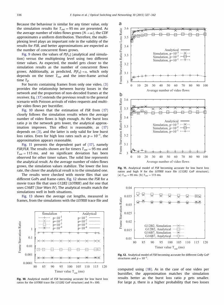
Fig. 4 shows the simulation results of the FLR and FSRversus the timer value Tout (lower x-axis) and the numberof frames per burst (upper x-axis). The x-axis range is largeenough to cover the GoP duration to show the effects of itsstructure. The longest timer duration considered in thefigure is 500 ms, still reasonable for live multicasting andcomparable to coding delays. The results show (Fig. 4) thatFLR is equal to the burst loss ratio p and is independentof the timer value. The FSR tends to FLR as the timervalue grows.
Fig. 5 shows that the estimation of FSR from (8) closelyfollows the simulation results. The theoretical resultprovides a slight overestimation of the FSR because thesituations with more than one burst loss containing framesfrom the same GoP have been ignored. For example, twolost bursts could contain frames from the same GoP. In thissituation, there is a high probability that some frames
F. Espina et al. / Optical Switching and Networking 10 (2013) 327–342 335
dropped due to the second loss were the same as some notdecoded due to those frames dropped in the first one.Therefore, the real FSR will be smaller than the computedone. However, as the burst loss ratio p becomes smaller,the probability of more than one loss per GoP becomesnegligible and the FSR estimation becomes more accurate.Even for high loss rates such as p¼ 10−1, the approxima-tion looks reasonable.
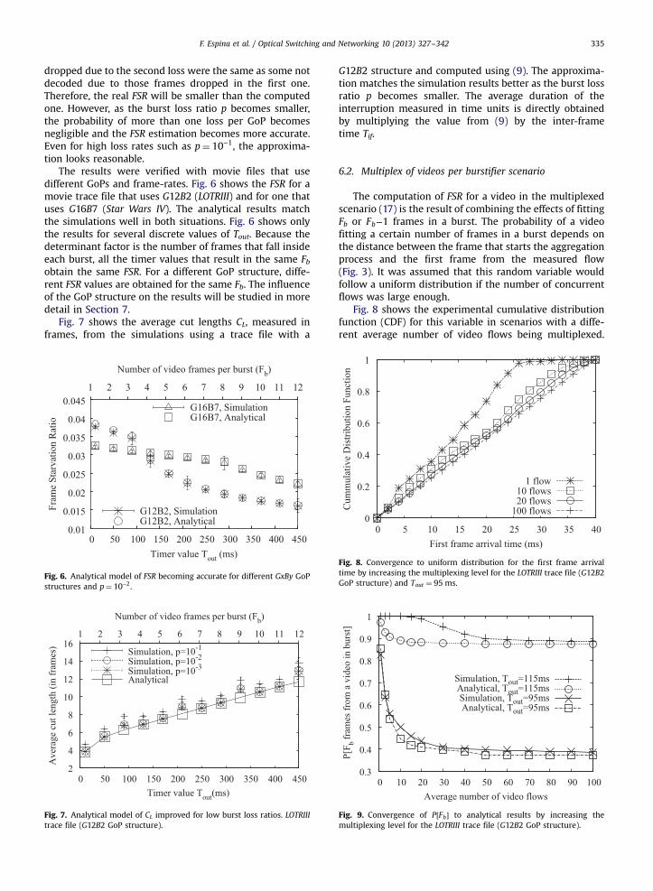
The results were verified with movie files that usedifferent GoPs and frame-rates. Fig. 6 shows the FSR for amovie trace file that uses G12B2 (LOTRIII) and for one thatuses G16B7 (Star Wars IV). The analytical results matchthe simulations well in both situations. Fig. 6 shows onlythe results for several discrete values of Tout. Because thedeterminant factor is the number of frames that fall insideeach burst, all the timer values that result in the same Fbobtain the same FSR. For a different GoP structure, diffe-rent FSR values are obtained for the same Fb. The influenceof the GoP structure on the results will be studied in moredetail in Section 7.
Fig. 7 shows the average cut lengths CL, measured inframes, from the simulations using a trace file with a
1 2 3 4 5 6 7 8 9 10 11 12
G16B7, SimulationG16B7, Analytical
0.01
0.015
0.02
0.025
0.03
0.035
0.04
0.045
0 50 100 150 200 250 300 350 400 450
Fram
e St
arva
tion
Rat
io
Timer value Tout (ms)
Number of video frames per burst (Fb)
G12B2, SimulationG12B2, Analytical
Fig. 6. Analytical model of FSR becoming accurate for different GxBy GoPstructures and p¼ 10−2.
2
4
6
8
10
12
14
16
0 50 100 150 200 250 300 350 400 450
1 2 3 4 5 6 7 8 9 10 11 12
Ave
rage
cut
leng
th (i
n fr
ames
)
Timer value Tout(ms)
Number of video frames per burst (Fb)
Simulation, p=10-1
Simulation, p=10-2
Simulation, p=10-3
Analytical
Fig. 7. Analytical model of CL improved for low burst loss ratios. LOTRIIItrace file (G12B2 GoP structure).
G12B2 structure and computed using (9). The approxima-tion matches the simulation results better as the burst lossratio p becomes smaller. The average duration of theinterruption measured in time units is directly obtainedby multiplying the value from (9) by the inter-frametime Tif.
6.2. Multiplex of videos per burstifier scenario
The computation of FSR for a video in the multiplexedscenario (17) is the result of combining the effects of fittingFb or Fb−1 frames in a burst. The probability of a videofitting a certain number of frames in a burst depends onthe distance between the frame that starts the aggregationprocess and the first frame from the measured flow(Fig. 3). It was assumed that this random variable wouldfollow a uniform distribution if the number of concurrentflows was large enough.
Fig. 8 shows the experimental cumulative distributionfunction (CDF) for this variable in scenarios with a diffe-rent average number of video flows being multiplexed.
0
0.2
0.4
0.6
0.8
1
0 5 10 15 20 25 30 35 40
Cum
mul
ativ
e D
istri
butio
n Fu
nctio
n
First frame arrival time (ms)
1 flow10 flows20 flows
100 flows
Fig. 8. Convergence to uniform distribution for the first frame arrivaltime by increasing the multiplexing level for the LOTRIII trace file (G12B2GoP structure) and Tout ¼ 95 ms.
0.3
0.4
0.5
0.6
0.7
0.8
0.9
1
0 10 20 30 40 50 60 70 80 90 100
P[F
b fr
ames
from
a v
ideo
in b
urst
]
Average number of video flows
Simulation, Tout=115msAnalytical, Tout=115msSimulation, Tout=95msAnalytical, Tout=95ms
Fig. 9. Convergence of P½Fb� to analytical results by increasing themultiplexing level for the LOTRIII trace file (G12B2 GoP structure).
3
3.1
3.2
3.3
3.4
3.5
3.6
0 10 20 30 40 50 60 70 80 90 100
Fram
e St
arva
tion
Rat
io/F
ram
e Lo
ss R
atio
Average number of video flows
AnalyticalSimulation, p=10-3
Simulation, p=10-2
Simulation, p=10-1
3
3.1
3.2
3.3
3.4
3.5
3.6
0 10 20 30 40 50 60 70 80 90 100
Fram
e St
arva
tion
Rat
io/F
ram
e Lo
ss R
atio
Average number of video flows
AnalyticalSimulation, p=10-3
Simulation, p=10-2
Simulation, p=10-1
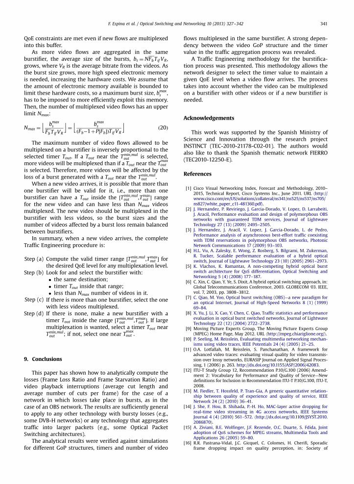
Fig. 11. Analytical model of FSR becoming accurate for low burst lossratios and high N for the LOTRIII trace file (G12B2 GoP structure).(a) Tout ¼ 95 ms. (b) Tout ¼ 115 ms.
0.035
0.04
atio
F. Espina et al. / Optical Switching and Networking 10 (2013) 327–342336
Because the behaviour is similar for any timer value, onlythe simulation results for Tout ¼ 95 ms are presented. Asthe average number of video flows grows (N-∞), the CDFapproximates a uniform distribution. Therefore, the multi-plexing level plays an important role in the validity of theresults for FSR, and better approximations are expected asthe number of concurrent flows grows.
Fig. 9 shows the values of P½Fb� (analytical and simula-tion) versus the multiplexing level using two differenttimer values. As expected, the model gets closer to thesimulation results as the number of concurrent flowsgrows. Additionally, as predicted, P½Fb�-α, which onlydepends on the timer Tout and the inter-frame arrivaltime Tif.
For bursts containing frames from only one video, (3)provides the relationship between bursty losses in thenetwork and the proportion of non-decoded frames at thereceiver. Eq. (17) extends the previous result to the generalscenario with Poisson arrivals of video requests and multi-ple video flows per burstifier.
Fig. 10 shows that the estimation of FSR from (17)closely follows the simulation results when the averagenumber of video flows is high enough. As the burst lossratio p in the network gets lower, the analytical approx-imation improves. This effect is reasonable, as (17)depends on (3), and the latter is only valid for low burstloss ratios. Even for high loss rates such as p¼ 10−1, theapproximation appears reasonable.
Fig. 11 presents the dependent part of (17), namelyFSR/FLR. The results shown are for timers Tout ¼ 95 ms andTout ¼ 115 ms, and no significant deviation has beenobserved for other timer values. The solid line representsthe analytical result. As the average number of video flowsgrows, the simulation values stabilize. The lower the lossrate, the closer the analytical result is to the simulated one.
The results were checked with movie files that usedifferent GoPs and frame-rates. Fig. 12 shows the FSR for amovie trace file that uses G12B2 (LOTRIII) and for one thatuses G16B7 (Star Wars IV). The analytical results match thesimulations well in both situations.
Fig. 13 shows the average cut lengths, measured inframes, from the simulations with the LOTRIII trace file and
0.0001
0.001
0.01
0.1
1
80 85 90 95 100 105 110 115 120
Fram
e St
arva
tion
Rat
io
Timer value Tout (ms)
Simulationp=10-1
p=10-2
p=10-3
p=10-4
Analyticalp=10-1
p=10-2
p=10-3
p=10-4
Fig. 10. Analytical model of FSR becoming accurate for low burst lossratios for the LOTRIII trace file (G12B2 GoP structure) and N¼100.
0.01
0.015
0.02
0.025
0.03
80 85 90 95 100 105 110 115 120
Fram
e St
arva
tion
R
Timer value Tout (ms)
G12B2, SimulationG12B2, AnalyticalG16B7, SimulationG16B7, Analytical
Fig. 12. Analytical model of FSR becoming accurate for different GxBy GoPstructures and p¼ 10−2.
computed using (18). As in the case of one video perburstifier, the approximation matches the simulationresults better as the burst loss ratio p gets smaller.For large p, there is a higher probability that two losses

5.8
6
6.2
6.4
6.6
6.8
7
0 2 4 6 8 10 12 14 16 18 20
Ave
rage
cut
leng
th (i
n fr
ames
)
Average number of video flows
Simulation, p=10-1
Simulation, p=10-2
Simulation, p=10-3
Simulation, p=5*10-4
Analytical
Fig. 13. Analytical model of CL becoming accurate for low burst loss ratiosfor the LOTRIII trace file (G12B2 GoP structure) and Tout ¼ 95 ms.
Fig. 14. NSFNet core network with video and interference traffic from allto all.
1e-05
0.0001
0.001
0.01
0.1
0.1 0.2 0.3 0.4 0.5 0.6
Bur
st lo
ss ra
tio (p
) and
Fram
e Lo
ss R
atio
(FLR
)
Utilization factor (ρ)
Tout=30ms, pFLR
Tout=90ms, pFLR
Tout=170ms, pFLR
Tout=250ms, pFLR
Fig. 15. Validation of analytical model of FLR for the Star Wars IV trace file(G16B7 GoP structure) in the NSFNet scenario.
1e-05
0.0001
0.001
0.01
0.1
1
0 0.05 0.1 0.15 0.2 0.25 0.3
Fram
e St
arva
tion
Rat
io
Time value Tout (s)
ρ=0.2, SimuAnalytic
ρ=0.3, SimuAnalytic
ρ=0.4, SimuAnalytic
ρ=0.5, SimuAnalytic
Fig. 16. Validation of analytical model of FSR for the Star Wars IV trace file(G16B7 GoP structure) in the NSFNet scenario.
F. Espina et al. / Optical Switching and Networking 10 (2013) 327–342 337
are in the same GoP or adjacent GoPs with the result of alarger video cut. Only results around p¼ 10−1 are signifi-cantly separated from analytical ones. As shown before,the analytical result becomes closer to the simulationvalues as the number of multiplexed flows grows due tothe assumptions taken for the analytical derivation. Finally,the timer value does not significantly influence the qualityof the approximation, as was verified for the scenario ofone video per burstifier.
6.3. NSFNet network scenario
In this subsection, we employ the NSFNet topologywith 14 core nodes (see Fig. 14) to validate the analyticalmodels over a full network topology. In this network, theburst loss ratio is the result of output port contention oncore nodes. Therefore, burst losses can present correlationwhich invalidates one of the model hypotheses. We intendto check whether the results still hold.
All the data links between nodes are bidirectional with12 data wavelengths at 1 Gbps. Each core node has oneedge node that introduces traffic to the network. The edgenodes generate two types of traffic, namely video trafficand Internet data traffic.
Each edge node sends a video flow to the other 13 edgenodes. In an interactive scenario, the users can select amovie and start a new video flow at any time, although themovie could be the same, the video flows will not besynchronized. This is modelled selecting a different ran-dom starting time between ½0,Tif � and a different randomstarting frame for each video.
The Internet data traffic is modelled [32] as a burstprocess with an exponential interarrival time distributionof mean Tout=m and a Gaussian size distribution of meanToutμ and variance T2H
outs2. The traffic from each edge node
is evenly distributed to the other 13 edge nodes. Assuggested in [32], the traffic parameters inferred fromthe Bellcore traces are used (coefficient of variationc2v ¼ s2=μ2 ¼ 0:1 and Hurst parameter H¼0.78) and m(number of FECs on the edge node) is fixed to 10. Thekey parameter of the average burst size, μ, is set todifferent values in order to obtain the different load
conditions ρ¼ ½0:2,0:5� at the output port on each edgenode, i.e., each edge node sends on average an Internetdata traffic of ρn12=13n1 Gbps to the other 13 edge nodes.

2 3 4 5 6 7 8 9
10 11 12
0 0.05 0.1 0.15 0.2 0.25 0.3
Ave
rage
cut
leng
th (i
n fr
ames
)
Time value Tout (s)
ρ=0.2, SimuAnalytic
ρ=0.3, SimuAnalytic
ρ=0.4, SimuAnalytic
ρ=0.5, SimuAnalytic
Fig. 17. Validation of analytical model of CL for the Star Wars IV trace file(G16B7 GoP structure) in the NSFNet scenario.
0.01
0.015
0.02
0.025
0.03
0.035
0.04
0.045
0 2 4 6 8 10 12
Fram
e St
arva
tion
Rat
io
Number of video frames per burst (Fb)
G12B1G12B2
G12B11G12B10
0.01
0.015
0.02
0.025
0.03
0.035
0.04
0.045
0.05
0.055
0 2 4 6 8 10 12 14 16
Fram
e St
arva
tion
Rat
io
Number of video frames per burst (Fb)
G16B1G16B3
G16B15G16B14
Fig. 18. Analytical model of FSR for different GxBy GoP structures andp¼ 10−2.
F. Espina et al. / Optical Switching and Networking 10 (2013) 327–342338
Fig. 15 shows the simulation results for the burst lossratio p and FLR in the network versus different loadconditions. The results show that FLR is equal to the burstloss ratio p and that it is independent of the timer value.
Fig. 16 shows that the estimation of FSR from theanalytical model (8) closely follows the simulation resultsfor the trace Star Wars IV with G16B7 structure.
Fig. 17 shows the average cut lengths CL, measured inframes, from the simulations using the trace Star Wars IVwith G16B7 structure and those computed using (13).
With these simulation results, we can conclude that theanalytical model for one video per burstifier can be appliedover a full network topology.
In the case of several multiplexed videos per burstifier,the results in a whole network scenario are similar. Theonly difference in the model is based on the uniformdistribution of the arrivals inside a burst, but this phe-nomenon takes place on the edge of the network andtherefore its validity will not change on a network scalescenario.
7. Influence of GoP structure on results
Section 6 showed that the analytical equations pre-sented in Sections 4 and 5 follow the simulation resultswell, obtaining better approximations as the burst lossratio p becomes smaller. All these equations depend on theGxBy GoP structure, as observed in Fig. 6. Thus, theinfluence of the GxBy GoP structure on the FSR and CLmust be studied in greater detail.
7.1. One video per burstifier scenario
Fig. 18 compares the FSR as obtained from (8) fordifferent GoP structures. For every GoP structure, as thetimer value Tout grows, more frames fall into each burst;hence, when a burst is lost, fewer frames outside the GoPare affected. Therefore, the larger the Tout, the better.However, this timer increase will result in larger burstsand larger video playback interruptions.
Fig. 18 shows that when using the same timer valueTout, better results (lower losses) can be obtained by coding
the movie with the proper GoP structure. For example,a target FSR quality value of 0.025 (2.5% of frames notdecoded) in a network that drops 1% of the bursts cannotbe achieved with a timer value Tout of 250 ms and a GoPstructure G16B7, but it is obtainable with a G12B2 struc-ture. It must be noted that the GoP structure can bechanged and the same flow rate can be kept by adjustingthe coding quality.
As shown in Fig. 18, the GoP structure has a non-lineareffect on the FSR. A similar behaviour is observed for CL.Fig. 19 compares CL as obtained from (9) for different GoPstructures. For any GoP structure, as the timer value Toutgrows, more frames fall into each burst; hence, when aburst is lost, the video playback interruption lasts longer.For larger GoP structures, video cuts become longer, evenreaching or surpassing the GoP length. Therefore, theshorter the GoP, the better. However, this GoP lengthreduction will result in larger bit rates because the numberof I-frames will increase.
7.2. Multiplex of videos per burstifier scenario
Fig. 20 presents the analytical quotient of FSR over FLRfor different GoP structures. To facilitate visual inspection,the values are computed as an increment of the value for

0
5
10
15
20
25
30
80 90 100 110 120 130Perc
enta
ge im
prov
emen
t in
FSR
/FLR
(%)
Timer value Tout (ms)
G12B1G12B10G12B2G12B3G12B5G12B11
0
5
10
15
20
25
30
80 90 100 110 120 130Perc
enta
ge im
prov
emen
t in
FSR
/FLR
(%)
Timer value Tout (ms)
G16B1G16B2G16B14G16B4G16B3G16B7G16B15
Fig. 20. Loss reduction with increasing timer value Tout depends on theGxBy GoP structure.
2
4
6
8
10
12
14
16
0 2 4 6 8 10 12
Ave
rage
cut
leng
th (i
n fr
ames
)
Number of video frames per burst (Fb)
G12B1G12B2
G12B10G12B11
2
4
6
8
10
12
14
16
18
20
0 2 4 6 8 10 12 14 16
Ave
rage
cut
leng
th (i
n fr
ames
)
Number of video frames per burst (Fb)
G16B1G16B3
G16B14G16B15
Fig. 19. Analytical model of CL for different GxBy GoP structures.
F. Espina et al. / Optical Switching and Networking 10 (2013) 327–342 339
timer Tout ¼ 82 ms. The figure shows that as the timervalue increases (x-axis), there is a reduction of the FSR ofas much as a 30% with respect to the value at Tout ¼ 82 ms.However, this improvement is obtained only for someGxBy GoP structures, e.g., G12B1 or G16B1. For other GoPstructures, e.g., G12B5, this improvement is insignificant.Therefore, selection of the GoP structure has a strongimpact on performance, measured as the number offrames that could not be decoded.
Fig. 21 presents, as in Fig. 20, the analytical quotient ofFSR over FLR for different GoP structures, but now, theabsolute values are plotted. Obviously, the figure showsthat as the timer value increases, there is a reduction ofthe FSR for some GoP structures. However, the figurealso shows that the FSR/FLR absolute values of each GoPstructure start from different levels. Thus, some GoPstructures may continue to have a worse FSR as the timervalue increases, although they greatly improve it, e.g.,G16B1. Other GoP structures may improve just enough asthe timer value increases to outperform other GoP struc-tures. For example, G12B1 outperforms G12B2 for timersgreater than 105 ms, and G16B4 outperforms G16B15 fortimers greater than 117 ms.
Therefore, the selection of the GxBy GoP structure notonly has a strong impact on performance, but it also hasa strong impact on the selection of the timer value Tout forthe aggregation process.
8. Traffic Engineering for the burstification process
From a video provider or a network manager's perspec-tive, it is necessary to maintain a minimum QoE as thenumber of transported flows varies. The aggregation timerTout is a network parameter that critically influences theQoE in an OBS network scenario. The network managermust decide the timer value for existing and newlyarriving flows to maintain a given QoE. The GoP structureis an external parameter that also influences the perfor-mance on losses and cut lengths. We assume that the GoPstructure is imposed due to a video compression qualityobjective. However, as stated in Section 7, the GoP struc-ture could have a serious impact on network performanceresults and, if possible, it should also be tuned.
The QoE metric presented in this paper is the setformed by the number of non-decoded frames (Fnd), theaverage cut length (CL) and the total number of cuts. Thesethree parameters are related, and by establishing two ofthem, the value of the third is also set. The best QoEsystem parameters for Traffic Engineering will be ones thatdo not depend on the video length (measured in time or innumber of frames), so the number of non-decoded framesand the total number of cuts are not appropriate. Theaverage number of cuts per frame CF (or per time CF=Tif )does not present such a problem, and it is directly relatedto the total number of cuts via the total number of frames

2
2.5
3
3.5
4
4.5
80 90 100 110 120 130Fram
e St
arva
tion
Rat
io/F
ram
e Lo
ss R
atio
Timer value Tout (ms)
G12B1G12B2G12B3G12B5G12B11G12B10
2
2.5
3
3.5
4
4.5
5
5.5
80 90 100 110 120 130Fram
e St
arva
tion
Rat
io/F
ram
e Lo
ss R
atio
Timer value Tout (ms)
G16B1G16B3G16B2G16B7G16B4G16B15G16B14
Fig. 21. Loss reduction with increasing timer value Tout depends on theGxBy GoP structure.
F. Espina et al. / Optical Switching and Networking 10 (2013) 327–342340
in the video. The second QoE system parameter will be theaverage cut length CL.
The Traffic Engineering objective will be to determine asuitable range of timer Tout, for a given GxBy GoP structureand burst loss ratio p in the network, so that the averagecut length CL is less than or equal to the maximum value δ,and the average number of cuts per frame CF is less than orequal to the maximum value β.
Looking at the equations for the scenario of one videoper burstifier, (9) and (13), it can be observed that they donot depend on the exact value of Tout but on the number oftimes that Tout is greater than Tif. Therefore, for any value ofTout inside each range ðjTif ,ðjþ1ÞTif �, the equations havethe same result, with j being an integer value equal to orgreater than 0. Thus, the problem is reduced to finding theranges ðjTif ,ðjþ1ÞTif � where each constraint fails.
Timer values greater than the GoP duration are notreasonable for live multicasting, so j will be bounded from0 to x−1. Because any value within each rangeðjTif ,ðjþ1ÞTif � is equally valid, the Traffic Engineeringprocedure will use the highest value in the range ðjþ1ÞTif .
The proposed procedure to find the range of timer Toutfor the desired QoE is:
Step 1. Try to find the maximum timer value, Tmaxout , thatsatisfies the average cut length constraint.
for j¼ x−1 to 0 do
Compute CL½ðjþ1ÞTif � using (9)
if CL½ðjþ1ÞTif �≤δ thenreturn Tmaxout ¼ ðjþ1ÞTif
end if
end for print “QoE requirements cannot be met” return falseStep 2.
Try to find the minimum timer value, Tminout , that satisfiesthe average number of cuts per frame constraint and issmaller than Tout
max.
for j¼0 to x−1 do
Compute CF ½ðjþ1ÞTif � using (13) if CF ½ðjþ1ÞTif �≤β thenif jT if≥Tmaxout then
print “QoE requirements cannot be met”
return falseelse
return Tminout ¼ jTif
end if
end ifend for
print “Tminout has to be larger than a GoP”
print “QoE requirements cannot be met”
return falseIf Tminout and Tmax
out can be computed, then the valid rangeof timer Tout for the desired QoE is ðTmin
out ,Tmaxout �.
In an OBS network, the video flows can be multiplexedin the same burstifier if they share the same destinationedge node. A newly arriving flow at an OBS ingress nodecan be multiplexed in a burstifier if the destination edgenode matches and if the timer being used falls inside therange ðTmin
out ,Tmaxout �. The timer must be chosen carefully in
the first instance so that the QoE requirements of thevideos in the burstifier are met as the number of multi-plexed videos grows.
Looking at the equations for the scenario with a multi-plex of videos per burstifier, (18) and (19), it can beobserved that as N grows, the average cut length CLdecreases and the number of cuts per frame CF grows.Thus, for a given timer Tout that satisfies the QoE require-ments, as the number of videos in the burstifier grows,the average cut length continues to comply with theconstraint, but the average number of cuts per frameconstraint fails to be met. This constraint imposes theminimum timer value of the range Tmin
out . Therefore, theminimum value of Tout for the multiplexation of videoflows, Tmin,mul
out , has to be computed for the worst case of N,i.e., for N-∞, if we intend to allow further multiplexationinto this burstifier. The procedure is
Fb ¼ ⌈Tminout =Tif ⌉þ1
P½Fb� ¼Cb½Tmin
out �p−ðFb−1ÞβðCb½Tmin
out �−Cb½Tminout þTif �Þpþβ
from ð19Þ
α≈P½Fb� from ð15Þ and N-∞
Tmin,mulout ¼ αTif þð⌊Tmin
out =Tif ⌋þ1ÞTif
Thus, the valid range of timer Tout for the desired QoEfor any level of multiplexation is ½Tmin,mul
out ,Tmaxout �. Selecting
any timer value inside this interval, we ensure that the
F. Espina et al. / Optical Switching and Networking 10 (2013) 327–342 341
QoE constraints are met even if new flows are multiplexedinto this buffer.
As more video flows are aggregated in the sameburstifier, the average size of the bursts, bs ¼NFbTif VR,grows, where VR is the average bitrate from the videos. Asthe burst size grows, more high speed electronic memoryis needed, increasing the hardware costs. We assume thatthe amount of electronic memory available is bounded tolimit these hardware costs, so a maximum burst size, bmax
s ,has to be imposed to more efficiently exploit this memory.Then, the number of multiplexed video flows has an upperlimit Nmax:
Nmax ¼ ⌊ bmaxs
FbTif VR⌋¼ ⌊ bmax
s
ðFb−1þP½Fb�ÞTif VR⌋ ð20Þ
The maximum number of video flows allowed to bemultiplexed on a burstifier is inversely proportional to theselected timer Tout. If a Tout near the Tmin,mul
out is selected,more videos will be multiplexed than if a Tout near the Tout
max
is selected. Therefore, more videos will be affected by theloss of a burst generated with a Tout near the Tmin,mul
out .When a new video arrives, it is possible that more than
one burstifier will be valid for it, i.e., more than oneburstifier can have a Tout inside the ½Tmin,mul
out ,Tmaxout � range
for the new video and can have less than Nmax videosmultiplexed. The new video should be multiplexed in theburstifier with less videos, so the burst sizes and thenumber of videos affected by a burst loss remain balancedbetween burstifiers.
In summary, when a new video arrives, the completeTraffic Engineering procedure is:
Step (a)
Compute the valid timer range ½Tmin,mulout ,Tmaxout � forthe desired QoE level for any multiplexation level.
Step (b)
Look for and select the burstifier with:� the same destination;� timer Tout inside that range;� less than Nmax number of videos in it.Step (c)
If there is more than one burstifier, select the onewith less videos multiplexed.Step (d)
If there is none, make a new burstifier with atimer Tout inside the range ½Tmin,mulout ,Tmaxout �. If large
multiplexation is wanted, select a timer Tout nearTmin,mulout ; if not, select one near Tout
max.
9. Conclusions
This paper has shown how to analytically compute thelosses (Frame Loss Ratio and Frame Starvation Ratio) andvideo playback interruptions (average cut length andaverage number of cuts per frame) for the case of anetwork in which losses take place in bursts, as in thecase of an OBS network. The results are sufficiently generalto apply to any other technology with bursty losses (e.g.,some DVB-H networks) or any technology that aggregatestraffic into larger packets (e.g., some Optical PacketSwitching architectures).
The analytical results were verified against simulationsfor different GoP structures, timers and number of video
flows multiplexed in the same burstifier. A strong depen-dency between the video GoP structure and the timervalue in the traffic aggregation process was revealed.
A Traffic Engineering methodology for the burstifica-tion process was presented. This methodology allows thenetwork designer to select the timer value to maintain agiven QoE level when a video flow arrives. The processtakes into account whether the video can be multiplexedon a burstifier with other videos or if a new burstifier isneeded.
Acknowledgements
This work was supported by the Spanish Ministry ofScience and Innovation through the research projectINSTINCT (TEC-2010-21178-C02-01). The authors wouldalso like to thank the Spanish thematic network FIERRO(TEC2010-12250-E).
References
[1] Cisco Visual Networking Index, Forecast and Methodology, 2010–2015, Technical Report, Cisco Systems Inc., June 2011. URL ⟨http://www.cisco.com/en/US/solutions/collateral/ns341/ns525/ns537/ns705/ns827/white_paper_c11-481360.pdf⟩.
[2] J. Hernandez, P. Reviriego, J. Garcia-Dorado, V. Lopez, D. Larrabeiti,J. Aracil, Performance evaluation and design of polymorphous OBSnetworks with guaranteed TDM services, Journal of LightwaveTechnology 27 (13) (2009) 2495–2505.
[3] J. Hernandez, J. Aracil, V. Lopez, J. Garcia-Dorado, L. de Pedro,Performance analysis of asynchronous best-effort traffic coexistingwith TDM reservations in polymorphous OBS networks, PhotonicNetwork Communications 17 (2009) 93–103.
[4] H.L. Vu, A. Zalesky, E. Wong, Z. Rosberg, S. Bilgrami, M. Zukerman,R. Tucker, Scalable performance evaluation of a hybrid opticalswitch, Journal of Lightwave Technology 23 (10) (2005) 2961–2973.
[5] K. Vlachos, K. Ramantas, A non-competing hybrid optical burstswitch architecture for QoS differentiation, Optical Switching andNetworking 5 (4) (2008) 177–187.
[6] C. Xin, C. Qiao, Y. Ye, S. Dixit, A hybrid optical switching approach, in:Global Telecommunications Conference, 2003. GLOBECOM '03. IEEE,vol. 7, 2003, pp. 3808–3812.
[7] C. Qiao, M. Yoo, Optical burst switching (OBS)—a new paradigm foran optical Internet, Journal of High-Speed Networks 8 (1) (1999)69–84.
[8] X. Yu, J. Li, X. Cao, Y. Chen, C. Qiao, Traffic statistics and performanceevaluation in optical burst switched networks, Journal of LightwaveTechnology 22 (12) (2004) 2722–2738.
[9] Moving Picture Experts Group, The Moving Picture Experts Group(MPEG) Home Page, May 2012. URL ⟨http://mpeg.chiariglione.org/⟩.
[10] P. Seeling, M. Reisslein, Evaluating multimedia networking mechan-isms using video traces, IEEE Potentials 24 (4) (2005) 21–25.
[11] O.A. Lotfallah, M. Reisslein, S. Panchanathan, A framework foradvanced video traces: evaluating visual quality for video transmis-sion over lossy networks, EURASIP Journal on Applied Signal Proces-sing, 1 (2006) p. 263. http://dx.doi.org/10.1155/ASP/2006/42083.
[12] ITU-T Study Group 12, Recommendation P.10/G.100 (2006) Amend-ment 2: Vocabulary for Performance and Quality of Service—Newdefinitions for Inclusion in Recommendation ITU-T P.10/G.100, ITU-T,2008.
[13] M. Fiedler, T. Hossfeld, P. Tran-Gia, A generic quantitative relation-ship between quality of experience and quality of service, IEEENetwork 24 (2) (2010) 36–41.
[14] J. She, F. Hou, B. Shihada, P.-H. Ho, MAC-layer active dropping forreal-time video streaming in 4G access networks, IEEE SystemsJournal 4 (4) (2010) 561–572. ⟨http://dx.doi.org/10.1109/JSYST.2010.2086870⟩.
[15] A. Ziviani, B.E. Wolfinger, J.F. Rezende, O.C. Duarte, S. Fdida, Jointadoption of QoS schemes for MPEG streams, Multimedia Tools andApplications 26 (2005) 59–80.
[16] R.R. Pastrana-Vidal, J.C. Gicquel, C. Colomes, H. Cherifi, Sporadicframe dropping impact on quality perception, in: Society of

F. Espina et al. / Optical Switching and Networking 10 (2013) 327–342342
Photo-Optical Instrumentation Engineers (SPIE) Conference Series,vol. 5292, SPIE, 2004, pp. 182–193.
[17] T. Vargas, J. Guerri, S. Sales, Effect and optimization of burstassembly algorithms for video traffic transmissions over OBS net-works, in: 5th International Conference on Broadband Communica-tions, Networks and Systems, 2008. BROADNETS 2008, 2008,pp. 105–112.
[18] K. Ramantas, T. Vargas, J. Guerri, K. Vlachos, A preemptive schedul-ing scheme for flexible QoS provisioning in OBS networks, in: SixthInternational Conference on Broadband Communications, Networks,and Systems, 2009. BROADNETS 2009, 2009.
[19] S. Askar, G. Zervas, D. Hunter, D. Simeonidou, A novel ingress nodedesign for video streaming over optical burst switching networks,in: 37th European Conference and Exhibition on Optical Commu-nication (ECOC), 2011.
[20] European Telecommunications Standards Institute (ETSI), DigitalVideo Broadcasting (DVB); Transmission System for HandheldTerminals (DVB-H), Standard EN 302 304 ver. 1.1.1., ETSI, 2004.
[21] D. Heyman, T. Lakshman, Source models for VBR broadcast-videotraffic, IEEE/ACM Transactions on Networking 4 (1) (1996) 40–48.
[22] ISO JTC 1/SC 29, ISO/IEC 13818-2:2000: Information technology—generic coding of moving pictures and associated audio informa-tion: Video, ISO, 2000.
[23] ISO JTC 1/SC 29, ISO/IEC 14496-2:2004: Information technology—coding of audio-visual objects—Part 2: Visual, ISO, 2009.
[24] ISO JTC 1/SC 29, ISO/IEC 14496-10:2010: Information technology –
Coding of audio-visual objects—Part 10: Advanced Video Coding,ISO, 2012.
[25] F. Espina, D. Morato, M. Izal, E. Magana, The effect of burst formationtimers on video streaming over optical burst switched networks, in:
Fifth International Conference on Broadband Communications, Net-works and Systems, 2008. BROADNETS 2008, 2008, pp. 282–289.
[26] L. Kleinrock, Queueing Systems, vol. 1, John Wiley and Sons, 1975.[27] C. Mortici, Improved convergence towards generalized Euler–
Mascheroni constant, Applied Mathematics and Computation 215(9) (2010) 3443–3448.
[28] F. Espina, J. Armendariz, N. Garca, D. Morat, M. Izal, E. Magaa, OBSnetwork model for OMNeTþþ: a performance evaluation, in: Pro-ceedings of the 3rd International ICST Conference on SimulationTools and Techniques, SIMUTools '10, ICST (Institute for ComputerSciences, Social-Informatics and Telecommunications Engineering),ICST, Brussels, Belgium, 2010.
[29] G. Van der Auwera, P. David, M. Reisslein, Traffic and qualitycharacterization of single-layer video streams encoded with theH.264/MPEG-4 advanced video coding standard and scalable videocoding extension, IEEE Transactions on Broadcasting 54 (3) (2008)698–718.
[30] P. Seeling, M. Reisslein, B. Kulapala, Network performance evalua-tion using frame size and quality traces of single-layer and two-layervideo: a tutorial, IEEE Communications Surveys Tutorials 6 (3)(2004) 58–78.
[31] W. Zhang, J. Wu, J. Lin, W. Minxue, S. Jindan, TCP performanceexperiment on LOBS network testbed, in: I. Tomkos, F. Neri, J. SolPareta, X. Masip Bruin, S. Snchez Lopez (Eds.), Optical NetworkDesign and Modeling, Lecture Notes in Computer Science, vol. 4534,Springer, Berlin, Heidelberg, 2007, pp. 186–193.
[32] M. Izal, J. Aracil, On the influence of self-similarity on optical burstswitching traffic, in: Global Telecommunications Conference, 2002.GLOBECOM '02. IEEE, vol. 3, 2002, pp. 2308–2312.
Related Documents