Optical fibers for precise radial velocities: an update Bruno Chazelas a , Francesco Pepe a , François Wildi a a Observatory of Geneva University of Geneva. ABSTRACT Optical fibers are an essential component for some of the most Precise Radial Velocity (PRV) instruments. They provide image and pupil scrambling, making the illumination of the instrument stable and independant of the the atmospheric perturbations. Square and octagonal fibers have been investigated 1 as a potential improvement for the PRV spectrographs and have already shown a great potential. Here we present an updated characterization of these fibers and present their performances on the HARPS-N 2 instrument. 1. INTRODUCTION For the PRV instrument using simultaneous calibration technique such as with sources like thorium lamps, 3 Fabry Perot Etalons 4 or laser comb, it is essential that the instrument stays stable between the wavelength calibration frame and the actual scientific measurement. These instruments are usually in pressure and temperature controlled environments for example under vacuum. However this is not sufficient to reach the instrumental stability required to get to precision level of the ms -1 and below required to build the next generation PRV instruments. Another requirement is an as constant as possible illumination of the spectrograph to stabilize the line profile of the instrument. To achieve this, it is necessary to use a device that will scramble the light coming from the star to mitigate the effects of the atmosphere. In addition this device should not increase significantly the beam etendue, which is already a technological challenge for large telescopes. The common solution to this problem is to use optical fibers. Historically the solution has been to use circular fibers 5–9 as they were the only one available. Recently for other purposes non-circular fibers have been developed and made available. They have been tested, 1, 10 and present an important improvement in the scrambling over the circular fibers. We will present in this paper the properties of the octagonal fibers used for the HARPS-N 2 instrument and the achieved performance of its fiber train. 2. HARPS-N HARPS-N is a copy of the HARPS south 11 instrument at La Silla. It is a fiber fed echelle spectrometer at high resolution. HARPS-N, 2 has recently been installed on the TNG at La Palma. For this telescope, the fiber train is 25 m long, and includes as in the HARPS south case a double scrambler. 7, 12 The fiber train has been upgraded to have octagonal fibers. This instrument will be dedicated mainly to exoplanet and in particular to the follow-up of the Kepler planet candidates. 3. FIBERS FOR HARPS-N The instrument being a copy of the HARPS and the TNG being of the same diameter of the 3.6m at La Silla, the diameter of fiber is fixed. The fiber has been fabricated by the CERAMOPTEC Company: a 70 microns core octagonal fiber with a circular cladding of 125 microns and a polyimide protection (see figure 1). The material for this fiber is optran WF from CERAMOPTEC. It gives an overall good transmission over the full spectrum of the instrument. A piece of this fiber has been drawn at a slightly higher diameter and has been used successfully on the SOPHIE spectrograph. 1, 10 4. FIBER TRAIN PERFORMANCES For an instrument like HARPS-N the fiber train should have the following characteristics: Modern Technologies in Space- and Ground-based Telescopes and Instrumentation II, edited by Ramón Navarro, Colin R. Cunningham, Eric Prieto, Proc. of SPIE Vol. 8450, 845013 © 2012 SPIE · CCC code: 0277-786X/12/$18 · doi: 10.1117/12.926188 Proc. of SPIE Vol. 8450 845013-1

Welcome message from author
This document is posted to help you gain knowledge. Please leave a comment to let me know what you think about it! Share it to your friends and learn new things together.
Transcript

Optical fibers for precise radial velocities: an update
Bruno Chazelasa, Francesco Pepea, François Wildia
aObservatory of Geneva University of Geneva.
ABSTRACT
Optical fibers are an essential component for some of the most Precise Radial Velocity (PRV) instruments. They provideimage and pupil scrambling, making the illumination of the instrument stable and independant of the the atmosphericperturbations. Square and octagonal fibers have been investigated1 as a potential improvement for the PRV spectrographsand have already shown a great potential. Here we present an updated characterization of these fibers and present theirperformances on the HARPS-N2 instrument.
1. INTRODUCTION
For the PRV instrument using simultaneous calibration technique such as with sources like thorium lamps,3 Fabry PerotEtalons4 or laser comb, it is essential that the instrument stays stable between the wavelength calibration frame and theactual scientific measurement. These instruments are usually in pressure and temperature controlled environments forexample under vacuum. However this is not sufficient to reach the instrumental stability required to get to precision levelof the ms−1 and below required to build the next generation PRV instruments. Another requirement is an as constant aspossible illumination of the spectrograph to stabilize the line profile of the instrument. To achieve this, it is necessary to usea device that will scramble the light coming from the star to mitigate the effects of the atmosphere. In addition this deviceshould not increase significantly the beam etendue, which is already a technological challenge for large telescopes. Thecommon solution to this problem is to use optical fibers. Historically the solution has been to use circular fibers5–9 as theywere the only one available. Recently for other purposes non-circular fibers have been developed and made available. Theyhave been tested,1, 10 and present an important improvement in the scrambling over the circular fibers. We will present inthis paper the properties of the octagonal fibers used for the HARPS-N2 instrument and the achieved performance of itsfiber train.
2. HARPS-N
HARPS-N is a copy of the HARPS south11 instrument at La Silla. It is a fiber fed echelle spectrometer at high resolution.HARPS-N,2 has recently been installed on the TNG at La Palma. For this telescope, the fiber train is 25 m long, andincludes as in the HARPS south case a double scrambler.7, 12 The fiber train has been upgraded to have octagonal fibers.
This instrument will be dedicated mainly to exoplanet and in particular to the follow-up of the Kepler planet candidates.
3. FIBERS FOR HARPS-N
The instrument being a copy of the HARPS and the TNG being of the same diameter of the 3.6m at La Silla, the diameterof fiber is fixed. The fiber has been fabricated by the CERAMOPTEC Company: a 70 microns core octagonal fiber with acircular cladding of 125 microns and a polyimide protection (see figure 1). The material for this fiber is optran WF fromCERAMOPTEC. It gives an overall good transmission over the full spectrum of the instrument. A piece of this fiber hasbeen drawn at a slightly higher diameter and has been used successfully on the SOPHIE spectrograph.1, 10
4. FIBER TRAIN PERFORMANCES
For an instrument like HARPS-N the fiber train should have the following characteristics:
Modern Technologies in Space- and Ground-based Telescopes and Instrumentation II, edited by Ramón Navarro, Colin R. Cunningham, Eric Prieto, Proc. of SPIE Vol. 8450, 845013
© 2012 SPIE · CCC code: 0277-786X/12/$18 · doi: 10.1117/12.926188
Proc. of SPIE Vol. 8450 845013-1

Cladding : fusi!j\
Figure 1: Photo of the manufactured fiber for HARPS-N
• A high transmission; there are several reasons for the loss in the system: the fiber material, the length of the fiber, theglass/air/vacuum interfaces and the Focal Ratio Degradation13 (FRD). All but the last parameters can and have beenoptimized at the design level. The material of the fiber has been chosen to fit the spectral range of the instrument,the length of fiber has been minimised, the interfaces have all been treated with anti-reflection coatings (as a matterof fact all the fiber tips have lens glued on their exit face. These lens output faces have been anti-reflection coated).Focal ratio degradation however is both a result of the fiber fabrication process and of the following step of theintegration of the fiber train. More over fiber manufacturer do not usually measure it. Thus it is one of the importantthings to monitor during the fabrication of the fiber train.
• A high degree of scrambling; the illumination at the output of the fiber should be as independent as possible of whathappens at its entrance as well in the near field and the far field. The image of the near field of the output of theinstrument fiber is directly the line profile. Thus as in a split spectrometer, fluctuation of the illumination barycentreat the tip of the fiber will be interpreted as a velocity shift. A modification of the far field illumination will producechromatic line profile changes that will also be interpreted globally as a velocity shift.
Octagonal fibers have very good scrambling properties in the near field and only radial scrambling in the far field.1 Thus adouble scrambler7, 12 is used in order to benefit from the scrambling of the fiber both in near and the far field.
5. TEST BENCH FOR THE CHARACTERISATION OF THE FIBERS
Some of the tests of the fiber train have been done by the manufacturers: the measurement of the spectral transmission andof the overall transmission. The measurements of the scrambling of the fiber and its FRD have been done in Geneva withthe test bench shown on figure 2. The description of its operation and measurement method has already been made in aprevious paper.1
This test bench provide a controlled illumination of the tested optical fiber entrance, in the image and the pupil plane. It ispossible to move with a motor the tip of the test fiber on the entrance side, thus simulating modification of the illuminationof the fiber at its entrance in a way very similar to what happens in an actual telescope setup. At the output of the testedfiber there are CCDs on which one can image the near field or the far field.
With this setup it is possible to measure fiber scrambling properties in the near field, in the far field and measure the FRD.Near field scrambling can be measured up to scrambling ratio of 10000 (ratio between the actual movement of the star atthe entrance of the fiber and the residual illumination barycentre movements).
FRD measurements are reproducible at a level of 3-4%. This is due to the fact that the injection into the fiber is done moreor less blindly. Although retro-injection is used, the angular alignment of the acceptance cone of the fiber and the injectedlight cone are not perfects. Solution exists to solve the issue but they could not be implemented for the measurementspresented in this paper.
Proc. of SPIE Vol. 8450 845013-2

5 axisadjustmentstage for tuningand scanning
Entrance of the testedfiber
Image of theobject fiber
Aperture controlobjective
LED
Object Fiber
FAR FIELD IMAGING
Micrometer to calibrate angles
CCD
NEAR FIELD IMAGING Microscope objectiveCCDNearField
Figure 2: Scheme and actual photo of the fiber test bench.
400 450 500 550 600 650 700λ in nm
0
20
40
60
80
100
fiber loss in dB/km
CERAMOPTEC Optran WF
Figure 3: View of the fiber transmission across the wavelength range of HARPS-N. For a 25 m fiber the maximum loss is~ 25 % at the extreme blue part of the spectrum.
6. CHARACTERISATION OF THE NAKED FIBER
Once the fibers have been manufactured, the provider made a transmission measurement check, shown on figure 3. Withsuch performances, for a fiber of 25 m the expected transmission is ~ 75% at 380nm and 97% at 690nm.
Then the FRD of the naked fiber (without connectors) has been measured. This measure was done to assess the fundamentalFRD properties the fiber. These properties are coming from the micro-roughness and micro-bending in the fiber and are theresult of the manufacturing process. Once the fiber is drawn there is no way to improve on these performances. As shownon figure 4 the general FRD of the fiber is quite low and has been accepted for the use in HARPS-N. It is to be noted thatthe same manufacturer produce an octagonal fiber with even lower FRD (see figure 6), having a very large buffer.
The scrambling properties of the fiber where in line with the expectations1 see figure 5. The scrambling ratio higher is 5-10times better than with a circular fiber. In the far field these fiber have a comparable behaviour than the circular fibers.
7. TEST OF THE FIBERS ALONG THE ASSEMBLY PROCESS
It is necessary to follow closely the FRD during the fabrication of an optical fiber train. The use of connector at theend tips of the fiber is a major source of FRD. A soft glue has to be used to avoid strains in the fiber. The process of
Proc. of SPIE Vol. 8450 845013-3

5008
Far Field Cut: ceram_no_nyl_cabling_ceram_optec
Numerical Aperture
iiF/4.05
F/5.05
ii 6
35000
30000
25000
20000
=0 15000
10000
5000
0.00 0.05 0.10 0.15 0.20 0.25 0.30 0.35 0.40Numerical Aperture
0
10000
20000
30000
40000
50000
Flux in AU
Non Connectorized Fiber
F/2.5F/2.8F/4.05F/5.85F/8.8F/12.6
(a) (b)Figure 4: Profile of the far field of the octagonal fiber as a function of the entrance beam aperture. From these measure-ments one can calculate the FRD. (a) The naked fiber (b) The connectorized fiber.
�20 �15 �10 �5 0 5 10 15 20Entrance image position in micron
�0.4
�0.2
0.0
0.2
0.4
0.6
Bary
cente
r m
ove in d
/1000
Amplitude Max : 0.14
Near Field Scrambling : octo_new_ok
Figure 5: Residual output near field illumination barycentre movements measured at the output of one of the HARPS-Noctagonal fiber when the source at the entrance of the fiber is moving by the amount shown on the x axis. This movementis expressed in one-thousandths of the core diameter. It corresponds to a scrambling ratio of 7100. A standard circularfiber has a typical scrambling ratio of ~ 900. Red points are for the x axis on the CCD, blue points are for the y axis on theCCD. The orientation of these axes is arbitrary.
Proc. of SPIE Vol. 8450 845013-4

2 4 6 8 10 12 14F#
55
60
65
70
75
80
85
90
95
100
FRD in %
Ceram Octo NakedCeram Octo ConnectorizedCeram Octo Big Buffer
Figure 6: Compared FRD for 3 fibers: The octagonal fiber for HARPS-N, naked and connectorized and another octagonalfiber from the same company with a much larger cladding and buffer. The later has the best FRD we have ever measured.The fact that the naked fiber seems to have a worse FRD than the connectorized one is to be attributed to systematic errorsin the measurements. One has to see they have a similar behaviour.
connectorizing should be monitored at the level of the workshop. A simple experiment show immediately the effects of abad connectorization: Injecting a laser into to the fiber at one end and measure the aperture of the beam at the other end.Bad connectorization gave us typical aperture around f/4.
When a fiber is suffering connector FRD, there is a minimum aperture of the beam at the output of the fiber with respect tothe entrance aperture. The far field shows at this minimal aperture a structure that is independent from the input and looksvery inhomogeneous.
Before assembling the complete fiber train, a test of connectorization has been performed in order to see if the manufacturerwas able to keep the FRD low enough for our purpose. The results are shown on figure 4 and 6 and are very good. The factthat the measurements of the connectorized fiber seem better than the naked fiber is to be attributed to a systematic error inthe measurement. Both FRD are comparable.
8. MEASUREMENT OF THE FRD OF THE CONNECTORIZED FIBERS OF THE HARPS-N TRAIN
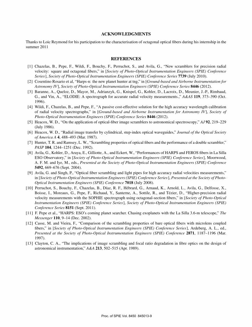
Systematic measurements of the FRD of the all the fibers needed for the instrument including the spares have been made.The train installed on the instrument is the one with the best performances. Figure 4show the statistics for all the fibers.The Obtained FRD is globally very good, and is always better than 85% for the fibers that have been installed into theinstrument. On figure 8 one can see an example of measurement at F/4 which is the working aperture of the beam insidethe fiber.
The output FRD losses of the optical train is near to 10%. The overall transmission of the optical train has been calculated2
taking into account length losses, Connection losses, the double scrambler and the FRD. It give en efficiency of 55% at380 nm and of 65% in the red. This is excellent and an improvement over the HARPS south fiber link.
9. SCRAMBLING MEASUREMENT OF THE COMPLETE TRAIN
The test bench has been used to measure the scrambling performances of the complete train of HARPS-N, including thedouble scrambler. Measurements have been done with success in the near field, and also in the far field as there is a doublescrambler.
The measurement in the near field is shown on figure 9. The measurement has been extended to have the image at theentrance of the fiber to move outside the core, to see the effects. The obtained scrambling ratio is around 10000 which isthe limit of measurement accuracy of the test bench.
Proc. of SPIE Vol. 8450 845013-5
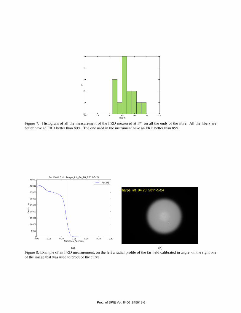
70 75 80 85 90 95 100FRD %
0
1
2
3
4
5
#
Figure 7: Histogram of all the measurement of the FRD measured at F/4 on all the ends of the fibre. All the fibers arebetter have an FRD better than 80%. The one used in the instrument have an FRD better than 85%.
0.00 0.05 0.10 0.15 0.20 0.25 0.30Numerical Aperture
0
5000
10000
15000
20000
25000
30000
35000
40000
45000
Flux
in U
A
Far Field Cut : harps_int_04_20_2011-5-24
F/4.05
(a) (b)Figure 8: Example of an FRD measurement, on the left a radial profile of the far field calibrated in angle, on the right oneof the image that was used to produce the curve.
Proc. of SPIE Vol. 8450 845013-6

�80 �60 �40 �20 0 20 40 60 80Entrance image position in micron
�0.4
�0.2
0.0
0.2
0.4
0.6
Bary
cente
r m
ove in d
/1000
Amplitude Max : 0.10
Near Field Scrambling : train_HARPS
(a)
0 20 40 60 80 100 120time in s
−0.08
−0.06
−0.04
−0.02
0.00
0.02
0.04
0.06
0.08
Bary
cente
r m
ove in d
/10
00
Amplitude Max : 0.15
Stability of the Bench
(b)Figure 9: Illustration of the near field scrambling of the HARPS-N fiber train, in the laboratory. (a) the movements of themeasurement in the near field of the scrambling performance of the whole fiber train. The scrambling Ratio is in the 10000range. (b) limits of the measurement capability of the test bench. Red points are for the x axis on the CCD, blue points arefor the y axis on the CCD. The orientation of these axes is arbitrary.
In the far field a similar test than in the near field is performed: An artificial star of a diameter of 12.5 microns for a coreof 70 microns is scanned across the core diameter. The far field illumination is recorded and analysed. The results areshown on figure 10. The analysed factor here is the illumination variation on a radial basis. These variations through theaberration of the spectrometer optics will produce line profile variations that are interpreted as velocity shifts. One can usethe measured flux variations to make simulations of the expected level of the effects on the instrument. In this case HARPS-N the observed variations could lead to velocity shifts of a maximum of 25cms−1 when the star is on the border of the fiber.More over figure 10 (b) shows the detailed results of the simulation resulting from the far field illumination measurements:in normal guiding condition there should be no measurable modification of the line profile. It is an improvement on theHARPS south fiber link.
10. PRELIMINARY TESTS ON SKY
The first light of HARPS-N has been achieved on March 25th 2012. After this some technical observation time gave thepossibility to have a first assessment of the scrambling performance of the fiber train on sky. The tests consisted in makingexposure of the same star repeatedly with different guiding set points. Half of the exposures are made in the standard modewhere the star is centred on the entrance fiber of the instrument; the other half was made in a way to have the star on theborder of the fiber. These measurements (see figure 11) give only an upper limit of 0.55 ms−1to scrambling performances.The exposure time was not long enough to average the p-mode oscillation of the stars, and furthermore the drift of theinstrument is not corrected (it is however extremely low). This number is already an improvement of a factor 4 on thescrambling performances of HARPS South.
11. CONCLUSION
In this paper we have shown the performances of a fiber link made of octagonal optical fibers for the HARPS-N spectro-graph. This new type of fiber is a huge improvement over circular fiber in terms of scrambling, and maintain an excellentoverall efficiency for the fiber link. These fibers remove one of the instrumental obstacle to the detection of very smallmass planets and paves the way for futur instruments like ESPRESSO or CODEX.
Proc. of SPIE Vol. 8450 845013-7

Uppe limit on effect 6.55 iii.
20 40 60 80time in minutes
Centered Exposures Off Centered Exposures
6
5
4
3
1
2
� �� ��� ��� ��� ��� �������� ��
� �����
�����
�����
�����
�����
�����
�����
��������������
������������������
������� �������
�����!�����"���� ��
� �� ��� ��� ��� ��� �������� ��
� �#�$
� �#��
� �#��
����
����
%�&��������
(a)
0 5 10 15 20 25 30 35 40Position of the artifical star in µm
0
10
20
30
40
50
∆v in cm.s−1
Border of the fiber co
re
Simulated effect of the far field illumination variations
(b)Figure 10: Far field illumination scrambling: The far field is characterized by its radial profile. Its stability versus theillumination perturbation at the entrance fiber is measured. One can use this measurement to simulate the expected effecton the radial velocity. In this case the extreme effect is of the order of 25cms−1. However in normal conditions, wherethe guiding is working properly the effect should be much smaller. (a) radial profile of the far field measured for differentposition of the artificial star at the entrance of the fiber field. (b) Simulated radial velocity shift for HARPS-N.
Figure 11: On sky test with HARPS-N: the star is observed, some exposure are made with the star centred (the purplezones) and other are off-centred (the star is on the border of the fiber). There is no obvious effect to be noted. An upperlimit 0.55 ms−1for the effect of decentring can be set. However this measure has not been done in an optimal way and thep-modes of the star are dominating all the effects.
Proc. of SPIE Vol. 8450 845013-8
ACKNOWLEDGMENTS
Thanks to Loic Reymond for his participation to the characterisation of octagonal optical fibers during his internship in thesummer 2011
REFERENCES
[1] Chazelas, B., Pepe, F., Wildi, F., Bouchy, F., Perruchot, S., and Avila, G., “New scramblers for precision radialvelocity: square and octagonal fibers,” in [Society of Photo-Optical Instrumentation Engineers (SPIE) ConferenceSeries], Society of Photo-Optical Instrumentation Engineers (SPIE) Conference Series 7739 (July 2010).
[2] Cosentino Rosario et al, “Harps-n: the new planet hunter at tng,” in [Ground-based and Airborne Instrumentation forAstronomy IV ], Society of Photo-Optical Instrumentation Engineers (SPIE) Conference Series 8446 (2012).
[3] Baranne, A., Queloz, D., Mayor, M., Adrianzyk, G., Knispel, G., Kohler, D., Lacroix, D., Meunier, J.-P., Rimbaud,G., and Vin, A., “ELODIE: A spectrograph for accurate radial velocity measurements.,” A&AS 119, 373–390 (Oct.1996).
[4] Wildi, F., Chazelas, B., and Pepe, F., “A passive cost-effective solution for the high accuracy wavelength calibrationof radial velocity spectrographs,” in [Ground-based and Airborne Instrumentation for Astronomy IV], Society ofPhoto-Optical Instrumentation Engineers (SPIE) Conference Series 8446 (2012).
[5] Heacox, W. D., “On the application of optical-fiber image scramblers to astronomical spectroscopy,” AJ 92, 219–229(July 1986).
[6] Heacox, W. D., “Radial image transfer by cylindrical, step-index optical waveguides,” Journal of the Optical Societyof America A 4, 488–493 (Mar. 1987).
[7] Hunter, T. R. and Ramsey, L. W., “Scrambling properties of optical fibers and the performance of a double scrambler,”PASP 104, 1244–1251 (Dec. 1992).
[8] Avila, G., Kohler, D., Araya, E., Gilliotte, A., and Eckert, W., “Performances of HARPS and FEROS fibers in La SillaESO Observatory,” in [Society of Photo-Optical Instrumentation Engineers (SPIE) Conference Series], Moorwood,A. F. M. and Iye, M., eds., Presented at the Society of Photo-Optical Instrumentation Engineers (SPIE) Conference5492, 669–676 (Sept. 2004).
[9] Avila, G. and Singh, P., “Optical fiber scrambling and light pipes for high accuracy radial velocities measurements,”in [Society of Photo-Optical Instrumentation Engineers (SPIE) Conference Series], Presented at the Society of Photo-Optical Instrumentation Engineers (SPIE) Conference 7018 (July 2008).
[10] Perruchot, S., Bouchy, F., Chazelas, B., Díaz, R. F., Hébrard, G., Arnaud, K., Arnold, L., Avila, G., Delfosse, X.,Boisse, I., Moreaux, G., Pepe, F., Richaud, Y., Santerne, A., Sottile, R., and Tézier, D., “Higher-precision radialvelocity measurements with the SOPHIE spectrograph using octagonal-section fibers,” in [Society of Photo-OpticalInstrumentation Engineers (SPIE) Conference Series], Society of Photo-Optical Instrumentation Engineers (SPIE)Conference Series 8151 (Sept. 2011).
[11] F. Pepe et al., “HARPS: ESO’s coming planet searcher. Chasing exoplanets with the La Silla 3.6-m telescope,” TheMessenger 110, 9–14 (Dec. 2002).
[12] Casse, M. and Vieira, F., “Comparison of the scrambling properties of bare optical fibers with microlens coupledfibers,” in [Society of Photo-Optical Instrumentation Engineers (SPIE) Conference Series], Ardeberg, A. L., ed.,Presented at the Society of Photo-Optical Instrumentation Engineers (SPIE) Conference 2871, 1187–1196 (Mar.1997).
[13] Clayton, C. A., “The implications of image scrambling and focal ratio degradation in fibre optics on the design ofastronomical instrumentation,” A&A 213, 502–515 (Apr. 1989).
Proc. of SPIE Vol. 8450 845013-9
Related Documents


