OPTICAL COMMUNICATION SYSTEM IN INDIAN RAILWAYS

OPTICAL COMMUNICATION SYSTEM IN INDIAN RAILWAYS, OFC
Aug 07, 2015
Welcome message from author
This document is posted to help you gain knowledge. Please leave a comment to let me know what you think about it! Share it to your friends and learn new things together.
Transcript
OPTICAL COMMUNICATION SYSTEM IN INDIAN RAILWAYS
CONTENTS
1. About the Organisation
2. An Optical Fiber
3. Optical Fiber used in Indian Railways
4. Methods of Jointing a Fiber Optic Cable
5. Mechanical Splicing
6. Fusion Splicing
7. Measurement And Testing Of Signals in an OFC
8. Indian Railway Telephone Exchange
9. Digital Multiplexing Hierarchies
10. PDH
11. SDH
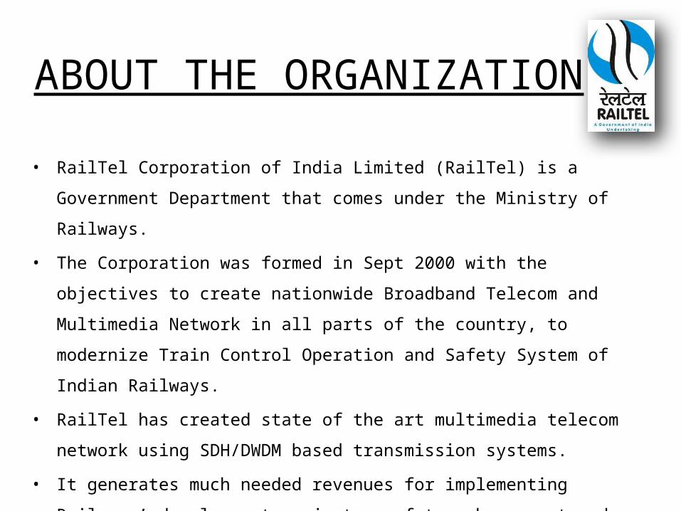
ABOUT THE ORGANIZATION
• RailTel Corporation of India Limited (RailTel) is a Government Department
that comes under the Ministry of Railways.
• The Corporation was formed in Sept 2000 with the objectives to create
nationwide Broadband Telecom and Multimedia Network in all parts of the
country, to modernize Train Control Operation and Safety System of Indian
Railways.
• RailTel has created state of the art multimedia telecom network using
SDH/DWDM based transmission systems.
• It generates much needed revenues for implementing Railways’
development projects, safety enhancement and asset replacement
programmes
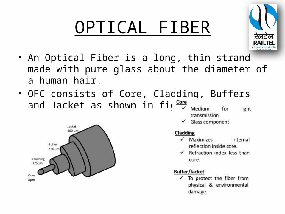
OPTICAL FIBER
• An Optical Fiber is a long, thin strand made with pure glass about the diameter of a human hair.
• OFC consists of Core, Cladding, Buffers and Jacket as shown in figure.
Specifications Of Optical Fiber Cable Used In Indian Railways
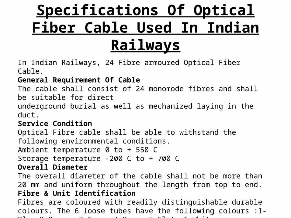
In Indian Railways, 24 Fibre armoured Optical Fiber Cable. General Requirement Of CableThe cable shall consist of 24 monomode fibres and shall be suitable for directunderground burial as well as mechanized laying in the duct. Service ConditionOptical Fibre cable shall be able to withstand the following environmental conditions.Ambient temperature 0 to + 550 CStorage temperature -200 C to + 700 COverall Diameter The overall diameter of the cable shall not be more than 20 mm and uniform throughout the length from top to end. Fibre & Unit Identification Fibres are coloured with readily distinguishable durable colours. The 6 loose tubes have the following colours :1-Blue,2-Orange,3-Green,4-Brown,5-Slate,6-White.
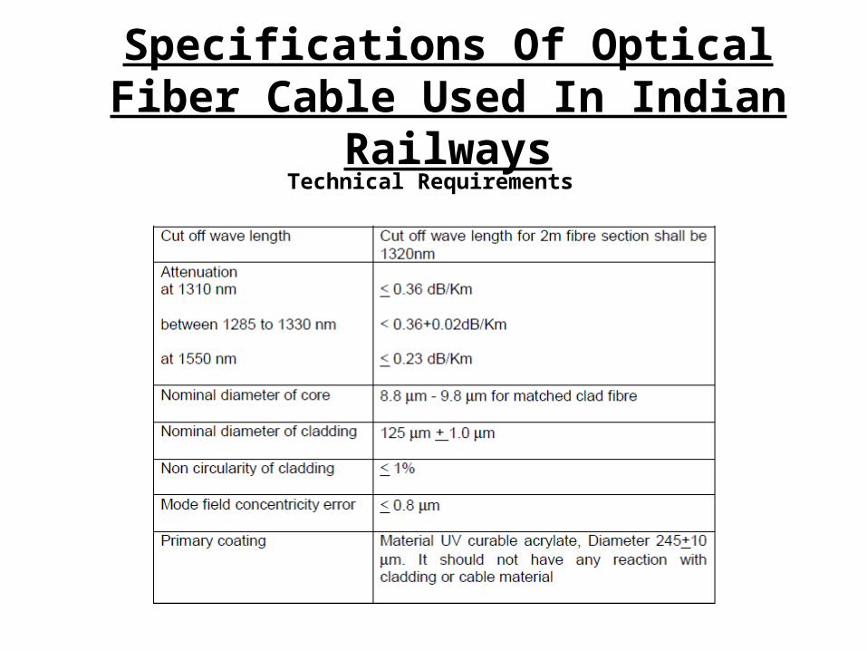
Specifications Of Optical Fiber Cable Used In Indian Railways
Technical Requirements
Methods for jointing of fibre optic cable
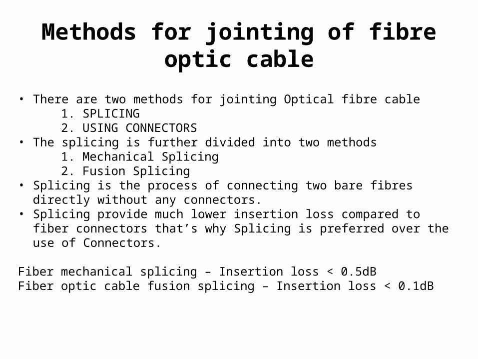
• There are two methods for jointing Optical fibre cable 1. SPLICING 2. USING CONNECTORS• The splicing is further divided into two methods 1. Mechanical Splicing 2. Fusion Splicing• Splicing is the process of connecting two bare fibres directly without any connectors.• Splicing provide much lower insertion loss compared to fiber connectors that’s why
Splicing is preferred over the use of Connectors.
Fiber mechanical splicing – Insertion loss < 0.5dBFiber optic cable fusion splicing – Insertion loss < 0.1dB
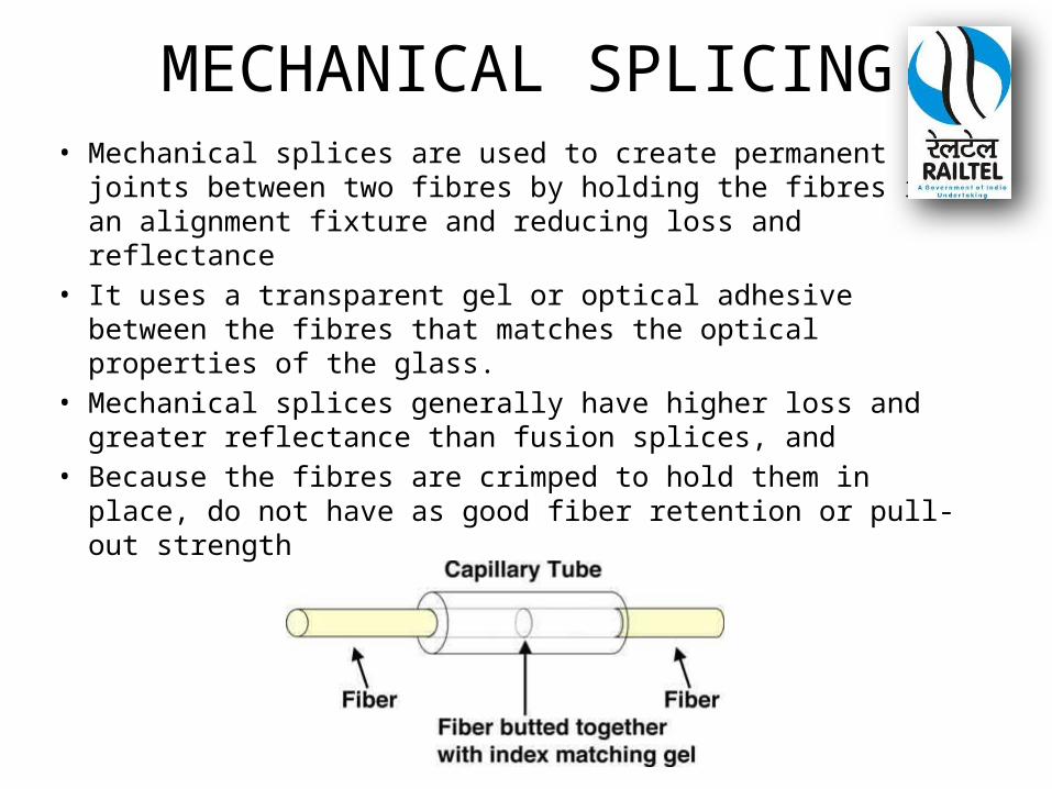
MECHANICAL SPLICING• Mechanical splices are used to create permanent joints
between two fibres by holding the fibres in an alignment fixture and reducing loss and reflectance
• It uses a transparent gel or optical adhesive between the fibres that matches the optical properties of the glass.
• Mechanical splices generally have higher loss and greater reflectance than fusion splices, and
• Because the fibres are crimped to hold them in place, do not have as good fiber retention or pull-out strength
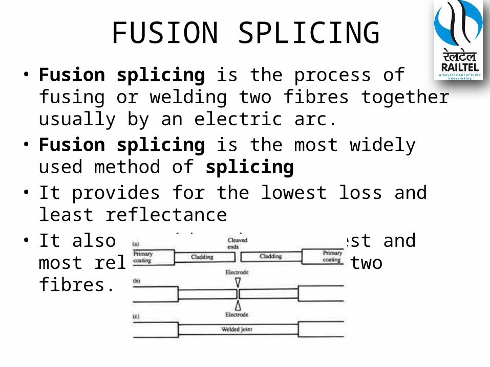
FUSION SPLICING• Fusion splicing is the process of fusing or welding
two fibres together usually by an electric arc. • Fusion splicing is the most widely used method
of splicing • It provides for the lowest loss and least reflectance• It also provides the strongest and most reliable joint
between two fibres.
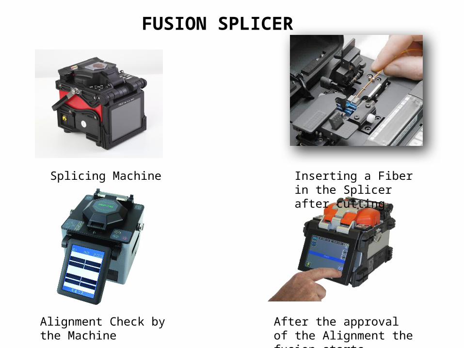
FUSION SPLICER
Splicing Machine Inserting a Fiber in the Splicer after cutting
Alignment Check by the Machine
After the approval of the Alignment the fusion starts
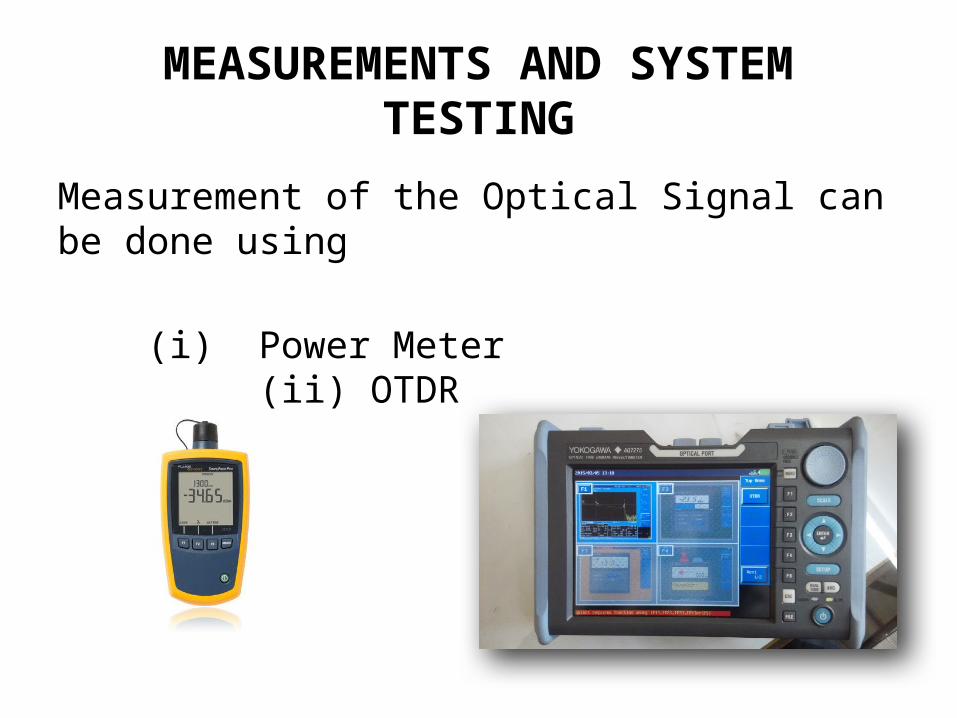
MEASUREMENTS AND SYSTEM TESTING
Measurement of the Optical Signal can be done using
(i) Power Meter (ii) OTDR
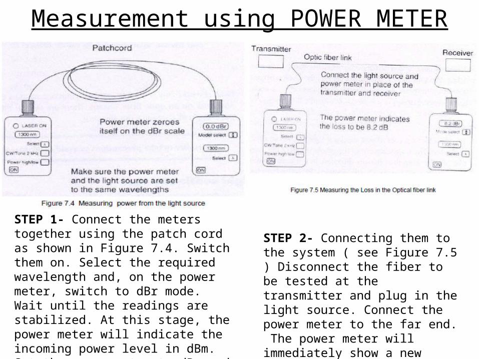
Measurement using POWER METER
STEP 1- Connect the meters together using the patch cord as shown in Figure 7.4. Switch them on. Select the required wavelength and, on the power meter, switch to dBr mode. Wait until the readings are stabilized. At this stage, the power meter will indicate the incoming power level in dBm. Set the power meter to dBr and it will accept the incoming light level as the reference level.
STEP 2- Connecting them to the system ( see Figure 7.5 ) Disconnect the fiber to be tested at the transmitter and plug in the light source. Connect the power meter to the far end. The power meter will immediately show a new figure such as – 8.2 dBr. This is the loss over the system.
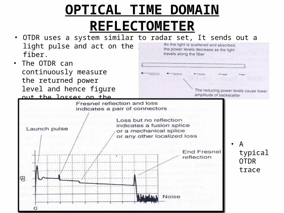
OPTICAL TIME DOMAIN REFLECTOMETER• OTDR uses a system similar to radar set, It sends out a light pulse and act on the
reflected light from the fiber.
• The OTDR can continuously measure the returned power level and hence figure out the losses on the fiber link.
• A typical OTDR trace
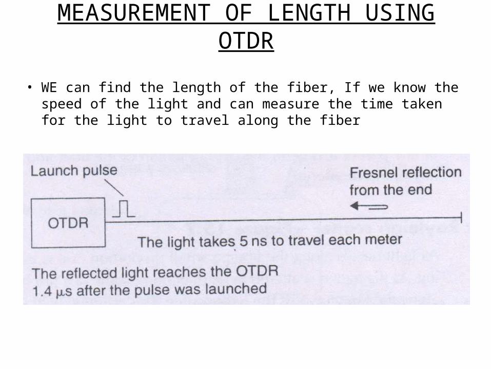
MEASUREMENT OF LENGTH USING OTDR
• WE can find the length of the fiber, If we know the speed of the light and can measure the time taken for the light to travel along the fiber
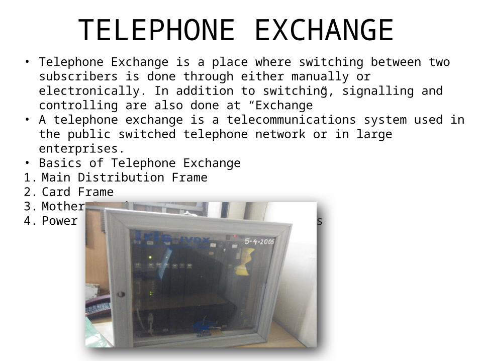
TELEPHONE EXCHANGE• Telephone Exchange is a place where switching between two subscribers is done through
either manually or electronically. In addition to switching, signalling and controlling are also done at “Exchange”
• A telephone exchange is a telecommunications system used in the public switched telephone network or in large enterprises.
• Basics of Telephone Exchange1. Main Distribution Frame2. Card Frame3. Mother Board4. Power Supply Panel & Protective Devices
COMPONENTS OF AN EXCHANGE
Main Distribution Frame (MDF)It is the place where both external and internal cables are terminated. The cross connection between the two cables conductors is done on the MDF and this is done by means of jumper wires It carries all the protective devices used in the exchange. They are Fuses, Heat coils & Lightning protectors The MDF is the most suitable place for testing purposes Card Frame: It contains different slots in which the nominated cards are to be inserted. It is different in different types of exchanges. Mother board: It is basically a connectivity between different cards. It is a PCB with 1,2,3 layers. Power supply panel: It provides power supply to different cards in the exchange at different low D.C. voltages. It also includes protective devices like fuses etc.
Main functional areas in Telephone Exchange
(a) Switching Function: It provides a temporary path for simultaneous, bi-directional speech between: i) Two subscribers connected to the same exchange. This is called as “Local switching”. ii) Two subscribers connected to different exchanges. This is known as “Trunk switching”.
(b) Signalling function: The signalling function enables the various equipment in a network to communicate with each other in order to establish and supervise the calls. It is of two types: i) Subscriber line signalling: It enables a call to be set up, supervised and cleared within same exchangeii) Inter exchange signalling: It enables a call to be set up, supervised and cleared between exchanges.
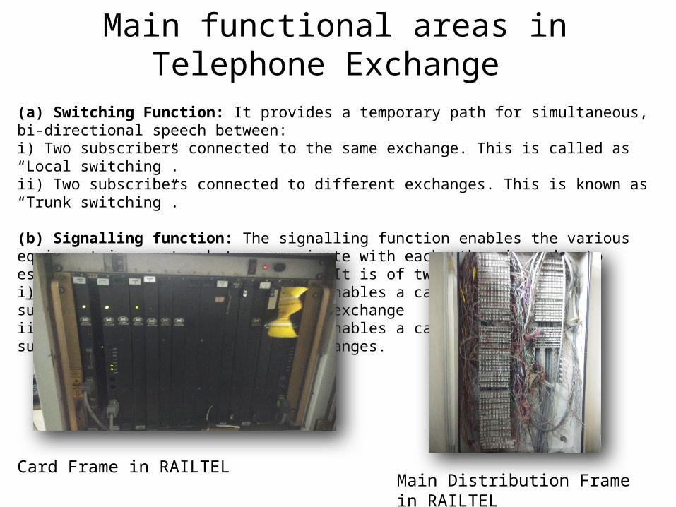
Card Frame in RAILTELMain Distribution Frame in RAILTEL
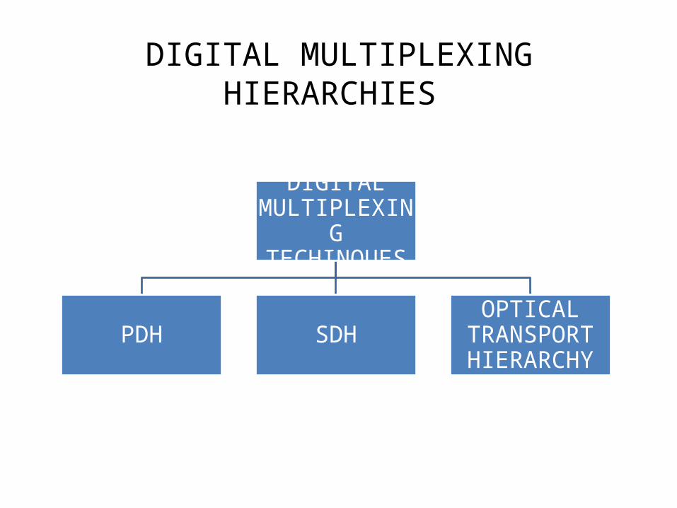
DIGITAL MULTIPLEXING HIERARCHIES
DIGITAL MULTIPLEXING TECHINQUES
PDH SDHOPTICAL
TRANSPORT HIERARCHY
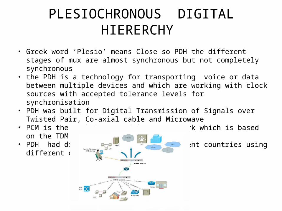
PLESIOCHRONOUS DIGITAL HIERERCHY
• Greek word ‘Plesio’ means Close so PDH the different stages of mux are almost synchronous but not completely synchronous
• the PDH is a technology for transporting voice or data between multiple devices and which are working with clock sources with accepted tolerance levels for synchronisation
• PDH was built for Digital Transmission of Signals over Twisted Pair, Co-axial cable and Microwave
• PCM is the technique used in PDH network which is based on the TDM• PDH had different standards in different countries using different data rates at same
levels
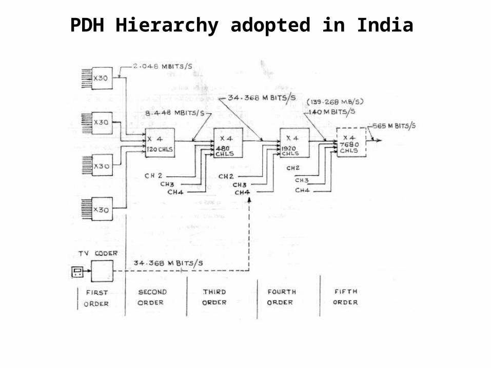
PDH Hierarchy adopted in India
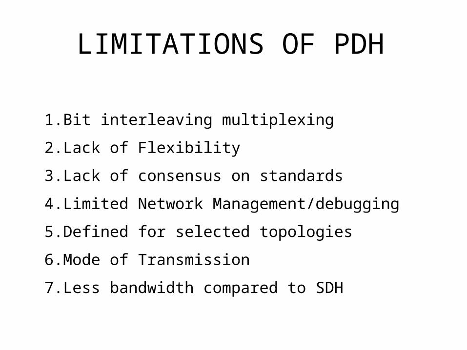
LIMITATIONS OF PDH
1. Bit interleaving multiplexing
2. Lack of Flexibility
3. Lack of consensus on standards
4. Limited Network Management/debugging
5. Defined for selected topologies
6. Mode of Transmission
7. Less bandwidth compared to SDH
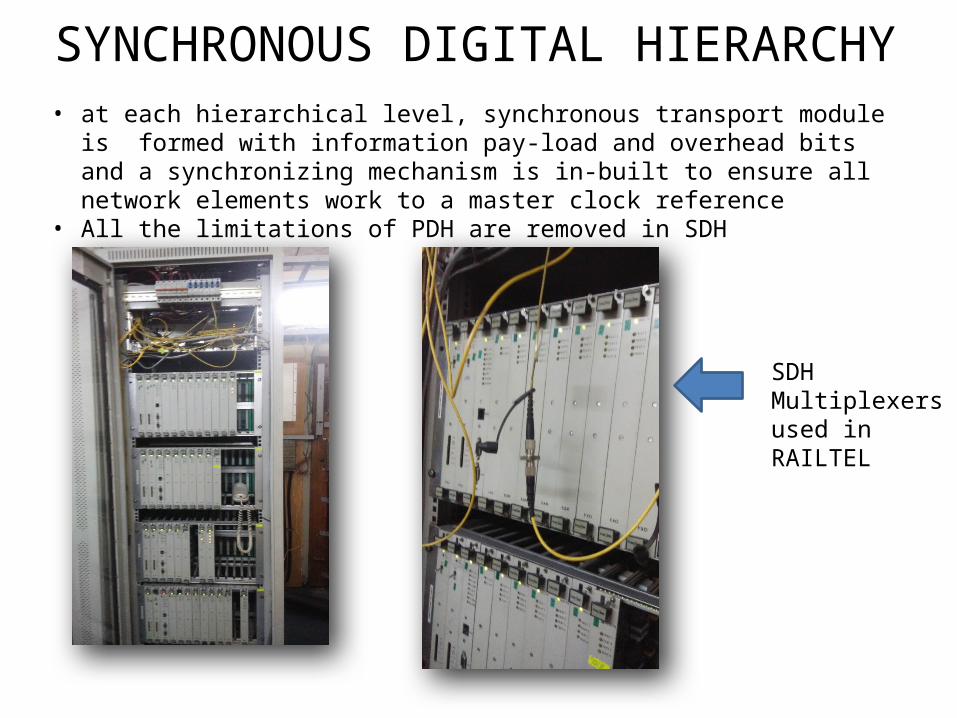
SYNCHRONOUS DIGITAL HIERARCHY• at each hierarchical level, synchronous transport module is formed with information
pay-load and overhead bits and a synchronizing mechanism is in-built to ensure all network elements work to a master clock reference
• All the limitations of PDH are removed in SDH
SDH Multiplexers used in RAILTEL
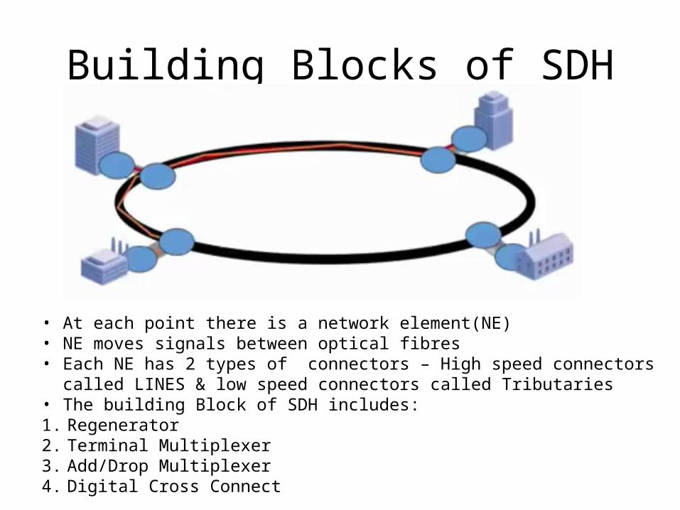
Building Blocks of SDH
• At each point there is a network element(NE)• NE moves signals between optical fibres• Each NE has 2 types of connectors – High speed connectors called LINES & low speed
connectors called Tributaries• The building Block of SDH includes:1. Regenerator2. Terminal Multiplexer3. Add/Drop Multiplexer4. Digital Cross Connect
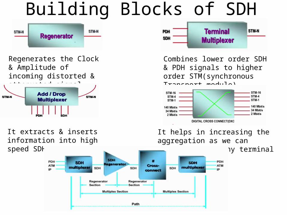
Building Blocks of SDH
Regenerates the Clock & Amplitude of incoming distorted & attenuated signal
Combines lower order SDH & PDH signals to higher order STM(synchronous Transport module)
It extracts & inserts information into high speed SDH
It helps in increasing the aggregation as we can connect any to any terminal
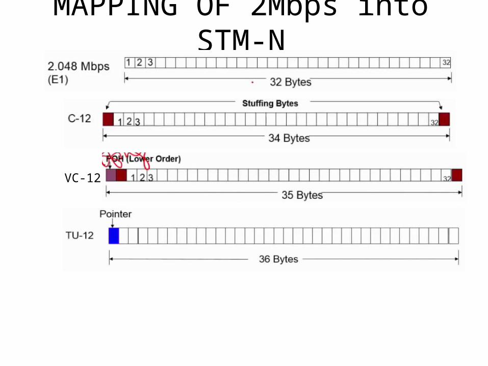
MAPPING OF 2Mbps into STM-N
VC-12
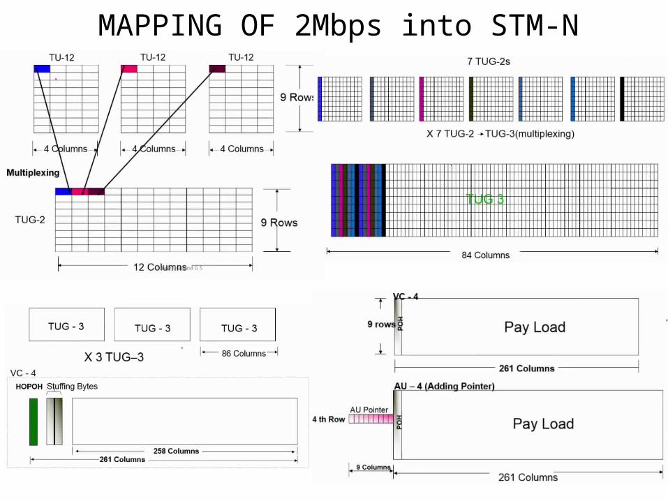
MAPPING OF 2Mbps into STM-N
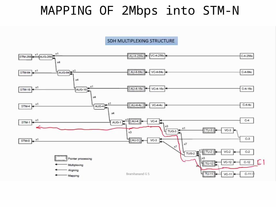
MAPPING OF 2Mbps into STM-N
ADVANTAGES OF SDH
• SDH permits the mixing of the existing European and North American PDH
bit rates
• All SDH equipment is based on the use of a single master reference clock
source & hence SDH is synchronous
• Compatible with the majority of existing PDH bit rates
• SDH provides for extraction/insertion, of a lower order bit rate from a higher
order aggregate stream, without the need to de-multiplex in stages.
• SDH provides for a standard optical interface thus allowing the inter-working
of different manufacturer’s equipment
Related Documents