OPGW Optic fiber Protection Overhead Ground Wire Other Aluminium products: AAC (All aluminium conductor) AAAC (All aluminium alloy conductor) AACSR (All aluminium alloy conductor steel reinforced) ACSR (All aluminium alloy conductor steel reinforced) Solid sector shaped aluminium conductor Aluminium strip Aluminium wire Aluminium alloy wire www.m-tec.co.ca / [email protected] / +2716 450 8200 Page 1 of 7

Welcome message from author
This document is posted to help you gain knowledge. Please leave a comment to let me know what you think about it! Share it to your friends and learn new things together.
Transcript
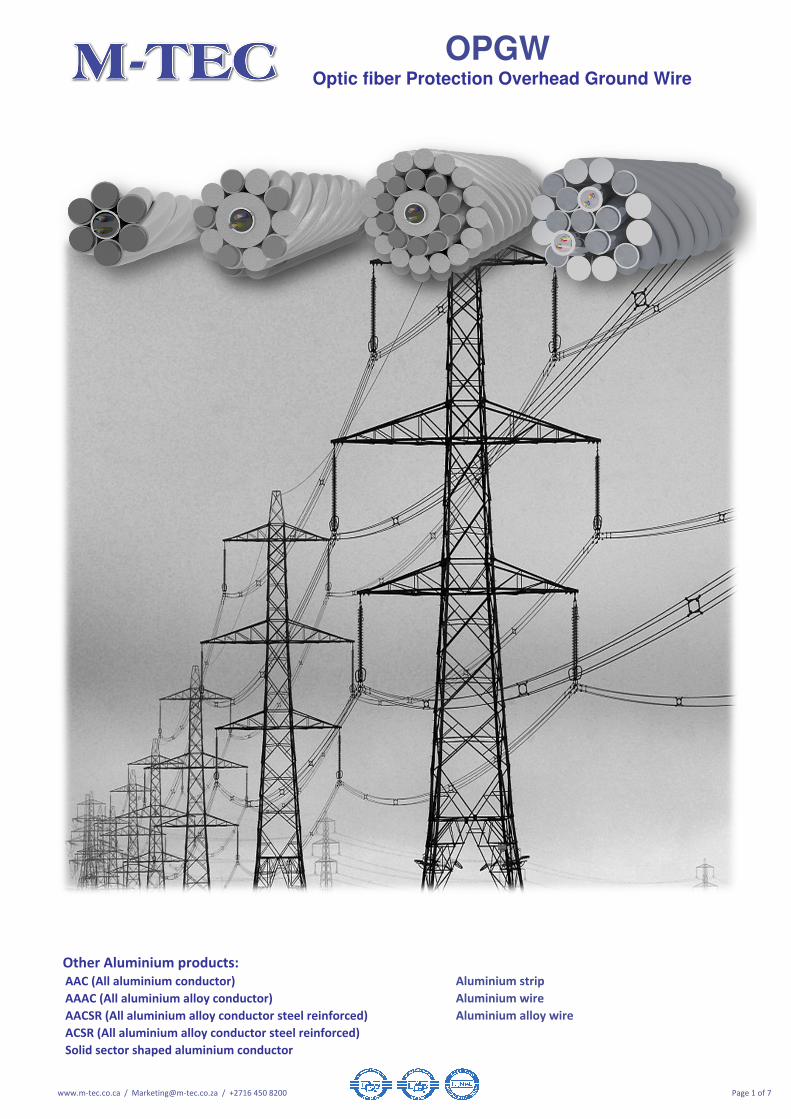
OPGW Optic fiber Protection Overhead Ground Wire
Other Aluminium products:
AAC (All aluminium conductor)
AAAC (All aluminium alloy conductor)
AACSR (All aluminium alloy conductor steel reinforced)
ACSR (All aluminium alloy conductor steel reinforced)
Solid sector shaped aluminium conductor
Aluminium strip
Aluminium wire
Aluminium alloy wire
www.m-tec.co.ca / [email protected] / +2716 450 8200 Page 1 of 7

OPGW Size: short circuit rating kA, 1sec 3.2 5 5 7 12.00 12.50 12.22
Tensile rating, RTS kN 65 36 60 60 60 62 107
Fibres per SUS tube number
Number of SUS tubes number 1 1 1 1 1 1 1
Fibre SUS tube outer diameter mm 3.1 3.4 4.00 6.3 7.4 9.1 7.9
Aluminium in Al cladded SUS tube (where applicable).
mm² 0.0 0.0 0.0 18.0 29.8 51.8 35.8
Number of wires # 6 6 6 9 5 5 8
Wire diameter 3.1 3.5 4.0 3.15 3.3 3.4 3.5
Wire area mm² 7.5 9.6 12.6 7.8 8.6 9.1 9.6
Total wire area nominal mm² 45.3 57.7 75.4 70.1 42.8 45.4 77.0
Aluminium in ACS mm² 19.5 32.4 32.4 30.2 18.4 13.2 33.1
Conductivity of wire @ 20°C % 30 40 30 30 30 20.3 30
Number of wires # - - - - 5 6 2
Wire diameter mm - - - - 3.3 3.4 3.5
Aluminium alloy area nom. mm² - - - - 43 54 19
Diameter 1st layer mm 9.3 10.4 12.0 12.6 14.0 15.9 14.9
Diameter 2nd layer mm - - - - - - -
Total weight nominal kg/km 322 461 461 523 517 630 697
Total OPGW area (conductive components) mm² 45 58 75 88 73 97 113
Final layer stranding direction S/Z S Z Z Z Z Z Z
* RTS (rated tensile strength) kN 54 60 60 60 71.2 72.2 72.2
kgf/mm² 16,519 14,378 13,500 13,500 10,095 12,339 12,339
Mpa 162,000 141,000 132,390 132,390 99,000 121,000 121,000
kgf/mm² 15,693 13,659 12,825 12,825 9,590 11,722 11,722
Mpa 153,900 133,950 125,770 125,770 94,050 114,950 114,950
** Coefficient of linear expansion nom. 10-6/°C 13.0 14.5 13.8 14.7 17.2 17.4 15.2
Maximum allowable temperature °C
* DC Resistance @ 20°C Ω/km 1.90 0.75 0.74 0.55 0.35 0.27 0.38
* Short Circuit 1.0 second kA 3.2 5 5 7 12 12.5 12.22
* Short circuit current capacity
- Initial temperature 20°C
- Final temperature maximum 200°C
kA².s 10 25 25 31 144 156 149
Continues current rating A
Lightning Class: 0, 1, 2 or 3
Ransfer rate (0:50C, 1:100C, 2:150C, 3:200C)Class 3 3 3 3 3 3 3
Lightning maximum durtation
Fibre identification: In all groups
1 x 12 fiber SUS tube: 12 fiber cable
1 x 24 fiber SUS tube: 24 fiber cable
1 x 48 fiber SUS tube: 12 fiber cable
Shipping length m 4000 4000 4000 4000 4000 4000 4000
Grease filling if applicable (IEC61089) Case 4 Case 4 Case 4 Case 4 Case 4 Case 4 Case 4
* Grease weight calculated: Nominal kg/km 4.4 5.6 7.4 4.6 5.0 5.3 5.6
Revision: R03 14/06/2017
0.5 seconds
The information contained within this document must not be copied, reprinted or reproduced in any form, either wholly or in part, without the written consent of M-TEC, The information is believed to be correct at the time of issue to the best of M-TEC’s knowledge. M-TEC reserves the right to
amend this specification without prior notification. This specification is not contractually valid unless specifically authorised by M-TEC. M-TEC shall not be liable for any damages whatsoever (including indirect, incidental, special, punitive or consequential damages and loss of profits, opportunities
or information) arising from or result from the use of or reliance on information contained in this document, and/or any inaccuracy or omission in such information contained in this document.
12 fiber: groups: 1st group (Blue), 2
nd group (Yellow)
1st tube 12 fiber: groups: 1
st group (Blue), 2
nd group (Yellow), 3
rdgroup (Green), 4
th group (Red),
Construction
Aluminium Clad Steel
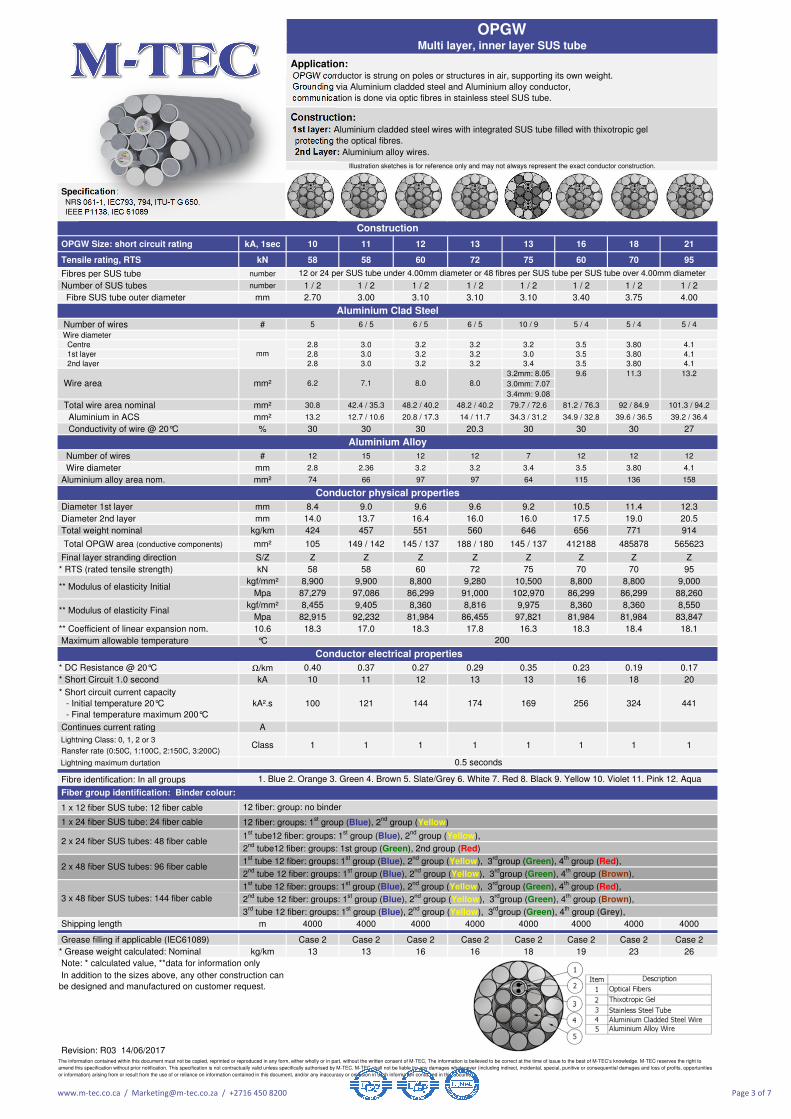
12, 24 or 48 fibres per SUS tube.
Aluminium Alloy
Conductor physical properties
Conductor electrical properties
** Modulus of elasticity Final
1. Blue 2. Orange 3. Green 4. Brown 5. Slate/Grey 6. White 7. Red 8. Black 9. Yellow 10. Violet 11. Pink 12. Aqua
12 fiber: group: no binder
Fiber group identification: Binder colour:
200
In addition to the sizes above, any other construction can be designed and manufactured on customer request.
Note: * calculated value, **data for information only
OPGW Centre SUS tube single layer
** Modulus of elasticity Initial
Construction: Centre wire: SUS tube or Al cladded SUS
1st layer: Aluminium cladded steel wires; Aluminium alloy wires; or combination of ACS & AA Wires
Application: OPGW conductor is strung on poles or structures in air, supporting its own weight.
Grounding via Aluminium cladded steel and Aluminium alloy conductor,
communication is done via optic fibres in stainless steel SUS tube.
Illustration sketches is for reference only and may not always represent the exact conductor construction.
Specification: NRS 061-1, IEC793, 794, ITU-T G 650,
IEEE P1138, IEC 61089
www.m-tec.co.ca / [email protected] / +2716 450 8200 Page 2 of 7
OPGW Size: short circuit rating kA, 1sec 10 11 12 13 13 16 18 21
Tensile rating, RTS kN 58 58 60 72 75 60 70 95
Fibres per SUS tube number
Number of SUS tubes number 1 / 2 1 / 2 1 / 2 1 / 2 1 / 2 1 / 2 1 / 2 1 / 2
Fibre SUS tube outer diameter mm 2.70 3.00 3.10 3.10 3.10 3.40 3.75 4.00
Number of wires # 5 6 / 5 6 / 5 6 / 5 10 / 9 5 / 4 5 / 4 5 / 4
Wire diameter
Centre 2.8 3.0 3.2 3.2 3.2 3.5 3.80 4.1
1st layer 2.8 3.0 3.2 3.2 3.0 3.5 3.80 4.1
2nd layer 2.8 3.0 3.2 3.2 3.4 3.5 3.80 4.1
3.2mm: 8.05 9.6 11.3 13.2
3.0mm: 7.07
3.4mm: 9.08
Total wire area nominal mm² 30.8 42.4 / 35.3 48.2 / 40.2 48.2 / 40.2 79.7 / 72.6 81.2 / 76.3 92 / 84.9 101.3 / 94.2
Aluminium in ACS mm² 13.2 12.7 / 10.6 20.8 / 17.3 14 / 11.7 34.3 / 31.2 34.9 / 32.8 39.6 / 36.5 39.2 / 36.4
Conductivity of wire @ 20°C % 30 30 30 20.3 30 30 30 27
Number of wires # 12 15 12 12 7 12 12 12
Wire diameter mm 2.8 2.36 3.2 3.2 3.4 3.5 3.80 4.1
Aluminium alloy area nom. mm² 74 66 97 97 64 115 136 158
Diameter 1st layer mm 8.4 9.0 9.6 9.6 9.2 10.5 11.4 12.3
Diameter 2nd layer mm 14.0 13.7 16.4 16.0 16.0 17.5 19.0 20.5
Total weight nominal kg/km 424 457 551 560 646 656 771 914
Total OPGW area (conductive components) mm² 105 149 / 142 145 / 137 188 / 180 145 / 137 412188 485878 565623
Final layer stranding direction S/Z Z Z Z Z Z Z Z Z
* RTS (rated tensile strength) kN 58 58 60 72 75 70 70 95
kgf/mm² 8,900 9,900 8,800 9,280 10,500 8,800 8,800 9,000
Mpa 87,279 97,086 86,299 91,000 102,970 86,299 86,299 88,260
kgf/mm² 8,455 9,405 8,360 8,816 9,975 8,360 8,360 8,550
Mpa 82,915 92,232 81,984 86,455 97,821 81,984 81,984 83,847
** Coefficient of linear expansion nom. 10.6 18.3 17.0 18.3 17.8 16.3 18.3 18.4 18.1
Maximum allowable temperature °C
* DC Resistance @ 20°C Ω/km 0.40 0.37 0.27 0.29 0.35 0.23 0.19 0.17
* Short Circuit 1.0 second kA 10 11 12 13 13 16 18 20
* Short circuit current capacity
- Initial temperature 20°C
- Final temperature maximum 200°C
kA².s 100 121 144 174 169 256 324 441
Continues current rating A
Lightning Class: 0, 1, 2 or 3
Ransfer rate (0:50C, 1:100C, 2:150C, 3:200C)Class 1 1 1 1 1 1 1 1
Lightning maximum durtation
Fibre identification: In all groups
1 x 12 fiber SUS tube: 12 fiber cable
1 x 24 fiber SUS tube: 24 fiber cable
Shipping length m 4000 4000 4000 4000 4000 4000 4000 4000
Grease filling if applicable (IEC61089) Case 2 Case 2 Case 2 Case 2 Case 2 Case 2 Case 2 Case 2
* Grease weight calculated: Nominal kg/km 13 13 16 16 18 19 23 26
Revision: R03 14/06/2017
8.0
** Modulus of elasticity Final
12 or 24 per SUS tube under 4.00mm diameter or 48 fibres per SUS tube per SUS tube over 4.00mm diameter
Aluminium Clad Steel
Construction
The information contained within this document must not be copied, reprinted or reproduced in any form, either wholly or in part, without the written consent of M-TEC, The information is believed to be correct at the time of issue to the best of M-TEC’s knowledge. M-TEC reserves the right to
amend this specification without prior notification. This specification is not contractually valid unless specifically authorised by M-TEC. M-TEC shall not be liable for any damages whatsoever (including indirect, incidental, special, punitive or consequential damages and loss of profits, opportunities
or information) arising from or result from the use of or reliance on information contained in this document, and/or any inaccuracy or omission in such information contained in this document.
In addition to the sizes above, any other construction can
be designed and manufactured on customer request.
Note: * calculated value, **data for information only
3rd
tube 12 fiber: groups: 1st group (Blue), 2
nd group (Yellow), 3
rdgroup (Green), 4
th group (Grey),
2nd
tube 12 fiber: groups: 1st group (Blue), 2
nd group (Yellow), 3
rdgroup (Green), 4
th group (Brown),
1st tube 12 fiber: groups: 1
st group (Blue), 2
nd group (Yellow), 3
rdgroup (Green), 4
th group (Red),
2nd
tube 12 fiber: groups: 1st group (Blue), 2
nd group (Yellow), 3
rdgroup (Green), 4
th group (Brown),
2 x 24 fiber SUS tubes: 48 fiber cable
2 x 48 fiber SUS tubes: 96 fiber cable 1
st tube 12 fiber: groups: 1
st group (Blue), 2
nd group (Yellow), 3
rdgroup (Green), 4
th group (Red),
2nd
tube12 fiber: groups: 1st group (Green), 2nd group (Red)
1st tube12 fiber: groups: 1
st group (Blue), 2
nd group (Yellow),
3 x 48 fiber SUS tubes: 144 fiber cable
12 fiber: groups: 1st group (Blue), 2
nd group (Yellow)
12 fiber: group: no binder
Aluminium Alloy
Conductor physical properties
Conductor electrical properties
1. Blue 2. Orange 3. Green 4. Brown 5. Slate/Grey 6. White 7. Red 8. Black 9. Yellow 10. Violet 11. Pink 12. Aqua
200
Fiber group identification: Binder colour:
** Modulus of elasticity Initial
6.2 7.1 8.0
Construction: 1st layer: Aluminium cladded steel wires with integrated SUS tube filled with thixotropic gel
protecting the optical fibres.
2nd Layer: Aluminium alloy wires.
Wire area mm²
Illustration sketches is for reference only and may not always represent the exact conductor construction.
mm
Specification: NRS 061-1, IEC793, 794, ITU-T G 650,
IEEE P1138, IEC 61089
OPGW Multi layer, inner layer SUS tube
Application: OPGW conductor is strung on poles or structures in air, supporting its own weight.
Grounding via Aluminium cladded steel and Aluminium alloy conductor,
communication is done via optic fibres in stainless steel SUS tube.
0.5 seconds
www.m-tec.co.ca / [email protected] / +2716 450 8200 Page 3 of 7

OPGW Size: short circuit rating kA, 1sec 10 12
Tensile rating, RTS kN 65 62
Fibres per SUS tube number
Number of SUS tubes number 1 1
Fibre SUS tube outer diameter mm 3.60 3.80
Number of wires # 7 4
Wire diameter
Centre
1st layer
2nd layer
Total wire area nominal mm² 40.1 25.5
Aluminium in ACS mm² 8.1 3.6
Conductivity of wire @ 20°C % 20.3 14
Number of wires # 14 16
Wire diameter mm 2.5 2.85
Aluminium alloy area nom. mm² 69 102
Diameter 1st layer mm 9.0 9.5
Diameter 2nd layer mm 14.0 15.2
Total weight nominal kg/km 476 473
Total OPGW area (conductive components) mm² 109 128
Final layer stranding direction S/Z Z Z
* RTS (rated tensile strength) kN 65 62
kgf/mm² 9,891 8,667
Mpa 97,000 85,000
kgf/mm² 9,396 8,234
Mpa 92,148 80,745
** Coefficient of linear expansion nom. 10-6/°C 16.9 18.6
Maximum allowable temperature °C
* DC Resistance @ 20°C Ω/km 0.39 0.30
* Short Circuit 1.0 second kA 10 12
* Short circuit current capacity
- Initial temperature 20°C
- Final temperature maximum 200°C
kA².s 100 144
Continues current rating A
Lightning Class: 0, 1, 2 or 3
Ransfer rate (0:50C, 1:100C, 2:150C, 3:200C)Class 1 1
Lightning maximum durtation
Fibre identification: In all groups
1 x 12 fiber SUS tube: 12 fiber cable
1 x 24 fiber SUS tube: 24 fiber cable
Shipping length m 4000 4000
Grease filling if applicable (IEC61089) Case 2 Case 2
* Grease weight calculated: Nominal kg/km 10 13
Revision: R03 14/06/2017
In addition to the sizes above, any other construction can
be designed and manufactured on customer request.
The information contained within this document must not be copied, reprinted or reproduced in any form, either wholly or in part, without the written consent of M-TEC, The information is believed to be correct at the time of issue to the best of M-TEC’s knowledge. M-TEC reserves the right to
amend this specification without prior notification. This specification is not contractually valid unless specifically authorised by M-TEC. M-TEC shall not be liable for any damages whatsoever (including indirect, incidental, special, punitive or consequential damages and loss of profits, opportunities
or information) arising from or result from the use of or reliance on information contained in this document, and/or any inaccuracy or omission in such information contained in this document.
48 per SUS tube
200
0.5 seconds
2.85
3 x 48 fiber SUS tubes: 144 fiber cable
1st tube 12 fiber: groups: 1
st group (Blue), 2
nd group (Yellow), 3
rdgroup (Green), 4
th group (Red),
2nd
tube 12 fiber: groups: 1st group (Blue), 2
nd group (Yellow), 3
rdgroup (Green), 4
th group (Brown),
3rd
tube 12 fiber: groups: 1st group (Blue), 2
nd group (Yellow), 3
rdgroup (Green), 4
th group (Grey),
Note: * calculated value, **data for information only
2 x 24 fiber SUS tubes: 48 fiber cable 1
st tube12 fiber: groups: 1
st group (Blue), 2
nd group (Yellow),
2nd
tube12 fiber: groups: 1st group (Green), 2nd group (Red)
2 x 48 fiber SUS tubes: 96 fiber cable 1
st tube 12 fiber: groups: 1
st group (Blue), 2
nd group (Yellow), 3
rdgroup (Green), 4
th group (Red),
2nd
tube 12 fiber: groups: 1st group (Blue), 2
nd group (Yellow), 3
rdgroup (Green), 4
th group (Brown),
1. Blue 2. Orange 3. Green 4. Brown 5. Slate/Grey 6. White 7. Red 8. Black 9. Yellow 10. Violet 11. Pink 12. Aqua
Fiber group identification: Binder colour:
12 fiber: group: no binder
12 fiber: groups: 1st group (Blue), 2
nd group (Yellow)
Aluminium Alloy
Conductor physical properties
** Modulus of elasticity Initial
** Modulus of elasticity Final
Conductor electrical properties
Construction: Centre wire: SUS tube filled with thixotropic gel
1st layer: Aluminium cladded steel wires; Aluminium alloy wires; or combination of ACS & AA Wires
2nd Layer: Aluminium alloy wires.
Wire area mm² 5.7 7.1
Specification: NRS 061-1, IEC793, 794, ITU-T G 650,
IEEE P1138, IEC 61089
Construction
Aluminium Clad Steel
OPGW Multi layer, Centre SUS tube
mm 2.70
Application: OPGW conductor is strung on poles or structures in air, supporting its own weight.
Grounding via Aluminium cladded steel and Aluminium alloy conductor,
communication is done via optic fibres in stainless steel SUS tube.
www.m-tec.co.ca / [email protected] / +2716 450 8200 Page 4 of 7
OPGW Size: short circuit rating kA, 1sec 10
Tensile rating, RTS kN 58
Fibres per PBT / AA loose tube number 48
Fibre AA loose tube outer diameter mm 2.70
Number of wires # 5
Wire diameter
Centre
1st layer
Wire area mm² 6.2
Total wire area nominal mm² 30.8
Aluminium in ACS mm² 13.2
Conductivity of wire @ 20°C % 30
Diameter 1st layer mm 8.4
Diameter 2nd layer mm 15.2
Total weight nominal kg/km 424
Total OPGW area (conductive components) mm² 31
Final layer stranding direction S/Z Z
* RTS (rated tensile strength) kN 58
kgf/mm² 8,900
Mpa 87,279
** Coefficient of linear expansion nom. 10-6/°C 18.3
Maximum allowable temperature °C
* DC Resistance @ 20°C Ω/km 0.40
* Short Circuit 1.0 second kA 10
* Short circuit current capacity
- Initial temperature 20°C
- Final temperature maximum 200°C
kA².s 100
Continues current rating A
Lightning Class: 0, 1, 2 or 3
Ransfer rate (0:50C, 1:100C, 2:150C, 3:200C)Class 1
Lightning maximum durtation
Fibre identification: In all tubes.
Loose Tube identification:
Shipping length m 4000
Grease filling if applicable (IEC61089) Case 2
* Grease weight calculated: Nominal kg/km 13
Revision: R03 14/06/2017
1. Blue 2. Orange 3. Green 4. Brown
0.5 seconds
** Modulus of elasticity
Conductor physical properties
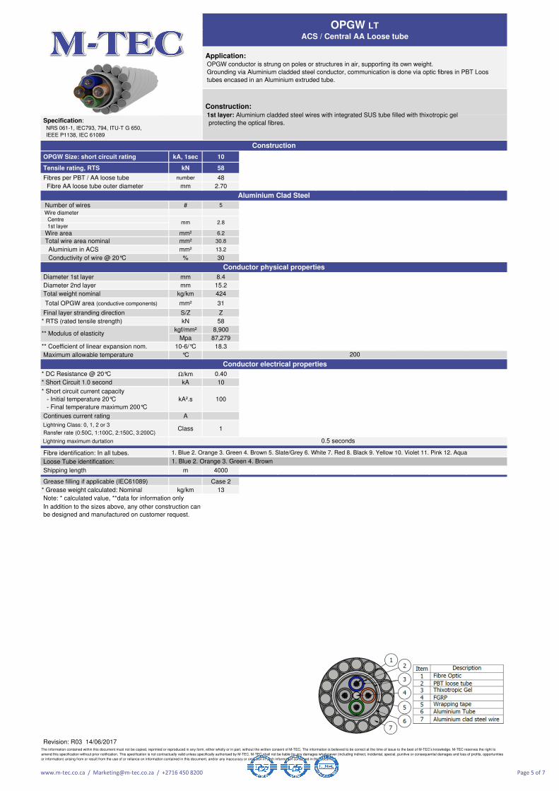
OPGW LT ACS / Central AA Loose tube
Construction: 1st layer: Aluminium cladded steel wires with integrated SUS tube filled with thixotropic gel
protecting the optical fibres.
Application: OPGW conductor is strung on poles or structures in air, supporting its own weight.
Grounding via Aluminium cladded steel conductor, communication is done via optic fibres in PBT Loos
tubes encased in an Aluminium extruded tube.
Specification: NRS 061-1, IEC793, 794, ITU-T G 650,
IEEE P1138, IEC 61089
Construction
Aluminium Clad Steel
Note: * calculated value, **data for information only
In addition to the sizes above, any other construction can
be designed and manufactured on customer request.
The information contained within this document must not be copied, reprinted or reproduced in any form, either wholly or in part, without the written consent of M-TEC, The information is believed to be correct at the time of issue to the best of M-TEC’s knowledge. M-TEC reserves the right to
amend this specification without prior notification. This specification is not contractually valid unless specifically authorised by M-TEC. M-TEC shall not be liable for any damages whatsoever (including indirect, incidental, special, punitive or consequential damages and loss of profits, opportunities
or information) arising from or result from the use of or reliance on information contained in this document, and/or any inaccuracy or omission in such information contained in this document.
mm 2.8
Conductor electrical properties
1. Blue 2. Orange 3. Green 4. Brown 5. Slate/Grey 6. White 7. Red 8. Black 9. Yellow 10. Violet 11. Pink 12. Aqua
200
www.m-tec.co.ca / [email protected] / +2716 450 8200 Page 5 of 7

1. GENERAL
1.1 Conductor Description
1.2 Quality
1.3 Reliability
2. OPTICAL FIBER
2.1 Single Mode Fiber, G652D
2.2 General Design
2.3 Construction
Mode field diameter at 1310nm
Mode field diameter at 1550nm
Mode field concentricity error
Cladding diameter
Cladding non-circularity
Primary coating material
Fibre diameter
2.4 Optical characteristics
Attenuation at 1310 nm
Attenuation at 1550 nm
Dispersion at 1285 ~ 1330nm
Dispersion at 1550nm
Zero dispersion wavelength
Zero dispersion slope
Cable cut off wavelength (λccf)
2.5 Mechanical characteristics
2.6 Removal of primary coating
3. Test and Inspection
4. Packing and Marking
Dimension of Wooden Drum
[Unit: mm]
Flange Flange BarrelSpindle
hole
diameter diameter diameter diameter
AS 1900 1900 960 90 1088 1240
TB 2000 2000 1200 90 908 1060
SB 1700 1700 830 90 908 1060
SC 1600 1600 830 90 900 1052
CB 1300 1300 700 90 900 1052
DB 1000 1000 500 90 800 952
Revision: R03 14/06/2017
Drum details (Nominal)
< 0.5
Bending test (75 mm diameter mandrel 100 turns)
Fiber proof test level
≤ 0.05 dB at 1550nm
≥ 1% x 1sec
Product reliability is ensured through rigorous qualification testing of each product family.
Both initial and periodic qualification testing are performed to assure the cable's performance and durability in the field environments.
Level of quality in our cable products is ensured through several quality control program including ISO 9001.
Loose tube conductor is a design that has high tensile strength and flexibility in a compact cable size.
The stainless steel loose tube cable provides excellent optical transmission and physical performance.
The information contained within this document must not be copied, reprinted or reproduced in any form, either wholly or in part, without the written consent of M-TEC, The information is believed to be correct at the time of issue to the best of M-TEC’s knowledge. M-TEC reserves the right to
amend this specification without prior notification. This specification is not contractually valid unless specifically authorised by M-TEC. M-TEC shall not be liable for any damages whatsoever (including indirect, incidental, special, punitive or consequential damages and loss of profits, opportunities
or information) arising from or result from the use of or reliance on information contained in this document, and/or any inaccuracy or omission in such information contained in this document.
- The dimension of drum is nominal value and so, if necessary, it will be possible to change applicable dimensions if needed.
All tests and inspection shall be made in accordance with above mentioned standard specification.
< 1260nm
Reel
number
For jointing, removal of primary coating is achieved without the use of any chemicals. A simple mechanical operation is sufficient to prepare the fiber for jointing.
- We apply ISO, BS and DEF standard for drum construction, bolt size and etc.
125 ± 0.7
≤ 0.36 dB/km
≤ 0.25 dB/km
≤ 3.5ps/(nm.km)
≤ 18ps/(nm.km)
Inner
width
Outer
width
Its optical properties are achieved through a germanium doped silica based core with a pure silica cladding.
An acrylate protective coating is applied over glass cladding to provide the necessary maximum fiber lifetime.
UV curable acrylate
250 ± 10
9.2 ± 0.4
10.4 ± 0.5
≤ 0.7%
4.1 Finished cable shall be delivered on wooden drum or metal drum.
1300 ~ 1322nm
< 0.093 ps/(nm².km)
4.4 The barrel diameter shall not be less than 40 times of the diameter of the cable.
4.2 Each dead-end of cable shall have effectively sealed with heat shrinkable cap.
4.3 On side of the cable drum, required marking shall be printed.
Single mode fiber manufactured by the vapour axial deposition (VAD) process to produce the highest quality glass with excellent geometry, high strength
characteristics, and attenuation that approaches theoretical minimum. The single mode fiber is fully compatible with other commercially available single mode fibres and
has the zero dispersion wavelength around 1310nm. The main operating wavelength region of the fiber is around 1310 nm and 1550 nm.
This specification covers the design requirements and performance standard for OPGW in overhead transmission line.
www.m-tec.co.ca / [email protected] / +2716 450 8200 Page 6 of 7
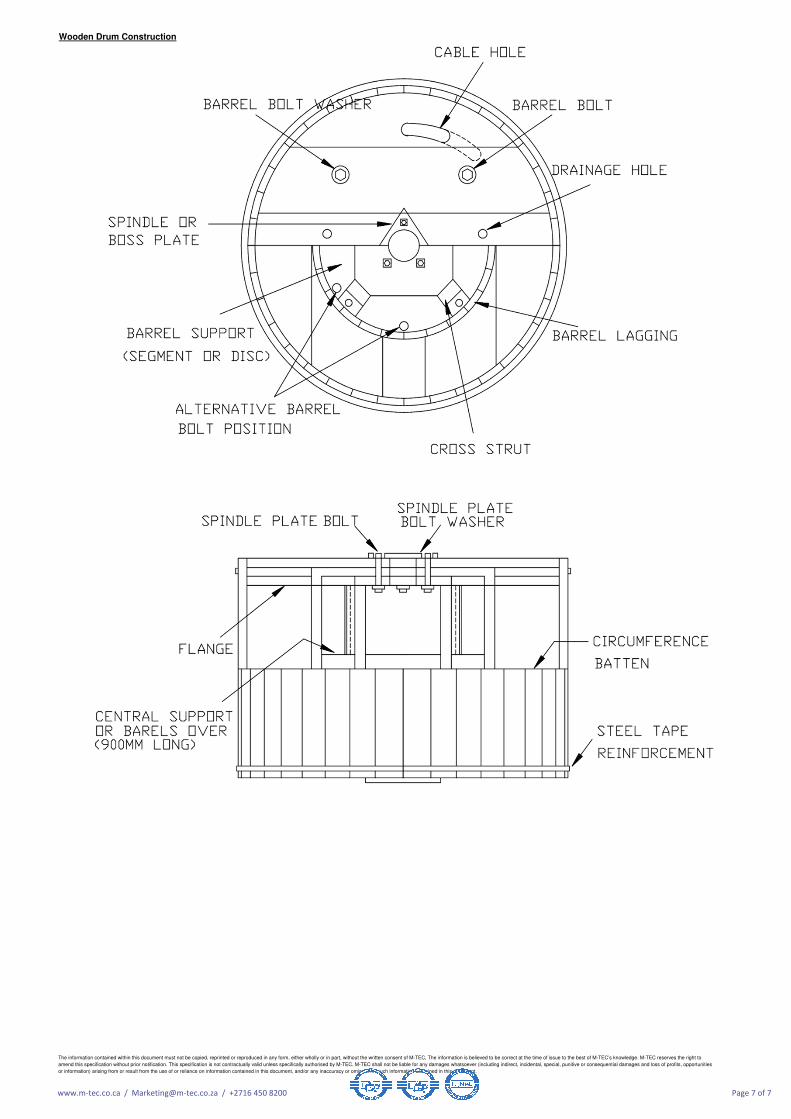
Wooden Drum Construction
The information contained within this document must not be copied, reprinted or reproduced in any form, either wholly or in part, without the written consent of M-TEC, The information is believed to be correct at the time of issue to the best of M-TEC’s knowledge. M-TEC reserves the right to
amend this specification without prior notification. This specification is not contractually valid unless specifically authorised by M-TEC. M-TEC shall not be liable for any damages whatsoever (including indirect, incidental, special, punitive or consequential damages and loss of profits, opportunities
or information) arising from or result from the use of or reliance on information contained in this document, and/or any inaccuracy or omission in such information contained in this document.
www.m-tec.co.ca / [email protected] / +2716 450 8200 Page 7 of 7
Related Documents