OPERATOR’S MANUAL Generating set and industrial engines 13 liter (EMS 2)

Welcome message from author
This document is posted to help you gain knowledge. Please leave a comment to let me know what you think about it! Share it to your friends and learn new things together.
Transcript

OPERATOR’S MANUALGenerating set and industrial engines
13 liter (EMS 2)
This Operator’s Manual may be ordered in a diffe-rent language free of charge up to 12 months after delivery, via internet.http://vppneuapps.volvo.com/manual/coupon/If internet access isn‘t possible, please contact your Volvo Penta dealer.
Diese Betriebsanleitung kann bis zu 12 Monate nachder Lieferung über Internet kostenlos in einer anderenSprache bestellt werden. http://vppneuapps.volvo.com/manual/coupon/Wenn Sie keinen Internet-Zugriff haben, kontaktierenSie bitte Ihren Volvo Penta-Händler.
Ce manuel d‘utilisation peut être commandé gratu-itement sur Internet en différentes langues, jusqu‘à 12 mois après la date de livraison.http://vppneuapps.volvo.com/manual/coupon/Veuillez contacter votre Distributeur Volvo Penta si vous avez un problème d‘accès à l‘Internet.
El presente libro de instrucciones puede solicitarse en otro idioma diferente, libre de cargo, hasta 12 meses después de la entrega, mediante internet.http://vppneuapps.volvo.com/manual/coupon/Si no se tiene acceso a internet, contacten al su concesio-nario Volvo Penta.
Denna instruktionsbok kan beställas via internet på ett annat språk gratis i upp till 12 månader efter leverans.http://vppneuapps.volvo.com/manual/coupon/Kontakta din Volvo Penta-återförsäljare om du inte har till-gång till internet.
Dit instructieboek kan gratis via internet in een a dere taal worden besteld tot 12 maanden na aflevering.http://vppneuapps.volvo.com/manual/coupon/Als toegang tot het internet niet mogelijk is, neem dan contact op met uw Volvo Penta dealer.
Denne instruktionsbog kan bestilles gratis på et andet sprog via Internettet i op til 12 måneder efter leveringen.http://vppneuapps.volvo.com/manual/coupon/Hvis det ikke er muligt at bestille via Internettet, bedes du kontakte din Volvo Penta forhandler.
Tämä käyttöohjekirja on tilattavissa Internetin kautta veloituk-setta eri kielillä 12 kuukauden ajan toimituksen jälkeen.http://vppneuapps.volvo.com/manual/coupon/aJos sinulla ei ole Internet-yhteyttä, ota yhteys lähimpään Volvo Penta jälleenmyyjään.
Este Manual do Operador pode ser encomendad em idiomas diferentes isento de custos até 12 meses após entrega, via internet.http://vppneuapps.volvo.com/manual/coupon/Se não for possível aceder à internet, contacte o seu concessionário Volvo Penta.
To παρόν Βιβλίο Χρήσης μπορεί να παραγγελθεί δωρεάν σε άλλη γλώσσα μέχρι 12 μήνες μετά την παράδοση,μέσω διαδικτύου.http://vppneuapps.volvo.com/manual/coupon/Εάν δεν είναι δυνατή η πρόσβαση στο διαδίκτυο,παρακαλούμε επικοινωνήστε με το δικό σας αντιπρόσωπο της Volvo Penta.
Данное руководство по эксплуатации можно бес-платно заказать на другом языке по Интернету в течение 12 месяцев после доставки.http://vppneuapps.volvo.com/manual/coupon/Если доступ к Интернету отсутствует, обратитесь к своему дилеру компании Volvo Penta.
Bu Kullanım Kılavuzu, teslimden 12 ay sonrasına kadar İnternet yoluyla ücretsiz olarak farklı bir dilde sipariş edilebilir.http://vppneuapps.volvo.com/manual/coupon/İnternet mümkün değilse, lütfen Volvo Penta yetkili satıcınızla tmasa geçin.
Il manuale per l‘operatore può essere ordinato tra-miteInternet, in varie lingue e per consegna gratuita, entro 12 mesi dalla consegna del prodottohttp://vppneuapps.volvo.com/manual/coupon/Se l‘accesso a Internet risulta impossibile, contattare la con-cessionaria Volvo Penta.
CALIFORNIA PROPOSITION 65 WARNING
Engine exhaust, some of its constituents, and a broad range of engine parts are known to the State ofCalifornia to cause cancer, birth defects, and other reproductive harm. Additionally, lubricants, fuels, andother fluids used in engines–including any waste created through the wearing of engine parts–contain orproduce chemicals known to the State of California to cause cancer and birth defects or other reproductiveharm.
Battery posts, terminals, and related accessories contain lead and lead compounds. Wash your hands afterhandling. Used engine oil contains chemicals that have caused cancer in laboratory animals. Alwaysprotect your skin by washing thoroughly with soap and water.
本操作手册可通过互联网以不同的言进行订购,交付后可免费使用达12 个月。http://vppneuapps.volvo.com/manual/coupon/ 如果无法访问互联网,请与沃尔沃遍达经销商联系。

Content
Foreword ...................................................................................................... 2Safety Information ...................................................................................... 3Introduction ................................................................................................. 7Presentation ................................................................................................ 9Instruments and Controls ........................................................................ 11Starting ...................................................................................................... 22Operation ................................................................................................... 26Engine Shutdown ...................................................................................... 28Fault Handling ........................................................................................... 30Fault Code Register .................................................................................. 37Maintenance Schedule ............................................................................. 49Maintenance .............................................................................................. 51Storage ....................................................................................................... 71Technical Data ........................................................................................... 73
Alphabetical index .................................................................................... 81
1
ForewordVolvo Penta engines are used all over the world. They are used in all possible operating conditions. This is nota coincidence. After 100 years as an engine manufacturer the Volvo Penta name has become a symbol of reli-ability, technical innovation, top of the range performance and long service life. We also believe that this iswhat you demand and expect of your Volvo Penta engine.
We would like you to read this operator’s manual thoroughly and consider the advice we give on running andmaintenance. Please pay attention to the safety instructions contained in the manual.
As owner of a Volvo Penta engine, we would also like to welcome you to a worldwide network of dealers andservice workshops to assist you with technical advice, service requirements and replacement parts. Pleasecontact your nearest authorized Volvo Penta dealer for assistance.
You will find your closest dealer at our home page on the Internet www.volvopenta.com - amongstother useful information about your Volvo Penta engine - we invite you to visit!
2 7748641 02-2012
Safety InformationRead the Operators Manual through very carefully before you start the engine or do any maintenance or serv-ice. It has to do with your safety, an incorrect operation can lead to personal injury and damage to products orproperty.This chapter describes how safety precaution is presented in the Operators Manual and on the product. It alsogives you an introduction to the basic safety rules for using and looking after the engine.If there is still something which is unclear or if you feel unsure about it, please contact your Volvo Penta dealerfor assistance.
NOTICE! Check that you have received the correct operator’s manual before you read on. If not, please con-tact your Volvo Penta dealer.
This symbol is used in the Operators Manual and on the product, to call your atten-tion to the fact that this is safety information. Always read such information very care-fully.Safety texts in the Operators Manual have the following order of priority:
DANGER!Indicates a hazardous situation which, if not avoided, will result in death or seriousinjury.
WARNING!Indicates a hazardous situation which, if not avoided, could result in death or seriouspersonal injury.
CAUTION!Indicates a hazardous situation which, if not avoided, could result in minor ormoderate personal injury.
IMPORTANT!Indicates a situation which, if not avoided, could result in property damage.
NOTICE! Used to draw your attention to important information that will facilitate thework or operation in progress.
This symbol is used on our products in some cases and refers to important informa-tion in the Operators Manual. Make sure that warning and information symbols on theengine are clearly visible and legible. Replace symbols which have been damaged orpainted over.
7748641 02-2012 3

Safety rules for operation and maintenanceDaily checksMake it a habit to give the engine and engine bay avisual check before starting (before the engine isstarted) and after operation (once the engine hasstopped). This helps you to quickly discoverwhether any leakage of fuel, coolant, oil or any otherabnormal event has happened, or is about to hap-pen.
Starting lockIf the instrument panel does not have a key switch,the engine room must be lockable, to prevent unau-thorized persons from starting the engine. Alterna-tively, a lockable main switch can be used.
Carbon monoxide poisoningOnly start the engine in a well ventilated area. Whenoperated in a confined space, exhaust fumes andcrankcase gases must be ventilated.
Hot surfaces and fluidsA hot engine always increases the risk for burns. Beon your guard against hot surfaces: the exhaustmanifold, turbocharger, oil pan, charge air pipe,starting heater, hot coolant and hot lubricating oil inpipes, hoses etc.
Cooling SystemAvoid opening the coolant filling cap when theengine is hot. Steam or hot coolant can spray outand cause scalding, at the same time as the pres-sure built up is lost.If the filler cap, coolant hose etc., still has to beopened or removed when the engine is hot, undothe filler cap slowly and carefully, to let the pressureout before removing the filler cap completely andstarting work. Note that the coolant can still be hotand cause scalding.
Fuel fillingThere is always a risk of fire and explosion duringfuel filling. Smoking is forbidden, and the engineshould be stopped.Never overfill the tank. Shut the tank cap securely.Only use the fuel recommended in the instructionbook. The wrong grade of fuel can cause seriousmalfunctions, power loss or stop the engine.
Fuel and lubrication oilsAlways protect your hands when searching forleaks. Fluids which leak under pressure can forcetheir way into body tissue and cause severe injury.There is a risk of blood poisoning (septicemia).Only use the fuel recommended in the OperatorsManual. The wrong grade of fuel can cause mal-functions or stop the engine. In a diesel engine, itcan also cause the injection pump to seize and theengine will over-rev, entailing a strong risk of per-sonal injury and machinery damage.Always cover the alternator if it is located beneaththe fuel filters. Fuel spillage can damage the alterna-tor.Always change the oil, oil filter and fuel filter at thespecified intervals.
OperationThe engine must not be operated in environmentswhich contain explosive media since none of theelectrical and mechanical components are explosionproof.Going close to a running engine is a safety risk.Hair, fingers, loose clothes, or dropped tools cancatch on rotating components and cause severeinjury.When engines are supplied without touch guards, allrotating components and hot surfaces must be pro-tected after installation in their application, if neces-sary for personal safety.
Safety Information
4 7748641 02-2012

Care and maintenanceKnowledgeThe Operators Manual contains instructions fordoing the most common service and maintenancetasks in a safe and correct manner. Read themcarefully before starting work.Literature for more major tasks is available fromyour Volvo Penta dealer.Never do a job if you are not entirely sure about howto do it. Please contact your Volvo Penta dealer andask for assistance instead.
Before startingRe-install all guards which have been removed dur-ing service work, before re-starting the engine.Make sure that there are no tools or other objectsleft behind on the engine.Never start a turbocharged engine without the air fil-ter in place. The rotating compressor turbine in theturbocharger can cause severe injury. There is alsoa risk that foreign bodies could be sucked in andcause damage to the machinery.
Stopping the engineStop the engine before opening or removing theengine hatch/hood. Service and maintenance workshould be done with the engine stopped unless oth-erwise specified.Prevent the engine from being started by pulling outthe starter key and disconnect the power with themain switch. Lock them in the “Off” position.If the instrument panel does not have a key switch,remove the system voltage with the main switch.Fix a notice by the operator position to say that workis in progress.Working with, or approaching a running engine is asafety risk. Hair, fingers, loose clothes, or droppedtools can catch on rotating components and causesevere injury. Volvo Penta recommends that allservice work which requires the engine to be run-ning should be done by an authorized Volvo Pentaworkshop.
Lifting the engineThe lifting eyes fitted on the engine should be usedfor lifting. Always check that the lifting devices are ingood condition and that they have the correctcapacity for the lift (engine weight together with aux-iliaries, if fitted). The engine should be lifted with anadjustable lifting boom for safe handling. All chainsor cables should be parallel to each other andshould be as square as possible to the top of theengine. Please note that auxiliary equipment instal-led on the engine could change its center of gravity.Special lifting devices may then be needed to obtainthe correct balance and safe handling. Never carryout work on an engine that is only suspended in ahoist.
Fire and explosionFuel and lubrication oilAll fuel, most lubricants and many chemicals areflammable. Always read and observe the advice onthe packages.Work on the fuel system must be done with theengine cold. Fuel leakage and spills on hot surfacesor electrical components can cause fires.Store oil and fuel soaked rags and other flammablematerial in a fireproof manner. Oil soaked rags canself-ignite in certain circumstances.Never smoke when filling fuel, lubrication oil or whenclose to fuel filling stations or the engine bay.
BatteriesBatteries contain and give off an explosive gas,especially when charged. This gas is very flamma-ble and highly explosive.Smoking, open flames or sparks must never occurin or near to batteries or the battery locker.Incorrect connection of a battery cable or start cablecan cause a spark which can be sufficient, in itsturn, to make the battery explode.
Spare partsComponents in fuel systems and electrical systemson Volvo Penta engines are designed and manufac-tured to minimize the risk of explosions and fire, inaccordance with applicable legal requirements.The use of spare parts not approved by Volvo Pentacan cause an explosion or fire.
Start sprayNever use start spray or similar preparations to helpin starting an engine with air pre-heating (glowplugs / starting heater). They may cause an explo-sion in the inlet manifold. Danger of personal injury.
Safety Information
7748641 02-2012 5

Electrical SystemDisconnect the powerBefore any work is done on the electrical system,the engine must be stopped and the power removedby switching off the main switch(es). Any externalpower supply for engine heaters, battery chargers orother auxiliary equipment connected to the enginemust be disconnected.
BatteriesBatteries contain a highly corrosive electrolyte. Pro-tect your eyes, skin and clothes during charging andother handling of batteries. Always use protectivegoggles and gloves.If acid comes into contact with your skin, wash atonce with soap and a lot of water.If you get battery acid in your eyes, flush at oncewith a lot of cold water, and get medical assistanceat once.
Electric weldingRemove the positive and negative cables from thebatteries.Then disconnect all cables connected to the alterna-tor. Disconnect both connectors from the enginecontrol module.Always connect the welder earth clamp to the com-ponent to be welded, and as close as possible to theweld site. The clamp must never be connected tothe engine or in such a way that current can passthrough a bearing.When welding is completed: Always connect thecables to the alternator and engine control unitconnector before reconnecting the battery cables.
Safety Information
6 7748641 02-2012
IntroductionThe Operator's Manual contains the information required for the correct, safe operation and maintenance ofyour Volvo Penta engine. We recommend therefore that you read the manual carefully and learn to handle theengine and other equipment in a safe manner before starting the engine.
The Operator's Manual describes the engine and equipment sold by Volvo Penta. The specifications, designinformation and illustrations used in the Operator's Manual are not definitive. We reserve the right to makechanges without prior notice.Differences in appearance and function of the controls and instruments may occur in certain variants. In suchcases, refer to the Operator's Manuals for the applications concerned.
When ordering service or spares, always specify the engine and transmission identification number. Refer toTechnical Data page 78.
WarrantyYour new Volvo Penta industrial engine is coveredby a limited warranty, according to the conditionsand instructions compiled in the Warranty and Serv-ice book.Note that AB Volvo Penta's liability is limited to thatwhich is described in the Warranty and ServiceBook. Read it carefully, as soon as possible afterdelivery. It contains important information about thewarranty card, service intervals and maintenancethat the owner must be aware of, check and per-form, otherwise AB Volvo Penta may disclaim itswarranty obligations in part or in full.Contact your Volvo Penta dealer if you have notreceived a Warranty and Service book, or a cus-tomer copy of the warranty card.
Maintenance and replacement partsVolvo Penta engines are designed for maximum reli-ability and long life. They are not only built to with-stand a demanding environment, but also to havethe smallest possible environmental impact. Thesequalities will be maintained through regular servicingand the use of genuine Volvo Penta replacementparts or replacement parts approved by VolvoPenta.Volvo Penta has a world-wide network of authorizeddealers. They are Volvo Penta product specialists,and have the accessories, genuine parts, test equip-ment and special tools needed for high quality serv-ice and repair work.Always observe the maintenance intervals in themanual, and remember to note the engine/trans-mission identification number when you orderservice and spare parts.
Breaking inThe engine must be broken in during its first 10operating hours, as follows:Run the engine in normal operations. However, fullload may not be applied other than for short periods.Never run the engine for long stretches at constantspeeds during this period.Higher oil consumption is normal during the first100-200 hours of operation. For this reason, checkthe oil level more frequently than the normal recom-mendation.When an disengageable clutch is installed, it shouldbe checked more carefully during the first days.Adjustments may be necessary to compensate bed-ding-in of the friction plates.
Fuel, oils and coolantOnly use fuel and oils of the grades recommendedin the Operator's Manual. Other grades may causeoperational malfunctions, increased fuel consump-tion and over time even shorten the life of theengine.Always change the oil, oil filter and fuel filter at thespecified intervals.
Future warranty claims related to the engine andaccessories may be declined if an unsuitable cool-ant has been used, or if the instructions for coolantmixture have not been followed.
7748641 02-2012 7
Environmental careAll of us like to live in a clean, healthy environment,where we can breathe clean air, see healthy trees,have clean water in lakes and seas, and enjoy sun-light without fearing for our health. Unfortunately,this cannot be taken for granted these days but it issomething we all must work to achieve.Volvo Penta has special responsibility as an enginemanufacturer, and for this reason environmentalcare is a natural cornerstone of our product develop-ment. Volvo Penta currently has a broad engine pro-gram in which great progress has been made inreducing exhaust emissions, fuel consumption andengine noise etc.We hope that you will be keen to preserve thesequalities. Always follow the directions in the Opera-tor's Manual about fuel grades, operation and main-tenance, to avoid unnecessary environmentaleffects. Contact your Volvo Penta dealer if younotice any changes such as increased fuel con-sumption or increased exhaust smoke.Remember always to hand in environmentally haz-ardous waste such as drained oil, coolant, old bat-teries, etc. for treatment at a recycling facility.Our united efforts can make a valuable contributionto the environment.
Certified enginesIf you own an emission-certified engine used inan area where exhaust emissions are regulatedby law, it is important to be aware of the follow-ing:Certification means that an engine type has beenchecked and approved by the relevant authority.The engine manufacturer guarantees that allengines of the same type conforms to the certifiedengine.This places special demands on the care and main-tenance you provide your engine in that
• the maintenance and service intervals recom-mended by Volvo Penta must be compliedwith.
• Only genuine Volvo Penta replacement partsmay be used.
• Service on injection pumps, pump settings andinjectors must always be carried out by anauthorized Volvo Penta workshop.
• The engine must not be converted or modified,except with accessories and service kits thatVolvo Penta has developed for the engine.
• No installation changes to the exhaust pipeand engine air inlet ducts may be made.
• Any warranty seals may be broken only byauthorized persons.
The general instructions in the Operator's Manualconcerning operation, service and maintenanceapply.NOTICE! Neglected or poorly performed mainte-nance/service, as well as the use of non-genuinereplacement parts, will mean that AB Volvo Pentacan no longer guarantee that the engine conforms tothe certified model.Damages and/or costs arising from this will not becompensated by Volvo Penta.
Introduction
8 7748641 02-2012

Presentation
EnginesThis Operator's Manual refers to TAD1341GE,TAD1342GE, TAD1343GE, TAD1344GE,TAD1345GE, TAD1350GE, TAD1351GE,TAD1352GE, TAD1353GE, TAD1354GE,TAD1355GE, TAD1340VE, TAD1341VE,TAD1342VE, TAD1343VE, TAD1344VE andTAD1345VE industrial engines.They are in-line, six-cylinder, direct injection indus-trial diesel engines. All of the engines are equippedwith electronically controlled fuel management (EMS), turbocharger, charge air cooler, thermostati-cally controlled cooling systems and electronic speedcontrol.
7748641 02-2012 9
EMS (Engine ManagementSystem)
EMS (Engine Management System) is an electronic system with CAN communication (Controller Area Net-work) for diesel engine control. The system has been developed by Volvo Penta and includes fuel control anddiagnostic functions.The system comprises among other things sensors, a control unit and unit injectors. The sensors send inputsignals to the control unit, which in turn controls the unit injectors.
Diagnostic functionThe purpose of the diagnostic function is to detectand localize any malfunctions in the EMS system, toprotect the engine and to ensure operation in theevent of serious malfunction.If a malfunction is detected, this is announced bywarning lamps, a flashing diagnostic lamp or in plainlanguage on the instrument panel, depending on theequipment used. If a fault code is obtained as aflashing code or in plain language, it is used forguidance in any fault tracing. Fault codes can alsobe read by Volvo’s VODIA tool at authorized VolvoPenta workshops.If there is a serious malfunction, the engine will beshut down altogether, or the control unit will reducethe power delivered (depending on application).Once again, a fault code is set for guidance in anyfault tracing.
Input signalsThe control unit receives input signals about engineoperating conditions etc. from the following compo-nents:
- coolant temperature sensor
- charge pressure / charge temperature sensor
- crankcase pressure sensor
- position sensor, camshaft
- rpm sensor, flywheel
- coolant level sensor
- oil level and temperature sensor
- oil pressure sensor
- fuel pressure sensor
- water-in-fuel indicator
Fuel controlThe engine fuel requirement is analyzed up to 100times per second. The amount of fuel injected intothe engine and the injection advance are fully elec-tronically controlled via fuel valves and the unitinjectors.This means that the engine always receives the cor-rect volume of fuel in all operating conditions, whichprovides lower fuel consumption, minimal exhaustemissions etc
Output signalsThe control module uses the input signals to controlthe following components:
- unit injectors
- starter motor
- main relay
- pre-heating relay
The information from the sensors provides precisedata about prevailing operating conditions andallows the processor in the control module to,among other things, calculate correct injectionamount, injection timing and check the engine's con-dition.
Presentation
10 7748641 02-2012
Instruments and Controls
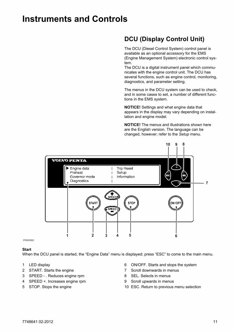
DCU (Display Control Unit)The DCU (Diesel Control System) control panel isavailable as an optional accessory for the EMS (Engine Management System) electronic control sys-tem.The DCU is a digital instrument panel which commu-nicates with the engine control unit. The DCU hasseveral functions, such as engine control, monitoring,diagnostics, and parameter setting.
The menus in the DCU system can be used to check,and in some cases to set, a number of different func-tions in the EMS system.
NOTICE! Settings and what engine data thatappears in the display may vary depending on instal-lation and engine model.
NOTICE! The menus and illustrations shown hereare the English version. The language can bechanged, however; refer to the Setup menu.
1 2 3 4 5 6
7
8910
P0002062
StartWhen the DCU panel is started, the “Engine Data” menu is displayed; press “ESC” to come to the main menu.
1 LED display 6 ON/OFF. Starts and stops the system2 START. Starts the engine 7 Scroll downwards in menus3 SPEED - . Reduces engine rpm 8 SEL. Selects in menus4 SPEED +. Increases engine rpm 9 Scroll upwards in menus5 STOP. Stops the engine 10 ESC. Return to previous menu selection
7748641 02-2012 11

MenusThere are several sub-menus under each mainmenu. There is not space for all the menu choices onthe display. To scroll through the menus, use the 7and 9 buttons on the display. Press the SEL button 8to make a selection. Refer to the illustration on theprevious page.
NOTICE! The Setup menu can be used to select thelanguage that you want to use on the display.
Main menu
• Engine data, current engine data
• Preheat, manual activation of pre-heating. Mustbe activated with temperatures below 0°C (32°F)
• Governor mode. activation of droop
• Diagnostics, shows fault codes as text
• Trip reset, resets trip data
• Setup, parameter setting
• Information, shows the currently applicable hard/software, data sets and engine identification forthe engine and DCU data
Engine datashows relevant engine data.
• Engine speed, can be controlled with the SPEED+and SPEED– buttons (rpm)
• Charge pressure (kPa)
• Coolant temperature (°C)
• Charge air temperature (°C)
• Oil pressure (kPa)
• Oil temperature (°C)
• Engine hours (h)
• Battery voltage (V)
• Fuel consumption (l/h)
• Instantaneous fuel consumption (trip fuel) (l)
Instruments and Controls
12 7748641 02-2012
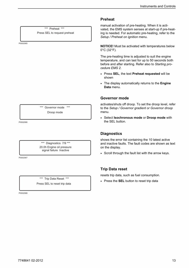
Preheatmanual activation of pre-heating. When it is acti-vated, the EMS system senses at start-up if pre-heat-ing is needed. For automatic pre-heating, refer to theSetup / Preheat on ignition menu.
NOTICE! Must be activated with temperatures below0°C (32°F).
The pre-heating time is adjusted to suit the enginetemperature, and can last for up to 50 seconds bothbefore and after starting. Refer also to Starting pro-cedure EMS 2.
• Press SEL, the text Preheat requested will beshown
• The display automatically returns to the EngineData menu.
Governor modeactivates/shuts off droop. To set the droop level, referto the Setup / Governor gradient or Governor droopmenu.
• Select Isochronous mode or Droop mode withthe SEL button.
Diagnosticsshows the error list containing the 10 latest activeand inactive faults. The fault codes are shown as texton the display.
• Scroll through the fault list with the arrow keys.
Trip Data resetresets trip data, such as fuel consumption.
• Press the SEL button to reset trip data
Instruments and Controls
7748641 02-2012 13
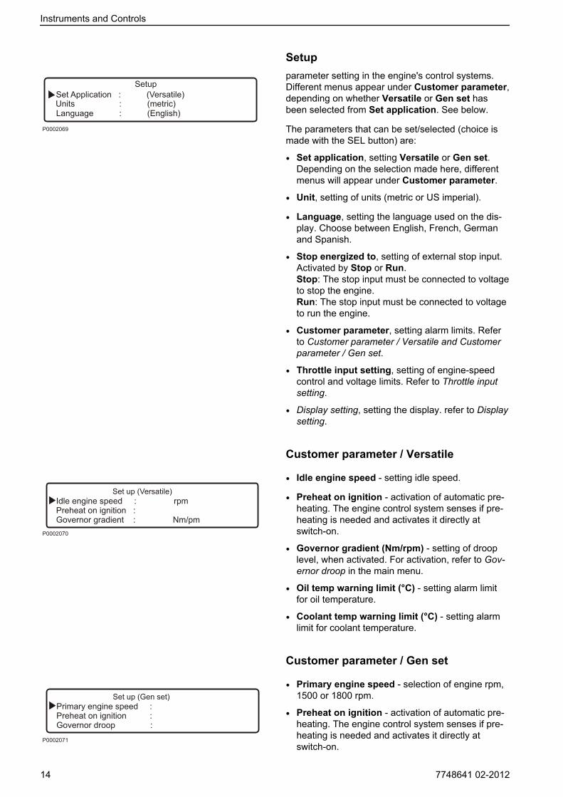
Setupparameter setting in the engine's control systems.Different menus appear under Customer parameter,depending on whether Versatile or Gen set hasbeen selected from Set application. See below.
The parameters that can be set/selected (choice ismade with the SEL button) are:
• Set application, setting Versatile or Gen set.Depending on the selection made here, differentmenus will appear under Customer parameter.
• Unit, setting of units (metric or US imperial).
• Language, setting the language used on the dis-play. Choose between English, French, Germanand Spanish.
• Stop energized to, setting of external stop input.Activated by Stop or Run.Stop: The stop input must be connected to voltageto stop the engine.Run: The stop input must be connected to voltageto run the engine.
• Customer parameter, setting alarm limits. Referto Customer parameter / Versatile and Customerparameter / Gen set.
• Throttle input setting, setting of engine-speedcontrol and voltage limits. Refer to Throttle inputsetting.
• Display setting, setting the display. refer to Displaysetting.
Customer parameter / Versatile
• Idle engine speed - setting idle speed.
• Preheat on ignition - activation of automatic pre-heating. The engine control system senses if pre-heating is needed and activates it directly atswitch-on.
• Governor gradient (Nm/rpm) - setting of drooplevel, when activated. For activation, refer to Gov-ernor droop in the main menu.
• Oil temp warning limit (°C) - setting alarm limitfor oil temperature.
• Coolant temp warning limit (°C) - setting alarmlimit for coolant temperature.
Customer parameter / Gen set
• Primary engine speed - selection of engine rpm,1500 or 1800 rpm.
• Preheat on ignition - activation of automatic pre-heating. The engine control system senses if pre-heating is needed and activates it directly atswitch-on.
Instruments and Controls
14 7748641 02-2012
• Governor droop (%) - setting of droop level, whenactivated. For activation, refer to “Governor droop”in the main menu.
• Overspeed limit (%) - setting of limit for over-speed alarm, % of set engine rpm.
• Overspeed shutdown - activation of engine shut-down with overspeed alarm. Refer to “Overspeedlimit” to activate the alarm limit for the excess rpmalarm.
• Oil temp warning limit (°C) - setting alarm limitfor oil temperature.
• Coolant temp limit (°C) - setting alarm limit forcoolant temperature.
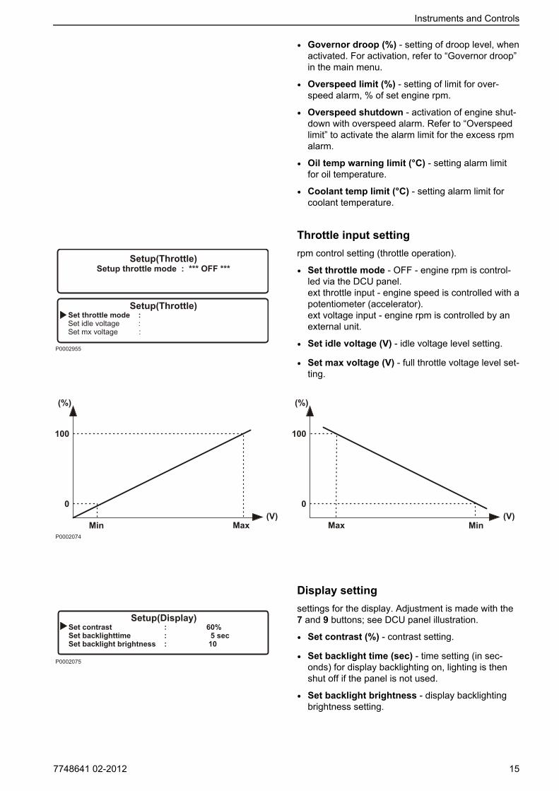
Throttle input settingrpm control setting (throttle operation).
• Set throttle mode - OFF - engine rpm is control-led via the DCU panel.ext throttle input - engine speed is controlled with apotentiometer (accelerator).ext voltage input - engine rpm is controlled by anexternal unit.
• Set idle voltage (V) - idle voltage level setting.
• Set max voltage (V) - full throttle voltage level set-ting.
Display settingsettings for the display. Adjustment is made with the7 and 9 buttons; see DCU panel illustration.
• Set contrast (%) - contrast setting.
• Set backlight time (sec) - time setting (in sec-onds) for display backlighting on, lighting is thenshut off if the panel is not used.
• Set backlight brightness - display backlightingbrightness setting.
Instruments and Controls
7748641 02-2012 15
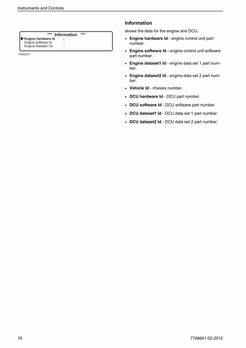
Informationshows the data for the engine and DCU.
• Engine hardware Id - engine control unit partnumber.
• Engine software Id - engine control unit softwarepart number.
• Engine dataset1 Id - engine data set 1 part num-ber.
• Engine dataset2 Id - engine data set 2 part num-ber.
• Vehicle Id - chassis number.
• DCU hardware Id - DCU part number.
• DCU software Id - DCU software part number.
• DCU dataset1 Id - DCU data set 1 part number.
• DCU dataset2 Id - DCU data set 2 part number.
Instruments and Controls
16 7748641 02-2012
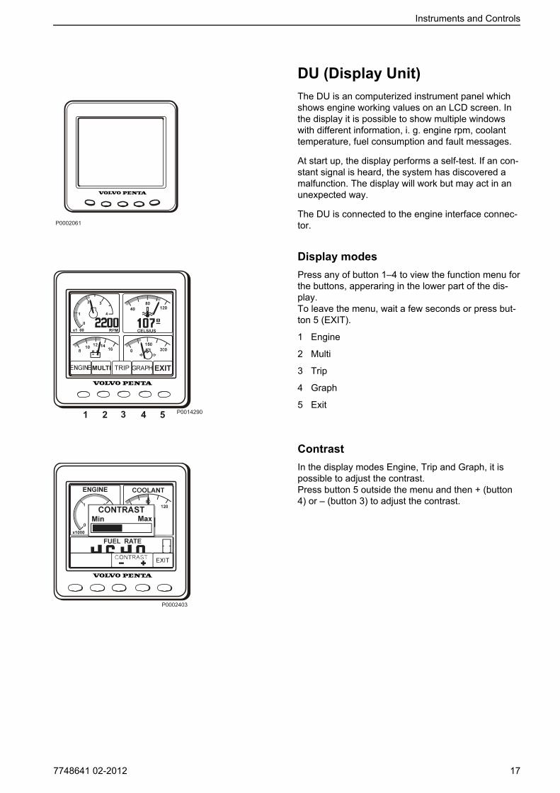
DU (Display Unit)The DU is an computerized instrument panel whichshows engine working values on an LCD screen. Inthe display it is possible to show multiple windowswith different information, i. g. engine rpm, coolanttemperature, fuel consumption and fault messages.
At start up, the display performs a self-test. If an con-stant signal is heard, the system has discovered amalfunction. The display will work but may act in anunexpected way.
The DU is connected to the engine interface connec-tor.
Display modesPress any of button 1–4 to view the function menu forthe buttons, apperaring in the lower part of the dis-play.To leave the menu, wait a few seconds or press but-ton 5 (EXIT).
1 Engine
2 Multi
3 Trip
4 Graph
5 Exit
ContrastIn the display modes Engine, Trip and Graph, it ispossible to adjust the contrast.Press button 5 outside the menu and then + (button4) or – (button 3) to adjust the contrast.
P0002061
Instruments and Controls
7748641 02-2012 17
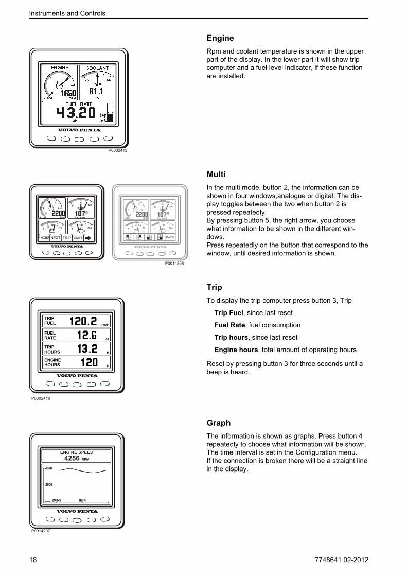
EngineRpm and coolant temperature is shown in the upperpart of the display. In the lower part it will show tripcomputer and a fuel level indicator, if these functionare installed.
MultiIn the multi mode, button 2, the information can beshown in four windows,analogue or digital. The dis-play toggles between the two when button 2 ispressed repeatedly.By pressing button 5, the right arrow, you choosewhat information to be shown in the different win-dows.Press repeatedly on the button that correspond to thewindow, until desired information is shown.
TripTo display the trip computer press button 3, Trip
Trip Fuel, since last reset
Fuel Rate, fuel consumption
Trip hours, since last reset
Engine hours, total amount of operating hours
Reset by pressing button 3 for three seconds until abeep is heard.
GraphThe information is shown as graphs. Press button 4repeatedly to choose what information will be shown.The time interval is set in the Configuration menu.If the connection is broken there will be a straight linein the display.
Instruments and Controls
18 7748641 02-2012

Configuration menuPress button 5 for three seconds to enter the Config-uration menu. Navigate with the up and down arrows,select with the right arrow.
Units
- PRESSURE; kPa, PSI
- VOLUME; LITRE, GAL, Imperial GAL.Fuel rate is adjusted according to volume unit, L/H,GAL/H, IGAL/H.
- TEMPERATURE; °C, °F
Alarm Status
List of active alarms, refer to FaultHandling page 34
Instruments and Controls
7748641 02-2012 19
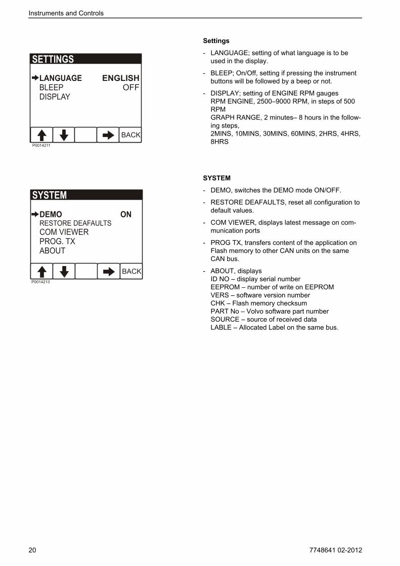
Settings
- LANGUAGE; setting of what language is to beused in the display.
- BLEEP; On/Off, setting if pressing the instrumentbuttons will be followed by a beep or not.
- DISPLAY; setting of ENGINE RPM gaugesRPM ENGINE, 2500–9000 RPM, in steps of 500RPMGRAPH RANGE, 2 minutes– 8 hours in the follow-ing steps,2MINS, 10MINS, 30MINS, 60MINS, 2HRS, 4HRS,8HRS
SYSTEM
- DEMO, switches the DEMO mode ON/OFF.
- RESTORE DEAFAULTS, reset all configuration todefault values.
- COM VIEWER, displays latest message on com-munication ports
- PROG TX, transfers content of the application onFlash memory to other CAN units on the sameCAN bus.
- ABOUT, displaysID NO – display serial numberEEPROM – number of write on EEPROMVERS – software version numberCHK – Flash memory checksumPART No – Volvo software part numberSOURCE – source of received dataLABLE – Allocated Label on the same bus.
Instruments and Controls
20 7748641 02-2012

CIU (Control Interface Unit)The CIU is a "translator" between the control unit (EMS) and the customer's own control panel. TheCIU has two serial communication links, one fast andone slow.
The fast one is a so-called CAN link. All data relatedto instruments, indication lamps, connectors andpotentiometers is controlled by this link.
The slow link manages diagnostic information forflashing codes etc.
Easy Link InstrumentsThe following Easy Link instruments are available:
- Tachometer / hours counter (fault codes are alsodisplayed on the tachometer display when thediagnostic button is pressed)
- Coolant temperature
- Oil pressure
- Oil temperature
- Battery voltage
- Alarm panel
- Turbo pressure
P0002060
Instruments and Controls
7748641 02-2012 21
StartingMake it a habit of giving the engine and engine room a visual check before starting. This will help you to dis-cover quickly if anything abnormal has happened, or is about to happen.Also check that instruments and warning displays show normal values after you have started the engine.
WARNING!Never use start spray or similar products as starting aid. Explosion risk!
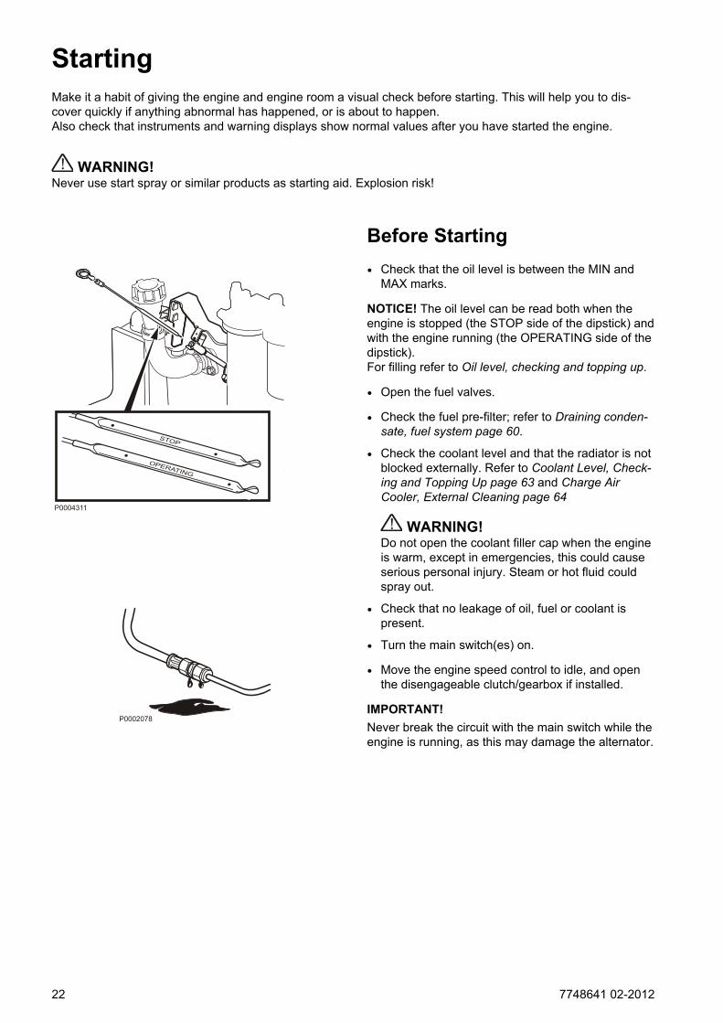
Before Starting• Check that the oil level is between the MIN and
MAX marks.
NOTICE! The oil level can be read both when theengine is stopped (the STOP side of the dipstick) andwith the engine running (the OPERATING side of thedipstick).For filling refer to Oil level, checking and topping up.
• Open the fuel valves.
• Check the fuel pre-filter; refer to Draining conden-sate, fuel system page 60.
• Check the coolant level and that the radiator is notblocked externally. Refer to Coolant Level, Check-ing and Topping Up page 63 and Charge AirCooler, External Cleaning page 64
WARNING!Do not open the coolant filler cap when the engineis warm, except in emergencies, this could causeserious personal injury. Steam or hot fluid couldspray out.
• Check that no leakage of oil, fuel or coolant ispresent.
• Turn the main switch(es) on.
• Move the engine speed control to idle, and openthe disengageable clutch/gearbox if installed.
IMPORTANT!Never break the circuit with the main switch while theengine is running, as this may damage the alternator.
STOP
OPERATING
P0004311
P0002078
22 7748641 02-2012

Starting the Engine
EMS (Engine Management System)The pre-heating time is adjusted to suit the enginetemperature, and can last for up to 50 seconds bothbefore and after starting.
The starter motor connection time is maximized to 20seconds. After that, the starter motor circuit is cut for80 seconds to protect the starter motor against over-heating.
DCU (Display Control Unit)
With pre-heating
1 Depress the ON/OFF-button (6).
2 Press the SEL button (8) to come to the main-menu.
3 Scroll down to Pre/heater with scroll button (7),press SEL-button (8)
4 In the pre-heater menu, press the SEL-button (8) to select pre-heating.
5 Press the START- button (2).
Without pre-heating
1 Depress the ON/OFF-button (6).
2 Press the START-button (2).
Leave the engine to idle for the first 10 seconds.Then warm the engine up at low speed and underlow load.Never race the engine when it is cold.
Starting
7748641 02-2012 23

Starting in Extreme ColdCertain preparations must be made to facilitateengine starting, and in some cases to make startingpossible at all:
• Use a winter grade fuel (of a well-known make)which has been approved for the relevant temper-ature. This reduces the risk of wax deposits in thefuel system. At extremely low temperatures, theuse of a fuel heater is recommended.
• For fully acceptable lubrication, a synthetic engineoil of recommended viscosity for the relevant tem-perature should be used. Please refer to the Main-tenance, lubrication system chapter. Syntheticlubricants are able to manage a wider temperaturerange than mineral-based lubricants.
• Pre-heat the coolant with a separately installedeletric engine heater. In extreme cases, a diesel-burning engine heater may be needed. Ask yourVolvo Penta dealer for advice.
• Make sure that the cooling system is filled with aglycol mixture. Please refer to the Maintenance,cooling system chapter.
• The batteries should be in good condition. Coldweather reduces battery capacity. Increased bat-tery capacity may be necessary.
Never Use Start Spray
WARNING!Never use start spray or similar products as startingaid. Explosion risk!
P0002080
Starting
24 7748641 02-2012
Starting Using Auxiliary Batteries
WARNING!Explosion hazard. Batteries contain and give off anexplosive gas which is highly flammable and explo-sive. A short circuit, open flame or spark could causea violent explosion. Ventilate well.
1 Check that the auxiliary batteries are connected (series or parallel) so that the rated voltage corre-sponds to the engine system voltage.
2 First connect the red (+) jumper cable to the auxil-iary battery, then to the flat battery. Then connectthe black (-) jumper cable to the auxiliary batteryand to a location that is somewhere away fromthe discharged battery, e.g. the main switchnegative terminal or the negative terminalon thestarter motor.
3 Start the engine.
WARNING!Do not touch the connections during the startattempt: Risk of arcing.Do not bend over any of the batteries either.
4 Remove the cables in the reverse order.
IMPORTANT!The ordinary cables to the standard batteries mustnot be loosened on any condition.
Starting
7748641 02-2012 25
OperationCorrect operating technique is very important for both fuel economy and engine life. Always let the enginewarm up to normal operating temperature before operating at full power. Avoid sudden throttle openings andoperation at high engine rpm.
Reading the InstrumentsCheck all instruments directly after starting, and thenregularly during operation.
NOTICE! On engines in continuous operation, thelubrication oil level must be checked at least every 24hours. Refer to Oil level, checking and topping up.
AlarmsIf the EMS 2 system receives abnormal signals fromthe engine, the control unit generates fault codes andalarms, in the form of lamps and audible warnings.This is done by means of CAN signals to the instru-ment.
More information about fault codes and fault tracingcan be found in the chapter. FaultHandling page 30.
Maneuvering
Operation at low loadAvoid long-term operation at idle or at low load, sincethis can lead to increased oil consumption and even-tually to oil leakage from the exhaust manifold, sinceoil will seep past the turbocharger seals and accom-pany the induction air into the inlet manifold at lowturbo pressure.One consequence of this is carbon build-up onvalves, piston crowns, exhaust ports and the exhaustturbine.
At low loads, the combustion temperature maybecome so low that complete combustion cannot beensured, resulting in possible fuel dilution of lubricat-ing oil and eventually leakage from the exhaust mani-fold.
If the following points are done as a complement tonormal maintenance, there will be no risk of malfunc-tions caused by operation at low load.
• Reduce operation at low load to a minimum. If theengine is regularly test-run without load once a
26 7748641 02-2012

week, the duration of this operation should be lim-ited to 5 minutes.
• Run the engine at full load for about 4 hours oncea year. In this way carbon deposits in the engineand exhaust system are given the chance to burnup.
Operation
7748641 02-2012 27

Engine ShutdownDuring longer breaks in operation, the engine must be warmed up at least once every two weeks. This pre-vents corrosion in the engine. If you expect the engine to remain unused for two months or more, it must belaid up: Refer to the chapter Storage page 71.
Before Engine ShutdownLet the engine run for a few minutes without loadingbefore stopping it. This allows engine temperatureequalization and prevents boiling once stopped andalso allows the turbocharger to cool down. This con-tributes to long service life without malfunctions.
Stop the Engine
• Disengage the clutch (if possible).
• Depress the STOP-button (5).
After Engine Shutdown
1 Check the engine and engine bay for leakage.
2 Turn off the main switches before any long stop-page.
3 Carry out maintenance in accordance with theschedule.
For longer breaks in operationDuring longer breaks in operation, the engine mustbe warmed up at least once every two weeks. Thisprevents corrosion attacks in the engine.If you expect the engine to be unused for two monthsor more, it must be laid up. Refer to the chapter ShortTerm Storage.
NOTICE! If there is a risk of frost, the coolant in thecooling system must have sufficient frost protection.Refer to the chapter Maintenance page 61.A poorly-charged battery can freeze and burst; referto Battery, Charging page 69.
P0002078
28 7748641 02-2012
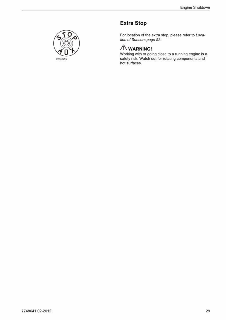
Extra Stop
For location of the extra stop, please refer to Loca-tion of Sensors page 52.
WARNING!Working with or going close to a running engine is asafety risk. Watch out for rotating components andhot surfaces.
Engine Shutdown
7748641 02-2012 29
Fault Handling
Fault TracingA number of symptoms and possible causes of engine malfunctions are described in the table below. Alwayscontact your Volvo Penta dealer if any problems occur which you can not solve by yourself.NOTICE! Read through the safety advice for care and maintenance work in the chapter Safety precautions forboat operation before you start work.
Symptoms and possible causesThe diagnosis button lamp flashes Please refer to Alarm handlingEngine can not be stopped 2, 5Starter motor does not rotate 1, 2, 3, 4, 5, 6, 7, 24Starter motor rotates slowly 1, 2Starter motor rotates normally but the enginedoes not start
8, 9, 10, 11,
Engine starts but stops again 8, 9, 10, 11, 13Engine does not reach correct operating speed atfull throttle
9, 10, 11, 12, 13, 21, 25, 26
Engine runs roughly 10, 11High fuel consumption 12, 13, 15, 25Black exhaust smoke 12, 13Blue or white exhaust smoke 15, 22Too low lubrication oil pressure 16Excessive coolant temperature 17, 18, 19, 20Too low coolant temperature 20No, or poor charge 2, 23
30 7748641 02-2012
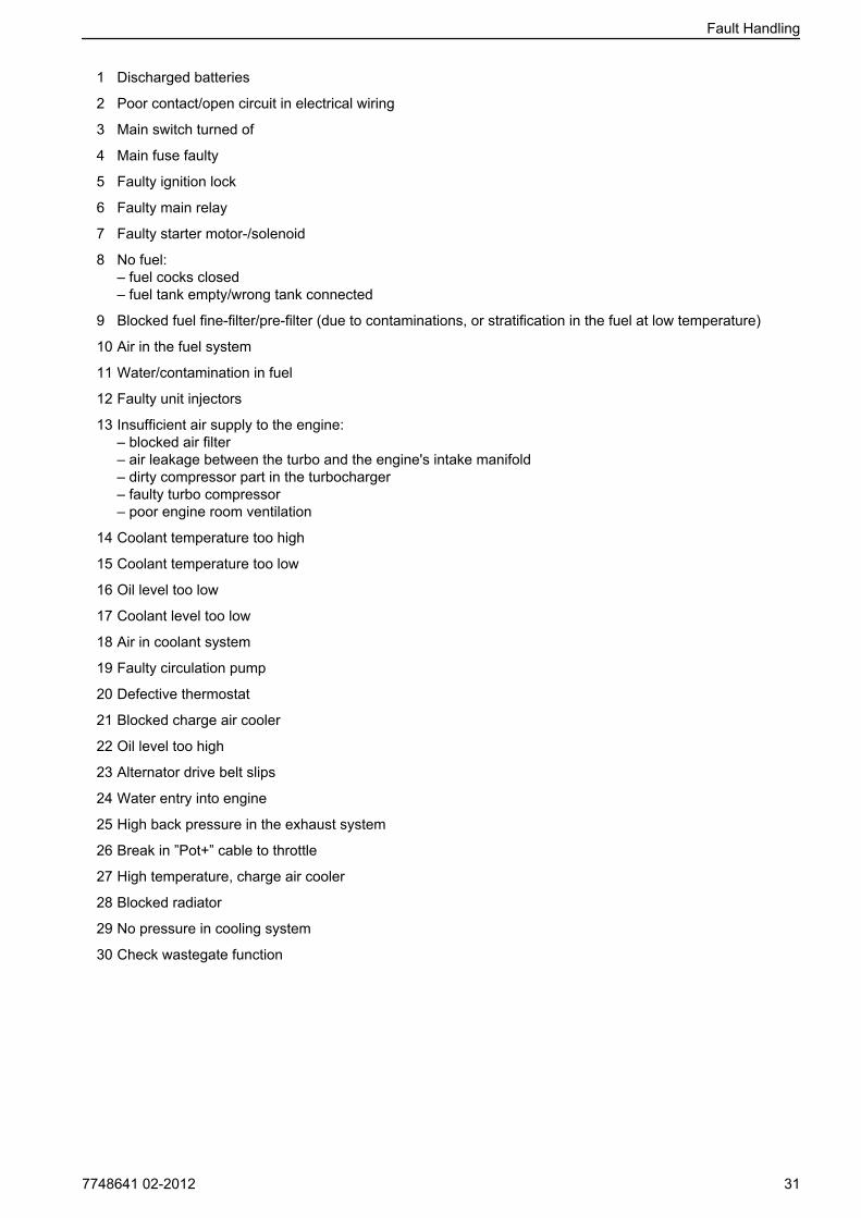
1 Discharged batteries
2 Poor contact/open circuit in electrical wiring
3 Main switch turned of
4 Main fuse faulty
5 Faulty ignition lock
6 Faulty main relay
7 Faulty starter motor-/solenoid
8 No fuel:– fuel cocks closed– fuel tank empty/wrong tank connected
9 Blocked fuel fine-filter/pre-filter (due to contaminations, or stratification in the fuel at low temperature)
10 Air in the fuel system
11 Water/contamination in fuel
12 Faulty unit injectors
13 Insufficient air supply to the engine:– blocked air filter– air leakage between the turbo and the engine's intake manifold– dirty compressor part in the turbocharger– faulty turbo compressor– poor engine room ventilation
14 Coolant temperature too high
15 Coolant temperature too low
16 Oil level too low
17 Coolant level too low
18 Air in coolant system
19 Faulty circulation pump
20 Defective thermostat
21 Blocked charge air cooler
22 Oil level too high
23 Alternator drive belt slips
24 Water entry into engine
25 High back pressure in the exhaust system
26 Break in ”Pot+” cable to throttle
27 High temperature, charge air cooler
28 Blocked radiator
29 No pressure in cooling system
30 Check wastegate function
Fault Handling
7748641 02-2012 31

Diagnostic FunctionThe diagnostic function monitors and controls theengine. The diagnostic function has the followingtasks:
• detecting and locating disturbances
• reporting detection of disturbances
• providing guidance when fault tracing
A fault message in the form of a fault code is alwaysgenerated when a disturbance is the detected by thediagnostic function. If the diagnostic function detectsa disturbance in the system, this is reported with afault code via the instruments.The diagnostic function protects the engine andensure continued operation by affecting the engine,depending on the severity the engine is affected dif-ferently.
Depending on what instrumentation that is beingused the fault message is shown in various ways (fault codes can also be read out by VODIA).All fault codes and fault messages can be found inthe Fault Code Register together with informationabout cause, reaction and actions, for further infor-mation see chapter Fault Code Register.
Fault Handling
32 7748641 02-2012
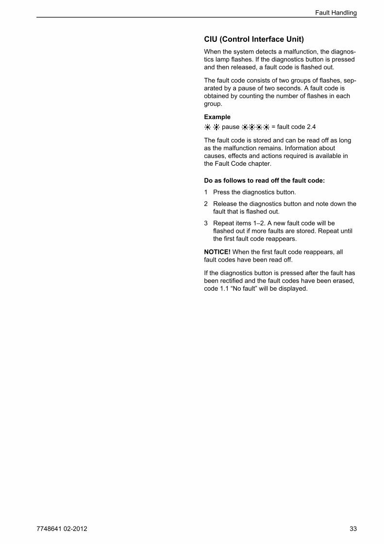
CIU (Control Interface Unit)When the system detects a malfunction, the diagnos-tics lamp flashes. If the diagnostics button is pressedand then released, a fault code is flashed out.
The fault code consists of two groups of flashes, sep-arated by a pause of two seconds. A fault code isobtained by counting the number of flashes in eachgroup.
Example pause = fault code 2.4
The fault code is stored and can be read off as longas the malfunction remains. Information aboutcauses, effects and actions required is available inthe Fault Code chapter.
Do as follows to read off the fault code:
1 Press the diagnostics button.
2 Release the diagnostics button and note down thefault that is flashed out.
3 Repeat items 1–2. A new fault code will beflashed out if more faults are stored. Repeat untilthe first fault code reappears.
NOTICE! When the first fault code reappears, allfault codes have been read off.
If the diagnostics button is pressed after the fault hasbeen rectified and the fault codes have been erased,code 1.1 “No fault” will be displayed.
Fault Handling
7748641 02-2012 33
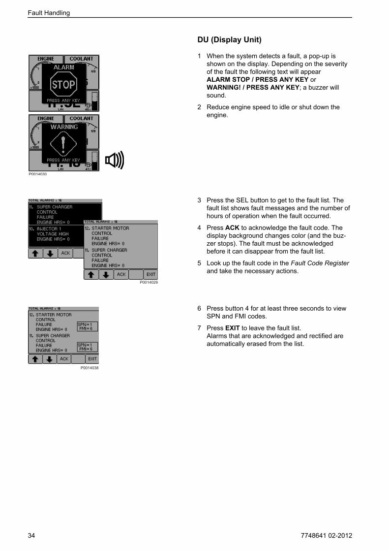
DU (Display Unit)
1 When the system detects a fault, a pop-up isshown on the display. Depending on the severityof the fault the following text will appearALARM STOP / PRESS ANY KEY orWARNING! / PRESS ANY KEY; a buzzer willsound.
2 Reduce engine speed to idle or shut down theengine.
3 Press the SEL button to get to the fault list. Thefault list shows fault messages and the number ofhours of operation when the fault occurred.
4 Press ACK to acknowledge the fault code. Thedisplay background changes color (and the buz-zer stops). The fault must be acknowledgedbefore it can disappear from the fault list.
5 Look up the fault code in the Fault Code Registerand take the necessary actions.
6 Press button 4 for at least three seconds to viewSPN and FMI codes.
7 Press EXIT to leave the fault list.Alarms that are acknowledged and rectified areautomatically erased from the list.
Fault Handling
34 7748641 02-2012
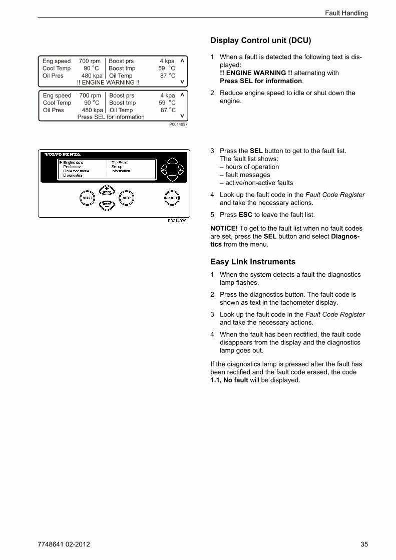
Display Control unit (DCU)
1 When a fault is detected the following text is dis-played:!! ENGINE WARNING !! alternating withPress SEL for information.
2 Reduce engine speed to idle or shut down theengine.
3 Press the SEL button to get to the fault list.The fault list shows:– hours of operation– fault messages– active/non-active faults
4 Look up the fault code in the Fault Code Registerand take the necessary actions.
5 Press ESC to leave the fault list.
NOTICE! To get to the fault list when no fault codesare set, press the SEL button and select Diagnos-tics from the menu.
Easy Link Instruments1 When the system detects a fault the diagnostics
lamp flashes.
2 Press the diagnostics button. The fault code isshown as text in the tachometer display.
3 Look up the fault code in the Fault Code Registerand take the necessary actions.
4 When the fault has been rectified, the fault codedisappears from the display and the diagnosticslamp goes out.
If the diagnostics lamp is pressed after the fault hasbeen rectified and the fault code erased, the code1.1, No fault will be displayed.
Fault Handling
7748641 02-2012 35
Erasing fault codesThe memory of the diagnostic function is reset whenthe power to the engine is disconnected.When the power is switched on again the diagnosticfunction will check if there are any malfunctions in thesystem. If so a new fault codes is registered.
NOTICE! Power must be disconnected completely.
This means that fault that hasn’t been corrected:
1 are shown as active, the active fault code canthen be erased with the VODIA tool.
2 must be acknowledge and read out every time theengine is switched on.
If the diagnostic button is depressed after the faulthas been corrected and fault code deleted, the code1.1,No fault, will show.
Fault Handling
36 7748641 02-2012

Fault Code RegisterNo fault (Code 1.1)Cause Reaction RemedyThere are no active faults.
Preheating Relay (Code 5.4, PID 45/SPN 626)Cause Reaction Remedy
• Short circuit to positive (+) orearth (ground) (–).
• Open circuit.
• Preheating can not be acti-vated.
• Preheating is constantly con-nected.
• Check that the relay inputcable is not damaged.
• Check relay function.
Fuel Pressure Sensor (Code 3.6, PID/SPN 94)Cause Reaction Remedy
• Short circuit to positive (+) orearth (ground) (–).
• Open circuit.
• None • Check that the fuel pressuresensor connector is correctlyinstalled.
• Check that the fuel pressuresensor cable is not dam-aged.
• Check that the fuel pressuresensor is correctly installed.
• Check fuel pressure sensorfunction.
Fuel Pressure (Code 3.8, PID/SPN 94)Cause Reaction Remedy
• Low supply pressure • None • Check if it is possible to buildup pressure with the handpump
• Check the fuel filter
• Check the fuel pre-filter
Water in Fuel (Code 2.1, PID/SPN 97)Cause Reaction Remedy
• Water in fuel • None • Empty the primary fuel filter
Indicator for Water in Fuel (Code 2.9, PID/SPN 97)Cause Reaction Remedy
• Short circuit
• Open circuit
• Fault in indicator
• None • Check the indicator cablesfor breaks and short circuits
• Check indicator function.Change indicator as neces-sary
Oil Level (Code 5.7, PID/SPN 98)Cause Reaction Remedy
• Oil level to low • None • Check the oil level
7748641 02-2012 37

Oil Level Sensor (Code 5.9, PID/SPN 98)Cause Reaction Remedy
• Shorted to plus (+) or minus (-)
• Break
• None • Check that the cable harnessto the oil level sensor has notbeen damaged
• Check the oil level sensorfunction
Oil Pressure Sensor (Code 3.1, PID/SPN 100)Cause Reaction Remedy
• Short circuit to positive (+) orearth (ground) (–)
• Open circuit
• None • Check that the oil pressuresensor cable is not damaged
• Check that the oil pressuresensor is correctly connected
Oil Pressure (Code 6.6, PID/SPN 100)Cause Reaction Remedy
• Oil pressure is too low • Engine control modulereduces engine power (unless the protection hasbeen shut off with the VODIAdiagnostic tool)
• Check oil level
• Check that the air filter is notblocked
• Check system pressurevalves and safety valves inthe oil system
• Check oil pressure sensorfunction
Boost Temperature Sensor (Code 3.2, PID/SPN 105)Cause Reaction Remedy
• Short circuit to positive (+) orearth (ground) (–)
• Open circuit
• None • Check that the boost temper-ature sensor connector iscorrectly installed
• Check that the boost temper-ature sensor cable is notdamaged
• Check that the boost temper-ature sensor is correctlyinstalled
• Check boost temperaturesensor function
Boost Temperature (Code 6.2, PID/SPN 105)Cause Reaction Remedy
• Boost temperature is toohigh
• Engine control modulereduces engine power (unless the protection hasbeen shut off with the VODIAdiagnostic tool)
• Check the coolant level
• Check the charge air cooler (cleanliness)
• Check boost temperaturesensor function
• Check the function of thethermostat
Fault Code Register
38 7748641 02-2012
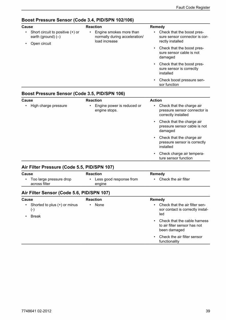
Boost Pressure Sensor (Code 3.4, PID/SPN 102/106)Cause Reaction Remedy
• Short circuit to positive (+) orearth (ground) (–)
• Open circuit
• Engine smokes more thannormally during acceleration/load increase
• Check that the boost pres-sure sensor connector is cor-rectly installed
• Check that the boost pres-sure sensor cable is notdamaged
• Check that the boost pres-sure sensor is correctlyinstalled
• Check boost pressure sen-sor function
Boost Pressure Sensor (Code 3.5, PID/SPN 106)Cause Reaction Action
• High charge pressure • Engine power is reduced orengine stops.
• Check that the charge airpressure sensor connector iscorrectly installed
• Check that the charge airpressure sensor cable is notdamaged
• Check that the charge airpressure sensor is correctlyinstalled
• Check charge air tempera-ture sensor function
Air Filter Pressure (Code 5.5, PID/SPN 107)Cause Reaction Remedy
• Too large pressure dropacross filter
• Less good response fromengine
• Check the air filter
Air Filter Sensor (Code 5.6, PID/SPN 107)Cause Reaction Remedy
• Shorted to plus (+) or minus (-)
• Break
• None • Check that the air filter sen-sor contact is correctly instal-led
• Check that the cable harnessto air filter sensor has notbeen damaged
• Check the air filter sensorfunctionality
Fault Code Register
7748641 02-2012 39
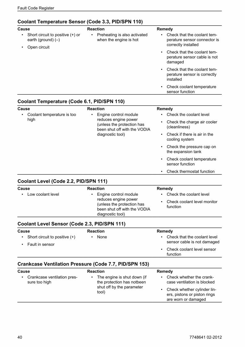
Coolant Temperature Sensor (Code 3.3, PID/SPN 110)Cause Reaction Remedy
• Short circuit to positive (+) orearth (ground) (–)
• Open circuit
• Preheating is also activatedwhen the engine is hot
• Check that the coolant tem-perature sensor connector iscorrectly installed
• Check that the coolant tem-perature sensor cable is notdamaged
• Check that the coolant tem-perature sensor is correctlyinstalled
• Check coolant temperaturesensor function
Coolant Temperature (Code 6.1, PID/SPN 110)Cause Reaction Remedy
• Coolant temperature is toohigh
• Engine control modulereduces engine power (unless the protection hasbeen shut off with the VODIAdiagnostic tool)
• Check the coolant level
• Check the charge air cooler (cleanliness)
• Check if there is air in thecooling system
• Check the pressure cap onthe expansion tank
• Check coolant temperaturesensor function
• Check thermostat function
Coolant Level (Code 2.2, PID/SPN 111)Cause Reaction Remedy
• Low coolant level • Engine control modulereduces engine power (unless the protection hasbeen shut off with the VODIAdiagnostic tool)
• Check the coolant level
• Check coolant level monitorfunction
Coolant Level Sensor (Code 2.3, PID/SPN 111)Cause Reaction Remedy
• Short circuit to positive (+)
• Fault in sensor
• None • Check that the coolant levelsensor cable is not damaged
• Check coolant level sensorfunction
Crankcase Ventilation Pressure (Code 7.7, PID/SPN 153)Cause Reaction Remedy
• Crankcase ventilation pres-sure too high
• The engine is shut down (ifthe protection has notbeenshut off by the parametertool)
• Check whether the crank-case ventilation is blocked
• Check whether cylinder lin-ers, pistons or piston ringsare worn or damaged
Fault Code Register
40 7748641 02-2012

Crankcase Ventilation Pressure Sensor (Code 7.8, PID/SPN 153)Cause Reaction Remedy
• Shorted to plus (+) or minus (-)
• Break
• None • Check that the crankcaseventilation pressure sensorcontact is correctly installed
• Check that the cable harnessto the crankcase ventilationpressure sensor has notbeen damaged
• Check that the crankcaseventilation pressure sensorcorrectly installed
• Check crankcase ventilationpressure sensor function
Battery Voltage, EMS (Code 3.9, PID/SPN 158)Cause Reaction Remedy
• Faulty alternator
• Faulty battery, battery cables
• None • Check the supply voltagefrom the control unit
Battery Voltage, CIU (Code 6.9, PID/SPN 158)Cause Reaction Remedy
• Short circuit to negative (-)
• Faulty alternator
• Faulty battery, battery cables
• Problems in engine starting • Check the supply voltagefrom the control unit
• Check the batteries
• Check the alternator
• Check the 8-pin contact
Air Temperature Sensor, Inlet (Code 7.9, PID/SPN 172)Cause Reaction Remedy
• Shorted to plus (+) or minus (-)
• Break
• None • Check that the air tempera-ture sensor contact is cor-rectly installed
• Check that the cable harnessto the air temperature sensorhas not been damaged
• Check that the air tempera-ture sensor is correctlyinstalled
• Check the air temperaturesensor functionality
Oil Temperature Sensor (Code 3.7, PID/SPN 175)Cause Reaction Remedy
• Shorted to plus (+) or minus (-)
• Break
• None • Check that the cable harnessto the oil temperature sensorhas not been damaged
• Check that the oil tempera-ture sensor has been con-nected correctly
Fault Code Register
7748641 02-2012 41

Oil Temperature (Code 5.8, PID/SPN 175)Cause Reaction Remedy
• Oil temperature is too high • The engine control modulelimits engine output(unlessprotection has been turnedoff with thediagnosis toolVODIA)
• Check the oil level
• Check the oil temperature
• Check the oil temperaturesensor function
Engine Speed (Code 2.6, PID/SPN 190)Cause Reaction Remedy
• Engine speed too high • None • After the engine has stop-ped, look for the reason forthe high speed
Starter Input CIU (Code 5.2, PPID 4/SPN 520194)Cause Reaction Remedy
• Shorted to minus (-)
• Activated for too long
• The engine cannot bestarted
• The engine starts immedi-ately when ignition is turnedon
• Check that connections tothe ignition key/start panelhave not been damaged
• Check that the cable harnessto the ignition key/start panelhas not been damaged
Stop Input CIU (Code 5.3, PPID 6/SPN 52095)Cause Reaction Remedy
• Short circuit to negative (-)
• Open circuit
• Activated for too long time
• Engine can only be stoppedwith the auxiliary stop (AUXSTOP) on engine
• Engine stops. A fault code isdisplayed for 40 secondsand the engine can not bestarted during this time.When a fault code is active,the engine can be started butnot stopped
• Check that the starter switchconnections are not dam-aged
• Check that the ignition switchcable is not damaged
Stop Input EMS (Code 4.8, PPID 6/SPN 970)Cause Reaction Remedy
• Short circuit to negative (-)
• Open circuit
• Engine can only be stoppedwith the auxiliarystop
• Check that the starter switchconnections are not dam-aged
Start output/Start motor relay (Code 4.6, PPID 3/ SPN 677)Cause Reaction Remedy
• Shorted to plus (+) or minus (-)
• Activated for too long
• The engine cannot bestarted
• The engine starts immedi-ately when ignition is turnedon
• Check that connections tothe ignition key/start panelhave not been damaged
• Check that the cable harnessto the ignition key/sart panelhas not been damaged
Piston Cooling Pressure (Code 6.7, PPID 8/SPN 520192)Cause Reaction Remedy
• Piston cooling pressure istoo low
• Engine stopped • Check that the oil pressure inthe engine exceeds175 kPa (25.4 psi)
Fault Code Register
42 7748641 02-2012
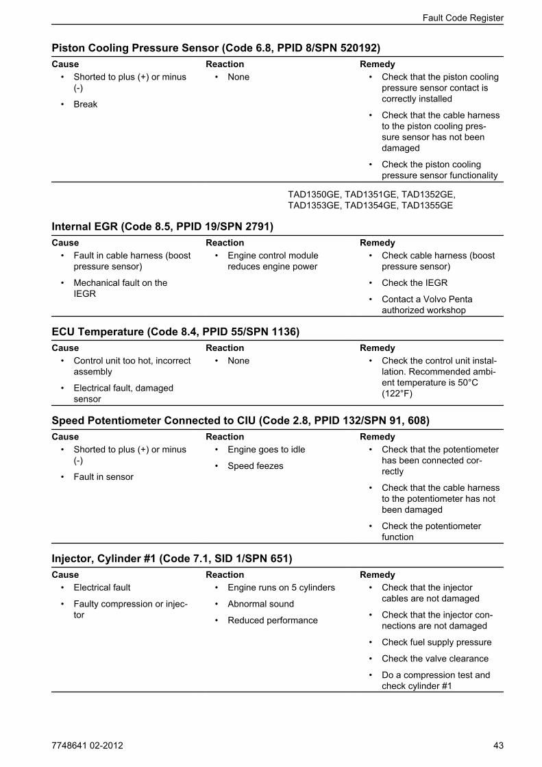
Piston Cooling Pressure Sensor (Code 6.8, PPID 8/SPN 520192)Cause Reaction Remedy
• Shorted to plus (+) or minus (-)
• Break
• None • Check that the piston coolingpressure sensor contact iscorrectly installed
• Check that the cable harnessto the piston cooling pres-sure sensor has not beendamaged
• Check the piston coolingpressure sensor functionality
TAD1350GE, TAD1351GE, TAD1352GE,TAD1353GE, TAD1354GE, TAD1355GE
Internal EGR (Code 8.5, PPID 19/SPN 2791)Cause Reaction Remedy
• Fault in cable harness (boostpressure sensor)
• Mechanical fault on theIEGR
• Engine control modulereduces engine power
• Check cable harness (boostpressure sensor)
• Check the IEGR
• Contact a Volvo Pentaauthorized workshop
ECU Temperature (Code 8.4, PPID 55/SPN 1136)Cause Reaction Remedy
• Control unit too hot, incorrectassembly
• Electrical fault, damagedsensor
• None • Check the control unit instal-lation. Recommended ambi-ent temperature is 50°C (122°F)
Speed Potentiometer Connected to CIU (Code 2.8, PPID 132/SPN 91, 608)Cause Reaction Remedy
• Shorted to plus (+) or minus (-)
• Fault in sensor
• Engine goes to idle
• Speed feezes
• Check that the potentiometerhas been connected cor-rectly
• Check that the cable harnessto the potentiometer has notbeen damaged
• Check the potentiometerfunction
Injector, Cylinder #1 (Code 7.1, SID 1/SPN 651)Cause Reaction Remedy
• Electrical fault
• Faulty compression or injec-tor
• Engine runs on 5 cylinders
• Abnormal sound
• Reduced performance
• Check that the injectorcables are not damaged
• Check that the injector con-nections are not damaged
• Check fuel supply pressure
• Check the valve clearance
• Do a compression test andcheck cylinder #1
Fault Code Register
7748641 02-2012 43
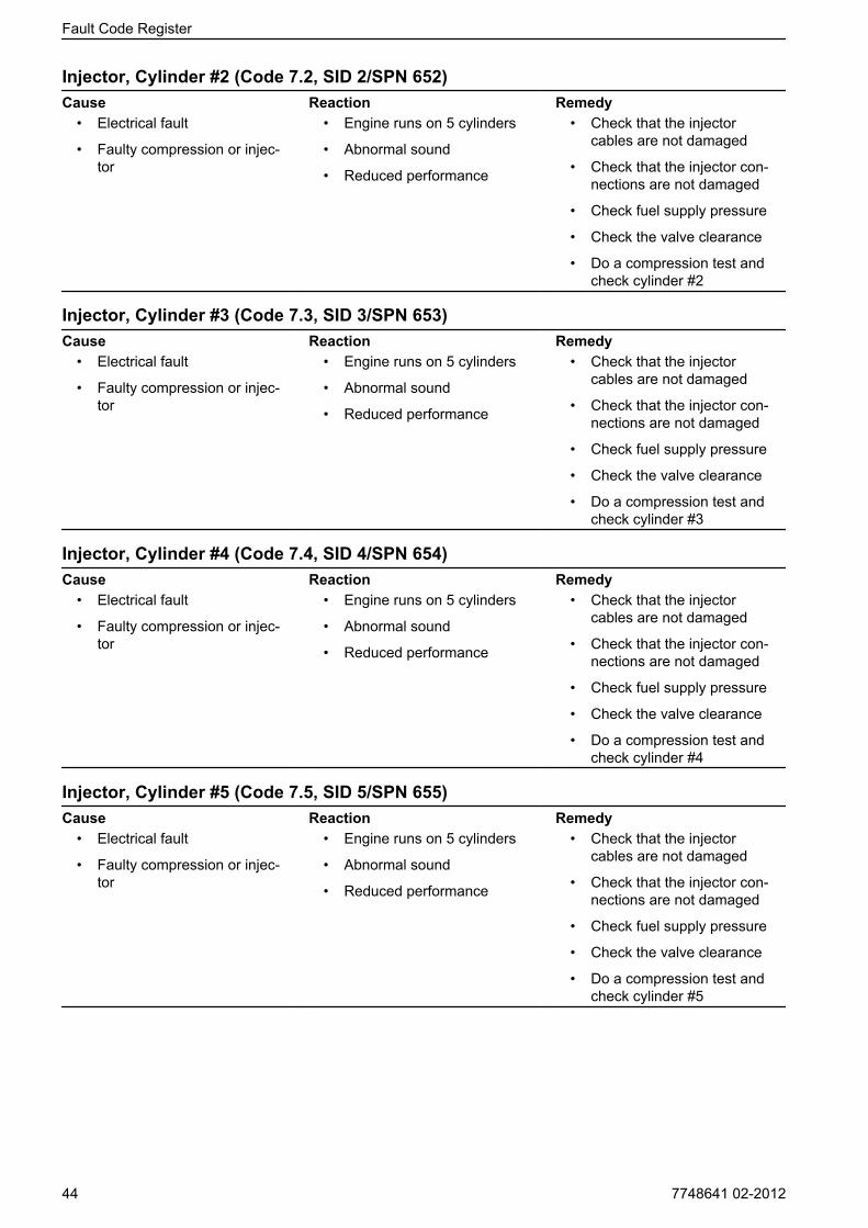
Injector, Cylinder #2 (Code 7.2, SID 2/SPN 652)Cause Reaction Remedy
• Electrical fault
• Faulty compression or injec-tor
• Engine runs on 5 cylinders
• Abnormal sound
• Reduced performance
• Check that the injectorcables are not damaged
• Check that the injector con-nections are not damaged
• Check fuel supply pressure
• Check the valve clearance
• Do a compression test andcheck cylinder #2
Injector, Cylinder #3 (Code 7.3, SID 3/SPN 653)Cause Reaction Remedy
• Electrical fault
• Faulty compression or injec-tor
• Engine runs on 5 cylinders
• Abnormal sound
• Reduced performance
• Check that the injectorcables are not damaged
• Check that the injector con-nections are not damaged
• Check fuel supply pressure
• Check the valve clearance
• Do a compression test andcheck cylinder #3
Injector, Cylinder #4 (Code 7.4, SID 4/SPN 654)Cause Reaction Remedy
• Electrical fault
• Faulty compression or injec-tor
• Engine runs on 5 cylinders
• Abnormal sound
• Reduced performance
• Check that the injectorcables are not damaged
• Check that the injector con-nections are not damaged
• Check fuel supply pressure
• Check the valve clearance
• Do a compression test andcheck cylinder #4
Injector, Cylinder #5 (Code 7.5, SID 5/SPN 655)Cause Reaction Remedy
• Electrical fault
• Faulty compression or injec-tor
• Engine runs on 5 cylinders
• Abnormal sound
• Reduced performance
• Check that the injectorcables are not damaged
• Check that the injector con-nections are not damaged
• Check fuel supply pressure
• Check the valve clearance
• Do a compression test andcheck cylinder #5
Fault Code Register
44 7748641 02-2012
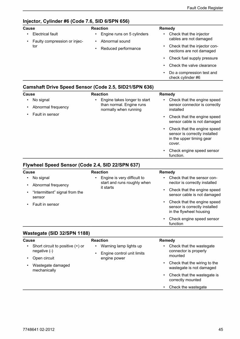
Injector, Cylinder #6 (Code 7.6, SID 6/SPN 656)Cause Reaction Remedy
• Electrical fault
• Faulty compression or injec-tor
• Engine runs on 5 cylinders
• Abnormal sound
• Reduced performance
• Check that the injectorcables are not damaged
• Check that the injector con-nections are not damaged
• Check fuel supply pressure
• Check the valve clearance
• Do a compression test andcheck cylinder #6
Camshaft Drive Speed Sensor (Code 2.5, SID21/SPN 636)Cause Reaction Remedy
• No signal
• Abnormal frequency
• Fault in sensor
• Engine takes longer to startthan normal. Engine runsnormally when running
• Check that the engine speedsensor connector is correctlyinstalled
• Check that the engine speedsensor cable is not damaged
• Check that the engine speedsensor is correctly installedin the upper timing gearcover.
• Check engine speed sensorfunction.
Flywheel Speed Sensor (Code 2.4, SID 22/SPN 637)Cause Reaction Remedy
• No signal
• Abnormal frequency
• “Intermittent” signal from thesensor
• Fault in sensor
• Engine is very difficult tostart and runs roughly whenit starts
• Check that the sensor con-nector is correctly installed
• Check that the engine speedsensor cable is not damaged
• Check that the engine speedsensor is correctly installedin the flywheel housing
• Check engine speed sensorfunction
Wastegate (SID 32/SPN 1188)Cause Reaction Remedy
• Short circuit to positive (+) ornegative (-)
• Open circuit
• Wastegate damagedmechanically
• Warning lamp lights up
• Engine control unit limitsengine power
• Check that the wastegateconnector is properlymounted
• Check that the wiring to thewastegate is not damaged
• Check that the wastegate iscorrectly mounted
• Check the wastegate
Fault Code Register
7748641 02-2012 45
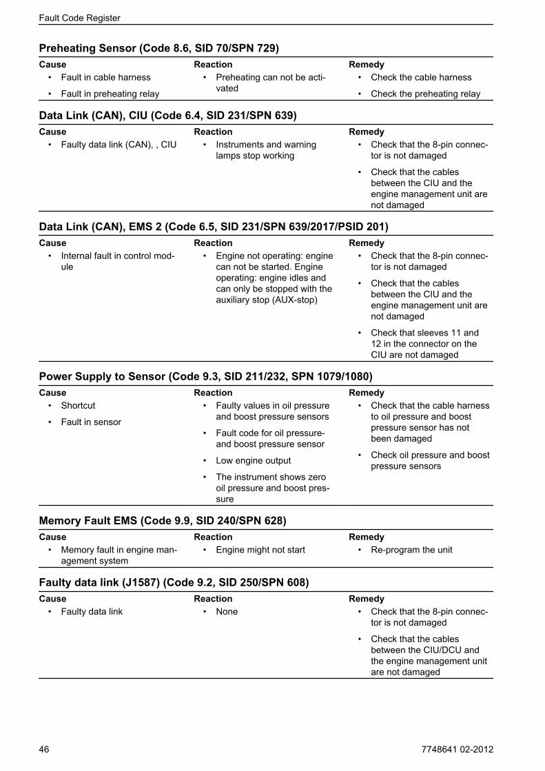
Preheating Sensor (Code 8.6, SID 70/SPN 729)Cause Reaction Remedy
• Fault in cable harness
• Fault in preheating relay
• Preheating can not be acti-vated
• Check the cable harness
• Check the preheating relay
Data Link (CAN), CIU (Code 6.4, SID 231/SPN 639)Cause Reaction Remedy
• Faulty data link (CAN), , CIU • Instruments and warninglamps stop working
• Check that the 8-pin connec-tor is not damaged
• Check that the cablesbetween the CIU and theengine management unit arenot damaged
Data Link (CAN), EMS 2 (Code 6.5, SID 231/SPN 639/2017/PSID 201)Cause Reaction Remedy
• Internal fault in control mod-ule
• Engine not operating: enginecan not be started. Engineoperating: engine idles andcan only be stopped with theauxiliary stop (AUX-stop)
• Check that the 8-pin connec-tor is not damaged
• Check that the cablesbetween the CIU and theengine management unit arenot damaged
• Check that sleeves 11 and12 in the connector on theCIU are not damaged
Power Supply to Sensor (Code 9.3, SID 211/232, SPN 1079/1080)Cause Reaction Remedy
• Shortcut
• Fault in sensor
• Faulty values in oil pressureand boost pressure sensors
• Fault code for oil pressure-and boost pressure sensor
• Low engine output
• The instrument shows zerooil pressure and boost pres-sure
• Check that the cable harnessto oil pressure and boostpressure sensor has notbeen damaged
• Check oil pressure and boostpressure sensors
Memory Fault EMS (Code 9.9, SID 240/SPN 628)Cause Reaction Remedy
• Memory fault in engine man-agement system
• Engine might not start • Re-program the unit
Faulty data link (J1587) (Code 9.2, SID 250/SPN 608)Cause Reaction Remedy
• Faulty data link • None • Check that the 8-pin connec-tor is not damaged
• Check that the cablesbetween the CIU/DCU andthe engine management unitare not damaged
Fault Code Register
46 7748641 02-2012

Data Set Memory EEPROM, CIU (Code 9.8, SID 253/SPN 630)Cause Reaction Remedy
• Internal fault in control mod-ule
• Programming faulty
• Engine does not start • Re-program the control mod-ule.
Data Set Memory EEPROM, EMS (Code 9.9, SID 253/SPN 630)Cause Reaction Remedy
• Internal fault in control mod-ule
• Internal fault in control mod-ule
• Engine does not start • Re-program the control mod-ule. If the fault remains,change the control module
Fault in Control Unit, CIU (Code 9.8, SID 254/SPN 629)Cause Reaction Remedy
• Faulty EEPROM, CIU
• Faulty flash memory, CIU
• Fault in control module, CIU
• CIU returns to factory setting
• Engine goes to idle
• Engine can not be started
• Re- program the unit
Control Module EMS (Code 9.9, SID 254/SPN 629)Cause Reaction Remedy
• Internal fault in control mod-ule
• Engine misfires
• Engine does not start
• Change engine control unit
Fan, rpm sensor (PID 26/SPN 975)Cause Reaction Remedy
• Open circuit • Warning lamp lights up • Check that the fan actuatoris properly mounted
• Check that the wiring to thefan actuator is not damaged
• Check that the fan actuatoris correctly mounted
• Check the fan actuator
Fan actuator (SID 33/SPN 975)Cause Reaction Remedy
• Short circuit to positive (+) ornegative (-)
• Open circuit
• Fan actuator damagedmechanically
• Warning lamp lights up • Check that the fan actuatoris properly mounted
• Check that the wiring to thefan actuator is not damaged
• Check that the fan actuatoris correctly mounted
• Check the fan actuator
EATSFault codes for the EATS system is in the installationmanual for this system.
Fault Code Register
7748641 02-2012 47
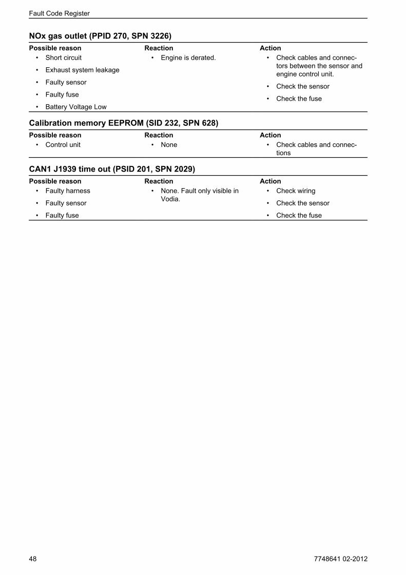
NOx gas outlet (PPID 270, SPN 3226)Possible reason Reaction Action
• Short circuit
• Exhaust system leakage
• Faulty sensor
• Faulty fuse
• Battery Voltage Low
• Engine is derated. • Check cables and connec-tors between the sensor andengine control unit.
• Check the sensor
• Check the fuse
Calibration memory EEPROM (SID 232, SPN 628)Possible reason Reaction Action
• Control unit • None • Check cables and connec-tions
CAN1 J1939 time out (PSID 201, SPN 2029)Possible reason Reaction Action
• Faulty harness
• Faulty sensor
• Faulty fuse
• None. Fault only visible inVodia.
• Check wiring
• Check the sensor
• Check the fuse
Fault Code Register
48 7748641 02-2012
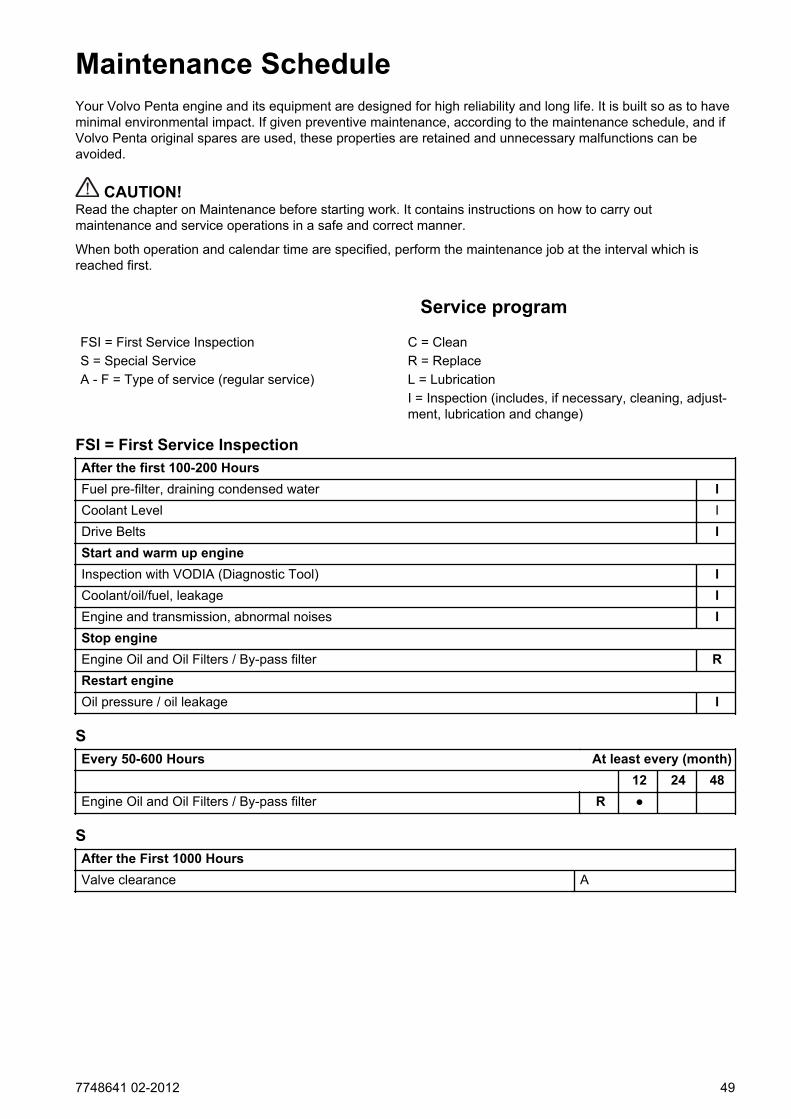
Maintenance ScheduleYour Volvo Penta engine and its equipment are designed for high reliability and long life. It is built so as to haveminimal environmental impact. If given preventive maintenance, according to the maintenance schedule, and ifVolvo Penta original spares are used, these properties are retained and unnecessary malfunctions can beavoided.
CAUTION!Read the chapter on Maintenance before starting work. It contains instructions on how to carry outmaintenance and service operations in a safe and correct manner.
When both operation and calendar time are specified, perform the maintenance job at the interval which isreached first.
Service program
FSI = First Service Inspection C = CleanS = Special Service R = ReplaceA - F = Type of service (regular service) L = Lubrication
I = Inspection (includes, if necessary, cleaning, adjust-ment, lubrication and change)
FSI = First Service InspectionAfter the first 100-200 HoursFuel pre-filter, draining condensed water ICoolant Level IDrive Belts IStart and warm up engineInspection with VODIA (Diagnostic Tool) ICoolant/oil/fuel, leakage IEngine and transmission, abnormal noises IStop engineEngine Oil and Oil Filters / By-pass filter RRestart engineOil pressure / oil leakage I
SEvery 50-600 Hours At least every (month)
12 24 48Engine Oil and Oil Filters / By-pass filter R ●
SAfter the First 1000 HoursValve clearance A
7748641 02-2012 49
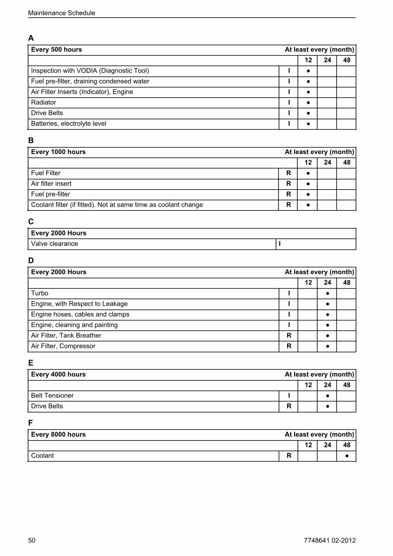
AEvery 500 hours At least every (month)
12 24 48Inspection with VODIA (Diagnostic Tool) I ●Fuel pre-filter, draining condensed water I ●Air Filter Inserts (Indicator), Engine I ●Radiator I ●Drive Belts I ●Batteries, electrolyte level I ●
BEvery 1000 hours At least every (month)
12 24 48Fuel Filter R ●Air filter insert R ●Fuel pre-filter R ●Coolant filter (if fitted). Not at same time as coolant change R ●
CEvery 2000 HoursValve clearance I
DEvery 2000 Hours At least every (month)
12 24 48Turbo I ●Engine, with Respect to Leakage I ●Engine hoses, cables and clamps I ●Engine, cleaning and painting I ●Air Filter, Tank Breather R ●Air Filter, Compressor R ●
EEvery 4000 hours At least every (month)
12 24 48Belt Tensioner I ●Drive Belts R ●
FEvery 8000 hours At least every (month)
12 24 48Coolant R ●
Maintenance Schedule
50 7748641 02-2012
MaintenanceThis chapter describes the most common maintenance items, see Service program for service intervals.NOTICE! Service points which are not described here must be performed by authorized Volvo Penta work-shop.
CAUTION!Read the chapter on Maintenance before starting work. It contains instructions on how to carry outmaintenance and service operations in a safe and correct manner.
WARNING!Care and maintenance work should be done with the engine stopped unless otherwise specified. Stop theengine before opening or removing the engine hatch/hood. Make it impossible to start the engine by removingthe start key and cutting the system voltage with the main switches.
Read about security measures for maintenance and service in the chapter Safety Information page 3 beforeyou begin.
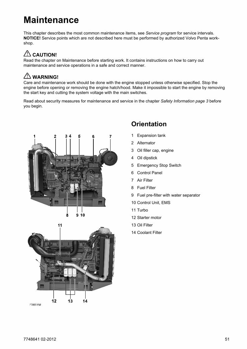
Orientation1 Expansion tank
2 Alternator
3 Oil filler cap, engine
4 Oil dipstick
5 Emergency Stop Switch
6 Control Panel
7 Air Filter
8 Fuel Filter
9 Fuel pre-filter with water separator
10 Control Unit, EMS
11 Turbo
12 Starter motor
13 Oil Filter
14 Coolant Filter
7748641 02-2012 51
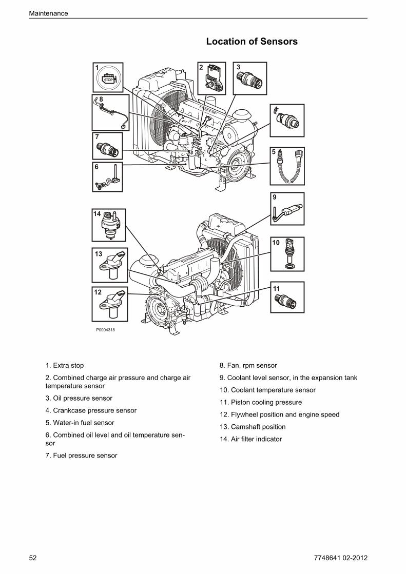
Location of Sensors
8
10
1112
13
14
P0004318
6
7
1 2 3
4
5
9
1. Extra stop
2. Combined charge air pressure and charge airtemperature sensor
3. Oil pressure sensor
4. Crankcase pressure sensor
5. Water-in fuel sensor
6. Combined oil level and oil temperature sen-sor
7. Fuel pressure sensor
8. Fan, rpm sensor
9. Coolant level sensor, in the expansion tank
10. Coolant temperature sensor
11. Piston cooling pressure
12. Flywheel position and engine speed
13. Camshaft position
14. Air filter indicator
Maintenance
52 7748641 02-2012
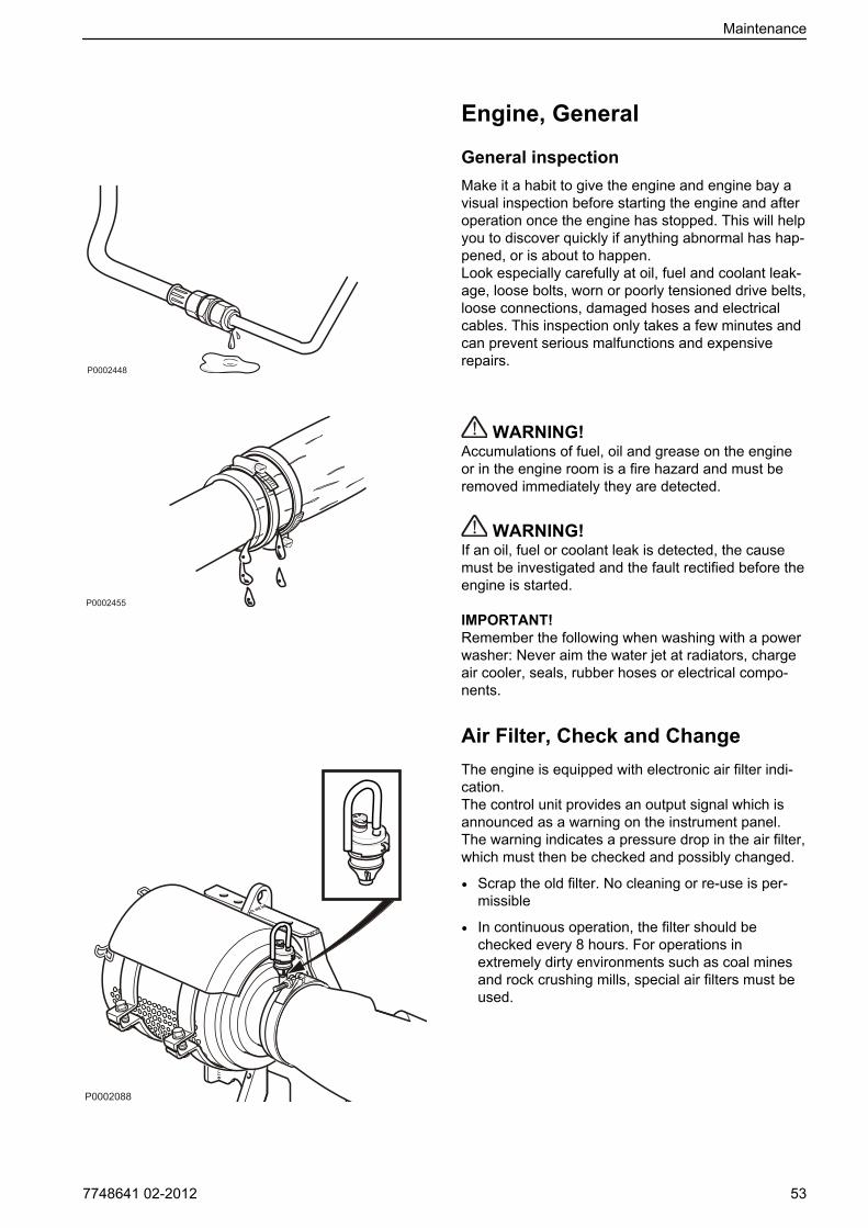
Engine, General
General inspectionMake it a habit to give the engine and engine bay avisual inspection before starting the engine and afteroperation once the engine has stopped. This will helpyou to discover quickly if anything abnormal has hap-pened, or is about to happen.Look especially carefully at oil, fuel and coolant leak-age, loose bolts, worn or poorly tensioned drive belts,loose connections, damaged hoses and electricalcables. This inspection only takes a few minutes andcan prevent serious malfunctions and expensiverepairs.
WARNING!Accumulations of fuel, oil and grease on the engineor in the engine room is a fire hazard and must beremoved immediately they are detected.
WARNING!If an oil, fuel or coolant leak is detected, the causemust be investigated and the fault rectified before theengine is started.
IMPORTANT!Remember the following when washing with a powerwasher: Never aim the water jet at radiators, chargeair cooler, seals, rubber hoses or electrical compo-nents.
Air Filter, Check and ChangeThe engine is equipped with electronic air filter indi-cation.The control unit provides an output signal which isannounced as a warning on the instrument panel.The warning indicates a pressure drop in the air filter,which must then be checked and possibly changed.
• Scrap the old filter. No cleaning or re-use is per-missible
• In continuous operation, the filter should bechecked every 8 hours. For operations inextremely dirty environments such as coal minesand rock crushing mills, special air filters must beused.
Maintenance
7748641 02-2012 53

Charge Air Pipe, Leakage Check
Inspect the condition of the charge air hoses, hoseunions and clamp condition for cracks and otherdamage. Change as necessary.
IMPORTANT!Clamps must be tightened using a torque wrench to9 ±2 Nm (6.6 ±1.5 lbf.ft.).
P0002083
Maintenance
54 7748641 02-2012
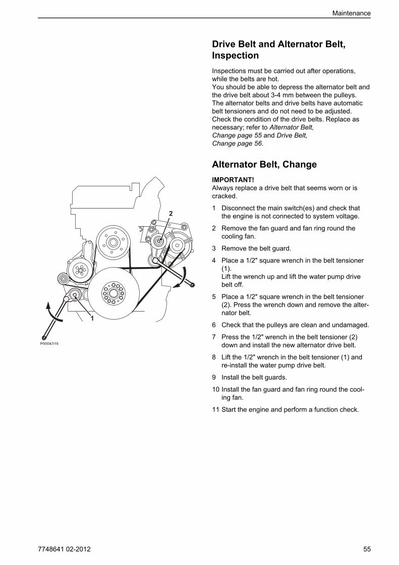
Drive Belt and Alternator Belt,InspectionInspections must be carried out after operations,while the belts are hot.You should be able to depress the alternator belt andthe drive belt about 3-4 mm between the pulleys.The alternator belts and drive belts have automaticbelt tensioners and do not need to be adjusted.Check the condition of the drive belts. Replace asnecessary; refer to Alternator Belt,Change page 55 and Drive Belt,Change page 56.
Alternator Belt, ChangeIMPORTANT!Always replace a drive belt that seems worn or iscracked.
1 Disconnect the main switch(es) and check thatthe engine is not connected to system voltage.
2 Remove the fan guard and fan ring round thecooling fan.
3 Remove the belt guard.
4 Place a 1/2" square wrench in the belt tensioner (1).Lift the wrench up and lift the water pump drivebelt off.
5 Place a 1/2" square wrench in the belt tensioner (2). Press the wrench down and remove the alter-nator belt.
6 Check that the pulleys are clean and undamaged.
7 Press the 1/2" wrench in the belt tensioner (2)down and install the new alternator drive belt.
8 Lift the 1/2" wrench in the belt tensioner (1) andre-install the water pump drive belt.
9 Install the belt guards.
10 Install the fan guard and fan ring round the cool-ing fan.
11 Start the engine and perform a function check.
Maintenance
7748641 02-2012 55

Drive Belt, Change
1 Disconnect the main switch(es) and check thatthe engine is not connected to system voltage.
2 Remove the fan guard and fan ring round thecooling fan.
3 Remove the belt guard.
4 Place a 1/2" square wrench in the belt tensioner (1).Lift the wrench and remove the drive belt.
5 Thread the drive belt round the fan and remove it.
6 Check that the pulleys are clean and undamaged.
7 Thread the new drive belt over the fan.
8 Lift the 1/2" wrench and install the new drive belt.
9 Install the belt guards.
10 Install the fan guard and fan ring round the cool-ing fan.
11 Start the engine and perform a function check.
Maintenance
56 7748641 02-2012
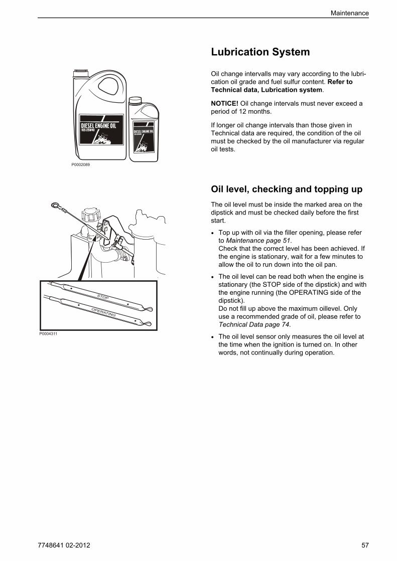
Lubrication System
Oil change intervalls may vary according to the lubri-cation oil grade and fuel sulfur content. Refer toTechnical data, Lubrication system.
NOTICE! Oil change intervals must never exceed aperiod of 12 months.
If longer oil change intervals than those given inTechnical data are required, the condition of the oilmust be checked by the oil manufacturer via regularoil tests.
Oil level, checking and topping upThe oil level must be inside the marked area on thedipstick and must be checked daily before the firststart.
• Top up with oil via the filler opening, please referto Maintenance page 51.Check that the correct level has been achieved. Ifthe engine is stationary, wait for a few minutes toallow the oil to run down into the oil pan.
• The oil level can be read both when the engine isstationary (the STOP side of the dipstick) and withthe engine running (the OPERATING side of thedipstick).Do not fill up above the maximum oillevel. Onlyuse a recommended grade of oil, please refer toTechnical Data page 74.
• The oil level sensor only measures the oil level atthe time when the ignition is turned on. In otherwords, not continually during operation.
P0002089
STOP
OPERATING
P0004311
Maintenance
7748641 02-2012 57
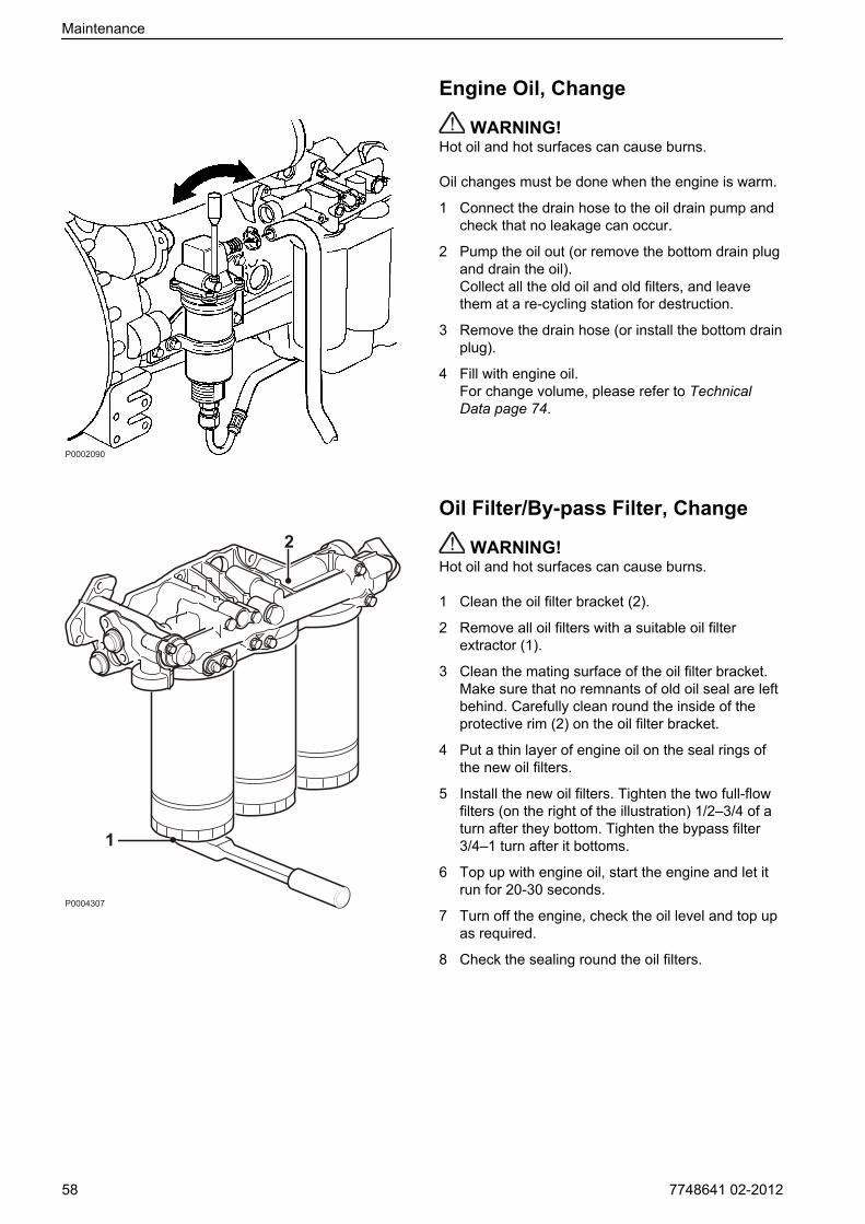
Engine Oil, Change
WARNING!Hot oil and hot surfaces can cause burns.
Oil changes must be done when the engine is warm.
1 Connect the drain hose to the oil drain pump andcheck that no leakage can occur.
2 Pump the oil out (or remove the bottom drain plugand drain the oil).Collect all the old oil and old filters, and leavethem at a re-cycling station for destruction.
3 Remove the drain hose (or install the bottom drainplug).
4 Fill with engine oil.For change volume, please refer to TechnicalData page 74.
Oil Filter/By-pass Filter, Change
WARNING!Hot oil and hot surfaces can cause burns.
1 Clean the oil filter bracket (2).
2 Remove all oil filters with a suitable oil filterextractor (1).
3 Clean the mating surface of the oil filter bracket.Make sure that no remnants of old oil seal are leftbehind. Carefully clean round the inside of theprotective rim (2) on the oil filter bracket.
4 Put a thin layer of engine oil on the seal rings ofthe new oil filters.
5 Install the new oil filters. Tighten the two full-flowfilters (on the right of the illustration) 1/2–3/4 of aturn after they bottom. Tighten the bypass filter3/4–1 turn after it bottoms.
6 Top up with engine oil, start the engine and let itrun for 20-30 seconds.
7 Turn off the engine, check the oil level and top upas required.
8 Check the sealing round the oil filters.
P0004307
1
2
Maintenance
58 7748641 02-2012
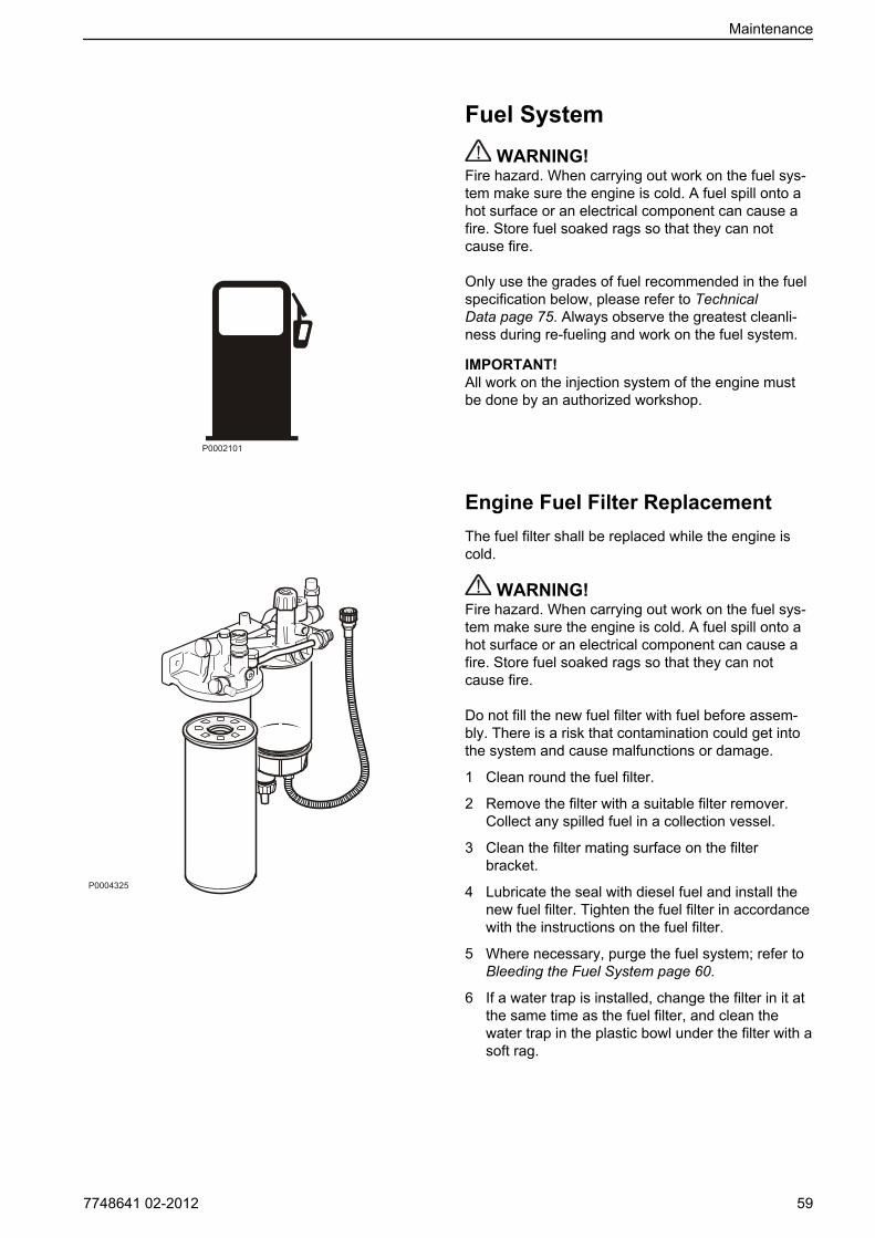
Fuel System WARNING!
Fire hazard. When carrying out work on the fuel sys-tem make sure the engine is cold. A fuel spill onto ahot surface or an electrical component can cause afire. Store fuel soaked rags so that they can notcause fire.
Only use the grades of fuel recommended in the fuelspecification below, please refer to TechnicalData page 75. Always observe the greatest cleanli-ness during re-fueling and work on the fuel system.
IMPORTANT!All work on the injection system of the engine mustbe done by an authorized workshop.
Engine Fuel Filter ReplacementThe fuel filter shall be replaced while the engine iscold.
WARNING!Fire hazard. When carrying out work on the fuel sys-tem make sure the engine is cold. A fuel spill onto ahot surface or an electrical component can cause afire. Store fuel soaked rags so that they can notcause fire.
Do not fill the new fuel filter with fuel before assem-bly. There is a risk that contamination could get intothe system and cause malfunctions or damage.
1 Clean round the fuel filter.
2 Remove the filter with a suitable filter remover.Collect any spilled fuel in a collection vessel.
3 Clean the filter mating surface on the filterbracket.
4 Lubricate the seal with diesel fuel and install thenew fuel filter. Tighten the fuel filter in accordancewith the instructions on the fuel filter.
5 Where necessary, purge the fuel system; refer toBleeding the Fuel System page 60.
6 If a water trap is installed, change the filter in it atthe same time as the fuel filter, and clean thewater trap in the plastic bowl under the filter with asoft rag.
P0002101
Maintenance
7748641 02-2012 59

Fuel Pre-filter, Change
1 Undo the cable from the water trap sensor.
2 Remove the water trap filter from the filter bracket.Collect any spilled fuel in a collection vessel.
3 Remove the lower part of the water trap from thefilter.
4 Clean the lower part of the water trap with a softrag. Check that the drain hole in the lower part isnot blocked.
5 Install a new seal on the lower part and lubricatethe seal with diesel fuel. Re-install the lower partof the filter.
6 Lubricate the seal with diesel fuel. Screw the filteronto the filter bracket by hand until the rubber sealjust touches the mating surface. Then tighten afurther half turn, no more.
7 Connect the cable to the water trap sensor.
8 Where necessary, purge the fuel system; refer toBleeding the Fuel System page 60.
Draining condensate, fuel system
1 Put a collection vessel under the fuel filter to col-lect the condensate and fuel.
2 Open the drain nipple (1) in the base of the fuelpre-filter.
3 Tighten the drain tap (1) when fuel without waterstarts to run out.
Bleeding the Fuel SystemThe system does not need to be purged unless it hasbeen run completely dry. Purging is then done withthe hand pump on the fuel filter bracket.
P0004327
1
Maintenance
60 7748641 02-2012

Cooling SystemThe engine's internal cooling system makes sure theengine works at the right temperature. It is a closedsystem that must always be filled with a mixture ofconcentrated coolant and water in order to protectthe engine against internal corrosion, cavitation andbursts due to freezing.
IMPORTANT!Coolant of a suitable chemical composition must beused all year round. This also applies in areas wherethere is never any risk of freezing, to provide theengine with full corrosion protection.The corrosion protection additives become lesseffective over time, which means that the coolantmust be changed at regular intervals; refer to theMaintenance Schedule. The cooling system must beflushed whenever the coolant is changed; refer to theCooling System, Cleaning page 66 section.
Volvo Penta engines are delivered with either “VolvoPenta Coolant” (green) or “Volvo Penta CoolantVCS” (yellow); both are available as concentratesand “Ready Mixed”.
Volvo Penta coolants have been prepared to workbest with Volvo Penta engines and offer excellentprotection against corrosion, cavitation damage, andbursts due to freezing. Only coolants of this qualityare adapted to, and approved by, Volvo Penta.
We recommend that the coolant supplied with theengine on delivery be used. Future warranty claimsrelated to engine and accessories may be declined ifan unsuitable coolant has been used, or if theinstructions for coolant mixture have not been fol-lowed.The use of anti-corrosion agents alone is not permit-ted in Volvo Penta engines. Never use water aloneas a substitute for coolant.
IMPORTANT!
• The two types of Volvo Penta coolant may neverbe mixed with each other as this will affect theanti-corrosion properties.
• Coolant filters may not be used together withVolvo Penta Coolant VCS.
• Engines using yellow Volvo Penta Coolant VCSmust have a yellow decal with the text VOLVOCOOLANT VCS on the expansion tank.
Ready MixedReady mixed coolant contains 40% Volvo PentaCoolant / Volvo Penta Coolant VCS and 60% water.This mixture protects the engine against internal cor-rosion, cavitation and bursts due to freezing down to–28°C (–18 F).
coolant vcs ready mixed
P0013077
Maintenance
7748641 02-2012 61

Coolant, MixingThe concentrated coolant must be mixed with purewater (distilled or de-ionized water) according tospecifications; refer to Water Quality page 76.
WARNING!All coolant is hazardous and harmful to the environ-ment. Do not consume. Coolant is flammable.
IMPORTANT!Different kinds of coolant must not be mixed witheach other!
Mix: 40% concentrated coolant and 60% waterThis mixture protects against internal corrosion, cavi-tation and bursts due to freezing down to –28°C (–18°F). A 60% glycol admix lowers the freezing pointto –54 °C (–65 °F).Never mix more than 60% concentrate in the coolant.A greater concentration provides reduced coolingeffect with the risk for overheating and reduced anti-freeze protection.It is extremely important that the system be filled withthe correct coolant concentration. Mix in a separateclean vessel before filling the cooling system. Makesure that the liquids mix.
Maintenance
62 7748641 02-2012
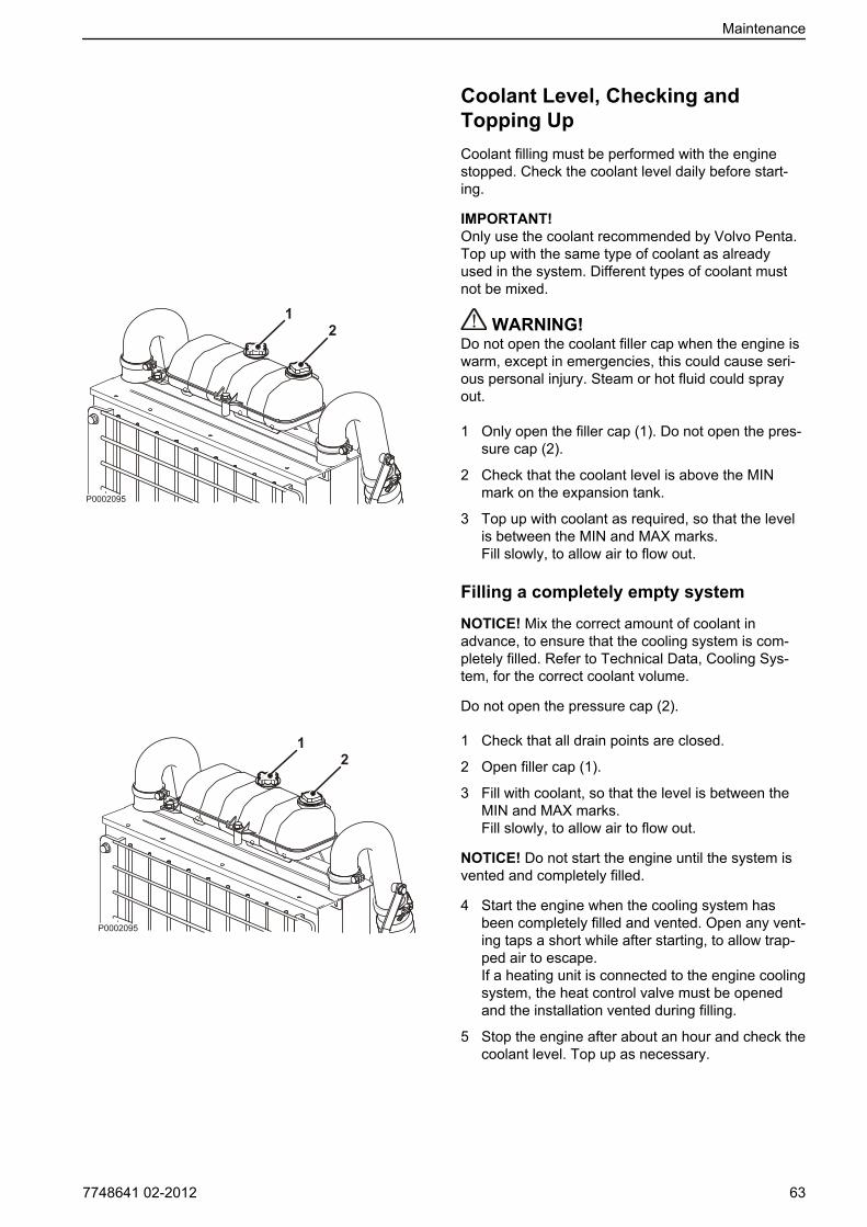
Coolant Level, Checking andTopping UpCoolant filling must be performed with the enginestopped. Check the coolant level daily before start-ing.
IMPORTANT!Only use the coolant recommended by Volvo Penta.Top up with the same type of coolant as alreadyused in the system. Different types of coolant mustnot be mixed.
WARNING!Do not open the coolant filler cap when the engine iswarm, except in emergencies, this could cause seri-ous personal injury. Steam or hot fluid could sprayout.
1 Only open the filler cap (1). Do not open the pres-sure cap (2).
2 Check that the coolant level is above the MINmark on the expansion tank.
3 Top up with coolant as required, so that the levelis between the MIN and MAX marks.Fill slowly, to allow air to flow out.
Filling a completely empty system
NOTICE! Mix the correct amount of coolant inadvance, to ensure that the cooling system is com-pletely filled. Refer to Technical Data, Cooling Sys-tem, for the correct coolant volume.
Do not open the pressure cap (2).
1 Check that all drain points are closed.
2 Open filler cap (1).
3 Fill with coolant, so that the level is between theMIN and MAX marks.Fill slowly, to allow air to flow out.
NOTICE! Do not start the engine until the system isvented and completely filled.
4 Start the engine when the cooling system hasbeen completely filled and vented. Open any vent-ing taps a short while after starting, to allow trap-ped air to escape.If a heating unit is connected to the engine coolingsystem, the heat control valve must be openedand the installation vented during filling.
5 Stop the engine after about an hour and check thecoolant level. Top up as necessary.
Maintenance
7748641 02-2012 63

Coolant, Draining
WARNING!Do not open the coolant filler cap when the engine iswarm, except in emergencies, this could cause seri-ous personal injury. Steam or hot fluid could sprayout.
IMPORTANT!On engines which are to be laid up or put in storage,the engine cooling system must not be drained. Thecoolant contains corrosion-inhibiting additives.
1 Stop the engine.
2 Remove the filler cap (1). Do not open the pres-sure cap (2).
3 Open all drain points. Drain the coolant from theradiator and engine block, using the drain hose.The drain nipples are situated under the radiatoron the right side of the engine block.
4 Check that all coolant drains out. Deposits may befound inside the drain plug/tap, and need to becleared away. There is otherwise a risk that cool-ant could remain and cause frost damage. Checkwhether the installation has any further taps orplugs at the lowest points of the cooling waterpipes.
5 Shut any taps and check that the spring-loadedcovers on the nipples close completely. Install therubber plugs.
Charge Air Cooler, ExternalCleaning
Remove guards as necessary, to access the radiator.Clean with water and a mild detergent. Use a softbrush. Be careful not to damage the radiator vanes.Reinstall removed parts.
IMPORTANT!Do not use a pressure washer.
Maintenance
64 7748641 02-2012
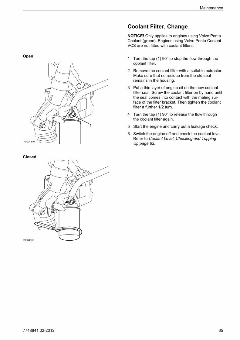
Coolant Filter, ChangeNOTICE! Only applies to engines using Volvo PentaCoolant (green). Engines using Volvo Penta CoolantVCS are not fitted with coolant filters.
1 Turn the tap (1) 90° to stop the flow through thecoolant filter.
2 Remove the coolant filter with a suitable extractor.Make sure that no residue from the old sealremains in the housing.
3 Put a thin layer of engine oil on the new coolantfilter seal. Screw the coolant filter on by hand untilthe seal comes into contact with the mating sur-face of the filter bracket. Then tighten the coolantfilter a further 1/2 turn.
4 Turn the tap (1) 90° to release the flow throughthe coolant filter again.
5 Start the engine and carry out a leakage check.
6 Switch the engine off and check the coolant level.Refer to Coolant Level, Checking and ToppingUp page 63.
Open
Closed
Maintenance
7748641 02-2012 65

Cooling System, CleaningCooling performance is reduced by deposits in theradiator and cooling galleries. The cooling systemshould be cleaned out when the coolant is changed.
IMPORTANT!Cleaning must not be done if there is any risk of thecooling system freezing, since the cleaning solutiondoes not have any frost prevention ability.
IMPORTANT!It is extremely important that the correct concentra-tion and volume of coolant is put in the system. Mixin a separate clean vessel before filling the coolingsystem. Make sure that the liquids mix.
1 Empty the cooling system. Refer to Coolant,Draining page 64.
2 Put a hose into the expansion tank filling hole andflush with clean water, as specified by VolvoPenta– refer to section Water quality in TechnicalData page 76 until the water draining out iscompletely clear.
3 If there should still be some contamination leftafter flushing for a long time, cleaning can bedone with coolant. Otherwise, continue as in item8 below.
4 Fill the cooling system with 15-20 % mixture ofconcentrated coolant. Use only Volvo Penta rec-ommended concentrated coolant mixed with cleanwater.
5 Drain the coolant after 1-2 days of operation.Remove the filler cap and possibly the lower radi-ator hose to increase the speed of emptying.To prevent suspended material from settling backin the system, emptying should be done rapidly,within the space of 10 minutes, when the enginehas not been standing still for a long time.
6 Flush the system immediately and thoroughly withclean hot water to prevent dirt from settling in theinner areas. Flush until the water that runs out iscompletely clean. Make sure that any heater con-trols are set to full heating during emptying.
7 If contamination should still be left after a longperiod of flushing, you can do a cleanout withVolvo Penta radiator cleaner, followed by finish-ing-off with Volvo Penta neutralizer. Carefully fol-low the instructions on the package. Otherwise,continue as in item 8 below.
8 When the cooling system is completely free fromcontamination, close the drain taps and plugs.
9 Fill up with Volvo Penta recommended coolant,following the instructions in the chapters entitledMaintenance page 61and Coolant Level, Check-ing and Topping Up page 63.
Maintenance
66 7748641 02-2012
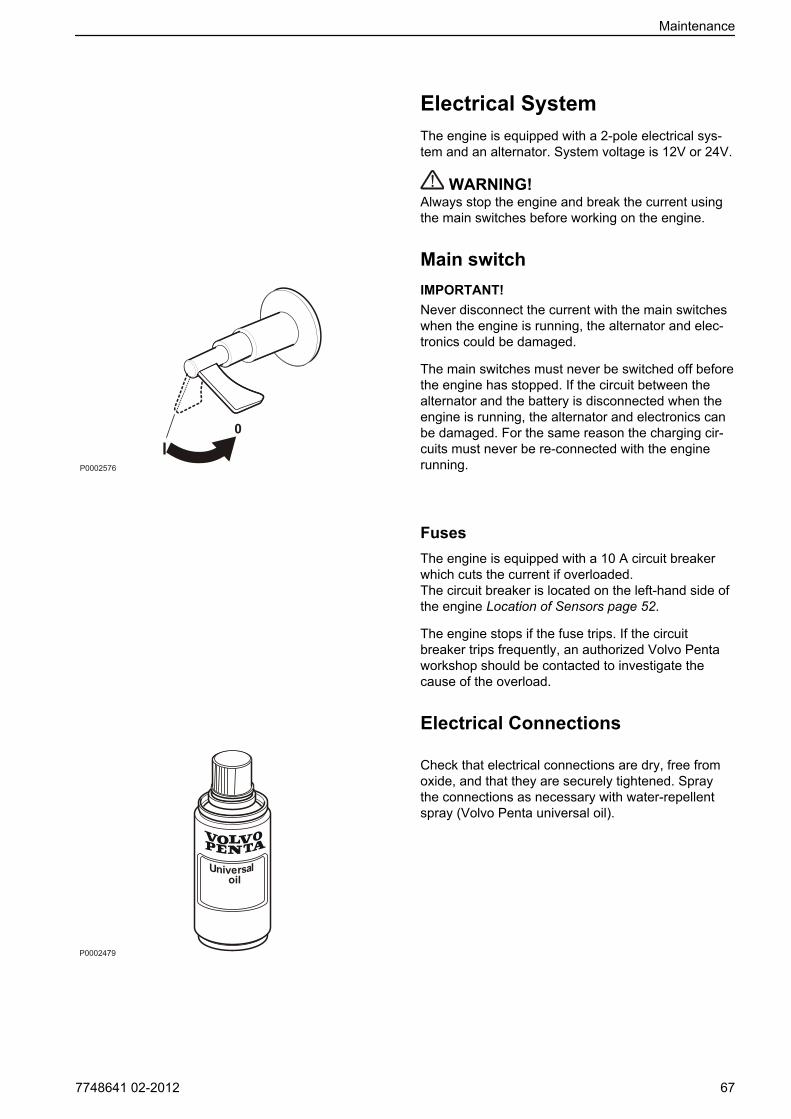
Electrical SystemThe engine is equipped with a 2-pole electrical sys-tem and an alternator. System voltage is 12V or 24V.
WARNING!Always stop the engine and break the current usingthe main switches before working on the engine.
Main switchIMPORTANT!Never disconnect the current with the main switcheswhen the engine is running, the alternator and elec-tronics could be damaged.
The main switches must never be switched off beforethe engine has stopped. If the circuit between thealternator and the battery is disconnected when theengine is running, the alternator and electronics canbe damaged. For the same reason the charging cir-cuits must never be re-connected with the enginerunning.
FusesThe engine is equipped with a 10 A circuit breakerwhich cuts the current if overloaded.The circuit breaker is located on the left-hand side ofthe engine Location of Sensors page 52.
The engine stops if the fuse trips. If the circuitbreaker trips frequently, an authorized Volvo Pentaworkshop should be contacted to investigate thecause of the overload.
Electrical Connections
Check that electrical connections are dry, free fromoxide, and that they are securely tightened. Spraythe connections as necessary with water-repellentspray (Volvo Penta universal oil).
Maintenance
7748641 02-2012 67

Battery, Maintenance
WARNING!Risk of fire and explosion. Never allow an open flameor electric sparks near the battery or batteries.
WARNING!Never confuse the positive and negative poles on thebatteries. Risk of arcing and explosion.
WARNING!The battery electrolyte contains extremely corrosivesulfuric acid. Protect your skin and clothes whencharging or handling batteries.Always use protective goggles and gloves. If batteryelectrolyte comes into contact with unprotected skinwhas off immediately using plenty of water and soap.If battery acid comes in contact with the eyes, flushimmediately with plenty of water and obtain medicalassistance without delay.
Connecting and disconnecting thebattery
Connecting
1 Connect the + cable (red) to the + pole on the bat-tery.
2 Connect the – cable (black) to the – pole on thebattery.
Disconnecting
1 Remove the – cable (black).
2 Remove the + cable (red).
CleaningKeep the batteries clean and dry. Contamination andoxide on the batteries and battery poles can causestray currents, voltage drop and discharge, especiallyin wet weather. Remove oxidation from the batterypoles and terminals, using a brass brush. Tighten theterminals securely and grease them with terminalgrease or petroleum jelly.
P0002107
-+P0002108
Maintenance
68 7748641 02-2012
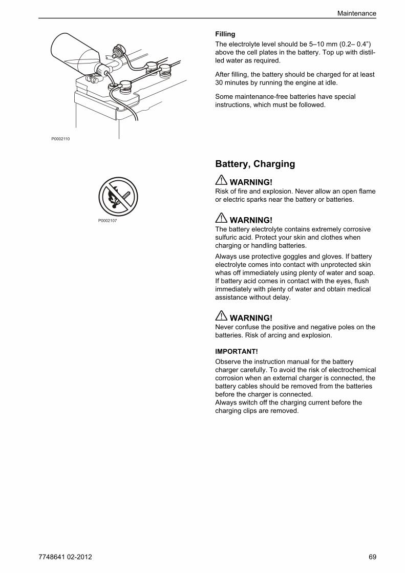
FillingThe electrolyte level should be 5–10 mm (0.2– 0.4”)above the cell plates in the battery. Top up with distil-led water as required.
After filling, the battery should be charged for at least30 minutes by running the engine at idle.
Some maintenance-free batteries have specialinstructions, which must be followed.
Battery, Charging
WARNING!Risk of fire and explosion. Never allow an open flameor electric sparks near the battery or batteries.
WARNING!The battery electrolyte contains extremely corrosivesulfuric acid. Protect your skin and clothes whencharging or handling batteries.Always use protective goggles and gloves. If batteryelectrolyte comes into contact with unprotected skinwhas off immediately using plenty of water and soap.If battery acid comes in contact with the eyes, flushimmediately with plenty of water and obtain medicalassistance without delay.
WARNING!Never confuse the positive and negative poles on thebatteries. Risk of arcing and explosion.
IMPORTANT!Observe the instruction manual for the batterycharger carefully. To avoid the risk of electrochemicalcorrosion when an external charger is connected, thebattery cables should be removed from the batteriesbefore the charger is connected.Always switch off the charging current before thecharging clips are removed.
P0002110
P0002107
Maintenance
7748641 02-2012 69
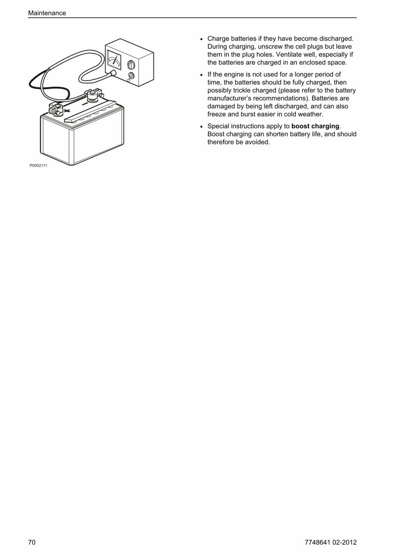
• Charge batteries if they have become discharged.During charging, unscrew the cell plugs but leavethem in the plug holes. Ventilate well, especially ifthe batteries are charged in an enclosed space.
• If the engine is not used for a longer period oftime, the batteries should be fully charged, thenpossibly trickle charged (please refer to the batterymanufacturer’s recommendations). Batteries aredamaged by being left discharged, and can alsofreeze and burst easier in cold weather.
• Special instructions apply to boost charging.Boost charging can shorten battery life, and shouldtherefore be avoided.
P0002111
Maintenance
70 7748641 02-2012
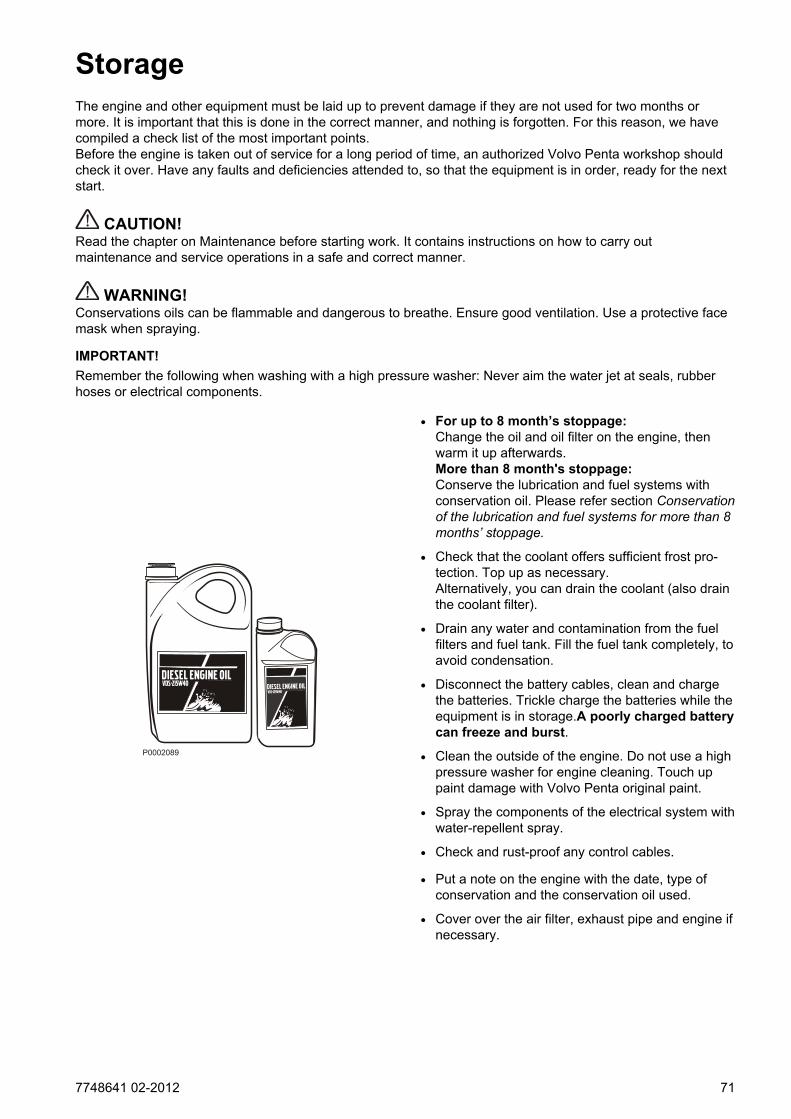
StorageThe engine and other equipment must be laid up to prevent damage if they are not used for two months ormore. It is important that this is done in the correct manner, and nothing is forgotten. For this reason, we havecompiled a check list of the most important points.Before the engine is taken out of service for a long period of time, an authorized Volvo Penta workshop shouldcheck it over. Have any faults and deficiencies attended to, so that the equipment is in order, ready for the nextstart.
CAUTION!Read the chapter on Maintenance before starting work. It contains instructions on how to carry outmaintenance and service operations in a safe and correct manner.
WARNING!Conservations oils can be flammable and dangerous to breathe. Ensure good ventilation. Use a protective facemask when spraying.
IMPORTANT!Remember the following when washing with a high pressure washer: Never aim the water jet at seals, rubberhoses or electrical components.
• For up to 8 month’s stoppage:Change the oil and oil filter on the engine, thenwarm it up afterwards.More than 8 month's stoppage:Conserve the lubrication and fuel systems withconservation oil. Please refer section Conservationof the lubrication and fuel systems for more than 8months’ stoppage.
• Check that the coolant offers sufficient frost pro-tection. Top up as necessary.Alternatively, you can drain the coolant (also drainthe coolant filter).
• Drain any water and contamination from the fuelfilters and fuel tank. Fill the fuel tank completely, toavoid condensation.
• Disconnect the battery cables, clean and chargethe batteries. Trickle charge the batteries while theequipment is in storage.A poorly charged batterycan freeze and burst.
• Clean the outside of the engine. Do not use a highpressure washer for engine cleaning. Touch uppaint damage with Volvo Penta original paint.
• Spray the components of the electrical system withwater-repellent spray.
• Check and rust-proof any control cables.
• Put a note on the engine with the date, type ofconservation and the conservation oil used.
• Cover over the air filter, exhaust pipe and engine ifnecessary.
P0002089
7748641 02-2012 71
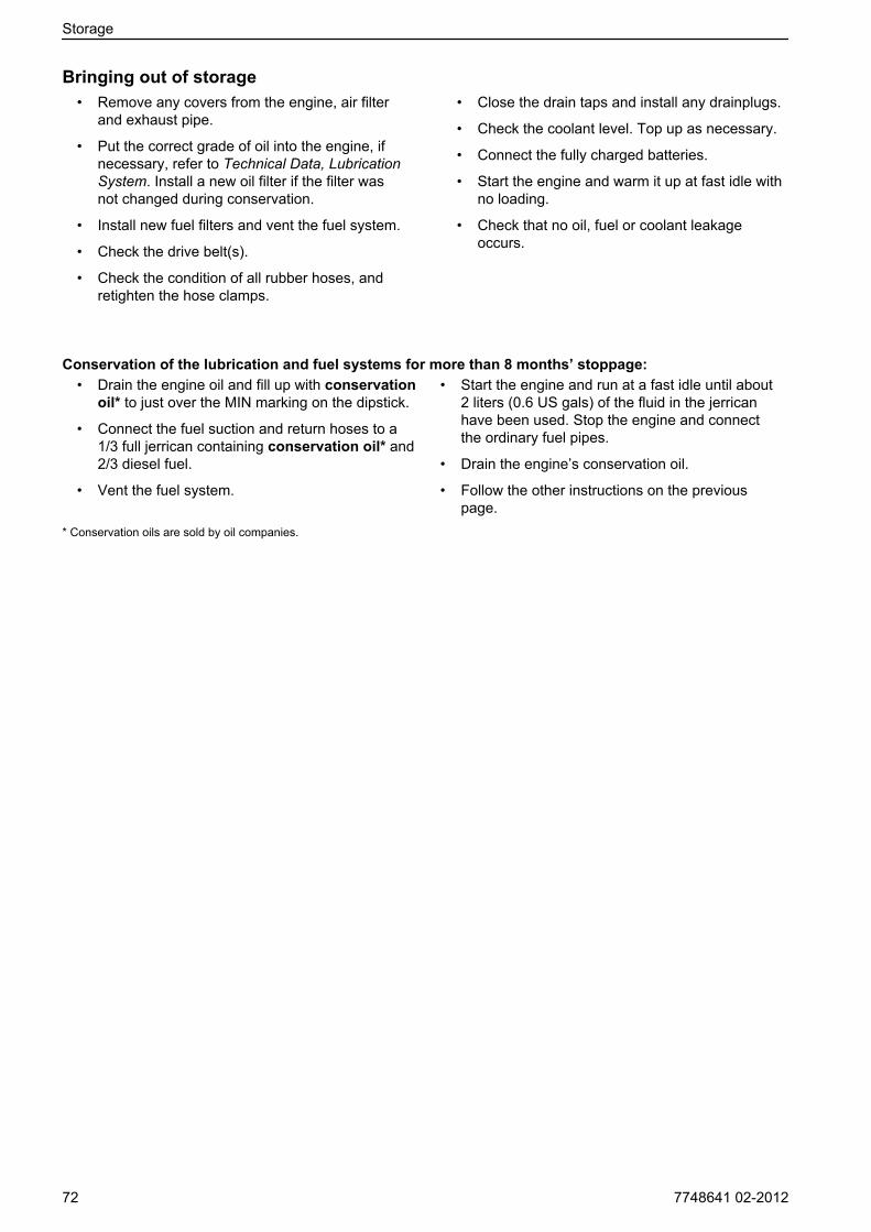
Bringing out of storage• Remove any covers from the engine, air filter
and exhaust pipe.
• Put the correct grade of oil into the engine, ifnecessary, refer to Technical Data, LubricationSystem. Install a new oil filter if the filter wasnot changed during conservation.
• Install new fuel filters and vent the fuel system.
• Check the drive belt(s).
• Check the condition of all rubber hoses, andretighten the hose clamps.
• Close the drain taps and install any drainplugs.
• Check the coolant level. Top up as necessary.
• Connect the fully charged batteries.
• Start the engine and warm it up at fast idle withno loading.
• Check that no oil, fuel or coolant leakageoccurs.
Conservation of the lubrication and fuel systems for more than 8 months’ stoppage:• Drain the engine oil and fill up with conservation
oil* to just over the MIN marking on the dipstick.
• Connect the fuel suction and return hoses to a1/3 full jerrican containing conservation oil* and2/3 diesel fuel.
• Vent the fuel system.
• Start the engine and run at a fast idle until about2 liters (0.6 US gals) of the fluid in the jerricanhave been used. Stop the engine and connectthe ordinary fuel pipes.
• Drain the engine’s conservation oil.
• Follow the other instructions on the previouspage.
* Conservation oils are sold by oil companies.
Storage
72 7748641 02-2012
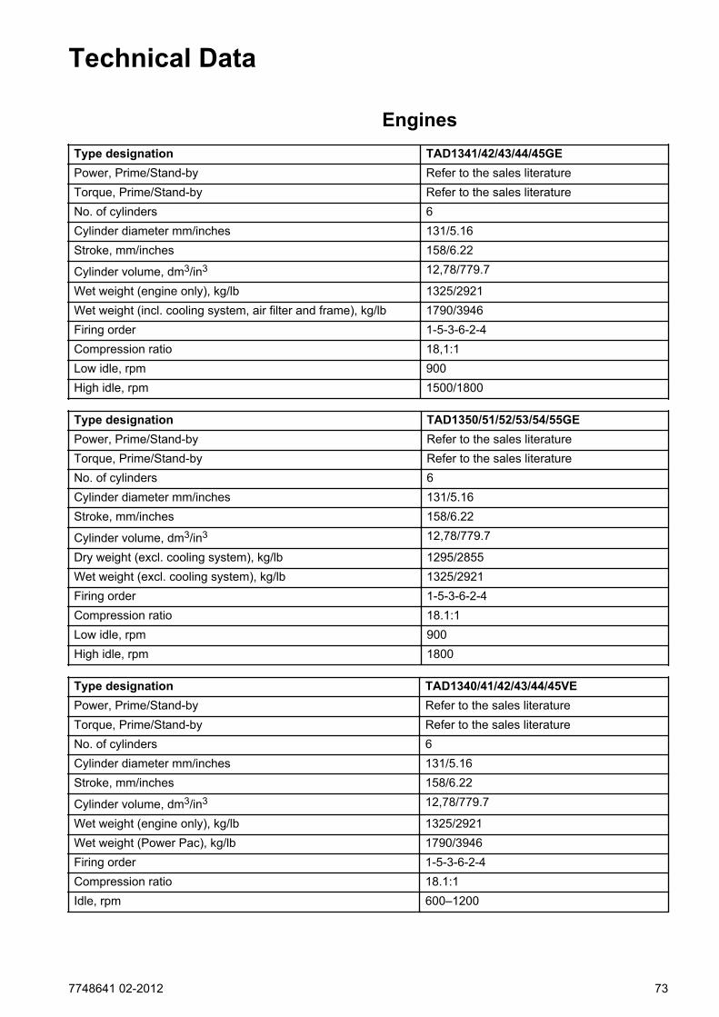
Technical Data
EnginesType designation TAD1341/42/43/44/45GEPower, Prime/Stand-by Refer to the sales literatureTorque, Prime/Stand-by Refer to the sales literatureNo. of cylinders 6Cylinder diameter mm/inches 131/5.16Stroke, mm/inches 158/6.22
Cylinder volume, dm3/in3 12,78/779.7
Wet weight (engine only), kg/lb 1325/2921Wet weight (incl. cooling system, air filter and frame), kg/lb 1790/3946Firing order 1-5-3-6-2-4Compression ratio 18,1:1Low idle, rpm 900High idle, rpm 1500/1800
Type designation TAD1350/51/52/53/54/55GEPower, Prime/Stand-by Refer to the sales literatureTorque, Prime/Stand-by Refer to the sales literatureNo. of cylinders 6Cylinder diameter mm/inches 131/5.16Stroke, mm/inches 158/6.22
Cylinder volume, dm3/in3 12,78/779.7
Dry weight (excl. cooling system), kg/lb 1295/2855Wet weight (excl. cooling system), kg/lb 1325/2921Firing order 1-5-3-6-2-4Compression ratio 18.1:1Low idle, rpm 900High idle, rpm 1800
Type designation TAD1340/41/42/43/44/45VEPower, Prime/Stand-by Refer to the sales literatureTorque, Prime/Stand-by Refer to the sales literatureNo. of cylinders 6Cylinder diameter mm/inches 131/5.16Stroke, mm/inches 158/6.22
Cylinder volume, dm3/in3 12,78/779.7
Wet weight (engine only), kg/lb 1325/2921Wet weight (Power Pac), kg/lb 1790/3946Firing order 1-5-3-6-2-4Compression ratio 18.1:1Idle, rpm 600–1200
7748641 02-2012 73
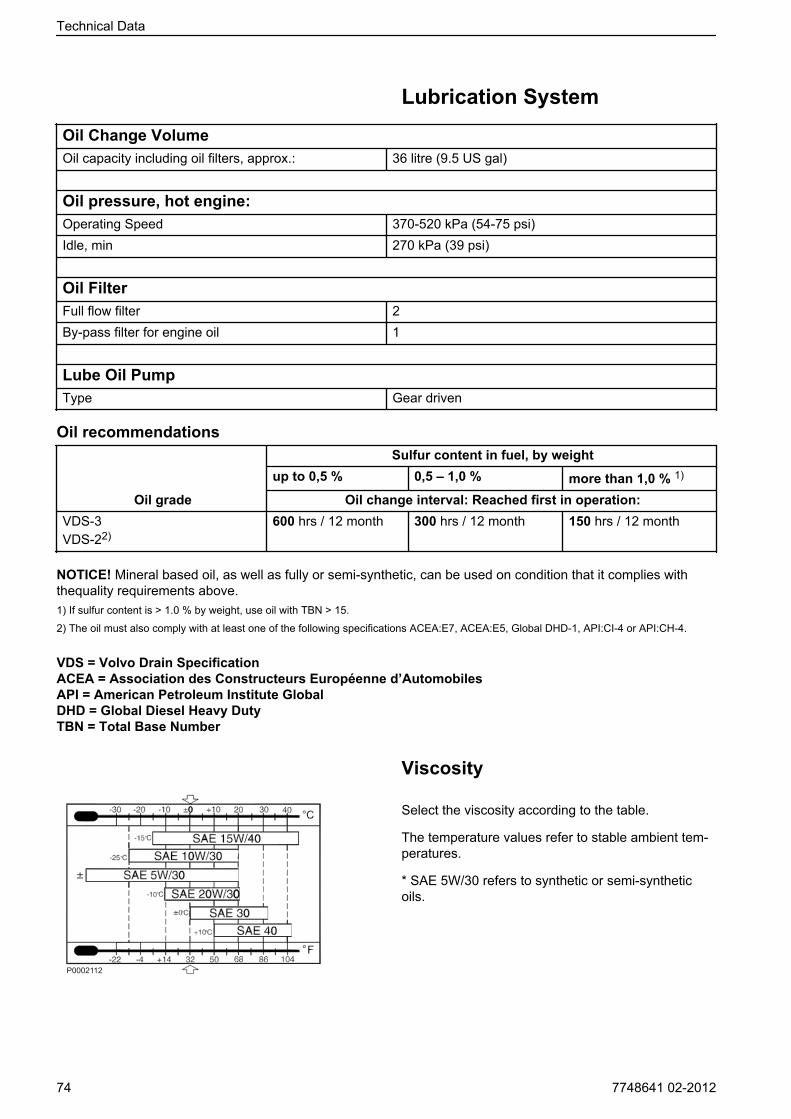
Lubrication SystemOil Change VolumeOil capacity including oil filters, approx.: 36 litre (9.5 US gal)
Oil pressure, hot engine:Operating Speed 370-520 kPa (54-75 psi)Idle, min 270 kPa (39 psi)
Oil FilterFull flow filter 2By-pass filter for engine oil 1
Lube Oil PumpType Gear driven
Oil recommendations
Oil grade
Sulfur content in fuel, by weightup to 0,5 % 0,5 – 1,0 % more than 1,0 % 1)
Oil change interval: Reached first in operation:VDS-3VDS-22)
600 hrs / 12 month 300 hrs / 12 month 150 hrs / 12 month
NOTICE! Mineral based oil, as well as fully or semi-synthetic, can be used on condition that it complies withthequality requirements above.1) If sulfur content is > 1.0 % by weight, use oil with TBN > 15.
2) The oil must also comply with at least one of the following specifications ACEA:E7, ACEA:E5, Global DHD-1, API:CI-4 or API:CH-4.
VDS = Volvo Drain SpecificationACEA = Association des Constructeurs Européenne d’AutomobilesAPI = American Petroleum Institute GlobalDHD = Global Diesel Heavy DutyTBN = Total Base Number
Viscosity
Select the viscosity according to the table.
The temperature values refer to stable ambient tem-peratures.
* SAE 5W/30 refers to synthetic or semi-syntheticoils.
Technical Data
74 7748641 02-2012
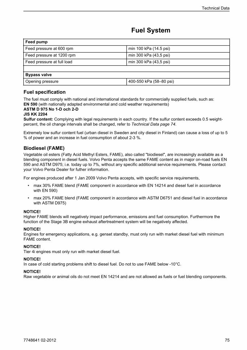
Fuel SystemFeed pumpFeed pressure at 600 rpm min 100 kPa (14.5 psi)Feed pressure at 1200 rpm min 300 kPa (43,5 psi)Feed pressure at full load min 300 kPa (43,5 psi)
Bypass valveOpening pressure 400-550 kPa (58–80 psi)
Fuel specificationThe fuel must comply with national and international standards for commercially supplied fuels, such as:EN 590 (with nationally adapted environmental and cold weather requirements)ASTM D 975 No 1-D och 2-DJIS KK 2204Sulfur content: Complying with legal requirements in each country. If the sulfur content exceeds 0.5 weight-percent, the oil change intervals shall be changed, refer to Technical Data page 74.
Extremely low sulfur content fuel (urban diesel in Sweden and city diesel in Finland) can cause a loss of up to 5% of power and an increase in fuel consumption of about 2-3 %.
Biodiesel (FAME)Vegetable oil esters (Fatty Acid Methyl Esters, FAME), also called "biodiesel", are increasingly available as ablending component in diesel fuels. Volvo Penta accepts the same FAME content as in major on-road fuels EN590 and ASTM D975; i.e. today up to 7%, without any specific additional service requirements. Please contactyour Volvo Penta Dealer for futher information.
For engines produced after 1 Jan 2009 Volvo Penta accepts, with specific service requirements,
• max 30% FAME blend (FAME component in accordance with EN 14214 and diesel fuel in accordancewith EN 590)
• max 20% FAME blend (FAME component in accordance with ASTM D6751 and diesel fuel in accordancewith ASTM D975)
NOTICE! Higher FAME blends will negatively impact performance, emissions and fuel consumption. Furthermore thefunction of the Stage 3B engine exhaust aftertreatment system will be negatively affected.
NOTICE! Engines for emergency applications, e.g. genset standby, must only run with market diesel fuel with minimumFAME content.
NOTICE! Tier 4i engines must only run with market diesel fuel.
NOTICE! In case of cold starting problems shift to diesel fuel. Do not to use FAME below -10°C.
NOTICE! Raw vegetable or animal oils do not meet EN 14214 and are not allowed as fuels or fuel blending components.
Technical Data
7748641 02-2012 75

Cooling SystemType Preassurized, sealedPressure cap, max opening pressure 70 kPa 1(0.2 psi)
Volume (engine) 20 liter (5.28 US gal)
Volume (engine+radiator and hoses) 24 liter (6,34 Us gal)
ThermostatNumber 1 pcsOpening temperature 82°C (180°F)
CoolantVolvo Penta Coolant VCS and VCS Ready Mixed (yellow colour) are based on Organic Acid Technol-ogy, OAT.
Volvo Penta Coolant and Coolant Ready Mixed (green colour) are silicate based.
Water Quality
ASTM D4985:
Total solid particles <340 ppmTotal hardness <9,5° dHChloride <40 ppmSulfate <100 ppmpH value 5.5–9Silica (acc. ASTM D859) <20 mg SiO2/l
Iron (acc. ASTM D1068) <0.10 ppmManganese (acc. ASTM D858) <0.05 ppmConductivity (acc. ASTM D1125) <500 µS/cmOrganic content, CODMn (acc.ISO8467)
<15 mg KMnO4/l
coolant vcs ready mixed
P0013077
P0002094
Technical Data
76 7748641 02-2012

Electrical SystemSystem voltage 24V
Alternatorvoltage/max. current 28V/80Apower app. 2200W
Battery capacity 2 pcs. series connected 12 V, max. 225 Ah
Battery electrolyte specific gravity at +25 °C:fully charged battery 1.28 g/cm3 (1.24 g/cm3)*batteriet omladdas vid 1.20 g/cm3 (1.20 g/cm3)*
* Note. Applies to batteries with tropical acid.
Technical Data
7748641 02-2012 77

Identification Numbers
1Chassis and serial number
2
A Engine designation
B Engine power, net, (without fan)
C Max. engine speed
D Main software
E Dataset 1
F Dataset 2
G Product number
3
1 Engine designation
2 Serial number
3 Specification number
ABCDEFG
P0002052
P0015924
Technical Data
78 7748641 02-2012
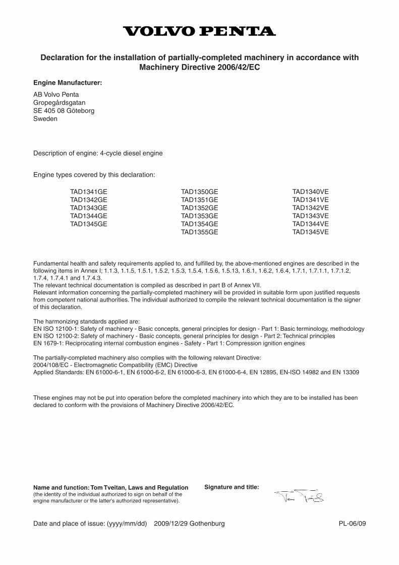
Fundamental health and safety requirements applied to, and fulfilled by, the above-mentioned engines are described in the following items in Annex I; 1.1.3, 1.1.5, 1.5.1, 1.5.2, 1.5.3, 1.5.4, 1.5.6, 1.5.13, 1.6.1, 1.6.2, 1.6.4, 1.7.1, 1.7.1.1, 1.7.1.2, 1.7.4, 1.7.4.1 and 1.7.4.3.The relevant technical documentation is compiled as described in part B of Annex VII.Relevant information concerning the partially-completed machinery will be provided in suitable form upon justified requests from competent national authorities. The individual authorized to compile the relevant technical documentation is the signer of this declaration.
The harmonizing standards applied are:EN ISO 12100-1: Safety of machinery - Basic concepts, general principles for design - Part 1: Basic terminology, methodologyEN ISO 12100-2: Safety of machinery - Basic concepts, general principles for design - Part 2: Technical principlesEN 1679-1: Reciprocating internal combustion engines - Safety - Part 1: Compression ignition engines
The partially-completed machinery also complies with the following relevant Directive:2004/108/EC - Electromagnetic Compatibility (EMC) DirectiveApplied Standards: EN 61000-6-1, EN 61000-6-2, EN 61000-6-3, EN 61000-6-4, EN 12895, EN-ISO 14982 and EN 13309
Declaration for the installation of partially-completed machinery in accordance with Machinery Directive 2006/42/EC
Engine Manufacturer:
AB Volvo PentaGropegårdsgatanSE 405 08 GöteborgSweden
Description of engine: 4-cycle diesel engine
Engine types covered by this declaration:
TAD1341GETAD1342GETAD1343GETAD1344GETAD1345GE
TAD1350GETAD1351GETAD1352GETAD1353GETAD1354GETAD1355GE
These engines may not be put into operation before the completed machinery into which they are to be installed has been declared to conform with the provisions of Machinery Directive 2006/42/EC.
Date and place of issue: (yyyy/mm/dd) 2009/12/29 Gothenburg PL-06/09
Name and function: Tom Tveitan, Laws and Regulation(the identity of the individual authorized to sign on behalf of the engine manufacturer or the latter's authorized representative).
Signature and title:
TAD1340VETAD1341VETAD1342VETAD1343VETAD1344VETAD1345VE

AAfter Engine Shutdown..............................................28Air Filter, Check and Change.................................... 53Alarms....................................................................... 26Alternator Belt, Change............................................. 55BBattery, Charging...................................................... 69Battery, Maintenance................................................ 68Before Engine Shutdown...........................................28Before Starting.......................................................... 22Bleeding the Fuel System......................................... 60CCharge Air Cooler, External Cleaning....................... 64Charge Air Pipe, Leakage Check.............................. 54CIU (Control Interface Unit).......................................21Coolant Filter, Change.............................................. 65Coolant Level, Checking and Topping Up.................63Coolant, Draining.......................................................64Cooling System, Cleaning......................................... 66DDCU (Display Control Unit)................................. 11, 23Declaration of Conformity..........................................79Diagnostic Function...................................................32Draining condensate, fuel system............................. 60Drive Belt and Alternator Belt, Inspection..................55Drive Belt, Change.................................................... 56DU (Display Unit).......................................................17EEasy Link Instruments............................................... 21Electrical Connections...............................................67EMS (Engine Management System)................... 10, 23Engine Fuel Filter Replacement................................ 59Engine Oil, Change................................................... 58Engine, General........................................................ 53Engines................................................................. 9, 73Erasing fault codes....................................................36Extra Stop..................................................................29FFault Tracing............................................................. 30Fuel Pre-filter, Change.............................................. 60Fuel System........................................................ 59, 75IIdentification Numbers...............................................78LLocation of Sensors...................................................52Lubrication System..............................................57, 74MMain switch................................................................67Maneuvering..............................................................26NNever Use Start Spray.............................................. 24OOil Filter/By-pass Filter, Change............................... 58Orientation.................................................................51
RReading the Instruments........................................... 26SService program........................................................ 49Starting in Extreme Cold........................................... 24Starting the Engine....................................................23Starting Using Auxiliary Batteries.............................. 25Stop the Engine.........................................................28VViscosity.................................................................... 74WWater Quality.............................................................76
Alphabetical index
7748641 02-2012 81


© 2012 AB VOLVO PENTA Volvo reserves the right to make changes Printed on environmentally friendly paper

7748
641
Engl
ish
02-2
012
Related Documents