www.mitox.co.uk Read this manual carefully before operating the machine Original Instructions Version June 16 28MTa_160616 Operator’s Manual user manual, maintenance instructions and spare parts 28MT Multi-Tool

Welcome message from author
This document is posted to help you gain knowledge. Please leave a comment to let me know what you think about it! Share it to your friends and learn new things together.
Transcript

www.mitox.co.uk
Read this manual carefully before operating the machineOriginal Instructions Version June 16
28MTa_160616
Operator’s Manualuser manual, maintenance instructions and spare parts
28MT Multi-Tool

28MT Multi-Tool
2 Original Instructions Version June 1628MTa_160616
PRODUCT DESCRIPTION
This Multi-Tool unit is a 2 stroke fast running power tool and is designed to be used in a domesticapplication with the attachments supplied. The Brushcutter attachment is designed for cutting grass and light brush, the Hedgetrimmer attachment for trimming new growth on hedges and the Pole Pruner for cutting up to 4” branches.

28MT Multi-Tool
3Original Instructions Version June 1628MTa_160616
Warnings in the Manual
This mark indicates instructions which must be followed in order to prevent accidents which could
lead to serious bodily injury or death.
This mark indicates instructions which must be followed or it leads to mechanical failure,
breakdown, or damage.
This mark indicates hints or useful directions in the use of the product.
IMPORTANT!
NOTE
Component Location
1. Fuel tank – 2 stroke mixture.2. Engine starter/Recoil.3. Carburettor / air filter.4. Safety lever.5. Throttle control lever.6. Ignition switch.7. Harness hanger.8. Loop handle.8A J-Handle.9. Transmission shaft.10. Attachment shaft.11. Safety guard.12. Gear box.13. Nylon head.14. Optional cutting blade.15. Nylon Cutting blade.16. Gear box.17. Attachment shaft.18. Rubber Grip.19. Gear box.20. Oil tank for lubrication.21. Guide Bar.22. Saw chain.23. Extension Shaft (Optional)24. Coupling.25. Cutter Blades.

28MT Multi-Tool
4 Original Instructions Version June 1628MTa_160616
Safety Symbols
Warning: Danger, Caution
Read the documentation and safety instructions which are provided in this user manual.
When operating this machine, use protective equipment such as goggles, helmet and ear defenders.
Wear security shoes and gloves.
Check the condition of the working area to avoid any accidents from hitting hidden obstacles such as stumps, stones, cans, or broken glass.
Hot surface: Risk of burn.
Directive 2000-14/CE. Guaranteed noise levels
Beware of objects being thrown from the operating zone
Warning: Keep all people, animals and vulnerable objects at least 15 metres from the working area.
Beware: Product conducts electricity. Keep the machine and operator at least 10 metres from electrical sources and over-head power cables.
Beware: Keep hands and feet away from moving parts.
Always keep a safe distance from the cutting parts.
Beware of blade thrust.

28MT Multi-Tool
5Original Instructions Version June 1628MTa_160616
Taking Care of Warning Labels
Always keep warning labels clean and free of scratches, which might make them illegible or
difficult to read. If the warning labels provided with your Multi-Tool become damaged, peel
off, or otherwise become illegible or difficult to read, order new labels from the authorised
servicing dealer and replace the damaged labels. When applying new labels, first wipe away any
dirt and dry the surface before applying the new label in the same place as the original label.
Explanation of Symbols on the Machine
For safe operation and maintenance, symbols are carved in relief on the machine:
FUEL TANK
Fuel tank 2 stroke mix
Position: Fuel cap
CHOKE OPERATION
<RUN>
Starting mode when the engine is hot (choke off).
Position: Air cleaner cover.
<START>
Starting mode when the engine is cold (choke on).
Position: Air cleaner cover.

28MT Multi-Tool
6 Original Instructions Version June 1628MTa_160616
Safety Precautions
Introduction
Read this Owner/Operator Manual carefully. Be sure you understand how to operate this Multi-
Tool properly before you use it. Failure to do so could result in serious injury.
Keep this manual handy so that you may refer to it later whenever any questions arise. Also note
that you are able to contact the dealer from whom you purchased the product for assistance.
Always include this manual when selling, lending, or otherwise transferring the ownership of this
product.
This product has been designed to be used as a Multi-Tool power tool as described previously and
it should never be used for any other purpose; doing so could result in unforeseen accidents and
injuries occurring. Only approved Mitox accessories should be used with this product.
This Multi-Tool is equipped with extremely sharp blades, always wear sturdy gloves when handling
the blades and fit the safety guards when not in use.
When using this Multi-Tool for the first time, take it to a wide, clear, open space, start the engine,
and practice handling the Multi-Tool until you are sure that you will be able to handle it properly in
actual operation.
You should never use this Multi-Tool when under the influence of alcohol, suffering from
exhaustion or lack of sleep, suffering from drowsiness as a result of having taken medicine, or at
any other time when your judgement might be impaired or that you might not be able to operate
the Multi-Tool properly and in a safe manner.
Never allow children or anyone unable to fully understand the directions given in this manual to
use this Multi-Tool.
When planning your work schedule, allow plenty of time to perform the work and allow plenty
of time for rest. Limit the amount of time you continuously use the Multi-Tool to 30~40 minutes
per session and take 10~20 minutes of rest between work sessions. Also, try to keep the total
amount of work performed in a single day to 2 hours.
Never run the engine indoors as the exhaust gases contain harmful carbon monoxide.

28MT Multi-Tool
7Original Instructions Version June 1628MTa_160616
Never use the Multi-Tool in conditions as described below:
When the ground is slippery or when other conditions exist which might make it difficult to
maintain a steady posture while using the Multi-Tool.
At night, at times of heavy fog, or at any other times when your field of vision is limited and it
would be difficult to gain a clear view of the area where the Multi-Tool is to be used. In heavy
rain, during lightning storms, at times of strong or gale-force winds, or at any other times when
weather conditions might make it unsafe to use this product.
Lack of sleep, tiredness, or physical exhaustion results in lower attention spans, and this in turn
can lead to accidents and injury.
Work Clothing and Safety Equipment
When using the product, you should wear proper clothing and protective equipment.
• Helmet
• Protection goggles or face protector
• Ear protectors
• Thick work gloves
• Non-slip sole work boots
• When using your Multi-Tool, always wear strong, durable, work clothing; shirts should be long-
sleeved and trousers should be full-length.
Safety and Operation
This Multi-Tool is equipped with very sharp blades, and when used incorrectly the blades can be
extremely dangerous.
Improper handling can cause accidents which may in turn lead to serious injury or death. For
this reason, you should always be careful to adhere to the following instructions when using your
Multi-Tool.

28MT Multi-Tool
8 Original Instructions Version June 1628MTa_160616
Never hold the Multi-Tool in a way in which the cutting head is pointing towards someone else.
Never allow the cutting head to come into contact with your body.
Always turn off the engine before adjusting the Multi-Tool, or at any time when coming into close
proximity with the cutting head.
Always wear thick work gloves when adjusting the Multi-Tool.
Safe Handling of Fuel
The engine of the Multi-Tool is designed to run on a two stroke oil/fuel mixture.
This fuel is highly flammable; never store cans of fuel or refill the fuel tank in any place where
there is a source of heat or fire, which might ignite the fuel.
Do not smoke whilst operating the Multi-Tool or refilling, keep lit cigarettes away from the Multi-
Tool at all times.
When refilling the fuel tank always stop the engine first and carefully make sure that there are no
sparks or naked flames anywhere nearby before refuelling.
If any fuel spillage occurs during refuelling, use a dry rag to wipe any fuel which has been spilled
onto the Multi-Tool before starting the engine.
After refuelling, screw the fuel cap back tightly onto the fuel tank and carry the Multi-Tool to a spot
5 metres or more away from where it was refuelled before starting the engine.

28MT Multi-Tool
9Original Instructions Version June 1628MTa_160616
Before Operating the Multi-Tool
Before beginning work, carefully check the work area and remove any obstacles. Within a
perimeter of 15 metres of the work area should be considered a hazardous area into which
no-one should enter while the Multi-Tool is being used, and when necessary this area should be
marked with a warning rope, warning signs, or other forms of warning.
When work is to be performed simultaneously by two or more operators, care should also be
taken to constantly look around to check the presence and locations of other operators within the
work area to maintain a safe distance between each operator.
Before beginning work, each component of the Multi-Tool should be checked to make sure that it
is in proper working order, make sure that there are no loose screws or bolts, fuel leaks, ruptures,
dents, broken guards or any other problems which might interfere with safe operation.
Keep all parts of your body away from the cutting head when the engine is running.
Before Starting the Engine
Carefully check the work area to make sure that no obstacles exist within a perimeter of 15
metres around the Multi-Tool before starting the engine.
To start the engine, place the Multi-Tool onto the ground in a flat clear area and hold it firmly
in place to ensure that neither the cutting head nor the throttle come into contact with any
obstacles when the engine starts.
After starting the engine, make sure that the cutting head stops moving when the throttle trigger
is released (idle). If the cutting head continues to move when the engine is at idle, adjust the
idle screw on the carburettor to a point where the cutting head stops moving, if this cannot be
achieved, take the Multi-Tool to your authorised service dealer for adjustment.

28MT Multi-Tool
10 Original Instructions Version June 1628MTa_160616
Avoid Noise Problems
Check and follow the local regulations for sound levels and hours of operation for garden
machinery.
In general, operate Multi-Tools between 8 am and 5 pm on week days and 9 am to 5 pm at
weekends.
Avoid using the Multi-Tool late at night and/or early in the morning.
Safety when using the Multi-Tool
When using the Multi-Tool, grip the handles firmly with both hands, place your feet slightly apart
so your weight is distributed evenly across both legs, and always maintain a steady even posture
while working. Do not use on ladders or if the ground surface is slippery or uneven. Never
attempt to cut directly overhead or with one hand.
• Maintain full engine speed when cutting.
• Never allow other persons to come within the work area as doing so
might expose them to danger.
• Keep work area clear of all persons, particularly small children and pets.
Injury may result from flying debris.
• If grass or other objects get caught in the Multi-Tool during operation,
always stop the engine before removing the object.
• Never touch the spark plug or plug HT cable while the engine is in
operation, doing so may result in an electrical shock.
• Never touch the exhaust, spark plug, or any metallic parts while the
engine is in operation or immediately after shutting down the engine.
These parts reach high temperatures during operation and doing so
could result in serious burns.
• When you finish cutting in one location and wish to continue work in another area, stop the
engine and fit the blade safety guards.
• Always remove fuel from the fuel tank before transportation to prevent fuel spillage.
• Never leave the Multi-Tool exposed to direct sunlight as this can heat the fuel tank and may
cause a discharge of fuel, and flood the engine.
• Be careful not to hit the nylon cutting head against stones or the ground.

28MT Multi-Tool
11Original Instructions Version June 1628MTa_160616
Two-Stroke Fuel
Fuel is very flammable. Do not smoke or bring any flame or sparks near fuel.
Always stop the engine and allow it to cool before refuelling.
Refuel outdoors on bare ground, restart the engine at least 5m away from the refuelling area.
The engine is lubricated by oil mixed into petrol. Prepare a mixture of unleaded petrol and semi-
synthetic two-stroke oil that meets the specifications of: API TC, ISO-L-EGC, JASO FC (Low Smoke)
oil.
Recommended mixing ratio is 40:1.
FUEL WITH NO OIL (RAW PETROL) will cause severe damage to the engine which is not
covered by manufacturer’s warranty.
Use fresh, unleaded petrol (95 RON) and semi-synthetic oil specially made for high performance
two-stroke engines. Mix in a ratio of 40 parts petrol to 1 part of oil.
By using two-stroke oil specially made for two-stroke engines you will reduce the formation of ash
and carbon deposits on the spark plug, piston, exhaust muffler and cylinder as well as reducing
emissions of harmful exhaust gases.
Oil FOR 4-CYCLE ENGINES should not be used as two-stroke lubrication oil as it can cause fouling
of the spark plug, exhaust port blocking, piston ring sticking and other internal engine damage.
NOTEDue to increased Ethanol content in petrol we recommend the use of B3C Ethanol Shield 2-Stroke Oil, or Ethanol Shield Fuel Stabiliser to protect your MITOX® engine against the harmful effects of Ethanol.
Visit www.b3cfuel.co.uk for more information.

28MT Multi-Tool
12 Original Instructions Version June 1628MTa_160616
Fuel Storage (Without Ethanol Shield)
Mixed two-stroke fuel which has been left unused for a period of one month or more may
damage the carburettor and result in the engine failing to start or operate correctly.
When storing the Multi-Tool for a period of more than one month, empty the fuel tank, and
run the engine to empty the carburettor of fuel.
Two stroke fuel can cause deterioration of rubber and/or plastic components during prolonged
storage.
It is important to only use good quality, fresh fuel mix.
Fuelling
Shake the fuel container to thoroughly mix the two-stroke oil and petrol.
Clean dirt from around the fuel cap before removing.
Pour two-stroke fuel into the fuel tank with a filtered funnel, up to 80% of the fuel tank’s capacity.
Replace the fuel cap and tighten securely. Spilled fuel must be wiped away from the Multi-Tool
before starting the engine.
Move at least 5m away from the refuelling area before restarting the engine.
When refilling the tank, always turn off the engine and allow it to cool down. Take a careful look
around to make sure that there are no sparks or open flames anywhere nearby before refuelling.

28MT Multi-Tool
13Original Instructions Version June 1628MTa_160616
Installing the Loop Handle Assembly
• Fit the upper handle to the shaft using the fixing holes to locate the handle to the
desired position (smooth side of the handle facing away from the engine).
• Fit the lower handle clamp and secure using the 2 Torx bolts.
Upper Handle
Torx Bolt
Clamp
Drive Shaft To Cutter Head
Drive Shaft To Engine

28MT Multi-Tool
14 Original Instructions Version June 1628MTa_160616
Assembly of the Brushcutter
The blade fitted to the guard is sharp and can cause injury, always wear gloves.
Installing the Guard
• Place the Brushcutter with the head facing down.
• Fit the shield using the bracket and 2 X Torx screws

28MT Multi-Tool
15Original Instructions Version June 1628MTa_160616
Installing the Nylon Head
• Lay the Brushcutter on its back with the gearbox shaft facing up.
Rotate the gear box shaft until the hole in the holder A lines up with the slot in the metal guard.
Insert an Allen key or screwdriver into the hole in the gearbox cover and into holder A.
Screw the nylon head anti-clockwise (turn left) onto the threaded shaft on the end of the gearbox.
Make sure that the nylon head is securely locked in position and remove the Allen key.
A A

28MT Multi-Tool
16 Original Instructions Version June 1628MTa_160616
Installing the 3 Point Blade
• Lay the Brushcutter on its back with the gearbox shaft facing up.
THE BLADE MUST BE CORRECTLY POSITIONED ON THE UPPER BLADE CLAMP
OTHERWISE SERIOUS DAMAGE AND INJURY TO PERSONS AND PROPERTY COULD
RESULT.
Rotate the gear box shaft until the hole in the holder A lines up with the slot in the metal guard.
Insert an Allen key or screwdriver into the hole in the gearbox cover and into
holder A.
Place the 3 tooth blade on the holder A, centering the blade on the raised centre.
Fit the holder
B over the
blade.
Fit the domed nut
protector C over
holder B and the
blade.
Fit the nut
anti-clockwise
(turn left) and
tighten using the
spanner provided.
Remove the Allen
key / screwdriver.
A A
A B
C

28MT Multi-Tool
17Original Instructions Version June 1628MTa_160616
Replacing the Nylon Cord
Check to see if the nylon head is damaged before replacing the cord. If you can see serious traces
of wear or damage, you must replace the complete nylon head.
1. Stop the engine.
2. Open the nylon head by pushing on the catch, (a), and lifting the cover (b).
3. Pull the bobbin out of the nylon head and take out the rest of the nylon cords.
4. Cut a new length of cord, 2.4mm Ø and 5 metres long.
5. Fold the new cord in half and place the centre of the fold (c) into the clip (d) in the empty bobbin.
6. Wind the line in the direction of the arrows on the bobbin, with half of the line above and half
below the divider (e). Maintain an even and firm tension onto the bobbin, being careful not to twist
the line.
6. After winding the cord, insert both ends into the notches on the bobbin, (f).
7. Put the filled bobbin back into the carrier. Release the cords from the notches in the bobbin
and place them into the eyelets in the carrier (g). The cords should stick out appx 15 cm either
side.
8. Refit the spool cover (b), ensuring it is securely clicked into place.
Never use a cutting device other than those supplied by the manufacturer. (Steel cord is never
allowed) Always use original spare parts in order to benefit from continuous warranty.
(a)
(b)
(g)
(f)
(e)
(f)
(c)
(d)

28MT Multi-Tool
18 Original Instructions Version June 1628MTa_160616
Using the Brushcutter
Choosing the cutting device
Choose the most suitable cutting device for the job to be done, according to these general
indications:
• The cutting line head can eliminate tall grass and non-woody vegetation
• The 3-point blade is suitable for cutting brushwood and small shrubs up to 2 cm in diameter.
Nylon Head
• Cut the grass in 1.5 metre widths, keeping the machine well balanced.
• Avoid engaging stones, piles of earth, small pieces of wood or anything that could be hidden or
difficult to see in the grass. If a large object is accidentally struck, if the cutting head gets blocked,
overloaded or stringy material gets wrapped in the cutting head, reduce the engine speed so the
engine idles. Make sure that the cutting head has stopped rotating, switch off the engine and
remove the material.
• Put the brushcutter on the ground and check that the cutting head has not been damaged. If
necessary, change the cutting head. If the head is only wrapped by vegetation, remove by hand
and clean the cutting head.
• Always wear safety gloves for this operation and ensure the engine is switched off and the head
is stationary.
• When the 2 nylon cords become too short, accelerate the engine and bump the nylon head on
the ground. Automatically the 2 nylon cords will feed out and be cut to the correct length. Repeat
the operation if necessary.
3-Point Blade
• Start cutting above the undergrowth and then move down with the blade so as to cut the brush
into small pieces.
• Avoid hitting stones, piles of earth, small pieces of wood or anything that could be hidden or
difficult to see in the grass.

28MT Multi-Tool
19Original Instructions Version June 1628MTa_160616
The thickness of fresh growth (green branches), which may be cut using this
hedgetrimmer, is limited to up to approximately 10mm. Never try to cut branches
thicker than this, as doing so may result in damage to the hedgetrimmer.
Blade information• Never cut hedges thicker than 10mm and only fresh growth.
• If wire is caught by the blades, damage can occur which is not covered by the warranty.
• When sharpening, removing, or reattaching the blades, be sure to wear thick, sturdy gloves
and use only appropriate tools and equipment to prevent injury.
• After you have finished using the hedgetrimmer, clean the blades and apply clean light grade
lubricating oil to the entire length of the blades, including the blade bolts.
NOTE
Assembly of the Hedgetrimmer

28MT Multi-Tool
20 Original Instructions Version June 1628MTa_160616
Operation
Adjusting the angle of the cutting blades
1. Stop the engine.
2. Always wear gloves when adjusting
the blades.
3. Lay the hedgetrimmer flat on the
ground and set the guard (1) to the
trimmer blade .
4. Squeeze the red locking lever (2) into the
black handle (5) to release the locking pin (3).
5. While holding the shaft (4), move the cutting
head to the desired position.
6. Release the red locking lever and ensure the locking
pin engages with the quadrant.

28MT Multi-Tool
21Original Instructions Version June 1628MTa_160616
Pole Pruner Attachment
KICKBACK AND PINCHING SAFETY PRECAUTIONS
Beware of kickback!
• Kickback can occur whenever the tip of the guide bar touches an object while the saw is
operating. Kickback may force the bar up and back towards the operator with speed!
Beware of pinching.
• Pinching the saw along the tip of the guide bar may force the bar back rapidly toward
the operator. Pinching can occur whenever wood closes in around the moving chain.
• Both kickback and pinching may cause you to lose control of the pole pruner which
could result in serious personal injury.
• Understand kickback and pinching!
• Keep a firm grip on the pole pruner with both hands whenever the engine is running. A
firm grip will help you reduce the effects of kickback and pinching as well as maintain
control of the machine.
• Cut at high engine speeds.
• Follow the manufacturer’s instructions for sharpening and maintaining the chain.
• Use only genuine spare parts.

28MT Multi-Tool
22 Original Instructions Version June 1628MTa_160616
Assembly of the Pole Pruner
Attaching the Pruning Mechanism
• Remove the locating screw (1).
• Using a T25 Torx key, loosen the clamping bolts (2).
• Slide the drive shaft (3) into the gearbox until the locating hole (4) in the drive shaft
is visible through the locating hole in the gearbox (5).
• Insert the locating screw (1) into the gearbox and tighten.
• Using a T25 Torx key, tighten the clamping bolts (2).
Install the guide bar and the saw chain on the gearbox as follows:
(1) Guide bar
(2) Saw chain
(3) Gearbox
(4) Sprocket
(5) Chain tension
adjust screw
(6) Nut
(7) Chain tensioner
(8) Chain cover

28MT Multi-Tool
23Original Instructions Version June 1628MTa_160616
The saw chain has very sharp edges. Use protective gloves for safety.
• Loosen the nut (6), and remove the chain cover (8).
• Mount the guide bar (1), then fit the saw chain around the bar and sprocket (4).
• Pay attention to the correct direction of the saw chain (2).
• Fit the chain tensioner (7) into the lower hole of the guide bar.
• Install the chain cover (8), and fasten the mounting nut (6) to finger tightness.
• Turn the adjuster screw (5) clockwise until the chain does not sag from the underside of the
guide bar.
• Fully tighten the chain cover nut (6).
• Wearing protective gloves, pull the chain around the guide bar by hand to check that the chain
has the correct tension, without any tight spots.
It is important to maintain the proper chain tension. Rapid wear of the guide bar or the chain
coming off can be caused by improper tension, especially when using a new chain.

28MT Multi-Tool
24 Original Instructions Version June 1628MTa_160616
Chain Oil
Filling the Oil Reservoir
• Fill the chain oil tank with low
viscosity chain oil or Mitox Chain Oil
this is availble online at
www.mitox.co.uk or at your local dealer.
• Do not use waste or regenerated oil that can cause damage to the oil pump.
• The oil reservoir has a capacity sufficient to provide about 20 minutes of cutting time. Be sure to
refill the oil tank every time when refuelling the saw.
Checking the Oil Supply
• After starting the engine, run the
chain at medium speed and see
if chain oil is thrown off as shown.
Adjusting the Oil Flow Rate
Never fill the oil reservoir or adjust the oiler with the engine running.
• An increase in bar oil flow rate will speed oil consumption, requiring more frequent checks on
the oil reservoir.
• The guide bar and chain are lubricated automatically by a pump that operates whenever
the chain rotates. The pump is set at the factory to deliver a minimum flow rate, but it can be
adjusted in the field. A temporary increase in oil flow is often desirable when cutting hardwood.
NOTE
28MT Multi-Tool
25Original Instructions Version June 1628MTa_160616
• When storing the pole pruner attachment, to prevent oil from seeping through the pump, either
1) Empty the oil tank.
2) Lay the pole pruner attachment with the tank facing down.
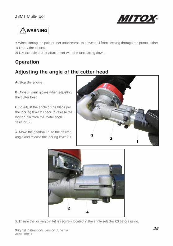
Operation
Adjusting the angle of the cutter head
A. Stop the engine.
B. Always wear gloves when adjusting
the cutter head.
C. To adjust the angle of the blade pull
the locking lever (1) back to release the
locking pin from the metal angle
selector (2).
4. Move the gearbox (3) to the desired
angle and release the locking lever (1).
5. Ensure the locking pin (4) is securely located in the angle selector (2) before using.

28MT Multi-Tool
26 Original Instructions Version June 1628MTa_160616
Maintenance of the Pruner Attachment
Oiling Port
• Dismount the guide bar and check the
oiling port for blockage (1).
Guide Bar
• Remove sawdust in the bar groove (1)
and the bar oiling port (2).
• Grease the nose sprocket (3) from the
feeding port on the tip of the bar (4)
with a sprocket grease gun (Oregon
Part Number 21939).
Gearbox
• Apply 2 or 3 pumps of grease every 15
hours of operation via the grease port (1).
• DO NOT force grease into the gear box.
• Always use lithium based grease.
1
2
3 4t

28MT Multi-Tool
27Original Instructions Version June 1628MTa_160616
Saw Chain Sharpening
It is very important for smooth and safe operation to always
keep the chain sharp.
The chain needs to be sharpened when:
• Sawdust becomes powder-like.
• You need extra force to saw.
• The cut does not go straight.
Be sure to wear safety gloves.
• Remove pruner attachment from the power unit.
• Clamp the guide bar in a vice to secure.
• Sharpen the chain with a 5/32 file and holder
(Oregon part number 16265)
• Place your file on the cutter and push straight forward.
Keep the file position as illustrated (a).
• After every cutter has been set, check the depth
gauge and file it to the proper level as illustrated (b).
• Make sure every cutter has the same length
and edge angles as illustrated (c).
(1) Depth gauge set tool (Oregon part no 27530)
(2) File shoulder round
(3) Depth gauge standard
(4) Cutter length
(5) Filing angle
(6) Side plate angle
(7) Top plate cutting angle
(a)
(b)
(c)

28MT Multi-Tool
28 Original Instructions Version June 1628MTa_160616
Installing the Attachments to the Power Unit(or Optional Extension Shaft)
• Pull out the locking pin (1) and twist (2) to lock in the outer position (3).
• Loosen the clamp by turning the handle (4).
• Insert the attachment shaft, lining up the locking hole with the locking pin .
• Twist the locking pin (5) to release it from the outer position. You may need to twist the
attachment shaft to ensure that the locking pin engages with the locking hole (6).
• Tighten the clamp by turning the handle (7).
ClampAttachment shaft
Lockinghole
Locking pin
1
2
34
5
7
6

28MT Multi-Tool
29Original Instructions Version June 1628MTa_160616
Operation
Keep clear of the cutter head as it may start moving when the engine starts.
Starting the Engine
CAUTION do not pull the starter cord all the way out and do not let go of the starter handle when
the cord is extended, this can damage the starter mechanism.
Cold Engine Starting
Rest the unit on a flat, firm surface. Keep the cutting head off the ground and clear of surrounding
objects as it may start moving when starting the engine.
Fig 4 - While holding the unit, pull out the
starter rope firmly until the engine fires
(indicated by a ‘cough’ from the engine).
Fig 3 - Set the ignition switch (d) to the START (I) position.
Fig 2 - Move the choke lever (c) to the
START ( ) position.
Fig 1 - Push the air purge bulb (a) until
fuel is visible in the clear return fuel
line (b)
(a)
(b)
START RUN
ONCE R
UNNING:
WAIT
6-1
0 SE
CONDS,
SQUEE
ZE T
HROTT
LE. H
OT ST
ART:
STOP
SWITCH
‘O’
1
2
STOP
3
5
PRIM
E x7
CHOK
E S
TART
PUL
L UNTIL
FIRE
CHOK
E R
UN
PUL
L TO
RUN
COLD
STAR
T:
(c)
(d)

28MT Multi-Tool
30 Original Instructions Version June 1628MTa_160616
Allow the engine to warm up before use. When cutting, always use the Multi-Tool on full throttle.
Hot Engine Starting
• Set the ignition switch to the START ( I ) position (fig 3 page 29).
• Check the clear return fuel line. If the line is empty, push the air purge bulb until fuel is
visible in the clear return fuel line.
• Move the choke lever to the START ( ) position, then back to the CLOSED ( )
position. This will set the throttle to the hot start position.
• Pull the starter rope until the engine starts, then squeeze the throttle briefly to release
the fast idle control and return the engine to idle.
• If the engine does not start after 5 pulls, use the Cold Start procedure.
OverchokingShould the engine become flooded due to overchoking, turn the ignition switch off, unscrew the
spark plug, wipe it dry or replace.
Stopping the Engine
Set the engine to idling by releasing the throttle lever.
Set the ignition switch to the off position ‘’O’’ (STOP).
If the engine fails to stop, set the choke lever to the closed position to stall the engine; do not use
the machine until the ignition switch is repaired.
NOTE
Fig 6 - Pull the starter rope until the engine
starts, then squeeze the throttle briefly to
release the fast idle control and return the
engine to idle.
Fig 5 - Move the choke lever (e) to the
RUN ( ) position.
START RUN
ONCE R
UNNING:
WAIT
6-1
0 SE
CONDS,
SQUEE
ZE T
HROTT
LE. H
OT ST
ART:
STOP
SWITCH
‘O’
1
2
STOP
3
5
PRIM
E x7
CHOK
E S
TART
PUL
L UNTIL
FIRE
CHOK
E R
UN
PUL
L TO
RUN
COLD
STAR
T:
(e)

28MT Multi-Tool
31Original Instructions Version June 1628MTa_160616
Running In
During the first ten hours of work, avoid running the engine at maximum speed for a prolonged
period until all the components have bedded in, after the engine has been run in, it will reach its
maximum power.
Transportation
Never transport the Multi-Tool with the engine running. An engine that is running could
be accidently accelerated causing the cutter head to engage.
Make sure the blade safety guards are in place when transporting the Multi-Tool.
When carrying by hand, the cutting head should be pointing backwards.
Ensure the Multi-Tool is secure when transporting in a vehicle and the tank is drained of fuel.
Maintenance
IMPORTANT
After every use, check that all nuts, bolts and screws are securely fastened and tighten if
necessary.
In the event of an accident, breakdown or blockage, ensure the engine is turned off before any
work is carried out to rectify this.
Make sure the engine has stopped and is cool before performing any service to the machine.
Contact with a moving cutting head or hot muffler may result in a personal injury.
Fuel Filter
Every 15 hours of operation, using a wire hook,
take the fuel filter from the fuel tank and clean
or replace with a new fuel filter.

28MT Multi-Tool
32 Original Instructions Version June 1628MTa_160616
Carburettor
The carburettor mixture setting has been set at the factory and will not need adjusting.
Adjusting the idle speed: If adjustment is necessary turn the T screw (a) clockwise until the
cutting head starts to move, then turn the T screw anticlockwise until the cutting head stops.
If the idle speed cannot be adjusted to stop the cutting head moving at idle, contact
your dealer for repair before use.
Safety Lock
The safety lock is to prevent the throttle lever from accidentally being engaged. The throttle lever
(b) can only be pressed in if the safety lock (c) is held down. Check if the safety lock and throttle
levers return to their original position and the engine returns to idling when you release your
hand from the handle.
Any defects contact your nearest service agent for repairs before using the machine.
(b)
(c)
(a)

28MT Multi-Tool
33Original Instructions Version June 1628MTa_160616
Spark PlugPoor starting or misfiring is often caused by a fouled
or defective spark plug, clean and reset the gap to
0.65 mm, or replace the spark plug with LD L8RTF;
CHAMPION RCJ7Y; NGK BPMR7A as necessary.
Air Filter
Before using the Multi-Tool, check the air filter (a). Being clogged, will reduce the engine
performance. Remove the air filter cover by pressing on the filter cover release (b) and opening
the filter cover (c). Clean the filter element in warm, soapy water, dry completely before installing.
If the element is broken or shrunk, replace with a new one.
Storage• Remove the spark plug, pour a small amount of oil into the cylinder. Rotate the crankshaft
several times using the starting rope in order to distribute the oil. Put the spark plug back in.
• Remove the fuel from the machine.
• Check the Multi-Tool for damage or problems at the intervals shown in the service schedule.
Hedgetrimmer Blades• After each session of operation, oil the cutting blades with light oil.
Gearbox Lubricant• DO NOT force grease into the gear boxes, apply 2 or 3 pumps of grease every 15 hours of
operation.
0.6 - 0.7mm
(b)
(c)
(a)

28MT Multi-Tool
34 Original Instructions Version June 1628MTa_160616
Brushcutter Gear Case
• Remove the bolt (a) on the gear case, top up the gearbox using Lithium grease and refit the
bolt.
Troubleshooting
Engine will not start, power loss:
• Check that the fuel tank is not empty. Fill with mixed fuel.
• The fuel does not reach the carburettor. Change the fuel filter in the fuel tank.
• There is water in the fuel. Drain and clean the fuel system.
• The air filter is dirty. Clean or replace the air filter.
• There are carbon deposits in the exhaust muffler restricting the engine. Clean or change the
muffler.
• Spark plug is worn. Replace spark plug.
(a)

28MT Multi-Tool
35Original Instructions Version June 1628MTa_160616
Service ScheduleComponent Procedure Before
useEvery 15Hours
Every 25Hours
Every 50Hours
Note
Engin
e
Fuel leaks / spillage
Wipe up
Fuel tank / filter
Inspect / clean
XReplace if necessary
Idle adjust screw
See aboveX X
Adjust carburettor if necessary
Spark plug LD L8RTF/CHAMPION RCJ7Y / NGK BPMR7A
Clean and readjust plug gap X
GAP .025” (0.6-0.7mm)Replace, if necessary
Cylinder fins / Intake air cooling vent
CleanX
Air filter Clean X
Muffler, Spark arrestor / cylinder exhaust port
Clean
X
Shaft
Throttle lever / ignition switch
Check operation
X
Screws / nuts / bolts
Tighten / replace X
Not adjustment screws
Gear Case Check X
Pole
Pru
ner
Oiling Port Clean X
Guide Bar Clean X
Sprocket Inspect/Replace
X
Saw Chain Inspect/Replace
X
LRH Blade Grease X
Blade Lubricate X

28MT Multi-Tool
36 Original Instructions Version June 1628MTa_160616
Specifications
MODEL MITOX 28MT
Engine Type Air cooled 2-stroke gasoline engine
Model IE34F-4A
Displacement : ( cm3) 25.4 cc
Max. output 0.75 (kw) in accordance with ISO 8893
Idle speed: rpm (min –1)
3100±400
Max. rpm (min –1) 9000
Fuel tank capacity 0.60L
Fuel Mixture (petrol 40 : Oil 1)
Carburettor Diaphragm type
Spark Plug LD L8RTF; CHAMPION RCJ7Y; NGK BPMR7A
Transmission Centrifugal clutch
Fixation hole diameter: (mm) 25.4
Weight (Power Unit Only) 4.63kg
EX-BC (When used as a Brushcutter)
Weight (Power Unit & Attachment) 6.51kg
Weight (Attachment Only) 1.88Kg
Reduction ratio 22 :17
Cutting head Cutting width
3 tooth blade
255mm
Nylon head
415mm
3 tooth blade thickness
1.4mm
Cutting line diameter 2.4mm
Max. blade rotation speed:
7500 rpm (min –1)
Rotation direction Counter clockwise (as seen from above)

28MT Multi-Tool
37Original Instructions Version June 1628MTa_160616
Specifications
EX-LRH (When used as a long reach hedge trimmer)
Weight (Power Unit & Attachment) 7.31kg
Weight (Attachment Only) 2.68kg
Tooth Spacing 27mm
Reduction ratio 4 : 1
Cutting head Type Reciprocating double blade
Effective cut Length 510mm
EX-PS (When used as a pruner saw)
Weight (Power Unit & Attachment) 6.70kg
Weight (Attachment Only) 2.07kg
Reduction ratio 0.94
Cutting head Guide bar size 10inches (250mm)
Saw chain Pitch x Gauge
3/8x0.050”
Oil pump Plunger type
Sprocket 7T

28MT Multi-Tool
38 Original Instructions Version June 1628MTa_160616
Parts Diagram - Engine

28MT Multi-Tool
39Original Instructions Version June 1628MTa_160616
Parts List - Engine
ID No. Part Number Description
1 MIGB/T2671.2 M5X12 SCREW M5X12
2 MITBC261D.01.12.00-00 STARTER ASSEMBLY
4 MIYD25.02.01-2 ROPE GUIDE
5 MIYD25.02.00-5 STARTER ROPE
6 MIYD62.02.00-3 STARTER HANDLE
7 MITBC261D.01.12.00-5 RECOIL SPRING
8 MITBC261D.01.12.00-4 RECOIL PULLEY
9 MITBC261D.01.12.00-6 STARTER SPRING
10 MITBC261D.01.12.00-7 RATCHET WHEEL
11 MIGB/T97.1 M5 WASHER M5
12 MIGB/T845 ST4.8X16 TAPPING SCREW ST4.8X16
13 MITBC260D.01.00.02-00 STARTER RATCHET ASSY
14 MIGB/T97.1 M8 FLAT WASHER M8
15 MIYD38-3.01.01.02-00 OIL SEAL 12X22X7
17 MITBC260D.01.01.00-3 GASKET - CRANKCASE
18 MIGB/T276 6001 BEARING 6001
20 MIGB/T1099 3X3.5X10 SEMI-CIRCULAR KEY 3X3.5X10
21 MITBC260D.01.03.03-00 BEARING 6001 8×11×11
22 MIYD38-3.01.03.00-4 PISTON PIN CIRCLIP
23 MIGJB25D.01.03.00-2 PISTON PIN
24 MIGJB25D.01.03.02-00 PISTON
25 MIGJB25D.01.03.00-1 PISTON RING
26 MITBC260D.01.00.00-4 GASKET - CYLINDER
27 MITBC261D.01.00.00-1 CYLINDER
28 MIGB/T2671.2 M5X20 SCREW M5X20
29 SPBPMR7A SPARK PLUG (EQUIV BPMR7A)
30 MITBC261D.01.00.00-2 ENGINE COVER
31 MIGB/T845 ST4.8X16 TAPPING SCREW ST4.8X16
32 MITBC260D.01.11.02-00 WIRE
33 MITBC431D.01.11.00-1 SPARK PLUG COVER

28MT Multi-Tool
40 Original Instructions Version June 1628MTa_160616
Parts List - Engine
ID No. Part Number Description
34 MITBC260D.01.11.01-00 IGNITION COIL
35 MIGB/T2671.2 M5X20 SCREW M5X20
36 MIGB/T119.2 5X10 PIN 5X10
38 MIGB/T2671.2 M5X25 SCREW M5X25
39 MIYD38-3.01.01.02-00 OIL SEAL 12X22X7
40 MITBC260D.01.10.00-00 FLYWHEEL
41 MIGB/T6177.2 M8X1 NUT M8X1
42 MIGJB25D.01.00.00-15 WAVE SPRING WASHER
43 MITBC260D.01.00.03-00 CLUTCH ASSEMBLY
44 MIGJB25D.01.00.00-14 BOLT FOR CLUTCH
45 MIGB/T119.2 4X10 PIN 4X10
46 MITBC261D.01.01.00-4 FAN COVER
47 MIGB/T2671.2 M5X20 SCREW M5X20
48 MITBC260D.01.14.01-00 CLUTCH DRUM ASSEMBLY
49 MIGB/T893.1 35 CIRCLIP (SIZE 35)
50 MIGB/T276 6202 BALL BEARING 6202-2Z
51 MIGB/T894.1 15 STOP RING (SIZE 15)
52 MITBC261D.01.14.00-1 CLUTCH DRUM HOUSING
53 MIGB/T2671.2 M6X20 SCREW M6X20
54 MITBC430D.01.14.00-2 ANTIVIBE RUBBER
55 MITBC430D.01.14.00-4 CLAMP RH
56 MITBC430D.01.14.00-3 CLAMP LH
57 MIGB/T2671.2 M5X25 SCREW M5X25
58 MIGB/T2671.2 M5X12 SCREW M5X12
59 MIGB/T2671.2 M5X52 SCREW M5X52
60 MITBC226D.1-2 MUFFLER COVER
61 MITBC261D.01.09.00-00 MUFFLER
62 MITBC261D.01.00.00-8 GASKET
63 MITBC260D.01.00.00-6 GASKET - MUFFLER
64 MIGB/T2671.2 M4X12 SCREW M4X12
65 MITBC260D.01.00.00-5 GASKET
66 MITBC261D.01.00.01-00 MANIFOLD

28MT Multi-Tool
41Original Instructions Version June 1628MTa_160616
Parts List - Engine
ID No. Part Number Description
67 MITBC431D.01.00.00-12 STRAP
68 MIGB/T845 ST3.5X9.5 ST SCREW 3.5X9.5
69 MIGB/T2671.2 M5X20 SCREW M5X20
70 MITBC261D.01.00.00-4 GASKET / CARBURETTOR
71 MITBC261D.01.06.00-00 CARBURETTOR
72 MITBC261D.01.08.00-00 AIR FILTER ASSEMBLY
74 MIGB/T2671.2 M5X45 SCREW M5X45
75 MITBC261D.01.08.00-3 AIR BOX ASSEMBLY
77 MITBC431D.01.13.01 FUEL CAP ASSY
78 MITBC431D.01.13.01-3 PETROL CAP RUBBER
79 MITBC431D.01.13.01-2 STOPPER
80 MITBC261D.01.13.00-1 FUEL TANK
81 MITBC431D.01.13.00-2 FUEL TANK RUBBER
82 MITBC261D.01.00.00-7 FUEL TANK BRACKET
83 MIGB/T2671.2 M5X25 SCREW M5X25
84 MIYD45.03.04-00 BREATHER ASSY
85 MITBC431D.01.13.00-6 BREATHER PIPE
86 MITBC430D.01.13.00-4 FUEL PIPE
87 MITBC430D.01.13.00-5 RETURN PIPE
88 MITBC431D.01.13.00-3 GROMMET
89 MIYD45.01.01.01-3 CIRCLIP
90 MITD38-3.03.04-00 FUEL FILTER

28MT Multi-Tool
42 Original Instructions Version June 1628MTa_160616
Parts Diagram - Body

28MT Multi-Tool
43Original Instructions Version June 1628MTa_160616
Parts List - Body
ID No. Part Number Description
1 MITBC431D.02.00-3 CLAMP
2 MITBC430D.03.02-00 HARNESS CLAMP ASSEMBLY
3 MIGB/T2671.2 M5X20 SCREW M5X20
4 MITBC430D.03.00-2 CLAMP
5 MIGB/T6170 M5 NUT M5
6 MITBC431SJ.03.02-00 OUTER SHAFT - UPPER
7 MITBC431DJ.03.03-00 COUPLING ASSEMBLY
8 MIGB/T2671.2 M5X25 SCREW M5X25
9 MIGB/T2671.2 M5X12 SCREW M5X12
10 MIGB/T5781 M6X50 BOLT M6X50
11 MIGB/T96 M6 WASHER M6
12 MITBC431DJ.03.03-7 LOCK KNOB
13 MIGB/T923 M6 NUT M6
14 MITBC431DJ.03.03-3 LOCK ASSY
15 MITBC431M.03.01-02 DRIVE SHAFT
16 MITBC431M.03.01-00 EXTENSION ASSEMBLY
17 MITBC431DJ.03.01-2 LIMIT SLEEVE
18 MITBC431DJ.03.03-00 COUPLING ASSEMBLY
19 MIGB/T2671.2 M5X25 SCREW M5X25
20 MIGB/T2671.2 M5X12 SCREW M5X12
21 MIGB/T5781 M6X50 BOLT M6X50
22 MIGB/T96 M6 WASHER M6
23 MITBC431DJ.03.03-7 LOCK KNOB
24 MIGB/T923 M6 NUT M6
25 MITBC431DJ.03.03-3 LOCK ASSY
26 MITBC431DJ.03.01-2 LIMIT SLEEVE
27 MITBC431DJ.03.01-00 FRONT SHAFT ASSEMBLY
28 MITBC430DJ.03.00-1 DRIVE SHAFT
29 MITBC431D.04.00-00 GEAR BOX ASSEMBLY
30 MIGB/T894.1 10 CIRCLIP (SIZE 10)
31 MIGB/T893.1 26 E CLIP (SIZE 26)

28MT Multi-Tool
44 Original Instructions Version June 1628MTa_160616
Parts List - Body
ID No. Part Number Description
32 MIGB/T276 6000-2Z BALL BEARING 6000-2Z
33 MITBC430D.04.00-2 PINION
34 MITBC431D.04.00-1 GEAR BOX
35 MITBC430D.04.00-7 GUARD
36 MIGB/T70.1 M5X8 SCREW M5X8
37 MIGB/T276 6000-2Z BALL BEARING 6000-2Z
38 MITBC430D.04.00-4 GEAR
39 MITBC431D.04.00-3 GEAR SHAFT
40 MIGB/T276 6002-2Z BALL BEARING 6002-2Z
41 MIGB/T893.1 32 CIRCLIP 32
42 MITBC431D.04.00-6 BLADE CLAMP - LOWER
43 MITBC431D.04.00-5 BLADE CLAMP - UPPER
44 MITBC431D.04.00-8 NUT PROTECTOR
45 MIGB/T6177.2 M10X1.25 NUT 10X1.25 LH
46 MIGB/T70.1 M6X12 SCREW M6X12
47 MIGB/T2671.2 M6X12 SCREW M6X12
48 MIGB/T2671.2 M6X25 SCREW M6X25
49 MITBC431D.06.01-1 SKIRT
50 MIGB/T845 ST4.8X13 TAPPING SCREW ST4.8X13
51 MITBC431D.06.00-2 LINE CUTTER
52 MITBC431D.06.02-00 DEBRIS GUARD
53 MITBC431D.06.00-3 SLEEVE
54 MITBC430D.06.00-1 CLAMP 26MM
55 MIGB/T2671.2 M6X20 SCREW M6X20
56 MITBC431S.05.01-1 FRONT HANDLE
57 MIGB/T6170 M5 NUT M5
58 MITBC431S.05.01-2 HANDLE BASE
59 MITBC431S.05.01-3 HANDLE CLAMP
60 MITBC431S.05.01-4 HANDLE BAR
61 MIGB/T2671.2 M5X28 SCREW M5X28
62 MIGB/T93 M5 SPRING WASHER M5

28MT Multi-Tool
45Original Instructions Version June 1628MTa_160616
Parts List - Body
ID No. Part Number Description
63 MIGB/T97.1 5X12X1.5 WASHER 5X12X1.5
64 MIGB/T97.1 5X11X2 WASHER 5X11X2
65 MIGB/T97.1 5X12X1.5 WASHER 5X12X1.5
66 MIGB/T845 ST4.8X19 TAPPING SCREW ST4.8X19
67 MI03.06.1.075 FOAM GRIP
68 MITBC430DJ.03.00-1 DRIVE SHAFT
69 MIGB/T6170 M5 NUT M5
70 MITBC431S.05.02-5 SPRING
71 MITBC431S.05.02-8 WIRE A
72 MITBC431S.05.02-9 WIRE B
73 MITBC431S.05.02-10 CONDUIT
74 MITBC431S.05.02-7 THROTTLE CABLE
75 MIGB/T2671.2 M5X14 SCREW M5X14
76 MIGB/T845 ST3.5X9.5 ST SCREW 3.5X9.5
77 MIGB/T845 ST4.2X10 ST SCREW 4.2X10
78 MIGB/T2671.2 M5X14 SCREW M5X14
79 MITBC431S.05.02-4 THROTTLE TRIGGER
80 MIYD38-3.01.11.04-00 ON/OFF SWITCH
81 MITBC431S.05.02-3 LOCK TRIGGER
82 MITBC431S.05.02-6 LOCK SPRING
83 MITBC431S.05.02-00 THROTTLE ASSEMBLY
84 MITBC431D.02.00-2 BLADE COVER
85 MITBC431D.02.00-1 BLADE
86 MIC43.0100.0300 NYLON HEAD ASSY
87 MITBC430D.07.01-00 HARNESS

28MT Multi-Tool
46 Original Instructions Version June 1628MTa_160616
Parts Diagram - Hedgetrimmer

28MT Multi-Tool
47Original Instructions Version June 1628MTa_160616
Parts List - Hedgetrimmer
ID No. Part Number Description
1 MIC26.1615.0100 RIGHT GEAR BOX ASSEMBLY
2 MIC26.1615.0103 POSITIONAL PLATE
3 MIGB/T97 M5 FLAT WASHER M5
4 MIGB/T93 M5 SPRING WASHER M5
5 MIGB/T2671.2 M5X16 SCREW M5X16
6 MIGB/T3452.1 34.5X1.8 O-RING 34.5X1.8
7 MIC26.1615.0201 LEFT GEAR BOX
8 MIGB6178 M6 NUT M6
9 MIGB91 2X14 COTTER PIN 2X14
10 MIC26.1615.0002 LEFT HALF HANDLE
11 MIC26.1615.0012 SMALL SPRING
12 MIC26.1615.0013 LARGE SPRING
13 MIGB/T2671.2 M5X20 SCREW M5X20
14 MIC26.1615.0001 RIGHT HAND HANDLE
15 MIGB/T119 B4X10 PIN B4X10
16 MIGB/T290 6X10X9 NEEDLE BEARNING
17 MIC26.1615.0005 SUBPLATE
18 MIC26.1615.0006 CONNECTING ROD
19 MIGB893.1 28 28 CIRCLIP
20 MIC26.1615.0202 GEAR BOX ASSEMBLY 2
21 MIGB/T3452.1 6X1.8 O-RING 6X1.8
22 MIGB/T97 M6 FLAT WASHER 6
23 MIGB/T2671.2 M6X12 SCREW M6X12
24 MIC26.1615.0107 SCREW
25 MIGB/T2671.2 M6X30 SCREW M6X30
26 MIGB/T93 M6 SPRING WASHER M6
27 MIC26.1615.0008 GEAR BOX ASSEMBLY 3
28 MIC26.1615.0004 SEALING GASKET
29 MIC26.1615.0003 GEAR BOX COVER
30 MIGB/T2672 M4X16 SCREW M4X16
31 MIC26.1615.0011 FELT SEALING GASKET

28MT Multi-Tool
48 Original Instructions Version June 1628MTa_160616
Parts List - Hedgetrimmer
ID No. Part Number Description
32 MIGB/T2672 M5X25 SCREW M5X25
33 MIGB/T2671.2 M5X25 SCREW M5X25
34 MIGB/T2671.2 M5X18 SCREW M5X18
35 MIC26.1615.0302 MOUNTED PLATE
36 MIC26.1615.0301 BLADE
37 MIC26.1615.0303 BUSHING
38 MIGB/T889.1 M5 NUT M5
39 MIB25.0119.0002 BLADE STRIP
40 MIC43.1212.0001 LIMIT SLEEVE
41 MIC43.0212.0001 DRIVE SHAFT
42 MIC43.1212.0100 FRONT ALU PIPE ASSEMBLY
43 MI03.06.1.075 FOAM GRIP
A MIC26.1615.0300 BLADE ASSEMBLY

28MT Multi-Tool
49Original Instructions Version June 1628MTa_160616
Parts Diagram - Pole Pruner

28MT Multi-Tool
50 Original Instructions Version June 1628MTa_160616
Parts List - Pole Pruner
ID No. Part Number Description
1 MITBC431DJ.03.01-00 FRONT SHAFT ASSEMBLY
2 MIGB/T2671.2 M5X12 SCREW M5X12
3 MIC33.0614.0001 OIL TANK
4 MIC33.0614.0002 OIL CAP
5 MIC33.0614.0003 CHECK VALVE
6 MIC33.0614.0004 FUEL HOSE CONNECTOR
7 MIC33.0614.0005 OIL TUBE
8 MIC33.0614.0006 FUEL HOSE SPRING
9 MIC33.0614.0100 GEAR BOX ASSEMBLY
10 MIC33.0614.0004 FUEL HOSE CONNECTOR
11 MIC33.0614.0007 TENSION BLOCK
12 MIC33.0614.0008 SPRING
13 MIC33.0614.0009 TENSION SCREW
14 MIGB/T899 M6X30 DOUBLE END STUDS M6×30
15 MI100SDEA318 GUIDE BAR
16 MI91P040X SAW CHAIN
17 MIGB/T6177.1 M6 NUT M6
18 MIC33.0614.0010 SPROCKET COVER
19 MIGB/T2671.2 M6X16 SCREWM6X16
20 MIGB/T97.1 M6 PLATE WASHER 6
21 MIC33.0614.0011 SPROCKET 3/8"
22 MIC33.0614.0012 SLEEVE 12×17×4
23 MIC33.0614.0013 PANEL
24 MIC33.0614.0014 POSITIONAL IRON SHELF
25 MIGB/T 276 6001 BEARING 6001
26 MIGB/T2671.2 M6X8 SCREWM6X8
27 MIC33.0614.0015 SLEEVE12×17×7.7
28 MIC33.0614.0016 GUIDE SLEEVE
29 MIGB895.2 5 CLAMP
30 MIC33.0614.0017 PIN SPRING CIRCLIP
31 MIC33.0614.0018 PIN SPRING

28MT Multi-Tool
51Original Instructions Version June 1628MTa_160616
Parts List - Pole Pruner
ID No. Part Number Description
32 MIC33.0614.0019 M10 PIN GUIDING NUT
33 MIC33.0614.0020 HANDLE PIN
34 MIC33.0614.0021 GUIDE BLOCK
35 MIGB/T2671.2 M5X25 SCREW M5X25
36 MIGB/T2671.2 M5X12 SCREW M5X12
37 MITBC430DJ.03.00-1 DRIVER SHAFT
38 MITBC431DJ.03.01-2 LIMIT SLEEVE
39 MIC26.0614.0013 BAR COVER
40 MI03.06.1.075 FOAM GRIP

28MT Multi-Tool
52 Original Instructions Version June 1628MTa_160616
EC Declaration of Conformity
We Mitox (Rochford Garden Machinery Ltd) - BA9 9RS (importer) declare that the product(s):
Designation: Petrol Powered Brushcutter / Hedgetrimmer / Pole Pruner
Model(s): MITOX 28MT SELECT
Type/Serial No: As per rating label on machine
Complies with the following directive(s):
2006/42/EC Machinery Directive
2004/108/EC EMC Directive
97/68/EC Directive as last amended by 2012/46/EU NRMM
2000/14/EC and 2005/88/EC Noise Directive for outdoor equipment use
The conformity assessment procedure followed was in accordance with:
EN ISO 11806-1:2011 EN ISO 11680-1:2011
EN ISO 10517:2009+A1:2013 EN ISO 14982:2009 ISO 22868:2011
Notified Body:
Intertek Testing Services
Address:
Building No. 86, 1198 Qinzhou Road (North) Shanghai 200233, China
Measured Sound Power Level: 110.6 dB (A)
Guaranteed Sound Power Level: 113 dB (A)
Authorised Signatory and Technical File Holder
Date: 20/11/2015
Signature:
Name: Stewart Anderson
Position: Managing Director
Company: Mitox (Rochford Garden Machinery Ltd)
Address: Wincanton Business Park Wincanton Somerset BA9 9RS

28MT Multi-Tool
53Original Instructions Version June 1628MTa_160616

28MT Multi-Tool
54 Original Instructions Version June 1628MTa_160616

28MT Multi-Tool
55Original Instructions Version June 1628MTa_160616

28MT Multi-Tool
56 Original Instructions Version June 1628MTa_160616
CONDITIONS OF WARRANTY
The manufacturer warrants the product against faulty materials and workmanship for a standard 1 year period and thereafter for the set period specific to each range from the date of purchase. Warranty does not extend to failure due to fair wear and tear.
SP - 1 YearSELECT - 3 Years (Subject to yearly servicing)PREMIUM - 5 Years (Subject to yearly servicing)PRO - 5 Years Domestic / 3 Years Commercial (Subject to yearly servicing)(Extended warranty is subject to online registration and yearly servicing)
SP, SELECT and PREMIUM ranges used for commercial purposes have a warranty period of 3 months from the date of purchase.
The manufacturer undertakes to replace any spare parts that are classified as defective by anappointed Mitox service dealer. The manufacturer will not accept liability for the replacement of the machine, either partially or wholly, and /or consequential damages and /or interest charges either directly or indirectly.
Warranty does not cover failure due to:Insufficient maintenance.Incorrect fuel mixture and stale fuel.Abnormal use or accidental damage.Incorrect assembly, adjustment or operation of the product.Spare parts that are subject to wear e.g. bag, blades, bearings, cables, guards, deflectors, spark plugs, air filters etc.
Neither does warranty extend to:Freight and packing costs.Use of non-genuine spare parts i.e. those from another manufacturer.Use of the machine for any other purpose than that for which it was designed.Use and maintenance of the machine in a manner not described in the owner’s manual.
As part of our policy of continuous product improvement, we reserve the right to alter or amend this specification without notice. As a result, the product may differ from the information contained herein but any alteration will only be implemented without notice if it is classified as an improvement to the above specification.
READ THE MANUAL CAREFULLY BEFORE OPERATING THE MACHINE
When ordering spare parts, please quote the part number, this can be found in the parts list included in this manual.
Retain your proof of purchase, without which no warranty can be offered.
Mitox Garden Machinery, Wincanton Business Park, Wincanton, Somerset, BA9 9RS
Related Documents