2052 O’Neil Rd, Macedon NY 14502 Telephone: (315) 986-8090 Fax: (315) 986-8091 www.ankom.com Operator’s Manual Rev 05/13/21

Welcome message from author
This document is posted to help you gain knowledge. Please leave a comment to let me know what you think about it! Share it to your friends and learn new things together.
Transcript
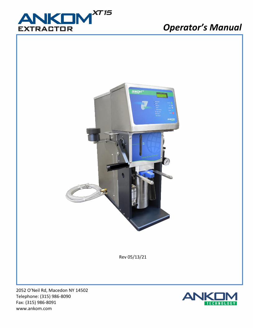
2052 O’Neil Rd, Macedon NY 14502 Telephone: (315) 986-8090 Fax: (315) 986-8091 www.ankom.com
Operator’s Manual
Rev 05/13/21

This page intentionally left blank
Table of Contents
Introduction .................................................................................................................................................................. 5
Warranty ....................................................................................................................................................................... 5
Filter Bags ..................................................................................................................................................................... 5
Operating Environment ................................................................................................................................................ 5
Contact Information ..................................................................................................................................................... 6
Instrument Description ................................................................................................................................................. 7
Safety Precautions ........................................................................................................................................................ 8
Instrument Installation and First Run ........................................................................................................................... 9
Fat Extraction Calculations ......................................................................................................................................... 13
Fat Extraction Support Items ...................................................................................................................................... 13
Sample Preparation .................................................................................................................................................... 15
Fat Extraction step-by-step procedure using the ANKOMXT15 .................................................................................... 21
Periodic Maintenance ................................................................................................................................................. 25
Troubleshooting & Replacement Parts ....................................................................................................................... 27
Diagnostics .................................................................................................................................................................. 29
Appendix A- Analytical Procedure .............................................................................................................................. 33
Appendix B – Electrical Diagram (pg. 1 of 3) ............................................................................................................... 35

This page intentionally left blank
Operator’s Manual
Rev 05/13/21 pg. 5
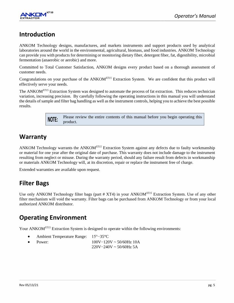
Introduction
ANKOM Technology designs, manufactures, and markets instruments and support products used by analytical
laboratories around the world in the environmental, agricultural, biomass, and food industries. ANKOM Technology
can provide you with products for determining or monitoring dietary fiber, detergent fiber, fat, digestibility, microbial
fermentation (anaerobic or aerobic) and more.
Committed to Total Customer Satisfaction, ANKOM designs every product based on a thorough assessment of
customer needs.
Congratulations on your purchase of the ANKOMXT15 Extraction System. We are confident that this product will
effectively serve your needs.
The ANKOMXT15 Extraction System was designed to automate the process of fat extraction. This reduces technician
variation, increasing precision. By carefully following the operating instructions in this manual you will understand
the details of sample and filter bag handling as well as the instrument controls, helping you to achieve the best possible
results.
Please review the entire contents of this manual before you begin operating this
product.
Warranty
ANKOM Technology warrants the ANKOMXT15 Extraction System against any defects due to faulty workmanship
or material for one year after the original date of purchase. This warranty does not include damage to the instrument
resulting from neglect or misuse. During the warranty period, should any failure result from defects in workmanship
or materials ANKOM Technology will, at its discretion, repair or replace the instrument free of charge.
Extended warranties are available upon request.
Filter Bags
Use only ANKOM Technology filter bags (part # XT4) in your ANKOMXT15 Extraction System. Use of any other
filter mechanism will void the warranty. Filter bags can be purchased from ANKOM Technology or from your local
authorized ANKOM distributor.
Operating Environment
Your ANKOMXT15 Extraction System is designed to operate within the following environments:
• Ambient Temperature Range: 15°−35°C • Power: 100V−120V ~ 50/60Hz 10A
220V−240V ~ 50/60Hz 5A

Operator’s Manual
pg. 6 Rev 05/13/21
Contact Information
At ANKOM Technology we are committed to your total satisfaction and therefore always available to help you get
the most from your ANKOM products. We are also very interested in any comments or suggestions you may have to
help us improve.
For any questions or suggestions regarding your instrument, please contact us at:
• Telephone: (315) 986-8090
• Fax: (315) 986-8091
• Email: [email protected]
• www.ankom.com
Operator’s Manual
Rev 05/13/21 pg. 7
Instrument Description
General Description
The ANKOMXT15 Extraction System is designed to extract Crude (Free) Fat using conventional solvents, typically
petroleum ether. The compounds extracted are primarily triacylglycerols together with a small quantity of related
lipids, traditionally termed “Crude Fat.” The analysis is achieved by measuring the loss of mass due to the extraction
of fat/oil from the sample encapsulated in a filter bag. The quantitative isolation of the sample is accomplished by
surrounding the sample in a sealed filter bag with a filtering capacity in the 2 to 3 micron range. The filter bag has
sufficient porosity to permit rapid solvent passage and is composed of polymeric material that is resistant to the higher
temperatures and solvents used in the instrument.
The quantitative isolation achieved by the filter bag permits the ANKOMXT15 Extraction System to automatically
process samples in batches of up to 15. With the solvent reservoir filled, simply place filter bags with sample in the
Extraction Vessel, lock the vessel in place, select the extraction time and temperature, and press “Start.” The
instrument will automatically fill the Extraction Vessel with solvent, extract the fat from the sample, and recycle the
solvent.
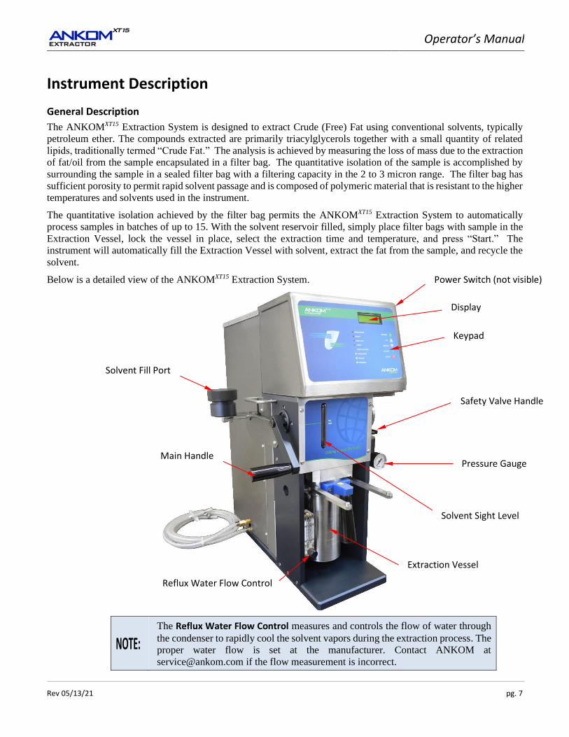
Below is a detailed view of the ANKOMXT15 Extraction System.
The Reflux Water Flow Control measures and controls the flow of water through
the condenser to rapidly cool the solvent vapors during the extraction process. The
proper water flow is set at the manufacturer. Contact ANKOM at
[email protected] if the flow measurement is incorrect.
Keypad
Display
Power Switch (not visible)
Safety Valve Handle
Pressure Gauge
Extraction Vessel
Solvent Fill Port
Main Handle
Solvent Sight Level
Reflux Water Flow Control
Operator’s Manual
pg. 8 Rev 05/13/21
Safety Precautions
Flammable Hazard: Static electricity is to be avoided as it is a spark hazard.
Hot Surfaces: Do not touch the extraction vessel during operation. The surface can
exceed 70°C (158°F). Failure to observe this caution may result in injury.
Hazardous Voltages: Do not operate the instrument with the electrical
compartment open. Hazardous voltages are present during operation. Failure to
observe this caution may result in electrical shock or electrocution.
Hazardous Materials: The ANKOMXT15 Extraction System comes equipped with
a charcoal filter which traps any residual vapor in the vent system. By properly
maintaining the charcoal filter, volatiles will not escape the vent system. We
recommend replacement of the filter every 3 months or after 100 extraction runs.
Trace amounts of vapor may also be present when samples are removed. It is
recommended that the ANKOMXT15 Extraction System be placed in a well
ventilated environment, away from any heat or ignition sources. Organic solvents
may be flammable. Follow safe laboratory practices according to both local and
federal regulations when installing this instrument and when handling any organic
solvents.
WARNING: Attempts to override safety features or to use this instrument in a
manner not specified by ANKOM Technology voids the warranty and may result
in serious injury or even death.
This system is designed to meet and/or exceed the applicable standards of CE, CSA, NRTL and OSHA.
Please review the entire contents of this manual before you begin operating this
instrument.
Operator’s Manual
Rev 05/13/21 pg. 9
Instrument Installation and First Run
Site Requirements
To install and operate the ANKOMXT15 Extraction System you will need the following:
• Adjustable wrench
• Chilled or tap water supply not to exceed 23°C
• Adequate power (see “Operating Environment” section)
• Drain
Instrument Installation and First Run Procedure
To install the ANKOMXT15 Extraction System and execute the first run, follow the procedure detailed below.
1. Remove the instrument from the shipping container and place it on a smooth level surface in an area that
is free of dust and excessive moisture, and is well ventilated (away from any heat or ignition sources).
Because the ANKOMXT15 Extraction System is a closed system, there is very
limited exposure to solvents. When used in conjunction with a charcoal filter on
the vent line the instrument produces less than 1ml of volatiles. It is the user’s
responsibility to determine whether venting of this instrument requires placement
in a hood. Please follow both local and federal regulations when installing this
instrument.
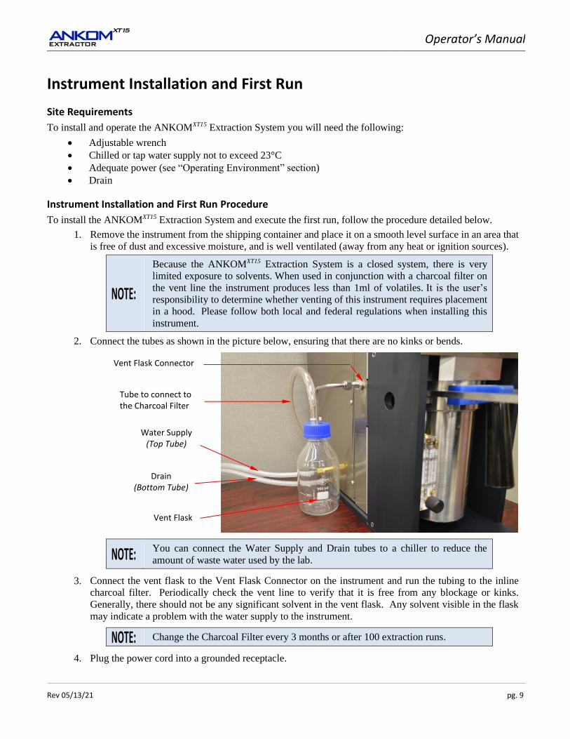
2. Connect the tubes as shown in the picture below, ensuring that there are no kinks or bends.
You can connect the Water Supply and Drain tubes to a chiller to reduce the
amount of waste water used by the lab.
3. Connect the vent flask to the Vent Flask Connector on the instrument and run the tubing to the inline
charcoal filter. Periodically check the vent line to verify that it is free from any blockage or kinks.
Generally, there should not be any significant solvent in the vent flask. Any solvent visible in the flask
may indicate a problem with the water supply to the instrument.
Change the Charcoal Filter every 3 months or after 100 extraction runs.
4. Plug the power cord into a grounded receptacle.
Drain (Bottom Tube)
Vent Flask
Water Supply (Top Tube)
Tube to connect to the Charcoal Filter
Vent Flask Connector
Operator’s Manual
pg. 10 Rev 05/13/21
5. To complete the installation, run the instrument (without samples) according to the procedure below.
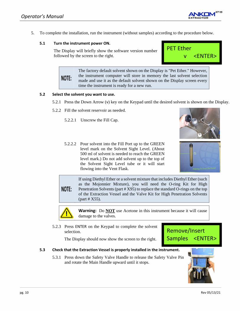
5.1 Turn the instrument power ON.
The Display will briefly show the software version number
followed by the screen to the right.
The factory default solvent shown on the Display is "Pet Ether." However,
the instrument computer will store in memory the last solvent selection
made and use it as the default solvent shown on the Display screen every
time the instrument is ready for a new run.
5.2 Select the solvent you want to use.
5.2.1 Press the Down Arrow (v) key on the Keypad until the desired solvent is shown on the Display.
5.2.2 Fill the solvent reservoir as needed.
5.2.2.1 Unscrew the Fill Cap.
5.2.2.2 Pour solvent into the Fill Port up to the GREEN
level mark on the Solvent Sight Level. (About
500 ml of solvent is needed to reach the GREEN
level mark.) Do not add solvent up to the top of
the Solvent Sight Level tube or it will start
flowing into the Vent Flask.
If using Diethyl Ether or a solvent mixture that includes Diethyl Ether (such
as the Mojonnier Mixture), you will need the O-ring Kit for High
Penetration Solvents (part # X95) to replace the standard O-rings on the top
of the Extraction Vessel and the Valve Kit for High Penetration Solvents
(part # X55).
Warning: Do NOT use Acetone in this instrument because it will cause
damage to the valves.
5.2.3 Press ENTER on the Keypad to complete the solvent
selection.
The Display should now show the screen to the right.
5.3 Check that the Extraction Vessel is properly installed in the instrument.
5.3.1 Press down the Safety Valve Handle to release the Safety Valve Pin
and rotate the Main Handle upward until it stops.
PET Ether v <ENTER>
Remove/Insert Samples <ENTER>
Operator’s Manual
Rev 05/13/21 pg. 11
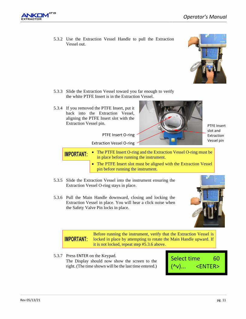
5.3.2 Use the Extraction Vessel Handle to pull the Extraction
Vessel out.
5.3.3 Slide the Extraction Vessel toward you far enough to verify
the white PTFE Insert is in the Extraction Vessel.
5.3.4 If you removed the PTFE Insert, put it
back into the Extraction Vessel,
aligning the PTFE Insert slot with the
Extraction Vessel pin.
• The PTFE Insert O-ring and the Extraction Vessel O-ring must be
in place before running the instrument.
• The PTFE Insert slot must be aligned with the Extraction Vessel
pin before running the instrument.
5.3.5 Slide the Extraction Vessel into the instrument ensuring the
Extraction Vessel O-ring stays in place.
5.3.6 Pull the Main Handle downward, closing and locking the
Extraction Vessel in place. You will hear a click noise when
the Safety Valve Pin locks in place.
Before running the instrument, verify that the Extraction Vessel is
locked in place by attempting to rotate the Main Handle upward. If
it is not locked, repeat step #5.3.6 above.
5.3.7 Press ENTER on the Keypad.
The Display should now show the screen to the
right. (The time shown will be the last time entered.)
Select time 60 (^v)... <ENTER>
PTFE Insert O-ring
Extraction Vessel O-ring
PTFE Insert slot and Extraction Vessel pin

Operator’s Manual
pg. 12 Rev 05/13/21
5.4 Set the Extraction Time.
5.4.1 Using the arrow keys on the Keypad, set the Extraction time to 20 minutes for the initial run.
(The recommended time is 60 minutes.)
5.4.2 Press ENTER on the Keypad to set the Time.
The Display should now show the screen to the
right. (The temperature shown will be the last
temperature entered.)
5.5 Set the Extraction Temperature.
5.5.1 Using the arrow keys on the Keypad, select the desired Extraction Temperature. (The
recommended maximum temperature is 90°C.)
5.5.2 Press ENTER on the Keypad to set the Temperature.
The Display should now show the screen to the
right.
5.6 Verify that the water supply is on.
5.7 Run the instrument.
Press START on the Keypad.
The instrument will run through its automatic operation, showing on the Display a time
countdown along with process information. The first operation is to fill the vessel.
5.7.1 For future reference, record the countdown time
on the screen when the vessel is full. The Heat light will turn on when the vessel is full.
5.7.2 For future reference, record the countdown time on the screen when the heat reaches 90°C.
5.7.3 After the instrument reaches 90°C, record the reflux water flow in the
flow controller. The value should be between 6 and 7 GPH (4 to 6 GPH
if using a chiller). If necessary, turn the front knob on the controller
counterclockwise to increase the value, and clockwise to decrease the
value. The reflux process runs on 90 second cycles. The reflux
controller must be read and adjusted during the first 1 minute of the
cycle. 5.7.4 Verify that the XT15 runs through the drain sequence with no errors.
When the instrument has completed its automatic operation,
the Display will show the screen to the right.
At this time, the only light shining on the Display should be the green power light.
Select temp 90 (^v)... <ENTER>
Close Vessel Water On <START>
PET Ether v <ENTER>
Operator’s Manual
Rev 05/13/21 pg. 13
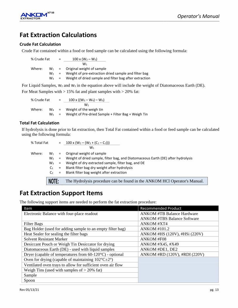
Fat Extraction Calculations Crude Fat Calculation
Crude Fat contained within a food or feed sample can be calculated using the following formula:
% Crude Fat = 100 x (W2 – W3)
W1 Where: W1 = Original weight of sample W2 = Weight of pre-extraction dried sample and filter bag W3 = Weight of dried sample and filter bag after extraction
For Liquid Samples, W2 and W3 in the equation above will include the weight of Diatomaceous Earth (DE).
For Meat Samples with > 15% fat and plant samples with > 20% fat:
% Crude Fat = 100 x ((W5 – W4) – W3)
W1 Where: W4
W5 = =
Weight of the weigh tin Weight of Pre-dried Sample + Filter Bag + Weigh Tin
Total Fat Calculation
If hydrolysis is done prior to fat extraction, then Total Fat contained within a food or feed sample can be calculated
using the following formula:
% Total Fat = 100 x (W2 – (W3 + (C1 – C2)))
W1
Where: W1 = Original weight of sample W2 = Weight of dried sample, filter bag, and Diatomaceous Earth (DE) after hydrolysis W3 = Weight of dry extracted sample, filter bag, and DE C1 = Blank filter bag dry weight after hydrolysis C2 = Blank filter bag weight after extraction
The Hydrolysis procedure can be found in the ANKOM HCl Operator's Manual.
Fat Extraction Support Items The following support items are needed to perform the fat extraction procedure:
Item Recommended Product Electronic Balance with four-place readout ANKOM #TB Balance Hardware
ANKOM #TBS Balance Software
Filter Bags ANKOM #XT4 Bag Holder (used for adding sample to an empty filter bag) ANKOM #101.2 Heat Sealer for sealing the filter bags ANKOM #HS (120V), #HSi (220V) Solvent Resistant Marker ANKOM #F08 Desiccant Pouch or Weigh Tin Desiccator for drying ANKOM #X45, #X49 Diatomaceous Earth (DE) - used with liquid samples ANKOM #DE1, DE2 Dryer (capable of temperatures from 60-120°C) - optional ANKOM #RD (120V), #RDI (220V) Oven for drying (capable of maintaining 102°C±2°) Ventilated oven trays to allow for sufficient oven air flow
Weigh Tins (used with samples of > 20% fat) Sample
Spoon

Operator’s Manual
pg. 14 Rev 05/13/21
This page intentionally left blank
Operator’s Manual
Rev 05/13/21 pg. 15
Sample Preparation
Sample Preparation Procedure for Crude Fat – for LOW fat samples
To prepare meat samples with ≤ 15% fat by weight or plant samples with ≤ 20% fat by weight for fat extraction,
follow the procedure detailed below.
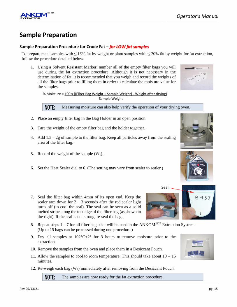
1. Using a Solvent Resistant Marker, number all of the empty filter bags you will
use during the fat extraction procedure. Although it is not necessary in the
determination of fat, it is recommended that you weigh and record the weights of
all the filter bags prior to filling them in order to calculate the moisture value for
the samples.
% Moisture = 100 x ((Filter Bag Weight + Sample Weight) - Weight after drying) Sample Weight
Measuring moisture can also help verify the operation of your drying oven.
2. Place an empty filter bag in the Bag Holder in an open position.
3. Tare the weight of the empty filter bag and the holder together.
4. Add 1.5 – 2g of sample to the filter bag. Keep all particles away from the sealing
area of the filter bag.
5. Record the weight of the sample (W1).
6. Set the Heat Sealer dial to 6. (The setting may vary from sealer to sealer.)
7. Seal the filter bag within 4mm of its open end. Keep the
sealer arm down for 2 – 3 seconds after the red sealer light
turns off (to cool the seal). The seal can be seen as a solid
melted stripe along the top edge of the filter bag (as shown to
the right). If the seal is not strong, re-seal the bag.
8. Repeat steps 1 – 7 for all filter bags that will be used in the ANKOMXT15 Extraction System.
(Up to 15 bags can be processed during one procedure.)
9. Dry all samples at 102°C±2° for 3 hours to remove moisture prior to the
extraction.
10. Remove the samples from the oven and place them in a Desiccant Pouch.
11. Allow the samples to cool to room temperature. This should take about 10 – 15
minutes.
12. Re-weigh each bag (W2) immediately after removing from the Desiccant Pouch.
The samples are now ready for the fat extraction procedure.
Seal
Operator’s Manual
pg. 16 Rev 05/13/21
Sample Preparation Procedure for Crude Fat – for HIGH fat samples
To prepare meat samples with > 15% fat by weight or plant samples with > 20% fat by weight for fat extraction,
follow the procedure detailed below.
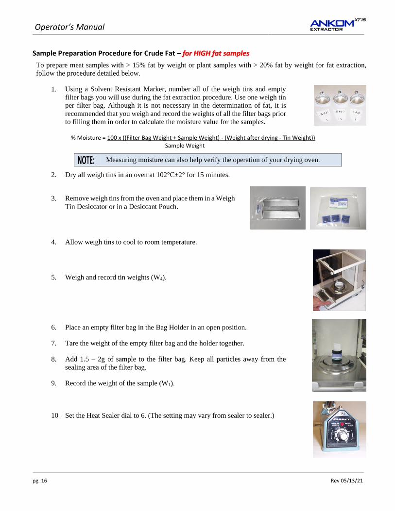
1. Using a Solvent Resistant Marker, number all of the weigh tins and empty
filter bags you will use during the fat extraction procedure. Use one weigh tin
per filter bag. Although it is not necessary in the determination of fat, it is
recommended that you weigh and record the weights of all the filter bags prior
to filling them in order to calculate the moisture value for the samples.
% Moisture = 100 x ((Filter Bag Weight + Sample Weight) - (Weight after drying - Tin Weight)) Sample Weight
Measuring moisture can also help verify the operation of your drying oven.
2. Dry all weigh tins in an oven at 102°C±2° for 15 minutes.
3. Remove weigh tins from the oven and place them in a Weigh
Tin Desiccator or in a Desiccant Pouch.
4. Allow weigh tins to cool to room temperature.
5. Weigh and record tin weights (W4).
6. Place an empty filter bag in the Bag Holder in an open position.
7. Tare the weight of the empty filter bag and the holder together.
8. Add 1.5 – 2g of sample to the filter bag. Keep all particles away from the
sealing area of the filter bag.
9. Record the weight of the sample (W1).
10. Set the Heat Sealer dial to 6. (The setting may vary from sealer to sealer.)
Operator’s Manual
Rev 05/13/21 pg. 17
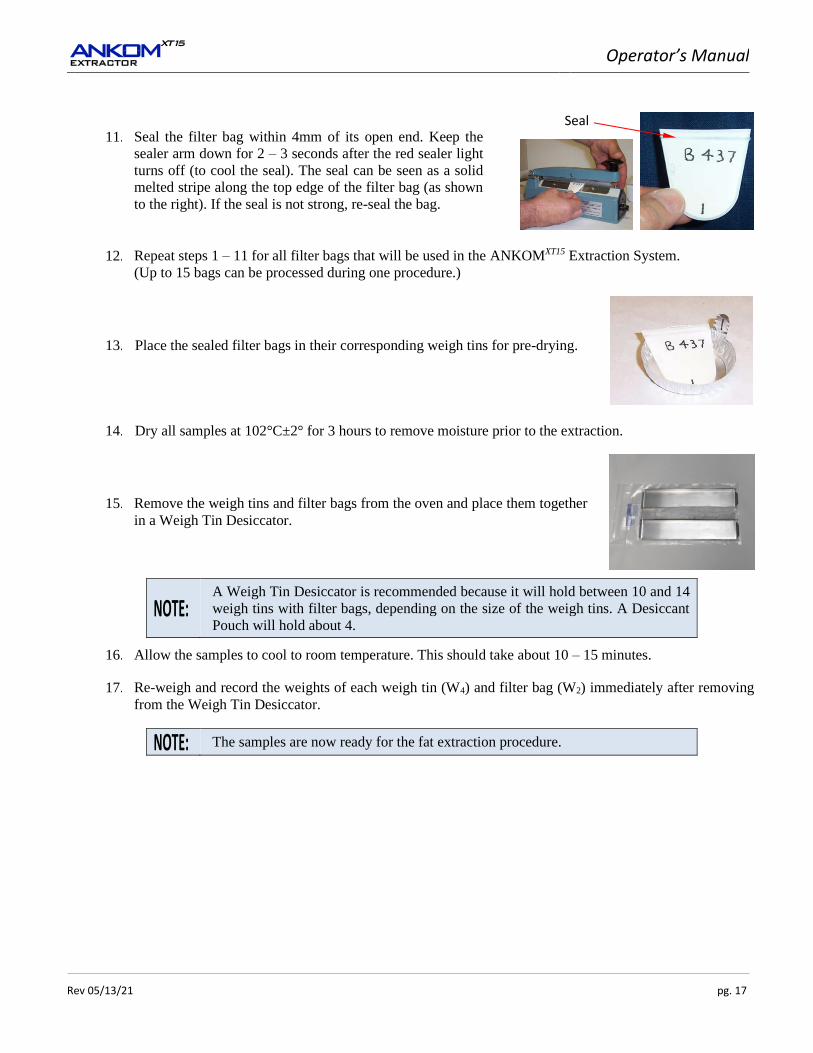
11. Seal the filter bag within 4mm of its open end. Keep the
sealer arm down for 2 – 3 seconds after the red sealer light
turns off (to cool the seal). The seal can be seen as a solid
melted stripe along the top edge of the filter bag (as shown
to the right). If the seal is not strong, re-seal the bag.
12. Repeat steps 1 – 11 for all filter bags that will be used in the ANKOMXT15 Extraction System.
(Up to 15 bags can be processed during one procedure.)
13. Place the sealed filter bags in their corresponding weigh tins for pre-drying.
14. Dry all samples at 102°C±2° for 3 hours to remove moisture prior to the extraction.
15. Remove the weigh tins and filter bags from the oven and place them together
in a Weigh Tin Desiccator.
A Weigh Tin Desiccator is recommended because it will hold between 10 and 14
weigh tins with filter bags, depending on the size of the weigh tins. A Desiccant
Pouch will hold about 4.
16. Allow the samples to cool to room temperature. This should take about 10 – 15 minutes.
17. Re-weigh and record the weights of each weigh tin (W4) and filter bag (W2) immediately after removing
from the Weigh Tin Desiccator.
The samples are now ready for the fat extraction procedure.
Seal
Operator’s Manual
pg. 18 Rev 05/13/21
Sample Preparation Procedure for Crude Fat – for Liquid samples
To prepare liquid samples for fat extraction, follow the procedure detailed below.
1. Using a Solvent Resistant Marker, number all of the empty filter bags you will use
during the fat extraction procedure. Although it is not necessary in the
determination of fat, it is recommended that you weigh and record the weights of
all the filter bags prior to filling them in order to calculate the moisture value for
the samples.
% Moisture = 100 x ((Filter Bag Weight + Sample Weight) - Weight after drying) Sample Weight
Measuring moisture can also help verify the operation of your drying oven.
2. Place an empty filter bag in the Bag Holder in an open position.
3. Tare the weight of the empty filter bag and the holder together.
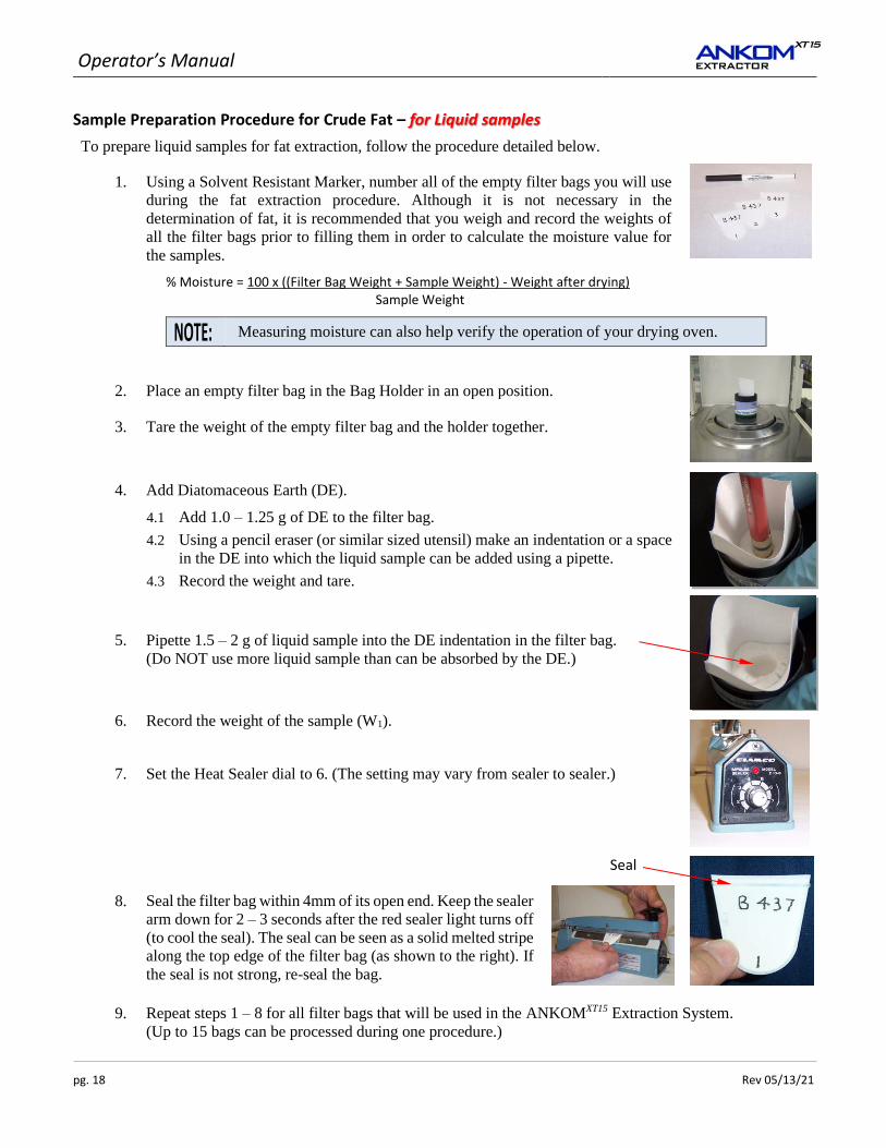
4. Add Diatomaceous Earth (DE).
4.1 Add 1.0 – 1.25 g of DE to the filter bag.
4.2 Using a pencil eraser (or similar sized utensil) make an indentation or a space
in the DE into which the liquid sample can be added using a pipette.
4.3 Record the weight and tare.
5. Pipette 1.5 – 2 g of liquid sample into the DE indentation in the filter bag.
(Do NOT use more liquid sample than can be absorbed by the DE.)
6. Record the weight of the sample (W1).
7. Set the Heat Sealer dial to 6. (The setting may vary from sealer to sealer.)
8. Seal the filter bag within 4mm of its open end. Keep the sealer
arm down for 2 – 3 seconds after the red sealer light turns off
(to cool the seal). The seal can be seen as a solid melted stripe
along the top edge of the filter bag (as shown to the right). If
the seal is not strong, re-seal the bag.
9. Repeat steps 1 – 8 for all filter bags that will be used in the ANKOMXT15 Extraction System.
(Up to 15 bags can be processed during one procedure.)
Seal
Operator’s Manual
Rev 05/13/21 pg. 19
10. Dry all samples at 102°C±2° for 3 hours to remove moisture prior to the extraction.
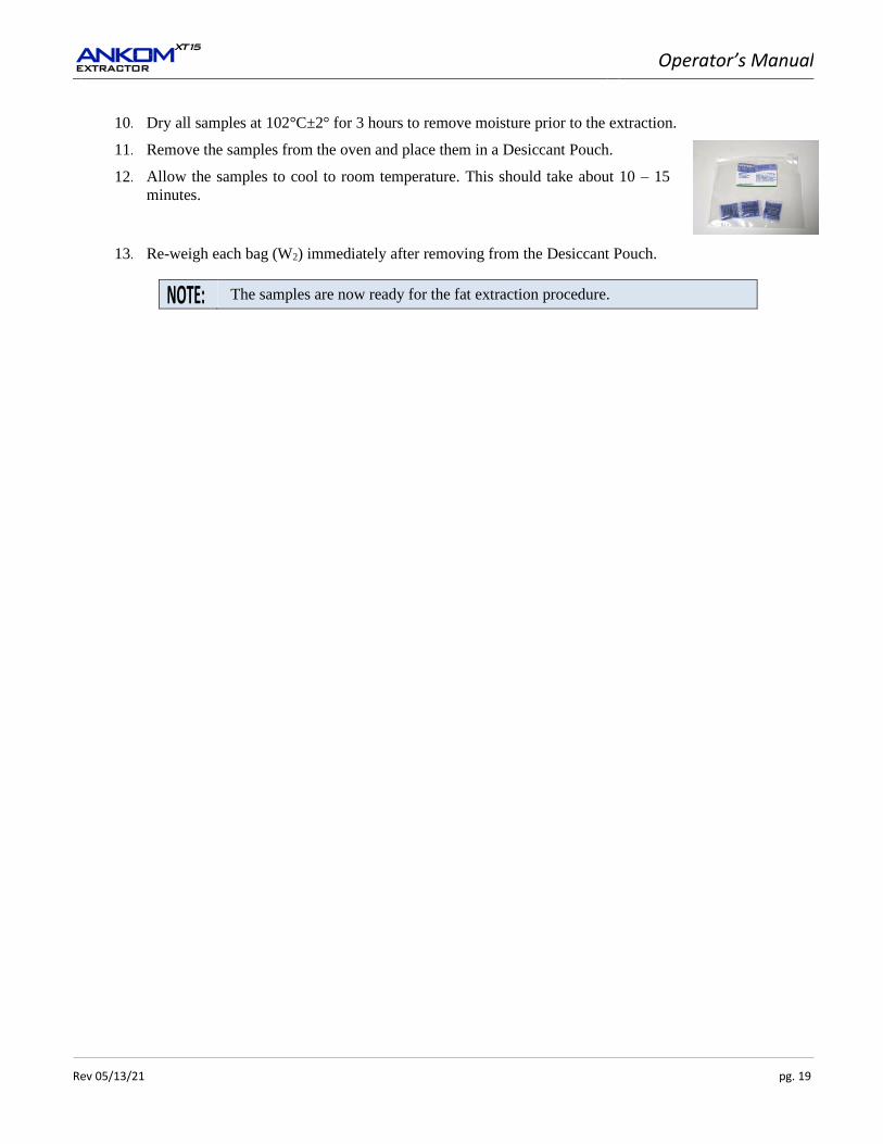
11. Remove the samples from the oven and place them in a Desiccant Pouch.
12. Allow the samples to cool to room temperature. This should take about 10 – 15
minutes.
13. Re-weigh each bag (W2) immediately after removing from the Desiccant Pouch.
The samples are now ready for the fat extraction procedure.

Operator’s Manual
pg. 20 Rev 05/13/21
This page intentionally left blank
Operator’s Manual
Rev 05/13/21 pg. 21
Fat Extraction step-by-step procedure using the ANKOMXT15
To perform fat extraction on prepared samples, follow the procedure detailed below.
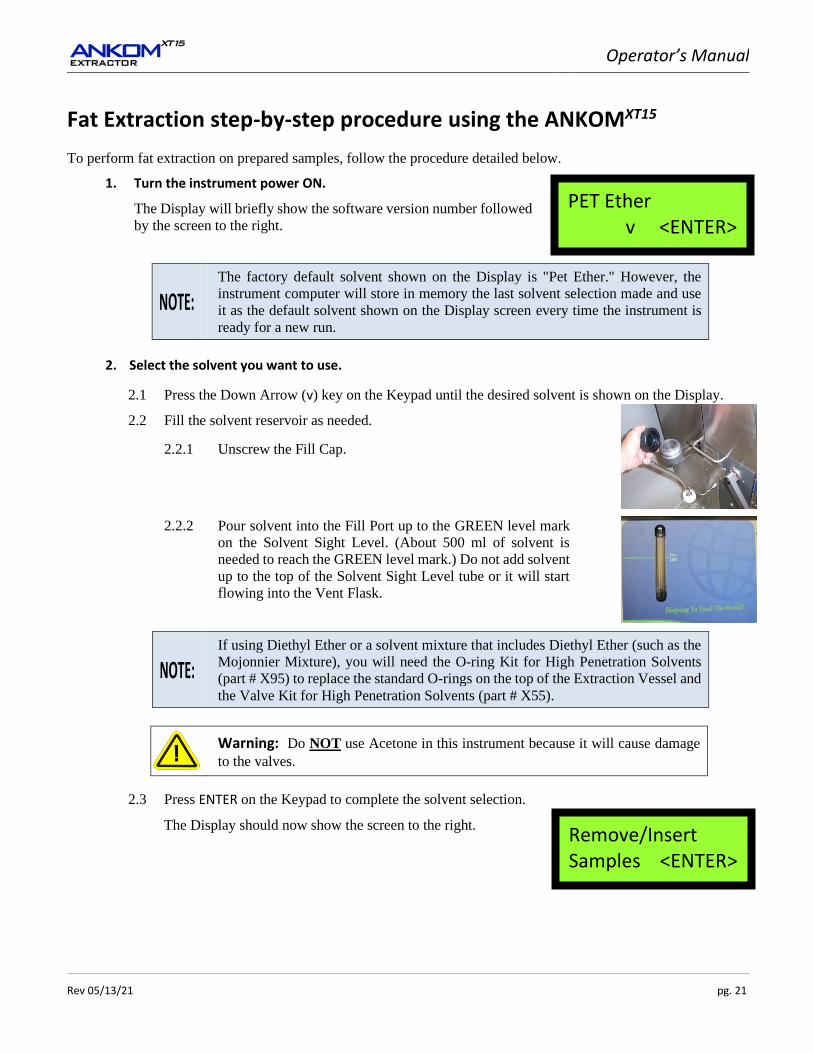
1. Turn the instrument power ON.
The Display will briefly show the software version number followed
by the screen to the right.
The factory default solvent shown on the Display is "Pet Ether." However, the
instrument computer will store in memory the last solvent selection made and use
it as the default solvent shown on the Display screen every time the instrument is
ready for a new run.
2. Select the solvent you want to use.
2.1 Press the Down Arrow (v) key on the Keypad until the desired solvent is shown on the Display.
2.2 Fill the solvent reservoir as needed.
2.2.1 Unscrew the Fill Cap.
2.2.2 Pour solvent into the Fill Port up to the GREEN level mark
on the Solvent Sight Level. (About 500 ml of solvent is
needed to reach the GREEN level mark.) Do not add solvent
up to the top of the Solvent Sight Level tube or it will start
flowing into the Vent Flask.
If using Diethyl Ether or a solvent mixture that includes Diethyl Ether (such as the
Mojonnier Mixture), you will need the O-ring Kit for High Penetration Solvents
(part # X95) to replace the standard O-rings on the top of the Extraction Vessel and
the Valve Kit for High Penetration Solvents (part # X55).
Warning: Do NOT use Acetone in this instrument because it will cause damage
to the valves.
2.3 Press ENTER on the Keypad to complete the solvent selection.
The Display should now show the screen to the right.
PET Ether v <ENTER>
Remove/Insert Samples <ENTER>
Operator’s Manual
pg. 22 Rev 05/13/21
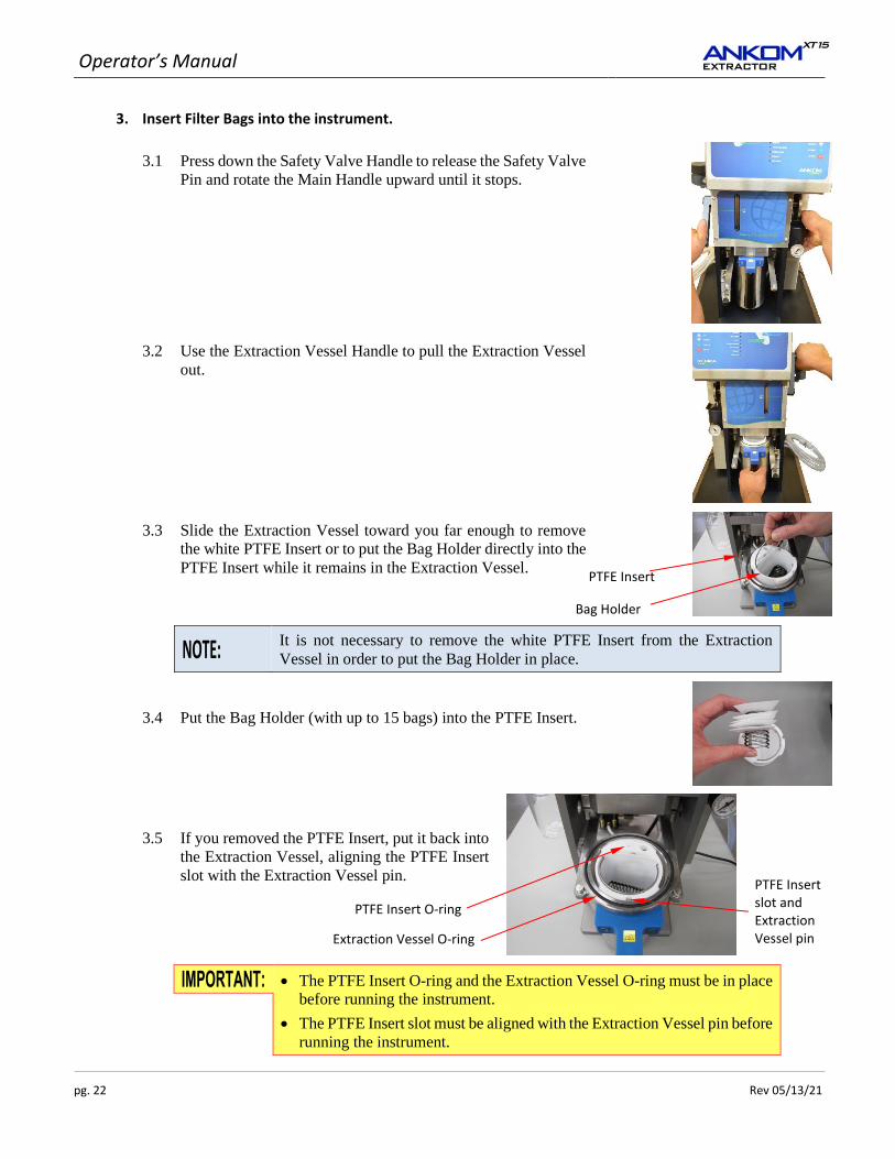
3. Insert Filter Bags into the instrument.
3.1 Press down the Safety Valve Handle to release the Safety Valve
Pin and rotate the Main Handle upward until it stops.
3.2 Use the Extraction Vessel Handle to pull the Extraction Vessel
out.
3.3 Slide the Extraction Vessel toward you far enough to remove
the white PTFE Insert or to put the Bag Holder directly into the
PTFE Insert while it remains in the Extraction Vessel.
It is not necessary to remove the white PTFE Insert from the Extraction
Vessel in order to put the Bag Holder in place.
3.4 Put the Bag Holder (with up to 15 bags) into the PTFE Insert.
3.5 If you removed the PTFE Insert, put it back into
the Extraction Vessel, aligning the PTFE Insert
slot with the Extraction Vessel pin.
• The PTFE Insert O-ring and the Extraction Vessel O-ring must be in place
before running the instrument.
• The PTFE Insert slot must be aligned with the Extraction Vessel pin before
running the instrument.
PTFE Insert O-ring
Extraction Vessel O-ring
PTFE Insert slot and Extraction Vessel pin
PTFE Insert
Bag Holder
Operator’s Manual
Rev 05/13/21 pg. 23
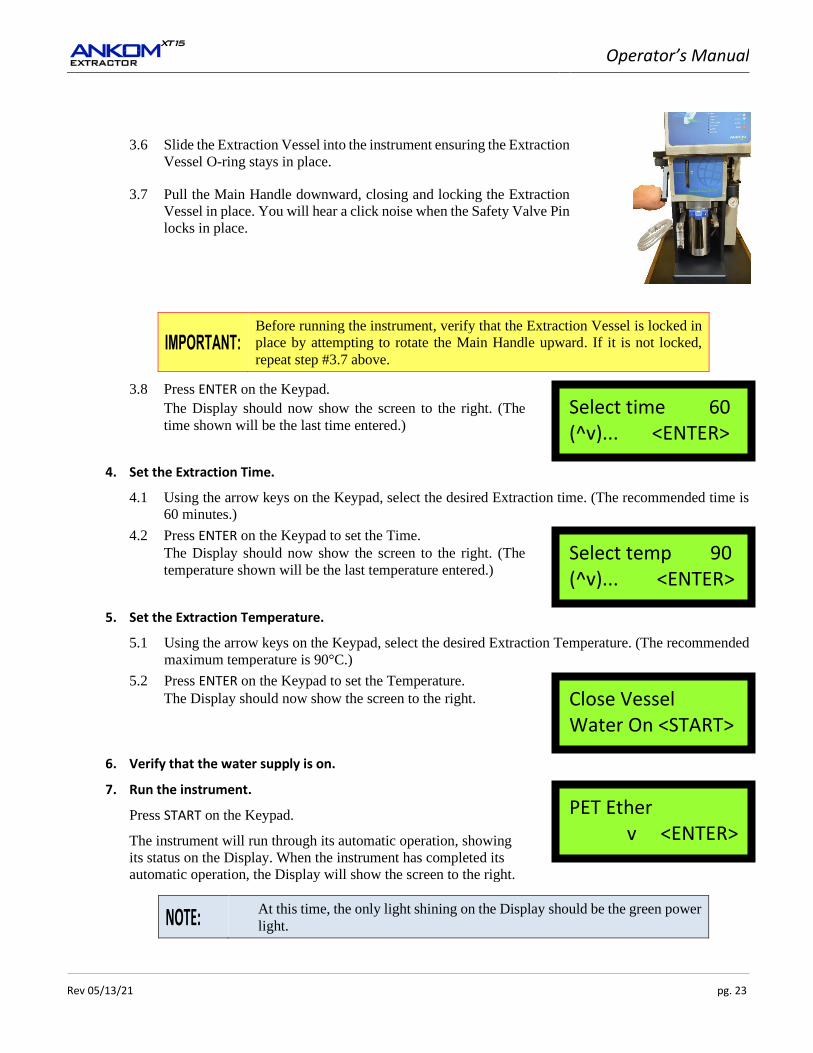
3.6 Slide the Extraction Vessel into the instrument ensuring the Extraction
Vessel O-ring stays in place.
3.7 Pull the Main Handle downward, closing and locking the Extraction
Vessel in place. You will hear a click noise when the Safety Valve Pin
locks in place.
Before running the instrument, verify that the Extraction Vessel is locked in
place by attempting to rotate the Main Handle upward. If it is not locked,
repeat step #3.7 above.
3.8 Press ENTER on the Keypad.
The Display should now show the screen to the right. (The
time shown will be the last time entered.)
4. Set the Extraction Time.
4.1 Using the arrow keys on the Keypad, select the desired Extraction time. (The recommended time is
60 minutes.)
4.2 Press ENTER on the Keypad to set the Time.
The Display should now show the screen to the right. (The
temperature shown will be the last temperature entered.)
5. Set the Extraction Temperature.
5.1 Using the arrow keys on the Keypad, select the desired Extraction Temperature. (The recommended
maximum temperature is 90°C.)
5.2 Press ENTER on the Keypad to set the Temperature.
The Display should now show the screen to the right.
6. Verify that the water supply is on.
7. Run the instrument.
Press START on the Keypad.
The instrument will run through its automatic operation, showing
its status on the Display. When the instrument has completed its
automatic operation, the Display will show the screen to the right.
At this time, the only light shining on the Display should be the green power
light.
Select time 60 (^v)... <ENTER>
Select temp 90 (^v)... <ENTER>
Close Vessel Water On <START>
PET Ether v <ENTER>
Operator’s Manual
pg. 24 Rev 05/13/21
8. Determine the amount of fat that was extracted.
8.1 When the Pressure Gauge reads zero, remove the Extraction Vessel by pushing down on the Safety
Valve Handle to release the locking pin and then rotating the Main Handle to the open position.
8.2 Use the Extraction Vessel Handle to remove the Extraction Vessel.
Warning: The Extraction Vessel interior and top will be HOT when the
extraction process is complete.
8.3 Remove the PTFE Insert from the Extraction Vessel.
8.4 Remove the Bag Holder from the PTFE Insert.
8.5 Remove the filter bags from the Bag Holder.
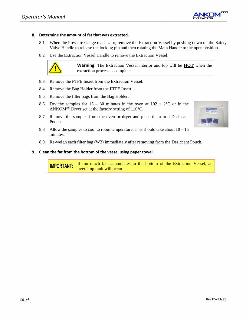
8.6 Dry the samples for 15 – 30 minutes in the oven at 102 ± 2°C or in the
ANKOMRD Dryer set at the factory setting of 110°C.
8.7 Remove the samples from the oven or dryer and place them in a Desiccant
Pouch.
8.8 Allow the samples to cool to room temperature. This should take about 10 – 15
minutes.
8.9 Re-weigh each filter bag (W3) immediately after removing from the Desiccant Pouch.
9. Clean the fat from the bottom of the vessel using paper towel.
If too much fat accumulates in the bottom of the Extraction Vessel, an
overtemp fault will occur.
Operator’s Manual
Rev 05/13/21 pg. 25
Periodic Maintenance
Cleaning the Extraction Vessel
Some compounds extracted during the fat extraction procedure can create a black residue in the bottom of the
Extraction Vessel. The vessel can most easily be cleaned by using a drill with a long shafted stiff wire brush (ANKOM
part # X107). This treatment will remove a lot of the black coating that accumulates on the bottom of the vessel.
When the vessel bottom is clean, put some solvent on a cloth or paper towel and wipe down the inside of the vessel
in an effort to remove any oil residue and particles that have been loosened from the vessel bottom.
Do not use soap and/or water to clean the vessel. When cleaning the vessel,
do not damage the level sensor tip. The tip may be cleaned with window
cleaner or alcohol.
Cleaning the exterior of the instrument
Wipe the outside of the instrument with window cleaner or a damp sponge as necessary.
Do not use Acetone to clean the instrument.
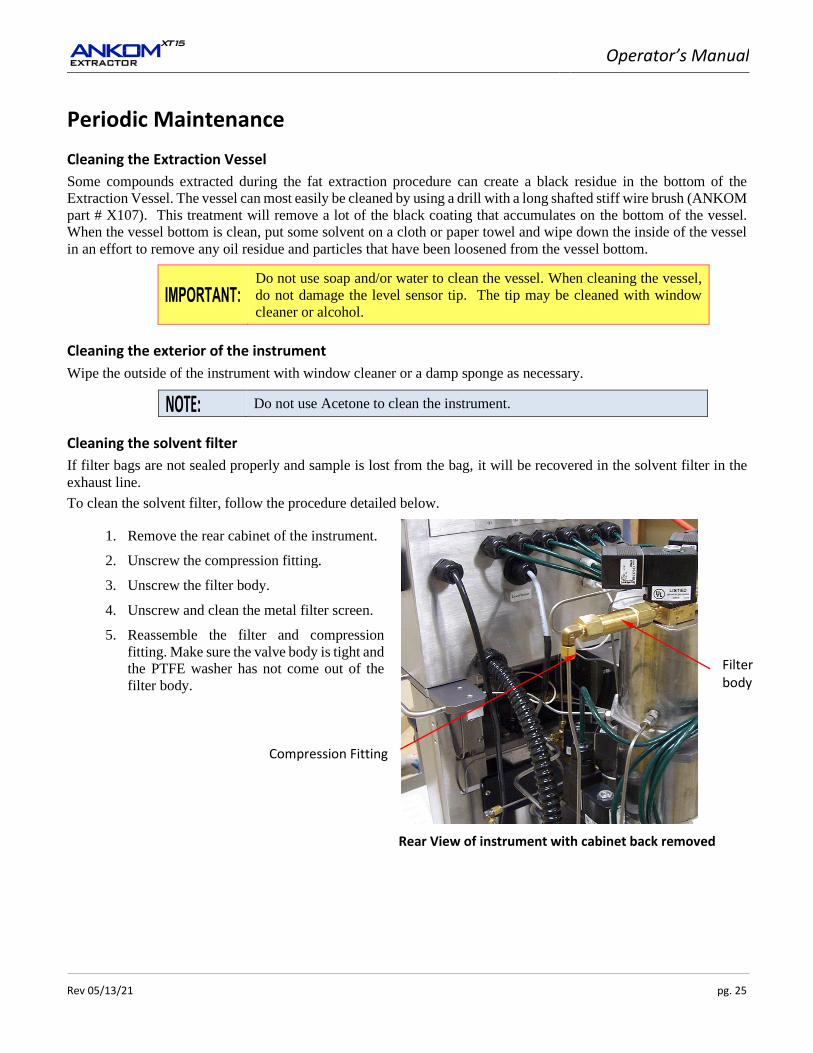
Cleaning the solvent filter
If filter bags are not sealed properly and sample is lost from the bag, it will be recovered in the solvent filter in the
exhaust line.
To clean the solvent filter, follow the procedure detailed below.
1. Remove the rear cabinet of the instrument.
Rear View of instrument with cabinet back removed
2. Unscrew the compression fitting.
3. Unscrew the filter body.
4. Unscrew and clean the metal filter screen.
5. Reassemble the filter and compression
fitting. Make sure the valve body is tight and
the PTFE washer has not come out of the
filter body.
Compression Fitting
Filter body
Operator’s Manual
pg. 26 Rev 05/13/21
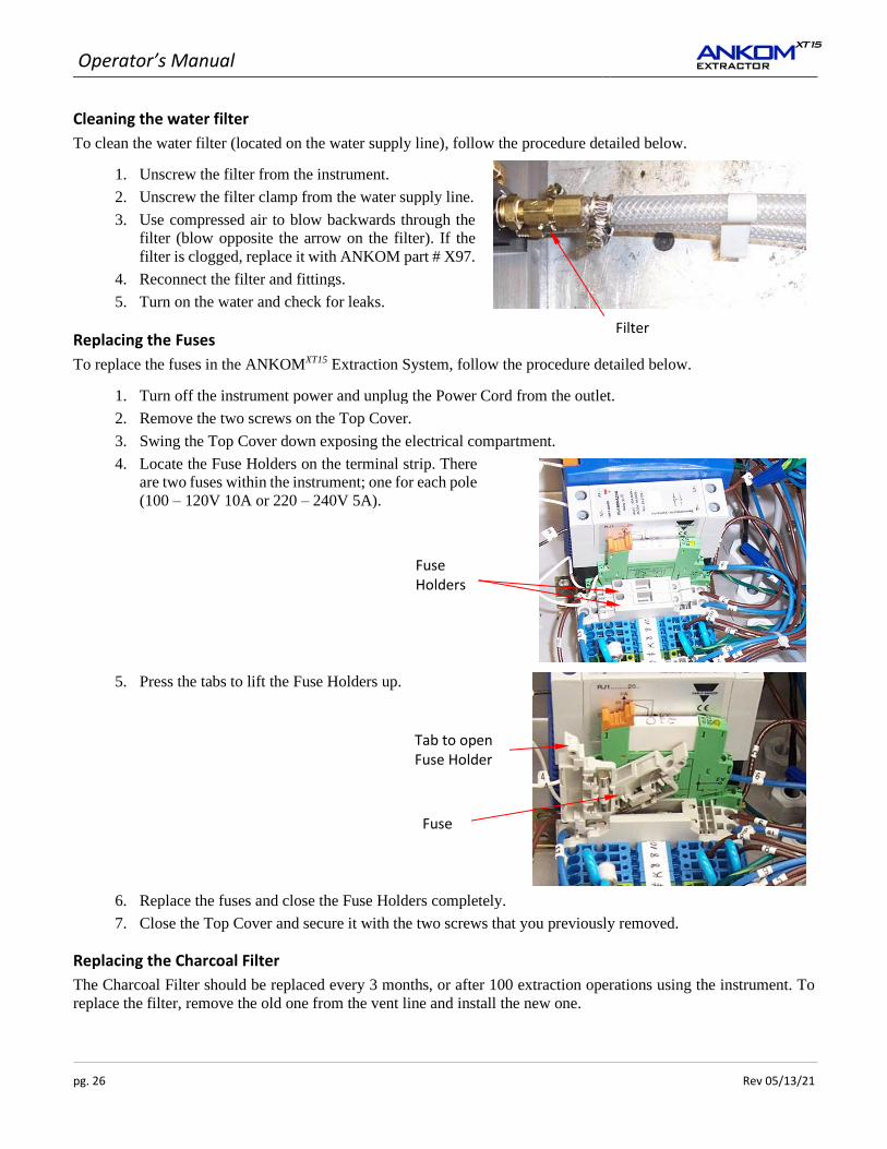
Cleaning the water filter
To clean the water filter (located on the water supply line), follow the procedure detailed below.
1. Unscrew the filter from the instrument.
2. Unscrew the filter clamp from the water supply line.
3. Use compressed air to blow backwards through the
filter (blow opposite the arrow on the filter). If the
filter is clogged, replace it with ANKOM part # X97.
4. Reconnect the filter and fittings.
5. Turn on the water and check for leaks.
Replacing the Fuses
To replace the fuses in the ANKOMXT15 Extraction System, follow the procedure detailed below.
1. Turn off the instrument power and unplug the Power Cord from the outlet.
2. Remove the two screws on the Top Cover.
3. Swing the Top Cover down exposing the electrical compartment.
4. Locate the Fuse Holders on the terminal strip. There
are two fuses within the instrument; one for each pole
(100 – 120V 10A or 220 – 240V 5A).
5. Press the tabs to lift the Fuse Holders up.
6. Replace the fuses and close the Fuse Holders completely.
7. Close the Top Cover and secure it with the two screws that you previously removed.
Replacing the Charcoal Filter
The Charcoal Filter should be replaced every 3 months, or after 100 extraction operations using the instrument. To
replace the filter, remove the old one from the vent line and install the new one.
Fuse Holders
Tab to open Fuse Holder
Fuse
Filter

Operator’s Manual
Rev 05/13/21 pg. 27
Troubleshooting & Replacement Parts
The ANKOM technology web site has the most current troubleshooting and replacement parts information.
Therefore, if you have any questions about the operation of your ANKOMXT15 Extraction System, or if you need
replacement parts, please visit our web site at www.ankom.com.

Operator’s Manual
pg. 28 Rev 05/13/21
This page intentionally left blank
Operator’s Manual
Rev 05/13/21 pg. 29
Diagnostics
To help solve problems that may occur while running the ANKOMXT15 Extractor, the following computer controlled
Diagnostics are available and accessible through the Display and Keypad.
1. Toggle Outputs (Q0 Heater Relay and Q1 - Q7 valves)
2. Check Temperature and Level Sensors
3. Check the state of the ETS (Emergency Temperature Shut-off switch) relay
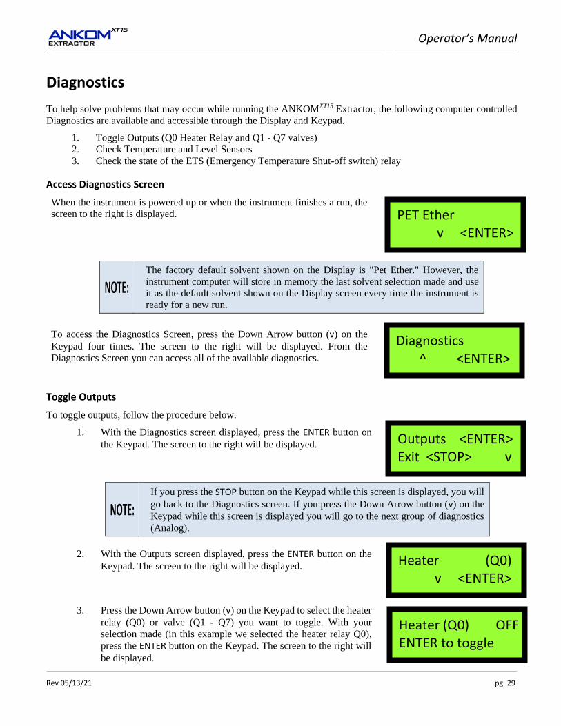
Access Diagnostics Screen
When the instrument is powered up or when the instrument finishes a run, the
screen to the right is displayed.
The factory default solvent shown on the Display is "Pet Ether." However, the
instrument computer will store in memory the last solvent selection made and use
it as the default solvent shown on the Display screen every time the instrument is
ready for a new run.
To access the Diagnostics Screen, press the Down Arrow button (v) on the
Keypad four times. The screen to the right will be displayed. From the
Diagnostics Screen you can access all of the available diagnostics.
Toggle Outputs
To toggle outputs, follow the procedure below.
1. With the Diagnostics screen displayed, press the ENTER button on
the Keypad. The screen to the right will be displayed.
If you press the STOP button on the Keypad while this screen is displayed, you will
go back to the Diagnostics screen. If you press the Down Arrow button (v) on the
Keypad while this screen is displayed you will go to the next group of diagnostics
(Analog).
2. With the Outputs screen displayed, press the ENTER button on the
Keypad. The screen to the right will be displayed.
3. Press the Down Arrow button (v) on the Keypad to select the heater
relay (Q0) or valve (Q1 - Q7) you want to toggle. With your
selection made (in this example we selected the heater relay Q0),
press the ENTER button on the Keypad. The screen to the right will
be displayed.
PET Ether v <ENTER>
Diagnostics ^ <ENTER>
Outputs <ENTER> Exit <STOP> v
Heater (Q0) v <ENTER>
Heater (Q0) OFF ENTER to toggle
Operator’s Manual
pg. 30 Rev 05/13/21
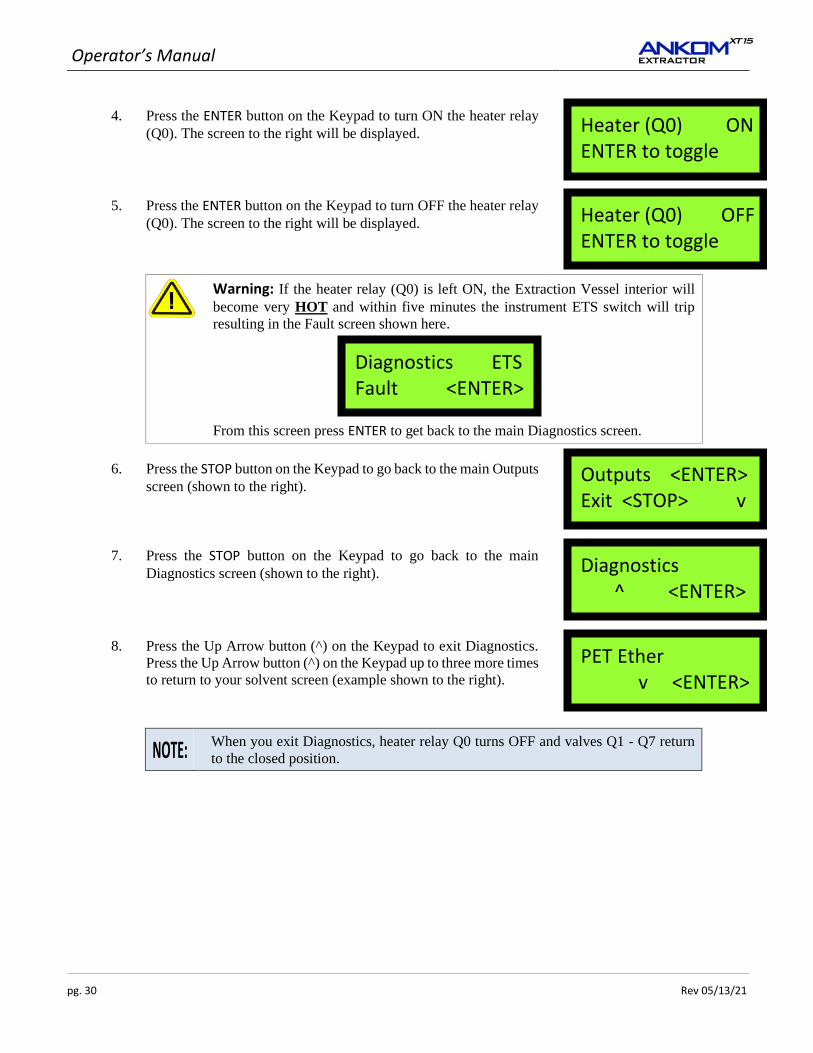
4. Press the ENTER button on the Keypad to turn ON the heater relay
(Q0). The screen to the right will be displayed.
5. Press the ENTER button on the Keypad to turn OFF the heater relay
(Q0). The screen to the right will be displayed.
Warning: If the heater relay (Q0) is left ON, the Extraction Vessel interior will
become very HOT and within five minutes the instrument ETS switch will trip
resulting in the Fault screen shown here.
From this screen press ENTER to get back to the main Diagnostics screen.
6. Press the STOP button on the Keypad to go back to the main Outputs
screen (shown to the right).
7. Press the STOP button on the Keypad to go back to the main
Diagnostics screen (shown to the right).
8. Press the Up Arrow button (^) on the Keypad to exit Diagnostics.
Press the Up Arrow button (^) on the Keypad up to three more times
to return to your solvent screen (example shown to the right).
When you exit Diagnostics, heater relay Q0 turns OFF and valves Q1 - Q7 return
to the closed position.
Heater (Q0) ON ENTER to toggle
Heater (Q0) OFF ENTER to toggle
Diagnostics ETS Fault <ENTER>
Outputs <ENTER> Exit <STOP> v
Diagnostics ^ <ENTER>
PET Ether v <ENTER>
Operator’s Manual
Rev 05/13/21 pg. 31
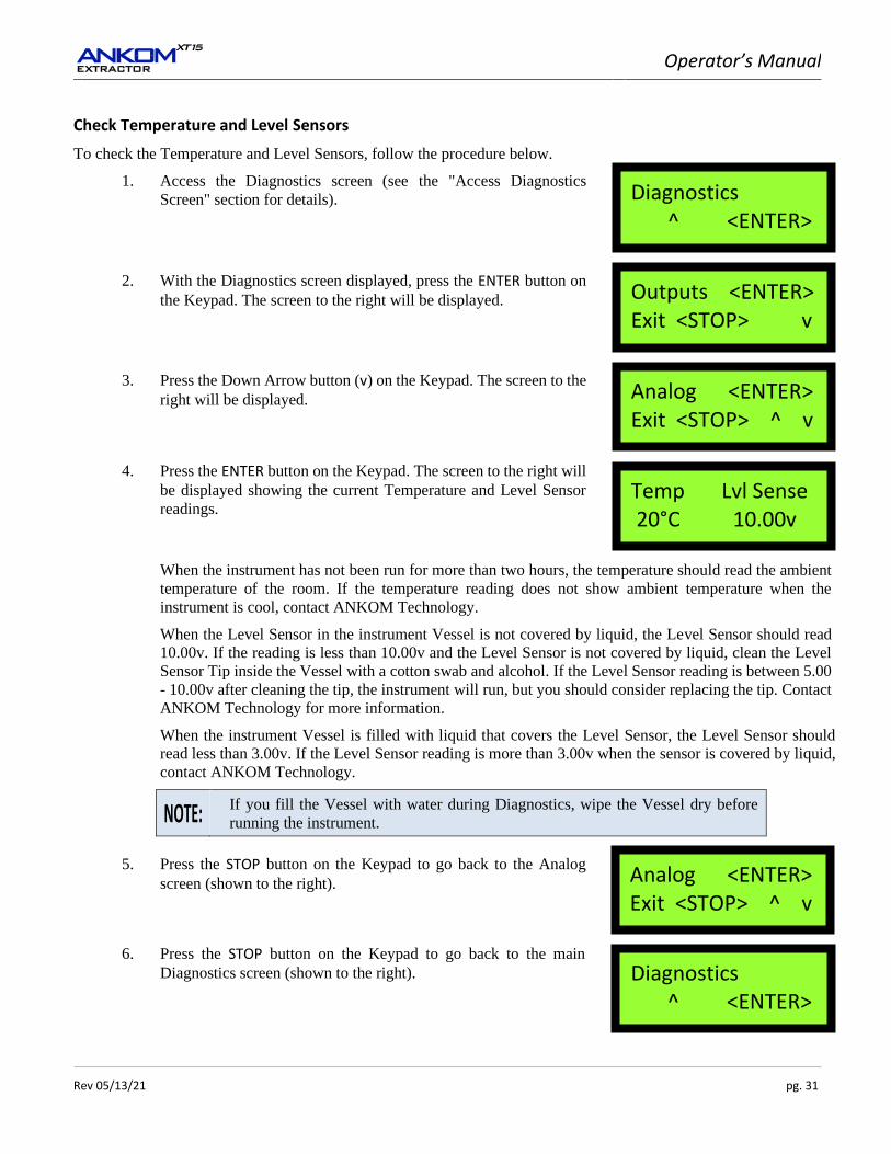
Check Temperature and Level Sensors
To check the Temperature and Level Sensors, follow the procedure below.
1. Access the Diagnostics screen (see the "Access Diagnostics
Screen" section for details).
2. With the Diagnostics screen displayed, press the ENTER button on
the Keypad. The screen to the right will be displayed.
3. Press the Down Arrow button (v) on the Keypad. The screen to the
right will be displayed.
4. Press the ENTER button on the Keypad. The screen to the right will
be displayed showing the current Temperature and Level Sensor
readings.
When the instrument has not been run for more than two hours, the temperature should read the ambient
temperature of the room. If the temperature reading does not show ambient temperature when the
instrument is cool, contact ANKOM Technology.
When the Level Sensor in the instrument Vessel is not covered by liquid, the Level Sensor should read
10.00v. If the reading is less than 10.00v and the Level Sensor is not covered by liquid, clean the Level
Sensor Tip inside the Vessel with a cotton swab and alcohol. If the Level Sensor reading is between 5.00
- 10.00v after cleaning the tip, the instrument will run, but you should consider replacing the tip. Contact
ANKOM Technology for more information.
When the instrument Vessel is filled with liquid that covers the Level Sensor, the Level Sensor should
read less than 3.00v. If the Level Sensor reading is more than 3.00v when the sensor is covered by liquid,
contact ANKOM Technology.
If you fill the Vessel with water during Diagnostics, wipe the Vessel dry before
running the instrument.
5. Press the STOP button on the Keypad to go back to the Analog
screen (shown to the right).
6. Press the STOP button on the Keypad to go back to the main
Diagnostics screen (shown to the right).
Diagnostics ^ <ENTER>
Outputs <ENTER> Exit <STOP> v
Analog <ENTER> Exit <STOP> ^ v
Temp Lvl Sense 20°C 10.00v
Analog <ENTER> Exit <STOP> ^ v
Diagnostics ^ <ENTER>
Operator’s Manual
pg. 32 Rev 05/13/21
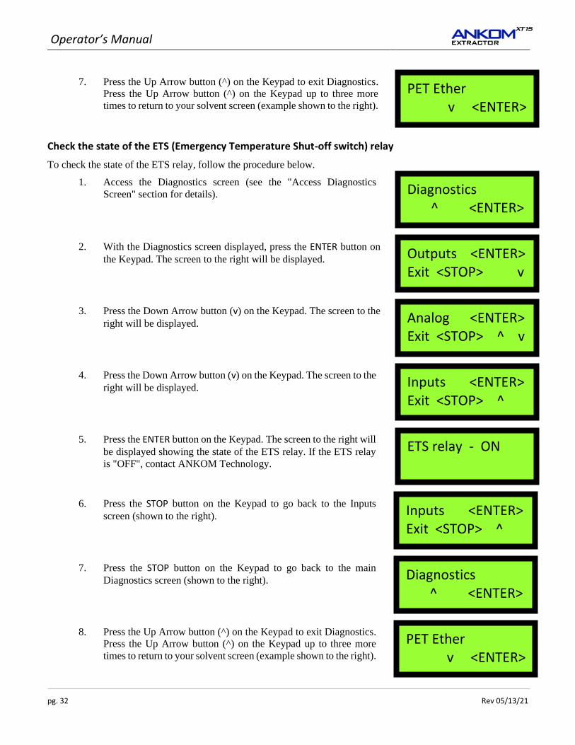
7. Press the Up Arrow button (^) on the Keypad to exit Diagnostics.
Press the Up Arrow button (^) on the Keypad up to three more
times to return to your solvent screen (example shown to the right).
Check the state of the ETS (Emergency Temperature Shut-off switch) relay
To check the state of the ETS relay, follow the procedure below.
1. Access the Diagnostics screen (see the "Access Diagnostics
Screen" section for details).
2. With the Diagnostics screen displayed, press the ENTER button on
the Keypad. The screen to the right will be displayed.
3. Press the Down Arrow button (v) on the Keypad. The screen to the
right will be displayed.
4. Press the Down Arrow button (v) on the Keypad. The screen to the
right will be displayed.
5. Press the ENTER button on the Keypad. The screen to the right will
be displayed showing the state of the ETS relay. If the ETS relay
is "OFF", contact ANKOM Technology.
6. Press the STOP button on the Keypad to go back to the Inputs
screen (shown to the right).
7. Press the STOP button on the Keypad to go back to the main
Diagnostics screen (shown to the right).
8. Press the Up Arrow button (^) on the Keypad to exit Diagnostics.
Press the Up Arrow button (^) on the Keypad up to three more
times to return to your solvent screen (example shown to the right).
PET Ether v <ENTER>
Diagnostics ^ <ENTER>
Outputs <ENTER> Exit <STOP> v
Analog <ENTER> Exit <STOP> ^ v
Inputs <ENTER> Exit <STOP> ^
ETS relay - ON
Inputs <ENTER> Exit <STOP> ^
Diagnostics ^ <ENTER>
PET Ether v <ENTER>
Operator’s Manual
Rev 05/13/21 pg. 33
Appendix A- Analytical Procedure
IMPORTANT: While infrequent, procedures may be updated with new information. For the most up-to-date
procedure revision refer to: https://www.ankom.com/analytical-methods-support/ankom-xt15-extractor
Rapid Determination of Oil/Fat Utilizing High Temperature Solvent Extraction
Analytical procedure- XT10/XT10i/XT15/XT15i
Definition
This method determines crude fat by extraction with petroleum ether or other common fat solvents. The compounds extracted are predominantly triacylglycerides along with small amounts of other lipids.
Scope
This method is applicable to solid processed foods with 0-100% fat content.
Abstract
AOCS AM 5-04 is used for the determination of crude fat in grains, cereals, meats, pet foods, mixed feeds, forages, oilseeds and other processed foods. The process uses the Soxhlet principle in a closed stainless steel extraction vessel allowing solvent temperatures to exceed solvent boiling points. This improves the kinetics and reduces extraction times. Up to 15 samples are encapsulated in XT4 filter bags and placed in a specially designed siphoning carrier that is secured in the extraction vessel. The instrument will automatically perform all of the necessary procedural steps to complete the extraction and recycle the solvent, ready for reuse. Extracted samples are dried for approximately 30 minutes, reweighed and fat content determined by loss of weight.
Complete operational details are available in the ANKOM User Manuals.
AOCS Am 5-04 can be obtained directly from AOCS
Operator’s Manual
pg. 34 Rev 05/13/21
Oilseed Extractions (FOSFA comparable) - XT10/XT10I and XT15/XT15I
The technique we use in the extraction of oilseeds is as follows:
1. Place 1.5 to 2.0 g of sample into the XT4 Filter Bag.
2. Dry the samples for three hours at 100o - 105o C.
3. Remove the samples from the oven and place them in a desiccant pouch, allow them to cool and record their weights.
4. Extract the samples in an ANKOM XT instrument for forty minutes.
5. Dry the samples for thirty minutes at 100o - 105o C.
6. Remove the samples from the oven and place them in a desiccant pouch, allow them to cool, and record their weights.
7. Place one XT4 Filter Bag (with sample) into a mortar and strike it with a pestle approximately 15-20 times being careful not to twist the pestle. There does not need to be a great deal of force when the pestle strikes the Filter Bag. Repeat for all Filter Bags.
8. Repeat steps 4-7 two more times (for a total of three times).
9. Add the three fat values together to get a combined fat total.
Operator’s Manual
Rev 05/13/21 pg. 35
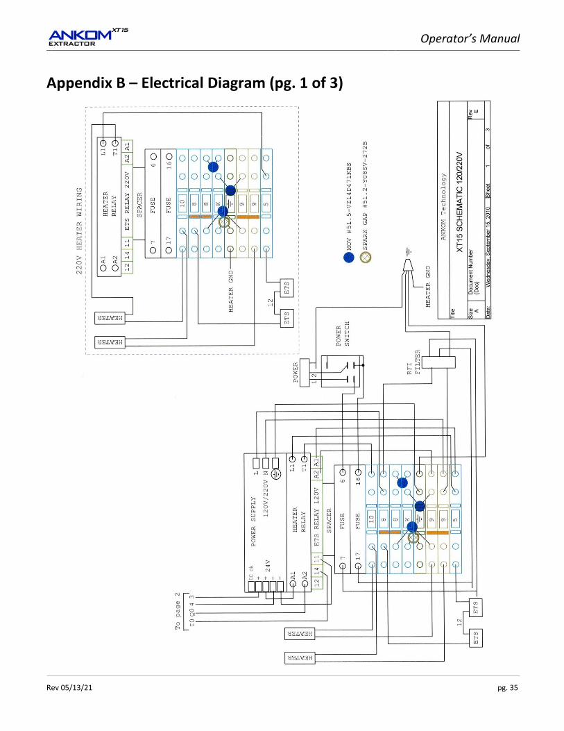
Appendix B – Electrical Diagram (pg. 1 of 3)
Operator’s Manual
pg. 36 Rev 05/13/21
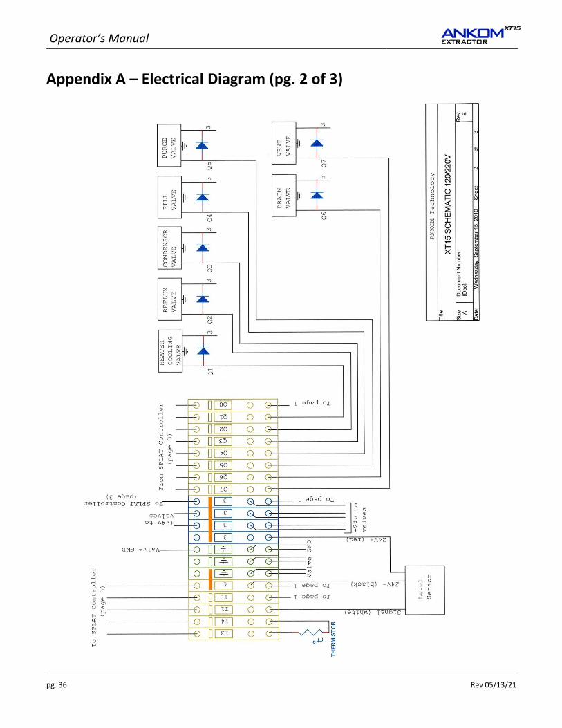
Appendix A – Electrical Diagram (pg. 2 of 3)
Operator’s Manual
Rev 05/13/21 pg. 37
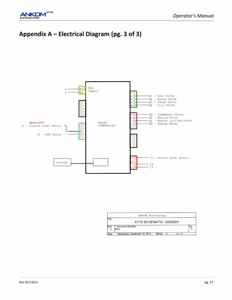
Appendix A – Electrical Diagram (pg. 3 of 3)
I1 – Analog Level Sensor
(Before 2017) I1 – Digital Level Sensor
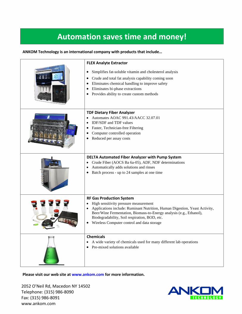
Automation saves time and money!
ANKOM Technology is an international company with products that include…
FLEX Analyte Extractor
• Simplifies fat-soluble vitamin and cholesterol analysis
• Crude and total fat analysis capability coming soon • Eliminates chemical handling to improve safety • Eliminates bi-phase extractions • Provides ability to create custom methods
TDF Dietary Fiber Analyzer • Automates AOAC 991.43/AACC 32.07.01
• IDF/SDF and TDF values
• Faster, Technician-free Filtering • Computer controlled operation • Reduced per assay costs
DELTA Automated Fiber Analyzer with Pump System • Crude Fiber (AOCS Ba 6a-05), ADF, NDF determinations
• Automatically adds solutions and rinses
• Batch process - up to 24 samples at one time
RF Gas Production System • High sensitivity pressure measurement
• Applications include: Ruminant Nutrition, Human Digestion, Yeast Activity,
Beer/Wine Fermentation, Biomass-to-Energy analysis (e.g., Ethanol),
Biodegradability, Soil respiration, BOD, etc.
• Wireless Computer control and data storage
Chemicals • A wide variety of chemicals used for many different lab operations
• Pre-mixed solutions available
Please visit our web site at www.ankom.com for more information.
2052 O’Neil Rd, Macedon NY 14502 Telephone: (315) 986-8090 Fax: (315) 986-8091 www.ankom.com
Related Documents