Operator’s Manual Serial number range First Edition First Printing Part No. 57.0303.5115 With Maintenance Information 500L Loading Shovel.................from serial n: 52730 800L Loading Shovel.................from serial n: 52584 Brick-Holder Basket..................from serial n: 52981 250L Mixing Bucket..................from serial n: 53993 500L Mixing Bucket..................from serial n: 54207 500L Man. Concrete Bucket...from serial n: 53019 500L Hyd. Concrete Bucket...from serial n: 53143 800L Man. Concrete Bucket...from serial n: 52988 800L Hyd. Concrete Bucket...from serial n: 53058

Welcome message from author
This document is posted to help you gain knowledge. Please leave a comment to let me know what you think about it! Share it to your friends and learn new things together.
Transcript

Operator’s Manual
Serial number range
First Edition
First Printing
Part No. 57.0303.5115
With Maintenance
Information
500L Loading Shovel.................from serial n: 52730
800L Loading Shovel.................from serial n: 52584
Brick-Holder Basket..................from serial n: 52981
250L Mixing Bucket..................from serial n: 53993
500L Mixing Bucket..................from serial n: 54207
500L Man. Concrete Bucket...from serial n: 53019
500L Hyd. Concrete Bucket...from serial n: 53143
800L Man. Concrete Bucket...from serial n: 52988
800L Hyd. Concrete Bucket...from serial n: 53058

Operator’s Manual
2 BUCKET - BASKET Part No. 57.0303.5115
First Edition - First Printing
Contact us:ZONA INDUSTRIALE I-06019 UMBERTIDE (PG) - ITALYTelephone +39 075 941811Telefax +39 075 9415382
Technical Assistance ServiceTelephone: +39 075 9418129 +39 075 9418175e-mail: [email protected]
ImportantRead, understand and obey these safety rules and operating instructions before operating the machine. Only trained and qualified personnel shall be authorized to operate the machine. This manual shall be kept with the machine at all times.
For any further information, please call Terexlift.
Contents
Introduction ..........................................Page 3Equipment Identification ......................Page 5Labels And Plates Applied...................Page 7Safety Precautions ..............................Page 9 Equipment Description ..........................Page 17 Inspections ..........................................Page 21 Operating Instructions .........................Page 25 Maintenance ........................................Page 55 Specifications ......................................Page 59 Load Charts .........................................Page 67 Diagrams And Schemes ......................Page 103EC Declaration of Conformity ..............Page 105 Warranty ..............................................Page 107
Original Instructions First Edition: First Printing, May 2010
For the electronic version of this manual visit www.genielift.com/operator_manuals.asp
Copyright © 2010 TEREXLIFT srlAll rights reserved
Produced by: TEREXLIFT Technical Literature Dept.Umbertide (PG) Italy

First Edition - First Printing Operator’s Manual
Part No. 57.0303.5115 BUCKET - BASKET 3
Introduction
Symbols
Safety alert symbol: used to alert you to potential personal injury hazards. Obey all safety messages that follow this symbol to avoid possible injury or death
DANGER Red: indicates a hazardous situation which, if not avoided, will result in death or serious injury.
WARNING Orange: indicates a hazardous situation which, if not avoided, could result in death or serious injury.
CAUTION Yellow : indicates a hazardous situation which, if not avoided, could result in minor or moderate injury.
NOTICE Blue: indicates a hazardous situation which, if not avoided, could result in property damage.
PROTECT THEENVIRONMENT Green: used to draw the
a t tent ion to important information on environment protection.

Operator’s Manual
4 BUCKET - BASKET Part No. 57.0303.5115
First Edition - First Printing
Intentionally blank page

First Edition - First Printing Operator’s Manual
Part No. 57.0303.5115 BUCKET - BASKET 5
Check that the Operator's Manual refers to the delivered equipment.
DESIGNATION: LOADING SHOVEL
BRICK-HOLDER BASKET MIXING BUCKET
CONCRETE BUCKET
MODEL: 500L Loading Shovel 800L Loading Shovel Brick-Holder Basket 250L Mixing Bucket 500L Mixing Bucket
500L Man. Concrete Bucket 500L Hyd. Concrete Bucket 800L Man. Concrete Bucket 800L Hyd. Concrete Bucket
MANUFACTURER:
TEREXLIFT srlZona Industriale - I-06019 UMBERTIDE (PG) - ITALY
Enrolled in the register of companies at the Court of Perugia under no. 4823
C.C.I.A.A. 102886
Fiscal Code/V.A.T. no. 00249210543
Equipment Identification
Model:
Model Year:
Designation:
Serial number:
Manufacture Year:
Manufacturer:Terexlift srl z.i.Buzzacchero06019 Umbertide, Italy
MMMMMMMMMMMMMMMMMMMMMMMMMMMMMM
AAAA
MMMMMMMMMMMMMMMMMMMMMMMMMMMMMM
AAAAAAAAAA
AAAA
AAAAAAAAA
MMMMMMMMM
AAAAAAAAA
Country of Manufacture: ITALY
Unit mass (Kg) :
Rated capacity:
Center of gravity from mounting face (mm):
MMMMMMMMMMMMMMMMMMMMMMMMMMMMMM
MMMM
APPLICABLE STANDARDSFor the operator’s safety, the following standards were obeyed during the risk assessment of the handler fitted with telescopic boom norme:
Directive Title
2006/42/EC Machinery Directive
Standard TitleEN 1459:1988/A2:2009 Safety of Industrial trucks -
Self- propelled variable reach trucks.
IDENTIFICATION PLATEThe following data plate is applied on the equipment.
The identification plate contains model, designation, serial number, weight, payload and year of manufacture, as shown below.

Operator’s Manual
6 BUCKET - BASKET Part No. 57.0303.5115
First Edition - First Printing
Intentionally blank page

First Edition - First Printing Operator’s Manual
Part No. 57.0303.5115 BUCKET - BASKET 7
Labels And Plates Applied
09.4618.1352
800 Kg09.4618.1353
09.4618.1354
09.4618.1355
Model:
Model Year:
Designation:
Serial number:
Manufacture Year:
Manufacturer:Terexlift srl z.i.Buzzacchero06019 Umbertide, Italy
MMMMMMMMMMMMMMMMMMMMMMMMMMMMMM
AAAA
MMMMMMMMMMMMMMMMMMMMMMMMMMMMMM
AAAAAAAAAA
AAAA
AAAAAAAAA
MMMMMMMMM
AAAAAAAAA
Country of Manufacture: ITALY
Unit mass (Kg) :
Rated capacity:
Center of gravity from mounting face (mm):
MMMMMMMMMMMMMMMMMMMMMMMMMMMMMM
MMMM

Operator’s Manual
8 BUCKET - BASKET Part No. 57.0303.5115
First Edition - First Printing
Intentionally blank page

First Edition - First Printing Operator’s Manual
Part No. 57.0303.5115 BUCKET - BASKET 9
DAMAGED MACHINE HAZARDS
• Do not use a damaged or defective equipment.• Do a thorough pre-operation inspection of the
equipment and test all functions before each work shift. Tag and remove from service a damaged or defective equipment.
• Make sure that all maintenance jobs have been carried out as specified in this manual and in the telehandler's specific manuals.
• Make sure that all plates are in place and legible.• Make sure that the operator’s manual is intact,
legible and placed in the special container located in the machine.
PERSONAL INJURY HAZARDS
• Do not operate the equipment in case of hydraulic oil or air leak of the telehandler. Air or hydraulic oil leaks can penetrate or burn the skin.
• Always operate the telehandler in a well ventilated area to avoid carbon monoxide poisoning.
• Do not lower the boom if the area underneath is not clear of personnel or obstructions.
SAFETY DEVICES
Several safety devices have been fitted to the telehandler. They must never be tampered with or removed.Regularly check the efficiency of such devices.In case of faults, stop working immediately and proceed in replacing the defective device.For the checking procedures, read chap. "Maintenance" of the telehandler Operator's Manual.
MOMENT LIMITING SYSTEM
The moment limiting system has been developed to help the operator to maintain the telehandler longitudinal stability. Audible and visual messages are provided when the limits of longitudinal stability are being approached.However this device cannot replace the experience of the operator. It is up to the user to adopt the necessary safety measures to work within the rated limits of the machine.
Safety Precautions

Operator’s Manual
10 BUCKET - BASKET Part No. 57.0303.5115
First Edition - First Printing
GENERAL REMARKS
Most accidents occurring while working, repairing or maintaining machines, are caused by not complying with the basic safety precautions.Therefore, it is necessary to pay steady attention to the potential hazards and the effects that may come of operations carried out on the telehandler.
If you recognise hazardous situations, you can prevent accidents!
DANGERThe instructions given in this handbook are the ones established by TEREXLIFT. They do not exclude other safe and most convenient ways for the telehandler and/or the equipment installation, operation and maintenance that take into account the available spaces and means.
If you decide to follow instructions other than those given in this manual, you shall absolutely:• be sure that the operations you are going to carry
out are not explicitly forbidden;• be sure that the methods are safe, say, in
compliance with the rules and provisions given in this section;
• be sure that the methods cannot damage the telehandler and/or the equipment, directly or indirectly, or make it unsafe;
• contact TEREXLIFT Assistance Service for any suggestion and the necessary written permission.
Not observing the instructions and safety rules in this manual may result in death or serious injury.
Do not operate the equipment unless:
• You learn and practice the principles of safe work equipment operation contained in this operator’s manual.1. Avoid hazardous situations. Read and
understand the safety instructions before going on to the next chapter.
2. Always perform a pre-operation inspection.3. Always test the equipment functions prior
to use.4. Inspect the work place.5. Only use the equipment for the intended
application. • Read, understand and obey the manufacturer’s
instructions and the safety rules, the safety and operator’s manuals, and the decals applied on the equipment.
• Read, understand and obey the employer’s safety rules and worksite regulations.
• Read, understand and obey the applicable national regulations.
• Only trained personnel informed on the safety rules can operate the equipment.
Safety Precautions
NOTICE
First Edition - First Printing Operator’s Manual
Part No. 57.0303.5115 BUCKET - BASKET 11
REQUISITES OF THE PERSONNEL IN CHARGE
Requisites of the TELEHANDLER OPERATORSThe operators who use the telehandler and/or the equipment, regularly or occasionally, shall have the following prerequisites:health: before and during any operation, operators shall never take alcoholic beverages, medicines or other substances that may alter their psycho-physical conditions and, consequently, their working abilities.physical: good eyesight, acute hearing, good co-ordination and ability to carry out all required operations in a safe way, according to the instructions of this manual.mental: ability to understand and apply the enforced rules, regulations and safety precautions. They shall be careful and sensible for their own as well as for the others’ safety and shall desire to carry out the work correctly and in a responsible way.emotional: they shall keep calm and always be able to evaluate their own physical and mental conditions.training: they shall read and be familiar with this handbook, its enclosed graphs and diagrams. They shall be skilled and trained about the telehandler and/or the equipment use.
NOTICEThe operator shall have a licence (or a driving licence) when provided for by the laws enforced in the country where the machine works. Please, ask the competent bodies.
Requisites of the SERVICEMENThe personnel charged with the telehandler and the equipment maintenance shall be qualified, specialized in their maintenance, and shall have the following prerequisites:physical: good eyesight, acute hearing, good co-ordination and ability to carry out all required maintenance operations in a safe way, according to this manual.mental: ability to understand and apply the enforced rules, regulations and safety precautions. They shall be careful and sensible for their own as well as for the others’ safety and shall desire to carry out the work correctly and in a responsible way.training: they shall read and be familiar with this handbook, its enclosed graphs and diagrams, the identification and warning plates. They shall be skilled and trained about the machine functioning.
NOTICEFrom a technical point of view, the ordinary maintenance of the telehandler and/or the equipment is not a complex intervention and can be carried out by the operator too, provided he has a basic knowledge of mechanics.
Safety Precautions

Operator’s Manual
12 BUCKET - BASKET Part No. 57.0303.5115
First Edition - First Printing
WORKING CLOTHESDuring work, but especially when maintaining or repairing the machine, operators must wear suitable protective clothing:• Overalls or any other comfortable garments.
Operators should not wear clothes with large sleeves or objects that can get stuck in moving parts of the machine.
• Ear-protectors or equivalent equipment.• Protective helmet.• Protective gloves.• Working shoes.
OTHER DANGERS Hazards on the JOBSITE
Always take into account the features of the job site where you are going to work:• Always examine the working area and compare
it with the telehandler dimensions in the different configurations.
DANGERThe telehandler is not electrically insulated and does not provide protection from contact with or proximity to electrical power lines.Always keep at a minimum safe distance from the telescopic boom and the lifted load. Electrical hazards!• Keep away from the machine in case of contact
with energized power lines. Personnel on the ground must never touch or operate the telehandler until energized power lines are shut off.
DANGERDo not, at any time, use the machine during a storm.
WARNINGOperator have to survey his/her field of vision when operating the telehandler.
Use only type-approved working clothing in good condition.
Personal PROTECTIVE EQUIPMENTUnder special working conditions, the following personal protective equipment should be used:• Breathing set (or dust mask).• Goggles or facial masks.
DEATH OR INJURY CAN RESULT FROMCONTACTING ELECTRIC POWER LINES.
ALWAYS CONTACT THE ELECTRIC POWER LINESOWNER. THE ELECTRIC POWER SHALL BEDISCONNECTED OR THE POWER LINES MOVEDOR INSULATED BEFORE MACHINE OPERATIONSBEGINPOWER LINE VOLTAGE REQUIRED CLEARANCE
0 to 50 kV 10 ft 3.00 m50 to 200 kV 15 ft 4.60 m
200 to 350 kV 20 ft 6.10 m350 to 500 kV 25 ft 7.62 m500 to 750 kV 35 ft 10.67 m750 to 1000 kV 45 ft 13.72 m
Safety Precautions

First Edition - First Printing Operator’s Manual
Part No. 57.0303.5115 BUCKET - BASKET 13
OPERATION or MAINTENANCE hazardsBefore any operation, following precautions should be taken:• First of all, make sure that the maintenance
interventions have been carried out with care according to the established schedule.
WARNINGSet the telehandler to working configuration and level it.
• Ensure you have enough fuel to avoid a sudden stop of the engine, especially during a crucial manoeuvre.
• Clean instruments, data plates, lights and the cab windscreen thoroughly.
• Check the correct functioning of all the safety devices installed on the telehandler and/or on the equipment.
• In case of troubles or difficulties, inform the foreman at once. Never start working under unsafe conditions.
• Do not carry out any repair work in a makeshift way to start working!
During work, and especially maintenance, always pay the greatest attention:• Do not walk or stop under raised loads or machine
parts supported by hydraulic cylinders or ropes only.
• Keep the machine handholds and access steps always clean from oil, grease or dirt to prevent falls or slips.
Safety Precautions
• When entering/leaving the cab or other raised parts, always face the machine; never turn the back.
• When carrying out operations at hazardous heights (over 1.5 meters from the ground), always use approved fall restraint or fall arrest devices.
• Do not enter/leave the machine while it is running.• Do not leave the driving place when the machine
is running.• Neither stop nor carry out interventions under
or between the machine wheels when engine is running. When maintenance in this area is required, stop the engine.
• Do not carry out maintenance or repair works without a sufficient lighting.
• When using the machine lights, the beam should be oriented in order not to blind the personnel at work.
• Before applying voltage to electric cables or components, check their connection and proper functioning.
• Do not carry out interventions on electric components with voltage over 48V.
• Do not connect wet plugs or sockets.• Plates and hazard warning stickers shall never
be removed, hidden or become unreadable.• Except for maintenance purposes, do not remove
safety devices, shields, protection cases, etc. Should their removal be necessary, stop the engine, remove them with the greatest care and always remember to refit them before starting the engine and using the machine again.
• Before any maintenance or repair work, stop the engine and disconnect the batteries.
• Do not lubricate, clean or adjust moving parts.

Operator’s Manual
14 BUCKET - BASKET Part No. 57.0303.5115
First Edition - First Printing
• Do not carry out operations manually when specific tools are provided for this purpose.
• Avoid the use of tools in bad condition or use in an improper way i.e. pliers instead of adjustable wrenches, etc.
• Applying loads in different points of the attachment holding plate is forbidden.
WARNINGAny intervention on the hydraulic circuit must be carried out by authorised personnel.The hydraulic circuit of this machine is fitted with pressure accumulators. You and others could be seriously injured if accumulators are not completely depressurised.For this purpose, shut the engine down and step on the brake pedal 8/10 times.
Safety Precautions
• When working, do not give instructions or signs to several people at the same time. Instructions and signs must be given by one person only.
• Always pay due attention to the instructions given by the foreman.
• Never distract the operator during working phases or crucial manoeuvres.
• Do no t ca l l an opera tor sudden ly , i f unnecessary.
• Do not frighten an operator or throw objects by any means.
• After work, never leave the machine under potentially dangerous conditions.
• Before any maintenance or repair work, remove the attachment.
MACHINE OPERATION hazardsAbsolutely avoid the following work situations:• Do not handle loads beyond the maximum
capacity of the machine.• Do not raise or extend the boom if the machine
is not on a firm, level surface.• Do not operate the machine in strong wind. Do
not increase the surface area of the machine or forked load exposed to the wind. Increasing the area exposed to the wind will decrease machine stability.
• Use extreme caution and slow speeds when the machine is driven across uneven or unstable grounds, slippery surfaces or near trenches or drop-offs.
• Limit travel speed according to ground conditions, slopes, presence of personnel or other factors which may cause collision.
• Do not place or attach overhanging loads to any part of the machine.
• Before carrying out operations on hydraulic lines under pressure or disconnecting hydraulic components, ensure the relevant line has been previously depressurised and does not contain any hot fluid.
• Do not empty catalytic mufflers or other vessels containing burning materials without taking the necessary precautions.
• After any maintenance or repair work, make sure that no tool, cloth or other object has been left within machine compartments, fitted with moving parts, or where suction and cooling air circulates.

First Edition - First Printing Operator’s Manual
Part No. 57.0303.5115 BUCKET - BASKET 15
EXPLOSION OR FIRE hazards
• Do not start the engine if you smell or detect LPG, gasoline, diesel fuel or other explosive substances.
• Do not refuel the machine with the engine running.
• Refuel the machine and charge the battery only in a well ventilated area away from sparks, naked flames and lighted cigarettes.
• Do not operate the machine in dangerous environments or in places with flammable or explosive gases or materials.
• Do not inject ether in engines equipped with glow plugs.
• Do not leave fuel cans or bottles in unsuitable places.
• Neither smoke nor use open flames in areas subject to fire dangers and in presence of fuel, oil or batteries.
• Carefully handle all flammable or dangerous substances.
• Do not tamper with fire-extinguishers or pressure accumulators.
Safety Precautions
DAMAGED COMPONENT hazards
• Do not use battery chargers or batteries with a voltage above 12V to start the engine.
• Do not use the machine as a ground for welding.
PERSONAL INJURY hazards
• Do not operate the machine in case of hydraulic oil or air leak. Air or hydraulic oil leaks can penetrate or burn the skin.
• Always operate the machine in a well ventilated area to avoid carbon monoxide poisoning.
• Do not lower the boom if the area underneath is not clear of personnel or obstructions.

Operator’s Manual
16 BUCKET - BASKET Part No. 57.0303.5115
First Edition - First Printing
Intentionally blank page

First Edition - First Printing Operator’s Manual
Part No. 57.0303.5115 BUCKET - BASKET 17
Equipment Description
BRICK HOLDER BASKET GENERAL DESCRIPTION
This attachment is designed to handle bricks pallets and to place them where are necessary in the construction working sites. It consists of a main cage made by welded steel square shaped tubes and steel grids preventing any debris exceeding small sizes can accidentally drop from the cage when this is operated at height.A door is hinged on the right side of the cage to make easier the load and unload of the bricks pallets on/from the cage. The door can be secured in the closed position by a dedicated latch. The overall cage is installed on a bottom structure having two rectangular hollow shaped steel tubes working as slots for the telehandlers forks. The longitudinal movement of the cage, when engaged with the forks, is controlled by a chain and a shackle which must be secured before to start any operation with the cage.
NOTICE This equipment is coupled to the telehandler through the forks slots A
�
SHOVEL GENERAL DESCRIPTION
The shovel consists of a welded concave shaped steel structure designed to move and load loose material such as soil, sand debris, cereals, inert material. The main components of this structure are the front blade, which works as the leading edge of the shovel “cutting” the material volume and separating the part which is gathered by the shovel itself, the central concave shell, which provides the volume for the material to be gathered, and the side walls, which laterally close the useful volume of the shovel. On the rear area of the shovel, there are two shaped plates welded to its main structure and designed to be mechanically interfaced with the GTH telehandlers standard attachments articulation. Considering the typical limitation in the maximum rotation of the attachments articulation, the design of the shovel and its mechanical interface with the attachments articulation is optimized to provide the best compromise in terms of material loading and unloading capabilities.
NOTICE This equipment is coupled to the telehandler through the coupling frame B
�
Operator’s Manual
18 BUCKET - BASKET Part No. 57.0303.5115
First Edition - First Printing
Equipment Description
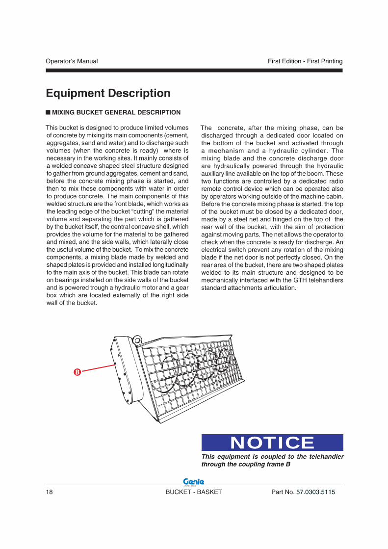
MIXING BUCKET GENERAL DESCRIPTION
This bucket is designed to produce limited volumes of concrete by mixing its main components (cement, aggregates, sand and water) and to discharge such volumes (when the concrete is ready) where is necessary in the working sites. It mainly consists of a welded concave shaped steel structure designed to gather from ground aggregates, cement and sand, before the concrete mixing phase is started, and then to mix these components with water in order to produce concrete. The main components of this welded structure are the front blade, which works as the leading edge of the bucket “cutting” the material volume and separating the part which is gathered by the bucket itself, the central concave shell, which provides the volume for the material to be gathered and mixed, and the side walls, which laterally close the useful volume of the bucket. To mix the concrete components, a mixing blade made by welded and shaped plates is provided and installed longitudinally to the main axis of the bucket. This blade can rotate on bearings installed on the side walls of the bucket and is powered trough a hydraulic motor and a gear box which are located externally of the right side wall of the bucket.
The concrete, after the mixing phase, can be discharged through a dedicated door located on the bottom of the bucket and activated through a mechanism and a hydraulic cylinder. The mixing blade and the concrete discharge door are hydraulically powered through the hydraulic auxiliary line available on the top of the boom. These two functions are controlled by a dedicated radio remote control device which can be operated also by operators working outside of the machine cabin. Before the concrete mixing phase is started, the top of the bucket must be closed by a dedicated door, made by a steel net and hinged on the top of the rear wall of the bucket, with the aim of protection against moving parts. The net allows the operator to check when the concrete is ready for discharge. An electrical switch prevent any rotation of the mixing blade if the net door is not perfectly closed. On the rear area of the bucket, there are two shaped plates welded to its main structure and designed to be mechanically interfaced with the GTH telehandlers standard attachments articulation.
NOTICE This equipment is coupled to the telehandler through the coupling frame B
�

First Edition - First Printing Operator’s Manual
Part No. 57.0303.5115 BUCKET - BASKET 19
Equipment Description
IMPROPER USEImproper use means an utilisation of the equipment following working criteria which do not comply with the instructions of this manual, and which, in general, may result in risks for both operator and bystanders. The compliance with and the strict respect of the use, maintenance and repair instructions of the Manufacturer represent an essential part of the allowed use.
DANGERWe list below some improper use of the buckets/baskets. Others may exist.- Not strictly complying with the operation and
maintenance instructions of this handbook and of the telehandler handbook;
- Never use the buckets/baskets to lift and/or transport people;
- Working beyond the operation limits of the euipment;
- Working the machine resting on unstable or yielding grounds;
- Working on steep slopes or working with a nonlevelled telehandler;
- Fit mobile guards that may increase the wind action and jeopardise the stability of the machine;
- Using telescopic handlers not approved or not manufactured by TEREXLIFT in combination with these attachments;
- Attach loads to the boom anywhere other than on the quick coupling frame.
It is also essential to comply with the national safety at work legislation, the provisions concerning the safety and health of workers at work, and the road traffic regulations.
NOTICEEffecting changes or carrying out interventions on the telehandler and/or on the equipment other than those of routine maintenance is expressly forbidden. Any modification of the telehandler and/or of the equipment not carried out by TEREXLIFT or an authorised assistance centre involves the automatic invalidation of the conformity of the machine.
CONCRETE BUCKET GENERAL DESCRIPTION
The bucket mainly consists of a welded pyramid shaped steel structure designed to handle limited volumes of concrete from one place to another place inside the typical construction working sites and to discharge such volumes of concrete where are necessary. This pyramidal structure is open on the top to allow the concrete to be easily loaded and has a section regularly reducing towards the bottom to make easier the discharge of the concrete. This latter operation is allowed by a dedicated steel door, located on the bottom of the bucket which can be activated by a mechanical lever manually moved by the operator or, according to the models selected, by a mechanical articulation which is hydraulically operated through the hydraulic auxiliary line available on the top of the boom. The overall bucket and door mechanism is installed on a bottom structure having two rectangular hollow shaped steel tubes working as slots for the telehandlers forks. The longitudinal movement of the bucket, when engaged with the forks, is controlled by a chain and a shackle which must be secured before to start any operation with the bucket.
NOTICE This equipment is coupled to the telehandler through the forks slots A
�
Operator’s Manual
20 BUCKET - BASKET Part No. 57.0303.5115
First Edition - First Printing
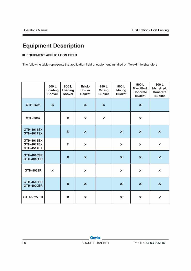
EQUIPMENT APPLICATION FIELD
The following table represents the application field of equipment installed on Terexlift telehandlers
Equipment Description
500 L Loading Shovel
800 L Loading Shovel
Brick-Holder Basket
250 L Mixing Bucket
500 L Mixing Bucket
500 L Man./Hyd.Concrete Bucket
800 L Man./Hyd.Concrete Bucket
GTH-2506
GTH-3007
GTH-4013SXGTH-4017SX
GTH-4013EXGTH-4017EXGTH-4514EX
GTH-4016SRGTH-4018SR
GTH-5022R
GTH-4518ERGTH-4020ER
GTH-6025 ER

First Edition - First Printing Operator’s Manual
Part No. 57.0303.5115 BUCKET - BASKET 21
Inspections
Make sure:
You learn and practice the principles of safe machine operation contained in this operator's manual and in the telehandler one.
1. Avoid hazardous situations.
2. Always perform a pre-operation inspection.
Know and understand the pre-operation inspection before going on to the next section.
3. Always perform function tests prior to use.
4. Inspect the workplace.
5. Only use the telehandler and the equipment as they were intended.
Pre-operation Inspection FundamentalsIt is the responsibility of the operator to perform a pre-operation inspection and routine maintenance.
The pre-operation inspection is a visual inspection performed by the operator prior to each work shift. The inspection is designed to discover if anything is apparently wrong with a telehandler and/or with an equipment before the operator performs the function tests.
The pre-operation inspection also serves to determine if routine maintenance procedures are required. Only routine maintenance items specified in this manual may be performed by the operator.
If damage or any unauthorized variation from factory delivered condition is discovered, the telehandler and/or the equipment must be tagged and removed from service.
Repairs to the telehandler and/or the equipment may only be made by a qualified service technician, according to the manufacturer's specifications. After repairs are completed, the operator must perform a pre-operation inspection again before going on to the function tests.
Scheduled maintenance inspections shall be performed by qualified service technicians, according to the manufacturer's specifications.

Operator’s Manual
22 BUCKET - BASKET Part No. 57.0303.5115
First Edition - First Printing
Inspections PRE-OPERATION INSPECTION
For the Maintenance and the Pre-operation Inspection of the telehandler, refer to the specific Operator's Manual presents placed inside the cabin.
For the equipment:• Make sure the operator’s manuals are intact,
legible and placed inside the telehandler.• Make sure all decals are present and legible. See
“Labels And Plates Applied” chapter.• Check for hydraulic oil leaks and proper oil level.
Top up if necessary. See “Maintenance” chapter.
Check the following components or zones for damage, missing or wrongly fitted parts or non-authorised modifications:
• electrical components and electrical cables• hydraulic hoses and fittings• fuel and hydraulic oil tanks• nuts, bolts and other fasteners
Check the entire structure for: • cracks on welds or structural components • dents or damage to the structure
WARNINGIf even one single item is damaged or defective, do not start work. Stop the machine and repair the fault.
NOTICE If the machine shall be used in a marine or equivalent environment, protect it against salt deposits with an adequate treatment against saltiness to prevent rust formation.

First Edition - First Printing Operator’s Manual
Part No. 57.0303.5115 BUCKET - BASKET 23
Inspections
TESTSAbout the telehandler:1. Select a test area that is firm, level and free of
obstruction.
2. Enter the operator's compartment and sit on the seat.
3. Fasten the seat belt.
4. Adjust all the mirrors.
5. Be sure the parking brake is on and the transmission control is in neutral.
6. Start the engine.
Perform all the tests provided for the telehandler and listed in the machine Operator's Manual.
Test the Control Lever
7. Using the control lever, momentarily lock and unlock the attachment for those telehandlers with hydraulic cylinder
Result: All functions should operate smoothly.
FUNCTION TESTS FUNDAMENTALS
The function tests are designed to discover any malfunctions before the machine is put into service. The operator must follow the step-by-step instructions to test all machine functions. A malfunctioning machine must never be used. If malfunctions are discovered, the machine must be tagged and removed from service. Repairs to the machine may only be made by a qualified service technician, according to the manufacturer's specifications. After repairs are completed, the operator must perform a pre-operation inspection and function tests again before putting the machine into service.
Make sure:
You learn and practice the principles of safe machine operation contained in this operator's manual and in the telehandler one.
1. Avoid hazardous situations.
2. Always perform a pre-operation inspection.
Know and understand the pre-operation inspection before going on to the next section.
3. Always perform function tests prior to use.
4. Inspect the workplace.
5. Only use the telehandler and the equipment as they were intended.
Operator’s Manual
24 BUCKET - BASKET Part No. 57.0303.5115
First Edition - First Printing
WORKPLACE INSPECTION
The workplace inspection helps the operator determine if the workplace is suitable for safe machine operation. It should be performed by the operator prior to moving the machine to the workplace.
It is the operator's responsibility to read and remember the workplace hazards, then watch for and avoid them while moving, setting up and operating the machine
Be aware of and avoid the following hazardous situations:
• drop-offs or holes
• bumps, floor obstructions or debris
• sloped surfaces
• unstable or slippery surfaces
• overhead obstructions and high voltage conductors
• hazardous locations
• inadequate surface support to withstand all load forces imposed by the machine
• wind and weather conditions
• the presence of unauthorized personnel
• other possible unsafe conditions
Inspections

First Edition - First Printing Operator’s Manual
Part No. 57.0303.5115 BUCKET - BASKET 25
Operating Instructions
This section provides the operator and the ground staff a practical guide for the gradual learning of the use of the telehandler fitted with bucket and basket.Both operator and ground staff shall have all the necessary requisites and shall become familiar with both telehandler and equipment before starting using them.This familiarisation ensures a proper use during work.
WARNINGBefore using the telehandler, inspect the job site and check for possible hazardous conditions. Make sure that there are no holes, moving banks or debris that may cause you to lose the control of the machine.
DANGERPay the greatest attention when working close to electric lines. Check their position and ensure that no part of the machine operates at less than 6 meters from the power lines.
WARNINGFor a safe use of the telehandler with equipment, always check the weight of the loads going to be handled.

Operator’s Manual
26 BUCKET - BASKET Part No. 57.0303.5115
First Edition - First Printing
Operating Instructions
WARNINGAfter substitution, visually check the attachment is correctly coupled to the boom, before operating the machine. A wrongly coupled attachment may result in damage to persons or things.
CHANGING THE EQUIPMENT
FOR SHOVEL & MIXING BUCKET
Version with MECHANICAL LOCKING
To change an attachment, operate as follows:• Drive to the place where you will release the
mounted attachment (when possible, a solid and sheltered site).
• Disconnect the quick connectors of the attachment (if any).
• Pull out pin 1 locking the attachment after removing the safety split-pin 2 at its end.
• Rest the attachment flat on the ground.• Pitch the attachment holding frame forward and
lower the boom to release the attachment upper lock.
• Move back with the machine and drive to the new attachment to be coupled.
• Hold the frame pitched forward and hook the upper lock of the new attachment.
• Retract and raise the attachment some centimetres. It will centre automatically on the quick coupling frame.
• Refit pin 1 fixing it with its safety split-pin 2.• Re-couple the connectors of the attachment (if
any).

First Edition - First Printing Operator’s Manual
Part No. 57.0303.5115 BUCKET - BASKET 27
Operating Instructions
Version with HYDRAULIC LOCKING
To change an attachment, operate as follows:• Drive to the place where you will release the
mounted attachment (when possible, a solid and sheltered site).
• Disconnect the quick connectors of the attachment (if any), and connect the hydraulic locking pipes of the attachments to couplings 3.
• Rest the attachment flat on the ground.• Remove the safety pin 2 placed at its end.• Free the attachment operating the control of the
attachment locking/unlocking cylinder• Pitch the attachment holding frame forward and
lower the boom to release the attachment upper lock.
• Move back with the machine and drive to the new attachment to be coupled.
• Hold the frame pitched forward and hook the upper lock of the new attachment.
• Retract and raise the attachment some centimetres. It will centre automatically on the quick coupling frame.
• Operate the attachment locking lever (optional) and secure the attachment in place with safety pin 2 previously removed.
• Re-couple the connectors of the attachment (if any).
FOR CONCRETE BUCKET & BRICK-HOLDER BASKET
Proceed as follow:1. Adjusting the forks: forks shall be spaced to suit
the fork slots position. For this purpose, with FEM forks:• Lift the clamping lever of the forks;• Slide the forks to the desired position, then re-
lock the lever;with FLOATING forks:• Loosen the nut of the locking screws.• Raise the forks and slide them on the pivot until
correct spacing.• Lock the screws re-tightening the nut.2. Loading phase• Approach the equipment to the load to be handled
perpendicularly and check that the machine is level on the inclinometer.
• Insert the forks in the fork slots and raise the equipment some centimetres.
• Pitch the forks back to retract the load.
WARNING• Secure the equipment longitudinal movement,
by the chain with shackle placed at its back, anchoring the equipment to the forks.
Fork the concrete bucket bearing in mind the side where the product will be unloaded.
09.4618.1354

Operator’s Manual
28 BUCKET - BASKET Part No. 57.0303.5115
First Edition - First Printing
Operating Instructions CONNECTING THE EQUIPMENT
Electrical connection (if any)
• Open cover A protecting the boom power socket and connect the cable reel plug B.
• Secure the spring catch C to the special hook to prevent the cable from breaking.
WARNINGThe proper electrical connection of the equipment to the machine is compulsory.
n Hydraulic connection (if any)
To use the equipment, these shall be connected hydraulically as follows:• after mounting the equipment as described
above, disconnect the hydraulic hoselines of the attachment locking/release cylinder from quick couplings 3,
• store the removed hoselines in rest position, • connect the hydraulic hoselines of the winch to
the quick couplings 3.
This hydraulic connection allows the equipment operation that is performed with the controls usually used for locking and releasing the attachments, as described in the relative paragraphes.
�
� �
��
only for SR models

First Edition - First Printing Operator’s Manual
Part No. 57.0303.5115 BUCKET - BASKET 29
Operating Instructions STABILITY CONTROL SYSTEM
All the telehandlers are equipped with an automatic stability control system which warns the operator of the variation of stability of the machine and blocks any manoeuvre before the same reaches a critical condition. A display inside the cabin shows the stability status of the machine and the relative equipment.The system changes according with the telehandler and can easly be recognized depending on the display fitted into the cabin:
MODEL N° 1
1 2 3
4
5 6 7 8
10
9
1. Calibration selection button2. Display3. Stability indicator with LED-bar4. Green light - power OK5. Yellow light - calibration mode6. Calibration confirmation button7. Not used8. Red light - outrigger position 9. Buzzer ON/OFF pushbutton10. Red light - overload pre-alarm/alarm
OperationWhen power is turned on, light 4 comes on. The display 2 remains off and the monitoring system runs a self-test before displaying number 0 on display 2. At this time, the system is activated.During operation, the led-bar 3 lights up gradually depending on the variation of stability.
Green LED’s: during normal operation when the percentage of overturning moment is between 0 and 89, these LED’s are ON. The machine is stable.
Yellow LED’s: they light up when the machine tends to overturn and the percentage of overturning moment with respect to the threshold value is between 90 and 100. The system enters the pre-alarm mode, light 10 flashes and the buzzer sounds with an intermittent sound.
Red LED’s: risk of overturning: the percentage of overturning moment is above 100 with respect to the threshold value. The machine enters the alarm mode: light 10 is lit, the buzzer sounds continuously and any dangerous manoeuvre is blocked. The operator can only retract the load within safety limits.
Alarm codes and resettingThe limiter has diagnostic facilities to aid in the identification of failures of the transducers, breakages of the cables or defects of the electronic system.When a failure is signalled, the limiter enters the safety mode blocking any dangerous manoeuvres. Lights 5, 8 and 10 start flashing, the buzzer start sounding and an error message is shown on the display.The meaning of the error messages is shown in Section “Faults and Troubleshooting” of each telehandler Operator's Manual.
DANGERBefore using the machine, make sure that the first green LED of the overload warning system is ON.

Operator’s Manual
30 BUCKET - BASKET Part No. 57.0303.5115
First Edition - First Printing
Operating Instructions MODEL N°2
1. Test button2. Stability indicator with LED-bar3. Green light - power OK4. Not used5. Buzzer cut off
TEST BUTTON, pushing this button all leds and buzzer are tested: LEDS flash and buzzer sounds for three times.BUZZER CUT OFF, pushing this button buzzer is cut off for 10 seconds.
OperationWhen power is turned on, light 3 comes on. The monitoring system runs a self-test.During operation, the LED-bar 2 lights up gradually depending on the variation of stability.
L1
L2
L3
L4
L5
L6
LED Bar
Green LED’s (L1 and L2): during normal operation when the percentage of overturning moment is between 0 and 89, these LED’s are ON. The machine is stable.
Orange LED’s (L3 and L4): they light up when the machine tends to overturn and the percentage of overturning moment with respect to the threshold value is between 90 and 99. The system enters the pre-alarm mode: the buzzer sounds with an intermittent sound and the boom extraction slows down.
Red LED’s (L5 and L6): risk of overturning! The percentage of overturning moment is above 100 with respect to the threshold value. The machine enters the alarm mode: the buzzer sounds continuously and any dangerous manoeuvre is blocked: boom up, boom down, boom out, forks frame forwards. The operator can only retract the load within safety limits.
Alarm codes and resettingThe limiter has diagnostic facilities to aid in the identification of failures of the transducers, breakages of the cables or defects of the electronic system.When a failure is signalled, the limiter enters the safety mode blocking any dangerous manoeuvres: LED L6 starts flashing in conjuction with another LED which represents the alarm code.The meaning of these alarm codes is shown in section “Faults and Troubleshooting”.
DANGERBefore using the machine, make sure that the first green LED of the overload warning system is ON.

First Edition - First Printing Operator’s Manual
Part No. 57.0303.5115 BUCKET - BASKET 31
Operating Instructions
MODEL N°3
1 Green LED ON Stability condition. The raised load does not
exceed 90% of maximum allowed load of the chart in that defined working position.
2 Yellow LED ON Pre-alarm condition. The raised load exceeds
90% of maximum allowed load, but it is still inferior to it: the boom movements are slow down and the acoustic alarm emits short bips.
3 Red LED ON Alarm condition. The raised load exceeds the
maximum allowed load, the acoustic alarm emits long bips and the machine motions are stopped, but for those allowing to return the load within safety limits.
The display of the limiting device is divided into three areas:
LED’s area: Three LED’s warn of the variation of the working condition: 1 green LED - machine stable 2 yellow LED - machine in pre-alarm 3 red LED - machine in alarm
Control Keys ESC To go back to the previous screen
page ENTER To confirm and open the screen
page linked ARROWS To scroll the lines up or down
PLUS (+) Additional selection button
MINUS (-) Additional selection button
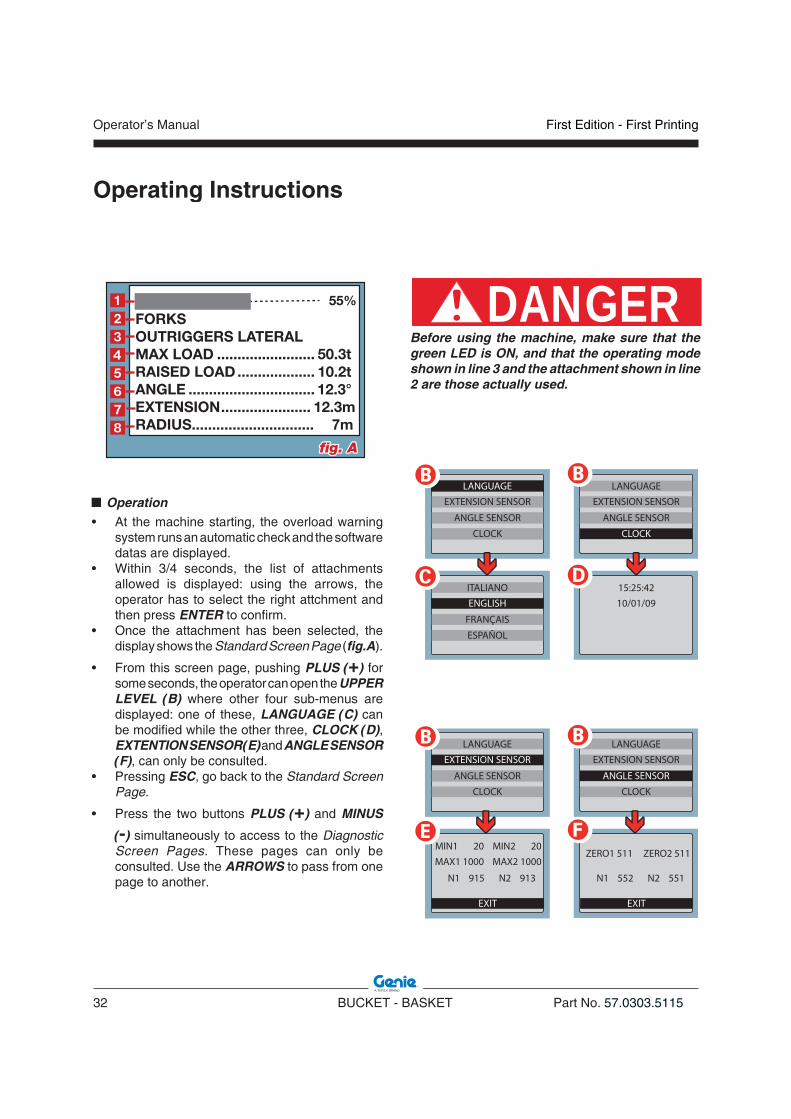
Display, which is divided into 8 lines_ fig.A 1. Load percentage strip 2. Indicates the attachment used3. Indicates the operating mode4. Indicates the max. load that can be raised5. Indicates the weight raised for the system
calibration6. Indicates the boom angle 7. Indicates the boom extension (it’ll be = 0
meters once the boom is fully retracted)8. Indicates the distance of the load from the
slewring axis and, in case of necessity, it displays the related warning message
ENTER
FORKSOUTRIGGERS LATERALMAX LOAD ........................ 50.3tRAISED LOAD................... 10.2tANGLE ............................... 12.3°EXTENSION...................... 12.3mRADIUS.............................. 7m
55%
ESC
+
-
Operator’s Manual
32 BUCKET - BASKET Part No. 57.0303.5115
First Edition - First Printing
Operating Instructions
DANGERBefore using the machine, make sure that the green LED is ON, and that the operating mode shown in line 3 and the attachment shown in line 2 are those actually used.
Operation• At the machine starting, the overload warning
system runs an automatic check and the software datas are displayed.
• Within 3/4 seconds, the list of attachments allowed is displayed: using the arrows, the operator has to select the right attchment and then press ENTER to confirm.
• Once the attachment has been selected, the display shows the Standard Screen Page (fig.A).
• From this screen page, pushing PLUS (+) for some seconds, the operator can open the UPPER LEVEL (B) where other four sub-menus are displayed: one of these, LANGUAGE (C) can be modified while the other three, CLOCK (D), EXTENTION SENSOR (E) and ANGLE SENSOR (F), can only be consulted.
• Pressing ESC, go back to the Standard Screen Page.
• Press the two buttons PLUS (+) and MINUS
(-) simultaneously to access to the Diagnostic Screen Pages. These pages can only be consulted. Use the ARROWS to pass from one page to another.
FORKSOUTRIGGERS LATERALMAX LOAD ........................ 50.3tRAISED LOAD................... 10.2tANGLE ............................... 12.3°EXTENSION...................... 12.3mRADIUS.............................. 7m
55%�����
�
fig. Afig. A
LANGUAGEEXTENSION SENSOR
ANGLE SENSOR
CLOCK
ITALIANO
FRANÇAIS
ESPAÑOL
ENGLISH15:25:4210/01/09
LANGUAGEEXTENSION SENSOR
ANGLE SENSOR
CLOCK
� �
�
MIN1 20
EXIT
MIN2 20MAX1 1000 MAX2 1000
N1 915 N2 913
LANGUAGEEXTENSION SENSOR
ANGLE SENSOR
CLOCK
EXIT
ZERO1 511 ZERO2 511
N1 552 N2 551
LANGUAGEEXTENSION SENSOR
ANGLE SENSOR
CLOCK
� �
� �
First Edition - First Printing Operator’s Manual
Part No. 57.0303.5115 BUCKET - BASKET 33
Operating Instructions
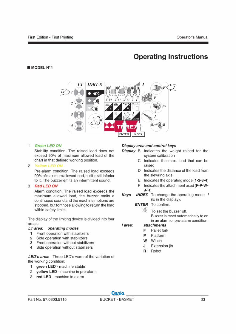
1 Green LED ON Stability condition. The raised load does not
exceed 90% of maximum allowed load of the chart in that defined working position.
2 Yellow LED ON Pre-alarm condition. The raised load exceeds
90% of maximum allowed load, but it is still inferior to it. The buzzer emits an intermittent sound.
3 Red LED ON Alarm condition. The raised load exceeds the
maximum allowed load, the buzzer emits a continuous sound and the machine motions are stopped, but for those allowing to return the load within safety limits.
The display of the limiting device is divided into four areas:LT area: operating modes 1 Front operation with stabilizers 2 Side operation with stabilizers 3 Front operation without stabilizers 4 Side operation without stabilizers
LED’s area: Three LED’s warn of the variation of the working condition: 1 green LED - machine stable 2 yellow LED - machine in pre-alarm 3 red LED - machine in alarm
ENTER
Display area and control keysDisplay B Indicates the weight raised for the
system calibration C Indicates the max. load that can be
raised D Indicates the distance of the load from
the slewring axis E Indicates the operating mode (1-2-3-4) F Indicates the attachment used (F-P-W-
J-R)Keys INDEX To change the operating mode I
(E in the display). ENTER To confirm.
To set the buzzer off. Buzzer is reset automatically to on
in an alarm or pre-alarm condition.I area: attachments F Pallet fork P Platform W Winch J Extension jib R Robot
MODEL N°4
Operator’s Manual
34 BUCKET - BASKET Part No. 57.0303.5115
First Edition - First Printing
Operating Instructions
WARNINGThe automatic recognition system of some attachments is a mere help for the operator who must, in any case, verify that the attachment on the display is the one actually in use.
When using an attachment other than those stated above, but supplied by TEREXLIFT, select the F - pallet fork operation mode.
OperationAt the machine starting, the overload warning system runs an automatic check.After about 10 seconds, the date and the machine model are displayed followed by the first page showing the last attachment used or the new attachment with electrical recognition.Once the automatic diagnosis is completed, the machine is ready for use.If the attachment used is of “mechanical” type, proceed with the manual search and selection. Press INDEX until the letter corresponding to the used attachment is displayed in the F window.Press ENTER to confirm.The machine is ready to use.
DANGERBefore using the machine, make sure that the first green LED is ON, and that the operating mode shown in window � and the attachment shown in window � are those actually used.The overload warning system must not be usedto check the load going to be lifted: it has onlybeen designed to signal possible unbalances ofthe machine along its motion axis.Such instable conditions may also be caused by an abrupt operation of the control lever during the load handling. If, during work, several LED’s switch on simultaneously, operate the levers more smoothly.

First Edition - First Printing Operator’s Manual
Part No. 57.0303.5115 BUCKET - BASKET 35
Operating Instructions
A B C D E
USING THE LOAD CHARTSThe load charts 1 indicates the maximum permissible load in relation to the boom extension and the type of attachment used. To operate under safe conditions, always refer to these charts. The extension level of the boom can be checked with the help of the letters (A, B, C, D, E) painted on the same boom (pos.3), while the actual degrees of inclination of the boom are shown by the angle indicator 2.All the load charts are placed into a dedicated holder installed in the cabin. The tag 4 located at the top of each load chart, indicates the type of attachment used.
The load chart illustrated in this chapter is given only as a mere example. To define the payload limits, refer to the load charts applied within the cab of your machine.
WARNINGThe load charts applied on the cab refer to a stationary machine standing on a solid and level ground.
CAUTIONThe load charts to be used with Man & Hyd Concrete Bucket, Brick-Holder Basket are the ones with FORKS.
09.4618.0937
GTH-4017 SX
EXAMPLEEXAMPLE

Operator’s Manual
36 BUCKET - BASKET Part No. 57.0303.5115
First Edition - First Printing
Operating Instructions
CONTROLS with the SHOVEL
n GTH-2506 and GTH-3007 controls
DANGERBefore discharging the material, make sure that nobody is within its working range.
To load/unload the material:
• set the control lever to central position,
• shift the control lever to position to unload the material;
• shift the control lever to position � to load the material.

First Edition - First Printing Operator’s Manual
Part No. 57.0303.5115 BUCKET - BASKET 37
Operating Instructions
n GTH-4013SX and GTH-4017SX controls
DANGERBefore discharging the material, make sure that nobody is within its working range.
To load/unload the material:
• set the lever � to central position,
• press button �,
• shift the lever to position to unload the material;
• shift the lever to position � to load the material.
1
Operator’s Manual
38 BUCKET - BASKET Part No. 57.0303.5115
First Edition - First Printing
Operating Instructions
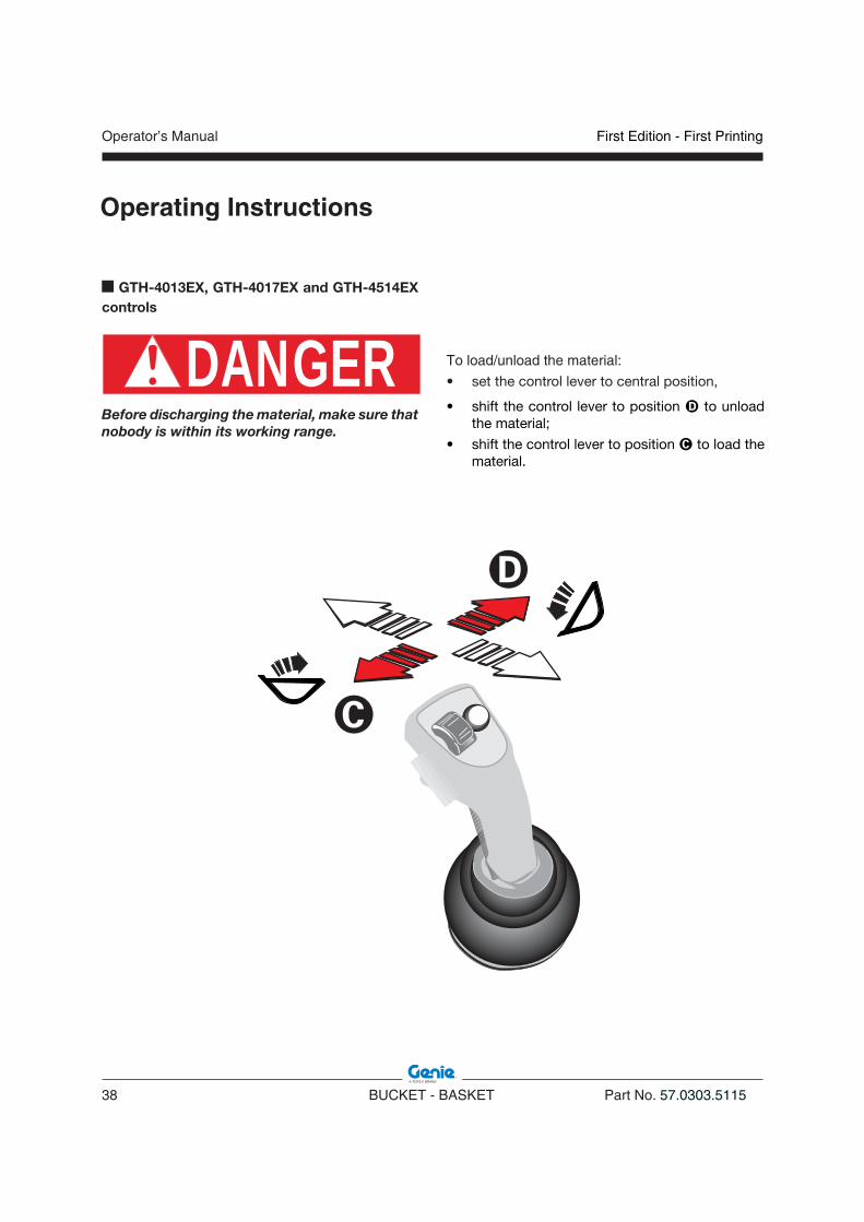
n GTH-4013EX, GTH-4017EX and GTH-4514EX controls
DANGERBefore discharging the material, make sure that nobody is within its working range.
To load/unload the material:
• set the control lever to central position,
• shift the control lever to position to unload the material;
• shift the control lever to position � to load the material.

First Edition - First Printing Operator’s Manual
Part No. 57.0303.5115 BUCKET - BASKET 39
Operating Instructions
n GTH-4016SR and GTH-4018SR controls
DANGERBefore discharging the material, make sure that nobody is within its working range.
To load/unload the material:
WITH LEFT JOYSTICK (Optional Configuration)• Set the control lever to central position and
press switch �.
• shift the lever to position to unload the material;
• shift the lever to position � to load the material.
WITH RIGHT JOYSTICK (Standard Configuration)• Set the control lever to central position and press
switch �.
• shift the lever to position to unload the material;
• shift the lever to position � to load the material.

Operator’s Manual
40 BUCKET - BASKET Part No. 57.0303.5115
First Edition - First Printing
Operating Instructions
n GTH-5022R controls
DANGERBefore discharging the material, make sure that nobody is within its working range.
To load/unload the material:• Set the control lever to central position and press
switch �.• Smoothly shift the lever to position to unload
the material;
• Shift the lever to position � to load the material; The indicator light �� will come on.
10

First Edition - First Printing Operator’s Manual
Part No. 57.0303.5115 BUCKET - BASKET 41
Operating Instructions
n GTH-4518ER, GTH-4020ER and GTH-6025ER controls
DANGERBefore discharging the material, make sure that nobody is within its working range.
To load/unload the material:• Set the control lever to central position and press
switch �.• Smoothly shift the lever to position to unload
the material;
• Shift the lever to position � to load the material.

Operator’s Manual
42 BUCKET - BASKET Part No. 57.0303.5115
First Edition - First Printing
n THE OTHER MODELS
Proceed as follow:1. Press the Mixing Bucket Switch A to enables
the movement of the internal mixer of the bucket. The selector has a block to keep the switch pressed. Before switching the selector to another position, unlock control B at the top of the selector.
2. By using the mixing bucket remote control, makes the desired movements.
For the use of this equipment and its remote control, please read the specific manual
B
CONTROLS with the MIXING BUCKET
n GTH-2506 and GTH-3007
Proceed as follow:1. Press the Flow Button 22 to switch the hydraulic
circuit feeding the attachments with auxiliary lines.
2. By turning the Continuous Oil Flow Potentiometer 18 clockwise, the flow rate in the circuit feeding the attachments’ movement lines is increased to one or the other direction.
3. By using the mixing bucket remote control, makes the desired movements.
For the use of this equipment and its remote control, please read the specific manual
A
B
18
22
A
Operating Instructions

First Edition - First Printing Operator’s Manual
Part No. 57.0303.5115 BUCKET - BASKET 43
Operating Instructions
CONTROLS with the HYDRAULIC CONCRETE BUCKET
n GTH-2506 and GTH-3007 controls
DANGERBefore discharging the concrete, make sure that nobody is within its working range.
1
To open/close the discharge door:
• set the control lever to central position,
• press button �,
• shift the control lever to position to open the discharge door,
• shift the control lever to position � to close the discharge door.

Operator’s Manual
44 BUCKET - BASKET Part No. 57.0303.5115
First Edition - First Printing
Operating Instructions
n GTH-4013SX and GTH-4017SX controls
DANGERBefore discharging the concrete, make sure that nobody is within its working range.
�
To open/close the discharge door:
• set the lever � to central position,
• shift the lever to position to open the discharge door,
• shift the lever to position � to close the discharge door.

First Edition - First Printing Operator’s Manual
Part No. 57.0303.5115 BUCKET - BASKET 45
Operating Instructions
n GTH-4013EX, GTH-4017EX and GTH-4514EX controls
DANGERBefore discharging the concrete, make sure that nobody is within its working range.
1
To open/close the discharge door:• Set the control lever to central position,• Press button �,• Shift the control lever to position to open the
discharge door,
• shift the lever to position � to close the discharge door.
Operator’s Manual
46 BUCKET - BASKET Part No. 57.0303.5115
First Edition - First Printing
Operating Instructions
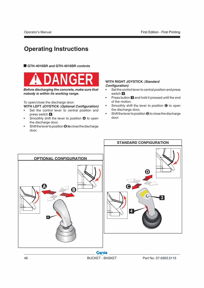
n GTH-4016SR and GTH-4018SR controls
DANGERBefore discharging the concrete, make sure that nobody is within its working range.
To open/close the discharge door:WITH LEFT JOYSTICK (Optional Configuration)• Set the control lever to central position and
press switch �.• Smoothly shift the lever to position � to open
the discharge door,• Shift the lever to position � to close the discharge
door,
OPTIONAL CONFIGURATION
WITH RIGHT JOYSTICK (Standard Configuration)• Set the control lever to central position and press
switch �.• Press button � and hold it pressed until the end
of the motion.• Smoothly shift the lever to position � to open
the discharge door,• Shift the lever to position to close the discharge
door.
STANDARD CONFIGURATION
First Edition - First Printing Operator’s Manual
Part No. 57.0303.5115 BUCKET - BASKET 47
Operating Instructions
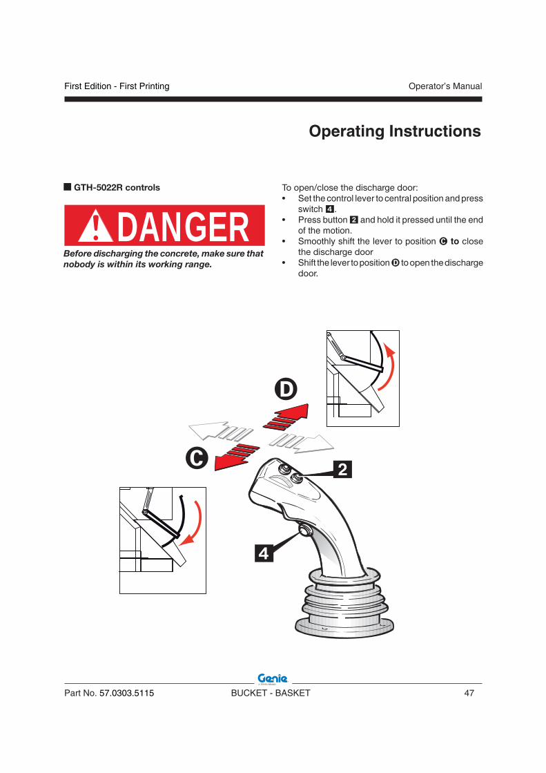
n GTH-5022R controls
DANGERBefore discharging the concrete, make sure that nobody is within its working range.
To open/close the discharge door:• Set the control lever to central position and press
switch �.• Press button � and hold it pressed until the end
of the motion.• Smoothly shift the lever to position � to close
the discharge door• Shift the lever to position to open the discharge
door.

Operator’s Manual
48 BUCKET - BASKET Part No. 57.0303.5115
First Edition - First Printing
Operating Instructions
n GTH-4518ER, GTH-4020ER and GTH-6025ER controls
DANGERBefore discharging the concrete, make sure that nobody is within its working range.
To open/close the discharge door:• Set the control lever to central position and press
switch �.• Press button � and hold it pressed until the end
of the motion.• Smoothly shift the lever to position to open
the discharge door• Shift the lever to position � to close the discharge
door.

First Edition - First Printing Operator’s Manual
Part No. 57.0303.5115 BUCKET - BASKET 49
Operating Instructions
LOADING THE EQUIPMENT
LOADING THE SHOVEL
WARNINGOperator have to survey his/her field of vision when operating the telehandler.
CAUTION• When using a shovel, load the material only
when the boom is completely retracted and push against the heap with straight wheels.
• Approach the load to be handled perpendicularly and check that the machine is level on the inclinometer.
• Insert the shovel under the load and raise it some centimetres.
• Pitch the load back to cradle the load.
WARNINGWhen loading round-shaped objects (as petrol drums, etc) bind them with straps or ropes and travel at reduced speed.
CAUTIONDo not use for digging operations.
DANGERDon’t use the shovel for rising or transporting people!
LOADING THE BRICK-HOLDER BASKET
• Approach the place where the material is stocked;
• lower the brick-holder basket on the ground;
• open the gate;
• insert the material;
• close the gate and secure it through the dedicated pin 1.
WARNINGPotential loose objects falling out!
DANGERThe brick-holder basket is designed to handle bricks pallets. IT IS NOT A MAN-PLATFORM!! Don’t use for rising or transporting people!
09.4618.1352
09.4618.1355
Operator’s Manual
50 BUCKET - BASKET Part No. 57.0303.5115
First Edition - First Printing
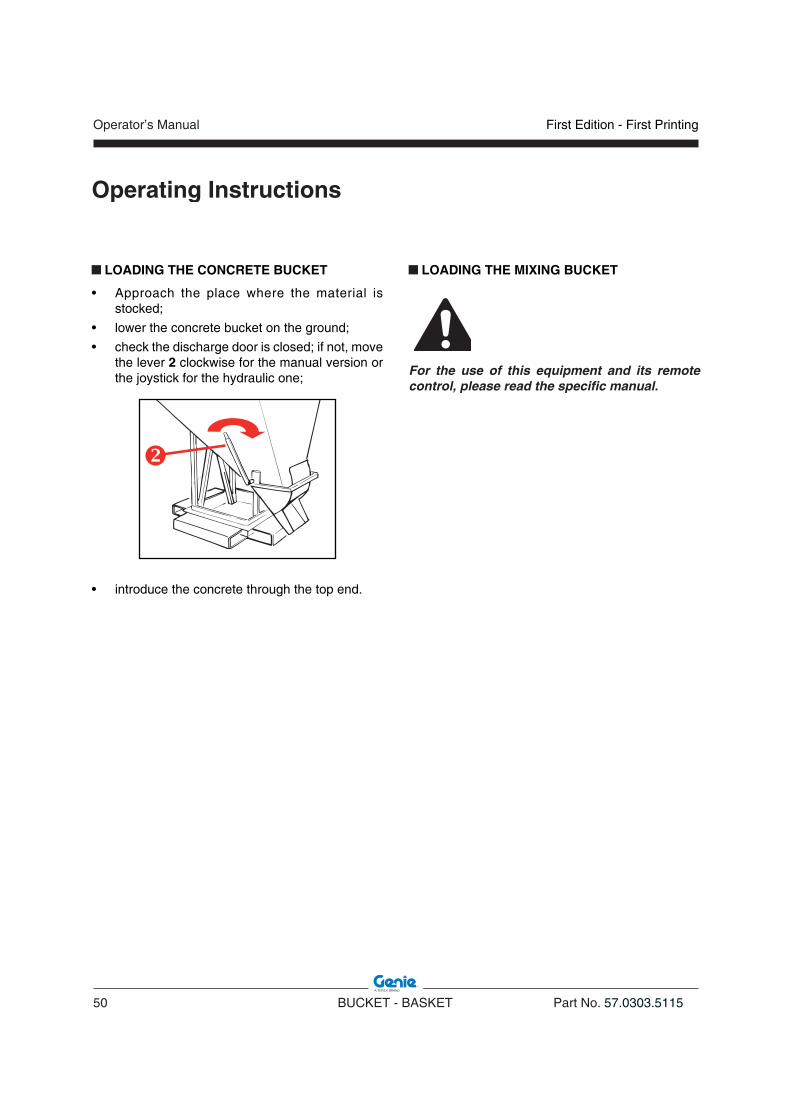
LOADING THE CONCRETE BUCKET
• Approach the place where the material is stocked;
• lower the concrete bucket on the ground;
• check the discharge door is closed; if not, move the lever 2 clockwise for the manual version or the joystick for the hydraulic one;
• introduce the concrete through the top end.
Operating Instructions
LOADING THE MIXING BUCKET
For the use of this equipment and its remote control, please read the specific manual.

First Edition - First Printing Operator’s Manual
Part No. 57.0303.5115 BUCKET - BASKET 51
Operating Instructions
TRANSPORTING THE LOADED MATERIAL
Once the material is loaded, operate as follow:• raise the equipment to the transport height of
300-500mm from the ground;• make sure a load is high enough to clear all
objects before starting to move;• identify any risks present on the route to be
travelled;• avoid excessively undulating ground when
travelling;• consider that when transporting load permissible
gradients are 10% downhill, 15% uphill, 5% side;• initiate movements of the load with the lowest
available speed;• travel at walking speed (1,5 km/h).
DANGER• Do not allow workers to walk or work under
the load. • Do not leave the load unattended.• Warn all people out of the load area before
starting the handling.
WARNING• When driving on a rise with loaded material,
proceed in forward gear and travel with load in the lowest possible position.
• When sloping downward with loaded mate-rial, proceed into reverse.
• When driving on a rise with empty shovel, proceed into reverse.
• When sloping downward with empty shovel, proceed in forward gear.
LOAD LANDING
Before a load is lifted, a place should be prepared where it is to be put down. The nature of the load will determine the type of preparation necessary.
Operator’s Manual
52 BUCKET - BASKET Part No. 57.0303.5115
First Edition - First Printing
STOPPING and STORING the EQUIPMENT and the TELEHANDLER
NOTICELay the equipment on a dry and level ground.
To release the attachment from the telehandler:
• Approach the place where you will release the equipment.
• Lower the equipment on the ground.
• Stop the engine of the telehandler
• Disconnect the hydraulic pipes of the equipment from the boom fittings.
• Remove the equipment power cable plug from the boom socket and close the cover to protect the socket against dirt and rain.
• Restart the engine.
• Operate the joystick to release the equipment from the quick coupling plate.
• Tilt the coupling plate forward and lower the boom to release the upper lock of the equipment.
• Move back with the telehandler.
The equipment itself can be handled by means of the telehandler to which it is coupled or by means of machines equipped with forks that have a suitable rated capacity.
n Parking for Short PeriodsAlways park the telehandler in a safe way after a working day, a shift and at night.Take all precautions to prevent damage to those persons who will approach the machine while stationary:• Park the machine so that it does not hinder other
operations.
• Put the parking brake.
• Remove the key from the ignition switch and lock the cab door.
Parking for Long PeriodsIn case of extended inactivity of the telehandler and/or the equipment, follow the above precautions and additionally:• Wash the machine thoroughly. For a better
cleaning, remove grills and protection casings.
CAUTIONDo not use gasoline, solvents or other flammable products for cleaning purposes. Use only authorized, non-flammable and harmless solvents. Wear safety goggles and a protection mask when you use compressed air. In case of washing, do not direct the jet of water towards electrical parts.
• Carefully dry all machine parts by blowing some compressed air.
• Lubricate the machine thoroughly.• Do a walk-around inspection and replace any
worn or damaged part.• Re-paint any worn or damaged part.• Store the machine in a sheltered and well-
ventilated place.
Operating Instructions

First Edition - First Printing Operator’s Manual
Part No. 57.0303.5115 BUCKET - BASKET 53
Operating Instructions DISPOSAL
PROTECT THEENVIRONMENT
At the end of the telehandler and/or the equipment life, call in a specialised firm to dispose of it in compliance with the local or national regulations.
BATTERY DISPOSAL
PROTECT THEENVIRONMENT
Used lead-acid batteries cannot be disposed of as normal industrial solid wastes. Because of the presence of harmful substances, they must be collected, eliminated and/or recycled in accordance with the laws of the UE.Used batteries must be kept in a dry and confined place. Make sure the battery is dry and the cell plugs are tight. Place a sign on the battery to warn of not using it. If before disposal the battery is left in the open air, it will be necessary to dry, smear the box and the elements with a coat of grease and tighten the plugs. Do not rest the battery on the ground; it is always advisable to rest it on a pallet and cover it. The disposal of batteries shall be as rapid as possible.
WARNINGAlways remember that the ordinary maintenance must be carried out even during the machine inactivity. Pay particular attention to the fluid levels and to those parts subject to ageing. Before re-starting the machine and the equipment, carry out an extraordinary maintenance and carefully check all mechanical, hydraulic and electrical components.

Operator’s Manual
54 BUCKET - BASKET Part No. 57.0303.5115
First Edition - First Printing
Intentionally blank page

First Edition - First Printing Operator’s Manual
Part No. 57.0303.5115 BUCKET - BASKET 55
Observe and obey:
* The operator can only perform the rout ine maintenance operations in this manual.
* Schedu led ma in tenance procedures shall be completed by qualified technical personnel according to the manufacturer’s specifications.
Maintenance symbol legend:
The following symbol is used in this manual to Indicates the time interval for the maintenance jobs expressed in working hours.
Maintenance
SERVICE INTERVALRunning-in ____________________________
Ordinary ______________________________
INTRODUCTION
A thorough and regular maintenance keeps the machine in a safe and efficient working condition.
For this reason, it is advisable to wash, grease and service the machine properly, especially after having worked under particular conditions (muddy or dusty environments, heavy operations, etc.).
Always ensure all machine components are in good condition. Check for oil leaks or loosening of guards, and make sure that the safety devices are efficient. In case of defects, find and rectify them before using the machine again.
Not respecting the ordinary maintenance schedule of this manual automatically voids TEREXLIFT warranty.
NOTICEEffecting changes or carrying out interventions on the telehndler or the equipment other than those of routine maintenance is expressly forbidden. Any modification not carried out by TEREXLIFT or an authorized assistance centre involves the automatic invalidation of the conformity of the machine to the Directive 2006/42/EC
Operator’s Manual
56 BUCKET - BASKET Part No. 57.0303.5115
First Edition - First Printing
ORDINARY MAINTENANCE
A wrong or neglected maintenance can result in possible risks for both operator and bystanders. Make sure maintenance and lubrication are carried out according to the manufacturer’s instructions to keep the machine or the equipment safe and efficient.The maintenance interventions are based on the machine working hours. Regularly check the hour-meter and keep it in good conditions to define the maintenance intervals correctly. Make sure any defect detected during the maintenance is promptly rectified before using the machine.
At every use1. Visually check the equipment for damage before
using it.2. Wash with water after use or in case of prolonged
inactivity to prevent the mix or residues from hardening.
3. Check for oil leaks from hoses and connectors (if any).
4. Carefully protect the quick connectors once disconnected to prevent impurities from entering the circuit (if any).
5. Check the chains after every use and replace them if worn or damaged (if any).
LUBRICANTS - HEALTH AND SAFETY PRECAUTIONS
HealthA prolonged skin contact with oil can cause irritation. Use rubber gloves and protective goggles. After handling oil, carefully wash your hands with soap and water.
StorageAlways keep lubricants in a closed place, out of the children’s reach. Never store lubricants on the open air and without a label indicating their contents.
DisposalNew or exhausted oil is always polluting! Never drain oil on the ground. Store new oil in a suitable warehouse. Pour exhausted oil into cans and deliver them to specialized firms for disposal.
Oil leaksIn case of accidental oil leaks, cover with sand or type-approved granulate. Then scrape off and dispose of it as chemical waste.
First aidEyes : In case of accidental contact with
the eyes, wash with fresh water. If the irritation persists, seek medical advice.
Intake : In case of oil intake, do not induce vomiting, but seek medical advice.
Skin : In case of a prolonged contact, wash with soap and water.
FireIn case of fire, use carbon dioxide, dry chemical or foam extinguishers. Do not use water.
Maintenance

First Edition - First Printing Operator’s Manual
Part No. 57.0303.5115 BUCKET - BASKET 57
Maintenance
CAUTIONHigh pressure lines must be replaced by qualified personnel only. Any foreign matters entering the closed circuit may result in a sudden deterioration of the transmission.
CAUTIONThe qualified staff charged with the maintenance of the hydraulic circuit must clean all areas around with care before any intervention.
PROTECT THEENVIRONMENT
The handling and disposing of used oils can be ruled by local or national regulations. Address to authorised centres.
NOTICEDuring maintenance or repair works, and while welding, turn off the disconnected battery switch, located into the engine compartment.
MAINTENANCE INTERVENTIONS
WARNINGAll maintenance interventions must be carried out with engine stopped, parking brake engaged, equipment flat on the ground and gear lever in neutral.
WARNINGAny intervention on the hydraulic circuit must be carried out by skilled personnel.The hydraulic circuit of the telehandler is fitted with pressure accumulators. You and others could be seriously injured if accumulators are not completely depressurised.For this purpose, shut the engine down and step on the brake pedal 8/10 times.
WARNINGBefore any operation on hydraulic lines or components, make sure there is no residual pressure. For this purpose, stop the engine, engage the parking brake and operate the control levers of the main valve in both working directions (alternately) to depressurise the hydraulic circuit.

Operator’s Manual
58 BUCKET - BASKET Part No. 57.0303.5115
First Edition - First Printing
Intentionally blank page

First Edition - First Printing Operator’s Manual
Part No. 57.0303.5115 BUCKET - BASKET 59
Specifications
TECHNICAL DATA
� Width 1840 mm
� Height 785 mm
� Length 890 mm
Weight 290 kg
Telehandler Payload 2500 kg
Equipment Payload 500 L
CoG 360 mm
500 L LOADING SHOVEL • code 59.0202.4000 for GTH-2506
TECHNICAL DATA
� Width 2435 mm
� Height 850 mm
� Length 780 mm
Weight 360 kg
Telehandler Payload 5000 kg
Equipment Payload 500 L
CoG 270 mm
500 L LOADING SHOVEL • code 59.0200.6000 for GTH-5022 R
�
�
�
�
�
�
� �
�
�
�
�
�
�
Operator’s Manual
60 BUCKET - BASKET Part No. 57.0303.5115
First Edition - First Printing
Specifications
TECHNICAL DATA
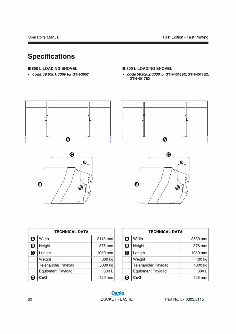
� Width 2115 mm
� Height 875 mm
� Length 1050 mm
Weight 360 kg
Telehandler Payload 3000 kg
Equipment Payload 800 L
� CoG 420 mm
800 L LOADING SHOVEL • code 59.0201.3000 for GTH-3007
TECHNICAL DATA
� Width 2350 mm
� Height 876 mm
� Length 1050 mm
Weight 400 kg
Telehandler Payload 4000 kg
Equipment Payload 800 L
� CoG 425 mm
800 L LOADING SHOVEL • code 59.0202.0000 for GTH-4013SX, GTH-4013EX,
GTH-4017SX
�
�
�
�
�
�
� �
�
�
�
�
�
�
First Edition - First Printing Operator’s Manual
Part No. 57.0303.5115 BUCKET - BASKET 61
Specifications
TECHNICAL DATA
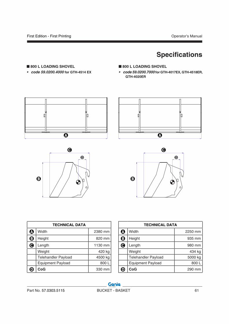
� Width 2380 mm
� Height 820 mm
� Length 1130 mm
Weight 420 kg
Telehandler Payload 4500 kg
Equipment Payload 800 L
� CoG 330 mm
800 L LOADING SHOVEL • code 59.0200.4000 for GTH-4514 EX
TECHNICAL DATA
� Width 2250 mm
� Height 935 mm
� Length 980 mm
Weight 434 kg
Telehandler Payload 5000 kg
Equipment Payload 800 L
� CoG 290 mm
800 L LOADING SHOVEL • code 59.0200.7000 for GTH-4017EX, GTH-4518ER,
GTH-4020ER
�
�
�
�
�
�
� �
�
�
�
�
�
�
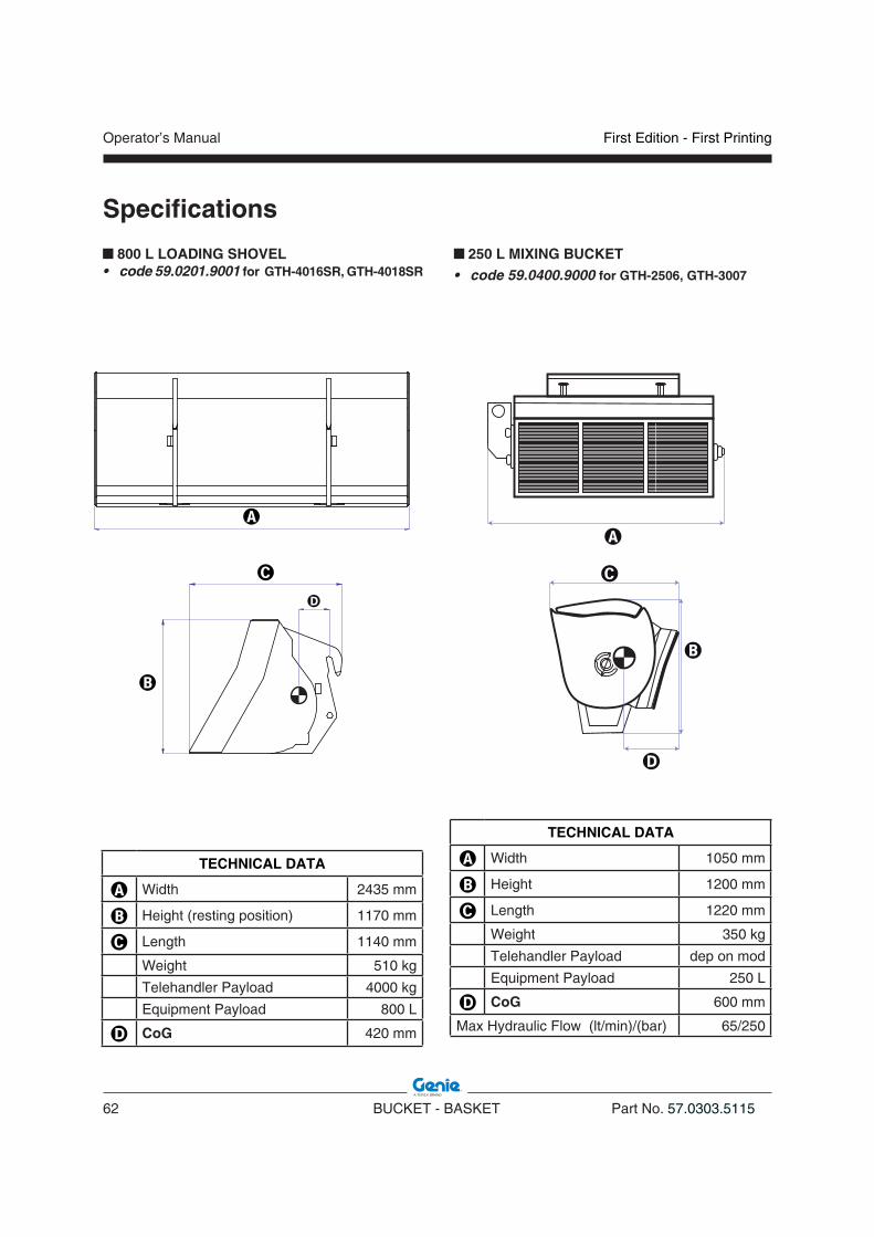
Operator’s Manual
62 BUCKET - BASKET Part No. 57.0303.5115
First Edition - First Printing
Specifications
800 L LOADING SHOVEL • code 59.0201.9001 for GTH-4016SR, GTH-4018SR
TECHNICAL DATA
� Width 2435 mm
� Height (resting position) 1170 mm
� Length 1140 mm
Weight 510 kg
Telehandler Payload 4000 kg
Equipment Payload 800 L
� CoG 420 mm
TECHNICAL DATA
� Width 1050 mm
� Height 1200 mm
� Length 1220 mm
Weight 350 kg
Telehandler Payload dep on mod
Equipment Payload 250 L
� CoG 600 mm
Max Hydraulic Flow (lt/min)/(bar) 65/250
250 L MIXING BUCKET • code 59.0400.9000 for GTH-2506, GTH-3007
�
�
�
�
�
�
��
�
�
�
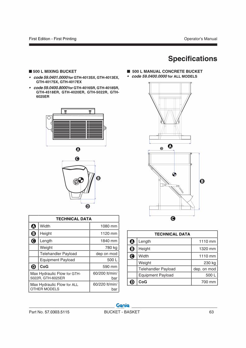
First Edition - First Printing Operator’s Manual
Part No. 57.0303.5115 BUCKET - BASKET 63
Specifications
500 L MANUAL CONCRETE BUCKET• code 59.0400.0000 for ALL MODELS
TECHNICAL DATA
� Length 1110 mm
� Height 1320 mm
� Width 1110 mm
Weight 230 kg
Telehandler Payload dep. on mod
Equipment Payload 500 L
� CoG 700 mm
TECHNICAL DATA
� Width 1080 mm
� Height 1120 mm
� Length 1840 mm
Weight 780 kg
Telehandler Payload dep on mod
Equipment Payload 500 L
� CoG 590 mm
Max Hydraulic Flow for GTH-5022R, GTH-6025ER
60/200 lt/min/bar
Max Hydraulic Flow for ALL OTHER MODELS
60/220 lt/min/bar
500 L MIXING BUCKET • code 59.0401.0000 for GTH-4013SX, GTH-4013EX,
GTH-4017SX, GTH-4017EX
• code 59.0400.8000 for GTH-4016SR, GTH-4018SR, GTH-4518ER, GTH-4020ER, GTH-5022R, GTH-6025ER
�
�
�
�
�
�
��
�
�
�

Operator’s Manual
64 BUCKET - BASKET Part No. 57.0303.5115
First Edition - First Printing
Specifications
500 L HYDRAULIC CONCRETE BUCKET• code 59.0400.1000 for ALL MODELS
TECHNICAL DATA
� Length 1110 mm
� Height 1320 mm
� Width 1110 mm
Weight 244 kg
Telehandler Payload dep. on mod
Equipment Payload 500 L
� CoG 700 mm
Max Hydraulic Flow for GTH-2506, GTH-3007
65/250 lt/min/bar
Max Hydraulic Flow for GTH-5022R, GTH-6025ER
60/200 lt/min/bar
Max Hydraulic Flow for ALL OTHER MODELS
60/220 lt/min/bar
800 L MANUAL CONCRETE BUCKET• code 59.0400.2000 for ALL MODELS
TECHNICAL DATA
� Width 1110 mm
� Height 1520 mm
� Length 1110 mm
Weight 250 kg
Telehandler Payload dep on mod
Equipment Payload 800 L
� CoG 750 mm
�
�
�
�
�
�
� �
�
�
�
�
�
�
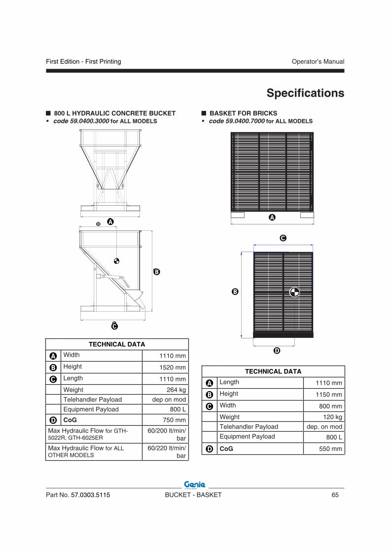
First Edition - First Printing Operator’s Manual
Part No. 57.0303.5115 BUCKET - BASKET 65
Specifications
800 L HYDRAULIC CONCRETE BUCKET• code 59.0400.3000 for ALL MODELS
TECHNICAL DATA
� Width 1110 mm
� Height 1520 mm
� Length 1110 mm
Weight 264 kg
Telehandler Payload dep on mod
Equipment Payload 800 L
� CoG 750 mm
Max Hydraulic Flow for GTH-5022R, GTH-6025ER
60/200 lt/min/bar
Max Hydraulic Flow for ALL OTHER MODELS
60/220 lt/min/bar
BASKET FOR BRICKS• code 59.0400.7000 for ALL MODELS
TECHNICAL DATA
� Length 1110 mm
� Height 1150 mm
� Width 800 mm
Weight 120 kg
Telehandler Payload dep. on mod
Equipment Payload 800 L
� CoG 550 mm
�
�
�
�
�
�
��
�
�
�

Operator’s Manual
66 BUCKET - BASKET Part No. 57.0303.5115
First Edition - First Printing
Intentionally blank page
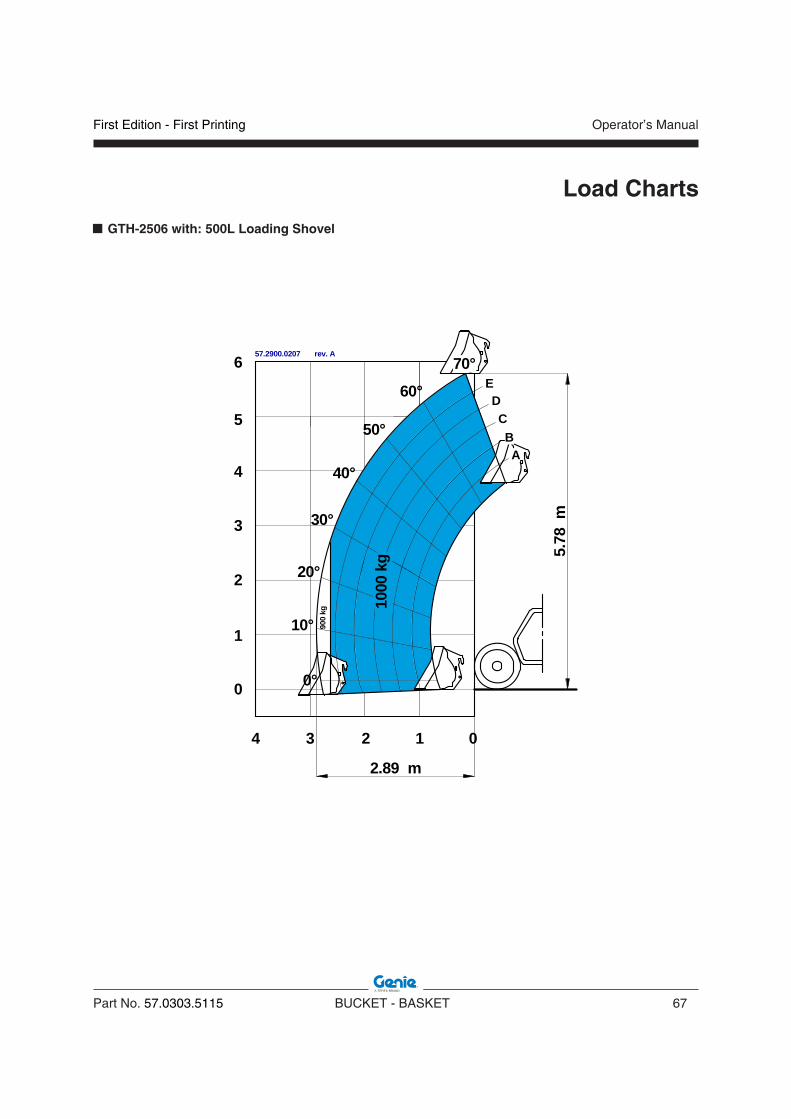
First Edition - First Printing Operator’s Manual
Part No. 57.0303.5115 BUCKET - BASKET 67
Load Charts
GTH-2506 with: 500L Loading Shovel
013
2.89 m
2
5.78
m1000 kg
900
kg
AB
CD
E60°
50°
40°
30°
20°
10°
0°
70°10
00kg
0
1
2
3
4
5
6
4
57.2900.0207 rev. A

Operator’s Manual
68 BUCKET - BASKET Part No. 57.0303.5115
First Edition - First Printing
GTH-2506 with: 500L Man & Hyd Concrete Bucket, Brick-Holder Basket
0°
10°
20°
30°
40°
50°
60°
0
0133.34 m
AB
CD
E70°
2
1
2
3
4
5
6
4
5.79
m
0.6 m
1500
kg
2000
kg
1000
kg
2500
kg
900
kg
57.2900.0203 rev. 0
WARNINGThe payload represents the weight of the equipment plus the weight of the handled material i.e. bricks, concrete, and so on.
Load Charts

First Edition - First Printing Operator’s Manual
Part No. 57.0303.5115 BUCKET - BASKET 69
Load Charts
GTH-2506 with: 250L Mixing Bucket
UNDER UNDER CONSTRUCTIONCONSTRUCTION

Operator’s Manual
70 BUCKET - BASKET Part No. 57.0303.5115
First Edition - First Printing
GTH-3007 with: 800L Loading Shovel
Load Charts

First Edition - First Printing Operator’s Manual
Part No. 57.0303.5115 BUCKET - BASKET 71
Load Charts
GTH-3007 with: 500L Man & Hyd Concrete Bucket, Brick-Holder Basket
57.2900.0314 rev. 0
012345
EDC
BA
30°
40°
50°
60°
20°
10°
0°-2.9°
67°
0.6 m
2500
kg
0
1
2
3
4
5
6
7
-1
1500
kg 6.
89 m
2000
kg
1250
kg
3000
kg
WARNINGThe payload represents the weight of the equipment plus the weight of the handled material i.e. bricks, concrete, and so on.

Operator’s Manual
72 BUCKET - BASKET Part No. 57.0303.5115
First Edition - First Printing
Load Charts
GTH-3007 with: 250L Mixing Bucket
UNDER UNDER CONSTRUCTIONCONSTRUCTION

First Edition - First Printing Operator’s Manual
Part No. 57.0303.5115 BUCKET - BASKET 73
Load Charts
57.2900.0228 rev. A
20°
012345678910
0
-1
1
2
3
4
5
6
7
8
9
10
11
12
13
0°
10°
30°
40°
50°
60°68.8°
A
B
C
D
E
-4.18°
8.58 m
12.8
1 m
1000
kg
500
kg25
0kg 15
00kg
750
kg
57.2900.0229 rev. A
20°
012345678910
0
-1
1
2
3
4
5
6
7
8
9
10
11
12
13
8.52 m
13.0
5 m
0°
10°
30°
40°
50°
60°
70°
A
B
C
D
E71.6°
-1.43°
1500 kg
GTH-4013SX & GTH-4013EX with: 800L Loading Shovel
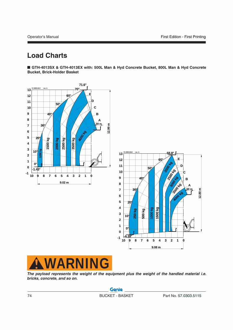
Operator’s Manual
74 BUCKET - BASKET Part No. 57.0303.5115
First Edition - First Printing
Load Charts
57.2900.0217 rev. A
20°
012345678910
0
-1
1
2
3
4
5
6
7
8
9
10
11
12
13
9.02 m
12.9
9 m
0°
10°
30°
40°
50°
60°
70°
3000
kg
A
B
C
D
E
2000
kg
1250
kg
71.6°
-1.43°
1500
kg
2500
kg
3500
kg 4000
kg
.60 m
57.2900.0218 rev. A
1500
kg
20°
012345678910
0
-1
1
2
3
4
5
6
7
8
9
10
11
12
13
0°
10°
30°
40°
50°
60°
68.8°
A
B
C
D
E
-4.18°
3500
kg
2500
kg
9.08 m
12.8
0 m
3000
kg
4000
kg
2000
kg
1000
kg
500
kg
250
kg
.60 m
GTH-4013SX & GTH-4013EX with: 500L Man & Hyd Concrete Bucket, 800L Man & Hyd Concrete Bucket, Brick-Holder Basket
WARNINGThe payload represents the weight of the equipment plus the weight of the handled material i.e. bricks, concrete, and so on.
First Edition - First Printing Operator’s Manual
Part No. 57.0303.5115 BUCKET - BASKET 75
Load Charts
GTH-4013SX & GTH-4013EX with: 500L Mixing Bucket
UNDER UNDER CONSTRUCTIONCONSTRUCTION
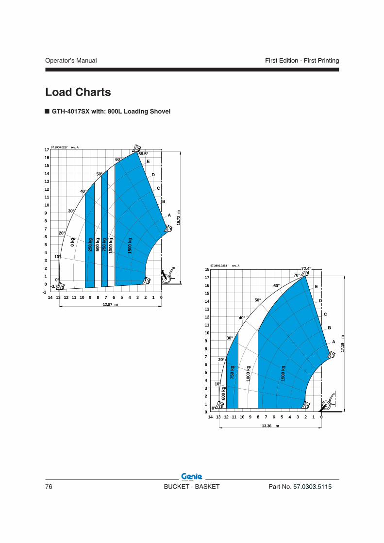
Operator’s Manual
76 BUCKET - BASKET Part No. 57.0303.5115
First Edition - First Printing
Load Charts
012345678910111213
0
-1
1
2
3
4
5
6
7
8
9
10
11
12
13
14
15
16
17
0°
10°
20°
30°
40°
50°
60°68.5°
12.87 m
14
16.7
2m
1000
kg
E
D
C
B
A
-3.7°
500
kg
1500
kg
0 kg
750
kg
250
kg
57.2900.0227 rev. A
0123456789101112130
1
2
3
4
5
6
7
8
9
10
11
12
13
14
15
16
17
0°
10°
20°
30°
40°
50°
60°
14
E
D
C
B
A
13.36 m
18
17.1
9m
70°
600
kg
1500
kg
750
kg
1000
kg
72.4°57.2900.0253 rev. A
GTH-4017SX with: 800L Loading Shovel

First Edition - First Printing Operator’s Manual
Part No. 57.0303.5115 BUCKET - BASKET 77
Load Charts
012345678910111213
0
-1
1
2
3
4
5
6
7
8
9
10
11
12
13
14
15
16
17
0°
10°
20°
30°
40°
50°
60°
68.5°
13.33 m
14
4000 kg
16.7
2m
.60 m
1000
kg
3500
kgE
D
C
B
A
-3.7°
250
kg
2000
kg40
00kg
1500
kg
0 kg
500
kg
3000
kg
57.2900.0174 rev. 0
0123456789101112130
1
2
3
4
5
6
7
8
9
10
11
12
13
14
15
16
17
0°
10°
20°
30°
40°
50°
60°
14
4000 kg
E
D
C
B
A
13.36 m
18
17.1
9m
4000
kg
3000
kg
1500
kg
2000
kg
700
kg
1000
kg
3500
kg
72.4°
0.6 m
70°
800
kg
57.2900.0175 rev. 0
GTH-4017SX with: 500L Man & Hyd Concrete Bucket, 800L Man & Hyd Concrete Bucket, Brick-Holder Basket
WARNINGThe payload represents the weight of the equipment plus the weight of the handled material i.e. bricks, concrete, and so on.

Operator’s Manual
78 BUCKET - BASKET Part No. 57.0303.5115
First Edition - First Printing
Load Charts
GTH-4017SX with: 500L Mixing Bucket
UNDER UNDER CONSTRUCTIONCONSTRUCTION

First Edition - First Printing Operator’s Manual
Part No. 57.0303.5115 BUCKET - BASKET 79
Load Charts
57.2900.0239 rev. A
GTH-4017EX with: 800L Loading Shovel

Operator’s Manual
80 BUCKET - BASKET Part No. 57.0303.5115
First Edition - First Printing
Load Charts
80,2°70°
60°
50°
40°
30°
20°
10°
2500
kg
3500 kg
1500
kg
600
kg
012345678910111213140
1
2
3
4
5
6
7
8
9
10
11
12
13
14
15
16
17
E
D
C
B
A
16.7
2m
12.53 m
0.6 m
4000kg
3000 kg
1000
kg
2000
kg
57.2900.0230 rev. A
0
-1
1
2
3
4
5
6
7
8
9
10
11
12
13
14
15
16
17
01234567891011121314
0°
30°
40°
50°
60°
77°
10°
20°
70°
16.5
9m
0.6 m
D
C
B
A
E
12.55 m
4000 kg
1000
kg
300
kg
0 kg
3000 kg
2000 kg
1500
kg
500
kg
100
kg
3500 kg
2500 kg
57.2900.0231 rev. A
GTH-4017EX with: 500L Man & Hyd Concrete Bucket, 800L Man & Hyd Concrete Bucket, Brick-Holder Basket
WARNINGThe payload represents the weight of the equipment plus the weight of the handled material i.e. bricks, concrete, and so on.

First Edition - First Printing Operator’s Manual
Part No. 57.0303.5115 BUCKET - BASKET 81
Load Charts
GTH-4017EX with: 500L Mixing Bucket
UNDER UNDER CONSTRUCTIONCONSTRUCTION

Operator’s Manual
82 BUCKET - BASKET Part No. 57.0303.5115
First Edition - First Printing
Load Charts
0
-1
1
2
3
4
5
6
7
8
9
10
11
12
13
15
012345678910
30°
40°
50°
60°
75°
10°
20°
70°
D
C
B
A
E
0°
14
500
kg
1500
kg
750
kg
1000
kg
250
kg
0 kg
9.15 m
13.6
4m
57.2900.0248 rev. A
012345678910
0
1
2
3
4
5
6
7
8
9
10
11
12
13
14
-1
77,3°70°
60°
50°
40°
30°
20°
10°
E
D
C
B
A
15
1500
kg
1000
kg
9.11 m
13.8
0m
57.2900.0249 rev. A
GTH-4514EX with: 800L Loading Shovel,
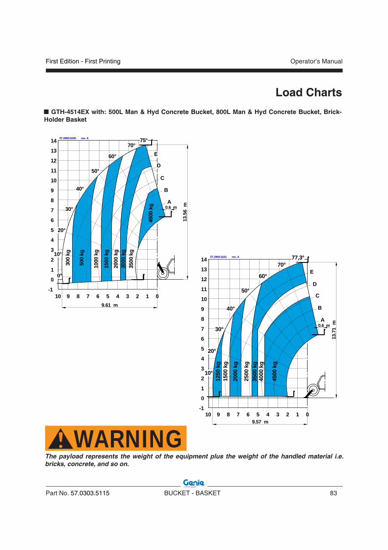
First Edition - First Printing Operator’s Manual
Part No. 57.0303.5115 BUCKET - BASKET 83
Load Charts
300
kg
0
-1
1
2
3
4
5
6
7
8
9
10
11
12
13
14
012345678910
1000
kg
2000
kg
3500
kg
30°
40°
50°
60°
75°
10°
20°
70°
D
C
B
A
E
0°
4500
kg
500
kg
1500
kg
3000
kg
9.61 m
13.5
6m0.6 m
57.2900.0240 rev. A
4000
kg
3500
kg
1250
kg
1500
kg
2500
kg
4500
kg
2000
kg
012345678910
0
1
2
3
4
5
6
7
8
9
10
11
12
13
14
-1
77,3°70°
60°
50°
40°
30°
20°
10°
E
D
C
B
A
9.57 m
13.7
1m0.6 m
57.2900.0241 rev. A
GTH-4514EX with: 500L Man & Hyd Concrete Bucket, 800L Man & Hyd Concrete Bucket, Brick-Holder Basket
WARNINGThe payload represents the weight of the equipment plus the weight of the handled material i.e. bricks, concrete, and so on.
Operator’s Manual
84 BUCKET - BASKET Part No. 57.0303.5115
First Edition - First Printing
Load Charts
GTH-4514EX with: 500L Mixing Bucket
UNDER UNDER CONSTRUCTIONCONSTRUCTION
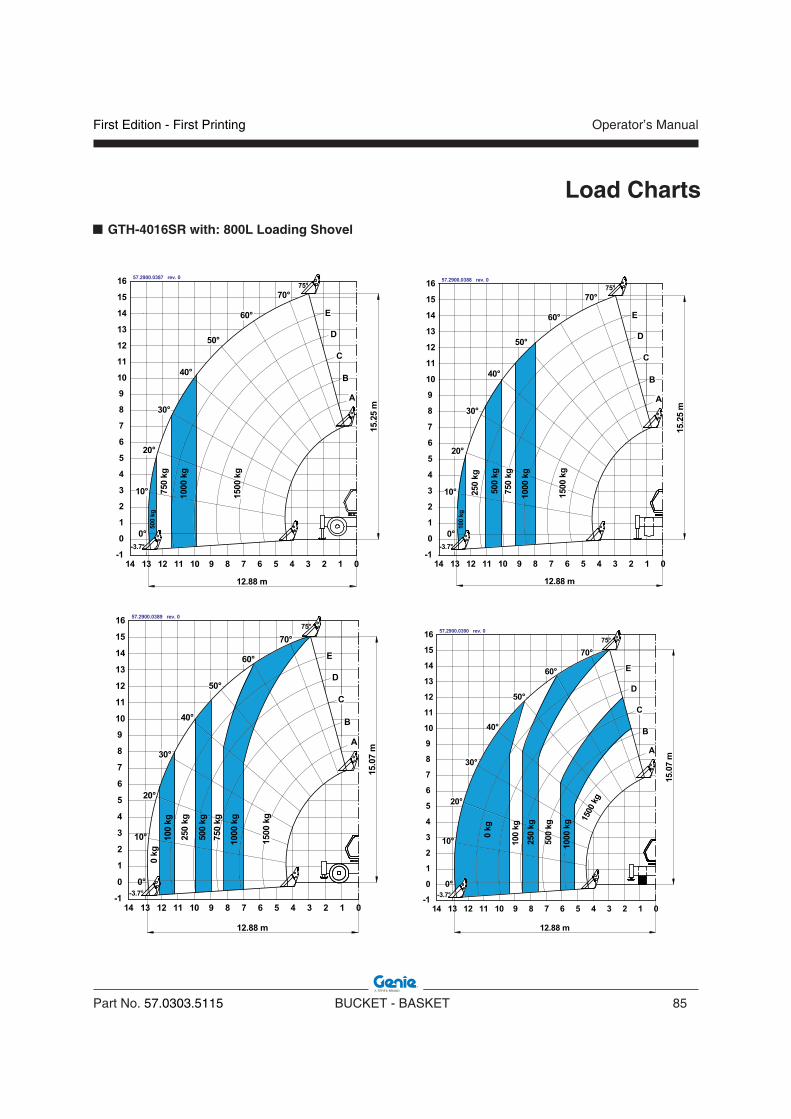
First Edition - First Printing Operator’s Manual
Part No. 57.0303.5115 BUCKET - BASKET 85
Load Charts
GTH-4016SR with: 800L Loading Shovel

Operator’s Manual
86 BUCKET - BASKET Part No. 57.0303.5115
First Edition - First Printing
Load Charts
0
-1
1
2
3
4
5
6
7
8
9
10
11
12
13
14
15
16
-2
0°
A
B
0123456789101112131415
10°
70°
-3.7°
75°
C
D
E
20°
30°
40°
50°
60°
15.4
2 m0.6 m
2500
kg
4000
kg
700
kg 1500
kg
1000
kg
2000
kg
3000
kg
13.35 m
57.2900.0318 rev. A
0
-1
1
2
3
4
5
6
7
8
9
10
11
12
13
14
15
16
-2
0°
A
B
0123456789101112131415
10°
70°
-3.7°
75°
C
D
E
20°
30°
40°
60°
750
kg
250
kg
50°
1000
kg
500
kg
1500
kg
3000
kg
2000
kg
4000
kg 15.3
1 m
13.35 m
57.2900.0320 rev. A
0
-1
1
2
3
4
5
6
7
8
9
10
11
12
13
14
15
16
-2
0°
A
B
0123456789101112131415
10°
70°
-3.7°
75°
C
D
E
20°
30°
40°
50°
60°
15.4
2 m0.6 m30
00 k
g
4000
kg
2500
kg
1000
kg
2000
kg
450
kg 1500
kg
750
kg
13.35 m
57.2900.0319 rev. A
0
-1
1
2
3
4
5
6
7
8
9
10
11
12
13
14
15
16
-2
0°
A
B
0123456789101112131415
10°
70°
-3.7°
75°
C
D
E
20°
30°
40°
60°
0.6 m
50°
2000
kg
1000
kg
0 kg
500
kg
250
kg
13.35 m
15.3
1 m
57.2900.0321 rev. A
GTH-4016SR with: 500L Man & Hyd Concrete Bucket, 800L Man & Hyd Concrete Bucket, Brick-Holder Basket
WARNINGThe payload represents the weight of the equipment plus the weight of the handled material i.e. bricks, concrete, and so on.

First Edition - First Printing Operator’s Manual
Part No. 57.0303.5115 BUCKET - BASKET 87
Load Charts
GTH-4016SR with: 500L Mixing Bucket
UNDER UNDER CONSTRUCTIONCONSTRUCTION

Operator’s Manual
88 BUCKET - BASKET Part No. 57.0303.5115
First Edition - First Printing
Load Charts
GTH-4018SR with: 800L Loading Shovel

First Edition - First Printing Operator’s Manual
Part No. 57.0303.5115 BUCKET - BASKET 89
Load Charts
GTH-4018SR with: 500L Man & Hyd Concrete Bucket, 800L Man & Hyd Concrete Bucket, Brick-Holder Basket
WARNINGThe payload represents the weight of the equipment plus the weight of the handled material i.e. bricks, concrete, and so on.

Operator’s Manual
90 BUCKET - BASKET Part No. 57.0303.5115
First Edition - First Printing
Load Charts
GTH-4018SR with: 500L Mixing Bucket
UNDER UNDER CONSTRUCTIONCONSTRUCTION

First Edition - First Printing Operator’s Manual
Part No. 57.0303.5115 BUCKET - BASKET 91
Load Charts
GTH-5022R with: 500L Loading Shovel
UNDER UNDER CONSTRUCTIONCONSTRUCTION

Operator’s Manual
92 BUCKET - BASKET Part No. 57.0303.5115
First Edition - First Printing
Load Charts
GTH-5022R with: 500L Man & Hyd Concrete Bucket, 800L Man & Hyd Concrete Bucket, Brick-Holder Basket
01234567891011121314
0
-1
1
2
3
4
5
6
7
8
9
10
11
12
13
14
15
16
17
1516
D18
19
20
-217181920
21
22
0°
10°
20°
30°
40°
50°
60°
70°
78°
E
B
A
C
18.93 m
21.9
3m
-4.4°
0.6 m
3700
kg
2500
kg
1000
kg
400
kg
650
kg
1500
kg
3000
kg
5000
kg
4500
kg
57.2900.0254 rev. A
01234567891011121314
0
-1
1
2
3
4
5
6
7
8
9
10
11
12
13
14
15
16
17
1516
-4.4°
500
kg
D
3000
kg
100
kg
18
19
20
-217181920
21
22
0°
10°
20°
30°
40°
50°
60°
70°
78°
E
B
A
C
1500
kg
300
kg
0 kg
4000
kg
2300
kg
1000
kg
0.6 m
18.93 m
21.6
7m
57.2900.0256 rev. A
01234567891011121314
0
-1
1
2
3
4
5
6
7
8
9
10
11
12
13
14
15
16
17
1516
D18
19
20
-217181920
21
22
0°
10°
20°
30°
40°
50°
60°
70°
78°
E
B
A
C
18.93 m
21.9
3m
-4.4°
3500
kg
5000
kg
2500
kg
1000
kg
500
kg
200
kg
750
kg
1500
kg
4500
kg
3000
kg
0.6 m
57.2900.0255 rev. A
01234567891011121314
0
-1
1
2
3
4
5
6
7
8
9
10
11
12
13
14
15
16
17
1516
-4.4°
400
kg
D
0 kg
18
19
20
-217181920
21
22
0°
10°
20°
30°
40°
50°
60°
70°
78°
E
B
A
C
1500
kg
0.6 m
18.93 m
21.6
7m
2500
kg
1000
kg
100
kg
57.2900.0257 rev. A
WARNINGThe payload represents the weight of the equipment plus the weight of the handled material i.e. bricks, concrete, and so on.

First Edition - First Printing Operator’s Manual
Part No. 57.0303.5115 BUCKET - BASKET 93
Load Charts
GTH-5022R with: 500L Mixing Bucket
UNDER UNDER CONSTRUCTIONCONSTRUCTION

Operator’s Manual
94 BUCKET - BASKET Part No. 57.0303.5115
First Edition - First Printing
Load Charts
GTH-4518ER with: 800L Loading Shovel
UNDER UNDER CONSTRUCTIONCONSTRUCTION

First Edition - First Printing Operator’s Manual
Part No. 57.0303.5115 BUCKET - BASKET 95
Load Charts
GTH-4518ER with: 500L Man & Hyd Concrete Bucket, 800L Man & Hyd Concrete Bucket, Brick-Holder Basket
01234567891011121314
0
-1
1
2
3
4
5
6
7
8
9
10
11
12
13
14
15
16
17
0°
10°
20°
30°
40°
60°
50°
70°
1516
78°
-4.4°
1500
kg
1000
kg
3500
kg
2500
kg
14.90 m
17.2
3mA
B
C
D
E
18
0.6 m
1500
kg
1000
kg
2000
kg
3000
kg
4000
kg
750
kg
4500
kg
57.2900.0188 rev. 0
01234567891011121314
0
-1
1
2
3
4
5
6
7
8
9
10
11
12
13
14
15
16
17
0°
10°
20°
30°
40°
60°
50°
70°
1516
78°
-4.4°
A
B
C
D
E
500
kg
0 kg
1500
kg
14.99 m
250
kg
1000
kg
2500
kg
16.9
8m
18
0.6 m
57.2900.0190 rev. 0
01234567891011121314
0
-1
1
2
3
4
5
6
7
8
9
10
11
12
13
14
15
16
17
0°
10°
20°
30°
40°
60°
50°
70°
1516
78°
-4.4°
750
kg
A
B
C
D
E
2000
kg
500
kg
1000
kg
3000
kg
1500
kg
4000
kg
250
kg
14.99 m
16.9
8m
0.6 m
18
0 kg
57.2900.0189 rev. 0
WARNINGThe payload represents the weight of the equipment plus the weight of the handled material i.e. bricks, concrete, and so on.

Operator’s Manual
96 BUCKET - BASKET Part No. 57.0303.5115
First Edition - First Printing
Load Charts
GTH-4518ER with: 500L Mixing Bucket
UNDER UNDER CONSTRUCTIONCONSTRUCTION
First Edition - First Printing Operator’s Manual
Part No. 57.0303.5115 BUCKET - BASKET 97
Load Charts
GTH-4020ER with: 800L Loading Shovel
UNDER UNDER CONSTRUCTIONCONSTRUCTION
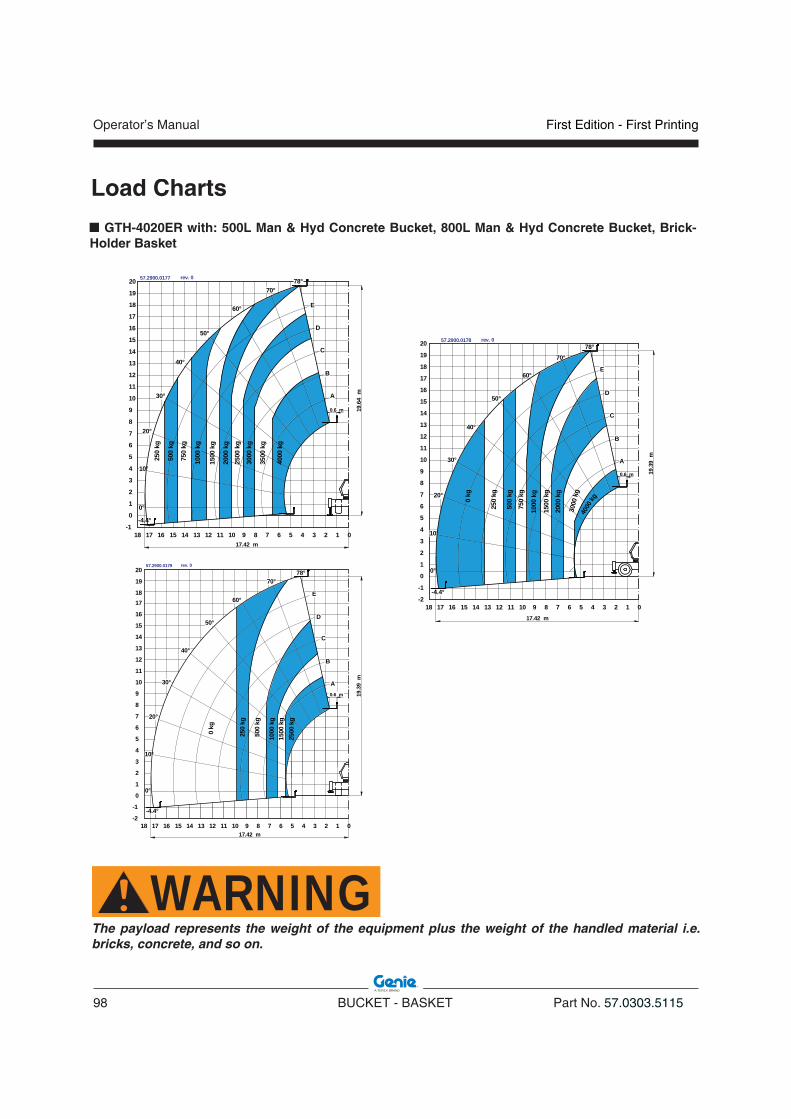
Operator’s Manual
98 BUCKET - BASKET Part No. 57.0303.5115
First Edition - First Printing
Load Charts
GTH-4020ER with: 500L Man & Hyd Concrete Bucket, 800L Man & Hyd Concrete Bucket, Brick-Holder Basket
0123456789101112131415161718
0
-1
1
2
3
4
5
6
7
8
9
10
11
12
13
14
15
16
17
18
19
20
0°
10°
20°
30°
40°
60°
50°
70°78°
-4.4°
3500
kg
2500
kg
750
kg
A
B
C
D
E
1500
kg
19.6
4m
0.6 m
17.42 m
250
kg
4000
kg
2000
kg
3000
kg
1000
kg
500
kg
57.2900.0177 rev. 0
01234567891011121314
0
-1
1
2
3
4
5
6
7
8
9
10
11
12
13
14
15
16
17
1516
18
-2
19
20
0°
10°
20°
30°
40°
60°
50°
70°78°
-4.4°
A
B
C
D
E
500
kg
0 kg
1500
kg
0.6 m 19.3
9m
1718
2500
kg
1000
kg
250
kg
17.42 m
57.2900.0179 rev. 0
01234567891011121314
0
-1
1
2
3
4
5
6
7
8
9
10
11
12
13
14
15
16
17
0°
10°
20°
30°
60°
50°
70°
1516
78°
-4.4°
750
kg
A
B
C
D
E
1500
kg
250
kg
18
19
20
-21718
40°
3000
kg
19.3
9m
0.6 m
2000
kg
500
kg
0 kg
1000
kg
4000
kg
17.42 m
57.2900.0178 rev. 0
WARNINGThe payload represents the weight of the equipment plus the weight of the handled material i.e. bricks, concrete, and so on.

First Edition - First Printing Operator’s Manual
Part No. 57.0303.5115 BUCKET - BASKET 99
Load Charts
GTH-4020ER with: 500L Mixing Bucket
UNDER UNDER CONSTRUCTIONCONSTRUCTION

Operator’s Manual
100 BUCKET - BASKET Part No. 57.0303.5115
First Edition - First Printing
Load Charts
GTH-6025ER with: 800L Loading Shovel
UNDER UNDER CONSTRUCTIONCONSTRUCTION

First Edition - First Printing Operator’s Manual
Part No. 57.0303.5115 BUCKET - BASKET 101
0
-1
1
2
3
4
5
6
7
8
9
10
11
12
13
14
15
16
17
18
-2
19
20
21
22
23
24
25
0°
20°
30°
40°
50°
70°
78°
A
B
C
D
E60°
012345678910111213141516171819202122
2000
kg
1000
kg
4000
kg
250
kg
6000
kg
5000
kg
3000
kg
1500
kg
500
kg
-4.4°
10°
24.8
4m
21.46 m
0.6 m
57.2900.0284 rev. 0
5000
kg
01234567891011121314
0
-1
1
2
3
4
5
6
7
8
9
10
11
12
13
14
15
16
17
1516
-5.5°
18
19
20
-217181920
21
22
23
24
25
2122
0°
20°
30°
40°
50°
70°
A
B
C
D
E60°
10°
2000
kg
1000
kg
250
kg
3000
kg
1500
kg
500
kg
4000
kg
6000 kg
21.46 m
24.6
6 m
78°
0 kg
57.2900.0286 rev. 0
012345678910111213141516171819202122
0
-1
1
2
3
4
5
6
7
8
9
10
11
12
13
14
15
16
17
18
-2
19
20
21
22
23
24
25
0°
20°
30°
40°
50°
70°
78°
A
B
C
D
E60°
-4.4°
10°
0 kg
24.8
4m
21.46 m
500
kg
1500
kg
3000
kg
5000
kg
250
kg
1000
kg
2000
kg
4000
kg
6000
kg
0.6 m
57.2900.0285 rev. 0
01234567891011121314
0
-1
1
2
3
4
5
6
7
8
9
10
11
12
13
14
15
16
17
1516
-5.5°
18
19
20
-217181920
21
22
23
24
25
2122
0°
20°
30°
40°
50°
70°
A
B
C
D
E60°
10°
21.46 m
24.6
6 m
78°25
00 k
g
1500
kg
1000
kg
750
kg50
0 kg
250
kg
0 kg
57.2900.0287 rev. 0
Load Charts
GTH-6025ER with: 500L Man & Hyd Concrete Bucket, 800L Man & Hyd Concrete Bucket, Brick-Holder Basket
WARNINGThe payload represents the weight of the equipment plus the weight of the handled material i.e. bricks, concrete, and so on.
Operator’s Manual
102 BUCKET - BASKET Part No. 57.0303.5115
First Edition - First Printing
Load Charts
GTH-6025ER with: 500L Mixing Bucket
UNDER UNDER CONSTRUCTIONCONSTRUCTION

First Edition - First Printing Operator’s Manual
Part No. 57.0303.5115 BUCKET - BASKET 103
Diagrams and Schemes
WIRING DIAGRAM ONLY for Mixing Bucket
NOTICETo consult the WIRING DIAGRAM, refer to the Operator's Manual of the telehandler associated to the equipment.

Operator’s Manual
104 BUCKET - BASKET Part No. 57.0303.5115
First Edition - First Printing
Diagrams and Schemes
HYDRAULIC DIAGRAM ONLY for Mixing Bucket & Hydraulic Concrete Bucket
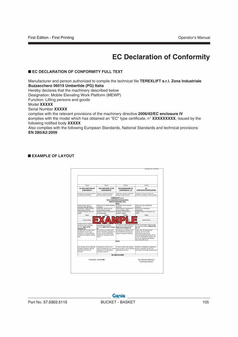
First Edition - First Printing Operator’s Manual
Part No. 57.0303.5115 BUCKET - BASKET 105
EC Declaration of Conformity
EC DECLARATION OF CONFORMITY FULL TEXT
Manufacturer and person authorized to compile the technical file TEREXLIFT s.r.l. Zona IndustrialeBuzzacchero 06019 Umbertide (PG) ItaliaHereby declares that the machinery described belowDesignation: Mobile Elevating Work Platform (MEWP)Function: Lifting persons and goodsModel XXXXXSerial Number XXXXXcomplies with the relevant provisions of the machinery directive 2006/42/EC enclosure IVcomplies with the model which has obtained an "EC" type certificate, n° XXXXXXXXX, Issued by the following notified body XXXXXAlso complies with the following European Standards, National Standards and technical provisions:EN 280/A2:2009
EXAMPLE OF LAYOUT
EXAMPLEEXAMPLE

Operator’s Manual
106 BUCKET - BASKET Part No. 57.0303.5115
First Edition - First Printing
Intentionally blank page

First Edition - First Printing Operator’s Manual
Part No. 57.0303.5115 BUCKET - BASKET 107
LIMITED PRODUCT WARRANTY
Genie Industries (“Seller”) warrants its new equipment manufactured and sold worldwide, to be free, under normal use and service, of any defects in manufacture or materials for the following time periods, commencing on the date on which such equipment is invoiced to the original purchaser or the date on which such equipment is first put into service, whichever occurs first:
• with respect to structural elements: 5 years; • with respect to electrical componentry: 2 years • with respect to hydraulic componentry (except
as provided below): 2 years • with respect to o-rings, seals, hoses and
brakes: 1 year
provided that:
1. Seller receives written notice of the defect within fourteen (14) days of its discovery and Buyer establishes that
i. the equipment has been maintained and operated within the limits of rated and normal usage
ii. the defect did not result in any manner from the intentional or negligent action or inaction by Buyer, its agents or employees
2. a new machine registration certificate has been completed, signed and delivered to Seller within fourteen (14) days of the equipment’s “in-service” date.
If requested by Seller, Buyer must return the defective equipment to Seller’s manufacturing facility, or other location designated by Seller, for inspection, and if Buyer cannot establish that conditions (1) (i) and(1) (ii) above have been met, then this warranty shall not cover the alleged defect. Delivery inspection certificates are required to be completed, signed and delivered to Seller within one hundred twenty (120) days of the equipment’s “in-service” date and on file with Seller’s service department for warranty validation and processing.Seller’s obligation and liability under this warranty is
expressly limited to, at Seller’s sole option, repairing or replacing, with new or remanufactured parts or components, any part, which appears to Seller upon inspection to have been defective in material or workmanship.Such parts shall be provided at no cost to the owner, FOB Seller’s parts facility. Freight charges are not covered. If requested by Seller, components or parts for which a warranty claim is made shall be returned to Seller at a location designated by Seller. All return freight charges are the responsibility of the buyer.All components and parts replaced under this limited product warranty become the property of Seller.This warranty shall be null and void if parts (including wear parts) other than genuine OEM Seller parts are used in the equipment.Accessories, assemblies and components included in the Seller equipment, which are not manufactured by Seller, are subject to the warranty of their respective manufacturers.Normal maintenance, adjustments, or maintenance/wear parts, including without limitation, glass, clutch and brake linings, filters, wire rope and paint, are not covered by this warranty and are the sole maintenance responsibility of Buyer.
Seller makes no other warranty, express or implied, and makes no warranty of merchantability or fitness for any particular purpose.
No employee or representative is authorized to modify this warranty unless such modification is made in writing and signed by an authorized officer of SellerSeller’s obligation under this warranty shall not include duty, taxes, environmental fees, including without limitation, disposal or handling of tires, batteries, petrochemical items, or any other charges whatsoever, or any liability for direct, indirect, incidental, or consequential damages.
Warranty

Operator’s Manual
108 BUCKET - BASKET Part No. 57.0303.5115
First Edition - First Printing
Improper maintenance, improper use, abuse, improper storage, operation beyond rated capacity, operation after discovery of defective or worn parts, accident, sabotage or alteration or repair of the equipment by persons not authorized by Seller shall render this warranty null and void. Seller reserves the right to inspect the installation of the product and review maintenance procedures to determine if the failure was due to improper maintenance, improper use, abuse, improper storage, operation beyond rated capacity, operation after discovery of defective or worn parts, or alteration or repair of the equipment by persons not authorized by Seller.
NO TRANSFERABILITY OF WARRANTY: This warranty is limited to the original end-user and is not assignable or otherwise transferable without the written agreement of Seller.
ITEMS NOT COVERED BY SELLER WARRANTY
The following items are not covered under the seller warranty (the following list is not Exhaustive):1. Lamps, lenses, filters, consumable items, utility
trailer decks, shop supplies.2. Items sold by any individual, corporation,
partnership or any other organization or legal Entity that is not an authorized seller distributor.
3. Inbound freight for replacement components or outbound freight for any part requested as a warranty return.
4. Components which are not manufactured by seller are not covered by seller’s warranty. Such components are covered only by the warranty, if any, that is provided by the Manufacturer of such components. Such components may include, but are not limited to, Engines, batteries, tires, customer-supplied products, transmissions, generators/gensets, Axles.
5. Replacement of Assemblies: seller has the option to repair or replace any defective part or assembly. It is seller’s policy to refuse claims for the replacement of a complete assembly that is field repairable by the replacement or repair of defective part(s) within the assembly.
6. Normal Operational Maintenance Services and Wear Parts: maintenance services and wear parts are excluded from warranty claims. Maintenance services and wear parts not covered include, but are not limited to, such items as: seals, gaskets, hoses, glass, clutch and brake linings, wire rope, exterior coatings, proper tightening of bolts, nuts and fittings, adding or replacing of fluids, breathers, belts, nozzles, adjustments of any kind, services supplies such as lubricants, inspections, diagnostic time, travel time.
7. Transportation Cost and/ or Damage: any damage caused by carrier handling is a transportation claim and should be filed immediately with the respective carrier.
8. Deterioration: repairs, work required or parts exposed as the result of age, storage, weathering, lack of use, demonstration use, or use for transportation of corrosive chemicals.
Warranty

First Edition - First Printing Operator’s Manual
Part No. 57.0303.5115 BUCKET - BASKET 109
Warranty
9. Secondary Failures: should the owner or operator continue to operate a machine after It has been noted that a failure has occurred, seller will not be responsible under the warranty for resultant damage to other parts due to that continued operation.
10. Workmanship of Others: seller does not accept responsibility for improper installation or labor costs or costs of any kind from personnel other than personnel authorized by seller.
11. Stop and Go Warranty: seller does not recognize “stop and go” warranties.
12. Incidental or Consequential Damage: SELLER SHALL NOT BE LIABLE FOR ANY INCIDENTAL OR CONSEQUENTIAL DAMAGES OF ANY KIND, INCLUDING, BUT NOT LIMITED TO, LOST PROFITS, LOSS OF PRODUCTION, INCREASED OVERHEAD, LOSS OF BUSINESS OPPORTUNITY, DELAYS IN PRODUCTION, COSTS OF REPLACEMENT COMPONENTS AND INCREASED COSTS OF OPERATION THAT MAY ARISE FROM THE BREACH OF THIS WARRANTY. Customer’s sole remedy shall be limited to (at seller’s sole option) repair or replacement of the defective part.
THIS WARRANTY IS EXPRESSLY IN LIEU OF AND EXCLUDES ALL OTHER WARRANTIES, EXPRESS OR IMPLIED (INCLUDING THE WARRANTIES OF MERCHANTABILITY AND FITNESS FOR A PARTICULAR PURPOSE) AND ALL OTHER OBLIGATIONS OR LIABILITY ON SELLER’S PART. THERE ARE NO WARRANTIES THAT EXTEND BEYOND THE LIMITED WARRANTY CONTAINED HEREIN. Seller neither assumes nor authorizes any other person to assume for seller any other liability in connection with the sale of seller’s equipment. This warranty shall not apply to any of seller’s equipment or any part thereof which has been subject to misuse, alteration, abuse, negligence, accident, acts of god or sabotage.
No action by any party shall operate to extend or revive this limited warranty without the prior written consent of seller. In the event that any provision of this warranty is held unenforceable for any reason, the remaining provisions shall remain in full force and effect.
IN THE EVENT OF ANY BREACH OF THE WARRANTY BY SELLER, SELLER’S LIABILITY SHALL BE LIMITED EXCLUSIVELY TO THE REMEDIES (AT SELLER’S SOLE OPTION) OF REPAIR OR REPLACEMENT OF ANY DEFECTIVE EQUIPMENT COVERED BY THE WARRANTY. IN NO EVENT SHALL SELLER, OR ANY SUBSIDIARY OR DIVISION THEREOF BE LIABLE FOR INCIDENTAL, INDIRECT, CONSEQUENTIAL OR OTHER DAMAGES OR LOSSES RESULTING FROM A BREACH OF WARRANTY INCLUDING, WITHOUT LIMITATION, LABOR COSTS, LOSS OF USE OF OTHER EQUIPMENT, THIRD PARTY REPAIRS, LOST PROFITS, LOST TIME, TOWING OR HAULING OF EQUIPMENT, RENTAL COSTS, PERSONAL INJURY, EMOTIONAL OR MENTAL DISTRESS, IMPROPER PERFORMANCE OR WORK, PENALTIES OF ANY KIND, LOSS OF SERVICE OF PERSONNEL, OR FAILURE OF EQUIPMENT TO COMPLY WITH ANY FEDERAL, STATE OR LOCAL LAWS.

Operator’s Manual
110 BUCKET - BASKET Part No. 57.0303.5115
First Edition - First Printing
Intentionally blank page

First Edition - First Printing Operator’s Manual
Part No. 57.0303.5115 BUCKET - BASKET 111
WARRANTY - HANDING OVER CERTIFICATE
War
rant
y is
sub
ject
to d
eliv
ery
acco
rdin
g to
the
regu
latio
n an
d th
e su
bmis
sion
of t
his
cert
ifica
te
to T
ER
EX
LIF
T s
.r.l.
Model
___________________
Serial Number
___________________
Delivery date
___________________
Dealer’s stamp and signature
We hereby acknowledge that we received the machine in perfect condition, as well as the Operator’s Manual.
DATAS OF THE OWNER:
Name: _______________________________________________________
City: ____________________________ Address: _____________________
Postal Code: _____________________ Country: ______________________
Telephone:_______________________ Telefax: ______________________
Signature: ____________________________________________________
Note_____________________________________________________________________________________________________________________________________________________________________________________________
Client’s Copy
WARRANTY - HANDING OVER CERTIFICATE
War
rant
y is
sub
ject
to d
eliv
ery
acco
rdin
g to
the
regu
latio
n an
d th
e su
bmis
sion
of t
his
cert
ifica
te
to T
ER
EX
LIF
T s
.r.l.
Model
___________________
Serial Number
___________________
Delivery date
___________________
Dealer’s stamp and signature
We hereby acknowledge that we received the machine in perfect condition, as well as the Operator’s Manual.
DATAS OF THE OWNER:
Name: _______________________________________________________
City: ____________________________ Address: _____________________
Postal Code: _____________________ Country: ______________________
Telephone:_______________________ Telefax: ______________________
Signature: ____________________________________________________
Note_____________________________________________________________________________________________________________________________________________________________________________________________
TEREXLIFT Copy

Related Documents