English (Australia) Code No. 3B693-9971-1 M5091 MODELS OPERATOR'S MANUAL 1MHJD00001A01 M5111 © KUBOTA Corporation 2019 M5091·M5111PRINTED IN JAPAN READ AND SAVE THIS MANUAL

Welcome message from author
This document is posted to help you gain knowledge. Please leave a comment to let me know what you think about it! Share it to your friends and learn new things together.
Transcript

English (Australia)Code No. 3B693-9971-1
M5091MODELS
OPERATOR'S MANUAL
1MHJD00001A01
M5111
© KUBOTA Corporation 2019
M5091·M5111
PRINTED IN JAPAN
READ AND SAVE THIS MANUAL

M5091, M5111AX . A . 1 - 1 . 1 . AK
KUBOTA Corporation is ···Since its inception in 1890, KUBOTA Corporation has grown to rank as one of the major firms in Japan.
To achieve this status, the company has through the years diversified the range of its products and services to a remarkable extent. 30 plants and 35,000 employees produce over 1,000 different items, large and small.
All these products and all the services which accompany them, however, are unified by one central commitment. Kubota makes products which, taken on a national scale, are basic necessities. Products which are indispensable. Products which are intended to help individuals and nations fulfill the potential inherent in their environment. Kubota is the basic necessities giant.
This potential includes water supply, food from the soil and from the sea, industrial development, architecture and construction, and transportation.
Thousands of people depend on Kubota's know-how, technology, experience and customer service. You too can depend on Kubota.
Abbreviations Definitions
ABBREVIATION LIST
2 Wheel Drive4 Wheel DriveAmerican Petroleum InstituteAmerican Society of Agricultural and Biological Engineers, USAAmerican Society for Testing and Materials, USADeutsches Institut für Normung, GERMANYDiesel Exhaust FluidDiesel Particulate FilterDual Traction [4WD]Feet Per MinuteGlide Shift TransmissionHigh Speed-Low SpeedHydrostatic TransmissionMeters Per SecondPower Take OffRight-hand and left-hand sides are determined by facing in the direction of forward travelRoll-Over Protective StructuresRevolutions Per MinuteRevolutions Per SecondSociety of Automotive Engineers, USA
2WD4WDAPI
ASABEASTMDINDEFDPFDTfpmGSTHi-LoHSTm/sPTO
RH/LH
ROPSrpmr/s
SAE

UNIVERSAL SYMBOLSAs a guide to the operation of your tractor, various universal symbols have been utilized on the instruments andcontrols. The symbols are shown below with an indication of their meaning.
General
Safety alert symbol
Master system warning
Fast
Slow
Creep
Lock
On (engage)
Off (disengage)
Engine - related
Diesel fuel
Empty
Full
Hour meter / elapsed operating hours
Engine coolant - temperature
Engine intake / combustion air-filter
Engine oil pressure
Water separator
Engine - warning
Engine - rotational speed
Engine - rev limiter
Engine - constant RPM management
Engine - over speed
Engine - rpm memory A
Engine - rpm memory B
Engine - rpm increase
Engine - run
Engine - start
Engine - stop
Electrical power - accessories
Diesel preheat / glow plug(low temperature start aid)
Regeneration
Regeneration inhibit
Regeneration (switch)

Parked regeneration
Vehicle body - related
4-wheel drive - on
Operator presence control
Clutch
Brake
Parking brake
Differential lock
Differential lock - automatic
Steering wheel - tilt
PTO - off (disengaged)
PTO - on (engaged)
PTO - 540 rpm
PTO - 540E rpm
PTO - 1000 rpm
PTO - front
PTO - rear
PTO - ground
Hydraulic - related
Draft control - shallow position
Draft control - deep position
Position control - raised position
Position control - lowered position
3 - point lowering speed control
Remote cylinder - retract
Remote cylinder - extend
Electric - related
Battery charging condition
Headlight - low beam
Headlight - high beam
Turn signal
Hazard warning lights
Audible warning device
Beacon light
Windshield wiper
Windshield wiper - intermittent
Windshield washer
Rear window defroster


CONTENTSSAFE OPERATION......................................................................................................................7SERVICING OF TRACTOR .......................................................................................................21
WARRANTY........................................................................................................................................................ 22SCRAPPING THE TRACTOR AND ITS PROCEDURE ..................................................................................... 22
SPECIFICATIONS......................................................................................................................23SPECIFICATION TABLE..................................................................................................................................... 23TRAVELING SPEEDS ........................................................................................................................................ 25
IMPLEMENT LIMITATIONS.......................................................................................................27IMPLEMENT SPECIFICATION TABLE............................................................................................................... 28
OVERVIEW OF TRACTOR PARTS...........................................................................................30INSTRUMENT PANEL AND CONTROLS.................................................................................32
SWITCHES AND HAND CONTROLS ................................................................................................................ 32INSTRUMENT PANEL........................................................................................................................................ 33FOOT AND HAND CONTROLS ......................................................................................................................... 34
PRE-OPERATION CHECK........................................................................................................35DAILY CHECK .................................................................................................................................................... 35
OPERATING THE ENGINE .......................................................................................................36EXHAUST AFTERTREATMENT DEVICES........................................................................................................ 36DIESEL PARTICULATE FILTER (DPF) MUFFLER ............................................................................................ 36
1. Handling points .......................................................................................................................................... 362. DPF regeneration process......................................................................................................................... 373. Operating procedure for auto regeneration mode ..................................................................................... 38
3.1 PM warning level and required procedures........................................................................................ 394. Operating procedure for regeneration inhibit mode................................................................................... 40
4.1 PM warning level and required procedures........................................................................................ 415. Operating procedure for parked regeneration ........................................................................................... 426. Tips on diesel particulate filter (DPF) regeneration ................................................................................... 43
STARTING THE ENGINE ................................................................................................................................... 431. Checking Easy Checker™ indicators ......................................................................................................... 45
OPERATING THE ENGINE IN FREEZING CONDITIONS................................................................................. 461. Block heater (if equipped).......................................................................................................................... 46
STOPPING THE ENGINE................................................................................................................................... 46WARMING UP THE ENGINE ............................................................................................................................. 46
1. Warm-up and transmission fluid at low temperature range ....................................................................... 46JUMP STARTING ............................................................................................................................................... 46
OPERATING THE TRACTOR....................................................................................................48OPERATING NEW TRACTOR ........................................................................................................................... 48
1. Do not operate the tractor at full speed for the first 50 hours .................................................................... 482. Changing lubricating oil for new tractors ................................................................................................... 48
BOARDING AND LEAVING THE TRACTOR ..................................................................................................... 48STARTING THE TRACTOR................................................................................................................................ 48
1. Operator's seat .......................................................................................................................................... 491.1 Mechanical suspension seat .............................................................................................................. 491.2 Air suspension seat (if equipped)....................................................................................................... 50
2. Seat belt .................................................................................................................................................... 503. Instructional seat (if equipped) .................................................................................................................. 50
3.1 Precautions in using the instructional seat ......................................................................................... 514. Tilt steering adjustment.............................................................................................................................. 52
M5091,M5111 1

5. Light switch................................................................................................................................................ 536. Turn signal switch and hazard light switch ................................................................................................ 53
6.1 With trailer connector ......................................................................................................................... 547. Horn button................................................................................................................................................ 548. Brake pedals (right and left) ...................................................................................................................... 54
8.1 4WD braking system (4WD model) .................................................................................................... 559. Parking brake lever.................................................................................................................................... 5510. Gear-locked parking brake lever ............................................................................................................. 5511. Clutch pedal ............................................................................................................................................. 5512. Travel speed control ................................................................................................................................ 5713. Travel speed limiter ................................................................................................................................. 5814. Main gear shift lever ................................................................................................................................ 5815. Range gear shift lever ............................................................................................................................. 58
15.1 Creep speed..................................................................................................................................... 5816. Shuttle shift lever ..................................................................................................................................... 5817. Dual speed shift switch (if equipped)....................................................................................................... 5918. Clutch-off switch (if equipped) ................................................................................................................. 5919. 4WD switch.............................................................................................................................................. 60
19.1 Front-wheel drive (4WD) usage ....................................................................................................... 6020. Hand throttle lever ................................................................................................................................... 6021. Foot throttle ............................................................................................................................................. 60
STOPPING THE TRACTOR ............................................................................................................................... 61CHECK DURING DRIVING ................................................................................................................................ 61
1. Engine over-speed limiting indicator.......................................................................................................... 612. Easy Checker™ ......................................................................................................................................... 613. Fuel gauge................................................................................................................................................. 624. Coolant temperature gauge....................................................................................................................... 635. Tachometer ................................................................................................................................................ 63
LCD MONITOR................................................................................................................................................... 631. Various setting mode ................................................................................................................................. 64
1.1 Clock setting....................................................................................................................................... 641.2 Setting the clock display ON/OFF ...................................................................................................... 651.3 Setting the tire circumference ............................................................................................................ 651.4 Setting the unit ................................................................................................................................... 661.5 Setting the PTO speed display........................................................................................................... 66
2. Performance monitor ................................................................................................................................. 68ELECTRONIC ENGINE CONTROL.................................................................................................................... 69
1. RPM dual memory setting ......................................................................................................................... 692. Constant RPM Management control ......................................................................................................... 70
PARKING THE TRACTOR.................................................................................................................................. 71OPERATING TECHNIQUES............................................................................................................................... 72
1. Differential lock .......................................................................................................................................... 722. Operating the tractor on a road ................................................................................................................. 733. Operating on slopes and rough terrain ...................................................................................................... 734. Transporting the tractor safely ................................................................................................................... 745. Directions for the use of power steering .................................................................................................... 746. Trailer electrical outlet................................................................................................................................ 74
PTO ............................................................................................................................................75PTO OPERATION............................................................................................................................................... 75
1. PTO clutch control switch .......................................................................................................................... 752. PTO clutch indicator .................................................................................................................................. 753. PTO rpm display ........................................................................................................................................ 764. PTO shaft cover and shaft cap .................................................................................................................. 76
PTO MODELS..................................................................................................................................................... 761. PTO 540/540E rpm model ......................................................................................................................... 76
1.1 PTO gear shift lever ........................................................................................................................... 761.2 PTO speed limiter............................................................................................................................... 77
2 M5091,M5111
2. Interchangeable PTO 540/1000 rpm model............................................................................................... 772.1 1000 rpm PTO shaft ........................................................................................................................... 77
3-POINT HITCH AND DRAWBAR.............................................................................................78THE 3-POINT HITCH SETUP............................................................................................................................. 79
1. Selecting the holes of lower links .............................................................................................................. 792. Adjusting lateral float ................................................................................................................................. 793. Selecting the top link mounting holes ........................................................................................................ 794. Drawbar ..................................................................................................................................................... 805. Lifting rod (left)........................................................................................................................................... 806. Lifting rod (right) ........................................................................................................................................ 807. Top link ...................................................................................................................................................... 808. Telescopic stabilizers ................................................................................................................................. 81
8.1 Telescopic lower links......................................................................................................................... 819. Quick hitch - hook type (if equipped) ......................................................................................................... 81
9.1 Installing ball-joint to implement ......................................................................................................... 829.2 Adjusting lower link width ................................................................................................................... 829.3 Attaching implement to tractor ........................................................................................................... 829.4 Detaching implement from tractor ...................................................................................................... 83
DRAWBAR.......................................................................................................................................................... 831. Adjusting drawbar length ........................................................................................................................... 832. Swing drawbar ........................................................................................................................................... 84
HYDRAULIC UNIT.....................................................................................................................853-POINT HITCH CONTROL SYSTEM................................................................................................................ 85
1. Position control .......................................................................................................................................... 852. Draft control ............................................................................................................................................... 853. Mixed control ............................................................................................................................................. 854. Float control ............................................................................................................................................... 865. 3-point hitch lowering speed knob ............................................................................................................. 86
REMOTE HYDRAULIC CONTROL SYSTEM..................................................................................................... 861. Remote control valve................................................................................................................................. 862. Remote control valve lever ........................................................................................................................ 873. Remote control valve coupler .................................................................................................................... 874. Flow control valve (option)......................................................................................................................... 88
4.1 Adjusting the flow rate........................................................................................................................ 884.2 Positions and advantages of the flow control valve ........................................................................... 88
5. Hydraulic control unit use-reference chart ................................................................................................. 90
TIRES, WHEELS AND BALLAST.............................................................................................91TIRES.................................................................................................................................................................. 91
1. Inflation pressure ....................................................................................................................................... 912. Dual tires ................................................................................................................................................... 91
WHEEL ADJUSTMENT ...................................................................................................................................... 911. Front wheels-4WD..................................................................................................................................... 92
1.1 Front jack point................................................................................................................................... 932. Rear wheels............................................................................................................................................... 94
2.1 Rear jack point ................................................................................................................................... 95
CAB OPERATION......................................................................................................................96CAB CLASSIFICATION AND MAINTENANCE................................................................................................... 96DOORS AND WINDOWS ................................................................................................................................... 96
1. Locking and unlocking the door................................................................................................................. 962. Opening the door ....................................................................................................................................... 963. Rear window.............................................................................................................................................. 974. Side window .............................................................................................................................................. 975. Sunroof ...................................................................................................................................................... 976. Emergency exit .......................................................................................................................................... 97
DOME LIGHT...................................................................................................................................................... 97
M5091,M5111 3
WORK LIGHT ..................................................................................................................................................... 981. Work light switch........................................................................................................................................ 982. Front work light .......................................................................................................................................... 983. Rear work light........................................................................................................................................... 98
WIPER ................................................................................................................................................................ 991. Front wiper and washer switch .................................................................................................................. 992. Rear wiper and washer switch................................................................................................................... 993. Using the wipers in cold season ................................................................................................................ 99
AIR CONDITIONER............................................................................................................................................ 991. Airflow........................................................................................................................................................ 992. Air control vent......................................................................................................................................... 1003. Control panel ........................................................................................................................................... 100
3.1 Mode switch ..................................................................................................................................... 1003.2 Temperature control dial................................................................................................................... 1013.3 Blower switch ................................................................................................................................... 1013.4 Air conditioner switch ....................................................................................................................... 1013.5 Recirculation or fresh air selection switch ........................................................................................ 101
4. Operation................................................................................................................................................. 1014.1 Heating............................................................................................................................................. 1014.2 Cooling or dehumidifying-heating..................................................................................................... 1024.3 Defrosting or demisting .................................................................................................................... 102
INSTALLING THE IMPLEMENT CONTROL BOX............................................................................................ 103ELECTRICAL OUTLET..................................................................................................................................... 103BEACON LIGHT ............................................................................................................................................... 103
MAINTENANCE.......................................................................................................................105SERVICE INTERVALS...................................................................................................................................... 105MAINTENANCE ITEMS CHART....................................................................................................................... 106LUBRICANTS, FUEL AND COOLANT ............................................................................................................. 108
PERIODIC SERVICE ...............................................................................................................110WASTE DISPOSAL .......................................................................................................................................... 110HOW TO OPEN THE HOOD ............................................................................................................................ 110
1. Hood ........................................................................................................................................................ 1102. Side cover................................................................................................................................................ 110
DAILY CHECK ...................................................................................................................................................1111. Walk around inspection ............................................................................................................................1112. Checking and refueling.............................................................................................................................1113. Checking water separator........................................................................................................................ 1124. Checking engine oil level ......................................................................................................................... 1125. Checking transmission fluid level ............................................................................................................ 1126. Checking coolant level............................................................................................................................. 1137. Cleaning evacuator valve ........................................................................................................................ 1138. Cleaning grill, radiator screen, oil cooler, fuel cooler, air conditioner condenser and battery mount....... 113
8.1 Detaching the panel ......................................................................................................................... 1148.2 Sliding the air conditioner condenser ............................................................................................... 1148.3 Cleaning ........................................................................................................................................... 114
9. Checking DPF muffler.............................................................................................................................. 11410. Checking brake pedal ............................................................................................................................ 11511. Checking gear-locked parking brake ..................................................................................................... 11512. Checking parking brake......................................................................................................................... 11513. Checking gauges, meter and Easy Checker™ ...................................................................................... 11514. Checking headlight, turn signal light, hazard light, and so on ............................................................... 11615. Checking seat belt ................................................................................................................................. 11616. Checking movable parts ........................................................................................................................ 116
INITIAL 50 HOURS........................................................................................................................................... 1161. Changing engine oil ................................................................................................................................. 1162. Replacing engine oil filter ........................................................................................................................ 116
4 M5091,M5111

EVERY 50 HOURS........................................................................................................................................... 1161. Checking engine start system ................................................................................................................. 116
1.1 Preparation before testing................................................................................................................ 1161.2 Testing switch for the shuttle shift lever............................................................................................ 1161.3 Testing switch for PTO clutch control switch .................................................................................... 116
2. Checking operator presence control (OPC) system ................................................................................ 1173. Checking wheel bolt torque ..................................................................................................................... 1174. Checking tie-rod dust cover ..................................................................................................................... 117
EVERY 100 HOURS......................................................................................................................................... 1171. Lubricating grease fittings........................................................................................................................ 1172. Cleaning air cleaner primary element ...................................................................................................... 1193. Adjusting fan belt tension ........................................................................................................................ 1194. Adjusting brake pedal .............................................................................................................................. 120
4.1 Checking brake pedal free travel ..................................................................................................... 1204.2 Checking brake pedal stroke............................................................................................................ 1204.3 Checking equalizer working level (anti-imbalance device)............................................................... 120
5. Checking gear-locked parking brake ....................................................................................................... 1206. Adjusting parking brake lever .................................................................................................................. 1217. Checking battery condition ...................................................................................................................... 121
7.1 How to read indicator ....................................................................................................................... 1217.2 Charging the battery......................................................................................................................... 1227.3 Directions for battery storage ........................................................................................................... 122
8. Adjusting air conditioner belt tension....................................................................................................... 122EVERY 200 HOURS......................................................................................................................................... 123
1. Adjusting toe-in ........................................................................................................................................ 1231.1 Adjusting toe-in procedure ............................................................................................................... 123
2. Draining fuel tank water ........................................................................................................................... 1233. Cleaning inner air filter............................................................................................................................. 1234. Cleaning fresh air filter............................................................................................................................. 124
4.1 Cleaning the filter ............................................................................................................................. 124EVERY 400 HOURS......................................................................................................................................... 124
1. Cleaning water separator ........................................................................................................................ 124EVERY 500 HOURS......................................................................................................................................... 125
1. Changing engine oil ................................................................................................................................. 1252. Replacing engine oil filter ........................................................................................................................ 1253. Replacing fuel filter .................................................................................................................................. 1264. Replacing hydraulic oil filter ..................................................................................................................... 1265. Checking power steering line .................................................................................................................. 1276. Checking radiator hose and clamp .......................................................................................................... 127
6.1 Overheating countermeasures......................................................................................................... 1287. Checking fuel line .................................................................................................................................... 1288. Checking intake air line ........................................................................................................................... 1289. Checking lift cylinder hose....................................................................................................................... 12910. Checking air conditioner pipe and hose ................................................................................................ 130
EVERY 600 HOURS......................................................................................................................................... 1301. Adjusting front axle pivot ......................................................................................................................... 130
EVERY 1000 HOURS....................................................................................................................................... 1301. Changing transmission fluid .................................................................................................................... 1302. Changing front differential case oil .......................................................................................................... 1303. Changing front axle gear case oil ............................................................................................................ 1314. Adjusting engine valve clearance ............................................................................................................ 131
EVERY 1000 HOURS OR 1 YEAR................................................................................................................... 1311. Replacing air cleaner primary element and secondary element.............................................................. 1312. Checking exhaust manifold ..................................................................................................................... 131
EVERY 1500 HOURS....................................................................................................................................... 1311. Cleaning fuel injector nozzle tip ............................................................................................................... 1312. Checking and cleaning EGR cooler......................................................................................................... 131
EVERY 2000 HOURS OR 2 YEARS ................................................................................................................ 131
M5091,M5111 5

1. Flushing cooling system and changing coolant ....................................................................................... 1312. Antifreeze ................................................................................................................................................ 132
EVERY 3000 HOURS....................................................................................................................................... 1331. Checking turbocharger ............................................................................................................................ 1332. Checking supply pump ............................................................................................................................ 1333. Checking intake air heater ....................................................................................................................... 1334. Checking and cleaning EGR system ....................................................................................................... 1335. Cleaning DPF muffler .............................................................................................................................. 133
EVERY 1 YEAR ................................................................................................................................................ 1331. Checking CAB isolation cushion.............................................................................................................. 1332. Checking DPF related pipe...................................................................................................................... 1333. Checking EGR pipe ................................................................................................................................. 134
EVERY 2 YEARS.............................................................................................................................................. 1341. Replacing breather related rubber pipe ................................................................................................... 1342. Replacing boost sensor hose .................................................................................................................. 1343. Replacing DPF related rubber pipe ......................................................................................................... 1344. Replacing EGR cooler hose .................................................................................................................... 1345. Cleaning master cylinder filter ................................................................................................................. 134
EVERY 3 YEARS.............................................................................................................................................. 1341. Replacing cables of both parking brakes................................................................................................. 134
EVERY 4 YEARS.............................................................................................................................................. 1341. Replacing radiator hose (water pipes) ..................................................................................................... 1342. Replacing fuel lines ................................................................................................................................. 1343. Replacing intake air line .......................................................................................................................... 1344. Replacing power steering line ................................................................................................................. 1345. Replacing lift cylinder hose...................................................................................................................... 1346. Replacing master cylinder kit................................................................................................................... 1347. Replacing brake seal 1 and 2 .................................................................................................................. 1348. Replacing air conditioner hose ................................................................................................................ 134
SERVICE AS REQUIRED................................................................................................................................. 1341. Bleeding fuel system ............................................................................................................................... 1342. Bleeding brake system ............................................................................................................................ 1353. Draining clutch housing water ................................................................................................................. 1354. Replacing fuses ....................................................................................................................................... 1355. Replacing slow-blow fuses ...................................................................................................................... 137
5.1 Replacement procedure................................................................................................................... 1376. Replacing light bulb ................................................................................................................................. 1387. Replacing head lamp............................................................................................................................... 1388. Lubricating points for door and window ................................................................................................... 1389. Adding washer liquid ............................................................................................................................... 13810. Checking amount of refrigerant (gas) .................................................................................................... 138
STORAGE................................................................................................................................140TRACTOR STORAGE ...................................................................................................................................... 140REMOVING THE TRACTOR FROM STORAGE.............................................................................................. 140
TROUBLESHOOTING.............................................................................................................141ENGINE TROUBLESHOOTING ....................................................................................................................... 141POWERTRAIN TROUBLESHOOTING............................................................................................................. 142
OPTIONS .................................................................................................................................143LIST OF OPTIONS ........................................................................................................................................... 143
INDEX.......................................................................................................................................144
6 M5091,M5111
SAFE OPERATIONCareful operation is your best insurance against anaccident.Read and understand this manual carefully beforeoperating the tractor.All operators, no matter how much experience theymay have, should read this and other related manualsbefore operating the tractor or any implement attachedto it. It is the owner's obligation to instruct all operatorsin safe operation.
BEFORE OPERATING THETRACTORKnow your equipment and its limitations. Read thisentire manual before attempting to start and operatethe tractor.
1. General• Pay special attention to safety labels on the tractor.• Do not operate the tractor or any implement
attached to it while under the influence of alcohol,medication, controlled substances or while fatigued.
• Before allowing other people to use your tractor,explain how to operate and have them read thismanual before operation.
• Never wear loose, torn, or bulky clothing aroundtractor. It may catch on moving parts or controls,leading to the risk of an accident.Use additional safety items, such as a hard hat,safety boots or shoes, eye and hearing protection,gloves and so on, as appropriate or required.
• Do not allow passengers to ride on any part of thetractor at any time. The operator must remain in thetractor seat during operation.
• Check brakes, clutch, linkage pins and othermechanical parts for improper adjustment andwear. Replace worn or damaged parts promptly.Check the tightness of all nuts and bolts regularly.(See MAINTENANCE on page 105.)
• Keep your tractor clean. Dirt, grease, and trashbuild up may contribute to fires and lead to personalinjury.
• Use only implements meeting the specificationslisted in this manual or implements approved byKUBOTA.(See IMPLEMENT LIMITATIONS on page 27.)
• Use proper weights on the front or rear of thetractor to reduce the risk of upsets. When using thefront loader, put an implement or ballast on the 3-point hitch to maintain proper balance and braking.
Follow the safe operating procedures specified inthe implement or attachment manual.
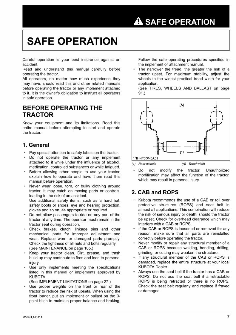
• The narrower the tread, the greater the risk of atractor upset. For maximum stability, adjust thewheels to the widest practical tread width for yourapplication.(See TIRES, WHEELS AND BALLAST on page91.)
(1) Rear wheels (A) Tread width
• Do not modify the tractor. Unauthorizedmodification may affect the function of the tractor,which may result in personal injury.
2. CAB and ROPS• Kubota recommends the use of a CAB or roll over
protective structures (ROPS) and seat belt inalmost all applications. This combination will reducethe risk of serious injury or death, should the tractorbe upset. Check for overhead clearance which mayinterfere with a CAB or ROPS.
• If the CAB or ROPS is loosened or removed for anyreason, make sure that all parts are reinstalledcorrectly before operating the tractor.
• Never modify or repair any structural member of aCAB or ROPS because welding, bending, drilling,grinding, or cutting may weaken the structure.
• If any structural member of the CAB or ROPS isdamaged, replace the entire structure at your localKUBOTA Dealer.
• Always use the seat belt if the tractor has a CAB orROPS. Do not use the seat belt if a retractableROPS is being retracted or there is no ROPS.Check the seat belt regularly and replace if frayedor damaged.
SAFE OPERATION
M5091,M5111 7

(1) CAB(2) Seat belt
• The CAB is not tested for falling object protectionstructure (FOPS).
• The CAB fulfills the requirements of category 2 (EN15695-1: 2009) for hazardous substances.(See CAB CLASSIFICATION AND MAINTENANCEon page 96.)
• The CAB provides protection against dust but notagainst aerosols and vapors.
• The CAB cannot be used under conditions requiringprotection against aerosols and vapors.
OPERATING THE TRACTOROperator safety is a priority. Safe operation, specificallywith respect to overturning hazards, entailsunderstanding the equipment and environmentalconditions at the time of use.Some prohibited uses which can affect overturninghazards include traveling and turning with implements,loads carried too high and so on. This manual sets forthsome of the obvious risks, but the list is not, and cannotbe, exhaustive. It is the operator's responsibility to bealert for any equipment or environmental condition thatcould compromise safe operation.
1. Starting to operate the tractor• Always sit in the operator's seat when starting the
engine or operating levers or controls. Adjust seatper instructions in the operating the tractor section.Never start the engine while standing on theground.
• Before starting the engine, make sure that all levers(including auxiliary control levers) are in theirneutral positions, that both parking brakes areapplied, and that both the clutch and the powertake-off (PTO) are disengaged or “OFF”. Fasten theseat belt if the tractor has a CAB, a fixed ROPS ora retractable ROPS in the upright and lockedposition.
• Do not start the engine by shorting across starterterminals or bypassing the safety start switch. The
machine may start in gear and move if the normalstarting circuitry is bypassed.
• Do not operate or idle the engine in an unventilatedarea. Carbon monoxide gas is colorless, odorless,and deadly.
• Check that the operator presence control (OPC)system is functioning correctly before each time youuse the tractor.Test the safety systems.(See Checking engine start system on page 116.)Do not operate unless they are functioningcorrectly.
2. Working the tractor• Pull only from the drawbar. Never hitch to axle
housing or any other point except the drawbar;such arrangements will increase the risk of seriouspersonal injury or death due to a tractor upset.
(1) Drawbar
• For trailing PTO-driven implements, set the drawbarto the towing position.
• Attach pulled or towed loads to the drawbar only.• Keep all shields and guards in place. Replace any
that are missing or damaged.• Avoid sudden starts. To avoid upsets, slow down
when turning, on uneven ground, and beforestopping.
• The tractor cannot turn with the differential lockedand attempting to do so could be dangerous.
• Do not operate near ditches, holes, embankments,or other ground surface features which maycollapse under the tractor's weight. The risk oftractor upset is even higher when the ground isloose or wet. Tall grass can hide obstacles; walk thearea first to be sure.
• Watch where you are going at all times. Watch forand avoid obstacles. Be alert at row ends, neartrees, and other obstructions.
• When working in groups, always let the othersknow what you are going to do before you do it.
• Never try to get on or off a moving tractor.
SAFE OPERATION
8 M5091,M5111

• Always sit in the operator's seat when operatinglevers or controls.
• Do not stand between tractor and implement ortrailed vehicle unless both parking brakes areapplied.
• Do not operate the tractor when there is apossibility of lightning. Even if the tractor isequipped with a CAB, the operator is not protectedfrom lightning.
3. Instructional seat (if equipped)• Always wear your seat belt and stabilize your body
by holding the handrail on the CAB frame.• It is not intended to carry children nor any other
person for any other purpose.• The left-hand door must be closed at all time
whenever the instructional seat is occupied and thetractor is in motion.
• Do not permit others to ride, except on thedesignated instructional seat.
• Use caution to avoid the risks of obstructingoperator's view, falling from the machine andinterfering with controls.
• Do not start and stop the tractor suddenly, nor takea sharp turn.
• Do not use the instructional seat if the seat belt orthe door lock fails to function.
• Do not use the instructional seat for transport.• When opening or closing the door while being
seated in the instructional seat, move the doorslowly. This is to prevent his or her hand(s) fromgetting caught by the door or his or her body to hitagainst the door.
4. Safety for childrenTragedy can occur if the operator is not alert to thepresence of children. Children generally are attracted tomachines and the work they do.• Never assume that children will remain where you
last saw them.• Keep children out of the work area and under the
watchful eye of another responsible adult.• Be alert and shut your machine down if children
enter the work area.• Never carry children on your machine. There is no
safe place for them to ride. They may fall off and berun over or interfere with your control of themachine.
• Never allow children to operate the machine evenunder adult supervision.
• Never allow children to play on the machine or onthe implement.
• Use extra caution when backing up. Look behindand down to make sure area is clear beforemoving.
5. Operating on slopesSlopes are a major factor related to loss-of-control andtip-over accidents, which can result in severe injury ordeath. All slopes require extra caution.• To avoid upsets, always back up steep slopes. If
you cannot back up the slope or if you feel uneasyon it, do not operate on it. Stay off slopes too steepfor safe operation.
• Driving forward out of a ditch, mired condition or upa steep slope increases the risk of rear rollovers.Always back out of these situations. Extra caution isrequired with 4-wheel drive models because theirincreased traction can give the operator falseconfidence in the tractor's ability to climb slopes.
• Keep all movement on slopes slow and gradual. Donot make sudden changes in speed, direction orbraking, nor make sudden motions with the steeringwheel.
• Avoid disengaging the clutch or changing gearswhen climbing or going down a slope. If on a slope,disengaging the clutch or changing gears to neutralcould cause the loss of control.
• Special attention should be paid to the weight andlocation of implements and loads as such will affectthe stability of the tractor.
• To improve stability on slopes, set the widestpossible wheel tread.(See TIRES, WHEELS AND BALLAST on page91.)Follow the recommendations for proper ballasting.
• To avoid free wheeling:– Do not shift the shuttle lever while on a slope.– Stop completely by using the brakes and by
depressing the clutch pedal, then shift theshuttle lever.
– Start off after selecting shuttle direction, byreleasing the clutch pedal.
• When driving down a slope, ensure that 4-wheeldrive is engaged to increase traction (if equipped).
6. Driving the tractor on the road• Lock the 2 brake pedals together to help assure
straight-line stops. Uneven braking at road speedscould cause the tractor to tip over.
SAFE OPERATION
M5091,M5111 9

(1) Brake pedal (LH)(2) Brake pedal (RH)(3) Brake pedal lock
(A) “Lock the brake pedalswhenever traveling on theroad”
• Check the front wheel engagement. The brakingcharacteristics are different between 2 and 4-wheeldrive. Be aware of the difference and use carefully.
• When driving down a slope, ensure that the 4-wheel drive is engaged to increase traction (ifequipped).
• Always slow down the tractor before turning.Turning at high speed may tip over the tractor.
• Observe all local traffic and safety regulations. Usethe registration plate as required.
(1) Registration plate
• Turn the headlights on. Dim them when meetinganother vehicle.
• Drive at speeds that allow you to maintain control atall times.
• Do not apply the differential lock while traveling atroad speeds. The tractor may run out of control.
• Avoid sudden motions of the steering wheel as theycan lead to a dangerous loss of stability. The risk isespecially great when the tractor is traveling at roadspeeds.
• Do not operate an implement while the tractor is onthe road. Lock the 3-point hitch in the raisedposition.
• Set the 3-point hitch lowering speed knob in the“LOCK” position to hold the implement in the raisedposition.
(1) 3-point hitch lowering speedknob
(A) “FAST”(B) “SLOW”(C) “LOCK”
PARKING THE TRACTOR• Disengage the PTO, lower all implements to the
ground, place all control levers in their neutralpositions, set both parking brakes, stop the engine,remove the key from the ignition and lock the CABdoor (if equipped).Leaving transmission in gear with the enginestopped will not prevent the tractor from rolling.
• Make sure that the tractor has come to a completestop before dismounting.
• Avoid parking on steep slopes. If at all possible,park on a firm and level surface; if not, park acrossa slope and chock the wheels.Failure to comply with this warning may allow thetractor to move and could cause injury or death.
OPERATING THE PTO• Wait until all moving components have completely
stopped before getting off the tractor, connecting,disconnecting, adjusting, cleaning, or servicing anyPTO driven equipment.
• Keep the PTO shaft cover in place at all times.Replace the PTO shaft cap when the shaft is not inuse.
SAFE OPERATION
10 M5091,M5111

(1) PTO shaft cover(2) PTO shaft cap
(A) “NORMAL POSITION”(B) “RAISED POSITION”
• Before installing or using PTO driven equipment,read the manufacturer's manual and review thesafety labels attached to the equipment.
• When operating stationary PTO driven equipment,always apply both of the tractor's parking brakesand place chocks behind and in front of the rearwheels. Stay clear of all rotating parts.Never step over rotating parts.
USING 3-POINT HITCH• Use the 3-point hitch only with equipment designed
for the appropriate category of 3-point hitch usage.• When using a 3-point hitch mounted implement, be
sure to install the proper counterbalance weight onthe front of the tractor.
• To avoid injury from separation:Do not extend the lift rod beyond the groove on thethreaded rod.
(1) Groove
SERVICING THE TRACTORBefore servicing the tractor, park it on a firm, flat andlevel surface, set both parking brakes, lower allimplements to the ground, place the gear shift lever inneutral, stop the engine and remove the key.
• Allow the tractor time to cool off before working onor near the engine, muffler, radiator and so on.
• Do not remove radiator cap while the coolant is hot.When cool, slowly rotate cap to the first stop andallow sufficient time for excess pressure to escapebefore removing the cap completely. If the tractorhas a coolant recovery tank, add coolant or water tothe tank, not the radiator.(See Checking coolant level on page 113.)
• Always stop the engine before refueling. Avoidspills and overfilling. Use only approved fuels.
• Always use grounded refueling facilities.• Do not smoke when working around the battery or
when refueling. Keep all sparks and flames awayfrom battery and fuel tank. The battery presents anexplosive hazard because it gives off hydrogen andoxygen especially when recharging.
• Before “jump-starting” a dead battery, read andfollow all of the instructions.(See JUMP STARTING on page 46.)
• Keep first aid kit and fire extinguisher handy at alltimes.
• Disconnect the battery's ground cable beforeworking on or near electric components.
• To avoid the possibility of battery explosion, do notuse or charge the refillable type battery if the fluidlevel is below the [LOWER] (lower limit level) mark.Check the fluid level regularly and add distilledwater as required so that the fluid level is betweenthe [UPPER] and [LOWER] levels.
• To avoid sparks from an accidental short circuit,always disconnect the battery's ground cable (-)first and reconnect it last.
(1) Battery
• Do not attempt to mount a tire on a rim. This shouldbe done by a qualified person with the properequipment.
• Always maintain the correct tire pressure. Do notinflate tires above the recommended pressureshown in the operator's manual.
SAFE OPERATION
M5091,M5111 11

• Securely support the tractor when either changingwheels or adjusting the wheel tread width.
• Make sure that wheel bolts have been tightened tothe specified torque.
• Disconnect the battery's ground cable and stop theengine to avoid the possibility of the machinerunaway due to 4WD braking system during testing,service or repair with only rear wheels off theground.
• Do not work under any hydraulically supporteddevices. They can settle, suddenly leak down, or beaccidentally lowered. If it is necessary to workunder the tractor or any machine elements forservicing or adjustment, securely support them withstands or suitable blocking beforehand.
• Escaping hydraulic fluid under pressure hassufficient force to penetrate the skin, causingserious personal injury. Before disconnectinghydraulic lines, be sure to release all residualpressure. Before applying pressure to the hydraulicsystem, make sure that all connections are tightand that all lines, pipes, and hoses are free ofdamage.
• Fluid escaping from pinholes may be invisible. Donot use hands to search for suspected leaks; use apiece of cardboard or wood. Use of safety gogglesor other eye protection is also highly recommended.If injured by escaping fluid, see a medical doctor atonce. This fluid will produce gangrene or severeallergic reactions.
(1) Cardboard(2) Hydraulic line(3) Magnifying glass
• Do not open the high-pressure fuel system.High-pressure fluid remaining in fuel lines cancause serious injury. Do not disconnect or attemptto repair fuel lines, sensors, or any othercomponents between the high-pressure fuel pumpand injectors on engines with high-pressurecommon rail fuel system.
• To avoid hazardous high voltage, turn the keyswitch to the “OFF” position if it is necessary tocheck or repair the computer, harness orconnectors.
• During diesel particulate filter (hereinafter calledDPF) regenerating operations, exhaust gases andexhaust filter components reach temperatures hotenough to burn people or ignite or melt commonmaterials.
• Keep the tractor away from people, animals orstructures which may be susceptible to harm ordamage from hot exhaust gases.
• To prevent fires, keep the DPF muffler and itssurroundings clear of anything flammable and keepclean at all times.
• To avoid fire hazard:After use and pressure-washing, make sure there isnothing flammable near the exhaust pipe. Grass ortwigs under the hood may cause fire.
• During regeneration, white exhaust gas may bevisible. Do not allow regeneration to happen in anunventilated place.
• During regeneration, do not leave the tractor.• The improper disposal or burning of waste causes
environmental pollution and can be punishable byyour local laws and regulations.– When draining fluids from the tractor, place a
container underneath the drain port.– Do not pour waste onto the ground, down a
drain, or into any water source (such as rivers,streams, lakes, marshes, seas, and oceans).
– Waste products such as used oil, fuel, coolant,hydraulic fluid, refrigerant, solvent, filters,rubber, batteries, and harmful substances, canharm the environment, people, pets and wildlife.
SAFE OPERATION
12 M5091,M5111

Please dispose of properly.See your local recycling center or KUBOTADealer to learn how to recycle or get rid ofwaste products.
SAFE OPERATION
M5091,M5111 13
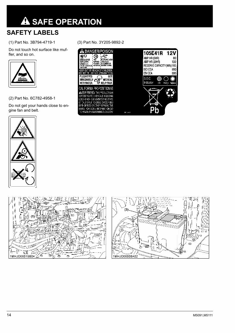
SAFETY LABELS(1) Part No. 3B794-4719-1 (3) Part No. 3Y205-9892-2
Do not touch hot surface like muf-fler, and so on.
(2) Part No. 6C782-4958-1
Do not get your hands close to en-gine fan and belt.
SAFE OPERATION
14 M5091,M5111

(1) Part No. 6C782-4958-1 (2) Part No. TC660-9861-1 (3) Part No. 3B794-4719-1
Do not get your handsclose to engine fan andbelt.
Do not touch hot surfacelike muffler, and so on.
(4) Part No. 3A481-9853-1 (5) Part No. 32310-4958-1 (6) Part No. 3J080-3822-1
Diesel fuelonly No fire Do not touch hot surface
like muffler, and so on.
SAFE OPERATION
M5091,M5111 15

(1) Part No. 3C581-9858-1
(2) Part No. 3F240-9857-1
(3) Part No. 6C150-4743-1
(4) Part No. 3B791-9778-1
If the optional instructional seat is installed
SAFE OPERATION
16 M5091,M5111
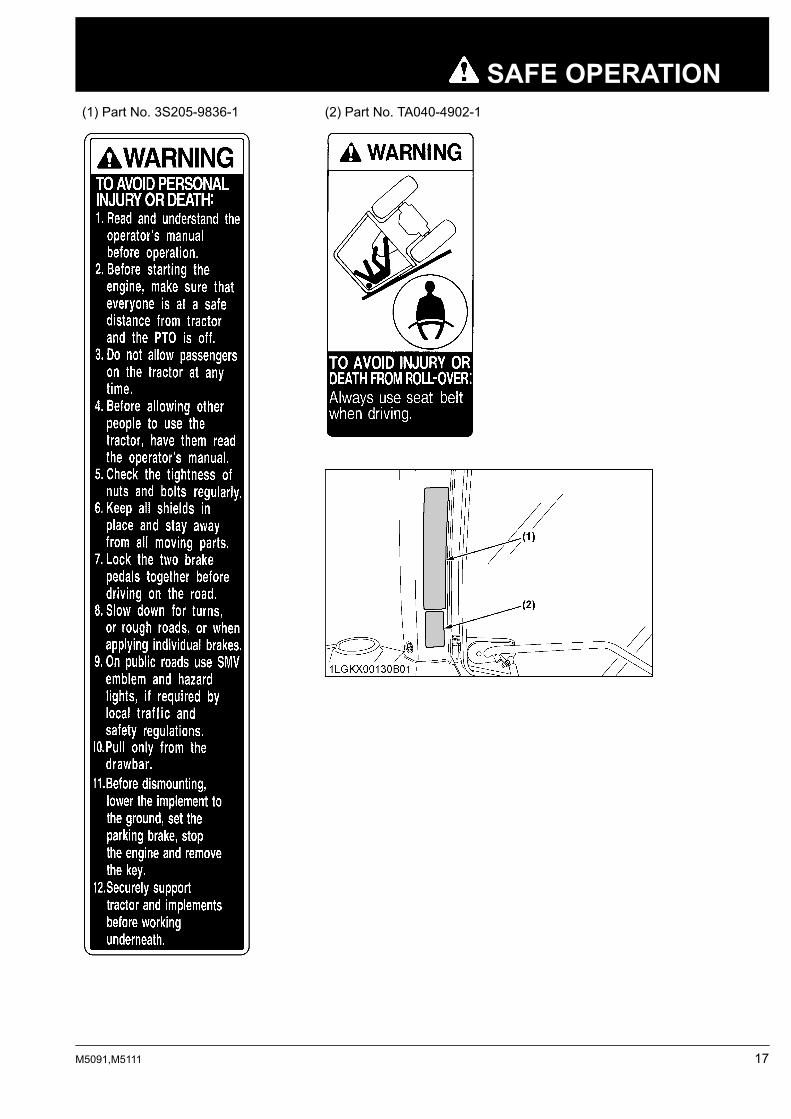
(1) Part No. 3S205-9836-1 (2) Part No. TA040-4902-1
SAFE OPERATION
M5091,M5111 17
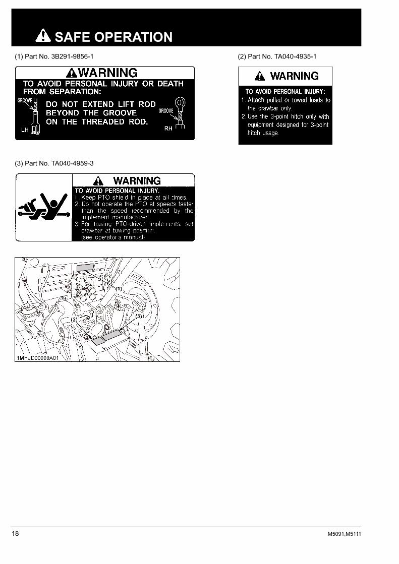
(1) Part No. 3B291-9856-1 (2) Part No. TA040-4935-1
(3) Part No. TA040-4959-3
SAFE OPERATION
18 M5091,M5111

CARE OF SAFETY LABELS• Keep safety labels clean and free from obstructing material.• Clean safety labels with soap and water, and dry with a soft cloth.• Replace damaged or missing safety labels with new labels from your local KUBOTA Dealer.• If a component with safety label(s) attached is replaced with a new part, make sure new label(s) is (are) attached
in the same location(s) as the replaced component.• Attach new safety labels by applying on a clean dry surface and pressing any bubbles to the outside edge.
SAFE OPERATION
M5091,M5111 19

20 M5091,M5111

SERVICING OF TRACTORYour dealer has knowledge of your new tractor and hasthe desire to help you get the most value from it.After reading this manual thoroughly, you will find thatyou can do some of the regular maintenance yourself.However, when in need of parts or major service, besure to see your KUBOTA Dealer.For service, contact the KUBOTA Dealership fromwhich you purchased your tractor or your localKUBOTA Dealer.When in need of parts, be prepared to give your dealerthe tractor, CAB/ROPS and engine serial numbers.Locate the serial numbers now and record them in thespace provided.
Date of purchase
Name of dealer
To be filled in by purchaser
Type Serial No.
Tractor
CAB/ROPS
Engine
To be filled in by purchaser
(1) Tractor identification plate
(1) Tractor serial number
(1) Engine serial number
(1) CAB identification plate (CAB serial number)
SERVICING OF TRACTOR
M5091,M5111 21

(1) Diesel particulate filter (DPF) serial number
WARRANTYThis tractor is warranted under the KUBOTA LimitedExpress Warranty, a copy of which may be obtainedfrom your selling dealer.No warranty shall, however, apply if the tractor has notbeen handled according to the instruction given in theoperator's manual, even if it is within the warrantyperiod.
SCRAPPING THE TRACTORAND ITS PROCEDURETo put the tractor out of service, correctly follow thelocal rules and regulations of the country or territorywhere you scrap it.If you have questions, consult your local KUBOTADealer.
SERVICING OF TRACTOR WARRANTY
22 M5091,M5111

SPECIFICATIONS
SPECIFICATION TABLEModel
M5091 M51114WD 4WD
Engine
Model V3800-CR-TE4-G1 V3800-CR-TIE4-G1
Type 4-cylinder inline, common rail system, di-rect injection
4-cylinder inline, common rail system, di-rect injection, intercooler
Number of cylinders 4
Total displacement cm3 3769
Bore and stroke mm 100 × 120
Rated revolution rpm 2600
Low idling revolution rpm 800 to 850
Rated engine HP(97/68/EC) kW (PS) 69.4 (94.3) 82.4 (112.0)
Net power*1 kW (PS) 63.9 (86.8) 76.9 (104.5)
Maximum torque N⋅m/rpm 320/1500 364/1500
Battery capacity 12 V, RC: 160 min, CCA 900 A
Fuel tank capacity L 105
Engine oil capacity L 10.7
Coolant capacity L 10.0
Dimensions
Overall length mm 3955
Overall width(minimum tread) mm 2047
Overall height mm 2650
Wheel base mm 2250
TreadFront mm 1611
Rear mm 1503 to 1695
Minimum ground clearance mm 466 (drawbar bracket)
Weight kg 3270
Traveling sys-tem
Standard tiresize
Front tires 360/70R24
Rear tires 480/70R34
Clutch Hydraulic multiple wet disks
Steering Hydraulic power steering
Braking system Hydraulically operated wet disk
Differential Bevel gears with differential lock (rear)
Hydraulic unit
Hydraulic control system Position, draft (top link sensing) and mix control
Pump capacity L/min 64.3
3-point hitch Category 2
Max. liftingforce
At liftingpoints*2 kg 3900
Remote hydraulic control 2 standard (3rd and flow control valve optional)
Remote control valve coupler ISO 7241-1 standards “A”(Continued)
SPECIFICATION TABLE SPECIFICATIONS
M5091,M5111 23

ModelM5091 M51114WD 4WD
Hydraulic unitSystem pressure MPa
(kgf/cm2) 20.2 (206)
Traction system Swinging drawbar, adjustable in direction
PTO Live PTO(independent)
Direction of turning Clockwise, viewed from tractor rear
PTO/enginespeed rpm
6 spline: 540/20356 spline: 540E/151921 spline: 1000/2389
The level of protection against hazardous substance*3 Category 2
The company reserves the right to change the specifications without notice.
*1 Manufacturer's estimate*2 At lower link end with links horizontal.*3 According to EN 15695-1: 2009
SPECIFICATIONS
24 M5091,M5111

TRAVELING SPEEDSModel with dual speed
ModelM5111
F36 / R36Rear tire size 480/70R34
Shuttle shift lever Range gear shift lever Main gear shiftlever
Dual speed: H Dual speed: L
km/h km/h
Forward
1 0.40 0.34
2 0.55 0.46
3 0.71 0.60
4 0.91 0.77
5 1.13 0.95
6 1.61 1.36
1 2.7 2.3
2 3.7 3.1
3 4.8 4.0
4 6.2 5.2
5 7.7 6.5
6 11.0 9.2
1 12.1 10.1
2 16.5 13.9
3 21.3 17.9
4 27.5 23.1
5 33.9 28.5
6 38.8*1 32.7*1
Reverse
1 0.41 0.34
2 0.56 0.47
3 0.72 0.60
4 0.92 0.78
5 1.14 0.96
6 1.63 1.38
1 2.8 2.3
2 3.8 3.2
3 4.9 4.1
4 6.3 5.3
5 7.8 6.5
6 11.1 9.4
1 12.2 10.3
2 16.7 14.0
3 21.5 18.1
4 27.8 23.4
5 34.3 28.9
6 39.3*1 33.1*1
At rated engine rpmThe company reserves the right to change the specifications without notice.
*1 At 2080 engine rpm.
TRAVELING SPEEDS SPECIFICATIONS
M5091,M5111 25

Model without dual speed
ModelM5111/M5091
F18 / R18Rear tire size 480/70R34
Shuttle shift lever Range gear shift lever Main gear shiftlever km/h
Forward
1 0.37
2 0.51
3 0.66
4 0.85
5 1.05
6 1.50
1 2.5
2 3.5
3 4.5
4 5.8
5 7.1
6 10.2
1 11.2
2 15.4
3 19.8
4 25.6
5 31.6
6 39.2*1
Reverse
1 0.37
2 0.51
3 0.66
4 0.85
5 1.04
6 1.50
1 2.5
2 3.5
3 4.5
4 5.8
5 7.1
6 10.2
1 11.2
2 15.3
3 19.7
4 25.4
5 31.4
6 39.0*1
At rated engine rpmThe company reserves the right to change the specifications without notice.
*1 At 2080 engine rpm.
SPECIFICATIONS
26 M5091,M5111
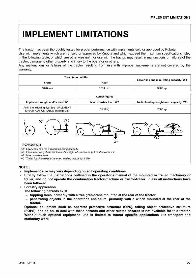
IMPLEMENT LIMITATIONSThe tractor has been thoroughly tested for proper performance with implements sold or approved by Kubota.Use with implements which are not sold or approved by Kubota and which exceed the maximum specifications listedin the following table, or which are otherwise unfit for use with the tractor, may result in malfunctions or failures of thetractor, damage to other property and injury to the operator or others.Any malfunctions or failures of the tractor resulting from use with improper implements are not covered by thewarranty.
Tread (max. width)Lower link end max. lifting capacity: W0
Front Rear
1628 mm 1714 mm 3900 kg
Actual figures
Implement weight and/or size: W1 Max. drawbar load: W2 Trailer loading weight max. capacity: W3
As in the following list (See IMPLEMENTSPECIFICATION TABLE on page 28.) 1500 kg 7000 kg
W0 Lower link end max, hydraulic lifting capacityW1 Implement weight-the implement's weight which can be put on the lower linkW2 Max. drawbar loadW3 Trailer loading weight-the max. loading weight for trailer
NOTE :• Implement size may vary depending on soil operating conditions.• Strictly follow the instructions outlined in the operator's manual of the mounted or trailed machinery or
trailer, and do not operate the combination tractor-machine or tractor-trailer unless all instructions havebeen followed
• Forestry applicationThe following hazards exist:– toppling trees, primarily with a tree grab-crane mounted at the rear of the tractor;– penetrating objects in the operator's enclosure, primarily with a winch mounted at the rear of the
tractor.Optional equipment such as operator protective structure (OPS), falling object protective structure(FOPS), and so on. to deal with these hazards and other related hazards is not available for this tractor.Without such optional equipment, use is limited to tractor specific applications like transport andstationary work.
IMPLEMENT LIMITATIONS
M5091,M5111 27

IMPLEMENT SPECIFICATION TABLENo. Implement Remarks M5091 M5111
1 Slurry tankMax. tank capacity L 4000
Max. load capacity kg 5000
2 TrailerMax. load capacity kg 7000
Max. drawbar load kg 1500
3 Mower
Rotary-cutterMax. cutting width mm 2800
Max. weight kg 600
Flail mower(heavy)
Max. cutting width mm 3660
Max. weight kg 1000
Sickle bar Max. cutting width mm 2743
4 Sprayer Max. tankcapacity
Mid L 800 1000
Rear 3P L 800 1000
Drawbar L 4500 5000
5 Rotary tillerMax. tilling width mm 2400
Max. weight kg 1000
6 Bottom plowMax. size
16 in. x 418 in. x 324 in. x 1
14 in. x 516 in. x 420 in. x 324 in. x 1
Max. weight(3P type) kg 750 900
7 Disk harrow3P type
Max. size 24 in. x 24 24 in. x 28
Max. harrowing width mm 2850 3300
Max. weight kg 750 900
Drawbar type Max. harrowing width mm 3660 4300
8 Disc plowMax. size 26 in. x 4
28 in. x 426 in. x 428 in. x 4
Max. weight kg 750 900
9 SubsoilerNumbers of cultivating tines 2
Cultivating depth mm 500 550
10 Cultivator
Max. width mm 4880 5490
Number of rows 6
Max. weight kg 750 900
11 Front blade*1*2Max. cutting width mm 2430 2600
Max. oil pressure MPa 19.6
12 Rear bladeMax. cutting width mm 2430 2600
Max. oil pressure MPa 19.6
13 Front loader*1*2
Max. lifting capacity(bucket pivot pin, max.height)
kg 1880*3
Max. oil pressure(extra hydro kit) MPa 20.5
14 Box bladeMax. cutting width mm 2430
Max. weight kg 750 800
15 Back hoe *2 Max. digging depth mm 3050(Continued)
IMPLEMENT LIMITATIONS IMPLEMENT SPECIFICATION TABLE
28 M5091,M5111

No. Implement Remarks M5091 M5111
15 Back hoe *2 Max. weight kg 1200
16 Snow bladeMax. width mm 2430 2600
Max. weight kg 750 800
NOTE :• Implement size may vary depending on soil operating conditions.
*1 Must remove front weight with this implement.*2 Need subframe*3 The value contains the weight of KUBOTA standard bucket.
IMPLEMENT LIMITATIONS
M5091,M5111 29

OVERVIEW OF TRACTOR PARTS
(1) CAB ............................................................................................... 96(2) Front work light .............................................................................. 98(3) Rear-view mirror(4) Door ............................................................................................... 96(5) Position, turn signal and hazard lights ........................................... 53(6) Rear tire ......................................................................................... 91
(7) Side cover.....................................................................................110(8) Front tire ........................................................................................ 91(9) Windshield(10) Hood .............................................................................................110(11) Headlight........................................................................................ 53
OVERVIEW OF TRACTOR PARTS
30 M5091,M5111
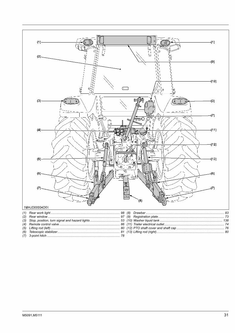
(1) Rear work light............................................................................... 98(2) Rear window .................................................................................. 97(3) Stop, position, turn signal and hazard lights .................................. 53(4) Remote control valve ..................................................................... 86(5) Lifting rod (left) ............................................................................... 80(6) Telescopic stabilizer....................................................................... 81(7) 3-point hitch ................................................................................... 78
(8) Drawbar ......................................................................................... 83(9) Registration plate........................................................................... 73(10) Washer liquid tank ....................................................................... 138(11) Trailer electrical outlet .................................................................... 74(12) PTO shaft cover and shaft cap ...................................................... 76(13) Lifting rod (right)............................................................................. 80
M5091,M5111 31
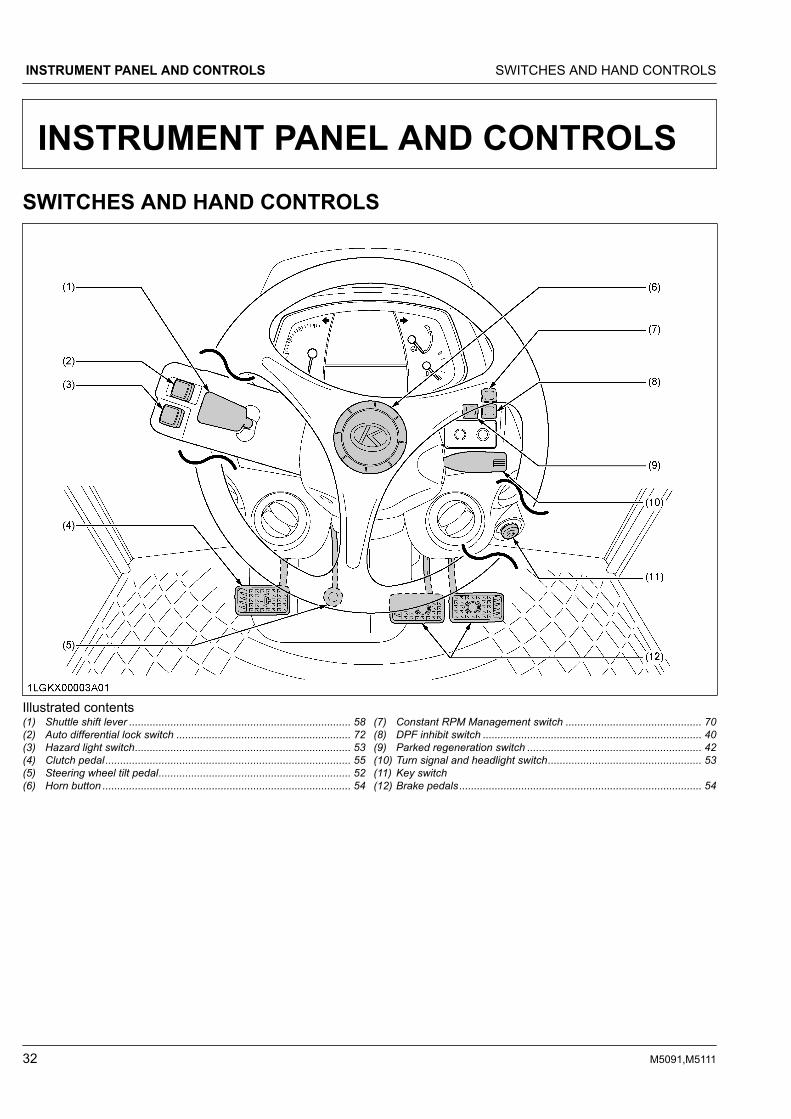
INSTRUMENT PANEL AND CONTROLSSWITCHES AND HAND CONTROLS
Illustrated contents(1) Shuttle shift lever ........................................................................... 58(2) Auto differential lock switch ........................................................... 72(3) Hazard light switch......................................................................... 53(4) Clutch pedal................................................................................... 55(5) Steering wheel tilt pedal................................................................. 52(6) Horn button .................................................................................... 54
(7) Constant RPM Management switch .............................................. 70(8) DPF inhibit switch .......................................................................... 40(9) Parked regeneration switch ........................................................... 42(10) Turn signal and headlight switch.................................................... 53(11) Key switch(12) Brake pedals.................................................................................. 54
INSTRUMENT PANEL AND CONTROLS SWITCHES AND HAND CONTROLS
32 M5091,M5111

INSTRUMENT PANEL
Illustrated contents(1) Tachometer .................................................................................... 63(2) Hazard and turn signal indicator .................................................... 53(3) Electrical charge warning indicator ................................................ 61(4) Engine oil pressure warning indicator............................................ 61(5) Engine warning indicator ............................................................... 61(6) Master system warning indicator ................................................... 61(7) Trailer indicator .............................................................................. 54(8) High beam indicator....................................................................... 53(9) Liquid crystal display (LCD) ........................................................... 63(10) Coolant temperature gauge ........................................................... 63(11) Fuel gauge..................................................................................... 62(12) Rev-limiter indicator ....................................................................... 58(13) Fuel level indicator......................................................................... 61(14) Front PTO indicator (if equipped)(15) 4WD indicator ................................................................................ 60
(16) Auto differential lock indicator........................................................ 72(17) Regeneration indicator................................................................... 38(18) Parked regeneration indicator........................................................ 40(19) Engine rpm increase indicator ....................................................... 38(20) Rear PTO indicator ........................................................................ 45(21) Ground PTO indicator (if equipped)(22) Dual speed shift indicator (if equipped) ......................................... 59(23) Differential lock indicator................................................................ 72(24) Parking brake warning indicator .................................................. 120(25) Water separator indicator............................................................... 61(26) Air cleaner indicator ....................................................................... 61(27) Heater indicator ............................................................................. 45(28) Mode selector switch ..................................................................... 64(29) Select switch.................................................................................. 64
INSTRUMENT PANEL INSTRUMENT PANEL AND CONTROLS
M5091,M5111 33

FOOT AND HAND CONTROLS
Illustrated contents(1) Differential lock pedal .................................................................... 72(2) Operator's seat .............................................................................. 49(3) Instructional seat (if equipped)....................................................... 50(4) Parking brake lever........................................................................ 55(5) Seat belt......................................................................................... 50(6) Cup holder(7) 3-Point hitch lowering speed knob................................................. 86(8) Foot throttle.................................................................................... 60(9) Main gear shift lever ...................................................................... 58(10) Clutch-off switch (if equipped) ....................................................... 59(11) Dual speed shift switch (if equipped) ............................................. 59
(12) RPM dual memory switch .............................................................. 69(13) Range gear shift lever.................................................................... 58(14) Front-wheel drive switch (4WD)..................................................... 60(15) Gear-locked parking brake lever.................................................... 55(16) Remote control valve lever ............................................................ 87(17) Hand throttle lever ......................................................................... 60(18) Position control lever ..................................................................... 85(19) Draft control lever .......................................................................... 85(20) PTO clutch control switch .............................................................. 75(21) Electrical outlet ............................................................................ 103(22) PTO gear shift lever (if equipped) .................................................. 76
Illustrated contents(1) Beacon light switch ................................................................. 103(2) Front work light switch .............................................................. 98(3) Rear work light switch............................................................... 98(4) Rear wiper and washer switch.................................................. 99(5) Front wiper and washer switch ................................................. 99
INSTRUMENT PANEL AND CONTROLS FOOT AND HAND CONTROLS
34 M5091,M5111

PRE-OPERATION CHECKDAILY CHECKTo prevent trouble from occurring, it is important toknow the condition of the tractor. Check it beforestarting.
WARNINGTo avoid personal injury or death:• Be sure to check and service the tractor on a
level surface with the engine shut off, bothparking brakes applied, and the implementlowered to the ground.
Check item• Walk around inspection• Check engine oil level• Check transmission oil level• Check coolant level• Check washer liquid level• Check water separator• Clean grill and radiator screen• Clean air conditioner condenser• Clean air conditioner condenser screen• Clean intercooler (if equipped)• Clean fuel cooler• Clean oil cooler• Check DPF muffler• Check air cleaner evacuator valve
(when used in a dusty place)• Check brake pedal• Check both parking brake levers• Check indicators, gauges and meter• Check lights• Check seat belt• Check movable parts• Refuel
(See DAILY CHECK on page 111.)• Care of the safety labels
(See SAFETY LABELS on page 14.)
DAILY CHECK PRE-OPERATION CHECK
M5091,M5111 35

OPERATING THE ENGINE
WARNINGTo avoid personal injury or death:• Read and understand the safe operation
section.• Read and understand the safety labels located
on the tractor.• To avoid the danger of exhaust fume poisoning,
do not operate the engine in a closed buildingwithout proper ventilation.
• Never start the engine while standing on theground. Start the engine only from operator'sseat.
• Make it a rule to set all shift levers to the“NEUTRAL” positions and to place PTO clutchcontrol switch in “OFF” position before startingthe engine.
Details regarding safe operation can be found in adifferent section.(See SAFE OPERATION on page 7.)
IMPORTANT :• Do not use starting fluid or ether.• To protect the battery and the starter, make sure
that the starter is not continuously turned formore than 10 seconds.
EXHAUST AFTERTREATMENTDEVICES
WARNINGTo avoid personal injury or death:• During diesel particulate filter (DPF)
regenerating operations, exhaust gases andexhaust filter components reach temperatureshot enough to burn people or ignite or meltcommon materials.
• Keep tractor away from people, animals orstructures which may be susceptible to harm ordamage from hot exhaust gases.
• During regeneration, white exhaust gases maybe visible. Do not allow regeneration in anunventilated garage or confined area.
• During regeneration, do not leave the tractor.
DIESEL PARTICULATE FILTER(DPF) MUFFLERThis tractor is equipped with an engine with a dieselparticulate filter (DPF) muffler which serves to reducehydrocarbons, carbon monoxide and other toxic gases,all of which are contained in diesel engine emissions, toharmless carbon dioxide and water. The DPF also trapsparticulate matter (PM).Please handle exhaust aftertreatment devices correctlyand in an environmentally responsible manner.
(1) Diesel particulate filter (DPF)
1. Handling pointsWhen a specific amount of particulate matter (PM) hasaccumulated in the DPF muffler, it is necessary torefresh the DPF muffler by burning the PM inside it.This burning off work is called “Regeneration”.To extend operating time to reach this regeneration,and to avoid DPF muffler trouble, make sure to observethe following handling matters.FuelBe sure to use ultra-low sulfur fuel (S15).
IMPORTANT :• Use of diesel fuel other than ultra-low sulfur fuel
may adversely affect the engine and DPFperformance.Use of fuels other than ultra-low sulfur fuel(S15) may not meet regulations for your region.
Engine oilUse DPF-compatible oil (CJ-4) for the engine.
OPERATING THE ENGINE EXHAUST AFTERTREATMENT DEVICES
36 M5091,M5111

IMPORTANT :• If any engine oil other than CJ-4 is used, the
DPF may become clogged earlier than expectedand the fuel economy may drop.
Prohibition of unnecessary idling operationGenerally, the lower the engine speed, the lower theexhaust gas temperature is, so the PM contained inexhaust gas will not be burned, and begins toaccumulate. Therefore, do not idle unnecessarily.RegenerationWhen there is “Regeneration” instruction sign by lampor buzzer, immediately perform the required procedurefor regeneration.
IMPORTANT :• Interrupting the regeneration cycle or
continuing operation while ignoring the warningsigns may cause DPF and engine damage.
2. DPF regeneration processDPF regeneration process can be performed bychoosing “Auto regeneration” or “Regeneration inhibit”mode according to your job conditions.For jobs not affected by hot gases emitted duringregeneration, “Auto regeneration” is advisable.Auto regeneration modeWhen starting the engine (switch operation isunnecessary), the “Auto regeneration” mode isautomatically activated.With the auto regeneration mode on, when a specificamount of PM has accumulated, and the regenerationconditions are satisfied, the DPF will be automaticallyregenerated whether the tractor is in motion or parked.(See Tips on diesel particulate filter (DPF) regenerationon page 43.)In this way, work efficiency is improved. For moredetails, read the “Auto regeneration” section of thismanual.(See Operating procedure for auto regeneration modeon page 38.)Regeneration inhibit modeAfter starting the engine, if the “DPF inhibit switch” ispressed to turn on the switch lamp, the “Regenerationinhibit” mode will be activated.With “Regeneration inhibit” mode on, the PM which hasaccumulated inside the DPF will not be burned, unlessthe operator performs the regeneration work manually.The “Regeneration inhibit” mode is effective for work inpoorly ventilated workspaces.For more details, read the regeneration prohibitionsection of this manual.(See Operating procedure for regeneration inhibit modeon page 40.)
NOTE :• If the engine is stopped once, the “Auto
regeneration” mode will be activated.
DIESEL PARTICULATE FILTER (DPF) MUFFLER OPERATING THE ENGINE
M5091,M5111 37

3. Operating procedure for auto regeneration mode
(1) Parked regeneration switch(2) DPF inhibit switch
(3) Regeneration indicator(4) Parked regeneration indicator
(5) Engine rpm increase indicator(6) Engine warning indicator
Regeneration operating procedure1. Start the engine.
Make sure that the DPF inhibit switch lamp is “OFF”.
Switch lamp “OFF”: Auto regeneration mode activated.Switch lamp “ON”: Regeneration inhibit mode activated.
NOTE :• When the engine is started, the “Auto regeneration” mode is automatically activated.• “Regeneration inhibit” mode is activated when the DPF inhibit switch is pushed after the engine is
started.
2. When the regeneration indicator starts flashing:
A specific amount of PM has built up in the DPF.Continue to operate the tractor, and the regeneration process will begin automatically; make sure the workingplace is in a safe area as DPF and exhaust temperature will rise.
3. When the engine rpm increase indicator starts flashing:
Keep on working and increase the engine rpm until the indicator turns “OFF”.
NOTE :• Even if the auto regeneration mode is selected, DPF regeneration may not begin because system
requirements have not been satisfied.• The engine rpm increase indicator is used as a guide to satisfy the regeneration conditions. If the engine
load is too heavy, the engine rpm increase indicator may continue to flash, even though regenerationsystem conditions are satisfied and regeneration may begin automatically.(See Tips on diesel particulate filter (DPF) regeneration on page 43.)
OPERATING THE ENGINE DIESEL PARTICULATE FILTER (DPF) MUFFLER
38 M5091,M5111
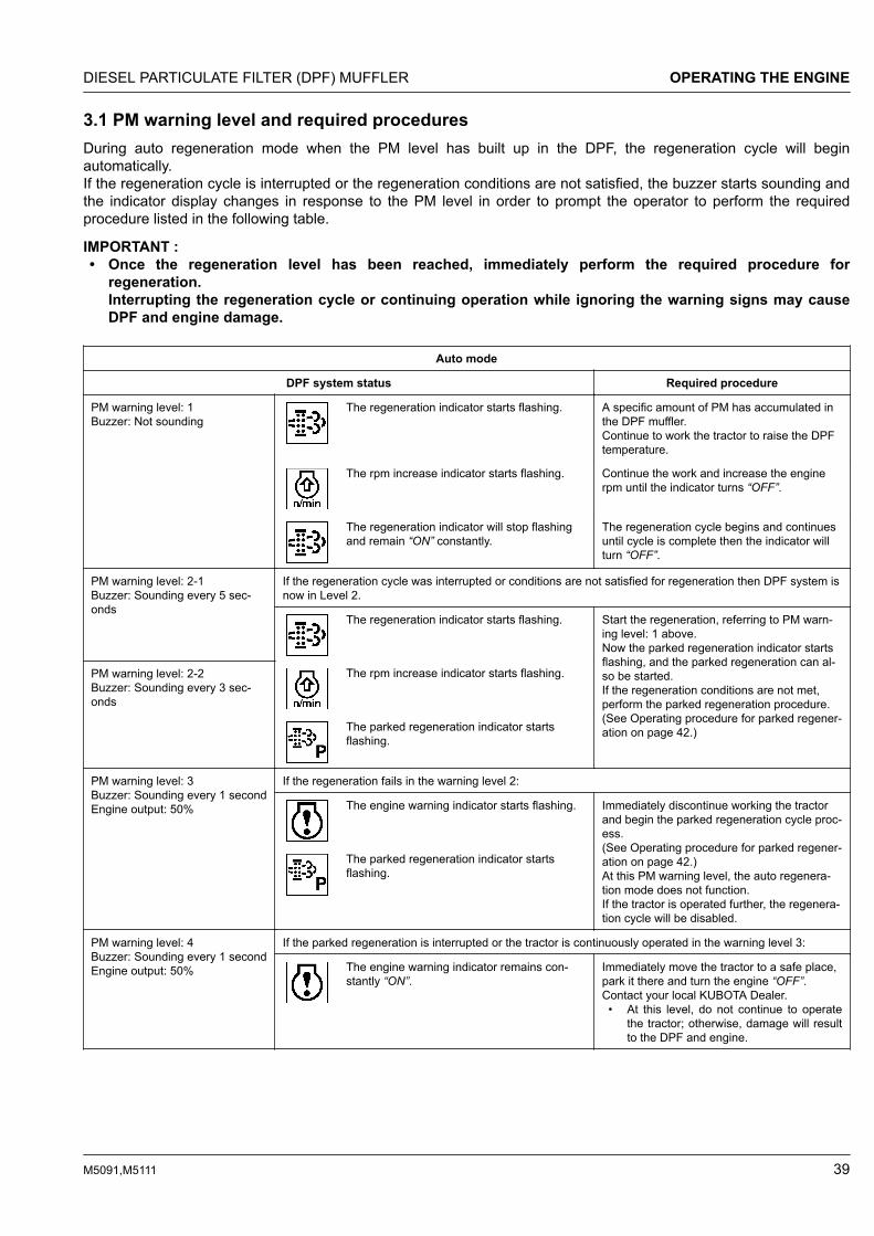
3.1 PM warning level and required proceduresDuring auto regeneration mode when the PM level has built up in the DPF, the regeneration cycle will beginautomatically.If the regeneration cycle is interrupted or the regeneration conditions are not satisfied, the buzzer starts sounding andthe indicator display changes in response to the PM level in order to prompt the operator to perform the requiredprocedure listed in the following table.
IMPORTANT :• Once the regeneration level has been reached, immediately perform the required procedure for
regeneration.Interrupting the regeneration cycle or continuing operation while ignoring the warning signs may causeDPF and engine damage.
Auto mode
DPF system status Required procedure
PM warning level: 1Buzzer: Not sounding
The regeneration indicator starts flashing. A specific amount of PM has accumulated inthe DPF muffler.Continue to work the tractor to raise the DPFtemperature.
The rpm increase indicator starts flashing. Continue the work and increase the enginerpm until the indicator turns “OFF”.
The regeneration indicator will stop flashingand remain “ON” constantly.
The regeneration cycle begins and continuesuntil cycle is complete then the indicator willturn “OFF”.
PM warning level: 2-1Buzzer: Sounding every 5 sec-onds
If the regeneration cycle was interrupted or conditions are not satisfied for regeneration then DPF system isnow in Level 2.
The regeneration indicator starts flashing. Start the regeneration, referring to PM warn-ing level: 1 above.Now the parked regeneration indicator startsflashing, and the parked regeneration can al-so be started.If the regeneration conditions are not met,perform the parked regeneration procedure.(See Operating procedure for parked regener-ation on page 42.)
PM warning level: 2-2Buzzer: Sounding every 3 sec-onds
The rpm increase indicator starts flashing.
The parked regeneration indicator startsflashing.
PM warning level: 3Buzzer: Sounding every 1 secondEngine output: 50%
If the regeneration fails in the warning level 2:
The engine warning indicator starts flashing. Immediately discontinue working the tractorand begin the parked regeneration cycle proc-ess.(See Operating procedure for parked regener-ation on page 42.)At this PM warning level, the auto regenera-tion mode does not function.If the tractor is operated further, the regenera-tion cycle will be disabled.
The parked regeneration indicator startsflashing.
PM warning level: 4Buzzer: Sounding every 1 secondEngine output: 50%
If the parked regeneration is interrupted or the tractor is continuously operated in the warning level 3:
The engine warning indicator remains con-stantly “ON”.
Immediately move the tractor to a safe place,park it there and turn the engine “OFF”.Contact your local KUBOTA Dealer.• At this level, do not continue to operate
the tractor; otherwise, damage will resultto the DPF and engine.
DIESEL PARTICULATE FILTER (DPF) MUFFLER OPERATING THE ENGINE
M5091,M5111 39

4. Operating procedure for regeneration inhibit mode
(1) Parked regeneration switch(2) DPF inhibit switch
(3) Regeneration indicator(4) Parked regeneration indicator
(5) Engine rpm increase indicator(6) Engine warning indicator
Regeneration operating procedure1. Start the engine.
2. Press the DPF inhibit switch , and the switch lamp illuminates.
Switch lamp “ON”: Regeneration inhibit mode selected.Switch lamp “OFF”: Auto regeneration mode selected.
3. When the parked regeneration indicator starts flashing:
A specific amount of PM has accumulated in the DPF muffler.Move the tractor to a safe place and activate the DPF muffler.(See Operating procedure for parked regeneration on page 42.)
OPERATING THE ENGINE DIESEL PARTICULATE FILTER (DPF) MUFFLER
40 M5091,M5111

4.1 PM warning level and required proceduresIn the regeneration inhibit mode, the buzzer starts sounding and the indicator display changes in response to the PMlevel in order to prompt the operator to perform the required procedure listed in the following table.
IMPORTANT :• Once the regeneration level has been reached, immediately perform the required procedure for
regeneration.Interrupting the regeneration cycle or continuing operation while ignoring the warning signs may causeDPF and engine damage.
Regeneration inhibit mode
DPF system status Required procedure
PM warning level: 1Buzzer: Not sounding
The regeneration indicator starts flashing. A specific level of PM has built up in the DPFmuffler.Continue with the operation as it is.
At PM warning levels range from 1 to 2-2, it is also possible to change DPF inhibit switch toauto regeneration mode, then perform the regeneration.
PM warning level: 2-1Buzzer: Sounding every 5 sec-onds
The regeneration indicator starts flashing. Move the tractor to a safe area, then beginthe parked regeneration cycle process.(See Operating procedure for parked regener-ation on page 42.)
PM warning level: 2-2Buzzer: Sounding every 3 sec-onds
The parked regeneration indicator startsflashing.
PM warning level: 3Buzzer: Sounding every 1 secondEngine output: 50%
If the parked regeneration cycle is interrupted or the tractor is continuously operated in the PM warning lev-el 2:
The engine warning indicator starts flashing. Immediately stop working the tractor, movethe tractor to a safe area, then begin theparked regeneration cycle process.(See Operating procedure for parked regener-ation on page 42.)If the tractor is operated further and the oper-ator ignores the warning signs, then regener-ation will be disabled.
The parked regeneration indicator startsflashing.
PM warning level: 4Buzzer: Sounding every 1 secondEngine output: 50%
If the regeneration cycle is interrupted or the tractor is continuously operated ignoring the warning signs, inthe PM warning level 3:
The engine warning indicator remains con-stantly “ON”.
Immediately move the tractor to a safe place,park it there and turn the engine “OFF”.Contact your local KUBOTA Dealer.• At this level, do not continue to operate
the tractor; otherwise, damage may re-sult to the DPF and engine.
DIESEL PARTICULATE FILTER (DPF) MUFFLER OPERATING THE ENGINE
M5091,M5111 41

5. Operating procedure for parked regeneration1. Park the tractor in a safe area away from buildings, people, and animals.2. Apply both parking brakes.3. Set the shuttle shift lever to the neutral position.4. Turn “OFF” the PTO clutch control switch.5. Return the engine rpm to the idle speed.6. Lower the implement to the ground.
7. Press the DPF inhibit switch , and the switch lamp turns “OFF”.
8. When the regeneration conditions are satisfied (2 to 5 and 7 mentioned previously), the parked regeneration
switch lamp starts flashing.
9. Press the parked regeneration switch to start the regeneration cycle.
The switch lamp will stop flashing and remain “ON” constantly during the cycle.10. The engine rpm will automatically rise, and the regeneration process will begin.
11. Both indicators stay “ON” while regenerating the DPF.
They turn “OFF” when the cycle is complete.12. After the lamp turns “OFF”, normal tractor work may resume.
When driving in “Regeneration inhibit” mode, press the DPF inhibit switch to turn on the switch lamp.
NOTE :• During the regeneration cycle, do not touch the above levers and switches (in steps 2, 3, 4), nor change
the engine rpm other than for an emergency stop. Otherwise, the regeneration will be interrupted.• Never leave the tractor when the parked regeneration process is activated.• If the parked regeneration cycle is interrupted, the engine rpm is fixed at the idling level for about 30
seconds. For this period, keep the hand throttle lever and foot throttle pedal at the idle position. Do notmove them. They will function again in 30 seconds.
OPERATING THE ENGINE DIESEL PARTICULATE FILTER (DPF) MUFFLER
42 M5091,M5111

6. Tips on diesel particulate filter(DPF) regeneration• Operation
The higher in speed or load the engine operates,the higher the exhaust temperature rises. As aresult, particulate matter (PM) inside the DPF isconsumed and the regeneration process is requiredless frequently over time.The lower in speed or load the engine operates, thelower the exhaust temperature. Accordingly, lessparticulate matter (PM) inside the DPF is consumedand more accumulation of PM will occur, whichrequires frequent regeneration. Therefore, avoidprolonged idling if possible.
• Necessary conditions for “Regeneration”When the conditions below are all satisfied,regeneration will start. However, if even onecondition is deviated from during the process, theregeneration will be interrupted.– The engine coolant temperature.– The DPF temperature.– The engine speed is 1200 rpm or higher.
• Usually, it takes 15-20 minutes to complete theregeneration cycle.Actual regeneration time may depend on ambienttemperature, exhaust temperature and enginespeed.
• It is recommended to do the regenerating while theengine is warm.
• Do not unnecessarily start and interrupt theregeneration process. Otherwise, a small amount offuel becomes mixed with the engine oil, whichdegrades the oil quality.
• While the DPF is being regenerated, the engine airflow rate is automatically limited to keep up theexhaust temperature. Because of this, the enginemay sound differently, but this is normal for thisengine.
• Just after the regeneration has ended, the DPFmuffler remains hot. It is advisable to keep theengine running for about 5 minutes to allow coolingof the exhaust components.
STARTING THE ENGINE1. Make sure both the parking brake and the gear-
locked parking brake are set.
NOTE :• The parking brake warning indicator on the
Easy Checker™ will turn on when a parkingbrake is set.
(1) Parking brake warning indicator
Applying the parking brake lever:Pull the parking brake lever up to the parkingposition.
(1) Parking brake lever (A) “Pull up to parking position”
IMPORTANT :• If the tractor is operated with the parking
brake set, the parking brake will bedamaged.
• If the tractor is traveling when the parkingbrake lever is applied, a warning buzzer willsound.If the buzzer sounds, immediately releasethe parking brake lever.
Applying the gear-locked parking brake lever:Depress the brake pedals, place the main gear shiftlever its neutral position, and pull the gear-lockedparking brake lever to the parking position.
DIESEL PARTICULATE FILTER (DPF) MUFFLER OPERATING THE ENGINE
M5091,M5111 43

(1) Gear-locked parking brakelever
(A) “Pull to parking position”
IMPORTANT :• Bring the tractor to a complete stop before
applying the gear-locked parking brakelever.
NOTE :• In moving the gear-locked parking brake
lever, you may feel it heavy sometimes, orlight at other times. This is normal.
2. Make sure the fuel shutoff-valve is in the “OPEN”position.
(1) Fuel shutoff-valve (A) “CLOSE”(B) “OPEN”
3. Place the shift levers in “NEUTRAL” position.
(1) Shuttle shift lever(2) Main gear shift lever
(F) “FORWARD”(N) “NEUTRAL POSITION”(R) “REVERSE”
4. Place the PTO clutch control switch in the “OFF”position and hydraulic control levers in the“LOWEST” position.
(1) PTO clutch control switch(2) Position control lever(3) Draft control lever
(A) “PUSH”(B) “DOWN”
5. Set the throttle lever at the minimum speedposition.
(1) Hand throttle lever “INCREASE”“DECREASE”
OPERATING THE ENGINE STARTING THE ENGINE
44 M5091,M5111

6. Insert the key into the key switch and turn it “ON”.If the ambient temperature is below 0 ℃ and theengine is very cold, turn the key to “ON” positionand hold it until the heater indicator turns off.
“OFF” (Engine-stop)“ACC” (Electrical power-accessories)“ON” (Engine-run)“START” (Engine-start)
(1) Heater indicator
NOTE :• The accessories can be used while the
engine is stopped.• Do not leave the key at “ACC” position. The
battery will be quickly discharged. Turn itback to “OFF” after use.
7. Check the Easy Checker™ indicators.(See Checking Easy Checker™ indicators on page45.)
8. Fully depress the clutch pedal.9. Turn the key to “START” position and release when
the engine starts.
IMPORTANT :• Because of the safety devices, the engine
will not start except when the PTO clutchcontrol switch is placed in the “OFF”position and the shuttle shift lever is placedin the “NEUTRAL” position.
• If the engine fails to start after 10 seconds,turn off the key for 30 seconds. Then repeatsteps 6 through 9. To protect the battery andthe starter, make sure that the starter is notcontinuously turned for more than 10seconds.
10. Check to see that all the indicators on the EasyChecker™ are “OFF”.If an indicator is still on, immediately stop theengine and determine the cause.
11. Release the clutch pedal.
1. Checking Easy Checker™
indicatorsIMPORTANT :• Daily checks with the Easy Checker™ only, are
not sufficient. Never fail to conduct daily checkscarefully by referring to the daily check.(See DAILY CHECK on page 111.)
NOTE :• Some of the Easy Checker™ indicators may
illuminate or start flashing depending on thepositions of the levers and switches.
1. When the key is turned “ON”, the electrical chargewarning indicator and the engine oil pressurewarning indicator should come on. If troubleshould occur at any location while the engine isrunning, the indicator corresponding to problem willturn “ON”.
2. Suppose that the engine coolant temperature is nothigh enough yet. The heater indicator also turns“ON” when the key is turned “ON” to preheat theengine and goes off automatically when preheat iscompleted.Illumination time of indicator varies according to thetemperature of coolant.
3. The PTO clutch indicator comes on while thePTO clutch control switch is engaged (“ON”) andgoes off when disengaged.
4. If the fuel level indicator lights up, the fuel levelis very low. Add fuel and the indicator will turn off.
5. If the water separator indicator lights up, thewater in the water separator is very high. Drain thewater and the indicator will turn off.
STARTING THE ENGINE OPERATING THE ENGINE
M5091,M5111 45

6. If the parking brake warning indicator does notlight up, set both parking brakes.
NOTE :• The parking brake warning indicator
lights up if one of the parking brakes isapplied. Even if the parking brake warningindicator is already on, make sure thatboth parking brakes are set.
(1) Electrical charge warning indicator(2) Engine oil pressure warning indicator(3) Rear PTO indicator(4) Parking brake warning indicator(5) Water separator indicator(6) Heater indicator(7) Fuel level indicator
OPERATING THE ENGINE INFREEZING CONDITIONS1. Block heater (if equipped)A block heater is available as an option from yourdealer. It will assist you in starting your tractor when theambient temperature is below -20 ℃.
STOPPING THE ENGINE1. After slowing the engine to idle, wait 3 to 5 minutes
for the turbo to slow down and then turn the key to“OFF”.
2. Remove the key.
NOTE :• If removing the key does not stop the engine,
consult your local KUBOTA Dealer.
WARMING UP THE ENGINE
WARNINGTo avoid personal injury or death:• Be sure to set both parking brakes during
warm-up.
• Be sure to set all shift levers to the “NEUTRAL”positions and to place PTO clutch controlswitch in “OFF” position during warm-up.
For 5 minutes after engine start-up, allow the engine towarm up without applying any load; this is to allow oil toreach every engine part. If load should be applied tothe engine without this warm-up period, trouble such asseizure, breakage or premature wear may develop.
1. Warm-up and transmission fluid atlow temperature rangeHydraulic oil serves as transmission fluid. In coldweather, the oil may be cold with increased viscosity.This can cause delayed oil circulation or abnormallylow hydraulic pressure for some time after engine start-up. This, in turn, can result in trouble in the hydraulicsystem.To prevent the above, observe the followinginstructions:Warm up the engine at about 50% of rated rpmaccording to the following table:
Ambient temperature Warm-up time requirement
Higher than 0 ℃ Approx. 5 minutes
0 to -10 ℃ 10 to 20 minutes
-10 to -20 ℃ 20 to 30 minutes
Below -20 ℃ More than 30 minutes
IMPORTANT :• Do not operate the tractor under full load
condition until it is sufficiently warmed up.
JUMP STARTING
WARNINGTo avoid personal injury or death:• Battery gases can explode. Keep cigarettes,
sparks, and flames away from the battery.• If the tractor battery is frozen, do not jump start
engine.• Do not connect the other end of the negative (-)
jumper cable to the negative (-) terminal of thetractor battery.
• When taking out the dead battery, putting in thebattery or fixing the battery, do not allow thepositive (+) terminal of the battery to touchother parts.
OPERATING THE ENGINE OPERATING THE ENGINE IN FREEZING CONDITIONS
46 M5091,M5111

When jump starting the engine, follow the instructionsbelow to safely start the engine.1. Bring the helper vehicle with a battery of the same
voltage as the disabled tractor within easy cablereach.
IMPORTANT :• The vehicles must not touch.
2. Engage the parking brakes of both vehicles and putthe shift levers in neutral. Shut both engines off.
3. Wear eye protection and rubber gloves.4. Attach the red clamp to the positive (red, (+) or
positive) terminal of the dead battery and clamp theother end of the same cable to the positive (red, (+)or positive) terminal of the helper battery.
5. Clamp the other cable to the negative (black, (-) ornegative) terminal of the helper battery.
6. Clamp the other end to the engine block or frame ofthe disabled tractor as far from the dead battery aspossible.
7. Start the helper vehicle and let its engine run for afew moments. Start the disabled tractor.
8. Disconnect the jumper cables in the exact reverseorder of attachment (steps 6, 5 and 4).
Connect cables in numerical order.Disconnect in reverse order after use.
(1) Dead battery(2) Jumper cables(3) Helper battery
IMPORTANT :• This tractor has a 12 volt negative (-) ground
starting system.• Use only the same voltage for jump starting.• Use of a higher voltage source on tractor's
electrical system could result in severedamage to tractor's electrical system.Use only matching voltage source when“Jump starting” a low or dead batterycondition.
• Do not operate the tractor with the batterycable disconnected from the battery.
• Do not operate the tractor without thebattery mounted.
• Do not operate the tractor with the batterydead. Charge the battery fully beforeoperating the tractor.Otherwise, the tractor might malfunction.
OPERATING THE ENGINE
M5091,M5111 47

OPERATING THE TRACTOROPERATING NEW TRACTORHow a new tractor is handled and maintaineddetermines the life of the tractor.A new tractor just off the factory production line hasbeen, of course, tested, but the various parts are notaccustomed to each other, so care should be taken tooperate the tractor for the first 50 hours at a slowerspeed and avoid excessive work or operation until thevarious parts become “broken-in”. The manner in whichthe tractor is handled during the “breaking-in” periodgreatly affects the life of your tractor.Therefore, to obtain the maximum performance and thelongest life of the tractor, it is very important to properlybreak-in your tractor. In handling a new tractor, thefollowing precautions should be observed.
1. Do not operate the tractor at fullspeed for the first 50 hours• Do not start quickly nor apply the brakes suddenly.• In winter, operate the tractor after fully warming up
the engine.• Do not run the engine at speeds faster than
necessary.• On rough roads, slow down to suitable speeds. Do
not operate the tractor at high speed.The above precautions are not limited only to newtractors, but to all tractors. However, they should beespecially observed in the case of new tractors.
2. Changing lubricating oil for newtractorsThe lubricating oil is especially important in the case ofa new tractor. The various parts are not “broken-in” andare not accustomed to each other. Small metal grit maydevelop during the operation of the tractor, and thismay wear out or damage the parts. Therefore, careshould be taken to change the lubricating oil a littleearlier than would ordinarily be required.For more details, read the maintenance section of thismanual.(See MAINTENANCE on page 105.)
BOARDING AND LEAVING THETRACTOR• Never try to get on or off a moving tractor or jump
off the tractor to exit.
• Face the tractor when getting into or out of thetractor. Do not use the controls as handholds toprevent inadvertent machine movements.
• Always keep steps and floor clean to avoid slipperyconditions.
STARTING THE TRACTOR1. Adjusting the operator's position.
NOTE :• The seat and suspension should be adjusted
to ensure that the controls are comfortablyat hand for the operator, ensuring that theoperator maintains a good posture andminimizes risks from whole body vibration.
• Operator's seat on page 49• Seat belt on page 50• Instructional seat (if equipped) on page 50• Tilt steering adjustment on page 52
2. Selecting light switch position.• Light switch on page 53• Turn signal switch and hazard light switch on
page 53• With trailer connector on page 54
3. Checking the brake pedal.• Brake pedals (right and left) on page 54
4. Pull the position control lever to raise theimplement.• Position control on page 85
OPERATING THE TRACTOR OPERATING NEW TRACTOR
48 M5091,M5111

5. Depress the brake pedals and release both parkingbrake levers.
NOTE :• The parking brake warning indicator on the
Easy Checker™ will turn off when bothparking brakes are released.
• Parking brake lever• Gear-locked parking brake lever on page 55
6. Depress the clutch pedal.• Clutch pedal on page 55
7. Selecting the travel speed.• Travel speed control on page 57• Travel speed limiter on page 58• Main gear shift lever on page 58• Range gear shift lever on page 58• Creep speed on page 58• Shuttle shift lever on page 58• Dual speed shift switch (if equipped) on page
59• Clutch-off switch (if equipped) on page 59• 4WD switch on page 60
8. Accelerate the engine.• Hand throttle lever on page 60• Foot throttle on page 60
9. Unlock the brake pedals and slowly release theclutch.
1. Operator's seat
WARNINGTo avoid personal injury or death:• Make adjustments to the seat only while the
tractor is stopped.• Make sure that the seat is completely secured
after each adjustment.• Do not allow any person other than the operator
to ride on the tractor.
IMPORTANT :• After adjusting the operator's seat, be sure to
check to see that the seat is properly locked.
1.1 Mechanical suspension seat
(1) Travel adjust lever(2) Weight adjust lever(3) Backrest tilt adjust lever(4) Armrest(5) Armrest angle adjust knob(6) Seat belt retractor
(A) “UNLOCK”(B) “TO INCREASE TENSION”(C) “TO DECREASE TENSION”(D) “TO INCREASE ANGLE”(E) “TO DECREASE ANGLE”
Travel adjustmentUnlock the travel adjust lever and slide the seatbackward or forward, as required. The seat will lock inposition when the lever is released.Weight adjustmentTurn the weight adjust lever to achieve the optimumsuspension setting.Height adjustmentPull up with your hands the seat pan to the desiredheight of the 3 available positions.Once it has reached the highest level, it will return tothe lowest level.Tilt adjustmentPull the backrest tilt adjust lever and tilt the backrest tothe desired position.ArmrestArmrest may be set at its upright position if desired.Armrest angle adjustmentTurn the armrest angle adjust knob to the desiredangle.
STARTING THE TRACTOR OPERATING THE TRACTOR
M5091,M5111 49
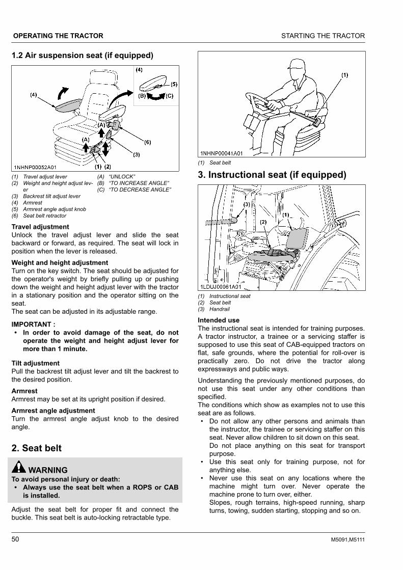
1.2 Air suspension seat (if equipped)
(1) Travel adjust lever(2) Weight and height adjust lev-
er(3) Backrest tilt adjust lever(4) Armrest(5) Armrest angle adjust knob(6) Seat belt retractor
(A) “UNLOCK”(B) “TO INCREASE ANGLE”(C) “TO DECREASE ANGLE”
Travel adjustmentUnlock the travel adjust lever and slide the seatbackward or forward, as required. The seat will lock inposition when the lever is released.Weight and height adjustmentTurn on the key switch. The seat should be adjusted forthe operator's weight by briefly pulling up or pushingdown the weight and height adjust lever with the tractorin a stationary position and the operator sitting on theseat.The seat can be adjusted in its adjustable range.
IMPORTANT :• In order to avoid damage of the seat, do not
operate the weight and height adjust lever formore than 1 minute.
Tilt adjustmentPull the backrest tilt adjust lever and tilt the backrest tothe desired position.ArmrestArmrest may be set at its upright position if desired.Armrest angle adjustmentTurn the armrest angle adjust knob to the desiredangle.
2. Seat belt
WARNINGTo avoid personal injury or death:• Always use the seat belt when a ROPS or CAB
is installed.
Adjust the seat belt for proper fit and connect thebuckle. This seat belt is auto-locking retractable type.
(1) Seat belt
3. Instructional seat (if equipped)
(1) Instructional seat(2) Seat belt(3) Handrail
Intended useThe instructional seat is intended for training purposes.A tractor instructor, a trainee or a servicing staffer issupposed to use this seat of CAB-equipped tractors onflat, safe grounds, where the potential for roll-over ispractically zero. Do not drive the tractor alongexpressways and public ways.Understanding the previously mentioned purposes, donot use this seat under any other conditions thanspecified.The conditions which show as examples not to use thisseat are as follows.• Do not allow any other persons and animals than
the instructor, the trainee or servicing staffer on thisseat. Never allow children to sit down on this seat.Do not place anything on this seat for transportpurpose.
• Use this seat only for training purpose, not foranything else.
• Never use this seat on any locations where themachine might turn over. Never operate themachine prone to turn over, either.Slopes, rough terrains, high-speed running, sharpturns, towing, sudden starting, stopping and so on.
OPERATING THE TRACTOR STARTING THE TRACTOR
50 M5091,M5111

• Do not use this seat whenever the operator's viewis affected by bad weather (such as rain and fog) orin the late afternoon.
WARNINGTo avoid personal injury or death:• Always wear your seat belt and stabilize your
body by holding the handrail on the CAB frame.• It is not intended to carry children nor any other
person for any other purposes.• The left-hand door must be closed at all time
whenever the instructional seat is occupied andthe tractor is in motion.
• Do not permit others to ride, except on thedesignated instructional seat.
• Use caution to avoid the risks of obstructingoperator's view, falling from the machine andinterfering with controls.
• Do not start and stop the tractor suddenly, nortake a sharp turn.
• Do not use the instructional seat if the seat beltor the door lock fails to function.
• Do not use the instructional seat for transport.• When opening or closing the door while being
seated in the instructional seat, move the doorslowly. This is to prevent his or her hand(s)from getting caught by the door or his or herbody to hit against the door.
3.1 Precautions in using the instructionalseatWhen getting on the tractor1. The operator is supposed to move the tractor onto
a flat surface and to apply both parking brakes for acomplete stop.
2. The passenger is supposed to stand on the groundand to set up the seat. Before use, make sure theseat is securely fixed.Procedure to set upa. Lift up the seat (1) until the rod (2) is fixed to the
fixing bracket (3).b. Press down on the seat to make sure it is
securely fixed.
(1) Seat(2) Rod(3) Fixing bracket
(A) Lift up
Get on the tractor. In getting on the tractor, stabilizeyourself by holding the specified handrail withattention not to get in contact with any controllevers.
3. Fasten the seat belt and close the door. Then getthe door locked.
(1) Handrail (climbing)(2) Handrail (sitting)(3) Seat belt
While the machine is in motion1. The person on the instructional seat should take
due care not to interfere with the operator's actions.
STARTING THE TRACTOR OPERATING THE TRACTOR
M5091,M5111 51

2. While sitting, be sure to keep the seat belt fastened.The person on the instructional seat is supposed togrip the handrail to prevent him or her from gettingout of balance due to violent machine movements.
3. Run the tractor at low speed.When getting off the tractor1. The operator is supposed to move the tractor onto
a flat surface and to apply both parking brakes for acomplete stop.
2. The person on the instructional seat is supposed toopen the door, unfasten the seat belt and get out ofthe tractor.
3. Recouple the left and right halves of the seat beltand store it in the holder because otherwise there isa risk of damage to the door.
(1) Seat belt holder(2) Seat belt LH(3) Seat belt RH
(A) Insert
4. Store the instructional seat with care not to get yourfingers caught by the linking parts.Finally, close the door.
Procedure to store1. Pull up the release lever with the front of the seat
slightly tilted up.
(1) Seat(2) Lever
(A) “Lift a little bit”(B) “Pull up”
2. Release the rod from the fixing bracket, and theseat moves downwards.
(1) Rod(2) Fixing bracket
(A) “Release”(B) “Moves in this direction”
(1) Seat (A) “Moves downward”
NOTE :• The instructional seat can be used only when
permitted by your local laws. Consult your localKUBOTA Dealer for further details.
4. Tilt steering adjustment
CAUTIONTo avoid personal injury:• Do not adjust the steering wheel while the
tractor is in motion.
Press down the steering wheel tilt pedal, to release thelock so the steering wheel can be adjusted to thedesired position.
OPERATING THE TRACTOR STARTING THE TRACTOR
52 M5091,M5111

(1) Steering wheel tilt pedal (A) “PRESS DOWN”
5. Light switchTurn the light switch clockwise, and the following lightsare activated on the switch position.
(1) Headlight switch Headlights OFF.Position lights ON.Headlights dimmed, lowbeam. Tail lights ON.Headlights ON, high beam.Tail light ON.
(1) Headlight
6. Turn signal switch and hazardlight switchHazard light1. When the hazard light switch is pushed, the hazard
lights flash, along with the LH and RH indicators onthe instrument panel.
2. Push the hazard light switch again to turn off thehazard lights.
Turn signal lightTo indicate a right turn, turn the turn signal light switchclockwise. To indicate a left turn, turn the turn signallight switch counter-clockwise. The corresponding rightand left turn signal lights and indicator on theinstrument panel will flash.
NOTE :• The hazard light switch is operative when the
key switch is in the “ON”, “ACC” or “OFF”position.
• The turn signal light switch is only operativewhen the key switch is in the “ON” position.
• Be sure to return the turn signal switch to itscenter position after turning.
(1) Hazard light switch(2) Turn signal light switch(3) Hazard and turn signal indi-
cator
(A) “RIGHT TURN”(B) “LEFT TURN”
(1) Turn signal and hazard light
STARTING THE TRACTOR OPERATING THE TRACTOR
M5091,M5111 53

(1) Turn signal and hazard light
6.1 With trailer connectorWhen you operate the turn signal light switch with thetrailer power connector connected, the trailer indicatorin the instrumental panel also starts flashing along withthe turn signal indicator.
(1) Hazard and turn signal indicator(2) Trailer indicator
7. Horn buttonThe horn will sound when the key switch is in “ON”position and horn button is pushed.
(1) Horn button (A) “PUSH”
8. Brake pedals (right and left)
WARNINGTo avoid personal injury or death:• Be sure to interlock the right and left pedals.
Applying only one rear wheel brake at highspeeds could cause the tractor to swerve orroll-over.
• Be sure brake pedals have equal adjustmentwhen using locked together. Incorrect orunequal brake pedal adjustment can cause thetractor to swerve or roll-over.
• Be aware of the enhanced brakingcharacteristics of the 4-wheel braking system.Appropriate care should be taken during hardbraking and/or when pulling towed loads.
• Do not brake suddenly.An accident may occur as a result of a heavytowed load shifting forward or loss of control.
• To avoid skidding and loss of steering controlwhen driving on icy, wet, or loose surfaces,make sure the tractor is correctly ballasted,operated at reduced speed and operated withthe front-wheel drive engaged (if equipped).
• The braking characteristics are differentbetween 2 and 4-wheel drive. Be aware of thedifference and use carefully.
• When driving down a slope, ensure that the 4-wheel drive is engaged to increase traction.
1. Before operating the tractor on the road, be sure tointerlock the right and left pedals as in the followingillustration.
2. Use individual brakes to assist in making sharpturns at low speeds (field operation only).Disengage the brake pedal lock and depress onlyone brake pedal.
3. Be sure brake pedals have equal adjustment whenbeing used locked together.
(1) Brake pedal lock (A) “LOCK”(B) “RELEASE”
OPERATING THE TRACTOR STARTING THE TRACTOR
54 M5091,M5111

8.1 4WD braking system (4WD model)The 4WD model tractor is equipped with 4WD brakingsystem. When both brake pedals are applied together,the front axle is engaged for 4-wheel brakingregardless of the mode selected at the 4WD switch.
WARNINGTo avoid the possibility of personal injury, death orproperty damage from machine runaway duringtesting, service or repair with the rear wheels offthe ground, make sure:• Battery is disconnected and engine is not
started.If it is necessary to run the engine, make sure:• Both front and rear wheels are off the ground
and secured with stands before starting engine.
When you step on the brake pedal while driving in 2WDmode, the “4WD braking system” gets activated.
NOTE :• The 4WD braking system is active even when
the hydraulic system is damaged or the engineis stopped.
9. Parking brake leverTo release the parking brake, depress the brakepedals, push the release button and push the parkingbrake lever down to transport position.
(1) Parking brake lever(2) Release button
(A) “Push down to transport po-sition”
IMPORTANT :• If the tractor is operated with the parking brake
set, the parking brake will be damaged.• If the tractor is traveling when the parking brake
lever is applied, a warning buzzer will sound.If the buzzer sounds, immediately release theparking brake lever.
10. Gear-locked parking brake leverTo release the gear-locked parking brake, depress thebrake pedals, push the release button and push thegear-locked parking brake lever to transport position.
(1) Gear-locked parking brakelever
(2) Release button
(A) “Push to transport position”
NOTE :• In moving the gear-locked parking brake lever,
you may feel it heavy sometimes, or light atother times. This is normal.
• The parking brake warning indicator on theEasy Checker™ will turn off when both parkingbrakes are released.
• If the shuttle shift lever is moved when the gear-locked parking brake is applied, a warningbuzzer will sound.
• Be sure to apply both parking brakes afterstopping the tractor.
11. Clutch pedal
WARNINGTo avoid personal injury or death:• The sudden release of the clutch may cause the
tractor to lunge in an unexpected manner.
The clutch is disengaged when the clutch pedal is fullypressed down.
STARTING THE TRACTOR OPERATING THE TRACTOR
M5091,M5111 55
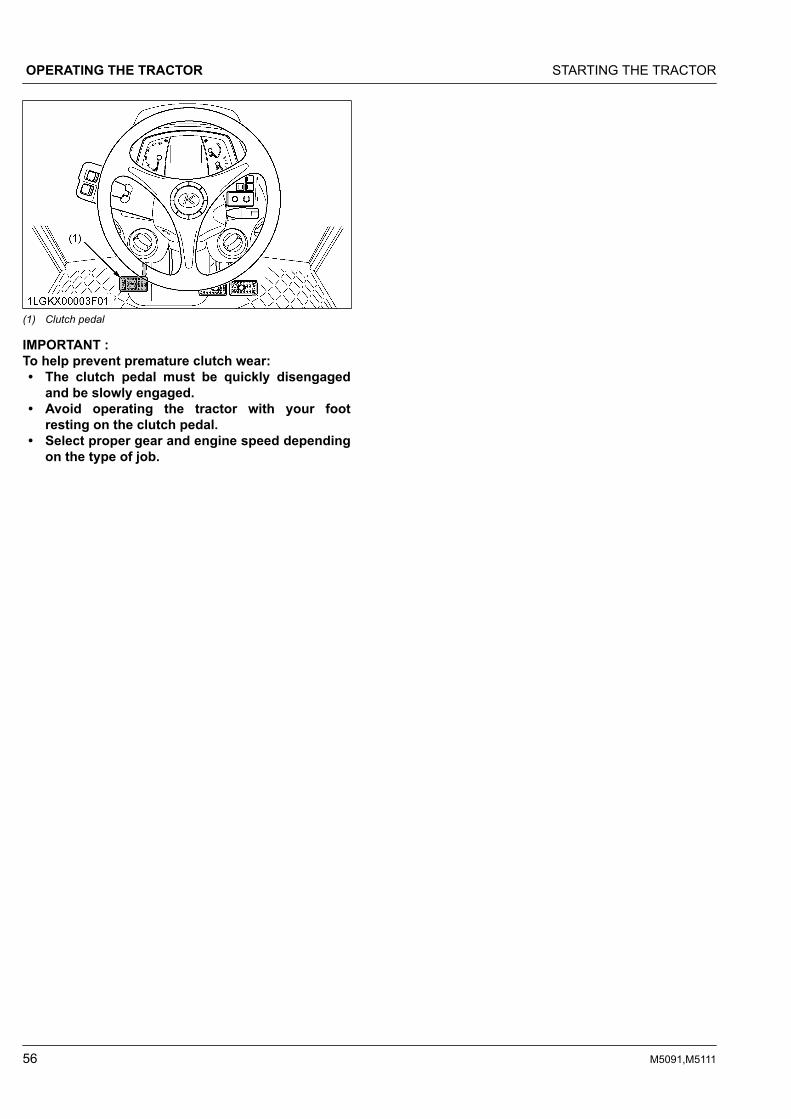
(1) Clutch pedal
IMPORTANT :To help prevent premature clutch wear:• The clutch pedal must be quickly disengaged
and be slowly engaged.• Avoid operating the tractor with your foot
resting on the clutch pedal.• Select proper gear and engine speed depending
on the type of job.
OPERATING THE TRACTOR STARTING THE TRACTOR
56 M5091,M5111

12. Travel speed control
(1) Shuttle shift lever(2) Main gear shift lever(3) Range gear shift lever(4) Clutch-off switch (if equipped)(5) Dual speed shift switch (if equipped)
(F) “FORWARD”(N) “NEUTRAL POSITION”(R) “REVERSE”
“CREEP”“LOW”“HIGH”
By using the main gear shift lever, dual speed shift switch (if equipped), range gear shift lever and shuttle shift levercombination, the forward speeds and reverse speeds shown in the following table are obtained.
M5111 model with dual speed 36 forward speeds36 reverse speeds
M5091/M5111 models without dual speed 18 forward speeds18 reverse speeds
STARTING THE TRACTOR OPERATING THE TRACTOR
M5091,M5111 57

13. Travel speed limiterThe highest travel speed is reachable when the enginerpm is at around the middle level with the maximumtravel speed range.This provides for a fuel-efficient run while travelingalong roads, pulling a trailer, and so on. Step on thefoot throttle, and the engine rpm rises proportionallyand the travel speed goes up accordingly.But the engine speed is limited to 2080 rpm or so, andit does not increase even if the foot throttle isincreased.When the main gear shift lever is set to the [H-6]position, the rev-limiter indicator illuminates.
(1) Rev-limiter indicator
14. Main gear shift leverThe main gear shift is fully synchronized to shift withoutstopping.
IMPORTANT :• The main gear shift may be shifted between
speeds on-the-go, but the clutch must bedepressed.
15. Range gear shift leverThe range gear shift can only be shifted when thetractor is completely stopped and the clutch isdepressed.
IMPORTANT :• To avoid transmission damage, depress the
clutch pedal and stop the tractor before shiftingbetween ranges.
15.1 Creep speed
WARNINGTo avoid personal injury or death:• When you leave the tractor, be sure to apply
both parking brakes and stop the engine.• In applying the brakes:
– The torque of the wheel axle is extremelyhigh while creep speed is being used. Besure to step down on the clutch pedalcompletely before applying the brakes, orthey will not work.
– When starting to operate the tractor, be sureto release both parking brakes.Misuse of the brakes may cause damage tothe transmission and is therefore notacceptable to KUBOTA for coverage underthe warranty.
IMPORTANT :• Press the clutch pedal completely down and
stop the tractor's motion before shifting therange gear shift lever.
Shift the range gear shift lever to to obtain lowspeeds.This shifting requires clutch operation.
(1) Range gear shift lever Creep “ON”
Creep speed should be used only when doing oneof the following jobs:• Deep rotary-tilling and harrowing• Planting• Turf application
Creep speed cannot be used for any of thefollowing jobs:• Pulling a trailer• Front-loader operation• Front-blade operation• Earth-moving• Entering and leaving a field• Loading onto and unloading from a truck
16. Shuttle shift lever
WARNINGTo avoid personal injury or death:• If the shuttle shift lever is moved in forward or
reverse position while the gear-locked parkingbrake is applied, an alarm buzzer will sound.
OPERATING THE TRACTOR STARTING THE TRACTOR
58 M5091,M5111

If the buzzer sounds, return the shuttle shiftlever to neutral position.
• If the gear-locked parking brake lever isreleased while the buzzer is sounding, thetractor will lunge unexpectedly.
Raise up and shift the shuttle shift lever forward toobtain forward speeds and shift back to obtain reversespeeds. This shifting does not require clutch operation.
IMPORTANT :• The shuttle shift lever may be shifted while the
tractor is moving slowly.
NOTE :• While the shuttle shift lever is at the
“NEUTRAL” position, the [N] character appearson the LCD monitor.
(1) “NEUTRAL”
17. Dual speed shift switch (ifequipped)The dual speed shift switch can be operated when thetractor is traveling without using the clutch.This switch affects tractor travel speed change by about19%. “LO” speed and “HI” speed switch back and fortheach time this switch is pushed.Dual speed indicatorThe indicator comes on when the dual speed switch isset to “LO”.The indicator goes off when the dual speed switch isset to “HI”.
(1) Dual speed shift switch(2) Dual speed indicator
(A) “LO”(B) “HI”
18. Clutch-off switch (if equipped)
WARNINGTo avoid personal injury or death:• If you release the clutch-off switch when the
travel speed is selected, the clutch becomesengaged and the tractor will begin to move.
• Always use the clutch pedal to start the tractor.
The clutch-off switch allows shifting gears without usingthe clutch pedal.While pressing the clutch-off switch, the clutch isdisengaged.When the clutch-off switch is released, the clutch isengaged. Similarly to how the shuttle shift lever isshifted from [N] to [F] (or [R]), the clutch is engagedthrough a smooth wave-like motion.
NOTE :• While pressing the clutch-off switch, the
position display of the shuttle shift lever on theLCD monitor flashes.
(1) Clutch-off switch (A) “FLASH”
STARTING THE TRACTOR OPERATING THE TRACTOR
M5091,M5111 59

19. 4WD switch
WARNINGTo avoid personal injury or death:• Do not engage the front-wheel drive when
traveling at road speed.• When driving on icy, wet, or loose surfaces,
make sure the tractor is correctly ballasted toavoid skidding and loss of steering control.Operate at reduced speed and engage front-wheel drive.
• 4WD model tractor is equipped with 4-wheelbraking and appropriate care should be takenduring hard braking.
• Do not brake suddenly.An accident may occur as a result of a heavytowed load shifting forward or loss of control.
• The braking characteristics are differentbetween 2 and 4-wheel drive tractor models. Beaware of the difference and use carefully.
• When driving down a slope, ensure that the 4-wheel drive is engaged to increase traction (ifequipped).
Press the bottom half of this switch;• The front-wheel drive (4WD) is engaged.• The switch with indicator and 4WD indicator come
on when the system is in 4WD mode.Press the top half of this switch;• The drive system returns to 2WD mode.• The all indicators goes off when the system is in
2WD mode.
(1) 4WD switch with indicator
(1) 4WD indicator
19.1 Front-wheel drive (4WD) usageFront-wheel drive is effective for the following jobs:• When greater pulling force is needed, such as
working in a wet field, when pulling a trailer, orwhen working with a front-end loader.
• When working in sandy soil.• When working on a hard soil where a rotary tiller
might push the tractor forward.
IMPORTANT :• Tires will wear quickly if the front-wheel drive is
engaged on paved roads.
20. Hand throttle leverPulling the throttle lever back decreases engine speed,and pushing it forward increases engine speed.
(1) Hand throttle lever “INCREASE”“DECREASE”
21. Foot throttleUse the foot throttle when traveling on the road. Pressdown on it for higher speed. The foot throttle isinterlocked with the hand throttle lever; when using thefoot throttle, keep the hand throttle lever in low idlingposition.
OPERATING THE TRACTOR STARTING THE TRACTOR
60 M5091,M5111

(1) Foot throttle
STOPPING THE TRACTOR1. Slow down the engine.2. Step on the clutch and brake pedal.3. Wait for the tractor to stop.4. Disengage the PTO.5. Lower the implement to the ground.6. Shift the transmission to neutral.7. Release the clutch pedal.8. Set both parking brakes.
CHECK DURING DRIVINGIMPORTANT :Immediately stop the engine if:• The engine suddenly slows down or
accelerates.• Unusual noises are suddenly heard.• Exhaust fumes suddenly become very dark.
While driving, check the following items to see that allthe parts are functioning normally:• Engine over-speed limiting indicator on page 61• Easy Checker™ on page 61• Fuel gauge on page 62• Coolant temperature gauge on page 63• Tachometer on page 63
1. Engine over-speed limitingindicatorThe engine over-speed limiting indicator informs theoperator of engine over-speed by indicator and warningbuzzer.If the warning sounds, immediately lower engine rpmwith brakes and such. When the engine rpmdecreases, the warning will stop.
(1) Engine over-speed limiting indicator
NOTE :• Normal operation will not lead to over-speed,
but, for instance, if suddenly shifting downwhen running with a trailer at full speed, thetractor will be pushed by the trailer and may gointo over-speed.
2. Easy Checker™
If the indicators on the Easy Checker™ come on duringoperation, immediately stop the engine and find thecause as follows.Never operate the tractor while an Easy Checker™indicator is on.
(1) Easy Checker™
Engine warningThis indicator serves the following 2 functions. If theindicator lights up, pinpoint the cause and takeproper measures.1. Error with the engine control system
If during operation the water temperature gaugereads an acceptable level but the indicator onthe Easy Checker™ comes on, stop the engineand then restart it. If the error happens again,consult your local KUBOTA Dealer.
STOPPING THE TRACTOR OPERATING THE TRACTOR
M5091,M5111 61

IMPORTANT :• If the warning indicator lights up, the
following phenomena may appeardepending on the engine's trouble spot.– The engine stops unexpectedly.– The engine fails to start or gets
interrupted just after starting.– The engine output is not enough.– The engine output is enough, but the
warning indicator stays on.If the engine output is not enough,immediately interrupt the operation andmove the tractor to a safe place and stopthe engine.
2. Engine overheatIf the water temperature gauge reads anunusual level and the indicator on the EasyChecker™ comes on, the engine may haveoverheated. Check the tractor by reading thetroubleshooting section of this manual.(See TROUBLESHOOTING on page 141.)
Engine oil pressureIf the oil pressure in the engine drops below theprescribed level, the indicator on the EasyChecker™ will come on.If this should happen during operation, and it doesnot go off when the engine is accelerated to morethan 1000 rpm, check the engine oil level.(See Checking engine oil level on page 112.)
Fuel levelIf the fuel in the tank drops below the prescribedlevel (less than 16 L), the indicator on the EasyChecker™ will come on.If this should happen during operation, refuel assoon as possible.(See Checking and refueling on page 111.)
IMPORTANT :• When the fuel indicator lights up, refuel the
tank as soon as possible. If the tractor runsout of fuel and stalls, the engine and itscomponents may be damaged.
Water separatorIf water or impurities collect in the water separator,the indicator on the Easy Checker™ will light up.If this should happen during operation, drain thewater from the water separator as soon as possible.(See Checking water separator on page 112.)
Air cleanerIf the air cleaner is clogged, the indicator on theEasy Checker™ will come on.If this should happen during operation, clean the aircleaner element.
(See Cleaning air cleaner primary element on page119.)
Electrical chargeIf the alternator is not charging the battery, theindicator on the Easy Checker™ will come on.If this should happen during operation, check theelectrical charging system or consult your localKUBOTA Dealer.
Master system warningIf trouble should occur at the engine, transmissionor other control parts, the indicator flashes as awarning.If the trouble is not corrected by restarting thetractor, consult your local KUBOTA Dealer.
NOTE :• For checking and servicing of your tractor,
consult your local KUBOTA Dealer forinstructions.
3. Fuel gaugeWhen the key switch is on, the fuel gauge indicates thefuel level.Be careful not to empty the fuel tank. Otherwise, airmay enter the fuel system.Should this happen, the system should be bled.(See Bleeding fuel system on page 134.)If the engine runs out of fuel and stalls, the mastersystem warning indicator lights up. When the indicatorappears, turn the key switch to “OFF” and then to “ON”again in order to turn off the indicator.If the indicator does not turn off by restarting the tractor,consult your local KUBOTA Dealer.
(1) Fuel gauge(2) Master system warning indi-
cator
(A) “FULL”(B) “EMPTY”
OPERATING THE TRACTOR CHECK DURING DRIVING
62 M5091,M5111

4. Coolant temperature gauge
WARNINGTo avoid personal injury or death:• Do not remove the radiator cap until coolant
temperature is well below its boiling point.Then, loosen the cap slightly to the first stop torelieve any pressure before removing the capcompletely.
1. With the key switch at “ON”, this gauge indicatesthe temperature of the coolant. [C] is for cold and[H] is for hot.
2. If the indicator reaches the red zone position, theengine coolant is overheated. Check the tractor byreading the troubleshooting section of this manual.(See TROUBLESHOOTING on page 141.)
(1) Coolant temperature gauge (A) “RED ZONE”
5. TachometerThe tachometer indicates the engine speed on the dial.
(1) Engine revolution
LCD MONITORThis display provides the operator with a variety ofinformation necessary to operate the tractor. Further,
part of the display can be modified by the operator asrequired.
No. Description Referencepage
(1)
Forward operation is selectedwith the shuttle lever. ---
Reverse operation is selectedwith the shuttle lever. ---
The shuttle lever is at neutralposition. ---
The gear-locked parking brakelever is at parking position. ---
Travel when the gear-lockedparking brake lever is engaged. ---
BlinkingClutch-off switch is pushed (ifequipped). Clutch is disengag-ed.
---
No display Shuttle lever system trouble. ---
(2)Engine over-speed limiting indi-cator 61
(3)Trouble displayA trouble-spot-pinpointing error code and therelated control unit are displayed.
142
(4) Clock 64
(5) Travel speed 64
(6) PTO speed 64
(7)Performance monitorVarious information can be selected by theoperator.
68
NOTE :• Errors may occur in the fuel consumption
display depending on the conditions of use.Use the displayed data only as an approximateguide. In particular, do not use the total fuel
CHECK DURING DRIVING OPERATING THE TRACTOR
M5091,M5111 63

consumption display mode in place of the fuelgauge.
• The travel speed displayed when the wheelsslip under traction is different from the actualone.
• In cold weather, the LCD monitor response willnormally be slower and the visibility be lessthan in warmer weather.
1. Various setting modeWhile pressing the mode selector switch, turn the keyswitch to “ON” position.The various setting mode screen appears on the LCDmonitor. The various setting mode can set 5 items.Turn the key switch to “OFF” position to finish setting.
(1) Key switch(2) Mode selector switch(3) Select switch(4) LCD monitor
(1) Clock setting(2) Clock ON/OFF setting(3) Tire circumference setting(4) Unit setting(5) PTO speed display setting
1.1 Clock setting1. Press the mode selector switch to choose “Clock
setting”.Then press the select switch, and the clock settingscreen appears.
(1) Clock setting
(1) Hour(2) Minute(3) Set switch
2. Setting the “Hour” of the clock:a. Press the mode selector switch to choose the
“Hour” (highlighted).b. To put the clock forward, press the select
switch.3. Setting the “Minute” of the clock:
a. Press the mode selector switch to choose the“Minute” (highlighted).
b. Carry out the “Minute” setting in the same wayas the “Hour” setting.
4. Press the mode selector switch.5. To complete the setting, select “Set” with the select
switch.The various setting mode screen appears again.
OPERATING THE TRACTOR LCD MONITOR
64 M5091,M5111
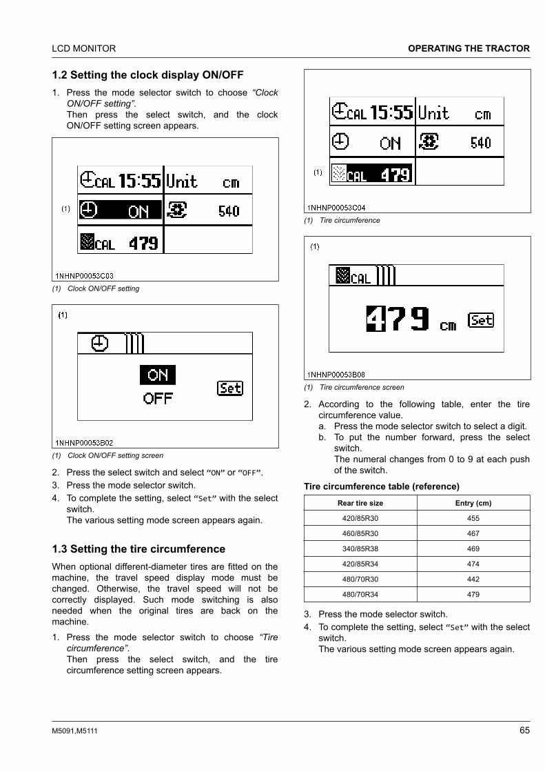
1.2 Setting the clock display ON/OFF1. Press the mode selector switch to choose “Clock
ON/OFF setting”.Then press the select switch, and the clockON/OFF setting screen appears.
(1) Clock ON/OFF setting
(1) Clock ON/OFF setting screen
2. Press the select switch and select “ON” or “OFF”.3. Press the mode selector switch.4. To complete the setting, select “Set” with the select
switch.The various setting mode screen appears again.
1.3 Setting the tire circumferenceWhen optional different-diameter tires are fitted on themachine, the travel speed display mode must bechanged. Otherwise, the travel speed will not becorrectly displayed. Such mode switching is alsoneeded when the original tires are back on themachine.1. Press the mode selector switch to choose “Tire
circumference”.Then press the select switch, and the tirecircumference setting screen appears.
(1) Tire circumference
(1) Tire circumference screen
2. According to the following table, enter the tirecircumference value.a. Press the mode selector switch to select a digit.b. To put the number forward, press the select
switch.The numeral changes from 0 to 9 at each pushof the switch.
Tire circumference table (reference)Rear tire size Entry (cm)
420/85R30 455
460/85R30 467
340/85R38 469
420/85R34 474
480/70R30 442
480/70R34 479
3. Press the mode selector switch.4. To complete the setting, select “Set” with the select
switch.The various setting mode screen appears again.
LCD MONITOR OPERATING THE TRACTOR
M5091,M5111 65

1.4 Setting the unit1. Press the mode selector switch to choose “Unit
setting”. Then press the select switch, and the unitsetting screen appears.
(1) Unit setting
(1) Unit setting screen
2. Press the select switch to select “Inch” or “cm”.3. Press the mode selector switch.4. To complete the setting, select “Set” with the select
switch.The various setting mode screen appears again.
1.5 Setting the PTO speed display540/540E rpm modelThe PTO speed display mode has been factory-set at“540/540E”. Do not attempt to change the setting.Otherwise the correct PTO speed will not be displayedon the LCD monitor.540/1000 rpm modelThe PTO speed display mode has been factory-set at“540/1000”. Do not attempt to change the setting.Otherwise the correct PTO speed will not be displayedon the LCD monitor.Interchangeable PTO 540/1000 rpm modelWhenever the PTO speed is changed to the otherspeed, it is necessary to switch the PTO speed display
mode. Otherwise the PTO speed will not be correctlydisplayed on the LCD monitor. When the PTO speed ischanged from 540 rpm to 1000 rpm or from 1000 rpmto 540 rpm, it is necessary to switch the PTO speeddisplay mode.
NOTE :• The current setting can be checked in the
following procedure.
1. Press the mode selector switch to choose “PTOspeed display setting”.Then press the “Select” switch, and the PTO speeddisplay setting screen appears.
(1) PTO speed display setting
(1) PTO speed display setting screen
2. According to the following table, press the “Select”switch and select the PTO speed.
Model Select the PTO speed (rpm)
Standard Not select
With interchangeable PTOshaft
540 option
1000 option
With PTO gear shift lever540/540E
540/1000
3. Press the mode selector switch.
OPERATING THE TRACTOR LCD MONITOR
66 M5091,M5111

4. To complete the setting, select [Set] with the“Select” switch.The various setting mode screen appears again.
LCD MONITOR OPERATING THE TRACTOR
M5091,M5111 67

2. Performance monitorDisplay changeUse the mode selector switch and select switch tochoose one of the items shown in the following table tobe displayed on screen.Priority display1. When the RPM dual memory setting is “ON”, the
engine rpm A or B is displayed on the screen.When selecting any other information such as“Hour meter” or “PM buildup”, the item will bedisplayed for approximately 5 seconds beforeresuming the engine rpm A or B display.
2. Turn “OFF” the RPM dual memory setting to displayany other information continuously.(See RPM dual memory setting on page 69.) (1) Performance monitor
(2) Mode selector switch(3) Select switch
List of types of information displayed on the performance monitorSelectedscreen(mode)
Display Remarks Referencepage
1/4
Elapsed time (hour meter)• The hour meter indicates in 6 digits the hours for which
the tractor has been used; the last digit indicates 1/10 ofan hour.
---
Trip meter • The total operating hours, counted from the previous re-setting, is displayed. ---
2/4
Instantaneous fuel con-sumption
• The “Instantaneous fuel consumption” is measured perhour. ---
Average fuel consumption • The “Average fuel consumption” is measured per hourfrom the previous resetting. ---
Total fuel consumption • The total fuel consumption, measured from the previousresetting, is displayed. ---
3/4
PM buildup (percentage) • The PM buildup inside the DPF muffler is displayed.• Regeneration is needed when the 100% level has been
reached.• The more the bar is extended to the right, the more PM
has built up.
---PM buildup (graph)
4/4
Memory A rpm • Engine RPM dual memory A rpm is displayed. 69
Memory B rpm • Engine RPM dual memory B rpm is displayed. 69
NOTE :• Hold down the mode selector switch for 2 seconds or longer to reset the “Trip meter”, “Average fuel
consumption” and “Total fuel consumption” displays to “0.0”.
OPERATING THE TRACTOR LCD MONITOR
68 M5091,M5111

ELECTRONIC ENGINECONTROLThe electronically controlled engine which is installed inthis tractor performs the following 2 types of control.1. RPM dual memory setting2. Constant RPM Management control
1. RPM dual memory settingTwo different engine speeds can each be set with asingle touch by pressing the RPM dual memory switchto the (A) or (B) side. This can be used to eliminatetroublesome acceleration operations.
(1) RPM dual memory switch (A) Switch A(B) Switch B
Example of useConsider an example in which an engine speed of2000 rpm is set for the switch (A) side and a speed of1000 rpm is set for the switch (B) side.
Work
During work, simply press theswitch to the (A) side to auto-matically set an engine speedof 2000 rpm.
Turning
When turning, press the switchto the (B) side to lower thespeed to 1000 rpm, allowingturning at low speed.
Work
After turning, press the switchagain to the (A) side to resumea speed of 2000 rpm.
• Keep the hand throttle lever above the minimumspeed. At the minimum speed, a memory setupcannot be performed.
• You can also depress the foot throttle to increasethe engine speed above the set speed.
Setting the speeds or changing the speed settingsSetting RPM dual memory switch (A).
1. Turn the key switch to “ON”.The speed setting can be made both when theengine is running and when it is stopped.
2. Set the hand throttle lever slightly toward thehigher-speed side.
ELECTRONIC ENGINE CONTROL OPERATING THE TRACTOR
M5091,M5111 69

3. Press the switch (A) side and then release theswitch.
4. Press again and hold down the switch (A) side (2.5seconds) until the buzzer sounds and then releasethe switch.
(A) Flashes
5. Press the switch to the (A) or (B) side and set thespeed.Pressing and holding down the switch will causethe speed to change continuously. Pressing andreleasing the switch changes the speed by 10 rpmeach time. Set the desired engine speed whilewatching the speed display.
(A) Increase speed(B) Decrease speed
6. If the switch is released and not operated for 4seconds, a continuous buzzer sounds and thesetting is completed.
7. Follow the same procedure as for the (A) side to setthe speed for the switch (B) side.
NOTE :• The set speeds will be stored even after the
engine is stopped.
Canceling the settingAny of the actions below will cancel the RPM dualmemory settings.1. For the switch (A) side, when the memory speed is
engaged, press the switch (A) again to cancel.For the switch (B) side, when the memory speed isengaged, press the switch (B) again to cancel.
2. When the memory speed is canceled, the speedwill return to the speed that is determined by thehand throttle lever (foot throttle).When the switch is pressed, the LCD will displaythe engine speed that is in effect after memoryspeed is canceled.
3. Return the hand throttle lever to the lowest speedposition.
4. Turn the key switch to “OFF”.
2. Constant RPM ManagementcontrolConstant RPM Management can be turned “ON” or“OFF” by operating the switch.Pressing the switch turns the control “ON” and pressingthe switch again turns it “OFF”.
OPERATING THE TRACTOR ELECTRONIC ENGINE CONTROL
70 M5091,M5111
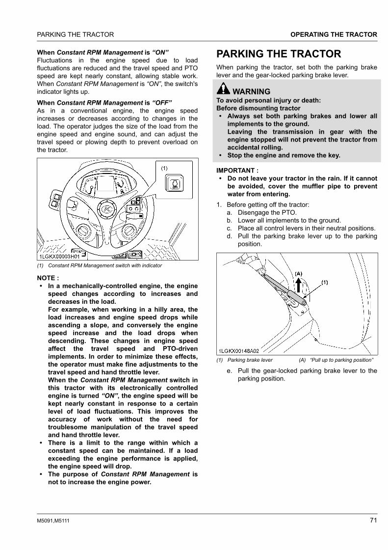
When Constant RPM Management is “ON”Fluctuations in the engine speed due to loadfluctuations are reduced and the travel speed and PTOspeed are kept nearly constant, allowing stable work.When Constant RPM Management is “ON”, the switch'sindicator lights up.When Constant RPM Management is “OFF”As in a conventional engine, the engine speedincreases or decreases according to changes in theload. The operator judges the size of the load from theengine speed and engine sound, and can adjust thetravel speed or plowing depth to prevent overload onthe tractor.
(1) Constant RPM Management switch with indicator
NOTE :• In a mechanically-controlled engine, the engine
speed changes according to increases anddecreases in the load.For example, when working in a hilly area, theload increases and engine speed drops whileascending a slope, and conversely the enginespeed increase and the load drops whendescending. These changes in engine speedaffect the travel speed and PTO-drivenimplements. In order to minimize these effects,the operator must make fine adjustments to thetravel speed and hand throttle lever.When the Constant RPM Management switch inthis tractor with its electronically controlledengine is turned “ON”, the engine speed will bekept nearly constant in response to a certainlevel of load fluctuations. This improves theaccuracy of work without the need fortroublesome manipulation of the travel speedand hand throttle lever.
• There is a limit to the range within which aconstant speed can be maintained. If a loadexceeding the engine performance is applied,the engine speed will drop.
• The purpose of Constant RPM Management isnot to increase the engine power.
PARKING THE TRACTORWhen parking the tractor, set both the parking brakelever and the gear-locked parking brake lever.
WARNINGTo avoid personal injury or death:Before dismounting tractor• Always set both parking brakes and lower all
implements to the ground.Leaving the transmission in gear with theengine stopped will not prevent the tractor fromaccidental rolling.
• Stop the engine and remove the key.
IMPORTANT :• Do not leave your tractor in the rain. If it cannot
be avoided, cover the muffler pipe to preventwater from entering.
1. Before getting off the tractor:a. Disengage the PTO.b. Lower all implements to the ground.c. Place all control levers in their neutral positions.d. Pull the parking brake lever up to the parking
position.
(1) Parking brake lever (A) “Pull up to parking position”
e. Pull the gear-locked parking brake lever to theparking position.
PARKING THE TRACTOR OPERATING THE TRACTOR
M5091,M5111 71

(1) Gear-locked parking brakelever
(A) “Pull to parking position”
f. Stop the engine.g. Remove the key.
2. If it is necessary to park on an incline, be sure tochock the wheels to prevent accidental rolling of thetractor.
IMPORTANT :For parking brake lever:• If the tractor is operated with the parking
brake set, the parking brake will bedamaged.
• If the tractor is travelling when the parkingbrake lever is applied, a warning buzzer willsound.If the buzzer sounds, immediately releasethe parking brake lever.
IMPORTANT :For gear-locked parking brake lever:• Bring the tractor to a complete stop before
applying the gear-locked parking lever.
NOTE :• The parking brake warning indicator on the
Easy Checker™ will turn on when a parkingbrake is set.
• Be sure to apply both parking brakes afterstopping the tractor.
(1) Parking brake warning indicator
OPERATING TECHNIQUES1. Differential lockIf one of the rear wheels starts slipping, engage thedifferential lock and both wheels will turn together, thusreducing wheel slip.
WARNINGTo avoid personal injury or death due to loss ofsteering control:• Do not operate the tractor at high speed with
differential lock engaged.• Do not attempt to turn with the differential lock
engaged.• Be sure to release the differential lock before
making a turn in field conditions.
Depending on the type of work, select either autodifferential lock mode or manual differential lock mode.Auto differential lockIn the auto differential lock mode, the rear wheels enterthe differential lock state when the tractor's speed isbetween 0.5 km/h and 15 km/h.Press the auto differential switch to engage ordisengage the auto differential lock mode. Whenengaged, the auto differential lock indicator will turn on.To disengage the auto differential lock mode, performone of the following operations:1. Push the auto differential switch again.2. Step on the differential lock pedal.3. Step on the brake pedal.4. Travel at under 0.5 km/h or over 15 km/h.
OPERATING THE TRACTOR OPERATING TECHNIQUES
72 M5091,M5111

(1) Auto differential lock switch(2) Auto differential lock indicator
Manual differential lockThe manual differential lock mode is engaged while thedifferential lock pedal is depressed.Engage the manual differential lock mode according tothe rear wheel slip.The manual differential lock indicator lights up while themanual differential lock mode is engaged.
(1) Differential lock pedal (A) Press to “ENGAGE”(B) Release to “DISENGAGE”
(1) Manual differential lock indicator
IMPORTANT :• When using the differential lock, always slow
the engine down.
• To prevent damage to the power train, do notengage the differential lock when one wheel isspinning and the other is completely stopped.
• If the differential lock cannot be released, steplightly on the brake pedals alternately.
2. Operating the tractor on a road
WARNINGTo avoid personal injury or death:• To help assure straight line stops when driving
at transport speeds, lock the brake pedalstogether. Uneven braking at road speeds couldcause the tractor to roll-over.
• When traveling on the road with a 3-point hitchmounted implement attached, be sure to havesufficient front weight on the tractor to maintainsteering ability.
• When traveling on the road with or without atrailer, you must comply with local regulationsat all time.The maximum traveling speed with trailer isdetermined by each country, and regulatedspeeds may vary according to the size of thetrailer and the type of trailer brake system.
Observe all local traffic and safety regulations.Use the registration plate.
(1) Registration plate
3. Operating on slopes and roughterrain
WARNINGTo avoid personal injury or death:• Always back up when going up a steep slope.
Driving forward could cause the tractor to tipover backward. Stay off hills and slopes toosteep for safe operation.
• Avoid changing gears when climbing ordescending a slope.
OPERATING TECHNIQUES OPERATING THE TRACTOR
M5091,M5111 73

• If operating on a slope, never disengage theclutch or shift levers to neutral. Doing so couldcause loss of control.
• Do not drive the tractor close to the edges ofditches or banks which may collapse under theweight of the tractor, especially when theground is loose or wet.
1. Be sure wheel tread is adjusted to providemaximum stability.(See WHEEL ADJUSTMENT on page 91.)
2. Slow down for slopes, rough ground, and sharpturns, especially when transporting heavy, rear-mounted equipment.
3. Before descending a slope, shift to a gear lowenough to control the speed without using brakes.
4. Transporting the tractor safely1. The tractor, if damaged, must be carried on a truck.
Secure the tractor tightly with ropes.2. Secure the tractor with chains or straps sized
appropriately. Make sure all loading ramps areproperly sized. Make sure all local tie-downrequirements are met.
3. Follow the instructions below when towing thetractor. Otherwise, the tractor's powertrain may bedamaged.• Set all the shift levers to “NEUTRAL” position.• If possible, start the engine and select 2WD; if
creep speed is fitted ensure that it isdisengaged.
• Tow the tractor using its front hitch or drawbar.• Never tow faster than 10 km/h.
5. Directions for the use of powersteering• Power steering is activated only while the engine is
running. Slow engine speeds make the steering alittle heavier. While the engine is stopped, tractorswith power steering function in the same manner astractors without power steering.
• When the steering wheel is turned all the way to thestop, the relief valve is activated. Do not hold thesteering wheel in this position for a long period oftime.
• Avoid turning the steering wheel while the tractor isstopped, or tires may wear out sooner.
• The power steering mechanism makes the steeringeasier. Be careful when driving on the road at highspeeds.
6. Trailer electrical outletA trailer electrical outlet is supplied for use with a traileror implement.
(1) Trailer electrical outlet
Function of each terminal in trailer electrical outlet
Terminal Function
(1) Turn signal light (LH)
(2) ---
(3) Ground
(4) Turn signal light (RH)
(5)Tail lightSide marker lightParking light
(6) Brake stop light
(7) Registration plate light
OPERATING THE TRACTOR OPERATING TECHNIQUES
74 M5091,M5111

PTOPTO OPERATION
WARNINGTo avoid personal injury or death:• Disengage the PTO, stop the engine, and allow
all rotating components to come to a completestop before connecting, disconnecting,adjusting, or cleaning any PTO drivenequipment.
1. PTO clutch control switchThe PTO clutch control switch engages or disengagesthe PTO clutch which gives the PTO independentcontrol.
(1) PTO clutch control switch “ON”“OFF”
Turn the switch to “ON” to engage the PTO clutch. Turnthe switch to “OFF” to disengage the PTO clutch.
IMPORTANT :• To avoid shock loads to the PTO, reduce engine
speed when engaging the PTO, then open thethrottle to the recommended speed.
NOTE :• Tractor engine will not start if PTO clutch
control switch is in the engaged “ON” position.
To turn “ON”1. While pushing the switch, turn clockwise to the
position and release your hand (in the “ON”position, switch slightly rises itself).
To turn “OFF”1. Push the switch, and the switch will return to the
“OFF” position.
(A) “PUSH”
2. PTO clutch indicatorThe PTO clutch indicator turns on while PTO clutchcontrol switch is in “ON” (engage) position.
(1) PTO clutch indicator
PTO OPERATION PTO
M5091,M5111 75

3. PTO rpm displayThe PTO rpm can be checked on the LCD monitor.
(1) PTO rpm
NOTE :Interchangeable PTO 540/1000 rpm model• When the PTO speed is changed from 540 rpm
to 1000 rpm, it is necessary to switch the PTOspeed display mode. Otherwise, the PTO speedwill not be correctly displayed on the LCDmonitor. Such mode switching is also neededwhen returning to the 540 rpm PTO speed.The PTO rpm can be checked on the LCDmonitor.(See LCD MONITOR on page 63.)
4. PTO shaft cover and shaft cap
WARNINGTo avoid personal injury or death:• Keep the PTO shaft cover in place at all times.
Put back the PTO shaft cap when the PTO is notin use.
• Before connecting or disconnecting a driveshaft to the PTO shaft, be sure the engine is“OFF” and raise up the PTO shaft cover.Afterward be sure to return the PTO-shaft-coverto the normal position.
(1) PTO shaft cover(2) PTO shaft cap
(A) “NORMAL POSITION”(B) “RAISED POSITION”
IMPORTANT :• The universal joint of the PTO drive shaft is
technically limited in its moving angle. Refer tothe PTO drive shaft instructions for proper use.
PTO MODELS1. PTO 540/540E rpm model1.1 PTO gear shift lever
WARNINGTo avoid personal injury or death:• Be sure to observe the PTO shaft speed
prescribed for the individual implements. It isextremely dangerous to run an implement athigh speed that is meant to be operated at lowspeed. Use only when this higher rpm isspecifically recommended by the implementmanufacturer.
The PTO gear shift lever can be set to either 540 rpmor 540E rpm positions.Move this lever to either position with the PTO clutchcontrol switch set to “OFF”.
(1) PTO gear shift lever (A) 540 rpm(B) 540E rpm
PTO PTO OPERATION
76 M5091,M5111

NOTE :• When light load, select the “540E” position for
economical operation.
PTO gear shift lev-er Engine speed rpm PTO speed rpm
540 2035 540
540E 1519 540
1.2 PTO speed limiterNOTE :• Move the PTO gear shift lever to “540E” and
then turn on the PTO clutch control switch, andthe rev-limiter indicator lights up on the meterpanel.
• If the PTO clutch control switch is turned onwith the engine rpm higher than the PTO 540Elimit level, the PTO clutch indicator on the meterpanel starts blinking and the PTO is disabled.After a while, the engine rpm automaticallydrops below the PTO 540E limit level and thePTO starts functioning.At the same time, the flashing PTO clutchindicator stays on.
• If the PTO clutch control switch is turned “OFF”but the engine rpm fails to rise with the throttle,return the engine rpm to a lower level. Thisenables acceleration again.
(1) Rev-limiter indicator(2) PTO clutch indicator
PTO Limitation PTO/Engine speed (rpm)
540E 630/1772
2. Interchangeable PTO540/1000 rpm model2.1 1000 rpm PTO shaft
WARNINGTo avoid personal injury or death:• Be sure to observe the PTO shaft speed
prescribed for the individual implements. It isextremely dangerous to run an implement athigh speed that is meant to be operated at lowspeed. Use only when this higher rpm isspecifically recommended by the implementmanufacturer.
By interchanging the PTO shafts, 2 different PTO shaftspeeds can be obtained.
(1) PTO shaft(2) Snap ring
(A) 540 rpm PTO shaft(B) 1000 rpm PTO shaft
PTO shaft interchanging procedureThe 6-spline 540 rpm PTO shaft is standard equipment.1. Place an oil pan under the PTO shaft to catch oil
spillage. Remove the snap ring, and then the PTOshaft.
2. Install the 21-spline PTO shaft (1000 rpm). Toensure that it is tight, push it in by turning.
3. Reinsert the snap ring.
IMPORTANT :• For maximum PTO shaft speeds of various
implements, see the implement operator'smanual.
Engine speed rpm PTO speed rpm
540 rpm PTO shaft 2035 540
1000 rpm PTOshaft 2389 1000
PTO MODELS PTO
M5091,M5111 77

3-POINT HITCH AND DRAWBAR
(1) Top link(2) Lifting rod (left)(3) Telescopic stabilizers
(4) Lower link(5) Lifting rod (right)(6) Drawbar
3-POINT HITCH AND DRAWBAR
78 M5091,M5111

THE 3-POINT HITCH SETUP1. Make preparations for attaching implement.
• Selecting the holes of lower links on page 79• Adjusting lateral float on page 79
2. Attaching and detaching implements.
WARNINGTo avoid personal injury or death:• Be sure to stop the engine.• Do not stand between the tractor and
implement unless both parking brakes areapplied.
• Before attaching or detaching theimplement, locate the tractor and implementon a firm level surface.
• Whenever an implement or other attachmentis connected to the tractor 3-point hitch,check the full range of operation forinterference, binding or PTO separation.
• Do not exceed the maximum allowablelength of either lifting rod, or the lifting rodwill come apart and the 3-point equipmentmay fall.
• Selecting the top link mounting holes on page79
• Drawbar on page 80• Lifting rod (left) on page 80• Lifting rod (right) on page 80• Top link on page 80• Telescopic stabilizers on page 81• Quick hitch - hook type (if equipped) on page
81
1. Selecting the holes of lower linksThere are 2 holes in the lower links. For mostoperations, the lifting rods should be attached to the (B)hole.
Type A
(1) Lower link(2) Lifting rod
(A) Hole(B) Hole
Type B (if equipped)
(1) Lower link(2) Lifting rod
(A) Hole(B) Hole
NOTE :• The lifting rods may be attached to (A) hole for
greater lifting force.
2. Adjusting lateral floatTo allow the implement to follow the shape of theground, attach the rectangular washers and pin headsin vertical position.To hold the implement, reset the rectangular washersand pin heads in horizontal position.
(1) Rectangular washer(2) Pin head
(A) Horizontal position(B) Vertical position
Floating mechanismWhen the floating mechanism is used, the implement isable to follow the tractor freely in response to the soiland ground conditions. This is suited for operation withimplements wider than the tractor.
3. Selecting the top link mountingholesSelect the proper set of holes.(See Hydraulic control unit use-reference chart on page90.)
THE 3-POINT HITCH SETUP 3-POINT HITCH AND DRAWBAR
M5091,M5111 79
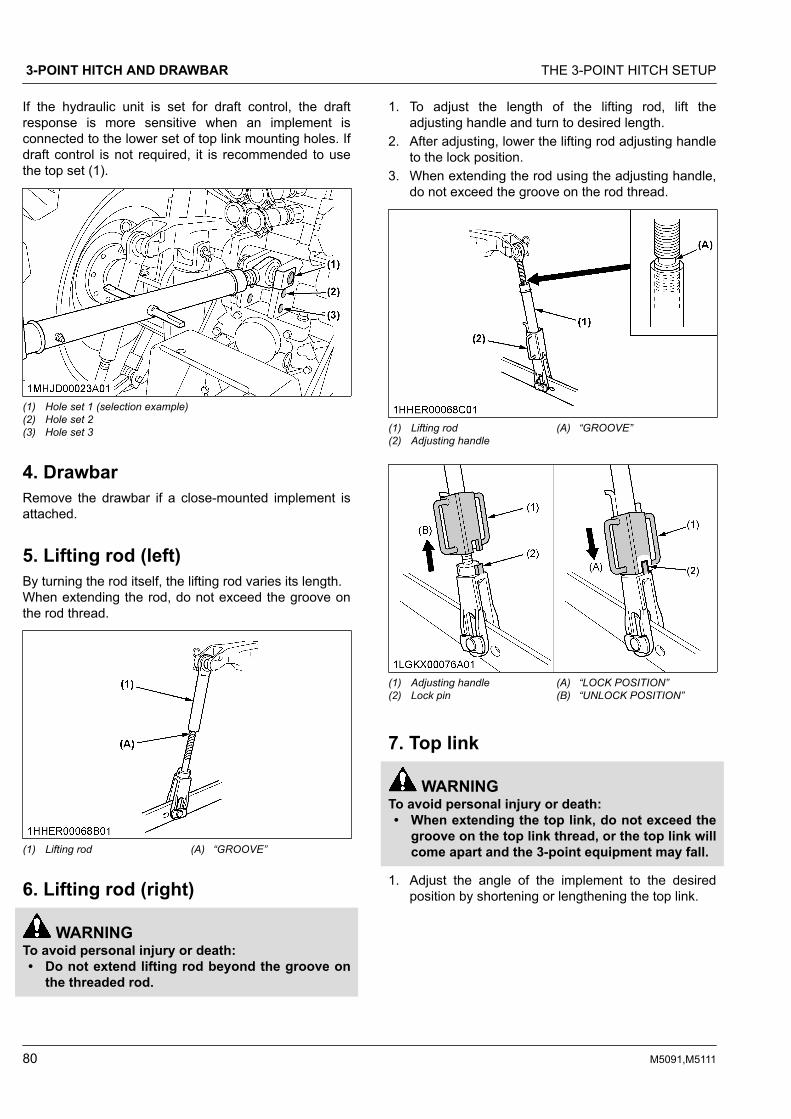
If the hydraulic unit is set for draft control, the draftresponse is more sensitive when an implement isconnected to the lower set of top link mounting holes. Ifdraft control is not required, it is recommended to usethe top set (1).
(1) Hole set 1 (selection example)(2) Hole set 2(3) Hole set 3
4. DrawbarRemove the drawbar if a close-mounted implement isattached.
5. Lifting rod (left)By turning the rod itself, the lifting rod varies its length.When extending the rod, do not exceed the groove onthe rod thread.
(1) Lifting rod (A) “GROOVE”
6. Lifting rod (right)
WARNINGTo avoid personal injury or death:• Do not extend lifting rod beyond the groove on
the threaded rod.
1. To adjust the length of the lifting rod, lift theadjusting handle and turn to desired length.
2. After adjusting, lower the lifting rod adjusting handleto the lock position.
3. When extending the rod using the adjusting handle,do not exceed the groove on the rod thread.
(1) Lifting rod(2) Adjusting handle
(A) “GROOVE”
(1) Adjusting handle(2) Lock pin
(A) “LOCK POSITION”(B) “UNLOCK POSITION”
7. Top link
WARNINGTo avoid personal injury or death:• When extending the top link, do not exceed the
groove on the top link thread, or the top link willcome apart and the 3-point equipment may fall.
1. Adjust the angle of the implement to the desiredposition by shortening or lengthening the top link.
3-POINT HITCH AND DRAWBAR THE 3-POINT HITCH SETUP
80 M5091,M5111

2. The proper length of the top link varies according tothe type of implement being used.
(1) Top link (A) “GROOVE”(B) “Length of the screw”
NOTE :• The length of the screw at both ends of the
top link must be the same always.
8. Telescopic stabilizers1. Adjust the telescopic stabilizers to control horizontal
sway of the implement.Select the proper set of holes.(See Hydraulic control unit use-reference chart onpage 90.)
2. After aligning satisfactorily, insert the set-pinthrough any one of the holes on the outer tube thatalign with one of the holes on the inner bar and bothstabilizers will be locked.If the set-pin is inserted through the slot to engageone of the holes on the inner bar, a limited degreeof sway will be permitted.
5-hole type stabilizer
(1) Outer tube(2) Inner bar(3) Set-pin(4) Hole(5) Slot
6-hole type stabilizer (if equipped)
(1) Outer tube(2) Inner bar(3) Set-pin(4) Hole(5) Slot
8.1 Telescopic lower linksTo attach an implement, follow the instructions below:1. Push the levers, pull out the lower link ends, and
attach to the implement.2. Back up the tractor slightly to make sure the lower
links are pushed in securely.
(1) Lever (A) “PUSH”(B) “PULL OUT”
9. Quick hitch - hook type (ifequipped)
WARNINGTo avoid personal injury or death:Confirm the below when installing the implement:• Make sure the hook of the quick hitch is
securely locked.
The 3-point hitch with quick-hitch, all of which haveclaw ends that permit rapid attaching and detaching ofimplements.
THE 3-POINT HITCH SETUP 3-POINT HITCH AND DRAWBAR
M5091,M5111 81

9.1 Installing ball-joint to implement1. Before the implement is installed on the 3-point
hitch with quick hitches, it is necessary to install theball-joints to the implement according to thefollowing instructions.
(1) Ball-joint
9.2 Adjusting lower link width1. Set the width (W1) of lower links to be the same as
width (W2) of the implement.Details regarding the adjustment of the width (W1)of lower links can be found in a different section.(See Telescopic stabilizers on page 81.)
(1) Lower link(2) Telescopic stabilizer(3) Implement
9.3 Attaching implement to tractor1. Set the release lever on the quick hitches to
“LOCK” position, if its lever is in “UNLOCK” position(self-locking latches are closed).
2. With the lower links fully lowered, reverse thetractor until the quick hitches are beneath theimplement ball-joints.
3. Raise the lower links using the hydraulic controllever until the quick hitches engage the ball-joints.
NOTE :• An audible click will be heard as the self-
locking latches engage the implement ball-joint.
3-POINT HITCH AND DRAWBAR THE 3-POINT HITCH SETUP
82 M5091,M5111
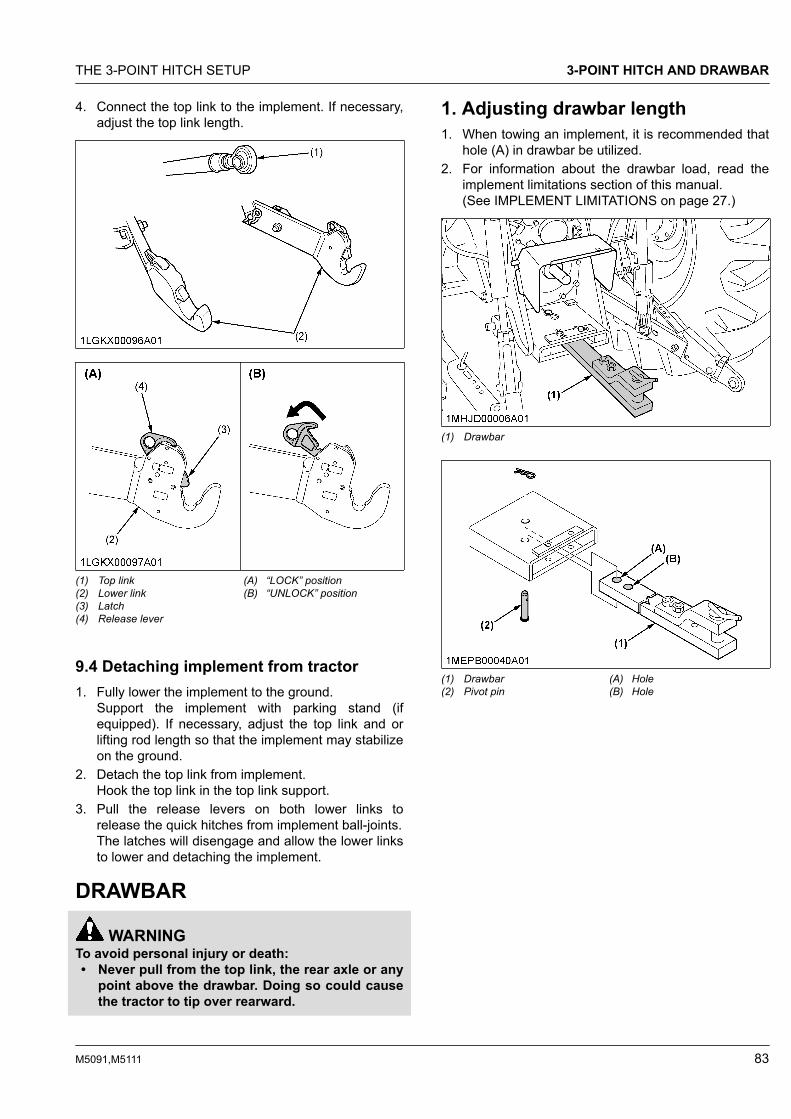
4. Connect the top link to the implement. If necessary,adjust the top link length.
(1) Top link(2) Lower link(3) Latch(4) Release lever
(A) “LOCK” position(B) “UNLOCK” position
9.4 Detaching implement from tractor1. Fully lower the implement to the ground.
Support the implement with parking stand (ifequipped). If necessary, adjust the top link and orlifting rod length so that the implement may stabilizeon the ground.
2. Detach the top link from implement.Hook the top link in the top link support.
3. Pull the release levers on both lower links torelease the quick hitches from implement ball-joints.The latches will disengage and allow the lower linksto lower and detaching the implement.
DRAWBAR
WARNINGTo avoid personal injury or death:• Never pull from the top link, the rear axle or any
point above the drawbar. Doing so could causethe tractor to tip over rearward.
1. Adjusting drawbar length1. When towing an implement, it is recommended that
hole (A) in drawbar be utilized.2. For information about the drawbar load, read the
implement limitations section of this manual.(See IMPLEMENT LIMITATIONS on page 27.)
(1) Drawbar
(1) Drawbar(2) Pivot pin
(A) Hole(B) Hole
THE 3-POINT HITCH SETUP 3-POINT HITCH AND DRAWBAR
M5091,M5111 83

2. Swing drawbarThe drawbar can be used in 3 different ways as shownin the following illustration. Assemble it correctly withlocating pins.
(1) Drawbar(2) Locating pin
3-POINT HITCH AND DRAWBAR DRAWBAR
84 M5091,M5111

HYDRAULIC UNITIMPORTANT :• Do not operate until the engine is warmed up. If
any operation is attempted when the engine isstill cold, the hydraulic system may bedamaged.
• If noises are heard when the implement is liftingafter the hydraulic control lever has beenactivated, the hydraulic mechanism is notadjusted properly. Unless corrected, the unitwill be damaged. Contact your KUBOTA Dealerfor adjustments.
A standard tractor has the following hydraulic controlsystems. Choose the most appropriate system for theimplement you are using.3-point hitch control system• Position control• Draft control• Mixed control• Float control
Remote hydraulic control system
3-POINT HITCH CONTROLSYSTEM
WARNINGTo avoid personal injury or death:• Before using the 3-point hitch controls, ensure
that no person or object is in the areasurrounding the implement or 3-point hitch. Donot stand on or near the implement or betweenthe implement and tractor when operating the 3-point hitch controls.
1. Position controlThis will control the working depth of the 3-point hitchmounted implement regardless of the amount of pullrequired.
(1) Position control lever(2) Draft control lever
(A) “FLOAT”(B) “DOWN”(C) “UP”
2. Draft controlThis will control the pull of the 3-point implement.As the load on the 3-point hitch changes due to varioussoil conditions, the draft control system automaticallyresponds to these changes by either raising or loweringthe implement slightly to maintain a constant pull.Place the position control lever in the lowest positionand set the implement pull with the draft control lever.
(1) Draft control lever(2) Position control lever
(A) “SENSITIVE”(B) “INSENSITIVE”(C) “FLOAT”
3. Mixed controlIn draft control, when draft decreases, the implementautomatically lowers to increase draft.However, the implement sometimes lowers too much.To limit the degree to which the implement can belowered, set the position control lever at the lowestworking depth desired for the implement. Lower the
3-POINT HITCH CONTROL SYSTEM HYDRAULIC UNIT
M5091,M5111 85
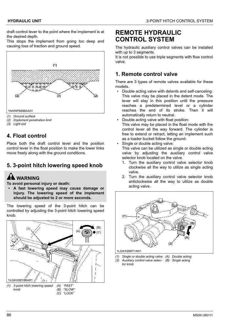
draft control lever to the point where the implement is atthe desired depth.This stops the implement from going too deep andcausing loss of traction and ground speed.
(1) Ground surface(2) Implement penetration limit(3) Light soil
4. Float controlPlace both the draft control lever and the positioncontrol lever in the float position to make the lower linksmove freely along with the ground conditions.
5. 3-point hitch lowering speed knob
WARNINGTo avoid personal injury or death:• A fast lowering speed may cause damage or
injury. The lowering speed of the implementshould be adjusted to 2 or more seconds.
The lowering speed of the 3-point hitch can becontrolled by adjusting the 3-point hitch lowering speedknob.
(1) 3-point hitch lowering speedknob
(A) “FAST”(B) “SLOW”(C) “LOCK”
REMOTE HYDRAULICCONTROL SYSTEMThe hydraulic auxiliary control valves can be installedwith up to 3 segments.It is not possible to use triple segments with flow controlvalve.
1. Remote control valveThere are 3 types of remote valves available for thesemodels.• Double acting valve with detents and self-canceling:
This valve may be placed in the detent mode. Thelever will stay in this position until the pressurereaches a predetermined level or a cylinderreaches the end of its stroke. Then it willautomatically return to neutral.
• Double acting valve with float position:This valve may be placed in the float mode with thecontrol lever all the way forward. The cylinder isfree to extend or retract, letting an implement suchas a loader bucket follow the ground.
• Single or double acting valve:This valve can be utilized as single or double actingvalve by adjusting the auxiliary control valveselector knob located on the valve.1. Turn the auxiliary control valve selector knob
clockwise all the way to utilize as single actingvalve.
2. Turn the auxiliary control valve selector knobanticlockwise all the way to utilize as doubleacting valve.
(1) Single or double acting valve(2) Auxiliary control valve selec-
tor knob
(A) Double acting(B) Single acting
HYDRAULIC UNIT 3-POINT HITCH CONTROL SYSTEM
86 M5091,M5111
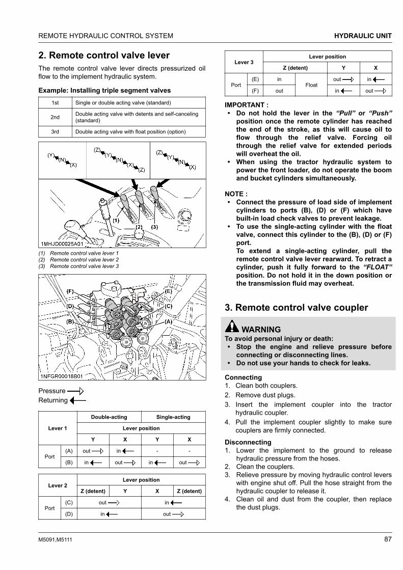
2. Remote control valve leverThe remote control valve lever directs pressurized oilflow to the implement hydraulic system.
Example: Installing triple segment valves1st Single or double acting valve (standard)
2nd Double acting valve with detents and self-canceling(standard)
3rd Double acting valve with float position (option)
(1) Remote control valve lever 1(2) Remote control valve lever 2(3) Remote control valve lever 3
Pressure Returning
Lever 1
Double-acting Single-acting
Lever position
Y X Y X
Port(A) out in - -
(B) in out in out
Lever 2Lever position
Z (detent) Y X Z (detent)
Port(C) out in
(D) in out
Lever 3Lever position
Z (detent) Y X
Port(E) in
Floatout in
(F) out in out
IMPORTANT :• Do not hold the lever in the “Pull” or “Push”
position once the remote cylinder has reachedthe end of the stroke, as this will cause oil toflow through the relief valve. Forcing oilthrough the relief valve for extended periodswill overheat the oil.
• When using the tractor hydraulic system topower the front loader, do not operate the boomand bucket cylinders simultaneously.
NOTE :• Connect the pressure of load side of implement
cylinders to ports (B), (D) or (F) which havebuilt-in load check valves to prevent leakage.
• To use the single-acting cylinder with the floatvalve, connect this cylinder to the (B), (D) or (F)port.To extend a single-acting cylinder, pull theremote control valve lever rearward. To retract acylinder, push it fully forward to the “FLOAT”position. Do not hold it in the down position orthe transmission fluid may overheat.
3. Remote control valve coupler
WARNINGTo avoid personal injury or death:• Stop the engine and relieve pressure before
connecting or disconnecting lines.• Do not use your hands to check for leaks.
Connecting1. Clean both couplers.2. Remove dust plugs.3. Insert the implement coupler into the tractor
hydraulic coupler.4. Pull the implement coupler slightly to make sure
couplers are firmly connected.
Disconnecting1. Lower the implement to the ground to release
hydraulic pressure from the hoses.2. Clean the couplers.3. Relieve pressure by moving hydraulic control levers
with engine shut off. Pull the hose straight from thehydraulic coupler to release it.
4. Clean oil and dust from the coupler, then replacethe dust plugs.
REMOTE HYDRAULIC CONTROL SYSTEM HYDRAULIC UNIT
M5091,M5111 87

NOTE :• Your local KUBOTA Dealer can supply parts for
adapting couplers to hydraulic hoses.
4. Flow control valve (option)The optional flow control valve may be added for thefollowing purposes.1. To operate within limits, the remote control valve (2)
above the flow control valve (3) and the 3-pointhitch at the same time without one affecting theother.
2. To operate within limits, the remote control valve (2)above the flow control valve (3) and the otherremote control valve (1) at the same time withoutone affecting the other. Activating the remotecontrol valve (1) will interrupt the operation of the 3-point hitch.
3. To maintain within limits, the constant speed of anattachment (hydraulic motor rpm, for example)when connected to the remote control valve (2)above the flow control valve (3).
NOTE :• At lower engine speeds the total hydraulic
flow rate may be inadequate forsimultaneous operation of the remotecontrol valve (2) and the 3-point hitch or theremote control valve (1), or operation of anattachment connected to the remote controlvalves (1)(2). Under these conditions, theengine speed must be increased to provideadditional hydraulic flow.
4.1 Adjusting the flow rate
WARNINGTo avoid the possibility of personal injury or deathbe aware of the following when makingadjustments:• The 3-point hitch operation is influenced by the
combination of the adjustment of the flowcontrol valve and the engine speed.
• The 3-point hitch may rise slowly or not at all atlow engine rpm.
• The 3-point hitch may rise suddenly if enginerpm is increased, or, flow control adjustment ischanged.
Refer to the following illustration.1. The flow rate for the remote control valve (2),
located on above the flow control valve (3), can beadjusted.
2. Turn the flow control knob (4) counterclockwise (A),and the flow rate for the remote control valve (2)increases. A clockwise turn (B) of the knob causes
the flow to decrease. If the knob is turned all theway (C), there will be no flow.
3. To adjust the flow rate, set the engine speed to theoperating rpm, turn the flow control knob once allthe way clockwise (C), and then turn it graduallycounterclockwise until a required flow rate isreached.
NOTE :• Full adjustment of the valve will occur in
approximately 1 1/2 revolutions of the flowcontrol knob. Turning the flow control knobbeyond this point will have no effect on theflow rate.
IMPORTANT :• When there is no need to adjust the flow
rate, turn the flow control knob all the waycounterclockwise and keep it in thisposition.
(1) Remote control valve (1)(2) Remote control valve (2)(3) Flow control valve(4) Flow control knob
(A) “INCREASE”(B) “DECREASE”(C) “STOP”
4.2 Positions and advantages of the flowcontrol valveRefer to the following illustration.Position 11. The attachment control speed (hydraulic motor rpm,
for example) of the remote control valve (1) can bemaintained at a constant level within limits.
2. The remote control valve (1) and the 3-point hitchcan be operated at the same time. The 3-point liftspeed will be influenced by the level of flowrequired at remote control valve (1).
HYDRAULIC UNIT REMOTE HYDRAULIC CONTROL SYSTEM
88 M5091,M5111

(1) Remote control valve (1)(2) Flow control valve
Position 21. The attachment control speed (hydraulic motor rpm,
for example) of the remote control valve (2) can bemaintained at a constant level.
2. The remote control valve (2) and the 3-point hitchcan be operated at the same time with the speed ofthe 3-point hitch being influenced by the adjustmentrange of the flow control valve.
3. Remote control valves (1) and (2) can be operatedat the same time with operation of the 3-point hitchbeing interrupted by activation of valve (1).
4. The operation of valve (1) is influenced by the flowadjustment to valve (2).
5. The 3-point hitch lift speed and the flow availablefor valve (1) are influenced by the flow adjustmentof valve (2).
(1) Remote control valve (1)(2) Remote control valve (2)(3) Flow control valve
REMOTE HYDRAULIC CONTROL SYSTEM HYDRAULIC UNIT
M5091,M5111 89

5. Hydraulic control unit use-reference chartIn order to handle the hydraulics properly, the operator must be familiar with the following.Although this information may not be applicable to all types of implements and soil conditions, it is useful for generalconditions.
Implement
Soil condi-tion
Top link mountingholes
(1) Position control lever(2) Draft control lever
Gaugewheel
(1) Telescopicstabilizer
Remarks
Moldboard plowLight soil
Medium soilHeavy soil
32 or 3
2 Draft and mixed control(place the draft control lev-er to the suitable positionand set the implement pull
with the position controllever).
Yes/No Loose
Insert the set-pinthrough the slot onthe outer tube thataligns with one ofthe holes on theinner bar.For implementswith gaugewheels, lower theposition controllever fully.
Disc plow --- 2 or 3
Harrow (spike,spring-tooth,disc type) --- 2
Subsoiler, etc.
Weeder, ridger,etc.
--- 1
Position control(hold the draft control lev-er at the frontmost position
during operation).
Yes
Tighten
Telescopic stabiliz-er should be tightenough to preventexcessive imple-ment movementwhen implement isin raised position.For implementswith gaugewheels, lower theposition controllever fully.
Earth mover,digger, scraper,manure fork,rear carrier, etc.
Yes/No
Mower (mid-andrear-mount type)Hay rake, ted-der, etc.
No
HYDRAULIC UNIT REMOTE HYDRAULIC CONTROL SYSTEM
90 M5091,M5111

TIRES, WHEELS AND BALLASTTIRES
WARNINGTo avoid personal injury or death:• Do not attempt to mount a tire on a rim. This
should be done by a qualified person with theproper equipment.
• Always maintain the correct tire pressure.Do not inflate tires above the recommendedpressure shown in the operator's manual.
IMPORTANT :• Do not use tires other than those approved by
KUBOTA.
NOTE :• When optional different-diameter tires are fitted
on the machine, the travel speed display modemust be changed. Otherwise, the travel speedwill not be correctly displayed. Such modeswitching is also needed when the original tiresare back on the machine.(See Setting the tire circumference on page 65.)
1. Inflation pressureAlthough the tire pressure is factory-set to theprescribed level, it naturally drops slowly in the courseof time. Thus, check it every day and inflate asnecessary.
NOTE :• Maintain the maximum pressure in front tires if
using a front loader or when equipped with afull load of front weights.
Tire size Inflation pressure
Front
320/85R20 160 kPa (1.6 kgf/cm2)
320/70R24 160 kPa (1.6 kgf/cm2)
360/70R24 160 kPa (1.6 kgf/cm2)
320/85R24 160 kPa (1.6 kgf/cm2)
380/70R20 160 kPa (1.6 kgf/cm2)
Rear
420/85R30 160 kPa (1.6 kgf/cm2)
460/85R30 160 kPa (1.6 kgf/cm2)
420/85R34 160 kPa (1.6 kgf/cm2)
480/70R34 160 kPa (1.6 kgf/cm2)
340/85R38 160 kPa (1.6 kgf/cm2)
480/70R30 160 kPa (1.6 kgf/cm2)
2. Dual tiresDual tires are not approved.
WHEEL ADJUSTMENT
WARNINGTo avoid personal injury or death:• When working on slopes or when working with
a trailer, set the wheel tread as wide as practicalfor maximum stability.
• Support the tractor securely on stands beforeremoving a wheel.
• Do not work under any hydraulically supporteddevices. They can settle, suddenly leak, or beaccidentally lowered. If necessary to workunder the tractor or any machine elements forservicing or adjustments, securely supportthem with stands or suitable blockingbeforehand.
• Never operate the tractor with a loose rim,wheel or axle.
TIRES TIRES, WHEELS AND BALLAST
M5091,M5111 91

1. Front wheels-4WDFront tread width can be adjusted as shown with thestandard equipped tires.To change the tread width:1. Remove the wheel rim and disk mounting bolts.2. Change the position of the rim and tire to the
desired position, and tighten the bolts.3. Adjust the toe-in as 2 to 8 mm.
(See Adjusting toe-in on page 123.)
IMPORTANT :• Always attach wheels as shown in the drawing.• If not attached as illustrated, transmission parts
may be damaged.• When re-fitting or adjusting a wheel, tighten the
bolts to the following torques then recheck afterdriving the tractor 200 m and 10 times of shuttlemovement by 5 m, and thereafter according toservice interval.
(See MAINTENANCE on page 105.)
(1) 260 to 304 N⋅m / 26.5 to 31 kgf⋅m
320/85R20 1567 mm 1654 mm --- --- ---
320/70R24 --- --- 1560 mm 1613 mm ---
320/85R24 --- --- --- 1611 mm ---
320/85R24*1 --- 1628 mm --- --- ---
360/70R24 --- --- --- 1611 mm ---
380/70R20 --- --- 1588 mm --- 1615 mm
(1) Front wheel disc(2) Front wheel rim(3) Tread
*1 Part No. W23TK01141 only
TIRES, WHEELS AND BALLAST WHEEL ADJUSTMENT
92 M5091,M5111

1.1 Front jack point
WARNINGTo avoid personal injury or death:• Before jacking up the tractor, park it on a firm
and level ground and chock the rear wheels.• Fix the front axle to keep it from pivoting.• Select jacks that withstand the machine weight
and set them up as follows.
(1) Jack point
WHEEL ADJUSTMENT TIRES, WHEELS AND BALLAST
M5091,M5111 93

2. Rear wheelsRear tread width can be adjusted as shown with thestandard equipped tires.To change the tread width1. Remove the wheel rim and/or disk mounting bolts.2. Change the position of the rim and/or disk (right
and left) to the desired position, and tighten thebolts.
IMPORTANT :• Always attach wheels as shown in the drawing.• If not attached as illustrated, transmission parts
may be damaged.• When re-fitting or adjusting a wheel, tighten the
bolts to the following torques then recheck afterdriving the tractor 200 m and 10 times of shuttlemovement by 5 m, and thereafter according toservice interval.(See MAINTENANCE on page 105.)
(1) 260 to 304 N⋅m / 26.5 to 31.0 kgf⋅m(2) 343 to 401 N⋅m / 35.0 to 41.0 kgf⋅m
420/85R30 1499 mm 1599 mm 1691 mm --- ---
460/85R30 1499 mm 1599 mm 1691 mm --- ---
420/85R34 1503 mm 1599 mm 1695 mm --- ---
480/70R34 1503 mm 1599 mm 1695 mm --- ---
340/85R38 1442 mm 1660 mm 1714 mm 1788 mm 1842 mm
480/70R30 1499 mm 1599 mm 1691 mm --- ---
(1) Rear wheel disc(2) Rear wheel rim(3) Tread
TIRES, WHEELS AND BALLAST WHEEL ADJUSTMENT
94 M5091,M5111
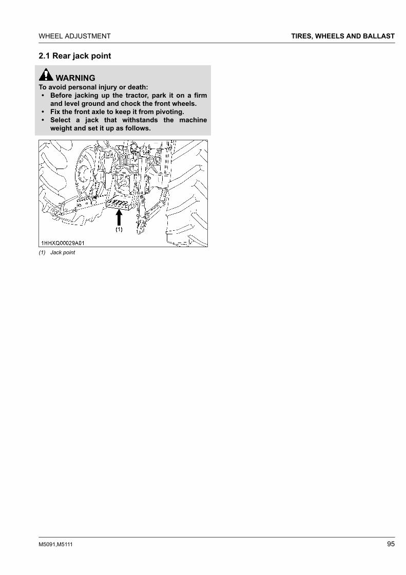
2.1 Rear jack point
WARNINGTo avoid personal injury or death:• Before jacking up the tractor, park it on a firm
and level ground and chock the front wheels.• Fix the front axle to keep it from pivoting.• Select a jack that withstands the machine
weight and set it up as follows.
(1) Jack point
WHEEL ADJUSTMENT TIRES, WHEELS AND BALLAST
M5091,M5111 95
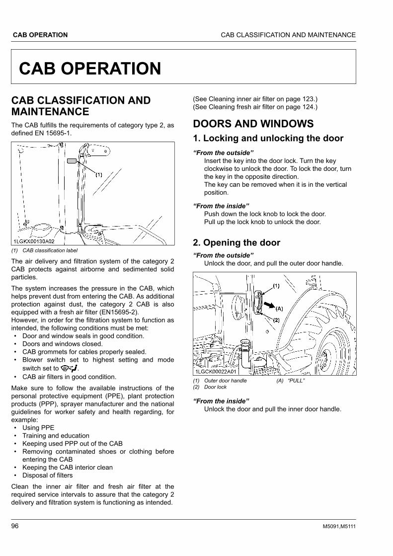
CAB OPERATIONCAB CLASSIFICATION ANDMAINTENANCEThe CAB fulfills the requirements of category type 2, asdefined EN 15695-1.
(1) CAB classification label
The air delivery and filtration system of the category 2CAB protects against airborne and sedimented solidparticles.The system increases the pressure in the CAB, whichhelps prevent dust from entering the CAB. As additionalprotection against dust, the category 2 CAB is alsoequipped with a fresh air filter (EN15695-2).However, in order for the filtration system to function asintended, the following conditions must be met:• Door and window seals in good condition.• Doors and windows closed.• CAB grommets for cables properly sealed.• Blower switch set to highest setting and mode
switch set to .• CAB air filters in good condition.
Make sure to follow the available instructions of thepersonal protective equipment (PPE), plant protectionproducts (PPP), sprayer manufacturer and the nationalguidelines for worker safety and health regarding, forexample:• Using PPE• Training and education• Keeping used PPP out of the CAB• Removing contaminated shoes or clothing before
entering the CAB• Keeping the CAB interior clean• Disposal of filters
Clean the inner air filter and fresh air filter at therequired service intervals to assure that the category 2delivery and filtration system is functioning as intended.
(See Cleaning inner air filter on page 123.)(See Cleaning fresh air filter on page 124.)
DOORS AND WINDOWS1. Locking and unlocking the door“From the outside”
Insert the key into the door lock. Turn the keyclockwise to unlock the door. To lock the door, turnthe key in the opposite direction.The key can be removed when it is in the verticalposition.
“From the inside”Push down the lock knob to lock the door.Pull up the lock knob to unlock the door.
2. Opening the door“From the outside”
Unlock the door, and pull the outer door handle.
(1) Outer door handle(2) Door lock
(A) “PULL”
“From the inside”Unlock the door and pull the inner door handle.
CAB OPERATION CAB CLASSIFICATION AND MAINTENANCE
96 M5091,M5111

(1) Inner door handle(2) Lock knob
(A) “PULL”(B) “PUSH” (Lock)(C) “PULL” (Unlock)
3. Rear windowTurn the rear window handle clockwise to the verticalposition and push the handle. The rear window isopened by the gas spring cylinder.
(1) Rear window handle (A) “OPEN”(B) “CLOSE”
4. Side windowPull the side window handle and push the side windowto open.
(1) Side window handle
5. SunroofRaise the front loader, and visually check to see if thetip of an attachment (bucket and fork, for example) isvisible in its position or angle from the operator's seat.
(1) Sunroof (A) “OPEN”(B) “CLOSE”
NOTE :• Open and close with the near center of the
sunroof.
6. Emergency exit1. In an emergency situation, open the right door of
the CAB if the left door is blocked and vice versa.2. Exit through the rear window if the CAB doors are
blocked.
DOME LIGHTSliding the dome light switch will give the following lightcondition:
[OFF]The light does not turn on when the door is opened.
DOORS AND WINDOWS CAB OPERATION
M5091,M5111 97

“DOOR”The light turns on when the door (LH) is opened. Itturns off when the door (LH) is closed.
[ON]The light remains on regardless of the doorposition.
(1) Dome light(2) Dome light switch
(A) [OFF](B) “DOOR”(C) [ON]
IMPORTANT :• The battery will discharge if the dome light
remains on. Be sure to check the dome lightswitch position and/or door closure.
WORK LIGHT
WARNINGTo avoid personal injury or death:• Do not operate on roads with work lights on.
Work lights may blind or confuse the drivers ofoncoming vehicles.
1. Work light switchTurn on the key switch and press the bottom half of thework light switch.The work light and the switch's indicator light up. Pressthe top half of the work light switch to turn off the lightand indicator.
(1) Front work light switch(2) Rear work light switch
(A) Indicator for work lights
2. Front work light
(1) Front work light
3. Rear work light
(1) Rear work light
CAB OPERATION WORK LIGHT
98 M5091,M5111

WIPER1. Front wiper and washer switch1. Turn on the key switch and press the bottom half of
the wiper switch to the first step to activate thecontinuous wiper.When the switch is pressed further to the secondstep, washer liquid jets out.The jetting continues while the switch is pressedand the continuous wiper is activated.
2. Press the top half of the wiper switch to the firststep to activate the intermittent wiper.When the switch is pressed further to the secondstep, washer liquid jets out and the intermittentwiper is activated.
2. Rear wiper and washer switch1. Turn on the key switch and press the top half of the
wiper switch to the first step to activate the wiper.When the switch is pressed further to the secondstep, washer liquid jets out.The jetting continues while the switch is pressedand the wiper is activated continuously.
2. Press the bottom half of the wiper and washerswitch, washer liquid only jets out.
(1) Front wiper and washer switch(2) Rear wiper and washer switch
IMPORTANT :• Do not activate the wipers when the
windows are dry, as they may be scratched.Be sure to jet washer liquid first and thenactivate the wipers.
3. Using the wipers in cold season1. While not used in cold season, keep the wiper
blades off the windshield to prevent them frombeing frozen to the windshield.
2. If the windshield is covered with snow, scrape it offthe windshield before using the wipers.
3. If the wiper blades are frozen to the windshield andfail to move, be sure to turn the main key switch to“OFF” and remove the ice from the blades. Thenplace the main key switch back to “ON”.
4. When commercially available cold-season wiperblades are used, make sure their size is the sameas or smaller than that of the standard ones.
IMPORTANT :• In the cold season, the wiper blades and the
wiper motor may become overloaded, andcause damage. To avoid this, be sure to takethe above precautions.
AIR CONDITIONER1. AirflowAir in the CAB and fresh air introduced into the CABflows as follows. Adjust the air ports to obtain thedesired condition.
WIPER CAB OPERATION
M5091,M5111 99

(1) Control panel(2) Defroster air outlets(3) Dashboard air outlets(4) Inner air filter
(A) “INNER AIR RECIRCULA-TION”
(1) Fresh air filter (A) “FRESH AIR INLET”
IMPORTANT :• Do not pour water directly into the fresh air port
while washing the tractor.
2. Air control ventDashboard air outletThe dashboard air outlets can be independentlyadjusted as required.
(1) Face area air outlets(2) Back area air outlets(3) Feet area air outlets
(A) “OPEN”(B) “SHUT”(C) “TURN”
CAUTIONTo avoid personal injury:• If the window fails to defrost in extreme
conditions or becomes cloudy whendehumidifying the CAB, wipe off moisture witha soft cloth.
• Do not block all the air outlets of the airconditioner. A problem could occur.
3. Control panel
(1) Mode switch(2) Temperature control dial(3) Blower switch(4) Air conditioner switch with in-
dicator light(5) Recirculation or fresh air se-
lection switch with indicatorlight
(A) “WARM”(B) “COOL”
3.1 Mode switchSet the mode switch to the desired position.
Air is blown from only the dashboard air outlets. Air is blown from the dashboard and defroster air
outlets. Air is blown from only the defroster air outlet.
CAB OPERATION AIR CONDITIONER
100 M5091,M5111

3.2 Temperature control dialSet this dial at the desired position to obtain theoptimum air temperature. Turn the dial in the “WARM”direction to obtain warmer air. Turn it in the “COOL”direction to obtain cooler air.
3.3 Blower switchAir volume can be changed in 4 steps. At the [4]position, the largest air volume is obtained.
3.4 Air conditioner switchPush this switch to activate the air conditioner. Anindicator light will light up when the switch is set to“ON”.Push the switch again to turn the air conditioner off, inwhich case the indicator light will turn off.
3.5 Recirculation or fresh air selectionswitchEach time the switch is pressed, the air flow positionchanges for “RECIRCULATION” or “FRESH AIR”. Anindicator light will light up when the switch is set to“RECIRCULATION”. And the indicator light will be offwhen the switch is set to “FRESH AIR”.
FRESH AIR:Indicator: “OFF”Fresh air will flow into the CAB. This is helpful whenyou work in dusty conditions or if the glass windowsget foggy.
RECIRCULATION:Indicator: “ON”In-CAB air will be recirculated. This is useful forcooling or heating the CAB quickly or keeping itextra cool or warm.
(1) Recirculation or fresh air se-lection switch with indicatorlight
(A) “RECIRCULATION”(B) “FRESH AIR”
NOTE :• When heating, do not keep the switch at the
“RECIRCULATION” position for a long time. Thewindshield easily gets foggy.
• While working in dusty conditions, keep theswitch at the “FRESH AIR” position. Thisincreases the pressure in the CAB, which helpsprevent dust from coming into the CAB.
4. Operation4.1 Heating1. Set the mode switch to the position.2. Set the recirculation or fresh air selection switch to
the “FRESH AIR” position. To raise the temperaturein the CAB quickly, set this switch to the“RECIRCULATION” position.
3. Adjust the blower ([1/2/3/4]) switch and thetemperature control dial to achieve a comfortabletemperature level.
(1) Mode switch(2) Blower switch(3) Temperature control dial(4) Recirculation or fresh air se-
lection switch with indicatorlight
(A) “WARM”(B) “COOL”
AIR CONDITIONER CAB OPERATION
M5091,M5111 101

4. Adjust the air volume and air direction from thedashboard air outlets. In general, open feet area airoutlets, and shut face and back area air outlets.
(1) Face area air outlets(2) Back area air outlets(3) Feet area air outlets
4.2 Cooling or dehumidifying-heating1. Set the mode switch to the position.2. Set the recirculation or fresh air selection switch to
the “FRESH AIR” position. To lower the temperaturein the CAB quickly, set this switch to the“RECIRCULATION” position.
3. Press and turn on the air conditioner switch withindicator.
4. Turn on the blower ([1/2/3/4]) switch.5. Adjust the temperature control dial to “COOL” or
intermediate position to achieve a comfortabletemperature level.
NOTE :• In summer when the heater is not used, keep
the temperature control dial at the max“COOL” (end of counterclockwise) position.Otherwise, hot air will raise the temperaturein the CAB.
(1) Mode switch(2) Temperature control dial(3) Blower switch(4) Air conditioner switch with in-
dicator light(5) Recirculation or fresh air se-
lection switch with indicatorlight
(A) “WARM”(B) “COOL”
6. Adjust the air volume and air direction from thedashboard air outlets. In general, the air volumefrom face area air outlets is adjusted to increase,and the air volume from feet and back area airoutlets is adjusted to decrease.
(1) Face area air outlets(2) Back area air outlets(3) Feet area air outlets
4.3 Defrosting or demistingTo defrost or demist the windshield, take the followingsteps.
1. Set the mode switch to the position.2. Set the recirculation or fresh air selection switch to
the “FRESH AIR” position.
CAB OPERATION AIR CONDITIONER
102 M5091,M5111

3. Set the blower switch and the temperature controldial to the [4] and max “WARM” (end of clockwise)positions, respectively.
(1) Mode switch(2) Temperature control dial(3) Blower switch(4) Recirculation or fresh air se-
lection switch with indicatorlight
(A) “WARM”(B) “COOL”
(1) Defroster air outlet
NOTE :• If you set the mode switch to position,
air will not come out from the dashboard airoutlets.
INSTALLING THE IMPLEMENTCONTROL BOX1. Make an opening in each rubber cap or corner plug.
Introduce the implement control cable and hydraulichose through these openings into the CAB.
(1) Rubber cap(2) Corner cover
ELECTRICAL OUTLETThe tractor is equipped with electrical outlets whichserve the following functions.
For use with implement
(1) Accessory electrical outlet (max 10 A)(2) Accessory electrical outlet(A) Terminal: through the ACC position of the key switch (max 5 A)(B) Terminal: through the battery direct (max 25 A)(C) Terminal: ground
BEACON LIGHT• The beacon light switch with wire harness for
beacon light connection is equipped.• Turn on the key switch and press the bottom half of
the beacon light switch. Then the beacon light andindicator of switch will be activated.
• Press the top half of the switch, and turn off thelight and the indicator.
INSTALLING THE IMPLEMENT CONTROL BOX CAB OPERATION
M5091,M5111 103

(1) Beacon light switch (A) Indicator for beacon light
(1) Beacon light (if equipped)(2) Relay harness for beacon light (max 7 A)(3) Stay(4) Beacon electrical outlet
NOTE :• The relay harness for beacon light is in the
accessories box.• Pre-assemble the beacon light and relay
harness, and connect the relay harness to theconnector of beacon electrical outlet.
CAB OPERATION
104 M5091,M5111

MAINTENANCESERVICE INTERVALS
Interval Items Ref.page
A initial 50Hr
Engine oil Change 116
Engine oil filter Re-place 116
B every 50Hr
Engine start system Check 116 *1
Wheel bolt torque Check 117
Tie-rod dust cover Check 117 *1
C every100 Hr
Greasing --- 117
Air cleaner primary ele-ment Clean 119 *2
Fan belt Adjust 119
Brake pedal Adjust 120 *1
Gear-locked parkingbrake Check 120 *1
Parking brake Adjust 121
Battery condition Check 121 *3
Air conditioner drivebelt Adjust 122
D every200 Hr
Toe-in Adjust 123
Fuel tank water Drain 123
Inner air filter Clean 123
Fresh air filter Clean 124 *4
E every400 Hr Water separator Clean 124
F every500 Hr
Engine oil Change 125 *5
Engine oil filter Re-place 125 *5
Fuel filter Re-place 126
Hydraulic oil filter Re-place 126
Power steering oil line Check 127 *6
Radiator hose andclamp Check 127 *6
Fuel line Check 128 *6
Intake air line Check 128 *6
Lift cylinder hose Check 129 *6
Air conditioner pipesand hoses Check 130 *6
(Continued)
Interval Items Ref.page
G every600 Hr Front axle pivot Adjust 130
H every1000Hr
Transmission fluid Change 130
Front differential caseoil Change 130
Front axle gear caseoil Change 131
Engine valve clearance Adjust 131 *1
I
every1000Hror 1year*7
Air cleaner primary ele-ment
Re-place 131
Air cleaner secondaryelement
Re-place 131
Exhaust manifold Check 131 *1
Fresh air filter Re-place - *1
J every1500Hr
Fuel injector nozzle tip Check 131 *1
EGR cooler CheckClean 131 *1
K
every2000Hror 2years*8
Cooling system Flush 131
Coolant Change 132
L every3000Hr
Turbocharger Check 133 *1
Supply pump Check 133 *1
Intake air heater Check 133 *1
EGR system CheckClean 133 *1
DPF muffler Clean 133 *1
M every 1year
CAB isolation cushion Check 133
DPF related pipe Check 133 *1
EGR pipe Check 134 *1
N every 2years
Breather related rubberpipe
Re-place 134 *1
Boost sensor hose Re-place 134 *1
DPF related rubberpipe
Re-place 134 *1
EGR cooler hose Re-place 134 *1
Master cylinder filter Clean 134 *1
O every 3years
Cables of both parkingbrakes
Re-place 134 *1
(Continued)
SERVICE INTERVALS MAINTENANCE
M5091,M5111 105

Interval Items Ref.page
P every 4years
Radiator hose andclamp
Re-place 134
Fuel line Re-place 134 *1
Intake air line Re-place 134 *1
Power steering oil line Re-place 134 *1
Lift cylinder hose Re-place 134 *1
Master cylinder kit Re-place 134 *1
Brake seal 1 and 2 Re-place 134 *1
Air conditioner pipesand hoses
Re-place 134 *1
QServiceas re-quired
Fuel system Bleed 134
Brake system Bleed 135 *1
Clutch housing water Drain 135
Fuse Re-place 135
Light bulb Re-place 138
Head lamp Re-place 138
Lubricating point fordoor and window --- 138
Washer liquid Add 138
Refrigerant (gas) Check 138
*1 Consult your local KUBOTA Dealer for this service.*2 Air cleaner should be cleaned more often in dusty conditions
than in normal conditions.*3 When the battery is used for less than 100 hours per year,
check the battery condition by reading the indicator annually.*4 Clean and replace the fresh air filter more frequently if used
under dusty conditions. When the filter is very dirty from dustyconditions, replace the filter.
*5 The initial 50 hours should not be a replacement cycle.*6 Replace if any deterioration (crack, hardening, scar, or defor-
mation) or damage occurred.*7 Every 1000 hours or every 1 year, whichever comes first.*8 Every 2000 hours or every 2 years, whichever comes first.
MAINTENANCE ITEMS CHARTHow to use the chart1. The circles in this at-a-glance chart indicate the
relevant points between the tractor's hour meterreadings and the service intervals. Following thesecircles and the maintenance item group (A thru P),keep up your tractor.
2. Details regarding maintenance items can be foundin a different section.(See SERVICE INTERVALS on page 105.)
MAINTENANCE MAINTENANCE ITEMS CHART
106 M5091,M5111

Chart at a glance
Hourmeter
Maintenance items
A B C D E F G H I J K L M N O P
50 ○ ○
100 ○ ○
150 ○
200 ○ ○ ○
250 ○
300 ○ ○
350 ○
400 ○ ○ ○ ○
450 ○
500 ○ ○ ○
550 ○
600 ○ ○ ○ ○
650 ○
700 ○ ○
750 ○
800 ○ ○ ○ ○
850 ○
900 ○ ○
950 ○
1000 ○ ○ ○ ○ ○
1050 ○
1100 ○ ○
1150 ○
1200 ○ ○ ○ ○ ○
1250 ○
1300 ○ ○
1350 ○
1400 ○ ○ ○
1450 ○
1500 ○ ○ ○ ○
1550 ○
1600 ○ ○ ○ ○
1650 ○
1700 ○ ○
1750 ○
1800 ○ ○ ○ ○
1850 ○
1900 ○ ○
(Continued)
Hourmeter
Maintenance items
A B C D E F G H I J K L M N O P
1950 ○
2000 ○ ○ ○ ○ ○ ○
2050 ○
2100 ○ ○
2150 ○
2200 ○ ○ ○
2250 ○
2300 ○ ○
2350 ○
2400 ○ ○ ○ ○ ○
2450 ○
2500 ○ ○ ○
2550 ○
2600 ○ ○ ○
2650 ○
2700 ○ ○
2750 ○
2800 ○ ○ ○ ○
2850 ○
2900 ○ ○
2950 ○
3000 ○ ○ ○ ○ ○ ○ ○ ○
Every1000
Hr or 1year
○
Every2000
Hr or 2years
○
Every 1year
○
Every 2years ○
Every 3years ○
Every 4years ○
MAINTENANCE
M5091,M5111 107

LUBRICANTS, FUEL AND COOLANT
No. LocationsCapacities
LubricantsM5091 M5111
1 Fuel 105 L No.2-D S15 diesel fuelNo.1-D S15 diesel fuel if temperature is below -10 ℃
2 Coolant 10 L(Recovery tank: 1.0 L) Fresh clean soft water with antifreeze
3 Washer liquid 1.3 L Automobile washer liquid
4 Engine crankcase(with filter) 10.7 L
• Engine oil:API service classification
CJ-4(DPF type engine)
Above 25 ℃ SAE30,SAE10W-30 or 15W-40
-10 ℃ to 25 ℃ SAE10W-30 or 15W-40
Below -10 ℃ SAE10W-30
5 Transmission case 60 L • KUBOTA UDT or SUPER UDT fluid*
6 Front differential case oil(4WD) 6.0 L
• KUBOTA UDT or SUPER UDT fluid* or SAE 80 - SAE 90gear oil
7 Front axle gear case oil(4WD) 3.5 L
8
Greasing No. of greasing points Capacity Type of grease
Top link 2
Until grease overflows. Multipurpose greaseNLGI-2 or
NLGI-1 (GC-LB)
Top link bracket 2
Lift rod 2
Hydraulic lift cylinder pin 4
Front axle gear case sup-port 2
Front axle support 2
Steering joint shaft 1
Battery terminal 2 A small amount
NOTE :• The product name of Kubota genuine UDT fluid may be different from that in the operator's manual
depending on countries or territories. Consult your local KUBOTA Dealer for further details.
Engine oil• The oil used in the engine should have an American Petroleum Institute (API) service classification and proper
SAE engine oil according to the ambient temperatures shown in the previous table.• Refer to the following table for the suitable API classification engine oil according to the diesel particulate filter
(DPF) type engines and the fuel.
Fuel usedEngine oil classification
(API classification)
Oil class for engines with DPF
Ultra low sulfur fuel<0.0015% (15 ppm) CJ-4
Fuel• Use the ultra low sulfur diesel fuel only (below 0.0015% or 15 ppm) for these engines.• Cetane number of 45 minimum. Cetane number greater than 50 is preferred, especially for temperatures below
-20 ℃ or elevations above 1500 m.• Diesel fuels specified to EN 590 or ASTM D975 are recommended.
MAINTENANCE LUBRICANTS, FUEL AND COOLANT
108 M5091,M5111

• No.2-D is a distillate fuel of lower volatility for engines in industrial and heavy mobile service (SAE J313 JUN87).Transmission oilThe oil used to lubricate the transmission is also used as hydraulic fluid. To ensure proper operation of the hydraulicsystem and to complete lubrication of the transmission, it is important that a multi-grade transmission fluid is used inthis system. We recommend the use of KUBOTA UDT or SUPER UDT fluid for optimum protection and performance.Consult your local KUBOTA Dealer for further detail.Do not mix different brands together.Indicated capacities of water and oil are manufacturer's estimate.
MAINTENANCE
M5091,M5111 109

PERIODIC SERVICE
WARNINGTo avoid personal injury or death:• Do not work under any hydraulically supported
devices. They can settle, suddenly leak, or beaccidentally lowered. If necessary to workunder the tractor or any machine elements forservicing or adjustments, securely supportthem with stands or suitable blockingbeforehand.
WASTE DISPOSAL• The improper disposal or burning of waste causes
environmental pollution and can be punishable byyour local laws and regulations.– When draining fluids from the tractor, place a
container underneath the drain port.– Do not pour waste onto the ground, down a
drain, or into any water source (such as rivers,streams, lakes, marshes, seas and oceans).
– Waste products such as used oil, fuel, coolant,hydraulic fluid, urea aqueous solution (DEF/AdBlue®), refrigerant, solvent, filters, rubber,batteries and harmful substances, can harm theenvironment, people, pets and wildlife.Please dispose properly.See your local recycling center or KUBOTADealer to learn how to recycle or get rid ofwaste products.
HOW TO OPEN THE HOOD
WARNINGTo avoid personal injury or death from contact withmoving parts:• Never open the hood while the engine is
running.• Do not touch the muffler or exhaust pipes while
they are hot; severe burns could result.• Hold the hood with the other hand while
unlocking the release lever.
1. Hood1. To open the hood, hold the hood, pull the release
lever and then open the hood.
(1) Tool(2) Hood
(A) “PULL”
NOTE :• To close the hood, push the hood into position
using both hands.
(A) “Push down using both hands to close the hood”
2. Side cover1. Remove the bolts (2).
Move the side cover 1 forward, and pull out thecover from pins.
PERIODIC SERVICE WASTE DISPOSAL
110 M5091,M5111

2. Loosen the bolts (5), and remove the side cover 2.
(1) Side cover 1(2) Bolt(3) Pin(4) Side cover 2(5) Bolt
(A) “MOVE”
DAILY CHECKFor your own safety and maximum service life of themachine, make a thorough daily inspection beforeoperating the machine to start the engine.
WARNINGTo avoid personal injury or death:Take the following precautions when checking thetractor.• Park the machine on firm and level ground.• Set both parking brakes.• Lower the implement to the ground.• Release all residual pressure from the hydraulic
system.• Stop the engine and remove the key.
1. Walk around inspectionLook around and under the tractor for items such asloose bolts, trash build-up, oil or coolant leaks, brokenor worn parts.
2. Checking and refueling
WARNINGTo avoid personal injury or death:• Never use fire.• Do not smoke while refueling.• Be sure to stop the engine and remove the key
before refueling.• Use properly grounded fueling systems. Make
sure that there is no static discharge whilerefueling.
• Be sure to close the fuel tank cap afterrefueling.
To avoid allergic skin reaction:• Wash hands immediately after contact with
diesel fuel.
1. Check the amount of fuel by looking at the fuelgauge.
2. When the fuel warning indicator lights up, it is timeto add fuel.
(1) Fuel tank cap
Fuel tank capacity 105 L
IMPORTANT :• Be sure to use ultra-low sulfur fuel (S15).• Do not permit dirt or trash to get into the fuel
system.• Be careful not to let the fuel tank become
empty. Otherwise, air will enter the fuel system,necessitating bleeding before the next enginestart.
• If the engine runs out of fuel and stalls, enginecomponents may become damaged.
• Be careful not to spill during refueling. If a spilloccurs wipe it off at once or it may cause a fire.
• To prevent condensation (water) accumulationin the fuel tank, fill the tank before parkingovernight.
DAILY CHECK PERIODIC SERVICE
M5091,M5111 111
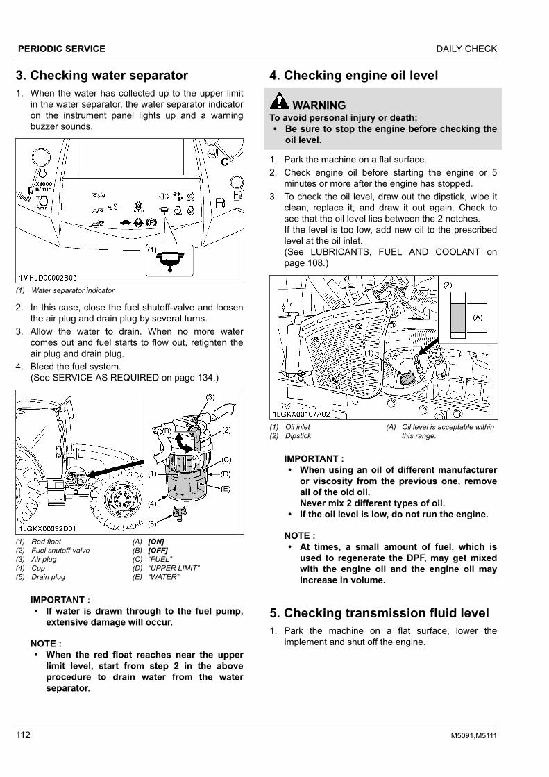
3. Checking water separator1. When the water has collected up to the upper limit
in the water separator, the water separator indicatoron the instrument panel lights up and a warningbuzzer sounds.
(1) Water separator indicator
2. In this case, close the fuel shutoff-valve and loosenthe air plug and drain plug by several turns.
3. Allow the water to drain. When no more watercomes out and fuel starts to flow out, retighten theair plug and drain plug.
4. Bleed the fuel system.(See SERVICE AS REQUIRED on page 134.)
(1) Red float(2) Fuel shutoff-valve(3) Air plug(4) Cup(5) Drain plug
(A) [ON](B) [OFF](C) “FUEL”(D) “UPPER LIMIT”(E) “WATER”
IMPORTANT :• If water is drawn through to the fuel pump,
extensive damage will occur.
NOTE :• When the red float reaches near the upper
limit level, start from step 2 in the aboveprocedure to drain water from the waterseparator.
4. Checking engine oil level
WARNINGTo avoid personal injury or death:• Be sure to stop the engine before checking the
oil level.
1. Park the machine on a flat surface.2. Check engine oil before starting the engine or 5
minutes or more after the engine has stopped.3. To check the oil level, draw out the dipstick, wipe it
clean, replace it, and draw it out again. Check tosee that the oil level lies between the 2 notches.If the level is too low, add new oil to the prescribedlevel at the oil inlet.(See LUBRICANTS, FUEL AND COOLANT onpage 108.)
(1) Oil inlet(2) Dipstick
(A) Oil level is acceptable withinthis range.
IMPORTANT :• When using an oil of different manufacturer
or viscosity from the previous one, removeall of the old oil.Never mix 2 different types of oil.
• If the oil level is low, do not run the engine.
NOTE :• At times, a small amount of fuel, which is
used to regenerate the DPF, may get mixedwith the engine oil and the engine oil mayincrease in volume.
5. Checking transmission fluid level1. Park the machine on a flat surface, lower the
implement and shut off the engine.
PERIODIC SERVICE DAILY CHECK
112 M5091,M5111

2. To check the oil level, draw out the dipstick, wipe itclean, replace it, and draw it out again. Check tosee that the oil level lies between the 2 notches.If the level is too low, add new oil to the prescribedlevel at the oil inlet.(See LUBRICANTS, FUEL AND COOLANT onpage 108.)
(1) Dipstick(2) Oil inlet
(A) Oil level is acceptable withinthis range.
IMPORTANT :• If the oil level is low, do not run the engine.
6. Checking coolant level
WARNINGTo avoid personal injury or death:• Do not remove the radiator cap while the
coolant is hot. When cool, slowly rotate the capto the first stop and allow sufficient time forexcess pressure to escape before removing thecap completely.
1. Check to see that the coolant level is between the[FULL] and [LOW] marks of the recovery tank.
2. When the coolant level drops due to evaporation,add soft water only up to the full level.In case of leakage, add antifreeze and soft water inthe specified mixing ratio up to the full level.(See Flushing cooling system and changing coolanton page 131.)
3. When the coolant level is lower than the [LOW]mark of the recovery tank, remove the radiator capand check to see that the coolant level is just belowthe port.If the level is low, add coolant.
(1) Recovery tank (A) [FULL](B) [LOW]
IMPORTANT :• If the radiator cap has to be removed, follow
the caution above and securely retighten thecap.
• Use clean, fresh soft water and antifreeze tofill the radiator.
• If coolant should leak, consult your localKUBOTA Dealer.
7. Cleaning evacuator valveOpen the evacuator valve to get rid of large particles ofdust and dirt.
(1) Evacuator valve
8. Cleaning grill, radiator screen, oilcooler, fuel cooler, air conditionercondenser and battery mount
WARNINGTo avoid personal injury or death:• Be sure to stop the engine before removing the
screen.• The condenser and receiver become hot while
the air conditioner is running. Before checking
DAILY CHECK PERIODIC SERVICE
M5091,M5111 113

or cleaning them, wait until they cool downenough.
8.1 Detaching the panel1. Pull the upper part of the panel outward.2. Raise the panel until pin (A) clears the hole, and
take out the panel.
(1) Panel
3. Attaching the panel is performed vice versa.
8.2 Sliding the air conditioner condenser1. Loosen the wing nut.2. Hold the handle, slide the air conditioner condenser
assembly toward yourself.
(1) Condenser(2) Receiver(3) Handle(4) Wing nut(5) Air conditioner hose
(A) “PULL”
IMPORTANT :• Do not hold the air conditioner receiver or
the air conditioner pipes when sliding outthe condenser for cleaning.
8.3 Cleaning1. Check the front grill to make sure it is clean from
debris.2. Detach the radiator and air conditioner screens and
remove all foreign materials.3. Check radiator, intercooler, oil cooler, fuel cooler, air
conditioner condenser and battery mount to be surethey are clean from debris.
(1) Radiator screen(2) Fuel cooler(3) Intercooler (if equipped)(4) Oil cooler(5) Battery mount
(1) Air conditioner condenser screen(2) Air conditioner condenser
9. Checking DPF muffler
WARNINGTo avoid personal injury or death:• Before checking or cleaning the DPF muffler,
stop the engine and wait until it is cooled downenough.
PERIODIC SERVICE DAILY CHECK
114 M5091,M5111
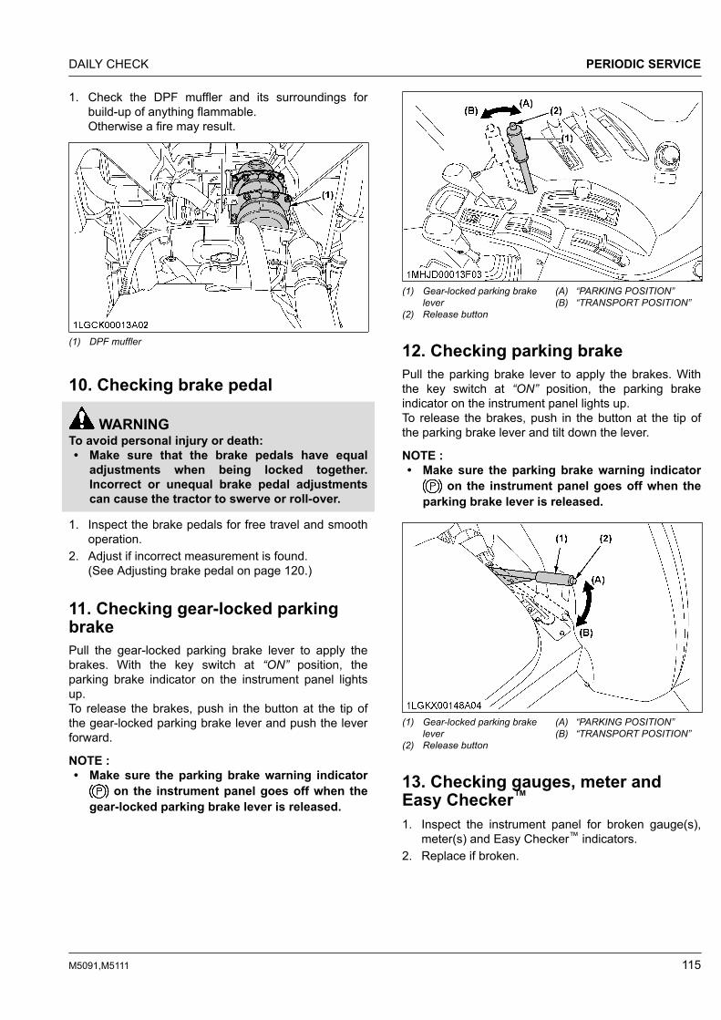
1. Check the DPF muffler and its surroundings forbuild-up of anything flammable.Otherwise a fire may result.
(1) DPF muffler
10. Checking brake pedal
WARNINGTo avoid personal injury or death:• Make sure that the brake pedals have equal
adjustments when being locked together.Incorrect or unequal brake pedal adjustmentscan cause the tractor to swerve or roll-over.
1. Inspect the brake pedals for free travel and smoothoperation.
2. Adjust if incorrect measurement is found.(See Adjusting brake pedal on page 120.)
11. Checking gear-locked parkingbrakePull the gear-locked parking brake lever to apply thebrakes. With the key switch at “ON” position, theparking brake indicator on the instrument panel lightsup.To release the brakes, push in the button at the tip ofthe gear-locked parking brake lever and push the leverforward.
NOTE :• Make sure the parking brake warning indicator
on the instrument panel goes off when thegear-locked parking brake lever is released.
(1) Gear-locked parking brakelever
(2) Release button
(A) “PARKING POSITION”(B) “TRANSPORT POSITION”
12. Checking parking brakePull the parking brake lever to apply the brakes. Withthe key switch at “ON” position, the parking brakeindicator on the instrument panel lights up.To release the brakes, push in the button at the tip ofthe parking brake lever and tilt down the lever.
NOTE :• Make sure the parking brake warning indicator
on the instrument panel goes off when theparking brake lever is released.
(1) Gear-locked parking brakelever
(2) Release button
(A) “PARKING POSITION”(B) “TRANSPORT POSITION”
13. Checking gauges, meter andEasy Checker™
1. Inspect the instrument panel for broken gauge(s),meter(s) and Easy Checker™ indicators.
2. Replace if broken.
DAILY CHECK PERIODIC SERVICE
M5091,M5111 115
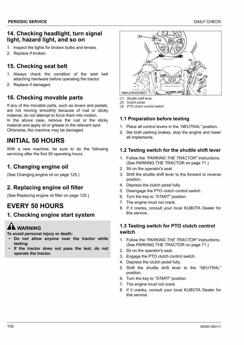
14. Checking headlight, turn signallight, hazard light, and so on1. Inspect the lights for broken bulbs and lenses.2. Replace if broken.
15. Checking seat belt1. Always check the condition of the seat belt
attaching hardware before operating the tractor.2. Replace if damaged.
16. Checking movable partsIf any of the movable parts, such as levers and pedals,are not moving smoothly because of rust or stickymaterial, do not attempt to force them into motion.In the above case, remove the rust or the stickymaterial and apply oil or grease to the relevant spot.Otherwise, the machine may be damaged.
INITIAL 50 HOURSWith a new machine, be sure to do the followingservicing after the first 50 operating hours.
1. Changing engine oil(See Changing engine oil on page 125.)
2. Replacing engine oil filter(See Replacing engine oil filter on page 125.)
EVERY 50 HOURS1. Checking engine start system
WARNINGTo avoid personal injury or death:• Do not allow anyone near the tractor while
testing.• If the tractor does not pass the test, do not
operate the tractor.
(1) Shuttle shift lever(2) Clutch pedal(3) PTO clutch control switch
1.1 Preparation before testing1. Place all control levers in the “NEUTRAL” position.2. Set both parking brakes, stop the engine and lower
all implements.
1.2 Testing switch for the shuttle shift lever1. Follow the “PARKING THE TRACTOR” instructions.
(See PARKING THE TRACTOR on page 71.)2. Sit on the operator's seat.3. Shift the shuttle shift lever to the forward or reverse
position.4. Depress the clutch pedal fully.5. Disengage the PTO clutch control switch.6. Turn the key to “START” position.7. The engine must not crank.8. If it cranks, consult your local KUBOTA Dealer for
this service.
1.3 Testing switch for PTO clutch controlswitch1. Follow the “PARKING THE TRACTOR” instructions.
(See PARKING THE TRACTOR on page 71.)2. Sit on the operator's seat.3. Engage the PTO clutch control switch.4. Depress the clutch pedal fully.5. Shift the shuttle shift lever to the “NEUTRAL”
position.6. Turn the key to “START” position.7. The engine must not crank.8. If it cranks, consult your local KUBOTA Dealer for
this service.
PERIODIC SERVICE DAILY CHECK
116 M5091,M5111

2. Checking operator presencecontrol (OPC) system
WARNINGTo avoid personal injury or death:• Before checking the PTO OPC, make sure that
the PTO drive shaft is disconnected from thetractor.
• If the buzzer does not sound during the PTOOPC check procedure, shut off the engine andconsult your local KUBOTA Dealer forimmediate servicing of the PTO OPC.
• The unit should not be operated until servicingis completed.
1. Follow the “PARKING THE TRACTOR” instructions.(See PARKING THE TRACTOR on page 71.)
2. Make sure the PTO drive shaft is disconnected fromthe tractor.
3. Sit on the operator's seat.4. Start the engine.5. Engage the PTO gear shift lever (if equipped).6. Engage the PTO clutch control switch. The PTO
should begin to rotate. Disengage the PTO clutchcontrol switch.
7. While lifting yourself from the seat, engage the PTOclutch control switch.a. The PTO should begin to rotate and a buzzer
should sound.b. Disengage the PTO clutch control switch.c. If the buzzer does not sound, shut off the
engine and consult your local KUBOTA Dealerfor immediate servicing of the PTO OPC.
8. If the PTO OPC is operating properly, shut off theengine, and reconnect the implement drive shaft tothe PTO. Restart the engine per the availableinstructions.
3. Checking wheel bolt torque
WARNINGTo avoid personal injury or death:• Never operate the tractor with a loose rim,
wheel or axle.• Any time bolts and nuts are loosened, retighten
to the specified torque.• Check all bolts and nuts frequently and keep
them tight.
Check wheel bolts and nuts regularly, especially whennew. If they are loose, tighten them as follows.
(1) 260 to 304 N⋅m / 26.5 to 31.0 kgf⋅m(2) 343 to 401 N⋅m / 35.0 to 41.0 kgf⋅m
4. Checking tie-rod dust coverCheck to see that dust covers are not damaged.If dust covers are damaged, consult your localKUBOTA Dealer for this service.
(1) Dust cover (both sides, RH not shown in illustration)
IMPORTANT :• If dust covers are cracked, water and dust can
cause premature wear of the tie-rod.
EVERY 100 HOURS1. Lubricating grease fittingsApply a small amount of multipurpose grease to thefollowing points every 100 hours.If you have been operating the machine in extremelywet and muddy conditions, lubricate the grease fittingsmore often.
EVERY 50 HOURS PERIODIC SERVICE
M5091,M5111 117

(1) Grease fitting (front axle support)
(1) Grease fitting (front axle support)
(1) Grease fitting (front axle gear case support) - both sides, RH notshown in illustration
(1) Grease fitting (top link)(2) Grease fitting (top link bracket)(3) Grease fitting (lifting rod)
(1) Grease fitting (hydraulic lift cylinders pin)
(1) Grease fitting (steering joint shaft)
PERIODIC SERVICE EVERY 100 HOURS
118 M5091,M5111

(1) Battery terminals
2. Cleaning air cleaner primaryelementNOTE :• If the air conditioner condenser is pulled out
when cleaning the air cleaner, the air cleanercover can be detached and attached easily.(See Cleaning grill, radiator screen, oil cooler,fuel cooler, air conditioner condenser andbattery mount on page 113.)
1. Remove the air cleaner cover and primary element.2. Clean the primary element:
• When dry dust adheres to the element, blowcompressed air from the inside, turning theelement. Pressure of compressed air must beunder 205 kPa (2.1 kgf/cm2 , 30 psi).
• When carbon or oil adheres to the element,soak the element in detergent for 15 minutes,then wash it several times in water, rinse withclean water and dry it naturally. After theelement has fully dried, inspect inside theelement with a light and check for damage.
3. Replace the air cleaner primary element:Once every 1000 hours or yearly, whichever comesfirst.
NOTE :• Check to see if the evacuator valve is
blocked with dust.
(1) Secondary (safety) element(2) Primary element(3) Evacuator valve(4) Cover
IMPORTANT :• The air cleaner uses a dry element; never
apply oil.• Do not run the engine with the filter element
removed.• Be sure to refit the cover with the arrow
(on the rear of the cover) upright. If thecover is improperly fitted, the evacuatorvalve will not function and dust will adhereto the element.
• Do not touch the secondary element exceptin cases where replacing is required.(See Replacing air cleaner primary elementand secondary element on page 131.)
Evacuator valveOpen and clean the evacuator valve to get rid oflarge particles of dust and dirt (once a week underordinary conditions, or daily when used in a dustyplace).
3. Adjusting fan belt tension
WARNINGTo avoid personal injury or death:• Be sure to stop the engine before checking the
belt tension.
Proper fan belt ten-sion
A deflection of between 13 to 15 mm whenthe belt is pressed in the middle of thespan.
1. Stop the engine and remove the key.2. Apply moderate thumb pressure to the belt between
pulleys.3. If the tension is incorrect, loosen the alternator
mounting bolts and turn the adjusting bolt to adjustthe belt tension within acceptable limits.
EVERY 100 HOURS PERIODIC SERVICE
M5091,M5111 119

4. Replace the fan belt if it is damaged.
(1) Adjusting bolt(2) Alternator mounting bolt
(A) Check the belt tension(B) To tighten
4. Adjusting brake pedal
WARNINGTo avoid personal injury or death:• Park on flat ground, stop the engine and chock
the wheels before checking the brake pedal.• To prevent uneven braking, the specification
must be within the recommended limit. If foundto be beyond the specification range, contactyour local KUBOTA Dealer for adjusting thebrakes.
4.1 Checking brake pedal free travel
Proper brake pedalfree travel
7 to 14 mm on the pedal
Keep the free travel in the right and leftbrake pedals equal.
1. Set both parking brakes.2. Slightly depress the brake pedals and measure free
travel at the top of pedal stroke.
(1) Brake pedals (A) “FREE TRAVEL”
NOTE :• Brake pedals should be equal when
depressed.
4.2 Checking brake pedal strokePedal stroke Less than 100 mm at each pedal
1. Disengage the brake pedal lock.2. Depress the brake pedal several times.3. Step on the right-hand pedal and measure the level
difference (pedal stroke) between this pedal and theleft-hand pedal.
4. Do the same for the left-hand pedal.
(1) Brake pedal (LH)(2) Brake pedal (RH)(3) Brake pedal lock
(A) “PEDAL STROKE”
4.3 Checking equalizer working level (anti-imbalance device)
Equalizer workinglevel
Minimum level difference of 5 mm betweenboth pedals
1. Gently step on both brake pedals at once.2. Further step on the right-hand pedal (the left-hand
pedal slightly raises itself) and measure the leveldifference between the pedals.
3. Do the same for the left-hand pedal.
5. Checking gear-locked parkingbrake
WARNINGTo avoid personal injury or death:• Do not dismount the tractor while checking the
gear-locked parking brake.
Confirm the tractor (tractor unit only) can surely beparked on the slope of about 15 degrees (slope thatrises by 2.7 meters every 10 meters).
PERIODIC SERVICE EVERY 100 HOURS
120 M5091,M5111

If the tractor moves, consult your local KUBOTA Dealer.Always engage the gear-locked parking brake beforedismounting the tractor.
6. Adjusting parking brake lever
WARNINGTo avoid personal injury or death:• Park on flat ground, stop the engine, and chock
the wheels before checking the parking brake.
Proper parking brakelever free travel 3 to 5 notches (ratchet sound 3 to 5)
1. Raise the parking brake lever to the parkingposition while counting the ratchet sound made bythe parking brake lever.
2. If adjustment is needed, loosen the lock nut andadjust the parking brake cable length withinacceptable limits.
3. Retighten the lock nut.
(1) Parking brake cable(2) Lock nut (x2)
7. Checking battery condition
DANGERTo avoid the possibility of battery explosion:For the refillable type battery, follow theinstructions below.• Do not use or charge the refillable type battery
if the fluid level is below the [LOWER] (lowerlimit level) mark. Otherwise, battery componentparts may prematurely deteriorate, which mayshorten the battery's service life or cause anexplosion. Check the fluid level regularly andadd distilled water as required so that the fluidlevel is between the [UPPER] and [LOWER]levels.
WARNINGTo avoid personal injury or death:• Never remove the battery cap while the engine
is running.• Keep electrolyte away from eyes, hands, and
clothes. If you are spattered with it, wash itaway completely with water immediately andget medical attention.
• Keep open sparks and flames away from thebattery at all times. Hydrogen gas mixed withoxygen becomes very explosive.
• Wear eye protection and rubber gloves whenworking around the battery.
NOTE :• The factory-installed battery is a non-refillable
type. If the indicator turns white, do not chargethe battery but replace it with a new one.
Mishandling the battery shortens the service life andadds to maintenance costs.The original battery is maintenance-free, but needssome servicing.If the battery is weak, the engine will be difficult to start,and the lights will be dim. It is important to check thebattery periodically.
(1) Battery(2) Indicator
7.1 How to read indicatorCheck the battery condition by reading the indicator.
Green Specific gravity of electrolyte and quality of elec-trolyte are both in good condition.
Black Battery needs charging.
White Battery needs replacing.
NOTE :• When viewing the indicator, check from directly
above by removing the air cleaner cover orusing a mirror.
EVERY 100 HOURS PERIODIC SERVICE
M5091,M5111 121

7.2 Charging the battery
WARNINGTo avoid personal injury or death:• When the battery is being activated, hydrogen
and oxygen gases in the battery are extremelyexplosive. Keep open sparks and flames awayfrom the battery at all times, especially whencharging the battery.
• When charging the battery, ensure the ventcaps are securely in place (if equipped).
• When disconnecting the cable from the battery,start with the negative terminal first.When connecting the cable to the battery, startwith the positive terminal first.
• Never check battery charge by placing a metalobject across the posts.Use a voltmeter or hydrometer.
(1) Battery
1. To slow charge the battery, connect the batterypositive terminal to the charger positive terminaland the negative to the negative, then recharge inthe standard fashion.
2. A boost charge is only for emergencies. It willpartially charge the battery at a high rate and in ashort time. When using a boost-charged battery, it isnecessary to recharge the battery as early aspossible.Failure to do this will shorten the battery's servicelife.
3. The battery is charged when the indicator displayturns from black to green.
4. When exchanging an old battery for a new one, usea battery of equivalent specification to those shownin the following table.
Table 1
Battery type Volts (V) Capacity at 5H.R(A.H)
GP31 (105E41R) 12 80
Reserve capacity(min)
Cold crankingamps
Normal chargingrate (A)
160 900 11
7.3 Directions for battery storage1. When storing the tractor for long periods of time,
remove the battery from the tractor, adjust theelectrolyte to the proper level and store in a dryplace out of direct sunlight.
2. The battery self-discharges while it is stored.Recharge it once every 3 months in hot seasonsand once every 6 months in cold seasons.
8. Adjusting air conditioner belttension
WARNINGTo avoid personal injury or death:• Be sure to stop the engine before checking the
belt tension.
Proper air condi-tioner belt tension
A deflection of between 10 to 12 mm whenthe belt is pressed (98 N / 10 kgf) in themiddle of the span.
1. Stop the engine and remove the key.2. Apply moderate thumb pressure to belt between
pulleys.3. If tension is incorrect, loosen the tension pulley
mounting nut and turn the adjusting bolt to adjustthe belt tension within acceptable limits.
4. Replace air conditioner belt if it is damaged.
(1) Adjusting bolt(2) Tension pulley mounting nut
(A) Check the belt tension(B) To tighten
PERIODIC SERVICE EVERY 100 HOURS
122 M5091,M5111

EVERY 200 HOURS1. Adjusting toe-in
(A) Wheel-to-wheel distance at the rear(B) Wheel-to-wheel distance at the front(C) “FRONT”
Proper toe-in 2 to 8 mm
1. Park the tractor on a flat surface.2. Turn the steering wheel so that the front wheels are
in the straight-ahead position.3. Lower the implement, apply both parking brakes
and stop the engine.4. Measure the distance between the tire beads at the
front of the tire, at hub height.5. Measure the distance between the tire beads at the
rear of the tire, at hub height.6. The front distance should be shorter than the rear
distance. If not, adjust the tie rod length.
1.1 Adjusting toe-in procedure1. Detach the snap ring.2. Loosen the tie-rod nut.3. Turn the tie-rod joint to adjust the rod length until
the proper toe-in measurement is obtained.4. Retighten the tie-rod nut.5. Attach the snap ring of the tie-rod joint.
(1) Snap ring (both sides, RH not shown in illustration)(2) Tie-rod nut (both sides, RH not shown in illustration)
167 to 196 N⋅m17 to 20 kgf⋅m
(3) Tie-rod joint (both sides, RH not shown in illustration)
2. Draining fuel tank waterLoosen the drain plug at the bottom of the fuel tank tolet sediments, impurities, and water out of the tank.Finally, tighten up the plug.
(1) Fuel Tank (left)(2) Drain plug
IMPORTANT :• If the fuel contains impurities, such as water,
drain the fuel tank at shorter intervals.• Drain the fuel tank before operating the tractor
after a long period of storage.• The fuel tank is made of plastic. Be careful not
to overtighten the bolts.
3. Cleaning inner air filterRemove the knob bolts and pull out the filter. Blow airfrom the direction opposite to the filter's normal air flow.Pressure of compressed air must be under 205 kPa(2.1 kgf/cm2 / 30 psi).
EVERY 200 HOURS PERIODIC SERVICE
M5091,M5111 123

(1) Inner air filter(2) Knob bolts
(A) “PULL OUT”
4. Cleaning fresh air filterRemove the knob bolts and pull out the filter.
(1) Fresh air filter(2) Cover(3) Knob bolt
(A) Air inlet port
NOTE :• After cleaning, attach the filter and cover as in
the previous illustration.
4.1 Cleaning the filterNormal useBlow air from the opposite direction to the filter's normalair flow.Pressure of compressed air must be under 205 kPa(2.1 kgf/cm2 / 30 psi).
IMPORTANT :• Do not hit the filter. If the filter becomes
deformed, dust may enter into the air-conditioner, which may cause damage andmalfunction.
(A) “AIR CONDITIONER AIRFLOW”
NOTE :• If the filter is very dirty:
Dip the filter in lukewarm water with milddishwashing detergent.Move it up and down as well as left and right toloosen dirt. Rinse the filter with clean water andlet it air-dry.
IMPORTANT :• Do not use gasoline, thinner or similar
chemicals to clean the filter as damage to thefilter may occur.
• It may also cause an unpleasant odor in theCAB next time the system is used.
EVERY 400 HOURS1. Cleaning water separatorThis job should not be done in the field, but in a cleanenvironment.1. Disconnect the water sensor connector.2. Close the fuel shutoff-valve.3. Unscrew the cup and remove it, then rinse the
inside with kerosene.4. Take out the element and dip it in the kerosene to
rinse.5. After cleaning, reassemble the water separator,
keeping out dust and dirt.6. Connect the water sensor connector.
PERIODIC SERVICE EVERY 200 HOURS
124 M5091,M5111

7. Bleed the fuel system.(See Bleeding fuel system on page 134.)
(1) Water sensor connector(2) Fuel shutoff-valve(3) Cup
(A) “CLOSE”
(1) O ring(2) Element(3) Element cup(4) Red float
(5) Cup(6) Drain plug(7) Water sensor connector
IMPORTANT :• If the water separator and/or fuel filter is not
well maintained, the supply pump andinjector may be damaged earlier thanexpected.
EVERY 500 HOURS1. Changing engine oil
WARNINGTo avoid personal injury or death:• Be sure to stop the engine before changing the
oil.• Allow the engine to cool down sufficiently; oil
can be hot and can burn.
1. To drain the used oil, remove the drain plug at thebottom of the engine and drain the oil completelyinto the oil pan.
2. After draining, reinstall the drain plug.3. Fill with new oil up to the upper notch on the
dipstick.(See LUBRICANTS, FUEL AND COOLANT onpage 108.)
Oil capacity with filter 10.7 L
IMPORTANT :• Use DPF-compatible oil (CJ-4) for the
engine.
(1) Oil inlet(2) Dipstick
(A) Oil level is acceptable withinthis range
(1) Drain plug
2. Replacing engine oil filter
WARNINGTo avoid personal injury or death:• Be sure to stop the engine before replacing the
oil filter cartridge.• Allow the engine to cool down sufficiently; oil
can be hot and can burn.
1. Remove the oil filter.2. Put a film of clean engine oil on the rubber seal of
the new filter.
EVERY 500 HOURS PERIODIC SERVICE
M5091,M5111 125

3. Tighten the filter quickly until it contacts themounting surface.Tighten the filter by hand an additional 1/2 turn only.
4. After the new filter has been replaced, the engineoil normally decreases by a small amount. Makesure that the engine oil does not leak through theseal and be sure to check the oil level on thedipstick. Then replenish the engine oil up to theprescribed level.
(1) Engine oil filter
IMPORTANT :• To prevent serious damage to the engine,
use only a Kubota genuine filter.
3. Replacing fuel filter1. Remove the fuel filter.2. Put a film of clean fuel on the rubber seal of the
new filter.3. Tighten the filter quickly until it contacts the
mounting surface.Tighten the filter by hand an additional 1/2 turn only.
4. Bleed the fuel system.(See Bleeding fuel system on page 134.)
(1) Fuel filter
4. Replacing hydraulic oil filter
WARNINGTo avoid personal injury or death:• Be sure to stop the engine before changing the
oil filter cartridge.• Allow the engine to cool down sufficiently; oil
can be hot and can burn.
1. Remove the drain plug at the bottom of thetransmission case and drain the oil completely intoan oil pan.
2. After draining reinstall the drain plug.
(1) Drain plug
3. Remove the 2 oil filters.4. Wipe off metal filings from the magnetic filter with a
clean rag.
(1) Hydraulic oil filter(2) Magnetic filter (wipe off metal filings)
5. Put a film of clean transmission oil on the rubberseal of the new filters.
6. Tighten the filter quickly until it contacts themounting surface.Tighten filter by hand an additional 1/2 turn only.
PERIODIC SERVICE EVERY 500 HOURS
126 M5091,M5111

7. After the new filters have been replaced, fill thetransmission oil up to the upper notch on thedipstick.
(1) Gauge (A) Oil level is acceptable withinthis range.
8. After running the engine for a few minutes, stop theengine and check the oil level again, add oil to theprescribed level.
9. Make sure that the transmission fluid does not leakpast the seal on the filter.
IMPORTANT :• To prevent serious damage to the hydraulic
system, use only a KUBOTA genuine filter.
5. Checking power steering line1. Check to see that all lines and hose clamps are
tight and not damaged.2. If the hoses and clamps are found to be worn or
damaged, replace or repair them at once.
(1) Power steering pressure hoses
6. Checking radiator hose and clampCheck to see if the radiator hoses are properly fixedevery 500 hours of operation.1. If the hose clamps are loose or water leaks, tighten
the bands securely.
2. Replace the hoses and tighten the hose clampssecurely, if the radiator hoses are swollen,hardened or cracked.Replace the hoses and hose clamps every 4 yearsor earlier if they are found to be swollen, hardenedor cracked.
(1) Radiator hoses(2) Hose clamps
(1) Radiator hoses(2) Hose clamps
(1) Radiator hoses(2) Hose clamps
EVERY 500 HOURS PERIODIC SERVICE
M5091,M5111 127

(1) Radiator hoses(2) Hose clamps
6.1 Overheating countermeasuresTake the following actions in the event the coolanttemperature is nearly at or over the boiling point, alsocalled “overheating”.1. Park the tractor in a safe place and keep the engine
idling unloaded.2. Allow the engine to idle unloaded for about 5
minutes before stopping it, rather than stopping itsuddenly.
3. Keep away from the machine for another 10minutes or while the steam blows out.
4. Check that there are no dangers such as burns. Getrid of the causes of overheating according to thetroubleshooting section of this manual.(See TROUBLESHOOTING on page 141.)Afterward, restart the engine.
7. Checking fuel line1. Check to see that all lines and hose clamps are
tight and not damaged.2. If the hoses and clamps are found to be worn or
damaged, replace or repair them at once.
(1) Fuel lines(2) Clamp bands
(1) Fuel lines(2) Clamp bands
NOTE :• If the fuel line has been replaced, be sure to
properly bleed the fuel system.(See Bleeding fuel system on page 134.)
8. Checking intake air line1. Check to see that hoses and hose clamps are tight
and not damaged.
PERIODIC SERVICE EVERY 500 HOURS
128 M5091,M5111

2. If the hoses and clamps are found to be worn ordamaged, replace or repair them at once.
M5091
(1) Hose(2) Hose clamps
M5111
(1) Hose(2) Hose clamps
M5111
(1) Hose(2) Hose clamps
M5111
(1) Hose(2) Hose clamps
M5111
(1) Hose(2) Hose clamps
9. Checking lift cylinder hose1. Check to see that hoses and hose clamps are tight
and not damaged.2. If hoses and clamps are found worn or damaged,
replace or repair them at once.
(1) Lift cylinder hoses
EVERY 500 HOURS PERIODIC SERVICE
M5091,M5111 129

10. Checking air conditioner pipeand hose1. Check to see that all lines and hose clamps are
tight and not damaged.2. If hoses and clamps are found to be worn or
damaged, consult your local KUBOTA Dealer forthis service.
EVERY 600 HOURS1. Adjusting front axle pivotIf the front axle pivot pin adjustment is incorrect, frontwheel vibration can occur, causing vibration in thesteering wheel.Adjusting procedure1. Loosen the lock nut and screw-in the adjusting
screw until seated.2. Tighten the screw by an additional 1/6 turn.3. Re-tighten the lock nut.
(1) Adjusting screw(2) Lock nut
EVERY 1000 HOURS1. Changing transmission fluid
WARNINGTo avoid personal injury or death:• Allow the engine to cool down sufficiently; oil
can be hot and can burn.
1. To drain the used oil, remove the drain plug at thebottom of the transmission case and drain the oilcompletely into the oil pan.
2. After draining, reinstall the drain plug.3. Fill with new KUBOTA SUPER UDT fluid up to the
upper notch on the dipstick.(See LUBRICANTS, FUEL AND COOLANT onpage 108.)
4. After running the engine for a few minutes, stop theengine, check the oil level again, and add oil to theprescribed level, if necessary.
Oil capacity 60 L
(1) Drain plug
(1) Dipstick(2) Oil inlet
(A) Oil level is acceptable withinthis range.
IMPORTANT :• Do not operate the tractor immediately after
changing the transmission fluid.Run the engine at medium speed for a fewminutes to prevent damage to thetransmission.
2. Changing front differential case oil1. To drain the used oil, remove the drain and filling
plug at the front differential case and drain the oilcompletely into the oil pan.
2. After draining, reinstall the drain plug.3. Remove the oil level check plug.4. Fill with the new oil up to the lower rim of check
plug port.(See LUBRICANTS, FUEL AND COOLANT onpage 108.)
PERIODIC SERVICE EVERY 500 HOURS
130 M5091,M5111

5. After filling, reinstall the filling plug and check plug.
Oil capacity 6.0 L
(1) Drain plug(2) Filling plug(3) Check plug
3. Changing front axle gear case oil1. To drain the used oil, remove the right and left drain
plugs and filling plugs at the front axle gear caseand drain the oil completely into the oil pan.
2. After draining, reinstall the drain plugs.3. Fill with the new oil up to the filling plug port.
(See LUBRICANTS, FUEL AND COOLANT onpage 108.)
4. After filling, reinstall the filling plugs.
Oil capacity 3.5 L for each side
(1) Drain plug (both sides, RH not shown in illustration)(2) Filling plug (both sides, RH not shown in illustration)
4. Adjusting engine valve clearanceConsult your local KUBOTA Dealer for this service.
EVERY 1000 HOURS OR 1 YEARBe sure to do the following servicing once every 1000hours or yearly, whichever comes first.
1. Replacing air cleaner primaryelement and secondary element(See Cleaning air cleaner primary element on page119.)
2. Checking exhaust manifoldConsult your local KUBOTA Dealer for this service.
EVERY 1500 HOURS1. Cleaning fuel injector nozzle tipConsult your local KUBOTA Dealer for this service.
2. Checking and cleaning EGRcoolerConsult your local KUBOTA Dealer for this service.
EVERY 2000 HOURS OR 2YEARSBe sure to do the following servicing once every 2000hours or biennially, whichever comes first.
1. Flushing cooling system andchanging coolant
WARNINGTo avoid personal injury or death:• Do not remove the radiator cap while the
coolant is hot. When cool, slowly rotate the capto the first stop and allow sufficient time forexcess pressure to escape before removing thecap completely.
1. Stop the engine, remove the key and let it cooldown.
2. To drain the coolant, open the radiator drain plug,remove the drain plug and remove the radiator cap.The radiator cap must be removed to completelydrain the coolant.
3. After the coolant has drained, reinstall the drainplug.
4. Fill with clean soft water and cooling systemcleaner.
5. Follow the cleaner instructions.
EVERY 1000 HOURS PERIODIC SERVICE
M5091,M5111 131

6. After flushing, fill with clean soft water and anti-freeze until the coolant level is just below theradiator cap.Install the radiator cap securely.
7. Fill with coolant up to the [FULL] mark of therecovery tank.
8. Start up and operate the engine for a few minutes.9. Stop the engine, remove the key and let it cool
down.10. Check the coolant level of the recovery tank and
add coolant if necessary.11. Properly dispose of the used coolant.
Coolant capacity 10 L
(1) Drain plug
(1) Drain plug
(1) Radiator cap(2) Recovery tank
IMPORTANT :• Do not start the engine without any coolant.• Use clean, fresh soft water and antifreeze to
fill the radiator and recovery tank.• When mixing the antifreeze with water, the
antifreeze mixing ratio is 50%.• Securely tighten the radiator cap. If the cap
is loose or improperly fitted, water may leakout and the engine could overheat.
NOTE :• On CAB type machines, coolant circulates
through the heater. This means thatapproximately one more liter of coolant isrequired.In changing coolant, pour coolant up to thefiller port of the recovery tank. Turn “ON”the heater (shift the temperature control dialtoward “WARM”), and run the engine for awhile in order to warm coolant. Then stopthe engine.When the coolant has cooled down, some ofthe coolant in the recovery tank is drawninto the pipes. Now the recovery tank isappropriately filled with coolant.
2. Antifreeze
WARNINGTo avoid personal injury or death:• When using antifreeze, put on some protection
such as rubber gloves (antifreeze containspoison).
• If you swallow the antifreeze, seek immediatemedical help. Do not make a person throw upunless told to do so by a poison control or ahealthcare professional. Use standard first aidand CPR for signs of shock or cardiac arrest.Call your local poison control center or yourlocal emergency number for further assistance.
PERIODIC SERVICE EVERY 2000 HOURS OR 2 YEARS
132 M5091,M5111

• When antifreeze comes in contact with the skinor clothing, wash it off immediately.
• Do not mix different types of antifreeze.The mixture can produce chemical reactionsresulting in harmful substances.
• Antifreeze is extremely flammable andexplosive under certain conditions. Keep fireand children away from antifreeze.
• When draining fluids from the engine, place acontainer underneath the engine body.
• Do not pour waste onto the ground, down adrain, or into any water source.
• Also, observe the relevant environmentalprotection regulations when disposing ofantifreeze.
Always use a 50/50 mix of long-life coolant and cleansoft water in Kubota engines.Consult your local KUBOTA Dealer concerning coolantfor extreme conditions.1. Long-life coolant (hereafter LLC) comes in several
types. Use ethylene glycol (EG) type for this engine.2. Before employing LLC-mixed cooling water, fill the
radiator with fresh water and empty it again.Repeat this procedure 2 or 3 times to clean up theinside.
3. Mixing the LLCPremix 50% LLC with 50% clean soft water. Whenmixing, stir it up well, and then pour it into theradiator.
4. The procedure for the mixing of water andantifreeze differs according to the make of theantifreeze and the ambient temperature. Refer toSAE J1034 standard, more specifically also to SAEJ814c.
Vol %antifreeze
Freezing point Boiling point *1
℃ ℃
50 -37 108
*1 At 1.013 x 10⁵ Pa (760 mmHg) pressure (atmospheric). A high-er boiling point is obtained by using a radiator pressure capwhich permits the development of pressure within the coolingsystem.
5. Adding the LLCa. Add only water if the mixture level is reduced by
evaporation.b. If there is a mixture leak, add LLC of the same
manufacturer and type in the same mixturepercentage.
IMPORTANT :• Never add any long-life coolant from a
different manufacturer. Different brands mayhave different additive components, and theengine may fail to perform as specified.
6. When the LLC is mixed, do not employ any radiatorcleaning agent. The LLC contains anticorrosiveagent. If mixed with the cleaning agent, sludge maybuild up, adversely affecting the engine parts.
7. Kubota's genuine long-life coolant has a service lifeof 2 years. Be sure to change the coolant every2000 hours or every 2 years, whichever comes first.
NOTE :• The above data represents industry
standards that necessitate a minimum glycolcontent in the concentrated antifreeze.
EVERY 3000 HOURS1. Checking turbochargerConsult your local KUBOTA Dealer for this service.
2. Checking supply pumpConsult your local KUBOTA Dealer for this service.
3. Checking intake air heaterConsult your local KUBOTA Dealer for this service.
4. Checking and cleaning EGRsystemConsult your local KUBOTA Dealer for this service.
5. Cleaning DPF muffler1. Remove the ash.
The longer the DPF operates, the more ash (burntresidue) is collected in the filter. Too much ashbuild-up adversely affects the DPF performance.Consult your local KUBOTA Dealer to clean thefilter.
IMPORTANT :• The DPF needs to be cleaned with a specific
cleaning device. Do not disassemble theDPF for cleaning or attempt to clean ityourself. Consult your local KUBOTA Dealer.
EVERY 1 YEAR1. Checking CAB isolation cushionCheck the cushion for any breakage or fatigue.Replace them if they have deteriorated.
2. Checking DPF related pipeConsult your local KUBOTA Dealer for this service.
EVERY 3000 HOURS PERIODIC SERVICE
M5091,M5111 133

3. Checking EGR pipeConsult your local KUBOTA Dealer for this service.
EVERY 2 YEARS1. Replacing breather related rubberpipeConsult your local KUBOTA Dealer for this service.
2. Replacing boost sensor hoseConsult your local KUBOTA Dealer for this service.
3. Replacing DPF related rubber pipeConsult your local KUBOTA Dealer for this service.
4. Replacing EGR cooler hoseConsult your local KUBOTA Dealer for this service.
5. Cleaning master cylinder filterConsult your local KUBOTA Dealer for this service.
EVERY 3 YEARS1. Replacing cables of both parkingbrakesConsult your local KUBOTA Dealer for this service.
EVERY 4 YEARS1. Replacing radiator hose (waterpipes)Replace the hoses and clamps.(See Checking radiator hose and clamp on page 127.)
2. Replacing fuel linesConsult your local KUBOTA Dealer for this service.
3. Replacing intake air lineConsult your local KUBOTA Dealer for this service.
4. Replacing power steering lineConsult your local KUBOTA Dealer for this service.
5. Replacing lift cylinder hoseConsult your local KUBOTA Dealer for this service.
6. Replacing master cylinder kitConsult your local KUBOTA Dealer for this service.
7. Replacing brake seal 1 and 2Consult your local KUBOTA Dealer for this service.
8. Replacing air conditioner hoseConsult your local KUBOTA Dealer for this service.
SERVICE AS REQUIRED1. Bleeding fuel systemAir must be removed:• When the fuel filter or lines are removed.• When the water is drained from the water
separator.• When the tank is completely empty.• After the tractor has not been used for a long period
of time.Bleeding procedure is as follows:1. Fill the fuel tank with fuel, and open the fuel shutoff-
valve.
(1) Fuel shutoff-valve (A) “CLOSE”(B) “OPEN”
PERIODIC SERVICE EVERY 1 YEAR
134 M5091,M5111

2. Disconnect the heater connector.
(1) Connector
IMPORTANT :• Do not try air-bleeding with the heater in
operation. Otherwise the battery may bedamaged.
3. Turn “ON” and “OFF” the key switch repeatedly 10times or so at the following intervals. This lets theair out of the fuel line.a. Key switch “ON” time: 30 secondsb. Key switch “OFF” time: 15 seconds
(1) Key switch (A) “ON”(B) “OFF”
4. Connect the heater connector.5. Set the hand throttle lever at the maximum speed
position, turn the key switch to start the engine andthen reset the throttle lever at the mid speed(around 1500 rpm) position.If the engine does not start, try it several times at 30second intervals.
IMPORTANT :• Do not hold the key switch at the engine
start position for more than 10 secondscontinuously. If more engine cranking isneeded, try again after 30 seconds.
6. Accelerate the engine to remove the small portionof air left in the fuel system.
7. If air still remains and the engine stops, repeat theprevious steps.
2. Bleeding brake systemConsult your local KUBOTA Dealer for this service.
3. Draining clutch housing waterThe tractor is equipped with a drain plug under theclutch housing.After operating in the rain or snow, or if the tractor hasbeen washed, water may get into the clutch housing.Remove the drain plug, drain the water and thenreinstall the plug.
(1) Water drain plug
4. Replacing fusesThe tractor electrical system is protected from potentialdamage by fuses.A blown fuse indicates that there is an overload or shortsomewhere in the electrical system.If any of the fuses should blow, replace with a new oneof the same capacity.
IMPORTANT :• Before replacing a blown fuse, determine why
the fuse blew and make any necessary repairs.Failure to follow this procedure may result inserious damage to the tractor electrical system.For specific information dealing with electricalproblems, read the troubleshooting section ofthis manual or contact your local KUBOTADealer.(See TROUBLESHOOTING on page 141.)
SERVICE AS REQUIRED PERIODIC SERVICE
M5091,M5111 135

(1) Fuse box 1(2) Fuse box 2
Fuse box 1
Fuse box 2
Fuse No. Capacity Protected circuit
(1) 20 A Spare fuse
(2) 15 A Spare fuse
(3) 10 A Spare fuse
(4) 5 A Spare fuse
(5) 15 A Work light (rear)
(6) 15 A Work light (front)
(7) 15 A Cigarette lighter
(8) 30 A Air conditioner (fan motor)
(9) 10 A Air conditioner (compressor)
(10) 20 A Work light (front side)
(11) 5 A Transmission control
(12) 15 A ECU
(13) 5 A Starter relay
(14) 5 A Radio
(15) 5 A Air conditioner (control)
(16) 15 A Wiper
(17) 10 A Alternator, PTO, engine
(18) 5 A Meter
(19) 10 A Turn signal
(20) 10 A Back up (meter)
(21) 20 A Headlight
(22) 20 A Flasher (hazard)
(23) 5 A Loader (ACC)
(24) Fuse puller
(25) 15 A Spare fuse
(26) 10 A Spare fuse
(27) 5 A Back up (ECU)
(28) 15 A Loader (+B)
(29) 15 A Work light (option)
(30) 15 A Stop lamp
(31) 10 A OBD
(32) 10 A Trailer brake valve
PERIODIC SERVICE SERVICE AS REQUIRED
136 M5091,M5111

Air suspension seat (if equipped)
Fuse No. Capacity Protected circuit
(1) 20 A CRS system fuel pump
(2) 15 A Air suspension (if equipped)
5. Replacing slow-blow fusesThe slow-blow fuses are intended to protect theelectrical cabling. If any of them has blown out, be sureto pinpoint the cause. Never use any substitute, useonly a Kubota genuine part.
Fuse No. Capacity Protected circuit Type
(1) 120 A Engine preheatBolt fixed
(2) 60 A Starter, air conditioner
(3) 30 A Electrical outlet Non-bolt-fixed(4) 40 A Work light
(5) 60 A Headlight, hazard
Bolt fixed(6) 30 A Main key switch
(7) 175 A Charge
5.1 Replacement procedureNon-bolt-fixed slow-blow fuse:1. Disconnect the negative cord of the battery.2. Pull out the fuse from the fuse box.3. Replace with a new one of the same capacity.Bolt fixed slow-blow fuse:Consult your local KUBOTA Dealer for this service.
(1) Fuse box(2) Bolt(3) Bolt fixed slow-blow fuse(4) Non-bolt-fixed slow-blow fuse
SERVICE AS REQUIRED PERIODIC SERVICE
M5091,M5111 137

6. Replacing light bulbLight Capacity
Headlight 12 V, 60 W (HB3)
Turn signal and hazard light (front) 12 V, 21 W
Turn signal and hazard light (rear) 12 V, 21 W
Brake stop light and tail light 12 V, 21/5 W
Front work light 12 V, 35 W
Work light (for outer roof) 12 V, 55 W
Dome light (room lamp) 12 V, 5 W
Registration plate light 12 V, 10 W
7. Replacing head lamp
CAUTIONTo avoid personal injury:• Be careful not to drop the bulb, hit anything
against the lamp, apply excess force, or get thelamp scratched. If broken, the glass may causeinjury. Pay more attention to halogen lamps inparticular, which have high pressure inside.
• Before replacing the lamp, be sure to turn offthe light and wait until the bulb cools down;otherwise, you may get burned.
1. While pushing the right and left lock buttons, pulland remove the electrical connector.
2. Turn the cover counterclockwise to remove it.3. Turn the bulb base counterclockwise to take out the
bulb.4. Replace it with a new bulb and reinstall the head
lamp assembly in the reverse order.
(1) Electrical connector(2) Lock buttons(3) Cover(4) Bulb base(5) Bulb
(A) “Base's wider projection toface upward”
IMPORTANT :• Be sure to use a new bulb of the specified
wattage.• Never touch the bulb surface (glass) with
bare hands. Fingerprints, for example, maybreak the bulb.
8. Lubricating points for door andwindow
(1) Door hinge(2) Rear window hinge
9. Adding washer liquidAdd a proper amount of automobile washer liquid.
(1) Washer liquid tank
Washer tank capacity 1.3 L
10. Checking amount of refrigerant(gas)
WARNINGTo avoid personal injury or death:• Liquid contact with eyes or skin may cause
frostbite.
PERIODIC SERVICE SERVICE AS REQUIRED
138 M5091,M5111

• In the event of a leakage, wear safety goggles.Escaping refrigerant can cause severe injuriesto eyes.
• In contact with a flame, R134a refrigerantproduces a toxic gas.
• Do not disconnect any part of the refrigerationcircuit of the air conditioning system. Consultyour local KUBOTA Dealer for assistance andservice.
A shortage of refrigerant impairs the air conditionerperformance. Check the following points. If it isindicated that the amount of refrigerant is extremelylow, ask your dealer to inspect and refill.Checking procedure1. Run the air conditioner in the following conditions.
• Engine speed - About 1500 rpm• Temperature control dial - Maximum cooling
position• Fan switch - Highest blow• Air conditioner switch - “ON”
2. Look into the sight glass to see if and how therefrigerant is flowing through its circuit.
(1) Sight glass
Proper Little or no air bubbles inthe refrigerant flow.
Low
Lots of air bubbles in therefrigerant flow (air bub-bles or foam passingcontinuously).
Overfull or no re-frigerant:
Colorless and transpar-ent.
IMPORTANT :• Charge only with R134a, not R12 refrigerant.
SERVICE AS REQUIRED PERIODIC SERVICE
M5091,M5111 139

STORAGE
WARNINGTo avoid personal injury or death:• Do not clean the machine while the engine is
running.• To avoid the danger of exhaust fume poisoning,
do not operate the engine indoors withoutproper ventilation.
• When storing, remove the key from the keyswitch to prevent unauthorized persons fromoperating the tractor and getting injured.
TRACTOR STORAGEIf you intend to store your tractor for an extendedperiod of time, follow the procedures outlined below.These procedures will ensure that the tractor is readyto operate with minimum preparation when it isremoved from storage.1. Check the bolts and nuts for looseness and tighten
if necessary.2. Apply grease to tractor areas where bare metal will
rust, and also to pivot areas.3. Detach the weights from the tractor body.4. Inflate the tires to a pressure a little higher than
usual.5. Change the engine oil and run the engine to
circulate oil throughout the engine block andinternal moving parts for about 5 minutes.
6. Keep the PTO clutch control switch or lever at“DISENGAGE” position while the tractor is storedfor a long period of time.
7. With all implements lowered to the ground, coat anyexposed hydraulic cylinder piston rods with grease.
8. Remove the battery from the tractor. Store thebattery following the battery storage procedures.(See Checking battery condition on page 121.)
9. Keep the tractor in a dry place where the tractor issheltered from the elements. Cover the tractor.
10. Store the tractor indoors in a dry area that isprotected from sunlight and excessive heat.If the tractor must be stored outdoors, cover it witha waterproof tarpaulin.Jack the tractor up and place blocks under the frontand rear axles so that all 4 tires are off the ground.Keep the tires out of direct sunlight and extremeheat.
IMPORTANT :• When washing the tractor, be sure to stop
the engine. Allow sufficient time for theengine to cool down before washing.
• Cover the tractor after the muffler and theengine have cooled down.
REMOVING THE TRACTORFROM STORAGE1. Check the tire air pressure and inflate the tires if
needed.2. Jack the tractor up and remove the support blocks
from under the front and rear axles.3. Install the battery. Before installing the battery, be
sure it is fully charged.4. Check the fan belt tension.5. Check all fluid levels (engine oil, transmission and
hydraulic oil, engine coolant, and any attachedimplements).
6. Start the engine. Observe all gauges.If all the gauges are functioning properly and havenormal readings, move the tractor outside.Once outside, park the tractor and let the engineidle for at least 5 minutes. Shut the engine off andwalk around the tractor and make a visualinspection looking for evidence of oil or water leaks.
7. With the engine fully warmed up, release bothparking brakes and test the brakes for properadjustment as you move forward. Adjust the brakesas necessary.
STORAGE TRACTOR STORAGE
140 M5091,M5111

TROUBLESHOOTINGENGINE TROUBLESHOOTINGIf something is wrong with the engine, refer to the following table for the cause and its corrective measure.
Trouble Cause Countermeasure
Engine is difficult tostart or will not start.
• No fuel flow. • Check the fuel tank and the fuel filter.Replace filter if necessary.
• Air or water is in the fuel system. • Check to see if the fuel line coupler bolt and nut are tight.• Bleed the fuel system
(See Bleeding fuel system on page 134.)
• In winter, oil viscosity increases, and en-gine revolution is slow.
• Use oils of different viscosities, depending on ambient tempera-tures.
• Use engine block heater (optional).
• Battery becomes weak and the enginedoes not turn over quick enough.
• Clean battery cables and terminals.• Charge the battery.• In cold weather, always remove the battery from the engine,
charge and store it indoors. Install it on the tractor only when thetractor is going to be used.
• Intake air heater system trouble. • Check to see if the slow blow fuse of the intake air heater blows.• Check to see if the intake air heater functions in cold weather.
Insufficient enginepower.
• Insufficient or dirty fuel.• The air cleaner is clogged.
• Check the fuel system.• Clean or replace the element.
Engine stops sud-denly.
• Insufficient fuel. • Refuel.• Bleed the fuel system if necessary.
Exhaustfumes arecolored.
Black• Fuel quality is poor.• Too much oil.• The air cleaner is clogged.
• Change the fuel and fuel filter.• Drain excess oil if necessary.• Clean or replace the element.
Bluewhite
• The inside of the exhaust muffler is dampwith fuel.
• Injection nozzle trouble.• Fuel quality is poor.
• Check to see if the intake air heater functions in cold weather.• Heat the muffler by applying load to the engine.• Check the injection nozzle.• Change the fuel and fuel filter.
Engine overheats.
• Engine overloaded. • Shift to lower gear or reduce load.
• Low coolant level. • Fill cooling system to the correct level; check radiator and hosesfor loose connections or leaks.
• Loose or defective fan belt. • Adjust or replace fan belt.
• Dirty radiator core or grille screens. • Remove all trash.
• Coolant flow route corroded. • Flush cooling system.
If you have any questions, contact your local KUBOTA Dealer.
Trouble Operator's action
Engine not overheated, but en-gine warning indicator on.
Stop the engine and get it restarted. If the engine fails to restart or the indicator stays on, immediately con-tact your local KUBOTA Dealer. If the warning indicator lights up, the following phenomena may appear de-pending on the engine's trouble spot.• The engine stops unexpected.• The engine fails to start or gets interrupted just after start.• The engine output is not enough.• The engine output is enough, but the warning indicator stays on.
If you have any questions, contact your local KUBOTA Dealer.
ENGINE TROUBLESHOOTING TROUBLESHOOTING
M5091,M5111 141

POWERTRAIN TROUBLESHOOTINGIf something is wrong with the powertrain, the master system warning indicator starts blinking, and the error codeshown in the following table is displayed on the LCD. The error code indicates the location of the trouble. If an errorcode appears, immediately contact your local KUBOTA Dealer for repairs.
(1) Master system warning indicator(2) Error code
Displayed error code (DBM) Trouble
[ERROR-1] Throttle sensor (main) trouble
[ERROR-2] Throttle sensor (sub) trouble
[ERROR-3] Throttle sensor phase shifting trouble
[ERROR-4] Shuttle sensor (main) trouble
[ERROR-5] Shuttle sensor (sub) trouble
[ERROR-6] Shuttle sensor phase shifting trouble
[ERROR-7] Shuttle sensor signal trouble
[ERROR-8] Parking brake switch signal error
[ERROR-11] Rear PTO solenoid valve
[ERROR-12] 4WD solenoid valve trouble
[ERROR-14] Shuttle forward solenoid valve trouble
[ERROR-15] Shuttle reverse solenoid valve trouble
[ERROR-17] Differential lock solenoid valve trouble
[ERROR-21] Range gear shift high switch trouble
[ERROR-22] Main gear shift 6th switch trouble
[ERROR-23] Shuttle revolution sensor signal error
[ERROR-24] Travel speed revolution sensor signal error
[ERROR-ENG][(ERROR-41)] CAN communication error (engine)
[ERROR-ECU][(ERROR-43)] CAN communication error (DBM)
[ERROR-60] Sensor supply error
[ERROR-63] Accelerator adjustment error
[ERROR-NET] Communication trouble
TROUBLESHOOTING POWERTRAIN TROUBLESHOOTING
142 M5091,M5111

OPTIONSLIST OF OPTIONSConsult your local KUBOTA Dealer for further details.• Instructional seat• Room mirror• Double acting remote hydraulic control valve with
detents and self-canceling• Double acting remote hydraulic control valve with
float position• Remote control valve lever kit• Flow control valve kit• Air suspension seat kit• Quick hitch lower link kit• Work light kit• 540/1000 switchable PTO
LIST OF OPTIONS OPTIONS
M5091,M5111 143

INDEXSymbols3-point hitch.................................................................78
lowering speed knob............................................. 86starting.................................................................. 79using......................................................................11
3-point hitch control system........................................ 854WD braking system................................................... 554WD switch................................................................. 604WD wheels tread (front)
adjusting................................................................92
Aaftertreatment devices.................................................36air cleaner primary element
cleaning............................................................... 119replacing..............................................................131
air cleaner secondary elementreplacing..............................................................131
air conditionercooling.................................................................102defrosting or demisting........................................102dehumidifying-heating.........................................102heating................................................................ 101
air conditioner beltadjusting tension................................................. 122
air conditioner condensercleaning........................................................ 113,114
air conditioner condenser assemblysliding.................................................................. 114
air conditioner hosechecking..............................................................130replacing..............................................................134
air conditioner pipechecking..............................................................130
air conditioner switch.................................................101air control vent...........................................................100air suspension seat (if equipped)................................ 50airflow..........................................................................99antifreeze
using....................................................................132
Bbattery
charging.............................................................. 122checking condition...............................................121checking condition by reading indicator.............. 121
battery mountcleaning........................................................ 113,114
battery storagedirections.............................................................122
beacon light...............................................................103before operating the tractor...........................................7block heater (if equipped)............................................46
blower switch (air conditioner)...................................101boost sensor hose
replacing..............................................................134brake pedal
adjusting..............................................................120checking.............................................................. 115checking equalizer working level (anti-imbalance
device).......................................................... 120checking free travel.............................................120checking stroke................................................... 120
brake pedals (right and left)........................................ 54brake seal 1 and 2
replacing..............................................................134brake system
bleeding...............................................................135braking system (4WD).................................................55breather related rubber pipe
replacing..............................................................134
CCAB classification....................................................... 96CAB isolation cushion
checking..............................................................133CAB maintenance....................................................... 96cables of both parking brakes
replacing..............................................................134clock
setting....................................................................64clock display
setting ON/OFF.....................................................65clutch housing water
draining .............................................................. 135clutch pedal................................................................. 55clutch-off switch (if equipped)......................................59constant RPM Management control............................70control panel (air conditioner)....................................100coolant.......................................................................108
changing..............................................................131checking level......................................................113
coolant temperature gauge......................................... 63cooling system
changing coolant.................................................131flushing................................................................131
creep speed................................................................ 58
Ddaily check............................................................ 35,111
attaching and detaching panel............................ 114checking brake pedal.......................................... 115checking coolant level......................................... 113checking DPF muffler.......................................... 114checking Easy Checker.......................................115checking engine oil level..................................... 112
144 M5091,M5111

checking fuel gauge.............................................111checking gauges................................................. 115checking hazard light...........................................116checking headlight...............................................116checking meter.................................................... 115checking movable parts.......................................116checking parking brake....................................... 115checking seat belt................................................116checking transmission fluid level......................... 112checking turn signal light..................................... 116checking water separator.................................... 112checking gear-locked parking brake....................115cleaning............................................................... 114cleaning air conditioner condenser...............113,114cleaning battery mount................................. 113,114cleaning evacuator valve.....................................113cleaning fuel cooler.......................................113,114cleaning grill..................................................113,114cleaning oil cooler.........................................113,114cleaning radiator screen............................... 113,114refueling...............................................................111walking around inspection................................... 111warning................................................................ 111
diesel particulate filter (DPF) muffler...........................36differential lock............................................................ 72dome light....................................................................97door
locking and unlocking............................................96lubricating points................................................. 138opening................................................................. 96
DPF auto regeneration mode......................................39operating procedure..............................................38
DPF muffler................................................................. 36checking.............................................................. 114cleaning...............................................................133handling points......................................................36
DPF parked regeneration modeoperating procedure..............................................42
DPF regenerationtips.........................................................................43
DPF regeneration inhibit mode................................... 41operating procedure..............................................40
DPF regeneration process.......................................... 37DPF related pipe
checking..............................................................133DPF related rubber pipe
replacing..............................................................134draft control................................................................. 85drawbar.................................................................. 78,83
adjusting length.....................................................83removing............................................................... 80
dual speed shift switch (if equipped)........................... 59dual tires......................................................................91
EEasy Checker
checking.............................................................. 115
Easy Checker indicatorchecking................................................................45
Easy Checker indicators............................................. 61EGR cooler
checking..............................................................131EGR cooler hose
replacing..............................................................134EGR pipe
checking..............................................................134EGR system
checking..............................................................133cleaning...............................................................133
electrical outlet.......................................................... 103electrical outlet for trailer............................................. 74electronic engine control............................................. 69emergency exit............................................................97engine
jump starting..........................................................46operating in freezing conditions............................ 46overheating......................................................... 128starting.................................................................. 43stopping.................................................................46stopping immediately............................................ 61troubleshooting....................................................141warming up............................................................46warming up at low temperature range...................46
engine oilchanging.......................................................116,125checking level......................................................112
engine oil filterreplacing.......................................................116,125
engine over-speed limiting indicator............................61engine start system
checking.............................................................. 116checking operator presence control (OPC) system..
...................................................................... 117preparation before testing................................... 116testing switch for PTO clutch control switch........ 116testing switch for shuttle shift lever......................116
engine valve clearanceadjusting..............................................................131
evacuator valvecleaning............................................................... 113
exhaust aftertreatment devices................................... 36exhaust manifold
checking..............................................................131
Ffan belt tension
adjusting.............................................................. 119float control..................................................................86flow control valve (option)........................................... 88flow control valve advantages..................................... 88flow control valve positions......................................... 88flow rate
adjusting................................................................88fluorinated greenhouse gases...................................138
M5091,M5111 145

foot controls.................................................................34foot throttle.................................................................. 60fresh air filter
cleaning...............................................................124removing............................................................. 124
front axle gear case oilchanging..............................................................131
front axle pivotadjusting..............................................................130
front differential case oilchanging..............................................................130
front jack point.............................................................93front wheels tread (4WD)
adjusting................................................................92front wiper and washer switch.....................................99front work light.............................................................98front-wheel drive (4WD).............................................. 60fuel............................................................................ 108fuel cooler
cleaning........................................................ 113,114fuel filter
replacing..............................................................126fuel gauge................................................................... 62fuel injector nozzle tip
cleaning...............................................................131fuel lines
checking..............................................................128replacing..............................................................134
fuel systembleeding...............................................................134
fuel tank waterdraining............................................................... 123
fusereplacing..............................................................135
Ggauge
checking.............................................................. 115gear-locked parking brake
checking.............................................................. 115gear-locked parking brake lever..................................55grease fittings
lubricating............................................................ 117grill
cleaning........................................................ 113,114
Hhand controls..........................................................32,34hand throttle lever....................................................... 60hazard and turn signal indicator............................. 53,54hazard light
checking.............................................................. 116hazard light switch.......................................................53head lamp
replacing..............................................................138headlight
checking.............................................................. 116
hood...........................................................................110horn button.................................................................. 54hydraulic control unit
reference chart......................................................90hydraulic oil filter
replacing..............................................................126
Iimplement
attaching to tractor................................................ 82detaching from tractor........................................... 83installing ball-joint..................................................82
implement control boxinstalling.............................................................. 103
implement limitations...................................................27indicator (hazard and turn signal)................................54indicator (trailer).......................................................... 54inner air filter
cleaning...............................................................123instructional seat (if equipped)...................................... 9instructional seat precautions......................................51instrument panel..........................................................33intake air heater
checking..............................................................133intake air line
checking..............................................................128replacing..............................................................134
Jjack point (front).......................................................... 93jack point (rear)........................................................... 95
Llateral float
adjusting................................................................79LCD monitor................................................................ 63lift cylinder hose
checking..............................................................129replacing..............................................................134
lifting rod (left)............................................................. 80lifting rod (right)........................................................... 80light bulb
replacing..............................................................138light switch...................................................................53lower link
adjusting width...................................................... 82selecting holes...................................................... 79
lower link (telescopic)..................................................81lubricants...................................................................108lubricating oil
changing................................................................48lubricating points (door).............................................138lubricating points (window)........................................138
146 M5091,M5111
Mmain gear shift lever....................................................58maintenance intervals............................................... 105maintenance items chart........................................... 106master cylinder filter
cleaning ..............................................................134master cylinder kit
replacing..............................................................134mechanical suspension seat....................................... 49meter
checking.............................................................. 115mixed control...............................................................85mode switch (air conditioner).................................... 100movable parts
checking.............................................................. 116
Ooil cooler
cleaning........................................................ 113,114operator presence control (OPC) system
checking.............................................................. 117operator's seat.............................................................49options
list........................................................................143overheating countermeasures...................................128
Ppanel
attaching and detaching...................................... 114parking brake
checking.............................................................. 115parking brake (gear-locked)
checking..............................................................120parking brake lever......................................................55
adjusting..............................................................121performance monitor................................................... 68PM warning level (DPF auto regeneration mode)....... 39PM warning level (DPF regeneration inhibit mode).....41position control............................................................ 85power steering
directions for use...................................................74power steering line
checking..............................................................127replacing..............................................................134
powertraintroubleshooting....................................................142
PTOoperating.......................................................... 10,75
PTO (540/540E rpm model)........................................ 76PTO 540/1000 rpm model...........................................77PTO clutch control switch............................................75PTO clutch control switch lever
testing..................................................................116PTO clutch indicator....................................................75PTO gear shift lever.................................................... 76PTO models................................................................ 76
PTO rpm display..........................................................76PTO shaft 1000 rpm (540/1000 rpm model)
interchanging.........................................................77PTO shaft cap............................................................. 76PTO shaft cover.......................................................... 76PTO speed display
setting....................................................................66PTO speed limiter........................................................77
Qquick hitch
hook type (if equipped)..........................................81
Rradiator clamp
checking..............................................................127radiator hose
checking..............................................................127radiator hose (water pipes)
replacing..............................................................134radiator screen
cleaning........................................................ 113,114range gear shift lever.................................................. 58rear jack point..............................................................95rear wheels tread
adjusting................................................................94rear window.................................................................97rear wiper and washer switch......................................99rear work light..............................................................98recirculation or fresh air selection switch.................. 101refrigerant (gas) amount
checking..............................................................138remote control valve....................................................86remote control valve coupler
connecting.............................................................87disconnecting........................................................ 87
remote control valve lever........................................... 87remote hydraulic control system................................. 86RPM dual memory
setting....................................................................69
Ssafety
CAB and ROPS.......................................................7driving tractor on the road....................................... 9general information................................................. 7instructional seat (if equipped)................................ 9operating PTO.......................................................10operating tractor......................................................8operating tractor on slopes......................................9parking tractor....................................................... 10safety labels.......................................................... 14servicing tractor..................................................... 11starting to operate tractor........................................8transporting tractor................................................74using 3-point hitch................................................. 11
M5091,M5111 147

working tractor.........................................................8safety for children..........................................................9safety labels................................................................ 14
taking care of the labels ....................................... 19seat belt.......................................................................50
checking.............................................................. 116seat for passenger (if equipped)................................. 50service intervals........................................................ 105shift lever (main gear)................................................. 58shift lever (PTO gear)..................................................76shift lever (range gear)................................................ 58shift lever (shuttle).......................................................58shuttle shift lever......................................................... 58shuttle shift lever switch
testing..................................................................116side cover.................................................................. 110side window.................................................................97slow-blow fuse
replacement procedure....................................... 137replacing..............................................................137
specification table (implement)....................................28specification table (tractor).......................................... 23sunroof........................................................................ 97supply pump
checking..............................................................133swing drawbar............................................................. 84switches...................................................................... 32
Ttachometer.................................................................. 63telescopic stabilizers................................................... 81temperature control dial (air conditioner).................. 101tie-rod dust cover
checking.............................................................. 117tilt steering
adjusting................................................................52tire circumference
setting....................................................................65tire size and inflation pressure.................................... 91tires............................................................................. 91toe-in
adjusting..............................................................123adjusting procedure.............................................123
top link.........................................................................80selecting mounting holes.......................................79
tractorbefore operating......................................................7boarding................................................................ 48detaching implement.............................................83driving on the road.................................................. 9leaving...................................................................48operating................................................................. 8operating on a road...............................................73operating on slopes.................................................9operating on slopes and rough terrain.................. 73operating techniques.............................................72parking............................................................. 10,71
removing from storage........................................ 140scrapping procedure............................................. 22servicing................................................................ 11starting.................................................................. 48starting to operate................................................... 8stopping.................................................................61storing procedure................................................ 140transporting safely.................................................74working....................................................................8
tractor (new)changing lubricating oil..........................................48operating............................................................... 48operating caution...................................................48
tractor parts (overview)............................................... 30trailer connector.......................................................... 54trailer indicator.............................................................54transmission fluid
changing..............................................................130checking level......................................................112
transmission fluid at low temperature range............... 46travel speed control.....................................................57travel speed limiter...................................................... 58travel speeds...............................................................25turbocharger
checking..............................................................133turn signal light
checking.............................................................. 116turn signal light switch................................................. 53
Uunit
setting....................................................................66
Vvarious setting mode................................................... 64
Wwarranty...................................................................... 22washer liquid
adding................................................................. 138waste disposal...........................................................110water separator
checking.............................................................. 112cleaning...............................................................124
wheeladjusting................................................................91
wheel bolt torquechecking.............................................................. 117
wheels tread (4WD, front)adjusting................................................................92
wheels tread (rear)adjusting................................................................94
windowlubricating points................................................. 138
window (rear).............................................................. 97window (side).............................................................. 97
148 M5091,M5111

wiper and washer switch (front).................................. 99wiper and washer switch (rear)................................... 99wipers
using in cold season..............................................99work light..................................................................... 98work light (front).......................................................... 98work light (rear)........................................................... 98work light switch.......................................................... 98
M5091,M5111 149
Related Documents