OPERATOR’S MANUAL Directional Acoustic Detector S.D.A.D. II by Aqua-Tronics, Inc. www.aquatronics.com

Welcome message from author
This document is posted to help you gain knowledge. Please leave a comment to let me know what you think about it! Share it to your friends and learn new things together.
Transcript
OPERATOR’S MANUAL
Directional Acoustic DetectorS.D.A.D.II
by Aqua-Tronics, Inc.
www.aquatronics.com
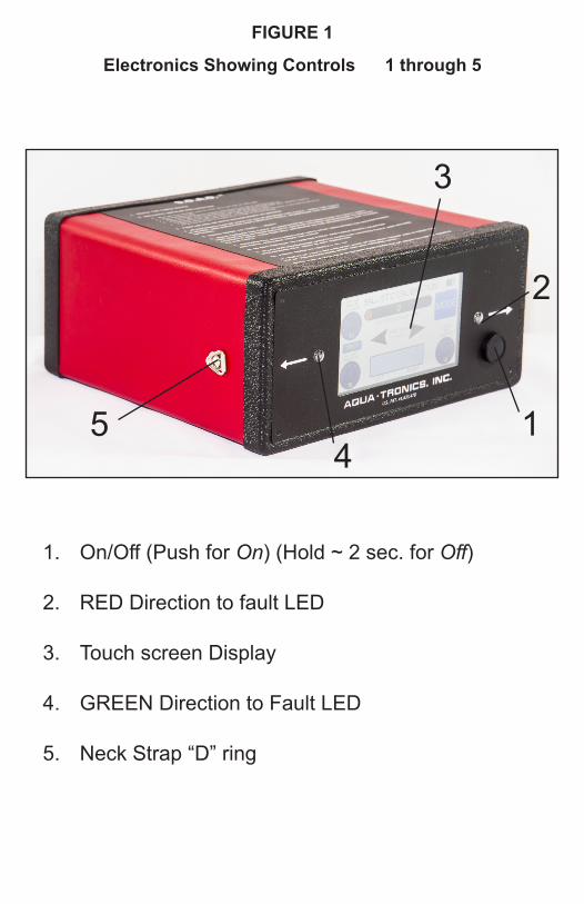
FIGURE 1
Electronics Showing Controls 1 through 5
1. On/Off (Push for On) (Hold ~ 2 sec. for Off)
2. RED Direction to fault LED
3. Touch screen Display
4. GREEN Direction to Fault LED
5. Neck Strap “D” ring
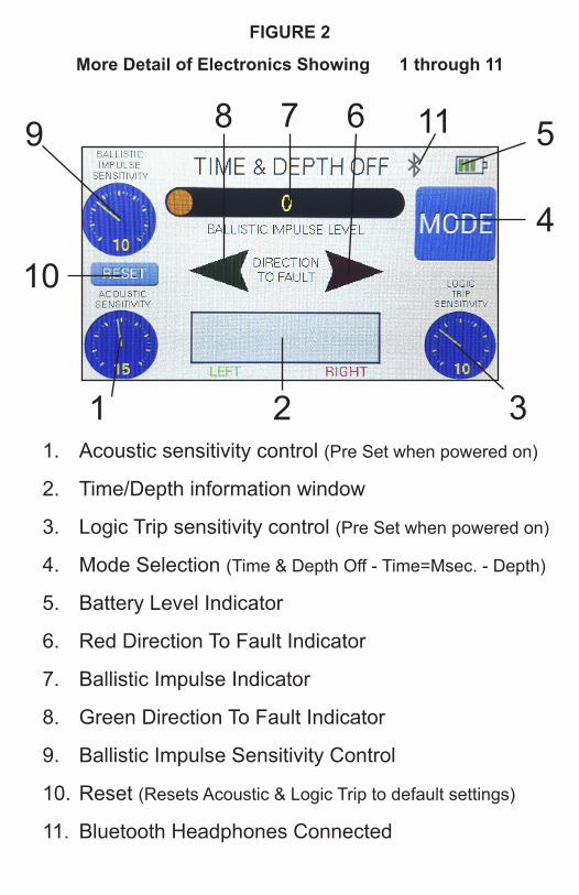
1. Acoustic sensitivity control (Pre Set when powered on)
2. Time/Depth information window
3. Logic Trip sensitivity control (Pre Set when powered on)
4. Mode Selection (Time & Depth Off - Time=Msec. - Depth)
5. Battery Level Indicator
6. Red Direction To Fault Indicator
7. Ballistic Impulse Indicator
8. Green Direction To Fault Indicator
9. Ballistic Impulse Sensitivity Control
10. Reset (Resets Acoustic & Logic Trip to default settings)
11. Bluetooth Headphones Connected
FIGURE 2
More Detail of Electronics Showing 1 through 11
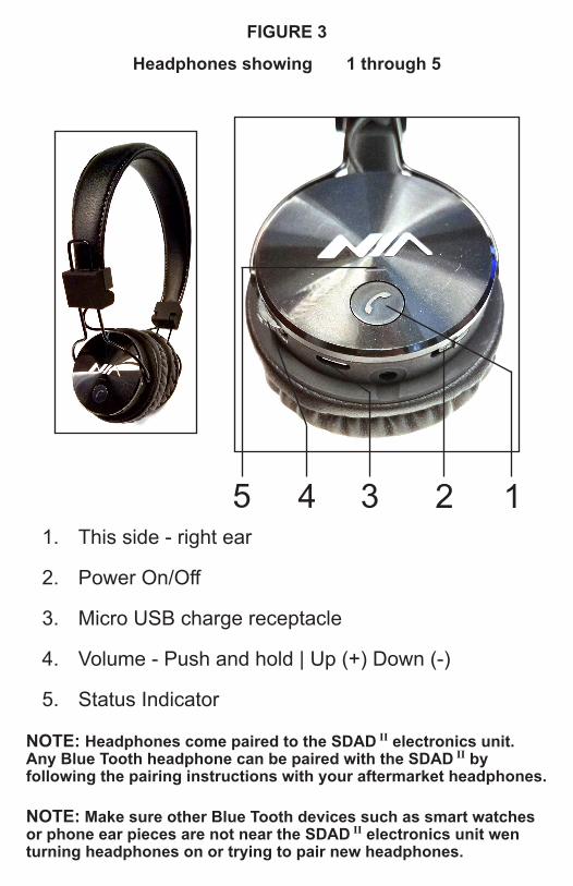
FIGURE 3
Headphones showing 1 through 5
1. This side - right ear
2. Power On/Off
3. Micro USB charge receptacle
4. Volume - Push and hold | Up (+) Down (-)
5. Status Indicator
NOTE: Headphones come paired to the SDAD II electronics unit. Any Blue Tooth headphone can be paired with the SDAD II by following the pairing instructions with your aftermarket headphones.
NOTE: Make sure other Blue Tooth devices such as smart watches or phone ear pieces are not near the SDAD II electronics unit wen turning headphones on or trying to pair new headphones.
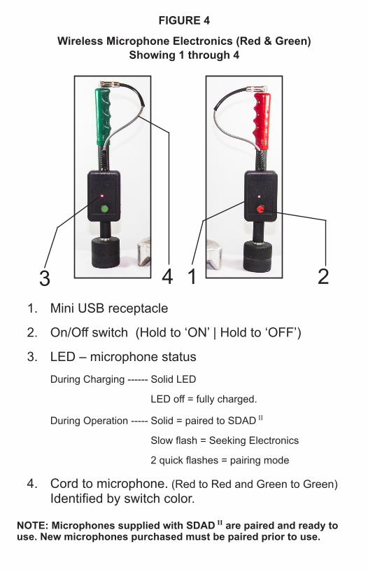
1. Mini USB receptacle
2. On/Off switch (Hold to ‘ON’ | Hold to ‘OFF’)
3. LED – microphone status During Charging ------ Solid LED
LED off = fully charged.
During Operation ----- Solid = paired to SDAD II
Slow flash = Seeking Electronics
2 quick flashes = pairing mode
4. Cord to microphone. (Red to Red and Green to Green) Identified by switch color.
NOTE: Microphones supplied with SDAD II are paired and ready to use. New microphones purchased must be paired prior to use.
FIGURE 4
Wireless Microphone Electronics (Red & Green)Showing 1 through 4
1
OPERATOR’S MANUALDirectional Acoustic Detector
S.D.A.D.II by Aqua-Tronics, Inc.
TABLE OF CONTENTSBATTERIES Microphone Wireless Transmitters . . . . . . . . . . . . . . . . . . . . . . . . . . . . . . . . . . . . . . . . . . . . . . 2 Headphones . . . . . . . . . . . . . . . . . . . . . . . . . . . . . . . . . . . . . . . . . . . . . . . . . . . . . . . . . . . . . . . 2 Battery Replacement . . . . . . . . . . . . . . . . . . . . . . . . . . . . . . . . . . . . . . . . . . . . . . . . . . . . . . . . 2
SOUND GENERAL CHARACTERISTICS . . . . . . . . . . . . . . . . . . . . . . . . . . . . . . . . . . . . . . . . . . . . . . . . . 3 Sound Traveling in Different Materials . . . . . . . . . . . . . . . . . . . . . . . . . . . . . . . . . . . . . . . . . . . 3
FACTORS AFFECTING SOUND IN FAULT - LOCATING EFFORTS Location of the Fault on the Cable . . . . . . . . . . . . . . . . . . . . . . . . . . . . . . . . . . . . . . . . . . . . . . 4 Soil Types . . . . . . . . . . . . . . . . . . . . . . . . . . . . . . . . . . . . . . . . . . . . . . . . . . . . . . . . . . . . . . . . . 4 Temperature . . . . . . . . . . . . . . . . . . . . . . . . . . . . . . . . . . . . . . . . . . . . . . . . . . . . . . . . . . . . . . . 4 Asphalt & Concrete Surfaces . . . . . . . . . . . . . . . . . . . . . . . . . . . . . . . . . . . . . . . . . . . . . . . . . . 4 Buried Ducts & Pipes . . . . . . . . . . . . . . . . . . . . . . . . . . . . . . . . . . . . . . . . . . . . . . . . . . . . . . . . 5 Submarine Cables . . . . . . . . . . . . . . . . . . . . . . . . . . . . . . . . . . . . . . . . . . . . . . . . . . . . . . . . . . 5
MICROPHONES Tri-Pods . . . . . . . . . . . . . . . . . . . . . . . . . . . . . . . . . . . . . . . . . . . . . . . . . . . . . . . . . . . . . . . . . . 6 Earth Probe Spike . . . . . . . . . . . . . . . . . . . . . . . . . . . . . . . . . . . . . . . . . . . . . . . . . . . . . . . . . . 6
FOOT PROBES Tricks and Tips . . . . . . . . . . . . . . . . . . . . . . . . . . . . . . . . . . . . . . . . . . . . . . . . . . . . . . . . . . . . . 7
FAULT LOCATION – PROCEDURES AND OPERATIONS TRACE THE CABLE ROUTE . . . . . . . . . . . . . . . . . . . . . . . . . . . . . . . . . . . . . . . . . . . . . . . . . . . . 7 FINDING THE GENERAL AREA OF THE FAULT . . . . . . . . . . . . . . . . . . . . . . . . . . . . . . . . . . . . 7 Ballistic Impulse – How It Works . . . . . . . . . . . . . . . . . . . . . . . . . . . . . . . . . . . . . . . . . . . . . . . 7 QUICK SEARCH WITH BALLISTIC IMPULSE ONLY . . . . . . . . . . . . . . . . . . . . . . . . . . . . . . . . 8 Automatic Ballistic Calibration . . . . . . . . . . . . . . . . . . . . . . . . . . . . . . . . . . . . . . . . . . . . . . . . . 8 LOCATING IN A NETWORK, OR ON A “Y” SPLICE . . . . . . . . . . . . . . . . . . . . . . . . . . . . . . . . . . 9
USING ONE MICROPHONE Setting the Acoustic Sensitivity Control . . . . . . . . . . . . . . . . . . . . . . . . . . . . . . . . . . . . . . . . . .11
FINDING THE EXACT POSITION OF THE FAULT CONNECTING AND USING TWO MICROPHONES . . . . . . . . . . . . . . . . . . . . . . . . . . . . . . . . 12 Setting the Logic Trip Sensitivity . . . . . . . . . . . . . . . . . . . . . . . . . . . . . . . . . . . . . . . . . . . . . . 13
“ZEROING IN” ON THE FAULT . . . . . . . . . . . . . . . . . . . . . . . . . . . . . . . . . . . . . . . . . . . . . . . . . . . . 13
VERIFYING THE FAULT’S LOCATION . . . . . . . . . . . . . . . . . . . . . . . . . . . . . . . . . . . . . . . . . . . . . . 14
WAGON WHEEL - LOCATE FROM OFF TO ONE SIDE . . . . . . . . . . . . . . . . . . . . . . . . . . . . . . . . 16
DEPTH OF FAULT . . . . . . . . . . . . . . . . . . . . . . . . . . . . . . . . . . . . . . . . . . . . . . . . . . . . . . . . . . . . . . . 17
WATER FILLED VAULTS . . . . . . . . . . . . . . . . . . . . . . . . . . . . . . . . . . . . . . . . . . . . . . . . . . . . . . . . . 18
SERVICE & WARRANTY INFORMATION Warranty . . . . . . . . . . . . . . . . . . . . . . . . . . . . . . . . . . . . . . . . . . . . . . . . . . . . . . . . . . . . . . . . . 19 Service . . . . . . . . . . . . . . . . . . . . . . . . . . . . . . . . . . . . . . . . . . . . . . . . . . . . . . . . . . . . . . . . . . 19
2
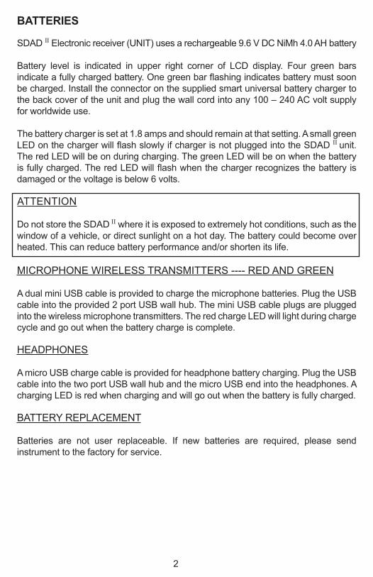
BATTERIES
SDAD II Electronic receiver (UNIT) uses a rechargeable 9.6 V DC NiMh 4.0 AH battery
Battery level is indicated in upper right corner of LCD display. Four green bars indicate a fully charged battery. One green bar flashing indicates battery must soon be charged. Install the connector on the supplied smart universal battery charger to the back cover of the unit and plug the wall cord into any 100 – 240 AC volt supply for worldwide use.
The battery charger is set at 1.8 amps and should remain at that setting. A small green LED on the charger will flash slowly if charger is not plugged into the SDAD II unit. The red LED will be on during charging. The green LED will be on when the battery is fully charged. The red LED will flash when the charger recognizes the battery is damaged or the voltage is below 6 volts.
ATTENTION
Do not store the SDAD II where it is exposed to extremely hot conditions, such as the window of a vehicle, or direct sunlight on a hot day. The battery could become over heated. This can reduce battery performance and/or shorten its life.
MICROPHONE WIRELESS TRANSMITTERS ---- RED AND GREEN
A dual mini USB cable is provided to charge the microphone batteries. Plug the USB cable into the provided 2 port USB wall hub. The mini USB cable plugs are plugged into the wireless microphone transmitters. The red charge LED will light during charge cycle and go out when the battery charge is complete.
HEADPHONES
A micro USB charge cable is provided for headphone battery charging. Plug the USB cable into the two port USB wall hub and the micro USB end into the headphones. A charging LED is red when charging and will go out when the battery is fully charged.
BATTERY REPLACEMENT
Batteries are not user replaceable. If new batteries are required, please send instrument to the factory for service.
3
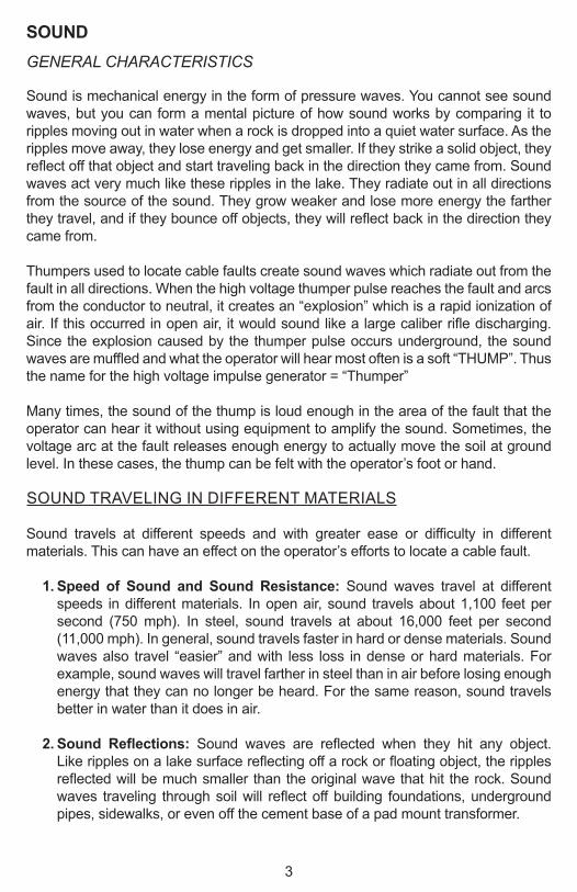
SOUNDGENERAL CHARACTERISTICS
Sound is mechanical energy in the form of pressure waves. You cannot see sound waves, but you can form a mental picture of how sound works by comparing it to ripples moving out in water when a rock is dropped into a quiet water surface. As the ripples move away, they lose energy and get smaller. If they strike a solid object, they reflect off that object and start traveling back in the direction they came from. Sound waves act very much like these ripples in the lake. They radiate out in all directions from the source of the sound. They grow weaker and lose more energy the farther they travel, and if they bounce off objects, they will reflect back in the direction they came from.
Thumpers used to locate cable faults create sound waves which radiate out from the fault in all directions. When the high voltage thumper pulse reaches the fault and arcs from the conductor to neutral, it creates an “explosion” which is a rapid ionization of air. If this occurred in open air, it would sound like a large caliber rifle discharging. Since the explosion caused by the thumper pulse occurs underground, the sound waves are muffled and what the operator will hear most often is a soft “THUMP”. Thus the name for the high voltage impulse generator = “Thumper”
Many times, the sound of the thump is loud enough in the area of the fault that the operator can hear it without using equipment to amplify the sound. Sometimes, the voltage arc at the fault releases enough energy to actually move the soil at ground level. In these cases, the thump can be felt with the operator’s foot or hand.
SOUND TRAVELING IN DIFFERENT MATERIALS
Sound travels at different speeds and with greater ease or difficulty in different materials. This can have an effect on the operator’s efforts to locate a cable fault.
1. Speed of Sound and Sound Resistance: Sound waves travel at different speeds in different materials. In open air, sound travels about 1,100 feet per second (750 mph). In steel, sound travels at about 16,000 feet per second (11,000 mph). In general, sound travels faster in hard or dense materials. Sound waves also travel “easier” and with less loss in dense or hard materials. For example, sound waves will travel farther in steel than in air before losing enough energy that they can no longer be heard. For the same reason, sound travels better in water than it does in air.
2. Sound Reflections: Sound waves are reflected when they hit any object. Like ripples on a lake surface reflecting off a rock or floating object, the ripples reflected will be much smaller than the original wave that hit the rock. Sound waves traveling through soil will reflect off building foundations, underground pipes, sidewalks, or even off the cement base of a pad mount transformer.
4
3. Sound in Air: Compared to many other materials, air is a very poor conductor of sound waves, or what we call “sound energy”. Place your ear on a railroad track and you will hear a train several miles away. Stand up and you will see the train before you hear it. This is the reason deep snow can be a problem to a cable fault.
FACTORS AFFECTING SOUND IN FAULT-LOCATING EFFORT
LOCATION OF THE FAULT ON THE CABLE
1. Fault on top of the cable. An easy fault to locate as all of the thumpers energy is coming straight up. You can normally hear this type without a listening device. Most of the time you can feel the pressure wave with your foot or hand.
2. Fault on the bottom of the cable. This fault is sometimes hard to hear because the thumpers pressure wave goes down and reflects back up, much of the energy is lost in the soil at the point of reflecting.
3. Fault on the side of the cable and the thump is arcing into another cable phase. The cable on the side will absorb most of the energy and very little of the sound wave is available to the operator. The operator will not be able to hear the thump without a good acoustical instrument of some type.
SOIL TYPES
Some types of soil can muffle the sound created by the “thump” more than other types. Dry, porous soil like sand is a good example. Even though grains of sand by themselves are dense and would be good conductors of sound if they were packed together, sand is filled with tiny air pockets that are poor conductors of sound. After a rain storm, the tiny pockets are filled with moisture and the overall sound conducting ability will improve.
TEMPERATURE
Frozen soil is generally quite easy to locate in because the ground is quite hard with ice frozen around the grains of soil and ice is a very good conductor of sound, however this is not always the case. Repeated freezing and thawing can create air pockets due to soil’s movement during the freezing and thawing process.
ASPHALT & CONCRETE SURFACES
How well a thump sound can be heard above an asphalt or concrete surface depends on how firm this material is in contact with the soil, or how much air space is between the soil and bottom side of the material the microphone is set on. Dead air spaces can be created under these surfaces by soil settling or by soil surface movement caused by freezing and thawing.
5
BURIED DUCTS & PIPES
Because sound travels best along the path of least resistance, a duct will act like a rifle barrel. Instead of the sound going out in all directions, most of it will travel in both directions and emerge at both ends of the duct.
In a quiet area where there is almost no back ground noise, try listening for the thump over the route of the cable if it’s in a duct. IF THE BACK GROUND NOISE EXCEEDS THE SOUND OF THE THUMP, YOU WILL NOT BE ABLE TO HEAR THE THUMP. If it is a quiet area, higher acoustic sensitivity and logic trip can be attempted. The settings explained later are for normal areas that do have some back ground noise. The operator will know because of false tripping if the controls are set higher than they should be for the area being searched.
SUBMARINE CABLES
Sound travels well in water with very little amplitude loss, so a thump can be heard a great distance from the fault with a microphone placed below the water surface. If the microphone is placed above the surface, no sound will be heard. When the sound wave changes from water to air, the surface cannot vibrate or reproduce the noise.
Fault locating submarine cables in a small lake are normally very easy because a lake does not have a current (water flow) passing by the microphone. The friction of the water moving over a microphone can create loud noises to the operator. Water is such a good conductor of sound and has so little loss in amplitude; the loudest sound will be hard to pin-point. A two microphone directional system makes this easy.
A frozen lake can be a problem unless two microphones are used. When the sound of the thump comes up from the cable and strikes the ice, the ice cover will act as a kettle drum and the entire frozen surface will have the same amplitude. This is also true for underwater microphone use. The sound can be heard from a great distance but the operator will not be able to hear the difference in amplitude. Using two microphones that can produce direction that is not dependent on amplitude must be used.
SPECIAL MICROPHONES ARE AVAILABLE FROM THE FACTORY FOR SUBMARINE CABLE FAULT LOCATING. THE STANDARD MICROPHONES SUPPLIED WITH SDAD II WILL BE DAMAGED IF THEY ARE PLACED UNDER WATER.
6
MICROPHONESTRI-PODS
When a sound wave hits a hard surface like a sidewalk or driveway, the sound wave reflects off and is much smaller than the initial wave. The difference in the two waves is transferred to the hard surface. The hard surface is now acting like the old phonograph record and an electronic pick up can be set on the surface that will reproduce the sound. Connect a microphone to a tri-pod using a 10 inch extension tube and stand it on the hard surface. The energy or vibration in the hard surface will activate the microphone so the thump can be heard.
NOTE: Background noise can be a problem when working over asphalt or concrete. In some cases this can hide or mask the sound of the “thump”.
NOTE: Tri-Pods do not work well in soft soil conditions. Pushing one or more of the tri-pods legs into the soil can sometimes work well enough that the earth spikes are not needed.
EARTH PROBE SPIKE
To solve the types of problems encountered with Tri-Pods on surfaces that are not solid, Aqua-Tronics developed the Earth Probe Microphone Spike for use in soil, water, snow and other soft materials. By inserting the metal spike through the surface skin, or top layer of soil, sound waves from the thump can be detected before they have a chance to reflect from the soil surface, or disperse into the air.
Earth probe microphone spikes also eliminate many background noise problems. Sound waves originating at the cable fault travel directly through the soil to the earth probe microphone spike. Because they greatly reduce background noise, the earth probe microphone spike should be used when possible. If a cable route lies under a sidewalk, using an earth probe microphone spike off to one side of the sidewalk will allow the operator to hear the thump more clearly.
FOOT PROBESEARTH PROBE MICROPHONES ARE NOT LAWN DARTS AND SHOULD NEVER BE DRIVEN OR FORCED INTO HARD SOIL, OR FROZEN GROUND.
Cantilever damaged can occur where the earth probe spike screws into the microphone bulb if the earth probe is not being inserted into the soil in a vertical (straight up and down) direction. Damage can also take place if the earth probe spike is not screwed up solid to the electronic bulb.
To eliminate the above possibilities, a unique foot probe has been developed to use with the earth probe microphones. The operator can push the microphone into the ground with his/her foot, using as much force as needed without placing undo stress on the microphone bulb.
NOTE: Hammerhead probes are available for extreme soil conditions.
7
TRICKS AND TIPS
a. Wind problems: Try placing the microphone inside a traffic cone.b. Hard ground too hard for any kind of spike insertion. Carry a cordless drill and
drill a 3/8 hole in the ground. Insert the microphone spike in the hole.c. The cable was under dirt and now it’s under concrete and its two miles back to
the truck for tri-pods. Set the electronics down on the concrete. Place the metal tip of the microphone spike on the concrete with the microphone handle resting on the electronics. Let go of the microphone and listen. If the thump can be heard, set the second microphone down in the same manner, over the route of the cable, but in the opposite direction. This will provide 30 inches of separation of the two microphone tips and by not touching either microphone, the only vibration they pick up should be the thump. If they are used correctly, the earth probe microphone can be used on hard surfaces.
FAULT LOCATION – PROCEDURES AND OPERATIONTRACE THE CABLE ROUTE!
Before the fault locate can begin, the route of the cable must be located and marked. While tracing the route of the cable, watch for signs of construction or digging near the route. This could be an indication of where the cable fault is located.
FINDING THE GENERAL AREA OF THE FAULT
There are two methods that can be used to find the general area of the fault.a. The ballistic impulse level drop off.b. Using one microphone to listen for the thump.
In either case, the ballistic impulse level indicator plays an important role.
BALLISTIC IMPULSE --- HOW IT WORKS
The ballistic impulse level indicator allows the operator to “see” the output pulse from the thumper as it travels down the cable route. The indicator provides a “reference signal” each time the thumper pulse occurs. It also provides the rate at which the thumper is pulsing the cable.
The ballistic impulse circuitry is independent from the acoustic circuitry. The headphone and microphones are not needed for the ”Quick Search with Ballistic Impulse Only” as listed in the following section of this manual.
When the thump pulse arrives at the fault, the voltage will arc to the neutral. Most of the current at the fault will return to the thumper, but not all of it. A small portion will be lost in the soil around the fault and a small portion will travel to the far end neutral ground rod connection. Most of the current is between the cable fault and the thumper. A large magnetic wave will be between the cable fault and the thumper
8
ground rod. A small magnetic wave will be between the cable fault and the ground rod at the far end of the cable. AS A RESULT, THE OPERATOR SHOULD SEE A REDUCTION OR COMPLETE LOSS IN BALLISTIC IMPULSE LEVEL WHEN THE FAULT HAS BEEN PASSED.
NOTE: Isolating the neutral at the far end of the cable on a jacketed primary will remove that current path and the magnetic fall off will be much more abrupt at the fault. Isolating the far end ground rod on a direct buried (NON-JACKETED) primary may help, but because the neutral is still in contact with the soil the fall off may not be as abrupt.
QUICK SEARCH WITH BALLISTIC IMPULSE ONLY
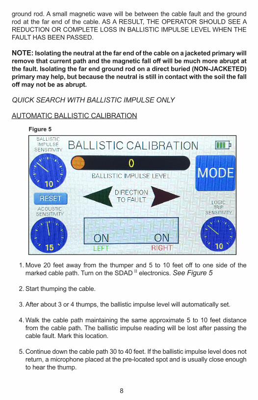
AUTOMATIC BALLISTIC CALIBRATION
1. Move 20 feet away from the thumper and 5 to 10 feet off to one side of the marked cable path. Turn on the SDAD II electronics. See Figure 5
2. Start thumping the cable.
3. After about 3 or 4 thumps, the ballistic impulse level will automatically set.
4. Walk the cable path maintaining the same approximate 5 to 10 feet distance from the cable path. The ballistic impulse reading will be lost after passing the cable fault. Mark this location.
5. Continue down the cable path 30 to 40 feet. If the ballistic impulse level does not return, a microphone placed at the pre-located spot and is usually close enough to hear the thump.
Figure 5
9
If the ballistic impulse returns at some short distance past the pre-located spot, the spot marked may not be the cable fault. A ground rod at a cable junction, a cathodic anode, or any kind of tie point can break up the magnetic wave in the area of connection. An open neutral can also break up the magnetic wave in the area of the open. If the signal comes back, keep moving down the route. When the real fault has been passed, the ballistic impulse will not come back to its original level.
NOTE: This same method of pre-locating can be made from inside a vehicle as long as the same distance from the cable path can be maintained. The electronics can be set on the seat, or held out the window and then repeat steps 1 through 5.
TO RE-ENTER BALLISTICS AUTOMATIC CALIBRATION MODE, TURN THE SDAD II ELECTRONICS OFF AND BACK ON.
The above pre-location method can be conducted at greater distances from the cable route as long as that distance is maintained throughout the ballistic search, however a manual setting of the ballistic impulse sensitivity control will be necessary at greater distances from the cable route.
NOTE: Never set up a magnetic adjustment or a ballistic search directly over the cable path. This can only be accomplished if the operator is off to one side of the cable path.
LOCATING IN A NETWORK, OR ON A “Y” SPLICE
With all of the conductors on one feed isolated. The thumper pulse can only travel in the conductor between the thumper and the cable fault. As a result, the magnetic wave (ballistic impulse) can only be in the cable between the thumper and the cable fault.
Walk or drive the cable route. If the magnetic wave is lost when a vault has been passed, go back to the vault and travel that portion of the cable where the magnetic wave is present. Keep in mind that magnetic waves are broken up around ground rods and tie points so move past the vault 30 to 40 feet before the determination is made that the magnetic wave is not in this portion of the cable.
10
USING ONE MICROPHONE
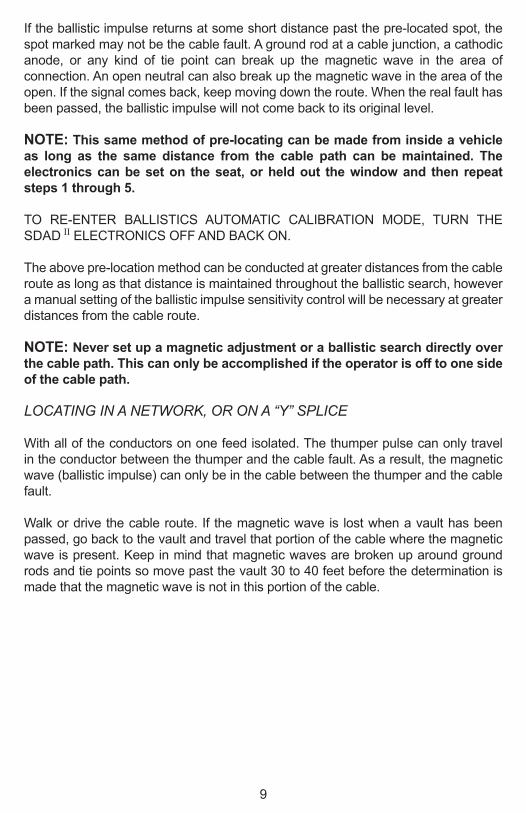
Once the general area of the fault has been located using ballistic impulse, it is time to us a microphone.
1. Connect one microphone. Turn on the microphone being used (red or green) See Figure 6. The ‘Time/Depth information window’ will show that channel as “ON” when that microphone is connected to the electronics.
2. Since direction to fault will require two microphones, the second microphone needs to be with the operator during the search. Keep that channel turned off until that microphone is needed.
3. Blue Tooth headphones will aid in hearing weak thump sounds.
Figure 6
11
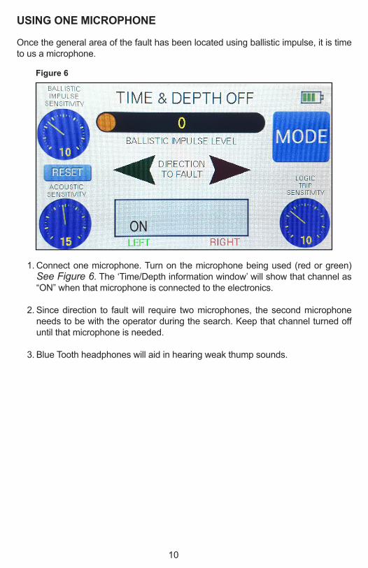
SETTING THE ACOUSTIC SENSITIVITY CONTROL
The acoustic sensitivity control is pre-set at power on. This setting can be used on the majority of cable faults. Touching any of the controls on the LCD will take the user to the adjustment screen. See Figure 7 . The user can increase or decrease any of the SDAD II parameters from the default settings. To return to the default settings, touch the reset button above the acoustic sensitivity control on the main screen. See Figure 6 .
The LCD should read “TIME/DEPTH OFF”. In this mode, direction to the fault using two microphones can be achieved; however background noise could provide false tripping.
In general, the lower acoustic (sound) sensitivity that can be used, the less background noise will be present during the fault locate. Until the actual “THUMP” is heard and the direction to fault is needed with a second microphone installed, the acoustic sensitivity control can be set to “MAXIMUM”.
With one microphone in place, listen for the “THUMP”. Once a “thump” can be heard at the same time the ballistic impulse indicator indicates a thump pulse has taken place, push the “MODE” button. The ‘Time/Depth information window’ should now read “TIME = ---MSEC”. See Figure 8 .
The next ballistic impulse passing the instrument will turn on a clock. When the thump is heard, the clock will turn off and a time to fault will be displayed in the ‘Time/Depth information window’. If the microphone is moved in either direction over the route of the cable, the next “thump” will display a shorter or longer time depending on the proximity of the microphone to the fault at the new listening spot.
In the “TIME = ---MSEC” mode, the ballistic impulse must be present to activate a
Figure 7
12
time to fault. This will greatly reduce false time indication due to random background noise. A constant background noise could still create problems when the ballistic impulse is passing by.
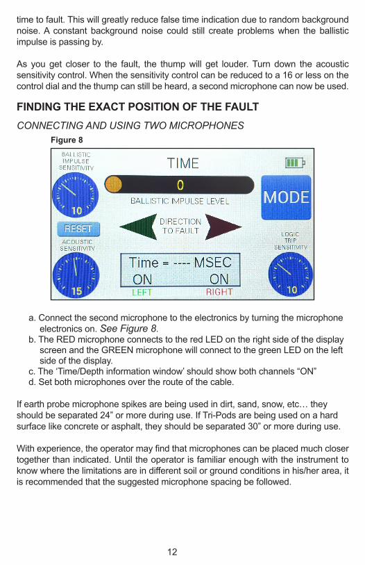
As you get closer to the fault, the thump will get louder. Turn down the acoustic sensitivity control. When the sensitivity control can be reduced to a 16 or less on the control dial and the thump can still be heard, a second microphone can now be used.
FINDING THE EXACT POSITION OF THE FAULTCONNECTING AND USING TWO MICROPHONES
a. Connect the second microphone to the electronics by turning the microphone electronics on. See Figure 8.
b. The RED microphone connects to the red LED on the right side of the display screen and the GREEN microphone will connect to the green LED on the left side of the display.
c. The ‘Time/Depth information window’ should show both channels “ON”d. Set both microphones over the route of the cable.
If earth probe microphone spikes are being used in dirt, sand, snow, etc… they should be separated 24” or more during use. If Tri-Pods are being used on a hard surface like concrete or asphalt, they should be separated 30” or more during use.
With experience, the operator may find that microphones can be placed much closer together than indicated. Until the operator is familiar enough with the instrument to know where the limitations are in different soil or ground conditions in his/her area, it is recommended that the suggested microphone spacing be followed.
Figure 8
13
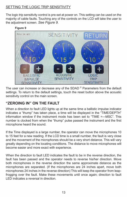
SETTING THE LOGIC TRIP SENSITIVITY
The logic trip sensitivity control is pre-set at power on. This setting can be used on the majority of cable faults. Touching any of the controls on the LCD will take the user to the adjustment screen. See Figure 9.
The user can increase or decrease any of the SDAD II Parameters from the default settings. To return to the default settings, touch the reset button above the acoustic sensitivity control on the main screen.
“ZEROING IN” ON THE FAULTWhen a direction to fault LED lights up at the same time a ballistic impulse indicator indicates a “thump” has taken place, a time will be displayed in the “TIME/DEPTH” information window if the instrument mode has been set to “TIME =---MSC”. This number is clocked from when the “thump” pulse passed the instrument and the first microphone heard the sound.
If the Time displayed is a large number, the operator can move the microphones 10 to 15 feet for a new reading. If the LCD time is a small number, the fault is very close and the movement of the microphones should be a very short distance. This will vary greatly depending on the locating conditions. The distance to move microphones will become easier and more exact with experience.
When the direction to fault LED indicates the fault to be in the reverse direction, the fault has been passed and the operator needs to reverse his/her direction. Move both microphones in the reverse direction the same approximate distance as the microphones are separated. (If the microphones are 24 inches apart, move both microphones 24 inches in the reverse direction) This will keep the operator from leap-frogging over the fault. Make these movements until once again; direction to fault LED indicates a reversal in direction.
Figure 9

14
The trailing microphone is near the fault and should be left were it is. Move the lead microphone back ¼ inch at a time. When both directions to fault LED’s light up, the fault is centered between the two microphones. This spot is called the “NULL”
The fault is equal distance from each microphone, but this could be off to one side of the cable route.
VERIFYING THE FAULT’S LOCATIONThe final step needed to verify the fault location is the “90 degree WALK AROUND”. Keep in mind that “DEAD INCH” accuracy can only be obtained if the “NULL” reading is found in both the IN-LINE locate and the ACROSS THE CABLE locate. See Figure 10 .
One microphone is placed directly over the “NULL” point or position of the fault. This microphone will be called the PIVOT MICROPHONE. Move the other microphone around the pivot microphone and take four ( 4 ) readings.
a. 30” up the cable route.b. 30” down the cable route.c. 30” off to one side of the cable route.d. 30” off to the other side of the cable route.
This will provide readings on all four sides of the fault at 90 degree intervals. The direction to the fault LED will show which microphone received the thump first.
Figure 10
What was thought tobe the cable route
What was thought to be the cable fault
Where microphoneswere placed for 90°walk around

15
If the cable route was off to one side of where the operator thought it was, the pivot microphone would not prove all four readings. Moving the microphones in the new direction until a “NULL” point is found will require the 90 degree readings to be taken again because a new spot was found for the pivot microphone. See Figure 11 .
THE LED FOR THE PIVOT MICROPHONE WILL LIGHT AT EACH OF THE FOUR READINGS IF THE FAULT IS UNDER THE PIVOT MICROPHONE ON THE 90 DEGREE WALK AROUND.
Figure 11
What was thought tobe the cable route
Actual cable route
CORRECT
INCORRECT
Actual cable fault
What was thought to be the cable fault
Where microphoneswere placed for 90°walk around
16
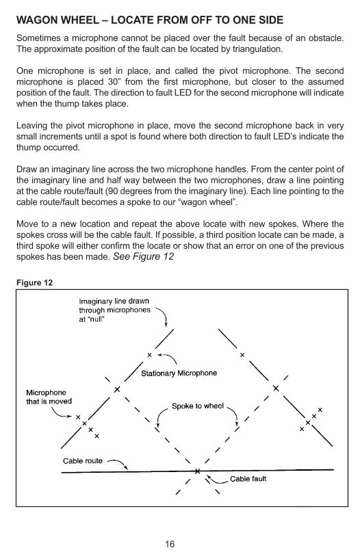
WAGON WHEEL – LOCATE FROM OFF TO ONE SIDESometimes a microphone cannot be placed over the fault because of an obstacle. The approximate position of the fault can be located by triangulation.
One microphone is set in place, and called the pivot microphone. The second microphone is placed 30” from the first microphone, but closer to the assumed position of the fault. The direction to fault LED for the second microphone will indicate when the thump takes place.
Leaving the pivot microphone in place, move the second microphone back in very small increments until a spot is found where both direction to fault LED’s indicate the thump occurred.
Draw an imaginary line across the two microphone handles. From the center point of the imaginary line and half way between the two microphones, draw a line pointing at the cable route/fault (90 degrees from the imaginary line). Each line pointing to the cable route/fault becomes a spoke to our “wagon wheel”.
Move to a new location and repeat the above locate with new spokes. Where the spokes cross will be the cable fault. If possible, a third position locate can be made, a third spoke will either confirm the locate or show that an error on one of the previous spokes has been made. See Figure 12
Figure 12
17
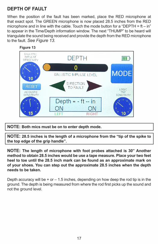
DEPTH OF FAULTWhen the position of the fault has been marked, place the RED microphone at that exact spot. The GREEN microphone is now placed 28.5 inches from the RED microphone and in line with the cable. Touch the mode button for a “DEPTH = ft – in” to appear in the Time/Depth information window. The next “THUMP” to be heard will triangulate the sound being received and provide the depth from the RED microphone to the fault. See Figure 13 .
NOTE: Both mics must be on to enter depth mode.
NOTE: 28.5 inches is the length of a microphone from the “tip of the spike to the top edge of the grip handle”.
NOTE: The length of microphone with foot probes attached is 30” Another method to obtain 28.5 inches would be use a tape measure. Place your two feet heel to toe until the 28.5 inch mark can be found as an approximate mark on of your shoes. You can step out the approximate 28.5 inches when the depth needs to be taken.
Depth accuracy will be + or – 1.5 inches, depending on how deep the rod tip is in the ground. The depth is being measured from where the rod first picks up the sound and not the ground level.
Figure 13
18
WATER FILLED VAULTSDO NOT PUMP OUT VAULT FULL OF WATER UNTIL YOU CHECK IT
When a thump takes place in a duct, the sound will travel both directions to the end of the duct. When the sound leaves the duct in air or water, it will not re-enter a new duct on the other side of the vault. By listening inside each vault, the operator can pin point the fault between two vaults.
The earth probe microphone bulbs are sealed and can be placed under water. DO NOT PLACE THE ELECTRONIC MICROPHONE TRANSMITTER OR THE PHONE JACK IN THE MICROPHONE HANDLE UNDER WATER. By placing the microphone spike or the spike and microphone bulb under water, the thump can be heard if the cable duct is at one side of the faulted cable. If the vault is not full of water, the sound will enter the vault into air. Each end of a duct entering the vault must make contact with the microphone one at a time to determine the duct having the faulted cable. If it is a plastic duct, the tip of the microphone spike can touch the duct.
IF THE DUCT IS METAL, DO NOT TOUCH THE DUCT WITH THE MICROPHONE OR ANY OTHER OBJECT WHILE THE THUMPER IS IN OPERATION. WHEN THE THUMP VOLTAGE ARCS TO THE NEUTRAL, ANY CONDUCTOR TOUCHING THAT NEUTRAL WILL RISE TO THE THUMPER VOLTAGE OUTPUT. A METAL DUCT IS A CONDUCTOR AND COULD HAVE HIGH VOLTAGE IMPULSES ON IT.
19
SERVICE AND WARRANTY INFORMATION
WARRANTY
All of Aqua-Tronics, Inc. products are warranted against defective materials and workmanship.
The Super D.A.D. is covered by a one-year warranty.
Aqua-Tronics, Inc. will repair or replace all products which prove defective during the warranty period. All repairs will be performed at our manufacturing plant or at one of our field service centers. Aqua-Tronics, Inc. retains sole and exclusive right to determine where repairs are to be made and to determine if defects are covered by warranty or are the result of misuse and/or abuse of the instrument and, thus, not subject to warranty repair or replacement.
ANY ATTEMPTS BY UNAUTHORIZED PERSONNEL TO REPAIR ANY AQUA-TRONICS, INC. INSTRUMENT WILL AUTOMATICALLY VOID THE WARRANTY COVERING THAT INSTRUMENT.
SERVICE
If you have trouble with this or any other instrument, or require assistance for any reason, contact the nearest Aqua-Tronics, Inc. sales outlet. You may also call or write directly to Aqua-Tronics, Inc. to explain your problem, or the type of assistance you need.
All instruments shipped to the factory must be sent prepaid. No collect or C.O.D. shipments will be accepted.

www.aquatronics.com
20
Related Documents


![Analysis and Re-Synthesis of Directional Spatial Impulse ... · racterize features in audio signals (rhythm, pitch, segmentation, harmony, etc.) [7] [8] [9] and it is used in this](https://static.cupdf.com/doc/110x72/5f48b7827d129b07481c0782/analysis-and-re-synthesis-of-directional-spatial-impulse-racterize-features.jpg)

