OPERATOR'S MANUAL 10 in. (254 mm) Compound Miter Saw Model TS1340 - Double Insulated Your new Miter Saw has been engineered and manufactured to Ryobi's high standards for dependability, ease of operation, and operator safety. Properly cared for, it will give you years of rugged, trouble-free performance. WARNING: To reduce the risk of injury, the user must read and understand the operator's manual before using this product. Thank you for buying a Ryobi tool. SAVE THIS MANUAL FOR FUTURE REFERENCE

Welcome message from author
This document is posted to help you gain knowledge. Please leave a comment to let me know what you think about it! Share it to your friends and learn new things together.
Transcript

OPERATOR'S MANUAL10 in. (254 mm) Compound Miter SawModel TS1340 - Double Insulated
Your new Miter Saw has been engineered and manufactured to Ryobi's high standards for dependability, ease ofoperation, and operator safety. Properly cared for, it will give you years of rugged, trouble-free performance.
WARNING: To reduce the risk of injury, the user must read and understand the operator's manual before usingthis product.
Thank you for buying a Ryobi tool.
SAVE THIS MANUAL FOR FUTURE REFERENCE
Page 2
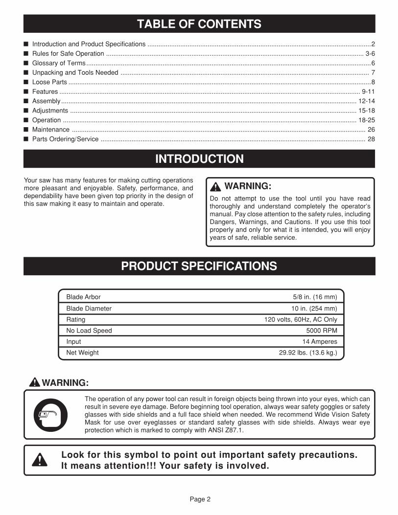
TABLE OF CONTENTS
PRODUCT SPECIFICATIONS
Blade Arbor 5/8 in. (16 mm)
Blade Diameter 10 in. (254 mm)
Rating 120 volts, 60Hz, AC Only
No Load Speed 5000 RPM
Input 14 Amperes
Net Weight 29.92 lbs. (13.6 kg.)
INTRODUCTION
Your saw has many features for making cutting operationsmore pleasant and enjoyable. Safety, performance, anddependability have been given top priority in the design ofthis saw making it easy to maintain and operate.
� Introduction and Product Specifications ...........................................................................................................................2
� Rules for Safe Operation .............................................................................................................................................. 3-6
� Glossary of Terms.............................................................................................................................................................6
� Unpacking and Tools Needed ......................................................................................................................................... 7
� Loose Parts .......................................................................................................................................................................8
� Features ...................................................................................................................................................................... 9-11
� Assembly................................................................................................................................................................... 12-14
� Adjustments .............................................................................................................................................................. 15-18
� Operation .................................................................................................................................................................. 18-25
� Maintenance .................................................................................................................................................................. 26
� Parts Ordering/Service .................................................................................................................................................. 28
WARNING:
The operation of any power tool can result in foreign objects being thrown into your eyes, which canresult in severe eye damage. Before beginning tool operation, always wear safety goggles or safetyglasses with side shields and a full face shield when needed. We recommend Wide Vision SafetyMask for use over eyeglasses or standard safety glasses with side shields. Always wear eyeprotection which is marked to comply with ANSI Z87.1.
Look for this symbol to point out important safety precautions.It means attention!!! Your safety is involved.
WARNING:Do not attempt to use the tool until you have readthoroughly and understand completely the operator’smanual. Pay close attention to the safety rules, includingDangers, Warnings, and Cautions. If you use this toolproperly and only for what it is intended, you will enjoyyears of safe, reliable service.
Page 3
RULES FOR SAFE OPERATION
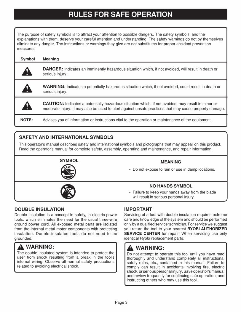
DOUBLE INSULATIONDouble insulation is a concept in safety, in electric powertools, which eliminates the need for the usual three-wireground power cord. All exposed metal parts are isolatedfrom the internal metal motor components with protectinginsulation. Double insulated tools do not need to begrounded.
WARNING:The double insulated system is intended to protect theuser from shock resulting from a break in the tool'sinternal wiring. Observe all normal safety precautionsrelated to avoiding electrical shock.
IMPORTANTServicing of a tool with double insulation requires extremecare and knowledge of the system and should be performedonly by a qualified service technician. For service we suggestyou return the tool to your nearest RYOBI AUTHORIZEDSERVICE CENTER for repair. When servicing use onlyidentical Ryobi replacement parts.
WARNING:Do not attempt to operate this tool until you have readthoroughly and understand completely all instructions,safety rules, etc., contained in this manual. Failure tocomply can result in accidents involving fire, electricshock, or serious personal injury. Save operator's manualand review frequently for continuing safe operation, andinstructing others who may use this tool.
SAFETY AND INTERNATIONAL SYMBOLSThis operator's manual describes safety and international symbols and pictographs that may appear on this product.Read the operator's manual for complete safety, assembly, operating and maintenance, and repair information.
MEANING
• Do not expose to rain or use in damp locations.
NO HANDS SYMBOL• Failure to keep your hands away from the blade
will result in serious personal injury.
SYMBOL
The purpose of safety symbols is to attract your attention to possible dangers. The safety symbols, and theexplanations with them, deserve your careful attention and understanding. The safety warnings do not by themselveseliminate any danger. The instructions or warnings they give are not substitutes for proper accident preventionmeasures.
Symbol Meaning
DANGER: Indicates an imminently hazardous situation which, if not avoided, will result in death orserious injury.
WARNING: Indicates a potentially hazardous situation which, if not avoided, could result in death orserious injury.
CAUTION: Indicates a potentially hazardous situation which, if not avoided, may result in minor ormoderate injury. It may also be used to alert against unsafe practices that may cause property damage.
NOTE: Advises you of information or instructions vital to the operation or maintenance of the equipment.

Page 4
Safe operation of this power tool requires that you read andunderstand this operator's manual and all labels affixed tothe tool. Safety is a combination of common sense, stayingalert, and knowing how your miter saw works.
READ ALL INSTRUCTIONS� KNOW YOUR POWER TOOL. Read the operator's
manual carefully. Learn the saw's applications and limita-tions as well as the specific potential hazards related tothis tool.
� GUARD AGAINST ELECTRICAL SHOCK by prevent-ing body contact with grounded surfaces such as pipes,radiators, ranges, refrigerator enclosures.
� KEEP GUARDS IN PLACE and in good working order.
� REMOVE WRENCHES AND ADJUSTING KEYS. Get inthe habit - before turning on tool - that hex keys andadjusting wrenches are removed from tool.
� KEEP THE WORK AREA CLEAN. Cluttered work areasand work benches invite accidents. DO NOT leave toolsor pieces of wood on the saw while it is in operation.
� DO NOT USE IN DANGEROUS ENVIRONMENTS. Donot use power tools near gasoline or other flammableliquids, in damp or wet locations, or expose them to rain.Keep the work area well lit.
� KEEP CHILDREN AND VISITORS AWAY. All visitorsshould wear safety glasses and be kept a safe distancefrom work area. Do not let visitors contact tool or exten-sion cord while operating.
� MAKE WORKSHOP CHILDPROOF with padlocks andmaster switches or by removing starter keys.
� DO NOT FORCE THE TOOL it will do the job better andsafer at the rate for which it was designed.
� USE THE RIGHT TOOL FOR THE JOB. Do not force thetool or attachment to do a job it was not designed for. Useit only the way it was intended.
� USE THE PROPER EXTENSION CORD. Make sureyour extension cord is in good condition. Use only a cordheavy enough to carry the current your product will draw.An undersized cord will cause a drop in line voltageresulting in loss of power and overheating. A wire gagesize (A.W.G.) of at least 14 is recommended for anextension cord 25 feet or less in length. If in doubt, use thenext heavier gage. The smaller the gage number, theheavier the cord.
� INSPECT TOOL CORDS AND EXTENSION CORDSPERIODICALLY and, if damaged, have repaired at yournearest authorized service center. Stay constantly awareof cord location and keep it well away from the movingblade.
� DRESS PROPERLY. Do not wear loose clothing, gloves,neckties, rings, bracelets, or other jewelry that can getcaught and draw you into moving parts. Nonslip footwearis recommended. Also wear protective hair covering tocontain long hair.
RULES FOR SAFE OPERATION
� ALWAYS WEAR SAFETY GLASSES WITH SIDESHIELDS. Everyday eyeglasses have only impact-resis-tant lenses; they are NOT safety glasses.
� WEAR A DUST MASK to keep from inhaling fine par-ticles.
� PROTECT YOUR HEARING. Wear hearing protectionduring extended periods of operation.
� SECURE WORK. Use clamps or a vise to hold workwhen practical. It's safer than using your hand and freesboth hands to operate tool.
� DO NOT OVERREACH. Keep proper footing and bal-ance at all times.
� MAINTAIN TOOLS WITH CARE. Keep tools sharp andclean for better and safer performance. Follow instruc-tions for lubricating and changing accessories.
� DISCONNECT ALL TOOLS. When not in use, beforeservicing, or when changing attachments, all tools shouldbe disconnected.
� AVOID ACCIDENTAL STARTING. Be sure switch is offwhen plugging in any tool.
� USE RECOMMENDED ACCESSORIES. Consult theoperator's manual for recommended accessories. Theuse of improper accessories may case risk of injury.
� NEVER STAND ON TOOL. Serious injury could occur ifthe tool is tipped or if the blade is unintentionally contacted.
� CHECK DAMAGED PARTS. Before using the tool, aguard or other part that is damaged should be carefullychecked to determine that it will operate properly andperform its intended function. Check for alignment ofmoving parts, binding of moving parts, breakage of parts,mounting and any other conditions that may affect itsoperation. A guard or other part that is damaged must beproperly repaired or replaced by an authorized servicecenter to avoid risk of personal injury.
� NEVER LEAVE TOOL RUNNING UNATTENDED, TURNTHE POWER OFF. Do not leave tool until it comes to acomplete stop.
� FIRMLY CLAMP OR BOLT your miter saw to a work-bench or table at approximately hip height.
� USE ONLY CORRECT BLADES. Use the right bladesize, style and cutting speed for material and type of cut.Do not use blades with incorrect size holes. Never useblade washers or blade bolts that are defective or incor-rect. The maximum blade capacity of your saw is 10 in.
� KEEP BLADES CLEAN, SHARP, AND WITH SUFFI-CIENT SET. Sharp blades minimize stalling and kick-back.
� DO NOT REMOVE THE SAW'S BLADE GUARDS.Never operate the saw with any guard or cover removed.Make sure all guards are operating properly before eachuse.
� KEEP HANDS AWAY FROM CUTTING AREA. Do notreach underneath work or in blade cutting path withhands and fingers for any reason. Always turn power off.
Page 5
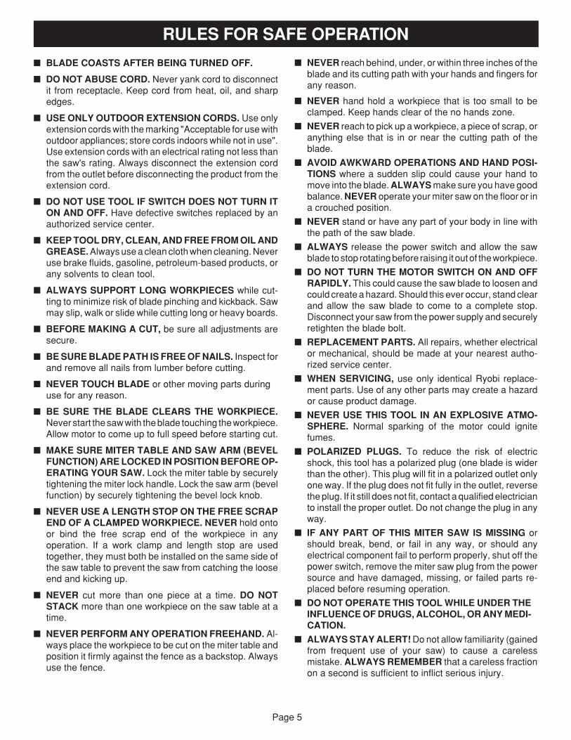
� NEVER reach behind, under, or within three inches of theblade and its cutting path with your hands and fingers forany reason.
� NEVER hand hold a workpiece that is too small to beclamped. Keep hands clear of the no hands zone.
� NEVER reach to pick up a workpiece, a piece of scrap, oranything else that is in or near the cutting path of theblade.
� AVOID AWKWARD OPERATIONS AND HAND POSI-TIONS where a sudden slip could cause your hand tomove into the blade. ALWAYS make sure you have goodbalance. NEVER operate your miter saw on the floor or ina crouched position.
� NEVER stand or have any part of your body in line withthe path of the saw blade.
� ALWAYS release the power switch and allow the sawblade to stop rotating before raising it out of the workpiece.
� DO NOT TURN THE MOTOR SWITCH ON AND OFFRAPIDLY. This could cause the saw blade to loosen andcould create a hazard. Should this ever occur, stand clearand allow the saw blade to come to a complete stop.Disconnect your saw from the power supply and securelyretighten the blade bolt.
� REPLACEMENT PARTS. All repairs, whether electricalor mechanical, should be made at your nearest autho-rized service center.
� WHEN SERVICING, use only identical Ryobi replace-ment parts. Use of any other parts may create a hazardor cause product damage.
� NEVER USE THIS TOOL IN AN EXPLOSIVE ATMO-SPHERE. Normal sparking of the motor could ignitefumes.
� POLARIZED PLUGS. To reduce the risk of electricshock, this tool has a polarized plug (one blade is widerthan the other). This plug will fit in a polarized outlet onlyone way. If the plug does not fit fully in the outlet, reversethe plug. If it still does not fit, contact a qualified electricianto install the proper outlet. Do not change the plug in anyway.
� IF ANY PART OF THIS MITER SAW IS MISSING orshould break, bend, or fail in any way, or should anyelectrical component fail to perform properly, shut off thepower switch, remove the miter saw plug from the powersource and have damaged, missing, or failed parts re-placed before resuming operation.
� DO NOT OPERATE THIS TOOL WHILE UNDER THEINFLUENCE OF DRUGS, ALCOHOL, OR ANY MEDI-CATION.
� ALWAYS STAY ALERT! Do not allow familiarity (gainedfrom frequent use of your saw) to cause a carelessmistake. ALWAYS REMEMBER that a careless fractionon a second is sufficient to inflict serious injury.
RULES FOR SAFE OPERATION
� BLADE COASTS AFTER BEING TURNED OFF.
� DO NOT ABUSE CORD. Never yank cord to disconnectit from receptacle. Keep cord from heat, oil, and sharpedges.
� USE ONLY OUTDOOR EXTENSION CORDS. Use onlyextension cords with the marking "Acceptable for use withoutdoor appliances; store cords indoors while not in use".Use extension cords with an electrical rating not less thanthe saw's rating. Always disconnect the extension cordfrom the outlet before disconnecting the product from theextension cord.
� DO NOT USE TOOL IF SWITCH DOES NOT TURN ITON AND OFF. Have defective switches replaced by anauthorized service center.
� KEEP TOOL DRY, CLEAN, AND FREE FROM OIL ANDGREASE. Always use a clean cloth when cleaning. Neveruse brake fluids, gasoline, petroleum-based products, orany solvents to clean tool.
� ALWAYS SUPPORT LONG WORKPIECES while cut-ting to minimize risk of blade pinching and kickback. Sawmay slip, walk or slide while cutting long or heavy boards.
� BEFORE MAKING A CUT, be sure all adjustments aresecure.
� BE SURE BLADE PATH IS FREE OF NAILS. Inspect forand remove all nails from lumber before cutting.
� NEVER TOUCH BLADE or other moving parts duringuse for any reason.
� BE SURE THE BLADE CLEARS THE WORKPIECE.Never start the saw with the blade touching the workpiece.Allow motor to come up to full speed before starting cut.
� MAKE SURE MITER TABLE AND SAW ARM (BEVELFUNCTION) ARE LOCKED IN POSITION BEFORE OP-ERATING YOUR SAW. Lock the miter table by securelytightening the miter lock handle. Lock the saw arm (bevelfunction) by securely tightening the bevel lock knob.
� NEVER USE A LENGTH STOP ON THE FREE SCRAPEND OF A CLAMPED WORKPIECE. NEVER hold ontoor bind the free scrap end of the workpiece in anyoperation. If a work clamp and length stop are usedtogether, they must both be installed on the same side ofthe saw table to prevent the saw from catching the looseend and kicking up.
� NEVER cut more than one piece at a time. DO NOTSTACK more than one workpiece on the saw table at atime.
� NEVER PERFORM ANY OPERATION FREEHAND. Al-ways place the workpiece to be cut on the miter table andposition it firmly against the fence as a backstop. Alwaysuse the fence.
Page 6
SAVE THESE INSTRUCTIONS
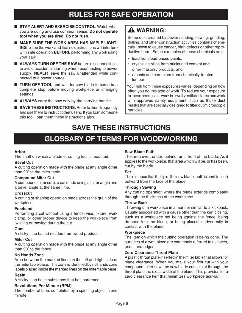
RULES FOR SAFE OPERATION
� STAY ALERT AND EXERCISE CONTROL. Watch whatyou are doing and use common sense. Do not operatetool when you are tired. Do not rush.
� MAKE SURE THE WORK AREA HAS AMPLE LIGHT-ING to see the work and that no obstructions will interferewith safe operation BEFORE performing any work usingyour saw.
� ALWAYS TURN OFF THE SAW before disconnecting itto avoid accidental starting when reconnecting to powersupply. NEVER leave the saw unattended while con-nected to a power source.
� TURN OFF TOOL and wait for saw blade to come to acomplete stop before moving workpiece or changingsettings.
� ALWAYS carry the saw only by the carrying handle.
� SAVE THESE INSTRUCTIONS. Refer to them frequentlyand use them to instruct other users. If you loan someonethis tool, loan them these instructions also.
WARNING:Some dust created by power sanding, sawing, grinding,drilling, and other construction activities contains chemi-cals known to cause cancer, birth defects or other repro-ductive harm. Some examples of these chemicals are:
• lead from lead-based paints,• crystalline silica from bricks and cement and
other masonry products, and• arsenic and chromium from chemically-treated
lumber.
Your risk from these exposures varies, depending on howoften you do this type of work. To reduce your exposureto these chemicals, work in a well ventilated area and workwith approved safety equipment, such as those dustmasks that are specially designed to filter out microscopicparticles.
Saw Blade PathThe area over, under, behind, or in front of the blade. As itapplies to the workpiece, that area which will be, or has been,cut by the blade.
SetThe distance that the tip of the saw blade tooth is bent (or set)outward from the face of the blade.
Through SawingAny cutting operation where the blade extends completelythrough the thickness of the workpiece.
Throw-BackThrowing of a workpiece in a manner similar to a kickback.Usually associated with a cause other than the kerf closing,such as a workpiece not being against the fence, beingdropped into the blade, or being placed inadvertently incontact with the blade.
WorkpieceThe item on which the cutting operation is being done. Thesurfaces of a workpiece are commonly referred to as faces,ends, and edges.
Zero Clearance Throat PlateA plastic throat plate inserted in the miter table that allows forblade clearance. When you make your first cut with yourcompound miter saw, the saw blade cuts a slot through thethroat plate the exact width of the blade. This provides for azero clearance kerf that minimizes workpiece tear-out.
GLOSSARY OF TERMS FOR WOODWORKING
ArborThe shaft on which a blade or cutting tool is mounted.
Bevel CutA cutting operation made with the blade at any angle otherthan 90˚ to the miter table.
Compound Miter CutA compound miter cut is a cut made using a miter angle anda bevel angle at the same time.
CrosscutA cutting or shaping operation made across the grain of theworkpiece.
FreehandPerforming a cut without using a fence, vise, fixture, workclamp, or other proper device to keep the workpiece fromtwisting or moving during the cut.
GumA sticky, sap based residue from wood products.
Miter CutA cutting operation made with the blade at any angle otherthan 90˚ to the fence.
No Hands ZoneArea between the marked lines on the left and right side ofthe miter table base. This zone is identified by no hands zonelabels placed inside the marked lines on the miter table base.
ResinA sticky, sap base substance that has hardened.
Revolutions Per Minute (RPM)The number of turns completed by a spinning object in oneminute.
Page 7
UNPACKING
� Lift the saw arm by the handle. Hand pressure shouldremain on the saw arm to prevent sudden rise uponrelease of the tie wrap.
� Examine all parts to make sure no breakage or damagehas occurred during shipping.
If any parts are missing, do not attempt to assemble the mitersaw, plug in the power cord, or turn the switch on until themissing parts are obtained and are installed correctly. Call1-800-525-2579 for assistance if any parts are missing ordamaged.
WARNING:If any parts are missing, do not operate this tool until themissing parts are replaced. Failure to do so could resultin possible serious personal injury.
Your Compound Miter Saw has been shipped completelyassembled except for the blade, miter lock handle, dust guideor dust bag, table extensions, work clamp, and stop block.� Remove all loose parts from the carton. Separate and
check with the list of loose parts. See Figure 1.
� Remove the packing materials from around your saw.
� Carefully lift saw from the carton by the carrying handleand place it on a level work surface. Although small, thissaw is heavy. To avoid back injury, get help when needed.
� Do not discard the packing materials until you havecarefully inspected the saw, identified all loose parts, andsatisfactorily operated your new saw.
� Your saw has been shipped with the saw arm secured inthe down position. To release the saw arm, push down ontop of saw arm and cut the tie-wrap.
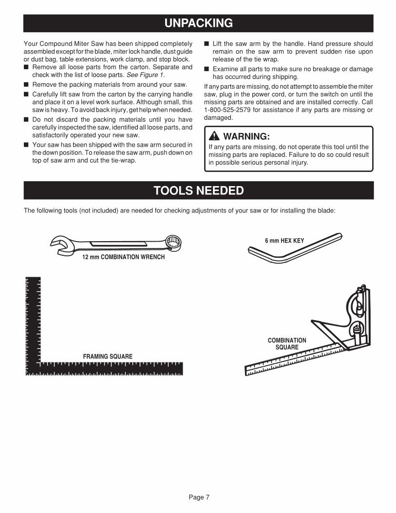
The following tools (not included) are needed for checking adjustments of your saw or for installing the blade:
TOOLS NEEDED
COMBINATIONSQUARE
FRAMING SQUARE
12 mm COMBINATION WRENCH
6 mm HEX KEY
Page 8
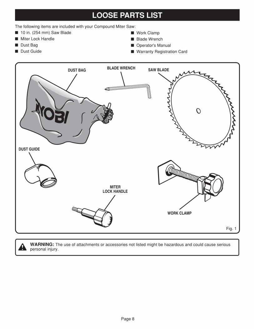
The following items are included with your Compound Miter Saw:
� 10 in. (254 mm) Saw Blade
� Miter Lock Handle
� Dust Bag
� Dust Guide
LOOSE PARTS LIST
� Work Clamp
� Blade Wrench
� Operator's Manual
� Warranty Registration Card
Fig. 1
SAW BLADE
DUST GUIDE
WARNING: The use of attachments or accessories not listed might be hazardous and could cause seriouspersonal injury.
BLADE WRENCH
MITERLOCK HANDLE
5
WORK CLAMP
DUST BAG
Page 9
FEATURES
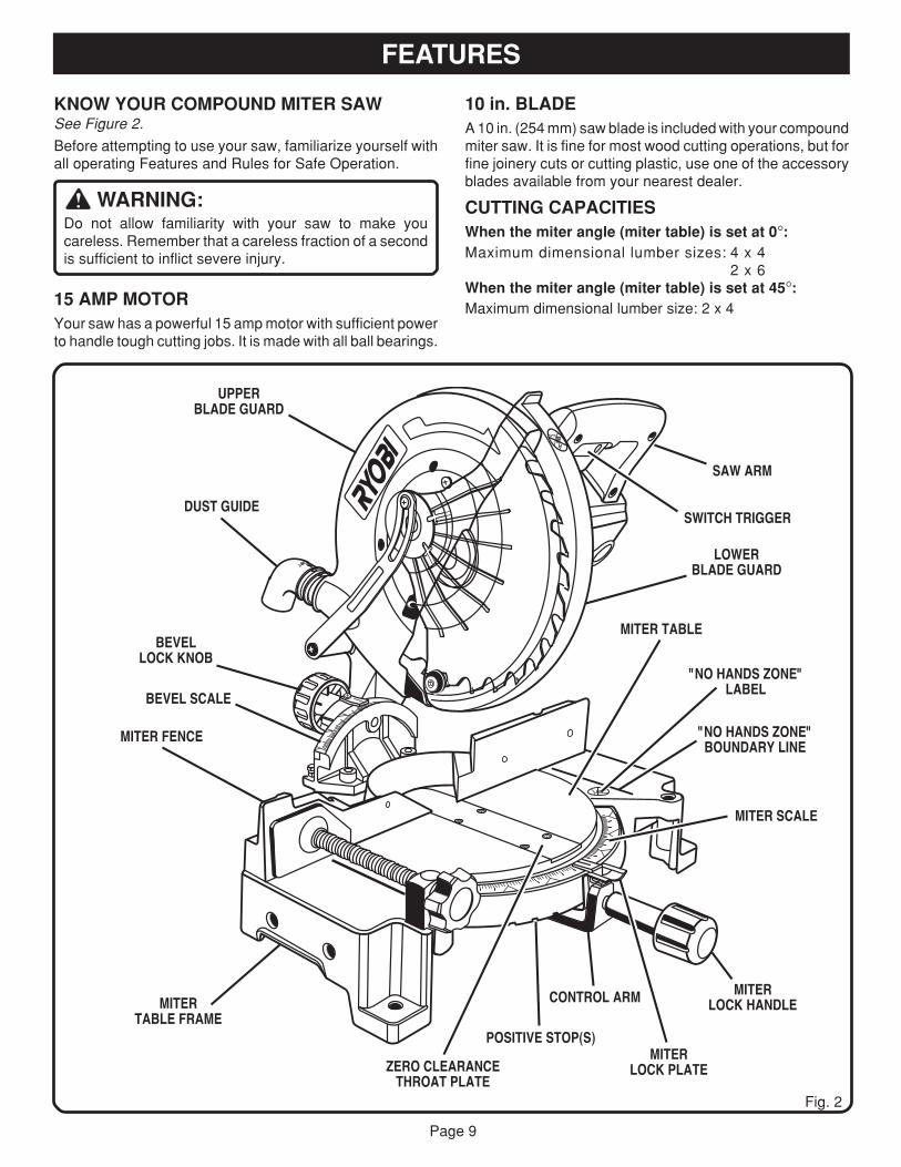
KNOW YOUR COMPOUND MITER SAWSee Figure 2.
Before attempting to use your saw, familiarize yourself withall operating Features and Rules for Safe Operation.
WARNING:Do not allow familiarity with your saw to make youcareless. Remember that a careless fraction of a secondis sufficient to inflict severe injury.
15 AMP MOTORYour saw has a powerful 15 amp motor with sufficient powerto handle tough cutting jobs. It is made with all ball bearings.
10 in. BLADEA 10 in. (254 mm) saw blade is included with your compoundmiter saw. It is fine for most wood cutting operations, but forfine joinery cuts or cutting plastic, use one of the accessoryblades available from your nearest dealer.
CUTTING CAPACITIESWhen the miter angle (miter table) is set at 0°:Maximum dimensional lumber sizes: 4 x 4
2 x 6When the miter angle (miter table) is set at 45°:Maximum dimensional lumber size: 2 x 4
Fig. 2
LOWERBLADE GUARD
SAW ARM
MITERLOCK HANDLE
SWITCH TRIGGER
"NO HANDS ZONE"LABEL
"NO HANDS ZONE"BOUNDARY LINE
MITER SCALE
DUST GUIDE
UPPERBLADE GUARD
MITER FENCE
MITER TABLE
BEVEL SCALE
BEVELLOCK KNOB
POSITIVE STOP(S)
ZERO CLEARANCETHROAT PLATE
CONTROL ARM
MITERLOCK PLATE
MITERTABLE FRAME
Page 10
FEATURES
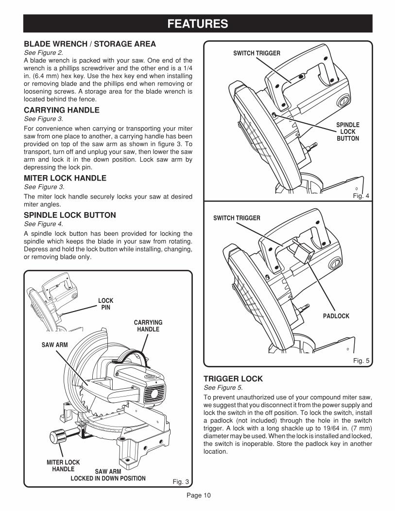
BLADE WRENCH / STORAGE AREASee Figure 2.A blade wrench is packed with your saw. One end of thewrench is a phillips screwdriver and the other end is a 1/4in. (6.4 mm) hex key. Use the hex key end when installingor removing blade and the phillips end when removing orloosening screws. A storage area for the blade wrench islocated behind the fence.
CARRYING HANDLESee Figure 3.
For convenience when carrying or transporting your mitersaw from one place to another, a carrying handle has beenprovided on top of the saw arm as shown in figure 3. Totransport, turn off and unplug your saw, then lower the sawarm and lock it in the down position. Lock saw arm bydepressing the lock pin.
MITER LOCK HANDLESee Figure 3.
The miter lock handle securely locks your saw at desiredmiter angles.
SPINDLE LOCK BUTTONSee Figure 4.
A spindle lock button has been provided for locking thespindle which keeps the blade in your saw from rotating.Depress and hold the lock button while installing, changing,or removing blade only.
CARRYINGHANDLE
Fig. 3
SAW ARMLOCKED IN DOWN POSITION
SAW ARM
MITER LOCKHANDLE
SPINDLELOCK
BUTTON
SWITCH TRIGGER
Fig. 4
Fig. 5
TRIGGER LOCKSee Figure 5.
To prevent unauthorized use of your compound miter saw,we suggest that you disconnect it from the power supply andlock the switch in the off position. To lock the switch, installa padlock (not included) through the hole in the switchtrigger. A lock with a long shackle up to 19/64 in. (7 mm)diameter may be used. When the lock is installed and locked,the switch is inoperable. Store the padlock key in anotherlocation.
LOCKPIN
PADLOCK
SWITCH TRIGGER
Page 11
15
30
45
015
30
45
FEATURES
POSITIVE STOPS ON MITER TABLEPositive stops have been provided at 0°, 15°, 22-1/2°, 30°, and45°. The 22-1/2° and 45° positive stops have been providedon both the left and right side of the miter table.
BEVEL LOCK KNOBThe bevel lock knob securely locks your compound mitersaw at desired bevel angles. Positive stop adjustment screwshave been provided on each side of the saw arm. Theseadjustment screws are for making fine adjustments at 0° and45°.
ELECTRIC BRAKEAn electric brake has been provided to quickly stop bladerotation after the switch is released.
MITER FENCEThe miter fence on your compound miter saw has beenprovided to hold your workpiece securely against whenmaking all cuts; the left side is also larger providing additionalsupport.
SELF-RETRACTING LOWER BLADE GUARDThe lower blade guard is made of shock-resistant, see-through plastic that provides protection from each side of theblade. It retracts over the upper blade guard as the saw islowered into the workpiece.
WARNING:To avoid serious personal injury, always assure saw isfully supported and securely attached to a level worksurface.
WARNING:Do not attempt to modify this tool or create accessoriesnot recommended for use with this tool. Any such alterationor modification is misuse and could result in a hazardouscondition leading to possible serious personal injury.
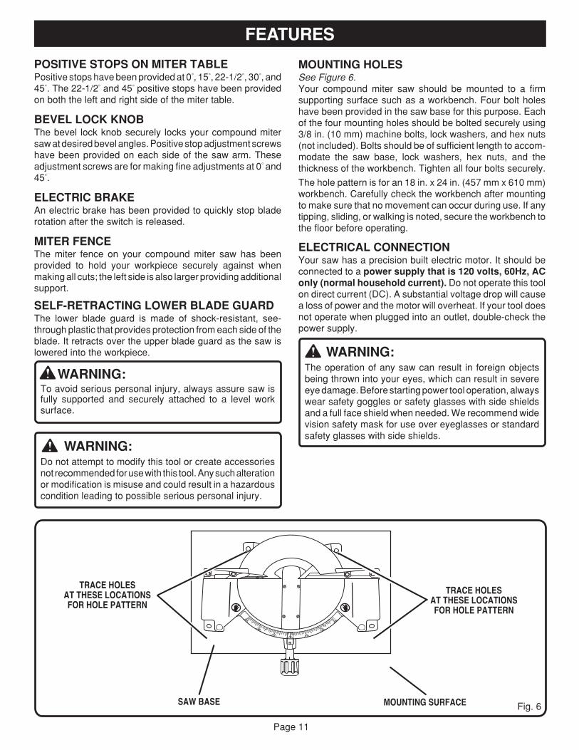
MOUNTING HOLESSee Figure 6.Your compound miter saw should be mounted to a firmsupporting surface such as a workbench. Four bolt holeshave been provided in the saw base for this purpose. Eachof the four mounting holes should be bolted securely using3/8 in. (10 mm) machine bolts, lock washers, and hex nuts(not included). Bolts should be of sufficient length to accom-modate the saw base, lock washers, hex nuts, and thethickness of the workbench. Tighten all four bolts securely.
The hole pattern is for an 18 in. x 24 in. (457 mm x 610 mm)workbench. Carefully check the workbench after mountingto make sure that no movement can occur during use. If anytipping, sliding, or walking is noted, secure the workbench tothe floor before operating.
ELECTRICAL CONNECTIONYour saw has a precision built electric motor. It should beconnected to a power supply that is 120 volts, 60Hz, AConly (normal household current). Do not operate this toolon direct current (DC). A substantial voltage drop will causea loss of power and the motor will overheat. If your tool doesnot operate when plugged into an outlet, double-check thepower supply.
WARNING:The operation of any saw can result in foreign objectsbeing thrown into your eyes, which can result in severeeye damage. Before starting power tool operation, alwayswear safety goggles or safety glasses with side shieldsand a full face shield when needed. We recommend widevision safety mask for use over eyeglasses or standardsafety glasses with side shields.
Fig. 6MOUNTING SURFACESAW BASE
TRACE HOLESAT THESE LOCATIONSFOR HOLE PATTERN
TRACE HOLESAT THESE LOCATIONSFOR HOLE PATTERN
Page 12
ASSEMBLY
WARNING:To prevent accidental starting that could cause possibleserious personal injury, assemble all parts, make sure alladjustments are complete, and make sure all fastenersare secure before connecting saw to power supply. Sawshould never be connected to power supply when you areassembling parts, making adjustments, installing or re-moving blades, or when not in use.
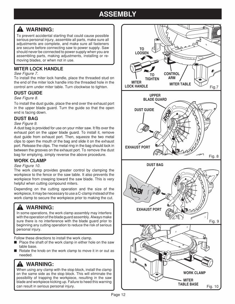
MITER LOCK HANDLESee Figure 7.To install the miter lock handle, place the threaded stud onthe end of the miter lock handle into the threaded hole in thecontrol arm under miter table. Turn clockwise to tighten.
DUST GUIDESee Figure 8.To install the dust guide, place the end over the exhaust portin the upper blade guard. Turn the guide so that the openend is facing down.
DUST BAGSee Figure 9.A dust bag is provided for use on your miter saw. It fits over theexhaust port on the upper blade guard. To install it, removedust guide from exhaust port. Then, squeeze the two metalclips to open the mouth of the bag and slide it on the exhaustport. Release the clips. The metal ring in the bag should lock inbetween the grooves on the exhaust port. To remove the dustbag for emptying, simply reverse the above procedure.
WORK CLAMPSee Figure 10.The work clamp provides greater control by clamping theworkpiece to the fence or the saw table. It also prevents theworkpiece from creeping toward the saw blade. This is veryhelpful when cutting compound miters.
Depending on the cutting operation and the size of theworkpiece, it may be necessary to use a C-clamp instead of thework clamp to secure the workpiece prior to making the cut.
WARNING:In some operations, the work clamp assembly may interferewith the operation of the blade guard assembly. Always makesure there is no interference with the blade guard prior tobeginning any cutting operation to reduce the risk of seriouspersonal injury.
Follow these directions to install the work clamp.� Place the shaft of the work clamp in either hole on the saw
table base.� Rotate the knob on the work clamp to move it in or out as
needed.
WARNING:When using any clamp with the stop block, install the clampon the same side as the stop block. This will eliminate thepossibility of trapping the workpiece, resulting in the sawblade and workpiece kicking up. Failure to heed this warningcan result in serious personal injury.
UPPERBLADE GUARD
CONTROLARM
TOLOOSEN
MITERLOCK HANDLE MITER TABLE
EXHAUST PORT
DUST GUIDE
TOTIGHTEN
Fig. 10
MITERTABLE BASE
WORK CLAMP
Fig.7
DUST BAG
EXHAUST PORT
Fig. 8
Fig. 9
Page 13
ASSEMBLY
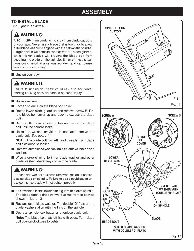
TO INSTALL BLADESee Figures 11 and 12.
WARNING:A 10 in. (254 mm) blade is the maximum blade capacityof your saw. Never use a blade that is too thick to allowouter blade washer to engage with the flats on the spindle.Larger blades will come in contact with the blade guards,while thicker blades will prevent the blade bolt fromsecuring the blade on the spindle. Either of these situa-tions could result in a serious accident and can causeserious personal injury.
� Unplug your saw.
WARNING:Failure to unplug your saw could result in accidentalstarting causing possible serious personal injury.
� Raise saw arm.
� Loosen screw A on the blade bolt cover.
� Rotate lower blade guard up and remove screw B. Ro-tate blade bolt cover up and back to expose the bladebolt.
� Depress the spindle lock button and rotate the bladebolt until the spindle locks.
� Using the wrench provided, loosen and remove theblade bolt. See figure 11.
NOTE: The blade bolt has left hand threads. Turn bladebolt clockwise to loosen.
� Remove outer blade washer. Do not remove inner bladewasher.
� Wipe a drop of oil onto inner blade washer and outerblade washer where they contact the blade.
WARNING:If inner blade washer has been removed, replace it beforeplacing blade on spindle. Failure to do so could cause anaccident since blade will not tighten properly.
� Fit saw blade inside lower blade guard and onto spindle.The blade teeth point downward at the front of saw asshown in figure 12.
� Replace outer blade washer. The double "D" flats on theblade washers align with the flats on the spindle.
� Depress spindle lock button and replace blade bolt.
Note: The blade bolt has left hand threads. Turn bladebolt counterclockwise to tighten.
Fig. 11
Fig. 12
LOWERBLADE GUARD
INNER BLADEWASHER WITH
DOUBLE "D" FLATS
BLADE
OUTER BLADE WASHERWITH DOUBLE "D" FLATS
BLADE BOLT
TOTIGHTEN
TOLOOSEN
SCREW A SCREW B
FLAT (S)ON SPINDLE
BLADEBOLT
COVER
SPINDLE LOCKBUTTON
Page 14
1545
30
45
30
31.631.6
51 22.5
ASSEMBLY
CAUTION:Always install the blade with the blade teeth and thearrow printed on the side of the blade pointing down at thefront of the saw. The direction of blade rotation is alsostamped with an arrow on the upper blade guard.
� Tighten blade bolt securely.
� Replace the lower blade guard and blade bolt cover.
� Replace screw B and tighten securely.
� Retighten screw A securely.
WARNING:Make sure the spindle lock button is not engaged beforereconnecting saw into power source. Never engagespindle lock button when blade is rotating.
Your compound miter saw has been adjusted at the factoryfor making very accurate cuts. However, some of the com-ponents might have been jarred out of alignment duringshipping. Also, over a period of time, readjustment willprobably become necessary due to wear. After unpackingyour saw, check the following adjustments before you beginusing saw. Make any readjustments that are necessary andperiodically check the parts alignment to make sure that yoursaw is cutting accurately.
WARNING:Your saw should never be connected to power supplywhen you are assembling parts, making adjustments,installing or removing blades, or when not in use.Disconnecting your saw will prevent accidental startingthat could cause serious injury.
Note: Many of the illustrations in this manual show onlyportions of your compound miter saw. This is intentional sothat we can clearly show points being made in the illustra-tions. Never operate your saw without all guards securely inplace and in good operating condition.
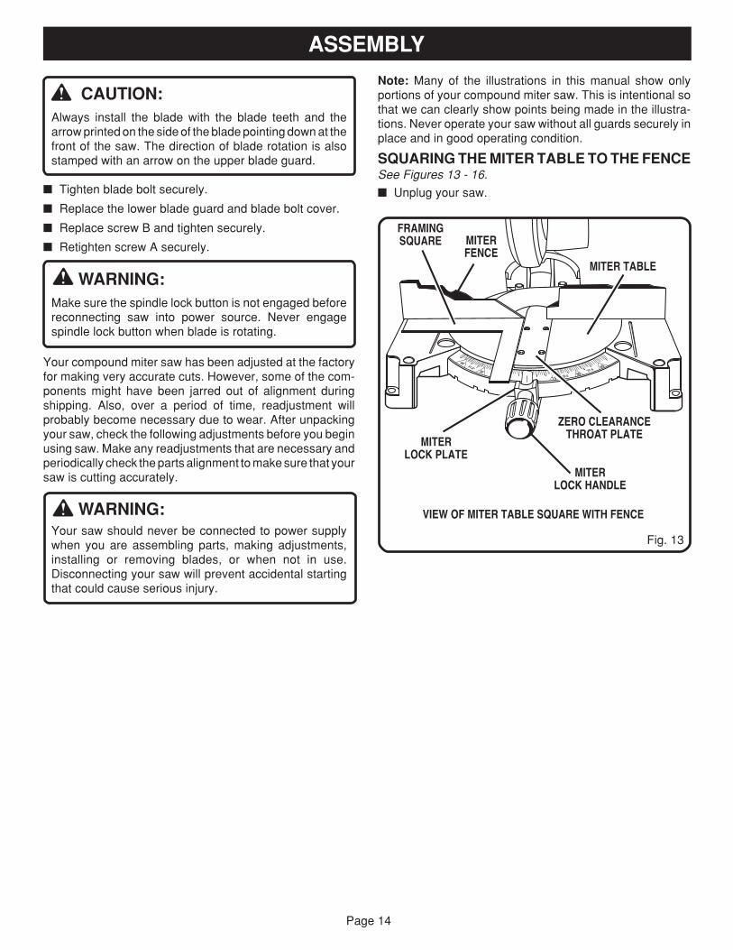
SQUARING THE MITER TABLE TO THE FENCESee Figures 13 - 16.
� Unplug your saw.
Fig. 13
VIEW OF MITER TABLE SQUARE WITH FENCE
MITERLOCK PLATE
MITERLOCK HANDLE
MITERFENCE
MITER TABLE
ZERO CLEARANCETHROAT PLATE
FRAMINGSQUARE
Page 15
ADJUSTMENTS
WARNING:Failure to unplug your saw could result in accidentalstarting causing possible serious personal injury.
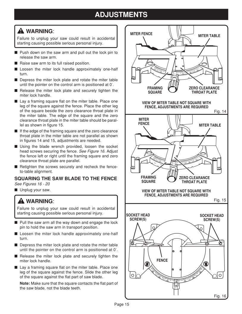
� Push down on the saw arm and pull out the lock pin torelease the saw arm.
� Raise saw arm to its full raised position.
� Loosen the miter lock handle approximately one-halfturn.
� Depress the miter lock plate and rotate the miter tableuntil the pointer on the control arm is positioned at 0°.
� Release the miter lock plate and securely tighten themiter lock handle.
� Lay a framing square flat on the miter table. Place oneleg of the square against the fence. Place the other legof the square beside the zero clearance throat plate inthe miter table. The edge of the square and the zeroclearance throat plate in the miter table should be paral-lel as shown in figure 15.
� If the edge of the framing square and the zero clearancethroat plate in the miter table are not parallel as shownin figures 14 and 15, adjustments are needed.
� Using the blade wrench provided, loosen the sockethead screws securing the fence. See Figure 16. Adjustthe fence left or right until the framing square and zeroclearance throat plate are parallel.
� Retighten the screws securely and recheck the fence-to-table alignment.
SQUARING THE SAW BLADE TO THE FENCESee Figures 16 - 20
� Unplug your saw.
WARNING:Failure to unplug your saw could result in accidentalstarting causing possible serious personal injury.
� Pull the saw arm all the way down and engage the lockpin to hold the saw arm in transport position.
� Loosen the miter lock handle approximately one-halfturn.
� Depress the miter lock plate and rotate the miter tableuntil the pointer on the control arm is positioned at 0°.
� Release the miter lock plate and securely tighten themiter lock handle.
� Lay a framing square flat on the miter table. Place oneleg of the square against the fence. Slide the other legof the square against the flat part of saw blade.
Note: Make sure that the square contacts the flat part ofthe saw blade, not the blade teeth.
FRAMINGSQUARE
Fig. 14
VIEW OF MITER TABLE NOT SQUARE WITHFENCE, ADJUSTMENTS ARE REQUIRED
MITER FENCE
ZERO CLEARANCETHROAT PLATE
MITER TABLE
FRAMINGSQUARE
MITERFENCE
Fig. 15
VIEW OF MITER TABLE NOT SQUARE WITHFENCE, ADJUSTMENTS ARE REQUIRED
MITER TABLE
ZERO CLEARANCETHROAT PLATE
Fig. 16
45
30
45
30
31.631.6
51
1522.5
45
30
45
30 15
22.5
31.6 5122.5
31.631.6
FENCE
SOCKET HEADSCREW(S)
SOCKET HEADSCREW(S)
15
30
45
015
30
45
33.6
22.5 22.5
33.6
Page 16
ADJUSTMENTS
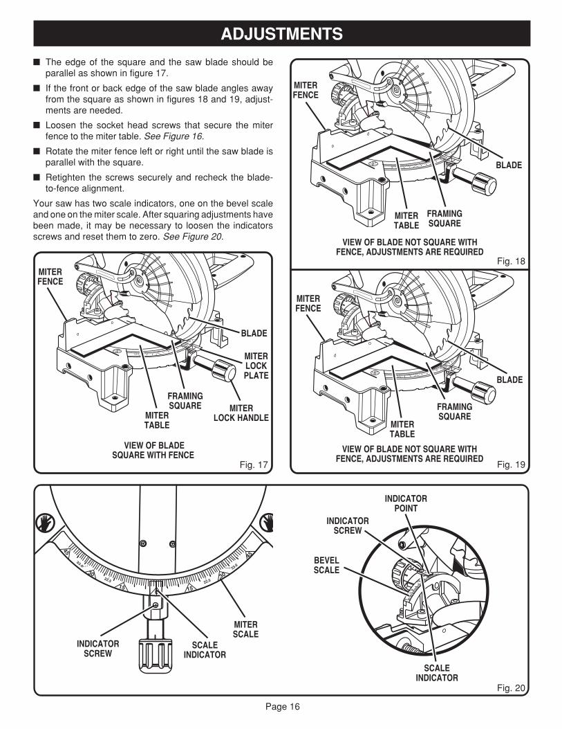
� The edge of the square and the saw blade should beparallel as shown in figure 17.
� If the front or back edge of the saw blade angles awayfrom the square as shown in figures 18 and 19, adjust-ments are needed.
� Loosen the socket head screws that secure the miterfence to the miter table. See Figure 16.
� Rotate the miter fence left or right until the saw blade isparallel with the square.
� Retighten the screws securely and recheck the blade-to-fence alignment.
Your saw has two scale indicators, one on the bevel scaleand one on the miter scale. After squaring adjustments havebeen made, it may be necessary to loosen the indicatorsscrews and reset them to zero. See Figure 20.
MITERTABLE
BLADE
MITERLOCK HANDLE
Fig. 17
MITERTABLE
VIEW OF BLADESQUARE WITH FENCE
BLADE
MITERLOCKPLATE
FRAMINGSQUARE
VIEW OF BLADE NOT SQUARE WITHFENCE, ADJUSTMENTS ARE REQUIRED
FRAMINGSQUARE
MITERFENCE
Fig. 18
MITERFENCE
Fig. 19
VIEW OF BLADE NOT SQUARE WITHFENCE, ADJUSTMENTS ARE REQUIRED
FRAMINGSQUARE
MITERTABLE
BLADE
SCALEINDICATOR
Fig. 20
MITERSCALE
INDICATORSCREW
MITERFENCE
15
30
45
015
30
45
33.6
22.5 22.5
33.6
SCALEINDICATOR
BEVELSCALE
INDICATORSCREW
INDICATORPOINT
Page 17
ADJUSTMENTS
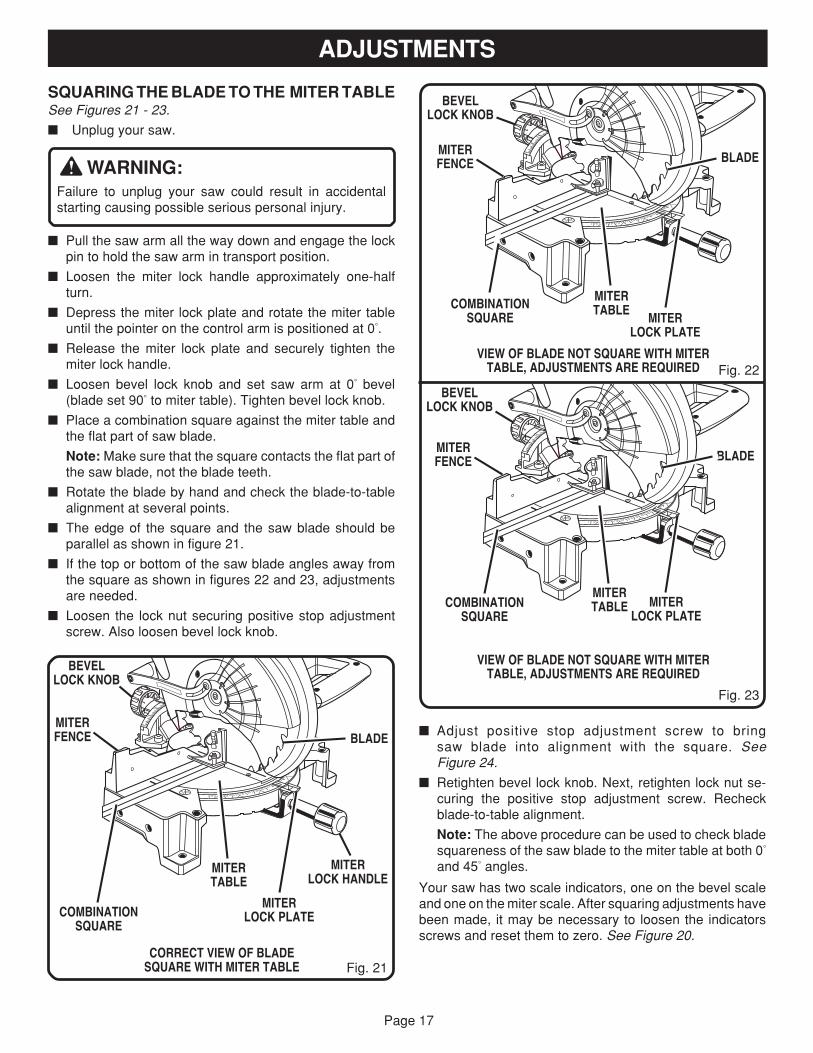
SQUARING THE BLADE TO THE MITER TABLESee Figures 21 - 23.
� Unplug your saw.
WARNING:Failure to unplug your saw could result in accidentalstarting causing possible serious personal injury.
� Pull the saw arm all the way down and engage the lockpin to hold the saw arm in transport position.
� Loosen the miter lock handle approximately one-halfturn.
� Depress the miter lock plate and rotate the miter tableuntil the pointer on the control arm is positioned at 0°.
� Release the miter lock plate and securely tighten themiter lock handle.
� Loosen bevel lock knob and set saw arm at 0° bevel(blade set 90° to miter table). Tighten bevel lock knob.
� Place a combination square against the miter table andthe flat part of saw blade.
Note: Make sure that the square contacts the flat part ofthe saw blade, not the blade teeth.
� Rotate the blade by hand and check the blade-to-tablealignment at several points.
� The edge of the square and the saw blade should beparallel as shown in figure 21.
� If the top or bottom of the saw blade angles away fromthe square as shown in figures 22 and 23, adjustmentsare needed.
� Loosen the lock nut securing positive stop adjustmentscrew. Also loosen bevel lock knob.
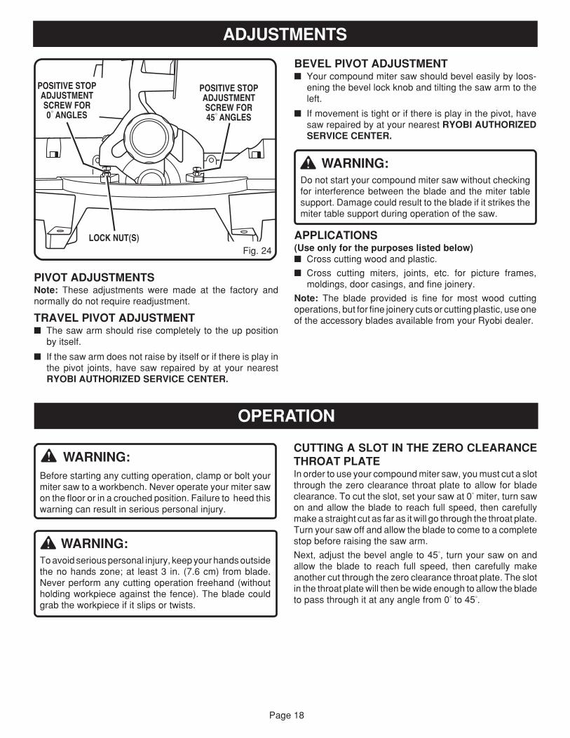
� Adjust positive stop adjustment screw to bringsaw blade into alignment with the square. SeeFigure 24.
� Retighten bevel lock knob. Next, retighten lock nut se-curing the positive stop adjustment screw. Recheckblade-to-table alignment.
Note: The above procedure can be used to check bladesquareness of the saw blade to the miter table at both 0°
and 45° angles.
Your saw has two scale indicators, one on the bevel scaleand one on the miter scale. After squaring adjustments havebeen made, it may be necessary to loosen the indicatorsscrews and reset them to zero. See Figure 20.
MITERLOCK PLATE
MITERFENCE
MITERTABLE
MITERLOCK HANDLE
COMBINATIONSQUARE
BLADE
Fig. 21CORRECT VIEW OF BLADE
SQUARE WITH MITER TABLE
VIEW OF BLADE NOT SQUARE WITH MITERTABLE, ADJUSTMENTS ARE REQUIRED Fig. 22
Fig. 23
VIEW OF BLADE NOT SQUARE WITH MITERTABLE, ADJUSTMENTS ARE REQUIRED
BEVELLOCK KNOB
MITERLOCK PLATE
MITERFENCE
MITERTABLECOMBINATION
SQUARE
BLADE
BEVELLOCK KNOB
MITERLOCK PLATE
MITERFENCE
MITERTABLECOMBINATION
SQUARE
BLADE
BEVELLOCK KNOB
Page 18
ADJUSTMENTS
BEVEL PIVOT ADJUSTMENT� Your compound miter saw should bevel easily by loos-
ening the bevel lock knob and tilting the saw arm to theleft.
� If movement is tight or if there is play in the pivot, havesaw repaired by at your nearest RYOBI AUTHORIZEDSERVICE CENTER.
WARNING:Do not start your compound miter saw without checkingfor interference between the blade and the miter tablesupport. Damage could result to the blade if it strikes themiter table support during operation of the saw.
APPLICATIONS(Use only for the purposes listed below)� Cross cutting wood and plastic.
� Cross cutting miters, joints, etc. for picture frames,moldings, door casings, and fine joinery.
Note: The blade provided is fine for most wood cuttingoperations, but for fine joinery cuts or cutting plastic, use oneof the accessory blades available from your Ryobi dealer.
PIVOT ADJUSTMENTSNote: These adjustments were made at the factory andnormally do not require readjustment.
TRAVEL PIVOT ADJUSTMENT� The saw arm should rise completely to the up position
by itself.
� If the saw arm does not raise by itself or if there is play inthe pivot joints, have saw repaired by at your nearestRYOBI AUTHORIZED SERVICE CENTER.
CUTTING A SLOT IN THE ZERO CLEARANCETHROAT PLATEIn order to use your compound miter saw, you must cut a slotthrough the zero clearance throat plate to allow for bladeclearance. To cut the slot, set your saw at 0° miter, turn sawon and allow the blade to reach full speed, then carefullymake a straight cut as far as it will go through the throat plate.Turn your saw off and allow the blade to come to a completestop before raising the saw arm.
Next, adjust the bevel angle to 45°, turn your saw on andallow the blade to reach full speed, then carefully makeanother cut through the zero clearance throat plate. The slotin the throat plate will then be wide enough to allow the bladeto pass through it at any angle from 0° to 45°.
OPERATION
WARNING:Before starting any cutting operation, clamp or bolt yourmiter saw to a workbench. Never operate your miter sawon the floor or in a crouched position. Failure to heed thiswarning can result in serious personal injury.
WARNING:To avoid serious personal injury, keep your hands outsidethe no hands zone; at least 3 in. (7.6 cm) from blade.Never perform any cutting operation freehand (withoutholding workpiece against the fence). The blade couldgrab the workpiece if it slips or twists.
POSITIVE STOPADJUSTMENTSCREW FOR45° ANGLES
LOCK NUT(S)Fig. 24
POSITIVE STOPADJUSTMENTSCREW FOR0° ANGLES
Page 19
CUTTING WITH YOUR COMPOUNDMITER SAW
WARNING:When using a work clamp or C-clamp to secure yourworkpiece, clamp workpiece on one side of the bladeonly. The workpiece must remain free on one side of theblade to prevent the blade from binding in workpiece. Theworkpiece binding the blade will cause motor stalling andkickback. This situation could cause an accident resultingin possible serious personal injury.
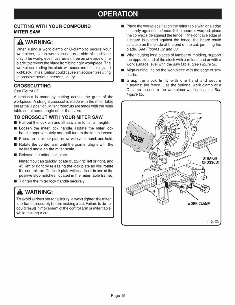
CROSSCUTTINGSee Figure 25.
A crosscut is made by cutting across the grain of theworkpiece. A straight crosscut is made with the miter tableset at the 0° position. Miter crosscuts are made with the mitertable set at some angle other than zero.
TO CROSSCUT WITH YOUR MITER SAW� Pull out the lock pin and lift saw arm to its full height.
� Loosen the miter lock handle. Rotate the miter lockhandle approximately one-half turn to the left to loosen.
� Press the miter lock plate down with your thumb and hold.
� Rotate the control arm until the pointer aligns with thedesired angle on the miter scale.
� Release the miter lock plate.
Note: You can quickly locate 0°, 22-1/2° left or right, and45° left or right by releasing the lock plate as you rotatethe control arm. The lock plate will seat itself in one of thepositive stop notches, located in the miter table frame.
� Tighten the miter lock handle securely.
WARNING:To avoid serious personal injury, always tighten the miterlock handle securely before making a cut. Failure to do socould result in movement of the control arm or miter tablewhile making a cut.
� Place the workpiece flat on the miter table with one edgesecurely against the fence. If the board is warped, placethe convex side against the fence. If the concave edge ofa board is placed against the fence, the board couldcollapse on the blade at the end of the cut, jamming theblade. See Figures 32 and 33.
� When cutting long pieces of lumber or molding, supportthe opposite end of the stock with a roller stand or with awork surface level with the saw table. See Figure 30.
� Align cutting line on the workpiece with the edge of sawblade.
� Grasp the stock firmly with one hand and secureit against the fence. Use the optional work clamp or aC-clamp to secure the workpiece when possible. SeeFigure 25.
STRAIGHTCROSSCUT
Fig. 25
WORK CLAMP
OPERATION
Page 20
BEVELSCALE
INDICATORSCREW SCALE
INDICATOR
OPERATION
� Pull out the lock pin and lift saw arm to its full height.
� Loosen the miter lock handle. Rotate the miter lockhandle approximately one-half turn to the left to loosen.
� Press the miter lock plate down with your thumb and hold.
� Rotate the control arm until the pointer aligns with zero onthe miter scale.
� Release the miter lock plate.
Note: You can quickly locate zero by releasing the lockplate as you rotate the control arm. The lock plate willseat itself in one of the built-in positive stop notches,located in the miter table frame.
� Tighten the miter lock handle securely.
WARNING:To avoid serious personal injury, always tighten the miterlock handle securely before making a cut. Failure to do socould result in movement of the control arm or miter tablewhile making a cut.
� Before turning on the saw, perform a dry run of the cuttingoperation just to make sure that no problems will occurwhen the cut is made.
� Grasp the saw handle firmly then squeeze the switchtrigger. Allow several seconds for the blade to reachmaximum speed.
� Slowly lower the blade into and through the workpiece.See Figure 25.
� Release the switch trigger and allow the saw blade to stoprotating before raising the blade out of workpiece. Waituntil the electric brake stops blade from turning beforeremoving the workpiece from the miter table.
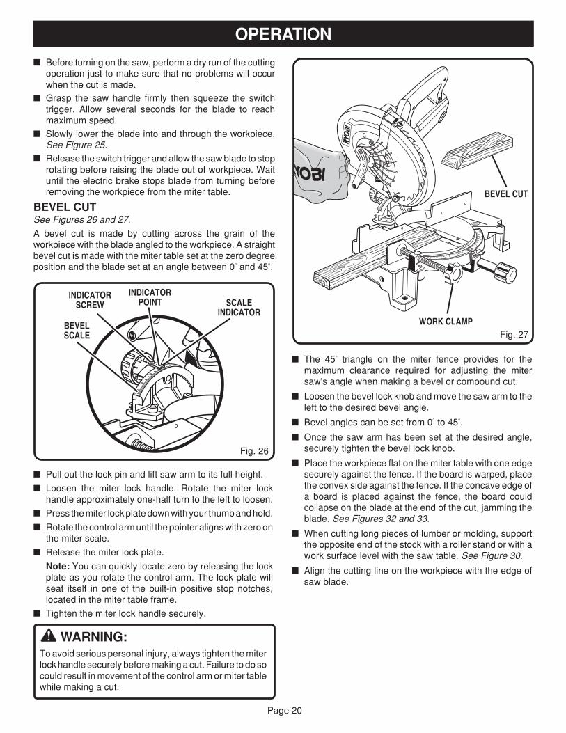
BEVEL CUTSee Figures 26 and 27.
A bevel cut is made by cutting across the grain of theworkpiece with the blade angled to the workpiece. A straightbevel cut is made with the miter table set at the zero degreeposition and the blade set at an angle between 0° and 45°.
� The 45° triangle on the miter fence provides for themaximum clearance required for adjusting the mitersaw's angle when making a bevel or compound cut.
� Loosen the bevel lock knob and move the saw arm to theleft to the desired bevel angle.
� Bevel angles can be set from 0° to 45°.
� Once the saw arm has been set at the desired angle,securely tighten the bevel lock knob.
� Place the workpiece flat on the miter table with one edgesecurely against the fence. If the board is warped, placethe convex side against the fence. If the concave edge ofa board is placed against the fence, the board couldcollapse on the blade at the end of the cut, jamming theblade. See Figures 32 and 33.
� When cutting long pieces of lumber or molding, supportthe opposite end of the stock with a roller stand or with awork surface level with the saw table. See Figure 30.
� Align the cutting line on the workpiece with the edge ofsaw blade.
Fig. 27WORK CLAMP
BEVEL CUT
Fig. 26
INDICATORPOINT
Page 21
OPERATION
� Grasp the stock firmly with one hand and secure it againstthe fence. Use the optional work clamp or a C-clamp tosecure the workpiece when possible. See Figure 27.
WARNING:To avoid serious personal injury, always keep your handsoutside the no hands zone; at least 3 in. (7.6 cm) fromblade. Never perform any cutting operation freehand(without holding workpiece against the fence). The bladecould grab the workpiece if it slips or twists.
� Before turning on the saw, perform a dry run of the cuttingoperation just to make sure that no problems will occurwhen the cut is made.
� Grasp the saw handle firmly then squeeze the switchtrigger. Allow several seconds for the blade to reachmaximum speed.
� Slowly lower the blade into and through the workpiece.See Figure 27.
� Release the switch trigger and allow the saw blade to stoprotating before raising the blade out of workpiece. Waituntil the electric brake stops blade from turning beforeremoving the workpiece from miter table.
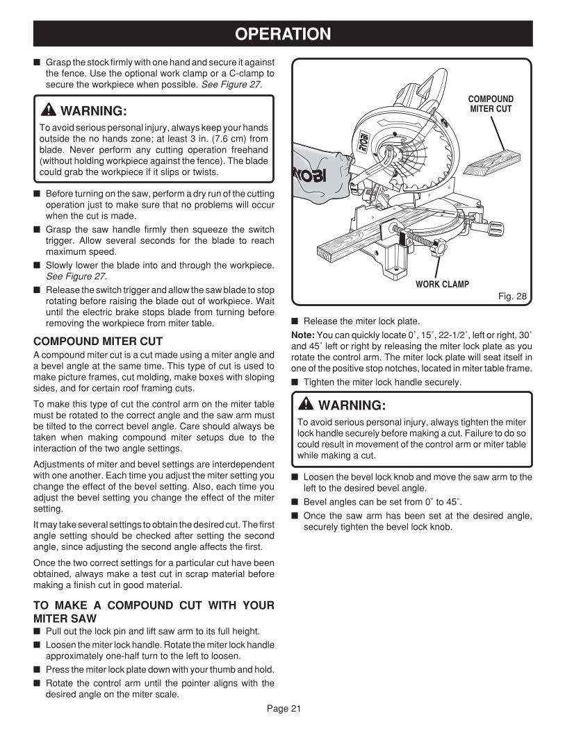
COMPOUND MITER CUTA compound miter cut is a cut made using a miter angle anda bevel angle at the same time. This type of cut is used tomake picture frames, cut molding, make boxes with slopingsides, and for certain roof framing cuts.
To make this type of cut the control arm on the miter tablemust be rotated to the correct angle and the saw arm mustbe tilted to the correct bevel angle. Care should always betaken when making compound miter setups due to theinteraction of the two angle settings.
Adjustments of miter and bevel settings are interdependentwith one another. Each time you adjust the miter setting youchange the effect of the bevel setting. Also, each time youadjust the bevel setting you change the effect of the mitersetting.
It may take several settings to obtain the desired cut. The firstangle setting should be checked after setting the secondangle, since adjusting the second angle affects the first.
Once the two correct settings for a particular cut have beenobtained, always make a test cut in scrap material beforemaking a finish cut in good material.
TO MAKE A COMPOUND CUT WITH YOURMITER SAW� Pull out the lock pin and lift saw arm to its full height.
� Loosen the miter lock handle. Rotate the miter lock handleapproximately one-half turn to the left to loosen.
� Press the miter lock plate down with your thumb and hold.
� Rotate the control arm until the pointer aligns with thedesired angle on the miter scale.
� Release the miter lock plate.
Note: You can quickly locate 0˚, 15˚, 22-1/2˚, left or right, 30˚and 45˚ left or right by releasing the miter lock plate as yourotate the control arm. The miter lock plate will seat itself inone of the positive stop notches, located in miter table frame.
� Tighten the miter lock handle securely.
WARNING:To avoid serious personal injury, always tighten the miterlock handle securely before making a cut. Failure to do socould result in movement of the control arm or miter tablewhile making a cut.
� Loosen the bevel lock knob and move the saw arm to theleft to the desired bevel angle.
� Bevel angles can be set from 0˚ to 45˚.
� Once the saw arm has been set at the desired angle,securely tighten the bevel lock knob.
Fig. 28WORK CLAMP
COMPOUNDMITER CUT
Page 22
� Recheck miter angle setting. Make a test cut in scrapmaterial.
� Place the workpiece flat on the miter table with one edgesecurely against the fence. If the board is warped, placethe convex side against the fence. If the concave edge ofa board could collapse on the blade at the end of the cut,jamming the blade. See Figures 32 and 33.
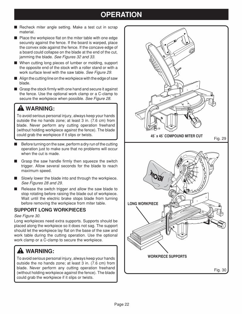
� When cutting long pieces of lumber or molding, supportthe opposite end of the stock with a roller stand or with awork surface level with the saw table. See Figure 29.
� Align the cutting line on the workpiece with the edge of sawblade.
� Grasp the stock firmly with one hand and secure it againstthe fence. Use the optional work clamp or a C-clamp tosecure the workpiece when possible. See Figure 28.
WARNING:To avoid serious personal injury, always keep your handsoutside the no hands zone; at least 3 in. (7.6 cm) fromblade. Never perform any cutting operation freehand(without holding workpiece against the fence). The bladecould grab the workpiece if it slips or twists.
� Before turning on the saw, perform a dry run of the cuttingoperation just to make sure that no problems will occurwhen the cut is made.
� Grasp the saw handle firmly then squeeze the switchtrigger. Allow several seconds for the blade to reachmaximum speed.
� Slowly lower the blade into and through the workpiece.See Figures 28 and 29.
� Release the switch trigger and allow the saw blade tostop rotating before raising the blade out of workpiece.Wait until the electric brake stops blade from turningbefore removing the workpiece from miter table.
SUPPORT LONG WORKPIECESSee Figure 30.Long workpieces need extra supports. Supports should beplaced along the workpiece so it does not sag. The supportshould let the workpiece lay flat on the base of the saw andwork table during the cutting operation. Use the optionalwork clamp or a C-clamp to secure the workpiece.
WARNING:To avoid serious personal injury, always keep your handsoutside the no hands zone; at least 3 in. (7.6 cm) fromblade. Never perform any cutting operation freehand(without holding workpiece against the fence). The bladecould grab the workpiece if it slips or twists.
OPERATION
Fig. 30
Fig. 2945° x 45° COMPOUND MITER CUT
LONG WORKPIECE
WORKPIECE SUPPORTS
0

Page 23
CUTTING COMPOUND MITERSTo aid in making the correct settings, the compound angle setting chart below has been provided. Since compound cutsare the most difficult to accurately obtain, trial cuts should be made in scrap material, and much thought and planningmade, prior to making your required cut.
OPERATION
4 PITCH OF SIDE
NUMBER OF SIDES
0°
6
M- 45.00°B- 0.00°
5°
10°
15°
20°
25°
30°
35°
40°
45°
50°
55°
60°
65°
70°
75°
80°
85°
90°
5 7 8 9 10
M- 36.00°B- 0.00°
M- 30.00°B- 0.00°
M- 25.71°B- 0.00°
M- 22.50°B- 0.00°
M- 20.00°B- 0.00°
M- 18.00°B- 0.00°
Each B (Bevel) and M (Miter) Setting is Given to the Closest 0.005°.COMPOUND-ANGLE SETTINGS FOR POPULAR STRUCTURES
M- 44.89°B- 3.53°
M- 35.90°B- 2.94°
M- 29.91°B- 2.50°
M- 25.63°B- 2.17°
M- 22.42°B- 1.91°
M- 19.93°B- 1.71°
M- 17.94°B- 1.54°
M- 7.82°B -16.26°
M- 14.51°B- 43.08°
M- 44.56°B- 7.05°
M- 35.58°B- 5.86°
M- 29.62°B- 4.98°
M- 25.37°B- 4.32°
M- 22.19°B- 3.81°
M- 19.72°B- 3.40°
M- 17.74°B- 3.08°
M- 44.01°B- 10.55°M- 43.22°B- 14.00°M- 42.19°B- 17.39°
M- 4.98°B- 44.78°
M- 0.00°B- 45.00°
M- 9.85°B- 44.14°
M- 18.88°B- 41.64°
M- 22.91°B- 39.86°
M- 26.57°B- 37.76°
M- 29.84°B- 35.40°
M- 32.73°B- 32.80°
M- 35.26°B- 30.00°
M- 37.45°B- 27.03°
M- 39.32°B- 23.93°
M- 40.89°B- 20.70°
M- 35.06°B- 8.75°
M- 29.15°B- 7.44°
M- 24.95°B- 6.45°
M- 21.81°B- 5.68°
M- 19.37°B- 5.08°
M- 17.42°B- 4.59°
M- 34.32°B- 11.60°
M- 28.48°B- 9.85°
M- 24.35°B- 8.53°
M- 21.27°B- 7.52°
M- 18.88°B- 6.72°
M- 16.98°B- 6.07°
M- 33.36°B- 14.38°
M- 27.62°B- 12.20°
M- 23.56°B- 10.57°
M- 20.58°B- 9.31°
M- 18.26°B- 8.31°
M- 16.41°B- 7.50°
M- 32.18°B- 17.09°
M- 26.57°B- 14.48°
M- 22.64°B- 12.53°
M- 19.73°B- 11.03°
M- 17.50°B- 9.85°
M- 15.72°B- 8.89°
M- 30.76°B- 19.70°
M- 25.31°B- 16.67°
M- 21.53°B- 14.41°
M- 18.74°B- 12.68°
M- 16.60°B- 11.31°
M- 14.90°B- 10.21°
M- 29.10°B- 22.20°
M- 23.86°B- 18.75°
M- 20.25°B- 16.19°
M- 17.60°B- 14.24°
M- 15.58°B- 12.70°
M- 13.98°B- 11.46°
M- 0.00°B- 36.00°
M- 0.00°B- 30.00°
M- 0.00°B- 25.71°
M- 0.00°B- 22.50°
M- 0.00°B- 20.00°
M- 0.00°B- 18.00°
M- 3.62°B- 35.84°
M- 2.88°B- 29.87°
M- 2.40°B- 25.61°
M- 2.07°B- 22.41°
M- 1.82°B- 19.92°
M- 1.62°B- 17.93°
M- 7.19°B- 35.37°
M- 5.73°B- 29.50°
M- 4.78°B- 25.30°
M- 4.11°B- 22.14°
M- 3.62°B- 19.68°
M- 3.23°B- 17.72°
M- 10.65°B- 34.59°
M- 8.50°B- 28.88°
M- 7.10°B- 24.78°
M- 6.12°B- 21.69°
M- 5.38°B- 19.29°
M- 4.81°B- 17.37°
M- 13.95°B- 33.53°
M- 11.17°B- 28.02°
M- 9.35°B- 24.06°
M- 8.06°B- 21.08°
M- 7.10°B- 18.75°
M- 6.34°B- 16.88°
M- 17.07°B- 32.19°
M- 13.71°B- 26.95°
M- 11.50°B- 23.16°
M- 9.93°B- 20.29°
M- 8.74°B- 18.06°
M- 19.96°B- 30.60°
M- 16.10°B- 25.66°
M- 13.54°B- 22.07°
M- 11.70°B- 19.35°
M- 10.31°B- 17.23°
M- 9.23°B- 15.52°
M- 22.62°B- 28.78°
M- 18.32°B- 24.18°
M- 15.44°B- 20.82°
M- 13.36°B- 18.27°
M- 11.79°B- 16.27°
M- 10.56°B- 14.66°
M- 25.03°B- 26.76°
M- 20.36°B- 22.52°
M- 17.20°B- 19.41°
M- 14.91°B- 17.05°
M- 13.17°B- 15.19°
M- 11.80°B- 13.69°
M- 27.19°B- 24.56°
M- 22.21°B- 20.70°
M- 18.80°B- 17.87°
M- 16.32°B- 15.70°
M- 14.43°B- 14.00°
M- 12.94°B- 12.62°
Page 24
When setting the bevel and miter angles for compoundmiters, remember that the settings are interdependent; chang-ing one angle changes the other angle as well.
Keep in mind that the angles for crown moldings are veryprecise and difficult to set. Since it is very easy for theseangles to shift, all settings should first be tested on scrapmolding. Also most walls do not have angles of exactly 90°,therefore, you will need to fine tune your settings.
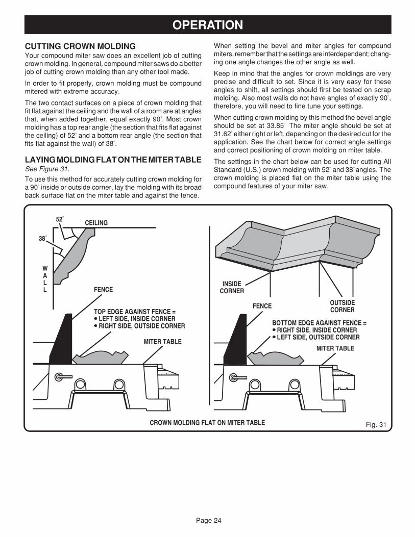
When cutting crown molding by this method the bevel angleshould be set at 33.85°. The miter angle should be set at31.62° either right or left, depending on the desired cut for theapplication. See the chart below for correct angle settingsand correct positioning of crown molding on miter table.
The settings in the chart below can be used for cutting AllStandard (U.S.) crown molding with 52° and 38° angles. Thecrown molding is placed flat on the miter table using thecompound features of your miter saw.
OPERATION
CEILING
WALL
INSIDECORNER
CROWN MOLDING FLAT ON MITER TABLE
38°
52°
FENCE
MITER TABLE
BOTTOM EDGE AGAINST FENCE = RIGHT SIDE, INSIDE CORNER LEFT SIDE, OUTSIDE CORNER
FENCE
MITER TABLE
Fig. 31
OUTSIDECORNERTOP EDGE AGAINST FENCE =
LEFT SIDE, INSIDE CORNER RIGHT SIDE, OUTSIDE CORNER
CUTTING CROWN MOLDINGYour compound miter saw does an excellent job of cuttingcrown molding. In general, compound miter saws do a betterjob of cutting crown molding than any other tool made.
In order to fit properly, crown molding must be compoundmitered with extreme accuracy.
The two contact surfaces on a piece of crown molding thatfit flat against the ceiling and the wall of a room are at anglesthat, when added together, equal exactly 90°. Most crownmolding has a top rear angle (the section that fits flat againstthe ceiling) of 52° and a bottom rear angle (the section thatfits flat against the wall) of 38°.
LAYING MOLDING FLAT ON THE MITER TABLESee Figure 31.
To use this method for accurately cutting crown molding fora 90° inside or outside corner, lay the molding with its broadback surface flat on the miter table and against the fence.
Page 25
0
15
30
45
015
30
45
33.6
22.5 22.5
33.6
WRONG
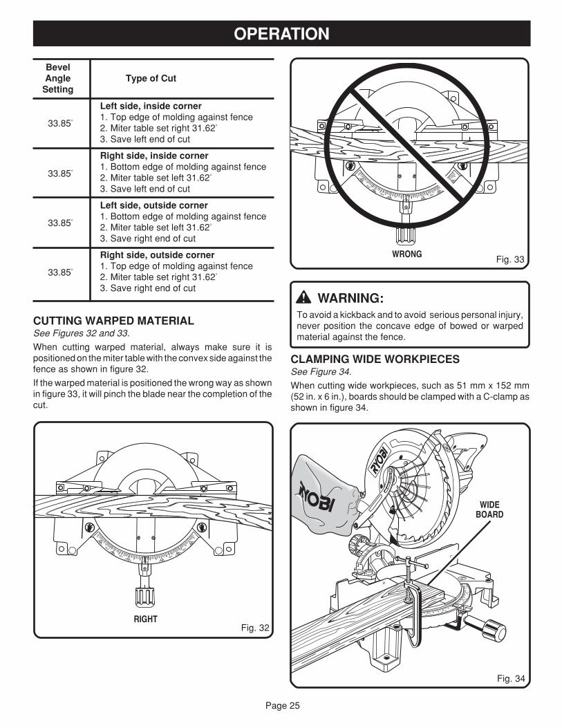
WARNING:To avoid a kickback and to avoid serious personal injury,never position the concave edge of bowed or warpedmaterial against the fence.
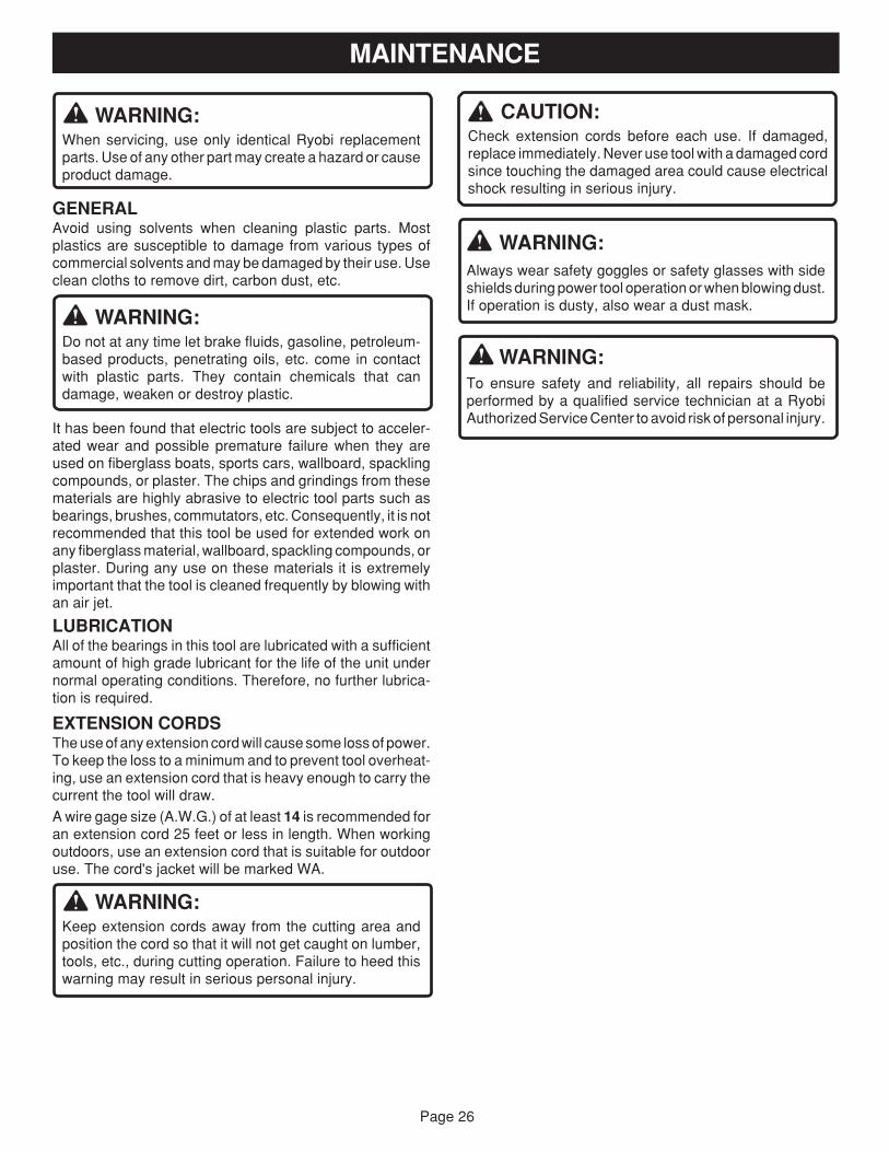
CLAMPING WIDE WORKPIECESSee Figure 34.
When cutting wide workpieces, such as 51 mm x 152 mm(52 in. x 6 in.), boards should be clamped with a C-clamp asshown in figure 34.
BevelAngle Type of Cut
Setting
Left side, inside corner1. Top edge of molding against fence2. Miter table set right 31.62°
3. Save left end of cut
Right side, inside corner1. Bottom edge of molding against fence2. Miter table set left 31.62°
3. Save left end of cut
Left side, outside corner1. Bottom edge of molding against fence2. Miter table set left 31.62°
3. Save right end of cut
Right side, outside corner1. Top edge of molding against fence2. Miter table set right 31.62°
3. Save right end of cut
33.85°
33.85°
33.85°
33.85°
Fig. 34
CUTTING WARPED MATERIALSee Figures 32 and 33.
When cutting warped material, always make sure it ispositioned on the miter table with the convex side against thefence as shown in figure 32.
If the warped material is positioned the wrong way as shownin figure 33, it will pinch the blade near the completion of thecut.
Fig. 32RIGHT
WIDEBOARD
OPERATION
Fig. 33
15
30
45
015
30
45
33.6
22.5 22.5
33.6
Page 26
WARNING:When servicing, use only identical Ryobi replacementparts. Use of any other part may create a hazard or causeproduct damage.
GENERALAvoid using solvents when cleaning plastic parts. Mostplastics are susceptible to damage from various types ofcommercial solvents and may be damaged by their use. Useclean cloths to remove dirt, carbon dust, etc.
WARNING:Do not at any time let brake fluids, gasoline, petroleum-based products, penetrating oils, etc. come in contactwith plastic parts. They contain chemicals that candamage, weaken or destroy plastic.
It has been found that electric tools are subject to acceler-ated wear and possible premature failure when they areused on fiberglass boats, sports cars, wallboard, spacklingcompounds, or plaster. The chips and grindings from thesematerials are highly abrasive to electric tool parts such asbearings, brushes, commutators, etc. Consequently, it is notrecommended that this tool be used for extended work onany fiberglass material, wallboard, spackling compounds, orplaster. During any use on these materials it is extremelyimportant that the tool is cleaned frequently by blowing withan air jet.
LUBRICATIONAll of the bearings in this tool are lubricated with a sufficientamount of high grade lubricant for the life of the unit undernormal operating conditions. Therefore, no further lubrica-tion is required.
EXTENSION CORDSThe use of any extension cord will cause some loss of power.To keep the loss to a minimum and to prevent tool overheat-ing, use an extension cord that is heavy enough to carry thecurrent the tool will draw.
A wire gage size (A.W.G.) of at least 14 is recommended foran extension cord 25 feet or less in length. When workingoutdoors, use an extension cord that is suitable for outdooruse. The cord's jacket will be marked WA.
WARNING:Keep extension cords away from the cutting area andposition the cord so that it will not get caught on lumber,tools, etc., during cutting operation. Failure to heed thiswarning may result in serious personal injury.
MAINTENANCE
CAUTION:Check extension cords before each use. If damaged,replace immediately. Never use tool with a damaged cordsince touching the damaged area could cause electricalshock resulting in serious injury.
WARNING:Always wear safety goggles or safety glasses with sideshields during power tool operation or when blowing dust.If operation is dusty, also wear a dust mask.
WARNING:To ensure safety and reliability, all repairs should beperformed by a qualified service technician at a RyobiAuthorized Service Center to avoid risk of personal injury.

Page 27
NOTES

Page 28
983000-248 3-03
RYOBI TECHNOLOGIES, INC.1428 Pearman Dairy Road Anderson SC 29625Post Office Box 1207 Anderson SC 29622-1207
Phone 1-800-525-2579www.ryobitools.com
EXTENSION CORD CAUTIONWhen using a power tool at a considerable distance from apower source, be sure to use an extension cord that has thecapacity to handle the current the tool will draw. An undersizedcord will cause a drop in line voltage, resulting in overheatingand loss of power. Use the chart to determine the minimumwire size required in an extension cord. Only round jacketedcords should be used.
When working with a tool outdoors, use an extension cord thatis designed for outside use. This is indicated by the letters"WA" on the cord's jacket.
Before using any extension cord, inspect it for loose or ex-posed wires and cut or worn insulation.
OPERATOR'S MANUAL10 in. (254 mm) Compound Miter SawModel TS1340 - Double Insulated
**Ampere rating (on tool data plate) 0-2.0 2.1-3.4 3.5-5.0 5.1-7.0 7.1-12.0 12.1-16.0
Cord Length Wire Size (A.W.G.)
25' 16 16 16 16 14 14
50' 16 16 16 14 14 12
CAUTION: Keep the extension cord clear of the workingarea. Position the cord so that it will not get caught onworkpiece, tools, or other obstructions while you are workingwith a power tool.
**Used on 12 gauge - 20 amp circuit.
• SERVICENow that you have purchased your tool, should a need ever exist for repair parts orservice, simply contact your nearest Ryobi Authorized Service Center. Be sure toprovide all pertinent facts when you call or visit. Please call 1-800-525-2579 for yournearest Ryobi Authorized Service Center. You can also check our web site atwww.ryobitools.com for a complete list of Authorized Service Centers.
• MODEL NO.The model and serial numbers of your tool will be found on a plate attached to the motorhousing. Please record the serial number in the space provided below.
• MODEL NUMBER TS1340
• SERIAL NUMBER
Related Documents