CHISEL MORTISER MODEL: MC-1000 © 2012 Baileigh Industrial, Inc. REPRODUCTION OF THIS MANUAL IN ANY FORM WITHOUT WRITTEN APPROVAL OF BAILEIGH INDUSTRIAL, INC. IS PROHIBITED. Baileigh Industrial, Inc. does not assume and hereby disclaims any liability for any damage or loss caused by an omission or error in this Operator’s Manual, resulting from accident, negligence, or other occurence. Rev. 8/2012 Baileigh Industrial, Inc. P.O. Box 531 Manitowoc, WI 54221-0531 Phone: 920.684.4990 Fax: 920.684.3944 [email protected] OPERATOR’S MANUAL

Welcome message from author
This document is posted to help you gain knowledge. Please leave a comment to let me know what you think about it! Share it to your friends and learn new things together.
Transcript

CHISEL MORTISER
MODEL: MC-1000
© 2012 Baileigh Industrial, Inc.
REPRODUCTION OF THIS MANUAL IN ANY FORM WITHOUT WRITTEN APPROVAL OF BAILEIGH INDUSTRIAL, INC. IS PROHIBITED. Baileigh Industrial, Inc. does not assume and hereby disclaims any liability for any damage or loss
caused by an omission or error in this Operator’s Manual, resulting from accident, negligence, or other occurence.
Rev. 8/2012
Baileigh Industrial, Inc. P.O. Box 531
Manitowoc, WI 54221-0531 Phone: 920.684.4990
Fax: 920.684.3944 [email protected]
OPERATOR’S
MANUAL

Table of Contents
THANK YOU & WARRANTY .......................................................................................... 1 INTRODUCTION ............................................................................................................ 3 GENERAL NOTES.......................................................................................................... 3
SAFETY INSTRUCTIONS .............................................................................................. 4 SAFETY PRECAUTIONS ............................................................................................... 6 SPECIFICATIONS .......................................................................................................... 9 TECHNICAL SUPPORT ................................................................................................. 9 UNPACKING AND CLEANING ..................................................................................... 10
Cleaning .................................................................................................................... 10 GETTING TO KNOW YOUR MACHINE ....................................................................... 11
Label Placement ........................................................................................................ 12 INSTALLATION ............................................................................................................ 13
Securing the Base ..................................................................................................... 13
ASSEMBLY ................................................................................................................... 14
ELECTRICAL ................................................................................................................ 15 Extension Cord Safety ............................................................................................... 16
WIRING DIAGRAM ....................................................................................................... 16 OPERATING CONTROLS AND ADJUSTMENTS ........................................................ 17
Installing Chisel and Bit ............................................................................................. 19
MAINTENANCE ............................................................................................................ 20 Sharpening Chisel and Bit ......................................................................................... 20
PARTS DIAGRAM ........................................................................................................ 22 Parts List - Mortiser ................................................................................................... 23
PARTS LIST FOR STAND ASSEMBLY ........................................................................ 25
PARTS LIST FOR CLAMPING BAR ASSEMBLY ......................................................... 26
PARTS LIST FOR WORK STOP ASSEMBLY .............................................................. 27

1 1
THANK YOU & WARRANTY
Thank you for your purchase of a machine from Baileigh Industrial. We hope that you find it productive and useful to you for a long time to come. Inspection & Acceptance. Buyer shall inspect all Goods within ten (10) days after receipt thereof. Buyer’s payment shall constitute final acceptance of the Goods and shall act as a waiver of the Buyer’s rights to inspect or reject the goods unless otherwise agreed. If Buyer rejects any merchandise, Buyer must first obtain a Returned Goods Authorization (“RGA”) number before returning any goods to Seller. Goods returned without a RGA will be refused. Seller will not be responsible for any freight costs, damages to goods, or any other costs or liabilities pertaining to goods returned without a RGA. Seller shall have the right to substitute a conforming tender. Buyer will be responsible for all freight costs to and from Buyer and repackaging costs, if any, if Buyer refuses to accept shipment. If Goods are returned in unsalable condition, Buyer shall be responsible for full value of the Goods. Buyer may not return any special order Goods. Any Goods returned hereunder shall be subject to a restocking fee equal to 30% of the invoice price. Specifications. Seller may, at its option, make changes in the designs, specifications or components of the Goods to improve the safety of such Goods, or if in Seller’s judgment, such changes will be beneficial to their operation or use. Buyer may not make any changes in the specifications for the Goods unless Seller approves of such changes in writing, in which event Seller may impose additional charges to implement such changes. Limited Warranty. Seller warrants to the original end-user that the Goods manufactured or provided by Seller under this Agreement shall be free of defects in material or workmanship for a period of twelve (12) months from the date of purchase, provided that the Goods are installed, used, and maintained in accordance with any instruction manual or technical guidelines provided by the Seller or supplied with the Goods, if applicable. The original end-user must give written notice to Seller of any suspected defect in the Goods prior to the expiration of the warranty period. The original end-user must also obtain a RGA from Seller prior to returning any Goods to Seller for warranty service under this paragraph. Seller will not accept any responsibility for Goods returned without a RGA. The original end-user shall be responsible for all costs and expenses associated with returning the Goods to Seller for warranty service. In the event of a defect, Seller, at its sole option, shall repair or replace the defective Goods or refund to the original end-user the purchase price for such defective Goods. Goods are not eligible for replacement or return after a period of 30 days from date of receipt. The foregoing warranty is Seller’s sole obligation, and the original end-user’s exclusive remedy, with regard to any defective Goods. This limited warranty does not apply to: (a) die sets, tooling, and saw blades; (b) periodic or routine maintenance and setup, (c) repair or replacement of the Goods due to normal wear and tear, (d) defects or damage to the Goods resulting from misuse, abuse, neglect, or accidents, (f) defects or damage to the Goods resulting from improper or unauthorized alterations, modifications, or changes; and (f) any Goods that has not been installed and/or maintained in accordance with the instruction manual or technical guidelines provided by Seller. EXCLUSION OF OTHER WARRANTIES. THE FOREGOING LIMITED WARRANTY IS IN LIEU OF ALL OTHER WARRANTIES, EXPRESS OR IMPLIED. ANY AND ALL OTHER EXPRESS, STATUTORY OR IMPLIED WARRANTIES, INCLUDING BUT NOT LIMITED TO, ANY WARRANTY OF MERCHANTABILITY OR FITNESS FOR ANY PARTICULAR PURPOSE ARE EXPRESSLY DISCLAIMED. NO WARRANTY IS MADE WHICH EXTENDS BEYOND THAT WHICH IS EXPRESSLY CONTAINED HEREIN. Limitation of Liability. IN NO EVENT SHALL SELLER BE LIABLE TO BUYER OR ANY OTHER PARTY FOR ANY INCIDENTIAL, CONSEQUENTIAL OR SPECIAL DAMAGES (INCLUDING, WITHOUT LIMITATION, LOST PROFITS OR DOWN TIME) ARISING FROM OR IN MANNER CONNECTED WITH THE GOODS, ANY BREACH BY SELLER OR ITS AGENTS OF THIS AGREEMENT, OR ANY OTHER CAUSE WHATSOEVER, WHETHER BASED ON CONTRACT, TORT OR ANY OTHER THEORY OF LIABILITY. BUYER’S REMEDY WITH RESPECT TO ANY CLAIM ARISING UNDER THIS AGREEMENT IS STRICTLY LIMITED TO NO MORE THAN THE AMOUNT PAID BY THE BUYER FOR THE GOODS.

2 2
Force Majuere. Seller shall not be responsible for any delay in the delivery of, or failure to deliver, Goods due to causes beyond Seller’s reasonable control including, without limitation, acts of God, acts of war or terrorism, enemy actions, hostilities, strikes, labor difficulties, embargoes, non-delivery or late delivery of materials, parts and equipment or transportation delays not caused by the fault of Seller, delays caused by civil authorities, governmental regulations or orders, fire, lightening, natural disasters or any other cause beyond Seller's reasonable control. In the event of any such delay, performance will be postponed by such length of time as may be reasonably necessary to compensate for the delay. Installation. If Buyer purchases any Goods that require installation, Buyer shall, at its expense, make all arrangements and connections necessary to install and operate the Goods. Buyer shall install the Goods in accordance with any Seller instructions and shall indemnify Seller against any and all damages, demands, suits, causes of action, claims and expenses (including actual attorneys’ fees and costs) arising directly or indirectly out of Buyer’s failure to properly install the Goods. Work By Others; Safety Devices. Unless agreed to in writing by Seller, Seller has no responsibility for labor or work performed by Buyer or others, of any nature, relating to design, manufacture, fabrication, use, installation or provision of Goods. Buyer is solely responsible for furnishing, and requiring its employees and customers to use all safety devices, guards and safe operating procedures required by law and/or as set forth in manuals and instruction sheets furnished by Seller. Buyer is responsible for consulting all operator’s manuals, ANSI or comparable safety standards, OSHA regulations and other sources of safety standards and regulations applicable to the use and operation of the Goods. Remedies. Each of the rights and remedies of Seller under this Agreement is cumulative and in addition to any other or further remedies provided under this Agreement or at law or equity. Attorney’s Fees. In the event legal action is necessary to recover monies due from Buyer or to enforce any provision of this Agreement, Buyer shall be liable to Seller for all costs and expenses associated therewith, including Seller’s actual attorneys' fees and costs. Governing Law/Venue. This Agreement shall be construed and governed under the laws of the State of Wisconsin, without application of conflict of law principles. Each party agrees that all actions or proceedings arising out of or in connection with this Agreement shall be commenced, tried, and litigated only in the state courts sitting in Manitowoc County, Wisconsin or the u.s. Federal Court for the Eastern District of Wisconsin. Each party waives any right it may have to assert the doctrine of “forum non conveniens” or to object to venue to the extent that any proceeding is brought in accordance with this section. Each party consents to and waives any objection to the exercise of personal jurisdiction over it by courts described in this section. Each party waives to the fullest extent permitted by applicable law the right to a trial by jury. Summary of Return Policy. 10 Day acceptance period from date of delivery. Damage claims and order discrepancies will not be accepted
after this time. You must obtain a Baileigh issued RGA number PRIOR to returning any materials. Returned materials must be received at Baileigh in new condition and in original packaging. Altered items are not eligible for return. Buyer is responsible for all shipping charges. A 30% re-stocking fee applies to all returns. Baileigh Industrial makes every effort to ensure that our posted specifications, images, pricing and product availability are as correct and timely as possible. We apologize for any discrepancies that may occur. Baileigh Industrial reserves the right to make any and all changes deemed necessary in the course of business including but not limited to pricing, product specifications, quantities, and product availability. For Customer Service & Technical Support: Please contact one of our knowledgeable Sales and Service team members at: (920) 684-4990 or e-mail us at [email protected]

3 3
INTRODUCTION The quality and reliability of the components assembled on a Baileigh Industrial machine guarantee near perfect functioning, free from problems, even under the most demanding working conditions. However if a situation arises, refer to the manual first. If a solution cannot be found, contact the distributor where you purchased our product. Make sure you have the serial number and production year of the machine (stamped on the nameplate). For replacement parts refer to the assembly numbers on the parts list drawings. Our technical staff will do their best to help you get your machine back in working order.
In this manual you will find: (when applicable)
Safety procedures
Correct installation guidelines
Description of the functional parts of the machine
Capacity charts
Set-up and start-up instructions
Machine operation
Scheduled maintenance
Parts lists
GENERAL NOTES After receiving your equipment remove the protective container. Do a complete visual inspection, and if damage is noted, photograph it for insurance claims and contact your carrier at once, requesting inspection. Also contact Baileigh Industrial and inform them of the unexpected occurrence. Temporarily suspend installation. Take necessary precautions while loading / unloading or moving the machine to avoid any injuries. Your machine is designed and manufactured to work smoothly and efficiently. Following proper maintenance instructions will help ensure this. Try and use original spare parts, whenever possible, and most importantly; DO NOT overload the machine or make any unauthorized modifications.
Note: This symbol refers to useful information throughout the manual.

4 4
LEARN TO RECOGNIZE SAFETY INFORMATION This is the safety alert symbol. When you see this symbol on your machine or in this manual, BE ALERT TO THE POTENTIAL FOR PERSONAL INJURY! Follow recommended precautions and safe operating practices. UNDERSTAND SIGNAL WORDS A signal word – DANGER, WARNING, or CAUTION is used with the safety alert symbol. DANGER identifies a hazard or unsafe practice that will result in severe Injury or Death. Safety signs with signal word DANGER or WARNING are typically near specific hazards. General precautions are listed on CAUTION safety signs. CAUTION also calls attention to safety messages in this manual.
IMPORTANT PLEASE READ THIS OPERATORS MANUAL CAREFULLY
It contains important safety information, instructions, and necessary operating procedures. The continual observance of these procedures will help increase your production and extend the life of the equipment.
SAFETY INSTRUCTIONS

5 5
SAVE THESE INSTRUCTIONS. Refer to them often and use them to instruct others.
PROTECT EYES
Wear safety glasses or suitable eye protection when working on or around machinery.
BEWARE OF PIERCING POINTS
Mortising chisels and bits are very sharp and can quickly pierce your fingers and hands. Always wear heavy leather gloves when handling these tools.
ENTANGLEMENT HAZARD – ROTATING SHAFT
Contain long hair, DO NOT wear jewelry or loose fitting clothing, and DO NOT wear gloves.
PROTECT AGAINST NOISE
Prolonged exposure to loud noise can cause impairment or loss of hearing. Wear suitable hearing protective devices such as ear muffs or earplugs to protect against objectionable or uncomfortable loud noises.
HIGH VOLTAGE
USE CAUTION IN HIGH VOLTAGE AREAS. DO NOT assume the power to be off. (FOLLOW PROPER LOCKOUT PROCEDURES)

6 6
SAFETY PRECAUTIONS
Wood working can be dangerous if safe and proper operating procedures are not followed. As with all machinery, there are certain hazards involved with the operation of the product. Using the machine with respect and caution will considerably lessen the possibility of personal injury. However, if normal safety precautions are overlooked or ignored, personal injury to the operator may result. Safety equipment such as guards, push sticks, hold-downs, feather boards, goggles, dust masks and hearing protection can reduce your potential for injury. But even the best guard won’t make up for poor judgment, carelessness or inattention. Always use common sense and exercise caution in the workshop. If a procedure feels dangerous, don’t try it. REMEMBER: Your personal safety is your responsibility.
1. FOR YOUR OWN SAFETY, READ INSTRUCTION MANUAL BEFORE OPERATING THE
MACHINE. Learn the machine’s application and limitations as well as the specific hazards.
2. Only trained and qualified personnel should operate this machine.
3. Make sure guards are in place and in proper working order before operating machinery.
4. Chisels and Bits. Chisels or bits that come loose from the machine during operation can cause serious personal injury. Make sure chisel and bit are not worn or damaged prior to securing to machine and turning on power.
5. Remove any adjusting tools. Before operating the machine, ALWAYS remove the chuck key and any adjusting tools to avoid personal injury.
6. Keep work area clean. Cluttered areas invite injuries.
7. Overloading machine. By overloading the machine you may cause injury from flying parts. DO NOT exceed the specified machine capacities.
8. Dress appropriate. DO NOT wear loose fitting clothing or jewelry as they can be caught in moving machine parts. Protective clothing and steel toe shoes are recommended when using machinery. Wear a restrictive hair covering to contain long hair.
9. Use eye and ear protection. Always wear ISO approved impact safety goggles.
10. Make sure machine is disconnected from power supply while motor is being mounted, connected or reconnected.
WARNING: FAILURE TO FOLLOW THESE RULES MAY RESULT IN
SERIOUS PERSONAL INJURY

7 7
SAFETY PRECAUTIONS (cont.)
11. Operating Speed. Always operate this machine at the appropriate speed for the chisel and
bit size you are using and the material that you are mortising.
12. Observe work area conditions. DO NOT use machines or power tools in damp or wet locations. Do not expose to rain. Keep work area well lighted. DO NOT use electrically powered tools in the presence of flammable gases or liquids.
13. DO NOT bypass or defeat any safety interlock systems.
14. Know the Location of the ON - OFF switch and the “E”- STOP button.
15. Keep visitors a safe distance from the work area.
16. Keep children away. Children must never be allowed in the work area. DO NOT let them handle machines, tools, or extension cords.
17. DO NOT operate machine if under the influence of alcohol or drugs. Read warning labels on prescriptions. If there is any doubt, DO NOT operate the machine.
18. Hand Protection. Mortising chisels and bits are sharp and can quickly pierce your hand. Always wear heavy leather gloves when handling these items. The chisels and bits may become very hot during operation. Always allow the chisels and bits to cool down before handling.
19. DO NOT touch live electrical components or parts.
20. Clearing Chips and Debris. Chips and dust build-up can present an injury hazard and affect the cut. Turn the machine OFF, allow the tooling to cool, and vacuum away the debris.
21. Be Sure all equipment is properly installed and grounded according to national, state, and local codes. If machine is equipped with a three-prong plug, it should be plugged into a three-hole electrical receptacle. If an adapter is used to accommodate a two-prong receptacle, the adapter plug must be attached to a known ground.
22. Inspect power and control cables periodically. Replace if damaged or bare wires are exposed. Bare wiring can kill!
23. Maintain machine in top condition. Keep clean for best and safest performance. Follow instructions for lubricating and changing accessories.
24. Reduce the risk of unintentional starting. Make sure switch is in “OFF” position before plugging in power cord.
25. Never leave machine running unattended. TURN POWER OFF. Don’t leave machine until it comes to a complete stop.
8 8
SAFETY PRECAUTIONS (cont.)
26. Mounting Piece Parts. Piece parts that move during the mortising operation can bind the
chisel and bit, causing personal injury or machine damage. Always make sure the piece part is properly secured to the table.
27. Stay alert. Watch what you are doing and use common sense. DO NOT operate any tool or machine when you are tired.
28. Using Correct Materials. Mortising materials other than natural wood fiber can result in serious personal injury and machine damage.
29. Warning: The dust generated by certain woods and wood products can be injurious to your health. Always operate machinery in well ventilated areas and provide for proper dust removal. Use wood dust collection systems whenever possible.
EMERGENCY STOP In the event of incorrect operation or dangerous conditions, the machine can be stopped immediately by pressing the STOP switch.

9 9
SPECIFICATIONS
Motor 750W (input power), 1PH, 110V, 60Hz
Spindle Speed 1700 rpm
Chisel Capacity 1/4" – 1” (6.35 – 25.4mm)
Chisel Shank 0.75” (19.05mm)
Maximum Chisel Stroke 8.66” (220 mm)
Distance, Fence to Center Chisel 5.5” (140mm)
Chuck Capacity 0.63” (16mm)
Bushing Size 0.75” (19.05mm)
Table Movement Long-Ways 6.69” (170mm)
Cross-Ways 5.5” (140mm)
Table Size 15.75” x 5.9” (400 x 150mm)
TECHNICAL SUPPORT Our technical support department can be reached at 920.684.4990, and asking for the support desk for purchased machines. Tech Support handles questions on machine setup, schematics, warranty issues, and individual parts needs: (other than die sets and blades). For specific application needs or future machine purchases contact the Sales Department at: [email protected], Phone: 920.684.4990, or Fax: 920.684.3944.
Note:The manual cover photo illustrates the current production model. All other illustrations are representative only and may not depict the actual color, labeling or accessories and may be intended to illustrate technique only.
Note: The specifications and dimensions presented here are subject to change without prior notice due to improvements of our products.

10 10
UNPACKING AND CLEANING Remove mortiser and stand from the shipping cartons. Check for damage and ensure all parts are intact. Any damage should be reported immediately to your distributor and shipping agent. Before assembling, read the manual thoroughly, familiarizing yourself with correct assembly and maintenance procedures and proper safety precautions. Contents of shipping cartons: Stand carton 1 Stand 1 Hardware package Mortiser carton 1 Mortiser with motor 1 Operating handle 2 Handwheel handles 1 Chuck key 3 Chisel 1 Wooden table Cleaning
Your machine may be shipped with a rustproof waxy oil coating and grease on the exposed unpainted metal surfaces. To remove this protective coating, use a degreaser or solvent cleaner. For a more thorough cleaning, some parts will occasionally have to be removed. DO NOT USE acetone or brake cleaner as they may damage painted surfaces. Follow manufacturer’s label instructions when using any type of cleaning product. After cleaning, wipe unpainted metal surfaces with a light coating of quality oil or grease for protection.
WARNING: DO NOT USE gasoline or other petroleum products to clean
the machine. They have low flash points and can explode or cause fire.
CAUTION: When using cleaning solvents work in a well ventilated area.
Many cleaning solvents are toxic if inhaled.
GAS
11 11
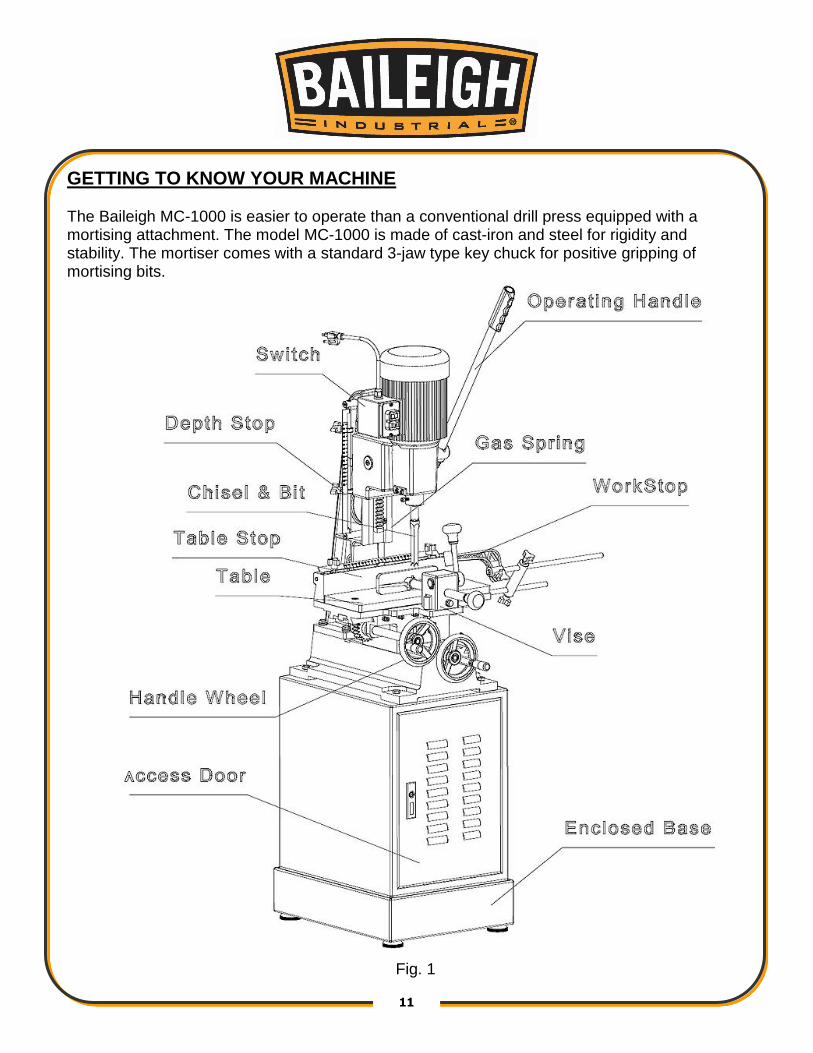
GETTING TO KNOW YOUR MACHINE The Baileigh MC-1000 is easier to operate than a conventional drill press equipped with a mortising attachment. The model MC-1000 is made of cast-iron and steel for rigidity and stability. The mortiser comes with a standard 3-jaw type key chuck for positive gripping of mortising bits.
Fig. 1

12 12
Label Placement

13 13
INSTALLATION
IMPORTANT:
Consider the following when looking for a suitable location to place the machine:
Overall weight of the machine.
Weight of material being processed.
Sizes of material to be processed through the machine.
Space needed for auxiliary stands, work tables, or other machinery.
Clearance from walls and other obstacles.
Maintain an adequate working area around the machine for safety.
Have the work area well illuminated with proper lighting.
Keep the floor free of oil and make sure it is not slippery.
Remove scrap and waste materials regularly, and make sure the work area is free from obstructing objects.
If long lengths of material are to be fed into the machine, make sure that they are safely supported and will not extend into any aisles.
Securing the Base
The machine should be sited on a level, concrete floor. The accuracy of any machine depends on the precise placement of it to the mounting surface. Place shims under the four feet mounted in the base as required for leveling. Using the holes in the mortiser base, the mortiser should be secured to the stand with four M12 x 120 hex head screws provided. Make sure there is enough room on each side of the mortiser for the size stock you plan to use.
WARNING: Before operating; make sure it is positioned firmly on a solid
level floor. If it tips over on you, it could cause severe injury or death.

14 14
ASSEMBLY
1. Assemble the handle into the hub Fig. 2.
2. Raise mortising machine head to the up position by lifting the handle.
3. Assemble the handwheels onto the crankshafts.
4. Install the wooded table onto the metal table.
5. Install the stop assembly onto the table.
Fig 2
WARNING: FOR YOUR OWN SAFETY, DO NOT CONNECT THE MACHINE
TO THE POWER SOURCE UNTIL THE MACHINE IS COMPLETELY ASSEMBLED AND
YOU READ AND UNDERSTAND THE ENTIRE INSTRUCTION MANUAL.

15 15
ELECTRICAL
Motor Specifications Your tool is wired for 110 volt, 60Hz alternating current. Before connecting the tool to the power source, make sure the machine is cut off from power source. Connections
A separate electrical circuit should be used for your tools. If an extension cord is used, use only 3-wire extension cords, which have grounding type plugs and receptacles, which accept the tool’s plug. Before connecting the motor to the power line, make sure the switch is in the “OFF” position and be sure that the electric current is of the same characteristics as indicated on the tool.
All line connections should make good contact. Running on low voltage will damage the motor.
In the event of a malfunction or breakdown, grounding provides a path of least resistance for electric current to reduce the risk of electric shock. This tool is equipped with an electric cord having an equipment-grounding conductor and a grounding plug. The plug must be plugged into a matching outlet that is properly installed and grounded in accordance with all local codes and ordinances.
Do not modify the plug provided - if it will not fit the outlet, have the proper outlet installed by a qualified electrician.
Improper connection of the equipment-grounding conductor can result in risk of electric
shock. The conductor with insulation having an outer surface that is green with or without yellow stripes is the equipment-grounding conductor. If repair or replacement of the electric cord or plug is necessary, do not connect the equipment-grounding conductor to a live terminal.
CAUTION: HAVE ELECTRICAL UTILITIES CONNECTED TO MACHINE BY
A CERTIFIED ELECTRICIAN!
Check if the available power supply is the same as listed on the machine nameplate.
WARNING: Make sure the grounding wire (green) is properly connected
to avoid electric shock. DO NOT switch the position of the green grounding wire if
any electrical plug wires are switched during hookup.
WARNING: IN ALL CASES, MAKE CERTAIN THE RECEPTACLE IN
QUESTION IS PROPERLY GROUNDED. IF YOU ARE NOT SURE, HAVE A QUALIFIED
ELECTRICIAN CHECK THE RECEPTACLE.
16 16
Check with a qualified electrician or service personnel if the grounding instructions are not completely understood, or if in doubt as to whether the tool is properly grounded.
Use only 3-wire extension cords that have grounding type plugs and receptacles that accept the tool’s plug.
Repair or replace damaged or worn cord immediately.
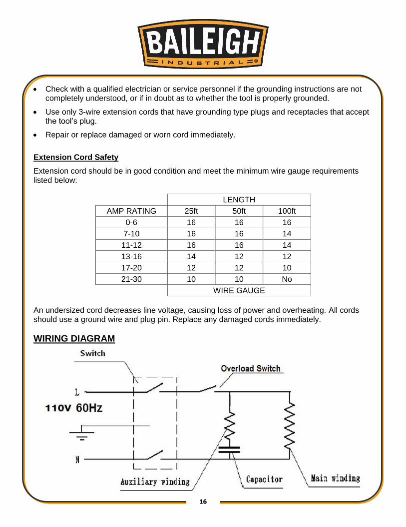
Extension Cord Safety
Extension cord should be in good condition and meet the minimum wire gauge requirements listed below:
LENGTH
AMP RATING 25ft 50ft 100ft
0-6 16 16 16
7-10 16 16 14
11-12 16 16 14
13-16 14 12 12
17-20 12 12 10
21-30 10 10 No
WIRE GAUGE
An undersized cord decreases line voltage, causing loss of power and overheating. All cords should use a ground wire and plug pin. Replace any damaged cords immediately.
WIRING DIAGRAM

17 17
OPERATING CONTROLS AND ADJUSTMENTS
1. Set depth stop to the required
depth of cut. See Figure 4.
Fig 4 2. Place workpiece on table and clamp it with the vise. Use the left handwheel to move table
forward or backward to suit the position of the mortise on the workpiece.
3. Adjust the table stops, Figure 5, according to the length of cut required, and then tighten the thumb screws.
Fig 5
CAUTION: Always wear proper eye protection with side shields, safety
footwear, and leather gloves to protect from , chips, dust, burrs, and slivers.
18 18
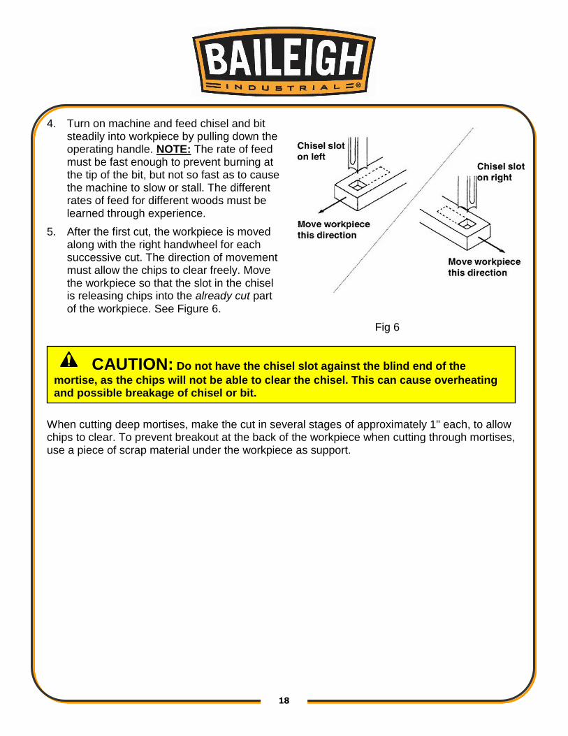
4. Turn on machine and feed chisel and bit steadily into workpiece by pulling down the operating handle. NOTE: The rate of feed must be fast enough to prevent burning at the tip of the bit, but not so fast as to cause the machine to slow or stall. The different rates of feed for different woods must be learned through experience.
5. After the first cut, the workpiece is moved along with the right handwheel for each successive cut. The direction of movement must allow the chips to clear freely. Move the workpiece so that the slot in the chisel is releasing chips into the already cut part of the workpiece. See Figure 6.
Fig 6
When cutting deep mortises, make the cut in several stages of approximately 1" each, to allow chips to clear. To prevent breakout at the back of the workpiece when cutting through mortises, use a piece of scrap material under the workpiece as support.
CAUTION: Do not have the chisel slot against the blind end of the
mortise, as the chips will not be able to clear the chisel. This can cause overheating and possible breakage of chisel or bit.

19 19
Installing Chisel and Bit
1. Loosen lock screw, shown in Figure 7.
2. Insert chisel bushing (with the hole facing forward) into the head. Tighten the screw just enough to hold the chisel in place.
Note: Set the slot in the side of the chisel to the left or right, NOT to the front or back. This will allow chips to escape when cutting mortises.
Fig 7 3. Push the chisel up as far as possible into the head. Then lower the chisel approximately
1/32” – 1/16” (0.8mm to 1.6mm), depending on the type of wood being worked. Tighten the screw to hold chisel in place.
4. Push bit up through the chisel opening as far as it will go. Lock the drill bit in place with the chuck key.
5. Loosen screw and push chisel up against the bushing, then tighten screw. This should provide the proper distance between the points of the chisel and the bit.
20 20
MAINTENANCE The Mortiser requires only minor maintenance, such as cleaning and lubrication and routine adjustment and sharpening of the chisel and bit. Dust the machine down after each use and, as necessary, use light applications of oil or grease to lubricate linkages, moving parts, etc. Sharpening Chisel and Bit
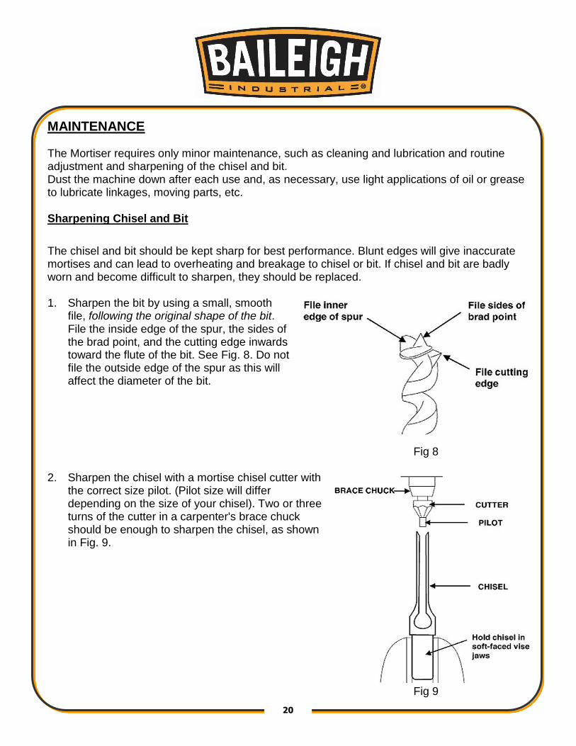
The chisel and bit should be kept sharp for best performance. Blunt edges will give inaccurate mortises and can lead to overheating and breakage to chisel or bit. If chisel and bit are badly worn and become difficult to sharpen, they should be replaced. 1. Sharpen the bit by using a small, smooth
file, following the original shape of the bit. File the inside edge of the spur, the sides of the brad point, and the cutting edge inwards toward the flute of the bit. See Fig. 8. Do not file the outside edge of the spur as this will affect the diameter of the bit.
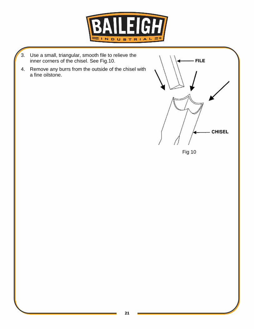
Fig 8 2. Sharpen the chisel with a mortise chisel cutter with
the correct size pilot. (Pilot size will differ depending on the size of your chisel). Two or three turns of the cutter in a carpenter's brace chuck should be enough to sharpen the chisel, as shown in Fig. 9.
Fig 9
21 21
3. Use a small, triangular, smooth file to relieve the inner corners of the chisel. See Fig.10.
4. Remove any burrs from the outside of the chisel with a fine oilstone.
Fig 10

22 22
PARTS DIAGRAM

23 23
Parts List - Mortiser
Item Description Qty. Item Description Qty.
A-1 Base 1 A-61 Screw, M6 x 10 1
A-2 Middle Base 1 A-62 Cover 1
A-3 Drift 1 A-63 Gear 1
A-4 Set Screw, M6 x 35 4 A-64 Shaft 1
A-5 Hex Nut, M6 4 A-65 Connecting Bend 1
A-6 Washer, 10 4 A-66 Spring 1
A-7 Wave Washer, 10 4 A-67 Screw 1
A-8 Cap Screw, M10 x 40 4 A-68 Headstock 1
A-9 Column 1 A-69 Screw 1
A-10 Screw 1 A-70 Ruler mark 1
A-11 Gas Spring 1 A-71 Screw 1
A-12 Set Screw, M6 x 35 3 A-72 Setting Collar 1
A-13 Hex Nut, M6 3 A-73 Screw, M4 x 12 2
A-14 Drift 1 A-74 Setting Rod 1
A-15 Screw 1 A-75 Setting Collar 1
A-16 Rack 1 A-76 Screw, M6 x 25 1
A-17 Screw,M6 x 10 4 A-77 Bushing 1
A-18 Fence 1 A-78 Mistising Chisel and Bit 1
A-19 Washer, 10 4 A-79 Pin 1
A-20 Wave Washer, 10 4 A-80 Clamp Plate 1
A-21 Cap Screw, M10 x 25 4 A-81 Spring 1
A-22 Localizer 1 A-82 Spring Cover 1
A-23 Washer, 6 2 A-83 Handle 1
A-24 Screw, M6 x 15 2 A-84 Cover 1
A-25 Screw, M6 x 10 2 A-85 Screw, M5 x 10 4
A-26 A-86 Cover Base 2
A-27 Hex Nut, M10 1 A-87 C—Spring C-20 2
A-28 Washer, 10 1 A-88 Handle 1
A-29 Screw 1 A-89 Shaft 1
A-30 Screw 1 A-90 Clamping Block 1
A-31 Setting Collar 1 A-91 Nut, M10 1
A-32 Setting Rod 1 A-92 Screw, M8 x 25 2
A-33 Setting Collar 1 A-93 Locking Shaft 1

24 24
Item Description Qty. Item Description Qty.
A-34 Hex Nut, M10 1 A-94 Handle 1
A-35 Washer, 10 1 A-95 Wood Table 1
A-36 Screw 1 A-96 Screw, M8 x 25 2
A-37 Screw, M6 x 15 1 A-97 Table 1
A-38 Screw 1 A-98 Washer, 10 2
A-39 Screw, M4 x 12 1 A-99 Screw, M10 x 25 2
A-40 Depth Ruler 1 A-100 Rack 1
A-41 Screw, M4 x 12 1 A-101 Screw, M6 x 10 3
A-42 Screw, M6 x 15 1 A-102 Gear 1
A-43 Screw, M6 x 15 2 A-103 Drift 1
A-44 Washer, 6 2 A-104 Nut, M6 4
A-45 Localizer 1 A-105 Screw, M6 x 15 4
A-46 Hex Nut, M12 1 A-106 Pin 1
A-47 Washer, 12 1 A-107 Gear Shaft 1
A-48 Spring 1 A-108 Collar 1
A-49 Washer, 14 1 A-109 Handwheel 1
A-50 Connecting Bend 1 A-110 Screw, M8 x 10 1
A-51 Handle 1 A-111 Handwheel 1
A-52 Motor 1 A-112 Screw, M8 x 10 1
A-53 Handle Grip 1 A-113 Collar 1
A-54 Power Cord 1 A-114 Lead Screw 1
A-55 Strain Relief Bushing 1 A-115 Lead Nut 1
A-56 Switch Box 1 A-116 Washer 10 2
A-57 Switch 1 A-117 Screw, M10 x 25 2
A-58 Washer 1 A-118 Screw, M8 x 25 1
A-59 Screw, M6 x 25 4 A-119 Screw, M8 x 25 1
A-60 Chuck, 16mm 1 A-120 Pin 1

25 25
PARTS LIST FOR STAND ASSEMBLY
Item Description Qty.
B-1 Base 1
B-2 Stand 1
B-3 Door 1
B-4 Door Latch 1
B-5 Hex Nut, M10 4
B-6 Stand Base 4
B-7 Hex Nut, M10 4
B-8 Washer , 10 4
B-9 Wave Washer 10 4
B-10 Cap Screw, M12 x 40 4
26 26
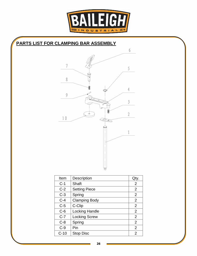
PARTS LIST FOR CLAMPING BAR ASSEMBLY
Item Description Qty.
C-1 Shaft 2
C-2 Setting Piece 2
C-3 Spring 2
C-4 Clamping Body 2
C-5 C-Clip 2
C-6 Locking Handle 2
C-7 Locking Screw 2
C-8 Spring 2
C-9 Pin 2
C-10 Stop Disc 2

27 27
PARTS LIST FOR WORK STOP ASSEMBLY
Item Description Qty. Item Description Qty.
D-1 Table 1 D-8 Length Setting Block 1
D-2 Cap Screw M6 x 25 2 D-9 Handle Screw (big) 1
D-3 Rear Length Setting Rod 1 D-10 Nut M6 1
D-4 Handle Screw 1 D-11 Stop Disc 1
D-5 Handle Screw (big) 1 D-12 Front Length Setting Rod 1
D-6 C-Clip 1 D-13 Washer 1
D-7 C-Clip 1 D-14 Stop Disc

28 28
NOTES

29 29
NOTES

30 30
BAILEIGH INDUSTRIAL, INC. 1625 DUFEK DRIVE MANITOWOC, WI 54220 PHONE: 920. 684. 4990 FAX: 920. 684. 3944
WWW.BAILEIGHINDUSTRIAL.COM
BAILEIGH INDUSTRIAL, INC. 1455 S. CAMPUS AVENUE ONTARIO, CA 91761 PHONE: 920. 684. 4990 FAX: 920. 684. 3944
BAILEIGH INDUSTRIAL LTD. UNIT 1 FULLWOOD CLOSE ALDERMANS GREEN INDUSTRIAL ESTATE COVENTRY, CV2 2SS UNITED KINGDOM
PHONE: +44 (0)24 7661 9267 FAX: +44 (0)24 7661 9276 WWW.BIFABUK.CO.UK
BAILEIGH INDUSTRIAL GMBH HOFENER STRAßE 64 70736 FELLBACH
DEUTCHSLAND WWW.BAILEIGHINDUSTRIAL.DE
Related Documents


![BIOENERGY MARKET ADJUSTING TARIFF POWER ...Seller’s Name], a [include place of formation and business type] (“Seller”) Name: Pacific Gas and Electric Company, a California corporation](https://static.cupdf.com/doc/110x72/5b4436b37f8b9a38048bca6f/bioenergy-market-adjusting-tariff-power-sellers-name-a-include-place-of.jpg)
