OPERATOR MANUAL Includes Safety, Service and Replacement Part Information Model MDF15 and MDF35 Long Reach Air Tool Form: GOM6019801 Version 1.0 Do not discard this manual. Before operation, read and comprehend its contents. Keep it readily available for reference during operation or when performing any service related function. When ordering replacement parts, please supply the following information: model number, serial number and part number. For customer service assistance, telephone 800.533.0524, +507.451.5510. Our Customer Service Department telefax number is 877.344.4375 (DIGGER 5), +507.451.5511. There is no charge for customer service activities . Internet address: http://www.generalequip.com. E-Mail location: [email protected]. Copyright 2003, General Equipment Company.

Welcome message from author
This document is posted to help you gain knowledge. Please leave a comment to let me know what you think about it! Share it to your friends and learn new things together.
Transcript

OPERATOR MANUALIncludes Safety, Service and Replacement Part Information
Model MDF15 and MDF35Long Reach Air Tool
Form: GOM6019801Version 1.0
Do not discard this manual. Before operation, read andcomprehend its contents. Keep it readily available for reference
during operation or when performing any service relatedfunction. When ordering replacement parts, please supply thefollowing information: model number, serial number and part
number. For customer service assistance, telephone800.533.0524, +507.451.5510. Our Customer Service Department
telefax number is 877.344.4375 (DIGGER 5), +507.451.5511.There is no charge for customer service activities .
Internet address: http://www.generalequip.com.E-Mail location: [email protected].
Copyright 2003, General Equipment Company.


Manufacturers of light construction equipment
620 Alexander Drive SW • P.O. Box 334 • Owatonna, Minnesota 55060-0334 USATelephone: 800.533.0524 • International Telephone: +507.451.5510
Telefax: +507.451.5511 • Sales/Customer Service Department Toll Free: 877.344.4375 (DIGGER 5)http://www.generalequip.com • e-mail: [email protected]
Congratulations on your decision to purchase a General light construction product. From ourhumble beginnings in 1955, it has been a continuing objective of General Equipment Company tomanufacture equipment that delivers uncompromising value, service life and investment return.Because of this continuous commitment for excellence, many products bearing the General nameactually set the standards by which competitive products are judged.
When you purchased this product, you also gained access to a team of dedicated andknowledgeable support personnel that stand willing and ready to provide field supportassistance. Our team of sales representatives and inhouse factory personnel are available toensure that each General product delivers the intended performance, value and investment return.Our personnel can readily answer your concerns or questions regarding proper applications,service requirements and warranty related problems.
General Equipment Company places great emphasis upon not only product performance, but alsoon product safety. It is important to remember that this product will only be as safe as the operatorswhich utilize it. It just makes good, common sense to take the time to read and fully understand thecontents of this manual before attempting to utilize this product in service. If you ever do have anyquestions or concerns about this product, please feel free to contact our Customer ServiceDepartment at the telephone numbers listed below for assistance.
If there is anything that I can do to assist your efforts when utilizing this product, please do nothesitate to contact me. For assistance after normal business hours, telephone me at 507.451.9409or 507.363.1033. If I am not immediately available, I will attempt to return your call as soon aspossible.
Sincerely,
GENERAL EQUIPMENT COMPANY
Dennis Von RudenPresident

DESCRIPTION PAGE
Notice to Operators
Operational Instructional Data Sheet
Safety PrecautionsPREPARATION.OPERATION.MAINTENANCE, REPAIR AND STORAGE.
AssemblyINSTALLING THE AIR HOSE ASSEMBLY.
Before Operating the Long Reach Air ToolINFORMATION RELATIVE TO MINIMUM SAFETY, OPERATIONALSTANDARDS AND PARAMETERS FOR THE USE OF THE LONG REACHAIR TOOL.INSTALLING THE MODEL MDF-1000 AIR CADDY.
OperationOPERATIONAL DISCLAIMER.CALIFORNIA PROPOSITION 65 DISCLAIMER.SAFETY RELATED EQUIPMENT AND APPAREL DISCLAIMER.SET UP FOR OPERATION.DETERMINATION OF POTENTIAL SUBSURFACE HAZARDS IN THEPROPOSED WORK LOCATION(S).INSTALLING AN ACCESSORY TOOL.ATTACHING THE LONG REACH AIR TOOL TO THE AIR CADDY AND AIRHOSE ASSEMBLIES.OPERATING THE LONG REACH AIR TOOL.STOPPING THE LONG REACH AIR TOOL.TEMPORARY STORAGE FOR THE LONG REACH AIR TOOL WHILE ONTHE JOB SITE.
Troubleshooting
RepairDISASSEMBLY OF THE CYLINDER ASSEMBLY FOR GENERALMAINTENANCE AND/OR REPAIR PURPOSES.DISASSEMBLY OF THE THROTTLE CONTROL VALVE FOR GENERALMAINTENANCE AND/OR REPAIR PURPOSES.
4
5
7789
1010
12
1213
1414151515
1616
182023
23
23
24
24
26
Table of Contents
MDF Series LONG REACH AIR TOOLS FORM GOM6019801, VERSION 1.0, AUTHORIZATION: DVR, PAGE: 2

MDF SERIES LONG REACH AIR TOOLS FORM GOM6019801, VERSION 1.0, AUTHORIZATION: DVR, PAGE: 3
DESCRIPTION PAGE
Storage
Specifications
Replacement Parts Diagrams
Accessory Tool Applications Chart
26
27
29
40

Notice to OperatorsIF YOU CAN NOT READ OR DO NOT FULLY UNDERSTAND THE CONTENTS OF THISMANUAL, PLEASE CONTACT THE FACTORY FOR PROPER ASSISTANCE BEFOREATTEMPTING TO OPERATE THIS PRODUCT.
SI TU NO PUEDES LE'ER O NO COMPRENDES EL CONTENIDO DE ESTE MANUALFAVOR DE PONERSE EN CONTACTO CON LA. FABRICA PARA ASSISTENCIA- APROPIA ANTES DE INTENTAR PARA OPERAR ESTE PRODUCTO.
SOLLTEN SIE DIESE GEBRAUCHSANWEISUNG NICHT LESEN KOENNEN ODER ESNICHT VOLLKOMMEN VERSTEHEN, WENDEN SIE SICH BITTE AN DENHERSTELLER FUER RICHTIGE HILFE EHE SIE VERSUCHEN DIESES PRODUKT ZUOPERIEREN.
SI VOUS NE LISEZ OU NE COMPRENDRE ENTIEREMENT LES MATIERES DE CEMANUEL, S'IL VOUS PLAIT, CONTACTEZ L'USINE POUR L'ASSISTANCEAPPROPRIEE AVANT D'UTILISER LE PRODUIT.
These safety alert symbols identify important safety messages in this manual. When you see thesesymbols, be alert to the possibility of personal injury and carefully read the message that follows.
Do not allow anyone to operate the Long Reach Air Tool without first reading this Operator Manual andbecoming familiar with its operation. The manufacturer of this Long Reach Air Tool has gone to greatextremes to provide the owner(s) and/or operator(s) with the finest equipment available for its intended jobfunction of removing materials from vertical and horizontal surfaces. Yet, the possibility exists that the LongReach Air Tool can be utilized in and/or subjected to job applications not perceived and/or anticipated by themanufacturer. Such misuse and/or misapplication of the Long Reach Air Tool can lead to the possibility ofserious damage, injury or even death. It is the responsibility of the owner(s) and/or operator(s) to determinethat the Long Reach Air Tool is being utilized and/or operated within the scope of its intended job function.It is the responsibility of the owner(s) and/or operator(s) to establish, monitor and constantly upgrade allsafety programs and/or practices utilized in and for the operation of the Long Reach Air Tool. The purposeof such programs is to provide for owner(s') and/or operator(s') safety. Operators must be instructed torecognize and avoid unsafe conditions associated with their work (29 CFR 1926.21 (b)(2)) and/or applicableupdated revisions. It is the responsibility of the owner(s) and/or operator(s) to determine that nomodifications and/or alterations have been made to the Long Reach Air Tool. Modifications and/oralterations can lead to the possibility of serious damage, injury or even death. It is the responsibility of theowner(s) and/or operator(s) to make this Operator Manual available for consultation during all phases ofoperation. Refer to OSHA 2207 and/or applicable updated revisions which contains all OSHA job safety andhealth rules and regulations (1926 and 1910) covering construction.
The concept of portable, pneumatically powered, long reach type air tools has been successfullyutilized for many years as a practical solution to removing materials from vertical and horizontalsurfaces. The basic concept is proven and well accepted within the associated marketplaces. Use ofa Long Reach Air Tool requires strenuous work activity. This type of work activity can be consideredto be greater in magnitude than that experienced with the use of many other types of both light
MDF Series LONG REACH AIR TOOLS FORM GOM6019801, VERSION 1.0, AUTHORIZATION: DVR, PAGE: 4

MDF SERIES LONG REACH AIR TOOLS FORM GOM6019801, VERSION 1.0, AUTHORIZATION: DVR, PAGE: 5
construction and lawn and garden related equipment. This type of work activity should only beattempted by operators of adequate physical size and stature, mental awareness and physicalstrength and condition. The body parts most noticeably affected during the material removalprocess are the arms, hands, wrists, shoulders, lower back and legs. The process can also produceexcessive stress/strain directly to the back muscles, spinal vertebrae and many other body parts.Back and wrist related pain can be side effects of utilizing a Long Reach Air Tool. A potentialoperator with a chronic back related problem or a history of back and/or other medically relatedproblems should not attempt to utilize the Long Reach Air Tool. Use of the Long Reach Air Tool mayonly aggravate this and any other medically related problem. Because of the diverse type ofprevailing job applications, job site conditions, operator experience levels and operator physicalcharacteristics, no warranty, guarantee, representation and/or liability is made by the manufactureras to the absolute correctness or sufficiency of any operational procedure, operational positionand/or technique. There is no absolute guarantee that an operator of any given experience level,physical size and/or physical condition will be immune to the possibility of and/or probable physicalside effects of the normal use of the Long Reach Air Tool. Each potential operator must be madeaware of and assume the operational and physical liability described and/or associated with the useof the Long Reach Air Tool. Improper use of the Long Reach Air Tool can result in property damageand/or personal injury, including death. Each potential operator not willing to assume theoperational and physical liability described and/or associated with the use of the Long Reach AirTool, should not operate it. Proper levels of operator experience, skill and common sense areessential for maximizing the safe and efficient operation of the Long Reach Air Tool.
Record the Long Reach Air Tool serial number in the spaces provided below.
_______________ Model Number
_______________ Serial Number
_______________ Date of Purchase
Specifications and design are subject to change without notice or obligation. All specifications aregeneral in nature and are not intended for specific application purposes. General EquipmentCompany reserves the right to make changes in design, engineering or specifications and to addimprovements or discontinue manufacture at any time without notice or obligation. GeneralEquipment Company and its agents accept no responsibility for variations which may be evident inactual products, specifications, pictures and descriptions contained in this publication.
Operator Instructional Data SheetThe following undersigned operators of the Long Reach Air Tool described and/or pertaining to thisOperator Manual have received formal safety and operational information/instruction from theundersigned owner(s)/instructor(s) in accordance to OSHA 29 CFR 1926.21 (b)(2) and/or applicableupdated revisions pertaining to, but not necessarily limited to the:
1) READING, COMPREHENSION AND ACKNOWLEDGEMENT OF THE MATERIAL COMPRISING THEENTIRE CONTENTS OF THE APPLICABLE OPERATOR MANUAL AND THE APPLICABLE SAFETY ANDOPERATIONAL INFORMATION VIDEO TAPE FOR THE LONG REACH AIR TOOL.
2) FORMALIZED OPERATOR SAFETY PROGRAM TO BE DEVISED BY THE OWNER OF THE LONGREACH AIR TOOL IN CONJUNCTION WITH THE CONTENTS OF THE APPLICABLE OPERATOR

MDF SERIES LONG REACH AIR TOOLS FORM GOM6019801, VERSION 1.0, AUTHORIZATION: DVR, PAGE: 6
MANUAL AND THE APPLICABLE SAFETY AND OPERATIONAL INFORMATION VIDEO TAPE FOR THELONG REACH AIR TOOL.
3) OSHA RULES AND REGULATIONS RESEARCHED FOR AND/OR BY THE OWNER OF THE LONGREACH AIR TOOL AND DEEMED APPLICABLE TO THE SAFE AND PROPER USE AND/OROPERATION OF THE LONG REACH AIR TOOL FOR ANY SPECIFIC JOB APPLICATION.
4) LOCAL LAWS, REGULATIONS AND CUSTOMS RESEARCHED FOR AND/OR BY THE OWNER OFTHE LONG REACH AIR TOOL AND DEEMED APPLICABLE TO THE SAFE AND PROPER USE AND/OROPERATION OF THE LONG REACH AIR TOOL FOR ANY SPECIFIC JOB APPLICATION.
5) FORMALIZED MAINTENANCE PROGRAM FOR THE LONG REACH AIR TOOL TO BE DEVISED BYTHE OWNER OF THE LONG REACH AIR TOOL IN ACCORDANCE WITH, BUT NOT NECESSARILYLIMITED TO, THE SPECIFICATIONS, GUIDELINES AND OPERATIONAL INFORMATION CONTAINEDIN THE APPLICABLE OPERATOR MANUAL.
6) COMPREHENSIVE OPERATIONAL INSTRUCTIONS FOR THE CORRECT AND PROPER USE OFTHE LONG REACH AIR TOOL AS PER THE CONTENTS OF THE APPLICABLE OPERATOR MANUALAND THE APPLICABLE SAFETY AND OPERATIONAL INFORMATION VIDEO TAPE.
_______________ Operator _______________ Owner/Instructor __________ Date
_______________ Operator _______________ Owner/Instructor __________ Date
_______________ Operator _______________ Owner/Instructor __________ Date
_______________ Operator _______________ Owner/Instructor __________ Date
_______________ Operator _______________ Owner/Instructor __________ Date
_______________ Operator _______________ Owner/Instructor __________ Date
NOTE: INSERT COPIES OF THIS PAGE WITHIN THE OPERATOR'S MANUAL IF SPACE FORADDITIONAL OPERATORS IS REQUIRED.

Safety Precautions
THE FOLLOWING SAFETY PRECAUTIONSPROVIDE SOME COMMON SENSE GUIDES TOPROMOTE SAFETY AND EFFICIENCY WITH THELONG REACH AIR TOOLS. NO WARRANTY,GUARANTEE OR REPRESENTATION IS MADE BYTHE MANUFACTURER AS TO THE ABSOLUTECORRECTNESS OR SUFFICIENCY OF ANYINFORMATION OR STATEMENT. THESE SAFETYPRECAUTIONS ARE INTENDED TO DEALPRINCIPALLY WITH COMMON PRACTICES ANDCONDITIONS ENCOUNTERED IN THE USE OF THELONG REACH AIR TOOLS AND ARE NOTINTENDED TO BE ALL INCLUSIVE. PROPERLEVELS OF OPERATOR EXPERIENCE, SKILL ANDCOMMON SENSE ARE ESSENTIAL FOR SAFE ANDEFFICIENT OPERATION.
THE BY PRODUCTS CREATED FROM THEOPERATION OF LONG REACH AIR TOOLS CANCONTAIN CHEMICALS KNOWN TO THE STATE OFCALIFORNIA TO CAUSE CANCER, BIRTHDEFECTS OR OTHER REPRODUCTIVE HARM.THIS STATEMENT IS MADE IN COMPLIANCE TOCALIFORNIA PROPOSITION 65.
INCORRECT USE OF THE LONG REACH AIR TOOLCAN RESULT IN PROPERTY DAMAGE, PERSONALINJURY OR EVEN DEATH. TO REDUCE THISPOSSIBILITY, GIVE COMPLETE AND UNDIVIDEDATTENTION TO THE JOB AT HAND AND FOLLOWTHESE SAFETY PRECAUTIONS:
PREPARATION.
1) The Long Reach Air Tools are a specialized type ofpowered equipment, designed for specific job functionsand require adequate and thorough instructionBEFORE they are operated. The size, power,complexity and operating characteristics of these typesof powered equipment would dictate that each operator
must receive adequate, professional instructionregarding the proper operation of the Long Reach AirTool before being allowed to utilize it. BEFOREattempting to utilize a Long Reach Air Tool read thisOperator's Manual and watch the applicable Safetyand Operational Information Video Tape to familiarizeeach operator with its correct operating procedures.Avoid the urge not to take the necessary time to readthis Operator's Manual before operating the LongReach Air Tool. DO NOT OPERATE THE LONGREACH AIR TOOL UNTIL EACH OPERATORCOMPLETELY COMPREHENDS THE CONTENTSOF THIS MANUAL, THE APPLICABLE SAFETY ANDOPERATIONAL INFORMATION VIDEO TAPE, ANDAPPLICABLE SUPPLEMENTAL INFORMATION.
2) Develop a comprehensive program for the safeoperation of the Long Reach Air Tool by its owner(s)and/or operator(s). Such a program will include, but isnot limited to: instructional requirements for operation,applicable OSHA requirements, local laws andregulations, job site safety and a Long Reach Air Toolmaintenance program. Constantly examine andupgrade this program to guarantee owner(s) and/oroperator(s) safety. Each operator must be fullyinstructed regarding the specifics of this safetyprogram.
3) Determine that the Long Reach Air Tool is in itsoriginal, factory configuration and has not beenmodified in any manner. Many modifications can resultin potentially dangerous configurations that can lead toproperty damage and/or personal injury. If there areany questions about possible modifications made tothe Long Reach Air Tool, contact the Customer ServiceDepartment for specific information BEFOREutilization. There is no charge for this service.
4) Minors should never be allowed to operate the LongReach Air Tool. Bystanders, especially children andanimals, should not be allowed in the area where theLong Reach Air Tool is in use. The hole diggingprocess can result in flying particles being emitted athigh velocity and striking the operator and/oronlookers. This can lead to the possibility of propertydamage and/or personal injury. Keep all body parts,loose clothing, foreign objects and onlookers clear ofthe rotating auger and/or auger extensions.
5) Operators must be in proper physical condition,mental health and not under the influence of anysubstance (drugs, alcohol, etc.) which might impairvision, dexterity or judgment. Working with the LongReach Air Tool is strenuous. If you have any conditionthat might be aggravated by strenuous work, check
MDF SERIES LONG REACH AIR TOOLS FORM GOM6019801, VERSION 1.0, AUTHORIZATION: DVR, PAGE: 7

with your doctor BEFORE operating the Long ReachAir Tool. Guard against the possibility of back relatedinjuries. Always lift the Long Reach Air Tool with legmuscles and not with the back.
6) Prolonged use of the Long Reach Air Tool (or other,similar machines) exposes the operator to vibrationswhich may produce Whitefinger Disease (Raynaud'sPhenomenon). This phenomenon reduces the hand'sability to feel and regulate temperature, producesnumbness and burning sensations and may causenerve and circulation damage and tissue necrosis.Antivibration systems do not guarantee that you will notsustain Whitefinger Disease. Therefore, continuousand regular users should closely monitor the conditionof their hands and fingers. After each period of use,exercise to restore normal blood circulation. If any ofthe symptoms appear, seek medical adviceimmediately. It is recommended that special gloves,designed to reduce the effects of Whitefinger Diseasebe worn whenever possible and practical. Contact theCustomer Service Department for additionalinformation. There is no charge for this service.
7) Clothing must be sturdy and snug fitting, but allowcomplete freedom of movement. Never wear loosefitting jackets, scarves, neckties, jewelry, flared orcuffed pants or anything that could become caught oncontrols or moving parts. Wear long pants to protectyour legs. Protect your hands with heavy duty, nonslipgloves to improve your grip. Good footing is mostimportant when operating the Long Reach Air Tool.Wear sturdy boots with nonslip soles. Steel-toed safetyshoes are highly recommended. Keep shoes properlylaced. Never wear tennis shoes or other, similar typeshoes which afford little or no protection. Wear anapproved safety hard hat to protect the operator'(s')head(s) where there is a danger of head injuries. Noisegenerated by the Long Reach Air Tool and the actualoperating process itself can damage your hearing.Wear approved sound barriers (ear plugs or earmufflers) to protect your hearing. Continuous andregular operators should have their hearing checkedregularly.
8) Visually inspect the Long Reach Air Tool andaccessory tools for damaged or worn parts. Look forloose and/or damaged handle grips. Check for looseand/or broken parts. Determine that operator controlswork freely, all safety devices are operative andinformation/safety decals are readable. Check todetermine that the Long Reach Air Tool and all relatedaccessories are in good mechanical conditionBEFORE utilization.
9) Contact appropriate representatives to determineif/where electrical cables, gas lines and otherhazardous items are buried under the work surfaceBEFORE utilization. The Long Reach Air Tool andrelated accessories are not classified as beinginsulated. Contact with buried electrical cables, gaslines and other hazardous items can result inelectrocution and/or an explosion.
10) Know how the controls operate. Know how to stopthe Long Reach Air Tool quickly in an emergency.
11) Never exceed the recommended capacities of theLong Reach Air Tool. Refer to the Specificationssection of this manual for more detailed information.Always utilize the correct accessory tool designed foruse with the Long Reach Air Tool. Use of an incorrectaccessory tool can result in property damage and/orpersonal injury.
OPERATION.
1) Give complete and undivided attention to the job athand. Do not chew gum, smoke and/or use smokelesstobacco while utilizing the Long Reach Air Tool. Do notattempt to eat and/or drink while utilizing the LongReach Air Tool. Determine that eyeglasses, hearing aiddevices and other medical related devices are properlysecured. Keep shoes properly laced. Use of the LongReach Air Tool is strenuous and causes fatigue. Helpprevent the cause of an accident. Plan to take workbreaks as required to help maintain proper mental andphysical alertness.
2) The MDF Series Long Reach Air Tools are notsealed or insulated. Do not operate any Long ReachAir Tool in an explosive atmosphere or nearcombustible materials. Refer to current OSHA andNational Electric Code® rules and regulations.
3) The MDF Series Long Reach Air Tools are designedfor use by one operator. Use of the Long Reach AirTool by more then one operator can lead to confusionand loss of control, resulting in property damage and/orpersonal injury. Never operate the Long Reach Air Toolwith an improper number of operators. If it is felt thatmore than one operator is required to furnish additional"down pressure" to the accessory tool STOP andcontact the Customer Service Department for specificoperational and service/maintenance information.There is no charge for this service.
4) Do not operate the Long Reach Air Tool withonlookers close by. Caution all onlookers to standclear. The operational process can result in flying
MDF SERIES LONG REACH AIR TOOLS FORM GOM6019801, VERSION 1.0, AUTHORIZATION: DVR, PAGE: 8

particles being emitted at high velocity and striking theoperator and/or onlookers. This can lead to thepossibility of property damage and/or personal injury.Keep all body parts, loose clothing and foreign objectsclear of the accessory tool.
5) Do not utilize a shovel and/or foreign object toremove loose material from around the work area whilethe Long Reach Air Tool is in use. Such a practice canresult in the shovel and/or foreign object to becomeentrapped by the accessory tool, leading to propertydamage and/or personal injury.
6) Operate the Long Reach Air Tool only in a wellventilated area. Dusts created as a by product of theoperating process can be hazardous. Breathing thesedusts can result in property damage and/or personalinjury. Operate the Long Reach Air Tool onlywhen/where visibility and light are adequate for the jobat hand. Work carefully. Always hold the Long ReachAir Tool firmly with both hands. Wrap your fingersaround the barrel, keeping it cradled between yourthumbs and fingers. Always make sure the handlegrips are in good condition and free of moisture, pitch,oil or grease. Wear gloves to improve your grip. Neverleave the Long Reach Air Tool operating unattended.
7) Stop the Long Reach Air Tool when moving it on thejob site. Allowing the Long Reach Air Tool to remainoperating while moving it substantially increases thepotential for property damage and/or personal injury.Special care must be exercised on slippery conditionsand on difficult, uneven surfaces. Watch for cracks,high spots and other, surface irregularities. Keepproper footing and balance at all times. The normal useof the Long Reach Air Tool is on level surfaces. Otherterrains can be dangerous and should be avoided.Only properly trained operators should attempt thesetechniques.
8) Because the Long Reach Air Tool is classified as alow cost, hand held, portable type machine, it is limitedin the number of practical and/or suitable jobapplications. A particular job site, actual surfaceconditions, job specifications and operatorskill/common sense may dictate that a different type ofmachine (with characteristics of higher purchase cost,being mounted to a carrier vehicle, with greaterhorsepower and less mobility), method and/or processbe utilized to properly complete the job with the degreeof efficiency and safety required. Contact the CustomerService Department for specific information regardingsuitable job applications, job site surface conditionsand operator experience/skill/common senserecommendations for the Long Reach Air ToolBEFORE utilization. There is no charge for this service.
MAINTENANCE, REPAIR AND STORAGE.
1) Use only genuine, approved replacement parts andaccessories for maintenance and repair. Use of partsand accessories manufactured by others can result inproperty damage and/or personal injury.
2) Follow the Service instructions as outlined in theappropriate section of this manual.
3) Always stop and disconnect the compressed airsource BEFORE checking or working on the LongReach Air Tool.
4) Always properly maintain the Long Reach Air Tool.Frequently check all fasteners and individual parts.Built in safety features are effective only if they aremaintained in good working condition. Replace anyquestionable part or assembly with a genuine, factoryapproved, replacement part. Do not forsake propermaintenance for the price of a few replacement parts.Proper maintenance does not cost...it actually paysdividends. Do not attempt any maintenance repairwork not described in this manual. Have such workperformed at your dealer's service facility.
5) Determine the throttle control is not damaged andallows for complete freedom of movement to allow it toperform its intended job function. Do not operate theLong Reach Air Tool with a damaged throttle control.
6) Maintain all safety and operation decals in propercondition. If any decal becomes damaged and/orunreadable, replace with a genuine, factory approved,replacement part only.
7) The Long Reach Air Tool may utilize self locking typehexagon head nuts to minimize the effects of vibration.Replace all self locking hardware with genuine, factoryapproved, replacement parts only.
8) Replace the accessory tool when signs of excessivewear is seen. When such components are not replacedat proper intervals, excessive wear will occur. Utilizingaccessory tools that are past their useful service life orthat have not been properly maintained can result insubstandard productivity, excessive property damageand/or personal injury. Accessory tool service life canbe greatly extended with a consistent maintenanceprogram.
MDF SERIES LONG REACH AIR TOOLS FORM GOM6019801, VERSION 1.0, AUTHORIZATION: DVR, PAGE: 9
Assembly
Open the shipping carton immediately upon receipt.Visually inspect the contents of the carton for freightdamage and/or missing parts. If shipping damage isevident, contact the delivering carrier immediately toarrange for an inspection of the damage by their claimsrepresentative. Federal law requires that a claim befiled within a specific time period. If missing parts aredetected, notify your dealer or contact the CustomerService Department for assistance in obtaining them.
Included in the shipment for all models of Long ReachAir Tools should be the following:
1 each, Long Reach Air Tool Assembly.1 each, air hose assembly, complete with support
spring.
Accessory tools and/or replacement parts will beshipped in separate shipping containers.
INSTALLING THE AIR HOSE ASSEMBLY.
Applications: All models.
Tools Required:
1 each, long nose pliers.1 each, small, adjustable wrench.
Parts Required:
1 each, 1/4 inch female quick type coupling device of operator's choice, complete with appropriate retention mechanism.
The Long Reach Air Tool is shipped from the factorycomplete with a 60 inch nominal length air hoseassembly. No device for direct coupling to the airsource is provided, given the variances in job siteapplications, available power sources andmechanisms for delivering the required air flow to theair tool.
All coupling devices utilized with the air tool mustcomply with all applicable OSHA and/or industrystandards for configuration, capacity and safety.
UTILIZING COUPLING DEVICES NOT MEETINGAPPLICABLE OSHA AND/OR INDUSTRY
STANDARDS FOR CONFIGURATION, CAPACITYAND SAFETY CAN RESULT IN PROPERTYDAMAGE AND/OR PERSONAL INJURY.
The assembly of the air hose to the Long Reach AirTool will require a level working platform of sufficientsize and appropriate height.
1) Inspect the air hose to determine it is free of anycuts, tears, abrasions or other damage. If any damageis detected, replace the hose assembly with a factoryapproved replacement only. The hose material isdesigned to withstand the internal forces developed bythe specified operating pressure of the air tool.
DO NOT UTILIZE ANY HOSE MATERIAL WITH THELONG REACH AIR TOOL UNLESS IT IS OF THEIDENTICAL DIMENSIONS AND PROPERLYMARKED WITH A MINIMUM WORKING PRESSUREOF 100 PSI. USE OF IMPROPER HOSE MATERIALCAN RESULT IN PROPERTY DAMAGE AND/ORPERSONAL INJURY.
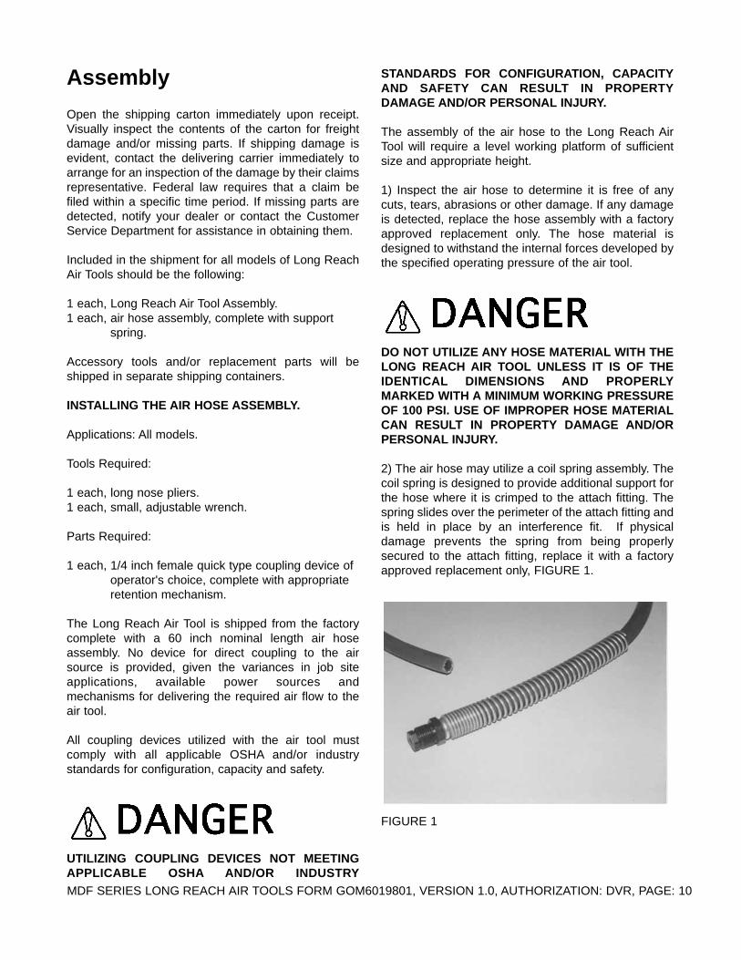
2) The air hose may utilize a coil spring assembly. Thecoil spring is designed to provide additional support forthe hose where it is crimped to the attach fitting. Thespring slides over the perimeter of the attach fitting andis held in place by an interference fit. If physicaldamage prevents the spring from being properlysecured to the attach fitting, replace it with a factoryapproved replacement only, FIGURE 1.
FIGURE 1
MDF SERIES LONG REACH AIR TOOLS FORM GOM6019801, VERSION 1.0, AUTHORIZATION: DVR, PAGE: 10

DO NOT OPERATE THE LONG REACH AIR TOOLWITHOUT THE PROPER SUPPORT SPRINGSECURED TO THE ATTACH FITTING IF THE AIRHOSE IS NOT OF THE WIRE REINFORCED TYPE.USE OF THE TOOL WITHOUT THE SUPPORTSPRING PROPERLY ATTACHED CAN RESULT INDAMAGE TO THE HOSE WHERE IT IS CRIMPED TOTHE ATTACH FITTING. SUCH AN OCCURRENCECAN RESULT IN PROPERTY DAMAGE AND/ORPERSONAL INJURY.
3) The air hose can be of a wire reinforcedconstruction. This type of material incorporates aninternal wire reinforcement similar to that of a hydraulichose. A wire reinforced air hose does not utilize anexternal support spring, FIGURE 2.
FIGURE 2
4) Using the long nose pliers, remove the protectiveclosure from the manifold. Determine the manifold isclear of dirt or any foreign material accumulation,FIGURE 3.
FIGURE 3
5) Insert the attach fitting into the manifold and securetight. There is no gasket or O type ring utilized forsealing purposes. Inspect the attach fitting andmanifold area for proper fit and security. If you feel theattach fitting and manifold do not have proper fit andsecurity, do not proceed further with the assemblyprocess. Contact the Customer Service Department forassistance. There is no charge for this service.
6) Install the coupling device of choice to the open endof the hose assembly. The coupling device must be ofthe following type:
a) Male, quick type design of sufficient capacity tocouple with the appropriate female design. The femalecoupler will immediately stop the airflow from thecompressed air source in the event that it becomesdisconnected for any reason while the air tool is in use,FIGURE 4. Various safety type lanyards can also beutilized for redundancy.
FIGURE 4
MDF SERIES LONG REACH AIR TOOLS FORM GOM6019801, VERSION 1.0, AUTHORIZATION: DVR, PAGE: 11

b) A standard air tool coupling device (sometimesreferred to as a Chicago type coupler) equipped with asafety pin connection or a short connecting cable.These safety mechanisms are designed to preventescaping, high pressure air from uncontrollablywhipping the hose in the event that it becomesdisconnected for any reason while the air tool is in use,FIGURE 5.
FIGURE 5
Follow the manufacturer's instructions for properinstallation of the coupling device of choice. If yourequire additional assistance with the installationprocess, contact the Customer Service Department forspecific information. There is no charge for this service.
DO NOT UTILIZE ANY COUPLING DEVICEWITHOUT AN APPROPRIATE SAFETY DEVICEPROPERLY INSTALLED TO PREVENT ESCAPING,HIGH PRESSURE AIR FROM UNCONTROLLABLYWHIPPING THE HOSE IN THE EVENT IT BECOMESDISCONNECTED OR SEVERED FOR ANY REASONWHILE THE AIR TOOL IS IN USE. SUCH ANOCCURRENCE CAN RESULT IN PROPERTYDAMAGE AND/OR PERSONAL INJURY.
6) Inspect the individual components of the LongReach Air Tool. Inspect all fasteners for security.Consult a fastener torque chart for the proper value ifany fastener is found to require retorquing.
Before Operating the LongReach Air Tool
INFORMATION RELATIVE TO MINIMUM SAFETY,OPERATIONAL STANDARDS AND PARAMETERSFOR THE USE OF THE LONG REACH AIR TOOL.
Applications: All models.
Before operating the Long Reach Air Tool, it isessential that a comprehensive safety and operationalinformation program be established to increasepersonal safety and help maximize overall productivity.Such a program will include, but not be limited to thefollowing:
a) Determine the compressed air power source is inproper mechanical condition, including power source,reservoir, valves, connections, couplers, etc.Determine the air reservoir has a current inspection byan appropriate government and/or testing agency.
b) Inspect all hoses, valves, connections, couplers, etcto determine that each is of appropriate structuralintegrity and/or proper rating and/or capacity.
c) Use of a compressed air power source equippedwith a gasoline/diesel engine can create CarbonMonoxide, an orderless, poisonous gas. BreathingCarbon Monoxide fumes can cause personal injury. Ifthe Long Reach Air Tool is to be operated in a closedarea near the compressed air power source, determineif supplemental ventilation is required to minimize thepotential effects of Carbon Monoxide to personnel.Follow current OSHA regulations pertaining toventilation.
d) Use of the Long Reach Air Tool can create dusts andother hazardous classified by-products which cancontaminate the atmosphere within the work spacearea. Determine each operator and/or supportpersonnel is provided with appropriate respiratoryequipment. Follow current OSHA regulationspertaining to ventilation
e) Each operator and/or support personnel must beprovided with appropriate safety equipment as deemednecessary for the job application. Typical equipmentmay include, but not be limited to, the following:specialty glove types, safety eyewear, safety typeshoes, special clothing, safety headwear and hearingprotection.
MDF SERIES LONG REACH AIR TOOLS FORM GOM6019801, VERSION 1.0, AUTHORIZATION: DVR, PAGE: 12

f) Operate the air tool with operator positions whichenhance stability, productivity and overall productivity.
g) Do not operate the air tool without a suitableaccessory tool properly installed. Damage to the airtool can result.
h) Do not install/remove accessory tools with the airtool connected to the air source. Properly shutting offthe air source and/or releasing air pressure from thehose BEFORE installing/removing accessory tools willmaximize safety and overall productivity.
i) For proper operation and extended service life, theLong Reach Air Tool will require a compressed airsource which provides:
1) Clean air free of moisture, dirt, sand and otherforeign substances.
2) Optimum air flow rate for each tool delivered at thespecified pressure level.
3) The addition of lubrication oil at specific intervals toprovide for the necessary lubrication between movingparts.
INSTALLING THE MODEL MDF-1000 AIR CADDY.
Application: All models.
Tools Required:
1 each, small, clean funnel.1 each, small, adjustable wrench (if required).
Parts Required:
1 each, quantity of pneumatic tool lubrication oil conforming to ISO 3498 HM.32. Refer to the Specifications section for additional information.
The MDF-1000 Air Caddy is an optional accessorydesigned to be placed between the compressed airsource and the Long Reach Air Tool. The function ofthe Air Caddy is to provide clean, lubricated air at thespecified pressure level and is composed of thefollowing components:
a) An inline air filter designed to remove contaminantssuch as water, dirt, etc.
b) An adjustable regulator designed to allow the air
pressure to the Long Reach Air Tool to be constantlyregulated to a maximum 90 PSI (600 kPa), regardlessof the air pressure being developed by the compressedair source.
c) An adjustable oiler unit designed to provide thenecessary lubrication to the moving components of theLong Reach Air Tool. Lubrication oil is utilized tominimize component wear and to allow the tool toproduce the stated blow frequency and blow force.
1) The filter is located at the inlet. Remove or loosenthe drain plug located on the bottom of the filterreservoir to remove all contamination. Variances inspecific design configurations can exist. Replace ortighten the drain plug after all the contamination hasproperly drained from the reservoir. FIGURE 6.
FIGURE 6
2) Turn the screw located on the bottom of thepressure regulator out in a counterclockwise directionto release all air pressure from the internal diaphragm.Variances in specific design configurations can exist.Do not allow the screw to become loose from theregulator. FIGURE 7.
MDF SERIES LONG REACH AIR TOOLS FORM GOM6019801, VERSION 1.0, AUTHORIZATION: DVR, PAGE: 13

FIGURE 7
3) Visually inspect the oil level in the oiler unit.Variances in specific design configurations can exist. Ifthe reservoir requires the addition of oil, carefully cleanthe filler plug located on top of the unit and surrounding area to insure no dirt or debris falls into thereservoir. Using the funnel, fill the reservoir to thespecified level with air tool lubrication oil conforming toISO 3498 HM.32. This oil can usually be obtained froman industrial air tool distributor or automotive partsstore. Do not substitute hydraulic or motor oil. Inspectthe oil filler plug gasket for property security. Ifnecessary, replace the gasket with a factory approvedreplacement part only. Reinstall the oil filler plug.Tighten securely. Wipe off any excess oil spilled on theoiler unit and/or Air Caddy. FIGURE 8.
FIGURE 8
4) The Air Caddy utilizes 1/2 inch NPT male nipples tofacilitate the addition of connecting devices to the airhose assemblies. Most operating configurations willallow for air hose (of specific lengths) to be attached to
the inlet and outlet nipples by use of direct, permanentfittings or coupling type devices. All coupling devicesutilized with the Air Caddy must comply with allapplicable OSHA and/or industry standards forconfiguration, capacity and safety. FIGURE 9.
FIGURE 9
UTILIZING COUPLING DEVICES NOT MEETINGAPPLICABLE OSHA AND/OR INDUSTRYSTANDARDS FOR CONFIGURATION, CAPACITYAND SAFETY CAN RESULT IN PROPERTYDAMAGE AND/OR PERSONAL INJURY.
OPERATING THE AIR CADDY WITH THECOMPRESSED AIR INLET AND OUTLETLOCATIONS MISMATCHED CAN RESTRICT THEAIR FLOW RATE AND PRESSURE VALUES. THISOCCURRENCE CAN RESULT IN PROPERTYDAMAGE AND/OR PERSONAL INJURY.
Operation
OPERATIONAL DISCLAIMER.
Applications: All models.
THE MANUFACTURER OF THIS LONG REACH AIRTOOL MAKES NO WARRANTY OR GUARANTEETHAT IT IS MERCHANTABLE FOR ANY SPECIFIC
MDF SERIES LONG REACH AIR TOOLS FORM GOM6019801, VERSION 1.0, AUTHORIZATION: DVR, PAGE: 14

JOB APPLICATION AND THAT IT WILL HAVESUFFICIENT POWER AND PRODUCTIVITY TOPERFORM ANY SPECIFIC JOB APPLICATION.
IT IS THE RESPONSIBILITY OF THE OPERATOR(S)AND/OR OWNER(S) OF THE LONG REACH AIRTOOL TO DETERMINE OPERATION FOR ANYSPECIFIC JOB APPLICATION IS IN COMPLIANCEWITH ALL APPLICABLE OSHA AND/OR EPAREGULATIONS REGARDING ITS USE.
CALIFORNIA PROPOSITION 65 DISCLAIMER.Applications: All models.
DUSTS AND BYPRODUCTS FROM THEOPERATIONAL PROCESS OF THIS PRODUCTCONTAIN CHEMICALS KNOWN TO THE STATE OFCALIFORNIA TO CAUSE CANCER, BIRTHDEFECTS, OR OTHER REPRODUCTIVE HARM.
SAFETY RELATED EQUIPMENT AND APPARELDISCLAIMER.
OPERATION OF THE LONG REACH AIR TOOLREQUIRES THE USE OF SPECIFIC SAFETYRELATED EQUIPMENT AND APPARELINCLUDING, BUT NOT LIMITED TO: SAFETYEYEWEAR, HARD HAT, HEARING PROTECTION,PROTECTIVE BREATHING MASK, ANTI-VIBRATION GLOVES, SAFETY CLOTHING ANDSAFETY FOOTWEAR. IT IS THE RESPONSIBILITYOF THE OWNER(S) AND/OR OPERATOR(S) TODETERMINE THE REQUIRED AND/ORAPPROPRIATE SAFETY RELATED EQUIPMENTAND APPAREL FOR ANY SPECIFIC JOBAPPLICATION. FAILURE TO WEAR THEREQUIRED AND/OR APPROPRIATE SAFETYRELATED EQUIPMENT AND APPAREL FOR ANYSPECIFIC JOB APPLICATION CAN RESULT INPROPERTY DAMAGE AND/OR PERSONAL INJURY.
INFORMATION RELATIVE TO MINIMUMCOMPONENT STANDARDS FOR THE OPERATIONOF THE LONG REACH AIR TOOL.
For operational safety and overall productivity
considerations, it is required that specific Long ReachAir Tool components meet minimum acceptableoperational standards BEFORE utilization:
1) The air hose assemblies and coupling devices are ofproper type and structural condition that allow them toperform their intended job function as outlined withinthis manual.
2) Throttle valve control is in a proper mechanicalcondition that allows it to perform its intended jobfunction as outlined in this manual. A throttle valve witha damaged or bent lever, a sticking or damaged valvemechanism must be replaced with a factory approvedreplacement only.
3) The protective cover for the throttle valve control isin proper structural condition to afford protection for thevalve in the event it comes in direct contact with aforeign object, thereby preventing inadvertentactuation.
4) The tool receiver is in a structural condition thatallows it to perform its intended job function of properlycontaining the accessory tool shank as outlined withinthis manual.
5) The tool retainer assembly (cover and retainingbushing) is in a structural condition that allows it toperform its intended job function of properly retainingthe accessory tool as outlined within this manual.
OPERATION OF A LONG REACH AIR TOOLUTILIZING COMPONENTS NOT MEETINGMINIMUM COMPONENT STANDARDS CANRESULT IN PROPERTY DAMAGE AND/ORPERSONAL INJURY.
SET UP FOR OPERATION.
Applications: All models.
In order to minimize the possibility of damage to theLong Reach Air Tool, always transport it to the job sitedisconnected from the air hoses and/or Air Caddy. Allequipment must be secured in/on vehicles withsuitable strapping or tie downs. Personnel should notbe transported in the same compartment as equipmentand fuel supplies. Consult applicable OSHAregulations.1) The Long Reach Air Tool is designed to be utilizedby one operator.
MDF SERIES LONG REACH AIR TOOLS FORM GOM6019801, VERSION 1.0, AUTHORIZATION: DVR, PAGE: 15

NEVER UTILIZE THE LONG REACH AIR TOOLWITH AN IMPROPER NUMBER OF OPERATORS.USE OF MORE THAN ONE PERSON TO OPERATETHE LONG REACH AIR TOOL CAN LEAD TOCONFUSION AND LOSS OF CONTROL,RESULTING IN PROPERTY DAMAGE AND/ORPERSONAL INJURY.
UNLESS CLEARLY MARKED WITH PROPERIDENTIFICATION, THE LONG REACH AIR TOOLAND ACCESSORY TOOLS ARE NOT DESIGNED TOBE OPERATED IN A HAZARDOUS CLASSIFIEDLOCATION (AS DEFINED BY THE NATIONALELECTRIC CODE®). OPERATION OF THE LONGREACH AIR TOOL AND ACCESSORY TOOL NOTDESIGNED FOR USE IN A HAZARDOUSCLASSIFIED LOCATION CAN RESULT IN ARANDOM SPARK BEING THE IGNITION SOURCEOF AN EXPLOSION. SUCH AN OCCURRENCE CANRESULT IN PROPERTY DAMAGE AND/ORPERSONAL INJURY.
OPERATION OF THE LONG REACH AIR TOOL ANDACCESSORY TOOL THAT RESULTS IN DIRECTAND/OR INDIRECT CONTACT WITH ASUBSURFACE HAZARD CAN RESULT INPROPERTY DAMAGE AND/OR PERSONAL INJURY.
DETERMINATION OF POTENTIAL SUBSURFACEHAZARDS IN THE PROPOSED WORKLOCATION(S).
BEFORE ATTEMPTING TO UTILIZE THE LONGREACH AIR TOOL, DETERMINE THE POTENTIALOF SURFACE AND SUBSURFACE HAZARDSWHICH MAY EXIST AND HOW THE IDENTIFIEDHAZARDS MAY AFFECT OPERATION IN THEPROPOSED WORK LOCATION(S). POTENTIAL
SURFACE AND SUBSURFACE HAZARDS MAYINCLUDE, BUT NOT BE LIMITED TO, THEFOLLOWING:
1) BURIED PRESSURIZED PIPELINESCONTAINING SUCH MATERIALS AS NATURALGAS, PROPANE, ETC.
2) BURIED POWER CABLES.
BEFORE OPERATING THE LONG REACH AIRTOOL AND ACCESSORY TOOL IN THE PROPOSEDLOCATION(S), CONTACT ALL APPROPRIATEAGENCIES TO DETERMINE THE EXACTLOCATION(S) OF ALL BURIED PIPELINES, POWERCABLES AND OTHER HAZARDS AND HOW THEHAZARDS MAY AFFECT OPERATION.
3) SURFACE AND/OR SUBSURFACE MATERIALSSUCH AS ASBESTOS OR OTHER, SIMILAR TYPEMATERIALS CLASSIFIED AS HAZARDOUS.
INSTALLING AN ACCESSORY TOOL.
Applications: All models.
DO NOT INSTALL AN ACCESSORY TOOL WHILETHE LONG REACH AIR TOOL IS DIRECTLYCONNECTED TO AN AIR SOURCE UNDERPRESSURE. SUCH A CONFIGURATION CANALLOW THE THROTTLE VALVE CONTROL TOEXPERIENCE ACCIDENTAL ACTUATION FROM ANEXTERNAL FORCE, RESULTING IN PROPERTYDAMAGE AND/OR PERSONAL INJURY.
1) Select the accessory tool of proper size andconfiguration for the intended job application. The malehexagon shank of the accessory tool must be of theidentical nominal size of that of the tool receiver. Ifthere are any questions regarding the selection of anaccessory tool for a specific job application, consult theCustomer Service Department for assistance BEFOREoperation. There is no charge for this service.
2) Inspect the accessory tool for proper structuralintegrity. Do not utilize a worn or damaged accessorytool. Properly discard a worn or damaged accessory
MDF SERIES LONG REACH AIR TOOLS FORM GOM6019801, VERSION 1.0, AUTHORIZATION: DVR, PAGE: 16

tool. The end of the male hexagon shank should beflat and perpendicular to the axis of the tool. FIGURE10. Properly discard any tool of a bent, crowned or"mushroomed" configuration.
FIGURE 10
USE OF AN ACCESSORY TOOL OF IMPROPERSIZE AND/OR CONFIGURATION FOR THEINTENDED JOB APPLICATION, OR ANACCESSORY TOOL WHICH IS WORN AND/ORDAMAGED CAN RESULT IN PROPERTY DAMAGEAND/OR PERSONAL INJURY.
3) Remove the tool retainer from the barrel. The toolretainer incorporates a right hand thread configuration.Remove the retaining bushing. FIGURE 11.
FIGURE 11
4) Insert the male hexagon shank of the accessory toolthrough the opening of the tool retainer. Install theretaining bushing over the round shank of theaccessory tool with the shoulder of the retainingbushing against the upset collar. The retaining bushingincorporates a split to facilitate installation. FIGURE12.
DO NOT OPERATE THE LONG REACH AIR TOOL WITHOUT THE
PROPER RETAINING BUSHING INSTALLED WITHIN THE TOOL
RETAINER. USE OF THE LONG REACH AIR TOOL WITHOUT
THE PROPER RETAINING BUSHING INSTALLED CAN RESULT IN
PROPERTY DAMAGE AND/OR PERSONAL INJURY.
FIGURE 12
5) Install the male hexagon shank of the accessory toolinto the tool receiver. If the accessory tool is of a chiselconfiguration, determine the desired orientation of thechisel blade in relationship to the throttle valve controlto facilitate maximum comfort and control duringoperation. FIGURE 13.
MDF SERIES LONG REACH AIR TOOLS FORM GOM6019801, VERSION 1.0, AUTHORIZATION: DVR, PAGE: 17

FIGURE 13
6) Install the tool retainer to the tool receiver assembly.The tool retainer incorporates a right hand threadconfiguration. Tighten by hand only until the retainerbottoms against the plastic gasket. Do not operate theLong Reach Air Tool without a tool receiver gasket ofproper structural integrity and without the tool retainerproperly attached to the tool receiver assembly.
HAND TIGHTEN THE TOOL RETAINER AGAINSTTHE TOOL RECEIVER GASKET BY HAND ONLY.USE OF A WRENCH CAN RESULT IN DAMAGE TOTHE THREADED COMPONENTS.
DO NOT OPERATE THE LONG REACH AIR TOOLWITHOUT THE TOOL RETAINER PROPERLYATTACHED TO THE TOOL RECEIVER ASSEMBLY.WITHOUT THE TOOL RETAINER PROPERLYATTACHED TO THE TOOL RECEIVER ASSEMBLY,SIGNIFICANTLY REDUCED OPERATOR CONTROLOF THE ACCESSORY TOOL WILL RESULT. SUCHOCCURRENCE CAN RESULT IN PROPERTYDAMAGE AND/OR PERSONAL INJURY.
7) Accessory tool removal is accomplished byreversing the installation process. The PN MDF15-7010 Service Tool can be utilized to help separate theretaining bushing from the tool retainer. A 1/8 inch longhandle Allen wrench can also be utilized. FIGURE 14.
FIGURE 14
ATTACHING THE LONG REACH AIR TOOL TO THEAIR CADDY AND AIR HOSE ASSEMBLIES.
1) Position the Long Reach Air Tool and installedaccessory tool on a suitable horizontal surface thatallows the throttle control valve to be protected fromunexpected actuation by an external force.
UNEXPECTED THROTTLE VALVE ACTUATIONFROM AN EXTERNAL FORCE CAN RESULT INPROPERTY DAMAGE AND/OR PERSONAL INJURY.
2) Disconnect the air hose from the compressed airsource.
3) Turn the screw located on the bottom of thepressure regulator out in a counterclockwise directionto release pressure from the internal diaphrarm.Variances in specific design configurations can exist.Do not allow the screw to separate from the regulator.FIGURE 15.
MDF SERIES LONG REACH AIR TOOLS FORM GOM6019801, VERSION 1.0, AUTHORIZATION: DVR, PAGE: 18

FIGURE 15
4) Determine the location of the compressed air inletand outlet of the Air Caddy. Connect the air hose fromthe compressed air source to the inlet of the Air Caddy.
5) Connect the air hose (if utilized) to the outlet of theAir Caddy.
6) Connect the air hose of the Long Reach Air Tool tothe outlet hose (if utilized) from the Air Caddy.
7) Connect the air hose attached to the inlet of the AirCaddy to the compressed air source.
8) Turn the screw located on the bottom of thepressure regulator in a clockwise direction to increasethe operating pressure to a maximum 90 PSI (600kPa). Lock the screw in position. Variances in specificdesign configurations can exist. The Long Reach AirTool has an operating pressure range of 40-90 PSI(400-600 kPa). Do not exceed 90 PSI (600 kPa)maximum operating pressure.
OPERATING THE LONG REACH AIR TOOL WITHAN AIR PRESSURE IN EXCESS OF 90 PSI (600 kPa)CAN RESULT IN PROPERTY DAMAGE AND/ORPERSONAL INJURY.
9) Adjust the oiler to deliver 1 drop of lubrication oil tothe Long Reach Air Tool per minute of operation.FIGURE 16. Variances in specific designconfigurations can exist.
FIGURE 16
10) If the Air Caddy is not being utilized for the jobapplication, proceed to manually lubricate the LongReach Air Tool with the following procedure:
a) Disconnect the air hose from the compressed airsource.
b) Disconnect the Long Reach Air Tool from the airhose.
c) Insert 5 to 10 drops of pneumatic air tool lubricationoil into the air hose supplied with the tool.
d) Reconnect the Long Reach Air Tool to the air hose.
e) Reconnect the air hose to the compressed air powersource.
f) Give the tool a short burst to allow the oil to penetratethe moving components and to expell excess oil beforecommencing with normal work.
f) Repeat the procedure every 30 minutes to maximizetool service life and productivity. Improper lubricationcan significantly reduce service life and overallproductivity.
11) Even if the Air Caddy is utilized, it is recommendedthat the manual lubricating procedure be utilized as itensures adequate starting lubrication for the movingcomponents. Care must be exercised not to over oil thetool or excess oil will be blown out and mark/stain thework surface. Lubrication oil must be clean and of thecorrect grade. A heavy or dirty oil will only gum up themoving components.
MDF SERIES LONG REACH AIR TOOLS FORM GOM6019801, VERSION 1.0, AUTHORIZATION: DVR, PAGE: 19

DO NOT OPERATE THE LONG REACH AIR TOOLWITHOUT PROPER LUBRICATION. IMPROPERLUBRICATION TO THE MOVING PARTS OF THELONG REACH AIR TOOL CAN RESULT INPROPERTY DAMAGE AND/OR PERSONAL INJURY.
OPERATING THE LONG REACH AIR TOOL.
Applications: All models.
Operation of the Long Reach Air Tool involves acombination of air flow rate in CFM (lit/sec) andpressure in PSI (kPa) to control the frequency rate andenergy by which the piston strikes the accessory tool.FIGURE 17.
FIGURE 17
1) The operator places the tip, chisel or blade of theaccessory tool in contact with the work surface in thedesired location.
DO NOT OPERATE THE LONG REACH AIR TOOLWITHOUT AN ACCESSORY TOOL PROPERLYINSTALLED IN THE TOOL RECEIVER ASSEMBLYAND/OR IF THE TIP, CHISEL OR BLADE OF THEACCESSORY TOOL IS NOT IN CONTACT WITH THEWORK SURFACE. THIS OPERATINGCONFIGURATION CAN RESULT IN PROPERTYDAMAGE AND/OR PERSONAL INJURY.
2) Keep a firm, but steady, grip on the handle grips.Wrap the fingers around the grips, keeping the gripscradled between the thumbs and forefingers.
ALWAYS DETERMINE THE GRIPS ARE IN GOODCONDITION AND FREE OF MOISTURE, PITCH, OILOR GREASE. WEAR GLOVES TO IMPROVE THEGRIP. GRIPS SHOULD BE REPAIRED AND/ORREPLACED WHEN THEY BECOME WORN AND/ORDAMAGED FROM USE. DO NOT OPERATE THELONG REACH AIR TOOL UNTIL SUCH GRIPS AREREPAIRED AND/OR REPLACED WITH FACTORYAPPROVED REPLACEMENT PARTS ONLY.OPERATION OF THE LONG REACH AIR TOOLWITH IMPROPER HANDLE GRIPS CAN RESULT INPROPERTY DAMAGE AND/OR PERSONALINJURY.
3) The operator positions himself in relation to the LongReach Air Tool as depicted in FIGURE 18. The LongReach Air Tool should be placed as close to the bodyas practical and possible for the specific jobapplication. Assume a position which allows reactive"body english" against the energy produced duringeach blow. Operators should position their backs asvertical as possible by bending the legs as requiredduring the job process. This procedure will helpminimize back related problems with use. Positioningone foot in front of the other will enhance proper bodyposition. Maintaining proper operating positions is oneof the most IMPORTANT and EFFECTIVE proceduresfor controlling fatigue, body stress and productivityrates. Improper operating positions only aggravate theside effects upon the operator. FIGURE 19 andFIGURE 20 depict typical improper operator positionswhich reduce machine control.
MDF SERIES LONG REACH AIR TOOLS FORM GOM6019801, VERSION 1.0, AUTHORIZATION: DVR, PAGE: 20

FIGURE 184) The throttle control valve is depressed to begin theflow of compressed air to the piston. The piston willbegin to strike the accessory tool and provide energyfor the specific job process. Depressing the throttlecontrol valve to its maximum open position willmaximize the air flow rate and correspondingfrequency rates and blow force values. Normaloperation of the Long Reach Air Tool is with the throttlecontrol valve in its maximum depressed position.FIGURE 21.
FIGURE 19
FIGURE 20
5) Do not depress the throttle control valve unless thetip, chisel or blade of the accessory tool is in contactwith the work surface.
FIGURE 21
DO NOT OPERATE THE LONG REACH AIR TOOLWITHOUT AN ACCESSORY TOOL PROPERLYINSTALLED IN THE TOOL RECEIVER ASSEMBLYAND/OR THE TIP, CHISEL OR BLADE OF THEACCESSORY TOOL IS IN CONTACT WITH THEWORK SURFACE. THIS OCCURRENCE CANRESULT IN PROPERTY DAMAGE AND/ORPERSONAL INJURY.
MDF SERIES LONG REACH AIR TOOLS FORM GOM6019801, VERSION 1.0, AUTHORIZATION: DVR, PAGE: 21
DO NOT DEPRESS THE THROTTLE CONTROLVALVE WITH THE ACCESSORY TOOL POINTINGTO PERSONNEL OR ANY OTHER, NON WORKOBJECT. OPERATION OF THE LONG REACH AIRTOOL IN THIS CONFIGURATION CAN EXPEL THEACCESSORY TOOL FROM THE TOOL RECEIVERAT HIGH VELOCITY AND WITH SIGNIFICANTFORCE. THIS OCCURRENCE CAN RESULT INPROPERTY DAMAGE AND/OR PERSONALINJURY.
6) Release the throttle control valve to the maximumclosed position when carrying or moving the LongReach Air Tool around on the job site. Remove yourhand from the throttle control valve area to minimizethe potential for accidental actuation. Special caremust be exercised in slippery conditions and in difficultterrain to minimize any trip and fall potential. Properattire, including shoes and the removal of any trip andfall hazard BEFORE attempting to utilize the LongReach Air Tool on the job site can substantially reducethe potential for this occurrence.
TO REDUCE THE POTENTIAL FOR PERSONALINJURY, RELEASE THE THROTTLE CONTROLVALVE TO THE MAXIMUM CLOSED POSITIONBEFORE CARRYING OR MOVING THE LONGREACH AIR TOOL ON THE JOB SITE. REMOVETHE HAND FROM THE THROTTLE CONTROLVALVE AREA TO MINIMIZE THE POTENTIAL FORACCIDENTAL ACTUATION. ELECTING TO KEEPTHE THROTTLE CONTROL VALVE DEPRESSED INTHIS CONFIGURATION CAN LEAD TO LOSS OFCONTROL, RESULTING IN PROPERTY DAMAGEAND/OR PERSONAL INJURY.
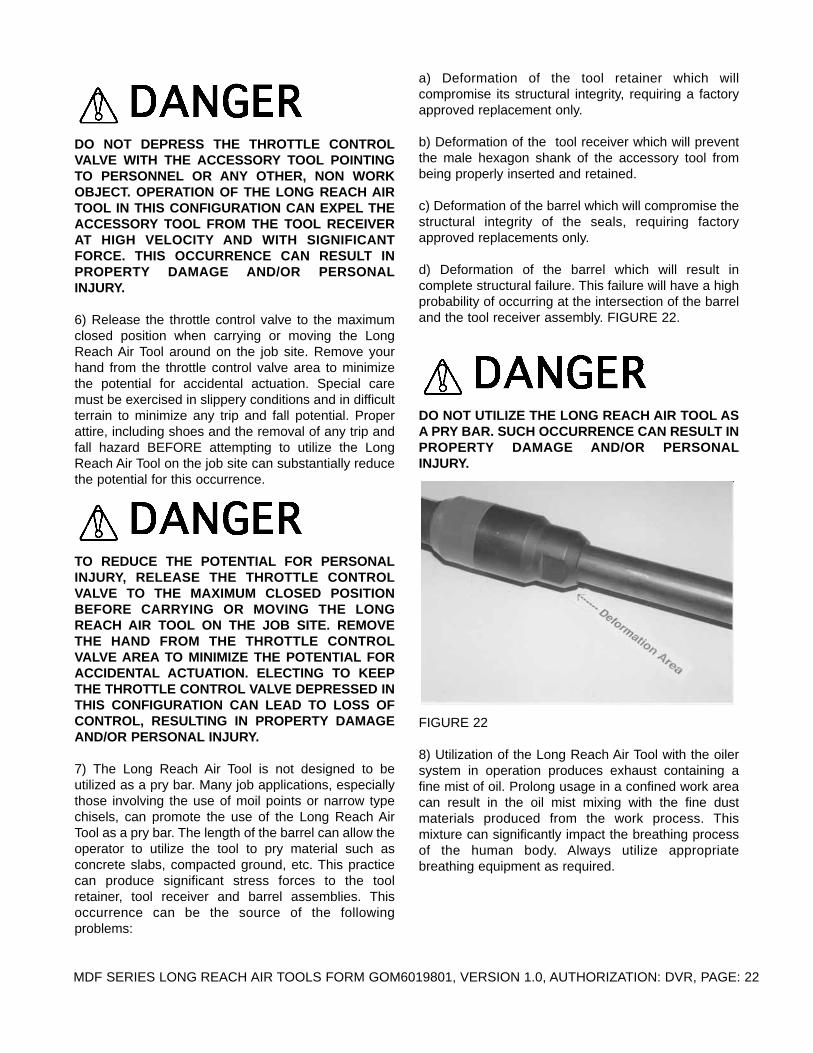
7) The Long Reach Air Tool is not designed to beutilized as a pry bar. Many job applications, especiallythose involving the use of moil points or narrow typechisels, can promote the use of the Long Reach AirTool as a pry bar. The length of the barrel can allow theoperator to utilize the tool to pry material such asconcrete slabs, compacted ground, etc. This practicecan produce significant stress forces to the toolretainer, tool receiver and barrel assemblies. Thisoccurrence can be the source of the followingproblems:
a) Deformation of the tool retainer which willcompromise its structural integrity, requiring a factoryapproved replacement only.
b) Deformation of the tool receiver which will preventthe male hexagon shank of the accessory tool frombeing properly inserted and retained.
c) Deformation of the barrel which will compromise thestructural integrity of the seals, requiring factoryapproved replacements only.
d) Deformation of the barrel which will result incomplete structural failure. This failure will have a highprobability of occurring at the intersection of the barreland the tool receiver assembly. FIGURE 22.
DO NOT UTILIZE THE LONG REACH AIR TOOL ASA PRY BAR. SUCH OCCURRENCE CAN RESULT INPROPERTY DAMAGE AND/OR PERSONALINJURY.
FIGURE 22
8) Utilization of the Long Reach Air Tool with the oilersystem in operation produces exhaust containing afine mist of oil. Prolong usage in a confined work areacan result in the oil mist mixing with the fine dustmaterials produced from the work process. Thismixture can significantly impact the breathing processof the human body. Always utilize appropriatebreathing equipment as required.
MDF SERIES LONG REACH AIR TOOLS FORM GOM6019801, VERSION 1.0, AUTHORIZATION: DVR, PAGE: 22

IT IS THE RESPONSIBILITY OF THE OPERATOR(S)AND/OR OWNER(S) OF THE LONG REACH AIRTOOL TO DETERMINE OPERATION FOR ANYSPECIFIC JOB APPLICATION IS IN FULLCOMPLIANCE WITH ALL APPLICABLE OSHAAND/OR EPA RESPIRATORY AND CONFINEDSPACE REGULATIONS.
9) The operational process of the Long Reach Air Toolproduces impulse forces (blow force) on a cyclic basis(frequency or blow rate). The vibration levels producedcan directly impact upon sensitive objects (buildingstructure, computers, electrically operated componentsetc.), resulting in damage. This potential occurrencemust be taken into consideration when operating theLong Reach Air Tool for any specific job application.
STOPPING THE LONG REACH AIR TOOL.
Applications: All models.
1) Stopping the Long Reach Air Tool is accomplishedby releasing the throttle control valve to its maximumclosed position. When not in operation, disconnect theLong Reach Air Tool from the compressed air source.FIGURE 23.
FIGURE 23
TEMPORARY STORAGE FOR THE LONG REACHAIR TOOL WHILE ON THE JOB SITE.
Applications: All models.
AN IMPROPER TEMPORARY STORAGECONFIGURATION FOR THE LONG REACH AIRTOOL CAN RESULT IN PROPERTY DAMAGEAND/OR PERSONAL INJURY.
Store the Long Reach Air Tool temporarily on the jobsite in a horizontal position on a suitable surface suchas a floor. Storage in a vertical position against a wallis an acceptable alternative if proper support can beafforded to prevent the unit from accidently falling.When not in operation, store the Long Reach Air Tool:
a) With the air hose disconnected from thecompressed air source.
b) With the accessory tool removed.
c) With the air hose disconnected from the Air Caddy.
d) With the screw located on the bottom of thepressure regulator (if utilizing the Air Caddy) turned outin a counterclockwise direction to release pressurefrom the internal diaphragm.
Troubleshooting
Applications: All models.
TOOL FAILS TO OPERATE WHEN THROTTLECONTROL VALVE IS DEPRESSED
TOOL OPERATES AT A REDUCED (SLOWER)FREQUENCY RATE
Dirt, oil or gummy byproducts have accumulated withinthe internal components. Add a small amount ofsuitable solvent to the inlet and allow to circulate. After30 minutes, depress the throttle control valve until thetool functions. After the solvent has completelycirculated and exhausted through the outlet port, add10 drops of pneumatic tool lubrication oil conforming toISO 3498 HM.32. Depress the throttle control valveuntil the lubrication oil is exhausting through the outletport at a steady rate. Repeat the procedure asnecessary.
MDF SERIES LONG REACH AIR TOOLS FORM GOM6019801, VERSION 1.0, AUTHORIZATION: DVR, PAGE: 23

TOOL ACCIDENTLY OPERATES WITHOUTDEPRESSING THE THROTTLE VALVE
Worn throttle control valve. Replace valve.
TOOL PRODUCES REDUCED BLOW ENERGY PERSTROKE
Worn distribution valve. Replace distribution valve.
Insufficient pressure from compressed air source.Increase air pressure within the recommendedoperating range until satisfactory productivity rates areobtained.
Worn piston. Replace piston.
TOOL OPERATES WITH IRREGULAR FUNCTION
Check all air hose connections. Replace and/or repairany affected connection.
ICE FORMATION AROUND EXHAUST PORT
Excessive condensation around the exhaust port.Install filter system to reduce the moisture content ofthe compressed air.
Add antifreeze solution to oiler system being utilized.
Repair
Inspect the Long Reach Air Tool on a regular basis forloose, worn or damaged parts. Replace anyquestionable part or assembly with a factory approvedreplacement part only. Do not attempt anymaintenance or repair work not described in theOperator Manual. Have such work performed at yourdealer's servicing shop.
With extended use, various internal components canbecome worn or require periodic maintenance due tothe accumulation of lubrication oil residue, theadmission of foreign dust contamination or simple wearto the point where individual replacement is necessary.Disassembly of the Long Reach Air Tool is required forcleaning purposes and the replacement of specifiedcomponents.
Repair related functions for the Long Reach Air Toolwill require a level working platform of sufficient sizeand appropriate height.
DISASSEMBLY OF THE CYLINDER ASSEMBLYFOR GENERAL MAINTENANCE AND/OR REPAIRPURPOSES.
Application: All models.
Tools Required:
1 each, 1-5/8 inch (42 mm) wrench (MDF15).1 each, 1-13/16 inch (46 mm) wrench (MDF35).
Parts Required:
1 each, MDF15-0140 or MDF35-0090 distribution valve (if required).
1 each, MDF15-0130 or MDF35-0130 distribution gauge (if required).
1 each, MDF15-0120 or MDF35-0120 disc (if required).2 each, MDF15-0240 roll pin (if required).1 each, MDF15-0090 or MDF35-0080 piston (if
required).
1) Disconnect the Long Reach Air Tool from thecompressed air source and the Air Caddy (if soequipped).
2) Remove the accessory tool (if so equipped).
3) Clean the Long Reach Air Tool with an appropriatesolvent.
OBSERVE ALL APPLICABLE SAFETYPRECAUTIONS FOR THE SOLVENT.
4) Remove the tool retainer assembly PN MDF15-0010or MDF35-0010 from the cylinder assembly.
5) Unscrew the friction head plug, PN MDF35-0030,from the cylinder assembly (MDF35 only).
6) Position the Long Reach Air Tool in a suitable vicewith the vice jaws in contact with the flat surfaces of thecylinder, FIGURE 24.
MDF SERIES LONG REACH AIR TOOLS FORM GOM6019801, VERSION 1.0, AUTHORIZATION: DVR, PAGE: 24

FIGURE 24
7) Using the applicable wrench, remove the cylinderhead, PN MDF15-0150 or MDF35-0150, from thecylinder assembly. The assembly incorporates a righthand thread configuration. This sequence will allowdirect access to the following components: PN MDF15-0090 or MDF35-0090 distribution valve, PN MDF15-0100 or MDF35-0100 valve distribution disc, PNMDF15-0130 or MDF35-0130 distribution gauge, PNMDF15-0120 or MDF35-0120 disc, PN MDF15-0110 orMDF35-0110 distribution valve cover, PN MDF15-0240roll pin (fits MDF35 also) and PN MDF15-0090 orMDF35-0080 piston. Clean all components with anappropriate solvent. Inspect each component fordamage and/or wear.
OBSERVE ALL APPLICABLE SAFETYPRECAUTIONS FOR THE SOLVENT.
8) Perform the following inspections:
a) Inspect the PN MDF15-0140 (MDF15) or MDF35-0090 (MDF35) valve for distortion or external marks onits surfaces. Replace the valve with a factory approvedreplacement part only if signs of distortion and/orexternal marks are present.
b) Inspect the PN MDF15-0090 (MDF15) or MDF35-0080 (MDF35) piston for excessive wear and externalmarks. Measure the diameter of the piston and replacewith a factory approved replacement part only if this
dimension is less than 0.7155 (18.1737) for the MDF15and 0.8625 inch (21.910 mm) for the MDF35 LongReach Air Tool.
c) The tool receiver bushing, PN MDF15-0050(MDF15) or MDF35-0040 (MDF35), must be free ofexcessive wear around each corner of the internalhexagon configuration. For the MDF15, measure theminor diameter of the receiver and replace with afactory approved replacement part only if thisdimension is greater than 0.391 inch (9.931 mm). Forthe MDF35 Long Reach Air Tool, measure the minordiameter of the receiver and replace with a factoryapproved replacement part only if this dimension isgreater than 0.6102 inch (15.5 mm). The tool receiverof the MDF15 can be removed from the cylinderassembly with a punch 0.485 inch (12.319 mm)diameter x 5 inch (127 mm) long (PN MDF15-7020).The tool receiver of the MDF35 can be removed fromthe cylinder assembly with a punch 0.700 inch (17.78mm) diameter x 6-1/2 inch (165 mm) long (PN MDF35-7010). FIGURE 25.
FIGURE 25
WEAR SAFETY EYEGLASSES AND OTHERAPPROPRIATE SAFETY APPAREL WHENREMOVING/INSTALLING THE TOOL RECEIVER ORPERFORMING ANY WORK WITH AN ARBORPRESS. CAUTION ALL ONLOOKERS ABOUT THEPOSSIBILITY OF FLYING DEBRIS AND PERSONALINJURY.
9) The assembly procedure for the specificcomponents follows the disassembly procedure inreverse order. It is important that the roll pins PN
MDF SERIES LONG REACH AIR TOOLS FORM GOM6019801, VERSION 1.0, AUTHORIZATION: DVR, PAGE: 25

MDF15-0240 be installed in the proper location withinthe cylinder head and the PN MDF15-0130 or MDF35-0130 distribution gauge be reinstalled in the properposition to allow the compressed air to properly flowthrough the Long Reach Air Tool.
DISASSEMBLY OF THE THROTTLE CONTROLVALVE FOR GENERAL MAINTENANCE AND/ORREPAIR PURPOSES.
Application: All models.
Tools Required:
1 each, large flat blade screwdriver.
Parts Required:
1 each, MDF15-0300 valve spool (if required).1 each, MDF15-0260 O ring (if required).1 each, PN MDF15-0270 O ring (if required).1 each, PN MDF15-0290 spring (if required).1 each, container of pipe joint compound.1 each, container of pneumatic tool lubrication oil.
1) Disconnect the Long Reach Air Tool from thecompressed air source and the Air Caddy (if soequipped).
2) Remove the accessory tool (if so equipped).
3) Clean the Long Reach Air Tool with an appropriatesolvent.
OBSERVE ALL APPLICABLE SAFETYPRECAUTIONS FOR THE SOLVENT.
4) Using the screwdriver, remove the threaded plug,PN MDF15-0280. The assembly incorporates a righthand thread configuration.
5) Remove the valve spool, PN MDF15-0300 from thevalve body. Clean the valve spool, spring and valvehousing with an appropriate solvent. Inspect the valvespool (PN MDF15-0300) and O rings (PN MDF15-0260and MDF15-0270) for wear, distortion and externalmarkings. If required, replace the valve and/or the Orings with a factory approved replacement part only.FIGURE 26.
OBSERVE ALL APPLICABLE SAFETYPRECAUTIONS FOR THE SOLVENT.
FIGURE 26
6) Inspect the throttle valve return spring, PN MDF15-0290, for visible damage, external markings andproper tension. If necessary, replace with a factoryapproved replacement part only.
7) The assembly procedure for the specificcomponents follows the disassembly procedure inreverse order. Apply a coating of pneumatic toollubrication oil to the valve spool and O rings beforereinstalling the O rings to the spool. This will minimizethe potential for external damage to the O rings. Applya small amount of pipe joint compound to the externalthreads of the throttle valve cover. Secure tight with thescrewdriver
Storage
Application: All models.
Proper procedure for long term storage of the LongReach Air Tool will protect it against the effects ofcorrosion and damage. If the Long Reach Air Tool isnot to be operated for a period of 30 days or more,proceed to store as follows:
1) Disconnect the Long Reach Air Tool from thecompressed air source.
MDF SERIES LONG REACH AIR TOOLS FORM GOM6019801, VERSION 1.0, AUTHORIZATION: DVR, PAGE: 26
2) Disconnect the Long Reach Air Tool from the AirCaddy (if so equipped).
3) Remove the accessory tool (if so equipped).
4) Clean all accumulated dirt and grease from the LongReach Air Tool and accessory tools utilizing anappropriate solvent.
Observe all applicable safety precautions for thesolvent.
5) Check all visible parts for wear, breakage ordamage. Order any part required to make thenecessary repair. This will avoid a needless delaywhen operating the Long Reach Air Tool at next use.
6) Fill the Long Reach Air Tool with one ounce ofpneumatic tool lubrication oil conforming to ISO 3498HM.32. Allow the oil to properly circulate within theinternal mechanisms. This will prevent the formation ofrust and/or corrosion on internal moving components.
7) Store the Long Reach Air Tool inside. If the LongReach Air Tool must be stored outside, protect it with asuitable covering. Outside exposure to the elementscan significantly reduce the service life of the air hoseassembly.
Specifications
Application: MDF15 Long Reach Air Tool
PISTON BORE .72 inch (18.5 mm)
PISTON STROKE 1.77 inch (45 mm)
RATED AIR PRESSURE 90 PSI (600 kPa)
OPERATING AIR PRESSURE RANGE 60 to 90 PSI(400-600 kPa). Lower pressure values may notproduce required performance for any specific jobapplication.
RATED AIR CONSUMPTION 6 CFM (3.0 lit/sec.)
ENERGY PER BLOW @ RATED 5.0 ft. lbs. (3.6 J)AIR CONSUMPTION
AND PRESSURE
BLOW FREQUENCY @ RATED AIR CONSUMPTION AND PRESSURE 3700 blows per minute.
Frequency rates will decrease with reducedair consumption and pressure values.
CONNECTING HOSE CONFIGURATION 3/8 inch(9.5 mm) diameter, 60 inch (1524 mm) nominallength. Quick type connecting coupler not furnished.
ACOUSTICAL PRESSURE LEVEL, Lp dB(a) CEE89/392 94
ACOUSTICAL POWER LEVEL, Lwa dB(a) CEE85/409 102
VIBRATION LEVEL PER ISO 8662-5 Less than 8.3ft/Sec2 (2.5 m/sec2).
BARREL CONSTRUCTION Aluminum
ACCESSORY TOOL RECEIVER SteelCONSTRUCTION
ACCESSORY TOOL .371 inch Industry StandardHEXAGON CONNECTION
OVERALL LENGTH (LESS 55 inch (1397 mm) ACCESSORY TOOL)
LUBRICATION OIL Air tool type conforming to ISO3498 HM.32. Other approved lubricants include: ShellClavus 25, BP Energol LPT 80, EssoZerice 46 and Mobil Almo 525.
WEIGHT (LESS 10 lbs. (4.5 kg)ACCESSORY TOOL)
Application: MDF35 Long Reach Air Tool
PISTON BORE .87 inch (22 mm)
PISTON STROKE 1.97 inch (50 mm)
RATED AIR PRESSURE 90 PSI (600 kPa)
OPERATING AIR PRESSURE RANGE 60 to 90 PSI(400-600 kPa). Lower pressure values may notproduce required performance for any specific jobapplication.
RATED AIR CONSUMPTION 10.8 CFM (5.0 lit/sec.)
MDF SERIES LONG REACH AIR TOOLS FORM GOM6019801, VERSION 1.0, AUTHORIZATION: DVR, PAGE: 27

ENERGY PER BLOW @ RATED 7.6 ft. lbs. (5.6 J) AIR CONSUMPTION AND PRESSURE
BLOW FREQUENCY @ RATEDAIR CONSUMPTION AND PRESSURE 3100 blows per minute.Frequency rates will decrease with reduced airconsumption and pressure values.
CONNECTING HOSE CONFIGURATION 3/8 inch(9.5 mm) diameter, 60 inch (1524 mm) nominallength. Quick type connecting coupler not furnished.
ACOUSTICAL PRESSURE LEVEL, Lp dB(a) CEE89/392 88
ACOUSTICAL POWER LEVEL, Lwa dB(a) CEE85/409 101
VIBRATION LEVEL PER ISO 8662-5 Less than8.3 ft/sec2 (2.5 m/sec2).
BARREL CONSTRUCTION Steel
ACCESSORY TOOL SteelRECEIVER CONSTRUCTION
ACCESSORY TOOL .580 inch industry standard HEXAGON CONNECTION
OVERALL LENGTH (LESS) 55 inch (1397 mm)ACCESSORY TOOL)
LUBRICATION OIL Air tool type conforming toISO 3498 HM.32. Other approved lubricants include:Shell Clavus 25, BP Energol LPT 80, Esso Zerice 46and Mobil Almo 525.
WEIGHT (LESS ) 18.5 lbs. (8.4 kg)ACCESSORY TOOL)
MDF SERIES LONG REACH AIR TOOLS FORM GOM6019801, VERSION 1.0, AUTHORIZATION: DVR, PAGE: 28

MDF SERIES LONG REACH AIR TOOLS FORM GOM6019801, VERSION 1.0, AUTHORIZATION: DVR, PAGE: 29
Replacement Parts DiagramsMDF Long Reach Air Tools
MDF15 MDF35

MDF SERIES LONG REACH AIR TOOLS FORM GOM6019801, VERSION 1.0, AUTHORIZATION: DVR, PAGE: 30
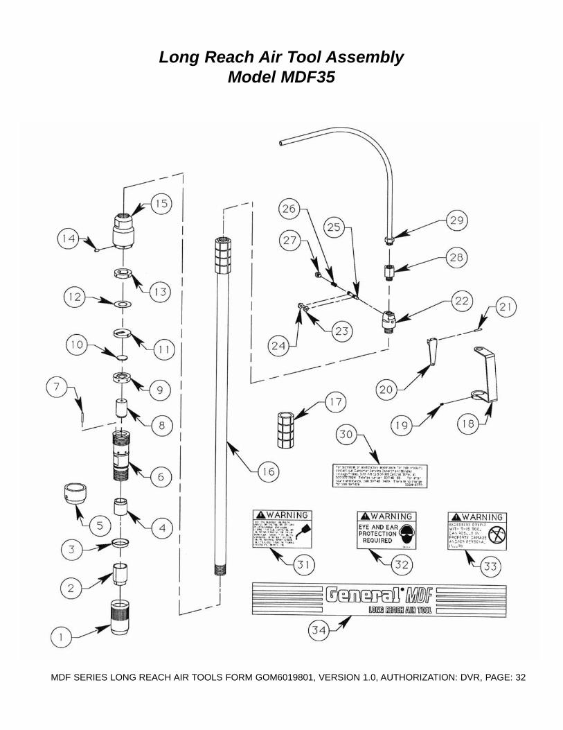
Long Reach Air Tool AssemblyModel MDF15

MDF SERIES LONG REACH AIR TOOLS FORM GOM6019801, VERSION 1.0, AUTHORIZATION: DVR, PAGE: 31
ReferenceNumber
PARTNUMBER
DESCRIPTION QTY
12345678910111213141516171819202122232425262728293031323334
MDF15-0010MDF15-0020MDF15-0040MDF15-0050MDF15-0030MDF15-0060MDF15-0070MDF15-0080MDF15-0090MDF15-0140MDF15-0100MDF15-0120MDF15-0110MDF15-0130MDF15-0150MDF15-0160MDF15-0200MDF15-0210MDF15-0220MDF15-0230MDF15-0240MDF15-0250MDF15-0260MDF15-0270MDF15-0300MDF15-0290MDF15-0280MDF15-0310MDF15-0320SG24-5070MDF-5050SP8-5040MDF-5040SP8-5010
Retainer, ToolBushing, Retaining
Deflector, AirBushing, Tool Receiver
“O” RingCylinder
Pin, AlignmentNut, Jam
PistonValve, Distribution
Disc, Valve DistributionDisc
Cover, Distribution ValveGauge, Distribution
Head, CylinderTube, Extension
Grip, HandleGuard, Throttle Control Lever
Screw, Set, Socket HeadLever, Throttle Control
Pin, RollHousing, Throttle Control Valve
“O” Ring“O” Ring
Spool, ValveSpringPlug
AdapterHose, Air, Wire Reinforced
Decal, AssistanceDecal, WarningDecal, WarningDecal, WarningDecal, General
1111112111111111212111111111111111
Long Reach Air Tool AssemblyModel MDF15
MDF SERIES LONG REACH AIR TOOLS FORM GOM6019801, VERSION 1.0, AUTHORIZATION: DVR, PAGE: 32
Long Reach Air Tool AssemblyModel MDF35

MDF SERIES LONG REACH AIR TOOLS FORM GOM6019801, VERSION 1.0, AUTHORIZATION: DVR, PAGE: 33
ReferenceNumber
PARTNUMBER
DESCRIPTION QTY
12345678910111213141516171819202122232425262728293031323334
MDF35-0010MDF35-0020MDF35-0030MDF35-0040MDF35-0050MDF35-0060MDF35-0070MDF35-0080MDF35-0090MDF35-0100MDF35-0110MDF35-0120MDF35-0130MDF35-0140MDF35-0150MDF35-0160MDF15-0200MDF15-0210MDF15-0220MDF15-0230MDF15-0240MDF15-0250MDF15-0260MDF15-0270MDF15-0280MDF15-0290MDF15-0300MDF15-0310MDF15-0320SG24-5070MDF-5050SP8-5040MDF-5040MDF-5010
Retainer, ToolBushing, RetainingHead Plug, Friction
Bushing, Tool ReceiverDeflector, Air
CylinderPin, Alignment
PistonValve, Distribution
Disc, Distribution ValveCover, Distribution Valve
DiscGauge, Distribution
Pin, AlignmentHead, Cylinder
Tube, ExtensionGrip, Handle
Guard, Throttle Control LeverScrew, Set, Socket Head
Lever, Throttle ControlPin, Roll
Housing, Throttle Control Valve“O” Ring“O” Ring
Spool, ValveSpringPlug
AdapterHose, Air, Wire Reinforced
Decal, AssistanceDecal, WarningDecal, WarningDecal, WarningDecal, General
1111112111111111212111111111111111
Long Reach Air Tool AssemblyModel MDF35
MDF SERIES LONG REACH AIR TOOLS FORM GOM6019801, VERSION 1.0, AUTHORIZATION: DVR, PAGE: 34
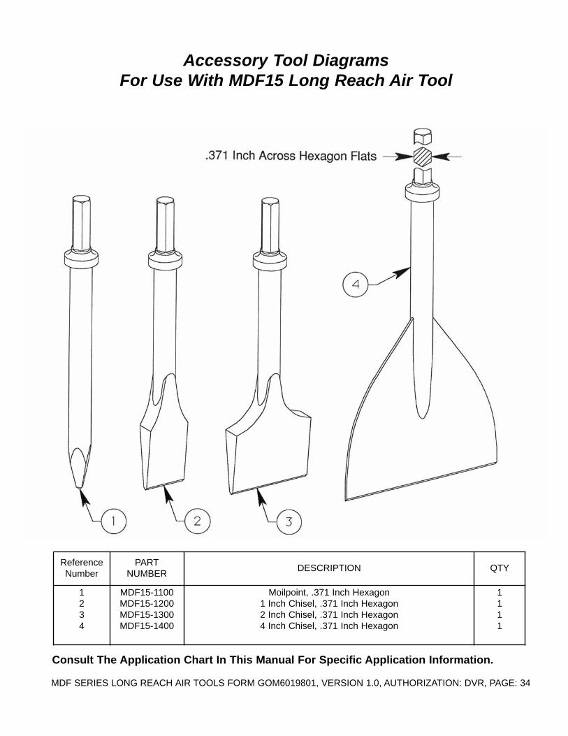
Accessory Tool DiagramsFor Use With MDF15 Long Reach Air Tool
ReferenceNumber
PARTNUMBER
DESCRIPTION QTY
1234
MDF15-1100MDF15-1200MDF15-1300MDF15-1400
Moilpoint, .371 Inch Hexagon1 Inch Chisel, .371 Inch Hexagon2 Inch Chisel, .371 Inch Hexagon4 Inch Chisel, .371 Inch Hexagon
1111
Consult The Application Chart In This Manual For Specific Application Information.

MDF SERIES LONG REACH AIR TOOLS FORM GOM6019801, VERSION 1.0, AUTHORIZATION: DVR, PAGE: 35
Accessory Tool DiagramsFor Use With MDF35 Long Reach Air Tool
ReferenceNumber
PARTNUMBER
DESCRIPTION QTY
1234
MDF35-1100MDF35-1200MDF35-1300MDF35-1400
Moilpoint, .580 Inch Hexagon1 Inch Chisel, .580 Inch Hexagon2 Inch Chisel, .580 Inch Hexagon4 Inch Chisel, .580 Inch Hexagon
1111
Consult The Application Chart In This Manual For Specific Application Information.

MDF SERIES LONG REACH AIR TOOLS FORM GOM6019801, VERSION 1.0, AUTHORIZATION: DVR, PAGE: 36
Accessory Tool DiagramsFor Use With MDF35 Long Reach Air Tool
ReferanceNumber
PARTNUMBER
DESCRIPTION QTY
123456
MDF35-15011608000015080800
MDF35-1600MDF35-1610MDF35-1620
Scraper Blade Holder (Less Blades)Washer, Lock, 1/2”, Plated
Screw, Cap, 1/2” x 1” UNC, Grade 8, PlatedBlade, Scraper, 5/1-2” Wide
Blade, Scraper, 8” WideBlade, Scraper, 12” Wide
144111

MDF SERIES LONG REACH AIR TOOLS FORM GOM6019801, VERSION 1.0, AUTHORIZATION: DVR, PAGE: 37
Air Caddy AsemblyModel MDF-1000
ReferenceNumber
PARTNUMBER
DESCRIPTION QTY
1234567891011
MDF-1000-010EP8-0140
MDF-1000-020MDF-1000-030MDF-1000-040
18040000160400001504070030040200
EP8HL-0120MDF-1000-050
Frame, Air CaddyMount, Rubber
Filter, AirRegulator, Air
Oiler, AirNut, Hex, 1/4”, Plated
Washer, Lock, 1/4”, PlatedScrew, Cap, 1/4-20 x 7/8” UNC, Plated
Screw, Set, Oval, 1/4-28 x 1/4 UNFPipe, Nipple, 1/2” NPT x 3”
Pipe, Nipple, Close, 1/2” NPT
14111444422

MDF SERIES LONG REACH AIR TOOLS FORM GOM6019801, VERSION 1.0, AUTHORIZATION: DVR, PAGE: 38
Display Stand AssemblyMDF Series Air Tools

MDF SERIES LONG REACH AIR TOOLS FORM GOM6019801, VERSION 1.0, AUTHORIZATION: DVR, PAGE: 39
ReferenceNumber
PARTNUMBER
DESCRIPTION QTY
12345678910111213141516171819
MDF-1100-0110MDF-1100-0230MDF-1100-0140MDF-1100-0130MDF-1100-0150MDF-1100-0100MDF-1100-0180MDF-1100-0160
660-0560MDF-1100-0170MDF-1100-0190
520400001504050015041200
MDF-1000-0220MDF-1100-0210MDF-1100-0200
15042000FP-164
Leg, StandLeg, Stand, Lower
Base (LH)Base (RH)Plate, Base
Tray, Tool BoxStrap, SupportTube Weldment
Tie, Nylon, 6” LongRod, Sign
Sign, Display StandNut, Hex, 2-Way Lock, 1/4” UNC, Plated
Screw, Cap, 1/4” x 5/8” UNC, Grade 5, PlatedScrew, Cap, 1/4” x 1-1/2” UNC, Grade 5, Plated
Lanyard, PlasticRing, Split
Pin, Detent, 5/16” x 3-1/8”Screw, Cap, 1/4” x 2-1/2” UNC, Grade 5, Plated
Cap, Plug, 1” Square
221122412112641822246
Display Stand AssemblyMDF Series Air Tools

MDF SERIES LONG REACH AIR TOOLS FORM GOM6019801, VERSION 1.0, AUTHORIZATION: DVR, PAGE: 40
Accessory Tool Application Chart MDF Long Reach Air Tool
ACCESSORY TOOLPART NUMBER AND
DESCRIPTION
OVERHEADOR ABOVE
WAISTCOATINGSREMOVAL
GENERALCONCRETEREMOVAL
FLOORCOATINGSREMOVAL
MATERIALBUILD-UPREMOVAL
MASTIC ORADHESIVEREMOVAL
FLOOR TILEREMOVAL
MDF15-1100Moilpoint
O
MDF15-12001 Inch Chisel
X O O O
MDF15-13002 Inch Chisel • O O O O O
MDF15-14004 Inch Chisel • X X X O
MDF35-1100Moilpoint •
MDF35-12001 Inch Chisel
O • O O
MDF35-13002 Inch Chisel
O X X X X X
MDF35-14004 Inch Chisel • • • •MDF35-1500Scraper Blade
Holder WithAppropriate Blade
• • •
OLimited performance or productivityrates for most applications.
XAcceptable performance or productivityrates for most job applications.
•Preferred method to produce maximumperformance or productivity rates formost job applications.
Information depicted is not intended for specific applicationpurposes. Performance or productivity rates for any accessory
tool are not guaranteed for any specific job application. Contactour Customer Service Department for specific application
assistance. There is no charge for this service.
Related Documents