Operator Manual RV Generator Set HDKAH (Spec A−N) HDKAJ (Spec A−K) HDKAK (Spec A−N) HDKAT (Spec A−R) HDKAU (Spec A−R) HDKAV (Spec A−R) English Original Instructions 3-2014 981−0161 (Issue 14)

Welcome message from author
This document is posted to help you gain knowledge. Please leave a comment to let me know what you think about it! Share it to your friends and learn new things together.
Transcript
Operator ManualRV Generator Set
HDKAH (Spec A−N)HDKAJ (Spec A−K)HDKAK (Spec A−N)HDKAT (Spec A−R)HDKAU (Spec A−R)HDKAV (Spec A−R)
EnglishOriginal Instructions 3-2014 981−0161 (Issue 14)

58
“Intentionally Left Blank”
gh414
Rectangle
gh414
Rectangle
i
Table of ContentsSAFETY PRECAUTIONS 2 . . . . . . . . . . . . . . . . . . . . . . . . . . . . . . . . . . . . . . . . . . . . . . . . . . . INTRODUCTION 4 . . . . . . . . . . . . . . . . . . . . . . . . . . . . . . . . . . . . . . . . . . . . . . . . . . . . . . . . . . .
About This Manual 4 . . . . . . . . . . . . . . . . . . . . . . . . . . . . . . . . . . . . . . . . . . . . . . . . . . . . . . Model Identification 4 . . . . . . . . . . . . . . . . . . . . . . . . . . . . . . . . . . . . . . . . . . . . . . . . . . . . . Typical Genset 5 . . . . . . . . . . . . . . . . . . . . . . . . . . . . . . . . . . . . . . . . . . . . . . . . . . . . . . . . . Fuel Recommendations 6 . . . . . . . . . . . . . . . . . . . . . . . . . . . . . . . . . . . . . . . . . . . . . . . . . Bio−diesel Fuels B5 − B20 6 . . . . . . . . . . . . . . . . . . . . . . . . . . . . . . . . . . . . . . . . . . . . . . . Engine Oil Recommendations 7 . . . . . . . . . . . . . . . . . . . . . . . . . . . . . . . . . . . . . . . . . . . . Starting Batteries 7 . . . . . . . . . . . . . . . . . . . . . . . . . . . . . . . . . . . . . . . . . . . . . . . . . . . . . . . Operator’s Console 8 . . . . . . . . . . . . . . . . . . . . . . . . . . . . . . . . . . . . . . . . . . . . . . . . . . . . . Remote Control Panel 8 . . . . . . . . . . . . . . . . . . . . . . . . . . . . . . . . . . . . . . . . . . . . . . . . . . .
OPERATION 10 . . . . . . . . . . . . . . . . . . . . . . . . . . . . . . . . . . . . . . . . . . . . . . . . . . . . . . . . . . . . . . . Conducting the Pre-Start Checks 10 . . . . . . . . . . . . . . . . . . . . . . . . . . . . . . . . . . . . . . . . . Priming the Fuel System 10 . . . . . . . . . . . . . . . . . . . . . . . . . . . . . . . . . . . . . . . . . . . . . . . . . Starting the Genset 10 . . . . . . . . . . . . . . . . . . . . . . . . . . . . . . . . . . . . . . . . . . . . . . . . . . . . . Stopping the Genset 11 . . . . . . . . . . . . . . . . . . . . . . . . . . . . . . . . . . . . . . . . . . . . . . . . . . . . Restarting the Genset 11 . . . . . . . . . . . . . . . . . . . . . . . . . . . . . . . . . . . . . . . . . . . . . . . . . . . Loading the Genset 11 . . . . . . . . . . . . . . . . . . . . . . . . . . . . . . . . . . . . . . . . . . . . . . . . . . . . . Resetting Circuit Breakers 12 . . . . . . . . . . . . . . . . . . . . . . . . . . . . . . . . . . . . . . . . . . . . . . . Connecting to Utility Power 12 . . . . . . . . . . . . . . . . . . . . . . . . . . . . . . . . . . . . . . . . . . . . . . Operating in Cold Weather 13 . . . . . . . . . . . . . . . . . . . . . . . . . . . . . . . . . . . . . . . . . . . . . . . Operating in Hot Weather 13 . . . . . . . . . . . . . . . . . . . . . . . . . . . . . . . . . . . . . . . . . . . . . . . . Operating at High Altitude 13 . . . . . . . . . . . . . . . . . . . . . . . . . . . . . . . . . . . . . . . . . . . . . . . Operating in Dusty Environments 13 . . . . . . . . . . . . . . . . . . . . . . . . . . . . . . . . . . . . . . . . . Breaking in a New Engine 13 . . . . . . . . . . . . . . . . . . . . . . . . . . . . . . . . . . . . . . . . . . . . . . . Exercising the Genset 13 . . . . . . . . . . . . . . . . . . . . . . . . . . . . . . . . . . . . . . . . . . . . . . . . . . . Storing the Genset 14 . . . . . . . . . . . . . . . . . . . . . . . . . . . . . . . . . . . . . . . . . . . . . . . . . . . . . .
PERIODIC MAINTENANCE 16 . . . . . . . . . . . . . . . . . . . . . . . . . . . . . . . . . . . . . . . . . . . . . . . . . Conducting General Inspections 17 . . . . . . . . . . . . . . . . . . . . . . . . . . . . . . . . . . . . . . . . . . Checking Engine Oil Level 18 . . . . . . . . . . . . . . . . . . . . . . . . . . . . . . . . . . . . . . . . . . . . . . . Changing Engine Oil and Oil Filter 19 . . . . . . . . . . . . . . . . . . . . . . . . . . . . . . . . . . . . . . . . Maintaining the Battery and Battery Connections 20 . . . . . . . . . . . . . . . . . . . . . . . . . . . Replacing the Air Filter Element 20 . . . . . . . . . . . . . . . . . . . . . . . . . . . . . . . . . . . . . . . . . . Cleaning the Spark Arrestor 21 . . . . . . . . . . . . . . . . . . . . . . . . . . . . . . . . . . . . . . . . . . . . . . Replacing the Fuel Filter 22 . . . . . . . . . . . . . . . . . . . . . . . . . . . . . . . . . . . . . . . . . . . . . . . . . Changing Coolant 23 . . . . . . . . . . . . . . . . . . . . . . . . . . . . . . . . . . . . . . . . . . . . . . . . . . . . . .
TROUBLESHOOTING 26 . . . . . . . . . . . . . . . . . . . . . . . . . . . . . . . . . . . . . . . . . . . . . . . . . . . . . . SPECIFICATIONS 36 . . . . . . . . . . . . . . . . . . . . . . . . . . . . . . . . . . . . . . . . . . . . . . . . . . . . . . . . . . INFORMATION FOR CALIFORNIA GENSET USERS 38 . . . . . . . . . . . . . . . . . . . . . . . . . . . HOW TO OBTAIN SERVICE 40 . . . . . . . . . . . . . . . . . . . . . . . . . . . . . . . . . . . . . . . . . . . . . . . . .

ii
MAINTENANCE RECORD 42 . . . . . . . . . . . . . . . . . . . . . . . . . . . . . . . . . . . . . . . . . . . . . . . . . . .
1
Safety PrecautionsThoroughly read the OPERATOR’S MANUALbefore operating the genset. Safe operation andtop performance can only be obtained whenequipment is operated and maintained properly.
The following symbols in this manual alert you to po-tential hazards to the operator, service person andequipment.
alerts you to an immediate hazardthat will result in severe personal injury ordeath.
WARNING alerts you to a hazard or unsafepractice that can result in severe personal injuryor death.
CAUTION alerts you to a hazard or unsafepractice that can result in personal injury orequipment damage.
When equipped with an integral or add−on Auto−matic Generator Starting System (AGS) control,ex-haust carbon monoxide (CO), electric shock, and-moving parts hazards are possible due to unex−pected starting. Turn off AGS whenever performing-maintenance or service, when the vehicle is stored-between uses, is awaiting service, or is parked inagarage or other confined area.
Electricity, fuel, exhaust, moving parts and batteriespresent hazards which can result in severe personalinjury or death.
ENGINE EXHAUST IS DEADLY
Inspect for exhaust leaks at every startup andafter every eight hours of running.
Prior to every startup and after every eighthours of running, all carbon monoxide detec-tors must be tested and confirmed to be work-ing in accordance with the manufacture’s in-structions or owners manual.
Learn the symptoms of carbon monoxide poi-soning in the Operator’s Manual.
Never occupy the vehicle while the genset isrunning unless the vehicle is equipped with aworking carbon monoxide detector.
Do not operate the genset when the vehicle isin a confined space, such as a garage.
Disable the automatic genset starting feature ofan inverter-charger or other automatic startingdevice before storing the vehicle or parking it ina garage or other confined space.
The exhaust system must be installed in accor-dance with the genset Installation Manual.
Engine cooling air must not be used for heatingworking or living spaces or compartments.
GENERATOR VOLTAGE IS DEADLY
Disable the automatic genset starting fea-ture(AGS) of an inverter−charger or other auto-matic starting device before servicing the gen-set to avoid electric shock from an unexpectedstart.
Generator electrical output connections mustbe made by a trained and experienced electri-cian in accordance with applicable codes.
The genset must not be connected to the publicutility or any other source of electrical power.Back-feed could lead to electrocution of utilitypersonnel and damage to equipment. An ap-proved switching device must be used to pre-vent interconnections.
Use caution when working on live electricalequipment. Remove jewelry, make sure cloth-ing and shoes are dry, stand on a dry woodenplatform or rubber insulating mat and use toolswith insulated handles.
DIESEL FUEL IS COMBUSTIBLE
Do not smoke or turn electrical switches ON orOFF where fuel fumes are present or in areassharing ventilation with fuel tanks or equip-ment. Keep flames, sparks, pilot lights, arc-pro-ducing equipment and all other sources of igni-tion well away.
Fuel lines must be secured, free of leaks andseparated or shielded from electrical wiring.

2
MOVING PARTS CAN CAUSE SEVEREPERSONAL INJURY OR DEATH
Disable the automatic genset starting fea-ture(AGS) of an inverter−charger or other auto-matic starting device before servicing the gen-set to avoid unexpected starting.
Do not wear loose clothing or jewelry near mov-ing parts such as PTO shafts, fans, belts andpulleys.
Keep hands away from moving parts.
BATTERY GAS IS EXPLOSIVE
Wear safety glasses.
Do not smoke.
To reduce arcing when disconnecting or recon-necting battery cables, always disconnect thenegative (−) battery cable first and reconnect itlast.
FLAMMABLE VAPOR CAN CAUSE ADIESEL ENGINE TO OVERSPEED
Flammable vapor can cause a diesel engine tooverspeed and become difficult to stop, resulting inpossible fire, explosion, severe personal injury anddeath. Do not operate a diesel-powered gensetwhere a flammable vapor environment can becreated by fuel spill, leak, etc. The owners and op-erators of the genset are solely responsible for oper-ating the genset safely.
GENERAL PRECAUTIONS
Keep children away from the genset.
Do not use evaporative starting fluids. They arehighly explosive.
To prevent accidental or remote starting whileworking on the genset, disconnect the nega-tive (−) battery cable at the battery.
Let the engine cool down before removing thecoolant pressure cap or opening the coolantdrain. Hot coolant under pressure can sprayout and cause severe burns.
Keep the genset and its compartment clean.Excess oil and oily rags can catch fire. Dirt andgear stowed in the compartment can restrictcooling air.
Make sure all fasteners are secure and torquedproperly.
Do not work on the genset when mentally orphysically fatigued or after consuming alcoholor drugs.
You must be trained and experienced to makeadjustments while the genset is running—hot,moving or electrically live parts can cause se-vere personal injury or death.
Used engine oil has been identified by someU. S. state and federal agencies as causingcancer or reproductive toxicity. Do not ingest,inhale, or contact used oil or its vapors.
Ethylene glycol, used as engine antifreeze, istoxic to humans and animals. Clean up spillsand dispose of used engine coolant in accor-dance with local environmental regulations.
Keep multi-class ABC fire extinguishers handy.Class A fires involve ordinary combustible ma-terials such as wood and cloth; Class B fires,combustible and flammable liquid fuels andgaseous fuels; Class C fires, live electricalequipment. (ref. NFPA No. 10)
Genset installation and operation must complywith all applicable local, state and federal codesand regulations.
Keep guards in place over fans, belts, pulleys,and other moving parts.
Mobile-8
3
IntroductionABOUT THIS MANUAL
This manual covers the operation and maintenanceof the generator set (genset) models on the frontcover. Study this manual carefully and observe all ofits instructions and precautions. Keep this manualand the genset Installation Manual with the other ve-hicle manuals.
Operation, Periodic Maintenance and Trouble-shooting provide the instructions necessary for op-erating the genset and maintaining it at top perfor-mance. The owner is responsible for performingmaintenance in accordance with the PERIODICMAINTENANCE SCHEDULE (Page 15). Thismanual also includes genset specifications, infor-mation on how to obtain service and information forCalifornia users.
WARNING This genset is not a life support sys-tem. It can stop without warning. Children, per-sons with physical or mental limitations, andpets could suffer personal injury or death. A per-sonal attendant, redundant power or an alarmsystem must be used if genset operation is criti-cal.
MODEL IDENTIFICATION
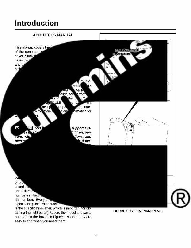
When contacting an Onan dealer for parts, serviceor product information, be ready to provide the mod-el and serial numbers on the genset nameplate. Fig-ure 1 illustrates the nameplate and its location. Thenumbers in the gray boxes are typical model and se-rial numbers. Every character in these numbers issignificant. (The last character of the model numberis the specification letter, which is important for ob-taining the right parts.) Record the model and serialnumbers in the boxes in Figure 1 so that they areeasy to find when you need them.
RECORD NUMBERS HERE
MODEL NUMBER:
SERIAL NUMBER:
SKB719U6D2RA 719 cc
80HDKAK11454JF990 123456
FIGURE 1. TYPICAL NAMEPLATE
4
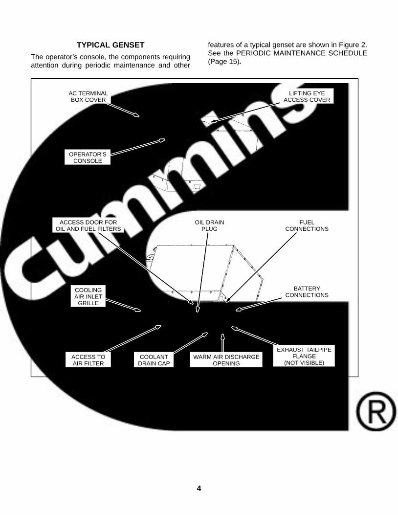
TYPICAL GENSET
The operator’s console, the components requiringattention during periodic maintenance and other
features of a typical genset are shown in Figure 2.See the PERIODIC MAINTENANCE SCHEDULE(Page 15).
OPERATOR’SCONSOLE
AC TERMINALBOX COVER
LIFTING EYEACCESS COVER
ACCESS TOAIR FILTER
COOLINGAIR INLET
GRILLE
OIL DRAINPLUG
ACCESS DOOR FOROIL AND FUEL FILTERS
FUELCONNECTIONS
BATTERYCONNECTIONS
COOLANTDRAIN CAP
WARM AIR DISCHARGEOPENING
EXHAUST TAILPIPEFLANGE
(NOT VISIBLE)
FIGURE 2. TYPICAL GENSET

5
FUEL RECOMMENDATIONS
WARNING Diesel fuel is combustible and cancause severe personal injury or death. Do notsmoke near diesel fuel tanks or equipment.Keep flames, sparks, pilot lights, electrical arcs,switches and arc-producing equipment and allother sources of ignition well away. Keep a typeABC fire extinguisher in the vehicle.
Use clean, fresh No. 2 diesel fuel (ASTM 2-D) whenthe outdoor ambient temperature is above freezing,and No. 1 diesel fuel (ASTM 1-D) when below freez-ing. The fuel should have a Cetane number of atleast 45 for reliable starting.
BIO−DIESEL FUELS B5 − B20
B5 bio−diesel fuel that meets industry specificationsand quality is suitable for use with this generator set.
Bio−Diesel Above B5 and up to B20Bio−Diesel Blends
The following must be verified before using bio−die-sel blends up to B20:
The generator set is at Spec M or higher.
The vehicle propulsion engine is capable of us-ing B20 when sharing the same fuel tank.
The OEM has installed B20 compatible fuel linefrom fuel tank to generator set.
The OEM has installed a water separator in thefuel line just before the generator set.
Approved Bio−Diesel Fuel:
For biodiesel blends above B5 and up to B20,Cummins Onan requires that the fuel meet thespecifications outlined in ASTM D7467. Thebiodiesel component of this fuel blend mustmeet ASTM D6751 or EN14214 and the petro-leum diesel component must meet ASTMD975.
Blended bio−diesels fuels should be boughtpre−blended and not made by customers.
Bio−Diesel Properties:
Bio−diesel has poor oxidation stability whichcan accelerate fuel oxidation. Fuel oxidationwill reduce generator performance. This effectis accelerated at increased ambient tempera-tures.
Bio−diesel properties change at low ambienttemperatures (below 23F/−5C). Necessaryprecautions must be taken when operating thegenerator with bio−diesel blends in low ambi-ent temperatures, such as a fuel heater, hoseinsulation, or additional anti−gel fuel additives.
Bio−diesel fuel blends are an excellent mediumfor microbial growth. Microbes cause fuel sys-tem corrosion and premature filter plugging.The effectiveness of all commercially availableconventional anti−microbial additives, whenused in bio−diesel, is not known. Consult yourfuel and additive supplier for assistance.
WARNING It is highly recommended that specificmarket applications are avoided or excercised withextra care due to some of the properties of bio−die-sel fuel blends such as cold weather operation, longterm storage, material incompatibilities and othereffects on engine operating characteristics. Suchapplications that should use standard fuels includeapplications that will experience seasonal usage,storage for periods exceeding 90 days, and extremetemperatures or humidity.
Storage Requirements:
If using bio−diesel for seasonal applications(stored more than 90 days), the generator mustbe purged before storage by running the en-gine on pure diesel fuel meeting ASTM D975for a mininmum of 30 minutes.
Warranty Coverage:
Cummins Onan Warranty covers failures that are adirect result of defects in material or factory work-manship. Generator damage, service issues and/orperformance issues determined by Cummins Onanto be caused by bio−diesel fuel blends not meetingthe specifications outlined in the applicable Installa-tion, Operator, and Service Manuals are not consid-ered to be defects in material or workmanship andmay affect your generator’s warranty.
6
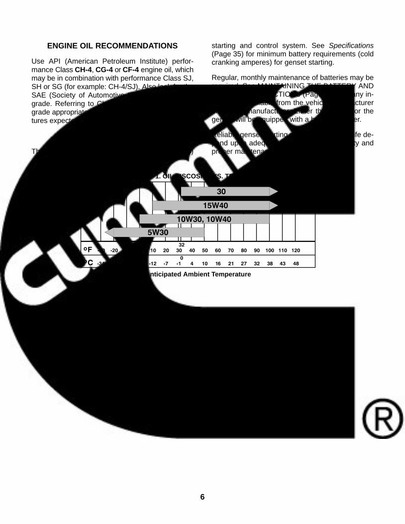
ENGINE OIL RECOMMENDATIONS
Use API (American Petroleum Institute) perfor-mance Class CH-4, CG-4 or CF-4 engine oil, whichmay be in combination with performance Class SJ,SH or SG (for example: CH-4/SJ). Also look for theSAE (Society of Automotive Engineers) viscositygrade. Referring to Chart 1, choose the viscositygrade appropriate for the outdoor ambient tempera-tures expected until the next scheduled oil change.
STARTING BATTERIES
These gensets have a 12 volt, direct current (DC)
starting and control system. See Specifications(Page 35) for minimum battery requirements (coldcranking amperes) for genset starting.
Regular, monthly maintenance of batteries may berequired. See MAINTAINING THE BATTERY ANDBATTERY CONNECTIONS (Page 19) and any in-structions available from the vehicle manufactureror battery manufacturer. Either the vehicle or thegenset will be equipped with a battery charger.
Reliable genset starting and starter service life de-pend upon adequate battery system capacity andproper maintenance.
CHART 1. OIL VISCOSITY VS. TEMPERATURE
Anticipated Ambient Temperature
7
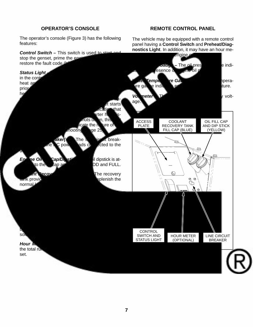
OPERATOR’S CONSOLE
The operator’s console (Figure 3) has the followingfeatures:
Control Switch − This switch is used to start andstop the genset, prime the engine fuel system andrestore the fault code (blinking status light).
Status Light − This is an LED (light emitting diode)in the control switch which blinks rapidly during pre-heat and cranking. (Preheat is the period of timeprior to engine cranking when the glow plugs pre-heat the combustion chambers. The time is auto-matically varied by the genset controller on the ba-sis of engine temperature.) After the genset startsup, this light stays on continuously, indicating thatthe genset is running and that the starter has dis-connected. Also, if the genset shuts down, this lightblinks in a coded fashion to indicate the nature of theshutdown (see Troubleshooting, Page 25).
Line Circuit Breaker(s) − The line circuit break-er(s) protect the AC power leads connected to thegenset.
Engine Oil Fill Cap/Dipstick − The oil dipstick is at-tached to the fill cap and is marked ADD and FULL.
Coolant Recovery Tank Fill Cap − The recoverytank provides for coolant expansion. Replenish thenormal loss of coolant by filling here.
Coolant Pressure Cap − The coolant pressure capis accessible by removing the access plate on thecontrol console. It provides for a pressurized enginecooling system. Fill coolant here when refilling thesystem.
Fuses F1, F2 and F3 − These fuses are accessibleby removing the access plate on the control con-sole. They protect the control circuits of the genset.
Hour Meter (Optional)− The hour meter recordsthe total running time of the genset. It cannot be re-set.
REMOTE CONTROL PANEL
The vehicle may be equipped with a remote controlpanel having a Control Switch and Preheat/Diag-nostics Light. In addition, it may have an hour me-ter and the following engine gauges:
Oil Pressure Gauge − The oil pressure gauge indi-cates the presence of engine oil pressure.
Water Temperature Gauge − The water tempera-ture gauge indicates engine coolant temperature.
Voltmeter − The voltmeter indicates battery volt-age.
ACCESSPLATE
COOLANTRECOVERY TANKFILL CAP (BLUE)
OIL FILL CAPAND DIP STICK
(YELLOW)
LINE CIRCUITBREAKER
HOUR METER(OPTIONAL)
CONTROLSWITCH AND
STATUS LIGHT
FIGURE 3. OPERATOR’S CONSOLE

8
THIS PAGE IS INTENDED TO BE BLANK
9
Operation
WARNING EXHAUST GAS IS DEADLY!
Exhaust gases contain carbon monoxide, an odorless, colorless gas. Carbon monoxide is poisonousand can cause unconsciousness and death. Symptoms of carbon monoxide poisoning include:
Dizziness Throbbing in Temples Nausea Muscular Twitching Headache Vomiting Weakness and Sleepiness Inability to Think Clearly
IF YOU OR ANYONE ELSE EXPERIENCES ANY OF THESE SYMPTOMS, GET OUT INTO THE FRESHAIR IMMEDIATELY. If symptoms persist, seek medical attention. Shut down the genset and do not op-erate it until it has been inspected and repaired.
Never occupy the vehicle with the genset running unless the vehicle is equipped with a working car-bon monoxide detector. Primary protection against poisoning due to inhaling carbon monoxide, how-ever, consists of proper installation of the exhaust system and inspections every day (every eighthours of operation) for visible and audible exhaust system leaks.
CONDUCTING THE PRE-START CHECKS
Before the first start of the day and after every eighthours of operation, inspect the genset as instructedunder CONDUCTING GENERAL INSPECTIONS(Page 16). Keep a log of maintenance and the hoursrun and perform any maintenance that may be due.See Returning the Genset to Service (Page 13) ifthe vehicle has been in storage.
Before each start:
1. Make sure all vehicle CO detectors are work-ing.
2. Check for signs of fuel and exhaust leaks andfor damage to the exhaust system.
3. Turn off the air conditioner and other large ap-pliances.
PRIMING THE FUEL SYSTEM
The fuel system should be primed after replacingthe fuel filter or running the genset out of fuel. Toprime the fuel system hold the control switch downin its Stop position for at least 1 minute.
STARTING THE GENSET
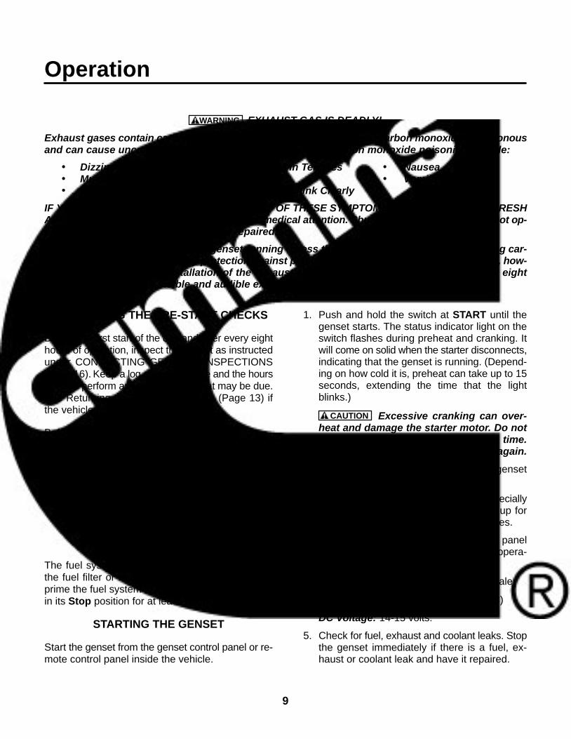
Start the genset from the genset control panel or re-mote control panel inside the vehicle.
1. Push and hold the switch at START until thegenset starts. The status indicator light on theswitch flashes during preheat and cranking. Itwill come on solid when the starter disconnects,indicating that the genset is running. (Depend-ing on how cold it is, preheat can take up to 15seconds, extending the time that the lightblinks.)
CAUTION Excessive cranking can over-heat and damage the starter motor. Do notcrank for more than 20 seconds at a time.Wait at least 2 minutes before trying again.
2. See Troubleshooting (Page 25) if the gensetdoes not start after three tries.
3. For top performance and engine life, especiallyin colder weather, let the engine warm up fortwo minutes before connecting appliances.
4. Monitor the engine gauges if the remote panelis so equipped. Normal readings during opera-tion are as follows:
Oil Pressure: Approximate center of scale
Temperature: 160-220 F (71-104 C)
DC Voltage: 14-15 volts.
5. Check for fuel, exhaust and coolant leaks. Stopthe genset immediately if there is a fuel, ex-haust or coolant leak and have it repaired.
10
STOPPING THE GENSET
Turn off the air conditioner and other large ap-pliances and let the genset run for two minutes tocool down. Then press the switch to STOP to stopthe genset.
RESTARTING THE GENSET
See Troubleshooting (Page 25) if the genset shutsdown abnormally.
LOADING THE GENSET
The genset can power AC motors, air conditioners,AC/DC converters, battery chargers and other ap-pliances. How much appliance load* can be pow-ered depends upon the genset power rating. Thegenset will shut down or its circuit breakers will trip ifthe sum of the loads exceeds genset power. (If thegenset shuts down, the status light will probably dis-play Fault Code No. 11, 13, 22 or 38. See Trouble-shooting, Page 25.)
To avoid overloading the genset and causing shut-downs, compare the sum of the loads of the ap-pliances that are likely to be used at the same time tothe power rating of the genset. Use Table 1 or theratings on the appliances themselves (if so marked)to obtain the individual appliance loads. It may benecessary to run fewer appliances at the sametime—the sum of the loads must not be greaterthan genset rating.
The genset may shut down due to overload when alarge motor or air conditioner is started or cycles offand then on again, even though the sum of the loadsis less than genset rating. The reason for this is thata motor’s startup load is much larger than its runningload. It may be necessary to run fewer ap-pliances when large motors and air condition-ers are cycling on and off.
Maximum power decreases as altitude increasesbecause air density decreases. For every 1000-foot(305 m) increase in elevation you can expect powerto decrease approximately 3 percent. Table 2shows the results of typical calculations. It may benecessary to run fewer appliances at higher alti-tudes.
TABLE 1. TYPICAL APPLIANCE LOADSAppliance Load (watts)
Air Conditioner 1400-2000
Battery Charger Up to 2000
DC Converter 300-1200
Refrigerator 600-1000
Microwave Oven 1000-1500
Electric Frying Pan or Wok 1000-1500
Electric Stove Element 350-1000
Electric Water Heater 1000-1500
Electric Iron 500-1200
Electric Hair Dryer 800-1500
Coffee Percolator 550-750
Television 200-600
Radio 50-200
Electric Drill 250-750
Electric Broom 200-500
Electric Blanket 50-200
TABLE 2. POWER VS. ALTITUDEElevation
above MeanSea Level
Max GensetPower*
Max GensetPower*
up to 500 ft(152 m)
7500 watts(rated)
8000 watts(rated)
2500 ft(762 m) 7050 watts 7520 watts
5500 ft(1676 m) 6375watts 6800watts
above5500 ft
(1676 m)
6375watts minus225 watts ev-
ery1000 ft(305 m)
6800watts minus240 watts ev-
ery1000 ft(305 m)
* This table does not take into account the effect cir-cuit breakers may have in limiting maximum power.
Commercial Genset Applications
Maximum genset power (nameplate rating) is7500 watts in an ambient of 85 F (29 C), but only6000 watts in an ambient of 120 F (50 C)—themaximum operating temperature. Also, continuousoperation at up to 80 percent of maximum power(6000 watts) is acceptable.
* Appliance load and genset power are measured in terms of watts (W) or kilowatts (kW), where 1 kilowatt (kW) = 1000 watts (W).
11
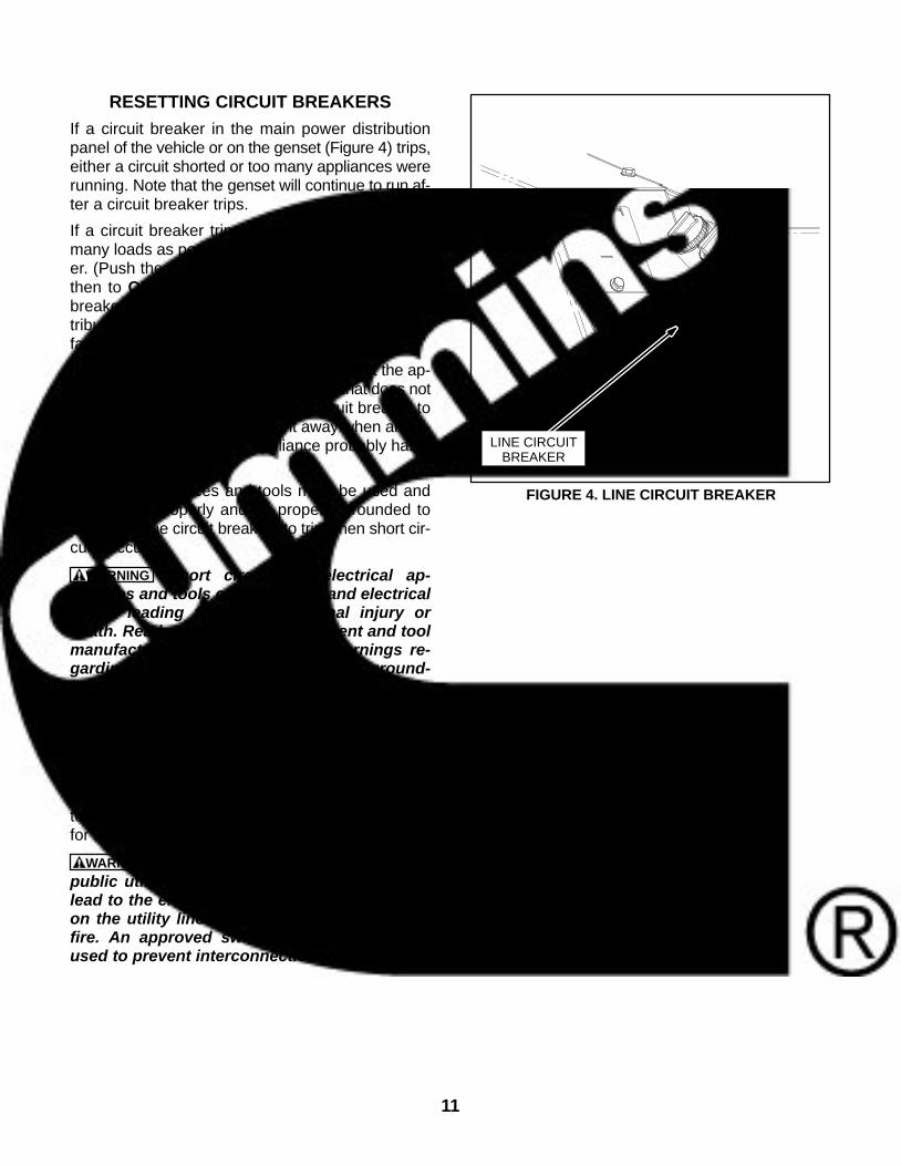
RESETTING CIRCUIT BREAKERS
If a circuit breaker in the main power distributionpanel of the vehicle or on the genset (Figure 4) trips,either a circuit shorted or too many appliances wererunning. Note that the genset will continue to run af-ter a circuit breaker trips.
If a circuit breaker trips, disconnect or turn off asmany loads as possible and reset the circuit break-er. (Push the circuit breaker to OFF to reset it andthen to ON to reconnect the circuit.) If the circuitbreaker trips right away, either the electrical dis-tribution system has a short or the circuit breaker isfaulty. Call a qualified electrician.
If the circuit breaker does not trip, reconnect the ap-pliances, one by one, up to a total load that does notoverload the genset or cause the circuit breaker totrip. If a circuit breaker trips right away when an ap-pliance is connected, the appliance probably has ashort.
Electrical appliances and tools must be used andmaintained properly and be properly grounded tocause the line circuit breakers to trip when short cir-cuits occur.
WARNING Short circuits in electrical ap-pliances and tools can cause fire and electricalshock leading to severe personal injury ordeath. Read and follow the equipment and toolmanufacturer’s instructions and warnings re-garding use, maintenance and proper ground-ing.
CONNECTING TO UTILITY POWER
When the vehicle has provisions for connecting toutility power, such as a cord for plugging into a pow-er outlet receptacle, it must also have an approveddevice to keep the genset and utility from being in-terconnected. See the genset Installation Manualfor more information.
WARNING Interconnecting the genset and thepublic utility (or any other power source) canlead to the electrocution of personnel workingon the utility lines, damage to equipment andfire. An approved switching device must beused to prevent interconnections.
LINE CIRCUITBREAKER
FIGURE 4. LINE CIRCUIT BREAKER

12
OPERATING IN COLD WEATHER
Make sure the engine oil viscosity is appropriate forthe cold weather temperatures. See ENGINE OILRECOMMENDATIONS (Page 6). Be sure tochange the oil if a sudden drop in temperature oc-curs.
OPERATING IN HOT WEATHER
Pay particular attention to the following items whenoperating the genset in hot weather:
1. Make sure nothing blocks airflow to and fromthe genset.
2. Make sure engine oil viscosity is appropriate forthe ambient temperatures. See ENGINE OILRECOMMENDATIONS (Page 6).
3. Keep the genset clean.
4. Perform maintenance due. See PERIODICMAINTENANCE SCHEDULE (Page 15).
OPERATING AT HIGH ALTITUDE
For the effect of altitude on maximum power, seeLOADING THE GENSET (Page 10).
OPERATING IN DUSTY ENVIRONMENTS
Pay particular attention to the following items whenoperating the genset in dusty environments:
1. Do not let dirt and debris accumulate inside thegenset compartment. Keep the genset clean.
2. Perform air cleaner maintenance more often.See PERIODIC MAINTENANCE SCHEDULE(Page 15).
3. Change engine oil more often. See PERIODICMAINTENANCE SCHEDULE (Page 15).
4. Keep containers of engine oil that have beenopened tightly closed to keep out dust.
BREAKING IN A NEW ENGINE
Proper engine break-in on a new genset or on onewith a rebuilt engine is essential for top engine per-formance and acceptable oil consumption. Run thegenset at approximately 1/2 rated power for the first2 hours and then at 3/4 rated power for 2 morehours. See LOADING THE GENSET (Page 10).
Proper engine oil and oil level are especially criticalduring break-in because of the higher engine tem-peratures that can be expected. Change the oil if notappropriate for the ambient temperatures duringbreak-in. See ENGINE OIL RECOMMENDATIONS(Page 6). Check oil level twice a day or every4 hours during the first 24 hours of operation andchange the oil and oil filter after the first 50 hours ofoperation.
EXERCISING THE GENSET
Exercise the genset at least 2 hours each month ifuse is infrequent. Run the genset at approximately1/2 rated power. See LOADING THE GENSET(Page 10). A single two hour exercise period is bet-ter than several shorter periods.
Exercising a genset drives off moisture, re-lubri-cates the engine, replaces stale fuel and removesoxides from electrical contacts. The result is betterstarting, more reliable operation and longer enginelife.

13
STORING THE GENSET
Proper storage is essential for preserving top gen-set performance and reliability when the gensetcannot be exercised regularly and will be idle formore than 120 days.
Storing the Genset
1. Push the genset line circuit breaker OFF(Page 11).
2. Change the engine oil and attach a tag indicat-ing oil viscosity. See ENGINE OIL REC-OMMENDATIONS (Page 6).
3. Disconnect the battery cables (negative [−]cable first) from the starting battery and storethe battery according to the battery manufac-turer’s recommendations. See MAINTAININGTHE BATTERY AND BATTERY CONNEC-TIONS (Page 19).
4. Plug the exhaust tail pipe to keep out dirt, mois-ture, bugs, etc.
5. Close the fuel supply valve (if so equipped).
Returning the Genset to Service
1. Check the oil tag on the genset and change theoil if the viscosity indicated is not appropriate forthe temperatures expected. See ENGINE OILRECOMMENDATIONS (Page 6).
2. Reconnect the starting battery (negative [−]cable last). See MAINTAINING THE BATTERYAND BATTERY CONNECTIONS (Page 19).
3. Remove the plug from the exhaust tailpipe.
4. Change the air filter element if it is dirty(Page 19).
5. Open the fuel supply valve (if so equipped).
6. Inspect the genset. See CONDUCTING GEN-ERAL INSPECTIONS (Page 16).
7. Push the genset line circuit breaker ON(Page 11) when the genset is ready to powerappliances.

14
THIS PAGE IS INTENDED TO BE BLANK

15
Periodic MaintenancePeriodic maintenance is essential for top perfor-mance and long genset life. Use Table 3 as a guidefor normal periodic maintenance. In hot and dustyenvironments some maintenance proceduresshould be performed more frequently, as indicatedby the footnotes in the table. Keeping a log of main-tenance performed and hours run (Page 41) will
help you keep genset maintenance regular and pro-vide a basis for supporting warranty claims.
Maintenance, replacement or repair of emissioncontrol devices and systems may be performed byany engine repair establishment or individual. How-ever, warranty work must be completed by an au-thorized Onan dealer.
TABLE 3. PERIODIC MAINTENANCE SCHEDULE
MAINTENANCE FREQUENCY
MAINTENANCE PROCEDURE EveryDay
After First50 Hours
EveryMonth
Every150
Hours
Every500
Hours
Every1000Hours
Page
General Inspection X 16
Check Engine Oil Level X 17
Check Engine Coolant Level X 22
Clean and Check Battery X3 19
Change Engine Oil and Filter X1 X2, 3, 4 18
Clean Spark Arrestor X4 20
Replace Engine Air Filter X2, 4 19
Replace Fuel Filter X8 21
Check Coolant Anti-freeze Protection X 22
Flush Coolant System X5 22
Replace Coolant Pressure Cap X5 22
Replace Engine V-belt X6,7 −
Clean Crankcase Breather X6,7 −
Replace Coolant Hoses and Thermostat X6, 7 −
1 − As a part of engine break-in, change the engine oil after the first 50 hours of operation.2 − Perform more often when operating in dusty conditions.3 − Perform more often when operating in hot weather.4 − Perform at least once a year.5 − Perform at least once every two years.6 − Perform at least once every five years.7 − Must be performed by a qualified mechanic (authorized Onan dealer).8 − Perform every 250 hours when using B20 Bio−diesel fuel.

16
CONDUCTING GENERAL INSPECTIONS
Inspect the genset before the first start of the dayand after every eight hours of operation.
Oil Level
Check engine oil level (Page 17).
Engine Coolant System
CAUTION Operating the genset when coolantlevel is low can cause serious engine damage.
Check the coolant level and look for coolant leaksaround the bottom of the genset and on the groundbelow. Minor leaks that can be replenished by dailyadditions of coolant to the recovery tank should berepaired by a qualified service technician as soon aspossible. Larger leaks are cause for shutting downthe genset until it can be repaired.
Exhaust System
WARNING EXHAUST GAS IS DEADLY! Do notoperate the genset if there is an exhaust leak orany danger of exhaust gases entering or beingdrawn into the vehicle.
Look and listen for exhaust system leaks while thegenset is running. Shut down the genset if a leak isfound and have it repaired before operating the gen-set again.
Look for openings or holes between the gensetcompartment and vehicle cab or living space if thegenset engine sounds louder than usual. Have allsuch openings or holes closed off or sealed to pre-vent exhaust gases from entering the vehicle.
Replace dented, bent or severely rusted sections ofthe tailpipe and make sure the tailpipe extends atleast 1 inch (25.4 mm) beyond the perimeter of thevehicle.
WARNING Do not park the vehicle in high grassor brush. Contact with the exhaust system cancause a fire.
Park the vehicle so that the genset exhaust gasescan disperse away from the vehicle. Barriers suchas walls, snow banks, high grass and brush and oth-er vehicles can cause exhaust gases to accumulatein and around the vehicle.
Do not operate power ventilators or exhaust fanswhile the vehicle is standing with the genset run-ning. The ventilator or fan can draw exhaust gasesinto the vehicle.
Fuel System
Check for leaks at hose, tube and pipe fittings in thefuel supply system while the genset is running andwhile it is stopped. Check flexible fuel hose sectionsfor cuts, cracks, and abrasions. Make sure the fuelline is not rubbing against other parts. Replace wornor damaged fuel line parts before leaks occur.
WARNING Diesel fuel leaks can lead to fire. Donot operate the genset if operation causes fuelto leak.
Battery Connections
Check the battery terminals for clean, tight connec-tions. Loose or corroded connections have highelectrical resistance which makes starting harder.See MAINTAINING THE BATTERY AND BATTERYCONNECTIONS (Page 19).
WARNING Arcing at battery terminals or inlight switches or other equipment, and flames orsparks, can ignite battery gas causing severepersonal injury.
Ventilate battery area before working on or nearbattery—Wear safety glasses—Do not smoke—Switch trouble light ON or OFF away from bat-tery—Stop genset and disconnect charger be-fore disconnecting battery cables—Disconnectnegative (−) cable first and reconnect last.
Mechanical
Look for mechanical damage. Start the genset andlook and listen for any unusual noises and vibra-tions.
Check the genset mounting bolts to make sure theyare secure.
Check to see that the genset air inlet and outletopenings are not clogged with debris or blocked.
Check the engine gauges from time to time while thegenset is running (if so equipped).
17
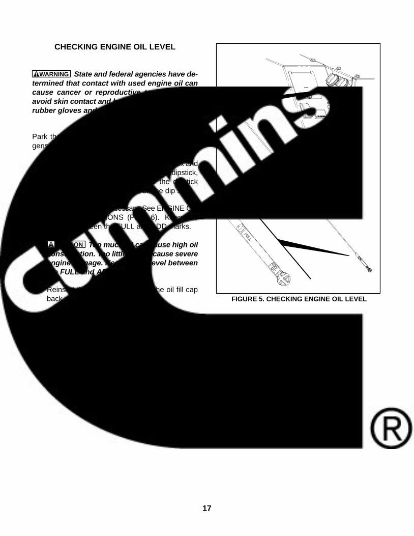
CHECKING ENGINE OIL LEVEL
WARNING State and federal agencies have de-termined that contact with used engine oil cancause cancer or reproductive toxicity. Try toavoid skin contact and breathing of vapors. Userubber gloves and wash exposed skin.
Park the vehicle on level ground and shut off thegenset before checking the engine oil level.
1. Unscrew the oil fill cap, pull out the dipstick andwipe off the oil (Figure 5). Reinsert the dipstick,screw the cap back on, remove the dipstickagain and check the oil level on the dip stick.
2. Add or drain oil as necessary. See ENGINE OILRECOMMENDATIONS (Page 6). Keep theoil level between the FULL and ADD marks.
CAUTION Too much oil can cause high oilconsumption. Too little oil can cause severeengine damage. Keep the oil level betweenthe FULL and ADD marks.
3. Reinsert the dipstick and screw the oil fill capback on securely. FIGURE 5. CHECKING ENGINE OIL LEVEL
18
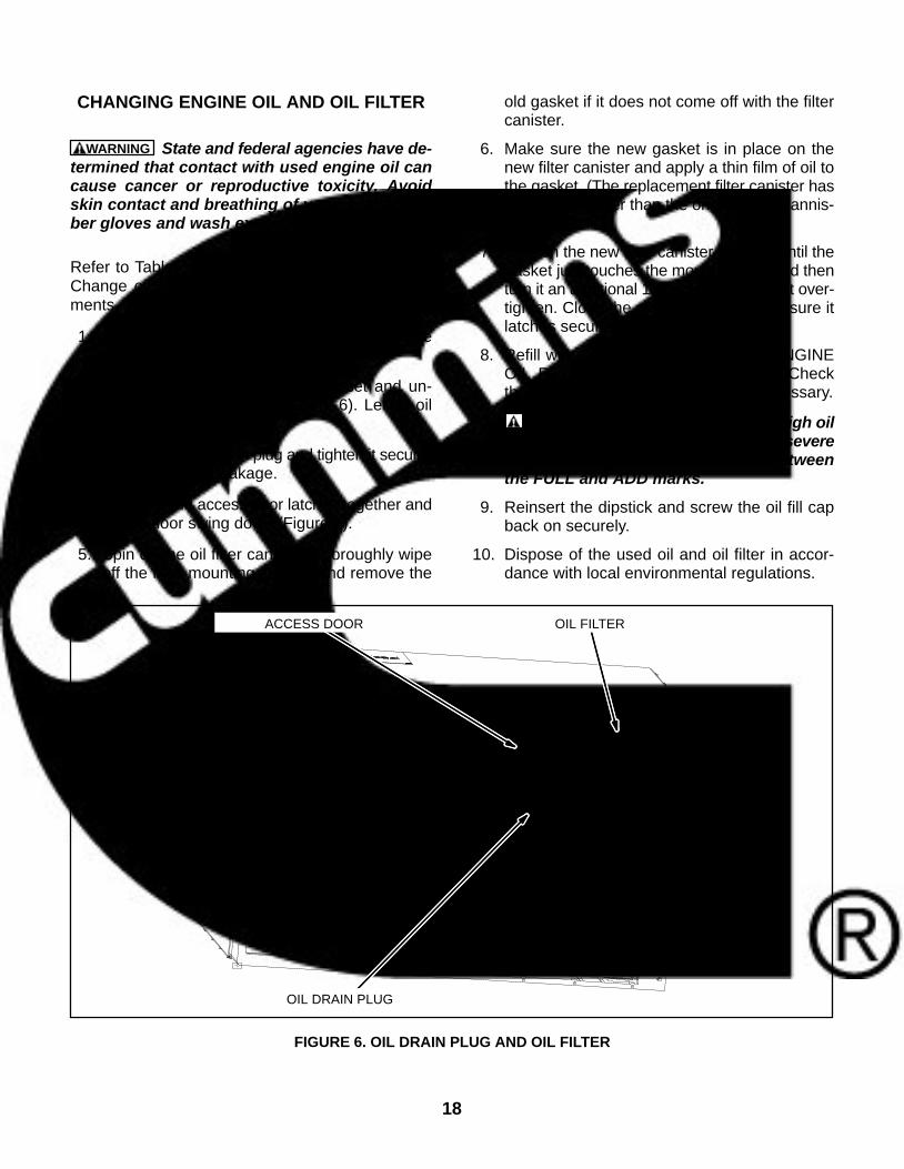
CHANGING ENGINE OIL AND OIL FILTER
WARNING State and federal agencies have de-termined that contact with used engine oil cancause cancer or reproductive toxicity. Avoidskin contact and breathing of vapors. Use rub-ber gloves and wash exposed skin.
Refer to Table 3 for scheduled engine oil change.Change oil more often in hot and dusty environ-ments.
1. Run the engine until warm, stop it and removethe oil fill cap and dipstick (Figure 5).
2. Place a pan underneath the genset and un-screw the oil drain plug (Figure 6). Let all oildrain from the engine.
3. Reinstall the oil drain plug and tighten it secure-ly to prevent oil leakage.
4. Squeeze the access door latches together andlet the door swing down (Figure 6).
5. Spin off the oil filter canister. Thoroughly wipeoff the filter mounting surface and remove the
old gasket if it does not come off with the filtercanister.
6. Make sure the new gasket is in place on thenew filter canister and apply a thin film of oil tothe gasket. (The replacement filter canister hasa larger diameter than the original filter cannis-ter, but will fit.)
7. Spin on the new filter canister by hand until thegasket just touches the mounting pad and thenturn it an additional 1/2 to 3/4 turn. Do not over-tighten. Close the access door, making sure itlatches securely.
8. Refill with 3 quarts (2.6 l) of oil. See ENGINEOIL RECOMMENDATIONS (Page 6). Checkthe oil level and add or drain oil as necessary.
CAUTION Too much oil can cause high oilconsumption. Too little oil can cause severeengine damage. Keep the oil level betweenthe FULL and ADD marks.
9. Reinsert the dipstick and screw the oil fill capback on securely.
10. Dispose of the used oil and oil filter in accor-dance with local environmental regulations.
OIL DRAIN PLUG
OIL FILTERACCESS DOOR
FIGURE 6. OIL DRAIN PLUG AND OIL FILTER
19
MAINTAINING THE BATTERY ANDBATTERY CONNECTIONS
WARNING Arcing at battery terminals or inlight switches or other equipment, and flames orsparks, can ignite battery gas causing severepersonal injury.
Ventilate battery area before working on or nearbattery—Wear safety glasses—Do not smoke—Switch trouble light ON or OFF away from bat-tery—Stop genset and disconnect charger be-fore disconnecting battery cables—Disconnectnegative (−) cable first and reconnect last.
Refer to Table 3 for scheduled battery maintenance,and follow the battery manufacturer’s instructions.Have the battery charging system serviced if DCsystem voltage is consistently low or high. Always:
1. Keep the battery case and terminals clean anddry and the terminals tight.
2. Remove battery cables with a battery terminalpuller.
3. Make sure which terminal is positive (+) andwhich is negative (−) before making batteryconnections, always removing the negative (−)cable first and reconnecting it last to reducearcing.
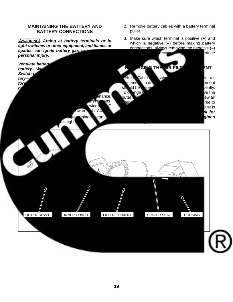
REPLACING THE AIR FILTER ELEMENT
Refer to Table 3 for scheduled air filter element re-placement. In dusty environments the filter elementshould be inspected and changed more frequently.To change the filter element (Figure 7), remove theouter and inner cover and reassemble with a new airfilter element. Turn the inner cover wingnut three tofour clicks past seating. Make sure the outer cover isseated before tightening its wingnut. Check fornoise when the genset is running, and retightenif necessary.
OUTER COVER INNER COVER FILTER ELEMENT SPACER SEAL HOUSING
FIGURE 7. REPLACING THE AIR FILTER ELEMENT
20
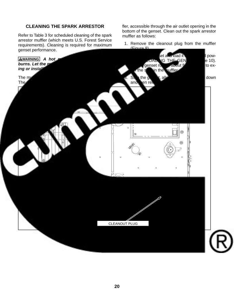
CLEANING THE SPARK ARRESTOR
Refer to Table 3 for scheduled cleaning of the sparkarrestor muffler (which meets U.S. Forest Servicerequirements). Cleaning is required for maximumgenset performance.
WARNING A hot muffler can cause severeburns. Let the muffler cool down before remov-ing or installing the cleanout plug.
The muffler is mounted inside the genset housing.The cleanout plug is located on the side of the muf-
fler, accessible through the air outlet opening in thebottom of the genset. Clean out the spark arrestormuffler as follows:
1. Remove the cleanout plug from the muffler(Figure 8).
2. Restart the genset and load it nearly to full pow-er. See LOADING THE GENSET (Page 10).Let the genset run for about five minutes to ex-pel the soot in the muffler.
3. Stop the genset, allow the muffler to cool downand then reinstall the plug.
CLEANOUT PLUG
FIGURE 8. SPARK ARRESTOR CLEANOUT PLUG
21
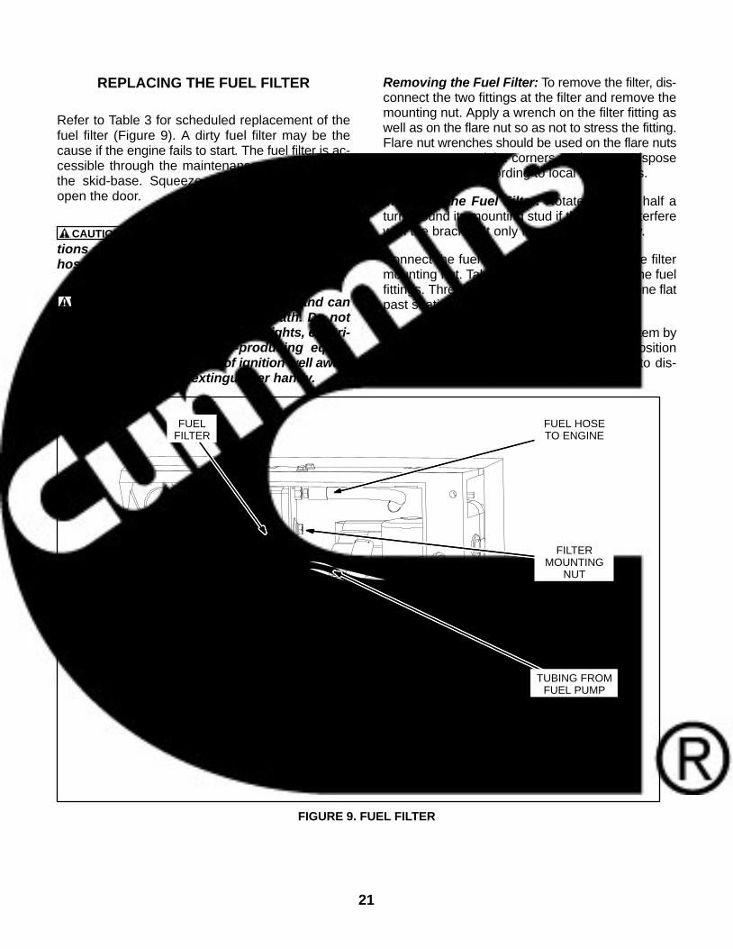
REPLACING THE FUEL FILTER
Refer to Table 3 for scheduled replacement of thefuel filter (Figure 9). A dirty fuel filter may be thecause if the engine fails to start. The fuel filter is ac-cessible through the maintenance access door inthe skid-base. Squeeze the latches together toopen the door.
CAUTION Wipe dirt off the fuel hose connec-tions at the fuel filter before disconnecting thehoses so as to keep dirt out of the fuel system.
WARNING Diesel fuel is combustible and cancause severe personal injury or death. Do notsmoke. Keep flames, sparks, pilot lights, electri-cal arcs, switches and arc-producing equip-ment and all other sources of ignition well away.Keep a type ABC fire extinguisher handy.
Removing the Fuel Filter: To remove the filter, dis-connect the two fittings at the filter and remove themounting nut. Apply a wrench on the filter fitting aswell as on the flare nut so as not to stress the fitting.Flare nut wrenches should be used on the flare nutsso as not to round the corners on the nuts. Disposeof the fuel filter according to local regulations.
Installing the Fuel Filter: Rotate the filter half aturn around its mounting stud if the fittings interferewith the bracket. It only fits properly one way.
Connect the fuel fittings before tightening the filtermounting nut. Take care not to crossthread the fuelfittings. Thread them in by hand and tighten one flatpast seating.
Close the access door and prime the fuel system byholding the control switch down in its Stop positionfor at least 1 minute. Priming is necessary to dis-place the air in the new filter with fuel.
FILTERMOUNTING
NUT
TUBING FROMFUEL PUMP
FUEL HOSETO ENGINE
FUELFILTER
FIGURE 9. FUEL FILTER

22
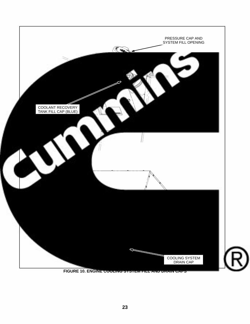
CHANGING COOLANT
Refer to Table 3 for scheduled maintenance. Theengine cooling system is filled with a 50/50 mixtureof ethylene glycol anti-freeze and water when thegenset leaves the factory, which is suitable for tem-peratures down to -34 F (-37 C).
Replace the coolant every two years. Use ethyleneor propylene glycol anti-freeze solution that con-tains a rust and corrosion inhibitor. The anti-freezeshould not contain a stop-leak additive.
The water used for engine coolant should be clean,low in minerals, and free of corrosive chemicals.Use distilled water if available. The cooling systemhas a 4.2 quart (4 l) capacity.
Pressure Cap
Replace the pressure cap (Figure 10) every twoyears because its seals can deteriorate and begin toleak. Proper cooling system pressure is essentialfor optimal engine cooling and minimal coolant loss.
Draining the Cooling System
WARNING Hot coolant spray can cause severeburns. Let the engine cool before releasing thepressure cap or removing the drain cap.
Allow the engine to cool before removing the pres-sure cap. Then relieve any remaining pressure byturning the pressure cap slowly, without pushingdown on it, until it catches. When the pressure hasbeen relieved, remove the pressure cap by pushing
down and turning it until it can be withdrawn. Thenget a suitable container and drain the coolant by re-moving the system drain cap (Figure 10).
WARNING Ethylene glycol antifreeze is con-sidered toxic. Dispose of it according to localregulations for hazardous substances.
It is recommended that the system be cleaned andflushed before refilling. Radiator cleaning chemicalsare available at local auto parts stores. Follow theinstructions for cleaning and flushing that come withthe cleaning solution.
Refilling the Cooling System
Fill the recovery tank with coolant mixture to theCOLD mark.
Secure the system drain cap. Fill the cooling systemwith coolant mixture through the pressure cap/fillopening. Pull the hose connected to the pressurecap assembly out as far as it will go. When coolantfills up to the fill opening, start and operate the gen-set for a few minutes and shut it down. (It is recom-mended that the air conditioners or other large loadsbe turned on so that the genset will operate underload, causing the engine to run faster and expeltrapped air.) Add more coolant if necessary and se-cure the pressure cap.
Coolant Level Check
Check coolant level in the recovery tank (Figure 10)before the first startup of each day and fill to theCOLD mark if necessary.
23
PRESSURE CAP ANDSYSTEM FILL OPENING
COOLING SYSTEMDRAIN CAP
COOLANT RECOVERYTANK FILL CAP (BLUE)
FIGURE 10. ENGINE COOLING SYSTEM FILL AND DRAIN CAPS

24
THIS PAGE IS INTENDED TO BE BLANK
25
TroubleshootingWARNING Hot engine parts can cause severe
burns. Always allow the engine time to cool be-fore performing any maintenance or service.
TABLE 4. TROUBLESHOOTING lists the FaultCodes in numerical order along with step-by-stepinstructions for corrective action. If you fail to re-solve the problem after taking the corrective actionssuggested, contact an authorized Onan dealer. SeeHow to Obtain Service (Page 39).
First note the following:
Maintaining engine oil level, keeping batteryconnections clean and tight, watching the fuelgauge, not overloading the genset, etc. willprevent most shutdowns.
When the genset and vehicle engine share acommon fuel tank the fuel dip tubes are usual-ly arranged so that the genset will run out offuel first. Marking the genset empty point onthe fuel gauge will make it easier to tell whento stop the genset before running it out of fuel.
FAULT CODES
The genset controller provides extensive diagnos-tics by causing the status indicator light on the Con-trol Switch to blink in a coded fashion. Proper proce-dure for obtaining the last recorded fault code:
1. To wake the control: Press and hold the STOP/Prime button until the indicator light illuminates (3−4seconds). Then release.
2. Press the STOP/Prime button 3 times within 5seconds to display the first level shutdown faultcode. The indicator light will repeatedly blink 1, 2,3,or 4 blinks at a time:
1 Blink: indicates shutdown due to high enginecoolant temperature. For example: blink−−−long pause−−−blink−−−long pause−−−repeat
2 Blinks: indicates a low oil pressure fault. ForExample: blink−blink−−long pause−−blink−blink−−long pause−−repeat
3 Blinks: indicates a service fault. For exam-ple:blink−blink−blink−long pause−repeat
4 Blinks: indicates that cranking exceeded 30seconds without the engine starting. For ex-ample:blink−blink−blink−blink−long pause−repeat
Note: Fault Code Nos. 1, 2, 3, and 4 are first levelfaults. Pay close attention to the pause se-quence to avoid interpreting first level faults assecond level Fault Codes Nos. 11, 22, 33, or 44.
Press STOP/Prime once more to cause the two−digit, second−level fault to blink. (Pressing STOP/Prime again will stop the blinking.) The two−digitcode consists of 1, 2, 3, 4, or 5 blinks, a short pause,and then 1 to 9 blinks. The first set of blinks repre-sents the tens digit and the second set of blinks rep-resents the ones digit of the fault code number. Thesecond set of blinks for the ones digit will blink slight-ly slower than the tens digit. For example, FaultCode No. 36 appears as:blink−blink−blink−shortpause−blink−blink−blink−blink−blink−blink−
long pause−repeat
Note: Generator systems equipped with anAutoGen Start of AGS feature may experi-ence shutdowns with no Fault Codes. Thisis because the AutoGen Start control issending the generator control a signal thatis sensed as a normal shutdown signal.
Because different fault logics are used on differentproducts, refer to the appropriate product’s servicemanual to translate the blink code shutdown fault.Each fault will have a description of the shutdownreason and a list of step bystep corrective actions.
Restoring Fault Code Blinking: The fault codestops blinking after five minutes. Press Stop threetimes within five seconds to restore blinking. Notethat the last fault logged will blink, even after thecondition that caused the shutdown has been cor-rected.
26
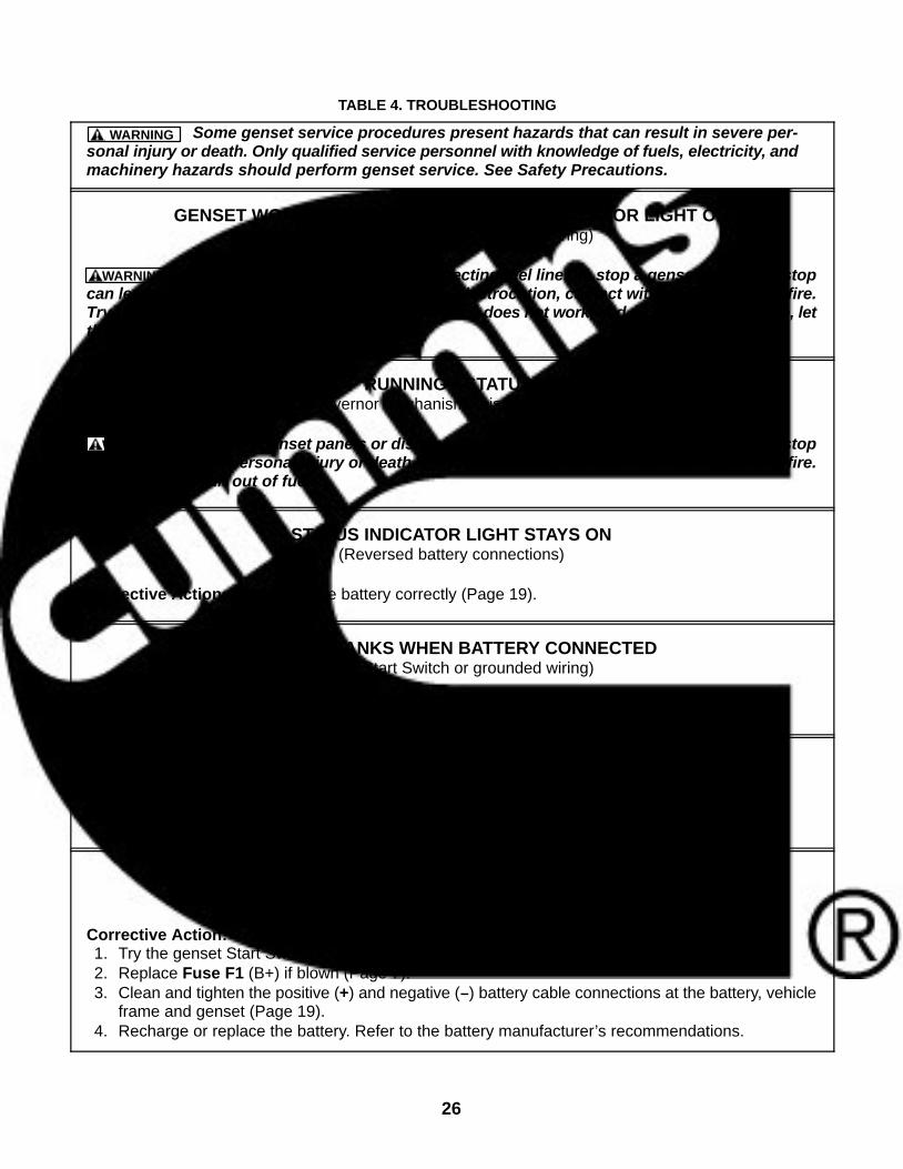
TABLE 4. TROUBLESHOOTING
Some genset service procedures present hazards that can result in severe per-sonal injury or death. Only qualified service personnel with knowledge of fuels, electricity, andmachinery hazards should perform genset service. See Safety Precautions.
WARNING
GENSET WON’T STOP RUNNING—STATUS INDICATOR LIGHT ON(Faulty Stop Switch or grounded wiring)
Removing genset panels or disconnecting fuel lines to stop a genset that won’t stopcan lead to severe personal injury or death from electrocution, contact with moving parts or fire.Try the genset Stop Switch if the remote Stop Switch does not work, and vice versa. Otherwise, letthe genset run out of fuel.
WARNING
GENSET WON’T STOP RUNNING—STATUS INDICATOR LIGHT OFF(Binding governor mechanism, misadjusted speed stop)
Removing genset panels or disconnecting fuel lines to stop a genset that won’t stopcan lead to severe personal injury or death from electrocution, contact with moving parts or fire.Let the genset run out of fuel.
WARNING
STATUS INDICATOR LIGHT STAYS ON(Reversed battery connections)
Corrective Action: Reconnect the battery correctly (Page 19).
ENGINE CRANKS WHEN BATTERY CONNECTED(Faulty Start Switch or grounded wiring)
Corrective Action: See an authorized Onan dealer.
ENGINE WON’T CRANK—FUEL PUMP WON’T STOP(Faulty Stop Switch or grounded wiring)
Corrective Action: See an authorized Onan dealer.
STATUS INDICATOR LIGHT DEAD(Faulty connections, no battery voltage)
Corrective Action:1. Try the genset Start Switch if the remote Start Switch does not work, and vice versa.2. Replace Fuse F1 (B+) if blown (Page 7).3. Clean and tighten the positive (+) and negative (−) battery cable connections at the battery, vehicle
frame and genset (Page 19).4. Recharge or replace the battery. Refer to the battery manufacturer’s recommendations.

27
TABLE 4. TROUBLESHOOTING (CONT.)
Some genset service procedures present hazards that can result in severe per-sonal injury or death. Only qualified service personnel with knowledge of fuels, electricity, andmachinery hazards should perform genset service. See Safety Precautions.
WARNING
STARTING BATTERIES RUN DOWN(Marginal battery, battery connections, or charging system; or parasitic loads)
Corrective Action:1. Clean and tighten the positive (+) and negative (−) battery cable connections at the battery, vehicle
frame and genset (Page 19).2. Recharge or replace the battery. Refer to the battery manufacturer’s recommendations.
ENGINE CRANKS BUT DOES NOT START(Fuel delivery, glow plugs or engine are marginal)
Corrective Action:1. Check fuel level. (Note: The genset fuel pickup is probably higher than the vehicle engine pickup.)2. Prime the engine fuel system by holding the control switch down in its Stop position for at least 1 min-
ute.3. Check the engine air filter and remove any blockage (Page 19).4. Replace Fuse F3 (glow plugs) if blown (Page 7).
STARTER ENGAGES-DISENGAGES(Cranking voltage dips below 6 volts—low battery charge, poor connections, long cables)
Corrective Action:1. Have the vehicle propulsion engine running while trying to start the genset—the battery charging
alternator may be able to maintain starting voltage high enough to get the genset started.2. Clean and tighten the positive (+) and negative (−) battery cable connections at the battery, vehicle
frame and genset (Page 19).3. Recharge or replace the battery. Refer to the battery manufacturer’s recommendations.4. Increase battery cable size or run parallel cables.
NO POWER—GENSET RUNNING, RUN LIGHT ON(Line circuit breaker OFF or tripped or faulty wiring)
Corrective Action: Reset or turn “On” the line circuit breaker on the genset operator’s console.
GENSET HUNTS UNDER FULL LOAD(Fuel delivery marginal, governor misadjusted)
Corrective Action: Prime the engine fuel system by holding the control switch down in its Stop posi-tion for at least 1 minute.

28
TABLE 4. TROUBLESHOOTING (CONT.)
Some genset service procedures present hazards that can result in severe per-sonal injury or death. Only qualified service personnel with knowledge of fuels, electricity, andmachinery hazards should perform genset service. See Safety Precautions.
WARNING
HIGH TEMPERATURE—FAULT CODE NO. 1(Engine coolant or inverter heat sink temperature exceeded design limit)
Corrective Action: Check the second-level fault code by touching Stop. The second-level fault will beeither No. 33 or No. 34.
LOW OIL PRESSURE—FAULT CODE NO. 2(Low oil pressure cutoff switch did not open)
Corrective Action:1. Check engine oil level and add oil as necessary (Page 17).2. Drain excess oil (above dipstick Full mark).
SERVICE CHECK FAULT—CODE NO. 3(A second-level fault occurred)
Corrective Action: Check the second-level fault code by touching Stop. The second-level fault will beone of the following in this table.
OVERLOAD—CODE NO. 8(Models HDKAH & HDKAV only: Load exceeded110 percent of genset rating for 2 minutes)
Corrective Action: Reduce load and restart
OVERCURRENT FAULT—CODE NO. 11(AC output short)
Corrective Action:1. Turn off the genset line circuit breaker. If the genset no longer shuts down, the genset is probably
okay—check for and repair a short circuit in the vehicle appliances, wiring or shorted battery chargertransformer.
2. Check whether the vehicle engine and genset share the same starting battery. If so, and this faultoccurs when cranking the vehicle engine, low battery voltage may be causing this shutdown. In-crease battery capacity or install a separate battery and battery charging system for the genset.

29
TABLE 4. TROUBLESHOOTING (CONT.)
Some genset service procedures present hazards that can result in severe per-sonal injury or death. Only qualified service personnel with knowledge of fuels, electricity, andmachinery hazards should perform genset service. See Safety Precautions.
WARNING
INVERTER OVERVOLTAGE FAULT—CODE NO. 12(Controller not able to regulate to rated voltage)
Corrective Action: Check whether the vehicle engine and genset share the same starting battery. Ifso, and this fault occurs when cranking the vehicle engine, low battery voltage may be causing thisshutdown. Increase battery capacity or install a separate battery and battery charging system for thegenset.
INVERTER UNDERVOLTAGE FAULT—CODE NO. 13(Controller not able to regulate to rated voltage)
Corrective Action: Check whether the vehicle engine and genset share the same starting battery. Ifso, and this fault occurs when cranking the vehicle engine, low battery voltage may be causing thisshutdown. Increase battery capacity or install a separate battery and battery charging system for thegenset.
INVERTER OVERFREQUENCY FAULT—CODE NO. 14(Controller not able to regulate to rated frequency)
Corrective Action: Reduce the number of connected appliances, especially when air conditioners andbattery chargers are running.
INVERTER UNDERFREQUENCY FAULT—CODE NO. 15(Controller not able to regulate to rated frequency)
Corrective Action:1. Reduce the number of connected appliances, especially when air conditioners and battery chargers
are running.2. Have air conditioners and other appliances checked for proper operation. (A locked compressor ro-
tor can cause very low power factor.)
GOVERNOR ACTUATOR FAULT—CODE NO. 19(Controller sensed open or short circuit)
Corrective Action: See an authorized Onan dealer.
GOVERNOR ACTUATOR OVERLOAD FAULT—CODE NO. 22(Duration of operation at or near full-duty cycle beyond design limit)
Corrective Action: Reduce the number of connected appliances, especially when air conditioners andbattery chargers are running.
30
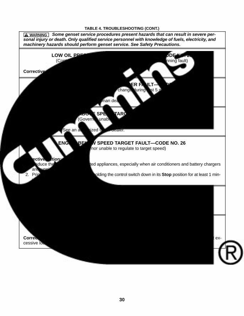
TABLE 4. TROUBLESHOOTING (CONT.)
Some genset service procedures present hazards that can result in severe per-sonal injury or death. Only qualified service personnel with knowledge of fuels, electricity, andmachinery hazards should perform genset service. See Safety Precautions.
WARNING
LOW OIL PRESSURE CUTOFF SWITCH FAULT—CODE NO. 23(Controller sensed switch still open during start—not a running fault)
Corrective Action: See an authorized Onan dealer.
COOLANT TEMPERATURE SENDER FAULT—CODE NO. 24(Controller did not sense temperature change during first 5 minutes of operation)
Corrective Action: See an authorized Onan dealer.
ENGINE ABOVE SPEED TARGET FAULT—CODE NO. 25(Governor unable to regulate to target speed)
Corrective Action: See an authorized Onan dealer.
ENGINE BELOW SPEED TARGET FAULT—CODE NO. 26(Governor unable to regulate to target speed)
Corrective Action:1. Reduce the number of connected appliances, especially when air conditioners and battery chargers
are running.2. Prime the engine fuel system by holding the control switch down in its Stop position for at least 1 min-
ute.
PMA SENSE LOST FAULT—CODE NO. 27(Controller unable to sense PMA frequency)
Corrective Action: See an authorized Onan dealer.
DC SENSE LOST FAULT—CODE NO. 28(Controller unable to sense DC bus voltage)
Corrective Action: Open the circuit breaker. If the fault does not persist, check for and disconnect ex-cessive loads from the genset before starting.

31
TABLE 4. TROUBLESHOOTING (CONT.)
Some genset service procedures present hazards that can result in severe per-sonal injury or death. Only qualified service personnel with knowledge of fuels, electricity, andmachinery hazards should perform genset service. See Safety Precautions.
WARNING
HIGH BATTERY VOLTAGE FAULT—CODE NO. 29(Voltage across battery system greater than 17.5 volts)
Corrective Action:1. Check battery bank connections and reconnect if necessary so that the 12 volt batteries serving the
genset are connected in parallel (12 volt) rather than in series (24 volt).2. Select a lower battery booster charge rate.
OVERSPEED FAULT—CODE NO. 31(Engine speed greater than 3600 rpm)
Corrective Action: See an authorized Onan dealer.
LOW CRANKING SPEED FAULT—CODE NO. 32(Cranking speed less than 180 rpm for more than 2 seconds)
Corrective Action:1. Replace Fuse F2 (starter solenoid) if blown (Page 7).2. Clean and tighten the positive (+) and negative (−) battery cable connections at the battery and at
the genset (Page 19).3. Recharge or replace the battery. Refer to the battery manufacturer’s recommendations.4. Replace the engine oil with oil of proper viscosity for the ambient temperature (Page 18). (High oil
viscosity can slow cranking speed.)
HIGH ENGINE COOLANT TEMPERATURE FAULT—CODE NO. 33(Engine coolant temperature exceeded design limit)
Corrective Action:1. Check the engine coolant level and add coolant and repair leaks as necessary (Page 22).2. Check for and remove any objects blocking the air inlet or outlet openings in the bottom of the genset.3. Reduce the number of appliances connected at the same time. (Note that high altitude and high am-
bient temperature decrease engine cooling capacity.)4. Clean and flush the cooling system to remove coolant passage fouling.5. If the genset overheats only underway, see the coach manufacture regarding air baffles or other
means to direct cooling air into the genset.
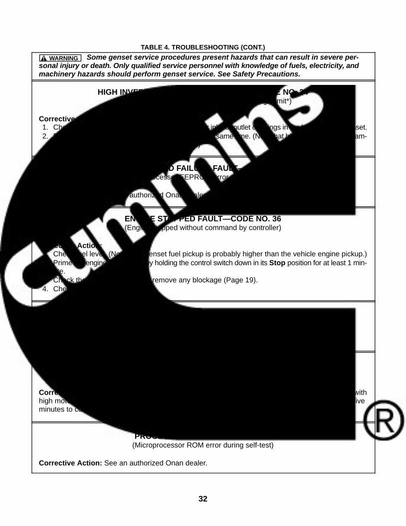
32
TABLE 4. TROUBLESHOOTING (CONT.)
Some genset service procedures present hazards that can result in severe per-sonal injury or death. Only qualified service personnel with knowledge of fuels, electricity, andmachinery hazards should perform genset service. See Safety Precautions.
WARNING
HIGH INVERTER TEMPERATURE FAULT—CODE NO. 34(Inverter heat sink temperature exceeded design limit*)
Corrective Action:1. Check for and remove any objects blocking the air inlet or outlet openings in the bottom of the genset.2. Reduce the number of appliances connected at the same time. (Note that high altitude and high am-
bient temperature decrease cooling capacity.)
CONTROL CARD FAILURE FAULT—CODE NO. 35(Microprocessor EEPROM error during self-test)
Corrective Action: See an authorized Onan dealer.
ENGINE STOPPED FAULT—CODE NO. 36(Engine stopped without command by controller)
Corrective Action:1. Check fuel level. (Note: The genset fuel pickup is probably higher than the vehicle engine pickup.)2. Prime the engine fuel system by holding the control switch down in its Stop position for at least 1 min-
ute.3. Check the engine air filter and remove any blockage (Page 19).4. Check for mechanical damage.
INVALID GENSET CONFIGURATION FAULT—CODE NO. 37(Genset configuration is preprogrammed at the factory)
Corrective Action: See an authorized Onan dealer.
OVERCURRENT FAULT—CODE NO. 38(Too many loads connected)
Corrective Action: Reduce the number of appliances running at the same time, especially those withhigh motor starting loads such as air conditioners. Start up with no load and let the genset run for fiveminutes to cool down the inverter.
PROCESSOR FAULT—CODE NO. 42(Microprocessor ROM error during self-test)
Corrective Action: See an authorized Onan dealer.
33
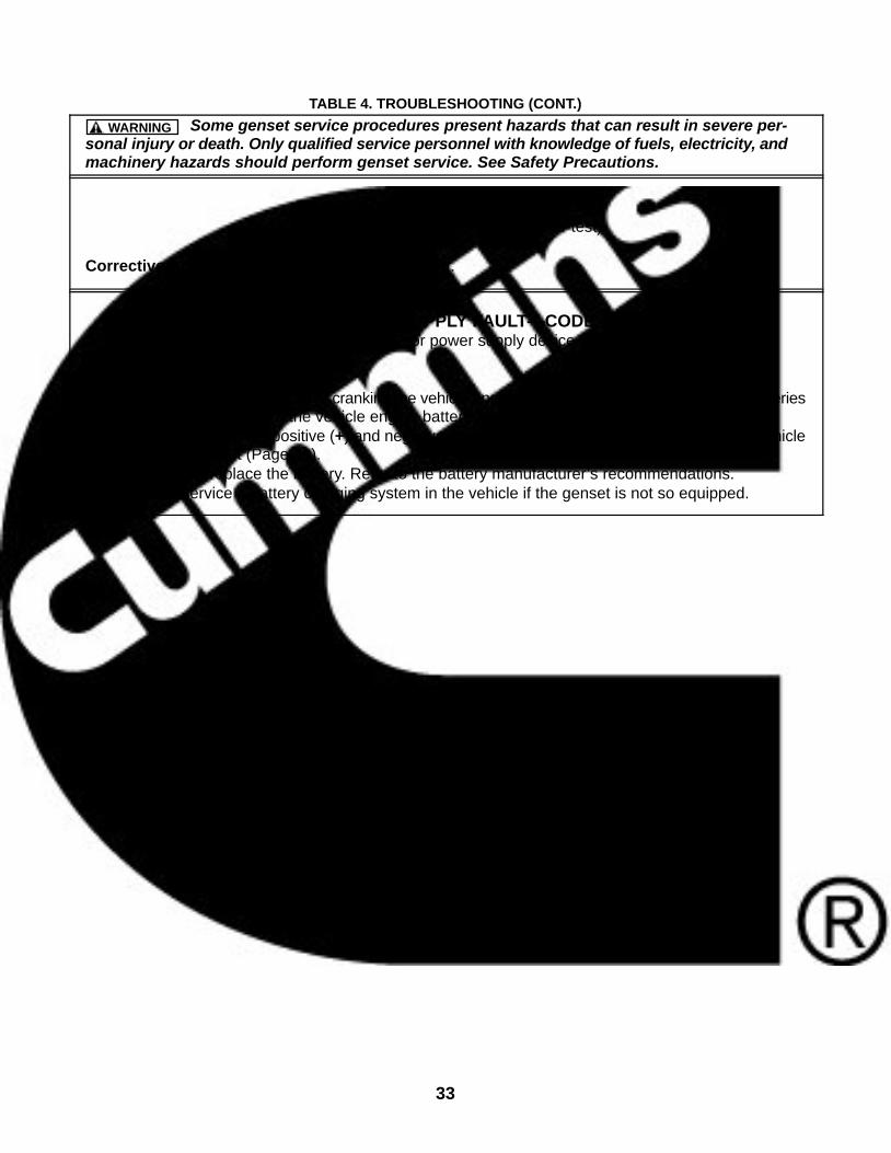
TABLE 4. TROUBLESHOOTING (CONT.)
Some genset service procedures present hazards that can result in severe per-sonal injury or death. Only qualified service personnel with knowledge of fuels, electricity, andmachinery hazards should perform genset service. See Safety Precautions.
WARNING
PROCESSOR FAULT—CODE NO. 43((Microprocessor RAM error during self-test)
Corrective Action: See an authorized Onan dealer.
INVERTER POWER SUPPLY FAULT—CODE NO. 46(Low battery voltage or power supply device failure)
Corrective Action:1. Avoid running the genset while cranking the vehicle engine in installations where the genset batteries
are used to supplement the vehicle engine batteries.2. Clean and tighten the positive (+) and negative (−) battery cable connections at the battery, vehicle
frame and genset (Page 19).3. Recharge or replace the battery. Refer to the battery manufacturer’s recommendations.4. Install or service a battery charging system in the vehicle if the genset is not so equipped.

34
THIS PAGE IS INTENDED TO BE BLANK
35
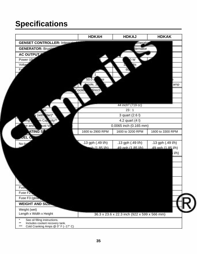
Specifications
HDKAH HDKAJ HDKAK
GENSET CONTROLLER: Integrated Microprocessor Based Engine and Generator Controller
GENERATOR: Brushless, Exciterless, Bearingless, Permanent Magnet Alternator
AC OUTPUT RATINGS:Power (@1.0 power factor) 6000 W 7500 W 8000 W
Voltage 120 volts 120 volts 120 volts
Frequency 60 Hz 60 Hz 60 Hz
Number of Phases 1 1 1
Current 50.0 ampere 62.5 ampere 66.7 ampere
Line Circuit Breaker(s) 2-pole, 30 amp 2-pole, 30 or 35 amp 2-pole, 30 or 35 amp
ENGINE: 3-Cylinder In-Line, Water-Cooled, Indirect-Injection, 4-Stroke Cycle DieselBore 2.64 inch (67 mm)
Stroke 2.68 inch (68 mm)
Displacement 44 inch3 (719 cc)
Compression Ratio 23 : 1
Oil Capacity (with filter)* 3 quart (2.6 l)
Cooling System Capacity** 4.2 quart (4 l)
Intake and Exhaust Valve Lash (Cold) 0.0065 inch (0.165 mm)
OPERATING SPEED RANGE: 1600 to 2900 RPM 1600 to 3200 RPM 1600 to 3300 RPM
FUEL CONSUMPTION:
No-loadHalf-load (4000 W)Full-load
.13 gph (.49 l/h)
.49 gph (1.85 l/h)
.80 gph (3.03 l/h)
.13 gph (.49 l/h)
.49 gph (1.85 l/h)
.96 gph (3.63 l/h)
.13 gph (.49 l/h)
.49 gph (1.85 l/h)
1.02 gph (3.86 l/h)
DC SYSTEM:Nominal Battery Voltage 12 volts
Minimum Battery Capacity450 CCA*** down to 0 F (−17 C)
650 CCA*** down to −20 F (−29 C)Maximum Regulated-Voltage BatteryCharging Current (Optional) 10 ampere
Fuse F1 (control circuit) 10 ampere mini-bayonet
Fuse F2 (starter solenoid circuit) 10 ampere mini-bayonet
Fuse F3 (glow plug circuit) 25 ampere
WEIGHT AND SIZE:
Weight (wet)Length x Width x Height
420 lbs (191 kg)
36.3 x 23.6 x 22.3 inch (922 x 599 x 566 mm)
* See oil filling instructions.** Includes coolant recovery tank.*** Cold Cranking Amps @ 0 F (−17 C)

36
HDKAV HDKAT HDKAUGENSET CONTROLLER: Integrated Microprocessor Based Engine and Generator Controller
GENERATOR: Brushless, Exciterless, Bearingless, Permanent Magnet Alternator
AC OUTPUT RATINGS:Power (@1.0 power factor) 6000 W 7500 W 8000 W
Voltage 120 volts 120 volts 120 volts
Frequency 60 Hz 60 Hz 60 Hz
Number of Phases 1 1 1
Current 50.0 ampere 62.5 ampere 66.7 ampere
Line Circuit Breaker(s) 2-pole, 30 amp 2-pole, 30 or 35 amp 2-pole, 30 or 35 amp
ENGINE: 3-Cylinder In-Line, Water-Cooled, Indirect-Injection, 4-Stroke Cycle DieselBore 2.64 inch (67 mm)
Stroke 2.68 inch (68 mm)
Displacement 44 inch3 (719 cc)
Compression Ratio 23 : 1
Oil Capacity (with filter)* 3 quart (2.6 l)Cooling System Capacity** 4.2 quart (4 l)Intake and Exhaust Valve Lash (Cold) 0.0065 inch (0.165 mm)
OPERATING SPEED RANGE: 1600 to 2900 RPM 1600 to 3200 RPM 1600 to 3300 RPM
FUEL CONSUMPTION:
No-loadHalf-load (4000 W)Full-load
.13 gph (.49 l/h)
.49 gph (1.85 l/h)
.80 gph (3.03 l/h)
.13 gph (.49 l/h)
.49 gph (1.85 l/h)
.96 gph (3.63 l/h)
.13 gph (.49 l/h)
.49 gph (1.85 l/h)
1.02 gph (3.86 l/h)
DC SYSTEM:Nominal Battery Voltage 12 volts
Minimum Battery Capacity450 CCA*** down to 0 F (−17 C)
650 CCA*** down to −20 F (−29 C)Maximum Regulated-Voltage BatteryCharging Current (Optional) 10 ampere
Fuse F1 (control circuit) 10 ampere mini-bayonetFuse F2 (starter solenoid circuit) 10 ampere mini-bayonetFuse F3 (glow plug circuit) 25 ampere
WEIGHT AND SIZE:
Weight (wet)Length x Width x Height
420 lbs (191 kg)
36.3 x 23.6 x 22.3 inch (922 x 599 x 566 mm)
* See oil filling instructions.** Includes coolant recovery tank.*** Cold Cranking Amps @ 0 F (−17 C)

37
Information for California Genset UsersThese gensets meet the requirements of Californi-a’s Exhaust Emissions Standards as stated on thenameplate (Page 3).
As a California user of these gensets, please beaware that unauthorized modifications or replace-ment of fuel, exhaust, air intake, or speed controlsystem components that affect engine emissionsare prohibited. Unauthorized modification, removalor replacement of the genset label is prohibited.
You should carefully review Operator (Owner),Installation and other manuals and information youreceive with your genset. If you are unsure that theinstallation, use, maintenance or service of yourgenset is authorized, you should seek assistancefrom an approved Onan dealer.
California genset users may use Table 5 as an aid inlocating information related to the California Air Re-sources Board requirements for emissions control.
TABLE 5. EMISSIONS CONTROL INFORMATION
Genset Warranty InformationThe California emissions control warranty statement is located inthe same packet of information as this manual when the genset isshipped from the factory.
Engine Valve Clearance (Lash) See Specifications (Page 35).
Engine Fuel RequirementsThe engine is certified to operate on diesel fuel. See FUEL REC-OMMENDATIONS (Page 6).
Engine Lubricating Oil Requirements See ENGINE OIL RECOMMENDATIONS (Page 6).
Engine AdjustmentsHigh Idle Speed. This is a service procedure requiring trainedpersonnel and proper tools. See the Service Manual.
Engine Emission Control SystemThe engine emission control system consists of engine designand precision manufacture. (IFI)

38
THIS PAGE IS INTENDED TO BE BLANK
39
How to Obtain ServiceWhen you need parts or service for your genset con-tact the nearest authorized dealer or distributor.Onan has factory-trained representatives to handleyour needs for genset parts and service. To locatethe nearest authorized distributor:
1. Check the North American Sales and ServiceDirectory (F-118) and the International Salesand Service Directory (IN-1013) supplied withyour Onan genset. These directories list autho-rized distributors who will assist you in locatingthe nearest authorized dealer.
2. Consult the Yellow Pages. Typically, our distrib-utors are listed under:
GENERATORS − ELECTRIC,ENGINES − GASOLINE OR DIESEL, orRECREATIONAL VEHICLES − EQUIPMENT,PARTS AND SERVICE.
3. Call 1-800-888-ONAN for the name and tele-phone number of the nearest Onan dealer inthe United States or Canada. (This automatedservice utilizes touch-tone phones only). Bycalling this number you can also request a di-
rectory of authorized RV servicing dealers: RVSales and Service Directory F-919.
To get service, contact the authorized dealer or dis-tributor nearest you, explain the problem and makean appointment. If you have difficulty in arrangingfor service or resolving a problem, please contactthe dealer coordinator or service manager at thenearest Onan dealer for assistance.
Before calling for service, have the following infor-mation available:
1. The complete genset model number and serialnumber. See Model Identification (Page 4).
2. The date of purchase
3. The nature of the problem. See Troubleshoot-ing (Page 25).
WARNING Improper service or replacement ofparts can result in severe personal injury, death,and/or equipment damage. Service personnelmust be qualified to perform electrical and/ormechanical service.

40
THIS PAGE IS INTENDED TO BE BLANK
41
Maintenance RecordRecord all periodic and unscheduled maintenance and service. See Periodic Maintenance (Page 15).
DATEHOURMETER
READINGMAINTENANCE OR SERVICE PERFORMED
Record the name, address, and phone number of your authorized Onan service center.

42
THIS PAGE IS INTENDED TO BE BLANK

THIS PAGE IS INTENDED TO BE BLANK
gh414
Rectangle

Cummins Power Generation1400 73rd Ave. NEMinneapolis, MN 55432 USA
Phone 1 763 574 5000Toll-free 1 800 888 6626Fax 1 763 574 5298Email www.cumminsonan.com/contactwww.cumminsonan.comCummins�, Onan�, the “C” logo, and “Performance you rely on.”are trademarks of Cummins Inc.
�2014 Cummins Power Generation, Inc. All rights reserved.
Related Documents