Operator´s Manual

Welcome message from author
This document is posted to help you gain knowledge. Please leave a comment to let me know what you think about it! Share it to your friends and learn new things together.
Transcript

Operator´sManual
OPERATOR’SMANUAL
(Canopy, Detroit S50)

2 (55)
TKU---B 01140---1 EN 4203
SANDVIK TAMROCK CORP., TORO LOADERS DIVISION 10/2003

3 (55)
TKU---B 01140---1 EN 4203
PREFACE
Congratulations on your choice of a TORO loader.This instructionmanual shall facilitate the task to become familiar with thisTORO loader andits intended use. You are about to operate TORO 007, a diesel powered, rubber tired, lowprofile underground mining loader.Each operator should familiarize themselves with his machine and fully understand thecontents of the Operator‘s manual, Maintenance manual and the General SafetyInstructions before operating it. This manual contains the information which outlinesoperator of the components, instruments and controls. Periodic maintenance is explainedin the Maintenance Instructions. Only those who have been given proper training areallowed to operate the loader.
Continuing research and development of TORO loader may have caused changes to yourmachine which are not included in this manual.If the machine is equipped with optional equipment e.g. remote--control system you shouldfamiliarize yourself with separate instruction, where the operation is explained.
This instruction manual must be read and used by each person incharge to work with TORO 007, operating it, transporting it, servicing orrepairing it.WARNING
This manual must permanently be available in the cabin when operating the TORO.Always obey national mandatory rules relating to accident preventation and enviromentalprotection. The generally recognized technical rules for safe and professional operationmust also be observed.
For demanding maintenance and repairs, we recommend that you contact your nearestauthorized Sandvik Tamrock Service. Our maintenance personnel have the skills andspecial tools required for the most demanding tasks.Through correct use and by following the maintenance instructions, you can expect a highdegree of utilization and long operating life of your loader.

4 (55)
TKU---B 01140---1 EN 4203
PREFACE 3. . . . . . . . . . . . . . . . . . . . . . . . . . . . . . . . . . . . . . . . . . . . . . . . . . . . . . . . . . . . . . . . . . . . . . . . . . . . . . . . . . . . .
DECLARATION OF CONFORMITY 5. . . . . . . . . . . . . . . . . . . . . . . . . . . . . . . . . . . . . . . . . . . . . . . . . . . . . . . . . . . . . . .
1. INTRODUCTION TO MACHINE 6. . . . . . . . . . . . . . . . . . . . . . . . . . . . . . . . . . . . . . . . . . . . . . . . . . . . . . . . . . . . . .
1.1. Intended use 6. . . . . . . . . . . . . . . . . . . . . . . . . . . . . . . . . . . . . . . . . . . . . . . . . . . . . . . . . . . . . . . . . . . . . .
1.2. Recommended operating conditions 6. . . . . . . . . . . . . . . . . . . . . . . . . . . . . . . . . . . . . . . . . . . . . . . .
1.3. Technical details 7. . . . . . . . . . . . . . . . . . . . . . . . . . . . . . . . . . . . . . . . . . . . . . . . . . . . . . . . . . . . . . . . . .1.3.1. Noise level and noise emission 7. . . . . . . . . . . . . . . . . . . . . . . . . . . . . . . . . . . . . . . . . . . . . . . . . . . .1.3.2. Acceleration value 7. . . . . . . . . . . . . . . . . . . . . . . . . . . . . . . . . . . . . . . . . . . . . . . . . . . . . . . . . . . . . . .1.3.3. Type plate 7. . . . . . . . . . . . . . . . . . . . . . . . . . . . . . . . . . . . . . . . . . . . . . . . . . . . . . . . . . . . . . . . . . . . . .
2. SAFETY INSTRUCTIONS 8. . . . . . . . . . . . . . . . . . . . . . . . . . . . . . . . . . . . . . . . . . . . . . . . . . . . . . . . . . . . . . . . . .
2.1. Warning labels on the equipment 8. . . . . . . . . . . . . . . . . . . . . . . . . . . . . . . . . . . . . . . . . . . . . . . . . . .
2.2. Warning of injury risks 8. . . . . . . . . . . . . . . . . . . . . . . . . . . . . . . . . . . . . . . . . . . . . . . . . . . . . . . . . . . . .
2.3. Warning of damage to equipment or property 8. . . . . . . . . . . . . . . . . . . . . . . . . . . . . . . . . . . . . . . .
2.4. Read the user or maintenance instructions 8. . . . . . . . . . . . . . . . . . . . . . . . . . . . . . . . . . . . . . . . . .
2.5. Operator safety instructions 9. . . . . . . . . . . . . . . . . . . . . . . . . . . . . . . . . . . . . . . . . . . . . . . . . . . . . . . .
2.6. Main safety hazards in use or maintenance work 10. . . . . . . . . . . . . . . . . . . . . . . . . . . . . . . . . . . . .
2.7. Manners and conditions where the loader is not allowed to operate 11. . . . . . . . . . . . . . . . . . . .
2.8. Warning signs 12. . . . . . . . . . . . . . . . . . . . . . . . . . . . . . . . . . . . . . . . . . . . . . . . . . . . . . . . . . . . . . . . . . . . .
2.9. Fire prevention 14. . . . . . . . . . . . . . . . . . . . . . . . . . . . . . . . . . . . . . . . . . . . . . . . . . . . . . . . . . . . . . . . . . . .
2.10. Emergency stops and stopping devices 16. . . . . . . . . . . . . . . . . . . . . . . . . . . . . . . . . . . . . . . . . . . . .
2.11. Emergency exit 17. . . . . . . . . . . . . . . . . . . . . . . . . . . . . . . . . . . . . . . . . . . . . . . . . . . . . . . . . . . . . . . . . . . .
2.12. Safety equipment 17. . . . . . . . . . . . . . . . . . . . . . . . . . . . . . . . . . . . . . . . . . . . . . . . . . . . . . . . . . . . . . . . . .
3. OPERATION INSTRUCTIONS 18. . . . . . . . . . . . . . . . . . . . . . . . . . . . . . . . . . . . . . . . . . . . . . . . . . . . . . . . . . . . . . .
3.1. Instruments and Controls 18. . . . . . . . . . . . . . . . . . . . . . . . . . . . . . . . . . . . . . . . . . . . . . . . . . . . . . . . . .
3.2. Symbol plates and safety notes 26. . . . . . . . . . . . . . . . . . . . . . . . . . . . . . . . . . . . . . . . . . . . . . . . . . . . .
3.3. Routine checks before starting the engine 27. . . . . . . . . . . . . . . . . . . . . . . . . . . . . . . . . . . . . . . . . . .
3.4. Getting into the cabin and starting the engine 30. . . . . . . . . . . . . . . . . . . . . . . . . . . . . . . . . . . . . . . .
3.5. Routine checks before driving 33. . . . . . . . . . . . . . . . . . . . . . . . . . . . . . . . . . . . . . . . . . . . . . . . . . . . . .
3.6. Driving 35. . . . . . . . . . . . . . . . . . . . . . . . . . . . . . . . . . . . . . . . . . . . . . . . . . . . . . . . . . . . . . . . . . . . . . . . . . .3.6.1. Gradient angles 35. . . . . . . . . . . . . . . . . . . . . . . . . . . . . . . . . . . . . . . . . . . . . . . . . . . . . . . . . . . . . . . . .3.6.2. Operator visibility 36. . . . . . . . . . . . . . . . . . . . . . . . . . . . . . . . . . . . . . . . . . . . . . . . . . . . . . . . . . . . . . . .3.6.3. Setting the unit in motion 37. . . . . . . . . . . . . . . . . . . . . . . . . . . . . . . . . . . . . . . . . . . . . . . . . . . . . . . . .3.6.4. Braking 38. . . . . . . . . . . . . . . . . . . . . . . . . . . . . . . . . . . . . . . . . . . . . . . . . . . . . . . . . . . . . . . . . . . . . . . .
3.7. Parking and stopping the engine 39. . . . . . . . . . . . . . . . . . . . . . . . . . . . . . . . . . . . . . . . . . . . . . . . . . . .
3.8. Operation in cold weather 40. . . . . . . . . . . . . . . . . . . . . . . . . . . . . . . . . . . . . . . . . . . . . . . . . . . . . . . . . .
3.9. Towing 41. . . . . . . . . . . . . . . . . . . . . . . . . . . . . . . . . . . . . . . . . . . . . . . . . . . . . . . . . . . . . . . . . . . . . . . . . . .
3.10. Transporting the loader 43. . . . . . . . . . . . . . . . . . . . . . . . . . . . . . . . . . . . . . . . . . . . . . . . . . . . . . . . . . . .
3.11. Storing instructions 44. . . . . . . . . . . . . . . . . . . . . . . . . . . . . . . . . . . . . . . . . . . . . . . . . . . . . . . . . . . . . . .
3.12. Lifting methods and lifting points 45. . . . . . . . . . . . . . . . . . . . . . . . . . . . . . . . . . . . . . . . . . . . . . . . . . .
4. LOADING, HAULING AND DUMPING 46. . . . . . . . . . . . . . . . . . . . . . . . . . . . . . . . . . . . . . . . . . . . . . . . . . . . . . . .
4.1. Loading 46. . . . . . . . . . . . . . . . . . . . . . . . . . . . . . . . . . . . . . . . . . . . . . . . . . . . . . . . . . . . . . . . . . . . . . . . . .
4.2. Hauling 49. . . . . . . . . . . . . . . . . . . . . . . . . . . . . . . . . . . . . . . . . . . . . . . . . . . . . . . . . . . . . . . . . . . . . . . . . . .
4.3. Dumping 51. . . . . . . . . . . . . . . . . . . . . . . . . . . . . . . . . . . . . . . . . . . . . . . . . . . . . . . . . . . . . . . . . . . . . . . . . .
4.4. Remote--control drive (opt.) 51. . . . . . . . . . . . . . . . . . . . . . . . . . . . . . . . . . . . . . . . . . . . . . . . . . . . . . . .
5. TROUBLESHOOTING 53. . . . . . . . . . . . . . . . . . . . . . . . . . . . . . . . . . . . . . . . . . . . . . . . . . . . . . . . . . . . . . . . . . . . . .
6. TECHNICAL SPECIFICATION 54. . . . . . . . . . . . . . . . . . . . . . . . . . . . . . . . . . . . . . . . . . . . . . . . . . . . . . . . . . . . . . .

5 (55)
TKU---B 01140---1 EN 4203
DECLARATION OF CONFORMITY
Manufacturer: SANDVIK TAMROCK CORP., Turku PlantP.O. Box 434FIN--20101 TURKU, FINLAND
Herewith declares that
TORO 007 loader
has been designed and manufactured according to good mechanical engineering.

INTRODUCTION TO MACHINE
6 (55)
TKU---B 01140---1 EN 4203
1. INTRODUCTION TO MACHINE
1.1. Intended useThis TORO loader is intended to load, haul and dump rock material exclusively. Any otheruse different from this is not considered as intended. The intended use also includesfollowing the instruction manual and to observe inspection and maintenance rules.The manufacturer or supplier will not be liable for any damage resulting from the productmisuse.
The front of the unit is the end with bucket. Right and left sides of the unit are designed inreference to the operators position, looking toward the front of the unit.This TORO is designed and constructed according to the state of art and the recognizedsafety rules. Nevertheless, unintended and careless use may cause damage to health ofthe user or ohter persons, or prejudice the machine and other properties.This TORO shall be used only
. for its intended use
. when it is in mechnical and operational condition
. conscious of safety and possible danger
. in strict notice and use of the instruction manual
1.2. Recommended operating conditions
Because the TORO 007 normally operates in mine conditions, its engine, transmission andhydraulic systems are filled with oils suitable for typical conditions. However, in coldconditions oils may thicken. This makes starting difficult and the torque converter andhydraulic pumps will be damaged. For this reason, avoid any temporary parking in frostyweather. If the machine is to work in very cold or very hot conditions, see the MaintenanceManual and Detroit Diesel Instruction Manual for the correct oils and the proper fuel.

INTRODUCTION TO MACHINE
7 (55)
TKU---B 01140---1 EN 4203
1.3. Technical details
1.3.1. Noise level and noise emissionThe measurement of the noise emission and the noise level at the operator’s position havebeen measured in accordance of European Standard 98/37/EC.
D Sound pressure level at the operator’s position 97 dB (A). . . . . . . . .(at high idle/full load (2100 rpm))
D Sound power level emitted by the machinery 117 dB (A). . . . . . . . . .(engine at high idle/full load (2100rpm))
1.3.2. Acceleration value
The measurement of the acceleration value at the operator’s positions have beenmeasured in accordance of European Standard 98/37/EC.D Acceleration value, aimed to body 1,5 m/s2. . . . . . .D Acceleration value, aimed to hand 1,7 m/s2. . . . . .
1.3.3. Type plate
SAFETY INSTRUCTIONS
8 (55)
TKU---B 01140---1 EN 4203
2. SAFETY INSTRUCTIONS
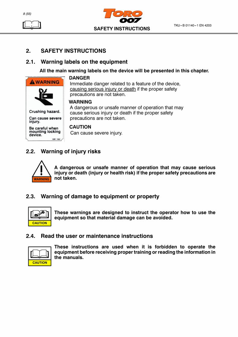
2.1. Warning labels on the equipment
All the main warning labels on the device will be presented in this chapter.DANGERImmediate danger related to a feature of the device,causing serious injury or death if the proper safetyprecautions are not taken.
WARNINGA dangerous or unsafe manner of operation that maycause serious injury or death if the proper safetyprecautions are not taken.
CAUTIONCan cause severe injury.
2.2. Warning of injury risks
A dangerous or unsafe manner of operation that may cause seriousinjury or death (injury or health risk) if the proper safety precautions arenot taken.
2.3. Warning of damage to equipment or property
These warnings are designed to instruct the operator how to use theequipment so that material damage can be avoided.
2.4. Read the user or maintenance instructions
These instructions are used when it is forbidden to operate theequipment before receiving proper training or reading the information inthe manuals.
WARNING
CAUTION
CAUTION

WARNING
................
WARNING
CAUTION
SAFETY INSTRUCTIONS
9 (55)
TKU---B 01140---1 EN 4203
2.5. Operator safety instructions
Operation, maintenance, and adjustments are only allowed topersons with specific training in operation and maintenance of theequipment. Read the operating and maintenance instructions beforeusing or servicing the equipment.
Plan your work carefully in advance to avoid possible accidents andinjuries. The operator must be familiar with the functions of theequipment before taking it into use.
The operatormust always wear required personal protection, such assafety helmet, protective clothing, safety boots, hearing protectors,safety goggles, etc., as dictated by company policy or localregulations.
Service operations (cleaning, oiling or adjusting) should be carriedout only when the machine is stopped and protected againstunprejudiced start the engine. Use the correct tools suitable for thework. Replace or repair faulty tools and equipment. Make sure thatthere are no unauthorized persons in theworking areawhen you carryout service and repair work.
In case of malfunction, stop immediately and safeguard the machine,have the malfunction immediately repaired.
If you have to weld on the machine, disconnect the alternator cablesand open the main switch before starting to weld. Consider also thefire and explosion risk caused bywelding.Make sure that themachineand its surroundings are clean and fire--safe.
Always have a fire extinguisher at hand, and learn how to use it. Havethe extinguisher inspected and serviced regularly according to thelocal regulations.
WARNING
WARNING
CAUTION
CAUTION
WARNING
CAUTION
WARNING
Max.
WARNING
WARNING
SAFETY INSTRUCTIONS
10 (55)
TKU---B 01140---1 EN 4203
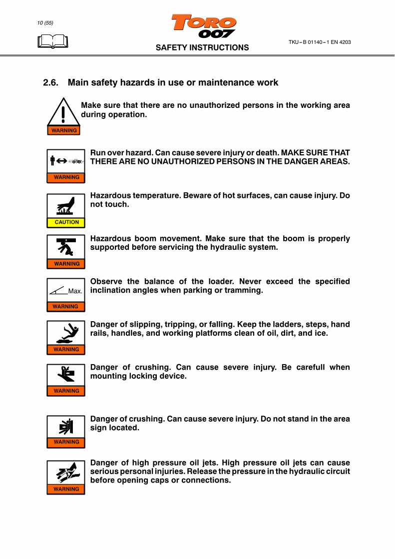
2.6. Main safety hazards in use or maintenance work
Make sure that there are no unauthorized persons in the working areaduring operation.
Run over hazard. Can cause severe injury or death.MAKESURETHATTHERE ARE NO UNAUTHORIZEDPERSONS IN THE DANGERAREAS.
Hazardous temperature. Beware of hot surfaces, can cause injury. Donot touch.
Hazardous boom movement. Make sure that the boom is properlysupported before servicing the hydraulic system.
Observe the balance of the loader. Never exceed the specifiedinclination angles when parking or tramming.
Danger of slipping, tripping, or falling. Keep the ladders, steps, handrails, handles, and working platforms clean of oil, dirt, and ice.
Danger of crushing. Can cause severe injury. Be carefull whenmounting locking device.
Danger of crushing. Can cause severe injury. Do not stand in the areasign located.
Danger of high pressure oil jets. High pressure oil jets can causeseriouspersonal injuries.Release thepressure in the hydraulic circuitbefore opening caps or connections.
WARNING
WARNING
WARNING
WARNING

SAFETY INSTRUCTIONS
11 (55)
TKU---B 01140---1 EN 4203
2.7. Manners and conditions where the loader is not allowed to beoperated
Risk factors for personnel
D Operator does not have sufficient trainingD Unauthorized persons are present in the working areaD Safety systems are deficient or out of orderD The field is chargedD Transportation of personsD Insufficient ventilation and too high water level in working area
Risk factors for loader and working site
D Risk of loose boulders falling on the loaderD Icy or otherwise slippery operating siteD Insufficient lightning
WARNING
CAUTION
SAFETY INSTRUCTIONS
12 (55)
TKU---B 01140---1 EN 4203
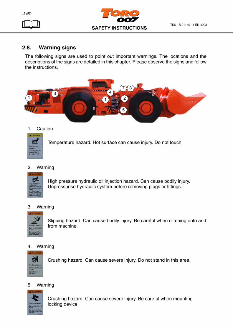
2.8. Warning signs
The following signs are used to point out important warnings. The locations and thedescriptions of the signs are detailed in this chapter. Please observe the signs and followthe instructions.
13
1
37
5
24
1. Caution
Temperature hazard. Hot surface can cause injury. Do not touch.
2. Warning
High pressure hydraulic oil injection hazard. Can cause bodily injury.Unpressurise hydraulic system before removing plugs or fittings.
3. Warning
Slipping hazard. Can cause bodily injury. Be careful when climbing onto andfrom machine.
4. Warning
Crushing hazard. Can cause severe injury. Do not stand in this area.
5. Warning
Crushing hazard. Can cause severe injury. Be careful when mountinglocking device.
SAFETY INSTRUCTIONS
13 (55)
TKU---B 01140---1 EN 4203
1
23
87
3
5
4
6
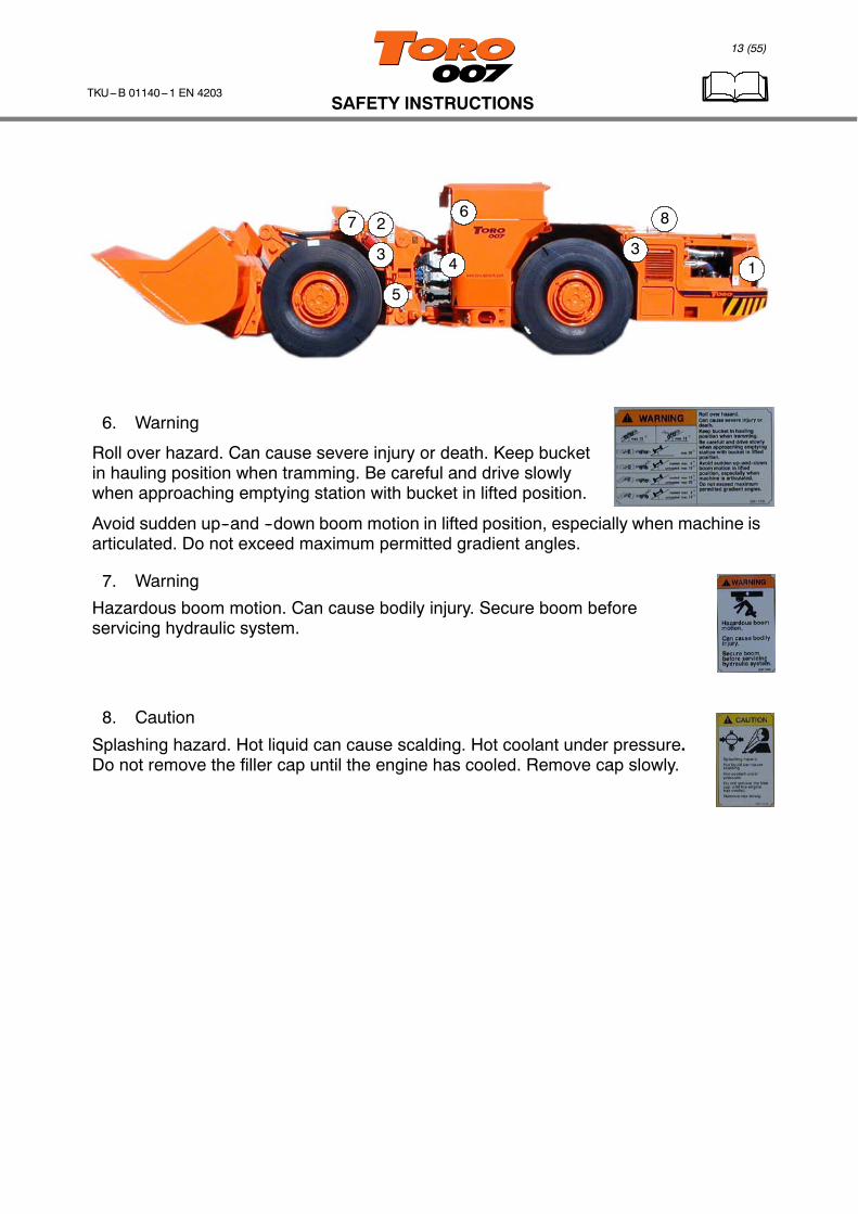
6. Warning
Roll over hazard. Can cause severe injury or death. Keep bucketin hauling position when tramming. Be careful and drive slowlywhen approaching emptying station with bucket in lifted position.
Avoid sudden up--and --down boom motion in lifted position, especially when machine isarticulated. Do not exceed maximum permitted gradient angles.
7. Warning
Hazardous boom motion. Can cause bodily injury. Secure boom beforeservicing hydraulic system.
8. Caution
Splashing hazard. Hot liquid can cause scalding. Hot coolant under pressure.Do not remove the filler cap until the engine has cooled. Remove cap slowly.

SAFETY INSTRUCTIONS
14 (55)
TKU---B 01140---1 EN 4203
2.9. Fire prevention
In case of fire, evacuate area to reduce the risk of injury from flames, heat,hazardous vapors, explosions, or other hazards that may be created.
Always obey local mandatory rules in case of fire.
Fire extinguisher
The fire extinguisher ismounted to the front frame
Read the operating instructions on the fire extinguisher bottle.Make sure that the extinguisher gauge needle is not in the redsector. If the needle points at red, the extinguisher must beserviced at once by an authorized service.
In case of fire:1. Stop the vehicle safely.2. Press Emergency stop Button (engine will stop and brakes will engage
automatically) or turn the electric current off from main switch.3. Actuate fire suppression system (opt.) and if possible to use hand held equipment
follow the instruction below, always refer to local regulations and instructions.4. Turn the extinguisher up and down a few times to mix the contents.5. Pull the safety pin and take the hose from its holder.6. Stand firmly, take a good grip of the hose, and direct it towards the base of the fire.
7. Spray the chemical by squeezing the extinguisher handle. As soon as the fire dies,stop spraying to save extinguishing power for possible reignition.
8. The extinguisher bottle must always be filled by authorized service after use.
WARNING
WARNING
WARNING

SAFETY INSTRUCTIONS
15 (55)
TKU---B 01140---1 EN 4203
Fire suppression system (opt.)
Familiarize the system mounted in your machine, if e.g. locally fitted system!
In case of fire1. Stop the vehicle safely.2. Press Emergency stop Button (engine will stop and brakes come on automatically).3. Activate suppression system by pulling the safety ring pin on the
actuator and strike the red button (there are two actuators, one onthe rear end of the vehicle and other on the cabin). The system buttonmight also be different in your machine as attached picture. Refer tolocally fitted fire suppression system instruction.
4. Always follow local safety guidelines
After fireHeat remaining from the fire can cause reignition after the suppression system hasdischarged.After the fire is out the machine should not be started until it has been serviced andcleaned. Wash the machine with plenty of water as soon as possible afterextinguishment because dry chemical can cause corrosion especially to the cables.Recharge and check the fire suppression system before re--starting the work.
Manual actuation will result in immediate system discharge. Make certainvehicle is stopped safely before manually actuating the system.
Do not re--start the loader again until the cause of the fire has beenestablished and the fault repaired.
Recharging the suppression system: Only authorized service with theinstallation may remove and fit powder tanks or liquid tank andpressurize system.
WARNING
WARNING
CAUTION
SAFETY INSTRUCTIONS
16 (55)
TKU---B 01140---1 EN 4203
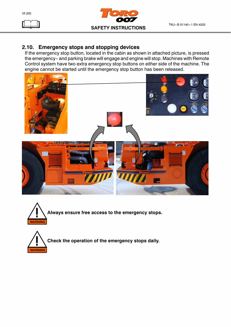
2.10. Emergency stops and stopping devicesIf the emergency stop button, located in the cabin as shown in attached picture, is pressedthe emergency-- and parking brake will engage and enginewill stop.Machines with RemoteControl system have two extra emergency stop buttons on either side of the machine. Theengine cannot be started until the emergency stop button has been released.
Always ensure free access to the emergency stops.
Check the operation of the emergency stops daily.
WARNING
WARNING
SAFETY INSTRUCTIONS
17 (55)
TKU---B 01140---1 EN 4203
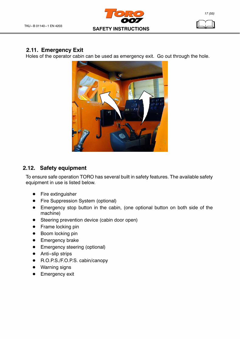
2.11. Emergency ExitHoles of the operator cabin can be used as emergency exit. Go out through the hole.
2.12. Safety equipment
To ensure safe operation TORO has several built in safety features. The available safetyequipment in use is listed below.
D Fire extinguisherD Fire Suppression System (optional)D Emergency stop button in the cabin, (one optional button on both side of the
machine)D Steering prevention device (cabin door open)D Frame locking pinD Boom locking pinD Emergency brakeD Emergency steering (optional)D Anti--slip stripsD R.O.P.S./F.O.P.S. cabin/canopyD Warning signsD Emergency exit
18 (55)
OPERATION INSTRUCTIONSTKU---B 01140---1 EN 4203
3. OPERATION INSTRUCTIONS
3.1. Instruments and Controls
6
7
84
3
1
5
29
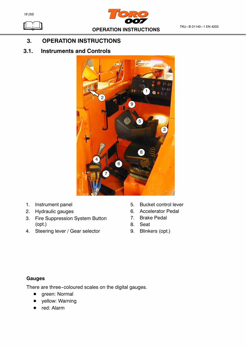
1. Instrument panel2. Hydraulic gauges3. Fire Suppression System Button
(opt.)4. Steering lever / Gear selector
5. Bucket control lever6. Accelerator Pedal7. Brake Pedal8. Seat9. Blinkers (opt.)
Gauges
There are three--coloured scales on the digital gauges.D green: NormalD yellow: WarningD red: Alarm

19 (55)
OPERATION INSTRUCTIONSTKU---B 01140---1 EN 4203
Gauges
8
43
5 76
2
1
1. Tachometer/HourmeterIdling speed 600 -- 700 r/min,max. speed 2200 r/min.The hour meter functions whenthe engine is running. It showsthe total operating hours of theengine.
2. Engine oil pressure
Oil pressure at idle should beat least 35 kPa (0,35 bar), atoperating speed (1800 rpm)the oil pressure should not fallbelow 193 kPa (1,93 bar).
3. Transmission Oil Pressure
This gauge shows thetransmission clutch pressure.It should be between 1,65MPa (16,5 bar) and 2,14 MPa(21,4 bar).
4. Voltmeter
This meter shows the batterycharge voltage. It should beappr. 26 -- 28 V when theengine is running.
5. Engine Temperature
Normal engine temperature isabout 75...99 _C. If thetemperature exceeds 100 _Cshut off the engine and troubleshoot for the cause after theengine has cooled.
6. Transmission Oil Temperature
The transmission oiltemperature should be below100 _C.
7. Hydraulic Oil Temp.
Oil temperature should bebelow 100_C.
8. Fuel Level
The light comes on red whenfuel level drops too low. Fill upthe tank as soon as possible.

5
1
9
8
7
4 2 36
20 (55)
OPERATION INSTRUCTIONSTKU---B 01140---1 EN 4203
Hydraulic gauges
1 2 3
Return oil filter back pressure (1)Measure the filter back pressure with lifting boom up with engine running at max. rpm.If the back pressure exceeds 1,5 bar (in normal working temperature) the filter elementmustbe changed.
Brake flushing return oil filter back pressure (2)Measure the filter back pressure in normal working temperature and max. engine rpm.If the back pressure reaches 0,6 bar the filter element must be changed.
Charging pressure for brake circuit (3)Charging pressure should be between 150 bar and 200 bar during operation.
Ignition key (or switch) and light etc. switches1. Ignition keyTurn the ignition key in the ignition switch
D Position P. parking lights on (only with key)D Position 0. electric current offD Position 1. electric power on.D Position 2. (preheating, not in use, only with key)D Position 3. starting the engine
2. Front light switch3. Rear light switch4. Horn5. Emergency stop6. Parking brake button7. Stop engine light (SEL)8. Check engine light (CEL)9. Stop engine over override (SEO)

21 (55)
OPERATION INSTRUCTIONSTKU---B 01140---1 EN 4203
Emergency stop (5)Pushing the button engages the service-- and parking brakes and shutsdown the engine. Button must be pulled out before starting the engine.Signal light illuminates when emergency brake is on.
Parking Brake Button (6)Pushing the button down engages the emergency/parking brake. Brake is released bypulling the three position button fully up and released to centre position. Brakes engagesautomatically, if
D Electric current is cut offD Engine stopsD Brake system oil pressure is too lowD Transmission oil pressure is too low (ABA, opt.)
Stop Engine light SEL (7)When ignition key is turned to power on position the ”Stop engine” and ”Check engine” lightscome on. If all the systems are OK, both lights will go out in approx. five seconds.Note! If the warning lights stay on, or if they do not come on momentarily after starting theengine, consult with a DDEC techician.Note! When the ”Stop Engine” light comes on, the computer has detected a majormalfunction in the engine that requires immediate attention. The conditions that cause the”Engine Stop” light to come on are:
D low coolant levelD high coolant temperatureD high engine oil temperatureD low engine oil pressureD low transmission oil pressure (optional)
Check Engine light CEL (8)When ignition key is turned to power on position the ”Check engine light“ comes on. If allthe systems are OK, CEL and SEL will go out in approximately 5 seconds.
Stop Engine Override SEO (9)During serious engine malfunction the ”Stop Engine” light comes on and the engine rpm willbe reduced to certain level for 30 seconds and after that the engine will stop automatically.If the machine is operating in a critical situation, the operator may select to ”override” theautomatic stop by pressing the ”Stop Engine Override” button. While the button is pressedthe engine revolutions will rise to normal and after the button is released the revolutions willbe reduced again and engine will stop after 30 seconds. The operator must press theoverride button just prior to engine shutdown until themachine canbebrought to a safestop.A data request can be made by pushing the SEO button and holding it there. For furtherinformation refer to the Detroit Diesel Engine Operator’s Guide. See ”Stop Engine” and”Check Engine” lights.

17 18 19 20 21
10 11 12 13 14 15 16
23
22
22 (55)
OPERATION INSTRUCTIONSTKU---B 01140---1 EN 4203
Warning-- and signal lights10. Parking brake onSignal light is on if parking brake is engaged11. Low brake accumulator pressureThe warning light is on when the accumulatorpressure drops too low.
12. Automatic central lubrication greasetank empty (opt.)
Fill immediately
13. Low fuel level (opt.)The light comes constantly on when fuel leveldrops too low. Refuel immediately!
14. Low hydraulic oil levelThe warning light is on , if hydraulic oil level drops too low.
15. Turn signals (opt.)16. Ride control system on (opt.)When the light is on the ride control system is activated17. Service brake is onSignal light illuminates when brake pedal is pressed or when emergency brake is on18. Low engine oil pressureThe warning light is on if engine oil pressure is low. If the oil pressure drops too low, theparking brakes engages automatically.
19. Automatic central lubrication system pressure (opt.)The indicator light goes on and off while the system is working.
20. Water tank level, exhaust scrubber (opt.)This light illuminates when the water tank (exhaust scrubber) is empty. Fill the water tank.
21. Emergency steering (opt.)This light illuminates when the emergency steering pressure is too low.
22. Ride control system (opt.)23. Remote Control switch (opt.)
Ride control system (22) (opt.)The Ride control system switch has three positions OFF--AUTO--MANUAL.In AUTO position the ride control system connects/disconnects automatically. When drivingwith second or higher gear the ride control is on and when first gear is selected the ridecontrol system will be automatically disconnected.MAN--position keeps the ride control connected constantly.There are indicator light for a ride control in the instrument panel.
Remote Control switch (23) (opt.)
Read the Remote--Control System Operators Manual carefully before operating withRC--system.Check remote control system functioning according to remote control systeminstruction before operation. TheRC--switch must be turned off before starting / operatingthe machine from the cabin.

25 26 2724
2928
23 (55)
OPERATION INSTRUCTIONSTKU---B 01140---1 EN 4203
24. Gear display select button (opt.)25. Gear selector mode (opt.)26. Brake releasing pump27. DDR--connector
Gear Display Select button (24) (opt.)When Gear Selector Mode switch (25) is in auto, manual or programming position,pushing the Display Select button brings the machine speed to the display (40 is 4 km/h).Select button is also used when programming or changing the parameters of theprogramme.
Gear Selector Mode switch (25) (opt.)When Gear Selector Mode switch is in manual position (M), the gears are selectedmanually with buttons (F & R) on the steering lever.When the switch is in AUTO position (A), the gears are changed automatically. Theoperator selects the highest gear by turning the switch from A (all four gears) to 1 (onlyfirst gear).When the switch is in programming position S, the Gear Display shows the engine rews.
Brake Releasing pump (26)Turn the switch which connects the brake releasing pump. Engine must be stopped andignition switch on “POWER ON” -- position. The pump can be used for towing purposes,when parking brake is engaged and machine must be towed. Refer to the Towing section.(Parking brake button has to pull fully up before the pump can start.)
DDR -- connector (27)Connector for Diagnostic Data Reader.A data request can be made by pushing the SEO button and holding it there.
Brake &Accelerator (28) & (29)The Brake pedel (28) is foot operated and is used to stop theloader. Pressing the pedal applies the brakes and stops theloader and vice versa.The Accelerator pedal (29) is also foot operated and is used toincrease the the engine speed. The harder you press theaccelerator, the higher the engine revolutions will rise.
43
2
1
24 (55)
OPERATION INSTRUCTIONSTKU---B 01140---1 EN 4203
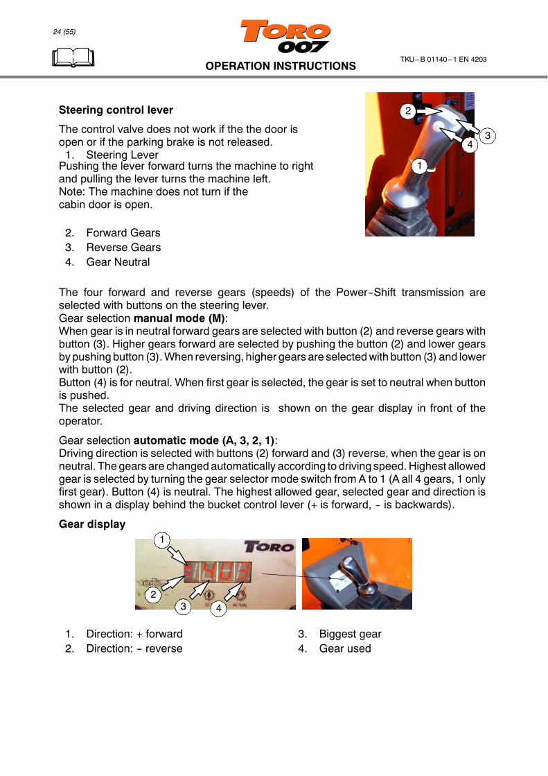
Steering control lever
The control valve does not work if the the door isopen or if the parking brake is not released.1. Steering LeverPushing the lever forward turns the machine to rightand pulling the lever turns the machine left.Note: The machine does not turn if thecabin door is open.
2. Forward Gears3. Reverse Gears4. Gear Neutral
The four forward and reverse gears (speeds) of the Power--Shift transmission areselected with buttons on the steering lever.Gear selection manual mode (M):When gear is in neutral forward gears are selected with button (2) and reverse gears withbutton (3). Higher gears forward are selected by pushing the button (2) and lower gearsby pushing button (3).When reversing, higher gears are selectedwith button (3) and lowerwith button (2).Button (4) is for neutral. When first gear is selected, the gear is set to neutral when buttonis pushed.The selected gear and driving direction is shown on the gear display in front of theoperator.
Gear selection automatic mode (A, 3, 2, 1):Driving direction is selected with buttons (2) forward and (3) reverse, when the gear is onneutral. The gears are changedautomatically according to driving speed. Highest allowedgear is selected by turning the gear selector mode switch from A to 1 (A all 4 gears, 1 onlyfirst gear). Button (4) is neutral. The highest allowed gear, selected gear and direction isshown in a display behind the bucket control lever (+ is forward, -- is backwards).
Gear display1
23 4
1. Direction: + forward2. Direction: -- reverse
3. Biggest gear4. Gear used
32
1
25 (55)
OPERATION INSTRUCTIONSTKU---B 01140---1 EN 4203
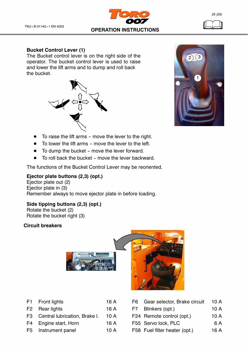
Bucket Control Lever (1)The Bucket control lever is on the right side of theoperator. The bucket control lever is used to raiseand lower the lift arms and to dump and roll backthe bucket.
D To raise the lift arms -- move the lever to the right.D To lower the lift arms -- move the lever to the left.D To dump the bucket -- move the lever forward.D To roll back the bucket -- move the lever backward.
The functions of the Bucket Control Lever may be reoriented.
Ejector plate buttons (2,3) (opt.)Ejector plate out (2)Ejector plate in (3)Remember always to move ejector plate in before loading.
Side tipping buttons (2,3) (opt.)Rotate the bucket (2)Rotate the bucket right (3)
Circuit breakers
F1 Front lights 16 AF2 Rear lights 16 AF3 Central lubrication, Brake l. 10 AF4 Engine start, Horn 16 AF5 Instrument panel 10 A
F6 Gear selector, Brake circuit 10 AF7 Blinkers (opt.) 10 AF24 Remote control (opt.) 10 AF55 Servo lock, PLC 6 AF58 Fuel filter heater (opt.) 16 A
26 (55)
OPERATION INSTRUCTIONSTKU---B 01140---1 EN 4203
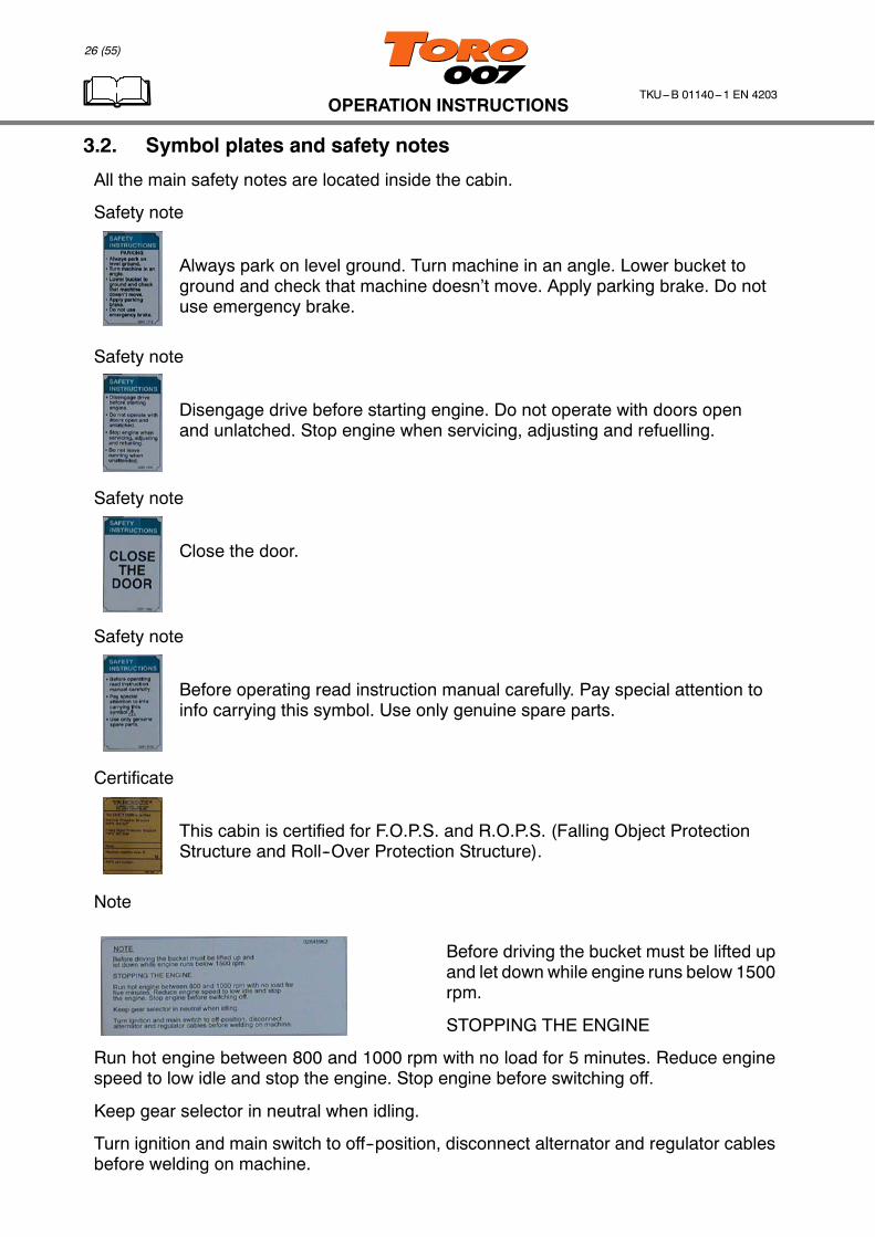
3.2. Symbol plates and safety notes
All the main safety notes are located inside the cabin.
Safety note
Always park on level ground. Turn machine in an angle. Lower bucket toground and check that machine doesn’t move. Apply parking brake. Do notuse emergency brake.
Safety note
Disengage drive before starting engine. Do not operate with doors openand unlatched. Stop engine when servicing, adjusting and refuelling.
Safety note
Close the door.
Safety note
Before operating read instruction manual carefully. Pay special attention toinfo carrying this symbol. Use only genuine spare parts.
Certificate
This cabin is certified for F.O.P.S. and R.O.P.S. (Falling Object ProtectionStructure and Roll--Over Protection Structure).
Note
Before driving the bucket must be lifted upand let down while engine runs below 1500rpm.
STOPPING THE ENGINE
Run hot engine between 800 and 1000 rpm with no load for 5 minutes. Reduce enginespeed to low idle and stop the engine. Stop engine before switching off.
Keep gear selector in neutral when idling.
Turn ignition and main switch to off--position, disconnect alternator and regulator cablesbefore welding on machine.

27 (55)
OPERATION INSTRUCTIONSTKU---B 01140---1 EN 4203
3.3. Routine checks before starting the engine
2 24
6
5
9
11
1112
4
22
10 8
3
7
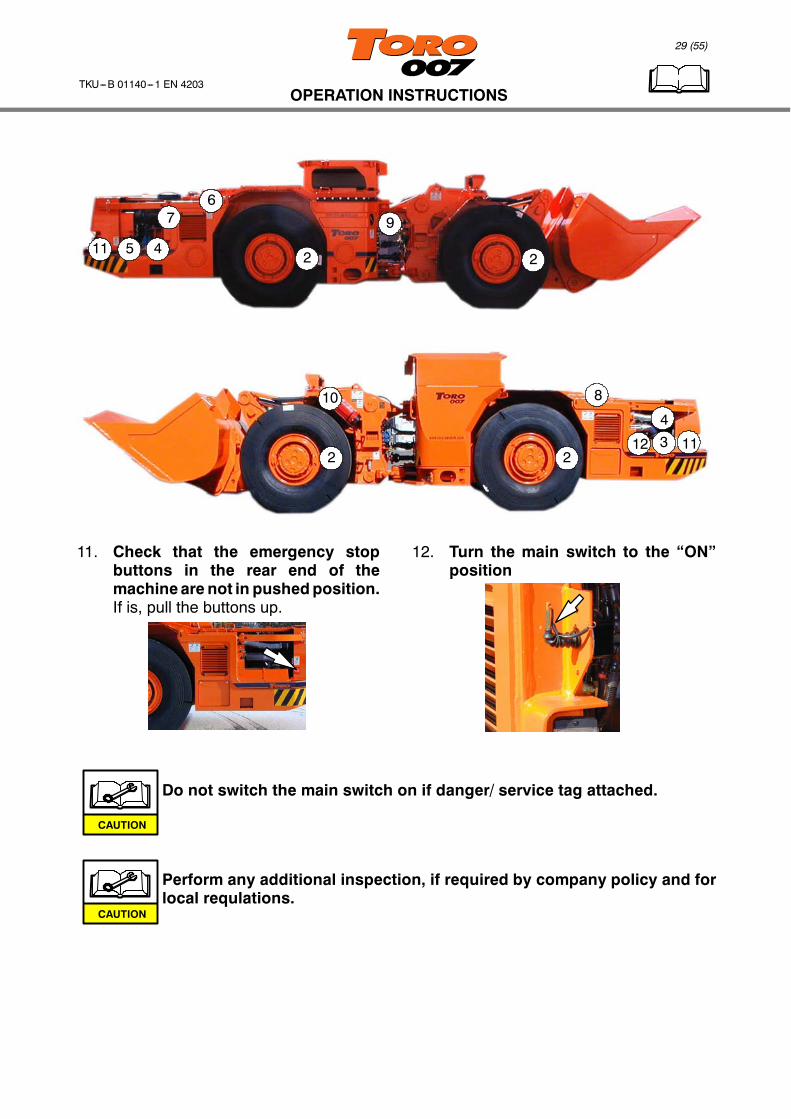
1. Walk around inspection. Check-- For defect tags or warnings-- Safety attachment not mounted-- Bucket and components condition-- Boom and components condition-- Front-- and rear frame hydrauliccomponents-- Central lubrication canister (opt.).Fill up if empty.-- Climbing steps and handles-- Canopy and door lock condition-- That all lubrication points are wellgreased.
2. Check tyres and wheel nuts-- Condition-- Tyre wear-- Visually for loose wheel nuts
3. Check engine oil levelMachine on level ground(20 minutes after stopping)
4. Check engine additional equipmentvisually-- Radiator, intercooler-- Fuel lines and hoses, filters-- Alternator, other electr. components
5. Check V--belts-- Visual condition-- Check belt for worn, grease coated,oil soaked and missing material.Replace as necessary.
6. Make sure that the fuel tank shut offvalves are open
28 (55)
OPERATION INSTRUCTIONSTKU---B 01140---1 EN 4203
2 24
6
5
9
11
1112
4
22
10 8
3
7
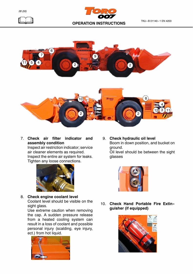
7. Check air filter indicator andassembly conditionInspect air restriction indicator; serviceair cleaner elements as required.Inspect the entire air system for leaks.Tighten any loose connections.
8. Check engine coolant levelCoolant level should be visible on thesight glass.Use extreme caution when removingthe cap. A sudden pressure releasefrom a heated cooling system canresult in a loss of coolant and possiblepersonal injury (scalding, eye injury,ect.) from hot liquid.
9. Check hydraulic oil levelBoom in down position, and bucket onground.Oil level should be between the sightglasses
10. Check Hand Portable Fire Extin--guisher (if equipped)
29 (55)
OPERATION INSTRUCTIONSTKU---B 01140---1 EN 4203
2 24
6
5
9
11
1112
4
22
10 8
3
7
11. Check that the emergency stopbuttons in the rear end of themachineare not in pushedposition.If is, pull the buttons up.
12. Turn the main switch to the “ON”position
Do not switch the main switch on if danger/ service tag attached.
Perform any additional inspection, if required by company policy and forlocal requlations.
CAUTION
CAUTION

30 (55)
OPERATION INSTRUCTIONSTKU---B 01140---1 EN 4203
3.4. Getting into the cabin and starting the engine
Always make sure before starting that there are no unauthorizedpersons in the danger areas, and that no controls are in the operatingposition.
1. Make sure that there is no clutter onthe floor when entering into the cabin.
2. When you have entered to operatorsposition check that the emergencystop button is not pushed in. If it is, pullthe button up.
3. Turn the ignition key to POWER ONposition and check the indicator lights(DDEC signal lights should go off afterabout 5 seconds).
WARNING

31 (55)
OPERATION INSTRUCTIONSTKU---B 01140---1 EN 4203
4. Check that the transmission is in“neutral”. Make sure that there are noalarms on the instrument panel.Activate parking brake (button pushedin).
5. Check fuel level
6. Check brake releasing pumpfunction Turn the switch. The
pump should start. (Parkingbrake button has to be pulled fullyup before the pump can start.)Warning! Releasing thebrakesmay cause that the machinestarts to move (especially ongradient level). Be sure that thereleasing does not cause dangerto other people or equipment.
7. Turn the ignition key to “START”position (there is a delay beforethe engine turns). Let the keyreturn to the ”POWER ON”position when the engine starts.
Do not run the starter motor longer than 20 seconds at a time. Allow thestarter motor to cool down for one minute before a new starting attempt.
8. Switch the lights on. 9. Check transmission oil level fromdipstick.-- Machine on level ground.-- Parking brake engaged-- The engine at low idle-- The gear shift lever in Neutralposition-- Transmission oil in operatingtemperature
CAUTION

32 (55)
OPERATION INSTRUCTIONSTKU---B 01140---1 EN 4203
10. Check transfer gearbox oil levelfrom dipstick.-- Machine on level ground.-- Parking brake engaged-- The engine at low idle-- The gear shift lever in Neutralposition-- Transfer gearbox oil inoperating temperature
11. Check hydraulic tank pressure.It should be 0,3 bar.
12. Check the lights-- Front-- Rear-- Optional lights
13. Check major components for oilleaks and mounting.Make sure that the safety locksare removed.Make a general visual inspectionof the machine, check for oilleaks and loose hoses, frayedwires or other apparentmaintenance needs; if anythinglooks suspicious call atechnician.
14. Check the emregency steeringsystem function (opt.). Turn theignition key to 0--position to shutdown the engine. When theengine has stopped, turn theignition key to 1--position. Turnthe steering lever, the machineshould turn.Note! The machine can not beturned, if the cabin door is open.
Never attempt to start a TORO by towing!CAUTION
33 (55)
OPERATION INSTRUCTIONSTKU---B 01140---1 EN 4203
3.5. Routine checks before driving
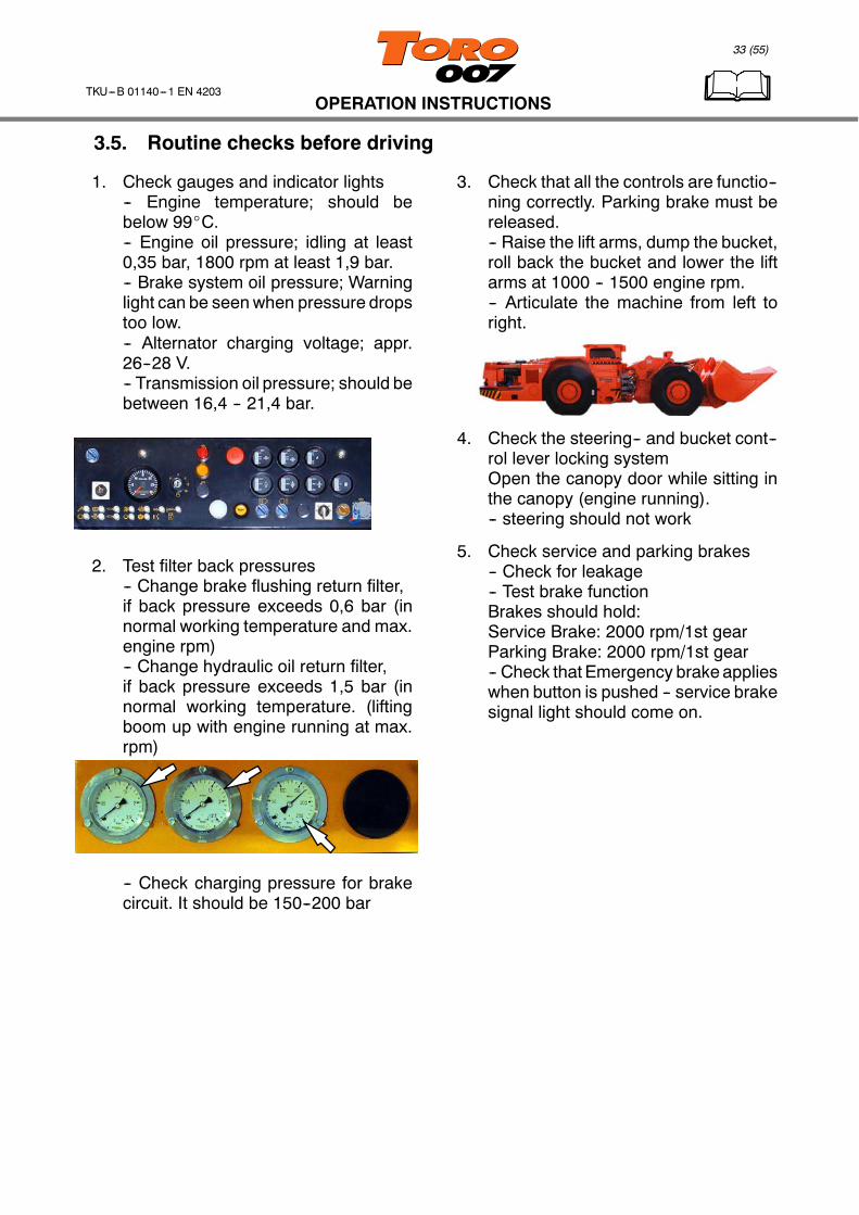
1. Check gauges and indicator lights-- Engine temperature; should bebelow 99_C.-- Engine oil pressure; idling at least0,35 bar, 1800 rpm at least 1,9 bar.-- Brake system oil pressure; Warninglight can be seenwhen pressure dropstoo low.-- Alternator charging voltage; appr.26--28 V.-- Transmission oil pressure; should bebetween 16,4 -- 21,4 bar.
2. Test filter back pressures-- Change brake flushing return filter,if back pressure exceeds 0,6 bar (innormal working temperature and max.engine rpm)-- Change hydraulic oil return filter,if back pressure exceeds 1,5 bar (innormal working temperature. (liftingboom up with engine running at max.rpm)
-- Check charging pressure for brakecircuit. It should be 150--200 bar
3. Check that all the controls are functio--ning correctly. Parking brake must bereleased.-- Raise the lift arms, dump the bucket,roll back the bucket and lower the liftarms at 1000 -- 1500 engine rpm.-- Articulate the machine from left toright.
4. Check the steering-- and bucket cont--rol lever locking systemOpen the canopy door while sitting inthe canopy (engine running).-- steering should not work
5. Check service and parking brakes-- Check for leakage-- Test brake functionBrakes should hold:Service Brake: 2000 rpm/1st gearParking Brake: 2000 rpm/1st gear-- Check that Emergency brake applieswhen button is pushed -- service brakesignal light should come on.

34 (55)
OPERATION INSTRUCTIONSTKU---B 01140---1 EN 4203
There are health risks due to nitrogen oxides and carbon monoxide inexhaust fumes of a diesel engine. GOOD VENTILATION MUST ALWAYSBE ENSURED WHEN THE ENGINE IS RUNNING INDOORS.
D Observe the warning lights.D Make sure that there are no active alarms.D Do not let the engine idle unnecessarily.D Be seated and have seat belt fastened when operating the machineD Donot let any persons in the hinge area,make sure that nobody is endangeredbefore
starting/driving/operating the machineD In case of malfunction, stop immediately and safeguard the machine, have the
malfunction immediately cleared
Never leave the machine running unattended.
Functional disorders must be repaired immediately!
Do not operate with passengers
WARNING
CAUTION
WARNING
WARNING
35 (55)
OPERATION INSTRUCTIONSTKU---B 01140---1 EN 4203
3.6. Driving
3.6.1. Gradient angles
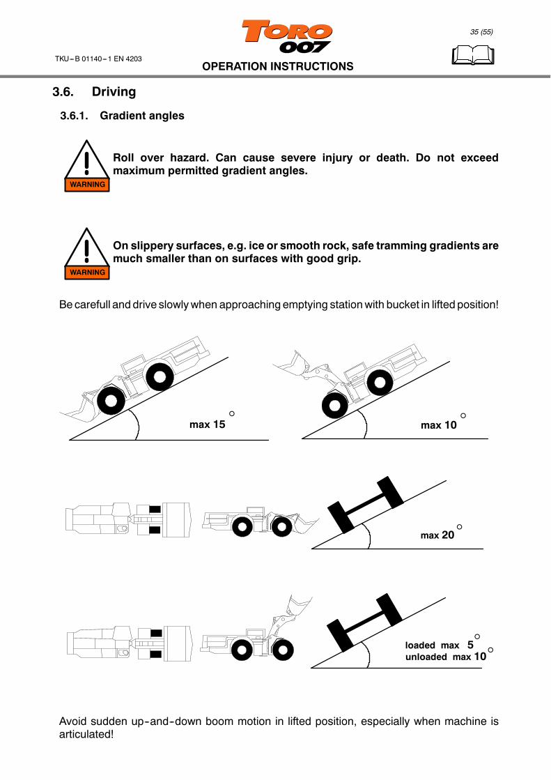
Roll over hazard. Can cause severe injury or death. Do not exceedmaximum permitted gradient angles.
On slippery surfaces, e.g. ice or smooth rock, safe tramming gradients aremuch smaller than on surfaces with good grip.
Becarefull and drive slowlywhen approaching emptying stationwith bucket in lifted position!
max 15_ max 10_
max 20_
loaded max 5unloaded max 10_
_
Avoid sudden up--and--down boom motion in lifted position, especially when machine isarticulated!
WARNING
WARNING

36 (55)
OPERATION INSTRUCTIONSTKU---B 01140---1 EN 4203
loaded max 10unloaded max 20
__
loaded max 2unloaded max 10_
_
3.6.2. Operator visibility
When operating with Toro 007, you should always remember that visibility is limited andyou should ensure that unauthorized persons are not present in the working area.
21
NR
F
37 (55)
OPERATION INSTRUCTIONSTKU---B 01140---1 EN 4203
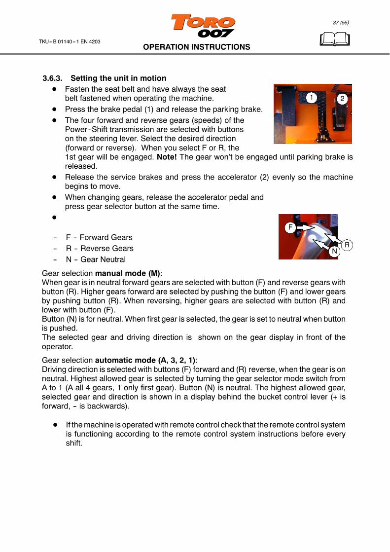
3.6.3. Setting the unit in motionD Fasten the seat belt and have always the seat
belt fastened when operating the machine.D Press the brake pedal (1) and release the parking brake.D The four forward and reverse gears (speeds) of the
Power--Shift transmission are selected with buttonson the steering lever. Select the desired direction(forward or reverse). When you select F or R, the1st gear will be engaged. Note! The gear won’t be engaged until parking brake isreleased.
D Release the service brakes and press the accelerator (2) evenly so the machinebegins to move.
D When changing gears, release the accelerator pedal andpress gear selector button at the same time.
D
-- F -- Forward Gears-- R -- Reverse Gears-- N -- Gear Neutral
Gear selection manual mode (M):When gear is in neutral forward gears are selected with button (F) and reverse gears withbutton (R). Higher gears forward are selected by pushing the button (F) and lower gearsby pushing button (R). When reversing, higher gears are selected with button (R) andlower with button (F).Button (N) is for neutral. When first gear is selected, the gear is set to neutral when buttonis pushed.The selected gear and driving direction is shown on the gear display in front of theoperator.
Gear selection automatic mode (A, 3, 2, 1):Driving direction is selected with buttons (F) forward and (R) reverse, when the gear is onneutral. Highest allowed gear is selected by turning the gear selector mode switch fromA to 1 (A all 4 gears, 1 only first gear). Button (N) is neutral. The highest allowed gear,selected gear and direction is shown in a display behind the bucket control lever (+ isforward, -- is backwards).
D If themachine is operatedwith remote control check that the remote control systemis functioning according to the remote control system instructions before everyshift.
Brake PedalFoot rest
38 (55)
OPERATION INSTRUCTIONSTKU---B 01140---1 EN 4203
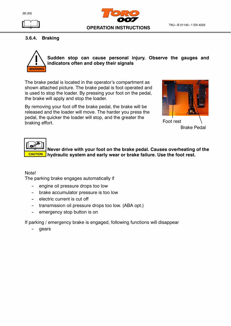
3.6.4. Braking
Sudden stop can cause personal injury. Observe the gauges andindicators often and obey their signals
The brake pedal is located in the operator’s compartment asshown attached picture. The brake pedal is foot operated andis used to stop the loader. By pressing your foot on the pedal,the brake will apply and stop the loader.
By removing your foot off the brake pedal, the brake will bereleased and the loader will move. The harder you press thepedal, the quicker the loader will stop, and the greater thebraking effort.
Never drive with your foot on the brake pedal. Causes overheating of thehydraulic system and early wear or brake failure. Use the foot rest.
Note!The parking brake engages automatically if
-- engine oil pressure drops too low-- brake accumulator pressure is too low-- electric current is cut off-- transmission oil pressure drops too low. (ABA opt.)-- emergency stop button is on
If parking / emergency brake is engaged, following functions will disappear-- gears
WARNING
CAUTION
39 (55)
OPERATION INSTRUCTIONSTKU---B 01140---1 EN 4203
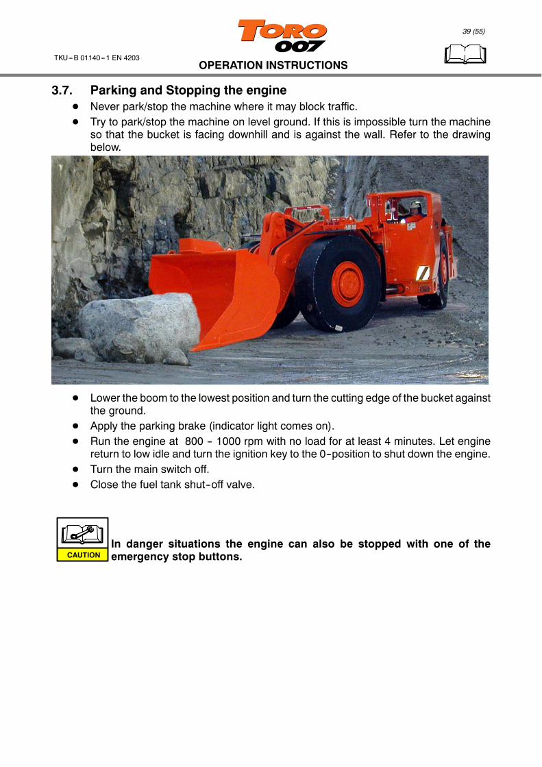
3.7. Parking and Stopping the engineD Never park/stop the machine where it may block traffic.D Try to park/stop the machine on level ground. If this is impossible turn the machine
so that the bucket is facing downhill and is against the wall. Refer to the drawingbelow.
D Lower the boom to the lowest position and turn the cutting edge of the bucket againstthe ground.
D Apply the parking brake (indicator light comes on).D Run the engine at 800 -- 1000 rpm with no load for at least 4 minutes. Let engine
return to low idle and turn the ignition key to the 0--position to shut down the engine.D Turn the main switch off.D Close the fuel tank shut--off valve.
In danger situations the engine can also be stopped with one of theemergency stop buttons.CAUTION

40 (55)
OPERATION INSTRUCTIONSTKU---B 01140---1 EN 4203
Aviod long engine idle periods. During long engine idling periods with thetransmission and boom control lever in neutral, the engine coolanttemperature may fall below the normal operating range. When prolongedidling is necessary, maintain at least 850 -- 1000 rpm.
Never turn the main switch off when the engine is running. This maydamage the alternator or the voltage regulator and machine electronicequipment..
Never park the machine on a gradient resting on the brakes only.
Refill the tank at end of each day’s operation to prevent condensation fromcontaminating the fuel.
Don’t leave the unit unattended unless the brakes are set and the engine isshut down.
3.8. Operation in cold weatherIf the temperature is below 0 ˚C, clear off ice from all steps and handles on the rig.Because the TORO 007 normally operates in mine conditions, its engine, transmission andhydraulic systems are filled with oils suitable for these conditions. However, in coldconditions they oils thicken. This makes starting difficult and may damage the torqueconverter and hydraulic pumps. For this reason, avoid any temporary parking in frostyweather. If the machine will work in very cold or very hot conditions, see the MaintenanceInstructions booklet for the correct oils and the Detroit Diesel Instruction Manual for theproper fuel.Starting aids such as preheating engine coolant and hydraulic oil are recommended intemperatures below --10˚C.
CAUTION
CAUTION
CAUTION
CAUTION
WARNING
41 (55)
OPERATION INSTRUCTIONSTKU---B 01140---1 EN 4203
3.9. Towing
Never attempt to start the engine by towing
Extreme caution must always be observed when towing the rig.
If the machine must be towed follow the directions below:
1. Apply parking brake and block all four wheels.2. Towing vehicle must be as heavy as TORO 007 or heavier and it must have ample
power and braking capacity to move, stop and hold both machines.3. Connect the twomachineswith suitable towbar (and a secondary safety chain orwire
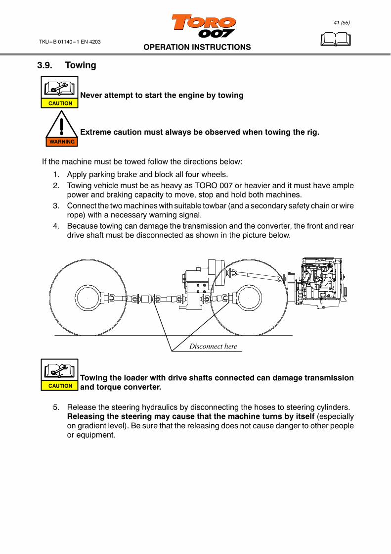
rope) with a necessary warning signal.4. Because towing can damage the transmission and the converter, the front and rear
drive shaft must be disconnected as shown in the picture below.
Disconnect here
Towing the loader with drive shafts connected can damage transmissionand torque converter.
5. Release the steering hydraulics by disconnecting the hoses to steering cylinders.Releasing the steering may cause that the machine turns by itself (especiallyon gradient level). Be sure that the releasing does not cause danger to other peopleor equipment.
CAUTION
WARNING
CAUTION
42 (55)
OPERATION INSTRUCTIONSTKU---B 01140---1 EN 4203
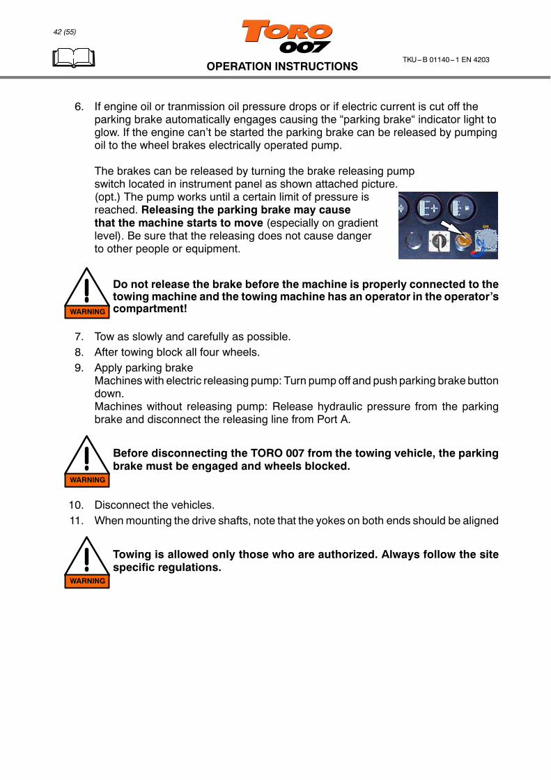
6. If engine oil or tranmission oil pressure drops or if electric current is cut off theparking brake automatically engages causing the “parking brake“ indicator light toglow. If the engine can’t be started the parking brake can be released by pumpingoil to the wheel brakes electrically operated pump.
The brakes can be released by turning the brake releasing pumpswitch located in instrument panel as shown attached picture.(opt.) The pump works until a certain limit of pressure isreached. Releasing the parking brake may causethat the machine starts to move (especially on gradientlevel). Be sure that the releasing does not cause dangerto other people or equipment.
Do not release the brake before the machine is properly connected to thetowing machine and the towing machine has an operator in the operator’scompartment!
7. Tow as slowly and carefully as possible.8. After towing block all four wheels.9. Apply parking brake
Machineswith electric releasing pump: Turn pump off and pushparking brake buttondown.Machines without releasing pump: Release hydraulic pressure from the parkingbrake and disconnect the releasing line from Port A.
Before disconnecting the TORO 007 from the towing vehicle, the parkingbrake must be engaged and wheels blocked.
10. Disconnect the vehicles.11. Whenmounting the drive shafts, note that the yokes on both ends should be aligned
Towing is allowed only those who are authorized. Always follow the sitespecific regulations.
WARNING
WARNING
WARNING
43 (55)
OPERATION INSTRUCTIONSTKU---B 01140---1 EN 4203
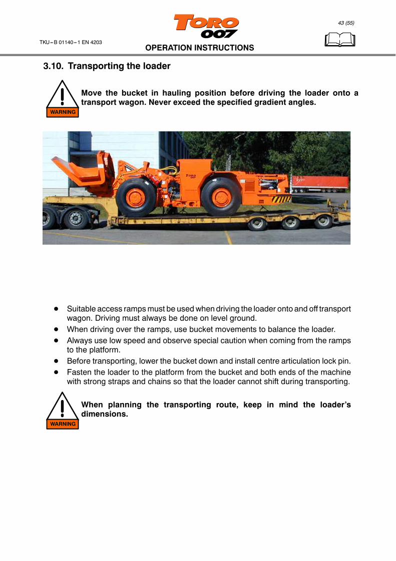
3.10. Transporting the loader
Move the bucket in hauling position before driving the loader onto atransport wagon. Never exceed the specified gradient angles.
D Suitable access rampsmust be usedwhendriving the loader onto and off transportwagon. Driving must always be done on level ground.
D When driving over the ramps, use bucket movements to balance the loader.D Always use low speed and observe special caution when coming from the ramps
to the platform.D Before transporting, lower the bucket down and install centre articulation lock pin.D Fasten the loader to the platform from the bucket and both ends of the machine
with strong straps and chains so that the loader cannot shift during transporting.
When planning the transporting route, keep in mind the loader’sdimensions.
WARNING
WARNING

44 (55)
OPERATION INSTRUCTIONSTKU---B 01140---1 EN 4203
3.11. Storing instructionsEnvironment:
D Storage temperature should be +0...+35˚C, and the machine should be protectedfrom direct sunlight and from rain.
D The humidity of the air should be below 90%.
_C F
0102030 86
685032 max 90%
Preparations:D Wash the loader thoroughly if it comes directly from use, or if it has been transported
by sea (use high pressure washer or steam).D Lubricate all greasing points.D Empty the pressure accumulators and place warning signs on the machine:
’Pressure accumulators must be filled before using the loader’.D Apply protective grease to the piston rods of the cylinders.D Change all lubricants and fluidsD Check engine air filter and service if necessary.D Protect electric devices with corrosion inhibitor to prevent contact failures.D Disconnect batteries
Apply protective grease to the following points:
-- terminal strips-- battery terminals-- multipole connectors-- connectors at caps of magnetic valves, pressure switches, etc. Fill the caps with
grease.

45 (55)
OPERATION INSTRUCTIONSTKU---B 01140---1 EN 4203
3.12. Lifting methods and lifting points
Always respect the law and all the local safety regulations in lifting work.
Keep in mind the total weight of the loader, given in the technical data ofthese instructions.
The lifting points (four) have been marked with hook symbols.
D The lifting device used must be of the correct type and havesufficient lifting capacity. The loader or parts of it must not belifted with any devices that are not specifically designed forlifting purposes.
D You must always know the exact weight of the load, and neverexceed the lifting capacity specified by themanufacturer of thelifting device.
D The lifting routes should be planned so that the load is notmoved over persons or such places where persons may bepresent.
D Make sure that the lifting equipment are in proper condition.D Wire ropes and chains used for lifting must be checked
regularly. Damaged wire ropes must be marked clearly anddiscarded at once.
D Lift the load only a few centimetres at first to make sure thatit is properly fastened and in balance. Do not continue liftinguntil you are sure of proper fastening and balance.
D Never wind the ropes around the hook of the hoist. Thelifting ropes must be fastened according to themanufacturer’s instructions.
WARNING
WARNING
INCORRECT
CORRECT

46 (55)
LOADING, HAULING AND DUMPINGTKU---B 01140---1 EN 4203
4. LOADING, HAULING AND DUMPING
TORO loader is intended to load, haul and dump rock material exclusively.Any other use different from this is not considered as intended.
Make sure that there are no unauthorized persons in the working area.
4.1. LoadingD Always obey national mandatory rules relating to accident prevention and
enviromental protection. The generally recognized technical rules for safe andprofessional operation must also be observed.
D Complete the instruction manual with obligatory reports and controls according tocompany rules.
Functional disorders must be repaired immediately!
keep all safety and danger signs on the machine in legible condition,observe and follow them
The effort spent in levelling the machine’s small operating area can pay dividends byincreasing its productivity. When loading, work the area on as wide as possible. Work theouter side of the muck pile first and then center.
If you follow correct loading procedures, you and the machine will be a more efficient team.Do not start lifting full loads until the engine and the converter are warmed up (converter+40_C).
WARNING
WARNING
WARNING
WARNING
47 (55)
LOADING, HAULING AND DUMPINGTKU---B 01140---1 EN 4203
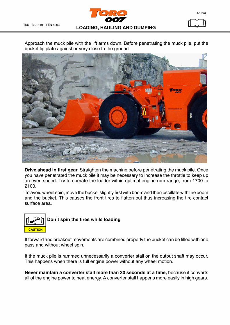
Approach the muck pile with the lift arms down. Before penetrating the muck pile, put thebucket lip plate against or very close to the ground.
Drive ahead in first gear. Straighten the machine before penetrating the muck pile. Onceyou have penetrated the muck pile it may be necessary to increase the throttle to keep upan even speed. Try to operate the loader within optimal engine rpm range, from 1700 to2100.To avoidwheel spin,move the bucket slightly firstwith boomand then oscillatewith the boomand the bucket. This causes the front tires to flatten out thus increasing the tire contactsurface area.
Don’t spin the tires while loading
If forward and breakout movements are combined properly the bucket can be filled with onepass and without wheel spin.
If the muck pile is rammed unnecessarily a converter stall on the output shaft may occur.This happens when there is full engine power without any wheel motion.
Never maintain a converter stall more than 30 seconds at a time, because it convertsall of the engine power to heat energy. A converter stall happens more easily in high gears.
CAUTION
48 (55)
LOADING, HAULING AND DUMPINGTKU---B 01140---1 EN 4203
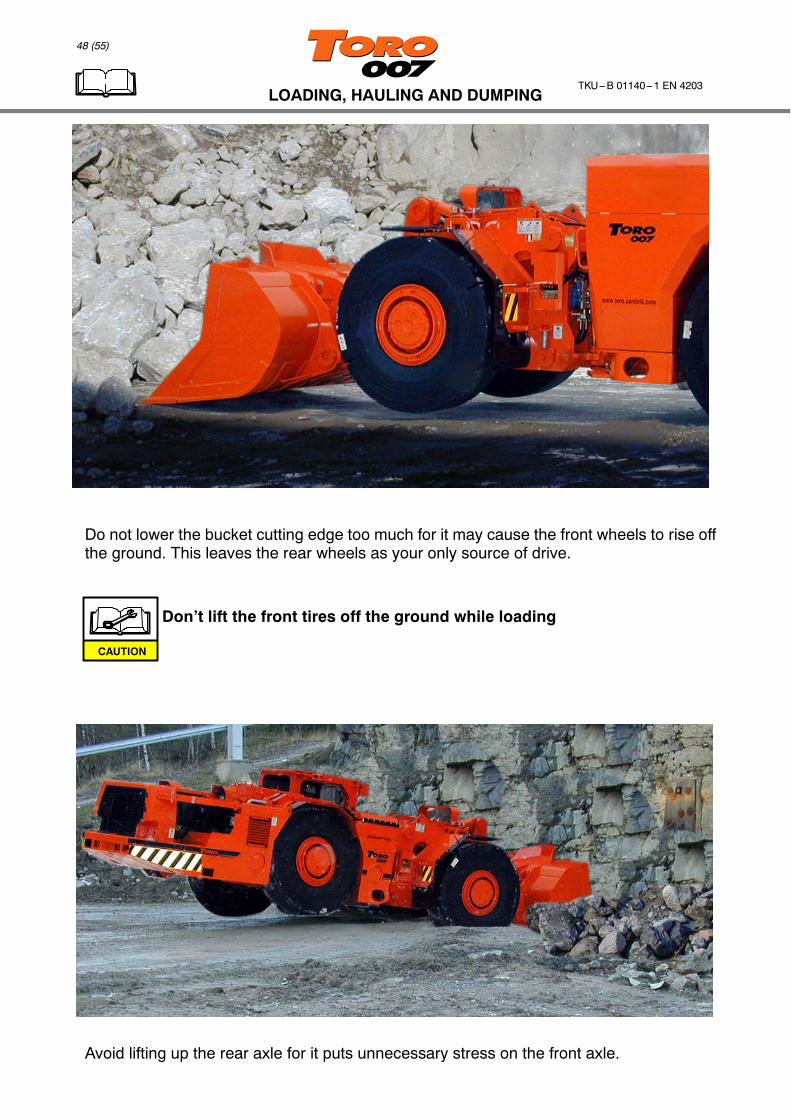
Do not lower the bucket cutting edge too much for it may cause the front wheels to rise offthe ground. This leaves the rear wheels as your only source of drive.
Don’t lift the front tires off the ground while loading
Avoid lifting up the rear axle for it puts unnecessary stress on the front axle.
CAUTION
49 (55)
LOADING, HAULING AND DUMPINGTKU---B 01140---1 EN 4203
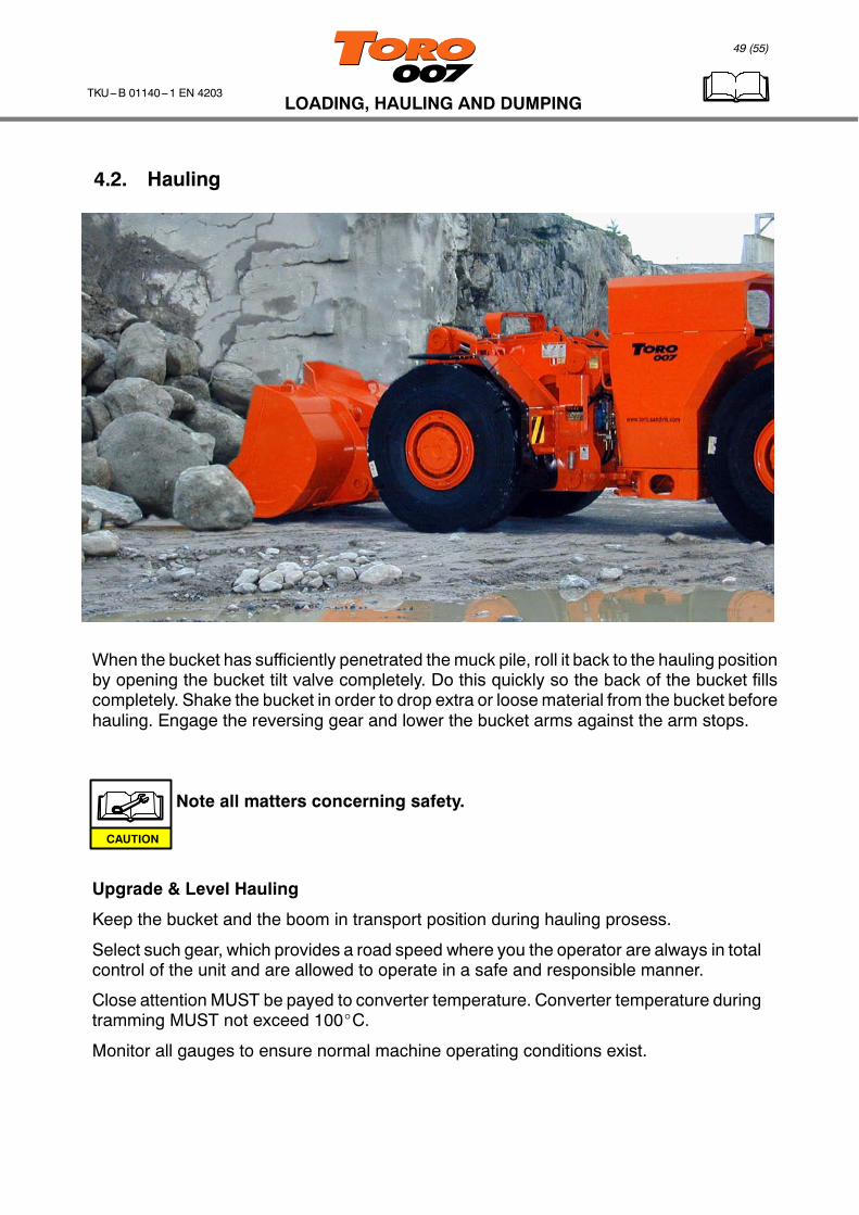
4.2. Hauling
When the bucket has sufficiently penetrated the muck pile, roll it back to the hauling positionby opening the bucket tilt valve completely. Do this quickly so the back of the bucket fillscompletely. Shake the bucket in order to drop extra or loose material from the bucket beforehauling. Engage the reversing gear and lower the bucket arms against the arm stops.
Note all matters concerning safety.
Upgrade & Level Hauling
Keep the bucket and the boom in transport position during hauling prosess.
Select such gear, which provides a road speed where you the operator are always in totalcontrol of the unit and are allowed to operate in a safe and responsible manner.
Close attention MUST be payed to converter temperature. Converter temperature duringtramming MUST not exceed 100_C.
Monitor all gauges to ensure normal machine operating conditions exist.
CAUTION
50 (55)
LOADING, HAULING AND DUMPINGTKU---B 01140---1 EN 4203
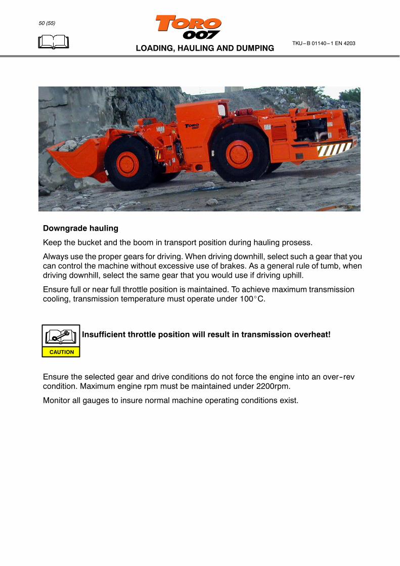
Downgrade hauling
Keep the bucket and the boom in transport position during hauling prosess.
Always use the proper gears for driving. When driving downhill, select such a gear that youcan control the machine without excessive use of brakes. As a general rule of tumb, whendriving downhill, select the same gear that you would use if driving uphill.
Ensure full or near full throttle position is maintained. To achieve maximum transmissioncooling, transmission temperature must operate under 100_C.
Insufficient throttle position will result in transmission overheat!
Ensure the selected gear and drive conditions do not force the engine into an over--revcondition. Maximum engine rpm must be maintained under 2200rpm.
Monitor all gauges to insure normal machine operating conditions exist.
CAUTION
51 (55)
LOADING, HAULING AND DUMPINGTKU---B 01140---1 EN 4203
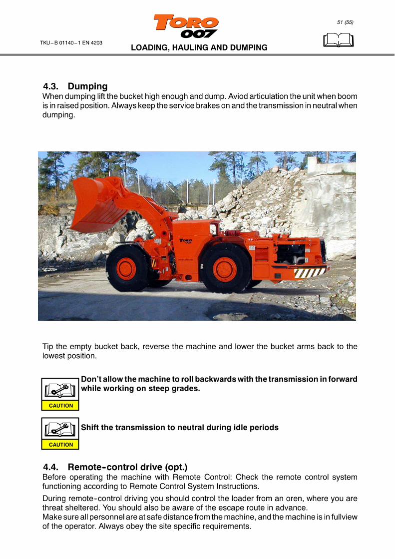
4.3. DumpingWhen dumping lift the bucket high enough and dump. Aviod articulation the unit when boomis in raised position. Always keep the service brakes on and the transmission in neutralwhendumping.
Tip the empty bucket back, reverse the machine and lower the bucket arms back to thelowest position.
Don’t allow themachine to roll backwardswith the transmission in forwardwhile working on steep grades.
Shift the transmission to neutral during idle periods
4.4. Remote--control drive (opt.)Before operating the machine with Remote Control: Check the remote control systemfunctioning according to Remote Control System Instructions.
During remote--control driving you should control the loader from an oren, where you arethreat sheltered. You should also be aware of the escape route in advance.Make sure all personnel are at safe distance from themachine, and themachine is in fullviewof the operator. Always obey the site specific requirements.
CAUTION
CAUTION
52 (55)
LOADING, HAULING AND DUMPINGTKU---B 01140---1 EN 4203
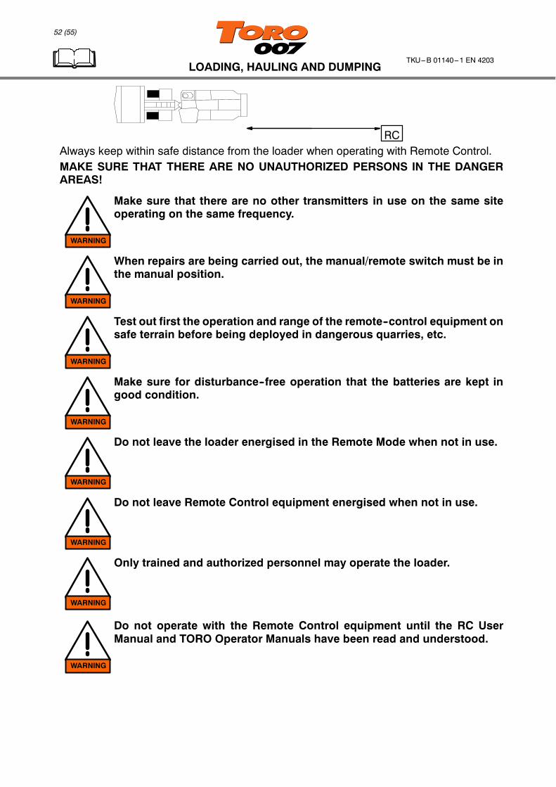
RCAlways keep within safe distance from the loader when operating with Remote Control.MAKE SURE THAT THERE ARE NO UNAUTHORIZED PERSONS IN THE DANGERAREAS!
Make sure that there are no other transmitters in use on the same siteoperating on the same frequency.
When repairs are being carried out, the manual/remote switch must be inthe manual position.
Test out first the operation and range of the remote--control equipment onsafe terrain before being deployed in dangerous quarries, etc.
Make sure for disturbance--free operation that the batteries are kept ingood condition.
Do not leave the loader energised in the Remote Mode when not in use.
Do not leave Remote Control equipment energised when not in use.
Only trained and authorized personnel may operate the loader.
Do not operate with the Remote Control equipment until the RC UserManual and TORO Operator Manuals have been read and understood.
WARNING
WARNING
WARNING
WARNING
WARNING
WARNING
WARNING
WARNING

53 (55)
TROUBLESHOOTINGTKU---B 01140---1 EN 4203
5. TROUBLESHOOTING
FAULT POSSIBLE REASON / CHECK
Ignition current does not goon.
1. Check system voltage on the gauge2. Check the main switch is in ON position
Engine does not start 1. Emergency stop button pushed (1) (One in thecanopy and one emergency stop buttons on theboth side of the machine, opt.)
1
1 1
23
2. Fuel tank empty3. RC -- switch in remote control position (opt.)
Parking brake can’t bereleased
1. Brake accumulator pressure too low2. Transmission oil pressure too low (ABA opt.)3. Engine oil pressure too low / engine not running4. RC -- switch in remote control position (opt.)
Steering control does notwork
1. Canopy door open2. Engine not running3. Safety attachment between front and rear frame4. RC -- switch in remote control position (opt.)

TECHNICAL SPECIFICATION
54 (55)
TKU---B 01140---1 EN 4203
6. TECHNICAL SPECIFICATION
Continuing research and development of TORO loader’s may have caused changes toyour machine which are not includedin this specification.
TECHNICAL SPECIFICATION
55 (55)
TKU---B 01140---1 EN 4203
Related Documents


![DATED [ ] 2000 [Operator] and [Vodafone AirTouch Plc ...ec.europa.eu/competition/mergers/cases/decisions/...("VFAT Operator"). The Operator and the VFAT Operator are jointly referred](https://static.cupdf.com/doc/110x72/5f957bfbb358510723214249/dated-2000-operator-and-vodafone-airtouch-plc-ec-vfat-operator.jpg)