OPERATIONS & MAINTENANCE MANUAL for the ULTRAFLOW 501 18B BANDMASK Part No: A10330 DIVEX LTD OM 157 P1884-OM-316 Rev3

Welcome message from author
This document is posted to help you gain knowledge. Please leave a comment to let me know what you think about it! Share it to your friends and learn new things together.
Transcript
OPERATIONS & MAINTENANCE
MANUAL
for the
ULTRAFLOW 501 18B BANDMASK
Part No: A10330
DIVEX LTD OM 157 P1884-OM-316 Rev3
DIVEX LTD OM 157 P1884-OM-316 Rev3
THIS PAGE IS LEFT BLANK INTENTIONALLY
DIVEX LTD OM 157 P1884-OM-316 Rev3
PREFACE
The following address should be used in all communications with the manufacturer:-
DIVEX Ltd. Enterprise Drive, Westhill, Aberdeen, AB32 6TQ
United Kingdom
Telephone +44 (0)1224 740145 Facsimile +44 (0)1224 740172
e-mail [email protected]
NATIONAL APPROVALS AND MARKINGS:
♦ ULTRAFLOW 501 18B BANDMASK MARKING: 0088
DIVEX Limited declares that this Personal Protective Equipment is in conformity with the provisions of Articles 10 and 11 of the EUROPEAN DIRECTIVE 89/686/EEC as a CATEGORY 3 DEVICE, and is manufactured under a Quality System approved by Lloyd’s Register Q.A. (Notified Body No. 0088). EC TYPE APPROVAL CONDUCTED BY:
SGS UNITED KINGDOM Ltd. ELLESMERE PORT CHESHIRE UNITED KINGDOM CH65 3EN NOTIFIED BODY No. 0120 ♦ NATIONAL APPROVALS
The DIVEX Limited Quality Management System has been approved by Lloyd’s Register Quality Assurance Limited to BS EN ISO 9001
Approval Certificate No. 850495.

DIVEX LTD OM 157 P1884-OM-316 Rev3
THIS PAGE IS LEFT BLANK INTENTIONALLY
DIVEX LTD OM 157 P1884-OM-316 Rev3
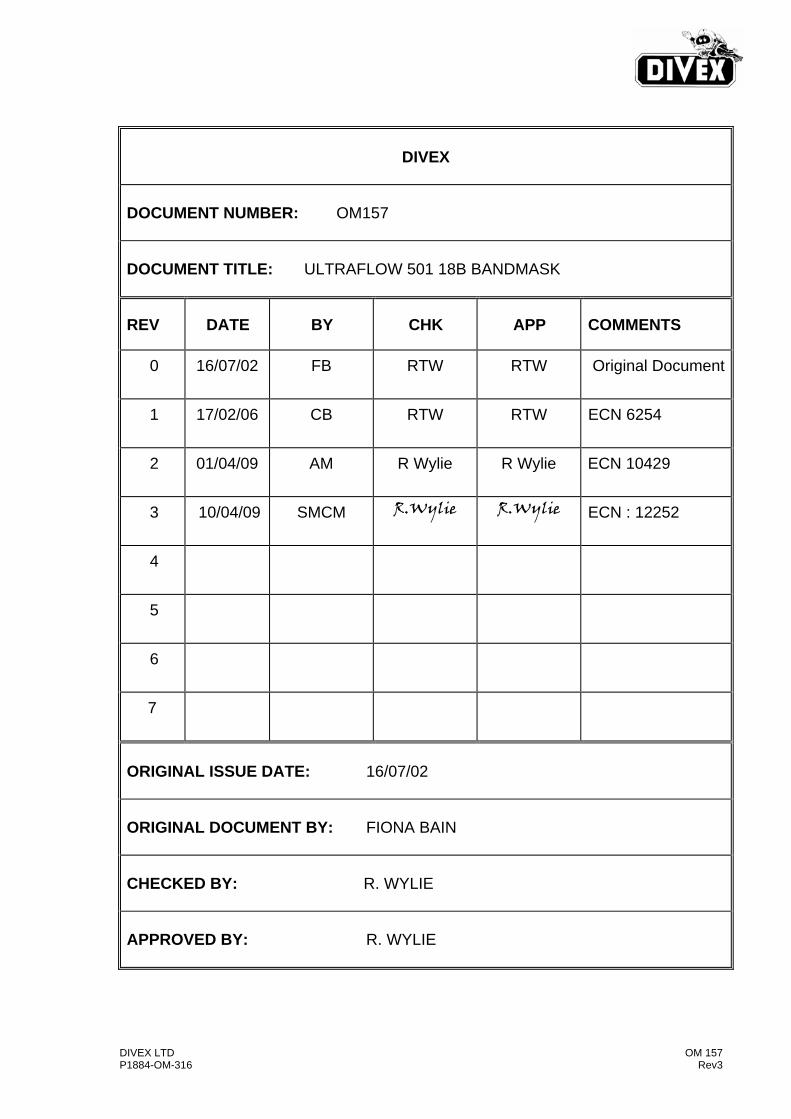
DIVEX
DOCUMENT NUMBER: OM157 DOCUMENT TITLE: ULTRAFLOW 501 18B BANDMASK
REV DATE BY CHK APP COMMENTS
0
16/07/02
FB RTW RTW Original Document
1
17/02/06 CB RTW RTW ECN 6254
2
01/04/09 AM R Wylie R Wylie ECN 10429
3
10/04/09 SMCM R.Wylie R.Wylie ECN : 12252
4
5
6
7
ORIGINAL ISSUE DATE: 16/07/02 ORIGINAL DOCUMENT BY: FIONA BAIN CHECKED BY: R. WYLIE APPROVED BY: R. WYLIE
DIVEX LTD OM 157 P1884-OM-316 Rev3
THIS PAGE IS LEFT BLANK INTENTIONALLY
DIVEX LTD OM 157 P1884-OM-316 Rev3
CONTENTS
1.0 INTRODUCTION
2.0 GENERAL DESCRIPTION AND FUNCTION
2.1 Bandmask Assembly
2.2 Ultraflow 501 Demand Regulator
2.3 Modification From Standard DSI Superflow Regulators
3.0 SERVICE & MAINTENANCE OF ULTRAFLOW 501 DEMAND REGULATOR
3.1 Ultraflow Disassembly
3.2 Ultraflow 501 Assembly
3.3 Adjustment
4.0 SERVICE & MAINTENANCE OF SIDE BLOCK
5.0 SERVICE & MAINTENANCE OF ORAL NASAL MASK
6.0 ROUTINE MAINTENANCE
7.0 SUPERLITE 18B EXPLODED PARTS
8.0 RECOMMENDED SUPPLY PRESSURES

DIVEX LTD OM 157 P1884-OM-316 Rev3
THIS PAGE IS LEFT BLANK INTENTIONALLY

DIVEX LTD Page 1.1 OM 157 Rev 2
1.0 INTRODUCTION
The ULTRAFLOW 501 Bandmask for open circuit air and Heliox diving operations consists principally of ULTRAFLOW 501 demand regulator fitted to a conventional DSI Superlite 18B Bandmask. ULTRAFLOW 501 is suitable for depths down to 50 msw on air and 500 msw on Heliox.
DIVEX LTD Page 1.2 OM 157 Rev 2
THIS PAGE IS LEFT BLANK INTENTIONALLY
Divex Page 2.1 OM 157 Rev 2
2.0 GENERAL DESCRIPTION AND FUNCTION
2.1 Bandmask Assembly
This manual covers the maintenance of the Ultraflow 501 Demand Valve and the operation of a converted 18B Bandmask with Ultraflow 501. For maintenance of the “Superlite” standard components then refer to the DSI manual.
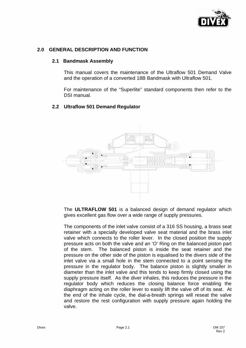
2.2 Ultraflow 501 Demand Regulator
The ULTRAFLOW 501 is a balanced design of demand regulator which gives excellent gas flow over a wide range of supply pressures. The components of the inlet valve consist of a 316 SS housing, a brass seat retainer with a specially developed valve seat material and the brass inlet valve which connects to the roller lever. In the closed position the supply pressure acts on both the valve and an ‘O’ Ring on the balanced piston part of the stem. The balanced piston is inside the seat retainer and the pressure on the other side of the piston is equalised to the divers side of the inlet valve via a small hole in the stem connected to a point sensing the pressure in the regulator body. The balance piston is slightly smaller in diameter than the inlet valve and this tends to keep firmly closed using the supply pressure itself. As the diver inhales, this reduces the pressure in the regulator body which reduces the closing balance force enabling the diaphragm acting on the roller lever to easily lift the valve off of its seat. At the end of the inhale cycle, the dial-a-breath springs will reseat the valve and restore the rest configuration with supply pressure again holding the valve.
Divex Page 2.2 OM 157 Rev 2
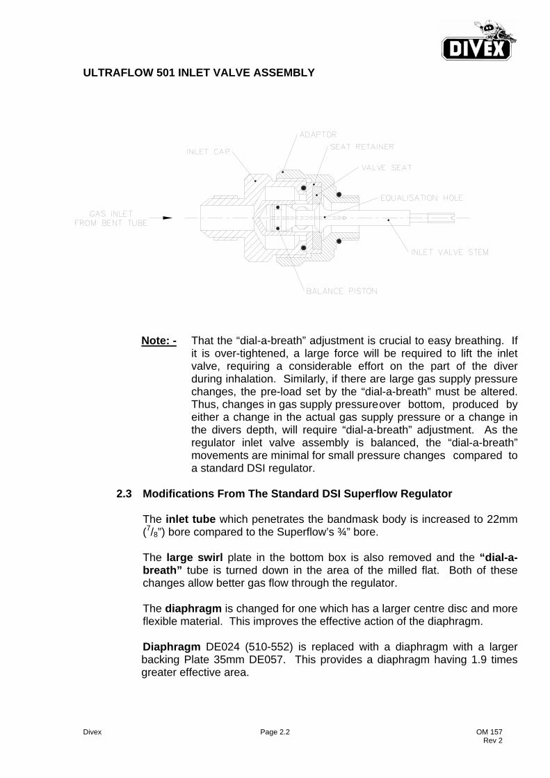
ULTRAFLOW 501 INLET VALVE ASSEMBLY
Note: - That the “dial-a-breath” adjustment is crucial to easy breathing. If
it is over-tightened, a large force will be required to lift the inlet valve, requiring a considerable effort on the part of the diver during inhalation. Similarly, if there are large gas supply pressure changes, the pre-load set by the “dial-a-breath” must be altered. Thus, changes in gas supply pressure over bottom, produced by either a change in the actual gas supply pressure or a change in the divers depth, will require “dial-a-breath” adjustment. As the regulator inlet valve assembly is balanced, the “dial-a-breath” movements are minimal for small pressure changes compared to a standard DSI regulator.
2.3 Modifications From The Standard DSI Superflow Regulator
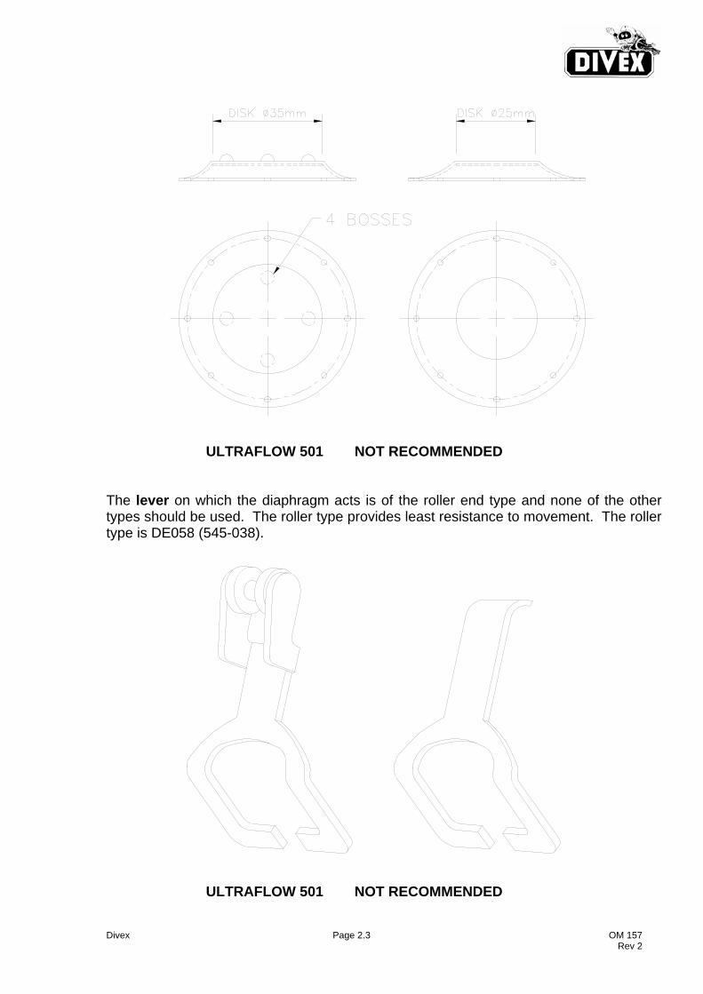
The inlet tube which penetrates the bandmask body is increased to 22mm (7/8”) bore compared to the Superflow’s ¾” bore. The large swirl plate in the bottom box is also removed and the “dial-a-breath” tube is turned down in the area of the milled flat. Both of these changes allow better gas flow through the regulator. The diaphragm is changed for one which has a larger centre disc and more flexible material. This improves the effective action of the diaphragm. Diaphragm DE024 (510-552) is replaced with a diaphragm with a larger backing Plate 35mm DE057. This provides a diaphragm having 1.9 times greater effective area.
Divex Page 2.3 OM 157 Rev 2
ULTRAFLOW 501 NOT RECOMMENDED The lever on which the diaphragm acts is of the roller end type and none of the other types should be used. The roller type provides least resistance to movement. The roller type is DE058 (545-038). ULTRAFLOW 501 NOT RECOMMENDED
Divex Page 2.4 OM 157 Rev2
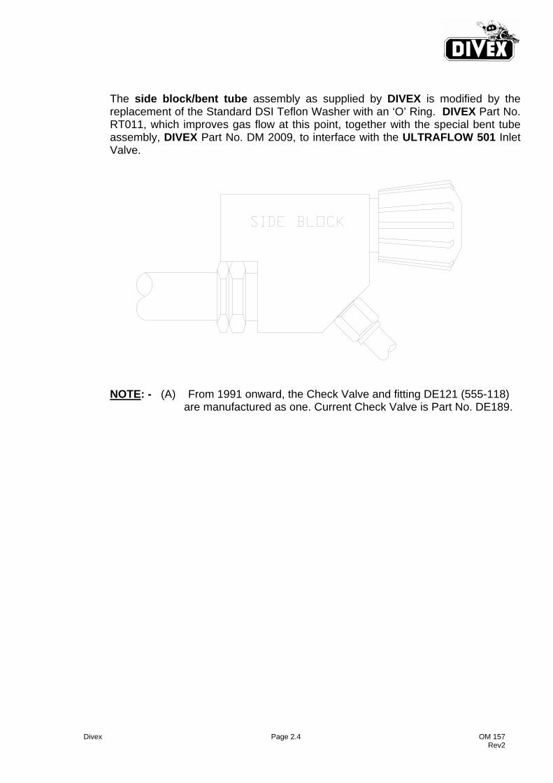
The side block/bent tube assembly as supplied by DIVEX is modified by the
replacement of the Standard DSI Teflon Washer with an ‘O’ Ring. DIVEX Part No. RT011, which improves gas flow at this point, together with the special bent tube assembly, DIVEX Part No. DM 2009, to interface with the ULTRAFLOW 501 Inlet Valve.
NOTE: - (A) From 1991 onward, the Check Valve and fitting DE121 (555-118)
are manufactured as one. Current Check Valve is Part No. DE189.
Divex Page 3.1 OM 157 Rev2
3.0 SERVICE & MAINTENANCE OF ULTRAFLOW 501 DEMAND REGULATOR
3.1 Ultraflow Disassembly To be read in conjunction with Drawing on Page 3.7 1. Remove the cover Clamp Screw (Item 29) and Cover Clamp (Item 15) lift the Cover (Item 13) off with Spring (Item 14) and pull out the Diaphragm (Item 11). 2. The “dial-a-breath” control is removed by backing the knob (Item 27) out until the
Nut (Item 25) is exposed enough to use a wrench. The knob (Item 27) Nut (Item 25), ‘O’ Ring (Item 28), Washer (Item 24) and Shaft (Item 23) all come out as one. The Knob (Item 27) may be removed from the shaft (Item 23) by punching out the
Lock Pin (Item 26). A 3/32” diameter punch should be used. The ‘O’ Ring (Item 28) and Washer (Item 24) remain on the shaft (Item 23) and may now be removed. Tilt the helmet so that the Spacer (Item 22), Spring Set (Item 21) and Piston (Item 20) fall out of the adjustment Shaft Tube of the Regulator Body (Item 8).
3. Remove the Bent Tube Assembly from the Inlet Valve Assembly. 4. Remove the complete Inlet Valve Assembly from the Demand Regulator Body (Item 8), using a wrench on the ULTRAFLOW Adapter Flats (Item 3). 5. The Inlet Valve Assembly can now be carefully pulled away from the Demand Regulator Body leaving the Valve Stem (Item 1) in place in the Regulator. 6. The Valve Stem can be removed from the Regulator by removing the Nut (Item 19). Use a straight slot screwdriver to rotate the Valve Stem (Item 1) while Retaining Nut (Item 19) is held with the correct spanner from the DSI Service Tool Kit. 7. Undo the Nut (Item 9) which secures the inlet tube to the Bandmask. Remove the Regulator Body (Item 8). Nut (Item 9) and ‘O’ Ring (Item 10). All parts should be thoroughly cleaned and parts replaced as indicated with ‘O’ rings being lubricated only with Christo-Lube fluorinated grease before installation.
Divex Page 3.2 OM 157 Rev2
3.2 Ultraflow 501 Assembly
To be read in conjunction with the drawing on page 3.7 During re-assembly of the Demand Regulator, replace all questionable and damaged parts with new. Lubricate all ‘O’ rings and threaded metal parts lightly only with Christo-Lube fluorinated grease.
1. Install the Inlet Valve Stem (Item 1) in the regulator Body. Fit the Washer (Item 16), Lever (Item 17) and Spacer (Item 18) on to the Shaft of the Inlet Valve Stem. Screw the nut on to the threaded end of the Inlet Valve Stem until the Inlet Valve threads protrude slightly (about 2 threads past the Nut). Use a straight slot screwdriver and special DSI spanner for this operation.
CAUTION: The Lock Nut (Item 19) is a Nyloc Nut and should always be replaced with new if removed from the Inlet Valve.
2. Assemble the ULTRAFLOW Adapter (Item 3), Seat Retainer (Item 4) and Inlet Cap (Item 2).
3. Install the Piston (Item 20), Spring Set (Item 21) and Spacer (Item 22) into the Adjustment Tube of the Regulator Body. Generously apply Christo-Lube Fluorinated Grease to this assembly.
4. Thread the main adjustment Shaft (Item 23) into the tube. Slide the
washer (Item 24) and ‘O’ Ring (Item 28) onto the adjustment shaft (Item 23). Slide the packing Nut (Item 25) onto the shaft and tighten in onto threaded tube of the Regulator (Item 8).
5. Fit the knob (item 27) onto the adjustment Shaft (Item 23) and align the
holes for the Retaining Pin (Item 26).
CAUTION: Support the adjustment knob (item 27) while tapping Retaining Pin (Item 26) to prevent damage to the Shaft (Item 23) and Body (Item 8).
6. Assemble the Bent Tube Assembly to the Inlet Valve Assembly.
NOTE: The sealing washer should be DIVEX Part No. RT011 which improves flow characteristics. Adjust the Regulator as described in Section 3.3.
Divex Page 3.3 OM 157 Rev2
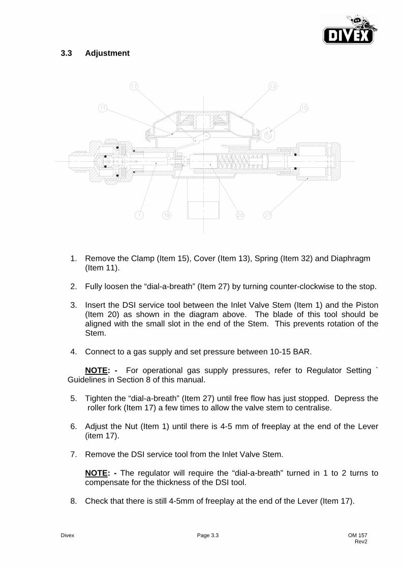
3.3 Adjustment
1. Remove the Clamp (Item 15), Cover (Item 13), Spring (Item 32) and Diaphragm (Item 11).
2. Fully loosen the “dial-a-breath” (Item 27) by turning counter-clockwise to the stop.
3. Insert the DSI service tool between the Inlet Valve Stem (Item 1) and the Piston
(Item 20) as shown in the diagram above. The blade of this tool should be aligned with the small slot in the end of the Stem. This prevents rotation of the Stem.
4. Connect to a gas supply and set pressure between 10-15 BAR.
NOTE: - For operational gas supply pressures, refer to Regulator Setting `
Guidelines in Section 8 of this manual.
5. Tighten the “dial-a-breath” (Item 27) until free flow has just stopped. Depress the roller fork (Item 17) a few times to allow the valve stem to centralise.
6. Adjust the Nut (Item 1) until there is 4-5 mm of freeplay at the end of the Lever
(item 17).
7. Remove the DSI service tool from the Inlet Valve Stem.
NOTE: - The regulator will require the “dial-a-breath” turned in 1 to 2 turns to compensate for the thickness of the DSI tool.
8. Check that there is still 4-5mm of freeplay at the end of the Lever (Item 17).
Divex Page 3.4 OM 157 Rev2
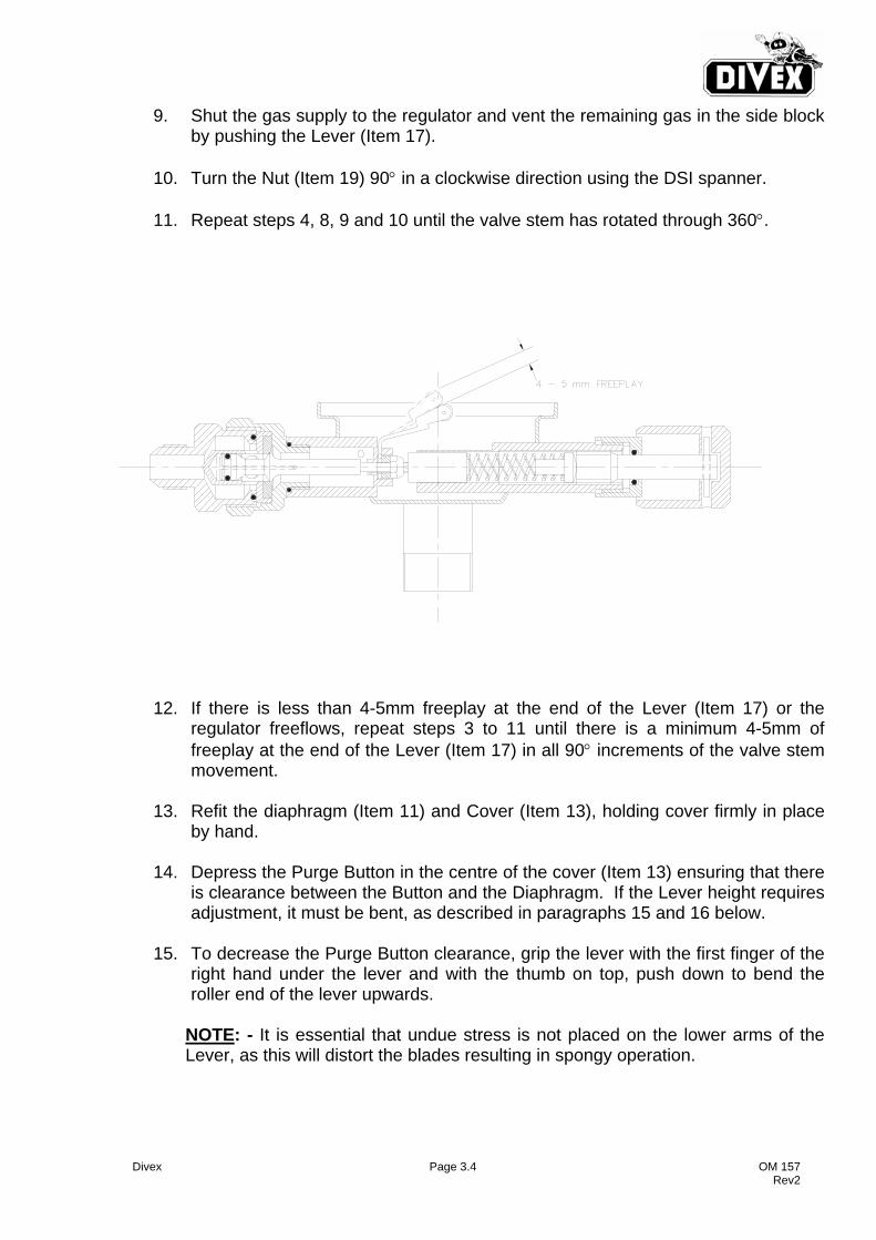
9. Shut the gas supply to the regulator and vent the remaining gas in the side block by pushing the Lever (Item 17).
10. Turn the Nut (Item 19) 90° in a clockwise direction using the DSI spanner.
11. Repeat steps 4, 8, 9 and 10 until the valve stem has rotated through 360°.
12. If there is less than 4-5mm freeplay at the end of the Lever (Item 17) or the regulator freeflows, repeat steps 3 to 11 until there is a minimum 4-5mm of freeplay at the end of the Lever (Item 17) in all 90° increments of the valve stem movement.
13. Refit the diaphragm (Item 11) and Cover (Item 13), holding cover firmly in place
by hand.
14. Depress the Purge Button in the centre of the cover (Item 13) ensuring that there is clearance between the Button and the Diaphragm. If the Lever height requires adjustment, it must be bent, as described in paragraphs 15 and 16 below.
15. To decrease the Purge Button clearance, grip the lever with the first finger of the
right hand under the lever and with the thumb on top, push down to bend the roller end of the lever upwards.
NOTE: - It is essential that undue stress is not placed on the lower arms of the Lever, as this will distort the blades resulting in spongy operation.
Divex Page 3.5 OM 157 Rev2
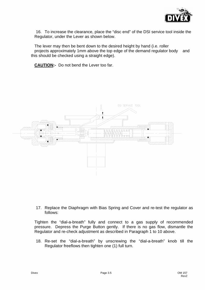
16. To increase the clearance, place the “disc end” of the DSI service tool inside the
Regulator, under the Lever as shown below. The lever may then be bent down to the desired height by hand (i.e. roller projects approximately 1mm above the top edge of the demand regulator body and this should be checked using a straight edge). CAUTION:- Do not bend the Lever too far.
17. Replace the Diaphragm with Bias Spring and Cover and re-test the regulator as follows:
Tighten the “dial-a-breath” fully and connect to a gas supply of recommended pressure. Depress the Purge Button gently. If there is no gas flow, dismantle the Regulator and re-check adjustment as described in Paragraph 1 to 10 above.
18. Re-set the “dial-a-breath” by unscrewing the “dial-a-breath” knob till the Regulator freeflows then tighten one (1) full turn.
Divex Page 3.6 OM 157 Rev2
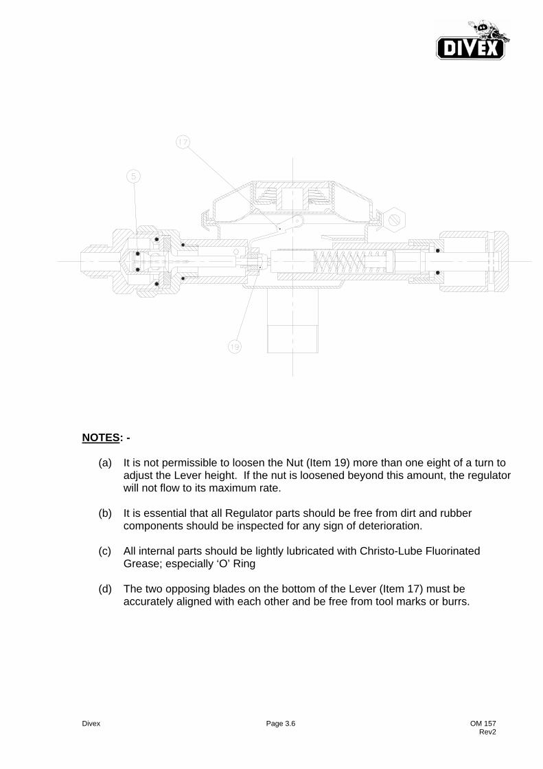
NOTES: -
(a) It is not permissible to loosen the Nut (Item 19) more than one eight of a turn to adjust the Lever height. If the nut is loosened beyond this amount, the regulator will not flow to its maximum rate.
(b) It is essential that all Regulator parts should be free from dirt and rubber
components should be inspected for any sign of deterioration.
(c) All internal parts should be lightly lubricated with Christo-Lube Fluorinated Grease; especially ‘O’ Ring
(d) The two opposing blades on the bottom of the Lever (Item 17) must be
accurately aligned with each other and be free from tool marks or burrs.
Divex Page 3.7 OM 157 Rev2
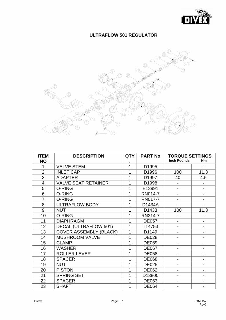
ULTRAFLOW 501 REGULATOR
ITEM NO
DESCRIPTION QTY.
PART No
TORQUE SETTINGS Inch Pounds Nm
1 VALVE STEM 1 D1995 - - 2 INLET CAP 1 D1996 100 11.3 3 ADAPTER 1 D1997 40 4.5 4 VALVE SEAT RETAINER 1 D1998 - - 5 O-RING 1 E13991 - - 6 O-RING 1 RN014-7 - - 7 O-RING 1 RN017-7 - - 8 ULTRAFLOW BODY 1 D1434A - - 9 NUT 1 D1433 100 11.3
10 O-RING 1 RN214-7 - - 11 DIAPHRAGM 1 DE057 - - 12 DECAL (ULTRAFLOW 501) 1 T14753 - - 13 COVER ASSEMBLY (BLACK) 1 D1149 - - 14 MUSHROOM VALVE 1 DE028 - - 15 CLAMP 1 DE069 - - 16 WASHER 1 DE067 - - 17 ROLLER LEVER 1 DE058 - - 18 SPACER 1 DE068 - - 19 NUT 1 DE025 - - 20 PISTON 1 DE062 - - 21 SPRING SET 1 D13800 - - 22 SPACER 1 DE063 - - 23 SHAFT 1 DE064 - -
Divex Page 3.8 OM 157 Rev2
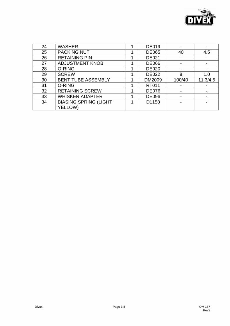
24 WASHER 1 DE019 - - 25 PACKING NUT 1 DE065 40 4.5 26 RETAINING PIN 1 DE021 - - 27 ADJUSTMENT KNOB 1 DE066 - - 28 O-RING 1 DE020 - - 29 SCREW 1 DE022 8 1.0 30 BENT TUBE ASSEMBLY 1 DM2009 100/40 11.3/4.5 31 O-RING 1 RT011 - - 32 RETAINING SCREW 1 DE076 - - 33 WHISKER ADAPTER 1 DE096 - - 34 BIASING SPRING (LIGHT
YELLOW) 1 D1158 - -
Divex Page 4.1 OM 157 Rev2
4.0 SERVICE AND MAINTENANCE OF SIDE BLOCK
Maintenance of the Side Block with regard to DIVEX equipment consists of checking the condition of the ‘O’ Ring at the top of the bent tube assembly. If there is any doubt about the condition, replace. For maintenance on the remained of the side block refer to the DSI Manual.
Divex Page 4.2 OM 157 Rev2
THIS PAGE IS LEFT BLANK INTENTIONALLY
Divex Page 5.1 OM 157 Rev 2
5.0 SERVICE AND MAINTENANCE OF ORAL NASAL MASK
Remove the Oral Nasal Mask first removing the nose block device by unscrewing the knob and removing the packing nut and ‘O’ rings. Pull the nose block device out of the oral nasal. Unscrew the outer nuts on the communications posts and remove the microphone wire lugs. Grasp the oral nasal and slowly pull of the regulator mount nut and the connector. The oral nasal is now out of the headgear and can be inspected. Replace if necessary noting that a light coat of silicone lubricant will preserve the rubber. Re-assembly is the reverse of the above sequence.

Divex Page 5.2 OM 157 Rev 2
THIS PAGE IS LEFT BLANK INTENTIONALLY
Divex Page 6.1 OM 157 Rev2
6.0 ROUTINE MAINTENANCE
Maintenance Schedule 24 Hours Clean and inspect mask inside and out. Check operation of all moving parts
Refer to DSI Manual for detailed procedures. Monthly Inspect oral nasal for signs of deterioration. Inspect and adjust demand regulator. Lubricate packing on nose clearing devise as described in DSI Manual. Test Check Valve on main supply connection as described in DSI Manual.
Divex Page 6.2 OM 157 Rev2
THIS PAGE IS LEFT BLANK INTENTIONALLY
Divex Page 7.1 OM 157 Rev 2
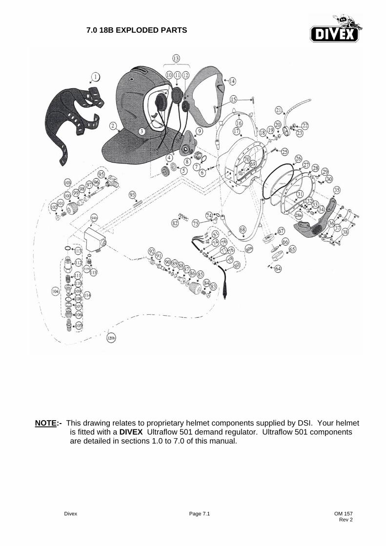
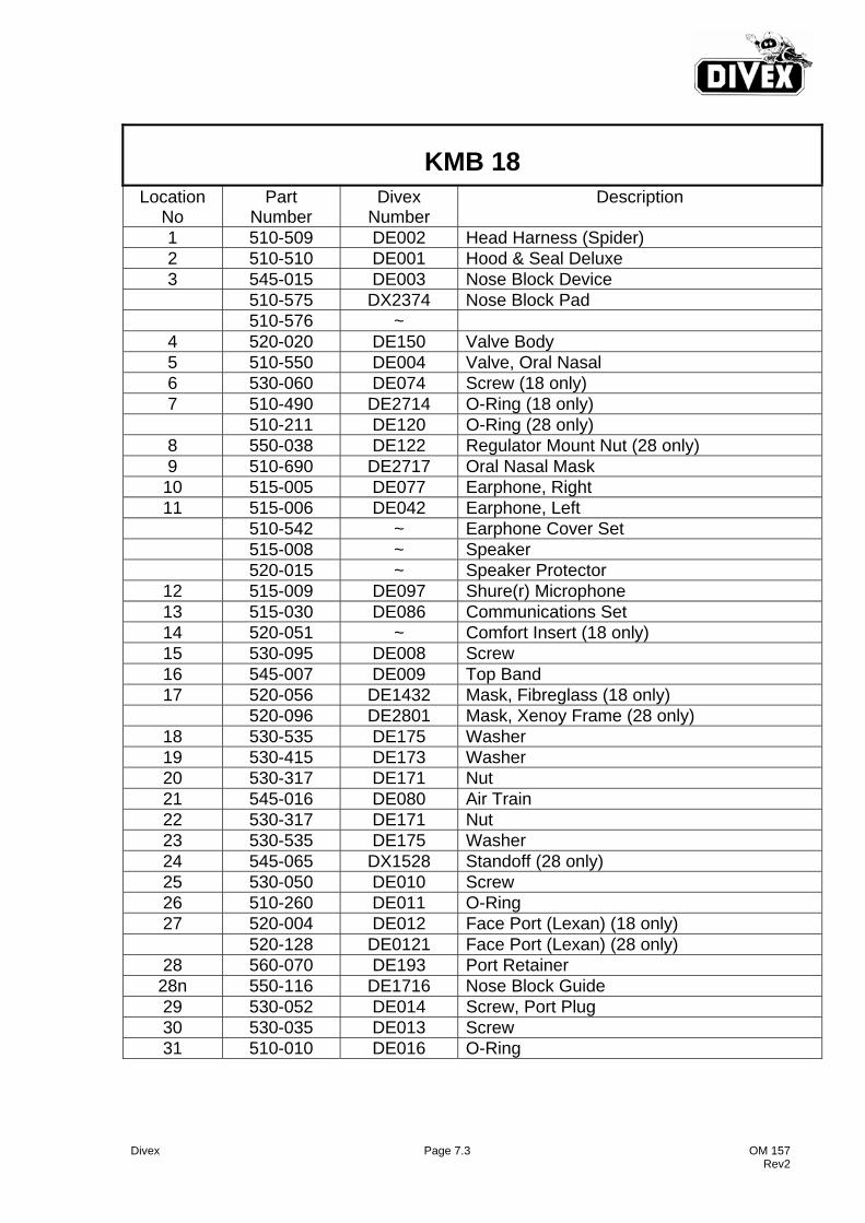
7.0 18B EXPLODED PARTS
NOTE:- This drawing relates to proprietary helmet components supplied by DSI. Your helmet is fitted with a DIVEX Ultraflow 501 demand regulator. Ultraflow 501 components are detailed in sections 1.0 to 7.0 of this manual.

Divex Page 7.2 OM 157 Rev 2
THIS PAGE IS LEFT BLANK INTENTIONALLY
Divex Page 7.3 OM 157 Rev2
KMB 18 Location
No Part
Number Divex
Number Description
1 510-509 DE002 Head Harness (Spider) 2 510-510 DE001 Hood & Seal Deluxe 3 545-015 DE003 Nose Block Device 510-575 DX2374 Nose Block Pad 510-576 ~
4 520-020 DE150 Valve Body 5 510-550 DE004 Valve, Oral Nasal 6 530-060 DE074 Screw (18 only) 7 510-490 DE2714 O-Ring (18 only) 510-211 DE120 O-Ring (28 only)
8 550-038 DE122 Regulator Mount Nut (28 only) 9 510-690 DE2717 Oral Nasal Mask 10 515-005 DE077 Earphone, Right 11 515-006 DE042 Earphone, Left 510-542 ~ Earphone Cover Set 515-008 ~ Speaker 520-015 ~ Speaker Protector
12 515-009 DE097 Shure(r) Microphone 13 515-030 DE086 Communications Set 14 520-051 ~ Comfort Insert (18 only) 15 530-095 DE008 Screw 16 545-007 DE009 Top Band 17 520-056 DE1432 Mask, Fibreglass (18 only) 520-096 DE2801 Mask, Xenoy Frame (28 only)
18 530-535 DE175 Washer 19 530-415 DE173 Washer 20 530-317 DE171 Nut 21 545-016 DE080 Air Train 22 530-317 DE171 Nut 23 530-535 DE175 Washer 24 545-065 DX1528 Standoff (28 only) 25 530-050 DE010 Screw 26 510-260 DE011 O-Ring 27 520-004 DE012 Face Port (Lexan) (18 only) 520-128 DE0121 Face Port (Lexan) (28 only)
28 560-070 DE193 Port Retainer 28n 550-116 DE1716 Nose Block Guide 29 530-052 DE014 Screw, Port Plug 30 530-035 DE013 Screw 31 510-010 DE016 O-Ring
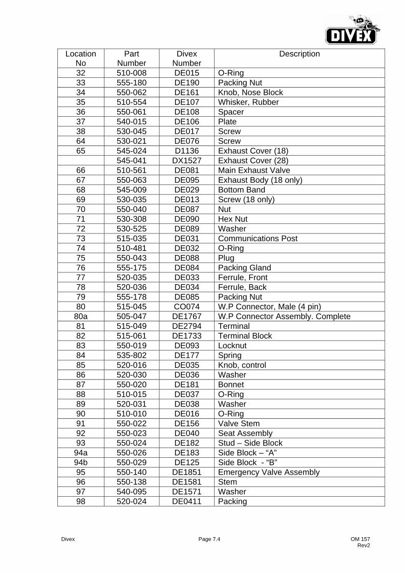
Divex Page 7.4 OM 157 Rev2
Location No
Part Number
Divex Number
Description
32 510-008 DE015 O-Ring 33 555-180 DE190 Packing Nut 34 550-062 DE161 Knob, Nose Block 35 510-554 DE107 Whisker, Rubber 36 550-061 DE108 Spacer 37 540-015 DE106 Plate 38 530-045 DE017 Screw 64 530-021 DE076 Screw 65 545-024 D1136 Exhaust Cover (18) 545-041 DX1527 Exhaust Cover (28)
66 510-561 DE081 Main Exhaust Valve 67 550-063 DE095 Exhaust Body (18 only) 68 545-009 DE029 Bottom Band 69 530-035 DE013 Screw (18 only) 70 550-040 DE087 Nut 71 530-308 DE090 Hex Nut 72 530-525 DE089 Washer 73 515-035 DE031 Communications Post 74 510-481 DE032 O-Ring 75 550-043 DE088 Plug 76 555-175 DE084 Packing Gland 77 520-035 DE033 Ferrule, Front 78 520-036 DE034 Ferrule, Back 79 555-178 DE085 Packing Nut 80 515-045 CO074 W.P Connector, Male (4 pin)
80a 505-047 DE1767 W.P Connector Assembly. Complete 81 515-049 DE2794 Terminal 82 515-061 DE1733 Terminal Block 83 550-019 DE093 Locknut 84 535-802 DE177 Spring 85 520-016 DE035 Knob, control 86 520-030 DE036 Washer 87 550-020 DE181 Bonnet 88 510-015 DE037 O-Ring 89 520-031 DE038 Washer 90 510-010 DE016 O-Ring 91 550-022 DE156 Valve Stem 92 550-023 DE040 Seat Assembly 93 550-024 DE182 Stud – Side Block
94a 550-026 DE183 Side Block – “A” 94b 550-029 DE125 Side Block - “B” 95 550-140 DE1851 Emergency Valve Assembly 96 550-138 DE1581 Stem 97 540-095 DE1571 Washer 98 520-024 DE0411 Packing
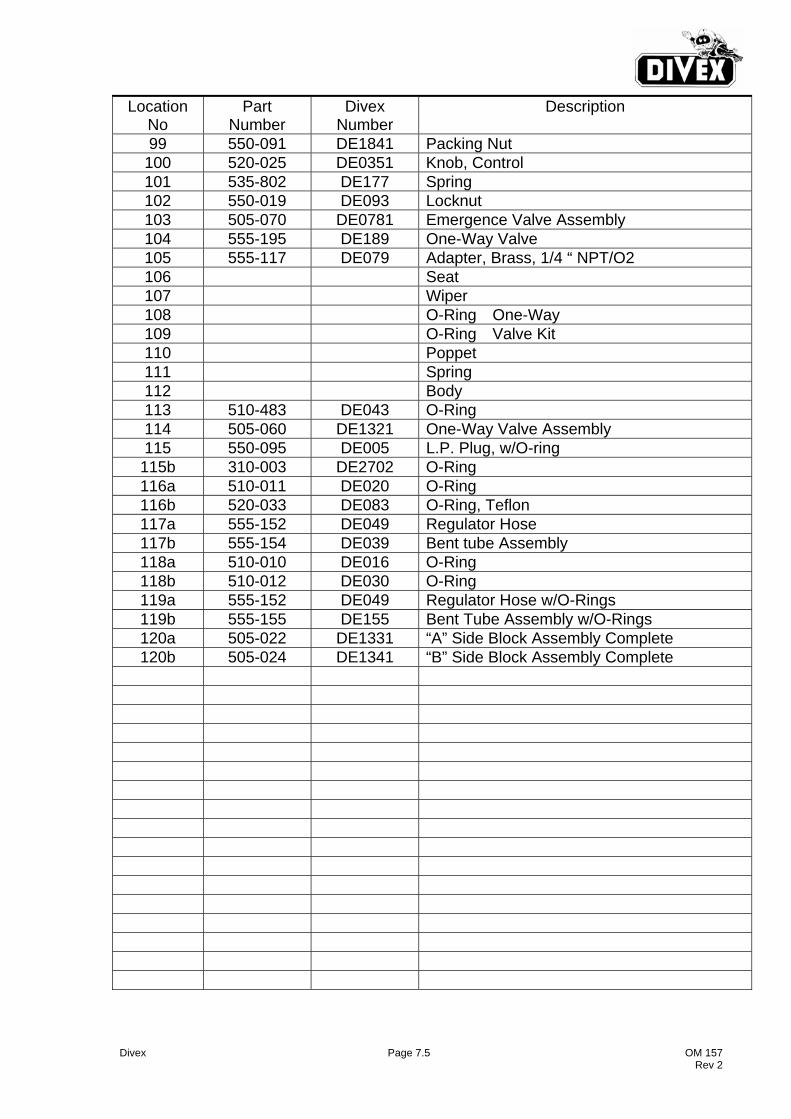
Divex Page 7.5 OM 157 Rev 2
Location No
Part Number
Divex Number
Description
99 550-091 DE1841 Packing Nut 100 520-025 DE0351 Knob, Control 101 535-802 DE177 Spring 102 550-019 DE093 Locknut 103 505-070 DE0781 Emergence Valve Assembly 104 555-195 DE189 One-Way Valve 105 555-117 DE079 Adapter, Brass, 1/4 “ NPT/O2 106 Seat 107 Wiper 108 O-Ring One-Way 109 O-Ring Valve Kit 110 Poppet 111 Spring 112 Body 113 510-483 DE043 O-Ring 114 505-060 DE1321 One-Way Valve Assembly 115 550-095 DE005 L.P. Plug, w/O-ring 115b 310-003 DE2702 O-Ring 116a 510-011 DE020 O-Ring 116b 520-033 DE083 O-Ring, Teflon 117a 555-152 DE049 Regulator Hose 117b 555-154 DE039 Bent tube Assembly 118a 510-010 DE016 O-Ring 118b 510-012 DE030 O-Ring 119a 555-152 DE049 Regulator Hose w/O-Rings 119b 555-155 DE155 Bent Tube Assembly w/O-Rings 120a 505-022 DE1331 “A” Side Block Assembly Complete 120b 505-024 DE1341 “B” Side Block Assembly Complete

Divex Page 8.1 OM 157 Rev 2
8.0 RECOMMENDED SUPPLY PRESSURES The operation of the ULTRAFLOW 501 Bandmask is no different from that of a standard DSI Superlite 18B Bandmask and optimum diver breathing resistance can be achieved by rotation of the Demand Regulator adjustment knob. Recommended Supply Pressure for Air Diving Applications To assist users of the ULTRAFLOW 501 Bandmask to gain maximum diver comfort and safety, it is recommended that the following minimum overbottom supply pressure settings are provided at the supervisors panel. The maximum overbottom settings should not exceed 20 barg.
Diving Depth MSW
Surface Supply Pressure (Barg)
300’ Umbilical 600’ Umbilical 10 10 10 20 10 10 30 10 10 40 11 12 50 13 14
Recommended Supply Pressure for Mixed Gas Diving Applications To assist users of the ULTRAFLOW 501 Bandmask to gain maximum comfort and safety, it is recommended that the following minimum supply pressure settings are provided in the Diving Bell. This pressure setting should no exceed 20 bar g.
BELL DEPTH DIVER SUPPLY (BELL)
MSW BAR 30-150 10
151-180 11 181-215 12 216-250 13 251-280 14 281-315 15 316-350 16 351-400 17 401-430 18 431-460 19 461-480 20 481-500 20
Related Documents