OPERATIONAL GUIDELINES FOR HUMANITARIAN CIVIC ASSISTANCE WATER WELL DRILLING Prepared by U.S. Army Engineer District, Mobile

Welcome message from author
This document is posted to help you gain knowledge. Please leave a comment to let me know what you think about it! Share it to your friends and learn new things together.
Transcript

OPERATIONAL GUIDELINES FOR HUMANITARIAN
CIVIC ASSISTANCE WATER WELL DRILLING
Prepared by
U.S. Army Engineer District, Mobile


OPERATIONAL GUIDELINES FOR HUMANITARIAN
CIVIC ASSISTANCE WATER WELL DRILLING
2nd Edition June 2001
PREPARED BY
UNITED STATES ARMY ENGINEER DISTRICT, MOBILE
ENGINEERING DIVISION GEOTECHNICAL AND ENVIRONMENTAL BRANCH
GEOTECHNICAL AND DAM SAFETY SECTION
John N. Baehr, P.G. Edited by Laura E. Waite
DSN 457-2686 or 2680
Comm. (251) 690-3480 or 3146 FAX (251) 690-2674


HCA Well Drilling Manual
Table of Contents Page
LIST OF ACRONYMS AND ABBREVIATIONS............................................................................................vi FOREWORD............................................................................................................................................... viii THE WHOS AND WHYS OF USING THIS MANUAL .................................................................................. ix
SECTION ONE ................................................................................................................................................ 1 SITE SELECTION FOR WELL DRILLING...................................................................................................... 1
1.1 THE POLITICS OF WATER WELLS...................................................................................................... 3 1.1.1 HCA Wells: ..................................................................................................................................... 3 1.1.2 Phased Completion: ....................................................................................................................... 5
1.2 OBTAINING WATER WELL DATA......................................................................................................... 7 1.2.1 Topographic Engineering Center: .................................................................................................. 7 1.2.2 Geophysical Exploration:................................................................................................................ 9 1.2.3 Initial Well Recommendations: ..................................................................................................... 11
1.3 POST EXERCISE INSPECTIONS ....................................................................................................... 11 SECTION TWO.............................................................................................................................................. 13 SITE RECONNAISSANCE PRIOR TO MOBILIZATION .............................................................................. 13
2.1 ACCESS ............................................................................................................................................... 15 2.1.1 Site Setup: .................................................................................................................................... 15 2.1.2 Soil or Surface Conditions:........................................................................................................... 15
2.2 LOCAL WATER REQUIREMENTS...................................................................................................... 15 2.3 EXISTING WATER RESOURCES ....................................................................................................... 17 2.4 LOCAL AVAILABILITY OF WELL CONSTRUCTION MATERIALS..................................................... 17 2.5 HYDROGEOLOGIC CONSIDERATIONS ............................................................................................ 19 2.6 FINAL SITE SELECTION ..................................................................................................................... 19
2.6.1 Priority Matrix:............................................................................................................................... 19 SECTION THREE .......................................................................................................................................... 25 WELL DESIGN .............................................................................................................................................. 25
3.1 DESIGNING THE HCA WELL FOR THE DRILLING EQUIPMENT..................................................... 27 3.1.1 Typical Well Completion Kits:....................................................................................................... 27 3.1.2 Typical Well Construction Specifications: .................................................................................... 27
3.2 WELL DESIGN, TACTICAL vs. CIVILIAN ............................................................................................ 29 3.3 LOCAL WATER DEMAND, POSSIBLE YIELD, AND CONSTRUCTION REALITY ............................ 29
3.3.1 Construction Limitations: .............................................................................................................. 29 3.3.2 Equipment Limitations: ................................................................................................................. 33
3.4 LOCAL WELL DESIGN REQUIREMENTS AND LAWS ...................................................................... 35 3.5 GENERAL WELL DESIGN CONSIDERATIONS ................................................................................. 35
3.5.1 Well Diameter: .............................................................................................................................. 35 3.5.2 Well Screens: Types, Diameter, Length, and Placement. ........................................................... 35 3.5.3 Gravel Packing/Filter Material: ..................................................................................................... 37
3.6 MILITARY WELL COMPLETION KITS................................................................................................. 39 3.6.1 600 Foot Well Completion Kit:...................................................................................................... 39 3.6.2 1500 Foot Well Completion Kit:.................................................................................................... 41 3.6.3 Navy and Air Force Kits:............................................................................................................... 41
SECTION FOUR ............................................................................................................................................ 43 MATERIALS FOR WELL CONSTRUCTION ................................................................................................ 43
i
HCA Well Drilling Manual
Table of Contents, Continued Page
4.1 WELL CASING ..................................................................................................................................... 45 4.1.1 General:........................................................................................................................................ 45 4.1.2 Steel Casing: ................................................................................................................................ 45 4.1.3 PVC Casing: ................................................................................................................................. 45 4.1.4 Other Casing Materials:................................................................................................................ 47
4.2 WELL SCREENS.................................................................................................................................. 47 4.2.1 General:........................................................................................................................................ 47 4.2.2 Stainless Steel, Continuous Slot: ................................................................................................. 47 4.2.3 PVC Well Screens:....................................................................................................................... 49 4.2.4 Slot Size: ...................................................................................................................................... 49
4.3 GRAVEL PACK/FILTER MATERIAL.................................................................................................... 51 4.4 DRILLING FLUIDS................................................................................................................................ 53
4.4.1 General:........................................................................................................................................ 53 4.4.2 Selection of Drilling Fluid:............................................................................................................. 55 4.4.3 Sterilization of Drilling Fluid: ......................................................................................................... 57
4.5 WELL GROUT ...................................................................................................................................... 59 4.6 WELL CONSTRUCTION ACCESSORIES........................................................................................... 59
4.6.1 Well Screen and Casing Centralizers: ......................................................................................... 59 4.6.2 Float Collar: .................................................................................................................................. 61 4.6.3 Float or Grouting Shoe: ................................................................................................................ 61 4.6.4 Surface Casing:............................................................................................................................ 63 4.6.5 Grouting Baskets:......................................................................................................................... 63
4.7 PUMPS ................................................................................................................................................. 64 SECTION FIVE .............................................................................................................................................. 65 KEYS TO SUCCESSFUL WELL CONSTRUCTION..................................................................................... 65
5.1 24-HR DRILLING OPERATIONS ......................................................................................................... 67 5.2 THE DRILL SITE................................................................................................................................... 67
5.2.1 General:........................................................................................................................................ 67 5.2.2 Mud Sump Design:....................................................................................................................... 67
5.3 DRILLING FLUID.................................................................................................................................. 71 5.3.1 General:........................................................................................................................................ 71 5.3.2 Bentonite: ..................................................................................................................................... 71 5.3.3 Additives for Bentonite Fluids:...................................................................................................... 71 5.3.4 Guar Base Fluid: .......................................................................................................................... 71 5.3.5 Foaming Agents: .......................................................................................................................... 73
5.4 WELL SANITATION.............................................................................................................................. 75 5.5 THE TEST HOLE.................................................................................................................................. 77
5.5.1 Sampling:...................................................................................................................................... 77 5.5.2 Plumbness and Alignment:........................................................................................................... 83 5.5.3 Geophysical Logging:................................................................................................................... 87
5.6 FINAL WELL DESIGN .......................................................................................................................... 87 5.6.1 General:........................................................................................................................................ 87 5.6.2 Test Hole Information: .................................................................................................................. 89 5.6.3 Placement of Well Screens: ......................................................................................................... 91
ii

HCA Well Drilling Manual
Table of Contents, Continued Page
5.6.4 Depth of Grouting: ........................................................................................................................ 93 5.7 INSTALLATION OF WELL SCREEN AND CASING............................................................................ 93
5.7.1 General:........................................................................................................................................ 93 5.7.2 Adding Filter Material: .................................................................................................................. 95 5.7.3 Rock Wall Well: ............................................................................................................................ 97
5.8 GROUTING........................................................................................................................................... 97 5.8.1 Methods:....................................................................................................................................... 97 5.8.2 Depths: ......................................................................................................................................... 99 5.8.3 Mixing: .......................................................................................................................................... 99
5.9 WELL DEVELOPMENT...................................................................................................................... 101 5.9.1 General:...................................................................................................................................... 101 5.9.2 Jetting Tools: .............................................................................................................................. 103 5.9.3 Air Development: ........................................................................................................................ 107 5.9.4 Surge Block: ............................................................................................................................... 109 5.9.5 Over-pumping:............................................................................................................................ 109 5.9.6 Completion of Well Development: .............................................................................................. 111
5.10 PUMP INSTALLATION..................................................................................................................... 113 5.11 TESTING THE COMPLETED WELL................................................................................................ 115
SECTION SIX .............................................................................................................................................. 117 OTHER CONSIDERATIONS....................................................................................................................... 117
6.1 THE ROLE OF THE DRILLER ........................................................................................................... 119 6.2 WELL DATA........................................................................................................................................ 119 6.3 WELL AND PUMP MAINTENANCE................................................................................................... 121 6.4 AQUIFER STRESS............................................................................................................................. 121 6.5 MULTIPLE WELL APPLICATIONS .................................................................................................... 121 6.6 WATER QUALITY STANDARDS ....................................................................................................... 123 6.7 AIRLIFT REQUIREMENTS ................................................................................................................ 125 6.8 SUMMARY.......................................................................................................................................... 125
LIST OF APPENDICES APPENDIX A – STANDARD WELL SPECIFICATIONS...............................................................................A-1 APPENDIX B – GLOSSARY.........................................................................................................................B-1 APPENDIX C – USEFUL DATA....................................................................................................................C-1 APPENDIX D – MEASUREMENT CONVERSION TABLES ........................................................................D-1 APPENDIX E – STANDARD FORMS FOR WELL DRILLING OPERATIONS.............................................E-1 APPENDIX F – WELL QUALITY CHECKLIST .............................................................................................F-1
LIST OF TABLES TABLE 3.1 RECOMMENDED WELL DIAMETERS....................................................................................... 27 TABLE 3.2 MAXIMUM DISCHARGE RATES FOR CASING OR SCREEN WITHOUT EXCEEDING
5 FT/SEC.................................................................................................................................... 37 TABLE 4.1 RECOMMENDED FILTER MATERIAL GRADATION, LOCALLY PRODUCED ........................ 51 TABLE 5.1 COMMON CHLORINE SOLUTIONS FOR USE IN WELL DRILLING
(FOR 1,000 GALLONS OF WATER) ......................................................................................... 77
iii

HCA Well Drilling Manual
Table of Contents, Continued Page
TABLE 5.2A 200 GPM AND 3 1/2-INCH RODS............................................................................................ 79 TABLE 5.2B 200 GPM AND 4 1/2-INCH RODS............................................................................................ 81 TABLE 5.3 RETURN VELOCITY IN FEET/MINUTE OF DRILLING FLUID FOR VARIOUS PUMP
DISCHARGES............................................................................................................................ 83 TABLE 5.4 EXAMPLE FORM FOR PUMPING TEST ................................................................................. 115 TABLE 6.1 W.H.O. GUIDELINES FOR DRINKING WATER....................................................................... 125 TABLE A – 1 WATER QUALITY ANALYSIS .............................................................................................A - 5 TABLE A – 2 INTERVALS FOR DRAWDOWN AND REBOUND READINGS ..........................................A - 6 TABLE C – 1 ESTIMATING FLOW FROM VERTICAL PIPES..................................................................C - 1 TABLE C – 2 ESTIMATING FLOW FROM HORIZONTAL OR INCLINED PIPES (FULL PIPES)............C - 1 TABLE C – 3 DETERMINING FLOW BY FILLING MEASURED CONTAINERS.......................................C - 1 TABLE C – 4 ASCENDING VELOCITY OF MUD (IN FEET PER MINUTE)..............................................C - 2 TABLE C – 5 CEMENT GROUP WITH BENTONITE SLURRY PROPERTIES.........................................C - 3 TABLE C – 6 COMPRESSIVE STRENGTHS – PSI ATMOSPHERIC PRESSURE..................................C - 3 TABLE C – 7 CAPACITY OF HOLE ...........................................................................................................C - 3 TABLE C – 8 MINIMUM AIR REQUIREMENTS FOR AIR/ROTARY DRILLING 3000' VELOCITY...........C - 4 TABLE C – 9 PVC PIPE - RESISTANCE TO HYDRAULIC COLLAPSE IN PSI AND FEET OF
WATER AT 73.4º F (UNSUPPORTED PIPE) .........................................................................C - 4
LIST OF EQUATIONS
EQUATION 2.1 – REQUIRED WELL YEILD................................................................................................. 17 EQUATION 3.1 – MAX HOLE SIZE BASED ON MUD PUMP OUTPUT ...................................................... 33 EQUATION 3.2 – MUD PUMP OUTPUT REQUIRED FOR HOLE SIZE ...................................................... 33 EQUATION 3.3 – MAX HOLE SIZE BASED ON AIR COMPRESSOR......................................................... 33 EQUATION 3.4 – AIR COMPRESSOR OUTPUT REQUIRED FOR HOLE SIZE......................................... 35 EQUATION 3.5 – REQUIRED WELL SCREEN LENGTH............................................................................. 37 EQUATION 3.6 – ALLOWABLE UPHOLE VELOCITY.................................................................................. 37 EQUATION 4.1 – HYDROSTATIC PRESSURE............................................................................................ 47 EQUATION 5.1 – SUMP VOLUME – SETTING SUMP ................................................................................ 69 EQUATION 5.2 – SUMP VOLUME – RESERVE SUMP............................................................................... 69 EQUATION 5.3 – DRILLING TIME – AIR/FOAM DRILLING......................................................................... 73 EQUATION 5.4 – WATER REQUIREMENT – AIR/FOAM DRILLING .......................................................... 73 EQUATION 5.5 – FOAMING AGENT REQUIREMENT – AIR/FOAM DRILLING......................................... 73 EQUATION 5.6 – AREA OF ANNULAR SPACE........................................................................................... 81 EQUATION 5.7 – MUD PUMP OUTPUT, CFM............................................................................................. 81 EQUATION 5.8 – ASENDING VELOCITY OF DRILLING FLUID ................................................................. 81 EQUATION 5.9 – RETURN TIME FOR MUD DRILLING.............................................................................. 81 EQUATION 5.10 – MAXIMUM HOLE DEVIATIONS ..................................................................................... 87 EQUATION 5.11 – REQUIRED FILTER MATERIAL VOLUME .................................................................... 95 EQUATION 5.12 – MAXIMUM DEPTH FOR AIR COMPRESSOR............................................................. 107 EQUATION 5.13 – AIR COMPRESSOR REQUIREMENT FOR HOLE DEPTH......................................... 107 EQUATION 5.14 – WELL YEILD FROM FLOW MEASUREMENT............................................................. 116
iv

HCA Well Drilling Manual
Table of Contents, Continued Page
LIST OF FIGURES
FIGURE 1 – SITE SELECTION FOR WELL DRILLING.................................................................................. 2 FIGURE 2 – SITE RECONNAISSANCE PRIOR TO MOBILIZATION........................................................... 14 FIGURE 3 – WELL DESIGN.......................................................................................................................... 26 FIGURE 3.1 – TYPICAL WELL CONSTRUCTION, 8-INCH WELL............................................................... 30 FIGURE 3.2 – TYPICAL WELL CONSTRUCTION, 6-INCH WELL............................................................... 31 FIGURE 4 – MATERIALS FOR WELL CONSTRUCTION ............................................................................ 44 FIGURE 4.1 – RECOMMENDED COMMERCIAL WELL FILTER MATERIAL GRADATIONS..................... 53 FIGURE 4.2 – BASKET TYPE CENTRALIZER............................................................................................. 59 FIGURE 4.3 – FLOAT COLLAR .................................................................................................................... 61 FIGURE 4.4 – FLOAT SHOE......................................................................................................................... 61 FIGURE 4.5 – SURFACE CASING ............................................................................................................... 63 FIGURE 4.6 – GROUTING BASKET............................................................................................................. 63 FIGURE 5 – KEYS TO SUCCESSFUL WELL CONSTRCTION ................................................................... 66 FIGURE 5.1 – BLOOEY LINE FOR AIR/FOAM DRILLING........................................................................... 75 FIGURE 5.2 – USE OF DRILL COLLARS..................................................................................................... 85 FIGURE 5.3 – EXAMPLE OF MAXIMUM DEVIATION OF HOLE USING DRILL COLLARS....................... 87 FIGURE 5.4 – EXAMPLE OF TYPICAL GEOPHYSICAL LOG..................................................................... 89 FIGURE 5.5 – PROPER SCREENING OF UNCONFINED AQUIFER (LOWER THIRD OF AQUIFER)..... 91 FIGURE 5.6 – PROPER SCREENING OF CONFINED AQUIFER (CENTRAL 75% OF AQUIFER) ........... 91 FIGURE 5.7 – TYPICAL GROUT INSTALLATION FOR HCA WELL............................................................ 93 FIGURE 5.8 – HIGH PRESSURE NOZZLE FOR MIXING GROUT............................................................ 101 FIGURE 5.9 – HYDROJETTING TOOL FOR PVC WELL SCREEN........................................................... 105 FIGURE 5.10 – HYDROJETTING TOOL FOR METAL WELL SCREEN.................................................... 105 FIGURE 6.1 – EXAMPLE OF WELL INTERFERENCE .............................................................................. 123
v

HCA Well Drilling Manual
LIST OF ACRONYMS AND ABBREVIATIONS
Acronyms AEHA U. S. Army Environmental Hygiene Agency AOR Area of Responsibility ΑSTM American Society for Testing and Materials AWWA American Water Works Association BOM Bill of Materials CB Construction Battalion CESAM U. S. Army Corps of Engineers, Mobile District CHPPM U. S. Army Center for Health Promotion and Preventive Medicine DHH Down-Hole-Hammer DOD Department of Defense EPA Environmental Protection Agency ERC Exercise-Related Construction HCA Humanitarian Civic Assistance HN Host Nation HTH Calcium Hypochlorite NCOIC Non-Commissioned Officer-in-Charge OIC Officer-in Charge RHCP Resisting to Hydraulic Collapse Pressure ROWPU Reverse Osmosis Water Purification Unit SCEN U. S. Southern Command, Engineers SOUTHCOM U. S. Southern Command TAC Terrain Analysis Center TEC Topographic Engineering Center WDRT Water Detection Response Team WHO World Health Organization WRDB Worldwide Water Resources Data Base WRMAG Water Resources Management Action Group USAED U. S. Army Engineer District USGS United States Geological Survey USMILGP U. S. Military Group
vi
HCA Well Drilling Manual
Abbreviations
CaCO3 calcium carbonate cc cubic centimeters cfm cubic feet per minute Cl chloride °C degrees Celsius ft/min feet per minute °F degrees Fahrenheit Fe iron fpm feet per minute ft feet gal gallon(s) GPM gallons per minute GPH gallons per hour ID inside diameter km2 square kilometers L/min liters per minute m3/s cubic meters per second mg/L, mg/l milligrams per liter mm millimeters Mm3 million cubic meters Mm3/yr million cubic meters per year MW megawatts NaCl sodium chloride NTU nephelometric turbidity unit OD outside diameter pH potential of hydrogen PM preventive maintenance ppm parts per million psi pounds per square inch PVC polyvinyl chloride qt quart RPM revolutions per minute SO4 sulfate SP spontaneous potential SWL static water level TDS total dissolved solids TSS total suspended solids (the sum of all dissolved solids in water or waste water)
vii

HCA Well Drilling Manual
FOREWORD The construction of a potable water well has become a major consideration in almost all of the exercises conducted under the United States Southern Command. There is no country within their area of operations where clean, safe potable water is not extremely important. This is often preferred over most other types of exercise-related construction. A water well should be a lasting gift that will provide many years of service, but this is dependent on proper design and construction. To be successful, a well drilling mission must have adequate support beginning with the site selection, followed by the procurement of suitable materials, and then the well construction. If either of the first two events are improperly executed, the construction will be difficult at best. Many personnel consider well drilling another job where a couple of weeks of training should qualify the military driller to be an expert. The driller is usually a heavy equipment operator that has a specialty. The soldier who is assigned to a driller's position suddenly becomes an equipment operator that is blind. Only by experience and feel can one know what is taking place hundreds of feet underground as the drill bit cuts it way downward. This feel takes time to develop and cannot be taught in a class. It is most important to understand that the driller is basically taught to operate the equipment in the drilling school, not to be a well driller. With all the unknowns in well drilling, this is by far the most difficult task for an engineer exercise. The U S Southern Command standard for success on New Horizons exercise is a well that produces potable water free of fines and objectionable matter, with a working hand pump installed, to be used by the general public. The well drilling log, drilling information, pumping test information, and pump manuals should be provided to the local and host nation water authorities before leaving the country.
Due to the uncertainty of what will be encountered during the drilling operation, the well drillers must have some amount of flexibility. Final well design requires understanding the information obtained during the drilling and designing a well based on that information. This design will require personnel with experience. Many on-site decisions require a math background or good references for obtaining information needed. All missions should be reviewed by an Engineer Officer to ensure that the supplies listed in the bill of materials (BOM) are suitable for the conditions that are expected during well construction. All personnel involved in well drilling must realize that a well drilled for humanitarian or civic assistance has very different requirements from a tactical well. This manual does not provide instruction in actual operation of the drilling rig or basic drilling practice. Drill rig operation instruction is available from any number of published well drilling manuals. However, this manual sets a format for everyone involved in well completion starting from site selection and ending with testing the performance of the finished well. Although all the details and information in this manual are important to most well drilling operations, a critical checklist was developed which should be reviewed and followed by the quality assurance/quality control personnel involved in the well operations. This checklist is provided as Appendix F. As directed by the U S Southern Command, all U S well drilling detachments participating in US military sponsored exercises in Latin America and the Caribbean should follow the guidelines in this manual.
“Well Drilling is just like Christmas – You never know what you’re getting until it gets here.”
- Charles Brown, Mobile District Driller, 2000
viii
HCA WELL DRILLING MANUAL
THE WHOS AND WHYS OF USING THIS MANUALThere are many different personnel involved in the military well drilling mission. Often, a person may only take part in one portion of the overall mission. The well driller, however, must live with everything that has occurred prior to the actual start of drilling. Efforts have been made to keep this manual as simple as possible, but some aspects of well drilling requires that hydrogeology and mathematics be incorporated into the process. Identified in the manual are personnel and agencies that can assist any branch of the military in all
aspects of well drilling. Anyone who needs assistance should not hesitate to call on these contacts if the need exists. The following items are the typical sequence of events that occur during an Humanitarian -Civic Assistance (HCA) water well mission. Following each item is a brief description of who should be involved and what portion of this manual will be of primary interest to that person.
1. INITIAL AND FINAL SITE SELECTION
WHO WILL BE INTERESTED: • Hydrogeologist, (WDRT and USAED,
Mobile) • Driller • Task Force Engineer • SOUTHCOM Desk Engineer
SELECTED READING: • CHAPTER ONE - SELECTION OF
SITES FOR WELL DRILLING • CHAPTER TWO - SITE
RECONNAISSANCE PRIOR TO MOBILIZATION
CHAPTER SIX - OTHER CONSIDERATIONS
2. WELL DESIGN
WHO WILL BE INTERESTED: • Hydrogeologist • Driller • Representative from Local Water
Supply Agency • SOUTHCOM Desk Engineer
SELECTED READING: • CHAPTER ONE - SELECTION OF
SITES FOR WELL DRILLING • CHAPTER TWO - SITE
RECONNAISSANCE PRIOR TO MOBILIZATION
• CHAPTER THREE - WELL DESIGN
3. PROCUREMENT OF THE WELL DRILLING MATERIALS
WHO WILL BE INTERESTED:
• Driller • Task Force Engineer • Procurement Agent • SOUTHCOM Desk Engineer
SELECTED READING:
• CHAPTER THREE - WELL DESIGN • CHAPTER FOUR - MATERIALS FOR
WELL CONSTRUCTION
4. ON-SITE WELL DRILLING OPERATIONS
WHO WILL BE INTERESTED: • Driller • Task Force Engineer • Site OIC and NCOIC
SELECTED READING: • CHAPTER THREE - WELL DESIGN • CHAPTER FOUR - MATERIALS FOR
WELL CONSTRUCTION • CHAPTER FIVE - KEYS TO
SUCCESSFUL WELL CONSTRUCTION
• CHAPTER SIX - OTHER CONSIDERATIONS
ix

HCA Well Drilling Manual
SECTION ONE
SITE SELECTION FOR WELL DRILLING
EXECUTIVE SUMMARY
The construction of potable water wells during engineer exercises should be based on sound engineering judgement. If well sites are based on political promises without regard to the actual availability of water-bearing formations, the mission will probably result in failure. Many well drilling detachments have little training in the construction of permanent wells designed for long term use. The tactical wells they are trained for have no value to the host nation where the exercise is being conducted. A valuable source of information has been established to provide needed data. This source, the Terrain Analysis Center at the Topographic Engineering Center, can assist all well drilling programs in obtaining data before mobilization. Using their support, the likelihood of success is increased dramatically. The support they provide can follow into the actual well construction with on-site experts. While not practical in many
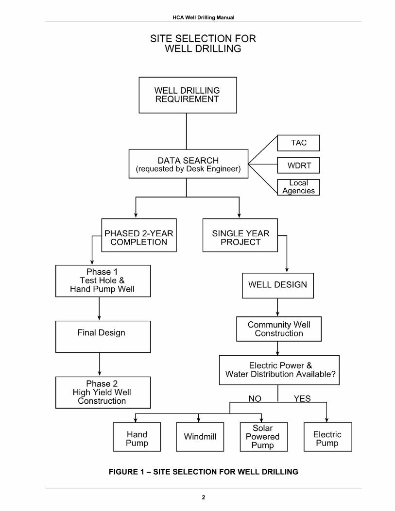
cases, or needed in others, a two year well drilling program would prove useful in areas where exercises are conducted annually. The first year would result in knowledge that either a sufficient aquifer is not available or the aquifer has the characteristics needed to develop a higher capacity well that would serve a large population. If the aquifer was identified, a small diameter well could be constructed to supply water to a hand pump or a small electric pump. In a follow-up exercise, using the data from the previous mission, a thorough program could be implemented to drill a larger well. Also available would be exact requirements for the BOM, the population that could be served, and the requirements for electric power and water distribution. The following simple flow diagram indicates the steps involved in site selection.
1
HCA Well Drilling Manual
FIGURE 1 – SITE SELECTION FOR WELL DRILLING
2

HCA Well Drilling Manual
1.1 THE POLITICS OF WATER WELLS In many parts of the world, the drilling of a producing water well is relatively simple. In other areas, no matter how hard you try to complete a producing well, the local geologic conditions preclude success. No matter how modern the drilling equipment, if an aquifer is not located within the depth capability of the drilling system, the completion of a producing water well is not likely. Oftentimes, construction of a water well is promised prior to or during a troop exercise without consideration to the availability of an aquifer. A clear definition of “aquifer” is important to the designer and the driller. Taken from the Glossary of Geology (published by the American Geological Institute), aquifer is defined as: "a body of rock that contains sufficient saturated permeable material to conduct ground water and to yield economically significant quantities of ground water to wells and springs.” The various branches of the United States Military have been tasked with the mission of constructing water wells within certain design limits. These military well drilling detachments possess an inventory of various drilling rigs for the completion of water wells. Many of these rigs were designed to have specialized capabilities. Outside of the engineering units that have well drilling capability, knowledge of the abilities of the military well drilling program is limited. This fundamental lack of knowledge is the basis for many of the problems that the well drillers face. There is a vast amount of data available in most of the world concerning the availability of groundwater. If a commitment is made to construct a well without consideration of the local hydrogeology and the piece of drilling equipment that will be committed to the mission, that commitment may be impossible to achieve. All Commands with a well drilling mission should be aware of these limitations before any well completion commitment is attempted. 1.1.1 HCA Wells: On many troop exercises, potable water wells are offered as humanitarian items that can be a lasting product of the mission. These wells
are known as Humanitarian Civic Assistance (HCA) wells. In many developing areas of the world, there is nothing more beneficial than a source of pure water. Improved roads or new schools will not make as much difference to a population as will potable water. In any local area where there is a population of people and there are wishes to provide a water source, the logical wish is to put the water source in the center of the population, usually the town square. The Mayor, or another local official, will generally suggest this location. If the personnel on the initial reconnaissance for a mission or exercise make a promise for a well at that location (or any other site) before obtaining data for that area, it may prove to be an embarrassment when no water can be produced at that site. This is not to say that inquiries should not be made as to the desires of the local officials, but their desires should be taken under advisement only until the data indicates that the well has a good probability of success. The general practice for siting water wells is to limit them to property that is publicly-owned, but in some cases, this is not possible. Should the available data indicate the well cannot be successfully completed on the property offered, the local officials should be so advised and information offered as to where the well will have a chance of success. When arrangements cannot make these new sites available, those wells should be dropped from the exercise.
When the SOUTHCOM Engineer (SCEN) is involved in well site selection, it is highly recommended that the SOUTHCOM project officer obtain a probability analysis. This service is available from the Water Detection Response Team (WDRT) via a request to the United States Army Engineer District, Mobile (USAED, Mobile). This is completed prior to any commitment to drill a HCA well at a particular site. The following section, 1.2, Obtaining Water Well Data, details how information can be obtained on well sites. One or two years prior to the exercise, the project officer should obtain a list from the Host Nation (HN) or the U. S. Military Group (USMILGP) in the HN of the locations where the well sites are desired.
3

HCA Well Drilling Manual
NOTES
_______________________________________________________________________________
_______________________________________________________________________________
_______________________________________________________________________________
_______________________________________________________________________________
_______________________________________________________________________________
_______________________________________________________________________________
_______________________________________________________________________________
_______________________________________________________________________________
_______________________________________________________________________________
_______________________________________________________________________________
_______________________________________________________________________________
4

HCA Well Drilling Manual
This list should include latitude and longitude of the sites and should be sent to CESAM for forwarding to WDRT. WDRT and CESAM will rank the list and identify the low and high probability sites. From this ranking, the SCEN project officer can identify the number of sites to be included in the well drilling portion of the exercise. One year prior to the exercise, a represen-tative from USAED, Mobile and the selected well driller attached to the Task Force should make a detailed site visit. Drilling assignments are made by the executive agent, USARSO, USSOUTHAF, or COMSECONDNCB. If a unit has not been chosen, a representative from each service should attend. Details of this site visit are discussed in Section Two - SITE RECONNAISSANCE PRIOR TO MOBILIZATION. Points of contact that may be needed include: CDR J. Johnston HQ USSOUTHCOM Attn: SCEN 3511 NW 91st Ave. Miami, FL 33172-1217 (305) 437-1160 DSN 567-1160 Tel, Comm'l (305) 437-1172 DSN 567-1172 Mr. John Baehr U. S. Army Engineer District, Mobile Attn: CESAM-EN-GG PO Box 2288, Mobile, AL 36628-0001 (251) 690-3146 DSN (312) 457-2680 or 2686 FAX (251) 690-2674 Ms. Laura Waite U. S. Army Engineer District, Mobile Attn: CESAM-EN-GG PO Box 2288, Mobile, AL 36628-0001 (251) 690-3480 DSN (312) 457-2686 FAX (251) 690-2674 Ms. Laura Dwyer Director U. S. Army Topographic Engineering Center Attn: CEERD-TO-H 7701 Telegraph Road, Alexandria, VA 22315-3846 (703) 428-6895
DSN (312) 328-6895 FAX (703) 428-8176 Commander Second Naval Construction Brigade Detachment, Gulfport, MS 39501 (228) 871-2364 DSN (312) 868-2364 823rd RHCES DOPWD Hurlburt Field, FL 32544 (850) 881-2177 DSN 641-2177 MSgt. Michael Deshon 819th RHS 6944 Goddard Drive Malmstrom AFB, MT 59402-6865 (406) 731-2697 FAX (406) 731-3527 DSN 632-2697 CMStg. Vincent Davis 820th RHS 5179 Malmstrom Avenue Nellis AFB, NV 89191-6126 (702) 652-1972 DSN 682-1972
1.1.2 Phased Completion: The ideal method to ensure a high level of success with the well drilling missions would be to phase the operation. This may not be possible in some cases, but doing so would prevent some of the disappointments that may occur in the completion of wells. The realities of scheduling, funding, and politics may prevent this approach. In the civilian world, the completion of a well includes the following phases:
• Phase One - data search and site investigation;
• Phase Two - test drilling to verify the data;
• Phase Three - construction of the permanent well.
The data search, Phase One, is extremely important and will be discussed more thoroughly in this Section. Phase Two is completed as part of the normal pilot hole drilling. Phase Three would be well design,
5

HCA Well Drilling Manual
NOTES
_______________________________________________________________________________
_______________________________________________________________________________
_______________________________________________________________________________
_______________________________________________________________________________
_______________________________________________________________________________
_______________________________________________________________________________
_______________________________________________________________________________
_______________________________________________________________________________
_______________________________________________________________________________
_______________________________________________________________________________
_______________________________________________________________________________
6

HCA Well Drilling Manual
material procurement, and well construction based on the results of Phase Two drilling. Unless detailed information is found in the data search, or an on-site investigation, only actual test drilling will provide the data needed to design the well. This second phase, test drilling, will produce data to design a well with precision. Even without giving a commitment to supply a well capable of providing a high yield, a test hole is a valuable offering. The test hole is drilled to assure that the desired aquifer is available before construction of an expensive well. Other information to be obtained from the test hole will include:
1) difficulty of drilling; 2) accurate depths to the aquifer; 3) time estimates for completion of the
permanent well; 4) an accurate BOM to construct the well; 5) information on the quality of the water
in the aquifer. To obtain some of this data, a test well would have to be installed in the test hole. Again, this is common in the civilian world of well drilling and actually required in many parts of the United States for public water supplies. For the military mission, the test hole could be used to verify the presence of an aquifer, and the test well will provide an assurance that the permanent well will satisfy the needs of the community. The test well can be a usable product after it is completed. Installing a casing with sufficient inside diameter (ID) to accommodate a hand pump or even a small electric submersible pump, the well can be left in place until the permanent well is constructed. This would ideally be on a later mission to allow time for procurement of proper materials. Up through this second point in the three phases of well drilling, a commitment for final completion of a larger permanent well should still not be made. Using data from Phase 2, enough data has now been collected in order to make that decision. The selected host area would have received a test drilling program to investigate their available groundwater resources. When applicable, they may also have a low capacity well (serving up to a few
hundred persons with a small electric pump) that is providing pure water. When the test well has sufficient quantity and quality of water to meet the needs of the community, a commitment to the construction of the high capacity well and any associated water distribution system can be made. The test drilling program is fast, the materials used are not expensive, and the data obtained is extremely valuable. If careful records are kept during drilling, the follow-up drilling of the permanent well need not be the same drilling detachment. The suggested mission scenario for a drilling detachment would be to have 25% of the time used for test drilling programs for future wells at a number of selected locations and 75% of the time for the completion of higher capacity wells that were designed from a previous exercise. Even if the second phase is impossible to conduct as a separate mission, in many cases, the data search from the first phase can yield sufficient hydrogeologic information to design a well and move into the third phase with reasonable accuracy. Only a person with a solid hydrogeologic background should make this decision, especially if serious political consequences are likely as a result of the well not being completed as promised. This type of assistance can be obtained from a number of sources which will be described in the following sections. Without site specific data, the designer should probably "overbuy" the materials to ensure that there are adequate supplies to compensate for the uncertainties. Ten percent overage is commonly used. In many cases, multiple aquifers may be present and the final well depth may be constructed at a depth that is considerably shallower than anticipated. This conservative overbuying of well casing should not be considered inefficient, but rather practical insurance. Any leftover casing can be used for future missions or left for the host nation.
1.2 OBTAINING WATER WELL DATA 1.2.1 Topographic Engineering Center: Water resources data is available in most parts of the world to some degree. While there are many agencies that can supply
7

HCA Well Drilling Manual
NOTES
_______________________________________________________________________________
_______________________________________________________________________________
_______________________________________________________________________________
_______________________________________________________________________________
_______________________________________________________________________________
_______________________________________________________________________________
_______________________________________________________________________________
_______________________________________________________________________________
_______________________________________________________________________________
_______________________________________________________________________________
_______________________________________________________________________________
8
HCA Well Drilling Manual
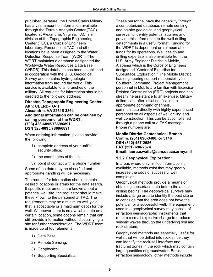
published literature, the United States Military has a vast amount of information available through the Terrain Analysis Center (TAC) located at Alexandria, Virginia. TAC is a division of the Topographic Engineering Center (TEC), a Corps of Engineers laboratory. Personnel at TAC and other locations have been assigned to the Water Detection Response Team (WDRT). The WDRT maintains a database designated the Worldwide Water Resources Data Base (WRDB). This database has been established in cooperation with the U. S. Geological Survey and contains hydrogeologic information from around the world. This service is available to all branches of the military. All requests for information should be directed to the following address: Director, Topographic Engineering Center Attn: CEERD-TO-H Alexandria, VA 22315-3864 Additional information can be obtained by calling personnel at the WDRT: (703) 428-6895/7869/6891 DSN 328-6895/7869/6891 When ordering information, please provide the following:
1) complete address of your unit's security office;
2) the coordinates of the site; 3) point of contact with a phone number.
Some of the data may be classified and appropriate handling will be necessary. The request for information should contain desired locations or areas for the data search. If specific requirements are known about a potential well site, the requestor should make these known to the personnel at TAC. The requirements may be a minimum well yield that is acceptable or a maximum depth for the well. Whenever there is no available data on a certain location, some options remain that can still provide information without disqualifying a site for further consideration. The WDRT team is made up of four elements:
1) Data Base; 2) Remote Sensing; 3) Geophysics; 4) Supporting Specialists.
These personnel have the capability through a computerized database, remote sensing, and on-site geological and geophysical surveys, to identify potential aquifers and provide this information to the well drilling detachments in a useful format. Funding for the WDRT is dependent on reimbursable funds for its operations. Well design and drilling expertise is also available from the U.S. Army Engineer District in Mobile, Alabama which is the Corps of Engineers designated “Center of Expertise for Subsurface Exploration.” The Mobile District has engineering support responsibility to Southern Command. Project Management personnel in Mobile are familiar with Exercise-Related Construction (ERC) projects and can streamline assistance to an exercise. Military drillers can, after initial notification to appropriate command channels, communicate directly with highly experienced personnel on all aspects of well drilling and well construction. This can be accomplished through a phone call or a FAX message. Phone numbers are:
Mobile District Geotechnical Branch Comm. (251) 690-3480, or 3146 DSN (312) 457-2686, FAX (251) 690-2674 Email: [email protected] 1.2.2 Geophysical Exploration: In areas where only limited information is available, methods exist that may greatly increase the odds of successful well completion. Geophysical methods provide a means of obtaining subsurface data before the actual drilling begins. The geophysical surveys may include a large area to identify the best site or to conclude that the area does not have the potential for a successful well. The equipment used in a geophysical survey may consist of refraction seismographic instruments that require a small explosive charge to produce seismic waves through the underlying soil and rock stratum. Geophysical methods are especially useful for wells that will be drilled into rock since they can identify the rock-soil interface and fractured zones in the rock which may contain large quantities of groundwater. Besides refraction seismology, other methods include
9

HCA Well Drilling Manual
NOTES
_______________________________________________________________________________
_______________________________________________________________________________
_______________________________________________________________________________
_______________________________________________________________________________
_______________________________________________________________________________
_______________________________________________________________________________
_______________________________________________________________________________
_______________________________________________________________________________
_______________________________________________________________________________
_______________________________________________________________________________
_______________________________________________________________________________
10

HCA Well Drilling Manual
electrical resistivity, long-wave electro-magnetic impulse, and magnetometer. For the utilization of geophysical methods, a team of specialized personnel can mobilize to the area where the well is needed. By using the various methods to obtain data and then making an interpretation of the data, sites can be selected. Should the test hole drilled at the selected site not indicate the presence of an aquifer, a new site can be selected for drilling using the results of the first hole and a reinterpretation of the geophysical survey.
1.2.3 Initial Well Recommendations: Using the resources previously detailed, the WDRT can provide recommendations concerning the potential for success in completing a potable well.
Wells with limited potential for success should be dropped from further consideration.
This may include well sites within whole geologic regions. Site visits to these locations are not recommended. 1.3 POST EXERCISE INSPECTIONS At the completion of each exercise, SCEN should task a post exercise inspection of each well site. This inspection should include someone knowledgeable in well construction such as a driller and a project officer from the task force. Before each well site visit, the as-built drawing of the well should be reviewed. The visits should be coordinated so the local person who will be responsible for each well (water authority) can be available. The inspection team should ensure that the well site was left in reasonably good condition, meaning the mud sumps were backfilled and graded, trash was removed, and the well was sealed to prevent pollutants from entering the well. The operation of the pump should be discussed with the local person as well as any required maintenance. Copies of the as-built well drawing, water quality testing, pumping test information, and any data about the pump that was installed should be provided to the water authority. This information will be extremely valuable to them in the future if they need to work on the well or pump.
11

HCA Well Drilling Manual
NOTES
_______________________________________________________________________________
_______________________________________________________________________________
_______________________________________________________________________________
_______________________________________________________________________________
_______________________________________________________________________________
_______________________________________________________________________________
_______________________________________________________________________________
_______________________________________________________________________________
_______________________________________________________________________________
_______________________________________________________________________________
_______________________________________________________________________________
12
HCA Well Drilling Manual
SECTION TWO
SITE RECONNAISSANCE PRIOR TO MOBILIZATION
EXECUTIVE SUMMARY
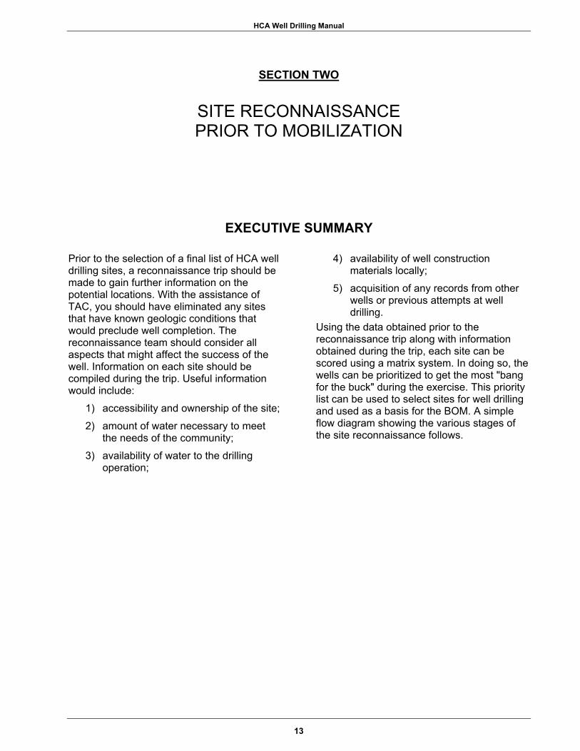
Prior to the selection of a final list of HCA well drilling sites, a reconnaissance trip should be made to gain further information on the potential locations. With the assistance of TAC, you should have eliminated any sites that have known geologic conditions that would preclude well completion. The reconnaissance team should consider all aspects that might affect the success of the well. Information on each site should be compiled during the trip. Useful information would include:
1) accessibility and ownership of the site; 2) amount of water necessary to meet
the needs of the community; 3) availability of water to the drilling
operation;
4) availability of well construction materials locally;
5) acquisition of any records from other wells or previous attempts at well drilling.
Using the data obtained prior to the reconnaissance trip along with information obtained during the trip, each site can be scored using a matrix system. In doing so, the wells can be prioritized to get the most "bang for the buck" during the exercise. This priority list can be used to select sites for well drilling and used as a basis for the BOM. A simple flow diagram showing the various stages of the site reconnaissance follows.
13

HCA Well Drilling Manual
FIGURE 2 – SITE RECONNAISSANCE PRIOR TO MOBILIZATION
14

HCA Well Drilling Manual
2.1 ACCESS As each of the potential well drilling sites are investigated in the reconnaissance survey, the mobility limitations of the drilling equipment should be considered. The amount of time available for a drilling mission is generally fixed and time lost in reaching a site is undesirable. Each site should be visited by someone knowledgeable about each piece of equipment that will be required. In many cases, the drill rigs will have a tender truck that will be required to haul multiple loads of water for use in mixing drilling fluid. The accessibility of the water source from the drill site should also be considered in this respect.
2.1.1 Site Setup: The site itself must be of sufficient size to accommodate the drilling rig, the tender truck, the sumps for the drilling fluid (mud sumps), the soil excavated from the sumps, the drilling supplies such as the casing, and other associated vehicles and equipment. At the time of the visit, the actual location of the well should be set. It must be clear of overhead lines and underground utilities. Another consideration is for the site to be sufficiently level for the setup. Many drill rigs have hydraulic leveling devices, but this varies with each piece of equipment. To be able to properly drill, the drilling rig must be perfectly level. The sump for the drilling fluid must be level with the rig or downhill to prevent an excessively deep excavation since the fluid flows by gravity to the sump.
2.1.2 Soil or Surface Conditions: Another condition to note is excessively soft or wet surface soils. In this case, timber planking may be required at the site to place under the equipment as needed. This is especially true of the drill rig which must remain level throughout the drilling process. This type of ground condition may also affect the ability of the tender truck or other equipment to move about the site. The last site consideration is the disposal of waste drilling fluids and excess water. This is not actually an access problem, but should be given consideration when making the site survey. The drilling fluid can cause damage to drainage systems and create hazardous conditions on roadways. The runoff of excess
water during well development or test pumping can cause serious erosion problems from a large well.
2.2 LOCAL WATER REQUIREMENTS The amount of water used per capita varies greatly from place to place. This may vary from as little as 10 gallons (38 liters) up to 150 gallons (570 liters) per capita per day. There are many things to consider when making this determination. Usually the more plumbing facilities that are available, the higher the per capita use. If there is a distribution system, the use is always higher than if water is provided from a single point. The use of water that must be carried home in jugs will be limited. Normally, there is some type of organized water authority in any town or village. This person should be contacted during the site reconnaissance and can usually provide a figure for the anticipated water use. When computing the well yield necessary for the requested water demand, always assume that the well will need to "rest" at least eight hours each day. This allows the water level in the well to recover from the withdrawal during the periods of pumping. To assume that a well can be pumped continuously is rarely a good idea. Unless the ground water is being continuously recharged, the water levels will continue to drop until the intake of the pump is reached by the falling water level, possibly causing pump damage.
The following example computation should be used in estimating desired well yield. This example assumes that a town of 650 persons will require 50 gallons of water for each person each day. 650 (local population)
x50 (gallons per capita) 32500 (gallons required)
60 (minutes per hour) x16 (hours per day pumping) 960 (minutes of pumping) 32500 gallons/960 minutes = 33.8 gpm
A simplified version of this computation for required well yield is as follows:
15

HCA Well Drilling Manual
NOTES
_______________________________________________________________________________
_______________________________________________________________________________
_______________________________________________________________________________
_______________________________________________________________________________
_______________________________________________________________________________
_______________________________________________________________________________
_______________________________________________________________________________
_______________________________________________________________________________
_______________________________________________________________________________
_______________________________________________________________________________
_______________________________________________________________________________
16

HCA Well Drilling Manual
Equation 2.1
G P M = ( U x P ) / 9 6 0
where, GPM = Required well yield U = Daily water use per person in gallons P = Population served
Use 25 to 50 gallons of water per capita per day as good working numbers for a town or village whose distribution system is limited to mostly faucets along a main trunk line. If most houses in the town have individual plumbing, use the upper limit of 150 gallons per person.
2.3 EXISTING WATER RESOURCES For any population of people to exist in a given location, there must be a source of water available. This is an important item to consider during the initial site visit. For the purpose of an anticipated well drilling mission, remember that "it takes water to make water.” Whether drilling with drilling mud or with air/foam, an adequate supply of water will be required. The amount of water will depend on several factors - one being the size of the well, i.e., a large well could require up to several thousand gallons of water. This water will be needed very early in the drilling operation and should be delivered at a rate sufficient to meet the needs of the mission. An example of this would be obtaining water from a small spring flowing only 3 gallons per minute. This spring may be serving 200 persons, but to use it to fill a 1000 gallon tank on a truck would take almost six hours. If several thousand gallons of water are needed for the well drilling, the time spent obtaining water would be a very significant factor. The distance required to obtain and transport water is also an important consideration. This time must be added to the time required to actually fill the tank. When the source of water to be used for the well drilling is the same as the source of water for the local population, both needs must be served. The population cannot be expected to suddenly be left without water for a few days without prior notice. This type of arrangement should be worked out with the local officials prior to the arrival of the drilling detachment.
The existence of wells, springs, or other water supplies should all be noted in the initial reconnaissance survey. This could have an influence on the priority of drilling at this site relative to other sites. It also can provide valuable data on the water levels in other wells, local surficial aquifers, water quality, and the existence of other, deeper aquifers. Water samples to determine quality may be taken from other local sources during the reconnaissance.
2.4 LOCAL AVAILABILITY OF WELL CONSTRUCTION MATERIALS Many items that are used in well construction may be locally available. The entire list of normal consumables should be checked against local availabilities. Many countries produce oil or gas and items such as drilling mud products and casings may be locally procured due to use in this field. Commercial water well drillers may supply casings, screens, filter material, and drilling mud. Either of these may also have drill bits, drill rods, or other supplies if needed during the mission. Concrete plants or quarries may have the proper gradations of sand for gravel packing. Quality material for gravel packing a well is very hard to find, but a local source can save a substantial amount of shipping costs. Cement is usually available from a number of sources; however, one should be sure of its availability in the desired quantities before a decision is made for local procurement. PVC pipe is another item that is widely available, but one must be sure that the proper strengths (SDR or schedule) can be obtained. In most cases, a thick walled PVC will be required for well construction. Procurement personnel should always check with the well driller or designer prior to making a decision to buy locally. The quality of some items may not warrant their purchase. The following items are sometimes available. This type of grocery list can be used to check availability and prices. PVC pipe: Check sizes, type of joints, lengths,wall thickness. Information should be obtained for 4- through 14-inch diameters.
17

HCA Well Drilling Manual
NOTES
_______________________________________________________________________________
_______________________________________________________________________________
_______________________________________________________________________________
_______________________________________________________________________________
_______________________________________________________________________________
_______________________________________________________________________________
_______________________________________________________________________________
_______________________________________________________________________________
_______________________________________________________________________________
_______________________________________________________________________________
_______________________________________________________________________________
18
HCA Well Drilling Manual
Steel pipe: Check sizes, type of joints, lengths, wall thickness. Information should be obtained for 2- through 8-inch diameters. PVC well screens: Check type, sizes, type of joints, lengths, wall thickness, slot sizes. Information should be obtained for 4- through 8-inch diameters. Stainless steel well screens: Check sizes, type of joints, lengths, collapse strength, slot sizes. Information should be obtained for 4- through 8-inch diameters. Drilling fluids: Check manufacturer, types, additives. Cement: Check types. Filter material for 'gravel-packed filter material' wells: Check available gradations, roundness (must be water worn, not crushed), packaging, type of material (only silica material should be considered). Be specific about the gradations that you require, sometimes the supplier can produce what you need. Ask for a sample of the material for inspection by the well designer. Procurement of quality filter material has always been a problem and availability should be confirmed if local supplies are considered.
An improperly-sized filter material can permanently ruin a well. Lumber: As needed for concrete forms, etc. In checking the availability of these materials, always get a delivery time since many items may not be in stock. In addition, obtain a price quote. Both the price and the delivery time should be included in the reconnaissance report. Depending on the item, savings can be considerable if local procurement is utilized. It is a good practice to have the locally-supplied items delivered well in advance of the arrival of the drilling detachment so that any shortcomings can be rectified. However, the quality of items should not be sacrificed for the sake of local purchase. Furthermore, all items ordered should have to fully meet certain specifications, and if these specifications are not met, the items should be obtained elsewhere.
2.5 HYDROGEOLOGIC CONSIDERATIONS Based on data obtained prior to the reconnaissance or after the initial reconnaissance survey, sites without a high potential for well completion should be eliminated. There have been repeated past attempts at some sites to complete wells with little or no success. This may be due to conditions that prohibit well construction. Questions pertaining to any previous drilling attempts should be asked. If past well drilling attempts have been made, any available records from these unsuccessful wells should be obtained. The list of potential sites should be examined by a geologist with a background in hydrogeology. Using published maps, literature obtained from TEC, remote sensing, and information obtained from local agencies, sites with potential for well success can be further narrowed down from the list of total sites.
2.6 FINAL SITE SELECTION 2.6.1 Priority Matrix: Using all the information obtained through the research and reconnaissance surveys, the final list of recommended sites can be made after elimination of sites with a low possibility of well completion. Final selection may be prioritized. This is best accomplished by completing a matrix using all the potential sites with certain criteria to score each site. The following items may be typically addressed in the matrix. In some cases, critical need of water to an area may outweigh all other factors. These sites should be prioritized in the normal fashion, then addressed separately. If they are moved to the top of the list, the reasons should be documented by the designer. An example of a matrix is included as Figure 2.2. Well Depth. This has a bearing on required time, cost of materials, and ease of construction. As an example, if a drill rig had a 600 foot depth capability, the following point system may be assigned: 0 to 150 feet = 5; 150 to 250 feet = 4; 250 to 350 feet = 3; 350 feet to 450 feet = 2; 450 to 550 feet = 1; over 550 feet = 0.
19

HCA Well Drilling Manual
NOTES
_______________________________________________________________________________
_______________________________________________________________________________
_______________________________________________________________________________
_______________________________________________________________________________
_______________________________________________________________________________
_______________________________________________________________________________
_______________________________________________________________________________
_______________________________________________________________________________
_______________________________________________________________________________
_______________________________________________________________________________
_______________________________________________________________________________
20
HCA Well Drilling Manual
Site Access. Site accessibility has a bearing on the time involved in setting up to drill the well. Considerable effort may be spent getting to the site, leveling the site, or clearing trees, surface boulders, etc., making the site less desirable due to time limitations. A flat and open site with a good access road = 5 and a steep and/or rocky site with a poor access road = 0. Makeup Water. As previously mentioned, it takes water to make water. The drilling crew may need several thousand gallons of water to mix the required drilling fluid (mud) and develop the well. The supply truck will usually carry about 1,000 gallons of water per load. To begin well drilling operations, several loads of water will be required, and more as drilling progresses. The water source should be sufficient to quickly fill the truck. A source of water near the drilling site will get the highest score. After the reconnaissance survey, the closest distance to a water source should be given a 5 and the farthest distance a 1. The other sites should be assigned a score based on the proportioned distance. Population Served. The goal of a HCA well is to provide a source of potable water to a population without this basic necessity. Using a maximum estimated daily well yield that should be available and the anticipated water use per person per day, the maximum population that can be served should be computed using Equation 2.1. Should that number of persons be available to be served by the well, the score would be given a 5. By reducing this "potential population served" figure in increments of 20 percent, other scores can be assigned to actual population numbers. The idea here is to provide water to the maximum number of persons possible. A well which could potentially serve 2,500 people, but only 150 live in the area would have a low potential for providing maximum water use. In this case, however, the larger well will allow for the local population to expand and this could be very desirable in some cases. Ease of Drilling. This factor has the highest potential points since the well must be completed in order to be of any value to anyone. The highest possible score here is 10 and points are awarded solely on personal
experience in well drilling. After considering the local geology, and probability of identifying the aquifer, a score is given. Lodging of Troops. This is one of the factors that is beyond the actual well drilling, but does play a part in selection of sites. If the crew must commute a great distance to the site for each change of shift, it seems to affect the morale which, in turn, affects the success of the well. The highest score here is 3. Critical Need. Depending on the location, this factor may have a high possible score or it may be about average to the rest of the factors. There are no exact criteria for this parameter and each mission will have different considerations. For example, villages under consideration that have an extremely high infant death rate due to a polluted water supply may raise the possible score for this parameter to a 10 (equal to "ease of drilling"). Areas that have existing potable water sufficient to serve the population would score low. Distance from Support Area/City. This is another factor that must be considered since breakdowns or other delays are affected by the distance to the closest location where repairs, parts or supplies are available. While the crews do carry an inventory of spare parts, it seems that there is always some local procurement or resupply required. Highest possible score will be 3.
21

HCA Well Drilling Manual
NOTES
_______________________________________________________________________________
_______________________________________________________________________________
_______________________________________________________________________________
_______________________________________________________________________________
_______________________________________________________________________________
_______________________________________________________________________________
_______________________________________________________________________________
_______________________________________________________________________________
_______________________________________________________________________________
_______________________________________________________________________________
_______________________________________________________________________________
22
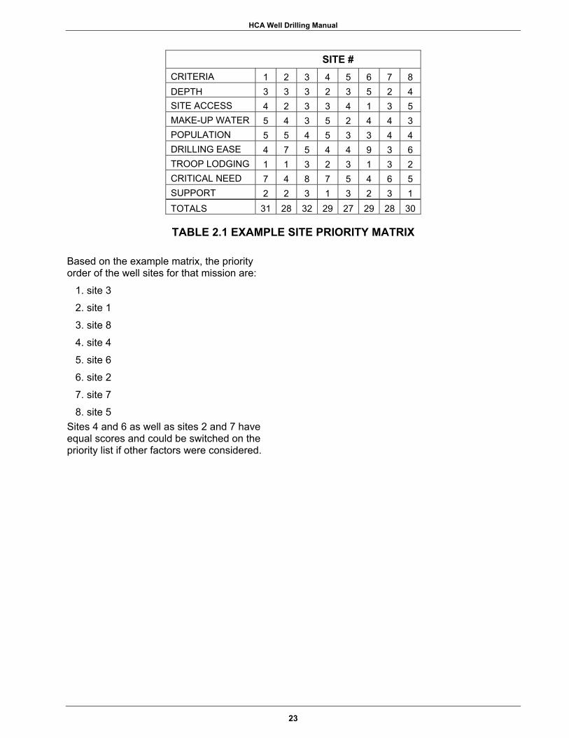
HCA Well Drilling Manual
SITE # CRITERIA 1 2 3 4 5 6 7 8 DEPTH 3 3 3 2 3 5 2 4 SITE ACCESS 4 2 3 3 4 1 3 5 MAKE-UP WATER 5 4 3 5 2 4 4 3 POPULATION 5 5 4 5 3 3 4 4 DRILLING EASE 4 7 5 4 4 9 3 6 TROOP LODGING 1 1 3 2 3 1 3 2 CRITICAL NEED 7 4 8 7 5 4 6 5 SUPPORT 2 2 3 1 3 2 3 1 TOTALS 31 28 32 29 27 29 28 30
TABLE 2.1 EXAMPLE SITE PRIORITY MATRIX
Based on the example matrix, the priority order of the well sites for that mission are:
1. site 3 2. site 1 3. site 8 4. site 4 5. site 6 6. site 2 7. site 7 8. site 5
Sites 4 and 6 as well as sites 2 and 7 have equal scores and could be switched on the priority list if other factors were considered.
23

HCA Well Drilling Manual
NOTES
_______________________________________________________________________________
_______________________________________________________________________________
_______________________________________________________________________________
_______________________________________________________________________________
_______________________________________________________________________________
_______________________________________________________________________________
_______________________________________________________________________________
_______________________________________________________________________________
_______________________________________________________________________________
_______________________________________________________________________________
_______________________________________________________________________________
24
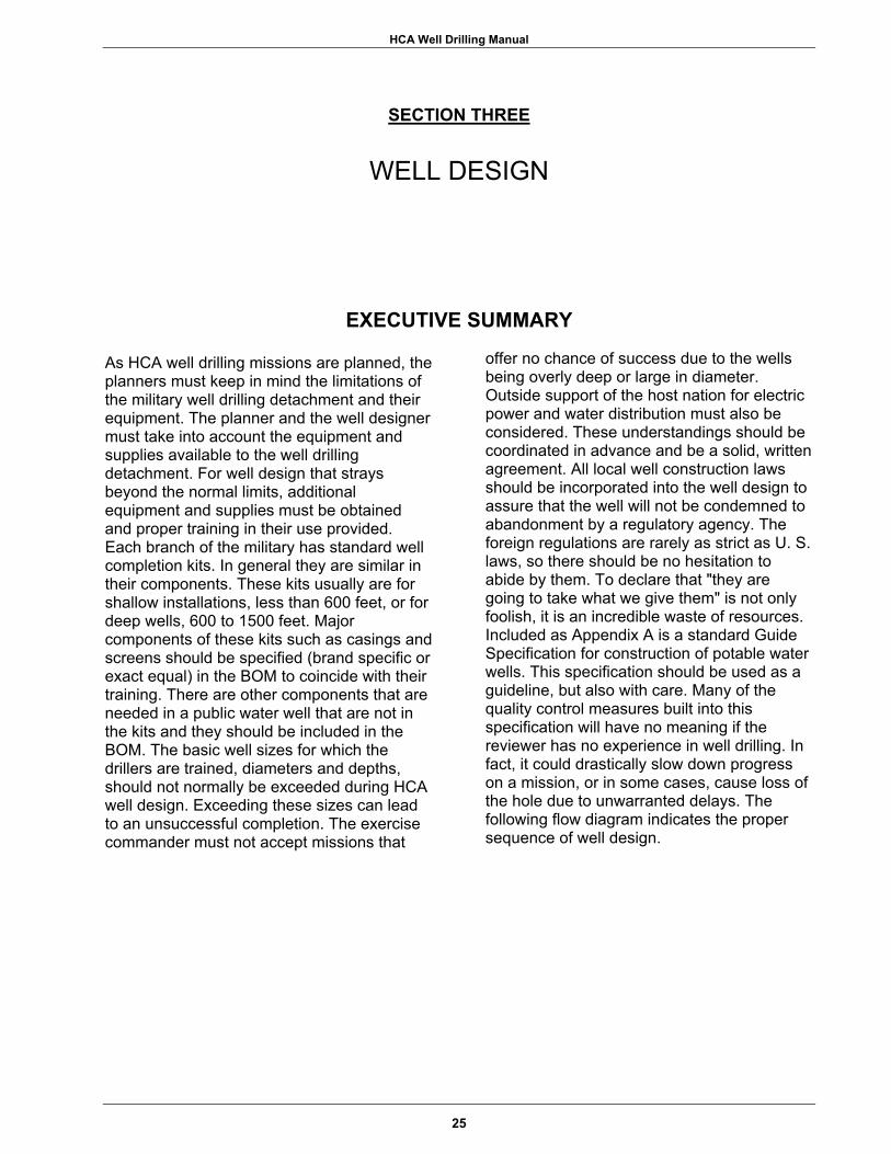
HCA Well Drilling Manual
SECTION THREE
WELL DESIGN
EXECUTIVE SUMMARY
As HCA well drilling missions are planned, the planners must keep in mind the limitations of the military well drilling detachment and their equipment. The planner and the well designer must take into account the equipment and supplies available to the well drilling detachment. For well design that strays beyond the normal limits, additional equipment and supplies must be obtained and proper training in their use provided. Each branch of the military has standard well completion kits. In general they are similar in their components. These kits usually are for shallow installations, less than 600 feet, or for deep wells, 600 to 1500 feet. Major components of these kits such as casings and screens should be specified (brand specific or exact equal) in the BOM to coincide with their training. There are other components that are needed in a public water well that are not in the kits and they should be included in the BOM. The basic well sizes for which the drillers are trained, diameters and depths, should not normally be exceeded during HCA well design. Exceeding these sizes can lead to an unsuccessful completion. The exercise commander must not accept missions that
offer no chance of success due to the wells being overly deep or large in diameter. Outside support of the host nation for electric power and water distribution must also be considered. These understandings should be coordinated in advance and be a solid, written agreement. All local well construction laws should be incorporated into the well design to assure that the well will not be condemned to abandonment by a regulatory agency. The foreign regulations are rarely as strict as U. S. laws, so there should be no hesitation to abide by them. To declare that "they are going to take what we give them" is not only foolish, it is an incredible waste of resources. Included as Appendix A is a standard Guide Specification for construction of potable water wells. This specification should be used as a guideline, but also with care. Many of the quality control measures built into this specification will have no meaning if the reviewer has no experience in well drilling. In fact, it could drastically slow down progress on a mission, or in some cases, cause loss of the hole due to unwarranted delays. The following flow diagram indicates the proper sequence of well design.
25
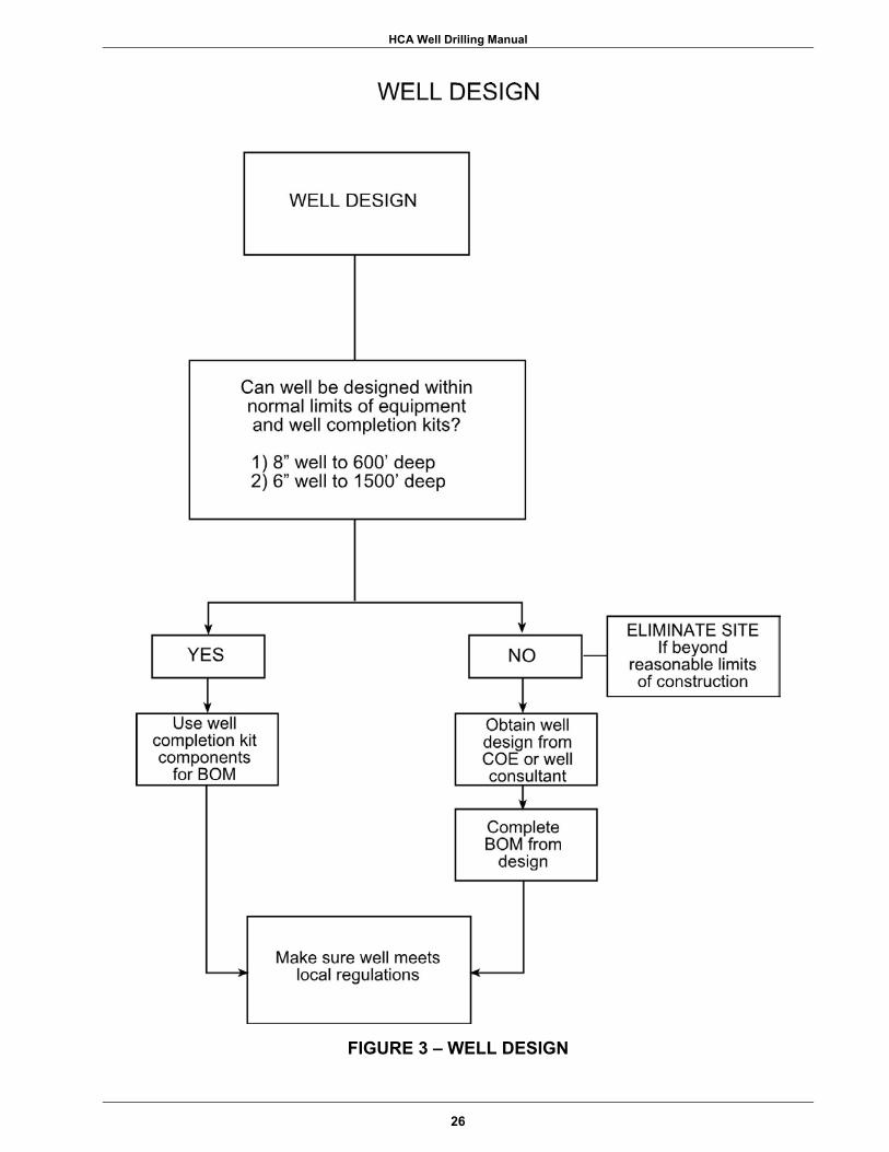
HCA Well Drilling Manual
FIGURE 3 – WELL DESIGN
26
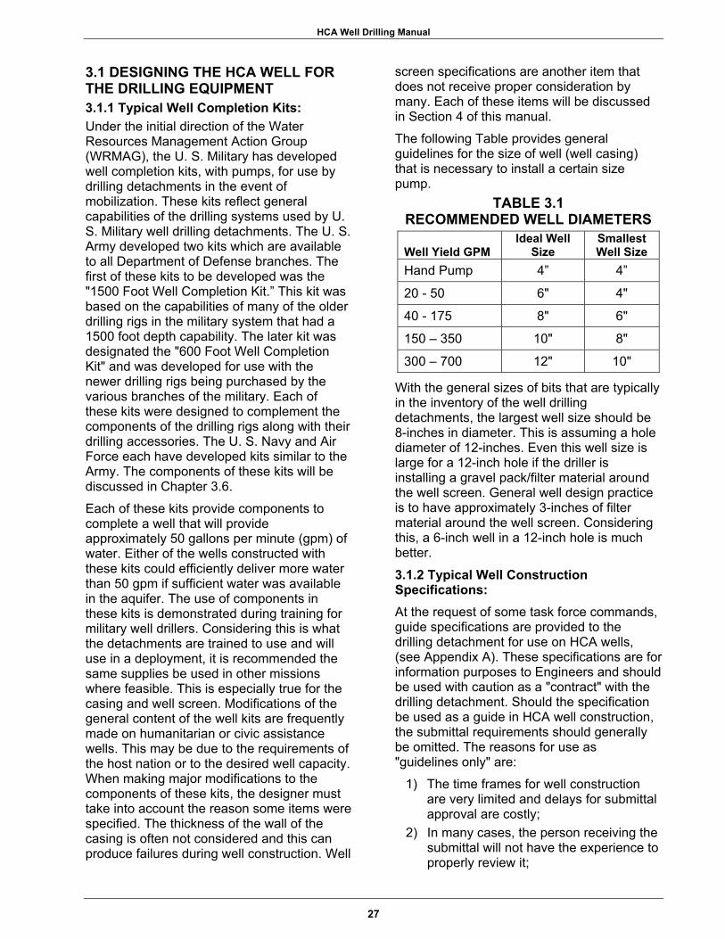
HCA Well Drilling Manual
3.1 DESIGNING THE HCA WELL FOR THE DRILLING EQUIPMENT 3.1.1 Typical Well Completion Kits: Under the initial direction of the Water Resources Management Action Group (WRMAG), the U. S. Military has developed well completion kits, with pumps, for use by drilling detachments in the event of mobilization. These kits reflect general capabilities of the drilling systems used by U. S. Military well drilling detachments. The U. S. Army developed two kits which are available to all Department of Defense branches. The first of these kits to be developed was the "1500 Foot Well Completion Kit.” This kit was based on the capabilities of many of the older drilling rigs in the military system that had a 1500 foot depth capability. The later kit was designated the "600 Foot Well Completion Kit" and was developed for use with the newer drilling rigs being purchased by the various branches of the military. Each of these kits were designed to complement the components of the drilling rigs along with their drilling accessories. The U. S. Navy and Air Force each have developed kits similar to the Army. The components of these kits will be discussed in Chapter 3.6. Each of these kits provide components to complete a well that will provide approximately 50 gallons per minute (gpm) of water. Either of the wells constructed with these kits could efficiently deliver more water than 50 gpm if sufficient water was available in the aquifer. The use of components in these kits is demonstrated during training for military well drillers. Considering this is what the detachments are trained to use and will use in a deployment, it is recommended the same supplies be used in other missions where feasible. This is especially true for the casing and well screen. Modifications of the general content of the well kits are frequently made on humanitarian or civic assistance wells. This may be due to the requirements of the host nation or to the desired well capacity. When making major modifications to the components of these kits, the designer must take into account the reason some items were specified. The thickness of the wall of the casing is often not considered and this can produce failures during well construction. Well
screen specifications are another item that does not receive proper consideration by many. Each of these items will be discussed in Section 4 of this manual. The following Table provides general guidelines for the size of well (well casing) that is necessary to install a certain size pump.
TABLE 3.1 RECOMMENDED WELL DIAMETERS
Well Yield GPM Ideal Well
Size Smallest Well Size
Hand Pump 4” 4”
20 - 50 6" 4"
40 - 175 8" 6"
150 – 350 10" 8"
300 – 700 12" 10"
With the general sizes of bits that are typically in the inventory of the well drilling detachments, the largest well size should be 8-inches in diameter. This is assuming a hole diameter of 12-inches. Even this well size is large for a 12-inch hole if the driller is installing a gravel pack/filter material around the well screen. General well design practice is to have approximately 3-inches of filter material around the well screen. Considering this, a 6-inch well in a 12-inch hole is much better.
3.1.2 Typical Well Construction Specifications: At the request of some task force commands, guide specifications are provided to the drilling detachment for use on HCA wells, (see Appendix A). These specifications are for information purposes to Engineers and should be used with caution as a "contract" with the drilling detachment. Should the specification be used as a guide in HCA well construction, the submittal requirements should generally be omitted. The reasons for use as "guidelines only" are:
1) The time frames for well construction are very limited and delays for submittal approval are costly;
2) In many cases, the person receiving the submittal will not have the experience to properly review it;
27

HCA Well Drilling Manual
NOTES
_______________________________________________________________________________
_______________________________________________________________________________
_______________________________________________________________________________
_______________________________________________________________________________
_______________________________________________________________________________
_______________________________________________________________________________
_______________________________________________________________________________
_______________________________________________________________________________
_______________________________________________________________________________
_______________________________________________________________________________
_______________________________________________________________________________
28
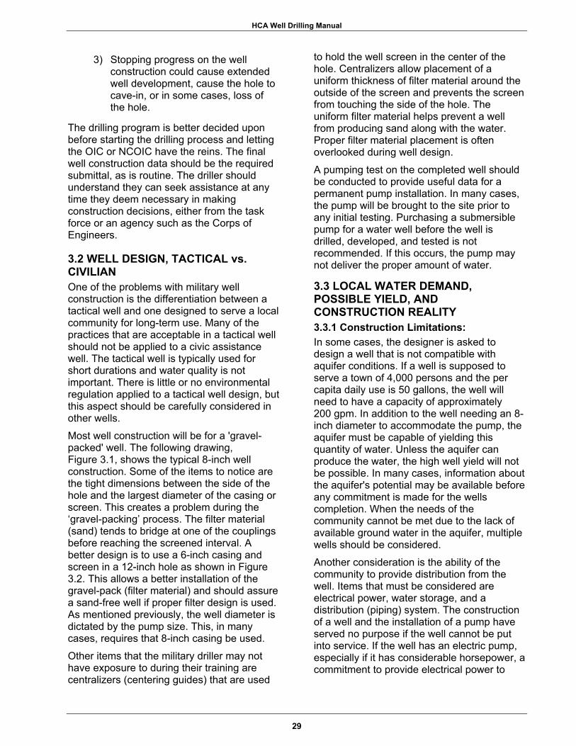
HCA Well Drilling Manual
3) Stopping progress on the well construction could cause extended well development, cause the hole to cave-in, or in some cases, loss of the hole.
The drilling program is better decided upon before starting the drilling process and letting the OIC or NCOIC have the reins. The final well construction data should be the required submittal, as is routine. The driller should understand they can seek assistance at any time they deem necessary in making construction decisions, either from the task force or an agency such as the Corps of Engineers.
3.2 WELL DESIGN, TACTICAL vs. CIVILIAN One of the problems with military well construction is the differentiation between a tactical well and one designed to serve a local community for long-term use. Many of the practices that are acceptable in a tactical well should not be applied to a civic assistance well. The tactical well is typically used for short durations and water quality is not important. There is little or no environmental regulation applied to a tactical well design, but this aspect should be carefully considered in other wells. Most well construction will be for a 'gravel-packed' well. The following drawing, Figure 3.1, shows the typical 8-inch well construction. Some of the items to notice are the tight dimensions between the side of the hole and the largest diameter of the casing or screen. This creates a problem during the ‘gravel-packing’ process. The filter material (sand) tends to bridge at one of the couplings before reaching the screened interval. A better design is to use a 6-inch casing and screen in a 12-inch hole as shown in Figure 3.2. This allows a better installation of the gravel-pack (filter material) and should assure a sand-free well if proper filter design is used. As mentioned previously, the well diameter is dictated by the pump size. This, in many cases, requires that 8-inch casing be used. Other items that the military driller may not have exposure to during their training are centralizers (centering guides) that are used
to hold the well screen in the center of the hole. Centralizers allow placement of a uniform thickness of filter material around the outside of the screen and prevents the screen from touching the side of the hole. The uniform filter material helps prevent a well from producing sand along with the water. Proper filter material placement is often overlooked during well design. A pumping test on the completed well should be conducted to provide useful data for a permanent pump installation. In many cases, the pump will be brought to the site prior to any initial testing. Purchasing a submersible pump for a water well before the well is drilled, developed, and tested is not recommended. If this occurs, the pump may not deliver the proper amount of water.
3.3 LOCAL WATER DEMAND, POSSIBLE YIELD, AND CONSTRUCTION REALITY 3.3.1 Construction Limitations: In some cases, the designer is asked to design a well that is not compatible with aquifer conditions. If a well is supposed to serve a town of 4,000 persons and the per capita daily use is 50 gallons, the well will need to have a capacity of approximately 200 gpm. In addition to the well needing an 8-inch diameter to accommodate the pump, the aquifer must be capable of yielding this quantity of water. Unless the aquifer can produce the water, the high well yield will not be possible. In many cases, information about the aquifer's potential may be available before any commitment is made for the wells completion. When the needs of the community cannot be met due to the lack of available ground water in the aquifer, multiple wells should be considered. Another consideration is the ability of the community to provide distribution from the well. Items that must be considered are electrical power, water storage, and a distribution (piping) system. The construction of a well and the installation of a pump have served no purpose if the well cannot be put into service. If the well has an electric pump, especially if it has considerable horsepower, a commitment to provide electrical power to
29

HCA Well Drilling Manual
FIGURE 3.1 – TYPICAL WELL CONSTRUCTION, 8-INCH WELL
30
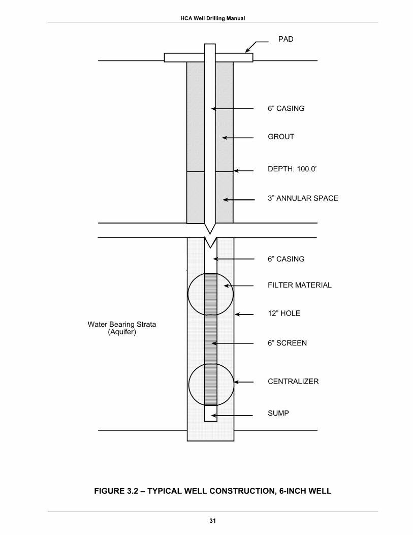
HCA Well Drilling Manual
FIGURE 3.2 – TYPICAL WELL CONSTRUCTION, 6-INCH WELL
31

HCA Well Drilling Manual
NOTES
_______________________________________________________________________________
_______________________________________________________________________________
_______________________________________________________________________________
_______________________________________________________________________________
_______________________________________________________________________________
_______________________________________________________________________________
_______________________________________________________________________________
_______________________________________________________________________________
_______________________________________________________________________________
_______________________________________________________________________________
_______________________________________________________________________________
32

HCA Well Drilling Manual
service the pump should be in place prior to completing the well. The same is true for the distribution of the water. If a large well is designed to serve a large population, there will have to be water lines and storage in place to utilize the well. These items may or may not be a part of the exercise. If not, the proper local agencies responsible to complete this portion of the work should be made part of the planning process. These agreements should be made as formal Memorandums of Understanding before the well is complete. Where there is no available electrical power, the community may be offered several small wells suitable for the installation of hand pumps in lieu of a single well with an electric pump. By completing the hand pump wells, the community will have a source of water without having to wait on further assistance to provide other needed utilities. The completion of the smaller wells will also provide valuable data for use in the future development of a larger well, if a unit is tasked with that mission.
3.3.2 Equipment Limitations: The upper limit for well size, (depth and diameter), that can be drilled by the drilling detachments is hard to define. Each drilling rig has certain rated capacities that allow it to perform to its full potential. The normal maximum hole size associated with most military drilling rigs is 12- to 13-inches. As mentioned previously, this can accommodate an 8-inch casing and screen. This may allow a pump installation that will produce up to 400 gpm, depending on the depth to the water level in the well. Occasionally, the military has been asked to design and construct wells that produce over 1000 gpm. This is possible, but should be avoided in most cases. In rotary drilling with mud, the hole sizes for wells such as this are grossly oversized for the mud pumps on the drilling rigs and this makes drilling very difficult. Ideally, the minimum velocity for the drilling fluid to be moving up the hole (uphole velocity) from the discharge at the drilling bit is 150 feet per minute (fpm), and the absolute minimum velocity is 50 fpm. For example, if the mud pump has a maximum output of 200 gallons per minute and the drill rods are 4 ½- inches outside diameter (OD), the maximum hole size that can be drilled while maintaining
50 fpm uphole velocity is 11-inches. This is based on the following formula and assuming an uphole velocity of 50 fpm.
Equation 3.1
D = √ [ ( G P M / 2 ) + ( d 2 ) ]
where, D = Hole diameter (in inches) d = Drill pipe size (in inches) GPM = Pump output
Another common variation of this formula is to compute the mud pump output needed to drill a certain size of hole while maintaining the 50 fpm uphole velocity. In that case use the following:
Equation 3.2 G P M = 2 ( D 2 - d 2 )
There are many other factors to consider such as available horsepower, mast capacity, and friction loss through the drill string. These factors only become important when drilling holes larger than 12-inches. In air rotary drilling, the air compressor becomes the important limiting factor. This is true if using either a roller bit or a down-hole-hammer (DHH). In air drilling, the minimum uphole velocity should be 3,000 fpm. Many of the military drilling rigs are equipped with an air compressor of limited capacity, often only 250 cubic feet per minute (cfm). These compressors can be used to drill holes of certain sizes and depths, but often will require the additional use of drilling foam to produce effective results. The general formula for the compressor output is similar to the one for drilling mud. To estimate the maximum hole size that can be drilled with a certain air compressor, use the following formula.
Equation 3.3
D = ( C F M / 1 6 . 5 ) - d 2
where, D = Hole size (in inches) d = Drill pipe size (in inches) CFM = Air compressor capacity To determine the minimum compressor size to drill a certain size of hole, use the following variation of Equation 3.3.
33

HCA Well Drilling Manual
NOTES
_______________________________________________________________________________
_______________________________________________________________________________
_______________________________________________________________________________
_______________________________________________________________________________
_______________________________________________________________________________
_______________________________________________________________________________
_______________________________________________________________________________
_______________________________________________________________________________
_______________________________________________________________________________
_______________________________________________________________________________
_______________________________________________________________________________
34
HCA Well Drilling Manual
Equation 3.4 C F M = 1 6 . 5 ( D 2 - d 2 )
If the uphole velocity of 3000 fpm cannot be obtained with the available compressor, drilling foam can be added into the airstream, which will greatly reduce the air requirement. If using a stiff foam, the uphole velocity can be as low as 50 fpm and still provide satisfactory hole cleaning results.
3.4 LOCAL WELL DESIGN REQUIREMENTS AND LAWS Many parts of the world have established laws or regulations concerning potable water well construction. These laws are in place to ensure public health and should always be taken into account when planning a well in any area. The regulations are typically not as strict as what one would expect to see when drilling wells in the United States. While a tactical well may not have this type of requirement, HCA wells should be constructed similar to a well in the United States under EPA regulations. Any one of the drilling detachments should be fully capable of drilling a well with these types of requirements. These requirements should not be considered a burden. A well that provides contaminated water or water that contains high levels of sand is useless and can create bad international relationships. The applicable laws should always be reviewed and incorporated into the well design. In many cases, the regulations will provide insight into problems that may exist with well drilling. A well that does not meet the required standards could be condemned by the appropriate regulating agency.
3.5 GENERAL WELL DESIGN CONSIDERATIONS 3.5.1 Well Diameter: Table 3.1 indicated the proper size of well diameter that should be used in designing a well. Always remember that the pump diameter, including the electric power cable, is what must go into the inside of the well, and the drill hole size is what the well casing must fit into. Another important factor is the term "nominal.” A 4-inch well casing can be several sizes. A 4-inch, schedule 40, PVC pipe has
an inside diameter of 4.0-inches and an outside diameter of 4.95-inches at the coupling, (bell joint, solvent weld). The difference in selecting a 4-inch, schedule 80, PVC casing is that the ID has been reduced to about 3.8-inches due to the increase in wall thickness. A designer who selects the thicker schedule 80 pipe for increased strength should remember the well will not accept most "4-inch well pumps.” This same type of consideration is required on all casing selections.
3.5.2 Well Screens: Types, Diameter, Length, and Placement. The selection of a well screen is best made after one has the results of a test hole. The military driller usually does not have that luxury. The choice of the design of the well screen may be based on many factors, but the continuous-slot types have more advantages than most other types. The most important considerations are the amount of open area and the ease of development. These types of screen have several times the percentage of open area than others. This means that they can pass more water per linear foot than other types and the different methods of well development are more effective. Other types of screen include slotted pipe, louvered screen, bridge louvers, and perforated pipe. Perforated pipe is rarely acceptable and should not be considered for use. The slotted pipe type can be either a machine-slotted type with uniform slots or may be hand cut slots made at the site. The hand cut pipe usually has poor slot uniformity and should be avoided if possible. Oversized slots may allow some of the filter material or formation material to enter the well during pumping. The slotted pipe, whether hand or machine cut, is the most widely used due to its low cost and ease of onsite manufacture.
When selecting well screen, keep in mind two important design parameters:
1) entrance velocity through the screen openings; and
2) uphole velocity inside the screen as the water moves up to the pump.
35

HCA Well Drilling Manual
NOTES
_______________________________________________________________________________
_______________________________________________________________________________
_______________________________________________________________________________
_______________________________________________________________________________
_______________________________________________________________________________
_______________________________________________________________________________
_______________________________________________________________________________
_______________________________________________________________________________
_______________________________________________________________________________
_______________________________________________________________________________
_______________________________________________________________________________
36
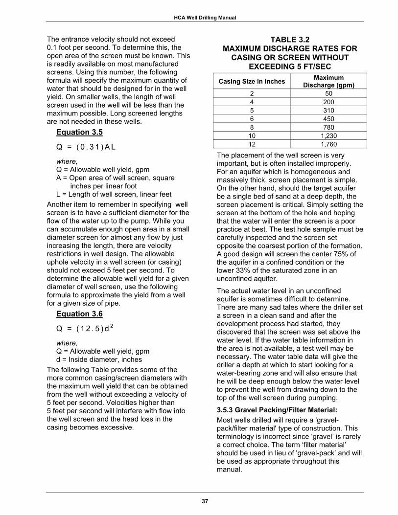
HCA Well Drilling Manual
The entrance velocity should not exceed 0.1 foot per second. To determine this, the open area of the screen must be known. This is readily available on most manufactured screens. Using this number, the following formula will specify the maximum quantity of water that should be designed for in the well yield. On smaller wells, the length of well screen used in the well will be less than the maximum possible. Long screened lengths are not needed in these wells.
Equation 3.5
Q = ( 0 . 3 1 ) A L
where, Q = Allowable well yield, gpm A = Open area of well screen, square
inches per linear foot L = Length of well screen, linear feet
Another item to remember in specifying well screen is to have a sufficient diameter for the flow of the water up to the pump. While you can accumulate enough open area in a small diameter screen for almost any flow by just increasing the length, there are velocity restrictions in well design. The allowable uphole velocity in a well screen (or casing) should not exceed 5 feet per second. To determine the allowable well yield for a given diameter of well screen, use the following formula to approximate the yield from a well for a given size of pipe.
Equation 3.6
Q = ( 1 2 . 5 ) d 2
where, Q = Allowable well yield, gpm d = Inside diameter, inches
The following Table provides some of the more common casing/screen diameters with the maximum well yield that can be obtained from the well without exceeding a velocity of 5 feet per second. Velocities higher than 5 feet per second will interfere with flow into the well screen and the head loss in the casing becomes excessive.
TABLE 3.2 MAXIMUM DISCHARGE RATES FOR
CASING OR SCREEN WITHOUT EXCEEDING 5 FT/SEC
Casing Size in inches Maximum Discharge (gpm)
2 50 4 200 5 310 6 450 8 780
10 1,230 12 1,760
The placement of the well screen is very important, but is often installed improperly. For an aquifer which is homogeneous and massively thick, screen placement is simple. On the other hand, should the target aquifer be a single bed of sand at a deep depth, the screen placement is critical. Simply setting the screen at the bottom of the hole and hoping that the water will enter the screen is a poor practice at best. The test hole sample must be carefully inspected and the screen set opposite the coarsest portion of the formation. A good design will screen the center 75% of the aquifer in a confined condition or the lower 33% of the saturated zone in an unconfined aquifer. The actual water level in an unconfined aquifer is sometimes difficult to determine. There are many sad tales where the driller set a screen in a clean sand and after the development process had started, they discovered that the screen was set above the water level. If the water table information in the area is not available, a test well may be necessary. The water table data will give the driller a depth at which to start looking for a water-bearing zone and will also ensure that he will be deep enough below the water level to prevent the well from drawing down to the top of the well screen during pumping.
3.5.3 Gravel Packing/Filter Material: Most wells drilled will require a 'gravel-pack/filter material' type of construction. This terminology is incorrect since ‘gravel’ is rarely a correct choice. The term ‘filter material’ should be used in lieu of 'gravel-pack’ and will be used as appropriate throughout this manual.
37

HCA Well Drilling Manual
NOTES _______________________________________________________________________________
_______________________________________________________________________________
_______________________________________________________________________________
_______________________________________________________________________________
_______________________________________________________________________________
_______________________________________________________________________________
_______________________________________________________________________________
_______________________________________________________________________________
_______________________________________________________________________________
_______________________________________________________________________________
_______________________________________________________________________________
38
HCA Well Drilling Manual
The proper procedure for selecting a filter material is described in most well drilling manuals. In most cases, the material will be a medium to coarse grained sand. The use of pea gravel for filter material will generally lead to a well that produces sand in the water and will have a short life. The procedure for filter material selection depends on accurate sampling of the formation during drilling of the test hole. In many cases, the well screen and filter material must be procured before the test hole is even drilled. In these cases, the recommended guideline is to select a 0.025-inch slot size for the well screen and to specify a filter material following guidelines described in Chapter 4.3, Gravel-Pack/Filter Material. This combination of screen and filter material will suffice in most situations. If most of the formation's grain size is larger than 0.025-inches, this slot size will work even without a filter. The filter material will still serve a purpose by surrounding the screen and preventing it from deforming and possibly collapsing during well development.
3.6 MILITARY WELL COMPLETION KITS As previously mentioned, the U.S. Army has two well completion kits for optional use by DOD well drilling detachments during a mobilization. The Navy and Air Force have each developed well completion kits with similar components. The Army kits will be discussed separately.
3.6.1 600 Foot Well Completion Kit: The 600 Foot Well Completion Kit is designed with the newer, air transportable drill rigs in mind. There was little value in having a relatively lightweight drilling rig if the well drilling supply package was massively bulky and heavy. The basis of this kit is PVC casing and screen. The casing is 8-inch, SDR 17, PVC with mechanical spline-joint couplings. The well screen sections are of two types, slotted pipe and continuous slot design, both with slot openings of 0.025-inches. The slotted pipe comes in sections of 5, 10, and 20 feet. CertainTeed no longer makes continuous slot screen. The slotted pipe screens are cheaper to purchase by the linear foot, but have only a fraction of the transmitting capacity of the continuous slot
type. The pump that is packaged with this kit will deliver 50 gallons of water from a depth of 600 feet. In reality, a much higher capacity pump could be installed in the well without any problem. The 50 feet, (29 pieces), of continuous slot screen will transmit up to 560 gpm of water through the openings without exceeding the ideal entrance velocity. This is allowing about 19 gpm per section of screen. The 100 feet of slotted pipe will properly transmit approxim- ately 500 gpm or about 100 gpm per 20 foot section. The use of PVC materials, however, does require special considerations. It does not have the strength and durability of steel and cannot withstand abuse in handling or during well development. When the well needs long grouted intervals along its casing, this too must be considered with PVC casing. These problems are addressed in Section 4.1.3. Also, wells should always be ‘gravel-packed’ with PVC screens to prevent collapse. Allowing the formation to suddenly collapse into an open annular space during development may collapse the screen. This kit is designed for use with a 12-inch hole. This hole size is much smaller than ideal for 8-inch casing, but with care, will suffice. While using the 8-inch PVC casing, remember that the largest diameter in the casing string will give you the problems. In this case, the outside diameter of the couplings is 10.19-inches. In a 12-inch hole, assuming a centered casing, the annular space around the coupling will only be 0.9-inches. Without care, the process of installing casing could be difficult in a hole with such limited annular space. Another consideration is that filter material may bridge on top of one of the couplings and prevent the filter material from ever reaching the well screen. Consider the process of a driller trying to use concrete aggregate type gravel where the gravel may be much larger than the annular space around the couplings. The material will simply block off at the first coupling and none will reach bottom. Some items that the kit will not provide is surface casing and screen centralizers. These items are necessary and should be added on all civic assistance wells.
39

HCA Well Drilling Manual
NOTES _______________________________________________________________________________
_______________________________________________________________________________
_______________________________________________________________________________
_______________________________________________________________________________
_______________________________________________________________________________
_______________________________________________________________________________
_______________________________________________________________________________
_______________________________________________________________________________
_______________________________________________________________________________
_______________________________________________________________________________
______________________________________________________________________________
40
HCA Well Drilling Manual
3.6.2 1500 Foot Well Completion Kit: The 1500 Foot Well Completion Kit was the first kit developed by the military for the various drill rigs in use. The 1500 foot designation was used due to the depth that many of the rigs were capable of reaching. This kit contains steel well casing and stainless steel screen, both of 6-inch diameter. This kit also includes a pump capable of delivering approximately 50 gpm from a depth of 1200 feet of total head. This pump has 61 stages and is powered by a 30 horsepower submersible motor. This pump is not an economically good choice at shallow depths due to its high horsepower. A pump with only 5 horsepower is available to pump 50 gpm if the total head pressure does not exceed 150 feet. This kit contains both 8-inch and 10-inch steel casing for use as surface casing. With the 6-inch diameter steel casing for the main well casing, neither of the two sizes of surface casing is the best choice for civic assistance wells. As in the 600 foot kit, the best hole size will be 12- to 13-inches and this will require a 14-inch surface casing. The 6-inch screen and casing can be set through the 10-inch casing, but this provides the same problems as the 8-inch casing in the 12-inch hole. The well screen is constructed from stainless steel with a continuous slot design. The slot opening is 0.010-inches which will filter all but the smallest sand. The kit contains four 10-foot lengths of this screen. Like the 600 foot kit, there are no screen centralizers in this kit. They should be added to the BOM for all civic assistance wells. The advantage of the steel components in this kit is durability during all the handling including transportation, well construction and development. The disadvantages include bulk, weight, and limited pump clearance. All other components to complete the well are included with the kit.
3.6.3 Navy and Air Force Kits: The Navy has a 600-foot well completion kit which is similar to the Army kit. Casing and well screen components are 8-inch PVC with spline joint connections. They also have a 1250 foot well completion kit, which is similar to the Army 1500 foot kit. The Air Force uses a standard well completion kit that utilizes 8-inch steel casing with stainless steel well screen. Other than the diameter, the kit is similar to the 1500 foot Army kit. For wells of low expected yield, or if low yield by design, they substitute 6-inch casing and screen for the usual 8-inch. These kits are used for most training and HCA missions, but the Air Force has elected to use the standard Army well completion kits in the event of a mobilization.
41

HCA Well Drilling Manual
NOTES
_______________________________________________________________________________
_______________________________________________________________________________
_______________________________________________________________________________
_______________________________________________________________________________
_______________________________________________________________________________
_______________________________________________________________________________
_______________________________________________________________________________
_______________________________________________________________________________
_______________________________________________________________________________
_______________________________________________________________________________
_______________________________________________________________________________
42

HCA Well Drilling Manual
SECTION FOUR
MATERIALS FOR WELL CONSTRUCTION
EXECUTIVE SUMMARY
There is a vast array of materials available for well construction. Many are commonly used and widely distributed through supply outlets. The major well components are well casing, well screen, grout, drilling fluid components, and filter material. The well casings and screens come in different styles, strengths, diameters, and are made of different materials. Drilling fluid selection is based on the geologic conditions that will be encountered and is a science in itself. The component of well construction that normally receives the least attention, but is very important, is the filter material. Even if everything else in the well is completely
installed and the well is producing water, the wrong filter material installed as 'gravel-pack filter material' may mean failure of the well. A high sand content in the water being pumped from the well may render it useless. Every component used in well construction must be properly sized for its intended use. Starting with the anticipated well yield, the well construction materials must be suitable for the installation conditions, properly specified in the BOM, and delivered as specified through the procurement process. The following flow diagram indicates the sequence of events in materials selection.
43

HCA Well Drilling Manual
FIGURE 4 – MATERIALS FOR WELL CONSTRUCTION
44
HCA Well Drilling Manual
4.1 WELL CASING 4.1.1 General: The well casing selection should be made on each project with many things taken into consideration. On projects such as HCA wells where the finished product is a very high profile item, material cost should be at the bottom of the list. In too many cases, the personnel ordering the well casing will specify inexpensive PVC plastic. The typical PVC pipe used is schedule 40, which will work in some cases. However, there are many conditions where this choice will not be suitable and all of these should be considered before procurement.
General guidelines are as follows: • Less than 300 feet - PVC screen and
casing; • 300 to 600 feet - PVC or steel screen
and casing; • Over 600 feet - steel screen and casing.
The well designer usually has good reason to specify a certain type of casing material and this BOM item should never be changed without first consulting him. Once the material is purchased, transported, and brought on-site, the drilling detachment has little choice but to try to use it. Should the mission fail due to improper casing selection (or any other component), the drillers are usually held responsible while the actual culprits are not held accountable.
4.1.2 Steel Casing: The casing material with the least chance of collapse, or other types of failure, is steel, either galvanized or black steel. This is generally available in many weights or wall thicknesses, but in most cases, standard weight pipe (schedule 40), will be the proper choice. This pipe comes threaded and coupled for ease of installation. The use of steel casing in deep holes may require the use of a float shoe to lessen the weight on the derrick. Steel casing should be specified as either ASTM A-53 or API 5-L.
4.1.3 PVC Casing: PVC is widely used as well casing due to its noncorrosive properties, light weight and low cost. Beyond 300 feet, PVC casing must be
used with care. Most of this consideration is due to its low collapse strength as compared to steel. The commonly used term for the hydraulic collapse pressure is RHCP or Resistance to Hydraulic Collapse Pressure. For the depths of wells that will be drilled by military drilling detachments, standard weight steel will never be subject to collapse. PVC, however, has properties that must be understood both by the designer and the drillers. PVC has a limited amount of resistance to external hydraulic collapse pressure. These values are well known and with proper procedures, the correct type of PVC casing can be used to a depth of several hundred feet. The use of a carefully placed filter material which fully and equally surrounds the casing will almost eliminate the potential for collapse. Certain restraints on changing the differential hydraulic pressure should always be considered. The collapse pressures for PVC pipe are shown in Appendix C. Other possible causes for the collapse of PVC casing are impact, improper backfill of filter material or other backfill material, formation squeeze, and/or overly rigorous well development. The process of grouting the well can also cause problems with PVC casing. The potential for hydraulic collapse can be considered with the following example. A hole for a well was drilled with drilling mud weighing 8.8 pounds per gallon. After the hole was drilled to a depth of 600 feet, 20 feet of screen was set to the bottom with 6-inch, schedule 40, PVC casing. The well was 'gravel-packed' up to a depth of 570 feet, then development was started. The screen was hydrojetted with clear water, then given a blast of air after the jetting tool was pulled back to the top of the screen, 580 feet. The air blew all the water from the inside of the casing and the casing collapsed above the jetting tool. What happened? At the top of the filter material, the casing was unsupported in the open borehole. The annular space of the borehole was still filled with drilling fluid at 8.8 pounds per gallon. After the air development suddenly removed the water inside the casing, the full hydrostatic pressure of the drilling mud was acting on the PVC and
45

HCA Well Drilling Manual
NOTES _______________________________________________________________________________
_______________________________________________________________________________
_______________________________________________________________________________
_______________________________________________________________________________
_______________________________________________________________________________
_______________________________________________________________________________
_______________________________________________________________________________
_______________________________________________________________________________
_______________________________________________________________________________
_______________________________________________________________________________
_______________________________________________________________________________
46
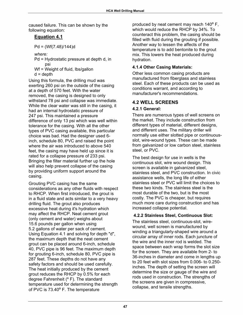
HCA Well Drilling Manual
caused failure. This can be shown by the following equation:
Equation 4.1
Pd = (Wf(7.48)/144)d
where: Pd = Hydrostatic pressure at depth d, in
psi Wf = Weight of fluid, lbs/gallon d = depth
Using this formula, the drilling mud was exerting 260 psi on the outside of the casing at a depth of 570 feet. With the water removed, the casing is designed to only withstand 78 psi and collapse was immediate. While the clear water was still in the casing, it had an internal hydrostatic pressure of 247 psi. This maintained a pressure difference of only 13 psi which was well within tolerance for the casing. With all the other types of PVC casing available, this particular choice was bad. Had the designer used 6-inch, schedule 80, PVC and raised the point where the air was introduced to above 540 feet, the casing may have held up since it is rated for a collapse pressure of 233 psi. Bringing the filter material further up the hole will also help prevent collapse of the casing by providing uniform support around the casing. Grouting PVC casing has the same considerations as any other fluids with respect to RHCP. When first introduced, the grout is in a fluid state and acts similar to a very heavy drilling fluid. The grout also produces excessive heat during it's hydration which may affect the RHCP. Neat cement grout (only cement and water) weighs about 15.6 pounds per gallon when using 5.2 gallons of water per sack of cement. Using Equation 4.1 and solving for depth "d", the maximum depth that the neat cement grout can be placed around 6-inch, schedule 40, PVC pipe is 96 feet. The maximum depth for grouting 6-inch, schedule 80, PVC pipe is 287 feet. These depths do not have any safety factors and should be used carefully. The heat initially produced by the cement grout reduces the RHCP by 0.5% for each degree Fahrenheit (º F). The standard temperature used for determining the strength of PVC is 73.40º F. The temperature
produced by neat cement may reach 140º F, which would reduce the RHCP by 34%. To counteract this problem, the casing should be filled with fluid during the grouting if possible. Another way to lessen the affects of the temperature is to add bentonite to the grout mix. This lowers the heat produced during hydration.
4.1.4 Other Casing Materials: Other less common casing products are manufactured from fiberglass and stainless steel. Each of these products can be used as conditions warrant, and according to manufacturer's recommendations.
4.2 WELL SCREENS 4.2.1 General: There are numerous types of well screens on the market. They include construction from different types of material, different designs, and different uses. The military driller will normally use either slotted pipe or continuous-slot, wire-wound types. These can be made from galvanized or low carbon steel, stainless steel, or PVC. The best design for use in wells is the continuous slot, wire wound design. This screen is available in galvanized steel, stainless steel, and PVC construction. In civic assistance wells, the long life of either stainless steel or PVC will limit the choices to these two kinds. The stainless steel is the most durable of the two, but is the most costly. The PVC is cheaper, but requires much more care during construction and has increased collapse potential.
4.2.2 Stainless Steel, Continuous Slot: The stainless steel, continuous-slot, wire-wound, well screen is manufactured by winding a triangularly-shaped wire around a circular array of inner rods. Each juncture of the wire and the inner rod is welded. The space between each wrap forms the slot size for the screen. They are available from 2- to 36-inches in diameter and come in lengths up to 20 feet with slot sizes from 0.006- to 0.250- inches. The depth of setting the screen will determine the size or gauge of the wire and rods used in construction. The strengths of the screens are given in compressive, collapse, and tensile strengths.
47

HCA Well Drilling Manual
NOTES _______________________________________________________________________________
_______________________________________________________________________________
_______________________________________________________________________________
_______________________________________________________________________________
_______________________________________________________________________________
_______________________________________________________________________________
_______________________________________________________________________________
_______________________________________________________________________________
_______________________________________________________________________________
_______________________________________________________________________________
_______________________________________________________________________________
48
HCA Well Drilling Manual
The compressive strength must support the column load of the pipe on top of the screen if allowed to rest on the bottom of the hole. In most cases, the entire string of casing and screen is suspended in the hole from the surface and no compression is felt by the screen. Once the screen is 'gravel-packed' the weight above the screen is no longer a consideration. As the screen is placed in the hole, more and more weight is added to the string. The uppermost piece of well screen will have to support all the weight below. This produces tensile forces on the screen and the screen must be designed to withstand these forces. The military driller will rarely have a well design that will exceed even the weakest stainless steel screen. The collapse strength of a screen is determined by the wire that is used to wrap the inner rods. This is based on the setting depth and should be specified when ordering these type screens.
4.2.3 PVC Well Screens: Continuous-slot, wire-wound, well screens are also constructed from PVC plastic much like the stainless steel types. These PVC screens have the same design considerations (compressive, tensile, and collapse) as other screens and should be specified when ordering well screens. The 600 foot well completion kit used by the Army has approximately 50 feet of this type of screen. This screen should always be 'gravel-packed' to increase RHCP. Well development is generally faster with continuous slot screen due to the ability of the development process to attack the filter material more readily. The high percentage of open area and the shape of the wire wrapping allows the water being used in the development to have more contact with the filter material. The percentage of open area is generally at least twice as high as other types of screen. Another type of well screen widely used is slotted casing. This screen is produced by cutting regularly spaced slots into well casing. The slots are usually cut perpendicular to the axis of the casing. These well screens have a
limited amount of open area and take longer to develop. The slotted screens available from manufacturers are generally uniformly slotted. In some cases, the drill crew will make their own well screen by cutting PVC pipe with a saw or by cutting steel casing with a torch. This should be avoided, if possible, since quality control is poor in doing this. The slot size is hard to control and the strength of the finished screen will be questionable. The kerf of the saw used to cut PVC will determine the resulting slot. The range may be from 0.035-inches using a fine hacksaw blade up to 0.125-inches when using a power circular saw. 4.2.4 Slot Size: The slot size that is selected for the well screen should be based on the grain size of the formation for which the screen is selected. Most well drilling manuals describe this process in detail. The military driller will rarely have the option of drilling a test hole to obtain the formation samples and later, ordering a well screen with the proper slot size. In some cases, data will be available to make this selection in advance. In most cases, however, the slot size will be decided before deployment. The best slot size to use with no available data is 0.025-inch. This slot size will retain a medium grained sand or coarser material and provide sufficient open area for most well designs.
There are simple field tests to determine if the 0.025-inch slot size will be suitable with or without a filter material.
1) Select a sample of the aquifer formation that was obtained from the test hole.
2) Air dry the sample. 3) Take a small portion of the sample and
place it into a #25 USA standard sieve, (0.0278-inch).
4) Gently shake the sample through the sieve, catching all the material that passes through the sieve.
5) Compare the amount of material that passes through to the material that is retained.
When more samples pass through than are retained, the well will then require a properly designed filter material to ensure the well can
49

HCA Well Drilling Manual
NOTES _______________________________________________________________________________
_______________________________________________________________________________
_______________________________________________________________________________
_______________________________________________________________________________
_______________________________________________________________________________
_______________________________________________________________________________
_______________________________________________________________________________
_______________________________________________________________________________
_______________________________________________________________________________
_______________________________________________________________________________
_______________________________________________________________________________
50

HCA Well Drilling Manual
be developed to a sand-free condition. If most of the material was retained on the sieve, the gradation of the filter material is less important. Even if the filter material used is excessively coarse, such as pea gravel, it will act as a formation stabilizer in the well, helping to prevent collapse of the screen and casing due to excessive hydrostatic pressure. The screen slots will form a filter from the formation. This happens as the finer fraction of the formation is pulled into the screen during the development process and the coarser grains are caught by the slot of the well screen.
4.3 GRAVEL PACK/FILTER MATERIAL The term 'gravel-pack' for a well is often a misnomer. Rarely will gravel be the proper material to use for filter material. Pea gravel can be used around well screen and casing for stabilizing open hole rock wells. The design of a filter material should be based on accepted methods and this can be found in most well drilling manuals. In most cases:
1) The filter material should be about 5 to 7 times the diameter of the 70% retained size of the formation sample and somewhat uniform in size, (uniformity coefficient of 2.5 or less).
2) The material for the filter material must be water worn and semi-rounded to rounded.
3) Quartz or other siliceous material should be used for filter since it will not be affected by solutioning as water passes through.
Commercially produced filter material is available in some locations. It is sold either in bulk or in sacks. Without prior knowledge of the geologic conditions, a common gradation of 10-30 or 6-20 will perform well in most cases. This nomenclature describes what will completely pass through the first sieve and be completely retained on the last sieve size. As an example, a 6-20 will pass 100% through a #6 USA standard sieve, but none will pass through a #20 USA standard sieve. These two gradations are illustrated on Figure 4.1. Table 4.1 provides a typical gradation of filter material that can be produced onsite by screening river sand.
Filter material may have to be produced during the exercise. This can be accomplished by screening river sand. River sand is normally sold just the way it is excavated. It will have a wide gradation with fines and gravel mixed with the sand. Using a system of two homemade screens or sieves, a reasonable quality filter can be produced at the site with river sand, provided that it has enough course sand in the mix. The two screens can be constructed with lumber and wire mesh of the appropriate size. The first screen should be constructed with 1/4-inch hardware cloth and the second with regular metal window screen. The window screen will require a backing of hardware cloth to provide some reinforcement. The river sand is shaken through the hardware cloth and everything retained on the screen is discarded. What passes through the hardware cloth is then shaken through the finer window screen. On this screen, everything that is retained is used as the well filter material and the finer fraction that passes through is discarded. This will produce a filter that will more or less conform to the gradation shown in Table 4.1. The fine fraction that passed through the smaller screen can be used for backfill in the well between the filter material and the well grout.
TABLE 4.1 RECOMMENDED FILTER MATERIAL GRADATION, LOCALLY PRODUCED
Sieve Size Percent Passing4 100 6 75 - 100 10 45 - 100 14 20 - 80 16 10 - 60 20 0 - 35 30 0 - 5
This process of making filter material is slow and tedious. The use of locally-hired labor is a good method for doing this and is generally welcomed in most small towns. The amount of usable material obtained from the river sand is hard to estimate since it will depend on the natural gradation of the material. The percent of usable material may be only a few percent of the river sand if it has excessive amounts of fines. The sand will be relatively inexpensive on the local market and should
51

HCA Well Drilling Manual
NOTES
_______________________________________________________________________________
_______________________________________________________________________________
_______________________________________________________________________________
_______________________________________________________________________________
_______________________________________________________________________________
_______________________________________________________________________________
_______________________________________________________________________________
_______________________________________________________________________________
_______________________________________________________________________________
_______________________________________________________________________________
_______________________________________________________________________________
52

HCA Well Drilling Manual
53
FIGURE 4.1 – RECOMMENDED COMMERCIAL WELL FILTER MATERIAL GRADATIONS
not be a big cost item. The finished product can be packed in sand bags for transport to the well sites if a central location is used. Using river sand will provide a source of contamination that must be eliminated. Many methods exist for the sterilization of the filter material. Sterilization with chlorinated water, before or during the 'gravel-packing' process, will prevent the problem of contaminants introduced with the filter material. Easy methods are to add calcium hypochlorite to the filter material as it is fed into the annular space or to pour chlorinated water over the filter material before it is added to the hole. The concentration for this operation should be 100 ppm to ensure proper sterilization takes place.
4.4 DRILLING FLUIDS 4.4.1 General: Any type of drilling will require some drilling fluid in its operation. Even cable tool drilling will require some water to make a slurry so
the ‘cuttings’ can be bailed from the hole. Air drilling also uses fluid since air is actually a fluid. Most of the drilling fluids used in military well drilling are simple water-based fluids or air/foam types.
Drilling fluids serve to do the following: 1) Removes ‘cuttings’ from the drill hole, by
carrying them to the surface as the fluid is circulated;
2) Stabilizes the drill hole by providing a greater hydrostatic pressure than water in the formation being penetrated;
3) Cools and lubricates the drill bit; 4) Prevents drill fluid loss by forming a filter
cake in permeable formations; 5) Allows the drill ‘cuttings’ to fall out of
suspension after the drill fluid is brought to the surface.
There are many types of drilling fluids because some work better than others under some conditions. This is why the well driller must know the right type in any situation.

HCA Well Drilling Manual
NOTES _____________________________________________________________________________
_____________________________________________________________________________
_____________________________________________________________________________
_____________________________________________________________________________
_____________________________________________________________________________
_____________________________________________________________________________
_____________________________________________________________________________
_____________________________________________________________________________
_____________________________________________________________________________
_____________________________________________________________________________
_____________________________________________________________________________
54
HCA Well Drilling Manual
4.4.2 Selection of Drilling Fluid: Basic, water-based drilling fluid is a mixture of water and bentonite. The bentonite commonly used as drilling fluid is mainly a special type of clay, sodium montmorillonite, which is commercially mined. Usually this clay is simply ground and sold, or it may be treated with certain polymer compounds to give it a higher ‘yield.’ The term ‘yield’ is referring to the amount of mud having a certain viscosity that can be produced with a given amount of bentonite. Typically, the regular bentonite is sold in 100 pound sacks and the high yield bentonite is sold in 50 pound sacks. One sack of either product will make approximately the same amount of drill fluid with the same viscosity. The average sack of bentonite will produce about 200 gallons of drilling fluid. There are numerous additives that control the properties of the drilling fluid. These may be used to change the viscosity (thicken or thin the fluid), seal zones in formations where fluid is being lost, raise the specific gravity of the fluid, or break down and disperse the mud. The proper use of these additives comes with experience or training. In general terms, the use of a bentonite drilling fluid without additives is best, under most conditions. The use of a dispersant such as NL Baroid's Barafos, is helpful in well development. Dispersants aid in removing the mud filter cake from the walls of the drill hole through chemical action. Many of the drilling detachments have portable "mud labs" that test for many fluid properties. These kits will perform numerous tests. Important ones are viscosity tests using the Marsh cone, mud weight or density using a mud balance, and sand content. The proper viscosity of the drilling fluid depends on the size of the ‘cuttings’ being removed from the hole. Using a Marsh cone, the time to pass drilling fluid should be 35 to 55 seconds. The range of 35 to 45 seconds will usually provide satisfactory results in most cases. The higher range may be necessary if the driller encounters gravel or very coarse sand. The use of the Marsh cone is simple. A sample of the drilling fluid is taken at the point where it is being picked up by the suction hose from the mud pump. The sample is placed in the Marsh cone and allowed to flow
out until the sample level is down to the screen. Stop the flow with a finger and hold the cone over the supplied measuring cup. Take your finger off and record the time that it takes for one quart of the fluid to flow out of the cone. This time is known as the funnel viscosity. To increase the viscosity, more bentonite can be added to the drilling fluid or a polymer, such as EZ Mud or EconoMud, can be added to the existing fluid. The mud density can be critical if the driller is expecting to encounter an aquifer that is under high artesian head. If the hydrostatic head in the formation is more than the hydrostatic head of the column of drilling fluid, the hole will be unstable. Usually in this case, the head pressure in the formation will cause ground water to flow at the ground surface, pushing all drilling fluid from the hole; and, if the formation is unconsolidated, it will generally collapse. This is commonly referred to as an artesian flow. In open drill holes, this is not a beneficial condition. This will prevent the installation of screen and casing and the flow may stop at any time as the hole continues to collapse. The drilling fluid should not normally weigh over 9 pounds per gallon unless the driller is attempting to overcome high artesian pressure. The formula used to compute the drilling fluid's hydrostatic pressure at a given depth with a certain weight of drilling fluid is the same as Equation 4.1. It is also possible to increase the density of drilling fluid to help remove large heavy particles, such as gravel, from drill holes by making them lighter in a relative manner. The usual additive to increase the density of drilling fluid is finely ground barite. Barite is added after the bentonite, following manufacturers directions to attain the desired mud density. Another problem with drilling fluid is the control of solids or sand content. If the drilling fluid's viscosity or density is too high, the ‘cuttings’ may not settle out from the fluid as it circulates across the mud sumps. If this happens, the ‘cuttings’, usually sand sized particles, will move with the mud to the suction from the pump and re-enter the drill hole through the drill rods.
55

HCA Well Drilling Manual
NOTES _______________________________________________________________________________
_______________________________________________________________________________
_______________________________________________________________________________
_______________________________________________________________________________
_______________________________________________________________________________
_______________________________________________________________________________
_______________________________________________________________________________
_______________________________________________________________________________
_______________________________________________________________________________
_______________________________________________________________________________
_______________________________________________________________________________
56
HCA Well Drilling Manual
This can cause the drilling fluid to have excessive density and cause formation damage or excessive wear to the drill rig components, especially the mud pump. Sand in the mud column may lead to yet another problem. The sand may tend to settle out of the mud into the drill hole when circulation has stopped. Over a period of time, such as when trying to set screen and casing, the sand can fill enough of the bottom of the drill hole to make getting the screen to the proper depth impossible. This has occurred before and resulted in the loss of a well when the drill crew tried to force the casing down the hole and collapsed the casing. Devices are made to overcome this when it happens, but they may not be readily available to the drill crew. Two of the more common devices are bail-down shoes and wash-down shoes. The measurement of the pH is also important because the bentonite will not perform properly if the pH is much below the neutral level of 7. This measurement should be made on the make-up water for the drilling fluid and adjusted before adding the bentonite. The use of soda ash will raise the pH up to the desired range of 8 to 9. When the pH of the drilling fluid is excessively high, 10 to 12, the level can be adjusted down by adding sodium bicarbonate. High pH levels are commonly caused by drilling through green concrete or cement grout. In some cases, the driller may elect to use a special drilling fluid made from water and natural guar gum. Guar gum is made from the finely-ground seed of the guar plant. The use of this product should be limited to well completions that are short, i.e., two to three days. This is because the drilling fluid made from this product has a short life and will break down. If it can be used, the self-destroying qualities help in well development. The manufacturer's instructions for using this product should be carefully followed. Once the product starts to break down, it cannot be used further. Completely new fluid, water and product, must be mixed if the well drilling is not complete. The use of air drilling is advantageous in many situations. When drilling in consolidated formations, air drilling can be performed with little or no water and the final development of
the well is greatly simplified. Common types of air drilling are air rotary and down-hole-percussion drilling. The air, in these cases, acts much like any other drilling fluid in the functions that it serves. In many cases, the size of the air compressor used will negate the requirement of any type of additive to the air stream. If the airflow does not meet the requirements described in Section 3.3, foaming additives must be used to increase viscosity to remove ‘cuttings’ from the hole. The foaming agents are mixed with water and forced into the air stream with high pressure injector pumps. This will produce foam of varying consistency that can be controlled by the mix. Many of the military drilling systems will require the use of drilling foam due to limited compressor size. This product is sold in 5-gallon and 55-gallon containers. The mixing directions from the manufacturer should be closely followed. For a drilling mission that is going to use air/foam drilling, the manufacturer's literature must be obtained before ordering the BOM. This is necessary to compute the amount of foaming agent necessary for the project. Other additives can be used with air/foam systems but are generally outside the requirements of military missions.
4.4.3 Sterilization of Drilling Fluid: Unless dry air is used as the drilling fluid, some amount of water will be used at the drill site. The water quality should be potable, or treated to destroy any harmful bacteria which may be present. Experience indicates the water will usually be pumped from a stream or lake. Should this be the case, the addition of chlorine to the water will prevent contamination of the well and the aquifer. The driller should always be conscious of the fact that the civic assistance well will probably not have any type of treatment system to remove bacteria from the water. Whenever the aquifer and well are left contaminated, they serve no purpose and could cause great harm. The type of chlorine used dictates which kind of mix in the water is required. The water should be mixed to, at least, 50 ppm chlorine. It is a good idea to maintain at least 10 ppm free chlorine in the mud during the well drilling. While using any type of polymers, the use of chlorine should be restricted to the
57

HCA Well Drilling Manual
NOTES _______________________________________________________________________________
_______________________________________________________________________________
_______________________________________________________________________________
_______________________________________________________________________________
_______________________________________________________________________________
_______________________________________________________________________________
_______________________________________________________________________________
_______________________________________________________________________________
_______________________________________________________________________________
_______________________________________________________________________________
_______________________________________________________________________________
58
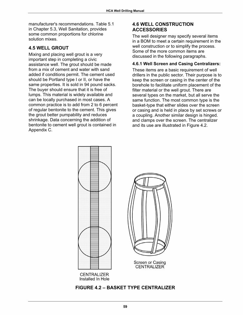
HCA Well Drilling Manual
manufacturer's recommendations. Table 5.1 in Chapter 5.3, Well Sanitation, provides some common proportions for chlorine solution mixes.
4.5 WELL GROUT Mixing and placing well grout is a very important step in completing a civic assistance well. The grout should be made from a mix of cement and water with sand added if conditions permit. The cement used should be Portland type I or II, or have the same properties. It is sold in 94 pound sacks. The buyer should ensure that it is free of lumps. This material is widely available and can be locally purchased in most cases. A common practice is to add from 2 to 6 percent of regular bentonite to the cement. This gives the grout better pumpability and reduces shrinkage. Data concerning the addition of bentonite to cement well grout is contained in Appendix C.
4.6 WELL CONSTRUCTION ACCESSORIES The well designer may specify several items in a BOM to meet a certain requirement in the well construction or to simplify the process. Some of the more common items are discussed in the following paragraphs.
4.6.1 Well Screen and Casing Centralizers: These items are a basic requirement of well drillers in the public sector. Their purpose is to keep the screen or casing in the center of the borehole to facilitate uniform placement of the filter material or the well grout. There are several types on the market, but all serve the same function. The most common type is the basket-type that either slides over the screen or casing and is held in place by set screws or a coupling. Another similar design is hinged. and clamps over the screen. The centralizer and its use are illustrated in Figure 4.2.
FIGURE 4.2 – BASKET TYPE CENTRALIZER
59

HCA Well Drilling Manual
NOTES _______________________________________________________________________________
_______________________________________________________________________________
_______________________________________________________________________________
_______________________________________________________________________________
_______________________________________________________________________________
_______________________________________________________________________________
_______________________________________________________________________________
_______________________________________________________________________________
_______________________________________________________________________________
_______________________________________________________________________________
_______________________________________________________________________________
60

HCA Well Drilling Manual
4.6.2 Float Collar: In some very deep well installations, the weight of the well casing and screen may exceed the mast capacity of the drill rig. This is not a problem when the designer specifies that a float collar be installed in the casing string just above the well screen. The float collar is simply a section of casing that has a drillable, valved plug on the inside. After this device is installed and lowered into the fluid-filled hole, the empty casing above the plug becomes buoyant and the drill rig feels little, if any, weight. Depending on the size and wall thickness of the casing, the driller may even add water inside the casing to allow it to sink into the hole. After the screen and casing are set to proper depth, the casing is secured at the surface using a casing clamp or similar device. The casing is then filled with water or thin drilling fluid and the plug is drilled out with a properly sized drill bit. This item is included in the Army 1500 Foot Well Completion Kit. This device is illustrated in Figure 4.3.
FIGURE 4.4 – FLOAT SHOE
FIGURE 4.3 – FLOAT COLLAR
4.6.3 Float or Grouting Shoe: This item serves a similar function as the float collar described above. The difference is that this item is installed on the end of a casing string without any screen attached. This device is also valved, drillable, and rounded on the end to facilitate installation of the casing into the hole. A float shoe is illustrated in Figure 4.4. This item will float the casing into place as will the drill collar. This device also allows the driller to place well grout through the float shoe from the bottom of the casing back to the surface. Depending on the exact design of the shoe, the grout can be placed using chaser plugs (sometimes referred to as pigs) or by setting pipe from the surface to the shoe. The grout is pumped out through the valve, allowing it to flow up the annular space to the surface and completely enclosing the casing. Further description of the grouting process will be discussed in Section 5.7, Grouting.
61

HCA Well Drilling Manual
NOTES _______________________________________________________________________________
_______________________________________________________________________________
_______________________________________________________________________________
_______________________________________________________________________________
_______________________________________________________________________________
_______________________________________________________________________________
_______________________________________________________________________________
_______________________________________________________________________________
_______________________________________________________________________________
_______________________________________________________________________________
_______________________________________________________________________________
62
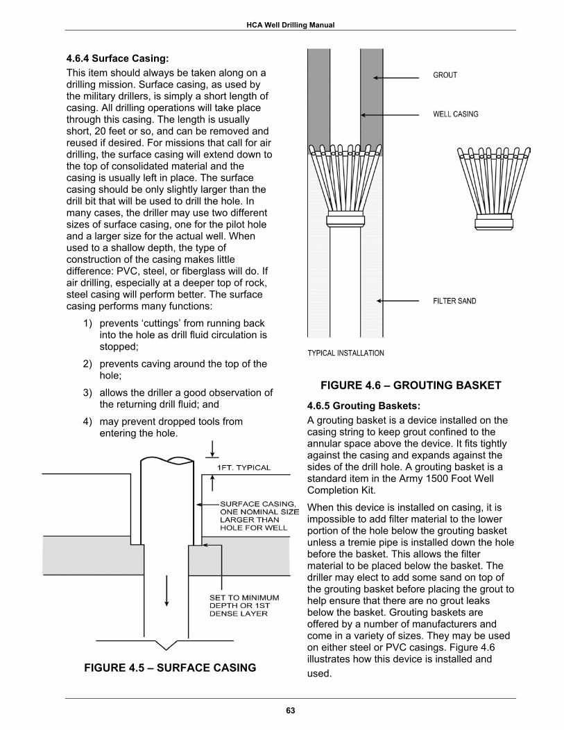
HCA Well Drilling Manual
4.6.4 Surface Casing: This item should always be taken along on a drilling mission. Surface casing, as used by the military drillers, is simply a short length of casing. All drilling operations will take place through this casing. The length is usually short, 20 feet or so, and can be removed and reused if desired. For missions that call for air drilling, the surface casing will extend down to the top of consolidated material and the casing is usually left in place. The surface casing should be only slightly larger than the drill bit that will be used to drill the hole. In many cases, the driller may use two different sizes of surface casing, one for the pilot hole and a larger size for the actual well. When used to a shallow depth, the type of construction of the casing makes little difference: PVC, steel, or fiberglass will do. If air drilling, especially at a deeper top of rock, steel casing will perform better. The surface casing performs many functions:
1) prevents ‘cuttings’ from running back into the hole as drill fluid circulation is stopped;
2) prevents caving around the top of the hole;
3) allows the driller a good observation of the returning drill fluid; and
4) may prevent dropped tools from entering the hole.
FIGURE 4.5 – SURFACE CASING
FIGURE 4.6 – GROUTING BASKET
4.6.5 Grouting Baskets: A grouting basket is a device installed on the casing string to keep grout confined to the annular space above the device. It fits tightly against the casing and expands against the sides of the drill hole. A grouting basket is a standard item in the Army 1500 Foot Well Completion Kit. When this device is installed on casing, it is impossible to add filter material to the lower portion of the hole below the grouting basket unless a tremie pipe is installed down the hole before the basket. This allows the filter material to be placed below the basket. The driller may elect to add some sand on top of the grouting basket before placing the grout to help ensure that there are no grout leaks below the basket. Grouting baskets are offered by a number of manufacturers and come in a variety of sizes. They may be used on either steel or PVC casings. Figure 4.6 illustrates how this device is installed and used.
63

HCA Well Drilling Manual
4.7 PUMPS The single, biggest problem with purchasing well completion materials before obtaining specific data about the completed well is buying the pump. The basic problems of selecting a pump were mentioned in Section 3.2. The fundamental factors in making a pump selection depend on yield, availability of electrical power, and a distribution system. There are other specifications that should be provided to the pump manufacturer. As the BOM is completed, pump specifications will require the following information:
1) Total dynamic head; 2) Size of well casing; 3) Available voltage/cycles/phase; 4) Type of pump (submersible, vertical
turbine, jet, deep-well hand pump); 5) Desired yield.
The experience of most military well drillers is limited to installation of hand pumps or electric, submersible pumps. In most cases, the well designer should specify these types of pumps for use in an exercise. The installation of a vertical turbine pump, for instance, is a much higher cost item than a submersible pump and the installation is more time consuming. When the well is completed and the anticipated yield is not attained, the pre-purchased pump will usually be installed and the flow restricted with a valve to prevent the water level from reaching the pump intake. This practice is unfortunate, but necessary in some cases. The problem with this is the short pump life that can be expected due to the lower efficiency and excess heat in the motor. The designer should rely on data obtained from the reconnaissance survey and other decisions about yields, water levels, etc.
64
HCA Well Drilling Manual
SECTION FIVE
KEYS TO SUCCESSFUL WELL CONSTRUCTION
EXECUTIVE SUMMARY
Arrival of the drill crew to a selected site starts the actual well construction process. Properly setting up the drill site will benefit continuing operations. Easy access of support vehicles and placement of needed supplies must be considered. The sumps used to contain the drilling mud (if used) must be started as soon as possible since drilling fluid is an initial requirement. Proper sanitation of the water used in making the drilling mud must be maintained to ensure that the well will be bacteria-free after completion. The first step in drilling is to complete a small diameter test hole. Every effort should be made to assure that the hole is being drilled straight and plumb. This hole will later be reamed to the full diameter, so the initial alignment is very important. This test hole will identify underlying formations and their physical characteristics. Samples of the formations are carried back to the surface by the drilling fluid where they can be collected and used to verify the types of formations being penetrated. After determining the presence of the water-bearing formation, the placement of the well screens, if needed, and the grouting depth are decided. The test hole is only reamed to the required depth. It is essential
that 24 hour drilling operations take place. Increased risk of failure occurs in well operations conducted less than 24 hours per day. The casings, well screens, and associated accessories are placed in the hole and the well is 'gravel-packed', then grouted. To complete the well, thorough well development is absolutely necessary. This process is often wrongly given a low priority which may result in failure of the well. There are many methods for well development available to the driller. In general, the more difficult methods to utilize are the most effective. The well should be left in a virtually sand-free (< 5 ppm) condition. If the well is a "sand pumper," this should not be dismissed. To have a small, poor community spend money on getting power and installing a distribution system for a defective well will certainly strain relations. There is no excuse for this to happen. The final part of the mission in well construction is to perform a pumping or drawdown test for the well. This will provide valuable information, both for the host community and the database at the TAC in Alexandria, Virginia. The following flow diagram illustrates the sequence of these considerations.
65
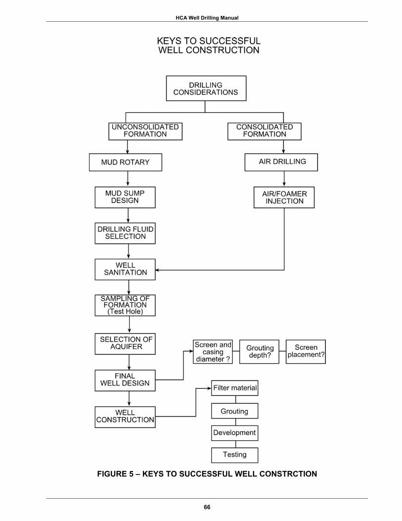
HCA Well Drilling Manual
FIGURE 5 – KEYS TO SUCCESSFUL WELL CONSTRCTION
66

HCA Well Drilling Manual
5.1 24-HR DRILLING OPERATIONS Drilling operations must continue 24 hours/day. Increased risk of failure occurs when well operations 'stop and start' in a single hole before well completion. Drilling fluid serves several purposes. Drilling fluid (e.g. mud, air, water, etc.) forms a 'cake' around the wall of the hole to keep the hole open during drilling and during well construction before filter packing. If drilling ceases before the hole is finished, there is increased risk for the borehole wall to collapse. The continuous drilling action helps keep the 'cake' in place against the borehole wall. If the drill steel and bit are in the hole when collapse occurs, the steel and bit can be permanently buried in the hole. Drilling fluid also floats the formation ‘cuttings’ out of the hole during drilling to keep the hole clean of ‘cuttings’. As drilling proceeds, formation ‘cuttings’ are continuously being generated, and are floated up out of the hole via the drilling fluid. If drilling ceases before hole completion, the ‘cuttings’ can fall out of suspension, settling on top of the bit, and around the drill steel. When this happens, the drill steel and bit can become permanently buried. Drilling operations must continue 24 hours a day, until a good stopping point is found. Sometimes this stopping point first occurs when the grout seal is setting up. When an officer and/or Task Force Commander requires drilling operations to be conducted less than 24 hours/day, for whatever reason, there is an increased risk of failure.
5.2 THE DRILL SITE 5.2.1 General: Proper setup is the first issue to address upon arrival at a site. The placement of all the equipment in relationship to the well should be given prior thought before drilling starts. Excavating the mud sumps will create a spoil pile of the soil removed. A backhoe may need access to dip out additional ‘cuttings’ during the drilling process. The driller will need the supply truck positioned to remove drill pipe, well casings, and other supplies next to the well. The supply truck should have the ability to come and go, as required. Another
important factor that should be given prior consideration is drainage at the site. The water from development, pumping, and rainfall will require a path for runoff from the site. Air drilling could also create dusty conditions, so consideration should be given to what is located downwind. The soil conditions at the site could require that planking be used to create firm bearing and work areas. The small pads supplied with most hydraulic leveling devices on drilling rigs will not support the weight of the rig in soft soils. Planking laid around the rig will create a safe work area for the crew. When an auxiliary air compressor is used, it should be located away from the driller's position. Locate the compressor in front of the drill rig when possible. This will minimize excessive noise where the crew is trying to work. Make-up water should be stored in portable tanks at the drill site, making sure the location is accessible by the supply truck and hoses on hand can reach the well and the mud sumps. The water should be chlorinated as soon as it is brought to the site, if this has not already been done. The filter material should be placed as close to the well as possible without interfering with work. This material will have to be moved by the crew and the volume may be several cubic yards. When the filter material requires screening before use, it should initially be placed far enough away so not to interfere with the drilling operation. A separate crew of laborers could be used to screen the material off to the side and then place the properly graded material close to the well. Avoid a long trip to the well through mud or other slippery conditions. 5.2.2 Mud Sump Design: Sumps for the drilling fluid should be placed within reach of the mud pump's suction to allow access and gravity drainage from the drill hole. The size of the sump should accommodate three times the volume of the drill hole, if possible. While some inexperienced drillers think this is excessive, consider the following:
67

HCA Well Drilling Manual
NOTES _______________________________________________________________________________
_______________________________________________________________________________
_______________________________________________________________________________
_______________________________________________________________________________
_______________________________________________________________________________
_______________________________________________________________________________
_______________________________________________________________________________
_______________________________________________________________________________
_______________________________________________________________________________
_______________________________________________________________________________
_______________________________________________________________________________
68
HCA Well Drilling Manual
The mud sump must serve two basic functions:
1) It must contain the ‘cuttings’ from the hole after they drop out of the drilling fluid;
2) It must always have a readily available volume of drilling fluid to overcome highly permeable zones encountered during the drilling operation.
The volume of ‘cuttings’ from the hole is equal to one hole volume, but this volume always increases. For instance, when digging a hole and then backfilling, there is always material left. This is because the material removed has been disturbed and the amount of pore space increased. Only by careful compaction can all the material be returned to the original hole. The same holds true while drilling, but the situation is worse. The ‘cuttings’ are disturbed, suspended in a fluid, then allowed to slowly settle out. This process may fluff the ‘cuttings’ up to 50% over their original volume. This is sometimes called a bulking factor. If a two sump system is used, the first one, the settling sump, should be two hole volumes. This will allow for containment of the fluffed drill ‘cuttings’ within the settling sump and still not completely fill it to capacity. An over-filled sump requires some of the ‘cuttings’ to be removed and this is a messy process that should be avoided. The second sump should be the reserve sump and contain one hole volume. This will generally provide sufficient fluid to get through zones of fluid loss such as coarse sand, gravel, or fractured rock.The sumps should be proportioned so they are not excessively deep nor too shallow. The shape of the sump can vary but they should be designed to allow the mud to enter, slow down to allow ‘cuttings’ to settle, then flow to the other sump or be picked up at the other end of the pit. Sumps should not exceed a depth of five feet, in most cases, and should be at least twice as long as they are wide. To estimate the volumes needed for the two sumps, the following equations can be used.
Equation 5.1
Vs = (3.14(d/12)2/4)2h
where, Vs = Volume of settling sump in cubic feet
d = Hole diameter in inches h = Depth of hole in feet
Equation 5.2
Vr = (3.14(d/12)2/4)h
where, Vr = Volume of reserve sump in cubic feet d = Hole diameter in inches h = Depth of hole in feet
When a portable sump is used or when a sump is constructed above ground with sandbag dikes, it will probably need periodic cleaning. Consider the following: Using the portable sump that is supplied with the Failing LP -12 drill rig, the total volume of the two-piece sump is approximately 300 gallons. While drilling a 12-inch hole and getting a 50% fluff factor, the sump will completely fill up every 36 feet of drilling. Using this for production drilling will require a full time crew member to shovel drill ‘cuttings’ from the hole. Building a sump above ground with sandbags or other means, the volume of the sump can be increased. This method will require the use of a short piece of surface casing to elevate the point where the fluid discharges into the sump. Normal surface casing will meet this requirement. When immediate completion of a well is critical, the drilling may commence using a portable sump, then switch to a larger dug sump after sufficient fluid has been mixed in the portable sumps. The ‘cuttings’ from the pilot hole will not fill the portable sump as quickly as a large hole, and the sump will be easier to keep shoveled free of settled drill ‘cuttings’. This will require only a portion of the first load of water to start the drilling. As mud sumps are being dug, the driller should make note of the soil conditions in the hole. Sandy soils will need the immediate addition of drilling mud to the make-up water to coat the sides and bottom of the pit to prevent fluid loss. It may be hopeless to try to fill a sump dug in sand with clear water. An easy way to accomplish this is to pump the water from the water tank through the mud gun into the sump, adding mud as the water
69
is pumped. This will allow the first tank ofwater to coat the bottom and sides of thehole, preventing further fluid loss from

HCA Well Drilling Manual
NOTES _______________________________________________________________________________
_______________________________________________________________________________
_______________________________________________________________________________
_______________________________________________________________________________
_______________________________________________________________________________
_______________________________________________________________________________
_______________________________________________________________________________
_______________________________________________________________________________
_______________________________________________________________________________
_______________________________________________________________________________
_______________________________________________________________________________
70

HCA Well Drilling Manual
sump. Another option to prevent initial water loss is to use a simple plastic sheet as a liner in the pit. This item is included in the Army well completion kits.
5.3 DRILLING FLUID 5.3.1 General: The general type of drilling fluid should have been decided upon before the crew deployed. The source of make-up water should have also been identified beforehand. As previously mentioned, the water should either be obtained from a potable source or chlorinated with 50 ppm chlorine prior to mixing the drilling fluid additives. The pH of the water should be tested to check for acidic conditions. If the water is acidic, soda ash should be added to bring the water up to a pH of eight to nine. If acidic water is used, the driller will notice that bentonite drilling fluid will not stay suspended in the fluid and will tend to settle to the bottom of the sump. There have been occasions where drillers have described the hole as "making water" when they notice a little clear water on top of the mud after it sits a short period of time. This is probably due to acidic make-up water instead of artesian pressure forcing the mud from the hole and into the sump.
5.3.2 Bentonite: Bentonite drilling mud is the most commonly used product. It is essential that the bentonite be properly mixed with a mud gun. This device is attached to a bypass hose from the mud pump, and as fluid is circulated through the mud gun, the bentonite is added. Here, a venturi effect occurs which pulls the bentonite into the stream of fluid where mixing takes place. The bentonite mud is mixed to the proper consistency before drilling starts. The general proportions are about 200 gallons of water per sack of bentonite. A Marsh funnel cone, which measures viscosity, will determine the proper mud mix. The procedure for measuring the viscosity was described in Chapter 4.4. While the Marsh viscosity may range from 35 to 55 seconds, 40 seconds is a good starting point. This should be checked frequently and the mix adjusted as needed.
5.3.3 Additives for Bentonite Fluids: There are numerous additives for bentonite based drilling fluids. Those most commonly
used are for purposes of stopping the loss of drilling fluid into highly permeable zones encountered in drilling. These products are used to make "soft plugs" at the zone of mud loss and should be readily available to the driller who must react quickly to prevent draining the mud pit. This product should be added at the mud pump suction where it will quickly enter the drill pipe and move to the zone of fluid loss. Products used for this purpose may vary. Some products are simply coarsely ground bentonite having greater sealing capabilities than regular bentonite drilling mud. There are also items like ground walnut hulls, mica flakes, and certain organic polymers that perform the same function. The proper use of these items will vary by manufacturer and the driller should follow their written instructions. Occasionally the driller will encounter gravel while drilling in alluvial deposits that is very hard to remove from the hole. This is due to the size and density of the gravel. The mud density and viscosity may not be enough to float and push the gravel from the hole. There are some options available in dealing with this type of problem. The density of the mud can be raised to make the gravel more buoyant (lighter) in the fluid. This is accomplished with the addition of finely ground barite to the drilling mud. The gravel may also be cleaned from the hole by adding a slug of organic polymer to the system and letting the highly viscous slug move the gravel up and out of the hole into the sump.
5.3.4 Guar Base Fluid: Another water based drilling fluid is made from ground guar beans. One of these products, Revert, is included in the Army 600 Foot Well Completion kit. This is a self-destroying drilling fluid that only has a life of approximately 72 hours. This life may vary due to temperature or certain additives. Revert is an excellent product to use on shallow or small wells where the drilling will be finished and the casing and screen set in the allotted time. Any attempts to extend the life of the product, using various additives recommended by the manufacturer, should be planned and implemented before the fluid starts to break down. Once this starts, it is difficult to stop and the entire batch of mud
71

HCA Well Drilling Manual
NOTES _______________________________________________________________________________
_______________________________________________________________________________
_______________________________________________________________________________
_______________________________________________________________________________
_______________________________________________________________________________
_______________________________________________________________________________
_______________________________________________________________________________
_______________________________________________________________________________
_______________________________________________________________________________
_______________________________________________________________________________
_______________________________________________________________________________
72
HCA Well Drilling Manual
should be discarded and new mud mixed. Adding more product to the old mud will not be successful. The self-destroying properties make this an ideal product to use in wells as development effort is greatly reduced since it does not have the clay filter cake on the wall of the hole. There are numerous other polymers, organic and inorganic, that can be used to make water based drilling fluid, but are not in general use by drilling detachments.
5.3.5 Foaming Agents: Foaming agents for air/foam drilling are commonly used when drilling wells in consolidated materials. The computations for air/foam drilling are found in a number of references and will only be briefly discussed here. The recommended reference for this subject is "Groundwater and Wells, Second Edition" by Driscoll. The experience of the driller must be relied on for this type of operation, but one must ensure that the driller has all necessary supplies to perform this operation. Just as with mud drilling, the use of air/foam drilling will require water to be available at the site. The amount of water can be estimated based on the time it will take to drill the hole to its full depth. Again, the driller's experience is the main factor here. A reasonable estimating assumption is to expect to penetrate about 25 feet per hour while drilling with a 6 to 7-inch bit using a down-hole-hammer. This rate will be much less if trying to use a roller bit in hard rock. Some types of rock may cut much faster than average while using the hammer. The typical amount of liquid (water and foaming agent) that is injected into the air stream is 2% . For gross estimating purposes, the figure of 1 gpm per inch of hole diameter can be used. The amount of foaming agent added to the water depends on the product, but a safe estimation is 1% or one gallon of foaming agent per 100 gallons of water. Using the above rules of thumb, the following computation shows the typical estimates for water and foaming agent requirements while drilling rock with a down-hole-hammer. These rules of thumb should always be checked against the recommendations of the products actually purchased to ensure that sufficient amounts of the product are being procured.
Equation 5.3
T = L / 2 5 Equation 5.4
W = T ( 6 0 ) ( D ) Equation 5.5
F = W / 1 0 0
where, T = time in hours L = hole depth in feet D = hole size in inches W = water in gallons F = foaming agent, gallons
As an example for a 500 foot deep hole, (L), using a 6 1/2-inch diameter, (D) DHH bit. T = 500/25 = 20 hours Water = 20 hours x 60 x 6 1/2 = 7,800 gallons Foam = 7,800/100 = 78 gallons For drilling the above example hole, the drilling detachment should deploy with at least 78 gallons of foaming agent with a requirement of 7,800 gallons of water to be transported to the site. One's first experience with using foam may have been a messy one. The soapy discharge that may have accumulated at the back of the drill rig should still be in mind. A rich foam mix will look similar to shaving cream as it rises out of the drill hole. If not removed, it will soon engulf the area behind the rig. A simple installation called a blooey line discharge will help remedy this problem. This device can be fashioned from pipe and fittings to fit on surface casing. The basic setup is shown in Figure 5.1. The purpose of the blooey line is to move the foam discharge point away from the driller and rig. The air supply is from the compressor and only a little is needed to pull, then push the foam out of the discharge pipe. Sampling can be accomplished at the discharge point. The use of an air compressor, which is large enough to remove ‘cuttings’ without the addition of foam, is the easy solution in air drilling. As discussed in Chapter 3.3.2, most drill rigs will require an additional compressor to accomplish this. Use Equation 3.4 to determine the minimum compressor size for a
73

HCA Well Drilling Manual
NOTES _______________________________________________________________________________
_______________________________________________________________________________
_______________________________________________________________________________
_______________________________________________________________________________
_______________________________________________________________________________
_______________________________________________________________________________
_______________________________________________________________________________
_______________________________________________________________________________
_______________________________________________________________________________
_______________________________________________________________________________
_______________________________________________________________________________
74
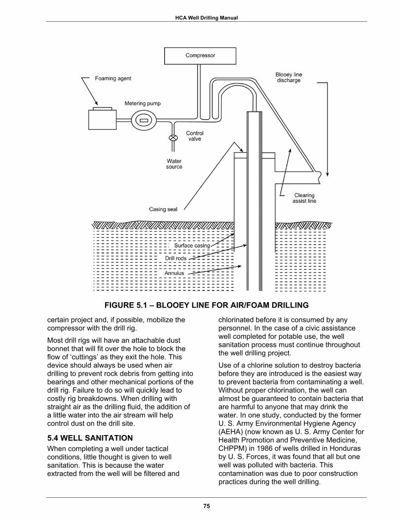
HCA Well Drilling Manual
FIGURE 5.1 – BLOOEY LINE FOR AIR/FOAM DRILLING
certain project and, if possible, mobilize the compressor with the drill rig. Most drill rigs will have an attachable dust bonnet that will fit over the hole to block the flow of ‘cuttings’ as they exit the hole. This device should always be used when air drilling to prevent rock debris from getting into bearings and other mechanical portions of the drill rig. Failure to do so will quickly lead to costly rig breakdowns. When drilling with straight air as the drilling fluid, the addition of a little water into the air stream will help control dust on the drill site.
5.4 WELL SANITATION When completing a well under tactical conditions, little thought is given to well sanitation. This is because the water extracted from the well will be filtered and
chlorinated before it is consumed by any personnel. In the case of a civic assistance well completed for potable use, the well sanitation process must continue throughout the well drilling project. Use of a chlorine solution to destroy bacteria before they are introduced is the easiest way to prevent bacteria from contaminating a well. Without proper chlorination, the well can almost be guaranteed to contain bacteria that are harmful to anyone that may drink the water. In one study, conducted by the former U. S. Army Environmental Hygiene Agency (AEHA) (now known as U. S. Army Center for Health Promotion and Preventive Medicine, CHPPM) in 1986 of wells drilled in Honduras by U. S. Forces, it was found that all but one well was polluted with bacteria. This contamination was due to poor construction practices during the well drilling.
75

HCA Well Drilling Manual
NOTES _______________________________________________________________________________
_______________________________________________________________________________
_______________________________________________________________________________
_______________________________________________________________________________
_______________________________________________________________________________
_______________________________________________________________________________
_______________________________________________________________________________
_______________________________________________________________________________
_______________________________________________________________________________
_______________________________________________________________________________
_______________________________________________________________________________
76

HCA Well Drilling Manual
The first likely source of contamination is the makeup water used to mix the drilling fluid. In most instances, the make-up water will be taken from lakes, streams, or other surface sources. It will almost always be contaminated with bacteria, which can be introduced into the well unless the water is treated before use. All make-up water from non-potable sources should be treated with 50 ppm chlorine solution before the additives are mixed for the drilling fluid. This is best accomplished in the tank which is used to haul the water. There are several simple indictor test kits to check the chlorine concentration in fluids. These can be obtained from the medical units or from chlorine suppliers. It is also recommended to maintain a 10 ppm chlorine concentration in the drilling fluid. The next step in well construction where chlorination should be used is the addition of the filter material. There are different ways to accomplish this. If the filter material is in bulk, dry chlorine powder (65% ) can be mixed into the filter material at the rate of one half pound per cubic yard. Another method is to mix a solution of 100 ppm and spray the filter material before it is placed. The finished well should be chlorinated with a 100 ppm solution introduced into the well. There should be ample solution to represent 150% of the volume of the water in the well including the filter-pack zone. This solution should be left in the well at least two hours. The driller should ensure that some of the solution runs down the sides of the well casing which is above the static water level in the well. The only way to be certain that the well is bacteria free is to conduct a test on a water sample. This test can be performed by a variety of sources, with most countries having an agency that will conduct the test. If the well does not pass the test, it cannot be considered potable. The well should be re-sterilized and retested until the water analysis is satisfactory. The well should remain free of bacteria after a thorough disinfection unless another source of contamination is allowed. The two most common sources are dirty pump parts or improper sealing of the top of the well. Installation of the well pump, regardless of the
type, should always be conducted with proper sterilization. This is a simple matter and can be accomplished by spraying or brushing all exposed pump, pipe, and wiring parts with 100 ppm chlorine solution before introduction into the well. The installation of the pump should be completed with a well seal at the top of the well to prevent further contamination. The following Table offers some common concentrations of chlorine mixes.
TABLE 5.1 COMMON CHLORINE SOLUTIONS FOR
USE IN WELL DRILLING (For 1,000 Gallons of Water)
Mix (ppm)
Liquid 5% Bleach
65% Calcium Hypochlorite (HTH)
50 1 gallon 0.6 pounds 100 2 gallons 1.3 pounds 500 10 gallons 6.4 pounds
1000 20 gallons 12.8 pounds
5.5 THE TEST HOLE After the rig and associated equipment is in place and the drilling site prepared, the drilling of the test hole can begin. This hole may also be known as the pilot hole. There are few exceptions to the requirement for completing this as a first step in the well completion. Some of the important functions of the test hole are listed below.
5.5.1 Sampling: A very important decision that has to be made for every well is where the aquifer is located. When drilling in an area for the first time, there are many unknowns to contend with. The only aquifer may be of limited extent in the underlying formations and an accurate depth to the top and bottom of the aquifer must be defined. In many cases, the geologist or engineer may have provided a maximum depth where they believe the aquifer should be penetrated. It is up to the driller to accurately define the actual aquifer within these depths. Clay confining layers are also of interest to the driller if attempting to seal out contaminants from surface deposits by extending the grout seal to these depths. By drilling a relatively small hole, 6- to 7-inches in diameter, the driller can cut through the formations at a fast speed. The drill bit is removing the formation as it cuts its way down.
77

HCA Well Drilling Manual
NOTES _______________________________________________________________________________
_______________________________________________________________________________
_______________________________________________________________________________
_______________________________________________________________________________
_______________________________________________________________________________
_______________________________________________________________________________
_______________________________________________________________________________
_______________________________________________________________________________
_______________________________________________________________________________
_______________________________________________________________________________
_______________________________________________________________________________
78

HCA Well Drilling Manual
Remember the rule of thumb is that when you double the diameter of a circle, you increase the area by a factor of 4. In other words, you are removing 4 times as much formation drilling a 12-inch hole as you are drilling a 6-inch hole. It only makes sense to do as little work as needed while you are looking for the aquifer. Another consideration is the quality of the sample that you recover from the drilling fluid. Drilling down a 10 foot interval with a smaller hole size will tend to send the ‘cuttings’ up the hole in more of a slug. By doing this, it is easier to associate samples with a particular depth and lessens the chance of mixing samples. This makes it easier to recover a representative sample of the different formations. With any given size of mud pump, the smaller the drill hole, the faster the ‘cuttings’ will reach the surface. A much better sample can be obtained by drilling a 10 foot interval at a fast
penetration rate and then letting the ‘cuttings’ reach the surface before proceeding with the next interval. Samples should be collected and labeled according to depth. At the completion of the test hole, the samples can be inspected and recommendations made for the location of screens and grouting intervals. The uphole velocity of the drilling fluid carrying the ‘cuttings’ will vary with the diameter of the hole. Tables 5.2A and 5.2B below indicate return times for a given discharge rate with a mud pump and using a certain diameter drill rod. Table 5.3 lists the change in uphole velocities with different sizes of hole. These do not account for the ‘cuttings’ trying to settle back through the fluid as it rises, but this is a minor consideration. The times indicated are how long the person taking samples should expect to wait before catching the sample at the surface after cutting a certain interval of test hole.
TABLES 5.2A AND 5.2B RETURN TIME IN MINUTES FOR DRILLING FLUID WITH KNOWN PUMP DISCHARGE
AND SELECTED DIAMETER OF DRILL PIPE
TABLE 5.2A 200 GPM AND 3 1/2-INCH RODS
HOLE DIAMETER, in.
HOLE DEPTH, ft. 6 7 8 9 10 11 12
25 .12 .19 .26 .35 .45 .55 .67
50 .24 .37 .53 .70 .89 1.1 1.5
100 .49 .75 1.0 1.4 1.8 2.2 2.7
200 .98 1.5 2.1 2.8 3.6 4.4 5.4
300 1.5 2.3 3.2 4.2 5.4 6.7 8.1
400 1.9 3.0 4.2 5.6 7.2 8.9 11
500 2.4 3.8 5.3 7.1 9 11 14
600 2.9 4.5 6.4 8.4 11 14 16
1000 4.9 7.5 11 14 18 22 27
79

HCA Well Drilling Manual
NOTES _______________________________________________________________________________
_______________________________________________________________________________
_______________________________________________________________________________
_______________________________________________________________________________
_______________________________________________________________________________
_______________________________________________________________________________
_______________________________________________________________________________
_______________________________________________________________________________
_______________________________________________________________________________
_______________________________________________________________________________
_______________________________________________________________________________
80
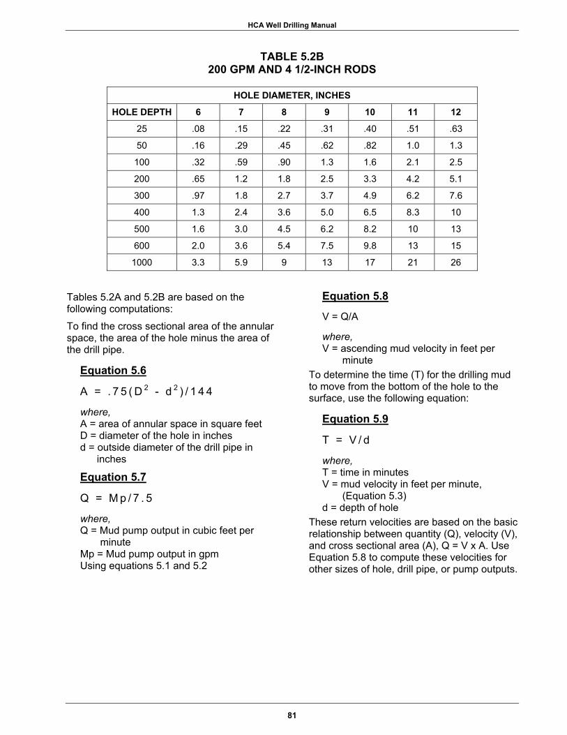
HCA Well Drilling Manual
TABLE 5.2B 200 GPM AND 4 1/2-INCH RODS
HOLE DIAMETER, INCHES
HOLE DEPTH 6 7 8 9 10 11 12
25 .08 .15 .22 .31 .40 .51 .63
50 .16 .29 .45 .62 .82 1.0 1.3
100 .32 .59 .90 1.3 1.6 2.1 2.5
200 .65 1.2 1.8 2.5 3.3 4.2 5.1
300 .97 1.8 2.7 3.7 4.9 6.2 7.6
400 1.3 2.4 3.6 5.0 6.5 8.3 10
500 1.6 3.0 4.5 6.2 8.2 10 13
600 2.0 3.6 5.4 7.5 9.8 13 15
1000 3.3 5.9 9 13 17 21 26
Tables 5.2A and 5.2B are based on the following computations: To find the cross sectional area of the annular space, the area of the hole minus the area of the drill pipe.
Equation 5.6
A = . 7 5 ( D 2 - d 2 ) / 1 4 4
where, A = area of annular space in square feet D = diameter of the hole in inches d = outside diameter of the drill pipe in
inches
Equation 5.7
Q = M p / 7 . 5
where, Q = Mud pump output in cubic feet per
minute Mp = Mud pump output in gpm Using equations 5.1 and 5.2
Equation 5.8
V = Q/A
where, V = ascending mud velocity in feet per
minute To determine the time (T) for the drilling mud to move from the bottom of the hole to the surface, use the following equation:
Equation 5.9
T = V / d
where, T = time in minutes V = mud velocity in feet per minute,
(Equation 5.3) d = depth of hole
These return velocities are based on the basic relationship between quantity (Q), velocity (V), and cross sectional area (A), Q = V x A. Use Equation 5.8 to compute these velocities for other sizes of hole, drill pipe, or pump outputs.
81

HCA Well Drilling Manual
NOTES _______________________________________________________________________________
_______________________________________________________________________________
_______________________________________________________________________________
_______________________________________________________________________________
_______________________________________________________________________________
_______________________________________________________________________________
_______________________________________________________________________________
_______________________________________________________________________________
_______________________________________________________________________________
_______________________________________________________________________________
_______________________________________________________________________________
82
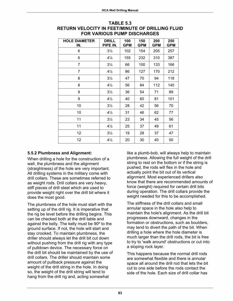
HCA Well Drilling Manual
TABLE 5.3 RETURN VELOCITY IN FEET/MINUTE OF DRILLING FLUID
FOR VARIOUS PUMP DISCHARGES HOLE DIAMETER
IN. DRILL
PIPE IN. 100
GPM 150
GPM 200
GPM 250
GPM 6 3½ 102 154 205 257
6 4¼ 155 232 310 387
7 3½ 66 100 133 166
7 4½ 86 127 170 212
8 3½ 47 70 94 118
8 4½ 56 84 112 140
9 3½ 36 54 71 89
9 4½ 40 60 81 101
10 3½ 28 42 56 70
10 4½ 31 46 62 77
11 3½ 23 34 45 56
11 4½ 25 37 49 61
12 3½ 19 28 37 47
12 4½ 20 30 40 50
5.5.2 Plumbness and Alignment: When drilling a hole for the construction of a well, the plumbness and the alignment (straightness) of the hole are very important. All drilling systems in the military come with drill collars. These are sometimes referred to as weight rods. Drill collars are very heavy, stiff pieces of drill steel which are used to provide weight right over the drill bit where it does the most good. The plumbness of the hole must start with the setting up of the drill rig. It is imperative that the rig be level before the drilling begins. This can be checked both at the drill table and against the kelly. The kelly must be 90º to the ground surface. If not, the hole will start and stay crooked. To maintain plumbness, the driller should always let the drill bit cut down without pushing from the drill rig with any type of pulldown device. The necessary force on the drill bit should be maintained by the use of drill collars. The driller should maintain some amount of pullback pressure against the weight of the drill string in the hole. In doing so, the weight of the drill string will tend to hang from the drill rig and, acting somewhat
like a plumb-bob, will always help to maintain plumbness. Allowing the full weight of the drill string to rest on the bottom or if the string is pushed, the rods will flex in the hole and actually point the bit out of its vertical alignment. Most experienced drillers also know that there are recommended amounts of force (weight) required for certain drill bits during operation. The drill collars provide the weight needed for this to be accomplished. The stiffness of the drill collars and small annular space in the hole also help to maintain the hole's alignment. As the drill bit progresses downward, changes in the formation or obstructions, such as boulders, may tend to divert the path of the bit. When drilling a hole where the hole diameter is much larger than the drill rods, the bit is free to try to 'walk around' obstructions or cut into a sloping rock layer. This happens because the normal drill rods are somewhat flexible and there is annular space all around the drill rod that lets the bit cut to one side before the rods contact the side of the hole. Each size of drill collar has
83

HCA Well Drilling Manual
NOTES _______________________________________________________________________________
_______________________________________________________________________________
_______________________________________________________________________________
_______________________________________________________________________________
_______________________________________________________________________________
_______________________________________________________________________________
_______________________________________________________________________________
_______________________________________________________________________________
_______________________________________________________________________________
_______________________________________________________________________________
_______________________________________________________________________________
84
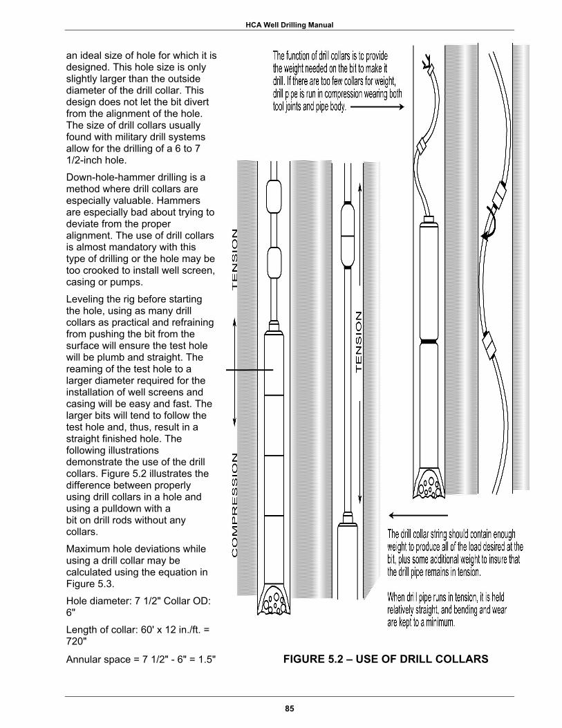
HCA Well Drilling Manual
an ideal size of hole for which it is designed. This hole size is only slightly larger than the outside diameter of the drill collar. This design does not let the bit divert from the alignment of the hole. The size of drill collars usually found with military drill systems allow for the drilling of a 6 to 7 1/2-inch hole. Down-hole-hammer drilling is a method where drill collars are especially valuable. Hammers are especially bad about trying to deviate from the proper alignment. The use of drill collars is almost mandatory with this type of drilling or the hole may be too crooked to install well screen, casing or pumps. Leveling the rig before starting the hole, using as many drill collars as practical and refraining from pushing the bit from the surface will ensure the test hole will be plumb and straight. The reaming of the test hole to a larger diameter required for the installation of well screens and casing will be easy and fast. The larger bits will tend to follow the test hole and, thus, result in a straight finished hole. The following illustrations demonstrate the use of the drill collars. Figure 5.2 illustrates the difference between properly using drill collars in a hole and using a pulldown with a bit on drill rods without any collars. Maximum hole deviations while using a drill collar may be calculated using the equation in Figure 5.3. Hole diameter: 7 1/2" Collar OD: 6" Length of collar: 60' x 12 in./ft. = 720" Annular space = 7 1/2" - 6" = 1.5" FIGURE 5.2 – USE OF DRILL COLLARS
85

HCA Well Drilling Manual
NOTES _______________________________________________________________________________
_______________________________________________________________________________
_______________________________________________________________________________
_______________________________________________________________________________
_______________________________________________________________________________
_______________________________________________________________________________
_______________________________________________________________________________
_______________________________________________________________________________
_______________________________________________________________________________
_______________________________________________________________________________
_______________________________________________________________________________
86

HCA Well Drilling Manual
Equation 5.10
Sin angle A = Annular space Collar length, (in inches)
where, Sin angle A = 1.5/60x12 Sin angle A = .0020833 Angle A = 0.12o
FIGURE 5.3 – EXAMPLE OF MAXIMUM DEVIATION OF
HOLE USING DRILL COLLARS
5.5.3 Geophysical Logging: When the drilling system includes a geophysical logger system or if one is available from other sources such as a local contractor, this will provide a good means of verifying the location of an aquifer. The test hole, upon its completion, can be used for the geophysical logging.
Common types of geophysical logs include: 1) Resistivity; 2) Spontaneous Potential (SP); 3) Natural Gamma.
The smaller hole size will generally provide a more accurate log. Interpretation of geophysical logs should be left to someone who has received training in this. General guidelines are that freshwater in a porous formation will have a high resistivity as compared to clayey formations or formations containing water high in chlorides (saline). Figure 5.4 provides a generalized illustration which shows some of the characteristics of a common geophysical log. The portable logger which is part of the LP-12 drilling system has only resistivity and SP capability. A gamma log cannot be obtained with this unit.
5.6 FINAL WELL DESIGN 5.6.1 General: After the test hole is completed, the driller will have information to start completion of the final well. Data from the test hole will include the following:
1) depth of well; 2) locations for well screens; 3) grain size of the aquifer.
The first step for further drilling is to install surface casing to prevent any cave-ins at the surface during the drilling operation. When a clay layer is present in the upper portion of the hole, it will make an ideal base for installation of the surface casing. Should no clay layer be present, the minimum length of the surface casing should be 20 feet. The pilot hole should be reamed as necessary for this installation. Oftentimes, the procurement of a larger drill bit is necessary for the drilling systems. The bit selection usually included with military drilling
87

HCA Well Drilling Manual
NOTES _______________________________________________________________________________
_______________________________________________________________________________
_______________________________________________________________________________
_______________________________________________________________________________
_______________________________________________________________________________
_______________________________________________________________________________
_______________________________________________________________________________
_______________________________________________________________________________
_______________________________________________________________________________
_______________________________________________________________________________
_______________________________________________________________________________
88

HCA Well Drilling Manual
89
FIGURE 5.4 – EXAMPLE OF TYPICAL GEOPHYSICAL LOG
systems does not have the 16-inch bit needed to set 14-inch surface casing. This 14-inch surface casing is the size needed to drill with a 12- to 13-inch bit when reaming the test hole.
5.6.2 Test Hole Information: The depth to the base of the aquifer should be noted from the samples taken from the test hole. The driller should keep in mind the lengths of casing, screen, and sediment sumps that are available for use. If the aquifer is not sufficiently thick, the reaming will have to continue past the aquifer to accommodate the sediment sump. It is always good design to have a few feet of open hole under the bottom of the sump or screen to allow the string to hang in the hole. ‘Gravel-packing’ and/or grouting will provide the needed support to the screen and casing. Some types of casing can be field cut to provide exact depths of setting the different components. One purpose of the test hole is to identify the
target aquifer(s), so the bottom depth is known. The driller should also observe the presence of clay layers in the test hole. It is preferable to extend the grouted zone from the surface into a clay layer to prevent any type of contaminant from migrating from the surface down the annular portion of the well and entering the well. Inspection of the ‘cuttings’ from the selected aquifer will indicate the requirement for a properly designed filter pack. In most cases, the well screen provided for the job will have a slot size of 0.025-inch. When most of the aquifer material is smaller than 0.025-inch, the design of the filter material will be critical to the success of the well. The decision of the average grain size can be made using a #25 U. S. standard sieve. This method was described in Chapter 4.2.4, Well Screen, Slot Size. When most of the material is coarser than 0.025-inch, the gradation of the filter material is not as important as long as the material is

HCA Well Drilling Manual
NOTES _______________________________________________________________________________
_______________________________________________________________________________
_______________________________________________________________________________
_______________________________________________________________________________
_______________________________________________________________________________
_______________________________________________________________________________
_______________________________________________________________________________
_______________________________________________________________________________
_______________________________________________________________________________
_______________________________________________________________________________
_______________________________________________________________________________
90

HCA Well Drilling Manual
relatively coarse as compared to the formation grain size. Even material such as "pea gravel" will work because the formation itself will make its own filter pack as the finer fraction of the material is drawn into the well screen during development. If the well requires use of a properly graded filter material, this material should be on site before the hole is reamed to full size from the test hole. There is no way to bypass the requirement for filter material when it is needed. To be effective, the filter must be placed uniformly around the well screen. The only way to accomplish this is to use a centering device attached to the well screen. These devices should be no more than 40 feet apart. Failure to use centering devices will allow the well screen to rest against one side of the hole as the filter material is added. With the screen in direct contact with the formation, the passage of sand into the well screen will be unrestricted. 5.6.3 Placement of Well Screens: Placement of the well screen in the hole is a decision that should be made with several things in mind:
1) Always place the well screens so they will not be dewatered while the well is pumping. The pump should always be set so the intake is above the uppermost screen.
2) In an unconfined aquifer, the lower one third of the aquifer should be screened to produce the maximum amount of water. This will allow the well to yield 90% of its available water without dewatering the well screen. (See Figure 5.5)
3) In confined aquifers, screen the middle 75% of the aquifer or if the aquifer is considerably thicker than the amount of screen on hand, pick the best (coarsest with the fewest fines) portion of the aquifer. (See Figure 5.6)
4) Use Equation 3.5 to determine the required screen length. Smaller wells will often not require the maximum screen length.
FIGURE 5.5 – PROPER SCREENING OF
UNCONFINED AQUIFER (LOWER THIRD OF AQUIFER)
FIGURE 5.6 – PROPER SCREENING OF CONFINED AQUIFER
(CENTRAL 75% OF AQUIFER)
91

HCA Well Drilling Manual
NOTES _______________________________________________________________________________
_______________________________________________________________________________
_______________________________________________________________________________
_______________________________________________________________________________
_______________________________________________________________________________
_______________________________________________________________________________
_______________________________________________________________________________
_______________________________________________________________________________
_______________________________________________________________________________
_______________________________________________________________________________
_______________________________________________________________________________
92

HCA Well Drilling Manual
5.6.4 Depth of Grouting: The depth of the well grout should also be determined before installing any screen or casing into the hole. It is always best to seal off the lower portion of the well from the upper portion with a low permeability formation such as a clay layer. These layers are commonly known as aquitards or aquicludes. This is done by selecting the aquitard from the ‘cuttings’ or geophysical logs and filling the annular space in the hole from the base of the aquitard to the surface with cement or cement/bentonite grout. When the well is deep and the water table has no aquitard above it, the grout should extend as deep as practical. The minimum depth for a grout seal should be 40 feet. This prevents contaminants at or near the surface from getting into the screened portion of the well. If there is any type of surface pollution source in the area of the well, the depth should be a minimum of 100 feet. A typical selection of grouting depths is illustrated in Figure 5.7.
5.7 INSTALLATION OF WELL SCREEN AND CASING 5.7.1 General: After the depths for surface casing, well screens, and grouting have been determined, the test hole is ready for reaming to final full diameter and depth. However, the hole should never be reamed into the aquifer before the well construction materials are on site or, at least, there is a guarantee that it will be on site by the time the reaming is finished. Reaming the hole, then allowing it to sit for a long period of time will result in a tough filter cake on the side of the hole. This will greatly increase the time required for well development. In extreme cases the well may never develop properly or the hole may collapse before the screen and casing are installed. The reaming of the hole should be accomplished using the drill collars plus a drill guide, properly-sized for the bit used. As in the test hole, this will help the drilling process and ensure that the reaming will follow the pilot hole.
The final diameter should be at least 4-inches larger than the outside diameter of the well screen in a 'gravel-packed’ well design and at least 2-inches larger than the screen
FIGURE 5.7 – TYPICAL GROUT INSTALLATION FOR HCA WELL
OD in a naturally developed well. The hole should always be drilled a little deeper than the actual bottom of the lowest portion of the screen or casing. This allows for some sediment to settle in the bottom of the hole without affecting the installation of the screens and casing. The amount of overdepth should be no more than a few percent of the total hole depth. The well screens, casings, and sediment traps should be measured using a tape measure to check the actual lengths. It is helpful to mark the lengths on each piece with a marking pen as they are measured. Steel casings may come in somewhat random lengths that must be measured individually. The materials that will be installed in the well should be laid out in the order of installation and separated from the remaining materials not used. Using the old carpenters rule of "measure twice, cut once," the driller should measure twice, install once. Separate needed supplies from large stockpiles. Unloading a
93

HCA Well Drilling Manual
NOTES _______________________________________________________________________________
_______________________________________________________________________________
_______________________________________________________________________________
_______________________________________________________________________________
_______________________________________________________________________________
_______________________________________________________________________________
_______________________________________________________________________________
_______________________________________________________________________________
_______________________________________________________________________________
_______________________________________________________________________________
_______________________________________________________________________________
94
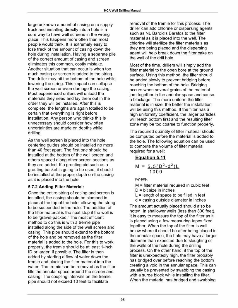
HCA Well Drilling Manual
large unknown amount of casing on a supply truck and installing directly into a hole is a sure way to have well screens in the wrong place. This happens more often than most people would think. It is extremely easy to lose track of the amount of casing down the hole during installation. Having a separate pile of the correct amount of casing and screen eliminates this common, costly mistake. Another situation that can occur is when too much casing or screen is added to the string. The driller may hit the bottom of the hole while lowering the string. This impact can collapse the well screen or even damage the casing. Most experienced drillers will unload the materials they need and lay them out in the order they will be installed. After this is complete, the lengths are again totalled to be certain that everything is right before installation. Any person who thinks this is unnecessary should consider how often uncertainties are made on depths while drilling. As the well screen is placed into the hole, centering guides should be installed no more than 40 feet apart. The first one should be installed at the bottom of the well screen and others spaced along other screen sections as they are added. If a grouting aid such as a grouting basket is going to be used, it should be installed at the proper depth on the casing as it is placed into the hole.
5.7.2 Adding Filter Material: Once the entire string of casing and screen is installed, the casing should be clamped in place at the top of the hole, allowing the string to be suspended in the hole. The addition of the filter material is the next step if the well is to be 'gravel-packed.’ The most efficient method to do this is with a tremie pipe installed along the side of the well screen and casing. This pipe should extend to the bottom of the hole and be removed as the filter material is added to the hole. For this to work properly, the tremie should be at least 1-inch ID or larger, if possible. The filter is then added by starting a flow of water down the tremie and placing the filter material into the water. The tremie can be removed as the filter fills the annular space around the screen and casing. The coupling intervals on the tremie pipe should not exceed 10 feet to facilitate
removal of the tremie for this process. The driller can add chlorine or dispersing agents such as NL Baroid's Barafos to the filter material as it is placed into the well. The chlorine will sterilize the filter materials as they are being placed and the dispersing agent will help break down the filter cake on the wall of the drill hole. Most of the time, drillers will simply add the filter material to the open bore at the ground surface. Using this method, the filter should be added slowly to prevent bridging before reaching the bottom of the hole. Bridging occurs when several grains of the material jam together in the annular space and cause a blockage. The more uniform the filter material is in size, the better the installation will be using this method. If the filter has a high uniformity coefficient, the larger particles will reach bottom first and the resulting filter zone may be too coarse to function properly. The required quantity of filter material should be computed before the material is added to the hole. The following equation can be used to compute the volume of filter material required for a well:
Equation 5.11
M = 5 . 5 ( D 2 - d 2 ) L 1 0 0 0
where, M = filter material required in cubic feet D = bit size in inches L = length of space to be filled in feet d = casing outside diameter in inches
The amount actually placed should also be noted. In shallower wells (less than 300 feet), it is easy to measure the top of the filter as it is placed using a few measuring tapes fixed together. When the top of the filter is well below where it should be after being placed in the annular space, the hole may have a larger diameter than expected due to sloughing of the walls of the hole during the drilling process. On the other hand, if the top of the filter is unexpectedly high, the filter probably has bridged over before reaching the bottom creating a void in the annular space. This can usually be prevented by swabbing the casing with a surge block while installing the filter. When the material has bridged and swabbing
95

HCA Well Drilling Manual
NOTES _______________________________________________________________________________
_______________________________________________________________________________
_______________________________________________________________________________
_______________________________________________________________________________
_______________________________________________________________________________
_______________________________________________________________________________
_______________________________________________________________________________
_______________________________________________________________________________
_______________________________________________________________________________
_______________________________________________________________________________
_______________________________________________________________________________
96
HCA Well Drilling Manual
does not help, the driller may elect to carefully pump water down the casing and out through the screen. This forces the water to rise up the bore and hopefully will cause the bridge to collapse. The filter should always be brought up at least 20 feet above the top of the uppermost well screen. The driller can use the additional filter material to fill the annular space up to the depth where grouting will begin. When supplies of filter material are limited, the interval from the top of the filter to the bottom of the well grout can be filled with other sands such as the waste material screened out to produce the filter material. This material, like the actual filter material, should be carefully chlorinated before introduction into the well.
5.7.3 Rock Wall Well: Some wells that are completed into con-solidated rock only require that the uncon-solidated material above the rock be cased. This condition justifies the well to be complet-ed as a "rock wall" well. The pilot hole would have identified the depth to the top of the consolidated formation requiring the casing. This type of well construction will require a well casing installed and grouted into the upper zone of the rock. The minimum depth that the casing should extend into rock is 5 feet. The casing should be grouted into place and time allowed for the grout to set before drilling is resumed. The length of the grouted casing should usually extend back to the ground surface, but in some cases, the designer or driller may elect to grout only part of the way towards the surface and leave the remainder of the annular space filled with bentonite drilling mud. When PVC pipe is being considered for the well casing, the designer must keep two things in mind. First, the well casing should not be very deep or the later drilling may rub a hole through the casing. This is due to the probability of a slight drifting of the original hole out of plumb while it was being drilled. This would allow the drill rods used in the air drilling to touch the casing wall as later drilling progressed. In a short period of time, the abrasion would cut through the PVC. The second consideration is use of a down-hole-hammer in PVC casing. The initial use of the hammer at the bottom of the casing will almost always shatter the casing.
The easy remedy for this is to use a section of steel for the lowest section of casing. This piece needs to be only several feet in length, which will allow the hammer to cut through the grout at the bottom of the casing without damaging the casing.
5.8 GROUTING 5.8.1 Methods: Once the filter material and any other backfill is placed up to the desired depths, the well is ready for grouting. To be effective, the grout must be placed by introducing the grout at the bottom of the zone to be grouted and forcing the grout back towards the surface. This is normally done by pumping the grout down a tremie pipe or hose and continuing the process until the grout flows from the hole at the surface. The high specific gravity of the grout will displace drilling fluid and water above it and push this material from the hole as it fills the annular space. The same tremie used to place filter material can be used to place the well grout. Many drillers prefer to add a few feet of fine sand on top of the filter material before grouting to prevent grout from invading the filter. When the well is designed to have a permanent surface casing that extends to a deep depth or is a “rock wall” design, other methods of grouting may be used. The easiest is commonly known as the Halliburton method. This method utilizes a float shoe attached to the bottom of the casing. After this is installed on the bottom of the casing and the casing is placed in the hole, cement grout is added by one of two methods. One method utilizes two rubber plugs of slightly different design. The driller must have a means of capping the casing with a casing head that can be attached to either the kelly or to a hose from the pump used to grout. With the casing in place and full of drilling fluid, the "bottom plug" is placed in the top of the casing and the casing head is screwed into place. The desired amount of grout is then pumped into the casing. The casing head is removed and the "top plug" is placed into the casing on top of the grout. The casing head is again placed on the casing and clear water is pumped through the casing head. The water will push the top plug down the hole that, in turn, pushes the grout and the bottom plug.
97

HCA Well Drilling Manual
NOTES _______________________________________________________________________________
_______________________________________________________________________________
_______________________________________________________________________________
_______________________________________________________________________________
_______________________________________________________________________________
_______________________________________________________________________________
_______________________________________________________________________________
_______________________________________________________________________________
_______________________________________________________________________________
_______________________________________________________________________________
______________________________________________________________________________
98
HCA Well Drilling Manual
The float shoe allows the grout fluid in the casing to escape out through a one-way valve. When the bottom plug hits the float shoe at the bottom of the casing, a thin membrane will rupture and allow the overlying grout to pass through the plug and float shoe. Any time the pumping is stopped, such as when adding a plug into the casing at the top, the valve in the float shoe will close and prevent any fluid or grout in the annular space from coming back into the casing. When the top plug reaches the bottom of the well casing, it will stop and prevent any additional fluid from passing out of the casing. The driller will become aware of this by the sudden increase in pump pressure. At this time, the pumping is stopped and the valve closes in the float shoe. The predetermined volume of grout is now in the annular space and the well casing is filled with water. The grout should be allowed to set at least 24 hours before drilling is resumed. When drilling does proceed, the driller will first drill through the two plugs and float shoe, then continue the drilling to the required depth. Another method is to set the casing to the required depth and install a tremie pipe down the inside of the fluid-filled casing to the bottom. The space between the tremie pipe and the top of the casing is sealed with a plate or plug, and the grout is then pumped down the tremie. With the space between the casing and the tremie filled with fluid, the grout can only move out of the bottom of the casing and flow back up the annular space between the casing and the wall of the hole. Grout placement should continue until the grout is flowing out of the annular space at the top of the hole. The driller can pump a measured volume of water down the pipe to reach only the bottom of the pipe. This will allow recovery and reuse of the tremie pipe that would, otherwise, be filled with grout. The grout should be allowed to set at least 24 hours before the plug or seal at the top of the casing is removed. Failure to let the grout harden will result in a backflow of grout up the inside of the casing if the plug is removed too early.
5.8.2 Depths: The volume of grout used for a HCA well is almost always more than a driller would use
for a tactical well. The absolute minimum depth for grouting should be 40 feet, however a depth of 100 feet is a better design. The grout should be added in one operation with as short a pause between batches as possible. The driller may use a 55-gallon drum to mix the grout or a larger mixing vessel if available. Each sack of cement will require approximately 5.5 gallons of water to properly mix a grout that is pumpable, and yet still maintain a consistency that will not shrink as the grout hardens. If a small amount of bentonite drilling mud is mixed with the cement, a better grout can be produced. The amount of bentonite should be from 2 to 6%. The addition of the bentonite, depending on the type, will increase the required volume of water. Regular bentonite, such as NL Baroid's AquaGel, will require an additional 0.65 gallons of water for each percent of bentonite added. High yield bentonite, such as NL Baroid's QuikGel, willneed only about one-half as much water. Data concerning cement/bentonite grout is included in Appendix C.
5.8.3 Mixing: The quickest way to mix grout without a grout or concrete mixer is to use a high pressure nozzle attached to the pump used to grout. The construction of a high pressure nozzle is illustrated in Figure 5.8. The mud pump on a drill rig will perform this function very well, but will have to be carefully cleaned after the grouting is completed. To use this method, the full amount of water for the batch should be placed into the mixing vessel. The pump suction is placed into the vessel and the high pressure nozzle is placed on a hose coming from the pump. With a member of the crew holding the nozzle in the vessel, the pump is started and the water allowed to circulate. The cement is added, a sack at a time, into the vessel of water using the nozzle to mix the grout. The best mixing action will be achieved by holding the nozzle close to the bottom. A 55-gallon drum will hold a mix of 27.5 gallons of water and five sacks of cement. This can be mixed in about four to five minutes, then by attaching the hose to the grout tremie, the grout can be pumped down the hole. In a typical twelve-inch hole with eight-inch casing, this batch will fill about
99

HCA Well Drilling Manual
NOTES _______________________________________________________________________________
_______________________________________________________________________________
_______________________________________________________________________________
_______________________________________________________________________________
_______________________________________________________________________________
_______________________________________________________________________________
_______________________________________________________________________________
_______________________________________________________________________________
_______________________________________________________________________________
_______________________________________________________________________________
_______________________________________________________________________________
100

HCA Well Drilling Manual
20 feet of annular space. By adding more water into the drum, the procedure can be repeated every few minutes. The use of bentonite in the grout will make the mixing more difficult, but this can be overcome by adding the bentonite into the water using a mud gun before the water is used to mix the cement. Provided the mixing vessel is large enough, up to 75 sacks of cement can easily be mixed at one time. Some areas may have cement grout available from a ready-mix plant that can be purchased and delivered to the site in a truck, much like buying concrete. If available, this is an ideal way to supply large amounts of grout for a job. This could be a project where several hundred feet of casing will be grouted and the volume of grout will be several cubic yards. The mix proportions are the same as the grout that is mixed on the job. The driller should have some type of vessel available for discharge of the grout from the ready-mix truck. The suction of the pump used for the grouting operation is simply placed into the vessel and grouting can begin.
5.9 WELL DEVELOPMENT 5.9.1 General: After the well screen, casing, filter material, and grout is in place, the well is ready for the development process. There are many ways to accomplish this, with some methods better than others. Development achieves several things, each of which is important to the final completion of the well.
Well development methods: • Good: Surge block and bailer; • Better: Surge block and air-lift; • Best: Hydrojetting and air-lift.
Using drilling mud as the drilling fluid creates a filter cake on the walls of the hole where a permeable formation is penetrated. The drilling fluid forms this filter cake as it tries to flow out into the formation, due to its hydrostatic head being higher than that in the formation. The clay particles from the bentonite are plate-like in appearance that move out against the formation and form a skin-like coating known as the filter cake. This cake prevents additional drilling fluid from
being lost into the formation and, by containing the higher hydrostatic pressure of the drilling fluid, prevents the walls of the hole from collapsing. As the annular space between the wall of the hole and the well screen is filled with filter material in a 'gravel-packed' well, the filter cake becomes sandwiched in place. The only means of removing this cake is to erode or disperse it into the well screen.
FIGURE 5.8 – HIGH PRESSURE NOZZLE FOR MIXING GROUT
In a naturally-developed well, the process is much easier since the lack of any filter material will allow the walls of the hole to collapse inward around the well screen. This breaks up the filter cake and makes further development focus on forming a natural filter from the formation with sand grains that are larger than the slot size of the well screen.
101

HCA Well Drilling Manual
NOTES _______________________________________________________________________________
_______________________________________________________________________________
_______________________________________________________________________________
_______________________________________________________________________________
_______________________________________________________________________________
_______________________________________________________________________________
_______________________________________________________________________________
_______________________________________________________________________________
_______________________________________________________________________________
_______________________________________________________________________________
_______________________________________________________________________________
102
HCA Well Drilling Manual
When the slot size is too large for the gradation of the formation, the development process will be slow or impossible due to the amount of sand that must be pulled through the slot. If all the material is able to pass through the slots, the well will never develop and will always produce sand with the water. Air drilling in consolidated formations makes the development process easier than using drilling mud. The air rising up the drill hole will remove the ‘cuttings’ as drilling progresses. After a water-bearing zone is penetrated, the water will begin to flow into the drill hole and be discharged with the air. This will continuously develop the aquifer as long as drilling proceeds. Development methods may vary with each driller. Some are quite easy and take little effort but generally are the least effective. Others are complicated and require specialized equipment. The function of the development process is to create a filter zone between the well screen and the aquifer that transmits the ground water with minimal head loss, and prevents the migration of solids into the well. This is accomplished by physical agitation of the material around the outside of the well screen. Chemicals can be used to aid the process by breaking down the bentonite or natural clays that are mixed in the formation around the screen. Using either clear water or water with chemical additives, the best methods alternately move the development water in and out of the well screen through the filter. Common tools used to perform this function are pumps, surge blocks, hydro-jets, bailers, and air-lifts. These tools may be used independently or in combination with each other. The type of well construction and the materials used in the construction will also have some bearing on the effectiveness of the different methods. Some of these tools are found in the well drilling systems common to the military, but others will have to be fabricated, as needed. 5.9.2 Jetting Tools: For well screens with a high percentage of open area such as a wire-wrapped, continuous slot design, the hydrojet is the most effective development tool. The device
forces a concentrated jet of water out through the slots into the formation. This water will flow through the filter zone and re-enter the well above and beneath the jet. This process agitates the filter and the returning water will wash finer sediments into the screen along with drilling mud from the filter cake. These devices work well with both PVC and steel well screens of the type described above. Tool designs for each type of screen manufacture is somewhat different. Figure 5.9 shows a tool designed for PVC wire-wrapped screen. This design was provided by PVC manufacturer CertainTeed Corp. They recommend this design for their PVC well screens. Fabrication of this tool is simple and can be made in any machine shop. This tool forces the water out in a circular spray instead of in narrow jets, reducing the chance of damaging the PVC plastic. The widely used jetting tool shown in Figure 5.10 is designed for stainless steel. The hydrojetting tool shown for stainless steel can be used in PVC if care is taken. The concern here is that the small high pressure jet of water could actually cut PVC at high pressures or if there are abrasives in the water such as sand. Each of these tools are made to work in a section of screen the length of the kelly. They are placed on drill steel and the water is pumped at high pressures through the mud pump on the rig. Ideally, the water should be exiting from the tool with at least a 100-feet-per-second velocity. The jetting tool is moved over the section being developed at a slow rate. The type designed for PVC does not require rotation due to its circular discharge. As this method is used, fine sand and other solids will collect in the bottom of the well screen or the sediment trap. This accumulation of sediment has to be removed as part of the development process. There are several ways to clean out the bottom of the screen. Possible means to remove the sediment include the use of a bailer, pumping, and airlifting. The depth of the well will be a factor in the selection of some methods. Some drillers may choose to use some removal methods while the jetting is going on, such as using an air-lift or pump set above the screen.
103

HCA Well Drilling Manual
NOTES _______________________________________________________________________________
_______________________________________________________________________________
_______________________________________________________________________________
_______________________________________________________________________________
_______________________________________________________________________________
_______________________________________________________________________________
_______________________________________________________________________________
_______________________________________________________________________________
_______________________________________________________________________________
_______________________________________________________________________________
_______________________________________________________________________________
104

HCA Well Drilling Manual
FIGURE 5.9 – HYDROJETTING TOOL FOR PVC WELL SCREEN
FIGURE 5.10 – HYDROJETTING TOOL FOR METAL WELL SCREEN
105

HCA Well Drilling Manual
NOTES _______________________________________________________________________________
_______________________________________________________________________________
_______________________________________________________________________________
_______________________________________________________________________________
_______________________________________________________________________________
_______________________________________________________________________________
_______________________________________________________________________________
_______________________________________________________________________________
_______________________________________________________________________________
_______________________________________________________________________________
______________________________________________________________________________
106

HCA Well Drilling Manual
FIGURE 5.11 - HYDROJETTING TOOL WITH BUILT-IN AIR LIFT
The jetting process will keep the sediment in suspension and the pumping will bring it out of the hole. Some jetting tools can be constructed with a built-in air-lift. This type of jetting tool is shown in Figure 5.11. The driller must use the drill steel as the eductor pipe with air introduced into the drill steel by an interior or exterior air line. Another way of using the jetting tool to remove the sediment is to alternately switch from water-jetting to air-jetting. This will remove the fines along with discharged water in a massive eruption of water from the well. This should only be done with caution if used in wells constructed with PVC casings and well screens. Before this method is selected, the air compressor must be considered. It must have sufficient pressure to overcome the head at the point where the air is being discharged. A complete discussion of these considerations and other aspects of airlift design is included in most well drilling manuals.
5.9.3 Air Development: The use of compressed air can provide several methods of well development. These
include air-jetting and various means of air-lifting. The limiting factor in the use of air is that it must displace the head of the water at the depth where the air is being discharged from the air line. On a drill rig equipped with an air compressor that has a maximum pressure of 250 psi, the air will only displace water down to a depth of 575 feet below the water level in the well. As an example, if a well being developed has a water level of 50 feet below the ground surface and the bottom of the well is at a depth of 700 feet, air jetting will not work. The maximum depth that the air can be discharged from the air line is shown in the following equation:
Equation 5.12 D = Pc(2.31) + SWL where, D = maximum depth for air discharge from
line Pc = compressor pressure SWL = static water level in well A variation of this equation will allow the driller to compute the required compressor psi for a given well. Equation 5.13
P c = ( D - S W L ) / 2 . 3 1 When the depth to the bottom of the well exceeds the available air pressure, air can still be used in the development. An air-lift can be constructed to discharge at a depth above the maximum, with the eductor section extending down to the required depth. A simple air-lift device can be made with inexpensive polyethylene tubing, commonly referred to as black plastic hose. This material comes in rolls up to 300 feet in length. This air-lift is made by cutting a hole through the side of the tubing near one end and inserting a small elbow that can be attached to a standard air hose similar to the type used to supply air for small pneumatic tools. The length of the air hose must be at least as long as the black plastic. The air hose is attached to the elbow fitting and taped firmly in place against the black plastic, with the other end of the elbow inserted into the plastic hose.
107

HCA Well Drilling Manual
NOTES _______________________________________________________________________________
_______________________________________________________________________________
_______________________________________________________________________________
_______________________________________________________________________________
_______________________________________________________________________________
_______________________________________________________________________________
_______________________________________________________________________________
_______________________________________________________________________________
_______________________________________________________________________________
_______________________________________________________________________________
_______________________________________________________________________________
108
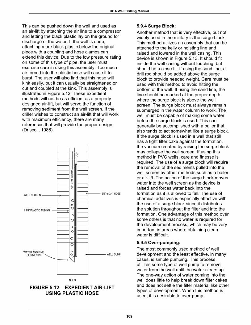
HCA Well Drilling Manual
This can be pushed down the well and used as an air-lift by attaching the air line to a compressor and letting the black plastic lay on the ground for discharge of the water. If the well is deep, attaching more black plastic below the original piece with a coupling and hose clamps can extend this device. Due to the low pressure rating on some of this type of pipe, the user must exercise care in using this assembly. Too much air forced into the plastic hose will cause it to burst. The user will also find that this hose will kink easily, but it can usually be straightened or cut and coupled at the kink. This assembly is illustrated in Figure 5.12. These expedient methods will not be as efficient as a properly designed air-lift, but will serve the function of removing sediment from the well screen. If the driller wishes to construct an air-lift that will work with maximum efficiency, there are many references that will provide the proper design (Driscoll, 1986).
FIGURE 5.12 – EXPEDIENT AIR-LIFT USING PLASTIC HOSE
5.9.4 Surge Block: Another method that is very effective, but not widely used in the military is the surge block. This method utilizes an assembly that can be attached to the kelly or hoisting line and raised and lowered in the well casing. This device is shown in Figure 5.13. It should fit inside the well casing without touching, but should be a close fit. If using the sand line, a drill rod should be added above the surge block to provide needed weight. Care must be used with this method to avoid hitting the bottom of the well. If using the sand line, the line should be marked at the proper depth where the surge block is above the well screen. The surge block must always remain submerged in the water column to work. The well must be capable of making some water before the surge block is used. This can generally be accomplished with a bailer that also tends to act somewhat like a surge block. If the surge block is used in a well that still has a tight filter cake against the formation, the vacuum created by raising the surge block may collapse the well screen. If using this method in PVC wells, care and finesse is required. The use of a surge block will require the removal of the sediments pulled into the well screen by other methods such as a bailer or air-lift. The action of the surge block moves water into the well screen as the device is raised and forces water back into the formation as it is allowed to fall. The use of chemical additives is especially effective with the use of a surge block since it distributes the solution throughout the filter and into the formation. One advantage of this method over some others is that no water is required for the development process, which may be very important in areas where obtaining clean water is difficult.
5.9.5 Over-pumping: The most commonly used method of well development and the least effective, in many cases, is simple pumping. This process utilizes some type of well pump to remove water from the well until the water clears up. The one-way action of water coming into the well does little to help break down filter cakes and does not settle the filter material like other types of development. When this method is used, it is desirable to over-pump
109

HCA Well Drilling Manual
NOTES _______________________________________________________________________________
_______________________________________________________________________________
_______________________________________________________________________________
_______________________________________________________________________________
_______________________________________________________________________________
_______________________________________________________________________________
_______________________________________________________________________________
_______________________________________________________________________________
_______________________________________________________________________________
_______________________________________________________________________________
_______________________________________________________________________________
110

HCA Well Drilling Manual
the well to create higher entrance velocities. This will require a well pump that can remove from 25 to 50% more water than the well is designed for. The reasoning for this is that, if the well will produce clean water at the higher yields, the final lower yield will never produce sand or turbid water. A practice that should never be allowed in a civic assistance well is to use the permanent well pump for well development. By allowing this, the life of the pump is shortened so severely that the useful life may be only several weeks. Quite simply, there is no excuse for allowing this to happen. As long as a well is producing sand in appreciable quantities (> 5 ppm) other means of well development must be used. The use of pumps can be allowed as long as they are temporary pumps provided solely for this purpose, and will not be left in the well.
FIGURE 5.13 – SURGE BLOCK
Sand or other grit in the water of an under-developed well will get into pump bearings, and in some cases, may erode away part of
the impellers of the pump. In either case, the recipients of the well will be given a defective product. 5.9.6 Completion of Well Development: The time estimate for well development is by far the hardest item to define. There are many factors that will influence well development. The driller must consider:
1) Type and length of well screen; 2) Thickness of the filter pack; 3) Gradation of the formation; 4) Method used for development; 5) Criteria used for being complete; 6) Type of drilling fluid.
The typical well development will vary from several hours to several days. There are few wells that can be developed to any degree in one or two hours, yet some drillers will not allow more time than this for the entire process. It should always be remembered that a well will generally remain in the condition that it is left. If drill rigs were readily available in an area, chances are the U. S. Military would not have a mission there. There is a point where the method of well development can be modified in such a manner that the drill rig can leave the site for another location. This should only be allowed after the well has been initially developed using normal methods, the well has started making water, and the sand content of the water produced has dropped sharply. This may require one or two days of development time. A final sediment removal process should be used to clean the fines accumulated in the bottom of the well screen or sediment trap. The tools used for development should be removed and the following procedure used. The drop pipe for the permanent pump installation should be used to set a string of pipe to the bottom of the well casing or as deep as practical. This pipe should be secured firmly at the top of the well casing using a casing clamp or similar means. Fittings should be attached to the top of the well casing so a small air compressor can be attached to the drop pipe. The depth of the bottom of the pipe below the water level
111

HCA Well Drilling Manual
NOTES _______________________________________________________________________________
_______________________________________________________________________________
_______________________________________________________________________________
_______________________________________________________________________________
_______________________________________________________________________________
_______________________________________________________________________________
_______________________________________________________________________________
_______________________________________________________________________________
_______________________________________________________________________________
_______________________________________________________________________________
_______________________________________________________________________________
112

HCA Well Drilling Manual
should not exceed the ability of the air compressor to displace the head of the water in the well. This can be computed using Equation 5.10. A small portable air compressor such as a 125 cfm that can be towed behind a pickup or similar vehicle is ideal for this operation. Leaving one person to continue development, the rig and the remainder of the crew can leave for the next well site. The person left to finish the development can simply pump the well with the air using the well casing as the eductor pipe. This is accomplished using short bursts of air followed by recovery in the well or, if the well is producing ample amounts of water, long periods of continuous pumping is permissible. This person can make the determination of when the well development is complete. All that is required, at this point, is to unhook the air compressor from the pipe, remove the fittings, and proceed to the next well site. Using this procedure, several days are available for complete well development without affecting additional drilling. The drilling detachment must schedule pump installation and testing for all the wells at the end of the exercise when using this method. As the drill crew returns to the site, the drop pipe is pulled, the pump attached, and the pump assembly installed. This is not hard to program since the pump installation and testing are well-defined and few problems should be encountered. Determination of the time when well development is complete can only be done using a direct observation of the water produced. Using a sand-free or "finished criteria" of 5 ppm sand in water with no turbidity should generally be set as the goal. The sand content can be determined by general observation or direct measurement using water discharged during the development. A rather simple way to do this is with a visual aid made before leaving on the drilling mission. Using a precision laboratory scale and a small quantity of fine sand, weigh out 94.7 milligrams of the sand. This can be placed in a small glass vial and carried along on the drilling mission. This will represent the maximum amount of sand that will be allowed in a 5-gallon sample of the water from the well. It is a simple matter to catch a bucket of water in a plastic 5-gallon bucket, let it settle
for a few minutes, then carefully pour off the water, keeping the sand that collects in the bottom. If the sand in the bucket is more than the sample in the vial, development is not complete. When a well does not respond to development and the sand content remains high after several days, the well may never be sand-free. This condition should be reported and a decision made as to further use of the well. The well may be salvaged, but it may be better-suited for alternate means of pumping than originally designed. There are certain types of pumps available that are not affected by sand content, however the life of the well will be shortened by sand filling the well screen and lowering its specific capacity. Another method may be to limit the volume of water produced from the well since there may be a point where the well does not produce sand in the water. A well should not be turned over to a community if it will only create problems for them. If the community is unaware of a problem with a well, it may spend precious resources to build tanks, distribution systems, and to bring power to the well. Sand in the water will quickly wear out the pump leaving the community without a usable well. Sand can also clog water lines and ruin plumbing fixtures. It is a better decision to realize and solve problems than to just pack up and leave a site. Even limiting the well to a hand pump will provide water to a limited number of people for a long time. Sand pumping wells can often be salvaged with a remedial design that could be accomplished in a future mission, but only if this condition is reported.
5.10 PUMP INSTALLATION Only after the well is thoroughly developed should the permanent pump be installed. The type of pump may depend on the wishes of the host nation, but will generally be a submersible electric pump or a hand pump. The installation of the pump should be performed only after sterilization of all components as described in Chapter 5.3. The pump selected for the well was assumed to meet certain criteria. If the well does not meet these expectations, the pump may not operate efficiently. In some cases, this can lead to a shortened pump life.
113

HCA Well Drilling Manual
NOTES _______________________________________________________________________________
_______________________________________________________________________________
_______________________________________________________________________________
_______________________________________________________________________________
_______________________________________________________________________________
_______________________________________________________________________________
_______________________________________________________________________________
_______________________________________________________________________________
_______________________________________________________________________________
_______________________________________________________________________________
_______________________________________________________________________________
114
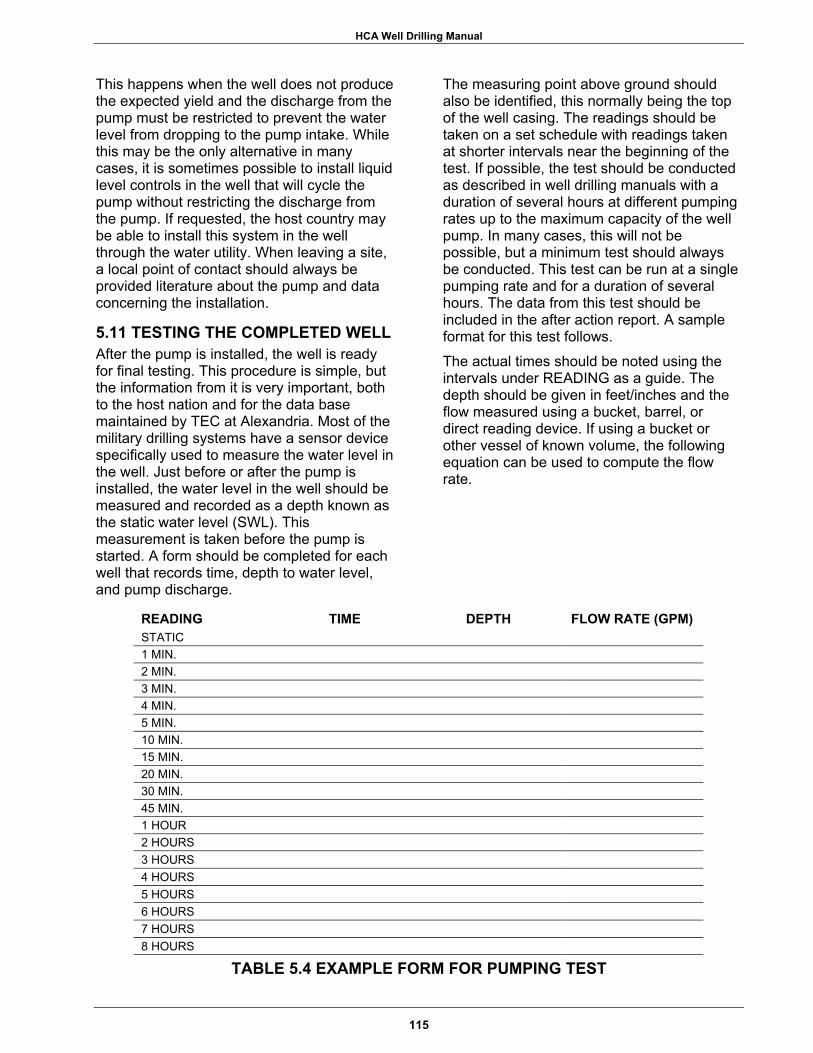
HCA Well Drilling Manual
This happens when the well does not produce the expected yield and the discharge from the pump must be restricted to prevent the water level from dropping to the pump intake. While this may be the only alternative in many cases, it is sometimes possible to install liquid level controls in the well that will cycle the pump without restricting the discharge from the pump. If requested, the host country may be able to install this system in the well through the water utility. When leaving a site, a local point of contact should always be provided literature about the pump and data concerning the installation.
5.11 TESTING THE COMPLETED WELL After the pump is installed, the well is ready for final testing. This procedure is simple, but the information from it is very important, both to the host nation and for the data base maintained by TEC at Alexandria. Most of the military drilling systems have a sensor device specifically used to measure the water level in the well. Just before or after the pump is installed, the water level in the well should be measured and recorded as a depth known as the static water level (SWL). This measurement is taken before the pump is started. A form should be completed for each well that records time, depth to water level, and pump discharge.
The measuring point above ground should also be identified, this normally being the top of the well casing. The readings should be taken on a set schedule with readings taken at shorter intervals near the beginning of the test. If possible, the test should be conducted as described in well drilling manuals with a duration of several hours at different pumping rates up to the maximum capacity of the well pump. In many cases, this will not be possible, but a minimum test should always be conducted. This test can be run at a single pumping rate and for a duration of several hours. The data from this test should be included in the after action report. A sample format for this test follows. The actual times should be noted using the intervals under READING as a guide. The depth should be given in feet/inches and the flow measured using a bucket, barrel, or direct reading device. If using a bucket or other vessel of known volume, the following equation can be used to compute the flow rate.
READING TIME DEPTH FLOW RATE (GPM) STATIC 1 MIN. 2 MIN. 3 MIN. 4 MIN. 5 MIN. 10 MIN. 15 MIN. 20 MIN. 30 MIN. 45 MIN. 1 HOUR 2 HOURS 3 HOURS 4 HOURS 5 HOURS 6 HOURS 7 HOURS 8 HOURS
TABLE 5.4 EXAMPLE FORM FOR PUMPING TEST
115
HCA Well Drilling Manual
Equation 5.14
Q = V / ( T / 6 0 )
where, Q = flow in gpm V = volume of vessel in gallons T = time in seconds to fill vessel
(Other methods of measuring flows are shown in Appendix C.) After the depth readings stabilize for two hours, the test can be terminated. When the water level stabilizes, the pump should be set at least 30 feet below the deepest water level measured. Occasionally, this depth of submergence would require that the pump be set below the top of the well screen. In this case, the pump discharge should be restricted to a flow where the pump can be set above the top of the well screen. Failure to maintain a good submergence with the pump may allow the water level to drop to the pump intake during seasonal fluctuations of the water level in the aquifer. When samples are to be taken for chemical and bacterial analysis, the pumping test is the ideal time. A simple test should even be performed on a well that will only be supplied with a hand pump. This type of well will typically be constructed with a 4-inch casing which may accommodate the installation of a small submersible pump at a later date. The local water authority would need test data to be able to purchase the proper pump. This test can be conducted using a small air-lift device or even the hand pump. The discharge from the air-lift can be captured in a bucket or barrel and the same procedures used as in a normal pumping test. When using the hand pump, the test can be shortened to 30 minutes. Several persons may be needed to maintain a constant pumping rate for this length of time.
116

HCA Well Drilling Manual
SECTION SIX
OTHER CONSIDERATIONS
EXECUTIVE SUMMARY
In prior sections of this manual, most aspects of picking a well site, selection of the well design that conforms to the geologic conditions, selection of a proper well construction materials, and some on-site well construction practices have been covered. A few topics remain that apply to every well drilling mission. Each branch of the military has a somewhat different philosophy concerning well drilling, and likewise, the driller's role varies from service to service. To be proficient, the military driller must be a hands-on person. Their interest in the subject must expand well beyond what is taught for completion of a tactical well. Only through practice and continuing education can the military driller ever become an expert well driller. The driller must research each HCA mission before deployment in order to anticipate drilling problems that may be
encountered. The driller must also know his equipment and be able to maintain it and make minor repairs as needed. The driller should ensure that all data concerning the well construction is documented and this information is forwarded to WDRT for the well database. As wells are completed, the driller should take into account the potential problems associated with placing too many wells in a small area. Though this can be a complex problem, experts are available through TAC to assist. The final concern after a well is complete is the quality of the water that is being produced. The water from a HCA well probably will not receive treatment, so the well must be free of bacteria and the chemical quality must be within specified guidelines. A well that will cause health problems for the consumers is not beneficial and could create liability problems.
117

HCA Well Drilling Manual
NOTES
_______________________________________________________________________________
_______________________________________________________________________________
_______________________________________________________________________________
_______________________________________________________________________________
_______________________________________________________________________________
_______________________________________________________________________________
_______________________________________________________________________________
_______________________________________________________________________________
_______________________________________________________________________________
_______________________________________________________________________________
_______________________________________________________________________________
118
HCA Well Drilling Manual
6.1 THE ROLE OF THE DRILLER The military driller has a disadvantage built into his occupation that most other military personnel do not have.
1) This task normally is assigned to a heavy equipment operator who must establish and maintain this proficiency, in addition to other duties.
2) Formal training is very limited and normally consists of a two-week class.
3) Training is focused on completion of a tactical well, which is quite different from a HCA well.
In the private sector, a driller is trained for years with a drill crew before assuming duties as a driller. It is this on-the-job training where tricks-of-the-trade and "short cuts" are picked up. The person that is designated as the driller for a crew has the ultimate responsibility for the performance of the crew. The driller should be responsible for ensuring that the well is drilled as designed, a safe work place is maintained for the crew, problems are reported, and answers obtained. The driller should be the best-trained person in the crew and should always be available at the rig while drilling is taking place. The driller should act as the driller and not as a site supervisor. While others in the crew are receiving training in operation of the drill rig, the driller should always be standing alongside the trainee to provide assistance, as needed. The driller should maintain his or her own log book with depths, drilling fluid properties, and any problems encountered and the depths at which they occurred. This requires only a small notebook kept in the pocket. A more comprehensive log can be maintained by another crew member, if so desired. Sample forms for this purpose from the Tri-Services "Well-Drilling Operations" (FM 5-484, NAVFAC P1065, AFP 85-23) are included in Appendix E. If this is done, the driller should periodically check with this person to ensure depths are in agreement. Each sample should be taken at the direction of the driller. If there is ever a disagreement concerning depths, it
should be resolved immediately. Well drilling machines are rugged pieces of equipment, but they do require preventative maintenance (PM) to remain operational. The driller must ensure that the PM is performed. Since there are sequences of drilling that should not be interrupted, the driller should pull PM as opportunities arise, but before the shutdown is required. Quite often, HCA wells will have specific designs that meet the requirements or desires of the host country. The driller should always contact the well designer and review the mission before the procurement of the supplies and mobilization to the site. There should be a complete understanding of the goals of the mission and a line of communica-tion set up to handle problems that may arise. If the driller has a lack of experience in any of the tasks involved in the well completion, this should also be discussed with the designer. Training or demonstrations can be scheduled to accommodate the driller, but this request must be conveyed to the well designer. In some cases, the well designer may want to have a pre-deployment conference with the driller, his NCOIC and the OIC for the mission. Each drilling detachment should also establish and maintain a library on water well drilling. There are a vast number of reference books that have been published and are available through catalogs, ads in magazines, and professional organizations. Other important references are product catalogs. These may include literature on well casing, well screen, drilling fluids, grouting products, pumps, and general drilling supplies. The latest product information should be requested each time an order is made with a supplier. Some manufacturers have periodic newsletters that are available at no cost upon request.
6.2 WELL DATA Each time a well is completed, a valuable collection of hydrogeologic data becomes available. It should be the responsibility of the driller to see that the OIC obtains an accurate and complete description of the conditions encountered at each well. This well completion data should include, but is not
119

HCA Well Drilling Manual
NOTES
_______________________________________________________________________________
_______________________________________________________________________________
_______________________________________________________________________________
_______________________________________________________________________________
_______________________________________________________________________________
_______________________________________________________________________________
_______________________________________________________________________________
_______________________________________________________________________________
_______________________________________________________________________________
_______________________________________________________________________________
_______________________________________________________________________________
120
HCA Well Drilling Manual
limited to, the following: • Well title; • Start and completion dates; • Location (6-digit coordinate); • Surface elevation; • Well depth; • Static water level; • Drilling machine used; • Drilling method; • Description of formations; • Geophysical logs; • Hole sizes; • Casing sizes and lengths; • Well screen sizes & lengths; • Type of casing; • Type and slot size of screen; • Gradation of 'gravel-pack/filter
material’; • Depths of 'gravel-pack/filter material'; • Depths of grouting; • Duration & type of development; • Type of pump; • Depth of pump in well; • Pumping test data; • Type of sterilization.
A standard well completion form taken from the Tri-Services "Well-Drilling Operations" should be used to assemble this information. A copy of this form is included in Appendix E. A form can be obtained from the well designer, TEC, or from the well drilling manual. Copies of all well completion forms should be forwarded to TEC for the database maintained there. The address is Director, Engineer Topographic Center, Attn: CEERD-TO-H, Alexandria, VA 22315-3864.
6.3 WELL AND PUMP MAINTENANCE Properly constructed HCA water wells should require very little maintenance. The well pump, depending on the type installed, will have a maintenance schedule. The drilling crew should provide literature on each pump installation to the recipient. Spare parts are not generally provided with the pump but, with
proper documents, parts can be obtained as needed.
6.4 AQUIFER STRESS Many aquifers do not have sufficient recharge to allow long term, continuous pumping. Recharge is defined as "the process of absorption and addition of water to the zone of saturation.” As an aquifer is losing water to a well, but is gaining water from recharge at the same rate, the system is in equilibrium. This stage has occurred when the drawdown in the well stabilizes during a constant withdrawal by pumping. The recharge may occur by direct infiltration from above in an unconfined condition or the groundwater may move laterally along a permeable zone from a remote recharge area. When there is no recharge occurring or the recharge to an area is less than the amount of water being removed, the drawdown in the well will continue without stabilization. With this condition, the drawdown will eventually reach the pump intake. To eliminate this possibility, the pump should only operate for a maximum of 16 hours each day. This figure should always be used when computing well yield requirements. Not pumping during the remaining eight hours will allow the local aquifer system to recharge and maintain water levels at the original static water level. For wells completed into a confined aquifer, the pump should always be placed no deeper than the top elevation of the aquifer. This will prevent the water level in the well from ever dropping below the top of the aquifer. When the water levels are allowed to drop below the top of the aquifer, consolidation may occur in the formation and this may lower the permeability. This type of aquifer stress can cause permanent damage to the aquifer and should always be avoided.
6.5 MULTIPLE WELL APPLICATIONS Some water supply designs may call for two or more wells to satisfy the required demand. Wells placed too close together may cause interference with each other from the combined drawdowns of the wells. Without a hydrogeologic study of the aquifer, the proper spacing of wells is difficult. While some aquifers can support two or more wells in a small area, as a general rule of thumb, wells
121

HCA Well Drilling Manual
NOTES
_______________________________________________________________________________
_______________________________________________________________________________
_______________________________________________________________________________
_______________________________________________________________________________
_______________________________________________________________________________
_______________________________________________________________________________
_______________________________________________________________________________
_______________________________________________________________________________
_______________________________________________________________________________
_______________________________________________________________________________
_______________________________________________________________________________
122

HCA Well Drilling Manual
should be spaced at least 100 meters apart. Even at this distance, there may be some overlap of the cones of depression that are created in the water levels of an aquifer. In an unconfined aquifer, the water level would be a true water surface (the water table) while in a confined system; the depression would be represented as a change in head known as the potentiometric surface. The interference from these cones of depression is cumulative at any point where they overlap. This condition is represented in Figure 6.1. Two wells should be drilled side by side only in special cases. Mainly, this would be done when one of the wells is designated as a backup well with only one well being pumped at a time. Unless space is unavailable, even this is not good practice since it may inhibit production from both wells, if both are needed.
6.6 WATER QUALITY STANDARDS The water quality of every well drilled by U. S. Forces for HCA purposes should be examined to ensure there are no health risks from drinking the water. In many cases, the chemical quality of the water may be known in advance through data obtained during the advance reconnaissance for the mission or hydrogeologic data from TEC. Bacteria content of the water should always be tested at the completion of every well. A chemical analysis, when required, should be complete enough to test for primary drinking water standards. Most wells drilled for HCA missions should use water quality standards set forth by the World Health Organization (WHO). Many countries will have an agency that is responsible for potable water systems that can test the water. These agencies will often take the samples and have them analyzed at no cost to the task force. When the drilling detachment is responsible for taking the samples, the laboratory performing the tests should be contacted before the mission. They can provide
FIGURE 6.1 – EXAMPLE OF WELL INTERFERENCE
123

HCA Well Drilling Manual
NOTES
_______________________________________________________________________________
_______________________________________________________________________________
_______________________________________________________________________________
_______________________________________________________________________________
_______________________________________________________________________________
_______________________________________________________________________________
_______________________________________________________________________________
_______________________________________________________________________________
_______________________________________________________________________________
_______________________________________________________________________________
_______________________________________________________________________________
124
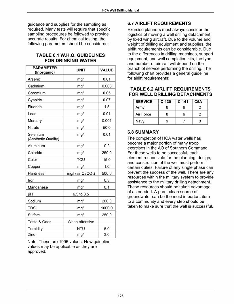
HCA Well Drilling Manual
guidance and supplies for the sampling as required. Many tests will require that specific sampling procedures be followed to provide accurate results. For chemical testing, the following parameters should be considered:
TABLE 6.1 W.H.O. GUIDELINES
FOR DRINKING WATER PARAMETER
(Inorganic) UNIT VALUE
Arsenic mg/l 0.01
Cadmium mg/l 0.003
Chromium mg/l 0.05
Cyanide mg/l 0.07
Fluoride mg/l 1.5
Lead mg/l 0.01
Mercury mg/l 0.001
Nitrate mg/l 50.0
Selenium (Aesthetic Quality)
mg/l 0.01
Aluminum mg/l 0.2
Chloride mg/l 250.0
Color TCU 15.0
Copper mg/l 1.0
Hardness mg/l (as CaCO3) 500.0
Iron mg/l 0.3
Manganese mg/l 0.1
pH 6.5 to 8.5
Sodium mg/l 200.0
TDS mg/l 1000.0
Sulfate mg/l 250.0
Taste & Odor When offensive
Turbidity NTU 5.0 Zinc mg/l 3.0
Note: These are 1996 values. New guideline values may be applicable as they are approved.
6.7 AIRLIFT REQUIREMENTS Exercise planners must always consider the logistics of moving a well drilling detachment by fixed wing aircraft. Due to the volume and weight of drilling equipment and supplies, the airlift requirements can be considerable. Due to the differences in drilling machines, support equipment, and well completion kits, the type and number of aircraft will depend on the branch of service performing the drilling. The following chart provides a general guideline for airlift requirements:
TABLE 6.2 AIRLIFT REQUIREMENTS FOR WELL DRILLING DETACHMENTS
SERVICE C-130 C-141 C5A Army 8 6 2
Air Force 8 6 2
Navy 9 7 3
6.8 SUMMARY The completion of HCA water wells has become a major portion of many troop exercises in the AO of Southern Command. For these wells to be successful, each element responsible for the planning, design, and construction of the well must perform certain duties. Failure of any single phase can prevent the success of the well. There are any resources within the military system to provide assistance to the military drilling detachment. These resources should be taken advantage of as needed. A pure, clean source of groundwater can be the most important item to a community and every step should be taken to make sure that the well is successful.
125

HCA Well Drilling Manual
NOTES
_______________________________________________________________________________
_______________________________________________________________________________
_______________________________________________________________________________
_______________________________________________________________________________
_______________________________________________________________________________
_______________________________________________________________________________
_______________________________________________________________________________
_______________________________________________________________________________
_______________________________________________________________________________
_______________________________________________________________________________
_______________________________________________________________________________
126

APPENDIX A Standard Well Specifications

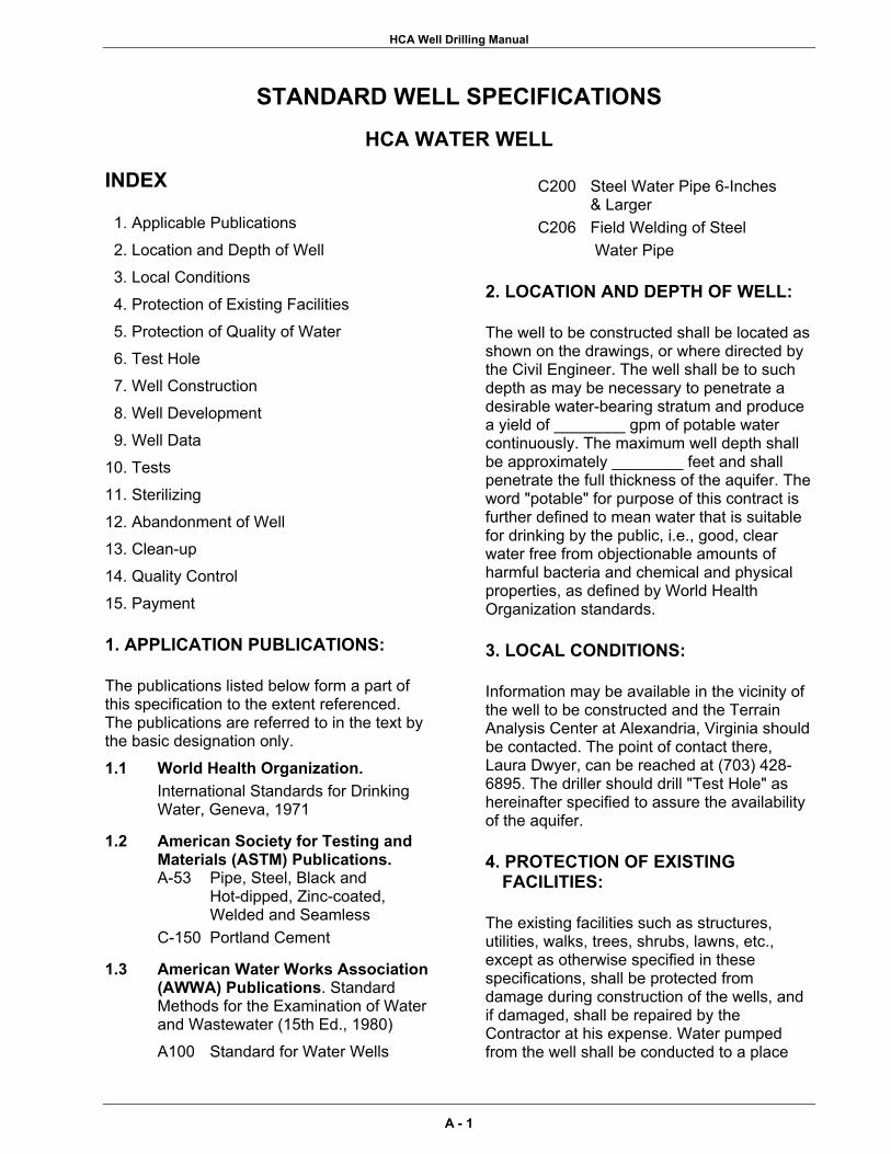
HCA Well Drilling Manual
STANDARD WELL SPECIFICATIONS
HCA WATER WELL
INDEX
1. Applicable Publications 2. Location and Depth of Well 3. Local Conditions 4. Protection of Existing Facilities 5. Protection of Quality of Water 6. Test Hole 7. Well Construction 8. Well Development 9. Well Data 10. Tests 11. Sterilizing 12. Abandonment of Well 13. Clean-up 14. Quality Control 15. Payment
1. APPLICATION PUBLICATIONS:
The publications listed below form a part of this specification to the extent referenced. The publications are referred to in the text by the basic designation only.
1.1 World Health Organization. International Standards for Drinking Water, Geneva, 1971
1.2 American Society for Testing and Materials (ASTM) Publications. A-53 Pipe, Steel, Black and Hot-dipped, Zinc-coated, Welded and Seamless C-150 Portland Cement
1.3 American Water Works Association (AWWA) Publications. Standard Methods for the Examination of Water and Wastewater (15th Ed., 1980) A100 Standard for Water Wells
C200 Steel Water Pipe 6-Inches & Larger C206 Field Welding of Steel Water Pipe
2. LOCATION AND DEPTH OF WELL:
The well to be constructed shall be located as shown on the drawings, or where directed by the Civil Engineer. The well shall be to such depth as may be necessary to penetrate a desirable water-bearing stratum and produce a yield of ________ gpm of potable water continuously. The maximum well depth shall be approximately ________ feet and shall penetrate the full thickness of the aquifer. The word "potable" for purpose of this contract is further defined to mean water that is suitable for drinking by the public, i.e., good, clear water free from objectionable amounts of harmful bacteria and chemical and physical properties, as defined by World Health Organization standards.
3. LOCAL CONDITIONS:
Information may be available in the vicinity of the well to be constructed and the Terrain Analysis Center at Alexandria, Virginia should be contacted. The point of contact there, Laura Dwyer, can be reached at (703) 428-6895. The driller should drill "Test Hole" as hereinafter specified to assure the availability of the aquifer.
4. PROTECTION OF EXISTING FACILITIES:
The existing facilities such as structures, utilities, walks, trees, shrubs, lawns, etc., except as otherwise specified in these specifications, shall be protected from damage during construction of the wells, and if damaged, shall be repaired by the Contractor at his expense. Water pumped from the well shall be conducted to a place
A - 1
HCA Well Drilling Manual
where it will be possible to dispose of the water without damage to property or the creation of a nuisance.
5. PROTECTION OF QUALITY OF WATER:
The Driller shall take precautions as necessary or as may be required to permanently prevent contaminated water or water having undesirable physical or chemical characteristics from entering the stratum from which the well is to draw it's supply. The Driller also shall take all necessary precautions during construction to prevent contaminated water, gasoline or other contaminated materials from entering the well either through the opening or by seepage through the ground surface. The Driller shall exercise extreme care in performance of his work in order to prevent the breakdown or caving of the strata overlying that from which the water is to be drawn. The Driller shall develop, pump or bail the well by accepted methods until the water pumped from the well shall be substantially free from sand (< 5.0 mg/l) and until the water is clear. After completion of the well, unless the permanent pump is immediately installed, the Contractor shall cap the well to prevent contamination of the well.
6. TEST HOLE:
Before starting construction of the permanent well, a test hole of at least 6-inches in diameter and ________ feet deep shall be drilled at the location of the well into the water-bearing stratum. The test hole shall be used to determine the location of the water-bearing strata, the character of the water-bearing strata and to obtain samples of the various formations. Samples shall be taken at every change of strata and at depth intervals not to exceed 10 feet. A driller's log shall be made based on the ‘cuttings’ obtained. If available, the test hole shall also be used to obtain geophysical logs to include resistivity, spontaneous potential and natural gamma for the full depth of the hole. The final selection of the screen settings, the proper filter material, and the depth of grouting will be finalized with the driller and the OIC. The drill ‘cuttings’ shall
be divided, put into suitable containers and labeled. These samples shall be approximately one pint each. If the test hole fails to indicate the presence of water-bearing strata or is abandoned for any other reason, the test hole shall be grouted from the bottom to the top with cement grout as hereinafter specified and in a manner approved by the OIC.
7. WELL CONSTRUCTION:
7.1 GENERAL: Well construction shall conform to guidelines set by U.S. Southern Command's Operational Manual, HCA Well Drilling. The execution of the work shall be by a competent crew performed under the direct supervision of an experienced well driller acceptable to the OIC. The well shall be drilled essentially straight, plumb and circular from top to bottom. The type of well construction, as determined by the test hole, shall be either an artificially gravel-packed well, a naturally developed well or a rock wall well. The well shall be constructed and developed to produce clear water with a minimum of drawdown. Wells not meeting the criteria for sand content, paragraph 10.2, will not be acceptable. 7.2 SURFACE CASING: Surface casing shall be used on all wells. This casing may be left in place or removed at the option of the driller. If the surface casing is to be left in place, the surface casing shall be grouted into place for the full length of the casing. 7.3 WELL CASING: The well casing shall be of the size hereinafter specified and be constructed either of black steel or, if allowed, PVC plastic. Only standard weight black steel pipe shall be used as casing for wells over 600 feet deep and it shall conform to ASTM A-53 steel pipe conforming to AWWA Specification C-200, as applicable. PVC casing may be used if depths are less than 600 feet. The resistance to collapse of all PVC casing shall be considered in the selection of this material and the appropriate wall thickness shall be used. Steel casing may be provided with drive shoes at the option of the driller. Driving of PVC casing will not be allowed. All casing used in the permanent well shall be new and unused.
A - 2

HCA Well Drilling Manual
Sufficient casing centralizers shall be used to keep casings centered in the hole. 7.4 CEMENTING WELL CASING: The annular space between the well casing and the walls of the hole shall be filled with cement grout as hereinafter specified. The grout shall be proportioned of Portland cement conforming to ASTM Specification C-150, Type I or II and the minimum quantity of water (not over 6 gallons per 94 pound sack of cement) required to give a mixture of such consistency that it can be forced through the grout pipes. Before placing the grout, the driller shall (consult with) (submit to) the OIC for approval; 1) the method of placing the grout; 2) the method of mixing the grout; and 3) the equipment to be used during placement. Acceptable methods of grouting are detailed in Appendix B, AWWA Specification A-100. No method will be approved that does not specify the forcing of the grout from the bottom of the space to be grouted towards the surface. The grouting shall be done continuously and in a manner that will insure the entire filling of the annular space in one operation. No drilling operations or other work in the wells will be permitted within 24 hours after the grouting operation to allow the grout to properly set. Up to 5% bentonite may be added to the mixture to reduce shrinkage of the grout. 7.5 WELL SCREEN: The well screen and attached fittings shall be constructed entirely of corrosion-resistant Type 304 stainless steel or, if allowed, PVC plastic. The preferred type is continuous slot, wire-wound design. Slotted casing may be used in lower yielding wells. The diameter of the screen be _____ inches minimum inside diameter. The minimum screen length shall be _____ feet and the screen shall have a minimum open inlet area of ____% of the screen surface. Specifications of the well screen shall be submitted to the site OIC for approval prior to installation. In a naturally developed well, the slot size of the screen will be based on a mechanical size analysis of the natural water-bearing sediments. In a gravel-packed application, the well screen shall have a slot size based on the gradation of the filter material which in-turn is based on a mechanical size analysis of the natural water-bearing sediments. Guidelines as described in
Section 5.4, AWWA Specification A-100, should be followed when selecting the slot size for the screen. The well screen shall be directly connected to the top of the inner casing. The bottom of the screen shall be sealed with a positive closure. A wash-down shoe may be used if desired. The screen used in a gravel-packed well shall be carefully lowered into the water-bearing strata and be centered in the hole using basket type centering devices not more than 30 feet apart. The well screen and all accessories required for satisfactory installation shall be essentially standard products of reliable manufacturers regularly engaged in the production of such equipment. Field welding of screen components shall be accomplished using products made to weld such products together in a reliable manner.
7.6 NATURALLY DEVELOPED WELL: 7.6.1 GENERAL: After setting the surface casing, a naturally developed well shall be initially drilled by reaming the test hole from the ground surface to the lower level of the water-bearing strata. The well casing and screen shall not be less than ________ inches in diameter. The hole shall be of sufficient size to leave a concentric annular space of not less than 2-inches between the outside of the casing and the walls of the hole. This space around the casing shall be filled with cement grout to a depth of _______ feet as hereinbefore specified. After grouting is completed, drilling operations shall not be resumed for at least 24 hours to allow proper setting of the grout. After the grout has set, the well shall be developed as hereinafter specified.
7.7 GRAVEL-PACKED WELL: 7.7.1 GENERAL: After setting the surface casing, a gravel-packed well shall be initially drilled by reaming the test hole from the ground surface to the lower-most level of the water-bearing strata. The casing and screen shall be as hereinbefore specified and shall be not less than ________ inches in diameter. The hole shall be of sufficient size to leave a concentric annular space of not less than 2-inches between the outside of the screen and casing and the walls of the hole. The space around the screen shall be filled with filter material as hereinafter specified.
A - 3

HCA Well Drilling Manual
The well casing shall be grouted in with cement grout as hereinafter specified. After grouting is completed, drilling operations shall not be resumed for at least 24 hours to allow proper setting of the grout. The hole below the outer casing shall penetrate the water-bearing strata a sufficient depth to install the well screen and produce the required yield without causing excessive velocities through the aquifer. The casing shall be connected directly to the top of the well screen and extend up to one foot above the ground surface. 7.7.2 GRAVEL-PACK: After the screen and casing have been installed, a filter pack shall be constructed around the screen by filling the entire space between the screen and the walls of the hole with filter material (sand). The filter sand shall have a wall thickness of ________ inches, measured from the outer edge of the screen to the wall of the hole. ‘Gravel-pack’ material shall be a properly sized, graded and well-rounded natural sand suitable for the strata encountered. The sand shall be of such size as will allow the maximum flow of water into the well and prevent the infiltration of formation sand. It shall be washed siliceous material, reasonably smooth and round and free of flat or elongated pieces as well as dirt, vegetable matter or other foreign matter. The sand shall be thoroughly sterilized with 100 ppm chlorine or hypochlorite solution immediately before being placed. The Driller shall demonstrate to the site OIC that the filter material is suitable for the conditions prior to placement. Unless processed filter material is purchased for the well construction, the Driller shall process the filter material by washing, screening, or blending to obtain the proper gradation. In no case will improperly sized filter material be added around the screen.
7.7.3 PIPE OR CONDUCTOR FOR GRAVEL PLACEMENT: If possible, a pipe or conductor having an inside nominal diameter of not less than 1-inch shall be lowered to the bottom of the well between the drilled hole and the screen. It shall be so arranged and connected at the surface of the ground to water pumping and graveling equipment so that water and gravel, fed at uniform rates, are discharged through it as the gravel fills the hole from the bottom up. The gravel and water conductor
shall be raised at the rate that will keep the bottom of the pipe approximately at the gravel level. 7.8 ROCK WELL: A rock well shall be initially drilled from the ground surface to a point at least 5 feet below the top of consolidated material, (bedrock), but not less than 30 feet below ground surface and the bottom of the casing set at this bottom elevation. The finished internal diameter of the casing shall be not less than ______ inches, and the hole shall be drilled to a sufficient diameter so as to leave a concentric annular space not less than 1 1/2-inches between the casing and the walls of the hole. A temporary casing may be used to prevent caving of the hole walls, but the temporary casing must be removed when the grouting of the permanent casing is performed. This space shall be filled with cement grout in a manner as hereinbefore specified. After the grouting is completed, drilling operations shall not be resumed for at least 24 hours to allow proper setting of the grout. Drilling into the water-bearing rock strata shall be resumed after the grout has set. A hole at least 6 1/2-inches in diameter, concentric with the casing above, shall be drilled into the water-bearing rock a sufficient depth to produce the required amount of water without causing excessive velocities of the water through the rock.
8. WELL DEVELOPMENT:
After completion, the well shall be thoroughly developed. The developing equipment shall be of sufficient capacity to remove all drilling fluids, sand, rock ‘cuttings’ or any other foreign matter. The wells shall be thoroughly cleaned from top to bottom before beginning the well tests. The recommended type of development is hydro-jetting; however surge blocks, air-development or other development techniques are permissible at the option of the Contractor. A sample procedure for use of a hydro-jet tool is described in the book "Groundwater and Wells" by Johnson Division, UOP.
A - 4

HCA Well Drilling Manual
9. WELL DATA:
After completion of the permanent well, all data pertaining to the construction of the well shall be shown on the attached Military Water Well Completion Summary Report. Attached to the data sheet shall be results of all TESTS as hereinafter specified.
10. TESTS:
10.1 TEST FOR QUALITY OF WATER: During the yield and drawdown test in the permanent well, the site OIC shall schedule to obtain samples of the water in suitable containers and of sufficient quantity to have bacterial, physical and chemical analyses made by a recognized testing laboratory. Water quality analyses shall address each item specified in Table A-1.
TABLE A - 1 WATER QUALITY ANALYSIS
PHYSICAL AS TESTED MAXIMUM
ALLOWABLE CONTENT Color 15 color units Taste when offensive Threshold odor no. when offensive Turbidity 5 NTU Resistivity, @ 25 º C pH Temperature Corrosivity
CHEMICAL (as mg/l) Arsenic 0.01 Barium 0.7 Cadmium 0.003 Chloride 250.0 Chromium 0.05 Copper 1.0 Fluoride 1.5 Foaming Agents 0.5 Iron 0.3 Lead 0.01 Manganese 0.01 Mercury 0.001 Nitrate 50.0 Selenium 0.01 Silver 0.05 Sodium 200.0 Sulfate 250.0 Total Dissolved Solids 1000.0
3.0 Zinc
A - 5
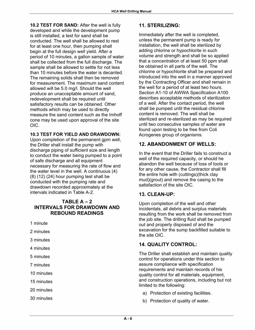
HCA Well Drilling Manual
10.2 TEST FOR SAND: After the well is fully developed and while the development pump is still installed, a test for sand shall be conducted. The well shall be allowed to rest for at least one hour, then pumping shall begin at the full design well yield. After a period of 10 minutes, a gallon sample of water shall be collected from the full discharge. The sample shall be allowed to settle for not less than 10 minutes before the water is decanted. The remaining solids shall then be removed for measurement. The maximum sand content allowed will be 5.0 mg/l. Should the well produce an unacceptable amount of sand, redevelopment shall be required until satisfactory results can be obtained. Other methods which may be used to directly measure the sand content such as the Imhoff cone may be used upon approval of the site OIC.
10.3 TEST FOR YIELD AND DRAWDOWN: Upon completion of the permanent gpm well, the Driller shall install the pump with discharge piping of sufficient size and length to conduct the water being pumped to a point of safe discharge and all equipment necessary for measuring the rate of flow and the water level in the well. A continuous (4) (8) (12) (24) hour pumping test shall be conducted with the pumping rate and drawdown recorded approximately at the intervals indicated in Table A-2.
TABLE A – 2 INTERVALS FOR DRAWDOWN AND
REBOUND READINGS
1 minute
2 minutes
3 minutes
4 minutes
5 minutes
7 minutes
10 minutes
15 minutes
20 minutes
30 minutes
11. STERILIZING:
Immediately after the well is completed, unless the permanent pump is ready for installation, the well shall be sterilized by adding chlorine or hypochlorite in such volume and strength and shall be so applied that a concentration of at least 50 ppm shall be obtained in all parts of the well. The chlorine or hypochlorite shall be prepared and introduced into the well in a manner approved by the Contracting Officer and shall remain in the well for a period of at least two hours. Section A1-10 of AWWA Specification A100 describes acceptable methods of sterilization of a well. After the contact period, the well shall be pumped until the residual chlorine content is removed. The well shall be sterilized and re-sterilized as may be required until two consecutive samples of water are found upon testing to be free from Coli Acrogenes group of organisms.
12. ABANDONMENT OF WELLS:
In the event that the Driller fails to construct a well of the required capacity, or should he abandon the well because of loss of tools or for any other cause, the Contractor shall fill the entire hole with (cuttings)(thick clay mud)(grout) and remove the casing to the satisfaction of the site OIC.
13. CLEAN-UP:
Upon completion of the well and other incidentals, all debris and surplus materials resulting from the work shall be removed from the job site. The drilling fluid shall be pumped out and properly disposed of and the excavation for the sump backfilled suitable to the site OIC.
14. QUALITY CONTROL:
The Driller shall establish and maintain quality control for operations under this section to assure compliance with specification requirements and maintain records of his quality control for all materials, equipment, and construction operations, including but not limited to the following:
a) Protection of existing facilities. b) Protection of quality of water.
A - 6
HCA Well Drilling Manual
c) Drilling, logging, and testing of test holes.
d) Drilling operations for well. e) Setting of casings, screens, and
grouting of casings. f) Placement of filter material if used. g) Well development. h) All testing of finished well. i) Well sterilization. j) Filling abandoned test hole or well if
required. A copy of these records and tests, as well as records of corrective action taken, shall be furnished to the Terrain Analysis Center, Topographic Engineering Center, Attn. CEERD-TO-H, Alexandria, VA, 22315-3864 and the Exercise Engineer.
A - 7


APPENDIX B Glossary


HCA Well Drilling Manual
GLOSSARY air-foam-gel technique Adding foamer to a fluid in the same proportions as clear water to get a richer, more stable foam. air-lift method A pumping test method that uses an air-lift pump. air-line method A procedure to measure the water level using an air line. The air line is copper tubing or galvanized pipe that is long enough to extend below the lowest water level being measured. air rotary drilling A well-drilling method that uses compressed air as the circulating fluid. alluvium Soils that are deposited by running water. Aquagel Commercial chemical agent added to mud drilling fluid to prevent it from freezing. See also barite; fibratex; gel-flake; impermex; micatex; smectite. aquiclude subsurface rock or soil unit, such as clay, shale, and unfractured igneous and metamorphic rock, that does not transmit water readily and cannot be used as a water-supply source. aquifer saturated rock or soil unit, such as gravel, sand, sandstone, limestone, and fractured igneous and metamorphic rock, that has sufficient hydraulic conductivity to supply water for a well or spring. aquitard A unit that retards or slows the passage of water. attapulgite Commercially processed clay used for drilling in brackish or salty water. augered well A well that is bored using hand or power-driven earth augers. AWWA American Water Works Association Barafos A white, granular sodium tetraphosphate thinner and dispersant added to drilling fluid to prevent mud from sticking to sand grains. barite Commercial chemical agent added to mud drilling fluid to prevent it from freezing. See also aquagel; fibertex; jel-flake; impermex; micatex; smectite. bentonite Commercially-processed clay used for drilling. Bentonite forms naturally from decomposition of volcanic ash, consists of aggregates of flat platelets, and contains sodium montmorillonite, which is important in building viscosity. BOM bill of materials cable-tool method A very slow drilling method that can be used to penetrate rocky soil or moderately hard sedimentary rock; the drill used in
this method does not require large amounts of drilling fluid. CB construction battalion cc cubic centimeter(s) centrifugal pump A variable displacement pump in which water flows by the centrifugal force transmitted to the pump in designed channels of a rotating impeller. CESAM U. S. Army Corps of Engineers, Mobile District cfm cubic feet per minute cfs cubic feet per second circular-orifice meter A device used to measure discharge rates. circular-orifice method A procedure to measure discharge rates using a circular-orifice meter. closed-well method A compressed-air method that involves using compressed air to close the top of the well with a cap and by arranging the equipment so air pressure can build up inside the casing to force water out through the screen openings. cm cubic meter(s) confined aquifer An aquifer that is completely filled with water and is overlaid by a confining bed. confining bed Aquiclude that exists between aquifers. consolidated deposit Rock that consists of mineral particles of different sizes and shapes. continuous-slot screen A screen with horizontal openings and one-piece welded construction containing no internal perforated pipe to restrict the intake area. Darcy's Law Principle Describes the flow of groundwater. discharge Water that moves from one area into another. dispersion treatment Adding dispersing agents to drilling fluid, backwashing, jetting water, or water standing in the well to counteract the tendency of mud to stick to sand grains.
DOD Department of Defense dolomite A carbonate rock that dissolves when carbon dioxide from the atmosphere and groundwater mix to form carbonic acid. DHH Pneumatic down-hole-hammer; air hammer. drawdown Measurement of how much the water level near the well is lowered when the well is pumped.
B - 1
HCA Well Drilling Manual
drilling blind A condition that exists when a driller continues to drill as fluid circulation is lost.
driven method Installing casing by cable-tool or driven-point well method. drive point Perforated pipe with a steel point at the lower end to break through pebbles or thin, hard layers. drive shoe Device attached to the lower end of the pipe to prevent the pipe from crumpling while being driven; a drive shoe is threaded to fit the pipe or casing. dump-bailer method Placing grout in a casing using a dump-bailer machine. electric-line method A procedure to measure the water level using an M-Scope. See also M-Scope. EPA Environmental Protection Agency
ERC Exercise-related construction
E-Z mud A synthetic, inorganic polymer.
filter cake Solids from the drilling mud deposited on the borehole wall as the water phase is lost into the formation. fish Portion of the drill string left in the borehole. See also fishing; string failure. fishing An attempt to retrieve the portion of the drill string left in the borehole. See also fish; string failure. float collar Device installed on casing above well screen that allows casing to be installed while full of air, reducing weight on the rig. float shoe Device installed on casing to aid in setting casing into drill hole, allows casing to remain full of air while setting, allows grouting through the casing using "Halliburton method.” foamer Substance used in air rotary drilling to enhance the air's ability to carry cuttings and reduce the velocity required to clean the borehole. formation stabilizer Material placed on the outside of the screen to help prevent deterioration of the annular space; using formation stabilizer is an alternative method to using gravel-pack material. fpm feet per minute ft foot(feet) ft/min feet per minute gal gallon(s) gel strength Thickness of drilling mud at rest. geologic structure Feature, such as a fold, fracture, joint, or fault, that disrupts the continuity of rock units. going crooked deviated borehole GPH gallons per hour
GPM gallons per minute gravel pack artificial sand filter; also known as filter material. gravity-outflow method A backwashing method that involves pouring water into the well rapidly to produce outflow through the screen openings. guide shoe Device installed on bottom of well casing to aid in guiding the casing down the hole. HN Host Nation for exercise hydraulic conductivity A measurement of the relative flow of water through subsurface material; the results of the measurement are related to the size and spacing of particles or grains in soils or to the number and size of fractures in rocks. hydraulic gradient Determines the direction of groundwater flow. hydrologic cycle The constant movement of water above, on, and below the earth's surface. ID inside diameter igneous rock Rock that forms when hot molten material (magma) cools or solidifies either inside the earth's crust or on the earth's surface (lava). See also lava; magma Imhoff cone a device used to estimate sediment concentration in small volumes of water. impermeable barriers Features (such as solid rock masses) through which groundwater cannot flow. in inch(es) inside-tremie method Placing grout in the bottom of the hole through a tremie pipe that is set inside the casing. jetted well A well that is dug using a high velocity stream of water. jetting method A backwashing method that involves using a jetting tool to remove caked drilling mud from the borehole wall; this method requires a large water supply. karst topography Results from the dissolution of carbonate rocks by groundwater and is characterized by cakes, sinkholes, closed depressions, and disappearing streams. lag time The time it takes sample material to reach the surface during a depth-determination test. limestone A carbonate rock that dissolves when carbon dioxide from the atmosphere and groundwater mix to form carbonic acid. LOG (logging) Position on the function switch on the electrical logging system. loss zone Area where drilling fluid grout is lost into the formation. lost circulation Volume loss of the drilling fluid returning to the surface.
B - 2

HCA Well Drilling Manual
m meter(s) marsh funnel Device used to test mud viscosity; the funnel is 12-inches long and 6-inches in diameter, having a No. 12 mesh strainer, a 1,500-ml cone, a 2-inch-long calibrated hard-rubber orifice (inside diameter of 3/16-inch), and a 1,000-ml capacity cup. Marsh-funnel test Procedure routinely conducted to determine the thickness or apparent viscosity of drilling fluid. metamorphic rock Igneous, sedimentary, or pre-existing metamorphic rock that undergoes further solid-state transformation by changes in pressure, temperature, or chemistry. min minute ml milliliter(s) M-Scope A two-conductor, battery-powered indicator used to measure water levels. mud pump A positive-displacement, double-acting piston pump with capacities ranging from one to several hundred GPM at pressures up to several hundred psi. mud rotary drilling A well-drilling method that uses mud to circulate the drilling fluid during the drilling process. OD outside diameter open-hole placement A method of installing gravel-pack material in a well. open-pipe method A procedure to measure discharge rates using a fully open pipe and measuring the distance the water stream travels parallel to the pipe at a 12-inch vertical drop. open-well method A compressed-air method that involves establishing the surging cycle by pumping from the well with an air-lift and by dropping the air pipe suddenly to cut off the pumping action.
outside-tremie method Placing grout outside the casing using a tremie pipe; this method is not recommended for depths greater than 100 feet. perched aquifer An aquifer that lies above an unconfined aquifer and is separated from the surrounding groundwater table by a confining layer. permeability The capacity of a porous rock or soil to transmit a fluid. pH Negative logarithm of the effective hydrogen-ion concentration or hydrogen-ion activity in gram equivalents per liter used in expressing acidity and alkalinity on a scale of 0 to 14 with 7 representing neutrality. pipe clamp A device used to hold the pipe at any position in the hole during drilling operations. pipe tong Device used to tighten 6- and 8-inch drive pipe.
polymer A water-based, organic, inorganic, natural, synthetic, or synthetically-formulated additive. Polymers are formulated for various drilling fluid purposes and can be used alone or to enhance clay muds. porosity Voids in soil and rocks. potable Water that does not contain objectionable pollution, contamination, minerals, or infective agents and is considered satisfactory for domestic consumption. ppm parts per million precipitation Moisture released from clouds to the earth in the form of rain, sleet, hail, or snow. psi pounds per square inch pull-back method A way of installing telescoping screen. pulldown Exert downward force on drill string with drill rig. PVC polyvinyl chloride qt quart(s) Quik-Gel High yield, Wyoming-type bentonite drilling fluid used for mixing mud. recharge Water that infiltrates the soil. recharge area Area where the groundwater reservoir is replenished. RED HORSE Rapid Engineer Deployable, Heavy Operational Repair Squadron. Revert A natural, organic polymer fluid derived from the guar plant. See also polymer. ringing off Fatigue failure in the drill-rod joints caused by excessive torque or thrust, or by borehole deviation. rock development A well-development method used in rock formations that involves combining jetting with air-lift pumping to wash out fine cuttings, silt, and clay. rotary table Rotating platform on a rotary rig that transmits torque to the drill rod through the kelly. ROWPU reverse osmosis water purification units RPM revolutions per minute rung off See string failure saltwater intrusion Invasion of salt water into freshwater during pumping. sanded in A condition that exists when the string becomes stuck when cuttings collect on the bit and collar shoulder. sandstone Consolidated or cemented sand. saturated thickness Distance between the top of the groundwater and the bottom of the aquifer. sedimentary rock Rocks that are composed of sediments that are converted to rock through compaction, cementation, or crystallization.
B - 3
HCA Well Drilling Manual
shale Fine-grained sedimentary rock that does not store much groundwater and does not transmit large quantities of groundwater. single-string method of installing casing Installing casing and screen (already joined) in a single assembly. single-string method of installing screen See single-string method of installing casing. SOP standard operating procedures SP spontaneous potential spring Effluence of groundwater occurring where the water table intercepts the ground surface; a spring is a good surface indicator of the presence of shallow groundwater occurrences. spudding Raising or lowering the drill string. spudding in Starting the borehole. squeezing See swelling soil STD standard string failure A condition that exists when the drill string parts, leaving a portion in the borehole; the drill string is rung off. See also fish; fishing submergence The proportion (percentage) of the length of the air pipe that is submerged below the pumping level. submersible pump A centrifugal pump closely coupled with an electric motor that can be operated underwater. submersible-pump test method A pumping test method that uses a submersible pump to test the water well. surge-block method A backwashing method that involves developing a well by surging water up and down the casing with a surge block or plunger. swelling soil Clay or other soil that squeezes into the drill hole. TAC Terrain Analysis Center tag-along compressor auxiliary compressor TEC Topographic Engineering Center tape method Procedure to measure the depth to the static level in a shallow well. transmissivity The product of hydraulic conductivity and the saturated thickness expressed in gallons per day per foot of aquifer width. transpiration Water that returns to the atmosphere from plants. tremie placement Placing grout or filter material using a tremie pipe. tricone bit A bit that consists of three cone-shaped rollers with steel teeth milled into the surfaces.
turbine pump A shaft-driven, multi-stage, centrifugal pump containing several impellers or bowl assemblies. uncased-interval method Installing casing in wells located in rock formations. unconfined aquifer An aquifer that is partly filled with water, has fluctuating water levels, and can receive direct recharge from percolating surface water. unconsolidated deposit Consists of weathered rock particles of varying materials and sizes. unscreened well A well in competent rock that does not require a screen; the aquifer is tapped through numerous, irregularly-spaced fractures. USAED U. S. Army Engineer District USGS United States Geological survey washdown method Installing screen in an aquifer that is composed of fine to coarse sand with little or no gravel. wash-in method Installing casing by advancing the borehole for an expedient jetted-well construction. water-table wells wells drilled into an unconfined aquifer. WDRT Water Detection Response Team WDS well-drilling system WRDB Water Resources Data Base
B - 4

APPENDIX C Useful Data

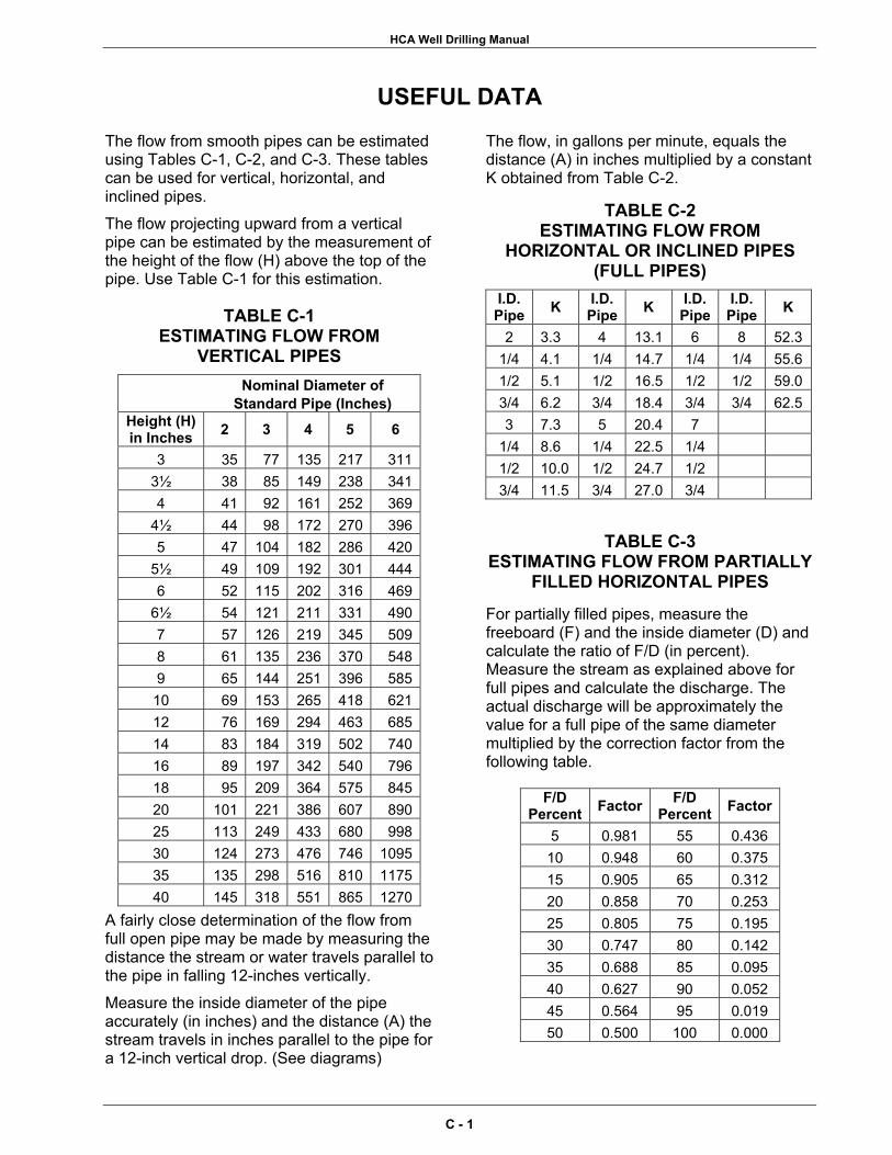
HCA Well Drilling Manual
USEFUL DATA
The flow from smooth pipes can be estimated using Tables C-1, C-2, and C-3. These tables can be used for vertical, horizontal, and inclined pipes. The flow projecting upward from a vertical pipe can be estimated by the measurement of the height of the flow (H) above the top of the pipe. Use Table C-1 for this estimation.
TABLE C-1 ESTIMATING FLOW FROM
VERTICAL PIPES Nominal Diameter of
Standard Pipe (Inches) Height (H) in Inches 2 3 4 5 6
3 35 77 135 217 3113½ 38 85 149 238 3414 41 92 161 252 369
4½ 44 98 172 270 3965 47 104 182 286 420
5½ 49 109 192 301 4446 52 115 202 316 469
6½ 54 121 211 331 4907 57 126 219 345 5098 61 135 236 370 5489 65 144 251 396 58510 69 153 265 418 62112 76 169 294 463 68514 83 184 319 502 74016 89 197 342 540 79618 95 209 364 575 84520 101 221 386 607 89025 113 249 433 680 99830 124 273 476 746 109535 135 298 516 810 117540 145 318 551 865 1270
A fairly close determination of the flow from full open pipe may be made by measuring the distance the stream or water travels parallel to the pipe in falling 12-inches vertically. Measure the inside diameter of the pipe accurately (in inches) and the distance (A) the stream travels in inches parallel to the pipe for a 12-inch vertical drop. (See diagrams)
The flow, in gallons per minute, equals the distance (A) in inches multiplied by a constant K obtained from Table C-2.
TABLE C-2 ESTIMATING FLOW FROM
HORIZONTAL OR INCLINED PIPES (FULL PIPES)
I.D. Pipe K I.D.
Pipe K I.D. Pipe
I.D. Pipe K
2 3.3 4 13.1 6 8 52.3 1/4 4.1 1/4 14.7 1/4 1/4 55.6 1/2 5.1 1/2 16.5 1/2 1/2 59.0 3/4 6.2 3/4 18.4 3/4 3/4 62.5 3 7.3 5 20.4 7
1/4 8.6 1/4 22.5 1/4 1/2 10.0 1/2 24.7 1/2 3/4 11.5 3/4 27.0 3/4
TABLE C-3 ESTIMATING FLOW FROM PARTIALLY
FILLED HORIZONTAL PIPES
For partially filled pipes, measure the freeboard (F) and the inside diameter (D) and calculate the ratio of F/D (in percent). Measure the stream as explained above for full pipes and calculate the discharge. The actual discharge will be approximately the value for a full pipe of the same diameter multiplied by the correction factor from the following table.
F/D Percent Factor F/D
Percent Factor
5 0.981 55 0.436 10 0.948 60 0.375 15 0.905 65 0.312 20 0.858 70 0.253 25 0.805 75 0.195 30 0.747 80 0.142 35 0.688 85 0.095 40 0.627 90 0.052 45 0.564 95 0.019 50 0.500 100 0.000
C - 1
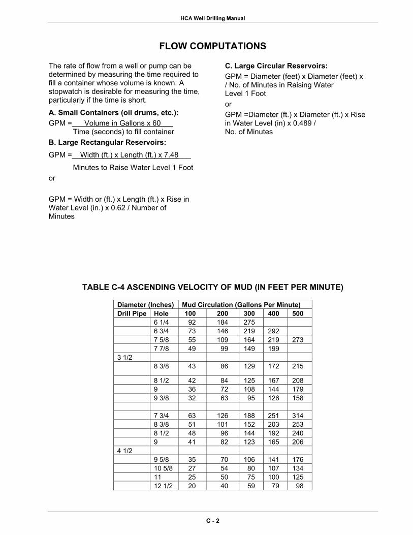
HCA Well Drilling Manual
FLOW COMPUTATIONS
The rate of flow from a well or pump can be determined by measuring the time required to fill a container whose volume is known. A stopwatch is desirable for measuring the time, particularly if the time is short. A. Small Containers (oil drums, etc.): GPM = Volume in Gallons x 60___
Time (seconds) to fill container B. Large Rectangular Reservoirs: GPM = Width (ft.) x Length (ft.) x 7.48___
Minutes to Raise Water Level 1 Foot or GPM = Width or (ft.) x Length (ft.) x Rise in Water Level (in.) x 0.62 / Number of Minutes
C. Large Circular Reservoirs: GPM = Diameter (feet) x Diameter (feet) x / No. of Minutes in Raising Water Level 1 Foot or GPM =Diameter (ft.) x Diameter (ft.) x Rise in Water Level (in) x 0.489 / No. of Minutes
TABLE C-4 ASCENDING VELOCITY OF MUD (IN FEET PER MINUTE)
Diameter (Inches) Mud Circulation (Gallons Per Minute) Drill Pipe Hole 100 200 300 400 500 6 1/4 92 184 275 6 3/4 73 146 219 292 7 5/8 55 109 164 219 273 7 7/8 49 99 149 199 3 1/2 8 3/8 43 86 129 172 215
8 1/2 42 84 125 167 208 9 36 72 108 144 179 9 3/8 32 63 95 126 158 7 3/4 63 126 188 251 314 8 3/8 51 101 152 203 253 8 1/2 48 96 144 192 240 9 41 82 123 165 206 4 1/2 9 5/8 35 70 106 141 176 10 5/8 27 54 80 107 134 11 25 50 75 100 125 12 1/2 20 40 59 79 98
C - 2
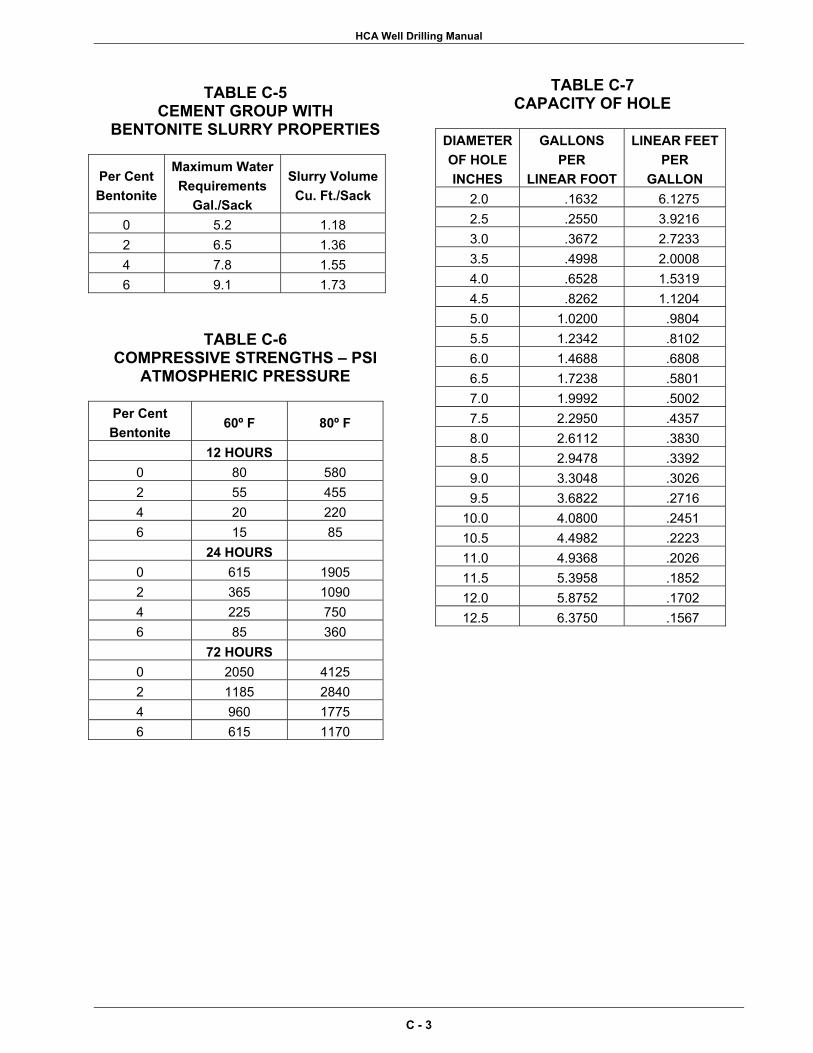
HCA Well Drilling Manual
TABLE C-5 CEMENT GROUP WITH
BENTONITE SLURRY PROPERTIES
Per Cent Bentonite
Maximum Water Requirements
Gal./Sack
Slurry VolumeCu. Ft./Sack
0 5.2 1.18 2 6.5 1.36 4 7.8 1.55 6 9.1 1.73
TABLE C-6
COMPRESSIVE STRENGTHS – PSI ATMOSPHERIC PRESSURE
Per Cent Bentonite
60º F 80º F
12 HOURS 0 80 580 2 55 455 4 20 220 6 15 85 24 HOURS
0 615 1905 2 365 1090 4 225 750 6 85 360 72 HOURS
0 2050 4125 2 1185 2840 4 960 1775 6 615 1170
TABLE C-7 CAPACITY OF HOLE
DIAMETEROF HOLE INCHES
GALLONS PER
LINEAR FOOT
LINEAR FEETPER
GALLON 2.0 .1632 6.1275 2.5 .2550 3.9216 3.0 .3672 2.7233 3.5 .4998 2.0008 4.0 .6528 1.5319 4.5 .8262 1.1204 5.0 1.0200 .9804 5.5 1.2342 .8102 6.0 1.4688 .6808 6.5 1.7238 .5801 7.0 1.9992 .5002 7.5 2.2950 .4357 8.0 2.6112 .3830 8.5 2.9478 .3392 9.0 3.3048 .3026 9.5 3.6822 .2716
10.0 4.0800 .2451 10.5 4.4982 .2223 11.0 4.9368 .2026 11.5 5.3958 .1852 12.0 5.8752 .1702 12.5 6.3750 .1567
C - 3
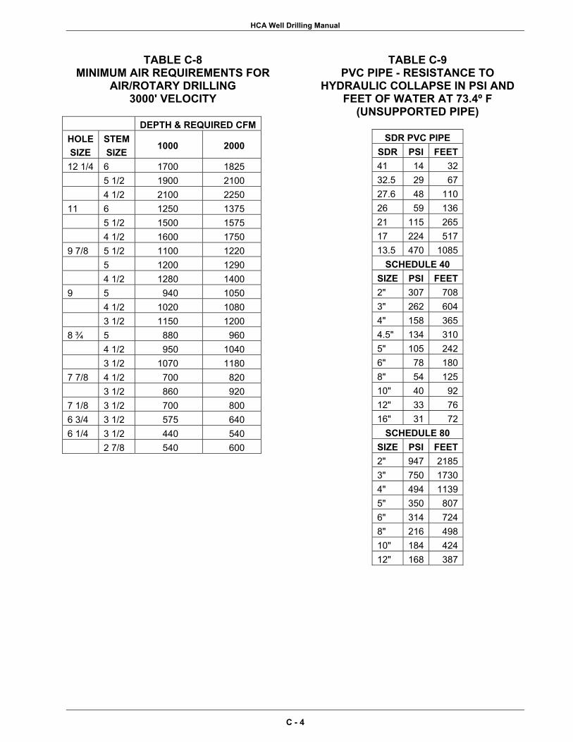
HCA Well Drilling Manual
TABLE C-8 MINIMUM AIR REQUIREMENTS FOR
AIR/ROTARY DRILLING 3000' VELOCITY
DEPTH & REQUIRED CFMHOLE SIZE
STEM SIZE
1000 2000
12 1/4 6 1700 1825 5 1/2 1900 2100 4 1/2 2100 2250 11 6 1250 1375 5 1/2 1500 1575 4 1/2 1600 1750 9 7/8 5 1/2 1100 1220 5 1200 1290 4 1/2 1280 1400 9 5 940 1050 4 1/2 1020 1080 3 1/2 1150 1200 8 ¾ 5 880 960 4 1/2 950 1040 3 1/2 1070 1180 7 7/8 4 1/2 700 820 3 1/2 860 920 7 1/8 3 1/2 700 800 6 3/4 3 1/2 575 640 6 1/4 3 1/2 440 540 2 7/8 540 600
TABLE C-9 PVC PIPE - RESISTANCE TO
HYDRAULIC COLLAPSE IN PSI AND FEET OF WATER AT 73.4º F
(UNSUPPORTED PIPE)
SDR PVC PIPE SDR PSI FEET 41 14 32 32.5 29 67 27.6 48 110 26 59 136 21 115 265 17 224 517 13.5 470 1085
SCHEDULE 40 SIZE PSI FEET 2" 307 708 3" 262 604 4" 158 365 4.5" 134 310 5" 105 242 6" 78 180 8" 54 125 10" 40 92 12" 33 76 16" 31 72
SCHEDULE 80 SIZE PSI FEET 2" 947 2185 3" 750 1730 4" 494 1139 5" 350 807 6" 314 724 8" 216 498 10" 184 424 12" 168 387
C - 4

APPENDIX D Measurement Conversion Tables


HCA Well Drilling Manual
Measurement Conversion Tables Atmosphere atm
76 centimeters of mercury at 0ºC 29.92-inches of mercury at 0ºC 406.8-inches of water at 4º C 14.7 pounds per square inch
Centimeter cm 0.010 meters 0.3937-inches
Cubic Centimeter cc 0.000001 cubic meters 0.06102 cubic inches 0.00003531 cubic feet
Cubic Foot cu ft 1728 cubic inches 0.0282 cubic meters 7.481 gallons 28.32 liters 62.4283 pounds of water
Cubic Inch cu in 16.39 cubic centimeters 0.0005787 cubic feet 0.00001639 cubic meters
Cubic Meter cu m 1,000,000 cubic centimeters 35.31 cubic feet 61023 cubic inches 264.2 gallons
Degree (arc) deg 60 minutes 3600 seconds 0.01745 radians
Foot ft 12-inches 0.333 yards 0.30481 meters 0.004329 gallons
Foot-Pound ft-lb 0.001285 Btu 1.356 joules
Foot of Water 0.0295 atmospheres 62.43 pounds per square foot 0.4335 pounds per square inch 2.242 centimeters of mercury
Gallon gal 0.1337 cubic feet 231 cubic inches 3.785 liters 8.336 pounds of water
Grain grain 0.06481 grams 0.002286 ounces
Gram g 15.43 grains 0.03527 ounces 0.002205 pounds
Gravity g 32.1740 feet per second per second 980.665 centimeters per second per second
Horsepower hp 550 foot-pounds per second 33,000 foot-pounds per minute 42.41 Btu per minute 745.7 watts
Inch in 0.08333 feet 2.54 centimeters
Inch of Water 0.002458 atmospheres 5.204 pounds per square foot 0.03613 pounds per square inch 0.1868 centimeters of mercury
Kilogram kg 1000 grams 2.2046 pounds 35.274 ounces
Kilometer km 1000 meters 0.6214 miles
Kilowatt kw 1.341 horsepower 44,257 foot pounds per minute 56.89 Btu per minute
Liter l 0.001 cubic meter 1.057 quarts 0.2642 gallons 0.03531 cubic feet
D - 1

HCA Well Drilling Manual
Meter m 100 centimeters 1,000 millimeters 39.37-inches 3.2808 feet
Micron mu 0.001 millimeters 10,000 Angstrom units 39.37 millionths of an inch
Micro Inch µin 0.000001 inches 0.0254 microns
Mil mil 0.001 inches 25.4 microns 0.0254 millimeters
Mile mile 5280 feet 1760 yards 1.609 kilometers
Miles per Hour mph 1 mph = 1.467 feet per second 1 mph = 88 feet per minute 1 mph = 44.7 centimeters per second
Ounce oz 0.0625 pounds 28.35 grams 437.5 grains
Pound (Avoirdupois) lb 16 ounces 0.4536 kilograms 7000 grains 1.2153 pounds Troy
Pounds per Square Inch lb/sq in 0.06804 atmospheres 5.171 centimeters of mercury 27.68 inches of water
Quart qt 2 pints 0.25 gallons 0.9464 liters 2.084 pounds of water
Radian radian 57.296 degrees 57º17'44.81" 360º2
Square Centimeter sq cm 0.0001 square meters 0.155 square inches
Square Foot sq ft 144 square inches 0.0929 square meters
Square Inch sq in 6.452 square centimeters 1,273,240 circular mils
Square Meter sq m 10000 square centimeters 10.764 square feet 1.196 square yards
Watt w 44.26 foot-pounds per minute 0.001 kilowatts 0.00134 horsepower
D - 2
APPENDIX E Standard Forms for Well Drilling
Operations

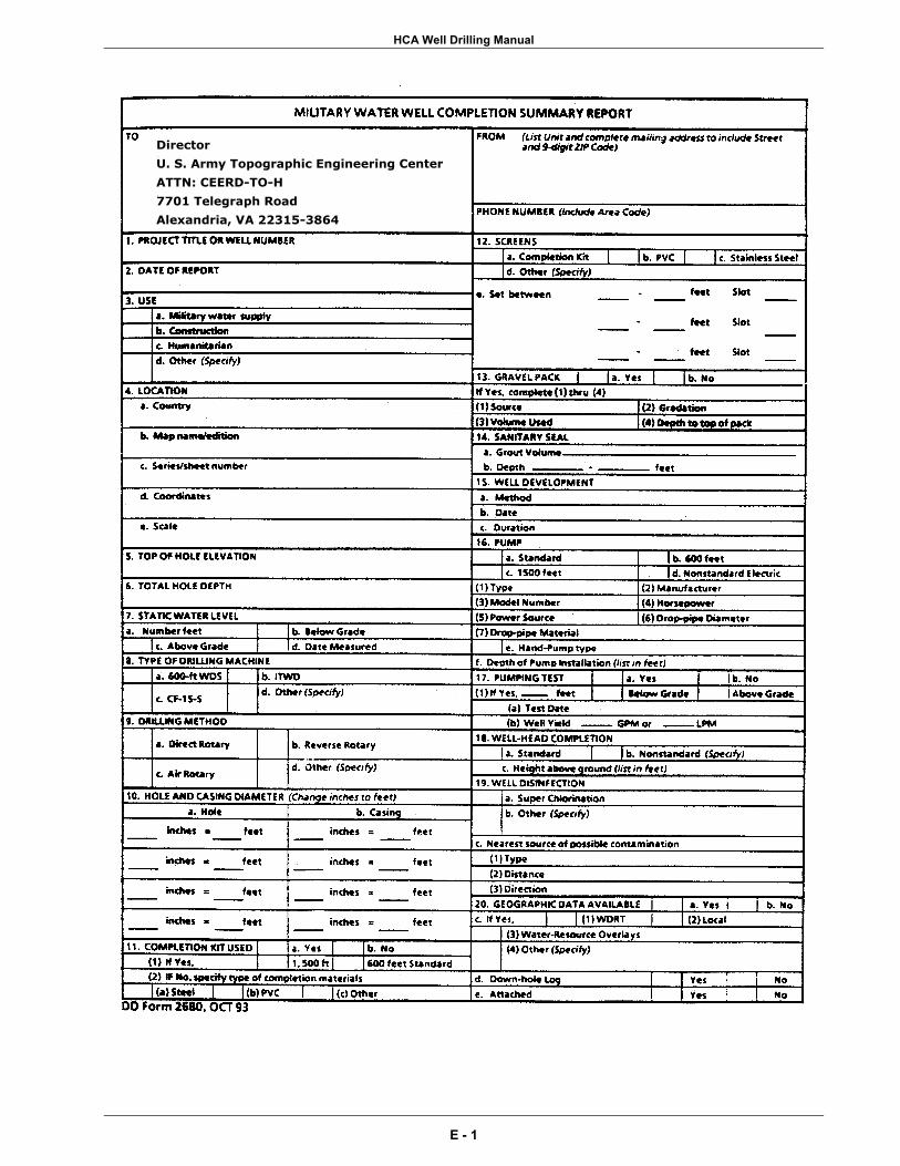
HCA Well Drilling Manual
Director
U. S. Army Topographic Engineering Center
ATTN: CEERD-TO-H
7701 Telegraph Road
Alexandria, VA 22315-3864
E - 1

HCA Well Drilling Manual
E - 2
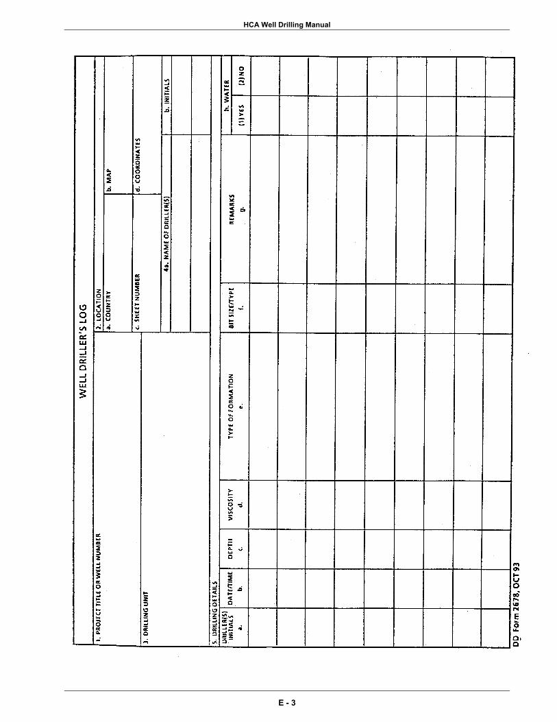
HCA Well Drilling Manual
E - 3
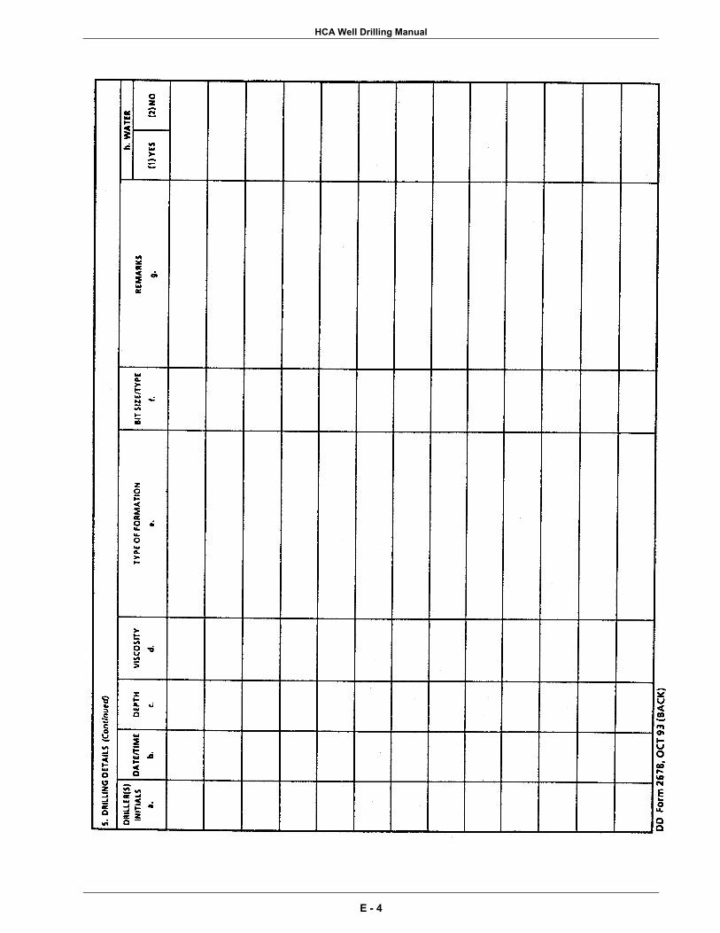
HCA Well Drilling Manual
E - 4
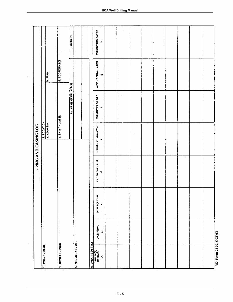
HCA Well Drilling Manual
E - 5

HCA Well Drilling Manual
E - 6

APPENDIX F Well Quality Checklist

HCA Well Drilling Manual
U.S. Army South Date........................................................................................................................ 06 Mar 02 To................................................................................. New Horizons Task Force Engineers From....................................... Otto F. Schick, USARSO Engineer Office, Tel. 787-707-2480 ................................................................... Laura Roebuck, COE Mobile, Tel. 251-690-3480 ................................................................................................................................................ Re.................................................................... Critical Checklist, Humanitarian Well Projects ...............................................................................................................................1st Edition Pages ....................................................................................................................................4 The list below of critical issues was written by USARSO and COE Mobile for humanitarian well drilling projects for New Horizons Exercises, based on technical information provided by the Mobile District. This list is intended for all TF engineers to understand in a field expedient manner the most critical lessons learned in well drilling. 1. Current Well Manual. The latest edition of the Corps of Engineers well manual,
titled "HCA Well Drilling Manual, 2nd Edition, June 2001", should be obtained and read by Task Force engineers and well drillers. The POC for this manual is Laura Roebuck at COE Mobile, tel. 251-690-3480.
Electronic PDF copy can be obtained at [email protected]
or [email protected] 2. Water Resources Assessment. Well planners should obtain a copy of the latest
WRA and use this to locate wells in areas that have a high probability of hitting water. These are prepared by COE Mobile. Electronic PDF copy can be obtained at [email protected] or [email protected]
Groundwater Resources Map. This is probably the best overall tool in the WRA.
This gives an overview of the groundwater resources of the country and the probability of successful groundwater exploration in a particular area. Planners use these assessments in the early planning stages.
F - 1

HCA Well Drilling Manual
3. Site Specific Analysis. After the basic sites are selected, the Topographic Engineering Center conducts research in the U.S. for all published hydrogeological information about the area. From this preliminary information, they prepare a site specific analysis of well success probability. This information is based on GPS coordinate readings of the selected proposed well site locations. TF members should make sure to obtain this information from COE Mobile.
An initial site survey is conducted six months to a year in advance of the exercise for the task force, drilling units, and geologists to look at the well sites. The well site survey report is produced by Mobile District and includes site details, drilling recommendations, well designs and a list of materials. This should be used as a guide during well operations, in conjunction with the HCA well manual, on-the-job training, and host nation water authority recommendations.
4. Weekend Training Session. One to two months prior to deployment, COE Mobile
will provide a training session for exercise well drillers. All participating units should be invited to attend.
5. OJT during exercise. The US military well drilling troops have limited training in
well drilling and installation. Therefore, at least one SME should be onsite for the duration of the well drilling and installation. Too many problems arise that inexperienced drillers cannot resolve without the proper expertise and experience.
6. Well Casing Material. For well depths greater than 200 meters, steel casing
should be used. PVC casings and screens should not be used for wells greater than 200 meters deep.
7. Minimum Grout Seal. There should be a 30 meter minimum grout seal from the
surface to prevent surface or groundwater contamination into the well. 8. Bentonite in Grout. A small amount, about 2-5% of bentonite should be added to
the grout to reduce shrinkage of the grout seal, and reduce the heat of hydration during grout setup which should be considered for pvc cased wells.
9. Filter Material. Specific quality requirements are necessary. See Well Manual
for details. For the HCA exercises, 6-20 gradation is generally specified which works for well screen slot size of .025-inch.
10. Pilot Holes. Since about 30-50% of all well holes are abandoned, it is
recommended to drill pilot holes (usually 15 cm) to determine if a suitable aquifer exists. This also aids in correct well screen placement.
F - 2
HCA Well Drilling Manual
11. Well Development. Well development is the process of removing the filter cake, a skin-like film which forms on the walls of the well hole as a result of drilling fluid hardening on the well hole walls. This filter cake acts as a barrier to prevent drilling fluid from escaping into the surrounding soil, and supports the well wall from collapsing while drilling the well. However, afterwards it must be removed to allow groundwater to flow through the well.
This filter cake must be eroded off the well walls using clean water, and there are several methods to do this.
The following are typical well development times:
Small wells with 1 - 2 meters of screen, minimum 5-6 hours of development Larger wells, with 10-12 meters of screen, minimum 2 days of development
12. Drill Operations. These should be conducted on a 24 hour continuous basis.
Drilling less than 24 hours/day increases the risk of failure, specifically for the hole collapsing on the drill steel and bit.
13. Drill Units. TF Engineers should identify all military units, not just the lead unit,
that will be involved in drilling for the exercise and include them in the planning, and place them in contact with COE Mobile for training, design and materials list input and orientation.
14. Bill of Materials. The COE Mobile develops the list of materials needed in
coordination with the drill units, and procures. 15. Finished Product Wells Only. No well should be drilled and fitted with an electric
pump and left with the expectation of future electrical connection, water storage and distribution. Many projects have been seen years later with wells unused due to no power, or means of storage and distribution or both. Hand pumps should be installed if power is not present at the time of well completion. In most cases, a hand pump is ordered for each planned well. Electric pumps can be purchased in-country if power is available.
In addition, wherever an electric pump is installed, a reservoir should be installed
so that the pump can be activated and a significant amount of water pumped at once, rather than cycling pumps on continuously for small amounts of water. Generally, every electric pump should be connected to a minimum 2 cubic meter plastic tank reservoir.
Prices are about: ............................................................................. $ 1,000......................................................................................... Handpump BOM
$ 3,000 - $ 6,000 submersible pump package (based on size)
F - 3
HCA Well Drilling Manual
16. Pumping Test. Pumping tests should be conducted on all wells to determine the performance characteristics of the well and the hydraulic parameters of the aquifer. Even if hand pumps are installed, it is critical for pumping tests to be conducted for future submersible pump installation.
17. Water Quality Test. TF Engineer should either contract with CHPPM or the host
nation to conduct water quality tests. At a minimum the World Health Organization (WHO) drinking water standards should be used (see Well Manual, page 141). If the host nation has stricter standards, the host nation standards should be used.
18. Groundwater and Wells book, by Johnson. This rather large, water well industry
'Bible' should be taken on all exercises for reference. 19. Tri-Services Well Manual. Should be taken on all exercises for reference.
Caution should be exercised in employing some of the recommended procedures, as this manual was predominantly written for tactical wells. The recommended guidelines in the HCA well manual, written by the Corps, should be followed for HCA wells.
End of Checklist.
F - 4

INDEX


HCA Well Drilling Manual
INDEX TOPIC PAGE NUMBERS 1500 Foot Well Completion Kit .......................................................................................27, 41, 61, 63 600 Foot Well Completion Kit ...................................................................................27, 39, 41, 49, 71 AEHA ........................................................................................................................................... vi, 75 aesthetic..........................................................................................................................................125 after action report............................................................................................................................115 air drilling.........................................................................................33, 53, 57, 63, 73, 67, 75, 97, 103 air rotary...................................................................................................................33, 57, B - 1, B - 2 air/foam.....................................................................................................................17, 53, 57, 73, 75 air-lift ............................................................................................101, 103, 107, 109, 116, B - 1, B - 3 alignment ..............................................................................................................................65, 83, 85 aluminum ........................................................................................................................................125 annular space ...................... 39, 45, 53, 61, 63, 81, 83, 85, 87, 93, 95, 97, 99, 101, A - 3, A - 4, B - 2 API 5-L ..............................................................................................................................................45 aquagel .................................................................................................................................. 99, B - 1 aquifer .................................................1, 3, 7, 9, 11, 17, 21, 27, 29, 37, 49, 55, 57, 77, 79, 87, 89, 91
.............................................................. 93, 103, 116, 121, 123, A - 1, A - 4, B - 1, B - 3, B - 4 aquifer stress ..................................................................................................................................121 aquitard ................................................................................................................................... 93, B - 1 arsenic .................................................................................................................................. 125, A - 5 artesian flow......................................................................................................................................55 ASTM A-53 ......................................................................................................... 45, A - 1, A - 2, A - 3 AWWA .......................................................................................... vi, A - 1, A - 2, A - 3, A - 6, B - 1 backflow ............................................................................................................................................99 bacteria ................................................................................57, 65, 75, 77, 116, 117, 123, A - 1, A - 5 bailer ..................................................................................................................... 101, 103, 109, B - 2 barafos .............................................................................................................................. 55, 95, B - 1 Barite................................................................................................................................ 55, 71, B - 1 bentonite .......................................... 47, 55, 57, 59, 71, 93, 97, 99, 101, 103, A - 3, B - 1, B - 3, C - 3 bill of materials .................................................................... iii, v, 1, 7, 13, 25, 41, 43, 57, 59, 64, B - 1 blooey line...................................................................................................................................73, 75 bridging .............................................................................................................................................95 cadmium ............................................................................................................................... 125, A - 5 casing.................... 7, 15, 17, 25, 27, 29, 33, 35, 37, 39, 41, 43, 45, 47, 49, 51, 55, 57, 59, 61, 63, 64
...................... 65, 67, 69, 71, 73, 77, 85, 87, 89, 93, 95, 97, 99, 101, 109, 111, 113, 115, 116
..............................................119, 121, A - 2, A - 3, A - 4, A - 6, A - 7, B - 1, B - 2, B - 3, B - 4 casing head.......................................................................................................................................97 cement ..................................................... 17, 19, 47, 57, 59, 93, 97, 99, 101, A - 2, A - 3, A - 4, C - 3 cement grout ..................................................................................... 45, 57, 97, 101, A - 2, A- 3, A - 4 cement/bentonite ........................................................................................................................93, 99 centering guides..........................................................................................................................29, 95
INDEX - 1

HCA Well Drilling Manual
TOPIC PAGE NUMBERS centralizers............................................................................................................ 29, 39, 41, 59, A - 3 cfm ............................................................................................................. vii, 33, 35, 113, B - 1, C - 4 chemical analysis............................................................................................................................123 chlorination..................................................................................................................................75, 77 chlorine ............................................................................................57, 59, 71, 75, 77, 95, A - 4, A - 6 chromium .............................................................................................................................. 125, A - 5 color ...................................................................................................................................... 125, A - 5 compressive strength.............................................................................................................. 47, C - 3 continuous slot .............................................................................................. 39, 41, 47, 49, 103, A - 3 copper ..........................................................................................................................125, A - 5, B - 1 cuttings.......................... 53, 55, 57, 63, 67, 69, 73, 75, 79, 89, 93, 103, A - 2, A - 4, A - 6, B - 2, B - 3 cyanide............................................................................................................................................125 development ............................. 15, 29, 33, 35, 37, 39, 41, 45, 49, 51, 55, 57, 65, 67, 73, 91, 93, 101
.................................................... 103, 107, 109, 111, 113, 121, A - 1, A - 4, A - 6, A - 7, B - 3 deviation............................................................................................................................ 85, 87, B - 3 DHH ..............................................................................................................................vi, 33, 73, B - 1 discharge ..........33, 37, 69, 73, 79, 101, 103, 107, 109, 113, 115, 116, A - 4, A - 6, B - 1, B - 3, C - 1 dispersant ............................................................................................................................... 55, B - 1 down-hole-hammer ...........................................................................................vi, 33, 73, 85, 97, B - 1 down-hole-percussion.......................................................................................................................57 drawdown............................................................................................65, 121, A - 2, A - 5, A - 6, B - 1 drill bit......................................................................................................viii, 17, 53, 61, 63, 79, 83, 87 drill collar...................................................................................................................61, 83, 85, 87, 93 drill rod ........................................................................................ 17, 33, 55, 79, 83, 85, 97, 109, B - 3 drilling fluid ........................................ 15, 19, 21, 33, 43, 45, 47, 53, 55, 57, 61, 65, 67, 69, 71, 73, 75
...................................................... 77, 79, 83, 97, 101, 111, 119, A - 4, A -6, B - 1, B - 2, B -3 drilling foam...........................................................................................................................33, 35, 57 dynamic head....................................................................................................................................64 electrical resistivity ............................................................................................................................11 Failing LP-12.....................................................................................................................................69 filter cake................................................................................. 53, 55, 73, 93, 95, 101, 103, 109, B - 2 filter material ............................... 17, 19, 27, 29, 35, 37, 39, 43, 45, 47, 49, 51, 53, 59, 63, 67, 77, 89
...................................................... 95, 97, 101, 109, 121, A - 2, A - 3, A - 4, A - 7, B - 2, B - 4 float collar................................................................................................................................ 61, B - 2 float shoe .............................................................................................................. 45, 61, 97, 99, B - 2 flow rate ..........................................................................................................................................115 fluoride .................................................................................................................................. 125, A - 5 foaming agent ................................................................................................................... 57, 73, A - 5 formation squeeze ............................................................................................................................45 formation stabilizer.................................................................................................................. 51, B - 2 fpm...............................................................................................................................vii, 33, 35, B - 2 gamma log ........................................................................................................................................87
INDEX - 2

HCA Well Drilling Manual
TOPIC PAGE NUMBERS geophysical log ................................................................................................... 87, 89, 93, 121, A - 2 geophysical survey .......................................................................................................................9, 11 gradation ................................................................17, 19, 49, 51, 53, 89, 103, 111, 121, A - 3, A - 4 gravel packing...........................................................................................................17, 29, 37, 39, 89 grouting basket ...........................................................................................................................63, 95 guar gum...........................................................................................................................................57 Halliburton............................................................................................................................... 97, B - 2 hand pump ....................................................................................................1, 7, 27, 33, 64, 113, 116 hardness .........................................................................................................................................125 HCA ..........................vi, ix, 3, 13, 21, 25, 27, 35, 41, 45, 93, 99, 117, 119, 121, 123, 125, A - 1, A - 2 health risks......................................................................................................................................123 high pressure nozzle.................................................................................................................99, 101 hydrogeologic data..................................................................................................................119, 123 hydrogeology ........................................................................................................................... ix, 3, 19 hydrojetting .............................................................................................................101, 103, 105, 107 hydrostatic pressure..........................................................................................45, 47, 51, 53, 55, 101 inorganic ................................................................................................................73, 125, B - 2, B - 3 iron ...................................................................................................................................vii, 125, A - 5 jetting tool........................................................................................................ 45, 103, 105, 107, B - 2 kelly................................................................................................................... 83, 97, 103, 109, B - 3 lead ....................................................................................................... 25, 39, 57, 75, 113, 125, A - 5 machine-slotted.................................................................................................................................35 makeup water .............................................................................................................................21, 77 making water.............................................................................................................................71, 111 manganese ........................................................................................................................... 125, A - 5 marsh funnel ........................................................................................................................... 71, B - 3 matrix ....................................................................................................................................13, 19, 23 maximum discharge..........................................................................................................................37 mercury ................................................................................................................125, A - 5, D -1, D -2 mud pump ............................................................................. 33, 55, 57, 67, 71, 79, 81, 99, 103, B - 3 mud sump design..............................................................................................................................67 naturally developed........................................................................................................93, A - 2, A - 3 nitrate .................................................................................................................................... 125, A - 5 odor....................................................................................................................................... 125, A - 5 overdepth ..........................................................................................................................................93 parameters..........................................................................................................................21, 35, 125 permeability..................................................................................................................... 93, 121, B - 3 permeable ............................................................................................... 3, 53, 69, 71, 101, 121, B - 2 pH .............................................................................................................. vii, 57, 71, 125, A - 5, B - 3 pilot hole..........................................................................................................5, 63, 69, 77, 87, 93, 97 plumbness.........................................................................................................................................83 polyethylene tubing .........................................................................................................................107
INDEX - 3

HCA Well Drilling Manual
TOPIC PAGE NUMBERS polymer ........................................................................................................55, 57, 71, 73, B - 2, B - 3 potentiometric surface.....................................................................................................................123 pumping test .......................................................................... 11, 29, 115, 121, 116, A - 6, B - 1, B - 4 PVC casing ....................................................................................... 35, 39, 45, 47, 63, 97, 107, A - 2 PVC pipe................................................................................................... 17, 35, 45, 47, 49, 97, C - 4 PVC screen...........................................................................................................................39, 45, 49 QuikGel .............................................................................................................................................99 ready-mix ........................................................................................................................................101 reaming ....................................................................................................................... 85, 89, 93, A - 3 recharge.................................................................................................................15, 121, B - 3, B - 4 reconnaissance........................................................................ ix, 3, 5, 13, 14, 15, 17, 19, 21, 64, 123 refraction seismology ..........................................................................................................................9 remote sensing .............................................................................................................................9, 19 rest .........................................................................................................15, 21, 49, 83, 91, A - 6, B - 2 revert....................................................................................................................................... 71, B - 3 RHCP............................................................................................................................... iii, 45, 47, 49 river sand ....................................................................................................................................51, 53 rock wall well........................................................................................................................... 97, A - 2 sand content ............................................................................................43, 55, 111, 113, A - 2, A - 6 sand-free.......................................................................................................................29, 49, 65, 113 screen ................. 17, 19, 25, 27, 29, 33, 35, 37, 39, 41, 43, 45, 47, 49, 51, 55, 57, 59, 61, 65, 67, 71
.................... 79, 85, 87, 89, 91, 93, 95, 97, 101, 103, 105, 107, 109, 111, 113, 116, 119, 121
................................................................................ A - 2, A - 3, A - 4, B - 1, B - 2, B - 3, B - 4 sediment trap ....................................................................................................................93, 103, 111 selenium................................................................................................................................ 125, A - 5 site access ..................................................................................................................................21, 23 sloughing...........................................................................................................................................95 sodium ....................................................................................................... vii, 55, 57, 125, A - 5, B - 1 sodium bicarbonate...........................................................................................................................57 spline-joint.........................................................................................................................................39 spring .........................................................................................................................3, 17, B - 1, B - 4 stabilizer.................................................................................................................................. 51, B - 2 stainless steel well screen ..........................................................................................................19, 41 static water level ................................................................................................. vii, 77, 107, 115, 121 steel pipe................................................................................................................................. 19, A - 2 sterilization ...............................................................................................53, 77, 113, 121, A - 6, A - 7 submersible pump................................................................................................. 7, 29, 64, 116, B - 4 sulfate ..............................................................................................................................vii, 125, A - 5 sump ..............................................................................11, 15, 55, 65, 67, 69, 71, 73, 89, A - 6, B - 3 surge block.....................................................................................95, 101, 103, 109, 111, A - 4, B - 4 swabbing...........................................................................................................................................95 tactical well..................................................................................................viii, 1, 29, 35, 99, 117, 119
INDEX - 4

HCA Well Drilling Manual
TOPIC PAGE NUMBERS taste ...................................................................................................................................... 125, A - 5 TDS........................................................................................................................................... vii, 125 test hole ..........................7, 11, 35, 37, 39, 49, 65, 77, 79, 85, 87, 89, 91, 93, A - 1, A - 2, A - 3, A - 7 test well .........................................................................................................................................7, 37 Topographic Engineering Center (TEC) .......................................................vi, 9, 115, 121, 123, B - 4 transmitting capacity .........................................................................................................................39 tremie ................................................................................................. 63, 95, 97, 99, B - 2, B - 3, B - 4 turbidity ....................................................................................................................vii, 113, 125, A - 5 turbine pump ........................................................................................................................... 64, B - 4 unconfined aquifer ...........................................................................................37, 91, 123, B - 3, B - 4 uniformity coefficient ...................................................................................................................51, 95 uphole velocity ................................................................................................................33, 35, 37, 79 viscosity .............................................................................................................55, 57, 71, B - 1, B - 3 wash-down shoe ..................................................................................................................... 57, A - 3 water table .......................................................................................................37, 93, 123, B - 3, B - 4 WDRT ........................................................................................................ vi, ix, 3, 5, 9, 11, 117, B - 4 well depth............................................................................................................7, 19, 121, A - 1, A -4 well sanitation .............................................................................................................................59, 75 World Health Organization (WHO)............................................................................................. vi, 123 WRDB ..................................................................................................................................vi, 9, B - 4 zinc...............................................................................................................................125, A - 1, A - 5
INDEX - 5
Related Documents