^I THE AMERICAN SOCIETY OF MECHANICAL ENGINEERS 86-GT-28 345 E. 47 St., New York, N.Y. 10017 The Society shall not be responsible for statements or opinions advanced in papers or in dis- cussion at meetings of the Society or of its Divisions or Sections, or printed in its publications. Discussion is printed only if the paper is published in an ASME Journal. Papers are available ^^C from ASME for fifteen months after the meeting. Printed in USA. Operation of the CT7 Turboprop Engine as an Auxiliary Power Unit (APU) J. D. Stewart—Manager, CT7 Aircraft Engine Business Group General Electric Company Lynn, Massachusetts INTRODUCTION In response to the need of the new genera- tion of commuter airliners, General Electric has developed the CT7 Turboprop engine so that it may be used as an Auxiliary Power Unit (APU) in addition to its normal mission as a prime propulsion unit. The General Electric CT7 Turboprop is a 1700 shaft horsepower class engine (Figure 1) developed for the new genera- tion of 30+ passenger commuter and executive aircraft( 1 ). Beyond this, the CT7 engine now offers the airlines a self-contained APU system to provide bleed air for the Environmental Control System (ECS) and electrical power for the aircraft during ground operation. This negates the need for a separate on-board APU with its extra cost, weight and fuel consumption and also eliminates the requirements for ground power units at the airlines' operational terminals. The development of the engine as an APU generated a new set of technical require- ments for the design and development and neces- sitated the development of special certification requirements as this was a new and unique operating condition for an aircraft prime pro- pulsion system. A propeller brake had to be developed to lock the propeller and power tur- bine system and the engine had to be designed to operate at or near idle while producing large amounts of bleed air and electrical power. This development program was successfully completed in mid-1985 with the certification of the air- craft to operate with the CT7 Turboprop engine running as an APU. BACKGROUND The CT7 Turboprop engine was designed, developed and certified in late 1983, and entered service in the commuter airline market in June of the following year. During the early development, it was recognized that operation of the engine as an APU, in addition to its prime propulsion use, would be beneficial to the aircraft system. To facilitate loading and off-loading of passengers and baggage with the engine operating, it is necessary to prevent propeller operation; this is accomplished by use of a propeller brake mounted on the propeller gearbox. The prop brake was designed and certified in conjunction with the engine certification program. Since there had not been previous certifi- cation of a locked rotor system, a set of certification requirements were developed and issued as a special case by the FAA. As a result of the technical requirements established for the system, it was determined that the engine had to operate over a wide range of ambient temperature and altitude conditions Presented at the International Gas Turbine Conference and Exhibit Dusseldorf, West Germany—June 8-12, 1986 Copyright © 1986 by ASME Downloaded from http://asmedigitalcollection.asme.org/GT/proceedings-pdf/GT1986/79290/V002T02A004/2396399/v002t02a004-86-gt-28.pdf by guest on 30 May 2022

Welcome message from author
This document is posted to help you gain knowledge. Please leave a comment to let me know what you think about it! Share it to your friends and learn new things together.
Transcript
^I
THE AMERICAN SOCIETY OF MECHANICAL ENGINEERS 86-GT-28345 E. 47 St., New York, N.Y. 10017
The Society shall not be responsible for statements or opinions advanced in papers or in dis-cussion at meetings of the Society or of its Divisions or Sections, or printed in its publications.Discussion is printed only if the paper is published in an ASME Journal. Papers are available
^^C from ASME for fifteen months after the meeting.Printed in USA.
Operation of the CT7 Turboprop Engine as an AuxiliaryPower Unit (APU)
J. D. Stewart—Manager, CT7
Aircraft Engine Business GroupGeneral Electric Company
Lynn, Massachusetts
INTRODUCTION
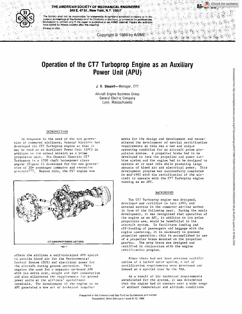
In response to the need of the new genera-tion of commuter airliners, General Electric hasdeveloped the CT7 Turboprop engine so that itmay be used as an Auxiliary Power Unit (APU) inaddition to its normal mission as a primepropulsion unit. The General Electric CT7Turboprop is a 1700 shaft horsepower classengine (Figure 1) developed for the new genera-tion of 30+ passenger commuter and executiveaircraft( 1 ). Beyond this, the CT7 engine now
offers the airlines a self-contained APU systemto provide bleed air for the EnvironmentalControl System (ECS) and electrical power forthe aircraft during ground operation. Thisnegates the need for a separate on-board APUwith its extra cost, weight and fuel consumptionand also eliminates the requirements for groundpower units at the airlines' operationalterminals. The development of the engine as anAPU generated a new set of technical require-
ments for the design and development and neces-sitated the development of special certificationrequirements as this was a new and uniqueoperating condition for an aircraft prime pro-pulsion system. A propeller brake had to bedeveloped to lock the propeller and power tur-bine system and the engine had to be designed tooperate at or near idle while producing largeamounts of bleed air and electrical power. Thisdevelopment program was successfully completedin mid-1985 with the certification of the air-craft to operate with the CT7 Turboprop enginerunning as an APU.
BACKGROUND
The CT7 Turboprop engine was designed,developed and certified in late 1983, andentered service in the commuter airline marketin June of the following year. During the earlydevelopment, it was recognized that operation ofthe engine as an APU, in addition to its primepropulsion use, would be beneficial to theaircraft system. To facilitate loading andoff-loading of passengers and baggage with theengine operating, it is necessary to preventpropeller operation; this is accomplished by useof a propeller brake mounted on the propellergearbox. The prop brake was designed andcertified in conjunction with the enginecertification program.
Since there had not been previous certifi-cation of a locked rotor system, a set ofcertification requirements were developed andissued as a special case by the FAA.
As a result of the technical requirementsestablished for the system, it was determinedthat the engine had to operate over a wide rangeof ambient temperature and altitude conditions
Presented at the International Gas Turbine Conference and ExhibitDusseldorf, West Germany—June 8-12, 1986
Copyright © 1986 by ASME
Dow
nloaded from http://asm
edigitalcollection.asme.org/G
T/proceedings-pdf/GT1986/79290/V002T02A004/2396399/v002t02a004-86-gt-28.pdf by guest on 30 M
ay 2022
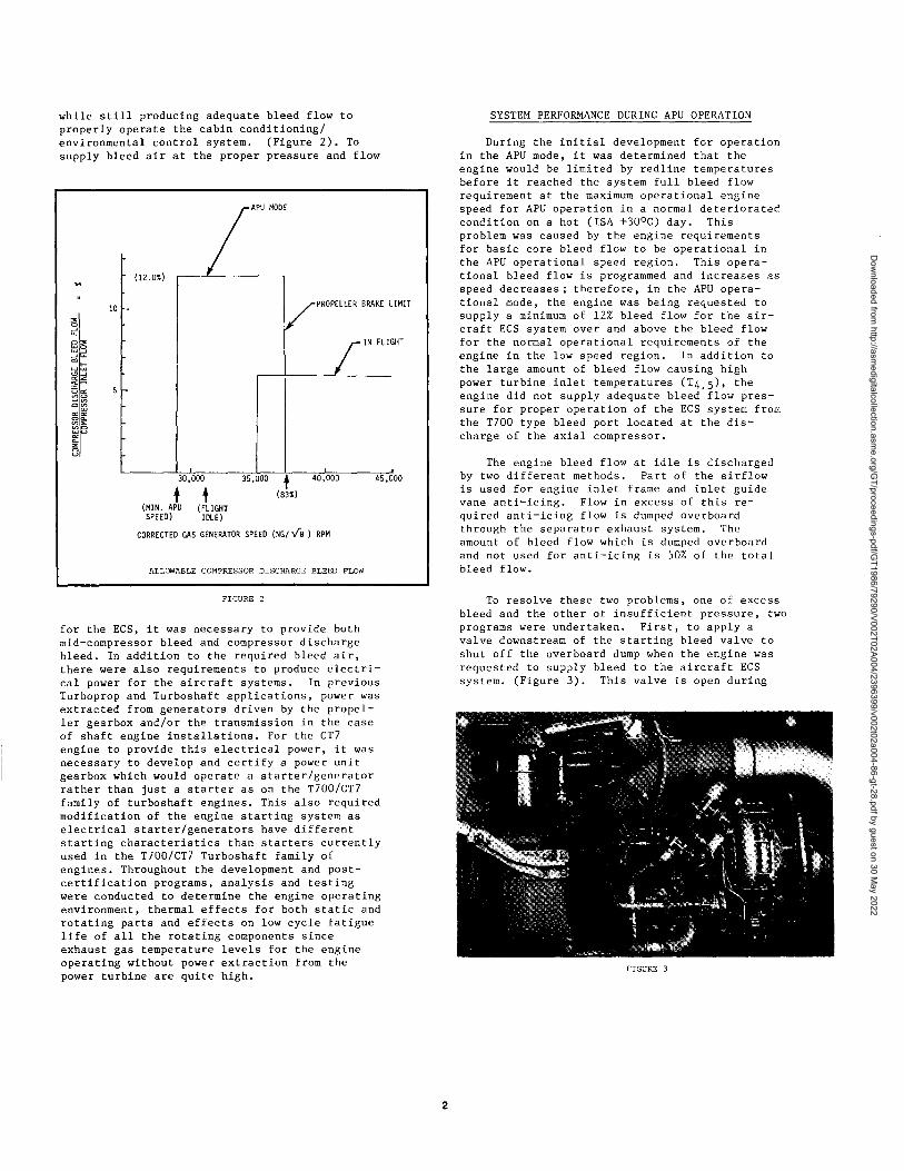
while still producing adequate bleed flow toproperly operate the cabin conditioning/environmental control system. (Figure 2). Tosupply bleed air at the proper pressure and flow
FIGURE 2
for the ECS, it was necessary to provide bothmid-compressor bleed and compressor dischargebleed. In addition to the required bleed air,there were also requirements to produce electri-cal power for the aircraft systems. In previousTurboprop and Turboshaft applications, power wasextracted from generators driven by the propel-ler gearbox and/or the transmission in the caseof shaft engine installations. For the CT7engine to provide this electrical power, it wasnecessary to develop and certify a power unitgearbox which would operate a starter/generatorrather than just a starter as on the T700/CT7family of turboshaft engines. This also requiredmodification of the engine starting system aselectrical starter/generators have differentstarting characteristics than starters currentlyused in the T700/CT7 Turboshaft family ofengines. Throughout the development and post-certification programs, analysis and testingwere conducted to determine the engine operatingenvironment, thermal effects for both static androtating parts and effects on low cycle fatiguelife of all the rotating components sinceexhaust gas temperature levels for the engineoperating without power extraction from thepower turbine are quite high.
SYSTEM PERFORMANCE DURING APU OPERATION
During the initial development for operationin the APU mode, it was determined that theengine would be limited by redline temperaturesbefore it reached the system full bleed flowrequirement at the maximum operational enginespeed for APU operation in a normal deterioratedcondition on a hot (ISA +30°C) day. Thisproblem was caused by the engine requirementsfor basic core bleed flow to be operational inthe APU operational speed region. This opera-tional bleed flow is programmed and increases asspeed decreases; therefore, in the APU opera-tional mode, the engine was being requested tosupply a minimum of 12% bleed flow for the air-craft ECS system over and above the bleed flowfor the normal operational requirements of theengine in the low speed region. In addition tothe large amount of bleed flow causing highpower turbine inlet temperatures (T45), theengine did not supply adequate bleed flow pres-sure for proper operation of the ECS system fromthe T700 type bleed port located at the dis-charge of the axial compressor.
The engine bleed flow at idle is dischargedby two different methods. Part of the airflowis used for engine inlet frame and inlet guidevane anti-icing. Flow in excess of this re -
quired anti-icing flow is dumped overboardthrough the separator exhaust system. Theamount of bleed flow which is dumped overboardand not used for anti-icing is 50% of the totalbleed flow.
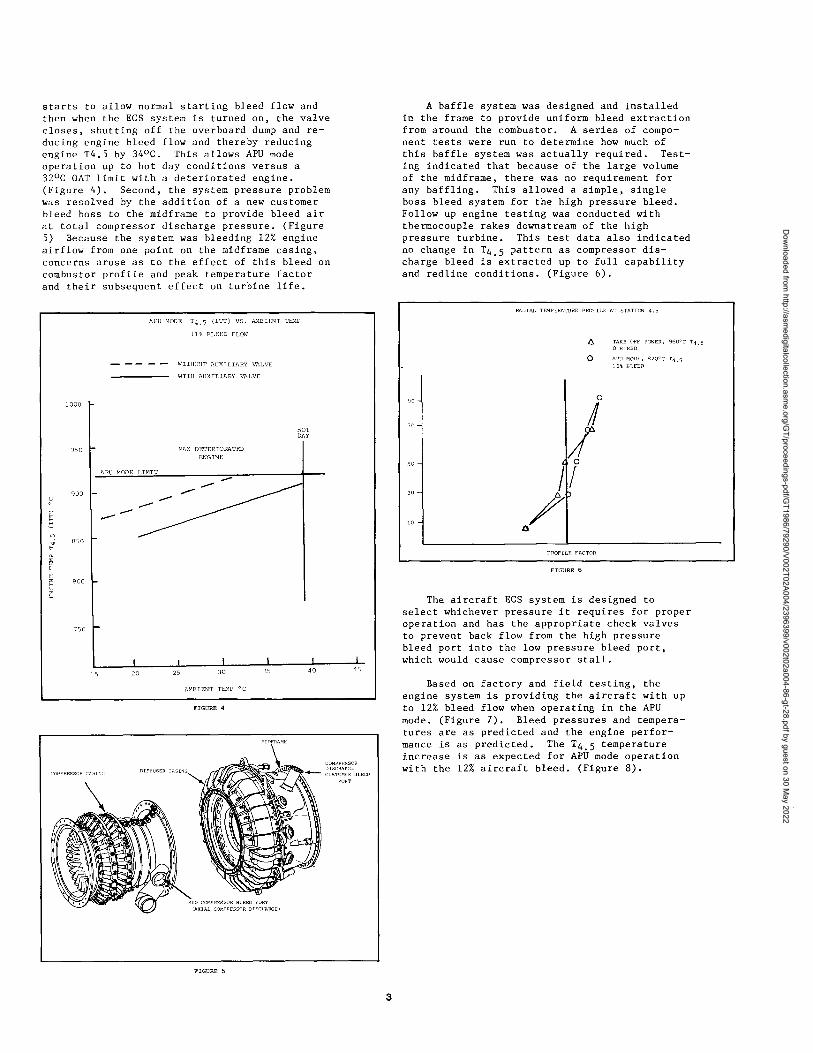
To resolve these two problems, one of excessbleed and the other of insufficient pressure, twoprograms were undertaken. First, to apply avalve downstream of the starting bleed valve toshut off the overboard dump when the engine wasrequested to supply bleed to the aircraft ECSsystem. (Figure 3). This valve is open during
FIGURE 3
Dow
nloaded from http://asm
edigitalcollection.asme.org/G
T/proceedings-pdf/GT1986/79290/V002T02A004/2396399/v002t02a004-86-gt-28.pdf by guest on 30 M
ay 2022
APU MODE T40 (ITT) VS. AMBIENT TEMP
11% BLEED FLOW
WITHOUT AUXILIARY VALVE
WITH AUXILIARY VALVE
1000
HOTDAY
950 MAX DETERIORATEDENGINE
APE MODE LIMIT
900 -o /
850V
SF
800US
750
i
15 20 25 30 35 40 45
AMBIENT TEMP °C
starts to allow normal starting bleed flow andthen when the ECS system is turned on, the valvecloses, shutting off the overboard dump and re-ducing engine bleed flow and thereby reducingengine T4.5 by 34°C. This allows APU modeoperation up to hot day conditions versus a32°C OAT limit with a deteriorated engine.(Figure 4). Second, the system pressure problemwas resolved by the addition of a new customerbleed boss to the midframe to provide bleed airat total compressor discharge pressure. (Figure5) Because the system was bleeding 12% engineairflow from one point on the midframe casing,concerns arose as to the effect of this bleed oncombustor profile and peak temperature factorand their subsequent effect on turbine life.
A baffle system was designed and installedin the frame to provide uniform bleed extractionfrom around the combustor. A series of compo-nent tests were run to determine how much ofthis baffle system was actually required. Test-ing indicated that because of the large volumeof the midframe, there was no requirement forany baffling. This allowed a simple, singleboss bleed system for the high pressure bleed.Follow up engine testing was conducted withthermocouple rakes downstream of the highpressure turbine. This test data also indicatedno change in T45 pattern as compressor dis-charge bleed is extracted up to full capabilityand redline conditions. (Figure 6).
The aircraft ECS system is designed toselect whichever pressure it requires for properoperation and has the appropriate check valvesto prevent back flow from the high pressurebleed port into the low pressure bleed port,which would cause compressor stall.
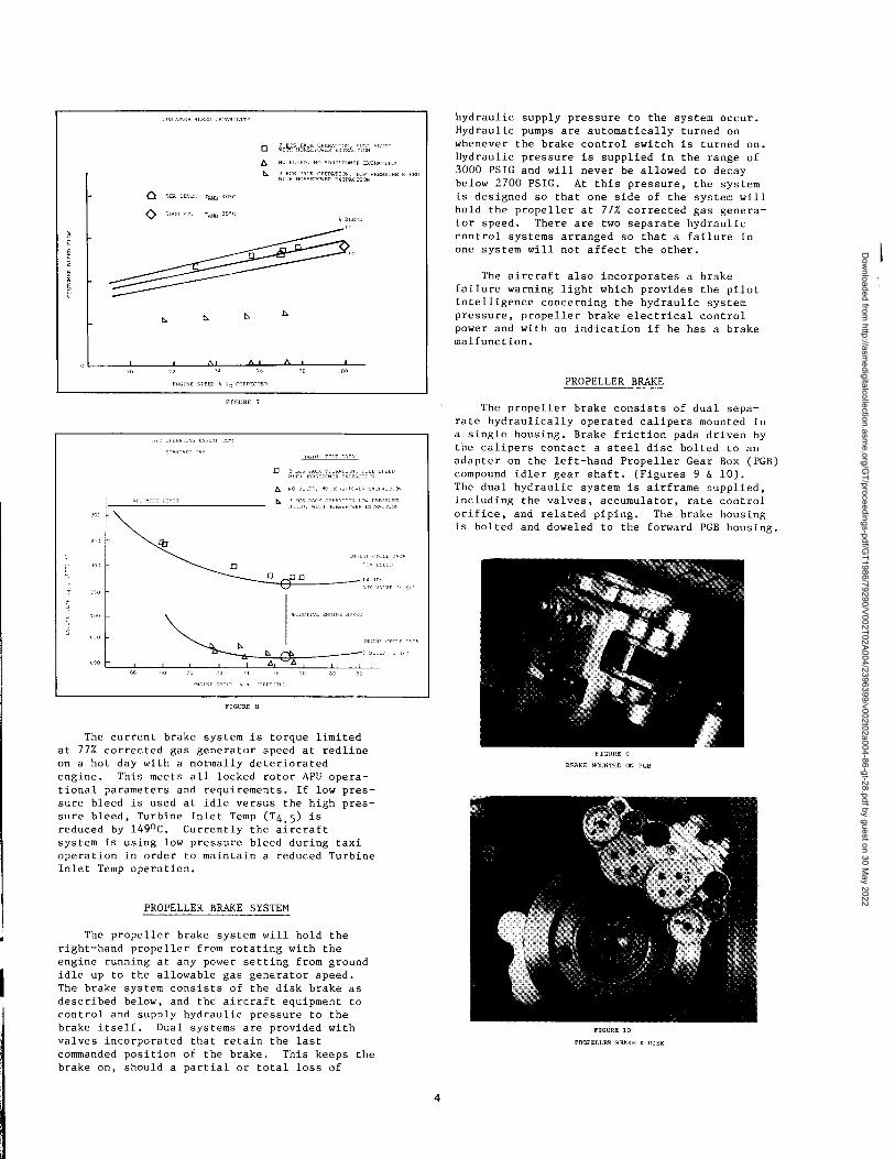
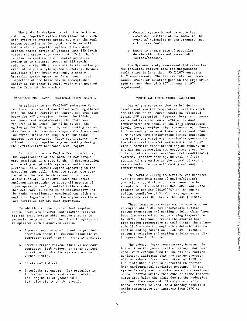
Based on factory and field testing, theengine system is providing the aircraft with upto 12% bleed flow when operating in the APUmode. (Figure 7). Bleed pressures and tempera-tures are as predicted and the engine perfor-mance is as predicted. The T45 temperatureincrease is as expected for APU mode operationwith the 12% aircraft bleed. (Figure 8).
3
Dow
nloaded from http://asm
edigitalcollection.asme.org/G
T/proceedings-pdf/GT1986/79290/V002T02A004/2396399/v002t02a004-86-gt-28.pdf by guest on 30 M
ay 2022
hydraulic supply pressure to the system occur.Hydraulic pumps are automatically turned onwhenever the brake control switch is turned on.Hydraulic pressure is supplied in the range of3000 PSIG and will never be allowed to decaybelow 2700 PSIG. At this pressure, the systemis designed so that one side of the system willhold the propeller at 77% corrected gas genera-tor speed. There are two separate hydrauliccontrol systems arranged so that a failure inone system will not affect the other.
The aircraft also incorporates a brakefailure warning light which provides the pilotintelligence concerning the hydraulic systempressure, propeller brake electrical controlpower and with an indication if he has a brakemalfunction.
❑ SoasEP° Ea exzBA ERRR BLED
NC BLEED, No BRE EDMEN EXTRA N
p z e , LCN EBBS XX BLEED
Q EBA LBDFL p e ao<c
O 5 B FT. y J5 - C
^ p fl
D E
Ro o1I.t , D_ L —1—
a ^
❑ ❑
p o 3^.=E:,, a a. x
^^ e e
The current brake system is torque limitedat 77% corrected gas generator speed at redlineon a hot day with a normally deterioratedengine. This meets all locked rotor APU opera-tional parameters and requirements. If low pres-sure bleed is used at idle versus the high pres-sure bleed, Turbine Inlet Temp (T45) isreduced by 149°C. Currently the aircraftsystem is using low pressure bleed during taxioperation in order to maintain a reduced TurbineInlet Temp operation.
PROPELLER BRAKE SYSTEM
The propeller brake system will hold theright-hand propeller from rotating with theengine running at any power setting from groundidle up to the allowable gas generator speed.The brake system consists of the disk brake asdescribed below, and the aircraft equipment tocontrol and supply hydraulic pressure to thebrake itself. Dual systems are provided withvalves incorporated that retain the lastcommanded position of the brake. This keeps thebrake on, should a partial or total loss of
PROPELLER BRAKE
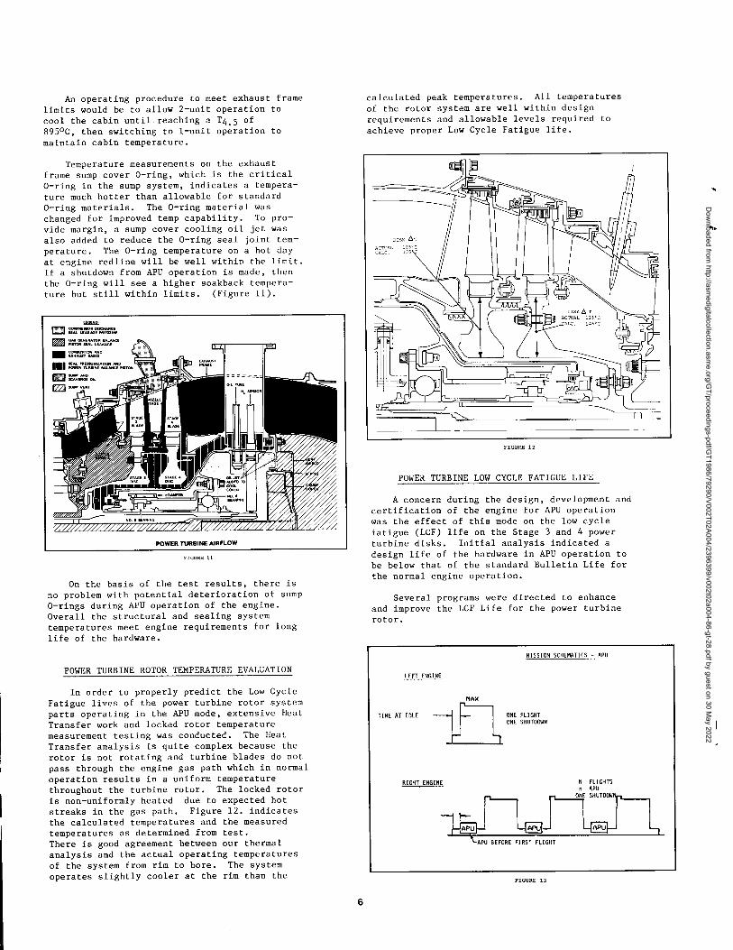
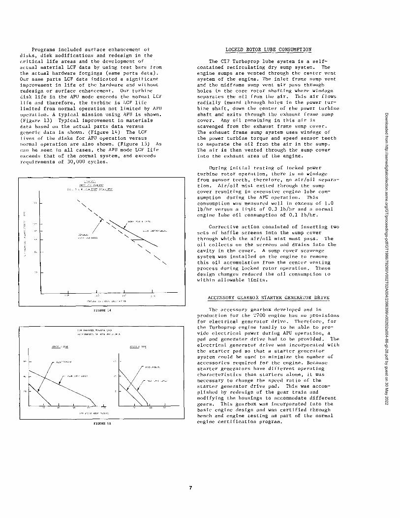
The propeller brake consists of dual sepa-rate hydraulically operated calipers mounted ina single housing. Brake friction pads driven bythe calipers contact a steel disc bolted to anadapter on the left-hand Propeller Gear Box (PGB)compound idler gear shaft. (Figures 9 & 10).The dual hydraulic system is airframe supplied,including the valves, accumulator, rate controlorifice, and related piping. The brake housingis bolted and doweled to the forward PGB housing.
FIGURE 9
BRAKE MOUNTED ON PGB
FIGURE 10
PROPELLER BRAKE 6 DISK
4
Dow
nloaded from http://asm
edigitalcollection.asme.org/G
T/proceedings-pdf/GT1986/79290/V002T02A004/2396399/v002t02a004-86-gt-28.pdf by guest on 30 M
ay 2022
The brake is designed to stop the featheredrotating propeller system from ground idle withboth hydraulic systems operating. With the dualsystem operating as designed, the brake willhold a static propeller system up to a demon-strated static torque of greater than 250 ft -lbversus the system requirement of 175 ft-lb. Itis also designed to hold a static propellersystem up to a static torque of 135 ft -lb.referred to the PGB drive shaft in the unlikelyevent of only a single system operating. Dynamicactuation of the brake with only a singlehydraulic system operating is not authorized.Inspection of the brake may be accomplishedeasily as the brake is fully visible as mountedon the front of the gearbox.
PROPELLER BRAKE/APU OPERATIONAL CERTIFICATION
In addition to the FAR33-87 Endurance Testrequirements, special conditions were negotiatedwith the FAA to certify the engine and propellerbrake for APU operation. Beyond the 150-hourendurance test requirements, the brake wasrequired to be tested for 45 hours with theengine in the APU mode. Dynamic braking demon-stration for 400 complete stops and releases and100 engine starts and stops with the brakeengaged were required. These requirements wereall met during propeller engine testing duringthe Certification Endurance Test Program.
In addition to the Engine Test conditions,1000 applications of the brake at max torquewere completed on a test bench. A demonstrationof the single hydraulic system actuation wasperformed on an actual engine operating in thepropeller test cell. Pressure tests were per-formed on the test bench as was hot and coldstatic testing. A Failure Modes and EffectAnalyses was provided to cover all aspects ofbrake operation and potential failure modes.This data was all found to be satisfactory andthe brake certification completed was with theengine in August of 1983. The engine was there-fore certified for APU mode operation.
In addition to the Special Test Require-ments, there are several installation featuresfor the brake system which ensure that it isproperly integrated with the aircraft system andis operated within approved limits.
o A power lever stop or detent to precludeoperation above the maximum allowable gasgenerator speed when the brake is applied.
o Thermal relief valves, fluid volume com -pensators, lock valves, or other devicesto maintain hydraulic system pressurewithin limits.
o "Brake on" indicator.
o Interlocks to ensure: (a) propeller isin feather before system can operate;(b) engine is at ground idle;(c) aircraft is on the ground.
Control system to maintain the lastcommanded position of the brake in theevent of hydraulic system pressure losswith brake "on".
Means to ensure rate of propellerdeceleration does not exceed 60radians/second 2 .
The Systems Safety assessment indicates thatthe potential failure rate for uncommandedapplication is less than .95 X 10 -6 versus a10-6 requirement. The failure rate for uncom-manded propeller rotation when in the prop brakemode is less than .6 X 10 -7 .versus a 10-7requirement.
STRUCTURAL TEMPERATURE EVALUATION
One of the concerns that we had duringdevelopment was the temperature level to whichthe aft end of the engine would be subjectedduring APU operation. Because there is no powerextracted from the power turbine, exhausttemperatures are equal to the T4 . 5 temperaturelevels (power turbine inlet temperature). Powerturbine casing, exhaust frame and exhaust framelube system sump temperatures during operationwere fully evaluated with particular concern tothe structural temperatures which would occurwith a normally deteriorated engine running on ahot day and supporting the necessary bleed fordriving both aircraft environmental conditioningsystems. Factory testing, as well as fieldtesting of the engine in the actual aircraft,was conducted to evaluate casing and sumptemperatures.
The turbine casing temperature was measuredover the complete range of engine/aircraftoperational conditions and was deemed to beacceptable. The data that was taken was extra-polated to hot day (ISA+30°C) at the engineredline condition of 917°C. Average casingtemperature was 30°C below the casing limit.
These temperature measurements were made onan engine which did not incorporate turbinecasing insulation and sealing shields which havebeen demonstrated to reduce casing temperatureby 50°C. This would reduce the average tur-bine casing temperature to well within the allow-able limits when the engine has deteriorated toredline and operating on a hot day. Turbinecasing insulation and sealing shields currentlyin operation in the field.
The exhaust frame temperature, however, ishotter than the power turbine casing. Our testdata, when extrapolated to the hot day redlinecondition, indicates that the engine operateswith an exhaust frame temperature of 11°C overthe limit when bleed is extracted to operateboth environmental condition systems. If thesystem is only used to drive one of the environ-mental control units, then exhaust frame tempera-tures drop below the limit due to the reductionin bleed flow required. If only one environ-mental control is used on a hot-day condition,cabin temperature can increase from 29°C to43°C.
Dow
nloaded from http://asm
edigitalcollection.asme.org/G
T/proceedings-pdf/GT1986/79290/V002T02A004/2396399/v002t02a004-86-gt-28.pdf by guest on 30 M
ay 2022
An operating procedure to meet exhaust framelimits would be to allow 2-unit operation tocool the cabin until reaching a T4 . 5 of895°C, then switching to 1-unit operation tomaintain cabin temperature.
Temperature measurements on the exhaustframe sump cover 0-ring, which is the critical0-ring in the sump system, indicates a tempera-ture much hotter than allowable for standard0-ring materials. The 0-ring material waschanged for improved temp capability. To pro-vide margin, a sump cover cooling oil jet wasalso added to reduce the 0-ring seal joint tem-perature. The 0-ring temperature on a hot dayat engine redline will be well within the limit.If a shutdown from APU operation is made, thenthe 0-ring will see a higher soakback tempera -
ture but still within limits. (Figure 11).
t -^
On the basis of the test results, there isno problem with potential deterioration of sump0-rings during APU operation of the engine.Overall the structural and sealing systemtemperatures meet engine requirements for longlife of the hardware.
POWER TURBINE ROTOR TEMPERATURE EVALUATION
In order to properly predict the Low CycleFatigue lives of the power turbine rotor systemparts operating in the APU mode, extensive HeatTransfer work and locked rotor temperaturemeasurement testing was conducted. The HeatTransfer analysis is quite complex because therotor is not rotating and turbine blades do notpass through the engine gas path which in normaloperation results in a uniform temperaturethroughout the turbine rotor. The locked rotoris non-uniformly heated due to expected hotstreaks in the gas path. Figure 12. indicatesthe calculated temperatures and the measuredtemperatures as determined from test.There is good agreement between our thermalanalysis and the actual operating temperaturesof the system from rim to bore. The systemoperates slightly cooler at the rim than the
calculated peak temperatures. All temperaturesof the rotor system are well within designrequirements and allowable levels required toachieve proper Low Cycle Fatigue life.
POWER TURBINE LOW CYCLE FATIGUE LIFE
A concern during the design, development andcertification of the engine for APU operationwas the effect of this mode on the low cyclefatigue (LCF) life on the Stage 3 and 4 powerturbine disks. Initial analysis indicated adesign life of the hardware in APU operation tobe below that of the standard Bulletin Life forthe normal engine operation.
Several programs were directed to enhanceand improve the LCF Life for the power turbinerotor.
MISSION SCHEMATICS - APU
LEFT ENGINE
MAX
TIME AT IDLE —may ONE FLIGHTONE SHUTDOWN
RIGHT ENGINE N FLIGHTSn APU
ONE SOSTDOW
APU AP APU
APU BEFORE FIRST FLIGHT
6
Dow
nloaded from http://asm
edigitalcollection.asme.org/G
T/proceedings-pdf/GT1986/79290/V002T02A004/2396399/v002t02a004-86-gt-28.pdf by guest on 30 M
ay 2022
Programs included surface enhancement ofdisks, disk modifications and redesign in thecritical life areas and the development ofactual material LCF data by using test bars fromthe actual hardware forgings (same parts data).Our same parts LCF data indicated a significantimprovement in life of the hardware and withoutredesign or surface enhancement. Our turbinedisk life in the APU mode exceeds the normal LCFlife and therefore, the turbine is LCF lifelimited from normal operation not limited by APUoperation. A typical mission using APU is shown.(Figure 13) Typical improvement in materialsdata based on the actual parts data versusgeneric data is shown. (Figure 14) The LCFlives of the disks for APU operation versusnormal operation are also shown. (Figure 15) Ascan be seen in all cases, the APU mode LCF lifeexceeds that of the normal system, and exceedsrequirements of 30,000 cycles.
LOCKED ROTOR LUBE CONSUMPTION
The CT7 Turboprop lube system is a self-contained recirculating dry sump system. Theengine sumps are vented through the center ventsystem of the engine. The inlet frame sump ventand the midframe sump vent air pass throughholes in the core rotor shafting where windageseparates the oil from the air. This air flowsradially inward through holes in the power tur-bine shaft, down the center of the power turbineshaft and exits through the exhaust frame sumpcover. Any oil remaining in this air isscavenged from the exhaust frame sump cover.The exhaust frame sump system uses windage ofthe power turbine torque and speed sensor teethto separate the oil from the air in the sump.The air is then vented through the sump coverinto the exhaust area of the engine.
During initial testing of locked powerturbine rotor operation, there is no windagefrom sensor teeth, therefore, no air/oil separa-tion. Air/oil mist exited through the sumpcover resulting in excessive engine lube con-sumption during the APU operation. Thisconsumption was measured well in excess of 1.0lb/hr versus a limit of 0.3 lb/hr and a normalengine lube oil consumption of 0.1 lb/hr.
Corrective action consisted of inserting twosets of baffle screens into the sump coverthrough which the air/oil mist must pass. Theoil collects on the screens and drains into thecavity in the cover. A sump cover scavengesystem was installed on the engine to removethis oil accumulation from the center ventingprocess during locked rotor operation. Thesedesign changes reduced the oil consumption towithin allowable limits.
ACCESSORY GEARBOX STARTER GENERATOR DRIVE
The accessory gearbox developed and inproduction for the T700 engine has no provisionsfor electrical generator drive. Therefore, forthe Turboprop engine family to be able to pro-vide electrical power during APU operation, apad and generator drive had to be provided. Theelectrical generator drive was incorporated withthe starter pad so that a starter generatorsystem could be used to minimize the number ofaccessories required for the engine. Becausestarter generators have different operatingcharacteristics than starters alone, it wasnecessary to change the speed ratio of thestarter generator drive pad. This was accom-plished by redesign of the gear train andmodifying the housings to accommodate differentgears. This gearbox was incorporated into thebasic engine design and was certified throughbench and engine testing as part of the normalengine certification program.
Dow
nloaded from http://asm
edigitalcollection.asme.org/G
T/proceedings-pdf/GT1986/79290/V002T02A004/2396399/v002t02a004-86-gt-28.pdf by guest on 30 M
ay 2022

ENGINE STARTING DEVELOPMENT
During the T700/CT7 Turboshaft DevelopmentProgram, starting had been accomplished throughhydraulic, air turbine, and electric starters.With the changeover to a starter generatorsystem, the starting torque characteristics werechanged.
This required extensive testing and develop-ment of modified start schedules for both sealevel and altitude operation. This starterdevelopment work was accomplished during theengine and aircraft certification program. Allchanges were incorporated prior to the beginningof revenue service with the engine.
C1TMMARV
The operation of the CT7 Turboprop engine inthe APU mode resulted in some new design anddevelopment challenges which were resolved byboth factory and field testing in the actualaircraft operating environment. The CT7 engineis now available to the Commuter Airline marketwith its APU feature which provides environ-mental control system bleed flow and aircraftelectrical power required for ground operation.
REFERENCES1) Stewart, J.D., "CT7-5A/7/7E Turboprop Engine
for Commuter Airline Service," 84-GT-257,
ASME 29th International Gas Turbine
Conference and Exhibit, Amsterdam, The
Netherlands, June 3 - 7, 1984.
8
Dow
nloaded from http://asm
edigitalcollection.asme.org/G
T/proceedings-pdf/GT1986/79290/V002T02A004/2396399/v002t02a004-86-gt-28.pdf by guest on 30 M
ay 2022
Related Documents