Operation MANUAL XRF-2000 Series Revision 1.0 July 2009

Welcome message from author
This document is posted to help you gain knowledge. Please leave a comment to let me know what you think about it! Share it to your friends and learn new things together.
Transcript
Operation
MANUAL
XRF-2000 Series
Revision 1.0 July 2009

XRF-2000 Series Operating Manual
Micro Pioneer 2
IMPORTANT – PLEASE READ THIS FIRST! COPYRIGHT○c2009 MICRO PIONEER ALL RIGHT RESERVED
PLEASE READ CAREFULLY THE OPERATION AND APPROPRIATE MAINTENANCE INSTRUCTIONS IN THIS
MANUAL BEFORE ATTEMPTING TO OPERATE THE EQUIPMENT. NOTWITHSTANDING MICRO PIONEER‟S LIMITED WARRANTY,
MICRO PIONEER WILL NOT ASSUME ANY LIABILITY FOR INJURY, LOSS OR DAMAGE TO PERSONNEL, PROPERTY OR
TO THE EQUIPMENT IF IT IS NOT CONNECTED OR OPERATED PROPERY.
SERVICE AND REPAIR OF THE SYSTEM SHOULD BE LIMITED TO QUALIFIED PERSONNEL ONLY. THE SYSTEM MUST BE
DISCONNECTED FROM THE ELECTRICAL POWER SOURCE BEFORE SERVICING.
MICRO PIONEER RESERVES THE RIGHT TO MAKE CHANGES AND IMPROVEMENTS IF THE SYSTEM, AS WELL AS IN THE SPECIFICATIONS AND DESCRIPTIONS PROVIDED IN THIS
MANUAL WITHOUT PRIOR NOTICE. FOR ADDITIONAL INFORMATION, PLEASE CONTACT:
Micro Pioneer
1414 Dae-Ryung Techno Town 8th
Kasan-Dong, Kumchun-Gu, Seoul, Korea www.micropioneer.com TEL : +82-2-2163-8650

XRF-2000 Series Operating Manual
Micro Pioneer 3
Table of Content
1. Introduction 1.1 System Purpose ................................................................................. 5
1.2 Principles of Operation ....................................................................... 5 1.3 Typical Specification .......................................................................... 7 2. System Operation 2.1 Safety Considerations ........................................................................ 8 2.2 Radiation Safety ................................................................................. 9 2.3 Site Preparation ................................................................................. 9 2.4 Software Installation ......................................................................... 10 2.5 Running XRF-2000 Software............................................................ 10 3. Main Measuring Window 3.1 File Menu ......................................................................................... 11 3.1.1 Config Window ....................................................................... 11 3.1.2 Administrator Login ................................................................ 12 3.1.3 Exit ......................................................................................... 13 3.2 Display ............................................................................................. 13 3.3 Cal ................................................................................................... 13 3.4 Etc.................................................................................................... 15 3.5 Micro Pioneer ................................................................................... 15 4. Main Toolbar 4.1 System Configuration ....................................................................... 17
4.1.1 Menu1 .................................................................................... 17 4.1.2 Menu2 .................................................................................... 18 4.1.3 Admin Set .............................................................................. 18 4.2 Set Limit ........................................................................................... 19 4.3 SET Measuring Time ....................................................................... 20 4.4 View Statistic Window ...................................................................... 20 4.4.1 File menu ............................................................................... 21 4.4.2 Print Menu .............................................................................. 21 4.4.3 Diff Block Menu ...................................................................... 22 4.4.4 Setup Menu ............................................................................ 23 4.5 PHA Display Window 4.5.1 Qualitative Analysis. ............................................................... 31 4.5.2 Editing and Manipulating Spectra ........................................... 31 4.6 Camera Display Window. ................................................................. 35 4.7 Stage Control Window...................................................................... 37 4.8 Periodic Table. ................................................................................. 38 4.9 2D&3D Measure Window. ................................................................ 38 4.9.1 2D(Step)................................................................................. 38 4.9.2 2D(Point). ............................................................................... 38 4.9.3 3D(Scan). ............................................................................... 39 4.9.4 3D(Point) ................................................................................ 39
XRF-2000 Series Operating Manual
Micro Pioneer 4
4.10 Random Stage. .............................................................................. 40 4.11 Set Display Unit. ............................................................................. 40 4.12 Set Display Resolution. .................................................................. 41 4.13 Cal File Select Window .................................................................. 41 4.14 Recalibration Window..................................................................... 42 4.15 New Calibration .............................................................................. 43
4.16 System Adjustment Window ........................................................... 46 4.17 Focus Laser ................................................................................... 46 4.18 Lamp .............................................................................................. 47 4.19 Set Y Stage Auto Move .................................................................. 47 4.20 Auto Cycle Measurement ............................................................... 47 4.21 Auto Cycle Number ........................................................................ 47 5. How To Measure ...................................................................................... 47 5.1 Loading Sample ............................................................................... 47 5.2 Adjust Focus. ................................................................................... 47 5.3 Select Cal File and Click Start Button. .............................................. 47 2.4. Change the Measuring time. ........................................................... 42 2.5. Change the Measuring unit. ............................................................ 42 2.6. Change the display decimal point. ................................................... 42 2.7. Use the Auto-Cycle function. ........................................................... 42 2.8. Change the calibration file. .............................................................. 43
Appendix A. Regression Models ............................................................................ 48 B. System Adjust. ................................................................................... 50 C. Collimator and Primary Filter Setting. ................................................ 56 D. Low CPS Problem. ............................................................................ 59 E. Installation and Pre Operation............................................................ 60
F. Creating a new CAL. File. .................................................................. 62 G. Stage Moving Concept for PIN Diode Detector .................................. 70

XRF-2000 Series Operating Manual
Micro Pioneer 5
1 Introduction 1.1 System Purpose
XRF-2000 systems are designed to measure the thickness of multi coating elements or to detect the elements in analyzed samples and determine their concentrations using X-Ray fluorescence (XRF). The analysis performed by XRF-2000 series can by divided into three categories: Thickness measurement – measure the thickness of multilayer
coating Qualitative analysis – Identification of the elements in a sample
and inspection of the acquired spectra on a comparative basis. Quantitative analysis – Quantitative determination of the
concentrations of the elements in a sample. This is performed after carrying out calibration procedures, using a pre-analyzed set of standards and empirical models, or via the fundamental parameters method.
The system software (XRayV4) runs under Windows XP, Vista or higher.
XRF-2000 Series
1.2 Principles of Operation
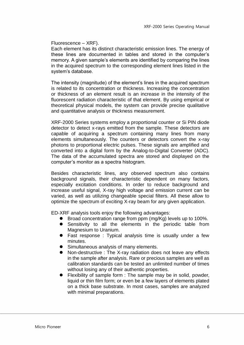
XRF-2000 Series systems utilize the phenomenon that when a sample is irradiated with x-ray radiation, the sample‟s atoms are excited. As the atoms return to their stable state, they emit x-ray photons (X-ray
XRF-2000 Series Operating Manual
Micro Pioneer 6
Fluorescence – XRF). Each element has its distinct characteristic emission lines. The energy of these lines are documented in tables and stored in the computer‟s memory. A given sample‟s elements are identified by comparing the lines in the acquired spectrum to the corresponding element lines listed in the system‟s database. The intensity (magnitude) of the element‟s lines in the acquired spectrum is related to its concentration or thickness. Increasing the concentration or thickness of an element result is an increase in the intensity of the fluorescent radiation characteristic of that element. By using empirical or theoretical physical models, the system can provide precise qualitative and quantitative analysis or thickness measurement. XRF-2000 Series systems employ a proportional counter or Si PIN diode detector to detect x-rays emitted from the sample. These detectors are capable of acquiring a spectrum containing many lines from many elements simultaneously. The counters or detectors convert the x-ray photons to proportional electric pulses. These signals are amplified and converted into a digital form by the Analog-to-Digital Converter (ADC). The data of the accumulated spectra are stored and displayed on the computer‟s monitor as a spectra histogram. Besides characteristic lines, any observed spectrum also contains background signals, their characteristic dependent on many factors, especially excitation conditions. In order to reduce background and increase useful signal, X-ray high voltage and emission current can be varied, as well as utilizing changeable special filters. All these allow to optimize the spectrum of exciting X-ray beam for any given application. ED-XRF analysis tools enjoy the following advantages: Broad concentration range from ppm (mg/Kg) levels up to 100%. Sensitivity to all the elements in the periodic table from
Magnesium to Uranium. Fast response : Typical analysis time is usually under a few
minutes. Simultaneous analysis of many elements. Non-destructive : The X-ray radiation does not leave any effects
in the sample after analysis. Rare or precious samples are well as calibration standards can be tested an unlimited number of times without losing any of their authentic properties.
Flexibility of sample form : The sample may be in solid, powder, liquid or thin film form; or even be a few layers of elements plated on a thick base substrate. In most cases, samples are analyzed with minimal preparations.
XRF-2000 Series Operating Manual
Micro Pioneer 7
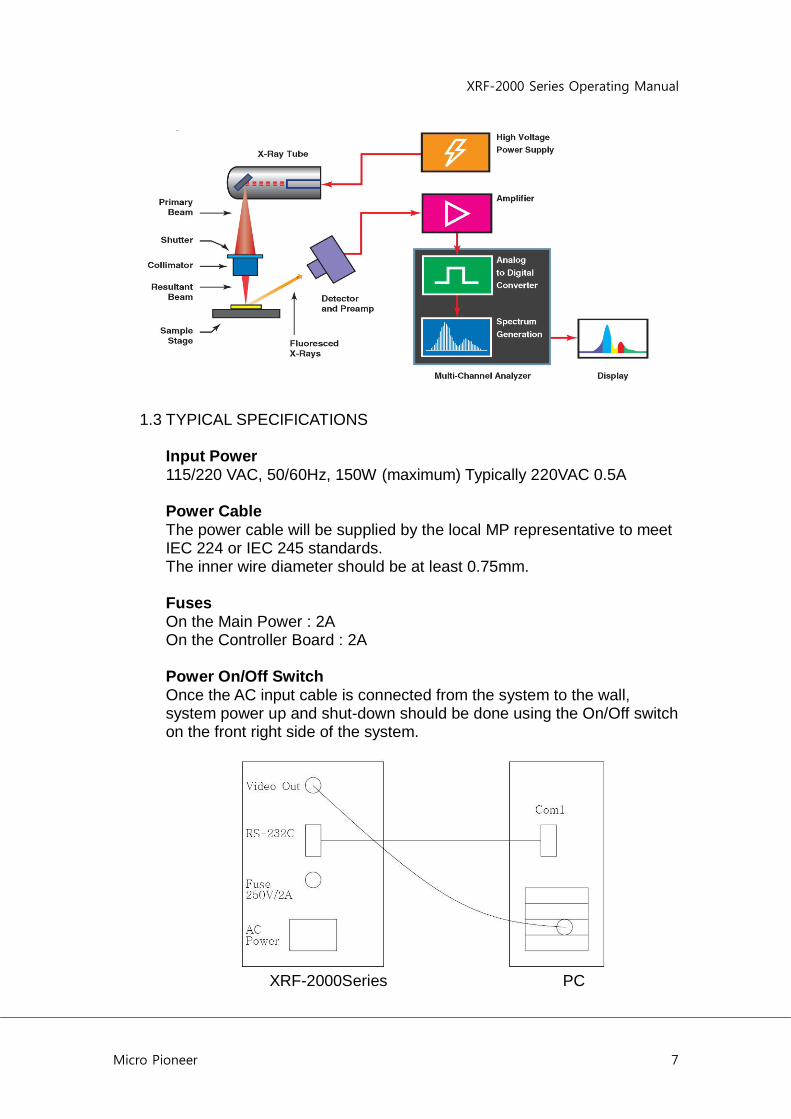
1.3 TYPICAL SPECIFICATIONS Input Power 115/220 VAC, 50/60Hz, 150W (maximum) Typically 220VAC 0.5A Power Cable The power cable will be supplied by the local MP representative to meet IEC 224 or IEC 245 standards. The inner wire diameter should be at least 0.75mm. Fuses On the Main Power : 2A On the Controller Board : 2A Power On/Off Switch Once the AC input cable is connected from the system to the wall, system power up and shut-down should be done using the On/Off switch on the front right side of the system.
XRF-2000Series PC

XRF-2000 Series Operating Manual
Micro Pioneer 8
2. System Operation
2.1 Safety Considerations Standard Procedures All standard safety procedures for operating electrical machinery should apply to spectrometers of this series.
Each system is intended to be operated only as indicated in its User‟s manual.
Maintenance work inside the machine should be performed only by authorized personnel.
Power Source
This product is intended to operate from a power source that does not supply more than 230 volts RMS (in 220 volt version) or 120 volts RMS (in 115 volt version) between either supply conductors or between either supply conductor and ground. A protective ground connection by way of the grounding conductor in the power cord is essential for safe operation.
Grounding the Product
This product is grounded through the grounding conductor of the power cord. To avoid electrical shock, plug the power cord into a properly wired receptacle before connecting to the product input or output terminals. A protective ground connection by way of grounding conductor in the power cord is essential for safe operation.
Danger arising from loss of Ground
Upon loss of the protective –ground, all accessible conductive parts (including knobs and controls that may appear to be insulated) can render an electric shock.
Use the proper power cord
Use only the power cord and connector specified for your product and valid in the country where the machine in installed. Make sure that both are in good condition and do not use extension cables.
Use the proper fuse
To avoid fire hazard, use only a fuse of the correct type, voltage rating and current rating as specified.

XRF-2000 Series Operating Manual
Micro Pioneer 9
2.2 Radiation Safety
XRF-2000 Series equipment is intrinsically safe from radiation hazards. Every machine is inspected prior to its delivery, ensuring that level of radiation anywhere around the sample chamber is not higher than the ambient radiation in the free environment. The instruments are equipped with safety magnetic switches to ensure that proper shielding is in place during x-ray operation, avoiding a possibility of exposure to radiation. Overriding safety features should not be done under any circumstances. These features have been installed for your safety.
Depending on the country, personnel operating X-ray instrumentation may have to be registered with the relevant health and radiation control authorities and may be required to wear dosimeters to monitor their exposure to radiation as well as to undergo annual medical examinations to safe guard their health. Local radiation control authorities may require that your instrument be registered with the relevant controlling bodies and that you carry out periodic radiation leak detection tests to ensure the ongoing safety in the utilization of the instrument.
You will need to check the relevant legislation and your compliance thereof with the correct controlling bodies in your country.
2.3 Site Preparation
INSTALLATION SITE
The system site should be free of excessive mechanical vibrations and strong acoustical noise. Strong electrical fields such as those generated by arc welding instruments, induction furnaces, large electric power lines, etc., can interfere with signals from the X-ray Detector and decrease its resolution.
Please do not hesitate to consult the service agent if you suspect that such problems exist.
PHYSICAL ENVIRONMENT
Keep the system and its vicinity clean and dust-free; circuit boards and components in the system and computer could fail due to an accumulation of conductive dust or from corrosion.
Avoid extreme temperatures or high humidity. The recommended operating temperature range is 20 - 25° C. Constant temperature assures the stability of system calibration.
XRF-2000 Series Operating Manual
Micro Pioneer 10
2.4 Software Installation
Make sure your computer is correctly connected and then turn on the monitor and computer. XrayV4 is software of XRF-2000 series and updated periodically. You can download it from Micro Pioneer‟s web site www.micropioneer.com. XRayV4 includes two folders as Net20 and Setup. Go to Setup Folder and double clicking the setup.exe will install the software. Typical location for installation is C:\XRayV4.
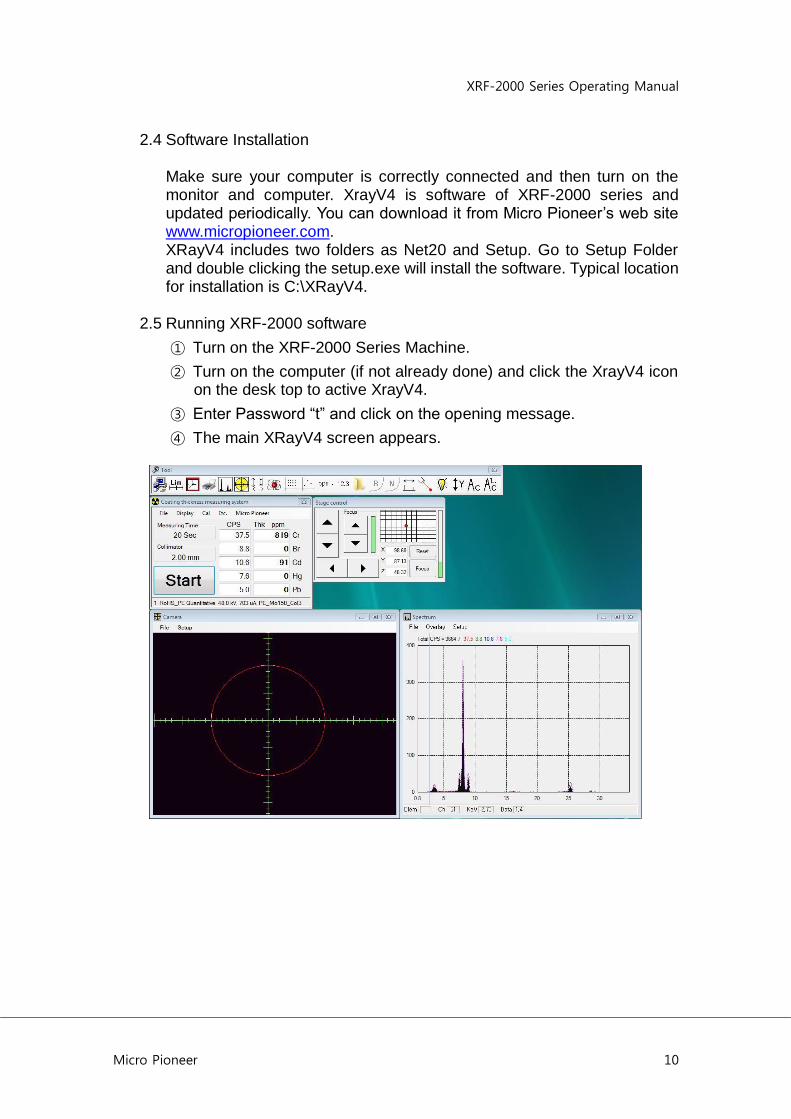
2.5 Running XRF-2000 software
① Turn on the XRF-2000 Series Machine.
② Turn on the computer (if not already done) and click the XrayV4 icon on the desk top to active XrayV4.
③ Enter Password “t” and click on the opening message.
④ The main XRayV4 screen appears.

XRF-2000 Series Operating Manual
Micro Pioneer 11
3. Main Measuring Window
Display Measuring Time, Collimator Size, Start and Stop Button, CPS Information, Result of Thickness or Concentration and Measuring Mode. Start Button toggle start and stop to measuring.
3.1 File Menu
3.1.1 Config window
XRF-2000 Series Operating Manual
Micro Pioneer 12
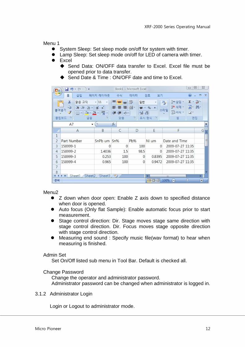
Menu 1 System Sleep: Set sleep mode on/off for system with timer. Lamp Sleep: Set sleep mode on/off for LED of camera with timer. Excel Send Data: ON/OFF data transfer to Excel. Excel file must be
opened prior to data transfer. Send Date & Time : ON/OFF date and time to Excel.
Menu2 Z down when door open: Enable Z axis down to specified distance
when door is opened. Auto focus (Only flat Sample): Enable automatic focus prior to start
measurement. Stage control direction: Dir. Stage moves stage same direction with
stage control direction. Dir. Focus moves stage opposite direction with stage control direction.
Measuring end sound : Specify music file(wav format) to hear when measuring is finished.
Admin Set
Set On/Off listed sub menu in Tool Bar. Default is checked all.
Change Password Change the operator and administrator password. Administrator password can be changed when administrator is logged in.
3.1.2 Administrator Login
Login or Logout to administrator mode.

XRF-2000 Series Operating Manual
Micro Pioneer 13
- Enable menu in administrator mode * Camera display window :
Moving by Click, Adjust Beam position, Find Beam center, Capture-Input No
* Main window & Main toolbar : Re Calibration, New Calibration, Y stage Auto, Measure data correction, Density compensation
* Select Cal File : Delete/Edit Cal File and comment on Cal File.
3.1.3 Exit Quit the program
3.2 Display
Toggle window on and off. Description of each window is described in Chapter 4.
3.3 Cal
XRF-2000 Series Operating Manual
Micro Pioneer 14
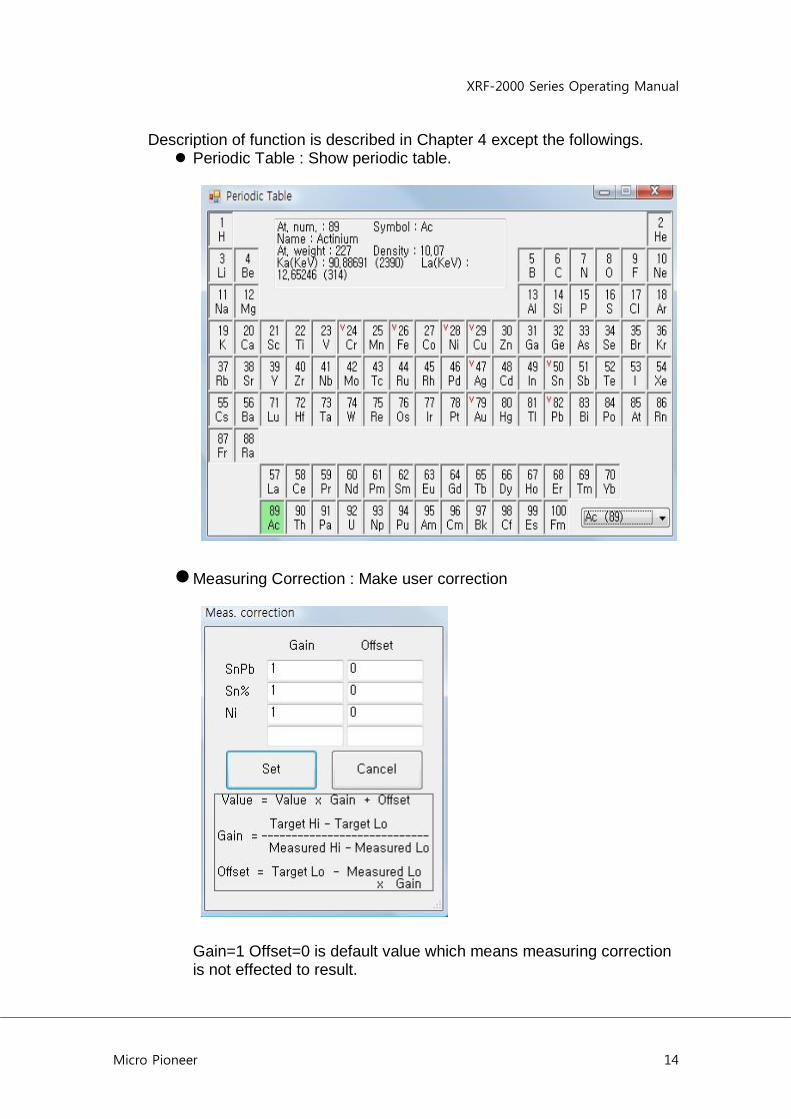
Description of function is described in Chapter 4 except the followings. Periodic Table : Show periodic table.
Measuring Correction : Make user correction
Gain=1 Offset=0 is default value which means measuring correction is not effected to result.

XRF-2000 Series Operating Manual
Micro Pioneer 15
3.4 Etc
Description of function is described in Chapter 4 except the followings. Auto cycle interval : Input Auto cycle interval time. The interval time is
measuring time plus rest time.
3.5 Micro Pioneer
Display Micro Pioneer company information and software version.

XRF-2000 Series Operating Manual
Micro Pioneer 16
4. Main Toolbar
Set Sleep Mode, Laser Focus, Send to Excel, Change Password
Set control limit
Set measuring time
Display statistic window
Display PHA windows
Display Camera window
Display Stage control window
Display Atom list window
Display 2D & 3D measure window
Display Random stage window
Set measuring unit
Set Display decimal point
Select calibration file
Display ReCalibration window
Display New Calibration window
Display System adjust window
ON/OFF the Focus Laser
ON/OFF the illumination lamp
ON/OFF the Y-Stage Push-Pull function. ON : Door open - Stage move to forward.
ON/OFF the Auto-Cycle function
Set number of Auto-Cycle count

XRF-2000 Series Operating Manual
Micro Pioneer 17
4.1 System Configuration 4.1.1 Menu 1
System Sleep: Set sleep mode on/off for system with timer. Lamp Sleep: Set sleep mode on/off for LED of camera with timer. Excel Send Data: ON/OFF data transfer to Excel. Excel file must be
opened prior to data transfer. Send Date & Time : ON/OFF date and time to Excel.
XRF-2000 Series Operating Manual
Micro Pioneer 18
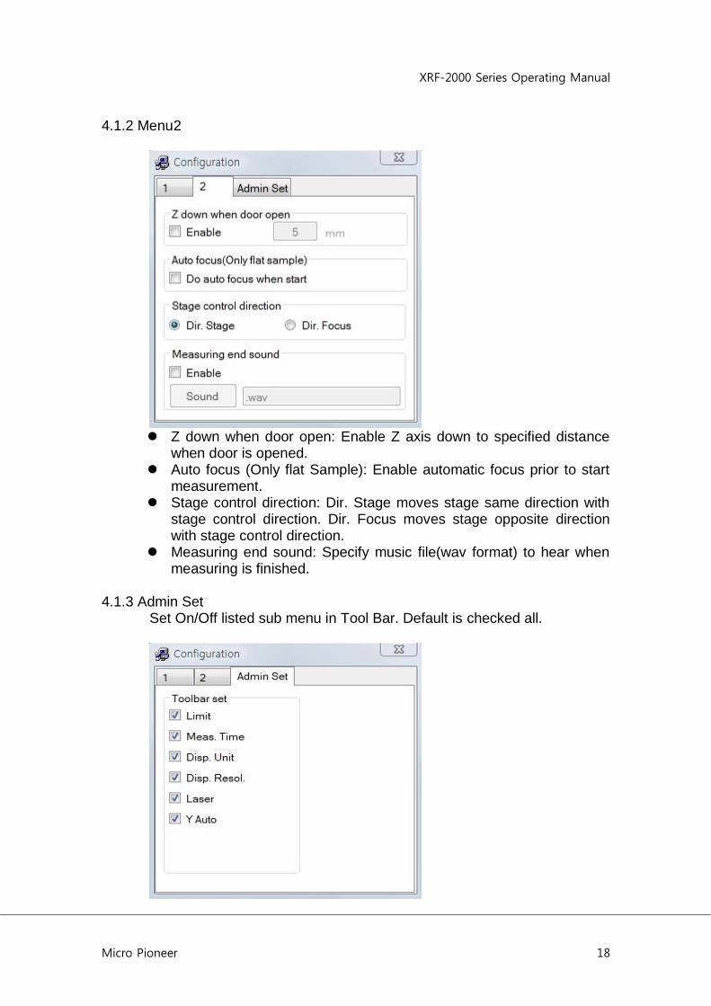
4.1.2 Menu2
Z down when door open: Enable Z axis down to specified distance
when door is opened. Auto focus (Only flat Sample): Enable automatic focus prior to start
measurement. Stage control direction: Dir. Stage moves stage same direction with
stage control direction. Dir. Focus moves stage opposite direction with stage control direction.
Measuring end sound: Specify music file(wav format) to hear when measuring is finished.
4.1.3 Admin Set Set On/Off listed sub menu in Tool Bar. Default is checked all.

XRF-2000 Series Operating Manual
Micro Pioneer 19
4.2 Set Limit
Lower : Lower limit value for Low Mode Upper : Upper limit value for Up Mode Mode Low : Measured data is bigger than 'Lower value' means good UP : Measured data is lower than 'Upper value„ means good LowUp : Measured data is between 'Lower value' and 'Upper Value'
means good. Auto Set Limit : Set the limit value automatically from measured data. Use Ng/Go Color : Display the data result as a color, Green means
good, Red means no good. Open/Save : Open or Save the limit value file. Set : Apply limit value. Cancel : Cancel limit value.
XRF-2000 Series Operating Manual
Micro Pioneer 20
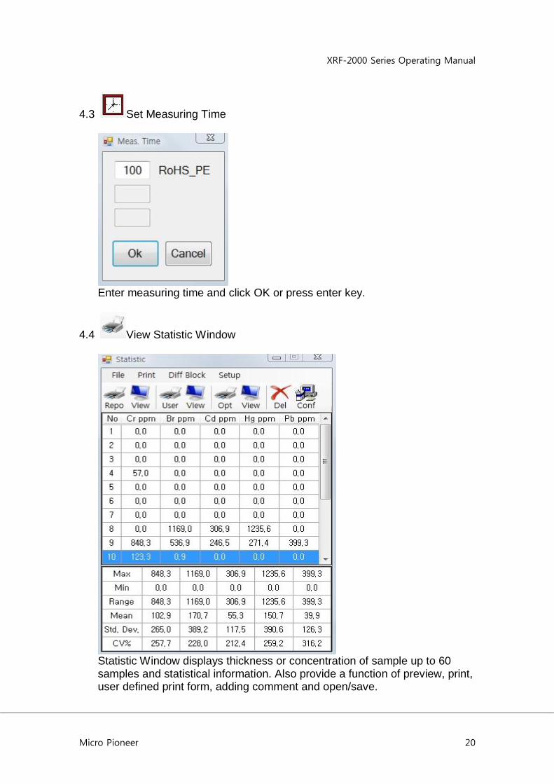
4.3 Set Measuring Time
Enter measuring time and click OK or press enter key.
4.4 View Statistic Window
Statistic Window displays thickness or concentration of sample up to 60 samples and statistical information. Also provide a function of preview, print, user defined print form, adding comment and open/save.
XRF-2000 Series Operating Manual
Micro Pioneer 21
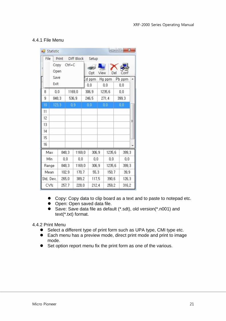
4.4.1 File Menu
Copy: Copy data to clip board as a text and to paste to notepad etc. Open: Open saved data file. Save: Save data file as default (*.sdt), old version(*.n001) and
text(*.txt) format. 4.4.2 Print Menu Select a different type of print form such as UPA type, CMI type etc. Each menu has a preview mode, direct print mode and print to image
mode. Set option report menu fix the print form as one of the various.

XRF-2000 Series Operating Manual
Micro Pioneer 22
4.4.3 Diff Block Menu
XRF-2000 Series Operating Manual
Micro Pioneer 23
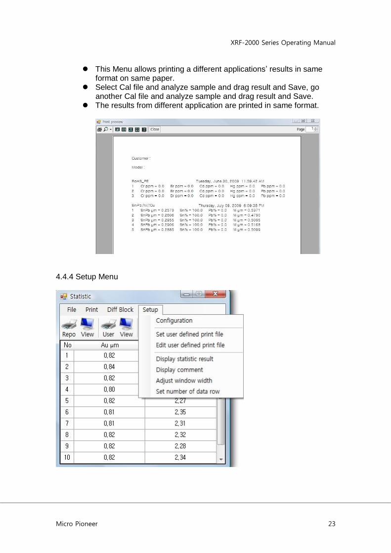
This Menu allows printing a different applications‟ results in same format on same paper.
Select Cal file and analyze sample and drag result and Save, go another Cal file and analyze sample and drag result and Save.
The results from different application are printed in same format.
4.4.4 Setup Menu

XRF-2000 Series Operating Manual
Micro Pioneer 24
4.4.4.1 Configuration
All option for print form is able to define in configuration menu, such as customer name, company logo and others. Company logo must saved in C:\XRayV4\User directory as Logo.bmp. 4.4.4.2 Edit User Defined Print File
1) Open the Statistic Window

XRF-2000 Series Operating Manual
Micro Pioneer 25
The sequence of creating the user defined print form is Configuration -> Edit user defined print file -> Save edited Edit user defined print file -> Set Edit user defined print file -> View and repeat until the completion.
2) Configuration Go to Setup -> Configuration and specify necessary field as follows
XRF-2000 Series Operating Manual
Micro Pioneer 26
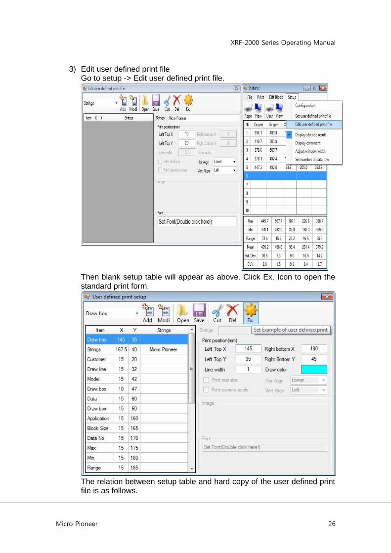
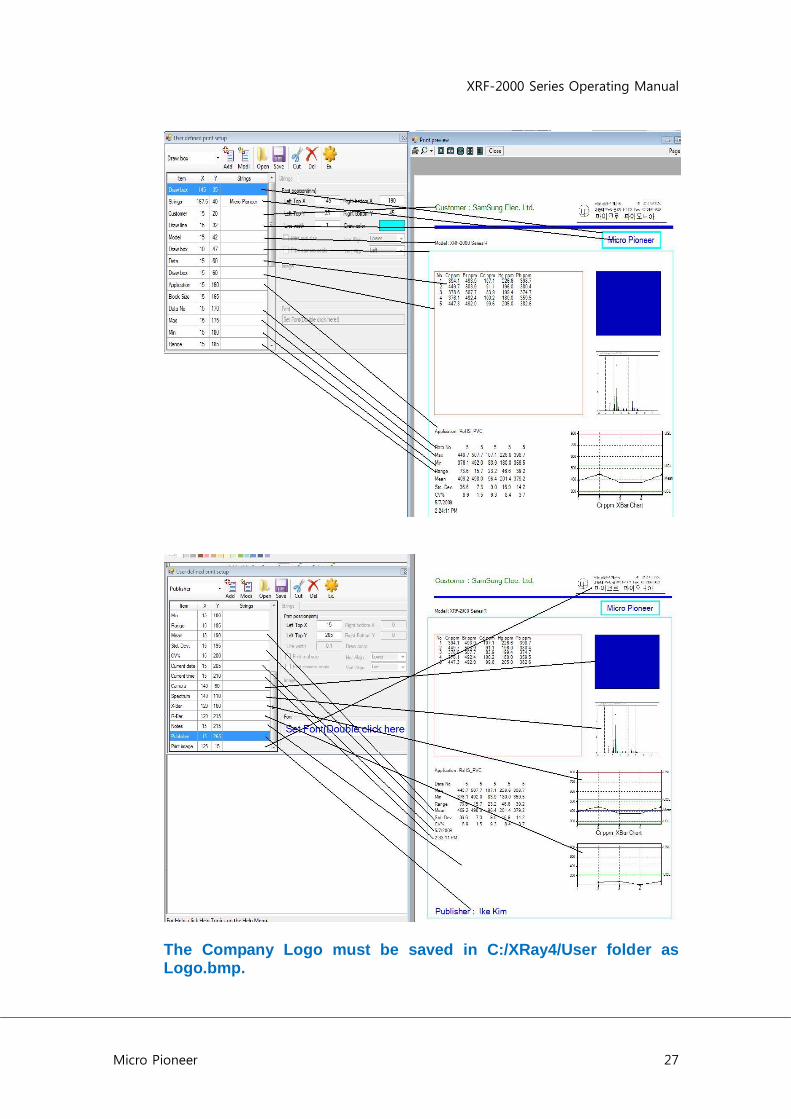
3) Edit user defined print file Go to setup -> Edit user defined print file.
Then blank setup table will appear as above. Click Ex. Icon to open the standard print form.
The relation between setup table and hard copy of the user defined print file is as follows.
XRF-2000 Series Operating Manual
Micro Pioneer 27
The Company Logo must be saved in C:/XRay4/User folder as Logo.bmp.
XRF-2000 Series Operating Manual
Micro Pioneer 28
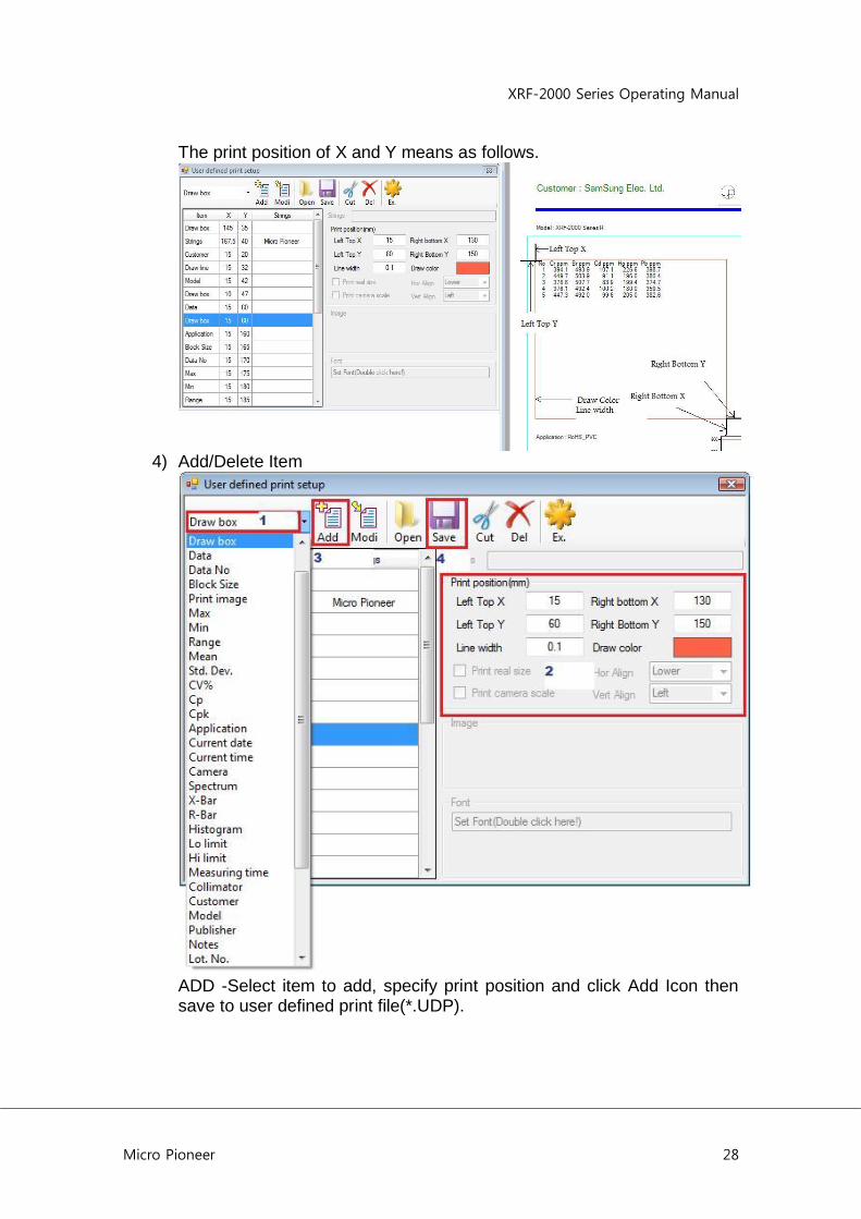
The print position of X and Y means as follows.
4) Add/Delete Item
ADD -Select item to add, specify print position and click Add Icon then save to user defined print file(*.UDP).

XRF-2000 Series Operating Manual
Micro Pioneer 29
Delete – Select item to delete and click Cut Icon then save to user defined print file(*.UDP).
5) Edit Item
Edit – Select item to edit and change the print option such as position, color, Font and line width etc. and click Modi Icon then save to user defined print file(*.UDP).
XRF-2000 Series Operating Manual
Micro Pioneer 30
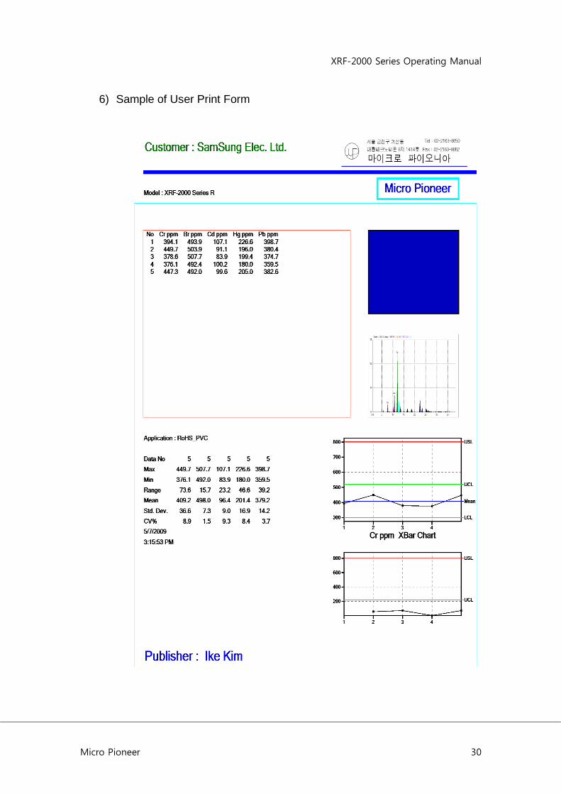
6) Sample of User Print Form

XRF-2000 Series Operating Manual
Micro Pioneer 31
4.5 PHA Display window
4.5.1 Qualitative Analysis The objective of qualitative analysis is to identify the elemental component of unknown substances. The first step in qualitative analysis is spectra acquisition. Following spectra acquisition, the spectra must be manipulated and studied to best determine additional spectra acquisition and/or the qualitative answer desired. This covers guidelines for qualitative analysis including various spectral manipulations. Setting acquisition parameters
(High Voltage and Tube Current setting in CAL File) Since the purpose of qualitative analysis is to identify the components in a sample, acquisition parameters should be selected to optimize the identification CAL File. This is done by maximizing the spectral range covered by the excitation-detection system as well as obtaining sufficient sensitivity to identify even trace amounts of the elements present in sample. This is accomplished by optimizing the X-Ray levels. Total CPS on PHA display is a good indication of this optimized level. Voltage(KV) and current(uA) settings, combined, should allow for CPS of 3,000 or less.
Guidelines to excitation parameter efficiencies The following are guidelines to help achieve good qualitative analysis. 1. Set the uA setting to achieve satisfactory CPS values, between 2K and
3K. If this is not achievable with the smallest uA setting use collimator to ensure that the count rate is within acceptable CPS limits.
2. For more specific excitation conditions, the use of filters to modify the exciting radiation is recommended. Filters modify the exciting radiation and may selectively enhance the excitation of certain analytes within the sample.
4.5.2 Editing and Manipulating Spectra
Automatic identification of peaks can be performed after spectra have been acquired. Click the Setup pull-down menu. Click Display element symbol in the PHA Display Window.
XRF-2000 Series Operating Manual
Micro Pioneer 32
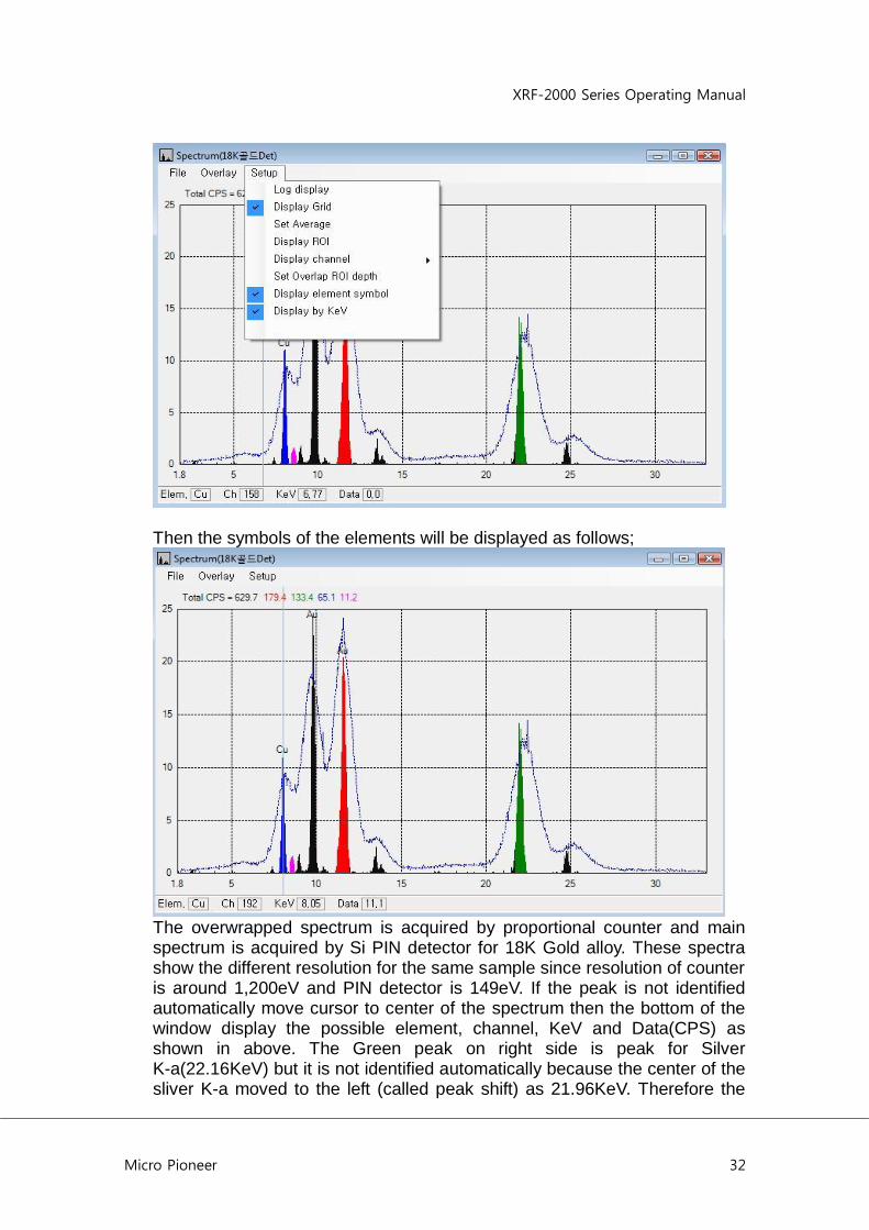
Then the symbols of the elements will be displayed as follows;
The overwrapped spectrum is acquired by proportional counter and main spectrum is acquired by Si PIN detector for 18K Gold alloy. These spectra show the different resolution for the same sample since resolution of counter is around 1,200eV and PIN detector is 149eV. If the peak is not identified automatically move cursor to center of the spectrum then the bottom of the window display the possible element, channel, KeV and Data(CPS) as shown in above. The Green peak on right side is peak for Silver K-a(22.16KeV) but it is not identified automatically because the center of the sliver K-a moved to the left (called peak shift) as 21.96KeV. Therefore the
XRF-2000 Series Operating Manual
Micro Pioneer 33
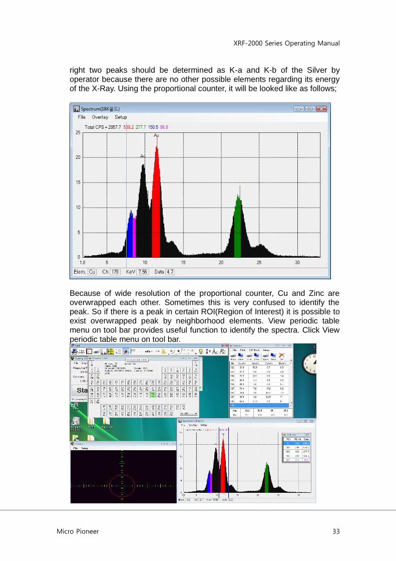
right two peaks should be determined as K-a and K-b of the Silver by operator because there are no other possible elements regarding its energy of the X-Ray. Using the proportional counter, it will be looked like as follows;
Because of wide resolution of the proportional counter, Cu and Zinc are overwrapped each other. Sometimes this is very confused to identify the peak. So if there is a peak in certain ROI(Region of Interest) it is possible to exist overwrapped peak by neighborhood elements. View periodic table menu on tool bar provides useful function to identify the spectra. Click View periodic table menu on tool bar.
XRF-2000 Series Operating Manual
Micro Pioneer 34
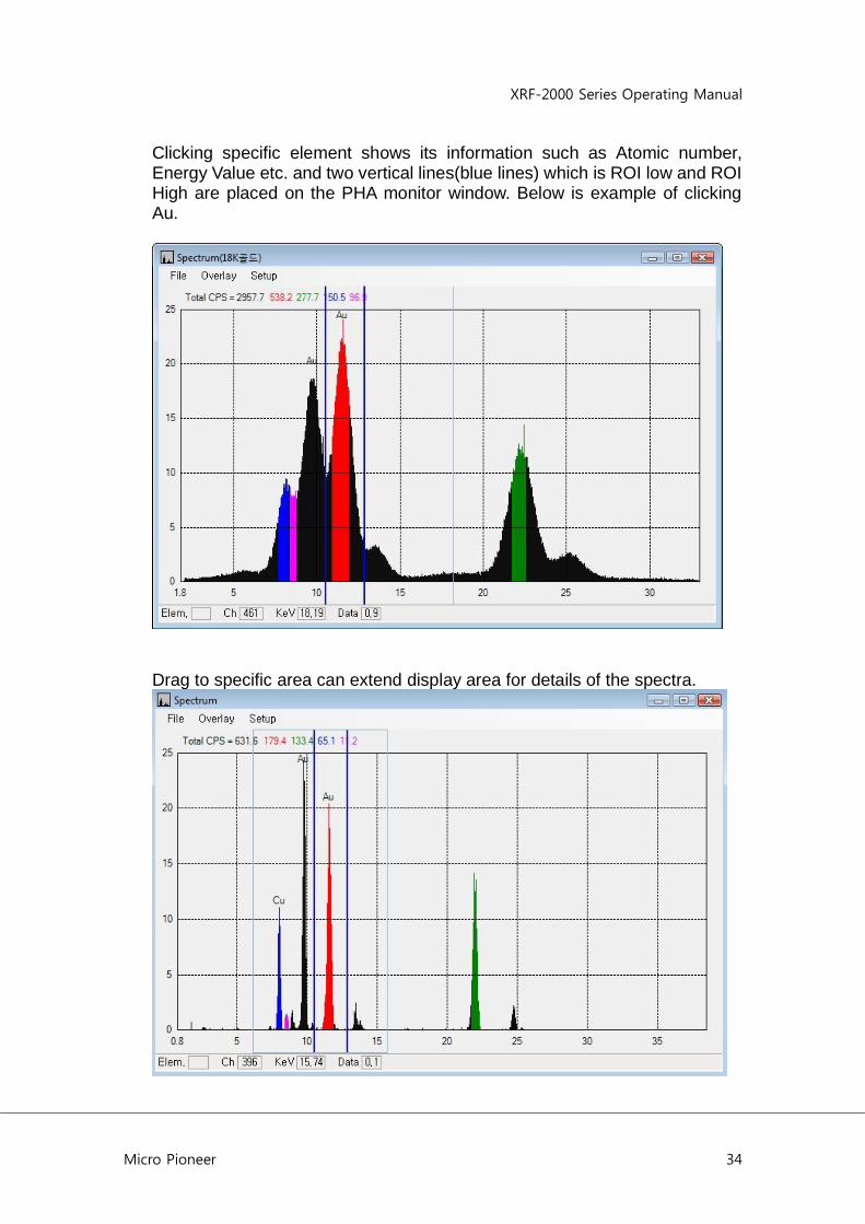
Clicking specific element shows its information such as Atomic number, Energy Value etc. and two vertical lines(blue lines) which is ROI low and ROI High are placed on the PHA monitor window. Below is example of clicking Au.
Drag to specific area can extend display area for details of the spectra.

XRF-2000 Series Operating Manual
Micro Pioneer 35
Click Right button shows menus to initialize, expend/reduce the vertical scale.
4.6 Camera display window
XRF-2000 Series Operating Manual
Micro Pioneer 36
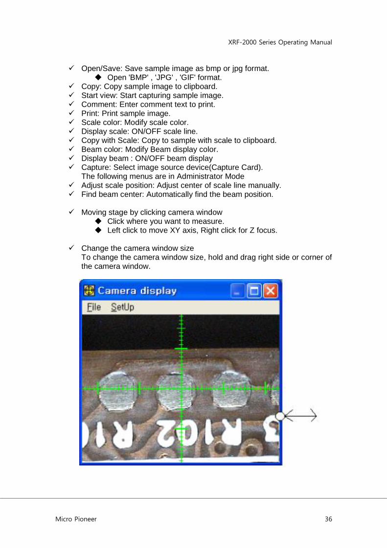
Open/Save: Save sample image as bmp or jpg format. Open 'BMP' , 'JPG' , 'GIF' format.
Copy: Copy sample image to clipboard. Start view: Start capturing sample image. Comment: Enter comment text to print. Print: Print sample image. Scale color: Modify scale color. Display scale: ON/OFF scale line. Copy with Scale: Copy to sample with scale to clipboard. Beam color: Modify Beam display color. Display beam : ON/OFF beam display Capture: Select image source device(Capture Card).
The following menus are in Administrator Mode Adjust scale position: Adjust center of scale line manually. Find beam center: Automatically find the beam position.
Moving stage by clicking camera window
Click where you want to measure. Left click to move XY axis, Right click for Z focus.
Change the camera window size
To change the camera window size, hold and drag right side or corner of the camera window.
XRF-2000 Series Operating Manual
Micro Pioneer 37
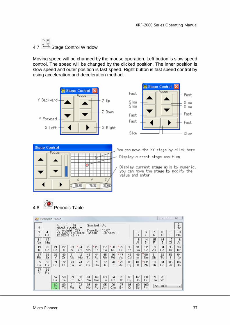
4.7 Stage Control Window
Moving speed will be changed by the mouse operation. Left button is slow speed control. The speed will be changed by the clicked position. The inner position is slow speed and outer position is fast speed. Right button is fast speed control by using acceleration and deceleration method.
4.8 Periodic Table
XRF-2000 Series Operating Manual
Micro Pioneer 38
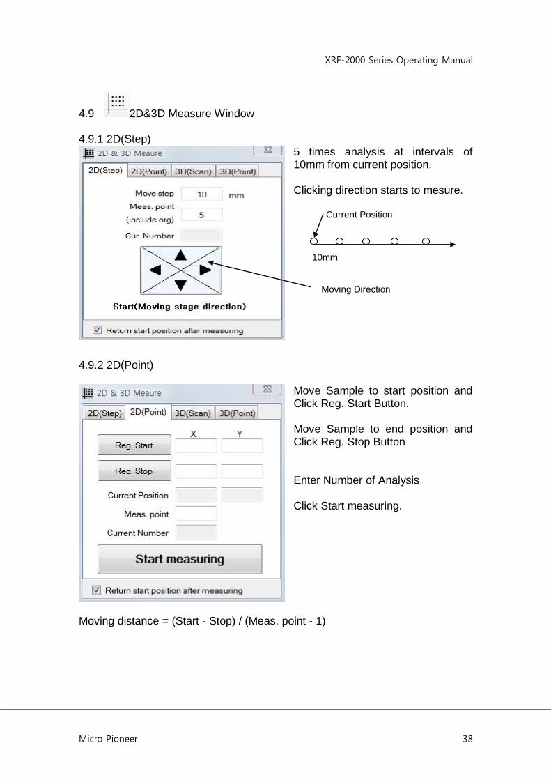
4.9 2D&3D Measure Window 4.9.1 2D(Step)
5 times analysis at intervals of 10mm from current position. Clicking direction starts to mesure. Current Position 10mm Moving Direction
4.9.2 2D(Point)
Move Sample to start position and Click Reg. Start Button. Move Sample to end position and Click Reg. Stop Button Enter Number of Analysis Click Start measuring.
Moving distance = (Start - Stop) / (Meas. point - 1)
XRF-2000 Series Operating Manual
Micro Pioneer 39
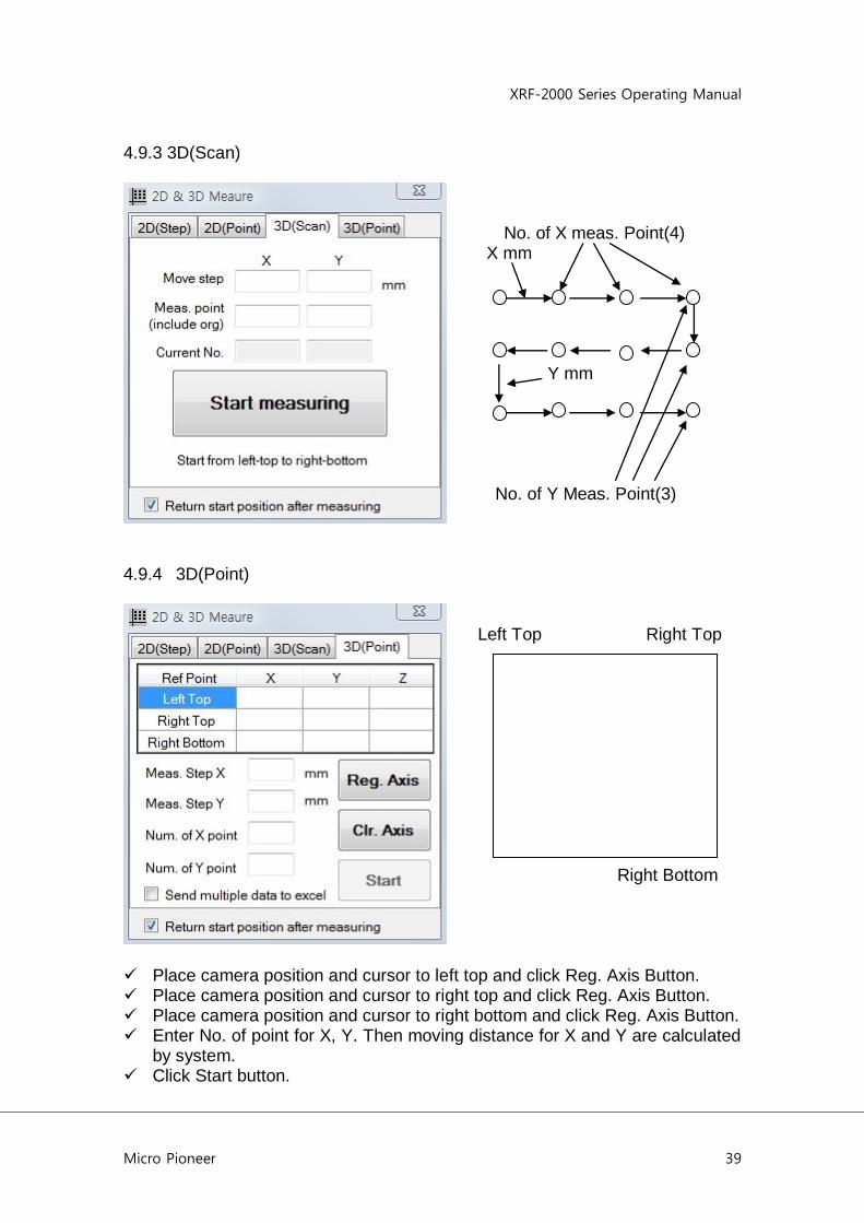
4.9.3 3D(Scan)
No. of X meas. Point(4) X mm Y mm No. of Y Meas. Point(3)
4.9.4 3D(Point)
Left Top Right Top Right Bottom
Place camera position and cursor to left top and click Reg. Axis Button. Place camera position and cursor to right top and click Reg. Axis Button. Place camera position and cursor to right bottom and click Reg. Axis Button. Enter No. of point for X, Y. Then moving distance for X and Y are calculated
by system. Click Start button.

XRF-2000 Series Operating Manual
Micro Pioneer 40
4.10 Random Stage
Open/Save : Open/Save position
data file. Set: Register the axis data. Run: Start the measuring. Del: Clear all axis data. Clicking right mouse button menu Del : delete the selected axis data. Move To axis: Move the stage to
selected axis data. Z axis can be used only type H
model.
4.11 Set Display Unit
XRF-2000 Series Operating Manual
Micro Pioneer 41
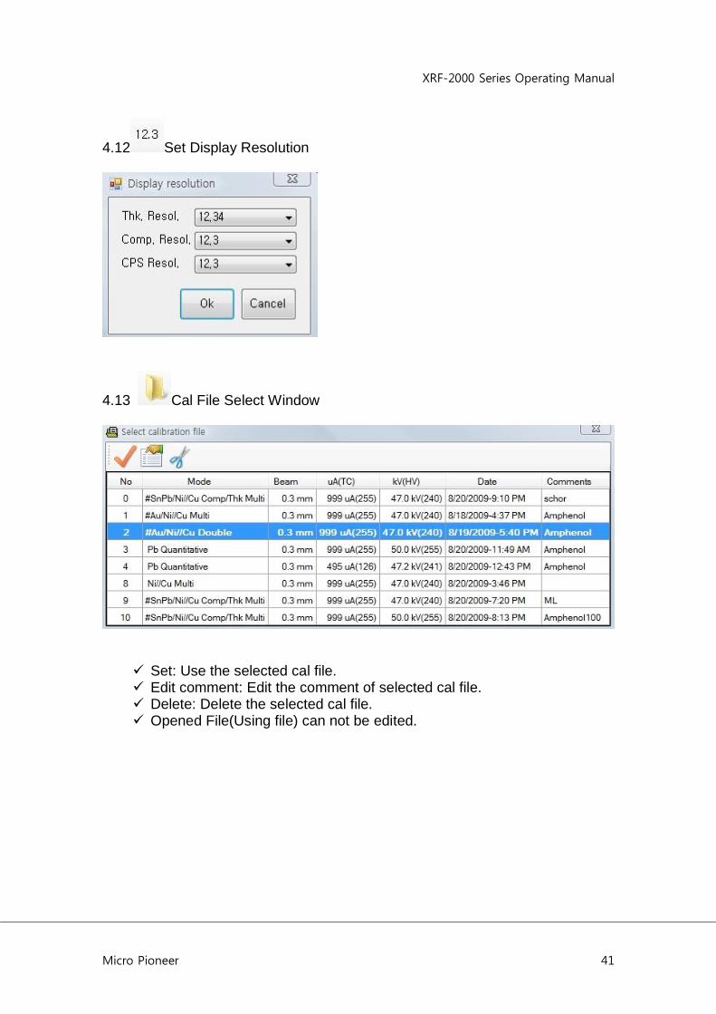
4.12 Set Display Resolution
4.13 Cal File Select Window
Set: Use the selected cal file. Edit comment: Edit the comment of selected cal file. Delete: Delete the selected cal file. Opened File(Using file) can not be edited.
XRF-2000 Series Operating Manual
Micro Pioneer 42
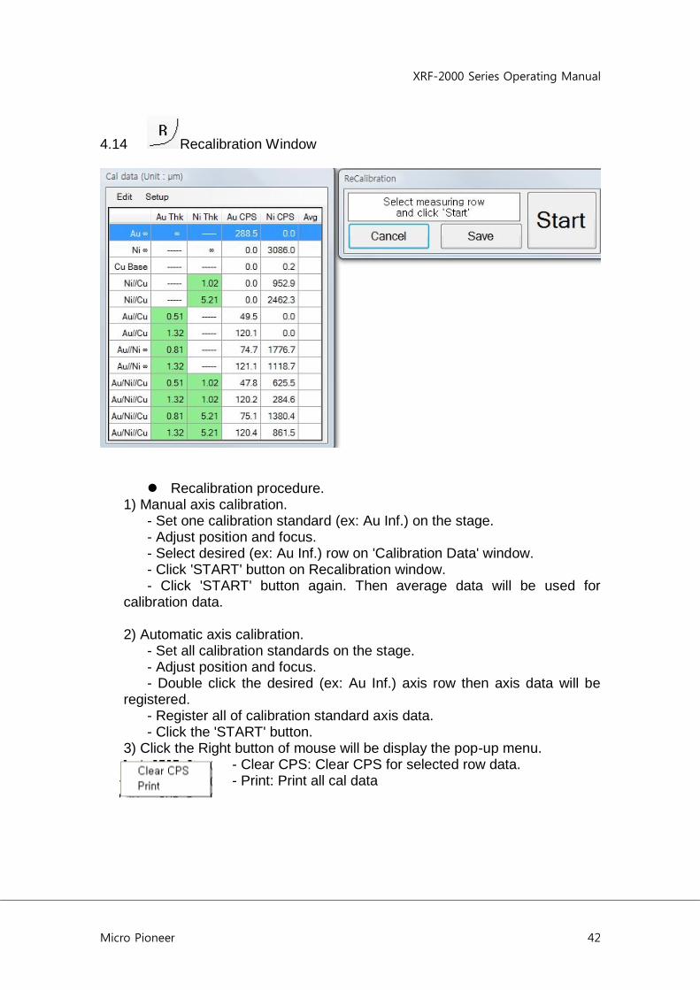
4.14 Recalibration Window
Recalibration procedure. 1) Manual axis calibration. - Set one calibration standard (ex: Au Inf.) on the stage. - Adjust position and focus. - Select desired (ex: Au Inf.) row on 'Calibration Data' window. - Click 'START' button on Recalibration window. - Click 'START' button again. Then average data will be used for calibration data. 2) Automatic axis calibration. - Set all calibration standards on the stage. - Adjust position and focus. - Double click the desired (ex: Au Inf.) axis row then axis data will be registered. - Register all of calibration standard axis data. - Click the 'START' button. 3) Click the Right button of mouse will be display the pop-up menu.
- Clear CPS: Clear CPS for selected row data. - Print: Print all cal data

XRF-2000 Series Operating Manual
Micro Pioneer 43
4.15 New Calibration 4.15.1 Thickness Calibration
New calibration will use pre-defined cal mode. Click Start Cal. button, next window will be displayed.
Follow the message of window and the next is same as Recalibration.

XRF-2000 Series Operating Manual
Micro Pioneer 44
4.15.2 Example of Calibration
: Enter or modify the thickness and composition value.

XRF-2000 Series Operating Manual
Micro Pioneer 45

XRF-2000 Series Operating Manual
Micro Pioneer 46
4.16 System Adjustment Window
'System adjustment' adjusts gain and offset of PHA system. Load Reference standard on the stage and adjust XY & focus. Click 'START' button to adjust. Below window is the Adjusted PHA display window.
4.17 Focus Laser On/Off Focus Laser.

XRF-2000 Series Operating Manual
Micro Pioneer 47
4.18 Lamp On/Off Lamp for Camera.
4.19 Set Y Stage Auto Move Analysis position moves to near door side when cover is opened and moves to analysis position automatically when cover is closed.
4.20 Auto Cycle Measurement Enable statistical Measurement.
4.21 Auto Cycle Number Number of Analysis for Auto Cycle Measurement.
5. How To Measure 5.1 Loading Sample
- Open the door. The stage will move forward when 'Push Pull' ( ) function is ON. - Load sample at laser beam position on the stage. - Close the door. The stage will move backward. - Adjust the sample by using stage control window. 5,2 Adjust Focus - Adjust Focus laser to vertical scale line.
5.3 Select Cal File and Click Start Button.
XRF-2000 Series Operating Manual
Micro Pioneer 48
Appendix
A. Regression Models
#1: Ci = Ao + Ai * Ii.
A simple linear relation between the intensity (Ii) of element "i" and its concentration (Ci). This model is applicable when the concentration of the analyzed elements is expected to vary over a relatively small range, and the influence of other elements on the analyzed element may be negligible. A good example is a trace analysis of heavy elements in organic samples or metal alloys. This model requires only two different standards to enable the program to determine the free regression coefficients Ai and Bi, but more than 3 or 4 are actually needed for good precision and higher confidence in the analysis results.
#2: Ii = Ao + Ai *Ii + Sum (Aij*Cj)
Where N is the number of interfering elements. This model accounts for inter-element influence or peak overlap. The model includes N + 1 free regression coefficients Aij, Bi and Ai (which are determined by the program). A minimum of N + 1 independent standards is required for the determination of Ai, Bi and Aij, but as many as (N + 1)2 is actually recommended for better confidence. The main disadvantage of using model 2 is that it does not resemble a physical model.
#3: Ci = Ao + Ai Ii + Sum (Aij*Ij)
Almost equivalent to model 2: no significant advantage, but the concentration of interfering elements need not be known.
#4: Ci = Ao + Ai*Ii + Ii*Sum (Aj*Cj) (i<>j)
The very popular, modified Traill-Lachance model. It provides a high degree of accuracy over a wide range of concentrations and compensates for interelement influence by the Aij coefficients.
#5: Ci = Ao + Ai*Ii + Ii*Sum (Aj*Ij) (i<>j) A modified Lucas-Tooth and Price model. It is applicable within a smaller dynamic range than model 4, but it has the advantage that only the concentration of the analyzed element appears in the equation. This means that the remainder of the concentrations in the standards don't have to be known or specified.

XRF-2000 Series Operating Manual
Micro Pioneer 49
#6: Ci = Ao + A1Ii + A2 Ii2
A quadratic model which may be more accurate when the concentration range of the analyzed element is wide and self-absorption is significant. It does not, however, account for any interelement influence.
XRF-2000 Series Operating Manual
Micro Pioneer 50
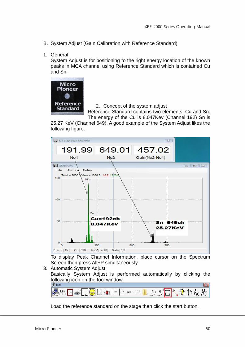
B. System Adjust (Gain Calibration with Reference Standard)
1. General System Adjust is for positioning to the right energy location of the known peaks in MCA channel using Reference Standard which is contained Cu and Sn.
2. Concept of the system adjust Reference Standard contains two elements, Cu and Sn. The energy of the Cu is 8.047Kev (Channel 192) Sn is
25.27 KeV (Channel 649). A good example of the System Adjust likes the following figure.
To display Peak Channel Information, place cursor on the Spectrum Screen then press Alt+P simultaneously.
3. Automatic System Adjust Basically System Adjust is performed automatically by clicking the following icon on the tool window.
Load the reference standard on the stage then click the start button.

XRF-2000 Series Operating Manual
Micro Pioneer 51
System will turn on X-Ray several times and adjust the value of the Offset and Gain automatically to find proper position for Cu and Sn peaks.
4. Manual System Adjust Sometimes automatic system adjust is not able to have a good result as described in above with some reason. Then just follow the next. 4.1 Administrator Login
Go to File -> Administrator Login in XRF Analyzer window and type “t” for Password. Click OK to login.
4.2 Select Cal file 0 Au/Ni Excitation

XRF-2000 Series Operating Manual
Micro Pioneer 52
4.3 Get Service Menu Place cursor on the XRF Analyzer window then press Alt+Cntrl+Shif simultaneously then type “pioneer” and Press Enter key. Click Service menu on the Spectrum window.
4.4 Set Acquisition Parameter Set the acquisition parameter in service panel as follows.

XRF-2000 Series Operating Manual
Micro Pioneer 53
Set HV 47.1, TC 180, Primary Ta50um and Collimator 3 then Start with 10 Sec measuring time. Get the total CPS around 2,000 by increasing or decreasing the TC value. If no peaks in this step, try to decrease TC value because more than 3,000 CPS is hard to detect peaks. When you get the proper CPS, adjust Gain and Offset value to place the both peaks of Cu and Sn in proper position as shown in step 2. Record Gain and Offset values and keep it. Close Service Panel.
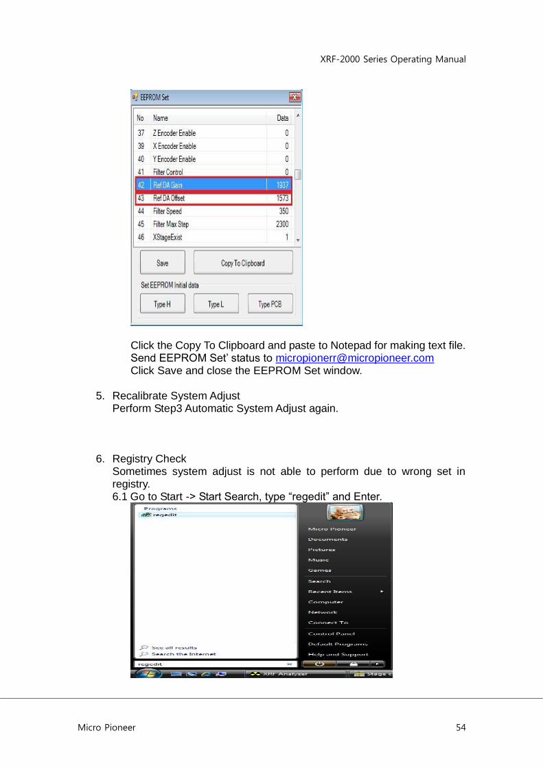
4.5 EEPROM Set Place cursor on the XRF Analyzer window then press Alt+Cntrl+Shif simultaneously then type “pioneer” and press “E” key. Then EEPROM Set window will appear. Make sure or edit the following items.
- 42 Ref DA Gain enter recorded value in step 4.4
- 43 Ref DA Offset enter recorded value in step 4.4
- 83 Max CPS for new cal(kCPS) 2 ; means 2000cps
- 92 SysAdj RefAdjCPSRatioFromMaxCount 1 ; means max cpsx1
- 97 SysAdj Primary filter 3 ; means Ta-50um
XRF-2000 Series Operating Manual
Micro Pioneer 54
Click the Copy To Clipboard and paste to Notepad for making text file. Send EEPROM Set‟ status to [email protected] Click Save and close the EEPROM Set window.
5. Recalibrate System Adjust Perform Step3 Automatic System Adjust again.
6. Registry Check Sometimes system adjust is not able to perform due to wrong set in registry. 6.1 Go to Start -> Start Search, type “regedit” and Enter.

XRF-2000 Series Operating Manual
Micro Pioneer 55
6.2 Edit Registry as follows; 1) HKEY_CURRENT_USER/Software/MicroPioneer/XRayV4/AutoRef/A
utoRefIntevalTime -> 10,240,- ( to change System Adjust Interval=10min after power on and every 240min, - means repeat)
2) HKEY_CURRENT_USER/Software/MicroPioneer/XRayV4/Mon/Mon2KVFlag -> False ( Set not to check High Voltage 2KV for the proportional Counter)
6.3 Regarding System Adjust, verify the following; HKEY_CURRENT_USER/Software/MicroPioneer/XRayV4/SysAdj/RefAdjustedTC ->20 It is not fixed value but sometimes it goes to 255 which means maximum Tube Current so when the system adjust has problem, this value must be checked and corrected.
6.4 Close Registry Edit Window

XRF-2000 Series Operating Manual
Micro Pioneer 56
C. Collimator and Primary Filter Setting
1. Getting Factory Service Place cursor on the XRF Analyzer window then press Alt+Cntrl+Shif simultaneously then type “pioneer” and “ok” key. Then Factory Service Menu will appear on the Tool Box.
Click Factory Service menu then Factory Service Window will appear.
2. EEPROM Set Click the EEPTOM Set Icon and Make sure or edit the following items.
- 41 Filter Control 0
- 75 Filter protect 0 Click the Save icon to Exit.
3. Diff Mirror Set Click Diff Mirror set icon in factory service window. X value is the distance between mirror position and analysis position.
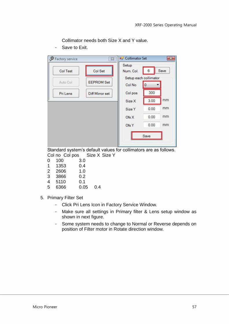
4. Collimator Set
- Click the Col Set Icon on Factory Service Window.
- Enter 6 in Number of Collimator and Click Save.
- Select Collimator No. and enter Collimator Position and Size X.
- The Circular collimator needs only Size X and Rectangular
XRF-2000 Series Operating Manual
Micro Pioneer 57
Collimator needs both Size X and Y value.
- Save to Exit.
Standard system‟s default values for collimators are as follows. Col no Col pos Size X Size Y 0 100 3.0 1 1353 0.4 2 2606 1.0 3 3866 0.2 4 5110 0.1 5 6366 0.05 0.4
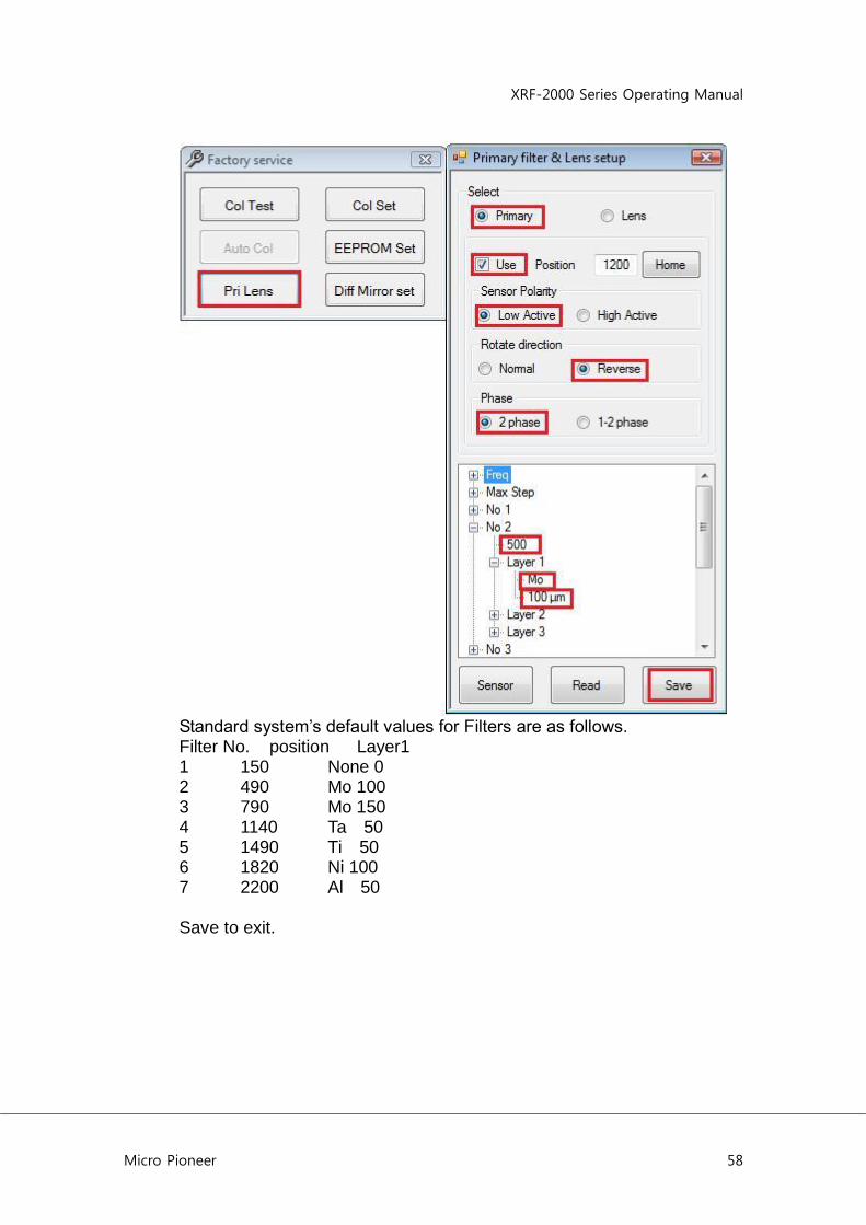
5. Primary Filter Set
- Click Pri Lens Icon in Factory Service Window.
- Make sure all settings in Primary filter & Lens setup window as shown in next figure.
- Some system needs to change to Normal or Reverse depends on position of Filter motor in Rotate direction window.
XRF-2000 Series Operating Manual
Micro Pioneer 58
Standard system‟s default values for Filters are as follows. Filter No. position Layer1 1 150 None 0 2 490 Mo 100 3 790 Mo 150 4 1140 Ta 50 5 1490 Ti 50 6 1820 Ni 100 7 2200 Al 50 Save to exit.
XRF-2000 Series Operating Manual
Micro Pioneer 59
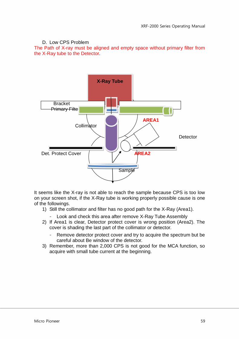
D. Low CPS Problem The Path of X-ray must be aligned and empty space without primary filter from the X-Ray tube to the Detector. X-Ray Tube Bracket Primary Filter AREA1 Collimator Detector Det. Protect Cover AREA2 Sample It seems like the X-ray is not able to reach the sample because CPS is too low on your screen shot, if the X-Ray tube is working properly possible cause is one of the followings.
1) Still the collimator and filter has no good path for the X-Ray (Area1).
- Look and check this area after remove X-Ray Tube Assembly 2) If Area1 is clear, Detector protect cover is wrong position (Area2). The
cover is shading the last part of the collimator or detector.
- Remove detector protect cover and try to acquire the spectrum but be careful about Be window of the detector.
3) Remember, more than 2,000 CPS is not good for the MCA function, so acquire with small tube current at the beginning.
XRF-2000 Series Operating Manual
Micro Pioneer 60
E. Installation and pre operation of XRF-2000 Series R
1. Unzip the XRayV4.zip file. 2. Install the XRayV4 software by executing the Setup.exe in XRayV4/Setup
folder. 3. Copy CalFile folder from Demo Unit and paste into C:/XRay4 where
XRayV4 software installed, overwrite it. 4. Edit Registry as follows;
3) HKEY_CURRENT_USER/Software/MicroPioneer/XRayV4/AutoRef/AutoRefIntevalTime -> 10,240,- ( to change System Adjust Interval=10min after power on and every 240min, - means repeat)
4) HKEY_CURRENT_USER/Software/MicroPioneer/XRayV4/Mon/Mon2KVFlag -> False ( Set not to check High Voltage 2KV for the proportional Counter)
5. Run XRayV4 program for the RoHS Analyzer. Password=”t”, click opening message.
6. Go to File -> Administrator Login, enter Password “t” 7. There are 7 Cal File PE, PVC, Cl in Plastic (Halogen Free), Al, Fe, Cu,
and Sn for RoHS application. Basic Analysis time is 300 sec for all applications.
8. For recalibration with bad result, Click „R” icon on the tool window then load standard sample that we provided on the stage platform, and Start and Save. The calibration needs only one standard sample.
9. To print result report, go to Display -> Statistic -> Print -> Quantitative -> Preview or others.
XRF-2000 Series Operating Manual
Micro Pioneer 61
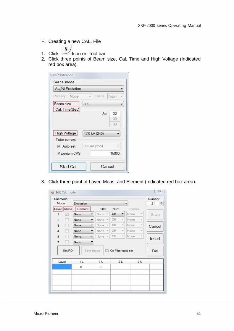
F. Creating a new CAL. File
1. Click Icon on Tool bar. 2. Click three points of Beam size, Cal. Time and High Voltage (Indicated
red box area).
3. Click three point of Layer, Meas, and Element (Indicated red box area).

XRF-2000 Series Operating Manual
Micro Pioneer 62
4. Click New and click and pull the element to be analyzed to element list box. Enter Symbol and Name for reference. Edit ROI value as shown. Click Modify and Save. Close the window.
5. Set mode to Quantitative, Element to Scan_MIT that you just saved in step 4. Click Set ROI, Save mode and Save.
Then back to first window for new calibration as below.
XRF-2000 Series Operating Manual
Micro Pioneer 63
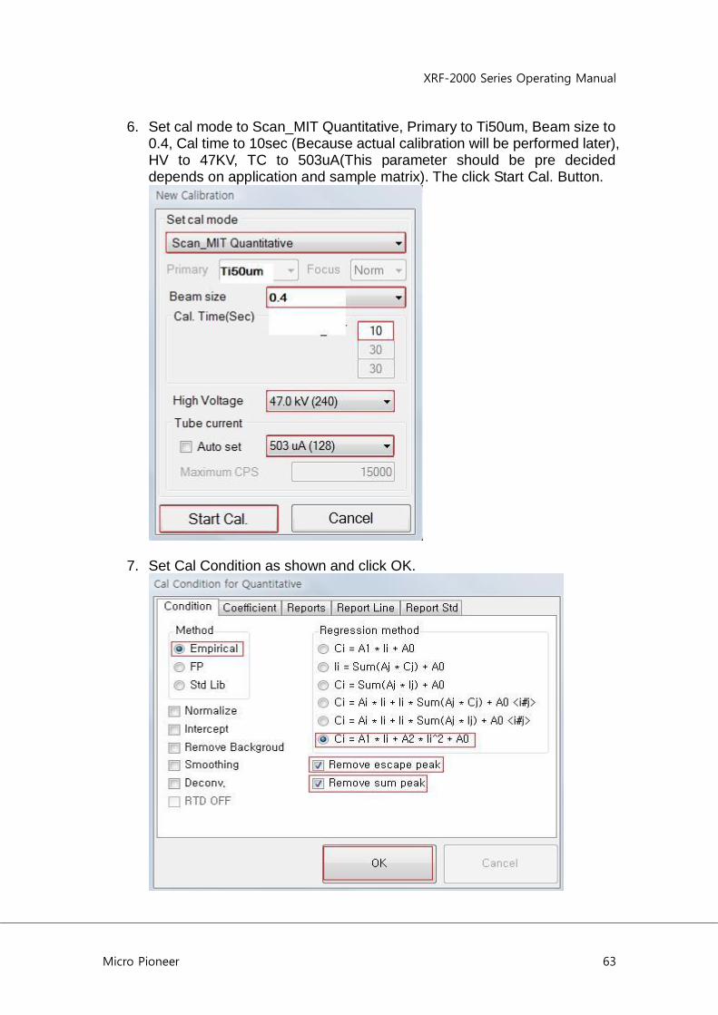
6. Set cal mode to Scan_MIT Quantitative, Primary to Ti50um, Beam size to 0.4, Cal time to 10sec (Because actual calibration will be performed later), HV to 47KV, TC to 503uA(This parameter should be pre decided depends on application and sample matrix). The click Start Cal. Button.
7. Set Cal Condition as shown and click OK.
XRF-2000 Series Operating Manual
Micro Pioneer 64
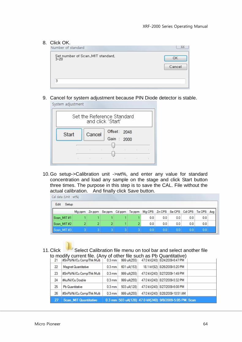
8. Click OK.
9. Cancel for system adjustment because PIN Diode detector is stable.
10. Go setup->Calibration unit ->wt%, and enter any value for standard concentration and load any sample on the stage and click Start button three times. The purpose in this step is to save the CAL. File without the actual calibration. And finally click Save button.
11. Click Select Calibration file menu on tool bar and select another file to modify current file. (Any of other file such as Pb Quantitative)

XRF-2000 Series Operating Manual
Micro Pioneer 65
12. Click Start and Stop button in Main Window. Type Ctrl+Shift+Alt+pioneer+c.
13. Change number of the standard and make sure all the parameters are same as shown below. Then click Save Button.
14. Click Select Calibration file menu on tool bar and select modified and saved file to recalibrate.
XRF-2000 Series Operating Manual
Micro Pioneer 66
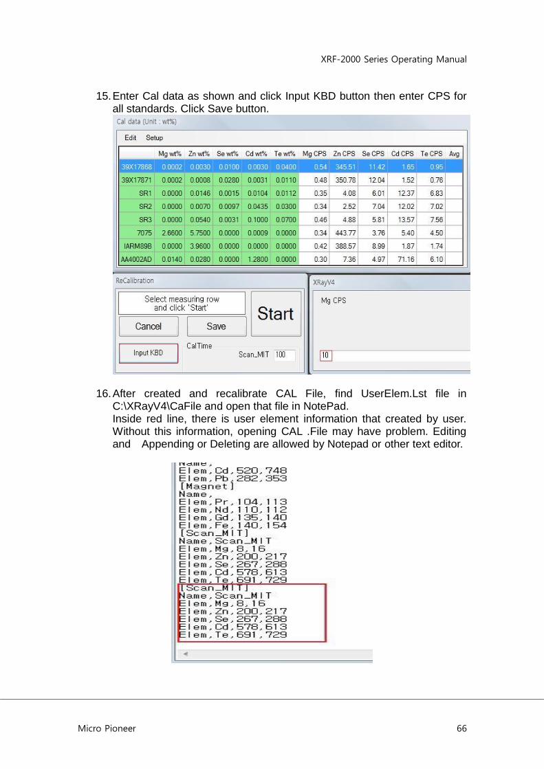
15. Enter Cal data as shown and click Input KBD button then enter CPS for all standards. Click Save button.
16. After created and recalibrate CAL File, find UserElem.Lst file in C:\XRayV4\CaFile and open that file in NotePad. Inside red line, there is user element information that created by user. Without this information, opening CAL .File may have problem. Editing and Appending or Deleting are allowed by Notepad or other text editor.

XRF-2000 Series Operating Manual
Micro Pioneer 67
17. ROI Data Table
Elm Line eV Low eV High Center CH Low CH High CH Center
Na Ka 916 1165 1040 2 10 6
Mg Ka 1126 1381 1260 8 16 12
Al Ka 1356 1617 1480 14 22 18
Si Ka 1606 1873 1720 21 29 24
P Ka 1877 2152 2020 28 37 32
S Ka 2166 2449 2310 35 45 40
Cl Ka 2476 2767 2620 43 53 48
Ar Ka 2807 3106 2960 52 62 57
K Ka 3159 3466 3310 61 72 66
Ca Ka 3533 3848 3690 71 82 76
Sc Ka 3927 4252 4090 81 93 87
Ti Ka 4342 4677 4510 92 105 98
V Ka 4780 5123 4950 104 117 110
Cr Ka 5237 5590 5410 116 129 122
Mn Ka 5716 6079 5900 128 143 135
Fe Ka 6216 6589 6400 142 156 148
Co Ka 6738 7121 6930 155 171 162
Ni Ka 7280 7673 7480 169 186 177
Cu Ka 7845 8248 8050 184 201 192
Zn Ka 8431 8844 8640 200 217 208
Ga Ka 9038 9463 9250 216 234 224
Ge Ka 9667 10102 9890 232 251 241
As Ka 10320 10765 10540 249 269 258
Se Ka 10992 11449 11240 267 288 277
Br Ka 11689 12156 11920 285 307 295
Kr Ka 12408 12887 12650 304 327 314
Rb Ka 13149 13638 13390 324 347 334
Sr Ka 13913 14414 14160 344 368 354
Y Ka 14701 15212 14960 364 389 375
Zr Ka 15512 16035 15780 386 412 397
Nb Ka 16346 16881 16620 407 434 419

XRF-2000 Series Operating Manual
Micro Pioneer 68
Mo Ka 17204 17751 17480 430 458 442
Tc Ka 18130 18689 18370 454 483 466
Ru Ka 18993 19562 19280 477 507 490
Rh Ka 19923 20504 20220 501 532 515
Pd Ka 20878 21471 21180 526 558 540
Ag Ka 21859 22464 22170 552 585 567
Cd Ka 22863 23480 23180 578 613 594
In Ka 23892 24521 24210 605 641 621
Sn Ka 24949 25590 25270 633 670 649
Sb Ka 26030 26683 26360 662 699 678
Te Ka 27138 27803 27470 691 729 707
I Ka 28271 28948 28620 720 760 738
Xe Ka 29457 30146 29780 752 793 769
Cs Ka 30619 31320 30970 782 825 800
Ba Ka 31883 32548 32200 815 858 833
La La 4482 4819 4650 96 109 102
Ce La 4669 5010 4650 101 114 102
Pr La 4861 5206 5030 106 119 112
Nd La 5055 5404 5230 111 124 117
Pm La 5254 5607 5430 116 130 123
Sm La 5457 5814 5640 122 135 128
Eu La 5665 6026 5850 127 141 134
Gd La 5876 6241 6050 133 147 139
Tb La 6089 6460 6270 138 153 145
Dy La 6307 6682 6490 144 159 151
Ho La 6530 6909 6720 150 165 157
Er La 6792 7175 6950 157 172 163
Tm La 6987 7374 7180 162 178 169
Yb La 7218 7609 7410 168 184 175
Lu La 7455 7852 7650 174 191 181
Hf La 7697 8098 7900 180 197 188
Ta La 7942 8347 8150 187 204 195
W La 8191 8600 8400 193 211 201
Re La 8444 8857 8650 200 218 208

XRF-2000 Series Operating Manual
Micro Pioneer 69
Os La 8700 9119 8910 207 225 215
Ir La 8961 9384 9170 214 232 222
Pt La 9227 9654 9440 221 239 229
Au La 9495 9926 9720 228 247 236
Hg La 9768 10205 9990 235 254 244
Tl La 10045 10486 10260 242 262 251
Pb La 10326 10771 10540 249 269 258
Bi La 10610 11061 10840 257 277 266
Po La 10900 11355 11130 264 285 274
At La 11194 11653 11430 272 293 282
Rn La 11491 11956 11720 280 301 289
Fr La 11794 12263 12030 288 310 298
Ra La 12101 12574 12340 296 318 306
Ac La 12410 12889
304 327 -22
Th La 12724 13207
312 335 -22
Pa La 13047 13534
321 344 -22
U La 13366 13859
329 353 -22

XRF-2000 Series Operating Manual
Micro Pioneer 70
G. Stage Moving for the Pin Diode Detector
1) Stage moves automatically after START : This is normal. Camera New Mirror Position in PIN Detector System The Mirror is here in Thickness Gage
Mirror Collimator Detector Diff Mirror Sample at standby pos. Sample moved to measuring position In PIN detector system, to improve the sensitivity of detector, the mirror is located in beside collimator. Standby position provides a good path for the camera to fine the measuring area and measuring position provides a goo path to avoid attenuation of the X-Ray Energy. This will effect to detect light element such as Al, Si, S, P etc. There is distance different in x-axis between standby and measuring position called “Diff Mirror”. The Diff Mirror can be adjusted in Factory Service Mode. To adjust go to Factory Service Mode (Alt+Shit+Cntl+pioneerok) -> Click Diff Mirror set -> Enter X value in millimeter unit -> click OK
2) Calibration for Quantitative Analysis Right Click XRayV4 icon on desktop -> Properties -> suffix “quan” next to XRayV4.exe, then the calibration of quantitative analysis will be activated.
3) Create a registry key In registry editing mode go to HKEY_CURRENT_USER -> Software -> MicroPioneer -> XRayV4 Right click on XRayV4 -> New -> Key -> Type “AutoRef” ->Enter Right Click on AutoRef (just created folder) -> New -> String Value -> Type “AutoRefIntervalTime” -> Enter Right Click on AutoRefIntevalTime (Just created String) -> Modify -> Enter Value data “10,240,-) -> OK
XRF-2000 Series Operating Manual
Micro Pioneer 71
Where; 10 : System adjust(Reference) will be performed 10 min after power on. 240 : System adjust will be performed every 240 min(4 hours).
- : System adjust will be repeat (do not miss this)
Related Documents