Turbo Systems Switzerland Ltd Operation Manual / Power2 550-M44 High-pressure stage PT003943 Document identification Document number HZTL4058 Revision F Language English Original Operation Manual Product identification Serial number PT003943 Customer part number Delivery date (yyyy-mm-dd) 2022-04-01 Weight 750 kg Operating limits according to rating plate Speed limit in test rig operation only n Mmax 527 1/s Speed limit during operation n Bmax 527 1/s Gas inlet temperature limit in test rig operation only t Mmax 650 °C Gas inlet temperature limit during operation t Bmax 620 °C Compressor inlet temperature after intercooler t Cmax 70 °C

Welcome message from author
This document is posted to help you gain knowledge. Please leave a comment to let me know what you think about it! Share it to your friends and learn new things together.
Transcript

Turbo Systems Switzerland Ltd
Operation Manual / Power2 550-M44High-pressure stage PT003943
Document identification
Document number HZTL4058
Revision F
Language English
Original Operation Manual
Product identification
Serial number PT003943
Customer part number
Delivery date (yyyy-mm-dd) 2022-04-01
Weight 750 kg
Operating limits according to rating plate
Speed limit in test rig operation only nMmax
527 1/s
Speed limit during operation nBmax
527 1/s
Gas inlet temperature limit in test rig operation only tMmax
650 °C
Gas inlet temperature limit during operation tBmax
620 °C
Compressor inlet temperature after intercooler tCmax
70 °C


Operation Manual / Power2 550-M / High-pressure stageTable of contents
© Copyright 2022 ABB. All rights reserved. HZTL4058_EN Rev.F March 2022
Power2 550-M / High-pressure stage1 Introduction............................................................................................................ 41.1 Purpose of the manual................................................................................................. 41.2 Contact information..................................................................................................... 41.3 Essential information.................................................................................................... 51.4 Power2 layout and function......................................................................................... 71.5 Layout and function of the high-pressure stage.................................................... 81.6 Symbols, definitions.................................................................................................... 101.7 Registered trademarks............................................................................................... 111.8 Storage of new low-pressure and high-pressure stages..................................... 12
2 Safety .................................................................................................................... 142.1 Introduction .................................................................................................................. 142.2 CE conformity............................................................................................................... 142.3 Definition of mandatory signs .................................................................................. 152.4 Definition of safety instructions .............................................................................. 152.5 Intended use ................................................................................................................. 162.6 Deflagration on gas engines ..................................................................................... 172.7 Warning plates on the high-pressure stage ........................................................... 182.8 Rating plate of the high-pressure stage ................................................................. 192.9 Periodic check of the pressure vessels................................................................... 202.10 Lifting of loads ............................................................................................................. 212.11 Prerequisites for operation and maintenance....................................................... 222.12 Hazards during operation and maintenance ......................................................... 232.13 Safe operation ............................................................................................................. 252.14 Safe maintenance ....................................................................................................... 26
3 Removal and installation .................................................................................... 303.1 Transport / weight ..................................................................................................... 303.2 Removing the high-pressure stage .......................................................................... 313.3 Installing the high-pressure stage .......................................................................... 34
4 Commissioning .................................................................................................... 414.1 Oil supply ....................................................................................................................... 414.2 Inspection procedures............................................................................................... 424.3 Commissioning after taking out of operation...................................................... 44
5 Monitoring during operation.............................................................................. 455.1 Lubricating oil pressure............................................................................................. 455.2 Lubricating oil temperature ..................................................................................... 465.3 Speeds........................................................................................................................... 47
6 Operation and service ......................................................................................... 506.1 Noise emission ............................................................................................................ 50
Operation Manual / Power2 550-M / High-pressure stageTable of contents
© Copyright 2022 ABB. All rights reserved. HZTL4058_EN Rev.F March 2022
6.2 Service work................................................................................................................. 526.3 Expected replacement intervals .............................................................................. 546.4 Stopping the engine................................................................................................... 56
7 Periodic maintenance.......................................................................................... 577.1 Foreword to maintenance.......................................................................................... 577.2 Cleaning the compressor during operation .......................................................... 587.3 Cleaning the high-pressure stage bellows (if present)....................................... 607.4 Cleaning turbines and nozzle rings during operation ......................................... 60
8 Troubleshooting................................................................................................... 678.1 Malfunctions when starting...................................................................................... 678.2 Malfunctions during operation ................................................................................ 688.3 Surging of the low-pressure or high-pressure stage ........................................... 728.4 Malfunctions when stopping..................................................................................... 738.5 Speed measurement system.................................................................................... 74
9 Disassembly and assembly................................................................................. 759.1 Introduction .................................................................................................................. 759.2 Material required......................................................................................................... 769.3 Weights of assemblies............................................................................................... 789.4 Removing the gas outlet casing .............................................................................. 799.5 Removing air inlets ..................................................................................................... 809.6 Removing the compressor casing............................................................................ 819.7 Removing the cartridge group................................................................................. 829.8 Installing the cartridge group .................................................................................. 859.9 Installing the compressor casing ............................................................................ 889.10 Installing the air inlets ............................................................................................... 899.11 Installing the gas outlet casing................................................................................ 909.12 Measuring radial clearances N and R ....................................................................... 919.13 Measuring clearance A and B.................................................................................... 929.14 Table of tightening torques...................................................................................... 93
10 Taking out of operation at short notice ........................................................... 9410.1 Possible emergency repairs...................................................................................... 9410.2 Installing a replacement cartridge group .............................................................. 9510.3 Fitting the cover plate................................................................................................ 9610.4 Cover plate drawing ................................................................................................... 97
11 Taking out of operation for a long period........................................................ 9911.1 General .......................................................................................................................... 9911.2 Lubricating oil.............................................................................................................. 9911.3 Process for taking out of operation........................................................................ 99
12 Material and Disposal........................................................................................ 10012.1 REACH and RoHS Compliance Declaration For Products ................................. 10012.2 Disposing of low-pressure and high-pressure stage components ................. 101
Operation Manual / Power2 550-M / High-pressure stageTable of contents
© Copyright 2022 ABB. All rights reserved. HZTL4058_EN Rev.F March 2022
13 Spare parts ......................................................................................................... 10213.1 Ordering spare parts................................................................................................ 10213.2 Spare part – Illustrations ......................................................................................... 104
14 Tools .................................................................................................................... 115
15 Gas piping (option)............................................................................................ 116
Figures.................................................................................................................. 117
Tables .................................................................................................................. 118

Operation Manual / Power2 550-M / High-pressure stage1 Introduction / 1.1 Purpose of the manual
© Copyright 2022 ABB. All rights reserved. HZTL4058_EN Rev.F March 2022
1 Introduction
1.1 Purpose of the manual
Operation Manual
The Operation Manual explains the two-stage turbocharging (Power2) from Turbo Systemsand contains instructions for safe operation.
The Operation Manual is a complement to and expansion of existing national regulations foroccupational safety, accident prevention and environmental protection.
Target group
The Operation Manual is aimed at engineers and trained mechanics responsible for theproper operation of the engine and for the Power2 connected to it.
Availability of the Operation Manual
The Operation Manual must be available where the Power2 is used.
All persons operating or working on the Power2 must have read and fully understood theOperation Manual.
1.2 Contact informationContact information for the Turbo Systems service stations is available online.
u Scan the QR code to access our website.
Turbo Systems Switzerland Ltd
Bruggerstrasse 71aCH-5401 BadenSwitzerland
www.abb.com/turbocharging
Pag
e 4
/ 11
9

Operation Manual / Power2 550-M / High-pressure stage1 Introduction / 1.3 Essential information
© Copyright 2022 ABB. All rights reserved. HZTL4058_EN Rev.F March 2022
1.3 Essential information
Design variants
This document is valid for different design variants of Power2 high-pressure stages. Thismay result in sections and descriptions of components that are not relevant for a specificPower2 high-pressure stage.
Please contact a Turbo Systems service station if you have any questions regarding a designvariant (see Contact information at www.abb.com/turbocharging).
Accuracy of illustrations
The illustrations in this document are general in nature and intended for ease of understand-ing. Differences in detail are therefore possible.
Pag
e 5
/ 11
9

Operation Manual / Power2 550-M / High-pressure stage1 Introduction / 1.3 Essential information
© Copyright 2022 ABB. All rights reserved. HZTL4058_EN Rev.F March 2022
Pag
e 6
/ 11
9
Operation Manual / Power2 550-M / High-pressure stage1 Introduction / 1.4 Power2 layout and function
© Copyright 2022 ABB. All rights reserved. HZTL4058_EN Rev.F March 2022
1.4 Power2 layout and function
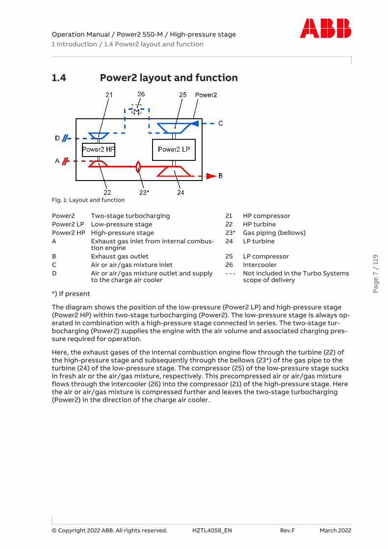
Fig. 1: Layout and function
Power2 Two-stage turbocharging 21 HP compressorPower2 LP Low-pressure stage 22 HP turbinePower2 HP High-pressure stage 23* Gas piping (bellows)A Exhaust gas inlet from internal combus-
tion engine24 LP turbine
B Exhaust gas outlet 25 LP compressorC Air or air/gas mixture inlet 26 IntercoolerD Air or air/gas mixture outlet and supply
to the charge air cooler- - - Not included in the Turbo Systems
scope of delivery
*) If present
The diagram shows the position of the low-pressure (Power2 LP) and high-pressure stage(Power2 HP) within two-stage turbocharging (Power2). The low-pressure stage is always op-erated in combination with a high-pressure stage connected in series. The two-stage tur-bocharging (Power2) supplies the engine with the air volume and associated charging pres-sure required for operation.
Here, the exhaust gases of the internal combustion engine flow through the turbine (22) ofthe high-pressure stage and subsequently through the bellows (23*) of the gas pipe to theturbine (24) of the low-pressure stage. The compressor (25) of the low-pressure stage sucksin fresh air or the air/gas mixture, respectively. This precompressed air or air/gas mixtureflows through the intercooler (26) into the compressor (21) of the high-pressure stage. Herethe air or air/gas mixture is compressed further and leaves the two-stage turbocharging(Power2) in the direction of the charge air cooler.
Pag
e 7
/ 11
9
Operation Manual / Power2 550-M / High-pressure stage1 Introduction / 1.5 Layout and function of the high-pressure stage
© Copyright 2022 ABB. All rights reserved. HZTL4058_EN Rev.F March 2022
1.5 Layout and function of the high-pressure stage
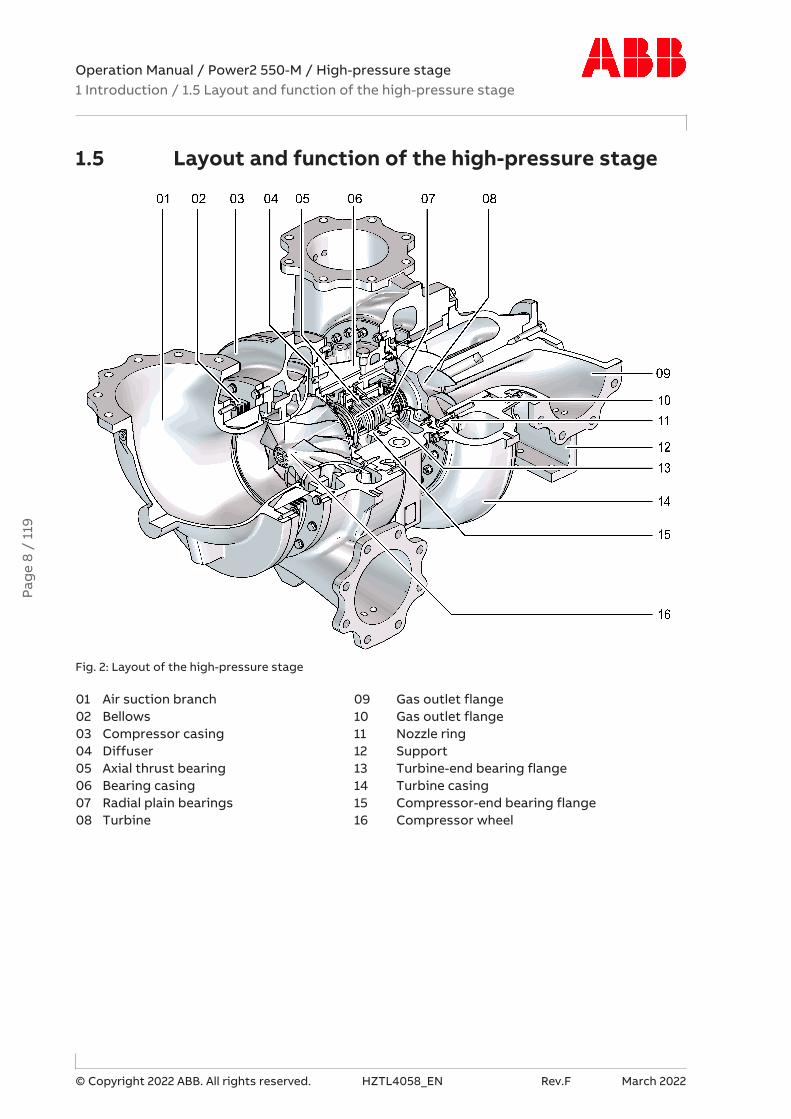
Fig. 2: Layout of the high-pressure stage
01 Air suction branch 09 Gas outlet flange02 Bellows 10 Gas outlet flange03 Compressor casing 11 Nozzle ring04 Diffuser 12 Support05 Axial thrust bearing 13 Turbine-end bearing flange06 Bearing casing 14 Turbine casing07 Radial plain bearings 15 Compressor-end bearing flange08 Turbine 16 Compressor wheel
Pag
e 8
/ 11
9

Operation Manual / Power2 550-M / High-pressure stage1 Introduction / 1.5 Layout and function of the high-pressure stage
© Copyright 2022 ABB. All rights reserved. HZTL4058_EN Rev.F March 2022
Mode of operation of the high-pressure stage (Power2 HP)
Fig. 3: Function of the high-pressure stage
Power2 Two-stage turbocharging 21 HP compressorPower2 LP Low-pressure stage 22 HP turbinePower2 HP High-pressure stage 23* Gas piping (bellows)A Exhaust gas inlet from internal combus-
tion engine24 LP turbine
B Exhaust gas outlet 25 LP compressorC Air or air/gas mixture inlet 26 IntercoolerD Air or air/gas mixture outlet and supply
to the charge air cooler- - - Not included in the Turbo Systems
scope of delivery
*) If present
The high-pressure stage (Power2 HP) is a turbomachine, and its main components are a tur-bine and a compressor. These components are installed on a common shaft and form the ro-tor (see Fig. 2: Layout of the high-pressure stage →8).
In the high-pressure stage (Power2 HP) shown in the sectional view (see Fig. 2: Layout of thehigh-pressure stage →8), the exhaust gas flows through the turbine casing (14) and thenozzle ring (11) and reaches the turbine (08). The HP turbine uses the energy contained in theexhaust gas to drive the rotor. The exhaust gases then flow through the gas outlet flange(10), the gas outlet casing (09) and the exhaust gas pipe connected to it before they reachthe turbine of the low-pressure stage (Power2 LP).
The rotor runs in two radial plain bearings (07), which are located in the bearing casing (06)between the compressor and turbine. The axial thrust bearing (05) is located between thetwo radial plain bearings. The plain bearings are connected to a central lubricating oil ductwhich is normally supplied by the lubricating oil circuit of the engine. The oil outlet lies at thedeepest point of the bearing casing.
The HP compressor wheel (16) connected to the shaft sucks in the precompressed air or anair/gas mixture from the low-pressure stage (25) through the air suction branch (01). The airis compressed further in the HP compressor (21) and the downstream diffuser (04) and sub-sequently supplied to the charge air cooler via the compressor casing (03).
Pag
e 9
/ 11
9

Operation Manual / Power2 550-M / High-pressure stage1 Introduction / 1.6 Symbols, definitions
© Copyright 2022 ABB. All rights reserved. HZTL4058_EN Rev.F March 2022
1.6 Symbols, definitions
Symbols
The following symbols are used in this document:
u Indicates an action step.
1. Indicates a numbered action step.
→ Refers to a page number
Accuracy of illustrations
The illustrations in this document are general in nature and intended for ease of understand-ing. Differences in detail are therefore possible.
Definition of mandatory signs
Mandatory signs show the protective equipment to be worn for a task. The mandatory signsare described in chapter Safety and must be complied with.
Definition of Caution / Warning
Caution and warning signs are described in chapter Safety.
Terms used
The following terms are used in this document:
¡ Two-stage turbocharging (Power2)
¡ Low-pressure stage (Power2 LP)
¡ High-pressure stage (Power2 HP)
¡ Low-pressure and high-pressure stage
Turbo Systems
Turbo Systems Switzerland Ltd is referred to in this document as Turbo Systems.
Official service stations of Turbo Systems
Official service stations are identified in this document as Turbo Systems service stations.These Turbo Systems service stations are regularly audited and certified by Turbo SystemsSwitzerland Ltd. See also chapter Contact information →4.
Pag
e 10
/ 1
19
Operation Manual / Power2 550-M / High-pressure stage1 Introduction / 1.7 Registered trademarks
© Copyright 2022 ABB. All rights reserved. HZTL4058_EN Rev.F March 2022
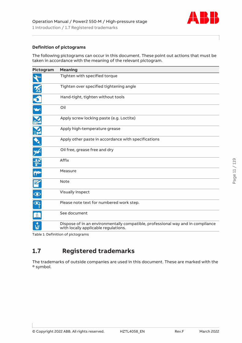
Definition of pictograms
The following pictograms can occur in this document. These point out actions that must betaken in accordance with the meaning of the relevant pictogram.
Pictogram MeaningTighten with specified torque
Tighten over specified tightening angle
Hand-tight, tighten without tools
Oil
Apply screw locking paste (e.g. Loctite)
Apply high-temperature grease
Apply other paste in accordance with specifications
Oil free, grease free and dry
Affix
Measure
Note
Visually inspect
Please note text for numbered work step.
See document
Dispose of in an environmentally compatible, professional way and in compliancewith locally applicable regulations.
Table 1: Definition of pictograms
1.7 Registered trademarksThe trademarks of outside companies are used in this document. These are marked with the® symbol.
Pag
e 11
/ 1
19
Operation Manual / Power2 550-M / High-pressure stage1 Introduction / 1.8 Storage of new low-pressure and high-pressurestages
© Copyright 2022 ABB. All rights reserved. HZTL4058_EN Rev.F March 2022
1.8 Storage of new low-pressure and high-pressurestages
Storage for up to 6 months
New low-pressure and high-pressure stages and spare parts from Turbo Systems can bestored in their closed packages for 6 months from the date of delivery without additionalmothballing measures.
Only dry rooms in which the relative humidity is between 40…70 % and condensation cannotform are suitable for storage.
Storage for more than 6 months (VCI)
As the contents of the package are adapted as required, low-pressure and high-pressurestages and spare parts may also be delivered without a VCI label.
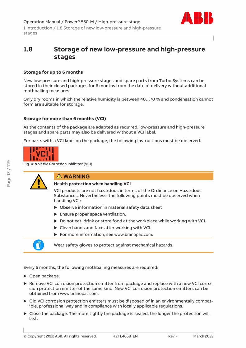
For parts with a VCI label on the package, the following instructions must be observed.
Fig. 4: Volatile Corrosion Inhibitor (VCI)
WARNINGHealth protection when handling VCIVCI products are not hazardous in terms of the Ordinance on HazardousSubstances. Nevertheless, the following points must be observed whenhandling VCI:
u Observe information in material safety data sheet
u Ensure proper space ventilation.
u Do not eat, drink or store food at the workplace while working with VCI.
u Clean hands and face after working with VCI.
u For more information, see www.branopac.com.
Wear safety gloves to protect against mechanical hazards.
Every 6 months, the following mothballing measures are required:
u Open package.
u Remove VCI corrosion protection emitter from package and replace with a new VCI corro-sion protection emitter of the same kind. New VCI corrosion protection emitters can beobtained from www.branopac.com.
u Old VCI corrosion protection emitters must be disposed of in an environmentally compat-ible, professional way and in compliance with locally applicable regulations.
u Close the package. The more tightly the package is sealed, the longer the protection willlast.
Pag
e 12
/ 1
19

Operation Manual / Power2 550-M / High-pressure stage1 Introduction / 1.8 Storage of new low-pressure and high-pressurestages
© Copyright 2022 ABB. All rights reserved. HZTL4058_EN Rev.F March 2022
Long-term storage of low-pressure and high-pressure stages
The low-pressure and high-pressure stages will be prepared for long-term storage if reques-ted in the purchase order. The package is equipped with a hygrometer (see illustration).
Fig. 5: Package with hygrometer
Every 6 months, the following measures are required:
u Check the hygrometer (02) in the sight-glass. There is an opening (01) in the woodencrate which allows this check to be carried out. When the display field has changed colourat the 70% level, the maximum permissible humidity has been exceeded. In this case, thelow-pressure or high-pressure stage or the cartridge group must be checked and repack-aged by a Turbo Systems service station.
u Inspect the package for damage. If the package is damaged, the low-pressure or high-pressure stage or the cartridge group must be checked and repackaged by a Turbo Sys-tems service station.
After every 3 years the following work steps must be performed by a Turbo Systems servicestation:
¡ Inspect the component
¡ Replace the desiccant agent
¡ Repackage the component.
NOTICE70% field of the hygrometer has not changed colourIf the 70% field of the hygrometer (02) has not changed colour and the pack-age is not damaged, the low-pressure or high-pressure stage can be put intooperation without previously having been checked by a Turbo Systems ser-vice station.
Unpacking the low-pressure and high-pressure stages
The corrosion protection effect ends after the material is unpacked from the VCI package.
To avoid the formation of condensation, the surroundings and the content of the packagemust have the same temperature during unpacking.
Pag
e 13
/ 1
19

Operation Manual / Power2 550-M / High-pressure stage2 Safety / 2.1 Introduction
© Copyright 2022 ABB. All rights reserved. HZTL4058_EN Rev.F March 2022
2 Safety
2.1 IntroductionThe two-stage turbocharging system (Power2) manufactured by Turbo Systems is state ofthe art and complies with the respective health and safety standards in effect at the timethe system was built. Thus Power2 is safe to operate. Nevertheless, there may be some re-sidual risks during operation of the Power2 and work on Power2 components, such as low-pressure stage and high-pressure stage, which:
¡ Are caused by Power2 itself or its accessories.
¡ Are caused by the operating equipment used or supplies and materials.
¡ Are a consequence of insufficient compliance with safety instructions.
¡ Are a consequence of insufficient or inappropriate performance of maintenance and in-spection work.
The operating company is responsible for defining measures that regulate safe access toand safe handling of the Power2.
All instructions contained in this chapter must be observed for safe and trouble-free opera-tion of the Power2 and during all work on the Power2 components.
All further safety instructions contained and specifically identified in every chapter of thisdocument (see section Definition of safety instructions) must also be observed.
2.2 CE conformity
Information
Low-pressure and high-pressure stages from Turbo Systems comply with the machinery dir-ective 2006/42/EC and are partly completed machinery as defined by Article 2 g.
Pag
e 14
/ 1
19

Operation Manual / Power2 550-M / High-pressure stage2 Safety / 2.3 Definition of mandatory signs
© Copyright 2022 ABB. All rights reserved. HZTL4058_EN Rev.F March 2022
2.3 Definition of mandatory signs
To be worn at all timesProtective clothing Safety footwear to protect
against mechanical hazard andrisk of falling
Table 2: Personal protective equipment to be worn at all times
To be worn specific to the respective taskSafety glasses Safety goggles
Safety gloves to protectagainst- Mechanical hazard- Chemical hazard- Thermal hazard- Electrical hazard
Respiratory mask to protectagainst- Dusts- Gases
Safety helmet Ear protection
Table 3: Personal protective equipment to be worn specific to the respective task
2.4 Definition of safety instructions
WARNINGDefinition of WarningNon-compliance or inaccurate compliance with working or operating in-structions indicated by this symbol and the word WARNING can lead to seri-ous injuries to personnel and even to fatal accidents.
u Warning signs must always be observed.
CAUTIONDefinition of CautionNon-compliance or inaccurate compliance with working or operating in-structions indicated by this symbol and the word CAUTION can lead to seri-ous damage to engine or property with grave consequences.
u Caution signs must always be observed.
Pag
e 15
/ 1
19

Operation Manual / Power2 550-M / High-pressure stage2 Safety / 2.5 Intended use
© Copyright 2022 ABB. All rights reserved. HZTL4058_EN Rev.F March 2022
2.5 Intended use
Use on internal combustion engines
Power2 from Turbo Systems is intended for charging internal combustion engines.
To ensure compliance with the machinery directive 2006/42/EC when using on gas engines,the Power2 must be operated in an engine room classified as "not at risk of explosion". Thisis in accordance with the position paper [2] relating to ATEX issued by EUROMOT [1].
The specific operating limits of Power2 were determined on the basis of information fromthe enginebuilder about the intended use. This data is given on the rating plate and is gener-ally different for the low-pressure stage and high-pressure stage.
The use of Power2 is limited to the specific application released at the time of delivery.
Turbo Systems accepts no liability and rejects all warranty claims for any non-intended ap-plications.
[1]Euromot = The European Association of Internal Combustion Engine Manufacturers[2]Directive 94/9/EC concerning equipment and protective systems intended for use in po-
tentially explosive atmospheres (ATEX) The Euromot Position as of November 2003, ATEXEuromot Position 191103
WARNINGUnapproved operationOperation of the Power2 outside of the operating limits can be hazardous topersonnel.
u Power2 must only be operated within the operating limits.
u Power2 must only be operated by trained personnel.
The intended use of the Power2 includes compliance with all regulations and conditions.
In particular, the following must be observed:
¡ The Operation Manual
¡ The instructions of the enginebuilder
State of the art
The Power2 is designed and built according to the state of the art and is safe to operate.
Perfect condition
The Power2 must be used in a technically perfect condition and in compliance with its inten-ded use.
Turbo Systems excludes any liability for damage resulting from unauthorized modificationsto the Power2 or improper operation.
Pag
e 16
/ 1
19

Operation Manual / Power2 550-M / High-pressure stage2 Safety / 2.6 Deflagration on gas engines
© Copyright 2022 ABB. All rights reserved. HZTL4058_EN Rev.F March 2022
2.6 Deflagration on gas enginesLow-pressure stages from Turbo Systems can tolerate a deflagration with a transient pres-sure increase of 12 bar (guideline value).
High-pressure stages from Turbo Systems can tolerate a deflagration with a transient pres-sure increase of 15 bar (guideline value).
After a deflagration event, Turbo Systems recommends verifying the following points on thelow-pressure and high-pressure stages:
¡ Position of the turbine and compressor casings to the bearing casing
¡ Shifting of the bearing casing in relation to the bracket
¡ Cracks in casings
If during external inspection anomalies are found or if a particularly strong deflagrationevent has taken place, it is also recommended to check the bearings of the low-pressure andhigh-pressure stages before the next start. This inspection and evaluation must be carriedout by a Turbo Systems service station.
Pag
e 17
/ 1
19
Operation Manual / Power2 550-M / High-pressure stage2 Safety / 2.7 Warning plates on the high-pressure stage
© Copyright 2022 ABB. All rights reserved. HZTL4058_EN Rev.F March 2022
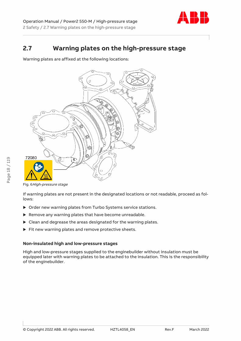
2.7 Warning plates on the high-pressure stageWarning plates are affixed at the following locations:
Fig. 6High-pressure stage
If warning plates are not present in the designated locations or not readable, proceed as fol-lows:
u Order new warning plates from Turbo Systems service stations.
u Remove any warning plates that have become unreadable.
u Clean and degrease the areas designated for the warning plates.
u Fit new warning plates and remove protective sheets.
Non-insulated high and low-pressure stages
High and low-pressure stages supplied to the enginebuilder without insulation must beequipped later with warning plates to be attached to the insulation. This is the responsibilityof the enginebuilder.
Pag
e 18
/ 1
19

Operation Manual / Power2 550-M / High-pressure stage2 Safety / 2.8 Rating plate of the high-pressure stage
© Copyright 2022 ABB. All rights reserved. HZTL4058_EN Rev.F March 2022
2.8 Rating plate of the high-pressure stage
Fig. 7: Rating plate
Operating limits1 Operating limits at engine overload (110%). In test rig operation only, unless otherwise
agreed with the enginebuilder.2 Operating limits during operationTable 4: Operating limits
Recommended inspection and replacement intervals3 Inspection interval of plain bearings in 1000 h4 Replacement interval of compressor in 1000 h5 Replacement interval of turbine in 1000 hTable 5: Recommended inspection and replacement intervals
Further data6 Power2 designation7 Power2 serial number8 Power2 stage9 Serial number of the low or high-pressure stage10 Year of construction of the low or high-pressure stage11 Weight of the low or high-pressure stage12 Part number of the customer of the low or high-pressure stageTable 6: Further data
Pag
e 19
/ 1
19

Operation Manual / Power2 550-M / High-pressure stage2 Safety / 2.9 Periodic check of the pressure vessels
© Copyright 2022 ABB. All rights reserved. HZTL4058_EN Rev.F March 2022
Explanations of the rating plate
The recommended replacement intervals and the corresponding operating limits are jointlydefined with the enginebuilder. This information is specific to the system.
The operating limits of the low-pressure stage are generally different from the operatinglimits of the high-pressure stage.
Operation above the indicated values nBmax, tBmax can considerably shorten the recommendedreplacement intervals. In such cases, Turbo Systems recommends contacting the nearestTurbo Systems service station.
nMmax, tMmax normally only apply when running at overload (110 %) during trials on the enginetest bed. These limit values can also be permitted during operation for special applications.Operation above nMmax and tMmax is not permitted.
Failure to observe the recommended replacement intervals increases the risk of unpredict-able component failures.
Locations of the rating plates on the high-pressure stage
Fig. 8: Location of Power2 HP rating plate
One rating plate each is attached on the left and the right side of the bearing casing.
2.9 Periodic check of the pressure vesselsThe pressure vessels used by Turbo Systems, such as those for wet or dry cleaning, are so-called "simple pressure vessels".
¡ The locally applicable legal regulations regarding periodic checks of the pressure vesselsmust be observed.
¡ The operating company is responsible for the safe operation of the pressure vessel.
WARNINGDanger due to pressure vesselsThe operating company must make sure the pressure vessels are in properworking condition and monitor them. Necessary repair or maintenance workmust be performed promptly, and the required safety measures must betaken.
u Pressure equipment must not be operated if defects are present.
Pag
e 20
/ 1
19

Operation Manual / Power2 550-M / High-pressure stage2 Safety / 2.10 Lifting of loads
© Copyright 2022 ABB. All rights reserved. HZTL4058_EN Rev.F March 2022
2.10 Lifting of loads
WARNINGSuspended loadsLoads that are not attached according to regulations can cause injury topersonnel or fatal accidents.
u Loads must always be fastened to properly functional lifting gear with asufficient load limit.
u Pay attention to the correct attachment of loads on the crane hook.
u People must not stand beneath suspended loads.
Wear safety gloves to protect against mechanical hazards.
Wear safety helmet.
Fig. 9: Attachment of loads on the crane hook
Fig. 10: Attachment angle
If there are two or more suspension points, the attachment angle of 45° must not be ex-ceeded. This prevents excessive loading due to diagonal pull.
u Before looping around the components of the low-pressure and high-pressure stage, al-low them to cool down (maximum 80 °C).
u Attach components of the low-pressure and high-pressure stage as described in the re-spective action steps.
u Use a suitable edge guard if there are sharp edges.
u The assembly devices must be completely screwed in and must not unscrew during use.
u Use assembly devices only for the described applications.
u Put down dismantled components of the low-pressure and high-pressure stage in such away that they cannot tip over.
Pag
e 21
/ 1
19

Operation Manual / Power2 550-M / High-pressure stage2 Safety / 2.11 Prerequisites for operation and maintenance
© Copyright 2022 ABB. All rights reserved. HZTL4058_EN Rev.F March 2022
2.11 Prerequisites for operation and maintenance
Responsibility of the operating company
In awareness of its responsibility, the operating company must ensure that only authorisedpersonnel work on the Power2, who:
¡ Are versed in the general and locally applicable regulations for occupational safety andaccident prevention
¡ Are equipped with the prescribed personal protective equipment
¡ Have read and understood the Operation Manual
¡ Have been instructed in the use of the Power2.
The safety-conscious work of the personnel and adherence to the Operation Manual must bechecked periodically.
Suitable working materials and personal protective equipment must be kept in a perfectcondition.
Only authorised personnel may remain in the vicinity of the Power2 when the engine is run-ning.
Competence of personnel
The Power2 may only be operated and serviced by trained and authorised personnel. Basicmechanical training is a prerequisite.
Modifications to the Power2
Modifications to the Power2 must be approved by Turbo Systems.
Original parts and safety
Original parts and accessories have been specially designed by Turbo Systems for thePower2.
WARNINGUse original partsOperation of the Power2 with non-original parts can impair the safety of thePower2 and can cause serious damage to property and injury to personnel.
u Only use original parts from Turbo Systems.
Turbo Systems accepts no liability for any damage resulting from the use of non-originalparts and corresponding accessories.
Pag
e 22
/ 1
19

Operation Manual / Power2 550-M / High-pressure stage2 Safety / 2.12 Hazards during operation and maintenance
© Copyright 2022 ABB. All rights reserved. HZTL4058_EN Rev.F March 2022
2.12 Hazards during operation and maintenance
Noise hazards
The turbocharger's noise emission is influenced by its installation and operating conditions.A noise level exceeding 85 dB(A) is harmful.
WARNINGNoise hazardsExposure to noise can harm the hearing system, impair health and the psy-chological state and may lead to lack of attention and irritation.
u When the engine is running, always wear ear protection.
u Always wear ear protection if the sound pressure level exceeds 85 dB(A).
Wear ear protection.
Hazards due to hot surfaces
Surfaces of the low-pressure and high-pressure stage, attached parts and operating fluids(lubricating oil) get hot during operation. The surface temperature depends on the efficacyof the existing insulation. The temperature may rise to a level that can cause burns.
WARNINGDanger of burnsTouching hot surfaces or contact with hot operating fluids can cause severeburns.
u Do not touch hot surfaces. Observe the warning plate on the low-pres-sure and high-pressure stage.
u Wear heat-resistant safety gloves and protective clothing.
u Wait for the low-pressure and high-pressure stage to cool down beforecarrying out any work.
Wear safety gloves to protect against thermal hazards.
Pag
e 23
/ 1
19

Operation Manual / Power2 550-M / High-pressure stage2 Safety / 2.12 Hazards during operation and maintenance
© Copyright 2022 ABB. All rights reserved. HZTL4058_EN Rev.F March 2022
WARNINGHot surfaces on the non-insulated low-pressure and high-pressure stageNon-insulated low-pressure and high-pressure stages can cause serious in-juries to personnel (burns).
Turbo Systems supplies the low-pressure and high-pressure stage with orwithout insulation in accordance with the purchase order received from theenginebuilder. If supply is without insulation, the enginebuilder is respons-ible for providing the low-pressure and high-pressure stage with proper in-sulation and for providing protection against contact with hot surfaces.
u Compliance with the instructions and specifications given by the en-ginebuilder to protect against contact with hot surfaces on the low-pres-sure and high-pressure stage is compulsory.
Wear safety gloves to protect against thermal hazards.
Hazards due to rotating parts
WARNINGPhysical hazards due to rotating partsContact with rotating parts can cause severe injury. The low-pressure stagemust never be used without the filter silencer or air inlet casing, respectively.With the engine stopped, the rotor can rotate due to the stack draughtalone.
u Operate the low-pressure and high-pressure stage in compliance with thespecifications.
u Secure the rotor against unintentional rotation during maintenance.
Wear safety gloves to protect against mechanical hazards.
Pag
e 24
/ 1
19

Operation Manual / Power2 550-M / High-pressure stage2 Safety / 2.13 Safe operation
© Copyright 2022 ABB. All rights reserved. HZTL4058_EN Rev.F March 2022
2.13 Safe operation
Mechanical hazards during operation
During standard operation, no mechanical hazards are caused by the low-pressure and high-pressure stage, provided that it has been properly installed.
Low-pressure and high-pressure stages are not designed for sudden pressure loss that mayoccur due to the piping system between the compressor or the turbine stages bursting.
Safety during commissioning and operation
u Visually inspect your working environment before starting work.
u Remove any obstacles and objects littering the workplace.
u Check all pipes to and from the Power2 for damage and leaks before commissioning.
u Check Power2 for recognisable damage or defects every 12 hours of operation or at leastonce a day.
u Report any damage and any alterations of operational characteristics to the responsibledepartment immediately.
u In case of damage, take the Power2 out of operation immediately and safeguard againstaccidental/unauthorised use.
u When switching on operating energy supplies (hydraulics, pneumatics, electricity), pay at-tention to the risks that may occur as a consequence of this energy input.
Pag
e 25
/ 1
19

Operation Manual / Power2 550-M / High-pressure stage2 Safety / 2.14 Safe maintenance
© Copyright 2022 ABB. All rights reserved. HZTL4058_EN Rev.F March 2022
2.14 Safe maintenance
Occupational safety
WARNINGInjuries to personsSevere injuries to personnel or fatal accidents can be caused by mechanicalinfluences as a consequence of hazardous and inadequate operational pro-cedures or non-compliance with safety and health standards.
u When working on the Power2, always wear safety footwear and protect-ive clothing to protect against mechanical hazards.
u Keep personal protective equipment in perfect condition.
u Obey mandatory signs.
u Observe the general rules for occupational safety and prevention of acci-dents.
u Only perform operations that are described in this chapter.
u Only perform operations for which you have received instruction or train-ing.
Wear safety footwear to protect against mechanical hazard and risk of fall-ing.
Wear protective clothing.
WARNINGRisk of fallingWhen work is performed on the low-pressure or high-pressure stage, thereis a risk of falling.
u Do not climb onto the low-pressure or high-pressure stage or onto at-tached parts and do not use them as climbing aids.
u Use suitable climbing aids and working platforms for work above bodyheight.
u Only perform work on the low-pressure or high-pressure stage when you are in a physic-ally and psychologically stable condition.
u Only work with suitable tools, equipment and appliances that function properly.
u Keep the workplace clean; clear away any loose objects and obstacles on the floor.
u Keep the floor, equipment and the low-pressure and high-pressure stage clean.
u Have oil binding agents ready and provide or keep oil pans at hand.
Use of assembly devices
Assembly devices are specially constructed and designed for the defined use; they are notcommercially available products.
u Use assembly devices only for the described applications.
Pag
e 26
/ 1
19
Operation Manual / Power2 550-M / High-pressure stage2 Safety / 2.14 Safe maintenance
© Copyright 2022 ABB. All rights reserved. HZTL4058_EN Rev.F March 2022
Welding work
u Wear personal protective equipment (PPE) for welding operations.
u When performing welding work in the vicinity of the low-pressure stage, always cover thefilter silencer to prevent the filter mat from being damaged.
u Keep flammable objects and substances out of the vicinity of flying sparks.
u Cover all connections on the low-pressure and high-pressure stage so that no foreign ob-jects can enter the low-pressure or high-pressure stage.
Safety during cleaning
If cleaning agents or solvents are used for cleaning, the corresponding material safety datasheet and the safety instructions in section Hazards due to operating materials and suppliesmust be observed.
u Observe the material safety data sheet for the cleaning agent or solvent.
u Wear personal protective equipment (PPE) according to the material safety data sheet.
u Inspect the electric cables for abrasion and damage before and after your cleaning work.
Safety during disassembly, assembly, maintenance and repair
u Observe the procedures for set-up, service and inspection work and the inspection inter-vals.
u Inform the operating staff before starting any service or repair work. Make sure the en-gine is not started while work is being conducted on the Power2.
u Before taking off any cover or removing any guard from the low-pressure or high-pres-sure stage, switch off the engine and wait until the low-pressure stage and the high-pres-sure stage have come to a standstill.
u Make sure that the oil supply is interrupted, especially with an external oil supply.
u Only restart the engine after all parts have been properly fitted again and oil supply is en-sured.
CAUTIONMechanical operations on the low-pressure and high-pressure stageComponents of the low-pressure or high-pressure stage can be damaged ordestroyed due to improper use.
u Only perform operations that are described in this manual.
u Only perform operations for which you have received instruction or train-ing.
Safety when taking out of operation or preparing for mothballing
u Observe the material safety data sheet for the cleaning and mothballing agents.
u Wear personal protective equipment (PPE) according to the material safety data sheet.
Pag
e 27
/ 1
19

Operation Manual / Power2 550-M / High-pressure stage2 Safety / 2.14 Safe maintenance
© Copyright 2022 ABB. All rights reserved. HZTL4058_EN Rev.F March 2022
Mechanical hazards when working on the low-pressure and high-pressure stage
WARNINGPhysical hazards due to rotating partsThe rotor can rotate due to the stack draught alone. Contact with rotatingparts can cause severe injury.
u Secure rotor against turning.
Hazards due to operating materials and supplies
Operating materials and supplies are substances required for the operation of the tur-bocharger or for the performance of maintenance work. Oils, greases, coolants, detergentsand solvents, acids and similar substances can be classified as hazardous substances.
WARNINGHandling operating materials and suppliesSwallowing or inhaling vapours of operating materials and supplies or con-tact with them may be harmful to health.
u Do not breathe in these substances and avoid contact with the skin.
u Ensure proper ventilation.
u Observe the information in the material safety data sheet for the operat-ing materials and supplies.
u Wear personal protective equipment (PPE) according to the materialsafety data sheet.
u Comply with local legislation.
Wear safety goggles.
Wear safety gloves to protect against chemical hazards.
Wear a respiratory mask to protect against gases.
WARNINGDanger of fire or explosionFlammable and combustible operating materials and supplies can catch fireor resulting vapours can lead to an explosion.
u Observe the information in the material safety data sheet for the operat-ing materials and supplies.
u Comply with local legislation.
u Do not allow any exposed flame or ignition source during cleaning work.
u Carry out cleaning in the open or provide sufficient ventilation.
Pag
e 28
/ 1
19

Operation Manual / Power2 550-M / High-pressure stage2 Safety / 2.14 Safe maintenance
© Copyright 2022 ABB. All rights reserved. HZTL4058_EN Rev.F March 2022
CAUTIONEnvironmental hazardImproper handling of operating materials and supplies can lead to environ-mental damage.
u Observe the information in the material safety data sheet for the operat-ing materials and supplies.
u Comply with local legislation.
Hazards due to the handling of insulation materials
WARNINGDanger from insulation materialsDust or fibres from insulation materials can have adverse effects on thehealth or cause irritations. Unsuitable and combustible insulation materialsare a fire hazard.
u Only use suitable and non-combustible insulation materials.
u Ensure good ventilation at the workplace.
u Avoid whirling up dust.
u Use dust-free tools and working methods.
u Remove package at the workplace only.
u Proceed with particular care when removing old insulation materials.
u Dispose of insulation materials properly and in an environmentally com-patible manner in compliance with the legal regulations.
Wear safety goggles.
Wear a respiratory mask to protect against dusts.
Wear safety gloves to protect against chemical hazards.Pa
ge
29 /
119

Operation Manual / Power2 550-M / High-pressure stage3 Removal and installation / 3.1 Transport / weight
© Copyright 2022 ABB. All rights reserved. HZTL4058_EN Rev.F March 2022
3 Removal and installation
3.1 Transport / weight
Swivel lifting eyes to be used
Swivel lifting eyes are required for the safe lifting of loads, which are not supplied by TurboSystems.
Fig. 11: Swivel lifting eye (example)
Thread M Length L Minimum load limit QuantityM16 20 ... 30 mm 750 kg 2
Table 7: Swivel lifting eyes
Lifting gear with a sufficient load limit must be used for removing and installing low-pres-sure and high-pressure stages. The following weight specifications apply to the heaviestvariant possible. Depending on the specification, the weight specified on the rating platemay be lower than the standard values specified here.
Fig. 12: Transport
Weight750 kg
Table 8: Weight of complete high-pressure stage
Pag
e 30
/ 1
19

Operation Manual / Power2 550-M / High-pressure stage3 Removal and installation / 3.2 Removing the high-pressure stage
© Copyright 2022 ABB. All rights reserved. HZTL4058_EN Rev.F March 2022
3.2 Removing the high-pressure stage
Preparing for removal
u Disconnect all pipes according to the instructions of the enginebuilder.
Fig. 13: Removing the high-pressure stage
1. Loosen screws (72013) between bellows (82300) and compressor casing (72000) and re-move with washer (72014). The air suction branch (82000) with the bellows does not haveto be dismantled from the air line. To protect the bellows, the high-pressure stage mustnot be lifted up together with the radial air suction branch and the bellows.
2. If present: Unplug the plug to the speed sensor (86505) and secure the rolled-upcable (2 m) to the high-pressure stage. This protects the plug from being crushed.
3. Treat the threads of the threaded rods (42191) and fixing screws (02) of the sup-port (61300) with penetrating oil and allow it to take effect. Do not oil the pressurescrews of the clamping nut (42201).
4. Attach lifting gear to high-pressure stage with two swivel lifting eyes (03).
5. Loosen and remove the fixing screws (02) of the support (61300).
u Loosen the clamping nuts (42201) in accordance with the following section.
Loosening the clamping nut
CAUTIONIncorrect procedure can make loosening impossibleIf individual pressure screws are fully relieved, the pressure screws can be-come compressed, making it impossible to loosen them.
u Comply with the following steps for loosening the pressure screws.
Pag
e 31
/ 1
19

Operation Manual / Power2 550-M / High-pressure stage3 Removal and installation / 3.2 Removing the high-pressure stage
© Copyright 2022 ABB. All rights reserved. HZTL4058_EN Rev.F March 2022
CAUTIONDo not clean pressure screwsThe pressure screws are equipped with a permanent sliding layer that mustnot be removed. In case of non-compliance, it cannot be ensured that thenecessary tension force is reached.
u Do not clean pressure screws.
u Do not lubricate pressure screws.
If a screw jams, the previously loosened screw must be tightened again a little.
Fig. 14: Loosening the clamping nut
1. Working in a circle, break loose each pressure screw (≤ 20°).
2. Working in a circle, loosen each pressure screw by 45° in 4 rounds.
3. Working in a circle, loosen each pressure screw by 90° in 1…5 rounds until all of the pres-sure screws have been relieved.
u Loosen clamping nut by hand.
Pag
e 32
/ 1
19

Operation Manual / Power2 550-M / High-pressure stage3 Removal and installation / 3.2 Removing the high-pressure stage
© Copyright 2022 ABB. All rights reserved. HZTL4058_EN Rev.F March 2022
Removing the high-pressure stage
Fig. 15: Removing the high-pressure stage
1. Unscrew the threaded rods (42191) until they have been completely removed from the en-gine support and the centering bush (42193).
2. Check whether the threaded rods (42191) can be moved.
3. Screw the threaded rods back into the centering bush by a few revolutions.
4. Manually lift threaded rods (42191) until the centering bushes (42193) are in the bearingcasing. If necessary, shake the threaded rods until the centering bushes (42193) releasethemselves from the engine support.
5. Screw down clamping nuts (42201) to the end of the expansion bush (42190). Thethreaded rod remains in position.
6. Remove the high-pressure stage.
7. Cover the oil connections (01) in the bracket to protect them from dirt.
Pag
e 33
/ 1
19

Operation Manual / Power2 550-M / High-pressure stage3 Removal and installation / 3.3 Installing the high-pressure stage
© Copyright 2022 ABB. All rights reserved. HZTL4058_EN Rev.F March 2022
3.3 Installing the high-pressure stage
3.3.1 Inserting gaskets
CAUTIONInserting the gasketsGaskets that are forgotten, damaged or improperly inserted will lead to oilleaks.
u Always use new gaskets and insert them carefully into the slot.
Fig. 16: Gaskets in the slots of the bearing casing
42001 Bearing casing42198 O-ring42199 O-ring01 Oil supply02 Oil drains
The oil is supplied (01) and drained (02) through the bracket.
u Insert the O-rings (42198 and 42199) into the slots of the bearing casing.
Pag
e 34
/ 1
19

Operation Manual / Power2 550-M / High-pressure stage3 Removal and installation / 3.3 Installing the high-pressure stage
© Copyright 2022 ABB. All rights reserved. HZTL4058_EN Rev.F March 2022
3.3.2 Placing the high-pressure stage on the bracket
Fig. 17: Preparing the fastening elements of the high-pressure stage
1. Insert expansion bush (42190) into bearing casing.
2. Screw the clamping nut (42201) flush onto the threaded rod (42191). The hexagon of thethread screw is at the top.
3. Place thrust washer (01) of clamping nut onto expansion bush.
4. Lead threaded rod (42191) with screwed-on clamping nut through thrust washer, expan-sion bush and bearing casing.
5. Screw the centering bush (42193) flush onto the threaded rod from below.
Pag
e 35
/ 1
19
Operation Manual / Power2 550-M / High-pressure stage3 Removal and installation / 3.3 Installing the high-pressure stage
© Copyright 2022 ABB. All rights reserved. HZTL4058_EN Rev.F March 2022
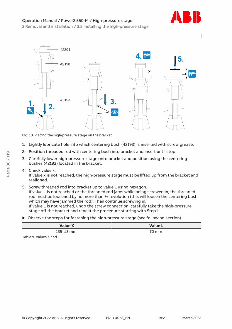
Fig. 18: Placing the high-pressure stage on the bracket
1. Lightly lubricate hole into which centering bush (42193) is inserted with screw grease.
2. Position threaded rod with centering bush into bracket and insert until stop.
3. Carefully lower high-pressure stage onto bracket and position using the centeringbushes (42193) located in the bracket.
4. Check value x. If value x is not reached, the high-pressure stage must be lifted up from the bracket andrealigned.
5. Screw threaded rod into bracket up to value L using hexagon.If value L is not reached or the threaded rod jams while being screwed in, the threadedrod must be loosened by no more than ½ revolution (this will loosen the centering bushwhich may have jammed the rod). Then continue screwing in.If value L is not reached, undo the screw connection, carefully take the high-pressurestage off the bracket and repeat the procedure starting with Step 1.
u Observe the steps for fastening the high-pressure stage (see following section).
Value X Value L135 ±2 mm 70 mm
Table 9: Values X and L
Pag
e 36
/ 1
19

Operation Manual / Power2 550-M / High-pressure stage3 Removal and installation / 3.3 Installing the high-pressure stage
© Copyright 2022 ABB. All rights reserved. HZTL4058_EN Rev.F March 2022
3.3.3 Steps for fastening the high-pressure stage
Fig. 19: Steps for fastening the high-pressure stage
1. Tighten the clamping nuts (42201) (see section Tightening the clamping nut).
2. Connect the cable connector (86515) to the speed sensor.
Pag
e 37
/ 1
19

Operation Manual / Power2 550-M / High-pressure stage3 Removal and installation / 3.3 Installing the high-pressure stage
© Copyright 2022 ABB. All rights reserved. HZTL4058_EN Rev.F March 2022
WARNINGSupport (61300)In radial gas outlet casings, the gas forces cause high torques to act on thehigh-pressure stage. If the high-pressure stage is fastened improperly, thiscan damage the high-pressure stage and cause serious injuries to personsor even fatal accidents.
u When using a radial gas outlet casing, only operate the high-pressurestage with a completely fitted support (61300).
Fig. 20: Steps for fastening the high-pressure stage
Part number Thread size and tightening torque01 M16
260 Nm61003 M20
365 NmTable 10: Tightening torque (01, 61003)
3. Fit the support (61300) using the fixing screws (01). Observe tightening torque.
4. Tighten the screw (61003) of the connection between gas outlet casing (61001) and sup-port (61300).
u Connect all gas pipes and air lines.
Pag
e 38
/ 1
19
Operation Manual / Power2 550-M / High-pressure stage3 Removal and installation / 3.3 Installing the high-pressure stage
© Copyright 2022 ABB. All rights reserved. HZTL4058_EN Rev.F March 2022
3.3.4 Tightening the clamping nut
Preparations for tightening the clamping nut
CAUTIONDo not clean pressure screws (04)The pressure screws are equipped with a permanent sliding layer that mustnot be removed.
Do neither clean nor lubricate the pressure screws. In case of non-compli-ance, it cannot be ensured that the necessary tension force is reached.
u Do not clean pressure screws.
u Do not lubricate pressure screws.
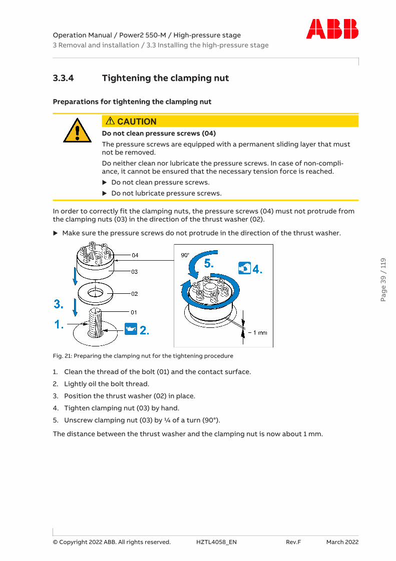
In order to correctly fit the clamping nuts, the pressure screws (04) must not protrude fromthe clamping nuts (03) in the direction of the thrust washer (02).
u Make sure the pressure screws do not protrude in the direction of the thrust washer.
Fig. 21: Preparing the clamping nut for the tightening procedure
1. Clean the thread of the bolt (01) and the contact surface.
2. Lightly oil the bolt thread.
3. Position the thrust washer (02) in place.
4. Tighten clamping nut (03) by hand.
5. Unscrew clamping nut (03) by ¼ of a turn (90°).
The distance between the thrust washer and the clamping nut is now about 1 mm.
Pag
e 39
/ 1
19
Operation Manual / Power2 550-M / High-pressure stage3 Removal and installation / 3.3 Installing the high-pressure stage
© Copyright 2022 ABB. All rights reserved. HZTL4058_EN Rev.F March 2022
Tightening pressure screws
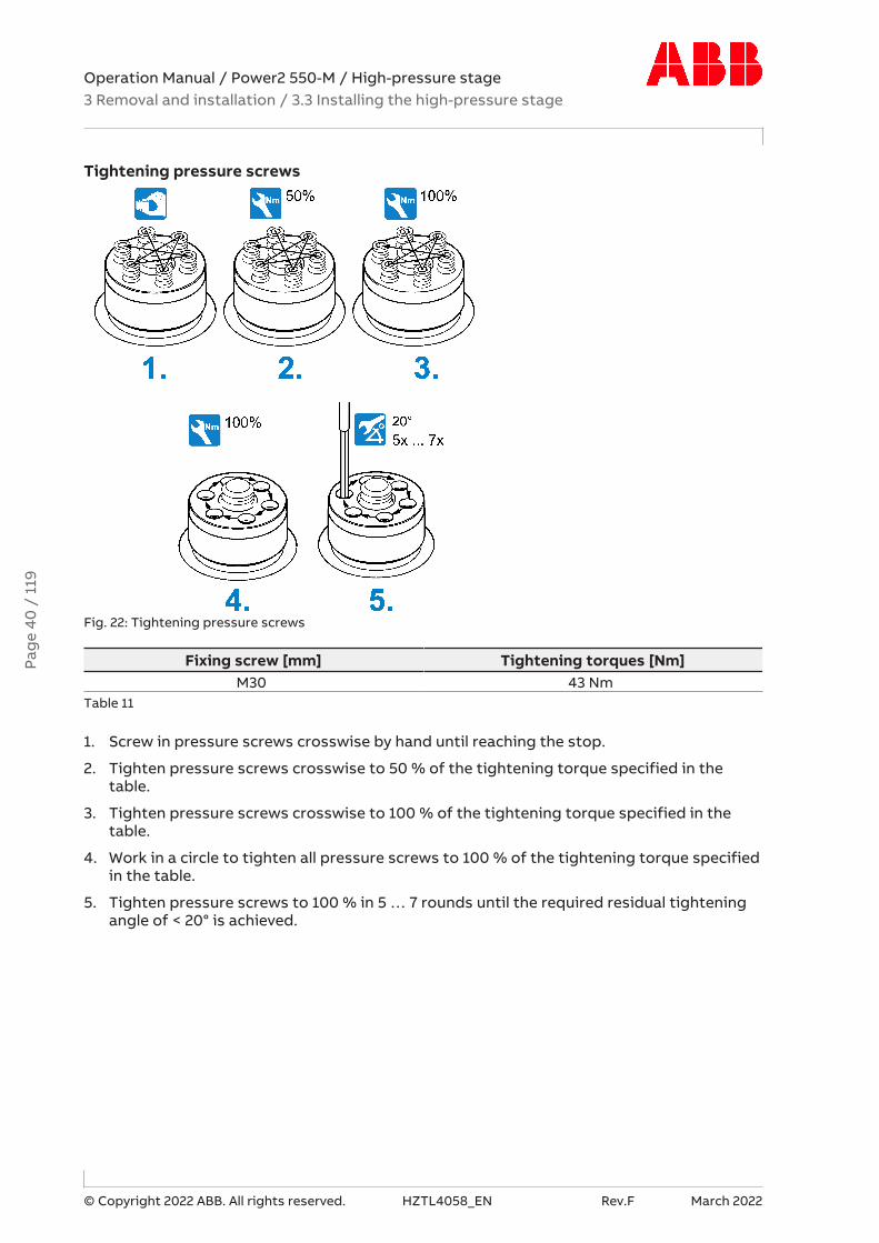
Fig. 22: Tightening pressure screws
Fixing screw [mm] Tightening torques [Nm]M30 43 Nm
Table 11
1. Screw in pressure screws crosswise by hand until reaching the stop.
2. Tighten pressure screws crosswise to 50 % of the tightening torque specified in thetable.
3. Tighten pressure screws crosswise to 100 % of the tightening torque specified in thetable.
4. Work in a circle to tighten all pressure screws to 100 % of the tightening torque specifiedin the table.
5. Tighten pressure screws to 100 % in 5 … 7 rounds until the required residual tighteningangle of < 20° is achieved.
Pag
e 40
/ 1
19

Operation Manual / Power2 550-M / High-pressure stage4 Commissioning / 4.1 Oil supply
© Copyright 2022 ABB. All rights reserved. HZTL4058_EN Rev.F March 2022
4 Commissioning
4.1 Oil supply
4.1.1 Introduction
In all operating states, a functioning and carefully executed oil supply is an important pre-requisite for trouble-free operation of the low-pressure and high-pressure stage.
The low-pressure and high-pressure stage are usually lubricated with oil from the engine oilcirculation.
u The directives of the enginebuilder on the selection of the lubricating oil and the oilchange intervals must be followed.
4.1.2 Pre-lubrication
Before the engine is started, the plain bearings of the low-pressure and high-pressure stagemust be pre-lubricated. You can do this by using an electrically driven oil pump.
u Switch on the oil pump.
u Build up oil pressure. Lubricating oil pressure →45
u Do not exceed a pre-lubrication time of 2 minutes.
u Start the engine.
u Let the oil pump run until the pump driven by the engine generates sufficient pressure.
Turbo Systems recommends integrating the entire pre-lubrication cycle into the engine con-trol.
4.1.3 Oil filtering
Lubricating oil filtering with a filter mesh width of ≤ 0.034 mm is sufficient for these low-pressure and high-pressure stages.
4.1.4 Oil pressure
Comply precisely with the oil pressure before the low-pressure and high-pressure stage fortrouble-free operation.
The admissible values are specified in chapter Monitoring during operation →45.
4.1.5 Oil orifice in the high-pressure stage
With an oil inlet pressure of more than 3 bar (when engine under load) before the high-pres-sure stage, the bearing casings are equipped as standard with an orifice at the oil inlet.
Pag
e 41
/ 1
19

Operation Manual / Power2 550-M / High-pressure stage4 Commissioning / 4.2 Inspection procedures
© Copyright 2022 ABB. All rights reserved. HZTL4058_EN Rev.F March 2022
4.2 Inspection procedures
4.2.1 Introduction
Inspection procedures include preventative visual controls, monitoring and measuring workbefore and during commissioning. Inspection procedures enable changes to the low andhigh-pressure stage to be detected. Engine damage can be prevented.
4.2.2 Checks before commissioning
Filter mat (if available)
u Check for damage and contamination.
Lubricating system
CAUTIONContaminated oilSerious damage to engine or property can be caused by dirt and solid ma-terial particles in the oil.
u For the initial commissioning phase and after all service work, flush thecomplete lubricating system with warm oil.
u Use special running-in filters when running in the engine and after all ser-vice work on the lubricating system.
u Check that the oil filter is clean before commissioning.
u Check the oil pressure in the oil supply pipes.
Warning plates
u Check whether warning plates are present and legible.
u Check whether the protective sheets have been removed from new warning plates.
Pag
e 42
/ 1
19
Operation Manual / Power2 550-M / High-pressure stage4 Commissioning / 4.2 Inspection procedures
© Copyright 2022 ABB. All rights reserved. HZTL4058_EN Rev.F March 2022
4.2.3 Checks after commissioning (engine in idle mode)
Lubricating system
u Check the oil pressure in the oil supply pipes.
u Check oil inlet temperature.
The admissible values are specified in chapter Monitoring during operation →45.
Leaktightness of pipes
WARNINGRisk of burning from hot gasEscaping gases are hot and will lead to serious burns in the event of contact.
u Check all pipes for leaks in accordance with the enginebuilder’s instruc-tions.
Wear safety gloves to protect against thermal hazards.
4.2.4 Checks when starting up the engine
u Measure speed, oil pressure and charging pressure at various engine performances.
u Measure the exhaust gas temperature before and after the turbine.
u Measure the air temperature before and after the compressor.
The measured values must be compared with the values of the acceptance protocol; differ-ent operating conditions must be taken into account here.
Escape of oily fluids
Lubricants and pastes used for the assembly of the low-pressure and high-pressure stagecan liquefy or vaporise and escape as oily fluids during the initial hours of operation. Con-tinual escape of an oily fluid indicates a possible oil leak.
In the event of a leak, contact a Turbo Systems service station.
Pag
e 43
/ 1
19
Operation Manual / Power2 550-M / High-pressure stage4 Commissioning / 4.3 Commissioning after taking out of operation
© Copyright 2022 ABB. All rights reserved. HZTL4058_EN Rev.F March 2022
4.3 Commissioning after taking out of operation
If present
u Remove cover plates (blind flanges) from the compressor casing, the gas inlet and thegas outlet.
u Remove protective film from oil connections on bearing casing foot.
General
u Check the exhaust gas pipe before and after the turbine for combustion residues or wa-ter residues and clean it. Remove any foreign objects that may be present.
u Check and clean filter silencer or air supply line, and remove any foreign objects that maybe present.
u With the high-pressure stage, check the bellows located between the radial air suctionbranch and the compressor casing for damage and replace if necessary.
u Put engine-side oil circulation to the low-pressure and high-pressure stage into opera-tion.
u Prepare the low-pressure and high-pressure stage for operation according to sectionChecks before commissioning.
u The low-pressure and high-pressure stage is now operational.
Pag
e 44
/ 1
19
Operation Manual / Power2 550-M / High-pressure stage5 Monitoring during operation / 5.1 Lubricating oil pressure
© Copyright 2022 ABB. All rights reserved. HZTL4058_EN Rev.F March 2022
5 Monitoring during operation
5.1 Lubricating oil pressure
CAUTIONAssuring lubricating oil pressureSerious damage to the engine or property can result from a missing or insuf-ficient lubricating oil supply.
u The lubricating oil pressure must be monitored during operation and thenecessary pressure assured at the oil inlet.
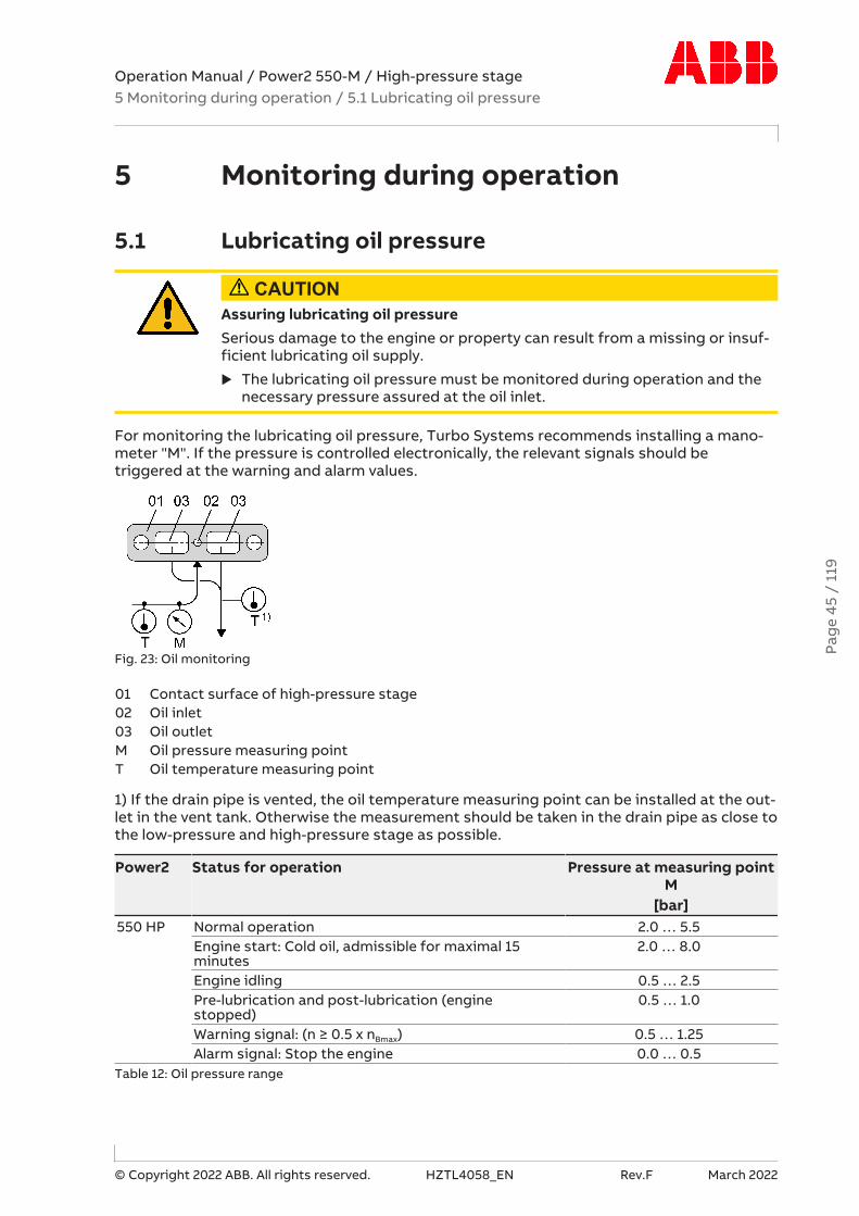
For monitoring the lubricating oil pressure, Turbo Systems recommends installing a mano-meter "M". If the pressure is controlled electronically, the relevant signals should betriggered at the warning and alarm values.
Fig. 23: Oil monitoring
01 Contact surface of high-pressure stage02 Oil inlet03 Oil outletM Oil pressure measuring pointT Oil temperature measuring point
1) If the drain pipe is vented, the oil temperature measuring point can be installed at the out-let in the vent tank. Otherwise the measurement should be taken in the drain pipe as close tothe low-pressure and high-pressure stage as possible.
Power2 Status for operation Pressure at measuring pointM
[bar]550 HP Normal operation 2.0 … 5.5
Engine start: Cold oil, admissible for maximal 15minutes
2.0 … 8.0
Engine idling 0.5 … 2.5Pre-lubrication and post-lubrication (enginestopped)
0.5 … 1.0
Warning signal: (n ≥ 0.5 x nBmax) 0.5 … 1.25Alarm signal: Stop the engine 0.0 … 0.5
Table 12: Oil pressure range
Pag
e 45
/ 1
19

Operation Manual / Power2 550-M / High-pressure stage5 Monitoring during operation / 5.2 Lubricating oil temperature
© Copyright 2022 ABB. All rights reserved. HZTL4058_EN Rev.F March 2022
5.2 Lubricating oil temperature
Lubricating oil temperature at the inlet
CAUTIONMachine damageIf the oil temperature at the oil inlet exceeds the admissible range, this maylead to engine damage.
u Observe oil temperature at the oil inlet according to the following table.
Power2 Status for operation Oil temperature at the in-let
Toil,inlet [°C]550 Admissible 30 … 90
Temporarily admissible (< 1 h) -> alarm > 90Not admissible -> stop engine > 95Not admissible -> do not start engine (before start: pre-heat oil)
< 30
Table 13: Oil temperature at the inlet
Lubricating oil temperature at the outlet
The oil temperature at the outlet is mainly dependant on:
¡ Lubricating oil temperature and pressure at the oil inlet
¡ Engine load and turbocharger speed
¡ Exhaust gas temperature
The maximum admissible oil temperature at the outlet is listed in the following table. Thespecified oil outlet temperature is to be considered as alarm value for the turbocharger op-eration and must be monitored according to the current regulations.
Power2 Status for operation Oil temperature at the out-let
Toil,outlet [°C]550 Admissible ≤ 140
Temporarily admissible -> alarm > 140Not admissible -> stop engine > 160
Table 14: Oil temperature at the outlet
If the turbocharger has been operated for a longer period of time outside the admissiblerange, Turbo Systems recommends having the turbocharger inspected by a Turbo Systemsservice station.
Pag
e 46
/ 1
19
Operation Manual / Power2 550-M / High-pressure stage5 Monitoring during operation / 5.3 Speeds
© Copyright 2022 ABB. All rights reserved. HZTL4058_EN Rev.F March 2022
5.3 Speeds
5.3.1 Introduction
Speed measurement systems enable the constant monitoring of the speeds of the low-pres-sure and the high-pressure stage.
5.3.2 Layout and overview
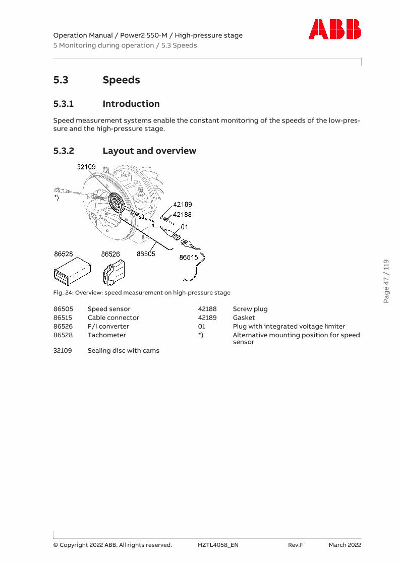
Fig. 24: Overview: speed measurement on high-pressure stage
86505 Speed sensor 42188 Screw plug86515 Cable connector 42189 Gasket86526 F/I converter 01 Plug with integrated voltage limiter86528 Tachometer *) Alternative mounting position for speed
sensor32109 Sealing disc with cams
Pag
e 47
/ 1
19

Operation Manual / Power2 550-M / High-pressure stage5 Monitoring during operation / 5.3 Speeds
© Copyright 2022 ABB. All rights reserved. HZTL4058_EN Rev.F March 2022
5.3.3 Differences in speed between the low-pressure or high-pressure stages
The speeds of the low-pressure stages differ significantly from the speeds of the high-pres-sure stages.
A Power2 turbocharging system for V-engines, for example, can consist of multiple low-pres-sure and multiple high-pressure stages. In this case the speeds of the low-pressure stagesonly differ a little from each other. The same also applies to the high-pressure stages.
The difference between the highest and the lowest speed must not be more than 3 %, relat-ive to the speed limit nBmax.
If this permissible range of difference is exceeded, the following steps must be carried out:
u Reduce the engine performance immediately until the maximum speed of all low andhigh-pressure stages no longer exceeds 70% of nBmax.
u If the engine cannot be stopped, it can continue to be driven with this reduced engineperformance or at this low-pressure and high-pressure stage speed.
u If a low-pressure or high-pressure stage surges continuously, the engine performancemust be reduced further.
u Measure the temperatures in the air lines and exhaust gas pipes from and to the low-pressure and high-pressure stages and compare with normal values.
u Check the pressure loss of the alternative air inlet and compare it with normal values.
If the engine can be stopped temporarily:
u Inspect air lines, exhaust gas pipes and the low-pressure and high-pressure stages andremedy any malfunctions.
u In any case, contacting the nearest Turbo Systems service station is recommended.
Pag
e 48
/ 1
19
Operation Manual / Power2 550-M / High-pressure stage5 Monitoring during operation / 5.3 Speeds
© Copyright 2022 ABB. All rights reserved. HZTL4058_EN Rev.F March 2022
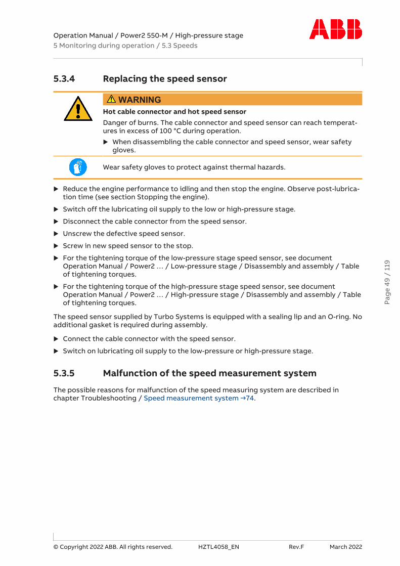
5.3.4 Replacing the speed sensor
WARNINGHot cable connector and hot speed sensorDanger of burns. The cable connector and speed sensor can reach temperat-ures in excess of 100 °C during operation.
u When disassembling the cable connector and speed sensor, wear safetygloves.
Wear safety gloves to protect against thermal hazards.
u Reduce the engine performance to idling and then stop the engine. Observe post-lubrica-tion time (see section Stopping the engine).
u Switch off the lubricating oil supply to the low or high-pressure stage.
u Disconnect the cable connector from the speed sensor.
u Unscrew the defective speed sensor.
u Screw in new speed sensor to the stop.
u For the tightening torque of the low-pressure stage speed sensor, see documentOperation Manual / Power2 … / Low-pressure stage / Disassembly and assembly / Tableof tightening torques.
u For the tightening torque of the high-pressure stage speed sensor, see documentOperation Manual / Power2 … / High-pressure stage / Disassembly and assembly / Tableof tightening torques.
The speed sensor supplied by Turbo Systems is equipped with a sealing lip and an O-ring. Noadditional gasket is required during assembly.
u Connect the cable connector with the speed sensor.
u Switch on lubricating oil supply to the low-pressure or high-pressure stage.
5.3.5 Malfunction of the speed measurement system
The possible reasons for malfunction of the speed measuring system are described inchapter Troubleshooting / Speed measurement system →74.
Pag
e 49
/ 1
19

Operation Manual / Power2 550-M / High-pressure stage6 Operation and service / 6.1 Noise emission
© Copyright 2022 ABB. All rights reserved. HZTL4058_EN Rev.F March 2022
6 Operation and service
6.1 Noise emission
WARNINGNoise hazardsExposure to noise can harm the hearing system, impair health and the psy-chological state and may lead to lack of attention and irritation.
u When the engine is running, always wear ear protection.
u Always wear ear protection if the sound pressure level exceeds 85 dB(A).
Wear ear protection.
The emission sound pressure level (A-weighted) is measured at a distance of 1 metre fromthe low-pressure and high-pressure stage.
The highest value of the emission sound pressure level1) reaches a maximum of 105 dB(A)near the compressor end (compressor casing, filter silencer, air suction branch).
The following prerequisites must be fulfilled with regard to the low-pressure and high-pres-sure stage to observe this limit value:
¡ Air inlet system and piping fitted
¡ All standard, noise-reducing measures2) have been fitted
¡ Bellows at the air outlet has been properly acoustically insulated by the enginebuilder (see Fig. 25: Noise insulation, bellows →51)
¡ Bellows between radial air inlet and compressor casing of the high-pressure stage hasbeen acoustically insulated
The enginebuilder is also responsible for insulating other components such as the chargeair/scavenging air lines and the cooler.
1) Directive 2006/42/EC, 1.7.4.2 / u / Paragraphs 5 + 7: A-weighted emission sound pressure level
2) The enginebuilder must provide acoustically equivalent measures in case of deviating in-sulation versions
Pag
e 50
/ 1
19

Operation Manual / Power2 550-M / High-pressure stage6 Operation and service / 6.1 Noise emission
© Copyright 2022 ABB. All rights reserved. HZTL4058_EN Rev.F March 2022
Suggestion for noise insulation, bellows
Fig. 25: Noise insulation, bellows
01 Compressor casing02 Bellows03 Charge air duct / scavenging air duct04 Insulation cushion05 Insulation mat (at least 15 mm)06 Sheet metal cover
Pag
e 51
/ 1
19

Operation Manual / Power2 550-M / High-pressure stage6 Operation and service / 6.2 Service work
© Copyright 2022 ABB. All rights reserved. HZTL4058_EN Rev.F March 2022
6.2 Service workService work includes visual controls, monitoring, measuring and inspection as well as func-tional checks. Service work enables the detection and rectification of changes to the low andhigh-pressure stage and ensures full operability of the low and high-pressure stage.
CAUTIONService intervalsService work on the low-pressure and high-pressure stage that is omitted orperformed too late can cause excessive contamination and wear as well asoperating failures.
u Carry out the service work at the specified time intervals.
CAUTIONSpecific service intervalExceptional stresses such as a high number of starts and stops, harsh envir-onmental conditions, poor fuel quality or high system vibrations can lead tountimely machine damage even if the prescribed service intervals are ob-served.
u Agree on a specific service interval with Turbo Systems.
To prevent machine damage caused by ageing and downtime, we recommend having an in-spection carried out by a Turbo Systems service station no later than 5 years after the lastservice.
6.2.1 Service work every 25 … 50 hours
CAUTIONUnknown operational changesImpairment to the degree of a possible operating failure can be the con-sequence.
u Have any unknown causes clarified by a Turbo Systems service station.
u Visual check for air, exhaust gas, and oil leaks.
u Record operating data and enter in the engine logbook.
u In case of deviations, determine the cause.
6.2.2 Service work at 100 hours after commissioning
u Clean or replace the oil filter located in the supply pipe to the low-pressure and high-pres-sure stage while the engine is stopped.
6.2.3 Service work according to instructions of enginebuilder
u Clean or replace the oil filter located in the supply pipe to the low-pressure and high-pres-sure stage while the engine is stopped.
Pag
e 52
/ 1
19

Operation Manual / Power2 550-M / High-pressure stage6 Operation and service / 6.2 Service work
© Copyright 2022 ABB. All rights reserved. HZTL4058_EN Rev.F March 2022
6.2.4 Service work every 12000 ... 15000 operating hours
The rotor and bearing parts must be checked and assessed by a Turbo Systems service sta-tion.
u Remove low-pressure and high-pressure stage from the engine and dismantle accordingto chapter Disassembly and assembly. Measure clearances.
u Clean nozzle ring and casing and check for cracks and erosion/corrosion.
Additional measures in conjunction with the high-pressure stage:
u Replace gaskets every time after disassembly.
u Check bellows between air-inlet casing and compressor casing for cracks and clean (seealso chapter Cleaning the high-pressure stage bellows (if present) →60).
6.2.5 Service work according to specifications on the ratingplate
The following work must be carried out by a Turbo Systems service station:
¡ Replacement of the bearing parts
¡ Replacement of the turbine and the compressor.
6.2.6 Entries in the engine logbook
The monitoring of the engine enables conclusions to be drawn on the behaviour of the low-pressure and high-pressure stage.
The following operating data and measured values must be entered regularly in the enginelogbook of the enginebuilder:
¡ Performance and speed of the engine
¡ Air intake temperature
¡ Pressure of the charge air
¡ Pressure loss in the charge air cooler and intercooler
¡ Lubricating oil pressure and lubricating oil temperature
If present:
¡ Speed of low-pressure and high-pressure stage
¡ Air temperature before and after the compressor and after the charge air cooler
¡ Exhaust gas temperature before and after the turbine
¡ Atmospheric humidity of the suction air (before the low-pressure stage)
Pag
e 53
/ 1
19

Operation Manual / Power2 550-M / High-pressure stage6 Operation and service / 6.3 Expected replacement intervals
© Copyright 2022 ABB. All rights reserved. HZTL4058_EN Rev.F March 2022
6.3 Expected replacement intervals
Rotating components
The recommended replacement intervals of the compressor and turbine wheels are spe-cified with the aid of the safety concept for rotating parts (SIKO) and dependent on the op-erating conditions. These intervals are shown on the rating plate of the low-pressure andhigh-pressure stage.
Non-rotating components
Depending on the system-specific operating conditions, a differentiation must be madebetween the intervals to be expected for:
¡ replacing the bearing parts and
¡ replacing the non-rotating components exposed to hot gas.
A decisive role is played by various influencing parameters which, in extreme cases, candrastically reduce the replacement interval of these parts.
During the prescribed periodic service work, the individual parts are examined for wear andreplaced if necessary.
Expected replacement intervals [h]
GAS / MDO HFOTurbine casing 25000 … 50000 25000Nozzle ring 25000 … 50000 25000Gas outlet flange 25000 … 50000 25000Heat shield 25000 … 50000 25000Heat sheet metal 25000 … 50000 25000Collecting grid in gas outlet casing 20000 20000Rotor components See information on rating plateBearing parts 12000 … 24000Other casings 50000 50000Table 15: Expected replacement intervals [h]
GAS = GasMDO = Marine Diesel OilHFO = Heavy Fuel Oil
The specified values are guideline values and are not guaranteed, see influencing paramet-ers.
Pag
e 54
/ 1
19
Operation Manual / Power2 550-M / High-pressure stage6 Operation and service / 6.3 Expected replacement intervals
© Copyright 2022 ABB. All rights reserved. HZTL4058_EN Rev.F March 2022
Influencing parameters
The actual values can deviate considerably from the guideline values, for example, due to thefollowing influences:
¡ Fuel quality and fuel treatment
¡ Load profile (thermal cycling, also number of starts/stops, emergency shutdowns)
¡ Gas inlet temperature
¡ Frequency and execution of turbine and compressor cleaning
¡ Specification of the high-pressure stage
¡ System-specific operating conditions (combustion quality, exhaust gas composition)
¡ Atmospheric humidity after the intercooler.
For bearing parts
¡ Lubricating oil quality (oil filtering, oil condition, oil monitoring)
¡ Load profile (speed, pressure conditions, temperature)
¡ Number of starts/stops
¡ Unbalance of the rotor (degree of contamination).
Pag
e 55
/ 1
19

Operation Manual / Power2 550-M / High-pressure stage6 Operation and service / 6.4 Stopping the engine
© Copyright 2022 ABB. All rights reserved. HZTL4058_EN Rev.F March 2022
6.4 Stopping the engine
CAUTIONResidual heat in the low-pressure and high-pressure stageIf the residual heat in the low-pressure and high-pressure stage is not suffi-ciently dissipated by the circulating lubricating oil, machine damage couldoccur.
u Observe the post-lubrication times and the oil pressure specified forpost-lubrication (see chapter Monitoring during operation / Lubricatingoil pressure).
Post-lubrication
Post-lubrication is required.
u Observe the oil pressure specified for post-lubrication. Lubricating oil pressure →45
Post-lubrication time [min]20
Table 16: Post-lubrication time
Pag
e 56
/ 1
19
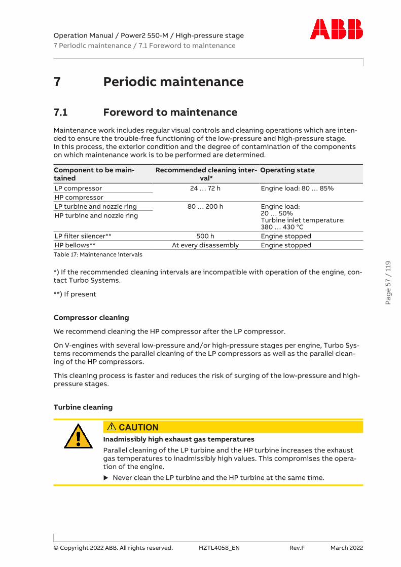
Operation Manual / Power2 550-M / High-pressure stage7 Periodic maintenance / 7.1 Foreword to maintenance
© Copyright 2022 ABB. All rights reserved. HZTL4058_EN Rev.F March 2022
7 Periodic maintenance
7.1 Foreword to maintenanceMaintenance work includes regular visual controls and cleaning operations which are inten-ded to ensure the trouble-free functioning of the low-pressure and high-pressure stage. In this process, the exterior condition and the degree of contamination of the componentson which maintenance work is to be performed are determined.
Component to be main-tained
Recommended cleaning inter-val*
Operating state
LP compressor 24 … 72 h Engine load: 80 … 85%HP compressorLP turbine and nozzle ring 80 … 200 h Engine load:
20 … 50%Turbine inlet temperature:380 … 430 °C
HP turbine and nozzle ring
LP filter silencer** 500 h Engine stoppedHP bellows** At every disassembly Engine stoppedTable 17: Maintenance intervals
*) If the recommended cleaning intervals are incompatible with operation of the engine, con-tact Turbo Systems.
**) If present
Compressor cleaning
We recommend cleaning the HP compressor after the LP compressor.
On V-engines with several low-pressure and/or high-pressure stages per engine, Turbo Sys-tems recommends the parallel cleaning of the LP compressors as well as the parallel clean-ing of the HP compressors.
This cleaning process is faster and reduces the risk of surging of the low-pressure and high-pressure stages.
Turbine cleaning
CAUTIONInadmissibly high exhaust gas temperaturesParallel cleaning of the LP turbine and the HP turbine increases the exhaustgas temperatures to inadmissibly high values. This compromises the opera-tion of the engine.
u Never clean the LP turbine and the HP turbine at the same time.
Pag
e 57
/ 1
19

Operation Manual / Power2 550-M / High-pressure stage7 Periodic maintenance / 7.2 Cleaning the compressor during operation
© Copyright 2022 ABB. All rights reserved. HZTL4058_EN Rev.F March 2022
7.2 Cleaning the compressor during operation
7.2.1 Prerequisite
¡ The enginebuilder approves the cleaning process and its specifications are adhered to.
¡ Instructions from Turbo Systems are followed.
7.2.2 Introduction
The contamination of the compressor stage (compressor wheel and diffuser) depends onthe degree of purity of the sucked-in air.
Deposits can form in the flow channels if salt, oil mist or dust are sucked in with the air.
Consequences of contamination:
¡ Impaired compressor efficiency
¡ Higher exhaust gas temperatures
¡ Increased fuel consumption
¡ Increased rotor unbalance
Periodic cleaning of the compressor during operation prevents or delays any great increasein the contamination, but never replaces the regular service work where the low and high-pressure stages are completely dismantled and the compressors are mechanically cleaned.
Cleaning process
The compressor is cleaned during operation using the wet cleaning method. This cleaningmethod is tested and approved by Turbo Systems.
Principle of wet cleaning
To clean the compressor stage during operation, water is injected before the compressorwheel.
The water does not act as a solvent. The coating is removed by the mechanical action of theimpacting droplets. The process is particularly suitable as long as the fouling is not too ad-vanced.
Pag
e 58
/ 1
19

Operation Manual / Power2 550-M / High-pressure stage7 Periodic maintenance / 7.2 Cleaning the compressor during operation
© Copyright 2022 ABB. All rights reserved. HZTL4058_EN Rev.F March 2022
7.2.3 Prerequisites for wet cleaning of compressor
¡ Engine load of 50 ... 85%
CAUTIONVolume of waterUncontrolled volumes of water can damage the pressure stages and the en-gine.
u Never connect injection tubes directly to a water pipe or a larger meter-ing container other than that specified by Turbo Systems.
CAUTIONCorrosion and deposits when cleaningSalt water and cooling water treatment substances damage and adverselyaffect parts of the low-pressure and high-pressure stage.
u Never use salt water, but only pure water for cleaning.
7.2.4 Wet cleaning of compressor
Wet cleaning operations for compressor with direct water supply
u Trigger water injection according to the instructions of the enginebuilder.
u The water pressure before the connection to the pressure stage must be observed (seetable Cleaning parameters).
u After cleaning operations, a waiting period of at least five minutes is required for thepressure stage to dry.
The cleaning process can be repeated up to three times.
The success of the cleaning can be recognised based on the charging pressure or the ex-haust gas temperature.
If the cleaning is still unsuccessful after three processes and the engine values are unsatis-factory, it is recommended to have the low-pressure and / or high-pressure stage checkedand cleaned by a service station.
Cleaning parameters for each compressor
Power2 Engine load Water pressure[bar]
Water injection period[s]
Ø of orifice [mm]
550 LP 80 … 85 % 3 10 2.1Table 18: Cleaning parameters
Power2 Engine load Water pressure[bar]
Water injection period[s]
550 HP 80 … 85 % pVE* + 3 10Table 19: Cleaning parameters
* Compressor inlet pressure depending on the operating point
Pag
e 59
/ 1
19

Operation Manual / Power2 550-M / High-pressure stage7 Periodic maintenance / 7.3 Cleaning the high-pressure stage bellows(if present)
© Copyright 2022 ABB. All rights reserved. HZTL4058_EN Rev.F March 2022
7.3 Cleaning the high-pressure stage bellows (ifpresent)
The disassembly and assembly of the bellows (82300) is described in chapter "Disassemblyand assembly".
Fig. 26: Bellows
The following maintenance work must be carried out on the bellows (82300):
u Remove insulation (if present).
u Perform a visual inspection for cracks, deposits and corrosion damage.
u Always replace cracked bellows with a new bellows.
u If deposits and water residue are present, clean the bellows with water.
u Perform a visual inspection of the sealing points (flange connection to the compressorcasing and air suction branch).
u Always replace bellows with a damaged sealing point with a new bellows.
7.4 Cleaning turbines and nozzle rings duringoperation
7.4.1 Introduction
The combustion of fuels such as marine diesel oil (MDO) and heavy fuel oil (HFO) in dieselengines causes contamination of the turbine components of the low and high-pressurestages. Poor quality fuel in conjunction with a high exhaust gas temperature can lead to veryhard deposits on the nozzle ring, the turbine blades and particularly on the casing walls sur-rounding the impellers (cover ring Power2 LP or gas outlet flange Power2 HP).
The formation of deposits on the turbine components stems from the following combustionproducts:
¡ Soot
¡ Molten ash
¡ Cinders
¡ Incompletely burnt fuel
¡ Sodium vanadyl vanadate
It is advantageous to use fuels with low ash, sulphur, sodium and vanadium contents. Thefuel must also be correctly stored, prepared and handled.
Pag
e 60
/ 1
19

Operation Manual / Power2 550-M / High-pressure stage7 Periodic maintenance / 7.4 Cleaning turbines and nozzle rings duringoperation
© Copyright 2022 ABB. All rights reserved. HZTL4058_EN Rev.F March 2022
Turbo Systems recommends using fuels with a mass ratio of vanadium to sodium of lessthan 3:1 so that the melting temperature of the sodium vanadyl vanadate is as high as pos-sible.
Consequences of contamination:
¡ Poor turbine efficiency
¡ Elevated exhaust gas temperatures
¡ Higher charging and ignition pressures with increasing speed of the low and high-pres-sure stages
¡ Lower engine performance
¡ Increased rotor unbalance
Experience in operation shows that, with periodic cleaning during operation, the intervalbetween overhauls can be extended. The wet cleaning of a turbine described in the followingcan be used for 4-stroke applications with heavy deposits (such as MDO and HFO applica-tions, for example). Generally, turbine cleaning is not required for the other applications.
Periodic cleaning of the turbines during operation never replaces the service work where thelow and high-pressure stages are completely dismantled and mechanically cleaned.
Very heavily contaminated turbines can no longer be cleaned in this way. In this case, thecontaminated components must be cleaned mechanically by a Turbo Systems service sta-tion.
Pag
e 61
/ 1
19
Operation Manual / Power2 550-M / High-pressure stage7 Periodic maintenance / 7.4 Cleaning turbines and nozzle rings duringoperation
© Copyright 2022 ABB. All rights reserved. HZTL4058_EN Rev.F March 2022
7.4.2 Cleaning method and principle
Cleaning of the turbine and the nozzle ring during operation is carried out by the cleaningmethod described in the following and is tested and approved by Turbo Systems:
¡ Wet cleaning
Wet cleaning makes use of various effects. These effects are used with varying levels of in-tensity, depending on the type of contamination:
¡ ErosionThe contamination is removed by the mechanical action of the impacting water droplets
¡ SolubilityWater solubility of the contamination deposits in water
¡ Thermal shockSpalling of contamination due to the temperature differential
CAUTIONCorrosion and deposits when cleaningSalt water and cooling water treatment substances damage and adverselyaffect parts of the low-pressure and high-pressure stage.
u Never use salt water, but only pure water for cleaning.
The turbine-end components are cleaned at reduced engine load. The exhaust gas temperat-ure must not exceed the value specified in the cleaning instructions (see section Prerequis-ites).
CAUTIONReduced service life of the componentsFailure to comply with the minimum stabilisation time before cleaning, theprescribed turbine inlet temperatures and the drying time after cleaning sig-nificantly reduces the expected service life of the components.
u Comply with the cleaning parameters given in the tables. (see Table 19:Cleaning parameters →66) and (see Table 20: Cleaning parameters→66)
Pag
e 62
/ 1
19

Operation Manual / Power2 550-M / High-pressure stage7 Periodic maintenance / 7.4 Cleaning turbines and nozzle rings duringoperation
© Copyright 2022 ABB. All rights reserved. HZTL4058_EN Rev.F March 2022
7.4.3 Wet cleaning of turbine blades and nozzle ring
Prerequisites
The following operating state and the following prerequisites have been tested and ap-proved by Turbo Systems for cleaning operations:
u Set the engine load between 20 … 50% so that the turbine inlet temperature is between380 … 430 °C.
Fig. 27: Load/time chart
u Once the turbine inlet temperature of the high-pressure stage is stable and lying below430 °C, wait at least another 10 minutes for the parts of the low and high-pressure stagesto cool down.
u Start the cleaning cycle according to the following description Wet cleaning operation.
u Only clean the low-pressure stage (Cleaning LP stage) if the low-pressure stage is con-figured with this option. If this is not the case, drying is initiated directly after cleaning ofthe high-pressure stage (Cleaning HP stage).
Pag
e 63
/ 1
19

Operation Manual / Power2 550-M / High-pressure stage7 Periodic maintenance / 7.4 Cleaning turbines and nozzle rings duringoperation
© Copyright 2022 ABB. All rights reserved. HZTL4058_EN Rev.F March 2022
Procedure
The prerequisites and operating state must be fulfilled prior to cleaning.
Fig. 28: Wet cleaning operation
u Make sure that the water supply (01) is connected, switched on and safeguarded.
u Open the drain pipe (08, 09) in the low-pressure stage, if present.
u Switch the 3-way valve (04) from scavenging air mode to water supply.
u Set the necessary water quantity on the flowmeter (11) according to the table in sectionCleaning parameters.
u Shut off the water supply again by switching the 3-way valve (04) to scavenging air modeafter injecting the required volume of water.
The injection process is complete.
u Shut the drain hole (if present) via the drain pipe (08, 09).
u After cleaning, continue to operate the engine for at least 10 minutes without any loadchange so that the pressure stages can dry.
It is necessary to have the corresponding water pipe pressure in order to achieve the correctwater flow rate (see table Cleaning parameters). If there is insufficient water pressure, thewater flow rate specified in the table will not be reached. A reduced cleaning effect can beexpected in this case.
Pag
e 64
/ 1
19

Operation Manual / Power2 550-M / High-pressure stage7 Periodic maintenance / 7.4 Cleaning turbines and nozzle rings duringoperation
© Copyright 2022 ABB. All rights reserved. HZTL4058_EN Rev.F March 2022
Repetitions of wet cleaning
The repetition of cleaning cycles one immediately after the other must be avoided as thiscan lead to excessive mechanical stress and thus to a reduction in the operating life of thecomponents.
If the cleaning process is ineffective, the duration can be extended. If the injection time is ex-tended, it is important to ensure that no impermissible volume of water collects in the gasoutlet casing. A drainage system should be installed for the gas outlet casing and openedduring cleaning. If there is no drainage system, the amount of water injected can be mon-itored with a flowmeter in the water supply. The permitted amount of water must be de-termined together with a Turbo Systems service station.
The action of the cleaning water on the peripheral units (such as boiler) must be clarified bythe operator.
Draining the gas outlet casing of the low-pressure stage
The following points must be observed with regard to draining the gas outlet casing:
¡ The exhaust gas temperature downstream of the low-pressure stage drops drasticallyduring cleaning (typical gas outlet temperatures during cleaning: 60...180 °C)
¡ Depending on the engine load, the drainage can take place through the drain pipe. Thisdrainage may occur after 2 … 3 minutes or not at all.
¡ If the drainage of the gas outlet casing is omitted, the low-pressure stage speed and/orthe gas inlet temperature must be monitored during the cleaning process. If the load istoo low, water can collect in the gas outlet casing. Indications for this are a suddensevere drop in the low-pressure stage speed or a very large increase in the gas inlet tem-perature. In such cases, the cleaning operations must be stopped and the cleaning cyclerestarted with reduced water pressure or higher engine load.
Pag
e 65
/ 1
19

Operation Manual / Power2 550-M / High-pressure stage7 Periodic maintenance / 7.4 Cleaning turbines and nozzle rings duringoperation
© Copyright 2022 ABB. All rights reserved. HZTL4058_EN Rev.F March 2022
Cleaning parameters for wet cleaning of the turbines
Power2 Max. temper-ature when
startingcleaningTTI [°C]
Lead timeat reduced
loadt i [min]
Injectiontime
t i [min]
Dryingtime
t i [min]
Water flow rateper low-pressurestage at pWater = 3
barVW [dm³/min]
Overpres-sure above
pTE of the ex-ternal scav-enging air
[bar]550 LP ≤ 430 ≥10 10 ≥10 18 ≥1Table 20: Cleaning parameters
Power2 Max. tem-perature
when start-ing cleaning
TTI [°C]
Lead time atreduced
loadt i [min]
Injectiontime
t i [min]
Dryingtime
t i [min]
Water flow rateper high-pres-sure stage atpWater = 3 bar
VW [dm³/min]
Overpres-sure above
pTE of the ex-ternal scav-enging air
[bar]550 HP ≤ 430 ≥10 10 ≥10 See the follow-
ing table, de-pending on theengine load andturbine specific-
ation
≥1
Table 21: Cleaning parameters
Power2 550 HP water volumes during turbine cleaning
Depending on the turbine specification (TV10TT50TA..), the corresponding water volume isset by the enginebuilder.
If operating with engine loads between the specified values, it is possible to interpolate theflow rate.
Engine load TV10 TT50TA13
TV10 TT50TA16
TV10 TT50TA20
TV10 TT50TA24
[%] Water flow rate VW [dm3/min]20 13.2 15.7 18.9 22.035 14.4 17.2 20.7 24.250 15.3 18.2 22.0 25.6
Table 22: Water volumes
Pag
e 66
/ 1
19

Operation Manual / Power2 550-M / High-pressure stage8 Troubleshooting / 8.1 Malfunctions when starting
© Copyright 2022 ABB. All rights reserved. HZTL4058_EN Rev.F March 2022
8 Troubleshooting
8.1 Malfunctions when starting
Delayed start-up
Possible causes RemedyLow-pressureorhigh-pressurestage
Pressure stage contaminated CleanBearing damaged Contact a Turbo Systems service sta-
tionRotor rubbingForeign object in pressure stage
Table 23: Malfunctions when starting – Delayed start-up
Vibrations
Possible causes RemedyEngine Vibrations from engine Contact enginebuilderLow-pressureorhigh-pressurestage
Rotor unbalance Contact a Turbo Systems service sta-tionTurbine or compressor damaged
Bearing damaged
Table 24: Malfunctions when starting – Vibrations
Rubbing of rotating parts
Normal behaviour, not a malfunctionLow-pressureorhigh-pressurestage
A minimal and uniform wear at the circumference of the rotor componentscaused by slight local rubbing against adjacent components is permitted. Thiscauses the compressor or turbine blades to be somewhat shortened. To pre-vent significant loss of efficiency, specific tolerances must be fulfilled.
¡ If there is any doubt about the extent of the rubbing, contact a TurboSystems service station.
¡ Have a dimension check carried out by a Turbo Systems service station.Table 25: Malfunctions when starting – Rubbing of rotating parts
Pag
e 67
/ 1
19

Operation Manual / Power2 550-M / High-pressure stage8 Troubleshooting / 8.2 Malfunctions during operation
© Copyright 2022 ABB. All rights reserved. HZTL4058_EN Rev.F March 2022
8.2 Malfunctions during operation
Lubricating oil pressure too low
Possible causes RemedyEngine Oil filter heavily contaminated Clean
Oil pump in lubricating system de-fective
Check/replace
Manometer displays incorrectly Replace manometerLow-pressureorhigh-pressurestage
Axial clearance of the rotor excessive Contact a Turbo Systems service sta-tion
Table 26: Malfunctions during operation – Lubricating oil pressure too low
Drop in low-pressure stage speed
Possible causes RemedyEngine Defects on the connected cylinders Contact enginebuilderLow-pressurestage
Heavy contamination of the tur-bine
Clean
Damaged rotor components orbearing
Contact a Turbo Systems service sta-tion
Change of operating state of high-pressure stage
Check the operating point of the high-pressure stage.
Pipes Defects, such as leaks, in the ex-haust gas pipes or charge air ducts
Repair
Table 27: Malfunctions during operation – Power2 LP speed reductions
Drop in high-pressure stage speed
Possible causes RemedyEngine Defects on the connected cylinders Contact enginebuilderHigh-pressurestage
Heavy contamination of the turbine CleanDamaged rotor components or bear-ing
Contact a Turbo Systems service sta-tion
Change of operating state of low-pressure stage
Check the operating point of the low-pressure stage.
Pipes Defects, such as leaks, in the exhaustgas pipes or charge air ducts
Repair
Table 28: Malfunctions during operation – Power2 HP speed reductions
Increase in low-pressure stage speed
Possible causes RemedyLow-pressurestage
Heavy contamination of the nozzlering
Contact a Turbo Systems service sta-tion
Table 29: Malfunctions during operation – Power2 LP speed increases
Pag
e 68
/ 1
19

Operation Manual / Power2 550-M / High-pressure stage8 Troubleshooting / 8.2 Malfunctions during operation
© Copyright 2022 ABB. All rights reserved. HZTL4058_EN Rev.F March 2022
Increase in high-pressure stage speed
Possible causes RemedyHigh-pressurestage
Heavy contamination of the nozzlering
Contact a Turbo Systems service sta-tion
Low-pressure stage defective Contact a Turbo Systems service sta-tion
Pipes Leak in exhaust gas pipe before thelow-pressure stage
Repair
Table 30: Malfunctions during operation – Power2 HP speed increases
Exhaust gas temperature too high
Engine performance and engine speed unchanged
Possible causes RemedyEngine Malfunction in the injection system Repair or contact manufacturerLow-pressureorhigh-pressurestage
Insufficient air, for example, becausefilter silencer is blocked by contam-ination
Clean
Compressor/turbine contaminatedExhaust gas back pressure too high Clean or repair boiler or exhaust gas si-
lencerTurbine damaged or eroded Contact a Turbo Systems service sta-
tionCharge aircooler/inter-cooler
Cooler contaminated CleanCooling water volume too low FillInlet temperature of cooling watertoo high
Check/clean cooling system
Insufficient ventilation Improve ventilationTable 31: Malfunctions during operation – Exhaust gas temperature too high
Pag
e 69
/ 1
19

Operation Manual / Power2 550-M / High-pressure stage8 Troubleshooting / 8.2 Malfunctions during operation
© Copyright 2022 ABB. All rights reserved. HZTL4058_EN Rev.F March 2022
Charge air pressure too low
Engine performance and engine speed unchanged, suction condition normal
Possible causes RemedyEngine Air receiver not sealed Repair
Gas piping between engine and tur-bine not sealedInjection mistimed Set correctlyValve control misadjusted
Low-pressureorhigh-pressurestage
Manometer display not correct Replace manometerSupply pipe to manometer notsealed
Repair leak
Filter silencer contaminated, there-fore pressure drop too high
Clean
Compressor/turbine contaminatedCompressor/turbine damaged Contact a Turbo Systems service sta-
tionExhaust gas back pressure too high Clean or repair boiler or exhaust gas si-
lencerTable 32: Malfunctions during operation – Charge air pressure too low
Charge air pressure too high
Engine performance and engine speed unchanged, suction condition normal
Possible causes RemedyEngine Malfunction in the injection system Repair or contact manufacturer
Injection mistimed Set correctlyEngine performance higher than ex-pected
Check engine performance
Low-pressureorhigh-pressurestage
Manometer display not correct Replace manometer
Table 33: Malfunctions during operation – Charge air pressure too high
Pag
e 70
/ 1
19
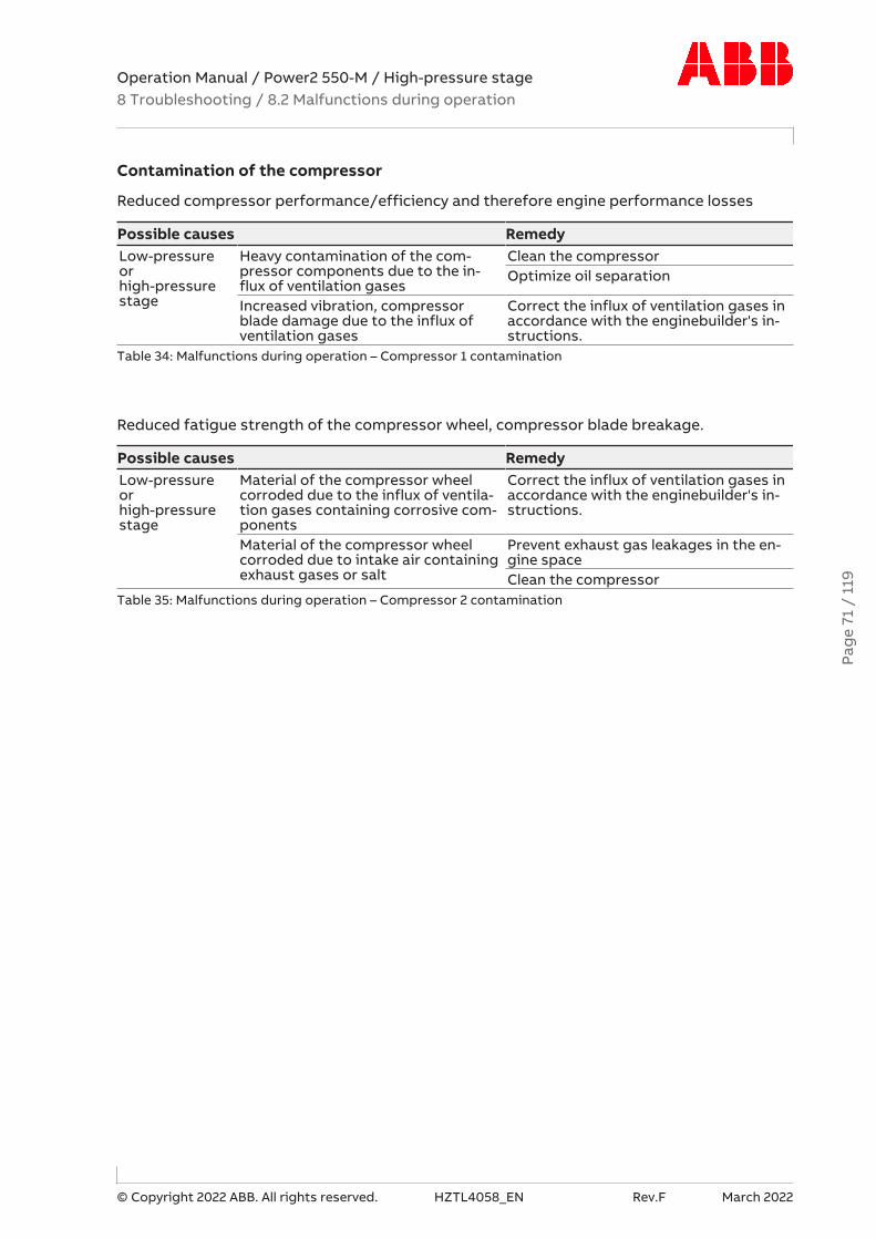
Operation Manual / Power2 550-M / High-pressure stage8 Troubleshooting / 8.2 Malfunctions during operation
© Copyright 2022 ABB. All rights reserved. HZTL4058_EN Rev.F March 2022
Contamination of the compressor
Reduced compressor performance/efficiency and therefore engine performance losses
Possible causes RemedyLow-pressureorhigh-pressurestage
Heavy contamination of the com-pressor components due to the in-flux of ventilation gases
Clean the compressorOptimize oil separation
Increased vibration, compressorblade damage due to the influx ofventilation gases
Correct the influx of ventilation gases inaccordance with the enginebuilder's in-structions.
Table 34: Malfunctions during operation – Compressor 1 contamination
Reduced fatigue strength of the compressor wheel, compressor blade breakage.
Possible causes RemedyLow-pressureorhigh-pressurestage
Material of the compressor wheelcorroded due to the influx of ventila-tion gases containing corrosive com-ponents
Correct the influx of ventilation gases inaccordance with the enginebuilder's in-structions.
Material of the compressor wheelcorroded due to intake air containingexhaust gases or salt
Prevent exhaust gas leakages in the en-gine spaceClean the compressor
Table 35: Malfunctions during operation – Compressor 2 contamination
Pag
e 71
/ 1
19
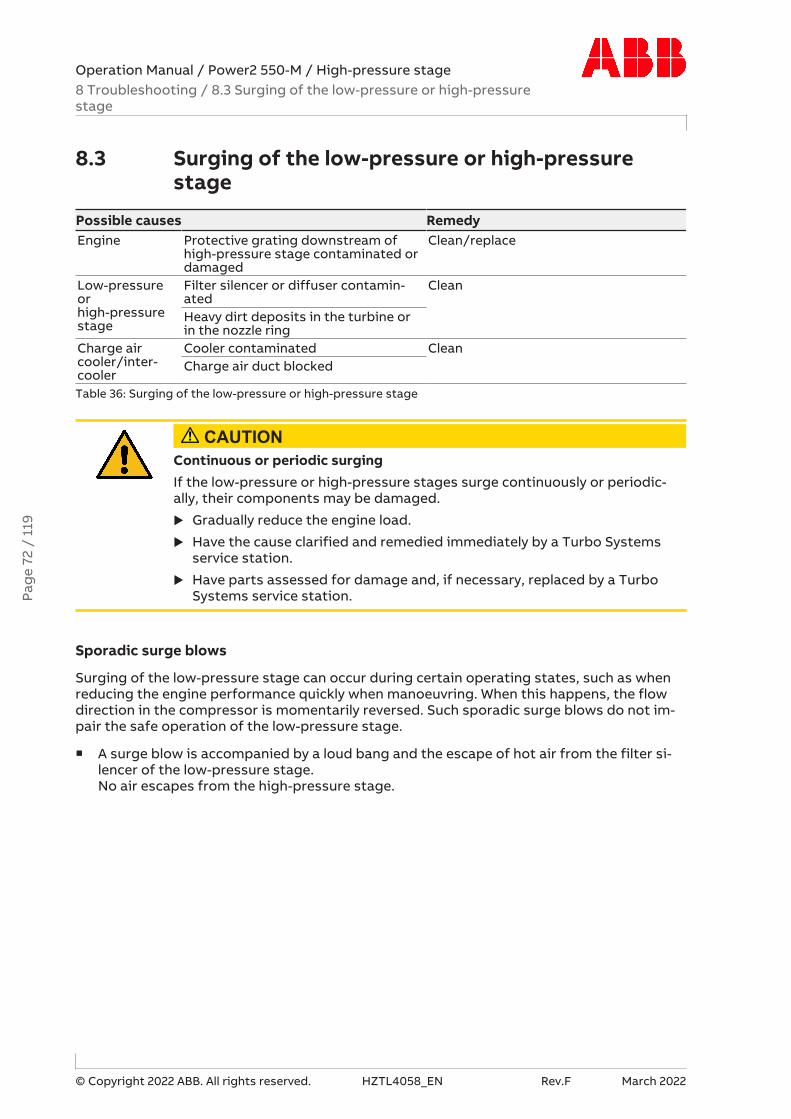
Operation Manual / Power2 550-M / High-pressure stage8 Troubleshooting / 8.3 Surging of the low-pressure or high-pressurestage
© Copyright 2022 ABB. All rights reserved. HZTL4058_EN Rev.F March 2022
8.3 Surging of the low-pressure or high-pressurestage
Possible causes RemedyEngine Protective grating downstream of
high-pressure stage contaminated ordamaged
Clean/replace
Low-pressureorhigh-pressurestage
Filter silencer or diffuser contamin-ated
Clean
Heavy dirt deposits in the turbine orin the nozzle ring
Charge aircooler/inter-cooler
Cooler contaminated CleanCharge air duct blocked
Table 36: Surging of the low-pressure or high-pressure stage
CAUTIONContinuous or periodic surgingIf the low-pressure or high-pressure stages surge continuously or periodic-ally, their components may be damaged.
u Gradually reduce the engine load.
u Have the cause clarified and remedied immediately by a Turbo Systemsservice station.
u Have parts assessed for damage and, if necessary, replaced by a TurboSystems service station.
Sporadic surge blows
Surging of the low-pressure stage can occur during certain operating states, such as whenreducing the engine performance quickly when manoeuvring. When this happens, the flowdirection in the compressor is momentarily reversed. Such sporadic surge blows do not im-pair the safe operation of the low-pressure stage.
¡ A surge blow is accompanied by a loud bang and the escape of hot air from the filter si-lencer of the low-pressure stage. No air escapes from the high-pressure stage.
Pag
e 72
/ 1
19

Operation Manual / Power2 550-M / High-pressure stage8 Troubleshooting / 8.4 Malfunctions when stopping
© Copyright 2022 ABB. All rights reserved. HZTL4058_EN Rev.F March 2022
8.4 Malfunctions when stopping
Runout noises
Possible causes RemedyLow-pressureorhigh-pressurestage
Pressure stage contaminated CleanBearing damaged Contact a Turbo Systems service sta-
tionRotor rubbingForeign object in the pressure stage
Table 37: Malfunctions when stopping – Runout noises
Runout time too short
Possible causes RemedyLow-pressureorhigh-pressurestage
Pressure stage contaminated CleanBearing damaged Contact a Turbo Systems service sta-
tionRotor rubbingForeign object in the pressure stage
Table 38: Malfunctions when stopping – Runout time too short
Pag
e 73
/ 1
19

Operation Manual / Power2 550-M / High-pressure stage8 Troubleshooting / 8.5 Speed measurement system
© Copyright 2022 ABB. All rights reserved. HZTL4058_EN Rev.F March 2022
8.5 Speed measurement system
No signal or poor signal amplitude of the speed measurement
Possible causes RemedyLow-pres-sure orhigh-pres-sure stage
The speed sensor was acci-dentally fitted with an addi-tional gasket.An enlarged distancebetween the sensor tip andthe signal-emitting sealingdisc reduces the voltageamplitude of the speed sig-nal.
The screw plug for the sensor is fitted with an ad-ditional gasket (copper ring).For information regarding the disassembly and as-sembly of the speed sensor, refer to the chapterReplacing the speed sensor.Install the speed sensor without the additionalgasket (copper ring).
Sensor defective Contact a Turbo Systems service station.Order new speed sensor (86505) (refer to chapterOrdering spare parts).Replace the speed sensor.
Table 39: Speed measurement – poor signal amplitude
Measured speed too high
Possible causes RemedyLow-pres-sure orhigh-pres-sure stage
Sensor tip contaminated,since it is magnetic and canattract metallic particles.This reduces the distance tothe signal-emitting sealingdisc, which can lead to ampli-fication of the noise com-ponent and therefore to falsetriggering.
For information regarding the disassembly and as-sembly of the speed sensor, refer to the chapterReplacing the speed sensor.Dismantle the sensor, clean the sensor tip, and fitthe sensor back on with the specified tighteningtorque.
Table 40: Speed measurement – speed too high
Measured speed too low
Possible causes RemedyLow-pres-sure orhigh-pres-sure stage
- - Contact a Turbo Systems service station
Table 41: Speed measurement – speed too low
Other causes of malfunction
If none of the measures described above remedy the malfunction, have the speed measure-ment system checked by a Turbo Systems service station.
Pag
e 74
/ 1
19

Operation Manual / Power2 550-M / High-pressure stage9 Disassembly and assembly / 9.1 Introduction
© Copyright 2022 ABB. All rights reserved. HZTL4058_EN Rev.F March 2022
9 Disassembly and assembly
9.1 IntroductionThe precondition for the work described in the following is a high-pressure stage that hasbeen removed from the engine (see chapter Removal and installation →30).
WARNINGNon-observance of the work steps and further workIncorrectly performed work or further work can cause injury to personnel ordamage to the machine.
u Only perform work that is described in this document.
u Only perform work for which you have previously received instruction ortraining.
u Have further work carried out only by trained personnel from a Turbo Sys-tems service station.
u Mark the casing position for assembly.
Oil orifice
When disassembling the high-pressure stage, an oil orifice fitted in the oil inlet must not beremoved (see Removing the cartridge group →82).
Tightening torques for components
The specified bolted connection tightening torques must be observed (see Table of tighten-ing torques →93).
Tightening torques for assembly devices
Unless otherwise described, the screws and nuts of the assembly devices supplied by TurboSystems must be tightened in such a way that they are tight-fitting.
Pag
e 75
/ 1
19

Operation Manual / Power2 550-M / High-pressure stage9 Disassembly and assembly / 9.2 Material required
© Copyright 2022 ABB. All rights reserved. HZTL4058_EN Rev.F March 2022
WARNINGSuspended loadsLoads that are not attached according to regulations can cause injury topersonnel or fatal accidents.
u Loads must always be fastened to properly functional lifting gear with asufficient load limit.
u Pay attention to the correct attachment of loads on the crane hook.
u People must not stand beneath suspended loads.
Wear safety gloves to protect against mechanical hazards.
Wear safety helmet.
9.2 Material required
Customer spare part set
Before starting work, make sure the required customer spare part set is available (seechapter Spare parts →102).
Customer tool set
Before starting work, make sure the required tool set is available (see chapter Tools →115).
Not all tools are marked with a part number. Identification is guaranteed by the tool list. Thislist is enclosed with the tool set.
WARNINGServicing the toolsThe tools must be checked for damage before and after use.
u Visually inspect for corrosion, cracks, deformation and wear.
u Damaged tools must no longer be used and must be replaced.
Identification of the assembly devices
Not all assembly devices are marked with a part number. Identification is guaranteed by thetool list. This list is enclosed with the toolbox.
Pag
e 76
/ 1
19

Operation Manual / Power2 550-M / High-pressure stage9 Disassembly and assembly / 9.2 Material required
© Copyright 2022 ABB. All rights reserved. HZTL4058_EN Rev.F March 2022
WARNINGServicing the assembly devicesAssembly devices must be checked for damage before and after use.
u Visually inspect for corrosion, cracks, deformation and wear.
u Damaged assembly devices must no longer be used and must be re-placed.
Definition of terms
¡ Suspension pointDefined loading point on a component or an assembly (blind hole thread, eyelet, lug).
¡ Assembly deviceDevices that are fitted on the low-pressure or high-pressure stage in order to obtain asuspension point. Assembly devices are specially constructed and designed for thedefined use; they are not commercially available products. Use assembly devices only forthe described applications.
¡ Lifting gearEquipment for the lifting and transporting of loads (lifting slings, chain block, crane).Lifting gear is not supplied by Turbo Systems.
Swivel lifting eyes to be used
Swivel lifting eyes are required for the safe lifting of loads, which are not supplied by TurboSystems.
Fig. 29: Swivel lifting eye (example)
Thread M Length L Minimum load limit QuantityM16 20 ... 30 mm 750 kg 2M10 15 ... 25 mm 400 kg 2
Table 42: Swivel lifting eyes
Pag
e 77
/ 1
19
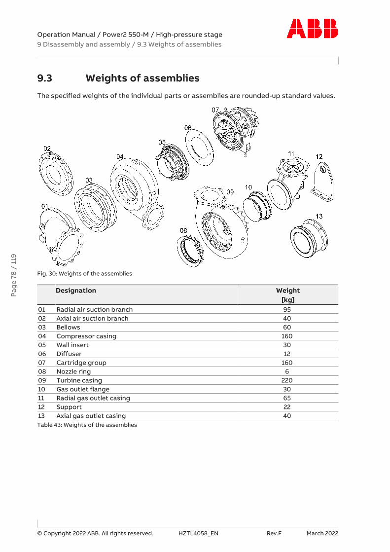
Operation Manual / Power2 550-M / High-pressure stage9 Disassembly and assembly / 9.3 Weights of assemblies
© Copyright 2022 ABB. All rights reserved. HZTL4058_EN Rev.F March 2022
9.3 Weights of assembliesThe specified weights of the individual parts or assemblies are rounded-up standard values.
Fig. 30: Weights of the assemblies
Designation Weight[kg]
01 Radial air suction branch 9502 Axial air suction branch 4003 Bellows 6004 Compressor casing 16005 Wall insert 3006 Diffuser 1207 Cartridge group 16008 Nozzle ring 609 Turbine casing 22010 Gas outlet flange 3011 Radial gas outlet casing 6512 Support 2213 Axial gas outlet casing 40Table 43: Weights of the assemblies
Pag
e 78
/ 1
19
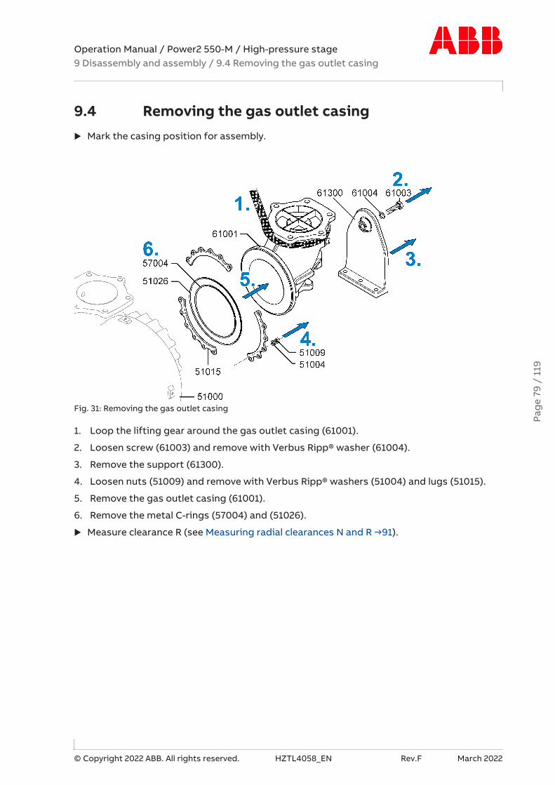
Operation Manual / Power2 550-M / High-pressure stage9 Disassembly and assembly / 9.4 Removing the gas outlet casing
© Copyright 2022 ABB. All rights reserved. HZTL4058_EN Rev.F March 2022
9.4 Removing the gas outlet casingu Mark the casing position for assembly.
Fig. 31: Removing the gas outlet casing
1. Loop the lifting gear around the gas outlet casing (61001).
2. Loosen screw (61003) and remove with Verbus Ripp® washer (61004).
3. Remove the support (61300).
4. Loosen nuts (51009) and remove with Verbus Ripp® washers (51004) and lugs (51015).
5. Remove the gas outlet casing (61001).
6. Remove the metal C-rings (57004) and (51026).
u Measure clearance R (see Measuring radial clearances N and R →91).Pa
ge
79 /
119

Operation Manual / Power2 550-M / High-pressure stage9 Disassembly and assembly / 9.5 Removing air inlets
© Copyright 2022 ABB. All rights reserved. HZTL4058_EN Rev.F March 2022
9.5 Removing air inletsu Mark the casing position for assembly.
Fig. 32: Removing the air inlets
1. Loop the lifting gear around the radial air suction branch (82000).
2. Loosen hexagon-head screws (72013) and remove with washers (72014).
3. Remove the bellows (82300) together with the radial air suction branch (82000) or theaxial air suction branch (82000) with the O-ring (82010), respectively.
u Measure clearance N (see Measuring radial clearances N and R →91).
Pag
e 80
/ 1
19

Operation Manual / Power2 550-M / High-pressure stage9 Disassembly and assembly / 9.6 Removing the compressor casing
© Copyright 2022 ABB. All rights reserved. HZTL4058_EN Rev.F March 2022
9.6 Removing the compressor casingu Mark the casing position for assembly.
u Measure radial clearance N before removing the compressor casing (72000) (see Measur-ing radial clearances N and R →91).
u Remove expansion bushes and threaded rods from the bearing casing.
Fig. 33: Removing the compressor casing
1. Loosen screws (72011) and remove together with fastening strips (72012).
2. Screw two swivel lifting eyes (01) into compressor casing (72000) and secure lifting gear.
3. Remove compressor casing (72000) and place on soft surface.
4. Loosen nuts (77022) and remove with washer (77021). Wall insert (77000) is loose.
5. Remove the O-ring (77005).Pa
ge
81 /
119

Operation Manual / Power2 550-M / High-pressure stage9 Disassembly and assembly / 9.7 Removing the cartridge group
© Copyright 2022 ABB. All rights reserved. HZTL4058_EN Rev.F March 2022
9.7 Removing the cartridge groupu Mark the casing position for assembly.
Do not remove oil orifice (if present)
To limit the oil flow rate through the bearing casing during operation (engine under load) tothe admissible values, an oil orifice is mandatory at the oil inlet of the bearing casing if theoil inlet pressure is > 3 bar (overpressure).
If an oil orifice is fitted in the oil inlet of the bearing casing, it must not be removed.
Oil orifice in the bearing casing
01 Bearing casing02 Oil orifice03 Circlip
Pag
e 82
/ 1
19

Operation Manual / Power2 550-M / High-pressure stage9 Disassembly and assembly / 9.7 Removing the cartridge group
© Copyright 2022 ABB. All rights reserved. HZTL4058_EN Rev.F March 2022
WARNINGLooping the lifting gear around the cartridge groupThe looped lifting gear can slip off and lead to serious injuries to persons oreven to fatal accidents.
u Make sure the surface for the loop on the cartridge group is free from oil.
Wear safety gloves to protect against mechanical hazards.
Wear safety helmet.
Fig. 34: Removing the cartridge group
1. Treat threads of studs (51006) with penetrating oil and leave to take effect.
2. Loosen nuts (51007) and remove Verbus Ripp® washers (51003) together with fasteningstrips (51002).
3. Attach swivel lifting eyes (01) to the cartridge group (10900)
4. Secure lifting gear to swivel lifting eye and loop around the cartridge group (10900) (seeillustration above).
5. Remove the cartridge group and turn it 90°.
6. Place cartridge group with fitted expansion sleeves (42190) on service support (90012).
7. Hand-tighten the cartridge group with the threaded rod (42191) and the clampingnut (42201) on the service support (90012).
8. Remove the metal C-ring (51105).
u Measure axial clearance A and radial clearance B (see Measuring clearance A and B →92).
Pag
e 83
/ 1
19

Operation Manual / Power2 550-M / High-pressure stage9 Disassembly and assembly / 9.7 Removing the cartridge group
© Copyright 2022 ABB. All rights reserved. HZTL4058_EN Rev.F March 2022
Removing the gas outlet flange / nozzle ring
Fig. 35: Removing the gas outlet flange / nozzle ring
1. Pull out the nozzle ring (56001) by hand. If the nozzle ring does not loosen, the gas outletflange (57002) must be removed first.
2. Screw in swivel lifting eyes (01) on the turbine casing (51000) and attach the lifting gear.
3. Turn the turbine casing 180° and lay it down on a soft base.
4. Loosen and remove screws (51005).
5. With screws (51005), press off the gas outlet flange (57002) from the turbine casing(51000). The nozzle ring (56001) loosens, if it has not already been removed.
6. Remove the gas outlet flange (57002).
7. Remove the lamellar sealing ring (56005) from the nozzle ring and replace it with a newone after cleaning the nozzle ring.
Pag
e 84
/ 1
19

Operation Manual / Power2 550-M / High-pressure stage9 Disassembly and assembly / 9.8 Installing the cartridge group
© Copyright 2022 ABB. All rights reserved. HZTL4058_EN Rev.F March 2022
9.8 Installing the cartridge group
Nozzle ring compression
In order for the nozzle ring (56001) to be fixed during operation, it must be clampedbetween the heat shield (43001) and the turbine casing (51000).
Fig. 36: Nozzle ring compression PD
42001 Bearing casing43001 Heat shield51000 Turbine casing56001 Nozzle ring
Compression PD0.09 ... 0.37 mm
Table 44: Nozzle ring compression PD
1. Measure dimensions A, B, and S on cleaned surfaces.
2. Calculate compression (PD).
u If the calculated value (PD) lies outside the specified range, contact a Turbo Systems ser-vice station.
Pag
e 85
/ 1
19
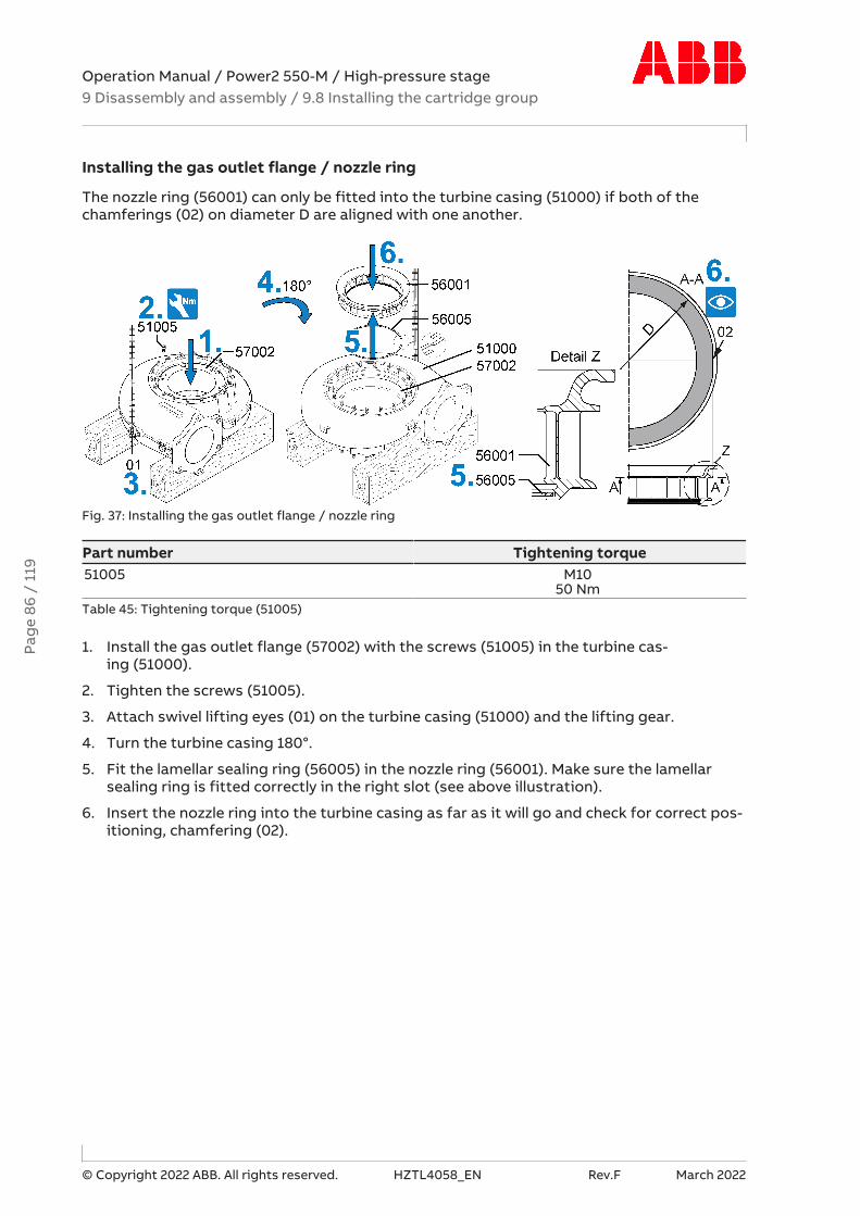
Operation Manual / Power2 550-M / High-pressure stage9 Disassembly and assembly / 9.8 Installing the cartridge group
© Copyright 2022 ABB. All rights reserved. HZTL4058_EN Rev.F March 2022
Installing the gas outlet flange / nozzle ring
The nozzle ring (56001) can only be fitted into the turbine casing (51000) if both of thechamferings (02) on diameter D are aligned with one another.
Fig. 37: Installing the gas outlet flange / nozzle ring
Part number Tightening torque51005 M10
50 NmTable 45: Tightening torque (51005)
1. Install the gas outlet flange (57002) with the screws (51005) in the turbine cas-ing (51000).
2. Tighten the screws (51005).
3. Attach swivel lifting eyes (01) on the turbine casing (51000) and the lifting gear.
4. Turn the turbine casing 180°.
5. Fit the lamellar sealing ring (56005) in the nozzle ring (56001). Make sure the lamellarsealing ring is fitted correctly in the right slot (see above illustration).
6. Insert the nozzle ring into the turbine casing as far as it will go and check for correct pos-itioning, chamfering (02).
Pag
e 86
/ 1
19

Operation Manual / Power2 550-M / High-pressure stage9 Disassembly and assembly / 9.8 Installing the cartridge group
© Copyright 2022 ABB. All rights reserved. HZTL4058_EN Rev.F March 2022
Installing the cartridge group
WARNINGLooping the lifting gear around the cartridge groupThe looped lifting gear can slip off and lead to serious injuries to persons oreven to fatal accidents.
u Make sure the surface for the loop on the cartridge group is free from oil.
Wear safety gloves to protect against mechanical hazards.
Wear safety helmet.
Fig. 38: Installing the cartridge group
Part number Tightening torque51007 M12
75 NmTable 46: Tightening torque (51007)
1. Insert new metal C-ring (51105) into turbine casing (51000).
2. Screw in swivel lifting eyes (01) on cartridge group (10900) and secure lifting gear.
3. Lift cartridge group out of service support (90012) and remove expansion bush (42190).
4. Rotate cartridge group by 90° and also loop lifting gear around cartridge group (10900)as shown.
5. Move cartridge group into turbine casing. When doing this, ensure that the metal C-ring (51105) is not crushed at one side.
6. Secure fastening strips (51002) together with nuts (51007) and secure and tighten theVerbus Ripp® washers (51003).
Pag
e 87
/ 1
19

Operation Manual / Power2 550-M / High-pressure stage9 Disassembly and assembly / 9.9 Installing the compressor casing
© Copyright 2022 ABB. All rights reserved. HZTL4058_EN Rev.F March 2022
9.9 Installing the compressor casingu Always replace the O-rings (42012 and 77005) with new ones (see Ordering spare parts
→102).
Fig. 39: Installing the compressor casing
Part number Tightening torque42007 M10
50 Nm72011 M12
130 Nm77022 M10
75 NmTable 47: Tightening torques (42007, 72011, 77022)
1. Fit new O-ring (77005) into wall insert (77000).
2. Screw two swivel lifting eyes (01) into compressor casing (72000) and secure lifting gear.
3. Lower compressor casing (72000) onto wall insert (77000) and fit with washer (77021)and nuts (77022).
4. Thoroughly clean the fastening strips (72012) before assembly.
5. Fit the diffuser (79000) with screw (42007).
6. Insert new O-ring (42012).
7. Position compressor casing (72000) on cartridge group (10900).
8. Fit the fastening strips (72012) with screws (72011) and tighten.
Pag
e 88
/ 1
19

Operation Manual / Power2 550-M / High-pressure stage9 Disassembly and assembly / 9.10 Installing the air inlets
© Copyright 2022 ABB. All rights reserved. HZTL4058_EN Rev.F March 2022
9.10 Installing the air inletsu Always replace the O-ring (82010) with a new one (see Ordering spare parts →102).
u Measure clearance N (see Measuring radial clearances N and R →91).
Fig. 40: Installing the air inlet
Part number Tightening torque72013 M12
85 NmTable 48: Tightening torque (72013)
1. Install the radial air suction branch (82000) with the bellows (82300) or the axial air suc-tion branch together with the O-ring (82010), respectively.
2. Tighten screw (72013).
Pag
e 89
/ 1
19

Operation Manual / Power2 550-M / High-pressure stage9 Disassembly and assembly / 9.11 Installing the gas outlet casing
© Copyright 2022 ABB. All rights reserved. HZTL4058_EN Rev.F March 2022
9.11 Installing the gas outlet casingu Measure clearance R (see chapter Measuring radial clearances N and R →91).
Fig. 41: Installing the gas outlet casing
Part number Tightening torque51009 M12
75 Nm61003 M20
365 NmTable 49: Tightening torques (51009, 61003)
1. Clean the sealing surfaces of the C-rings (57004, 51026) on the turbine casing (51000)and the gas outlet casing (61001).
2. Insert new C-rings (57004, 51026) and position with high-vacuum grease.
3. Coat the threaded stud (51008) with high-temperature grease.
4. Loop the lifting gear around the gas outlet casing (61001).
5. Place gas outlet casing (61001) on turbine casing (51000).
6. Fit gas outlet casing (61001) with lugs (51015), Verbus Ripp® washers (51004) andnuts (51009) and tighten.
7. Fit support (61300) with Verbus Ripp® washer (61004) and screw (61003) and tighten.
Pag
e 90
/ 1
19

Operation Manual / Power2 550-M / High-pressure stage9 Disassembly and assembly / 9.12 Measuring radial clearances N and R
© Copyright 2022 ABB. All rights reserved. HZTL4058_EN Rev.F March 2022
9.12 Measuring radial clearances N and R
Fig. 42: Measuring clearances N and R
Clearance N Clearance R0.50 ... 0.80 mm 0.65 ... 0.95 mm
Table 50: Permissible clearances N and R
1. Push the feeler gauges (01) into the gap without clearance, and measure simultaneouslyat the top (N1) and the bottom (N2).
2. Calculate clearance N and compare it with the permissible values in the table.
3. Push the feeler gauges (01) into the gap without clearance, and measure simultaneouslyat the top (R2) and the bottom (R1).
4. Calculate clearance R and compare it with the permissible values in the table.
CAUTIONClearances outside the toleranceSerious damage to engines or property can be caused by clearances outsidethe tolerance and excessively worn parts.
u Have the components assessed and, if necessary, replaced by a TurboSystems service station.
Pag
e 91
/ 1
19

Operation Manual / Power2 550-M / High-pressure stage9 Disassembly and assembly / 9.13 Measuring clearance A and B
© Copyright 2022 ABB. All rights reserved. HZTL4058_EN Rev.F March 2022
9.13 Measuring clearance A and Bu Measure and record clearances A and B after the removal and before the installation of
the cartridge group.
u Attach the dial indicator and align it for the respective clearance as per the illustration.
Fig. 43: Measuring clearance A and B
A [mm] B [mm]0.24 ... 0.43 0.91 ... 1.51
Table 51: Permissible clearances A and B
1. Move the rotor to and fro up to the stop. In order to obtain a correct measurement, elev-ate the turbine a little.
2. Measure clearance A and compare it with the permissible values in the table.
3. Raise the compressor and push the turbine down at the same time.
4. Raise the turbine and push the compressor down at the same time.
5. Measure clearance B and compare it with the permissible values in the table.
CAUTIONClearances outside the toleranceSerious damage to engines or property can be caused by clearances outsidethe tolerance and excessively worn parts.
u Have the components assessed and, if necessary, replaced by a TurboSystems service station.
Pag
e 92
/ 1
19

Operation Manual / Power2 550-M / High-pressure stage9 Disassembly and assembly / 9.14 Table of tightening torques
© Copyright 2022 ABB. All rights reserved. HZTL4058_EN Rev.F March 2022
9.14 Table of tightening torques
Fig. 44: Overview of tightening torques
The following tightening torques [Nm] must be observed for the designated bolted connec-tions:
Part number Tightening torque [Nm]01 72005, 82005, 82007 M18x1.5
60 Nm02 82022 M12
85 Nm03 72013 M12
85 Nm04 77022 M10
75 Nm05 42007 M10
50 Nm06 72011 M12
130 Nm07 42009 M20
65 Nm08 51007 M12
75 Nm09 51005 M10
50 Nm10 51009 M12
75 Nm11 51028, 61005 M18x1.5
60 Nm12 61003 M20
365 Nm13 86505 M12x1.5
15 Nm14 42188 M12x1.5
35 NmTable 52: Tightening torques [Nm]
Pag
e 93
/ 1
19

Operation Manual / Power2 550-M / High-pressure stage10 Taking out of operation at short notice / 10.1 Possible emergency re-pairs
© Copyright 2022 ABB. All rights reserved. HZTL4058_EN Rev.F March 2022
10 Taking out of operation at short notice
10.1 Possible emergency repairs
WARNINGDanger of fire and explosion due to lubricating oil leaksLeaking oil may ignite on hot surfaces. This can result in serious injuries topersonnel or fatal accidents.
u Cordon off danger area.
u Raise the alarm and, depending on the situation, stop the engine.
u Seal the oil leak.
u Soak up oil and dispose of in an environmentally compatible manner.
Wear safety gloves to protect against thermal hazards.
CAUTIONDirectives for taking out of operationSerious damage to engine or property can be caused by non-compliancewith the directives for blanking off the low-pressure or high-pressure stageon the engine.
u Follow the directives of the enginebuilder.
If the engine has to be brought back into operation again as quickly as possible in the eventof a low-pressure or high-pressure stage defect, there are options for emergency repairs:
¡ If present: Fit replacement cartridge group.
¡ If a replacement cartridge group is not available: Fit the cover plate and contact a TurboSystems service station.
u Observe the following sections in connection with the emergency repairs mentioned.
Pag
e 94
/ 1
19

Operation Manual / Power2 550-M / High-pressure stage10 Taking out of operation at short notice / 10.2 Installing a replace-ment cartridge group
© Copyright 2022 ABB. All rights reserved. HZTL4058_EN Rev.F March 2022
10.2 Installing a replacement cartridge groupThe repair of a cartridge group requires special tools and the expertise of a Turbo Systemsservice station. The rotating parts rotate extremely quickly, and are sensitive to unbalance.
WARNINGCartridge groupIncorrect handling of a cartridge group can damage the low-pressure orhigh-pressure stage and cause injuries to persons.
u Always have repairs to the cartridge group carried out by a Turbo Sys-tems service station.
NOTICEQuick recommissioningTo enable you to put a defective low-pressure or high-pressure stage backinto operation quickly, Turbo Systems recommends having a replacementcartridge group available in stock. A replacement cartridge group can be in-stalled within a short period of time, and the low-pressure or high-pressurestage can be operated again.
A replacement cartridge group is ready for use immediately and includes the complete bear-ing casing with bearing and a balanced rotor.
u For information on how to remove and install the cartridge group, see chapter Disas-sembly and assembly.
u Send the defective cartridge group to a Turbo Systems service station for inspection andrepair.
Pag
e 95
/ 1
19

Operation Manual / Power2 550-M / High-pressure stage10 Taking out of operation at short notice / 10.3 Fitting the cover plate
© Copyright 2022 ABB. All rights reserved. HZTL4058_EN Rev.F March 2022
10.3 Fitting the cover plateThe cover plate has two functions. It seals the turbine casing from exhaust gas and thebracket from oil leaks.
u Remove high-pressure stage (see chapter Removal and installation →30).
u Fit the turbine casing with the gas outlet casing into the gas pipe again.
u Attach the cover plate (see following section).
Fig. 45: Attaching a cover plate
1. With the high-pressure stage, make sure that the oil connections of the high-pressurestage are sealed with a gasket under the cover plate (01) or with O-rings inside the coverplate (01). If the O-rings of the high-pressure stage are used, slots must be cut in thecontact surface of the cover plate (see Fig. 47: Figure for cover plate, slots for O-rings→98).
2. Close the opening in the turbine casing (51000) with the cover plate (01).
3. Thoroughly clean the fastening strips (51002) before assembly. Coat the threads of thestuds (51006) with high-temperature grease.
4. Fasten cover plate (01) to turbine casing (51000) with fastening strips (51002), VerbusRipp® washers (51003) and nuts (51007) and screw to bracket.
Part number Tightening torque [Nm]51007 M12
75Table 53: Tightening torque (51007)
Pag
e 96
/ 1
19

Operation Manual / Power2 550-M / High-pressure stage10 Taking out of operation at short notice / 10.4 Cover plate drawing
© Copyright 2022 ABB. All rights reserved. HZTL4058_EN Rev.F March 2022
10.4 Cover plate drawingThe cover plate is not included in the Turbo Systems scope of delivery and must be manufac-tured by the operating company according to the following drawing.
Material: General structural steel, in accordance with DIN EN 10025-2.
Fig. 46: Cover plate drawing
B1± 0.5
B2 B3 B4± 0.2
B5 B6 B7 ØD1± 0.2
ØD2 R1 M
120.5 100 230 29.3 2 310 70.4 367 31 ≤ 173 M10Table 54: Cover plate dimensions [mm]
Pag
e 97
/ 1
19

Operation Manual / Power2 550-M / High-pressure stage10 Taking out of operation at short notice / 10.4 Cover plate drawing
© Copyright 2022 ABB. All rights reserved. HZTL4058_EN Rev.F March 2022
Slots for O-rings in cover plate
Fig. 47: Figure for cover plate, slots for O-rings
A B C D E F G H J K R1251 125.5 78 39 5.2 31.5 5.2 4.5 5.2 4.5 24
Table 55: Dimensions of cover plate, slots for O-rings [mm]
Pag
e 98
/ 1
19
Operation Manual / Power2 550-M / High-pressure stage11 Taking out of operation for a long period / 11.1 General
© Copyright 2022 ABB. All rights reserved. HZTL4058_EN Rev.F March 2022
11 Taking out of operation for a longperiod
11.1 GeneralWhen taking the low-pressure and high-pressure stage out of operation, mothballing meas-ures must be taken in order to minimise the risk of corrosion on components. The necessarymeasures depend on the condition of the lubricating oil and the process used to take thelow-pressure and high-pressure stage out of operation.
11.2 Lubricating oilNo measures must be taken with regard to the lubricating oil if:
¡ The directives of the enginebuilder on lubricating oil selection and on the oil change in-tervals are followed.
Or:
¡ The engine lubricating oil is replaced by a preservative oil and circulated with the pre-lub-rication pump before the engine is taken out of operation.
If neither of the criteria above are met, mothballing by a service station is necessary. This in-cludes cleaning and applying preservative oil to the relevant components.
11.3 Process for taking out of operationDifferent measures are required depending on the process used to take the low-pressureand high-pressure stage out of operation.
¡ The low-pressure and high-pressure stage remains on the engine– Take countermeasures if there is a risk that the rotor will turn due to the stack
draught. One option is to install a blind flange on the outlet flange of the gas outletcasing or the compressor casing.
– If the engine is being taken out of operation for a long period in a corrosive environ-ment, all components through which air flows must be provided with corrosion pro-tection. Contact a service station for this purpose.
¡ Disassembly of the low-pressure and high-pressure stage as a whole unit or in individualparts
– Seal all openings of the low-pressure and high-pressure stage with paraffin paper andwooden lids.
– Store the disassembled parts in a dry room with 40-70% atmospheric humidity inwhich no condensation can form.
– Check all low-pressure and high-pressure stage parts for corrosion annually.– If there are signs of rust, thoroughly clean the parts and renew the corrosion protec-
tion.
Pag
e 99
/ 1
19

Operation Manual / Power2 550-M / High-pressure stage12 Material and Disposal / 12.1 REACH and RoHS Compliance Declara-tion For Products
© Copyright 2022 ABB. All rights reserved. HZTL4058_EN Rev.F March 2022
12 Material and Disposal
12.1 REACH and RoHS Compliance Declaration ForProducts
Turbo Systems hereby confirms that all genuine products, parts and components suppliedby Turbo Systems are fully compliant with the requirements of European Union Regulation(EC) 1907/2006 concerning the Registration, Evaluation, Authorization and Restriction ofChemicals (REACH).
Article 33 (of requirements of European Union Regulation (EC) 1907/2006)
[in English only]
A supplier of a product composed of one or more constituent articles (products) of whichcontain(s) a candidate list substance (SVHC, Substance of Very High Concern) in a concen-tration above 0.1% wlw, shall inform the customer of the presence of such substance(s) withsufficient information, available to the supplier.
RoHS2 Directive 2011/65/EC
[in English only]
The EU Directive 2011/65/EC (recast) restricts the use of certain hazardous substances inelectrical and electronic equipment (RoHS2). Products and related accessories manufac-tured by Turbo Systems Switzerland Ltd do not fall within the Scope of RoHS2 due to theirapplication in large scale fixed installations, means of transports for persons or goods, non-road mobile machinery (Directive 2011/65/EC Article 2, 4.(e), (f), (g)).
Electrical or electronic equipment supplied by Turbo Systems fulfil requirements of RoHS2Directive 2011/65/EC and fall under the exception 6a and 6c of the same Directive:
¡ 6a) Lead as an alloying element in steel for machining purposes and in galvanised steelcontaining up to 0.35 % lead by weight
¡ 6c) Copper alloy containing up to 4 % lead by weight.
The maximum concentration of lead and lead compounds for our products is known to reachmax. 0.8 % (mass % in homogeneous material).
Pag
e 10
0 /
119

Operation Manual / Power2 550-M / High-pressure stage12 Material and Disposal / 12.2 Disposing of low-pressure and high-pressure stage components
© Copyright 2022 ABB. All rights reserved. HZTL4058_EN Rev.F March 2022
12.2 Disposing of low-pressure and high-pressurestage components
Disposal must be environmentally compatible, professional, and in compliance with locallyapplicable regulations.
The low-pressure and high-pressure stages mainly consist of metal (cast iron materials,steel, nickel-steel alloys, aluminium and bearing brass).
Further components are: Non-metallic materials (filter components of felt and polyethylene),lubricants (engine oil), electronic parts (speed sensor and associated components), andthermal insulation.
u Dispose of metals as scrap metal for recycling.
u Dispose of non-metallic materials as waste.
u Dispose of residues of lubricants as waste oil.
u Dispose of electronic components as electronic waste.
WARNINGHandling damaged thermal insulationDamaged thermal insulation can lead to dust exposure. The glass fibres cancause mechanical irritation of the eyes, skin, and respiratory tracts.
u Avoid the formation of dust.
u Vacuum up dust with a suitable vacuum cleaner.
u Wear a respiratory mask to protect against dusts (P1 or P2 mask).
u Wear safety gloves.
Wear safety goggles.
Wear a respiratory mask to protect against dusts.
Wear safety gloves to protect against mechanical hazards.
u Dispose of thermal insulation as hazardous waste.
Pag
e 10
1 /
119

Operation Manual / Power2 550-M / High-pressure stage13 Spare parts / 13.1 Ordering spare parts
© Copyright 2022 ABB. All rights reserved. HZTL4058_EN Rev.F March 2022
13 Spare parts
13.1 Ordering spare parts
CAUTIONSpare part storageAll spare parts that were ordered together with the low-pressure and/orhigh-pressure stage must be kept intact and ready for use.
u Carefully clean any rusted parts and grease them.
Please quote the following data when making queries and ordering spare parts:
¡ Serial number of Power2 (HT……)
¡ Serial number of the low or high-pressure stage (PT……)
¡ Designation and part number.
Spare parts can be ordered from an Turbo Systems Service Station.
u If different model variants are not taken into account in this document, contact an TurboSystems Service Station.
u Dispose of placed and unusable parts in an environmentally-friendly and professionalmanner in accordance with the local regulations.
u Dispose of the packaging of new parts in an environmentally-friendly and professionalmanner in accordance with the local regulations.
Pag
e 10
2 /
119

Operation Manual / Power2 550-M / High-pressure stage13 Spare parts / 13.1 Ordering spare parts
© Copyright 2022 ABB. All rights reserved. HZTL4058_EN Rev.F March 2022
Required customer spare part set (97070)
For the work described in the Operation Manual, the customer spare part set (97070) is re-quired. These parts are only available in the complete set.
97070 Designation Quantity42010 O-ring 142012 O-ring 142198 O-ring 142199 O-ring 151005 Socket screw 351026 Metal C-ring 151105 Metal C-ring 156005 Lamellar sealing ring 157004 Metal C-ring 177005 O-ring 182010 O-ring 1
(only for P135)61007 Metal C-ring 1
(only for axial gas outlet casing)Table 56: Customer spare part set (97070)
Pag
e 10
3 /
119
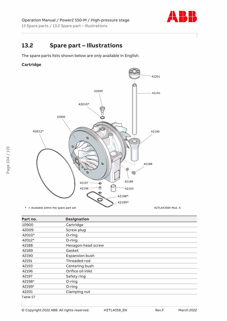
Operation Manual / Power2 550-M / High-pressure stage13 Spare parts / 13.2 Spare part – Illustrations
© Copyright 2022 ABB. All rights reserved. HZTL4058_EN Rev.F March 2022
13.2 Spare part – IllustrationsThe spare parts lists shown below are only available in English.
Cartridge
42198*
42199*
42196
42197
42193
10900
42010*
42009
42189
42188
42012* 42190
42191
42201
* = Available within the spare part set HZTL443584 Mod. A
Part no. Designation10900 Cartridge42009 Screw plug42010* O-ring42012* O-ring42188 Hexagon-head screw42189 Gasket42190 Expansion bush42191 Threaded rod42193 Centering bush42196 Orifice oil inlet42197 Safety ring42198* O-ring42199* O-ring42201 Clamping nutTable 57
Pag
e 10
4 /
119
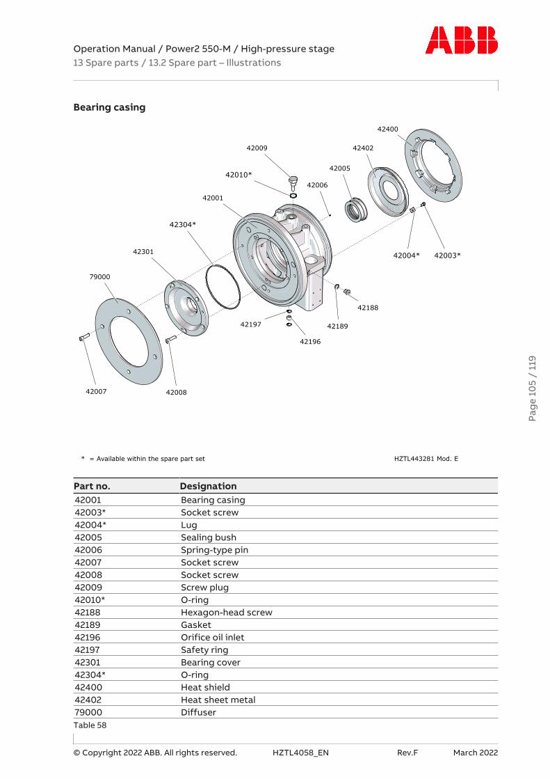
Operation Manual / Power2 550-M / High-pressure stage13 Spare parts / 13.2 Spare part – Illustrations
© Copyright 2022 ABB. All rights reserved. HZTL4058_EN Rev.F March 2022
Bearing casing
42400
42003*
42402
42004*
42196
42005
42197
42006
42001
42010*
42009
42189
42304*
42188
42008
42301
42007
79000
* = Available within the spare part set HZTL443281 Mod. E
Part no. Designation42001 Bearing casing42003* Socket screw42004* Lug42005 Sealing bush42006 Spring-type pin42007 Socket screw42008 Socket screw42009 Screw plug42010* O-ring42188 Hexagon-head screw42189 Gasket42196 Orifice oil inlet42197 Safety ring42301 Bearing cover42304* O-ring42400 Heat shield42402 Heat sheet metal79000 DiffuserTable 58
Pag
e 10
5 /
119

Operation Manual / Power2 550-M / High-pressure stage13 Spare parts / 13.2 Spare part – Illustrations
© Copyright 2022 ABB. All rights reserved. HZTL4058_EN Rev.F March 2022
Rotor and Bearing parts
32167*
21000
32114*
32102*
32108*
21011
32112
21002*
21006*
32107*
2500032115
32116
32175*
32113*
32110
42002
32101*
32109*42302*
* = Available within the spare part set HZTL443583 Mod. A
Part no. Designation21000 Turbine21002* Piston ring21006* Piston ring21011 Sleeve25000 Compressor wheel32101* Radial bearing32102* Radial bearing32107* Thrust bearing sleeve32108* Piston ring32109* Sealing disc32110 Bearing flange32112 Bearing flange32113* Socket screw32114* Socket screw32115 Hexagon-head screw32116 Lug32167* Snap ring32175* O-ring42002 Socket screw42302* Piston ringTable 59
Pag
e 10
6 /
119
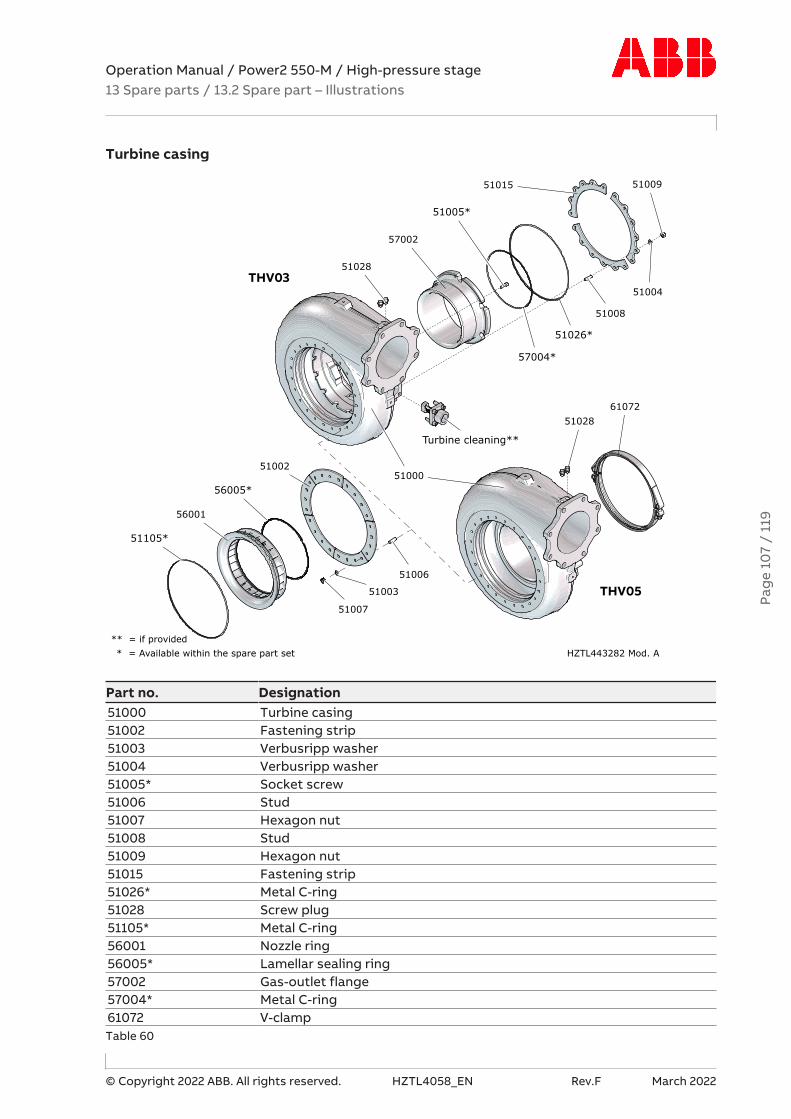
Operation Manual / Power2 550-M / High-pressure stage13 Spare parts / 13.2 Spare part – Illustrations
© Copyright 2022 ABB. All rights reserved. HZTL4058_EN Rev.F March 2022
Turbine casing
51003
51105*
51026*
51005*
51015 51009
51004
51008
57004*
57002
Turbine cleaning**
51028
51006
61072
5100251000
51007
56005*
56001
51028
* = Available within the spare part set HZTL443282 Mod. A** = if provided
THV03
THV05
Part no. Designation51000 Turbine casing51002 Fastening strip51003 Verbusripp washer51004 Verbusripp washer51005* Socket screw51006 Stud51007 Hexagon nut51008 Stud51009 Hexagon nut51015 Fastening strip51026* Metal C-ring51028 Screw plug51105* Metal C-ring56001 Nozzle ring56005* Lamellar sealing ring57002 Gas-outlet flange57004* Metal C-ring61072 V-clampTable 60
Pag
e 10
7 /
119

Operation Manual / Power2 550-M / High-pressure stage13 Spare parts / 13.2 Spare part – Illustrations
© Copyright 2022 ABB. All rights reserved. HZTL4058_EN Rev.F March 2022
Turbine cleaning
52155
52100
5214052135
52150
52130
52125
52120
52145
52115
52110
52160
HZTL443585 Mod. A
Part no. Designation52100 Cleaning unit52110 Compensator52115 Metall C-Ring52120 Metall C-Ring52125 Connection part52130 Stud52135 Hexagon nut52140 Hexagon-head screw52145 Extension sleeve52150 Stud52155 Hexagon nut52160 Hex socket head cap screwTable 61
Pag
e 10
8 /
119
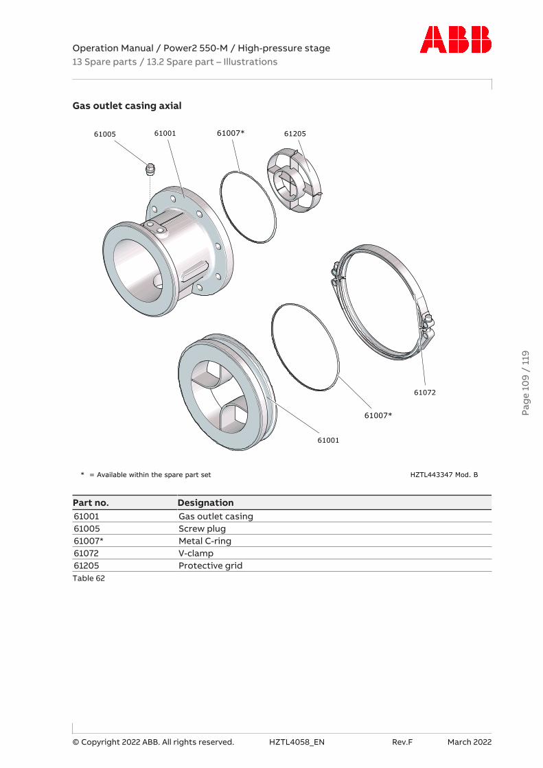
Operation Manual / Power2 550-M / High-pressure stage13 Spare parts / 13.2 Spare part – Illustrations
© Copyright 2022 ABB. All rights reserved. HZTL4058_EN Rev.F March 2022
Gas outlet casing axial
6120561007*6100161005
61072
61007*
61001
* = Available within the spare part set HZTL443347 Mod. B
Part no. Designation61001 Gas outlet casing61005 Screw plug61007* Metal C-ring61072 V-clamp61205 Protective gridTable 62
Pag
e 10
9 /
119

Operation Manual / Power2 550-M / High-pressure stage13 Spare parts / 13.2 Spare part – Illustrations
© Copyright 2022 ABB. All rights reserved. HZTL4058_EN Rev.F March 2022
Gas outlet casing radial
61003
61004
61300
61001 61005
61205
HZTL443289 Mod. B
Part no. Designation61001 Gas-outlet casing61003 Hexagon-head screw61004 Verbusripp washer61005 Screw plug61205 Protective grid61300 SupportTable 63
Pag
e 11
0 /
119

Operation Manual / Power2 550-M / High-pressure stage13 Spare parts / 13.2 Spare part – Illustrations
© Copyright 2022 ABB. All rights reserved. HZTL4058_EN Rev.F March 2022
Compressor casing
72012
72011
81080
77000
77005*
72014
72013
77022
72006
72000
72005
* = Available within the spare part set HZTL443283 Mod. B
Part no. Designation72000 Compressor casing72005 Screw plug72006 Gasket72011 Hexagon-head screw72012 Fastening strip72013 Hexagon-head screw72014 Washer77000 Wall insert77005* O-ring77022 Hexagon nut81080 Warning plateTable 64
Pag
e 11
1 /
119
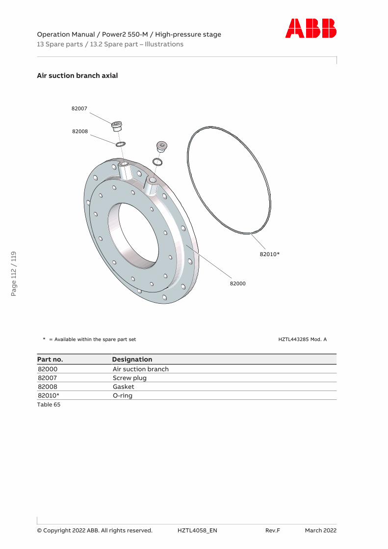
Operation Manual / Power2 550-M / High-pressure stage13 Spare parts / 13.2 Spare part – Illustrations
© Copyright 2022 ABB. All rights reserved. HZTL4058_EN Rev.F March 2022
Air suction branch axial
82010*
82008
82000
82007
* = Available within the spare part set HZTL443285 Mod. A
Part no. Designation82000 Air suction branch82007 Screw plug82008 Gasket82010* O-ringTable 65
Pag
e 11
2 /
119

Operation Manual / Power2 550-M / High-pressure stage13 Spare parts / 13.2 Spare part – Illustrations
© Copyright 2022 ABB. All rights reserved. HZTL4058_EN Rev.F March 2022
Air suction branch radial
82300
82022
82021
82130
82140
82145
82000
82008
82007
HZTL443284 Mod. B
Part no. Designation82000 Air suction branch82007 Screw plug82008 Gasket82021 Washer82022 Hexagon-head screw82130 Insulation cushion82140 Cleaning nozzle82145 Verbusripp washer82300 CompensatorTable 66
Pag
e 11
3 /
119
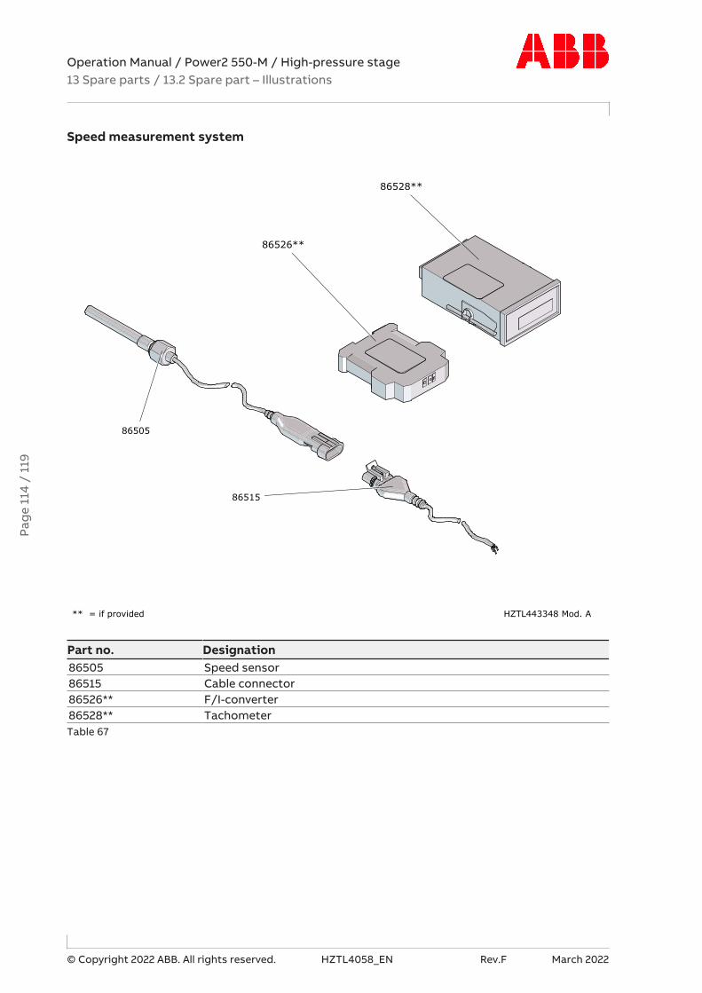
Operation Manual / Power2 550-M / High-pressure stage13 Spare parts / 13.2 Spare part – Illustrations
© Copyright 2022 ABB. All rights reserved. HZTL4058_EN Rev.F March 2022
Speed measurement system
86528**
86505
86526**
86515
HZTL443348 Mod. A** = if provided
Part no. Designation86505 Speed sensor86515 Cable connector86526** F/I-converter86528** TachometerTable 67
Pag
e 11
4 /
119

Operation Manual / Power2 550-M / High-pressure stage14 Tools /
© Copyright 2022 ABB. All rights reserved. HZTL4058_EN Rev.F March 2022
14 ToolsFor the work described in the Operation Manual, the customer tool set 90000 is required.
Part number Designation Quantity90012 Service support 190056 Toolbox 190070 Extraction device 290245 Compressor wheel key 190380 Press-on bush 190381 Snap ring pliers 190401 Piston ring pliers 190402 Positioning pin 190403 Plate 190405 Washer 390407 Support 390416 Pressure piece 190417 Set screw 190432 Hexagon nut 390663 Extraction plate 290665 Press-off tool, long 3Table 68: Customer tool set 90000
This tool set can be ordered from any Turbo Systems Service Station. The following specific-ations must be included in the order:
¡ Equipment type
¡ Designation and part number of the tool set.
Pag
e 11
5 /
119
Operation Manual / Power2 550-M / High-pressure stage15 Gas piping (option) /
© Copyright 2022 ABB. All rights reserved. HZTL4058_EN Rev.F March 2022
15 Gas piping (option)The gas piping documentation can be found in the Operation Manual of the Power2 low-pressure stage.
Pag
e 11
6 /
119

Operation Manual / Power2 550-M / High-pressure stageFigures
© Copyright 2022 ABB. All rights reserved. HZTL4058_EN Revision F March 2022
FiguresFig. 1: Layout and function ............................................ 7
Fig. 2: Layout of the high-pressure stage ................. 8
Fig. 3: Function of the high-pressure stage.............. 9
Fig. 4: Volatile Corrosion Inhibitor (VCI)................... 12
Fig. 5: Package with hygrometer................................ 13
Fig. 6High-pressure stage........................................... 18
Fig. 7: Rating plate ........................................................ 19
Fig. 8: Location of Power2 HP rating plate ............. 20
Fig. 9: Attachment of loads on the crane hook ....... 21
Fig. 10: Attachment angle............................................ 21
Fig. 11: Swivel lifting eye (example) .......................... 30
Fig. 12: Transport.......................................................... 30
Fig. 13: Removing the high-pressure stage.............. 31
Fig. 14: Loosening the clamping nut ......................... 32
Fig. 15: Removing the high-pressure stage.............. 33
Fig. 16: Gaskets in the slots of the bearing casing 34
Fig. 17: Preparing the fastening elements of thehigh-pressure stage..................................................... 35
Fig. 18: Placing the high-pressure stage on thebracket ........................................................................... 36
Fig. 19: Steps for fastening the high-pressure stage .37
Fig. 20: Steps for fastening the high-pressure stage .38
Fig. 21: Preparing the clamping nut for the tighten-ing procedure ............................................................... 39
Fig. 22: Tightening pressure screws......................... 40
Fig. 23: Oil monitoring................................................. 45
Fig. 24: Overview: speed measurement on high-pressure stage .............................................................. 47
Fig. 25: Noise insulation, bellows............................... 51
Fig. 26: Bellows ............................................................. 60
Fig. 27: Load/time chart ............................................. 63
Fig. 28: Wet cleaning operation................................. 64
Fig. 29: Swivel lifting eye (example)........................... 77
Fig. 30: Weights of the assemblies........................... 78
Fig. 31: Removing the gas outlet casing ................... 79
Fig. 32: Removing the air inlets................................... 80
Fig. 33: Removing the compressor casing................ 81
Fig. 34: Removing the cartridge group ..................... 83
Fig. 35: Removing the gas outlet flange / nozzle ring.84
Fig. 36: Nozzle ring compression PD ......................... 85
Fig. 37: Installing the gas outlet flange / nozzle ring ..86
Fig. 38: Installing the cartridge group....................... 87
Fig. 39: Installing the compressor casing................. 88
Fig. 40: Installing the air inlet...................................... 89
Fig. 41: Installing the gas outlet casing..................... 90
Fig. 42: Measuring clearances N and R ...................... 91
Fig. 43: Measuring clearance A and B ........................ 92
Fig. 44: Overview of tightening torques ................... 93
Fig. 45: Attaching a cover plate .................................. 96
Fig. 46: Cover plate drawing........................................ 97
Fig. 47: Figure for cover plate, slots for O-rings ..... 98
Pag
e 11
7 /
119
Pag
e 11
7 /
119

Operation Manual / Power2 550-M / High-pressure stageTables
© Copyright 2022 ABB. All rights reserved. HZTL4058_EN Revision F March 2022
TablesTable 1: Definition of pictograms .............................. 11
Table 2: Personal protective equipment to be wornat all times ...................................................................... 15
Table 3: Personal protective equipment to be wornspecific to the respective task ................................... 15
Table 4: Operating limits ............................................. 19
Table 5: Recommended inspection and replacementintervals........................................................................... 19
Table 6: Further data .................................................... 19
Table 7: Swivel lifting eyes.......................................... 30
Table 8: Weight of complete high-pressure stage 30
Table 9: Values X and L................................................ 36
Table 10: Tightening torque (01, 61003).................. 38
Table 11........................................................................... 40
Table 12: Oil pressure range ....................................... 45
Table 13: Oil temperature at the inlet....................... 46
Table 14: Oil temperature at the outlet ................... 46
Table 15: Expected replacement intervals [h]......... 54
Table 16: Post-lubrication time ................................. 56
Table 17: Maintenance intervals ................................. 57
Table 18: Cleaning parameters .................................. 59
Table 19: Cleaning parameters .................................. 59
Table 20: Cleaning parameters.................................. 66
Table 21: Cleaning parameters .................................. 66
Table 22: Water volumes ............................................. 66
Table 23: Malfunctions when starting – Delayedstart-up .......................................................................... 67
Table 24: Malfunctions when starting – Vibrations 67
Table 25: Malfunctions when starting – Rubbing ofrotating parts................................................................ 67
Table 26: Malfunctions during operation – Lubricat-ing oil pressure too low............................................... 68
Table 27: Malfunctions during operation – Power2 LPspeed reductions.......................................................... 68
Table 28: Malfunctions during operation – Power2HP speed reductions ................................................... 68
Table 29: Malfunctions during operation – Power2LP speed increases........................................................ 68
Table 30: Malfunctions during operation – Power2HP speed increases ....................................................... 69
Table 31: Malfunctions during operation – Exhaustgas temperature too high............................................ 69
Table 32: Malfunctions during operation – Charge airpressure too low............................................................ 70
Table 33: Malfunctions during operation – Charge airpressure too high .......................................................... 70
Table 34: Malfunctions during operation – Com-pressor 1 contamination ............................................... 71
Table 35: Malfunctions during operation – Com-pressor 2 contamination............................................... 71
Table 36: Surging of the low-pressure or high-pres-sure stage........................................................................ 72
Table 37: Malfunctions when stopping – Runoutnoises............................................................................... 73
Table 38: Malfunctions when stopping – Runouttime too short ................................................................ 73
Table 39: Speed measurement – poor signal amp-litude ................................................................................ 74
Table 40: Speed measurement – speed too high.... 74
Table 41: Speed measurement – speed too low...... 74
Table 42: Swivel lifting eyes......................................... 77
Table 43: Weights of the assemblies ......................... 78
Table 44: Nozzle ring compression PD...................... 85
Table 45: Tightening torque (51005) ......................... 86
Table 46: Tightening torque (51007) ......................... 87
Table 47: Tightening torques (42007, 72011, 77022) ...88
Table 48: Tightening torque (72013).......................... 89
Table 49: Tightening torques (51009, 61003).......... 90
Table 50: Permissible clearances N and R................. 91
Table 51: Permissible clearances A and B ................. 92
Table 52: Tightening torques [Nm] ............................ 93
Table 53: Tightening torque (51007) ......................... 96
Table 54: Cover plate dimensions [mm] ................... 97
Pag
e 11
8 /
119
Pag
e 11
8 /
119

Operation Manual / Power2 550-M / High-pressure stageTables
© Copyright 2022 ABB. All rights reserved. HZTL4058_EN Revision F March 2022
Table 55: Dimensions of cover plate, slots for O-rings [mm] ..................................................................... 98
Table 56: Customer spare part set (97070) .......... 103
Table 57 ........................................................................ 104
Table 58........................................................................ 105
Table 59 ........................................................................ 106
Table 60......................................................................... 107
Table 61 ........................................................................ 108
Table 62 ........................................................................ 109
Table 63 ......................................................................... 110
Table 64......................................................................... 111
Table 65 ......................................................................... 112
Table 66......................................................................... 113
Table 67 ......................................................................... 114
Table 68: Customer tool set 90000......................... 115
Pag
e 11
9 /
119
Pag
e 11
9 /
119

Related Documents


![Kasserine Pass [M44 World Cup] - Days of Wonder](https://static.cupdf.com/doc/110x72/61c0f78b1a51a51d603d5223/kasserine-pass-m44-world-cup-days-of-wonder.jpg)