Operaon Manual 2018 MODELS: DP-DPSL-DPXSL-DPX4T-DPX8T-DPX12T-DPX16GT Grain Dryer

Welcome message from author
This document is posted to help you gain knowledge. Please leave a comment to let me know what you think about it! Share it to your friends and learn new things together.
Transcript

Operation Manual
2018 MODELS:
DP-DPSL-DPXSL-DPX4T-DPX8T-DPX12T-DPX16GT
Grain Dryer

TABLE OF CONTENTS 1
01/01/2016
TABLE OF CONTENTS
General 3 Introduction 3 Use of Manual 3 Safety Code 3 Dryer Labels 4 Serial Tag 6 Service Information 6 Warranty Procedures 7 Warranty Statement 9 Startup Procedure 13 Stay‐Kleen Operation & Maintenance 13 Fresh‐Air Intakes 13 Main Power 14 Safety Circuit 14 Starting Wet Fill 14 Starting Fans 14 Starting Burners 15 Starting Unload 15 EZ‐Zone Automatic Temperature Controller 17 EZ‐Zone Automatic Moisture Controller 26 Grain Dryer Performance Chart 29 Grain Shrinkage Table 30 Dryer Operation Log 31 Special‐Sunflower Drying 48 Sequence Analysis 50 Shutdown Procedure 74 Standard Shutdown 68 Emergency Shutdown 68 General Maintenance 75 Component Specifications / Charts 78 Component Literature 122
1

2
GENERAL 1
01/01/2016
General Instructions Introduction Delux Manufacturing Company of Kearney, Nebraska has many years of experience in producing energy saving, high capacity continuous flow grain dryers for both farm and commercial applications. Delux grain dryers are designed and manufactured to produce quality grain at a profit. An ideal balance of holding capacity, air flow, heat and exposure time are provided. All dryers are designed for continuous flow operation. Grain enters the roof section of the dryer where it is preheated as it flows down into the columns where the drying process is started. Twelve (12) inch grain columns on each side of the dryer provide for maximum fuel efficiency and minimum grain moisture differential across the columns. As the grain enters the cooling chamber, outside ambient air is drawn through the warm grain reducing the dryer fuel consumption over competitive conventional dryers, thus completing the drying process and conditioning the grain for a long safe storage life.
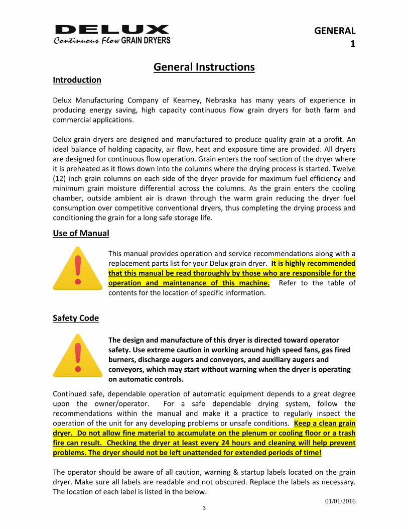
Use of Manual This manual provides operation and service recommendations along with a replacement parts list for your Delux grain dryer. It is highly recommended that this manual be read thoroughly by those who are responsible for the operation and maintenance of this machine. Refer to the table of contents for the location of specific information.
Safety Code The design and manufacture of this dryer is directed toward operator safety. Use extreme caution in working around high speed fans, gas fired burners, discharge augers and conveyors, and auxiliary augers and conveyors, which may start without warning when the dryer is operating on automatic controls.
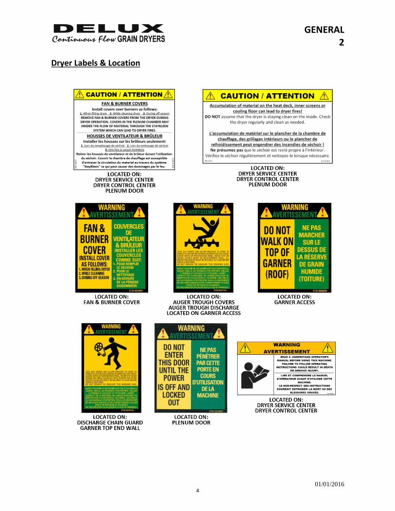
Continued safe, dependable operation of automatic equipment depends to a great degree upon the owner/operator. For a safe dependable drying system, follow the recommendations within the manual and make it a practice to regularly inspect the operation of the unit for any developing problems or unsafe conditions. Keep a clean grain dryer. Do not allow fine material to accumulate on the plenum or cooling floor or a trash fire can result. Checking the dryer at least every 24 hours and cleaning will help prevent problems. The dryer should not be left unattended for extended periods of time! The operator should be aware of all caution, warning & startup labels located on the grain dryer. Make sure all labels are readable and not obscured. Replace the labels as necessary. The location of each label is listed in the below.
3
GENERAL 2
01/01/2016
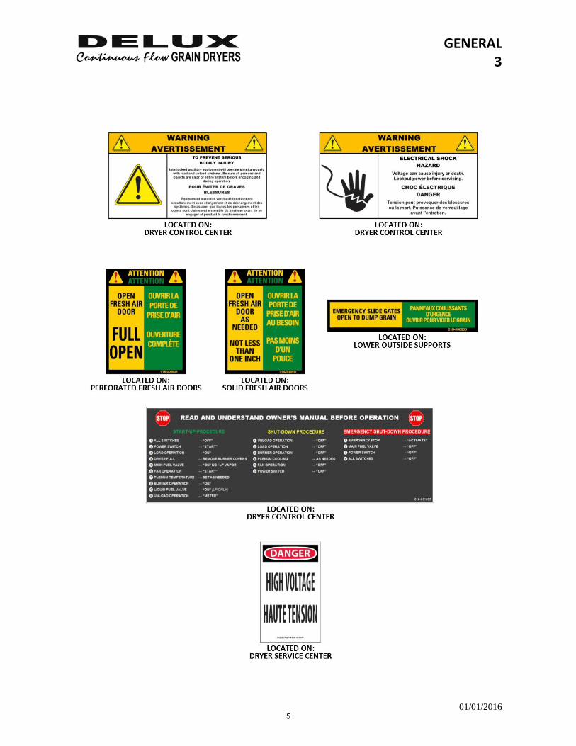
Dryer Labels & Location
4
GENERAL 3
01/01/2016
5
GENERAL 4
01/01/2016
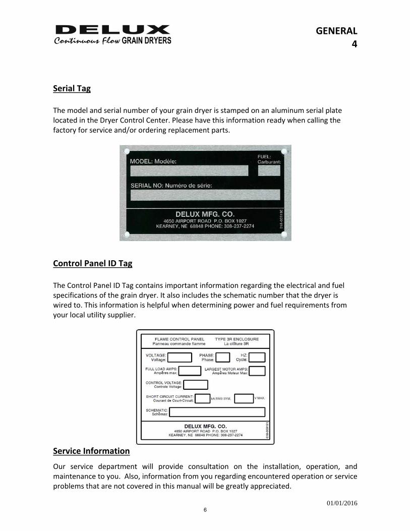
Serial Tag The model and serial number of your grain dryer is stamped on an aluminum serial plate located in the Dryer Control Center. Please have this information ready when calling the factory for service and/or ordering replacement parts.
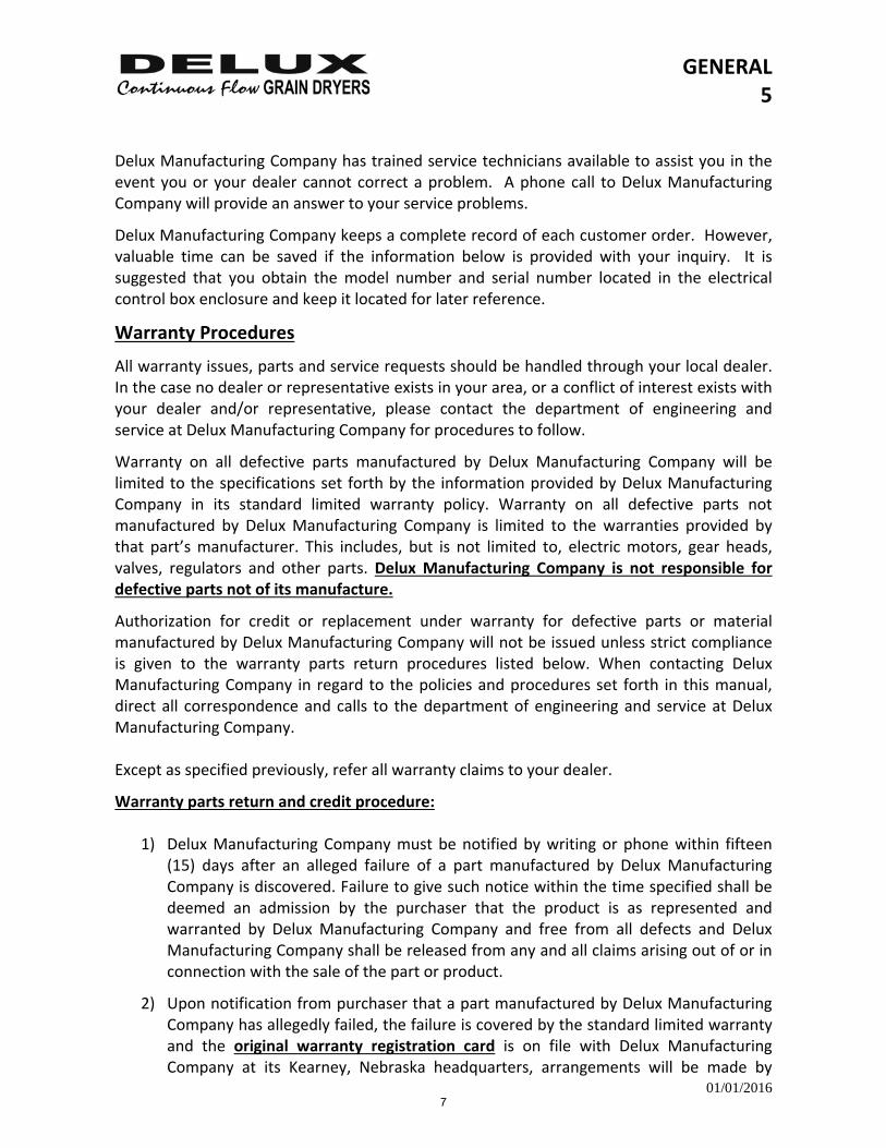
Control Panel ID Tag The Control Panel ID Tag contains important information regarding the electrical and fuel specifications of the grain dryer. It also includes the schematic number that the dryer is wired to. This information is helpful when determining power and fuel requirements from your local utility supplier.
Service Information
Our service department will provide consultation on the installation, operation, and maintenance to you. Also, information from you regarding encountered operation or service problems that are not covered in this manual will be greatly appreciated.
6
GENERAL 5
01/01/2016
Delux Manufacturing Company has trained service technicians available to assist you in the event you or your dealer cannot correct a problem. A phone call to Delux Manufacturing Company will provide an answer to your service problems.
Delux Manufacturing Company keeps a complete record of each customer order. However, valuable time can be saved if the information below is provided with your inquiry. It is suggested that you obtain the model number and serial number located in the electrical control box enclosure and keep it located for later reference.
Warranty Procedures
All warranty issues, parts and service requests should be handled through your local dealer. In the case no dealer or representative exists in your area, or a conflict of interest exists with your dealer and/or representative, please contact the department of engineering and service at Delux Manufacturing Company for procedures to follow.
Warranty on all defective parts manufactured by Delux Manufacturing Company will be limited to the specifications set forth by the information provided by Delux Manufacturing Company in its standard limited warranty policy. Warranty on all defective parts not manufactured by Delux Manufacturing Company is limited to the warranties provided by that part’s manufacturer. This includes, but is not limited to, electric motors, gear heads, valves, regulators and other parts. Delux Manufacturing Company is not responsible for defective parts not of its manufacture.
Authorization for credit or replacement under warranty for defective parts or material manufactured by Delux Manufacturing Company will not be issued unless strict compliance is given to the warranty parts return procedures listed below. When contacting Delux Manufacturing Company in regard to the policies and procedures set forth in this manual, direct all correspondence and calls to the department of engineering and service at Delux Manufacturing Company. Except as specified previously, refer all warranty claims to your dealer.
Warranty parts return and credit procedure:
1) Delux Manufacturing Company must be notified by writing or phone within fifteen (15) days after an alleged failure of a part manufactured by Delux Manufacturing Company is discovered. Failure to give such notice within the time specified shall be deemed an admission by the purchaser that the product is as represented and warranted by Delux Manufacturing Company and free from all defects and Delux Manufacturing Company shall be released from any and all claims arising out of or in connection with the sale of the part or product.
2) Upon notification from purchaser that a part manufactured by Delux Manufacturing Company has allegedly failed, the failure is covered by the standard limited warranty and the original warranty registration card is on file with Delux Manufacturing Company at its Kearney, Nebraska headquarters, arrangements will be made by
7
GENERAL 6
01/01/2016
Delux Manufacturing Company to ship the replacement part to purchaser with freight charged at the standard ground shipping rate.
3) Once the replacement part has been shipped, purchaser will receive an invoice for the value of the equipment shipped plus the shipping charges. Purchaser must then fully complete a return parts tag identifying the alleged part failure and return said tag along with the allegedly failed part to Delux Manufacturing Company with freight prepaid by purchaser. No warranty credit shall be given to purchaser on allegedly failed parts that are not returned to Delux Manufacturing Company within thirty (30) days from date of the discovery of the alleged failure or within fifteen (15) days from the shipping date indicated upon the invoice sent with the replacement part, whichever date is later. Purchaser must use proper packing material to ensure against damage during shipping. Any shipping damage caused by improper packing is not covered under the standard limited warranty.
4) The invoice for the replacement part plus the freight charge remains payable by purchaser until such time as the allegedly failed part has been returned with a completed return parts tag attached and the part has been inspected by Delux Manufacturing Company to determine if the warranty claim is valid. Purchaser will then receive notification from Delux Manufacturing Company as to the receipt of the defective part and Delux Manufacturing Company’s findings on the warranty claim within a reasonable time thereafter.
5) If the part is found to be defective by Delux Manufacturing Company, Delux Manufacturing Company shall credit the amount owed under the invoice sent with the replacement part except for the freight incurred in shipping the replacement part to purchaser.
6) If the part returned by purchaser is found by Delux Manufacturing Company to be functional and operational and in compliance with the manufactured specifications, it will be returned upon request to purchaser at purchaser’s cost. If no request is received by purchaser, the part shall be destroyed after a period of ten (10) days. Delux Manufacturing Company’s charges for inspection of a non‐defective Delux Manufacturing Co part will be subject to the standard hourly rate and zone charges.
7) No non‐Delux Manufacturing Company labor or non‐Delux Manufacturing Company replacement part will be authorized without first an estimate of the cost of part and labor provided to Delux Manufacturing Company. Deviations from this estimate will be solely at the purchaser or dealer’s cost.
8
GENERAL 7
01/01/2016
DELUX MANUFACTURING COMPANY STANDARD LIMITED WARRANTY
DELUX MANUFACTURING COMPANY’S WARRANTY OBLIGATIONS ARE LIMITED TO THE TERMS SET FORTH BELOW:
DELUX MANUFACTURING COMPANY WARRANTS TO THE ORIGINAL PURCHASER THAT IF ANY PART MANUFACTURED BY DELUX MANUFACTURING COMPANY IS PROVEN TO BE DEFECTIVE IN MATERIAL OR WORKMANSHIP WITHIN ONE (1) YEAR FROM DATE OF ORIGINAL INVOICE FROM DELUX MANUFACTURING COMPANY AND PURCHASER FOLLOWS THE ABOVE WARRANTY PARTS AND CREDIT PROCEDURE, DELUX MANUFACTURING COMPANY WILL, AT ITS OPTION, EITHER REPLACE OR REPAIR SAID PART AT ITS COST. THIS STANDARD LIMITED WARRANTY DOES NOT APPLY TO ANY DAMAGE RESULTING FROM NEGLIGENT USE, MISUSE, ACCIDENTAL DAMAGE, ABNORMAL OR UNUSUALLY HEAVY USE, NORMAL WEAR AND TEAR, NEGLECT, ABUSE, ALTERATION, IMPROPER INSTALLATION, UNAUTHORIZED REPAIR OR MODIFICATION, POOR OR IMPROPER MAINTENANCE OR USE BEYOND RATED CAPACITY. THIS WARRANTY AND THE REMEDY SET FORTH ABOVE ARE EXCLUSIVE AND IN LIEU OF ALL OTHERS, WHETHER ORAL OR WRITTEN, EXPRESSED, IMPLIED OR STATUTORY. DELUX MANUFACTURING COMPANY SPECIFICALLY DISCLAIMS TO THE MAXIMUM EXTENT PERMITTED BY LAW ANY AND ALL IMPLIED WARRANTIES OR CONDITIONS AS TO THE PRODUCTS OR ANY OTHER MATTER WHATSOEVER. IN PARTICULAR, BUT WITHOUT LIMITATION, DELUX MANUFACTURING COMPANY SPECIFICALLY DISCLAIMS ANY AND ALL IMPLIED WARRANTIES OR CONDITIONS OF SATISFACTORY QUALITY, MERCHANTABILITY, FITNESS FOR A PARTICULAR PURPOSE, DESCRIPTION, NON‐INFRINGEMENT OF THIRD PARTY RIGHTS, ANY ADVICE, INSTRUCTION, RECOMMENDATION OR SUGGESTION PROVIDED BY AN AGENT, REPRESENTATIVE OR EMPLOYEE OF DELUX MANUFACTURING COMPANY REGARDING OR RELATED TO THE CONFIGURATION, INSTALLATION, LAYOUT, SUITABILITY FOR A PARTICULAR PURPOSE, OR DESIGN OF SUCH PRODUCT OR PRODUCTS, OR ANY OTHER WARRANTY ARISING FROM A COURSE OF DEALING OR USAGE OF TRADE. DELUX MANUFACTURING COMPANY RESERVES THE RIGHT TO MAKE DESIGN OR SPECIFICATION CHANGES AT ANY TIME. THIS STANDARD LIMITED WARRANTY DOES NOT APPLY TO, AND DELUX MANUFACTURING COMPANY MAKES NO WARRANTY TO THE PURCHASER WITH REGARD TO, PARTS AND PRODUCTS NOT MANUFACTURED BY DELUX MANUFACTURING COMPANY. IN THE EVENT AND TO THE EXTENT THAT APPLICABLE LAW DOES NOT ALLOW THE EXCLUSION OF IMPLIED WARRANTIES, THE ABOVE EXCLUSION WITH REGARD TO IMPLIED WARRANTIES MAY NOT APPLY. DELUX MANUFACTURING COMPANY SHALL NOT BE RESPONSIBLE OR LIABLE FOR ANY LOST PROFITS, DIRECT, INDIRECT, UNFORESEEABLE, SPECIAL, INCIDENTAL OR CONSEQUENTIAL DAMAGES HOWEVER CAUSED AND WHETHER OR NOT DELUX MANUFACTURING COMPANY WAS ADVISED OF THE POSSIBILITY OF SUCH DAMAGES, WHETHER BASED ON CONTRACT, IN TORT OR ANY OTHER LEGAL THEORY. THE REMEDY STATED HEREIN SHALL BE THE SOLE AND EXCLUSIVE REMEDY AVAILABLE UNDER THIS WARRANTY. DELUX MANUFACTURING COMPANY ASSUMES NO RESPONSIBILITY FOR FIELD MODIFICATIONS OR ERECTION DEFECTS WHICH CREATE STRUCTURAL OR STORAGE QUALITY PROBLEMS, MODIFICATIONS TO THE PRODUCT NOT SPECIFICALLY COVERED BY THE CONTENTS OF THE DELUX MANUFACTURING COMPANY SERVICE MANUAL WILL NULLIFY ANY PRODUCT WARRANTY THAT MIGHT HAVE BEEN AVAILABLE OTHERWISE. NO DELUX MANUFACTURING COMPANY DISTRIBUTOR, RESELLER, DEALER, AGENT OR EMPLOYEE IS AUTHORIZED TO MAKE ANY MODIFICATIONS, EXTENSION OR ADDITION TO THIS WARRANTY. DELUX MANUFACTURING COMPANY SHALL NOT BE RESPONSIBLE FOR ANY CHARGES INCURRED IN THE REPAIRING OR SERVICING OF ANY DELUX MANUFACTURING COMPANY PRODUCT OR PART EXCEPT AS SUCH REPAIRS ARE MADE BY AUTHORIZED DELUX MANUFACTURING COMPANY FIELD SERVICE PERSONNEL OR AS APPROVED IN WRITING FROM DELUX MANUFACTURING COMPANY. PRIOR TO INSTALLATION, PURCHASER IS RESPONSIBLE FOR RESEARCHING AND COMPLYING WITH ALL FEDERAL, STATE AND LOCAL STATUTES, REGULATIONS AND/OR CODES WHICH MIGHT APPLY TO THE LOCATION AND INSTALLATION OF THE DELUX MANUFACTURING COMPANY PRODUCT.
9
GENERAL 8
01/01/2016
Additional disclaimer of warranty:
All manufacturer label products not manufactured by Delux Manufacturing Company are excluded from coverage under the Delux Manufacturing Company standard limited warranty.
No electric motor warranty:
Delux Manufacturing Company’s standard limited warranty does not cover any and all electric motors used by Delux Manufacturing Company in its products. Purchaser’s sole claim for warranty on these electric motors lies with the motor’s manufactures. In such event, purchaser’s dryer service manual contains a list of the motor manufacture’s service centers where all further inquiries regarding the motor and its warranty should be placed. Under no circumstances whatsoever will Delux Manufacturing Company be liable for an unauthorized electric motor repair by a local motor shop or electrician.
Return merchandise procedures:
1. CONTACT: DELUX MANUFACTURING COMPANY
4650 AIRPORT ROAD P.O. BOX 1027 KEARNEY, NE 68848‐1027
PHONE: 308‐237‐2274 TOLL FREE: 800‐658‐3240 FAX: 308‐234‐3765 WEB: http://www.deluxmfg.com
Ask for an RMA #. In that request, identify the merchandise you wish to return, its condition and the invoice on which it was originally billed.
2. After receipt of the return parts tag, ship the item(s) with prepaid freight along with the return parts tag to Delux Manufacturing Company. A 15% restocking fee will be charged on all merchandise returned thirty (30) days after the original date of purchase.
3. Once the merchandise has been received and inspected by Delux Manufacturing Company, if appropriate a credit will be issued to your account.
4. Any merchandise returned that has been used or abused will not receive a credit to your account. Shipments of incorrect merchandise due to miss‐ordering by the purchaser are also subject to a 15% restocking fee.
Out of warranty service:
Dryers requiring Delux Manufacturing Company repair work will be repaired at the standard service charges (hourly labor charge, trip charge (includes cost of lodging, meals, and mileage costs), plus parts). The repaired parts will carry a thirty (30) day limited warranty. The same exclusions and limitations of the Delux Manufacturing Company standard limited warranty policy referenced above also apply to this thirty (30) day limited warranty.
10
GENERAL 9
01/01/2016
Terms:
Delux dryers requiring service for customers who have an established line of credit will be invoiced for services rendered. Customers not having an established line of credit will be on cash in advance or cash on completion of service basis. All service or repair work rendered by authorized Delux service personnel must be invoiced through an existing authorized Delux Manufacturing Company dealer.
11

12
STARTUP 1
01/01/2016
Startup Procedure
Safety Considerations
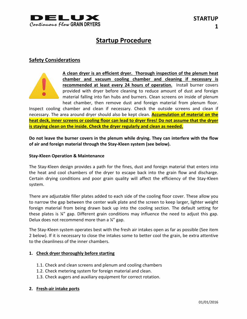
A clean dryer is an efficient dryer. Thorough inspection of the plenum heat chamber and vacuum cooling chamber and cleaning if necessary is recommended at least every 24 hours of operation. Install burner covers provided with dryer before cleaning to reduce amount of dust and foreign material falling into fan hubs and burners. Clean screens on inside of plenum heat chamber, then remove dust and foreign material from plenum floor.
Inspect cooling chamber and clean if necessary. Check the outside screens and clean if necessary. The area around dryer should also be kept clean. Accumulation of material on the heat deck, inner screens or cooling floor can lead to dryer fires! Do not assume that the dryer is staying clean on the inside. Check the dryer regularly and clean as needed. Do not leave the burner covers in the plenum while drying. They can interfere with the flow of air and foreign material through the Stay‐Kleen system (see below). Stay‐Kleen Operation & Maintenance
The Stay‐Kleen design provides a path for the fines, dust and foreign material that enters into the heat and cool chambers of the dryer to escape back into the grain flow and discharge. Certain drying conditions and poor grain quality will affect the efficiency of the Stay‐Kleen system. There are adjustable filler plates added to each side of the cooling floor cover. These allow you to narrow the gap between the center walk plate and the screen to keep larger, lighter weight foreign material from being drawn back up into the cooling section. The default setting for these plates is ¼” gap. Different grain conditions may influence the need to adjust this gap. Delux does not recommend more than a ¼” gap.
The Stay‐Kleen system operates best with the fresh air intakes open as far as possible (See item 2 below). If it is necessary to close the intakes some to better cool the grain, be extra attentive to the cleanliness of the inner chambers. 1. Check dryer thoroughly before starting
1.1. Check and clean screens and plenum and cooling chambers 1.2. Check metering system for foreign material and clean. 1.3. Check augers and auxiliary equipment for correct rotation.
2. Fresh‐air intake ports
STARTUP 2
01/01/2016
2.1. Fresh‐air intake ports are provided to allow fresh air to flow directly to the fan(s). The fan(s) cannot receive enough air directly through the grain being cooled so fresh‐air intake ports are provided. These ports allow the operator to have more control over the outgoing temperature of the product being dried.
2.2. Settings: Open the doors that are labeled ‘Full Open’, located directly on the fan(s), full open. Open other doors labeled ‘As Needed’ as far as possible while still cooling the grain as needed. When the grain is not cool enough close the doors down that are not located directly on the fan(s) ‐ when grain is too cool open these doors. Keep all doors that are being adjusted the same as each other. When drying low moisture products, it may be necessary to adjust the plenum temperature down to get the product as cool as desired.
2.3. CAUTION: Having the fresh air intake doors closed too far can decrease capacity and cause excessive heat which could result in uneven moisture content of discharge grain and in extreme conditions, fires on the heat deck or cooling floor.
3. All switches in “OFF” position
4. Turn on main power
4.1. Main power light will come “ON”.
5. Turn on panel power and prove safety circuit 5.1. Move power switch to “RUN” position. After 10 seconds, move and hold switch to
“START” position. This will energize panel power relay and provide 120VAC to control system. Safety circuit monitor lights will come on and safety circuit light will come on. Release switch back to “RUN”.
6. To fill with wet grain
6.1. Move load operation switch to "ON" position. Loading system will be activated and will
fill dryer. When dryer is full of grain, high grain shutdown will shut off all loading equipment automatically. (Leave load switch in "ON" position.) Grain loading light will come on during filling ‐ low grain light will come on until dryer is full of grain then go out.
7. To start fan(s) 7.1. Move and hold fan switch to "START" position until all fan(s) start, then release to
“RUN” position. Fan proven light(s) will come on as fan(s) prove. Purging light will come on after fan(s) prove.
7.2. Dryers with two (2) or more fans are equipped with delay timers, which allow only one (1) fan to start at a time.
STARTUP 3
01/01/2016
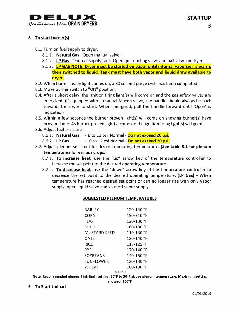
8. To start burner(s) 8.1. Turn on fuel supply to dryer.
8.1.1. Natural Gas ‐ Open manual valve. 8.1.2. LP Gas ‐ Open at supply tank. Open quick acting valve and ball valve on dryer. 8.1.3. LP GAS NOTE: Dryer must be started on vapor until internal vaporizer is warm,
then switched to liquid. Tank must have both vapor and liquid draw available to dryer.
8.2. When burner ready light comes on, a 30 second purge cycle has been completed. 8.3. Move burner switch to "ON" position. 8.4. After a short delay, the ignition firing light(s) will come on and the gas safety valves are
energized. (If equipped with a manual Maxon valve, the handle should always be back towards the dryer to start. When energized, pull the handle forward until ‘Open’ is indicated.)
8.5. Within a few seconds the burner proven light(s) will come on showing burner(s) have proven flame. As burner proven light(s) come on the ignition firing light(s) will go off.
8.6. Adjust fuel pressure 8.6.1. Natural Gas ‐ 8 to 12 psi Normal ‐ Do not exceed 20 psi. 8.6.2. LP Gas ‐ 10 to 12 psi Normal ‐ Do not exceed 20 psi.
8.7. Adjust plenum set point for desired operating temperature. (See table 5.1 for plenum temperatures for various crops.) 8.7.1. To increase heat, use the “up” arrow key of the temperature controller to
increase the set point to the desired operating temperature. 8.7.2. To decrease heat, use the “down” arrow key of the temperature controller to
decrease the set point to the desired operating temperature. (LP Gas) ‐ When temperature has reached desired set point or can no longer rise with only vapor supply, open liquid valve and shut off vapor supply.
SUGGESTED PLENUM TEMPERATURES
BARLEY 120‐140 °F CORN 190‐210 °F FLAX 120‐130 °F MILO 160‐180 °F MUSTARD SEED 110‐130 °F OATS 120‐140 °F RICE 115‐125 °F RYE 120‐140 °F SOYBEANS 140‐160 °F SUNFLOWER 120‐130 °F WHEAT 160‐180 °F
TABLE 5.1
Note: Recommended plenum high limit setting: 30F to 50F above plenum temperature. Maximum setting
allowed: 260F 9. To Start Unload

STARTUP 4
01/01/2016
9.1. Turn discharge operation switch to “ON” to start the discharge auger and other auxiliary handling equipment. Turn the switch to “METER” to active the DC metering roll system. The Watlow Moisture Control becomes the source of metering the grain from the dryer in either automatic or manual mode. (SEE BELOW)
STARTUP 5
01/01/2016
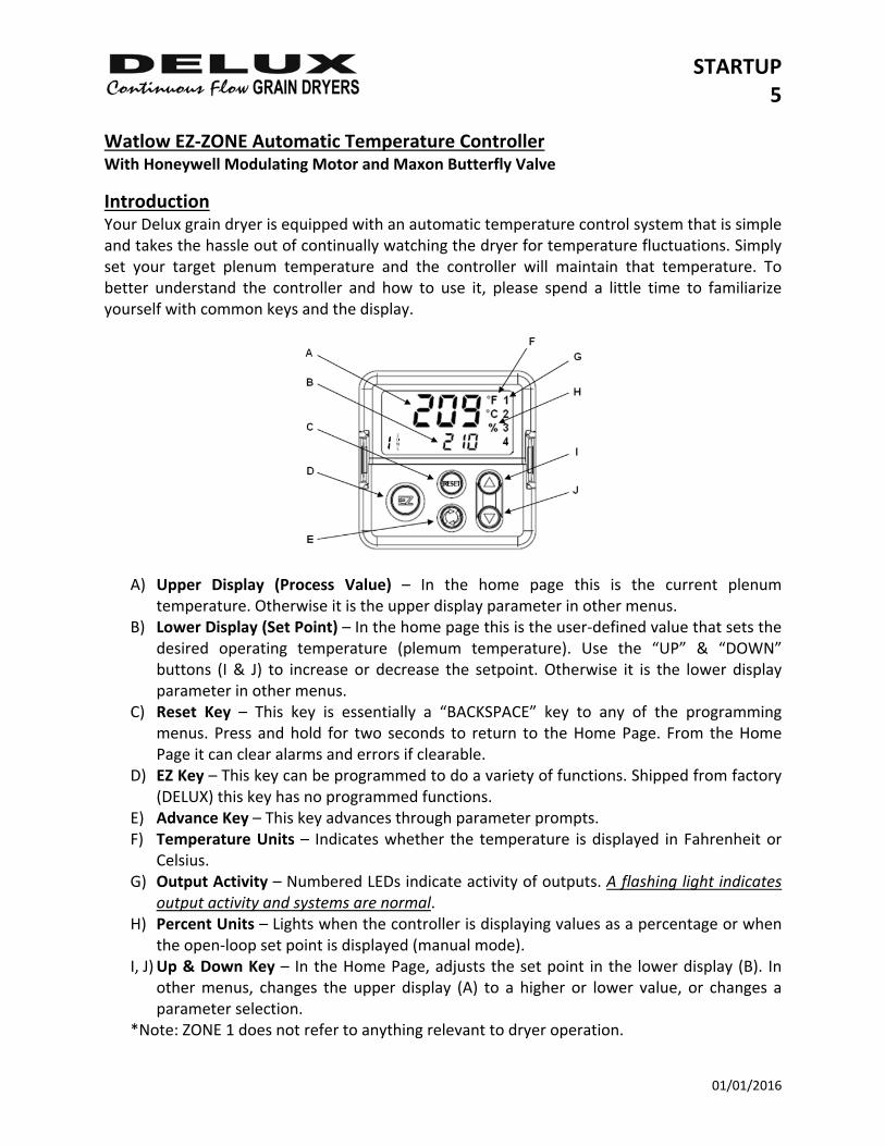
Watlow EZ‐ZONE Automatic Temperature Controller With Honeywell Modulating Motor and Maxon Butterfly Valve
Introduction Your Delux grain dryer is equipped with an automatic temperature control system that is simple and takes the hassle out of continually watching the dryer for temperature fluctuations. Simply set your target plenum temperature and the controller will maintain that temperature. To better understand the controller and how to use it, please spend a little time to familiarize yourself with common keys and the display.
A) Upper Display (Process Value) – In the home page this is the current plenum temperature. Otherwise it is the upper display parameter in other menus.
B) Lower Display (Set Point) – In the home page this is the user‐defined value that sets the desired operating temperature (plemum temperature). Use the “UP” & “DOWN” buttons (I & J) to increase or decrease the setpoint. Otherwise it is the lower display parameter in other menus.
C) Reset Key – This key is essentially a “BACKSPACE” key to any of the programming menus. Press and hold for two seconds to return to the Home Page. From the Home Page it can clear alarms and errors if clearable.
D) EZ Key – This key can be programmed to do a variety of functions. Shipped from factory (DELUX) this key has no programmed functions.
E) Advance Key – This key advances through parameter prompts. F) Temperature Units – Indicates whether the temperature is displayed in Fahrenheit or
Celsius. G) Output Activity – Numbered LEDs indicate activity of outputs. A flashing light indicates
output activity and systems are normal. H) Percent Units – Lights when the controller is displaying values as a percentage or when
the open‐loop set point is displayed (manual mode). I, J) Up & Down Key – In the Home Page, adjusts the set point in the lower display (B). In
other menus, changes the upper display (A) to a higher or lower value, or changes a parameter selection.
*Note: ZONE 1 does not refer to anything relevant to dryer operation.
STARTUP 6
01/01/2016
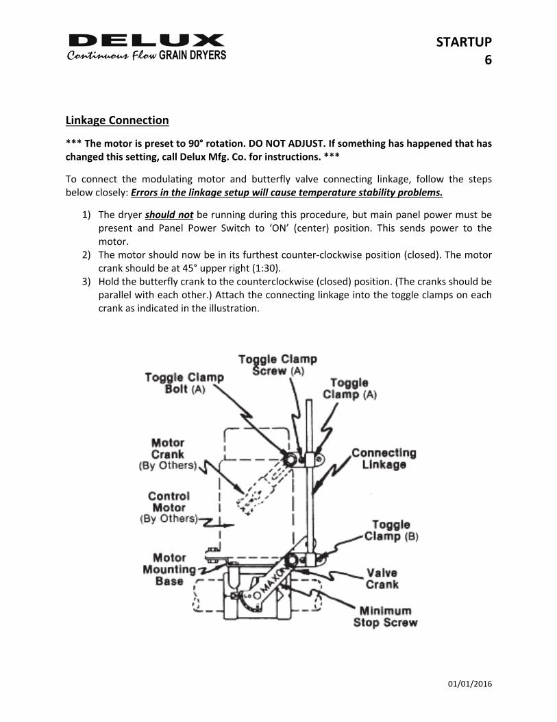
Linkage Connection
*** The motor is preset to 90° rotation. DO NOT ADJUST. If something has happened that has changed this setting, call Delux Mfg. Co. for instructions. ***
To connect the modulating motor and butterfly valve connecting linkage, follow the steps below closely: Errors in the linkage setup will cause temperature stability problems.
1) The dryer should not be running during this procedure, but main panel power must be present and Panel Power Switch to ‘ON’ (center) position. This sends power to the motor.
2) The motor should now be in its furthest counter‐clockwise position (closed). The motor crank should be at 45° upper right (1:30).
3) Hold the butterfly crank to the counterclockwise (closed) position. (The cranks should be parallel with each other.) Attach the connecting linkage into the toggle clamps on each crank as indicated in the illustration.
STARTUP 7
01/01/2016
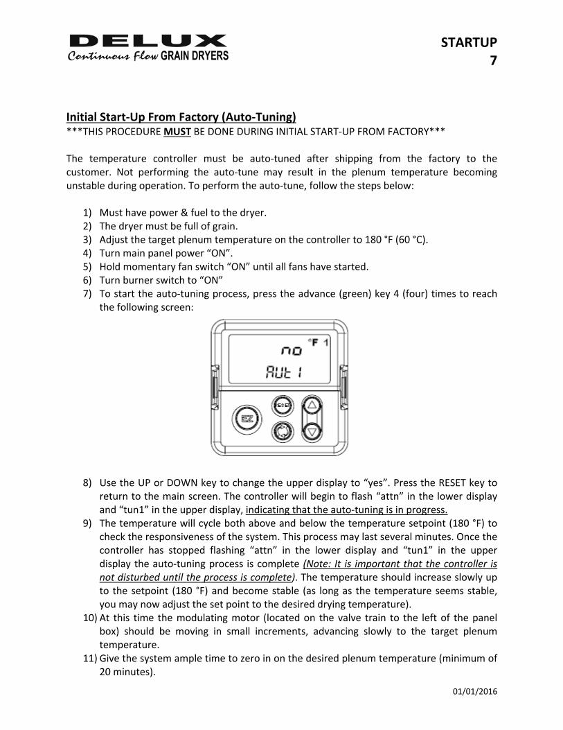
Initial Start‐Up From Factory (Auto‐Tuning) ***THIS PROCEDURE MUST BE DONE DURING INITIAL START‐UP FROM FACTORY*** The temperature controller must be auto‐tuned after shipping from the factory to the customer. Not performing the auto‐tune may result in the plenum temperature becoming unstable during operation. To perform the auto‐tune, follow the steps below:
1) Must have power & fuel to the dryer. 2) The dryer must be full of grain. 3) Adjust the target plenum temperature on the controller to 180 °F (60 °C). 4) Turn main panel power “ON”. 5) Hold momentary fan switch “ON” until all fans have started. 6) Turn burner switch to “ON” 7) To start the auto‐tuning process, press the advance (green) key 4 (four) times to reach
the following screen:
8) Use the UP or DOWN key to change the upper display to “yes”. Press the RESET key to
return to the main screen. The controller will begin to flash “attn” in the lower display and “tun1” in the upper display, indicating that the auto‐tuning is in progress.
9) The temperature will cycle both above and below the temperature setpoint (180 °F) to check the responsiveness of the system. This process may last several minutes. Once the controller has stopped flashing “attn” in the lower display and “tun1” in the upper display the auto‐tuning process is complete (Note: It is important that the controller is not disturbed until the process is complete). The temperature should increase slowly up to the setpoint (180 °F) and become stable (as long as the temperature seems stable, you may now adjust the set point to the desired drying temperature).
10) At this time the modulating motor (located on the valve train to the left of the panel box) should be moving in small increments, advancing slowly to the target plenum temperature.
11) Give the system ample time to zero in on the desired plenum temperature (minimum of 20 minutes).
STARTUP 8
01/01/2016
12) It may be necessary to repeat the process with changing variables outside the system, but not needed every time starting the dryer.
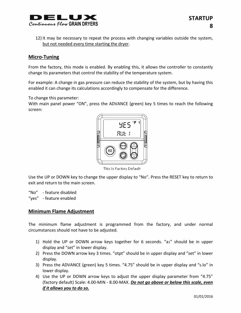
Micro‐Tuning
From the factory, this mode is enabled. By enabling this, it allows the controller to constantly change its parameters that control the stability of the temperature system.
For example: A change in gas pressure can reduce the stability of the system, but by having this enabled it can change its calculations accordingly to compensate for the difference.
To change this parameter: With main panel power “ON”, press the ADVANCE (green) key 5 times to reach the following screen:
Use the UP or DOWN key to change the upper display to “No”. Press the RESET key to return to exit and return to the main screen.
“No” ‐ feature disabled “yes” ‐ feature enabled
Minimum Flame Adjustment The minimum flame adjustment is programmed from the factory, and under normal circumstances should not have to be adjusted.
1) Hold the UP or DOWN arrow keys together for 6 seconds. “a1” should be in upper display and “set” in lower display.
2) Press the DOWN arrow key 3 times. “otpt” should be in upper display and “set” in lower display.
3) Press the ADVANCE (green) key 5 times. “4.75” should be in upper display and “s.lo” in lower display.
4) Use the UP or DOWN arrow keys to adjust the upper display parameter from “4.75” (factory default) Scale: 4.00‐MIN ‐ 8.00‐MAX. Do not go above or below this scale, even if it allows you to do so.
STARTUP 9
01/01/2016
High Limit The controller is equipped with an integrated high limit control. Should the operating temperature rise above the high limit set point, the dryer will shut down automatically. To change the high limit temperature set point:
1) From the Home Page press the ADVANCE (green) key 6 times. “250” (factory default) should appear in the upper display and “sp.5i” in the lower display.
2) Use the UP or DOWN key to adjust the high limit set point. 3) Hold the RESET key until you return to the Home Page.
If under normal operation, the high limit set point is reached the dryer will shut down, and prevent the dryer from being restarted until the dryer has had sufficient time to cool down. Reset the panel power after the dryer has had time to cool to clear high limit error. Error message: “li.h1” in the upper display and “attn” in the lower display. The integrated system has its own sensor that monitors the temperature inside the plenum, separate from the sensor that controls the actual temperature. However these sensors are located in the same junction box. Should the high limit sensor fail, it will automatically shut control circuit power to the dryer and prevent it from being started until the problem with the high limit sensor is fixed. Error messages: “li.e1” ; “er.i 2” in the upper display and “attn” in the lower display. If the temperature control sensor fails, the system is designed to flash a warning message that indicates that there is a sensor error. The dryer will still operate under this condition, but it is advised the temperature control sensor be fixed. Error message: “er.i1” in the upper display and “attn” in the lower display
STARTUP 10
01/01/2016
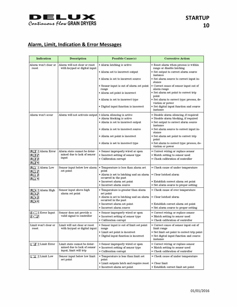
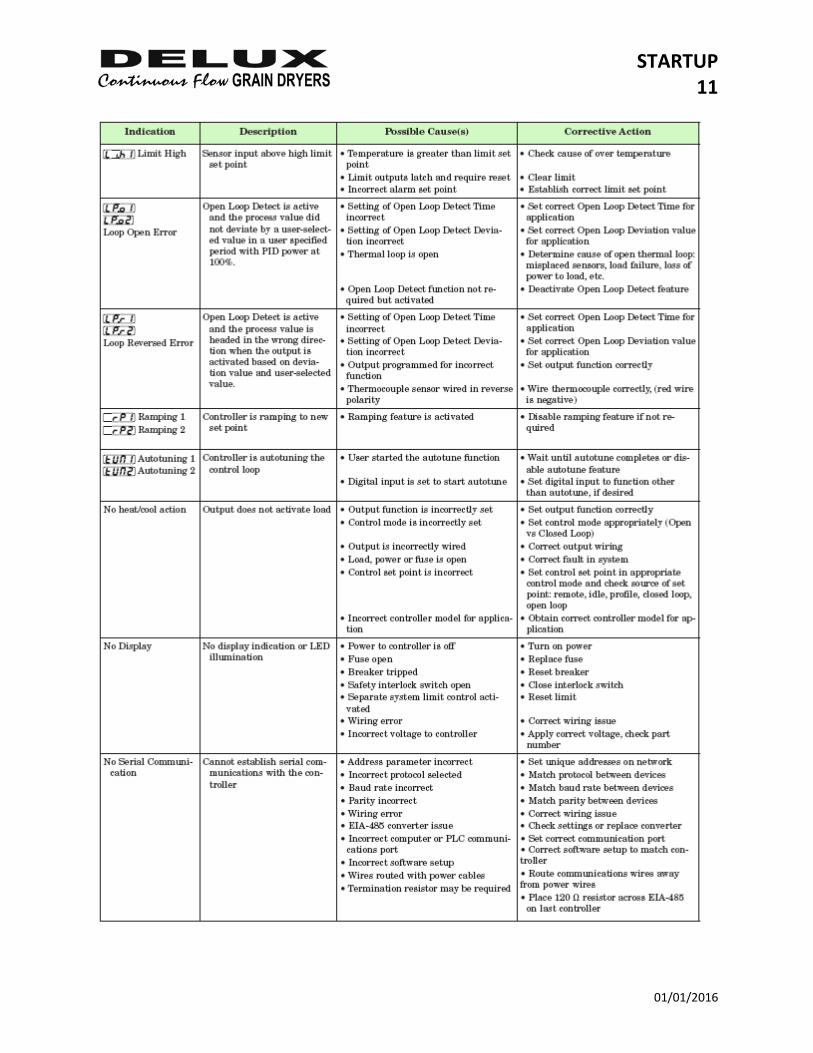
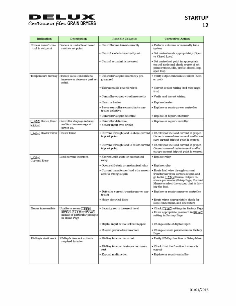
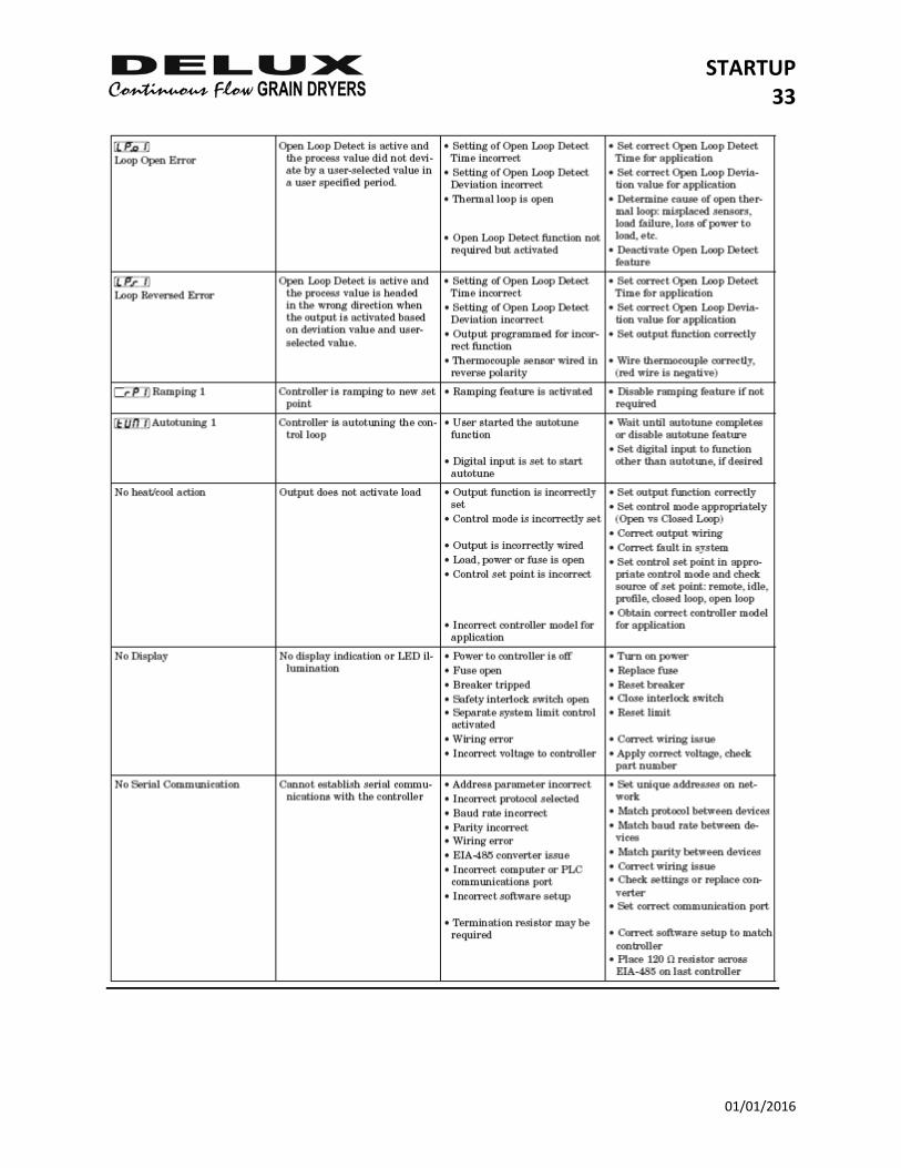
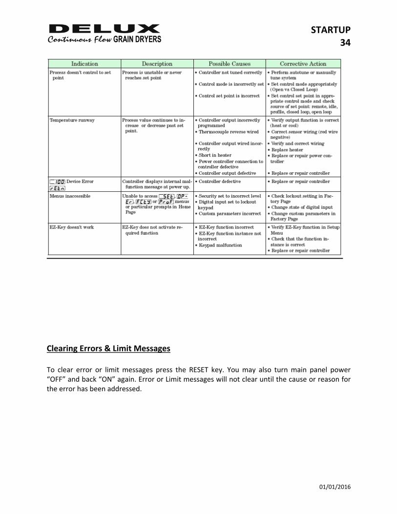
Alarm, Limit, Indication & Error Messages
STARTUP 11
01/01/2016
STARTUP 12
01/01/2016

STARTUP 13
01/01/2016
Clearing Errors & Limit Messages To clear error or limit messages press the RESET key. You may also turn main panel power “OFF” and back “ON” again. Error or Limit messages will not clear until the cause or reason for the error has been addressed.
STARTUP 14
01/01/2016
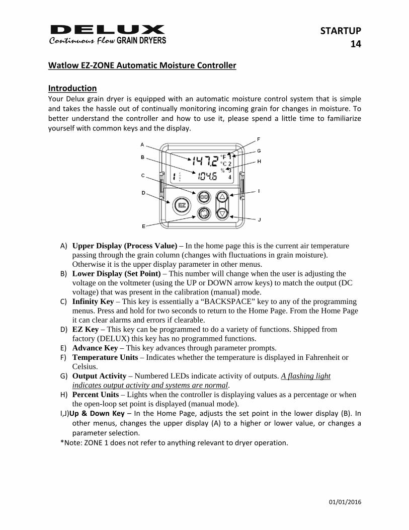
Watlow EZ‐ZONE Automatic Moisture Controller Introduction Your Delux grain dryer is equipped with an automatic moisture control system that is simple and takes the hassle out of continually monitoring incoming grain for changes in moisture. To better understand the controller and how to use it, please spend a little time to familiarize yourself with common keys and the display.
A) Upper Display (Process Value) – In the home page this is the current air temperature passing through the grain column (changes with fluctuations in grain moisture). Otherwise it is the upper display parameter in other menus.
B) Lower Display (Set Point) – This number will change when the user is adjusting the voltage on the voltmeter (using the UP or DOWN arrow keys) to match the output (DC voltage) that was present in the calibration (manual) mode.
C) Infinity Key – This key is essentially a “BACKSPACE” key to any of the programming menus. Press and hold for two seconds to return to the Home Page. From the Home Page it can clear alarms and errors if clearable.
D) EZ Key – This key can be programmed to do a variety of functions. Shipped from factory (DELUX) this key has no programmed functions.
E) Advance Key – This key advances through parameter prompts. F) Temperature Units – Indicates whether the temperature is displayed in Fahrenheit or
Celsius. G) Output Activity – Numbered LEDs indicate activity of outputs. A flashing light
indicates output activity and systems are normal. H) Percent Units – Lights when the controller is displaying values as a percentage or when
the open-loop set point is displayed (manual mode). I,J)Up & Down Key – In the Home Page, adjusts the set point in the lower display (B). In
other menus, changes the upper display (A) to a higher or lower value, or changes a parameter selection.
*Note: ZONE 1 does not refer to anything relevant to dryer operation.
STARTUP 15
01/01/2016
Automatic Moisture Set‐Up Guide
1) On initial start‐up with wet grain, it is advisable to let the dryer run at operating temperature for 10‐20 minutes before starting the discharge process.
2) Move Unload Operation switch to “ON” position (grain unloading light will come on) to start discharge auger system. Note: Metering rolls will not operate unless all auger systems are on.
3) Move Unload Operation switch to “METER” position and with the Watlow Moisture Controller in MANUAL (MAN) mode, adjust the percent of power output to desired discharge rate in DC volts. (see formula & charts below for determining initial unloading rate)
a. Metering Roll Adjustment
The dry grain discharge rate is adjusted by changing the percent of power output coming from the Watlow Moisture Control. ARROW DOWN – Will increase the grain discharge rate & DC volts ARROW UP – Will decrease the grain discharge rate & DC volts NOTE: The Watlow Moisture Controller operates as a PID tuner in cool mode. Because of this, the output power display on the Watlow Moisture Controller will always be shown with a minus (‐) sign to the left. This is an absolute value. ‐100.0% = 100% FULL POWER OUTPUT ‐0.0% = 0% POWER OUTPUT
4) Wait at least one (1) hour – until a complete cycle of grain through the dryer has been
completed. One cycle consists from the time the grain enters the top of the dryer to the time it is discharge from the metering rolls, and the dryer has stabilized. Then check grain moisture. Note: With wetter grain it may be necessary to wait longer to check samples.
5) If grain is too wet, decrease Watlow Moisture Control output (decrease DC voltage) and repeat step 4, allowing grain to stabilize.
6) If grain is too dry, increase Watlow Moisture Control output (increase DC voltage) and repeat step 4, allowing grain to stabilize.
7) Repeat the steps above until final moisture content has been established and dryer has completely stabilize
8) With the moisture now stabilized in manual mode, note the voltage present on the DC voltmeter.
9) Switch the Watlow Moisture Controller from MANUAL to AUTOMATIC. Press the Advance Key (GREEN) once. The top LED (RED) should read MAN. Use the UP/DOWN arrow key to change it to AUTO. Press the Infinity Key to return to the home page.
10) Adjust slowly so that the drive has time to react. DC voltage will not change until the UP
or DOWN key is released.
STARTUP 16
01/01/2016
11) If final moisture content is within 1 or 2 points of target moisture, minor adjustments can be made while in automatic mode. Be cautious not to make too much change too often. Let the system have ample time to process and adjust. If the variance is too great or not consistent, it may be necessary to return to manual mode and establish a new set point.
12) Proportional Band (h.pb) – The proportional band is factory set for each model of dryer. It can be changed by pressing the ADVANCE key until reaching “h.pb” in the lower display. It can be adjusted up or down depending on what the moisture of the discharged grain is doing.
a. Decrease PB if it seems the dryer isn’t reacting quickly enough to changes in
incoming grain moisture. b. Increase PB if it seems the dryer is reacting too quickly to changes in incoming
grain moisture. Note: It is the moisture of your discharging grain over a period of time that is important. Do not make changes too soon because the system appears to be changing speeds too quickly. Sometimes it takes aggressive action to maintain the desired results.
13) Moisture samples should be taken at regular intervals. At this time, a visual inspection of the dryer should be made, checking the temperature and feedroll operation. Make sure all columns are flowing by observing grain flow on each side.
14) For further information regarding the automatic metering system refer to Section 9, Sequence 7B.
STARTUP 17
01/01/2016
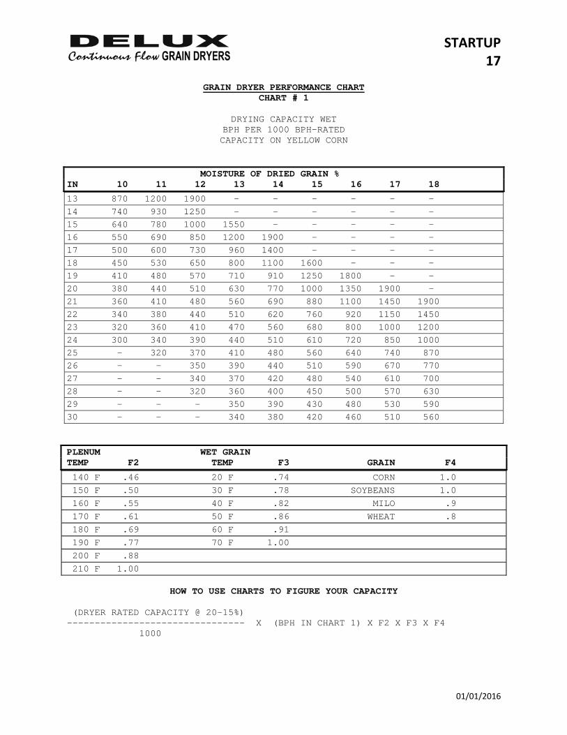
GRAIN DRYER PERFORMANCE CHART CHART # 1
DRYING CAPACITY WET
BPH PER 1000 BPH-RATED CAPACITY ON YELLOW CORN
MOISTURE OF DRIED GRAIN % IN 10 11 12 13 14 15 16 17 18
13 870 1200 1900 - - - - - - 14 740 930 1250 - - - - - - 15 640 780 1000 1550 - - - - - 16 550 690 850 1200 1900 - - - - 17 500 600 730 960 1400 - - - - 18 450 530 650 800 1100 1600 - - - 19 410 480 570 710 910 1250 1800 - - 20 380 440 510 630 770 1000 1350 1900 - 21 360 410 480 560 690 880 1100 1450 1900 22 340 380 440 510 620 760 920 1150 1450 23 320 360 410 470 560 680 800 1000 1200 24 300 340 390 440 510 610 720 850 1000 25 - 320 370 410 480 560 640 740 870 26 - - 350 390 440 510 590 670 770 27 - - 340 370 420 480 540 610 700 28 - - 320 360 400 450 500 570 630 29 - - - 350 390 430 480 530 590 30 - - - 340 380 420 460 510 560 PLENUM WET GRAIN TEMP F2 TEMP F3 GRAIN F4
140 F .46 20 F .74 CORN 1.0 150 F .50 30 F .78 SOYBEANS 1.0 160 F .55 40 F .82 MILO .9 170 F .61 50 F .86 WHEAT .8 180 F .69 60 F .91 190 F .77 70 F 1.00 200 F .88 210 F 1.00
HOW TO USE CHARTS TO FIGURE YOUR CAPACITY (DRYER RATED CAPACITY @ 20-15%) -------------------------------- X (BPH IN CHART 1) X F2 X F3 X F4 1000
STARTUP 18
01/01/2016
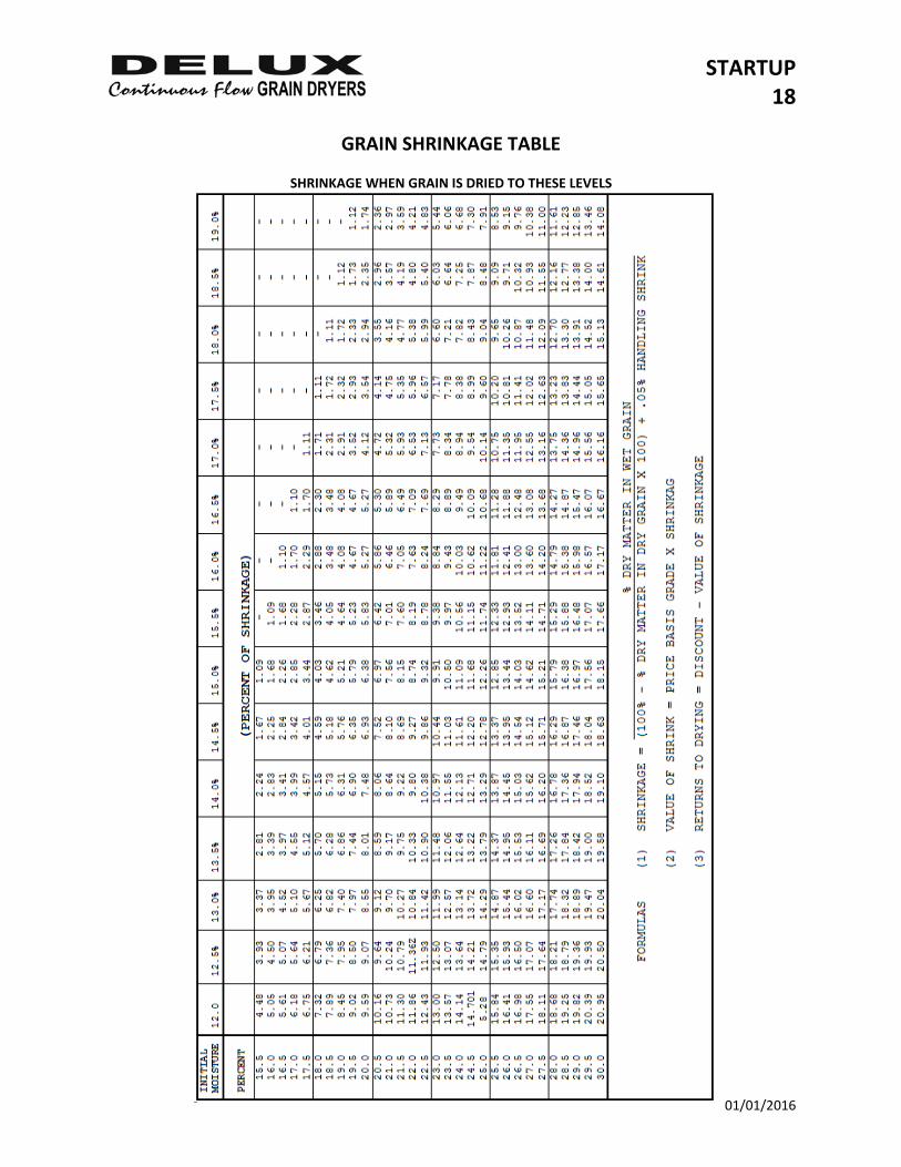
GRAIN SHRINKAGE TABLE
SHRINKAGE WHEN GRAIN IS DRIED TO THESE LEVELS
STARTUP 19
01/01/2016
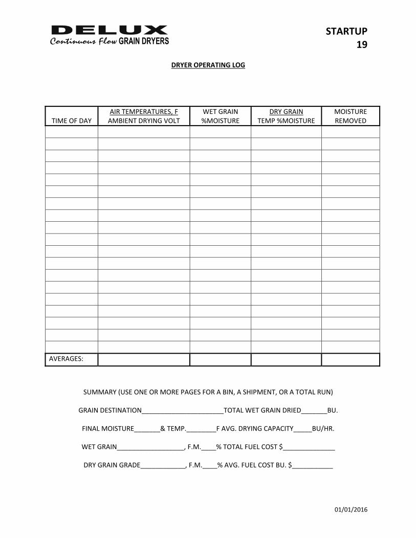
DRYER OPERATING LOG
TIME OF DAY
AIR TEMPERATURES, F AMBIENT DRYING VOLT
WET GRAIN %MOISTURE
DRY GRAIN TEMP %MOISTURE
MOISTURE REMOVED
AVERAGES:
SUMMARY (USE ONE OR MORE PAGES FOR A BIN, A SHIPMENT, OR A TOTAL RUN)
GRAIN DESTINATION______________________TOTAL WET GRAIN DRIED_______BU.
FINAL MOISTURE_______& TEMP.________F AVG. DRYING CAPACITY_____BU/HR.
WET GRAIN__________________, F.M.____% TOTAL FUEL COST $______________
DRY GRAIN GRADE____________, F.M.____% AVG. FUEL COST BU. $___________
STARTUP 20
01/01/2016
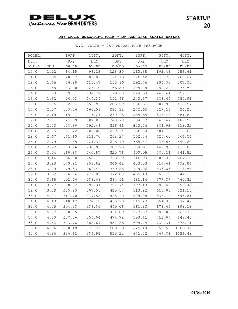
DRY GRAIN UNLOADING RATE – DP AND DPSL SERIES DRYERS
D.C. VOLTS = DRY UNLOAD RATE PER HOUR
MODEL: 10FT. 15FT. 20FT. 25FT. 30FT. 40FT.
D.C. DRY DRY DRY DRY DRY DRY VOLTS RPM BU/HR BU/HR BU/HR BU/HR BU/HR BU/HR
10.0 1.22 64.15 96.23 128.30 160.38 192.46 256.61 11.0 1.34 70.57 105.85 141.13 176.42 211.71 282.27 12.0 1.46 76.98 115.47 153.96 192.46 230.95 307.93 13.0 1.58 83.40 125.10 166.80 208.49 250.20 333.59 14.0 1.70 89.81 134.72 179.63 224.53 269.44 359.25 15.0 1.82 96.23 144.34 192.46 240.57 288.69 384.91 16.0 1.94 102.64 153.96 205.29 256.61 307.93 410.57 17.0 2.07 109.06 163.59 218.12 272.65 327.18 436.23 18.0 2.19 115.47 173.21 230.95 288.68 346.42 461.89 19.0 2.31 121.89 182.83 243.78 304.72 365.67 487.56 20.0 2.43 128.30 192.46 256.61 320.76 384.92 513.22 21.0 2.55 134.72 202.08 269.44 336.80 404.16 538.88 22.0 2.67 141.13 211.70 282.27 352.84 423.41 564.54 23.0 2.79 147.55 221.32 295.10 368.87 442.65 590.20 24.0 2.92 153.96 230.95 307.93 384.91 461.90 615.86 25.0 3.04 160.38 240.57 320.76 400.95 481.14 641.52 26.0 3.16 166.80 250.19 333.59 416.99 500.39 667.18 27.0 3.28 173.21 259.82 346.42 433.03 519.64 692.84 28.0 3.40 179.63 269.44 359.25 449.06 538.88 718.55 29.0 3.52 186.04 279.06 372.08 465.10 558.13 744.16 30.0 3.65 192.46 288.68 384.91 481.14 577.37 769.82 31.0 3.77 198.87 298.31 397.74 497.18 596.62 795.48 32.0 3.89 205.29 307.93 410.57 513.22 615.86 821.15 33.0 4.01 211.70 317.55 423.40 529.25 635.11 846.81 34.0 4.13 218.12 324.18 436.23 545.29 654.35 872.47 35.0 4.25 224.53 336.80 449.06 561.33 673.60 898.13 36.0 4.37 230.95 346.42 461.89 577.37 692.85 923.79 37.0 4.50 237.36 356.04 474.72 593.41 712.09 949.45 38.0 4.62 243.78 365.67 487.56 609.44 731.34 975.11 39.0 4.74 250.19 375.29 500.39 625.48 750.58 1000.77 40.0 4.86 256.61 384.91 513.22 641.52 769.83 1026.43
STARTUP 21
01/01/2016
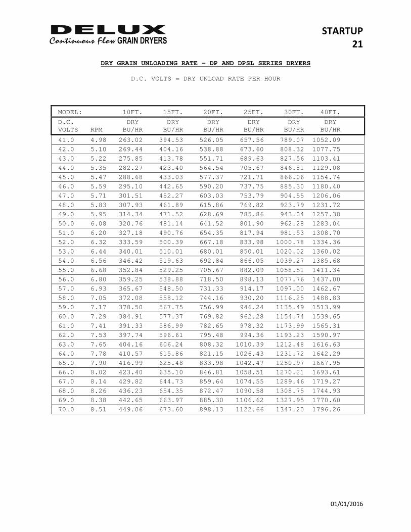
DRY GRAIN UNLOADING RATE – DP AND DPSL SERIES DRYERS
D.C. VOLTS = DRY UNLOAD RATE PER HOUR
MODEL: 10FT. 15FT. 20FT. 25FT. 30FT. 40FT.
D.C. DRY DRY DRY DRY DRY DRY VOLTS RPM BU/HR BU/HR BU/HR BU/HR BU/HR BU/HR
41.0 4.98 263.02 394.53 526.05 657.56 789.07 1052.09 42.0 5.10 269.44 404.16 538.88 673.60 808.32 1077.75 43.0 5.22 275.85 413.78 551.71 689.63 827.56 1103.41 44.0 5.35 282.27 423.40 564.54 705.67 846.81 1129.08 45.0 5.47 288.68 433.03 577.37 721.71 866.06 1154.74 46.0 5.59 295.10 442.65 590.20 737.75 885.30 1180.40 47.0 5.71 301.51 452.27 603.03 753.79 904.55 1206.06 48.0 5.83 307.93 461.89 615.86 769.82 923.79 1231.72 49.0 5.95 314.34 471.52 628.69 785.86 943.04 1257.38 50.0 6.08 320.76 481.14 641.52 801.90 962.28 1283.04 51.0 6.20 327.18 490.76 654.35 817.94 981.53 1308.70 52.0 6.32 333.59 500.39 667.18 833.98 1000.78 1334.36 53.0 6.44 340.01 510.01 680.01 850.01 1020.02 1360.02 54.0 6.56 346.42 519.63 692.84 866.05 1039.27 1385.68 55.0 6.68 352.84 529.25 705.67 882.09 1058.51 1411.34 56.0 6.80 359.25 538.88 718.50 898.13 1077.76 1437.00 57.0 6.93 365.67 548.50 731.33 914.17 1097.00 1462.67 58.0 7.05 372.08 558.12 744.16 930.20 1116.25 1488.83 59.0 7.17 378.50 567.75 756.99 946.24 1135.49 1513.99 60.0 7.29 384.91 577.37 769.82 962.28 1154.74 1539.65 61.0 7.41 391.33 586.99 782.65 978.32 1173.99 1565.31 62.0 7.53 397.74 596.61 795.48 994.36 1193.23 1590.97 63.0 7.65 404.16 606.24 808.32 1010.39 1212.48 1616.63 64.0 7.78 410.57 615.86 821.15 1026.43 1231.72 1642.29 65.0 7.90 416.99 625.48 833.98 1042.47 1250.97 1667.95 66.0 8.02 423.40 635.10 846.81 1058.51 1270.21 1693.61 67.0 8.14 429.82 644.73 859.64 1074.55 1289.46 1719.27 68.0 8.26 436.23 654.35 872.47 1090.58 1308.75 1744.93 69.0 8.38 442.65 663.97 885.30 1106.62 1327.95 1770.60 70.0 8.51 449.06 673.60 898.13 1122.66 1347.20 1796.26
STARTUP 22
01/01/2016
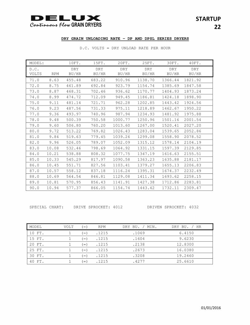
DRY GRAIN UNLOADING RATE – DP AND DPSL SERIES DRYERS
D.C. VOLTS = DRY UNLOAD RATE PER HOUR MODEL: 10FT. 15FT. 20FT. 25FT. 30FT. 40FT.
D.C. DRY DRY DRY DRY DRY DRY VOLTS RPM BU/HR BU/HR BU/HR BU/HR BU/HR BU/HR
71.0 8.63 455.48 683.22 910.96 1138.70 1366.44 1821.92 72.0 8.75 461.89 692.84 923.79 1154.74 1385.69 1847.58 73.0 8.87 468.31 702.46 936.62 1170.77 1404.93 1873.24 74.0 8.99 474.72 712.09 949.45 1186.81 1424.18 1898.90 75.0 9.11 481.14 721.71 962.28 1202.85 1443.42 1924.56 76.0 9.23 487.56 731.33 975.11 1218.89 1462.67 1950.22 77.0 9.36 493.97 740.96 987.94 1234.93 1481.92 1975.88 78.0 9.48 500.39 750.58 1000.77 1250.96 1501.16 2001.54 79.0 9.60 506.80 760.20 1013.60 1267.00 1520.41 2027.20 80.0 9.72 513.22 769.82 1026.43 1283.04 1539.65 2052.86 81.0 9.84 519.63 779.45 1039.26 1299.08 1558.90 2078.52 82.0 9.96 526.05 789.07 1052.09 1315.12 1578.14 2104.19 83.0 10.08 532.46 798.69 1064.92 1331.15 1597.39 2129.85 84.0 10.21 538.88 808.32 1077.75 1347.19 1616.63 2155.51 85.0 10.33 545.29 817.97 1090.58 1363.23 1635.88 2181.17 86.0 10.45 551.71 827.56 1103.41 1379.27 1655.13 2206.83 87.0 10.57 558.12 837.18 1116.24 1395.31 1674.37 2232.49 88.0 10.69 564.54 846.81 1129.08 1411.34 1693.62 2258.15 89.0 10.81 570.95 856.43 1141.91 1427.38 1712.86 2283.81 90.0 10.94 577.37 866.05 1154.74 1443.42 1732.11 2309.47 SPECIAL CHART: DRIVE SPROCKET: 4012 DRIVEN SPROCKET: 4032 MODEL VOLT (=) RPM DRY BU. / MIN. DRY BU. / HR
10 FT. 1 (=) .1215 .1069 6.4150 15 FT. 1 (=) .1215 .1604 9.6230 20 FT. 1 (=) .1215 .2138 12.8300 25 FT. 1 (=) .1215 .2673 16.0380 30 FT. 1 (=) .1215 .3208 19.2460 40 FT. 1 (=) .1215 .4277 25.6610
STARTUP 23
01/01/2016
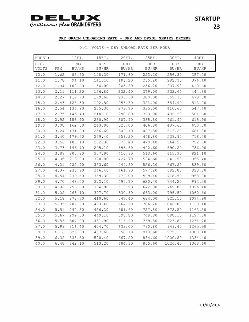
DRY GRAIN UNLOADING RATE – DPX AND DPXSL SERIES DRYERS
D.C. VOLTS = DRY UNLOAD RATE PER HOUR
MODEL: 10FT. 15FT. 20FT. 25FT. 30FT. 40FT
D.C. DRY DRY DRY DRU DRY DRY VOLTS RPM BU/HR BU/HR BU/HR BU/HR BU/HR BU/HR
10.0 1.62 85.50 128.30 171.60 223.20 256.80 357.00 11.0 1.78 94.10 141.10 188.20 235.20 282.30 376.40 12.0 1.94 102.60 154.00 205.30 256.20 307.90 410.60 13.0 2.11 111.20 166.80 222.40 279.00 333.60 444.80 14.0 2.27 119.70 179.60 239.50 300.00 359.30 479.00 15.0 2.43 128.30 192.50 256.60 321.00 384.90 513.20 16.0 2.54 136.80 205.30 273.70 335.00 410.60 547.40 17.0 2.75 145.40 218.10 290.80 363.00 436.20 581.60 18.0 2.92 153.90 230.90 307.90 385.80 461.90 615.90 19.0 3.08 162.59 243.80 325.00 406.80 487.60 650.00 20.0 3.24 171.00 256.60 342.10 427.80 513.20 684.30 21.0 3.40 179.60 269.40 359.30 448.80 538.90 718.50 22.0 3.56 188.10 282.30 376.40 470.40 564.50 752.70 23.0 3.73 196.70 295.10 393.50 492.60 590.20 786.90 24.0 3.89 205.30 307.90 410.60 513.60 615.90 821.10 25.0 4.05 213.80 320.80 427.70 534.60 641.50 855.40 26.0 4.21 222.40 333.60 444.80 556.20 667.20 889.60 27.0 4.37 230.90 346.40 461.90 577.20 692.80 923.80 28.0 4.54 239.50 359.30 479.00 599.40 718.50 958.00 29.0 4.70 248.00 372.10 496.10 620.40 744.20 992.20 30.0 4.86 256.60 384.90 513.20 642.00 769.80 1026.40 31.0 5.02 265.10 397.70 530.30 663.00 795.50 1060.60 32.0 5.18 273.70 410.60 547.40 684.00 821.10 1094.90 33.0 5.35 282.20 423.40 564.50 706.20 846.80 1129.10 34.0 5.51 290.80 436.20 581.60 727.80 872.50 1163.30 35.0 5.67 299.30 449.10 598.80 748.80 898.10 1197.50 36.0 5.83 307.90 461.90 615.90 769.80 923.80 1231.70 37.0 5.99 316.40 474.70 633.00 790.80 949.40 1265.90 38.0 6.16 325.00 487.60 650.10 813.60 975.10 1300.10 39.0 6.32 333.60 500.40 667.20 834.60 1000.80 1334.40 40.0 6.48 342.10 513.20 684.30 855.60 1026.40 1368.60
STARTUP 24
01/01/2016
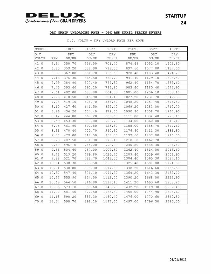
DRY GRAIN UNLOADING RATE - DPX AND DPXSL SERIES DRYERS
D.C. VOLTS = DRY UNLOAD RATE PER HOUR
MODEL: 10FT. 15FT. 20FT. 25FT. 30FT. 40FT.
D.C. DRY DRY DRY DRU DRY DRY VOLTS RPM BU/HR BU/HR BU/HR BU/HR BU/HR BU/HR
41.0 6.64 350.70 526.00 701.40 876.48 1052.10 1402.80 42.0 6.80 359.20 538.90 718.50 897.60 1077.80 1437.00 43.0 6.97 367.80 551.70 735.60 920.40 1103.40 1471.20 44.0 7.13 376.30 564.50 752.70 941.40 1129.10 1505.40 45.0 7.29 384.90 577.40 769.80 962.40 1154.70 1539.60 46.0 7.45 393.40 590.20 786.90 983.40 1180.40 1573.90 47.0 7.61 402.00 603.00 804.00 1005.00 1206.10 1608.10 48.0 7.78 410.50 615.90 821.10 1027.20 1231.70 1642.30 49.0 7.94 419.10 628.70 838.30 1048.20 1257.40 1676.50 50.0 8.10 427.60 641.50 855.40 1069.20 1283.00 1710.70 51.0 8.26 436.20 654.40 872.50 1090.80 1308.70 1744.90 52.0 8.42 444.80 667.20 889.60 1111.80 1334.40 1779.10 53.0 8.59 453.30 680.00 906.70 1134.00 1360.00 1813.40 54.0 8.75 461.90 692.80 923.80 1155.00 1385.70 1847.60 55.0 8.91 470.40 705.70 940.90 1176.60 1411.30 1881.80 56.0 9.07 479.00 718.50 958.00 1197.60 1437.00 1916.00 57.0 9.23 487.50 731.30 975.10 1218.60 1462.70 1950.20 58.0 9.40 496.10 744.20 992.20 1240.80 1488.30 1984.40 59.0 9.56 504.60 757.00 1009.30 1262.40 1514.00 2018.60 60.0 9.72 513.20 769.80 1026.40 1283.40 1539.60 2052.90 61.0 9.88 521.70 782.70 1043.50 1304.40 1565.30 2087.10 62.0 10.04 530.30 795.50 1060.60 1325.40 1591.00 2121.30 63.0 10.21 538.80 808.30 1077.80 1348.20 1616.60 2155.50 64.0 10.37 547.40 821.10 1094.90 1369.20 1642.30 2189.70 65.0 10.53 555.90 834.00 1112.00 1390.20 1668.00 2223.90 66.0 10.69 564.50 846.80 1129.10 1411.20 1693.60 2258.20 67.0 10.85 573.10 859.60 1146.20 1432.20 1719.30 2292.40 68.0 11.02 581.60 872.50 1163.30 1455.00 1744.90 2326.60 69.0 11.18 590.20 885.30 1180.40 1476.00 1770.60 2360.80 70.0 11.34 598.70 898.10 1197.50 1497.00 1796.30 2395.00
STARTUP 25
01/01/2016
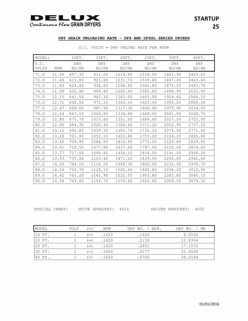
DRY GRAIN UNLOADING RATE - DPX AND DPXSL SERIES DRYERS
D.C. VOLTS = DRY UNLOAD RATE PER HOUR
MODEL: 10FT. 15FT. 20FT. 25FT. 30FT. 40FT.
D.C. DRY DRY DRY DRU DRY DRY VOLTS RPM BU/HR BU/HR BU/HR BU/HR BU/HR BU/HR
71.0 11.50 607.30 911.00 1214.60 1518.00 1821.90 2429.20 72.0 11.66 615.80 923.80 1231.70 1539.60 1847.60 2463.40 73.0 11.83 624.40 936.60 1248.80 1561.80 1873.20 2497.70 74.0 11.99 632.90 949.40 1265.90 1582.80 1898.90 2531.90 75.0 12.15 641.50 962.30 1283.00 1603.08 1924.60 2566.10 76.0 12.31 650.00 975.10 1300.10 1625.40 1950.20 2600.30 77.0 12.47 658.60 987.90 1317.30 1646.40 1975.90 2634.50 78.0 12.64 667.10 1000.80 1334.40 1668.60 2001.50 2668.70 79.0 12.80 675.70 1013.60 1351.50 1689.60 2027.20 2702.90 80.0 12.96 684.30 1026.40 1368.60 1711.20 2052.90 2737.20 81.0 13.12 692.80 1039.30 1385.70 1732.20 2078.50 2771.40 82.0 13.28 701.40 1052.10 1402.80 1753.20 2104.20 2805.60 83.0 13.45 709.90 1064.90 1419.90 1775.00 2129.80 2839.80 84.0 13.61 718.50 1077.80 1437.00 1797.00 2155.50 2874.00 85.0 13.77 727.00 1090.60 1454.10 1818.00 2181.20 2908.20 86.0 13.93 735.60 1103.40 1471.20 1839.00 2206.80 2942.40 87.0 14.09 744.10 1116.20 1488.30 1860.00 2232.50 2976.70 88.0 14.26 752.70 1129.10 1505.40 1882.80 2258.20 3010.90 89.0 14.42 761.20 1141.90 1522.50 1903.80 2283.80 3045.10 90.0 14.58 769.80 1154.70 1539.60 1924.80 2309.50 3079.30
SPECIAL CHART: DRIVE SPROCKET: 4016 DRIVEN SPROCKET: 4032
MODEL VOLT (=) RPM DRY BU. / MIN. DRY BU. / HR
10 FT. 1 (=) .1620 .1426 8.5536 15 FT. 1 (=) .1620 .2138 12.8304 20 FT. 1 (=) .1620 .2851 17.1072 30 FT. 1 (=) .1620 .4277 25.6608 40 FT. 1 (=) .1620 .5702 34.2144
STARTUP 26
01/01/2016
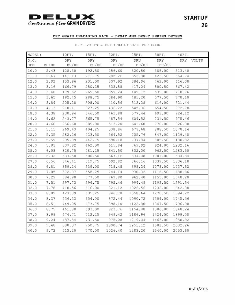
DRY GRAIN UNLOADING RATE - DPX4T AND DPX8T SERIES DRYERS
D.C. VOLTS = DRY UNLOAD RATE PER HOUR MODEL: 10FT. 15FT. 20FT. 25FT. 30FT. 40FT.
D.C. DRY DRY DRY DRU DRY DRY VOLTS RPM BU/HR BU/HR BU/HR BU/HR BU/HR BU/HR
10.0 2.43 128.30 192.50 256.60 320.80 385.00 513.40 11.0 2.67 141.13 211.75 282.26 352.88 423.50 564.74 12.0 2.92 153.96 231.00 307.92 384.96 462.00 616.08 13.0 3.16 166.79 250.25 333.58 417.04 500.50 667.42 14.0 3.40 179.62 269.50 359.24 449.12 539.00 718.76 15.0 3.65 192.45 288.75 384.90 481.20 577.50 770.10 16.0 3.89 205.28 308.00 410.56 513.28 616.00 821.44 17.0 4.13 218.11 327.25 436.22 545.36 654.50 872.78 18.0 4.38 230.94 346.50 461.88 577.44 693.00 924.12 19.0 4.62 243.77 365.75 487.54 609.52 731.50 975.46 20.0 4.68 256.60 385.00 513.20 641.60 770.00 1026.80 21.0 5.11 269.43 404.25 538.86 673.68 808.50 1078.14 22.0 5.35 282.26 423.50 564.52 705.76 847.00 1129.48 23.0 5.59 295.09 442.75 590.18 737.84 885.50 1180.82 24.0 5.83 307.92 462.00 615.84 769.92 924.00 1232.16 25.0 6.08 320.75 481.25 641.50 802.00 962.50 1283.50 26.0 6.32 333.58 500.50 667.16 834.08 1001.00 1334.84 27.0 6.56 346.41 519.75 692.82 866.16 1039.50 1386.18 28.0 6.81 359.24 539.00 718.48 898.24 1078.00 1437.52 29.0 7.05 372.07 558.25 744.14 930.32 1116.50 1488.86 30.0 7.29 384.90 577.50 769.80 962.40 1155.00 1540.20 31.0 7.51 397.73 596.75 795.46 994.48 1193.50 1591.54 32.0 7.78 410.56 616.00 821.12 1026.56 1232.00 1642.88 33.0 8.02 423.39 635.25 846.78 1058.64 1270.50 1694.22 34.0 8.27 436.22 654.00 872.44 1090.72 1309.00 1745.56 35.0 8.51 449.05 673.75 898.10 1122.80 1347.50 1796.90 36.0 8.75 461.88 693.00 923.76 1154.88 1386.00 1848.24 37.0 8.99 474.71 712.25 949.42 1186.96 1424.50 1899.58 38.0 9.24 487.54 731.50 975.08 1219.04 1463.00 1950.92 39.0 9.48 500.37 750.75 1000.74 1251.12 1501.50 2002.26 40.0 9.72 513.20 770.00 1026.40 1283.20 1540.00 2053.60
STARTUP 27
01/01/2016
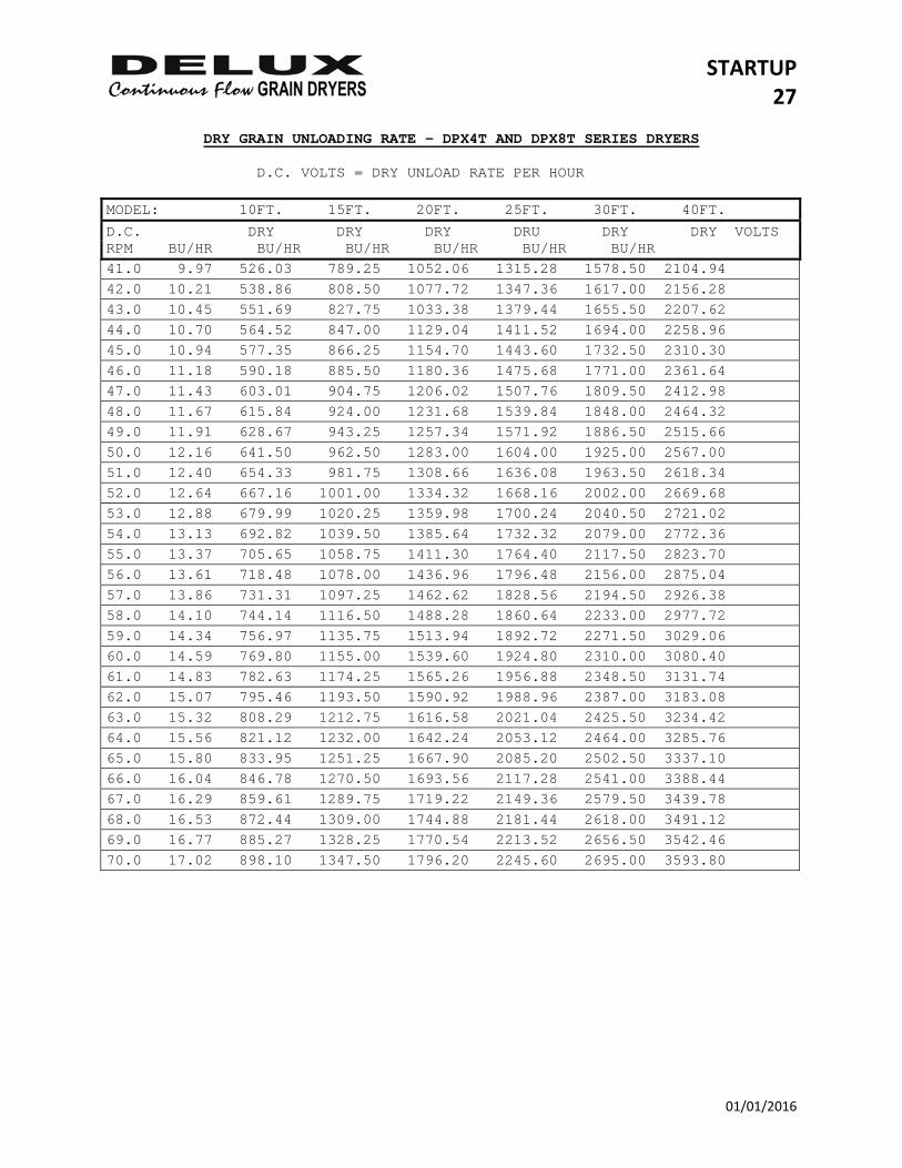
DRY GRAIN UNLOADING RATE - DPX4T AND DPX8T SERIES DRYERS D.C. VOLTS = DRY UNLOAD RATE PER HOUR MODEL: 10FT. 15FT. 20FT. 25FT. 30FT. 40FT.
D.C. DRY DRY DRY DRU DRY DRY VOLTS RPM BU/HR BU/HR BU/HR BU/HR BU/HR BU/HR 41.0 9.97 526.03 789.25 1052.06 1315.28 1578.50 2104.94 42.0 10.21 538.86 808.50 1077.72 1347.36 1617.00 2156.28 43.0 10.45 551.69 827.75 1033.38 1379.44 1655.50 2207.62 44.0 10.70 564.52 847.00 1129.04 1411.52 1694.00 2258.96 45.0 10.94 577.35 866.25 1154.70 1443.60 1732.50 2310.30 46.0 11.18 590.18 885.50 1180.36 1475.68 1771.00 2361.64 47.0 11.43 603.01 904.75 1206.02 1507.76 1809.50 2412.98 48.0 11.67 615.84 924.00 1231.68 1539.84 1848.00 2464.32 49.0 11.91 628.67 943.25 1257.34 1571.92 1886.50 2515.66 50.0 12.16 641.50 962.50 1283.00 1604.00 1925.00 2567.00 51.0 12.40 654.33 981.75 1308.66 1636.08 1963.50 2618.34 52.0 12.64 667.16 1001.00 1334.32 1668.16 2002.00 2669.68 53.0 12.88 679.99 1020.25 1359.98 1700.24 2040.50 2721.02 54.0 13.13 692.82 1039.50 1385.64 1732.32 2079.00 2772.36 55.0 13.37 705.65 1058.75 1411.30 1764.40 2117.50 2823.70 56.0 13.61 718.48 1078.00 1436.96 1796.48 2156.00 2875.04 57.0 13.86 731.31 1097.25 1462.62 1828.56 2194.50 2926.38 58.0 14.10 744.14 1116.50 1488.28 1860.64 2233.00 2977.72 59.0 14.34 756.97 1135.75 1513.94 1892.72 2271.50 3029.06 60.0 14.59 769.80 1155.00 1539.60 1924.80 2310.00 3080.40 61.0 14.83 782.63 1174.25 1565.26 1956.88 2348.50 3131.74 62.0 15.07 795.46 1193.50 1590.92 1988.96 2387.00 3183.08 63.0 15.32 808.29 1212.75 1616.58 2021.04 2425.50 3234.42 64.0 15.56 821.12 1232.00 1642.24 2053.12 2464.00 3285.76 65.0 15.80 833.95 1251.25 1667.90 2085.20 2502.50 3337.10 66.0 16.04 846.78 1270.50 1693.56 2117.28 2541.00 3388.44 67.0 16.29 859.61 1289.75 1719.22 2149.36 2579.50 3439.78 68.0 16.53 872.44 1309.00 1744.88 2181.44 2618.00 3491.12 69.0 16.77 885.27 1328.25 1770.54 2213.52 2656.50 3542.46 70.0 17.02 898.10 1347.50 1796.20 2245.60 2695.00 3593.80
STARTUP 28
01/01/2016
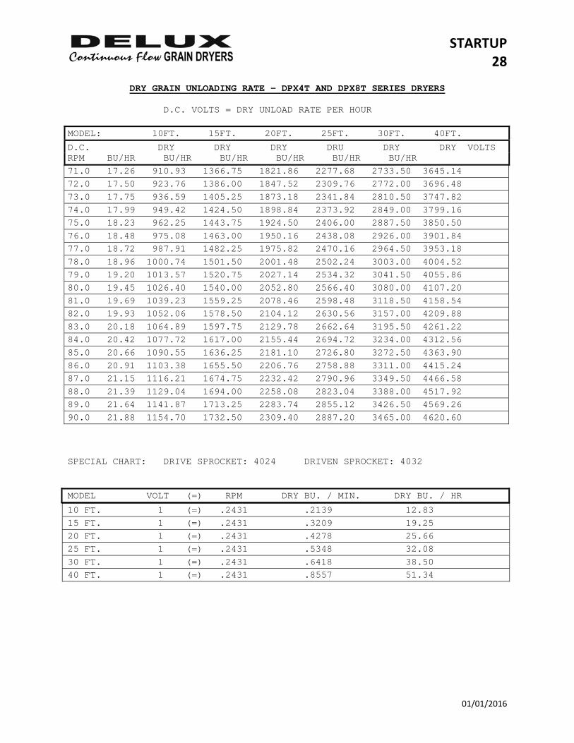
DRY GRAIN UNLOADING RATE - DPX4T AND DPX8T SERIES DRYERS D.C. VOLTS = DRY UNLOAD RATE PER HOUR MODEL: 10FT. 15FT. 20FT. 25FT. 30FT. 40FT.
D.C. DRY DRY DRY DRU DRY DRY VOLTS RPM BU/HR BU/HR BU/HR BU/HR BU/HR BU/HR 71.0 17.26 910.93 1366.75 1821.86 2277.68 2733.50 3645.14 72.0 17.50 923.76 1386.00 1847.52 2309.76 2772.00 3696.48 73.0 17.75 936.59 1405.25 1873.18 2341.84 2810.50 3747.82 74.0 17.99 949.42 1424.50 1898.84 2373.92 2849.00 3799.16 75.0 18.23 962.25 1443.75 1924.50 2406.00 2887.50 3850.50 76.0 18.48 975.08 1463.00 1950.16 2438.08 2926.00 3901.84 77.0 18.72 987.91 1482.25 1975.82 2470.16 2964.50 3953.18 78.0 18.96 1000.74 1501.50 2001.48 2502.24 3003.00 4004.52 79.0 19.20 1013.57 1520.75 2027.14 2534.32 3041.50 4055.86 80.0 19.45 1026.40 1540.00 2052.80 2566.40 3080.00 4107.20 81.0 19.69 1039.23 1559.25 2078.46 2598.48 3118.50 4158.54 82.0 19.93 1052.06 1578.50 2104.12 2630.56 3157.00 4209.88 83.0 20.18 1064.89 1597.75 2129.78 2662.64 3195.50 4261.22 84.0 20.42 1077.72 1617.00 2155.44 2694.72 3234.00 4312.56 85.0 20.66 1090.55 1636.25 2181.10 2726.80 3272.50 4363.90 86.0 20.91 1103.38 1655.50 2206.76 2758.88 3311.00 4415.24 87.0 21.15 1116.21 1674.75 2232.42 2790.96 3349.50 4466.58 88.0 21.39 1129.04 1694.00 2258.08 2823.04 3388.00 4517.92 89.0 21.64 1141.87 1713.25 2283.74 2855.12 3426.50 4569.26 90.0 21.88 1154.70 1732.50 2309.40 2887.20 3465.00 4620.60 SPECIAL CHART: DRIVE SPROCKET: 4024 DRIVEN SPROCKET: 4032 MODEL VOLT (=) RPM DRY BU. / MIN. DRY BU. / HR
10 FT. 1 (=) .2431 .2139 12.83 15 FT. 1 (=) .2431 .3209 19.25 20 FT. 1 (=) .2431 .4278 25.66 25 FT. 1 (=) .2431 .5348 32.08 30 FT. 1 (=) .2431 .6418 38.50 40 FT. 1 (=) .2431 .8557 51.34
STARTUP 29
01/01/2016
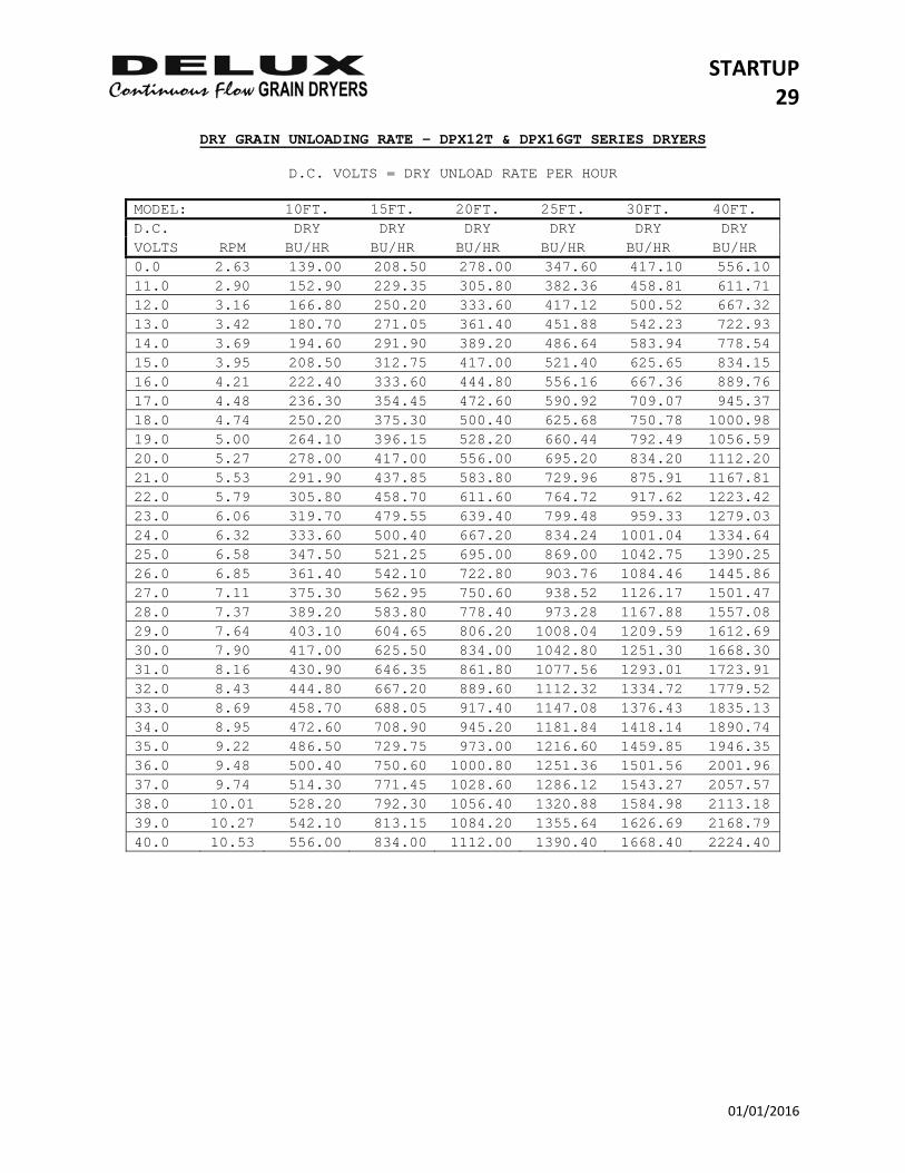
DRY GRAIN UNLOADING RATE – DPX12T & DPX16GT SERIES DRYERS
D.C. VOLTS = DRY UNLOAD RATE PER HOUR
MODEL: 10FT. 15FT. 20FT. 25FT. 30FT. 40FT. D.C. DRY DRY DRY DRY DRY DRY VOLTS RPM BU/HR BU/HR BU/HR BU/HR BU/HR BU/HR 0.0 2.63 139.00 208.50 278.00 347.60 417.10 556.10 11.0 2.90 152.90 229.35 305.80 382.36 458.81 611.71 12.0 3.16 166.80 250.20 333.60 417.12 500.52 667.32 13.0 3.42 180.70 271.05 361.40 451.88 542.23 722.93 14.0 3.69 194.60 291.90 389.20 486.64 583.94 778.54 15.0 3.95 208.50 312.75 417.00 521.40 625.65 834.15 16.0 4.21 222.40 333.60 444.80 556.16 667.36 889.76 17.0 4.48 236.30 354.45 472.60 590.92 709.07 945.37 18.0 4.74 250.20 375.30 500.40 625.68 750.78 1000.98 19.0 5.00 264.10 396.15 528.20 660.44 792.49 1056.59 20.0 5.27 278.00 417.00 556.00 695.20 834.20 1112.20 21.0 5.53 291.90 437.85 583.80 729.96 875.91 1167.81 22.0 5.79 305.80 458.70 611.60 764.72 917.62 1223.42 23.0 6.06 319.70 479.55 639.40 799.48 959.33 1279.03 24.0 6.32 333.60 500.40 667.20 834.24 1001.04 1334.64 25.0 6.58 347.50 521.25 695.00 869.00 1042.75 1390.25 26.0 6.85 361.40 542.10 722.80 903.76 1084.46 1445.86 27.0 7.11 375.30 562.95 750.60 938.52 1126.17 1501.47 28.0 7.37 389.20 583.80 778.40 973.28 1167.88 1557.08 29.0 7.64 403.10 604.65 806.20 1008.04 1209.59 1612.69 30.0 7.90 417.00 625.50 834.00 1042.80 1251.30 1668.30 31.0 8.16 430.90 646.35 861.80 1077.56 1293.01 1723.91 32.0 8.43 444.80 667.20 889.60 1112.32 1334.72 1779.52 33.0 8.69 458.70 688.05 917.40 1147.08 1376.43 1835.13 34.0 8.95 472.60 708.90 945.20 1181.84 1418.14 1890.74 35.0 9.22 486.50 729.75 973.00 1216.60 1459.85 1946.35 36.0 9.48 500.40 750.60 1000.80 1251.36 1501.56 2001.96 37.0 9.74 514.30 771.45 1028.60 1286.12 1543.27 2057.57 38.0 10.01 528.20 792.30 1056.40 1320.88 1584.98 2113.18 39.0 10.27 542.10 813.15 1084.20 1355.64 1626.69 2168.79 40.0 10.53 556.00 834.00 1112.00 1390.40 1668.40 2224.40
STARTUP 30
01/01/2016
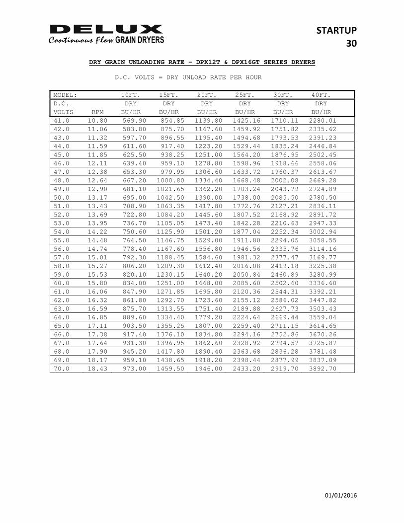
DRY GRAIN UNLOADING RATE – DPX12T & DPX16GT SERIES DRYERS D.C. VOLTS = DRY UNLOAD RATE PER HOUR MODEL: 10FT. 15FT. 20FT. 25FT. 30FT. 40FT. D.C. DRY DRY DRY DRY DRY DRY VOLTS RPM BU/HR BU/HR BU/HR BU/HR BU/HR BU/HR
41.0 10.80 569.90 854.85 1139.80 1425.16 1710.11 2280.0142.0 11.06 583.80 875.70 1167.60 1459.92 1751.82 2335.6243.0 11.32 597.70 896.55 1195.40 1494.68 1793.53 2391.2344.0 11.59 611.60 917.40 1223.20 1529.44 1835.24 2446.8445.0 11.85 625.50 938.25 1251.00 1564.20 1876.95 2502.4546.0 12.11 639.40 959.10 1278.80 1598.96 1918.66 2558.0647.0 12.38 653.30 979.95 1306.60 1633.72 1960.37 2613.6748.0 12.64 667.20 1000.80 1334.40 1668.48 2002.08 2669.2849.0 12.90 681.10 1021.65 1362.20 1703.24 2043.79 2724.8950.0 13.17 695.00 1042.50 1390.00 1738.00 2085.50 2780.5051.0 13.43 708.90 1063.35 1417.80 1772.76 2127.21 2836.1152.0 13.69 722.80 1084.20 1445.60 1807.52 2168.92 2891.7253.0 13.95 736.70 1105.05 1473.40 1842.28 2210.63 2947.3354.0 14.22 750.60 1125.90 1501.20 1877.04 2252.34 3002.9455.0 14.48 764.50 1146.75 1529.00 1911.80 2294.05 3058.5556.0 14.74 778.40 1167.60 1556.80 1946.56 2335.76 3114.1657.0 15.01 792.30 1188.45 1584.60 1981.32 2377.47 3169.7758.0 15.27 806.20 1209.30 1612.40 2016.08 2419.18 3225.3859.0 15.53 820.10 1230.15 1640.20 2050.84 2460.89 3280.9960.0 15.80 834.00 1251.00 1668.00 2085.60 2502.60 3336.6061.0 16.06 847.90 1271.85 1695.80 2120.36 2544.31 3392.2162.0 16.32 861.80 1292.70 1723.60 2155.12 2586.02 3447.8263.0 16.59 875.70 1313.55 1751.40 2189.88 2627.73 3503.4364.0 16.85 889.60 1334.40 1779.20 2224.64 2669.44 3559.0465.0 17.11 903.50 1355.25 1807.00 2259.40 2711.15 3614.6566.0 17.38 917.40 1376.10 1834.80 2294.16 2752.86 3670.2667.0 17.64 931.30 1396.95 1862.60 2328.92 2794.57 3725.8768.0 17.90 945.20 1417.80 1890.40 2363.68 2836.28 3781.4869.0 18.17 959.10 1438.65 1918.20 2398.44 2877.99 3837.0970.0 18.43 973.00 1459.50 1946.00 2433.20 2919.70 3892.70
STARTUP 31
01/01/2016
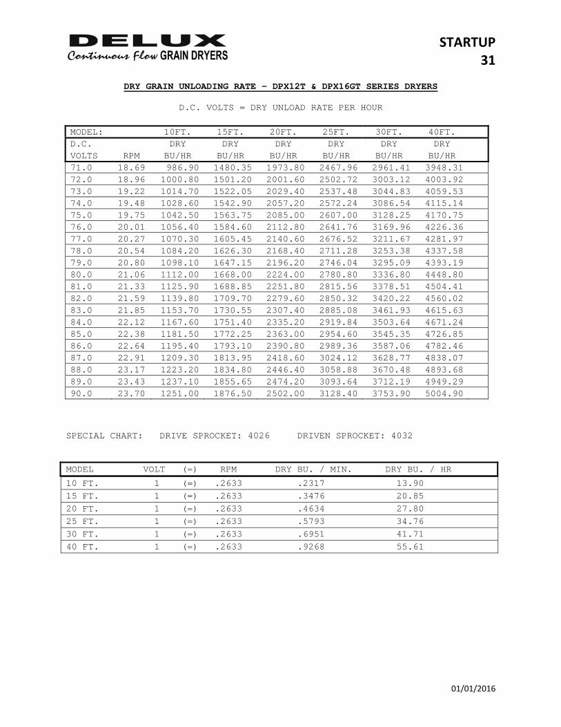
DRY GRAIN UNLOADING RATE – DPX12T & DPX16GT SERIES DRYERS
D.C. VOLTS = DRY UNLOAD RATE PER HOUR MODEL: 10FT. 15FT. 20FT. 25FT. 30FT. 40FT. D.C. DRY DRY DRY DRY DRY DRY VOLTS RPM BU/HR BU/HR BU/HR BU/HR BU/HR BU/HR
71.0 18.69 986.90 1480.35 1973.80 2467.96 2961.41 3948.3172.0 18.96 1000.80 1501.20 2001.60 2502.72 3003.12 4003.9273.0 19.22 1014.70 1522.05 2029.40 2537.48 3044.83 4059.5374.0 19.48 1028.60 1542.90 2057.20 2572.24 3086.54 4115.1475.0 19.75 1042.50 1563.75 2085.00 2607.00 3128.25 4170.7576.0 20.01 1056.40 1584.60 2112.80 2641.76 3169.96 4226.3677.0 20.27 1070.30 1605.45 2140.60 2676.52 3211.67 4281.9778.0 20.54 1084.20 1626.30 2168.40 2711.28 3253.38 4337.5879.0 20.80 1098.10 1647.15 2196.20 2746.04 3295.09 4393.1980.0 21.06 1112.00 1668.00 2224.00 2780.80 3336.80 4448.8081.0 21.33 1125.90 1688.85 2251.80 2815.56 3378.51 4504.4182.0 21.59 1139.80 1709.70 2279.60 2850.32 3420.22 4560.0283.0 21.85 1153.70 1730.55 2307.40 2885.08 3461.93 4615.6384.0 22.12 1167.60 1751.40 2335.20 2919.84 3503.64 4671.2485.0 22.38 1181.50 1772.25 2363.00 2954.60 3545.35 4726.8586.0 22.64 1195.40 1793.10 2390.80 2989.36 3587.06 4782.4687.0 22.91 1209.30 1813.95 2418.60 3024.12 3628.77 4838.0788.0 23.17 1223.20 1834.80 2446.40 3058.88 3670.48 4893.6889.0 23.43 1237.10 1855.65 2474.20 3093.64 3712.19 4949.2990.0 23.70 1251.00 1876.50 2502.00 3128.40 3753.90 5004.90
SPECIAL CHART: DRIVE SPROCKET: 4026 DRIVEN SPROCKET: 4032 MODEL VOLT (=) RPM DRY BU. / MIN. DRY BU. / HR
10 FT. 1 (=) .2633 .2317 13.90 15 FT. 1 (=) .2633 .3476 20.85 20 FT. 1 (=) .2633 .4634 27.80 25 FT. 1 (=) .2633 .5793 34.76 30 FT. 1 (=) .2633 .6951 41.71 40 FT. 1 (=) .2633 .9268 55.61
STARTUP 32
01/01/2016
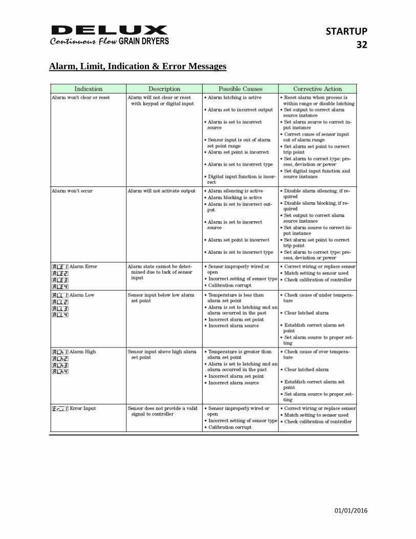
Alarm, Limit, Indication & Error Messages
STARTUP 33
01/01/2016
STARTUP 34
01/01/2016
Clearing Errors & Limit Messages To clear error or limit messages press the RESET key. You may also turn main panel power “OFF” and back “ON” again. Error or Limit messages will not clear until the cause or reason for the error has been addressed.
SPECIAL‐SUNFLOWER 1
01/01/16
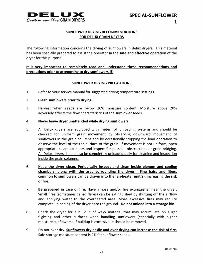
SUNFLOWER DRYING RECOMMENDATIONS FOR DELUX GRAIN DRYERS
The following information concerns the drying of sunflowers in delux dryers. This material has been specially prepared to assist the operator in the safe and effective operation of the dryer for this purpose.
It is very important to completely read and understand these recommendations and precautions prior to attempting to dry sunflowers !!!
SUNFLOWER DRYING PRECAUTIONS
1. Refer to your service manual for suggested drying temperature settings.
2. Clean sunflowers prior to drying.
3. Harvest when seeds are below 20% moisture content. Moisture above 20% adversely affects the flow characteristics of the sunflower seeds.
4. Never leave dryer unattended while drying sunflowers.
5. All Delux dryers are equipped with meter roll unloading systems and should be checked for uniform grain movement by observing downward movement of sunflowers in the grain columns and by occasionally stopping the load operation to observe the level of the top surface of the grain. If movement is not uniform, open appropriate clean‐out doors and inspect for possible obstructions or grain bridging. All Delux dryers should also be completely unloaded daily for cleaning and inspection inside the grain columns.
6. Keep the dryer clean. Periodically inspect and clean inside plenum and cooling chambers, along with the area surrounding the dryer. Fine hairs and fibers common to sunflowers can be drawn into the fan‐heater unit(s), increasing the risk of fire.
7. Be prepared in case of fire. Have a hose and/or fire extinguisher near the dryer. Small fires (sometimes called flares) can be extinguished by shutting off the airflow and applying water to the overheated area. More excessive fires may require complete unloading of the dryer onto the ground. Do not unload into a storage bin.
8. Check the dryer for a buildup of waxy material that may accumulate on auger flighting and other surfaces when handling sunflowers (especially with higher moisture sunflowers). If buildup is excessive, it should be removed.
9. Do not over dry. Sunflowers dry easily and over drying can increase the risk of fire. Safe storage moisture content is 9% for sunflower seeds.
47

48
SEQUENCE ANALYSIS 1
01/01/2016
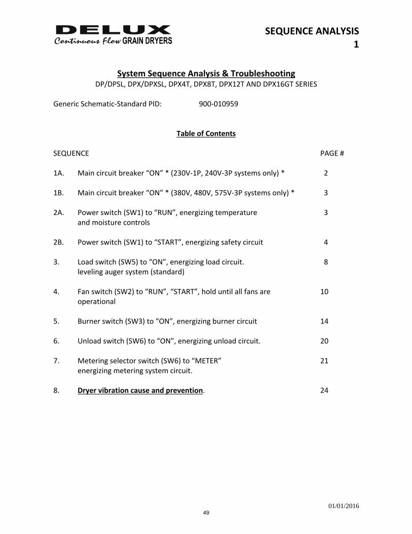
System Sequence Analysis & Troubleshooting DP/DPSL, DPX/DPXSL, DPX4T, DPX8T, DPX12T AND DPX16GT SERIES
Generic Schematic‐Standard PID: 900‐010959
Table of Contents SEQUENCE PAGE # 1A. Main circuit breaker “ON” * (230V‐1P, 240V‐3P systems only) * 2 1B. Main circuit breaker “ON” * (380V, 480V, 575V‐3P systems only) * 3 2A. Power switch (SW1) to “RUN”, energizing temperature 3
and moisture controls 2B. Power switch (SW1) to “START”, energizing safety circuit 4 3. Load switch (SW5) to “ON”, energizing load circuit. 8
leveling auger system (standard) 4. Fan switch (SW2) to “RUN”, “START”, hold until all fans are 10 operational 5. Burner switch (SW3) to “ON”, energizing burner circuit 14 6. Unload switch (SW6) to “ON”, energizing unload circuit. 20 7. Metering selector switch (SW6) to “METER” 21
energizing metering system circuit. 8. Dryer vibration cause and prevention. 24
49
SEQUENCE ANALYSIS 2
01/01/2016
1A. Sequence: main circuit breaker "ON" *(230V‐1P, 240V‐3P systems) *
Action: Main power light "ON", applies power to high voltage circuits and 120v control circuit breaker (CB1).
Symptoms: A. No main power light (LT1). B. Control circuit breaker (CB1) has tripped.
Possible Causes: A1. Defective main power light (LT1).
A2. Defective control circuit breaker (CB1). A3. Defective fuse in main panel disconnect. A4. Missing 120 volt wire.
B1. Short circuit. B2. Overload condition has occurred.
B3. Defective control circuit breaker (CB1).
Corrective Action: A1. Check terminal #2 for 120 volts. If power is
Present the main power light (LT1) is defective, replace.
A2. Check circuit breaker (CB1) for fault.
A3. Check across L1 & L3 (L2 on 1P) on the main power distribution block. If 240 volts is not present, check main panel disconnect for power and if fuses are defective, replace. (Wild Leg is on L2 – 3P only)
A4. If voltage is present across L1 & L3 (L2 on 1P) on the main power distribution block, check to see if the black wire is connected from L1 on the main power distribution block to the positive side on the 120V panel power distribution block (TB2). Also check to see that the ground lead (green wire) is connected to chassis ground and the common lead of the incoming power source is connected to chassis ground.
B1. Repair or replace burned or bare wiring in contact with chassis or other wiring.
B2. Check current for any overload conditions and Correct.
B3. Inspect circuit breaker (CB1) for defect. Replace.
1B. Sequence: Main circuit breaker "ON" *(380V, 480V, 575V‐3P systems)*
50
SEQUENCE ANALYSIS 3
01/01/2016
Action: Main power light "ON", applies power to high voltage circuits, step down transformer (XMFR1) and 120V control circuit breaker (CB1).
Symptoms: A. No main power light (LT1). B. Control circuit breaker (CB1) has tripped.
Possible Causes: A1. Defective main power light (LT1). A2. Defective control circuit breaker (CB1). A3. Defective fuse in main panel disconnect. A4. Defective fuses F1 and/or F2. A5. Defective transformer (XMFR1).
B1. Short circuit. B2. Overload condition. B3. Defective circuit breaker (CB1).
Corrective Action: A1. Check terminal #2 for 120 volts. If power is present the main power light (LT1) is defective, replace.
A2. Check control circuit breaker (CB1), if defective, replace.
A3. Check across L1 & L3 on the main power distribution block. If line voltage is not present, check main panel disconnect for power. If fuses are defective, replace.
A4. Check to see if voltage is present on terminal #1 (HOT) to terminal #N (NEUTRAL). If power is not present, check fuse F1 and F2. If defective, replace.
A5. If fuse F1 and F2 are okay and no voltage is present on terminal #1 (HOT) to terminal #N (NEUTRAL) the step down transformer (XMFR 5) is defective, replace.
B1. Repair or replace burned or bare wiring in contact with chassis or other wiring.
B2. Check current for any overload conditions and correct.
B3. Inspect circuit breaker (CB1) for defect. Replace.
2A. Sequence: Power switch (SW1) to "RUN", energizing temperature And moisture controls
51
SEQUENCE ANALYSIS 4
01/01/2016
Action: Temperature control (Watlow EZ‐Zone) and moisture control (Watlow EZ‐Zone) are energized. Approximate 3 second delay for temperature control to lock in related safety functions before moving to “START”.
For information on operation and troubleshooting of the Watlow Controls, see section 5.
2B. Sequence: Power switch (SW1) to "START", energizing safety circuit.
Action: Safety circuit proven light on (LT12), all safety circuit monitor lights on (LT2 – LT8) applies power to entire 120 volt circuit and energizes power relay (K1).
How the safety circuit monitor lights work:
Safety circuit monitor lights (LT2 – LT8) indicate what part of the safety circuit is working. To find the problem, press the power switch (SW1) to the "START" position and hold. Find the first light that is not on. That will show the device that is not allowing the safety circuit to lock in.
* Place all switches in "OFF" position before trouble shooting *
Symptoms: A. No safety circuit proven light (LT12) when the power switch (SW1) is engaged, but some of the safety circuit monitor lights (LT2 – LT8) will light when the power switch (SW1) is engaged but will go off when the power switch (SW1) is released.
B. Safety circuit proven light (LT12) on when the power switch (SW1) is engaged but will go off when the power switch (SW1) is released.
Possible Causes: A1. Defective power switch (SW1).
A2. No fan overload light (LT2), defective fan overload device (S2, S3, S4, S4), or starter overload tripped from a fan motor drawing high amperage.
A3. No conveyor overload light (LT3), defective conveyor overload device (S5, S6, S7, S8), or starter overload tripped from an auger drawing high amperage.
A4. No feedroll monitor light (LT4), defective feedroll monitor switch (SW8), or defective feedroll monitor time delay relay (TD2 & TD3)
A5. No discharge overflow light (LT5), defective discharge overflow switch or overflow condition has tripped switch.
A6. No exhaust temperature limit light (LT6), defective exhaust limit or limit has tripped because of excessive exhaust air temperature.
52
SEQUENCE ANALYSIS 5
01/01/2016
A7. No access door light (LT7), defective door safety switch(s) or plenum and/or cooling door open.
A8. No auxiliary safety light (LT8), (customer installed). A9. Defective burner switch (SW3). A10. Defective safety circuit proven light (LT12). A11. Defective power relay (K1). A12. Defective safety circuit relay (K2)
Corrective Action: A1. If voltage is present on terminal #2 (120 volts) then
check for voltage on terminal #4 (120 volts) while holding the power switch (SW1) in the "START" position. If no voltage is present, the power switch (SW1) is defective, replace.
A2. If voltage is present on terminal #5 (120 volts) then check for voltage on terminal #6 (120 volts) while holding the power switch (SW1) in the "START" position. If no voltage is present, one or more fan starter overloads (S1 thru S4) may have tripped from a motor drawing high amperage. Determine which one is open. Reset tripped overload. It will be necessary to determine if a short circuit or overload condition exists in this system and what corrective steps need to be taken to resolve this condition. If voltage is present on terminal #6 (120 volts) the fan overload light (LT2) is defective, replace.
A3. If voltage is present on terminal #6 (120 volts) then check for
voltage on terminal #7 (120 volts) while holding the power switch (SW1) in the "START" position. If no voltage is present, one or more conveyor starter overloads (S5 thru S8) may have tripped from a motor drawing high amperage. Determine which one is open. Reset tripped overload. It will be necessary to determine if a short circuit or overload condition exists in this system and what corrective steps need to be taken to resolve this condition. If voltage is present on terminal #7 (120 volts) the conveyor overload light (LT3) is defective, replace.
A4. If voltage is present on terminal #7 (120 volts) then check for
voltage on terminal #8 (120 volts) while holding the power switch (SW1) in the "START" position. If the unload switch (SW6) is off and no voltage is present, one or both of the time delay relays (TD2 & TD3) are defective, replace. With the metering system switch (SW6) to “METER”, if dryer shuts down within 60 seconds, check voltage (120 volts) on terminals #20
53
SEQUENCE ANALYSIS 6
01/01/2016
and #21. Voltage should be present on each terminal about every 2 to 4 seconds while the feedrolls are turning. If voltage is not present on both terminals check feedroll monitor switch (SW8) for correct operation and cam nut adjustment located on feedroll sprocket. Adjust cam nut or replace feedroll monitor switch (SW8). If voltage is present, check the time delay relays (TD2 & TD3) for proper operation and setting (60 sec.). Set to 60 seconds or replace if defective.
A5. If voltage is present on terminal #8 (120 volts then check for
voltage on terminal #9 (120 volts) while holding the power switch (SW1) in the "START" position. If no voltage is present, check the discharge overflow switch for correct operation or if an overflow condition has tripped the switch. Clear the overflow or replace the switch. If voltage is present on terminal #9 (120 volts) the discharge overflow light (LT5) is defective, replace.
A6. If voltage is present on terminal #9 (120 volts) then check for
voltage on terminal #10 (120 volts) while holding the power switch (SW1) in the "START" position. If no voltage is present, one of the exhaust temperature limits has tripped because of excessive exhaust air temperature or is defective. With the power switch (SW1) in the "OFF" position, check continuity on exhaust limits. Open circuit indicates tripped or defective limit switch. If still open after dryer cools down, switch is defective. Replace. If voltage is present on terminal #10 (120 volts) the exhaust temperature limit light (LT6) is defective, replace.
A7. If voltage is present on terminal #10 (120 volts) then check for
voltage on terminal #11 (120 volts) while holding the power switch (SW1) in the "START" position. If no voltage is present, one or both of the access door switches are open because of an open plenum and/or cooling door or switch is defective. If a door is open, close and latch it (be sure switch activating angle is adjusted to push the plunger of the switch in far enough to activate the switch contacts). If door(s) are closed and adjusted properly, with the power switch (SW1) in the "OFF" position, check continuity across the brown to blue lead on each switch. Open circuit indicates switch is defective, replace. If voltage is present on terminal #11 (120 volts) the access door switch light (LT7) is defective, replace.
54
SEQUENCE ANALYSIS 7
01/01/2016
A8. The auxiliary safety light would be installed as a special option at the customer’s request. If voltage is present on terminal #12 (120 volts) the auxiliary safety light (LT8) is defective, replace.
A9. If voltage is present on terminal #14 (120 volts) then check for
voltage on terminal #18 (120 volts) while holding the power switch (SW1) in the "START" position and with the burner switch (SW3) in the "OFF" position. If no voltage is present, the burner switch contact (SW3) is defective, replace.
A10. If voltage is present on terminal #22 (120 volts) while holding
the power switch (SW1) in the "START" position and the burner switch (SW3) is in the "OFF" position, the safety circuit proven light is defective, replace.
A11. If voltage is present on terminal #18 (120 volts) then check for
voltage on terminal #22 (120 volts) while holding the power switch (SW1) in the "START" position. If no voltage is present and the burner switch (SW3) is in the "OFF" position, the power relay (K1) is defective, replace.
A12. If voltage is present on terminal #12 (120 volts) then check for
voltage on terminal #14 (120 volts) while holding the power switch (SW1) in the "START" position. If no voltage is present, the safety circuit relay (K2) is defective, replace.
55
SEQUENCE ANALYSIS 8
01/01/2016
Note: Delux provides three (3) types of loading systems.
A. Leveling system. (Standard) [(Auger ‐ standard) (Drag conveyor ‐ optional)] B. Gravity flow without high and low bin switches. (Optional) C. Gravity flow with high and low bin switches. (Optional)
3. Sequence: Load switch (SW5) to "ON", energizing load circuit. Leveling system (standard)
Action: Load switch (SW5) "ON", grain load light "ON", grain loading light (LT26) “ON”. Starts leveling auger (conveyor) on dryer and wet auxiliary loading. Loads dryer automatically as required. Grain loading light (LT26) on until high / low grain monitor shuts load auger off. Low grain light(s) (LT10, LT11) on until grain engages paddle(s) on low grain switch(s) (SW9, SW10).
Symptoms: A. No grain loading light (LT12). B. Grain loading light (LT12) on but loading system not running. C. Dryer shuts down immediately or during loading operation. D. Low grain light(s) (LT10, LT11) stay lit. E. Leveling auger and auxiliary loading run continually.
F. Dryer overloads (too full).
Possible Causes: A1. Defective load switch (SW5).
A2. Defective switch (low) in high / low grain monitor. A3. Defective grain loading light (LT12).
B1. Defective load auger starter coil (S5). B2. Defective load auger starter interlock (AC6). B3. Defective auxiliary load starter coil (S6).
C. Overload(s) on load auger and/or auxiliary load starter(s) (S5, S6) tripped.
D1. Grain has not engaged paddles properly on low grain switch(s) (SW9, SW10).
D2. Defective low grain switch(s) (SW9, SW10).
E. Improper grain loading rate.
F. Improper adjustment of high / low grain monitor.
Corrective Action: A1. If voltage is present on terminal #18 (120 volts),
56
SEQUENCE ANALYSIS 9
01/01/2016
Turn load switch (SW5) to "ON" then check for voltage on terminal #38. If voltage is not present the load switch (SW5) is defective, replace.
A2. If voltage is present on terminal #38 (120 volts), then check for voltage on terminal #39. Note: make sure high / low grain monitor paddle is hanging in the down position. If voltage is not present, the switch (low) is defective, replace.
A3. If voltage is present on terminal #39 (120 volts), the grain loading light (LT12) is defective, replace.
B1. If load auger starter (S5) does not pull‐in and voltage is present at load side of coil, the holding coil is defective, replace.
B2. If load auger starter (S5) does pull‐in, check load side of interlock (AC6) on load auger starter (S5) for presence of voltage (120 volts). If voltage is present at load side of interlock (AC6), check opposite side of interlock (AC6). If no power is present, the interlock (AC6) is defective, replace.
B3. If auxiliary load starter (S6) does not pull‐in and voltage is present at load side of coil, the holding coil is defective, replace.
C. Overloads on load auger and/or auxiliary load starters (S5, S6) may have tripped from a motor drawing high amperage. Determine which one is open. Reset defective overload. It will be necessary to determine if a short circuit or excessive overload condition exists in this isolated system and what corrective steps need to be taken to resolve this condition. Other possible causes could be (1) bad motor, replace. (2) jammed auxiliary load system, correct. (3) loose wiring connections on terminals, tighten. (4) defective overload, replace. (5) improper adjustment of high / low grain monitor, (auger only) adjust tilt switches (low and/or high) in high / low grain monitor box. Adjust low tilt switch so that the load system will turn on just before the grain paddle swings to a straight down position. Adjust high tilt switch so that the load system will turn off when the grain pushes the paddle forward to 40° angle.
D1. Trash and plugging problem ‐ check low grain switch(s) (SW9, SW10) for trash buildup behind paddle.
57
SEQUENCE ANALYSIS 10
01/01/2016
D2a. Front low grain switch (SW9). If voltage (120 volts) is present on terminal #15 check voltage on terminal #16 with switch paddle engaged. If voltage is not present the low grain switch front (SW9) is defective, replace.
D2b. Rear low grain switch (SW10). If voltage (120 volts) is present on terminal #16 check voltage on terminal #17 with switch paddle engaged. If voltage is not present the low grain switch rear (SW10) is defective, replace.
E. Check for empty wet grain supply. Check auxiliary load system for plugging, broken belt, improper flow rate, undersized load system, etc. That may restrict grain flow to dryer.
F. Adjust tilt switches (low and/or high) in high / low grain monitor box (auger only). Adjust low tilt switch so that the load system will turn "on" just before the grain paddle swings to a straight down position. Adjust high tilt switch so that the load system will turn off when the grain pushes the paddle forward to 40° angle.
4. Sequence: Fan operation switch (SW2) to "START", hold until all fans are operational.
Action: Fan starter(s) (S1, S2, S3, S4) start and lock into operation (3 seconds delay between fans on multi fan units). All fan proven light(s) on (LT13, LT14, LT15, LT16) will be “ON” after airflow is proven. The purging light (LT17) will light and after 30 seconds the burner ready light (LT18) will light.
Note: Fan number one (# 1) is closest to control panel.
Symptoms: A. Dryer shuts down immediately or during fan(s) (S1, S2, S3, S4) startup.
B. Fan starter(s) (S1, S2, S3, S4) will not lock into operation when fan switch (SW2) is released.
C. Some or none of the fan proven light(s) (LT13, LT14, LT15, LT16) stay lit, after the fan starter(s) (S1, S2, S3, S4) lock into operation.
D. Purging light (LT17) will not light. E. Burner ready light will not light.
Possible Causes: A1. Overload(s) on fan starter(s) (S1, S2, S3, S4), tripped.
A2. Fan air sensor(s) (AS1, AS2, AS3, AS4), shorted. A3. Misc. short circuit(s) in system.
58
SEQUENCE ANALYSIS 11
01/01/2016
B1. Defective fan switch (SW2). B2. Defective starter coil (S1, S2, S3, S4). B3. Defective starter interlock (AC1, AC2, AC3, AC4). B4. Defective fan timer (TD6, TD7, TD8).
C1. Incorrect fan rotation. C2. Defective fan air sensor (AS1).
Defective fan proven light (LT13). C3. Defective fan air sensor (AS2).
Defective fan proven light (LT14). C4. Defective fan air sensor (AS3).
Defective fan proven light (LT15). C5. Defective fan air sensor (AS4).
Defective fan proven light (LT16).
D1. Defective fan sensor relay (TD5). Defective purging light (LT17).
E1. Defective purge relay (TD4). Defective burner ready light.
Corrective Note: The burner switch (SW3) must be in "OFF" position Action:
A1. One or more starter overloads (S1, S2, S3, S4) have tripped from a motor drawing high amperage. Determine which one is open. Reset tripped overload. It will be necessary to determine if a short circuit or overload condition exists in this isolated system and what corrective steps need to be taken to resolve this condition. Other possible causes could be: (1) Bad fan starter overload module, replace; (2) Fan pitch set to high, re‐pitch to correct setting; (3) Incorrect setting on overload, set overload to motor full load amps; (4) Loose wiring connections on terminals, tighten.
A2. Check the terminations inside the fan air sensor(s) (AS1, AS2,
AS3, AS4) to insure the switch has not come loose or the terminals are tight and a wire is not shorting against the case. The fan air sensor(s) (AS1, AS2, AS3, AS4) are located in the cooling chamber on the side of the fan drum.
A3. Repair or replace burned or bare wiring in contact with chassis or other wiring.
B1. If voltage is present on terminal #18 (120 volts) then check for voltage on terminal #24 (120 volts) while holding the fan switch (SW2) in the "START" position. If no voltage is present
59
SEQUENCE ANALYSIS 12
01/01/2016
the fan switch contact (SW2) is defective, replace. The burner switch (SW3) must be in "OFF" position.
B2. If fan #1 does not pull in and voltage is present at terminal #24 (120 volts), check load side of starter coil for presence of voltage when fan switch (SW2) is depressed. If voltage is present at load side of coil on starter (S1), the holding coil is defective and must be replaced. Check all coils on other fan starter(s) (S2, S3, S4) in sequence to find defective coil and replace. Note: when checking coils on fan starter(s) (S2, S3, S4) the starter interlock(s) (AC2, AC3, AC4) on the previous starter must pull in and the fan timer(s) (TD6, TD7, TD8) must time out to see voltage present on the next starter.
B3. If fan #1 pulls in, check load side of interlock (AC1) for presence of voltage when fan switch (SW2) is depressed. If voltage is present at load side of interlock (AC1) check opposite side of interlock (SW14). If no power is present the interlock (AC1) is defective, replace. Check all interlocks on other fan starter(s) (S2, S3, S4) in sequence to find defective interlock and replace. Note: to check interlock(s) (AC2, AC3, AC4) on other fan starter(s) (S2, S3, S4) starters must be pulled in.
B4. If fan #1 pulls in, check load side of fan timer (TD6) on terminal #2 (A1) located on fan timer plug‐in base. If voltage is present (120 volts) then check terminal #3 located on fan timer (K13) plug‐in base, remember to allow the timer to time out before checking voltage on terminal #3, if voltage is not present the fan timer (TD6) is defective, replace. Note: to check other timer(s) (TD7, TD8) follow the same procedure.
C1. If some or none of the fan proven lights stay lit check to see if the fan(s) are rotating in the correct direction. When electrical service is installed, attention must be paid to proper phasing. All motors have been phased at the factory. In the event phases are reversed, shutoff power on main breaker, reverse L1 and L3 at main breaker. (Wild leg must be on L2)
C2. If voltage is present on terminal #24 (120 volts) then check for voltage on terminal #25 (120 volts) while the fan(s) are locked into operation. If no voltage is present the fan air sensor (AS1) is defective, replace. If voltage is present on terminal #25 the fan proven light (LT13) is defective, replace.
C3. If voltage is present on terminal #25 (120 volts) then check for voltage on terminal #26 (120 volts) while the fan(s) are locked
60
SEQUENCE ANALYSIS 13
01/01/2016
into operation. If no voltage is present the fan air sensor (AS2) is defective, replace. If voltage is present on terminal #26 the fan proven light (LT14) is defective, replace.
C4. If voltage is present on terminal #26 (120 volts) then check for voltage on terminal #27 (120 volts) while the fan(s) are locked into operation. If no voltage is present the fan air sensor (AS3) is defective, replace. If voltage is present on terminal #27 the fan proven light (LT15) is defective, replace.
C5. If voltage is present on terminal #27 (120 volts) then check for voltage on terminal #28 (120 volts) while the fan(s) are locked into operation. If no voltage is present the fan air sensor (AS4) is defective, replace. If voltage is present on terminal #28 the fan proven light (LT16) is defective, replace.
D1. With fan(s) running check to see if voltage is present on terminal #28 (120 volts), then check for voltage (120 volts) on terminal #A1 (2) on the purge relay (TD4), if voltage is not present the fan sensor relay (TD5) is defective, replace. If voltage (120 volts) is not present on terminal #29, and present on terminal #A1 (2) of the purge relay (TD4), purge relay is defective, replace. If voltage (120 volts) is present on terminal #30 but purging light (LT17) is not lit, purging light (LT17) is defective, replace.
E1. With fan(s) running check to see if voltage is present on terminal #31 (120 volts) before the purge relay (TD4) has timed out (60 sec). Then after 60 seconds, check for voltage on terminal #29 (120 volt). If voltage is not present, the purge relay (TD4) is defective, replace. If voltage is present, the burner ready light (LT18) is defective, replace.
61
SEQUENCE ANALYSIS 14
01/01/2016
5. Sequence: Burner operation switch (SW3) to "ON", energizing burner circuit.
Action: Fuel supplied to burners. Ignition firing light(s) (LT18, LT19, LT20, LT21) on for 3‐5 seconds, burner proven light(s) (LT22, LT23, LT24, LT25) on.
Symptoms: A. Dryer shuts down immediately upon engaging burner Switch (SW3).
B. Reset flame control light on. C. Some or none of the ignition firing light(s) (LT18, LT19, LT20,
LT21) light. D. Some or none of the burner proven light(s) (LT22, LT23, LT24,
LT25) stay lit. E. All burner proven light(s) (LT22, LT23, LT24, LT25) come on
momentarily, then dryer shuts down.
Possible Causes: A1. Low grain situation (low grain light(s) (LT9, LT10) on,
indicating low grain). Note: burners will not fire without dryer being full of grain.
A2. Defective low grain switch(s) (SW9, SW10). A3. Flame system bypass delay relay (TD1) is set too low (15 sec). A4. Vapor cutoff valve coil (SOL1) or liquid cutoff valve coil (SOL2)
shorted.
B. Flame failure, safety lockout on flame control(s) (FC1, FC2, FC3, FC4).
C1. Defective burner switch (SW3) C2a. Defective flame control (FC1). Defective
ignition firing light (LT18). C2b. Defective flame control (FC2). Defective
ignition firing light (LT19). C2c. Defective flame control (FC3). Defective
ignition firing light (LT20). C2d. Defective flame control (FC4). Defective
ignition firing light (LT21).
D1. No fuel to dryer. D2. Plugged fuel line strainer.
D3. Defective vapor cutoff valve coil (SOL1) or liquid cutoff valve coil (SOL2).
D4. Defective pressure regulator. D5. Plugged burner holes. D6. Leak in gas line to burners.
62
SEQUENCE ANALYSIS 15
01/01/2016
D7. Defective ignition transformer (XMFR 2), ignition plug, and/or ignition wire
D8. Defective ignition transformer (XMFR 3), ignition plug, and/or ignition wire
D9. Defective ignition transformer (XMFR 4), ignition plug, and/or ignition wire
D10. Defective ignition transformer (XMFR 5), ignition plug, and/or ignition wire
D11. Defective burner proven light (LT22), flame control (FC1), flame sensor, flame sensor wire, and/or burner ground wire.
D12. Defective burner proven light (LT23), flame control (FC2), flame sensor, flame sensor wire, and/or burner ground wire.
D13. Defective burner proven light (LT24), flame control (FC3), flame sensor, flame sensor wire, and/or burner ground wire.
D14. Defective burner proven light (LT25), flame control (FC4), flame sensor, flame sensor wire, and/or burner ground wire.
E1. Defective flame relay (K7). E2. Defective flame relay (K8). E3. Defective flame relay (K9). E4. Defective burner relay (K5).
Corrective Action: A1a. Fill dryer full of grain.
A1b. Trash and plugging problem ‐ check low grain switch(s) (SW9, SW10) for trash buildup behind paddle.
A2a. Front low grain switch (SW9). If voltage (120 volts) is present on terminal #15 check voltage on terminal #16 with switch paddle engaged. If voltage is not present the low grain switch front (SW9) is defective, replace.
A2b. Rear low grain switch (SW10). If voltage (120 volts) is present on terminal #16 check voltage on terminal #17 with switch paddle engaged. If voltage is not present the low grain switch rear (SW10) is defective, replace.
A3. Set flame system bypass delay relay (TD1) to 15 Seconds.
A4. Inspect coils (SOL1, SOL2) for bad connections inside coil cases or disconnect each coil separately and connect to an outside 120 volt source and listen for the valve to pull in, if not pulling in the coil is defective, replace. Note: test should be performed with all power "OFF" to dryer.
63
SEQUENCE ANALYSIS 16
01/01/2016
B. Manual reset is required, push reset button (SW4) located on switch panel of dryer control center. Note: when resetting Fireye model MicroM, fan(s) must be running.
C1. If voltage is not present on terminal #35 (120 volts), with burner switch (SW3) "ON" the burner switch contact (SW3) is defective, replace.
C2. If voltage is present on terminal #35 (120 volts) with burner switch (SW3) "ON":
C2a. Check for voltage on terminal #61 (there will be a 4 to 5 second delay before voltage will be present on terminal #61). If voltage is not present on terminal #61 the flame control (FC1) is defective, replace. If voltage is present the ignition firing light (LT18) is defective, replace.
C2b. Check for voltage on terminal #71 (there will be a 4 to 5 second
delay before voltage will be present on terminal #71). If voltage is not present on terminal #71 the flame control (FC2) is defective, replace. If voltage is present the ignition firing light (LT19) is defective, replace.
C2c. Check for voltage on terminal #76 (there will be a 4 to 5 second
delay before voltage will be present on terminal #76). If voltage is not present on terminal #76 the flame control (FC3) is defective, replace. If voltage is present the ignition firing light (LT20) is defective, replace.
C2d. Check for voltage on terminal #81 (there will be a 4 to 5 second
delay before voltage will be present on terminal #81). If voltage is not present on terminal #81 the flame control (FC4) is defective, replace. If voltage is present the ignition firing light (LT21) is defective, replace.
D1. Check fuel supply to dryer, check gas pressure, and manual valves "open" on dryer. Note: On LP units are check manual valves at tank.
D2. Remove strainer and clean. (LP units only)
D3. Test should be performed with power "OFF" to dryer. Inspect coils (SOL1, SOL2) for bad connections inside coil cases or disconnect each coil separately and connect to an outside 120
64
SEQUENCE ANALYSIS 17
01/01/2016
volt source and listen for the valve to pull in, if not pulling in, the coil is defective, replace.
D4. Adjust regulator for 12 pounds of gas pressure on LP units and 10 pounds on natural gas units. If no pressure is present call your local supplier.
D5a. Inspect burner(s) for plugged holes and clean. (Burner holes are 5/64" diameter). If burner holes are open it may be necessary to remove and vacuum inside of burner using a shop vacuum connected to fuel inlet hole.
D5b. Water in burner(s) ‐ it's possible over the off season that water has gotten into the burner ring. Remove pipe plug located on fuel train outside burner drum.
D6. Check for loose or broken fittings and pipe from valve assembly to burners.
D7a. To D10a. Inspect ignition plug for carbon buildup on Electrodes, check gap 1/8" to 3/16", and inspect ignition wire for tight connections and condition of wire. If defective, replace as required.
D7b. To D10b. Remove transformer, ignition wire and ignition Plug from dryer. Connect 120 volts to ignition transformer with ignition plug and wire connected. If no spark on ignition plug, transformer is defective, replace.
D11. If voltage is present on terminal #66 (120 volts), burner proven light (LT22) is defective, replace. If voltage is not present on terminal #66, refer to Fireye bulletin located in section 14, component literature. Check for flame signal per bulletin instructions. If flame signal is not present, inspect flame sensor for cracked porcelain, broken rod, loose flame rod, and inspect flame sensor wire for tight connections and condition of wire. Also inspect green burner ground wire for tight connections and condition of wire. Replace as required. If flame signal is present, flame control (FC1) is defective, replace.
D12. If voltage is present on terminal #72 (120 volts), burner proven light (LT23) is defective, replace. If voltage is not present on terminal #72, refer to Fireye bulletin located in section 14, component literature. Check for flame signal per bulletin instructions. If flame signal is not present, inspect flame sensor for cracked porcelain, broken rod, loose flame rod, and inspect
65
SEQUENCE ANALYSIS 18
01/01/2016
flame sensor wire for tight connections and condition of wire. Also inspect green burner ground wire for tight connections and condition of wire. Replace as required. If flame signal is present, flame control (FC2) is defective, replace.
D13. If voltage is present on terminal #77 (120 volts), burner proven light (LT24) is defective, replace. If voltage is not present on terminal #77, refer to Fireye bulletin located in section 14, component literature. Check for flame signal per bulletin instructions. If flame signal is not present, inspect flame sensor for cracked porcelain, broken rod, loose flame rod, and inspect flame sensor wire for tight connections and condition of wire. Also inspect green burner ground wire for tight connections and condition of wire. Replace as required. If flame signal is present, flame control (FC3) is defective, replace.
D14. If voltage is present on terminal #82 (120 volts), burner proven light (LT25) is defective, replace. If voltage is not present on terminal #82, refer to Fireye bulletin located in section 14, component literature. Check for flame signal per bulletin instructions. If flame signal is not present, inspect flame sensor for cracked porcelain, broken rod, loose flame rod, and inspect flame sensor wire for tight connections and condition of wire. Also inspect green burner ground wire for tight connections and condition of wire. Replace as required. If flame signal is present, flame control (FC4) is defective, replace.
E1. With flame system “ON”, burner proven lights (LT22, LT23) on, check terminal #14 (3) (120 volts) located on the flame relay (K7) plug‐in base. If no voltage is present the flame relay (K7) is defective, replace.
E2. With flame system "ON”, burner proven lights (LT22, LT23, LT24) on, check terminal #14 (3) (120 volts) located on the flame relay (K8) plug‐in base. If no voltage is present the flame relay (K8) is defective, replace.
E3. With flame system "ON", burner proven lights (LT22, LT23, LT24, LT25) on, check terminal #14 (3) (120 volts) located on the flame relay (K9) plug‐in base. If no voltage is present the flame relay (K9) is defective, replace.
E4. With flame system "ON", burner proven light(s) (LT22, LT23, LT24, LT25) on. Visually inspect the contacts in the flame relay (K9) to see if they are closing. If not, the flame relay (K9) is defective, replace.
66
SEQUENCE ANALYSIS 19
01/01/2016
6. Sequence: Unload operation switch (SW6) to "ON", energizing unload circuit.
Action: Unload switch (SW6) "ON", switch unload light “ON”, starts unload auger and dry auxiliary unloading.
Symptoms: A. No switch unload light. B. Switch unload light “ON” but unloading system not running. C. Dryer shuts down immediately or during unloading operation.
Possible Causes: A. Defective grain unloading switch contact (SW6).
Defective switch unloading light.
B1. Defective auxiliary unload starter coil (S8). B2. Defective auxiliary unload starter interlock (AC7).
B3. Defective unload auger starter coil (S7).
C1. Overload(s) on unload auger and/or auxiliary unload starter(s) (S7, S8) tripped.
Corrective Action: A. If voltage is present on terminal #18 (120 volts), turn unload
switch (SW6) to "ON". Then check for voltage on terminal #44. If voltage is not present the unload switch (SW6) is defective, replace. If voltage is present, the switch unload light is defective, replace.
B1. If auxiliary unload starter (S8) does not pull in and voltage is present at load side of coil, the holding coil is defective, replace.
B2. If auxiliary unload starter (S8) does pull in, check load side of interlock (AC7) on auxiliary unload starter (S8) for presence of voltage (120 volts). If voltage is present at load side of interlock (AC7), check opposite side of interlock (AC7). If no voltage is present, the interlock (AC7) is defective, replace.
B3. If unload auger starter (S7) does not pull in and voltage is present at load side of coil, the holding coil is defective, replace.
C1. Overloads on unload auger and/or auxiliary unload starter(s) (S7, S8) may have tripped from a motor drawing high amperage. Determine which one is open. Reset defective overload. It will be necessary to determine if a short circuit or excessive overload condition exists in this isolated system and
67
SEQUENCE ANALYSIS 20
01/01/2016
what corrective steps need to be taken to resolve this condition. Other possible causes could be: (1) Bad motor, replace; (2) Jammed unload system, correct; (3) Loose wiring connections on terminals, tighten; (4) Defective overload, replace.
C2. Check for overflow condition, correct.
7A. Sequence: Unload Operation switch (SW6) to "METER", energizing metering system circuit.
Action: Metering selector switch (SW6) to "METER" position, starts metering rolls and discharges at variable rate controlled by setting of Watlow moisture control.
Symptoms: A. Metering rolls do not start. B. Dryer shuts down immediately or during unloading operation.
C. Rate of discharge cannot be controlled.
Possible Cause: A1. Defective unload starter interlock (AC8). A2. Defective fuse(s) – DC motor drive (SCR1). A3. Defective contact (SW6). A4. Defective DC motor drive (SCR1). A5. Defective DC motor and/or brushes.
B1. Short circuit in dc motor and/or brushes. B2. Short circuit in dc motor drive (SCR1).
C2. Defective DC motor drive (SCR1). C3. DC motor drive (SCR1) out of calibration.
Corrective Action: A1. If unload auger starter (S7) does pull in, check
Load side of interlock (AC8) on unload auger starter (S7) for presence of voltage (120 volts). If voltage is present at load side of interlock (AC8), check opposite side of interlock (AC8). If no voltage is present, the interlock (AC8) is defective, replace.
A2. Check fuse(s) located on dc drive (SCR1) if defective, replace.
A3. If voltage is present on terminal #45 (120 volts) with unload operation switch (SW6) on "METER" then check for voltage on terminal #46. If voltage is not present the switch contact (SW6) is defective, replace.
A4. If voltage is present on terminal #46 (120 volts) with unload operation switch (SW6) "ON" then check for voltage (0 to 90
68
SEQUENCE ANALYSIS 21
01/01/2016
volts DC) on terminals #47 (+) & #48 (‐). If voltage is not present, the SCR control is defective, replace.
A5. Disconnect motor wires and check for continuity. If no continuity, check brushes to insure both brushes are making contact with the rotor. If they are not, clean or replace. If both brushes are making contact the motor is defective, repair or replace. Note: a defective motor or brushes can result in damage to the dc drive (SCR1).
B1. Disconnect motor wires and check for continuity. If continuity is present check each wire to ground for a short circuit. If a short circuit is present repair or replace motor.
B2. With power "OFF" and dc motor wire disconnected check terminal #47 to ground for a short circuit. If a short circuit is present the dc drive (SCR1) needs to be repaired or replaced.
B3. Check for jammed metering roll(s), correct, or check broken chain, repair or replace.
C1. If voltage is present on terminal #46 (120 volts) with metering selector switch (SW6) "on" then check for voltage (0 to 90 volts dc) on terminals #47 (+) & #48 (‐), if voltage is not present the SCR control is defective, replace.
C3. Step 1: Remove the cover of the dc drive (SCR1) and locate the "MIN", "MAX" and "IR COMP" pots on the circuit board.
Step 2: Set the unload operation selector switch (SW6) to the "METER" position.
Step 3: IR compensation adjustment: (a.) IR compensation is provided to overcome the motor's
natural tendency to slow down as load increases. If the motor slows down excessively as it is loaded, the pot marked "IR COMP" should be adjusted clockwise.
(b.) If the “IR COMP” is adjusted too far clockwise, the motor will begin to oscillate in speed or "hunt". If this pulsing of speed occurs, adjust the “IR COMP” counterclockwise until the motor speed stabilizes.
Step 4: Minimum speed adjustment: (a.) Adjust the Watlow moisture controller to 0% output.
69
SEQUENCE ANALYSIS 22
01/01/2016
(b.) Adjust the "MIN" speed pot on DC drive (SCR1) with a screwdriver until you read 8 VDC on the dc voltmeter (M1).
Step 5: Maximum speed adjustment: (a.) Adjust the Watlow moisture controller to 100% output. (b.) Adjust the "MAX" speed pot on the dc drive (SCR1) with
a screwdriver until you read 85 VDC on the dc voltmeter (M1). Note: do not exceed 90 VDC in manual or automatic mode. This will cause damage to the dc motor.
Step 6: Make sure your take away system can handle 90 VDC output of grain. If not, you can adjust the "MAX" speed pot on the dc drive (SCR1) down to meet your system capacity. (ex. 75 VDC).
Step 7: Recheck the unloading rate by starting at step 4 and verify that the minimum and maximum voltages have been properly set.
Step 8: Place cover on the dc drive (SCR1).
Note: For more information on the dc drive (SCR1), refer to component literature.
8. Dryer vibration cause and prevention.
Symptoms: A. Fan(s) vibrating. B. Discharge auger and/or leveling auger vibrating. C. Dryer not level. Possible Causes: A1. Dirt in fan hub. A2. Loose fan hub. A3. Loose fan blade(s). A4. Blade(s) damaged. A5. Loose or broken motor mounts. A6. Defective fan motor bearing(s).
B1. Auger(s) out of balance. B2. Defective auger bearing(s). B3. Bent auger shaft(s).
B4. Loose or broken bearing hanger(s).
C1. Not leveled when installed. C2. Inadequate dryer support.
70
SEQUENCE ANALYSIS 23
01/01/2016
Corrective Action: A1. Clean fan hub.
A2. Tighten and align hub bolts. A3. Reset blade pitch to proper setting and tighten. A4. Replace fan or have fan repaired and rebalanced.
A5. Repair and check fan for vibration cause and correct. A6. Replace motor bearing(s) or replace motor.
B1. Inspect for problem, repair or replace. (1) Bent auger tube (2) Fighting not wearing even. B2. Replace bearing(s). B3. Replace shaft(s). B4. Replace hanger(s).
C1. Level dryer properly. C2. Support dryer per foundation print.
FAN VIBRATION: CAUSE AND PREVENTION Extreme damage can occur from fan vibration. The major cause of vibration is related to dust accumulation and improper maintenance of the fan assembly and fan motor. During the drying process, a considerable amount of dust is dispersed into the air. This air is channeled across the motor and fan into the plenum chamber. The dust can collect on the motor and on the inside of the fan hub or the center portion of the fan. The amount of dust varies from the type and quality of product being dried. When a dryer is shut down, dust may fall off the fan hub unevenly. Upon restarting, this accumulation of dust will act as extra weight on the fan, causing the fan to be out of balance. Preventive maintenance procedures to eliminate vibration causes are as follows: inspect the fan hub for dirt, check the fan blades for chips, cracks and proper setting, make sure all bolts on the bushing are tight. Check the fan motor making sure motor mount bolts are secure, motor bearings running cool and not noisy. Major motor manufacturers recommend that motors be rotated a minimum of five revolutions every thirty days to provide proper lubrication of bearings and prevent moisture contamination in the motor housing. Inspect motor and fan assembly ensuring free turning of fan blades and to ensure proper clearance between blades and fan drum. Fan and/or motor vibration over a long period of time will eventually cause problems. Check your dryer!
71

72
SHUTDOWN PROCEDURE 1
01/01/2016
SHUTDOWN PROCEDURE 1. Move Unload Operation selector switch to "OFF" position. 2. Move load switch to "OFF" position. 4. Move burner switch to "OFF" position. Holding the power switch to "START"
position momentarily while moving the burner switch to the "OFF" position will allow fans to continue to run. Otherwise moving burner switch to "OFF" position will shutdown entire dryer and restart of fans will be necessary to cool grain.
Note: To clear the lines of fuel ‐ turn "OFF" fuel supply at tank or dryer with burner switch
in "ON" position. As soon as pressure gauge on dryer drops to zero, immediately switch burner switch to "OFF" as noted above to avoid burner safety lockout.
5. After dryer has cooled approximately 30 minutes and plenum thermometer reads
ambient temperature conditions, move power switch to "OFF". 6. Turn "OFF" manual fuel supply to dryer. 7. Return all switches to "OFF" position.
EMERGENCY SHUTDOWN
1. Activate EMERGENCY STOP switch. 2. Turn "OFF" manual fuel supply to dryer. 4. Turn “OFF” ALL OTHER SWITCHES. 3. Turn "OFF" main disconnect to dryer.
73

74
GENERAL MAINTENANCE 1
01/01/2016
GENERAL OPERATOR MAINTENANCE
The design and manufacture of this dryer is directed toward operator safety. Use extreme caution in working around high speed fans, gas fired burners, discharge augers, and auxiliary augers, which may start without warning when the dryer is operating on automatic controls. Continued safe, dependable operation of automatic equipment depends to a great degree upon the owner/operator. For a safe dependable drying system, follow the recommendations within the manual and make it a practice to regularly inspect the operation of the unit for any developing problems or unsafe conditions.
Keep a clean dryer Do not allow fine material to accumulate on the plenum floor or a trash fire can result. Checking the dryer at least every 24 hours and cleaning will help prevent problems. The dryer should not be left unattended for extended periods of time. Safety first! Use only approved ladders and walkways to gain access to the dryer.
Disconnect and lockout all energy sources to the dryer before repair or maintenance is performed.
Be sure all guards and shields are in place before operating the dryer.
Preparing dryer for operation Check all safety controls for proper operation. Check for worn or broken parts that need to be replaced. Lubricate per instruction literature located in section 14. Open air intakes doors. Check belts for wear and tension. Check chain tension and sprocket alignment. Run fans and discharge system to assure proper function.
75
GENERAL MAINTENANCE 2
01/01/2016
Clean fuel strainer‐drain fuel lines.
During season
Inspect plenum and cooling chambers daily. Clean out any accumulation of dirt, chaff, fines, etc.
Check feedrolls for proper grain flow. Check chain and belt alignment daily. Inspect exterior screens for plugging‐‐clean for effective drying.
Post season service Turn off all fuel and power to the dryer. Clean out plenum and cooling chambers, grain columns and augers. Clean exterior of dryer. Leave auger slide gates open for drainage. Clean fuel strainer‐drain fuel lines. Lubricate per instructions ‐ section 14. Apply protective coating to chain and sprockets. Inspect for worn/damaged parts that should be replaced. Keep all access doors closed.
General lubrication 1. Gear drives a. Lubrication levels to be checked on initial startup. b. Lubricate per instruction plate on gear head. 2. Auger bearings
76
GENERAL MAINTENANCE 3
01/01/2016
a. Bearings used are of the permanently lubricated type. 3. Auger hanger bearings a. Bearings used are of the permanently lubricated type. 4. Roller chain a. Spray with rust preventative lubricant at the end of each season. 5. Fan motor a. Follow manufacturer's instructions.
77

78
SPECS-2016-18-STD 1 OF 12
MODEL NO: LENGTH: FT SERIAL NO:
SPECIFICATIONS – 2-BOX DESIGN - STANDARD DP/DPSL/DPXSL/DPX4T/DPX8T/DPX12T/DPX16GT
SCHEMATIC: 900-010959 STANDARD CONTROLS – 2-BOX (2016-18) FUEL: [ ] NG - NATURAL GAS [ ] LP - LIQUID PROPANE VOLTAGE: [ ]230V-1P [ ]208V-3P [ ]230V-3P [ ]380V-3P(50HZ)[ ]460V-3P [ ]575V-3P PHASE CONVERTER: [ ]YES [ ]NO CONTROL BOX DOOR LOCKS: AUSTIN - KEY #BP112 ------------------------------------------------------------------------------- CONTROL CIRCUIT PART DESCRIPTION - INFORMATION DELUX PART NUMBER DISTRIBUTION BLOCK: 2 POLE 350 MCM 005-004765 DISTRIBUTION BLOCK: 3 POLE 350 MCM 005-003090 DISTRIBUTION BLOCK: 3 POLE 600 MCM 005-005724 DISTRIBUTION BLOCK: 3 POLE 500 MCM X 2 005-006018 STEP DOWN TRANSFORMER: GE - 1.5 KVA - 380V 008-006351 STEP DOWN TRANSFORMER: GE - 1.5 KVA - 480V 008-001928 STEP DOWN TRANSFORMER: GE - 1.5 KVA - 575V 008-007420 FUSE BLOCK: 2P – 600V – 30A 005-000683 FUSE: STEP DOWN TRANSFORMER: FRS 7 - 380V & 460V 000-000553 FUSE: STEP DOWN TRANSFORMER: FRS 5 - 575V 000-001862 CONTROL CIRCUIT BREAKER 015-010136 MAIN POWER LIGHT: WHITE 019-010381 POWER SWITCH: 22MM - ACT SWITCH - 3-POS. ON/OFF/MOM. 010-010919 CONTACT: 22MM - ACT SWITCH – NORM. OPEN (N/O) 010-010925 CONTACT: 22MM - ACT SWITCH – NORM. CLOSED (N/C) 010-010926 SAFETY CIRCUIT PROVEN LIGHT: GREEN 019-010379 SWITCH-E/STOP-40MM-ROT. RELEASE 010-010923 HOUR METER (LOWER PANEL): HOBBS - 20001-18 016-006717 TERMINAL BLOCK – 2 CONDUCTOR WITH FUSE 016-010056 TERMINAL BLOCK END CAP 016-010575 FUSE - 3AMP - 1/4"X1-1/4 –FAST ACTING 000-010851 POWER RELAY: (8)PIN - DPDT - 120V 007-000725 RELAY SOCKET: 8 PIN 120V 007-008938 SAFETY CIRCUIT RELAY & ISOLATION RELAY: INTERFACE RELAY-12A-120V 007-010929 -------------------------------------------------------------------------------
FAN CONTROL CIRCUIT FAN SWITCH: 22MM - ACT SWITCH - 3-POS. ON/OFF/MOM. 010-010919 CONTACT: 22MM - ACT SWITCH – NORM. OPEN (N/O) 010-010925 CONTACT: 22MM - ACT SWITCH – NORM. CLOSED (N/C) 010-010926 MAIN POWER LIGHT: BLUE 019-010380 FAN TIMER(S): (8) PIN - DPDT - 120V - 0 TO 60 SEC. 007-009166 RELAY SOCKET: 8 PIN 120V - FAN TIMER 007-008938 FAN SAIL SENSOR ASS'Y - SENSOR AND WIDE ALUM. PADDLE ASS'Y 400-009148 FAN SAIL SENSOR ASS'Y - SENSOR AND SOLID PADDLE ASS'Y 400-007230
SPECS-2016-18-STD 2 OF 12
FAN SAIL SENSOR ASS'Y - SENSOR AND PERF PADDLE ASS'Y 400-008700 FAN SAIL SENSOR(S): HONEYWELL - S437A 1009 009-005213 FAN SAIL SENSOR WIDE ALUM. PADDLE W/ ARM ASS'Y: 400-009147 FAN SAIL SENSOR SOLID PADDLE W/ ARM ASS'Y: 400-007229 FAN SAIL SENSOR PERFORATED PADDLE W/ ASS'Y: 400-008699 FAN SAIL SENSOR WIDE ALUM. PADDLE: 100-009039 FAN SAIL SENSOR SOLID PADDLE: 100-007228 FAN SAIL SENSOR PERFORATED PADDLE: 100-008698 FAN VACUUM SWITCH: BEC R72-C1-ID-192 009-003435 TUBE ASS’Y.- AIR SENSOR – COPPER W/MESH COVER 400-006729 ELBOW 90 DEG 1/4" TO 1/8" – BRASS 021-001137 FAN SENSOR RELAY: DELAY OFF, DIN MOUNT (2 SEC.) 007-011036 PURGE RELAY: (8)PIN - DPDT - 120V - 60 SEC. 007-009166 RELAY SOCKET: 8 PIN 120V - PURGE 007-008938 PURGING LIGHT: YELLOW 019-010378 FAN GREENHECK - 38" – ADJUSTABLE PITCH: 038-008298 FAN GREENHECK - 43" – ADJUSTABLE PITCH: 038-008299 SPINNER DOMED - FAN GREENHECK 21” (HUB) 038-008300 SPLIT TAPER BUSHING- QD-E X 1 3/8: FAN - 10HP 056-008704 SPLIT TAPER BUSHING- QD-E X 1 5/8: FAN - 15/20HP 056-008705 SPLIT TAPER BUSHING- QD-E X 1 7/8: FAN - 25/30HP 056-008706 SPLIT TAPER BUSHING- QD-E X 2 1/8: FAN - 40/50HP 056-008707 SPLIT TAPER BUSHING- QD-E X 2 3/8: FAN - 60HP 056-008708 NOTE: FOR MOTORS, FAN PITCH, STARTER SIZES, AND WIRE SIZES REFER TO CHARTS. -------------------------------------------------------------------------------
BURNER AND IGNITION SYSTEM BURNER SWITCH: 22MM - ACT SWITCH - 2-POS. OFF/ON 010-010921 CONTACT: 22MM - ACT SWITCH – NORM. OPEN (N/O) 010-010925 CONTACT: 22MM - ACT SWITCH – NORM. CLOSED (N/C) 010-010926 IGNITION FIRING LIGHT: YELLOW 019-010378 BURNER PROVEN LIGHT: RED 019-010377 FLAME CONTROL(S): FIREYE – MicroM (TOTAL ASSEMBLY) 400-011368 CHASSIS MEC 120RC 007-011002 PROGRAMMER MODULE MEP 100 007-009335 AMPLIFIER MODULE MERT 4 007-009336 WIRING BASE: FLAME CONTROL 007-000741 RESET FLAME CONTROL SWITCH: 22MM PUSHBUTTON ILLUM. RED 010-010994 FLAME SENSOR(S) ROD: AUBURN - FRS-4-6 031-001384 WIRE ASS'Y-FLAME SENSOR - 102" 400-006303 WIRE ASS'Y - GND BURNER - 102" 400-006304 IGNITION TRANSFORMER(S): ALLANSON - 120V 008-000755 IGNITION SPARK PLUG(S): CHAMPION - W95D 031-001955 WIRE ASS'Y-IGNITION TRANSFORMER TO SPARK PLUG - 109" 400-006302 IGNITION WIRE: (PER FOOT) 031-001366 FLAME RELAY & BURNER RELAY: INTERFACE RELAY-12A-120V 007-010929 BURNER DELAY OFF RELAY: DIN MOUNT - 120V 007-011036
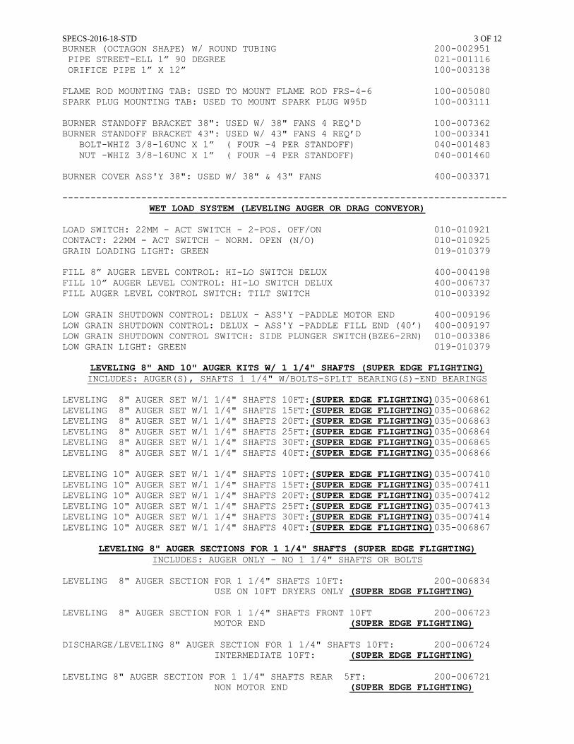
SPECS-2016-18-STD 3 OF 12
BURNER (OCTAGON SHAPE) W/ ROUND TUBING 200-002951 PIPE STREET-ELL 1” 90 DEGREE 021-001116 ORIFICE PIPE 1” X 12” 100-003138 FLAME ROD MOUNTING TAB: USED TO MOUNT FLAME ROD FRS-4-6 100-005080 SPARK PLUG MOUNTING TAB: USED TO MOUNT SPARK PLUG W95D 100-003111 BURNER STANDOFF BRACKET 38": USED W/ 38" FANS 4 REQ'D 100-007362 BURNER STANDOFF BRACKET 43": USED W/ 43" FANS 4 REQ’D 100-003341 BOLT-WHIZ 3/8-16UNC X 1” ( FOUR –4 PER STANDOFF) 040-001483 NUT -WHIZ 3/8-16UNC X 1” ( FOUR –4 PER STANDOFF) 040-001460 BURNER COVER ASS'Y 38": USED W/ 38" & 43" FANS 400-003371 -------------------------------------------------------------------------------
WET LOAD SYSTEM (LEVELING AUGER OR DRAG CONVEYOR) LOAD SWITCH: 22MM - ACT SWITCH - 2-POS. OFF/ON 010-010921 CONTACT: 22MM - ACT SWITCH – NORM. OPEN (N/O) 010-010925 GRAIN LOADING LIGHT: GREEN 019-010379 FILL 8” AUGER LEVEL CONTROL: HI-LO SWITCH DELUX 400-004198 FILL 10” AUGER LEVEL CONTROL: HI-LO SWITCH DELUX 400-006737 FILL AUGER LEVEL CONTROL SWITCH: TILT SWITCH 010-003392 LOW GRAIN SHUTDOWN CONTROL: DELUX - ASS'Y –PADDLE MOTOR END 400-009196 LOW GRAIN SHUTDOWN CONTROL: DELUX - ASS'Y –PADDLE FILL END (40’) 400-009197 LOW GRAIN SHUTDOWN CONTROL SWITCH: SIDE PLUNGER SWITCH(BZE6-2RN) 010-003386 LOW GRAIN LIGHT: GREEN 019-010379
LEVELING 8" AND 10" AUGER KITS W/ 1 1/4" SHAFTS (SUPER EDGE FLIGHTING) INCLUDES: AUGER(S), SHAFTS 1 1/4" W/BOLTS-SPLIT BEARING(S)-END BEARINGS
LEVELING 8" AUGER SET W/1 1/4" SHAFTS 10FT:(SUPER EDGE FLIGHTING)035-006861 LEVELING 8" AUGER SET W/1 1/4" SHAFTS 15FT:(SUPER EDGE FLIGHTING)035-006862 LEVELING 8" AUGER SET W/1 1/4" SHAFTS 20FT:(SUPER EDGE FLIGHTING)035-006863 LEVELING 8" AUGER SET W/1 1/4" SHAFTS 25FT:(SUPER EDGE FLIGHTING)035-006864 LEVELING 8" AUGER SET W/1 1/4" SHAFTS 30FT:(SUPER EDGE FLIGHTING)035-006865 LEVELING 8" AUGER SET W/1 1/4" SHAFTS 40FT:(SUPER EDGE FLIGHTING)035-006866 LEVELING 10" AUGER SET W/1 1/4" SHAFTS 10FT:(SUPER EDGE FLIGHTING)035-007410 LEVELING 10" AUGER SET W/1 1/4" SHAFTS 15FT:(SUPER EDGE FLIGHTING)035-007411 LEVELING 10" AUGER SET W/1 1/4" SHAFTS 20FT:(SUPER EDGE FLIGHTING)035-007412 LEVELING 10" AUGER SET W/1 1/4" SHAFTS 25FT:(SUPER EDGE FLIGHTING)035-007413 LEVELING 10" AUGER SET W/1 1/4" SHAFTS 30FT:(SUPER EDGE FLIGHTING)035-007414 LEVELING 10" AUGER SET W/1 1/4" SHAFTS 40FT:(SUPER EDGE FLIGHTING)035-006867
LEVELING 8" AUGER SECTIONS FOR 1 1/4" SHAFTS (SUPER EDGE FLIGHTING) INCLUDES: AUGER ONLY - NO 1 1/4" SHAFTS OR BOLTS LEVELING 8" AUGER SECTION FOR 1 1/4" SHAFTS 10FT: 200-006834 USE ON 10FT DRYERS ONLY (SUPER EDGE FLIGHTING) LEVELING 8" AUGER SECTION FOR 1 1/4" SHAFTS FRONT 10FT 200-006723 MOTOR END (SUPER EDGE FLIGHTING) DISCHARGE/LEVELING 8" AUGER SECTION FOR 1 1/4" SHAFTS 10FT: 200-006724 INTERMEDIATE 10FT: (SUPER EDGE FLIGHTING) LEVELING 8" AUGER SECTION FOR 1 1/4" SHAFTS REAR 5FT: 200-006721 NON MOTOR END (SUPER EDGE FLIGHTING)
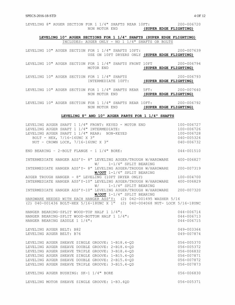
SPECS-2016-18-STD 4 OF 12
LEVELING 8" AUGER SECTION FOR 1 1/4" SHAFTS REAR 10FT: 200-006720 NON MOTOR END (SUPER EDGE FLIGHTING)
LEVELING 10" AUGER SECTIONS FOR 1 1/4" SHAFTS (SUPER EDGE FLIGHTING) INCLUDES: AUGER ONLY - NO 1 1/4" SHAFTS OR BOLTS
LEVELING 10" AUGER SECTION FOR 1 1/4" SHAFTS 10FT: 200-007639 USE ON 10FT DRYERS ONLY (SUPER EDGE FLIGHTING) LEVELING 10" AUGER SECTION FOR 1 1/4" SHAFTS FRONT 10FT 200-006794 MOTOR END (SUPER EDGE FLIGHTING) LEVELING 10" AUGER SECTION FOR 1 1/4" SHAFTS 200-006793 INTERMEDIATE 10FT: (SUPER EDGE FLIGHTING) LEVELING 10" AUGER SECTION FOR 1 1/4" SHAFTS REAR 5FT: 200-007640 NON MOTOR END (SUPER EDGE FLIGHTING) LEVELING 10" AUGER SECTION FOR 1 1/4" SHAFTS REAR 10FT: 200-006792 NON MOTOR END (SUPER EDGE FLIGHTING)
LEVELING 8" AND 10" AUGER PARTS FOR 1 1/4" SHAFTS LEVELING AUGER SHAFT 1 1/4" FRONT: KEYED - MOTOR END 100-006727 LEVELING AUGER SHAFT 1 1/4" INTERMEDIATE: 100-006726 LEVELING AUGER SHAFT 1 1/4" REAR: NON-KEYED 100-006728 BOLT - HEX, 7/16-16UNC X 3” 040-005324 NUT – CROWN LOCK, 7/16-16UNC X 3” 040-006732 END BEARING – 2-BOLT FLANGE - 1 1/4" BORE: 044-001510 INTERMEDIATE HANGER ASS’Y- 8” LEVELING AUGER/TROUGH W/HARDWARE 400-006827 W/ 1-1/4” SPLIT BEARING INTERMEDIATE HANGER ASS’Y- 8” LEVELING AUGER/TROUGH W/HARDWARE 200-007319 W/OUT 1-1/4” SPLIT BEARING AUGER TROUGH HANGER - 8” LEVELING (10FT DRYER ONLY) 100-004700 INTERMEDIATE HANGER ASS’Y-10” LEVELING AUGER/TROUGH W/HARDWARE 400-006829 W/ 1-1/4” SPLIT BEARING INTERMEDIATE HANGER ASS’Y-10” LEVELING AUGER/TROUGH W/HARDWARE 200-007320 W/OUT 1-1/4” SPLIT BEARING HARDWARE NEEDED WITH EACH HANGER ASS’Y: (2) 042-001495 WASHER 5/16 (2) 040-001436 BOLT-HEX 5/16-18UNC X 1” (2) 040-004068 NUT- LOCK 5/16-18UNC HANGER BEARING–SPLIT WOOD-TOP HALF 1 1/4": 044-006714 HANGER BEARING–SPLIT WOOD-BOTTOM HALF 1 1/4": 044-006713 HANGER BEARING SADDLE 1 1/4": 044-006715 LEVELING AUGER BELT: B82 049-003364 LEVELING AUGER BELT: B76 049-007874 LEVELING AUGER SHEAVE SINGLE GROOVE: 1-B18.4-QD 056-005370 LEVELING AUGER SHEAVE DOUBLE GROOVE: 2-B18.4-QD 056-005372 LEVELING AUGER SHEAVE TRIPLE GROOVE: 3-B18.4-QD 056-006832 LEVELING AUGER SHEAVE SINGLE GROOVE: 1-B15.4-QD 056-007871 LEVELING AUGER SHEAVE DOUBLE GROOVE: 2-B15.4-QD 056-007872 LEVELING AUGER SHEAVE TRIPLE GROOVE: 3-B15.4-QD 056-007873 LEVELING AUGER BUSHING: SK-1 1/4" BORE 056-006830 LEVELING MOTOR SHEAVE SINGLE GROOVE: 1-B3.4QD 056-005371
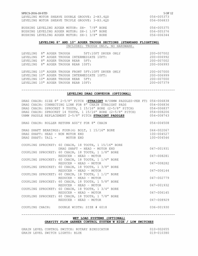
SPECS-2016-18-STD 5 OF 12
LEVELING MOTOR SHEAVE DOUBLE GROOVE: 2-B3.4QD 056-005373 LEVELING MOTOR SHEAVE TRIPLE GROOVE: 3-B3.4QD 056-006833 BUSHING LEVELING AUGER MOTOR: SH- 7/8" BORE 056-005375 BUSHING LEVELING AUGER MOTOR: SH-1 1/8" BORE 056-005376 BUSHING LEVELING AUGER MOTOR: SH-1 3/8" BORE 056-006344
LEVELING 8" AND 10" AUGER TROUGH SECTIONS (STANDARD FLIGHTING) INCLUDES: TROUGH ONLY, NO HARDWARE. LEVELING 8" AUGER TROUGH 5FT:10FT DRYER ONLY 200-007002 LEVELING 8" AUGER TROUGH INTERMEDIATE 10FT: 200-006992 LEVELING 8" AUGER TROUGH REAR 5FT: 200-007002 LEVELING 8" AUGER TROUGH REAR 10FT: 200-006993 LEVELING 10" AUGER TROUGH FRONT 5FT:10FT DRYER ONLY 200-007000 LEVELING 10" AUGER TROUGH INTERMEDIATE 10FT: 200-006999 LEVELING 10" AUGER TROUGH REAR 5FT: 200-007000 LEVELING 10" AUGER TROUGH REAR 10FT: 200-007379 -------------------------------------------------------------------------------
LEVELING DRAG CONVEYOR (OPTIONAL) DRAG CHAIN: SIZE 8” 2-5/8” PITCH (STRAIGHT W/UHMW PADDLES-PER FT) 054-006838 DRAG CHAIN: CONNECTING LINK FOR 8” CHAIN STRAIGHT PADS 054-006836 DRAG CHAIN: SPROCKET 9 TOOTH, 1 15/16” BORE (2-5/8” PITCH) 054-006837 DRAG CHAIN: SPROCKET 14 TOOTH, 1 15/16” BORE (2-5/8” PITCH) 054-008206 UHMW PADDLE REPLACEMENT 2-5/8” PITCH STRAIGHT PADDLES 054-008743 DRAG CHAIN: ROLLER RETURN ASS'Y FOR 8" CHAIN 054-004508 DRAG SHAFT BEARINGS: FOUR(4) BOLT, 1 15/16" BORE 044-002067 DRAG SHAFT: HEAD - NON MOTOR END 100-004527 DRAG SHAFT: TAIL - MOTOR END 100-004546 COUPLING SPROCKET: 60 CHAIN, 18 TOOTH, 1 15/16" BORE DRAG SHAFT - HEAD - MOTOR END 047-001931 COUPLING SPROCKET: 60 CHAIN, 18 TOOTH, 1 1/8” BORE REDUCER – HEAD – MOTOR 047-008281 COUPLING SPROCKET: 60 CHAIN, 18 TOOTH, 1 1/4" BORE REDUCER – HEAD – MOTOR 047-008282 COUPLING SPROCKET: 60 CHAIN, 18 TOOTH, 1 3/8” BORE REDUCER – HEAD – MOTOR 047-006144 COUPLING SPROCKET: 60 CHAIN, 18 TOOTH, 1 1/2” BORE REDUCER – HEAD – MOTOR 047-002779 COUPLING SPROCKET: 60 CHAIN, 18 TOOTH, 1 5/8” BORE REDUCER – HEAD – MOTOR 047-001932 COUPLING SPROCKET: 60 CHAIN, 18 TOOTH, 1 3/4” BORE REDUCER – HEAD – MOTOR 047-006145 COUPLING SPROCKET: 60 CHAIN, 18 TOOTH, 1 7/8” BORE REDUCER – HEAD – MOTOR 047-008929 COUPLING CHAIN: DOUBLE WIDTH: SIZE # 6018 036-001930 -------------------------------------------------------------------------------
WET LOAD SYSTEMS (OPTIONAL) GRAVITY FLOW GARNER CONTROL SYSTEM W HIGH / LOW SWITCHES
GRAIN LEVEL CONTROL SWITCH: ROTARY BINDICATOR 010-002655 GRAIN LEVEL SWITCH LIGHTS: BLUE 019-010380
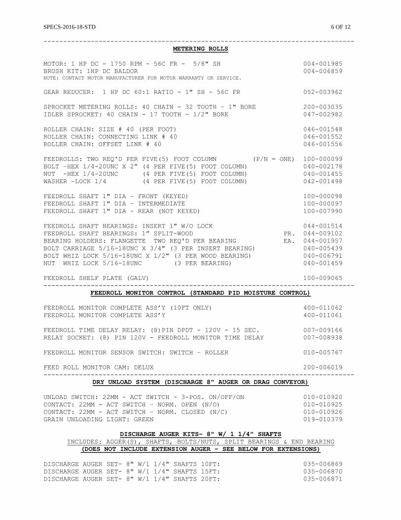
SPECS-2016-18-STD 6 OF 12
-------------------------------------------------------------------------------
METERING ROLLS MOTOR: 1 HP DC - 1750 RPM - 56C FR - 5/8" SH 004-001985 BRUSH KIT: 1HP DC BALDOR 004-006859 NOTE: CONTACT MOTOR MANUFACTURER FOR MOTOR WARRANTY OR SERVICE. GEAR REDUCER: 1 HP DC 60:1 RATIO - 1" SH - 56C FR 052-003962 SPROCKET METERING ROLLS: 40 CHAIN - 32 TOOTH – 1" BORE 200-003035 IDLER SPROCKET: 40 CHAIN - 17 TOOTH – 1/2" BORE 047-002982 ROLLER CHAIN: SIZE # 40 (PER FOOT) 046-001548 ROLLER CHAIN: CONNECTING LINK # 40 046-001552 ROLLER CHAIN: OFFSET LINK # 40 046-001556 FEEDROLLS: TWO REQ'D PER FIVE(5) FOOT COLUMN (P/N = ONE) 100-000099 BOLT –HEX 1/4-20UNC X 2” (4 PER FIVE(5) FOOT COLUMN) 040-002178 NUT -HEX 1/4-20UNC (4 PER FIVE(5) FOOT COLUMN) 040-001455 WASHER –LOCK 1/4 (4 PER FIVE(5) FOOT COLUMN) 042-001498 FEEDROLL SHAFT 1" DIA – FRONT (KEYED) 100-000098 FEEDROLL SHAFT 1" DIA – INTERMEDIATE 100-000097 FEEDROLL SHAFT 1" DIA – REAR (NOT KEYED) 100-007990 FEEDROLL SHAFT BEARINGS: INSERT 1" W/O LOCK 044-001514 FEEDROLL SHAFT BEARINGS: 1” SPLIT-WOOD PR. 044-009102 BEARING HOLDERS: FLANGETTE TWO REQ'D PER BEARING EA. 044-001957 BOLT CARRIAGE 5/16-18UNC X 3/4" (3 PER INSERT BEARING) 040-005439 BOLT WHIZ LOCK 5/16-18UNC X 1/2" (3 PER WOOD BEARING) 040-006791 NUT WHIZ LOCK 5/16-18UNC (3 PER BEARING) 040-001459 FEEDROLL SHELF PLATE (GALV) 100-009065 -------------------------------------------------------------------------------
FEEDROLL MONITOR CONTROL (STANDARD PID MOISTURE CONTROL) FEEDROLL MONITOR COMPLETE ASS’Y (10FT ONLY) 400-011062 FEEDROLL MONITOR COMPLETE ASS’Y 400-011061 FEEDROLL TIME DELAY RELAY: (8)PIN DPDT - 120V - 15 SEC. 007-009166 RELAY SOCKET: (8) PIN 120V - FEEDROLL MONITOR TIME DELAY 007-008938 FEEDROLL MONITOR SENSOR SWITCH: SWITCH – ROLLER 010-005767 FEED ROLL MONITOR CAM: DELUX 200-006019 -------------------------------------------------------------------------------
DRY UNLOAD SYSTEM (DISCHARGE 8" AUGER OR DRAG CONVEYOR) UNLOAD SWITCH: 22MM - ACT SWITCH - 3-POS. ON/OFF/ON 010-010920 CONTACT: 22MM - ACT SWITCH – NORM. OPEN (N/O) 010-010925 CONTACT: 22MM - ACT SWITCH – NORM. CLOSED (N/C) 010-010926 GRAIN UNLOADING LIGHT: GREEN 019-010379
DISCHARGE AUGER KITS- 8" W/ 1 1/4" SHAFTS
INCLUDES: AUGER(S), SHAFTS, BOLTS/NUTS, SPLIT BEARINGS & END BEARING (DOES NOT INCLUDE EXTENSION AUGER – SEE BELOW FOR EXTENSIONS)
DISCHARGE AUGER SET- 8" W/1 1/4" SHAFTS 10FT: 035-006869 DISCHARGE AUGER SET- 8" W/1 1/4" SHAFTS 15FT: 035-006870 DISCHARGE AUGER SET- 8" W/1 1/4" SHAFTS 20FT: 035-006871
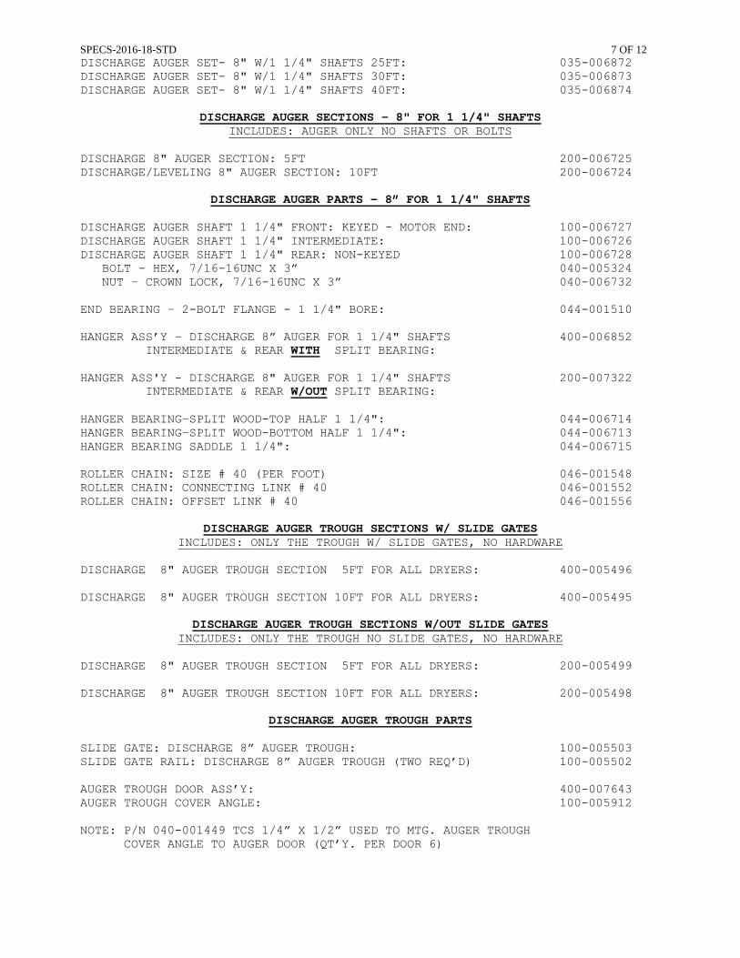
SPECS-2016-18-STD 7 OF 12
DISCHARGE AUGER SET- 8" W/1 1/4" SHAFTS 25FT: 035-006872 DISCHARGE AUGER SET- 8" W/1 1/4" SHAFTS 30FT: 035-006873 DISCHARGE AUGER SET- 8" W/1 1/4" SHAFTS 40FT: 035-006874
DISCHARGE AUGER SECTIONS - 8" FOR 1 1/4" SHAFTS INCLUDES: AUGER ONLY NO SHAFTS OR BOLTS
DISCHARGE 8" AUGER SECTION: 5FT 200-006725 DISCHARGE/LEVELING 8" AUGER SECTION: 10FT 200-006724
DISCHARGE AUGER PARTS – 8” FOR 1 1/4" SHAFTS
DISCHARGE AUGER SHAFT 1 1/4" FRONT: KEYED - MOTOR END: 100-006727 DISCHARGE AUGER SHAFT 1 1/4" INTERMEDIATE: 100-006726 DISCHARGE AUGER SHAFT 1 1/4" REAR: NON-KEYED 100-006728 BOLT - HEX, 7/16-16UNC X 3” 040-005324 NUT – CROWN LOCK, 7/16-16UNC X 3” 040-006732 END BEARING – 2-BOLT FLANGE - 1 1/4" BORE: 044-001510 HANGER ASS’Y – DISCHARGE 8” AUGER FOR 1 1/4" SHAFTS 400-006852 INTERMEDIATE & REAR WITH SPLIT BEARING: HANGER ASS'Y - DISCHARGE 8" AUGER FOR 1 1/4" SHAFTS 200-007322 INTERMEDIATE & REAR W/OUT SPLIT BEARING: HANGER BEARING–SPLIT WOOD-TOP HALF 1 1/4": 044-006714 HANGER BEARING–SPLIT WOOD-BOTTOM HALF 1 1/4": 044-006713 HANGER BEARING SADDLE 1 1/4": 044-006715 ROLLER CHAIN: SIZE # 40 (PER FOOT) 046-001548 ROLLER CHAIN: CONNECTING LINK # 40 046-001552 ROLLER CHAIN: OFFSET LINK # 40 046-001556
DISCHARGE AUGER TROUGH SECTIONS W/ SLIDE GATES
INCLUDES: ONLY THE TROUGH W/ SLIDE GATES, NO HARDWARE DISCHARGE 8" AUGER TROUGH SECTION 5FT FOR ALL DRYERS: 400-005496 DISCHARGE 8" AUGER TROUGH SECTION 10FT FOR ALL DRYERS: 400-005495
DISCHARGE AUGER TROUGH SECTIONS W/OUT SLIDE GATES INCLUDES: ONLY THE TROUGH NO SLIDE GATES, NO HARDWARE
DISCHARGE 8" AUGER TROUGH SECTION 5FT FOR ALL DRYERS: 200-005499 DISCHARGE 8" AUGER TROUGH SECTION 10FT FOR ALL DRYERS: 200-005498
DISCHARGE AUGER TROUGH PARTS SLIDE GATE: DISCHARGE 8” AUGER TROUGH: 100-005503 SLIDE GATE RAIL: DISCHARGE 8” AUGER TROUGH (TWO REQ’D) 100-005502 AUGER TROUGH DOOR ASS’Y: 400-007643 AUGER TROUGH COVER ANGLE: 100-005912 NOTE: P/N 040-001449 TCS 1/4” X 1/2” USED TO MTG. AUGER TROUGH
COVER ANGLE TO AUGER DOOR (QT’Y. PER DOOR 6)
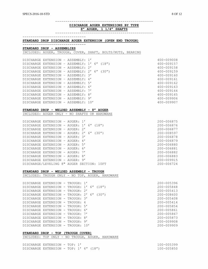
SPECS-2016-18-STD 8 OF 12
------------------------------------------------
DISCHARGE AUGER EXTENSIONS BY TYPE 8” AUGER, 1 1/4” SHAFTS
------------------------------------------------ ------------------------------- STANDARD DROP DISCHARGE AUGER EXTENSION (OPEN END TROUGH) ------------------------------- STANDARD DROP – ASSEMBLIES INCLUDES: AUGER, TROUGH, COVER, SHAFT, BOLTS/NUTS, BEARING DISCHARGE EXTENSION – ASSEMBLY: 1’ 400-009008 DISCHARGE EXTENSION – ASSEMBLY: 1’ 6” (18”) 400-009157 DISCHARGE EXTENSION – ASSEMBLY: 2’ 400-009158 DISCHARGE EXTENSION – ASSEMBLY: 2’ 6” (30”) 400-009159 DISCHARGE EXTENSION – ASSEMBLY: 3’ 400-009160 DISCHARGE EXTENSION – ASSEMBLY: 4’ 400-009161 DISCHARGE EXTENSION – ASSEMBLY: 5’ 400-009162 DISCHARGE EXTENSION – ASSEMBLY: 6’ 400-009163 DISCHARGE EXTENSION – ASSEMBLY: 7’ 400-009164 DISCHARGE EXTENSION – ASSEMBLY: 8’ 400-009165 DISCHARGE EXTENSION – ASSEMBLY: 9’ 400-009906 DISCHARGE EXTENSION – ASSEMBLY: 10’ 400-009907 STANDARD DROP - WELDED ASSEMBLY – 8” AUGER INCLUDES: AUGER ONLY - NO SHAFTS OR HARDWARE DISCHARGE EXTENSION – AUGER: 1’ 200-006875 DISCHARGE EXTENSION – AUGER: 1’ 6” (18”) 200-006876 DISCHARGE EXTENSION – AUGER: 2’ 200-006877 DISCHARGE EXTENSION – AUGER: 2’ 6” (30”) 200-008597 DISCHARGE EXTENSION – AUGER: 3’ 200-006878 DISCHARGE EXTENSION – AUGER: 4’ 200-006879 DISCHARGE EXTENSION – AUGER: 5’ 200-006880 DISCHARGE EXTENSION – AUGER: 6’ 200-006881 DISCHARGE EXTENSION – AUGER: 7’ 200-006882 DISCHARGE EXTENSION – AUGER: 8’ 200-006883 DISCHARGE EXTENSION – AUGER: 9’ 200-009915 DISCHARGE/LEVELING 8" AUGER SECTION: 10FT 200-006724 STANDARD DROP - WELDED ASSEMBLY – TROUGH INCLUDES: TROUGH ONLY - NO TOP, AUGER, HARDWARE DISCHARGE EXTENSION - TROUGH: 1’ 200-005396 DISCHARGE EXTENSION - TROUGH: 1’ 6” (18”) 200-005848 DISCHARGE EXTENSION - TROUGH: 2’ 200-005413 DISCHARGE EXTENSION - TROUGH: 2’ 6” (30”) 200-008600 DISCHARGE EXTENSION - TROUGH: 3’ 200-005408 DISCHARGE EXTENSION - TROUGH: 4 200-005414 DISCHARGE EXTENSION - TROUGH: 5’ 200-005854 DISCHARGE EXTENSION - TROUGH: 6’ 200-005861 DISCHARGE EXTENSION - TROUGH: 7’ 200-005867 DISCHARGE EXTENSION - TROUGH: 8’ 200-005873 DISCHARGE EXTENSION - TROUGH: 9’ 200-009908 DISCHARGE EXTENSION - TROUGH: 10’ 200-009909 STANDARD DROP - TOP (TROUGH COVER) INCLUDES: TOP ONLY - NO TROUGH, AUGER, HARDWARE DISCHARGE EXTENSION - TOP: 1’ 100-005399 DISCHARGE EXTENSION - TOP: 1’ 6” (18”) 100-005850
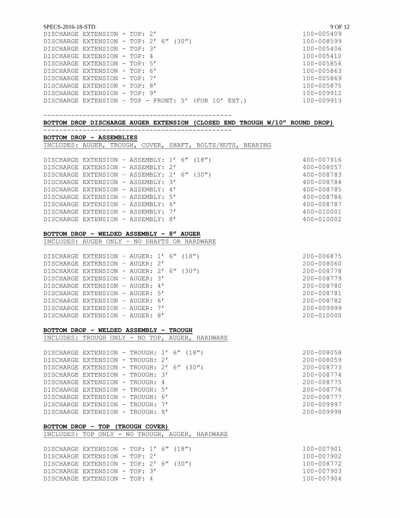
SPECS-2016-18-STD 9 OF 12
DISCHARGE EXTENSION - TOP: 2’ 100-005409 DISCHARGE EXTENSION - TOP: 2’ 6” (30”) 100-008599 DISCHARGE EXTENSION - TOP: 3’ 100-005406 DISCHARGE EXTENSION - TOP: 4 100-005410 DISCHARGE EXTENSION - TOP: 5’ 100-005856 DISCHARGE EXTENSION - TOP: 6’ 100-005863 DISCHARGE EXTENSION - TOP: 7’ 100-005869 DISCHARGE EXTENSION - TOP: 8’ 100-005875 DISCHARGE EXTENSION - TOP: 9’ 100-009912 DISCHARGE EXTENSION – TOP - FRONT: 5’ (FOR 10’ EXT.) 100-009913 ------------------------------------------------ BOTTOM DROP DISCHARGE AUGER EXTENSION (CLOSED END TROUGH W/10” ROUND DROP) ------------------------------------------------ BOTTOM DROP - ASSEMBLIES INCLUDES: AUGER, TROUGH, COVER, SHAFT, BOLTS/NUTS, BEARING DISCHARGE EXTENSION – ASSEMBLY: 1’ 6” (18”) 400-007916 DISCHARGE EXTENSION – ASSEMBLY: 2’ 400-008057 DISCHARGE EXTENSION – ASSEMBLY: 2’ 6” (30”) 400-008783 DISCHARGE EXTENSION – ASSEMBLY: 3’ 400-008784 DISCHARGE EXTENSION – ASSEMBLY: 4’ 400-008785 DISCHARGE EXTENSION – ASSEMBLY: 5’ 400-008786 DISCHARGE EXTENSION – ASSEMBLY: 6’ 400-008787 DISCHARGE EXTENSION – ASSEMBLY: 7’ 400-010001 DISCHARGE EXTENSION – ASSEMBLY: 8’ 400-010002 BOTTOM DROP - WELDED ASSEMBLY – 8” AUGER INCLUDES: AUGER ONLY - NO SHAFTS OR HARDWARE DISCHARGE EXTENSION – AUGER: 1’ 6” (18”) 200-006875 DISCHARGE EXTENSION – AUGER: 2’ 200-008060 DISCHARGE EXTENSION – AUGER: 2’ 6” (30”) 200-008778 DISCHARGE EXTENSION – AUGER: 3’ 200-008779 DISCHARGE EXTENSION – AUGER: 4’ 200-008780 DISCHARGE EXTENSION – AUGER: 5’ 200-008781 DISCHARGE EXTENSION – AUGER: 6’ 200-008782 DISCHARGE EXTENSION – AUGER: 7’ 200-009999 DISCHARGE EXTENSION – AUGER: 8’ 200-010000 BOTTOM DROP - WELDED ASSEMBLY – TROUGH INCLUDES: TROUGH ONLY - NO TOP, AUGER, HARDWARE DISCHARGE EXTENSION - TROUGH: 1’ 6” (18”) 200-008058 DISCHARGE EXTENSION - TROUGH: 2’ 200-008059 DISCHARGE EXTENSION - TROUGH: 2’ 6” (30”) 200-008773 DISCHARGE EXTENSION - TROUGH: 3’ 200-008774 DISCHARGE EXTENSION - TROUGH: 4 200-008775 DISCHARGE EXTENSION - TROUGH: 5’ 200-008776 DISCHARGE EXTENSION - TROUGH: 6’ 200-008777 DISCHARGE EXTENSION - TROUGH: 7’ 200-009997 DISCHARGE EXTENSION - TROUGH: 8’ 200-009998 BOTTOM DROP - TOP (TROUGH COVER) INCLUDES: TOP ONLY - NO TROUGH, AUGER, HARDWARE DISCHARGE EXTENSION - TOP: 1’ 6” (18”) 100-007901 DISCHARGE EXTENSION - TOP: 2’ 100-007902 DISCHARGE EXTENSION - TOP: 2’ 6” (30”) 100-008772 DISCHARGE EXTENSION - TOP: 3’ 100-007903 DISCHARGE EXTENSION - TOP: 4 100-007904
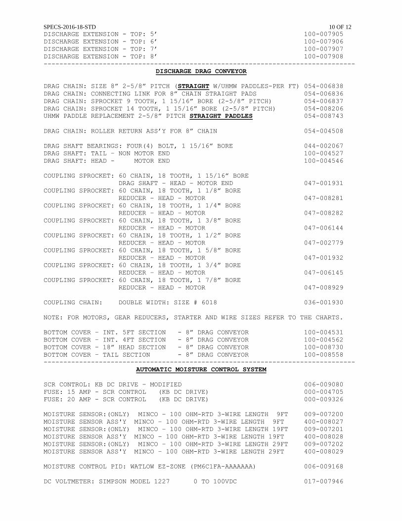
SPECS-2016-18-STD 10 OF 12
DISCHARGE EXTENSION - TOP: 5’ 100-007905 DISCHARGE EXTENSION - TOP: 6’ 100-007906 DISCHARGE EXTENSION - TOP: 7’ 100-007907 DISCHARGE EXTENSION - TOP: 8’ 100-007908 -------------------------------------------------------------------------------
DISCHARGE DRAG CONVEYOR DRAG CHAIN: SIZE 8” 2-5/8” PITCH (STRAIGHT W/UHMW PADDLES-PER FT) 054-006838 DRAG CHAIN: CONNECTING LINK FOR 8” CHAIN STRAIGHT PADS 054-006836 DRAG CHAIN: SPROCKET 9 TOOTH, 1 15/16” BORE (2-5/8” PITCH) 054-006837 DRAG CHAIN: SPROCKET 14 TOOTH, 1 15/16” BORE (2-5/8” PITCH) 054-008206 UHMW PADDLE REPLACEMENT 2-5/8” PITCH STRAIGHT PADDLES 054-008743 DRAG CHAIN: ROLLER RETURN ASS’Y FOR 8” CHAIN 054-004508 DRAG SHAFT BEARINGS: FOUR(4) BOLT, 1 15/16” BORE 044-002067 DRAG SHAFT: TAIL – NON MOTOR END 100-004527 DRAG SHAFT: HEAD - MOTOR END 100-004546 COUPLING SPROCKET: 60 CHAIN, 18 TOOTH, 1 15/16” BORE DRAG SHAFT – HEAD – MOTOR END 047-001931 COUPLING SPROCKET: 60 CHAIN, 18 TOOTH, 1 1/8” BORE REDUCER – HEAD – MOTOR 047-008281 COUPLING SPROCKET: 60 CHAIN, 18 TOOTH, 1 1/4" BORE REDUCER – HEAD – MOTOR 047-008282 COUPLING SPROCKET: 60 CHAIN, 18 TOOTH, 1 3/8” BORE REDUCER – HEAD – MOTOR 047-006144 COUPLING SPROCKET: 60 CHAIN, 18 TOOTH, 1 1/2” BORE REDUCER – HEAD – MOTOR 047-002779 COUPLING SPROCKET: 60 CHAIN, 18 TOOTH, 1 5/8” BORE REDUCER – HEAD – MOTOR 047-001932 COUPLING SPROCKET: 60 CHAIN, 18 TOOTH, 1 3/4” BORE REDUCER – HEAD – MOTOR 047-006145 COUPLING SPROCKET: 60 CHAIN, 18 TOOTH, 1 7/8” BORE REDUCER – HEAD – MOTOR 047-008929 COUPLING CHAIN: DOUBLE WIDTH: SIZE # 6018 036-001930 NOTE: FOR MOTORS, GEAR REDUCERS, STARTER AND WIRE SIZES REFER TO THE CHARTS.
BOTTOM COVER – INT. 5FT SECTION - 8” DRAG CONVEYOR 100-004531 BOTTOM COVER – INT. 4FT SECTION - 8” DRAG CONVEYOR 100-004562 BOTTOM COVER – 18” HEAD SECTION - 8” DRAG CONVEYOR 100-008730 BOTTOM COVER – TAIL SECTION - 8” DRAG CONVEYOR 100-008558 -------------------------------------------------------------------------------
AUTOMATIC MOISTURE CONTROL SYSTEM SCR CONTROL: KB DC DRIVE – MODIFIED 006-009080 FUSE: 15 AMP - SCR CONTROL (KB DC DRIVE) 000-004705 FUSE: 20 AMP - SCR CONTROL (KB DC DRIVE) 000-009326 MOISTURE SENSOR:(ONLY) MINCO – 100 OHM-RTD 3-WIRE LENGTH 9FT 009-007200 MOISTURE SENSOR ASS'Y MINCO – 100 OHM-RTD 3-WIRE LENGTH 9FT 400-008027 MOISTURE SENSOR:(ONLY) MINCO – 100 OHM-RTD 3-WIRE LENGTH 19FT 009-007201 MOISTURE SENSOR ASS'Y MINCO – 100 OHM-RTD 3-WIRE LENGTH 19FT 400-008028 MOISTURE SENSOR:(ONLY) MINCO – 100 OHM-RTD 3-WIRE LENGTH 29FT 009-007202 MOISTURE SENSOR ASS'Y MINCO – 100 OHM-RTD 3-WIRE LENGTH 29FT 400-008029 MOISTURE CONTROL PID: WATLOW EZ-ZONE (PM6C1FA-AAAAAAA) 006-009168 DC VOLTMETER: SIMPSON MODEL 1227 0 TO 100VDC 017-007946
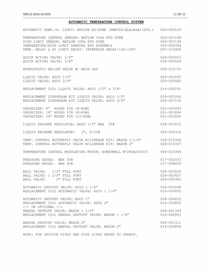
SPECS-2016-18-STD 11 OF 12
------------------------------------------------------------------------------- AUTOMATIC TEMPERATURE CONTROL SYSTEM
AUTOMATIC TEMP./H. LIMIT: WATLOW EZ-ZONE (PM6CFA-ALEJAAA)(STD.) 006-009149 TEMPERATURE CONTROL SENSOR: WATLOW 100Ω RTD STEM 009-007199 HIGH LIMIT SENSOR: WATLOW 100Ω RTD STEM 009-007199 TEMPERATURE/HIGH LIMIT SENSORS BOX ASSEMBLY 400-009304 TEMP. RELAY & HI LIMIT RELAY: INTERFACE RELAY-12A-120V 007-010929 QUICK ACTING VALVE: 1/2" 028-003013 QUICK ACTING VALVE: 3/4" 028-005529 HYDROSTATIC RELIEF VALVE W/ RAIN CAP 028-010730 LIQUID VALVE: ASCO 1/2" 028-003097 LIQUID VALVE: ASCO 3/4" 028-005482 REPLACEMENT COIL LIQUID VALVE: ASCO 1/2" & 3/4" 014-006291 REPLACEMENT DIAPHRAGM KIT LIQUID VALVE: ASCO 1/2" 028-005206 REPLACEMENT DIAPHRAGM KIT LIQUID VALVE: ASCO 3/4" 028-007150 VAPORIZER: 8” ROUND FIN (4-ROW) 031-003093 VAPORIZER: 16” ROUND FIN (8-ROW) 031-003094 VAPORIZER: 24” ROUND FIN (12-ROW) 031-003095 LIQUID PROPANE REGULATOR: REGO 1/2" MAX 30# 028-003012 LIQUID PROPANE REGULATOR: 2", 8-20# 028-006316 TEMP. CONTROL BUTTERFLY VALVE W/LINKAGE KIT: MAXON 1-1/4” 028-010346 TEMP. CONTROL BUTTERFLY VALVE W/LINKAGE KIT: MAXON 2” 028-010347 TEMPERATURE CONTROL MODULATING MOTOR: HONEYWELL M7284A2004/U 004-010348 PRESSURE GAUGE: MAX 30# 017-001033 PRESSURE GAUGE: MAX 60# 017-008459 BALL VALVE: 1/2" FULL PORT 028-003026 BALL VALVE: 1 1/4" FULL PORT 028-003027 BALL VALVE: 2" FULL PORT 028-005362 AUTOMATIC SHUTOFF VALVE: ASCO 1 1/4” 028-003098 REPLACEMENT COIL AUTOMATIC VALVE: ASCO 1 1/4" 014-000852 AUTOMATIC SHUTOFF VALVE: ASCO 2” 028-004623 REPLACEMENT COIL AUTOMATIC VALVE: ASCO 2" 014-000852 --- OR OPTIONAL --- MANUAL SHUTOFF VALVE: MAXON 1 1/4" 028-001309 REPLACEMENT COIL MANUAL SHUTOFF VALVE: MAXON 1 1/4" 014-000853 MANUAL SHUTOFF VALVE: MAXON 2" 028-001311 REPLACEMENT COIL MANUAL SHUTOFF VALVE: MAXON 2" 014-000854 NOTE: FOR ORIFICE SIZES AND PIPE SIZES REFER TO CHARTS.
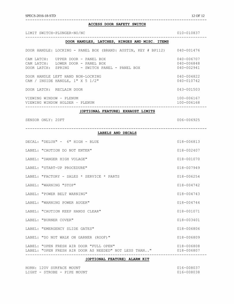
SPECS-2016-18-STD 12 OF 12
------------------------------------------------------------------------------- ACCESS DOOR SAFETY SWITCH
LIMIT SWITCH-PLUNGER-NO/NC 010-010837 -------------------------------------------------------------------------------
DOOR HANDLES, LATCHES, HINGES AND MISC. ITEMS DOOR HANDLE: LOCKING - PANEL BOX (BRAND: AUSTIN, KEY # BP112) 040-001476 CAM LATCH: UPPER DOOR - PANEL BOX 040-006707 CAM LATCH: LOWER DOOR - PANEL BOX 040-006848 DOOR LATCH: SPRING - SWITCH PANEL - PANEL BOX 040-002941 DOOR HANDLE LEFT HAND NON-LOCKING 040-004822 CAM / INSIDE HANDLE, 1" X 5 1/2" 040-010742 DOOR LATCH: RECLAIM DOOR 043-001503 VIEWING WINDOW – PLENUM 100-006167 VIEWING WINDOW HOLDER – PLENUM 100-006168 -------------------------------------------------------------------------------
(OPTIONAL FEATURE) EXHAUST LIMITS SENSOR ONLY: 20FT 006-006925 -------------------------------------------------------------------------------
LABELS AND DECALS DECAL: "DELUX" - 6" HIGH - BLUE 018-006813 LABEL: "CAUTION DO NOT ENTER" 018-002407 LABEL: "DANGER HIGH VOLAGE" 018-001070 LABEL: "START-UP PROCEDURE" 018-007949 LABEL: "FACTORY - SALES * SERVICE * PARTS 018-006254 LABEL: "WARNING "STOP" 018-004742 LABEL: "POWER BELT WARNING" 018-004743 LABEL: "WARNING POWER AUGER" 018-004744 LABEL: "CAUTION KEEP HANDS CLEAR" 018-001071 LABEL: "BURNER COVER" 018-003401 LABEL: "EMERGENCY SLIDE GATES" 018-006806 LABEL: "DO NOT WALK ON GARNER (ROOF)" 018-006809 LABEL: "OPEN FRESH AIR DOOR "FULL OPEN" 018-006808 LABEL: "OPEN FRESH AIR DOOR AS NEEDED" NOT LESS THAN.." 018-006807 -------------------------------------------------------------------------------
(OPTIONAL FEATURE) ALARM KIT HORN: 120V SURFACE MOUNT 016-008037 LIGHT - STROBE - PIPE MOUNT 016-008038
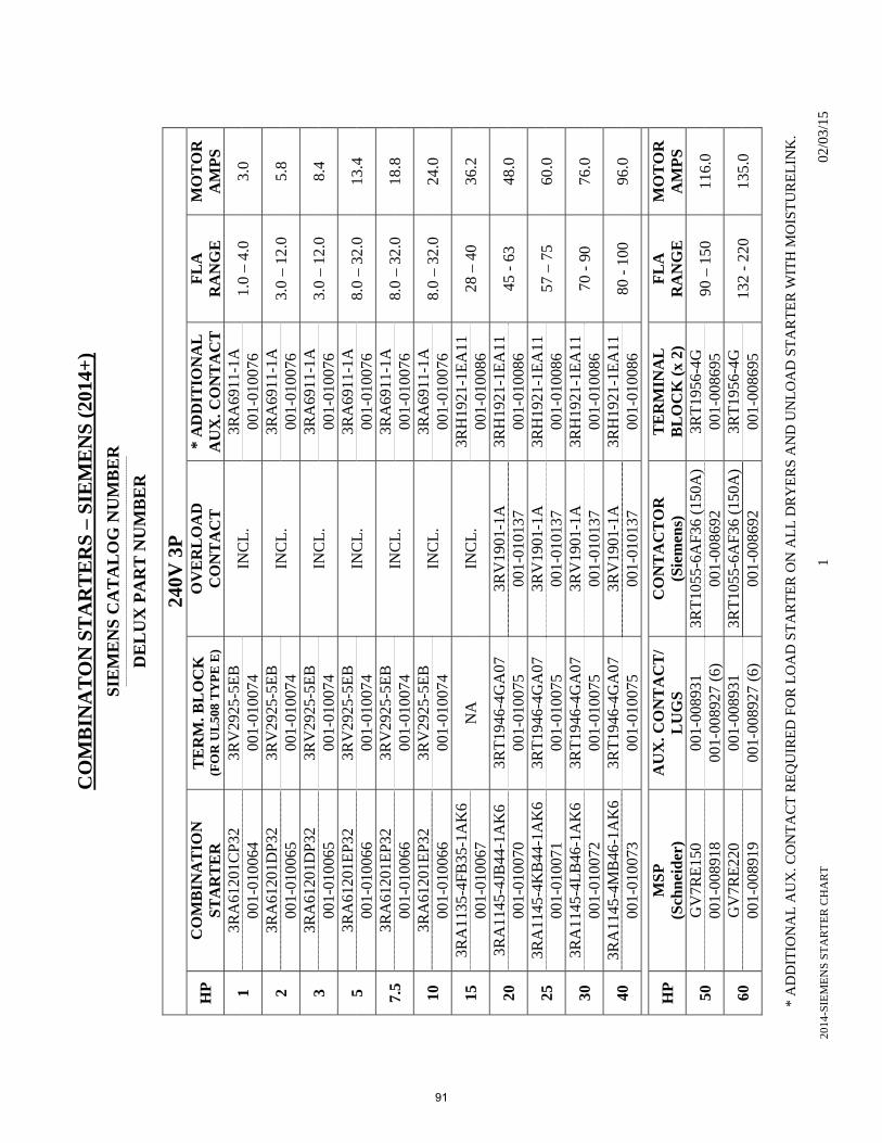
2014
-SIE
ME
NS
ST
AR
TE
R C
HA
RT
1
02/
03/1
5
CO
MB
INA
TO
N S
TA
RT
ER
S –
SIE
ME
NS
(20
14+
)
SIE
ME
NS
CA
TA
LO
G N
UM
BE
R
----
----
----
----
----
----
----
----
----
----
----
----
----
----
----
----
----
----
----
----
----
----
----
----
----
----
----
----
----
----
DE
LU
X P
AR
T N
UM
BE
R
240V
3P
HP
C
OM
BIN
AT
ION
S
TA
RT
ER
T
ER
M. B
LO
CK
(F
OR
UL
508
TY
PE
E)
OV
ER
LO
AD
C
ON
TA
CT
*
AD
DIT
ION
AL
A
UX
. CO
NT
AC
T
FL
A
RA
NG
E
MO
TO
R
AM
PS
1 3R
A61
201C
P32
3R
V29
25-5
EB
IN
CL
. 3R
A69
11-1
A
1.0
– 4.
0 3.
0 00
1-01
0064
00
1-01
0074
00
1-01
0076
2 3R
A61
201D
P32
3R
V29
25-5
EB
IN
CL
. 3R
A69
11-1
A
3.0
– 12
.0
5.8
001-
0100
65
001-
0100
74
001-
0100
76
3 3R
A61
201D
P32
3R
V29
25-5
EB
IN
CL
. 3R
A69
11-1
A
3.0
– 12
.0
8.4
001-
0100
65
001-
0100
74
001-
0100
76
5 3R
A61
201E
P32
3RV
2925
-5E
B
INC
L.
3RA
6911
-1A
8.
0 –
32.0
13
.4
001-
0100
66
001-
0100
74
001-
0100
76
7.5
3RA
6120
1EP3
2 3R
V29
25-5
EB
IN
CL
. 3R
A69
11-1
A
8.0
– 32
.0
18.8
00
1-01
0066
00
1-01
0074
00
1-01
0076
10
3RA
6120
1EP3
2 3R
V29
25-5
EB
IN
CL
. 3R
A69
11-1
A
8.0
– 32
.0
24.0
00
1-01
0066
00
1-01
0074
00
1-01
0076
15
3RA
1135
-4FB
35-1
AK
6 N
A
INC
L.
3RH
1921
-1E
A11
28
– 4
0 36
.2
001-
0100
67
001-
0100
86
20
3RA
1145
-4JB
44-1
AK
6 3R
T19
46-4
GA
07
3RV
1901
-1A
3R
H19
21-1
EA
11
45 -
63
48.0
00
1-01
0070
00
1-01
0075
00
1-01
0137
00
1-01
0086
25
3RA
1145
-4K
B44
-1A
K6
3RT
1946
-4G
A07
3R
V19
01-1
A
3RH
1921
-1E
A11
57
– 7
5 60
.0
001-
0100
71
001-
0100
75
001-
0101
37
001-
0100
86
30
3RA
1145
-4L
B46
-1A
K6
3RT
1946
-4G
A07
3R
V19
01-1
A
3RH
1921
-1E
A11
70
- 9
0 76
.0
001-
0100
72
001-
0100
75
001-
0101
37
001-
0100
86
40
3RA
1145
-4M
B46
-1A
K6
3RT
1946
-4G
A07
3R
V19
01-1
A
3RH
1921
-1E
A11
80
- 1
00
96.0
00
1-01
0073
00
1-01
0075
00
1-01
0137
00
1-01
0086
HP
M
SP
(S
chn
eid
er)
AU
X. C
ON
TA
CT
/ L
UG
S
CO
NT
AC
TO
R
(Sie
men
s)
TE
RM
INA
L
BL
OC
K (
x 2)
F
LA
R
AN
GE
M
OT
OR
A
MP
S
50
GV
7RE
150
001-
0089
31
3RT
1055
-6A
F36
(15
0A)
3RT
1956
-4G
90
– 1
50
116.
0 00
1-00
8918
00
1-00
8927
(6)
00
1-00
8692
00
1-00
8695
60
GV
7RE
220
001-
0089
31
3RT
1055
-6A
F36
(15
0A)
3RT
1956
-4G
13
2 -
220
135.
0 00
1-00
8919
00
1-00
8927
(6)
00
1-00
8692
00
1-00
8695
* A
DD
ITIO
NA
L A
UX
. CO
NT
AC
T R
EQ
UIR
ED
FO
R L
OA
D S
TA
RT
ER
ON
AL
L D
RY
ER
S A
ND
UN
LO
AD
ST
AR
TE
R W
ITH
MO
IST
UR
EL
INK
.
91
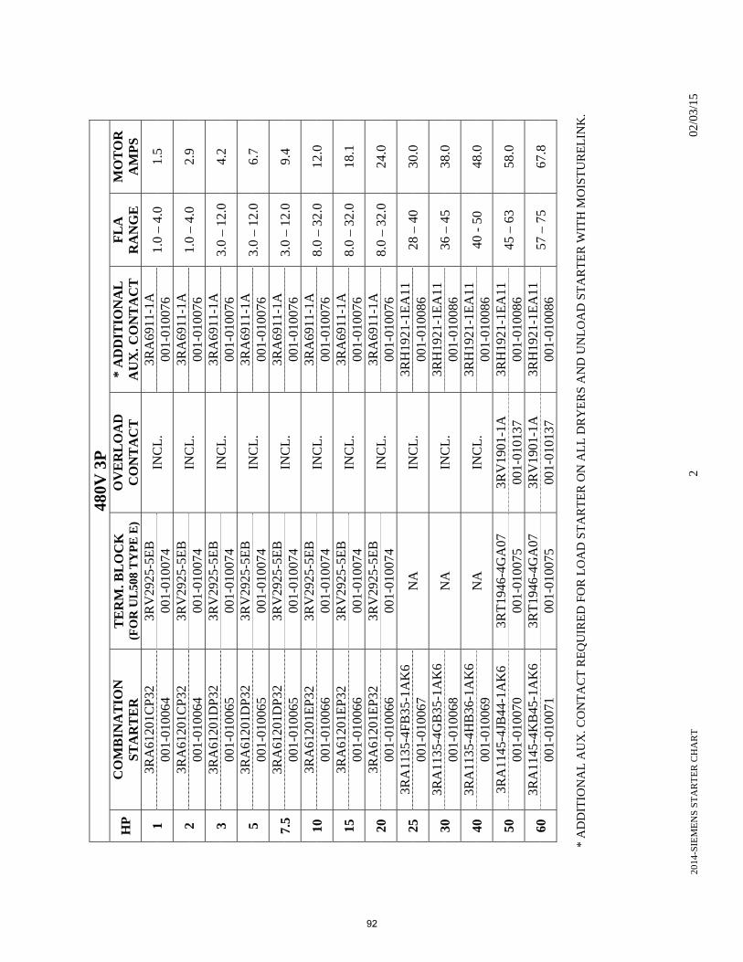
2014
-SIE
ME
NS
ST
AR
TE
R C
HA
RT
2
02/
03/1
5
480V
3P
HP
C
OM
BIN
AT
ION
S
TA
RT
ER
T
ER
M. B
LO
CK
(F
OR
UL
508
TY
PE
E)
OV
ER
LO
AD
C
ON
TA
CT
*
AD
DIT
ION
AL
A
UX
. CO
NT
AC
T
FL
A
RA
NG
E
MO
TO
R
AM
PS
1 3R
A61
201C
P32
3R
V29
25-5
EB
IN
CL
. 3R
A69
11-1
A
1.0
– 4.
0 1.
5 00
1-01
0064
00
1-01
0074
00
1-01
0076
2 3R
A61
201C
P32
3R
V29
25-5
EB
IN
CL
. 3R
A69
11-1
A
1.0
– 4.
0 2.
9 00
1-01
0064
00
1-01
0074
00
1-01
0076
3 3R
A61
201D
P32
3R
V29
25-5
EB
IN
CL
. 3R
A69
11-1
A
3.0
– 12
.0
4.2
001-
0100
65
001-
0100
74
001-
0100
76
5 3R
A61
201D
P32
3R
V29
25-5
EB
IN
CL
. 3R
A69
11-1
A
3.0
– 12
.0
6.7
001-
0100
65
001-
0100
74
001-
0100
76
7.5
3RA
6120
1DP
32
3RV
2925
-5E
B
INC
L.
3RA
6911
-1A
3.
0 –
12.0
9.
4 00
1-01
0065
00
1-01
0074
00
1-01
0076
10
3RA
6120
1EP3
2 3R
V29
25-5
EB
IN
CL
. 3R
A69
11-1
A
8.0
– 32
.0
12.0
00
1-01
0066
00
1-01
0074
00
1-01
0076
15
3RA
6120
1EP3
2 3R
V29
25-5
EB
IN
CL
. 3R
A69
11-1
A
8.0
– 32
.0
18.1
00
1-01
0066
00
1-01
0074
00
1-01
0076
20
3RA
6120
1EP3
2 3R
V29
25-5
EB
IN
CL
. 3R
A69
11-1
A
8.0
– 32
.0
24.0
00
1-01
0066
00
1-01
0074
00
1-01
0076
25
3RA
1135
-4FB
35-1
AK
6 N
A
INC
L.
3RH
1921
-1E
A11
28
– 4
0 30
.0
001-
0100
67
001-
0100
86
30
3RA
1135
-4G
B35
-1A
K6
NA
IN
CL
. 3R
H19
21-1
EA
11
36 –
45
38.0
00
1-01
0068
00
1-01
0086
40
3RA
1135
-4H
B36
-1A
K6
NA
IN
CL
. 3R
H19
21-1
EA
11
40 -
50
48.0
00
1-01
0069
00
1-01
0086
50
3RA
1145
-4JB
44-1
AK
6 3R
T19
46-4
GA
07
3RV
1901
-1A
3R
H19
21-1
EA
11
45 –
63
58.0
00
1-01
0070
00
1-01
0075
00
1-01
0137
00
1-01
0086
60
3RA
1145
-4K
B45
-1A
K6
3RT
1946
-4G
A07
3R
V19
01-1
A
3RH
1921
-1E
A11
57
– 7
5 67
.8
001-
0100
71
001-
0100
75
001-
0101
37
001-
0100
86
*
AD
DIT
ION
AL
AU
X. C
ON
TA
CT
RE
QU
IRE
D F
OR
LO
AD
ST
AR
TE
R O
N A
LL
DR
YE
RS
AN
D U
NL
OA
D S
TA
RT
ER
WIT
H M
OIS
TU
RE
LIN
K.
92
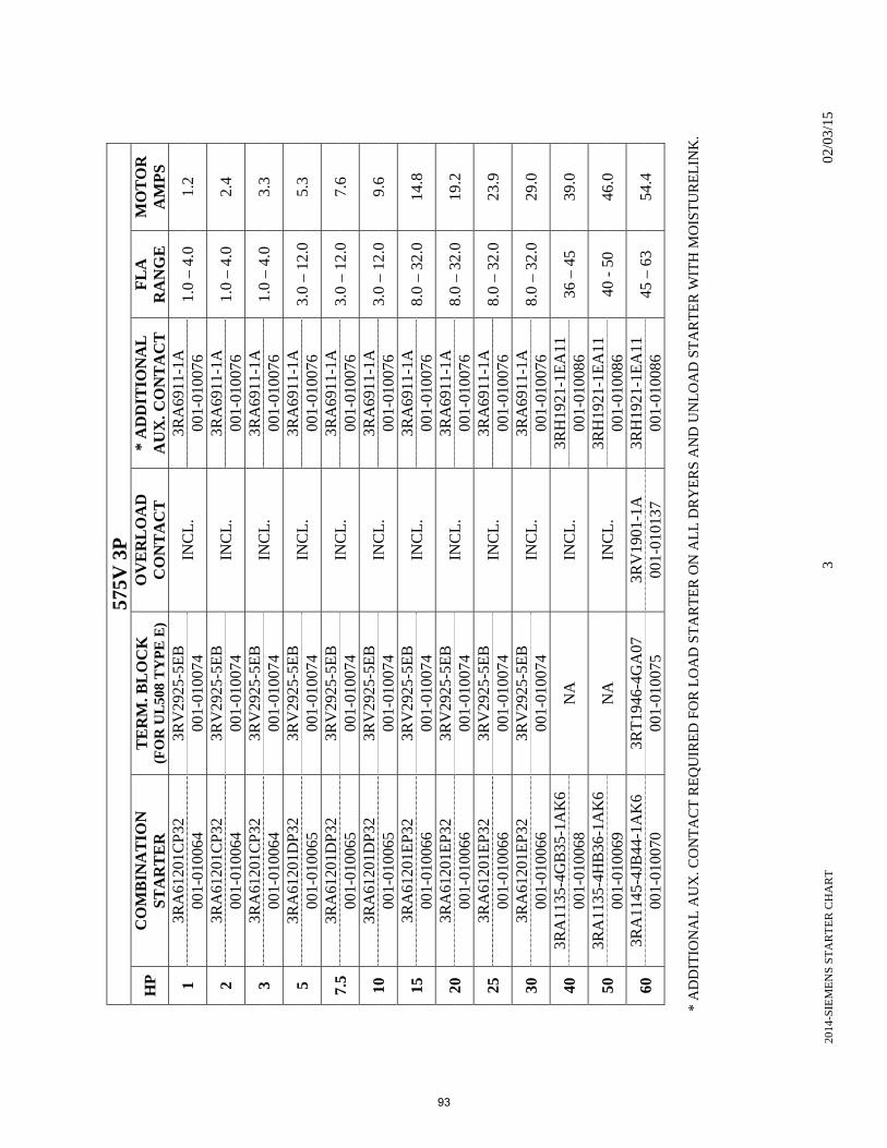
2014
-SIE
ME
NS
ST
AR
TE
R C
HA
RT
3
02/
03/1
5
575V
3P
HP
C
OM
BIN
AT
ION
S
TA
RT
ER
T
ER
M. B
LO
CK
(F
OR
UL
508
TY
PE
E)
OV
ER
LO
AD
C
ON
TA
CT
*
AD
DIT
ION
AL
A
UX
. CO
NT
AC
T
FL
A
RA
NG
E
MO
TO
R
AM
PS
1 3R
A61
201C
P32
3R
V29
25-5
EB
IN
CL
. 3R
A69
11-1
A
1.0
– 4.
0 1.
2 00
1-01
0064
00
1-01
0074
00
1-01
0076
2 3R
A61
201C
P32
3R
V29
25-5
EB
IN
CL
. 3R
A69
11-1
A
1.0
– 4.
0 2.
4 00
1-01
0064
00
1-01
0074
00
1-01
0076
3 3R
A61
201C
P32
3R
V29
25-5
EB
IN
CL
. 3R
A69
11-1
A
1.0
– 4.
0 3.
3 00
1-01
0064
00
1-01
0074
00
1-01
0076
5 3R
A61
201D
P32
3R
V29
25-5
EB
IN
CL
. 3R
A69
11-1
A
3.0
– 12
.0
5.3
001-
0100
65
001-
0100
74
001-
0100
76
7.5
3RA
6120
1DP
32
3RV
2925
-5E
B
INC
L.
3RA
6911
-1A
3.
0 –
12.0
7.
6 00
1-01
0065
00
1-01
0074
00
1-01
0076
10
3RA
6120
1DP
32
3RV
2925
-5E
B
INC
L.
3RA
6911
-1A
3.
0 –
12.0
9.
6 00
1-01
0065
00
1-01
0074
00
1-01
0076
15
3RA
6120
1EP3
2 3R
V29
25-5
EB
IN
CL
. 3R
A69
11-1
A
8.0
– 32
.0
14.8
00
1-01
0066
00
1-01
0074
00
1-01
0076
20
3RA
6120
1EP3
2 3R
V29
25-5
EB
IN
CL
. 3R
A69
11-1
A
8.0
– 32
.0
19.2
00
1-01
0066
00
1-01
0074
00
1-01
0076
25
3RA
6120
1EP3
2 3R
V29
25-5
EB
IN
CL
. 3R
A69
11-1
A
8.0
– 32
.0
23.9
00
1-01
0066
00
1-01
0074
00
1-01
0076
30
3RA
6120
1EP3
2 3R
V29
25-5
EB
IN
CL
. 3R
A69
11-1
A
8.0
– 32
.0
29.0
00
1-01
0066
00
1-01
0074
00
1-01
0076
40
3RA
1135
-4G
B35
-1A
K6
NA
IN
CL
. 3R
H19
21-1
EA
11
36 –
45
39.0
00
1-01
0068
00
1-01
0086
50
3RA
1135
-4H
B36
-1A
K6
NA
IN
CL
. 3R
H19
21-1
EA
11
40 -
50
46.0
00
1-01
0069
00
1-01
0086
60
3RA
1145
-4JB
44-1
AK
6 3R
T19
46-4
GA
07
3RV
1901
-1A
3R
H19
21-1
EA
11
45 –
63
54.4
00
1-01
0070
00
1-01
0075
00
1-01
0137
00
1-01
0086
* A
DD
ITIO
NA
L A
UX
. CO
NT
AC
T R
EQ
UIR
ED
FO
R L
OA
D S
TA
RT
ER
ON
AL
L D
RY
ER
S A
ND
UN
LO
AD
ST
AR
TE
R W
ITH
MO
IST
UR
EL
INK
.
93
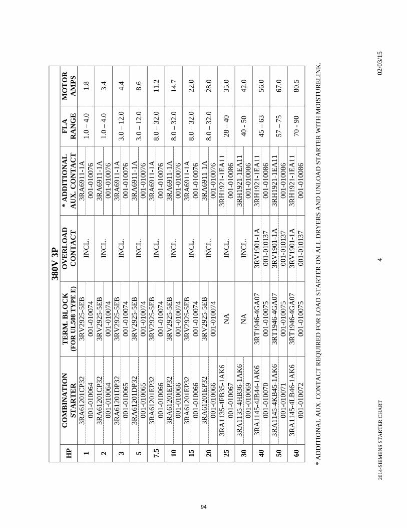
2014
-SIE
ME
NS
ST
AR
TE
R C
HA
RT
4
02/
03/1
5
380V
3P
HP
C
OM
BIN
AT
ION
S
TA
RT
ER
T
ER
M. B
LO
CK
(F
OR
UL
508
TY
PE
E)
OV
ER
LO
AD
C
ON
TA
CT
*
AD
DIT
ION
AL
A
UX
. CO
NT
AC
T
FL
A
RA
NG
E
MO
TO
R
AM
PS
1 3R
A61
201C
P32
3R
V29
25-5
EB
IN
CL
. 3R
A69
11-1
A
1.0
– 4.
0 1.
8 00
1-01
0064
00
1-01
0074
00
1-01
0076
2 3R
A61
201C
P32
3R
V29
25-5
EB
IN
CL
. 3R
A69
11-1
A
1.0
– 4.
0 3.
4 00
1-01
0064
00
1-01
0074
00
1-01
0076
3 3R
A61
201D
P32
3R
V29
25-5
EB
IN
CL
. 3R
A69
11-1
A
3.0
– 12
.0
4.4
001-
0100
65
001-
0100
74
001-
0100
76
5 3R
A61
201D
P32
3R
V29
25-5
EB
IN
CL
. 3R
A69
11-1
A
3.0
– 12
.0
8.6
001-
0100
65
001-
0100
74
001-
0100
76
7.5
3RA
6120
1EP3
2 3R
V29
25-5
EB
IN
CL
. 3R
A69
11-1
A
8.0
– 32
.0
11.2
00
1-01
0066
00
1-01
0074
00
1-01
0076
10
3RA
6120
1EP3
2 3R
V29
25-5
EB
IN
CL
. 3R
A69
11-1
A
8.0
– 32
.0
14.7
00
1-01
0066
00
1-01
0074
00
1-01
0076
15
3RA
6120
1EP3
2 3R
V29
25-5
EB
IN
CL
. 3R
A69
11-1
A
8.0
– 32
.0
22.0
00
1-01
0066
00
1-01
0074
00
1-01
0076
20
3RA
6120
1EP3
2 3R
V29
25-5
EB
IN
CL
. 3R
A69
11-1
A
8.0
– 32
.0
28.0
00
1-01
0066
00
1-01
0074
00
1-01
0076
25
3RA
1135
-4FB
35-1
AK
6 N
A
INC
L.
3RH
1921
-1E
A11
28
– 4
0 35
.0
001-
0100
67
001-
0100
86
30
3RA
1135
-4H
B36
-1A
K6
NA
IN
CL
. 3R
H19
21-1
EA
11
40 -
50
42.0
00
1-01
0069
00
1-01
0086
40
3RA
1145
-4JB
44-1
AK
6 3R
T19
46-4
GA
07
3RV
1901
-1A
3R
H19
21-1
EA
11
45 –
63
56.0
00
1-01
0070
00
1-01
0075
00
1-01
0137
00
1-01
0086
50
3RA
1145
-4K
B45
-1A
K6
3RT
1946
-4G
A07
3R
V19
01-1
A
3RH
1921
-1E
A11
57
– 7
5 67
.0
001-
0100
71
001-
0100
75
001-
0101
37
001-
0100
86
60
3RA
1145
-4L
B46
-1A
K6
3RT
1946
-4G
A07
3R
V19
01-1
A
3RH
1921
-1E
A11
70
- 9
0 80
.5
001-
0100
72
001-
0100
75
001-
0101
37
001-
0100
86
*
AD
DIT
ION
AL
AU
X. C
ON
TA
CT
RE
QU
IRE
D F
OR
LO
AD
ST
AR
TE
R O
N A
LL
DR
YE
RS
AN
D U
NL
OA
D S
TA
RT
ER
WIT
H M
OIS
TU
RE
LIN
K.
94
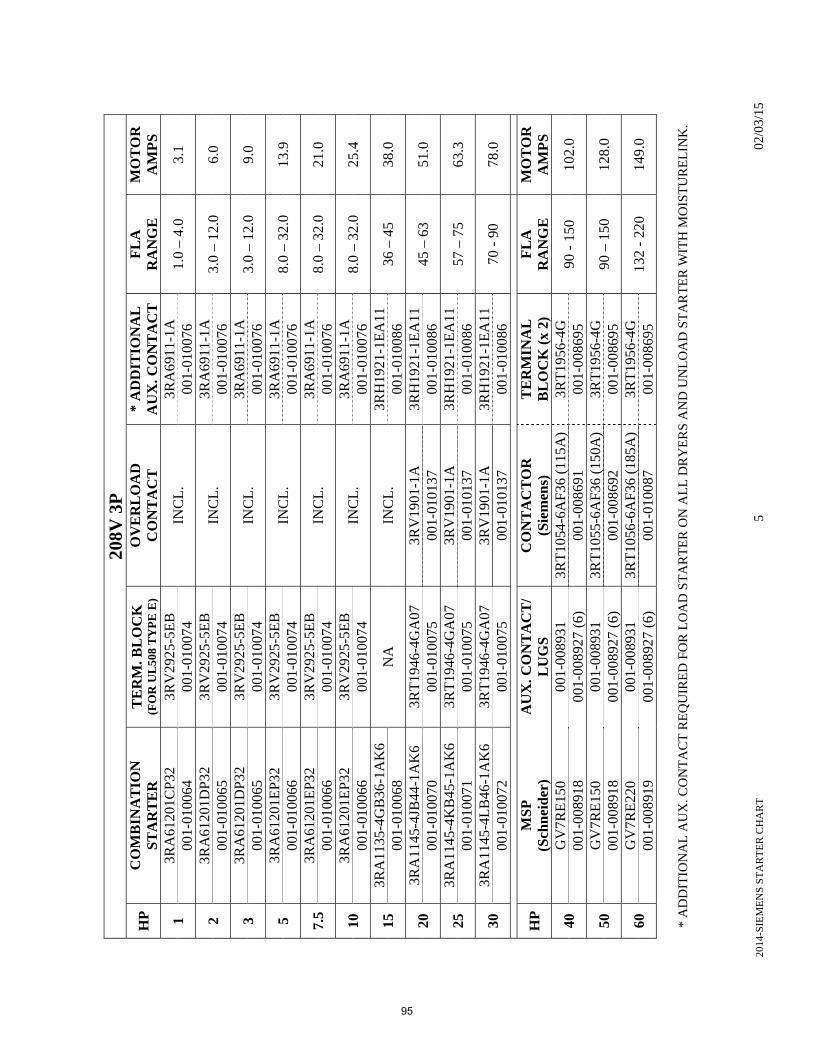
2014
-SIE
ME
NS
ST
AR
TE
R C
HA
RT
5
02/
03/1
5
208V
3P
HP
C
OM
BIN
AT
ION
S
TA
RT
ER
T
ER
M. B
LO
CK
(F
OR
UL
508
TY
PE
E)
OV
ER
LO
AD
C
ON
TA
CT
*
AD
DIT
ION
AL
A
UX
. CO
NT
AC
T
FL
A
RA
NG
E
MO
TO
R
AM
PS
1 3R
A61
201C
P32
3R
V29
25-5
EB
IN
CL
. 3R
A69
11-1
A
1.0
– 4.
0 3.
1 00
1-01
0064
00
1-01
0074
00
1-01
0076
2 3R
A61
201D
P32
3R
V29
25-5
EB
IN
CL
. 3R
A69
11-1
A
3.0
– 12
.0
6.0
001-
0100
65
001-
0100
74
001-
0100
76
3 3R
A61
201D
P32
3R
V29
25-5
EB
IN
CL
. 3R
A69
11-1
A
3.0
– 12
.0
9.0
001-
0100
65
001-
0100
74
001-
0100
76
5 3R
A61
201E
P32
3RV
2925
-5E
B
INC
L.
3RA
6911
-1A
8.
0 –
32.0
13
.9
001-
0100
66
001-
0100
74
001-
0100
76
7.5
3RA
6120
1EP3
2 3R
V29
25-5
EB
IN
CL
. 3R
A69
11-1
A
8.0
– 32
.0
21.0
00
1-01
0066
00
1-01
0074
00
1-01
0076
10
3RA
6120
1EP3
2 3R
V29
25-5
EB
IN
CL
. 3R
A69
11-1
A
8.0
– 32
.0
25.4
00
1-01
0066
00
1-01
0074
00
1-01
0076
15
3RA
1135
-4G
B36
-1A
K6
NA
IN
CL
. 3R
H19
21-1
EA
11
36 –
45
38.0
00
1-01
0068
00
1-01
0086
20
3RA
1145
-4JB
44-1
AK
6 3R
T19
46-4
GA
07
3RV
1901
-1A
3R
H19
21-1
EA
11
45 –
63
51.0
00
1-01
0070
00
1-01
0075
00
1-01
0137
00
1-01
0086
25
3RA
1145
-4K
B45
-1A
K6
3RT
1946
-4G
A07
3R
V19
01-1
A
3RH
1921
-1E
A11
57
– 7
5 63
.3
001-
0100
71
001-
0100
75
001-
0101
37
001-
0100
86
30
3RA
1145
-4L
B46
-1A
K6
3RT
1946
-4G
A07
3R
V19
01-1
A
3RH
1921
-1E
A11
70
- 9
0 78
.0
001-
0100
72
001-
0100
75
001-
0101
37
001-
0100
86
HP
M
SP
(S
chn
eid
er)
AU
X. C
ON
TA
CT
/ L
UG
S
CO
NT
AC
TO
R
(Sie
men
s)
TE
RM
INA
L
BL
OC
K (
x 2)
F
LA
R
AN
GE
M
OT
OR
A
MP
S
40
GV
7RE
150
001-
0089
31
3RT
1054
-6A
F36
(11
5A)
3RT
1956
-4G
90
- 1
50
102.
0 00
1-00
8918
00
1-00
8927
(6)
00
1-00
8691
00
1-00
8695
50
GV
7RE
150
001-
0089
31
3RT
1055
-6A
F36
(15
0A)
3RT
1956
-4G
90
– 1
50
128.
0 00
1-00
8918
00
1-00
8927
(6)
00
1-00
8692
00
1-00
8695
60
GV
7RE
220
001-
0089
31
3RT
1056
-6A
F36
(18
5A)
3RT
1956
-4G
13
2 -
220
149.
0 00
1-00
8919
00
1-00
8927
(6)
00
1-01
0087
00
1-00
8695
* A
DD
ITIO
NA
L A
UX
. CO
NT
AC
T R
EQ
UIR
ED
FO
R L
OA
D S
TA
RT
ER
ON
AL
L D
RY
ER
S A
ND
UN
LO
AD
ST
AR
TE
R W
ITH
MO
IST
UR
EL
INK
.
95
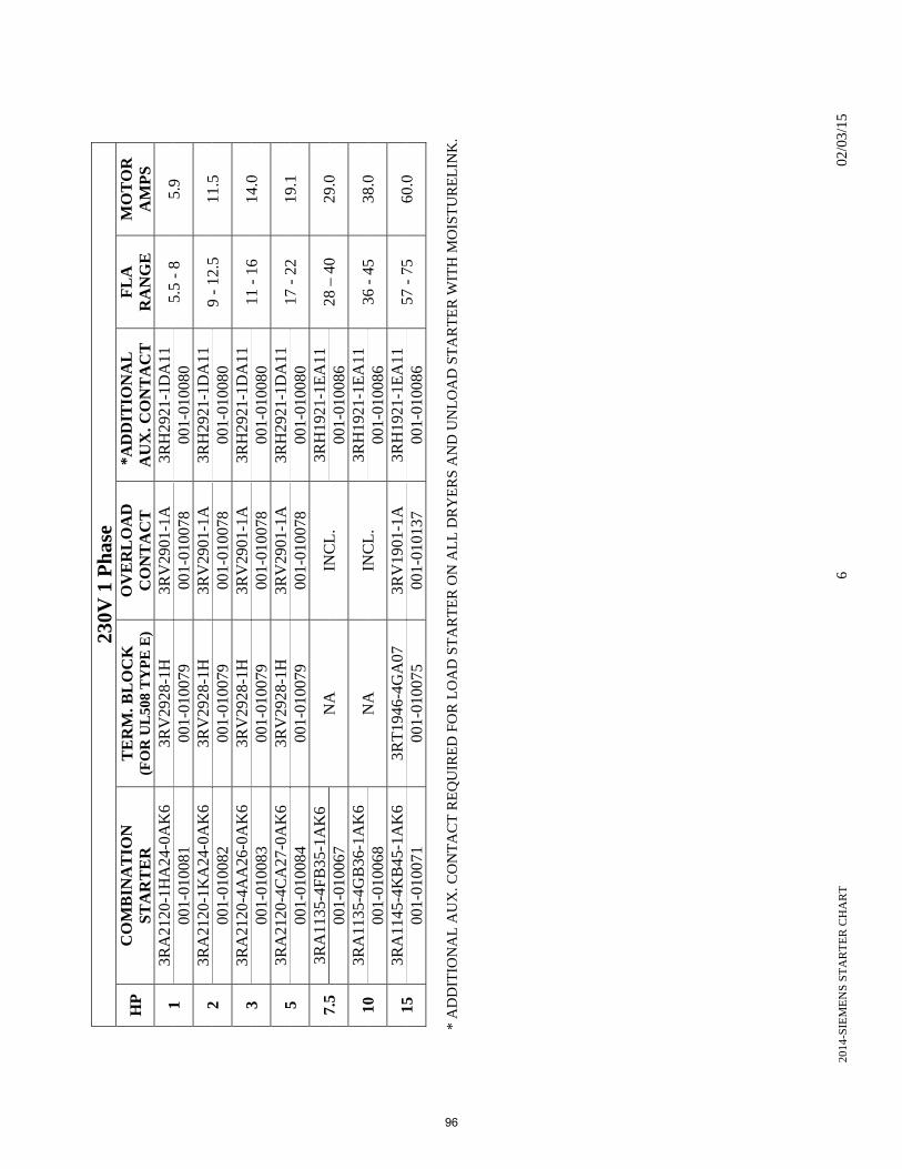
2014
-SIE
ME
NS
ST
AR
TE
R C
HA
RT
6
02/
03/1
5
230V
1 P
has
e
HP
C
OM
BIN
AT
ION
S
TA
RT
ER
T
ER
M. B
LO
CK
(F
OR
UL
508
TY
PE
E)
OV
ER
LO
AD
C
ON
TA
CT
*
AD
DIT
ION
AL
A
UX
. CO
NT
AC
T
FL
A
RA
NG
E
MO
TO
R
AM
PS
1 3R
A21
20-1
HA
24-0
AK
6 3R
V29
28-1
H
3RV
2901
-1A
3R
H29
21-1
DA
11
5.5
- 8
5.9
001-
0100
81
001-
0100
79
001-
0100
78
001-
0100
80
2 3R
A21
20-1
KA
24-0
AK
6 3R
V29
28-1
H
3RV
2901
-1A
3R
H29
21-1
DA
11
9 -
12.5
11
.5
001-
0100
82
001-
0100
79
001-
0100
78
001-
0100
80
3 3R
A21
20-4
AA
26-0
AK
6 3R
V29
28-1
H
3RV
2901
-1A
3R
H29
21-1
DA
11
11 -
16
14.0
00
1-01
0083
00
1-01
0079
00
1-01
0078
00
1-01
0080
5 3R
A21
20-4
CA
27-0
AK
6 3R
V29
28-1
H
3RV
2901
-1A
3R
H29
21-1
DA
11
17 -
22
19.1
00
1-01
0084
00
1-01
0079
00
1-01
0078
00
1-01
0080
7.5
3RA
1135
-4FB
35-1
AK
6 N
A
INC
L.
3RH
1921
-1E
A11
28
– 4
0 29
.0
001-
0100
67
001-
0100
86
10
3RA
1135
-4G
B36
-1A
K6
NA
IN
CL
. 3R
H19
21-1
EA
11
36 -
45
38.0
00
1-01
0068
00
1-01
0086
15
3RA
1145
-4K
B45
-1A
K6
3RT
1946
-4G
A07
3R
V19
01-1
A
3RH
1921
-1E
A11
57
- 7
5 60
.0
001-
0100
71
001-
0100
75
001-
0101
37
001-
0100
86
*
AD
DIT
ION
AL
AU
X. C
ON
TA
CT
RE
QU
IRE
D F
OR
LO
AD
ST
AR
TE
R O
N A
LL
DR
YE
RS
AN
D U
NL
OA
D S
TA
RT
ER
WIT
H M
OIS
TU
RE
LIN
K.
96
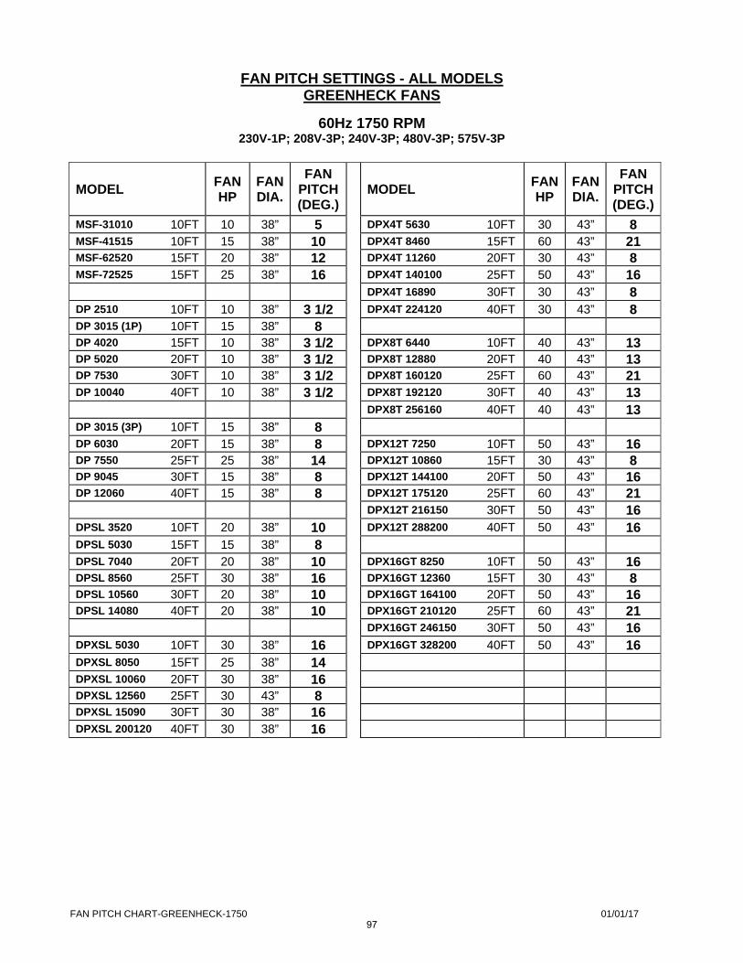
FAN PITCH CHART-GREENHECK-1750 01/01/17
FAN PITCH SETTINGS - ALL MODELS GREENHECK FANS
60Hz 1750 RPM 230V-1P; 208V-3P; 240V-3P; 480V-3P; 575V-3P
MODEL
FAN HP
FAN DIA.
FAN PITCH (DEG.)
MODEL FAN HP
FANDIA.
FAN PITCH(DEG.)
MSF-31010 10FT 10 38” 5
DPX4T 5630 10FT 30 43” 8 MSF-41515 10FT 15 38” 10
DPX4T 8460 15FT 60 43” 21 MSF-62520 15FT 20 38” 12
DPX4T 11260 20FT 30 43” 8 MSF-72525 15FT 25 38” 16
DPX4T 140100 25FT 50 43” 16
DPX4T 16890 30FT 30 43” 8 DP 2510 10FT 10 38” 3 1/2
DPX4T 224120 40FT 30 43” 8 DP 3015 (1P) 10FT 15 38” 8
DP 4020 15FT 10 38” 3 1/2
DPX8T 6440 10FT 40 43” 13 DP 5020 20FT 10 38” 3 1/2
DPX8T 12880 20FT 40 43” 13 DP 7530 30FT 10 38” 3 1/2
DPX8T 160120 25FT 60 43” 21 DP 10040 40FT 10 38” 3 1/2
DPX8T 192120 30FT 40 43” 13
DPX8T 256160 40FT 40 43” 13 DP 3015 (3P) 10FT 15 38” 8
DP 6030 20FT 15 38” 8
DPX12T 7250 10FT 50 43” 16 DP 7550 25FT 25 38” 14
DPX12T 10860 15FT 30 43” 8 DP 9045 30FT 15 38” 8
DPX12T 144100 20FT 50 43” 16 DP 12060 40FT 15 38” 8
DPX12T 175120 25FT 60 43” 21
DPX12T 216150 30FT 50 43” 16 DPSL 3520 10FT 20 38” 10
DPX12T 288200 40FT 50 43” 16 DPSL 5030 15FT 15 38” 8
DPSL 7040 20FT 20 38” 10
DPX16GT 8250 10FT 50 43” 16 DPSL 8560 25FT 30 38” 16
DPX16GT 12360 15FT 30 43” 8 DPSL 10560 30FT 20 38” 10
DPX16GT 164100 20FT 50 43” 16 DPSL 14080 40FT 20 38” 10
DPX16GT 210120 25FT 60 43” 21
DPX16GT 246150 30FT 50 43” 16 DPXSL 5030 10FT 30 38” 16
DPX16GT 328200 40FT 50 43” 16 DPXSL 8050 15FT 25 38” 14
DPXSL 10060 20FT 30 38” 16
DPXSL 12560 25FT 30 43” 8
DPXSL 15090 30FT 30 38” 16
DPXSL 200120 40FT 30 38” 16
97

98
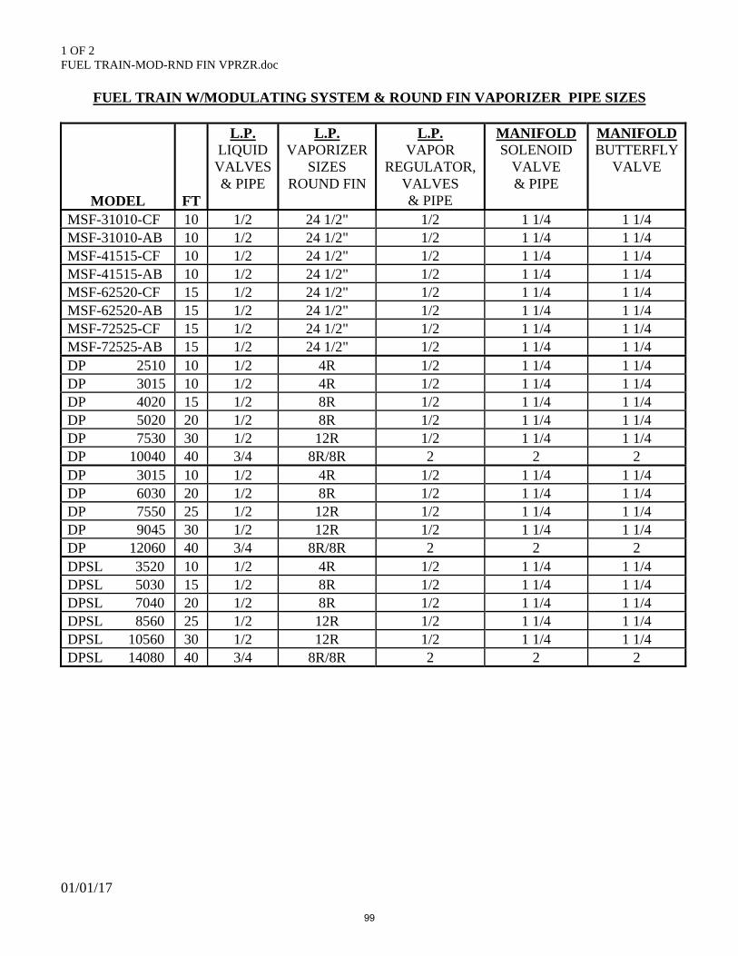
1 OF 2 FUEL TRAIN-MOD-RND FIN VPRZR.doc
01/01/17
FUEL TRAIN W/MODULATING SYSTEM & ROUND FIN VAPORIZER PIPE SIZES
MODEL
FT
L.P. LIQUID VALVES & PIPE
L.P. VAPORIZER
SIZES ROUND FIN
L.P. VAPOR
REGULATOR, VALVES & PIPE
MANIFOLD SOLENOID
VALVE & PIPE
MANIFOLDBUTTERFLY
VALVE
MSF-31010-CF 10 1/2 24 1/2" 1/2 1 1/4 1 1/4 MSF-31010-AB 10 1/2 24 1/2" 1/2 1 1/4 1 1/4 MSF-41515-CF 10 1/2 24 1/2" 1/2 1 1/4 1 1/4 MSF-41515-AB 10 1/2 24 1/2" 1/2 1 1/4 1 1/4 MSF-62520-CF 15 1/2 24 1/2" 1/2 1 1/4 1 1/4 MSF-62520-AB 15 1/2 24 1/2" 1/2 1 1/4 1 1/4 MSF-72525-CF 15 1/2 24 1/2" 1/2 1 1/4 1 1/4 MSF-72525-AB 15 1/2 24 1/2" 1/2 1 1/4 1 1/4 DP 2510 10 1/2 4R 1/2 1 1/4 1 1/4 DP 3015 10 1/2 4R 1/2 1 1/4 1 1/4 DP 4020 15 1/2 8R 1/2 1 1/4 1 1/4 DP 5020 20 1/2 8R 1/2 1 1/4 1 1/4 DP 7530 30 1/2 12R 1/2 1 1/4 1 1/4 DP 10040 40 3/4 8R/8R 2 2 2 DP 3015 10 1/2 4R 1/2 1 1/4 1 1/4 DP 6030 20 1/2 8R 1/2 1 1/4 1 1/4 DP 7550 25 1/2 12R 1/2 1 1/4 1 1/4 DP 9045 30 1/2 12R 1/2 1 1/4 1 1/4 DP 12060 40 3/4 8R/8R 2 2 2 DPSL 3520 10 1/2 4R 1/2 1 1/4 1 1/4 DPSL 5030 15 1/2 8R 1/2 1 1/4 1 1/4 DPSL 7040 20 1/2 8R 1/2 1 1/4 1 1/4 DPSL 8560 25 1/2 12R 1/2 1 1/4 1 1/4 DPSL 10560 30 1/2 12R 1/2 1 1/4 1 1/4 DPSL 14080 40 3/4 8R/8R 2 2 2
99
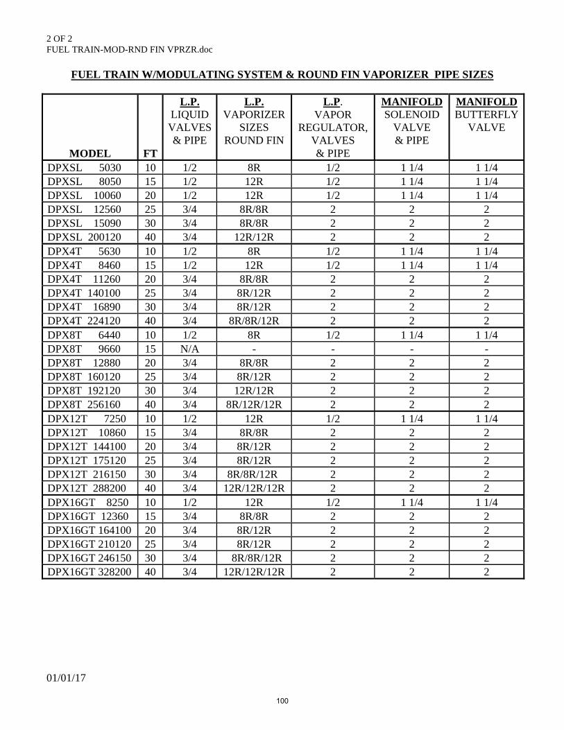
2 OF 2 FUEL TRAIN-MOD-RND FIN VPRZR.doc
01/01/17
FUEL TRAIN W/MODULATING SYSTEM & ROUND FIN VAPORIZER PIPE SIZES
MODEL
FT
L.P. LIQUID VALVES & PIPE
L.P. VAPORIZER
SIZES ROUND FIN
L.P. VAPOR
REGULATOR, VALVES & PIPE
MANIFOLD SOLENOID
VALVE & PIPE
MANIFOLDBUTTERFLY
VALVE
DPXSL 5030 10 1/2 8R 1/2 1 1/4 1 1/4 DPXSL 8050 15 1/2 12R 1/2 1 1/4 1 1/4 DPXSL 10060 20 1/2 12R 1/2 1 1/4 1 1/4 DPXSL 12560 25 3/4 8R/8R 2 2 2 DPXSL 15090 30 3/4 8R/8R 2 2 2 DPXSL 200120 40 3/4 12R/12R 2 2 2 DPX4T 5630 10 1/2 8R 1/2 1 1/4 1 1/4 DPX4T 8460 15 1/2 12R 1/2 1 1/4 1 1/4 DPX4T 11260 20 3/4 8R/8R 2 2 2 DPX4T 140100 25 3/4 8R/12R 2 2 2 DPX4T 16890 30 3/4 8R/12R 2 2 2 DPX4T 224120 40 3/4 8R/8R/12R 2 2 2 DPX8T 6440 10 1/2 8R 1/2 1 1/4 1 1/4 DPX8T 9660 15 N/A - - - - DPX8T 12880 20 3/4 8R/8R 2 2 2 DPX8T 160120 25 3/4 8R/12R 2 2 2 DPX8T 192120 30 3/4 12R/12R 2 2 2 DPX8T 256160 40 3/4 8R/12R/12R 2 2 2 DPX12T 7250 10 1/2 12R 1/2 1 1/4 1 1/4 DPX12T 10860 15 3/4 8R/8R 2 2 2 DPX12T 144100 20 3/4 8R/12R 2 2 2 DPX12T 175120 25 3/4 8R/12R 2 2 2 DPX12T 216150 30 3/4 8R/8R/12R 2 2 2 DPX12T 288200 40 3/4 12R/12R/12R 2 2 2 DPX16GT 8250 10 1/2 12R 1/2 1 1/4 1 1/4 DPX16GT 12360 15 3/4 8R/8R 2 2 2 DPX16GT 164100 20 3/4 8R/12R 2 2 2 DPX16GT 210120 25 3/4 8R/12R 2 2 2 DPX16GT 246150 30 3/4 8R/8R/12R 2 2 2 DPX16GT 328200 40 3/4 12R/12R/12R 2 2 2
100
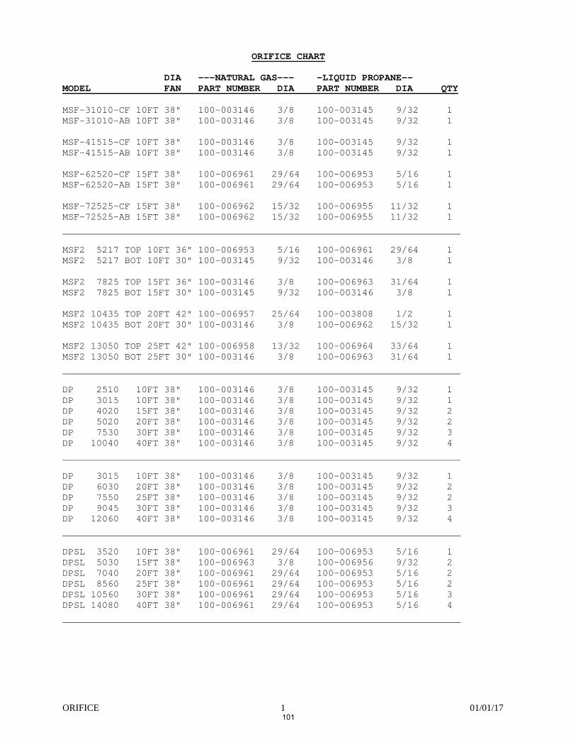
ORIFICE 1 01/01/17
ORIFICE CHART
DIA ---NATURAL GAS--- -LIQUID PROPANE-- MODEL FAN PART NUMBER DIA PART NUMBER DIA QTY MSF-31010-CF 10FT 38" 100-003146 3/8 100-003145 9/32 1 MSF-31010-AB 10FT 38" 100-003146 3/8 100-003145 9/32 1 MSF-41515-CF 10FT 38" 100-003146 3/8 100-003145 9/32 1 MSF-41515-AB 10FT 38" 100-003146 3/8 100-003145 9/32 1 MSF-62520-CF 15FT 38" 100-006961 29/64 100-006953 5/16 1 MSF-62520-AB 15FT 38" 100-006961 29/64 100-006953 5/16 1 MSF-72525-CF 15FT 38" 100-006962 15/32 100-006955 11/32 1 MSF-72525-AB 15FT 38" 100-006962 15/32 100-006955 11/32 1 MSF2 5217 TOP 10FT 36" 100-006953 5/16 100-006961 29/64 1 MSF2 5217 BOT 10FT 30" 100-003145 9/32 100-003146 3/8 1 MSF2 7825 TOP 15FT 36" 100-003146 3/8 100-006963 31/64 1 MSF2 7825 BOT 15FT 30" 100-003145 9/32 100-003146 3/8 1 MSF2 10435 TOP 20FT 42" 100-006957 25/64 100-003808 1/2 1 MSF2 10435 BOT 20FT 30" 100-003146 3/8 100-006962 15/32 1 MSF2 13050 TOP 25FT 42" 100-006958 13/32 100-006964 33/64 1 MSF2 13050 BOT 25FT 30" 100-003146 3/8 100-006963 31/64 1 DP 2510 10FT 38" 100-003146 3/8 100-003145 9/32 1 DP 3015 10FT 38" 100-003146 3/8 100-003145 9/32 1 DP 4020 15FT 38" 100-003146 3/8 100-003145 9/32 2 DP 5020 20FT 38" 100-003146 3/8 100-003145 9/32 2 DP 7530 30FT 38" 100-003146 3/8 100-003145 9/32 3 DP 10040 40FT 38" 100-003146 3/8 100-003145 9/32 4 DP 3015 10FT 38" 100-003146 3/8 100-003145 9/32 1 DP 6030 20FT 38" 100-003146 3/8 100-003145 9/32 2 DP 7550 25FT 38" 100-003146 3/8 100-003145 9/32 2 DP 9045 30FT 38" 100-003146 3/8 100-003145 9/32 3 DP 12060 40FT 38" 100-003146 3/8 100-003145 9/32 4 DPSL 3520 10FT 38" 100-006961 29/64 100-006953 5/16 1 DPSL 5030 15FT 38" 100-006963 3/8 100-006956 9/32 2 DPSL 7040 20FT 38" 100-006961 29/64 100-006953 5/16 2 DPSL 8560 25FT 38" 100-006961 29/64 100-006953 5/16 2 DPSL 10560 30FT 38" 100-006961 29/64 100-006953 5/16 3 DPSL 14080 40FT 38" 100-006961 29/64 100-006953 5/16 4
101
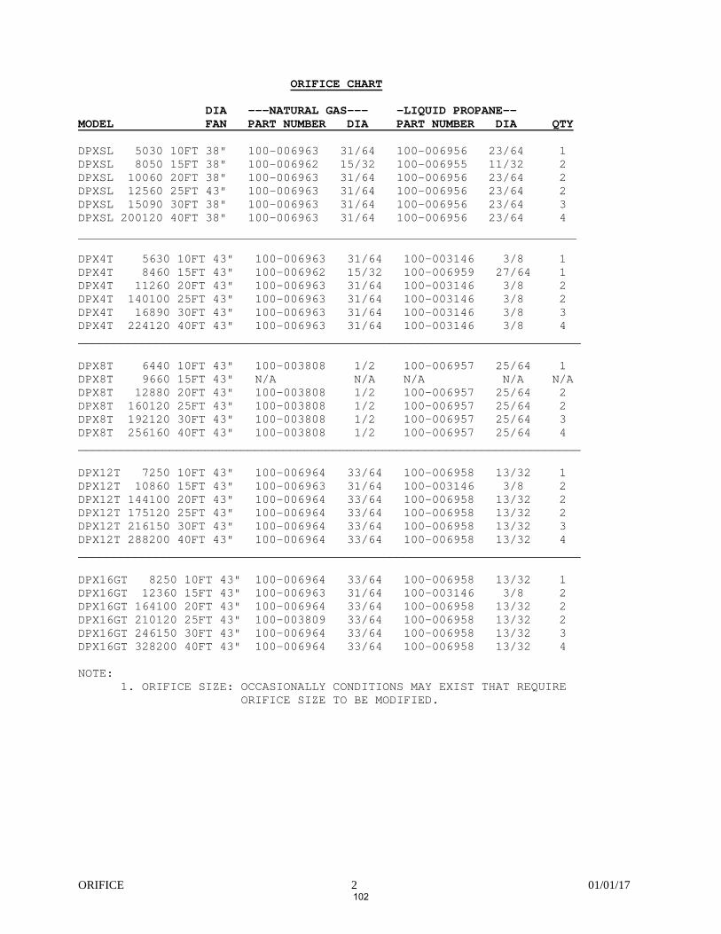
ORIFICE 2 01/01/17
ORIFICE CHART DIA ---NATURAL GAS--- -LIQUID PROPANE-- MODEL FAN PART NUMBER DIA PART NUMBER DIA QTY DPXSL 5030 10FT 38" 100-006963 31/64 100-006956 23/64 1 DPXSL 8050 15FT 38" 100-006962 15/32 100-006955 11/32 2 DPXSL 10060 20FT 38" 100-006963 31/64 100-006956 23/64 2 DPXSL 12560 25FT 43" 100-006963 31/64 100-006956 23/64 2 DPXSL 15090 30FT 38" 100-006963 31/64 100-006956 23/64 3 DPXSL 200120 40FT 38" 100-006963 31/64 100-006956 23/64 4 DPX4T 5630 10FT 43" 100-006963 31/64 100-003146 3/8 1 DPX4T 8460 15FT 43" 100-006962 15/32 100-006959 27/64 1 DPX4T 11260 20FT 43" 100-006963 31/64 100-003146 3/8 2 DPX4T 140100 25FT 43" 100-006963 31/64 100-003146 3/8 2 DPX4T 16890 30FT 43" 100-006963 31/64 100-003146 3/8 3 DPX4T 224120 40FT 43" 100-006963 31/64 100-003146 3/8 4 _______________________________________________________________________ DPX8T 6440 10FT 43" 100-003808 1/2 100-006957 25/64 1 DPX8T 9660 15FT 43" N/A N/A N/A N/A N/A DPX8T 12880 20FT 43" 100-003808 1/2 100-006957 25/64 2 DPX8T 160120 25FT 43" 100-003808 1/2 100-006957 25/64 2 DPX8T 192120 30FT 43" 100-003808 1/2 100-006957 25/64 3 DPX8T 256160 40FT 43" 100-003808 1/2 100-006957 25/64 4 _______________________________________________________________________ DPX12T 7250 10FT 43" 100-006964 33/64 100-006958 13/32 1 DPX12T 10860 15FT 43" 100-006963 31/64 100-003146 3/8 2 DPX12T 144100 20FT 43" 100-006964 33/64 100-006958 13/32 2 DPX12T 175120 25FT 43" 100-006964 33/64 100-006958 13/32 2 DPX12T 216150 30FT 43" 100-006964 33/64 100-006958 13/32 3 DPX12T 288200 40FT 43" 100-006964 33/64 100-006958 13/32 4 _______________________________________________________________________ DPX16GT 8250 10FT 43" 100-006964 33/64 100-006958 13/32 1 DPX16GT 12360 15FT 43" 100-006963 31/64 100-003146 3/8 2 DPX16GT 164100 20FT 43" 100-006964 33/64 100-006958 13/32 2 DPX16GT 210120 25FT 43" 100-003809 33/64 100-006958 13/32 2 DPX16GT 246150 30FT 43" 100-006964 33/64 100-006958 13/32 3 DPX16GT 328200 40FT 43" 100-006964 33/64 100-006958 13/32 4 NOTE:
1. ORIFICE SIZE: OCCASIONALLY CONDITIONS MAY EXIST THAT REQUIRE ORIFICE SIZE TO BE MODIFIED.
102
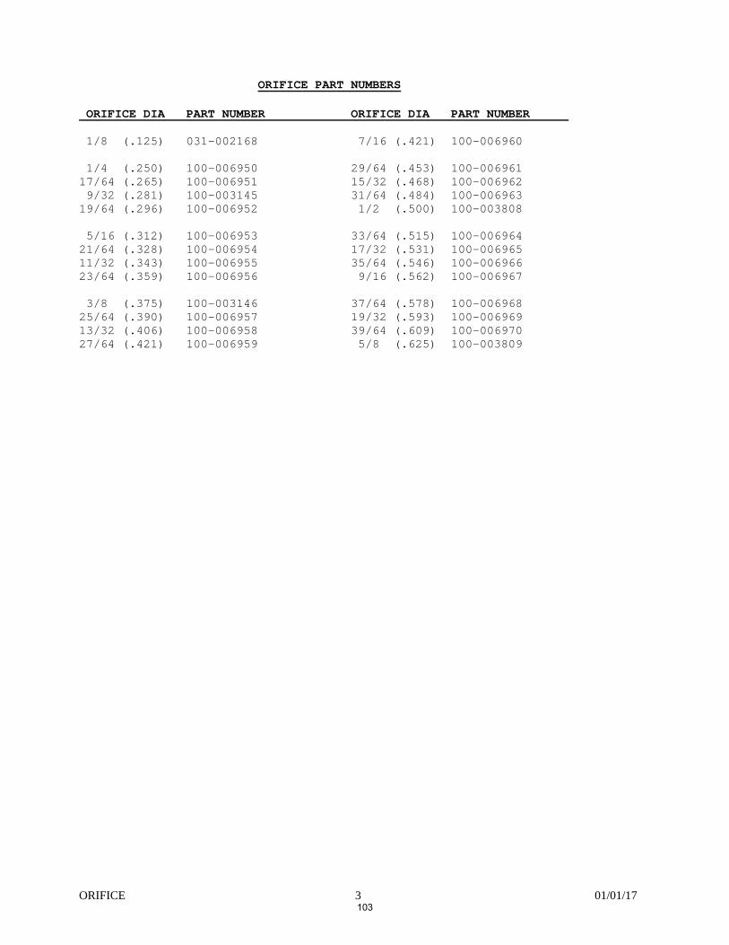
ORIFICE 3 01/01/17
ORIFICE PART NUMBERS ORIFICE DIA PART NUMBER ORIFICE DIA PART NUMBER 1/8 (.125) 031-002168 7/16 (.421) 100-006960 1/4 (.250) 100-006950 29/64 (.453) 100-006961 17/64 (.265) 100-006951 15/32 (.468) 100-006962 9/32 (.281) 100-003145 31/64 (.484) 100-006963 19/64 (.296) 100-006952 1/2 (.500) 100-003808 5/16 (.312) 100-006953 33/64 (.515) 100-006964 21/64 (.328) 100-006954 17/32 (.531) 100-006965 11/32 (.343) 100-006955 35/64 (.546) 100-006966 23/64 (.359) 100-006956 9/16 (.562) 100-006967 3/8 (.375) 100-003146 37/64 (.578) 100-006968 25/64 (.390) 100-006957 19/32 (.593) 100-006969 13/32 (.406) 100-006958 39/64 (.609) 100-006970 27/64 (.421) 100-006959 5/8 (.625) 100-003809
103

104
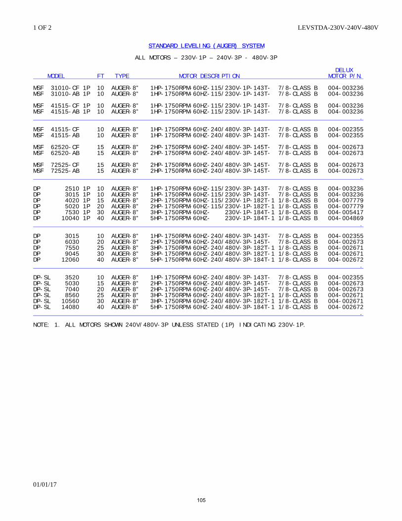
1 OF 2 LEVSTDA-230V-240V-480V
01/01/17
STANDARD LEVELING (AUGER) SYSTEM
ALL MOTORS – 230V-1P – 240V-3P - 480V-3P
DELUX MODEL FT TYPE MOTOR DESCRIPTION MOTOR P/N. MSF 31010-CF 1P 10 AUGER-8” 1HP-1750RPM-60HZ-115/230V-1P-143T- 7/8-CLASS B 004-003236 MSF 31010-AB 1P 10 AUGER-8” 1HP-1750RPM-60HZ-115/230V-1P-143T- 7/8-CLASS B 004-003236 MSF 41515-CF 1P 10 AUGER-8” 1HP-1750RPM-60HZ-115/230V-1P-143T- 7/8-CLASS B 004-003236 MSF 41515-AB 1P 10 AUGER-8” 1HP-1750RPM-60HZ-115/230V-1P-143T- 7/8-CLASS B 004-003236 . MSF 41515-CF 10 AUGER-8” 1HP-1750RPM-60HZ-240/480V-3P-143T- 7/8-CLASS B 004-002355 MSF 41515-AB 10 AUGER-8” 1HP-1750RPM-60HZ-240/480V-3P-143T- 7/8-CLASS B 004-002355 MSF 62520-CF 15 AUGER-8” 2HP-1750RPM-60HZ-240/480V-3P-145T- 7/8-CLASS B 004-002673 MSF 62520-AB 15 AUGER-8” 2HP-1750RPM-60HZ-240/480V-3P-145T- 7/8-CLASS B 004-002673 MSF 72525-CF 15 AUGER-8” 2HP-1750RPM-60HZ-240/480V-3P-145T- 7/8-CLASS B 004-002673 MSF 72525-AB 15 AUGER-8” 2HP-1750RPM-60HZ-240/480V-3P-145T- 7/8-CLASS B 004-002673 . DP 2510 1P 10 AUGER-8” 1HP-1750RPM-60HZ-115/230V-3P-143T- 7/8-CLASS B 004-003236 DP 3015 1P 10 AUGER-8” 1HP-1750RPM-60HZ-115/230V-3P-143T- 7/8-CLASS B 004-003236 DP 4020 1P 15 AUGER-8” 2HP-1750RPM-60HZ-115/230V-1P-182T-1 1/8-CLASS B 004-007779 DP 5020 1P 20 AUGER-8” 2HP-1750RPM-60HZ-115/230V-1P-182T-1 1/8-CLASS B 004-007779 DP 7530 1P 30 AUGER-8” 3HP-1750RPM-60HZ- 230V-1P-184T-1 1/8-CLASS B 004-005417 DP 10040 1P 40 AUGER-8” 5HP-1750RPM-60HZ- 230V-1P-184T-1 1/8-CLASS B 004-004869 . DP 3015 10 AUGER-8” 1HP-1750RPM-60HZ-240/480V-3P-143T- 7/8-CLASS B 004-002355 DP 6030 20 AUGER-8” 2HP-1750RPM-60HZ-240/480V-3P-145T- 7/8-CLASS B 004-002673 DP 7550 25 AUGER-8” 3HP-1750RPM-60HZ-240/480V-3P-182T-1 1/8-CLASS B 004-002671 DP 9045 30 AUGER-8” 3HP-1750RPM-60HZ-240/480V-3P-182T-1 1/8-CLASS B 004-002671 DP 12060 40 AUGER-8” 5HP-1750RPM-60HZ-240/480V-3P-184T-1 1/8-CLASS B 004-002672 . DP-SL 3520 10 AUGER-8” 1HP-1750RPM-60HZ-240/480V-3P-143T- 7/8-CLASS B 004-002355 DP-SL 5030 15 AUGER-8” 2HP-1750RPM-60HZ-240/480V-3P-145T- 7/8-CLASS B 004-002673 DP-SL 7040 20 AUGER-8” 2HP-1750RPM-60HZ-240/480V-3P-145T- 7/8-CLASS B 004-002673 DP-SL 8560 25 AUGER-8” 3HP-1750RPM-60HZ-240/480V-3P-182T-1 1/8-CLASS B 004-002671 DP-SL 10560 30 AUGER-8” 3HP-1750RPM-60HZ-240/480V-3P-182T-1 1/8-CLASS B 004-002671 DP-SL 14080 40 AUGER-8” 5HP-1750RPM-60HZ-240/480V-3P-184T-1 1/8-CLASS B 004-002672 . NOTE: 1. ALL MOTORS SHOWN 240V/480V-3P UNLESS STATED (1P) INDICATING 230V-1P.
105
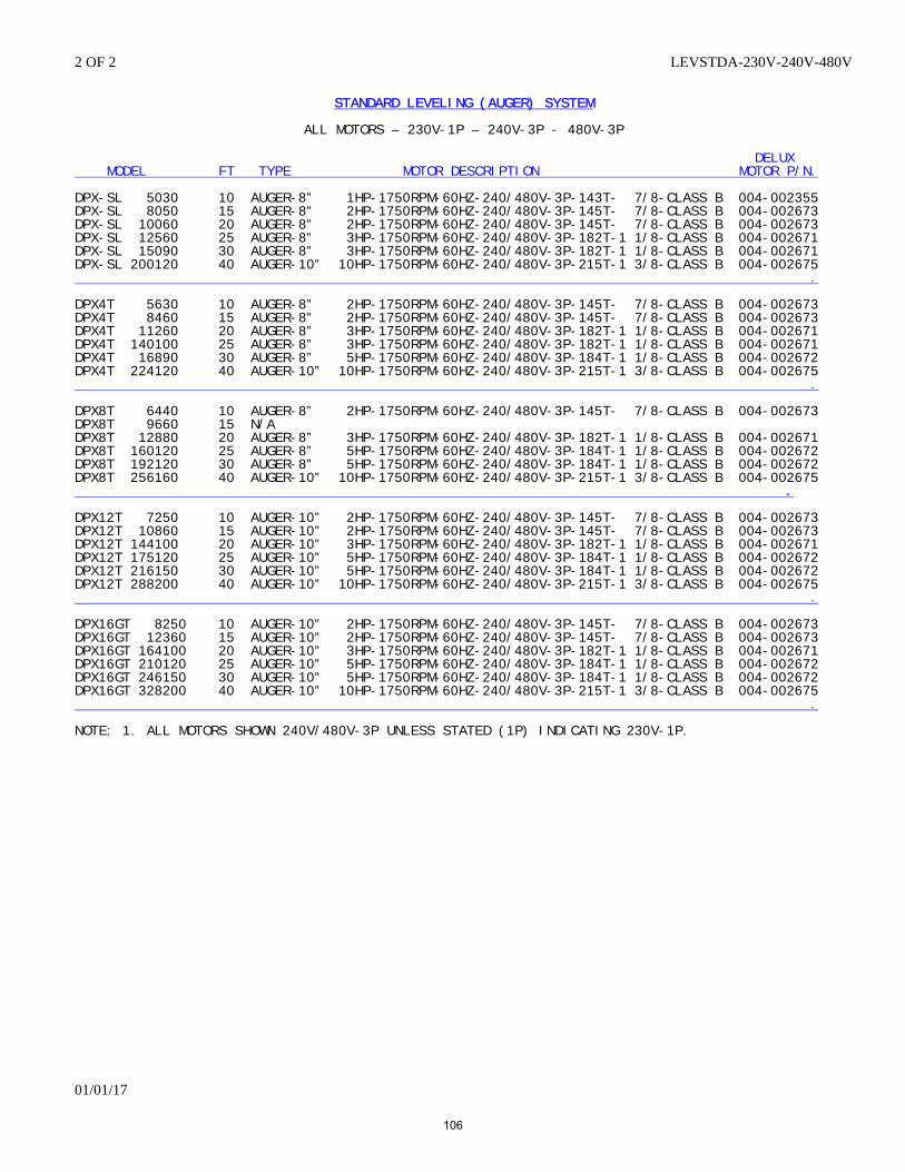
2 OF 2 LEVSTDA-230V-240V-480V
01/01/17
STANDARD LEVELING (AUGER) SYSTEM
ALL MOTORS – 230V-1P – 240V-3P - 480V-3P
DELUX MODEL FT TYPE MOTOR DESCRIPTION MOTOR P/N. DPX-SL 5030 10 AUGER-8” 1HP-1750RPM-60HZ-240/480V-3P-143T- 7/8-CLASS B 004-002355 DPX-SL 8050 15 AUGER-8” 2HP-1750RPM-60HZ-240/480V-3P-145T- 7/8-CLASS B 004-002673 DPX-SL 10060 20 AUGER-8” 2HP-1750RPM-60HZ-240/480V-3P-145T- 7/8-CLASS B 004-002673 DPX-SL 12560 25 AUGER-8” 3HP-1750RPM-60HZ-240/480V-3P-182T-1 1/8-CLASS B 004-002671 DPX-SL 15090 30 AUGER-8” 3HP-1750RPM-60HZ-240/480V-3P-182T-1 1/8-CLASS B 004-002671 DPX-SL 200120 40 AUGER-10” 10HP-1750RPM-60HZ-240/480V-3P-215T-1 3/8-CLASS B 004-002675 . DPX4T 5630 10 AUGER-8” 2HP-1750RPM-60HZ-240/480V-3P-145T- 7/8-CLASS B 004-002673 DPX4T 8460 15 AUGER-8” 2HP-1750RPM-60HZ-240/480V-3P-145T- 7/8-CLASS B 004-002673 DPX4T 11260 20 AUGER-8” 3HP-1750RPM-60HZ-240/480V-3P-182T-1 1/8-CLASS B 004-002671 DPX4T 140100 25 AUGER-8” 3HP-1750RPM-60HZ-240/480V-3P-182T-1 1/8-CLASS B 004-002671 DPX4T 16890 30 AUGER-8” 5HP-1750RPM-60HZ-240/480V-3P-184T-1 1/8-CLASS B 004-002672 DPX4T 224120 40 AUGER-10” 10HP-1750RPM-60HZ-240/480V-3P-215T-1 3/8-CLASS B 004-002675 . DPX8T 6440 10 AUGER-8” 2HP-1750RPM-60HZ-240/480V-3P-145T- 7/8-CLASS B 004-002673 DPX8T 9660 15 N/A DPX8T 12880 20 AUGER-8” 3HP-1750RPM-60HZ-240/480V-3P-182T-1 1/8-CLASS B 004-002671 DPX8T 160120 25 AUGER-8” 5HP-1750RPM-60HZ-240/480V-3P-184T-1 1/8-CLASS B 004-002672 DPX8T 192120 30 AUGER-8” 5HP-1750RPM-60HZ-240/480V-3P-184T-1 1/8-CLASS B 004-002672 DPX8T 256160 40 AUGER-10” 10HP-1750RPM-60HZ-240/480V-3P-215T-1 3/8-CLASS B 004-002675 . DPX12T 7250 10 AUGER-10” 2HP-1750RPM-60HZ-240/480V-3P-145T- 7/8-CLASS B 004-002673 DPX12T 10860 15 AUGER-10” 2HP-1750RPM-60HZ-240/480V-3P-145T- 7/8-CLASS B 004-002673 DPX12T 144100 20 AUGER-10” 3HP-1750RPM-60HZ-240/480V-3P-182T-1 1/8-CLASS B 004-002671 DPX12T 175120 25 AUGER-10” 5HP-1750RPM-60HZ-240/480V-3P-184T-1 1/8-CLASS B 004-002672 DPX12T 216150 30 AUGER-10” 5HP-1750RPM-60HZ-240/480V-3P-184T-1 1/8-CLASS B 004-002672 DPX12T 288200 40 AUGER-10” 10HP-1750RPM-60HZ-240/480V-3P-215T-1 3/8-CLASS B 004-002675 .
DPX16GT 8250 10 AUGER-10” 2HP-1750RPM-60HZ-240/480V-3P-145T- 7/8-CLASS B 004-002673 DPX16GT 12360 15 AUGER-10” 2HP-1750RPM-60HZ-240/480V-3P-145T- 7/8-CLASS B 004-002673 DPX16GT 164100 20 AUGER-10” 3HP-1750RPM-60HZ-240/480V-3P-182T-1 1/8-CLASS B 004-002671 DPX16GT 210120 25 AUGER-10” 5HP-1750RPM-60HZ-240/480V-3P-184T-1 1/8-CLASS B 004-002672 DPX16GT 246150 30 AUGER-10” 5HP-1750RPM-60HZ-240/480V-3P-184T-1 1/8-CLASS B 004-002672 DPX16GT 328200 40 AUGER-10” 10HP-1750RPM-60HZ-240/480V-3P-215T-1 3/8-CLASS B 004-002675 . NOTE: 1. ALL MOTORS SHOWN 240V/480V-3P UNLESS STATED (1P) INDICATING 230V-1P.
106
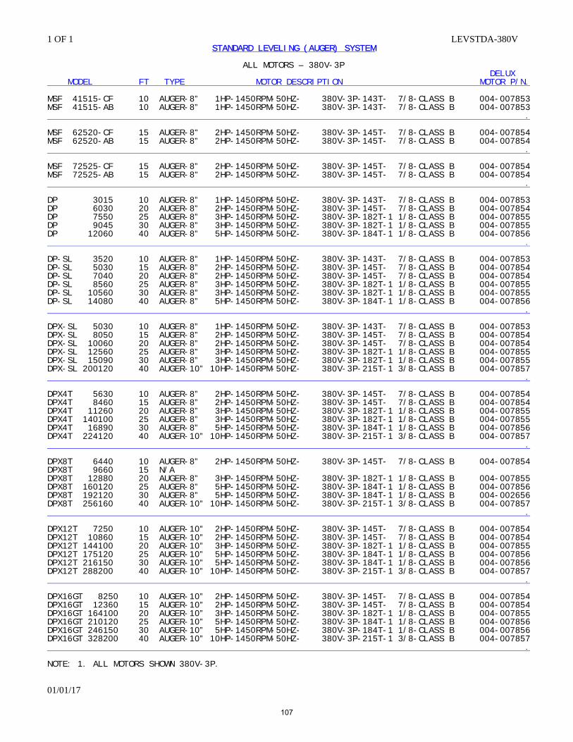
1 OF 1 LEVSTDA-380V
01/01/17
STANDARD LEVELING (AUGER) SYSTEM
ALL MOTORS – 380V-3P DELUX MODEL FT TYPE MOTOR DESCRIPTION MOTOR P/N. MSF 41515-CF 10 AUGER-8” 1HP-1450RPM-50HZ- 380V-3P-143T- 7/8-CLASS B 004-007853 MSF 41515-AB 10 AUGER-8” 1HP-1450RPM-50HZ- 380V-3P-143T- 7/8-CLASS B 004-007853 . MSF 62520-CF 15 AUGER-8" 2HP-1450RPM-50HZ- 380V-3P-145T- 7/8-CLASS B 004-007854 MSF 62520-AB 15 AUGER-8” 2HP-1450RPM-50HZ- 380V-3P-145T- 7/8-CLASS B 004-007854 . MSF 72525-CF 15 AUGER-8” 2HP-1450RPM-50HZ- 380V-3P-145T- 7/8-CLASS B 004-007854 MSF 72525-AB 15 AUGER-8" 2HP-1450RPM-50HZ- 380V-3P-145T- 7/8-CLASS B 004-007854 . DP 3015 10 AUGER-8” 1HP-1450RPM-50HZ- 380V-3P-143T- 7/8-CLASS B 004-007853 DP 6030 20 AUGER-8” 2HP-1450RPM-50HZ- 380V-3P-145T- 7/8-CLASS B 004-007854 DP 7550 25 AUGER-8” 3HP-1450RPM-50HZ- 380V-3P-182T-1 1/8-CLASS B 004-007855 DP 9045 30 AUGER-8” 3HP-1450RPM-50HZ- 380V-3P-182T-1 1/8-CLASS B 004-007855 DP 12060 40 AUGER-8” 5HP-1450RPM-50HZ- 380V-3P-184T-1 1/8-CLASS B 004-007856 . DP-SL 3520 10 AUGER-8” 1HP-1450RPM-50HZ- 380V-3P-143T- 7/8-CLASS B 004-007853 DP-SL 5030 15 AUGER-8” 2HP-1450RPM-50HZ- 380V-3P-145T- 7/8-CLASS B 004-007854 DP-SL 7040 20 AUGER-8” 2HP-1450RPM-50HZ- 380V-3P-145T- 7/8-CLASS B 004-007854 DP-SL 8560 25 AUGER-8” 3HP-1450RPM-50HZ- 380V-3P-182T-1 1/8-CLASS B 004-007855 DP-SL 10560 30 AUGER-8” 3HP-1450RPM-50HZ- 380V-3P-182T-1 1/8-CLASS B 004-007855 DP-SL 14080 40 AUGER-8” 5HP-1450RPM-50HZ- 380V-3P-184T-1 1/8-CLASS B 004-007856 . DPX-SL 5030 10 AUGER-8” 1HP-1450RPM-50HZ- 380V-3P-143T- 7/8-CLASS B 004-007853 DPX-SL 8050 15 AUGER-8” 2HP-1450RPM-50HZ- 380V-3P-145T- 7/8-CLASS B 004-007854 DPX-SL 10060 20 AUGER-8” 2HP-1450RPM-50HZ- 380V-3P-145T- 7/8-CLASS B 004-007854 DPX-SL 12560 25 AUGER-8” 3HP-1450RPM-50HZ- 380V-3P-182T-1 1/8-CLASS B 004-007855 DPX-SL 15090 30 AUGER-8” 3HP-1450RPM-50HZ- 380V-3P-182T-1 1/8-CLASS B 004-007855 DPX-SL 200120 40 AUGER-10” 10HP-1450RPM-50HZ- 380V-3P-215T-1 3/8-CLASS B 004-007857 . DPX4T 5630 10 AUGER-8” 2HP-1450RPM-50HZ- 380V-3P-145T- 7/8-CLASS B 004-007854 DPX4T 8460 15 AUGER-8” 2HP-1450RPM-50HZ- 380V-3P-145T- 7/8-CLASS B 004-007854 DPX4T 11260 20 AUGER-8” 3HP-1450RPM-50HZ- 380V-3P-182T-1 1/8-CLASS B 004-007855 DPX4T 140100 25 AUGER-8” 3HP-1450RPM-50HZ- 380V-3P-182T-1 1/8-CLASS B 004-007855 DPX4T 16890 30 AUGER-8” 5HP-1450RPM-50HZ- 380V-3P-184T-1 1/8-CLASS B 004-007856 DPX4T 224120 40 AUGER-10” 10HP-1450RPM-50HZ- 380V-3P-215T-1 3/8-CLASS B 004-007857 . DPX8T 6440 10 AUGER-8” 2HP-1450RPM-50HZ- 380V-3P-145T- 7/8-CLASS B 004-007854 DPX8T 9660 15 N/A DPX8T 12880 20 AUGER-8” 3HP-1450RPM-50HZ- 380V-3P-182T-1 1/8-CLASS B 004-007855 DPX8T 160120 25 AUGER-8” 5HP-1450RPM-50HZ- 380V-3P-184T-1 1/8-CLASS B 004-007856 DPX8T 192120 30 AUGER-8” 5HP-1450RPM-50HZ- 380V-3P-184T-1 1/8-CLASS B 004-002656 DPX8T 256160 40 AUGER-10” 10HP-1450RPM-50HZ- 380V-3P-215T-1 3/8-CLASS B 004-007857 . DPX12T 7250 10 AUGER-10” 2HP-1450RPM-50HZ- 380V-3P-145T- 7/8-CLASS B 004-007854 DPX12T 10860 15 AUGER-10” 2HP-1450RPM-50HZ- 380V-3P-145T- 7/8-CLASS B 004-007854 DPX12T 144100 20 AUGER-10” 3HP-1450RPM-50HZ- 380V-3P-182T-1 1/8-CLASS B 004-007855 DPX12T 175120 25 AUGER-10” 5HP-1450RPM-50HZ- 380V-3P-184T-1 1/8-CLASS B 004-007856 DPX12T 216150 30 AUGER-10” 5HP-1450RPM-50HZ- 380V-3P-184T-1 1/8-CLASS B 004-007856 DPX12T 288200 40 AUGER-10” 10HP-1450RPM-50HZ- 380V-3P-215T-1 3/8-CLASS B 004-007857 .
DPX16GT 8250 10 AUGER-10” 2HP-1450RPM-50HZ- 380V-3P-145T- 7/8-CLASS B 004-007854 DPX16GT 12360 15 AUGER-10” 2HP-1450RPM-50HZ- 380V-3P-145T- 7/8-CLASS B 004-007854 DPX16GT 164100 20 AUGER-10” 3HP-1450RPM-50HZ- 380V-3P-182T-1 1/8-CLASS B 004-007855 DPX16GT 210120 25 AUGER-10” 5HP-1450RPM-50HZ- 380V-3P-184T-1 1/8-CLASS B 004-007856 DPX16GT 246150 30 AUGER-10” 5HP-1450RPM-50HZ- 380V-3P-184T-1 1/8-CLASS B 004-007856 DPX16GT 328200 40 AUGER-10” 10HP-1450RPM-50HZ- 380V-3P-215T-1 3/8-CLASS B 004-007857 . NOTE: 1. ALL MOTORS SHOWN 380V-3P.
107
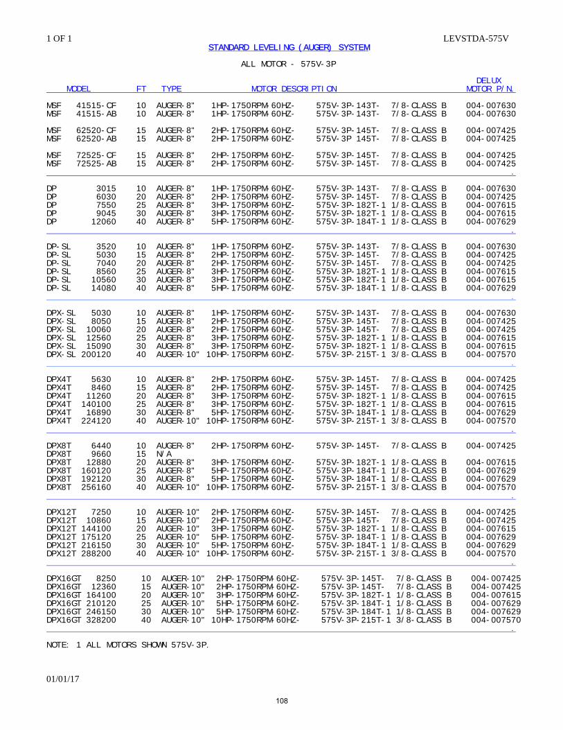
1 OF 1 LEVSTDA-575V
01/01/17
STANDARD LEVELING (AUGER) SYSTEM
ALL MOTOR - 575V-3P
DELUX MODEL FT TYPE MOTOR DESCRIPTION MOTOR P/N. MSF 41515-CF 10 AUGER-8" 1HP-1750RPM-60HZ- 575V-3P-143T- 7/8-CLASS B 004-007630 MSF 41515-AB 10 AUGER-8" 1HP-1750RPM-60HZ- 575V-3P-143T- 7/8-CLASS B 004-007630 MSF 62520-CF 15 AUGER-8" 2HP-1750RPM-60HZ- 575V-3P-145T- 7/8-CLASS B 004-007425 MSF 62520-AB 15 AUGER-8" 2HP-1750RPM-60HZ- 575V-3P 145T- 7/8-CLASS B 004-007425 MSF 72525-CF 15 AUGER-8" 2HP-1750RPM-60HZ- 575V-3P-145T- 7/8-CLASS B 004-007425 MSF 72525-AB 15 AUGER-8" 2HP-1750RPM-60HZ- 575V-3P-145T- 7/8-CLASS B 004-007425 . DP 3015 10 AUGER-8" 1HP-1750RPM-60HZ- 575V-3P-143T- 7/8-CLASS B 004-007630 DP 6030 20 AUGER-8" 2HP-1750RPM-60HZ- 575V-3P-145T- 7/8-CLASS B 004-007425 DP 7550 25 AUGER-8" 3HP-1750RPM-60HZ- 575V-3P-182T-1 1/8-CLASS B 004-007615 DP 9045 30 AUGER-8" 3HP-1750RPM-60HZ- 575V-3P-182T-1 1/8-CLASS B 004-007615 DP 12060 40 AUGER-8" 5HP-1750RPM-60HZ- 575V-3P-184T-1 1/8-CLASS B 004-007629 . DP-SL 3520 10 AUGER-8" 1HP-1750RPM-60HZ- 575V-3P-143T- 7/8-CLASS B 004-007630 DP-SL 5030 15 AUGER-8" 2HP-1750RPM-60HZ- 575V-3P-145T- 7/8-CLASS B 004-007425 DP-SL 7040 20 AUGER-8" 2HP-1750RPM-60HZ- 575V-3P-145T- 7/8-CLASS B 004-007425 DP-SL 8560 25 AUGER-8" 3HP-1750RPM-60HZ- 575V-3P-182T-1 1/8-CLASS B 004-007615 DP-SL 10560 30 AUGER-8" 3HP-1750RPM-60HZ- 575V-3P-182T-1 1/8-CLASS B 004-007615 DP-SL 14080 40 AUGER-8" 5HP-1750RPM-60HZ- 575V-3P-184T-1 1/8-CLASS B 004-007629 . DPX-SL 5030 10 AUGER-8" 1HP-1750RPM-60HZ- 575V-3P-143T- 7/8-CLASS B 004-007630 DPX-SL 8050 15 AUGER-8" 2HP-1750RPM-60HZ- 575V-3P-145T- 7/8-CLASS B 004-007425 DPX-SL 10060 20 AUGER-8" 2HP-1750RPM-60HZ- 575V-3P-145T- 7/8-CLASS B 004-007425 DPX-SL 12560 25 AUGER-8" 3HP-1750RPM-60HZ- 575V-3P-182T-1 1/8-CLASS B 004-007615 DPX-SL 15090 30 AUGER-8" 3HP-1750RPM-60HZ- 575V-3P-182T-1 1/8-CLASS B 004-007615 DPX-SL 200120 40 AUGER-10" 10HP-1750RPM-60HZ- 575V-3P-215T-1 3/8-CLASS B 004-007570 . DPX4T 5630 10 AUGER-8" 2HP-1750RPM-60HZ- 575V-3P-145T- 7/8-CLASS B 004-007425 DPX4T 8460 15 AUGER-8" 2HP-1750RPM-60HZ- 575V-3P-145T- 7/8-CLASS B 004-007425 DPX4T 11260 20 AUGER-8" 3HP-1750RPM-60HZ- 575V-3P-182T-1 1/8-CLASS B 004-007615 DPX4T 140100 25 AUGER-8" 3HP-1750RPM-60HZ- 575V-3P-182T-1 1/8-CLASS B 004-007615 DPX4T 16890 30 AUGER-8" 5HP-1750RPM-60HZ- 575V-3P-184T-1 1/8-CLASS B 004-007629 DPX4T 224120 40 AUGER-10" 10HP-1750RPM-60HZ- 575V-3P-215T-1 3/8-CLASS B 004-007570 . DPX8T 6440 10 AUGER-8" 2HP-1750RPM-60HZ- 575V-3P-145T- 7/8-CLASS B 004-007425 DPX8T 9660 15 N/A DPX8T 12880 20 AUGER-8" 3HP-1750RPM-60HZ- 575V-3P-182T-1 1/8-CLASS B 004-007615 DPX8T 160120 25 AUGER-8" 5HP-1750RPM-60HZ- 575V-3P-184T-1 1/8-CLASS B 004-007629 DPX8T 192120 30 AUGER-8" 5HP-1750RPM-60HZ- 575V-3P-184T-1 1/8-CLASS B 004-007629 DPX8T 256160 40 AUGER-10" 10HP-1750RPM-60HZ- 575V-3P-215T-1 3/8-CLASS B 004-007570 . DPX12T 7250 10 AUGER-10" 2HP-1750RPM-60HZ- 575V-3P-145T- 7/8-CLASS B 004-007425 DPX12T 10860 15 AUGER-10" 2HP-1750RPM-60HZ- 575V-3P-145T- 7/8-CLASS B 004-007425 DPX12T 144100 20 AUGER-10" 3HP-1750RPM-60HZ- 575V-3P-182T-1 1/8-CLASS B 004-007615 DPX12T 175120 25 AUGER-10" 5HP-1750RPM-60HZ- 575V-3P-184T-1 1/8-CLASS B 004-007629 DPX12T 216150 30 AUGER-10" 5HP-1750RPM-60HZ- 575V-3P-184T-1 1/8-CLASS B 004-007629 DPX12T 288200 40 AUGER-10" 10HP-1750RPM-60HZ- 575V-3P-215T-1 3/8-CLASS B 004-007570 . DPX16GT 8250 10 AUGER-10" 2HP-1750RPM-60HZ- 575V-3P-145T- 7/8-CLASS B 004-007425 DPX16GT 12360 15 AUGER-10" 2HP-1750RPM-60HZ- 575V-3P-145T- 7/8-CLASS B 004-007425 DPX16GT 164100 20 AUGER-10" 3HP-1750RPM-60HZ- 575V-3P-182T-1 1/8-CLASS B 004-007615 DPX16GT 210120 25 AUGER-10" 5HP-1750RPM-60HZ- 575V-3P-184T-1 1/8-CLASS B 004-007629 DPX16GT 246150 30 AUGER-10" 5HP-1750RPM-60HZ- 575V-3P-184T-1 1/8-CLASS B 004-007629 DPX16GT 328200 40 AUGER-10" 10HP-1750RPM-60HZ- 575V-3P-215T-1 3/8-CLASS B 004-007570 . NOTE: 1 ALL MOTORS SHOWN 575V-3P.
108
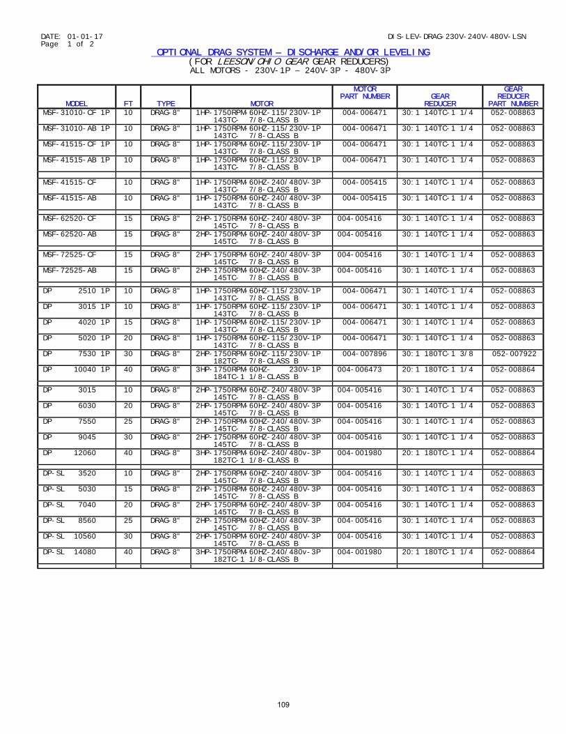
DATE: 01-01-17 DIS-LEV-DRAG-230V-240V-480V-LSN Page 1 of 2
OPTIONAL DRAG SYSTEM – DISCHARGE AND/OR LEVELING (FOR LEESON/OHIO GEAR GEAR REDUCERS) ALL MOTORS - 230V-1P – 240V-3P - 480V-3P
MODEL
FT
TYPE
MOTOR
MOTOR PART NUMBER
GEAR
REDUCER
GEAR REDUCER
PART NUMBER MSF-31010-CF 1P 10 DRAG-8" 1HP-1750RPM-60HZ-115/230V-1P
143TC- 7/8-CLASS B 004-006471 30:1 140TC-1 1/4 052-008863
MSF-31010-AB 1P 10 DRAG-8" 1HP-1750RPM-60HZ-115/230V-1P 143TC- 7/8-CLASS B
004-006471 30:1 140TC-1 1/4 052-008863
MSF-41515-CF 1P 10 DRAG-8" 1HP-1750RPM-60HZ-115/230V-1P 143TC- 7/8-CLASS B
004-006471 30:1 140TC-1 1/4 052-008863
MSF-41515-AB 1P 10 DRAG-8" 1HP-1750RPM-60HZ-115/230V-1P 143TC- 7/8-CLASS B
004-006471 30:1 140TC-1 1/4 052-008863
MSF-41515-CF 10 DRAG-8" 1HP-1750RPM-60HZ-240/480V-3P 143TC- 7/8-CLASS B
004-005415 30:1 140TC-1 1/4 052-008863
MSF-41515-AB 10 DRAG-8" 1HP-1750RPM-60HZ-240/480V-3P 143TC- 7/8-CLASS B
004-005415 30:1 140TC-1 1/4 052-008863
MSF-62520-CF 15 DRAG-8" 2HP-1750RPM-60HZ-240/480V-3P 145TC- 7/8-CLASS B
004-005416 30:1 140TC-1 1/4 052-008863
MSF-62520-AB 15 DRAG-8" 2HP-1750RPM-60HZ-240/480V-3P 145TC- 7/8-CLASS B
004-005416 30:1 140TC-1 1/4 052-008863
MSF-72525-CF 15 DRAG-8" 2HP-1750RPM-60HZ-240/480V-3P 145TC- 7/8-CLASS B
004-005416 30:1 140TC-1 1/4 052-008863
MSF-72525-AB 15 DRAG-8" 2HP-1750RPM-60HZ-240/480V-3P 145TC- 7/8-CLASS B
004-005416 30:1 140TC-1 1/4 052-008863
DP 2510 1P 10 DRAG-8" 1HP-1750RPM-60HZ-115/230V-1P 143TC- 7/8-CLASS B
004-006471 30:1 140TC-1 1/4 052-008863
DP 3015 1P 10 DRAG-8" 1HP-1750RPM-60HZ-115/230V-1P 143TC- 7/8-CLASS B
004-006471 30:1 140TC-1 1/4 052-008863
DP 4020 1P 15 DRAG-8" 1HP-1750RPM-60HZ-115/230V-1P 143TC- 7/8-CLASS B
004-006471 30:1 140TC-1 1/4 052-008863
DP 5020 1P 20 DRAG-8" 1HP-1750RPM-60HZ-115/230V-1P 143TC- 7/8-CLASS B
004-006471 30:1 140TC-1 1/4 052-008863
DP 7530 1P 30 DRAG-8" 2HP-1750RPM-60HZ-115/230V-1P 182TC- 7/8-CLASS B
004-007896 30:1 180TC-1 3/8 052-007922
DP 10040 1P 40 DRAG-8" 3HP-1750RPM-60HZ- 230V-1P 184TC-1 1/8-CLASS B
004-006473 20:1 180TC-1 1/4 052-008864
DP 3015 10 DRAG-8" 2HP-1750RPM-60HZ-240/480V-3P 145TC- 7/8-CLASS B
004-005416 30:1 140TC-1 1/4 052-008863
DP 6030 20 DRAG-8" 2HP-1750RPM-60HZ-240/480V-3P 145TC- 7/8-CLASS B
004-005416 30:1 140TC-1 1/4 052-008863
DP 7550 25 DRAG-8" 2HP-1750RPM-60HZ-240/480V-3P 145TC- 7/8-CLASS B
004-005416 30:1 140TC-1 1/4 052-008863
DP 9045 30 DRAG-8" 2HP-1750RPM-60HZ-240/480V-3P 145TC- 7/8-CLASS B
004-005416 30:1 140TC-1 1/4 052-008863
DP 12060 40 DRAG-8" 3HP-1750RPM-60HZ-240/480v-3P 182TC-1 1/8-CLASS B
004-001980 20:1 180TC-1 1/4 052-008864
DP-SL 3520 10 DRAG-8" 2HP-1750RPM-60HZ-240/480V-3P 145TC- 7/8-CLASS B
004-005416 30:1 140TC-1 1/4 052-008863
DP-SL 5030 15 DRAG-8" 2HP-1750RPM-60HZ-240/480V-3P 145TC- 7/8-CLASS B
004-005416 30:1 140TC-1 1/4 052-008863
DP-SL 7040 20 DRAG-8" 2HP-1750RPM-60HZ-240/480V-3P 145TC- 7/8-CLASS B
004-005416 30:1 140TC-1 1/4 052-008863
DP-SL 8560 25 DRAG-8" 2HP-1750RPM-60HZ-240/480V-3P 145TC- 7/8-CLASS B
004-005416 30:1 140TC-1 1/4 052-008863
DP-SL 10560 30 DRAG-8" 2HP-1750RPM-60HZ-240/480V-3P 145TC- 7/8-CLASS B
004-005416 30:1 140TC-1 1/4 052-008863
DP-SL 14080 40 DRAG-8" 3HP-1750RPM-60HZ-240/480v-3P 182TC-1 1/8-CLASS B
004-001980 20:1 180TC-1 1/4 052-008864
109
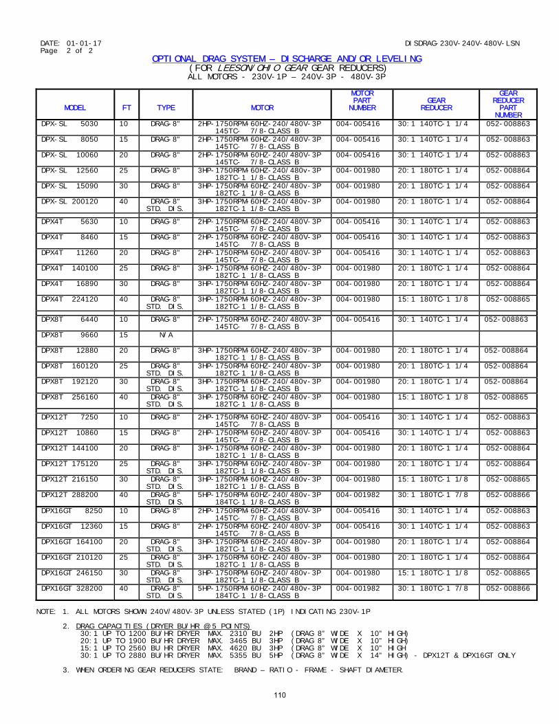
DATE: 01-01-17 DISDRAG-230V-240V-480V-LSN Page 2 of 2
OPTIONAL DRAG SYSTEM – DISCHARGE AND/OR LEVELING (FOR LEESON/OHIO GEAR GEAR REDUCERS) ALL MOTORS - 230V-1P – 240V-3P - 480V-3P
MODEL
FT
TYPE
MOTOR
MOTOR PART
NUMBER
GEAR
REDUCER
GEAR REDUCER PART
NUMBER DPX-SL 5030 10 DRAG-8" 2HP-1750RPM-60HZ-240/480V-3P
145TC- 7/8-CLASS B 004-005416 30:1 140TC-1 1/4 052-008863
DPX-SL 8050 15 DRAG-8" 2HP-1750RPM-60HZ-240/480V-3P 145TC- 7/8-CLASS B
004-005416 30:1 140TC-1 1/4 052-008863
DPX-SL 10060 20 DRAG-8" 2HP-1750RPM-60HZ-240/480V-3P 145TC- 7/8-CLASS B
004-005416 30:1 140TC-1 1/4 052-008863
DPX-SL 12560 25 DRAG-8" 3HP-1750RPM-60HZ-240/480v-3P 182TC-1 1/8-CLASS B
004-001980 20:1 180TC-1 1/4 052-008864
DPX-SL 15090 30 DRAG-8" 3HP-1750RPM-60HZ-240/480v-3P 182TC-1 1/8-CLASS B
004-001980 20:1 180TC-1 1/4 052-008864
DPX-SL 200120 40 DRAG-8" STD. DIS.
3HP-1750RPM-60HZ-240/480v-3P 182TC-1 1/8-CLASS B
004-001980 20:1 180TC-1 1/4 052-008864
DPX4T 5630 10 DRAG-8" 2HP-1750RPM-60HZ-240/480V-3P 145TC- 7/8-CLASS B
004-005416 30:1 140TC-1 1/4 052-008863
DPX4T 8460 15 DRAG-8" 2HP-1750RPM-60HZ-240/480V-3P 145TC- 7/8-CLASS B
004-005416 30:1 140TC-1 1/4 052-008863
DPX4T 11260 20 DRAG-8" 2HP-1750RPM-60HZ-240/480V-3P 145TC- 7/8-CLASS B
004-005416 30:1 140TC-1 1/4 052-008863
DPX4T 140100 25 DRAG-8" 3HP-1750RPM-60HZ-240/480v-3P 182TC-1 1/8-CLASS B
004-001980 20:1 180TC-1 1/4 052-008864
DPX4T 16890 30 DRAG-8" 3HP-1750RPM-60HZ-240/480v-3P 182TC-1 1/8-CLASS B
004-001980 20:1 180TC-1 1/4 052-008864
DPX4T 224120 40 DRAG-8" STD. DIS.
3HP-1750RPM-60HZ-240/480v-3P 182TC-1 1/8-CLASS B
004-001980 15:1 180TC-1 1/8 052-008865
DPX8T 6440 10 DRAG-8" 2HP-1750RPM-60HZ-240/480V-3P 145TC- 7/8-CLASS B
004-005416 30:1 140TC-1 1/4 052-008863
DPX8T 9660
15 N/A
DPX8T 12880 20 DRAG-8" 3HP-1750RPM-60HZ-240/480v-3P 182TC-1 1/8-CLASS B
004-001980 20:1 180TC-1 1/4 052-008864
DPX8T 160120 25 DRAG-8" STD. DIS.
3HP-1750RPM-60HZ-240/480v-3P 182TC-1 1/8-CLASS B
004-001980 20:1 180TC-1 1/4 052-008864
DPX8T 192120 30 DRAG-8" STD. DIS.
3HP-1750RPM-60HZ-240/480v-3P 182TC-1 1/8-CLASS B
004-001980 20:1 180TC-1 1/4 052-008864
DPX8T 256160 40 DRAG-8" STD. DIS.
3HP-1750RPM-60HZ-240/480v-3P 182TC-1 1/8-CLASS B
004-001980 15:1 180TC-1 1/8 052-008865
DPX12T 7250 10 DRAG-8" 2HP-1750RPM-60HZ-240/480V-3P 145TC- 7/8-CLASS B
004-005416 30:1 140TC-1 1/4 052-008863
DPX12T 10860 15 DRAG-8" 2HP-1750RPM-60HZ-240/480V-3P 145TC- 7/8-CLASS B
004-005416 30:1 140TC-1 1/4 052-008863
DPX12T 144100 20 DRAG-8" 3HP-1750RPM-60HZ-240/480v-3P 182TC-1 1/8-CLASS B
004-001980 20:1 180TC-1 1/4 052-008864
DPX12T 175120 25 DRAG-8" STD. DIS.
3HP-1750RPM-60HZ-240/480v-3P 182TC-1 1/8-CLASS B
004-001980 20:1 180TC-1 1/4 052-008864
DPX12T 216150 30 DRAG-8" STD. DIS.
3HP-1750RPM-60HZ-240/480v-3P 182TC-1 1/8-CLASS B
004-001980 15:1 180TC-1 1/8 052-008865
DPX12T 288200 40 DRAG-8" STD. DIS.
5HP-1750RPM-60HZ-240/480v-3P 184TC-1 1/8-CLASS B
004-001982 30:1 180TC-1 7/8 052-008866
DPX16GT 8250 10 DRAG-8" 2HP-1750RPM-60HZ-240/480V-3P 145TC- 7/8-CLASS B
004-005416 30:1 140TC-1 1/4 052-008863
DPX16GT 12360 15 DRAG-8" 2HP-1750RPM-60HZ-240/480V-3P 145TC- 7/8-CLASS B
004-005416 30:1 140TC-1 1/4 052-008863
DPX16GT 164100 20 DRAG-8" STD. DIS.
3HP-1750RPM-60HZ-240/480v-3P 182TC-1 1/8-CLASS B
004-001980 20:1 180TC-1 1/4 052-008864
DPX16GT 210120 25 DRAG-8" STD. DIS.
3HP-1750RPM-60HZ-240/480v-3P 182TC-1 1/8-CLASS B
004-001980 20:1 180TC-1 1/4 052-008864
DPX16GT 246150 30 DRAG-8" STD. DIS.
3HP-1750RPM-60HZ-240/480v-3P 182TC-1 1/8-CLASS B
004-001980 15:1 180TC-1 1/8 052-008865
DPX16GT 328200 40 DRAG-8" STD. DIS.
5HP-1750RPM-60HZ-240/480v-3P 184TC-1 1/8-CLASS B
004-001982 30:1 180TC-1 7/8 052-008866
NOTE: 1. ALL MOTORS SHOWN 240V/480V-3P UNLESS STATED (1P) INDICATING 230V-1P 2. DRAG CAPACITIES (DRYER BU/HR @ 5 POINTS) 30:1 UP TO 1200 BU/HR DRYER MAX. 2310 BU 2HP (DRAG 8” WIDE X 10” HIGH) 20:1 UP TO 1900 BU/HR DRYER MAX. 3465 BU 3HP (DRAG 8” WIDE X 10” HIGH) 15:1 UP TO 2560 BU HR DRYER MAX. 4620 BU 3HP (DRAG 8” WIDE X 10” HIGH 30:1 UP TO 2880 BU/HR DRYER MAX. 5355 BU 5HP (DRAG 8” WIDE X 14” HIGH) - DPX12T & DPX16GT ONLY 3. WHEN ORDERING GEAR REDUCERS STATE: BRAND – RATIO - FRAME - SHAFT DIAMETER.
110
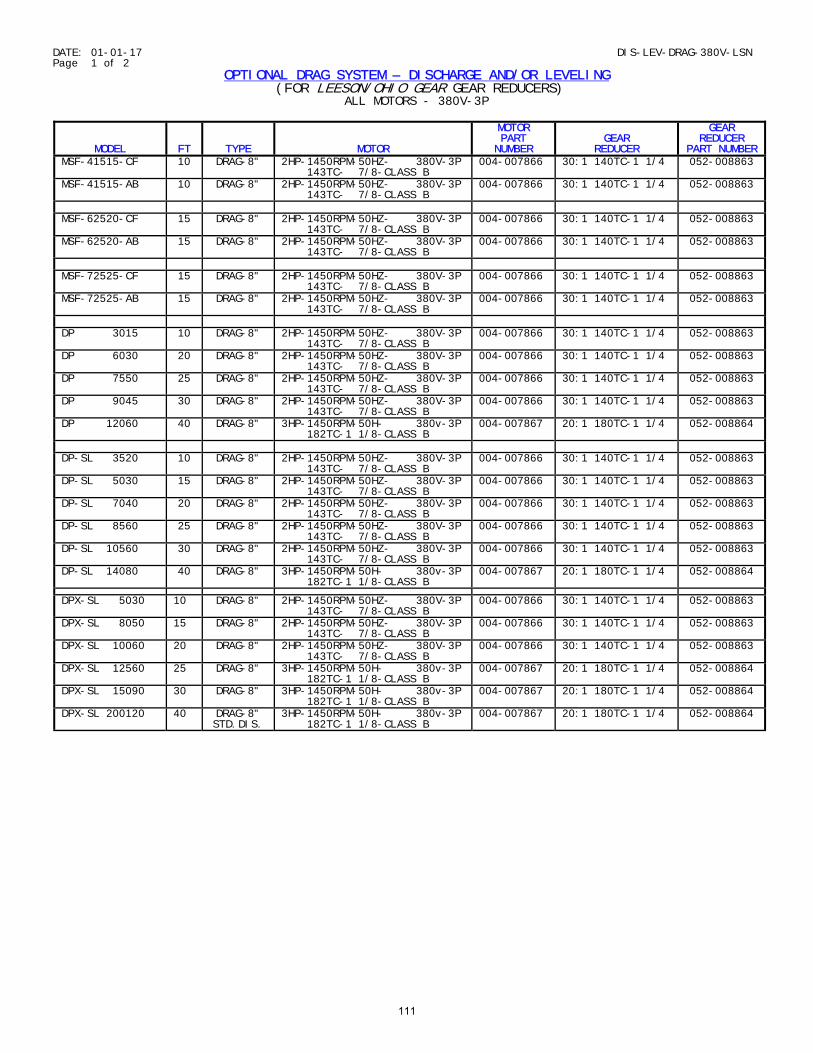
DATE: 01-01-17 DIS-LEV-DRAG-380V-LSN Page 1 of 2
OPTIONAL DRAG SYSTEM – DISCHARGE AND/OR LEVELING (FOR LEESON/OHIO GEAR GEAR REDUCERS)
ALL MOTORS - 380V-3P
MODEL
FT
TYPE
MOTOR
MOTOR PART NUMBER
GEAR
REDUCER
GEAR REDUCER
PART NUMBER MSF-41515-CF 10 DRAG-8" 2HP-1450RPM-50HZ- 380V-3P
143TC- 7/8-CLASS B 004-007866 30:1 140TC-1 1/4 052-008863
MSF-41515-AB 10 DRAG-8" 2HP-1450RPM-50HZ- 380V-3P 143TC- 7/8-CLASS B
004-007866 30:1 140TC-1 1/4 052-008863
MSF-62520-CF 15 DRAG-8" 2HP-1450RPM-50HZ- 380V-3P
143TC- 7/8-CLASS B 004-007866 30:1 140TC-1 1/4 052-008863
MSF-62520-AB 15 DRAG-8" 2HP-1450RPM-50HZ- 380V-3P 143TC- 7/8-CLASS B
004-007866 30:1 140TC-1 1/4 052-008863
MSF-72525-CF 15 DRAG-8" 2HP-1450RPM-50HZ- 380V-3P
143TC- 7/8-CLASS B 004-007866 30:1 140TC-1 1/4 052-008863
MSF-72525-AB 15 DRAG-8" 2HP-1450RPM-50HZ- 380V-3P 143TC- 7/8-CLASS B
004-007866 30:1 140TC-1 1/4 052-008863
DP 3015 10 DRAG-8" 2HP-1450RPM-50HZ- 380V-3P
143TC- 7/8-CLASS B 004-007866 30:1 140TC-1 1/4 052-008863
DP 6030 20 DRAG-8" 2HP-1450RPM-50HZ- 380V-3P 143TC- 7/8-CLASS B
004-007866 30:1 140TC-1 1/4 052-008863
DP 7550 25 DRAG-8" 2HP-1450RPM-50HZ- 380V-3P 143TC- 7/8-CLASS B
004-007866 30:1 140TC-1 1/4 052-008863
DP 9045 30 DRAG-8" 2HP-1450RPM-50HZ- 380V-3P 143TC- 7/8-CLASS B
004-007866 30:1 140TC-1 1/4 052-008863
DP 12060 40 DRAG-8" 3HP-1450RPM-50H- 380v-3P 182TC-1 1/8-CLASS B
004-007867 20:1 180TC-1 1/4 052-008864
DP-SL 3520 10 DRAG-8" 2HP-1450RPM-50HZ- 380V-3P
143TC- 7/8-CLASS B 004-007866 30:1 140TC-1 1/4 052-008863
DP-SL 5030 15 DRAG-8" 2HP-1450RPM-50HZ- 380V-3P 143TC- 7/8-CLASS B
004-007866 30:1 140TC-1 1/4 052-008863
DP-SL 7040 20 DRAG-8" 2HP-1450RPM-50HZ- 380V-3P 143TC- 7/8-CLASS B
004-007866 30:1 140TC-1 1/4 052-008863
DP-SL 8560 25 DRAG-8" 2HP-1450RPM-50HZ- 380V-3P 143TC- 7/8-CLASS B
004-007866 30:1 140TC-1 1/4 052-008863
DP-SL 10560 30 DRAG-8" 2HP-1450RPM-50HZ- 380V-3P 143TC- 7/8-CLASS B
004-007866 30:1 140TC-1 1/4 052-008863
DP-SL 14080 40 DRAG-8" 3HP-1450RPM-50H- 380v-3P 182TC-1 1/8-CLASS B
004-007867 20:1 180TC-1 1/4 052-008864
DPX-SL 5030 10 DRAG-8" 2HP-1450RPM-50HZ- 380V-3P 143TC- 7/8-CLASS B
004-007866 30:1 140TC-1 1/4 052-008863
DPX-SL 8050 15 DRAG-8" 2HP-1450RPM-50HZ- 380V-3P 143TC- 7/8-CLASS B
004-007866 30:1 140TC-1 1/4 052-008863
DPX-SL 10060 20 DRAG-8" 2HP-1450RPM-50HZ- 380V-3P 143TC- 7/8-CLASS B
004-007866 30:1 140TC-1 1/4 052-008863
DPX-SL 12560 25 DRAG-8" 3HP-1450RPM-50H- 380v-3P 182TC-1 1/8-CLASS B
004-007867 20:1 180TC-1 1/4 052-008864
DPX-SL 15090 30 DRAG-8" 3HP-1450RPM-50H- 380v-3P 182TC-1 1/8-CLASS B
004-007867 20:1 180TC-1 1/4 052-008864
DPX-SL 200120 40 DRAG-8" STD.DIS.
3HP-1450RPM-50H- 380v-3P 182TC-1 1/8-CLASS B
004-007867 20:1 180TC-1 1/4 052-008864
111

DATE: 01-01-17 DIS-LEV-DRAG-380V-LSN Page 2 of 2
OPTIONAL DRAG SYSTEM – DISCHARGE AND/OR LEVELING (FOR LEESON/OHIO GEAR GEAR REDUCERS)
ALL MOTORS - 380V-3P
MODEL
FT
TYPE
MOTOR
MOTOR PART NUMBER
GEAR
REDUCER
GEAR REDUCER PART NUMBER
DPX4T 5630 10 DRAG-8" 2HP-1450RPM-50HZ- 380V-3P 143TC- 7/8-CLASS B
004-007866 30:1 140TC-1 1/4 052-008863
DPX4T 8460 15 DRAG-8" 2HP-1450RPM-50HZ- 380V-3P 143TC- 7/8-CLASS B
004-007866 30:1 140TC-1 1/4 052-008863
DPX4T 11260 20 DRAG-8" 2HP-1450RPM-50HZ- 380V-3P 143TC- 7/8-CLASS B
004-007866 30:1 140TC-1 1/4 052-008863
DPX4T 140100 25 DRAG-8" 3HP-1450RPM-50H- 380v-3P 182TC-1 1/8-CLASS B
004-007867 20:1 180TC-1 1/4 052-008864
DPX4T 16890 30 DRAG-8" 3HP-1450RPM-50H- 380v-3P 182TC-1 1/8-CLASS B
004-007867 20:1 180TC-1 1/4 052-008864
DPX4T 224120 40 DRAG-8" STD.DIS.
3HP-1450RPM-50H- 380v-3P 182TC-1 1/8-CLASS B
004-007867 15:1 180TC-1 1/8 052-008865
DPX8T 6440 10 DRAG-8" 2HP-1450RPM-50HZ- 380V-3P 143TC- 7/8-CLASS B
004-007866 30:1 140TC-1 1/4 052-008863
DPX8T 9660
15 N/A
DPX8T 12880 20 DRAG-8" 3HP-1750RPM-50H- 380v-3P 182TC-1 1/8-CLASS B
004-007867 20:1 180TC-1 1/4 052-008864
DPX8T 160120 25 DRAG-8" STD.DIS.
3HP-1450RPM-50H- 380v-3P 182TC-1 1/8-CLASS B
004-007867 20:1 180TC-1 1/4 052-008864
DPX8T 192120 30 DRAG-8" STD.DIS.
3HP-1450RPM-50H- 380v-3P 182TC-1 1/8-CLASS B
004-007867 20:1 180TC-1 1/4 052-008864
DPX8T 256160 40 DRAG-8" STD.DIS.
3HP-1450RPM-50H- 380v-3P 182TC-1 1/8-CLASS B
004-007867 15:1 180TC-1 1/8 052-008865
DPX12T 7250 10 DRAG-8" 2HP-1450RPM-50HZ- 380V-3P 143TC- 7/8-CLASS B
004-007866 30:1 140TC-1 1/4 052-008863
DPX12T 10860 15 DRAG-8" 2HP-1450RPM-50HZ- 380V-3P 143TC- 7/8-CLASS B
004-007866 30:1 140TC-1 1/4 052-008863
DPX12T 144100 20 DRAG-8" 3HP-1450RPM-50H- 380v-3P 182TC-1 1/8-CLASS B
004-007867 20:1 180TC-1 1/4 052-008864
DPX12T 175120 25 DRAG-8" STD.DIS.
3HP-1450RPM-50H- 380v-3P 182TC-1 1/8-CLASS B
004-007867 20:1 180TC-1 1/4 052-008864
DPX12T 216150 30 DRAG-8" STD.DIS.
3HP-1450RPM-50H- 380v-3P 182TC-1 1/8-CLASS B
004-007867 15:1 180TC-1 1/8 052-008865
DPX12T 288200 40 DRAG-8" STD.DIS.
5HP-1450RPM-50HZ- 380v-3P 184TC-1 1/8-CLASS B
004-007868 30:1 180TC-1 7/8 052-008866
DPX16GT 8250 10 DRAG-8" 2HP-1450RPM-50HZ- 380V-3P 143TC- 7/8-CLASS B
004-007866 30:1 140TC-1 1/4 052-008863
DPX16GT 12360 15 DRAG-8" 2HP-1450RPM-50HZ- 380V-3P 143TC- 7/8-CLASS B
004-007866 30:1 140TC-1 1/4 052-008863
DPX16GT 164100 20 DRAG-8" STD.DIS.
3HP-1450RPM-50H- 380v-3P 182TC-1 1/8-CLASS B
004-007867 20:1 180TC-1 1/4 052-008864
DPX16GT 210120 25 DRAG-8" STD.DIS.
3HP-1450RPM-50H- 380v-3P 182TC-1 1/8-CLASS B
004-007867 20:1 180TC-1 1/4 052-008864
DPX16GT 246150 30 DRAG-8" STD.DIS.
3HP-1450RPM-50H- 380v-3P 182TC-1 1/8-CLASS B
004-007867 15:1 180TC-1 1/8 052-008865
DPX16GT 328200 40 DRAG-8" STD.DIS.
5HP-1450RPM-50HZ- 380v-3P 184TC-1 1/8-CLASS B
004-007868 30:1 180TC-1 7/8 052-008866
NOTE: 1. ALL MOTORS SHOWN 380V-3P. 2. DRAG CAPACITIES @ 5 POINTS 30:1 UP TO 1200 BU/HR DRYER MAX. 2310 BU 2HP (DRAG 8” WIDE X 10” HIGH) 20:1 UP TO 1900 BU/HR DRYER MAX. 3465 BU 3HP (DRAG 8” WIDE X 10” HIGH) 15:1 UP TO 2560 BU HR DRYER MAX. 4620 BU 3HP (DRAG 8” WIDE X 10” HIGH 30:1 UP TO 2880 BU/HR DRYER MAX. 5355 BU 5HP (DRAG 8” WIDE X 14” HIGH) - DPX12T/DPX16GT ONLY 3. WHEN ORDERING GEAR REDUCERS STATE: BRAND – RATIO - FRAME - SHAFT DIAMETER.
112
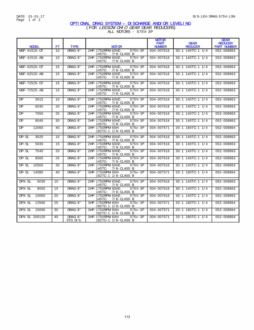
DATE: 01-01-17 DIS-LEV-DRAG-575V-LSN Page 1 of 2
OPTIONAL DRAG SYSTEM – DISCHARGE AND/OR LEVELING (FOR LEESON/OHIO GEAR GEAR REDUCERS)
ALL MOTORS - 575V-3P
MODEL
FT
TYPE
MOTOR
MOTOR PART NUMBER
GEAR
REDUCER
GEAR REDUCER
PART NUMBER MSF-41515-CF 10 DRAG-8" 2HP-1750RPM-60HZ- 575V-3P
145TC- 7/8-CLASS B 004-007616 30:1 140TC-1 1/4 052-008863
MSF-41515-AB 10 DRAG-8" 2HP-1750RPM-60HZ- 575V-3P 145TC- 7/8-CLASS B
004-007616 30:1 140TC-1 1/4 052-008863
MSF-62520-CF 15 DRAG-8" 2HP-1750RPM-60HZ- 575V-3P 145TC- 7/8-CLASS B
004-007616 30:1 140TC-1 1/4 052-008863
MSF-62520-AB 15 DRAG-8" 2HP-1750RPM-60HZ- 575V-3P 145TC- 7/8-CLASS B
004-007616 30:1 140TC-1 1/4 052-008863
MSF-72525-CF 15 DRAG-8" 2HP-1750RPM-60HZ- 575V-3P 145TC- 7/8-CLASS B
004-007616 30:1 140TC-1 1/4 052-008863
MSF-72525-AB 15 DRAG-8" 2HP-1750RPM-60HZ- 575V-3P 145TC- 7/8-CLASS B
004-007616 30:1 140TC-1 1/4 052-008863
DP 3015 10 DRAG-8" 2HP-1750RPM-60HZ- 575V-3P 145TC- 7/8-CLASS B
004-007616 30:1 140TC-1 1/4 052-008863
DP 6030 20 DRAG-8" 2HP-1750RPM-60HZ- 575V-3P 145TC- 7/8-CLASS B
004-007616 30:1 140TC-1 1/4 052-008863
DP 7550 25 DRAG-8" 2HP-1750RPM-60HZ- 575V-3P 145TC- 7/8-CLASS B
004-007616 30:1 140TC-1 1/4 052-008863
DP 9045 30 DRAG-8" 2HP-1750RPM-60HZ- 575V-3P 145TC- 7/8-CLASS B
004-007616 30:1 140TC-1 1/4 052-008863
DP 12060 40 DRAG-8" 3HP-1750RPM-60H- 575v-3P 182TC-1 1/8-CLASS B
004-007571 20:1 180TC-1 1/4 052-008864
DP-SL 3520 10 DRAG-8" 2HP-1750RPM-60HZ- 575V-3P 145TC- 7/8-CLASS B
004-007616 30:1 140TC-1 1/4 052-008863
DP-SL 5030 15 DRAG-8" 2HP-1750RPM-60HZ- 575V-3P 145TC- 7/8-CLASS B
004-007616 30:1 140TC-1 1/4 052-008863
DP-SL 7040 20 DRAG-8" 2HP-1750RPM-60HZ- 575V-3P 145TC- 7/8-CLASS B
004-007616 30:1 140TC-1 1/4 052-008863
DP-SL 8560 25 DRAG-8" 2HP-1750RPM-60HZ- 575V-3P 145TC- 7/8-CLASS B
004-007616 30:1 140TC-1 1/4 052-008863
DP-SL 10560 30 DRAG-8" 2HP-1750RPM-60HZ- 575V-3P 145TC- 7/8-CLASS B
004-007616 30:1 140TC-1 1/4 052-008863
DP-SL 14080 40 DRAG-8" 3HP-1750RPM-60H- 575v-3P 182TC-1 1/8-CLASS B
004-007571 20:1 180TC-1 1/4 052-008864
DPX-SL 5030 10 DRAG-8" 2HP-1750RPM-60HZ- 575V-3P 145TC- 7/8-CLASS B
004-007616 30:1 140TC-1 1/4 052-008863
DPX-SL 8050 15 DRAG-8" 2HP-1750RPM-60HZ- 575V-3P 145TC- 7/8-CLASS B
004-007616 30:1 140TC-1 1/4 052-008863
DPX-SL 10060 20 DRAG-8" 2HP-1750RPM-60HZ- 575V-3P 145TC- 7/8-CLASS B
004-007616 30:1 140TC-1 1/4 052-008863
DPX-SL 12560 25 DRAG-8" 3HP-1750RPM-60H- 575v-3P 182TC-1 1/8-CLASS B
004-007571 20:1 180TC-1 1/4 052-008864
DPX-SL 15090 30 DRAG-8" 3HP-1750RPM-60H- 575v-3P 182TC-1 1/8-CLASS B
004-007571 20:1 180TC-1 1/4 052-008864
DPX-SL 200120 40 DRAG-8" STD.DIS.
3HP-1750RPM-60H- 575v-3P 182TC-1 1/8-CLASS B
004-007571 20:1 180TC-1 1/4 052-008864
113
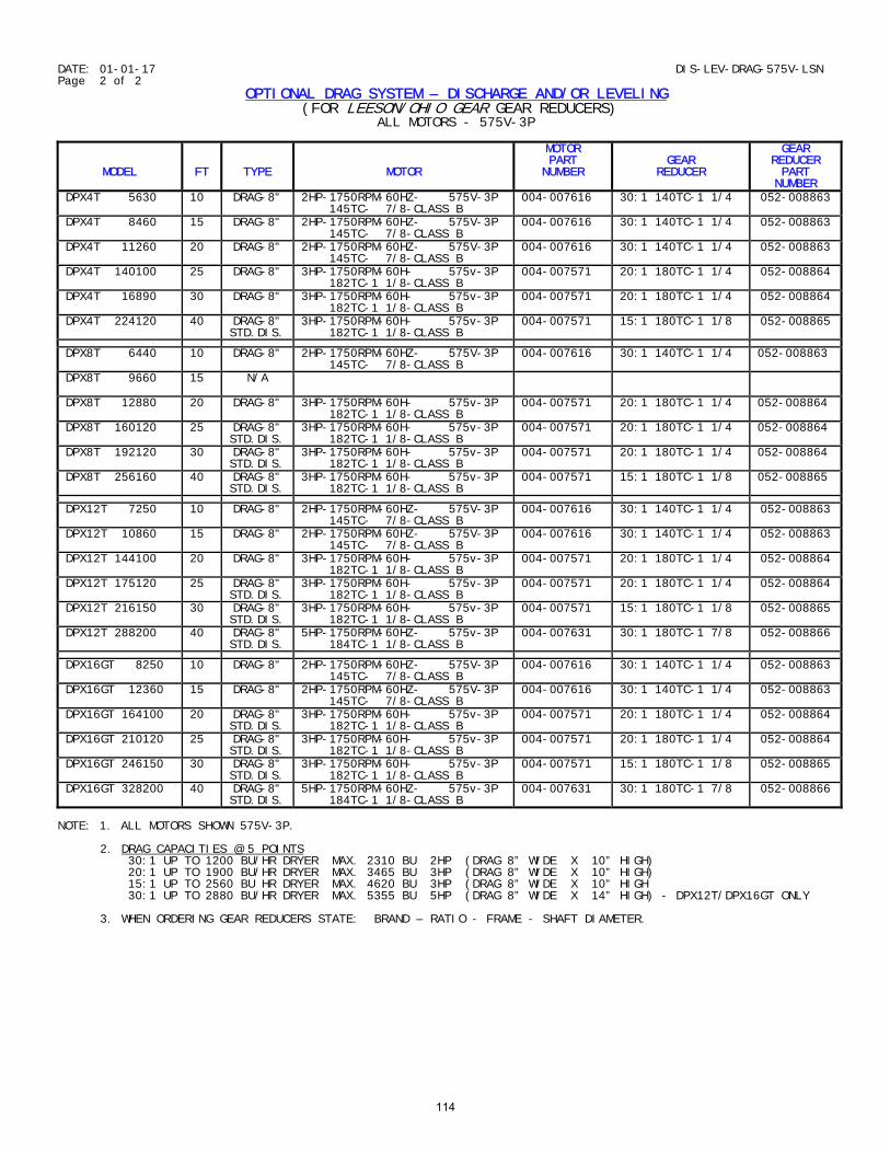
DATE: 01-01-17 DIS-LEV-DRAG-575V-LSN Page 2 of 2
OPTIONAL DRAG SYSTEM – DISCHARGE AND/OR LEVELING (FOR LEESON/OHIO GEAR GEAR REDUCERS)
ALL MOTORS - 575V-3P
MODEL
FT
TYPE
MOTOR
MOTOR PART NUMBER
GEAR
REDUCER
GEAR REDUCER PART NUMBER
DPX4T 5630 10 DRAG-8" 2HP-1750RPM-60HZ- 575V-3P 145TC- 7/8-CLASS B
004-007616 30:1 140TC-1 1/4 052-008863
DPX4T 8460 15 DRAG-8" 2HP-1750RPM-60HZ- 575V-3P 145TC- 7/8-CLASS B
004-007616 30:1 140TC-1 1/4 052-008863
DPX4T 11260 20 DRAG-8" 2HP-1750RPM-60HZ- 575V-3P 145TC- 7/8-CLASS B
004-007616 30:1 140TC-1 1/4 052-008863
DPX4T 140100 25 DRAG-8" 3HP-1750RPM-60H- 575v-3P 182TC-1 1/8-CLASS B
004-007571 20:1 180TC-1 1/4 052-008864
DPX4T 16890 30 DRAG-8" 3HP-1750RPM-60H- 575v-3P 182TC-1 1/8-CLASS B
004-007571 20:1 180TC-1 1/4 052-008864
DPX4T 224120 40 DRAG-8" STD.DIS.
3HP-1750RPM-60H- 575v-3P 182TC-1 1/8-CLASS B
004-007571 15:1 180TC-1 1/8 052-008865
DPX8T 6440 10 DRAG-8" 2HP-1750RPM-60HZ- 575V-3P 145TC- 7/8-CLASS B
004-007616 30:1 140TC-1 1/4 052-008863
DPX8T 9660
15 N/A
DPX8T 12880 20 DRAG-8" 3HP-1750RPM-60H- 575v-3P 182TC-1 1/8-CLASS B
004-007571 20:1 180TC-1 1/4 052-008864
DPX8T 160120 25 DRAG-8" STD.DIS.
3HP-1750RPM-60H- 575v-3P 182TC-1 1/8-CLASS B
004-007571 20:1 180TC-1 1/4 052-008864
DPX8T 192120 30 DRAG-8" STD.DIS.
3HP-1750RPM-60H- 575v-3P 182TC-1 1/8-CLASS B
004-007571 20:1 180TC-1 1/4 052-008864
DPX8T 256160 40 DRAG-8" STD.DIS.
3HP-1750RPM-60H- 575v-3P 182TC-1 1/8-CLASS B
004-007571 15:1 180TC-1 1/8 052-008865
DPX12T 7250 10 DRAG-8" 2HP-1750RPM-60HZ- 575V-3P 145TC- 7/8-CLASS B
004-007616 30:1 140TC-1 1/4 052-008863
DPX12T 10860 15 DRAG-8" 2HP-1750RPM-60HZ- 575V-3P 145TC- 7/8-CLASS B
004-007616 30:1 140TC-1 1/4 052-008863
DPX12T 144100 20 DRAG-8" 3HP-1750RPM-60H- 575v-3P 182TC-1 1/8-CLASS B
004-007571 20:1 180TC-1 1/4 052-008864
DPX12T 175120 25 DRAG-8" STD.DIS.
3HP-1750RPM-60H- 575v-3P 182TC-1 1/8-CLASS B
004-007571 20:1 180TC-1 1/4 052-008864
DPX12T 216150 30 DRAG-8" STD.DIS.
3HP-1750RPM-60H- 575v-3P 182TC-1 1/8-CLASS B
004-007571 15:1 180TC-1 1/8 052-008865
DPX12T 288200 40 DRAG-8" STD.DIS.
5HP-1750RPM-60HZ- 575v-3P 184TC-1 1/8-CLASS B
004-007631 30:1 180TC-1 7/8 052-008866
DPX16GT 8250 10 DRAG-8" 2HP-1750RPM-60HZ- 575V-3P 145TC- 7/8-CLASS B
004-007616 30:1 140TC-1 1/4 052-008863
DPX16GT 12360 15 DRAG-8" 2HP-1750RPM-60HZ- 575V-3P 145TC- 7/8-CLASS B
004-007616 30:1 140TC-1 1/4 052-008863
DPX16GT 164100 20 DRAG-8" STD.DIS.
3HP-1750RPM-60H- 575v-3P 182TC-1 1/8-CLASS B
004-007571 20:1 180TC-1 1/4 052-008864
DPX16GT 210120 25 DRAG-8" STD.DIS.
3HP-1750RPM-60H- 575v-3P 182TC-1 1/8-CLASS B
004-007571 20:1 180TC-1 1/4 052-008864
DPX16GT 246150 30 DRAG-8" STD.DIS.
3HP-1750RPM-60H- 575v-3P 182TC-1 1/8-CLASS B
004-007571 15:1 180TC-1 1/8 052-008865
DPX16GT 328200 40 DRAG-8" STD.DIS.
5HP-1750RPM-60HZ- 575v-3P 184TC-1 1/8-CLASS B
004-007631 30:1 180TC-1 7/8 052-008866
NOTE: 1. ALL MOTORS SHOWN 575V-3P. 2. DRAG CAPACITIES @ 5 POINTS 30:1 UP TO 1200 BU/HR DRYER MAX. 2310 BU 2HP (DRAG 8” WIDE X 10” HIGH) 20:1 UP TO 1900 BU/HR DRYER MAX. 3465 BU 3HP (DRAG 8” WIDE X 10” HIGH) 15:1 UP TO 2560 BU HR DRYER MAX. 4620 BU 3HP (DRAG 8” WIDE X 10” HIGH 30:1 UP TO 2880 BU/HR DRYER MAX. 5355 BU 5HP (DRAG 8” WIDE X 14” HIGH) - DPX12T/DPX16GT ONLY 3. WHEN ORDERING GEAR REDUCERS STATE: BRAND – RATIO - FRAME - SHAFT DIAMETER.
114
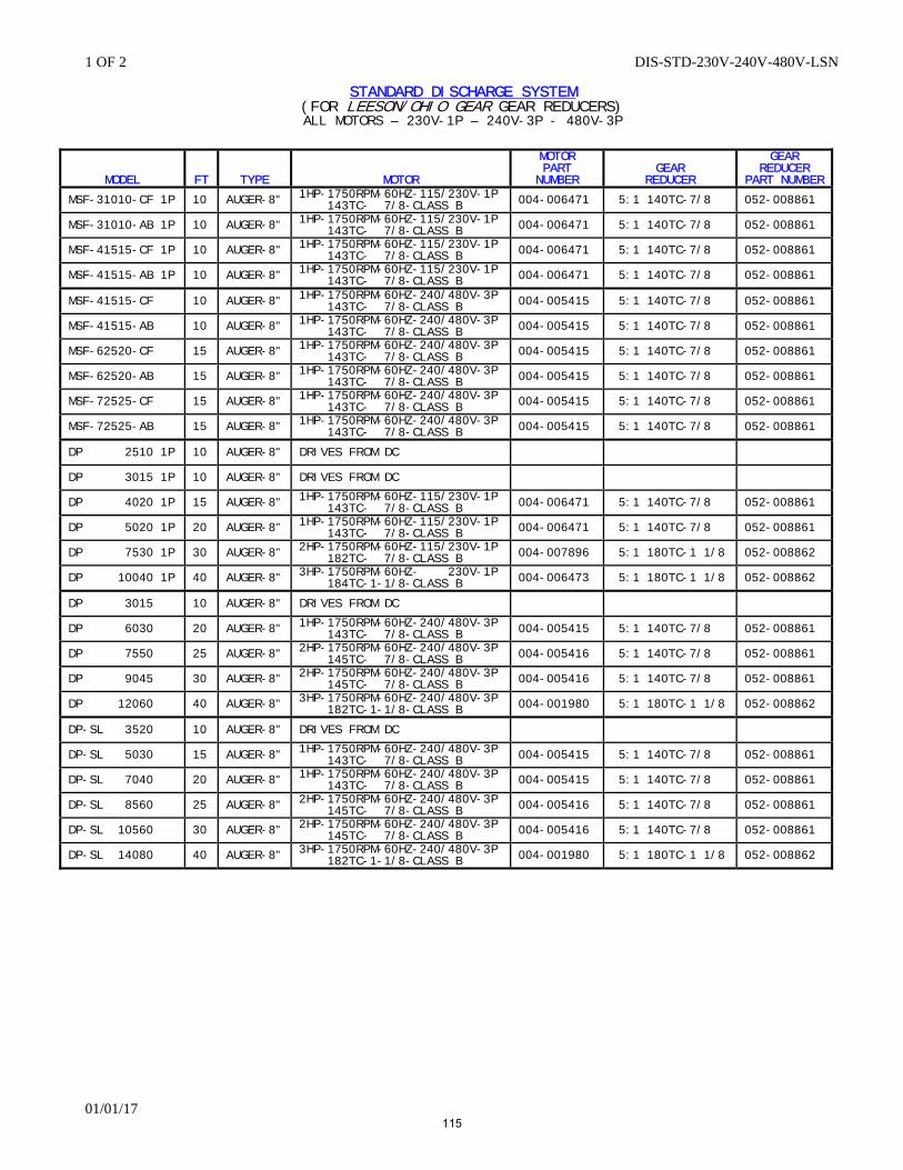
1 OF 2 DIS-STD-230V-240V-480V-LSN
01/01/17
STANDARD DISCHARGE SYSTEM
(FOR LEESON/OHIO GEAR GEAR REDUCERS) ALL MOTORS – 230V-1P – 240V-3P - 480V-3P
MODEL
FT
TYPE
MOTOR
MOTOR PART
NUMBER
GEAR
REDUCER
GEAR REDUCER
PART NUMBER
MSF-31010-CF 1P 10 AUGER-8" 1HP-1750RPM-60HZ-115/230V-1P 143TC- 7/8-CLASS B
004-006471 5:1 140TC-7/8 052-008861
MSF-31010-AB 1P 10 AUGER-8" 1HP-1750RPM-60HZ-115/230V-1P 143TC- 7/8-CLASS B
004-006471 5:1 140TC-7/8 052-008861
MSF-41515-CF 1P 10 AUGER-8" 1HP-1750RPM-60HZ-115/230V-1P 143TC- 7/8-CLASS B
004-006471 5:1 140TC-7/8 052-008861
MSF-41515-AB 1P 10 AUGER-8" 1HP-1750RPM-60HZ-115/230V-1P 143TC- 7/8-CLASS B
004-006471 5:1 140TC-7/8 052-008861
MSF-41515-CF 10 AUGER-8" 1HP-1750RPM-60HZ-240/480V-3P 143TC- 7/8-CLASS B
004-005415 5:1 140TC-7/8 052-008861
MSF-41515-AB 10 AUGER-8" 1HP-1750RPM-60HZ-240/480V-3P 143TC- 7/8-CLASS B
004-005415 5:1 140TC-7/8 052-008861
MSF-62520-CF 15 AUGER-8" 1HP-1750RPM-60HZ-240/480V-3P 143TC- 7/8-CLASS B
004-005415 5:1 140TC-7/8 052-008861
MSF-62520-AB 15 AUGER-8" 1HP-1750RPM-60HZ-240/480V-3P 143TC- 7/8-CLASS B
004-005415 5:1 140TC-7/8 052-008861
MSF-72525-CF 15 AUGER-8" 1HP-1750RPM-60HZ-240/480V-3P 143TC- 7/8-CLASS B
004-005415 5:1 140TC-7/8 052-008861
MSF-72525-AB 15 AUGER-8" 1HP-1750RPM-60HZ-240/480V-3P 143TC- 7/8-CLASS B
004-005415 5:1 140TC-7/8 052-008861
DP 2510 1P 10 AUGER-8" DRIVES FROM DC
DP 3015 1P 10 AUGER-8" DRIVES FROM DC
DP 4020 1P 15 AUGER-8" 1HP-1750RPM-60HZ-115/230V-1P 143TC- 7/8-CLASS B
004-006471 5:1 140TC-7/8 052-008861
DP 5020 1P 20 AUGER-8" 1HP-1750RPM-60HZ-115/230V-1P 143TC- 7/8-CLASS B
004-006471 5:1 140TC-7/8 052-008861
DP 7530 1P 30 AUGER-8" 2HP-1750RPM-60HZ-115/230V-1P 182TC- 7/8-CLASS B
004-007896 5:1 180TC-1 1/8 052-008862
DP 10040 1P 40 AUGER-8" 3HP-1750RPM-60HZ- 230V-1P 184TC-1-1/8-CLASS B
004-006473 5:1 180TC-1 1/8 052-008862
DP 3015 10 AUGER-8" DRIVES FROM DC
DP 6030 20 AUGER-8" 1HP-1750RPM-60HZ-240/480V-3P 143TC- 7/8-CLASS B
004-005415 5:1 140TC-7/8 052-008861
DP 7550 25 AUGER-8" 2HP-1750RPM-60HZ-240/480V-3P 145TC- 7/8-CLASS B
004-005416 5:1 140TC-7/8 052-008861
DP 9045 30 AUGER-8" 2HP-1750RPM-60HZ-240/480V-3P 145TC- 7/8-CLASS B
004-005416 5:1 140TC-7/8 052-008861
DP 12060 40 AUGER-8" 3HP-1750RPM-60HZ-240/480V-3P 182TC-1-1/8-CLASS B
004-001980 5:1 180TC-1 1/8 052-008862
DP-SL 3520 10 AUGER-8" DRIVES FROM DC
DP-SL 5030 15 AUGER-8" 1HP-1750RPM-60HZ-240/480V-3P 143TC- 7/8-CLASS B
004-005415 5:1 140TC-7/8 052-008861
DP-SL 7040 20 AUGER-8" 1HP-1750RPM-60HZ-240/480V-3P 143TC- 7/8-CLASS B
004-005415 5:1 140TC-7/8 052-008861
DP-SL 8560 25 AUGER-8" 2HP-1750RPM-60HZ-240/480V-3P 145TC- 7/8-CLASS B
004-005416 5:1 140TC-7/8 052-008861
DP-SL 10560 30 AUGER-8" 2HP-1750RPM-60HZ-240/480V-3P 145TC- 7/8-CLASS B
004-005416 5:1 140TC-7/8 052-008861
DP-SL 14080 40 AUGER-8" 3HP-1750RPM-60HZ-240/480V-3P 182TC-1-1/8-CLASS B
004-001980 5:1 180TC-1 1/8 052-008862
115
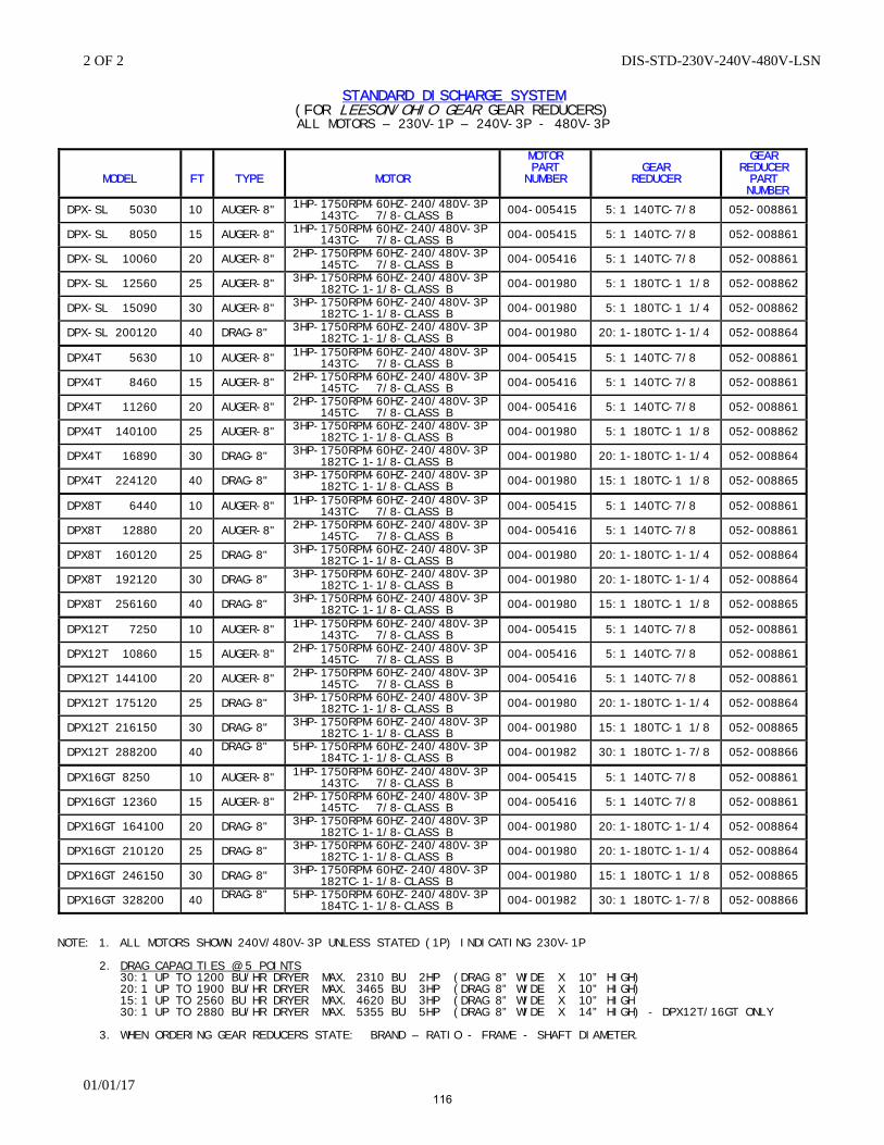
2 OF 2 DIS-STD-230V-240V-480V-LSN
01/01/17
STANDARD DISCHARGE SYSTEM
(FOR LEESON/OHIO GEAR GEAR REDUCERS) ALL MOTORS – 230V-1P – 240V-3P - 480V-3P
MODEL
FT
TYPE
MOTOR
MOTOR PART
NUMBER
GEAR
REDUCER
GEAR REDUCER PART
NUMBER
DPX-SL 5030 10 AUGER-8" 1HP-1750RPM-60HZ-240/480V-3P 143TC- 7/8-CLASS B
004-005415 5:1 140TC-7/8 052-008861
DPX-SL 8050 15 AUGER-8" 1HP-1750RPM-60HZ-240/480V-3P 143TC- 7/8-CLASS B
004-005415 5:1 140TC-7/8 052-008861
DPX-SL 10060 20 AUGER-8" 2HP-1750RPM-60HZ-240/480V-3P 145TC- 7/8-CLASS B
004-005416 5:1 140TC-7/8 052-008861
DPX-SL 12560 25 AUGER-8" 3HP-1750RPM-60HZ-240/480V-3P 182TC-1-1/8-CLASS B
004-001980 5:1 180TC-1 1/8 052-008862
DPX-SL 15090 30 AUGER-8" 3HP-1750RPM-60HZ-240/480V-3P 182TC-1-1/8-CLASS B
004-001980 5:1 180TC-1 1/4 052-008862
DPX-SL 200120 40 DRAG-8" 3HP-1750RPM-60HZ-240/480V-3P 182TC-1-1/8-CLASS B
004-001980 20:1-180TC-1-1/4 052-008864
DPX4T 5630 10 AUGER-8" 1HP-1750RPM-60HZ-240/480V-3P 143TC- 7/8-CLASS B
004-005415 5:1 140TC-7/8 052-008861
DPX4T 8460 15 AUGER-8" 2HP-1750RPM-60HZ-240/480V-3P 145TC- 7/8-CLASS B
004-005416 5:1 140TC-7/8 052-008861
DPX4T 11260 20 AUGER-8" 2HP-1750RPM-60HZ-240/480V-3P 145TC- 7/8-CLASS B
004-005416 5:1 140TC-7/8 052-008861
DPX4T 140100 25 AUGER-8" 3HP-1750RPM-60HZ-240/480V-3P 182TC-1-1/8-CLASS B
004-001980 5:1 180TC-1 1/8 052-008862
DPX4T 16890 30 DRAG-8" 3HP-1750RPM-60HZ-240/480V-3P 182TC-1-1/8-CLASS B
004-001980 20:1-180TC-1-1/4 052-008864
DPX4T 224120 40 DRAG-8" 3HP-1750RPM-60HZ-240/480V-3P 182TC-1-1/8-CLASS B
004-001980 15:1 180TC-1 1/8 052-008865
DPX8T 6440 10 AUGER-8" 1HP-1750RPM-60HZ-240/480V-3P 143TC- 7/8-CLASS B
004-005415 5:1 140TC-7/8 052-008861
DPX8T 12880 20 AUGER-8" 2HP-1750RPM-60HZ-240/480V-3P 145TC- 7/8-CLASS B
004-005416 5:1 140TC-7/8 052-008861
DPX8T 160120 25 DRAG-8" 3HP-1750RPM-60HZ-240/480V-3P 182TC-1-1/8-CLASS B
004-001980 20:1-180TC-1-1/4 052-008864
DPX8T 192120 30 DRAG-8" 3HP-1750RPM-60HZ-240/480V-3P 182TC-1-1/8-CLASS B
004-001980 20:1-180TC-1-1/4 052-008864
DPX8T 256160 40 DRAG-8" 3HP-1750RPM-60HZ-240/480V-3P 182TC-1-1/8-CLASS B
004-001980 15:1 180TC-1 1/8 052-008865
DPX12T 7250 10 AUGER-8" 1HP-1750RPM-60HZ-240/480V-3P 143TC- 7/8-CLASS B
004-005415 5:1 140TC-7/8 052-008861
DPX12T 10860 15 AUGER-8" 2HP-1750RPM-60HZ-240/480V-3P 145TC- 7/8-CLASS B
004-005416 5:1 140TC-7/8 052-008861
DPX12T 144100 20 AUGER-8" 2HP-1750RPM-60HZ-240/480V-3P 145TC- 7/8-CLASS B
004-005416 5:1 140TC-7/8 052-008861
DPX12T 175120 25 DRAG-8" 3HP-1750RPM-60HZ-240/480V-3P 182TC-1-1/8-CLASS B
004-001980 20:1-180TC-1-1/4 052-008864
DPX12T 216150 30 DRAG-8" 3HP-1750RPM-60HZ-240/480V-3P 182TC-1-1/8-CLASS B
004-001980 15:1 180TC-1 1/8 052-008865
DPX12T 288200 40 DRAG-8"
5HP-1750RPM-60HZ-240/480V-3P 184TC-1-1/8-CLASS B
004-001982 30:1 180TC-1-7/8 052-008866
DPX16GT 8250 10 AUGER-8" 1HP-1750RPM-60HZ-240/480V-3P 143TC- 7/8-CLASS B
004-005415 5:1 140TC-7/8 052-008861
DPX16GT 12360 15 AUGER-8" 2HP-1750RPM-60HZ-240/480V-3P 145TC- 7/8-CLASS B
004-005416 5:1 140TC-7/8 052-008861
DPX16GT 164100 20 DRAG-8" 3HP-1750RPM-60HZ-240/480V-3P 182TC-1-1/8-CLASS B
004-001980 20:1-180TC-1-1/4 052-008864
DPX16GT 210120 25 DRAG-8" 3HP-1750RPM-60HZ-240/480V-3P 182TC-1-1/8-CLASS B
004-001980 20:1-180TC-1-1/4 052-008864
DPX16GT 246150 30 DRAG-8" 3HP-1750RPM-60HZ-240/480V-3P 182TC-1-1/8-CLASS B
004-001980 15:1 180TC-1 1/8 052-008865
DPX16GT 328200 40 DRAG-8"
5HP-1750RPM-60HZ-240/480V-3P 184TC-1-1/8-CLASS B
004-001982 30:1 180TC-1-7/8 052-008866
NOTE: 1. ALL MOTORS SHOWN 240V/480V-3P UNLESS STATED (1P) INDICATING 230V-1P 2. DRAG CAPACITIES @ 5 POINTS 30:1 UP TO 1200 BU/HR DRYER MAX. 2310 BU 2HP (DRAG 8” WIDE X 10” HIGH) 20:1 UP TO 1900 BU/HR DRYER MAX. 3465 BU 3HP (DRAG 8” WIDE X 10” HIGH) 15:1 UP TO 2560 BU HR DRYER MAX. 4620 BU 3HP (DRAG 8” WIDE X 10” HIGH 30:1 UP TO 2880 BU/HR DRYER MAX. 5355 BU 5HP (DRAG 8” WIDE X 14” HIGH) - DPX12T/16GT ONLY 3. WHEN ORDERING GEAR REDUCERS STATE: BRAND – RATIO - FRAME - SHAFT DIAMETER.
116
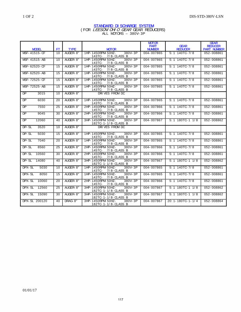
1 OF 2 DIS-STD-380V-LSN
01/01/17
STANDARD DISCHARGE SYSTEM (FOR LEESON/OHIO GEAR GEAR REDUCERS)
ALL MOTORS – 380V-3P
MODEL
FT
TYPE
MOTOR
MOTOR PART NUMBER
GEAR
REDUCER
GEAR REDUCER
PART NUMBER MSF-41515-CF 10 AUGER-8" 1HP-1450RPM-50HZ- 380V-3P
143TC- 7/8-CLASS B 004-007865 5:1 140TC-7/8 052-008861
MSF-41515-AB 10 AUGER-8" 1HP-1450RPM-50HZ- 380V-3P 143TC- 7/8-CLASS B
004-007865 5:1 140TC-7/8 052-008861
MSF-62520-CF 15 AUGER-8" 1HP-1450RPM-50HZ- 380V-3P 143TC- 7/8-CLASS B
004-007865 5:1 140TC-7/8 052-008861
MSF-62520-AB 15 AUGER-8" 1HP-1450RPM-50HZ- 380V-3P 143TC- 7/8-CLASS B
004-007865 5:1 140TC-7/8 052-008861
MSF-72525-CF 15 AUGER-8" 1HP-1450RPM-50HZ- 380V-3P 143TC- 7/8-CLASS B
004-007865 5:1 140TC-7/8 052-008861
MSF-72525-AB 15 AUGER-8" 1HP-1450RPM-50HZ- 380V-3P 143TC- 7/8-CLASS B
004-007865 5:1 140TC-7/8 052-008861
DP 3015
10 AUGER-8" DRIVES FROM DC
DP 6030 20 AUGER-8" 1HP-1450RPM-50HZ- 380V-3P 143TC- 7/8-CLASS B
004-007865 5:1 140TC-7/8 052-008861
DP 7550 25 AUGER-8" 2HP-1450RPM-50HZ- 380V-3P 145TC- 7/8-CLASS B
004-007866 5:1 140TC-7/8 052-008861
DP 9045 30 AUGER-8" 2HP-1450RPM-50HZ- 380V-3P 145TC- 7/8-CLASS B
004-007866 5:1 140TC-7/8 052-008861
DP 12060 40 AUGER-8" 3HP-1450RPM-50HZ- 380V-3P 182TC-1-1/8-CLASS B
004-007867 5:1 180TC-1 1/8 052-008862
DP-SL 3520
10 AUGER-8" DRIVES FROM DC
DP-SL 5030 15 AUGER-8" 1HP-1450RPM-50HZ- 380V-3P 143TC- 7/8-CLASS B
004-007865 5:1 140TC-7/8 052-008861
DP-SL 7040 20 AUGER-8" 1HP-1450RPM-50HZ- 380V-3P 143TC- 7/8-CLASS B
004-007865 5:1 140TC-7/8 052-008861
DP-SL 8560 25 AUGER-8" 2HP-1450RPM-50HZ- 380V-3P 145TC- 7/8-CLASS B
004-007866 5:1 140TC-7/8 052-008861
DP-SL 10560 30 AUGER-8" 2HP-1450RPM-50HZ- 380V-3P 145TC- 7/8-CLASS B
004-007866 5:1 140TC-7/8 052-008861
DP-SL 14080 40 AUGER-8" 3HP-1450RPM-50HZ- 380V-3P 182TC-1-1/8-CLASS B
004-007867 5:1 180TC-1 1/8 052-008862
DPX-SL 5030 10 AUGER-8" 1HP-1450RPM-50HZ- 380V-3P 143TC- 7/8-CLASS B
004-007865 5:1 140TC-7/8 052-008861
DPX-SL 8050 15 AUGER-8" 1HP-1450RPM-50HZ- 380V-3P 143TC- 7/8-CLASS B
004-007865 5:1 140TC-7/8 052-008861
DPX-SL 10060 20 AUGER-8" 2HP-1450RPM-50HZ- 380V-3P 145TC- 7/8-CLASS B
004-007866 5:1 140TC-7/8 052-008861
DPX-SL 12560 25 AUGER-8" 3HP-1450RPM-50HZ- 380V-3P 182TC-1-1/8-CLASS B
004-007867 5:1 180TC-1 1/8 052-008862
DPX-SL 15090 30 AUGER-8" 3HP-1450RPM-50HZ- 380V-3P 182TC-1-1/8-CLASS B
004-007867 5:1 180TC-1 1/8 052-008862
DPX-SL 200120 40 DRAG-8" 3HP-1450RPM-50HZ- 380V-3P 182TC-1-1/8-CLASS B
004-007867 20:1-180TC-1-1/4 052-008864
117
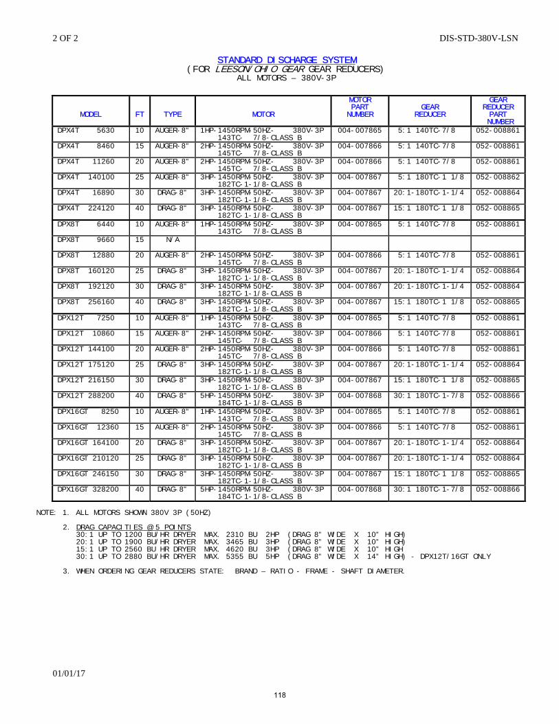
2 OF 2 DIS-STD-380V-LSN
01/01/17
STANDARD DISCHARGE SYSTEM (FOR LEESON/OHIO GEAR GEAR REDUCERS)
ALL MOTORS – 380V-3P
MODEL
FT
TYPE
MOTOR
MOTOR PART NUMBER
GEAR
REDUCER
GEAR REDUCER PART
NUMBER DPX4T 5630 10 AUGER-8" 1HP-1450RPM-50HZ- 380V-3P
143TC- 7/8-CLASS B 004-007865 5:1 140TC-7/8 052-008861
DPX4T 8460 15 AUGER-8" 2HP-1450RPM-50HZ- 380V-3P 145TC- 7/8-CLASS B
004-007866 5:1 140TC-7/8 052-008861
DPX4T 11260 20 AUGER-8" 2HP-1450RPM-50HZ- 380V-3P 145TC- 7/8-CLASS B
004-007866 5:1 140TC-7/8 052-008861
DPX4T 140100 25 AUGER-8" 3HP-1450RPM-50HZ- 380V-3P 182TC-1-1/8-CLASS B
004-007867 5:1 180TC-1 1/8 052-008862
DPX4T 16890 30 DRAG-8" 3HP-1450RPM-50HZ- 380V-3P 182TC-1-1/8-CLASS B
004-007867 20:1-180TC-1-1/4 052-008864
DPX4T 224120 40 DRAG-8" 3HP-1450RPM-50HZ- 380V-3P 182TC-1-1/8-CLASS B
004-007867 15:1 180TC-1 1/8 052-008865
DPX8T 6440 10 AUGER-8" 1HP-1450RPM-50HZ- 380V-3P 143TC- 7/8-CLASS B
004-007865 5:1 140TC-7/8 052-008861
DPX8T 9660
15 N/A
DPX8T 12880 20 AUGER-8" 2HP-1450RPM-50HZ- 380V-3P 145TC- 7/8-CLASS B
004-007866 5:1 140TC-7/8 052-008861
DPX8T 160120 25 DRAG-8" 3HP-1450RPM-50HZ- 380V-3P 182TC-1-1/8-CLASS B
004-007867 20:1-180TC-1-1/4 052-008864
DPX8T 192120 30 DRAG-8" 3HP-1450RPM-50HZ- 380V-3P 182TC-1-1/8-CLASS B
004-007867 20:1-180TC-1-1/4 052-008864
DPX8T 256160 40 DRAG-8" 3HP-1450RPM-50HZ- 380V-3P 182TC-1-1/8-CLASS B
004-007867 15:1 180TC-1 1/8 052-008865
DPX12T 7250 10 AUGER-8" 1HP-1450RPM-50HZ- 380V-3P 143TC- 7/8-CLASS B
004-007865 5:1 140TC-7/8 052-008861
DPX12T 10860 15 AUGER-8" 2HP-1450RPM-50HZ- 380V-3P 145TC- 7/8-CLASS B
004-007866 5:1 140TC-7/8 052-008861
DPX12T 144100 20 AUGER-8" 2HP-1450RPM-50HZ- 380V-3P 145TC- 7/8-CLASS B
004-007866 5:1 140TC-7/8 052-008861
DPX12T 175120 25 DRAG-8" 3HP-1450RPM-50HZ- 380V-3P 182TC-1-1/8-CLASS B
004-007867 20:1-180TC-1-1/4 052-008864
DPX12T 216150 30 DRAG-8" 3HP-1450RPM-50HZ- 380V-3P 182TC-1-1/8-CLASS B
004-007867 15:1 180TC-1 1/8 052-008865
DPX12T 288200 40 DRAG-8"
5HP-1450RPM-50HZ- 380V-3P 184TC-1-1/8-CLASS B
004-007868 30:1 180TC-1-7/8 052-008866
DPX16GT 8250 10 AUGER-8" 1HP-1450RPM-50HZ- 380V-3P 143TC- 7/8-CLASS B
004-007865 5:1 140TC-7/8 052-008861
DPX16GT 12360 15 AUGER-8" 2HP-1450RPM-50HZ- 380V-3P 145TC- 7/8-CLASS B
004-007866 5:1 140TC-7/8 052-008861
DPX16GT 164100 20 DRAG-8" 3HP-1450RPM-50HZ- 380V-3P 182TC-1-1/8-CLASS B
004-007867 20:1-180TC-1-1/4 052-008864
DPX16GT 210120 25 DRAG-8" 3HP-1450RPM-50HZ- 380V-3P 182TC-1-1/8-CLASS B
004-007867 20:1-180TC-1-1/4 052-008864
DPX16GT 246150 30 DRAG-8" 3HP-1450RPM-50HZ- 380V-3P 182TC-1-1/8-CLASS B
004-007867 15:1 180TC-1 1/8 052-008865
DPX16GT 328200 40 DRAG-8"
5HP-1450RPM-50HZ- 380V-3P 184TC-1-1/8-CLASS B
004-007868 30:1 180TC-1-7/8 052-008866
NOTE: 1. ALL MOTORS SHOWN 380V 3P (50HZ) 2. DRAG CAPACITIES @ 5 POINTS 30:1 UP TO 1200 BU/HR DRYER MAX. 2310 BU 2HP (DRAG 8” WIDE X 10” HIGH) 20:1 UP TO 1900 BU/HR DRYER MAX. 3465 BU 3HP (DRAG 8” WIDE X 10” HIGH) 15:1 UP TO 2560 BU HR DRYER MAX. 4620 BU 3HP (DRAG 8” WIDE X 10” HIGH 30:1 UP TO 2880 BU/HR DRYER MAX. 5355 BU 5HP (DRAG 8” WIDE X 14” HIGH) - DPX12T/16GT ONLY 3. WHEN ORDERING GEAR REDUCERS STATE: BRAND – RATIO - FRAME - SHAFT DIAMETER.
118
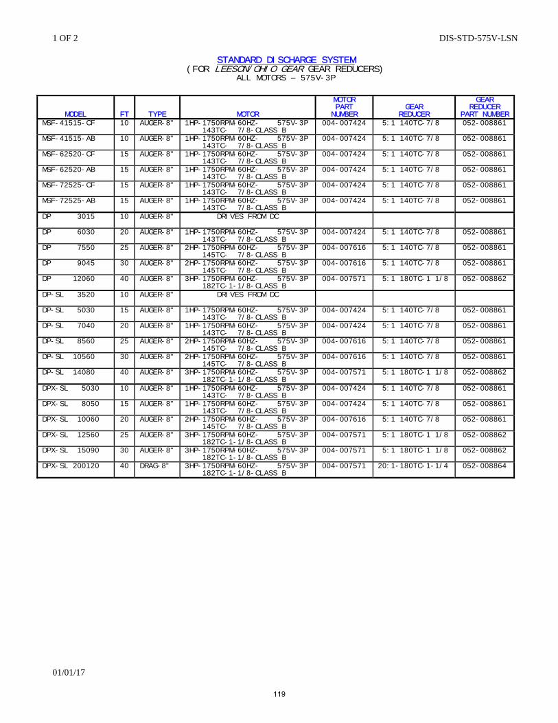
1 OF 2 DIS-STD-575V-LSN
01/01/17
STANDARD DISCHARGE SYSTEM (FOR LEESON/OHIO GEAR GEAR REDUCERS)
ALL MOTORS – 575V-3P
MODEL
FT
TYPE
MOTOR
MOTOR PART NUMBER
GEAR
REDUCER
GEAR REDUCER
PART NUMBER MSF-41515-CF 10 AUGER-8" 1HP-1750RPM-60HZ- 575V-3P
143TC- 7/8-CLASS B 004-007424 5:1 140TC-7/8 052-008861
MSF-41515-AB 10 AUGER-8" 1HP-1750RPM-60HZ- 575V-3P 143TC- 7/8-CLASS B
004-007424 5:1 140TC-7/8 052-008861
MSF-62520-CF 15 AUGER-8" 1HP-1750RPM-60HZ- 575V-3P 143TC- 7/8-CLASS B
004-007424 5:1 140TC-7/8 052-008861
MSF-62520-AB 15 AUGER-8" 1HP-1750RPM-60HZ- 575V-3P 143TC- 7/8-CLASS B
004-007424 5:1 140TC-7/8 052-008861
MSF-72525-CF 15 AUGER-8" 1HP-1750RPM-60HZ- 575V-3P 143TC- 7/8-CLASS B
004-007424 5:1 140TC-7/8 052-008861
MSF-72525-AB 15 AUGER-8" 1HP-1750RPM-60HZ- 575V-3P 143TC- 7/8-CLASS B
004-007424 5:1 140TC-7/8 052-008861
DP 3015
10 AUGER-8" DRIVES FROM DC
DP 6030 20 AUGER-8" 1HP-1750RPM-60HZ- 575V-3P 143TC- 7/8-CLASS B
004-007424 5:1 140TC-7/8 052-008861
DP 7550 25 AUGER-8" 2HP-1750RPM-60HZ- 575V-3P 145TC- 7/8-CLASS B
004-007616 5:1 140TC-7/8 052-008861
DP 9045 30 AUGER-8" 2HP-1750RPM-60HZ- 575V-3P 145TC- 7/8-CLASS B
004-007616 5:1 140TC-7/8 052-008861
DP 12060 40 AUGER-8" 3HP-1750RPM-60HZ- 575V-3P 182TC-1-1/8-CLASS B
004-007571 5:1 180TC-1 1/8 052-008862
DP-SL 3520
10 AUGER-8" DRIVES FROM DC
DP-SL 5030 15 AUGER-8" 1HP-1750RPM-60HZ- 575V-3P 143TC- 7/8-CLASS B
004-007424 5:1 140TC-7/8 052-008861
DP-SL 7040 20 AUGER-8" 1HP-1750RPM-60HZ- 575V-3P 143TC- 7/8-CLASS B
004-007424 5:1 140TC-7/8 052-008861
DP-SL 8560 25 AUGER-8" 2HP-1750RPM-60HZ- 575V-3P 145TC- 7/8-CLASS B
004-007616 5:1 140TC-7/8 052-008861
DP-SL 10560 30 AUGER-8" 2HP-1750RPM-60HZ- 575V-3P 145TC- 7/8-CLASS B
004-007616 5:1 140TC-7/8 052-008861
DP-SL 14080 40 AUGER-8" 3HP-1750RPM-60HZ- 575V-3P 182TC-1-1/8-CLASS B
004-007571 5:1 180TC-1 1/8 052-008862
DPX-SL 5030 10 AUGER-8" 1HP-1750RPM-60HZ- 575V-3P 143TC- 7/8-CLASS B
004-007424 5:1 140TC-7/8 052-008861
DPX-SL 8050 15 AUGER-8" 1HP-1750RPM-60HZ- 575V-3P 143TC- 7/8-CLASS B
004-007424 5:1 140TC-7/8 052-008861
DPX-SL 10060 20 AUGER-8" 2HP-1750RPM-60HZ- 575V-3P 145TC- 7/8-CLASS B
004-007616 5:1 140TC-7/8 052-008861
DPX-SL 12560 25 AUGER-8" 3HP-1750RPM-60HZ- 575V-3P 182TC-1-1/8-CLASS B
004-007571 5:1 180TC-1 1/8 052-008862
DPX-SL 15090 30 AUGER-8" 3HP-1750RPM-60HZ- 575V-3P 182TC-1-1/8-CLASS B
004-007571 5:1 180TC-1 1/8 052-008862
DPX-SL 200120 40 DRAG-8" 3HP-1750RPM-60HZ- 575V-3P 182TC-1-1/8-CLASS B
004-007571 20:1-180TC-1-1/4 052-008864
119
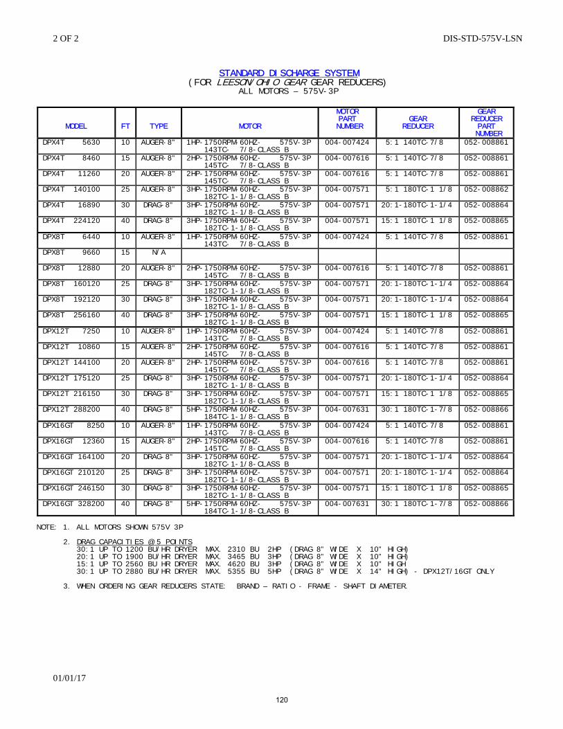
2 OF 2 DIS-STD-575V-LSN
01/01/17
STANDARD DISCHARGE SYSTEM
(FOR LEESON/OHIO GEAR GEAR REDUCERS) ALL MOTORS – 575V-3P
MODEL
FT
TYPE
MOTOR
MOTOR PART
NUMBER
GEAR
REDUCER
GEAR REDUCER PART
NUMBER DPX4T 5630 10 AUGER-8" 1HP-1750RPM-60HZ- 575V-3P
143TC- 7/8-CLASS B 004-007424 5:1 140TC-7/8 052-008861
DPX4T 8460 15 AUGER-8" 2HP-1750RPM-60HZ- 575V-3P 145TC- 7/8-CLASS B
004-007616 5:1 140TC-7/8 052-008861
DPX4T 11260 20 AUGER-8" 2HP-1750RPM-60HZ- 575V-3P 145TC- 7/8-CLASS B
004-007616 5:1 140TC-7/8 052-008861
DPX4T 140100 25 AUGER-8" 3HP-1750RPM-60HZ- 575V-3P 182TC-1-1/8-CLASS B
004-007571 5:1 180TC-1 1/8 052-008862
DPX4T 16890 30 DRAG-8" 3HP-1750RPM-60HZ- 575V-3P 182TC-1-1/8-CLASS B
004-007571 20:1-180TC-1-1/4 052-008864
DPX4T 224120 40 DRAG-8" 3HP-1750RPM-60HZ- 575V-3P 182TC-1-1/8-CLASS B
004-007571 15:1 180TC-1 1/8 052-008865
DPX8T 6440 10 AUGER-8" 1HP-1750RPM-60HZ- 575V-3P 143TC- 7/8-CLASS B
004-007424 5:1 140TC-7/8 052-008861
DPX8T 9660
15 N/A
DPX8T 12880 20 AUGER-8" 2HP-1750RPM-60HZ- 575V-3P 145TC- 7/8-CLASS B
004-007616 5:1 140TC-7/8 052-008861
DPX8T 160120 25 DRAG-8" 3HP-1750RPM-60HZ- 575V-3P 182TC-1-1/8-CLASS B
004-007571 20:1-180TC-1-1/4 052-008864
DPX8T 192120 30 DRAG-8" 3HP-1750RPM-60HZ- 575V-3P 182TC-1-1/8-CLASS B
004-007571 20:1-180TC-1-1/4 052-008864
DPX8T 256160 40 DRAG-8" 3HP-1750RPM-60HZ- 575V-3P 182TC-1-1/8-CLASS B
004-007571 15:1 180TC-1 1/8 052-008865
DPX12T 7250 10 AUGER-8" 1HP-1750RPM-60HZ- 575V-3P 143TC- 7/8-CLASS B
004-007424 5:1 140TC-7/8 052-008861
DPX12T 10860 15 AUGER-8" 2HP-1750RPM-60HZ- 575V-3P 145TC- 7/8-CLASS B
004-007616 5:1 140TC-7/8 052-008861
DPX12T 144100 20 AUGER-8" 2HP-1750RPM-60HZ- 575V-3P 145TC- 7/8-CLASS B
004-007616 5:1 140TC-7/8 052-008861
DPX12T 175120 25 DRAG-8" 3HP-1750RPM-60HZ- 575V-3P 182TC-1-1/8-CLASS B
004-007571 20:1-180TC-1-1/4 052-008864
DPX12T 216150 30 DRAG-8" 3HP-1750RPM-60HZ- 575V-3P 182TC-1-1/8-CLASS B
004-007571 15:1 180TC-1 1/8 052-008865
DPX12T 288200 40 DRAG-8"
5HP-1750RPM-60HZ- 575V-3P 184TC-1-1/8-CLASS B
004-007631 30:1 180TC-1-7/8 052-008866
DPX16GT 8250 10 AUGER-8" 1HP-1750RPM-60HZ- 575V-3P 143TC- 7/8-CLASS B
004-007424 5:1 140TC-7/8 052-008861
DPX16GT 12360 15 AUGER-8" 2HP-1750RPM-60HZ- 575V-3P 145TC- 7/8-CLASS B
004-007616 5:1 140TC-7/8 052-008861
DPX16GT 164100 20 DRAG-8" 3HP-1750RPM-60HZ- 575V-3P 182TC-1-1/8-CLASS B
004-007571 20:1-180TC-1-1/4 052-008864
DPX16GT 210120 25 DRAG-8" 3HP-1750RPM-60HZ- 575V-3P 182TC-1-1/8-CLASS B
004-007571 20:1-180TC-1-1/4 052-008864
DPX16GT 246150 30 DRAG-8" 3HP-1750RPM-60HZ- 575V-3P 182TC-1-1/8-CLASS B
004-007571 15:1 180TC-1 1/8 052-008865
DPX16GT 328200 40 DRAG-8"
5HP-1750RPM-60HZ- 575V-3P 184TC-1-1/8-CLASS B
004-007631 30:1 180TC-1-7/8 052-008866
NOTE: 1. ALL MOTORS SHOWN 575V 3P 2. DRAG CAPACITIES @ 5 POINTS 30:1 UP TO 1200 BU/HR DRYER MAX. 2310 BU 2HP (DRAG 8” WIDE X 10” HIGH) 20:1 UP TO 1900 BU/HR DRYER MAX. 3465 BU 3HP (DRAG 8” WIDE X 10” HIGH) 15:1 UP TO 2560 BU HR DRYER MAX. 4620 BU 3HP (DRAG 8” WIDE X 10” HIGH 30:1 UP TO 2880 BU/HR DRYER MAX. 5355 BU 5HP (DRAG 8” WIDE X 14” HIGH) - DPX12T/16GT ONLY 3. WHEN ORDERING GEAR REDUCERS STATE: BRAND – RATIO - FRAME - SHAFT DIAMETER.
120
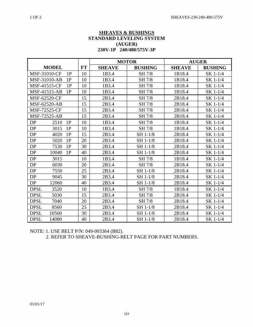
1 OF 2 SHEAVES-230-240-480-575V
01/01/17
SHEAVES & BUSHINGS STANDARD LEVELING SYSTEM
(AUGER) 230V-1P 240/480/575V-3P
MODEL
FT MOTOR AUGER
SHEAVE BUSHING SHEAVE BUSHING MSF-31010-CF 1P 10 1B3.4 SH 7/8 1B18.4 SK 1-1/4 MSF-31010-AB 1P 10 1B3.4 SH 7/8 1B18.4 SK 1-1/4 MSF-41515-CF 1P 10 1B3.4 SH 7/8 1B18.4 SK 1-1/4 MSF-41515-AB 1P 10 1B3.4 SH 7/8 1B18.4 SK 1-1/4 MSF-62520-CF 15 2B3.4 SH 7/8 2B18.4 SK 1-1/4 MSF-62520-AB 15 2B3.4 SH 7/8 2B18.4 SK 1-1/4 MSF-72525-CF 15 2B3.4 SH 7/8 2B18.4 SK 1-1/4 MSF-72525-AB 15 2B3.4 SH 7/8 2B18.4 SK 1-1/4 DP 2510 1P 10 1B3.4 SH 7/8 1B18.4 SK 1-1/4 DP 3015 1P 10 1B3.4 SH 7/8 1B18.4 SK 1-1/4 DP 4020 1P 15 2B3.4 SH 1-1/8 2B18.4 SK 1-1/4 DP 5020 1P 20 2B3.4 SH 1-1/8 2B18.4 SK 1-1/4 DP 7530 1P 30 2B3.4 SH 1-1/8 2B18.4 SK 1-1/4 DP 10040 1P 40 2B3.4 SH 1-1/8 2B18.4 SK 1-1/4 DP 3015 10 1B3.4 SH 7/8 1B18.4 SK 1-1/4 DP 6030 20 2B3.4 SH 7/8 2B18.4 SK 1-1/4 DP 7550 25 2B3.4 SH 1-1/8 2B18.4 SK 1-1/4 DP 9045 30 2B3.4 SH 1-1/8 2B18.4 SK 1-1/4 DP 12060 40 2B3.4 SH 1-1/8 2B18.4 SK 1-1/4 DPSL 3520 10 1B3.4 SH 7/8 1B18.4 SK 1-1/4 DPSL 5030 15 2B3.4 SH 7/8 2B18.4 SK 1-1/4 DPSL 7040 20 2B3.4 SH 7/8 2B18.4 SK 1-1/4 DPSL 8560 25 2B3.4 SH 1-1/8 2B18.4 SK 1-1/4 DPSL 10560 30 2B3.4 SH 1-1/8 2B18.4 SK 1-1/4 DPSL 14080 40 2B3.4 SH 1-1/8 2B18.4 SK 1-1/4 NOTE: 1. USE BELT P/N: 049-003364 (B82). 2. REFER TO SHEAVE-BUSHING-BELT PAGE FOR PART NUMBERS.
121
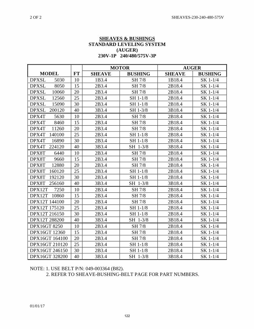
2 OF 2 SHEAVES-230-240-480-575V
01/01/17
SHEAVES & BUSHINGS
STANDARD LEVELING SYSTEM (AUGER)
230V-1P 240/480/575V-3P
MODEL
FT
MOTOR AUGER SHEAVE BUSHING SHEAVE BUSHING
DPXSL 5030 10 1B3.4 SH 7/8 1B18.4 SK 1-1/4 DPXSL 8050 15 2B3.4 SH 7/8 2B18.4 SK 1-1/4 DPXSL 10060 20 2B3.4 SH 7/8 2B18.4 SK 1-1/4 DPXSL 12560 25 2B3.4 SH 1-1/8 2B18.4 SK 1-1/4 DPXSL 15090 30 2B3.4 SH 1-1/8 2B18.4 SK 1-1/4 DPXSL 200120 40 3B3.4 SH 1-3/8 3B18.4 SK 1-1/4 DPX4T 5630 10 2B3.4 SH 7/8 2B18.4 SK 1-1/4 DPX4T 8460 15 2B3.4 SH 7/8 2B18.4 SK 1-1/4 DPX4T 11260 20 2B3.4 SH 7/8 2B18.4 SK 1-1/4 DPX4T 140100 25 2B3.4 SH 1-1/8 2B18.4 SK 1-1/4 DPX4T 16890 30 2B3.4 SH 1-1/8 2B18.4 SK 1-1/4 DPX4T 224120 40 3B3.4 SH 1-3/8 3B18.4 SK 1-1/4 DPX8T 6440 10 2B3.4 SH 7/8 2B18.4 SK 1-1/4 DPX8T 9660 15 2B3.4 SH 7/8 2B18.4 SK 1-1/4 DPX8T 12880 20 2B3.4 SH 7/8 2B18.4 SK 1-1/4 DPX8T 160120 25 2B3.4 SH 1-1/8 2B18.4 SK 1-1/4 DPX8T 192120 30 2B3.4 SH 1-1/8 2B18.4 SK 1-1/4 DPX8T 256160 40 3B3.4 SH 1-3/8 3B18.4 SK 1-1/4 DPX12T 7250 10 2B3.4 SH 7/8 2B18.4 SK 1-1/4 DPX12T 10860 15 2B3.4 SH 7/8 2B18.4 SK 1-1/4 DPX12T 144100 20 2B3.4 SH 7/8 2B18.4 SK 1-1/4 DPX12T 175120 25 2B3.4 SH 1-1/8 2B18.4 SK 1-1/4 DPX12T 216150 30 2B3.4 SH 1-1/8 2B18.4 SK 1-1/4 DPX12T 288200 40 3B3.4 SH 1-3/8 3B18.4 SK 1-1/4 DPX16GT 8250 10 2B3.4 SH 7/8 2B18.4 SK 1-1/4 DPX16GT 12360 15 2B3.4 SH 7/8 2B18.4 SK 1-1/4 DPX16GT 164100 20 2B3.4 SH 7/8 2B18.4 SK 1-1/4 DPX16GT 210120 25 2B3.4 SH 1-1/8 2B18.4 SK 1-1/4 DPX16GT 246150 30 2B3.4 SH 1-1/8 2B18.4 SK 1-1/4 DPX16GT 328200 40 3B3.4 SH 1-3/8 3B18.4 SK 1-1/4 NOTE: 1. USE BELT P/N: 049-003364 (B82). 2. REFER TO SHEAVE-BUSHING-BELT PAGE FOR PART NUMBERS.
122
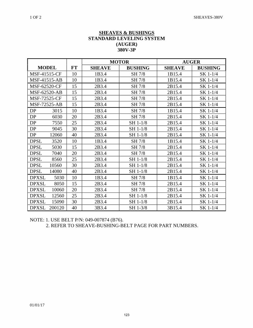
1 OF 2 SHEAVES-380V
01/01/17
SHEAVES & BUSHINGS STANDARD LEVELING SYSTEM
(AUGER) 380V-3P
MODEL
FT MOTOR AUGER
SHEAVE BUSHING SHEAVE BUSHING MSF-41515-CF 10 1B3.4 SH 7/8 1B15.4 SK 1-1/4 MSF-41515-AB 10 1B3.4 SH 7/8 1B15.4 SK 1-1/4 MSF-62520-CF 15 2B3.4 SH 7/8 2B15.4 SK 1-1/4 MSF-62520-AB 15 2B3.4 SH 7/8 2B15.4 SK 1-1/4 MSF-72525-CF 15 2B3.4 SH 7/8 2B15.4 SK 1-1/4 MSF-72525-AB 15 2B3.4 SH 7/8 2B15.4 SK 1-1/4 DP 3015 10 1B3.4 SH 7/8 1B15.4 SK 1-1/4 DP 6030 20 2B3.4 SH 7/8 2B15.4 SK 1-1/4 DP 7550 25 2B3.4 SH 1-1/8 2B15.4 SK 1-1/4 DP 9045 30 2B3.4 SH 1-1/8 2B15.4 SK 1-1/4 DP 12060 40 2B3.4 SH 1-1/8 2B15.4 SK 1-1/4 DPSL 3520 10 1B3.4 SH 7/8 1B15.4 SK 1-1/4 DPSL 5030 15 2B3.4 SH 7/8 2B15.4 SK 1-1/4 DPSL 7040 20 2B3.4 SH 7/8 2B15.4 SK 1-1/4 DPSL 8560 25 2B3.4 SH 1-1/8 2B15.4 SK 1-1/4 DPSL 10560 30 2B3.4 SH 1-1/8 2B15.4 SK 1-1/4 DPSL 14080 40 2B3.4 SH 1-1/8 2B15.4 SK 1-1/4 DPXSL 5030 10 1B3.4 SH 7/8 1B15.4 SK 1-1/4 DPXSL 8050 15 2B3.4 SH 7/8 2B15.4 SK 1-1/4 DPXSL 10060 20 2B3.4 SH 7/8 2B15.4 SK 1-1/4 DPXSL 12560 25 2B3.4 SH 1-1/8 2B15.4 SK 1-1/4 DPXSL 15090 30 2B3.4 SH 1-1/8 2B15.4 SK 1-1/4 DPXSL 200120 40 3B3.4 SH 1-3/8 3B15.4 SK 1-1/4 NOTE: 1. USE BELT P/N: 049-007874 (B76). 2. REFER TO SHEAVE-BUSHING-BELT PAGE FOR PART NUMBERS.
123
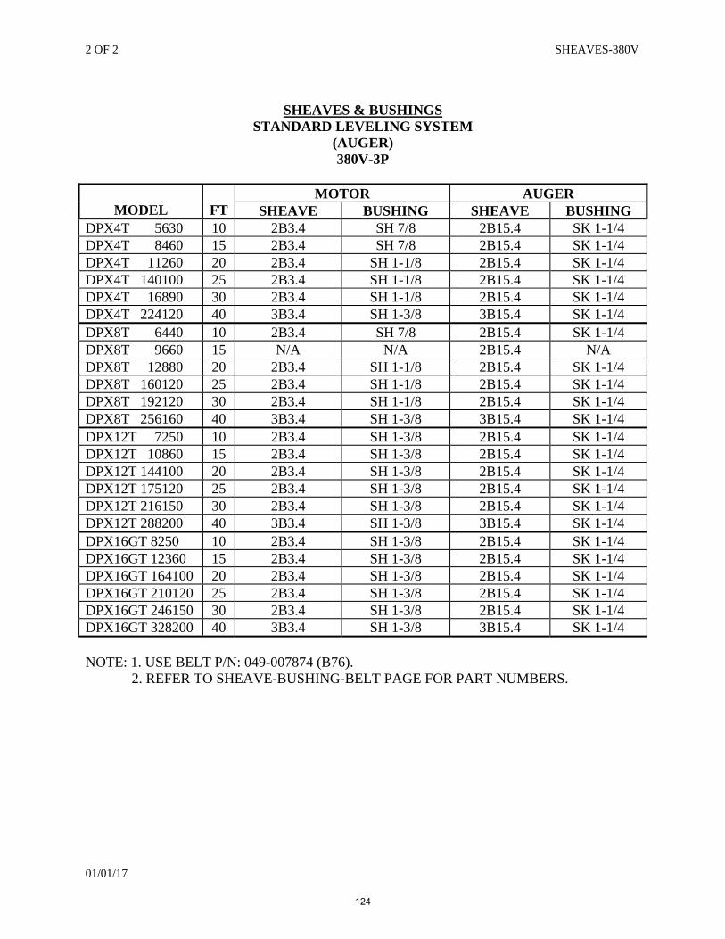
2 OF 2 SHEAVES-380V
01/01/17
SHEAVES & BUSHINGS
STANDARD LEVELING SYSTEM (AUGER) 380V-3P
MODEL
FT MOTOR AUGER
SHEAVE BUSHING SHEAVE BUSHING DPX4T 5630 10 2B3.4 SH 7/8 2B15.4 SK 1-1/4 DPX4T 8460 15 2B3.4 SH 7/8 2B15.4 SK 1-1/4 DPX4T 11260 20 2B3.4 SH 1-1/8 2B15.4 SK 1-1/4 DPX4T 140100 25 2B3.4 SH 1-1/8 2B15.4 SK 1-1/4 DPX4T 16890 30 2B3.4 SH 1-1/8 2B15.4 SK 1-1/4 DPX4T 224120 40 3B3.4 SH 1-3/8 3B15.4 SK 1-1/4 DPX8T 6440 10 2B3.4 SH 7/8 2B15.4 SK 1-1/4 DPX8T 9660 15 N/A N/A 2B15.4 N/A DPX8T 12880 20 2B3.4 SH 1-1/8 2B15.4 SK 1-1/4 DPX8T 160120 25 2B3.4 SH 1-1/8 2B15.4 SK 1-1/4 DPX8T 192120 30 2B3.4 SH 1-1/8 2B15.4 SK 1-1/4 DPX8T 256160 40 3B3.4 SH 1-3/8 3B15.4 SK 1-1/4 DPX12T 7250 10 2B3.4 SH 1-3/8 2B15.4 SK 1-1/4 DPX12T 10860 15 2B3.4 SH 1-3/8 2B15.4 SK 1-1/4 DPX12T 144100 20 2B3.4 SH 1-3/8 2B15.4 SK 1-1/4 DPX12T 175120 25 2B3.4 SH 1-3/8 2B15.4 SK 1-1/4 DPX12T 216150 30 2B3.4 SH 1-3/8 2B15.4 SK 1-1/4 DPX12T 288200 40 3B3.4 SH 1-3/8 3B15.4 SK 1-1/4 DPX16GT 8250 10 2B3.4 SH 1-3/8 2B15.4 SK 1-1/4 DPX16GT 12360 15 2B3.4 SH 1-3/8 2B15.4 SK 1-1/4 DPX16GT 164100 20 2B3.4 SH 1-3/8 2B15.4 SK 1-1/4 DPX16GT 210120 25 2B3.4 SH 1-3/8 2B15.4 SK 1-1/4 DPX16GT 246150 30 2B3.4 SH 1-3/8 2B15.4 SK 1-1/4 DPX16GT 328200 40 3B3.4 SH 1-3/8 3B15.4 SK 1-1/4 NOTE: 1. USE BELT P/N: 049-007874 (B76). 2. REFER TO SHEAVE-BUSHING-BELT PAGE FOR PART NUMBERS.
124
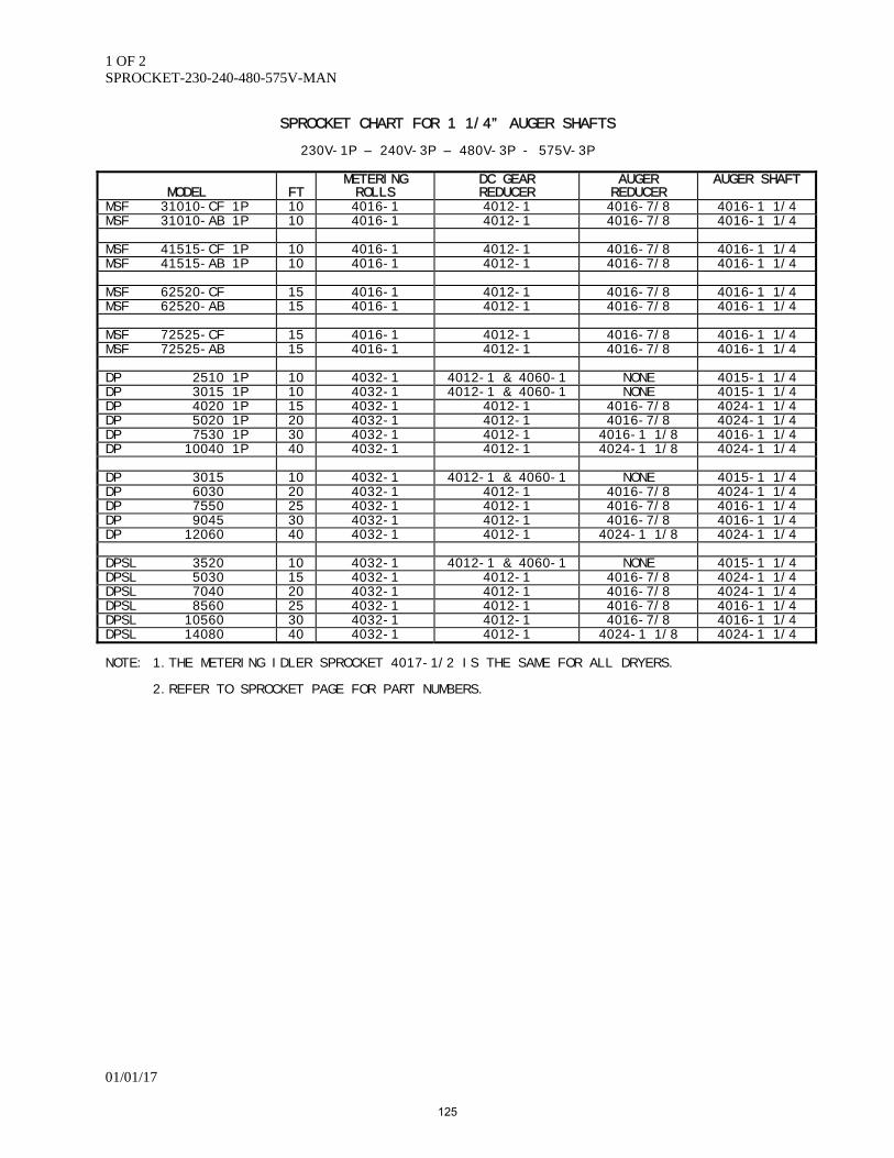
1 OF 2 SPROCKET-230-240-480-575V-MAN
01/01/17
SPROCKET CHART FOR 1 1/4” AUGER SHAFTS
230V-1P – 240V-3P – 480V-3P - 575V-3P
MODEL
FT METERING ROLLS
DC GEAR REDUCER
AUGER REDUCER
AUGER SHAFT
MSF 31010-CF 1P 10 4016-1 4012-1 4016-7/8 4016-1 1/4 MSF 31010-AB 1P 10 4016-1 4012-1 4016-7/8 4016-1 1/4 MSF 41515-CF 1P 10 4016-1 4012-1 4016-7/8 4016-1 1/4 MSF 41515-AB 1P 10 4016-1 4012-1 4016-7/8 4016-1 1/4 MSF 62520-CF 15 4016-1 4012-1 4016-7/8 4016-1 1/4 MSF 62520-AB 15 4016-1 4012-1 4016-7/8 4016-1 1/4 MSF 72525-CF 15 4016-1 4012-1 4016-7/8 4016-1 1/4 MSF 72525-AB 15 4016-1 4012-1 4016-7/8 4016-1 1/4 DP 2510 1P 10 4032-1 4012-1 & 4060-1 NONE 4015-1 1/4 DP 3015 1P 10 4032-1 4012-1 & 4060-1 NONE 4015-1 1/4 DP 4020 1P 15 4032-1 4012-1 4016-7/8 4024-1 1/4 DP 5020 1P 20 4032-1 4012-1 4016-7/8 4024-1 1/4 DP 7530 1P 30 4032-1 4012-1 4016-1 1/8 4016-1 1/4 DP 10040 1P 40 4032-1 4012-1 4024-1 1/8 4024-1 1/4 DP 3015 10 4032-1 4012-1 & 4060-1 NONE 4015-1 1/4 DP 6030 20 4032-1 4012-1 4016-7/8 4024-1 1/4 DP 7550 25 4032-1 4012-1 4016-7/8 4016-1 1/4 DP 9045 30 4032-1 4012-1 4016-7/8 4016-1 1/4 DP 12060 40 4032-1 4012-1 4024-1 1/8 4024-1 1/4 DPSL 3520 10 4032-1 4012-1 & 4060-1 NONE 4015-1 1/4 DPSL 5030 15 4032-1 4012-1 4016-7/8 4024-1 1/4 DPSL 7040 20 4032-1 4012-1 4016-7/8 4024-1 1/4 DPSL 8560 25 4032-1 4012-1 4016-7/8 4016-1 1/4 DPSL 10560 30 4032-1 4012-1 4016-7/8 4016-1 1/4 DPSL 14080 40 4032-1 4012-1 4024-1 1/8 4024-1 1/4 NOTE: 1.THE METERING IDLER SPROCKET 4017-1/2 IS THE SAME FOR ALL DRYERS. 2.REFER TO SPROCKET PAGE FOR PART NUMBERS.
125
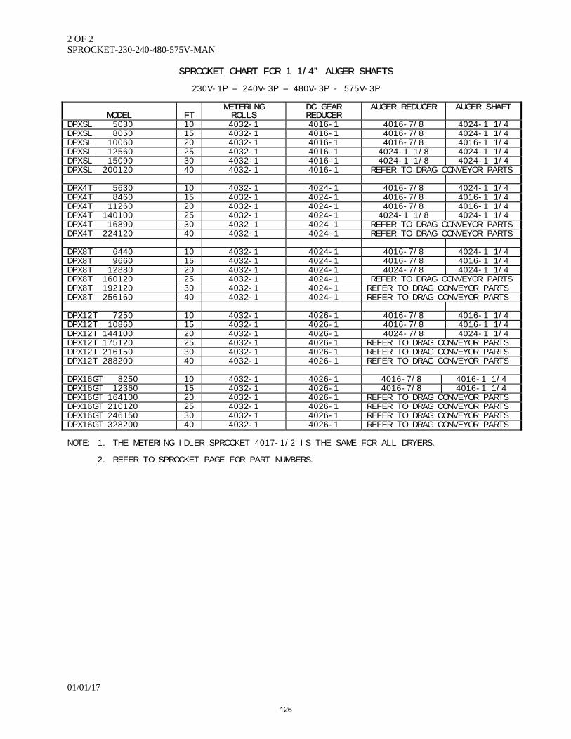
2 OF 2 SPROCKET-230-240-480-575V-MAN
01/01/17
SPROCKET CHART FOR 1 1/4” AUGER SHAFTS
230V-1P – 240V-3P – 480V-3P - 575V-3P
MODEL
FT
METERING ROLLS
DC GEAR REDUCER
AUGER REDUCER AUGER SHAFT
DPXSL 5030 10 4032-1 4016-1 4016-7/8 4024-1 1/4 DPXSL 8050 15 4032-1 4016-1 4016-7/8 4024-1 1/4 DPXSL 10060 20 4032-1 4016-1 4016-7/8 4016-1 1/4 DPXSL 12560 25 4032-1 4016-1 4024-1 1/8 4024-1 1/4 DPXSL 15090 30 4032-1 4016-1 4024-1 1/8 4024-1 1/4 DPXSL 200120 40 4032-1 4016-1 REFER TO DRAG CONVEYOR PARTS DPX4T 5630 10 4032-1 4024-1 4016-7/8 4024-1 1/4 DPX4T 8460 15 4032-1 4024-1 4016-7/8 4016-1 1/4 DPX4T 11260 20 4032-1 4024-1 4016-7/8 4016-1 1/4 DPX4T 140100 25 4032-1 4024-1 4024-1 1/8 4024-1 1/4 DPX4T 16890 30 4032-1 4024-1 REFER TO DRAG CONVEYOR PARTS DPX4T 224120 40 4032-1 4024-1 REFER TO DRAG CONVEYOR PARTS DPX8T 6440 10 4032-1 4024-1 4016-7/8 4024-1 1/4 DPX8T 9660 15 4032-1 4024-1 4016-7/8 4016-1 1/4 DPX8T 12880 20 4032-1 4024-1 4024-7/8 4024-1 1/4 DPX8T 160120 25 4032-1 4024-1 REFER TO DRAG CONVEYOR PARTS DPX8T 192120 30 4032-1 4024-1 REFER TO DRAG CONVEYOR PARTS DPX8T 256160 40 4032-1 4024-1 REFER TO DRAG CONVEYOR PARTS DPX12T 7250 10 4032-1 4026-1 4016-7/8 4016-1 1/4 DPX12T 10860 15 4032-1 4026-1 4016-7/8 4016-1 1/4 DPX12T 144100 20 4032-1 4026-1 4024-7/8 4024-1 1/4 DPX12T 175120 25 4032-1 4026-1 REFER TO DRAG CONVEYOR PARTS DPX12T 216150 30 4032-1 4026-1 REFER TO DRAG CONVEYOR PARTS DPX12T 288200 40 4032-1 4026-1 REFER TO DRAG CONVEYOR PARTS DPX16GT 8250 10 4032-1 4026-1 4016-7/8 4016-1 1/4 DPX16GT 12360 15 4032-1 4026-1 4016-7/8 4016-1 1/4 DPX16GT 164100 20 4032-1 4026-1 REFER TO DRAG CONVEYOR PARTS DPX16GT 210120 25 4032-1 4026-1 REFER TO DRAG CONVEYOR PARTS DPX16GT 246150 30 4032-1 4026-1 REFER TO DRAG CONVEYOR PARTS DPX16GT 328200 40 4032-1 4026-1 REFER TO DRAG CONVEYOR PARTS NOTE: 1. THE METERING IDLER SPROCKET 4017-1/2 IS THE SAME FOR ALL DRYERS. 2. REFER TO SPROCKET PAGE FOR PART NUMBERS.
126
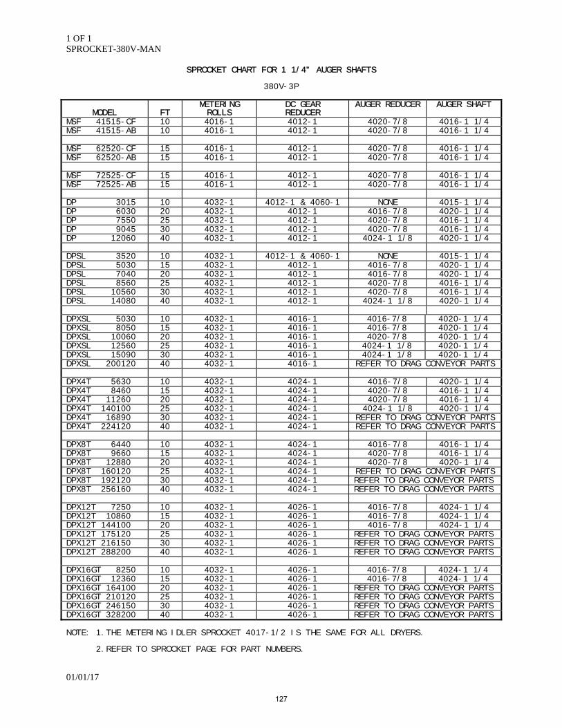
1 OF 1 SPROCKET-380V-MAN
01/01/17
SPROCKET CHART FOR 1 1/4” AUGER SHAFTS
380V-3P
MODEL
FT
METERING ROLLS
DC GEAR REDUCER
AUGER REDUCER AUGER SHAFT
MSF 41515-CF 10 4016-1 4012-1 4020-7/8 4016-1 1/4 MSF 41515-AB 10 4016-1 4012-1 4020-7/8 4016-1 1/4 MSF 62520-CF 15 4016-1 4012-1 4020-7/8 4016-1 1/4 MSF 62520-AB 15 4016-1 4012-1 4020-7/8 4016-1 1/4 MSF 72525-CF 15 4016-1 4012-1 4020-7/8 4016-1 1/4 MSF 72525-AB 15 4016-1 4012-1 4020-7/8 4016-1 1/4 DP 3015 10 4032-1 4012-1 & 4060-1 NONE 4015-1 1/4 DP 6030 20 4032-1 4012-1 4016-7/8 4020-1 1/4 DP 7550 25 4032-1 4012-1 4020-7/8 4016-1 1/4 DP 9045 30 4032-1 4012-1 4020-7/8 4016-1 1/4 DP 12060 40 4032-1 4012-1 4024-1 1/8 4020-1 1/4 DPSL 3520 10 4032-1 4012-1 & 4060-1 NONE 4015-1 1/4 DPSL 5030 15 4032-1 4012-1 4016-7/8 4020-1 1/4 DPSL 7040 20 4032-1 4012-1 4016-7/8 4020-1 1/4 DPSL 8560 25 4032-1 4012-1 4020-7/8 4016-1 1/4 DPSL 10560 30 4032-1 4012-1 4020-7/8 4016-1 1/4 DPSL 14080 40 4032-1 4012-1 4024-1 1/8 4020-1 1/4 DPXSL 5030 10 4032-1 4016-1 4016-7/8 4020-1 1/4 DPXSL 8050 15 4032-1 4016-1 4016-7/8 4020-1 1/4 DPXSL 10060 20 4032-1 4016-1 4020-7/8 4020-1 1/4 DPXSL 12560 25 4032-1 4016-1 4024-1 1/8 4020-1 1/4 DPXSL 15090 30 4032-1 4016-1 4024-1 1/8 4020-1 1/4 DPXSL 200120 40 4032-1 4016-1 REFER TO DRAG CONVEYOR PARTS DPX4T 5630 10 4032-1 4024-1 4016-7/8 4020-1 1/4 DPX4T 8460 15 4032-1 4024-1 4020-7/8 4016-1 1/4 DPX4T 11260 20 4032-1 4024-1 4020-7/8 4016-1 1/4 DPX4T 140100 25 4032-1 4024-1 4024-1 1/8 4020-1 1/4 DPX4T 16890 30 4032-1 4024-1 REFER TO DRAG CONVEYOR PARTS DPX4T 224120 40 4032-1 4024-1 REFER TO DRAG CONVEYOR PARTS DPX8T 6440 10 4032-1 4024-1 4016-7/8 4016-1 1/4 DPX8T 9660 15 4032-1 4024-1 4020-7/8 4016-1 1/4 DPX8T 12880 20 4032-1 4024-1 4020-7/8 4020-1 1/4 DPX8T 160120 25 4032-1 4024-1 REFER TO DRAG CONVEYOR PARTS DPX8T 192120 30 4032-1 4024-1 REFER TO DRAG CONVEYOR PARTS DPX8T 256160 40 4032-1 4024-1 REFER TO DRAG CONVEYOR PARTS DPX12T 7250 10 4032-1 4026-1 4016-7/8 4024-1 1/4 DPX12T 10860 15 4032-1 4026-1 4016-7/8 4024-1 1/4 DPX12T 144100 20 4032-1 4026-1 4016-7/8 4024-1 1/4 DPX12T 175120 25 4032-1 4026-1 REFER TO DRAG CONVEYOR PARTS DPX12T 216150 30 4032-1 4026-1 REFER TO DRAG CONVEYOR PARTS DPX12T 288200 40 4032-1 4026-1 REFER TO DRAG CONVEYOR PARTS DPX16GT 8250 10 4032-1 4026-1 4016-7/8 4024-1 1/4 DPX16GT 12360 15 4032-1 4026-1 4016-7/8 4024-1 1/4 DPX16GT 164100 20 4032-1 4026-1 REFER TO DRAG CONVEYOR PARTS DPX16GT 210120 25 4032-1 4026-1 REFER TO DRAG CONVEYOR PARTS DPX16GT 246150 30 4032-1 4026-1 REFER TO DRAG CONVEYOR PARTS DPX16GT 328200 40 4032-1 4026-1 REFER TO DRAG CONVEYOR PARTS NOTE: 1.THE METERING IDLER SPROCKET 4017-1/2 IS THE SAME FOR ALL DRYERS. 2.REFER TO SPROCKET PAGE FOR PART NUMBERS.
127

128
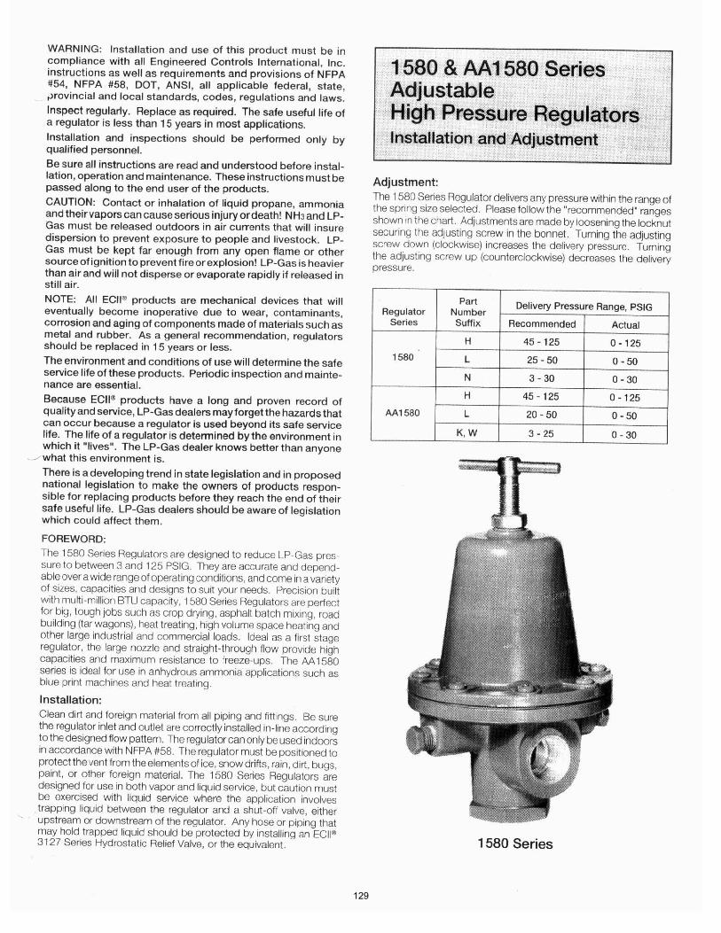
129
130
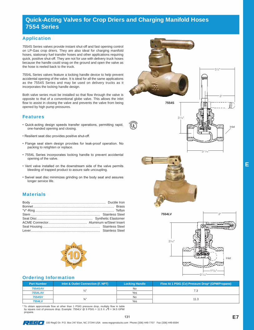
E7
E
100 RegO Dr. P.O. Box 247 Elon, NC 27244 USA www.regoproducts.com Phone (336) 449-7707 Fax (336) 449-6594
Application7554S Series valves provide instant shut-off and fast opening control on LP-Gas crop driers. They are also ideal for charging manifold hoses, stationary fuel transfer hoses and other applications requiring quick, positive shut-off. They are not for use with delivery truck hoses because the handle could snag on the ground and open the valve as the hose is reeled back to the truck.
7554L Series valves feature a locking handle device to help prevent accidental opening of the valve. It is ideal for all the same applications as the 7554S Series and may be used on delivery trucks as it incorporates the locking handle design.
Both valve series must be installed so that flow through the valve is opposite to that of a conventional globe valve. This allows the inlet flow to assist in closing the valve and prevents the valve from being opened by high pump pressures.
Features
one-handed opening and closing.
packing to retighten or replace.
opening of the valve.
bleeding of trapped product to assure safe uncoupling.
longer service life.
Quick-Acting Valves for Crop Driers and Charging Manifold Hoses7554 Series
UL®
Ordering Information
MaterialsBody ................................................................................. Ductile IronBonnet ....................................................................................... Brass“V”-Ring ..................................................................................... TeflonStem ........................................................................... Stainless SteelSeat Disc ............................................................ Synthetic ElastomerACME Connector.......................................... Aluminum w/Steel InsertSeal Housing .............................................................. Stainless SteelLever........................................................................... Stainless Steel
1010REG
O PRODUCTS
10 YEAR WARRANTY
7554S
* To obtain approximate flow at other than 1 PSIG pressure drop, multiply flow in table by square root of pressure drop. Example: 7554LV @ 9 PSIG = 11.5 X 9 = 34.5 GPM/propane.
Part Number Inlet & Outlet Connection (F. NPT) Locking Handle Flow At 1 PSIG (Cv) Pressure Drop* (GPM/Propane)
7554SAV½”
No7.3
7554LAV Yes
7554SV¾”
No11.3
7554LV Yes
7554LV
131
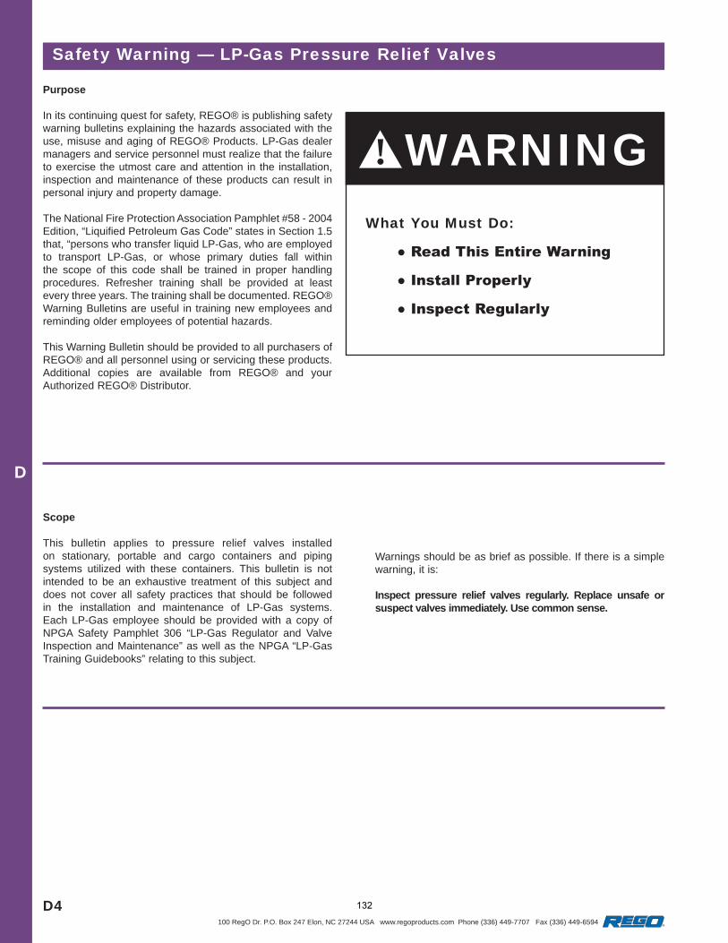
D4
D
100 RegO Dr. P.O. Box 247 Elon, NC 27244 USA www.regoproducts.com Phone (336) 449-7707 Fax (336) 449-6594
Safety Warning — LP-Gas Pressure Relief Valves
Purpose
In its continuing quest for safety, REGO® is publishing safety warning bulletins explaining the hazards associated with the use, misuse and aging of REGO® Products. LP-Gas dealer managers and service personnel must realize that the failure to exercise the utmost care and attention in the installation, inspection and maintenance of these products can result in personal injury and property damage.
The National Fire Protection Association Pamphlet #58 - 2004 Edition, “Liquified Petroleum Gas Code” states in Section 1.5 that, “persons who transfer liquid LP-Gas, who are employed to transport LP-Gas, or whose primary duties fall within the scope of this code shall be trained in proper handling procedures. Refresher training shall be provided at least every three years. The training shall be documented. REGO® Warning Bulletins are useful in training new employees and reminding older employees of potential hazards.
This Warning Bulletin should be provided to all purchasers of REGO® and all personnel using or servicing these products. Additional copies are available from REGO® and your Authorized REGO® Distributor.
Scope
This bulletin applies to pressure relief valves installed on stationary, portable and cargo containers and piping systems utilized with these containers. This bulletin is not intended to be an exhaustive treatment of this subject and does not cover all safety practices that should be followed in the installation and maintenance of LP-Gas systems. Each LP-Gas employee should be provided with a copy of NPGA Safety Pamphlet 306 “LP-Gas Regulator and Valve Inspection and Maintenance” as well as the NPGA “LP-Gas Training Guidebooks” relating to this subject.
! WARNINGWhat You Must Do:
Warnings should be as brief as possible. If there is a simple warning, it is:
Inspect pressure relief valves regularly. Replace unsafe or suspect valves immediately. Use common sense.
132
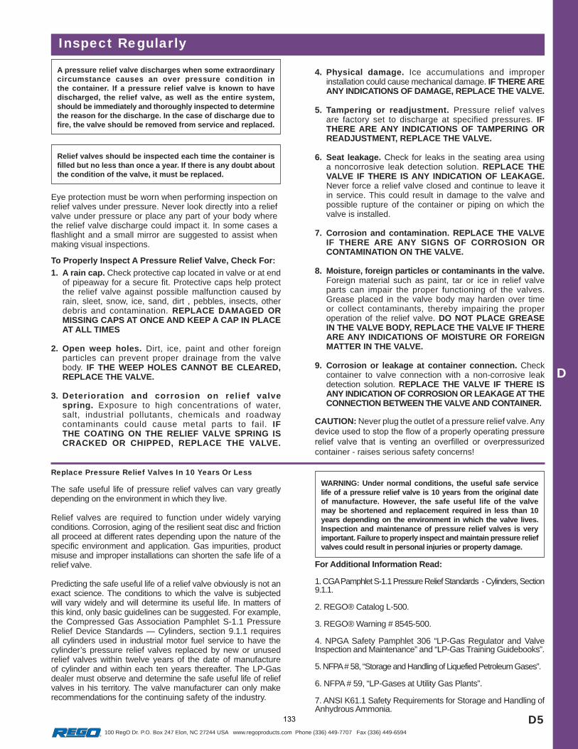
D5
D
100 RegO Dr. P.O. Box 247 Elon, NC 27244 USA www.regoproducts.com Phone (336) 449-7707 Fax (336) 449-6594
To Properly Inspect A Pressure Relief Valve, Check For:
1. A rain cap. Check protective cap located in valve or at end of pipeaway for a secure fit. Protective caps help protect the relief valve against possible malfunction caused by rain, sleet, snow, ice, sand, dirt , pebbles, insects, other debris and contamination. REPLACE DAMAGED OR MISSING CAPS AT ONCE AND KEEP A CAP IN PLACE AT ALL TIMES
2. Open weep holes. Dirt, ice, paint and other foreign particles can prevent proper drainage from the valve body. IF THE WEEP HOLES CANNOT BE CLEARED, REPLACE THE VALVE.
3. Deterioration and corrosion on relief valve spring. Exposure to high concentrations of water, salt, industrial pollutants, chemicals and roadway contaminants could cause metal parts to fail. IF THE COATING ON THE RELIEF VALVE SPRING IS CRACKED OR CHIPPED, REPLACE THE VALVE.
A pressure relief valve discharges when some extraordinary circumstance causes an over pressure condition in the container. If a pressure relief valve is known to have discharged, the relief valve, as well as the entire system, should be immediately and thoroughly inspected to determine the reason for the discharge. In the case of discharge due to fire, the valve should be removed from service and replaced.
Replace Pressure Relief Valves In 10 Years Or Less
Inspect Regularly
Relief valves should be inspected each time the container is filled but no less than once a year. If there is any doubt about the condition of the valve, it must be replaced.
Eye protection must be worn when performing inspection on relief valves under pressure. Never look directly into a relief valve under pressure or place any part of your body where the relief valve discharge could impact it. In some cases a flashlight and a small mirror are suggested to assist when making visual inspections.
4. Physical damage. Ice accumulations and improper installation could cause mechanical damage. IF THERE ARE ANY INDICATIONS OF DAMAGE, REPLACE THE VALVE.
5. Tampering or readjustment. Pressure relief valves are factory set to discharge at specified pressures. IF THERE ARE ANY INDICATIONS OF TAMPERING OR READJUSTMENT, REPLACE THE VALVE.
6. Seat leakage. Check for leaks in the seating area using a noncorrosive leak detection solution. REPLACE THE VALVE IF THERE IS ANY INDICATION OF LEAKAGE. Never force a relief valve closed and continue to leave it in service. This could result in damage to the valve and possible rupture of the container or piping on which the valve is installed.
7. Corrosion and contamination. REPLACE THE VALVE IF THERE ARE ANY SIGNS OF CORROSION OR CONTAMINATION ON THE VALVE.
8. Moisture, foreign particles or contaminants in the valve.Foreign material such as paint, tar or ice in relief valve parts can impair the proper functioning of the valves. Grease placed in the valve body may harden over time or collect contaminants, thereby impairing the proper operation of the relief valve. DO NOT PLACE GREASE IN THE VALVE BODY, REPLACE THE VALVE IF THERE ARE ANY INDICATIONS OF MOISTURE OR FOREIGN MATTER IN THE VALVE.
9. Corrosion or leakage at container connection. Check container to valve connection with a non-corrosive leak detection solution. REPLACE THE VALVE IF THERE IS ANY INDICATION OF CORROSION OR LEAKAGE AT THE CONNECTION BETWEEN THE VALVE AND CONTAINER.
CAUTION: Never plug the outlet of a pressure relief valve. Any
container - raises serious safety concerns!
WARNING: Under normal conditions, the useful safe service life of a pressure relief valve is 10 years from the original date of manufacture. However, the safe useful life of the valve may be shortened and replacement required in less than 10 years depending on the environment in which the valve lives. Inspection and maintenance of pressure relief valves is very important. Failure to properly inspect and maintain pressure relief valves could result in personal injuries or property damage.
The safe useful life of pressure relief valves can vary greatly depending on the environment in which they live.
Relief valves are required to function under widely varying conditions. Corrosion, aging of the resilient seat disc and friction all proceed at different rates depending upon the nature of the specific environment and application. Gas impurities, product misuse and improper installations can shorten the safe life of a relief valve.
Predicting the safe useful life of a relief valve obviously is not an exact science. The conditions to which the valve is subjected will vary widely and will determine its useful life. In matters of this kind, only basic guidelines can be suggested. For example, the Compressed Gas Association Pamphlet S-1.1 Pressure Relief Device Standards — Cylinders, section 9.1.1 requires all cylinders used in industrial motor fuel service to have the cylinder’s pressure relief valves replaced by new or unused relief valves within twelve years of the date of manufacture of cylinder and within each ten years thereafter. The LP-Gas dealer must observe and determine the safe useful life of relief valves in his territory. The valve manufacturer can only make recommendations for the continuing safety of the industry.
For Additional Information Read:
1. CGA Pamphlet S-1.1 Pressure Relief Standards - Cylinders, Section 9.1.1.
2. REGO® Catalog L-500.
3. REGO® Warning # 8545-500.
4. NPGA Safety Pamphlet 306 “LP-Gas Regulator and Valve Inspection and Maintenance” and “LP-Gas Training Guidebooks”.
5. NFPA # 58, “Storage and Handling of Liquefied Petroleum Gases”.
6. NFPA # 59, “LP-Gases at Utility Gas Plants”.
7. ANSI K61.1 Safety Requirements for Storage and Handling of Anhydrous Ammonia.
133
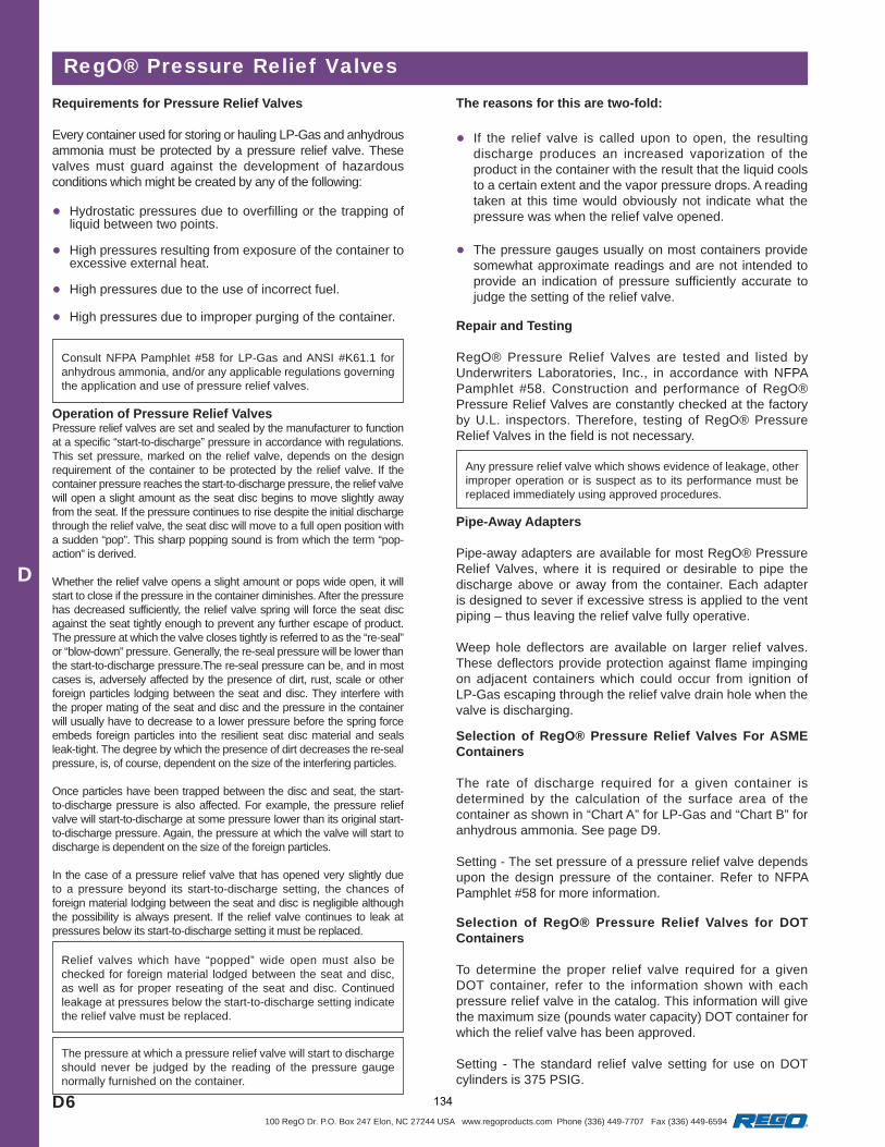
D6
D
100 RegO Dr. P.O. Box 247 Elon, NC 27244 USA www.regoproducts.com Phone (336) 449-7707 Fax (336) 449-6594
Consult NFPA Pamphlet #58 for LP-Gas and ANSI #K61.1 for anhydrous ammonia, and/or any applicable regulations governing the application and use of pressure relief valves.
RegO® Pressure Relief ValvesRequirements for Pressure Relief Valves
Every container used for storing or hauling LP-Gas and anhydrous ammonia must be protected by a pressure relief valve. These valves must guard against the development of hazardous conditions which might be created by any of the following:
Hydrostatic pressures due to overfilling or the trapping of liquid between two points.
High pressures resulting from exposure of the container to excessive external heat.
High pressures due to the use of incorrect fuel.
High pressures due to improper purging of the container.
Operation of Pressure Relief ValvesPressure relief valves are set and sealed by the manufacturer to function at a specific “start-to-discharge” pressure in accordance with regulations. This set pressure, marked on the relief valve, depends on the design requirement of the container to be protected by the relief valve. If the container pressure reaches the start-to-discharge pressure, the relief valve will open a slight amount as the seat disc begins to move slightly away from the seat. If the pressure continues to rise despite the initial discharge through the relief valve, the seat disc will move to a full open position with a sudden “pop”. This sharp popping sound is from which the term “pop-action” is derived.
Whether the relief valve opens a slight amount or pops wide open, it will start to close if the pressure in the container diminishes. After the pressure has decreased sufficiently, the relief valve spring will force the seat disc against the seat tightly enough to prevent any further escape of product. The pressure at which the valve closes tightly is referred to as the “re-seal” or “blow-down” pressure. Generally, the re-seal pressure will be lower than the start-to-discharge pressure.The re-seal pressure can be, and in most cases is, adversely affected by the presence of dirt, rust, scale or other foreign particles lodging between the seat and disc. They interfere with the proper mating of the seat and disc and the pressure in the container will usually have to decrease to a lower pressure before the spring force embeds foreign particles into the resilient seat disc material and seals leak-tight. The degree by which the presence of dirt decreases the re-seal pressure, is, of course, dependent on the size of the interfering particles.
Once particles have been trapped between the disc and seat, the start-to-discharge pressure is also affected. For example, the pressure relief valve will start-to-discharge at some pressure lower than its original start-to-discharge pressure. Again, the pressure at which the valve will start to discharge is dependent on the size of the foreign particles.
In the case of a pressure relief valve that has opened very slightly due to a pressure beyond its start-to-discharge setting, the chances of foreign material lodging between the seat and disc is negligible although the possibility is always present. If the relief valve continues to leak at pressures below its start-to-discharge setting it must be replaced.
Relief valves which have “popped” wide open must also be checked for foreign material lodged between the seat and disc, as well as for proper reseating of the seat and disc. Continued leakage at pressures below the start-to-discharge setting indicate the relief valve must be replaced.
The pressure at which a pressure relief valve will start to discharge should never be judged by the reading of the pressure gauge normally furnished on the container.
The reasons for this are two-fold:
If the relief valve is called upon to open, the resulting discharge produces an increased vaporization of the product in the container with the result that the liquid cools to a certain extent and the vapor pressure drops. A reading taken at this time would obviously not indicate what the pressure was when the relief valve opened.
The pressure gauges usually on most containers provide somewhat approximate readings and are not intended to provide an indication of pressure sufficiently accurate to judge the setting of the relief valve.
Repair and Testing
RegO® Pressure Relief Valves are tested and listed by Underwriters Laboratories, Inc., in accordance with NFPA Pamphlet #58. Construction and performance of RegO® Pressure Relief Valves are constantly checked at the factory by U.L. inspectors. Therefore, testing of RegO® Pressure Relief Valves in the field is not necessary.
Any pressure relief valve which shows evidence of leakage, other improper operation or is suspect as to its performance must be replaced immediately using approved procedures.
Pipe-Away Adapters
Pipe-away adapters are available for most RegO® Pressure Relief Valves, where it is required or desirable to pipe the discharge above or away from the container. Each adapter is designed to sever if excessive stress is applied to the vent piping – thus leaving the relief valve fully operative.
Weep hole deflectors are available on larger relief valves. These deflectors provide protection against flame impinging on adjacent containers which could occur from ignition of LP-Gas escaping through the relief valve drain hole when the valve is discharging.
Selection of RegO® Pressure Relief Valves For ASME Containers
The rate of discharge required for a given container is determined by the calculation of the surface area of the container as shown in “Chart A” for LP-Gas and “Chart B” for anhydrous ammonia. See page D9.
Setting - The set pressure of a pressure relief valve depends upon the design pressure of the container. Refer to NFPA Pamphlet #58 for more information.
Selection of RegO® Pressure Relief Valves for DOT Containers
To determine the proper relief valve required for a given DOT container, refer to the information shown with each pressure relief valve in the catalog. This information will give the maximum size (pounds water capacity) DOT container for which the relief valve has been approved.
Setting - The standard relief valve setting for use on DOT cylinders is 375 PSIG.
134
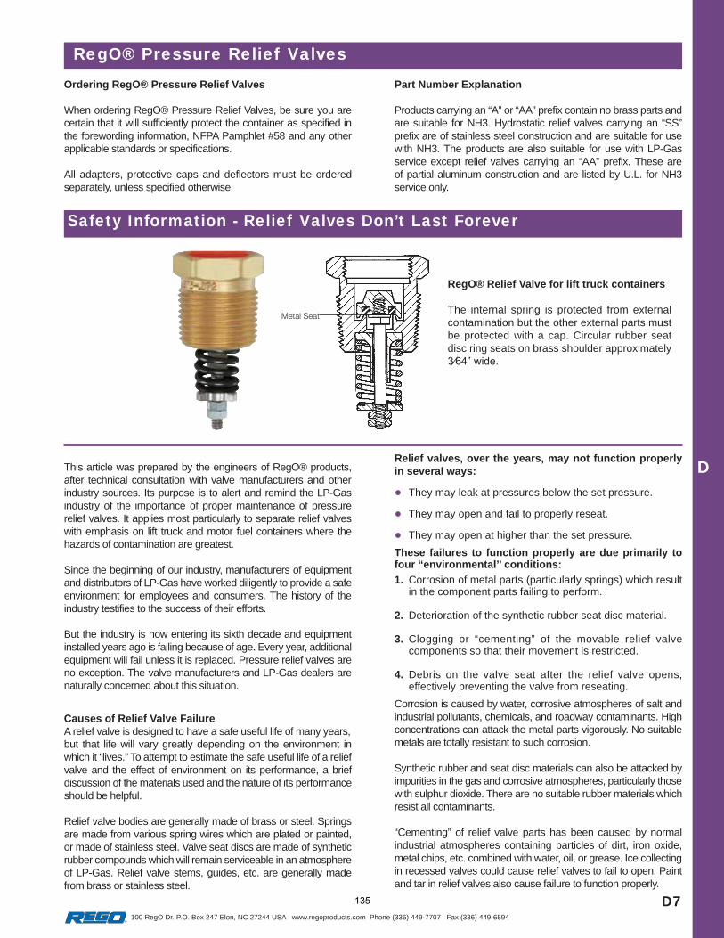
D7
D
100 RegO Dr. P.O. Box 247 Elon, NC 27244 USA www.regoproducts.com Phone (336) 449-7707 Fax (336) 449-6594
RegO® Pressure Relief ValvesOrdering RegO® Pressure Relief Valves
When ordering RegO® Pressure Relief Valves, be sure you are certain that it will sufficiently protect the container as specified in the forewording information, NFPA Pamphlet #58 and any other applicable standards or specifications.
All adapters, protective caps and deflectors must be ordered separately, unless specified otherwise.
Part Number Explanation
Products carrying an “A” or “AA” prefix contain no brass parts and are suitable for NH3. Hydrostatic relief valves carrying an “SS” prefix are of stainless steel construction and are suitable for use with NH3. The products are also suitable for use with LP-Gas service except relief valves carrying an “AA” prefix. These are of partial aluminum construction and are listed by U.L. for NH3 service only.
Safety Information - Relief Valves Don’t Last Forever
RegO® Relief Valve for lift truck containers
The internal spring is protected from external contamination but the other external parts must be protected with a cap. Circular rubber seat disc ring seats on brass shoulder approximately
This article was prepared by the engineers of RegO® products, after technical consultation with valve manufacturers and other industry sources. Its purpose is to alert and remind the LP-Gas industry of the importance of proper maintenance of pressure relief valves. It applies most particularly to separate relief valves with emphasis on lift truck and motor fuel containers where the hazards of contamination are greatest.
Since the beginning of our industry, manufacturers of equipment and distributors of LP-Gas have worked diligently to provide a safe environment for employees and consumers. The history of the industry testifies to the success of their efforts.
But the industry is now entering its sixth decade and equipment installed years ago is failing because of age. Every year, additional equipment will fail unless it is replaced. Pressure relief valves are no exception. The valve manufacturers and LP-Gas dealers are naturally concerned about this situation.
Relief valves, over the years, may not function properly in several ways:
They may leak at pressures below the set pressure.
They may open and fail to properly reseat.
They may open at higher than the set pressure.
Causes of Relief Valve FailureA relief valve is designed to have a safe useful life of many years,but that life will vary greatly depending on the environment in which it “lives.” To attempt to estimate the safe useful life of a relief valve and the effect of environment on its performance, a brief discussion of the materials used and the nature of its performance should be helpful.
Relief valve bodies are generally made of brass or steel. Springs are made from various spring wires which are plated or painted, or made of stainless steel. Valve seat discs are made of synthetic rubber compounds which will remain serviceable in an atmosphere of LP-Gas. Relief valve stems, guides, etc. are generally made from brass or stainless steel.
These failures to function properly are due primarily to four “environmental’’ conditions:
1. Corrosion of metal parts (particularly springs) which result in the component parts failing to perform.
2. Deterioration of the synthetic rubber seat disc material.
3. Clogging or “cementing” of the movable relief valve components so that their movement is restricted.
4. Debris on the valve seat after the relief valve opens, effectively preventing the valve from reseating.
Corrosion is caused by water, corrosive atmospheres of salt and industrial pollutants, chemicals, and roadway contaminants. High concentrations can attack the metal parts vigorously. No suitable metals are totally resistant to such corrosion.
Synthetic rubber and seat disc materials can also be attacked by impurities in the gas and corrosive atmospheres, particularly those with sulphur dioxide. There are no suitable rubber materials which resist all contaminants.
“Cementing” of relief valve parts has been caused by normal industrial atmospheres containing particles of dirt, iron oxide, metal chips, etc. combined with water, oil, or grease. Ice collecting in recessed valves could cause relief valves to fail to open. Paint and tar in relief valves also cause failure to function properly.
135
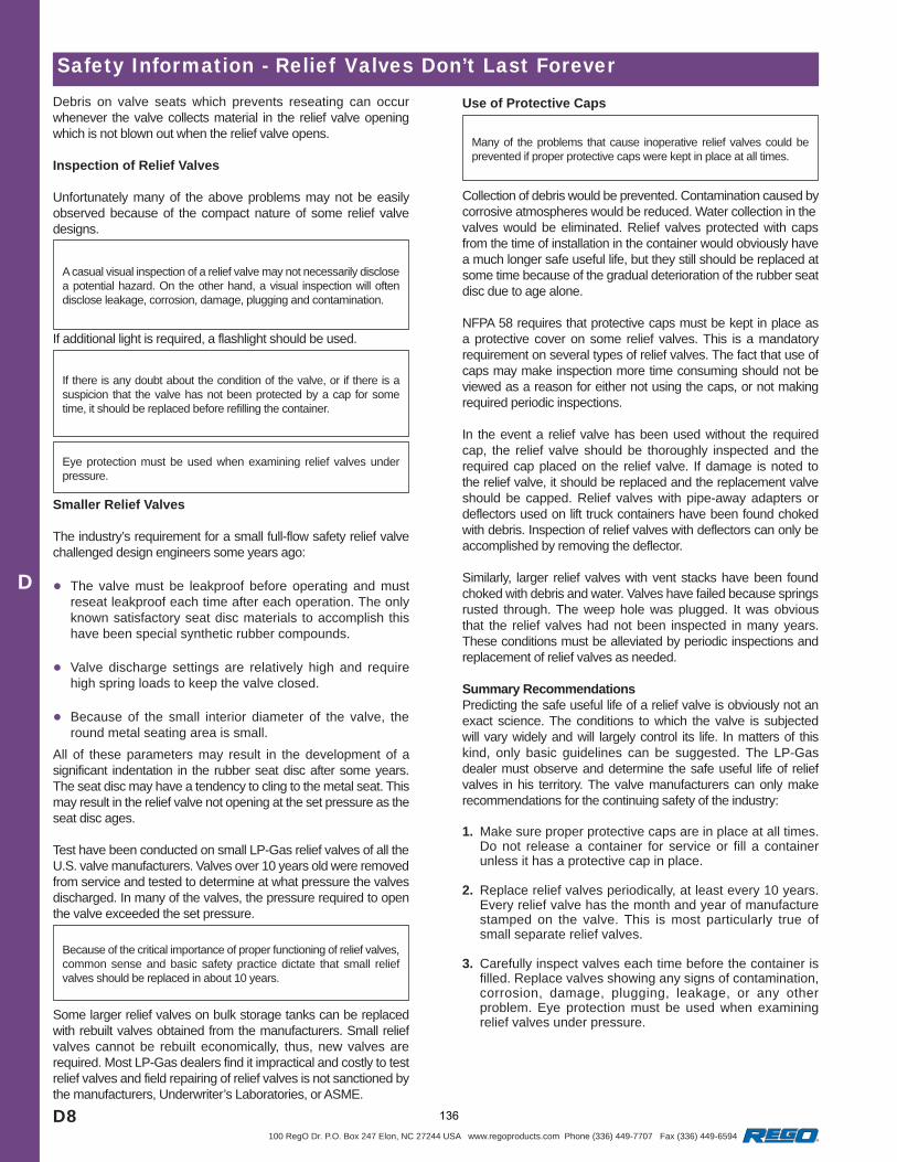
D8
D
100 RegO Dr. P.O. Box 247 Elon, NC 27244 USA www.regoproducts.com Phone (336) 449-7707 Fax (336) 449-6594
Smaller Relief Valves
The industry’s requirement for a small full-flow safety relief valve challenged design engineers some years ago:
The valve must be leakproof before operating and must reseat leakproof each time after each operation. The only known satisfactory seat disc materials to accomplish this have been special synthetic rubber compounds.
Valve discharge settings are relatively high and require high spring loads to keep the valve closed.
Because of the small interior diameter of the valve, the round metal seating area is small.
Safety Information - Relief Valves Don’t Last ForeverDebris on valve seats which prevents reseating can occur whenever the valve collects material in the relief valve opening which is not blown out when the relief valve opens.
Inspection of Relief Valves
Unfortunately many of the above problems may not be easily observed because of the compact nature of some relief valve designs.
A casual visual inspection of a relief valve may not necessarily disclose a potential hazard. On the other hand, a visual inspection will often disclose leakage, corrosion, damage, plugging and contamination.
If additional light is required, a flashlight should be used.
If there is any doubt about the condition of the valve, or if there is a suspicion that the valve has not been protected by a cap for some time, it should be replaced before refilling the container.
Eye protection must be used when examining relief valves under pressure.
All of these parameters may result in the development of a significant indentation in the rubber seat disc after some years. The seat disc may have a tendency to cling to the metal seat. This may result in the relief valve not opening at the set pressure as the seat disc ages.
Test have been conducted on small LP-Gas relief valves of all the U.S. valve manufacturers. Valves over 10 years old were removed from service and tested to determine at what pressure the valves discharged. In many of the valves, the pressure required to open the valve exceeded the set pressure.
Because of the critical importance of proper functioning of relief valves, common sense and basic safety practice dictate that small relief valves should be replaced in about 10 years.
Some larger relief valves on bulk storage tanks can be replaced with rebuilt valves obtained from the manufacturers. Small relief valves cannot be rebuilt economically, thus, new valves are required. Most LP-Gas dealers find it impractical and costly to test relief valves and field repairing of relief valves is not sanctioned by the manufacturers, Underwriter’s Laboratories, or ASME.
Use of Protective Caps
Many of the problems that cause inoperative relief valves could be prevented if proper protective caps were kept in place at all times.
Collection of debris would be prevented. Contamination caused by corrosive atmospheres would be reduced. Water collection in thevalves would be eliminated. Relief valves protected with caps from the time of installation in the container would obviously have a much longer safe useful life, but they still should be replaced at some time because of the gradual deterioration of the rubber seat disc due to age alone.
NFPA 58 requires that protective caps must be kept in place as a protective cover on some relief valves. This is a mandatory requirement on several types of relief valves. The fact that use of caps may make inspection more time consuming should not be viewed as a reason for either not using the caps, or not making required periodic inspections.
In the event a relief valve has been used without the required cap, the relief valve should be thoroughly inspected and the required cap placed on the relief valve. If damage is noted to the relief valve, it should be replaced and the replacement valve should be capped. Relief valves with pipe-away adapters or deflectors used on lift truck containers have been found choked with debris. Inspection of relief valves with deflectors can only be accomplished by removing the deflector.
Similarly, larger relief valves with vent stacks have been found choked with debris and water. Valves have failed because springs rusted through. The weep hole was plugged. It was obvious that the relief valves had not been inspected in many years. These conditions must be alleviated by periodic inspections and replacement of relief valves as needed.
Summary RecommendationsPredicting the safe useful life of a relief valve is obviously not an exact science. The conditions to which the valve is subjected will vary widely and will largely control its life. In matters of this kind, only basic guidelines can be suggested. The LP-Gas dealer must observe and determine the safe useful life of relief valves in his territory. The valve manufacturers can only make recommendations for the continuing safety of the industry:
1. Make sure proper protective caps are in place at all times. Do not release a container for service or fill a container unless it has a protective cap in place.
2. Replace relief valves periodically, at least every 10 years. Every relief valve has the month and year of manufacture stamped on the valve. This is most particularly true of small separate relief valves.
3. Carefully inspect valves each time before the container is filled. Replace valves showing any signs of contamination, corrosion, damage, plugging, leakage, or any other problem. Eye protection must be used when examining relief valves under pressure.
136

MEGR-1630 HIGH FLOW GAS REGULATOR
Instruction Manual- Look Inside For: Description Installation
Overpressure Protection Startup and Adjustment
Shutdown Maintenance
Parts Ordering Parts List
Marshall Excelsior Company Marshall, MI 49068
269-789-6700 FAX 269-781-8340
www.marshallexcelsior.com
MEG
R-1630 Instruction M
anual
137
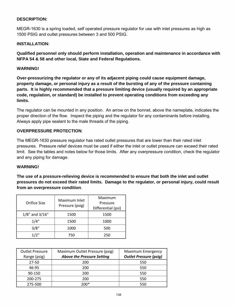
DESCRIPTION:
MEGR-1630 is a spring loaded, self operated pressure regulator for use with inlet pressures as high as 1500 PSIG and outlet pressures between 3 and 500 PSIG.
INSTALLATION:
Qualified personnel only should perform installation, operation and maintenance in accordance with NFPA 54 & 58 and other local, State and Federal Regulations.
WARNING!
Over-pressurizing the regulator or any of its adjacent piping could cause equipment damage, property damage, or personal injury as a result of the bursting of any of the pressure containing parts. It is highly recommended that a pressure limiting device (usually required by an appropriate code, regulation, or standard) be installed to prevent operating conditions from exceeding any limits.
The regulator can be mounted in any position. An arrow on the bonnet, above the nameplate, indicates the proper direction of the flow. Inspect the piping and the regulator for any contaminants before installing. Always apply pipe sealant to the male threads of the piping.
OVERPRESSURE PROTECTION:
The MEGR-1630 pressure regulator has rated outlet pressures that are lower than their rated inlet pressures. Pressure relief devices must be used if either the inlet or outlet pressure can exceed their rated limit. See the tables and notes below for those limits. After any overpressure condition, check the regulator and any piping for damage.
WARNING!
The use of a pressure-relieving device is recommended to ensure that both the inlet and outlet pressures do not exceed their rated limits. Damage to the regulator, or personal injury, could result from an overpressure condition.
Orifice Size Maximum Inlet Pressure (psig)
Maximum Pressure
Differential (psi) 1/8" and 3/16" 1500 1500
1/4" 1500 1000
3/8" 1000 500
1/2" 750 250
Outlet Pressure Range (psig)
Maximum Outlet Pressure (psig) Above the Pressure Setting
Maximum Emergency Outlet Pressure (psig)
27-50 200 550 46-95 200 550
90-150 200 550 200-275 200 550 275-500 200* 550
138
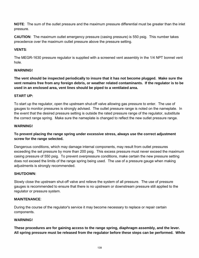
NOTE: The sum of the outlet pressure and the maximum pressure differential must be greater than the inlet pressure.
CAUTION: The maximum outlet emergency pressure (casing pressure) is 550 psig. This number takes precedence over the maximum outlet pressure above the pressure setting.
VENTS:
The MEGR-1630 pressure regulator is supplied with a screened vent assembly in the 1/4 NPT bonnet vent hole.
WARNING!
The vent should be inspected periodically to insure that it has not become plugged. Make sure the vent remains free from any foreign debris, or weather related contaminants. If the regulator is to be used in an enclosed area, vent lines should be piped to a ventilated area.
START UP:
To start up the regulator, open the upstream shut-off valve allowing gas pressure to enter. The use of gauges to monitor pressures is strongly advised. The outlet pressure range is noted on the nameplate. In the event that the desired pressure setting is outside the rated pressure range of the regulator, substitute the correct range spring. Make sure the nameplate is changed to reflect the new outlet pressure range.
WARNING!
To prevent placing the range spring under excessive stress, always use the correct adjustment screw for the range selected.
Dangerous conditions, which may damage internal components, may result from outlet pressures exceeding the set pressure by more than 200 psig. This excess pressure must never exceed the maximum casing pressure of 550 psig. To prevent overpressure conditions, make certain the new pressure setting does not exceed the limits of the range spring being used. The use of a pressure gauge when making adjustments is strongly recommended.
SHUTDOWN:
Slowly close the upstream shut-off valve and relieve the system of all pressure. The use of pressure gauges is recommended to ensure that there is no upstream or downstream pressure still applied to the regulator or pressure system.
MAINTENANCE:
During the course of the regulator's service it may become necessary to replace or repair certain components.
WARNING!
These procedures are for gaining access to the range spring, diaphragm assembly, and the lever. All spring pressure must be released from the regulator before these steps can be performed. While
139
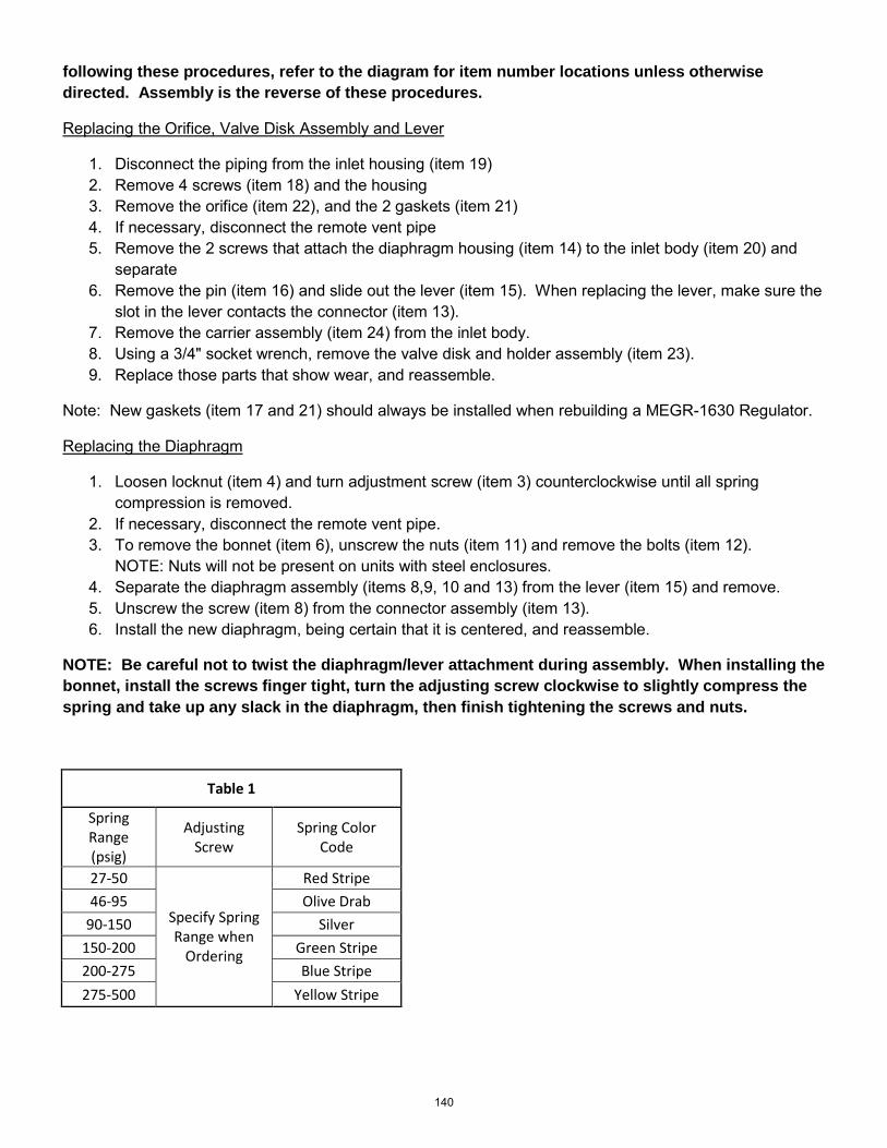
following these procedures, refer to the diagram for item number locations unless otherwise directed. Assembly is the reverse of these procedures.
Replacing the Orifice, Valve Disk Assembly and Lever
1. Disconnect the piping from the inlet housing (item 19) 2. Remove 4 screws (item 18) and the housing 3. Remove the orifice (item 22), and the 2 gaskets (item 21) 4. If necessary, disconnect the remote vent pipe 5. Remove the 2 screws that attach the diaphragm housing (item 14) to the inlet body (item 20) and
separate 6. Remove the pin (item 16) and slide out the lever (item 15). When replacing the lever, make sure the
slot in the lever contacts the connector (item 13). 7. Remove the carrier assembly (item 24) from the inlet body. 8. Using a 3/4" socket wrench, remove the valve disk and holder assembly (item 23). 9. Replace those parts that show wear, and reassemble.
Note: New gaskets (item 17 and 21) should always be installed when rebuilding a MEGR-1630 Regulator.
Replacing the Diaphragm
1. Loosen locknut (item 4) and turn adjustment screw (item 3) counterclockwise until all spring compression is removed.
2. If necessary, disconnect the remote vent pipe. 3. To remove the bonnet (item 6), unscrew the nuts (item 11) and remove the bolts (item 12).
NOTE: Nuts will not be present on units with steel enclosures. 4. Separate the diaphragm assembly (items 8,9, 10 and 13) from the lever (item 15) and remove. 5. Unscrew the screw (item 8) from the connector assembly (item 13). 6. Install the new diaphragm, being certain that it is centered, and reassemble.
NOTE: Be careful not to twist the diaphragm/lever attachment during assembly. When installing the bonnet, install the screws finger tight, turn the adjusting screw clockwise to slightly compress the spring and take up any slack in the diaphragm, then finish tightening the screws and nuts.
Table 1
Spring Range (psig)
Adjusting Screw
Spring Color Code
27-50
Specify Spring Range when
Ordering
Red Stripe 46-95 Olive Drab
90-150 Silver 150-200 Green Stripe 200-275 Blue Stripe 275-500 Yellow Stripe
140
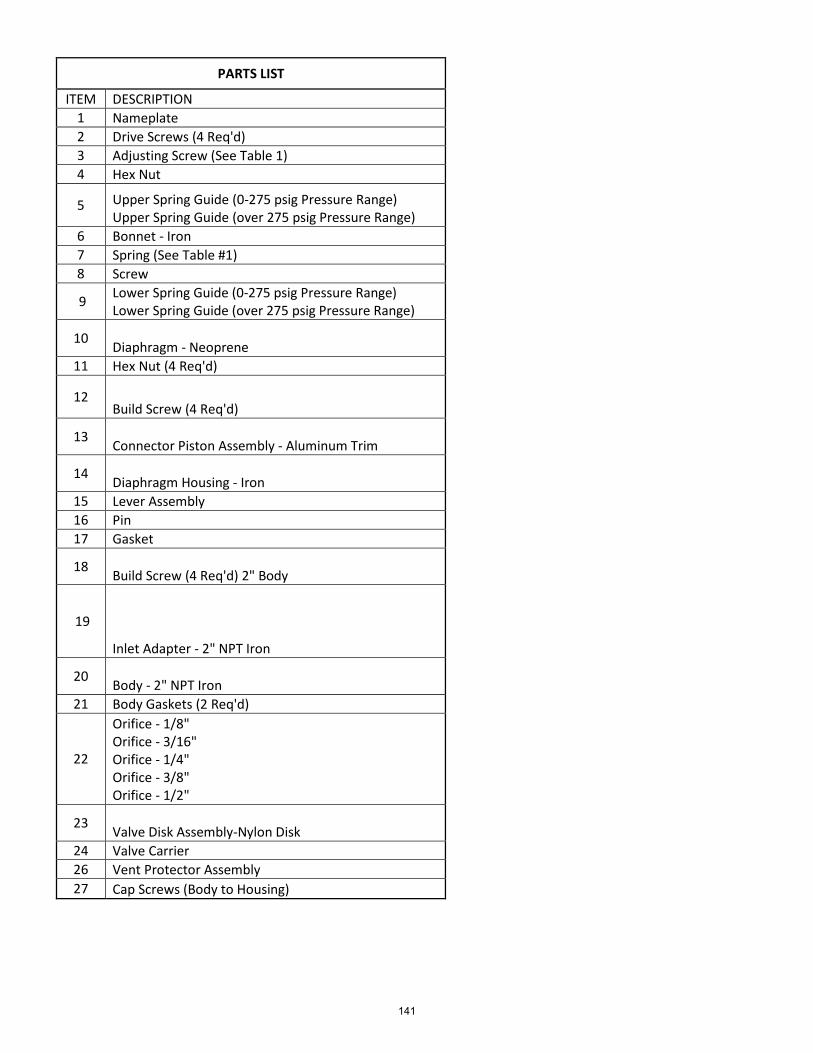
PARTS LIST
ITEM DESCRIPTION 1 Nameplate 2 Drive Screws (4 Req'd) 3 Adjusting Screw (See Table 1) 4 Hex Nut
5 Upper Spring Guide (0-275 psig Pressure Range) Upper Spring Guide (over 275 psig Pressure Range)
6 Bonnet - Iron 7 Spring (See Table #1) 8 Screw
9 Lower Spring Guide (0-275 psig Pressure Range) Lower Spring Guide (over 275 psig Pressure Range)
10 Diaphragm - Neoprene 11 Hex Nut (4 Req'd)
12 Build Screw (4 Req'd)
13 Connector Piston Assembly - Aluminum Trim
14 Diaphragm Housing - Iron 15 Lever Assembly 16 Pin 17 Gasket
18 Build Screw (4 Req'd) 2" Body
19
Inlet Adapter - 2" NPT Iron
20 Body - 2" NPT Iron 21 Body Gaskets (2 Req'd)
22
Orifice - 1/8" Orifice - 3/16" Orifice - 1/4" Orifice - 3/8" Orifice - 1/2"
23 Valve Disk Assembly-Nylon Disk 24 Valve Carrier 26 Vent Protector Assembly 27 Cap Screws (Body to Housing)
141
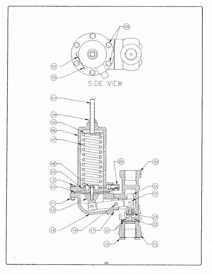
142
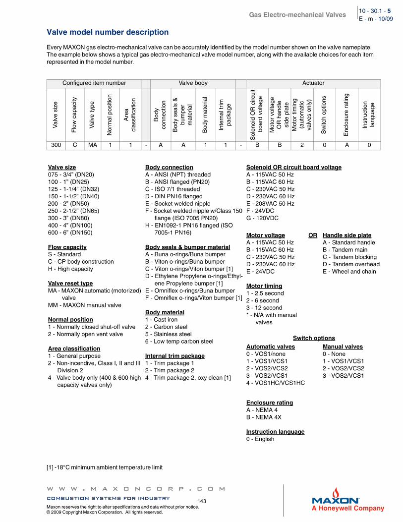
Gas Electro-mechanical Valves
w w w . m a x o n c o r p . c o mcombustion systems for industry
Maxon reserves the right to alter specifications and data without prior notice. © 2009 Copyright Maxon Corporation. All rights reserved.
10 - 30.1 - 5E - m - 10/09
Valve model number description
Every MAXON gas electro-mechanical valve can be accurately identified by the model number shown on the valve nameplate. The example below shows a typical gas electro-mechanical valve model number, along with the available choices for each item represented in the model number.
[1] -18°C minimum ambient temperature limit
Configured item number Valve body Actuator
Val
ve s
ize
Flo
w c
apac
ity
Val
ve ty
pe
Nor
mal
pos
ition
Are
acl
assi
ficat
ion
Bod
yco
nnec
tion
Bod
y se
als
&bu
mpe
rm
ater
ial
Bod
y m
ater
ial
Inte
rnal
trim
pack
age
Sol
enoi
d O
R c
ircui
t b
oard
vol
tage
Mot
or v
olta
geO
R h
andl
esi
de p
late
Mot
or ti
min
g(a
utom
atic
valv
es o
nly)
Sw
itch
optio
ns
Enc
losu
re r
atin
g
Inst
ruct
ion
lang
uage
300 C MA 1 1 - A A 1 1 - B B 2 0 A 0
Valve size075 - 3/4” (DN20)100 - 1” (DN25)125 - 1-1/4” (DN32)150 - 1-1/2” (DN40)200 - 2” (DN50)250 - 2-1/2” (DN65)300 - 3” (DN80)400 - 4” (DN100)600 - 6” (DN150)
Flow capacityS - StandardC - CP body constructionH - High capacity
Valve reset typeMA - MAXON automatic (motorized)
valveMM - MAXON manual valve
Normal position1 - Normally closed shut-off valve2 - Normally open vent valve
Area classification1 - General purpose2 - Non-incendive, Class I, II and III
Division 24 - Valve body only (400 & 600 high
capacity valves only)
Body connectionA - ANSI (NPT) threadedB - ANSI flanged (PN20)C - ISO 7/1 threadedD - DIN PN16 flangedE - Socket welded nippleF - Socket welded nipple w/Class 150
flange (ISO 7005 PN20)H - EN1092-1 PN16 flanged (ISO
7005-1 PN16)
Body seals & bumper materialA - Buna o-rings/Buna bumperB - Viton o-rings/Buna bumperC - Viton o-rings/Viton bumper [1]D - Ethylene Propylene o-rings/Ethyl-
ene Propylene bumper [1]E - Omniflex o-rings/Buna bumperF - Omniflex o-rings/Viton bumper [1]
Body material1 - Cast iron2 - Carbon steel5 - Stainless steel6 - Low temp carbon steel
Internal trim package1 - Trim package 12 - Trim package 24 - Trim package 2, oxy clean [1]
Solenoid OR circuit board voltageA - 115VAC 50 HzB - 115VAC 60 HzC - 230VAC 50 HzD - 230VAC 60 HzE - 208VAC 50 HzF - 24VDCG - 120VDC
Motor voltageA - 115VAC 50 HzB - 115VAC 60 HzC - 230VAC 50 HzD - 230VAC 60 HzE - 24VDC
Motor timing1 - 2.5 second2 - 6 second3 - 12 second* - N/A with manual
valves
OR Handle side plateA - Standard handleB - Tandem mainC - Tandem blockingD - Tandem overheadE - Wheel and chain
Switch optionsAutomatic valves0 - VOS1/none1 - VOS1/VCS12 - VOS2/VCS23 - VOS2/VCS14 - VOS1HC/VCS1HC
Manual valves0 - None1 - VOS1/VCS12 - VOS2/VCS23 - VOS2/VCS1
Enclosure ratingA - NEMA 4B - NEMA 4X
Instruction language0 - English
143
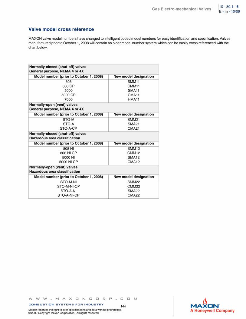
Gas Electro-mechanical Valves
w w w . m a x o n c o r p . c o mcombustion systems for industry
Maxon reserves the right to alter specifications and data without prior notice. © 2009 Copyright Maxon Corporation. All rights reserved.
10 - 30.1 - 6E - m - 10/09
Valve model cross reference
MAXON valve model numbers have changed to intelligent coded model numbers for easy identification and specification. Valves manufactured prior to October 1, 2008 will contain an older model number system which can be easily cross referenced with the chart below.
Normally-closed (shut-off) valvesGeneral purpose, NEMA 4 or 4X
Model number (prior to October 1, 2008) New model designation808
808 CP5000
5000 CP7000
SMM11CMM11SMA11CMA11HMA11
Normally-open (vent) valvesGeneral purpose, NEMA 4 or 4X
Model number (prior to October 1, 2008) New model designationSTO-MSTO-A
STO-A-CP
SMM21SMA21CMA21
Normally-closed (shut-off) valvesHazardous area classification
Model number (prior to October 1, 2008) New model designation808 NI
808 NI CP5000 NI
5000 NI CP
SMM12CMM12SMA12CMA12
Normally-open (vent) valvesHazardous area classification
Model number (prior to October 1, 2008) New model designationSTO-M-NI
STO-M-NI-CPSTO-A-NI
STO-A-NI-CP
SMM22CMM22SMA22CMA22
144
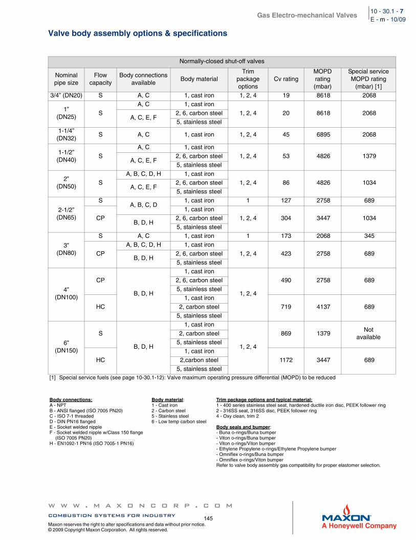
Gas Electro-mechanical Valves
w w w . m a x o n c o r p . c o mcombustion systems for industry
Maxon reserves the right to alter specifications and data without prior notice. © 2009 Copyright Maxon Corporation. All rights reserved.
10 - 30.1 - 7E - m - 10/09
Valve body assembly options & specifications
Normally-closed shut-off valves
Nominal pipe size
Flow capacity
Body connections available
Body materialTrim
package options
Cv ratingMOPD rating (mbar)
Special service MOPD rating
(mbar) [1]3/4” (DN20) S A, C 1, cast iron 1, 2, 4 19 8618 2068
1” (DN25)
S
A, C 1, cast iron
1, 2, 4 20 8618 2068A, C, E, F
2, 6, carbon steel5, stainless steel
1-1/4” (DN32)
S A, C 1, cast iron 1, 2, 4 45 6895 2068
1-1/2”(DN40)
S
A, C 1, cast iron
1, 2, 4 53 4826 1379A, C, E, F
2, 6, carbon steel5, stainless steel
2”(DN50)
SA, B, C, D, H 1, cast iron
1, 2, 4 86 4826 1034A, C, E, F
2, 6, carbon steel5, stainless steel
2-1/2”(DN65)
SA, B, C, D
1, cast iron 1 127 2758 689
CP1, cast iron
1, 2, 4 304 3447 1034B, D, H
2, 6, carbon steel
5, stainless steel
3”(DN80)
S A, C 1, cast iron 1 173 2068 345
CP
A, B, C, D, H 1, cast iron
1, 2, 4 423 2758 689B, D, H
2, 6, carbon steel5, stainless steel
4”(DN100)
CP
B, D, H
1, cast iron
1, 2, 4
490 2758 6892, 6, carbon steel5, stainless steel
HC
1, cast iron
719 4137 6892, carbon steel5, stainless steel
6”(DN150)
S
B, D, H
1, cast iron
1, 2, 4
869 1379Not
available2, carbon steel
5, stainless steel
HC
1, cast iron
1172 3447 6892,carbon steel5, stainless steel
[1] Special service fuels (see page 10-30.1-12): Valve maximum operating pressure differential (MOPD) to be reduced
Body connections:A - NPTB - ANSI flanged (ISO 7005 PN20)C - ISO 7-1 threadedD - DIN PN16 flangedE - Socket welded nippleF - Socket welded nipple w/Class 150 flange
(ISO 7005 PN20)H - EN1092-1 PN16 (ISO 7005-1 PN16)
Body material:1 - Cast iron2 - Carbon steel5 - Stainless steel6 - Low temp carbon steel
Trim package options and typical material:1 - 400 series stainless steel seat, hardened ductile iron disc, PEEK follower ring2 - 316SS seat, 316SS disc, PEEK follower ring4 - Oxy clean, trim 2
Body seals and bumper:- Buna o-rings/Buna bumper- Viton o-rings/Buna bumper- Viton o-rings/Viton bumper- Ethylene Propylene o-rings/Ethylene Propylene bumper- Omniflex o-rings/Buna bumper- Omniflex o-rings/Viton bumperRefer to valve body assembly gas compatibility for proper elastomer selection.
145
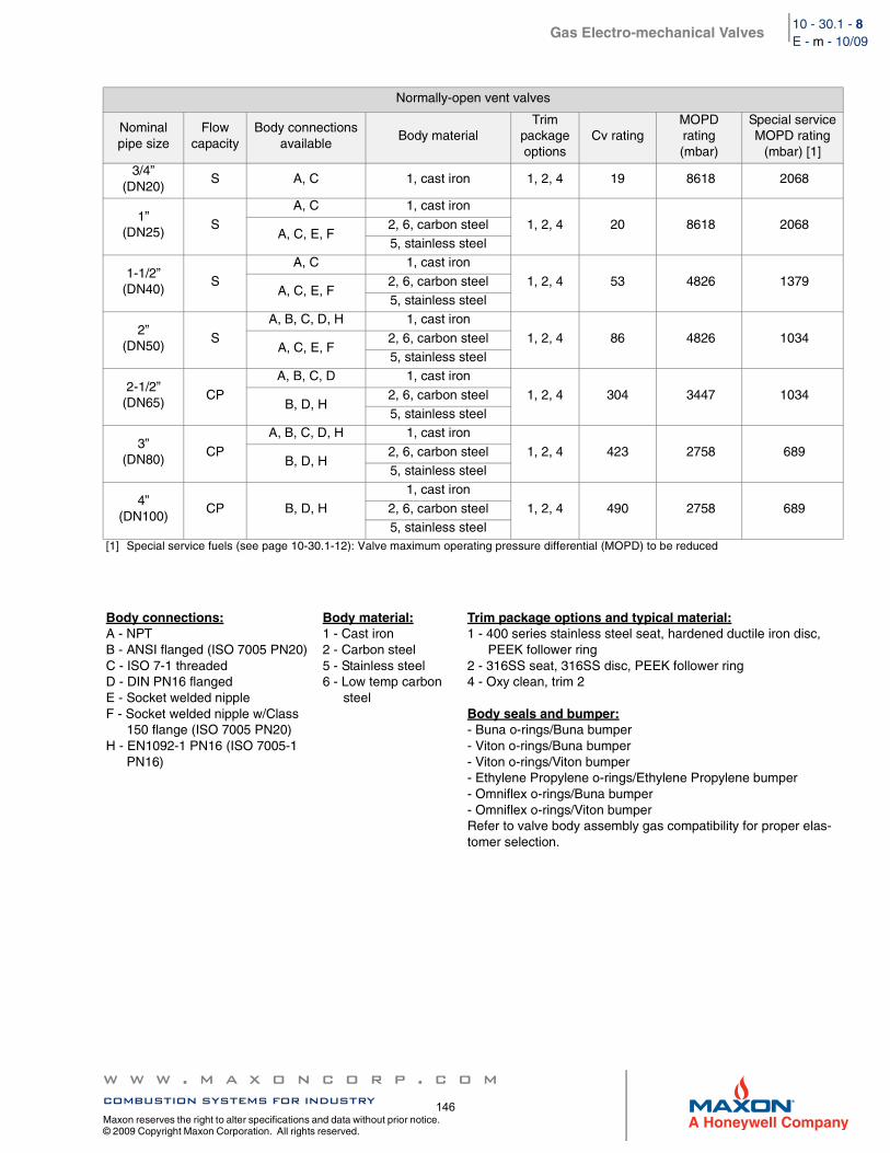
Gas Electro-mechanical Valves
w w w . m a x o n c o r p . c o mcombustion systems for industry
Maxon reserves the right to alter specifications and data without prior notice. © 2009 Copyright Maxon Corporation. All rights reserved.
10 - 30.1 - 8E - m - 10/09
Normally-open vent valves
Nominalpipe size
Flowcapacity
Body connectionsavailable
Body materialTrim
package options
Cv ratingMOPDrating(mbar)
Special serviceMOPD rating
(mbar) [1]3/4”
(DN20)S A, C 1, cast iron 1, 2, 4 19 8618 2068
1”(DN25)
S
A, C 1, cast iron
1, 2, 4 20 8618 2068A, C, E, F
2, 6, carbon steel5, stainless steel
1-1/2”(DN40)
S
A, C 1, cast iron
1, 2, 4 53 4826 1379A, C, E, F
2, 6, carbon steel5, stainless steel
2”(DN50)
S
A, B, C, D, H 1, cast iron
1, 2, 4 86 4826 1034A, C, E, F
2, 6, carbon steel5, stainless steel
2-1/2”(DN65)
CP
A, B, C, D 1, cast iron
1, 2, 4 304 3447 1034B, D, H
2, 6, carbon steel5, stainless steel
3”(DN80)
CP
A, B, C, D, H 1, cast iron
1, 2, 4 423 2758 689B, D, H
2, 6, carbon steel5, stainless steel
4”(DN100)
CP B, D, H
1, cast iron
1, 2, 4 490 2758 6892, 6, carbon steel5, stainless steel
[1] Special service fuels (see page 10-30.1-12): Valve maximum operating pressure differential (MOPD) to be reduced
Body connections:A - NPTB - ANSI flanged (ISO 7005 PN20)C - ISO 7-1 threadedD - DIN PN16 flangedE - Socket welded nippleF - Socket welded nipple w/Class
150 flange (ISO 7005 PN20)H - EN1092-1 PN16 (ISO 7005-1
PN16)
Body material:1 - Cast iron2 - Carbon steel5 - Stainless steel6 - Low temp carbon
steel
Trim package options and typical material:1 - 400 series stainless steel seat, hardened ductile iron disc,
PEEK follower ring2 - 316SS seat, 316SS disc, PEEK follower ring4 - Oxy clean, trim 2
Body seals and bumper:- Buna o-rings/Buna bumper- Viton o-rings/Buna bumper- Viton o-rings/Viton bumper- Ethylene Propylene o-rings/Ethylene Propylene bumper- Omniflex o-rings/Buna bumper- Omniflex o-rings/Viton bumperRefer to valve body assembly gas compatibility for proper elas-tomer selection.
146
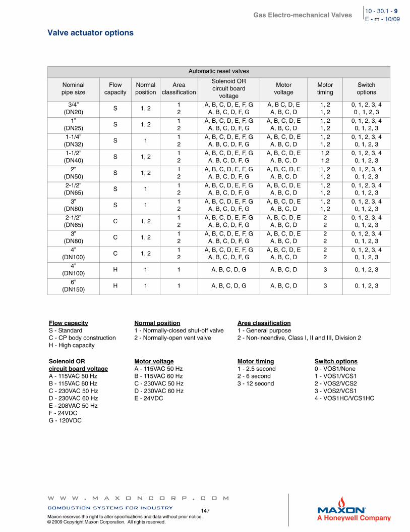
Gas Electro-mechanical Valves
w w w . m a x o n c o r p . c o mcombustion systems for industry
Maxon reserves the right to alter specifications and data without prior notice. © 2009 Copyright Maxon Corporation. All rights reserved.
10 - 30.1 - 9E - m - 10/09
Valve actuator options
Automatic reset valves
Nominal pipe size
Flowcapacity
Normal position
Areaclassification
Solenoid ORcircuit board
voltage
Motorvoltage
Motortiming
Switchoptions
3/4” (DN20)
S 1, 212
A, B, C, D, E, F, GA, B, C, D, F, G
A, B C, D, EA, B, C, D
1, 21, 2
0, 1, 2, 3, 40 , 1, 2, 3
1” (DN25)
S 1, 212
A, B, C, D, E, F, GA, B, C, D, F, G
A, B, C, D, EA, B, C, D
1, 21, 2
0, 1, 2, 3, 40, 1, 2, 3
1-1/4”(DN32)
S 112
A, B, C, D, E, F, GA, B, C, D, F, G
A, B, C, D, EA, B, C, D
1, 21, 2
0, 1, 2, 3, 40, 1, 2, 3
1-1/2”(DN40)
S 1, 212
A, B, C, D, E, F, GA, B, C, D, F, G
A, B, C, D, EA, B, C, D
1,21,2
0, 1, 2, 3, 40, 1, 2, 3
2”(DN50)
S 1, 212
A, B, C, D, E, F, GA, B, C, D, F, G
A, B, C, D, EA, B, C, D
1, 21, 2
0, 1, 2, 3, 40, 1, 2, 3
2-1/2”(DN65)
S 112
A, B, C, D, E, F, GA, B, C, D, F, G
A, B, C, D, EA, B, C, D
1, 21, 2
0, 1, 2, 3, 40, 1, 2, 3
3”(DN80)
S 112
A, B, C, D, E, F, GA, B, C, D, F, G
A, B, C, D, EA, B, C, D
1, 21, 2
0, 1, 2, 3, 40, 1, 2, 3
2-1/2”(DN65)
C 1, 212
A, B, C, D, E, F, GA, B, C, D, F, G
A, B, C, D, EA, B, C, D
22
0, 1, 2, 3, 40, 1, 2, 3
3”(DN80)
C 1, 212
A, B, C, D, E, F, GA, B, C, D, F, G
A, B, C, D, EA, B, C, D
22
0, 1, 2, 3, 40, 1, 2, 3
4”(DN100)
C 1, 212
A, B, C, D, E, F, GA, B, C, D, F, G
A, B, C, D, EA, B, C, D
22
0, 1, 2, 3, 40, 1, 2, 3
4”(DN100)
H 1 1 A, B, C, D, G A, B, C, D 3 0, 1, 2, 3
6”(DN150)
H 1 1 A, B, C, D, G A, B, C, D 3 0. 1, 2, 3
Flow capacityS - StandardC - CP body constructionH - High capacity
Normal position1 - Normally-closed shut-off valve2 - Normally-open vent valve
Area classification1 - General purpose2 - Non-incendive, Class I, II and III, Division 2
Solenoid ORcircuit board voltageA - 115VAC 50 HzB - 115VAC 60 HzC - 230VAC 50 HzD - 230VAC 60 HzE - 208VAC 50 HzF - 24VDCG - 120VDC
Motor voltageA - 115VAC 50 HzB - 115VAC 60 HzC - 230VAC 50 HzD - 230VAC 60 HzE - 24VDC
Motor timing1 - 2.5 second2 - 6 second3 - 12 second
Switch options0 - VOS1/None1 - VOS1/VCS12 - VOS2/VCS23 - VOS2/VCS14 - VOS1HC/VCS1HC
147
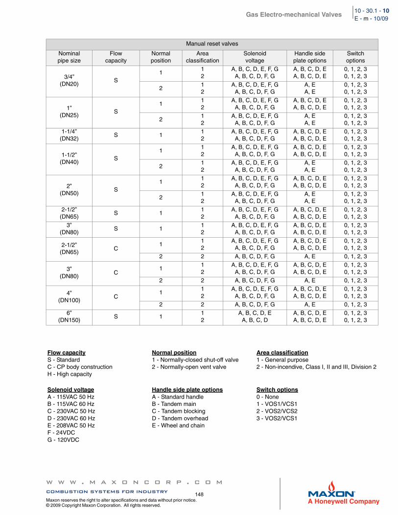
Gas Electro-mechanical Valves
w w w . m a x o n c o r p . c o mcombustion systems for industry
Maxon reserves the right to alter specifications and data without prior notice. © 2009 Copyright Maxon Corporation. All rights reserved.
10 - 30.1 - 10E - m - 10/09
Manual reset valves
Nominalpipe size
Flowcapacity
Normal position
Areaclassification
Solenoidvoltage
Handle sideplate options
Switchoptions
3/4”(DN20)
S1
12
A, B, C, D, E, F, GA, B, C, D, F, G
A, B, C, D, EA, B, C, D, E
0, 1, 2, 30, 1, 2, 3
212
A, B, C, D, E, F, GA, B, C, D, F, G
A, EA, E
0, 1, 2, 30, 1, 2, 3
1”(DN25)
S1
12
A, B, C, D, E, F, GA, B, C, D, F, G
A, B, C, D, EA, B, C, D, E
0, 1, 2, 30, 1, 2, 3
212
A, B, C, D, E, F, GA, B, C, D, F, G
A, EA, E
0, 1, 2, 30, 1, 2, 3
1-1/4”(DN32)
S 112
A, B, C, D, E, F, GA, B, C, D, F, G
A, B, C, D, EA, B, C, D, E
0, 1, 2, 30, 1, 2, 3
1-1/2”(DN40)
S1
12
A, B, C, D, E, F, GA, B, C, D, F, G
A, B, C, D, EA, B, C, D, E
0, 1, 2, 30, 1, 2, 3
212
A, B, C, D, E, F, GA, B, C, D, F, G
A, EA, E
0, 1, 2, 30, 1, 2, 3
2”(DN50)
S1
12
A, B, C, D, E, F, GA, B, C, D, F, G
A, B, C, D, EA, B, C, D, E
0, 1, 2, 30, 1, 2, 3
212
A, B, C, D, E, F, GA, B, C, D, F, G
A, EA, E
0, 1, 2, 30, 1, 2, 3
2-1/2”(DN65)
S 112
A, B, C, D, E, F, GA, B, C, D, F, G
A, B, C, D, EA, B, C, D, E
0, 1, 2, 30, 1, 2, 3
3”(DN80)
S 112
A, B, C, D, E, F, GA, B, C, D, F, G
A, B, C, D, EA, B, C, D, E
0, 1, 2, 30, 1, 2, 3
2-1/2”(DN65)
C1
12
A, B, C, D, E, F, GA, B, C, D, F, G
A, B, C, D, EA, B, C, D, E
0, 1, 2, 30, 1, 2, 3
2 2 A, B, C, D, F, G A, E 0, 1, 2, 3
3”(DN80)
C1
12
A, B, C, D, E, F, GA, B, C, D, F, G
A, B, C, D, EA, B, C, D, E
0, 1, 2, 30, 1, 2, 3
2 2 A, B, C, D, F, G A, E 0, 1, 2, 3
4”(DN100)
C1
12
A, B, C, D, E, F, GA, B, C, D, F, G
A, B, C, D, EA, B, C, D, E
0, 1, 2, 30, 1, 2, 3
2 2 A, B, C, D, F, G A, E 0, 1, 2, 3
6”(DN150)
S 112
A, B, C, D, EA, B, C, D
A, B, C, D, EA, B, C, D, E
0, 1, 2, 30, 1, 2, 3
Flow capacityS - StandardC - CP body constructionH - High capacity
Normal position1 - Normally-closed shut-off valve2 - Normally-open vent valve
Area classification1 - General purpose2 - Non-incendive, Class I, II and III, Division 2
Solenoid voltageA - 115VAC 50 HzB - 115VAC 60 HzC - 230VAC 50 HzD - 230VAC 60 HzE - 208VAC 50 HzF - 24VDCG - 120VDC
Handle side plate optionsA - Standard handleB - Tandem mainC - Tandem blockingD - Tandem overheadE - Wheel and chain
Switch options0 - None1 - VOS1/VCS12 - VOS2/VCS23 - VOS2/VCS1
148
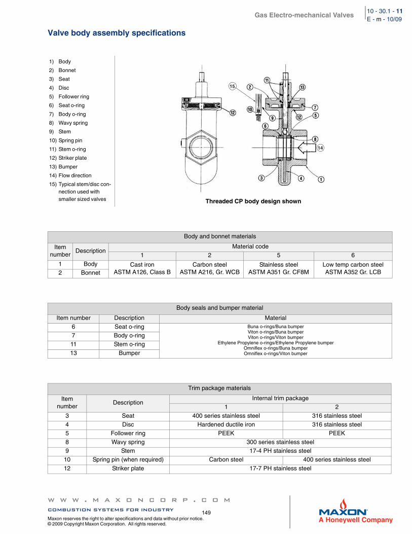
Gas Electro-mechanical Valves
w w w . m a x o n c o r p . c o mcombustion systems for industry
Maxon reserves the right to alter specifications and data without prior notice. © 2009 Copyright Maxon Corporation. All rights reserved.
10 - 30.1 - 11E - m - 10/09
Valve body assembly specifications
1) Body
2) Bonnet
3) Seat
4) Disc
5) Follower ring
6) Seat o-ring
7) Body o-ring
8) Wavy spring
9) Stem
10) Spring pin
11) Stem o-ring
12) Striker plate
13) Bumper
14) Flow direction
15) Typical stem/disc con-nection used with smaller sized valves Threaded CP body design shown
Body and bonnet materials
Item number
DescriptionMaterial code
1 2 5 6
1 Body Cast ironASTM A126, Class B
Carbon steelASTM A216, Gr. WCB
Stainless steelASTM A351 Gr. CF8M
Low temp carbon steelASTM A352 Gr. LCB2 Bonnet
Body seals and bumper material
Item number Description Material
6 Seat o-ring Buna o-rings/Buna bumperViton o-rings/Buna bumperViton o-rings/Viton bumper
Ethylene Propylene o-rings/Ethylene Propylene bumperOmniflex o-rings/Buna bumperOmniflex o-rings/Viton bumper
7 Body o-ring11 Stem o-ring
13 Bumper
Trim package materials
Item number
DescriptionInternal trim package
1 2
3 Seat 400 series stainless steel 316 stainless steel4 Disc Hardened ductile iron 316 stainless steel5 Follower ring PEEK PEEK
8 Wavy spring 300 series stainless steel9 Stem 17-4 PH stainless steel
10 Spring pin (when required) Carbon steel 400 series stainless steel
12 Striker plate 17-7 PH stainless steel
14
15
149
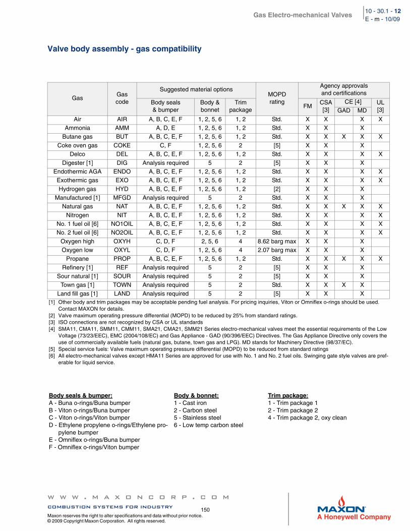
Gas Electro-mechanical Valves
w w w . m a x o n c o r p . c o mcombustion systems for industry
Maxon reserves the right to alter specifications and data without prior notice. © 2009 Copyright Maxon Corporation. All rights reserved.
10 - 30.1 - 12E - m - 10/09
Valve body assembly - gas compatibility
GasGascode
Suggested material optionsMOPDrating
Agency approvals and certifications
Body seals & bumper
Body & bonnet
Trimpackage
FMCSA[3]
CE [4] UL [3]GAD MD
Air AIR A, B, C, E, F 1, 2, 5, 6 1, 2 Std. X X X XAmmonia AMM A, D, E 1, 2, 5, 6 1, 2 Std. X X X
Butane gas BUT A, B, C, E, F 1, 2, 5, 6 1, 2 Std. X X X X X
Coke oven gas COKE C, F 1, 2, 5, 6 2 [5] X X XDelco DEL A, B, C, E, F 1, 2, 5, 6 1, 2 Std. X X X X
Digester [1] DIG Analysis required 5 2 [5] X X XEndothermic AGA ENDO A, B, C, E, F 1, 2, 5, 6 1, 2 Std. X X X X
Exothermic gas EXO A, B, C, E, F 1, 2, 5, 6 1, 2 Std. X X X X
Hydrogen gas HYD A, B, C, E, F 1, 2, 5, 6 1, 2 [2] X X XManufactured [1] MFGD Analysis required 5 2 Std. X X X
Natural gas NAT A, B, C, E, F 1, 2, 5, 6 1, 2 Std. X X X X X
Nitrogen NIT A, B, C, E, F 1, 2, 5, 6 1, 2 Std. X X X XNo. 1 fuel oil [6] NO1OIL A, B, C, E, F 1, 2, 5, 6 1, 2 Std. X X X XNo. 2 fuel oil [6] NO2OIL A, B, C, E, F 1, 2, 5, 6 1, 2 Std. X X X X
Oxygen high OXYH C, D, F 2, 5, 6 4 8.62 barg max X X XOxygen low OXYL C, D, F 1, 2, 5, 6 4 2.07 barg max X X X
Propane PROP A, B, C, E, F 1, 2, 5, 6 1, 2 Std. X X X X X
Refinery [1] REF Analysis required 5 2 [5] X X XSour natural [1] SOUR Analysis required 5 2 [5] X X X
Town gas [1] TOWN Analysis required 5 2 Std. X X X X
Land fill gas [1] LAND Analysis required 5 2 [5] X X X[1] Other body and trim packages may be acceptable pending fuel analysis. For pricing inquiries, Viton or Omniflex o-rings should be used.
Contact MAXON for details.[2] Valve maximum operating pressure differential (MOPD) to be reduced by 25% from standard ratings.[3] ISO connections are not recognized by CSA or UL standards[4] SMA11, CMA11, SMM11, CMM11, SMA21, CMA21, SMM21 Series electro-mechanical valves meet the essential requirements of the Low
Voltage (73/23/EEC), EMC (2004/108/EC) and Gas Appliance - GAD (90/396/EEC) Directives. The Gas Appliance Directive only covers the use of commercially available fuels (natural gas, butane, town gas and LPG). MD stands for Machinery Directive (98/37/EC).
[5] Special service fuels: Valve maximum operating pressure differential (MOPD) to be reduced from standard ratings[6] All electro-mechanical valves except HMA11 Series are approved for use with No. 1 and No. 2 fuel oils. Swinging gate style valves are pref-
erable for liquid service.
Body seals & bumper:A - Buna o-rings/Buna bumperB - Viton o-rings/Buna bumperC - Viton o-rings/Viton bumperD - Ethylene propylene o-rings/Ethylene pro-
pylene bumperE - Omniflex o-rings/Buna bumperF - Omniflex o-rings/Viton bumper
Body & bonnet:1 - Cast iron2 - Carbon steel5 - Stainless steel6 - Low temp carbon steel
Trim package:1 - Trim package 12 - Trim package 24 - Trim package 2, oxy clean
150
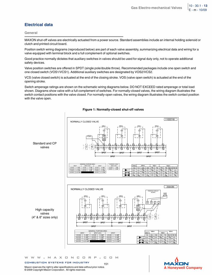
Gas Electro-mechanical Valves
w w w . m a x o n c o r p . c o mcombustion systems for industry
Maxon reserves the right to alter specifications and data without prior notice. © 2009 Copyright Maxon Corporation. All rights reserved.
10 - 30.1 - 13E - m - 10/09
Electrical data
General
MAXON shut-off valves are electrically actuated from a power source. Standard assemblies include an internal holding solenoid or clutch and printed circuit board.
Position switch wiring diagrams (reproduced below) are part of each valve assembly, summarizing electrical data and wiring for a valve equipped with terminal block and a full complement of optional switches.
Good practice normally dictates that auxiliary switches in valves should be used for signal duty only, not to operate additional safety devices.
Valve position switches are offered in SPDT (single pole/double throw). Recommended packages include one open switch and one closed switch (VOS1/VCS1). Additional auxiliary switches are designated by VOS2/VCS2.
VCS (valve closed switch) is actuated at the end of the closing stroke. VOS (valve open switch) is actuated at the end of the opening stroke.
Switch amperage ratings are shown on the schematic wiring diagrams below. DO NOT EXCEED rated amperage or total load shown. Diagrams show valve with a full complement of switches. For normally-closed valves, the wiring diagram illustrates the switch contact positions with the valve closed. For normally-open valves, the wiring diagram illustrates the switch contact position with the valve open.
Figure 1: Normally-closed shut-off valves
Standard and CPvalves
High capacityvalves
(4” & 6” sizes only)
1-31-3 4-5 4-6 7-8 7-97-87-9 10-11 10-12VOS-1 VOS-2 VCS-1 VCS-2
1 2 3 4 5 6 7 8 9 10 11 12L(+) N(-)
M
VOS-1 VOS-2 VCS-1 VCS-2
SPDT SPDT
DPDTDPDT
SPDTSPDT L N
1102216/NORMALLY CLOSED VALVE
125VAC 1 AMP28VDC 5 AMP
SPDT (HS)DIVISION 2 AREA
125VAC 15 AMP 125VAC 10 AMP 125VAC 10 AMP250VAC 15 AMP 125VDC 10 AMP 250VAC 10 AMP125VDC 0.5 AMP 250VDC 3 AMP 125VDC 0.3 AMP
PMA 51.0CDV052PMA 52.0CDV052
SPDT (HC)SPDT DPDTGENERAL PURPOSE AREA
1-3 4-5 4-6 7-8 7-9 10-11 10-12VOS-1
VOS-2VCS-1
VCS-2
12 11 10 9 8 7 6 5 4 3 2 1 L(+) N(-)
M
VOS-1VOS-2VCS-1VCS-2
SPDTSPDT
DPDT DPDT
SPDT SPDT L N
25643N
1 2 3 4
PRINTED CIRCUITBOARD 90 VDC
125VAC 15 AMP 125VAC 10 AMP 125VAC 10 AMP250VAC 15 AMP 125VDC 10 AMP 250VAC 10 AMP125VDC 0.5 AMP 250VDC 3 AMP 125VDC 0.3 AMP
PMA 51.0CDV052PMA 52.0CDV052
SPDT (HC)SPDT DPDTGENERAL PURPOSE AREA
NORMALLY CLOSED VALVE
151
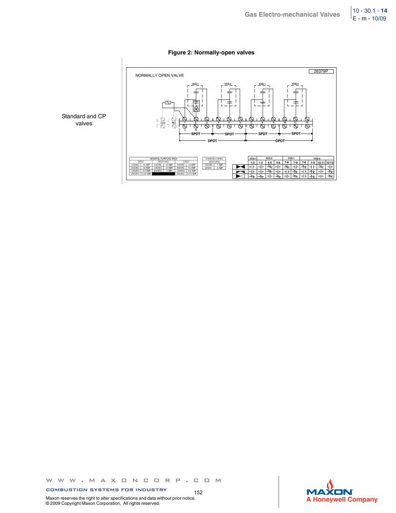
Gas Electro-mechanical Valves
w w w . m a x o n c o r p . c o mcombustion systems for industry
Maxon reserves the right to alter specifications and data without prior notice. © 2009 Copyright Maxon Corporation. All rights reserved.
10 - 30.1 - 14E - m - 10/09
Figure 2: Normally-open valves
Standard and CPvalves
NORMALLY OPEN VALVE
1-31-3 4-5 4-6 7-8 7-97-87-9 10-11 10-12VCS-1 VCS-2 VOS-1 VOS-2
1 2 3 4 5 6 7 8 9 10 11 12L(+) N(-)
M
VCS-1 VCS-2 VOS-1 VOS-2
SPDT SPDT
DPDTDPDT
SPDTSPDTL N
26379P
125VAC 15 AMP 125VAC 10 AMP 125VAC 10 AMP250VAC 15 AMP 125VDC 10 AMP 250VAC 10 AMP125VDC 0.5 AMP 250VDC 3 AMP 125VDC 0.3 AMP
PMA 51.0CDV052PMA 52.0CDV052
SPDT (HC)SPDT DPDTGENERAL PURPOSE AREA
125VAC 1 AMP28VDC 5 AMP
SPDT (HS)DIVISION 2 AREA
152
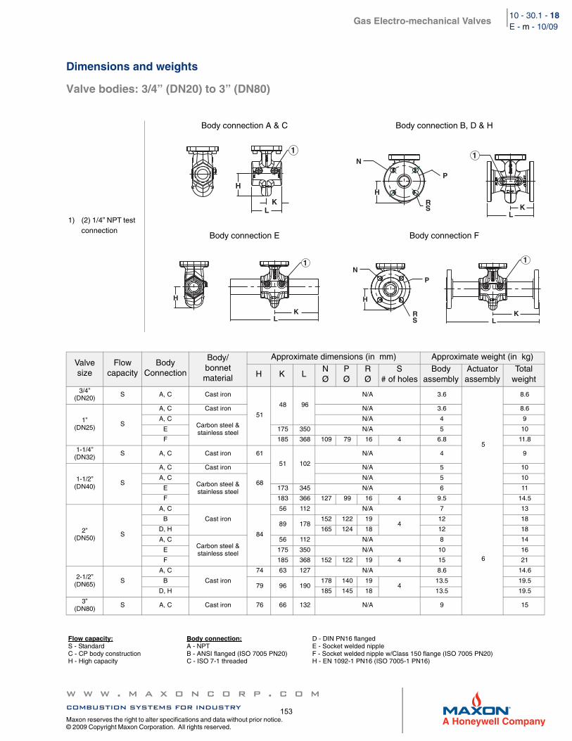
Gas Electro-mechanical Valves
w w w . m a x o n c o r p . c o mcombustion systems for industry
Maxon reserves the right to alter specifications and data without prior notice. © 2009 Copyright Maxon Corporation. All rights reserved.
10 - 30.1 - 18E - m - 10/09
Dimensions and weights
Valve bodies: 3/4” (DN20) to 3” (DN80)
1) (2) 1/4” NPT test connection
Body connection A & C Body connection B, D & H
Body connection E Body connection F
Valvesize
Flowcapacity
BodyConnection
Body/bonnet material
Approximate dimensions (in mm) Approximate weight (in kg)
H K LNØ
PØ
RØ
S# of holes
Bodyassembly
Actuatorassembly
Totalweight
3/4”(DN20) S A, C Cast iron
51
48 96
N/A 3.6
5
8.6
1”(DN25) S
A, C Cast iron N/A 3.6 8.6
A, CCarbon steel & stainless steel
N/A 4 9
E 175 350 N/A 5 10
F 185 368 109 79 16 4 6.8 11.8
1-1/4”(DN32)
S A, C Cast iron 61
51 102
N/A 4 9
1-1/2”(DN40) S
A, C Cast iron
68
N/A 5 10
A, CCarbon steel & stainless steel
N/A 5 10
E 173 345 N/A 6 11
F 183 366 127 99 16 4 9.5 14.5
2”(DN50) S
A, C
Cast iron
84
56 112 N/A 7
6
13
B 89 178
152 122 194
12 18
D, H 165 124 18 12 18
A, CCarbon steel & stainless steel
56 112 N/A 8 14
E 175 350 N/A 10 16
F 185 368 152 122 19 4 15 21
2-1/2”(DN65) S
A, C
Cast iron
74 63 127 N/A 8.6 14.6
B 79 96 190
178 140 194
13.5 19.5
D, H 185 145 18 13.5 19.5
3”(DN80)
S A, C Cast iron 76 66 132 N/A 9 15
Flow capacity:S - StandardC - CP body constructionH - High capacity
Body connection:A - NPTB - ANSI flanged (ISO 7005 PN20)C - ISO 7-1 threaded
D - DIN PN16 flangedE - Socket welded nippleF - Socket welded nipple w/Class 150 flange (ISO 7005 PN20)H - EN 1092-1 PN16 (ISO 7005-1 PN16)
L K
H
1
R S
N
H
K L
P
1
L K
H
1
R S L
N
K
H
P
1
153
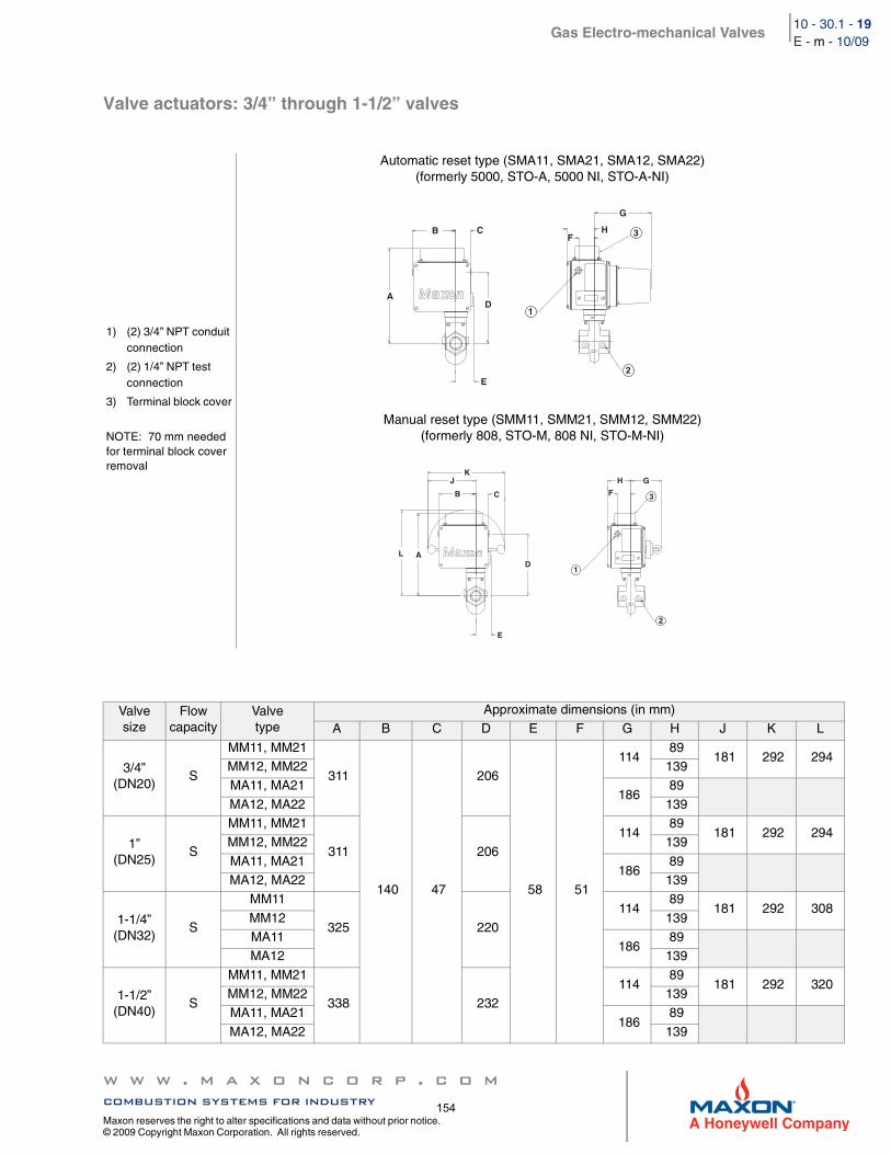
Gas Electro-mechanical Valves
w w w . m a x o n c o r p . c o mcombustion systems for industry
Maxon reserves the right to alter specifications and data without prior notice. © 2009 Copyright Maxon Corporation. All rights reserved.
10 - 30.1 - 19E - m - 10/09
Valve actuators: 3/4” through 1-1/2” valves
1) (2) 3/4” NPT conduit connection
2) (2) 1/4” NPT test connection
3) Terminal block cover
NOTE: 70 mm needed for terminal block cover removal
Automatic reset type (SMA11, SMA21, SMA12, SMA22)(formerly 5000, STO-A, 5000 NI, STO-A-NI)
Manual reset type (SMM11, SMM21, SMM12, SMM22)(formerly 808, STO-M, 808 NI, STO-M-NI)
Valvesize
Flowcapacity
Valvetype
Approximate dimensions (in mm)A B C D E F G H J K L
3/4”(DN20)
S
MM11, MM21
311
140 47
206
58 51
114 89
181 292 294MM12, MM22 139MA11, MA21
186 89
MA12, MA22 139
1”(DN25)
S
MM11, MM21
311 206 114
89 181 292 294
MM12, MM22 139
MA11, MA21 186
89MA12, MA22 139
1-1/4”(DN32)
S
MM11
325 220
114 89
181 292 308MM12 139MA11
186 89
MA12 139
1-1/2”(DN40)
S
MM11, MM21
338 232 114
89 181 292 320
MM12, MM22 139MA11, MA21
186 89
MA12, MA22 139
C
E
AD
F
G
HB
1
2
3
KJ
B C
D
E
L A
H G
F
1
2
3
154
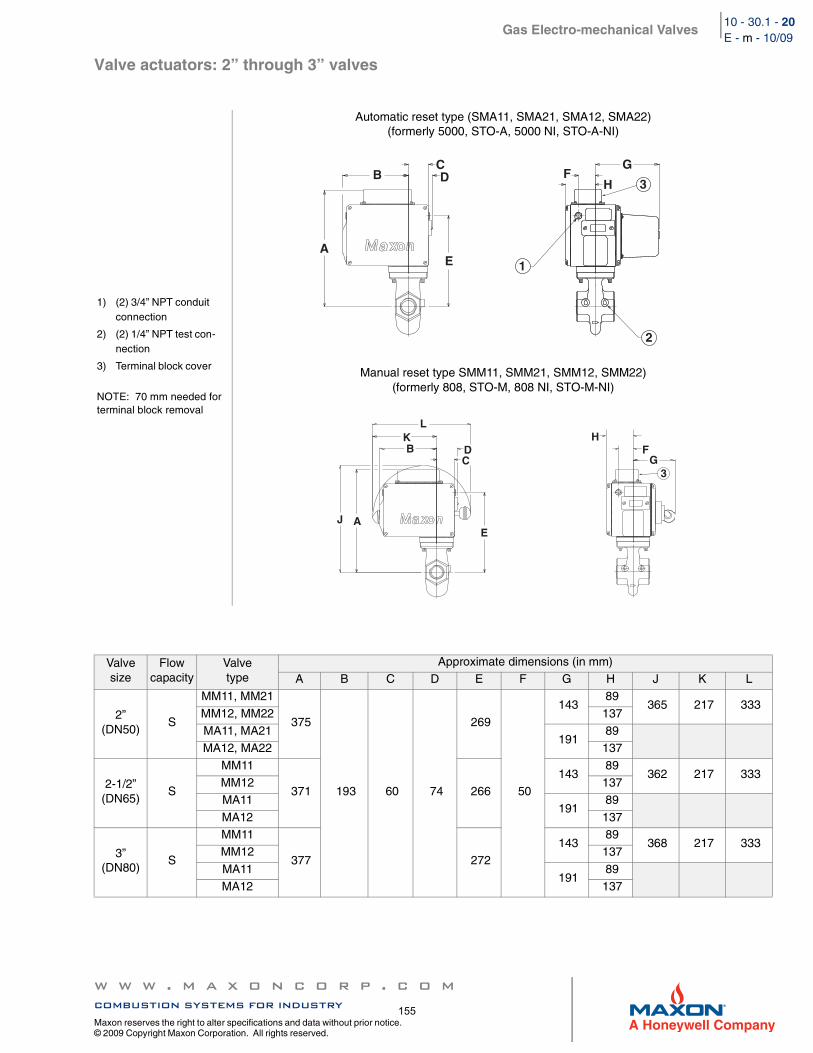
Gas Electro-mechanical Valves
w w w . m a x o n c o r p . c o mcombustion systems for industry
Maxon reserves the right to alter specifications and data without prior notice. © 2009 Copyright Maxon Corporation. All rights reserved.
10 - 30.1 - 20E - m - 10/09
Valve actuators: 2” through 3” valves
1) (2) 3/4” NPT conduit connection
2) (2) 1/4” NPT test con-nection
3) Terminal block cover
NOTE: 70 mm needed for terminal block removal
Automatic reset type (SMA11, SMA21, SMA12, SMA22)(formerly 5000, STO-A, 5000 NI, STO-A-NI)
Manual reset type SMM11, SMM21, SMM12, SMM22)(formerly 808, STO-M, 808 NI, STO-M-NI)
Valvesize
Flowcapacity
Valvetype
Approximate dimensions (in mm)A B C D E F G H J K L
2”(DN50)
S
MM11, MM21
375
193 60 74
269
50
143 89
365 217 333MM12, MM22 137MA11, MA21
191 89
MA12, MA22 137
2-1/2”(DN65)
S
MM11
371 266 143
89 362 217 333
MM12 137MA11
191 89
MA12 137
3”(DN80)
S
MM11
377 272 143
89 368 217 333
MM12 137
MA11 191
89MA12 137
CDB
AE
G
HF
1
2
3
LKB D
C
EJ A
FG
H
3
155
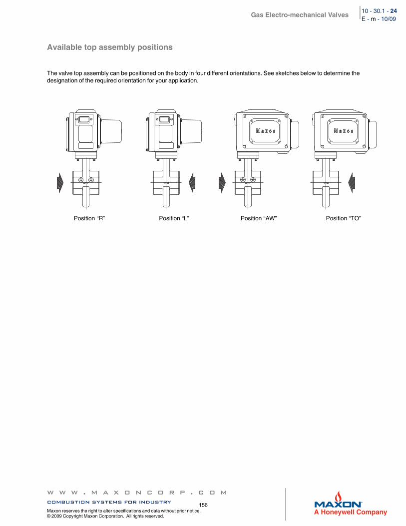
Gas Electro-mechanical Valves
w w w . m a x o n c o r p . c o mcombustion systems for industry
Maxon reserves the right to alter specifications and data without prior notice. © 2009 Copyright Maxon Corporation. All rights reserved.
10 - 30.1 - 24E - m - 10/09
Available top assembly positions
The valve top assembly can be positioned on the body in four different orientations. See sketches below to determine the designation of the required orientation for your application.
Position “R” Position “L” Position “AW” Position “TO”
156
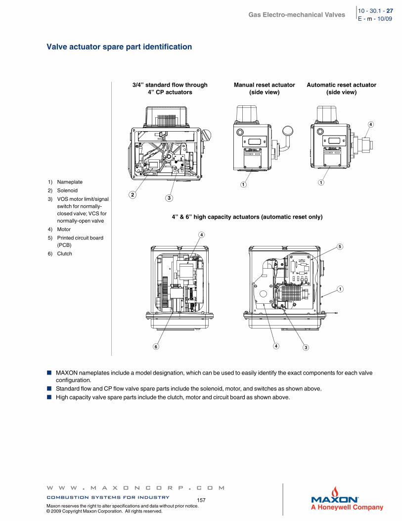
Gas Electro-mechanical Valves
w w w . m a x o n c o r p . c o mcombustion systems for industry
Maxon reserves the right to alter specifications and data without prior notice. © 2009 Copyright Maxon Corporation. All rights reserved.
10 - 30.1 - 27E - m - 10/09
Valve actuator spare part identification
MAXON nameplates include a model designation, which can be used to easily identify the exact components for each valve configuration.Standard flow and CP flow valve spare parts include the solenoid, motor, and switches as shown above.
High capacity valve spare parts include the clutch, motor and circuit board as shown above.
1) Nameplate
2) Solenoid
3) VOS motor limit/signal switch for normally-closed valve; VCS for normally-open valve
4) Motor
5) Printed circuit board (PCB)
6) Clutch
3/4” standard flow through 4” CP actuators
Manual reset actuator(side view)
Automatic reset actuator(side view)
4” & 6” high capacity actuators (automatic reset only)
23
1 1
4
6
4
4 3
1
5
157
Gas Electro-mechanical Valves
w w w . m a x o n c o r p . c o mcombustion systems for industry
Maxon reserves the right to alter specifications and data without prior notice. © 2009 Copyright Maxon Corporation. All rights reserved.
10 - 30.1 - 28E - m - 10/09
Please read the operating and mounting instructions before using the equipment. Install the equipment in compliance with the prevailing regulations.
Bedrijfs- en montagehandleiding voor gebruik goed lezen! Apparaat moet volgens de geldende voorschriften worden geïnstalleerd.
Lire les instructions de montage et de service avant utilisation! L’appareil doit imperativement être installé selon les règlementations en vigueur.
Betriebs- und Montageanleitung vor Gebrauch lesen! Gerät muß nach den geltenden Vorschriften installiert werden.
158
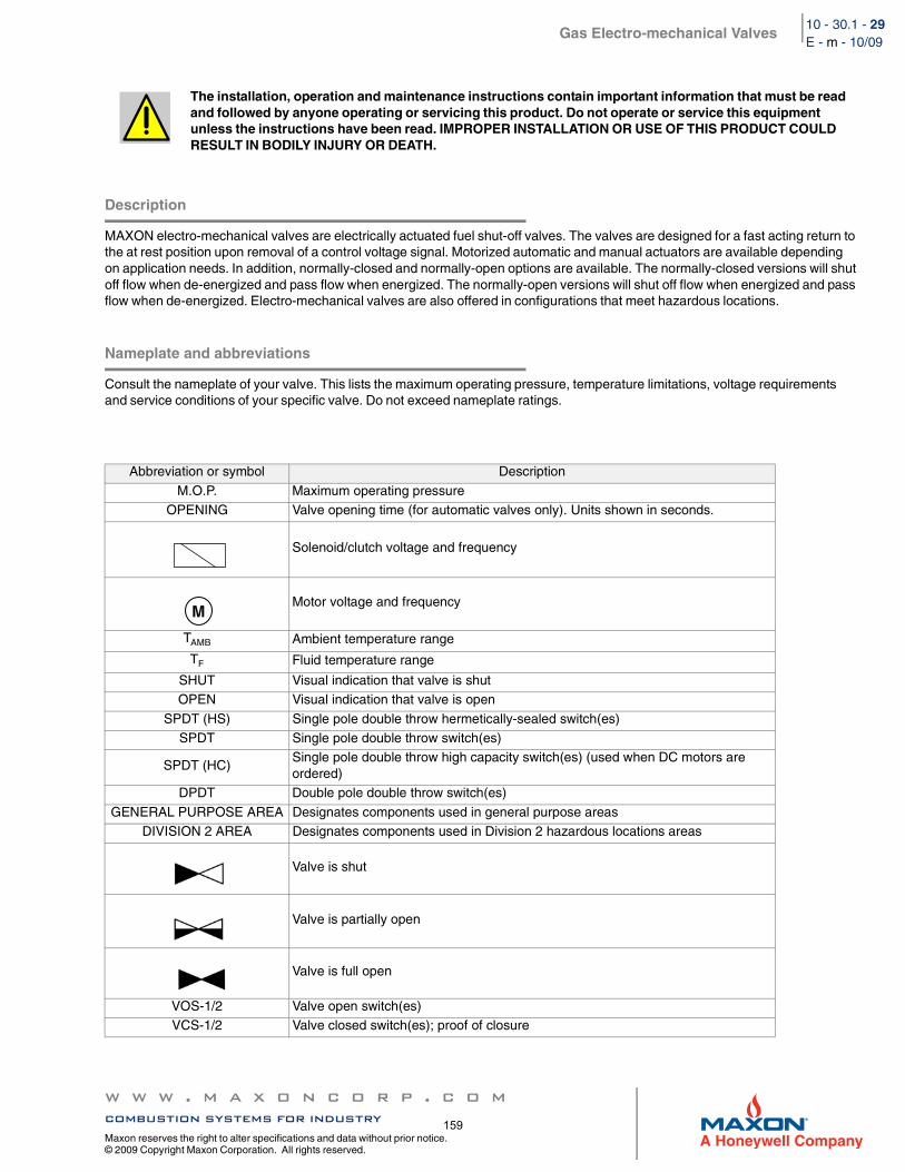
Gas Electro-mechanical Valves
w w w . m a x o n c o r p . c o mcombustion systems for industry
Maxon reserves the right to alter specifications and data without prior notice. © 2009 Copyright Maxon Corporation. All rights reserved.
10 - 30.1 - 29E - m - 10/09
Description
MAXON electro-mechanical valves are electrically actuated fuel shut-off valves. The valves are designed for a fast acting return to the at rest position upon removal of a control voltage signal. Motorized automatic and manual actuators are available depending on application needs. In addition, normally-closed and normally-open options are available. The normally-closed versions will shut off flow when de-energized and pass flow when energized. The normally-open versions will shut off flow when energized and pass flow when de-energized. Electro-mechanical valves are also offered in configurations that meet hazardous locations.
Nameplate and abbreviations
Consult the nameplate of your valve. This lists the maximum operating pressure, temperature limitations, voltage requirements and service conditions of your specific valve. Do not exceed nameplate ratings.
The installation, operation and maintenance instructions contain important information that must be read and followed by anyone operating or servicing this product. Do not operate or service this equipment unless the instructions have been read. IMPROPER INSTALLATION OR USE OF THIS PRODUCT COULD RESULT IN BODILY INJURY OR DEATH.
Abbreviation or symbol Description
M.O.P. Maximum operating pressureOPENING Valve opening time (for automatic valves only). Units shown in seconds.
Solenoid/clutch voltage and frequency
Motor voltage and frequency
TAMB Ambient temperature range
TF Fluid temperature range
SHUT Visual indication that valve is shutOPEN Visual indication that valve is open
SPDT (HS) Single pole double throw hermetically-sealed switch(es)SPDT Single pole double throw switch(es)
SPDT (HC)Single pole double throw high capacity switch(es) (used when DC motors are ordered)
DPDT Double pole double throw switch(es)
GENERAL PURPOSE AREA Designates components used in general purpose areasDIVISION 2 AREA Designates components used in Division 2 hazardous locations areas
Valve is shut
Valve is partially open
Valve is full open
VOS-1/2 Valve open switch(es)VCS-1/2 Valve closed switch(es); proof of closure
M
159
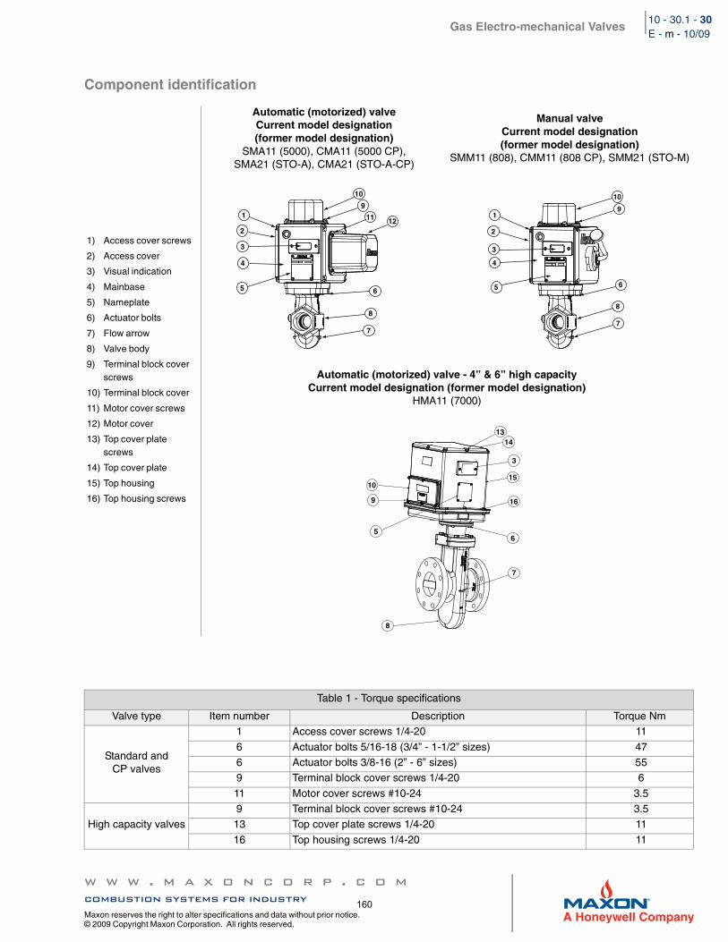
Gas Electro-mechanical Valves
w w w . m a x o n c o r p . c o mcombustion systems for industry
Maxon reserves the right to alter specifications and data without prior notice. © 2009 Copyright Maxon Corporation. All rights reserved.
10 - 30.1 - 30E - m - 10/09
Component identification
1) Access cover screws
2) Access cover
3) Visual indication
4) Mainbase
5) Nameplate
6) Actuator bolts
7) Flow arrow
8) Valve body
9) Terminal block cover screws
10) Terminal block cover
11) Motor cover screws
12) Motor cover
13) Top cover plate screws
14) Top cover plate
15) Top housing
16) Top housing screws
Automatic (motorized) valveCurrent model designation (former model designation)
SMA11 (5000), CMA11 (5000 CP), SMA21 (STO-A), CMA21 (STO-A-CP)
Manual valveCurrent model designation (former model designation)
SMM11 (808), CMM11 (808 CP), SMM21 (STO-M)
Automatic (motorized) valve - 4” & 6” high capacityCurrent model designation (former model designation)
HMA11 (7000)
Table 1 - Torque specifications
Valve type Item number Description Torque Nm
Standard and CP valves
1 Access cover screws 1/4-20 11
6 Actuator bolts 5/16-18 (3/4” - 1-1/2” sizes) 476 Actuator bolts 3/8-16 (2” - 6” sizes) 559 Terminal block cover screws 1/4-20 6
11 Motor cover screws #10-24 3.5
High capacity valves9 Terminal block cover screws #10-24 3.513 Top cover plate screws 1/4-20 11
16 Top housing screws 1/4-20 11
10
11 12
9
6
8
7
1
2
3
4
5
10
9
6
8
7
1
2
3
4
5
10
9
5
7
3
1314
15
16
6
8
160
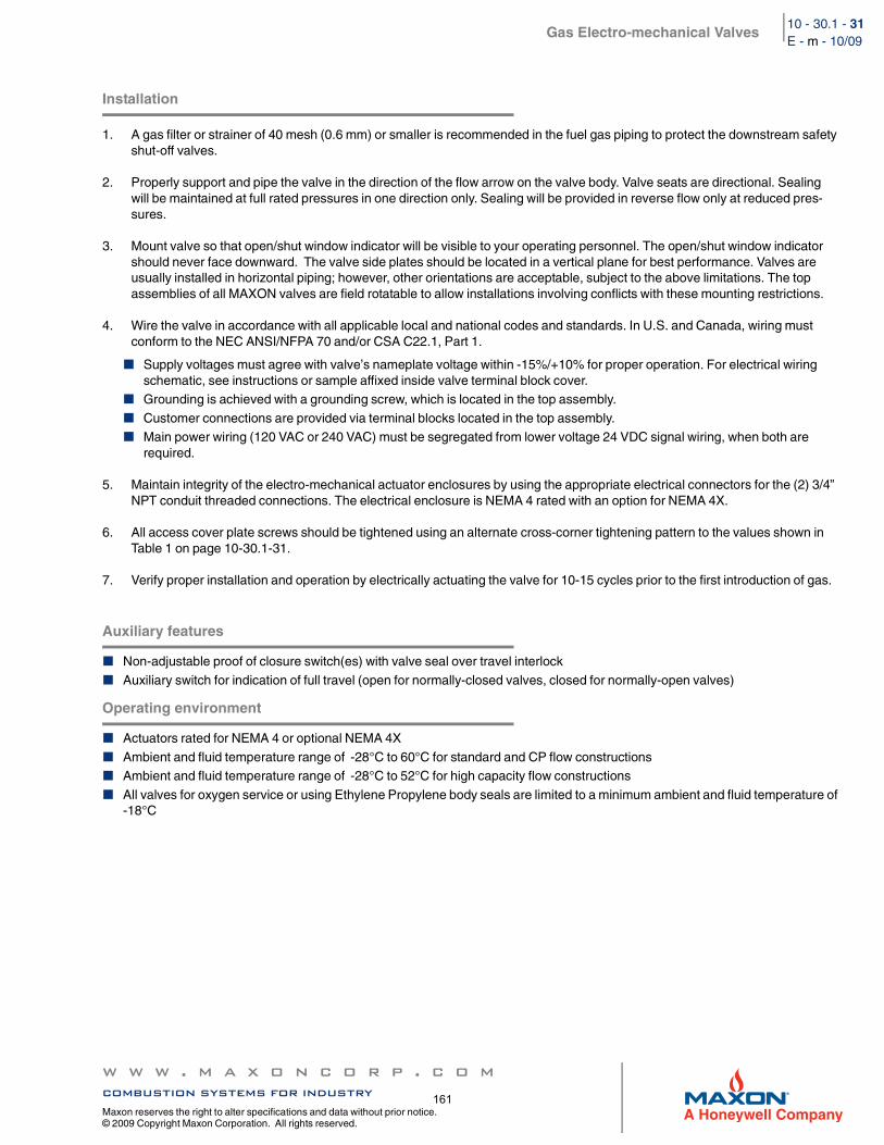
Gas Electro-mechanical Valves
w w w . m a x o n c o r p . c o mcombustion systems for industry
Maxon reserves the right to alter specifications and data without prior notice. © 2009 Copyright Maxon Corporation. All rights reserved.
10 - 30.1 - 31E - m - 10/09
Installation
1. A gas filter or strainer of 40 mesh (0.6 mm) or smaller is recommended in the fuel gas piping to protect the downstream safety shut-off valves.
2. Properly support and pipe the valve in the direction of the flow arrow on the valve body. Valve seats are directional. Sealing will be maintained at full rated pressures in one direction only. Sealing will be provided in reverse flow only at reduced pres-sures.
3. Mount valve so that open/shut window indicator will be visible to your operating personnel. The open/shut window indicator should never face downward. The valve side plates should be located in a vertical plane for best performance. Valves are usually installed in horizontal piping; however, other orientations are acceptable, subject to the above limitations. The top assemblies of all MAXON valves are field rotatable to allow installations involving conflicts with these mounting restrictions.
4. Wire the valve in accordance with all applicable local and national codes and standards. In U.S. and Canada, wiring must conform to the NEC ANSI/NFPA 70 and/or CSA C22.1, Part 1.
Supply voltages must agree with valve’s nameplate voltage within -15%/+10% for proper operation. For electrical wiring schematic, see instructions or sample affixed inside valve terminal block cover.Grounding is achieved with a grounding screw, which is located in the top assembly.
Customer connections are provided via terminal blocks located in the top assembly.Main power wiring (120 VAC or 240 VAC) must be segregated from lower voltage 24 VDC signal wiring, when both are required.
5. Maintain integrity of the electro-mechanical actuator enclosures by using the appropriate electrical connectors for the (2) 3/4” NPT conduit threaded connections. The electrical enclosure is NEMA 4 rated with an option for NEMA 4X.
6. All access cover plate screws should be tightened using an alternate cross-corner tightening pattern to the values shown in Table 1 on page 10-30.1-31.
7. Verify proper installation and operation by electrically actuating the valve for 10-15 cycles prior to the first introduction of gas.
Auxiliary features
Non-adjustable proof of closure switch(es) with valve seal over travel interlock
Auxiliary switch for indication of full travel (open for normally-closed valves, closed for normally-open valves)
Operating environment
Actuators rated for NEMA 4 or optional NEMA 4X
Ambient and fluid temperature range of -28°C to 60°C for standard and CP flow constructionsAmbient and fluid temperature range of -28°C to 52°C for high capacity flow constructions
All valves for oxygen service or using Ethylene Propylene body seals are limited to a minimum ambient and fluid temperature of -18°C
161
Gas Electro-mechanical Valves
w w w . m a x o n c o r p . c o mcombustion systems for industry
Maxon reserves the right to alter specifications and data without prior notice. © 2009 Copyright Maxon Corporation. All rights reserved.
10 - 30.1 - 32E - m - 10/09
Actuator assembly rotation
1. Shut off all electrical power and close off upstream manual cock.2. Remove terminal block cover plate and disconnect power lead wires. (Tag carefully for later re-assembly.)3. Remove conduit and electrical leads.4. Note physical position of any signal switch actuator wands on auxiliary signal switches.5. Unscrew the two actuator bolts screwed up from the bottom to 6 mm. DO NOT completely remove. These bolts secure the
valve body to the valve’s top assembly housing.6. Gently lift the top assembly (not more than 6 mm in height); just enough to break the seal between the valve body assembly
and the rubber gasket adhering to the bottom of the top housing.
7. Remove the two actuator bolts screwed up from the bottom (were partially unscrewed in step 5).8. Carefully rotate top assembly to the desired position in a plane parallel to the top of the valve body casting. Rotate the top
housing about 30° beyond this position, and then rotate it back. Reposition the top housing back down onto the valve body casting. This should align the open/shut indicator with its window and provide proper alignment of the internal mechanism.
9. Realign holes in valve body casting with the corresponding tapped holes in the bottom of the top assembly housing. Be sure the gasket is still in place between the body and top housing.
10. Reinsert the actuator bolts up from the bottom through the body and carefully engage threads of the top assembly. Tighten securely.
11. Reconnect conduit and electrical leads, then check that signal switch wands are properly positioned and that the open/shut indicator moves freely. Failure to correct any such misalignment can result in extensive damage to the internal mechanism of your valve.
12. Energize valve and cycle several times from closed to full open position. Also electrically trip the valve in a partially opened position to prove valve operates properly.
13. Replace and secure terminal block cover plate and place valve in service.
MAXON electro-mechanical valves should be ordered in a configuration compatible with planned piping. If valve orientation is not correct, the actuator assembly can be rotated in 90° increments around the valve body centerline axis using the procedure below.
WARNING: Lifting too far may dislodge some small parts inside the top housing, requiring complex re-assembly and retesting by trained factory personnel.
162
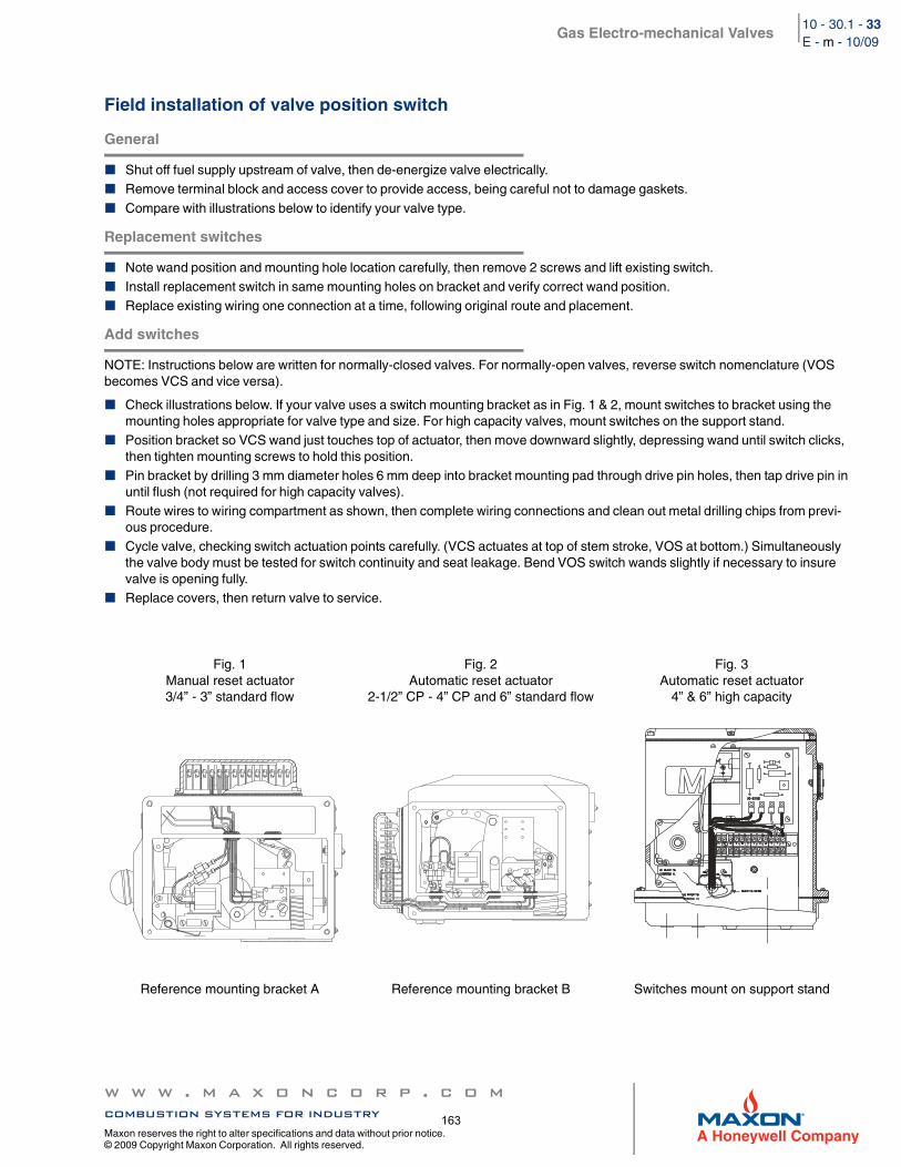
Gas Electro-mechanical Valves
w w w . m a x o n c o r p . c o mcombustion systems for industry
Maxon reserves the right to alter specifications and data without prior notice. © 2009 Copyright Maxon Corporation. All rights reserved.
10 - 30.1 - 33E - m - 10/09
Field installation of valve position switch
General
Shut off fuel supply upstream of valve, then de-energize valve electrically.Remove terminal block and access cover to provide access, being careful not to damage gaskets.
Compare with illustrations below to identify your valve type.
Replacement switches
Note wand position and mounting hole location carefully, then remove 2 screws and lift existing switch. Install replacement switch in same mounting holes on bracket and verify correct wand position.Replace existing wiring one connection at a time, following original route and placement.
Add switches
NOTE: Instructions below are written for normally-closed valves. For normally-open valves, reverse switch nomenclature (VOS becomes VCS and vice versa).
Check illustrations below. If your valve uses a switch mounting bracket as in Fig. 1 & 2, mount switches to bracket using the mounting holes appropriate for valve type and size. For high capacity valves, mount switches on the support stand.Position bracket so VCS wand just touches top of actuator, then move downward slightly, depressing wand until switch clicks, then tighten mounting screws to hold this position.Pin bracket by drilling 3 mm diameter holes 6 mm deep into bracket mounting pad through drive pin holes, then tap drive pin in until flush (not required for high capacity valves).Route wires to wiring compartment as shown, then complete wiring connections and clean out metal drilling chips from previ-ous procedure.Cycle valve, checking switch actuation points carefully. (VCS actuates at top of stem stroke, VOS at bottom.) Simultaneously the valve body must be tested for switch continuity and seat leakage. Bend VOS switch wands slightly if necessary to insure valve is opening fully.Replace covers, then return valve to service.
Fig. 1Manual reset actuator3/4” - 3” standard flow
Fig. 2Automatic reset actuator
2-1/2” CP - 4” CP and 6” standard flow
Fig. 3Automatic reset actuator
4” & 6” high capacity
Reference mounting bracket A Reference mounting bracket B Switches mount on support stand
NCCOM#1 BLACK TO
#3 BLACK TO
BLACK TO MOTOR
TERMINAL #1
TERMINAL #3
NO
12
12 11 10 9 8 7 6 5 4 3 2 1
TO CLUTCH
163
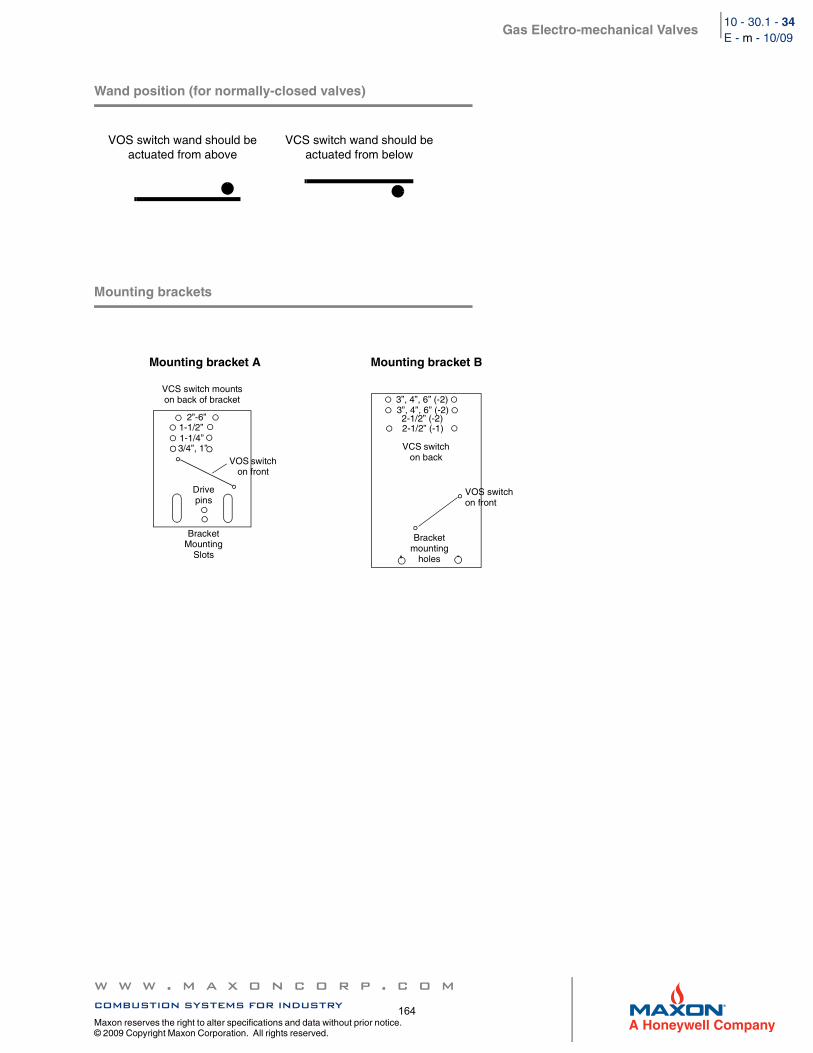
Gas Electro-mechanical Valves
w w w . m a x o n c o r p . c o mcombustion systems for industry
Maxon reserves the right to alter specifications and data without prior notice. © 2009 Copyright Maxon Corporation. All rights reserved.
10 - 30.1 - 34E - m - 10/09
Wand position (for normally-closed valves)
Mounting brackets
VOS switch wand should be actuated from above
VCS switch wand should be actuated from below
Mounting bracket A Mounting bracket B
VCS switch mountson back of bracket
BracketMounting
Slots
2”-6”1-1/2”1-1/4”3/4”, 1”
Drive pins
VOS switch on front
3”, 4”, 6” (-2)3”, 4”, 6” (-2)2-1/2” (-2)2-1/2” (-1)
VCS switch on back
Bracket mounting
holes
VOS switchon front
164
Gas Electro-mechanical Valves
w w w . m a x o n c o r p . c o mcombustion systems for industry
Maxon reserves the right to alter specifications and data without prior notice. © 2009 Copyright Maxon Corporation. All rights reserved.
10 - 30.1 - 37E - m - 10/09
Maintenance instructions
MAXON electro-mechanical valves are endurance tested far in excess of the most stringent requirements of the various approval agencies. They are designed for long life even if frequently cycled, and to be as maintenance-free and trouble-free as possible. A valve operational test should be performed on an annual basis. If abnormal opening or closing is observed, the valve should be removed from service and your MAXON representative should be contacted. (See MAXON Technical Document 10-35.1.)
Valve leak test should be performed on an annual basis to assure continued safe and reliable operation. Every MAXON valve is operationally tested and meets the requirements of FCI 70-2 Class VI Seat Leakage when in good operable condition. Zero leakage may not be obtained in the field after it has been in service. For specific recommendations on leak test procedures, see MAXON Technical Document 10-35.2. Any valve that exceeds the allowable leakage, as set forth by your local codes or insurance requirements should be removed from service and your MAXON representative should be contacted.
Actuator assembly components require no field lubrication and should never be oiled.
Auxiliary switches, solenoids, motors, clutches or circuit boards may be replaced in the field.
If foreign material or corrosive substances are present in the fuel line, it will be necessary to inspect the valve to make certain it is operating properly. If abnormal opening or closing is observed, the valve should be removed from service. Contact your MAXON representative for instructions.
Operator should be aware of and observe characteristic opening/closing action of the valve. Should operation ever become sluggish, remove valve from service and contact MAXON for recommendations.
Address inquiries to MAXON. Local worldwide offices may be located at www.maxoncorp.com. Include valve serial number and nameplate information.
Do not attempt field repair of valve body or actuator. Any alterations void all warranties and can create potentially hazardous situations.
165

166
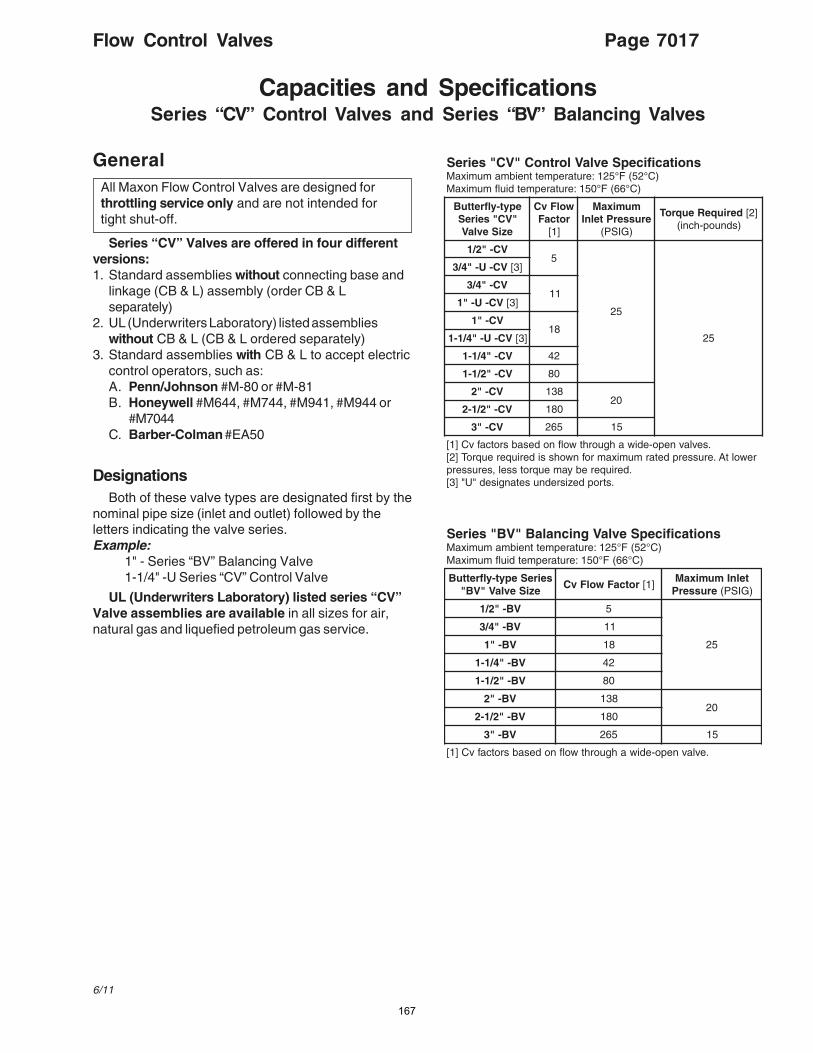
Flow Control Valves Page 7017
6/11
Capacities and SpecificationsSeries “CV” Control Valves and Series “BV” Balancing Valves
GeneralAll Maxon Flow Control Valves are designed forthrottling service only and are not intended fortight shut-off.
Series “CV” Valves are offered in four differentversions:1. Standard assemblies without connecting base and
linkage (CB & L) assembly (order CB & Lseparately)
2. UL (Underwriters Laboratory) listed assemblieswithout CB & L (CB & L ordered separately)
3. Standard assemblies with CB & L to accept electriccontrol operators, such as:A. Penn/Johnson #M-80 or #M-81B. Honeywell #M644, #M744, #M941, #M944 or
#M7044C. Barber-Colman #EA50
DesignationsBoth of these valve types are designated first by the
nominal pipe size (inlet and outlet) followed by theletters indicating the valve series.Example:
1" - Series “BV” Balancing Valve1-1/4" -U Series “CV” Control Valve
UL (Underwriters Laboratory) listed series “CV”Valve assemblies are available in all sizes for air,natural gas and liquefied petroleum gas service.
snoitacificepSevlaVlortnoC"VC"seireS)C°25(F°521:erutarepmettneibmamumixaM
)C°66(F°051:erutarepmetdiulfmumixaM
epyt-ylfrettuB"VC"seireS
eziSevlaV
wolFvCrotcaF
]1[
mumixaMerusserPtelnI
)GISP(
deriuqeReuqroT ]2[)sdnuop-hcni(
VC-"2/15
52
52
VC-U-"4/3 ]3[
VC-"4/311
VC-U-"1 ]3[
VC-"181
VC-U-"4/1-1 ]3[
VC-"4/1-1 24
VC-"2/1-1 08
VC-"2 83102
VC-"2/1-2 081
VC-"3 562 51
.sevlavnepo-ediwahguorhtwolfnodesabsrotcafvC]1[rewoltA.erusserpdetarmumixamrofnwohssideriuqereuqroT]2[
.deriuqerebyameuqrotssel,serusserp.stropdezisrednusetangised"U"]3[
snoitacificepSevlaVgnicnalaB"VB"seireS)C°25(F°521:erutarepmettneibmamumixaM
)C°66(F°051:erutarepmetdiulfmumixaM
seireSepyt-ylfrettuBeziSevlaV"VB"
rotcaFwolFvC ]1[telnImumixaM
erusserP )GISP(
VB-"2/1 5
52
VB-"4/3 11
VB-"1 81
VB-"4/1-1 24
VB-"2/1-1 08
VB-"2 83102
VB-"2/1-2 081
VB-"3 562 51
.evlavnepo-ediwahguorhtwolfnodesabsrotcafvC]1[
167
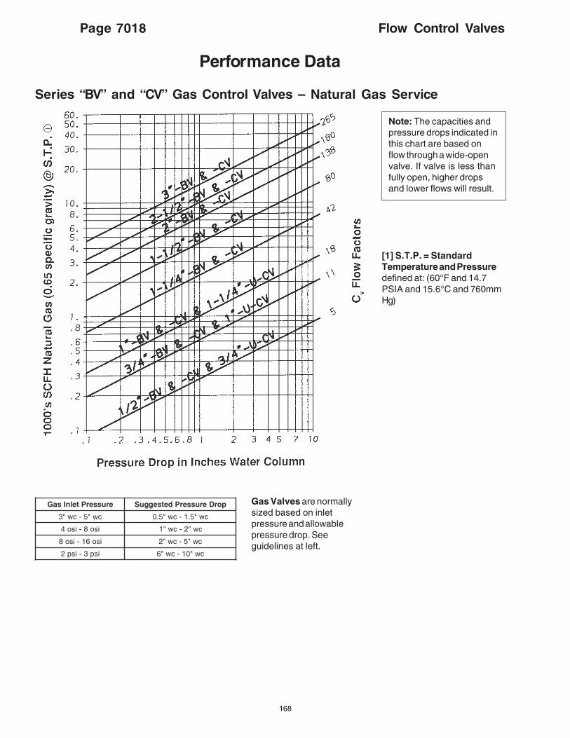
Page 7018 Flow Control Valves
Performance Data
Series “BV” and “CV” Gas Control Valves – Natural Gas Service
Note: The capacities andpressure drops indicated inthis chart are based onflow through a wide-openvalve. If valve is less thanfully open, higher dropsand lower flows will result.
[1] S.T.P. = StandardTemperature and Pressuredefined at: (60°F and 14.7PSIA and 15.6°C and 760mmHg)
Gas Valves are normallysized based on inletpressure and allowablepressure drop. Seeguidelines at left.
erusserPtelnIsaG porDerusserPdetsegguS
cw"5-cw"3 cw"5.1-cw"5.0
iso8-iso4 cw"2-cw"1
iso61-iso8 cw"5-cw"2
isp3-isp2 cw"01-cw"6
168
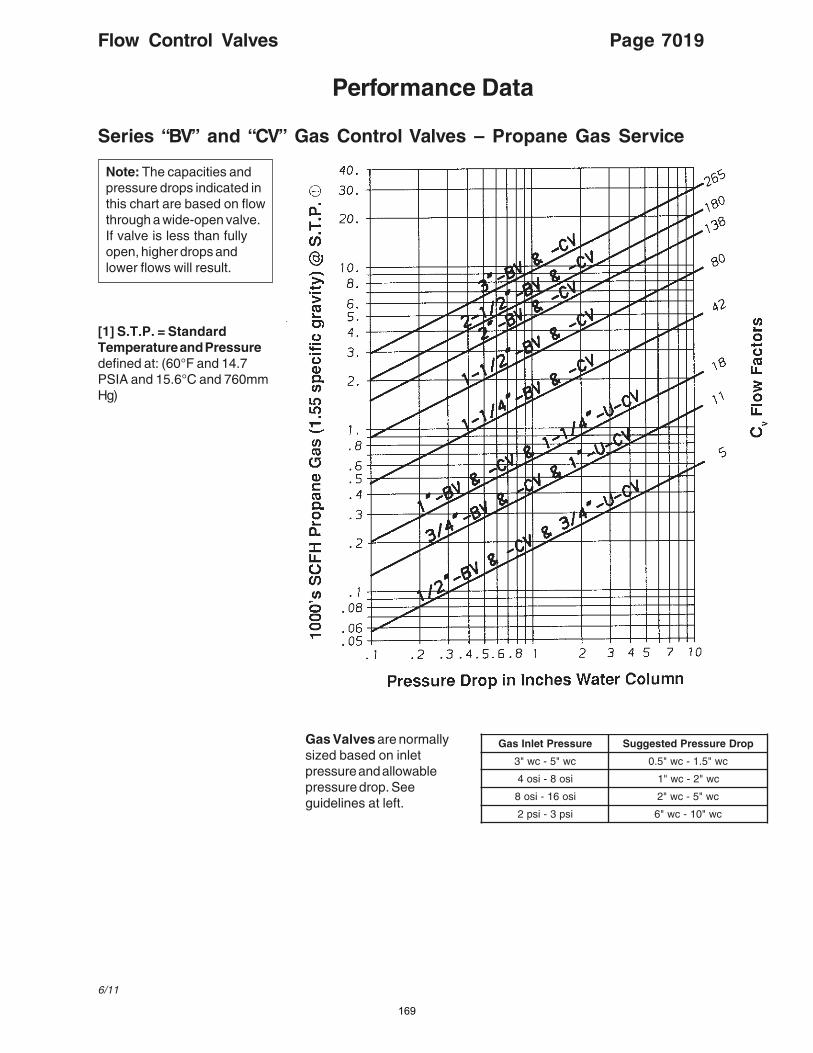
Flow Control Valves Page 7019
6/11
Series “BV” and “CV” Gas Control Valves – Propane Gas Service
Performance Data
Note: The capacities andpressure drops indicated inthis chart are based on flowthrough a wide-open valve.If valve is less than fullyopen, higher drops andlower flows will result.
[1] S.T.P. = StandardTemperature and Pressuredefined at: (60°F and 14.7PSIA and 15.6°C and 760mmHg)
Gas Valves are normallysized based on inletpressure and allowablepressure drop. Seeguidelines at left.
erusserPtelnIsaG porDerusserPdetsegguS
cw"5-cw"3 cw"5.1-cw"5.0
iso8-iso4 cw"2-cw"1
iso61-iso8 cw"5-cw"2
isp3-isp2 cw"01-cw"6
169
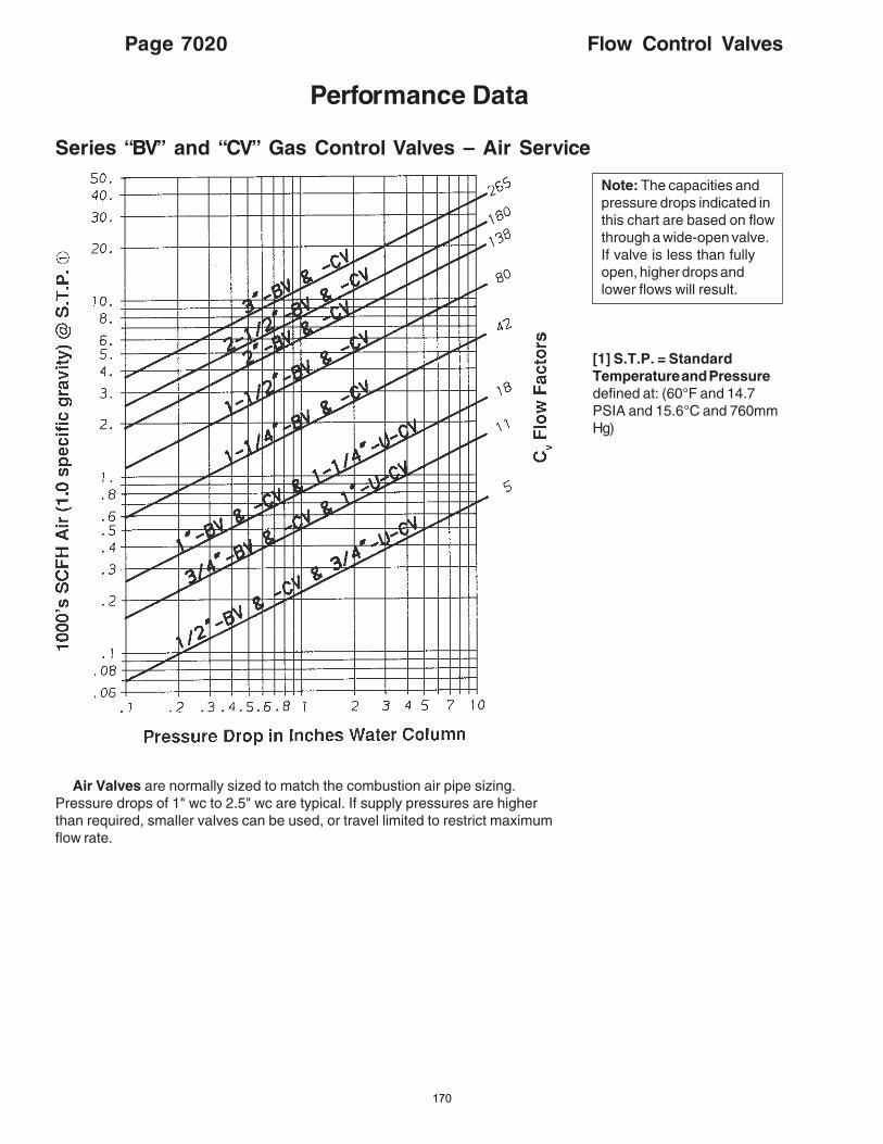
Page 7020 Flow Control Valves
Performance Data
Series “BV” and “CV” Gas Control Valves – Air Service
Note: The capacities andpressure drops indicated inthis chart are based on flowthrough a wide-open valve.If valve is less than fullyopen, higher drops andlower flows will result.
[1] S.T.P. = StandardTemperature and Pressuredefined at: (60°F and 14.7PSIA and 15.6°C and 760mmHg)
Air Valves are normally sized to match the combustion air pipe sizing.Pressure drops of 1" wc to 2.5" wc are typical. If supply pressures are higherthan required, smaller valves can be used, or travel limited to restrict maximumflow rate.
170
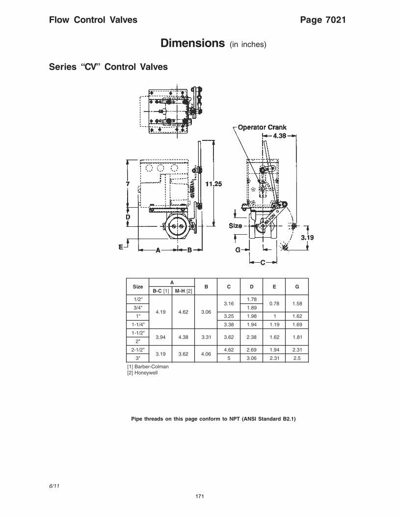
Flow Control Valves Page 7021
6/11
Dimensions (in inches)
Series “CV” Control Valves
Pipe threads on this page conform to NPT (ANSI Standard B2.1)
eziSA
B C D E GC-B ]1[ H-M ]2[
"2/1
91.4 26.4 60.3
61.387.1
87.0 85.1"4/3 98.1
"1 52.3 89.1 1 26.1
"4/1-1 83.3 49.1 91.1 96.1
"2/1-149.3 83.4 13.3 26.3 83.2 26.1 18.1
"2
"2/1-291.3 26.3 60.4
26.4 96.2 49.1 13.2
"3 5 60.3 13.2 5.2
namloC-rebraB]1[llewyenoH]2[
171
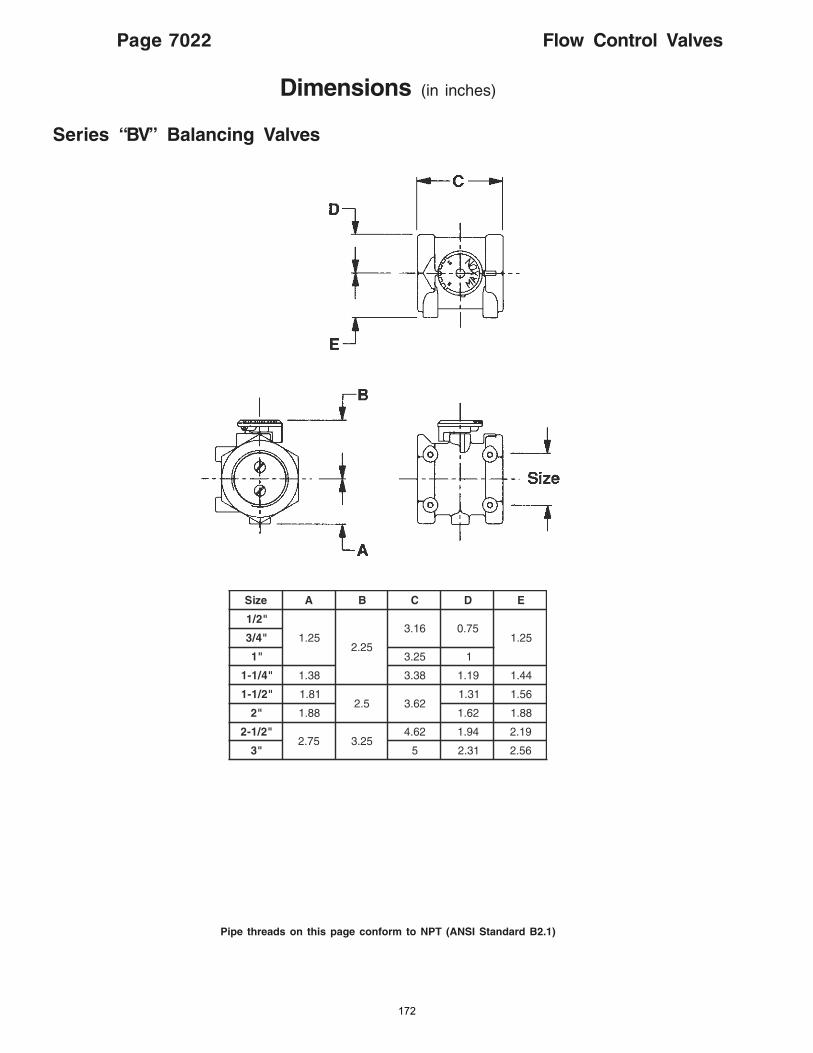
Page 7022 Flow Control Valves
Pipe threads on this page conform to NPT (ANSI Standard B2.1)
Series “BV” Balancing Valves
Dimensions (in inches)
eziS A B C D E
"2/1
52.152.2
61.3 57.052.1"4/3
"1 52.3 1
"4/1-1 83.1 83.3 91.1 44.1
"2/1-1 18.15.2 26.3
13.1 65.1
"2 88.1 26.1 88.1
"2/1-257.2 52.3
26.4 49.1 91.2
"3 5 13.2 65.2
172
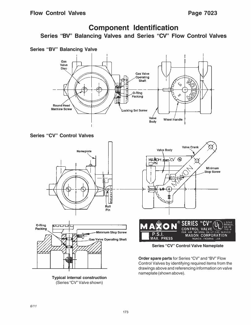
Flow Control Valves Page 7023
6/11
Component IdentificationSeries “BV” Balancing Valves and Series “CV” Flow Control Valves
Series “BV” Balancing Valve
Series “CV” Control Valves
Typical internal construction(Series “CV” Valve shown)
Series “CV” Control Valve Nameplate
Order spare parts for Series “CV” and “BV” FlowControl Valves by identifying required items from thedrawings above and referencing information on valvenameplate (shown above).
173

INDUSTRIAL COMBUSTION EQUIPMENT AND VALVES
Maxon practices a policy of continuous product improvement. It reserves the right to alter specifications without prior notice.
Flow Control Valves Page 7000-S-1
6/11
lessens the chance of internal flow turbulence beingset-up in the piping manifolds and control valve.
– Check fluid flow direction through “-P” and “-O”poppet-type valves. It must flow only in directionmatching the arrow cast into valve body. If neces-sary, valve body may be rotated per instructionsgiven on page 7016.
– Install flow control valves carefully and maintainadequate dimensional clearance to allow fullstroke and travel of the valve’s control linkage.Internal drive mechanisms within a control motormay be damaged if linkage is restricted as to causebinding in high or low flow position.
CAUTION: All Flow Control Valves are designedfor throttling service only and are not intendedfor tight shut-off.
– Main system shut-off should always use amanual “leak-tight” upstream fuel cock.
– Support weight of piping independently. Do notplace any Maxon Flow Control Valve in a pipingbind. Provide pipe hangers and/or special supportfor related manifolds.
– Maxon connecting base and linkage assembliesare designed to locate and/or position thecontrol operator for its interaction with the FlowControl Valve assembly. They are not intended tosupport the weight of the control motor. Specialprovisions will be required to support the weight ofthe control operators.
– Use of pipe heavier than schedule #40 cancause interference with butterfly-type Flow ControlValves and restrict the valve from full opening.
– Flow Control Valves provide the means toadjust fluid and/or gas flows. They should beinstalled with at least four pipe diameter lengths ofstraight pipe before and after the valve. This
Mounting Instructions for motor operator on Series “CV” Flow Control Valves
For those Series “CV” Valve assemblies furnished withconnecting base and linkage, the accompanying diagramsillustrate mounting procedures relative to each specific typeoperator.
First, mount your control motor to connecting base inaccordance with diagrams at right.
Secondly, determine if your electric operator travelsthrough 90° or 180° rotations. Then arrange connectinglinkage and motor crank arm as shown below for yourspecific operator.
90° Control Motor 160° – 180° Control Motor
Honeywell#M644, M744,M941 or M944
(7616BR Crank)
Mount with four short boltsand nuts at indicated holes.
Barber-ColmanEA50
Mount with three short boltsand nuts at indicated holes.
Penn/JohnsonM80, M81
(MD3-600 Crank)
Mount with two short boltsand nuts and long boltscrewed into operator basethrough slotted hole.
Installation Instructions
Crank & Linkage Side
Crank & Linkage Side
Crank & Linkage Side
174
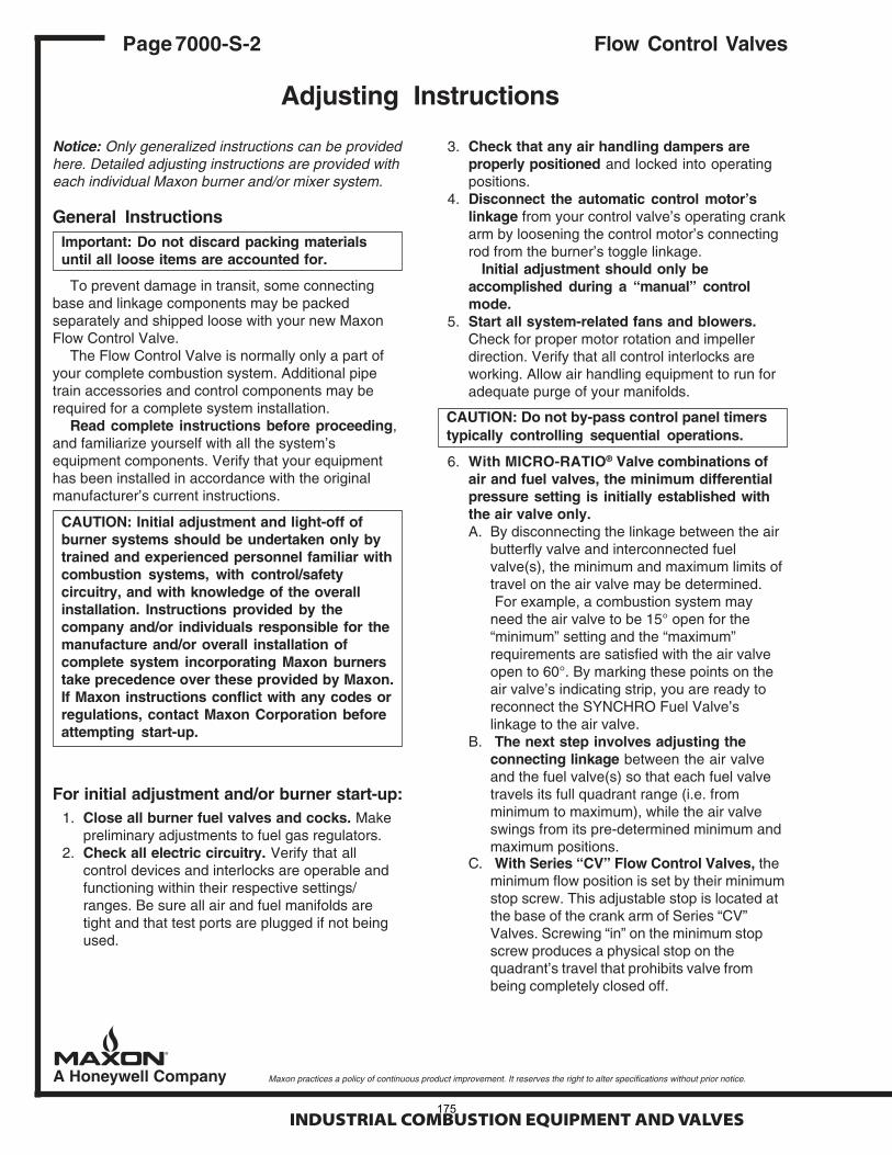
INDUSTRIAL COMBUSTION EQUIPMENT AND VALVES
Maxon practices a policy of continuous product improvement. It reserves the right to alter specifications without prior notice.
Page 7000-S-2 Flow Control Valves
Adjusting Instructions
Notice: Only generalized instructions can be providedhere. Detailed adjusting instructions are provided witheach individual Maxon burner and/or mixer system.
General InstructionsImportant: Do not discard packing materialsuntil all loose items are accounted for.
To prevent damage in transit, some connectingbase and linkage components may be packedseparately and shipped loose with your new MaxonFlow Control Valve.
The Flow Control Valve is normally only a part ofyour complete combustion system. Additional pipetrain accessories and control components may berequired for a complete system installation.
Read complete instructions before proceeding,and familiarize yourself with all the system’sequipment components. Verify that your equipmenthas been installed in accordance with the originalmanufacturer’s current instructions.
CAUTION: Initial adjustment and light-off ofburner systems should be undertaken only bytrained and experienced personnel familiar withcombustion systems, with control/safetycircuitry, and with knowledge of the overallinstallation. Instructions provided by thecompany and/or individuals responsible for themanufacture and/or overall installation ofcomplete system incorporating Maxon burnerstake precedence over these provided by Maxon.If Maxon instructions conflict with any codes orregulations, contact Maxon Corporation beforeattempting start-up.
For initial adjustment and/or burner start-up:1. Close all burner fuel valves and cocks. Make
preliminary adjustments to fuel gas regulators.2. Check all electric circuitry. Verify that all
control devices and interlocks are operable andfunctioning within their respective settings/ranges. Be sure all air and fuel manifolds aretight and that test ports are plugged if not beingused.
3. Check that any air handling dampers areproperly positioned and locked into operatingpositions.
4. Disconnect the automatic control motor’slinkage from your control valve’s operating crankarm by loosening the control motor’s connectingrod from the burner’s toggle linkage.
Initial adjustment should only beaccomplished during a “manual” controlmode.
5. Start all system-related fans and blowers.Check for proper motor rotation and impellerdirection. Verify that all control interlocks areworking. Allow air handling equipment to run foradequate purge of your manifolds.
CAUTION: Do not by-pass control panel timerstypically controlling sequential operations.
6. With MICRO-RATIO® Valve combinations ofair and fuel valves, the minimum differentialpressure setting is initially established withthe air valve only.A. By disconnecting the linkage between the air
butterfly valve and interconnected fuelvalve(s), the minimum and maximum limits oftravel on the air valve may be determined.For example, a combustion system may
need the air valve to be 15° open for the“minimum” setting and the “maximum”requirements are satisfied with the air valveopen to 60°. By marking these points on theair valve’s indicating strip, you are ready toreconnect the SYNCHRO Fuel Valve’slinkage to the air valve.
B. The next step involves adjusting theconnecting linkage between the air valveand the fuel valve(s) so that each fuel valvetravels its full quadrant range (i.e. fromminimum to maximum), while the air valveswings from its pre-determined minimum andmaximum positions.
C. With Series “CV” Flow Control Valves, theminimum flow position is set by their minimumstop screw. This adjustable stop is located atthe base of the crank arm of Series “CV”Valves. Screwing “in” on the minimum stopscrew produces a physical stop on thequadrant’s travel that prohibits valve frombeing completely closed off.
175

176
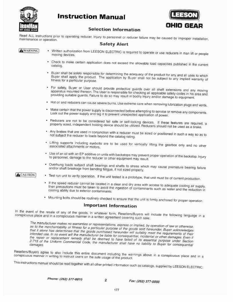
177
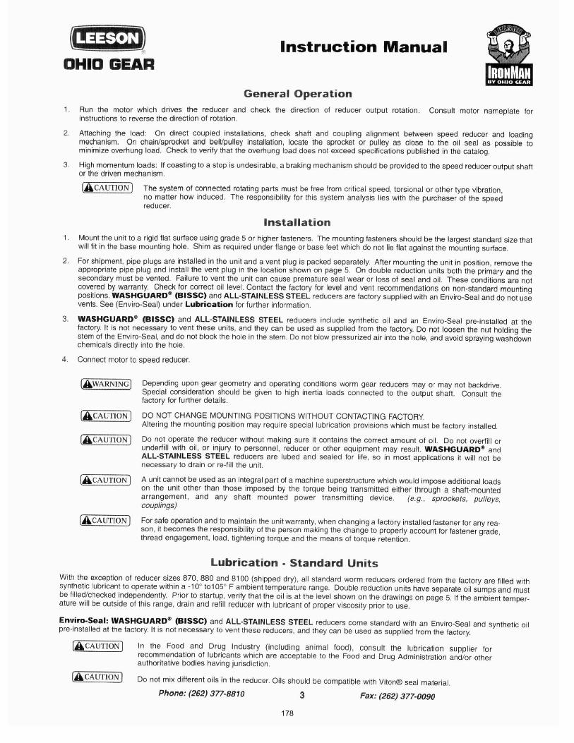
178
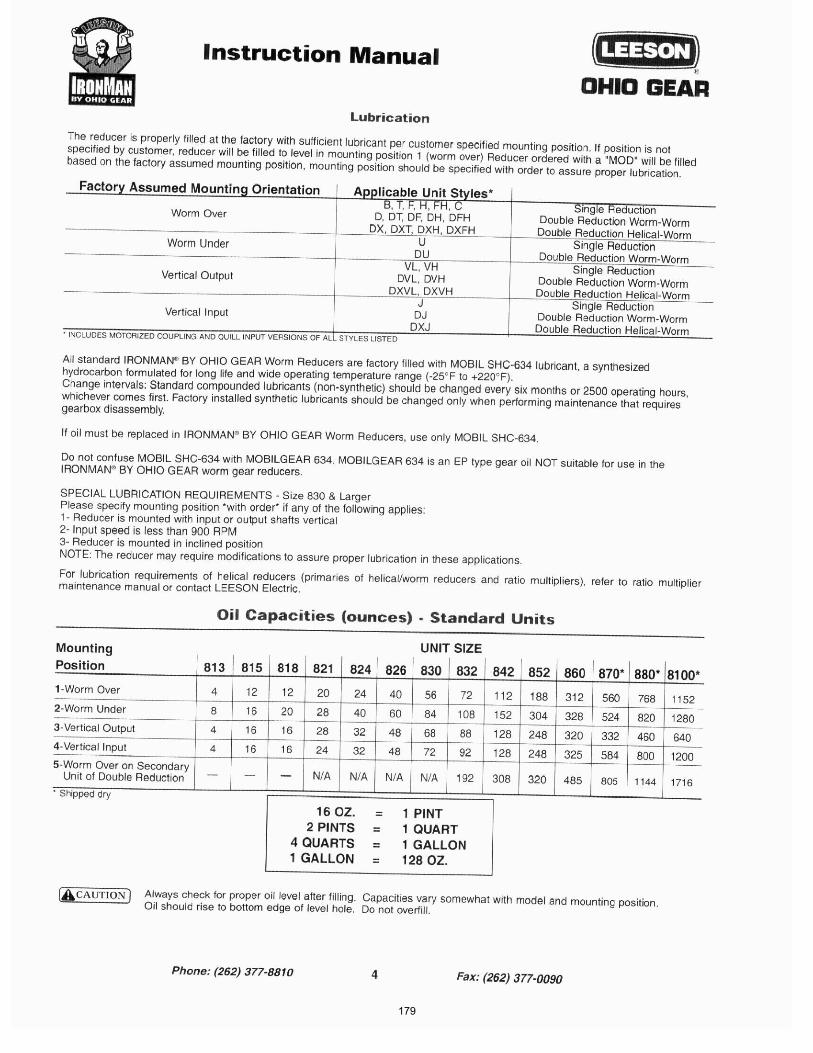
179
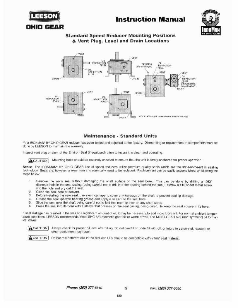
180
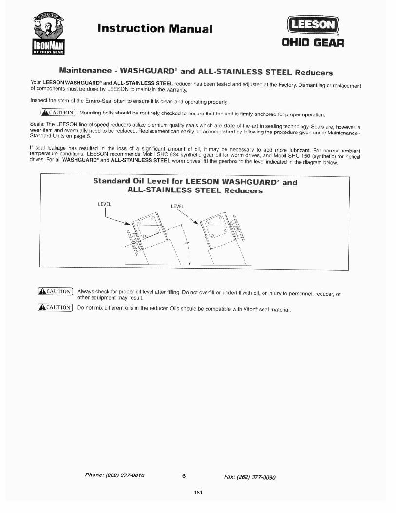
181
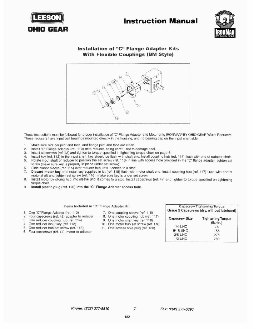
182

183
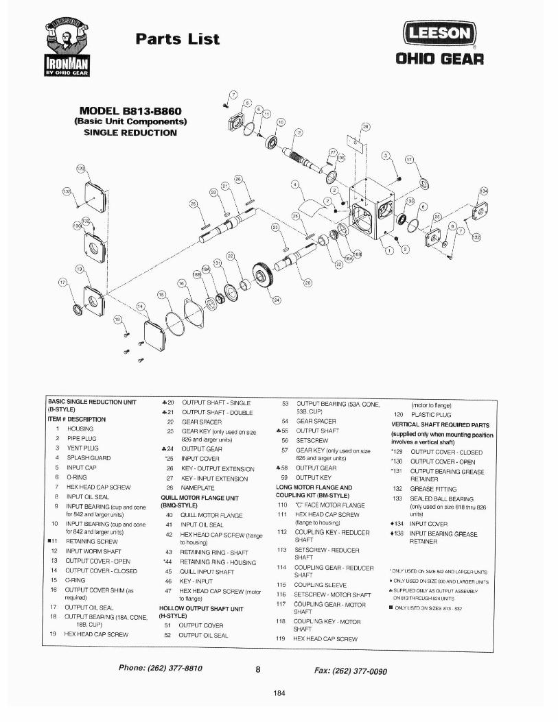
184
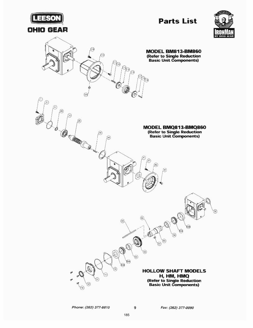
185
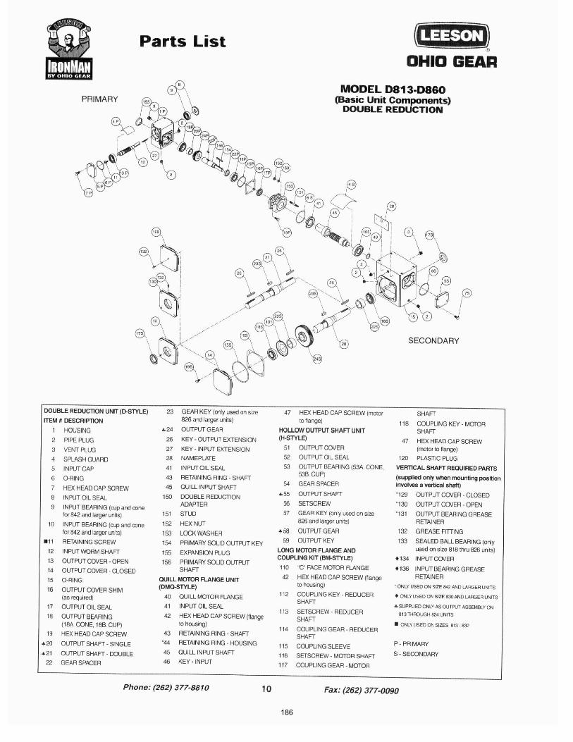
186
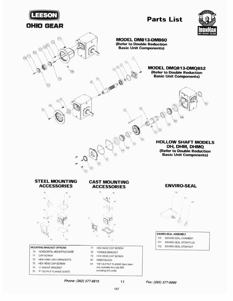
187
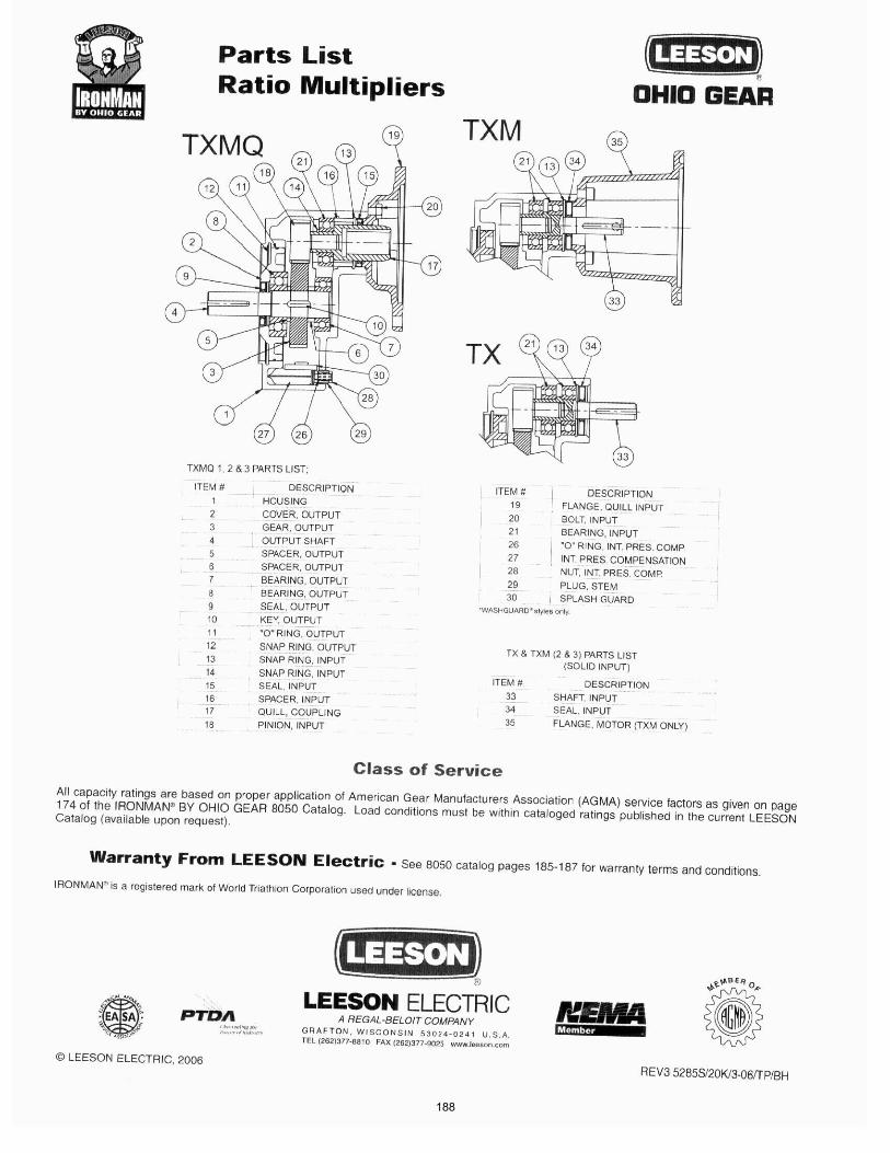
188

189

190
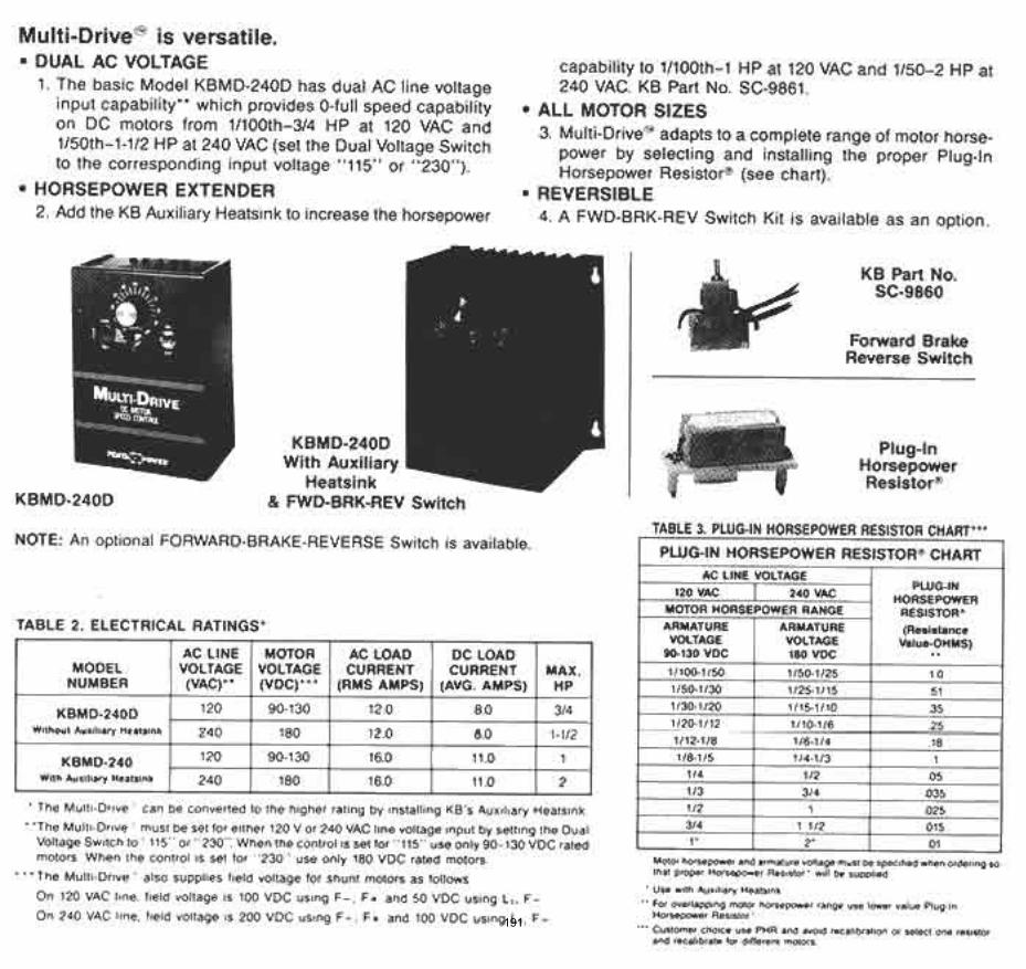
191
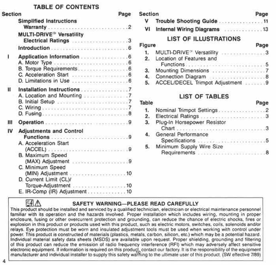
192
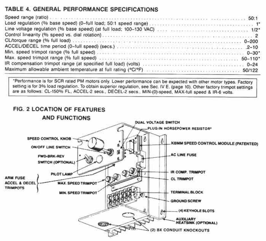
193

194
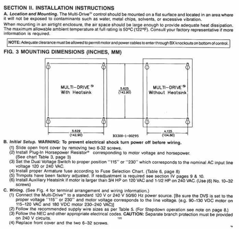
195
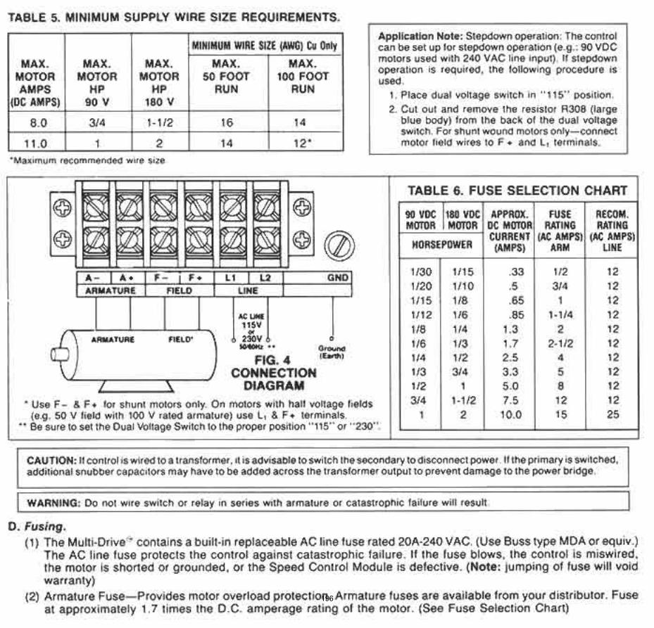
196
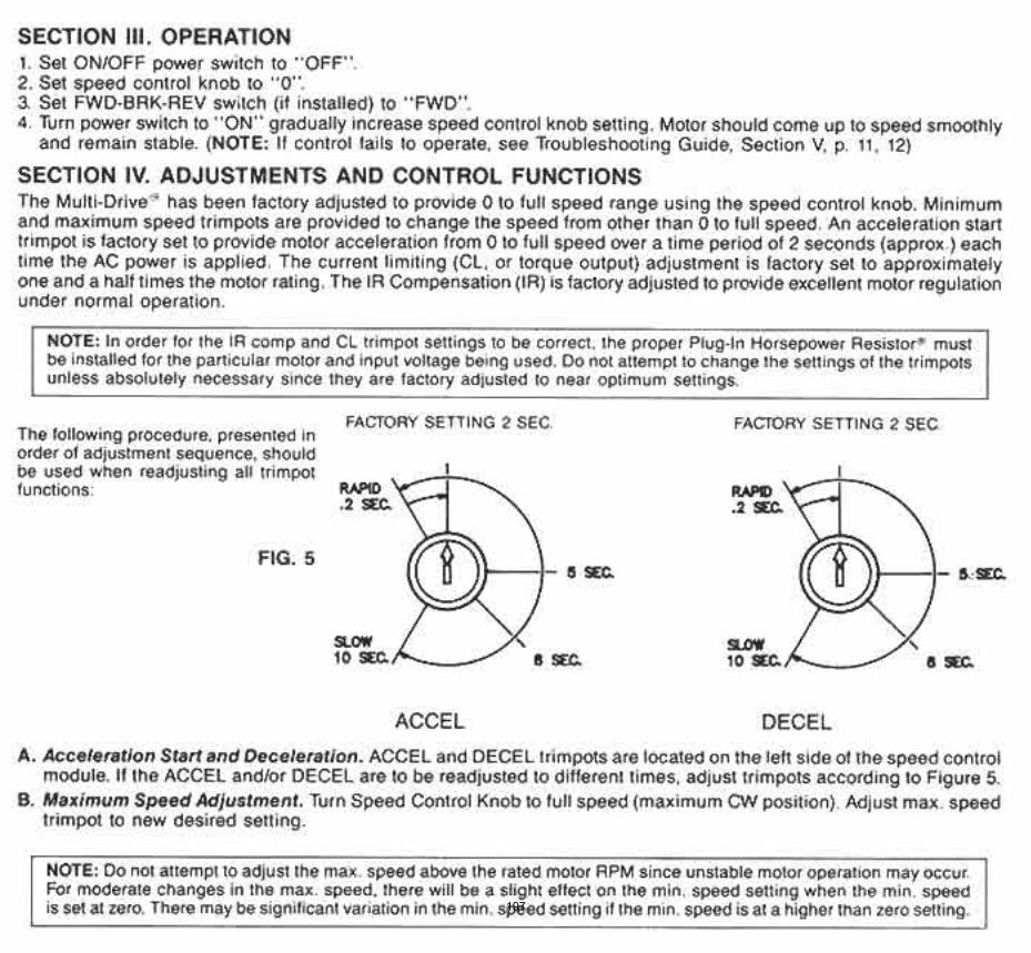
197
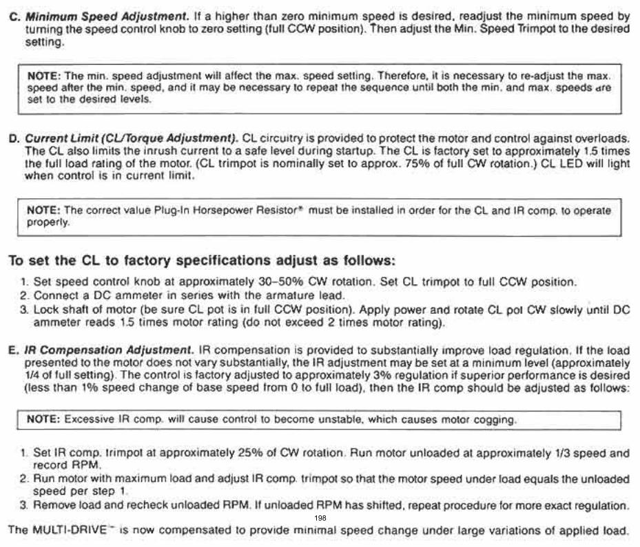
198
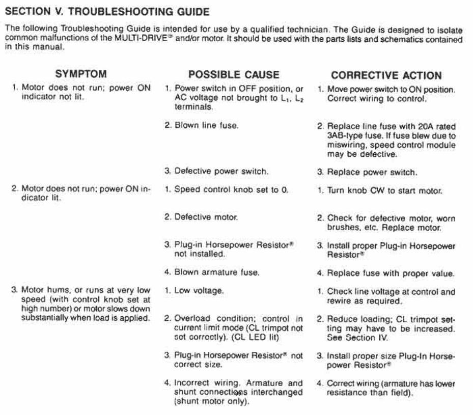
199
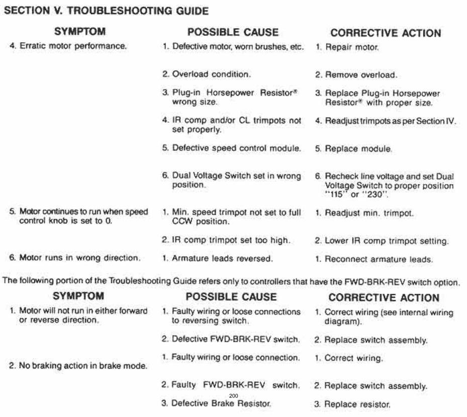
200
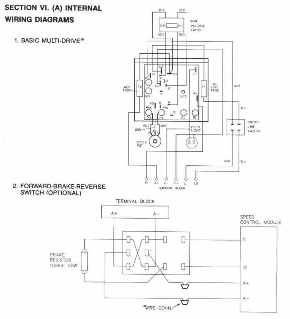
201
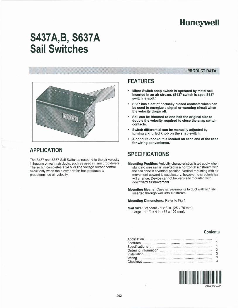
202
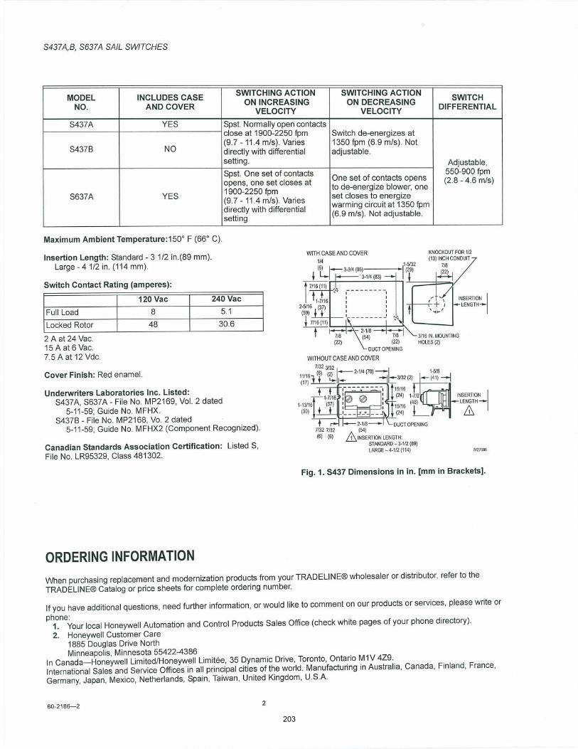
203
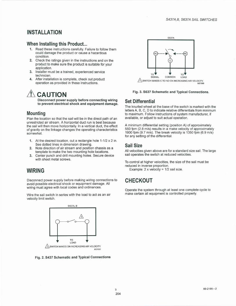
204
205

PRODUCT DATA
êíóîêìðóðè
Series 71, 72, and 76Modutrol IV Motors
APPLICATIONThe Series 71, 72 and 76 Modutrol IV Motors are spring return and non-spring return motors used to control dampers and valves. The motors accept a current or voltage signal from an electronic controller to position a damper or valve at any point between open and closed.
FEATURES Replaces M734H,J,; M744S,T,Y; and M745L,S,T,Y
Motors. M7164, M7261, M7284, and M7294 are non-spring
return motors; M7282, M7285, M7286 and M7685 are spring return motors.
Integral spring return returns motor to normal position when power is interrupted.
Integral junction box provides NEMA 3 weather protection.
Motor and circuitry operate from 24 Vac. Models available with factory installed transformer, or a field added internal transformer.
Quick-connect terminals are standardscrew terminal adapter is available.
Adapter bracket for matching shaft height of older motors is available.
Most motors have field adjustable stroke (90° to 160°). Die-cast aluminum housing. Integral auxiliary switches are available factory
mounted, or can be field added. Nominal timing standard of 30 seconds (90° stroke),
and 60 seconds (160° stroke). Other timings available. Spring return motors can operate valve linkages from
power end or auxiliary end shafts for normally closed or normally open valve applications.
All models have dual shafts (slotted and tapped on both ends).
All models have auxiliary switch cams. Fixed torque throughout the entire voltage range. Motors are designed for either normally open or
normally closed valves and dampers. Models available with adjustable start (zero) and span. Models available with 4 to 20 mA input signal. Models available with 2 to 10 Vdc input signal.
Contents
Application ........................................................................ 1Features ........................................................................... 1Specifications ................................................................... 2Ordering Information ........................................................ 2Installation ........................................................................ 5Settings and Adjustments ................................................. 8Operation and Checkout ................................................... 11
206
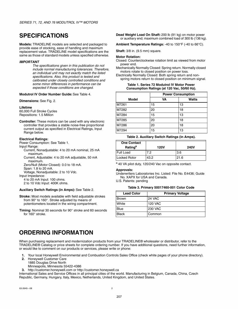
SERIES 71, 72, AND 76 MODUTROL IV MOTORS
63-264008 2
ORDERING INFORMATIONWhen purchasing replacement and modernization products from your TRADELINE® wholesaler or distributor, refer to the TRADELINE® Catalog or price sheets for complete ordering number. If you have additional questions, need further information, or would like to comment on our products or services, please write or phone:
1. Your local Honeywell Environmental and Combustion Controls Sales Office (check white pages of your phone directory).2. Honeywell Customer Care
1885 Douglas Drive NorthMinneapolis, Minnesota 55422-4386
3. http://customer.honeywell.com or http://customer.honeywell.caInternational Sales and Service Offices in all principal cities of the world. Manufacturing in Belgium, Canada, China, Czech Republic, Germany, Hungary, Italy, Mexico, Netherlands, United Kingdom, and United States.
SPECIFICATIONSModels: TRADELINE models are selected and packaged to provide ease of stocking, ease of handling and maximum replacement value. TRADELINE model specifications are the same as those of standard models unless specified otherwise.
The specifications given in this publication do not include normal manufacturing tolerances. Therefore, an individual unit may not exactly match the listed specifications. Also, this product is tested and calibrated under closely controlled conditions and some minor differences in performance can be expected if those conditions are changed.
Modutrol IV Order Number Guide: See Table 4.
Dimensions: See Fig. 2.
Lifetime60,000 Full Stroke CyclesRepositions: 1.5 Million
Controller: These motors can be used with any electronic controller that provides a stable noise-free proportional current output as specified in Electrical Ratings, Input Range below.
Electrical Ratings:Power Consumption: See Table 1.Input Range:
Current, Nonadjustable: 4 to 20 mA nominal, 25 mA maximum.
Current, Adjustable: 4 to 20 mA adjustable, 50 mA maximum.
Zero/Null (Motor Closed): 0.0 to 18 mA.Span: 1.8 to 20 mA.Voltage, Nonadjustable: 2 to 10 Vdc.
Input Impedance:4 to 20 mA Input: 100 ohms.2 to 10 Vdc Input: 400K ohms.
Auxiliary Switch Ratings (in Amps): See Table 2.
Stroke: Most models available with field adjustable strokes from 90° to 160°. Stroke adjusted by means of potentiometers located in the wiring compartment.
Timing: Nominal 30 seconds for 90° stroke and 60 seconds for 160° stroke.
Dead Weight Load On Shaft: 200 lb (91 kg) on motor power or auxiliary end; maximum combined load of 300 lb (136 kg).
Ambient Temperature Ratings: -40 to 150°F (-40 to 66°C).
Shaft: 3/8 in. (9.5 mm) square.
Motor Rotation:Closed: Counterclockwise rotation limit as viewed from motor
power end.Mechanically Normally Closed: Spring return. Normally closed
motors rotate to closed position on power loss.Electrically Normally Closed: Both spring return and non-
spring motors return to closed position on minimum signal.
Table 1. Series 72 Modutrol IV Motor Power Consumption Ratings (at 120 Vac, 50/60 Hz).
Table 2. Auxiliary Switch Ratings (in Amps).
a 40 VA pilot duty, 120/240 Vac on opposite contact.
Approvals:Underwriters Laboratories Inc. Listed: File No. E4436; Guide
No. XAPX for USA and Canada.U.S. Patents: pending
Table 3. Primary 50017460-001 Color Code
Model
Power Consumption
VA Watts
M7261 15 13
M7282 20 18
M7284 15 13
M7285 20 18
M7286 20 18
M7294 15 13
One Contact Ratinga 120V 240V
Full Load 7.2 3.6
Locked Rotor 43.2 21.6
Lead Color Primary Voltage
Brown 24 VAC
White 120 VAC
Blue 230 VAC
Black Common
207
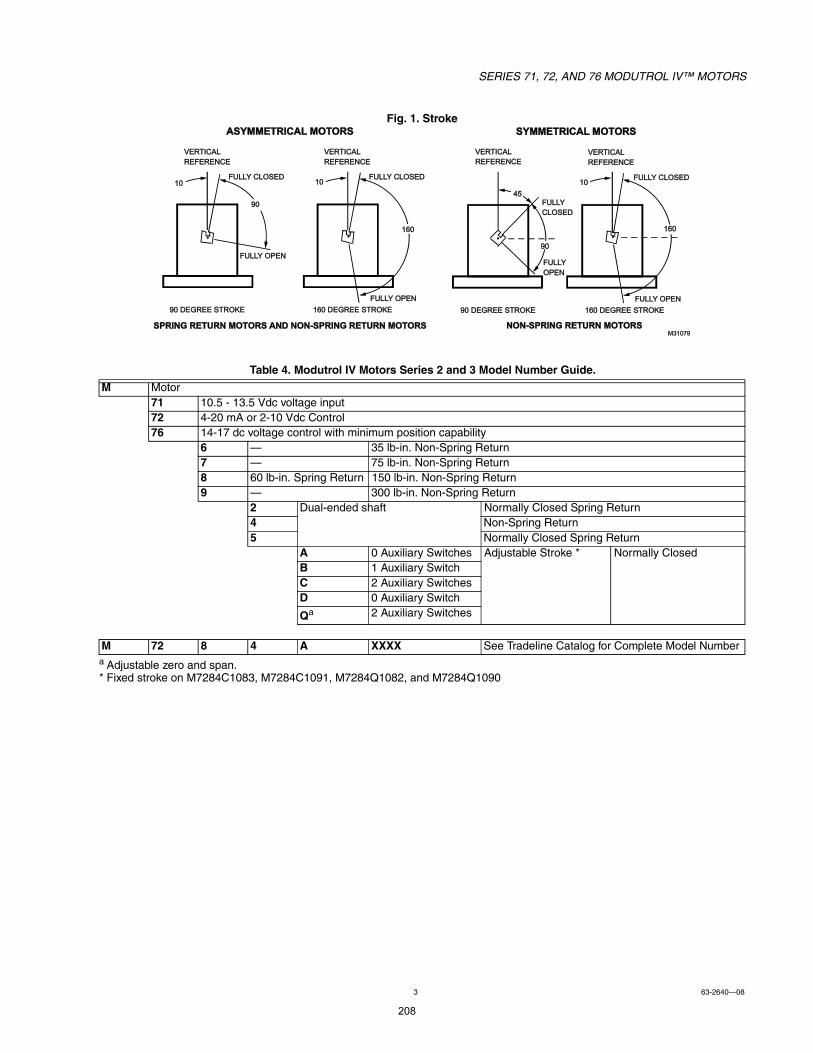
SERIES 71, 72, AND 76 MODUTROL IV MOTORS
3 63-264008
Fig. 1. Stroke
Table 4. Modutrol IV Motors Series 2 and 3 Model Number Guide.
a Adjustable zero and span.* Fixed stroke on M7284C1083, M7284C1091, M7284Q1082, and M7284Q1090
M Motor71 10.5 - 13.5 Vdc voltage input72 4-20 mA or 2-10 Vdc Control76 14-17 dc voltage control with minimum position capability
6 35 lb-in. Non-Spring Return7 75 lb-in. Non-Spring Return8 60 lb-in. Spring Return 150 lb-in. Non-Spring Return9 300 lb-in. Non-Spring Return
2 Dual-ended shaft Normally Closed Spring Return4 Non-Spring Return5 Normally Closed Spring Return
A 0 Auxiliary Switches Adjustable Stroke * Normally ClosedB 1 Auxiliary SwitchC 2 Auxiliary SwitchesD 0 Auxiliary Switch
Qa 2 Auxiliary Switches
M 72 8 4 A XXXX See Tradeline Catalog for Complete Model Number
ÚËÔÔÇ ÑÐÛÒ
çð ÜÛÙÎÛÛ ÍÌÎÑÕÛ ïêð ÜÛÙÎÛÛ ÍÌÎÑÕÛ
Óíïðéç
ÊÛÎÌ×ÝßÔ
ÎÛÚÛÎÛÒÝÛ
ÚËÔÔÇ ÝÔÑÍÛÜ
ïêð
ïð
ÊÛÎÌ×ÝßÔ
ÎÛÚÛÎÛÒÝÛ
ÚËÔÔÇ ÝÔÑÍÛÜ
çð
ïð
ÚËÔÔÇ ÑÐÛÒ
ÊÛÎÌ×ÝßÔ
ÎÛÚÛÎÛÒÝÛ
ÊÛÎÌ×ÝßÔ
ÎÛÚÛÎÛÒÝÛ
ÚËÔÔÇ ÝÔÑÍÛÜ
ÚËÔÔÇ ÑÐÛÒ
ÚËÔÔÇ
ÝÔÑÍÛÜ
ÚËÔÔÇ
ÑÐÛÒ
çð ÜÛÙÎÛÛ ÍÌÎÑÕÛ ïêð ÜÛÙÎÛÛ ÍÌÎÑÕÛ
ÒÑÒóÍÐÎ×ÒÙ ÎÛÌËÎÒ ÓÑÌÑÎÍ
ïêð
ïð
çð
ìë
ÍÐÎ×ÒÙ ÎÛÌËÎÒ ÓÑÌÑÎÍ ßÒÜ ÒÑÒóÍÐÎ×ÒÙ ÎÛÌËÎÒ ÓÑÌÑÎÍ
ßÍÇÓÓÛÌÎ×ÝßÔ ÓÑÌÑÎÍ ÍÇÓÓÛÌÎ×ÝßÔ ÓÑÌÑÎÍ
208
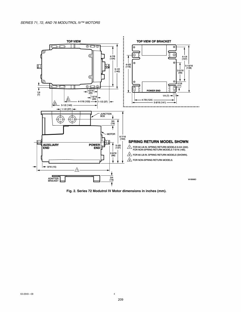
SERIES 71, 72, AND 76 MODUTROL IV MOTORS
63-264008 4
Fig. 2. Series 72 Modutrol IV Motor dimensions in inches (mm).
ÓïèççèÜ
ìóéñèøïîì÷
ëóïñîøïìð÷
ïíñïêøîð÷
ìóïñïê øïðí÷
ïñìøé÷
ïóïñî øíé÷
ëóïñî øïìð÷
ÖËÒÝÌ×ÑÒÞÑÈ
ÓÑÌÑÎ
ßËÈ×Ô×ßÎÇ
ÛÒÜ
ÐÑÉÛÎ
ÛÒÜ
ßÜßÐÌÛÎÞÎßÝÕÛÌ
îóçñïêøêê÷
ëóíñèøïíé÷
êóéñïêøïêì÷
çñïê øïë÷
íñìøïç÷
ÌÑÐ Ê×ÛÉ ÑÚ ÞÎßÝÕÛÌ ÌÑÐ Ê×ÛÉ
ìóëñèøïïê÷
ìóïñìøïðé÷
îóëñïêøëè÷
ïïñïêøïé÷
ìóéñè øïîì÷ëóçñïê øïìï÷
ïñì øé÷
ëóïíñïêøïìè÷
ï
ÐÑÉÛÎ ÛÒÜ
î
í
ïóïñî øíé÷
íñìøïç÷
ÍÐÎ×ÒÙ ÎÛÌËÎÒ ÓÑÜÛÔ ÍØÑÉÒ
ÚÑÎ êð ÔÞó×Òò ÍÐÎ×ÒÙ ÎÛÌËÎÒ ÓÑÜÛÔÍ èóíñì øîîî÷ò ÚÑÎ ÒÑÒóÍÐÎ×ÒÙ ÎÛÌËÎÒ ÓÑÜÛÔÍ éóëñïê øïèë÷ò
ÚÑÎ êð ÔÞó×Òò ÍÐÎ×ÒÙ ÎÛÌËÎÒ ÓÑÜÛÔÍ øÍØÑÉÒ÷ò
ÚÑÎ ÒÑÒóÍÐÎ×ÒÙ ÎÛÌËÎÒ ÓÑÜÛÔÍò
ï
î
í
ïíñïêøîð÷
209
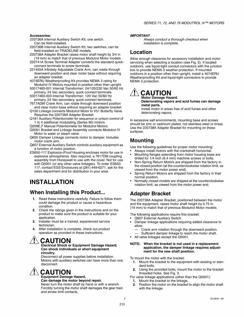
SERIES 71, 72, AND 76 MODUTROL IV MOTORS
5 63-264008
Accessories:220736A Internal Auxiliary Switch Kit; one switch.
Can be field-installed.220736B Internal Auxiliary Switch Kit; two switches, can be
field-installed on TRADELINE models.220738A Adapter Bracket raises motor shaft height by 3/4 in
(19 mm) to match that of previous Modutrol Motor models.220741A Screw Terminal Adapter converts the standard quick-
connect terminals to screw terminals.221455A Infinitely Adjustable Crank Arm, can rotate through
downward position and clear motor base without requiring an adapter bracket.
4074ERU Weatherproofing Kit provides NEMA 3 rating for Modutrol IV Motors mounted in position other than upright.
50017460-001 Internal Transformer; 24/120/230 Vac 50/60 Hz primary, 24 Vac secondary, quick connect terminals.
50017460-003 Internal Transformer; 120 Vac 50/60 Hz primary, 24 Vac secondary, quick connect terminals.
7617ADW Crank Arm, can rotate through downward position and clear motor base without requiring an adapter bracket.
Q100 Linkage connects Modutrol Motor to V51 Butterfly Valve. Requires the 220738A Adapter Bracket.
Q181 Auxiliary Potentiometer for sequence or unison control of 1 to 4 additional modulating (Series 90) motors.
Q209E,F Manual Potentiometer for Modutrol MotorsQ5001 Bracket and Linkage Assembly connects Modutrol IV
Motor to water or steam valve.Q605 Damper Linkage connects motor to damper. Includes
motor crank arm.Q607 External Auxiliary Switch controls auxiliary equipment as
a function of motor position.ES650-117 Explosion-Proof Housing encloses motor for use in
explosive atmospheres. Also required, a 7617DM coupling assembly from Honeywell to use with the cover. Not for use with Q5001 (or any other valve linkages). To order ES650-117, contact EGS Enclosures at (281) 449-6271, ask for the sales department and for distribution in your area.
INSTALLATION
When Installing this Product...1. Read these instructions carefully. Failure to follow them
could damage the product or cause a hazardous condition.
2. Check the ratings given in the instructions and on the product to make sure the product is suitable for your application.
3. Installer must be a trained, experienced service technician.
4. After installation is complete, check out product operation as provided in these instructions.
CAUTIONElectrical Shock or Equipment Damage Hazard.Can shock individuals or short equipment circuitry.Disconnect all power supplies before installation.Motors with auxiliary switches can have more than one disconnect.
CAUTIONEquipment Damage Hazard.Can damage the motor beyond repair.Never turn the motor shaft by hand or with a wrench.Forcibly turning the motor shaft damages the gear train and stroke limit contacts.
Always conduct a thorough checkout when installation is complete.
LocationAllow enough clearance for accessory installation and motor servicing when selecting a location (see Fig. 2). If located outdoors, use liquid-tight conduit connectors with the junction box to provide NEMA 3 weather protection. If mounted outdoors in a position other than upright, install a 4074ERU Weatherproofing Kit and liquid-tight connectors to provide NEMA 3 protection.
CAUTIONMotor Damage Hazard.Deteriorating vapors and acid fumes can damage metal parts.Install motor in areas free of acid fumes and other deteriorating vapors.
In excessive salt environments, mounting base and screws should be zinc or cadmium plated, not stainless steel or brass. Use the 220738A Adapter Bracket for mounting on these surfaces.
MountingUse the following guidelines for proper motor mounting: Always install motors with the crankshaft horizontal. Mounting flanges extending from motor housing base are
drilled for 1/4 inch (6.4 mm) machine screws or bolts. Non-Spring Return Motors are shipped from the factory in
the closed position (at the counterclockwise rotation limit, as viewed from the motor power end).
Spring Return Motors are shipped from the factory in their normal position.
Normally closed models are shipped at the counterclockwise rotation limit, as viewed from the motor power end.
Adapter BracketThe 220738A Adapter Bracket, positioned between the motor and the equipment, raises motor shaft height by 0.75 in. (19 mm) to match that of previous Modutrol Motor models.
The following applications require this bracket: Q607 External Auxiliary Switch. Damper linkage applications requiring added clearance to
allow: Crank arm rotation through the downward position. Sufficient damper linkage to reach the motor shaft.
All valve linkages except the Q5001.
NOTE: When the bracket is not used in a replacement application, the damper linkage requires adjust-ment for the new shaft position.
To mount the motor with the bracket:1. Mount the bracket to the equipment with existing or stan-
dard bolts.2. Using the provided bolts, mount the motor to the bracket
threaded holes. See Fig. 3.For valve linkage applications (other than the Q5001):
1. Mount the bracket to the linkage.2. Position the motor on the bracket to align the motor shaft
with the linkage.
210
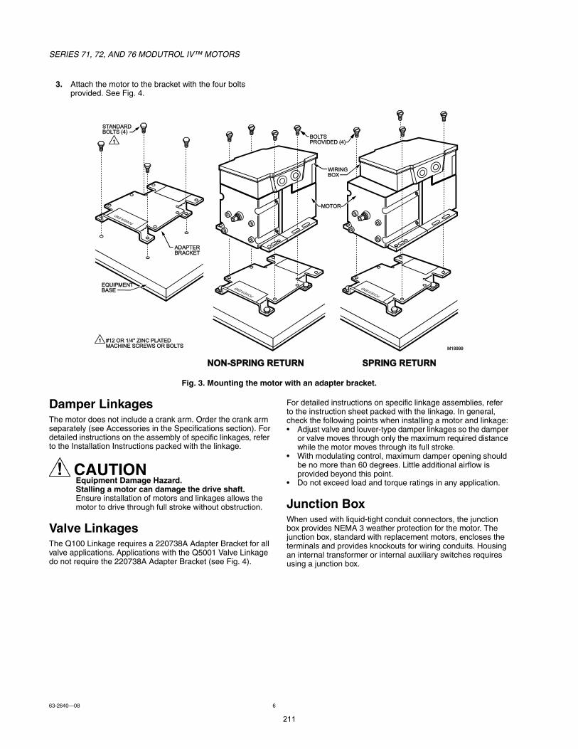
SERIES 71, 72, AND 76 MODUTROL IV MOTORS
63-264008 6
3. Attach the motor to the bracket with the four bolts provided. See Fig. 4.
Fig. 3. Mounting the motor with an adapter bracket.
Damper LinkagesThe motor does not include a crank arm. Order the crank arm separately (see Accessories in the Specifications section). For detailed instructions on the assembly of specific linkages, refer to the Installation Instructions packed with the linkage.
CAUTIONEquipment Damage Hazard.Stalling a motor can damage the drive shaft.Ensure installation of motors and linkages allows the motor to drive through full stroke without obstruction.
Valve LinkagesThe Q100 Linkage requires a 220738A Adapter Bracket for all valve applications. Applications with the Q5001 Valve Linkage do not require the 220738A Adapter Bracket (see Fig. 4).
For detailed instructions on specific linkage assemblies, refer to the instruction sheet packed with the linkage. In general, check the following points when installing a motor and linkage: Adjust valve and louver-type damper linkages so the damper
or valve moves through only the maximum required distance while the motor moves through its full stroke.
With modulating control, maximum damper opening should be no more than 60 degrees. Little additional airflow is provided beyond this point.
Do not exceed load and torque ratings in any application.
Junction BoxWhen used with liquid-tight conduit connectors, the junction box provides NEMA 3 weather protection for the motor. The junction box, standard with replacement motors, encloses the terminals and provides knockouts for wiring conduits. Housing an internal transformer or internal auxiliary switches requires using a junction box.
Óïèççç
ÛÏË×ÐÓÛÒÌÞßÍÛ
ßÜßÐÌÛÎÞÎßÝÕÛÌ
ÍÌßÒÜßÎÜÞÑÔÌÍ øì÷
ÓÑÌÑÎ
ÞÑÔÌÍ ÐÎÑÊ×ÜÛÜ øì÷
É×Î×ÒÙ ÞÑÈ
ÒÑÒóÍÐÎ×ÒÙ ÎÛÌËÎÒ ÍÐÎ×ÒÙ ÎÛÌËÎÒ
ï ýïî ÑÎ ïñìþ Æ×ÒÝ ÐÔßÌÛÜ ÓßÝØ×ÒÛ ÍÝÎÛÉÍ ÑÎ ÞÑÔÌÍ
ï
211
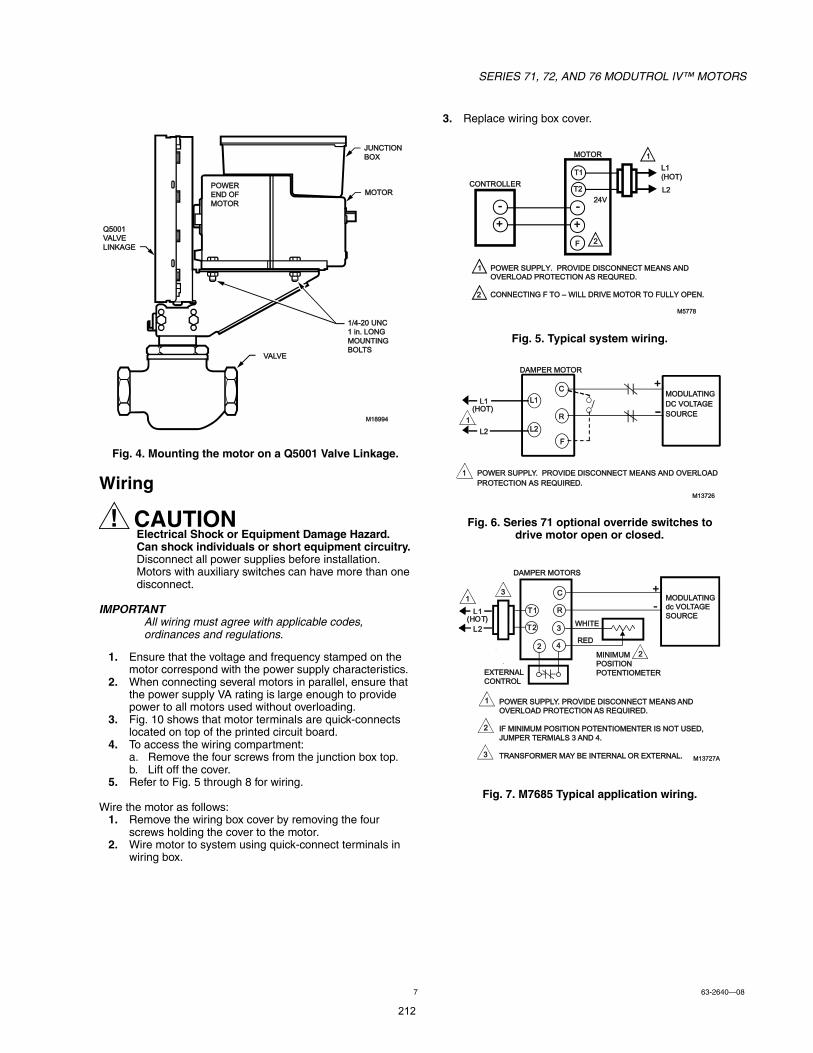
SERIES 71, 72, AND 76 MODUTROL IV MOTORS
7 63-264008
Fig. 4. Mounting the motor on a Q5001 Valve Linkage.
Wiring
CAUTIONElectrical Shock or Equipment Damage Hazard.Can shock individuals or short equipment circuitry.Disconnect all power supplies before installation.Motors with auxiliary switches can have more than one disconnect.
All wiring must agree with applicable codes, ordinances and regulations.
1. Ensure that the voltage and frequency stamped on the motor correspond with the power supply characteristics.
2. When connecting several motors in parallel, ensure that the power supply VA rating is large enough to provide power to all motors used without overloading.
3. Fig. 10 shows that motor terminals are quick-connects located on top of the printed circuit board.
4. To access the wiring compartment:a. Remove the four screws from the junction box top.b. Lift off the cover.
5. Refer to Fig. 5 through 8 for wiring.
Wire the motor as follows:1. Remove the wiring box cover by removing the four
screws holding the cover to the motor.2. Wire motor to system using quick-connect terminals in
wiring box.
3. Replace wiring box cover.
Fig. 5. Typical system wiring.
Fig. 6. Series 71 optional override switches to drive motor open or closed.
Fig. 7. M7685 Typical application wiring.
ïñìóîð ËÒÝ
ï ·²ò ÔÑÒÙ
ÓÑËÒÌ×ÒÙ
ÞÑÔÌÍ
Ïëððï
ÊßÔÊÛ
Ô×ÒÕßÙÛ
Óïèççì
ÓÑÌÑÎ
ÖËÒÝÌ×ÑÒ
ÞÑÈ
ÐÑÉÛÎ
ÛÒÜ ÑÚ
ÓÑÌÑÎ
ÊßÔÊÛ
ÝÑÒÌÎÑÔÔÛÎ
Ôï
øØÑÌ÷
Ôî
ÐÑÉÛÎ ÍËÐÐÔÇò ÐÎÑÊ×ÜÛ Ü×ÍÝÑÒÒÛÝÌ ÓÛßÒÍ ßÒÜÑÊÛÎÔÑßÜ ÐÎÑÌÛÝÌ×ÑÒ ßÍ ÎÛÏËÎÛÜò
ÝÑÒÒÛÝÌ×ÒÙ Ú ÌÑ É×ÔÔ ÜÎ×ÊÛ ÓÑÌÑÎ ÌÑ ÚËÔÔÇ ÑÐÛÒò
ï
Óëééè
ï
ó
ÓÑÌÑÎ
îÚ
Ìï
Ìî
î
õ
ó
õ
îìÊ
ÐÑÉÛÎ ÍËÐÐÔÇò ÐÎÑÊ×ÜÛ Ü×ÍÝÑÒÒÛÝÌ ÓÛßÒÍ ßÒÜ ÑÊÛÎÔÑßÜ
ÐÎÑÌÛÝÌ×ÑÒ ßÍ ÎÛÏË×ÎÛÜò
Óïíéîê
Ôï
Ôî
Î
ÓÑÜËÔßÌ×ÒÙ
ÜÝ ÊÑÔÌßÙÛ
ÍÑËÎÝÛï
Ôï
Ôî
øØÑÌ÷
õÝ
Ú
ï
ÜßÓÐÛÎ ÓÑÌÑÎ
ï
î
í
Ìï
Ìî
Ý
Î
ì
í
ï
Ôï
Ôî
øØ ÑÌ ÷
õ
ó
îî
í
ÜßÓÐÛÎ ÓÑÌÑÎÍ
ÉØ×ÌÛ
ÎÛÜ
ÓÑÜËÔßÌ×ÒÙ
¼½ ÊÑÔÌßÙÛ
ÍÑËÎÝÛ
Ó×Ò×ÓËÓ
ÐÑÍ×Ì×ÑÒ
ÐÑÌÛÒÌ×ÑÓÛÌÛÎ ÛÈÌÛÎÒßÔ
ÝÑÒÌÎÑÔ
ÐÑÉÛÎ ÍËÐÐÔÇò ÐÎÑÊ×ÜÛ Ü×ÍÝÑÒÒÛÝÌ ÓÛßÒÍ ßÒÜ
ÑÊÛÎÔÑßÜ ÐÎÑÌÛÝÌ×ÑÒ ßÍ ÎÛÏË×ÎÛÜò
×Ú Ó×Ò×ÓËÓ ÐÑÍ×Ì×ÑÒ ÐÑÌÛÒÌ×ÑÓÛÒÌÛÎ ×Í ÒÑÌ ËÍÛÜô
ÖËÓÐÛÎ ÌÛÎÓ×ßÔÍ í ßÒÜ ìò
ÌÎßÒÍÚÑÎÓÛÎ ÓßÇ ÞÛ ×ÒÌÛÎÒßÔ ÑÎ ÛÈÌÛÎÒßÔò Óïíéîéß
212
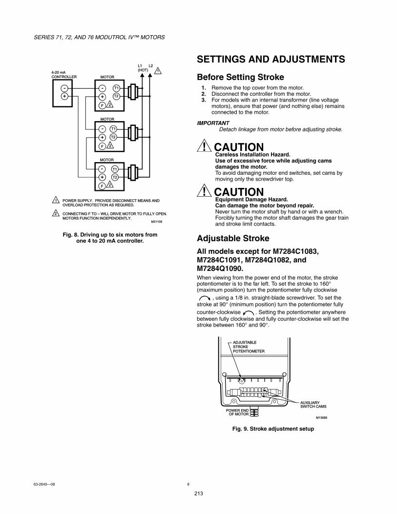
SERIES 71, 72, AND 76 MODUTROL IV MOTORS
63-264008 8
Fig. 8. Driving up to six motors from one 4 to 20 mA controller.
SETTINGS AND ADJUSTMENTS
Before Setting Stroke1. Remove the top cover from the motor.2. Disconnect the controller from the motor.3. For models with an internal transformer (line voltage
motors), ensure that power (and nothing else) remains connected to the motor.
Detach linkage from motor before adjusting stroke.
CAUTIONCareless Installation Hazard.Use of excessive force while adjusting cams damages the motor.To avoid damaging motor end switches, set cams by moving only the screwdriver top.
CAUTIONEquipment Damage Hazard.Can damage the motor beyond repair.Never turn the motor shaft by hand or with a wrench.Forcibly turning the motor shaft damages the gear train and stroke limit contacts.
Adjustable StrokeAll models except for M7284C1083, M7284C1091, M7284Q1082, and M7284Q1090.When viewing from the power end of the motor, the stroke potentiometer is to the far left. To set the stroke to 160° (maximum position) turn the potentiometer fully clockwise
, using a 1/8 in. straight-blade screwdriver. To set the stroke at 90° (minimum position) turn the potentiometer fully counter-clockwise . Setting the potentiometer anywhere between fully clockwise and fully counter-clockwise will set the stroke between 160° and 90°.
Fig. 9. Stroke adjustment setup
ìóîð ³ß
ÝÑÒÌÎÑÔÔÛÎ
Ôï
øØÑÌ÷
Ôî
ÐÑÉÛÎ ÍËÐÐÔÇò ÐÎÑÊ×ÜÛ Ü×ÍÝÑÒÒÛÝÌ ÓÛßÒÍ ßÒÜ
ÑÊÛÎÔÑßÜ ÐÎÑÌÛÝÌ×ÑÒ ßÍ ÎÛÏËÎÛÜò
ÝÑÒÒÛÝÌ×ÒÙ Ú ÌÑ É×ÔÔ ÜÎ×ÊÛ ÓÑÌÑÎ ÌÑ ÚËÔÔÇ ÑÐÛÒò
ÓÑÌÑÎÍ ÚËÒÝÌ×ÑÒ ×ÒÜÛÐÛÒÜÛÒÌÔÇò
ï
Óíïïðç
ï
ÓÑÌÑÎ
ÓÑÌÑÎ
õ
ó
ÓÑÌÑÎ
îÚ
Ìï
Ìî
îÚ
Ìï
Ìî
îÚ
Ìï
Ìî
î
õ
ó
õ
õ
ó
ó
Óïíêçç
ÐÑÉÛÎ ÛÒÜÑÚ ÓÑÌÑÎ
ßËÈ×Ô×ßÎÇ ÍÉ×ÌÝØ ÝßÓÍ
ßÜÖËÍÌßÞÔÛ
ÍÌÎÑÕÛ
ÐÑÌÛÒÌ×ÑÓÛÌÛÎ
213
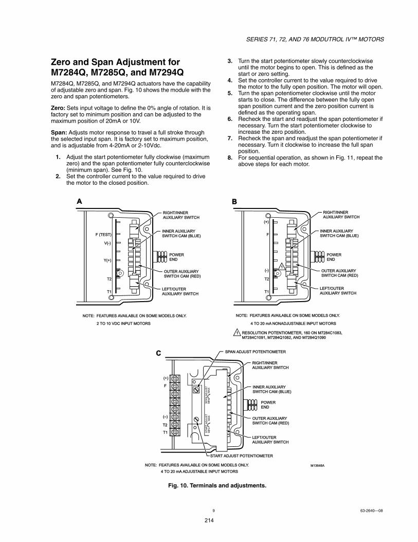
SERIES 71, 72, AND 76 MODUTROL IV MOTORS
9 63-264008
Zero and Span Adjustment for M7284Q, M7285Q, and M7294QM7284Q, M7285Q, and M7294Q actuators have the capability of adjustable zero and span. Fig. 10 shows the module with the zero and span potentiometers.
Zero: Sets input voltage to define the 0% angle of rotation. It is factory set to minimum position and can be adjusted to the maximum position of 20mA or 10V.
Span: Adjusts motor response to travel a full stroke through the selected input span. It is factory set to maximum position, and is adjustable from 4-20mA or 2-10Vdc.
1. Adjust the start potentiometer fully clockwise (maximum zero) and the span potentiometer fully counterclockwise (minimum span). See Fig. 10.
2. Set the controller current to the value required to drive the motor to the closed position.
3. Turn the start potentiometer slowly counterclockwise until the motor begins to open. This is defined as the start or zero setting.
4. Set the controller current to the value required to drive the motor to the fully open position. The motor will open.
5. Turn the span potentiometer clockwise until the motor starts to close. The difference between the fully open span position current and the zero position current is defined as the operating span.
6. Recheck the start and readjust the span potentiometer if necessary. Turn the start potentiometer clockwise to increase the zero position.
7. Recheck the span and readjust the span potentiometer if necessary. Turn it clockwise to increase the full span position.
8. For sequential operation, as shown in Fig. 11, repeat the above steps for each motor.
Fig. 10. Terminals and adjustments.
Î×ÙØÌñ×ÒÒÛÎ
ßËÈ×Ô×ßÎÇ ÍÉ×ÌÝØ
×ÒÒÛÎ ßËÈ×Ô×ßÎÇ
ÍÉ×ÌÝØ ÝßÓ øÞÔËÛ÷
ÐÑÉÛÎ
ÛÒÜ
ÑËÌÛÎ ßËÈ×Ô×ßÎÇ
ÍÉ×ÌÝØ ÝßÓ øÎÛÜ÷
ÔÛÚÌñÑËÌÛÎ
ßËÈ×Ô×ßÎÇ ÍÉ×ÌÝØ
ÒÑÌÛæ ÚÛßÌËÎÛÍ ßÊß×ÔßÞÔÛ ÑÒ ÍÑÓÛ ÓÑÜÛÔÍ ÑÒÔÇò
Óïíêìèß
øõ÷
øó÷
Ìî
Ìï
Ú
Î×ÙØÌñ×ÒÒÛÎ
ßËÈ×Ô×ßÎÇ ÍÉ×ÌÝØ
×ÒÒÛÎ ßËÈ×Ô×ßÎÇ
ÍÉ×ÌÝØ ÝßÓ øÞÔËÛ÷
ÐÑÉÛÎ
ÛÒÜ
ÑËÌÛÎ ßËÈ×Ô×ßÎÇ
ÍÉ×ÌÝØ ÝßÓ øÎÛÜ÷
ÔÛÚÌñÑËÌÛÎ
ßËÈ×Ô×ßÎÇ ÍÉ×ÌÝØ
ÒÑÌÛæ ÚÛßÌËÎÛÍ ßÊß×ÔßÞÔÛ ÑÒ ÍÑÓÛ ÓÑÜÛÔÍ ÑÒÔÇò
Çøõ÷
Ìî
Ìï
Ú øÌÛÍÌ÷
ß Þ
Êøó÷
î ÌÑ ïð ÊÜÝ ×ÒÐËÌ ÓÑÌÑÎÍ ì ÌÑ îð ³ß ÒÑÒßÜÖËÍÌßÞÔÛ ×ÒÐËÌ ÓÑÌÑÎÍ
ÒÑÌÛæ ÚÛßÌËÎÛÍ ßÊß×ÔßÞÔÛ ÑÒ ÍÑÓÛ ÓÑÜÛÔÍ ÑÒÔÇò
ì ÌÑ îð ³ß ßÜÖËÍÌßÞÔÛ ×ÒÐËÌ ÓÑÌÑÎÍ
Ý ÍÐßÒ ßÜÖËÍÌ ÐÑÌÛÒÌ×ÑÓÛÌÛÎ
ÍÌßÎÌ ßÜÖËÍÌ ÐÑÌÛÒÌ×ÑÓÛÌÛÎ
Î×ÙØÌñ×ÒÒÛÎ
ßËÈ×Ô×ßÎÇ ÍÉ×ÌÝØ
×ÒÒÛÎ ßËÈ×Ô×ßÎÇ
ÍÉ×ÌÝØ ÝßÓ øÞÔËÛ÷
ÐÑÉÛÎ
ÛÒÜ
ÑËÌÛÎ ßËÈ×Ô×ßÎÇ
ÍÉ×ÌÝØ ÝßÓ øÎÛÜ÷
ÔÛÚÌñÑËÌÛÎ
ßËÈ×Ô×ßÎÇ ÍÉ×ÌÝØ
Ìï
Ìî
ø÷
øõ÷
Ú
ï
ï ÎÛÍÑÔËÌ×ÑÒ ÐÑÌÛÒÌ×ÑÓÛÌÛÎô ïêð ÑÒ ÓéîèìÝïðèíô
ÓéîèìÝïðçïô ÓéîèìÏïðèîô ßÒÜ ÓéîèìÏïðçð
214
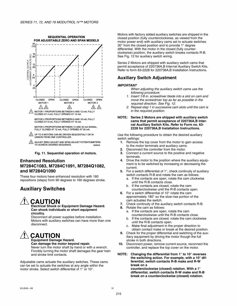
SERIES 71, 72, AND 76 MODUTROL IV MOTORS
63-264008 10
Fig. 11. Sequential operation of motors.
Enhanced ResolutionM7284C1083, M7284C1091, M7284Q1082, and M7284Q1090These four motors have enhanced resolution with 160 repositions (steps) from 90 degrees to 160 degrees stroke.
Auxiliary Switches
CAUTIONElectrical Shock or Equipment Damage Hazard.Can shock individuals or short equipment circuitry.Disconnect all power supplies before installation.Motors with auxiliary switches can have more than one disconnect.
CAUTIONEquipment Damage Hazard.Can damage the motor beyond repair.Never turn the motor shaft by hand or with a wrench.Forcibly turning the motor shaft damages the gear train and stroke limit contacts.
Adjustable cams actuate the auxiliary switches. These cams can be set to actuate the switches at any angle within the motor stroke. Select switch differential of 1° or 10°.
Motors with factory added auxiliary switches are shipped in the closed position (fully counterclockwise, as viewed from the motor power end) with auxiliary cams set to actuate switches 30° from the closed position and to provide 1° degree differential. With the motor in the closed (fully counter-clockwise) position, the auxiliary switch breaks contacts R-B. See Fig. 12 for auxiliary switch wiring.
Series 2 Motors are shipped with auxiliary switch cams that permit acceptance of 220736A,B Internal Auxiliary Switch Kits. Refer to form 63-2228 for 220736A,B Installation Instructions.
Auxiliary Switch Adjustment
When adjusting the auxiliary switch cams use the following procedure:
1. Insert 1/8 in. screwdriver blade into a slot on cam and move the screwdriver top as far as possible in the required direction. See Fig. 12.
2. Repeat step 1 in successive cam slots until the cam is in the required position.
NOTE: Series 2 Motors are shipped with auxiliary switch cams that permit acceptance of 220736A,B Inter-nal Auxiliary Switch Kits. Refer to Form no. 63-2228 for 220736A,B Installation Instructions.
Use the following procedure to obtain the desired auxiliary switch settings:
1. Remove the top cover from the motor to gain access to the motor terminals and auxiliary cams.
2. Disconnect the controller from the motor.3. Connect a current source to the positive and negative
terminals.4. Drive the motor to the position where the auxiliary equip-
ment is to be switched by increasing or decreasing the current.
5. For a switch differential of 1°, check continuity of auxiliary switch contacts R-B and rotate the cam as follows:a. If the contacts are open, rotate the cam clockwise
until the R-B contacts close.b. If the contacts are closed, rotate the cam
counterclockwise until the R-B contacts open.6. For a switch differential of 10° rotate the cam
approximately 180° so the slow-rise portion of the cam actuates the switch.
7. Check continuity of the auxiliary switch contacts R-B.8. Rotate the cam as follows:
a. If the contacts are open, rotate the cam counterclockwise until the R-B contacts close.
b. If the contacts are closed, rotate the cam clockwise until the R-B contacts open.
c. Make final adjustment in the proper direction to obtain contact make or break at the desired position.
9. Check for the proper differential and switching of the aux-iliary equipment by driving the motor though the full stroke in both directions.
10. Disconnect power, remove current source, reconnect the controller, and replace the top cover on the motor.
NOTE: Changing the differential from 1° to 10° reverses the switching action. For example, with a 10° dif-ferential, switch contacts R-B make and R-W break on a counterclockwise (closed) rotation. With a 1° differential, switch contacts R-W make and R-B break on a counterclockwise (closed) rotation.
îðøïð÷
ïêøè÷
ïîøê÷
èøì÷
ìøî÷
ð
ÝÔÑÍÛÜ ÑÐÛÒ ÝÔÑÍÛÜ ÑÐÛÒ ÝÔÑÍÛÜ ÑÐÛÒ
ÓÑÌÑÎ ï ÓÑÌÑÎ î ÓÑÌÑÎ í
ï í í í
ï ÓÑÌÑÎ ï ÐÎÑÐÑÎÌ×ÑÒÍ ÞÛÌÉÛÛÒ ì ßÒÜ ïî ³ßå ÚËÔÔÇÝÔÑÍÛÜ ßÌ ì ³ßô ÚËÔÔÇ ÑÐÛÒÛÜ ßÌ ïî ³ßò
ÓÑÌÑÎ î ÐÎÑÐÑÎÌ×ÑÒÍ ÞÛÌÉÛÛÒ è ßÒÜ ïê ³ßå ÚËÔÔÇÝÔÑÍÛÜ ßÌ è ³ßô ÚËÔÔÇ ÑÐÛÒÛÜ ßÌ ïê ³ßò
ÓÑÌÑÎ í ÐÎÑÐÑÎÌ×ÑÒÍ ÞÛÌÉÛÛÒ ïî ßÒÜ îð ³ß Í×ÙÒßÔå ÚËÔÔÇ ÝÔÑÍÛÜ ßÌ ïî ³ßô ÚËÔÔÇ ÑÐÛÒÛÜ ßÌ îð ³ßò
ËÐ ÌÑ ê ÓÑÌÑÎÍ ÝßÒ ÞÛ ÜÎ×ÊÛÒ ÍÛÏËÛÒÌ×ßÔÇ ÑÎ ×Ò ËÒ×ÍÑÒ ÚÎÑÓ ÑÒÛ ÝÑÒÌÎÑÔÔÛÎò
ßÜÖËÍÌ ÆÛÎÑ ßÜÖËÍÌ ßÒÜ ÍÐßÒ ßÜÖËÍÌ ÐÑÌÛÒÌ×ÑÓÛÌÛÎÍ ÌÑ ßÝØ×ÛÊÛ ÜÛÍ×ÎÛÜ ÍÛÏËÛÒÝÛò
î
î
í
ÍÛÏËÛÒÌ×ßÔ ÑÐÛÎßÌ×ÑÒ
ÚÑÎ ßÜÖËÍÌßÞÔÛ ÆÛÎÑ ßÒÜ ÍÐßÒ ÓÑÜÛÔÍ
Óîèçíß
215
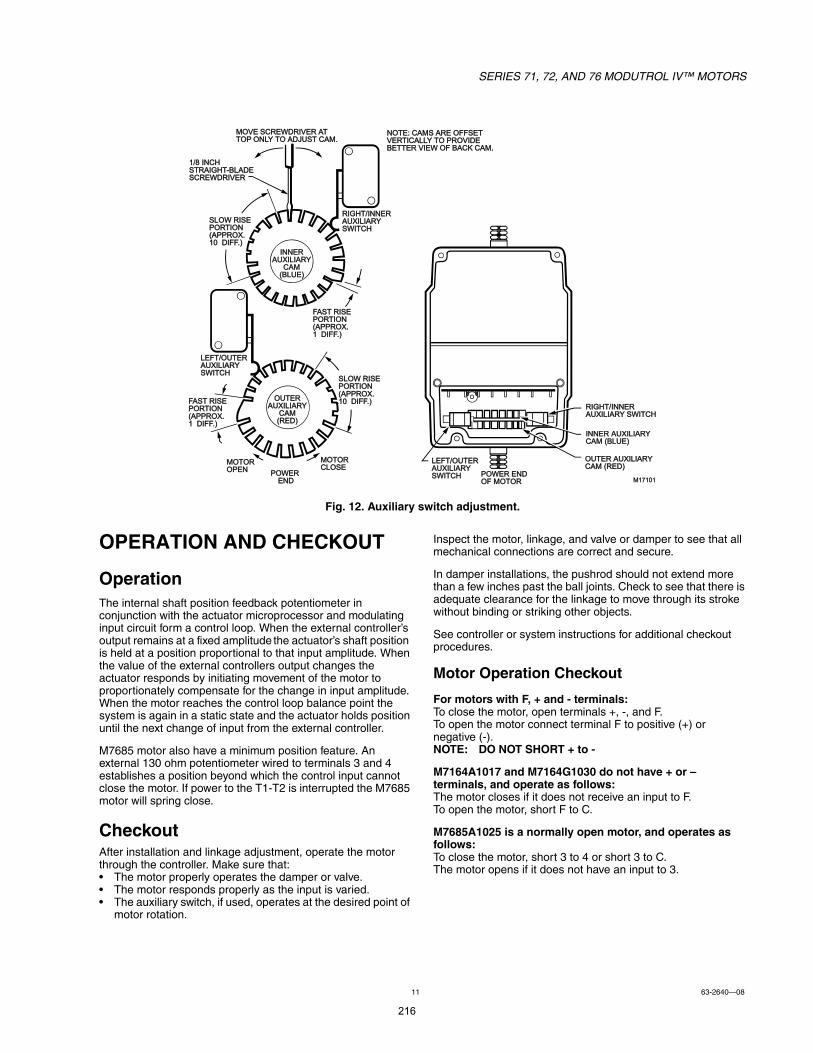
SERIES 71, 72, AND 76 MODUTROL IV MOTORS
11 63-264008
Fig. 12. Auxiliary switch adjustment.
OPERATION AND CHECKOUT
OperationThe internal shaft position feedback potentiometer in conjunction with the actuator microprocessor and modulating input circuit form a control loop. When the external controllers output remains at a fixed amplitude the actuators shaft position is held at a position proportional to that input amplitude. When the value of the external controllers output changes the actuator responds by initiating movement of the motor to proportionately compensate for the change in input amplitude. When the motor reaches the control loop balance point the system is again in a static state and the actuator holds position until the next change of input from the external controller.
M7685 motor also have a minimum position feature. An external 130 ohm potentiometer wired to terminals 3 and 4 establishes a position beyond which the control input cannot close the motor. If power to the T1-T2 is interrupted the M7685 motor will spring close.
CheckoutAfter installation and linkage adjustment, operate the motor through the controller. Make sure that: The motor properly operates the damper or valve. The motor responds properly as the input is varied. The auxiliary switch, if used, operates at the desired point of
motor rotation.
Inspect the motor, linkage, and valve or damper to see that all mechanical connections are correct and secure.
In damper installations, the pushrod should not extend more than a few inches past the ball joints. Check to see that there is adequate clearance for the linkage to move through its stroke without binding or striking other objects.
See controller or system instructions for additional checkout procedures.
Motor Operation Checkout
For motors with F, + and - terminals:To close the motor, open terminals +, -, and F.To open the motor connect terminal F to positive (+) or negative (-).NOTE: DO NOT SHORT + to -
M7164A1017 and M7164G1030 do not have + or terminals, and operate as follows:The motor closes if it does not receive an input to F.To open the motor, short F to C.
M7685A1025 is a normally open motor, and operates as follows:To close the motor, short 3 to 4 or short 3 to C.The motor opens if it does not have an input to 3.
Î×ÙØÌñ×ÒÒÛÎ ßËÈ×Ô×ßÎÇÍÉ×ÌÝØ
ÚßÍÌ Î×ÍÛÐÑÎÌ×ÑÒøßÐÐÎÑÈò ï Ü×ÚÚò÷
ÍÔÑÉ Î×ÍÛÐÑÎÌ×ÑÒøßÐÐÎÑÈò ïð Ü×ÚÚò÷
×ÒÒÛÎßËÈ×Ô×ßÎÇ
ÝßÓøÞÔËÛ÷
ÒÑÌÛæ ÝßÓÍ ßÎÛ ÑÚÚÍÛÌ ÊÛÎÌ×ÝßÔÔÇ ÌÑ ÐÎÑÊ×ÜÛ ÞÛÌÌÛÎ Ê×ÛÉ ÑÚ ÞßÝÕ ÝßÓò
ÚßÍÌ Î×ÍÛÐÑÎÌ×ÑÒøßÐÐÎÑÈò ï Ü×ÚÚò÷
ÍÔÑÉ Î×ÍÛÐÑÎÌ×ÑÒøßÐÐÎÑÈò ïð Ü×ÚÚò÷
ÓÑÌÑÎ ÑÐÛÒ
ÓÑÌÑÎ ÝÔÑÍÛ
ÐÑÉÛÎ ÛÒÜ
ÑËÌÛÎßËÈ×Ô×ßÎÇ
ÝßÓøÎÛÜ÷
ÔÛÚÌñÑËÌÛÎßËÈ×Ô×ßÎÇÍÉ×ÌÝØ
ÓïéïðïÐÑÉÛÎ ÛÒÜÑÚ ÓÑÌÑÎ
ÑËÌÛÎ ßËÈ×Ô×ßÎÇ ÝßÓ øÎÛÜ÷
×ÒÒÛÎ ßËÈ×Ô×ßÎÇ ÝßÓ øÞÔËÛ÷
Î×ÙØÌñ×ÒÒÛÎßËÈ×Ô×ßÎÇ ÍÉ×ÌÝØ
ÔÛÚÌñÑËÌÛÎßËÈ×Ô×ßÎÇ ÍÉ×ÌÝØ
ÓÑÊÛ ÍÝÎÛÉÜÎ×ÊÛÎ ßÌ ÌÑÐ ÑÒÔÇ ÌÑ ßÜÖËÍÌ ÝßÓò
ïñè ×ÒÝØ ÍÌÎß×ÙØÌóÞÔßÜÛ ÍÝÎÛÉÜÎ×ÊÛÎ
216
SERIES 71, 72, AND 76 MODUTROL IV MOTORS
Automation and Control SolutionsHoneywell International Inc.
1985 Douglas Drive North
Golden Valley, MN 55422
customer.honeywell.com
® U.S. Registered Trademark© 2012 Honeywell International Inc.63-264008 M.S. Rev. 10-12Printed in United States
217
218
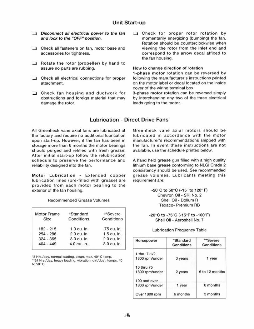
219
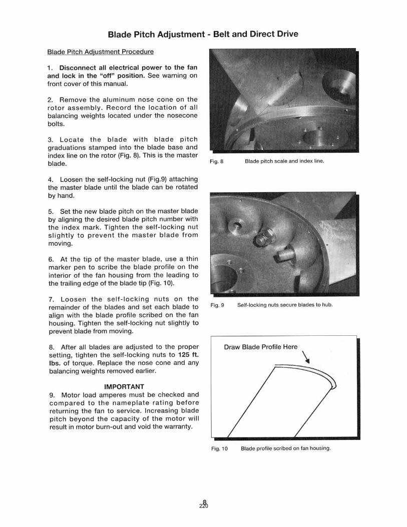
220
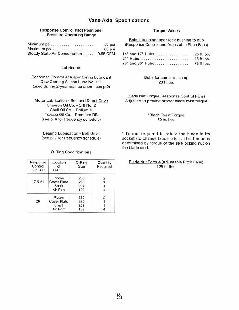
221
ï
Ú×ÎÛÇÛÓÑÜËÔßÎ
Ó·½®±ÓÚÔßÓÛ ÍßÚÛÙËßÎÜ ÝÑÒÌÎÑÔÍ
ÉßÎÒ×ÒÙæ Í»´»½¬·±² ±º ¬¸· ½±²¬®±´ º±® ¿ °¿®¬·½«´¿® ¿°°´·½¿¬·±² ¸±«´¼ ¾» ³¿¼» ¾§ ¿ ½±³ó°»¬»²¬ °®±º»·±²¿´ô ·½»²»¼ ¾§ ¿ ¬¿¬» ±® ±¬¸»® ¹±ª»®²³»²¬ ¿¹»²½§ò ײ¿°°®±°®·¿¬» ¿°°´·½¿¬·±²±º ¬¸· °®±¼«½¬ ½±«´¼ ®»«´¬ ·² ¿² «²¿º» ½±²¼·¬·±² ¸¿¦¿®¼±« ¬± ´·º» ¿²¼ °®±°»®¬§ò
ÜÛÍÝÎ×ÐÌ×ÑÒ
̸» Ú·®»§» Ó·½®±Ó Í»®·» Ú´¿³» Í¿º»¹«¿®¼ ݱ²¬®±´ · ¿ ½±³°¿½¬ô ³·½®±°®±½»±® ¾¿»¼ô ³±¼«´¿®
¾«®²»® ³¿²¿¹»³»²¬ §¬»³ ¼»·¹²»¼ ¬± °®±ª·¼» ¿«¬±³¿¬·½ ·¹²·¬·±² ¿²¼ ½±²¬·²«±« º´¿³» ³±²·¬±®·²¹
º±® ½±³³»®½·¿´ ·¦» ±º ¸»¿¬·²¹ ¿²¼ °®±½» »¯«·°³»²¬ º·®·²¹ ¿²§ ¬§°» ±º º«»´ò
̸» Ó·½®±Ó · ¼»·¹²»¼ ¬± ¾» ¾¿½µ©¿®¼ ½±³°¿¬·¾´» ©·¬¸ »¨·¬·²¹ ÌÚÓô ËÊÓ ¿²¼ ÓóÍ»®·» ×× ½±²ó
¬®±´ò ̸» Ó·½®±Ó ÓÛÝïîð ¿²¼ ÓÛÝîí𠽸¿· ©·¬¸ ¬¸» ¿°°®±°®·¿¬» ÓÛÐïððô ÓÛÐîðð ¿²¼
ÓÛÐëðð »®·» °®±¹®¿³³»® °®±ª·¼» ±°»®¿¬·±² ·³·´¿® ¬± ·¬ °®»¼»½»±® ¿²¼ · ««¿´´§ ¼·®»½¬´§
·²¬»®½¸¿²¹»¿¾´»ò ̸» ÓÛÝíîð ¿²¼ ÓÛÝìè𠽸¿· ©·¬¸ ¬¸» ¿°°®±°®·¿¬» ÓÛÐíððô ÓÛÐìðð ¿²¼
ÓÛÐêðð »®·» °®±¹®¿³³»® °®±ª·¼» ¿¼¼·¬·±²¿´ »²¸¿²½»³»²¬ «½¸ ¿ »¿®´§ °¿®µ ¬»®³·²¿¬·±²ô °·´±¬
°®±ª·²¹ô ¿²¼ ·²¬»®®«°¬»¼ °·´±¬ò
̸» ¿¼ª¿²¬¿¹» ±º ¬¸» Ó·½®±Ó ¿®» ¦»®± ¼»°»²¼»²½» ±² ¼·½®»¬» ½±³°±²»²¬ °®»ª·±«´§ «»¼ º±® ¬·³ó
·²¹ º«²½¬·±²ò ̸» Ó·½®±Óô ¬¸®±«¹¸ ¬¸» «» ±º ³·½®±ó½±²¬®±´´»® ¬»½¸²±´±¹§ô ·²½±®°±®¿¬» ³¿®¬ ¼·¿¹ó
²±¬·½ ÔÛÜùô ³¿®¬ ®»»¬ º«²½¬·±² º±® ³«´¬·ó¾«®²»® ¿°°´·½¿¬·±²ô ±°¬·±²¿´ ¿´°¸¿ó²«³»®·½ ¼·°´¿§
±«¬°«¬ øÛÜëïð÷ô ¿²¼ »®·¿´ ½±³³«²·½¿¬·±² ª·¿ ¿ Ó±¼¾« ±® Ûëðð ݱ³³«²·½¿¬·±² ײ¬»®º¿½»ò ̸»
Ó·½®±Ó §¬»³ ¿´± °®±ª·¼» ¿¼¼·¬·±²¿´ ¿³°´·º·»® »´»½¬·±²ò ß´±²¹ ©·¬¸ ¬¸» ¬¿²¼¿®¼ ËÊ ¿²¼
Ú´¿³» α¼ ¿³°´·º·»® ¿®» ËÊ »´ºó½¸»½µô ײº®¿®»¼ô Ý¿¼³·«³ Í«´º·¼» ¿²¼ ¿ ¼®§ ½±²¬¿½¬ ¿³°´·º·»® º±®
«» ©·¬¸ ¬¸» Ú·®»§» и±»²·¨ ½¿²²»®ò ß´´ ¿³°´·º·»® ¿®» ¿ª¿·´¿¾´» ©·¬¸ º´¿³» º¿·´«®» ®»°±²» ¬·³» ±º
ðòè »½±²¼ ±® í »½±²¼ ²±³·²¿´ øì »½±²¼ ³¿¨·³«³÷ ¿²¼ »¿½¸ °®±ª·¼» ¿ »¬ ±º ¬»¬ ¶¿½µ ©·¬¸ ¿
«²·º±®³ ®¿²¹» ±º ðóïð ÊÜÝ º±® ¬¸» ³»¿«®»³»²¬ ±º º´¿³» ·¹²¿´ ·²¬»²·¬§ò
ß ½±³°´»¬» Ó·½®±Ó §¬»³ ·²½´«¼» ¬¸» ¿°°®±°®·¿¬» º´¿³» ¼»¬»½¬±®ô °´«¹ó·² ¿³°´·º·»® ¿²¼ °®±¹®¿³ó
³»® ³±¼«´» ©¸·½¸ ½±²²»½¬ ·²¬± ¿ ¬¿²¼¿®¼ ½¸¿· ¿²¼ ©·®·²¹ ¾¿»ò ײ¬»®½¸¿²¹»¿¾´» °®±¹®¿³³»®
¿²¼ ¿³°´·º·»® ³±¼«´» ¿´´±© º±® ½±³°´»¬» ª»®¿¬·´·¬§ ·² »´»½¬·±² ±º ½±²¬®±´ º«²½¬·±²ô ¬·³·²¹ ¿²¼
º´¿³» ½¿²²·²¹ ³»¿²ò Ú«²½¬·±² «½¸ ¿ ®»´·¹¸¬ô ®»½§½´»ô ²±²ó®»½§½´»ô ¬©± ¬¿¹» ½¿°¿¾·´·¬§ô ²±²ó
®»½§½´» ¿·® º´±©ô °®±±º ±º ¿·® º´±© ±°»² ¿¬ ¬¿®¬ô °«®¹» ¬·³·²¹ô »¿®´§ °¿®µ ¬»®³·²¿¬·±²ô °·´±¬ °®±ª·²¹
¿²¼ °·´±¬ ½«¬±ºº ¿®» ¼»¬»®³·²»¼ ¾§ ¬¸» ¿°°®±°®·¿¬» °®±¹®¿³³»® ³±¼«´»ò ̧°» ±º º´¿³» ½¿²²»® øËÊô
λ°»¬·¬·ª» ËÊ Í»´ºóݸ»½µô Ú´¿³» α¼ô ×Î ±® Ý¿¼³·«³ Í«´º·¼» ±® ¼®§ ½±²¬¿½¬÷ ¿²¼ ¬¸» º´¿³» º¿·´«®»
®»°±²» ¬·³» øÚÚÎÌ÷ ¿®» ¼»¬»®³·²»¼ ¾§ ¬¸» ¿³°´·º·»® ³±¼«´»ò Ñ°¬·±²¿´ °´«¹ó·² ¼¿«¹¸¬»® ¾±¿®¼
°®±ª·¼» ¿¼¼·¬·±²¿´ º»¿¬«®» «½¸ ¿ ®»³±¬» ®»»¬ô ¿´°¸¿ó²«³»®·½ ¼·°´¿§ ¿²¼ »®·¿´ ½±³³«²·½¿¬·±²ò
̸» Ó·½®±Ó °®±¹®¿³³»® ¿®» ³·½®±ó½±²¬®±´´»® ¾¿»¼ ³±¼«´» ¬¸¿¬ ½±²¬®±´ ¬¸» »¯«»²½» ±º ±°»®¿ó
¬·±² ¿²¼ ¿´± ·²¬»®º¿½» ©·¬¸ °´«¹ó·² ¿³°´·º·»®ô ³»¬»® ¾±¿®¼ô ¼·°´¿§ ¼®·ª»® ¿²¼ »¨¬»®²¿´ ½±³³«²·ó
½¿¬·±² ¼»ª·½»ò ̸» °®±¹®¿³³»® ¿®» ¿ª¿·´¿¾´» ·² ¿² ¿±®¬³»²¬ ±º ½±²º·¹«®¿¬·±² ²»½»¿®§ ¬±
®»±´ª» ¬¸» ¿°°´·½¿¬·±² ®»¯«·®»³»²¬ò Ý«®®»²¬ º¿³·´·» ±º °®±¹®¿³³»® º±® «» ©·¬¸ ¬¸» ÓÛÝïîð ¿²¼
ÓÝóëðððÑÝÌÑÞÛÎ ïìô îððç
ßÐÐÎÑÊÛÜ
222
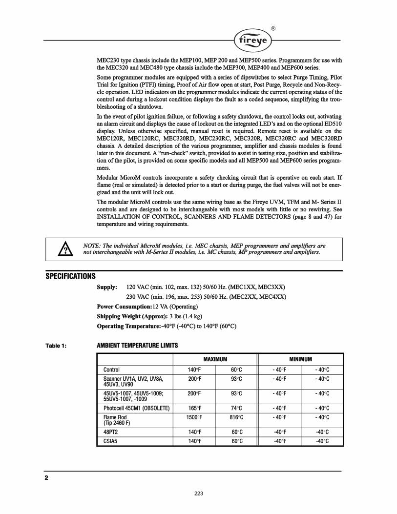
î
ÓÛÝîí𠬧°» ½¸¿· ·²½´«¼» ¬¸» ÓÛÐïððô ÓÛÐ îðð ¿²¼ ÓÛÐëðð »®·»ò Ю±¹®¿³³»® º±® «» ©·¬¸
¬¸» ÓÛÝíîð ¿²¼ ÓÛÝìè𠬧°» ½¸¿· ·²½´«¼» ¬¸» ÓÛÐíððô ÓÛÐìðð ¿²¼ ÓÛÐêðð »®·»ò
ͱ³» °®±¹®¿³³»® ³±¼«´» ¿®» »¯«·°°»¼ ©·¬¸ ¿ »®·» ±º ¼·°©·¬½¸» ¬± »´»½¬ Ы®¹» Ì·³·²¹ô з´±¬
Ì®·¿´ º±® ×¹²·¬·±² øÐÌÚ×÷ ¬·³·²¹ô Ю±±º ±º ß·® º´±© ±°»² ¿¬ ¬¿®¬ô б¬ Ы®¹»ô 뽧½´» ¿²¼ Ò±²ó뽧ó
½´» ±°»®¿¬·±²ò ÔÛÜ ·²¼·½¿¬±® ±² ¬¸» °®±¹®¿³³»® ³±¼«´» ·²¼·½¿¬» ¬¸» ½«®®»²¬ ±°»®¿¬·²¹ ¬¿¬« ±º ¬¸»
½±²¬®±´ ¿²¼ ¼«®·²¹ ¿ ´±½µ±«¬ ½±²¼·¬·±² ¼·°´¿§ ¬¸» º¿«´¬ ¿ ¿ ½±¼»¼ »¯«»²½»ô ·³°´·º§·²¹ ¬¸» ¬®±«ó
¾´»¸±±¬·²¹ ±º ¿ ¸«¬¼±©²ò
ײ ¬¸» »ª»²¬ ±º °·´±¬ ·¹²·¬·±² º¿·´«®»ô ±® º±´´±©·²¹ ¿ ¿º»¬§ ¸«¬¼±©²ô ¬¸» ½±²¬®±´ ´±½µ ±«¬ô ¿½¬·ª¿¬·²¹
¿² ¿´¿®³ ½·®½«·¬ ¿²¼ ¼·°´¿§ ¬¸» ½¿«» ±º ´±½µ±«¬ ±² ¬¸» ·²¬»¹®¿¬»¼ ÔÛÜ ¿²¼ ±² ¬¸» ±°¬·±²¿´ ÛÜëïð
¼·°´¿§ò ˲´» ±¬¸»®©·» °»½·º·»¼ô ³¿²«¿´ ®»»¬ · ®»¯«·®»¼ò λ³±¬» ®»»¬ · ¿ª¿·´¿¾´» ±² ¬¸»
ÓÛÝïîðÎô ÓÛÝïîðÎÝô ÓÛÝíîðÎÜô ÓÛÝîíðÎÝô ÓÛÝíîðÎô ÓÛÝíîðÎÝ ¿²¼ ÓÛÝíîðÎÜ
½¸¿·ò ß ¼»¬¿·´»¼ ¼»½®·°¬·±² ±º ¬¸» ª¿®·±« °®±¹®¿³³»®ô ¿³°´·º·»® ¿²¼ ½¸¿· ³±¼«´» · º±«²¼
´¿¬»® ·² ¬¸· ¼±½«³»²¬ò ß ®«²ó½¸»½µ ©·¬½¸ô °®±ª·¼»¼ ¬± ¿·¬ ·² ¬»¬·²¹ ·¦»ô °±·¬·±² ¿²¼ ¬¿¾·´·¦¿ó
¬·±² ±º ¬¸» °·´±¬ô · °®±ª·¼»¼ ±² ±³» °»½·º·½ ³±¼»´ ¿²¼ ¿´´ ÓÛÐëðð ¿²¼ ÓÛÐêðð »®·» °®±¹®¿³ó
³»®ò
Ó±¼«´¿® Ó·½®±Ó ½±²¬®±´ ·²½±®°±®¿¬» ¿ ¿º»¬§ ½¸»½µ·²¹ ½·®½«·¬ ¬¸¿¬ · ±°»®¿¬·ª» ±² »¿½¸ ¬¿®¬ò ׺
º´¿³» ø®»¿´ ±® ·³«´¿¬»¼÷ · ¼»¬»½¬»¼ °®·±® ¬± ¿ ¬¿®¬ ±® ¼«®·²¹ °«®¹»ô ¬¸» º«»´ ª¿´ª» ©·´´ ²±¬ ¾» »²»®ó
¹·¦»¼ ¿²¼ ¬¸» «²·¬ ©·´´ ´±½µ ±«¬ò
̸» ³±¼«´¿® Ó·½®±Ó ½±²¬®±´ «» ¬¸» ¿³» ©·®·²¹ ¾¿» ¿ ¬¸» Ú·®»§» ËÊÓô ÌÚÓ ¿²¼ Óó Í»®·» ××
½±²¬®±´ ¿²¼ ¿®» ¼»·¹²»¼ ¬± ¾» ·²¬»®½¸¿²¹»¿¾´» ©·¬¸ ³±¬ ³±¼»´ ©·¬¸ ´·¬¬´» ±® ²± ®»©·®·²¹ò Í»»
×ÒÍÌßÔÔßÌ×ÑÒ ÑÚ ÝÑÒÌÎÑÔô ÍÝßÒÒÛÎÍ ßÒÜ ÚÔßÓÛ ÜÛÌÛÝÌÑÎÍ ø°¿¹» è ¿²¼ ìé÷ º±®
¬»³°»®¿¬«®» ¿²¼ ©·®·²¹ ®»¯«·®»³»²¬ò
ÍÐÛÝ×Ú×ÝßÌ×ÑÒÍ
Í«°°´§æ ïîð ÊßÝ ø³·²ò ïðîô ³¿¨ò ïíî÷ ëðñêð ئò øÓÛÝïÈÈô ÓÛÝíÈÈ÷
îíð ÊßÝ ø³·²ò ïçêô ³¿¨ò îëí÷ ëðñêð ئò øÓÛÝîÈÈô ÓÛÝìÈÈ÷
б©»® ݱ²«³°¬·±²æïî Êß øÑ°»®¿¬·²¹÷
͸·°°·²¹ É»·¹¸¬ øß°°®±¨÷æ í ´¾ øïòì µ¹÷
Ñ°»®¿¬·²¹ Ì»³°»®¿¬«®»æóìðpÚ øóìðpÝ÷ ¬± ïìðpÚ øêðpÝ÷
Ì¿¾´» ïæ ßÓÞ×ÛÒÌ ÌÛÓÐÛÎßÌËÎÛ Ô×Ó×ÌÍ
ÓßÈ×ÓËÓ Ó×Ò×ÓËÓ
ݱ²¬®±´ ïìð Ú êð Ý ó ìð Ú ó ìð Ý
ͽ¿²²»® ËÊïßô ËÊîô ËÊèßô ìëËÊíô ËÊçð
îðð Ú çí Ý ó ìð Ú ó ìð Ý
ìëËÊëóïððéô ìëËÊëóïððçåëëËÊëóïððéô óïððç
îðð Ú çí Ý ó ìð Ú ó ìð Ý
豬±½»´´ ìëÝÓï øÑÞÍÑÔÛÌÛ÷ ïêë Ú éì Ý ó ìð Ú ó ìð Ý
Ú´¿³» α¼øÌ·° îìêð Ú÷
ïëðð Ú èïê Ý ó ìð Ú ó ìð Ý
ìèÐÌî ïìð Ú êð Ý óìð Ú óìð Ý
ÝÍ×ßë ïìð Ú êð Ý óìð Ú óìð Ý
ÒÑÌÛæ ̸» ·²¼·ª·¼«¿´ Ó·½®±Ó ³±¼«´»ô ·ò»ò ÓÛÝ ½¸¿·ô ÓÛÐ °®±¹®¿³³»® ¿²¼ ¿³°´·º·»® ¿®»²±¬ ·²¬»®½¸¿²¹»¿¾´» ©·¬¸ ÓóÍ»®·» ×× ³±¼«´»ô ·ò»ò ÓÝ ½¸¿·ô ÓÐ °®±¹®¿³³»® ¿²¼ ¿³°´·º·»®òá
223
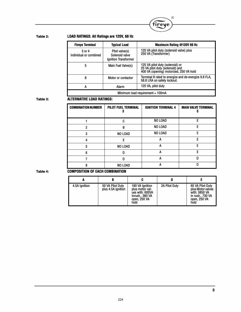
í
Ì¿¾´» îæ ÔÑßÜ ÎßÌ×ÒÙÍæ ß´´ ο¬·²¹ ¿®» ïîðÊô êð ئ
Ì¿¾´» íæ ßÔÌÛÎÒßÌ×ÊÛ ÔÑßÜ ÎßÌ×ÒÙÍæ
Ì¿¾´» ìæ ÝÑÓÐÑÍ×Ì×ÑÒ ÑÚ ÛßÝØ ÝÑÓÞ×ÒßÌ×ÑÒ
Ú·®»§» Ì»®³·²¿´ ̧°·½¿´ Ô±¿¼ Ó¿¨·³«³ ο¬·²¹ àïîðÊ êð ئ
í ±® ìײ¼·ª·¼«¿´ ±® ½±³¾·²»¼
з´±¬ ª¿´ª»ø÷ͱ´»²±·¼ ª¿´ª»
×¹²·¬·±² Ì®¿²º±®³»®
ïîë Êß °·´±¬ ¼«¬§ ø±´»²±·¼ ª¿´ª»÷ °´«îëð Êß øÌ®¿²º±®³»®÷
ë Ó¿·² Ú«»´ Ê¿´ª»ø÷ ïîë Êß °·´±¬ ¼«¬§ ø±´»²±·¼÷ ±®îë Êß °·´±¬ ¼«¬§ ø±´»²±·¼÷ ¿²¼ìðð Êß ø±°»²·²¹÷ ³±¬±®·¦»¼ô îëð Êß ¸±´¼
è Ó±¬±® ±® ½±²¬¿½¬±® Ì»®³·²¿´ è ®¿¬»¼ ¬± »²»®¹·¦» ¿²¼ ¼»ó»²»®¹·¦» çòè ÚÔßô ëèòè ÔÎß ±² ¿º»¬§ ´±½µ±«¬ò
ß ß´¿®³ ïîë Êßô °·´±¬ ¼«¬§
Ó·²·³«³ ´±¿¼ ®»¯«·®»³»²¬ ã ïðð³ß
ÝÑÓÞ×ÒßÌ×ÑÒ ÒËÓÞÛÎ Ð×ÔÑÌ ÚËÛÔ ÌÛÎÓ×ÒßÔ í
×ÙÒ×Ì×ÑÒ ÌÛÎÓ×ÒßÔ ì Óß×Ò ÊßÔÊÛ ÌÛÎÓ×ÒßÔ ë
ï Ý ÒÑ ÔÑßÜ Û
î Þ ÒÑ ÔÑßÜ Û
í ÒÑ ÔÑßÜ ÒÑ ÔÑßÜ Û
ì Û ß Û
ë ÒÑ ÔÑßÜ ß Û
ê Ü ß Û
é Ü ß Ü
è ÒÑ ÔÑßÜ ß Ü
ß Þ Ý Ü Û
ìòëß ×¹²·¬·±² ëð Êß Ð·´±¬ Ü«¬§ °´« ìòëß ·¹²·¬·±²
ïèð Êß ×¹²·¬·±² °´« ³±¬±® ª¿´ó«» ©·¬¸æ êððÊß ·²®«¸òô íêð Êß ±°»²ô îëð Êß ¸±´¼
îß Ð·´±¬ Ü«¬§ êë Êß Ð·´±¬ Ü«¬§ °´« Ó±¬±® ª¿´ª» ©·¬¸æ íèëð Êß ·² ®«¸òô éðð Êß ±°»²ô îëð Êß ¸±´¼
224
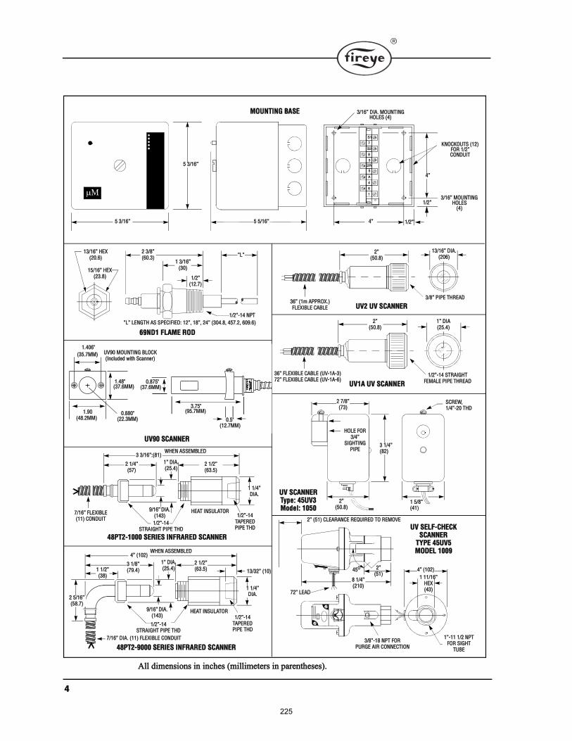
ì
ØÑÔÛ ÚÑÎíñì
Í×ÙØÌ×ÒÙÐ×ÐÛ
ÍÝÎÛÉôïñìóîð ÌØÜ
î øëï÷ ÝÔÛßÎßÒÝÛ ÎÛÏË×ÎÛÜ ÌÑ ÎÛÓÑÊÛ
îøëï÷
ïñîóïìÍÌÎß×ÙØÌ Ð×ÐÛ ÌØÜ
è ïñìøîïð÷
ìëÑ
íñèóïè ÒÐÌ ÚÑÎÐËÎÙÛ ß×Î ÝÑÒÒÛÝÌ×ÑÒ
ì øïðî÷
ï ïïñïêØÛÈøìí÷
ïóïï ïñî ÒÐÌÚÑÎ Í×ÙØÌ
ÌËÞÛ
îøëðòè÷
íê øï³ ßÐÐÎÑÈò÷ÚÔÛÈ×ÞÔÛ ÝßÞÔÛ
íñè Ð×ÐÛ ÌØÎÛßÜ
ïíñïê Ü×ßòøîðê÷
ËÊî ËÊ ÍÝßÒÒÛÎ
ËÊ ÍÛÔÚóÝØÛÝÕÍÝßÒÒÛÎ
ÌÇÐÛ ìëËÊëÓÑÜÛÔ ïððç
îøëðòè÷
ïñîóïì ÍÌÎß×ÙØÌÚÛÓßÔÛ Ð×ÐÛ ÌØÎÛßÜ
ï Ü×ßøîëòì÷
ËÊïß ËÊ ÍÝßÒÒÛÎ
íê ÚÔÛÈ×ÞÔÛ ÝßÞÔÛ øËÊóïßóí÷éî ÚÔÛÈ×ÞÔÛ ÝßÞÔÛ øËÊóïßóê÷
éî ÔÛßÜ
î éñèøéí÷
îøëðòè÷
ï ëñèøìï÷
í ïñìøèî÷
ËÊ ÍÝßÒÒÛÎ̧°»æ ìëËÊíÓ±¼»´æ ïðëð
î íñèøêðòí÷
ï íñïêøíð÷
ïñîøïîòé÷
Ô
ïñîóïì ÒÐÌ
ïíñïê ØÛÈøîðòê÷
ïëñïê ØÛÈøîíòè÷
Ô ÔÛÒÙÌØ ßÍ ÍÐÛÝ×Ú×ÛÜæ ïîô ïèô îì øíðìòèô ìëéòîô êðçòê÷
êçÒÜï ÚÔßÓÛ ÎÑÜ
î ïñìøëé÷
î ïñîøêíòë÷
í íñïêæøèï÷ÉØÛÒ ßÍÍÛÓÞÔÛÜ
ï ïñì Ü×ßò
çñïê Ü×ßòøïìí÷
ï Ü×ßòøîëòì÷
ØÛßÌ ×ÒÍËÔßÌÑÎéñïê ÚÔÛÈ×ÞÔÛøïï÷ ÝÑÒÜË×Ì
ïñîóïìÌßÐÛÎÛÜÐ×ÐÛ ÌØÜ
ïñîóïìÍÌÎß×ÙØÌ Ð×ÐÛ ÌØÜ
ìèÐÌîóïððð ÍÛÎ×ÛÍ ×ÒÚÎßÎÛÜ ÍÝßÒÒÛÎ
í ïñèøéçòì÷
î ïñîøêíòë÷
ì øïðî÷ÉØÛÒ ßÍÍÛÓÞÔÛÜ
ï ïñì Ü×ßò
çñïê Ü×ßòøïìí÷
ï Ü×ßòøîëòì÷
ØÛßÌ ×ÒÍËÔßÌÑÎ
éñïê Ü×ßò øïï÷ ÚÔÛÈ×ÞÔÛ ÝÑÒÜË×Ì
ïñîóïìÌßÐÛÎÛÜÐ×ÐÛ ÌØÜ
î ëñïêøëèòé÷
ï ïñîøíè÷
ïíñíî øïð÷
ìèÐÌîóçððð ÍÛÎ×ÛÍ ×ÒÚÎßÎÛÜ ÍÝßÒÒÛÎ
ËÊçð ÍÝßÒÒÛÎ
ë íñïê
ë íñïê
ÓÑËÒÌ×ÒÙ ÞßÍÛ
ë ëñïê
ì
ì ïñî
ïñî
íñïê Ü×ßò ÓÑËÒÌ×ÒÙ ØÑÔÛÍ øì÷
ÕÒÑÝÕÑËÌÍ øïî÷ÚÑÎ ïñîÝÑÒÜË×Ì
ß´´ ¼·³»²·±² ·² ·²½¸» ø³·´´·³»¬»® ·² °¿®»²¬¸»»÷ò
Íï
é
Íî
è
í
îñÒ
ë
ß
ì
ï
ê
íñïê ÓÑËÒÌ×ÒÙ ØÑÔÛÍ
øì÷
ðòèèðþøîîòíÓÓ÷
ïòçðøìèòîÓÓ÷
ïòìðêþ
øíëòéÓÓ÷
ïòìèþøíéòêÓÓ÷
ðòèéëþøíéòêÓÓ÷
íòéëþøçëòéÓÓ÷
ðòëþøïîòéÓÓ÷
ËÊçð ÓÑËÒÌ×ÒÙ ÞÔÑÝÕøײ½´«¼»¼ ©·¬¸ ͽ¿²²»®÷
225
ë
ßÐÐÎÑÊßÔÍ
˲¼»®©®·¬»® Ô¿¾±®¿¬±®·» ײ½òæ
ÓÝÝÆ Ú·´» ÓÐ ïëíé
ݱ²¬®±´ô Ю·³¿®§ Í¿º»¬§ ó Ô·¬»¼
ÓÝÝÆî Ú·´» ÓÐïëíé
ݱ²¬®±´ô Ю·³¿®§ Í¿º»¬§ ó ݱ³°±²»²¬
ÓÝÝÆé Ú·´» ÓÐïëíé
ݱ²¬®±´ô Ю·³¿®§ Í¿º»¬§ Ý»®¬·º·»¼ º±® Ý¿²¿¼¿
ÓÝÝÆè º·´» ÓÐïëíé
ݱ²¬®±´ô Ю·³¿®§ Í¿º»¬§ Ý»®¬·º·»¼ º±® Ý¿²¿¼¿ ó ݱ³°±²»²¬
Ú¿½¬±®§ Ó«¬«¿´ ͧ¬»³ øÚÓ÷ ß°°®±ª»¼
ËÔ ¿°°®±ª¿´ ¼±» ²±¬ ¿°°´§ ¬± îíðÊßÝ ±°»®¿¬·±²ò
ÉßÎÒ×ÒÙæ ̸· »¯«·°³»²¬ · ¿ Ý´¿ Þ ¼·¹·¬¿´ ¿°°¿®¿¬« ©¸·½¸ ½±³°´·» ©·¬¸ ¬¸» ο¼·±×²¬»®º»®»²½» λ¹«´¿¬·±²ô ÝÎÝ ½òïíéìò
ÝßËÌ×ÑÒæ Ы¾´·¸»¼ ´±¿¼ ®¿¬·²¹ ¿«³» ¬¸¿¬ ²± ½±²¬®±´ ¾» ®»¯«·®»¼ ¬± ¸¿²¼´» ·²®«¸½«®®»²¬ ³±®» ±º¬»² ¬¸¿² ±²½» ·² ïë »½±²¼ò ̸» «» ±º ½±²¬®±´ ©·¬½¸»ô ±´»²±·¼ô ®»´¿§ô»¬½ò ©¸·½¸ ½¸¿¬¬»® ©·´´ ´»¿¼ ¬± °®»³¿¬«®» º¿·´«®»ò ׬ · ·³°±®¬¿²¬ ¬± ®«² ¬¸®±«¹¸ ¿ ¬»¬±°»®¿¬·±² ø©·¬¸ º«»´ ¸«¬ ±ºº÷ º±´´±©·²¹ ¬¸» ¬®·°°·²¹ ±º ¿ ½·®½«·¬ ¾®»¿µ»®ô ¿ ¾´±©² º«»ô ±®¿²§ ·²¬¿²½» ±º ½¸¿¬¬»®·²¹ ±º ¿²§ »¨¬»®²¿´ ½«®®»²¬ ½±²«³·²¹ ¼»ª·½»ò
ÉßÎÒ×ÒÙæ Í»´»½¬·±² ±º °®±¹®¿³³»® ¿²¼ ¿³°´·º·»® ¬§°» º±® ¿ °¿®¬·½«´¿® ¿°°´·½¿¬·±² ¸±«´¼
¾» ³¿¼» ¾§ ¿ ½±³°»¬»²¬ °®±º»·±²¿´ô «½¸ ¿ ¿ Þ±·´»®ñÞ«®²»® ¬»½¸²·½·¿² ´·½»²»¼ ¾§ ¿ ¬¿¬»
±® ¹±ª»®²³»²¬ ¿¹»²½§ô »²¹·²»»®·²¹ °»®±²²»´ ±º ¬¸» ¾«®²»®ô ¾±·´»® ±® º«®²¿½» ³¿²«º¿½¬«®»®
øÑÛÓ÷ ±® ·² ¬¸» °»®º±®³¿²½» ±º ¼«¬·» ¾¿»¼ ±² ¬¸» ·²º±®³¿¬·±² º®±³ ¬¸» ÑÛÓò
ÉßÎÒ×ÒÙæ ̸· »¯«·°³»²¬ ¹»²»®¿¬» ¿²¼ ½¿² ®¿¼·¿¬» ®¿¼·± º®»¯«»²½§ »²»®¹§ô ¿²¼ ·º ²±¬
·²¬¿´´»¼ ¿²¼ «»¼ ·² ¿½½±®¼¿²½» ©·¬¸ ¬¸» ·²¬®«½¬·±² ³¿²«¿´ ³¿§ ½¿«» ·²¬»®º»®»²½» ¬±
®¿¼·± ½±³³«²·½¿¬·±²ò ׬ ¸¿ ¾»»² ¬»¬»¼ ¿²¼ º±«²¼ ¬± ½±³°´§ ©·¬¸ ¬¸» ´·³·¬ º±® ¿ Ý´¿ ß
½±³°«¬·²¹ ¼»ª·½» °«®«¿²¬ ¬± Í«¾°¿®¬ Ö ±º °¿®¬ ïë ±º ÚÝÝ Î«´»ô ©¸·½¸ ¿®» ¼»·¹²»¼ ¬± °®±ó
ª·¼» ®»¿±²¿¾´» °®±¬»½¬·±² ¿¹¿·²¬ «½¸ ·²¬»®º»®»²½» ©¸»² ±°»®¿¬»¼ ·² ¿ ½±³³»®½·¿´ »²ª·ó
®±²³»²¬ò Ñ°»®¿¬·±² ±º ¬¸· »¯«·°³»²¬ ·² ¿ ®»·¼»²¬·¿´ ¿®»¿ · ´·µ»´§ ¬± ½¿«» ·²¬»®º»®»²½» ·²
©¸·½¸ ½¿» ¬¸» «»®ô ¿¬ ¸· ±©² »¨°»²»ô ©·´´ ¾» »¯«·°°»¼ ¬± ¬¿µ» ©¸¿¬»ª»® ³»¿«®» ¬¸¿¬
³¿§ ¾» ®»¯«·®»¼ ¬± ½±®®»½¬ ¬¸» °®±¾´»³ò
ײ ±®¼»® º±® ¬¸» Ó·½®±Ó ¬± ¹¿¬¸»® ¿²¼ ®»¬¿·² ¬¿¬·¬·½¿´ ¿²¼ ¸·¬±®·½ ¼¿¬¿ «½¸ ¿ ¾«®²»®
¸±«®ô ¾«®²»® ½§½´»ô §¬»³ ¸±«® ¿²¼ ¿ª»®¿¹» º´¿³» ·¹²¿´ô ·¬ · ²»½»¿®§ ¬¸¿¬ Ì»®³·²¿´ ï
¾» °±©»®»¼ ¿¬ ¿´´ ¬·³»ò λ³±ª·²¹ °±©»® º®±³ Ì»®³·²¿´ ï ¿¬ ¬¸» »²¼ ±º ¬¸» º·®·²¹ ½§½´»
½¿«» ¿´´ ¼¿¬¿ ¹¿¬¸»®»¼ ¼«®·²¹ ¬¸» °®»ª·±« ïê ¸±«® ±® ´¿¬ ç ½§½´» ¬± ¾» ´±¬ò Ú±® ½±²ª»®ó
·±² ±® «°¹®¿¼» º®±³ ±´¼»® ÌÚÓ ±® ÓóÍ»®·» ×× ½±²¬®±´ ¬¸¿¬ «» ÓßÎÌï ¿³°´·º·»®ô ·¬ ·
²»½»¿®§ ¬¸¿¬ Ì»®³·²¿´ ï ¾» ¼·®»½¬´§ °±©»®»¼ ©·¬¸ ïîð ÊßÝò
á
226
ê
ÑÎÜÛÎ×ÒÙ ×ÒÚÑÎÓßÌ×ÑÒ
öÍ°¿®µ ×¹²·¬»® Í»²·²¹ л®·±¼
Ó·½®±Ó ݸ¿· ̧°» øÚ±® «» ©·¬¸ ÓÛÐïÈÈô ÓÛÐîÈÈô ¿²¼ ÓÛÐëÈÈô ·²½´«¼» ¼«¬ ½±ª»®÷
ÓÛÝïîð ïîð ÊßÝ ·²°«¬ ©·¬¸ ¬¿²¼¿®¼ °´«¹ó·² ¾±¿®¼ò
ÓÛÝïîðÎ ïîð ÊßÝ ·²°«¬ ©·¬¸ ®»³±¬» ®»»¬ ½¿°¿¾·´·¬§ò
ÓÛÝïîðÜ ïîð ÊßÝ ·²°«¬ ©·¬¸ ¿´°¸¿ó²«³»®·½ ¼·°´¿§ ·²¬»®º¿½» ¬± ÛÜëïðò
ÓÛÝïîðÎÜ ïîð ÊßÝ ·²°«¬ ©·¬¸ ¿´°¸¿ó²«³»®·½ ¼·°´¿§ ·²¬»®º¿½» ¬± ÛÜëïð ¿²¼ ®»³±¬» ®»»¬ ½¿°¿¾·´·¬§ò
ÓÛÝïîðÝ ïîð ÊßÝ ·²°«¬ ©·¬¸ ·²¬»®º¿½» ¬± Ûëðð ݱ³³«²·½¿¬·±² ײ¬»®º¿½» ¿²¼ Ó±¼¾« ½¿°¿¾·´·¬§ò
ÓÛÝïîðÎÝ ïîð ÊßÝ ·²°«¬ ©·¬¸ ®»³±¬» ®»»¬ ½¿°¿¾·´·¬§ô ¿´°¸¿ó²«³»®·½ ¼·°´¿§ ·²¬»®º¿½» ¬± ÛÜëïðô ·²¬»®º¿½» ¬± Ûëðð ݱ³³«²·½¿ó¬·±² ײ¬»®º¿½» ¿²¼ Ó±¼¾« ½¿°¿¾·´·¬§ò
ÓÛÝîíð îíð ÊßÝ ·²°«¬ ©·¬¸ ¬¿²¼¿®¼ °´«¹ó·² ¾±¿®¼ò
ÓÛÝîíðÎÝ îíð ÊßÝ ·²°«¬ ©·¬¸ ®»³±¬» ®»»¬ ½¿°¿¾·´·¬§ô ¿´°¸¿ó²«³»®·½ ¼·°´¿§ ·²¬»®º¿½» ¬± ÛÜëïðô ¿²¼ Ó±¼¾« ½¿°¿¾·´·¬§ò
Ó·½®±Ó ݸ¿· ̧°» øÚ±® «» ©·¬¸ ÓÛÐíÈÈô ÓÛÐìÈÈô ¿²¼ ÓÛÐêÈÈô ·²½´«¼» ¼«¬ ½±ª»®÷
ÓÛÝíîð ïîð ÊßÝ ·²°«¬ ©·¬¸ ¬¿²¼¿®¼ °´«¹ó·² ¾±¿®¼ò
ÓÛÝíîðÎ ïîð ÊßÝ ·²°«¬ ©·¬¸ ®»³±¬» ®»»¬ ½¿°¿¾·´·¬§ò
ÓÛÝíîðÜ ïîð ÊßÝ ·²°«¬ ©·¬¸ ¿´°¸¿ó²«³»®·½ ¼·°´¿§ ·²¬»®º¿½» ¬± ÛÜëïðò
ÓÛÝíîðÎÜ ïîð ÊßÝ ·²°«¬ ©·¬¸ ¿´°¸¿ó²«³»®·½ ¼·°´¿§ ·²¬»®º¿½» ¬± ÛÜëïð ¿²¼ ®»³±¬» ®»»¬ ½¿°¿¾·´·¬§ò
ÓÛÝíîðÝ ïîð ÊßÝ ·²°«¬ ©·¬¸ ·²¬»®º¿½» ¬± Ûëðð ݱ³³«²·½¿¬·±² ײ¬»®º¿½» ¿²¼ Ó±¼¾« ½¿°¿¾·´·¬§ò
ÓÛÝíîðÎÝ ïîð ÊßÝ ·²°«¬ ©·¬¸ ®»³±¬» ®»»¬ ½¿°¿¾·´·¬§ô ¿´°¸¿ó²«³»®·½ ¼·°´¿§ ·²¬»®º¿½» ¬± ÛÜëïðô ·²¬»®º¿½» ¬± Ûëðð ݱ³³«²·½¿ó¬·±² ײ¬»®º¿½» ¿²¼ Ó±¼¾« ½¿°¿¾·´·¬§ò
ÓÛÝíîðÌÍ ïîð ÊßÝ ·²°«¬ ©·¬¸ ¼·°´¿§ ·²¬»®º¿½» ¬± ÛÜëïðô Ó±¼¾« ·²¬»®º¿½» ¿²¼ ¿«¨·´·¿®§ ®»´¿§ ±«¬°«¬ ©·¬¸ ¼®§ ½±²¬¿½¬ º±® ½±²ó¬®±´´»® ·²¬»®º¿½» øÓÛÜè÷ò
ÓÛÝìèð îíð ÊßÝ ·²°«¬ ©·¬¸ ¬¿²¼¿®¼ °´«¹ó·² ¾±¿®¼ò
ÓÛÝìèðÎÝ îíð ÊßÝ ·²°«¬ ©·¬¸ ®»³±¬» ®»»¬ ½¿°¿¾·´·¬§ô ¿´°¸¿ó²«³»®·½ ¼·°´¿§ ·²¬»®º¿½» ¬± ÛÜëïðô ¿²¼ Ó±¼¾« ½¿°¿¾·´·¬§ò
Ó·½®±Ó Ю±¹®¿³³»® Ó±¼»´ øÚ±® «» ©·¬¸ ÓÛÝïîð ¿²¼ ÓÛÝ îíð ݸ¿·÷
ÓÛÐïðð λ´·¹¸¬ ±°»®¿¬·±²ô ïð »½ò ÐÌÚ×ò
ÓÛÐïðï λ´·¹¸¬ ±°»®¿¬·±²ô ¿´´±© º´¿³» ·¹²¿´ «²¬·´ êð »½±²¼ ¿º¬»® ·²¬»®´±½µ ½´±»¼ò
ÓÛÐïðî Ò±²ó®»½§½´» ±² º´¿³» º¿·´ô ë »½±²¼ ÐÌÚ×ò
ÓÛÐïðí Ú·¨»¼ ïð »½±²¼ Í×ÍÐöô ïð »½±²¼ ÓÌÚ×ô ®»ó¬®§ ±²½» ±² ·¹²·¬»® º¿·´«®»ô º·¨»¼ íð »½±²¼ °±¬ °«®¹»ò
ÓÛÐïðì Ò±²ó®»½§½´» ±² º´¿³» º¿·´ô ïð »½±²¼ ÐÌÚ×ò
ÓÛÐïðë Ò±²ó®»½§½´» ±² º´¿³» º¿·´ô ´±½µ±«¬ ±² ¿·®óº´±© ±°»² ©·¬¸ º´¿³» °®»»²¬ô ïð »½±²¼ ÐÌÚ×ò
ÓÛÐïðê Í¿³» ¿ ÓÛÐïððò ïî »½±²¼ °®»ó°«®¹»ô ¿¼¼»¼ ®»»¬ º®±³ ´±½µ±«¬ ª·¿ ´·²» ª±´¬¿¹»ò
ÓÛÐïðé Í¿³» ¿ ÓÛÐïððò Ú±®½» ë ³·²«¬» °«®¹» ¼»´¿§ ¿º¬»® ³¿·² º´¿³» º¿·´ò
ÓÛÐïðè Í¿³» ¿ ÓÛÐïðð ©·¬¸ ð »½±²¼ °«®¹»ô ïë »½±²¼ ÐÌÚ×ô ²±²ó®»½§½´» ±² º´¿³» º¿·´ò Ò±¬ ÚÓ ¿°°®±ª»¼ò
ÓÛÐïðç ׳³»¼·¿¬» ·¹²·¬·±² ¿²¼ °·´±¬ô ïð »½±²¼ º·¨»¼ ÐÌÚ×ô ïð »½±²¼ ÓÌÚ×ô ·²¬»®³·¬¬»²¬ °·´±¬ô ²±²ó®»½§½´» ±² º´¿³» º¿·´ò
ÓÛÐïððРλ´·¹¸¬ ±°»®¿¬·±²ô ïð »½ ÐÌÚ×ô º·¨»¼ ïë »½±²¼ °±¬ °«®¹»ò
ÓÛÐïíð Í¿³» ¿ ÓÛÐïððô íð »½±²¼ ÐÌÚ×ò Ò±¬ ÚÓ ¿°°®±ª»¼ò
ÓÛÐîíð Í»´»½¬¿¾´» °«®¹» ¬·³·²¹ øéô íðô êðô çð »½ò÷ ïð »½ ÐÌÚ× ¬·³·²¹ô ®»½§½´»ñ²±²ó®»½§½´»ô °±¬ °«®¹»ô °®±ª» ¿·® ±°»² ¿¬ ¬¿®¬ò
ÓÛÐîíðØ Í¿³» ¿ ÓÛÐîíð ©·¬¸ è »½±²¼ °·´±¬ ¬¿¾·´·¦¿¬·±²ò
ÓÛÐîíë Í¿³» ¿ ÓÛÐîíð ©·¬¸ ´±½µ±«¬ ±² ¿·® º´±© ±°»² ïð »½±²¼ ¿º¬»® ¬¸» ¬¿®¬ ±º ¿ ½§½´»ô »´»½¬¿¾´» ®»½§½´»ñ²±²®»½§½´» ´±½µ±«¬ ±² ¿·® º´±© ±°»² ¿º¬»® º´¿³» · °®±ª»² ¿²¼ ¼»¼·½¿¬»¼ ´±½µ±«¬ ¿º¬»® ´± ±º º´¿³»ò
ÓÛÐîíê Í¿³» ¿ ÓÛÐîíð ©·¬¸ ¿¼¼·¬·±²¿´ ê »½±²¼ ·¹²·¬»® ±² ¬·³» ©·¬¸ ³¿·² º«»´ò ̱ ¾» «»¼ ©·¬¸ ·²¬»®³·¬¬»²¬ °·´±¬ ±²´§ò
ÓÛÐîíé Í¿³» ¿ ÓÛÐîíð ©·¬¸ º·¨»¼ ÐÌÚ× ¬·³·²¹ ¿²¼ ½¸»½µñ®«² ©·¬½¸ò Ë»¼ ©·¬¸ ÓÛÜÝî ¿³°´·º·»® ¬± °®±ª·¼» ±°»®¿¬·±² ©·¬¸ èë Í»®·» øи±»²·¨÷ ¿²¼ çë Í»®·» øײͷ¹¸¬÷ ½¿²²»®ò
ÓÛÐîíè Í¿³» ¿ ÓÛÐîíðò ×¹²·¬·±² ¼»ó»²»®¹·¦»¼ í »½±²¼ ¿º¬»® °·´±¬ º´¿³» ¼»¬»½¬»¼ò Ю±ª·¼» è »½±²¼ °·´±¬ ¬¿¾·´·¦¿¬·±² °»®·±¼ò
ÓÛÐîçð Í¿³» ¿ ÓÛÐîí𠻨½»°¬ »´»½¬¿¾´» °±¬ °«®¹» · ð ±® çð »½±²¼ò
ÓÛÐëêð Í¿³» ¿ ÓÛÐîíðØô ïð »½±²¼ ³¿·² ¬®·¿´ º±® ·¹²·¬·±²ô ®«²ó½¸»½µ ©·¬½¸ò
ÓÛÐëêï Í¿³» ¿ ÓÛÐëêð ©·¬¸±«¬ è »½±²¼ °·´±¬ ¬¿¾·´·¦¿¬·±²ò Í»´»½¬¿¾´» °«®¹» ¬·³» ±º éô ïðô ïëô íðò
ÓÛÐëêî Í¿³» ¿ ÓÛÐëêðô ´±½µ±«¬ ±² ´± ±º ¿·® º´±©ô ²±²ó®»½§½´» ±°»®¿¬·±² ±²´§ò
ÓÛÐëêì Í¿³» ¿ ÓÛÐëêðò Í»´»½¬¿¾´» °«®¹» ¬·³» ±º éô íðô êðô îìðò
ÓÛÐëíê Í¿³» ¿ ÓÛÐîíðô ïð »½±²¼ ³¿·² ¬®·¿´ º±® ·¹²·¬·±²ô ®«²ó½¸»½µ ©·¬½¸ô ©·´´ ²±¬ ´±½µ±«¬ ±² ¿·® º´±© ±°»² ¼«®·²¹ °«®¹»ò
ÓÛÐëíé Í¿³» ¿ ÓÛÐëíê »¨½»°¬ °®±ª·¼» ±²» ®»½§½´» ±² ³¿·² º´¿³» º¿·´«®»ò
227
é
Ó·½®±Ó Ю±¹®¿³³»® Ó±¼»´ øÚ±® «» ©·¬¸ ÓÛÝíîð ¿²¼ ÓÛÝ ìèð ݸ¿·÷
ÓÛÐíðð λ´·¹¸¬ ±°»®¿¬·±²ô ïð »½ò º·¨»¼ ÐÌÚ×ô ë »½ò°·´±¬ °®±ª·²¹ °»®·±¼ô ë »½±²¼ ÓÌÚ×ò ´±½µ±«¬ ±² º´¿³» º¿·´ ¼«®·²¹ ÐÌÚ×ô °·´±¬ °®±ª·²¹ ¿²¼ ÓÌÚ×ò 뽧½´» ±² ¿·® º´±© ±°»²ò Ò± °±¬ °«®¹»ò 뻬 ±² ´·²» ª±´¬¿¹»ò
ÓÛÐíðì Ò±²ó®»½§½´» ±² º´¿³» º¿·´ô ë »½ò °«®¹»ô ïð »½òº·¨»¼ ÐÌÚ×ô ë »½ò °·´±¬ °®±ª·²¹ô ïð »½òÓÌÚ×ô ·²¬»®®«°¬»¼ °·´±¬ô »¿®´§ °¿®µ ¬»®³·²¿¬·±²ò
ÓÛÐííë Ò±²ó®»½§½´» ±² º´¿³» º¿·´ô íð »½±²¼ °«®¹»ô íë »½±²¼ ¸±¬ «®º¿½» ·¹²·¬·±² ±² ¬»®³·²¿´ ìô í »½±²¼ ÐÌÚ× ±² ¬»®³·²¿´ íô ë »½±²¼ °·´±¬ °®±ª·²¹ °»®·±¼ô ·²¬»®³·¬¬»²¬ °·´±¬ô ïë »½±²¼ °±¬ °«®¹»ò Ó¿²«¿´ ®»»¬ ±²´§ò
ÓÛÐíçé 뽧½´» ±² ³¿·² º´¿³» º¿·´ô ïë »½ò °«®¹»ô é »½±²¼ º·¨»¼ ÐÌÚ×ô ë »½ò °·´±¬ °®±ª·²¹ ë »½ò ÓÌÚ×ô »¿®´§ °¿®µ ¬»®³·²¿¬·±² ¿²¼ ·²¬»®®«°¬»¼ °·´±¬ò 뽧½´» ±² ¿·® º´±© º¿·´«®»ò Ò± °±¬ °«®¹»ô ®«²ñ½¸»½µ ©·¬½¸ò 뻬 ±² ´·²» ª±´¬¿¹»ò
ÓÛÐìíé 뽧½´» ±²½» ±² ³¿·² º´¿³» º¿·´«®»ô »´»½¬¿¾´» ë ±® ïð »½ò º·¨»¼ ÐÌÚ×ô »´»½¬¿¾´» ·²¬»®®«°¬»¼ ±® ·²¬»®³·¬¬»²¬ °·´±¬ô ë »½ò ÓÌÚ×ô »´»½¬¿¾´» °«®¹» ¬·³» ¬± îìð »½±²¼ô ³¿·² ª¿´ª» °®±±º ±º ½´±«®»ô ïë »½ò °±¬ °«®¹»ò 뻬 ±² ´·²» ª±´¬¿¹»ò
ÓÛÐêçê Ю±ª·¼» íð »½ò °®»ó°«®¹»ô ´±½µ±«¬ ±² ¿·®º´±© ¿º¬»® ïð »½òô ïð »½ò ÐÌÚ×ô ë »½ò °·´±¬ °®±ª·²¹ô »¿®´§ °¿®µ ¬»®³·²¿¬·±²ô ë »½ò ÓÌÚ×ô ·²¬»®®«°¬»¼ °·´±¬ô »´»½¬¿¾´» ®»½§½´»ñ²±²ó®»½§½´» ±² º´¿³» º¿·´ô êð »½ò °±¬ °«®¹»ô »´»½¬¿¾´» ¾¿«¼ ®¿¬» º±® ½±³³«²·½¿¬·±²ô ±«¬°«¬ º±® »¨¬»®²¿´ ½±²¬®±´´»® ±°»®¿¬·±²ò
ÓÛÐêçé Ю±ª·¼» ¼·°ó©·¬½¸ »´»½¬¿¾´» °®»ó°«®¹»ô »´»½¬¿¾´» ¿·® º´±© °®±ª·²¹ ¿¬ ¬¿®¬«°ô »´»½¬¿¾´» °±¬ °«®¹»ô »´»½¬¿¾´» ëñïð »½ò ÐÌÚ×ô ë »½ò °·´±¬ °®±ª·²¹ »¿®´§ °¿®µ ¬»®³·²¿¬·±²ô ë »½ò ÓÌÚ×ô ·²¬»®®«°¬»¼ °·´±¬ô »´»½¬¿¾´» ®»½§½´»ñ²±² ®»½§½´» ±² º´¿³» º¿·´ô ±«¬°«¬ º±® »¨¬»®²¿´ ½±²¬®±´´»® ±°»®¿¬·±²ò
Ó·½®±Ó ß³°´·º·»® Ó±¼»´æ
ÓÛËÊï ËÊ ¿³°´·º·»®ô ðòè »½±²¼ ÚÚÎÌô «» ËÊïßô ËÊîô ËÊèßô ËÊçð ¿²¼ ìëËÊíóïðë𠽿²²»®ò
ÓÛËÊì ËÊ ¿³°´·º·»®ô í »½±²¼ ÚÚÎÌô «» ËÊïßô ËÊîô ËÊèßô ËÊçð ¿²¼ ìëËÊíóïðë𠽿²²»®ò
ÓÛËÊÍï ËÊ Í»´ºóݸ»½µ ¿³°´·º·»®ô ðòè »½±²¼ ÚÚÎÌô «» ìëËÊëóïððç ½¿²²»®ò
ÓÛËÊÍì ËÊ Í»´ºóݸ»½µ ¿³°´·º·»®ô í »½±²¼ ÚÚÎÌô «» ìëËÊëóïððç ½¿²²»®ò
ÓÛÎÌï Ú´¿³» α¼ ¿³°´·º·»®ô ðòè »½±²¼ ÚÚÎÌô «» êçÒÜïò
ÓÛÎÌì Ú´¿³» α¼ ¿³°´·º·»®ô í »½±²¼ ÚÚÎÌô «» êçÒÜïò
ÓÛ×Îï ײº®¿®»¼ ¿³°´·º·»®ô ðòè »½±²¼ ÚÚÎÌô «» ìèÐÌî ½¿²²»®ò
ÓÛ×Îì ײº®¿®»¼ ¿³°´·º·»®ô í »½±²¼ ÚÚÎÌô «» ìèÐÌî ½¿²²»®ò
ÓÛÝÜï Ý¿¼³·«³ «´º·¼» ¿³°´·º·»®ô ðòè »½±²¼ ÚÚÎÌô «» ÝÍïßë ½¿²²»®ò
ÓÛÝÜì Ý¿¼³·«³ «´º·¼» ¿³°´·º·»®ô í »½±²¼ ÚÚÎÌô «» ÝÍïßë ½¿²²»®ò
ÓÛÜÝî ݱ²¬¿½¬ ·²°«¬ ¿³°´·º·»® º±® «» ©·¬¸ ÓÛÐîíé ¬± °®±ª·¼» ±°»®¿¬·±² ©·¬¸ èë Í»®·» øи±»²·¨÷ ¿²¼ çë Í»®·» øײͷ¹¸¬÷ ½¿²²»®
Ñ°¬·±²¿´ д«¹óײ Þ±¿®¼ Ó±¼«´»æ
ÓÛÜï ͬ¿²¼¿®¼ ´±½¿´ ®»»¬ ©·¬½¸ò
ÓÛÜî Í¿³» ¿ ÓÛÜï ©·¬¸ ¼·°´¿§ ±«¬°«¬ò
ÓÛÜí Í¿³» ¿ ÓÛÜï ©·¬¸ ®»³±¬» ®»»¬ò
ÓÛÜì Í¿³» ¿ ÓÛÜï ©·¬¸ ¼·°´¿§ ±«¬°«¬ ¿²¼ ®»³±¬» ®»»¬ò
ÓÛÜë Í¿³» ¿ ÓÛÜï ©·¬¸ ¼·°´¿§ ±«¬°«¬ ¿²¼ ÎÍìèë ½±³³«²·½¿¬·±²ò
ÓÛÜê Í¿³» ¿ ÓÛÜï ©·¬¸ ¼·°´¿§ ±«¬°«¬ô ®»³±¬» ®»»¬ ¿²¼ ÎÍìèë ½±³³«²·½¿¬·±²ò
ÓÛÜé Í¿³» ¿ ÓÛÜï ©·¬¸ ÎÍìèë ½±³³«²·½¿¬·±²ò
ÓÛÜè Í¿³» ¿ ÓÛÜï ©·¬¸ ¼·°´¿§ ±«¬°«¬ô ÎÍìèë Ó±¼¾« ·²¬»®º¿½» ¿²¼ ¿«¨·´·¿®§ ®»´¿§ ±«¬°«¬ ©·¬¸ ²±®³¿´´§ ½´±»¼ ¼®§ ½±²¬¿½¬ º±® ½±²¬®±´´»® ·²¬»®º¿½»ò
ÓÛÜç Í¿³» ¿ ÓÛÜï ©·¬¸ ¼·°´¿§ ±«¬°«¬ô ÎÍìèë Ó±¼¾« ·²¬»®º¿½» ¿²¼ ¿«¨·´·¿®§ ®»´¿§ ±«¬°«¬ ©·¬¸ ²±®³¿´´§ ±°»² ¼®§ ½±²¬¿½¬ º±® ½±²¬®±´´»® ·²¬»®º¿½»ò
É·®·²¹ Þ¿» øݱ³³±² º±® ¿´´ ݱ²¬®±´÷æ
êïóíðêð Ý´±»¼ ©·®·²¹ ¾¿»ô «®º¿½» ³±«²¬·²¹ò
êïóëðìî Ñ°»² ©·®·²¹ ¾¿»ô ½¿¾·²»¬ ³±«²¬·²¹ò
228
è
ÚÔßÓÛ ÍÝßÒÒÛÎÍ
Ú±® ¿ ½±³°´»¬» §¬»³ô ½¸±±» ±²» ±º »¿½¸ ±º ¬¸» º±´´±©·²¹æ
ó ݸ¿· ó Ú´¿³» Ü»¬»½¬±®
ó Ю±¹®¿³³»® Ó±¼«´» ó É·®·²¹ Þ¿»
ó ß³°´·º·»® Ó±¼«´»
ß½½»±®·»
ÛÜëïð Ì©± ´·²» ¾§ ïê ½¸¿®¿½¬»®ô ¾¿½µ ´·¬ ÔÝÜ ¼·°´¿§ ©·¬¸ µ»§°¿¼ò
ÛÜëèðóîô óìô óè λ³±¬» ¼·°´¿§ ½¿¾´» ©·¬¸ ÎÖìë ½±²²»½¬·±² ·² îô ì ±® è º±±¬ ´±²¹ ´»²¹¬¸ò ̱ ¾» «»¼ ©·¬¸ ¬¸» ¿°°®±°®·¿¬» ¼¿«¹¸¬»® ¾±¿®¼ò
ÛÝìèë ÎÍîíî ¬± ÎÍìèë ½±²ª»®¬»® ©·¬¸ °±©»® «°°´§ ¿²¼ ÎÖïî ¶¿½µò
ËÝìèë ËÍÞ ¬± ÎÍìèë ½±²ª»®¬»®ò Í«°°´·»¼ ©·¬¸ ËÍÞ ½¿¾´»ò
ÍÓÜÕóïððì Í»®ª·½»³¿² ¼·°´¿§ µ·¬ «»¼ º±® ¼·¿¹²±·²¹ Ó·½®±Ó §¬»³ò ݱ²·¬ ±º ÛÜëï𠻯«·°°»¼ ©·¬¸ ¾¿½µ °´¿¬»ô ÓÛÜ ¼¿«¹¸¬»® ¾±¿®¼ ¿²¼ ÛÜëèðóìò
ïîçóïìëóïô óîô óí ÛÜëïð ®»³±¬» ¼·°´¿§ ³±«²¬·²¹ µ·¬ ©·¬¸ ìô è ±® î ½¿¾´» ®»°»½¬·ª»´§ò Ю±ª·¼» ÒÛÓß ì °®±¬»½¬·±²ò
×Ìïððð Ó±²·¬±®·²¹ ¼»ª·½» «·²¹ ½»´´«´¿® ²»¬©±®µò Ю±ª·¼» ª¿®·±« ®»°±®¬·²¹ ³»¬¸±¼
ÝßËÌ×ÑÒæ ̸» ËÊïßô ËÊîô ËÊèßô ËÊçð ¿²¼ ìëËÊí «´¬®¿óª·±´»¬ º´¿³» ½¿²²»® ¿²¼ ¿±ó
½·¿¬»¼ ¿³°´·º·»® ³±¼«´» ¿®» ²±² »´ºó½¸»½µ·²¹ ËÊ §¬»³ ¿²¼ ¸±«´¼ ¾» ¿°°´·»¼ ±²´§ ¬±
¾«®²»® ¬¸¿¬ ½§½´» ±º¬»² ø»ò¹òæ ¿ ³·²·³«³ ±º ±²½» °»® ïî ¸±«®÷ ·² ±®¼»® º±® ¬¸» ¿º»¬§ ½¸»½µó
·²¹ ½·®½«·¬ ¬± ¾» »¨»®½·»¼ò ׺ ½±³°±²»²¬ ½¸»½µ·²¹ · ®»¯«·®»¼ ¼«®·²¹ ¾«®²»® ±°»®¿¬·±² º±®
½±²¬¿²¬´§ º·®»¼ ¾«®²»®ô «¬·´·¦» ¬¸» »´ºó½¸»½µ·²¹ «´¬®¿óª·±´»¬ º´¿³» ½¿²²»® øìëËÊë÷ ©·¬¸
¿±½·¿¬»¼ ¿³°´·º·»® ³±¼«´» øÓÛËÊÍïô ÓÛËÊÍì÷ ±® ¬¸» ·²º®¿®»¼ º´¿³» ½¿²²»® øìèÐÌî÷
©·¬¸ ¿±½·¿¬»¼ ß«¬±Ý¸»½µ ¿³°´·º·»® øÓÛ×Îïô ÓÛ×Îì÷ò
229
ç
×ÒÍÌßÔÔßÌ×ÑÒ ÑÚ ÝÑÒÌÎÑÔô ÍÝßÒÒÛÎÍ ßÒÜ ÚÔßÓÛ ÜÛÌÛÝÌÑÎÍ
É·®·²¹ Þ¿»
Ó±«²¬ ¬¸» ©·®·²¹ ¾¿» ±² ¬¸» ¾«®²»® ±® ±² ¿ °¿²»´ò ̸» ´±½¿¬·±² ¸±«´¼ ¾» º®»» º®±³ »¨½»·ª» ª·¾®¿ó
¬·±² ¿²¼ ©·¬¸·² ¬¸» °»½·º·»¼ ¿³¾·»²¬ ¬»³°»®¿¬«®» ®¿¬·²¹ò ̸» ¾¿» ³¿§ ¾» ³±«²¬»¼ ·² ¿²§ ¿²¹«´¿®
°±·¬·±²ò
ß´´ ©·®·²¹ ¸±«´¼ ½±³°´§ ©·¬¸ ¿°°´·½¿¾´» »´»½¬®·½¿´ ½±¼»ô ®»¹«´¿¬·±² ¿²¼ ´±½¿´ ±®¼·²¿²½»ò Ë»
³±·¬«®» ®»·¬¿²¬ ©·®» «·¬¿¾´» º±® ¿¬ ´»¿¬ çð ¼»¹®»» Ýò Ù±±¼ »´»½¬®·½¿´ ©·®·²¹ °®¿½¬·½» ¸±«´¼ ¾»
º±´´±©»¼ ¬± »²«®» ¿² ¿¼»¯«¿¬» ¹®±«²¼ §¬»³ò λº»® ¬± Ú·®»§» Í»®ª·½» Ò±¬» ÍÒóïðð »°¿®¿¬»´§ ¿²¼
Ù»²»®¿´ Ù®±«²¼·²¹ Ϋ´» ´¿¬»® ·² ¬¸· ¼±½«³»²¬ º±® ¹®±«²¼·²¹ ³»¬¸±¼ò
ß ¹±±¼ ¹®±«²¼ §¬»³ ¸±«´¼ ¾» °®±ª·¼»¼ ¬± ³·²·³·¦» ¬¸» »ºº»½¬ ±º ßÝ ¯«¿´·¬§ °®±¾´»³ò ß °®±°ó
»®´§ ¼»·¹²»¼ ¹®±«²¼ §¬»³ ³»»¬·²¹ ¿´´ ¬¸» ¿º»¬§ ®»¯«·®»³»²¬ ©·´´ »²«®» ¬¸¿¬ ¿²§ ßÝ ª±´¬¿¹»
¯«¿´·¬§ °®±¾´»³ô «½¸ ¿ °·µ»ô «®¹» ¿²¼ ·³°«´» ¸¿ª» ¿ ´±© ·³°»¼¿²½» °¿¬¸ ¬± ¹®±«²¼ò ß ´±©
·³°»¼¿²½» °¿¬¸ ¬± ¹®±«²¼ · ®»¯«·®»¼ ¬± »²«®» ¬¸¿¬ ´¿®¹» ½«®®»²¬ ·²ª±´ª»¼ ©·¬¸ ¿²§ «®¹» ª±´¬¿¹»
©·´´ º±´´±© ¬¸» ¼»·®»¼ °¿¬¸ ·² °®»º»®»²½» ¬± ¿´¬»®²¿¬·ª» °¿¬¸ô ©¸»®» »¨¬»²·ª» ¼¿³¿¹» ³¿§ ±½½«® ¬±
»¯«·°³»²¬ò
Ý·®½«·¬ ®»½±³³»²¼¿¬·±² ¿®» º±«²¼ ±² °¿¹» íè ¬¸®±«¹¸ ìíò ݱ²«´¬ ¬¸» º¿½¬±®§ º±® ¿·¬¿²½» ©·¬¸
²±²ó¬¿²¼¿®¼ ¿°°´·½¿¬·±²ò
ÉßÎÒ×ÒÙæ ײ¬¿´´»® ³«¬ ¾» ¬®¿·²»¼ ¿²¼ ¯«¿´·º·»¼ò Ú±´´±© ¬¸» ¾«®²»® ³¿²«º¿½¬«®»®
·²¬®«½¬·±²ô ·º «°°´·»¼ò Ѭ¸»®©·»ô °®±½»»¼ ¿ º±´´±©æ
ÉßÎÒ×ÒÙæ ݱ²¬®±´ ®»¯«·®» ¿º»¬§ ´·³·¬ «¬·´·¦·²¹ ·±´¿¬»¼ ³»½¸¿²·½¿´ ½±²¬¿½¬ò Û´»½¬®±²·½ ´·³·¬ ©·¬½¸» ³¿§ ½¿«» »®®¿¬·½ ±°»®¿¬·±² ¿²¼ ¸±«´¼ ¾» ¿ª±·¼»¼ò
Ý¿®» ³«¬ ¾» ¬¿µ»² ¬± ÒÑÌ ®±«¬» ¬¸» ¸·¹¸ »²»®¹§ ·¹²·¬·±² ©·®» ·² ½´±» °®±¨·³ó
·¬§ ¬± ¬¸» º´¿³» »²±® ©·®·²¹ô °¿®¬·½«´¿®´§ ©¸»² «·²¹ ÓÛÎÌ ¿³°´·º·»®ò
230
ïð
×ÒÍÌßÔÔ×ÒÙ ÌØÛ ÐÎÑÙÎßÓÓÛÎ ßÒÜ ßÓÐÔ×Ú×ÛÎ ÓÑÜËÔÛÍ
Ú×ÙËÎÛ ïò ò
Í»´»½¬ ¬¸» ¿°°®±°®·¿¬» °®±¹®¿³³»® ¿²¼ ¿³°´·º·»® ³±¼«´» º±® §±«® ¿°°´·½¿¬·±²ò λ³±ª» ¬¸» ¼«¬
½±ª»® º®±³ ¬¸» ½¸¿·ò ײ»®¬ ¬¸» ¿³°´·º·»® ³±¼«´» ·²¬± ¬¸» ´±¬ ·² ¬¸» ½±®²»® ±º ¬¸» ½¸¿· ¿²¼ ¹»²ó
¬´§ °«¸ ¬¸» ³±¼«´» ·²¬± °±·¬·±²ò ײ»®¬ ¬¸» °®±¹®¿³³»® ³±¼«´» ·²¬± ¬¸» ´±¬ ¿¬ ¬¸» ®·¹¸¬ ·¼» ±º ¬¸»
½¸¿· ¿²¼ ¹»²¬´§ °«¸ ¬¸» ³±¼«´» ·²¬± °±·¬·±²ò
λº»® ¬± °®±¹®¿³³»® ¼·°©·¬½¸ »¬¬·²¹ ±² °¿¹» ïï º±® ¬¸» °®±°»® »¬¬·²¹ ±º ¬¸» ¼·°©·¬½¸»º±® ¬¸±» °®±¹®¿³³»® ©·¬¸ ¬¸· º»¿¬«®»ò
λ°´¿½»¿¾´» Ú«»
̸» ½¸¿· ³±¼«´» ¿®» ¼»·¹²»¼ ©·¬¸ ¿ º·»´¼ ®»°´¿½»¿¾´» º«»ò ̸» º«» · ´±½¿¬»¼ ±² ¬¸» °®·²¬»¼ ½·®ó
½«·¬ ¾±¿®¼ ¾»´±© ¬¸» ¬®¿²º±®³»®ò ײ ¬¸» »ª»²¬ ¬¸» º«» ¾»½±³» ÑÐÛÒô ¬¸» Ñ°»®¿¬·²¹ ݱ²¬®±´ô ÐÌÚ×ô
¿²¼ Ú´¿³» ÔÛÜ ©·´´ ´·¹¸¬ò ر©»ª»®ô ÕÔ ±® ÕÚ øÉ·®·²¹ ß®®¿²¹»³»²¬ »½¬·±² ±² °¿¹» íí ¬¸®±«¹¸
íè÷ ©·´´ ²±¬ ¾» »²»®¹·¦»¼ ¿²¼ ¬¸» ½±²¬®±´ ©·´´ ´±½µ ±«¬ ¿²¼ ·²¼·½¿¬» Ô±½µ±«¬ô ݸ»½µ Þ´±©² Ú«»ò ̸»
º«» ©·´´ ¾´±© ¿ ¿ ®»«´¬ ±º ¿² ±ª»®´±¿¼ ½±²¼·¬·±² ±² Ì»®³·²¿´ íô ìô ±® ëò ̱ ®»°´¿½» ¬¸» º«»ô
®»³±ª» °±©»® º®±³ ¬¸» §¬»³ ¿²¼ «·²¹ ¿ ³¿´´ ½®»©¼®·ª»® ±® ·³·´¿® ¬±±´ô ·²¬¿´´ ¿ Ú·®»§» ®»°´¿½»ó
³»²¬ º«» øÐñÒ îíóïçé÷ ±® »¯«·ª¿´»²¬ ïð ¿³° º«» ø»ò¹ò É·½µ³¿² ý ïçíéíóðéïóÕ÷ò
ÚÑÎ ÓÛÝîíðô ÑÎÜÛÎ Ú×ÎÛÇÛ ÎÛÐÔßÝÛÓÛÒÌ ÚËÍÛ ÐñÒ îíóïçè ÑÎ ÛÏË×ÊßÔÛÒÌ ì ßÓÐ
ÚËÍÛ øÛòÙò É×ÝÕÓßÒ ý ïçíéíóðêîóÕ÷ò
ÉßÎÒ×ÒÙæ λ³±ª» °±©»® º®±³ ¬¸» ½±²¬®±´ ¾»º±®» °®±½»»¼·²¹ò
ÐÎÑÙÎßÓÓÛÎßÓÐÔ×Ú×ÛÎ
ÉßÎÒ×ÒÙæ Ì«®² ±ºº ¬¸» °±©»® ©¸»² ·²¬¿´´·²¹ ±® ®»³±ª·²¹ ¬¸» ½±²¬®±´ò
ÉßÎÒ×ÒÙæ Ü·½±²²»½¬ °±©»® ¾»º±®» »®ª·½·²¹ò
231
ïï
Ú×ÙËÎÛ îò
ÐÎÑÙÎßÓÓÛÎ Ü×ÐÍÉ×ÌÝØ ÍÛÌÌ×ÒÙÍ
̸» ¼·°©·¬½¸ »¬¬·²¹ ¾»½±³» °»®³¿²»²¬´§ ¬±®»¼ ©·¬¸·² ¬¸» °®±¹®¿³³»® »»°®±³ ³»³±®§¿º¬»® è ¸±«® ±º ½±²¬·²«±« »´»½¬®·½¿´ ±°»®¿¬·±²ò
̸» º·®¬ è ¸±«® ±º ½±²¬·²«±« ±°»®¿¬·±² · ¼»¬»®³·²»¼ º®±³ ¬¸» ª¿´«» ±º §¬»³ ¸±«® ¾»·²¹ ¿½½«ó³«´¿¬»¼ ¾§ ¬¸» Ó·½®±Óò ͧ¬»³ ¸±«® ¿®» ¬±®»¼ ¬± ³»³±®§ ø»»°®±³÷ ¿«¬±³¿¬·½¿´´§ »ª»®§ ïôððð³·²«¬» ±® ¿¬ ¬¸» ±½½«®®»²½» ±º ¿ ´±½µ±«¬ò ̸»®»º±®»ô ¿²§ ´±½µ±«¬ ¬¸¿¬ ±½½«® ¼«®·²¹ ¬¸» º·®¬ è ¸±«®©·´´ ½¿«» ¬¸» §¬»³ ¸±«® ª¿´«» ¬± ¾»½±³» ¬¸» ¬·³» ©¸»² ¬¸» ´¿¬ ´±½µ±«¬ ±½½«®®»¼ò ׺ °±©»® ·®»³±ª»¼ ¿²¼ ®»¬±®»¼ô ¬¸» ½±²¬·²«±« è ¸±«® º»¿¬«®» ©·´´ ¾» ®»¼«½»¼ ¾§ ¬¸» ¬·³» ©¸»² ¬¸» ´±½µ±«¬±½½«®®»¼ò
̸· ¿´´±© «ºº·½·»²¬ ±°°±®¬«²·¬§ ¬± ³¿µ» ¬¸» ¿°°®±°®·¿¬» »´»½¬·±²ô ¬»¬ ¿²¼ ½¸»½µ±«¬ ¬¸» §¬»³òѲ½» ¬±®»¼ô ¬¸» »¬¬·²¹ ½¿²²±¬ ¾» ¿´¬»®»¼ò
̸» ÓÛÐîðð ¿²¼ ÓÛÐëðð »®·» °®±¹®¿³³»® ¸¿ª» ¿ »®·» ±º ê ¼·°©·¬½¸» ø»» Ú·¹«®» í÷ ©¸·½¸
¿´´±© ¬¸» «»® ¬± °®±¹®¿³ ¬¸» °«®¹» ¬·³·²¹ô ¬®·¿´ º±® ·¹²·¬·±² ¬·³·²¹ô »²¿¾´» °±¬ °«®¹»ô »²¿¾´» °®±±º
±º ¿·® º´±© ±°»² ¿¬ ¬¿®¬ ¿²¼ »´»½¬ ®»½§½´»ñ²±²ó®»½§½´» ±°»®¿¬·±²ò
Ó·½®±Ó Ю±¹®¿³³»® Ü·° Í©·¬½¸ ݱ²º·¹«®¿¬·±²
ø»» ¾«´´»¬·² ÓÝóíîð𠺱® ÓÛÐêçê »¬¬·²¹÷
Ý ®»º»® ¬± ©·¬½¸ ½´±»¼ °±·¬·±²ô ½´±»¼ °±·¬·±² · ©¸»² ¬¸» ©·¬½¸ · ¬±©¿®¼ ¬¸» °®·²¬»¼ ½·®½«·¬ ¾±¿®¼ò Ñ ®»º»® ¬± ©·¬½¸ ±°»² °±·¬·±² ±® ©¸»² ¬¸» ©·¬½¸ · ³±ª»¼ ¿©¿§ º®±³ ¬¸» °®·²¬»¼½·®½«·¬ ¾±¿®¼ò ײ¼·½¿¬·²¹ ¿®®±© ±² ¬±° ±º °®±¹®¿³³»® ½±ª»® °±·²¬ ¬±©¿®¼ ½´±»¼ °±·¬·±²ò
ÍÉ×ÌÝØ ÚËÒÝÌ×ÑÒ ÒÑÌÛÍ
ê ë ì í î ï ÍÌÜ ÓÛÐëêï ÓÛÐëêì
ÐËÎÙÛ
Ì×ÓÛ
ÍÛÝÑÒÜÍ
Ý Ý é é é
Ý Ñ íð ïð íð
Ñ Ý êð ïë êð
Ñ Ñ çð íð îìð
Ý Ü×ÍßÞÔÛÜ ÐÑÍÌö
ÐËÎÙÛ
ö ̸» ÓÛÐîçð Ю±¹®¿³³»® ³±¼«´» ¸¿
»´»½¬¿¾´» °±¬ °«®¹» ±º çð »½±²¼ò
Ñ ïë ÍÛÝÑÒÜÍ
Ý ë ÐÌÚ×
Ì×ÓÛÑ ïð
Ý Ü×ÍßÞÔÛ ÐÎÑÊÛ ß×Î ÚÔÑÉ ÑÐÛÒ
ßÌ ÍÌßÎÌÑ ÛÒßÞÔÛ
Ý ÎÛÝÇÝÔÛ
Ñ ÒÑÒóÎÛÝÇÝÔÛ
λ°´¿½»¿¾´»
Ú«» Ô±½¿¬·±²
232
ïî
Ѳ½» ¬¸» ©·¬½¸» ¿®» »¬ô ¬¸»§ ¾»½±³» °»®³¿²»²¬´§ ¬±®»¼ ¿º¬»® è ¸±«® ±º ½±²¬·²«±« ±°»®¿¬·±² ±®
¬¸»§ ½¿² ¾» ³¿²«¿´´§ »¬ ¬¸®±«¹¸ ¬¸» «» ±º ¬¸» ±°¬·±²¿´ ÛÜëïð ¼·°´¿§ò λº»® ¬± ¬¸» »½¬·±² «·²¹
¬¸» ±°¬·±²¿´ ÛÜëïð ¼·°´¿§ º±® ¼»¬¿·´»¼ ·²º±®³¿¬·±²ò
ɸ»®» ¿°°´·½¿¾´»ô »¿½¸ Ó·½®±Ó °®±¹®¿³³»® · ¸·°°»¼ ©·¬¸ ¼·°ó©·¬½¸ ê »¬ ¬± ²±²ó®»½§½´» ±²
º´¿³» º¿·´ô ¼·°©·¬½¸ ì »¬ ¬± ë »½±²¼ ÐÌÚ× ¬·³»ô ¿²¼ ¼·°©·¬½¸» ï ú î »¬ ¬± ¬¸» ´±²¹»¬ °«®¹»
¬·³»ò
Ú×ÙËÎÛ íò
Ü·°©·¬½¸ Ü»º·²·¬·±²
Ы®¹» Ì·³»æ Þ»¹·² ¿º¬»® °±©»® · ¼»¬»½¬»¼ ±² Ì»®³·²¿´ ýé ø´·³·¬ ½±²¬®±´÷ ¿²¼ Ì»®³·²¿´ ýê ø®«²²·²¹
·²¬»®´±½µ ©·¬½¸÷ ¿²¼ ²± º´¿³» ø®»¿´ ±® ·³«´¿¬»¼÷ · ¼»¬»½¬»¼ò
б¬ Ы®¹»æ ׺ »²¿¾´»¼ô Ì»®³·²¿´ ýè ø¾´±©»® ³±¬±® ±® ½±²¬¿½¬±®÷ ©·´´ ®»³¿·² »²»®¹·¦»¼ º±® ïë »½ó
±²¼ ¿º¬»® ¬»®³·²¿´ ýé ±® Ì»®³·²¿´ ýê · ¼»¬»½¬»¼ ¿ ±°»²ò
ÐÌÚ× Ì·³»æ ̸» ³¿¨·³«³ ´»²¹¬¸ ±º ¬·³» ¬¸¿¬ Ì»®³·²¿´ ýí ¿²¼ Ì»®³·²¿´ ýì ©·´´ ¾» »²»®¹·¦»¼ ¿º¬»®
¬¸» °®»ó°«®¹» °»®·±¼ ¬± ¼»¬»½¬ °·´±¬ º´¿³»ò Ú±® ¿´´ °®±¹®¿³³»®ô ¬¸» Ó·½®±Ó º±®½» ¿ í »½±²¼ ¼»´¿§
¾»º±®» ¿¼ª¿²½·²¹ ¬± ¬¸» ²»¨¬ ´±¹·½ ³±¼«´» øͬ¿¾·´·¦¿¬·±²ô ÓÌÚ× ±® ß«¬±÷ ¿º¬»® º´¿³» · ¼»¬»½¬»¼ ¼«®ó
·²¹ ¬¸» ÐÌÚ× °»®·±¼ò ̸· · ¬± ¿´´±© »¬¿¾´·¸³»²¬ ±º ¿ °·´±¬ ¿²¼ ¬¿¾·´·¦¿¬·±² ±º ¬¸» º«»´ º´±©ò
Ю±ª» ß·® Ú´±© Ñ°»²æ ߺ¬»® °±©»® · ¼»¬»½¬»¼ ±² Ì»®³·²¿´ ýé ø´·³·¬ ½±²¬®±´÷ ¿²¼ ¾»º±®» »²»®¹·¦·²¹
Ì»®³·²¿´ ýè ø¾´±©»® ³±¬±® ±® ½±²¬¿½¬±®÷ ²± °±©»® ³«¬ ¾» ¼»¬»½¬»¼ ±² Ì»®³·²¿´ ýê ø®«²²·²¹ ·²¬»®ó
´±½µ ©·¬½¸÷ò ׺ °±©»® · ¼»¬»½¬»¼ ±² Ì»®³·²¿´ ýêô ¬¸» Ó·½®±Ó ©·´´ ¸±´¼ º±® êð »½±²¼ ¿º¬»® ©¸·½¸
¿º»¬§ ´±½µ±«¬ ©·´´ ±½½«®ò Ѳ ®»½§½´» ±°»®¿¬·±²ô ·º ¬¸· · »²¿¾´»¼ô Ì»®³·²¿´ ýè ©·´´ ¾» ¼»ó»²»®¹·¦»¼ ¬±
¿´´±© Ì»®³·²¿´ ýê ¬± ±°»²ò
뽧½´» ñ Ò±²ó뽧½´»æ ß°°´·» ¬± º´¿³» º¿·´«®» ¼«®·²¹ ¬¸» Ϋ² ½±²¼·¬·±²ò ׺ ¿ º´¿³» º¿·´«®» ±½½«®ô
¬¸» ½±²¬®±´ ©·´´ ¼»ó»²»®¹·¦» Ì»®³·²¿´ ýí ¿²¼ ýë ¿²¼ ·º 뽧½´» · »´»½¬»¼ ¿ ²»© °®»°«®¹» °»®·±¼
©·´´ ¾»¹·²ò Ô±½µ±«¬ ©·´´ ±½½«® ·³³»¼·¿¬»´§ ¿²¼ ¬¸» ¿´¿®³ ©·´´ »²»®¹·¦» ïë »½±²¼ ¿º¬»® º´¿³» º¿·´ó
«®» ·º Ò±²ó뽧½´» · »´»½¬»¼ò ˲´» ±¬¸»®©·» ¬¿¬»¼ ø»» Ю±¹®¿³³»® Ü»½®·°¬·±²÷ô ¬¸» Ó·½®±Ó
®»½§½´» ±² ¿´´ ±½½«®®»²½» ±º ¿·® º´±© º¿·´«®»ò ̸» ÓÛÐîíë ¿²¼ ÓÛÐëêî ©·´´ ¿´©¿§ ·²·¬·¿¬» ¿ ´±½µó
±«¬ ±² º´¿³» º¿·´«®»ò
ÔÛÜ ×ÒÜ×ÝßÌÑÎ Ô×ÙØÌÍ
ß´´ Ó·½®±Ó Ю±¹®¿³³»® Ó±¼«´» ¸¿ª» ë ÔÛÜ ´·¹¸¬ ¬± ·²¼·½¿¬» ¬¸» ±°»®¿¬·²¹ ¬¿¬« ±º ¬¸» ½±²¬®±´
¿²¼ ¿´± ¬± ¼·°´¿§ ¬¸» ½±¼»¼ »¯«»²½» «²¼»® ´±½µ»¼ ±«¬ ½±²¼·¬·±²ò ̸» º«²½¬·±² ±º ¬¸» ´·¹¸¬ «²¼»®
¿ ²±®³¿´ ±°»®¿¬·²¹ ½±²¼·¬·±² ·æ
Ñ°»®¿¬·²¹ ݱ²¬®±´æ ̸· ÔÛÜ · »²»®¹·¦»¼ ©¸»²»ª»® ¬¸» ¾«®²»® ½±²¬®±´ ©·¬½¸ ¿²¼ ¿´´ ±¬¸»® ª¿®·±«
´·³·¬ ©·¬½¸» ¿®» ½´±»¼ ¿²¼ °±©»® · ¿°°´·»¼ ¬± Ì»®³·²¿´ ýéò
ײ¬»®´±½µ ±® ß·® Ú´±©æ ̸· ÔÛÜ · ·´´«³·²¿¬»¼ ©¸»²»ª»® °±©»® · ¼»¬»½¬»¼ ±² Ì»®³·²¿´ ýêô ·²¼·ó
½¿¬·²¹ ¬¸» ¿·® º´±© ©·¬½¸ ±® ±¬¸»® ®«²²·²¹ ·²¬»®´±½µ · ½´±»¼ò ׺ ¬¸» ±°»®¿¬·²¹ ½±²¬®±´ · ½´±»¼ ¿²¼
¬¸» ®«²²·²¹ ·²¬»®´±½µ ©·¬½¸ ®»³¿·² ±°»²ô ¬¸· ÔÛÜ ©·´´ º´¿¸ ¿¬ ¿ ï »½±²¼ ®¿¬» ·²¼»º·²·¬»´§ º±® ¬¸»
ÓÛÐïðð ¿²¼ ÓÛÐîð𠺿³·´§ò Ô±½µ±«¬ ©·´´ ±½½«® ·º ¬¸» ©·¬½¸ ®»³¿·² ±°»² º±® ïð ³·²«¬» ·² ¬¸»
ÓÛÐëð𠺿³·´§ò ̸· ÔÛÜ ©·´´ ¾´·²µ ©¸»² ½±²º·¹«®»¼ ¿ ¿ º´¿³» ©·¬½¸ ¿²¼ º´¿³» ¼»¬»½¬»¼ò
ÔÛÜ
×ÒÜ×ÝßÌÑÎÍ ÍÉ×ÌÝØÛÍø¸±©² ·² ½´±»¼ ±® ÑÚÚ °±·¬·±²÷
Ü×Ð
233
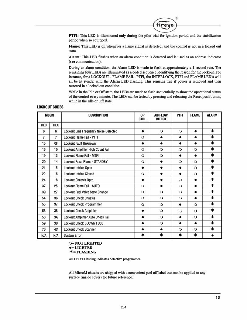
ïí
ÐÌÚ×æ ̸· ÔÛÜ · ·´´«³·²¿¬»¼ ±²´§ ¼«®·²¹ ¬¸» °·´±¬ ¬®·¿´ º±® ·¹²·¬·±² °»®·±¼ ¿²¼ ¬¸» ¬¿¾·´·¦¿¬·±²
°»®·±¼ ©¸»² ± »¯«·°°»¼ò
Ú´¿³»æ ̸· ÔÛÜ · ±² ©¸»²»ª»® ¿ º´¿³» ·¹²¿´ · ¼»¬»½¬»¼ô ¿²¼ ¬¸» ½±²¬®±´ · ²±¬ ·² ¿ ´±½µ»¼ ±«¬
¬¿¬»ò
ß´¿®³æ ̸· ÔÛÜ º´¿¸» ©¸»² ¿² ¿´¿®³ ½±²¼·¬·±² · ¼»¬»½¬»¼ ¿²¼ · «»¼ ¿ ¿² ¿¼¼®» ·²¼·½¿¬±®
ø»» ½±³³«²·½¿¬·±²÷ò
Ü«®·²¹ ¿² ¿´¿®³ ½±²¼·¬·±²ô ¬¸» ß´¿®³ ÔÛÜ · ³¿¼» ¬± º´¿¸ ¿¬ ¿°°®±¨·³¿¬»´§ ¿ ï »½±²¼ ®¿¬»ò ̸»
®»³¿·²·²¹ º±«® ÔÛÜ ¿®» ·´´«³·²¿¬»¼ ¿ ¿ ½±¼»¼ »¯«»²½» ·¼»²¬·º§·²¹ ¬¸» ®»¿±² º±® ¬¸» ´±½µ±«¬ò Ú±®
·²¬¿²½»ô º±® ¿ ÔÑÝÕÑËÌ ó ÚÔßÓÛ Úß×Ôó ÐÌÚ×ô ¬¸» ×ÒÌÛÎÔÑÝÕô ÐÌÚ× ¿²¼ ÚÔßÓÛ ÔÛÜ ©·´´
¿´´ ¾» ´·¬ ¬»¿¼§ô ©·¬¸ ¬¸» ß´¿®³ ÔÛÜ º´¿¸·²¹ò ̸· ®»³¿·² ¬®«» ·º °±©»® · ®»³±ª»¼ ¿²¼ ¬¸»²
®»¬±®»¼ ·² ¿ ´±½µ»¼ ±«¬ ½±²¼·¬·±²ò
ɸ·´» ·² ¬¸» ×¼´» ±® Ѻº ¬¿¬»ô ¬¸» ÔÛÜ ¿®» ³¿¼» ¬± º´¿¸ »¯«»²¬·¿´´§ ¬± ¸±© ¬¸» ±°»®¿¬·±²¿´ ¬¿¬«
±º ¬¸» ½±²¬®±´ »ª»®§ ³·²«¬»ò ̸» ÔÛÜ ½¿² ¾» ¬»¬»¼ ¾§ °®»·²¹ ¿²¼ ®»´»¿·²¹ ¬¸» 뻬 °«¸ ¾«¬¬±²ô
©¸·´» ·² ¬¸» ×¼´» ±® Ѻº ¬¿¬»ò
ÔÑÝÕÑËÌ ÝÑÜÛÍ
ã ÒÑÌ Ô×ÙØÌÛÜ
ã Ô×ÙØÌÛÜ
ã ÚÔßÍØ×ÒÙ
ß´´ ÔÛÜ Ú´¿¸·²¹ ·²¼·½¿¬» ¼»º»½¬·ª» °®±¹®¿³³»®ò
ß´´ Ó·½®±Ó ½¸¿· ¿®» ¸·°°»¼ ©·¬¸ ¿ ½±²ª»²·»²¬ °»»´ ±ºº ´¿¾»´ ¬¸¿¬ ½¿² ¾» ¿°°´·»¼ ¬± ¿²§
«®º¿½» ø·²·¼» ½±ª»®÷ º±® º«¬«®» ®»º»®»²½»ò
ÓÍÙÒ ÜÛÍÝÎ×ÐÌ×ÑÒ ÑÐ ÝÌÎÔ
ß×ÎÚÔÑÉ×ÒÌÔÝÕ
ÐÌÚ× ÚÔßÓÛ ßÔßÎÓ
ÜÛÝ ØÛÈ
ê ê Ô±½µ±«¬ Ô·²» Ú®»¯«»²½§ Ò±·» Ü»¬»½¬»¼
é é Ô±½µ±«¬ Ú´¿³» Ú¿·´ ó ÐÌÚ×
ïë ðÚ Ô±½µ±«¬ Ú¿«´¬ ˲µ²±©²
ïê ïð Ô±½µ±«¬ ß³°´·º·»® Ø·¹¸ ݱ«²¬ Ú¿·´
ïç ïí Ô±½µ±«¬ Ú´¿³» Ú¿·´ ó ÓÌÚ×
îð ïì Ô±½µ±«¬ Ú¿´» Ú´¿³» ó ÍÌßÒÜÞÇ
îï ïë Ô±½µ±«¬ ײ¬®´½µ Ñ°»²
îî ïê Ô±½µ±«¬ ײ¬®´½µ Ý´±»¼
îì ïè Ô±½µ±«¬ ݸ¿· Ñ°¬±
íé îë Ô±½µ±«¬ Ú´¿³» Ú¿·´ ó ßËÌÑ
íç îé Ô±½µ±«¬ Ú«»´ Ê¿´ª» ͬ¿¬» ݸ¿²¹»
ëì íê Ô±½µ±«¬ ݸ»½µ ݸ¿·
ëë íé Ô±½µ±«¬ ݸ»½µ Ю±¹®¿³³»®
ëê íè Ô±½µ±«¬ ݸ»½µ ß³°´·º·»®
ëè íß Ô±½µ±«¬ ß³°´·º·»® ß«¬± ݸ»½µ Ú¿·´
ëç íÞ Ô±½µ±«¬ ݸ»½µ ÞÔÑÉÒ ÚËÍÛ
éê ìÝ Ô±½µ±«¬ ݸ»½µ ͽ¿²²»®
Òñß Òñß Í§¬»³ Û®®±®
234
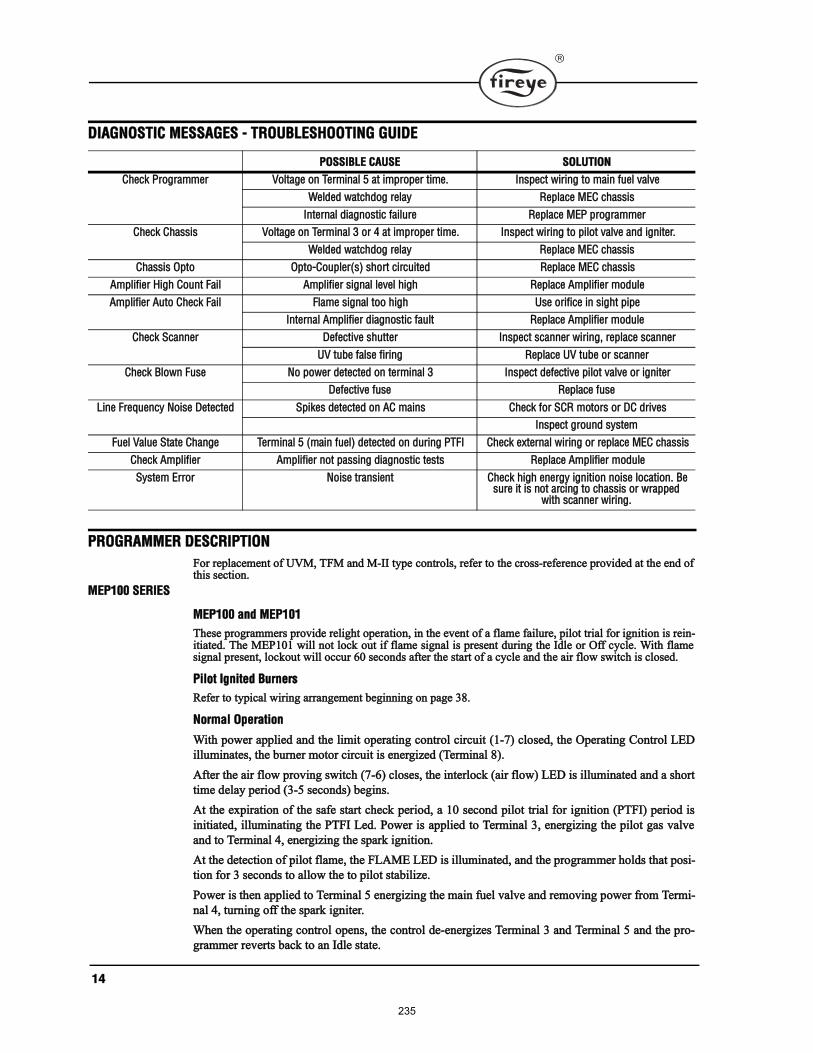
ïì
Ü×ßÙÒÑÍÌ×Ý ÓÛÍÍßÙÛÍ ó ÌÎÑËÞÔÛÍØÑÑÌ×ÒÙ ÙË×ÜÛ
ÐÎÑÙÎßÓÓÛÎ ÜÛÍÝÎ×ÐÌ×ÑÒ
Ú±® ®»°´¿½»³»²¬ ±º ËÊÓô ÌÚÓ ¿²¼ Óó×× ¬§°» ½±²¬®±´ô ®»º»® ¬± ¬¸» ½®±ó®»º»®»²½» °®±ª·¼»¼ ¿¬ ¬¸» »²¼ ±º¬¸· »½¬·±²ò
ÓÛÐïðð ÍÛÎ×ÛÍ
ÓÛÐïðð ¿²¼ ÓÛÐïðï
̸»» °®±¹®¿³³»® °®±ª·¼» ®»´·¹¸¬ ±°»®¿¬·±²ô ·² ¬¸» »ª»²¬ ±º ¿ º´¿³» º¿·´«®»ô °·´±¬ ¬®·¿´ º±® ·¹²·¬·±² · ®»·²ó·¬·¿¬»¼ò ̸» ÓÛÐïðï ©·´´ ²±¬ ´±½µ ±«¬ ·º º´¿³» ·¹²¿´ · °®»»²¬ ¼«®·²¹ ¬¸» ×¼´» ±® Ѻº ½§½´»ò É·¬¸ º´¿³»·¹²¿´ °®»»²¬ô ´±½µ±«¬ ©·´´ ±½½«® êð »½±²¼ ¿º¬»® ¬¸» ¬¿®¬ ±º ¿ ½§½´» ¿²¼ ¬¸» ¿·® º´±© ©·¬½¸ · ½´±»¼ò
з´±¬ ×¹²·¬»¼ Þ«®²»®
λº»® ¬± ¬§°·½¿´ ©·®·²¹ ¿®®¿²¹»³»²¬ ¾»¹·²²·²¹ ±² °¿¹» íèò
Ò±®³¿´ Ñ°»®¿¬·±²
É·¬¸ °±©»® ¿°°´·»¼ ¿²¼ ¬¸» ´·³·¬ ±°»®¿¬·²¹ ½±²¬®±´ ½·®½«·¬ øïóé÷ ½´±»¼ô ¬¸» Ñ°»®¿¬·²¹ ݱ²¬®±´ ÔÛÜ
·´´«³·²¿¬»ô ¬¸» ¾«®²»® ³±¬±® ½·®½«·¬ · »²»®¹·¦»¼ øÌ»®³·²¿´ è÷ò
ߺ¬»® ¬¸» ¿·® º´±© °®±ª·²¹ ©·¬½¸ øéóê÷ ½´±»ô ¬¸» ·²¬»®´±½µ ø¿·® º´±©÷ ÔÛÜ · ·´´«³·²¿¬»¼ ¿²¼ ¿ ¸±®¬
¬·³» ¼»´¿§ °»®·±¼ øíóë »½±²¼÷ ¾»¹·²ò
߬ ¬¸» »¨°·®¿¬·±² ±º ¬¸» ¿º» ¬¿®¬ ½¸»½µ °»®·±¼ô ¿ ïð »½±²¼ °·´±¬ ¬®·¿´ º±® ·¹²·¬·±² øÐÌÚ×÷ °»®·±¼ ·
·²·¬·¿¬»¼ô ·´´«³·²¿¬·²¹ ¬¸» ÐÌÚ× Ô»¼ò б©»® · ¿°°´·»¼ ¬± Ì»®³·²¿´ íô »²»®¹·¦·²¹ ¬¸» °·´±¬ ¹¿ ª¿´ª»
¿²¼ ¬± Ì»®³·²¿´ ìô »²»®¹·¦·²¹ ¬¸» °¿®µ ·¹²·¬·±²ò
߬ ¬¸» ¼»¬»½¬·±² ±º °·´±¬ º´¿³»ô ¬¸» ÚÔßÓÛ ÔÛÜ · ·´´«³·²¿¬»¼ô ¿²¼ ¬¸» °®±¹®¿³³»® ¸±´¼ ¬¸¿¬ °±·ó
¬·±² º±® í »½±²¼ ¬± ¿´´±© ¬¸» ¬± °·´±¬ ¬¿¾·´·¦»ò
б©»® · ¬¸»² ¿°°´·»¼ ¬± Ì»®³·²¿´ ë »²»®¹·¦·²¹ ¬¸» ³¿·² º«»´ ª¿´ª» ¿²¼ ®»³±ª·²¹ °±©»® º®±³ Ì»®³·ó
²¿´ ìô ¬«®²·²¹ ±ºº ¬¸» °¿®µ ·¹²·¬»®ò
ɸ»² ¬¸» ±°»®¿¬·²¹ ½±²¬®±´ ±°»²ô ¬¸» ½±²¬®±´ ¼»ó»²»®¹·¦» Ì»®³·²¿´ í ¿²¼ Ì»®³·²¿´ ë ¿²¼ ¬¸» °®±ó
¹®¿³³»® ®»ª»®¬ ¾¿½µ ¬± ¿² ×¼´» ¬¿¬»ò
ÐÑÍÍ×ÞÔÛ ÝßËÍÛ ÍÑÔËÌ×ÑÒ
ݸ»½µ Ю±¹®¿³³»® ʱ´¬¿¹» ±² Ì»®³·²¿´ ë ¿¬ ·³°®±°»® ¬·³»ò ײ°»½¬ ©·®·²¹ ¬± ³¿·² º«»´ ª¿´ª»
É»´¼»¼ ©¿¬½¸¼±¹ ®»´¿§ λ°´¿½» ÓÛÝ ½¸¿·
ײ¬»®²¿´ ¼·¿¹²±¬·½ º¿·´«®» λ°´¿½» ÓÛÐ °®±¹®¿³³»®
ݸ»½µ ݸ¿· ʱ´¬¿¹» ±² Ì»®³·²¿´ í ±® ì ¿¬ ·³°®±°»® ¬·³»ò ײ°»½¬ ©·®·²¹ ¬± °·´±¬ ª¿´ª» ¿²¼ ·¹²·¬»®ò
É»´¼»¼ ©¿¬½¸¼±¹ ®»´¿§ λ°´¿½» ÓÛÝ ½¸¿·
ݸ¿· Ñ°¬± Ñ°¬±óݱ«°´»®ø÷ ¸±®¬ ½·®½«·¬»¼ λ°´¿½» ÓÛÝ ½¸¿·
ß³°´·º·»® Ø·¹¸ ݱ«²¬ Ú¿·´ ß³°´·º·»® ·¹²¿´ ´»ª»´ ¸·¹¸ λ°´¿½» ß³°´·º·»® ³±¼«´»
ß³°´·º·»® ß«¬± ݸ»½µ Ú¿·´ Ú´¿³» ·¹²¿´ ¬±± ¸·¹¸ Ë» ±®·º·½» ·² ·¹¸¬ °·°»
ײ¬»®²¿´ ß³°´·º·»® ¼·¿¹²±¬·½ º¿«´¬ λ°´¿½» ß³°´·º·»® ³±¼«´»
ݸ»½µ ͽ¿²²»® Ü»º»½¬·ª» ¸«¬¬»® ײ°»½¬ ½¿²²»® ©·®·²¹ô ®»°´¿½» ½¿²²»®
ËÊ ¬«¾» º¿´» º·®·²¹ λ°´¿½» ËÊ ¬«¾» ±® ½¿²²»®
ݸ»½µ Þ´±©² Ú«» Ò± °±©»® ¼»¬»½¬»¼ ±² ¬»®³·²¿´ í ײ°»½¬ ¼»º»½¬·ª» °·´±¬ ª¿´ª» ±® ·¹²·¬»®
Ü»º»½¬·ª» º«» λ°´¿½» º«»
Ô·²» Ú®»¯«»²½§ Ò±·» Ü»¬»½¬»¼ Í°·µ» ¼»¬»½¬»¼ ±² ßÝ ³¿·² ݸ»½µ º±® ÍÝÎ ³±¬±® ±® ÜÝ ¼®·ª»
ײ°»½¬ ¹®±«²¼ §¬»³
Ú«»´ Ê¿´«» ͬ¿¬» ݸ¿²¹» Ì»®³·²¿´ ë ø³¿·² º«»´÷ ¼»¬»½¬»¼ ±² ¼«®·²¹ ÐÌÚ× Ý¸»½µ »¨¬»®²¿´ ©·®·²¹ ±® ®»°´¿½» ÓÛÝ ½¸¿·
ݸ»½µ ß³°´·º·»® ß³°´·º·»® ²±¬ °¿·²¹ ¼·¿¹²±¬·½ ¬»¬ λ°´¿½» ß³°´·º·»® ³±¼«´»
ͧ¬»³ Û®®±® Ò±·» ¬®¿²·»²¬ ݸ»½µ ¸·¹¸ »²»®¹§ ·¹²·¬·±² ²±·» ´±½¿¬·±²ò Þ» «®» ·¬ · ²±¬ ¿®½·²¹ ¬± ½¸¿· ±® ©®¿°°»¼
©·¬¸ ½¿²²»® ©·®·²¹ò
235
ïë
Í¿º»¬§ ͸«¬¼±©²
ײ ¬¸» »ª»²¬ °·´±¬ º´¿³» · ²±¬ ¼»¬»½¬»¼ ¿¬ ¬¸» »²¼ ±º ¬¸» ïð »½±²¼ ÐÌÚ× °»®·±¼ô ¬¸» °·´±¬ ¹¿ ª¿´ª»
¿²¼ °¿®µ ·¹²·¬·±² ¿®» ¼»ó»²»®¹·¦»¼ò ß ¿º»¬§ ´±½µ±«¬ ±½½«® ©¸·½¸ ¼»ó»²»®¹·¦» ¬¸» ¾«®²»® ³±¬±®
¿²¼ »²»®¹·¦» ¬¸» ´±½µ±«¬ ¿´¿®³ ®»´¿§ ½·®½«·¬ô ´·¹¸¬·²¹ ¬¸» ß´¿®³ ÔÛÜô ïë »½±²¼ ¿º¬»® ¬¸» ¿º»¬§
´±½µ±«¬ ±½½«®ò Ó¿²«¿´ ®»»¬ · ®»¯«·®»¼ò
ײ ¬¸» »ª»²¬ ±º ¿ º´¿³» º¿·´«®» ¼«®·²¹ ¿ º·®·²¹ °»®·±¼ô ¬¸» ³¿·² º«»´ ª¿´ª» · ¼»ó»²»®¹·¦»¼ øÌ»®³·²¿´ ë÷
¿²¼ ¬¸» °¿®µ ·¹²·¬·±² · ®»ó»²»®¹·¦»¼ øÌ»®³·²¿´ ì÷ô ¬¸» ÐÌÚ× °»®·±¼ ¾»¹·² ¿¹¿·² ¿ ¼»½®·¾»¼ ¿¾±ª»
«²¼»® Ò±®³¿´ Ñ°»®¿¬·±²ò
ײ ¬¸» »ª»²¬ ±º ¬¸» ·²¬»®´±½µ ©·¬½¸ ±°»²·²¹ô ¬¸» ³¿·² º«»´ ª¿´ª» ¿²¼ °·´±¬ ª¿´ª» ¿®» ¼»ó»²»®¹·¦»¼ò
̸» ½±²¬®±´ ®»ª»®¬ ¾¿½µ ¬± ¬¸» ×¼´» ¬¿¬» ¿²¼ ¾»¹·² ¿¹¿·² ¿ ²»© ½§½´» ¬¿®¬·²¹ ©·¬¸ ¬¸» ¿º» ¬¿®¬
½¸»½µ °»®·±¼ò
Ü·®»½¬ Í°¿®µ ×¹²·¬»¼ Þ«®²»®
λº»® ¬± ¬§°·½¿´ ©·®·²¹ ¿®®¿²¹»³»²¬ ·´´«¬®¿¬»¼ ±² °¿¹» ìð ¿²¼ ìïò
Ò±®³¿´ Ñ°»®¿¬·±²
É·¬¸ °±©»® ¿°°´·»¼ ¿²¼ ¬¸» ´·³·¬ ±°»®¿¬·²¹ ½±²¬®±´ ½·®½«·¬ øïóé÷ ½´±»¼ô ¬¸» Ñ°»®¿¬·²¹ ݱ²¬®±´ ÔÛÜ
·´´«³·²¿¬»ô ¬¸» ¾«®²»® ³±¬±® ½·®½«·¬ · »²»®¹·¦»¼ øÌ»®³·²¿´ è÷ò
̸» ·²¬»®´±½µ °®±ª·²¹ ©·¬½¸ øéóê÷ ½´±»ô ¬¸» ×ÒÌÎÔÝÕ ÔÛÜ · ·´´«³·²¿¬»¼ ¿²¼ ¿ ¸±®¬ ¬·³» ¼»´¿§
°»®·±¼ øí »½±²¼÷ ¾»¹·² ø¿º» ¬¿®¬ ½¸»½µ °»®·±¼÷ò
߬ ¬¸» »¨°·®¿¬·±² ±º ¬¸» ¿º» ¬¿®¬ ½¸»½µ °»®·±¼ô ¿ ïð »½±²¼ ÐÌÚ× °»®·±¼ · ·²·¬·¿¬»¼ò ̸» ÐÌÚ× Ô»¼ ·
·´´«³·²¿¬»¼ô °±©»® · ¿°°´·»¼ ¬± Ì»®³·²¿´ íô »²»®¹·¦·²¹ ¬¸» ³¿·² º«»´ ª¿´ª» ¿²¼ ¬± Ì»®³·²¿´ ìô »²»®ó
¹·¦·²¹ ¬¸» °¿®µ ·¹²·¬·±²ò
߬ ¬¸» ¼»¬»½¬·±² ±º ³¿·² º´¿³»ô ¬¸» ÚÔßÓÛ ÔÛÜ · ·´´«³·²¿¬»¼ô ¿²¼ ¬¸» °®±¹®¿³³»® ¸±´¼ ¬¸¿¬ °±·ó
¬·±² º±® íóë »½±²¼ ¬± ¿´´±© ¬¸» ³¿·² º´¿³» ¬± ¬¿¾·´·¦»ò
б©»® · ¬¸»² ®»³±ª»¼ º®±³ Ì»®³·²¿´ ìô ¬«®²·²¹ ±ºº ¬¸» °¿®µ ·¹²·¬»®ò
ɸ»² ¬¸» ±°»®¿¬·²¹ ½±²¬®±´ ±°»²ô ¬¸» ½±²¬®±´ ¼»ó»²»®¹·¦» Ì»®³·²¿´ í ¿²¼ Ì»®³·²¿´ ë ¿²¼ ¬¸» °®±ó
¹®¿³³»® ®»ª»®¬ ¾¿½µ ¬± ¿² ×¼´» ¬¿¬»ò Ì»®³·²¿´ è · ·³³»¼·¿¬»´§ ¼»ó»²»®¹·¦»¼ò
Í¿º»¬§ ͸«¬¼±©²
ײ ¬¸» »ª»²¬ ¬¸» ³¿·² º´¿³» · ²±¬ ¼»¬»½¬»¼ ¿¬ ¬¸» »²¼ ±º ¿ ïð »½±²¼ ÐÌÚ× °»®·±¼ô ¬¸» ³¿·² º«»´ ª¿´ª»
¿²¼ °¿®µ ·¹²·¬·±² ¿®» ¼»ó»²»®¹·¦»¼ò ß ¿º»¬§ ´±½µ±«¬ ±½½«® ©¸·½¸ ¼»ó»²»®¹·¦» ¬¸» ¾«®²»® ³±¬±®
¿²¼ »²»®¹·¦» ¬¸» ´±½µ±«¬ ¿´¿®³ ®»´¿§ ½·®½«·¬ô ´·¹¸¬·²¹ ¬¸» ß´¿®³ ÔÛÜô ïë »½±²¼ ¿º¬»® ¬¸» ¿º»¬§
´±½µ±«¬ ±½½«®ò Ó¿²«¿´ ®»»¬ · ®»¯«·®»¼ò
ײ ¬¸» »ª»²¬ ±º ¿ º´¿³» º¿·´«®» ¼«®·²¹ ¿ º·®·²¹ °»®·±¼ô ¬¸» »½±²¼¿®§ º«»´ ª¿´ª» ø·º «»¼÷ · ¼»ó»²»®ó
¹·¦»¼ ¿²¼ ¬¸» °¿®µ ·¹²·¬·±² · ®»ó»²»®¹·¦»¼ô ¬¸» ÐÌÚ× °»®·±¼ ¾»¹·² ¿¹¿·² ¿ ¼»½®·¾»¼ ¿¾±ª» «²¼»®
Ò±®³¿´ Ñ°»®¿¬·±²ò
ײ ¬¸» »ª»²¬ ±º ¬¸» ·²¬»®´±½µ ©·¬½¸ ±°»²·²¹ô ¬¸» ³¿·² º«»´ ª¿´ª» ¿²¼ °·´±¬ ª¿´ª» ¿®» ¼»ó»²»®¹·¦»¼ò
̸» ½±²¬®±´ ®»ª»®¬ ¾¿½µ ¬± ¬¸» ×¼´» ¬¿¬» ¿²¼ ¾»¹·² ¿¹¿·² ¿ ²»© ½§½´» ¬¿®¬·²¹ ©·¬¸ ¬¸» ¿º» ¬¿®¬
½¸»½µ °»®·±¼ò
ÓÛÐïðî ú ÓÛÐïðì
̸» ÓÛÐïðî ¿²¼ ÓÛÐïðì °®±¹®¿³³»® ±°»®¿¬» ¬¸» ¿³» ¿ ¬¸» ÓÛÐïððô »¨½»°¬ ¬¸» ÐÌÚ× ¬·³» ·
´·³·¬»¼ ¬± ë »½±²¼ ¿²¼ ïð »½±²¼ ®»°»½¬·ª»´§ô ¬¸» ®»´·¹¸¬ º»¿¬«®» · »´·³·²¿¬»¼ ¿²¼ ·²¬»¿¼ô ¬¸»
½±²¬®±´ ©·´´ »²¬»® ¿º»¬§ ´±½µ±«¬ ±² º´¿³» º¿·´«®»ò 뽧½´» ¬± ¬¸» ¬¿®¬ ±º ¿º» ¬¿®¬ ½¸»½µ °»®·±¼ ¬±
¾»¹·² ¿ ²»© ½§½´» ©·´´ ±½½«® ±² ¿·® º´±© ©·¬½¸ ±°»²·²¹ò
ÓÛÐïðí
̸» ÓÛÐïðí °®±¹®¿³³»® ·³°´»³»²¬ ¿ º·¨»¼ ïð »½±²¼ °¿®µ ·¹²·¬»® »²·²¹ °»®·±¼ øÍ×ÍÐ÷ «»¼ ¬±
¼»¬»½¬ °¿®µô º±´´±©»¼ ¾§ ¿ ïð »½±²¼ ³¿·² ¬®·¿´ º±® ·¹²·¬·±² øÓÌÚ×÷ò Í¿º»¬§ ´±½µ±«¬ ±½½«® ±² º´¿³»
º¿·´«®» ¼«®·²¹ ¬¸» ³¿·² º·®·²¹ °»®·±¼ øßËÌÑ÷ò 뽧½´» ±½½«® ±² ¿·® º´±© ©·¬½¸ ±°»²·²¹ò ׺ °¿®µ ·
²±¬ ¼»¬»½¬»¼ ¼«®·²¹ ¬¸» °¿®µ ·¹²·¬»® »²·²¹ °»®·±¼ ¬¸» ½±²¬®±´ ³¿µ» ±²» ¿¬¬»³°¬ ¬± »¬¿¾´·¸ °·´±¬
236
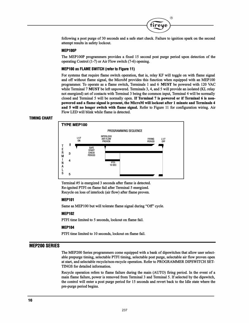
ïê
º±´´±©·²¹ ¿ °±¬ °«®¹» ±º íð »½±²¼ ¿²¼ ¿ ¿º» ¬¿®¬ ½¸»½µò Ú¿·´«®» ¬± ·¹²·¬·±² °¿®µ ±² ¬¸» »½±²¼
¿¬¬»³°¬ ®»«´¬ ·² ¿º»¬§ ´±½µ±«¬ò
ÓÛÐïððÐ
̸» ÓÛÐïððÐ °®±¹®¿³³»® °®±ª·¼» ¿ º·¨»¼ ïë »½±²¼ °±¬ °«®¹» °»®·±¼ «°±² ¼»¬»½¬·±² ±º ¬¸»
±°»®¿¬·²¹ ݱ²¬®±´ øïóé÷ ±® ß·® Ú´±© ©·¬½¸ øéóê÷ ±°»²·²¹ò
ÓÛÐïðð ¿ ÚÔßÓÛ ÍÉ×ÌÝØ ø®»º»® ¬± Ú·¹«®» ïï÷
Ú±® §¬»³ ¬¸¿¬ ®»¯«·®» º´¿³» ©·¬½¸ ±°»®¿¬·±²ô ¬¸¿¬ ·ô ®»´¿§ ÕÚ ©·´´ ¬±¹¹´» ±² ©·¬¸ º´¿³» ·¹²¿´
¿²¼ ±ºº ©·¬¸±«¬ º´¿³» ·¹²¿´ô ¬¸» Ó·½®±Ó °®±ª·¼» ¬¸· º«²½¬·±² ©¸»² »¯«·°°»¼ ©·¬¸ ¿² ÓÛÐïðð
°®±¹®¿³³»®ò ̱ ±°»®¿¬» ¿ ¿ º´¿³» ©·¬½¸ô Ì»®³·²¿´ ï ¿²¼ ê ÓËÍÌ ¾» °±©»®»¼ ©·¬¸ ïîð ÊßÝ
©¸·´» Ì»®³·²¿´ é ÓËÍÌ ¾» ´»º¬ «²°±©»®»¼ò Ì»®³·²¿´ íô ìô ¿²¼ ë ©·´´ °®±ª·¼» ¿² ·±´¿¬»¼ øÕÔ ®»´¿§
²±¬ »²»®¹·¦»¼÷ »¬ ±º ½±²¬¿½¬ ©·¬¸ Ì»®³·²¿´ í ¾»·²¹ ¬¸» ½±³³±² ·²°«¬ô Ì»®³·²¿´ ì ©·´´ ¾» ²±®³¿´´§
½´±»¼ ¿²¼ Ì»®³·²¿´ ë ©·´´ ¾» ²±®³¿´´§ ±°»²ò ׺ Ì»®³·²¿´ é · °±©»®»¼ ±® ·º Ì»®³·²¿´ ê · ²±²ó
°±©»®»¼ ¿²¼ ¿ º´¿³» ·¹²¿´ · °®»»²¬ô ¬¸» Ó·½®±Ó ©·´´ ´±½µ±«¬ ¿º¬»® ï ³·²«¬» ¿²¼ Ì»®³·²¿´ ì
¿²¼ ë ©·´´ ²± ´±²¹»® ©·¬½¸ ©·¬¸ º´¿³» ·¹²¿´ò λº»® ¬± Ú·¹«®» ïï º±® ½±²º·¹«®¿¬·±² ©·®·²¹ò ß·®
Ú´±© ÔÛÜ ©·´´ ¾´·²µ ©¸·´» º´¿³» · ¼»¬»½¬»¼ò
Ì×Ó×ÒÙ ÝØßÎÌ
Ì»®³·²¿´ ýë · »²»®¹·¦»¼ í »½±²¼ ¿º¬»® º´¿³» · ¼»¬»½¬»¼ò
λ󷹲·¬»¼ ÐÌÚ× ±² º´¿³» º¿·´ ¿º¬»® Ì»®³·²¿´ ë »²»®¹·¦»¼ò
뽧½´» ±² ´± ±º ·²¬»®´±½µ ø¿·® º´±©÷ ¿º¬»® º´¿³» °®±ª»²ò
ÓÛÐïðï
Í¿³» ¿ ÓÛÐïð𠾫¬ ©·´´ ¬±´»®¿¬» º´¿³» ·¹²¿´ ¼«®·²¹ Ѻº ½§½´»ò
ÓÛÐïðî
ÐÌÚ× ¬·³» ´·³·¬»¼ ¬± ë »½±²¼ô ´±½µ±«¬ ±² º´¿³» º¿·´ò
ÓÛÐïðì
ÐÌÚ× ¬·³» ´·³·¬»¼ ¬± ïð »½±²¼ô ´±½µ±«¬ ±² º´¿³» º¿·´ò
ÓÛÐîðð ÍÛÎ×ÛÍ
̸» ÓÛÐîðð Í»®·» °®±¹®¿³³»® ½±³» »¯«·°°»¼ ©·¬¸ ¿ ¾¿²µ ±º ¼·°©·¬½¸» ¬¸¿¬ ¿´´±© «»® »´»½¬ó
¿¾´» °®»°«®¹» ¬·³·²¹ô »´»½¬¿¾´» ÐÌÚ× ¬·³·²¹ô »´»½¬¿¾´» °±¬ °«®¹»ô »´»½¬¿¾´» ¿·® º´±© °®±ª»² ±°»²
¿¬ ¬¿®¬ô ¿²¼ »´»½¬¿¾´» ®»½§½´»ñ²±²ó®»½§½´» ±°»®¿¬·±²ò λº»® ¬± ÐÎÑÙÎßÓÓÛÎ Ü×ÐÍÉ×ÌÝØ ÍÛÌó
Ì×ÒÙÍ º±® ¼»¬¿·´»¼ ·²º±®³¿¬·±²ò
뽧½´» ±°»®¿¬·±² ®»º»® ¬± º´¿³» º¿·´«®» ¼«®·²¹ ¬¸» ³¿·² øßËÌÑ÷ º·®·²¹ °»®·±¼ò ײ ¬¸» »ª»²¬ ±º ¿
³¿·² º´¿³» º¿·´«®»ô °±©»® · ®»³±ª»¼ º®±³ Ì»®³·²¿´ í ¿²¼ Ì»®³·²¿´ ëò ׺ »´»½¬»¼ ¾§ ¬¸» ¼·°©·¬½¸ô
¬¸» ½±²¬®±´ ©·´´ »²¬»® ¿ °±¬ °«®¹» °»®·±¼ º±® ïë »½±²¼ ¿²¼ ®»ª»®¬ ¾¿½µ ¬± ¬¸» ×¼´» ¬¿¬» ©¸»®» ¬¸»
°®»ó°«®¹» °»®·±¼ ¾»¹·²ò
ÌÇÐÛ ÓÛÐïðð
ÐÎÑÙÎßÓÓ×ÒÙ ÍÛÏËÛÒÝÛ
ÔïñéÑÒ
×ÒÌÛÎÔÑÝÕß×Î ÚÔÑÉÐÎÑÊÛÒ
Ú×Î×ÒÙÐÛÎ×ÑÜ
ÔïñéÑÚÚ
ÐÌÚ×ïð ÍÛÝ
ÍßÚÛÍÌßÎÌÝØÛÝÕÐÛÎ×ÑÜ
èÌÛÎÓ×ÒßÔÍ
í
ì
ë
237
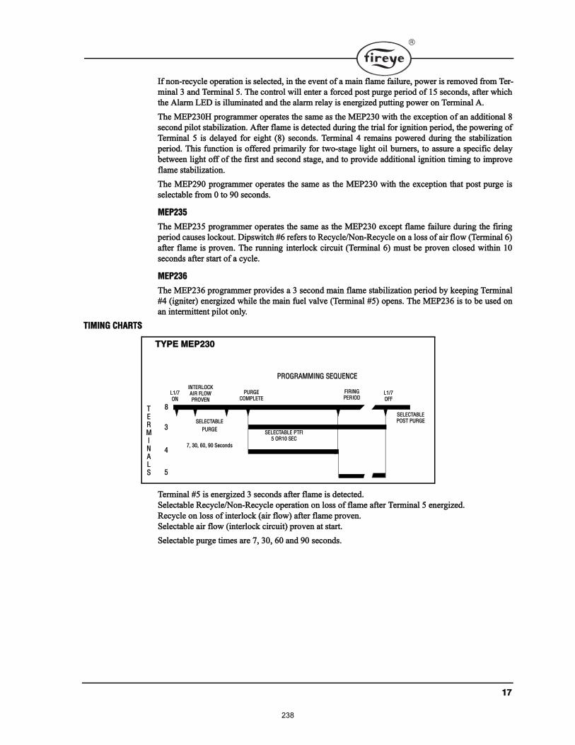
ïé
׺ ²±²ó®»½§½´» ±°»®¿¬·±² · »´»½¬»¼ô ·² ¬¸» »ª»²¬ ±º ¿ ³¿·² º´¿³» º¿·´«®»ô °±©»® · ®»³±ª»¼ º®±³ Ì»®ó
³·²¿´ í ¿²¼ Ì»®³·²¿´ ëò ̸» ½±²¬®±´ ©·´´ »²¬»® ¿ º±®½»¼ °±¬ °«®¹» °»®·±¼ ±º ïë »½±²¼ô ¿º¬»® ©¸·½¸
¬¸» ß´¿®³ ÔÛÜ · ·´´«³·²¿¬»¼ ¿²¼ ¬¸» ¿´¿®³ ®»´¿§ · »²»®¹·¦»¼ °«¬¬·²¹ °±©»® ±² Ì»®³·²¿´ ßò
̸» ÓÛÐîíðØ °®±¹®¿³³»® ±°»®¿¬» ¬¸» ¿³» ¿ ¬¸» ÓÛÐîíð ©·¬¸ ¬¸» »¨½»°¬·±² ±º ¿² ¿¼¼·¬·±²¿´ è
»½±²¼ °·´±¬ ¬¿¾·´·¦¿¬·±²ò ߺ¬»® º´¿³» · ¼»¬»½¬»¼ ¼«®·²¹ ¬¸» ¬®·¿´ º±® ·¹²·¬·±² °»®·±¼ô ¬¸» °±©»®·²¹ ±º
Ì»®³·²¿´ ë · ¼»´¿§»¼ º±® »·¹¸¬ øè÷ »½±²¼ò Ì»®³·²¿´ ì ®»³¿·² °±©»®»¼ ¼«®·²¹ ¬¸» ¬¿¾·´·¦¿¬·±²
°»®·±¼ò ̸· º«²½¬·±² · ±ºº»®»¼ °®·³¿®·´§ º±® ¬©±ó¬¿¹» ´·¹¸¬ ±·´ ¾«®²»®ô ¬± ¿«®» ¿ °»½·º·½ ¼»´¿§
¾»¬©»»² ´·¹¸¬ ±ºº ±º ¬¸» º·®¬ ¿²¼ »½±²¼ ¬¿¹»ô ¿²¼ ¬± °®±ª·¼» ¿¼¼·¬·±²¿´ ·¹²·¬·±² ¬·³·²¹ ¬± ·³°®±ª»
º´¿³» ¬¿¾·´·¦¿¬·±²ò
̸» ÓÛÐîçð °®±¹®¿³³»® ±°»®¿¬» ¬¸» ¿³» ¿ ¬¸» ÓÛÐîíð ©·¬¸ ¬¸» »¨½»°¬·±² ¬¸¿¬ °±¬ °«®¹» ·
»´»½¬¿¾´» º®±³ 𠬱 çð »½±²¼ò
ÓÛÐîíë
̸» ÓÛÐîíë °®±¹®¿³³»® ±°»®¿¬» ¬¸» ¿³» ¿ ¬¸» ÓÛÐîí𠻨½»°¬ º´¿³» º¿·´«®» ¼«®·²¹ ¬¸» º·®·²¹
°»®·±¼ ½¿«» ´±½µ±«¬ò Ü·°©·¬½¸ ýê ®»º»® ¬± 뽧½´»ñÒ±²ó뽧½´» ±² ¿ ´± ±º ¿·® º´±© øÌ»®³·²¿´ ê÷
¿º¬»® º´¿³» · °®±ª»²ò ̸» ®«²²·²¹ ·²¬»®´±½µ ½·®½«·¬ øÌ»®³·²¿´ ê÷ ³«¬ ¾» °®±ª»² ½´±»¼ ©·¬¸·² ïð
»½±²¼ ¿º¬»® ¬¿®¬ ±º ¿ ½§½´»ò
ÓÛÐîíê
̸» ÓÛÐîíê °®±¹®¿³³»® °®±ª·¼» ¿ í »½±²¼ ³¿·² º´¿³» ¬¿¾·´·¦¿¬·±² °»®·±¼ ¾§ µ»»°·²¹ Ì»®³·²¿´
ýì ø·¹²·¬»®÷ »²»®¹·¦»¼ ©¸·´» ¬¸» ³¿·² º«»´ ª¿´ª» øÌ»®³·²¿´ ýë÷ ±°»²ò ̸» ÓÛÐîíê · ¬± ¾» «»¼ ±²
¿² ·²¬»®³·¬¬»²¬ °·´±¬ ±²´§ò
Ì×Ó×ÒÙ ÝØßÎÌÍ
Ì»®³·²¿´ ýë · »²»®¹·¦»¼ í »½±²¼ ¿º¬»® º´¿³» · ¼»¬»½¬»¼ò
Í»´»½¬¿¾´» 뽧½´»ñÒ±²ó뽧½´» ±°»®¿¬·±² ±² ´± ±º º´¿³» ¿º¬»® Ì»®³·²¿´ ë »²»®¹·¦»¼ò
뽧½´» ±² ´± ±º ·²¬»®´±½µ ø¿·® º´±©÷ ¿º¬»® º´¿³» °®±ª»²ò
Í»´»½¬¿¾´» ¿·® º´±© ø·²¬»®´±½µ ½·®½«·¬÷ °®±ª»² ¿¬ ¬¿®¬ò
Í»´»½¬¿¾´» °«®¹» ¬·³» ¿®» éô íðô êð ¿²¼ çð »½±²¼ò
ÌÇÐÛ ÓÛÐîíð
ÐÎÑÙÎßÓÓ×ÒÙ ÍÛÏËÛÒÝÛ
ÔïñéÑÒ
ÐËÎÙÛÝÑÓÐÔÛÌÛ
Ú×Î×ÒÙÐÛÎ×ÑÜ
ÔïñéÑÚÚ
ÍÛÔÛÝÌßÞÔÛ ÐÌÚ×ë ÑÎïð ÍÛÝ
ÍÛÔÛÝÌßÞÔÛ
ÐËÎÙÛ
éô íðô êðô çð Í»½±²¼
èÌÛÎÓ×ÒßÔÍ
í
ì
ë
ÍÛÔÛÝÌßÞÔÛ ÐÑÍÌ ÐËÎÙÛ
×ÒÌÛÎÔÑÝÕß×Î ÚÔÑÉÐÎÑÊÛÒ
238
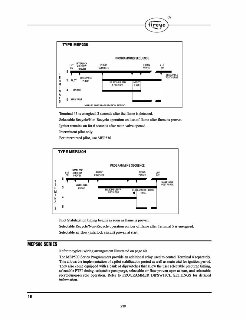
ïè
Ì»®³·²¿´ ýë · »²»®¹·¦»¼ í »½±²¼ ¿º¬»® ¬¸» º´¿³» · ¼»¬»½¬»¼ò
Í»´»½¬¿¾´» 뽧½´»ñÒ±²ó뽧½´» ±°»®¿¬·±² ±² ´± ±º º´¿³» ¿º¬»® º´¿³» · °®±ª»²ò
×¹²·¬»® ®»³¿·² ±² º±® ê »½±²¼ ¿º¬»® ³¿·² ª¿´ª» ±°»²»¼ò
ײ¬»®³·¬¬»²¬ °·´±¬ ±²´§ò
Ú±® ·²¬»®®«°¬»¼ °·´±¬ô «» ÓÛÐëíê
з´±¬ ͬ¿¾·´·¦¿¬·±² ¬·³·²¹ ¾»¹·² ¿ ±±² ¿ º´¿³» · °®±ª»²ò
Í»´»½¬¿¾´» 뽧½´»ñÒ±²ó뽧½´» ±°»®¿¬·±² ±² ´± ±º º´¿³» ¿º¬»® Ì»®³·²¿´ ë · »²»®¹·¦»¼ò
Í»´»½¬¿¾´» ¿·® º´±© ø·²¬»®´±½µ ½·®½«·¬÷ °®±ª»² ¿¬ ¬¿®¬ò
ÓÛÐëðð ÍÛÎ×ÛÍ
λº»® ¬± ¬§°·½¿´ ©·®·²¹ ¿®®¿²¹»³»²¬ ·´´«¬®¿¬»¼ ±² °¿¹» ìðò
̸» ÓÛÐëðð Í»®·» Ю±¹®¿³³»® °®±ª·¼» ¿² ¿¼¼·¬·±²¿´ ®»´¿§ «»¼ ¬± ½±²¬®±´ Ì»®³·²¿´ ì »°¿®¿¬»´§ò
̸· ¿´´±© ¬¸» ·³°´»³»²¬¿¬·±² ±º ¿ °·´±¬ ¬¿¾·´·¦¿¬·±² °»®·±¼ ¿ ©»´´ ¿ ³¿·² ¬®·¿´ º±® ·¹²·¬·±² °»®·±¼ò
̸»§ ¿´± ½±³» »¯«·°°»¼ ©·¬¸ ¿ ¾¿²µ ±º ¼·°©·¬½¸» ¬¸¿¬ ¿´´±© ¬¸» «»® »´»½¬¿¾´» °®»°«®¹» ¬·³·²¹ô
»´»½¬¿¾´» ÐÌÚ× ¬·³·²¹ô »´»½¬¿¾´» °±¬ °«®¹»ô »´»½¬¿¾´» ¿·® º´±© °®±ª»² ±°»² ¿¬ ¬¿®¬ô ¿²¼ »´»½¬¿¾´»
®»½§½´»ñ²±²ó®»½§½´» ±°»®¿¬·±²ò λº»® ¬± ÐÎÑÙÎßÓÓÛÎ Ü×ÐÍÉ×ÌÝØ ÍÛÌÌ×ÒÙÍ º±® ¼»¬¿·´»¼
·²º±®³¿¬·±²ò
ÌÇÐÛ ÓÛÐîíê
ÐÎÑÙÎßÓÓ×ÒÙ ÍÛÏËÛÒÝÛ
ÔïñéÑÒ
ÐËÎÙÛÝÑÓÐÔÛÌÛ
Ú×Î×ÒÙÐÛÎ×ÑÜ
ÔïñéÑÚÚ
ÍÛÔÛÝÌßÞÔÛ ÐÌÚ×ë ÑÎïð ÍÛÝ
ÍÛÔÛÝÌßÞÔÛ
ÐËÎÙÛ
èÌÛÎÓ×ÒßÔÍ
í
ì
ë
ÍÛÔÛÝÌßÞÔÛ ÐÑÍÌ ÐËÎÙÛ
Ð×ÔÑÌ
×ÙÒ×ÌÛÎ
Óß×Ò ÊßÔÊÛ
ÓÚÍÐöê ÍÛÝ
öÓß×Ò ÚÔßÓÛ ÍÌßÞ×Ô×ÆßÌ×ÑÒ ÐÛÎ×ÑÜ
×ÒÌÛÎÔÑÝÕß×Î ÚÔÑÉÐÎÑÊÛÒ
ÌÇÐÛ ÓÛÐîíðØ
ÐÎÑÙÎßÓÓ×ÒÙ ÍÛÏËÛÒÝÛ
ÔïñéÑÒ
ÐËÎÙÛÝÑÓÐÔÛÌÛ
Ú×Î×ÒÙÐÛÎ×ÑÜ
ÔïñéÑÚÚ
ÍÛÔÛÝÌßÞÔÛ ÐÌÚ×ë ÑÎïð ÍÛÝ
ÍÛÔÛÝÌßÞÔÛ
ÐËÎÙÛ
èÌÛÎÓ×ÒßÔÍ
í
ì
ë
ÍÛÔÛÝÌßÞÔÛ ÐÑÍÌ ÐËÎÙÛ
ÍÌßÞ×Ô×ÆßÌ×ÑÒ ÐÛÎ×ÑÜè ÍÛÝ
×ÒÌÛÎÔÑÝÕß×Î ÚÔÑÉÐÎÑÊÛÒ
239
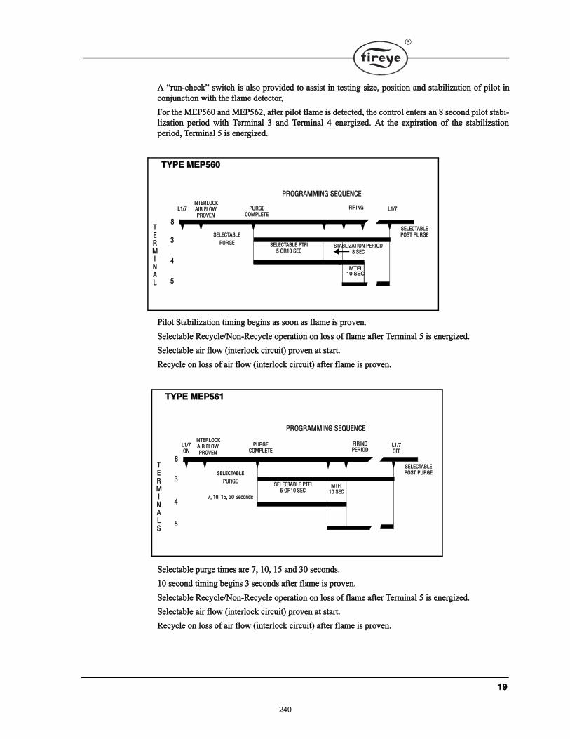
ïç
ß ®«²ó½¸»½µ ©·¬½¸ · ¿´± °®±ª·¼»¼ ¬± ¿·¬ ·² ¬»¬·²¹ ·¦»ô °±·¬·±² ¿²¼ ¬¿¾·´·¦¿¬·±² ±º °·´±¬ ·²
½±²¶«²½¬·±² ©·¬¸ ¬¸» º´¿³» ¼»¬»½¬±®ô
Ú±® ¬¸» ÓÛÐëêð ¿²¼ ÓÛÐëêîô ¿º¬»® °·´±¬ º´¿³» · ¼»¬»½¬»¼ô ¬¸» ½±²¬®±´ »²¬»® ¿² è »½±²¼ °·´±¬ ¬¿¾·ó
´·¦¿¬·±² °»®·±¼ ©·¬¸ Ì»®³·²¿´ í ¿²¼ Ì»®³·²¿´ ì »²»®¹·¦»¼ò ߬ ¬¸» »¨°·®¿¬·±² ±º ¬¸» ¬¿¾·´·¦¿¬·±²
°»®·±¼ô Ì»®³·²¿´ ë · »²»®¹·¦»¼ò
з´±¬ ͬ¿¾·´·¦¿¬·±² ¬·³·²¹ ¾»¹·² ¿ ±±² ¿ º´¿³» · °®±ª»²ò
Í»´»½¬¿¾´» 뽧½´»ñÒ±²ó뽧½´» ±°»®¿¬·±² ±² ´± ±º º´¿³» ¿º¬»® Ì»®³·²¿´ ë · »²»®¹·¦»¼ò
Í»´»½¬¿¾´» ¿·® º´±© ø·²¬»®´±½µ ½·®½«·¬÷ °®±ª»² ¿¬ ¬¿®¬ò
뽧½´» ±² ´± ±º ¿·® º´±© ø·²¬»®´±½µ ½·®½«·¬÷ ¿º¬»® º´¿³» · °®±ª»²ò
Í»´»½¬¿¾´» °«®¹» ¬·³» ¿®» éô ïðô ïë ¿²¼ íð »½±²¼ò
ïð »½±²¼ ¬·³·²¹ ¾»¹·² í »½±²¼ ¿º¬»® º´¿³» · °®±ª»²ò
Í»´»½¬¿¾´» 뽧½´»ñÒ±²ó뽧½´» ±°»®¿¬·±² ±² ´± ±º º´¿³» ¿º¬»® Ì»®³·²¿´ ë · »²»®¹·¦»¼ò
Í»´»½¬¿¾´» ¿·® º´±© ø·²¬»®´±½µ ½·®½«·¬÷ °®±ª»² ¿¬ ¬¿®¬ò
뽧½´» ±² ´± ±º ¿·® º´±© ø·²¬»®´±½µ ½·®½«·¬÷ ¿º¬»® º´¿³» · °®±ª»²ò
ÌÇÐÛ ÓÛÐëêð
ÐÎÑÙÎßÓÓ×ÒÙ ÍÛÏËÛÒÝÛ
Ôïñé ÐËÎÙÛÝÑÓÐÔÛÌÛ
Ú×Î×ÒÙ Ôïñé
ÍÛÔÛÝÌßÞÔÛ ÐÌÚ×ë ÑÎïð ÍÛÝ
ÍÛÔÛÝÌßÞÔÛ
ÐËÎÙÛ
èÌÛÎÓ×ÒßÔ
í
ì
ë
ÍÛÔÛÝÌßÞÔÛ ÐÑÍÌ ÐËÎÙÛ
ÍÌßÞÔ×ÆßÌ×ÑÒ ÐÛÎ×ÑÜè ÍÛÝ
ÓÌÚ×
ïð ÍÛÝ
×ÒÌÛÎÔÑÝÕß×Î ÚÔÑÉÐÎÑÊÛÒ
ÌÇÐÛ ÓÛÐëêï
ÐÎÑÙÎßÓÓ×ÒÙ ÍÛÏËÛÒÝÛ
ÔïñéÑÒ
ÐËÎÙÛÝÑÓÐÔÛÌÛ
Ú×Î×ÒÙÐÛÎ×ÑÜ
ÔïñéÑÚÚ
ÍÛÔÛÝÌßÞÔÛ ÐÌÚ×ë ÑÎïð ÍÛÝ
ÍÛÔÛÝÌßÞÔÛ
ÐËÎÙÛ
éô ïðô ïëô íð Í»½±²¼
èÌÛÎÓ×ÒßÔÍ
í
ì
ë
ÍÛÔÛÝÌßÞÔÛ ÐÑÍÌ ÐËÎÙÛ
ÓÌÚ×ïð ÍÛÝ
×ÒÌÛÎÔÑÝÕß×Î ÚÔÑÉÐÎÑÊÛÒ
240
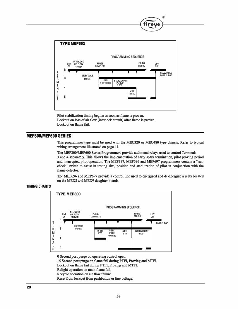
îð
з´±¬ ¬¿¾·´·¦¿¬·±² ¬·³·²¹ ¾»¹·² ¿ ±±² ¿ º´¿³» · °®±ª»²ò
Ô±½µ±«¬ ±² ´± ±º ¿·® º´±© ø·²¬»®´±½µ ½·®½«·¬÷ ¿º¬»® º´¿³» · °®±ª»²ò
Ô±½µ±«¬ ±² º´¿³» º¿·´ò
ÓÛÐíððñÓÛÐêðð ÍÛÎ×ÛÍ
̸· °®±¹®¿³³»® ¬§°» ³«¬ ¾» «»¼ ©·¬¸ ¬¸» ÓÛÝíîð ±® ÓÛÝìè𠬧°» ½¸¿·ò λº»® ¬± ¬§°·½¿´
©·®·²¹ ¿®®¿²¹»³»²¬ ·´´«¬®¿¬»¼ ±² °¿¹» ìïò
̸» ÓÛÐíððñÓÛÐêðð Í»®·» Ю±¹®¿³³»® °®±ª·¼» ¿¼¼·¬·±²¿´ ®»´¿§ «»¼ ¬± ½±²¬®±´ Ì»®³·²¿´
í ¿²¼ ì »°¿®¿¬»´§ò ̸· ¿´´±© ¬¸» ·³°´»³»²¬¿¬·±² ±º »¿®´§ °¿®µ ¬»®³·²¿¬·±²ô °·´±¬ °®±ª·²¹ °»®·±¼
¿²¼ ·²¬»®®«°¬»¼ °·´±¬ ±°»®¿¬·±²ò ̸» ÓÛÐíçéô ÓÛÐêçê ¿²¼ ÓÛÐêçé °®±¹®¿³³»® ½±²¬¿·² ¿ ®«²ó
½¸»½µ ©·¬½¸ ¬± ¿·¬ ·² ¬»¬·²¹ ·¦»ô °±·¬·±² ¿²¼ ¬¿¾·´·¦¿¬·±² ±º °·´±¬ ·² ½±²¶«²½¬·±² ©·¬¸ ¬¸»
º´¿³» ¼»¬»½¬±®ò
̸» ÓÛÐêçê ¿²¼ ÓÛÐêçé °®±ª·¼» ¿ ½±²¬®±´ ´·²» «»¼ ¬± »²»®¹·¦»¼ ¿²¼ ¼»ó»²»®¹·¦» ¿ ®»´¿§ ´±½¿¬»¼
±² ¬¸» ÓÛÜè ¿²¼ ÓÛÜç ¼¿«¹¸¬»® ¾±¿®¼ò
Ì×Ó×ÒÙ ÝØßÎÌÍ
ð Í»½±²¼ °±¬ °«®¹» ±² ±°»®¿¬·²¹ ½±²¬®±´ ±°»²ò
ïë Í»½±²¼ °±¬ °«®¹» ±² º´¿³» º¿·´ ¼«®·²¹ ÐÌÚ×ô Ю±ª·²¹ ¿²¼ ÓÌÚ×ò
Ô±½µ±«¬ ±² º´¿³» º¿·´ ¼«®·²¹ ÐÌÚ×ô Ю±ª·²¹ ¿²¼ ÓÌÚ×ò
λ´·¹¸¬ ±°»®¿¬·±² ±² ³¿·² º´¿³» º¿·´ò
뽧½´» ±°»®¿¬·±² ±² ¿·® º´±© º¿·´«®»ò
뻬 º®±³ ´±½µ±«¬ º®±³ °«¸¾«¬¬±² ±® ´·²» ª±´¬¿¹»ò
ÌÇÐÛ ÓÛÐëêî
ÐÎÑÙÎßÓÓ×ÒÙ ÍÛÏËÛÒÝÛ
ÔïñéÑÒ
ÐËÎÙÛÝÑÓÐÔÛÌÛ
Ú×Î×ÒÙÐÛÎ×ÑÜ
ÔïñéÑÚÚ
ÐÌÚ×ë ÑÎïð ÍÛÝ
ÍÛÔÛÝÌßÞÔÛ
ÐËÎÙÛ
èÌÛÎÓ×ÒßÔÍ
í
ì
ë
ÍÛÔÛÝÌßÞÔÛ ÐÑÍÌ ÐËÎÙÛ
ÓÌÚ×ïð ÍÛÝ
ÍÌßÞÔ×ÆßÌ×ÑÒ
è ÍÛÝ ÐÛÎ×ÑÜ
×ÒÌÛÎÔÑÝÕß×Î ÚÔÑÉÐÎÑÊÛÒ
ÌÇÐÛ ÓÛÐíðð
ÐÎÑÙÎßÓÓ×ÒÙ ÍÛÏËÛÒÝÛ
ÔïñéÑÒ
ÐËÎÙÛÝÑÓÐÔÛÌÛ
Ú×Î×ÒÙÐÛÎ×ÑÜ
ÔïñéÑÚÚ
ïð ÍÛÝÐÌÚ×
ë ÍÛÝÑÒÜÐËÎÙÛ
èÌÛÎÓ×ÒßÔÍ
í
ì
ë
ÐÑÍÌ ÐËÎÙÛ
×ÒÌÛÎÔÑÝÕß×Î ÚÔÑÉÐÎÑÊÛÒ
ë ÍÛÝÐ×ÔÑÌ
ÐÎÑÊ×ÒÙ
ëÍÛÝÓÌÚ×
×ÒÌÛÎÓ×ÌÌÛÒÌÐ×ÔÑÌ
241
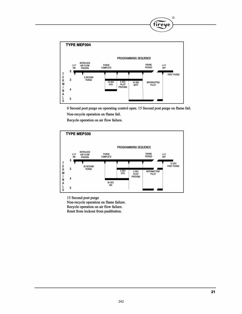
îï
ð Í»½±²¼ °±¬ °«®¹» ±² ±°»®¿¬·²¹ ½±²¬®±´ ±°»²ò ïë Í»½±²¼ °±¬ °«®¹» ±² º´¿³» º¿·´ò
Ò±²ó®»½§½´» ±°»®¿¬·±² ±² º´¿³» º¿·´ò
뽧½´» ±°»®¿¬·±² ±² ¿·® º´±© º¿·´«®»ò
ïë Í»½±²¼ °±¬ °«®¹»
Ò±²ó®»½§½´» ±°»®¿¬·±² ±² º´¿³» º¿·´«®»ò
뽧½´» ±°»®¿¬·±² ±² ¿·® º´±© º¿·´«®»ò
뻬 º®±³ ´±½µ±«¬ º®±³ °«¸¾«¬¬±²ò
ÌÇÐÛ ÓÛÐíðì
ÐÎÑÙÎßÓÓ×ÒÙ ÍÛÏËÛÒÝÛ
ÔïñéÑÒ
ÐËÎÙÛÝÑÓÐÔÛÌÛ
Ú×Î×ÒÙÐÛÎ×ÑÜ
ÔïñéÑÚÚ
ïð ÍÛÝÐÌÚ×
ë ÍÛÝÑÒÜÐËÎÙÛ
èÌÛÎÓ×ÒßÔÍ
í
ì
ë
ÐÑÍÌ ÐËÎÙÛ
×ÒÌÛÎÔÑÝÕß×Î ÚÔÑÉÐÎÑÊÛÒ
ë ÍÛÝÐ×ÔÑÌ
ÐÎÑÊ×ÒÙ
ïð ÍÛÝÓÌÚ×
×ÒÌÛÎÎËÐÌÛÜÐ×ÔÑÌ
ÌÇÐÛ ÓÛÐííë
ÐÎÑÙÎßÓÓ×ÒÙ ÍÛÏËÛÒÝÛ
ÔïñéÑÒ
ÐËÎÙÛÝÑÓÐÔÛÌÛ
Ú×Î×ÒÙÐÛÎ×ÑÜ
ÔïñéÑÚÚ
íë ÍÛÝØÍ×
íð ÍÛÝÑÒÜÐËÎÙÛ
èÌÛÎÓ×ÒßÔÍ
í
ì
ë
ïë ÍÛÝÐÑÍÌ ÐËÎÙÛ
×ÒÌÛÎÔÑÝÕß×Î ÚÔÑÉÐÎÑÊÛÒ
í ÍÛÝÐÌÚ×
ë ÍÛÝÐ×ÔÑÌ
ÐÎÑÊ×ÒÙ
×ÒÌÛÎÓ×ÌÌÛÒÌÐ×ÔÑÌ
242
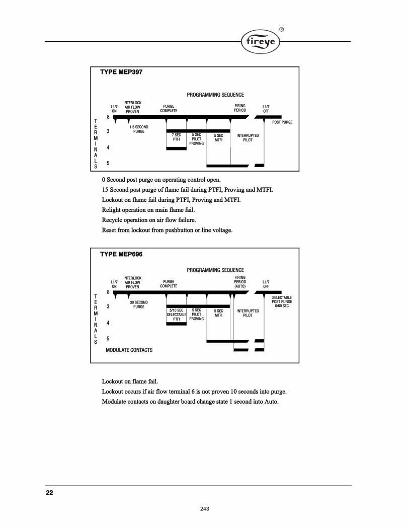
îî
ð Í»½±²¼ °±¬ °«®¹» ±² ±°»®¿¬·²¹ ½±²¬®±´ ±°»²ò
ïë Í»½±²¼ °±¬ °«®¹» ±º º´¿³» º¿·´ ¼«®·²¹ ÐÌÚ×ô Ю±ª·²¹ ¿²¼ ÓÌÚ×ò
Ô±½µ±«¬ ±² º´¿³» º¿·´ ¼«®·²¹ ÐÌÚ×ô Ю±ª·²¹ ¿²¼ ÓÌÚ×ò
λ´·¹¸¬ ±°»®¿¬·±² ±² ³¿·² º´¿³» º¿·´ò
뽧½´» ±°»®¿¬·±² ±² ¿·® º´±© º¿·´«®»ò
뻬 º®±³ ´±½µ±«¬ º®±³ °«¸¾«¬¬±² ±® ´·²» ª±´¬¿¹»ò
Ô±½µ±«¬ ±² º´¿³» º¿·´ò
Ô±½µ±«¬ ±½½«® ·º ¿·® º´±© ¬»®³·²¿´ ê · ²±¬ °®±ª»² ïð »½±²¼ ·²¬± °«®¹»ò
Ó±¼«´¿¬» ½±²¬¿½¬ ±² ¼¿«¹¸¬»® ¾±¿®¼ ½¸¿²¹» ¬¿¬» ï »½±²¼ ·²¬± ß«¬±ò
ÌÇÐÛ ÓÛÐíçé
ÐÎÑÙÎßÓÓ×ÒÙ ÍÛÏËÛÒÝÛ
ÔïñéÑÒ
ÐËÎÙÛÝÑÓÐÔÛÌÛ
Ú×Î×ÒÙÐÛÎ×ÑÜ
ÔïñéÑÚÚ
é ÍÛÝÐÌÚ×
ï ë ÍÛÝÑÒÜÐËÎÙÛ
èÌÛÎÓ×ÒßÔÍ
í
ì
ë
ÐÑÍÌ ÐËÎÙÛ
×ÒÌÛÎÔÑÝÕß×Î ÚÔÑÉÐÎÑÊÛÒ
ë ÍÛÝÐ×ÔÑÌ
ÐÎÑÊ×ÒÙ
ë ÍÛÝÓÌÚ×
×ÒÌÛÎÎËÐÌÛÜÐ×ÔÑÌ
ÌÇÐÛ ÓÛÐêçê
ÐÎÑÙÎßÓÓ×ÒÙ ÍÛÏËÛÒÝÛ
ÔïñéÑÒ
ÐËÎÙÛÝÑÓÐÔÛÌÛ
Ú×Î×ÒÙÐÛÎ×ÑÜøßËÌÑ÷
ÔïñéÑÚÚ
ëñïð ÍÛÝÍÛÔÛÝÌßÞÔÛ
ÐÌÚ×
íð ÍÛÝÑÒÜÐËÎÙÛ
èÌÛÎÓ×ÒßÔÍ
í
ì
ë
ÍÛÔÛÝÌßÞÔÛ ÐÑÍÌ ÐËÎÙÛ
ðñêð ÍÛÝ
×ÒÌÛÎÔÑÝÕß×Î ÚÔÑÉÐÎÑÊÛÒ
ë ÍÛÝÐ×ÔÑÌ
ÐÎÑÊ×ÒÙ
ë ÍÛÝÓÌÚ×
×ÒÌÛÎÎËÐÌÛÜÐ×ÔÑÌ
ÓÑÜËÔßÌÛ ÝÑÒÌßÝÌÍ
243
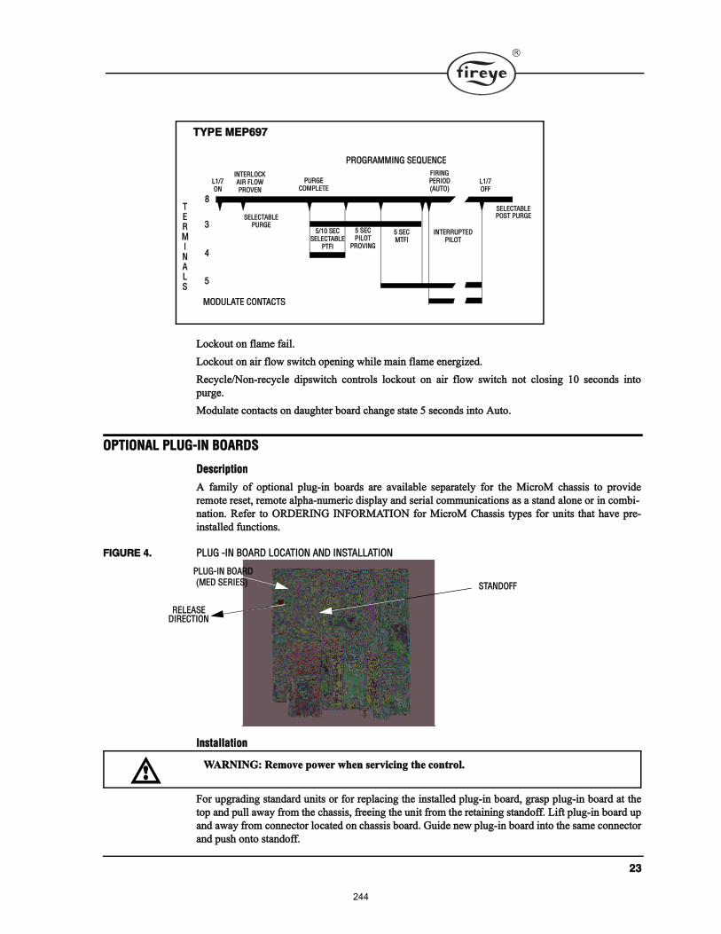
îí
Ô±½µ±«¬ ±² º´¿³» º¿·´ò
Ô±½µ±«¬ ±² ¿·® º´±© ©·¬½¸ ±°»²·²¹ ©¸·´» ³¿·² º´¿³» »²»®¹·¦»¼ò
뽧½´»ñÒ±²ó®»½§½´» ¼·°©·¬½¸ ½±²¬®±´ ´±½µ±«¬ ±² ¿·® º´±© ©·¬½¸ ²±¬ ½´±·²¹ ïð »½±²¼ ·²¬±
°«®¹»ò
Ó±¼«´¿¬» ½±²¬¿½¬ ±² ¼¿«¹¸¬»® ¾±¿®¼ ½¸¿²¹» ¬¿¬» ë »½±²¼ ·²¬± ß«¬±ò
ÑÐÌ×ÑÒßÔ ÐÔËÙó×Ò ÞÑßÎÜÍ
Ü»½®·°¬·±²
ß º¿³·´§ ±º ±°¬·±²¿´ °´«¹ó·² ¾±¿®¼ ¿®» ¿ª¿·´¿¾´» »°¿®¿¬»´§ º±® ¬¸» Ó·½®±Ó ½¸¿· ¬± °®±ª·¼»
®»³±¬» ®»»¬ô ®»³±¬» ¿´°¸¿ó²«³»®·½ ¼·°´¿§ ¿²¼ »®·¿´ ½±³³«²·½¿¬·±² ¿ ¿ ¬¿²¼ ¿´±²» ±® ·² ½±³¾·ó
²¿¬·±²ò λº»® ¬± ÑÎÜÛÎ×ÒÙ ×ÒÚÑÎÓßÌ×ÑÒ º±® Ó·½®±Ó ݸ¿· ¬§°» º±® «²·¬ ¬¸¿¬ ¸¿ª» °®»ó
·²¬¿´´»¼ º«²½¬·±²ò
Ú×ÙËÎÛ ìò ÐÔËÙ ó×Ò ÞÑßÎÜ ÔÑÝßÌ×ÑÒ ßÒÜ ×ÒÍÌßÔÔßÌ×ÑÒ
ײ¬¿´´¿¬·±²
Ú±® «°¹®¿¼·²¹ ¬¿²¼¿®¼ «²·¬ ±® º±® ®»°´¿½·²¹ ¬¸» ·²¬¿´´»¼ °´«¹ó·² ¾±¿®¼ô ¹®¿° °´«¹ó·² ¾±¿®¼ ¿¬ ¬¸»
¬±° ¿²¼ °«´´ ¿©¿§ º®±³ ¬¸» ½¸¿·ô º®»»·²¹ ¬¸» «²·¬ º®±³ ¬¸» ®»¬¿·²·²¹ ¬¿²¼±ººò Ô·º¬ °´«¹ó·² ¾±¿®¼ «°
¿²¼ ¿©¿§ º®±³ ½±²²»½¬±® ´±½¿¬»¼ ±² ½¸¿· ¾±¿®¼ò Ù«·¼» ²»© °´«¹ó·² ¾±¿®¼ ·²¬± ¬¸» ¿³» ½±²²»½¬±®
¿²¼ °«¸ ±²¬± ¬¿²¼±ººò
ÌÇÐÛ ÓÛÐêçé
ÐÎÑÙÎßÓÓ×ÒÙ ÍÛÏËÛÒÝÛ
ÔïñéÑÒ
ÐËÎÙÛÝÑÓÐÔÛÌÛ
Ú×Î×ÒÙÐÛÎ×ÑÜøßËÌÑ÷
ÔïñéÑÚÚ
ëñïð ÍÛÝÍÛÔÛÝÌßÞÔÛ
ÐÌÚ×
ÍÛÔÛÝÌßÞÔÛÐËÎÙÛ
èÌÛÎÓ×ÒßÔÍ
í
ì
ë
ÍÛÔÛÝÌßÞÔÛ ÐÑÍÌ ÐËÎÙÛ
×ÒÌÛÎÔÑÝÕß×Î ÚÔÑÉÐÎÑÊÛÒ
ë ÍÛÝÐ×ÔÑÌ
ÐÎÑÊ×ÒÙ
ë ÍÛÝÓÌÚ×
×ÒÌÛÎÎËÐÌÛÜÐ×ÔÑÌ
ÓÑÜËÔßÌÛ ÝÑÒÌßÝÌÍ
ÍÌßÒÜÑÚÚ
ÐÔËÙó×Ò ÞÑßÎÜ
øÓÛÜ ÍÛÎ×ÛÍ÷
ÎÛÔÛßÍÛ Ü×ÎÛÝÌ×ÑÒ
ÉßÎÒ×ÒÙæ λ³±ª» °±©»® ©¸»² »®ª·½·²¹ ¬¸» ½±²¬®±´ò
244
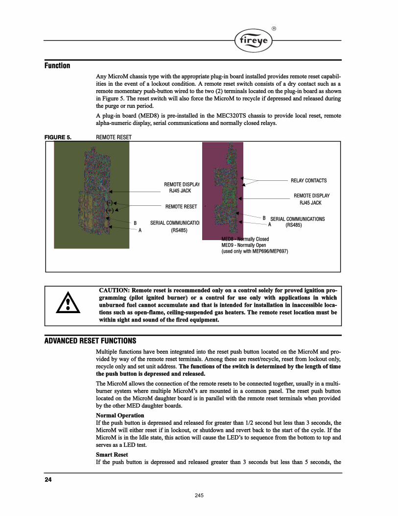
îì
Ú«²½¬·±²
ß²§ Ó·½®±Ó ½¸¿· ¬§°» ©·¬¸ ¬¸» ¿°°®±°®·¿¬» °´«¹ó·² ¾±¿®¼ ·²¬¿´´»¼ °®±ª·¼» ®»³±¬» ®»»¬ ½¿°¿¾·´ó
·¬·» ·² ¬¸» »ª»²¬ ±º ¿ ´±½µ±«¬ ½±²¼·¬·±²ò ß ®»³±¬» ®»»¬ ©·¬½¸ ½±²·¬ ±º ¿ ¼®§ ½±²¬¿½¬ «½¸ ¿ ¿
®»³±¬» ³±³»²¬¿®§ °«¸ó¾«¬¬±² ©·®»¼ ¬± ¬¸» ¬©± øî÷ ¬»®³·²¿´ ´±½¿¬»¼ ±² ¬¸» °´«¹ó·² ¾±¿®¼ ¿ ¸±©²
·² Ú·¹«®» ëò ̸» ®»»¬ ©·¬½¸ ©·´´ ¿´± º±®½» ¬¸» Ó·½®±Ó ¬± ®»½§½´» ·º ¼»°®»»¼ ¿²¼ ®»´»¿»¼ ¼«®·²¹
¬¸» °«®¹» ±® ®«² °»®·±¼ò
ß °´«¹ó·² ¾±¿®¼ øÓÛÜè÷ · °®»ó·²¬¿´´»¼ ·² ¬¸» ÓÛÝíîðÌÍ ½¸¿· ¬± °®±ª·¼» ´±½¿´ ®»»¬ô ®»³±¬»
¿´°¸¿ó²«³»®·½ ¼·°´¿§ô »®·¿´ ½±³³«²·½¿¬·±² ¿²¼ ²±®³¿´´§ ½´±»¼ ®»´¿§ò
Ú×ÙËÎÛ ëò ÎÛÓÑÌÛ ÎÛÍÛÌ
ßÜÊßÒÝÛÜ ÎÛÍÛÌ ÚËÒÝÌ×ÑÒÍ
Ó«´¬·°´» º«²½¬·±² ¸¿ª» ¾»»² ·²¬»¹®¿¬»¼ ·²¬± ¬¸» ®»»¬ °«¸ ¾«¬¬±² ´±½¿¬»¼ ±² ¬¸» Ó·½®±Ó ¿²¼ °®±ó
ª·¼»¼ ¾§ ©¿§ ±º ¬¸» ®»³±¬» ®»»¬ ¬»®³·²¿´ò ß³±²¹ ¬¸»» ¿®» ®»»¬ñ®»½§½´»ô ®»»¬ º®±³ ´±½µ±«¬ ±²´§ô
®»½§½´» ±²´§ ¿²¼ »¬ «²·¬ ¿¼¼®»ò ̸» º«²½¬·±² ±º ¬¸» ©·¬½¸ · ¼»¬»®³·²»¼ ¾§ ¬¸» ´»²¹¬¸ ±º ¬·³»
¬¸» °«¸ ¾«¬¬±² · ¼»°®»»¼ ¿²¼ ®»´»¿»¼ò
̸» Ó·½®±Ó ¿´´±© ¬¸» ½±²²»½¬·±² ±º ¬¸» ®»³±¬» ®»»¬ ¬± ¾» ½±²²»½¬»¼ ¬±¹»¬¸»®ô ««¿´´§ ·² ¿ ³«´¬·ó
¾«®²»® §¬»³ ©¸»®» ³«´¬·°´» Ó·½®±Ó ¿®» ³±«²¬»¼ ·² ¿ ½±³³±² °¿²»´ò ̸» ®»»¬ °«¸ ¾«¬¬±²
´±½¿¬»¼ ±² ¬¸» Ó·½®±Ó ¼¿«¹¸¬»® ¾±¿®¼ · ·² °¿®¿´´»´ ©·¬¸ ¬¸» ®»³±¬» ®»»¬ ¬»®³·²¿´ ©¸»² °®±ª·¼»¼
¾§ ¬¸» ±¬¸»® ÓÛÜ ¼¿«¹¸¬»® ¾±¿®¼ò
Ò±®³¿´ Ñ°»®¿¬·±²
׺ ¬¸» °«¸ ¾«¬¬±² · ¼»°®»»¼ ¿²¼ ®»´»¿»¼ º±® ¹®»¿¬»® ¬¸¿² ïñî »½±²¼ ¾«¬ ´» ¬¸¿² í »½±²¼ô ¬¸»
Ó·½®±Ó ©·´´ »·¬¸»® ®»»¬ ·º ·² ´±½µ±«¬ô ±® ¸«¬¼±©² ¿²¼ ®»ª»®¬ ¾¿½µ ¬± ¬¸» ¬¿®¬ ±º ¬¸» ½§½´»ò ׺ ¬¸»
Ó·½®±Ó · ·² ¬¸» ×¼´» ¬¿¬»ô ¬¸· ¿½¬·±² ©·´´ ½¿«» ¬¸» ÔÛÜ ¬± »¯«»²½» º®±³ ¬¸» ¾±¬¬±³ ¬± ¬±° ¿²¼
»®ª» ¿ ¿ ÔÛÜ ¬»¬ò
ͳ¿®¬ 뻬
׺ ¬¸» °«¸ ¾«¬¬±² · ¼»°®»»¼ ¿²¼ ®»´»¿»¼ ¹®»¿¬»® ¬¸¿² í »½±²¼ ¾«¬ ´» ¬¸¿² ë »½±²¼ô ¬¸»
ÍÛÎ×ßÔ ÝÑÓÓËÒ×ÝßÌ×ÑÒÍ
ß
Þ
ÎÛÓÑÌÛ Ü×ÍÐÔßÇ
ÎÖìë ÖßÝÕ
ÎÛÓÑÌÛ ÎÛÍÛÌ
øÎÍìèë÷
øõ÷
øó÷
ÍÛÎ×ßÔ ÝÑÓÓËÒ×ÝßÌ×ÑÒÍ
ÎÛÓÑÌÛ Ü×ÍÐÔßÇ
ÎÖìë ÖßÝÕ
ÎÛÔßÇ ÝÑÒÌßÝÌÍ
øÎÍìèë÷
Þ
ß
ÓÛÜè ó Ò±®³¿´´§ Ý´±»¼ÓÛÜç ó Ò±®³¿´´§ Ñ°»²
ø«»¼ ±²´§ ©·¬¸ ÓÛÐêçêñÓÛÐêçé÷
ÝßËÌ×ÑÒæ λ³±¬» ®»»¬ · ®»½±³³»²¼»¼ ±²´§ ±² ¿ ½±²¬®±´ ±´»´§ º±® °®±ª»¼ ·¹²·¬·±² °®±ó
¹®¿³³·²¹ ø°·´±¬ ·¹²·¬»¼ ¾«®²»®÷ ±® ¿ ½±²¬®±´ º±® «» ±²´§ ©·¬¸ ¿°°´·½¿¬·±² ·² ©¸·½¸
«²¾«®²»¼ º«»´ ½¿²²±¬ ¿½½«³«´¿¬» ¿²¼ ¬¸¿¬ · ·²¬»²¼»¼ º±® ·²¬¿´´¿¬·±² ·² ·²¿½½»·¾´» ´±½¿ó
¬·±² «½¸ ¿ ±°»²óº´¿³»ô ½»·´·²¹ó«°»²¼»¼ ¹¿ ¸»¿¬»®ò ̸» ®»³±¬» ®»»¬ ´±½¿¬·±² ³«¬ ¾»
©·¬¸·² ·¹¸¬ ¿²¼ ±«²¼ ±º ¬¸» º·®»¼ »¯«·°³»²¬ò
245
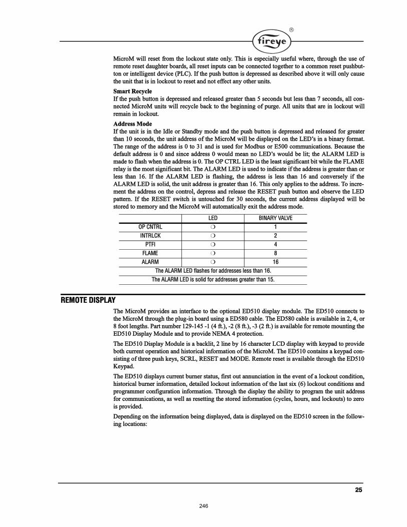
îë
Ó·½®±Ó ©·´´ ®»»¬ º®±³ ¬¸» ´±½µ±«¬ ¬¿¬» ±²´§ò ̸· · »°»½·¿´´§ «»º«´ ©¸»®»ô ¬¸®±«¹¸ ¬¸» «» ±º
®»³±¬» ®»»¬ ¼¿«¹¸¬»® ¾±¿®¼ô ¿´´ ®»»¬ ·²°«¬ ½¿² ¾» ½±²²»½¬»¼ ¬±¹»¬¸»® ¬± ¿ ½±³³±² ®»»¬ °«¸¾«¬ó
¬±² ±® ·²¬»´´·¹»²¬ ¼»ª·½» øÐÔÝ÷ò ׺ ¬¸» °«¸ ¾«¬¬±² · ¼»°®»»¼ ¿ ¼»½®·¾»¼ ¿¾±ª» ·¬ ©·´´ ±²´§ ½¿«»
¬¸» «²·¬ ¬¸¿¬ · ·² ´±½µ±«¬ ¬± ®»»¬ ¿²¼ ²±¬ »ºº»½¬ ¿²§ ±¬¸»® «²·¬ò
ͳ¿®¬ 뽧½´»
׺ ¬¸» °«¸ ¾«¬¬±² · ¼»°®»»¼ ¿²¼ ®»´»¿»¼ ¹®»¿¬»® ¬¸¿² ë »½±²¼ ¾«¬ ´» ¬¸¿² é »½±²¼ô ¿´´ ½±²ó
²»½¬»¼ Ó·½®±Ó «²·¬ ©·´´ ®»½§½´» ¾¿½µ ¬± ¬¸» ¾»¹·²²·²¹ ±º °«®¹»ò ß´´ «²·¬ ¬¸¿¬ ¿®» ·² ´±½µ±«¬ ©·´´
®»³¿·² ·² ´±½µ±«¬ò
ß¼¼®» Ó±¼»
׺ ¬¸» «²·¬ · ·² ¬¸» ×¼´» ±® ͬ¿²¼¾§ ³±¼» ¿²¼ ¬¸» °«¸ ¾«¬¬±² · ¼»°®»»¼ ¿²¼ ®»´»¿»¼ º±® ¹®»¿¬»®
¬¸¿² ïð »½±²¼ô ¬¸» «²·¬ ¿¼¼®» ±º ¬¸» Ó·½®±Ó ©·´´ ¾» ¼·°´¿§»¼ ±² ¬¸» ÔÛÜ ·² ¿ ¾·²¿®§ º±®³¿¬ò
̸» ®¿²¹» ±º ¬¸» ¿¼¼®» · 𠬱 íï ¿²¼ · «»¼ º±® Ó±¼¾« ±® Ûëðð ½±³³«²·½¿¬·±²ò Þ»½¿«» ¬¸»
¼»º¿«´¬ ¿¼¼®» · ð ¿²¼ ·²½» ¿¼¼®» ð ©±«´¼ ³»¿² ²± ÔÛÜ ©±«´¼ ¾» ´·¬å ¬¸» ßÔßÎÓ ÔÛÜ ·
³¿¼» ¬± º´¿¸ ©¸»² ¬¸» ¿¼¼®» · ðò ̸» ÑÐ ÝÌÎÔ ÔÛÜ · ¬¸» ´»¿¬ ·¹²·º·½¿²¬ ¾·¬ ©¸·´» ¬¸» ÚÔßÓÛ
®»´¿§ · ¬¸» ³±¬ ·¹²·º·½¿²¬ ¾·¬ò ̸» ßÔßÎÓ ÔÛÜ · «»¼ ¬± ·²¼·½¿¬» ·º ¬¸» ¿¼¼®» · ¹®»¿¬»® ¬¸¿² ±®
´» ¬¸¿² ïêò ׺ ¬¸» ßÔßÎÓ ÔÛÜ · º´¿¸·²¹ô ¬¸» ¿¼¼®» · ´» ¬¸¿² ïê ¿²¼ ½±²ª»®»´§ ·º ¬¸»
ßÔßÎÓ ÔÛÜ · ±´·¼ô ¬¸» «²·¬ ¿¼¼®» · ¹®»¿¬»® ¬¸¿² ïêò ̸· ±²´§ ¿°°´·» ¬± ¬¸» ¿¼¼®»ò ̱ ·²½®»ó
³»²¬ ¬¸» ¿¼¼®» ±² ¬¸» ½±²¬®±´ô ¼»°®» ¿²¼ ®»´»¿» ¬¸» ÎÛÍÛÌ °«¸ ¾«¬¬±² ¿²¼ ±¾»®ª» ¬¸» ÔÛÜ
°¿¬¬»®²ò ׺ ¬¸» ÎÛÍÛÌ ©·¬½¸ · «²¬±«½¸»¼ º±® íð »½±²¼ô ¬¸» ½«®®»²¬ ¿¼¼®» ¼·°´¿§»¼ ©·´´ ¾»
¬±®»¼ ¬± ³»³±®§ ¿²¼ ¬¸» Ó·½®±Ó ©·´´ ¿«¬±³¿¬·½¿´´§ »¨·¬ ¬¸» ¿¼¼®» ³±¼»ò
ÎÛÓÑÌÛ Ü×ÍÐÔßÇ
̸» Ó·½®±Ó °®±ª·¼» ¿² ·²¬»®º¿½» ¬± ¬¸» ±°¬·±²¿´ ÛÜëïð ¼·°´¿§ ³±¼«´»ò ̸» ÛÜëïð ½±²²»½¬ ¬±
¬¸» Ó·½®±Ó ¬¸®±«¹¸ ¬¸» °´«¹ó·² ¾±¿®¼ «·²¹ ¿ ÛÜëè𠽿¾´»ò ̸» ÛÜëè𠽿¾´» · ¿ª¿·´¿¾´» ·² îô ìô ±®
è º±±¬ ´»²¹¬¸ò ﮬ ²«³¾»® ïîçóïìë óï øì º¬ò÷ô óî øè º¬ò÷ô óí øî º¬ò÷ · ¿ª¿·´¿¾´» º±® ®»³±¬» ³±«²¬·²¹ ¬¸»
ÛÜëïð Ü·°´¿§ Ó±¼«´» ¿²¼ ¬± °®±ª·¼» ÒÛÓß ì °®±¬»½¬·±²ò
̸» ÛÜëïð Ü·°´¿§ Ó±¼«´» · ¿ ¾¿½µ´·¬ô î ´·²» ¾§ ïê ½¸¿®¿½¬»® ÔÝÜ ¼·°´¿§ ©·¬¸ µ»§°¿¼ ¬± °®±ª·¼»
¾±¬¸ ½«®®»²¬ ±°»®¿¬·±² ¿²¼ ¸·¬±®·½¿´ ·²º±®³¿¬·±² ±º ¬¸» Ó·½®±Óò ̸» ÛÜëïð ½±²¬¿·² ¿ µ»§°¿¼ ½±²ó
·¬·²¹ ±º ¬¸®»» °«¸ µ»§ô ÍÝÎÔô ÎÛÍÛÌ ¿²¼ ÓÑÜÛò λ³±¬» ®»»¬ · ¿ª¿·´¿¾´» ¬¸®±«¹¸ ¬¸» ÛÜëïð
Õ»§°¿¼ò
̸» ÛÜëïð ¼·°´¿§ ½«®®»²¬ ¾«®²»® ¬¿¬«ô º·®¬ ±«¬ ¿²²«²½·¿¬·±² ·² ¬¸» »ª»²¬ ±º ¿ ´±½µ±«¬ ½±²¼·¬·±²ô
¸·¬±®·½¿´ ¾«®²»® ·²º±®³¿¬·±²ô ¼»¬¿·´»¼ ´±½µ±«¬ ·²º±®³¿¬·±² ±º ¬¸» ´¿¬ ·¨ øê÷ ´±½µ±«¬ ½±²¼·¬·±² ¿²¼
°®±¹®¿³³»® ½±²º·¹«®¿¬·±² ·²º±®³¿¬·±²ò ̸®±«¹¸ ¬¸» ¼·°´¿§ ¬¸» ¿¾·´·¬§ ¬± °®±¹®¿³ ¬¸» «²·¬ ¿¼¼®»
º±® ½±³³«²·½¿¬·±²ô ¿ ©»´´ ¿ ®»»¬¬·²¹ ¬¸» ¬±®»¼ ·²º±®³¿¬·±² ø½§½´»ô ¸±«®ô ¿²¼ ´±½µ±«¬÷ ¬± ¦»®±
· °®±ª·¼»¼ò
Ü»°»²¼·²¹ ±² ¬¸» ·²º±®³¿¬·±² ¾»·²¹ ¼·°´¿§»¼ô ¼¿¬¿ · ¼·°´¿§»¼ ±² ¬¸» ÛÜëïð ½®»»² ·² ¬¸» º±´´±©ó
·²¹ ´±½¿¬·±²æ
ÔÛÜ Þ×ÒßÎÇ ÊßÔÊÛ
ÑÐ ÝÒÌÎÔ ï
×ÒÌÎÔÝÕ î
ÐÌÚ× ì
ÚÔßÓÛ è
ßÔßÎÓ ïê
̸» ßÔßÎÓ ÔÛÜ º´¿¸» º±® ¿¼¼®»» ´» ¬¸¿² ïêò
̸» ßÔßÎÓ ÔÛÜ · ±´·¼ º±® ¿¼¼®»» ¹®»¿¬»® ¬¸¿² ïëò
246
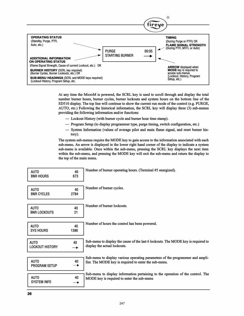
îê
߬ ¿²§ ¬·³» ¬¸» Ó·½®±Ó · °±©»®»¼ô ¬¸» ÍÝÎÔ µ»§ · «»¼ ¬± ½®±´´ ¬¸®±«¹¸ ¿²¼ ¼·°´¿§ ¬¸» ¬±¬¿´
²«³¾»® ¾«®²»® ¸±«®ô ¾«®²»® ½§½´»ô ¾«®²»® ´±½µ±«¬ ¿²¼ §¬»³ ¸±«® ±² ¬¸» ¾±¬¬±³ ´·²» ±º ¬¸»
ÛÜëïð ¼·°´¿§ò ̸» ¬±° ´·²» ©·´´ ½±²¬·²«» ¬± ¸±© ¬¸» ½«®®»²¬ ®«² ³±¼» ±º ¬¸» ½±²¬®±´ ø»ò¹ò ÐËÎÙÛô
ßËÌÑô »¬½ò÷ Ú±´´±©·²¹ ¬¸» ¸·¬±®·½¿´ ·²º±®³¿¬·±²ô ¬¸» ÍÝÎÔ µ»§ ©·´´ ¼·°´¿§ ¬¸®»» øí÷ «¾ó³»²«
°®±ª·¼·²¹ ¬¸» º±´´±©·²¹ ·²º±®³¿¬·±² ¿²¼ñ±® º«²½¬·±²æ
Ô±½µ±«¬ Ø·¬±®§ ø©·¬¸ ¾«®²»® ½§½´» ¿²¼ ¾«®²»® ¸±«® ¬·³» ¬¿³°÷ò
Ю±¹®¿³ Í»¬«° ø¬± ¼·°´¿§ °®±¹®¿³³»® ¬§°»ô °«®¹» ¬·³·²¹ô ©·¬½¸ ½±²º·¹«®¿¬·±²ô »¬½ò÷
ͧ¬»³ ײº±®³¿¬·±² øª¿´«» ±º ¿ª»®¿¹» °·´±¬ ¿²¼ ³¿·² º´¿³» ·¹²¿´ô ¿²¼ ®»»¬ ¾«®²»® ¸·ó
¬±®§÷ò
̸» §¬»³ «¾ó³»²« ®»¯«·®» ¬¸» ÓÑÜÛ µ»§ ¬± ¹¿·² ¿½½» ¬± ¬¸» ·²º±®³¿¬·±² ¿±½·¿¬»¼ ©·¬¸ »¿½¸
«¾ó³»²«ò ß² ¿®®±© · ¼·°´¿§»¼ ·² ¬¸» ´±©»® ®·¹¸¬ ¸¿²¼ ½±®²»® ±º ¬¸» ¼·°´¿§ ¬± ·²¼·½¿¬» ¿ §¬»³
«¾ó³»²« · ¿ª¿·´¿¾´»ò Ѳ½» ©·¬¸·² ¬¸» «¾ó³»²«ô °®»·²¹ ¬¸» ÍÝÎÔ µ»§ ¼·°´¿§ ¬¸» ²»¨¬ ·¬»³
©·¬¸·² ¬¸» «¾ó³»²«ô ¿²¼ °®»·²¹ ¬¸» ÓÑÜÛ µ»§ ©·´´ »¨·¬ ¬¸» «¾ó³»²« ¿²¼ ®»¬«®² ¬¸» ¼·°´¿§ ¬±
¬¸» ¬±° ±º ¬¸» ³¿·² ³»²«ò
Ò«³¾»® ±º ¾«®²»® ±°»®¿¬·²¹ ¸±«®ò øÌ»®³·²¿´ ýë »²»®¹·¦»¼÷ò
Ò«³¾»® ±º ¾«®²»® ½§½´»ò
Ò«³¾»® ±º ¾«®²»® ´±½µ±«¬ò
Ò«³¾»® ±º ¸±«® ¬¸» ½±²¬®±´ ¸¿ ¾»»² °±©»®»¼ò
Í«¾ó³»²« ¬± ¼·°´¿§ ¬¸» ½¿«» ±º ¬¸» ´¿¬ ê ´±½µ±«¬ò ̸» ÓÑÜÛ µ»§ · ®»¯«·®»¼ ¬±
¼·°´¿§ ¬¸» ¿½¬«¿´ ´±½µ±«¬ò
Í«¾ó³»²« ¬± ¼·°´¿§ ª¿®·±« ±°»®¿¬·²¹ °¿®¿³»¬»® ±º ¬¸» °®±¹®¿³³»® ¿²¼ ¿³°´·ó
º·»®ò ̸» ÓÑÜÛ µ»§ · ®»¯«·®»¼ ¬± »²¬»® ¬¸» «¾ó³»²«ò
Í«¾ó³»²« ¬± ¼·°´¿§ ·²º±®³¿¬·±² °»®¬¿·²·²¹ ¬± ¬¸» ±°»®¿¬·±² ±º ¬¸» ½±²¬®±´ò ̸»
ÓÑÜÛ µ»§ · ®»¯«·®»¼ ¬± »²¬»® ¬¸» «¾ó³»²«
ÐËÎÙÛ ððæðëÍÌßÎÌ×ÒÙ ÞËÎÒÛÎ
ÑÐÛÎßÌ×ÒÙ ÍÌßÌËÍ
øͬ¿²¼¾§ô Ы®¹»ô ÐÌÚ×ô
ß«¬±ô »¬½ò÷
ßÜÜ×Ì×ÑÒßÔ ×ÒÚÑÎÓßÌ×ÑÒ
øÚ´¿³» Í·¹²¿´ ͬ®»²¹¬¸ô Ý¿«» ±º ½«®®»²¬ Ô±½µ±«¬ô »¬½ò÷ ÑÎ
ÞËÎÒÛÎ Ø×ÍÌÑÎÇ øÍÝÎÔ µ»§ ®»¯«·®»¼÷øÞ«®²»® ݧ½´»ô Þ«®²»® Ô±½µ±«¬ô »¬½ò÷ ÑÎ
ÍËÞóÓÛÒË ØÛßÜ×ÒÙÍ øÍÝÎÔ ¿²¼ ÓÑÜÛ µ»§ ®»¯«·®»¼÷øÔ±½µ±«¬ Ø·¬±®§ô Ю±¹®¿³ Í»¬«°ô »¬½ò
ÑÒ ÑÐÛÎßÌ×ÒÙ ÍÌßÌËÍ
Ì×Ó×ÒÙ
øÜ«®·²¹ Ы®¹» ±® ÐÌÚ×÷ ÑÎ
ÚÔßÓÛ Í×ÙÒßÔ ÍÌÎÛÒÙÌØøÜ«®·²¹ ÐÌÚ×ô ÓÌÚ×ô ±® ß«¬±÷
ßÎÎÑÉ ¼·°´¿§»¼ ©¸»²ÓÑÜÛ µ»§ · ®»¯«·®»¼ ¬±¿½½» «¾ó³»²«øÔ±½µ±«¬ô Ø·¬±®§ô Ю±¹®¿³ Í»¬«°ô »¬½ò÷
ßËÌÑ ìð
ÞÒÎ ØÑËÎÍ êéí
ßËÌÑ ìðÞÒÎ ÝÇÝÔÛÍ îéèì
ßËÌÑ ìðÞÒÎ ÔÑÝÕÑËÌÍ îï
ßËÌÑ ìðÍÇÍ ØÑËÎÍ ïíèê
ßËÌÑ ìðÔÑÝÕÑËÌ Ø×ÍÌÑÎÇ
ßËÌÑ ìðÐÎÑÙÎßÓ ÍÛÌËÐ
ßËÌÑ ìðÍÇÍÌÛÓ ×ÒÚÑ
247
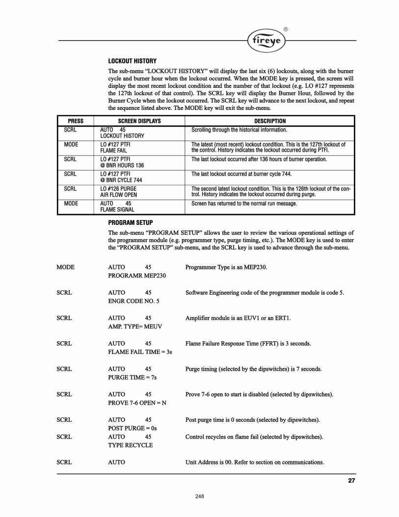
îé
ÔÑÝÕÑËÌ Ø×ÍÌÑÎÇ
̸» «¾ó³»²« ÔÑÝÕÑËÌ Ø×ÍÌÑÎÇ ©·´´ ¼·°´¿§ ¬¸» ´¿¬ ·¨ øê÷ ´±½µ±«¬ô ¿´±²¹ ©·¬¸ ¬¸» ¾«®²»®
½§½´» ¿²¼ ¾«®²»® ¸±«® ©¸»² ¬¸» ´±½µ±«¬ ±½½«®®»¼ò ɸ»² ¬¸» ÓÑÜÛ µ»§ · °®»»¼ô ¬¸» ½®»»² ©·´´
¼·°´¿§ ¬¸» ³±¬ ®»½»²¬ ´±½µ±«¬ ½±²¼·¬·±² ¿²¼ ¬¸» ²«³¾»® ±º ¬¸¿¬ ´±½µ±«¬ ø»ò¹ò ÔÑ ýïîé ®»°®»»²¬
¬¸» ïî鬸 ´±½µ±«¬ ±º ¬¸¿¬ ½±²¬®±´÷ò ̸» ÍÝÎÔ µ»§ ©·´´ ¼·°´¿§ ¬¸» Þ«®²»® ر«®ô º±´´±©»¼ ¾§ ¬¸»
Þ«®²»® ݧ½´» ©¸»² ¬¸» ´±½µ±«¬ ±½½«®®»¼ò ̸» ÍÝÎÔ µ»§ ©·´´ ¿¼ª¿²½» ¬± ¬¸» ²»¨¬ ´±½µ±«¬ô ¿²¼ ®»°»¿¬
¬¸» »¯«»²½» ´·¬»¼ ¿¾±ª»ò ̸» ÓÑÜÛ µ»§ ©·´´ »¨·¬ ¬¸» «¾ó³»²«ò
ÐÎÑÙÎßÓ ÍÛÌËÐ
̸» «¾ó³»²« ÐÎÑÙÎßÓ ÍÛÌËÐ ¿´´±© ¬¸» «»® ¬± ®»ª·»© ¬¸» ª¿®·±« ±°»®¿¬·±²¿´ »¬¬·²¹ ±º
¬¸» °®±¹®¿³³»® ³±¼«´» ø»ò¹ò °®±¹®¿³³»® ¬§°»ô °«®¹» ¬·³·²¹ô »¬½ò÷ò ̸» ÓÑÜÛ µ»§ · «»¼ ¬± »²¬»®
¬¸» ÐÎÑÙÎßÓ ÍÛÌËÐ «¾ó³»²«ô ¿²¼ ¬¸» ÍÝÎÔ µ»§ · «»¼ ¬± ¿¼ª¿²½» ¬¸®±«¹¸ ¬¸» «¾ó³»²«ò
ÓÑÜÛ ßËÌÑ ìë Ю±¹®¿³³»® ̧°» · ¿² ÓÛÐîíðò
ÐÎÑÙÎßÓÎ ÓÛÐîíð
ÍÝÎÔ ßËÌÑ ìë ͱº¬©¿®» Û²¹·²»»®·²¹ ½±¼» ±º ¬¸» °®±¹®¿³³»® ³±¼«´» · ½±¼» ëò
ÛÒÙÎ ÝÑÜÛ ÒÑò ë
ÍÝÎÔ ßËÌÑ ìë ß³°´·º·»® ³±¼«´» · ¿² ÛËÊï ±® ¿² ÛÎÌïò
ßÓÐò ÌÇÐÛã ÓÛËÊ
ÍÝÎÔ ßËÌÑ ìë Ú´¿³» Ú¿·´«®» λ°±²» Ì·³» øÚÚÎÌ÷ · í »½±²¼ò
ÚÔßÓÛ Úß×Ô Ì×ÓÛ ã í
ÍÝÎÔ ßËÌÑ ìë Ы®¹» ¬·³·²¹ ø»´»½¬»¼ ¾§ ¬¸» ¼·°©·¬½¸»÷ · é »½±²¼ò
ÐËÎÙÛ Ì×ÓÛ ã é
ÍÝÎÔ ßËÌÑ ìë Ю±ª» éóê ±°»² ¬± ¬¿®¬ · ¼·¿¾´»¼ ø»´»½¬»¼ ¾§ ¼·°©·¬½¸»÷ò
ÐÎÑÊÛ éóê ÑÐÛÒ ã Ò
ÍÝÎÔ ßËÌÑ ìë б¬ °«®¹» ¬·³» · ð »½±²¼ ø»´»½¬»¼ ¾§ ¼·°©·¬½¸»÷ò
ÐÑÍÌ ÐËÎÙÛ ã ð
ÍÝÎÔ ßËÌÑ ìë ݱ²¬®±´ ®»½§½´» ±² º´¿³» º¿·´ ø»´»½¬»¼ ¾§ ¼·°©·¬½¸»÷ò
ÌÇÐÛ ÎÛÝÇÝÔÛ
ÍÝÎÔ ßËÌÑ Ë²·¬ ß¼¼®» · ððò λº»® ¬± »½¬·±² ±² ½±³³«²·½¿¬·±²ò
ÐÎÛÍÍ ÍÝÎÛÛÒ Ü×ÍÐÔßÇÍ ÜÛÍÝÎ×ÐÌ×ÑÒ
ÍÝÎÔ ßËÌÑ ìëÔÑÝÕÑËÌ Ø×ÍÌÑÎÇ
ͽ®±´´·²¹ ¬¸®±«¹¸ ¬¸» ¸·¬±®·½¿´ ·²º±®³¿¬·±²ò
ÓÑÜÛ ÔÑ ýïîé ÐÌÚ×ÚÔßÓÛ Úß×Ô
̸» ´¿¬»¬ ø³±¬ ®»½»²¬÷ ´±½µ±«¬ ½±²¼·¬·±²ò ̸· · ¬¸» ïî鬸 ´±½µ±«¬ ±º ¬¸» ½±²¬®±´ò Ø·¬±®§ ·²¼·½¿¬» ¬¸» ´±½µ±«¬ ±½½«®®»¼ ¼«®·²¹ ÐÌÚ×ò
ÍÝÎÔ ÔÑ ýïîé ÐÌÚ×à ÞÒÎ ØÑËÎÍ ïíê
̸» ´¿¬ ´±½µ±«¬ ±½½«®®»¼ ¿º¬»® ïíê ¸±«® ±º ¾«®²»® ±°»®¿¬·±²ò
ÍÝÎÔ ÔÑ ýïîé ÐÌÚ×à ÞÒÎ ÝÇÝÔÛ éìì
̸» ´¿¬ ´±½µ±«¬ ±½½«®®»¼ ¿¬ ¾«®²»® ½§½´» éììò
ÍÝÎÔ ÔÑ ýïîê ÐËÎÙÛß×Î ÚÔÑÉ ÑÐÛÒ
̸» »½±²¼ ´¿¬»¬ ´±½µ±«¬ ½±²¼·¬·±²ò ̸· · ¬¸» ïîꬸ ´±½µ±«¬ ±º ¬¸» ½±²ó¬®±´ò Ø·¬±®§ ·²¼·½¿¬» ¬¸» ´±½µ±«¬ ±½½«®®»¼ ¼«®·²¹ °«®¹»ò
ÓÑÜÛ ßËÌÑ ìëÚÔßÓÛ Í×ÙÒßÔ
ͽ®»»² ¸¿ ®»¬«®²»¼ ¬± ¬¸» ²±®³¿´ ®«² ³»¿¹»ò
248
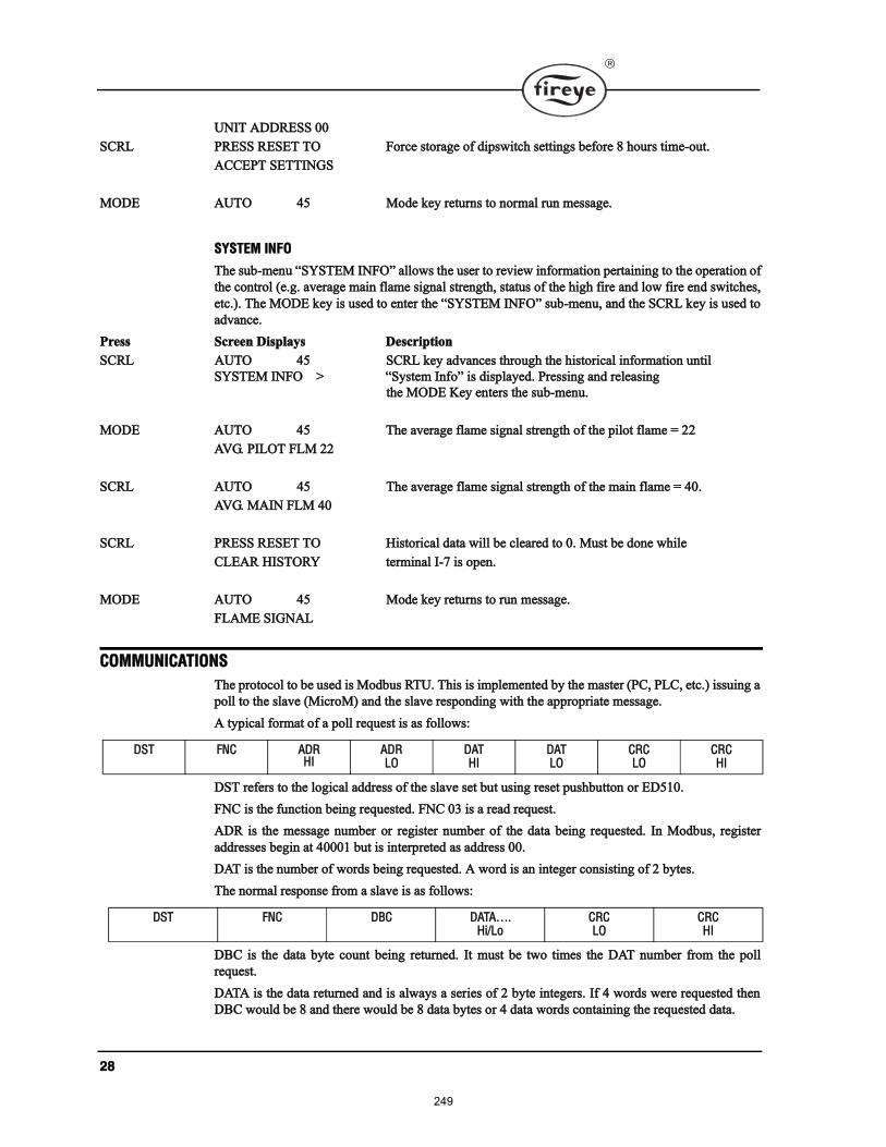
îè
ËÒ×Ì ßÜÜÎÛÍÍ ðð
ÍÝÎÔ ÐÎÛÍÍ ÎÛÍÛÌ ÌÑ Ú±®½» ¬±®¿¹» ±º ¼·°©·¬½¸ »¬¬·²¹ ¾»º±®» è ¸±«® ¬·³»ó±«¬ò
ßÝÝÛÐÌ ÍÛÌÌ×ÒÙÍ
ÓÑÜÛ ßËÌÑ ìë Ó±¼» µ»§ ®»¬«®² ¬± ²±®³¿´ ®«² ³»¿¹»ò
ÍÇÍÌÛÓ ×ÒÚÑ
̸» «¾ó³»²« ÍÇÍÌÛÓ ×ÒÚÑ ¿´´±© ¬¸» «»® ¬± ®»ª·»© ·²º±®³¿¬·±² °»®¬¿·²·²¹ ¬± ¬¸» ±°»®¿¬·±² ±º
¬¸» ½±²¬®±´ ø»ò¹ò ¿ª»®¿¹» ³¿·² º´¿³» ·¹²¿´ ¬®»²¹¬¸ô ¬¿¬« ±º ¬¸» ¸·¹¸ º·®» ¿²¼ ´±© º·®» »²¼ ©·¬½¸»ô
»¬½ò÷ò ̸» ÓÑÜÛ µ»§ · «»¼ ¬± »²¬»® ¬¸» ÍÇÍÌÛÓ ×ÒÚÑ «¾ó³»²«ô ¿²¼ ¬¸» ÍÝÎÔ µ»§ · «»¼ ¬±
¿¼ª¿²½»ò
Ю» ͽ®»»² Ü·°´¿§ Ü»½®·°¬·±²
ÍÝÎÔ ßËÌÑ ìë ÍÝÎÔ µ»§ ¿¼ª¿²½» ¬¸®±«¹¸ ¬¸» ¸·¬±®·½¿´ ·²º±®³¿¬·±² «²¬·´
ÍÇÍÌÛÓ ×ÒÚÑ â ͧ¬»³ ײº± · ¼·°´¿§»¼ò Ю»·²¹ ¿²¼ ®»´»¿·²¹
¬¸» ÓÑÜÛ Õ»§ »²¬»® ¬¸» «¾ó³»²«ò
ÓÑÜÛ ßËÌÑ ìë ̸» ¿ª»®¿¹» º´¿³» ·¹²¿´ ¬®»²¹¬¸ ±º ¬¸» °·´±¬ º´¿³» ã îî
ßÊÙò Ð×ÔÑÌ ÚÔÓ îî
ÍÝÎÔ ßËÌÑ ìë ̸» ¿ª»®¿¹» º´¿³» ·¹²¿´ ¬®»²¹¬¸ ±º ¬¸» ³¿·² º´¿³» ã ìðò
ßÊÙò Óß×Ò ÚÔÓ ìð
ÍÝÎÔ ÐÎÛÍÍ ÎÛÍÛÌ ÌÑ Ø·¬±®·½¿´ ¼¿¬¿ ©·´´ ¾» ½´»¿®»¼ ¬± ðò Ó«¬ ¾» ¼±²» ©¸·´»
ÝÔÛßÎ Ø×ÍÌÑÎÇ ¬»®³·²¿´ ×óé · ±°»²ò
ÓÑÜÛ ßËÌÑ ìë Ó±¼» µ»§ ®»¬«®² ¬± ®«² ³»¿¹»ò
ÚÔßÓÛ Í×ÙÒßÔ
ÝÑÓÓËÒ×ÝßÌ×ÑÒÍ
̸» °®±¬±½±´ ¬± ¾» «»¼ · Ó±¼¾« ÎÌËò ̸· · ·³°´»³»²¬»¼ ¾§ ¬¸» ³¿¬»® øÐÝô ÐÔÝô »¬½ò÷ ·«·²¹ ¿
°±´´ ¬± ¬¸» ´¿ª» øÓ·½®±Ó÷ ¿²¼ ¬¸» ´¿ª» ®»°±²¼·²¹ ©·¬¸ ¬¸» ¿°°®±°®·¿¬» ³»¿¹»ò
ß ¬§°·½¿´ º±®³¿¬ ±º ¿ °±´´ ®»¯«»¬ · ¿ º±´´±©æ
ÜÍÌ ®»º»® ¬± ¬¸» ´±¹·½¿´ ¿¼¼®» ±º ¬¸» ´¿ª» »¬ ¾«¬ «·²¹ ®»»¬ °«¸¾«¬¬±² ±® ÛÜëïðò
ÚÒÝ · ¬¸» º«²½¬·±² ¾»·²¹ ®»¯«»¬»¼ò ÚÒÝ ðí · ¿ ®»¿¼ ®»¯«»¬ò
ßÜÎ · ¬¸» ³»¿¹» ²«³¾»® ±® ®»¹·¬»® ²«³¾»® ±º ¬¸» ¼¿¬¿ ¾»·²¹ ®»¯«»¬»¼ò ײ Ó±¼¾«ô ®»¹·¬»®
¿¼¼®»» ¾»¹·² ¿¬ ìðððï ¾«¬ · ·²¬»®°®»¬»¼ ¿ ¿¼¼®» ððò
ÜßÌ · ¬¸» ²«³¾»® ±º ©±®¼ ¾»·²¹ ®»¯«»¬»¼ò ß ©±®¼ · ¿² ·²¬»¹»® ½±²·¬·²¹ ±º î ¾§¬»ò
̸» ²±®³¿´ ®»°±²» º®±³ ¿ ´¿ª» · ¿ º±´´±©æ
ÜÞÝ · ¬¸» ¼¿¬¿ ¾§¬» ½±«²¬ ¾»·²¹ ®»¬«®²»¼ò ׬ ³«¬ ¾» ¬©± ¬·³» ¬¸» ÜßÌ ²«³¾»® º®±³ ¬¸» °±´´
®»¯«»¬ò
ÜßÌß · ¬¸» ¼¿¬¿ ®»¬«®²»¼ ¿²¼ · ¿´©¿§ ¿ »®·» ±º î ¾§¬» ·²¬»¹»®ò ׺ ì ©±®¼ ©»®» ®»¯«»¬»¼ ¬¸»²
ÜÞÝ ©±«´¼ ¾» è ¿²¼ ¬¸»®» ©±«´¼ ¾» è ¼¿¬¿ ¾§¬» ±® ì ¼¿¬¿ ©±®¼ ½±²¬¿·²·²¹ ¬¸» ®»¯«»¬»¼ ¼¿¬¿ò
ÜÍÌ ÚÒÝ ßÜÎØ×
ßÜÎÔÑ
ÜßÌØ×
ÜßÌÔÑ
ÝÎÝÔÑ
ÝÎÝØ×
ÜÍÌ ÚÒÝ ÜÞÝ ÜßÌßòØ·ñÔ±
ÝÎÝÔÑ
ÝÎÝØ×
249
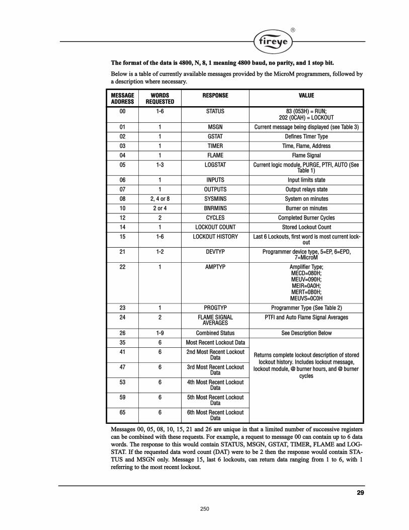
îç
̸» º±®³¿¬ ±º ¬¸» ¼¿¬¿ · ìèððô Òô èô ï ³»¿²·²¹ ìèð𠾿«¼ô ²± °¿®·¬§ô ¿²¼ ï ¬±° ¾·¬ò
Þ»´±© · ¿ ¬¿¾´» ±º ½«®®»²¬´§ ¿ª¿·´¿¾´» ³»¿¹» °®±ª·¼»¼ ¾§ ¬¸» Ó·½®±Ó °®±¹®¿³³»®ô º±´´±©»¼ ¾§
¿ ¼»½®·°¬·±² ©¸»®» ²»½»¿®§ò
Ó»¿¹» ððô ðëô ðèô ïðô ïëô îï ¿²¼ îê ¿®» «²·¯«» ·² ¬¸¿¬ ¿ ´·³·¬»¼ ²«³¾»® ±º «½½»·ª» ®»¹·¬»®
½¿² ¾» ½±³¾·²»¼ ©·¬¸ ¬¸»» ®»¯«»¬ò Ú±® »¨¿³°´»ô ¿ ®»¯«»¬ ¬± ³»¿¹» ð𠽿² ½±²¬¿·² «° ¬± ê ¼¿¬¿
©±®¼ò ̸» ®»°±²» ¬± ¬¸· ©±«´¼ ½±²¬¿·² ÍÌßÌËÍô ÓÍÙÒô ÙÍÌßÌô Ì×ÓÛÎô ÚÔßÓÛ ¿²¼ ÔÑÙó
ÍÌßÌò ׺ ¬¸» ®»¯«»¬»¼ ¼¿¬¿ ©±®¼ ½±«²¬ øÜßÌ÷ ©»®» ¬± ¾» î ¬¸»² ¬¸» ®»°±²» ©±«´¼ ½±²¬¿·² ÍÌßó
ÌËÍ ¿²¼ ÓÍÙÒ ±²´§ò Ó»¿¹» ïëô ´¿¬ ê ´±½µ±«¬ô ½¿² ®»¬«®² ¼¿¬¿ ®¿²¹·²¹ º®±³ ï ¬± êô ©·¬¸ ï
®»º»®®·²¹ ¬± ¬¸» ³±¬ ®»½»²¬ ´±½µ±«¬ò
ÓÛÍÍßÙÛßÜÜÎÛÍÍ
ÉÑÎÜÍÎÛÏËÛÍÌÛÜ
ÎÛÍÐÑÒÍÛ ÊßÔËÛ
ðð ïóê ÍÌßÌËÍ èí øðëíØ÷ ã ÎËÒåîðî øðÝßØ÷ ã ÔÑÝÕÑËÌ
ðï ï ÓÍÙÒ Ý«®®»²¬ ³»¿¹» ¾»·²¹ ¼·°´¿§»¼ ø»» Ì¿¾´» í÷
ðî ï ÙÍÌßÌ Ü»º·²» Ì·³»® ̧°»
ðí ï Ì×ÓÛÎ Ì·³»ô Ú´¿³»ô ß¼¼®»
ðì ï ÚÔßÓÛ Ú´¿³» Í·¹²¿´
ðë ïóí ÔÑÙÍÌßÌ Ý«®®»²¬ ±¹·½ ³±¼«´»ô ÐËÎÙÛô ÐÌÚ×ô ßËÌÑ øÍ»» Ì¿¾´» ï÷
ðê ï ×ÒÐËÌÍ ×²°«¬ ´·³·¬ ¬¿¬»
ðé ï ÑËÌÐËÌÍ Ñ«¬°«¬ ®»´¿§ ¬¿¬»
ðè îô ì ±® è ÍÇÍÓ×ÒÍ Í§¬»³ ±² ³·²«¬»
ïð î ±® ì ÞÒÎÓ×ÒÍ Þ«®²»® ±² ³·²«¬»
ïî î ÝÇÝÔÛÍ Ý±³°´»¬»¼ Þ«®²»® ݧ½´»
ïì ï ÔÑÝÕÑËÌ ÝÑËÒÌ Í¬±®»¼ Ô±½µ±«¬ ݱ«²¬
ïë ïóê ÔÑÝÕÑËÌ Ø×ÍÌÑÎÇ Ô¿¬ ê Ô±½µ±«¬ô º·®¬ ©±®¼ · ³±¬ ½«®®»²¬ ´±½µó±«¬
îï ïóî ÜÛÊÌÇРЮ±¹®¿³³»® ¼»ª·½» ¬§°»ô ëãÛÐô êãÛÐÜô éãÓ·½®±Ó
îî ï ßÓÐÌÇÐ ß³°´·º·»® ̧°»å ÓÛÝÜãðèðØåÓÛËÊãðçðØåÓÛ×ÎãðßðØåÓÛÎÌãðÞðØåÓÛËÊÍãðÝðØ
îí ï ÐÎÑÙÌÇРЮ±¹®¿³³»® ̧°» øÍ»» Ì¿¾´» î÷
îì î ÚÔßÓÛ Í×ÙÒßÔ ßÊÛÎßÙÛÍ
ÐÌÚ× ¿²¼ ß«¬± Ú´¿³» Í·¹²¿´ ߪ»®¿¹»
îê ïóç ݱ³¾·²»¼ ͬ¿¬« Í»» Ü»½®·°¬·±² Þ»´±©
íë ê Ó±¬ λ½»²¬ Ô±½µ±«¬ Ü¿¬¿
묫®² ½±³°´»¬» ´±½µ±«¬ ¼»½®·°¬·±² ±º ¬±®»¼ ´±½µ±«¬ ¸·¬±®§ò ײ½´«¼» ´±½µ±«¬ ³»¿¹»ô
´±½µ±«¬ ³±¼«´»ô à ¾«®²»® ¸±«®ô ¿²¼ à ¾«®²»® ½§½´»
ìï ê î²¼ Ó±¬ λ½»²¬ Ô±½µ±«¬ Ü¿¬¿
ìé ê í®¼ Ó±¬ λ½»²¬ Ô±½µ±«¬ Ü¿¬¿
ëí ê 쬸 Ó±¬ λ½»²¬ Ô±½µ±«¬ Ü¿¬¿
ëç ê 문 Ó±¬ λ½»²¬ Ô±½µ±«¬ Ü¿¬¿
êë ê ꬸ Ó±¬ λ½»²¬ Ô±½µ±«¬ Ü¿¬¿
250
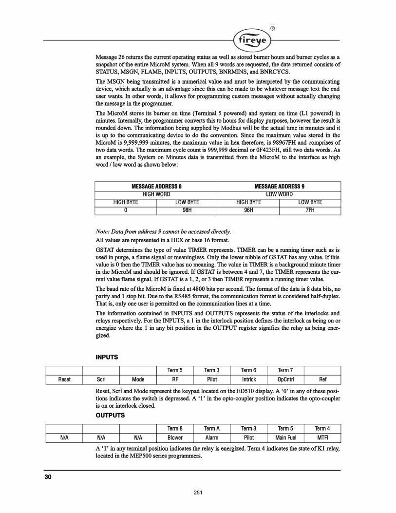
íð
Ó»¿¹» îê ®»¬«®² ¬¸» ½«®®»²¬ ±°»®¿¬·²¹ ¬¿¬« ¿ ©»´´ ¿ ¬±®»¼ ¾«®²»® ¸±«® ¿²¼ ¾«®²»® ½§½´» ¿ ¿
²¿°¸±¬ ±º ¬¸» »²¬·®» Ó·½®±Ó §¬»³ò ɸ»² ¿´´ ç ©±®¼ ¿®» ®»¯«»¬»¼ô ¬¸» ¼¿¬¿ ®»¬«®²»¼ ½±²·¬ ±º
ÍÌßÌËÍô ÓÍÙÒô ÚÔßÓÛô ×ÒÐËÌÍô ÑËÌÐËÌÍô ÞÒÎÓ×ÒÍô ¿²¼ ÞÒÎÝÇÝÍò
̸» ÓÍÙÒ ¾»·²¹ ¬®¿²³·¬¬»¼ · ¿ ²«³»®·½¿´ ª¿´«» ¿²¼ ³«¬ ¾» ·²¬»®°®»¬»¼ ¾§ ¬¸» ½±³³«²·½¿¬·²¹
¼»ª·½»ô ©¸·½¸ ¿½¬«¿´´§ · ¿² ¿¼ª¿²¬¿¹» ·²½» ¬¸· ½¿² ¾» ³¿¼» ¬± ¾» ©¸¿¬»ª»® ³»¿¹» ¬»¨¬ ¬¸» »²¼
«»® ©¿²¬ò ײ ±¬¸»® ©±®¼ô ·¬ ¿´´±© º±® °®±¹®¿³³·²¹ ½«¬±³ ³»¿¹» ©·¬¸±«¬ ¿½¬«¿´´§ ½¸¿²¹·²¹
¬¸» ³»¿¹» ·² ¬¸» °®±¹®¿³³»®ò
̸» Ó·½®±Ó ¬±®» ·¬ ¾«®²»® ±² ¬·³» øÌ»®³·²¿´ ë °±©»®»¼÷ ¿²¼ §¬»³ ±² ¬·³» øÔï °±©»®»¼÷ ·²
³·²«¬»ò ײ¬»®²¿´´§ô ¬¸» °®±¹®¿³³»® ½±²ª»®¬ ¬¸· ¬± ¸±«® º±® ¼·°´¿§ °«®°±»ô ¸±©»ª»® ¬¸» ®»«´¬ ·
®±«²¼»¼ ¼±©²ò ̸» ·²º±®³¿¬·±² ¾»·²¹ «°°´·»¼ ¾§ Ó±¼¾« ©·´´ ¾» ¬¸» ¿½¬«¿´ ¬·³» ·² ³·²«¬» ¿²¼ ·¬
· «° ¬± ¬¸» ½±³³«²·½¿¬·²¹ ¼»ª·½» ¬± ¼± ¬¸» ½±²ª»®·±²ò Í·²½» ¬¸» ³¿¨·³«³ ª¿´«» ¬±®»¼ ·² ¬¸»
Ó·½®±Ó · çôçççôççç ³·²«¬»ô ¬¸» ³¿¨·³«³ ª¿´«» ·² ¸»¨ ¬¸»®»º±®»ô · çèçêéÚØ ¿²¼ ½±³°®·» ±º
¬©± ¼¿¬¿ ©±®¼ò ̸» ³¿¨·³«³ ½§½´» ½±«²¬ · çççôççç ¼»½·³¿´ ±® ðÚìîíÚØô ¬·´´ ¬©± ¼¿¬¿ ©±®¼ò ß
¿² »¨¿³°´»ô ¬¸» ͧ¬»³ ±² Ó·²«¬» ¼¿¬¿ · ¬®¿²³·¬¬»¼ º®±³ ¬¸» Ó·½®±Ó ¬± ¬¸» ·²¬»®º¿½» ¿ ¸·¹¸
©±®¼ ñ ´±© ©±®¼ ¿ ¸±©² ¾»´±©æ
Ü¿¬¿ º®±³ ¿¼¼®» ç ½¿²²±¬ ¾» ¿½½»»¼ ¼·®»½¬´§ò
ß´´ ª¿´«» ¿®» ®»°®»»²¬»¼ ·² ¿ ØÛÈ ±® ¾¿» ïê º±®³¿¬ò
ÙÍÌßÌ ¼»¬»®³·²» ¬¸» ¬§°» ±º ª¿´«» Ì×ÓÛÎ ®»°®»»²¬ò Ì×ÓÛÎ ½¿² ¾» ¿ ®«²²·²¹ ¬·³»® «½¸ ¿ ·
«»¼ ·² °«®¹»ô ¿ º´¿³» ·¹²¿´ ±® ³»¿²·²¹´»ò Ѳ´§ ¬¸» ´±©»® ²·¾¾´» ±º ÙÍÌßÌ ¸¿ ¿²§ ª¿´«»ò ׺ ¬¸·
ª¿´«» · 𠬸»² ¬¸» Ì×ÓÛÎ ª¿´«» ¸¿ ²± ³»¿²·²¹ò ̸» ª¿´«» ·² Ì×ÓÛÎ · ¿ ¾¿½µ¹®±«²¼ ³·²«¬» ¬·³»®
·² ¬¸» Ó·½®±Ó ¿²¼ ¸±«´¼ ¾» ·¹²±®»¼ò ׺ ÙÍÌßÌ · ¾»¬©»»² ì ¿²¼ éô ¬¸» Ì×ÓÛÎ ®»°®»»²¬ ¬¸» ½«®ó
®»²¬ ª¿´«» º´¿³» ·¹²¿´ò ׺ ÙÍÌßÌ · ¿ ïô îô ±® í ¬¸»² Ì×ÓÛÎ ®»°®»»²¬ ¿ ®«²²·²¹ ¬·³»® ª¿´«»ò
̸» ¾¿«¼ ®¿¬» ±º ¬¸» Ó·½®±Ó · º·¨»¼ ¿¬ ìèðð ¾·¬ °»® »½±²¼ò ̸» º±®³¿¬ ±º ¬¸» ¼¿¬¿ · è ¼¿¬¿ ¾·¬ô ²±
°¿®·¬§ ¿²¼ ï ¬±° ¾·¬ò Ü«» ¬± ¬¸» ÎÍìèë º±®³¿¬ô ¬¸» ½±³³«²·½¿¬·±² º±®³¿¬ · ½±²·¼»®»¼ ¸¿´ºó¼«°´»¨ò
̸¿¬ ·ô ±²´§ ±²» «»® · °»®³·¬¬»¼ ±² ¬¸» ½±³³«²·½¿¬·±² ´·²» ¿¬ ¿ ¬·³»ò
̸» ·²º±®³¿¬·±² ½±²¬¿·²»¼ ·² ×ÒÐËÌÍ ¿²¼ ÑËÌÐËÌÍ ®»°®»»²¬ ¬¸» ¬¿¬« ±º ¬¸» ·²¬»®´±½µ ¿²¼
®»´¿§ ®»°»½¬·ª»´§ò Ú±® ¬¸» ×ÒÐËÌÍô ¿ ï ·² ¬¸» ·²¬»®´±½µ °±·¬·±² ¼»º·²» ¬¸» ·²¬»®´±½µ ¿ ¾»·²¹ ±² ±®
»²»®¹·¦» ©¸»®» ¬¸» ï ·² ¿²§ ¾·¬ °±·¬·±² ·² ¬¸» ÑËÌÐËÌ ®»¹·¬»® ·¹²·º·» ¬¸» ®»´¿§ ¿ ¾»·²¹ »²»®ó
¹·¦»¼ò
뻬ô ͽ®´ ¿²¼ Ó±¼» ®»°®»»²¬ ¬¸» µ»§°¿¼ ´±½¿¬»¼ ±² ¬¸» ÛÜëïð ¼·°´¿§ò ß ð ·² ¿²§ ±º ¬¸»» °±·ó
¬·±² ·²¼·½¿¬» ¬¸» ©·¬½¸ · ¼»°®»»¼ò ß ï ·² ¬¸» ±°¬±ó½±«°´»® °±·¬·±² ·²¼·½¿¬» ¬¸» ±°¬±ó½±«°´»®
· ±² ±® ·²¬»®´±½µ ½´±»¼ò
ß ï ·² ¿²§ ¬»®³·²¿´ °±·¬·±² ·²¼·½¿¬» ¬¸» ®»´¿§ · »²»®¹·¦»¼ò Ì»®³ ì ·²¼·½¿¬» ¬¸» ¬¿¬» ±º Õï ®»´¿§ô
´±½¿¬»¼ ·² ¬¸» ÓÛÐëðð »®·» °®±¹®¿³³»®ò
ÓÛÍÍßÙÛ ßÜÜÎÛÍÍ è ÓÛÍÍßÙÛ ßÜÜÎÛÍÍ ç
Ø×ÙØ ÉÑÎÜ ÔÑÉ ÉÑÎÜ
Ø×ÙØ ÞÇÌÛ ÔÑÉ ÞÇÌÛ Ø×ÙØ ÞÇÌÛ ÔÑÉ ÞÇÌÛ
ð çèØ çêØ éÚØ
×ÒÐËÌÍ
Ì»®³ ë Ì»®³ í Ì»®³ ê Ì»®³ é
뻬 ͽ®´ Ó±¼» ÎÚ Ð·´±¬ ײ¬®´½µ Ѱݲ¬®´ λº
ÑËÌÐËÌÍ
Ì»®³ è Ì»®³ ß Ì»®³ í Ì»®³ ë Ì»®³ ì
Òñß Òñß Òñß Þ´±©»® ß´¿®³ з´±¬ Ó¿·² Ú«»´ ÓÌÚ×
251
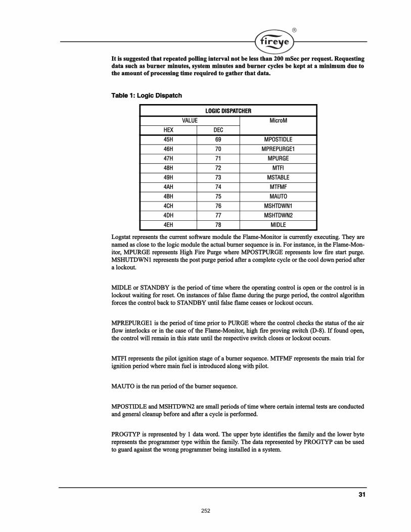
íï
׬ · «¹¹»¬»¼ ¬¸¿¬ ®»°»¿¬»¼ °±´´·²¹ ·²¬»®ª¿´ ²±¬ ¾» ´» ¬¸¿² îðð ³Í»½ °»® ®»¯«»¬ò λ¯«»¬·²¹
¼¿¬¿ «½¸ ¿ ¾«®²»® ³·²«¬»ô §¬»³ ³·²«¬» ¿²¼ ¾«®²»® ½§½´» ¾» µ»°¬ ¿¬ ¿ ³·²·³«³ ¼«» ¬±
¬¸» ¿³±«²¬ ±º °®±½»·²¹ ¬·³» ®»¯«·®»¼ ¬± ¹¿¬¸»® ¬¸¿¬ ¼¿¬¿ò
Ô±¹¬¿¬ ®»°®»»²¬ ¬¸» ½«®®»²¬ ±º¬©¿®» ³±¼«´» ¬¸» Ú´¿³»óÓ±²·¬±® · ½«®®»²¬´§ »¨»½«¬·²¹ò ̸»§ ¿®»
²¿³»¼ ¿ ½´±» ¬± ¬¸» ´±¹·½ ³±¼«´» ¬¸» ¿½¬«¿´ ¾«®²»® »¯«»²½» · ·²ò Ú±® ·²¬¿²½»ô ·² ¬¸» Ú´¿³»óÓ±²ó
·¬±®ô ÓÐËÎÙÛ ®»°®»»²¬ Ø·¹¸ Ú·®» Ы®¹» ©¸»®» ÓÐÑÍÌÐËÎÙÛ ®»°®»»²¬ ´±© º·®» ¬¿®¬ °«®¹»ò
ÓÍØËÌÜÉÒï ®»°®»»²¬ ¬¸» °±¬ °«®¹» °»®·±¼ ¿º¬»® ¿ ½±³°´»¬» ½§½´» ±® ¬¸» ½±±´ ¼±©² °»®·±¼ ¿º¬»®
¿ ´±½µ±«¬ò
Ó×ÜÔÛ ±® ÍÌßÒÜÞÇ · ¬¸» °»®·±¼ ±º ¬·³» ©¸»®» ¬¸» ±°»®¿¬·²¹ ½±²¬®±´ · ±°»² ±® ¬¸» ½±²¬®±´ · ·²
´±½µ±«¬ ©¿·¬·²¹ º±® ®»»¬ò Ѳ ·²¬¿²½» ±º º¿´» º´¿³» ¼«®·²¹ ¬¸» °«®¹» °»®·±¼ô ¬¸» ½±²¬®±´ ¿´¹±®·¬¸³
º±®½» ¬¸» ½±²¬®±´ ¾¿½µ ¬± ÍÌßÒÜÞÇ «²¬·´ º¿´» º´¿³» ½»¿» ±® ´±½µ±«¬ ±½½«®ò
ÓÐÎÛÐËÎÙÛï · ¬¸» °»®·±¼ ±º ¬·³» °®·±® ¬± ÐËÎÙÛ ©¸»®» ¬¸» ½±²¬®±´ ½¸»½µ ¬¸» ¬¿¬« ±º ¬¸» ¿·®
º´±© ·²¬»®´±½µ ±® ·² ¬¸» ½¿» ±º ¬¸» Ú´¿³»óÓ±²·¬±®ô ¸·¹¸ º·®» °®±ª·²¹ ©·¬½¸ øÜóè÷ò ׺ º±«²¼ ±°»²ô
¬¸» ½±²¬®±´ ©·´´ ®»³¿·² ·² ¬¸· ¬¿¬» «²¬·´ ¬¸» ®»°»½¬·ª» ©·¬½¸ ½´±» ±® ´±½µ±«¬ ±½½«®ò
ÓÌÚ× ®»°®»»²¬ ¬¸» °·´±¬ ·¹²·¬·±² ¬¿¹» ±º ¿ ¾«®²»® »¯«»²½»ò ÓÌÚÓÚ ®»°®»»²¬ ¬¸» ³¿·² ¬®·¿´ º±®
·¹²·¬·±² °»®·±¼ ©¸»®» ³¿·² º«»´ · ·²¬®±¼«½»¼ ¿´±²¹ ©·¬¸ °·´±¬ò
ÓßËÌÑ · ¬¸» ®«² °»®·±¼ ±º ¬¸» ¾«®²»® »¯«»²½»ò
ÓÐÑÍÌ×ÜÔÛ ¿²¼ ÓÍØÌÜÉÒî ¿®» ³¿´´ °»®·±¼ ±º ¬·³» ©¸»®» ½»®¬¿·² ·²¬»®²¿´ ¬»¬ ¿®» ½±²¼«½¬»¼
¿²¼ ¹»²»®¿´ ½´»¿²«° ¾»º±®» ¿²¼ ¿º¬»® ¿ ½§½´» · °»®º±®³»¼ò
ÐÎÑÙÌÇÐ · ®»°®»»²¬»¼ ¾§ ï ¼¿¬¿ ©±®¼ò ̸» «°°»® ¾§¬» ·¼»²¬·º·» ¬¸» º¿³·´§ ¿²¼ ¬¸» ´±©»® ¾§¬»
®»°®»»²¬ ¬¸» °®±¹®¿³³»® ¬§°» ©·¬¸·² ¬¸» º¿³·´§ò ̸» ¼¿¬¿ ®»°®»»²¬»¼ ¾§ ÐÎÑÙÌÇÐ ½¿² ¾» «»¼
¬± ¹«¿®¼ ¿¹¿·²¬ ¬¸» ©®±²¹ °®±¹®¿³³»® ¾»·²¹ ·²¬¿´´»¼ ·² ¿ §¬»³ò
Ì¿¾´» ïæ Ô±¹·½ Ü·°¿¬½¸
ÔÑÙ×Ý Ü×ÍÐßÌÝØÛÎ
ÊßÔËÛ Ó·½®±Ó
ØÛÈ ÜÛÝ
ìëØ êç ÓÐÑÍÌ×ÜÔÛ
ìêØ éð ÓÐÎÛÐËÎÙÛï
ìéØ éï ÓÐËÎÙÛ
ìèØ éî ÓÌÚ×
ìçØ éí ÓÍÌßÞÔÛ
ìßØ éì ÓÌÚÓÚ
ìÞØ éë ÓßËÌÑ
ìÝØ éê ÓÍØÌÜÉÒï
ìÜØ éé ÓÍØÌÜÉÒî
ìÛØ éè Ó×ÜÔÛ
252
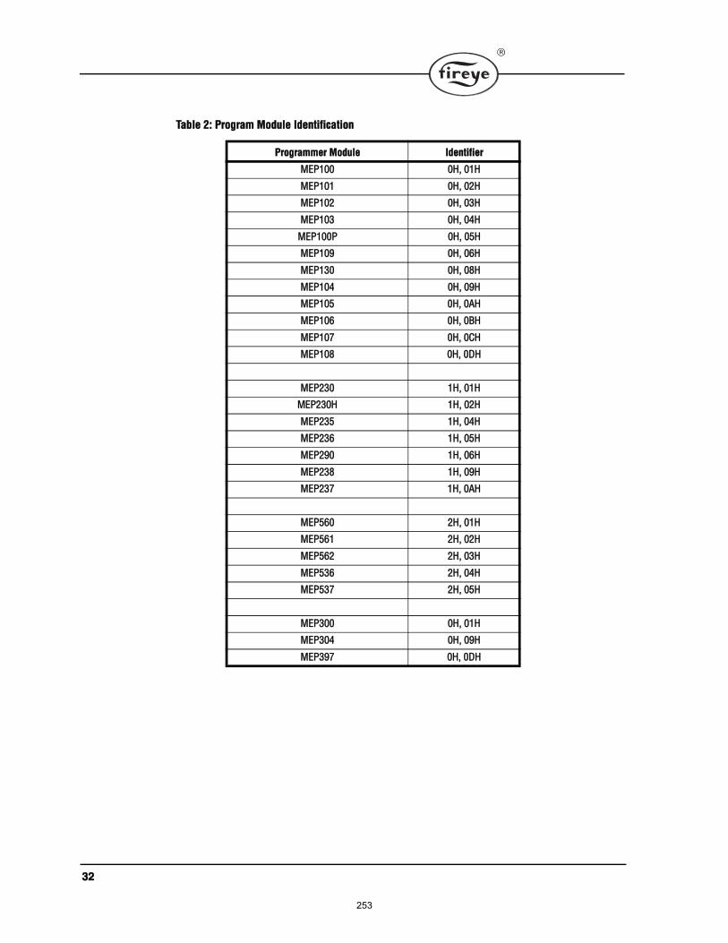
íî
Ì¿¾´» îæ Ю±¹®¿³ Ó±¼«´» ×¼»²¬·º·½¿¬·±²
Ю±¹®¿³³»® Ó±¼«´» ×¼»²¬·º·»®
ÓÛÐïðð ðØô ðïØ
ÓÛÐïðï ðØô ðîØ
ÓÛÐïðî ðØô ðíØ
ÓÛÐïðí ðØô ðìØ
ÓÛÐïððÐ ðØô ðëØ
ÓÛÐïðç ðØô ðêØ
ÓÛÐïíð ðØô ðèØ
ÓÛÐïðì ðØô ðçØ
ÓÛÐïðë ðØô ðßØ
ÓÛÐïðê ðØô ðÞØ
ÓÛÐïðé ðØô ðÝØ
ÓÛÐïðè ðØô ðÜØ
ÓÛÐîíð ïØô ðïØ
ÓÛÐîíðØ ïØô ðîØ
ÓÛÐîíë ïØô ðìØ
ÓÛÐîíê ïØô ðëØ
ÓÛÐîçð ïØô ðêØ
ÓÛÐîíè ïØô ðçØ
ÓÛÐîíé ïØô ðßØ
ÓÛÐëêð îØô ðïØ
ÓÛÐëêï îØô ðîØ
ÓÛÐëêî îØô ðíØ
ÓÛÐëíê îØô ðìØ
ÓÛÐëíé îØô ðëØ
ÓÛÐíðð ðØô ðïØ
ÓÛÐíðì ðØô ðçØ
ÓÛÐíçé ðØô ðÜØ
253
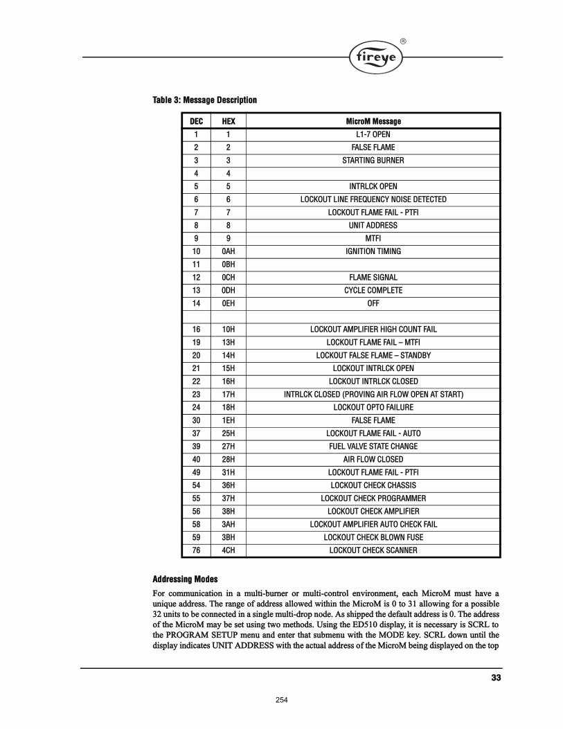
íí
ß¼¼®»·²¹ Ó±¼»
Ú±® ½±³³«²·½¿¬·±² ·² ¿ ³«´¬·ó¾«®²»® ±® ³«´¬·ó½±²¬®±´ »²ª·®±²³»²¬ô »¿½¸ Ó·½®±Ó ³«¬ ¸¿ª» ¿
«²·¯«» ¿¼¼®»ò ̸» ®¿²¹» ±º ¿¼¼®» ¿´´±©»¼ ©·¬¸·² ¬¸» Ó·½®±Ó · 𠬱 íï ¿´´±©·²¹ º±® ¿ °±·¾´»
íî «²·¬ ¬± ¾» ½±²²»½¬»¼ ·² ¿ ·²¹´» ³«´¬·ó¼®±° ²±¼»ò ß ¸·°°»¼ ¬¸» ¼»º¿«´¬ ¿¼¼®» · ðò ̸» ¿¼¼®»
±º ¬¸» Ó·½®±Ó ³¿§ ¾» »¬ «·²¹ ¬©± ³»¬¸±¼ò Ë·²¹ ¬¸» ÛÜëïð ¼·°´¿§ô ·¬ · ²»½»¿®§ · ÍÝÎÔ ¬±
¬¸» ÐÎÑÙÎßÓ ÍÛÌËÐ ³»²« ¿²¼ »²¬»® ¬¸¿¬ «¾³»²« ©·¬¸ ¬¸» ÓÑÜÛ µ»§ò ÍÝÎÔ ¼±©² «²¬·´ ¬¸»
¼·°´¿§ ·²¼·½¿¬» ËÒ×Ì ßÜÜÎÛÍÍ ©·¬¸ ¬¸» ¿½¬«¿´ ¿¼¼®» ±º ¬¸» Ó·½®±Ó ¾»·²¹ ¼·°´¿§»¼ ±² ¬¸» ¬±°
Ì¿¾´» íæ Ó»¿¹» Ü»½®·°¬·±²
ÜÛÝ ØÛÈ Ó·½®±Ó Ó»¿¹»
ï ï Ôïóé ÑÐÛÒ
î î ÚßÔÍÛ ÚÔßÓÛ
í í ÍÌßÎÌ×ÒÙ ÞËÎÒÛÎ
ì ì
ë ë ×ÒÌÎÔÝÕ ÑÐÛÒ
ê ê ÔÑÝÕÑËÌ Ô×ÒÛ ÚÎÛÏËÛÒÝÇ ÒÑ×ÍÛ ÜÛÌÛÝÌÛÜ
é é ÔÑÝÕÑËÌ ÚÔßÓÛ Úß×Ô ó ÐÌÚ×
è è ËÒ×Ì ßÜÜÎÛÍÍ
ç ç ÓÌÚ×
ïð ðßØ ×ÙÒ×Ì×ÑÒ Ì×Ó×ÒÙ
ïï ðÞØ
ïî ðÝØ ÚÔßÓÛ Í×ÙÒßÔ
ïí ðÜØ ÝÇÝÔÛ ÝÑÓÐÔÛÌÛ
ïì ðÛØ ÑÚÚ
ïê ïðØ ÔÑÝÕÑËÌ ßÓÐÔ×Ú×ÛÎ Ø×ÙØ ÝÑËÒÌ Úß×Ô
ïç ïíØ ÔÑÝÕÑËÌ ÚÔßÓÛ Úß×Ô ÓÌÚ×
îð ïìØ ÔÑÝÕÑËÌ ÚßÔÍÛ ÚÔßÓÛ ÍÌßÒÜÞÇ
îï ïëØ ÔÑÝÕÑËÌ ×ÒÌÎÔÝÕ ÑÐÛÒ
îî ïêØ ÔÑÝÕÑËÌ ×ÒÌÎÔÝÕ ÝÔÑÍÛÜ
îí ïéØ ×ÒÌÎÔÝÕ ÝÔÑÍÛÜ øÐÎÑÊ×ÒÙ ß×Î ÚÔÑÉ ÑÐÛÒ ßÌ ÍÌßÎÌ÷
îì ïèØ ÔÑÝÕÑËÌ ÑÐÌÑ Úß×ÔËÎÛ
íð ïÛØ ÚßÔÍÛ ÚÔßÓÛ
íé îëØ ÔÑÝÕÑËÌ ÚÔßÓÛ Úß×Ô ó ßËÌÑ
íç îéØ ÚËÛÔ ÊßÔÊÛ ÍÌßÌÛ ÝØßÒÙÛ
ìð îèØ ß×Î ÚÔÑÉ ÝÔÑÍÛÜ
ìç íïØ ÔÑÝÕÑËÌ ÚÔßÓÛ Úß×Ô ó ÐÌÚ×
ëì íêØ ÔÑÝÕÑËÌ ÝØÛÝÕ ÝØßÍÍ×Í
ëë íéØ ÔÑÝÕÑËÌ ÝØÛÝÕ ÐÎÑÙÎßÓÓÛÎ
ëê íèØ ÔÑÝÕÑËÌ ÝØÛÝÕ ßÓÐÔ×Ú×ÛÎ
ëè íßØ ÔÑÝÕÑËÌ ßÓÐÔ×Ú×ÛÎ ßËÌÑ ÝØÛÝÕ Úß×Ô
ëç íÞØ ÔÑÝÕÑËÌ ÝØÛÝÕ ÞÔÑÉÒ ÚËÍÛ
éê ìÝØ ÔÑÝÕÑËÌ ÝØÛÝÕ ÍÝßÒÒÛÎ
254
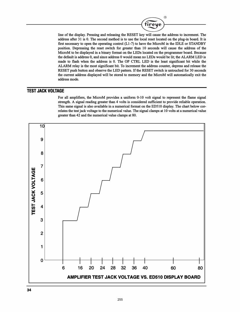
íì
´·²» ±º ¬¸» ¼·°´¿§ò Ю»·²¹ ¿²¼ ®»´»¿·²¹ ¬¸» ÎÛÍÛÌ µ»§ ©·´´ ½¿«» ¬¸» ¿¼¼®» ¬± ·²½®»³»²¬ò ̸»
¿¼¼®» ¿º¬»® íï · ðò ̸» »½±²¼ ³»¬¸±¼ · ¬± «» ¬¸» ´±½¿´ ®»»¬ ´±½¿¬»¼ ±² ¬¸» °´«¹ó·² ¾±¿®¼ò ׬ ·
º·®¬ ²»½»¿®§ ¬± ±°»² ¬¸» ±°»®¿¬·²¹ ½±²¬®±´ øÔïóé÷ ¬± ¸¿ª» ¬¸» Ó·½®±Ó ·² ¬¸» ×ÜÔÛ ±® ÍÌßÒÜÞÇ
°±·¬·±²ò Ü»°®»·²¹ ¬¸» ®»»¬ ©·¬½¸ º±® ¹®»¿¬»® ¬¸¿² ïð »½±²¼ ©·´´ ½¿«» ¬¸» ¿¼¼®» ±º ¬¸»
Ó·½®±Ó ¬± ¾» ¼·°´¿§»¼ ·² ¿ ¾·²¿®§ º±®³¿¬ ±² ¬¸» ÔÛÜ ´±½¿¬»¼ ±² ¬¸» °®±¹®¿³³»® ¾±¿®¼ò Þ»½¿«»
¬¸» ¼»º¿«´¬ · ¿¼¼®» ðô ¿²¼ ·²½» ¿¼¼®» ð ©±«´¼ ³»¿² ²± ÔÛÜ ©±«´¼ ¾» ´·¬å ¬¸» ßÔßÎÓ ÔÛÜ ·
³¿¼» ¬± º´¿¸ ©¸»² ¬¸» ¿¼¼®» · ðò ̸» ÑÐ ÝÌÎÔ ÔÛÜ · ¬¸» ´»¿¬ ·¹²·º·½¿²¬ ¾·¬ ©¸·´» ¬¸»
ßÔßÎÓ ®»´¿§ · ¬¸» ³±¬ ·¹²·º·½¿²¬ ¾·¬ò ̱ ·²½®»³»²¬ ¬¸» ¿¼¼®» ½±«²¬»®ô ¼»°®» ¿²¼ ®»´»¿» ¬¸»
ÎÛÍÛÌ °«¸ ¾«¬¬±² ¿²¼ ±¾»®ª» ¬¸» ÔÛÜ °¿¬¬»®²ò ׺ ¬¸» ÎÛÍÛÌ ©·¬½¸ · «²¬±«½¸»¼ º±® íð »½±²¼
¬¸» ½«®®»²¬ ¿¼¼®» ¼·°´¿§»¼ ©·´´ ¾» ¬±®»¼ ¬± ³»³±®§ ¿²¼ ¬¸» Ó·½®±Ó ©·´´ ¿«¬±³¿¬·½¿´´§ »¨·¬ ¬¸»
¿¼¼®» ³±¼»ò
ÌÛÍÌ ÖßÝÕ ÊÑÔÌßÙÛ
Ú±® ¿´´ ¿³°´·º·»®ô ¬¸» Ó·½®±Ó °®±ª·¼» ¿ «²·º±®³ ðóï𠪱´¬ ·¹²¿´ ¬± ®»°®»»²¬ ¬¸» º´¿³» ·¹²¿´
¬®»²¹¬¸ò ß ·¹²¿´ ®»¿¼·²¹ ¹®»¿¬»® ¬¸¿² ì ª±´¬ · ½±²·¼»®»¼ «ºº·½·»²¬ ¬± °®±ª·¼» ®»´·¿¾´» ±°»®¿¬·±²ò
̸· ¿³» ·¹²¿´ · ¿´± ¿ª¿·´¿¾´» ·² ¿ ²«³»®·½¿´ º±®³¿¬ ±² ¬¸» ÛÜëïð ¼·°´¿§ò ̸» ½¸¿®¬ ¾»´±© ½±®ó
®»´¿¬» ¬¸» ¬»¬ ¶¿½µ ª±´¬¿¹» ¬± ¬¸» ²«³»®·½¿´ ª¿´«»ò ̸» ·¹²¿´ ½´¿³° ¿¬ ï𠪱´¬ ¿¬ ¿ ²«³»®·½¿´ ª¿´«»
¹®»¿¬»® ¬¸¿² ìî ¿²¼ ¬¸» ²«³»®·½¿´ ª¿´«» ½´¿³° ¿¬ èðò
ð
ï
î
í
ì
ë
ê
é
è
ç
ïð
ê ïê îð îì îè íî íê ìð êð èð
ßÓÐÔ×Ú×ÛÎ ÌÛÍÌ ÖßÝÕ ÊÑÔÌßÙÛ ÊÍò ÛÜëïð Ü×ÍÐÔßÇ ÞÑßÎÜ
ÌÛ
ÍÌ
Öß
ÝÕ
ÊÑ
ÔÌ
ßÙ
Û
255
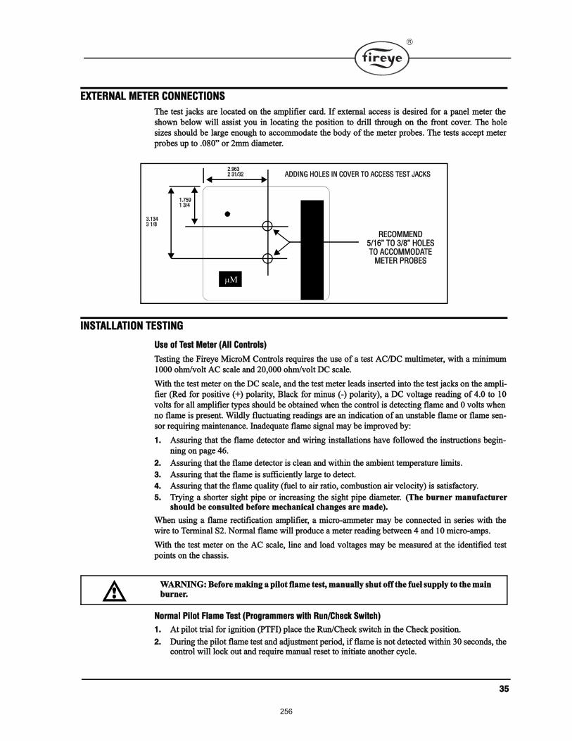
íë
ÛÈÌÛÎÒßÔ ÓÛÌÛÎ ÝÑÒÒÛÝÌ×ÑÒÍ
̸» ¬»¬ ¶¿½µ ¿®» ´±½¿¬»¼ ±² ¬¸» ¿³°´·º·»® ½¿®¼ò ׺ »¨¬»®²¿´ ¿½½» · ¼»·®»¼ º±® ¿ °¿²»´ ³»¬»® ¬¸»
¸±©² ¾»´±© ©·´´ ¿·¬ §±« ·² ´±½¿¬·²¹ ¬¸» °±·¬·±² ¬± ¼®·´´ ¬¸®±«¹¸ ±² ¬¸» º®±²¬ ½±ª»®ò ̸» ¸±´»
·¦» ¸±«´¼ ¾» ´¿®¹» »²±«¹¸ ¬± ¿½½±³³±¼¿¬» ¬¸» ¾±¼§ ±º ¬¸» ³»¬»® °®±¾»ò ̸» ¬»¬ ¿½½»°¬ ³»¬»®
°®±¾» «° ¬± òðèð ±® î³³ ¼·¿³»¬»®ò
×ÒÍÌßÔÔßÌ×ÑÒ ÌÛÍÌ×ÒÙ
Ë» ±º Ì»¬ Ó»¬»® øß´´ ݱ²¬®±´÷
Ì»¬·²¹ ¬¸» Ú·®»§» Ó·½®±Ó ݱ²¬®±´ ®»¯«·®» ¬¸» «» ±º ¿ ¬»¬ ßÝñÜÝ ³«´¬·³»¬»®ô ©·¬¸ ¿ ³·²·³«³
ïðð𠱸³ñª±´¬ ßÝ ½¿´» ¿²¼ îðôðð𠱸³ñª±´¬ ÜÝ ½¿´»ò
É·¬¸ ¬¸» ¬»¬ ³»¬»® ±² ¬¸» ÜÝ ½¿´»ô ¿²¼ ¬¸» ¬»¬ ³»¬»® ´»¿¼ ·²»®¬»¼ ·²¬± ¬¸» ¬»¬ ¶¿½µ ±² ¬¸» ¿³°´·ó
º·»® øλ¼ º±® °±·¬·ª» øõ÷ °±´¿®·¬§ô Þ´¿½µ º±® ³·²« øó÷ °±´¿®·¬§÷ô ¿ ÜÝ ª±´¬¿¹» ®»¿¼·²¹ ±º ìò𠬱 ïð
ª±´¬ º±® ¿´´ ¿³°´·º·»® ¬§°» ¸±«´¼ ¾» ±¾¬¿·²»¼ ©¸»² ¬¸» ½±²¬®±´ · ¼»¬»½¬·²¹ º´¿³» ¿²¼ 𠪱´¬ ©¸»²
²± º´¿³» · °®»»²¬ò É·´¼´§ º´«½¬«¿¬·²¹ ®»¿¼·²¹ ¿®» ¿² ·²¼·½¿¬·±² ±º ¿² «²¬¿¾´» º´¿³» ±® º´¿³» »²ó
±® ®»¯«·®·²¹ ³¿·²¬»²¿²½»ò ײ¿¼»¯«¿¬» º´¿³» ·¹²¿´ ³¿§ ¾» ·³°®±ª»¼ ¾§æ
ïò ß«®·²¹ ¬¸¿¬ ¬¸» º´¿³» ¼»¬»½¬±® ¿²¼ ©·®·²¹ ·²¬¿´´¿¬·±² ¸¿ª» º±´´±©»¼ ¬¸» ·²¬®«½¬·±² ¾»¹·²ó
²·²¹ ±² °¿¹» ìêò
îò ß«®·²¹ ¬¸¿¬ ¬¸» º´¿³» ¼»¬»½¬±® · ½´»¿² ¿²¼ ©·¬¸·² ¬¸» ¿³¾·»²¬ ¬»³°»®¿¬«®» ´·³·¬ò
íò ß«®·²¹ ¬¸¿¬ ¬¸» º´¿³» · «ºº·½·»²¬´§ ´¿®¹» ¬± ¼»¬»½¬ò
ìò ß«®·²¹ ¬¸¿¬ ¬¸» º´¿³» ¯«¿´·¬§ øº«»´ ¬± ¿·® ®¿¬·±ô ½±³¾«¬·±² ¿·® ª»´±½·¬§÷ · ¿¬·º¿½¬±®§ò
ëò Ì®§·²¹ ¿ ¸±®¬»® ·¹¸¬ °·°» ±® ·²½®»¿·²¹ ¬¸» ·¹¸¬ °·°» ¼·¿³»¬»®ò ø̸» ¾«®²»® ³¿²«º¿½¬«®»®¸±«´¼ ¾» ½±²«´¬»¼ ¾»º±®» ³»½¸¿²·½¿´ ½¸¿²¹» ¿®» ³¿¼»÷ò
ɸ»² «·²¹ ¿ º´¿³» ®»½¬·º·½¿¬·±² ¿³°´·º·»®ô ¿ ³·½®±ó¿³³»¬»® ³¿§ ¾» ½±²²»½¬»¼ ·² »®·» ©·¬¸ ¬¸»
©·®» ¬± Ì»®³·²¿´ Íîò Ò±®³¿´ º´¿³» ©·´´ °®±¼«½» ¿ ³»¬»® ®»¿¼·²¹ ¾»¬©»»² ì ¿²¼ ïð ³·½®±ó¿³°ò
É·¬¸ ¬¸» ¬»¬ ³»¬»® ±² ¬¸» ßÝ ½¿´»ô ´·²» ¿²¼ ´±¿¼ ª±´¬¿¹» ³¿§ ¾» ³»¿«®»¼ ¿¬ ¬¸» ·¼»²¬·º·»¼ ¬»¬
°±·²¬ ±² ¬¸» ½¸¿·ò
Ò±®³¿´ з´±¬ Ú´¿³» Ì»¬ øЮ±¹®¿³³»® ©·¬¸ Ϋ²ñݸ»½µ Í©·¬½¸÷
ïò ߬ °·´±¬ ¬®·¿´ º±® ·¹²·¬·±² øÐÌÚ×÷ °´¿½» ¬¸» Ϋ²ñݸ»½µ ©·¬½¸ ·² ¬¸» ݸ»½µ °±·¬·±²ò
îò Ü«®·²¹ ¬¸» °·´±¬ º´¿³» ¬»¬ ¿²¼ ¿¼¶«¬³»²¬ °»®·±¼ô ·º º´¿³» · ²±¬ ¼»¬»½¬»¼ ©·¬¸·² íð »½±²¼ô ¬¸»½±²¬®±´ ©·´´ ´±½µ ±«¬ ¿²¼ ®»¯«·®» ³¿²«¿´ ®»»¬ ¬± ·²·¬·¿¬» ¿²±¬¸»® ½§½´»ò
ÎÛÝÑÓÓÛÒÜëñïê ÌÑ íñè ØÑÔÛÍÌÑ ßÝÝÑÓÓÑÜßÌÛ
ÓÛÌÛÎ ÐÎÑÞÛÍ
îòçêíî íïñíî
ïòéëçï íñì
íòïíìí ïñè
ßÜÜ×ÒÙ ØÑÔÛÍ ×Ò ÝÑÊÛÎ ÌÑ ßÝÝÛÍÍ ÌÛÍÌ ÖßÝÕÍ
ÉßÎÒ×ÒÙæ Þ»º±®» ³¿µ·²¹ ¿ °·´±¬ º´¿³» ¬»¬ô ³¿²«¿´´§ ¸«¬ ±ºº ¬¸» º«»´ «°°´§ ¬± ¬¸» ³¿·²¾«®²»®ò
256
íê
íò Ѿ»®ª» ¬¸» °·´±¬ º´¿³» ·¹²¿´ ±² ¬¸» ¬»¬ ³»¬»® ±® ¬¸» ÛÜëïð ¼·°´¿§ò ׺ ¬¸» º´¿³» ·¹²¿´ ·¾»´±© ìò𠪱´¬ ÜÝ ±® ¿ ®»¿¼·²¹ ±º ïð ±² ¿ ®»³±¬» ¼·°´¿§ô ®»ó¿¼¶«¬ ¬¸» °·´±¬ º´¿³» ±® ®»¿´·¹²¬¸» º´¿³» ¼»¬»½¬±®ò
ìò ɸ»² «·²¹ ËÊ ¼»¬»½¬·±²ô ¿ ¬»¬ · ®»¯«·®»¼ ¬± ª»®·º§ ¬¸¿¬ ËÊ ®¿¼·¿¬·±² º®±³ ¬¸» ·¹²·¬·±² °¿®µ· ²±¬ ¾»·²¹ ¼»¬»½¬»¼ò ̱ ¿½½±³°´·¸ ¬¸·ô ³¿²«¿´´§ ¸«¬ ±ºº ¾±¬¸ ¬¸» °·´±¬ ¿²¼ ³¿·² º«»´ò ײ·¬·ó¿¬» ¿ ²±®³¿´ ¬¿®¬ó«°ò Ѿ»®ª» ¬¸» ¬»¬ ³»¬»® ©¸·½¸ ¸±«´¼ ®»¿¼ ²± ³±®» ¬¸¿² ïñî ª±´¬ ÜÝò ׺¸·¹¸»® ´»ª»´ ¿®» ±¾»®ª»¼ô ®»¿´·¹² ¬¸» ËÊ ½¿²²»®ô ¿²¼ñ±® ¸·»´¼ ¬¸» °¿®µ º®±³ ¬¸» ½¿²²»®ª·»©ò
ëò Ó±ª» ¬¸» Ϋ²ñݸ»½µ ©·¬½¸ ¬± ¬¸» Ϋ² °±·¬·±²ô ½¸»½µ °·´±¬ º´¿³» ®»°±²» ¬·³» ¾§ ³¿²«¿´´§¸«¬¬·²¹ ±ºº ¬¸» °·´±¬ º«»´ ¿²¼ ·²·¬·¿¬» ¿ ²±®³¿´ ¬¿®¬ó«°ò É·¬¸ ²± °·´±¬ º´¿³» °®»»²¬ô ¬¸» ½±²¬®±´©·´´ ¼»ó»²»®¹·¦» ¬¸» °·´±¬ ¿»³¾´§ ¿¬ ¬¸» »²¼ ±º ¬¸» ¬®·¿´ º±® ·¹²·¬·±² ·²¬»®ª¿´ ø»´»½¬¿¾´» ¾§¼·°©·¬½¸ ýì÷ ¿²¼ ¹± ·²¬± ¿º»¬§ ¸«¬¼±©²ò
Ó·²·³«³ з´±¬ Ì»¬
̸· ¬»¬ ¿«®» ¬¸¿¬ ¬¸» º´¿³» ¼»¬»½¬±® ©·´´ ²±¬ »²» ¿ °·´±¬ º´¿³» ¬±± ³¿´´ ¬± ´·¹¸¬ ¿ ¬¸» ³¿·²
º´¿³» ®»´·¿¾´§ò ׬ ³«¬ ¾» ³¿¼» ±² »ª»®§ ²»© ·²¬¿´´¿¬·±² ¿ ©»´´ ¿ º±´´±©·²¹ ¬¸» ®»°±·¬·±²·²¹ ±®
®»°´¿½»³»²¬ ±º ¬¸» º´¿³» ¼»¬»½¬±®ò ̸· °®±½»¼«®» ¸±«´¼ ²±¬ ¾» «»¼ ±² ¿ ¼·®»½¬ °¿®µ ¾«®²»®ò
ïò Ó¿²«¿´´§ ¸«¬ ±ºº ¬¸» º«»´ ¬± ¬¸» ³¿·² ¾«®²»®ò
îò д¿½» ¬¸» Ϋ²ñݸ»½µ ©·¬½¸ ·² ¬¸» ݸ»½µ °±·¬·±²ò øÓÛÐëðð Í»®·» Ю±¹®¿³³»® ±²´§÷ò
íò ݱ²²»½¬ ¿ ¬»¬ ³»¬»® ¬± ¬¸» ¬»¬ ¶¿½µ ±² ¬¸» ß³°´·º·»® Ó±¼«´» ±® ±¾»®ª» ¬¸» ®»¿¼·²¹ ±² ¬¸»ÛÜëïð ¼·°´¿§ò
ìò ײ·¬·¿¬» ¿ ²±®³¿´ ¬¿®¬ó«°ò
ëò λ¼«½» ¬¸» º«»´ ¬± ¬¸» °·´±¬ «²¬·´ ¬¸» ÜÝ ª±´¬³»¬»® ®»¿¼ ìò𠪱´¬ò ̸· · ¬¸» ³·²·³«³ °·´±¬òÚ±® º´¿³» ®»½¬·º·½¿¬·±² ¬¸» º´¿³» ·¹²¿´ º±® ³·²·³«³ °·´±¬ ª¿®·» ¼»°»²¼·²¹ ±² ¬¸» ¿°°´·½¿¬·±²òÍ»» ÉßÎÒ×ÒÙ ¾»´±©ò
êò 묫®² ¬¸» Ϋ²ñݸ»½µ ©·¬½¸ ¬± ¬¸» Ϋ² °±·¬·±² øÓÛÐëðð Í»®·» Ю±¹®¿³³»® ±²´§÷ò
éò Í´±©´§ ¬«®² ±² ¬¸» ³¿·² º«»´ ¿²¼ ·²«®» ¬¸» ³¿·² º´¿³» ´·¹¸¬ ±ºº °®±³°¬´§ ¿²¼ ²±®³¿´´§ò
Ú´¿³» Ú¿·´«®» Ì»¬
ïò Ì»³°±®¿®·´§ ½±²²»½¬ °¿®µ ·¹²·¬·±² ¿²¼ °·´±¬ ¬± Ì»®³·²¿´ ýíò
îò ײ·¬·¿¬» ¿ ²±®³¿´ ¬¿®¬ó«°ò
íò Ó¿²«¿´´§ ¸«¬ ±ºº ¿´´ º«»´ ¿²¼ ±¾»®ª» ¬¸» ´± ±º º´¿³» ·¹²¿´ ±² ¬¸» ¬»¬ ³»¬»®ò
ìò ׺ º´¿³» ·¹²¿´ ¼±» ²±¬ ®»¼«½» ¬± ¦»®± ©·¬¸·² ¬¸» º´¿³» º¿·´«®» ®»°±²» ¬·³» ±º ¬¸» ½±²¬®±´øÚÚÎÌ ¼»¬»®³·²»¼ ¾§ ¬¸» »´»½¬·±² ±º ¬¸» ¿³°´·º·»®÷ô ª»®·º§ ¬¸» ËÊ º´¿³» ¼»¬»½¬±® · ²±¬ ¿½¬«ó¿¬»¼ ¾§ ¬¸» ·¹²·¬·±² °¿®µò ׺ °¿®µ · ¼»¬»½¬»¼ô ¿ ³»¬¿´´·½ ¸·»´¼ ±® ®»´±½¿¬·±² ±º ¬¸» ËÊ ¼»¬»½¬±®· ®»¯«·®»¼ò
ÉßÎÒ×ÒÙæ ÜÑ ÒÑÌ ÌÑËÝØ ¿ º´¿³» ®»½¬·º·½¿¬·±² ®±¼ ©·¬¸ °±©»® ¿°°´·»¼ò
ÉßÎÒ×ÒÙæ ̸» ³·²·³«³ °·´±¬ ¬»¬ ³«¬ ¾» ¿½½±³°´·¸»¼ ¾§ ¿ ¬®¿·²»¼ ¿²¼ ¯«¿´·º·»¼¾«®²»® ¬»½¸²·½·¿²ò
ÉßÎÒ×ÒÙæ ׺ ´·¹¸¬ ±ºº · ¼»´¿§»¼ô ¸«¬ ±ºº ¬¸» °±©»® ¬± ¬¸» ·²¬¿´´¿¬·±²ò λ¿´·¹² ¬¸» º´¿³»¼»¬»½¬±® ± ¿ ´¿®¹»® °·´±¬ º´¿³» · ®»¯«·®»¼ ¾»º±®» º´¿³» · ¼»¬»½¬»¼ò λ°»¿¬ ¬¸· ¬»¬ «²¬·´¬¸» ³¿·² º´¿³» ´·¹¸¬ ®»´·¿¾´§ ©·¬¸ ³·²·³«³ °·´±¬ò
ëò ×ÓÐÑÎÌßÒÌæ ɸ»² ¬¸» ¬»¬ · ½±³°´»¬»¼ô ®»½±²²»½¬ ¬¸» °¿®µ ·¹²·¬·±² ¬± Ì»®³·²¿´ ýìò
257
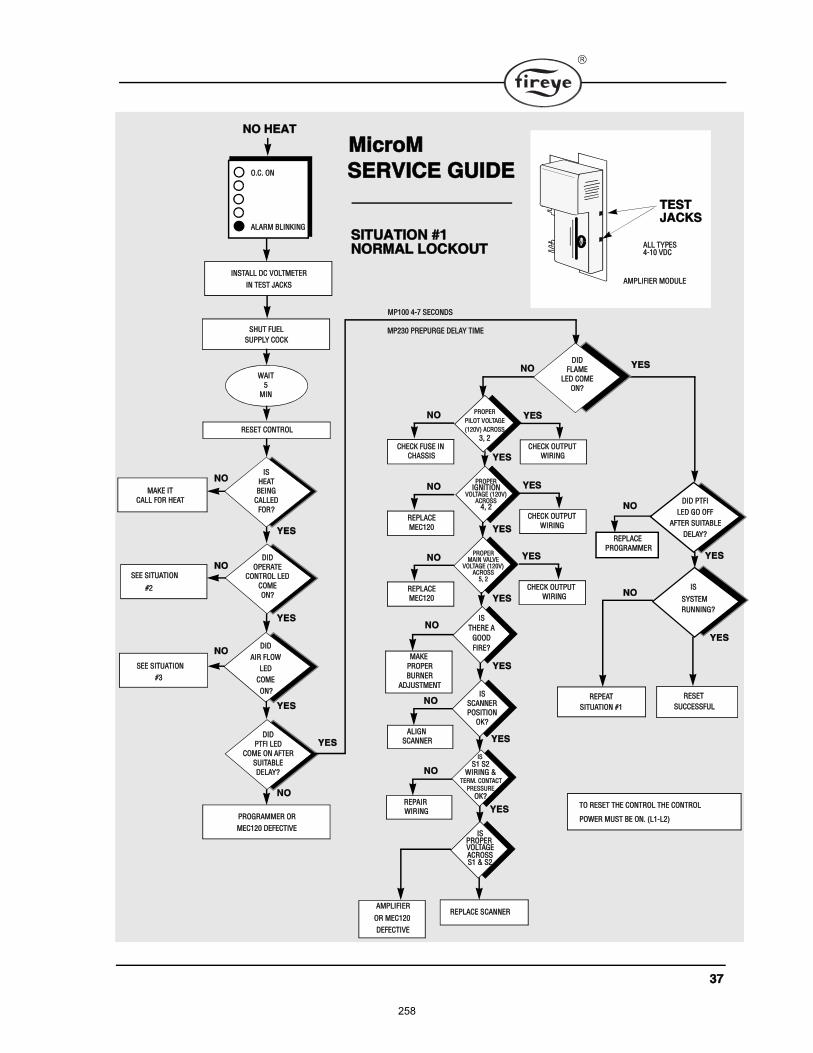
íé
ÓßÕÛ
ÐÎÑÐÛÎ
ÞËÎÒÛÎ
ßÜÖËÍÌÓÛÒÌ
Ü×Ü
ÑÐÛÎßÌÛ
ÝÑÒÌÎÑÔ ÔÛÜ
ÝÑÓÛ
ÑÒá
Ü×Ü
ÐÌÚ× ÔÛÜ
ÝÑÓÛ ÑÒ ßÚÌÛÎ
ÍË×ÌßÞÔÛ
ÜÛÔßÇá
Ü×Ü
ß×Î ÚÔÑÉ
ÔÛÜ
ÝÑÓÛ
ÑòÝò ÑÒ
ßÔßÎÓ ÞÔ×ÒÕ×ÒÙ
ÒÑ ØÛßÌ
×ÒÍÌßÔÔ ÜÝ ÊÑÔÌÓÛÌÛÎ
×Ò ÌÛÍÌ ÖßÝÕÍ
ÍØËÌ ÚËÛÔ
ÍËÐÐÔÇ ÝÑÝÕ
Éß×Ì
ë
Ó×Ò
ÎÛÍÛÌ ÝÑÒÌÎÑÔ
ÐÎÑÙÎßÓÓÛÎ ÑÎ
ÓÛÝïîð ÜÛÚÛÝÌ×ÊÛ
ÓßÕÛ ×Ì
ÝßÔÔ ÚÑÎ ØÛßÌ
ÍÛÛ Í×ÌËßÌ×ÑÒ
ÍÛÛ Í×ÌËßÌ×ÑÒ
×Í
ØÛßÌ
ÞÛ×ÒÙ
ÝßÔÔÛÜ
ÚÑÎá
ÑÒá
ýí
ýî
ÇÛÍ
ÇÛÍ
ÇÛÍ
ÒÑ
Í×ÌËßÌ×ÑÒ ýï
ÒÑ
ÒÑ
ÒÑ
ÇÛÍ
ÇÛÍ
ÇÛÍ
ÇÛÍ
Ü×Ü ÐÌÚ×
×Í
ÍÇÍÌÛÓ
ÎËÒÒ×ÒÙá
ßÔ×ÙÒ
ÍÝßÒÒÛÎ
ÎÛÐß×Î
É×Î×ÒÙ
ÍËÝÝÛÍÍÚËÔ
ÎÛÍÛÌ
ÎÛÐÔßÝÛ
ÐÎÑÙÎßÓÓÛÎ
Ü×Ü
ÚÔßÓÛ
ÔÛÜ ÝÑÓÛ
ÑÒá
ÇÛÍ
ÓÐïðð ìóé ÍÛÝÑÒÜÍ
ÓÐîíð ÐÎÛÐËÎÙÛ ÜÛÔßÇ Ì×ÓÛ
ÒÑ ÇÛÍ
ÒÑÎÓßÔ ÔÑÝÕÑËÌ
ÒÑ
ÒÑ
ÒÑ
ÒÑ
ÒÑ
ÇÛÍ
ßÓÐÔ×Ú×ÛÎ
ÜÛÚÛÝÌ×ÊÛ
ÑÎ ÓÛÝïîð ÎÛÐÔßÝÛ ÍÝßÒÒÛÎ
ÎÛÐÛßÌ
Í×ÌËßÌ×ÑÒ ýï
ÔÛÜ ÙÑ ÑÚÚ
ßÚÌÛÎ ÍË×ÌßÞÔÛ
ÜÛÔßÇá
Ó·½®±Ó
ÍÛÎÊ×ÝÛ ÙË×ÜÛ
ÌÑ ÎÛÍÛÌ ÌØÛ ÝÑÒÌÎÑÔ ÌØÛ ÝÑÒÌÎÑÔ
ÐÑÉÛÎ ÓËÍÌ ÞÛ ÑÒò øÔïóÔî÷
×Í
ÌØÛÎÛ ß
ÙÑÑÜ
Ú×ÎÛá
×ÍÐÎÑÐÛÎ
ßÝÎÑÍÍÍï ú Íî
ÊÑÔÌßÙÛ
×Í
É×Î×ÒÙ úÌÛÎÓò ÝÑÒÌßÝÌ
ÐÎÛÍÍËÎÛ
ÑÕá
Íï Íî
×Í
ÍÝßÒÒÛÎ
ÐÑÍ×Ì×ÑÒ
ÑÕá
ÐÎÑÐÛÎ
Ð×ÔÑÌ ÊÑÔÌßÙÛ
øïîðÊ÷ ßÝÎÑÍÍ
íô î
ÇÛÍ
ÐÎÑÐÛÎ×ÙÒ×Ì×ÑÒ
ÊÑÔÌßÙÛ øïîðÊ÷ßÝÎÑÍÍ
ìô î
ÇÛÍ
ÐÎÑÐÛÎÓß×Ò ÊßÔÊÛ
ÊÑÔÌßÙÛ øïîðÊ÷ßÝÎÑÍÍ
ëô î
ÇÛÍ
ÝØÛÝÕ ÚËÍÛ ×Ò
ÝØßÍÍ×Í
ÒÑ
ÝØÛÝÕ ÑËÌÐËÌ
ÇÛÍ
É×Î×ÒÙ
ÎÛÐÔßÝÛ
ÓÛÝïîð
ÒÑ
ÎÛÐÔßÝÛ
ÓÛÝïîð
ÒÑ
ÝØÛÝÕ ÑËÌÐËÌ
ÇÛÍ
É×Î×ÒÙ
ÝØÛÝÕ ÑËÌÐËÌ
ÇÛÍ
É×Î×ÒÙ
ÌÛÍÌÖßÝÕÍ
ßÓÐÔ×Ú×ÛÎ ÓÑÜËÔÛ
ßÔÔ ÌÇÐÛÍìóïð ÊÜÝ
258
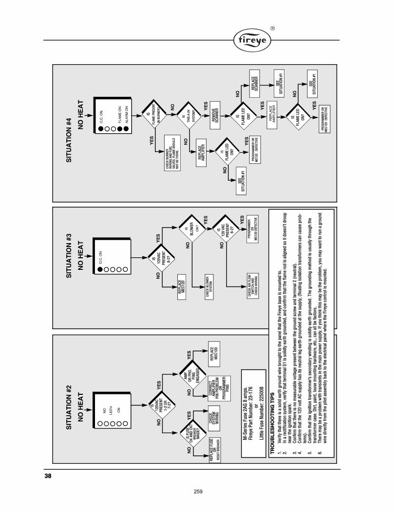
íè
×Í
ÐÎ
ÛÍ
ÛÒ
Ì
èóî
á
ÎÛÐ
Ôß
ÝÛ
ÓÛÝ
ïîð
ÐÎ
ÑÙ
Îß
ÓÓ
ÛÎÑ
ÎÓ
Ýï
îð
ÜÛÚ
ÛÝÌ
×ÊÛ
ÝØ
ÛÝÕ
ÞÔ
ÑÉ
ÛÎ
ÍÇ
ÍÌ
ÛÓ
ÝØ
ÛÝÕ
ß×Î
ÚÔ
ÑÉ
ÍÉ
×ÌÝ
Ø ß
ÒÜ
Ý
ØÛÝ
Õ É
×Î×Ò
Ù
ÞÔ
ÑÉ
ÛÎ
×Íï
îð Ê
ßÝ
Ð
ÎÛÍ
ÛÒ
Ì ê
óîá
ÎÛÐ
Ôß
ÝÛ
ÚËÍ
ÛÑ
ÎÎ
ÛÍÛ
Ì Þ
ÎÛß
ÕÛÎ
ÝØ
ÛÝÕ
ÍÇ
ÍÌ
ÛÓ
É×Î
×ÒÙ
ÎÛÐ
Ôß
ÝÛ
ÓÛÝ
ïîð
ÝÑ
ÎÎ
ÛÝÌ
ßÓ
ÐÔ
×Ú×Û
ÎÐ
×Ò Ð
ÎÑ
ÞÔÛ
Ó
Í Ú
ËÍ
ÛÑ
Õ ß
ÒÜ
ÝÕ
ÌÞ
ÎÛß
ÕÛÎ
Óß
ÜÛ
á
×Í
ïîð
Êß
ÝÐ
ÎÛÍ
ÛÒ
Ìï
îðÊ
ßÝ
ßÓ
ÐòÑ
Î Ð
ÎÑ
òÐ
×ÒÍ
Û
ÒÙ
ßÙ
ÛÜ
ïóî
ÑÎ
ÑÎ
ÐÎ
ÑÙ
Îß
ÓÓ
ÛÎ
Ð×Ò
Í
éóî
á
ÎÛÓ
ÑÊ
ÛÍ
Ýß
ÒÒ
ÛÎ
ÎÛÐ
Ôß
ÝÛ
ßÓ
ÐÔ
×Ú×Û
Î
ÍÛÛ
Í×Ì
ËßÌ
×ÑÒ
ýï
ÍÛÛ
Í×Ì
ËßÌ
×ÑÒ
ýï
ÐÎ
ÑÙ
Îß
ÓÓ
ÛÎ
ÑÎ
ÜÛÚ
ÛÝÌ
×ÊÛ
ÓÝ
ïîð
ÎÛÐ
Ôß
ÝÛ
ÍÝ
ßÒ
ÒÛÎ
ÍÛÛ
Í×Ì
ËßÌ
×ÑÒ
ýï
ÝØ
ÛÝÕ
ÞË
ÎÒ
ÛÎ
É×Î
×ÒÙ
ßÒ
Ü Ú
ËÛÔ
Êß
ÔÊÛ
Íò Ú
ÔßÓ
Û Í
ØÑ
ËÔ
ÜÒ
ÑÌ
ÞÛ
ÌØ
ÛÎÛ
ò
×Í
ÚÔß
ÓÛ
ÔÛÜ
ÑÒ
á
×Í
ÌØ×Í
ß Ë
Ê
ÍÇ
ÍÌ
ÛÓ
á
×Í
ÚÔß
ÓÛ
ÔÛ
Ü
ÑÒ
á
ÚÔß
ÓÛ
ÔÛÜ
ÑÒ
á
×Í
ÚÔß
ÓÛ
ÐÎ
ÛÍÛÒ
Ì
×Ò Þ
ËÎ
ÒÛ
Îá
ÌÎ
ÑË
ÞÔ
ÛÍ
ØÑ
ÑÌ
×ÒÙ
Ì×Ð
Í
ïò
Ê»®
ἤ
¬¸¿¬
¬¸
»®»
· ¿
±
´·¼ »
¿®¬¸
¹®±
«²
¼ ©
·®»
¾®±
«¹
¸¬
¬± ¬
¸»
°¿²
»´ ¬
¸¿¬
¬¸
» Ú·
®»§»
¾¿
» ·
³±
«²
¬»¼
±
òî
òײ
¿ ®
»½¬·
º·½¿
¬·±
²
§¬»
³ô ª
»®·º
§ ¬¸
¿¬ ¬
»®³
·²¿´
Íï
·
±´·¼
´§ »
¿®¬¸
¹®±
«²¼
»¼ô ¿
²¼ ½
±²º·
®³ ¬
¸¿¬
¬¸
» º´
¿³»
®±¼ ·
¿´·¹
²»¼
±
·¬ ¼
±»
²¬
¼®±
±°
²
»¿®
¬¸»
·¹²
·¬·±
²
°¿®
µòí
òÝ
±²
º·®³
¬¸
¿¬ ¬
¸»®
» ·
²±
³»¿
«®¿
¾´»
ª±
´¬¿¹
» °
®»»
²¬
¾»¬
©»»
² ¬
¸»
¹®±
«²
¼
½®»©
¿²¼
¬»®
³·²
¿´ î
ø²
»«¬®
¿´÷ò
ìò
ݱ
²º·
®³ ¬
¸¿¬
¬¸
» ï
îð
ª±
´¬ ß
Ý
«°
°´§
¸¿
·¬
²»«
¬®¿´
´»¹
»¿®
¬¸ ¹
®±«²
¼»¼
¿¬
¬¸»
«°°
´§ô
øº´±
¿¬·²
¹ ·
±´¿
¬·±² ¬
®¿²º
±®³
»®
½¿² ½
¿«»
°®±
¾ó
´»³
÷ò
ëò
ݱ
²º·
®³ ¬
¸¿¬
¬¸
» ·¹
²·¬
·±²
¨²º
±®³
»®
»½
±²
¼¿®
§ ©
·²¼
·²¹ ·
±´·¼
´§ »
¿®¬¸
¹®±
«²
¼»¼
ò Ì
¸»
¹®±
«²¼
·²¹
³»¬
¸±¼
· «
«¿´
´§ ¬
¸®±
«¹¸
¬¸»
¬®¿²
º±
®³»®
½¿
»ò Ü
·®¬ô
°¿·
²¬ô
´±±
» ³
±«
²¬·
²¹
¸¿®
¼©
¿®»ô
»¬½
òô ½
¿² ¿
´´ ¾»
º¿½¬
±®
òê
òÌ
¸»®
» ³
¿§ ¾
» ¿
°®±
¾´»
³ ©
·¬¸
¨²·
»²¬
·² ¬
¸»
³¿·
² °
±©
»®
«°
°´§
ò ׺
§±« ¬
¸·²
µ ¬¸
· ³
¿§ ¾
» ¬¸
» °
®±¾´»
³ô §
±«
³¿§
©¿²
 ±
®«
² ¿
¹®±
«²¼
©
·®»
¼·®
»½¬´
§ º®
±³
¬¸
» °
·´±¬
¿»
³¾
´§ ¾
¿½µ
¬± ¬
¸»
»´»½
¬®·½
¿´ °
¿²»´
©¸»®
» ¬¸
» Ú·
®»§»
½±²¬®
±´ ·
³
±«
²¬»
¼ò
ÓóÍ
»®·»
Ú«
» î
ßÙ
è ¿
³°ò
Ú·®»
§» Ð
¿®¬
Ò«³
¾»®
æ îíóï
éê
±®
Ô·¬
¬´»
Ú«»
Ò«³
¾»®
æ îîëðð
è
ÐÎ
ÑÙ
Îß
ÓÓ
ÛÎ
ÑÎ
ÜÛÚ
ÛÝÌ
×ÊÛ
ÓÛ
Ýïî
ð
259
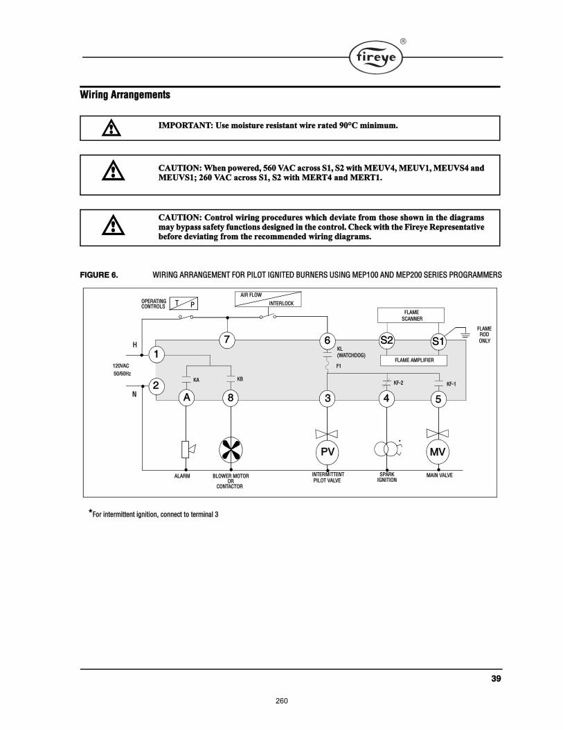
íç
É·®·²¹ ß®®¿²¹»³»²¬
Ú×ÙËÎÛ êò É×Î×ÒÙ ßÎÎßÒÙÛÓÛÒÌ ÚÑÎ Ð×ÔÑÌ ×ÙÒ×ÌÛÜ ÞËÎÒÛÎÍ ËÍ×ÒÙ ÓÛÐïðð ßÒÜ ÓÛÐîðð ÍÛÎ×ÛÍ ÐÎÑÙÎßÓÓÛÎÍ
×ÓÐÑÎÌßÒÌæ Ë» ³±·¬«®» ®»·¬¿²¬ ©·®» ®¿¬»¼ çðpÝ ³·²·³«³ò
ÝßËÌ×ÑÒæ ɸ»² °±©»®»¼ô ëêð ÊßÝ ¿½®± Íïô Íî ©·¬¸ ÓÛËÊìô ÓÛËÊïô ÓÛËÊÍì ¿²¼ÓÛËÊÍïå îêð ÊßÝ ¿½®± Íïô Íî ©·¬¸ ÓÛÎÌì ¿²¼ ÓÛÎÌïò
ÝßËÌ×ÑÒæ ݱ²¬®±´ ©·®·²¹ °®±½»¼«®» ©¸·½¸ ¼»ª·¿¬» º®±³ ¬¸±» ¸±©² ·² ¬¸» ¼·¿¹®¿³³¿§ ¾§°¿ ¿º»¬§ º«²½¬·±² ¼»·¹²»¼ ·² ¬¸» ½±²¬®±´ò ݸ»½µ ©·¬¸ ¬¸» Ú·®»§» λ°®»»²¬¿¬·ª»¾»º±®» ¼»ª·¿¬·²¹ º®±³ ¬¸» ®»½±³³»²¼»¼ ©·®·²¹ ¼·¿¹®¿³ò
ÐÊ ÓÊ
Íïé
í ëì
ï
ß
Íî
×ÒÌÛÎÓ×ÌÌÛÒÌ Óß×Ò ÊßÔÊÛÞÔÑÉÛÎ ÓÑÌÑÎßÔßÎÓ
è
ïîðÊßÝ
ëðñêðئ
Ì Ð
ÚÔßÓÛ ßÓÐÔ×Ú×ÛÎ
ÍÐßÎÕ
ÕÔ
ÕÚóî ÕÚóï
Ð×ÔÑÌ ÊßÔÊÛ ×ÙÒ×Ì×ÑÒ
ö
Ø
Òî
öÚ±® ·²¬»®³·¬¬»²¬ ·¹²·¬·±²ô ½±²²»½¬ ¬± ¬»®³·²¿´ í
ÚÔßÓÛ
ÍÝßÒÒÛÎ
ÑÎÝÑÒÌßÝÌÑÎ
ÑÐÛÎßÌ×ÒÙÝÑÒÌÎÑÔÍ
ÕÞÕß
øÉßÌÝØÜÑÙ÷
ß×Î ÚÔÑÉ
×ÒÌÛÎÔÑÝÕ
Úï
ê
ÚÔßÓÛÎÑÜ
ÑÒÔÇ
260
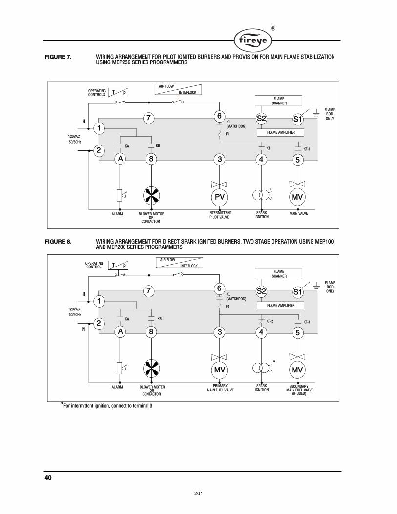
ìð
Ú×ÙËÎÛ éò É×Î×ÒÙ ßÎÎßÒÙÛÓÛÒÌ ÚÑÎ Ð×ÔÑÌ ×ÙÒ×ÌÛÜ ÞËÎÒÛÎÍ ßÒÜ ÐÎÑÊ×Í×ÑÒ ÚÑÎ Óß×Ò ÚÔßÓÛ ÍÌßÞ×Ô×ÆßÌ×ÑÒ ËÍ×ÒÙ ÓÛÐîíê ÍÛÎ×ÛÍ ÐÎÑÙÎßÓÓÛÎÍ
Ú×ÙËÎÛ èò É×Î×ÒÙ ßÎÎßÒÙÛÓÛÒÌ ÚÑÎ Ü×ÎÛÝÌ ÍÐßÎÕ ×ÙÒ×ÌÛÜ ÞËÎÒÛÎÍô ÌÉÑ ÍÌßÙÛ ÑÐÛÎßÌ×ÑÒ ËÍ×ÒÙ ÓÛÐïðð ßÒÜ ÓÛÐîðð ÍÛÎ×ÛÍ ÐÎÑÙÎßÓÓÛÎÍ
ÐÊ ÓÊ
Íïé
í ëì
ï
ß
Íî
×ÒÌÛÎÓ×ÌÌÛÒÌ Óß×Ò ÊßÔÊÛÞÔÑÉÛÎ ÓÑÌÑÎßÔßÎÓ
è
ïîðÊßÝ
ëðñêðئ
Ì Ð
ÚÔßÓÛ ßÓÐÔ×Ú×ÛÎ
ÍÐßÎÕ
Õï ÕÚóï
Ð×ÔÑÌ ÊßÔÊÛ ×ÙÒ×Ì×ÑÒ
ö
Ø
î
ÚÔßÓÛ
ÍÝßÒÒÛÎ
ÑÎÝÑÒÌßÝÌÑÎ
ÑÐÛÎßÌ×ÒÙÝÑÒÌÎÑÔÍ
ÕÞÕß
ß×Î ÚÔÑÉ
×ÒÌÛÎÔÑÝÕ
ÚÔßÓÛÎÑÜ
ÑÒÔÇÕÔ
øÉßÌÝØÜÑÙ÷
Úï
ê
ÓÊ ÓÊ
Íïé
í ëì
ï
ß
Íî
ÐÎ×ÓßÎÇ ÍÛÝÑÒÜßÎÇÞÔÑÉÛÎ ÓÑÌÛÎßÔßÎÓ
è
ïîðÊßÝ
ëðñêðئ
Ì Ð
ÚÔßÓÛ ßÓÐÔ×Ú×ÛÎ
ÍÐßÎÕ
ÕÚóî ÕÚóï
Óß×Ò ÚËÛÔ ÊßÔÊÛ ×ÙÒ×Ì×ÑÒ
Ø
Òî
ÚÔßÓÛ
ÍÝßÒÒÛÎ
Óß×Ò ÚËÛÔ ÊßÔÊÛø×Ú ËÍÛÜ÷
ÑÎ ÝÑÒÌßÝÌÑÎ
Õß ÕÞ
ÑÐÛÎßÌ×ÒÙ ÝÑÒÌÎÑÔ
ß×Î ÚÔÑÉ
×ÒÌÛÎÔÑÝÕ
öÚ±® ·²¬»®³·¬¬»²¬ ·¹²·¬·±²ô ½±²²»½¬ ¬± ¬»®³·²¿´ í
ö
ÚÔßÓÛÎÑÜ ÑÒÔÇ
ÕÔ
øÉßÌÝØÜÑÙ÷
Úï
ê
261
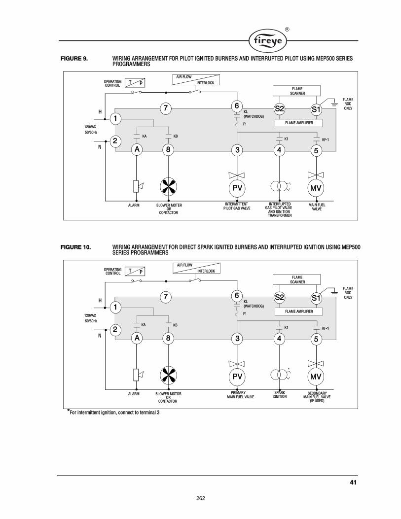
ìï
Ú×ÙËÎÛ çò É×Î×ÒÙ ßÎÎßÒÙÛÓÛÒÌ ÚÑÎ Ð×ÔÑÌ ×ÙÒ×ÌÛÜ ÞËÎÒÛÎÍ ßÒÜ ×ÒÌÛÎÎËÐÌÛÜ Ð×ÔÑÌ ËÍ×ÒÙ ÓÛÐëðð ÍÛÎ×ÛÍ ÐÎÑÙÎßÓÓÛÎÍ
Ú×ÙËÎÛ ïðò É×Î×ÒÙ ßÎÎßÒÙÛÓÛÒÌ ÚÑÎ Ü×ÎÛÝÌ ÍÐßÎÕ ×ÙÒ×ÌÛÜ ÞËÎÒÛÎÍ ßÒÜ ×ÒÌÛÎÎËÐÌÛÜ ×ÙÒ×Ì×ÑÒ ËÍ×ÒÙ ÓÛÐëðð ÍÛÎ×ÛÍ ÐÎÑÙÎßÓÓÛÎÍ
ÐÊ ÓÊ
Íïé
í ëì
ï
ß
Íî
×ÒÌÛÎÓ×ÌÌÛÒÌ ÞÔÑÉÛÎ ÓÑÌÛÎßÔßÎÓ
è
ïîðÊßÝ
ëðñêðئ
Ì Ð
ÚÔßÓÛ ßÓÐÔ×Ú×ÛÎ
×ÒÌÛÎÎËÐÌÛÜ
Õï ÕÚóï
Ð×ÔÑÌ ÙßÍ ÊßÔÊÛ
Ø
Òî
ÚÔßÓÛ
ÍÝßÒÒÛÎ
Óß×Ò ÚËÛÔ ÑÎ
ÝÑÒÌßÝÌÑÎÊßÔÊÛ
ßÒÜ ×ÙÒ×Ì×ÑÒÌÎßÒÍÚÑÎÓÛÎ
ÙßÍ Ð×ÔÑÌ ÊßÔÊÛ
ÑÐÛÎßÌ×ÒÙ ÝÑÒÌÎÑÔ
Õß ÕÞ
ß×Î ÚÔÑÉ
×ÒÌÛÎÔÑÝÕ
ÚÔßÓÛÎÑÜ
ÑÒÔÇÕÔ
øÉßÌÝØÜÑÙ÷
Úï
ê
ÐÊ ÓÊ
Íïé
í ëì
ï
ß
Íî
ÐÎ×ÓßÎÇ ÍÛÝÑÒÜßÎÇ ÞÔÑÉÛÎ ÓÑÌÑÎßÔßÎÓ
è
ïîðÊßÝ
ëðñêðئ
Ì Ð
ÚÔßÓÛ ßÓÐÔ×Ú×ÛÎ
ÍÐßÎÕ
Õï ÕÚóï
Óß×Ò ÚËÛÔ ÊßÔÊÛ ×ÙÒ×Ì×ÑÒ
ö
Ø
Òî
öÚ±® ·²¬»®³·¬¬»²¬ ·¹²·¬·±²ô ½±²²»½¬ ¬± ¬»®³·²¿´ í
ÚÔßÓÛ
ÍÝßÒÒÛÎ
ÑÎÝÑÒÌßÝÌÑÎ
Óß×Ò ÚËÛÔ ÊßÔÊÛø×Ú ËÍÛÜ÷
ÑÐÛÎßÌ×ÒÙ ÝÑÒÌÎÑÔ
Õß ÕÞ
ß×Î ÚÔÑÉ
×ÒÌÛÎÔÑÝÕ
ÚÔßÓÛÎÑÜ
ÑÒÔÇÕÔ
øÉßÌÝØÜÑÙ÷
Úï
ê
262
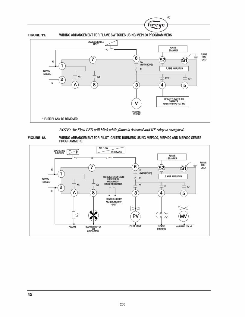
ìî
Ú×ÙËÎÛ ïïò É×Î×ÒÙ ßÎÎßÒÙÛÓÛÒÌ ÚÑÎ ÚÔßÓÛ ÍÉ×ÌÝØÛÍ ËÍ×ÒÙ ÓÛÐïðð ÐÎÑÙÎßÓÓÛÎÍ
ß·® Ú´±© ÔÛÜ ©·´´ ¾´·²µ ©¸·´» º´¿³» · ¼»¬»½¬»¼ ¿²¼ ÕÚ ®»´¿§ · »²»®¹·¦»¼ò
Ú×ÙËÎÛ ïîò É×Î×ÒÙ ßÎÎßÒÙÛÓÛÒÌ ÚÑÎ Ð×ÔÑÌ ×ÙÒ×ÌÛÜ ÞËÎÒÛÎÍ ËÍ×ÒÙ ÓÛÐíððô ÓÛÐìðð ßÒÜ ÓÛÐêðð ÍÛÎ×ÛÍ ÐÎÑÙÎßÓÓÛÎÍò
Ê
Íïé
í ëì
ï
ß
Íî
ÊÑÔÌßÙÛ
è
ïîðÊßÝ
ëðñêðئ
ÚÔßÓÛ ßÓÐÔ×Ú×ÛÎ
ÕÚóî ÕÚóï
Ø
Òî
ÚÔßÓÛ
ÍÝßÒÒÛÎ
ÛÒßÞÔÛñÜ×ÍßÞÔÛ
Õß ÕÞ
ÍÑËÎÝÛ
×ÍÑÔßÌÛÜ ÍÉ×ÌÝØÛÜÑËÌÐËÌÍ
ÎÛÚÛÎ ÌÑ ÔÑßÜ ÎßÌ×ÒÙÑËÌÐËÌÍ
×ÒÐËÌ
ö ÚËÍÛ Úï ÝßÒ ÞÛ ÎÛÓÑÊÛÜ
ÚÔßÓÛÎÑÜ
ÑÒÔÇÕÔ
øÉßÌÝØÜÑÙ÷
Úï
ê
ÐÊ ÓÊ
Íïé
í ëì
ï
ß
Íî
Ð×ÔÑÌ ÊßÔÊÛ ÞÔÑÉÛÎ ÓÑÌÑÎßÔßÎÓ
è
ïîðÊßÝ
ëðñêðئ
Ì Ð
ÚÔßÓÛ ßÓÐÔ×Ú×ÛÎ
ÍÐßÎÕ
Õ× ÕÚ
×ÙÒ×Ì×ÑÒ
Ø
Òî
ÚÔßÓÛ
ÍÝßÒÒÛÎ
ÑÎÝÑÒÌßÝÌÑÎ
Óß×Ò ÚËÛÔ ÊßÔÊÛ
ÑÐÛÎßÌ×ÒÙ ÝÑÒÌÎÑÔ
Õß ÕÞ
ß×Î ÚÔÑÉ
×ÒÌÛÎÔÑÝÕ
ÚÔßÓÛÎÑÜ
ÑÒÔÇÕÔ
øÉßÌÝØÜÑÙ÷
Úï
ê
ÕÐ
ÓÑÜËÔßÌÛ ÝÑÒÌßÝÌÍ
ÓÛÜèñÓÛÜçÜßËÙØÌÛÎ ÞÑßÎÜ
ÔÑÝßÌÛÜ ÑÒ
ÝÑÒÌÎÑÔÔÛÜ ÞÇ
ÓÛÐêçêñÓÛÐêçé
ÑÒÔÇ
263
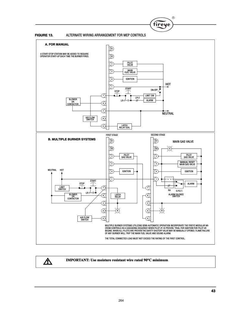
ìí
Ú×ÙËÎÛ ïíò ßÔÌÛÎÒßÌÛ É×Î×ÒÙ ßÎÎßÒÙÛÓÛÒÌ ÚÑÎ ÓÛÐ ÝÑÒÌÎÑÔÍ
Íî
í
ë
ì
ï
Óß×Ò
×ÙÒ×Ì×ÑÒ
é
è
î
ß
ê
ÍÌÑÐ
Ð×ÔÑÌ
Íï
ÍÌßÎÌ
Ô×Ó×Ì ÍÉ
ÚËÛÔ ÊßÔÊÛ
ßÔßÎÓ
ÑÒóÑÚÚ
ØÑÌ
ÒÛËÌÎßÔ
ÔÎóï
ÔÎóî
ÔßÌÝØ
ß×Î ÚÔÑÉÍÉ×ÌÝØ
ßò ÚÑÎ ÓßÒËßÔ
ß ÍÌßÎÌóÍÌÑÐ ÍÌßÌ×ÑÒ ÓßÇ ÞÛ ßÜÜÛÜ ÌÑ ÎÛÏË×ÎÛ ÑÐÛÎßÌÑÎ ÍÌßÎÌóËÐ ÛßÝØ Ì×ÓÛ ÌØÛ ÞËÎÒÛÎ Ú×ÎÛÍò
Íî
í
ë
ì
ï
×ÙÒ×Ì×ÑÒ
é
è
î
ß
ê
Ð×ÔÑÌ
ÍïÞò ÓËÔÌ×ÐÔÛ ÞËÎÒÛÎ ÍÇÍÌÛÓÍ
Íî
í
ë
ì
ï
×ÙÒ×Ì×ÑÒ
é
è
î
ß
ê
Ð×ÔÑÌ
Íï
Ô×Ó×Ì
Î
ÓßÒËßÔ ÎÛÍÛÌ
Óß×Ò ÙßÍ ÊßÔÊÛ
ßÔßÎÓ
ÍòÐòÜòÌòÎß
ßÔßÎÓ Í×ÔÛÒÝÛÍÉ×ÌÝØ
Ù
Î
ÍÌÑÐÍÌßÎÌ
ÔÎóï
ß×Î ÚÔÑÉ
ÞÔÑÉÛÎÑÎ
ÔßÌÝØ
ØÑÌÒÛËÌÎßÔ
ÓËÔÌ×ÐÔÛ ÞËÎÒÛÎ ÍÇÍÌÛÓÍ ËÌ×Ô×Æ×ÒÙ ÍÛÓ×óßËÌÑÓßÌ×Ý ÑÐÛÎßÌ×ÑÒ ×ÒÝÑÎÐÑÎßÌÛ ÌØÛ Ú×ÎÛÇÛ ÓÑÜËÔßÎ Ó×óÝÎÑÓ ÝÑÒÌÎÑÔÍ ×Ò ß ÝßÍÝßÜ×ÒÙ ÍÛÏËÛÒÝÛ ÉØÛÒ Ð×ÔÑÌ ýï ×Í ÐÎÑÊÛÒò ÌÎ×ßÔ ÚÑÎ ×ÙÒ×Ì×ÑÒ ÚÑÎ Ð×ÔÑÌ ýî ÞÛÙ×ÒÍò ÉØÛÒ ßÔÔ Ð×ÔÑÌÍ ßÎÛ ÐÎÑÊÛÒ ÌØÛ ÍßÚÛÌÇ ÍØËÌÑÚÚ ÊßÔÊÛ ÓßÇ ÞÛ ÓßÒËßÔÔÇ ÑÐÛÒÛÜò ÚÔßÓÛ Úß×ÔËÎÛ ÑÚ ßÒÇ ÞËÎÒÛÎ É×ÔÔ ÌÎ×Ð ÌØÛ Óß×Ò ÚËÛÔ ÊßÔÊÛ ßÒÜ ÍÑËÒÜ ßÔßÎÓò
ÌØÛ ÌÑÌßÔ ÝÑÒÒÛÝÌÛÜ ÔÑßÜ ÓËÍÌ ÒÑÌ ÛÈÝÛÛÜ ÌØÛ ÎßÌ×ÒÙ ÑÚ ÌØÛ Ú×ÎÍÌ ÝÑÒÌÎÑÔò
ÊßÔÊÛ
ÎÛÔßÇ ÝÑ×Ô
Óß×Ò ÙßÍ ÊßÔÊÛ
ÙßÍ ÊßÔÊÛ
ÎÛÔßÇ
ÙßÍ ÊßÔÊÛ
ÍÉ×ÌÝØ
ÍÉ×ÌÝØ
ÞÔÑÉÛÎ ÑÎ
ÝÑÒÌßÝÌÑÎ
Ú×ÎÍÌ ÍÌßÙÛ ÍÛÝÑÒÜ ÍÌßÙÛ
ÝÑÒÌßÝÌÑÎ
×ÓÐÑÎÌßÒÌæ Ë» ³±·¬«®» ®»·¬¿²¬ ©·®» ®¿¬»¼ çðpÝ ³·²·³«³ ò
264
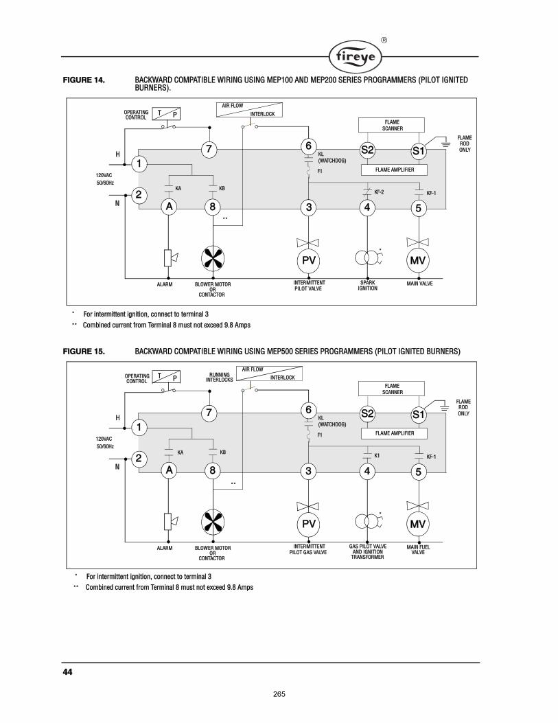
ìì
Ú×ÙËÎÛ ïìò ÞßÝÕÉßÎÜ ÝÑÓÐßÌ×ÞÔÛ É×Î×ÒÙ ËÍ×ÒÙ ÓÛÐïðð ßÒÜ ÓÛÐîðð ÍÛÎ×ÛÍ ÐÎÑÙÎßÓÓÛÎÍ øÐ×ÔÑÌ ×ÙÒ×ÌÛÜ ÞËÎÒÛÎÍ÷ò
Ú×ÙËÎÛ ïëò ÞßÝÕÉßÎÜ ÝÑÓÐßÌ×ÞÔÛ É×Î×ÒÙ ËÍ×ÒÙ ÓÛÐëðð ÍÛÎ×ÛÍ ÐÎÑÙÎßÓÓÛÎÍ øÐ×ÔÑÌ ×ÙÒ×ÌÛÜ ÞËÎÒÛÎÍ÷
ÐÊ ÓÊ
Íïé
í ëì
ï
ß
Íî
×ÒÌÛÎÓ×ÌÌÛÒÌ Óß×Ò ÊßÔÊÛÞÔÑÉÛÎ ÓÑÌÑÎßÔßÎÓ
è
ïîðÊßÝ
ëðñêðئ
Ì Ð
ÚÔßÓÛ ßÓÐÔ×Ú×ÛÎ
ÍÐßÎÕ
ÕÚóî ÕÚóï
Ð×ÔÑÌ ÊßÔÊÛ ×ÙÒ×Ì×ÑÒ
ö
Ø
Òî
ö Ú±® ·²¬»®³·¬¬»²¬ ·¹²·¬·±²ô ½±²²»½¬ ¬± ¬»®³·²¿´ í
ÚÔßÓÛ
ÍÝßÒÒÛÎ
ÑÎÝÑÒÌßÝÌÑÎ
ÑÐÛÎßÌ×ÒÙÝÑÒÌÎÑÔ
ÕÞÕß
öö
öö ݱ³¾·²»¼ ½«®®»²¬ º®±³ Ì»®³·²¿´ è ³«¬ ²±¬ »¨½»»¼ çòè ß³°
ß×Î ÚÔÑÉ
×ÒÌÛÎÔÑÝÕ
ÚÔßÓÛÎÑÜ ÑÒÔÇ
ÕÔ
øÉßÌÝØÜÑÙ÷
Úï
ê
ÐÊ ÓÊ
Íïé
í ëì
ï
ß
Íî
×ÒÌÛÎÓ×ÌÌÛÒÌ Óß×Ò ÚËÛÔ
ÎËÒÒ×ÒÙ
ÞÔÑÉÛÎ ÓÑÌÑÎßÔßÎÓ
è
ïîðÊßÝ
ëðñêðئ
Ì Ð
ÚÔßÓÛ ßÓÐÔ×Ú×ÛÎ
ÙßÍ Ð×ÔÑÌ ÊßÔÊÛ
Õï ÕÚóï
Ð×ÔÑÌ ÙßÍ ÊßÔÊÛ ßÒÜ ×ÙÒ×Ì×ÑÒ
ö
Ø
Òî
ÚÔßÓÛ
ÍÝßÒÒÛÎ
ÑÎÝÑÒÌßÝÌÑÎ
ÊßÔÊÛÌÎßÒÍÚÑÎÓÛÎ
ÑÐÛÎßÌ×ÒÙ ÝÑÒÌÎÑÔ
öö
×ÒÌÛÎÔÑÝÕÍ
ÕÞÕß
ö Ú±® ·²¬»®³·¬¬»²¬ ·¹²·¬·±²ô ½±²²»½¬ ¬± ¬»®³·²¿´ í
ß×Î ÚÔÑÉ
×ÒÌÛÎÔÑÝÕ
ÚÔßÓÛÎÑÜ
ÑÒÔÇÕÔ
øÉßÌÝØÜÑÙ÷
Úï
ê
öö ݱ³¾·²»¼ ½«®®»²¬ º®±³ Ì»®³·²¿´ è ³«¬ ²±¬ »¨½»»¼ çòè ß³°
265
ìë
ÍËÙÙÛÍÌÛÜ ÙÎÑËÒÜ×ÒÙ ÎËÔÛÍ
̸» Ó·½®±Ó §¬»³ô ¾»·²¹ ³·½®±°®±½»±® ¾¿»¼ô ®»¯«·®» ¿ ¹®±«²¼ §¬»³ ¬¸¿¬ °®±ª·¼» ¿ ¦»®±ó
ª±´¬¿¹» ®»º»®»²½»ò ̸» ª±´¬¿¹» ³»¿«®»¼ º®±³ Ôî ¬± ¿´´ ±¬¸»® ¬»®³·²¿´ »¨½»°¬ Ôï ¸±«´¼ ¾» 𠪱´¬ò
ïò ̸» ³±¬ »ºº»½¬·ª» ¹®±«²¼ · ¬± ®«² ¬¸» ¹®±«²¼ ©·®» ·² ¬¸» ¿³» ®¿½»©¿§ ¿ ¬¸» ¸±¬ ¿²¼ ²»«¬®¿´
º®±³ ¬¸» ³¿·² ¼·¬®·¾«¬·±² »®ª·½» °¿²»´ ø²±¬ ·²¬»®³»¼·¿¬» «¾ó°¿²»´÷ ¬± ¬¸» ¾«®²»® ½±²¬®±´
°¿²»´ ¿²¼ ·²«®» ¬¸¿¬ ¬¸· ¹®±«²¼ ©·®» · ©»´´ ¾±²¼»¼ ¬± ¬¸» ½±²¬®±´ °¿²»´ò
îò ̸» ©·®·²¹ ¾¿» ±º ¬¸» Ó·½®±Ó ³«¬ ¸¿ª» »¿®¬¸ ¹®±«²¼ °®±ª·¼·²¹ ¿ ½±²²»½¬·±² ¾»¬©»»² ¬¸»«¾ó¾¿» ¿²¼ ¬¸» ½±²¬®±´ °¿²»´ ±® ¬¸» ¾«®²»®ò
íò ̸» »¿®¬¸ ¹®±«²¼ ©·®» ³«¬ ¾» ½¿°¿¾´» ±º ½±²¼«½¬·²¹ ¬¸» ½«®®»²¬ ¬± ¾´±© ¬¸» îðß º«» ·² »ª»²¬±º ¿² ·²¬»®²¿´ ¸±®¬ ½·®½«·¬ò ß ²«³¾»® ïì ßÉÙ ½±°°»® ½±²¼«½¬±® · ¿¼»¯«¿¬»ô ©·¼» ¬®¿° ±®¾®¿½µ»¬ ¿®» °®»º»®®»¼ ®¿¬¸»® ¬¸¿² ´»¿¼ ©·®»ò
ìò ̸» ¹®±«²¼ °¿¬¸ ²»»¼ ¬± ¾» ´±© ·³°»¼¿²½» ø´» ¬¸¿² ï ±¸³÷ ¬± ¬¸» »¯«·°³»²¬ º®¿³» ©¸·½¸ ·²¬«®² ²»»¼ ¿ ´±© ·³°»¼¿²½» ¬± »¿®¬¸ ¹®±«²¼ò Ú±® ¿ ¹®±«²¼ °¿¬¸ ¬± ¾» ´±© ·³°»¼¿²½» ¿¬ ÎÚ º®»ó¯«»²½·»ô ¬¸» ½±²²»½¬·±² ³«¬ ¾» ³¿¼» ©·¬¸ ³·²·³«³ ´»²¹¬¸ ½±²¼«½¬±® ¸¿ª·²¹ ³¿¨·³«³ «®óº¿½» ¿®»¿ò
ëò ß´´ ½±²²»½¬·±² ¸±«´¼ ¾» º®»» ±º ²±²½±²¼«½¬·ª» ½±¿¬·²¹ ¿²¼ °®±¬»½¬»¼ ¿¹¿·²¬ ®«¬ò
êò ˬ·´·¦·²¹ ½±²¼«·¬ ¿ ¿ ³»¿² ±º °®±ª·¼·²¹ ¿ ¹®±«²¼ ³«¬ ¾» ¿ª±·¼»¼ò
éò ײ¬¿´´·²¹ ¹®±«²¼ ®±¼ ¿¬ ¬¸» ¾«®²»® ½±²¬®±´ °¿²»´ ¼»º»¿¬ ¬¸» °«®°±» ±º ¿ ·²¹´» °±·²¬ ¹®±«²¼ ¿¼»½®·¾»¼ ¿¾±ª» ¿²¼ ½±«´¼ ¿´± °®»»²¬ ¿ ¿º»¬§ ¸¿¦¿®¼ò
×ÒÍÌßÔÔßÌ×ÑÒ
ܱ ²±¬ ®«² ¸·¹¸ ª±´¬¿¹» ·¹²·¬·±² ¬®¿²º±®³»® ©·®» ·² ¬¸» ¿³» ½±²¼«·¬ ©·¬¸ º´¿³» ¼»¬»½¬·±² ©·®·²¹ò
ܱ ²±¬ ®«² ½¿²²»® ©·®» ·² ¿ ½±²¼«·¬ ©·¬¸ ´·²» ª±´¬¿¹» ½·®½«·¬ò
Û²«®» ¬¸» º®¿³» ±º ¬¸» ·¹²·¬·±² ¬®¿²º±®³»® · »½«®»´§ ½±²²»½¬»¼ ¬± ½±²¬®±´ °¿²»´ º®¿³» ±® °®»º»®¿ó
¾´§ ¬¸» ¾«®²»® º®¿³»ò
̸» Ó·½®±Ó ½¸¿· øÓÛÝïîð÷ ½±²¬¿·² ¿ ¬®¿²·»²¬ «°°®»·²¹ ¼»ª·½» ½±²²»½¬»¼ ·²¬»®²¿´´§ ¿½®±
¸±¬ ¿²¼ ²»«¬®¿´ ¿²¼ ¬¸»² ¬± ¬¸» ·²¬»®²¿´ ¾®¿½µ»¬ò Ú±® ¬¸· ¬± ¾» »ºº»½¬·ª» ¬¸» ½¸¿· ³«¬ ¾» ½®»©»¼
»½«®»´§ ·²¬± ¬¸» ©·®·²¹ «¾¾¿»ò
ÎÛÓÑÌÛ Ü×ÍÐÔßÇ
ɸ»² ¬¸» ÛÜëïð · ¬± ¾» ®»³±¬»´§ ³±«²¬»¼ ±² ¬¸» º®±²¬ ±º ¬¸» ½±²¬®±´ °¿²»´ô ¬¸» ÛÜëè𠽿¾´» ³«¬
½±²¬¿·² ¿ º»®®·¬» ½±®»ô ½«®®»²¬´§ «°°´·»¼ ¾§ Ú·®»§» ©·¬¸ ¬¸» ½¿¾´»ò ̸» ½¿¾´» »²¼ ©·¬¸ ¬¸» º»®®·¬» ½±®»
³«¬ ¾» ³±«²¬»¼ ¿¬ ¬¸» ½±²¬®±´ »²¼ò Ø·¹¸ º®»¯«»²½§ ½«®®»²¬ º´±© ³±®» ¬± ¬¸» «®º¿½» ±º ¬¸» ½±²¼«½ó
¬±®ò ̸» êð ئ ¹®±«²¼ §¬»³ô °®±°»®´§ ¼»·¹²»¼ô ¸¿ «ºº·½·»²¬ ´±©ó·³°»¼¿²½» ¿¬ êð ئ ¬± ³¿·²¬¿·²
¿´´ ³»¬¿´ «®º¿½» ¿¬ ¬¸» ¿³» ¹®±«²¼ ®»º»®»²½»ò Þ«¬ô ¬¸· ¿³» §¬»³ · «²¿¾´» ¬± °®±ª·¼» ¬¸· ¿¬
¸·¹¸»® º®»¯«»²½·»ô ¾»½¿«» ±º ¬¸» ·²½®»¿»¼ ·³°»¼¿²½» ½¿«»¼ ¾§ ¬¸» µ·² »ºº»½¬ò ̸» °«®°±» ±º
¬¸» º»®®·¬» ½±®» · ¬± °®±ª·¼» ¿ ´±©ó·³°»¼¿²½» ¿¬ ¬¸»» ¸·¹¸»® º®»¯«»²½·» ¿²¼ ¿¾±®¾ ¬¸· «²©¿²¬»¼
»²»®¹§ò
Ý¿®» ³«¬ ¾» ¬¿µ»² ²±¬ ¬± ®±«¬» ¬¸» ÛÜëè𠽿¾´» ·² ½´±» °®±¨·³·¬§ ¬± ¿²§ ¬¿®¬»® ³±¬±® ½±²¬¿½¬±®
´±½¿¬»¼ ·² ¬¸» ½±²¬®±´ °¿²»´ ±® ¿½®± ¿²§ ¸·¹¸ ª±´¬¿¹» ·¹²·¬·±² ©·®»ò λº»® ¬± Ú·®»§» ¾«´´»¬·² Ûóèððî
º±® °®±°»® ·²¬¿´´¿¬·±²ò
266
ìê
ÝÑÓÓËÒ×ÝßÌ×ÑÒÍ
ɸ»² ·²¬»®º¿½·²¹ Ú·®»§» ½±²¬®±´ ¬± ¿ ½±³³«²·½¿¬·±² §¬»³ô ¾» ·¬ ¿² Ûëððô ÐÔÝ ±® ±¬¸»® ³·½®±°®±ó
½»±® ¾¿»¼ ¼»ª·½»ô º»®®·¬» ½±®» ¸±«´¼ ¿´± ¾» «¬·´·¦»¼ò Ю±°»® ¬©·¬»¼ ¸·»´¼»¼ °¿·® ½¿¾´» ³«¬ ¾»
«¬·´·¦»¼ò ײ ¿ ³«´¬·ó¼®±° §¬»³ô ¬¸» ¸·»´¼ ¸±«´¼ ¾» ¬·»¼ ¬±¹»¬¸»® ©·¬¸·² ¿ ½¿¾·²»¬ ¿²¼ ²±¬ ¬± ¿²§
¹®±«²¼ °±·²¬ò ̸» ¸·»´¼ ¿¬ ¬¸» ±«®½» »²¼ ±º ¬¸» ½¿¾´» ±º ¬¸» ³«´¬·ó¼®±° ½±²²»½¬·±² ½¿² ¬¸»² ¾» ¬»®ó
³·²¿¬»¼ ¬± ¹®±«²¼ò ͱ«®½» »²¼ · ¼»º·²»¼ ¿ ¬¸» ±®·¹·²¿¬·²¹ »²¼ ±º ¬¸» ½±³³«²·½¿¬·±² §¬»³
Ý¿®» ³«¬ ¾» ¬¿µ»² ²±¬ ¬± ®±«¬» ½±³³«²·½¿¬·±² ½¿¾´» ·² ½´±» °®±¨·³·¬§ ¬± ¿²§ ¬¿®¬»® ³±¬±® ½±²¬¿½ó
¬±® ´±½¿¬»¼ ·² ¬¸» ½±²¬®±´ °¿²»´ ±® ¿½®± ¿²§ ¸·¹¸ ª±´¬¿¹» ·¹²·¬·±² ©·®»ò λº»® ¬± Ú·®»§» ¾«´´»¬·² Ûó
èððî º±® °®±°»® ·²¬¿´´¿¬·±²ò
ÍÝßÒÒÛÎÍ
̸» ¿®³±®»¼ ½¿¾´» «°°´·»¼ ©·¬¸ ¬¸» Ë´¬®¿óÊ·±´»¬ ¿²¼ ײº®¿®»¼ ½¿²²»® ¸±«´¼ ¾» ½±²²»½¬»¼ ¬±
»¯«·°³»²¬ ¾§ ³»¿² ±º ¿ ¹±±¼ ³»½¸¿²·½¿´ ½±²²»½¬·±² «½¸ ¿ ¿ ½±²¼«·¬ º·¬¬·²¹ò ׬ ³¿§ ¾» ²»½»¿®§
¬± «¬·´·¦» ¸»¿¬ ·²«´¿¬±® øÐñÒ íëóêç÷ ¬± ·±´¿¬» ¬¸» »²·²¹ »²¼ ±º ¬¸» ½¿²²»® º®±³ ¾±·´»® ¹®±«²¼ò
Ý¿®» ³«¬ ¾» ¬¿µ»² ²±¬ ¬± ®±«¬» ¬¸» ½¿²²»® ½¿¾´» ¿½®± ¬¸» ¸·¹¸ ª±´¬¿¹» ·¹²·¬·±² ½¿¾´»ò ̸» ¸·¹¸
»²»®¹§ ·¹²·¬·±² ½¿¾´» ¸±«´¼ ¾» ½¸»½µ»¼ °»®·±¼·½¿´´§ º±® ½®¿½µ·²¹ô ½±²²»½¬·±² ¿²¼ ¿¹·²¹ò
ײ ¿°°´·½¿¬·±² «·²¹ º´¿³» ®±¼ «²·¬ ¿²¼ ¬¸» ÓÛÎÌ ¿³°´·º·»®ô ·¬ ³¿§ ¾» ¾»²»º·½·¿´ ¬± ®±«¬» ¿ »°¿®¿¬»
®»¬«®² ©·®» º®±³ ¬¸» Íï ¬»®³·²¿´ ¬± ¬¸» º´¿³» ®±¼ ¿»³¾´§ò ̸· ©·´´ ³·²·³·¦» ¬¸» »ºº»½¬ ±º ¬®¿²ó
·»²¬ ½«®®»²¬ º´±©·²¹ ·²¬± ¬¸» Ó·½®±Óò
ײ ¿´´ ½¿»ô ½¿²²»® ©·®» ¸±«´¼ ¾» ®±«¬»¼ ·² »°¿®¿¬» ½±²¼«·¬ ¿²¼ ²±¬ ¶±·²»¼ ©·¬¸ ¿²§ ¸·¹¸ ª±´¬¿¹»
ßÝ ±® ·¹²·¬·±² ½¿¾´»ò
Óß×ÒÌÛÒßÒÝÛ
л®·±¼·½¿´´§ô ¬¸» °¿®µ »´»½¬®±¼» ¸±«´¼ ¾» ·²°»½¬»¼ º±® °®±°»® ¹¿°°·²¹ ¿²¼ ½®¿½µ»¼ ½»®¿³·½ò ߬
·¹²·¬·±² ¬·³»ô ¬¸» ¸·¹¸ »²»®¹§ º®±³ ¬¸» ·¹²·¬·±² ¬®¿²º±®³»® ©·´´ ¿¬¬»³°¬ ¬± ½±²¼«½¬ ¬± ¬¸» °±·²¬ ±º
´»¿¬ ®»·¬¿²½» ¿²¼ ©·¬¸ ¿² ·³°®±°»® °¿®µ ¹¿°ô ©¸»®» ¬¸» ½±²¼«½¬·±² ¬¿µ» °´¿½» ©·´´ ²± ´±²¹»® ¾»
½±²¬®±´´»¼ò
̸» Êß ®¿¬·²¹ ±º ¬¸» ½±²¬®±´ ¬®¿²º±®³»® ³«¬ ¾» ·¦»¼ ¬± ¸¿²¼´» ¬¸» ·²®«¸ ½«®®»²¬ ±º ¬¸» °·´±¬ ±´»ó
²±·¼ ¿²¼ ·¹²·¬·±² ¬®¿²º±®³»® ¿¬ ÐÌÚ× ¿²¼ ¬¸»² ¬¸» ·²®«¸ ½«®®»²¬ ±º ¬¸» ³¿·² º«»´ ª¿´ª» ¿»³¾´§ ¿¬
ÓÌÚ× ¬·³»ò
ײ°»½¬ ²»¿¬²» ±º ©·®·²¹ ·² ¶«²½¬·±² ¾±¨» ¿²¼ ½¿¾·²»¬ò ׬ · ¾»¬ ¬± ¸¿ª» ½±²²»½¬·±² ¸±®¬ ¿²¼
¼·®»½¬ ¿²¼ ¿´± ²±¬ ¸¿ª·²¹ ©·®» ¾«²½¸»¼ «° ¿²¼ ¬·»¼ ±ººò ß´±ô ½±²²»½¬·±² ¸±«´¼ ¾» °»®·±¼·½¿´´§
·²°»½¬»¼ º±® ¬·¹¸¬²» ¿²¼ ½±®®±·±²ò
×ÒÍÌßÔÔßÌ×ÑÒ ó ËÊ ÍÝßÒÒÛÎÍ
ɸ»®» °±·¾´»ô ±¾¬¿·² ¬¸» ¾«®²»® ³¿²«º¿½¬«®»® ·²¬®«½¬·±² º±® ³±«²¬·²¹ ¬¸» ½¿²²»®ò ̸· ·²º±®ó
³¿¬·±² · ¿ª¿·´¿¾´» º±® ³±¬ ¬¿²¼¿®¼ ¾«®²»®ò ̸» ½¿²²»® ³±«²¬·²¹ ¸±«´¼ ½±³°´§ ©·¬¸ ¬¸» º±´´±©ó
·²¹ ¹»²»®¿´ ·²¬®«½¬·±²æ
ïò б·¬·±² ¬¸» ËÊïßô ËÊî ½¿²²»® ©·¬¸·² íð ·²½¸» ±º ¬¸» º´¿³» ¬± ¾» ³±²·¬±®»¼å ¬¸» ìëËÊë
©·¬¸·² éî ·²½¸»ô ½´±»® ·º °±·¾´»ò
îò Í»´»½¬ ¿ ½¿²²»® ´±½¿¬·±² ¬¸¿¬ ©·´´ ®»³¿·² ©·¬¸·² ¬¸» ¿³¾·»²¬ ¬»³°»®¿¬«®» ´·³·¬ ±º ¬¸» ËÊ Í½¿²ó²»®ò ׺ ½±±´·²¹ · ®»¯«·®»¼ô «» ¿² ·²«´¿¬·²¹ ½±«°´·²¹ øÚ·®»§» ÐñÒ íëóêç º±® ËÊïßô ËÊî ͽ¿²ó²»®ô ÐñÒ íëóïîéóï º±® ìëËÊë÷ ¬± ®»¼«½» ½±²¼«½¬»¼ ¸»¿¬ò
íò ̸» ËÊ´ßô ËÊîô ìëËÊë ͽ¿²²»® ¿®» ¼»·¹²»¼ ¬± »¿´ ±ºº ¬¸» ·¹¸¬ °·°» «° ¬± ï ÐÍ× °®»«®»òØ·¹¸»® º«®²¿½» °®»«®» ¸±«´¼ ¾» »¿´»¼ ±ººò ̱ »¿´ ±ºº °±·¬·ª» º«®²¿½» °®»«®» «° ¬± ïððÐÍ× º±® ËÊïßô ËÊî ͽ¿²²»®ô ·²¬¿´´ ¿ ¯«¿®¬¦ ©·²¼±© ½±«°´·²¹ øýêðóïîëé÷ Ú±® ìëËÊë ͽ¿²ó²»®ô «» ýêðóïïçç ½±«°´·²¹ò ß¼¼ ½±±´·²¹ ¿·® ¬± ®»¼«½» ¬¸» ½¿²²»® ·¹¸¬ °·°» ¬»³°»®¿¬«®»ò
ìò ײ¬¿´´ ¬¸» ½¿²²»® ±² ¿ ¬¿²¼¿®¼ ÒÐÌ °·°» øËÊïßæ ïñîþô ËÊîæ íñèþô ìëËÊëæ ïþ÷ ©¸±» °±·¬·±²· ®·¹·¼´§ º·¨»¼ò ׺ ¬¸» ½¿²²»® ³±«²¬·²¹ °·°» ·¹¸¬ ¬¸®±«¹¸ ¬¸» ®»º®¿½¬±®§ô ¼± ²±¬ »¨¬»²¼ ·¬ ³±®»
267
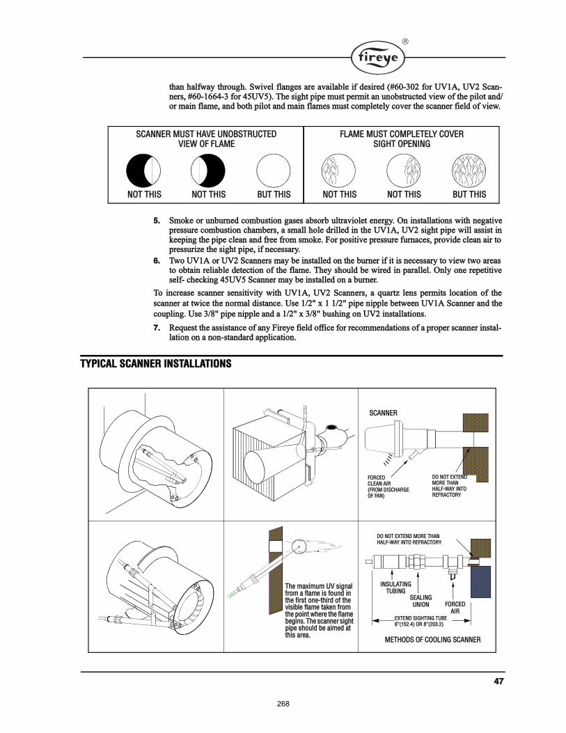
ìé
¬¸¿² ¸¿´º©¿§ ¬¸®±«¹¸ò Í©·ª»´ º´¿²¹» ¿®» ¿ª¿·´¿¾´» ·º ¼»·®»¼ øýêðóíðî º±® ËÊïßô ËÊî ͽ¿²ó²»®ô ýêðóïêêìóí º±® ìëËÊë÷ò ̸» ·¹¸¬ °·°» ³«¬ °»®³·¬ ¿² «²±¾¬®«½¬»¼ ª·»© ±º ¬¸» °·´±¬ ¿²¼ñ±® ³¿·² º´¿³»ô ¿²¼ ¾±¬¸ °·´±¬ ¿²¼ ³¿·² º´¿³» ³«¬ ½±³°´»¬»´§ ½±ª»® ¬¸» ½¿²²»® º·»´¼ ±º ª·»©ò
ëò ͳ±µ» ±® «²¾«®²»¼ ½±³¾«¬·±² ¹¿» ¿¾±®¾ «´¬®¿ª·±´»¬ »²»®¹§ò Ѳ ·²¬¿´´¿¬·±² ©·¬¸ ²»¹¿¬·ª»°®»«®» ½±³¾«¬·±² ½¸¿³¾»®ô ¿ ³¿´´ ¸±´» ¼®·´´»¼ ·² ¬¸» ËÊïßô ËÊî ·¹¸¬ °·°» ©·´´ ¿·¬ ·²µ»»°·²¹ ¬¸» °·°» ½´»¿² ¿²¼ º®»» º®±³ ³±µ»ò Ú±® °±·¬·ª» °®»«®» º«®²¿½»ô °®±ª·¼» ½´»¿² ¿·® ¬±°®»«®·¦» ¬¸» ·¹¸¬ °·°»ô ·º ²»½»¿®§ò
êò Ì©± ËÊïß ±® ËÊî ͽ¿²²»® ³¿§ ¾» ·²¬¿´´»¼ ±² ¬¸» ¾«®²»® ·º ·¬ · ²»½»¿®§ ¬± ª·»© ¬©± ¿®»¿¬± ±¾¬¿·² ®»´·¿¾´» ¼»¬»½¬·±² ±º ¬¸» º´¿³»ò ̸»§ ¸±«´¼ ¾» ©·®»¼ ·² °¿®¿´´»´ò Ѳ´§ ±²» ®»°»¬·¬·ª»»´ºó ½¸»½µ·²¹ ìëËÊë ͽ¿²²»® ³¿§ ¾» ·²¬¿´´»¼ ±² ¿ ¾«®²»®ò
̱ ·²½®»¿» ½¿²²»® »²·¬·ª·¬§ ©·¬¸ ËÊïßô ËÊî ͽ¿²²»®ô ¿ ¯«¿®¬¦ ´»² °»®³·¬ ´±½¿¬·±² ±º ¬¸»
½¿²²»® ¿¬ ¬©·½» ¬¸» ²±®³¿´ ¼·¬¿²½»ò Ë» ïñîþ ¨ ï ïñîþ °·°» ²·°°´» ¾»¬©»»² ËÊïß Í½¿²²»® ¿²¼ ¬¸»
½±«°´·²¹ò Ë» íñèþ °·°» ²·°°´» ¿²¼ ¿ ïñîþ ¨ íñèþ ¾«¸·²¹ ±² ËÊî ·²¬¿´´¿¬·±²ò
éò λ¯«»¬ ¬¸» ¿·¬¿²½» ±º ¿²§ Ú·®»§» º·»´¼ ±ºº·½» º±® ®»½±³³»²¼¿¬·±² ±º ¿ °®±°»® ½¿²²»® ·²¬¿´ó´¿¬·±² ±² ¿ ²±²ó¬¿²¼¿®¼ ¿°°´·½¿¬·±²ò
ÌÇÐ×ÝßÔ ÍÝßÒÒÛÎ ×ÒÍÌßÔÔßÌ×ÑÒÍ
ÍÝßÒÒÛÎ ÓËÍÌ ØßÊÛ ËÒÑÞÍÌÎËÝÌÛÜÊ×ÛÉ ÑÚ ÚÔßÓÛ
ÒÑÌ ÌØ×Í ÒÑÌ ÌØ×Í ÞËÌ ÌØ×Í
ÚÔßÓÛ ÓËÍÌ ÝÑÓÐÔÛÌÛÔÇ ÝÑÊÛÎÍ×ÙØÌ ÑÐÛÒ×ÒÙ
ÒÑÌ ÌØ×Í ÒÑÌ ÌØ×Í ÞËÌ ÌØ×Í
̸» ³¿¨·³«³ ËÊ ·¹²¿´ º®±³ ¿ º´¿³» · º±«²¼ ·² ¬¸» º·®¬ ±²»ó¬¸·®¼ ±º ¬¸» ª··¾´» º´¿³» ¬¿µ»² º®±³ ¬¸» °±·²¬ ©¸»®» ¬¸» º´¿³» ¾»¹·²ò ̸» ½¿²²»® ·¹¸¬ °·°» ¸±«´¼ ¾» ¿·³»¼ ¿¬ ¬¸· ¿®»¿ò
ÜÑ ÒÑÌ ÛÈÌÛÒÜÓÑÎÛ ÌØßÒØßÔÚóÉßÇ ×ÒÌÑÎÛÚÎßÝÌÑÎÇ
ÍÝßÒÒÛÎ
ÚÑÎÝÛÜÝÔÛßÒ ß×ÎøÚÎÑÓ Ü×ÍÝØßÎÙÛÑÚ ÚßÒ÷
ÓÛÌØÑÜÍ ÑÚ ÝÑÑÔ×ÒÙ ÍÝßÒÒÛÎ
×ÒÍËÔßÌ×ÒÙÌËÞ×ÒÙ
ÍÛßÔ×ÒÙ ËÒ×ÑÒ ÚÑÎÝÛÜ
ß×ÎÛÈÌÛÒÜ Í×ÙØÌ×ÒÙ ÌËÞÛêøïëîòì÷ ÑÎ èøîðíòî÷
ÜÑ ÒÑÌ ÛÈÌÛÒÜ ÓÑÎÛ ÌØßÒØßÔÚóÉßÇ ×ÒÌÑ ÎÛÚÎßÝÌÑÎÇ
268
ìè
ÑÐÛÎßÌ×ÑÒ ìëËÊë ÍÛÔÚóÝØÛÝÕ×ÒÙ ËÊ ÍÝßÒÒÛÎ
Í»´ºó½¸»½µ·²¹ «´¬®¿ª·±´»¬ ½¿²²»® ¸±«´¼ ¾» «»¼ ·² ¿°°´·½¿¬·±² ©¸»®» ¾«®²»® º·®·²¹ ±°»®¿¬·±² ·
½±²¬·²«±« ±® ©¸»®» ¬¸» ¾«®²»® · ±² º±® ´±²¹ °»®·±¼ ±º ¬·³» ©·¬¸±«¬ ®»½§½´·²¹ò ײ ¿¼¼·¬·±²ô «´¬®¿ó
ª·±´»¬ »´ºó½¸»½µ·²¹ §¬»³ ¿®» ³¿²¼¿¬±®§ ·² ±³» ´±½¿¬·±²ò
̸» ±°»®¿¬·±² ±º ¬¸· ¬§°» ±º §¬»³ ½±²·¬ ±º ³¿·²¬¿·²·²¹ ¬¸» º´¿³» ½¿²²·²¹ ½¿°¿¾·´·¬§ ¿¬ ¿´´ ¬·³»
©¸·´» ¿´± °®±ª·²¹ ¬¸¿¬ ¬¸» «´¬®¿ª·±´»¬ ¬«¾» · º·®·²¹ °®±°»®´§ò ̸· · ¼±²» °»®·±¼·½¿´´§ ¾§ ³»½¸¿²·ó
½¿´´§ ½´±·²¹ ±ºº ¬¸» ·¹¸¬ ±º ¬¸» ËÊ ¬«¾» ¿²¼ ½¸»½µ·²¹ ¬± ³¿µ» «®» ¬¸¿¬ ¬¸» º´¿³» ·¹²¿´ ¹±» ¿©¿§ò
ß ¸«¬¬»® ¿»³¾´§ ·² ¬¸» ìëËÊë ½¿²²»® °»®º±®³ ¬¸· º«²½¬·±²ò ̸» ¼·¿¹®¿³ ¾»´±© »¨°´¿·² ¬¸»
°®±½» º«®¬¸»®ò
׺ ¬¸» ¸«¬¬»® ¿»³¾´§ ·² ¬¸» ½¿²²»® º¿·´ô ¬¸» ¬«¾» · º¿«´¬§ô ±® ¬¸»®» · ·²«ºº·½·»²¬ °±©»® ¬± ¬¸»
½¿²²»®ô ¬¸» Ó·½®±Ó ©·´´ ÔÑÝÕÑËÌ ¿²¼ ¼·°´¿§ ¬¸» º±´´±©·²¹ ³»¿¹» ÔÑÝÕÑËÌ ÝØÛÝÕ
ÍÝßÒÒÛÎò ̸» «´¬®¿ª·±´»¬ ¬«¾» · ®»°´¿½»¿¾´» øÐñÒ ìóíïìóï÷ò
ß ´±½µ±«¬ ©·´´ ®»«´¬ ·º ¿ ³·²·³«³ ·¹²¿´ · ¼»¬»½¬»¼ º±® ¬¸®»» ½±²»½«¬·ª» ¸«¬¬»® ½´±»¼ °»®·±¼ò
É×Î×ÒÙ ó ËÊ ÍÝßÒÒÛÎÍ
̱ ½±²²»½¬ ¬¸» ½¿²²»® ¬± ¬¸» ½±²¬®±´ô ¬¸» ËÊïß Í½¿²²»® · «°°´·»¼ ©·¬¸ íê ±® éî ±º º´»¨·¾´»
½¿¾´»ò
̸» ìëËÊë · «°°´·»¼ ©·¬¸ º±«® éî ·²½¸ ´»¿¼ ©·®»ò ײ¬¿´´ ¬¸»³ ·² ¿ «·¬¿¾´» ´»²¹¬¸ ±º º´»¨·¾´»
¿®³±® ½¿¾´» ¿²¼ ½±²²»½¬ ·¬ ¬± ¬¸» ½±²¬®±´ò ß ½±²¼«·¬ ½±²²»½¬±® · «°°´·»¼ ©·¬¸ ¬¸» ½¿²²»®ò ݱ²²»½¬
¾´¿½µ ©·®» ø¸«¬¬»®÷ ¬± ¬»®³·²¿´ Ôïô Ôîå ®»¼ ©·®» øËÊ ¬«¾»÷ ¬± ¬»®³·²¿´ Íïô Íîò
׺ ·¬ · ²»½»¿®§ ¬± »¨¬»²¼ ¬¸» ½¿²²»® ©·®·²¹ô ¬¸» º±´´±©·²¹ ·²¬®«½¬·±² ¿°°´§æ
ͽ¿²²»® ©·®» ¸±«´¼ ¾» ·²¬¿´´»¼ ·² ¿ »°¿®¿¬» ½±²¼«·¬ò ̸» ©·®» º®±³ »ª»®¿´ ½¿²²»® ³¿§ ¾»
·²¬¿´´»¼ ·² ¿ ½±³³±² ½±²¼«·¬ò
ïò Í»´»½¬·±² ±º É·®»
¿ò É·®·²¹æ Ú±® »¨¬»²¼»¼ ½¿²²»® ©·®·²¹ «° ¬± ëð𠺻»¬ô ¿²¼ º±® ¸±®¬»® ´»²¹¬¸ ¬± ®»¼«½» ·¹²¿´
´±ô «» ¿ ¸·»´¼»¼ ©·®» øÞ»´¼»² èîëìóÎÙêî ½±¿¨·¿´ ½¿¾´»ô ±® »¯«¿´÷ º±® »¿½¸ ½¿²²»® ©·®»
±º ËÊïßô ËÊî ¿²¼ »¿½¸ ®»¼ ©·®» ±º ¬¸» ìëËÊëò ̸» »²¼ ±º ¬¸» ¸·»´¼·²¹ ³«¬ ¾» ¬¿°»¼
¿²¼ ²±¬ ¹®±«²¼»¼ò
¾ò ß¾»¬± ·²«´¿¬»¼ ©·®» ¸±«´¼ ¾» ¿ª±·¼»¼ò
½ò Ó«´¬·½±²¼«½¬±® ½¿¾´» · ²±¬ ®»½±³³»²¼»¼ ©·¬¸±«¬ °®·±® º¿½¬±®§ ¿°°®±ª¿´ò
îò Ø·¹¸ ª±´¬¿¹» ·¹²·¬·±² ©·®·²¹ ¸±«´¼ ²±¬ ¾» ·²¬¿´´»¼ ·² ¬¸» ¿³» ½±²¼«·¬ ©·¬¸ º´¿³» ¼»¬»½¬±®©·®»ò
ÍØËÌÌÛÎ ÑÐÛÒ
ÍØËÌÌÛÎ ÝÔÑÍÛÜ
íòé ÍÛÝò
ðòì ÍÛÝò Ì×ÓÛ
269
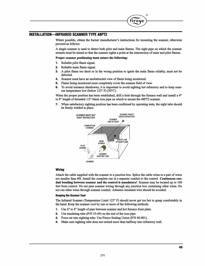
ìç
×ÒÍÌßÔÔßÌ×ÑÒ×ÒÚÎßÎÛÜ ÍÝßÒÒÛÎ ÌÇÐÛ ìèÐÌî
ɸ»®» °±·¾´»ô ±¾¬¿·² ¬¸» ¾«®²»® ³¿²«º¿½¬«®»® ·²¬®«½¬·±² º±® ³±«²¬·²¹ ¬¸» ½¿²²»®ô ±¬¸»®©·»
°®±½»»¼ ¿ º±´´±©æ
ß ·²¹´» ½¿²²»® · «»¼ ¬± ¼»¬»½¬ ¾±¬¸ °·´±¬ ¿²¼ ³¿·² º´¿³»ò ̸» ·¹¸¬ °·°» ±² ©¸·½¸ ¬¸» ½¿²²»®
³±«²¬ ³«¬ ¾» ¿·³»¼ ± ¬¸¿¬ ¬¸» ½¿²²»® ·¹¸¬ ¿ °±·²¬ ¿¬ ¬¸» ·²¬»®»½¬·±² ±º ³¿·² ¿²¼ °·´±¬ º´¿³»ò
Ю±°»® ½¿²²»® °±·¬·±²·²¹ ³«¬ ¿«®» ¬¸» º±´´±©·²¹æ
ïò λ´·¿¾´» °·´±¬ º´¿³» ·¹²¿´ò
îò λ´·¿¾´» ³¿·² º´¿³» ·¹²¿´ò
íò ß °·´±¬ º´¿³» ¬±± ¸±®¬ ±® ·² ¬¸» ©®±²¹ °±·¬·±² ¬± ·¹²·¬» ¬¸» ³¿·² º´¿³» ®»´·¿¾´§ô ³«¬ ²±¬ ¾»¼»¬»½¬»¼ò
ìò ͽ¿²²»® ³«¬ ¸¿ª» ¿² «²±¾¬®«½¬»¼ ª·»© ±º º´¿³» ¾»·²¹ ³±²·¬±®»¼ò
ëò Ú´¿³» ¾»·²¹ ³±²·¬±®»¼ ³«¬ ½±³°´»¬»´§ ½±ª»® ¬¸» ½¿²²»® º·»´¼ ±º ª·»©ò
êò ̱ ¿ª±·¼ ²«·¿²½» ¸«¬¼±©²ô ·¬ · ·³°±®¬¿²¬ ¬± ¿ª±·¼ ·¹¸¬·²¹ ¸±¬ ®»º®¿½¬±®§ ¿²¼ ¬± µ»»° ½¿²ó²»® ¬»³°»®¿¬«®» ´±© ø¾»´±© ïîëp Ú÷ øëðpÝ÷ò
ɸ»² ¬¸» °®±°»® °±·¬·±² ¸¿ ¾»»² »¬¿¾´·¸»¼ô ¼®·´´ ¿ ¸±´» ¬¸®±«¹¸ ¬¸» º«®²¿½» ©¿´´ ¿²¼ ·²¬¿´´ ¿ ìþ
¬± èþ ´»²¹¬¸ ±º ¬¸®»¿¼»¼ ïñîþ ¾´¿½µ ·®±² °·°» ±² ©¸·½¸ ¬± ³±«²¬ ¬¸» ìèÐÌî ½¿²²»®ò
éò ɸ»² ¿¬·º¿½¬±®§ ·¹¸¬·²¹ °±·¬·±² ¸¿ ¾»»² ½±²º·®³»¼ ¾§ ±°»®¿¬·²¹ ¬»¬ô ¬¸» ·¹¸¬ ¬«¾» ¸±«´¼¾» º·®³´§ ©»´¼»¼ ·² °´¿½»ò
É·®·²¹
߬¬¿½¸ ¬¸» ½¿¾´» «°°´·»¼ ©·¬¸ ¬¸» ½¿²²»® ¬± ¿ ¶«²½¬·±² ¾±¨ò Í°´·½» ¬¸» ½¿¾´» ©·®» ¬± ¿ °¿·® ±º ©·®»
²±¬ ³¿´´»® ¬¸¿² ý´èò ײ¬¿´´ ¬¸» ½±³°´»¬» ®«² ·² ¿ »°¿®¿¬» ½±²¼«·¬ ¬± ¬¸» ½±²¬®±´ò ݱ²¬·²«±« ½±²ó
¼«·¬ ¾±²¼·²¹ ¾»¬©»»² ½¿²²»® ¿²¼ ¬¸» ½±²¬®±´ · ³¿²¼¿¬±®§ÿ ͽ¿²²»® ³¿§ ¾» ´±½¿¬»¼ «° ¬± ïðð
º»»¬ º®±³ ½±²¬®±´ò ܱ ²±¬ °¿ ½¿²²»® ©·®·²¹ ¬¸®±«¹¸ ¿²§ ¶«²½¬·±² ¾±¨ ½±²¬¿·²·²¹ ±¬¸»® ©·®»ò ܱ
²±¬ ®«² ±¬¸»® ©·®» ¬¸®±«¹¸ ½¿²²»® ½±²¼«·¬ò ß¾»¬± ·²«´¿¬»¼ ©·®» ¸±«´¼ ¾» ¿ª±·¼»¼ò
Õ»»°·²¹ ¬¸» ͽ¿²²»® ݱ±´
̸» ײº®¿®»¼ ͽ¿²²»® øÌ»³°»®¿¬«®» Ô·³·¬ ïîëp Ú÷ ¸±«´¼ ²»ª»® ¹»¬ ¬±± ¸±¬ ¬± ¹®¿° ½±³º±®¬¿¾´§ ·²
¬¸» ¸¿²¼ò Õ»»° ¬¸» ½¿²²»® ½±±´ ¾§ ±²» ±® ³±®» ±º ¬¸» º±´´±©·²¹ ³»¬¸±¼ò
ïò Ë» êþ ¬± èþ ´»²¹¬¸ ±º °·°» ¾»¬©»»² ½¿²²»® ¿²¼ ¸±¬ º«®²¿½» º®±²¬ °´¿¬»ò
îò Ë» ·²«´¿¬·²¹ ¬«¾» øÐñÒ íëóêç÷ ±² ¬¸» »²¼ ±º ¬¸» ·®±² °·°»ò
íò Ú±®½» ¿·® ·²¬± ·¹¸¬·²¹ ¬«¾»ò Ë» Ú·®»§» Í»¿´·²¹ ˲·±² øÐñÒ êðóèðï÷ò
ìò Ó¿µ» «®» ·¹¸¬·²¹ ¬«¾» ¼±» ²±¬ »¨¬»²¼ ³±®» ¬¸¿² ¸¿´º©¿§ ·²¬± ®»º®¿½¬±®§ ©¿´´ò
ÝÛÒÌÛÎ Ô×ÒÛÑÚ Óß×Ò ÚÔßÓÛ
ÍÝßÒÒÛÎÔ×ÒÛóÑÚóÍ×ÙØÌ
ÍÝßÒÒÛÎ ÌßÎÙÛÌßÞÑÊÛ ÎÛÚÎßÝÌÑÎÇ
ÝÑÓÞËÍÌ×ÑÒÝØßÓÞÛÎ
Ð×ÔÑÌÞËÎÒÛÎ
ÍÝßÒÒÛÎ
ÍÝßÒÒÛÎÍ×ÙØÌ×ÒÙ ÌËÞÛ
Óß×ÒÞËÎÒÛÎ
ÍÝßÒÒÛÎ ÓËÍÌ ÒÑÌÍ×ÙØÌ ÎÛÚÎßÝÌÑÎÇ
270
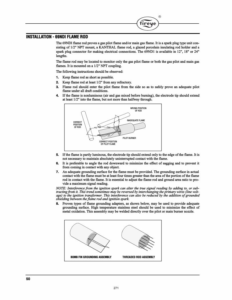
ëð
×ÒÍÌßÔÔßÌ×ÑÒ ó êçÒÜ´ ÚÔßÓÛ ÎÑÜ
̸» êçÒÜ´ º´¿³» ®±¼ °®±ª» ¿ ¹¿ °·´±¬ º´¿³» ¿²¼ñ±® ³¿·² ¹¿ º´¿³»ò ׬ · ¿ °¿®µ °´«¹ ¬§°» «²·¬ ½±²ó
·¬·²¹ ±º ïñîþ ÒÐÌ ³±«²¬ô ¿ ÕßÒÌØßÔ º´¿³» ®±¼ô ¿ ¹´¿¦»¼ °±®½»´¿·² ·²«´¿¬·²¹ ®±¼ ¸±´¼»® ¿²¼ ¿
°¿®µ °´«¹ ½±²²»½¬±® º±® ³¿µ·²¹ »´»½¬®·½¿´ ½±²²»½¬·±²ò ̸» êçÒÜï · ¿ª¿·´¿¾´» ·² ïîþô ïèþ ±® îìþ
´»²¹¬¸ò
̸» º´¿³» ®±¼ ³¿§ ¾» ´±½¿¬»¼ ¬± ³±²·¬±® ±²´§ ¬¸» ¹¿ °·´±¬ º´¿³» ±® ¾±¬¸ ¬¸» ¹¿ °·´±¬ ¿²¼ ³¿·² ¹¿
º´¿³»ò ׬ · ³±«²¬»¼ ±² ¿ ïñîþ ÒÐÌ ½±«°´·²¹ò
̸» º±´´±©·²¹ ·²¬®«½¬·±² ¸±«´¼ ¾» ±¾»®ª»¼æ
ïò Õ»»° º´¿³» ®±¼ ¿ ¸±®¬ ¿ °±·¾´»ò
îò Õ»»° º´¿³» ®±¼ ¿¬ ´»¿¬ ïñîþ º®±³ ¿²§ ®»º®¿½¬±®§ò
íò Ú´¿³» ®±¼ ¸±«´¼ »²¬»® ¬¸» °·´±¬ º´¿³» º®±³ ¬¸» ·¼» ± ¿ ¬± ¿º»´§ °®±ª» ¿² ¿¼»¯«¿¬» °·´±¬º´¿³» «²¼»® ¿´´ ¼®¿º¬ ½±²¼·¬·±²ò
ìò ׺ ¬¸» º´¿³» · ²±²´«³·²±« ø¿·® ¿²¼ ¹¿ ³·¨»¼ ¾»º±®» ¾«®²·²¹÷ô ¬¸» »´»½¬®±¼» ¬·° ¸±«´¼ »¨¬»²¼¿¬ ´»¿¬ ïñîþ ·²¬± ¬¸» º´¿³»ô ¾«¬ ²±¬ ³±®» ¬¸¿² ¸¿´º©¿§ ¬¸®±«¹¸ò
ëò ׺ ¬¸» º´¿³» · °¿®¬´§ ´«³·²±«ô ¬¸» »´»½¬®±¼» ¬·° ¸±«´¼ »¨¬»²¼ ±²´§ ¬± ¬¸» »¼¹» ±º ¬¸» º´¿³»ò ׬ ·²±¬ ²»½»¿®§ ¬± ³¿·²¬¿·² ¿¾±´«¬»´§ «²·²¬»®®«°¬»¼ ½±²¬¿½¬ ©·¬¸ ¬¸» º´¿³»ò
êò ׬ · °®»º»®¿¾´» ¬± ¿²¹´» ¬¸» ®±¼ ¼±©²©¿®¼ ¬± ³·²·³·¦» ¬¸» »ºº»½¬ ±º ¿¹¹·²¹ ¿²¼ ¬± °®»ª»²¬ ·¬º®±³ ½±³·²¹ ·² ½±²¬¿½¬ ©·¬¸ ¿²§ ±¾¶»½¬ò
éò ß² ¿¼»¯«¿¬» ¹®±«²¼·²¹ «®º¿½» º±® ¬¸» º´¿³» ³«¬ ¾» °®±ª·¼»¼ò ̸» ¹®±«²¼·²¹ «®º¿½» ·² ¿½¬«¿´½±²¬¿½¬ ©·¬¸ ¬¸» º´¿³» ³«¬ ¾» ¿¬ ´»¿¬ º±«® ¬·³» ¹®»¿¬»® ¬¸¿² ¬¸» ¿®»¿ ±º ¬¸» °±®¬·±² ±º ¬¸» º´¿³»®±¼ ·² ½±²¬¿½¬ ©·¬¸ ¬¸» º´¿³»ò ׬ · »»²¬·¿´ ¬± ¿¼¶«¬ ¬¸» º´¿³» ®±¼ ¿²¼ ¹®±«²¼ ¿®»¿ ®¿¬·± ¬± °®±óª·¼» ¿ ³¿¨·³«³ ·¹²¿´ ®»¿¼·²¹ò
ÒÑÌÛæ ײ¬»®º»®»²½» º®±³ ¬¸» ·¹²·¬·±² °¿®µ ½¿² ¿´¬»® ¬¸» ¬®«» ·¹²¿´ ®»¿¼·²¹ ¾§ ¿¼¼·²¹ ¬±ô ±® «¾ó¬®¿½¬·²¹ º®±³ ·¬ò ̸· ¬®»²¼ ±³»¬·³» ³¿§ ¾» ®»ª»®»¼ ¾§ ·²¬»®½¸¿²¹·²¹ ¬¸» °®·³¿®§ ©·®» ø´·²» ª±´¬ó¿¹»÷ ¬± ¬¸» ·¹²·¬·±² ¬®¿²º±®³»®ò ̸· ·²¬»®º»®»²½» ½¿² ¿´± ¾» ®»¼«½»¼ ¾§ ¬¸» ¿¼¼·¬·±² ±º ¹®±«²¼»¼¸·»´¼·²¹ ¾»¬©»»² ¬¸» º´¿³» ®±¼ ¿²¼ ·¹²·¬·±² °¿®µò
èò Ю±ª»² ¬§°» ±º º´¿³» ¹®±«²¼·²¹ ¿¼¿°¬»®ô ¿ ¸±©² ¾»´±©ô ³¿§ ¾» «»¼ ¬± °®±ª·¼» ¿¼»¯«¿¬»¹®±«²¼·²¹ «®º¿½»ò Ø·¹¸ ¬»³°»®¿¬«®» ¬¿·²´» ¬»»´ ¸±«´¼ ¾» «»¼ ¬± ³·²·³·¦» ¬¸» »ºº»½¬ ±º³»¬¿´ ±¨·¼¿¬·±²ò ̸· ¿»³¾´§ ³¿§ ¾» ©»´¼»¼ ¼·®»½¬´§ ±ª»® ¬¸» °·´±¬ ±® ³¿·² ¾«®²»® ²±¦¦´»ò
ÉÎÑÒÙ ÐÑÍ×Ì×ÑÒÑÚ ÎÑÜ
×ÒßÜÛÏËßÌÛ ÚÔßÓÛ
Ð×ÔÑÌ ÞËÎÒÛÎ
ÝÑÎÎÛÝÌ ÐÑÍ×Ì×ÑÒÑÚ Ð×ÔÑÌ ÚÔßÓÛ
ÝÑÎÎÛÝÌÐÑÍ×Ì×ÑÒÑÚ ÎÑÜ
ÞÑÓÞ Ú×Ò ÙÎÑËÒÜ×ÒÙ ßÍÍÛÓÞÔÇ ÌØÎÛßÜÛÜ ÎÑÜ ßÍÍÛÓÞÔÇ
271
ëï
Óß×ÒÌÛÒßÒÝÛ
̧°» ìèÐÌî ײº®¿®»¼ ¿²¼ ̧°» ËÊïßô ËÊî ¿²¼ ìëËÊë Ë´¬®¿ª·±´»¬ ͽ¿²²»®
̸» ª·»©·²¹ ¿®»¿ ±º ¬¸» ½¿²²»® ³«¬ ¾» µ»°¬ ½´»¿²ò Ûª»² ¿ ³¿´´ ¿³±«²¬ ±º ½±²¬¿³·²¿¬·±² ©·´´
®»¼«½» ¬¸» º´¿³» ·¹²¿´ ®»¿½¸·²¹ ¬¸» ¼»¬»½¬±® ¾§ ¿ ³»¿«®¿¾´» ¿³±«²¬ò É·°» ¬¸» ª·»©·²¹ ¿®»¿ ®±«ó
¬·²»´§ «·²¹ ¿ ±º¬ ½´±¬¸ ¼¿³°»²»¼ ©·¬¸ ½±²½»²¬®¿¬»¼ ¼»¬»®¹»²¬ò
̧°» ìèÐÌî ͽ¿²²»® ·²½´«¼» ¿ ®»°´¿½»¿¾´» ýìóîêíóï Ú·®»¬®±² ½»´´ò
̧°» ìëËÊë ͽ¿²²»® ·²½´«¼» ¿ ®»°´¿½»¿¾´» ýìóíïìóï ËÊ ¬«¾»ò
̧°» êçÒÜï Ú´¿³» α¼
̸» º´¿³» ®±¼ ¿²¼ ·¬ ·²«´¿¬±® ¸±«´¼ ¾» µ»°¬ ½´»¿² ¾§ ©¿¸·²¹ ®±«¬·²»´§ ©·¬¸ ±¿° ¿²¼ ©¿¬»®ò α¼
¸±«´¼ ¾» ®±«¬·²»´§ ®»°´¿½»¼ ¿ ¬¸»§ ±¨·¼·¦»ò
Ú´¿³» Í·¹²¿´ ͬ®»²¹¬¸
᫬·²» ±¾»®ª¿¬·±² ±º ¬¸» º´¿³» ·¹²¿´ ¬®»²¹¬¸ ©·´´ º±®»©¿®² ¿²§ ¼»¬»®·±®¿¬·±² ·² ¬¸» ½¿°¿¾·´·¬§ ±º
¬¸» º´¿³» ¼»¬»½¬±® ±® ·¬ ¿°°´·½¿¬·±²ò
ݱ²¬¿½¬
̸»®» ¿®» ²± ¿½½»·¾´» ½±²¬¿½¬ ·² ¬¸» Ó·½®±Óò ɸ»®» ½±²¬¿½¬ ¿®» «»¼ô ¬¸»·® ¼»·¹² ¿«®» ´±²¹
¬®±«¾´»óº®»» ´·º» ©¸»² ¬¸» ´±¿¼ ½·®½«·¬ ¿®» ³¿·²¬¿·²»¼ ©·¬¸·² ¬¸» °«¾´·¸»¼ ´±¿¼ ®¿¬·²¹ò
Ø«³·¼·¬§
ײ ¿®»¿ ±º ¸·¹¸ ¸«³·¼·¬§ô ¬¸» ½±²¬®±´ ½¸¿· ¸±«´¼ ¾» ®»³±ª»¼ ¿²¼ °´¿½»¼ ·² ¿ ¼®§ ¿¬³±°¸»®»
©¸»² ¬¸» §¬»³ · »¨°»½¬»¼ ¬± ¾» ±«¬ ±º »®ª·½» º±® ¿² »¨¬»²¼»¼ °»®·±¼ò
л®·±¼·½ Í¿º»¬§ ݸ»½µ
׬ · ®»½±³³»²¼»¼ ¬¸¿¬ ¿ °®±½»¼«®» ¾» »¬¿¾´·¸»¼ ¬± ¬»¬ ¬¸» ½±³°´»¬» º´¿³» ¿º»¹«¿®¼ §¬»³ ¿¬
´»¿¬ ±²½» ¿ ³±²¬¸ôò ̸· ¬»¬ ¸±«´¼ ª»®·º§ ¬¸» °®±°»® ±°»®¿¬·±² ±º ¿´´ ´·³·¬ ©·¬½¸» ¿²¼ ¿º»¬§ ·²¬»®ó
´±½µ ¿ ©»´´ ¿ º´¿³» º¿·´«®» °®±¬»½¬·±² ¿²¼ º«»´ ¿º»¬§ ¸«¬±ºº ª¿´ª» ¬·¹¸¬²»ò
ન¬·±²
׬ · ®»½±³³»²¼»¼ ¬¸¿¬ ½±²¬®±´ ¿²¼ ½¿²²»® «²·¬ °«®½¸¿»¼ ¿ °¿®» ¾» ·²¬¿´´»¼ °»®·±¼·½¿´´§ ¬±
»²«®» °®±°»® ±°»®¿¬·±²ò
272
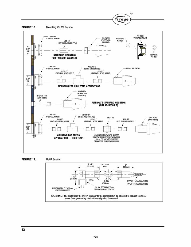
ëî
Ú×ÙËÎÛ ïêò Ó±«²¬·²¹ ìëËÊë ͽ¿²²»®
Ú×ÙËÎÛ ïéò ËÊèß Í½¿²²»®
îòéëøéð÷
ýêðóïêêìï ÍÉ×ÊÛÔ ÓÑËÒÌ
ýíëóïîéØÛßÌ ×ÒÍËÔßÌ×ÒÙ Ò×ÐÐÔÛ
ÍÌßÒÜßÎÜ ÓÑËÒÌ×ÒÙÚÑÎ ÌÇÐÛÍ ÑÚ ÍÝßÒÒÛÎÍ
ß×Î ÛÒÌÎÇøÐËÎÙÛ ßÒÜ
ÝÑÑÔ×ÒÙ÷
ýêðóïêêìï ÍÉ×ÊÛÔ ÓÑËÒÌ
ýíëóïîéØÛßÌ ×ÒÍËÔßÌ×ÒÙ Ò×ÐÐÔÛ
ÓÑËÒÌ×ÒÙ ÚÑÎ Ø×ÙØ ÌÛÓÐò ßÐÐÔ×ÝßÌ×ÑÒÍ
ÐËÎÙÛ ß×Î ÛÒÌÎÇß×ÎñÛÒÌÎÇ
øÐËÎÙÛ ßÞÜ ÝÑÑÔ×ÒÙ÷
ýíëóïîéØÛßÌ ×ÒÍËÔßÌ×ÒÙ Ò×ÐÐÔÛ
ï Í×ÙØÌ Ð×ÐÛøÞÇ ÑÌØÛÎÍ÷
ß×Î ÛÒÌÎÇøÐËÎÙÛ ßÒÜ
ÝÑÑÔ×ÒÙ÷
ßÔÌÛÎÒßÌÛ ÍÌßÒÜßÎÜ ÓÑËÒÌ×ÒÙøÒÑÌ ßÜÖËÍÌßÞÔÛ÷
ýêðóïêêìï ÍÉ×ÊÛÔ ÓÑËÒÌ
ýíëóïîéØÛßÌ ×ÒÍËÔßÌ×ÒÙ Ò×ÐÐÔÛ
ÓÑËÒÌ×ÒÙ ÚÑÎ ÍÐÛÝ×ßÔßÐÐÔ×ÝßÌ×ÑÒÍ Ø×ÙØ ÌÛÓÐò
íñè ÐÔËÙøÞÇ ÑÌØÛÎÍ÷
ß×ÎñÛÒÌÎÇøÐËÎÙÛ ßÒÜ ÝÑÑÔ×ÒÙ÷
ýíëóïîéØÛßÌ ×ÒÍËÔßÌ×ÒÙ Ò×ÐÐÔÛ
ýíëóïîéØÛßÌ ×ÒÍËÔßÌ×ÒÙ Ò×ÐÐÔÛ
ýêðóïïçç
ÍÛßÔ×ÒÙ É×ÒÜÑÉ É×ÌØ ÏËßÎÌÆÉ×ÒÜÑÉò ÎÛÏË×ÎÛÜ ÉØÛÒ ÍÝßÒÒÛÎ
ÔÛÒÍ ×Í ÛÈÐÑÍÛÜ ÌÑ ÛÈÝÛÍÍ×ÊÛÚËÎÒßÝÛ ÑÎ É×ÒÜÞÑÈ ÐÎÛÍÍËÎÛ
ßÐÛÎÌËÎÛýëíóïîï
ýêðóïêêìï ÍÉ×ÊÛÔ ÓÑËÒÌ
ÎÛÌß×ÒÛÎýíìóïèï
îòéëøéð÷
îòéëøéð÷
î ïñìøëéòî³³÷
ËÊïßí í ÚÌò ÚÔÛÈ×ÞÔÛ ÝßÞÔÛ
ËÊïßê ê ÚÌò ÚÔÛÈ×ÞÔÛ ÝßÞÔÛ
ï ïñîøíèòïÓÓ÷
ËÊèß
ïñî È ïì ÍÌòÐ×ÐÛ
ï ×Òò Ü×ßòøîëòì³³÷
îøëðòè³³÷
ÍØ×ÛÔÜ×ÒÙ ÑÚ ê ÚÌò øïèíð³³÷ÔÛßÜÍ ×Í ÎÛÏË×ÎÛÜ
òéðð Ü×ßò Ú×ÌÌ×ÒÙ øïéòè³³÷ÚÑÎ ÉßÌÛÎóÌ×ÙØÌ ÝÑÒÜË×Ì
ÉßÎÒ×ÒÙæ ̸» ´»¿¼ º®±³ ¬¸» ËÊèß Í½¿²²»® ¬± ¬¸» ½±²¬®±´ ³«¬ ¾» ¸·»´¼»¼ ¬± °®»ª»²¬ »´»½¬®·½¿´ ²±·» º®±³ ¹»²»®¿¬·²¹ ¿ º¿´» º´¿³» ·¹²¿´ ¬± ¬¸» ½±²¬®±´ò
273
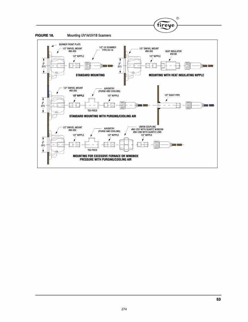
ëí
Ú×ÙËÎÛ ïèò Ó±«²¬·²¹ ËÊïßñËÊïÞ Í½¿²²»®
ËÒ×ÑÒ ÝÑËÐÔ×ÒÙýêðóïîëé É×ÌØ ÏËßÎÌÆ É×ÒÜÑÉ
ýêðóïîçð É×ÌØ ÏËßÎÌÆ ÔÛÒÍ
îøëï÷
ïñî Ò×ÐÐÔÛ
ØÛßÌ ×ÒÍËÔßÌÑÎýíëóêç
ïñî ÍÉ×ÊÛÔ ÓÑËÒÌýêðóíðî
ÓÑËÒÌ×ÒÙ É×ÌØ ØÛßÌ ×ÒÍËÔßÌ×ÒÙ Ò×ÐÐÔÛ
ïñî Ò×ÐÐÔÛ
ïñî ÍÉ×ÊÛÔ ÓÑËÒÌýêðóíðî
ÍÌßÒÜßÎÜ ÓÑËÒÌ×ÒÙ
ÞËÎÒÛÎ ÚÎÑÒÌ ÐÔßÌÛ
ïñî ËÊ ÍÝßÒÒÛÎÌÇÐÛ ËÊóïß
ïñî Ò×ÐÐÔÛ
ïñî ÍÉ×ÊÛÔ ÓÑËÒÌýêðóíðî
ÍÌßÒÜßÎÜ ÓÑËÒÌ×ÒÙ É×ÌØ ÐËÎÙ×ÒÙñÝÑÑÔ×ÒÙ ß×Î
ïñî Ò×ÐÐÔÛ ïñî Ò×ÐÐÔÛ
ÌÛÛóÐ×ÛÝÛ
ïñî Ò×ÐÐÔÛ
ïñî ÍÉ×ÊÛÔ ÓÑËÒÌýêðóíðî
ÓÑËÒÌ×ÒÙ ÚÑÎ ÛÈÝÛÍÍ×ÊÛ ÚËÎÒßÝÛ ÑÎ É×ÒÜÞÑÈÐÎÛÍÍËÎÛ É×ÌØ ÐËÎÙ×ÒÙñÝÑÑÔ×ÒÙ ß×Î
ïñî Ò×ÐÐÔÛ
ÌÛÛóÐ×ÛÝÛ
ïñî Ò×ÐÐÔÛ
ß×ÎñÛÒÌÎÇøÐËÎÙÛ ßÞÜ ÝÑÑÔ×ÒÙ÷
ïñî Í×ÙØÌ Ð×ÐÛ
ß×ÎñÛÒÌÎÇøÐËÎÙÛ ßÒÜ ÝÑÑÔ×ÒÙ÷
îøëï÷
îøëï÷
îøëï÷
274
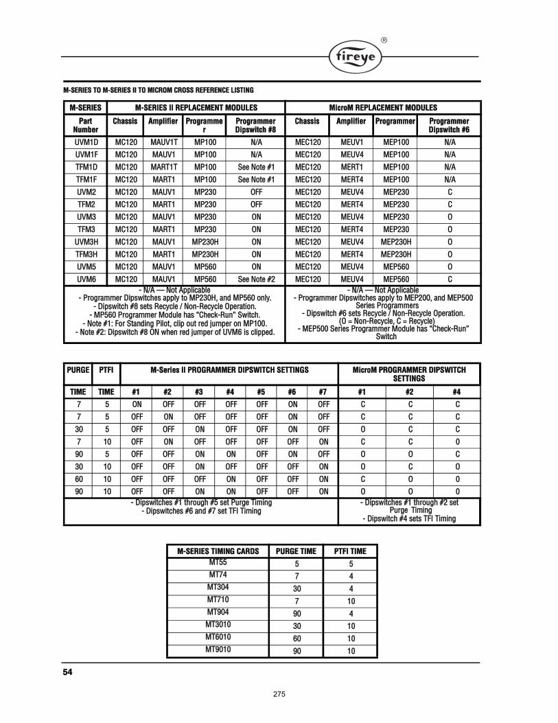
ëì
ÓóÍÛÎ×ÛÍ ÌÑ ÓóÍÛÎ×ÛÍ ×× ÌÑ Ó×ÝÎÑÓ ÝÎÑÍÍ ÎÛÚÛÎÛÒÝÛ Ô×ÍÌ×ÒÙ
ÓóÍÛÎ×ÛÍ ÓóÍÛÎ×ÛÍ ×× ÎÛÐÔßÝÛÓÛÒÌ ÓÑÜËÔÛÍ Ó·½®±Ó ÎÛÐÔßÝÛÓÛÒÌ ÓÑÜËÔÛÍ
ﮬ Ò«³¾»®
ݸ¿· ß³°´·º·»® Ю±¹®¿³³»®
Ю±¹®¿³³»®Ü·°©·¬½¸ ýè
ݸ¿· ß³°´·º·»® Ю±¹®¿³³»® Ю±¹®¿³³»®Ü·°©·¬½¸ ýê
ËÊÓïÜ ÓÝïîð ÓßËÊïÌ ÓÐïðð Òñß ÓÛÝïîð ÓÛËÊï ÓÛÐïðð Òñß
ËÊÓïÚ ÓÝïîð ÓßËÊï ÓÐïðð Òñß ÓÛÝïîð ÓÛËÊì ÓÛÐïðð Òñß
ÌÚÓïÜ ÓÝïîð ÓßÎÌïÌ ÓÐïðð Í»» Ò±¬» ýï ÓÛÝïîð ÓÛÎÌï ÓÛÐïðð Òñß
ÌÚÓïÚ ÓÝïîð ÓßÎÌï ÓÐïðð Í»» Ò±¬» ýï ÓÛÝïîð ÓÛÎÌì ÓÛÐïðð Òñß
ËÊÓî ÓÝïîð ÓßËÊï ÓÐîíð ÑÚÚ ÓÛÝïîð ÓÛËÊì ÓÛÐîíð Ý
ÌÚÓî ÓÝïîð ÓßÎÌï ÓÐîíð ÑÚÚ ÓÛÝïîð ÓÛÎÌì ÓÛÐîíð Ý
ËÊÓí ÓÝïîð ÓßËÊï ÓÐîíð ÑÒ ÓÛÝïîð ÓÛËÊì ÓÛÐîíð Ñ
ÌÚÓí ÓÝïîð ÓßÎÌï ÓÐîíð ÑÒ ÓÛÝïîð ÓÛÎÌì ÓÛÐîíð Ñ
ËÊÓíØ ÓÝïîð ÓßËÊï ÓÐîíðØ ÑÒ ÓÛÝïîð ÓÛËÊì ÓÛÐîíðØ Ñ
ÌÚÓíØ ÓÝïîð ÓßÎÌï ÓÐîíðØ ÑÒ ÓÛÝïîð ÓÛÎÌì ÓÛÐîíðØ Ñ
ËÊÓë ÓÝïîð ÓßËÊï ÓÐëêð ÑÒ ÓÛÝïîð ÓÛËÊì ÓÛÐëêð Ñ
ËÊÓê ÓÝïîð ÓßËÊï ÓÐëêð Í»» Ò±¬» ýî ÓÛÝïîð ÓÛËÊì ÓÛÐëêð Ý
ó Òñß Ò±¬ ß°°´·½¿¾´»ó Ю±¹®¿³³»® Ü·°©·¬½¸» ¿°°´§ ¬± ÓÐîíðØô ¿²¼ ÓÐëêð ±²´§ò
ó Ü·°©·¬½¸ ýè »¬ 뽧½´» ñ Ò±²ó뽧½´» Ñ°»®¿¬·±²ò ó ÓÐëêð Ю±¹®¿³³»® Ó±¼«´» ¸¿ ݸ»½µóΫ² Í©·¬½¸ò
ó Ò±¬» ýïæ Ú±® ͬ¿²¼·²¹ з´±¬ô ½´·° ±«¬ ®»¼ ¶«³°»® ±² ÓÐïððò ó Ò±¬» ýîæ Ü·°©·¬½¸ ýè ÑÒ ©¸»² ®»¼ ¶«³°»® ±º ËÊÓê · ½´·°°»¼ò
ó Òñß Ò±¬ ß°°´·½¿¾´»ó Ю±¹®¿³³»® Ü·°©·¬½¸» ¿°°´§ ¬± ÓÛÐîððô ¿²¼ ÓÛÐëðð
Í»®·» Ю±¹®¿³³»®ó Ü·°©·¬½¸ ýê »¬ 뽧½´» ñ Ò±²ó뽧½´» Ñ°»®¿¬·±²ò
øÑ ã Ò±²ó뽧½´»ô Ý ã 뽧½´»÷ó ÓÛÐëðð Í»®·» Ю±¹®¿³³»® Ó±¼«´» ¸¿ ݸ»½µóΫ²
Í©·¬½ò
ÐËÎÙÛ ÐÌÚ× ÓóÍ»®·» ×× ÐÎÑÙÎßÓÓÛÎ Ü×ÐÍÉ×ÌÝØ ÍÛÌÌ×ÒÙÍ Ó·½®±Ó ÐÎÑÙÎßÓÓÛÎ Ü×ÐÍÉ×ÌÝØ ÍÛÌÌ×ÒÙÍ
Ì×ÓÛ Ì×ÓÛ ýï ýî ýí ýì ýë ýê ýé ýï ýî ýì
é ë ÑÒ ÑÚÚ ÑÚÚ ÑÚÚ ÑÚÚ ÑÒ ÑÚÚ Ý Ý Ý
é ë ÑÚÚ ÑÒ ÑÚÚ ÑÚÚ ÑÚÚ ÑÒ ÑÚÚ Ý Ý Ý
íð ë ÑÚÚ ÑÚÚ ÑÒ ÑÚÚ ÑÚÚ ÑÒ ÑÚÚ Ñ Ý Ý
é ïð ÑÚÚ ÑÒ ÑÚÚ ÑÚÚ ÑÚÚ ÑÚÚ ÑÒ Ý Ý ð
çð ë ÑÚÚ ÑÚÚ ÑÒ ÑÒ ÑÚÚ ÑÒ ÑÚÚ Ñ Ñ Ý
íð ïð ÑÚÚ ÑÚÚ ÑÒ ÑÚÚ ÑÚÚ ÑÚÚ ÑÒ Ñ Ý Ñ
êð ïð ÑÚÚ ÑÚÚ ÑÚÚ ÑÒ ÑÚÚ ÑÚÚ ÑÒ Ý Ñ ð
çð ïð ÑÚÚ ÑÚÚ ÑÒ ÑÒ ÑÚÚ ÑÚÚ ÑÒ Ñ Ñ ð
ó Ü·°©·¬½¸» ýï ¬¸®±«¹¸ ýë »¬ Ы®¹» Ì·³·²¹ó Ü·°©·¬½¸» ýê ¿²¼ ýé »¬ ÌÚ× Ì·³·²¹
ó Ü·°©·¬½¸» ýï ¬¸®±«¹¸ ýî »¬ Ы®¹» Ì·³·²¹
ó Ü·°©·¬½¸ ýì »¬ ÌÚ× Ì·³·²¹
ÓóÍÛÎ×ÛÍ Ì×Ó×ÒÙ ÝßÎÜÍ ÐËÎÙÛ Ì×ÓÛ ÐÌÚ× Ì×ÓÛ
ÓÌëë ë ë
ÓÌéì é ì
ÓÌíðì íð ì
ÓÌéïð é ïð
ÓÌçðì çð ì
ÓÌíðïð íð ïð
ÓÌêðïð êð ïð
ÓÌçðïð çð ïð
275
ëë
276
ÒÑÌ×ÝÛ
ɸ»² Ú·®»§» °®±¼«½¬ ¿®» ½±³¾·²»¼ ©·¬¸ »¯«·°³»²¬ ³¿²«º¿½¬«®»¼ ¾§ ±¬¸»® ¿²¼ñ±® ·²¬»¹®¿¬»¼ ·²¬±
§¬»³ ¼»·¹²»¼ ±® ³¿²«º¿½¬«®»¼ ¾§ ±¬¸»®ô ¬¸» Ú·®»§» ©¿®®¿²¬§ô ¿ ¬¿¬»¼ ·² ·¬ Ù»²»®¿´ Ì»®³ ¿²¼
ݱ²¼·¬·±² ±º Í¿´»ô °»®¬¿·² ±²´§ ¬± ¬¸» Ú·®»§» °®±¼«½¬ ¿²¼ ²±¬ ¬± ¿²§ ±¬¸»® »¯«·°³»²¬ ±® ¬± ¬¸» ½±³ó
¾·²»¼ §¬»³ ±® ·¬ ±ª»®¿´´ °»®º±®³¿²½»ò
ÉßÎÎßÒÌ×ÛÍ
Ú×ÎÛÇÛ ¹«¿®¿²¬»» º±® ±²» §»¿® º®±³ ¬¸» ¼¿¬» ±º ·²¬¿´´¿¬·±² ±® ïè ³±²¬¸ º®±³ ¼¿¬» ±º ³¿²«º¿½¬«®»
±º ·¬ °®±¼«½¬ ¬± ®»°´¿½»ô ±®ô ¿¬ ·¬ ±°¬·±²ô ¬± ®»°¿·® ¿²§ °®±¼«½¬ ±® °¿®¬ ¬¸»®»±º ø»¨½»°¬ ´¿³° ¿²¼ °¸±ó
¬±½»´´÷ ©¸·½¸ · º±«²¼ ¼»º»½¬·ª» ·² ³¿¬»®·¿´ ±® ©±®µ³¿²¸·° ±® ©¸·½¸ ±¬¸»®©·» º¿·´ ¬± ½±²º±®³ ¬±
¬¸» ¼»½®·°¬·±² ±º ¬¸» °®±¼«½¬ ±² ¬¸» º¿½» ±º ·¬ ¿´» ±®¼»®ò ÌØÛ ÚÑÎÛÙÑ×ÒÙ ×Í ×Ò Ô×ÛË ÑÚ
ßÔÔ ÑÌØÛÎ ÉßÎÎßÒÌ×ÛÍ ßÒÜ Ú×ÎÛÇÛ ÓßÕÛÍ ÒÑ ÉßÎÎßÒÌÇ ÑÚ ÓÛÎÝØßÒÌó
ßÞ×Ô×ÌÇ ÑÎ ßÒÇ ÑÌØÛÎ ÉßÎÎßÒÌÇô ÛÈÐÎÛÍÍ ÑÎ ×ÓÐÔ×ÛÜò Û¨½»°¬ ¿ °»½·º·½¿´´§
¬¿¬»¼ ·² ¬¸»» ¹»²»®¿´ ¬»®³ ¿²¼ ½±²¼·¬·±² ±º ¿´»ô ®»³»¼·» ©·¬¸ ®»°»½¬ ¬± ¿²§ °®±¼«½¬ ±® °¿®¬ ²«³ó
¾»® ³¿²«º¿½¬«®»¼ ±® ±´¼ ¾§ Ú·®»§» ¸¿´´ ¾» ´·³·¬»¼ »¨½´«·ª»´§ ¬± ¬¸» ®·¹¸¬ ¬± ®»°´¿½»³»²¬ ±® ®»°¿·® ¿
¿¾±ª» °®±ª·¼»¼ò ײ ²± »ª»²¬ ¸¿´´ Ú·®»§» ¾» ´·¿¾´» º±® ½±²»¯«»²¬·¿´ ±® °»½·¿´ ¼¿³¿¹» ±º ¿²§ ²¿¬«®»
¬¸¿¬ ³¿§ ¿®·» ·² ½±²²»½¬·±² ©·¬¸ «½¸ °®±¼«½¬ ±® °¿®¬ò
Ú×ÎÛÇÛ ÓÝóëðððí Ó¿²½¸»¬»® α¿¼ ÑÝÌÑÞÛÎ ïìô îððçÜ»®®§ô Ò»© Ø¿³°¸·®» ðíðíè ËÍß Í«°»®»¼» Ö¿²«¿®§ çô îððç©©©òº·®»§»ò½±³
277
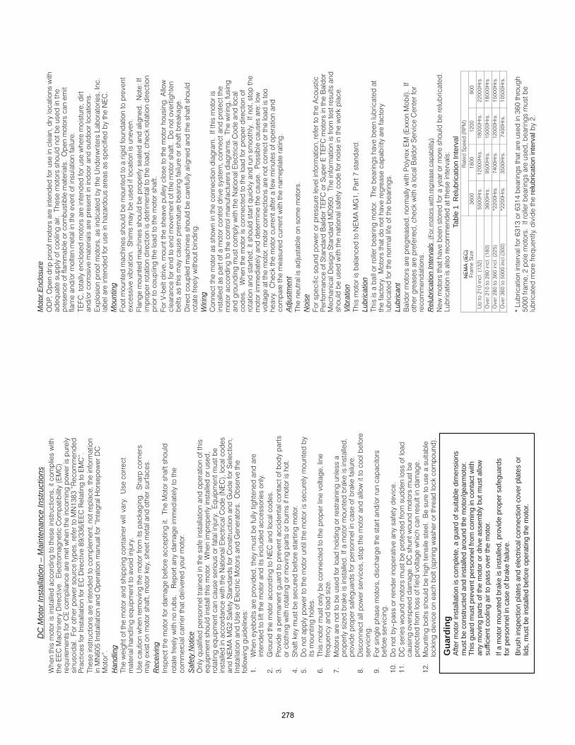
DC
Mot
or In
stal
latio
n –
Mai
nten
ance
Inst
ruct
ions
!
"!#$%&%'(
) !* !&+,%%-,( .
/ !
#-01* 2 !'* 3
.
Han
dlin
g/! 4
5
4 ! 6 7
8 !6 !
Rec
eivi
ng*! ! / !
!(
Safe
ty N
otic
e2 ! ! !
! 5
# #
#9:;7 !7 ! :!7
* 4! : 2
!<
$
!
!
;
: #
%
) !
!
=
7 !6!
1
-
/
! >
?
!
> 6 *! 6
! ! ! 6!
&
!
+
" ,
!
$0@ !
$$!!
!!!
$;A
6 6
Gu
ard
ing
Afte
r m
otor
inst
alla
tion
is c
ompl
ete,
a g
uard
of s
uita
ble
dim
ensi
ons
mus
t be
cons
truc
ted
and
inst
alle
d ar
ound
the
mot
or/g
earm
otor
.T
his
guar
d m
ust p
reve
nt p
erso
nnel
from
com
ing
in c
onta
ct w
ithan
y m
ovin
g pa
rts
of th
e m
otor
or
driv
e as
sem
bly
but m
ust a
llow
suffi
cien
t coo
ling
air
to p
ass
over
the
mot
or.
If a
mot
or m
ount
ed b
rake
is in
stal
led,
pro
vide
pro
per
safe
guar
dsfo
r pe
rson
nel i
n ca
se o
f bra
ke fa
ilure
.
Bru
sh in
spec
tion
plat
es a
nd e
lect
rical
con
nect
ion
cove
r pl
ates
or
lids,
mus
t be
inst
alle
d be
fore
ope
ratin
g th
e m
otor
.
Mot
or E
nclo
sure
2)
!
! /
!! 2
! , ! !
/"
!
,
4B *
! > !#
Mou
ntin
g
!
8 7 !
#<*!
6
!
"
9
!! !
! ! 6
! !
!
Wiri
ng *!
!
! /!
#
!!
6 *!
) <
6 ! !!
Adj
ustm
ent
/ 5
Noi
se"!! !9
)! !7 A /"7/"A
7 +10/! !
!!6
Vibr
atio
n/ #9:$) ?
Lubr
icat
ion
/ /
! !
! !!
Lubr
ican
tA )888*!
!6 A 7!
Rel
ubric
atio
n In
terv
als "
# !
B <
Tabl
e 1
Rel
ubric
atio
n In
terv
al#9*
( 7()
#9*
" 7>
%-00
$&00
$;00
+00
4;$0$%;
11003
$;0003
$&0003
;;0003
2;$0;&0$&0
%-003
+1003
$10003
$&0003
2;&0%-0;;1
C;;003
?=003
$;0003
$10003
2%-01000%00
C;;003
%1003
?=003
$01003
CB !-%$%-%$= %-0
1000! ;*!
! r
elub
ricat
ion
inte
rval;
278
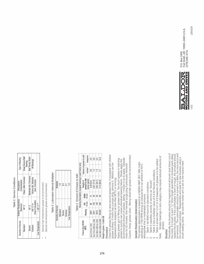
Tabl
e 2
Ser
vice
Con
ditio
ns
°
!
"
#
$°
%
&
'
$°
(
)*
!+
,-.
°
((
C7
CC7
Tabl
e 3
Lub
ricat
ion
Inte
rval
Mul
tiplie
r
/0
0$
&
0
/
!+
/0
Tabl
e 4
Am
ount
of G
reas
e to
Add
"
1!
23
4
2
5
&
1*
&
3
6
"7
7
8
1*
&
3
6
""
7
1
3
.
9
:
/
01
/.:3
;.<
=:/
0.
1=0
30
;:0
6
:/
:=
01/=
3;.
///:
:>
0;/
1/<
03
/0:
.0>
6
:=
.;
01::
$3;.
/./
..
0=/
1:.
0/3
/0$
$0:
6
.;
$
01
.3
59
.::
:
$:0
/:1
;0
30
//.
0
7
?0
$
"
Pro
cedu
re ! !
*!
&0
°
9 ! / 5
6 ! 7
! 6$ 2
!;0 !
<D 8
Sam
ple
Rel
ubric
atio
n D
eter
min
atio
n/ #9;&-/*$&0
$?10() 8 ! !=%
°
$
/ $+100!
;
/ ; !! '7.
%
/ % !01!7
=
/ = $;%%+ !
#<
7 > !
Bru
shes
) !
*! $, ;
″!!
*!
/
(
A6 6
P.O
. Box
240
0F
ort S
mith
, AR
729
02–2
400
U.S
.A.
(479
) 64
6–47
11
BA10;+
$,0%
279
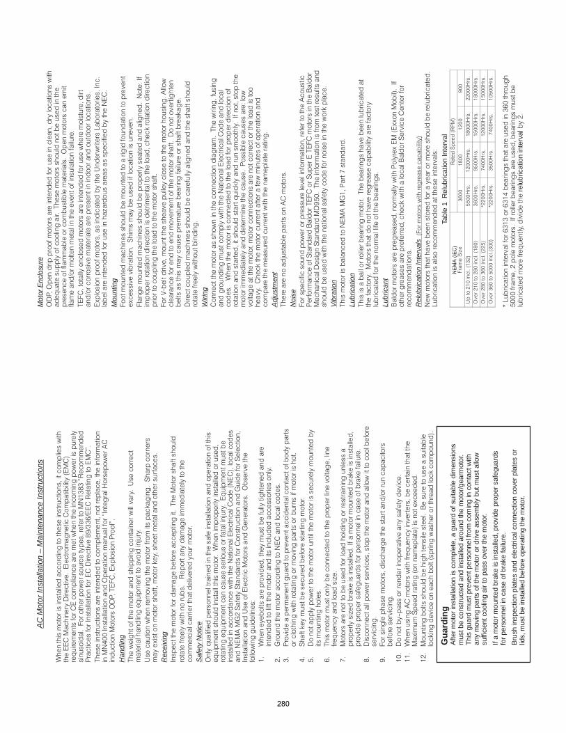
AC
Mot
or In
stal
latio
n –
Mai
nten
ance
Inst
ruct
ions
!
"!#$%&%'(
) !* !&+,%%-,( .
/ !
#011* 2 !'* 34
2)/"5)!.
Han
dlin
g/! 6
7
6 ! 8 9
5 !8 !
Rec
eivi
ng*! ! / !
!(
Safe
ty N
otic
e2 ! ! !
! 7
# #
#4:;9 !9 ! :!9
* 6! : 2
!<
$
!
!
;
: #
%
) !
!
0
9 !8!
=
-
/
! >
?
!
> 8 *! 8
! ! ! 8!
&
!
+
" ,
!
$1@ !
$$4!
59 5
$;A
8 8
Gu
ard
ing
Afte
r m
otor
inst
alla
tion
is c
ompl
ete,
a g
uard
of s
uita
ble
dim
ensi
ons
mus
t be
cons
truc
ted
and
inst
alle
d ar
ound
the
mot
or/g
earm
otor
.T
his
guar
d m
ust p
reve
nt p
erso
nnel
from
com
ing
in c
onta
ct w
ithan
y m
ovin
g pa
rts
of th
e m
otor
or
driv
e as
sem
bly
but m
ust a
llow
suffi
cien
t coo
ling
air
to p
ass
over
the
mot
or.
If a
mot
or m
ount
ed b
rake
is in
stal
led,
pro
vide
pro
per
safe
guar
dsfo
r pe
rson
nel i
n ca
se o
f bra
ke fa
ilure
.
Bru
sh in
spec
tion
plat
es a
nd e
lect
rical
con
nect
ion
cove
r pl
ates
or
lids,
mus
t be
inst
alle
d be
fore
ope
ratin
g th
e m
otor
.
Mot
or E
nclo
sure
2)
!
! /
!! 2
! , ! !
/"
!
,
6B *
! > !#
Mou
ntin
g
!
5 9 !
#<*!
8
!
"
4
!! !
! ! 8
! !
!
Wiri
ng /!
#
!!
8 *!
) <
8 ! !!
Adj
ustm
ent
/ 7 4
Noi
se"!! !4
)! !9 A /"9/"A
9 +=1/! !
!!8
Vibr
atio
n/ #4:$) ?
Lubr
icat
ion
/ /
! !
! !!
Lubr
ican
tA )555*!
!8 A 9!
Rel
ubric
atio
n In
terv
als "
# !
B <
Tabl
e 1
Rel
ubric
atio
n In
terv
al#4*
( 9()
#4*
" 9>
%-11
$&11
$;11
+11
6;$1$%;
==113
$;1113
$&1113
;;1113
2;$1;&1$&1
%-113
+=113
$=1113
$&1113
2;&1%-1;;=
C;;113
?0113
$;1113
$=1113
2%-1=111%11
C;;113
%=113
?0113
$1=113
CB !-%$%-%$0 %-1
=111! ;*!
! r
elub
ricat
ion
inte
rval;
280
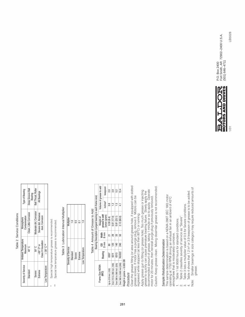
Tabl
e 2
Ser
vice
Con
ditio
ns
°
!
"
#
$°
%
&
'
$°
(
)*
!+
,-.
°
((
C9
CC9
Tabl
e 3
Lub
ricat
ion
Inte
rval
Mul
tiplie
r
/0
0$
&
0
/
!+
/0
Tabl
e 4
Am
ount
of G
reas
e to
Add
"
1!
23
4
2
5
&
1*
&
3
6
"7
7
8
1*
&
3
6
""
7
1
3
.
9
:
/
01
/.:3
;.<
=:/
0.
1=0
30
;:0
6
:/
:=
01/=
3;.
///:
:>
0;/
1/<
03
/0:
.0>
6
:=
.;
01::
$3;.
/./
..
0=/
1:.
0/3
/0$
$0:
6
.;
$
01
.3
59
.::
:
$:0
/:1
;0
30
//.
0
7
?0
$
"
Pro
cedu
re ! !
*!
&1
°
4 ! / 7
8 ! 9
! 8$ 2
!;1 !
<D 5
Sam
ple
Rel
ubric
atio
n D
eter
min
atio
n/ #4;&-/*$&1
$?=1() 5 ! !0%
°
$
/ $+=11!
;
/ ; !! '9.
%
/ % !1=!9
0
/ 0 $;%%+ !
#<
9 > !
P.O
. Box
240
0F
ort S
mith
, AR
729
02–2
400
U.S
.A.
(501
) 64
6–47
11
BA=1;&
$,1$
281
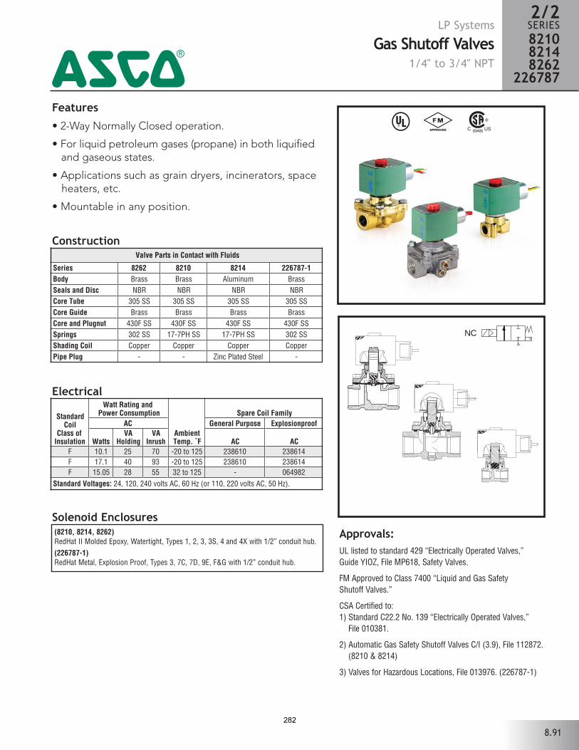
Features
• 2-Way Normally Closed operation.
• For liquid petroleum gases (propane) in both liquified and gaseous states.
• Applications such as grain dryers, incinerators, space heaters, etc.
• Mountable in any position.
Solenoid Enclosures
Construction
(8210, 8214, 8262)RedHat II Molded Epoxy, Watertight, Types 1, 2, 3, 3S, 4 and 4X with 1/2” conduit hub. (226787-1)RedHat Metal, Explosion Proof, Types 3, 7C, 7D, 9E, F&G with 1/2” conduit hub.
Electrical
^ #
Approvals:UL listed to standard 429 “Electrically Operated Valves,” Guide YIOZ, File MP618, Safety Valves.
FM Approved to Class 7400 “Liquid and Gas Safety Shutoff Valves.”
CSA Certified to:1) Standard C22.2 No. 139 “Electrically Operated Valves,”
File 010381.
2) Automatic Gas Safety Shutoff Valves C/I (3.9), File 112872.(8210 & 8214)
3) Valves for Hazardous Locations, File 013976. (226787-1)
NC
LP Systems
Gas Shutoff Valves1/4" to 3/4" NPT
2/2SERIES821082148262
2267874
8.91
Valve Parts in Contact with Fluids
Series 8262 8210 8214 226787-1 Body Brass Brass Aluminum Brass Seals and Disc NBR NBR NBR NBR Core Tube 305 SS 305 SS 305 SS 305 SS Core Guide Brass Brass Brass Brass Core and Plugnut 430F SS 430F SS 430F SS 430F SS Springs 302 SS 17-7PH SS 17-7PH SS 302 SS Shading Coil Copper Copper Copper Copper Pipe Plug - - Zinc Plated Steel -
StandardCoil
Class of Insulation
Watt Rating and Power Consumption
AmbientTemp. ˚F
Spare Coil FamilyAC General Purpose Explosionproof
WattsVA
HoldingVA
Inrush AC ACF 10.1 25 70 -20 to 125 238610 238614F 17.1 40 93 -20 to 125 238610 238614F 15.05 28 55 32 to 125 - 064982
Standard Voltages: 24, 120, 240 volts AC, 60 Hz (or 110, 220 volts AC, 50 Hz).
282
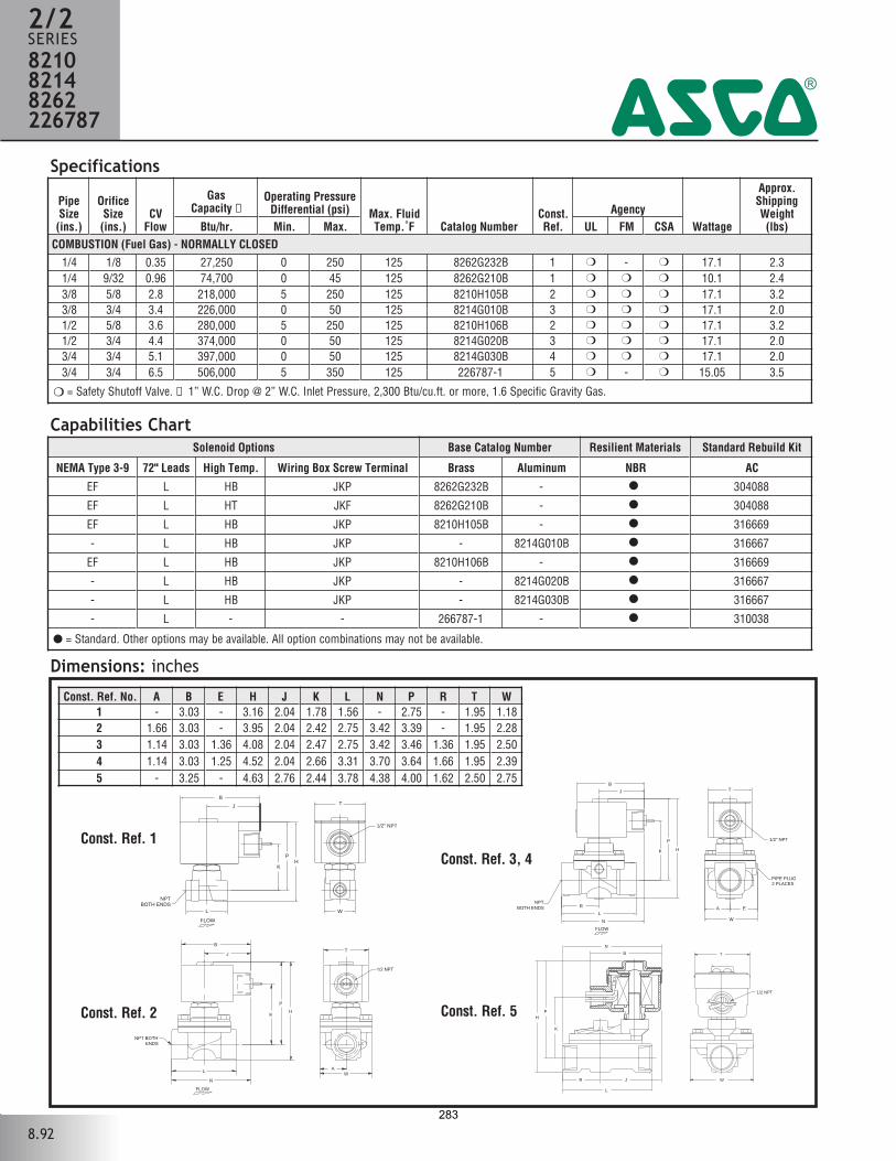
Specifications
Dimensions: inches
Const. Ref. 1
NPTBOTH ENDS
1/2" NPT
TB
J
K
PH
L W
238432-8262-DIM
FLOW
4
Capabilities Chart
8.92
PipeSize(ins.)
OrificeSize(ins.)
CVFlow
GasCapacity ➀
Operating PressureDifferential (psi) Max. Fluid
Temp.˚F Catalog NumberConst.Ref.
AgencyWattage
Approx.ShippingWeight(lbs)Btu/hr. Min. Max. UL FM CSA
COMBUSTION (Fuel Gas) - NORMALLY CLOSED1/4 1/8 0.35 27,250 0 250 125 8262G232B 1 - 17.1 2.31/4 9/32 0.96 74,700 0 45 125 8262G210B 1 10.1 2.43/8 5/8 2.8 218,000 5 250 125 8210H105B 2 17.1 3.23/8 3/4 3.4 226,000 0 50 125 8214G010B 3 17.1 2.01/2 5/8 3.6 280,000 5 250 125 8210H106B 2 17.1 3.21/2 3/4 4.4 374,000 0 50 125 8214G020B 3 17.1 2.03/4 3/4 5.1 397,000 0 50 125 8214G030B 4 17.1 2.03/4 3/4 6.5 506,000 5 350 125 226787-1 5 - 15.05 3.5
= Safety Shutoff Valve. ➀ 1” W.C. Drop @ 2” W.C. Inlet Pressure, 2,300 Btu/cu.ft. or more, 1.6 Specific Gravity Gas.
Solenoid Options Base Catalog Number Resilient Materials Standard Rebuild Kit
NEMA Type 3-9 72" Leads High Temp. Wiring Box Screw Terminal Brass Aluminum NBR AC
EF L HB JKP 8262G232B - 304088
EF L HT JKF 8262G210B - 304088
EF L HB JKP 8210H105B - 316669
- L HB JKP - 8214G010B 316667
EF L HB JKP 8210H106B - 316669
- L HB JKP - 8214G020B 316667
- L HB JKP - 8214G030B 316667
- L - - 266787-1 - 310038
= Standard. Other options may be available. All option combinations may not be available.
Const. Ref. No. A B E H J K L N P R T W1 - 3.03 - 3.16 2.04 1.78 1.56 - 2.75 - 1.95 1.182 1.66 3.03 - 3.95 2.04 2.42 2.75 3.42 3.39 - 1.95 2.283 1.14 3.03 1.36 4.08 2.04 2.47 2.75 3.42 3.46 1.36 1.95 2.504 1.14 3.03 1.25 4.52 2.04 2.66 3.31 3.70 3.64 1.66 1.95 2.395 - 3.25 - 4.63 2.76 2.44 3.78 4.38 4.00 1.62 2.50 2.75
FLOW
1/2 NPT
NPT BOTHENDS
L
K
P
H
W
B
JT
N
A
1/2" NPT
PIPE PLUG2 PLACES
NPTBOTH ENDS
T
L
K
P
W
H
B
J
N
R A E
FLOW
Const. Ref. 3, 4
Const. Ref. 2 Const. Ref. 5
R
L
WJ
T
1/2 NPT
B
N
HP
K
2/2SERIES821082148262226787
283
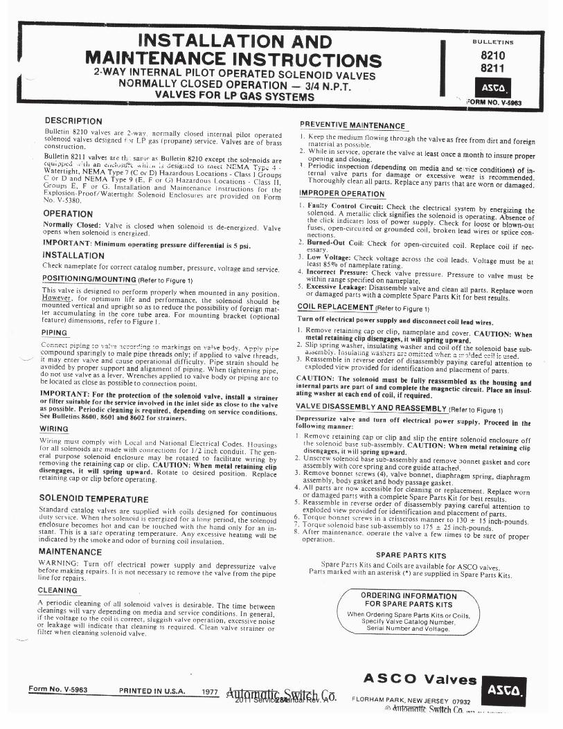
2011 Service Manual Rev. A284
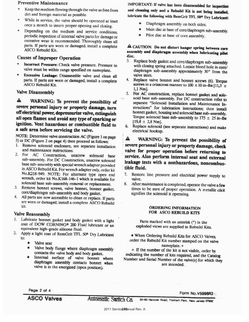
2011 Service Manual Rev. A285
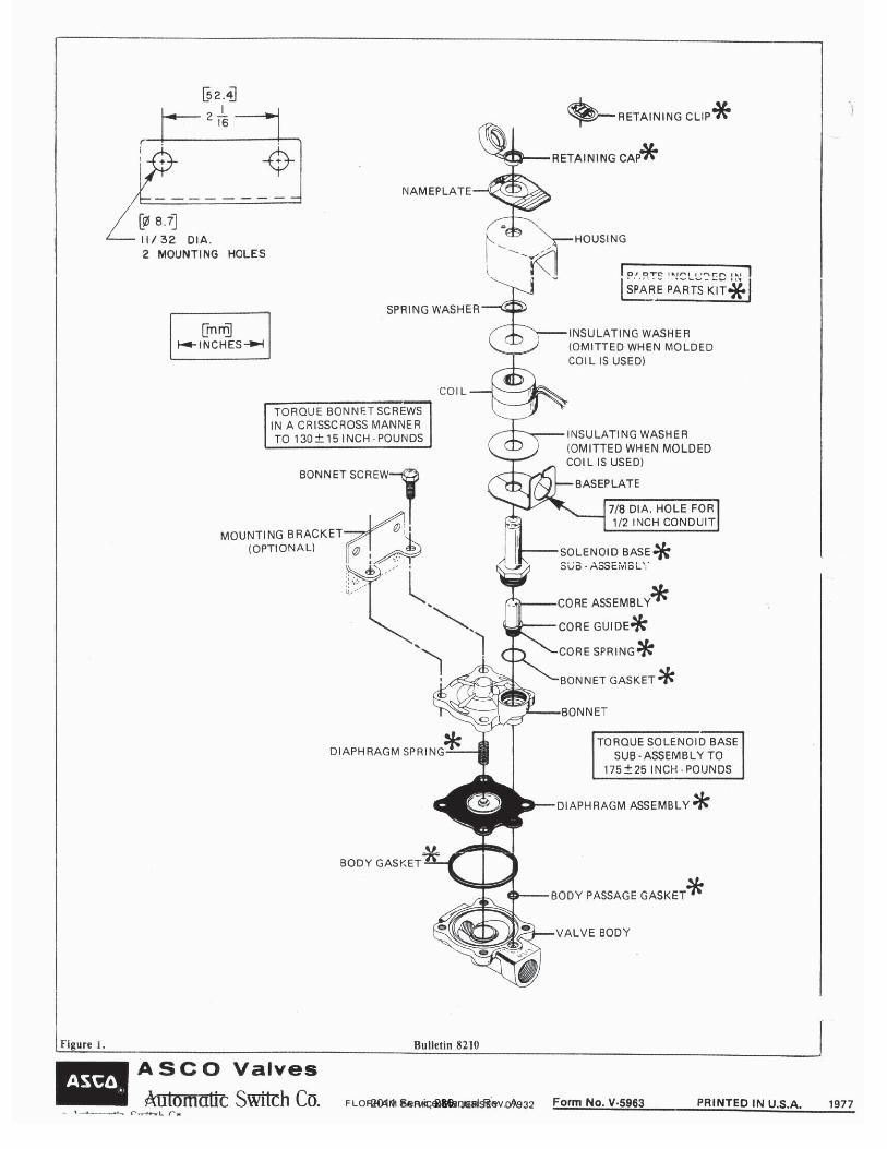
2011 Service Manual Rev. A286
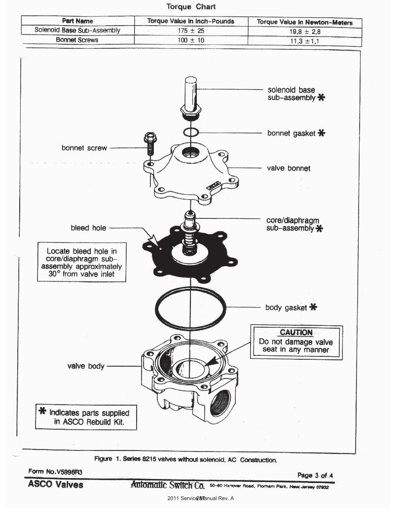
2011 Service Manual Rev. A287
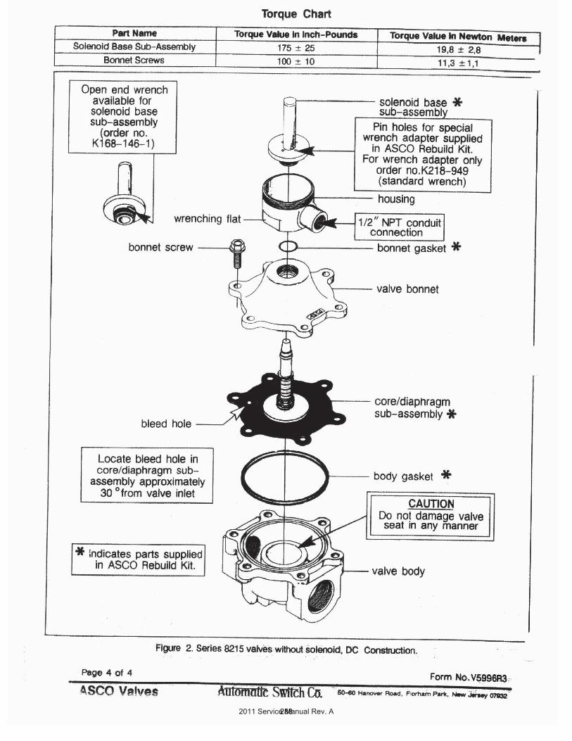
2011 Service Manual Rev. A288
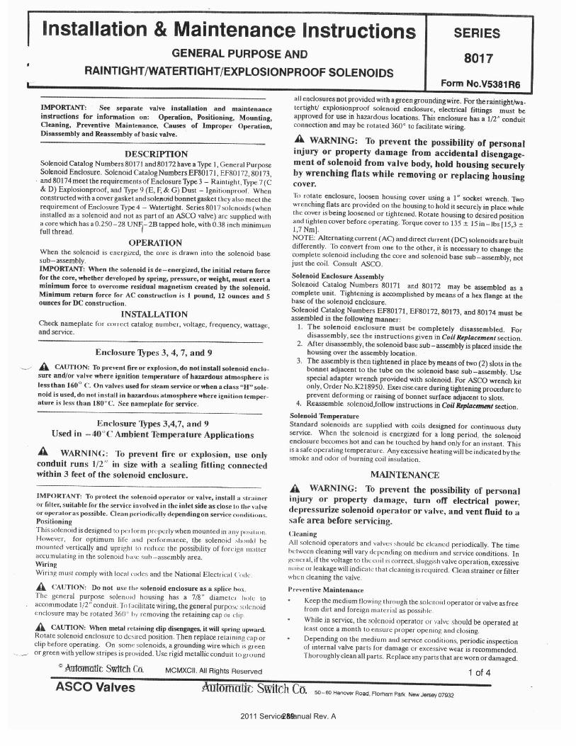
2011 Service Manual Rev. A289
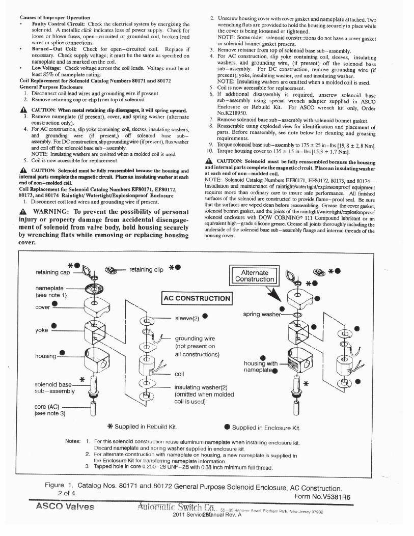
2011 Service Manual Rev. A290
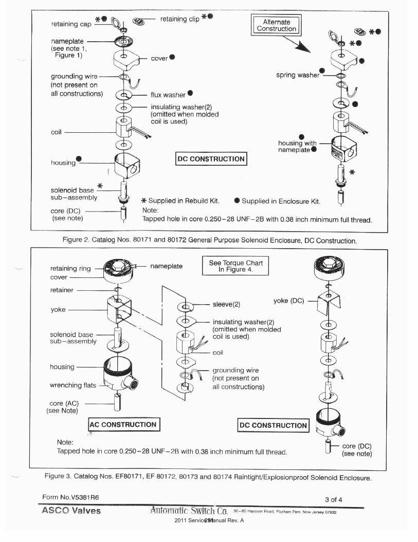
2011 Service Manual Rev. A291
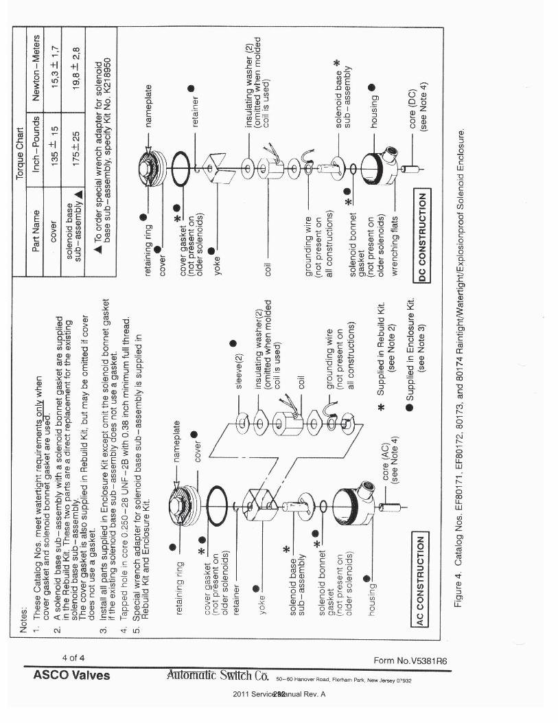
2011 Service Manual Rev. A292
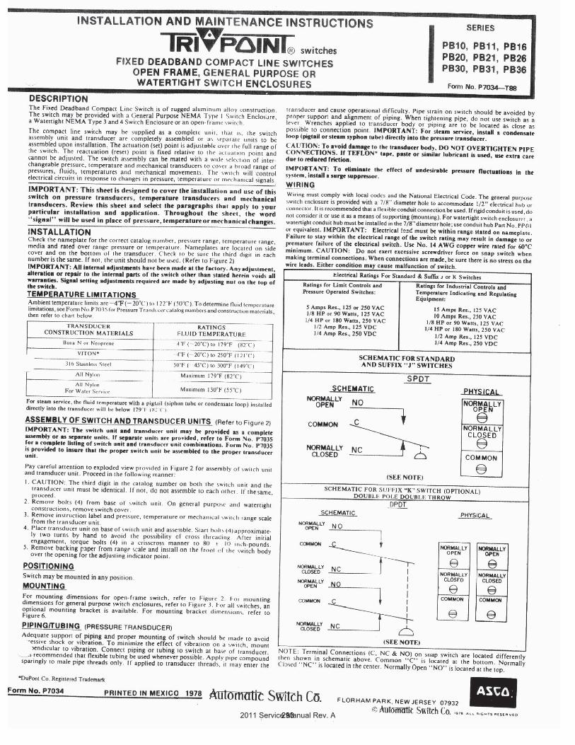
2011 Service Manual Rev. A293
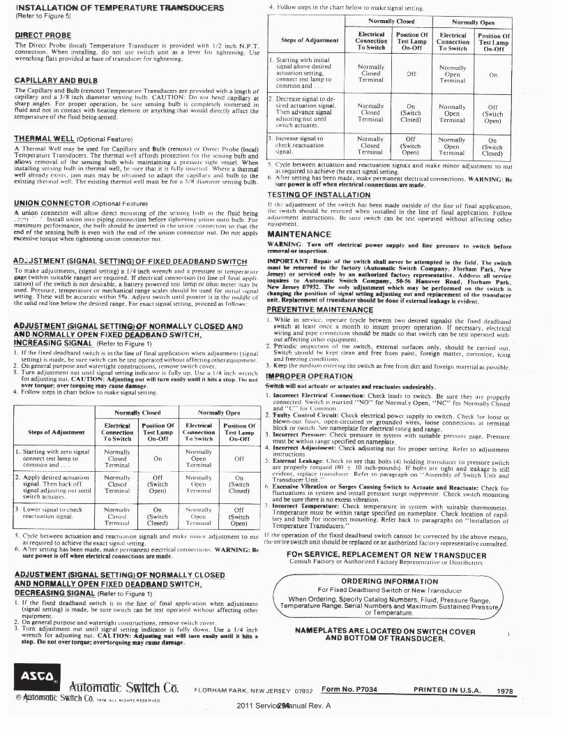
2011 Service Manual Rev. A294
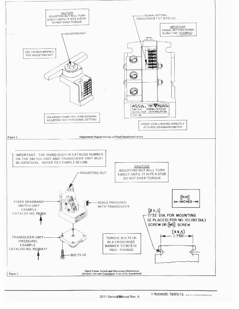
2011 Service Manual Rev. A295
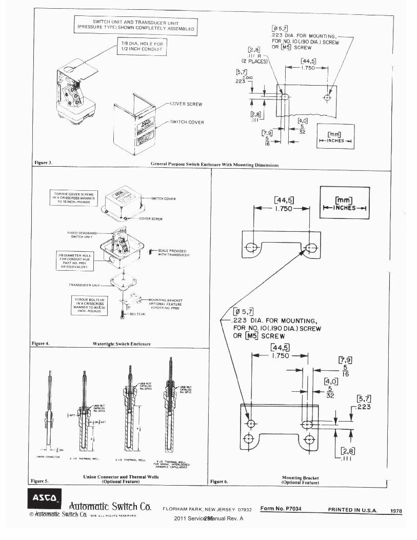
2011 Service Manual Rev. A295
Related Documents


