OPERATION MANUAL DAKOTA ULTRASONICS MODEL PX-7 PRECISION THICKNESS GAUGE P/N P-129 -0002 Rev1. 60 January 2008

Welcome message from author
This document is posted to help you gain knowledge. Please leave a comment to let me know what you think about it! Share it to your friends and learn new things together.
Transcript
OPERATION MANUAL
DAKOTA ULTRASONICS MODEL PX-7 PRECISION THICKNESS GAUGE
P/N P-129-0002 Rev1.60 January 2008
Copyright 2008 Dakota Ultrasonics. All rights reserved.
No part of this publication may be reproduced, translated into another
language, stored in a retrieval system, or transmitted in any form or by any
means; electronic, mechanical, photocopying, recording, or otherwise,
without the prior written consent of Dakota Ultrasonics.
Every precaution has been taken in the preparation of this publication.
Dakota Ultrasonics assumes no responsibility for errors or omissions.
Neither is any liability assumed for damages resulting from the use of
information contained herein.
Any brand or product names mentioned herein are used for identification
purposes only, and are trademarks or registered trademarks of their
respective holders.
1500 Green Hills Road, #107 Scotts Valley, CA 95066 USA
Tel (831) 431-9722 Fax (831) 431-9723 www.dakotaultrasonics.com
PX-7 Ultrasonic Thickness Gauge
CONTENTS
INTRODUCTION
OPERATION
THE KEYPAD
THE DISPLAY
THE TRANSDUCER
MAKING MEASUREMENTS
CONDITION AND PREPARATION OF SURFACES
SELECTING MEASUREMENT MODE & THE LOCK MODE
CALIBRATION
SCAN MODE, ALARM MODE, DIFF MODE, RS232 PORT
TRANSDUCER SELECTION
APPENDIX A: PRODUCT SPECIFICATIONS
APPENDIX B: APPLICATION NOTES
APPENDIX C: SOUND VELOCITIES OF COMMON MATERIALS
WARRANTY INFORMATION
1
3
3
7
9
10
12
13
14
17
22
25
27
29
31
DISCLAIMER
Inherent in ultrasonic thickness measurement is the possibility that the
instrument will use the second rather than the first echo from the back
surface of the material being measured. This may result in a thickness
reading that is TWICE what it should be. Responsibility for proper use of
the instrument and recognition of this phenomenon rests solely with the
user of the instrument.

Dakota Ultrasonics
blank page
PX-7 Ultrasonic Thickness Gauge
1
INTRODUCTION
The Dakota Ultrasonics model PX-7 is a precision Ultrasonic
Micrometer. Based on the same operating principles as SONAR, the PX-7
is capable of measuring the thickness of various materials with accuracy as
high as ± 0.0001 inches, or ± 0.001 millimeters. The principle advantage of
ultrasonic measurement over traditional methods is that ultrasonic
measurements can be performed with access to only one side of the
material being measured.
This manual is presented in three sections. The first section covers
operation of the PX-7, and explains the keypad controls and display. The
second section provides guidelines in selecting a transducer for a specific
application. The last section provides application notes and a table of
sound velocity values for various materials.
Dakota Ultrasonics maintains a customer support resource in order to
assist users with questions or difficulties not covered in this manual.
Customer support may be reached at any of the following:
• Dakota Ultrasonics, 1500 Green Hills Road, #107 Scotts Valley, CA 95066 USA
• Telephone: (831) 431-9722
• Facsimile: (831) 431-9723
• www.dakotaultrasonics.com

Dakota Ultrasonics
2
blank page
PX-7 Ultrasonic Thickness Gauge
3
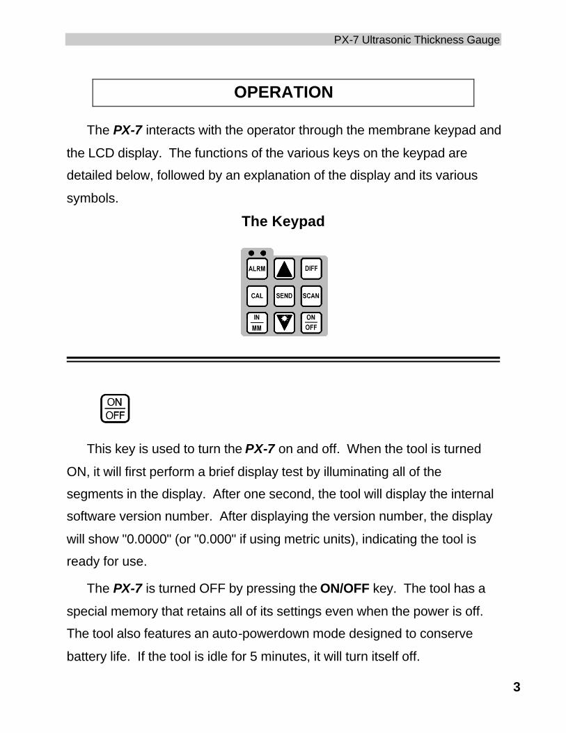
OPERATION
The PX-7 interacts with the operator through the membrane keypad and
the LCD display. The functions of the various keys on the keypad are
detailed below, followed by an explanation of the display and its various
symbols.
The Keypad
This key is used to turn the PX-7 on and off. When the tool is turned
ON, it will first perform a brief display test by illuminating all of the
segments in the display. After one second, the tool will display the internal
software version number. After displaying the version number, the display
will show "0.0000" (or "0.000" if using metric units), indicating the tool is
ready for use.
The PX-7 is turned OFF by pressing the ON/OFF key. The tool has a
special memory that retains all of its settings even when the power is off.
The tool also features an auto-powerdown mode designed to conserve
battery life. If the tool is idle for 5 minutes, it will turn itself off.
Dakota Ultrasonics
4
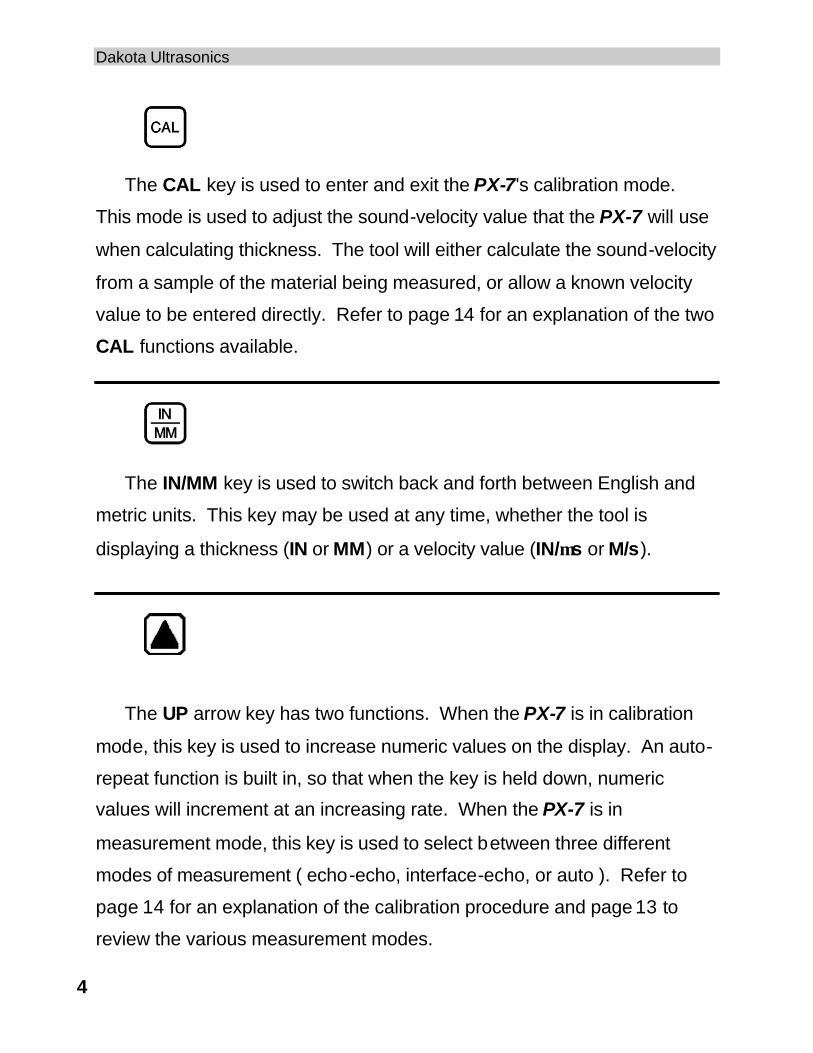
The CAL key is used to enter and exit the PX-7's calibration mode.
This mode is used to adjust the sound-velocity value that the PX-7 will use
when calculating thickness. The tool will either calculate the sound-velocity
from a sample of the material being measured, or allow a known velocity
value to be entered directly. Refer to page 14 for an explanation of the two
CAL functions available.
The IN/MM key is used to switch back and forth between English and
metric units. This key may be used at any time, whether the tool is
displaying a thickness (IN or MM) or a velocity value (IN/µs or M/s).
The UP arrow key has two functions. When the PX-7 is in calibration
mode, this key is used to increase numeric values on the display. An auto-
repeat function is built in, so that when the key is held down, numeric
values will increment at an increasing rate. When the PX-7 is in
measurement mode, this key is used to select between three different
modes of measurement ( echo-echo, interface-echo, or auto ). Refer to
page 14 for an explanation of the calibration procedure and page 13 to
review the various measurement modes.
PX-7 Ultrasonic Thickness Gauge
5
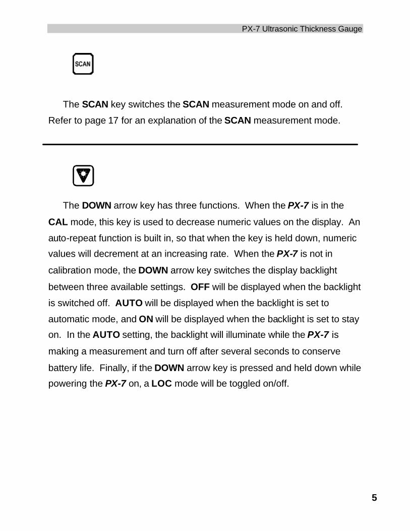
The SCAN key switches the SCAN measurement mode on and off.
Refer to page 17 for an explanation of the SCAN measurement mode.
The DOWN arrow key has three functions. When the PX-7 is in the
CAL mode, this key is used to decrease numeric values on the display. An
auto-repeat function is built in, so that when the key is held down, numeric
values will decrement at an increasing rate. When the PX-7 is not in
calibration mode, the DOWN arrow key switches the display backlight
between three available settings. OFF will be displayed when the backlight
is switched off. AUTO will be displayed when the backlight is set to
automatic mode, and ON will be displayed when the backlight is set to stay
on. In the AUTO setting, the backlight will illuminate while the PX-7 is
making a measurement and turn off after several seconds to conserve
battery life. Finally, if the DOWN arrow key is pressed and held down while
powering the PX-7 on, a LOC mode will be toggled on/off.
Dakota Ultrasonics
6
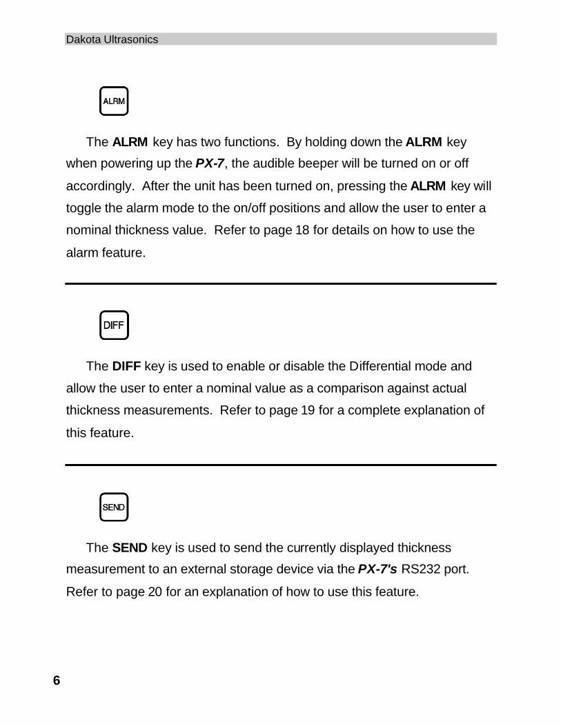
The ALRM key has two functions. By holding down the ALRM key
when powering up the PX-7, the audible beeper will be turned on or off
accordingly. After the unit has been turned on, pressing the ALRM key will
toggle the alarm mode to the on/off positions and allow the user to enter a
nominal thickness value. Refer to page 18 for details on how to use the
alarm feature.
The DIFF key is used to enable or disable the Differential mode and
allow the user to enter a nominal value as a comparison against actual
thickness measurements. Refer to page 19 for a complete explanation of
this feature.
The SEND key is used to send the currently displayed thickness
measurement to an external storage device via the PX-7's RS232 port.
Refer to page 20 for an explanation of how to use this feature.
PX-7 Ultrasonic Thickness Gauge
7
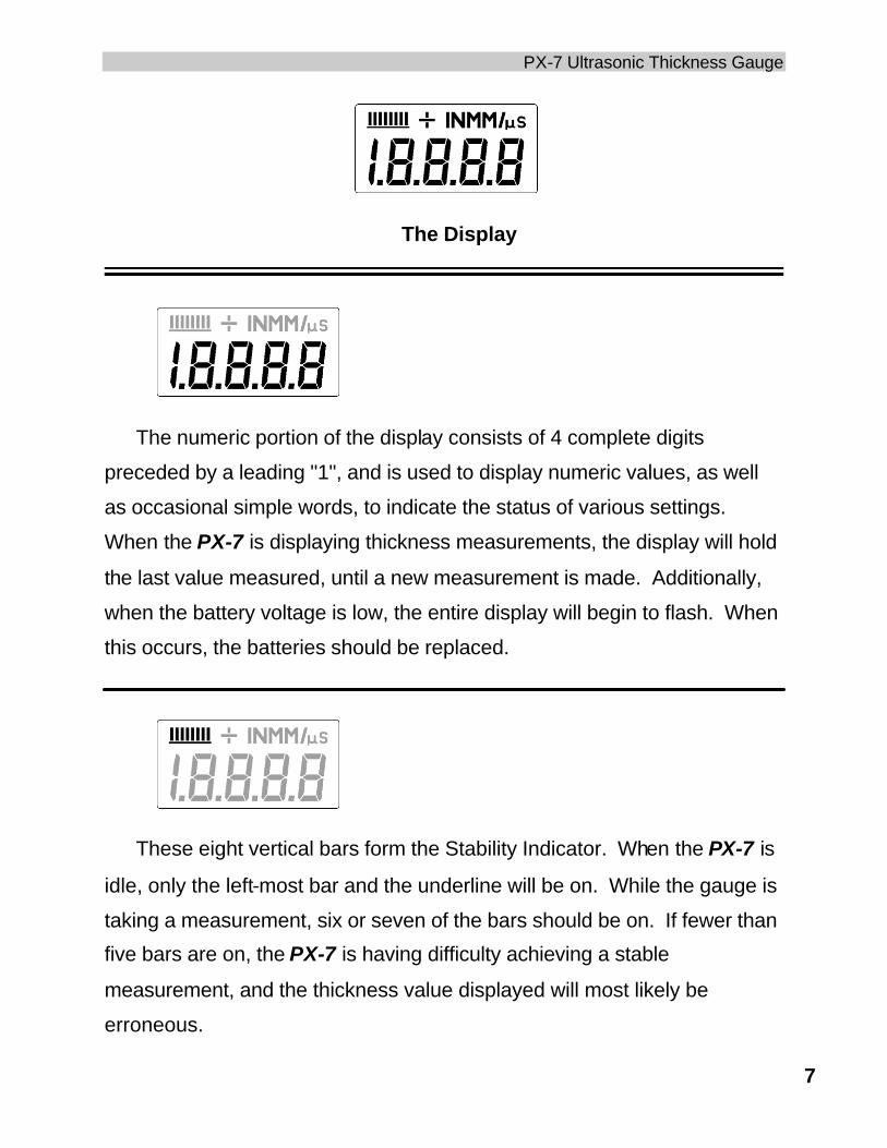
The Display
The numeric portion of the display consists of 4 complete digits
preceded by a leading "1", and is used to display numeric values, as well
as occasional simple words, to indicate the status of various settings.
When the PX-7 is displaying thickness measurements, the display will hold
the last value measured, until a new measurement is made. Additionally,
when the battery voltage is low, the entire display will begin to flash. When
this occurs, the batteries should be replaced.
These eight vertical bars form the Stability Indicator. When the PX-7 is
idle, only the left-most bar and the underline will be on. While the gauge is
taking a measurement, six or seven of the bars should be on. If fewer than
five bars are on, the PX-7 is having difficulty achieving a stable
measurement, and the thickness value displayed will most likely be
erroneous.
Dakota Ultrasonics
8
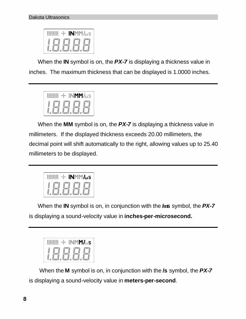
When the IN symbol is on, the PX-7 is displaying a thickness value in
inches. The maximum thickness that can be displayed is 1.0000 inches.
When the MM symbol is on, the PX-7 is displaying a thickness value in
millimeters. If the displayed thickness exceeds 20.00 millimeters, the
decimal point will shift automatically to the right, allowing values up to 25.40
millimeters to be displayed.
When the IN symbol is on, in conjunction with the /µs symbol, the PX-7
is displaying a sound-velocity value in inches-per-microsecond.
When the M symbol is on, in conjunction with the /s symbol, the PX-7
is displaying a sound-velocity value in meters-per-second.
PX-7 Ultrasonic Thickness Gauge
9
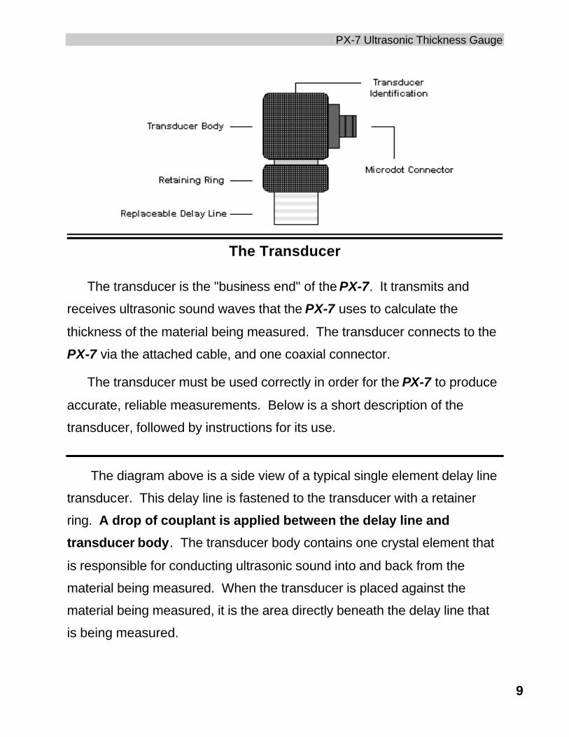
The Transducer
The transducer is the "business end" of the PX-7. It transmits and
receives ultrasonic sound waves that the PX-7 uses to calculate the
thickness of the material being measured. The transducer connects to the
PX-7 via the attached cable, and one coaxial connector.
The transducer must be used correctly in order for the PX-7 to produce
accurate, reliable measurements. Below is a short description of the
transducer, followed by instructions for its use.
The diagram above is a side view of a typical single element delay line
transducer. This delay line is fastened to the transducer with a retainer
ring. A drop of couplant is applied between the delay line and
transducer body. The transducer body contains one crystal element that
is responsible for conducting ultrasonic sound into and back from the
material being measured. When the transducer is placed against the
material being measured, it is the area directly beneath the delay line that
is being measured.
Dakota Ultrasonics
10
When measuring, press against the top of the transducer with the
thumb or index finger to hold the transducer in place. Moderate pressure is
sufficient, as it is only necessary to keep the transducer stationary, and the
delay line seated flat against the surface of the material being measured.
Making Measurements
In order for the transducer to do its job, there must be no air gaps
between the wear-face and the surface of the material being measured.
This is accomplished with the use of a "coupling" fluid, commonly called
"couplant". This fluid serves to "couple", or transfer, the ultrasonic sound
waves from the transducer, into the material, and back again. Before
attempting to make a measurement, a small amount of couplant should be
applied to the surface of the material being measured. Typically, a single
droplet of couplant is sufficient.
After applying couplant, press the transducer (wearface down) firmly
against the area to be measured. The Stability Indicator should have six or
seven bars darkened, and a number should appear in the display. If the
PX-7 has been set to the correct sound velocity (see page 14), the number
in the display will indicate the actual thickness of the material directly
beneath the transducer.
PX-7 Ultrasonic Thickness Gauge
11
If the Stability Indicator has fewer than five bars darkened, or the
numbers on the display seem erratic, first check to make sure that there is
an adequate film of couplant beneath the transducer, and that the
transducer is seated flat against the material. If the condition persists, it
may be necessary to select a different transducer (size or frequency) for
the material being measured. See page 22 for information on transducer
selection.
While the transducer is in contact with the material that is being
measured, the PX-7 will perform four measurements every second,
updating its display as it does so. When the transducer is removed from
the surface, the display will hold the last measurement made.
IMPORTANT
Occasionally, a small film of couplant will be drawn out between the
transducer and the surface as the transducer is removed. When this
happens, the PX-7 may perform a measurement through this couplant film,
resulting in a measurement that is larger or smaller than it should be. This
phenomenon is obvious when one thickness value is observed while the
transducer is in place, and another value is observed after the transducer is
removed.
Dakota Ultrasonics
12
Condition and Preparation of Surfaces
In any ultrasonic measurement scenario, the shape and roughness of
the test surface are of paramount importance. Rough, uneven surfaces
may limit the penetration of ultrasound through the material, and result in
unstable, and therefore unreliable, measurements. The surface being
measured should be clean, and free of any small particulate matter, rust, or
scale. The presence of such obstructions will prevent the transducer from
seating properly against the surface. Often, a wire brush or scraper will be
helpful in cleaning surfaces. In more extreme cases, rotary sanders or
grinding wheels may be used, though care must be taken to prevent
surface gouging, which will inhibit proper transducer coupling.
Extremely rough surfaces, such as the pebble-like finish of some cast
iron, will prove most difficult to measure. These kinds of surfaces act on
the sound beam like frosted glass on light:, the beam becomes diffused
and scattered in all directions.
In addition to posing obstacles to measurement, rough surfaces
contribute to excessive wear of the transducer, particularly in situations
where the transducer is "scrubbed" along the surface.
PX-7 Ultrasonic Thickness Gauge
13
Selecting Measurement Mode
The PX-7 is equipped with four measurement mode options (echo-
echo, interface-echo, auto, or plas). In echo-echo mode, the gauge has the
ability to read thin metals down to .006 inches (.15 millimeters). The echo-
echo mode also allows the user to measure the thickness of metals that
have been previously coated or painted on the surface. This enables the
user to determine the thickness of the metal without having to remove the
paint. In interface-echo mode, the gauge has the ability to read plastics
and thicker materials. The PX-7's auto mode will automatically switch
between echo-echo and interface-echo according to the different materials
being measured. Finally, the plas mod can be used to measure thin plastics
using a special graphite tip. The following section outlines how to switch
between measurement modes:
Measurement Modes
1) Make sure the PX-7 is on.
2) Press the UP arrow key to toggle between measurement modes.
The gauge will display GatE followed by I-E, E-E, Auto, or PLAS
depending on which mode the PX-7 was last used in.
3) Repeat step 2 until the desired mode has been displayed.
Note: Once the mode has been selected, the user can use the built-in
LOC feature to prevent additional users from accidentally changing
the mode. When the PX-7 is in LOC mode, all features (with the
exception of the calibration and units), are locked and cannot be
Dakota Ultrasonics
14
altered by the user. Press and hold the DOWN arrow key while
powering up the PX-7 to toggle the LOC feature on/off. Repeat
procedure to toggle on/off status.
Calibration
In order for the PX-7 to make accurate measurements, it must be set to
the correct sound-velocity for the material being measured. Different types
of material have different inherent sound-velocities. For example, the
velocity of sound through steel is about 0.233 inches-per-microsecond,
versus that of aluminum, which is about 0.248 inches-per-microsecond. If
the tool is not set to the correct sound-velocity, all of the measurements the
tool makes will be erroneous by some fixed percentage. The one point
calibration is the simplest and most commonly used calibration procedure -
optimizing linearity over large ranges. The PX-7 provides two simple
methods for setting the sound-velocity, described in the following pages.
PX-7 Ultrasonic Thickness Gauge
15
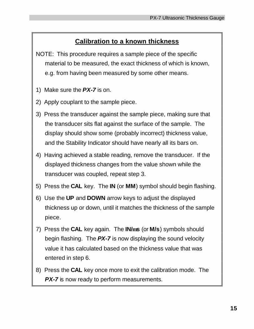
Calibration to a known thickness
NOTE: This procedure requires a sample piece of the specific
material to be measured, the exact thickness of which is known,
e.g. from having been measured by some other means.
1) Make sure the PX-7 is on.
2) Apply couplant to the sample piece.
3) Press the transducer against the sample piece, making sure that
the transducer sits flat against the surface of the sample. The
display should show some (probably incorrect) thickness value,
and the Stability Indicator should have nearly all its bars on.
4) Having achieved a stable reading, remove the transducer. If the
displayed thickness changes from the value shown while the
transducer was coupled, repeat step 3.
5) Press the CAL key. The IN (or MM) symbol should begin flashing.
6) Use the UP and DOWN arrow keys to adjust the displayed
thickness up or down, until it matches the thickness of the sample
piece.
7) Press the CAL key again. The IN/µs (or M/s) symbols should
begin flashing. The PX-7 is now displaying the sound velocity
value it has calculated based on the thickness value that was
entered in step 6.
8) Press the CAL key once more to exit the calibration mode. The
PX-7 is now ready to perform measurements.
Dakota Ultrasonics
16
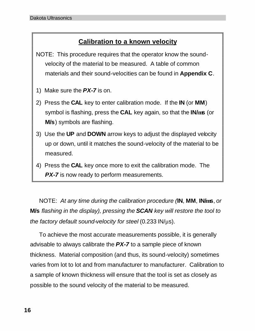
Calibration to a known velocity
NOTE: This procedure requires that the operator know the sound-
velocity of the material to be measured. A table of common
materials and their sound-velocities can be found in Appendix C.
1) Make sure the PX-7 is on.
2) Press the CAL key to enter calibration mode. If the IN (or MM)
symbol is flashing, press the CAL key again, so that the IN/µs (or
M/s) symbols are flashing.
3) Use the UP and DOWN arrow keys to adjust the displayed velocity
up or down, until it matches the sound-velocity of the material to be
measured.
4) Press the CAL key once more to exit the calibration mode. The
PX-7 is now ready to perform measurements.
NOTE: At any time during the calibration procedure (IN, MM, IN/µs, or
M/s flashing in the display), pressing the SCAN key will restore the tool to
the factory default sound-velocity for steel (0.233 IN/µs).
To achieve the most accurate measurements possible, it is generally
advisable to always calibrate the PX-7 to a sample piece of known
thickness. Material composition (and thus, its sound-velocity) sometimes
varies from lot to lot and from manufacturer to manufacturer. Calibration to
a sample of known thickness will ensure that the tool is set as closely as
possible to the sound velocity of the material to be measured.
PX-7 Ultrasonic Thickness Gauge
17
PX-7 Modes
Scan Mode
While the PX-7 excels at making single point measurements, it is
sometimes desirable to examine a larger region, searching for the thinnest
point. The PX-7 includes a feature, called Scan Mode, which allows it to do
just that.
In normal operation, the PX-7 performs and displays four
measurements every second, which is quite adequate for single
measurements. In Scan Mode, however, the tool performs eight
measurements every second, but does not display them. While the
transducer is in contact with the material being measured, the PX-7 is
keeping track of the lowest measurement it finds. The transducer may be
"scrubbed" across a surface, and any brief interruptions in the signal will be
ignored. When the transducer loses contact with the surface for more than
a second, the PX-7 will display the smallest measurement it found.
When the PX-7 is not in calibration mode, press the SCAN key to turn
Scan Mode on and off. A brief message will appear in the display
confirming the operation. While scanning, the display will show a moving
series of dashes instead of a thickness value. When the transducer is
removed from the material being scanned, the PX-7 will (after a brief
pause) display the smallest measurement it found.
Dakota Ultrasonics
18
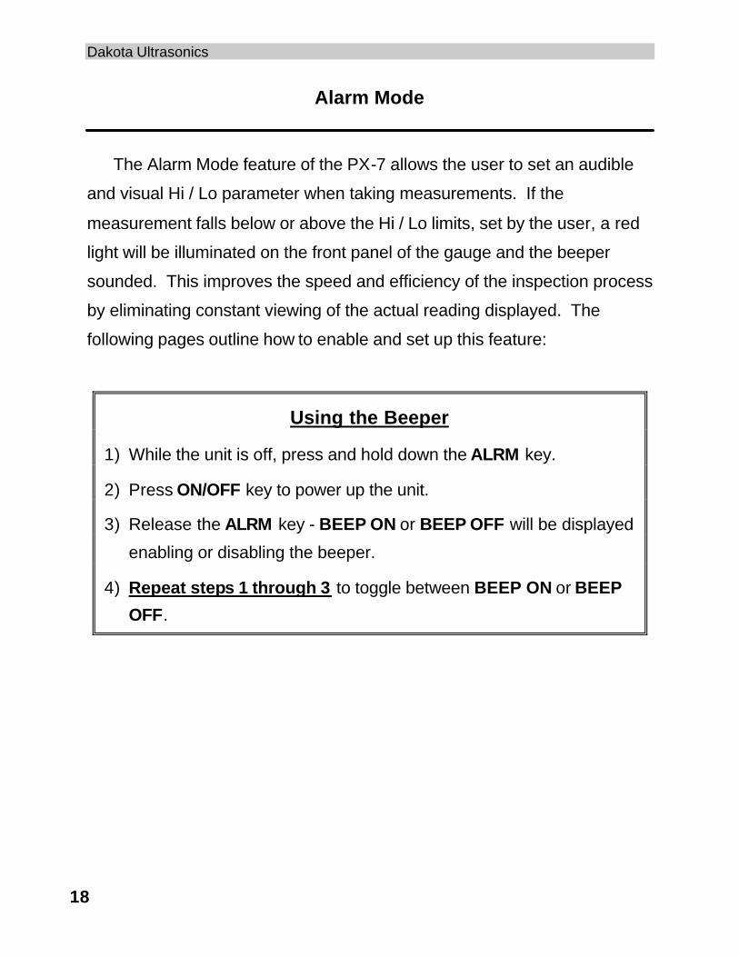
Alarm Mode
The Alarm Mode feature of the PX-7 allows the user to set an audible
and visual Hi / Lo parameter when taking measurements. If the
measurement falls below or above the Hi / Lo limits, set by the user, a red
light will be illuminated on the front panel of the gauge and the beeper
sounded. This improves the speed and efficiency of the inspection process
by eliminating constant viewing of the actual reading displayed. The
following pages outline how to enable and set up this feature:
Using the Beeper
1) While the unit is off, press and hold down the ALRM key.
2) Press ON/OFF key to power up the unit.
3) Release the ALRM key - BEEP ON or BEEP OFF will be displayed
enabling or disabling the beeper.
4) Repeat steps 1 through 3 to toggle between BEEP ON or BEEP
OFF.
PX-7 Ultrasonic Thickness Gauge
19
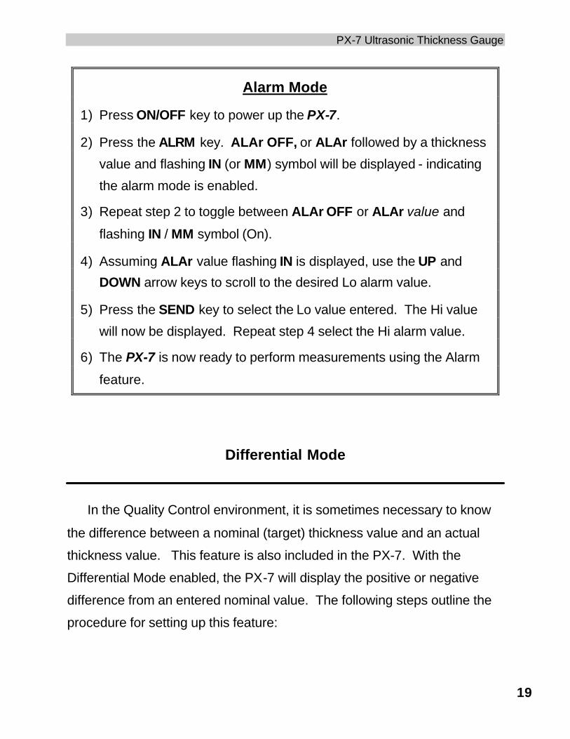
Alarm Mode
1) Press ON/OFF key to power up the PX-7.
2) Press the ALRM key. ALAr OFF, or ALAr followed by a thickness
value and flashing IN (or MM) symbol will be displayed - indicating
the alarm mode is enabled.
3) Repeat step 2 to toggle between ALAr OFF or ALAr value and
flashing IN / MM symbol (On).
4) Assuming ALAr value flashing IN is displayed, use the UP and
DOWN arrow keys to scroll to the desired Lo alarm value.
5) Press the SEND key to select the Lo value entered. The Hi value
will now be displayed. Repeat step 4 select the Hi alarm value.
6) The PX-7 is now ready to perform measurements using the Alarm
feature.
Differential Mode
In the Quality Control environment, it is sometimes necessary to know
the difference between a nominal (target) thickness value and an actual
thickness value. This feature is also included in the PX-7. With the
Differential Mode enabled, the PX-7 will display the positive or negative
difference from an entered nominal value. The following steps outline the
procedure for setting up this feature:
Dakota Ultrasonics
20
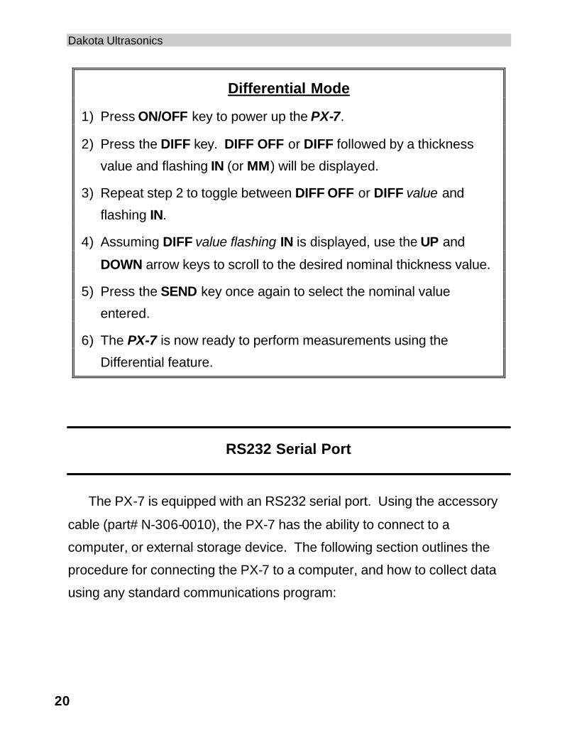
Differential Mode
1) Press ON/OFF key to power up the PX-7.
2) Press the DIFF key. DIFF OFF or DIFF followed by a thickness
value and flashing IN (or MM) will be displayed.
3) Repeat step 2 to toggle between DIFF OFF or DIFF value and
flashing IN.
4) Assuming DIFF value flashing IN is displayed, use the UP and
DOWN arrow keys to scroll to the desired nominal thickness value.
5) Press the SEND key once again to select the nominal value
entered.
6) The PX-7 is now ready to perform measurements using the
Differential feature.
RS232 Serial Port
The PX-7 is equipped with an RS232 serial port. Using the accessory
cable (part# N-306-0010), the PX-7 has the ability to connect to a
computer, or external storage device. The following section outlines the
procedure for connecting the PX-7 to a computer, and how to collect data
using any standard communications program:
PX-7 Ultrasonic Thickness Gauge
21
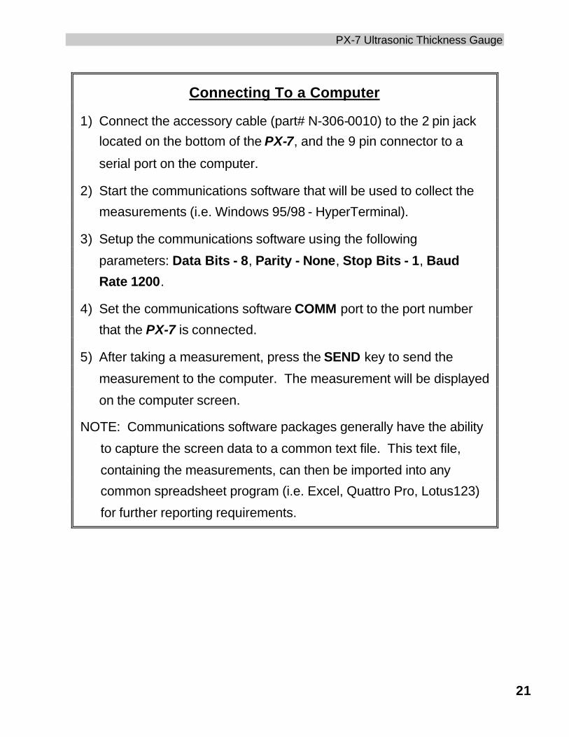
Connecting To a Computer
1) Connect the accessory cable (part# N-306-0010) to the 2 pin jack
located on the bottom of the PX-7, and the 9 pin connector to a
serial port on the computer.
2) Start the communications software that will be used to collect the
measurements (i.e. Windows 95/98 - HyperTerminal).
3) Setup the communications software using the following
parameters: Data Bits - 8, Parity - None, Stop Bits - 1, Baud
Rate 1200.
4) Set the communications software COMM port to the port number
that the PX-7 is connected.
5) After taking a measurement, press the SEND key to send the
measurement to the computer. The measurement will be displayed
on the computer screen.
NOTE: Communications software packages generally have the ability
to capture the screen data to a common text file. This text file,
containing the measurements, can then be imported into any
common spreadsheet program (i.e. Excel, Quattro Pro, Lotus123)
for further reporting requirements.
Dakota Ultrasonics
22
TRANSDUCER SELECTION
The PX-7 is inherently capable of performing measurements on a wide
range of materials, from various metals to glass and plastics. Different
types of material, however, will require the use of different transducers.
Choosing the correct transducer for a job is critical to being able to easily
perform accurate and reliable measurements. The following paragraphs
highlight the important properties of transducers, which should be
considered when selecting a transducer for a specific job.
Generally speaking, the best transducer for a job is one that sends
sufficient ultrasonic energy into the material being measured such that a
strong, stable echo is received by the PX-7. Several factors affect the
strength of ultrasound as it travels. These are outlined below:
• Initial Signal Strength
The stronger a signal is to begin with, the stronger its return echo
will be. Initial signal strength is largely a factor of the size of the
ultrasound emitter in the transducer. A large emitting area will send
more energy into the material being measured than a small emitting
area. Thus, a so-called "1/4-inch" transducer will emit a stronger signal
than a "1/8-inch" transducer.
• Absorption and Scattering
As ultrasound travels through any material, it is partly absorbed. If
the material through which the sound travels has any grain structure,
the sound waves will experience scattering. Both of these effects
reduce the strength of the waves, and thus, the PX-7's ability to detect
the returning echo.
PX-7 Ultrasonic Thickness Gauge
23
Higher frequency ultrasound is absorbed and scattered more than
ultrasound of a lower frequency. While it may seem that using a lower
frequency transducer might be better in every instance, low frequencies
are less directional than high frequencies.
• Geometry of the Transducer
The physical constraints of the measuring environment sometimes
determine a transducer's suitability for a given job. Some transducers
may simply be too large to be used in tightly confined areas. Also, the
surface area available for contacting with the transducer may be limited,
requiring the use of a transducer with a small cone tipped delay line.
Measuring on a curved surface, may require the use of a transducer
with a matching curved wearface.
• Temperature of the Material
When it is necessary to measure on surfaces that are exceedingly
hot, special delay lines may be neccessary. Additionally, care must be
taken when performing a "Calibration to Known Thickness" with a high
temperature application. See Appendix B for more information on
measuring materials with a high temperatures.
Selection of the proper transducer is often a matter of tradeoffs
between various characteristics. It may be necessary to experiment
with a variety of transducers in order to find one that works well for a
given job. Dakota Ultrasonics can provide assistance in choosing a
transducer, and offers a broad selection of transducers for evaluation in
specialized applications.

Dakota Ultrasonics
24
blank page
PX-7 Ultrasonic Thickness Gauge
25
APPENDIX A
Product Specifications
Physical
Weight: 10 ounces(with batteries).
Size: 2.5W x 4.5 H x 1.24 D inches
(63.5W x 114.3 H x 31.5 D mm).
Operating Temperature: -20 to 120 °F ( -30 to 50 °C)
Case: Extruded aluminum body / nickel plated aluminum end
caps.
Keypad
Sealed membrane, resistant to water and petroleum products.
Power Source
Two “AA” size, 1.5 volt alkaline or 1.2 volt NiCad cells. 150 hours
typical operating time on alkaline, 100 hours on NiCad.
Display
Liquid-Crystal-Display, 4.5 digits, 0.500 inch high numerals. LED
backlight.
Measuring
Range: 0.0060 to 1.0000 inches (0.15 to 25.40 millimeters) -Steel
Resolution: 0.0001 inch (0.001 millimeter)
Accuracy: ±0.0001 inch (0.001 millimeter), depends on material
and conditions
Sound Velocity Range: 0.0492 to 0.3937 in/µs (1250 to 10000m/s)

Dakota Ultrasonics
26
blank page
PX-7 Ultrasonic Thickness Gauge
27
APPENDIX B
Application Notes
• Measuring tubing
When measuring a piece of tubing for wall thickness, it may prove
beneficial to have multiple delay lines with different radiuses for different
tubing diameters. The delay lines can be easily radiused by placing a
piece of emery cloth around the tubing and moving the transducer back
and forth until a radius has formed on the tip of the delay line.
• Measuring hot surfaces
The velocity of sound through a substance is dependant upon its
temperature. As materials heat up, the velocity of sound through them
decreases. In most applications with surface temperatures less than about
200°F (100°C), no special procedures must be observed. At temperatures
above this point, the change in sound velocity of the material being
measured starts to have a noticeable effect upon ultrasonic measurement.
At such elevated temperatures, it is recommended that the user perform
a calibration procedure (refer to page 14) on a sample piece of known
thickness, which is at or near the temperature of the material to be
measured. This will allow the PX-7 to correctly calculate the velocity of
sound through the hot material.
When performing measurements on hot surfaces, it may also be
necessary to use a specially constructed high-temperature delay line. It is
recommended that the probe be left in contact with the surface for as short

Dakota Ultrasonics
28
a time as needed to acquire a stable measurement. While the transducer
is in contact with a hot surface, it will begin to heat up, and through thermal
expansion and other effects, may begin to adversely affect the accuracy of
measurements.
• Measuring laminated materials
Laminated materials are unique in that their density (and therefore
sound-velocity) may vary considerably from one piece to another. Some
laminated materials may even exhibit noticeable changes in sound-velocity
across a single surface. The only way to reliably measure such materials is
by performing a calibration procedure on a sample piece of known
thickness. Ideally, this sample material should be a part of the same piece
being measured, or at least from the same lamination batch. By calibrating
to each test piece individually, the effects of variation of sound-velocity will
be minimized.
An additional important consideration when measuring laminates, is that
any included air gaps or pockets will cause an early reflection of the
ultrasound beam. This effect will be noticed as a sudden decrease in
thickness in an otherwise regular surface. While this may impede accurate
measurement of total material thickness, it does provide the user with
positive indication of air gaps in the laminate.
PX-7 Ultrasonic Thickness Gauge
29
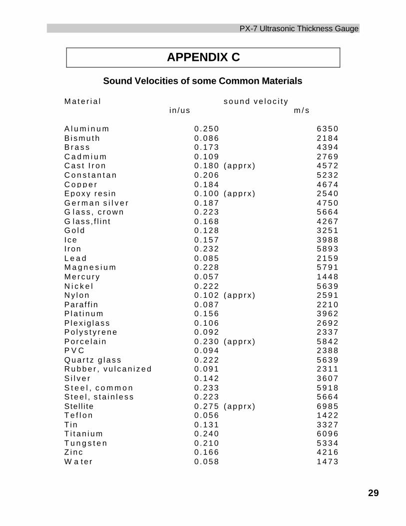
APPENDIX C
Sound Velocities of some Common Materials
M a t e r i a l s o u n d v e l o c i t yin /us m / s
A l u m i n u m 0 . 2 5 0 6 3 5 0B i s m u t h 0 . 0 8 6 2 1 8 4B r a s s 0 . 1 7 3 4 3 9 4C a d m i u m 0 . 1 0 9 2 7 6 9C a s t I r o n 0 . 1 8 0 (app rx ) 4 5 7 2C o n s t a n t a n 0 . 2 0 6 5 2 3 2C o p p e r 0 . 1 8 4 4 6 7 4Epoxy res in 0 . 1 0 0 (app rx ) 2 5 4 0G e r m a n s i l v e r 0 . 1 8 7 4 7 5 0G l a s s , c r o w n 0 . 2 2 3 5 6 6 4G lass , f l i n t 0 . 1 6 8 4 2 6 7G o l d 0 . 1 2 8 3 2 5 1Ice 0 . 1 5 7 3 9 8 8I ron 0 . 2 3 2 5 8 9 3L e a d 0 . 0 8 5 2 1 5 9M a g n e s i u m 0 . 2 2 8 5 7 9 1M e r c u r y 0 . 0 5 7 1 4 4 8N i c k e l 0 . 2 2 2 5 6 3 9N y l o n 0 . 1 0 2 (app rx ) 2 5 9 1Paraf f in 0 . 0 8 7 2 2 1 0P l a t i n u m 0 . 1 5 6 3 9 6 2P lex i g l ass 0 . 1 0 6 2 6 9 2P o l y s t y r e n e 0 . 0 9 2 2 3 3 7P o r c e l a i n 0 . 2 3 0 (app rx ) 5 8 4 2P V C 0 . 0 9 4 2 3 8 8Q u a r t z g l a s s 0 . 2 2 2 5 6 3 9R u b b e r , v u l c a n i z e d 0 . 0 9 1 2 3 1 1S i l v e r 0 . 1 4 2 3 6 0 7S t e e l , c o m m o n 0 . 2 3 3 5 9 1 8S t e e l , s t a i n l e s s 0 . 2 2 3 5 6 6 4Stel l i te 0 . 2 7 5 (app rx ) 6 9 8 5T e f l o n 0 . 0 5 6 1 4 2 2T in 0 . 1 3 1 3 3 2 7T i t a n i u m 0 . 2 4 0 6 0 9 6T u n g s t e n 0 . 2 1 0 5 3 3 4Z i n c 0 . 1 6 6 4 2 1 6W a te r 0 . 0 5 8 1 4 7 3

Dakota Ultrasonics
30
blank page
PX-7 Ultrasonic Thickness Gauge
31
WARRANTY INFORMATION
• Warranty Statement •
Dakota Ultrasonics warrants the PX-7 against defects in materials and workmanship for a period of five years from receipt by the end user. Additionally, Dakota Ultrasonics warrants transducers and accessories against such defects for a period of 90 days from receipt by the end user. If Dakota Ultrasonics receives notice of such defects during the warranty period, Dakota Ultrasonics will either, at its option, repair or replace products that prove to be defective.
Should Dakota Ultrasonics be unable to repair or replace the product within a reasonable amount of time, the customer's alternative exclusive remedy shall be refund of the purchase price upon return of the product.
• Exclusions •
The above warranty shall not apply to defects resulting from: improper or inadequate maintenance by the customer; unauthorized modification or misuse; or operation outside the environmental specifications for the product.
Dakota Ultrasonics makes no other warranty, either express or implied, with respect to this product. Dakota Ultrasonics specifically disclaims any implied warranties of merchantability or fitness for a particular purpose. Some states or provinces do not allow limitations on the duration of an implied warranty, so the above limitation or exclusion may not apply to you. However, any implied warranty of merchantability or fitness is limited to the five-year duration of this written warranty.
This warranty gives you specific legal rights, and you may also have other rights which may vary from state to state or province to province.
• Obtaining Service During Warranty Period •
If your hardware should fail during the warranty period, contact Dakota Ultrasonics and arrange for servicing of the product. Retain proof of purchase in order to obtain warranty service.
For products that require servicing, Dakota Ultrasonics may use one of the following methods:
- Repair the product - Replace the product with a re-manufactured unit - Replace the product with a product of equal or greater performance - Refund the purchase price.
• After the Warranty Period •
If your hardware should fail after the warranty period, contact Dakota Ultrasonics for
details of the services available, and to arrange for non-warranty service.
MATERIAL SAFETY DATA SHEETN/A = not applicable or not available (To comply with 29 CFR 1910.1200)
SECTION 1 – PRODUCT IDENTIFICATION
Product Name: SOUNDSAFEGeneric Name: Ultrasonic CouplantManufacturer: Sonotech, Inc. 774 Marine Dr., Bellingham, WA 98225 (360) 671-9121
NFPA Hazardous MaterialsIdentification System (est)Health……………………0Flammability…………….0Reactivity………………..0
SECTION 2 – HAZARDOUS INGREDIENTS
This material does not contain any ingredients havingknown health hazards in concentrations greater than 1%.
This material does not contain any known or suspectedcarcinogens.
SECTION 3 – PHYSICAL DATA(nominal)
Boiling Point: >220°F pH: 7.35 – 7.9Freezing Point: <20°F Acoustic Imp.: 1.726x10⁶
Vapor Pressure: N/A Vapor Density: N/AEvaporation Rate: N/A Specific Gravity: >1.02Solubility in Water: completeAppearance and Odor: water white, opaque gel; bland odor
SECTION 4 – FIRE AND EXPLOSIONHAZARD DATA
Flash Point: noneUpper Exposure Limit: noneLower Exposure Limit: noneSpecial Fire Fighting Procedures: N/AExtinguishing media: N/AUnusual Fire and Explosion Hazards: none
SECTION 5 – REACTIVITY DATA
Stability: StableConditions to Avoid: noneIncompatibility (Materials to Avoid): none knownHazardous Polymerization: will not occurHazardous Decomposition or Byproducts: none known
SECTION 6 – HEALTH HAZARD AND FIRST AID DATA
Routes of Entry:1
Skin: not likely Ingestion: not normallyEyes: not normally Inhalation: noEffects of Overexposure: Acute: May cause temporary
eye irritationChronic: none expected
First Aid Procedures:Skin: Remove with water if desired.Eyes: Flush with water for 15 minutes.Ingestion: For large quantities, induce vomiting and
call a physician.Inhalation: N/A
SECTION 7 – STORAGE AND HANDLINGINFORMATION
Precautions to be taken in handling and storage: Storebetween 20°F and 120°F. Spills are slippery and shouldbe cleaned up immediately.Steps to be taken in case material is released or spilled:Pick up excess for disposal. Clean with water.Waste disposal method: Dispose of in accordance withfederal, state, and local regulations.
SECTION 8 – CONTROL MEASURES
Respiratory Protection: not requiredVentilation: not requiredProtective Gloves: on individuals demonstrating
sensitivity to SOUNDSAFEEye Protection: as required by working conditionsOther Protective Equipment: not required
1SOUNDSAFE contains only food grade and cosmetic grade ingredients.
Toll Free: 1-800-458-4254
SONOTECH, INC.774 Marine Dr., Bellingham, WA 98225
Telephone: (360) 671-9121 Fax: (360) 671-9024
Related Documents