SAFETY.CAT.COM Operation and Maintenance Manual C15 and C18 Engines BDN 1-Up (C15 Engine) LDN 1-Up (C18 Engine) SEBU8598-09 December 2014

Welcome message from author
This document is posted to help you gain knowledge. Please leave a comment to let me know what you think about it! Share it to your friends and learn new things together.
Transcript

SAFETY.CAT.COM
Operation andMaintenanceManualC15 and C18 EnginesBDN 1-Up (C15 Engine)LDN 1-Up (C18 Engine)
SEBU8598-09December 2014

Important Safety InformationMost accidents that involve product operation, maintenance and repair are caused by failure to observebasic safety rules or precautions. An accident can often be avoided by recognizing potentially hazardoussituations before an accident occurs. A person must be alert to potential hazards, including human factorsthat can affect safety. This person should also have the necessary training, skills and tools to perform thesefunctions properly.
Improper operation, lubrication, maintenance or repair of this product can be dangerous and couldresult in injury or death.
Do not operate or perform any lubrication,maintenance or repair on this product, until you verifythat you are authorized to perform this work, and have read and understood the operation,lubrication, maintenance and repair information.
Safety precautions and warnings are provided in this manual and on the product. If these hazard warningsare not heeded, bodily injury or death could occur to you or to other persons.
The hazards are identified by the “Safety Alert Symbol” and followed by a “Signal Word” such as“DANGER”, “WARNING” or “CAUTION”. The Safety Alert “WARNING” label is shown below.
The meaning of this safety alert symbol is as follows:
Attention! Become Alert! Your Safety is Involved.
The message that appears under the warning explains the hazard and can be either written or pictoriallypresented.
A non-exhaustive list of operations that may cause product damage are identified by “NOTICE” labels onthe product and in this publication.
Caterpillar cannot anticipate every possible circumstance that might involve a potential hazard.The warnings in this publication and on the product are, therefore, not all inclusive. You must notuse this product in any manner different from that considered by this manual without first satisfyingyourself that you have considered all safety rules and precautions applicable to the operation of theproduct in the location of use, including site-specific rules and precautions applicable to theworksite. If a tool, procedure, work method or operating technique that is not specificallyrecommended by Caterpillar is used, you must satisfy yourself that it is safe for you and for others.You should also ensure that you are authorized to perform this work, and that the product will not bedamaged or become unsafe by the operation, lubrication, maintenance or repair procedures thatyou intend to use.
The information, specifications, and illustrations in this publication are on the basis of information that wasavailable at the time that the publication was written. The specifications, torques, pressures,measurements, adjustments, illustrations, and other items can change at any time. These changes canaffect the service that is given to the product. Obtain the complete and most current information before youstart any job. Cat dealers have the most current information available.
When replacement parts are required for thisproduct Caterpillar recommends using Cat re-placement parts.
Failure to follow this warning may lead to pre-mature failures, product damage, personal in-jury or death.
In the United States, the maintenance, replacement, or repair of the emission control devices andsystemsmay be performed by any repair establishment or individual of the owner's choosing.
i05296198
Table of Contents
Foreword.............................. ............................. 4
Safety Section
Safety Messages....................... ....................... 5
General Hazard Information ............... .............. 7
Burn Prevention....................... ....................... 10
Fire Prevention and Explosion Prevention ... ...11
Crushing Prevention and Cutting Prevention . 13
Mounting and Dismounting............... .............. 13
Before Starting Engine ................. .................. 13
Engine Starting........................ ....................... 14
Engine Stopping ....................... ...................... 14
Electrical System...................... ...................... 14
Engine Electronics..................... ..................... 15
Product InformationSection
General Information.................... .................... 16
Product Identification Information.......... ......... 20
Operation Section
Lifting and Storage..................... ..................... 23
Features and Controls .................. .................. 27
Engine Diagnostics..................... .................... 32
Engine Starting........................ ....................... 33
Engine Operation...................... ...................... 37
Cold Weather Operation................. ................ 42
Engine Stopping ....................... ...................... 44
MaintenanceSection
Refill Capacities....................... ....................... 45
Maintenance Recommendations.......... .......... 51
Maintenance Interval Schedule (C15 Engines)54
Maintenance Interval Schedule (C15 EnginesWith Ratings Greater Than 579 hp) ....... ....... 55
Maintenance Interval Schedule (C18 EnginesWith Ratings Greater Than 760 HP)....... ...... 56
Maintenance Interval Schedule (C18 Engines)58
Warranty Section
Warranty Information ................... ................... 94
Reference InformationSection
Engine Ratings ........................ ....................... 95
Customer Service ...................... ..................... 96
ReferenceMaterials ........................................ 98
Index Section
Index............................... .............................. 102
SEBU8598 3Table of Contents

Foreword
Literature InformationThis manual contains safety, operation instructions,lubrication and maintenance information. This manualshould be stored in or near the engine area in aliterature holder or literature storage area. Read,study and keep it with the literature and engineinformation.
English is the primary language for all Catpublications. The English used facilitates translationand consistency in electronic media delivery.
Some photographs or illustrations in this manualshow details or attachments that may be differentfrom your engine. Guards and covers may have beenremoved for illustrative purposes. Continuingimprovement and advancement of product designmay have caused changes to your engine which arenot included in this manual. Whenever a questionarises regarding your engine, or this manual, pleaseconsult with your Cat dealer for the latest availableinformation.
SafetyThis safety section lists basic safety precautions. Inaddition, this section identifies hazardous, warningsituations. Read and understand the basicprecautions listed in the safety section beforeoperating or performing lubrication, maintenance andrepair on this product.
OperationOperating techniques outlined in this manual arebasic. They assist with developing the skills andtechniques required to operate the engine moreefficiently and economically. Skill and techniquesdevelop as the operator gains knowledge of theengine and its capabilities.
The operation section is a reference for operators.Photographs and illustrations guide the operatorthrough procedures of inspecting, starting, operatingand stopping the engine. This section also includes adiscussion of electronic diagnostic information.
MaintenanceThe maintenance section is a guide to engine care.The illustrated, step-by-step instructions are groupedby fuel consumption, service hours and/or calendartime maintenance intervals. Items in the maintenanceschedule are referenced to detailed instructions thatfollow.
Use fuel consumption or service hours to determineintervals. Calendar intervals shown (daily, annually,etc.) may be used instead of service meter intervals ifthey provide more convenient schedules andapproximate the indicated service meter reading.
Recommended service should be performed at theappropriate intervals as indicated in the MaintenanceInterval Schedule. The actual operating environmentof the engine also governs the Maintenance IntervalSchedule. Therefore, under extremely severe, dusty,wet or freezing cold operating conditions, morefrequent lubrication and maintenance than isspecified in the Maintenance Interval Schedule maybe necessary.
The maintenance schedule items are organized for apreventive maintenance management program. If thepreventive maintenance program is followed, aperiodic tune-up is not required. The implementationof a preventive maintenance management programshould minimize operating costs through costavoidances resulting from reductions in unscheduleddowntime and failures.
Maintenance IntervalsPerformmaintenance on items at multiples of theoriginal requirement. Each level and/or individualitems in each level should be shifted ahead or backdepending upon your specific maintenance practices,operation and application. We recommend that themaintenance schedules be reproduced and displayednear the engine as a convenient reminder. We alsorecommend that a maintenance record be maintainedas part of the engine's permanent record.
See the section in the Operation and MaintenanceManual, “Maintenance Records” for informationregarding documents that are generally accepted asproof of maintenance or repair. Your authorized Catdealer can assist you in adjusting your maintenanceschedule to meet the needs of your operatingenvironment.
OverhaulMajor engine overhaul details are not covered in theOperation and Maintenance Manual except for theinterval and the maintenance items in that interval.Major repairs are best left to trained personnel or anauthorized Cat dealer. Your Cat dealer offers a varietyof options regarding overhaul programs. If youexperience a major engine failure, there are alsonumerous after failure overhaul options availablefrom your Cat dealer. Consult with your dealer forinformation regarding these options.
California Proposition 65 WarningDiesel engine exhaust and some of its constituentsare known to the State of California to cause cancer,birth defects, and other reproductive harm.
Battery posts, terminals and related accessoriescontain lead and lead compounds.Wash hands afterhandling.
4 SEBU8598Foreword

Safety Sectioni04085252
Safety MessagesSMCS Code: 1000; 7405
There may be several specific safety messages onyour engine. The exact location and a description ofthe safety messages are reviewed in this section.Become familiar with all safety messages.
Ensure that all of the safety messages are legible.Clean the safety messages or replace the safetymessages if the words cannot be read or if theillustrations are not visible. Use a cloth, water, andsoap to clean the safety messages. Do not usesolvents, gasoline, or other harsh chemicals.Solvents, gasoline, or harsh chemicals could loosenthe adhesive that secures the safety messages. Thesafety messages that are loosened could drop off theengine.
Replace any safety message that is damaged ormissing. If a safety message is attached to a part ofthe engine that is replaced, install a new safetymessage on the replacement part. Your Caterpillardealer can provide new safety messages.
Illustration 1 g02295113
View of the right side of a typical C15 or C18 Industrial Engine
SEBU8598 5Safety Section
Safety Messages

UniversalWarning (1)
Illustration 2 g01370904
One safety message is located on the left side of thevalve cover. One safety message is located on theright side of the valve cover.
Do not operate or work on this equipment unlessyou have read and understand the instructionsand warnings in the Operation and MaintenanceManual. Failure to follow the instructions or heedthe warnings could result in injury or death. Con-tact any Caterpillar dealer for replacement man-uals. Proper care is your responsibility.
Sulfuric Acid Burn (2)
Illustration 3 g01382725
One safety message for sulfuric acid burn is locatedon top of the exhaust cooler. One safety message forsulfuric acid burn is located on the right side of theexhaust cooler.
Sulfuric Acid Burn Hazard may cause serious per-sonal injury or death.
The exhaust gas cooler may contain a smallamount of sulfuric acid. The use of fuel with sulfurlevels greater than 15 ppm may increase theamount of sulfuric acid formed. The sulfuric acidmay spill from the cooler during service of the en-gine. The sulfuric acid will burn the eyes, skin andclothing on contact. Always wear the appropriatepersonal protective equipment (PPE) that is notedon a material safety data sheet (MSDS) for sulfuricacid. Always follow the directions for first aid thatare noted on a material safety data sheet (MSDS)for sulfuric acid.
6 SEBU8598Safety SectionSafety Messages

i05334609
General Hazard InformationSMCS Code: 1000; 4450; 7405
Illustration 4 g00104545
Attach a “Do Not Operate” warning tag to the startswitch or controls before the engine is serviced orrepaired. These warning tags (Special Instruction,SEHS7332) are available from your Cat dealer.Attach the warning tags to the engine and to eachoperator control station. When appropriate,disconnect the starting controls.
Do not allow unauthorized personnel on the engine,or around the engine when the engine is beingserviced.
Cautiously remove the following parts. To helpprevent spraying or splashing of pressurized fluids,hold a rag over the part that is being removed.
• Filler caps
• Grease fittings
• Pressure taps
• Breathers
• Drain plugs
Use caution when cover plates are removed.Gradually loosen, but do not remove the last two boltsor nuts that are located at opposite ends of the coverplate or the device. Before removing the last two boltsor nuts, pry the cover loose in order to relieve anyspring pressure or other pressure.
Illustration 5 g00702020
• Wear a hard hat, protective glasses, and otherprotective equipment, as required.
• When work is performed around an engine that isoperating, wear protective devices for ears in orderto help prevent damage to hearing.
• Do not wear loose clothing or jewelry that can snagon controls or on other parts of the engine.
• Ensure that all protective guards and all covers aresecured in place on the engine.
• Never put maintenance fluids into glasscontainers. Glass containers can break.
• Use all cleaning solutions with care.
• Report all necessary repairs.
Unless other instructions are provided, performthe maintenance under the following conditions:
SEBU8598 7Safety Section
General Hazard Information

• The engine is stopped. Ensure that the enginecannot be started.
• The protective locks or the controls are in theapplied position.
• Disconnect the batteries when maintenance isperformed or when the electrical system isserviced. Disconnect the battery ground leads.Tape the leads in order to help prevent sparks.
• When starting a new engine, make provisions tostop the engine if an overspeed occurs. If anengine has not been started since service hasbeen performed, make provisions to stop theengine if an overspeed occurs. Shutting down theengine may be accomplished by shutting off thefuel supply and/or the air supply to the engine.
• Do not attempt any repairs that are notunderstood. Use the proper tools. Replace anyequipment that is damaged or repair theequipment.
• Start the engine with the operator controls. Nevershort across the starting motor terminals or thebatteries. This method of starting the engine couldbypass the engine neutral start system and/or theelectrical system could be damaged.
Pressurized Air and WaterPressurized air and/or water can cause debris and/orhot water to be blown out which could result inpersonal injury.
The maximum air pressure for cleaning purposesmust be reduced to 205 kPa (30 psi) when the airnozzle is deadheaded and used with effective chipguarding (if applicable) and personal protectiveequipment. The maximum water pressure forcleaning purposes must be below 275 kPa (40 psi).
When pressurized air and/or pressurized water isused for cleaning, wear protective clothing, protectiveshoes, and eye protection. Eye protection includesgoggles or a protective face shield. Always wear eyeprotection for cleaning the cooling system.
Avoid direct spraying of water on electricalconnectors, connections, and components. Whenusing air for cleaning, allow the machine to cool toreduce the possibility of fine debris igniting whenredeposited on hot surfaces.
Fluid Penetration
Illustration 6 g00687600
Always use a board or cardboard when you check fora leak. Leaking fluid that is under pressure canpenetrate body tissue. Fluid penetration can causeserious injury and possible death. A pin hole leak cancause severe injury. If fluid is injected into your skin,you must get treatment immediately. Seek treatmentfrom a doctor that is familiar with this type of injury.
Containing Fluid SpillageNOTICE
Care must be taken to ensure that fluids are con-tained during performance of inspection, mainte-nance, testing, adjusting, and repair of the product.Be prepared to collect the fluid with suitable contain-ers before opening any compartment or disassem-bling any component containing fluids.
Refer to Special Publication, NENG2500, “Cat DealerService Tool Catalog” or refer to Special Publication,PECJ0003, “Cat Shop Supplies and Tools Catalog”for tools and supplies suitable to collect and containfluids on Cat products.
Dispose of all fluids according to local regulations andmandates.
8 SEBU8598Safety SectionGeneral Hazard Information

Static Electricity Hazard whenFueling with Ultra-lowSulfur DieselFuelThe removal of sulfur and other compounds in ultra-low sulfur diesel fuel (ULSD fuel) decreases theconductivity of ULSD and increases the ability ofULSD to store static charge. Refineries may havetreated the fuel with a static dissipating additive.Many factors can reduce the effectiveness of theadditive over time. Static charges can build up inULSD fuel while the fuel is flowing through fueldelivery systems. Static electricity discharge whencombustible vapors are present could result in a fireor explosion. Ensure that the entire system used torefuel your machine (fuel supply tank, transfer pump,transfer hose, nozzle, and others) is properlygrounded and bonded. Consult with your fuel or fuelsystem supplier to ensure that the delivery systemcomplies with fueling standards for proper groundingand bonding.
Avoid static electricity risk when fueling. Ultra-lowsulfur diesel fuel (ULSD fuel) poses a greater stat-ic ignition hazard than earlier diesel formulationswith a higher sulfur contents. Avoid death or seri-ous injury from fire or explosion. Consult withyour fuel or fuel system supplier to ensure the de-livery system is in compliance with fueling stand-ards for proper grounding and bonding practices.
Lines, Tubes, and HosesDo not bend or strike high-pressure lines. Do notinstall lines, tubes, or hoses that are damaged.
Repair any fuel lines, oil lines, tubes, or hoses thatare loose or damaged. Leaks can cause fires.
Inspect all lines, tubes, and hoses carefully. Do notuse bare hands to check for leaks. Always use aboard or cardboard for checking engine componentsfor leaks. Tighten all connections to therecommended torque.
Check for the following conditions:
• End fittings that are damaged or leaking
• Outer covering that is chafed or cut
• Wire that is exposed in reinforced hose
• Outer covering that is ballooning locally
• Flexible part of the hose that is kinked or crushed
• Armoring that is embedded in the outer covering
Ensure that all of the clamps, the guards, and theheat shields are installed correctly. Correct installationof these components will help to prevent theseeffects: vibration, rubbing against other parts andexcessive heat during operation.
Inhalation
Illustration 7 g02159053
ExhaustUse caution. Exhaust fumes can be hazardous toyour health. If you operate the equipment in anenclosed area, adequate ventilation is necessary.
Asbestos InformationCat equipment and replacement parts that areshipped from Caterpillar are asbestos free. Caterpillarrecommends the use of only genuine Catreplacement parts. Use the following guidelines whenyou handle any replacement parts that containasbestos or when you handle asbestos debris.
Use caution. Avoid inhaling dust that might begenerated when you handle components that containasbestos fibers. Inhaling this dust can be hazardousto your health. The components that may containasbestos fibers are brake pads, brake bands, liningmaterial, clutch plates, and some gaskets. Theasbestos that is used in these components is boundin a resin or sealed in some way. Normal handling isnot hazardous unless airborne dust that containsasbestos is generated.
If dust that may contain asbestos is present, there areseveral guidelines that should be followed:
SEBU8598 9Safety Section
General Hazard Information
• Never use compressed air for cleaning.
• Avoid brushing materials that contain asbestos.
• Avoid grinding materials that contain asbestos.
• Use a wet method in order to clean up asbestosmaterials.
• A vacuum cleaner that is equipped with a highefficiency particulate air filter (HEPA) can also beused.
• Use exhaust ventilation on permanent machiningjobs.
• Wear an approved respirator if there is no otherway to control the dust.
• Comply with applicable rules and regulations forthe work place. In the United States, useOccupational Safety and Health Administration(OSHA) requirements. These OSHA requirementscan be found in “29 CFR 1910.1001”.
• Obey environmental regulations for the disposal ofasbestos.
• Stay away from areas that might have asbestosparticles in the air.
SoftwrapKeep the engine room ventilation operating at fullcapacity. Wear a particulate respirator that has beenapproved by the National Institute of OccupationalSafety and Health (NIOSH). Wear appropriateprotective clothing in order to minimize direct contact.Use good hygiene practices and wash handsthoroughly after handling Softwrap material. Do notsmoke until washing hands thoroughly after handlingSoftwrap material. Clean up debris with a vacuum orby wet sweeping. Do not use pressurized air to cleanup debris.
Reference: The applicable material safety datasheets can be found at the following web site bysearching using part number or the name:
http://dsf2ws.cat.com/msds/servlet/cat.cis.ecs.msdsSearch.controller.UserIdentificationDisplayServlet
Dispose of Waste Properly
Illustration 8 g00706404
Improperly disposing of waste can threaten theenvironment. Potentially harmful fluids should bedisposed of according to local regulations.
Always use leakproof containers when you drainfluids. Do not pour waste onto the ground, down adrain, or into any source of water.
i03895768
Burn PreventionSMCS Code: 1000; 4450; 7405
Do not touch any part of an operating engine orengine aftertreatment system. Allow the engine or theengine aftertreatment system to cool before anymaintenance is performed on the engine or theengine aftertreatment system. Relieve all pressure inthe appropriate system before any lines, fittings orrelated items are disconnected.
CoolantWhen the engine is at operating temperature, theengine coolant is hot. The coolant is also underpressure. The radiator and all lines to the heaters orto the engine contain hot coolant. Any contact withhot coolant or with steam can cause severe burns.Allow cooling system components to cool before thecooling system is drained.
Check the coolant level after the engine has stoppedand the engine has been allowed to cool. Ensure thatthe filler cap is cool before removing the filler cap.The filler cap must be cool enough to touch with abare hand. Remove the filler cap slowly in order torelieve pressure.
Cooling system conditioner contains alkali. Alkali cancause personal injury. Do not allow alkali to contactthe skin, the eyes, or the mouth.
10 SEBU8598Safety SectionBurn Prevention
OilsHot oil and hot lubricating components can causepersonal injury. Do not allow hot oil or hotcomponents to contact the skin.
If the application has a makeup tank, remove the capfor the makeup tank after the engine has stopped.The filler cap must be cool to the touch.
BatteriesThe liquid in a battery is an electrolyte. Electrolyte isan acid that can cause personal injury. Do not allowelectrolyte to contact the skin or the eyes.
Do not smoke while checking the battery electrolytelevels. Batteries give off flammable fumes which canexplode.
Always wear protective glasses when you work withbatteries. Wash hands after touching batteries. Theuse of gloves is recommended.
i05626649
Fire Prevention and ExplosionPreventionSMCS Code: 1000; 4450; 7405
Illustration 9 g00704000
Use of personal protection equipment (PPE) may beneeded.
All fuels, most lubricants, and some coolant mixturesare flammable.
Always perform a Walk-Around Inspection, whichmay help you identify a fire hazard. Do not operate aproduct when a fire hazard exists. Contact your Catdealer for service.
Flammable fluids that are leaking or spilled onto hotsurfaces or onto electrical components can cause afire. Fire may cause personal injury and propertydamage.
A flash fire may result if the covers for the enginecrankcase are removed within 15 minutes after anemergency shutdown.
Determine whether the engine will be operated in anenvironment that allows combustible gases to bedrawn into the air inlet system. These gases couldcause the engine to overspeed. Personal injury,property damage, or engine damage could result.
If the application involves the presence ofcombustible gases, consult your Cat dealer foradditional information about suitable protectiondevices.
Remove all flammable materials such as fuel, oil, anddebris from the engine. Do not allow any flammablematerials to accumulate on the engine.
All fluids that are captured in the fluid spillcontainment basin should be cleaned up immediately.Failure to clean up spilled fluids can cause a fire. Firemay cause personal injury and property damage.
Store fuels and lubricants in properly markedcontainers away from unauthorized persons. Storeoily rags and any flammable materials in protectivecontainers. Do not smoke in areas that are used forstoring flammable materials.
Do not expose the engine to any flame.
Exhaust shields (if equipped) protect hot exhaustcomponents from oil or fuel spray in a line, a tube, ora seal failure. Exhaust shields must be installedcorrectly.
Do not weld on lines or tanks that contain flammablefluids. Do not flame cut lines or tanks that containflammable fluid. Clean any such lines or tanksthoroughly with a nonflammable solvent prior towelding or flame cutting.
Wiring must be kept in good condition. Properly routeand attach all electrical wires. Check all electricalwires daily. Repair any wires that are loose or frayedbefore you operate the engine. Clean all electricalconnections and tighten all electrical connections.
Eliminate all wiring that is unattached or unnecessary.Do not use any wires or cables that are smaller thanthe recommended gauge. Do not bypass any fusesand/or circuit breakers.
Arcing or sparking could cause a fire. Secureconnections, recommended wiring, and properlymaintained battery cables will help to prevent arcingor sparking.
Inspect all lines and hoses for wear or fordeterioration. Properly route all hoses. The lines andhoses must have adequate support and secureclamps. Tighten all connections to the recommendedtorque. Leaks can cause fires.
Properly install all oil filters and fuel filters. The filterhousings must be tightened to the proper torque.
SEBU8598 11Safety Section
Fire Prevention and Explosion Prevention

Illustration 10 g00704059
Use caution when you are refueling an engine. Do notsmoke while you are refueling an engine. Do notrefuel an engine near open flames or sparks. Alwaysstop the engine before refueling.
Avoid static electricity risk when fueling. Ultra LowSulfur Diesel (ULSD) poses a greater static ignitionhazard than earlier diesel formulations with a higherSulfur content. Avoid death or serious injury from fireor explosion. Consult with your fuel or fuel systemsupplier to ensure that the delivery system is incompliance with fueling standards for propergrounding and bonding practices.
Illustration 11 g02298225
Gases from a battery can explode. Keep any openflames or sparks away from the top of a battery. Donot smoke in battery charging areas.
Never check the battery charge by placing a metalobject across the terminal posts. Use a voltmeter or ahydrometer.
Improper jumper cable connections can cause anexplosion that can result in injury. Refer to theOperation Section of this manual for specificinstructions.
Do not charge a frozen battery. Charging a frozenbattery may result in an explosion.
The batteries must be kept clean. The covers (ifequipped) must be kept on the cells. Use therecommended cables, connections, and battery boxcovers when the engine is operated.
Fire ExtinguisherMake sure that a fire extinguisher is available. Befamiliar with the operation of the fire extinguisher.Inspect the fire extinguisher and service the fireextinguisher regularly. Obey the recommendations onthe instruction plate.
EtherEther is flammable and poisonous.
Use ether in ventilated areas. Do not smoke whileyou are replacing an ether cylinder or while you areusing an ether spray.
12 SEBU8598Safety SectionFire Prevention and Explosion Prevention
Do not store ether cylinders in living areas or in theengine compartment. Do not store ether cylinders indirect sunlight or in temperatures above 49 °C(120 °F). Keep ether cylinders away from openflames or sparks.
Dispose of used ether cylinders properly. Do notpuncture an ether cylinder. Keep ether cylinders awayfrom unauthorized personnel.
Do not spray ether into an engine if the engine isequipped with a thermal starting aid for cold weatherstarting.
Lines, Tubes, and HosesDo not bend high-pressure lines. Do not strike high-pressure lines. Do not install any lines that are bent ordamaged.
Repair any lines that are loose or damaged. Leakscan cause fires. Consult your Cat dealer for repair orfor replacement parts.
Check lines, tubes, and hoses carefully. Do not useyour bare hand to check for leaks. Use a board orcardboard to check for leaks. Tighten all connectionsto the recommended torque.
Replace the parts if any of the following conditionsare present:
• End fittings are damaged or leaking.
• Outer coverings are chafed or cut.
• Wires are exposed.
• Outer coverings are ballooning.
• Flexible parts of the hoses are kinked.
• Outer covers have embedded armoring.
• End fittings are displaced.
Make sure that all clamps, guards, and heat shieldsare installed correctly in order to prevent vibration,rubbing against other parts, and excessive heat.
i01359666
Crushing Prevention andCutting PreventionSMCS Code: 1000; 4450; 7405
Support the component properly when work beneaththe component is performed.
Unless other maintenance instructions are provided,never attempt adjustments while the engine isrunning.
Stay clear of all rotating parts and of all moving parts.Leave the guards in place until maintenance isperformed. After the maintenance is performed,reinstall the guards.
Keep objects away frommoving fan blades. The fanblades will throw objects or cut objects.
When objects are struck, wear protective glasses inorder to avoid injury to the eyes.
Chips or other debris may fly off objects when objectsare struck. Before objects are struck, ensure that noone will be injured by flying debris.
i01372247
Mounting and DismountingSMCS Code: 1000; 4450; 7405
Inspect the steps, the handholds, and the work areabefore mounting the engine. Keep these items cleanand keep these items in good repair.
Mount the engine and dismount the engine only atlocations that have steps and/or handholds. Do notclimb on the engine, and do not jump off the engine.
Face the engine in order to mount the engine ordismount the engine. Maintain a three-point contactwith the steps and handholds. Use two feet and onehand or use one foot and two hands. Do not use anycontrols as handholds.
Do not stand on components which cannot supportyour weight. Use an adequate ladder or use a workplatform. Secure the climbing equipment so that theequipment will not move.
Do not carry tools or supplies when you mount theengine or when you dismount the engine. Use a handline to raise and lower tools or supplies.
i03560601
Before Starting EngineSMCS Code: 1000
NOTICEFor initial start-up of a new or rebuilt engine, and forstart-up of an engine that has been serviced, makeprovision to shut the engine off should an overspeedoccur. This may be accomplished by shutting off theair and/or fuel supply to the engine.
SEBU8598 13Safety Section
Crushing Prevention and Cutting Prevention

Engine exhaust contains products of combustionwhich may be harmful to your health. Always startand operate the engine in a well ventilated areaand, if in an enclosed area, vent the exhaust to theoutside.
Inspect the engine for potential hazards.
Do not start the engine or move any of the controls ifthere is a “DO NOT OPERATE” warning tag orsimilar warning tag attached to the start switch or tothe controls.
Before starting the engine, ensure that no one is on,underneath, or close to the engine. Ensure that thearea is free of personnel.
If equipped, ensure that the lighting system for theengine is suitable for the conditions. Ensure that alllights work properly, if equipped.
All protective guards and all protective covers mustbe installed if the engine must be started in order toperform service procedures. To help prevent anaccident that is caused by parts in rotation, workaround the parts carefully.
Do not bypass the automatic shutoff circuits. Do notdisable the automatic shutoff circuits. The circuits areprovided in order to help prevent personal injury. Thecircuits are also provided in order to help preventengine damage.
See the Service Manual for repairs and foradjustments.
i03941639
Engine StartingSMCS Code: 1000
If a warning tag is attached to the engine start switchor to the controls, DO NOTstart the engine or movethe controls. Consult with the person that attachedthe warning tag before the engine is started.
All protective guards and all protective covers mustbe installed if the engine must be started in order toperform service procedures. To help prevent anaccident that is caused by parts in rotation, workaround the parts carefully.
Start the engine with the engine start switch.
Always start the engine according to the procedurethat is described in this Operation and MaintenanceManual, “Starting the Engine” for information aboutstarting the engine. Know the correct procedure toprevent major damage to the engine components.Know the correct procedure to prevent personalinjury.
To ensure that the jacket water heater (if equipped)and/or the lube oil heater (if equipped) is workingproperly, check the water temperature gauge and theoil temperature gauge during the heater operation.
Engine exhaust contains products of combustion thatcan be harmful to your health. Always start the engineand operate the engine in a ventilated area. If theengine is started in an enclosed area, vent the engineexhaust to the outside.
i01462046
Engine StoppingSMCS Code: 1000
Stop the engine according to the procedure in theOperation and Maintenance Manual, “EngineStopping (Operation Section)” in order to avoidoverheating of the engine and accelerated wear ofthe engine components.
Use the Emergency Stop Button (if equipped) ONLYin an emergency situation. Do not use the EmergencyStop Button for normal engine stopping. After anemergency stop, DO NOTstart the engine until theproblem that caused the emergency stop has beencorrected.
Stop the engine if an overspeed condition occursduring the initial start-up of a new engine or an enginethat has been overhauled. This may be accomplishedby shutting off the fuel supply to the engine and/orshutting off the air supply to the engine.
To stop an electronically controlled engine, cut thepower to the engine.
i03896010
Electrical SystemSMCS Code: 1000; 1400
Never disconnect any charging unit circuit or batterycircuit cable from the battery when the charging unit isoperating. A spark can cause the combustible gasesthat are produced by some batteries to ignite.
To help prevent sparks from igniting combustiblegases that are produced by some batteries, thenegative “−” jump start cable should be connectedlast from the external power source to the negative“−” terminal of the starting motor. If the starting motoris not equipped with a negative “−” terminal, connectthe jump start cable to the engine block.
Check the electrical wires daily for wires that areloose or frayed. Tighten all loose electrical wiresbefore the engine is started. Repair all frayedelectrical wires before the engine is started. Refer tothe “Engine Starting” section of this Operation andMaintenance Manual for specific starting instructions.
14 SEBU8598Safety SectionEngine Starting

GroundingPracticesProper grounding for the engine electrical system isnecessary for optimum engine performance andreliability. Improper grounding will result inuncontrolled electrical circuit paths and in unreliableelectrical circuit paths.
Uncontrolled electrical circuit paths can result indamage to main bearings, to crankshaft bearingjournal surfaces, and to aluminum components.
Engines that are installed without engine-to-frameground straps can be damaged by electricaldischarge.
To ensure that the engine and the engine electricalsystems function properly, an engine-to-frame groundstrap with a direct path to the battery must be used.This path may be provided by way of a starting motorground, a starting motor ground to the frame, or adirect engine ground to the frame.
All grounds should be tight and free of corrosion. Theengine alternator must be grounded to the negative“-” battery terminal with a wire that is adequate tohandle the full charging current of the alternator.
i04021529
Engine ElectronicsSMCS Code: 1000; 1900
Tampering with the electronic system installationor the OEM wiring installation can be dangerousand could result in personal injury or death and/orengine damage.
The Electronic Control Module (ECM) provides acomprehensive, programmable engine monitoringsystem for this engine. The ECM monitors specificengine operating parameters in order to detectabnormal conditions that may develop. The ECM willgenerate an event code if a specific engine parameterexceeds an acceptable range that is defined by theengine monitoring system. The ECM will react with anaction that is dependent on the severity of thecondition. For information on event codes, refer tothis Operation and Maintenance Manual, “EventCodes” topic (Operation Section) The followingactions may be initiated by the ECM. These actionsare dependent on the severity of the condition:
• Illumination of a warning lamp or warning alarm
• Engine derate
• Engine protection shutdown
The Engine Monitoring package can vary for differentengine models and different engine applications.However, the monitoring system and the enginemonitoring control will be similar for all engines.
Note:Many of the engine control systems anddisplay modules that are available for CaterpillarEngines will work in unison with the EngineMonitoring System. Together, the two controls willprovide the engine monitoring function for the specificengine application. Refer to the TroubleshootingManual for more information.
SEBU8598 15Safety Section
Engine Electronics

Product InformationSection
General Information
i04060965
Model View IllustrationsSMCS Code: 1000
Illustration 12 g02272773
Left side view of a typical C15 or C18 Industrial Engine(1) Fuel pressure sensor pre-filter(2) Fuel pressure sensor post-filter(3) Charge air cooler outlet sensor(4) Open crankcase ventilation breather(5) NRS temperature sensor
(6) NRS valve(7) Engine control module (ECM)(8) Crankcase pressure sensor(9) Engine speed sensor(10) Fuel pump
(11) Secondary fuel filter base(12) Oil filler(13) Fuel temperature sensor
16 SEBU8598Product Information SectionModel View Illustrations

Illustration 13 g02272613
Right side view of a typical C15 or C18 Industrial Engine(14) NRS cooler (15) Turbocharger (16) Oil filter base
i04061067
Product DescriptionSMCS Code: 1000; 4450; 4491
Engine DescriptionThe Caterpillar C15 and C18 Industrial Engineprovides the following features:
• Four stroke cycle
• Mechanically actuated electronically controlled fuelinjection system
• Turbocharged
Engine Specifications
Note: The front end of the engine is opposite theflywheel end of the engine. The left and the rightsides of the engine are determined from the flywheelend. The number 1 cylinder is the front cylinder.
SEBU8598 17General InformationProduct Description

Illustration 14 g01387009
Cylinder and valve location(A) Exhaust valve(B) Inlet valve
Table 1
C15 Engine Specifications
Arrangement and Cylinders In-line six cylinder
Bore 137 mm (5.4 inch)
Stroke 171 mm (6.7 inch)
Aspiration ATAAC(1)
Displacement 15.2 L (928 cubic inch)
Firing Order 1-5-3-6-2-4
Rotation (flywheel end) Counterclockwise
(1) Air-to-air aftercooled
Table 2
C18 Engine Specifications
Arrangement and Cylinders In-Line six cylinder
Bore 145 mm (5.7 inch)
Stroke 183 mm (7.2 inch)
Aspiration ATAAC(1)
Displacement 18.1 L (1105 cubic inch)
Firing Order 1-5-3-6-2-4
Rotation (flywheel end) Counterclockwise
(1) Air-to-air aftercooled
Electronic Engine Features
The Caterpillar C15 and C18 Engine are designedfor electronic controls. The integral on boardcomputer controls the operation of the engine.Current operating conditions are monitored. TheElectronic Control Module (ECM) controls theresponse of the engine to these conditions and to thedemands of the operator. These conditions andoperator demands determine the precise control offuel injection by the ECM. The electronic enginecontrol system provides the following features:
• Engine speed governor
• Automatic air/fuel ratio control
• Torque rise shaping
• Injection timing control
• System diagnostics
• Aftertreatment regeneration control
• NOx reduction system control
Additional FeaturesThe following additional features provide increasedengine fuel economy and serviceability:
• Cold starting capability
• Tampering detection
• Diagnostics
Engine Diagnostics
The engine has built-in diagnostics in order to ensurethat all of the components are functioning properly.Under certain conditions, the engine horsepower andthe vehicle speed may be limited. A Caterpillarelectronic service tool may be used to display thediagnostic code.
There are two categories of codes: diagnostic codeand event code. These two categories of codes maybe in two different states: active and logged.
Most of the diagnostic codes are logged and stored inthe ECM. For additional information, refer to theOperation and Maintenance Manual, “EngineDiagnostics” topic (Operation Section).
Engine Service Life
Engine efficiency and maximum utilization of engineperformance depend on the adherence to properoperation and maintenance recommendations. Inaddition, use recommended fuels, coolants, andlubricants. Use the Operation and MaintenanceManual as a guide for required engine maintenance.
18 SEBU8598General InformationProduct Description

Expected engine life is predicted by the averagepower that is demanded. The average power that isdemanded is based on fuel consumption of theengine over a time. Reduced hours of operation at fullthrottle and/or operating at reduced throttle settingsresult in a lower average power demand. Reducedhours of operation will increase the length ofoperating time before an engine overhaul is required.For more information, refer to the Operation andMaintenance Manual, “Overhaul Considerations”topic (Maintenance Section).
Aftermarket Products and CaterpillarEngines
NOTICEIn order to maximize fuel system life and prevent pre-mature wear out from abrasive particles in the fuel, afour micron[c] absolute high efficiency fuel filter is re-quired for all Caterpillar common rail fuel systems.Caterpillar High Efficiency Fuel Filters meet these re-quirements. Consult your Caterpillar dealer for theproper part numbers.
When auxiliary devices, accessories, or consumables(filters, additives, catalysts, etc.) which are made byother manufacturers are used on Caterpillarproducts, the Caterpillar warranty is not affectedsimply because of such use.
However, failures that result from the installationor use of devices, accessories, or consumablesfrom other manufacturers are NOT Caterpillardefects. Therefore, the defects are NOTcoveredunder the Caterpillar warranty.
SEBU8598 19General InformationProduct Description

Product IdentificationInformation
i04092302
Plate Locations and FilmLocationsSMCS Code: 1000; 4450
Illustration 15 g02273593
View of the left side of a typical C15 or C18 IndustrialEngine
The serial number plate is located on the left side ofthe cylinder block. The engine control module willobstruct the view of the serial number plate.
Illustration 16 g00123229
Serial number plate
The following information is stamped on the serialnumber plate: engine serial number, engine modeland arrangement number.
Illustration 17 g02272993
View of the top of a typical C15 or C18 IndustrialEngine
The engine information plate is located toward therear of the valve cover. The engine information platemay be read from the right side of the engine.
Illustration 18 g01347963
Engine information plate
The following information is on the information plate:engine serial number, engine model, enginearrangement number, maximum altitude of the enginethat is necessary to achieve the rated power,horsepower, high idle, full load rpm, fuel settings andother information
20 SEBU8598Product Identification InformationPlate Locations and Film Locations

Illustration 19 g02236893
View of the exhaust system of a C15 or C18 IndustrialEngine
Illustration 20 g02236574
CEM plate
The Clean Emission Module (CEM) identificationplate contains the following information: part number,serial number, change level and configuration IDcode. This informationmay be needed by the Catdealer when inquiries are being made on the CEM.
i04019095
Emissions CertificationFilmSMCS Code: 1000; 7405
Note: This information is pertinent in the UnitedStates, in Canada and in Europe.
Consult your Cat dealer for an Emission ControlWarranty Statement.
This label is located on the engine.
i00844066
Emissions CertificationFilmSMCS Code: 1000; 7405
S/N: BDN1–Up
Illustration 21 g00284658
EPA Emissions Certification Film
Illustration 22 g00415538
European Emissions Certification Film
The EPA Emissions Certification Film (if equipped)and/or the European Emissions Certification Film (ifequipped) is located on the side of the engine.
i01382270
Reference InformationSMCS Code: 1000; 4450
Identification of the items in Table 3 may be neededin order to obtain parts and service. Some of theinformation is on the engine Serial Number Plate and/or Information Plate. Locate the information for yourengine. Record the information on the appropriatespace in Table 3 . Make a copy of this list for a record.Retain the information for future reference.
SEBU8598 21Product Identification Information
Emissions Certification Film
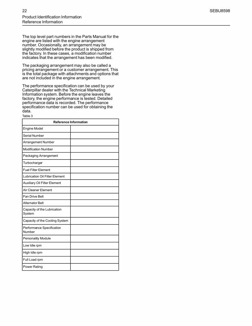
The top level part numbers in the Parts Manual for theengine are listed with the engine arrangementnumber. Occasionally, an arrangement may beslightly modified before the product is shipped fromthe factory. In these cases, a modification numberindicates that the arrangement has been modified.
The packaging arrangement may also be called apricing arrangement or a customer arrangement. Thisis the total package with attachments and options thatare not included in the engine arrangement.
The performance specification can be used by yourCaterpillar dealer with the Technical MarketingInformation system. Before the engine leaves thefactory, the engine performance is tested. Detailedperformance data is recorded. The performancespecification number can be used for obtaining thedata.Table 3
Reference Information
Engine Model
Serial Number
Arrangement Number
Modification Number
Packaging Arrangement
Turbocharger
Fuel Filter Element
Lubrication Oil Filter Element
Auxiliary Oil Filter Element
Air Cleaner Element
Fan Drive Belt
Alternator Belt
Capacity of the LubricationSystem
Capacity of the Cooling System
Performance SpecificationNumber
Personality Module
Low Idle rpm
High Idle rpm
Full Load rpm
Power Rating
22 SEBU8598Product Identification InformationReference Information
Operation Section
Lifting and Storagei04037083
Product LiftingSMCS Code: 7000; 7002
Illustration 23 g00103219
NOTICENever bend the eyebolts and the brackets. Only loadthe eyebolts and the brackets under tension. Remem-ber that the capacity of an eyebolt is less as the anglebetween the supporting members and the object be-comes less than 90 degrees.
When it is necessary to remove a component at anangle, only use a link bracket that is properly rated forthe weight.
Use a hoist to remove heavy components. Use anadjustable lifting beam to lift the engine. Allsupporting members (chains and cables) should beparallel to each other. The chains and cables shouldbe perpendicular to the top of the object that is beinglifted.
Some removals require lifting the fixtures in order toobtain proper balance and safety.
To remove the engine ONLY, use the lifting eyes thatare on the engine.
Lifting eyes are designed and installed for the specificengine arrangement. Alterations to the lifting eyesand/or the engine make the lifting eyes and the liftingfixtures obsolete. If alterations are made, ensure thatproper lifting devices are provided. Consult yourCaterpillar dealer for information regarding fixturesfor proper engine lifting.
Engine Liftingwith a Fuel Tank
Lift eyes or tank can fail when lifting tank contain-ing fluids resulting in possible personal injury.Drain tank of all fluids before lifting.
Lifting the engine with a fuel tank that is mounted tothe engine requires special equipment andprocedures. Do not lift the unit with fuel in the fueltank. Consult your Caterpillar dealer for informationregarding fixtures for proper lifting of your completepackage.
Clean EmissionModule Lifting
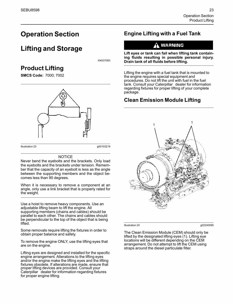
Illustration 24 g02240095
The Clean Emission Module (CEM) should only belifted by the designated lifting eyes (1). Lifting eyelocations will be different depending on the CEMarrangement. Do not attempt to lift the CEM usingstraps around the diesel particulate filter.
SEBU8598 23Operation Section
Product Lifting

i05242858
Product StorageSMCS Code: 7002
Storage (Less Than One Year)If an engine is not used, oil can run off the followingparts that normally receive lubrication: cylinder walls,piston rings, main bearings, connecting rod bearings,crankshaft and gears.
This lack of lubricant allows corrosion to begin toappear on the metal. This condition is worse in areasof high humidity.
When the engine is started again, metal to metalcontact will cause wear before the surfaces receiveoil. To minimize this wear, use the starter to turn theengine with the throttle in the FUEL OFF position.When oil pressure is shown on the pressure gauge,start the engine.
1. Clean the engine of any dirt, rust, grease, and oil.Inspect the exterior. Paint areas that contain paintdamage with a good quality paint.
2. Remove dirt from the air cleaners. Check all seals,gaskets, and the filter element for damage.
3. Apply lubricant to all points in this Operation andMaintenance Manual, “Maintenance IntervalSchedule”.
4. Drain the crankcase oil. Replace the crankcase oiland change the oil filters. For the properprocedure, refer to this Operation andMaintenance Manual.
5. If the engine is equipped with an air starting motor,fill the reservoir with the following mixture: 50percent volatile corrosion inhibitor oil(<nomen>VCI oil</nomen>) and 50 percentengine oil.
6. Add VCI oil to the crankcase oil. The volume of VCIoil in the crankcase oil should be 3 to 4 percent.
Note: If the engine crankcase is full, drain enoughengine oil so the mixture can be added.
7. Remove the air filter elements. Turn the engine atcranking speed with the throttle control in FUELOFF position. Use a sprayer to add a mixture of 50percent VCI oil and 50 percent engine oil into theair inlet or turbocharger inlet.
Note: The mixture of VCI oil can be added to the inletby removing the plug for checking turbocharger boostpressure. The minimum application rate for the VCIoil mixture is 5.5 mL per L (3 oz per 1000 cu in) ofengine displacement.
8. Use a sprayer to apply a mixture of 50 percent VCIoil and 50 percent crankcase oil into the exhaustopenings. The minimum application rate for the oilmixture is 5.5 mL per L (3 oz per 1000 cu in) ofengine displacement. Seal the exhaust pipe andseal any drain holes in the muffler.
9. Remove the fuel from the secondary fuel filterhousing. Alternately, empty and reinstall the spin-on fuel filter element in order to remove any dirtand water. Drain any sleeve metering fuel pump.
Clean the primary fuel filter. Fill with calibrationfluid or kerosene. Install the primary fuel filter andoperate the priming pump. This procedure willsend clean oil to the secondary filter and theengine.
Open the fuel tank drain valve in order to drain anywater and dirt from the fuel tank. Apply a spray ofcalibration fluid or kerosene at the rate of30 mL per 30 L (1 oz per 7.50 gal US) of fuel tankcapacity in order to prevent rust in the fuel tank.Add 0.15 mL per L (.02 oz per 1 gal US) ofcommercial biocide such as Biobor JF to the fuel.
Apply a small amount of oil to the threads on thefuel tank filler neck and install the cap. Seal allopenings to the tank in order to preventevaporation of the fuel and as a preservative.
10. Remove the fuel nozzles or spark plugs. Apply30 mL (1 oz) of the mixture of oils (50 percent VCIoil and 50 percent engine oil) into each cylinder.
Use a bar or a turning tool in order to turn over theengine slowly. This procedure puts the oil on thecylinder walls. Install all fuel nozzles or spark plugsand tighten to the correct torque.
11. Spray a thin amount of a mixture of 50 percentVCI oil and 50 percent engine oil onto the followingcomponents: flywheel, ring gear teeth and starterpinion. Install the covers in order to preventevaporation of the vapors from the VCI oil.
12. Apply a heavy amount of Cat MultipurposeGrease (MPGM) to all outside parts that move,such as rod threads, ball joints, linkage.
Note: Install all covers. Ensure that tape has beeninstalled over all openings, air inlets, exhaustopenings, the flywheel housing, the crankcasebreathers, the dipstick tubes.
24 SEBU8598Lifting and StorageProduct Storage

Ensure that all covers are airtight andweatherproof. Use a waterproof weather resistanttape such as Kendall No. 231 or an equivalent.Do not use duct tape. Duct tape will only seal for ashort time.
13. Under most conditions, removing the batteries isthe best procedure. As an alternative, place thebatteries in storage. As needed, periodicallycharge the batteries while the batteries are instorage.
If the batteries are not removed, wash the tops ofthe batteries until the tops are clean. Apply anelectrical charge to the batteries in order to obtaina specific gravity of 1.225.
Disconnect the battery terminals. Place a plasticcover over the batteries.
Note: For additional information, refer to SpecialInstruction, SEHS7633, “Battery Test Procedure”.
14. Loosen all belts.
15. Place a waterproof cover over the engine. Ensurethat the engine cover is secure. The cover shouldbe loose enough to allow air to circulate around theengine in order to prevent damage fromcondensation.
16. Attach a tag with the storage date to the engine.
17. Remove the waterproof cover at 2 month or 3month intervals in order to check the engine forcorrosion. If the engine has signs of corrosion,repeat the protection procedure.
Coolant System
Completely fill the cooling system before storage.
Refer to this Operation and Maintenance Manual,“Fluid Recommendations” for more information aboutcoolants.
Removal from Storage1. Remove all outside protective covers.
2. Change the oil and filters.
3. Check the condition of the fan and alternator belts.Replace the belts, if necessary. Refer to thisOperation and Maintenance Manual, “Belts -Inspect/Adjust/Replace” for the correct procedure.
4. Replace the fuel filter elements.
5. Remove the plastic covers from the air cleanerelements.
6. Use a bar or a turning tool in order to turn theengine in the normal direction of rotation. Theprocedure ensures that no hydraulic locks orresistance exist.
7. Before starting the engine, remove the valve coveror covers. Put a large amount of engine oil on thecamshaft, cam followers, and valve mechanism inorder to prevent damage to the mechanism.
8. Pressure-lubricate the engine before starting theengine. Pressure lubricating the engine ensuresimmediate lubrication and prevents damage to theengine during the first few minutes of engineoperation. If the engine is not equipped with aprelube pump, contact your Cat dealer forinformation about lubrication of the engine beforestarting the engine.
9. Check the condition of all rubber hoses. Replaceany worn hoses. Replace any damaged hoses.
10. Before start-up, test the cooling system for a 3percent ro a 6 percent concentration of coolantconditioner. Add liquid coolant conditioner or acoolant conditioner element, if equipped.
Test the coolant mixture for proper nitrite level. Ifnecessary, adjust the coolant mixture.
Prime the engine with clean diesel fuel beforestarting.
11. Ensure that the cooling system is clean. Ensurethat the system is full. Ensure that the system hasthe correct amount of supplemental cooling systemconditioner.
12. On the first day of operation, check the entireengine several times for leaks and correctoperation.
13. If the engine was removed from storage in whichtemperatures of less than -12°C (10°F) wereencountered, refer to Service Manual, SEBU5898,“Cold Weather Recommendations Operation andMaintenance”.
Engines with 2 year preservation groupfrom the factory
Note: Engines that are stored more than 6 monthsmust be prelubed and rotated in 6 month intervals.
For engines purchased with a factory applied, 2 yearpreservation group, follow the instructions from thisOperation and Maintenance Manual, “Removal FromStorage”, step 8 and in this Operation andMaintenance Manual, “Storage (less than 1 year)”section.
SEBU8598 25Lifting and StorageProduct Storage

For engine CEM's stored for more than one year, usefuel system cleaner (part no. 343-6210) or equivalentas recommenced in PEHJ0237, for 80 hours ofoperation.
26 SEBU8598Lifting and StorageProduct Storage
Features and Controlsi03646563
Battery Disconnect Switch(If Equipped)SMCS Code: 1411
The battery disconnect switch and the engine startswitch perform different functions. Turn off the batterydisconnect switch in order to disable the entireelectrical system. The battery remains connected tothe electrical system when you turn off the enginestart switch.
Turn the battery disconnect switch to the OFFposition and remove the key when you service theelectrical system or any other components.
Also turn the battery disconnect switch to the OFFposition and remove the key when the engine will notbe used for an extended period of a month or more.This will prevent drainage of the battery.
NOTICENever move the battery disconnect switch to the OFFposition while the engine is operating. Serious dam-age to the electrical system could result.
To ensure that no damage to the engine occurs, verifythat the engine is fully operational before cranking theengine. Do not crank an engine that is not fullyoperational.
Perform the following procedure in order to check thebattery disconnect switch for proper operation:
1.With the battery disconnect switch in the ONposition, verify that electrical components arefunctioning. Verify that the hour meter is displayinginformation. Verify that the engine will crank.
2. Turn the battery disconnect switch to the OFFposition.
3. Verify that the following items are not functioning:electrical components, hour meter and enginecranking. If any of the items continue to functionwith the battery disconnect switch in the OFFposition, consult your Caterpillar dealer.
i05316709
MonitoringSystemSMCS Code: 1900; 7400; 7450; 7451
The monitoring system is designed to alert theoperator to an immediate problem with any of theengine systems that are monitored. The MonitoringSystem is also designed to alert the operator to animpending problem with any of the engine systemsthat are monitored.
The monitoring system parameters can be accessedvia the Cat ETservice tool. Many of the parameterswithin the monitoring system can be tailored to suitthe operation of the engine.
An example of adjustments that may be made withinthe monitoring system is changing the setpoint of theengine overspeed indicator from the factory defaultsetting.
Indicators and GaugesThe instrument panel may look like the instrumentpanel that is pictured in illustration 25 or theinstrument panel may look like the instrument panelthat is pictured in illustration 26 . The instrumentpanel may not include all of the instruments that areshown in the illustration.
SEBU8598 27Features and Controls
Battery Disconnect Switch

Illustration 25 g02212133
Illustration 26 g02215293
Circuit Breaker (1) – Reset the circuitbreaker if a circuit breaker trips. Pressthe button in order to reset the circuit
breaker. If the electrical system is workingproperly, the button will remain pressed. If thebutton does not remain pressed or if the circuitbreaker trips soon after being reset, check theappropriate electrical circuit. Repair the electricalcircuit, if necessary.
Resetting the circuit breakers in a flammable at-mosphere or a combustible atmosphere may leadto fire hazards or explosion hazards which mayresult in personal injury or death. DO NOT resetthe circuit breaker when a flammable atmosphereor a combustible atmosphere is present and thepower has not been removed from the equipment.
Diesel Particulate Filter (DPF) Lamp (2) –The DPF lamp will illuminate when aregeneration of the DPF is needed. Refer
to this Operation and MaintenanceManual,“Diesel Particulate Filter Regeneration” for moreinformation on this lamp.
High Exhaust Temperature Lamp (3) –This lamp is illuminatedwhen a DPFregeneration is active.
Regeneration Disabled (4) – This lampwill be illuminated if the regeneration ismanually disabled through the
regeneration switch or through the Cat (ET)service tool.
Start Switch (5) – The start switch hasthree positions: OFF, RUN and START.When the start switch is turned
clockwise to the RUN position, the lamps willflash for 5 seconds during the system test. Thelamps will then shut off. In the RUN position, theElectronic Control Module (ECM) and electronicsystems are powered up.
Diagnostic Lamp (6) – The diagnosticlamp will illuminate when an active faultcode is present.
Shutdown Lamp (7) – The shutdownlamp will illuminate when a criticalengine event occurs which requires that
the engine be shut down. The event should beaddressed as quickly as possible.
Shutdown Switch (8) – Use the engineshutdown switch in order to stop theengine. Push the shutdown switch in
order to put the switch in the OFF position.Moving the switch to the OFF position will stopthe engine. After the engine stops, turn the knobclockwise. Turning the knob will reset the engineshutdown switch to the ON position.
Service Hour Meter (9) – This gaugeindicates the total number of clock hoursof engine operation. Hours of operation
are logged in the ECM. A service tool is needed toretrieve the hours from the ECM. A Service HourMeter may be installed on the engine.
Idle Speed Switch (10) – When the switchis in the up position, the engine speedincreases to HIGH IDLE. When the
switch is in the down position, the engine speeddecreases to LOW IDLE.
28 SEBU8598Features and ControlsMonitoring System

Regeneration Switch (11) – Used toactivate a forced regeneration ormanually disable regeneration. Refer to
this Operation and MaintenanceManual, “DieselParticulate Filter Regeneration” for moreinformation on this switch.
Illustration 27 g02333673
OK to Elevate Idle Switch (12) – Pressing in andlocking the “OK to Elevate Idle” switch enables theengine ECM to elevate engine speed automaticallywhen needed. For example, if the engine is running atlow idle and a DPF regeneration is activated, havingthe “OK to Elevate Idle” switch in the LOCKEDposition will allow the engine speed to increase inorder for the DPF regeneration to occur.
Tachometer (13) – This gauge indicatesengine speed (rpm). When the throttlecontrol lever is moved to the full throttle
positionwithout load, the engine is running athigh idle. The engine is running at the full loadrpm when the throttle control lever is at the fullthrottle position with maximum rated load.
Voltmeter (14) – This gauge indicates thevoltage of the electrical system. Theneedle in the red range indicates low
voltage or high voltage.
Fuel Pressure (15) – This gaugeindicates fuel pressure to the fuelinjection pump from the fuel filter. A
decrease in fuel pressure usually indicates a dirtyfuel filter or a plugged fuel filter. As the fuel filterbecomes plugged, there will be a noticeablereduction in the performance of the engine.
Engine Oil Pressure (16) – The oilpressure should be greatest after a coldengine is started. The pressure will
decrease as the engine warms up. The pressurewill increase when the engine rpm is increased.The pressure will stabilize when the engine rpm isstable.
A lower oil pressure is normal at low idle. If the load isstable and the gauge reading changes, perform thefollowing procedure:
1. Remove the load.
2. Reduce engine speed to low idle.
3. Check and maintain the oil level.
NOTICETo help prevent engine damage, never exceed thehigh idle rpm. An overspeed can result in seriousdamage to the engine. The engine can be operated athigh idle without damage, but the engine shouldnever be allowed to exceed the high idle rpm.
Note: The high idle rpm and the full load rpm arestamped on the Information Plate.
Jacket Water Coolant Temperature (17) –Typical temperature range is 87 to 98°C(189 to 208°F). Higher temperatures may
occur under certain conditions. The watertemperature readingmay vary according to load.The reading should never exceed the boilingpoint for the pressurized system that is beingused.
Coolant Temperature (18) – When thecoolant temperature is above the normaloperating value, the coolant temperature
gauge will be in the red zone. Refer to theMessenger panel for any additional informationthat may be available.
Warning Lamp (19) – There is a generalfault in the engine. Refer to theMessenger display for any additional
information that may be available.
Service Tool Connector (20) – For more informationabout the use of Cat ETand the PC requirements forCat ET, refer to the documentation thataccompanies your Cat ETsoftware.
Mini Industrial Power Display(MIPD)The mini industrial power display provides for ameans to view various types of engine information.The information that can be viewed is describedbelow.
SEBU8598 29Features and Controls
Monitoring System
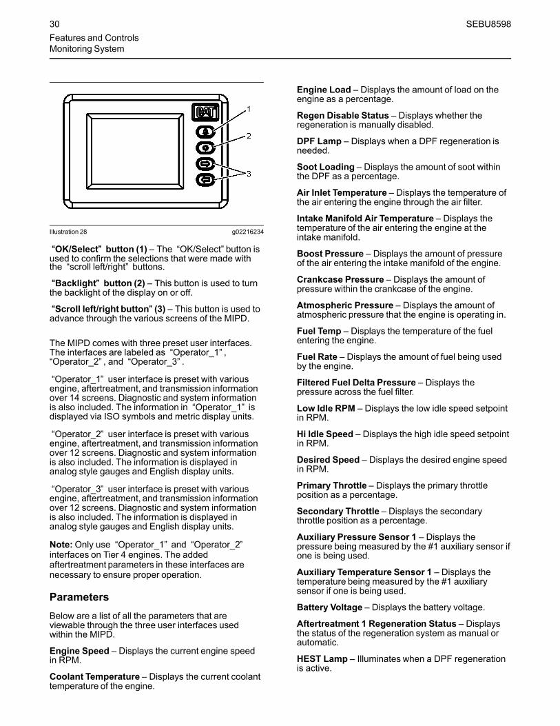
Illustration 28 g02216234
““OK/Select”” button (1) – The “OK/Select” button isused to confirm the selections that were made withthe “scroll left/right” buttons.
““Backlight”” button (2) – This button is used to turnthe backlight of the display on or off.
““Scroll left/right button”” (3) – This button is used toadvance through the various screens of the MIPD.
The MIPD comes with three preset user interfaces.The interfaces are labeled as “Operator_1” ,“Operator_2” , and “Operator_3” .
“Operator_1” user interface is preset with variousengine, aftertreatment, and transmission informationover 14 screens. Diagnostic and system informationis also included. The information in “Operator_1” isdisplayed via ISO symbols and metric display units.
“Operator_2” user interface is preset with variousengine, aftertreatment, and transmission informationover 12 screens. Diagnostic and system informationis also included. The information is displayed inanalog style gauges and English display units.
“Operator_3” user interface is preset with variousengine, aftertreatment, and transmission informationover 12 screens. Diagnostic and system informationis also included. The information is displayed inanalog style gauges and English display units.
Note:Only use “Operator_1” and “Operator_2”interfaces on Tier 4 engines. The addedaftertreatment parameters in these interfaces arenecessary to ensure proper operation.
ParametersBelow are a list of all the parameters that areviewable through the three user interfaces usedwithin the MIPD.
Engine Speed – Displays the current engine speedin RPM.
Coolant Temperature – Displays the current coolanttemperature of the engine.
Engine Load – Displays the amount of load on theengine as a percentage.
Regen Disable Status – Displays whether theregeneration is manually disabled.
DPF Lamp – Displays when a DPF regeneration isneeded.
Soot Loading – Displays the amount of soot withinthe DPF as a percentage.
Air Inlet Temperature – Displays the temperature ofthe air entering the engine through the air filter.
Intake Manifold Air Temperature – Displays thetemperature of the air entering the engine at theintake manifold.
Boost Pressure – Displays the amount of pressureof the air entering the intake manifold of the engine.
Crankcase Pressure – Displays the amount ofpressure within the crankcase of the engine.
Atmospheric Pressure – Displays the amount ofatmospheric pressure that the engine is operating in.
Fuel Temp – Displays the temperature of the fuelentering the engine.
Fuel Rate – Displays the amount of fuel being usedby the engine.
Filtered Fuel Delta Pressure – Displays thepressure across the fuel filter.
Low Idle RPM – Displays the low idle speed setpointin RPM.
Hi Idle Speed – Displays the high idle speed setpointin RPM.
Desired Speed – Displays the desired engine speedin RPM.
Primary Throttle – Displays the primary throttleposition as a percentage.
Secondary Throttle – Displays the secondarythrottle position as a percentage.
Auxiliary Pressure Sensor 1 – Displays thepressure being measured by the #1 auxiliary sensor ifone is being used.
Auxiliary Temperature Sensor 1 – Displays thetemperature being measured by the #1 auxiliarysensor if one is being used.
Battery Voltage – Displays the battery voltage.
Aftertreatment 1 Regeneration Status – Displaysthe status of the regeneration system as manual orautomatic.
HEST Lamp – Illuminates when a DPF regenerationis active.
30 SEBU8598Features and ControlsMonitoring System

DPF Intake Temperature – Displays the temperatureof the exhaust gas entering the DPF.
DPF Outlet Temperature – Displays the temperatureof the exhaust gas leaving the DPF.
Transmission Selected Gear – Displays thetransmission gear being requested.
Transmission Requested Gear – Displays thetransmission gear being requested.
Transmission Oil Pressure – Displays the oilpressure inside the transmission.
Transmission Oil Temperature – Displays the oiltemperature of the transmission.
Transmission Torque Limit – Displays the limit oftorque allowed by the transmission.
System Information
User Name – Displays the preset user name that isselected.
Software Version – Displays the version of softwarethat is programmed in the MIPD.
Serial Number – Displays the serial number of theMIPD.
Display Units – Displays the units of measurementthat is selected for the given user.
Engine Location – Displays which engine data isbeing reported if more than one engine is connectedto the MIPD.
Language – Displays the selected language.
Alarm – Indicates whether audible alarm is set to ONor OFF when an audible alarm is connected to theMIPD.
SEBU8598 31Features and Controls
Monitoring System
Engine Diagnosticsi00863835
Self-DiagnosticsSMCS Code: 1000; 1900; 1901; 1902
The electronic control module has some self-diagnostic ability. When an electronic problem with aninput or an output is detected, a diagnostic code isgenerated. This indicates the specific problem withthe circuitry.
Diagnostic codes are also generated when anabnormal engine operating condition is detected. Forexample, a diagnostic code will be generated if thelow oil pressure alarm is activated. In this case, thediagnostic code indicates the symptom of a problem.This type of diagnostic code is called an event. Anevent is triggered by the detection of an abnormalengine operating condition.
A diagnostic code which represents a problem thatcurrently exists is called an active code.
A diagnostic code that is stored in memory is called alogged code. Always service active codes prior toservicing logged codes. Logged codes may includethe following categories:
• Intermittent problems
• Recorded events
• Performance history
Logged codes may not indicate that a repair isneeded. The problems may have been repaired sincethe logging of the code. Logged codes may be helpfulto troubleshoot intermittent problems.
32 SEBU8598Engine DiagnosticsSelf-Diagnostics
Engine Startingi02109067
Before Starting EngineSMCS Code: 1000; 1400; 1450
Perform the required daily maintenance and otherperiodic maintenance before the engine is started.Inspect the engine compartment. This inspection canhelp prevent major repairs at a later date. Refer to theOperation and Maintenance Manual, “MaintenanceInterval Schedule” for more information.
• For the maximum service life of the engine, makea thorough inspection before the engine is started.Look for the following items: oil leaks, coolantleaks, loose bolts and trash buildup. Remove trashbuildup and arrange for repairs, as needed.
• Inspect the aftercooler for loose connections andfor debris buildup.
• Inspect the cooling system hoses for cracks andfor loose clamps.
• Inspect the alternator and accessory drive belts forcracks, breaks, and other damage.
• Inspect the wiring for loose connections and forworn wires or frayed wires.
• Check the fuel supply. Drain water from the waterseparator (if equipped). Open the fuel supplyvalve.
NOTICEAll valves in the fuel return line must be open beforeand during engine operation to help prevent high fuelpressure. High fuel pressure may cause filter housingfailure or other damage.
If the engine has not been started for several weeks,fuel may have drained from the fuel system. Air mayhave entered the filter housing. Also, when fuel filtershave been changed, some air pockets will be trappedin the engine. In these instances, prime the fuelsystem. Refer to the Operation and MaintenanceManual, “Fuel System - Prime” for more informationon priming the fuel system.
Engine exhaust contains products of combustionwhich may be harmful to your health. Always startand operate the engine in a well ventilated areaand, if in an enclosed area, vent the exhaust to theoutside.
• Do not start the engine or move any of the controlsif there is a “DO NOT OPERATE” warning tag orsimilar warning tag attached to the start switch orto the controls.
• Ensure that the areas around the rotating parts areclear.
• All of the guards must be put in place. Check fordamaged guards or for missing guards. Repair anydamaged guards. Replace damaged guards and/or missing guards.
• Disconnect any battery chargers that are notprotected against the high current drain that iscreated when the electric starting motor (ifequipped) is engaged. Check electrical cables andcheck the battery for poor connections and forcorrosion.
• Reset all of the shutoffs or alarm components.
• Check the engine lubrication oil level. Maintain theoil level between the “ADD” mark and the “FULL”mark on the oil level gauge.
• Check the coolant level. Observe the coolant levelin the coolant recovery tank (if equipped). Maintainthe coolant level to the “FULL” mark on thecoolant recovery tank.
• If the engine is not equipped with a coolantrecovery tank maintain the coolant level within13 mm (0.5 inch) of the bottom of the filler pipe. Ifthe engine is equipped with a sight glass, maintainthe coolant level in the sight glass.
• Observe the air cleaner service indicator (ifequipped). Service the air cleaner when the yellowdiaphragm enters the red zone, or when the redpiston locks in the visible position.
• Ensure that any driven equipment has beendisengaged. Minimize electrical loads or removeany electrical loads.
i04132731
Cold Weather StartingSMCS Code: 1000; 1250; 1450; 1453; 1456; 1900
Startability will be improved at temperatures below10°C (50°F) from the use of a cylinder block coolantheater or from other means that are used to heat thecrankcase oil. Some engine applications use a jacketwater heater to improve startability. Use of a jacketwater heater will help reduce white smoke and misfireduring start-up in cold weather.
SEBU8598 33Engine Starting
Before Starting Engine
Note: If the engine has not been run for severalweeks, fuel may have drained. Air may have movedinto the filter housing. Also, when fuel filters havebeen changed, some air will be left in the filterhousing. Refer to the Operation and MaintenanceManual, “Fuel System - Prime” (MaintenanceSection) for more information on priming the fuelsystem.
Ether Injection System (IfEquipped)The ether injection system is controlled by the ECM.The ECM monitors the coolant temperature, intake airtemperature, ambient air temperature, and barometricpressure to determine when ether injection is needed.At sea level, ether will be used if any of thetemperatures fails to exceed 0° C (32° F). Thistemperature is subject to an increase as barometricpressure increases.
Personal injury or property damage can resultfrom alcohol or starting fluids.
Alcohol or starting fluids are highly flammableand toxic and if improperly stored could result ininjury or property damage.
Follow the procedure in this Operation andMaintenance Manual, “Starting the Engine”.
i04032033
Starting the EngineSMCS Code: 1000; 1450
Engine exhaust contains products of combustionwhich may be harmful to your health. Always startand operate the engine in a well ventilated areaand, if in an enclosed area, vent the exhaust to theoutside.
Starting the EngineRefer to the Owner's Manual of the OEM for your typeof controls. Use the following procedure to start theengine.
1. Place the transmission in NEUTRAL. Disengagethe flywheel clutch in order to allow the engine tostart faster, and to reduce the draining of thebattery.
2. Turn the ignition switch to the ON position.
During the key on, the diagnostic lamp, warninglamp, regeneration lamps, and DPF disabled lampwill be checked for proper bulb operation. If any ofthe lamps do not illuminate, replace the bulb.
NOTICEDo not engage the starting motor when flywheel isturning. Do not start the engine under load.
If the engine fails to start within 30 seconds, releasethe starter switch or button and wait two minutes to al-low the starting motor to cool before attempting tostart the engine again.
3. Push the start button or turn the ignition switch tothe START position in order to crank the engine.
Do not push down or hold the throttle down whilethe engine is cranked. The system willautomatically provide the correct amount of fuelthat is needed to start the engine.
4. If the engine fails to start within 30 seconds,release the start button, or the ignition switch. Waitfor 2 minutes in order to allow the starting motor tocool before attempting to start the engine again.
NOTICEOil pressure should rise within 15 seconds after theengine starts. Do not increase engine rpm until the oilpressure gauge indicates normal. If oil pressure is notindicated on the gauge within 15 seconds, DO NOToperate the engine. STOP the engine, investigateand correct the cause.
5. Allow the engine to idle for approximately 3minutes. Idle the engine until the watertemperature gauge has begun to rise. Check allgauges during the warm-up period.
Note:Oil pressures and fuel pressures should be inthe normal range on the instrument panel. Enginesthat are equipped with “WARNING” lamps do nothave an operating range. The “WARNING andDIAGNOSTIC” lamp (if equipped) will flash while theengine is cranking. The lamp should turn off afterproper engine oil pressure or fuel pressure isachieved. Do not apply a load to the engine orincrease engine rpm until the oil pressure gaugeindicates at least normal pressure. Inspect the enginefor leaks and/or unusual noises.
34 SEBU8598Engine StartingStarting the Engine
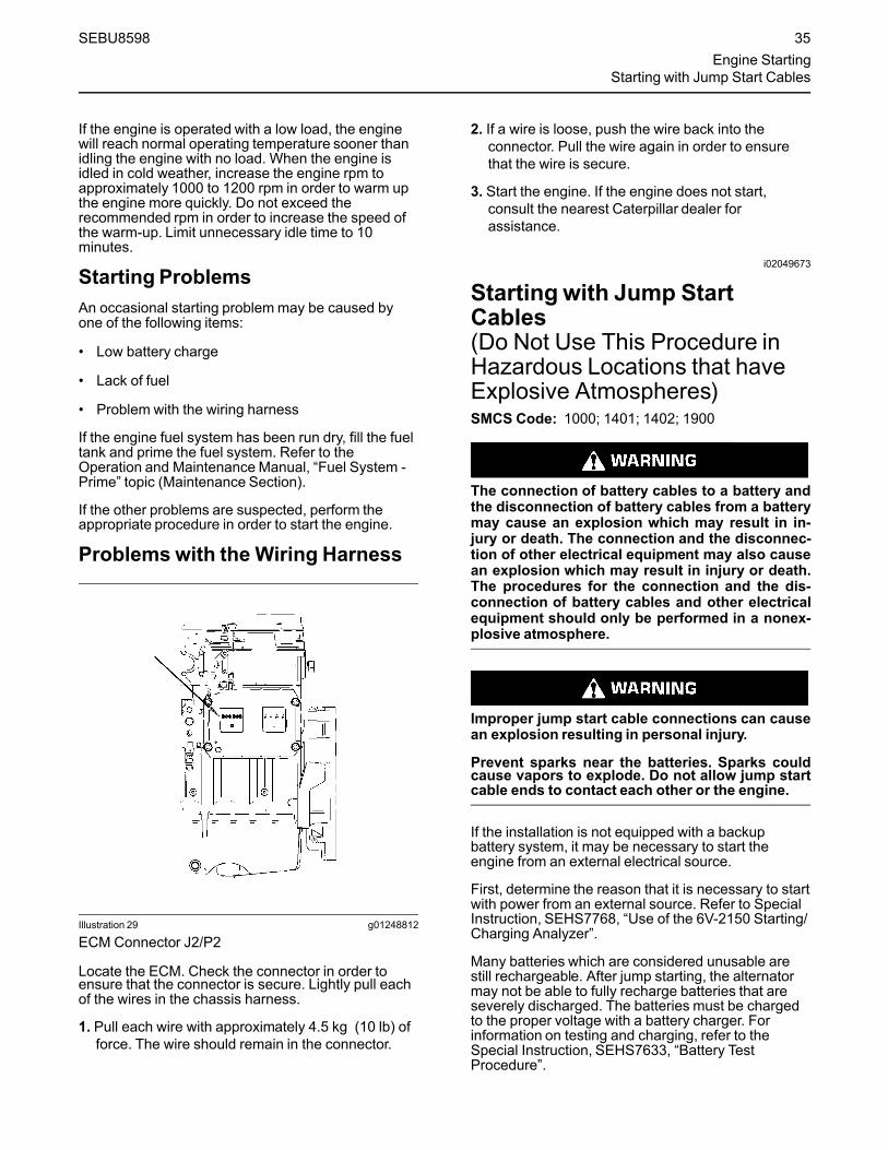
If the engine is operated with a low load, the enginewill reach normal operating temperature sooner thanidling the engine with no load. When the engine isidled in cold weather, increase the engine rpm toapproximately 1000 to 1200 rpm in order to warm upthe engine more quickly. Do not exceed therecommended rpm in order to increase the speed ofthe warm-up. Limit unnecessary idle time to 10minutes.
Starting ProblemsAn occasional starting problemmay be caused byone of the following items:
• Low battery charge
• Lack of fuel
• Problem with the wiring harness
If the engine fuel system has been run dry, fill the fueltank and prime the fuel system. Refer to theOperation and Maintenance Manual, “Fuel System -Prime” topic (Maintenance Section).
If the other problems are suspected, perform theappropriate procedure in order to start the engine.
Problems with the Wiring Harness
Illustration 29 g01248812
ECM Connector J2/P2
Locate the ECM. Check the connector in order toensure that the connector is secure. Lightly pull eachof the wires in the chassis harness.
1. Pull each wire with approximately 4.5 kg (10 lb) offorce. The wire should remain in the connector.
2. If a wire is loose, push the wire back into theconnector. Pull the wire again in order to ensurethat the wire is secure.
3. Start the engine. If the engine does not start,consult the nearest Caterpillar dealer forassistance.
i02049673
Starting with Jump StartCables(Do Not Use This Procedure inHazardous Locations that haveExplosive Atmospheres)SMCS Code: 1000; 1401; 1402; 1900
The connection of battery cables to a battery andthe disconnection of battery cables from a batterymay cause an explosion which may result in in-jury or death. The connection and the disconnec-tion of other electrical equipment may also causean explosion which may result in injury or death.The procedures for the connection and the dis-connection of battery cables and other electricalequipment should only be performed in a nonex-plosive atmosphere.
Improper jump start cable connections can causean explosion resulting in personal injury.
Prevent sparks near the batteries. Sparks couldcause vapors to explode. Do not allow jump startcable ends to contact each other or the engine.
If the installation is not equipped with a backupbattery system, it may be necessary to start theengine from an external electrical source.
First, determine the reason that it is necessary to startwith power from an external source. Refer to SpecialInstruction, SEHS7768, “Use of the 6V-2150 Starting/Charging Analyzer”.
Many batteries which are considered unusable arestill rechargeable. After jump starting, the alternatormay not be able to fully recharge batteries that areseverely discharged. The batteries must be chargedto the proper voltage with a battery charger. Forinformation on testing and charging, refer to theSpecial Instruction, SEHS7633, “Battery TestProcedure”.
SEBU8598 35Engine Starting
Starting with Jump Start Cables

NOTICEUsing a battery source with the same voltage as theelectric starting motor. Use ONLY equal voltage forjump starting. The use of higher voltage will damagethe electrical system.
Do not reverse the battery cables. The alternator canbe damaged. Attach ground cable last and removefirst.
When using an external electrical source to start theengine, turn the generator set control switch to the“OFF” position. Turn all electrical accessories OFFbefore attaching the jump start cables.
Ensure that the main power switch is in the OFF posi-tion before attaching the jump start cables to the en-gine being started.
1. Turn the start switch on the stalled engine to theOFF position. Turn off all accessories.
2. Connect one positive end of the jump start cable tothe positive cable terminal of the dischargedbattery. Connect the other positive end of the jumpstart cable to the positive cable terminal of theelectrical source.
3. Connect one negative end of the jump start cableto the negative cable terminal of the electricalsource. Connect the other negative end of thejump start cable to the engine block or to thechassis ground. This procedure helps to preventpotential sparks from igniting combustible gasesthat are produced by some batteries.
4. Charge the batteries. The engine will not continueto run after starting if the batteries have not beencharged.
5. Start the engine.
6. Immediately after the stalled engine is started,disconnect the jump start cables in reverse order.
Refer to the Electrical Schematic for your engine.Consult your Caterpillar dealer for more information.
i05359363
After Starting EngineSMCS Code: 1000
Note: In temperatures from 0 to 60°C (32 to 140°F),the warm-up time is approximately 3 minutes. Intemperatures below 0°C (32°F), additional warm-uptime may be required.
When the engine is idling during warm-up, observethe following conditions:
• Check for fluid or air leaks at idle rpm and at one-half full rpm (no load on the engine) beforeoperating the engine under load. Operating theengine at idle and at one-half full rpm with no loadis not possible in some applications.
• Operate the engine at low idle until all systemsachieve operating temperatures. Check all gaugesduring the warm-up period.
Note:Gauge readings should be observed and thedata should be recorded frequently while the engineis operating. Comparing the data over time will help todetermine normal readings for each gauge.Comparing data over time will also help detectabnormal operating developments. Significantchanges in the readings should be investigated.
Extended Idle at Cold AmbientTemperatureThe engine may automatically change speeds whenthe engine is idling in cold ambient temperatures(typically less than 0° C (32° F) for extended periods.The purpose of the automatic speed change isthreefold: to maintain the desired operation of theNOx reduction system, to maintain the desiredoperation of the regeneration system and to keep theengine coolant warm. The engine speed may rise to1600 rpm for as long as 20 minutes.
The high exhaust system temperature lamp mayilluminate during extended idling conditions. Thisillumination signals that a diesel particulate filter(DPF) regeneration is in progress. Regenerationsduring cold ambient extended idling may only last upto 10 minutes.
36 SEBU8598Engine StartingAfter Starting Engine
Engine Operationi06014851
Engine OperationSMCS Code: 1000
Correct operation and maintenance are key factors inobtaining the maximum life and economy of theengine. If the directions in the Operation andMaintenance Manual are followed, costs can beminimized and engine service life can be maximized.
The engine can be operated at the rated rpm after theengine reaches operating temperature. The enginewill reach normal operating temperature soonerduring a low engine speed (rpm) and during a lowpower demand. This procedure is more effective thanidling the engine at no load. The engine should reachoperating temperature in a few minutes.
Gauge readings should be observed and the datashould be recorded frequently while the engine isoperating. Comparing the data over time will help todetermine normal readings for each gauge.Comparing data over time will also help detectabnormal operating developments. Significantchanges in the readings should be investigated.
i05317310
Diesel Particulate FilterRegenerationSMCS Code: 108F
RegenerationRegeneration is the removal of soot from the dieselparticulate filter (DPF). The aftertreatmentregeneration device (ARD) is used to regenerate theDPF. The DPF traps both soot and ash. The ash isremoved through a manual cleaning process. Referto this Operation and Maintenance Manual, “DieselParticulate Filter - Clean” for more information aboutservicing the DPF.
SEBU8598 37Engine OperationEngine Operation

Regeneration Indicator Lamps and Controls
Illustration 30 g02334417
The engine may be equipped with one of the control panels pictured above.(1) “DPF” Indicator lamp(2) “HIGH EXHAUST TEMPERATURE”
indicator lamp(3) “REGENERATION DISABLED”
indicator lamp
(4) “START KEY” switch(5) “DIAGNOSTIC” lamp(6) “SHUTDOWN” lamp(7) “IDLE SPEED” switch
(8) “REGENERATION” switch(9) “HIGH SPEED REGENERATION”
enable switch
Note: For further information about the monitoringsystem, refer to this Operation and MaintenanceManual, “Monitoring System”.
““HIGH EXHAUST SYSTEMTEMPERATURE (HEST)”” – This indicatorlamp illuminates to show that a
regeneration is active. This indicator lamp turnsoff when the regeneration is complete.
““DPF”” – This indicator lamp illuminatesto show that a regeneration is needed.This indicator lamp illuminateswhen the
soot level reaches 80%.
““REGENERATION DISABLED”” – Thisindicator lamp illuminates to show that aregeneration has been disabled.
RegenerationControls
RegenerationControl Switch
Illustration 31 g02333653
“REGENERATION” control switchThe position of the “REGENERATION” switch in theside view is the MIDDLE position.
Note: The MIDDLE position of the switch is thedefault position for low and high speed regenerations.
Note: Some OEMs use other means of activating aforced regeneration such as a touch screen interface.
38 SEBU8598Engine OperationDiesel Particulate Filter Regeneration

““FORCE REGENERATION”” – Press andhold in the top of the switch for 3seconds to start regeneration.
““DISABLE REGENERATION”” – Pressand hold in the bottom of the switch for 3seconds to disable regeneration.
Note: To re-enable the regeneration, cycle the engine“START SWITCH KEY” or press and hold in the“FORCE REGENERATION” switch for 2 seconds.
Note: If the engine “START SWITCH KEY” is cycledwhile the regeneration system is disabled via the“DISABLE REGENERATION” switch, press and holdin the “DISABLE REGENERATION” switch for 3seconds to reinitiate the disable regeneration.
OK to Elevate Idle Switch
Illustration 32 g02333673
“OK to Elevate Idle Switch” switchThe position of the “OK to Elevate Idle Switch”switch in the side view is the LOCKED position.
OK to Elevate Idle Switch – Pressing in and lockingthe “OK to Elevate Idle” switch enables the engineECM to elevate engine speed automatically whenneeded. For example, if the engine is running at lowidle and a DPF regeneration is activated, having the“OK to Elevate Idle” switch in the LOCKED positionwill allow the engine speed to increase in order for theDPF regeneration to occur.
Note: This switch is only available on engines withinstrument panels supplied by Cat.
Soot Level Monitoring
Illustration 33 g02228033
The soot level monitor indicates the level of soot thathas accumulated within the DPF. The five marks onthe monitor represent the percentage of soot withinthe DPF. The first mark indicates 0% soot level. Thesecond mark indicates 25% soot level. The third markindicates 50% soot level. The fourth mark indicates75% soot level. The last mark indicates 100% sootlevel. The soot level monitor may be used to optimizeDPF regenerations based upon the work cycle of theengine. If operating conditions do not allow forautomatic regeneration, a manual regenerationshould be performed before the soot level gaugeindicates 100%
Note: The soot level monitor may not be applied to allengines. Some OEM's may also use a differentmethod of displaying soot load of the DPF. Refer toOEM operation manual for explanation.
Modes of Regeneration
AutomaticThe engine control module (ECM) uses multipleelectrical inputs from the engine to determine the besttime for an automatic regeneration. An automaticregenerationmay take place throughout the operatingcycle of the engine. An automatic regenerationmaystart when the engine is at the low idle speed or whenthe engine is at normal operating speed. The “HEST”indicator lamp is illuminated when a regeneration isbeing performed.
If an automatic regeneration starts while the engine isat the low idle speed, the engine may be returned tonormal work at any time. Returning to normal workmay stop the regeneration. The ECM will continue tomonitor inputs to determine the best time to restartthe regeneration.
Interruptions of the regeneration are acceptable. If aregeneration needs to be stopped for any reason,press the DISABLE REGENERATION switch or turnoff the engine.
Note: An automatic adjustment of engine speed maybe noticed during an automatic regeneration. If theengine is taken to a low idle speed while aregeneration is occurring, the engine speed mayremain elevated in order for the regeneration tocontinue.
SEBU8598 39Engine Operation
Diesel Particulate Filter Regeneration
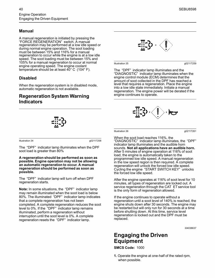
ManualA manual regeneration is initiated by pressing the“FORCE REGENERATION” switch. A manualregenerationmay be performed at a low idle speed orduring normal engine operation. The soot loadingmust be between 15% and 116% for a manualregeneration to occur while the engine is at a low idlespeed. The soot loading must be between 15% and105% for a manual regeneration to occur at normalengine operating speed. The engine coolanttemperature should be at least 40° C (104° F).
DisabledWhen the regeneration system is in disabled mode,automatic regeneration is not available.
RegenerationSystemWarningIndicators
Illustration 34 g02117258
The “DPF” indicator lamp illuminates when the DPFsoot load is greater than 80%
A regeneration should be performed as soon aspossible. Engine operationmay not be allowingan automatic regeneration to occur. A manualregeneration should be performed as soon aspossible.
The “DPF” indicator lamp will turn off when DPFregeneration starts.
Note: In some situations, the “DPF” indicator lampmay remain illuminated when the soot load is below80%. The illuminated “DPF” indicator lamp indicatesthat a complete regeneration has not beencompleted. A complete regeneration reduces the sootlevel to 0%. If the “DPF” indicator lamp remainsilluminated, perform a regeneration withoutinterruption until the soot level is 0%. A completeregeneration resets the “DPF” indicator lamp.
Illustration 35 g02117259
The “DPF” indicator lamp illuminates and the“DIAGNOSTIC” indicator lamp illuminates when theengine control module (ECM) determines that theamount of soot collected in the DPF has reached alevel that requires a regeneration. Place the engineinto a low idle state immediately. Initiate a manualregeneration. The engine power will be derated if theengine continues to operate.
Illustration 36 g02117261
When the soot load reaches 116%, the“DIAGNOSTIC” indicator lamp illuminates, the “DPF”indicator lamp illuminates and the audible hornsounds. Not all applications have an audible horn.After 5 minutes of engine operation at 116% of sootload, the engine is automatically taken to theprogrammed low idle speed. A manual regenerationin the low speed region is then required. A completeregeneration will unlock the forced low idle speed.Cycling the engine “START SWITCH KEY” unlocksthe forced low idle speed.
After the engine operates at 116% of soot level for 10minutes, all types of regeneration are locked out. Aservice regeneration through the CAT ETservice toolis the only form of regeneration allowed.
If the engine continues to operate without aregeneration until a soot level of 140% is reached, theengine shuts down after 30 seconds. The engine maybe restarted but will only run for 30 seconds at a timebefore shutting down. At this time, service levelregeneration is locked out and the DPF must bereplaced.
i04038637
Engaging the DrivenEquipmentSMCS Code: 1000
1. Operate the engine at one-half of the rated rpm,when possible.
40 SEBU8598Engine OperationEngaging the Driven Equipment

2. Engage the driven equipment without a load on theequipment, when possible.
Interrupted starts put excessive stress on the drivetrain. Interrupted starts also waste fuel. To get thedriven equipment in motion, engage the clutchsmoothly with no load on the equipment. Thismethod should produce a start that is smooth andeasy. The engine rpm should not increase and theclutch should not slip.
3. Ensure that the ranges of the gauges are normalwhen the engine is operating at one-half of therated rpm. Ensure that all gauges operate properly.
4. Increase the engine rpm to the rated rpm. Alwaysincrease the engine rpm to the rated rpm beforethe load is applied.
5. Apply the load. Begin operating the engine at lowload. Check the gauges and equipment for properoperation. After normal oil pressure is reached andthe temperature gauge begins to move, the enginemay be operated at full load. Check the gaugesand equipment frequently when the engine isoperated under load.
Extended operation at low idle or at reduced loadmay cause increased oil consumption and carbonbuildup in the cylinders. This carbon buildupresults in a loss of power and/or poor performance.
i05893104
Fuel ConservationPracticesSMCS Code: 1000; 1250
The efficiency of the engine can affect the fueleconomy. The design and technology usedbyCaterpillar in manufacturing provides maximumfuel efficiency in all applications. Follow therecommended procedures in order to attain optimumperformance for the life of the engine.
• Avoid spilling fuel.
Fuel expands when the fuel is warmed up. The fuelmay overflow from the fuel tank. Inspect fuel lines forleaks. Repair the fuel lines, as needed.
• Be aware of the properties of the different fuels.Use only the recommended fuels.
• Avoid unnecessary operation at no load.
Shut off the engine instead of operating the engine atno load for long periods of time.
• Observe the service indicator for the air cleanerfrequently, if equipped. Keep the air cleanerelements clean.
• Do not remove the cover for the air cleaner unlessthe air filter service indicator indicates the need forcleaning of the filter.
• Maintain a good electrical system.
One bad battery cell will overwork the alternator. Thiswill consume excess power and excess fuel.
• Ensure that the belts are properly adjusted. Thebelts should be in good condition.
• Ensure that all of the connections of the hoses aretight. The connections should not leak.
• Ensure that the driven equipment is in goodworking order.
• Cold engines consume excess fuel. Keep coolingsystem components clean and keep coolingsystem components in good repair. Never operatethe engine without water temperature regulators.All of these items will help maintain operatingtemperatures.
SEBU8598 41Engine Operation
Fuel Conservation Practices
Cold Weather Operationi01646447
Radiator RestrictionsSMCS Code: 1353; 1396
Caterpillar discourages the use of airflow restrictiondevices that are mounted in front of radiators. Airflowrestriction can cause the following conditions:
• High exhaust temperatures
• Power loss
• Excessive fan usage
• Reduction in fuel economy
If an airflow restriction device must be used, thedevice should have a permanent opening directly inline with the fan hub. A centered opening that isdirectly in line with the fan hub is specified in order toprevent an interrupted airflow on the fan blades.Interrupted airflow on the fan blades could cause afan failure.
Caterpillar recommends a warning device for the inletmanifold temperature and/or the installation of an inletair temperature gauge. The warning device for theinlet manifold temperature should be set at 75 °C(167 °F). The inlet manifold air temperature shouldnot exceed 75 °C (167 °F). Temperatures thatexceed this limit can cause power loss and potentialengine damage.
i03895851
Fuel and the Effect from ColdWeatherSMCS Code: 1000; 1250; 1280
The following fuels are the grades that are availablefor Caterpillar engines:
• No. 1
• No. 2
• Blend of No. 1 and No. 2
No. 2 diesel fuel is the most commonly used fuel.Either No. 1 diesel fuel or a blend of No. 1 and No. 2is best suited for cold weather operation.
Note:No. 2 diesel fuel can begin to form crystals atapproximately −9° C (15° F).
Quantities of No. 1 diesel fuel are limited. No. 1 dieselfuels are usually available during the months of thewinter in the colder climates. During cold weatheroperation, if No. 1 diesel fuel is not available, use No.2 diesel fuel, if necessary.
There are three major differences between No. 1 andNo. 2 diesel fuel. No. 1 diesel fuel has the followingproperties:
• Lower cloud point
• Lower pour point
• Lower rating of kJ (BTU) per unit volume of fuel
When No. 1 diesel fuel is used, a decrease in powerand in fuel efficiency may be noticed. Other operatingeffects should not be experienced.
The cloud point is the temperature when a cloud ofwax crystals begins to form in the fuel. These crystalscan cause the fuel filters to plug. The pour point is thetemperature when diesel fuel will thicken. The dieselfuel becomes more resistant to flow through fuelpumps and through fuel lines.
Be aware of these values when diesel fuel ispurchased. Anticipate the average ambienttemperature for the engine area. Engines that arefueled in one climate may not operate well if theengines are moved to another climate. Problems canresult due to changes in temperature.
Before troubleshooting for low power or for poorperformance during cold weather, check the type offuel that is being used.
i03480664
Fuel Related Components inCold WeatherSMCS Code: 1000; 1250; 1280
Fuel TanksCondensation can form in partially filled fuel tanks.Top off the fuel tanks after you operate the engine.
Fuel tanks should contain some provision for drainingwater and sediment from the bottom of the tanks.Some fuel tanks use supply pipes that allow waterand sediment to settle below the end of the fuelsupply pipe.
Some fuel tanks use supply lines that take fueldirectly from the bottom of the tank. If the engine isequipped with this system, regular maintenance ofthe fuel system filter is important.
Fuel FiltersCold fuel may contain wax which will block the fuelfilters. One of the following changes can preventproblems in many conditions: a change in the locationof fuel filters and/or supply lines and the addition ofinsulation.
42 SEBU8598Cold Weather OperationRadiator Restrictions
Fuel HeatersIn extreme temperatures, heating of the fuel may berequired to prevent the filters from plugging. Thereare several types of fuel heaters that are available.These systems may prevent filter waxing problemswithout the use of de-icers or cold flow improvers.These systems may be ineffective when the fuelcontains a large amount of dirt or of water. A fuelheater should be installed so that the fuel is heatedbefore flowing into the fuel filter.
Note:Only use properly sized fuel heaters that arecontrolled by thermostats or use fuel heaters that areself-regulated. Thermostatically controlled fuelheaters generally heat fuel to 15.5° C (60° F). Do notuse fuel heaters in warm temperatures.
Note:Do not allow the fuel to get too warm, becausefuel above 52°C (125°F) will affect the power outputof the engine. Never exceed 75°C (165°F) withstraight distillate fuel. The high fuel temperatures alsoaffect the fuel viscosity. When the fuel viscosity fallsbelow 1.4 cSt at the fuel injection pump, pumpdamage may occur.
Overheating the fuel or the fuel filter can result inpersonal injury and/or damage to the engine. Useextreme care and caution for heating of the fueland/or the fuel filter.
Select a fuel heater that is mechanically simple, yetadequate for the application. The fuel heater shouldalso prevent overheating of the fuel. Disconnect thefuel heater or deactivate the fuel heater in warmweather. An unacceptable loss of fuel viscosity andengine power will occur if the fuel supply temperatureis allowed to become too hot.
For additional information on fuel heaters, consultyour Caterpillar dealer.
SEBU8598 43Cold Weather Operation
Fuel Related Components in Cold Weather

Engine Stoppingi04315380
Manual Stop ProcedureSMCS Code: 1000; 7418
NOTICEStopping the engine immediately after it has beenworking under load can result in overheating and ac-celerated wear of the engine components.
If the engine has been operating at high rpm and/orhigh loads, run at low idle for at least three minutes toreduce and stabilize internal engine temperature be-fore stopping the engine.
Avoiding hot engine shutdowns will maximize turbo-charger shaft and bearing life.
Note: Individual applications have different controlsystems. Ensure that the shutoff procedures areunderstood. Use the following general guidelines inorder to stop the engine.
1. Remove the load from the engine so that theengine has no more than 30% power.
2. Run the engine at the programmed low idle speedfor at least 3 minutes.
3. After the cool down period, turn the start switch tothe OFF position.
i04137729
After Stopping EngineSMCS Code: 1000
Note: After operation, allow 10 minutes for the engineoil to return to the oil pan before checking the engineoil level.
• Check the crankcase oil level. Maintain the oil levelbetween the “ADD” mark and the “FULL” markon the oil level gauge.
Note:Only use oil that is recommended in thisOperation and Maintenance Manual, “FluidRecommendations” article. Failure to do so mayresult in engine damage.
• If necessary, performminor adjustments. Repairany leaks and tighten any loose bolts.
• Note the service hour meter reading. Perform themaintenance that is in the Operation andMaintenance Manual, “Maintenance IntervalSchedule”.
• Fill the fuel tank to prevent accumulation ofmoisture in the fuel. Do not overfill the fuel tank.
• Allow the engine to cool. Check the coolant level.Maintain the cooling system at 13 mm (0.5 inch)from the bottom of the pipe for filling.
Note:Only use coolant that is recommended in thisOperation and Maintenance Manual, “FluidRecommendations” article. Failure to do so mayresult in engine damage.
• If freezing temperatures are expected, check thecoolant for proper antifreeze protection. Thecooling system must be protected against freezingto the lowest expected outside temperature. Addthe proper coolant/water mixture, if necessary.
• Perform all required periodic maintenance on alldriven equipment. This maintenance is outlined inthe instructions from the OEM.
44 SEBU8598Engine StoppingManual Stop Procedure

MaintenanceSection
Refill Capacitiesi04133774
Refill CapacitiesSMCS Code: 1000; 1348; 1395; 7560
Refer to this Operation and Maintenance Manual,“Fluid Recommendations” for information about thefluids which are acceptable for this engine.
Note:Refer to Special Publication, SEBU6251,“CaterpillarCommercial Diesel Engine FluidsRecommendations” for additional information.
Lubricant Refill Capacity
Illustration 37 g02300456
Standard pan
Illustration 38 g02300473
Center pan
Illustration 39 g02300474
Deep pan
The refill capacities for the engine crankcase reflectthe approximate capacity of the crankcase or sumpplus standard oil filters. Auxiliary oil filter systems willrequire additional oil. Refer to the OEM specificationsfor the capacity of the auxiliary oil filter.Table 4
C15 and C18 Industrial EnginesApproximate Refill Capacities
Oil Sump(1) Engine with 1Filter
Engine with 2Filters
Standard pan 34 L (36 qt) 36 L (38 qt)
Center pan 60 L (63 qt) 62 L (66 qt)
Deep pan 68 L (72 qt) 70 L (74 qt)
(1) These values are approximate capacities for the crankcase oilsump which include the standard oil filters that are installed atthe factory. Engines with auxiliary oil filters will require additionaloil. Refer to the OEM specifications for the capacity of the auxili-ary oil filter.
Coolant Refill CapacityTo maintain the cooling system, the total coolingsystem capacity must be known. The capacity of thetotal cooling system will vary. The capacity willdepend on the size of the radiator (capacity). Table 5should be completed by the customer for themaintenance of the cooling system.Table 5
Approximate Capacity of the Cooling System
Compartment orSystem Liters Quarts
Total Cooling System(1)
(1) The total cooling system capacity includes the following compo-nents:the engine block, the radiator and all coolant hoses andlines.
i05489209
Fluid RecommendationsSMCS Code: 1280; 1348; 1395; 7560
NOTICEEvery attempt is made to provide accurate, up-to-dateinformation. By the use of this document, you agreethat Caterpillar Inc. is not responsible for errors oromissions.
NOTICEThese recommendations are subject to change with-out prior notice. Contact your Caterpillar dealer for themost up to date recommendations.
SEBU8598 45Maintenance Section
Refill Capacities
Refer to Special Publication, SEBU6251, “CatCommercial Diesel Engine Fluids Recommendations”for additional information.
Refer to this Operation and Maintenance Manual,“Severe Service Application” for information aboutoperating an engine in a severe service application.
Note: Instructions for the installation of the filter areprinted on the side of each Cat spin-on filter. Forfilters that are not Cat filters, refer to the installationinstructions that are provided by the supplier of thefilter.
Diesel Engine Oil
Cat DEO (Diesel Engine Oil)
Due to significant variations in the quality and in theperformance of commercially available oils,Caterpillar makes the following recommendations:
• Cat DEO-ULS (Diesel Engine Oil Ultra LowSulfur) (SAE 5W-40)
• Cat DEO-ULS (Diesel Engine Oil Ultra LowSulfur) (SAE 10W-30)
• Cat DEO-ULS (Diesel Engine Oil Ultra LowSulfur) (SAE 15W-40)
Engine Oil
Cat oils have been developed and tested in order toprovide the full performance and life that has beendesigned and built into Cat engines.
Cat DEO-ULS or oils that meet the Cat ECF-3specification and the API CJ-4 are required for use inthe applications listed below. Cat DEO-ULS and oilsmeeting Cat ECF-3 specification and the API CJ-4and ACEA E9 oil categories have been developedwith limited sulfated ash, phosphorus, and sulfur.These chemical limits are designed to maintain theexpected aftertreatment devices life, performance,and service interval. If oils meeting the Cat ECF-3specification and the API CJ-4 specifications are notavailable, oils meeting ACEA E9 may be used. ACEAE9 oils meet the chemical limits designed to maintainaftertreatment device life. ACEA E9 oils are validatedusing some but not all ECF-3 and API CJ-4 standardengine performance tests. Consult your oil supplierwhen considering use of an oil that is not Cat ECF-3or API CJ-4 qualified.
Failure to meet the listed requirements will damageaftertreatment-equipped engines and can negativelyimpact the performance of the aftertreatment devices.The Diesel Particulate Filter (DPF) will plug soonerand require more frequent DPF ash service intervals.
Typical aftertreatment systems include the following:
• Diesel Particulate Filters (DPF)
• Diesel Oxidation Catalysts (DOC)
• Selective Catalytic Reduction (SCR)
• Lean NOx Traps (LNT)
Other systems may apply.
46 SEBU8598Refill CapacitiesFluid Recommendations

Table 6
Lubricant Viscosities for Ambient Temperatures
Compartment or System Oil Type and PerformanceRequirements Oil Viscosities
°C °F
Min Max Min Max
Engine Crankcase
Cat DEO-ULS ColdWeather SAE 0W-40 −40 40 −40 104
Cat DEO-ULS SAE 10W-30 −18 40 0 104
Cat DEO-ULS SAE 15W-40 −9.5 50 15 122
NOTICEOil Renewal systems should not be used in enginesequipped with aftertreatment systems. Reduced lifeor damage to the aftertreatment may occur.
S·O·S Services Oil Analysis
NOTICEThese recommendations are subject to change with-out prior notice. Contact your Caterpillar dealer for themost up to date recommendations.
Caterpillar has developed a maintenance tool thatevaluates oil degradation. the maintenancemanagement also detects the early signs of wear oninternal components. The Cat tool for oil analysis iscalled S·O·S Oil Analysis and the tool is part of theS·O·S Services program. S·O·S Oil Analysis dividesoil analysis into four categories:
• Component wear rate
• Oil condition
• Oil contamination
• Identification of oil
These four types of analysis are used to monitor thecondition of your equipment. The four types ofanalysis will also help you identify potential problems.A properly administered S·O·S Oil Analysis programwill reduce repair costs and the program will lessenthe impact of downtime.
The S·O·S Oil Analysis program uses a wide range oftests to determine the condition of the oil and thelubricated compartment. Guidelines that are based onexperience and a correlation to failures have beenestablished for these tests. Exceeding one or more ofthese guidelines could indicate serious fluiddegradation or a pending component failure. Atrained person at your Cat dealership should makethe final analysis.
NOTICEAlways use a designated pump for oil sampling, anduse a separate designated pump for coolant sam-pling. Using the same pump for both types of samplesmay contaminate the samples that are being drawn.This contaminate may cause a false analysis and anincorrect interpretation that could lead to concerns byboth dealers and customers.
Refer to Special Publication, SEBU6251, “CatCommercial Diesel Engine Fluids Recommendations”in order to obtain additional information about S·O·SServices oil analysis. You can also contact your localCat dealer in order to obtain additional informationabout the S·O·S Services Oil Analysis program.
Diesel Fuel Recommendations
Illustration 40 g02157153
NACD Film
SEBU8598 47Refill Capacities
Fluid Recommendations

Illustration 41 g02052934
EAME Film
Diesel fuel must meet “Cat Specification for DistillateFuel” and the latest versions of “ASTM D975” or “EN590” in order to ensure optimum engine performance.Refer to Special Publication, SEBU6251, “CatCommercial Diesel Engine Fluids Recommendations”for the latest fuel information and for Cat fuelspecification. This manual may be found on the Webat Safety.Cat.com.
NOTICEUltra Low Sulfur Diesel (ULSD) fuel 0.0015 percent(≤15 ppm (mg/kg)) sulfur is required by regulation foruse in engines certified to nonroad Tier 4 standards(U.S. EPA Tier 4 certified) and that are equipped withexhaust aftertreatment systems.
European ULSD 0.0010 percent (≤10ppm (mg/kg))sulfur fuel is required by regulation for use in enginescertified to European nonroad Stage IIIB and newerstandards and are equipped with exhaust aftertreat-ment systems.
Misfuelingwith fuels of higher sulfur level canhave the following negative effects:
• Shorten the time interval betweenaftertreatment device service intervals (causethe need for more frequent service intervals)
• Adversely impact the performance and life ofaftertreatment devices (cause loss ofperformance)
• Reduce regeneration intervals ofaftertreatment devices
• Reduce engine efficiency and durability.
• Increase the wear.
• Increase the corrosion.
• Increase the deposits.
• Lower fuel economy
• Shorten the time period between oil drain intervals(more frequent oil drain intervals).
• Increase overall operating costs.
Failures that result from the use of improper fuels arenot Cat factory defects. Therefore the cost of repairswould not be covered by a Cat warranty.
Cat does not require the use of ULSD in off road andmachine applications that are not Tier 4/Stage IIIBcertified engines. ULSD is not required in enginesthat are not equipped with after treatment devices.For Tier 4/Stage IIIB/Stage IV certified enginesalways follow operating instructions. Fuel tank inletlabels are installed in order to ensure that the correctfuels are used.
Refer to Special Publication, SEBU6251, “CatCommercial Diesel Engine Fluids Recommendations”for more details about fuels, lubricants, and Tier 4requirements. This manual may be found on the Webat Safety.Cat.com.
LubricatingGreaseNOTICE
These recommendations are subject to change with-out prior notice. Contact your Caterpillar dealer for themost up to date recommendations.
Cat provides various greases that vary inperformance from a moderate performance to highperformance. Cat greases service the entire line ofCat products in the wide variety of climatesthroughout the world. From this variety of Cat greaseproducts, you can find a Cat grease that will meet orexceed the performance requirements of mostengines.
48 SEBU8598Refill CapacitiesFluid Recommendations
The performance requirements of your engine mustbe determined before you select any Cat grease.Consult the recommendations for greases that aremade by the OEM for the equipment. Then, consultwith your Cat dealer for a list of greases that have theperformance specifications and the available sizes ofcontainers.
Note: Always choose grease that meets or exceedsthe recommendations that are specified by theequipment manufacturer for the application.
If choosing a single grease to use for all of theequipment at one site is necessary , always choose agrease that meets or exceeds the requirements of themost demanding application. Remember that theproducts which barely meet the minimumperformance requirements can be expected toproduce the minimum lives of your parts. Falseeconomy is being used if a grease is purchased withthe lowest cost as the only consideration. Instead,use the grease that yields the lowest total operatingcost. This cost should be based on an analysis thatincludes the costs of parts, labor, downtime, and thecost of the amount of grease that is required.
Note: Purge all of the old grease from a joint beforeyou change from one type of grease to another typeof grease. Some greases are not chemicallycompatible with other greases. Consult your supplierin order to determine if the greases are compatible.
If you are not certain that the old grease is compatiblewith the new grease, purge the old grease from thesystem before applying the new grease.
Note: All Cat greases are chemically compatiblewith each other. Mixing of Cat greases does notresult in an adverse chemical reaction. However,mixing of Cat greases may result in reducedperformance.
Non-Cat commercial greases are as a group secondchoice greases. Within this grouping of secondchoice greases, there are tiered levels ofperformance. For more information, refer to SpecialPublication, SEBU6251, “Cat Commercial DieselEngines Fluids Recommendations”.
CoolantNOTICE
These recommendations are subject to change with-out prior notice. Contact your Caterpillar dealer for themost up to date recommendations.
NOTICENever add coolant to an overheated engine. Enginedamage could result. Allow the engine to cool first.
NOTICEFrequently check the specific gravity of the coolant forproper freeze protection or for anti-boil protection.
NOTICENever operate an engine without water temperatureregulators in the cooling system. Water temperatureregulators help to maintain the engine coolant at theproper operating temperature. Cooling system prob-lems can develop without water temperatureregulators.
NOTICENever use water alone as a coolant. Water alone iscorrosive at engine operating temperatures. In addi-tion, water alone does not provide adequate protec-tion against boiling or freezing.
NOTICEAll Cat engines that are equipped with a Cat NOx Re-duction System require a minimum of 50 percent gly-col to help prevent cavitation damage and boiling ofthe engine coolant. These engines include Tier 4engines.
The following two coolants are used in Cat DieselEngines :
Preferred – Cat ELC (Extended Life Coolant) or acommercial extended life coolant that meets the CatEngine Coolant-1 (EC-1) specification.
Acceptable – Cat DEAC (Diesel Engine Antifreeze/Coolant) or a commercial heavy-duty coolant thatmeets “ASTM D4985”, or “ASTM D6210”specifications
Note: Cat DEAC does not require a treatment with aSupplemental Coolant Additive (SCA) at the initial fill.However, a commercial heavy-duty coolant that onlymeets the “ASTM D4985” specification will require atreatment with an SCA at the initial fill. A commercialheavy-duty coolant that meets the “ASTM D6210”specification will not require a treatment with an SCAat the initial fill. Read the label or the instructions thatare provided by the manufacturer of the commercialheavy-duty coolant.
Note: These coolants will require a treatment with asupplemental coolant additive on a maintenancebasis.
SEBU8598 49Refill Capacities
Fluid Recommendations

Table 7
Service Life Before Flushing and Before Refilling
Coolant Service Life(1)
Cat ELC 12,000 hours, or 6 years
Commercial coolant that meets theCat EC-1 specification
6000 hours, or 6 years
Cat DEAC 3000 hours, or 3 years
Commercial Heavy-Duty Coolantthat meets “ASTM D4985” or
“ASTM D6210”3000 hours, or 1 year
(1) Use the interval that occurs first.
Note: Add the Cat ELC Extender at the halfwaypoint of the coolant change interval.
Note: These coolant change intervals are onlypossible with annual S·O·S Services Level 2 coolantsampling and analysis.
S·O·S Services Coolant AnalysisTable 8
Recommended IntervalType ofCoolant Level 1 Level 2
DEACEvery 500 Hours(1)
(2)Every 2000 Hoursor Yearly(1) (3)
ELC Optional(3) Yearly(3)
(1) This interval is recommended for the sampling of all convention-al heavy-duty coolant.
(2) This interval is also recommended for the sampling of a com-mercial coolant that meets the Cat (Engine Coolant specifica-tion - 1) requirement.
(3) The Level 2 coolant analysis should be performed sooner if aproblem is suspected or identified.
Testing the engine coolant is important to ensure thatthe engine is protected from internal cavitation andfrom corrosion. The analysis also tests the ability ofthe coolant to protect the engine from boiling andfrom freezing. The S·O·S Coolant Analysis can beperformed at your Cat dealer. Cat S·O·S CoolantAnalysis is the best way to monitor the condition ofyour coolant and your cooling system. S·O·S CoolantAnalysis is a program that is based on periodicsamples.
NOTICEAlways use a designated pump for oil sampling, anduse a separate designated pump for coolant sam-pling. Using the same pump for both types of samplesmay contaminate the samples that are being drawn.This contaminate may cause a false analysis and anincorrect interpretation that could lead to concerns byboth dealers and customers.
For more information, refer to Special Publication,SEBU6251, “Cat Commercial Diesel Engines FluidsRecommendations”
50 SEBU8598Refill CapacitiesFluid Recommendations

MaintenanceRecommendations
i02909163
System Pressure ReleaseSMCS Code: 1250; 1300; 1350; 5050
Coolant System
Pressurized system: Hot coolant can cause seri-ous burn. To open cap, stop engine, wait until ra-diator is cool. Then loosen cap slowly to relievethe pressure.
To relieve the pressure from the coolant system, turnoff the engine. Allow the cooling system pressure capto cool. Remove the cooling system pressure capslowly in order to relieve pressure.
Fuel SystemTo relieve the pressure from the fuel system, turn offthe engine.
High Pressure Fuel Lines (If Equipped)
Contact with high pressure fuel may cause fluidpenetration and burn hazards. High pressure fuelspray may cause a fire hazard. Failure to followthese inspection, maintenance and service in-structionsmay cause personal injury or death.
The high pressure fuel lines are the fuel lines that arebetween the high pressure fuel pump and the highpressure fuel manifold and the fuel lines that arebetween the fuel manifold and cylinder head. Thesefuel lines are different from fuel lines on other fuelsystems.
This is because of the following differences:
• The high pressure fuel lines are constantlycharged with high pressure.
• The internal pressures of the high pressure fuellines are higher than other types of fuel system.
Before any service or repair is performed on theengine fuel lines, perform the following tasks:
1. Stop the engine.
2.Wait for ten minutes.
Do not loosen the high pressure fuel lines in order toremove air pressure from the fuel system.
Engine OilTo relieve pressure from the lubricating system, turnoff the engine.
i05182568
Welding on Engines withElectronic ControlsSMCS Code: 1000
NOTICEBecause the strength of the frame may decrease,some manufacturers do not recommend welding ontoa chassis frame or rail. Consult the OEM of the equip-ment or your Cat dealer regarding welding on a chas-sis frame or rail.
Proper welding procedures are necessary in order toavoid damage to the engine Electronic ControlModule (ECM), Clean Emissions Module (CEM),sensors, and associated components. Whenpossible, remove the component from the unit andthen weld the component. If removal of thecomponent is not possible, the following proceduremust be followed when you weld on a unit that isequipped with a Caterpillar Electronic Engine. Thefollowing procedure is considered to be the safestprocedure to weld on a component. This procedureshould provide a minimum risk of damage toelectronic components.
NOTICEDo not ground the welder to electrical componentssuch as the ECM or sensors. Improper grounding cancause damage to the drive train, the bearings, hy-draulic components, electrical components, and othercomponents.
Do not ground the welder across the centerline of thepackage. Improper grounding could cause damage tothe bearings, the crankshaft, the rotor shaft, and othercomponents.
Clamp the ground cable from the welder to the com-ponent that will be welded. Place the clamp as closeas possible to the weld. This will help reduce the pos-sibility of damage.
Note: Perform the welding in areas that are free fromexplosive hazards.
1. Stop the engine. Turn the switched power to theOFF position.
SEBU8598 51Maintenance Recommendations
System Pressure Release

2. Disconnect the negative battery cable from thebattery. If a battery disconnect switch is provided,open the switch.
3. Disconnect the J1/P1 and J2/P2 connectors fromthe ECM and. Disconnect the wiring from the CEM.Move the harnesses to a position that will not allowthe harnesses to contact with any of the ECM,CEM, or pins accidentally.
Illustration 42 g01075639
Use the example above. The current flow from thewelder to the ground clamp of the welder will notdamage any associated components.(1) Engine(2) Welding electrode(3) Keyswitch in the OFF position(4) Battery disconnect switch in the open position(5) Disconnected battery cables(6) Battery(7) Electrical/Electronic component(8) Minimum distance between the component that is being welded
and any electrical/electronic component(9) The component that is being welded(10) Current path of the welder(11) Ground clamp for the welder
4. Connect the welding ground cable directly to thepart that will be welded. Place the ground cable asclose as possible to the weld in order to reduce thepossibility of welding current damage to bearings,hydraulic components, electrical components, andground straps.
Note: If electrical/electronic components are used asa ground for the welder, or electrical/electroniccomponents are located between the welder groundand the weld, current flow from the welder couldseverely damage the component.
5. Protect the wiring harness from welding debris andspatter.
6. Use standard welding practices to weld thematerials.
i04889860
Severe Service ApplicationSMCS Code: 1000
An engine which operates outside of normalconditions is operating in a severe serviceapplication.
An engine that operates in a severe serviceapplication may need more frequent maintenanceintervals in order to maximize the followingconditions:
• Reliability
• Service life
The number of individual applications cause theimpossibility of identifying all of the factors which maycontribute to severe service operation. Consult yourCat dealer for the unique maintenance that may benecessary for your engine.
An application is a severe service application if any ofthe following conditions apply:
Severe Environmental Factors• Frequent operation in dirty air
• Frequent operation at an altitude which is above1525 m (5000 ft)
• Frequent operation in ambient temperatures whichare above 32° C (90° F)
• Frequent operation in ambient temperatures whichare below 0° C (32° F)
52 SEBU8598Maintenance RecommendationsSevere Service Application
Severe Operating Conditions• Frequent operation with inlet air which has a
corrosive content
• Operation with inlet air which has a combustiblecontent
• Operation which is outside of the intendedapplication
• Operation with a plugged fuel filter
• Extended operation at low idle (more than 20% ofhours)
• Frequent cold starts at temperatures below 0° C(32° F)
• Frequent dry starts (starting after more than 72hours of shutdown)
• Frequent hot shutdowns (shutting down the enginewithout the minimum of 2 minutes to 5 minutes ofcool down time)
• Operation above the engine rated speed
• Operation below the peak torque speed
• Operating with fuel which does not meet thestandards for distillate diesel fuel as stated inSpecial Publication, SEBU6251, “Cat CommercialDiesel Engine Fluids Recommendations”,“Distillate Diesel Fuel”
• Operating with a blend of distillate fuel whichcontains more than 20 percent biodiesel
Improper MaintenanceProcedures(MaintenanceProceduresWhichMay Contribute to a Severe ServiceApplication)• Inadequate maintenance of fuel storage tanks from
causes such as excessive water, sediment, andmicroorganism growth.
• Extending maintenance intervals beyond therecommended intervals
• Using fluids which are not recommended inSpecial Publication, SEBU6251, “Cat CommercialDiesel Engine Fluids Recommendations”
• Extending maintenance intervals for changing theengine oil and engine coolant without S·O·Svalidation
• Extending maintenance intervals for changing airfilters, oil filters, and fuel filters
• Failure to use a water separator
• Using filters which are not recommended bySpecial Publication, PEWJ0074, “2008 Cat Filterand Fluid Application Guide”
SEBU8598 53Maintenance Recommendations
Severe Service Application

i06002369
Maintenance Interval Schedule(C15 Engines)SMCS Code: 1000; 4450; 7500
S/N: LDN1–Up
Ensure that all safety information, warnings, andinstructions are read and understood before anyoperation or any maintenance procedures areperformed.
The user is responsible for the performance of allmaintenance which includes the following items:performing all adjustments, using proper lubricants,fluids, and filters and replacing old components withnew components due to normal wear and aging .
Failure to adhere to proper maintenance intervals andprocedures may result in diminished performance ofthe product and/or accelerated wear of components.
Before each consecutive interval is performed, allmaintenance from the previous intervals must beperformed.
Choose the interval that occurs first in order todetermine the correct maintenance interval: fuelconsumption, service hours and calendar time .Products that operate in severe operating conditionsmay require more frequent maintenance.
All of the following will affect the oil change interval:operating conditions, fuel type, oil type and size of theoil sump . Scheduled oil sampling analyzes used oil inorder to determine if the oil change interval is suitablefor your specific engine.
Refer to this Operation and Maintenance Manual,“Engine Oil and Filter - Change” in order to determinethe oil change interval that is suitable for your specificengine.
To determine the maintenance intervals for theoverhauls, refer to this Operation and MaintenanceManual, “Maintenance Recommendations” .
When Required“Battery - Recycle” ...................................................61
“Battery - Replace”...................................................61
“Battery or Battery Cable - Disconnect”...................62
“Engine - Clean”.......................................................73
“Engine Air Cleaner Element (Dual Element/BoxType) - Replace” ......................................................73
“Engine Air Cleaner Element (Single Element) -Inspect/Clean/Replace” ...........................................75
“Engine Storage Procedure - Check” ......................80
“Fuel System - Prime”..............................................81
“Fuel Tank Water and Sediment - Drain” .................84
“Radiator - Clean” ....................................................92
Daily“Air Tank Moisture and Sediment - Drain” ...............61
“Coolant Level - Check”...........................................69
“Driven Equipment - Check” ....................................72
“Engine Air Cleaner Service Indicator - Inspect” .....76
“Engine Oil Level - Check”.......................................77
“Fuel System Primary Filter/Water Separator -Drain” .......................................................................81
“Power Take-Off Clutch - Check”.............................91
“Walk-Around Inspection” ........................................92
Every 250 Service Hours“Engine Oil Sample - Obtain”...................................78
“Grounding Stud - Inspect/Clean/Tighten”...............86
Every 500 Service Hours“Battery Electrolyte Level - Check”..........................62
“Belts - Inspect/Replace” .........................................63
“Coolant Sample (Level 1) - Obtain”........................69
“Cooling System Supplemental Coolant Additive(SCA) - Test/Add”.....................................................70
“Engine Oil and Filter - Change”..............................78
“Fuel System Primary Filter (Water Separator)Element - Replace”..................................................82
“Fuel System Secondary Filter - Replace” ..............83
“Hoses and Clamps - Inspect/Replace”...................86
Every 2000 Service Hours“Air Shutoff - Test” ....................................................60
“Fumes Disposal Filter Element - Replace”.............84
Every 2000 Service Hours or 1 Year“Coolant Sample (Level 2) - Obtain”........................70
Every 2500 Service Hours“Compression Brake - Inspect/Adjust/Replace” ......64
“Electronic Unit Injector - Check/Replace” ..............72
“Engine Valve Lash - Check” ...................................80
54 SEBU8598Maintenance RecommendationsMaintenance Interval Schedule
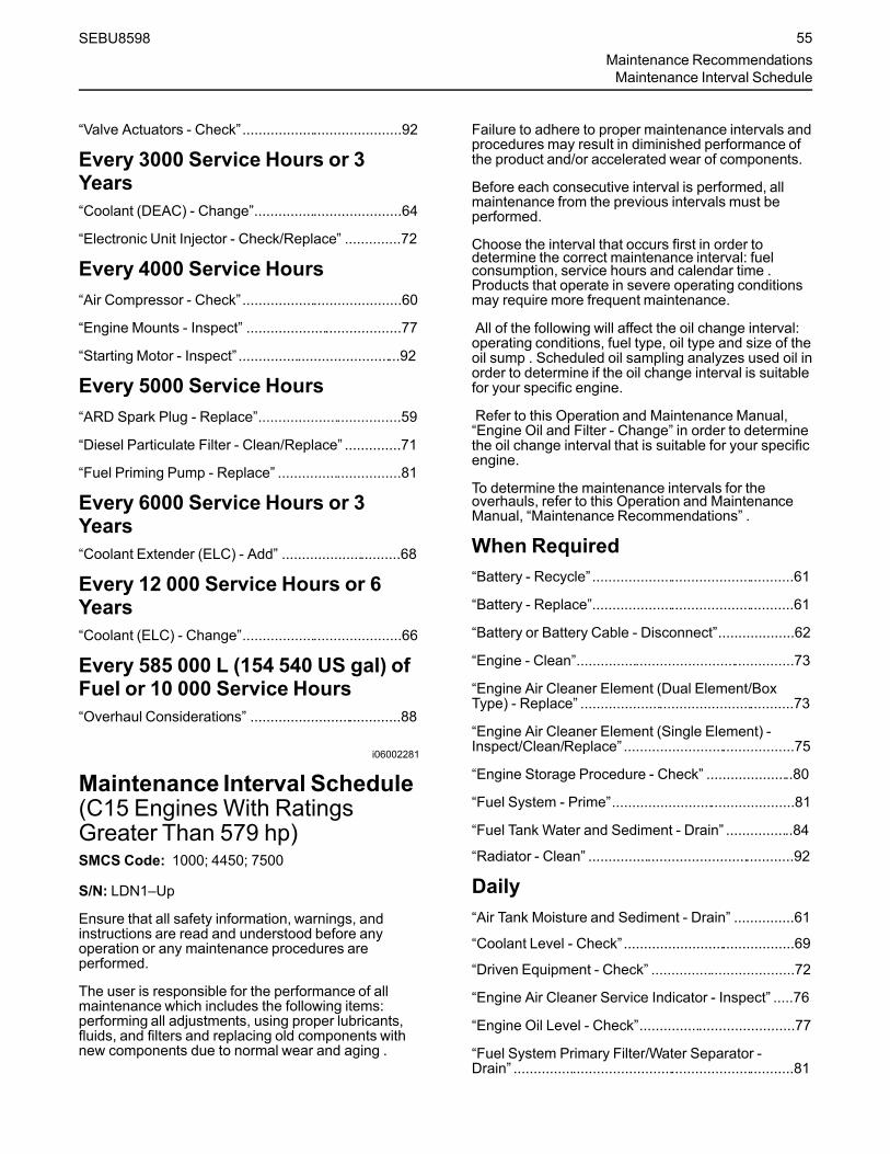
“Valve Actuators - Check”........................................92
Every 3000 Service Hours or 3Years“Coolant (DEAC) - Change”.....................................64
“Electronic Unit Injector - Check/Replace” ..............72
Every 4000 Service Hours“Air Compressor - Check”........................................60
“Engine Mounts - Inspect” .......................................77
“Starting Motor - Inspect” .........................................92
Every 5000 Service Hours“ARD Spark Plug - Replace”....................................59
“Diesel Particulate Filter - Clean/Replace” ..............71
“Fuel Priming Pump - Replace” ...............................81
Every 6000 Service Hours or 3Years“Coolant Extender (ELC) - Add” ..............................68
Every 12 000 Service Hours or 6Years“Coolant (ELC) - Change”........................................66
Every 585 000 L (154 540 US gal) ofFuel or 10 000 Service Hours“Overhaul Considerations” ......................................88
i06002281
Maintenance Interval Schedule(C15 Engines With RatingsGreater Than 579 hp)SMCS Code: 1000; 4450; 7500
S/N: LDN1–Up
Ensure that all safety information, warnings, andinstructions are read and understood before anyoperation or any maintenance procedures areperformed.
The user is responsible for the performance of allmaintenance which includes the following items:performing all adjustments, using proper lubricants,fluids, and filters and replacing old components withnew components due to normal wear and aging .
Failure to adhere to proper maintenance intervals andprocedures may result in diminished performance ofthe product and/or accelerated wear of components.
Before each consecutive interval is performed, allmaintenance from the previous intervals must beperformed.
Choose the interval that occurs first in order todetermine the correct maintenance interval: fuelconsumption, service hours and calendar time .Products that operate in severe operating conditionsmay require more frequent maintenance.
All of the following will affect the oil change interval:operating conditions, fuel type, oil type and size of theoil sump . Scheduled oil sampling analyzes used oil inorder to determine if the oil change interval is suitablefor your specific engine.
Refer to this Operation and Maintenance Manual,“Engine Oil and Filter - Change” in order to determinethe oil change interval that is suitable for your specificengine.
To determine the maintenance intervals for theoverhauls, refer to this Operation and MaintenanceManual, “Maintenance Recommendations” .
When Required“Battery - Recycle” ...................................................61
“Battery - Replace”...................................................61
“Battery or Battery Cable - Disconnect”...................62
“Engine - Clean”.......................................................73
“Engine Air Cleaner Element (Dual Element/BoxType) - Replace” ......................................................73
“Engine Air Cleaner Element (Single Element) -Inspect/Clean/Replace” ...........................................75
“Engine Storage Procedure - Check” ......................80
“Fuel System - Prime”..............................................81
“Fuel Tank Water and Sediment - Drain” .................84
“Radiator - Clean” ....................................................92
Daily“Air Tank Moisture and Sediment - Drain” ...............61
“Coolant Level - Check”...........................................69
“Driven Equipment - Check” ....................................72
“Engine Air Cleaner Service Indicator - Inspect” .....76
“Engine Oil Level - Check”.......................................77
“Fuel System Primary Filter/Water Separator -Drain” .......................................................................81
SEBU8598 55Maintenance RecommendationsMaintenance Interval Schedule
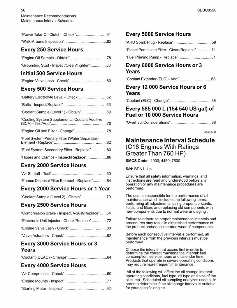
“Power Take-Off Clutch - Check”.............................91
“Walk-Around Inspection”........................................92
Every 250 Service Hours“Engine Oil Sample - Obtain”...................................78
“Grounding Stud - Inspect/Clean/Tighten”...............86
Initial 500 Service Hours“Engine Valve Lash - Check” ...................................80
Every 500 Service Hours“Battery Electrolyte Level - Check” ..........................62
“Belts - Inspect/Replace” .........................................63
“Coolant Sample (Level 1) - Obtain”........................69
“Cooling System Supplemental Coolant Additive(SCA) - Test/Add”.....................................................70
“Engine Oil and Filter - Change”..............................78
“Fuel System Primary Filter (Water Separator)Element - Replace”..................................................82
“Fuel System Secondary Filter - Replace” ..............83
“Hoses and Clamps - Inspect/Replace”...................86
Every 2000 Service Hours“Air Shutoff - Test” ....................................................60
“Fumes Disposal Filter Element - Replace”.............84
Every 2000 Service Hours or 1 Year“Coolant Sample (Level 2) - Obtain”........................70
Every 2500 Service Hours“Compression Brake - Inspect/Adjust/Replace” ......64
“Electronic Unit Injector - Check/Replace” ..............72
“Engine Valve Lash - Check” ...................................80
“Valve Actuators - Check”........................................92
Every 3000 Service Hours or 3Years“Coolant (DEAC) - Change”.....................................64
Every 4000 Service Hours“Air Compressor - Check”........................................60
“Engine Mounts - Inspect” .......................................77
“Starting Motor - Inspect” .........................................92
Every 5000 Service Hours“ARD Spark Plug - Replace”....................................59
“Diesel Particulate Filter - Clean/Replace” ..............71
“Fuel Priming Pump - Replace” ...............................81
Every 6000 Service Hours or 3Years“Coolant Extender (ELC) - Add” ..............................68
Every 12 000 Service Hours or 6Years“Coolant (ELC) - Change”........................................66
Every 585 000 L (154 540 US gal) ofFuel or 10 000 Service Hours“Overhaul Considerations” ......................................88
i06002437
Maintenance Interval Schedule(C18 Engines With RatingsGreater Than 760 HP)SMCS Code: 1000; 4450; 7500
S/N: BDN1–Up
Ensure that all safety information, warnings, andinstructions are read and understood before anyoperation or any maintenance procedures areperformed.
The user is responsible for the performance of allmaintenance which includes the following items:performing all adjustments, using proper lubricants,fluids, and filters and replacing old components withnew components due to normal wear and aging .
Failure to adhere to proper maintenance intervals andprocedures may result in diminished performance ofthe product and/or accelerated wear of components.
Before each consecutive interval is performed, allmaintenance from the previous intervals must beperformed.
Choose the interval that occurs first in order todetermine the correct maintenance interval: fuelconsumption, service hours and calendar time .Products that operate in severe operating conditionsmay require more frequent maintenance.
All of the following will affect the oil change interval:operating conditions, fuel type, oil type and size of theoil sump . Scheduled oil sampling analyzes used oil inorder to determine if the oil change interval is suitablefor your specific engine.
56 SEBU8598Maintenance RecommendationsMaintenance Interval Schedule

Refer to this Operation and Maintenance Manual,“Engine Oil and Filter - Change” in order to determinethe oil change interval that is suitable for your specificengine.
To determine the maintenance intervals for theoverhauls, refer to this Operation and MaintenanceManual, “Maintenance Recommendations” .
When Required“Battery - Recycle” ...................................................61
“Battery - Replace”...................................................61
“Battery or Battery Cable - Disconnect”...................62
“Engine - Clean”.......................................................73
“Engine Air Cleaner Element (Dual Element/BoxType) - Replace” ......................................................73
“Engine Air Cleaner Element (Single Element) -Inspect/Clean/Replace” ...........................................75
“Engine Storage Procedure - Check” ......................80
“Fuel System - Prime”..............................................81
“Fuel Tank Water and Sediment - Drain” .................84
“Radiator - Clean” ....................................................92
Daily“Air Tank Moisture and Sediment - Drain” ...............61
“Coolant Level - Check”...........................................69
“Driven Equipment - Check” ....................................72
“Engine Air Cleaner Service Indicator - Inspect” .....76
“Engine Oil Level - Check”.......................................77
“Fuel System Primary Filter/Water Separator -Drain” .......................................................................81
“Power Take-Off Clutch - Check”.............................91
“Walk-Around Inspection”........................................92
Every 250 Service Hours“Engine Oil Sample - Obtain”...................................78
“Grounding Stud - Inspect/Clean/Tighten”...............86
Initial 500 Service Hours“Engine Valve Lash - Check” ...................................80
Every 500 Service Hours“Battery Electrolyte Level - Check” ..........................62
“Belts - Inspect/Replace” .........................................63
“Coolant Sample (Level 1) - Obtain”........................69
“Cooling System Supplemental Coolant Additive(SCA) - Test/Add”.....................................................70
“Engine Oil and Filter - Change”..............................78
“Fuel System Primary Filter (Water Separator)Element - Replace”..................................................82
“Fuel System Secondary Filter - Replace” ..............83
“Hoses and Clamps - Inspect/Replace”...................86
Every 2000 Service Hours“Air Shutoff - Test” ....................................................60
“Fumes Disposal Filter Element - Replace”.............84
Every 2000 Service Hours or 1 Year“Coolant Sample (Level 2) - Obtain”........................70
Every 2500 Service Hours“Compression Brake - Inspect/Adjust/Replace” ......64
“Electronic Unit Injector - Check/Replace” ..............72
“Engine Valve Lash - Check” ...................................80
“Valve Actuators - Check”........................................92
Every 3000 Service Hours or 3Years“Coolant (DEAC) - Change”.....................................64
Every 4000 Service Hours“Air Compressor - Check”........................................60
“Engine Mounts - Inspect” .......................................77
“Starting Motor - Inspect” .........................................92
Every 6000 Service Hours or 3Years“Coolant Extender (ELC) - Add” ..............................68
Every 12 000 Service Hours or 6Years“Coolant (ELC) - Change”........................................66
Every 760 000 L (200 770 US gal) ofFuel or 10 000 Service Hours“Overhaul Considerations” ......................................88
SEBU8598 57Maintenance RecommendationsMaintenance Interval Schedule
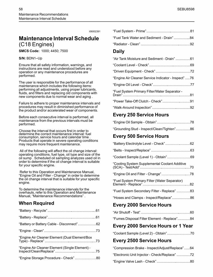
i06002391
Maintenance Interval Schedule(C18 Engines)SMCS Code: 1000; 4450; 7500
S/N: BDN1–Up
Ensure that all safety information, warnings, andinstructions are read and understood before anyoperation or any maintenance procedures areperformed.
The user is responsible for the performance of allmaintenance which includes the following items:performing all adjustments, using proper lubricants,fluids, and filters and replacing old components withnew components due to normal wear and aging .
Failure to adhere to proper maintenance intervals andprocedures may result in diminished performance ofthe product and/or accelerated wear of components.
Before each consecutive interval is performed, allmaintenance from the previous intervals must beperformed.
Choose the interval that occurs first in order todetermine the correct maintenance interval: fuelconsumption, service hours and calendar time .Products that operate in severe operating conditionsmay require more frequent maintenance.
All of the following will affect the oil change interval:operating conditions, fuel type, oil type and size of theoil sump . Scheduled oil sampling analyzes used oil inorder to determine if the oil change interval is suitablefor your specific engine.
Refer to this Operation and Maintenance Manual,“Engine Oil and Filter - Change” in order to determinethe oil change interval that is suitable for your specificengine.
To determine the maintenance intervals for theoverhauls, refer to this Operation and MaintenanceManual, “Maintenance Recommendations” .
When Required“Battery - Recycle” ...................................................61
“Battery - Replace”...................................................61
“Battery or Battery Cable - Disconnect”...................62
“Engine - Clean”.......................................................73
“Engine Air Cleaner Element (Dual Element/BoxType) - Replace” ......................................................73
“Engine Air Cleaner Element (Single Element) -Inspect/Clean/Replace” ...........................................75
“Engine Storage Procedure - Check” ......................80
“Fuel System - Prime”..............................................81
“Fuel Tank Water and Sediment - Drain” .................84
“Radiator - Clean” ....................................................92
Daily“Air Tank Moisture and Sediment - Drain” ...............61
“Coolant Level - Check”...........................................69
“Driven Equipment - Check” ....................................72
“Engine Air Cleaner Service Indicator - Inspect” .....76
“Engine Oil Level - Check”.......................................77
“Fuel System Primary Filter/Water Separator -Drain” .......................................................................81
“Power Take-Off Clutch - Check”.............................91
“Walk-Around Inspection” ........................................92
Every 250 Service Hours“Engine Oil Sample - Obtain”...................................78
“Grounding Stud - Inspect/Clean/Tighten”...............86
Every 500 Service Hours“Battery Electrolyte Level - Check”..........................62
“Belts - Inspect/Replace” .........................................63
“Coolant Sample (Level 1) - Obtain”........................69
“Cooling System Supplemental Coolant Additive(SCA) - Test/Add”.....................................................70
“Engine Oil and Filter - Change”..............................78
“Fuel System Primary Filter (Water Separator)Element - Replace”..................................................82
“Fuel System Secondary Filter - Replace” ..............83
“Hoses and Clamps - Inspect/Replace”...................86
Every 2000 Service Hours“Air Shutoff - Test” ....................................................60
“Fumes Disposal Filter Element - Replace”.............84
Every 2000 Service Hours or 1 Year“Coolant Sample (Level 2) - Obtain”........................70
Every 2500 Service Hours“Compression Brake - Inspect/Adjust/Replace” ......64
“Electronic Unit Injector - Check/Replace” ..............72
“Engine Valve Lash - Check” ...................................80
58 SEBU8598Maintenance RecommendationsMaintenance Interval Schedule

“Valve Actuators - Check”........................................92
Every 3000 Service Hours or 3Years“Coolant (DEAC) - Change”.....................................64
Every 4000 Service Hours“Air Compressor - Check”........................................60
“Engine Mounts - Inspect” .......................................77
“Starting Motor - Inspect” .........................................92
Every 5000 Service Hours“ARD Spark Plug - Replace”....................................59
“Diesel Particulate Filter - Clean/Replace” ..............71
“Fuel Priming Pump - Replace” ...............................81
Every 6000 Service Hours or 3Years“Coolant Extender (ELC) - Add” ..............................68
Every 12 000 Service Hours or 6Years“Coolant (ELC) - Change”........................................66
Every 760 000 L (200 770 US gal) ofFuel or 10 000 Service Hours“Overhaul Considerations” ......................................88
i04880449
ARD Spark Plug - Replace(If Equipped)SMCS Code: 1555-510
Removing the Spark PlugNOTICE
If the engine is running or the key is in the ON positionthe ARD plug will continue to fire. Turn the key to theOFF position before servicing the ARD plug.
Illustration 43 g02139990
(1) Wiring harness(2) Spark plug
1. Remove wire harness (1) from spark plug (2).
Personal injury can result from air pressure.
Personal injury can result without following prop-er procedure. When using pressure air, wear aprotective face shield and protective clothing.
The maximum air pressure for cleaning purposesmust be reduced to 205 kPa (30 psi) when the airnozzle is deadheaded.
2. Debris may have collected in the spark plug well.Thoroughly remove any debris. Use compressedair. The maximum air pressure for cleaningpurposes must be below 205 kPa (30 psi). Ensurethat the area around the spark plug is clean andfree of dirt and debris.
3. Use a deep well socket and a breaker bar to loosenthe spark plug. If necessary, see your Caterpillardealer for the part number of the socket. After thespark plug has been loosened, use the socket toremove the spark plug by hand in order to detectproblems with the threads. After the spark plug hasbeen removed, inspect the used spark plug andthe gasket.
If the spark plug could not be removed by hand, cleanthe threads with a 305-2389 brush. This toolscrapes debris from the seat and from the threads.
SEBU8598 59Maintenance Recommendations
ARD Spark Plug - Replace

NOTICEDo not use a thread tap. A thread tap will remove met-al unnecessarily. The threads could be stripped andthe combustion group could be damaged.
Installing the Spark Plug
Note:Do not use anti-seize compound on the sparkplug. Most of the heat is transferred through thethreads and the seat area of the spark plug. Contactof the metal surfaces must be maintained in order toprovide the heat transfer that is required.1. Ensure that the spark plug is clean and free of dirt
and oil.
NOTICEDo not overtighten the spark plug. The shell can becracked and the gasket can be deformed. The metalcan deform and the gasket can be damaged. Theshell can be stretched. This will loosen the seal that isbetween the shell and the insulator, allowing combus-tion pressure to blow past the seal. Serious damageto the engine can occur.
Use the proper torque.
2. Install the spark plug by hand until the spark plugcontacts the ARD. Torque the spark plug to theproper specification. Refer to Specifications,“Spark Plug” for the proper torque specification.
3. Connect the wiring harness.
i03966490
Air Compressor - Check(If equipped)SMCS Code: 1803-535
Do not disconnect the air line from the air com-pressor governor without purging the air brakeand the auxiliary air systems. Failure to purge theair brake and the auxiliary air systems before re-moving the air compressor and/or the air linescould cause personal injury.
Illustration 44 g01212654
Typical example(1) Pressure relief valve
If the air compressor pressure relief valve that ismounted in the air compressor cylinder head isbypassing compressed air, there is a malfunctionin the air system, possibly ice blockage. Underthese conditions, your engine may have insuffi-cient air for normal brake operation.
Do not operate the engine until the reason for theair bypass is identified and corrected. Failure toheed this warning could lead to property damage,personal injury, or death to the operator orbystanders.
The function of the pressure relief valve is to bypassair when there is a malfunction in the system for theair compressor.
The pressure relief valve for the air compressorreleases air at 1723 kPa (250 psi). If the pressurerelief valve for the air compressor exhausts, allpersonnel should be at a safe distance away from theair compressor. All personnel should also stay clearof the air compressor when the engine is operatingand the air compressor is exposed.
Refer to the Service Manual or refer to the OEMspecifications in order to find information concerningthe air compressor. Consult your Caterpillar dealerfor assistance.
i05341564
Air Shutoff - TestSMCS Code: 1078-081
To ensure that the air shutoff valve always shutsdown when the engine ingests gaseous fumes,perform the test below at each oil change. A testfailure can indicate wear in the block off plate to valvebody interface and/or the bearing system.
60 SEBU8598Maintenance RecommendationsAir Compressor - Check

1. Place engine at low idle speed. Ensure allaccessories that are normally used for theapplication are in use, like a fan, or power takeoffs.
2. Actuate the air shutoff manually. On electricaloperator air shutoffs, utilize an applicable powersupply or jumper cables from the battery toenergize the air shut-off solenoid. Ensure that thesolenoid receives only a momentary signal toprevent overheating. On hydraulic operator airshutoffs, found on some hazardous location units,actuate by pulling the emergency stop handle.
3. Ensure that air shutoff was actuated and that theengine comes to a complete stop.
Note: As every application has different parasiticloads and inertia, the duration for the problem tooccur cannot be specified. However, if the enginestumbles or attempts to continue running, thesesymptoms may be an indication that worncomponents may need replacement.
If additional help is needed, contact the DealerSolution Network.
NOTICEActuating the air shutoff valve may result in oil leak-age past the shaft seal in some cases. Repeated ac-tuation of the air shutoff valve during loaded operationof the engine can result in mechanical damage to theturbocharger and reduce turbocharger life.
i00847451
Air Tank Moisture andSediment - Drain(If Equipped)SMCS Code: 1466-543-M&S
Moisture and sediment in the air starting system cancause the following conditions:
• Freezing
• Corrosion of internal parts
• Malfunction of the air starting system
When opening the drain valve, wear protectivegloves, a protective face shield, protective cloth-ing, and protective shoes. Pressurized air couldcause debris to be blown and result in personalinjury.
1. Open the drain valve that is on the bottom of the airtank. Allow the moisture and sediment to drain.
2. Close the drain valve.
3. Check the air supply pressure. The air startingmotor requires a minimum of 620 kPa (90 psi) ofair pressure to operate properly. The maximum airpressure must not exceed 1550 kPa (225 psi).The normal air pressure will be 758 to 965 kPa(110 to 140 psi).
i02039199
Battery - RecycleSMCS Code: 1401-005; 1401-510; 1401-535; 1401-561; 1401
Always recycle a battery. Never discard a battery.Return used batteries to one of the followinglocations:
• A battery supplier
• An authorized battery collection facility
• A recycling facility
i01878164
Battery - ReplaceSMCS Code: 1401-510
Batteries give off combustible gases which canexplode. A spark can cause the combustiblegases to ignite. This can result in severe personalinjury or death.
Ensure proper ventilation for batteries that are inan enclosure. Follow the proper procedures in or-der to help prevent electrical arcs and/or sparksnear batteries. Do not smoke when batteries areserviced.
The battery cables or the batteries should not beremoved with the battery cover in place. The bat-tery cover should be removed before any servic-ing is attempted.
Removing the battery cables or the batteries withthe cover in place may cause a battery explosionresulting in personal injury.
SEBU8598 61Maintenance Recommendations
Air Tank Moisture and Sediment - Drain

1. Switch the engine to the OFF position. Remove allelectrical loads.
2. Turn off any battery chargers. Disconnect anybattery chargers.
3. The NEGATIVE “-” cable connects the NEGATIVE“-” battery terminal to the NEGATIVE “-” terminalon the starter motor. Disconnect the cable from theNEGATIVE “-” battery terminal.
4. The POSITIVE “+” cable connects the POSITIVE“+” battery terminal to the POSITIVE “+” terminalon the starting motor. Disconnect the cable fromthe POSITIVE “+” battery terminal.
Note: Always recycle a battery. Never discard abattery. Return used batteries to an appropriaterecycling facility.5. Remove the used battery.
6. Install the new battery.
Note: Before the cables are connected, ensure thatthe engine start switch is OFF.7. Connect the cable from the starting motor to the
POSITIVE “+” battery terminal.
8. Connect the cable from the NEGATIVE “-”terminal on the starter motor to the NEGATIVE “-”battery terminal.
i02601752
Battery Electrolyte Level -CheckSMCS Code: 1401-535-FLV
When the engine is not run for long periods of time orwhen the engine is run for short periods, the batteriesmay not fully recharge. Ensure a full charge in orderto help prevent the battery from freezing.
All lead-acid batteries contain sulfuric acid whichcan burn the skin and clothing. Always wear aface shield and protective clothing when workingon or near batteries.
1. Remove the filler caps. Maintain the electrolytelevel to the “FULL” mark on the battery.
If the addition of water is necessary, use distilledwater. If distilled water is not available use cleanwater that is low in minerals. Do not use artificiallysoftened water.
2. Check the condition of the electrolyte with the245-5829Coolant Battery Tester Refractometer.
3. Keep the batteries clean.
Clean the battery case with one of the followingcleaning solutions:
• A mixture of 0.1 kg (0.2 lb) of baking soda and1 L (1 qt) of clean water
• A mixture of 0.1 L (0.11 qt) of ammonia and 1 L(1 qt) of clean water
Thoroughly rinse the battery case with clean water.
Use a fine grade of sandpaper to clean theterminals and the cable clamps. Clean the itemsuntil the surfaces are bright or shiny. DO NOTremove material excessively. Excessive removal ofmaterial can cause the clamps to not fit properly.Coat the clamps and the terminals with 5N-5561Silicone Lubricant, petroleum jelly or MPGM.
i01492654
Battery or Battery Cable -DisconnectSMCS Code: 1401; 1402-029
The battery cables or the batteries should not beremoved with the battery cover in place. The bat-tery cover should be removed before any servic-ing is attempted.
Removing the battery cables or the batteries withthe cover in place may cause a battery explosionresulting in personal injury.
1. Turn the start switch to the OFF position. Turn theignition switch (if equipped) to the OFF positionand remove the key and all electrical loads.
2. Disconnect the negative battery terminal at thebattery that goes to the start switch. Ensure thatthe cable cannot contact the terminal. When four12 volt batteries are involved, the negative side oftwo batteries must be disconnected.
3. Tape the leads in order to help prevent accidentalstarting.
4. Proceed with necessary system repairs. Reversethe steps in order to reconnect all of the cables.
62 SEBU8598Maintenance RecommendationsBattery Electrolyte Level - Check
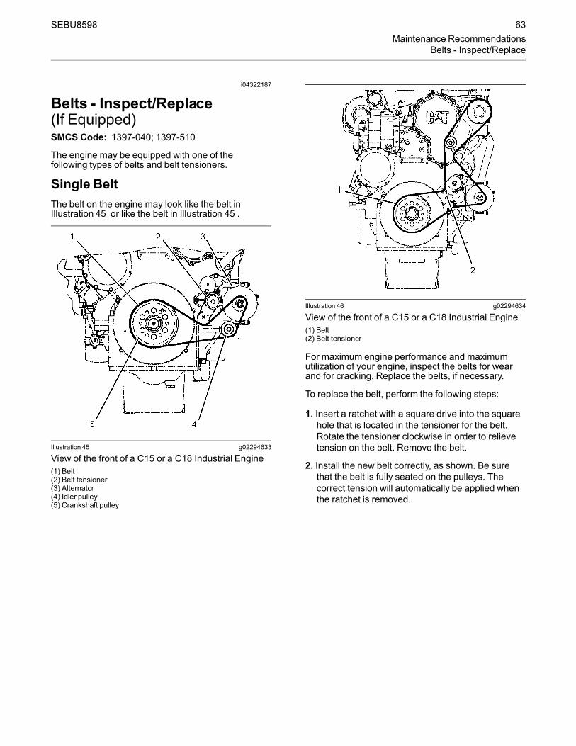
i04322187
Belts - Inspect/Replace(If Equipped)SMCS Code: 1397-040; 1397-510
The engine may be equipped with one of thefollowing types of belts and belt tensioners.
Single BeltThe belt on the engine may look like the belt inIllustration 45 or like the belt in Illustration 45 .
Illustration 45 g02294633
View of the front of a C15 or a C18 Industrial Engine(1) Belt(2) Belt tensioner(3) Alternator(4) Idler pulley(5) Crankshaft pulley
Illustration 46 g02294634
View of the front of a C15 or a C18 Industrial Engine(1) Belt(2) Belt tensioner
For maximum engine performance and maximumutilization of your engine, inspect the belts for wearand for cracking. Replace the belts, if necessary.
To replace the belt, perform the following steps:
1. Insert a ratchet with a square drive into the squarehole that is located in the tensioner for the belt.Rotate the tensioner clockwise in order to relievetension on the belt. Remove the belt.
2. Install the new belt correctly, as shown. Be surethat the belt is fully seated on the pulleys. Thecorrect tension will automatically be applied whenthe ratchet is removed.
SEBU8598 63Maintenance Recommendations
Belts - Inspect/Replace

Two or More Belts
Illustration 47 g02478261
Belt tensioner(1) Adjustment bolt(2) 46 mm (1-13/16 inch) jamming locknut (jam nut)(A) 22 mm (0.87 inch)
Inspection of the Belts
Inspect the fan drive belts for wear and for cracking.Replace the belts if the belts are not in goodcondition.
Belt Replacement
For applications that require multiple drive belts,replace the drive belts in matched sets. Replacingone drive belt of a matched set will cause the newdrive belt to carry more load because the older drivebelts are stretched. The additional load on the newdrive belt could cause the new drive belt to fail.
Use the following procedure to change the belts.
1. Using a 46 mm (1-13/16 inch) wrench, loosen thejam nut (2).
Note: See figure 47 , dimension (A).
2. Loosen the adjustment bolt (1).
3. Remove the old belt and replace with a new belt.Contact your Cat dealer for assistance in choosingand ordering new belts.
4. Tighten the adjustment bolt (1). Use a 144-0235Belt Tension Gauge to ensure that belt is tensionedaccording to table 9 .
5. Tighten the jam nut to a torque of 200 ± 25 N·m(148 ± 18 lb ft)
Table 9
Fan Drive Belt Adjustment
Belt Tension (Initial) Belt Tension (Used)(1)
801 ± 44 N (180 ± 10 lb) 378 ± 44 N (85 ± 10 lb)
(1) Belt with over 30 minutes of operation at a rated speed
Belt Adjustment
Repeat steps 1, 4, and 5 from the belt replacementprocedure.
i03965390
CompressionBrake - Inspect/Adjust/ReplaceSMCS Code: 1119-025; 1119-040; 1119-510
Contact your Cat dealer for the proper procedure.
i04156977
Coolant (DEAC) - ChangeSMCS Code: 1350-070; 1395-044
Clean the cooling system and flush the coolingsystem before the recommended maintenanceinterval if the following conditions exist:
• The engine overheats frequently.
• Foaming is observed.
• The oil has entered the cooling system and thecoolant is contaminated.
• The fuel has entered the cooling system and thecoolant is contaminated.
NOTICEUse of commercially available cooling systemcleaners may cause damage to cooling system com-ponents. Use only cooling system cleaners that areapproved for Caterpillar engines.
Note: Inspect the water pump and the watertemperature regulator after the cooling system hasbeen drained.
64 SEBU8598Maintenance RecommendationsCompression Brake - Inspect/Adjust/Replace

Illustration 48 g02351659
The cooling system drain valve is towards the bottomof the radiator.
Drain
Pressurized System: Hot coolant can cause seri-ous burns. To open the cooling system filler cap,stop the engine and wait until the cooling systemcomponents are cool. Loosen the cooling systempressure cap slowly in order to relieve thepressure.
NOTICECare must be taken to ensure that fluids are con-tained during performance of inspection, mainte-nance, testing, adjusting and repair of the product. Beprepared to collect the fluid with suitable containersbefore opening any compartment or disassemblingany component containing fluids.
Refer to Special Publication, NENG2500, “CaterpillarDealer Service Tool Catalog” or refer to Special Publi-cation, PECJ0003, “Caterpillar Shop Supplies andTools Catalog” for tools and supplies suitable to col-lect and contain fluids on Caterpillar products.
Dispose of all fluids according to local regulations andmandates.
1. Stop the engine and allow the engine to cool.Loosen the cooling system filler cap slowly in orderto relieve any pressure. Remove the coolingsystem filler cap.
2. Open the cooling system drain valve.
Allow the coolant to drain.
NOTICEDispose of used engine coolant properly or recycle.Various methods have been proposed to reclaim usedcoolant for reuse in engine cooling systems. The fulldistillation procedure is the only method acceptableby Caterpillar to reclaim the used coolant.
For information regarding the disposal and therecycling of used coolant, consult your Cat dealer orconsult Cat Dealer Service Tools Group :
Outside Illinois 1-800-542-TOOLInside Illinois 1-800-541-TOOLCanada 1-800-523-TOOLInternational 1-309-578-7372
Flush1. Flush the cooling system with clean water in order
to remove any debris.
2. Close the drain valve.
NOTICEFill the cooling system no faster than 19 L (5 US gal)per minute to avoid air locks.
3. Fill the cooling system with a mixture of clean waterand Cat Fast Acting Cooling System Cleaner. Add0.5 L (1 pt) of cleaner per 15 L (4 US gal) of thecooling system capacity. Install the cooling systemfiller cap.
4. Start and run the engine at low idle for a minimumof 30 minutes. The coolant temperature should beat least 82 °C (180 °F).
NOTICEImproper or incomplete rinsing of the cooling systemcan result in damage to copper and other metalcomponents.
To avoid damage to the cooling system, make sure tocompletely flush the cooling system with clear water.Continue to flush the system until all signs of thecleaning agent are gone.
SEBU8598 65Maintenance Recommendations
Coolant (DEAC) - Change

5. Stop the engine and allow the engine to cool.Loosen the cooling system filler cap slowly in orderto relieve any pressure. Remove the coolingsystem filler cap. Open the drain valve. Allow thewater to drain. Flush the cooling system with cleanwater. If equipped, be sure to flush the heater andany related supply and return lines. Close the drainvalve.
Cooling Systems with HeavyDeposits or PluggingNote: For the following procedure to be effective,there must be some active flow through the coolingsystem components.
1. Flush the cooling system with clean water in orderto remove any debris.
2. Close the drain valve.
NOTICEFill the cooling system no faster than 19 L (5 US gal)per minute to avoid air locks.
3. Fill the cooling system with a mixture of clean waterand Cat Fast Acting Cooling System Cleaner. Add0.5 L (1 pt) of cleaner per 3.8 to 7.6 L(1 to 2 US gal) of the cooling system capacity.Install the cooling system filler cap.
4. Start and run the engine at low idle for a minimumof 90 minutes. The coolant temperature should beat least 82 °C (180 °F).
NOTICEImproper or incomplete rinsing of the cooling systemcan result in damage to copper and other metalcomponents.
To avoid damage to the cooling system, make sure tocompletely flush the cooling system with clear water.Continue to flush the system until all signs of thecleaning agent are gone.
5. Stop the engine and allow the engine to cool.Loosen the cooling system filler cap slowly in orderto relieve any pressure. Remove the coolingsystem filler cap. Open the drain valve. Allow thewater to drain. Flush the cooling system with cleanwater.
Fill
NOTICEFill the cooling system no faster than 19 L (5 US gal)per minute to avoid air locks.
1. Fill the cooling system with coolant/antifreeze.Refer to this Operation and Maintenance Manual,“Fluid Recommendations” topic for moreinformation on cooling system specifications. Donot install the cooling system filler cap.
2. Start and run the engine at low idle. Increase theengine rpm to 1500 rpm. Run the engine at highidle for 1 minute in order to purge the air from thecavities of the engine block. Stop the engine.
3. Check the coolant level. Maintain the coolant levelwithin 13 mm (0.5 inch) below the bottom of thepipe for filling. Maintain the coolant level within13 mm (0.5 inch) to the proper level on the sightglass.
4. Clean the cooling system filler cap. Inspect thegasket that is on the cooling system filler cap. If thegasket that is on the cooling system filler cap isdamaged, discard the old filler cap and install anew filler cap. If the gasket that is on the coolingsystem filler cap is not damaged, perform apressure test. A 9S-8140 Pressurizing Pump isused to perform the pressure test. The correctpressure for the cooling system filler cap isstamped on the face of the cooling system fillercap. If the cooling system filler cap does not retainthe correct pressure, install a new cooling systemfiller cap.
5. Start the engine. Inspect the cooling system forleaks and for proper operating temperature.
i04156979
Coolant (ELC) - ChangeSMCS Code: 1350-070; 1395-044
Clean the cooling system and flush the coolingsystem before the recommended maintenanceinterval if the following conditions exist:
• The engine overheats frequently.
• Foaming is observed.
• The oil has entered the cooling system and thecoolant is contaminated.
• The fuel has entered the cooling system and thecoolant is contaminated.
66 SEBU8598Maintenance RecommendationsCoolant (ELC) - Change

Note:When the cooling system is cleaned, onlyclean water is needed when the ELC is drained andreplaced.
Note: Inspect the water pump and the watertemperature regulator after the cooling system hasbeen drained.
Illustration 49 g02351659
Drain
Pressurized System: Hot coolant can cause seri-ous burns. To open the cooling system filler cap,stop the engine and wait until the cooling systemcomponents are cool. Loosen the cooling systempressure cap slowly in order to relieve thepressure.
1. Stop the engine and allow the engine to cool.Loosen the cooling system filler cap slowly in orderto relieve any pressure. Remove the coolingsystem filler cap.
2. Open the cooling system drain valve.
Allow the coolant to drain.
NOTICEDispose of used engine coolant properly or recycle.Various methods have been proposed to reclaim usedcoolant for reuse in engine cooling systems. The fulldistillation procedure is the only method acceptableby Caterpillar to reclaim the used coolant.
NOTICECare must be taken to ensure that fluids are con-tained during performance of inspection, mainte-nance, testing, adjusting and repair of the product. Beprepared to collect the fluid with suitable containersbefore opening any compartment or disassemblingany component containing fluids.
Refer to Special Publication, NENG2500, “CaterpillarDealer Service Tool Catalog” or refer to Special Publi-cation, PECJ0003, “Caterpillar Shop Supplies andTools Catalog” for tools and supplies suitable to col-lect and contain fluids on Caterpillar products.
Dispose of all fluids according to local regulations andmandates.
For information regarding the disposal and therecycling of used coolant, consult your Cat dealer orconsult Cat Dealer Service Tool Group :
OutsideIllinois 1-800-542-TOOLInsideIllinois 1-800-541-TOOLCanada 1-800-523-TOOLInternational 1-309-578-7372
Flush1. Flush the cooling system with clean water in order
to remove any debris.
2. Close the drain valve.
NOTICEFill the cooling system no faster than 19 L (5 US gal)per minute to avoid air locks.
3. Fill the cooling system with clean water. Install thecooling system filler cap.
4. Start and run the engine at low idle until thetemperature reaches49 to 66 °C (120 to 150 °F).
5. Stop the engine and allow the engine to cool.Loosen the cooling system filler cap slowly in orderto relieve any pressure. Remove the coolingsystem filler cap. Open the drain valve. Allow thewater to drain. Flush the cooling system with cleanwater. Close the drain valve.
Fill
SEBU8598 67Maintenance Recommendations
Coolant (ELC) - Change

NOTICEFill the cooling system no faster than 19 L (5 US gal)per minute to avoid air locks.
1. Fill the cooling system with Extended Life Coolant(ELC). Refer to this Operation and MaintenanceManual, “Fluid Recommendations” for moreinformation on cooling system specifications. Donot install the cooling system filler cap.
2. Start and run the engine at low idle. Increase theengine rpm to high idle. Run the engine at high idlefor 1 minute in order to purge the air from thecavities of the engine block. Stop the engine.
3. Check the coolant level. Maintain the coolant levelwithin 13 mm (0.5 inch) below the bottom of thepipe for filling. Maintain the coolant level within13 mm (0.5 inch) to the proper level on the sightglass.
4. Clean the cooling system filler cap. Inspect thegasket that is on the cooling system filler cap. Onlyinstall the used filler cap if the gasket is notdamaged. Use a 9S-8140 Pressurizing Pump topressure test a reinstalled cooling system filler cap.The correct pressure for the cooling system fillercap is stamped on the face of the cooling systemfiller cap. If the cooling system filler cap does notretain the correct pressure, install a new coolingsystem filler cap.
5. Start the engine. Inspect the cooling system forleaks and for proper operating temperature.
i04745732
Coolant Extender (ELC) - AddSMCS Code: 1352-544-NL
Cat ELC (Extended Life Coolant) does not requirethe frequent additions of any supplemental coolingadditives which are associated with the presentconventional coolants. The Cat ELC Extender willonly be added one time.
NOTICEUse only Cat Extended Life Coolant (ELC) Extenderwith Cat ELC.
Do NOT use conventional supplemental coolant addi-tive (SCA) with Cat ELC. Mixing Cat ELC with con-ventional coolants and/or conventional SCA reducesthe Cat ELC service life.
Check the cooling system only when the engine isstopped and cool.
Personal injury can result from hot coolant, steamand alkali.
At operating temperature, engine coolant is hotand under pressure. The radiator and all lines toheaters or the engine contain hot coolant orsteam. Any contact can cause severe burns.
Remove cooling system pressure cap slowly torelieve pressure only when engine is stopped andcooling system pressure cap is cool enough totouch with your bare hand.
Do not attempt to tighten hose connections whenthe coolant is hot, the hose can come off causingburns.
Cooling System Coolant Additive contains alkali.Avoid contact with skin and eyes.
NOTICECare must be taken to ensure that fluids are con-tained during performance of inspection, mainte-nance, testing, adjusting, and repair of the product.Be prepared to collect the fluid with suitable contain-ers before opening any compartment or disassem-bling any component containing fluids.
Refer to Special Publication, NENG2500, “Cat DealerService Tool Catalog” or refer to Special Publication,PECJ0003, “Cat Shop Supplies and Tools Catalog”for tools and supplies suitable to collect and containfluids on Cat products.
Dispose of all fluids according to local regulations andmandates.
1. Loosen the cooling system filler cap slowly in orderto relieve pressure. Remove the cooling systemfiller cap.
2. If necessary, drain enough coolant from the coolingsystem in order to add the Cat ELC Extender .
3. Add Cat ELC Extender according to therequirements for the cooling system capacity.Refer to this Operation and Maintenance Manual,“Refill Capacities” or to this Operation andMaintenance Manual, “Fluid Recommendations”for more information.
4. Clean the cooling system filler cap. Inspect thegaskets on the cooling system filler cap. Replacethe cooling system filler cap if the gaskets aredamaged. Install the cooling system filler cap.
68 SEBU8598Maintenance RecommendationsCoolant Extender (ELC) - Add
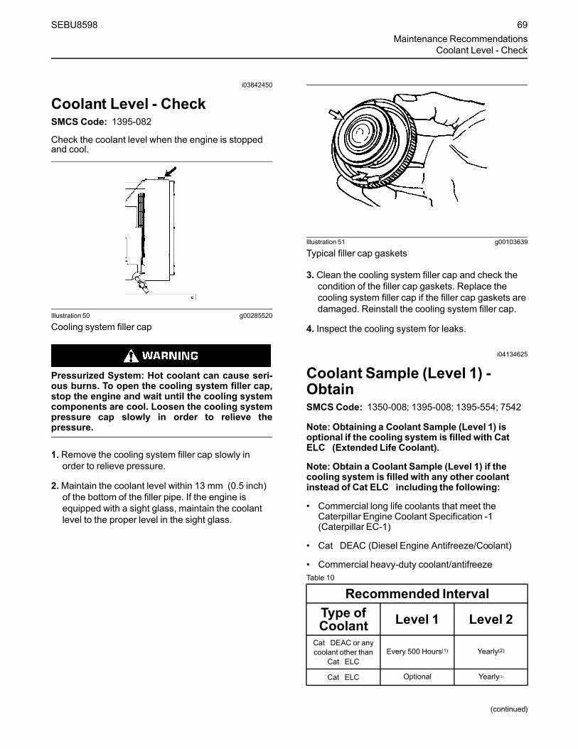
i03842450
Coolant Level - CheckSMCS Code: 1395-082
Check the coolant level when the engine is stoppedand cool.
Illustration 50 g00285520
Cooling system filler cap
Pressurized System: Hot coolant can cause seri-ous burns. To open the cooling system filler cap,stop the engine and wait until the cooling systemcomponents are cool. Loosen the cooling systempressure cap slowly in order to relieve thepressure.
1. Remove the cooling system filler cap slowly inorder to relieve pressure.
2.Maintain the coolant level within 13 mm (0.5 inch)of the bottom of the filler pipe. If the engine isequipped with a sight glass, maintain the coolantlevel to the proper level in the sight glass.
Illustration 51 g00103639
Typical filler cap gaskets
3. Clean the cooling system filler cap and check thecondition of the filler cap gaskets. Replace thecooling system filler cap if the filler cap gaskets aredamaged. Reinstall the cooling system filler cap.
4. Inspect the cooling system for leaks.
i04134625
Coolant Sample (Level 1) -ObtainSMCS Code: 1350-008; 1395-008; 1395-554; 7542
Note: Obtaining a Coolant Sample (Level 1) isoptional if the cooling system is filled with CatELC (Extended Life Coolant).
Note: Obtain a Coolant Sample (Level 1) if thecooling system is filled with any other coolantinstead of Cat ELC including the following:
• Commercial long life coolants that meet theCaterpillar Engine Coolant Specification -1(Caterpillar EC-1)
• Cat DEAC (Diesel Engine Antifreeze/Coolant)
• Commercial heavy-duty coolant/antifreezeTable 10
Recommended IntervalType ofCoolant Level 1 Level 2
Cat DEAC or anycoolant other than
Cat ELCEvery 500 Hours(1) Yearly(2)
Cat ELC Optional Yearly(2)
(continued)
SEBU8598 69Maintenance Recommendations
Coolant Level - Check

(Table 10, contd)(1) This interval is the recommended interval for coolant samples
for all conventional heavy-duty coolant/antifreeze. This intervalis also the recommended interval for coolant samples of com-mercial coolants that meet the Cat EC-1 specification for enginecoolant.
(2) The Level 2 Coolant Analysis should be performed sooner if aproblem is suspected or identified.
NOTICEAlways use a designated pump for oil sampling, anduse a separate designated pump for coolant sam-pling. Using the same pump for both types of samplesmay contaminate the samples that are being drawn.This contaminate may cause a false analysis and anincorrect interpretation that could lead to concerns byboth dealers and customers.
Note: Level 1 results may indicate a need forLevel 2 Analysis.
Obtain the sample of the coolant as close as possibleto the recommended sampling interval. In order toreceive the full effect of S·O·S analysis, establish aconsistent trend of data. In order to establish apertinent history of data, perform consistentsamplings that are evenly spaced. Supplies forcollecting samples can be obtained from your Catdealer.
Use the following guidelines for proper sampling ofthe coolant:
• Complete the information on the label for thesampling bottle before you begin to take thesamples.
• Keep the unused sampling bottles stored in plasticbags.
• Obtain coolant samples directly from the coolantsample port. You should not obtain the samplesfrom any other location.
• Keep the lids on empty sampling bottles until youare ready to collect the sample.
• Place the sample in the mailing tube immediatelyafter obtaining the sample in order to avoidcontamination.
• Never collect samples from expansion bottles.
• Never collect samples from the drain for a system.
Submit the sample for Level 1 analysis.
For additional information about coolant analysis, seethis Operation and Maintenance Manual, “FluidRecommendations” or consult your Cat dealer.
i05378320
Coolant Sample (Level 2) -ObtainSMCS Code: 1350-008; 1395-008; 1395-554; 7542
NOTICEAlways use a designated pump for oil sampling, anduse a separate designated pump for coolant sam-pling. Using the same pump for both types of samplesmay contaminate the samples that are being drawn.This contaminate may cause a false analysis and anincorrect interpretation that could lead to concerns byboth dealers and customers.
NOTICECare must be taken to ensure that fluids are con-tained during performance of inspection, mainte-nance, testing, adjusting, and repair of the product.Be prepared to collect the fluid with suitable contain-ers before opening any compartment or disassem-bling any component containing fluids.
Refer to Special Publication, NENG2500, “Cat DealerService Tool Catalog” or refer to Special Publication,PECJ0003, “Cat Shop Supplies and Tools Catalog”for tools and supplies suitable to collect and containfluids on Cat products.
Dispose of all fluids according to local regulations andmandates.
Refer to Operation and Maintenance Manual,“Cooling System Coolant Sample (Level 1) - Obtain”for the guidelines for a proper sampling of the coolant.
Submit the sample for Level 2 analysis.
For additional information about coolant analysis, seeSpecial Publication, SEBU7003, “Cat 3600 Seriesand C280 Series Diesel Engine FluidsRecommendations” or consult your Cat dealer.
i04269112
Cooling System SupplementalCoolant Additive (SCA) - Test/Add(SystemsWhich are Filled withConventional Coolant)SMCS Code: 1352-045; 1395-081
This maintenance procedure is required forconventional coolants such as DEAC.Do notperform this maintenance for cooling systemsthat are filled with Cat Extended Life Coolant (CatELC) or Cat Extended Life Inhibitor (Cat ELI).
70 SEBU8598Maintenance RecommendationsCoolant Sample (Level 2) - Obtain
Cooling system coolant additive contains alkali.To help prevent personal injury, avoid contactwith the skin and eyes. Do not drink cooling sys-tem coolant additive.
NOTICEExcessive supplemental coolant additive concentra-tion can form deposits on the higher temperature sur-faces of the cooling system, reducing the engine'sheat transfer characteristics. Reduced heat transfercould cause cracking of the cylinder head and otherhigh temperature components.
Excessive supplemental coolant additive concentra-tion could also result in blockage of the heat exchang-er, overheating, and/or accelerated wear of the waterpump seal.
Do not exceed the recommended amount of supple-mental coolant additive concentration.
NOTICEDo NOT mix brands or types of SCA. Do NOT mixSCAs and extenders.
Failure to follow the recommendations can result inshortened cooling system component life.
NOTICEUse Only Approved SCAs. Conventional coolantsrequire the maintenance addition of SCA throughouttheir expected life. Do NOT use an SCA with a cool-ant unless specifically approved by the coolant suppli-er for use with their coolant. It is the responsibility ofthe coolant manufacturer to ensure compatibility andacceptable performance.
Failure to follow the recommendations can result inshortened cooling system component life.
NOTICECare must be taken to ensure that fluids are con-tained during performance of inspection, mainte-nance, testing, adjusting, and repair of the product.Be prepared to collect the fluid with suitable contain-ers before opening any compartment or disassem-bling any component containing fluids.
Refer to Special Publication, NENG2500, “Cat DealerService Tool Catalog” and to Special Publication,GECJ0003, “Cat Shop Supplies and Tools” for toolsand supplies suitable to collect and contain fluids onCat products.
Dispose of all fluids according to applicable regula-tions and mandates.
Note: Caterpillar recommends that an S·O·S CoolantAnalysis (Level 1) be performed to check theconcentration of SCA.
Maintain the Proper Concentrationof SCA in the Coolant
Pressurized System: Hot coolant can cause seri-ous burns. To open the cooling system filler cap,stop the engine and wait until the cooling systemcomponents are cool. Loosen the cooling systempressure cap slowly in order to relieve thepressure.
1. Remove the cooling system filler cap slowly.
2. Test the concentration of the SCA with a286-2578Nitrite Test Strip or review the resultsof the S·O·S Coolant Analysis (Level 1).
3. If necessary, drain some coolant in order to allowspace for the addition of the SCA.
4. Add the amount of SCA required to maintain aconcentration of 3 percent to 6 percent SCA in thecoolant.
5. Clean the cooling system filler cap. Install thecooling system filler cap.
For further information, refer to Special Publication,SEBU6251, “Cat Commercial Diesel Engine FluidsRecommendations”.
i04880440
Diesel Particulate Filter - Clean/Replace(If Equipped)SMCS Code: 108F-070; 108F-510; 1091-070; 1091-510
Consult your Cat dealer when the DPF needs to becleaned.
The approved Caterpillar DPF maintenanceprocedure requires that one of the following actionsbe taken when the DPF needs to be cleaned:
SEBU8598 71Maintenance Recommendations
Diesel Particulate Filter - Clean/Replace

• The DPF from your engine can be replaced with anew DPF
• The DPF from your engine can be replaced with aremanufactured DPF
• The DPF from your engine can be cleaned by yourlocal authorized Cat dealer, or a Caterpillarapproved DPF cleaning machine, and reinstalled
Note: In order to maintain emissions documentation,the DPF that is removed from the engine when theDPF is cleaned must be reinstalled on the sameengine.
Note: A specific ash service regenerationmust beperformed before removing a DPF that will becleaned. All three scenarios listed above require areset of the ash monitoring system in the engineECM.
i00934883
Driven Equipment - CheckSMCS Code: 3279-535
Check the AlignmentTo minimize bearing problems and vibration of theengine crankshaft and the driven equipment, thealignment between the engine and driven equipmentmust be properly maintained.
Check the alignment according to the instructions thatare provided by the following manufacturers:
• Caterpillar
• OEM of the drive coupling
• OEM of the driven equipment
Torque all of the fasteners to the properspecifications.
Inspect the Drive CouplingInspect the drive coupling according to theinstructions that are provided by the OEM of thecoupling. For the following service information, seethe literature that is provided by the OEM of thecoupling:
• Lubrication requirements
• Specifications for the end play
• “Reusability Guidelines”
• Replacement instructions
Inspect the Rear Gear TrainInspect the crankshaft gear. If excessive wear isfound, replace the crankshaft gear and the largecluster idler.
If any gear causes damage to other gears throughfailure, replace the entire rear gear train.
For the correct parts, see the Parts Manual for theengine. For removal and replacement instructions,see the Service Manual, “Disassembly andAssembly” module. Consult your Caterpillar dealer forassistance.
i04230004
Electronic Unit Injector -Check/ReplaceSMCS Code: 1251-510; 1251-535; 1290-510; 1290-535
Be sure the engine cannot be started while thismaintenance is being performed. To prevent pos-sible injury, do not use the starting motor to turnthe flywheel.
Hot engine components can cause burns. Allowadditional time for the engine to cool before meas-uring/adjusting the unit injectors.
The electronic unit injectors use high voltage. Dis-connect the unit injector enable circuit connectorin order to prevent personal injury. Do not comein contact with the injector terminals while the en-gine is running.
The operation of a Cat Engine with an electronic unitinjector which is improperly adjusted may reduceengine efficiency. This reduced efficiency may resultin excessive fuel usage and/or shortened enginecomponent life.
Note:Only qualified service personnel shouldperform this maintenance.
Refer to the Systems Operation, Testing andAdjusting, “Electronic Unit Injector - Test” for the testprocedure. Refer to Systems Operation, Testing andAdjusting, “Electronic Unit Injector - Adjust” for theadjustment procedure.
Refer to the Disassembly and Assembly Manual forthe procedure for the removal and replacement of theinjector.
72 SEBU8598Maintenance RecommendationsDriven Equipment - Check

NOTICEThe camshafts must be correctly timed with the crank-shaft before an adjustment of the lash for the fuel in-jector is made. The timing pins must be removed fromthe camshafts before the crankshaft is turned or dam-age to the cylinder block will be the result.
i01646701
Engine - CleanSMCS Code: 1000-070
Personal injury or death can result from highvoltage.
Moisture can create paths of electricalconductivity.
Make sure that the electrical system is OFF. Lockout the starting controls and tag the controls ““DONOT OPERATE”” .
NOTICEAccumulated grease and oil on an engine is a firehazard. Keep the engine clean. Remove debris andfluid spills whenever a significant quantity accumu-lates on the engine.
Periodic cleaning of the engine is recommended.Steam cleaning the engine will remove accumulatedoil and grease. A clean engine provides the followingbenefits:
• Easy detection of fluid leaks
• Maximum heat transfer characteristics
• Ease of maintenance
Note:Caution must be used in order to preventelectrical components from being damaged byexcessive water when you clean the engine. Avoidelectrical components such as the alternator, thestarter, and the ECM.
i04134990
Engine Air Cleaner Element(Dual Element/Box Type) -ReplaceSMCS Code: 1054-510
Primary FilterNOTICE
Service the primary filter element only when the alertindicator for the intake air filter is flashing. Do notopen the filter compartment unless it is time for serv-ice. Opening the filter compartment can cause dirt toget into the clean side of the filter housing.
NOTICEExtremely short air filter life can result if the pre-cleaner system malfunctions. If air filter life is drasti-cally reduced from typical for the operatingconditions, consult your Caterpillar Dealer. The ex-haust system dust ejector for the strata tube pre-cleaner must pull a minimum vacuum of 508 mm(20 inch) of water.
NOTICEService the engine air filters with the engine stopped.Engine damage could result.
NOTICEDo not use the filter for longer than one year.
SEBU8598 73Maintenance Recommendations
Engine - Clean

Illustration 52 g02105115
1. Remove the air cleaner cover (1). Pull out in orderto remove the element.
2. Remove the primary filter element (2) from the aircleaner housing (4).
3.Mark the secondary filter element (3) in order toshow that the primary filter element has beenserviced. The secondary filter element should bereplaced when the primary filter element isserviced for the third time. Refer to the section“Secondary Filter”.
4. Clean the inside of the air cleaner housing (4).Keep the secondary filter element in place whileyou clean the housing.
5. Install a new primary air filter. Push the filterelement firmly in order to properly seat theelement. Write the date on the element, if theprimary element is replaced.
6. Install the air cleaner cover.
Secondary FilterNOTICE
Always replace the secondary filter element. Neverattempt to reuse the filter by cleaning.
The secondary filter element should be replaced atthe time the primary element is serviced for the thirdtime.
NOTICEThe filter should be kept in service for no longer than1 year.
NOTICEAlways leave the secondary filter element in placewhile you clean the air cleaner housing.
1. Open the engine access door.
Illustration 53 g02105115
2. Remove the air cleaner housing cover (1).
3. Remove the primary filter element (2). Refer to thesection “Primary Filter”.
4. Clean the inside of the air cleaner housing (4).
5. Remove the secondary filter element (3). Pull out inorder to remove the element.
6. Install a new secondary filter element. Push theelement firmly in order to properly seat theelement. Write the date on the element, if theelement is replaced.
7. Install the primary filter element and the air cleanerhousing cover.
74 SEBU8598Maintenance RecommendationsEngine Air Cleaner Element (Dual Element/Box Type) - Replace

i04342930
Engine Air Cleaner Element(Single Element) - Inspect/Clean/ReplaceSMCS Code: 1051; 1054-040; 1054-070; 1054-510
NOTICENever run the engine without an air cleaner elementinstalled. Never run the engine with a damaged aircleaner element. Do not use air cleaner elements withdamaged pleats, gaskets or seals. Dirt entering theengine causes premature wear and damage to en-gine components. Air cleaner elements help to pre-vent airborne debris from entering the air inlet.
NOTICENever service the air cleaner element with the enginerunning since this will allow dirt to enter the engine.
Note:Use of a platformmay be necessary to reachthe air cleaner element.
Clean the air cleaner elements or replace the aircleaner elements when the following conditionsoccur:
• Inspect the air cleaner elements before the air filterrestriction reaches 2.5 kPa (10 inches of H2O). Aloss of engine performance may occur when theair filter restriction exceeds this limit.
• The air cleaner elements must be cleaned orreplaced before the air filter restriction exceeds3.75 kPa (15 inches of H2O).
Note: The air filter restriction is measured before theair inlet to the turbocharger compressor.
Servicing the Air Cleaner ElementsNote: If the air cleaner is not manufactured byCaterpillar, follow the instructions that are provided bythe OEM of the air cleaner.
If the air cleaner element becomes plugged, the aircan split the material of the air cleaner element.Unfiltered air will drastically accelerate internal enginewear. Your Cat dealer has the proper air cleanerelements for your application. Consult your Caterpillardealer for the correct air cleaner element.
• Check the precleaner (if equipped) daily foraccumulation of dirt and debris. Remove any dirtand debris, as needed.
Replace the dirty paper air cleaner elements withclean air cleaner elements. Before installation,thoroughly inspect the air cleaner elements for tearsand/or holes in the filter material. Inspect the gasketor the seal of the air cleaner element for damage.Maintain a supply of suitable air cleaner elements forreplacement purposes.
1. Remove the air cleaner cover. Remove the aircleaner element.
2. Cover the air inlet to the turbocharger with tape inorder to keep dirt out.
3. Clean the inside of the air cleaner cover and bodywith a clean, dry cloth.
4. Remove the tape for the air inlet to theturbocharger. Install an air cleaner element that isnew or cleaned.
5. Install the air cleaner cover.
InspectingAir Cleaner Elements
Illustration 54 g00281693
Inspect the clean, dry air cleaner element. Use a 60watt blue light in a dark room or in a similar facility.Place the blue light in the element. Rotate theelement. Inspect the element for tears and/or holes.Inspect the element for light that may show throughthe filter material. If it is necessary in order to confirmthe result, compare the element to a new element thathas the same part number.
Do not use an element that has any tears and/orholes in the filter material. Do not use an element withdamaged pleats, gaskets or seals. Discard damagedelements.
Storing Air Cleaner Elements
If an element that passes inspection will not be used,the element can be stored for future use.
SEBU8598 75Maintenance Recommendations
Engine Air Cleaner Element (Single Element) - Inspect/Clean/Replace

Illustration 55 g00281694
Do not use paint, a waterproof cover, or plastic as aprotective covering for storage. Restricted air flowmay result. To protect against dirt and damage, wrapthe elements in Volatile Corrosion Inhibited (VCI)paper.
Place the element into a box for storage. Foridentification, mark the outside of the box.
Store the box in a dry location.
i01900118
Engine Air Cleaner ServiceIndicator - Inspect(If Equipped)SMCS Code: 7452-040
Some engines may be equipped with a differentservice indicator.
Some engines are equipped with a differential gaugefor inlet air pressure. The differential gauge for inletair pressure displays the difference in the pressurethat is measured before the air cleaner element andthe pressure that is measured after the air cleanerelement. As the air cleaner element becomes dirty,the pressure differential rises. If your engine isequipped with a different type of service indicator,follow the OEM recommendations in order to servicethe air cleaner service indicator.
The service indicator may be mounted on the aircleaner housing or in a remote location.
Illustration 56 g00103777
Typical service indicator
Observe the service indicator. The air cleanerelement should be cleaned or the air cleaner elementshould be replaced when one of the followingconditions occur:
• The yellow diaphragm enters the red zone.
• The red piston locks in the visible position.
Test the Service IndicatorService indicators are important instruments.
• Check for ease of resetting. The service indicatorshould reset in less than three pushes.
• Check the movement of the yellow core when theengine is accelerated to the engine rated speed.The yellow core should latch approximately at thegreatest vacuum that is attained.
If the service indicator does not reset easily, or if theyellow core does not latch at the greatest vacuum,the service indicator should be replaced. If the newservice indicator will not reset, the hole for the serviceindicator may be plugged.
The service indicator may need to be replacedfrequently in environments that are severely dusty, ifnecessary. Replace the service indicator annuallyregardless of the operating conditions. Replace theservice indicator when the engine is overhauled, andwhenever major engine components are replaced.
Note:When a new service indicator is installed,excessive force may crack the top of the serviceindicator. Tighten the service indicator to a torque of2 N·m (18 lb in).
76 SEBU8598Maintenance RecommendationsEngine Air Cleaner Service Indicator - Inspect

i02436689
Engine Mounts - InspectSMCS Code: 1152-040; 1152
Inspect the engine mounts for deterioration and forproper bolt torque. Engine vibration can be caused bythe following conditions:
• Improper mounting of the engine
• Deterioration of the engine mounts
• Loose mounting bolts
Any engine mount that shows deterioration should bereplaced. Refer to the Specifications Manual,SENR3130, “Torque Specifications”. Refer to yourCaterpillar dealer for more information.
i04137771
Engine Oil Level - CheckSMCS Code: 1348-535-FLV
Hot oil and hot components can cause personalinjury. Do not allow hot oil or hot components tocontact the skin.
Illustration 57 g01414582
Typical installation of the oil level gauge(1) Oil filler cap(2) Oil level gauge
Illustration 58 g00110310
Partial view of the oil level gauge(Y) “ADD” mark(X) “FULL” mark
NOTICEPerform this maintenance with the engine stopped.
NOTICEEngine damage can occur if the crankcase is filledabove the “FULL” mark on the oil level gauge(dipstick).
An overfull crankcase can cause the crankshaft to dipinto the oil. This will reduce the power that is devel-oped and also force air bubbles into the oil. Thesebubbles (foam) can cause the following problems: re-duction of the oil's ability to lubricate, reduction of oilpressure, inadequate cooling, oil blowing out of thecrankcase breathers and excessive oil consumption.
Excessive oil consumption will cause deposits to formon the pistons and in the combustion chamber. De-posits in the combustion chamber lead to the follow-ing problems: guttering of the valves, packing ofcarbon under the piston rings and wear of the cylinderliner.
If the oil level is above the “FULL” mark on the oil lev-el gauge, drain some of the oil immediately.
1. Remove the oil filler cap and check the oil level.Maintain the oil level between the “ADD” mark (Y)and the “FULL” mark (X) on the oil level gauge(1). Do not fill the crankcase above “FULL” mark(X).
2. In order to choose the correct type of oil for thisengine, refer to this Operation and MaintenanceManual, “Fluid Recommendations”.
3. Clean the oil filler cap. Install the oil filler cap.
4. Record the amount of oil that is added. For the nextoil sample and analysis, include the total amount ofoil that has been added since the previous sample.Recording this information helps to provide themost accurate oil analysis.
SEBU8598 77Maintenance Recommendations
Engine Mounts - Inspect
i04237495
Engine Oil Sample - ObtainSMCS Code: 1348-554-SM
In addition to a good preventive maintenanceprogram, Caterpillar recommends using S·O·S oilanalysis at regularly scheduled intervals. S·O·S oilanalysis provides infrared analysis, which is requiredfor determining nitration and oxidation levels.
Obtain the Sample and the Analysis
Hot oil and hot components can cause personalinjury. Do not allow hot oil or hot components tocontact the skin.
Before you take the oil sample, complete the Label,PEEP5031 for identification of the sample. In order tohelp obtain the most accurate analysis, provide thefollowing information:
• Engine model
• Service hours on the engine
• The number of hours that have accumulated sincethe last oil change
• The amount of oil that has been added since thelast oil change
To ensure that the sample is representative of the oilin the crankcase, obtain a warm, mixed oil sample.
To avoid contamination of the oil samples, the toolsand the supplies that are used for obtaining oilsamples must be clean.
Caterpillar recommends using the sampling valve inorder to obtain oil samples. The quality and theconsistency of the samples are better when thesampling valve is used. The location of the samplingvalve allows oil that is flowing under pressure to beobtained during normal engine operation.
The 169-8373 Fluid Sampling Bottle isrecommended for use with the sampling valve. Thefluid sampling bottle includes the parts that areneeded for obtaining oil samples. Instructions arealso provided.
NOTICEAlways use a designated pump for oil sampling, anduse a separate designated pump for coolant sam-pling. Using the same pump for both types of samplesmay contaminate the samples that are being drawn.This contaminate may cause a false analysis and anincorrect interpretation that could lead to concerns byboth dealers and customers.
If the engine is not equipped with a sampling valve,use the 1U-5718 Vacuum Pump. The pump isdesigned to accept sampling bottles. Disposabletubing must be attached to the pump for insertion intothe sump.
For instructions, see Special Publication, PEGJ0047,“How To Take A Good S·O·S Oil Sample”. Consultyour Cat dealer for complete information andassistance in establishing an S·O·S program for yourengine.
i05295270
Engine Oil and Filter - ChangeSMCS Code: 1318-510
Hot oil and hot components can cause personalinjury. Do not allow hot oil or hot components tocontact the skin.
Selection of Oil Change IntervalRefer to this Operation and Maintenance Manual,“Fluid Recommendations” for further informationabout oils that may be used in Caterpillar engines.
Refer to this Operation and Maintenance Manual,“Severe Service Application” to determine if the oilchange interval should be reduced from the normalchange interval. If operating in any of the conditionsor environments outlined in the Severe ServiceApplication, use S·O·S Services oil analysis todetermine the oil change interval. If S·O·S Servicesoil analysis is not being used, the oil change intervalshould be reduced to 250 hrs.Table 11
Oil Change Interval (1)
MultigradeOil Type Operating Conditions
Normal Severe ServiceApplication
(continued)
78 SEBU8598Maintenance RecommendationsEngine Oil Sample - Obtain

(Table 11, contd)
Cat DEO-ULSPreferred
500 hr 250 hr
Oil meeting the requirementsof the Cat ECF-3 Specifica-
tion or the API CJ-4classification
8 minimumTBNPreferred
500 hr 250 hr
Oil meeting the requirementsof the ACEA C9/E6
SpecificationTBN below 10.4
500 hr 250 hr
(1) Refer to Special Publication, PEHJ0192, “Optimizing OilChange Intervals” for further information..
Drain the Engine OilAfter the engine has been run at the normal operatingtemperature, stop the engine. Attach a “DO NOTOPERATE” or a similar warning tag to the ignitionkeyswitch before the engine is serviced.
NOTICECare must be taken to ensure that fluids are con-tained during performance of inspection, mainte-nance, testing, adjusting, and repair of the product.Be prepared to collect the fluid with suitable contain-ers before opening any compartment or disassem-bling any component containing fluids.
Refer to Special Publication, NENG2500, “Cat DealerService Tool Catalog” or refer to Special Publication,PECJ0003, “Cat Shop Supplies and Tools Catalog”for tools and supplies suitable to collect and containfluids on Cat products.
Dispose of all fluids according to local regulations andmandates.
1. Remove the oil drain plug in order to allow the oil todrain.
2. After the oil has drained, the oil drain plug shouldbe cleaned and installed.
Replace the Oil FilterNOTICE
Caterpillar oil filters are built to Caterpillar specifica-tions. Use of an oil filter not recommended by Cater-pillar could result in severe engine damage to theengine bearings, crankshaft, etc., as a result of thelarger waste particles from unfiltered oil entering theengine lubricating system. Only use oil filters recom-mended by Caterpillar .
Illustration 59 g00103713
Typical filter mounting base and filter gasket
1. Remove the oil filter with a 185-3630StrapWrench.
2. Cut the oil filter open with a 175-7546Oil FilterCutter Gp. Break apart the pleats and inspect theoil filter for metal debris. An excessive amount ofmetal debris in the oil filter may indicate early wearor a pending failure.
Use a magnet to differentiate between the ferrousmetals and the nonferrous metals that are found inthe oil filter element. Ferrous metals may indicatewear on the steel and cast iron parts of the engine.
Nonferrous metals may indicate wear on thealuminum parts, brass parts, or bronze parts of theengine. Parts that may be affected include thefollowing items: main bearings, rod bearings,turbocharger bearings and cylinder heads.
Due to normal wear and friction, small amounts ofdebris may be found in the oil filter. Consult yourCat dealer in order to arrange for a furtheranalysis if an excessive amount of debris is foundin the oil filter.
3. Clean the sealing surface of the filter mountingbase. Ensure that all of the old oil filter gasket isremoved.
4. Apply clean engine oil to the new oil filter gasket.
NOTICEDo not fill the oil filters with oil before installing them.This oil would not be filtered and could be contami-nated. Contaminated oil can cause accelerated wearto engine components.
SEBU8598 79Maintenance RecommendationsEngine Oil and Filter - Change

5. Install the oil filter. Tighten the oil filter until the oilfilter gasket contacts the base. Tighten the oil filterby hand according to the instructions that areshown on the oil filter. Do not overtighten the oilfilter.
Fill the Engine Crankcase1. Remove the oil filler cap. Fill the crankcase with the
proper amount of oil. Refer to the Operation andMaintenance Manual, “Fluid Recommendations”topic (Maintenance Section) for more information.
NOTICEIf equipped with an auxiliary oil filter or system, extraoil must be added when filling the crankcase. Followthe OEM or filter manufacturer's recommendations. Ifthe extra oil is not added, the engine may starve foroil.
NOTICETo help prevent crankshaft or bearing damage, crankengine to fill all filters before starting. Do not crank en-gine for more than 30 seconds.
2. Start the engine and run the engine at “LOW IDLE”for 2 minutes. Perform this procedure in order toensure that the lubrication system has oil and thatthe oil filters are filled. Inspect the oil filter for oilleaks.
3. Stop the engine and allow the oil to drain back tothe sump for a minimum of 10 minutes.
4. Remove the oil level gauge in order to check the oillevel. Maintain the oil level between the “ADD”and “FULL” marks on the “ENGINE STOPPED”side of the oil level gauge.
i01458399
Engine Storage Procedure -CheckSMCS Code: 1000-535
The oil change interval may be extended to 12months for a vehicle that is operated seasonally andplaced in storage for the remainder of the year byusing the required storage procedures and therequired start-up procedures. This extension ispermitted if the following categories for oil changeintervals in the Operation and Maintenance Manual,“Maintenance Interval Schedule” have not beenreached:
• Mileage
• Operating hours
• Fuel consumption
If an engine is out of operation and if use of theengine is not planned, special precautions should bemade. If the engine will be stored for more than threemonths, a complete protection procedure isrecommended. For more detailed information onengine storage, see Special Instruction, SEHS9031,“Storage Procedure For Caterpillar Products”.
If the engine will not be started for several weeks, thelubricating oil will drain from the cylinder walls andfrom the piston rings. Rust can form on the cylinderliner surface. Rust on the cylinder liner surface willcause increased engine wear and a reduction inengine service life. Caterpillar recommends the useof volatile corrosion inhibitor (VCI) oil in order toprevent internal engine damage due to moistureduring storage. These inhibitors in the VCI oil act byevaporating inside the engine. The inhibitors thencondense over the inside surfaces of the engine. Theevaporation process and the condensing processoffers full protection to surfaces that cannot bereached with preservatives. 0.9 L (1.0 qt) of4C-6792 VCI oil will treat 28.4 L (30.0 qt) of engineoil. This will give a 3 percent concentration of VCI oil.The engine must be completely sealed when theengine is stored in order for the VCI oil to functionproperly. The VCI oil is easily cleaned from the enginewhen you remove the engine from storage. Thevolatile vapors are removed by simply running theengine to operating temperature. A mineral oil base isleft behind after the volatile vapors are removed.
i03964791
Engine Valve Lash - CheckSMCS Code: 1105-535
Note: Procedures for adjusting the valve lash can befound in Systems Operation/Testing and Adjusting,“Valve Lash Adjustment”. Consult your Cat dealer forassistance.
Ensure that the engine cannot be started whilethis maintenance is being performed. To help pre-vent possible injury, do not use the starting motorto turn the flywheel.
Hot engine components can cause burns. Allowadditional time for the engine to cool before meas-uring/adjusting valve lash clearance.
80 SEBU8598Maintenance RecommendationsEngine Storage Procedure - Check

i03927830
Fuel Priming Pump - ReplaceSMCS Code: 1258-510
A replacement kit is available for the electronic fuelpriming pump. Contact your Cat dealer for the correctpart number and details for your application.
i02096133
Fuel System - PrimeSMCS Code: 1250-548; 1258-548
NOTICEDo not allow dirt to enter the fuel system. Thoroughlyclean the area around a fuel system component thatwill be disconnected. Fit a suitable cover over discon-nected fuel system component.
1. Turn the engine start switch to the ON position.Leave the engine start switch in the ON position fortwo minutes.
2. Verify that the water separator is full of fuel.
3. If the water separator is not full of fuel, turn theengine start switch OFF and then turn the enginestart switch ON. This will cycle the fuel primingpump again.
4.When the water separator is full of fuel, attempt tostart the engine. If the engine starts and the engineruns rough or the engine misfires, operate at lowidle until the engine is running smoothly. If theengine cannot be started, or if the enginecontinues to misfire or smoke, repeat Step 1.
i02927285
Fuel System Primary Filter/Water Separator - DrainSMCS Code: 1260-543; 1263-543
Fuel leaked or spilled onto hot surfaces or electri-cal components can cause a fire. To help preventpossible injury, turn the start switch off whenchanging fuel filters or water separator elements.Clean up fuel spills immediately.
NOTICECare must be taken to ensure that fluids are con-tained during performance of inspection, mainte-nance, testing, adjusting and repair of the product. Beprepared to collect the fluid with suitable containersbefore opening any compartment or disassemblingany component containing fluids.
Refer to Special Publication, NENG2500, “CaterpillarDealer Service Tool Catalog” for tools and suppliessuitable to collect and contain fluids on Caterpillarproducts.
Dispose of all fluids according to local regulations andmandates.
NOTICEDo not allow dirt to enter the fuel system. Thoroughlyclean the area around a fuel system component thatwill be disconnected. Fit a suitable cover over discon-nected fuel system component.
Illustration 60 g01453091
(1) Element(2) Bowl(3) Drain
Bowl (2) should be monitored daily for signs of water.If water is present, drain the water from the bowl.
1. Open drain (3). The drain is a self-ventilated drain.Catch the draining water in a suitable container.Dispose of the water properly.
2. Close drain (3).
NOTICEThe water separator is under suction during normalengine operation. Ensure that the drain valve is tight-ened securely to help prevent air from entering thefuel system.
SEBU8598 81Maintenance Recommendations
Fuel Priming Pump - Replace

i05354209
Fuel System Primary Filter(Water Separator) Element -ReplaceSMCS Code: 1260-510-FQ; 1263-510-FQ
Water in the fuel can cause the engine to run rough.Water in the fuel may cause an electronic unit injectorto fail. If the fuel has been contaminated with water,the element should be changed before the regularlyscheduled interval.
The primary filter/water separator also providesfiltration in order to help extend the life of thesecondary fuel filter. The element should be changedregularly. If a vacuum gauge is installed, the primaryfilter/water separator should be changed at50 to 70 kPa (15 to 20 inches Hg).
Replace the Element
Fuel leaked or spilled onto hot surfaces or electri-cal components can cause a fire. To help preventpossible injury, turn the start switch off whenchanging fuel filters or water separator elements.Clean up fuel spills immediately.
NOTICECare must be taken to ensure that fluids are con-tained during performance of inspection, mainte-nance, testing, adjusting, and repair of the product.Be prepared to collect the fluid with suitable contain-ers before opening any compartment or disassem-bling any component containing fluids.
Refer to Special Publication, NENG2500, “DealerService Tool Catalog” for tools and supplies suitableto collect and contain fluids on Cat products.
Dispose of all fluids according to local regulations andmandates.
NOTICEDo not allow dirt to enter the fuel system. Thoroughlyclean the area around a fuel system component thatwill be disconnected. Fit a suitable cover over discon-nected fuel system component.
NOTICEDo not fill fuel filters with fuel before installingthem. The fuel will not be filtered and could becontaminated. Contaminated fuel will cause accel-erated wear to fuel system parts. The fuel systemshould be primed prior to starting the engine.
1. Close the main fuel supply valve.
Illustration 61 g01453091
(1) Element(2) Bowl(3) Drain
2. Remove element (1) from the element mountingbase while bowl (2) is attached.
3. Dispose of the contents of the filter. Remove bowl(2) from element (1). The bowl is reusable. Do notdiscard the bowl. Dispose of the used element.
4. Remove the O-ring from the gland of the bowl.Clean the following components:
• Bowl
• O-ring
• Mounting base
Inspect the O-ring for damage and fordeterioration. Replace the O-ring, if necessary.
5. Lubricate the O-ring with clean diesel fuel.
6. Install bowl (2) on a new element. Tighten the bowlby hand. Do not use tools in order to tighten thebowl.
7. Lubricate the top seal of element (1) with cleandiesel fuel. Install the new element on themounting base. Tighten the element by hand.
82 SEBU8598Maintenance RecommendationsFuel System Primary Filter (Water Separator) Element - Replace

NOTICEThe water separator is under suction during normalengine operation. Ensure that the vent plug is tight-ened securely to help prevent air from entering thefuel system.
8. Open the main fuel supply valve.
9. Start the engine and check for leaks. Run theengine for 1 minute. Stop the engine and check forleaks again.
Detecting leaks is difficult while the engine isrunning. The primary filter/water separator is undersuction. A leak will allow air to enter the fuel. Theair in the fuel can cause low power due to aerationof the fuel. Ensure that the components arecorrectly installed to prevent air from entering thefuel system.
i04158105
Fuel System Secondary Filter -ReplaceSMCS Code: 1261-510-SE
Fuel leaked or spilled onto hot surfaces or electri-cal components can cause a fire. To help preventpossible injury, turn the start switch off whenchanging fuel filters or water separator elements.Clean up fuel spills immediately.
NOTICEDo not allow dirt to enter the fuel system. Thoroughlyclean the area around a fuel system component thatwill be disconnected. Fit a suitable cover over any dis-connected fuel system components.
NOTICECare must be taken to ensure that fluids are con-tained during performance of inspection, mainte-nance, testing, adjusting and repair of the product. Beprepared to collect the fluid with suitable containersbefore opening any compartment or disassemblingany component containing fluids.
Refer to Special Publication, NENG2500, “CaterpillarDealer Service Tool Catalog” or refer to Special Publi-cation, PECJ0003, “Caterpillar Shop Supplies andTools Catalog” for tools and supplies suitable to col-lect and contain fluids on Caterpillar products.
Dispose of all fluids according to local regulations andmandates.
1. Stop the engine. Turn the ignition switch to the OFFposition or disconnect the battery. Refer to thisOperation and Maintenance Manual, “Battery orBattery Cable - Disconnect” for more information.Shut off the fuel supply valve (if equipped).
2. It may be necessary to relieve residual fuelpressure from the fuel system before the fuel filtersare removed. Wait from 1 minute to 5 minutes untilthe fuel pressure has lowered. Use a suitablecontainer in order to catch any fuel that may spill.
3. Remove the used fuel filters and discard the usedfuel filters.
4. Apply clean diesel fuel to the new fuel filter o-rings.
NOTICEDo not fill the secondary fuel filter with fuel before in-stalling. The fuel would not be filtered and could becontaminated. Contaminated fuel will cause acceler-ated wear to fuel system parts.
NOTICEIn order to meet expected fuel system component life,4 micron(c) absolute or less secondary fuel filtration isrequired for all Caterpillar Diesel Engines that areequipped with unit injected fuel systems. Note that allcurrent Caterpillar Diesel Engines are factoryequipped with Caterpillar Advanced Efficiency 4 mi-cron(c) absolute fuel filters.
Caterpillar does not warrant the quality or perform-ance of non-Caterpillar fluids and filters.
5. Install the new fuel filters. Spin the fuel filters ontothe fuel filter bases until the o-rings contact thebases. Use the rotation index marks on the filtersas a guide for proper tightening. Tighten the filtersaccording to the instructions that are on the fuelfilters. Do not overtighten the filters.
6. Open the fuel supply valve. The engine will need tobe purged of air. Refer to this Operation andMaintenance Manual, “Fuel System - Prime” formore information.
SEBU8598 83Maintenance Recommendations
Fuel System Secondary Filter - Replace

i06007431
Fuel Tank Water and Sediment- DrainSMCS Code: 1273-543-M&S
NOTICECare must be taken to ensure that fluids are con-tained during performance of inspection, mainte-nance, testing, adjusting, and repair of the product.Be prepared to collect the fluid with suitable contain-ers before opening any compartment or disassem-bling any component containing fluids.
Refer to Special Publication, NENG2500, “Cat DealerService Tool Catalog” or refer to Special Publication,PECJ0003, “Cat Shop Supplies and Tools Catalog”for tools and supplies suitable to collect and containfluids on Cat products.
Dispose of all fluids according to local regulations andmandates.
Fuel TankFuel quality is critical to the performance and to theservice life of the engine. Water in the fuel can causeexcessive wear to the fuel system. Condensationoccurs during the heating and cooling of fuel. Thecondensation occurs as the fuel passes through thefuel system and the fuel returns to the fuel tank. Thiscauses water to accumulate in fuel tanks. Drainingthe fuel tank regularly and obtaining fuel from reliablesources can help to eliminate water in the fuel.
Drain the Water and the SedimentFuel tanks should contain some provision for drainingwater and draining sediment from the bottom of thefuel tanks.
Prepare to catch water and sediment in anappropriate container. Connect a hose (if necessary)to the valve prior to opening the valve.
Open the drain valve on the bottom of the fuel tank inorder to drain the water and the sediment. Close thedrain valve.
Note: Failure to close the drain can allow air into thesystem, which could have detrimental results toperformance.
Check the fuel daily. Drain the water and sedimentfrom the fuel tank after operating the engine. Drainthe water and sediment from the fuel tank after thefuel tank has been filled. Allow 5 to 10 minutes beforeperforming this procedure.
Fill the fuel tank after operating the engine in order todrive out moist air. This procedure will help preventcondensation. Do not fill the tank to the top. The fuelexpands as the fuel gets warm. The tank mayoverflow.
Some fuel tanks use supply pipes that allow waterand sediment to settle below the end of the fuelsupply pipe. Some fuel tanks use supply lines thattake fuel directly from the bottom of the tank. If theengine is equipped with this system, regularmaintenance of the fuel system filter is important.
Fuel Storage TanksDrain the water and the sediment from the fuelstorage tank during the following conditions:
• Weekly
• Oil change
• Refill of the tank
This procedure will help prevent water or sedimentfrom being pumped from the storage tank into theengine fuel tank. A four micron(c) absolute filter forthe breather vent on the fuel tank is alsorecommended.
If a bulk storage tank has been refilled or movedrecently, allow adequate time for the sediment tosettle before filling the engine fuel tank. Internalbaffles in the bulk storage tank will also help trapsediment. Filtering fuel that is pumped from thestorage tank helps to ensure the quality of the fuel.When possible, water separators should be used.
i03735862
Fumes Disposal Filter Element- Replace(Open Crankcase Ventilation(OCV) Filter)
84 SEBU8598Maintenance RecommendationsFuel Tank Water and Sediment - Drain
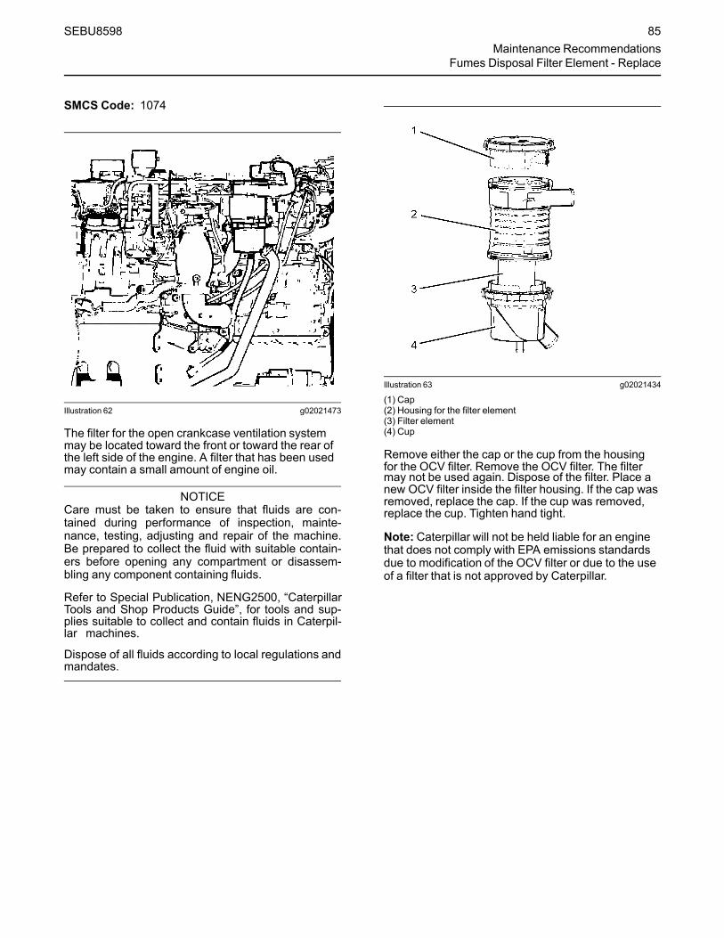
SMCS Code: 1074
Illustration 62 g02021473
The filter for the open crankcase ventilation systemmay be located toward the front or toward the rear ofthe left side of the engine. A filter that has been usedmay contain a small amount of engine oil.
NOTICECare must be taken to ensure that fluids are con-tained during performance of inspection, mainte-nance, testing, adjusting and repair of the machine.Be prepared to collect the fluid with suitable contain-ers before opening any compartment or disassem-bling any component containing fluids.
Refer to Special Publication, NENG2500, “CaterpillarTools and Shop Products Guide”, for tools and sup-plies suitable to collect and contain fluids in Caterpil-lar machines.
Dispose of all fluids according to local regulations andmandates.
Illustration 63 g02021434
(1) Cap(2) Housing for the filter element(3) Filter element(4) Cup
Remove either the cap or the cup from the housingfor the OCV filter. Remove the OCV filter. The filtermay not be used again. Dispose of the filter. Place anew OCV filter inside the filter housing. If the cap wasremoved, replace the cap. If the cup was removed,replace the cup. Tighten hand tight.
Note: Caterpillar will not be held liable for an enginethat does not comply with EPA emissions standardsdue to modification of the OCV filter or due to the useof a filter that is not approved by Caterpillar.
SEBU8598 85Maintenance Recommendations
Fumes Disposal Filter Element - Replace
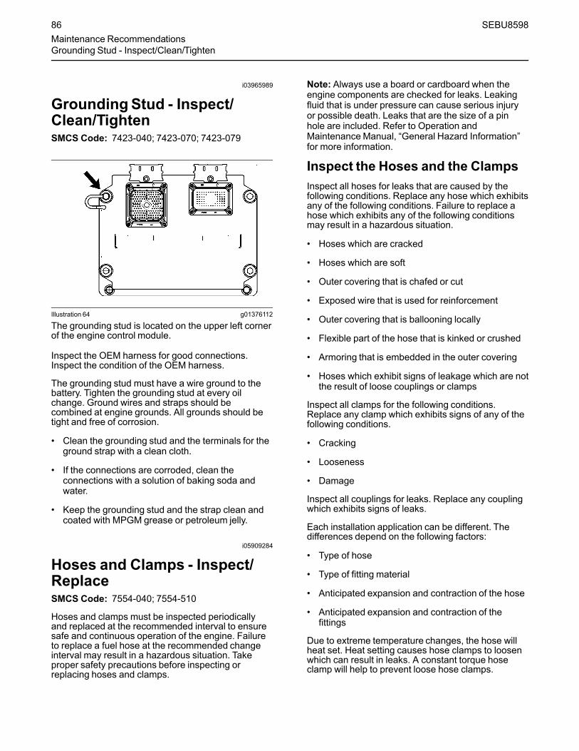
i03965989
GroundingStud - Inspect/Clean/TightenSMCS Code: 7423-040; 7423-070; 7423-079
Illustration 64 g01376112
The grounding stud is located on the upper left cornerof the engine control module.
Inspect the OEM harness for good connections.Inspect the condition of the OEM harness.
The grounding stud must have a wire ground to thebattery. Tighten the grounding stud at every oilchange. Ground wires and straps should becombined at engine grounds. All grounds should betight and free of corrosion.
• Clean the grounding stud and the terminals for theground strap with a clean cloth.
• If the connections are corroded, clean theconnections with a solution of baking soda andwater.
• Keep the grounding stud and the strap clean andcoated with MPGM grease or petroleum jelly.
i05909284
Hoses and Clamps - Inspect/ReplaceSMCS Code: 7554-040; 7554-510
Hoses and clamps must be inspected periodicallyand replaced at the recommended interval to ensuresafe and continuous operation of the engine. Failureto replace a fuel hose at the recommended changeinterval may result in a hazardous situation. Takeproper safety precautions before inspecting orreplacing hoses and clamps.
Note: Always use a board or cardboard when theengine components are checked for leaks. Leakingfluid that is under pressure can cause serious injuryor possible death. Leaks that are the size of a pinhole are included. Refer to Operation andMaintenance Manual, “General Hazard Information”for more information.
Inspect the Hoses and the ClampsInspect all hoses for leaks that are caused by thefollowing conditions. Replace any hose which exhibitsany of the following conditions. Failure to replace ahose which exhibits any of the following conditionsmay result in a hazardous situation.
• Hoses which are cracked
• Hoses which are soft
• Outer covering that is chafed or cut
• Exposed wire that is used for reinforcement
• Outer covering that is ballooning locally
• Flexible part of the hose that is kinked or crushed
• Armoring that is embedded in the outer covering
• Hoses which exhibit signs of leakage which are notthe result of loose couplings or clamps
Inspect all clamps for the following conditions.Replace any clamp which exhibits signs of any of thefollowing conditions.
• Cracking
• Looseness
• Damage
Inspect all couplings for leaks. Replace any couplingwhich exhibits signs of leaks.
Each installation application can be different. Thedifferences depend on the following factors:
• Type of hose
• Type of fitting material
• Anticipated expansion and contraction of the hose
• Anticipated expansion and contraction of thefittings
Due to extreme temperature changes, the hose willheat set. Heat setting causes hose clamps to loosenwhich can result in leaks. A constant torque hoseclamp will help to prevent loose hose clamps.
86 SEBU8598Maintenance RecommendationsGrounding Stud - Inspect/Clean/Tighten
Replace hoses that are cracked or soft. Replacehoses that show signs of leakage. Replace hosesthat show signs of damage. Replace hose clampsthat are cracked or damaged. Tighten or replace hoseclamps which are loose.
Replace the Hoses and the ClampsNOTICE
Care must be taken to ensure that fluids are con-tained during performance of inspection, mainte-nance, testing, adjusting, and repair of the product.Be prepared to collect the fluid with suitable contain-ers before opening any compartment or disassem-bling any component containing fluids.
Refer to Special Publication, NENG2500, “Cat DealerService Tool Catalog” or refer to Special Publication,PECJ0003, “Cat Shop Supplies and Tools Catalog”for tools and supplies suitable to collect and containfluids on Cat products.
Dispose of all fluids according to local regulations andmandates.
Cooling System
Pressurized System: Hot coolant can cause seri-ous burns. To open the cooling system filler cap,stop the engine and wait until the cooling systemcomponents are cool. Loosen the cooling systempressure cap slowly in order to relieve thepressure.
Personal injury can result from removing hosesor fittings in a pressure system.
Failure to relieve pressure can cause personalinjury.
Do not disconnect or remove hoses or fittings un-til all pressure in the system has been relieved.
1. Stop the engine.
2. Allow the engine to cool.
3. Before servicing a coolant hose, slowly loosen thefiller cap for the cooling system in order to relieveany pressure.
4. Remove the filler cap for the cooling system.
5. Drain the coolant from the cooling system to a levelthat is below the hose that is being replaced. Drainthe coolant into a suitable clean container. Thecoolant can be reused.
6. Remove the hose clamps.
7. Disconnect the old hose.
8. Replace the old hose with a new hose.
9. Install hose clamps which have been inspected orinstall new hose clamps. Refer to Specifications,SENR3130, “Torque Specifications”, “HoseClamps” for information about selecting andinstalling the proper hose clamps.
10. Refill the cooling system.
11. Clean the filler cap for the cooling system. Inspectthe gaskets on the filler cap. Replace the filler capif the gaskets are damaged. Install the filler cap.
12. Start the engine. Inspect the cooling system forleaks.
Fuel System
Personal injury can result from removing hosesor fittings in a pressure system.
Failure to relieve pressure can cause personalinjury.
Do not disconnect or remove hoses or fittings un-til all pressure in the system has been relieved.
Contact with high pressure fuel may cause fluidpenetration and burn hazards. High pressure fuelspray may cause a fire hazard. Failure to followthese inspection, maintenance and service in-structionsmay cause personal injury or death.
NOTICEDo not bend or strike high pressure lines. Do not in-stall bent or damaged lines, tubes or hoses. Repairany loose or damaged fuel and oil lines, tubes andhoses. Leaks can cause fires. Inspect all lines, tubesand hoses carefully. Tighten all connections to therecommended torque.
SEBU8598 87Maintenance Recommendations
Hoses and Clamps - Inspect/Replace
NOTICEDo not allow dirt to enter the fuel system. Thoroughlyclean the area around a fuel system component thatwill be disconnected. Fit a suitable cover over any dis-connected fuel system components.
Note:High-pressure fuel lines may be installedbetween the high-pressure fuel pump and the fuelinjectors. High-pressure fuel lines are constantlycharged with high pressure. Do not check the high-pressure fuel lines with the engine or the startingmotor in operation. Wait for 10 minutes after theengine stops before you perform any service or repairon high-pressure fuel lines. Waiting for 10 minutes willto allow the pressure to be purged.1. Drain the fuel from the fuel system to a level that is
below the hose that is being replaced.
2. Remove the hose clamps.
3. Disconnect the old hose.
Note:When servicing fuel system, use cap/s orcover/s as required to protect the system andmaintain fuel system cleanliness.
4. Replace the old hose with a new hose.
5. Install hose clamps which have been inspected orinstall new hose clamps. Refer to Specifications,SENR3130, “Torque Specifications”, “HoseClamps” for information about selecting andinstalling the proper hose clamps.
6. Carefully inspect the engine for any spilled fuel.Make sure that no fuel remains on or close to theengine.
Note: Fuel must be added to the fuel system aheadof the fuel filter.7. Refill the fuel system. Refer to this Operation and
Maintenance Manual, “Fuel System - Prime” forinformation about priming the engine with fuel.
8. Start the engine. Inspect the fuel system for leaks.
LubricationSystem
Hot oil and hot components can cause personalinjury. Do not allow hot oil or hot components tocontact the skin.
1. Drain the oil from the lubrication system to a levelthat is below the hose that is being replaced.
2. Remove the hose clamps.
3. Disconnect the old hose.
4. Replace the old hose with a new hose.
5. Install hose clamps which have been inspected orinstall new hose clamps. Refer to Specifications,SENR3130, “Torque Specifications”, “HoseClamps” for information about selecting andinstalling the proper hose clamps.
6. Refill the lubrication system. Refer to thisOperation and Maintenance Manual, “Engine OilLevel - Check” in order to ensure that thelubrication system is filled with the proper amountof engine oil.
7. Start the engine. Inspect the lubrication system forleaks.
Air System
1. Remove the hose clamps.
2. Disconnect the old hose.
3. Replace the old hose with a new hose.
4. Install hose clamps which have been inspected orinstall new hose clamps. Refer to Specifications,SENR3130, “Torque Specifications”, “HoseClamps” for information about selecting andinstalling the proper hose clamps.
Note: The bellows and the V-clamps that are used onthe bellows should never be reused.
5. Start the engine. Inspect the air lines for leaks.
i04138631
Overhaul ConsiderationsSMCS Code: 7595-043
Reduced hours of operation at full load will result in alower average power demand and reduced fuelconsumption. A decreased average power demandshould increase both the engine service life and theoverhaul interval.
The need for an overhaul is indicated by increasedfuel consumption, increased oil consumption,excessive engine blowby, and reduced power. Arctictemperatures, extreme high temperatures, corrosiveenvironments, or extreme dusty conditions contributeto premature wear and the need for an overhaul.
88 SEBU8598Maintenance RecommendationsOverhaul Considerations

The following factors are important when a decision isbeing made on the proper time for an engineoverhaul:
• The need for preventive maintenance
• The quality of the fuel that is being used
• The operating conditions
• The results of the S·O·S analysis
Note: The aftertreatment system can be expected tofunction properly for the useful life of the engine(emissions durability period), as defined byregulation, subject to prescribed maintenancerequirements being followed.
Oil Consumption as an OverhaulIndicatorOil consumption, fuel consumption, and maintenanceinformation can be used to estimate the totaloperating cost for your Caterpillar engine. Oilconsumption can also be used to estimate therequired capacity of a makeup oil tank that is suitablefor the maintenance intervals.
Oil consumption is in proportion to the percentage ofthe rated engine load. As the percentage of theengine load is increased, the amount of oil that isconsumed per hour also increases.
The oil consumption rate (brake-specific oilconsumption) is measured in grams per kW/h (lb perbhp). The brake-specific oil consumption (BSOC)depends on the engine load. Consult your Caterpillardealer for assistance in determining the typical oilconsumption rate for your engine.
When the oil consumption of an engine has risen tothree times the original oil consumption rate due tonormal wear, an engine overhaul should bescheduled. There may be a corresponding increasein blowby and a slight increase in fuel consumption.
Overhaul Options
Before Failure OverhaulA planned overhaul before failure may be the bestvalue for the following reasons:
• Costly unplanned downtime can be avoided.
• Many original parts can be reused according to thestandards for reusable parts.
• The service life of the engine can be extendedwithout the risk of a major catastrophe due toengine failure.
• The best cost/value relationship per hour ofextended life can be attained.
After Failure OverhaulIf a major engine failure occurs and the engine mustbe removed, many options are available. An overhaulshould be performed if the engine block or thecrankshaft needs to be repaired.
If the engine block is repairable and/or the crankshaftis repairable, the overhaul cost should be between 40percent and 50 percent of the cost of a new enginewith a similar exchange core.
This lower cost can be attributed to three aspects:
• Specially designed Caterpillar engine features
• Caterpillar dealer exchange components
• Caterpillar Inc. remanufactured exchangecomponents
Overhaul RecommendationTo minimize downtime, Caterpillar Inc. recommends ascheduled engine overhaul by your Caterpillar dealerbefore the engine fails. A scheduled engine overhaulwill provide you with the best cost/value relationship.
Note:Overhaul programs vary according to theengine application and according to the dealer thatperforms the overhaul. Consult your Caterpillar dealerfor specific information about the available overhaulprograms and about overhaul services for extendingthe engine life.
If an overhaul is performed without overhaul servicefrom your Caterpillar dealer, be aware of the followingmaintenance recommendations.
Rebuild or Exchange
Cylinder Head Assembly, Cylinder Packs,Oil Pump, and Fuel Transfer Pump
These components should be inspected according tothe instructions that are found in various Caterpillarreusability publications. The Special Publication,SEBF8029 lists the reusability publications that areneeded for inspecting the engine parts.
If the parts comply with the established inspectionspecifications that are expressed in the reusableparts guideline, the parts should be reused.
Parts that are not within the established inspectionspecifications should be dealt with in one of thefollowing manners:
• Salvaging
• Repairing
• Replacing
SEBU8598 89Maintenance Recommendations
Overhaul Considerations
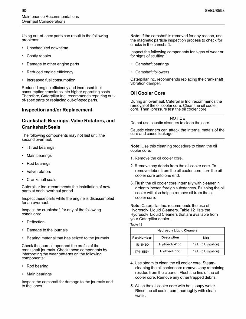
Using out-of-spec parts can result in the followingproblems:
• Unscheduled downtime
• Costly repairs
• Damage to other engine parts
• Reduced engine efficiency
• Increased fuel consumption
Reduced engine efficiency and increased fuelconsumption translates into higher operating costs.Therefore, Caterpillar Inc. recommends repairing out-of-spec parts or replacing out-of-spec parts.
Inspection and/or Replacement
Crankshaft Bearings, Valve Rotators, andCrankshaft SealsThe following components may not last until thesecond overhaul.
• Thrust bearings
• Main bearings
• Rod bearings
• Valve rotators
• Crankshaft seals
Caterpillar Inc. recommends the installation of newparts at each overhaul period.
Inspect these parts while the engine is disassembledfor an overhaul.
Inspect the crankshaft for any of the followingconditions:
• Deflection
• Damage to the journals
• Bearing material that has seized to the journals
Check the journal taper and the profile of thecrankshaft journals. Check these components byinterpreting the wear patterns on the followingcomponents:
• Rod bearing
• Main bearings
Inspect the camshaft for damage to the journals andto the lobes.
Note: If the camshaft is removed for any reason, usethe magnetic particle inspection process to check forcracks in the camshaft.
Inspect the following components for signs of wear orfor signs of scuffing:
• Camshaft bearings
• Camshaft followers
Caterpillar Inc. recommends replacing the crankshaftvibration damper.
Oil Cooler CoreDuring an overhaul, Caterpillar Inc. recommends theremoval of the oil cooler core. Clean the oil coolercore. Then, pressure test the oil cooler core.
NOTICEDo not use caustic cleaners to clean the core.
Caustic cleaners can attack the internal metals of thecore and cause leakage.
Note: Use this cleaning procedure to clean the oilcooler core.
1. Remove the oil cooler core.
2. Remove any debris from the oil cooler core. Toremove debris from the oil cooler core, turn the oilcooler core onto one end.
3. Flush the oil cooler core internally with cleaner inorder to loosen foreign substances. Flushing the oilcooler will also help to remove oil from the oilcooler core.
Note: Caterpillar Inc. recommends the use ofHydrosolv Liquid Cleaners. Table 12 lists theHydrosolv Liquid Cleaners that are available fromyour Caterpillar dealer.Table 12
Hydrosolv Liquid Cleaners
Part Number Description Size
1U-5490 Hydrosolv 4165 19 L (5 US gallon)
174-6854 Hydrosolv 100 19 L (5 US gallon)
4. Use steam to clean the oil cooler core. Steam-cleaning the oil cooler core removes any remainingresidue from the cleaner. Flush the fins of the oilcooler core. Remove any other trapped debris.
5.Wash the oil cooler core with hot, soapy water.Rinse the oil cooler core thoroughly with cleanwater.
90 SEBU8598Maintenance RecommendationsOverhaul Considerations

Personal injury can result from air pressure.
Personal injury can result without following prop-er procedure. When using pressure air, wear aprotective face shield and protective clothing.
Maximum air pressure at the nozzle must be lessthan 205 kPa (30 psi) for cleaning purposes.
6. Dry the oil cooler core with compressed air. Directthe air in the reverse direction of the normal flow.
7. Inspect the components in order to ensurecleanliness. The oil cooler core should be pressuretested. Repair the oil cooler core, if necessary.Install the oil cooler core.
For more information about cleaning the cores,consult your Caterpillar dealer.
Obtain Coolant Analysis
The concentration of supplemental coolant additive(SCA) should be checked regularly with test kits orwith S·O·S Coolant Analysis (Level 1). Furthercoolant analysis is recommended when the engine isoverhauled.
For example, considerable deposits are found in thewater jacket areas on the external cooling system, butthe concentrations of coolant additives were carefullymaintained. The coolant water probably containedminerals that were deposited on the engine over time.
A coolant analysis can be conducted in order to verifythe condition of the water that is being used in thecooling system. A full water analysis can be obtainedby consulting your local water utility company or anagricultural agent. Private laboratories are alsoavailable for water analysis.
Caterpillar Inc. recommends an S·O·S CoolantAnalysis (Level 2).
S·O·S Coolant Analysis (Level 2)
An S·O·S Coolant Analysis (Level 2) is acomprehensive coolant analysis which completelyanalyzes the coolant and the effects on the coolingsystem. An S·O·S Coolant Analysis (Level 2)provides the following information:
• Complete S·O·S Coolant Analysis (Level 1)
• Visual inspection of properties
• Identification of metal corrosion
• Identification of contaminants
• Identification of built up impurities (corrosion andscale)
S·O·S Coolant Analysis (Level 2) provides a report ofthe results of both the analysis and the maintenancerecommendations.
For more information about coolant analysis, see yourCaterpillar dealer.
i03901481
Power Take-Off Clutch - CheckSMCS Code: 3055-535
NOTICENew power take-offs should have the clutch adjust-ment checked before being placed into service. Theclutch adjustment should be checked again after thefirst ten hours of operation. New clutch plates have a“wear in” period, and the clutch may require severaladjustments until the new plates are “worn in”.
Illustration 65 g00781502
(1) Instruction plate(2) Serial number plate
Check the clutch adjustment regularly after “wear in”.Heavy-duty applications which have engagementsthat are frequent and relatively long periods of clutchslippage require more frequent adjustment than light-duty applications. The operating torque should bemeasured in order to determine if a clutch adjustmentis required.
Refer to the OEM information and instruction plate (1)for instructions on lubrication, adjustment, and otherrecommendations for service. Perform themaintenance that is specified on the instruction plate.
SEBU8598 91Maintenance RecommendationsPower Take-Off Clutch - Check
Do not operate the engine with the InstructionPlate cover removed from the clutch. Personal in-jury may result.
If the clutch is damaged to the point of burst fail-ure, expelled pieces can cause personal injury toanyone in the immediate area. Proper safeguardsmust be followed to help prevent accidents.
i04020194
Radiator - CleanSMCS Code: 1353-070
Note: Adjust the frequency of cleaning according tothe effects of the operating environment.
Inspect the radiator for these items: damaged fins,corrosion, dirt, grease, insects, leaves, oil and otherdebris. Clean the radiator, if necessary.
Personal injury can result from air pressure.
Personal injury can result without following prop-er procedure. When using pressure air, wear aprotective face shield and protective clothing.
The maximum air pressure for cleaning purposesmust be reduced to 205 kPa (30 psi) when the airnozzle is deadheaded.
Pressurized air is the preferredmethod for removingloose debris. Direct the air in the opposite direction ofthe air flow. Hold the nozzle approximately 6 mm(0.25 inch) away from the fins. Slowly move the airnozzle in a direction that is parallel with the tubes.This movement will remove debris that is between thetubes.
Pressurized water may also be used for cleaning. Themaximumwater pressure for cleaning purposes mustbe less than 275 kPa (40 psi). Use pressurized waterin order to soften mud. Clean the core from bothsides.
Use a degreaser and steam for removal of oil andgrease. Clean both sides of the core. Wash the corewith detergent and hot water. Thoroughly rinse thecore with clean water.
After cleaning, start the engine and accelerate theengine to high idle rpm. This procedure will help in theremoval of debris and drying of the core. Stop theengine. Use a light bulb behind the core in order toinspect the core for cleanliness. Repeat the cleaning,if necessary.
Inspect the fins for damage. Bent fins may be openedwith a “comb”. Inspect these items for good condition:welds, mounting brackets, air lines, connections,clamps and seals. Make repairs, if necessary.
i00651416
StartingMotor - InspectSMCS Code: 1451-040; 1453-040
Caterpillar Inc. recommends a scheduled inspectionof the starting motor. If the starting motor fails, theengine may not start in an emergency situation.
Check the starting motor for proper operation. Checkthe electrical connections and clean the electricalconnections. Refer to the Service Manual for moreinformation on the checking procedure and forspecifications or consult your Caterpillar dealer forassistance.
i03965991
Valve Actuators - CheckSMCS Code: 1105-535
The valve actuators should be inspected andadjusted when adjustments to the followingcomponents occur.
• Valves
• Injectors
• Compression brakes
Contact your Cat dealer for the proper procedure.
i01185304
Walk-Around InspectionSMCS Code: 1000-040
Inspect the Engine for Leaks andfor Loose ConnectionsA walk-around inspection should only take a fewminutes. When the time is taken to perform thesechecks, costly repairs and accidents can be avoided.
For maximum engine service life, make a thoroughinspection of the engine compartment before startingthe engine. Look for items such as oil leaks or coolantleaks, loose bolts, worn belts, loose connections andtrash buildup. Make repairs, as needed:
92 SEBU8598Maintenance RecommendationsRadiator - Clean

• The guards must be in the proper place. Repairdamaged guards or replace missing guards.
• Wipe all caps and plugs before the engine isserviced in order to reduce the chance of systemcontamination.
NOTICEFor any type of leak (coolant, lube, or fuel) clean upthe fluid. If leaking is observed, find the source andcorrect the leak. If leaking is suspected, check the flu-id levels more often than recommended until the leakis found or fixed, or until the suspicion of a leak isproved to be unwarranted.
NOTICEAccumulated grease and/or oil on an engine or deckis a fire hazard. Remove this debris with steam clean-ing or high pressure water.
• Ensure that the cooling lines are properly clampedand that the cooling lines are tight. Check forleaks. Check the condition of all pipes.
• Inspect the water pumps for coolant leaks.
Note: The water pump seal is lubricated by coolant inthe cooling system. It is normal for a small amount ofleakage to occur as the engine cools down and theparts contract.
Excessive coolant leakage may indicate the need toreplace the water pump seal. For the removal ofwater pumps and the installation of water pumps and/or seals, refer to the Service Manual for the engine orconsult your Caterpillar dealer.
• Inspect the lubrication system for leaks at the frontcrankshaft seal, the rear crankshaft seal, the oilpan, the oil filters and the valve cover.
• Inspect the fuel system for leaks. Look for loosefuel line clamps or for loose fuel line tie-wraps.
• Inspect the piping for the air inlet system and theelbows for cracks and for loose clamps. Ensurethat hoses and tubes are not contacting otherhoses, tubes, wiring harnesses, etc.
• Inspect the alternator belt and the accessory drivebelts for cracks, breaks or other damage.
Belts for multiple groove pulleys must be replaced asmatched sets. If only one belt is replaced, the belt willcarry more load than the belts that are not replaced.The older belts are stretched. The additional load onthe new belt could cause the belt to break.
• Drain the water and the sediment from fuel tankson a daily basis in order to ensure that only cleanfuel enters the fuel system.
• Inspect the wiring and the wiring harnesses forloose connections and for worn wires or frayedwires.
• Inspect the ground strap for a good connectionand for good condition.
• Inspect the ECM to the cylinder head ground strapfor a good connection and for good condition.
• Disconnect any battery chargers that are notprotected against the current drain of the startingmotor. Check the condition and the electrolytelevel of the batteries, unless the engine isequipped with a maintenance free battery.
• Check the condition of the gauges. Replace anygauges that are cracked. Replace any gauge thatcan not be calibrated.
SEBU8598 93Maintenance Recommendations
Walk-Around Inspection
Warranty Section
Warranty Informationi05627331
Emissions WarrantyInformationSMCS Code: 1000
The certifying engine manufacturer warrants to theultimate purchaser and each subsequent purchaserthat:
1. New non-road diesel engines and stationary dieselengines less than 10 liters per cylinder (includingTier 1 and Tier 2 marine engines < 37 kW, butexcluding locomotive and other marine engines)operated and serviced in the United States andCanada, including all parts of their emission controlsystems (“emission related components”), are:
a. Designed, built, and equipped so as toconform, at the time of sale, with applicableemission standards prescribed by the UnitedStates Environmental Protection Agency(EPA) by way of regulation.
b. Free from defects in materials andworkmanship in emission-related componentsthat can cause the engine to fail to conform toapplicable emission standards for the warrantyperiod.
2. New non-road diesel engines (including Tier 1 andTier 2 marine propulsion engines < 37 kW and Tier1 through Tier 4 marine auxiliary engines < 37 kW,but excluding locomotive and other marineengines) operated and serviced in the state ofCalifornia, including all parts of their emissioncontrol systems (“emission related components”),are:
a. Designed, built, and equipped so as toconform, at the time of sale, to all applicableregulations adopted by the California AirResources Board (ARB).
b. Free from defects in materials andworkmanship which cause the failure of anemission-related component to be identical inall material respects to the component asdescribed in the engine manufacturer'sapplication for certification for the warrantyperiod.
A detailed explanation of the Emission ControlWarranty that is applicable to new non-road andstationary diesel engines, including the componentscovered and the warranty period, is found in asupplemental Special Publication. Consult yourauthorized Cat dealer to determine if your engine issubject to an Emission Control Warranty and toobtain a copy of the applicable Special Publication.
94 SEBU8598Warranty SectionEmissions Warranty Information

Reference InformationSection
Engine Ratingsi01097462
Engine Rating ConditionsSMCS Code: 1000
All engine ratings are based on “SAE J1349”.
Ratings relate to the standard conditions of“AS1501”, of “ISO3046/1”, of “DIN6271”, and of“BS5514”.
The engine ratings are gross output ratings.
Gross Output Ratings – The total output capabilityof the engine that is equipped with standardaccessories.
Standard accessories include the followingcomponents:
• Oil pumps
• Fuel pumps
• Water pumps
Subtract the power that is required to drive auxiliarycomponents from the gross output. This will producethe net power that is available for the external load(flywheel).
i03880100
Engine Rating DefinitionsSMCS Code: 1000
In selecting a rating for a specific application, themost important consideration is the time that is spentat full throttle. These rating definitions identify thepercent of time at full throttle. The definitions alsoidentify the corresponding times below rated rpm.Refer to this Operation and Maintenance Manual,“Configuration Parameters” for information about therating for this engine.
Note: The examples of the applications are only forreference. For an exact determination of theappropriate rating, follow the OEM specifications orconsult your Caterpillar dealer.
Table 13
Engine Rating Information
Perform-anceRating
LoadFactor
Time at Rated Load(1)Examples ofApplicationsOverall Any One
Instance
A 100% 100% n/aPipe linepumpingVentilation
B 85% 75% n/a
Irrigation pumpsDrillingapplicationsPlant aircompressors
C 70% 50% Less than1hour
Fire pumpsChippersRock crushersPortable aircompressors
D 50% 10% Less than 30minutes
SnowgroomerSnowblowersCranesWater well drills
E 35% 5% Less than 15minutes
Standby centrifu-gal pumpsOil well servicing
(1) Both the overall time at rated load and the time the engine is op-erated in any one instance must be considered.
NOTICEOperating engines above the rating definitions can re-sult in shorter service life before overhaul.
SEBU8598 95Reference Information Section
Engine Rating Conditions

Customer Servicei03910306
Customer AssistanceSMCS Code: 1000; 4450
USA and CanadaWhen a problem arises concerning the operation orthe service of an engine, the problem will normally bemanaged by the dealer in your area.
Your satisfaction is a primary concern to Caterpillarand to Caterpillar dealers. If you have a problem thathas not been handled to your complete satisfaction,follow these steps:
1. Discuss your problem with a manager from thedealership.
2. If your problem cannot be resolved at the dealerlevel, use the phone number that is listed below totalk with a Field Service Coordinator:
1-800-447-4986
The normal hours are from 8:00 to 4:30 Mondaythrough Friday Central Standard Time.
3. If your needs have not been met still, submit thematter in writing to the following address:
Caterpillar Inc.Manager, Customer Service, Engine DivisionMossville Bldg ACP.O. Box 610Mossville, Illinois 61552-0610
Please keep in mind: probably, your problem willultimately be solved at the dealership, using thedealership facilities, equipment, and personnel.Therefore, follow the steps in sequence when aproblem is experienced.
Outside of the USA and of CanadaIf a problem arises outside the USA and outsideCanada, and if the problem cannot be resolved at thedealer level, consult the appropriate Caterpillaroffice.
Latin America, Mexico, CarribeanCaterpillar Americas Co.701 WaterfordWay, Suite 200Miami, FL 33126-4670USAPhone: 305-476-6800Fax: 305-476-6801
Europe, Africa, and Middle EastCaterpillar Overseas S.A.76 Route de FrontenexP.O. Box 6000CH-1211 Geneva 6SwitzerlandPhone: 22-849-4444Fax: 22-849-4544
Far EastCaterpillar Asia Pte. Ltd.7 Tractor RoadJurong, Singapore 627968Republic of SingaporePhone: 65-662-8333Fax: 65-662-8302
ChinaCaterpillar China Ltd.37/F., The Lee Gardens33 Hysan AvenueCauseway BayG.P.O. Box 3069Hong KongPhone: 852-2848-0333Fax: 852-2848-0440
JapanShin Caterpillar Mitsubishi Ltd.SBS Tower10-1, Yoga 4-ChomeSetagaya-Ku, Tokyo 158-8530JapanPhone: 81-3-5717-1150Fax: 81-3-5717-1177
JapanCaterpillar Power Systems, Inc.SBS Tower (14th floor)4-10-1, YogaSetagaya-Ku, Tokyo 158-0097Phone: 81-3-5797-4300Fax: 81-3-5797-4359
Australia and New ZealandCaterpillar of Australia Ltd.1 Caterpillar DrivePrivate Mail Bag 4Tullamarine, Victoria 3043AustraliaPhone: 03-9953-9333Fax: 03-9335-3366
96 SEBU8598Customer ServiceCustomer Assistance

i01028392
Ordering Replacement PartsSMCS Code: 4450; 7567
When replacement parts are required for thisproduct Caterpillar recommends using Caterpillarreplacement parts or parts with equivalent specifi-cations including, but not limited to, physical di-mensions, type, strength and material.
Failure to heed this warning can lead to prematurefailures, product damage, personal injury ordeath.
Quality Caterpillar replacement parts are availablefrom Caterpillar dealers throughout the world.Caterpillar dealers' parts inventories are up-to-date.The parts stocks include all of the parts that arenormally needed to protect your Caterpillar engineinvestment.
When you order parts, please specify the followinginformation:
• Part number
• Part name
• Quantity
If there is a question concerning the part number,please provide your dealer with a completedescription of the needed item.
When a Caterpillar engine requires maintenanceand/or repair, provide the dealer with all theinformation that is stamped on the Information Plate.This information is described in this Operation andMaintenance Manual (Product Information Section).
Discuss the problem with the dealer. Inform thedealer about the conditions of the problem and thenature of the problem. Inform the dealer about whenthe problem occurs. This will help the dealer introubleshooting the problem and solving the problemfaster.
SEBU8598 97Customer Service
Ordering Replacement Parts

ReferenceMaterialsi05264255
MaintenanceRecordsSMCS Code: 1000; 4450
Caterpillar Inc. recommends the retention of accuratemaintenance records. Accurate maintenance recordscan be used for the following purposes:
• Determine operating costs.
• Establish maintenance schedules for otherengines that are operated in the sameenvironment.
• Show compliance with the required maintenancepractices and maintenance intervals.
Maintenance records can be used for various otherbusiness decisions that are related to enginemaintenance.
Maintenance records are a key element of amaintenance program that is managed. Accuratemaintenance records can help your Cat dealer to fine-tune the recommended maintenance intervals inorder to meet the specific operating situation. Thisshould result in a lower engine operating cost.
Records should be kept for the following items:
Fuel Consumption – A record of fuel consumption isessential in order to determine when the loadsensitive components should be inspected orrepaired. Fuel consumption also determines overhaulintervals.
Service Hours – A record of service hours isessential to determine when the speed sensitivecomponents should be inspected or repaired.
Documents – These items should be easy to obtain,and these items should be kept in the engine historyfile. All of the documents should show thisinformation: date, service hours, fuel consumption,unit number and engine serial number. The followingtypes of documents should be kept as proof ofmaintenance or repair for warranty:
Keep the following types of documents as proof ofmaintenance for warranty. Also, keep these types ofdocuments as proof of repair for warranty:
• Dealer work orders and itemized bills
• Owner repair costs
• Owner receipts
• Maintenance log
98 SEBU8598Reference MaterialsMaintenance Records

i01176304
MaintenanceLogSMCS Code: 1000; 4450
Table 14
Engine Model Customer Identifier
Serial Number Arrangement Number
ServiceHours
QuantityOfFuel Service Item Date Authorization
SEBU8598 99Reference Materials
Maintenance Log

i04785009
Reference MaterialSMCS Code: 1000; 4450
The following literature can be obtained through anyCat dealer.
Coolants• Data Sheet, PEHJ0067, “Cat ELC (Extended Life
Coolant) (Worldwide Formulation)”
• Data Sheet, PEHP9554, “Diesel EngineAntifreeze/Coolant (DEAC)”
• Special Publication, PMEP5027, “Label - ELCRadiator Label”
• Special Publication, SEBD0518, “Know YourCooling System”
Fuels• Special Publication, SENR9620, “Improving Fuel
System Durability”
Greases• Data Sheet, NEHP6010, “Cat Ultra 5Moly Grease”
• Data Sheet, NEHP6011, “Arctic Platinum GreaseSpec Sheet”
• Data Sheet, NEHP6012, “Cat Desert Gold Grease”
• Data Sheet, NEHP6015, “Cat Special PurposeGrease”
• Special Publication, PEGJ0035, “Grease SelectionGuide”
• Data Sheet, PEHJ0088, “Cat MultipurposeGrease”
• Data Sheet, PEHP0002, “Molybdenum GreaseData Sheet”
• Data Sheet, PEHP6002, “Cat Advanced 3MolyGrease”
Lubricants• Special Publication, PEHJ0192, “Optimizing S·O·S
Oil Change Intervals”
• Data Sheet, PEHJ0021, “Product Data Sheet forCat DEO (Diesel Engine Oil) APD, EAME, LACDOnly”
• Data Sheet, PEHJ0059, “Cat DEO (for NorthAmerica)”
• Data Sheet, PEHJ0072, “Cat DEO (Brazil Only)”
• Special Publication, PEHP6001, “How To Take AGood Oil Sample”
• Data Sheet, PEHP7062, “Full Synthetic DieselEngine Oil Data Sheet”
• Special Publication, PELJ0179, “FLU03-02Caterpillar Engine Crankcase Fluid-1Specifications (All World Market Areas)”
S·O·S Services• Data Sheet, NEHP6013, “S·O·S Fluids Analysis
Products”
• Special Publication, PEHJ0191, “Cat S·O·S FluidsAnalysis”
• Special Publication, PEHP7076, “UnderstandingS·O·S Services Tests”
100 SEBU8598Reference MaterialsReference Material

Miscellaneous• Special Instruction, NENG2500, “Cat dealer
Service Tool Catalog”
• Special Publication, PECP9067, “One SafeSource”
• Special Instruction, REHS0354, “Charging SystemTroubleshooting for All Engines”
• Special Instruction, REHS0871, “ElectronicInstallation Guide”.
• Special Publication, SEBF8029, “Index toGuidelines for Reusable Parts and SalvageOperations”
• Special Publication, SEBF8062, “Guideline forReusable Parts - Procedure to Inspect and CleanAir Filters”
• Special Publication, SEBU6251, “CaterpillarCommercial Diesel Engine FluidsRecommendations”
• Special Instruction, SEHS7332, “Warning Tag -Danger Do Not Operate”
• Special Instruction, SEHS7633, “Battery TestProcedure”
• Special Instruction, SEHS9031, “StorageProcedure for Caterpillar Products”
• Specifications, SENR3130, “Torque SpecificationsModule”
• Service Manual, SENR9840, “C15 and C18Industrial Engines”
• Special Instruction, SMHS7001, “Assembly of FanDrive Pulley Assemblies”
Additional ReferenceMaterialThe “Engine Fluids Data Book” can be obtained fromthe following locations: local technological society,local library and local college. If necessary, consultEMA at the following address:
Engine Manufacturers AssociatonTwo North LaSalle Street, Suite 2200Chicago, IL, USA 60602E-mail: [email protected] (312) 827-8700Facsimile (312) 827-8737
The “Society of Automotive Engineers (SAE)Specifications” can be found in your SAE handbook.This publication can also be obtained from thefollowing locations: local technological society, locallibrary and local college. If necessary, consult SAE atthe following address:
SAE International400 Commonwealth DriveWarrendale, PA, USA 15096-0001Telephone (724) 776-4841
The “American Petroleum Institute Publication No.1509” can be obtained from the following locations:local technological society, local library and localcollege. If necessary, consult API at the followingaddress:
American Petroleum Institute1220 L St. N.W.Washington, DC, USA 20005Telephone (202) 682-8000
The International Organization for Standardization(ISO) offers information and customer serviceregarding international standards and standardizingactivities. ISO can also supply information on thefollowing subjects that are not controlled by ISO:national standards, local standards, regulations,certification and related activities. Consult themember of ISO in your country.
International Organization for Standardization(ISO)1, rue de VarembéCase postale 56CH-1211 Genève 20SwitzerlandTelephone +41 22 749 01 11Facsimile +41 22 733 34 30E-mail [email protected] site http://www.iso.ch
European classifications are established by theCounseil International Des Machines a Combustion(CIMAC) (International Council on CombustionEngines).
CIMAC Central SecretariatLyoner Strasse 1860528 FrankfurtGermanyTelephone +49 69 6603 1567Facsimile +49 69 6603 1566
i03989612
Decommissioning andDisposalSMCS Code: 1000
When the product is removed from service, localregulations for the product decommissioning will vary.Disposal of the product will vary with localregulations. Consult the nearest Cat dealer foradditional information.
SEBU8598 101Reference Materials
Decommissioning and Disposal

Index
AAfter Starting Engine........................................ 36Extended Idle at Cold Ambient Temperature................................................................... 36
After Stopping Engine...................................... 44Air Compressor - Check (If equipped) ............. 60Air Shutoff - Test .............................................. 60Air Tank Moisture and Sediment - Drain (IfEquipped) ...................................................... 61ARD Spark Plug - Replace (If Equipped)......... 59Installing the Spark Plug .............................. 60Removing the Spark Plug ............................ 59
BBattery - Recycle ............................................. 61Battery - Replace............................................. 61Battery Disconnect Switch (If Equipped) ......... 27Battery Electrolyte Level - Check .................... 62Battery or Battery Cable - Disconnect ............. 62Before Starting Engine ...............................13, 33Belts - Inspect/Replace (If Equipped) .............. 63Single Belt.................................................... 63Two or More Belts ........................................ 64
Burn Prevention............................................... 10Batteries........................................................11Coolant......................................................... 10Oils................................................................11
CCold Weather Operation.................................. 42Cold Weather Starting ..................................... 33Ether Injection System (If Equipped) ........... 34
Compression Brake - Inspect/Adjust/Replace.......................................................... 64Coolant (DEAC) - Change ............................... 64Cooling Systems with Heavy Deposits orPlugging ..................................................... 66Drain ............................................................ 65Fill................................................................. 66Flush ............................................................ 65
Coolant (ELC) - Change .................................. 66Drain ............................................................ 67Fill................................................................. 67Flush ............................................................ 67
Coolant Extender (ELC) - Add......................... 68Coolant Level - Check ..................................... 69
Coolant Sample (Level 1) - Obtain .................. 69Coolant Sample (Level 2) - Obtain .................. 70Cooling System Supplemental CoolantAdditive (SCA) - Test/Add (SystemsWhichare Filled with Conventional Coolant) ............ 70Maintain the Proper Concentration of SCA inthe Coolant................................................. 71
Crushing Prevention and Cutting Prevention .. 13Customer Assistance....................................... 96Outside of the USA and of Canada.............. 96USA and Canada......................................... 96
Customer Service ............................................ 96
DDecommissioning and Disposal .................... 101Diesel Particulate Filter - Clean/Replace (IfEquipped) ...................................................... 71Diesel Particulate Filter Regeneration............. 37Modes of Regeneration................................ 39Regeneration ............................................... 37Regeneration Controls................................. 38Regeneration Indicator Lamps and Controls................................................................... 38
Regeneration SystemWarning Indicators ... 40Soot Level Monitoring .................................. 39
Driven Equipment - Check............................... 72Check the Alignment.................................... 72Inspect the Drive Coupling........................... 72Inspect the Rear Gear Train......................... 72
EElectrical System............................................. 14Grounding Practices .................................... 15
Electronic Unit Injector - Check/Replace......... 72Emissions Certification Film ............................ 21Emissions Warranty Information...................... 94Engaging the Driven Equipment...................... 40Engine - Clean................................................. 73Engine Air Cleaner Element (Dual Element/Box Type) - Replace ...................................... 73Primary Filter................................................ 73Secondary Filter........................................... 74
Engine Air Cleaner Element (SingleElement) - Inspect/Clean/Replace................. 75Inspecting Air Cleaner Elements.................. 75Servicing the Air Cleaner Elements ............. 75
102 SEBU8598Index Section

Engine Air Cleaner Service Indicator -Inspect (If Equipped)...................................... 76Test the Service Indicator............................. 76
Engine Diagnostics.......................................... 32Engine Electronics........................................... 15Engine Mounts - Inspect.................................. 77Engine Oil and Filter - Change ........................ 78Drain the Engine Oil ..................................... 79Fill the Engine Crankcase............................ 80Replace the Oil Filter.................................... 79Selection of Oil Change Interval .................. 78
Engine Oil Level - Check ................................. 77Engine Oil Sample - Obtain ............................. 78Obtain the Sample and the Analysis............ 78
Engine Operation............................................. 37Engine Rating Conditions................................ 95Engine Rating Definitions ................................ 95Engine Ratings ................................................ 95Engine Starting...........................................14, 33Engine Stopping .........................................14, 44Engine Storage Procedure - Check................. 80Engine Valve Lash - Check.............................. 80
FFeatures and Controls ..................................... 27Fire Prevention and Explosion Prevention .......11Ether ............................................................ 12Fire Extinguisher.......................................... 12Lines, Tubes, and Hoses ............................. 13
Fluid Recommendations.................................. 45Coolant......................................................... 49Diesel Engine Oil ......................................... 46Diesel Fuel Recommendations.................... 47Lubricating Grease....................................... 48
Foreword............................................................ 4California Proposition 65 Warning ................. 4Literature Information..................................... 4Maintenance .................................................. 4Maintenance Intervals.................................... 4Operation ....................................................... 4Overhaul ........................................................ 4Safety............................................................. 4
Fuel and the Effect from Cold Weather............ 42Fuel Conservation Practices............................ 41Fuel Priming Pump - Replace.......................... 81Fuel Related Components in Cold Weather .... 42Fuel Filters ................................................... 42Fuel Heaters ................................................ 43Fuel Tanks.................................................... 42
Fuel System - Prime ........................................ 81
Fuel System Primary Filter (Water Separator)Element - Replace ......................................... 82Replace the Element.................................... 82
Fuel System Primary Filter/Water Separator- Drain ............................................................ 81Fuel System Secondary Filter - Replace ......... 83Fuel Tank Water and Sediment - Drain............ 84Drain the Water and the Sediment............... 84Fuel Storage Tanks ...................................... 84Fuel Tank ..................................................... 84
Fumes Disposal Filter Element - Replace(Open Crankcase Ventilation (OCV) Filter).... 84
GGeneral Hazard Information .............................. 7Containing Fluid Spillage ............................... 8Dispose of Waste Properly........................... 10Fluid Penetration............................................ 8Inhalation ....................................................... 9Lines, Tubes, and Hoses ............................... 9Pressurized Air and Water ............................. 8Softwrap....................................................... 10Static Electricity Hazard when Fueling withUltra-low Sulfur Diesel Fuel.......................... 9
General Information......................................... 16Grounding Stud - Inspect/Clean/Tighten ......... 86
HHoses and Clamps - Inspect/Replace............. 86Inspect the Hoses and the Clamps.............. 86Replace the Hoses and the Clamps ............ 87
IImportant Safety Information ............................. 2
LLifting and Storage........................................... 23
MMaintenance Interval Schedule (C15Engines With Ratings Greater Than 579hp).................................................................. 55Daily ............................................................. 55Every 12 000 Service Hours or 6 Years ....... 56Every 2000 Service Hours ........................... 56
SEBU8598 103Index Section

Every 2000 Service Hours or 1 Year............ 56Every 250 Service Hours ............................. 56Every 2500 Service Hours ........................... 56Every 3000 Service Hours or 3 Years .......... 56Every 4000 Service Hours ........................... 56Every 500 Service Hours ............................. 56Every 5000 Service Hours ........................... 56Every 585 000 L (154 540 US gal) of Fuel or10 000 Service Hours................................. 56Every 6000 Service Hours or 3 Years .......... 56Initial 500 Service Hours .............................. 56When Required............................................ 55
Maintenance Interval Schedule (C15Engines)......................................................... 54Daily ............................................................. 54Every 12 000 Service Hours or 6 Years ....... 55Every 2000 Service Hours ........................... 54Every 2000 Service Hours or 1 Year............ 54Every 250 Service Hours ............................. 54Every 2500 Service Hours ........................... 54Every 3000 Service Hours or 3 Years .......... 55Every 4000 Service Hours ........................... 55Every 500 Service Hours ............................. 54Every 5000 Service Hours ........................... 55Every 585 000 L (154 540 US gal) of Fuel or10 000 Service Hours................................. 55Every 6000 Service Hours or 3 Years .......... 55When Required............................................ 54
Maintenance Interval Schedule (C18Engines With Ratings Greater Than 760HP)................................................................. 56Daily ............................................................. 57Every 12 000 Service Hours or 6 Years ....... 57Every 2000 Service Hours ........................... 57Every 2000 Service Hours or 1 Year............ 57Every 250 Service Hours ............................. 57Every 2500 Service Hours ........................... 57Every 3000 Service Hours or 3 Years .......... 57Every 4000 Service Hours ........................... 57Every 500 Service Hours ............................. 57Every 6000 Service Hours or 3 Years .......... 57Every 760 000 L (200 770 US gal) of Fuel or10 000 Service Hours................................. 57Initial 500 Service Hours .............................. 57When Required............................................ 57
Maintenance Interval Schedule (C18Engines)......................................................... 58Daily ............................................................. 58Every 12 000 Service Hours or 6 Years ....... 59Every 2000 Service Hours ........................... 58Every 2000 Service Hours or 1 Year............ 58
Every 250 Service Hours ............................. 58Every 2500 Service Hours ........................... 58Every 3000 Service Hours or 3 Years .......... 59Every 4000 Service Hours ........................... 59Every 500 Service Hours ............................. 58Every 5000 Service Hours ........................... 59Every 6000 Service Hours or 3 Years .......... 59Every 760 000 L (200 770 US gal) of Fuel or10 000 Service Hours................................. 59When Required............................................ 58
Maintenance Log ............................................. 99Maintenance Recommendations..................... 51Maintenance Records...................................... 98Maintenance Section....................................... 45Manual Stop Procedure................................... 44Model View Illustrations................................... 16Monitoring System........................................... 27Indicators and Gauges................................. 27Mini Industrial Power Display (MIPD) .......... 29
Mounting and Dismounting.............................. 13
OOperation Section............................................ 23Ordering Replacement Parts ........................... 97Overhaul Considerations ................................. 88Oil Consumption as an Overhaul Indicator .. 89Overhaul Recommendation ......................... 89
PPlate Locations and Film Locations................. 20Power Take-Off Clutch - Check ....................... 91Product Description ......................................... 17Engine Description....................................... 17
Product Identification Information.................... 20Product Information Section ............................ 16Product Lifting.................................................. 23Clean Emission Module Lifting..................... 23Engine Lifting with a Fuel Tank .................... 23
Product Storage............................................... 24Removal from Storage................................. 25Storage (Less Than One Year) .................... 24
RRadiator - Clean............................................... 92Radiator Restrictions ....................................... 42Reference Information..................................... 21Reference Information Section........................ 95ReferenceMaterial ........................................ 100
104 SEBU8598Index Section
Additional ReferenceMaterial.................... 101Coolants..................................................... 100Fuels .......................................................... 100Greases ..................................................... 100Lubricants .................................................. 100Miscellaneous............................................ 101S·O·S Services .......................................... 100
ReferenceMaterials ........................................ 98Refill Capacities............................................... 45Coolant Refill Capacity................................. 45Lubricant Refill Capacity .............................. 45
SSafety Messages............................................... 5Sulfuric Acid Burn (2) ..................................... 6Universal Warning (1) .................................... 6
Safety Section ................................................... 5Self-Diagnostics............................................... 32Severe Service Application.............................. 52ImproperMaintenance Procedures(Maintenance ProceduresWhich MayContribute to a Severe Service Application)................................................................... 53
Severe Environmental Factors .................... 52Severe Operating Conditions....................... 53
Starting Motor - Inspect ................................... 92Starting the Engine .......................................... 34Problems with the Wiring Harness............... 35Starting Problems ........................................ 35Starting the Engine ...................................... 34
Starting with Jump Start Cables (Do NotUse This Procedure in HazardousLocations that have ExplosiveAtmospheres) ................................................ 35System Pressure Release............................... 51Coolant System............................................ 51Engine Oil .................................................... 51Fuel System................................................. 51
TTable of Contents............................................... 3
VValve Actuators - Check .................................. 92
WWalk-Around Inspection .................................. 92Inspect the Engine for Leaks and for LooseConnections............................................... 92
Warranty Information ....................................... 94Warranty Section ............................................. 94Welding on Engines with Electronic Controls .. 51
SEBU8598 105Index Section

106 SEBU8598Index Section
Product and Dealer InformationNote: Forproduct identification plate locations, see the section “Product IdentificationInformation” in the Operation and Maintenance Manual.
Delivery Date:
Product InformationModel:
Product Identification Number:
Engine Serial Number:
TransmissionSerial Number:
Generator Serial Number:
Attachment Serial Numbers:
Attachment Information:
Customer Equipment Number:
Dealer EquipmentNumber:
Dealer InformationName: Branch:
Address:
DealerContact
PhoneNumber
Hours
Sales:
Parts:
Service:

©2014 CaterpillarAll Rights Reserved
CAT, CATERPILLAR, their respective logos, “Caterpillar Yellow”, and the POWER EDGE tradedress as well as corporate and product identity used herein, are trademarks of Caterpillar andmay not be used without permission.
Related Documents