
Welcome message from author
This document is posted to help you gain knowledge. Please leave a comment to let me know what you think about it! Share it to your friends and learn new things together.
Transcript
OPERATING SYSTEMS [As per Choice Based Credit System (CBCS) scheme]
(Effective from the academic year 2016 -2017)
SEMESTER – VI
Subject Code 15CS64 IA Marks 20
Number of Lecture Hours/Week 04 Exam Marks 80
Total Number of Lecture Hours 50 Exam Hours 03
CREDITS – 04
Module -1 10 Hours
Introduction to operating systems, System structures: What operating systems do; Computer
System organization; Computer System architecture; Operating System structure; Operating System
operations; Process management; Memory management; Storage management; Protection and
Security; Distributed system; Special-purpose systems; Computing environments. Operating System
Services; User - Operating System interface; System calls; Types of system calls; System programs;
Operating system design and implementation; Operating System structure; Virtual machines;
Operating System generation; System boot. Process Management Process concept; Process
scheduling; Operations on processes; Inter process communication
Module -2 10 Hours
Multi-threaded Programming: Overview; Multithreading models; Thread Libraries; Threading
issues. Process Scheduling: Basic concepts; Scheduling Criteria; Scheduling Algorithms; Multiple-
processor scheduling; Thread scheduling. Process Synchronization: Synchronization: The critical
section problem; Peterson’s solution; Synchronization hardware; Semaphores; Classical problems of
synchronization; Monitors.
Module -3 10 Hours
Deadlocks : Deadlocks; System model; Deadlock characterization; Methods for handling deadlocks;
Deadlock prevention; Deadlock avoidance; Deadlock detection and recovery from deadlock. Memory
Management: Memory management strategies: Background; Swapping; Contiguous memory
allocation; Paging; Structure of page table; Segmentation.
Module -4 10 Hours
Virtual Memory Management: Background; Demand paging; Copy-on-write; Page replacement;
Allocation of frames; Thrashing. File System, Implementation of File System: File system: File
concept; Access methods; Directory structure; File system mounting; File sharing; Protection:
Implementing File system: File system structure; File system implementation; Directory
implementation; Allocation methods; Free space management.
Module -5 10 Hours
Secondary Storage Structures, Protection: Mass storage structures; Disk structure; Disk
attachment; Disk scheduling; Disk management; Swap space management. Protection: Goals of
protection, Principles of protection, Domain of protection, Access matrix, Implementation of access
matrix, Access control, Revocation of access rights, Capability- Based systems. Case Study: The
Linux Operating System: Linux history; Design principles; Kernel modules; Process management;
Scheduling; Memory Management; File systems, Input and output; Inter-process communication. VTUNOTESBYSRI
OPERATING SYSTEMS
1-1
MODULE 1: INTRODUCTION
OPERATING-SYSTEM STRUCTURES
PROCESSES
1.1 Operating System
1.2 What Operating Systems Do
1.2.1 User View
1.2.2 System View
1.3 Computer-System Organization
1.3.1 Computer System Organization
1.3.2 Storage Structure
1.3.3 I/O Structure
1.4 Computer-System Architecture
1.4.1 Single Processor Systems
1.4.2 Multiprocessor Systems
1.4.3 Clustered Systems
1.5 Operating-System Structure
1.5.1 Batch systems
1.5.2 Multi-Programmed Systems
1.5.3 Time-Sharing systems
1.6 Operating-System Operations
1.6.1 Dual Mode Operation
1.6.2 Timer
1.7 Process Management
1.8 Memory Management
1.9 Storage Management
1.9.1 File System Management
1.9.2 Mass Storage Management
1.9.3 Caching
1.9.4 I/O Systems
1.10 Protection and Security
1.11 Distributed System
1.12 Special-Purpose Systems
1.12.1 Real-Time Embedded Systems
1.12.2 Multimedia Systems
1.12.3 Handheld Systems
1.13 Computing Environments
1.13.1 Traditional Computing
1.13.2 Client-Server Computing
1.13.3 Peer-to-Peer Computing
1.13.4 Web Based Computing
1.14 Operating-System Services
1.15 User and Operating-System Interface
1.16 System Calls
1.17 Types of System Calls
1.17.1 Process Control
1.17.2 File Management
1.17.3 Device Management
1.17.4 Information Maintenance
1.17.5 Communication
1.17.5.1 Message Passing Model
1.17.5.2 Shared Memory Model
VTUNOTESBYSRI
Even when you fall on your face, you are still falling forward.
OPERATING SYSTEMS
1-2
1.18 System Programs
1.19 Operating-System Design and Implementation
1.19.1 Design Goals
1.19.2 Mechanisms & Policies
1.19.3 Implementation
1.20 Operating-System Structure
1.20.1 Simple Structure
1.20.2 Layered Approach
1.20.3 Micro-Kernels
1.20.4 Modules
1.21 Virtual Machines
1.22 Operating-System Generation
1.23 System Boot
1.24 Process Concept
1.24.1 The Process
1.24.2 Process State
1.24.3 Process Control Block
1.25 Process Scheduling
1.25.1 Scheduling Queues
1.25.2 Schedulers
1.25.3 Context Switch
1.26 Operations on Processes
1.26.1 Process Creation
1.26.2 Process Termination
1.27 Inter-process Communication
1.27.1 Shared-Memory Systems
1.27.2 Message-Passing Systems
1.27.2.1 Naming
1.27.2.2 Synchronization
1.27.2.3 Buffering
VTUNOTESBYSRI
The secret to life is meaningless unless you discover it yourself.
OPERATING SYSTEMS
1-3
MODULE 1: INTRODUCTION
1.1 Operating System
• An OS is a program that acts as an intermediary between
→ computer-user and
→ computer-hardware.
• It also provides a basis for application-programs
• Goals of OS: To execute programs.
To make solving user-problems easier.
To make the computer convenient to use.
• The OS (also called kernel) is the one program running at all times on the computer.
• Different types of OS: Mainframe OS is designed to optimize utilization of hardware.
Personal computer (PC) OS supports complex game, business application.
Handheld computer OS is designed to provide an environment in which a user can easily
interface with the computer to execute programs.
1.2 What Operating Systems do?
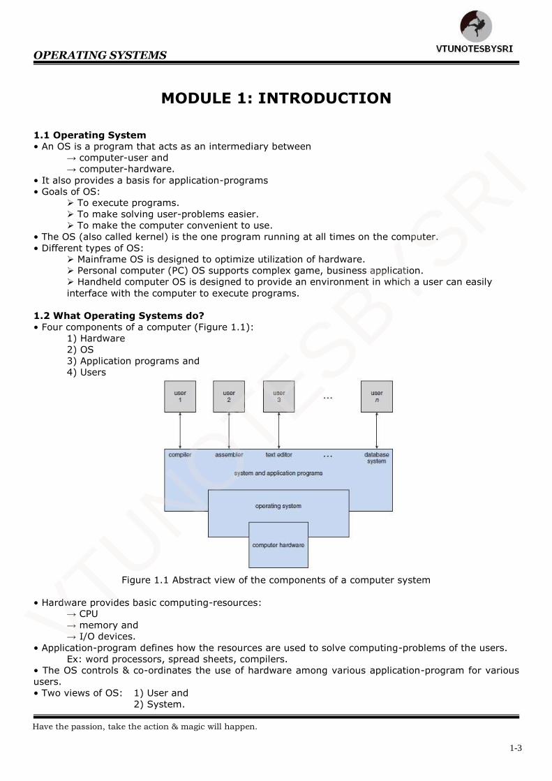
• Four components of a computer (Figure 1.1):
1) Hardware
2) OS
3) Application programs and
4) Users
Figure 1.1 Abstract view of the components of a computer system
• Hardware provides basic computing-resources: → CPU
→ memory and
→ I/O devices.
• Application-program defines how the resources are used to solve computing-problems of the users.
Ex: word processors, spread sheets, compilers.
• The OS controls & co-ordinates the use of hardware among various application-program for various
users.
• Two views of OS: 1) User and
2) System.
VTUNOTESBYSRI
Have the passion, take the action & magic will happen.
OPERATING SYSTEMS
1-4
1.2.1 User View
• The user's view of the computer depends on the interface being used:
1) Most users use a PC consisting of a monitor, keyboard and system-unit. The OS is designed mostly for ease of use.
Some attention is paid to performance.
No attention is paid to resource utilization. The OS is optimized for the single-user experience.
2) Some users use a terminal connected to a mainframe or (a minicomputer). The OS is designed
→ to maximize resource utilization.
→ to assure that no individual user takes more than her fair share.
3) Some users use a workstation connected to network. The users have dedicated resources such as networking and servers.
The OS is designed to compromise between
→ individual usability and
→ resource utilization.
4) Some users use a handheld computer. The OS is designed mostly for individual usability.
Performance per unit of battery life is a very important factor.
1.2.2 System View
1) An OS as a resource allocator Resources used to solve a computing-problem:
→ CPU time
→ memory-space
→ file-storage space and
→ I/0 devices.
The OS manages and allocates the above resources to programs and the users.
2) An OS is a control program The OS is needed to control:
→ operations of I/0 devices and
→ execution of user-programs to prevent errors.
VTUNOTESBYSRI
When your experience, qualifications, and skills fail you. Let your hope, prayer, and faith carry you through.
OPERATING SYSTEMS
1-5
1.3 Computer System Organization
1.3.1 Computer System Organization
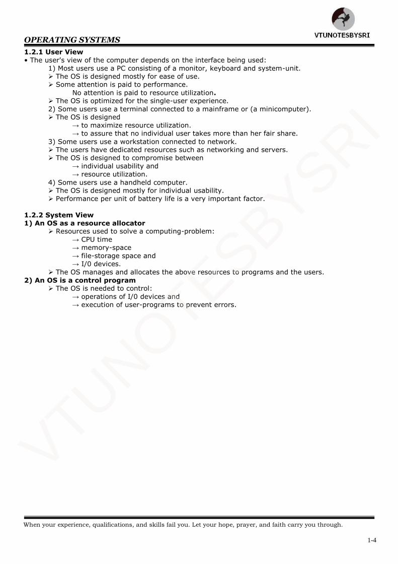
• A computer consists of → one or more CPUs and
→ no. of device-controllers (Figure 1.2).
• Controller is in charge of a specific type of device (for ex: audio devices).
• CPU and controllers can execute concurrently.
• A memory-controller is used to synchronize access to the shared-memory.
• Following events occur for a computer to start running:
1) Bootstrap program is an initial program that runs when computer is powered-up.
2) Bootstrap program → initializes all the system from registers to memory-contents and
→ loads OS into memory.
3) Then, OS
→ starts executing the first process (such as "init") and
→ waits for some event to occur.
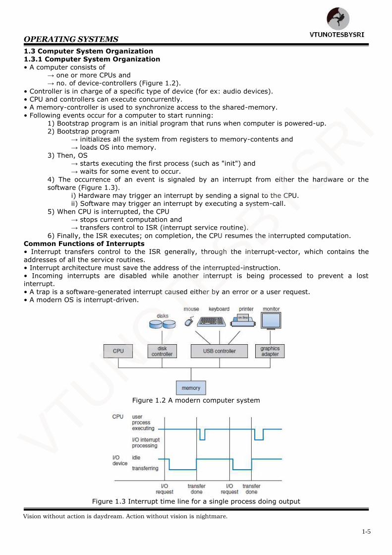
4) The occurrence of an event is signaled by an interrupt from either the hardware or the
software (Figure 1.3).
i) Hardware may trigger an interrupt by sending a signal to the CPU.
ii) Software may trigger an interrupt by executing a system-call.
5) When CPU is interrupted, the CPU → stops current computation and
→ transfers control to ISR (interrupt service routine).
6) Finally, the ISR executes; on completion, the CPU resumes the interrupted computation.
Common Functions of Interrupts
• Interrupt transfers control to the ISR generally, through the interrupt-vector, which contains the
addresses of all the service routines.
• Interrupt architecture must save the address of the interrupted-instruction.
• Incoming interrupts are disabled while another interrupt is being processed to prevent a lost
interrupt.
• A trap is a software-generated interrupt caused either by an error or a user request.
• A modern OS is interrupt-driven.
Figure 1.2 A modern computer system
Figure 1.3 Interrupt time line for a single process doing output
VTUNOTESBYSRI
Vision without action is daydream. Action without vision is nightmare.
OPERATING SYSTEMS
1-6
1.3.2 Storage Structure
• Programs must be in main-memory (also called RAM) to be executed.
• Interaction with memory is done through a series of load or store instructions.
1) Load Instruction Moves a word from main-memory to an internal register within the CPU.
2) Store Instruction
Moves the content of a register to main-memory.
• Also, the CPU automatically loads instructions from main-memory for execution.
• Ideally, we want the programs & data to reside in main-memory permanently. This is not possible for
2 reasons:
1) Main-memory is small.
2) Main-memory is volatile i.e. it loses its contents when powered-off.
• Most computers provide secondary-storage as an extension of main-memory.
For ex: magnetic disk.
• Main requirement:
The secondary-storage must hold large amount of data permanently.
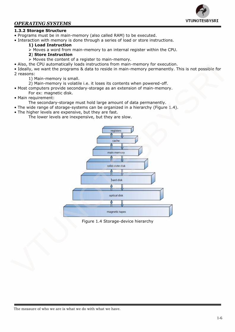
• The wide range of storage-systems can be organized in a hierarchy (Figure 1.4).
• The higher levels are expensive, but they are fast.
The lower levels are inexpensive, but they are slow.
Figure 1.4 Storage-device hierarchy
VTUNOTESBYSRI
The measure of who we are is what we do with what we have.
OPERATING SYSTEMS
1-7
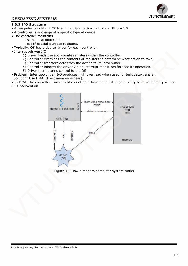
1.3.3 I/O Structure
• A computer consists of CPUs and multiple device controllers (Figure 1.5).
• A controller is in charge of a specific type of device.
• The controller maintains → some local buffer and
→ set of special-purpose registers.
• Typically, OS has a device-driver for each controller.
• Interrupt-driven I/O:
1) Driver loads the appropriate registers within the controller.
2) Controller examines the contents of registers to determine what action to take.
3) Controller transfers data from the device to its local buffer.
4) Controller informs the driver via an interrupt that it has finished its operation.
5) Driver then returns control to the OS.
• Problem: Interrupt-driven I/O produces high overhead when used for bulk data-transfer.
Solution: Use DMA (direct memory access).
• In DMA, the controller transfers blocks of data from buffer-storage directly to main memory without
CPU intervention.
Figure 1.5 How a modern computer system works
VTUNOTESBYSRI
Life is a journey, its not a race. Walk through it.
OPERATING SYSTEMS
1-8
1.4 Computer System Architecture
1) Single-Processor Systems
2) Multiprocessor Systems
3) Clustered Systems
1.4.1 Single Processor Systems
• The system has only one general-purpose CPU.
• The CPU is capable of executing a general-purpose instruction-set.
• These systems range from PDAs through mainframes.
• Almost all systems have following processors:
1) Special Purpose Processors Include disk, keyboard, and graphics controllers.
2) General Purpose Processors
Include I/O processors.
• Special-purpose processors run a limited instruction set and do not run user-processes.
1.4.2 Multi-Processor Systems
• These systems have two or more processors which can share: → bus → clock → memory/peripheral devices
• Advantages:
1) Increased Throughput By increasing no. of processors, we expect to get more work done in less time.
2) Economy of Scale These systems are cheaper because they can share
→ peripherals → mass-storage → power-supply.
If many programs operate on same data, they will be stored on one disk & all processors can
share them.
3) Increased Reliability
The failure of one processor will not halt the system.
• Two types of multiple-processor systems: 1) Asymmetric multiprocessing (AMP) and
2) Symmetric multiprocessing (SMP)
1) Asymmetric Multiprocessing
• This uses master-slave relationship (Figure 1.6).
• Each processor is assigned a specific task.
• A master-processor controls the system.
The other processors look to the master for instruction.
• The master-processor schedules and allocates work to the slave-processors.
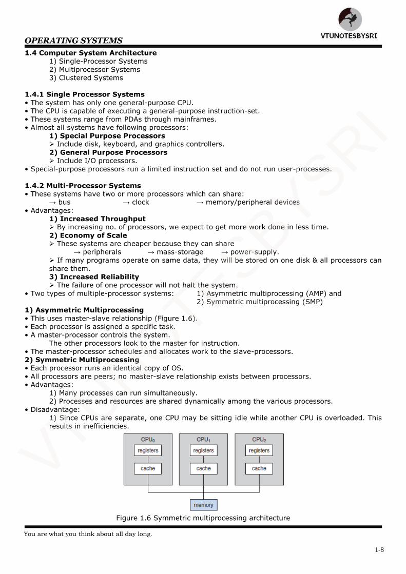
2) Symmetric Multiprocessing
• Each processor runs an identical copy of OS.
• All processors are peers; no master-slave relationship exists between processors.
• Advantages:
1) Many processes can run simultaneously.
2) Processes and resources are shared dynamically among the various processors.
• Disadvantage:
1) Since CPUs are separate, one CPU may be sitting idle while another CPU is overloaded. This
results in inefficiencies.
Figure 1.6 Symmetric multiprocessing architecture
VTUNOTESBYSRI
You are what you think about all day long.
OPERATING SYSTEMS
1-9
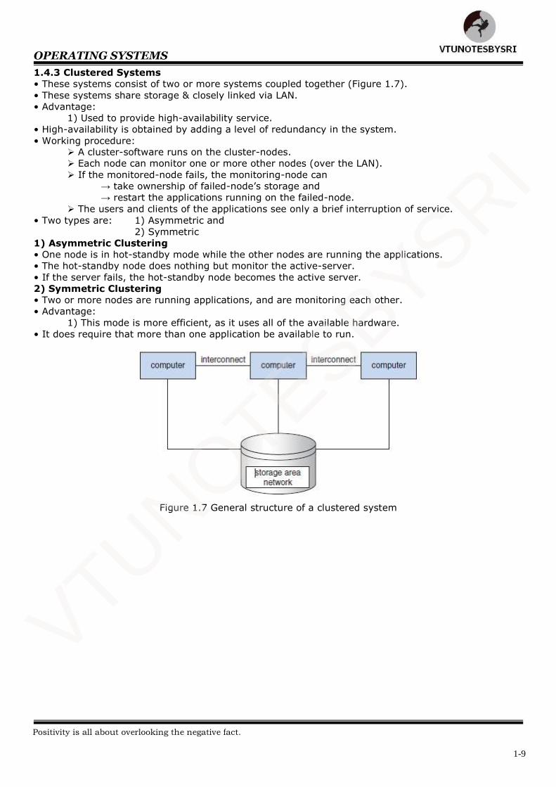
1.4.3 Clustered Systems
• These systems consist of two or more systems coupled together (Figure 1.7).
• These systems share storage & closely linked via LAN.
• Advantage:
1) Used to provide high-availability service.
• High-availability is obtained by adding a level of redundancy in the system.
• Working procedure: A cluster-software runs on the cluster-nodes.
Each node can monitor one or more other nodes (over the LAN).
If the monitored-node fails, the monitoring-node can
→ take ownership of failed-node‟s storage and
→ restart the applications running on the failed-node.
The users and clients of the applications see only a brief interruption of service.
• Two types are: 1) Asymmetric and
2) Symmetric
1) Asymmetric Clustering
• One node is in hot-standby mode while the other nodes are running the applications.
• The hot-standby node does nothing but monitor the active-server.
• If the server fails, the hot-standby node becomes the active server.
2) Symmetric Clustering
• Two or more nodes are running applications, and are monitoring each other.
• Advantage:
1) This mode is more efficient, as it uses all of the available hardware.
• It does require that more than one application be available to run.
Figure 1.7 General structure of a clustered system
VTUNOTESBYSRI
Positivity is all about overlooking the negative fact.
OPERATING SYSTEMS
1-10
1.5 Operating System Structure
1) Batch Systems
2) Multi-Programmed Systems
3. Time-Sharing Systems
1.5.1 Batch Systems
• Early computers were physically enormous machines run from a console.
• The common input devices were card readers and tape drives.
• The common output devices were line printers, tape drives, and card punches.
• The user
→ prepared a job which consisted of the program, the data, and control information
→ submitted the job to the computer-operator.
• The job was usually in the form of punch cards.
• At some later time (after minutes, hours, or days), the output appeared.
• To speed up processing, operators batched together jobs with similar needs and ran them through
the computer as a group.
• Disadvantage:
1) The CPU is often idle, because the speeds of the mechanical I/O devices.
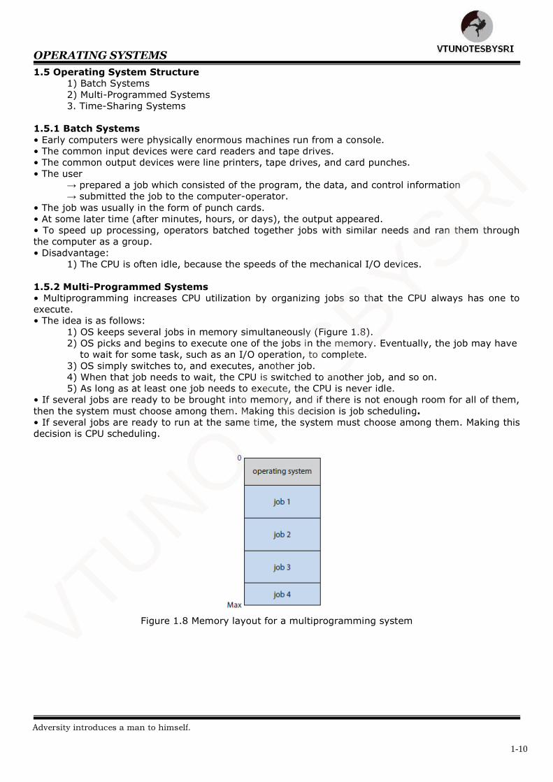
1.5.2 Multi-Programmed Systems
• Multiprogramming increases CPU utilization by organizing jobs so that the CPU always has one to
execute.
• The idea is as follows:
1) OS keeps several jobs in memory simultaneously (Figure 1.8).
2) OS picks and begins to execute one of the jobs in the memory. Eventually, the job may have
to wait for some task, such as an I/O operation, to complete.
3) OS simply switches to, and executes, another job.
4) When that job needs to wait, the CPU is switched to another job, and so on.
5) As long as at least one job needs to execute, the CPU is never idle.
• If several jobs are ready to be brought into memory, and if there is not enough room for all of them,
then the system must choose among them. Making this decision is job scheduling.
• If several jobs are ready to run at the same time, the system must choose among them. Making this
decision is CPU scheduling.
Figure 1.8 Memory layout for a multiprogramming system
VTUNOTESBYSRI
Adversity introduces a man to himself.
OPERATING SYSTEMS
1-11
1.5.3 Time Sharing Systems
• Time sharing (or multitasking) is a logical extension of multiprogramming.
• The CPU executes multiple jobs by switching between them.
• Switching between jobs occur so frequently that the users can interact with each program while it is
running.
• Many users are allowed to share the computer simultaneously.
• CPU scheduling and multiprogramming are used to provide each user with a small portion of a time-
shared computer.
• To obtain a good response time, jobs may have to be swapped in and out of main memory to the
disk (called as backing store).
• Virtual memory is a technique that allows the execution of a job that may not be completely in
memory.
• Advantage of virtual-memory:
1) Programs can be larger than physical memory.
• Main requirements: The system must provide a file-system.
The system must provide disk-management.
The system must provide CPU-scheduling to support concurrent execution.
The system must provide job-synchronization to ensure orderly execution.
VTUNOTESBYSRI
There is no education like adversity.
OPERATING SYSTEMS
1-12
1.6 Operating System Operations
• Modern OS is interrupt driven.
• Events are always signaled by the occurrence of an interrupt or a trap.
• A trap is a software generated interrupt caused either by → error (for example division by zero) or
→ request from a user-program that an OS service be performed.
• For each type of interrupt, separate segments of code in the OS determine what action should be
taken.
• ISR (Interrupt Service Routine) is provided that is responsible for dealing with the interrupt.
1.6.1 Dual Mode Operation
• Problem: We must be able to differentiate between the execution of
→ OS code and
→ user-defined code.
Solution: Most computers provide hardware-support.
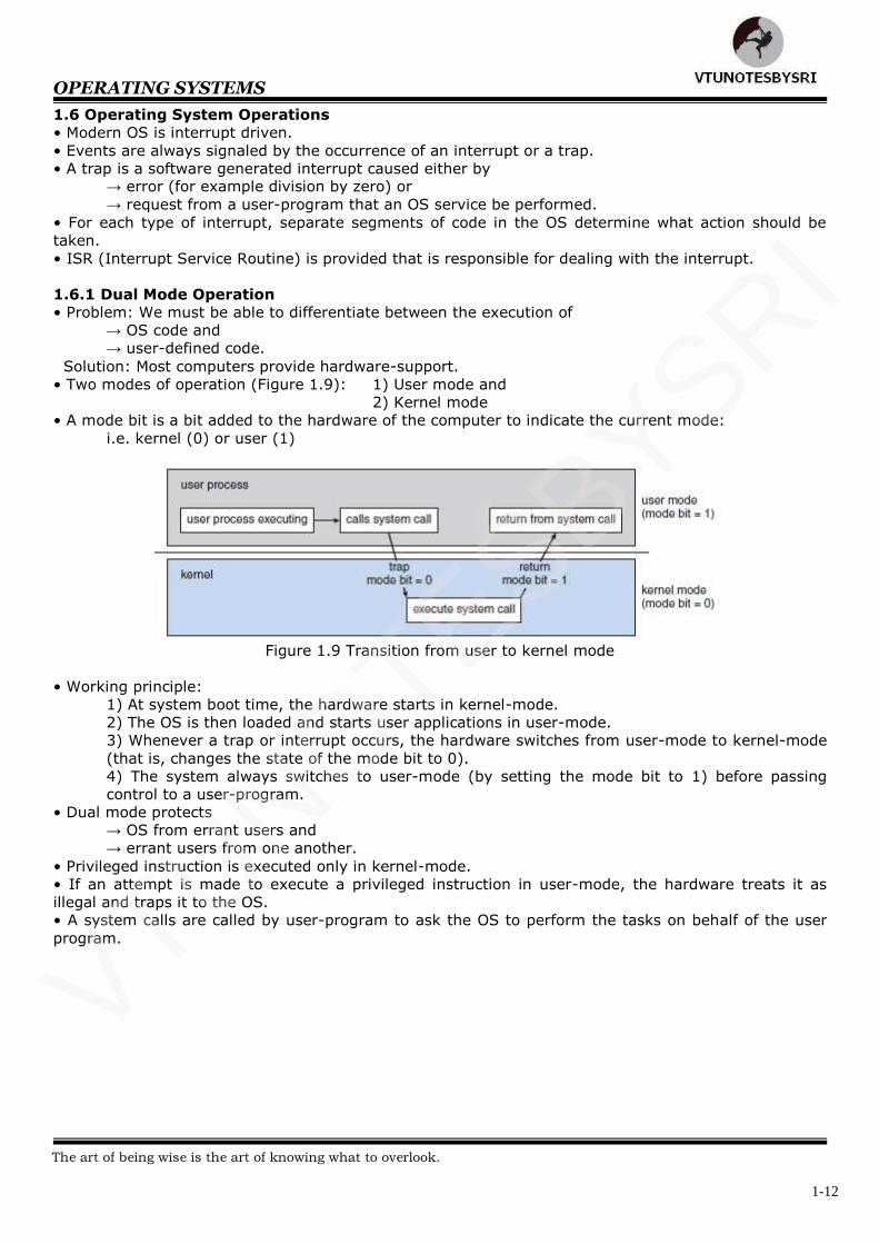
• Two modes of operation (Figure 1.9): 1) User mode and
2) Kernel mode
• A mode bit is a bit added to the hardware of the computer to indicate the current mode:
i.e. kernel (0) or user (1)
Figure 1.9 Transition from user to kernel mode
• Working principle:
1) At system boot time, the hardware starts in kernel-mode.
2) The OS is then loaded and starts user applications in user-mode.
3) Whenever a trap or interrupt occurs, the hardware switches from user-mode to kernel-mode
(that is, changes the state of the mode bit to 0).
4) The system always switches to user-mode (by setting the mode bit to 1) before passing
control to a user-program.
• Dual mode protects
→ OS from errant users and
→ errant users from one another.
• Privileged instruction is executed only in kernel-mode.
• If an attempt is made to execute a privileged instruction in user-mode, the hardware treats it as
illegal and traps it to the OS.
• A system calls are called by user-program to ask the OS to perform the tasks on behalf of the user
program.
VTUNOTESBYSRI
The art of being wise is the art of knowing what to overlook.
OPERATING SYSTEMS
1-13
1.6.2 Timer
• Problem: We cannot allow a user-program to get stuck in an infinite loop and never return control to
the OS.
Solution: We can use a timer.
• A timer can be set to interrupt the computer after a specific period.
• The period may be fixed (for ex: 1/60 second) or variable (for ex: from 1ns to 1ms).
• A variable timer is implemented by a fixed-rate clock and a counter.
• Working procedure:
1) The OS sets the counter.
2) Every time the clock ticks, the counter is decremented.
3) When the counter reaches 0, an interrupt occurs.
• The instructions that modify the content of the timer are privileged instructions.
1.7 Process Management
• The OS is responsible for the following activities:
1) Creating and deleting both user and system processes
2) Suspending and resuming processes
3) Providing mechanisms for process synchronization
4) Providing mechanisms for process communication
5) Providing mechanisms for deadlock handling
• A process needs following resources to do a task: → CPU
→ memory and
→ files.
• The resources are allocated to process → when the process is created or
→ while the process is running.
• When the process terminates, the OS reclaims all the reusable resources.
• A program by itself is not a process;
1) A program is a passive entity (such as the contents of a file stored on disk).
2) A process is an active entity.
• Two types of process:
1) Single-threaded process has one PC(program counter) which specifies location of the next
instruction to be executed.
2) Multi-threaded process has one PC per thread which specifies location of next instruction
to execute in each thread
1.8 Memory Management
• The OS is responsible for the following activities:
1) Keeping track of which parts of memory are currently being used and by whom
2) Deciding which processes are to be loaded into memory when memory space becomes
available
3) Allocating and de-allocating memory space as needed.
• Main memory is the array of bytes ranging from hundreds to billions.
• Each byte has its own address.
• The CPU
→ reads instructions from main memory during the instruction-fetch cycle.
→ reads/writes data from/to main-memory during the data-fetch cycle.
• To execute a program:
1) The program will be → loaded into memory and
→ mapped to absolute addresses.
2) Then, program accesses instructions & data from memory by generating absolute addresses.
3) Finally, when program terminates, its memory-space is freed.
• To improve CPU utilization, keep several programs will be kept in memory
• Selection of a memory-management scheme depends on hardware-design of the system.
VTUNOTESBYSRI
All our dreams can come true if we have the courage to pursue them.
OPERATING SYSTEMS
1-14
1.9 Storage Management
1) File-System Management
2) Mass-Storage Management
3) Caching
1.9.1 File System Management
• The OS is responsible for following activities:
1) Creating and deleting files.
2) Creating and deleting directories.
3) Supporting primitives for manipulating files & directories.
4) Mapping files onto secondary storage.
5) Backing up files on stable (non-volatile) storage media.
• Computer stores information on different types of physical media.
For ex: magnetic disk, optical disk.
• Each medium is controlled by a device (e.g. disk drive).
• The OS → maps files onto physical media and
→ accesses the files via the storage devices
• File is a logical collection of related information.
• File consists of both program & data.
• Data files may be numeric, alphabets or binary.
• When multiple users have access to files, access control (read, write) must be specified.
1.9.2 Mass Storage Management
• The OS is responsible for following activities:
1) Free-space management
2) Storage allocation and
3) Disk scheduling.
• Usually, disks used to store → data that does not fit in main memory or
→ data that must be kept for a “long” period of time.
• Most programs are stored on disk until loaded into memory.
• The programs include → compilers
→ word processors and
→ editors.
• The programs use the disk as both the source and destination of their processing.
• Entire speed of computer operation depends on disk and its algorithms.
1.9.3 Caching
• Caching is an important principle of computer systems.
• Information is normally kept in some storage system (such as main memory).
• As it is used, it is copied into a faster storage system called as the cache on a temporary basis.
• When we need a particular piece of information:
1) We first check whether the information is in the cache.
2) If information is in cache, we use the information directly from the cache.
3) If information is not in cache, we use the information from the source, putting a copy in the
cache under the assumption that we will need it again soon.
• In addition, internal programmable registers, such as index registers, provide high-speed cache for
main memory.
• The compiler implements the register-allocation and register-replacement algorithms to decide which
information to keep in registers and which to keep in main memory.
• Most systems have an instruction cache to hold the instructions expected to be executed next.
• Most systems have one or more high-speed data caches in the memory hierarchy
• Because caches have limited size, cache management is an important design problem
Careful selection of cache size & of a replacement policy can result in greatly increased performance
VTUNOTESBYSRI
The meaning of life is to find your gift. The purpose of life is to give it away.
OPERATING SYSTEMS
1-15
1.9.4 I/O Systems
• The OS must hide peculiarities of hardware devices from users.
• In UNIX, the peculiarities of I/O devices are hidden from the bulk of the OS itself by the I/O
subsystem.
• The I/O subsystem consists of
1) A memory-management component that includes buffering, caching, and spooling.
2) A general device-driver interface.
3) Drivers for specific hardware devices.
• Only the device driver knows the peculiarities of the specific device to which it is assigned.
1.10 Protection and Security
• Protection is a mechanism for controlling access of processes or users to resources defined by OS.
• This mechanism must provide
→ means for specification of the controls to be imposed and
→ means for enforcement.
• Protection can improve reliability by detecting latent errors at the interfaces between subsystems.
• Security means defense of the system against internal and external attacks.
• The attacks include → viruses and worms
→ DOS(denial-of-service)
→ identity theft.
• Protection and security require the system to be able to distinguish among all its users.
1) User identities (user IDs) include name and associated number, one per user. User IDs are associated with all files (or processes) of that user to determine access control.
2) Group identifier (group ID): can be used to define a group name and the set of users
belonging to that group. A user can be in one or more groups, depending on operating-system design decisions.
1.11 Distributed System
• This is a collection of physically separate, possibly heterogeneous computer-systems.
• The computer-systems are networked to provide the users with access to the various resources.
• Access to a shared resource increases → computation speed
→ functionality
→ data availability and
→ reliability
• A network is a communication path between two or more systems.
• Networks vary by the → protocols used
→ distances between nodes and
→ transport media.
• Common network protocol are → TCP/IP
→ ATM.
• Networks are characterized based on the distances between their nodes. → A local-area network (LAN) connects computers within a building.
→ A wide-area network (WAN) usually links buildings, cities, or countries.
→ A metropolitan-area network (MAN) could link buildings within a city.
• The media to carry networks are equally varied. They include
→ copper wires,
→ fiber strands, and
→ wireless transmissions.
VTUNOTESBYSRI
Do one thing every day that scares you.
OPERATING SYSTEMS
1-16
1.12 Special Purpose Systems
1) Real-Time Embedded Systems
2) Multimedia Systems
3) Handheld Systems
1.12.1 Real-Time Embedded Systems
• Embedded computers are the most prevalent form of computers in existence.
• These devices are found everywhere, from car engines and manufacturing robots to VCRs and
microwave ovens.
• They tend to have very specific tasks.
• The systems they run on are usually primitive, and so the operating systems provide limited
features.
• Usually, they prefer to spend their time monitoring & managing hardware devices such as
→ automobile engines and
→ robotic arms.
• Embedded systems almost always run real-time operating systems.
• A real-time system is used when rigid time requirements have been placed on the operation of a
processor.
1.12.2 Multimedia Systems
• Multimedia data consist of audio and video files as well as conventional files.
• These data differ from conventional data in that multimedia data must be delivered(streamed)
according to certain time restrictions.
• Multimedia describes a wide range of applications. These include → audio files such as MP3
→ DVD movies
→ video conferencing
→ live webcasts of speeches
1.12.3 Handheld Systems
• Handheld systems include
→ PDAs and
→ cellular telephones.
• Main challenge faced by developers of handheld systems: Limited size of devices.
• Because of small size, most handheld devices have a → small amount of memory,
→ slow processors, and
→ small display screens.
VTUNOTESBYSRI
Innovation distinguishes between a leader and a follower.
OPERATING SYSTEMS
1-17
1.13 Computing Environments
1) Traditional Computing
2) Client-Server Computing
3) Peer-to-Peer Computing
4) Web-Based Computing
1.13.1 Traditional Computing
• Used in office environment: PCs connected to a network, with servers providing file and print services.
• Used in home networks: At home, most users had a single computer with a slow modem.
Some homes have firewalls to protect their networks from security breaches.
• Web technologies are stretching the boundaries of traditional computing. Companies establish portals, which provide web accessibility to their internal servers.
Network computers are terminals that understand web computing.
Handheld PDAs can connect to wireless networks to use company's web portal.
• Systems were either batch or interactive.
1) Batch system processed jobs in bulk, with predetermined input.
2) Interactive systems waited for input from users.
1.13.2 Client-Server Computing
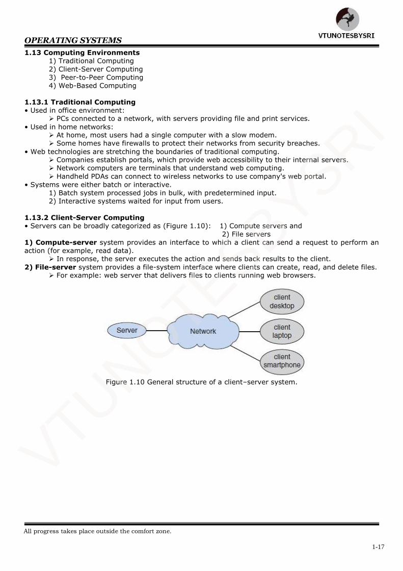
• Servers can be broadly categorized as (Figure 1.10): 1) Compute servers and
2) File servers
1) Compute-server system provides an interface to which a client can send a request to perform an
action (for example, read data). In response, the server executes the action and sends back results to the client.
2) File-server system provides a file-system interface where clients can create, read, and delete files. For example: web server that delivers files to clients running web browsers.
Figure 1.10 General structure of a client–server system.
VTUNOTESBYSRI
All progress takes place outside the comfort zone.
OPERATING SYSTEMS
1-18
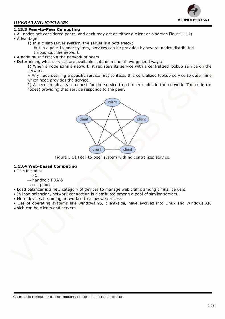
1.13.3 Peer-to-Peer Computing
• All nodes are considered peers, and each may act as either a client or a server(Figure 1.11).
• Advantage:
1) In a client-server system, the server is a bottleneck;
but in a peer-to-peer system, services can be provided by several nodes distributed
throughout the network.
• A node must first join the network of peers.
• Determining what services are available is done in one of two general ways:
1) When a node joins a network, it registers its service with a centralized lookup service on the
network.
Any node desiring a specific service first contacts this centralized lookup service to determine
which node provides the service.
2) A peer broadcasts a request for the service to all other nodes in the network. The node (or
nodes) providing that service responds to the peer.
Figure 1.11 Peer-to-peer system with no centralized service.
1.13.4 Web-Based Computing
• This includes → PC
→ handheld PDA &
→ cell phones
• Load balancer is a new category of devices to manage web traffic among similar servers.
• In load balancing, network connection is distributed among a pool of similar servers.
• More devices becoming networked to allow web access
• Use of operating systems like Windows 95, client-side, have evolved into Linux and Windows XP,
which can be clients and servers
VTUNOTESBYSRI
Courage is resistance to fear, mastery of fear - not absence of fear.
OPERATING SYSTEMS
1-19
MODULE 1 (CONT.): OPERATING-SYSTEM STRUCTURES
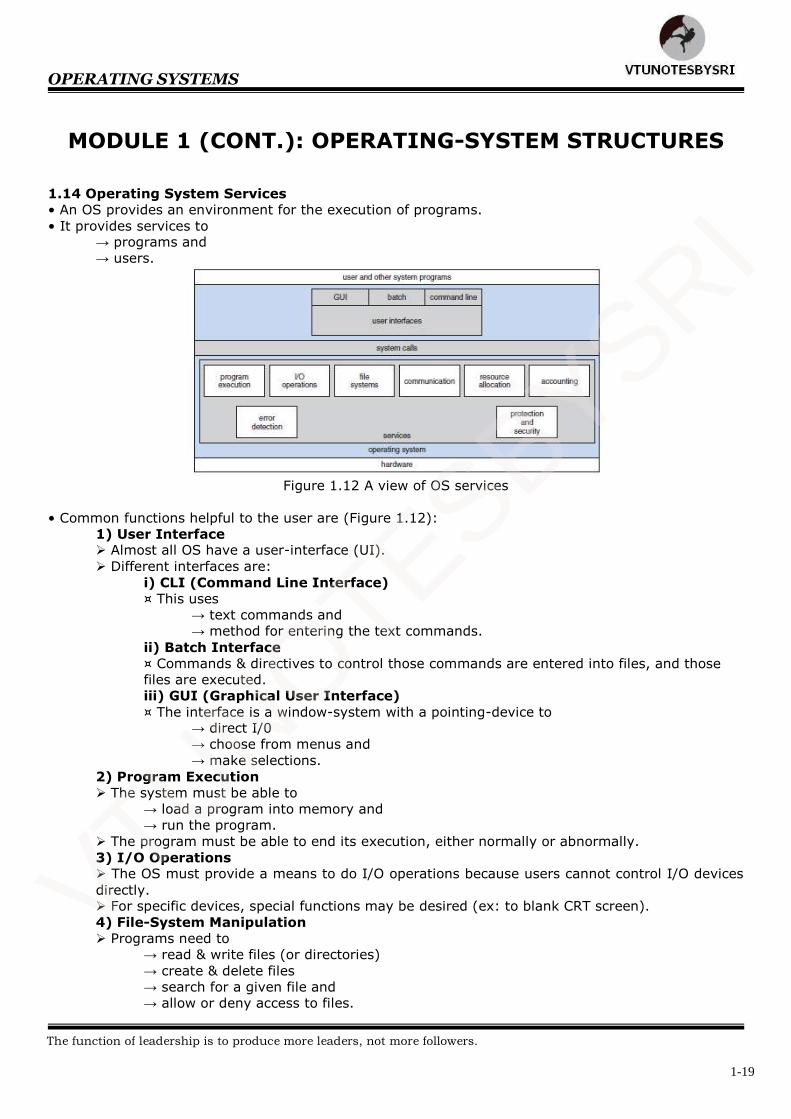
1.14 Operating System Services
• An OS provides an environment for the execution of programs.
• It provides services to → programs and
→ users.
Figure 1.12 A view of OS services
• Common functions helpful to the user are (Figure 1.12):
1) User Interface Almost all OS have a user-interface (UI).
Different interfaces are:
i) CLI (Command Line Interface)
¤ This uses
→ text commands and
→ method for entering the text commands.
ii) Batch Interface
¤ Commands & directives to control those commands are entered into files, and those
files are executed.
iii) GUI (Graphical User Interface)
¤ The interface is a window-system with a pointing-device to → direct I/0
→ choose from menus and
→ make selections.
2) Program Execution
The system must be able to
→ load a program into memory and
→ run the program.
The program must be able to end its execution, either normally or abnormally.
3) I/O Operations The OS must provide a means to do I/O operations because users cannot control I/O devices
directly. For specific devices, special functions may be desired (ex: to blank CRT screen).
4) File-System Manipulation
Programs need to
→ read & write files (or directories)
→ create & delete files
→ search for a given file and
→ allow or deny access to files.
VTUNOTESBYSRI
The function of leadership is to produce more leaders, not more followers.
OPERATING SYSTEMS
1-20
5) Communications In some situations, one process needs to communicate with another process.
Communications may be implemented via
1. Shared memory or
2. Message passing
In message passing, packets of information are moved between processes by OS.
6) Error Detection Errors may occur in
→ CPU & memory-hardware (ex: power failure)
→ I/O devices (ex: lack of paper in the printer) and
→ user program (ex: arithmetic overflow)
For each type of error, OS should take appropriate action to ensure correct & consistent
computing.
• Common functions for efficient operation of the system are:
1) Resource Allocation When multiple users are logged on the system at the same time, resources must be allocated
to each of them.
The OS manages different types of resources.
Some resources (say CPU cycles) may have special allocation code.
Other resources (say I/O devices) may have general request & release code.
2) Accounting We want to keep track of
→ which users use how many resources and
→ which kinds of resources.
This record keeping may be used for
→ accounting (so that users can be billed) or
→ gathering usage-statistics.
3) Protection
When several separate processes execute concurrently, it should not be possible for one
process to interfere with the others or with the OS itself. Protection involves ensuring that all access to resources is controlled.
Security starts with each user having authenticated to the system by means of a password.
VTUNOTESBYSRI
Success is liking yourself, liking what you do, and liking how you do it.
OPERATING SYSTEMS
1-21
1.15 User Operating System Interface
• Two ways that users interface with the OS: 1) Command Interpreter (Command-line interface)
2) Graphical User Interface (GUI)
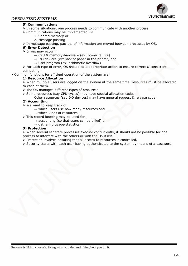
1) Command Interpreter
• Main function:
To get and execute the next user-specified command (Figure 1.13).
• The commands are used to manipulate files i.e. create, copy, print, execute, etc.
• Two general ways to implement:
1) Command interpreter itself contains code to execute command.
2) Commands are implemented through system programs. This is used by UNIX.
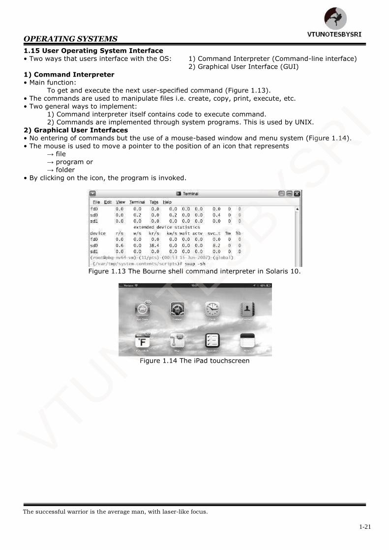
2) Graphical User Interfaces
• No entering of commands but the use of a mouse-based window and menu system (Figure 1.14).
• The mouse is used to move a pointer to the position of an icon that represents
→ file
→ program or
→ folder
• By clicking on the icon, the program is invoked.
Figure 1.13 The Bourne shell command interpreter in Solaris 10.
Figure 1.14 The iPad touchscreen
VTUNOTESBYSRI
The successful warrior is the average man, with laser-like focus.
OPERATING SYSTEMS
1-22
1.16 System Calls
• These provide an interface to the OS services.
• These are available as routines written in C and C++.
• The programmers design programs according to an API.
(API=application programming interface).
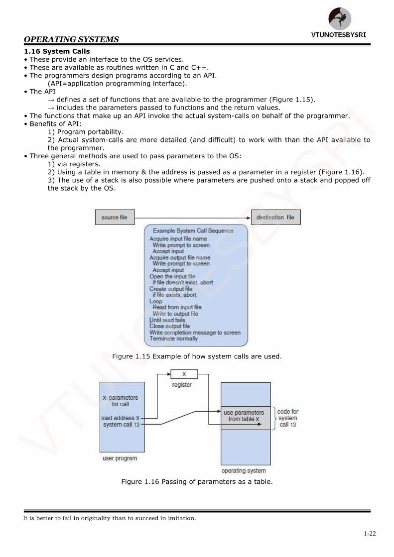
• The API
→ defines a set of functions that are available to the programmer (Figure 1.15).
→ includes the parameters passed to functions and the return values.
• The functions that make up an API invoke the actual system-calls on behalf of the programmer.
• Benefits of API:
1) Program portability.
2) Actual system-calls are more detailed (and difficult) to work with than the API available to
the programmer.
• Three general methods are used to pass parameters to the OS:
1) via registers.
2) Using a table in memory & the address is passed as a parameter in a register (Figure 1.16).
3) The use of a stack is also possible where parameters are pushed onto a stack and popped off
the stack by the OS.
Figure 1.15 Example of how system calls are used.
Figure 1.16 Passing of parameters as a table.
VTUNOTESBYSRI
It is better to fail in originality than to succeed in imitation.
OPERATING SYSTEMS
1-23
VTUNOTESBYSRI
You may have to fight a battle more than once to win it.
OPERATING SYSTEMS
1-24
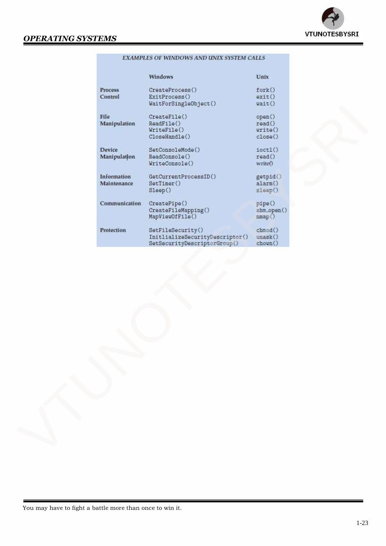
1.17 Types of System Calls
1) Process control
2) File management
3) Device management
4) Information maintenance
5) Communications
1.17.1 Process Control
• System calls used: end, abort
load, execute
create process, terminate process
get process attributes, set process attributes
wait for time
wait event, signal event
allocate and free memory
• A running program needs to be able to halt its execution either normally (end) or abnormally
(abort).
• If program runs into a problem, error message may be generated and dumped into a file.
This file can be examined by a debugger to determine the cause of the problem.
• The OS must transfer control to the next invoking command interpreter. Command interpreter then reads next command.
In interactive system, the command interpreter simply continues with next command.
In GUI system, a pop-up window will request action from user.
How to deal with new process?
• A process executing one program can load and execute another program.
• Where to return control when the loaded program terminates?
The answer depends on the existing program:
1) If control returns to the existing program when the new program terminates, we must save
the memory image of the existing program. (Thus, we have effectively created a mechanism for
one program to call another program).
2) If both programs continue concurrently, we created a new process to be multiprogrammed.
• We should be able to control the execution of a process. i.e. we should be able to determine and
reset the attributes of a process such as: → job's priority or
→ maximum execution time
• We may also want to terminate process that we created if we find that it → is incorrect or
→ is no longer needed.
• We may need to wait for processes to finish their execution.
We may want to wait for a specific event to occur.
• The processes should then signal when that event has occurred.
VTUNOTESBYSRI
Failure defeats losers, failure inspires winners.
OPERATING SYSTEMS
1-25
1.17.2 File Management
• System calls used:
create file, delete file
open, close
read, write, reposition
get file attributes, set file attributes
• Working procedure:
1) We need to create and delete files.
2) Once the file is created, → we need to open it and to use it.
→ we may also read or write.
3) Finally, we need to close the file.
• We need to be able to → determine the values of file-attributes and
→ reset the file-attributes if necessary.
• File attributes include → file name
→ file type
→ protection codes and
→ accounting information.
1.17.3 Device Management
• System calls used: request device, release device;
read, write, reposition;
get device attributes, set device attributes;
logically attach or detach devices.
• A program may need additional resources to execute.
• Additional resources may be → memory
→ tape drives or
→ files.
• If the resources are available, they can be granted, and control can be returned to the user program;
If the resources are unavailable, the program may have to wait until sufficient resources are
available.
• Files can be thought of as virtual devices. Thus, many of the system calls used for files are also used
for devices.
• In multi-user environment,
1) We must first request the device, to ensure exclusive use of it.
2) After we are finished with the device, we must release it.
• Once the device has been requested (and allocated), we can read and write the device.
• Due to lot of similarity between I/O devices and files, OS (like UNIX) merges the two into a combined
file-device structure.
• UNIX merges I/O devices and files into a combined file-device structure.
VTUNOTESBYSRI
Stop chasing the money and start chasing the passion.
OPERATING SYSTEMS
1-26
1.17.4 Information Maintenance
• System calls used:
get time or date, set time or date
get system data, set system data
get process, file, or device attributes
set process, file, or device attributes
• Many system calls exist simply for the purpose of transferring information between the user program
and the OS.
For ex,
1) Most systems have a system call to return → current time and
→ current date.
2) Other system calls may return information about the system, such as → number of current users
→ version number of the OS
→ amount of free memory or disk space.
3) The OS keeps information about all its processes, and there are system calls to access
this information.
VTUNOTESBYSRI
Failure will never overtake me if my determination to succeed is strong enough.
OPERATING SYSTEMS
1-27
1.17.5 Communication
• System calls used:
create, delete communication connection
send, receive messages
transfer status information
attach or detach remote devices
• Two models of communication.
1) Message-passing model and 2) Shared Memory Model
1.17.5.1 Message Passing Model
• Information is exchanged through an IPC provided by OS.
(IPC=inter process communication).
• Steps for communication:
1) Firstly, a connection must be opened using open connection system-call.
2) Each computer has a host-name, such as an IP name.
Similarly, each process has a process-name, which is translated into an equivalent identifier.
The get hostid & get processid system-calls do this translation.
3) Then, identifiers are passed to the open and close system-calls.
4) The recipient-process must give its permission for communication to take place with an
accept connection system-call.
(The processes that will be receiving connections are called daemons processes).
5) Daemon processes → execute a wait for connection system-call and
→ are awakened when a connection is made.
6) Then, client & server exchange messages by read message and write message system
calls.
7) Finally, the close connection system-call terminates the communication.
• Advantages:
1) Useful when smaller numbers of data need to be exchanged.
2) It is also easier to implement than is shared memory.
1.17.5.2 Shared Memory Model
• Processes use map memory system-calls to gain access to regions of memory owned by other
processes.
• Several processes exchange information by reading and writing data in the shared memory.
• The shared memory
→ is determined by the processes and
→ are not under the control of OS.
• The processes are also responsible for ensuring that they are not writing to the same location
simultaneously.
• Advantage:
1) Shared memory allows maximum speed and convenience of communication,
• Disadvantage:
1) Problems exist in the areas of protection and synchronization.
VTUNOTESBYSRI
We may encounter many defeats but we must not be defeated.
OPERATING SYSTEMS
1-28
1.18 System Programs
• They provide a convenient environment for program development and execution.
(System programs also known as system utilities).
• They can be divided into these categories:
• Six categories of system-programs:
1) File Management
These programs manipulate files i.e. create, delete, copy, and rename files.
2) Status Information Some programs ask the system for
→ date (or time)
→ amount of memory(or disk space) or
→ no. of users.
These information is then printed to the terminal (or output-device or file).
3) File Modification
Text editors can be used to create and modify the content of files stored on disk.
4) Programming Language Support Compilers, assemblers, and interpreters for common programming-languages (such as C,
C++) are provided to the user.
5) Program Loading & Execution The system may provide
→ absolute loaders
→ relocatable loaders
→ linkage editors and
→ overlay loaders.
Debugging-systems are also needed.
6) Communications These programs are used for creating virtual connections between
→ processes
→ users and
→ computer-systems.
They allow users to
→ browse web-pages
→ send email or
→ log-in remotely.
• Most OSs are supplied with programs that
→ solve common problems or
→ perform common operations. Such programs include
→ web-browsers
→ word-processors
→ spreadsheets and
→ games.
These programs are known as application programs.
VTUNOTESBYSRI
The man who has confidence in himself gains the confidence of others.
OPERATING SYSTEMS
1-29
1.19 Operating System Design & Implementation
1.19.1 Design Goals
• The first problem in designing a system is to → define goals and
→ define specifications.
• The design of the system will be affected by → choice of hardware and
→ type of system such as
1) batch or time shared
2) single user or multiuser
• Two basic groups of requirements: 1) User goals and
2) System goals
1) User Goals
• The system should be
→ convenient to use
→ easy to learn and to use
→ reliable, safe, and fast.
2) System Goals
• The system should be → easy to design
→ implement, and maintain
→ flexible, reliable, error free, and efficient.
1.19.2 Mechanisms & Policies
• Mechanisms determine how to do something.
• Policies determine what will be done.
• Separating policy and mechanism is important for flexibility.
• Policies change over time; mechanisms should be general.
1.19.3 Implementation
• OS's are nowadays written in higher-level languages like C/C++
• Advantages of higher-level languages:
1) Faster development and
2) OS is easier to port.
• Disadvantages of higher-level languages:
1) Reduced speed and
2) Increased storage requirements.
VTUNOTESBYSRI
We generate fears while we sit. We overcome them by action.
OPERATING SYSTEMS
1-30
1.20 Operating System Structure
1) Simple Structure
2) Layered Approach
3) Micro-kernels
4) Modules
1.20.1 Simple Structure
• These OSs are small, simple, and limited system.
• For example: MS-DOS and UNIX.
1) MS-DOS was written to provide the most functionality in the least space.
Disadvantages:
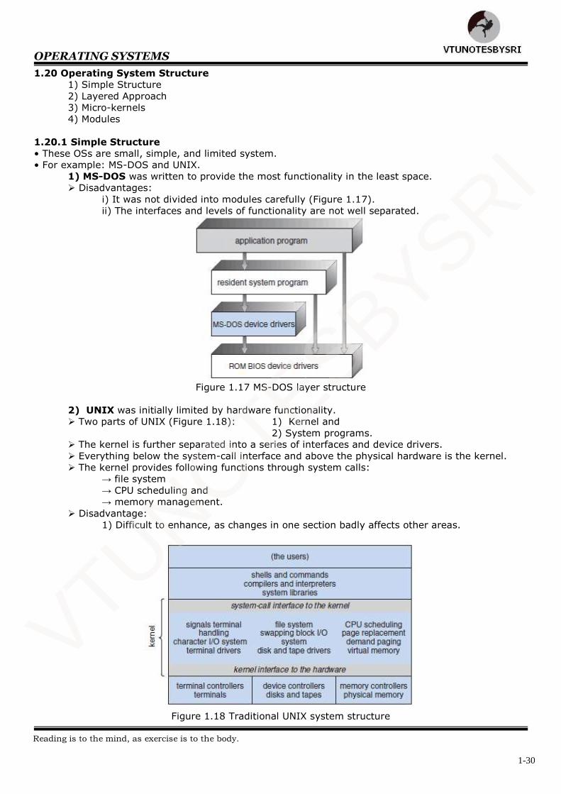
i) It was not divided into modules carefully (Figure 1.17).
ii) The interfaces and levels of functionality are not well separated.
Figure 1.17 MS-DOS layer structure
2) UNIX was initially limited by hardware functionality.
Two parts of UNIX (Figure 1.18): 1) Kernel and
2) System programs. The kernel is further separated into a series of interfaces and device drivers.
Everything below the system-call interface and above the physical hardware is the kernel.
The kernel provides following functions through system calls:
→ file system
→ CPU scheduling and
→ memory management.
Disadvantage:
1) Difficult to enhance, as changes in one section badly affects other areas.
Figure 1.18 Traditional UNIX system structure
VTUNOTESBYSRI
Reading is to the mind, as exercise is to the body.
OPERATING SYSTEMS
1-31
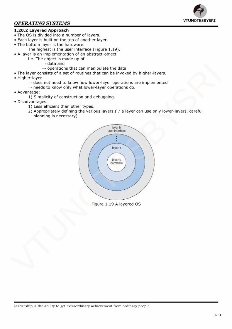
1.20.2 Layered Approach
• The OS is divided into a number of layers.
• Each layer is built on the top of another layer.
• The bottom layer is the hardware.
The highest is the user interface (Figure 1.19).
• A layer is an implementation of an abstract-object.
i.e. The object is made up of → data and
→ operations that can manipulate the data.
• The layer consists of a set of routines that can be invoked by higher-layers.
• Higher-layer → does not need to know how lower-layer operations are implemented
→ needs to know only what lower-layer operations do.
• Advantage:
1) Simplicity of construction and debugging.
• Disadvantages:
1) Less efficient than other types.
2) Appropriately defining the various layers.(„.‟ a layer can use only lower-layers, careful
planning is necessary).
Figure 1.19 A layered OS
VTUNOTESBYSRI
Leadership is the ability to get extraordinary achievement from ordinary people.
OPERATING SYSTEMS
1-32
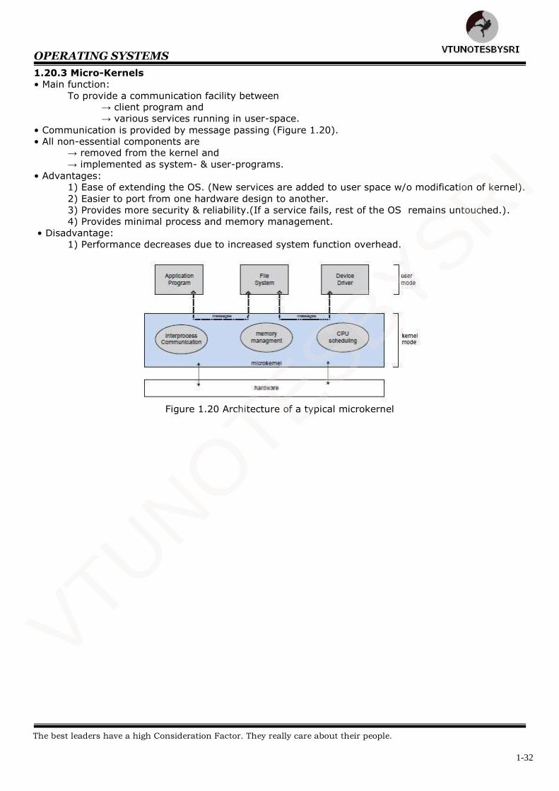
1.20.3 Micro-Kernels
• Main function:
To provide a communication facility between → client program and
→ various services running in user-space.
• Communication is provided by message passing (Figure 1.20).
• All non-essential components are → removed from the kernel and
→ implemented as system- & user-programs.
• Advantages:
1) Ease of extending the OS. (New services are added to user space w/o modification of kernel).
2) Easier to port from one hardware design to another.
3) Provides more security & reliability.(If a service fails, rest of the OS remains untouched.).
4) Provides minimal process and memory management.
• Disadvantage:
1) Performance decreases due to increased system function overhead.
Figure 1.20 Architecture of a typical microkernel
VTUNOTESBYSRI
The best leaders have a high Consideration Factor. They really care about their people.
OPERATING SYSTEMS
1-33
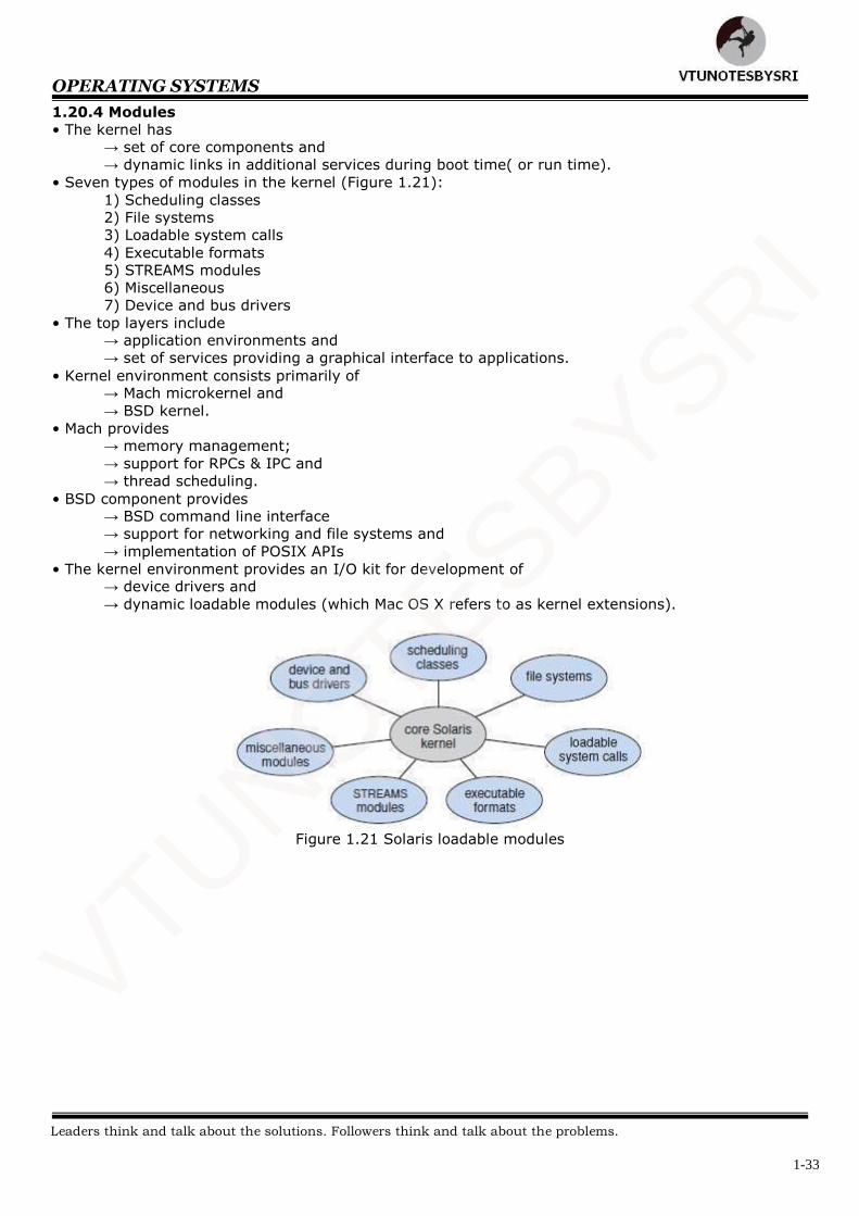
1.20.4 Modules
• The kernel has
→ set of core components and
→ dynamic links in additional services during boot time( or run time).
• Seven types of modules in the kernel (Figure 1.21):
1) Scheduling classes
2) File systems
3) Loadable system calls
4) Executable formats
5) STREAMS modules
6) Miscellaneous
7) Device and bus drivers
• The top layers include → application environments and
→ set of services providing a graphical interface to applications.
• Kernel environment consists primarily of → Mach microkernel and
→ BSD kernel.
• Mach provides → memory management;
→ support for RPCs & IPC and
→ thread scheduling.
• BSD component provides → BSD command line interface
→ support for networking and file systems and
→ implementation of POSIX APIs
• The kernel environment provides an I/O kit for development of → device drivers and
→ dynamic loadable modules (which Mac OS X refers to as kernel extensions).
Figure 1.21 Solaris loadable modules
VTUNOTESBYSRI
Leaders think and talk about the solutions. Followers think and talk about the problems.
OPERATING SYSTEMS
1-34
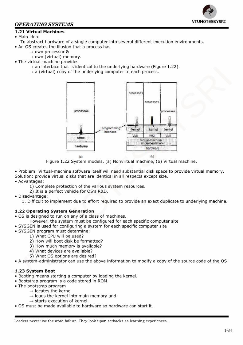
1.21 Virtual Machines
• Main idea:
To abstract hardware of a single computer into several different execution environments.
• An OS creates the illusion that a process has → own processor &
→ own (virtual) memory.
• The virtual-machine provides → an interface that is identical to the underlying hardware (Figure 1.22).
→ a (virtual) copy of the underlying computer to each process.
Figure 1.22 System models, (a) Nonvirtual machine, (b) Virtual machine.
• Problem: Virtual-machine software itself will need substantial disk space to provide virtual memory.
Solution: provide virtual disks that are identical in all respects except size.
• Advantages:
1) Complete protection of the various system resources.
2) It is a perfect vehicle for OS‟s R&D.
• Disadvantage:
1. Difficult to implement due to effort required to provide an exact duplicate to underlying machine.
1.22 Operating System Generation
• OS is designed to run on any of a class of machines.
However, the system must be configured for each specific computer site
• SYSGEN is used for configuring a system for each specific computer site
• SYSGEN program must determine:
1) What CPU will be used?
2) How will boot disk be formatted?
3) How much memory is available?
4) What devices are available?
5) What OS options are desired?
• A system-administrator can use the above information to modify a copy of the source code of the OS
1.23 System Boot
• Booting means starting a computer by loading the kernel.
• Bootstrap program is a code stored in ROM.
• The bootstrap program → locates the kernel
→ loads the kernel into main memory and
→ starts execution of kernel.
• OS must be made available to hardware so hardware can start it.
VTUNOTESBYSRI
Leaders never use the word failure. They look upon setbacks as learning experiences.
OPERATING SYSTEMS
1-35
MODULE 1 (CONT.): PROCESSES
1.24 Process Concept
• A process is the unit-of-work.
• A system consists of a collection of processes:
1) OS process can execute system-code and
2) User process can execute user-code.
1.24.1 The Process
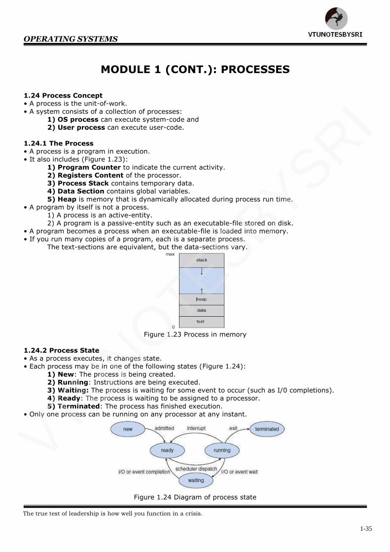
• A process is a program in execution.
• It also includes (Figure 1.23):
1) Program Counter to indicate the current activity.
2) Registers Content of the processor.
3) Process Stack contains temporary data.
4) Data Section contains global variables.
5) Heap is memory that is dynamically allocated during process run time.
• A program by itself is not a process.
1) A process is an active-entity.
2) A program is a passive-entity such as an executable-file stored on disk.
• A program becomes a process when an executable-file is loaded into memory.
• If you run many copies of a program, each is a separate process.
The text-sections are equivalent, but the data-sections vary.
Figure 1.23 Process in memory
1.24.2 Process State
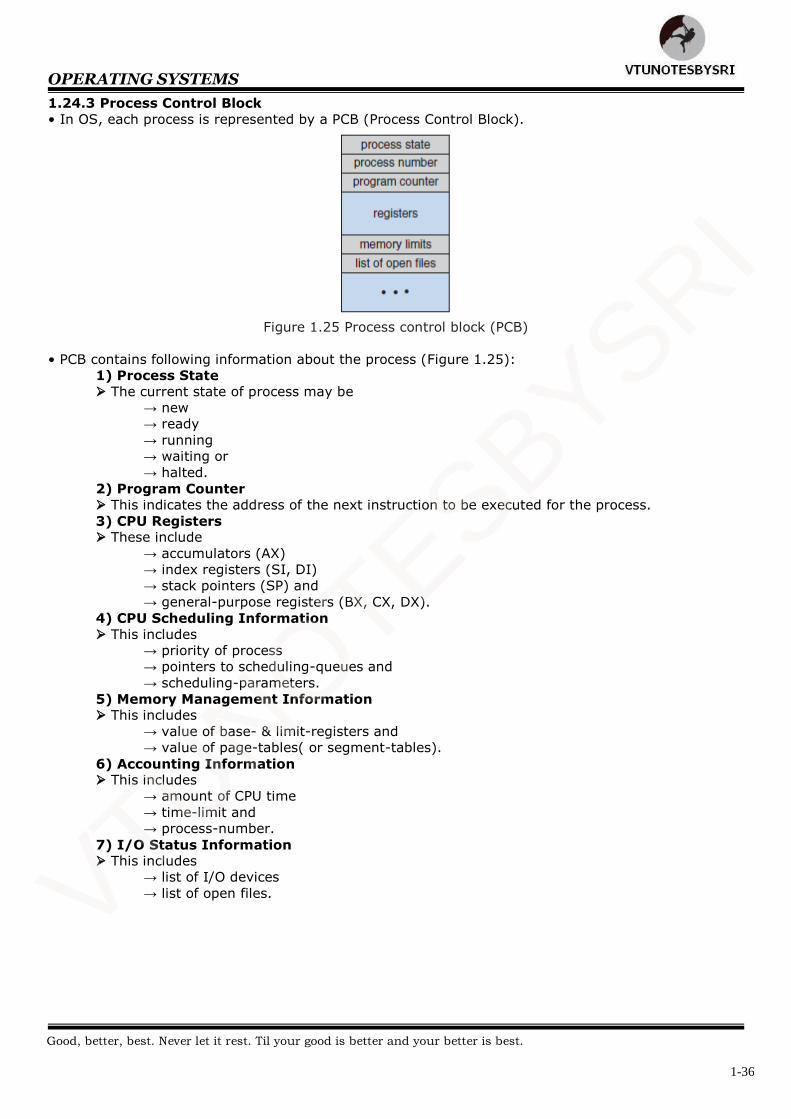
• As a process executes, it changes state.
• Each process may be in one of the following states (Figure 1.24):
1) New: The process is being created.
2) Running: Instructions are being executed.
3) Waiting: The process is waiting for some event to occur (such as I/0 completions).
4) Ready: The process is waiting to be assigned to a processor.
5) Terminated: The process has finished execution.
• Only one process can be running on any processor at any instant.
Figure 1.24 Diagram of process state
VTUNOTESBYSRI
The true test of leadership is how well you function in a crisis.
OPERATING SYSTEMS
1-36
1.24.3 Process Control Block
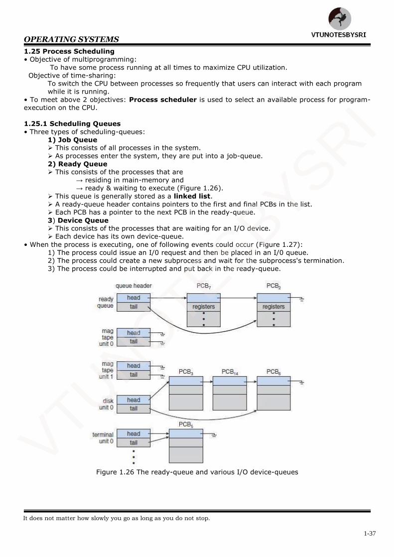
• In OS, each process is represented by a PCB (Process Control Block).
Figure 1.25 Process control block (PCB)
• PCB contains following information about the process (Figure 1.25):
1) Process State
The current state of process may be
→ new
→ ready
→ running
→ waiting or
→ halted.
2) Program Counter
This indicates the address of the next instruction to be executed for the process.
3) CPU Registers These include
→ accumulators (AX)
→ index registers (SI, DI)
→ stack pointers (SP) and
→ general-purpose registers (BX, CX, DX).
4) CPU Scheduling Information
This includes
→ priority of process
→ pointers to scheduling-queues and
→ scheduling-parameters.
5) Memory Management Information This includes
→ value of base- & limit-registers and
→ value of page-tables( or segment-tables).
6) Accounting Information This includes
→ amount of CPU time
→ time-limit and
→ process-number.
7) I/O Status Information This includes
→ list of I/O devices
→ list of open files.
VTUNOTESBYSRI
Good, better, best. Never let it rest. Til your good is better and your better is best.
OPERATING SYSTEMS
1-37
1.25 Process Scheduling
• Objective of multiprogramming:
To have some process running at all times to maximize CPU utilization.
Objective of time-sharing:
To switch the CPU between processes so frequently that users can interact with each program
while it is running.
• To meet above 2 objectives: Process scheduler is used to select an available process for program-
execution on the CPU.
1.25.1 Scheduling Queues
• Three types of scheduling-queues:
1) Job Queue This consists of all processes in the system.
As processes enter the system, they are put into a job-queue.
2) Ready Queue This consists of the processes that are
→ residing in main-memory and
→ ready & waiting to execute (Figure 1.26).
This queue is generally stored as a linked list.
A ready-queue header contains pointers to the first and final PCBs in the list.
Each PCB has a pointer to the next PCB in the ready-queue.
3) Device Queue This consists of the processes that are waiting for an I/O device.
Each device has its own device-queue.
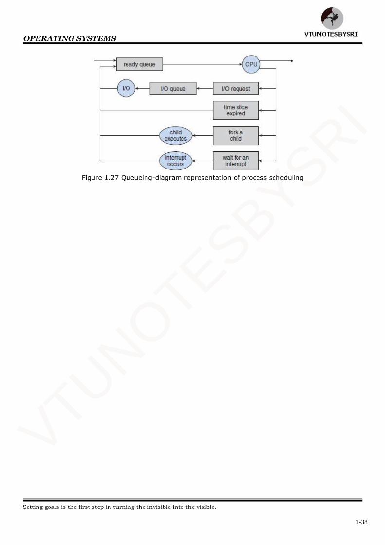
• When the process is executing, one of following events could occur (Figure 1.27):
1) The process could issue an I/0 request and then be placed in an I/0 queue.
2) The process could create a new subprocess and wait for the subprocess's termination.
3) The process could be interrupted and put back in the ready-queue.
Figure 1.26 The ready-queue and various I/O device-queues
VTUNOTESBYSRI
It does not matter how slowly you go as long as you do not stop.
OPERATING SYSTEMS
1-38
Figure 1.27 Queueing-diagram representation of process scheduling
VTUNOTESBYSRI
Setting goals is the first step in turning the invisible into the visible.
OPERATING SYSTEMS
1-39
1.25.2 Schedulers
• Three types of schedulers:
1) Long-term scheduler
2) Short-term scheduler and
3) Medium-term schedulers
Long-Term Scheduler Short-Term Scheduler
Also called job scheduler. Also called CPU scheduler.
Selects which processes should be brought
into the ready-queue.
Selects which process should be executed
next and allocates CPU.
Need to be invoked only when a process
leaves the system and therefore executes
much less frequently.
Need to be invoked to select a new process
for the CPU and therefore executes much
more frequently.
May be slow „,‟ minutes may separate the
creation of one new process and the next.
Must be fast „,‟ a process may execute for
only a few milliseconds.
Controls the degree of multiprogramming.
• Processes can be described as either:
1) I/O-bound Process Spends more time doing I/O operation than doing computations.
Many short CPU bursts.
2) CPU-bound Process Spends more time doing computations than doing I/O operation.
Few very long CPU bursts.
• Why long-term scheduler should select a good process mix of I/O-bound and CPU-bound processes ?
Ans: 1) If all processes are I/0 bound, then
i) Ready-queue will almost always be empty, and
ii) Short-term scheduler will have little to do.
2) If all processes are CPU bound, then
i) I/0 waiting queue will almost always be empty (devices will go unused) and
ii) System will be unbalanced.
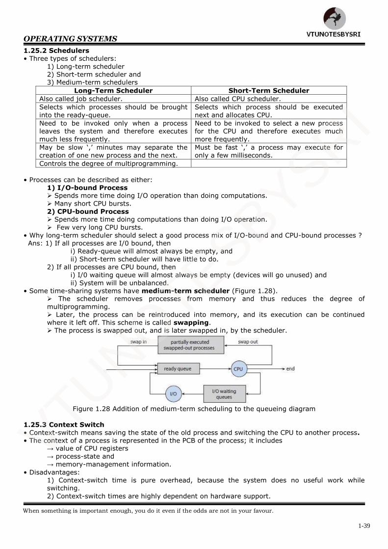
• Some time-sharing systems have medium-term scheduler (Figure 1.28). The scheduler removes processes from memory and thus reduces the degree of
multiprogramming.
Later, the process can be reintroduced into memory, and its execution can be continued
where it left off. This scheme is called swapping. The process is swapped out, and is later swapped in, by the scheduler.
Figure 1.28 Addition of medium-term scheduling to the queueing diagram
1.25.3 Context Switch
• Context-switch means saving the state of the old process and switching the CPU to another process.
• The context of a process is represented in the PCB of the process; it includes → value of CPU registers
→ process-state and
→ memory-management information.
• Disadvantages:
1) Context-switch time is pure overhead, because the system does no useful work while
switching.
2) Context-switch times are highly dependent on hardware support.
VTUNOTESBYSRI
When something is important enough, you do it even if the odds are not in your favour.
OPERATING SYSTEMS
1-40
1.26 Operations on Processes
1) Process Creation and
2) Process Termination
1.26.1 Process Creation
• A process may create a new process via a create-process system-call.
• The creating process is called a parent-process.
The new process created by the parent is called the child-process (Sub-process).
• OS identifies processes by pid (process identifier), which is typically an integer-number.
• A process needs following resources to accomplish the task:
→ CPU time
→ memory and
→ I/0 devices.
• Child-process may → get resources directly from the OS or
→ get resources of parent-process. This prevents any process from overloading the system.
• Two options exist when a process creates a new process:
1) The parent & the children execute concurrently.
2) The parent waits until all the children have terminated.
• Two options exist in terms of the address-space of the new process:
1) The child-process is a duplicate of the parent-process (it has the same program and data as
the parent).
2) The child-process has a new program loaded into it.
Process creation in UNIX
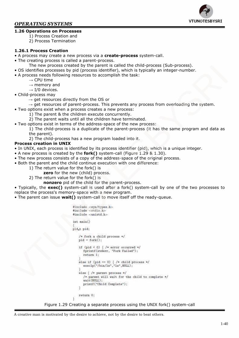
• In UNIX, each process is identified by its process identifier (pid), which is a unique integer.
• A new process is created by the fork() system-call (Figure 1.29 & 1.30).
• The new process consists of a copy of the address-space of the original process.
• Both the parent and the child continue execution with one difference:
1) The return value for the fork() is
zero for the new (child) process.
2) The return value for the fork() is
nonzero pid of the child for the parent-process.
• Typically, the exec() system-call is used after a fork() system-call by one of the two processes to
replace the process's memory-space with a new program.
• The parent can issue wait() system-call to move itself off the ready-queue.
Figure 1.29 Creating a separate process using the UNIX fork() system-call
VTUNOTESBYSRI
A creative man is motivated by the desire to achieve, not by the desire to beat others.
OPERATING SYSTEMS
1-41
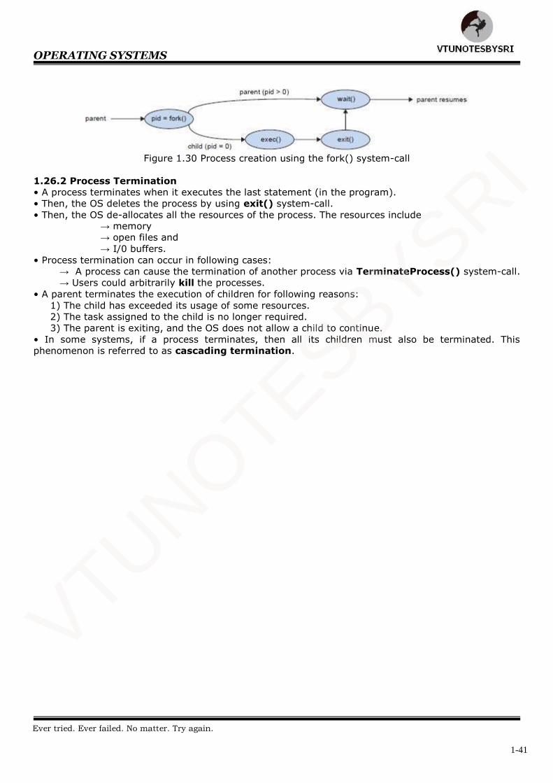
Figure 1.30 Process creation using the fork() system-call
1.26.2 Process Termination
• A process terminates when it executes the last statement (in the program).
• Then, the OS deletes the process by using exit() system-call.
• Then, the OS de-allocates all the resources of the process. The resources include → memory
→ open files and
→ I/0 buffers.
• Process termination can occur in following cases:
→ A process can cause the termination of another process via TerminateProcess() system-call.
→ Users could arbitrarily kill the processes.
• A parent terminates the execution of children for following reasons:
1) The child has exceeded its usage of some resources.
2) The task assigned to the child is no longer required.
3) The parent is exiting, and the OS does not allow a child to continue.
• In some systems, if a process terminates, then all its children must also be terminated. This
phenomenon is referred to as cascading termination.
VTUNOTESBYSRI
Ever tried. Ever failed. No matter. Try again.
OPERATING SYSTEMS
1-42
1.27 Inter Process Communication (IPC)
• Processes executing concurrently in the OS may be 1) Independent processes or
2) Co-operating processes.
1) A process is independent if
i) The process cannot affect or be affected by the other processes.
ii) The process does not share data with other processes.
2) A process is co-operating if
i) The process can affect or be affected by the other processes.
ii) The process shares data with other processes.
• Advantages of process co-operation:
1) Information Sharing Since many users may be interested in same piece of information (ex: shared file).
2) Computation Speedup
We must break the task into subtasks.
Each subtask should be executed in parallel with the other subtasks.
The speed can be improved only if computer has multiple processing elements such as
→ CPUs or
→ I/O channels.
3) Modularity Divide the system-functions into separate processes or threads.
4) Convenience
An individual user may work on many tasks at the same time.
For ex, a user may be editing, printing, and compiling in parallel.
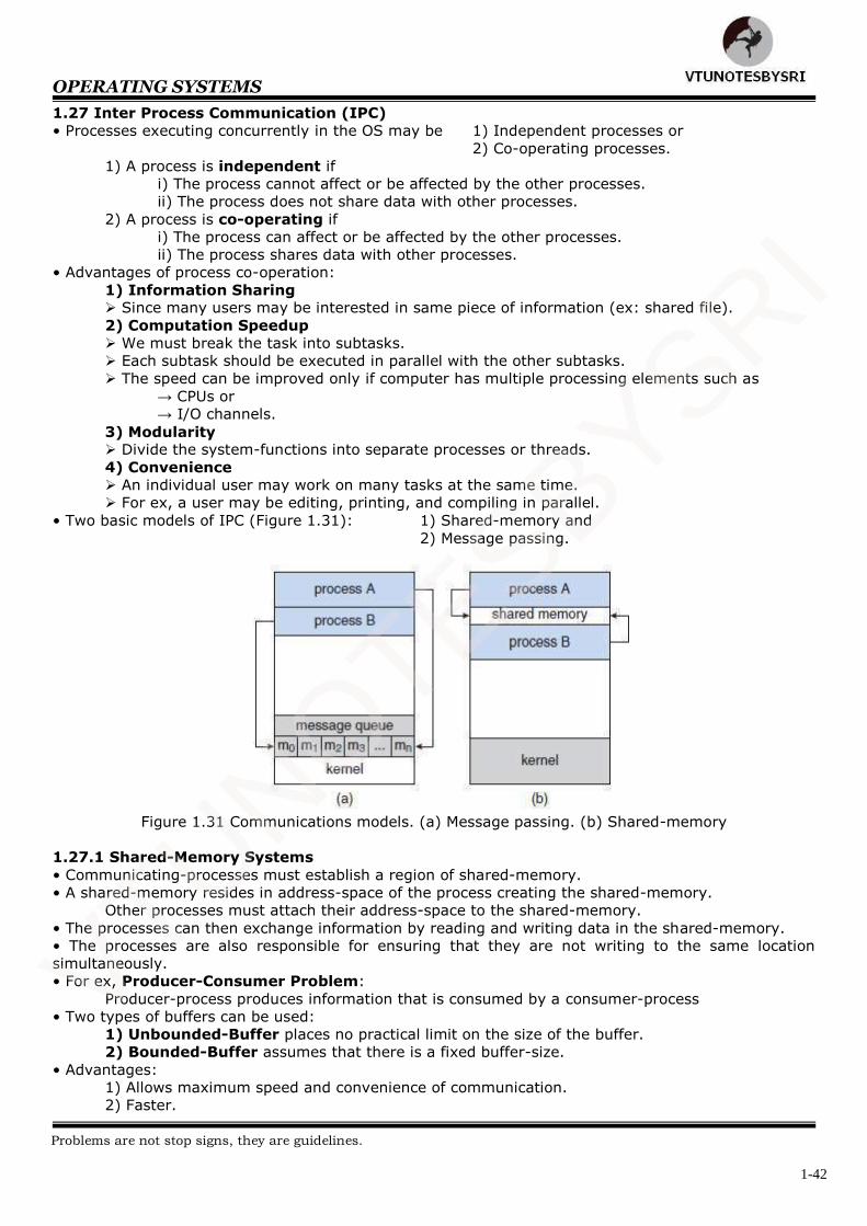
• Two basic models of IPC (Figure 1.31): 1) Shared-memory and
2) Message passing.
Figure 1.31 Communications models. (a) Message passing. (b) Shared-memory
1.27.1 Shared-Memory Systems
• Communicating-processes must establish a region of shared-memory.
• A shared-memory resides in address-space of the process creating the shared-memory.
Other processes must attach their address-space to the shared-memory.
• The processes can then exchange information by reading and writing data in the shared-memory.
• The processes are also responsible for ensuring that they are not writing to the same location
simultaneously.
• For ex, Producer-Consumer Problem:
Producer-process produces information that is consumed by a consumer-process
• Two types of buffers can be used:
1) Unbounded-Buffer places no practical limit on the size of the buffer.
2) Bounded-Buffer assumes that there is a fixed buffer-size.
• Advantages:
1) Allows maximum speed and convenience of communication.
2) Faster.
VTUNOTESBYSRI
Problems are not stop signs, they are guidelines.
OPERATING SYSTEMS
1-43
1.27.2 Message-Passing Systems
• These allow processes to communicate and to synchronize their actions without sharing the same
address-space.
• For example, a chat program used on the WWW.
• Messages can be of 2 types: 1) Fixed size or
2) Variable size.
1) If fixed-sized messages are used, the system-level implementation is simple. However, the programming task becomes more difficult.
2) If variable-sized messages are used, the system-level implementation is complex.
However, the programming task becomes simpler.
• A communication-link must exist between processes to communicate
• Three methods for implementing a link:
1) Direct or indirect communication.
2) Symmetric or asymmetric communication.
3) Automatic or explicit buffering.
• Two operations:
1) send(P,message): Send a message to process P.
2) receive(Q,message): Receive a message from process Q.
• Advantages:
1) Useful for exchanging smaller amounts of data („.‟ No conflicts need be avoided).
2) Easier to implement.
3) Useful in a distributed environment.
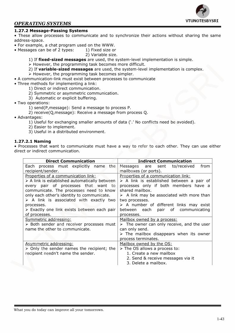
1.27.2.1 Naming
• Processes that want to communicate must have a way to refer to each other. They can use either
direct or indirect communication.
Direct Communication Indirect Communication
Each process must explicitly name the
recipient/sender.
Messages are sent to/received from
mailboxes (or ports).
Properties of a communication link: A link is established automatically between
every pair of processes that want to
communicate. The processes need to know
only each other‟s identity to communicate.
A link is associated with exactly two
processes. Exactly one link exists between each pair
of processes.
Properties of a communication link: A link is established between a pair of
processes only if both members have a
shared mailbox. A link may be associated with more than
two processes. A number of different links may exist
between each pair of communicating
processes.
Symmetric addressing: Both sender and receiver processes must
name the other to communicate.
Mailbox owned by a process: The owner can only receive, and the user
can only send. The mailbox disappears when its owner
process terminates.
Asymmetric addressing: Only the sender names the recipient; the
recipient needn't name the sender.
Mailbox owned by the OS: The OS allows a process to:
1. Create a new mailbox
2. Send & receive messages via it
3. Delete a mailbox. VTUNOTESBYSRI
What you do today can improve all your tomorrows.
OPERATING SYSTEMS
1-44
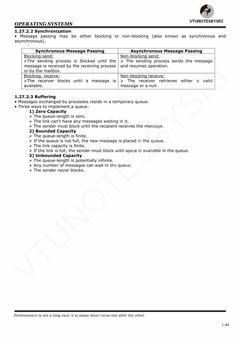
1.27.2.2 Synchronization
• Message passing may be either blocking or non-blocking (also known as synchronous and
asynchronous).
Synchronous Message Passing Asynchronous Message Passing
Blocking send: The sending process is blocked until the
message is received by the receiving process
or by the mailbox.
Non-blocking send: The sending process sends the message
and resumes operation.
Blocking receive: The receiver blocks until a message is
available.
Non-blocking receive: The receiver retrieves either a valid
message or a null.
1.27.2.3 Buffering
• Messages exchanged by processes reside in a temporary queue.
• Three ways to implement a queue:
1) Zero Capacity The queue-length is zero.
The link can't have any messages waiting in it.
The sender must block until the recipient receives the message.
2) Bounded Capacity The queue-length is finite.
If the queue is not full, the new message is placed in the queue.
The link capacity is finite.
If the link is full, the sender must block until space is available in the queue.
3) Unbounded Capacity
The queue-length is potentially infinite.
Any number of messages can wait in the queue.
The sender never blocks.
VTUNOTESBYSRI
Perseverance is not a long race; it is many short races one after the other.
OPERATING SYSTEMS
2-1
MODULE 2: MULTI-THREADED PROGRAMMING
PROCESS SCHEDULING
PROCESS SYNCHRONIZATION
2.1 Multi-Threaded Programming
2.1.1 Motivation
2.1.2 Benefits
2.2 Multi-Threading Models
2.2.1 Many-to-One Model
2.2.2 One-to-One Model
2.2.3 Many-to-Many Model
2.3 Thread Libraries
2.3.1 Pthreads
2.3.2 Java Threads
2.4 Threading Issues
2.4.1 fork() and exec() System-calls
2.4.2 Thread Cancellation
2.4.3 Signal Handling
2.4.4 Thread Pools
2.5 Basic Concepts
2.5.1 CPU-I/0 Burst Cycle
2.5.2 CPU Scheduler
2.5.3 CPU Scheduling
2.5.4 Dispatcher
2.6 Scheduling Criteria
2.7 Scheduling Algorithms
2.7.1 FCFS Scheduling
2.7.2 SJF Scheduling
2.7.3 Priority Scheduling
2.7.4 Round Robin Scheduling
2.7.5 Multilevel Queue Scheduling
2.7.6 Multilevel Feedback Queue Scheduling
2.8 Multiple-Processor Scheduling
2.8.1 Processor Affinity
2.8.2 Load Balancing
2.8.3 Symmetric Multithreading
2.9 Thread Scheduling
2.9.1 Contention Scope
2.9.2 Pthread Scheduling
2.10 Synchronization
2.11 The Critical-Section Problem
2.12 Peterson‘s Solution
2.13 Synchronization Hardware
2.13.1 Hardware based Solution for Critical-section Problem
2.13.2 Hardware instructions for solving critical-section problem
2.13.2.1 TestAndSet()
2.13.2.2 TestAndSet with Mutual Exclusion
2.13.2.3 Swap()
2.13.2.4 Bounded waiting Mutual Exclusion with TestAndSet()
VTUNOTESBYSRI
By failing to prepare, you are preparing to fail.
OPERATING SYSTEMS
2-2
2.14 Semaphores
2.14.1 Semaphore Usage
2.14.2 Semaphore Implementation
2.14.3 Deadlocks & Starvation
2.15 Classic Problems of Synchronization
2.15.1 Bounded-Buffer Problem
2.15.2 Readers-Writers Problem
2.15.3 Dining-Philosophers Problem
2.16 Monitors
2.16.1 Monitors Usage
2.16.2 Dining-Philosophers Solution Using Monitors
2.16.3 Implementing a Monitor using Semaphores
2.16.4 Resuming Processes within a Monitor
VTUNOTESBYSRI
Patience is a key element of success.
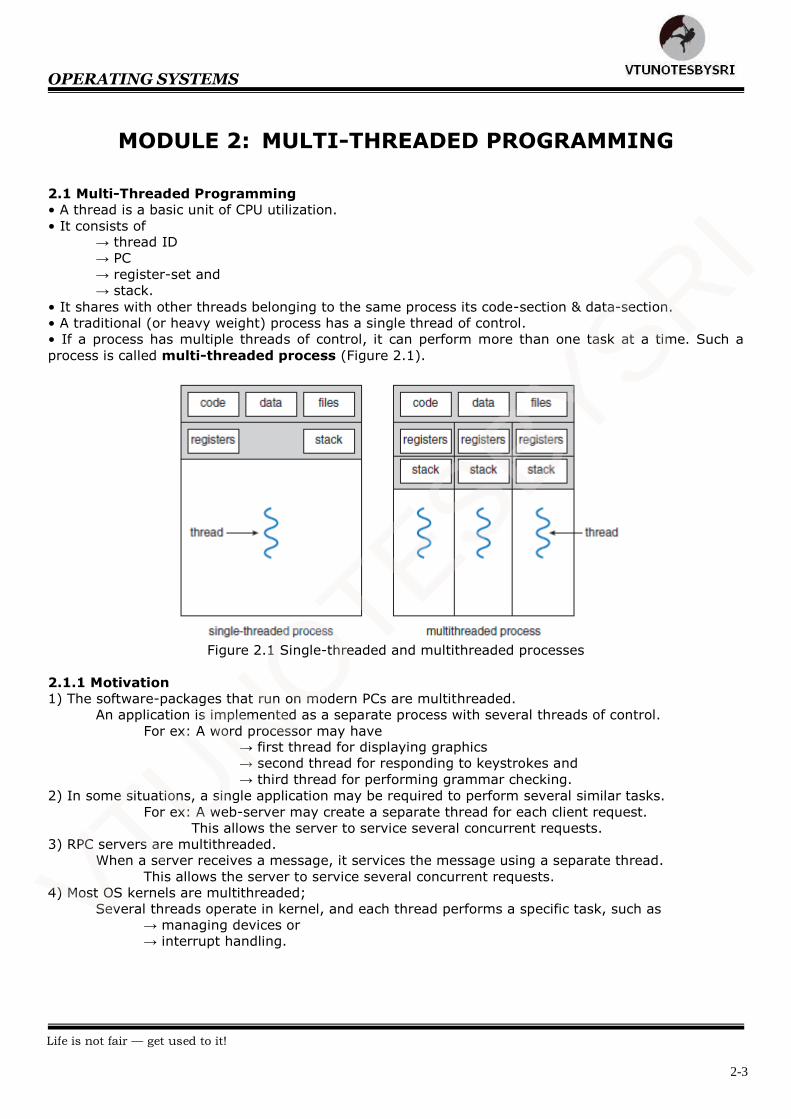
OPERATING SYSTEMS
2-3
MODULE 2: MULTI-THREADED PROGRAMMING
2.1 Multi-Threaded Programming
• A thread is a basic unit of CPU utilization.
• It consists of → thread ID
→ PC
→ register-set and
→ stack.
• It shares with other threads belonging to the same process its code-section & data-section.
• A traditional (or heavy weight) process has a single thread of control.
• If a process has multiple threads of control, it can perform more than one task at a time. Such a
process is called multi-threaded process (Figure 2.1).
Figure 2.1 Single-threaded and multithreaded processes
2.1.1 Motivation
1) The software-packages that run on modern PCs are multithreaded.
An application is implemented as a separate process with several threads of control.
For ex: A word processor may have → first thread for displaying graphics
→ second thread for responding to keystrokes and
→ third thread for performing grammar checking.
2) In some situations, a single application may be required to perform several similar tasks.
For ex: A web-server may create a separate thread for each client request.
This allows the server to service several concurrent requests.
3) RPC servers are multithreaded.
When a server receives a message, it services the message using a separate thread.
This allows the server to service several concurrent requests.
4) Most OS kernels are multithreaded;
Several threads operate in kernel, and each thread performs a specific task, such as
→ managing devices or
→ interrupt handling.
VTUNOTESBYSRI
Life is not fair — get used to it!
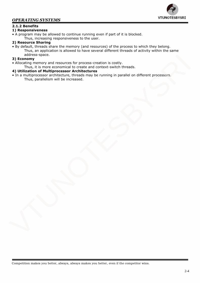
OPERATING SYSTEMS
2-4
2.1.2 Benefits
1) Responsiveness
• A program may be allowed to continue running even if part of it is blocked.
Thus, increasing responsiveness to the user.
2) Resource Sharing
• By default, threads share the memory (and resources) of the process to which they belong.
Thus, an application is allowed to have several different threads of activity within the same
address-space.
3) Economy
• Allocating memory and resources for process-creation is costly.
Thus, it is more economical to create and context-switch threads.
4) Utilization of Multiprocessor Architectures
• In a multiprocessor architecture, threads may be running in parallel on different processors.
Thus, parallelism will be increased.
VTUNOTESBYSRI
Competition makes you better, always, always makes you better, even if the competitor wins.
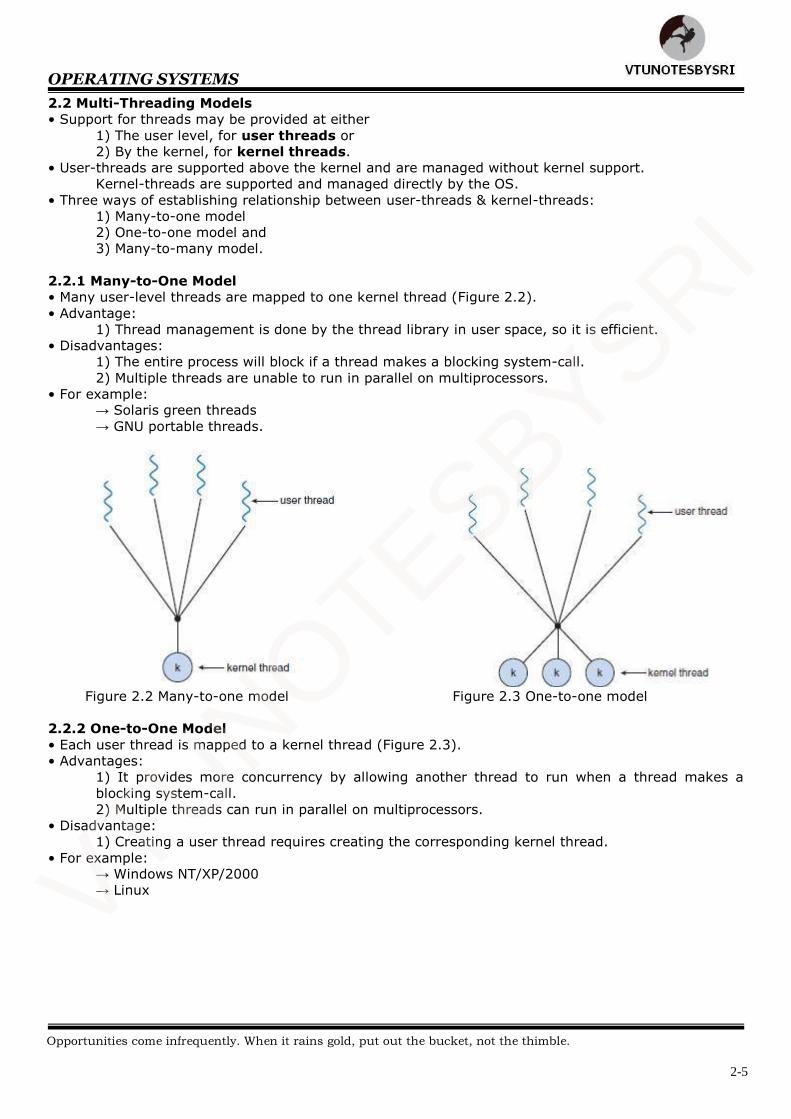
OPERATING SYSTEMS
2-5
2.2 Multi-Threading Models
• Support for threads may be provided at either
1) The user level, for user threads or
2) By the kernel, for kernel threads.
• User-threads are supported above the kernel and are managed without kernel support.
Kernel-threads are supported and managed directly by the OS.
• Three ways of establishing relationship between user-threads & kernel-threads:
1) Many-to-one model
2) One-to-one model and
3) Many-to-many model.
2.2.1 Many-to-One Model
• Many user-level threads are mapped to one kernel thread (Figure 2.2).
• Advantage:
1) Thread management is done by the thread library in user space, so it is efficient.
• Disadvantages:
1) The entire process will block if a thread makes a blocking system-call.
2) Multiple threads are unable to run in parallel on multiprocessors.
• For example: → Solaris green threads
→ GNU portable threads.
Figure 2.2 Many-to-one model Figure 2.3 One-to-one model
2.2.2 One-to-One Model
• Each user thread is mapped to a kernel thread (Figure 2.3).
• Advantages:
1) It provides more concurrency by allowing another thread to run when a thread makes a
blocking system-call.
2) Multiple threads can run in parallel on multiprocessors.
• Disadvantage:
1) Creating a user thread requires creating the corresponding kernel thread.
• For example: → Windows NT/XP/2000
→ Linux
VTUNOTESBYSRI
Opportunities come infrequently. When it rains gold, put out the bucket, not the thimble.
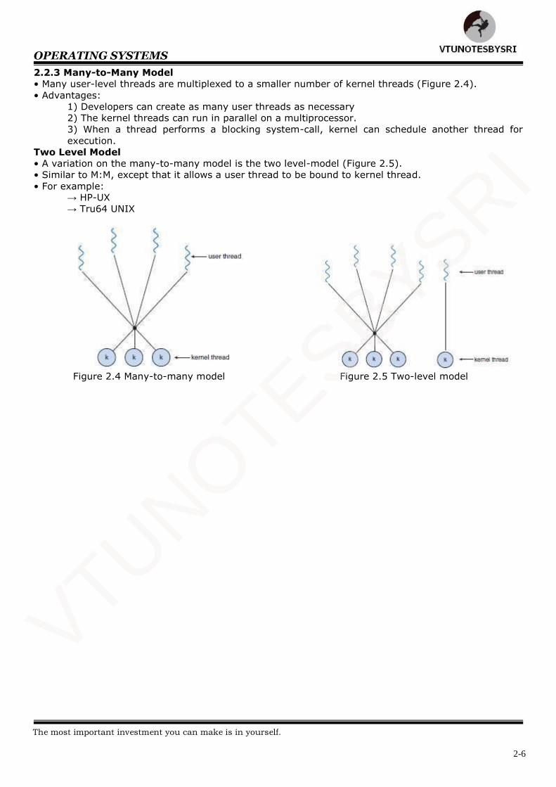
OPERATING SYSTEMS
2-6
2.2.3 Many-to-Many Model
• Many user-level threads are multiplexed to a smaller number of kernel threads (Figure 2.4).
• Advantages:
1) Developers can create as many user threads as necessary
2) The kernel threads can run in parallel on a multiprocessor.
3) When a thread performs a blocking system-call, kernel can schedule another thread for
execution.
Two Level Model
• A variation on the many-to-many model is the two level-model (Figure 2.5).
• Similar to M:M, except that it allows a user thread to be bound to kernel thread.
• For example: → HP-UX
→ Tru64 UNIX
Figure 2.4 Many-to-many model Figure 2.5 Two-level model
VTUNOTESBYSRI
The most important investment you can make is in yourself.
OPERATING SYSTEMS
2-7
2.3 Thread Libraries
• It provides the programmer with an API for the creation and management of threads.
• Two ways of implementation:
1) First Approach Provides a library entirely in user space with no kernel support.
All code and data structures for the library exist in the user space.
2) Second Approach Implements a kernel-level library supported directly by the OS.
Code and data structures for the library exist in kernel space.
• Three main thread libraries: 1) POSIX Pthreads
2) Win32 and
3) Java.
2.3.1 Pthreads
• This is a POSIX standard API for thread creation and synchronization.
• This is a specification for thread-behavior, not an implementation.
• OS designers may implement the specification in any way they wish.
• Commonly used in: UNIX and Solaris.
2.3.2 Java Threads
• Threads are the basic model of program-execution in → Java program and
→ Java language.
• The API provides a rich set of features for the creation and management of threads.
• All Java programs comprise at least a single thread of control.
• Two techniques for creating threads:
1) Create a new class that is derived from the Thread class and override its run() method.
2) Define a class that implements the Runnable interface. The Runnable interface is defined as
follows:
VTUNOTESBYSRI
When I do something, it is all about self-discovery. I want to learn and discover my own limits.
OPERATING SYSTEMS
2-8
2.4 Threading Issues
2.4.1 fork() and exec() System-calls
• fork() is used to create a separate, duplicate process.
• If one thread in a program calls fork(), then
1) Some systems duplicates all threads and
2) Other systems duplicate only the thread that invoked the fork().
• If a thread invokes the exec(), the program specified in the parameter to exec() will replace the
entire process including all threads.
2.4.2 Thread Cancellation
• This is the task of terminating a thread before it has completed.
• Target thread is the thread that is to be canceled
• Thread cancellation occurs in two different cases:
1) Asynchronous cancellation: One thread immediately terminates the target thread.
2) Deferred cancellation: The target thread periodically checks whether it should be terminated.
2.4.3 Signal Handling
• In UNIX, a signal is used to notify a process that a particular event has occurred.
• All signals follow this pattern:
1) A signal is generated by the occurrence of a certain event.
2) A generated signal is delivered to a process.
3) Once delivered, the signal must be handled.
• A signal handler is used to process signals.
• A signal may be received either synchronously or asynchronously, depending on the source.
1) Synchronous signals Delivered to the same process that performed the operation causing the signal.
E.g. illegal memory access and division by 0.
2) Asynchronous signals Generated by an event external to a running process.
E.g. user terminating a process with specific keystrokes <ctrl><c>.
• Every signal can be handled by one of two possible handlers:
1) A Default Signal Handler Run by the kernel when handling the signal.
2) A User-defined Signal Handler Overrides the default signal handler.
• In single-threaded programs, delivering signals is simple.
In multithreaded programs, delivering signals is more complex. Then, the following options exist:
1) Deliver the signal to the thread to which the signal applies.
2) Deliver the signal to every thread in the process.
3) Deliver the signal to certain threads in the process.
4) Assign a specific thread to receive all signals for the process.
2.4.4 Thread Pools
• The basic idea is to
→ create a no. of threads at process-startup and
→ place the threads into a pool (where they sit and wait for work).
• Procedure:
1) When a server receives a request, it awakens a thread from the pool.
2) If any thread is available, the request is passed to it for service.
3) Once the service is completed, the thread returns to the pool.
• Advantages:
1) Servicing a request with an existing thread is usually faster than waiting to create a thread.
2) The pool limits the no. of threads that exist at any one point.
• No. of threads in the pool can be based on factors such as → no. of CPUs
→ amount of memory and
→ expected no. of concurrent client-requests.
VTUNOTESBYSRI
Move fast and break things. Unless you are breaking stuff, you are not moving fast enough.
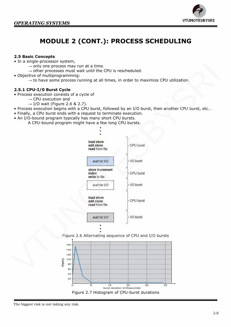
OPERATING SYSTEMS
2-9
MODULE 2 (CONT.): PROCESS SCHEDULING
2.5 Basic Concepts
• In a single-processor system,
→ only one process may run at a time.
→ other processes must wait until the CPU is rescheduled.
• Objective of multiprogramming: → to have some process running at all times, in order to maximize CPU utilization.
2.5.1 CPU-I/0 Burst Cycle
• Process execution consists of a cycle of → CPU execution and
→ I/O wait (Figure 2.6 & 2.7).
• Process execution begins with a CPU burst, followed by an I/O burst, then another CPU burst, etc…
• Finally, a CPU burst ends with a request to terminate execution.
• An I/O-bound program typically has many short CPU bursts.
A CPU-bound program might have a few long CPU bursts.
Figure 2.6 Alternating sequence of CPU and I/O bursts
Figure 2.7 Histogram of CPU-burst durations
VTUNOTESBYSRI
The biggest risk is not taking any risk.
OPERATING SYSTEMS
2-10
2.5.2 CPU Scheduler
• This scheduler
→ selects a waiting-process from the ready-queue and
→ allocates CPU to the waiting-process.
• The ready-queue could be a FIFO, priority queue, tree and list.
• The records in the queues are generally process control blocks (PCBs) of the processes.
2.5.3 CPU Scheduling
• Four situations under which CPU scheduling decisions take place:
1) When a process switches from the running state to the waiting state.
For ex; I/O request.
2) When a process switches from the running state to the ready state.
For ex: when an interrupt occurs.
3) When a process switches from the waiting state to the ready state.
For ex: completion of I/O.
4) When a process terminates.
• Scheduling under 1 and 4 is non-preemptive.
Scheduling under 2 and 3 is preemptive.
Non Preemptive Scheduling
• Once the CPU has been allocated to a process, the process keeps the CPU until it releases the CPU
either → by terminating or
→ by switching to the waiting state.
Preemptive Scheduling
• This is driven by the idea of prioritized computation.
• Processes that are runnable may be temporarily suspended
• Disadvantages:
1) Incurs a cost associated with access to shared-data.
2) Affects the design of the OS kernel.
2.5.4 Dispatcher
• It gives control of the CPU to the process selected by the short-term scheduler.
• The function involves:
1) Switching context
2) Switching to user mode &
3) Jumping to the proper location in the user program to restart that program.
• It should be as fast as possible, since it is invoked during every process switch.
• Dispatch latency means the time taken by the dispatcher to → stop one process and
→ start another running.
VTUNOTESBYSRI
Find that thing you are super passionate about.
OPERATING SYSTEMS
2-11
2.6 Scheduling Criteria
• Different CPU-scheduling algorithms
→ have different properties and
→ may favor one class of processes over another.
• Criteria to compare CPU-scheduling algorithms:
1) CPU Utilization We must keep the CPU as busy as possible.
In a real system, it ranges from 40% to 90%.
2) Throughput Number of processes completed per time unit.
For long processes, throughput may be 1 process per hour;
For short transactions, throughput might be 10 processes per second.
3) Turnaround Time The interval from the time of submission of a process to the time of completion.
Turnaround time is the sum of the periods spent
→ waiting to get into memory
→ waiting in the ready-queue
→ executing on the CPU and
→ doing I/O.
4) Waiting Time The amount of time that a process spends waiting in the ready-queue.
5) Response Time
The time from the submission of a request until the first response is produced.
The time is generally limited by the speed of the output device.
• We want
→ to maximize CPU utilization and throughput and
→ to minimize turnaround time, waiting time, and response time.
VTUNOTESBYSRI
Life is too short to spend your time avoiding failure.
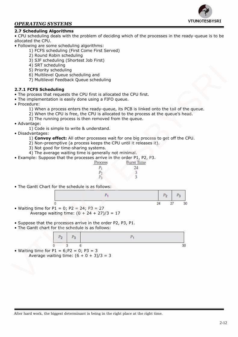
OPERATING SYSTEMS
2-12
2.7 Scheduling Algorithms
• CPU scheduling deals with the problem of deciding which of the processes in the ready-queue is to be
allocated the CPU.
• Following are some scheduling algorithms:
1) FCFS scheduling (First Come First Served)
2) Round Robin scheduling
3) SJF scheduling (Shortest Job First)
4) SRT scheduling
5) Priority scheduling
6) Multilevel Queue scheduling and
7) Multilevel Feedback Queue scheduling
2.7.1 FCFS Scheduling
• The process that requests the CPU first is allocated the CPU first.
• The implementation is easily done using a FIFO queue.
• Procedure:
1) When a process enters the ready-queue, its PCB is linked onto the tail of the queue.
2) When the CPU is free, the CPU is allocated to the process at the queue‘s head.
3) The running process is then removed from the queue.
• Advantage:
1) Code is simple to write & understand.
• Disadvantages:
1) Convoy effect: All other processes wait for one big process to get off the CPU.
2) Non-preemptive (a process keeps the CPU until it releases it).
3) Not good for time-sharing systems.
4) The average waiting time is generally not minimal.
• Example: Suppose that the processes arrive in the order P1, P2, P3.
• The Gantt Chart for the schedule is as follows:
• Waiting time for P1 = 0; P2 = 24; P3 = 27
Average waiting time: (0 + 24 + 27)/3 = 17
• Suppose that the processes arrive in the order P2, P3, P1.
• The Gantt chart for the schedule is as follows:
• Waiting time for P1 = 6;P2 = 0; P3 = 3
Average waiting time: (6 + 0 + 3)/3 = 3
VTUNOTESBYSRI
After hard work, the biggest determinant is being in the right place at the right time.
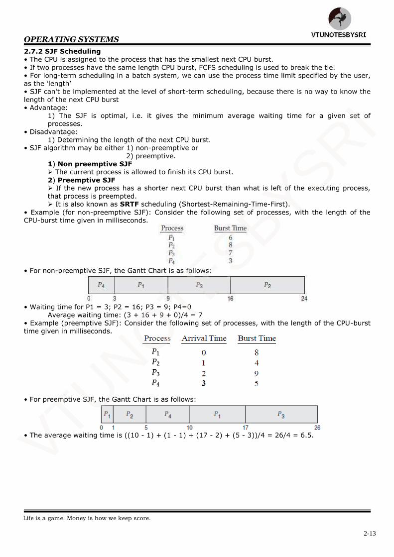
OPERATING SYSTEMS
2-13
2.7.2 SJF Scheduling
• The CPU is assigned to the process that has the smallest next CPU burst.
• If two processes have the same length CPU burst, FCFS scheduling is used to break the tie.
• For long-term scheduling in a batch system, we can use the process time limit specified by the user,
as the ‗length‘
• SJF can't be implemented at the level of short-term scheduling, because there is no way to know the
length of the next CPU burst
• Advantage:
1) The SJF is optimal, i.e. it gives the minimum average waiting time for a given set of
processes.
• Disadvantage:
1) Determining the length of the next CPU burst.
• SJF algorithm may be either 1) non-preemptive or
2) preemptive.
1) Non preemptive SJF The current process is allowed to finish its CPU burst.
2) Preemptive SJF If the new process has a shorter next CPU burst than what is left of the executing process,
that process is preempted. It is also known as SRTF scheduling (Shortest-Remaining-Time-First).
• Example (for non-preemptive SJF): Consider the following set of processes, with the length of the
CPU-burst time given in milliseconds.
• For non-preemptive SJF, the Gantt Chart is as follows:
• Waiting time for P1 = 3; P2 = 16; P3 = 9; P4=0
Average waiting time: (3 + 16 + 9 + 0)/4 = 7
• Example (preemptive SJF): Consider the following set of processes, with the length of the CPU-burst
time given in milliseconds.
• For preemptive SJF, the Gantt Chart is as follows:
• The average waiting time is ((10 - 1) + (1 - 1) + (17 - 2) + (5 - 3))/4 = 26/4 = 6.5.
VTUNOTESBYSRI
Life is a game. Money is how we keep score.
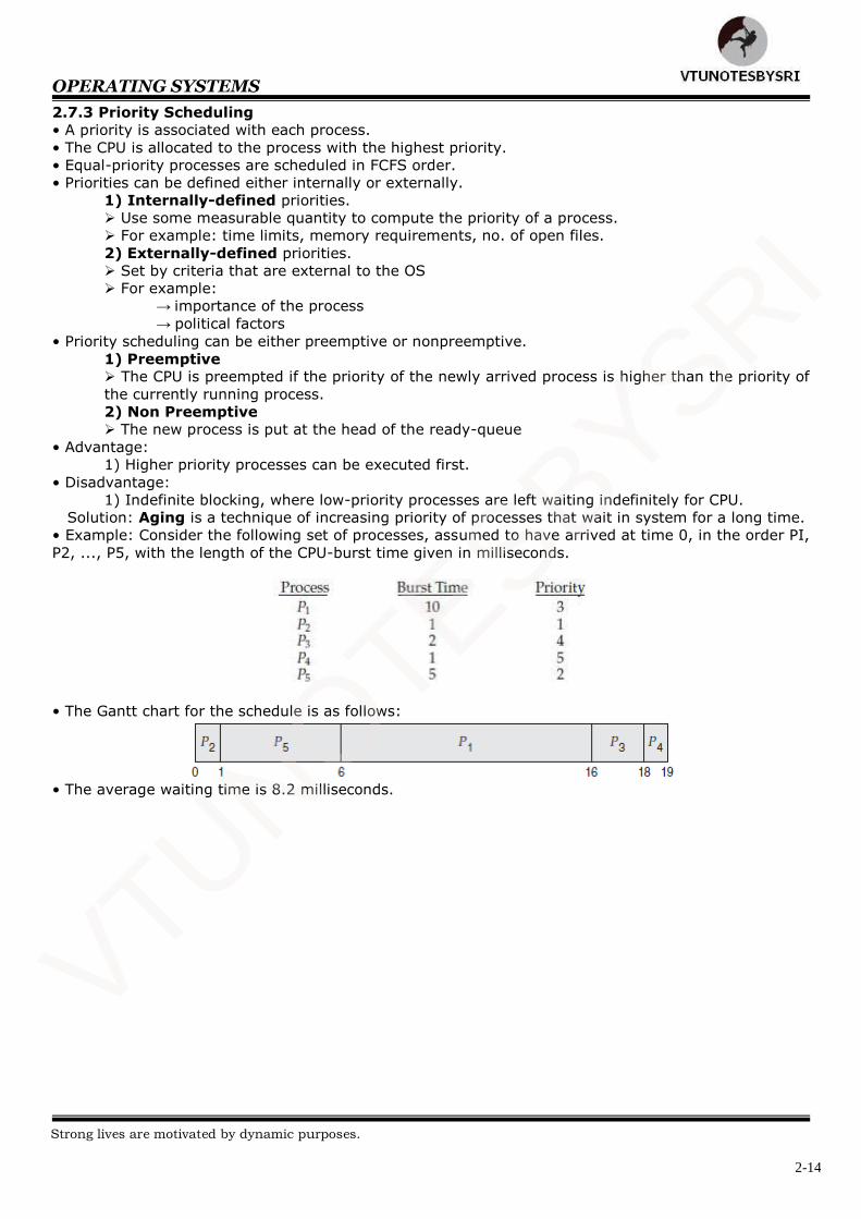
OPERATING SYSTEMS
2-14
2.7.3 Priority Scheduling
• A priority is associated with each process.
• The CPU is allocated to the process with the highest priority.
• Equal-priority processes are scheduled in FCFS order.
• Priorities can be defined either internally or externally.
1) Internally-defined priorities.
Use some measurable quantity to compute the priority of a process.
For example: time limits, memory requirements, no. of open files.
2) Externally-defined priorities.
Set by criteria that are external to the OS
For example:
→ importance of the process
→ political factors
• Priority scheduling can be either preemptive or nonpreemptive.
1) Preemptive The CPU is preempted if the priority of the newly arrived process is higher than the priority of
the currently running process.
2) Non Preemptive
The new process is put at the head of the ready-queue
• Advantage:
1) Higher priority processes can be executed first.
• Disadvantage:
1) Indefinite blocking, where low-priority processes are left waiting indefinitely for CPU.
Solution: Aging is a technique of increasing priority of processes that wait in system for a long time.
• Example: Consider the following set of processes, assumed to have arrived at time 0, in the order PI,
P2, ..., P5, with the length of the CPU-burst time given in milliseconds.
• The Gantt chart for the schedule is as follows:
• The average waiting time is 8.2 milliseconds.
VTUNOTESBYSRI
Strong lives are motivated by dynamic purposes.
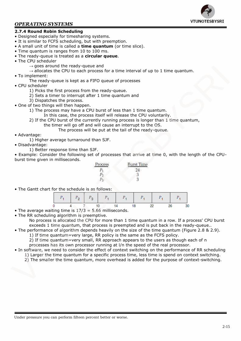
OPERATING SYSTEMS
2-15
2.7.4 Round Robin Scheduling
• Designed especially for timesharing systems.
• It is similar to FCFS scheduling, but with preemption.
• A small unit of time is called a time quantum (or time slice).
• Time quantum is ranges from 10 to 100 ms.
• The ready-queue is treated as a circular queue.
• The CPU scheduler → goes around the ready-queue and
→ allocates the CPU to each process for a time interval of up to 1 time quantum.
• To implement:
The ready-queue is kept as a FIFO queue of processes
• CPU scheduler
1) Picks the first process from the ready-queue.
2) Sets a timer to interrupt after 1 time quantum and
3) Dispatches the process.
• One of two things will then happen.
1) The process may have a CPU burst of less than 1 time quantum.
In this case, the process itself will release the CPU voluntarily.
2) If the CPU burst of the currently running process is longer than 1 time quantum,
the timer will go off and will cause an interrupt to the OS.
The process will be put at the tail of the ready-queue.
• Advantage:
1) Higher average turnaround than SJF.
• Disadvantage:
1) Better response time than SJF.
• Example: Consider the following set of processes that arrive at time 0, with the length of the CPU-
burst time given in milliseconds.
• The Gantt chart for the schedule is as follows:
• The average waiting time is 17/3 = 5.66 milliseconds.
• The RR scheduling algorithm is preemptive.
No process is allocated the CPU for more than 1 time quantum in a row. If a process' CPU burst
exceeds 1 time quantum, that process is preempted and is put back in the ready-queue..
• The performance of algorithm depends heavily on the size of the time quantum (Figure 2.8 & 2.9).
1) If time quantum=very large, RR policy is the same as the FCFS policy.
2) If time quantum=very small, RR approach appears to the users as though each of n
processes has its own processor running at l/n the speed of the real processor.
• In software, we need to consider the effect of context switching on the performance of RR scheduling
1) Larger the time quantum for a specific process time, less time is spend on context switching.
2) The smaller the time quantum, more overhead is added for the purpose of context-switching.
VTUNOTESBYSRI
Under pressure you can perform fifteen percent better or worse.
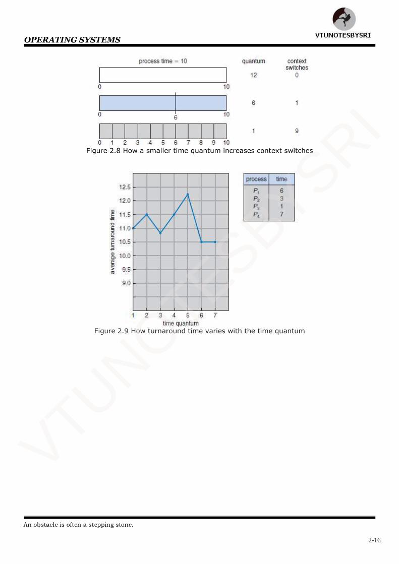
OPERATING SYSTEMS
2-16
Figure 2.8 How a smaller time quantum increases context switches
Figure 2.9 How turnaround time varies with the time quantum
VTUNOTESBYSRI
An obstacle is often a stepping stone.
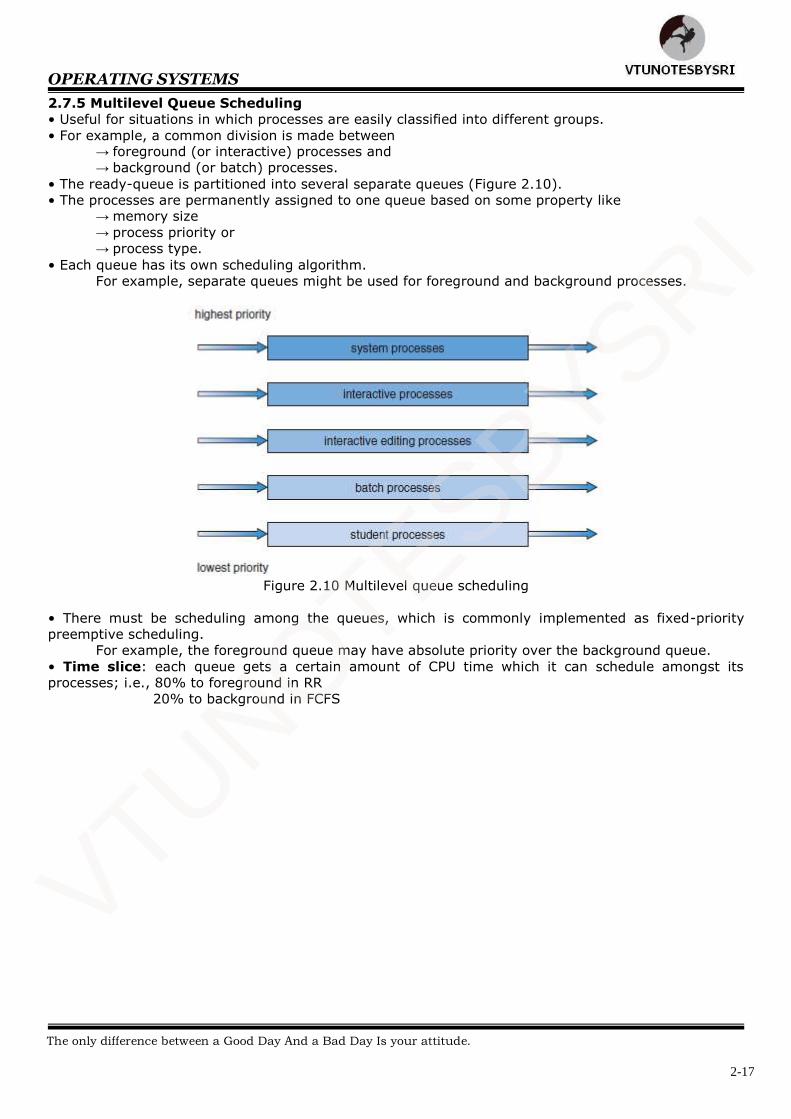
OPERATING SYSTEMS
2-17
2.7.5 Multilevel Queue Scheduling
• Useful for situations in which processes are easily classified into different groups.
• For example, a common division is made between → foreground (or interactive) processes and
→ background (or batch) processes.
• The ready-queue is partitioned into several separate queues (Figure 2.10).
• The processes are permanently assigned to one queue based on some property like → memory size
→ process priority or
→ process type.
• Each queue has its own scheduling algorithm.
For example, separate queues might be used for foreground and background processes.
Figure 2.10 Multilevel queue scheduling
• There must be scheduling among the queues, which is commonly implemented as fixed-priority
preemptive scheduling.
For example, the foreground queue may have absolute priority over the background queue.
• Time slice: each queue gets a certain amount of CPU time which it can schedule amongst its
processes; i.e., 80% to foreground in RR
20% to background in FCFS
VTUNOTESBYSRI
The only difference between a Good Day And a Bad Day Is your attitude.
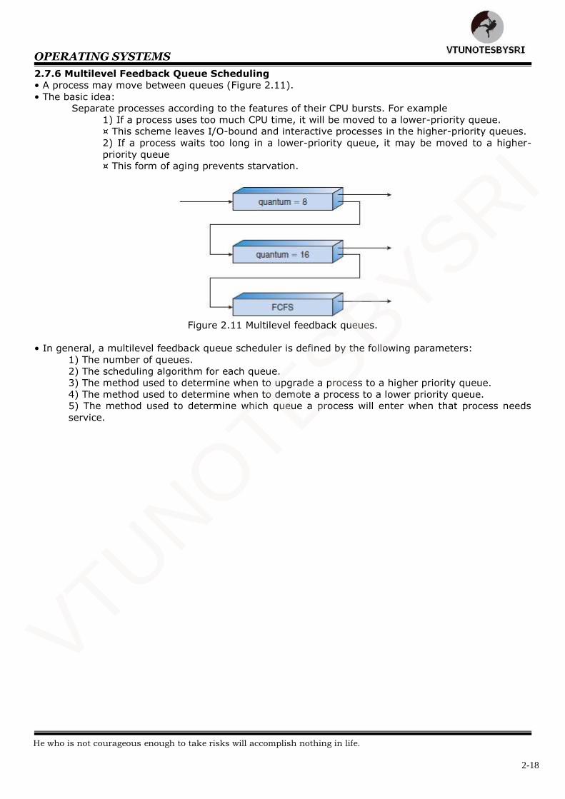
OPERATING SYSTEMS
2-18
2.7.6 Multilevel Feedback Queue Scheduling
• A process may move between queues (Figure 2.11).
• The basic idea:
Separate processes according to the features of their CPU bursts. For example
1) If a process uses too much CPU time, it will be moved to a lower-priority queue.
¤ This scheme leaves I/O-bound and interactive processes in the higher-priority queues.
2) If a process waits too long in a lower-priority queue, it may be moved to a higher-
priority queue
¤ This form of aging prevents starvation.
Figure 2.11 Multilevel feedback queues.
• In general, a multilevel feedback queue scheduler is defined by the following parameters:
1) The number of queues.
2) The scheduling algorithm for each queue.
3) The method used to determine when to upgrade a process to a higher priority queue.
4) The method used to determine when to demote a process to a lower priority queue.
5) The method used to determine which queue a process will enter when that process needs
service.
VTUNOTESBYSRI
He who is not courageous enough to take risks will accomplish nothing in life.
OPERATING SYSTEMS
2-19
2.8 Multiple Processor Scheduling
• If multiple CPUs are available, the scheduling problem becomes more complex.
• Two approaches:
1) Asymmetric Multiprocessing The basic idea is:
i) A master server is a single processor responsible for all scheduling decisions, I/O
processing and other system activities.
ii) The other processors execute only user code. Advantage:
i) This is simple because only one processor accesses the system data structures,
reducing the need for data sharing.
2) Symmetric Multiprocessing The basic idea is:
i) Each processor is self-scheduling.
ii) To do scheduling, the scheduler for each processor
i. Examines the ready-queue and
ii. Selects a process to execute. Restriction: We must ensure that two processors do not choose the same process and that
processes are not lost from the queue.
2.8.1 Processor Affinity
• In SMP systems,
1) Migration of processes from one processor to another are avoided and
2) Instead processes are kept running on same processor. This is known as processor affinity.
• Two forms:
1) Soft Affinity
When an OS try to keep a process on one processor because of policy, but cannot guarantee
it will happen. It is possible for a process to migrate between processors.
2) Hard Affinity When an OS have the ability to allow a process to specify that it is not to migrate to other
processors. Eg: Solaris OS
2.8.2 Load Balancing
• This attempts to keep the workload evenly distributed across all processors in an SMP system.
• Two approaches:
1) Push Migration A specific task periodically checks the load on each processor and if it finds an imbalance, it
evenly distributes the load to idle processors.
2) Pull Migration
An idle processor pulls a waiting task from a busy processor.
2.8.3 Symmetric Multithreading
• The basic idea:
1) Create multiple logical processors on the same physical processor.
2) Present a view of several logical processors to the OS.
• Each logical processor has its own architecture state, which includes general-purpose and machine-
state registers.
• Each logical processor is responsible for its own interrupt handling.
• SMT is a feature provided in hardware, not software.
VTUNOTESBYSRI
Keep your face to the sunshine and you cannot see the shadows.
OPERATING SYSTEMS
2-20
2.9 Thread Scheduling
• On OSs, it is kernel-level threads but not processes that are being scheduled by the OS.
• User-level threads are managed by a thread library, and the kernel is unaware of them.
• To run on a CPU, user-level threads must be mapped to an associated kernel-level thread.
2.9.1 Contention Scope
• Two approaches:
1) Process-Contention scope On systems implementing the many-to-one and many-to-many models, the thread library
schedules user-level threads to run on an available LWP. Competition for the CPU takes place among threads belonging to the same process.
2) System-Contention scope The process of deciding which kernel thread to schedule on the CPU.
Competition for the CPU takes place among all threads in the system.
Systems using the one-to-one model schedule threads using only SCS.
2.9.2 Pthread Scheduling
• Pthread API that allows specifying either PCS or SCS during thread creation.
• Pthreads identifies the following contention scope values:
1) PTHREAD_SCOPEJPROCESS schedules threads using PCS scheduling.
2) PTHREAD-SCOPE_SYSTEM schedules threads using SCS scheduling.
• Pthread IPC provides following two functions for getting and setting the contention scope policy:
1) pthread_attr_setscope(pthread_attr_t *attr, int scope)
2) pthread_attr_getscope(pthread_attr_t *attr, int *scope)
VTUNOTESBYSRI
Formal education will make you a living. Self education will make you a fortune.
OPERATING SYSTEMS
2-21
Exercise Problems
1) Consider the following set of processes, with length of the CPU burst time given in milliseconds:
Process Arrival Time Burst Time Priority
P1 0 10 3
P2 0 1 1
P3 3 2 3
P4 5 1 4
P5 10 5 2
(i) Draw four Gantt charts illustrating the execution of these processing using FCFS, SJF, a non
preemptive priority and RR (Quantum=2) scheduling.
(ii) What is the turn around time of each process for each scheduling algorithm in (i).
(iii) What is waiting time of each process in (i)
Solution:
(i) FCFS:
Average waiting time = (0+10+8+8+4)/5 = 6
Average turnaround time = (10+11+13+14+19)/5 = 13.4
(ii) SJF (non-preemptive):
Average waiting time = (1+0+9+6+4)/5 = 4
Average turnaround time = (11+1+14+12+19)/5 = 11.4
SJF (preemptive):
Average waiting time = (4+0+0+0+4)/5 = 1.6
Average turnaround time = (14+1+5+6+19)/5 = 9
(iii) Non-preemptive, Priority:
Average waiting time = (1+0+13+13+1)/5 = 5.6
Average turnaround time = (11+1+18+19+16)/5 = 13
(iv) Round Robin (Quantum=2):
Average waiting time = (8+2+0+0+4)/5 = 2.8
Average turnaround time = (18+3+5+6+19)/5 = 10.2
VTUNOTESBYSRI
The difference between ordinary and extraordinary is that little extra.
OPERATING SYSTEMS
2-22
2) Consider the following set of process with arrival time:
i) Draw grant chart using FCFS, SJF preemptive and non preemptive scheduling.
ii) Calculate the average waiting and turnaround time for each process of the scheduling
algorithm.
Process Arrival Time Burst Time
P1 0 10
P2 0 1
P3 1 2
P4 2 4
P5 2 3
Solution:
(i) FCFS:
Average waiting time = (0+10+10+11+15)/5 = 9.2
Average turnaround time = (10+11+13+17+20)/5 = 14.2
(ii) SJF (non-preemptive):
Average waiting time = (10+0+0+4+1)/5 = 3
Average turnaround time = (20+1+3+10+6)/5 = 8
(iii) SJF (preemptive):
Average waiting time = (10+0+0+4+1)/5 = 3
Average turnaround time = (20+1+3+10+6)/5 = 8
VTUNOTESBYSRI
Real leaders are ordinary people with extraordinary determination.
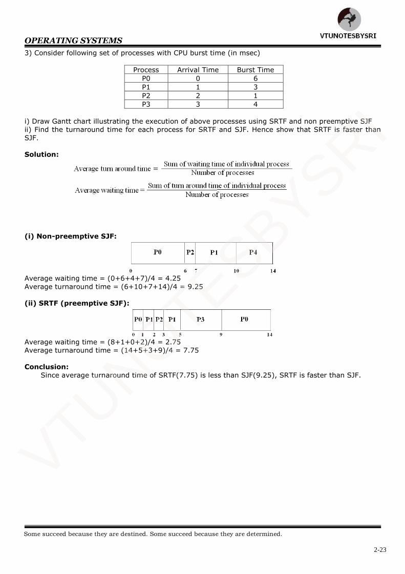
OPERATING SYSTEMS
2-23
3) Consider following set of processes with CPU burst time (in msec)
Process Arrival Time Burst Time
P0 0 6
P1 1 3
P2 2 1
P3 3 4
i) Draw Gantt chart illustrating the execution of above processes using SRTF and non preemptive SJF
ii) Find the turnaround time for each process for SRTF and SJF. Hence show that SRTF is faster than
SJF.
Solution:
(i) Non-preemptive SJF:
Average waiting time = (0+6+4+7)/4 = 4.25
Average turnaround time = (6+10+7+14)/4 = 9.25
(ii) SRTF (preemptive SJF):
Average waiting time = (8+1+0+2)/4 = 2.75
Average turnaround time = (14+5+3+9)/4 = 7.75
Conclusion:
Since average turnaround time of SRTF(7.75) is less than SJF(9.25), SRTF is faster than SJF.
VTUNOTESBYSRI
Some succeed because they are destined. Some succeed because they are determined.
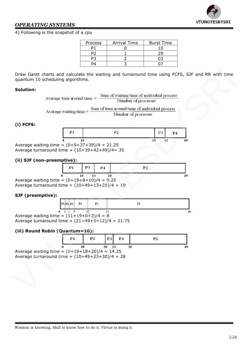
OPERATING SYSTEMS
2-24
4) Following is the snapshot of a cpu
Process Arrival Time Burst Time
P1 0 10
P2 1 29
P3 2 03
P4 3 07
Draw Gantt charts and calculate the waiting and turnaround time using FCFS, SJF and RR with time
quantum 10 scheduling algorithms.
Solution:
(i) FCFS:
Average waiting time = (0+9+37+39)/4 = 21.25
Average turnaround time = (10+39+42+49)/4= 35
(ii) SJF (non-preemptive):
Average waiting time = (0+19+8+10)/4 = 9.25
Average turnaround time = (10+49+13+20)/4 = 19
SJF (preemptive):
Average waiting time = (11+19+0+2)/4 = 8
Average turnaround time = (21+49+5+12)/4 = 21.75
(iii) Round Robin (Quantum=10):
Average waiting time = (0+19+18+20)/4 = 14.25
Average turnaround time = (10+49+23+30)/4 = 28
VTUNOTESBYSRI
Wisdom is knowing. Skill is know how to do it. Virtue is doing it.
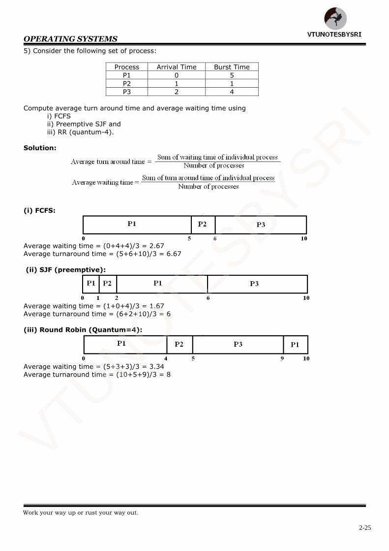
OPERATING SYSTEMS
2-25
5) Consider the following set of process:
Process Arrival Time Burst Time
P1 0 5
P2 1 1
P3 2 4
Compute average turn around time and average waiting time using
i) FCFS
ii) Preemptive SJF and
iii) RR (quantum-4).
Solution:
(i) FCFS:
Average waiting time = (0+4+4)/3 = 2.67
Average turnaround time = (5+6+10)/3 = 6.67
(ii) SJF (preemptive):
Average waiting time = (1+0+4)/3 = 1.67
Average turnaround time = (6+2+10)/3 = 6
(iii) Round Robin (Quantum=4):
Average waiting time = (5+3+3)/3 = 3.34
Average turnaround time = (10+5+9)/3 = 8
VTUNOTESBYSRI
Work your way up or rust your way out.
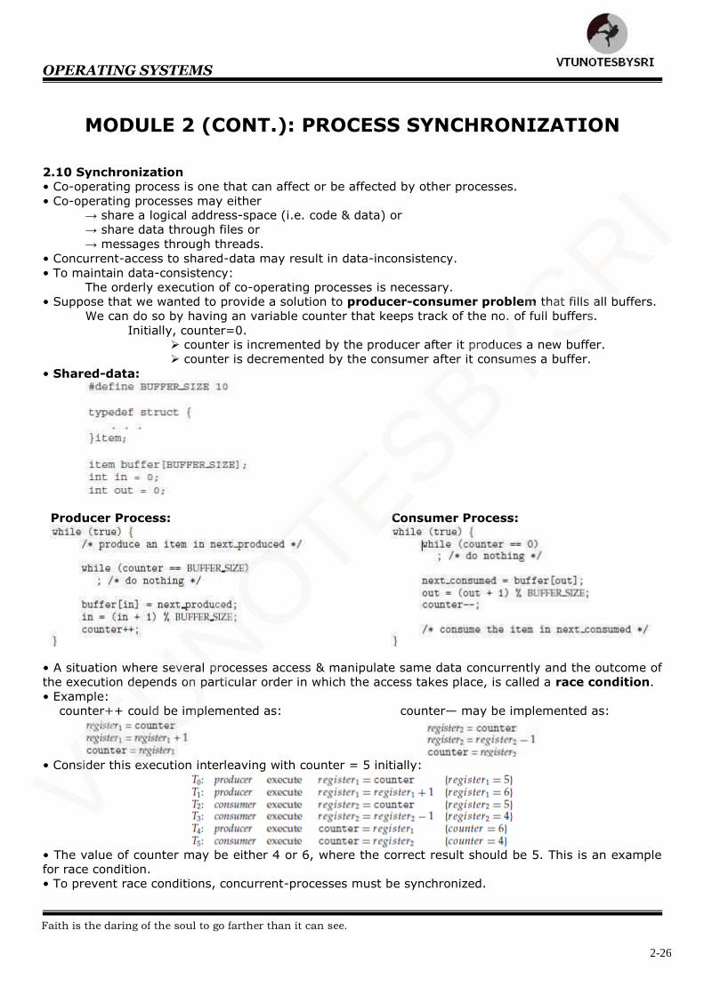
OPERATING SYSTEMS
2-26
MODULE 2 (CONT.): PROCESS SYNCHRONIZATION
2.10 Synchronization
• Co-operating process is one that can affect or be affected by other processes.
• Co-operating processes may either → share a logical address-space (i.e. code & data) or
→ share data through files or
→ messages through threads.
• Concurrent-access to shared-data may result in data-inconsistency.
• To maintain data-consistency:
The orderly execution of co-operating processes is necessary.
• Suppose that we wanted to provide a solution to producer-consumer problem that fills all buffers.
We can do so by having an variable counter that keeps track of the no. of full buffers.
Initially, counter=0. counter is incremented by the producer after it produces a new buffer.
counter is decremented by the consumer after it consumes a buffer.
• Shared-data:
Producer Process: Consumer Process:
• A situation where several processes access & manipulate same data concurrently and the outcome of
the execution depends on particular order in which the access takes place, is called a race condition.
• Example:
counter++ could be implemented as: counter— may be implemented as:
• Consider this execution interleaving with counter = 5 initially:
• The value of counter may be either 4 or 6, where the correct result should be 5. This is an example
for race condition.
• To prevent race conditions, concurrent-processes must be synchronized.
VTUNOTESBYSRI
Faith is the daring of the soul to go farther than it can see.
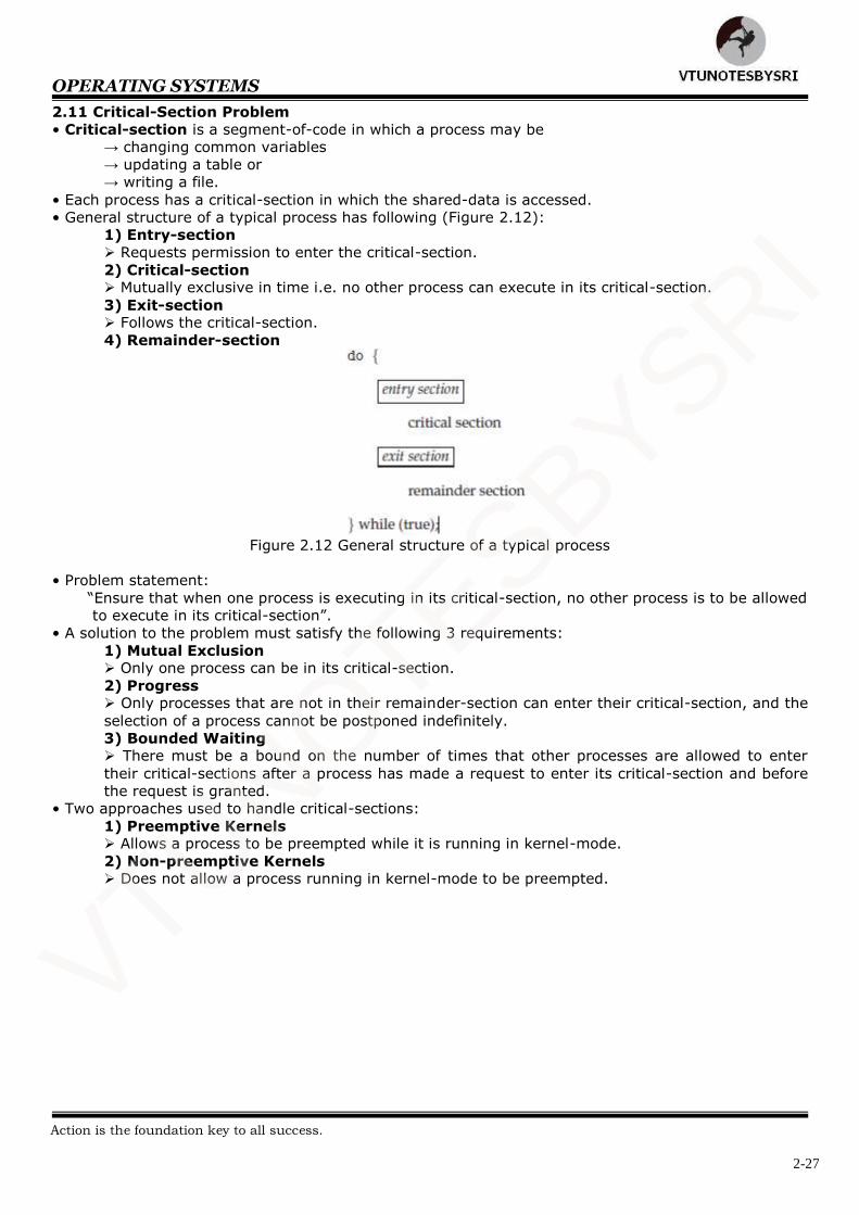
OPERATING SYSTEMS
2-27
2.11 Critical-Section Problem
• Critical-section is a segment-of-code in which a process may be
→ changing common variables
→ updating a table or
→ writing a file.
• Each process has a critical-section in which the shared-data is accessed.
• General structure of a typical process has following (Figure 2.12):
1) Entry-section
Requests permission to enter the critical-section.
2) Critical-section Mutually exclusive in time i.e. no other process can execute in its critical-section.
3) Exit-section Follows the critical-section.
4) Remainder-section
Figure 2.12 General structure of a typical process
• Problem statement:
―Ensure that when one process is executing in its critical-section, no other process is to be allowed
to execute in its critical-section‖.
• A solution to the problem must satisfy the following 3 requirements:
1) Mutual Exclusion Only one process can be in its critical-section.
2) Progress Only processes that are not in their remainder-section can enter their critical-section, and the
selection of a process cannot be postponed indefinitely.
3) Bounded Waiting There must be a bound on the number of times that other processes are allowed to enter
their critical-sections after a process has made a request to enter its critical-section and before
the request is granted.
• Two approaches used to handle critical-sections:
1) Preemptive Kernels Allows a process to be preempted while it is running in kernel-mode.
2) Non-preemptive Kernels Does not allow a process running in kernel-mode to be preempted.
VTUNOTESBYSRI
Action is the foundation key to all success.
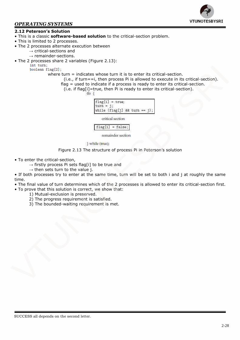
OPERATING SYSTEMS
2-28
2.12 Peterson’s Solution
• This is a classic software-based solution to the critical-section problem.
• This is limited to 2 processes.
• The 2 processes alternate execution between → critical-sections and
→ remainder-sections.
• The 2 processes share 2 variables (Figure 2.13):
where turn = indicates whose turn it is to enter its critical-section.
(i.e., if turn==i, then process Pi is allowed to execute in its critical-section).
flag = used to indicate if a process is ready to enter its critical-section.
(i.e. if flag[i]=true, then Pi is ready to enter its critical-section).
Figure 2.13 The structure of process Pi in Peterson‘s solution
• To enter the critical-section, → firstly process Pi sets flag[i] to be true and
→ then sets turn to the value j.
• If both processes try to enter at the same time, turn will be set to both i and j at roughly the same
time.
• The final value of turn determines which of the 2 processes is allowed to enter its critical-section first.
• To prove that this solution is correct, we show that:
1) Mutual-exclusion is preserved.
2) The progress requirement is satisfied.
3) The bounded-waiting requirement is met.
VTUNOTESBYSRI
SUCCESS all depends on the second letter.
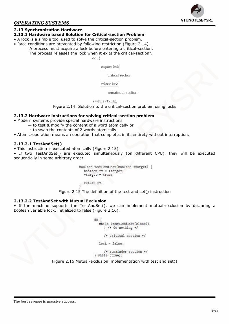
OPERATING SYSTEMS
2-29
2.13 Synchronization Hardware
2.13.1 Hardware based Solution for Critical-section Problem
• A lock is a simple tool used to solve the critical-section problem.
• Race conditions are prevented by following restriction (Figure 2.14).
―A process must acquire a lock before entering a critical-section.
The process releases the lock when it exits the critical-section‖.
Figure 2.14: Solution to the critical-section problem using locks
2.13.2 Hardware instructions for solving critical-section problem
• Modern systems provide special hardware instructions
→ to test & modify the content of a word atomically or
→ to swap the contents of 2 words atomically.
• Atomic-operation means an operation that completes in its entirety without interruption.
2.13.2.1 TestAndSet()
• This instruction is executed atomically (Figure 2.15).
• If two TestAndSet() are executed simultaneously (on different CPU), they will be executed
sequentially in some arbitrary order.
Figure 2.15 The definition of the test and set() instruction
2.13.2.2 TestAndSet with Mutual Exclusion
• If the machine supports the TestAndSet(), we can implement mutual-exclusion by declaring a
boolean variable lock, initialized to false (Figure 2.16).
Figure 2.16 Mutual-exclusion implementation with test and set()
VTUNOTESBYSRI
The best revenge is massive success.
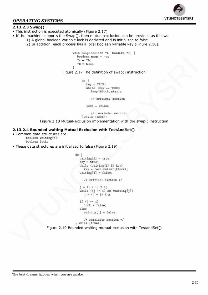
OPERATING SYSTEMS
2-30
2.13.2.3 Swap()
• This instruction is executed atomically (Figure 2.17).
• If the machine supports the Swap(), then mutual-exclusion can be provided as follows:
1) A global boolean variable lock is declared and is initialized to false.
2) In addition, each process has a local Boolean variable key (Figure 2.18).
Figure 2.17 The definition of swap() instruction
Figure 2.18 Mutual-exclusion implementation with the swap() instruction
2.13.2.4 Bounded waiting Mutual Exclusion with TestAndSet()
• Common data structures are
• These data structures are initialized to false (Figure 2.19).
Figure 2.19 Bounded-waiting mutual-exclusion with TestandSet()
VTUNOTESBYSRI
The best dreams happen when you are awake.
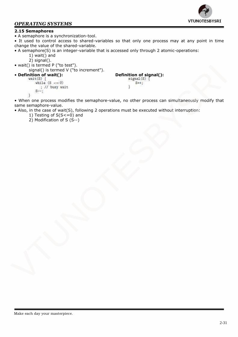
OPERATING SYSTEMS
2-31
2.15 Semaphores
• A semaphore is a synchronization-tool.
• It used to control access to shared-variables so that only one process may at any point in time
change the value of the shared-variable.
• A semaphore(S) is an integer-variable that is accessed only through 2 atomic-operations:
1) wait() and
2) signal().
• wait() is termed P ("to test").
signal() is termed V ("to increment").
• Definition of wait(): Definition of signal():
• When one process modifies the semaphore-value, no other process can simultaneously modify that
same semaphore-value.
• Also, in the case of wait(S), following 2 operations must be executed without interruption:
1) Testing of S(S<=0) and
2) Modification of S (S--)
VTUNOTESBYSRI
Make each day your masterpiece.
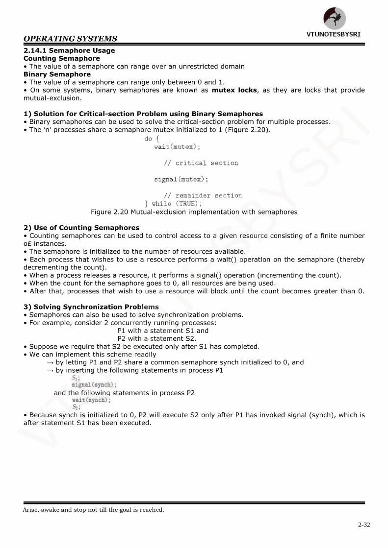
OPERATING SYSTEMS
2-32
2.14.1 Semaphore Usage
Counting Semaphore
• The value of a semaphore can range over an unrestricted domain
Binary Semaphore
• The value of a semaphore can range only between 0 and 1.
• On some systems, binary semaphores are known as mutex locks, as they are locks that provide
mutual-exclusion.
1) Solution for Critical-section Problem using Binary Semaphores
• Binary semaphores can be used to solve the critical-section problem for multiple processes.
• The ‗n‘ processes share a semaphore mutex initialized to 1 (Figure 2.20).
Figure 2.20 Mutual-exclusion implementation with semaphores
2) Use of Counting Semaphores
• Counting semaphores can be used to control access to a given resource consisting of a finite number
o£ instances.
• The semaphore is initialized to the number of resources available.
• Each process that wishes to use a resource performs a wait() operation on the semaphore (thereby
decrementing the count).
• When a process releases a resource, it performs a signal() operation (incrementing the count).
• When the count for the semaphore goes to 0, all resources are being used.
• After that, processes that wish to use a resource will block until the count becomes greater than 0.
3) Solving Synchronization Problems
• Semaphores can also be used to solve synchronization problems.
• For example, consider 2 concurrently running-processes:
P1 with a statement S1 and
P2 with a statement S2.
• Suppose we require that S2 be executed only after S1 has completed.
• We can implement this scheme readily → by letting P1 and P2 share a common semaphore synch initialized to 0, and
→ by inserting the following statements in process P1
and the following statements in process P2
• Because synch is initialized to 0, P2 will execute S2 only after P1 has invoked signal (synch), which is
after statement S1 has been executed.
VTUNOTESBYSRI
Arise, awake and stop not till the goal is reached.
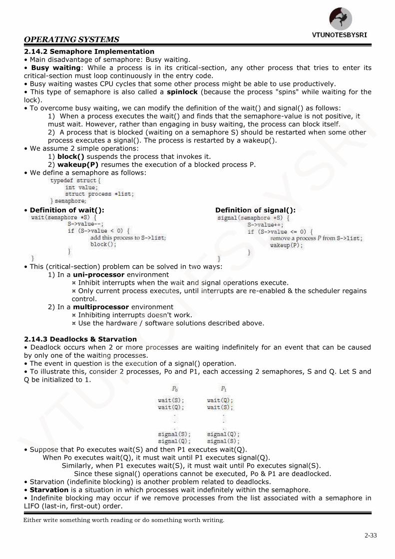
OPERATING SYSTEMS
2-33
2.14.2 Semaphore Implementation
• Main disadvantage of semaphore: Busy waiting.
• Busy waiting: While a process is in its critical-section, any other process that tries to enter its
critical-section must loop continuously in the entry code.
• Busy waiting wastes CPU cycles that some other process might be able to use productively.
• This type of semaphore is also called a spinlock (because the process "spins" while waiting for the
lock).
• To overcome busy waiting, we can modify the definition of the wait() and signal() as follows:
1) When a process executes the wait() and finds that the semaphore-value is not positive, it
must wait. However, rather than engaging in busy waiting, the process can block itself.
2) A process that is blocked (waiting on a semaphore S) should be restarted when some other
process executes a signal(). The process is restarted by a wakeup().
• We assume 2 simple operations:
1) block() suspends the process that invokes it.
2) wakeup(P) resumes the execution of a blocked process P.
• We define a semaphore as follows:
• Definition of wait(): Definition of signal():
• This (critical-section) problem can be solved in two ways:
1) In a uni-processor environment
¤ Inhibit interrupts when the wait and signal operations execute.
¤ Only current process executes, until interrupts are re-enabled & the scheduler regains
control.
2) In a multiprocessor environment
¤ Inhibiting interrupts doesn't work.
¤ Use the hardware / software solutions described above.
2.14.3 Deadlocks & Starvation
• Deadlock occurs when 2 or more processes are waiting indefinitely for an event that can be caused
by only one of the waiting processes.
• The event in question is the execution of a signal() operation.
• To illustrate this, consider 2 processes, Po and P1, each accessing 2 semaphores, S and Q. Let S and
Q be initialized to 1.
• Suppose that Po executes wait(S) and then P1 executes wait(Q).
When Po executes wait(Q), it must wait until P1 executes signal(Q).
Similarly, when P1 executes wait(S), it must wait until Po executes signal(S).
Since these signal() operations cannot be executed, Po & P1 are deadlocked.
• Starvation (indefinite blocking) is another problem related to deadlocks.
• Starvation is a situation in which processes wait indefinitely within the semaphore.
• Indefinite blocking may occur if we remove processes from the list associated with a semaphore in
LIFO (last-in, first-out) order.
VTUNOTESBYSRI
Either write something worth reading or do something worth writing.
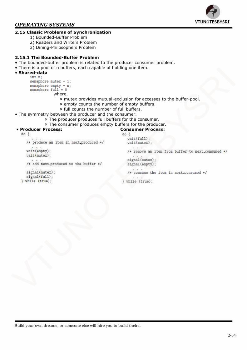
OPERATING SYSTEMS
2-34
2.15 Classic Problems of Synchronization
1) Bounded-Buffer Problem
2) Readers and Writers Problem
3) Dining-Philosophers Problem
2.15.1 The Bounded-Buffer Problem
• The bounded-buffer problem is related to the producer consumer problem.
• There is a pool of n buffers, each capable of holding one item.
• Shared-data
where,
¤ mutex provides mutual-exclusion for accesses to the buffer-pool.
¤ empty counts the number of empty buffers.
¤ full counts the number of full buffers.
• The symmetry between the producer and the consumer.
¤ The producer produces full buffers for the consumer.
¤ The consumer produces empty buffers for the producer.
• Producer Process: Consumer Process:
VTUNOTESBYSRI
Build your own dreams, or someone else will hire you to build theirs.
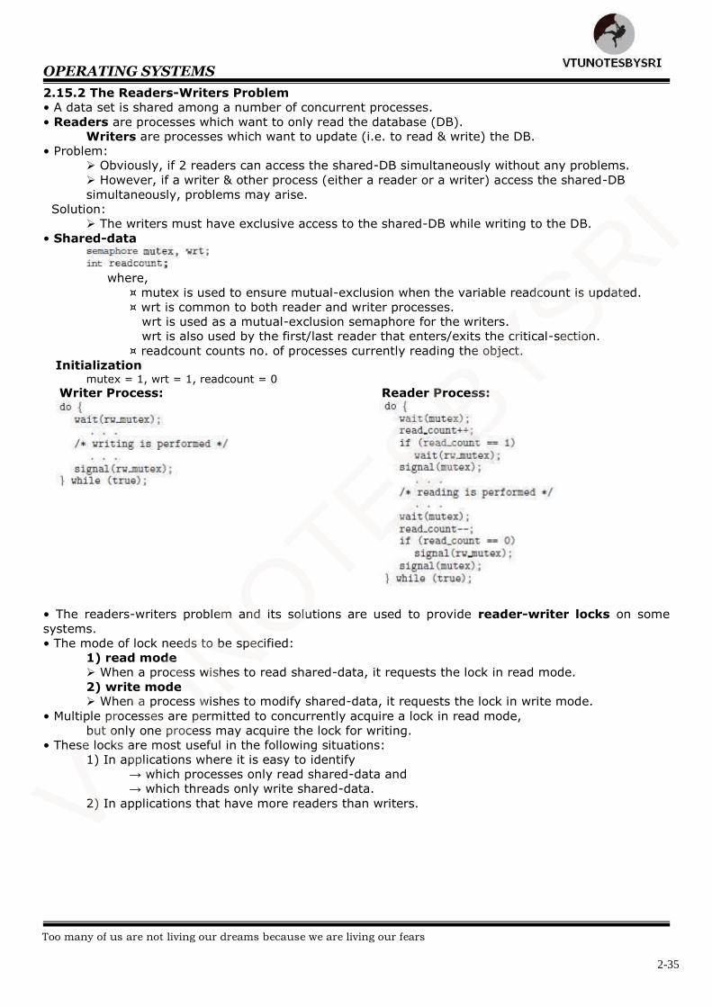
OPERATING SYSTEMS
2-35
2.15.2 The Readers-Writers Problem
• A data set is shared among a number of concurrent processes.
• Readers are processes which want to only read the database (DB).
Writers are processes which want to update (i.e. to read & write) the DB.
• Problem: Obviously, if 2 readers can access the shared-DB simultaneously without any problems.
However, if a writer & other process (either a reader or a writer) access the shared-DB
simultaneously, problems may arise.
Solution:
The writers must have exclusive access to the shared-DB while writing to the DB.
• Shared-data
where,
¤ mutex is used to ensure mutual-exclusion when the variable readcount is updated.
¤ wrt is common to both reader and writer processes.
wrt is used as a mutual-exclusion semaphore for the writers.
wrt is also used by the first/last reader that enters/exits the critical-section.
¤ readcount counts no. of processes currently reading the object.
Initialization mutex = 1, wrt = 1, readcount = 0
Writer Process: Reader Process:
• The readers-writers problem and its solutions are used to provide reader-writer locks on some
systems.
• The mode of lock needs to be specified:
1) read mode
When a process wishes to read shared-data, it requests the lock in read mode.
2) write mode When a process wishes to modify shared-data, it requests the lock in write mode.
• Multiple processes are permitted to concurrently acquire a lock in read mode,
but only one process may acquire the lock for writing.
• These locks are most useful in the following situations:
1) In applications where it is easy to identify
→ which processes only read shared-data and
→ which threads only write shared-data.
2) In applications that have more readers than writers.
VTUNOTESBYSRI
Too many of us are not living our dreams because we are living our fears
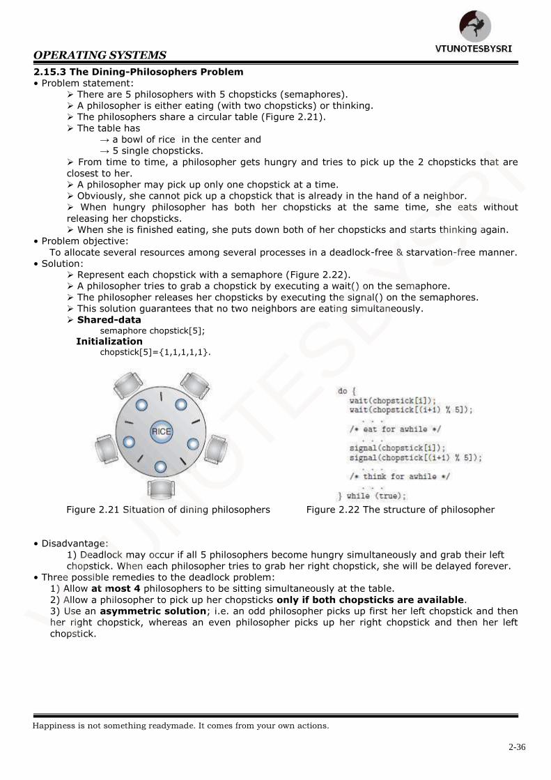
OPERATING SYSTEMS
2-36
2.15.3 The Dining-Philosophers Problem
• Problem statement:
There are 5 philosophers with 5 chopsticks (semaphores).
A philosopher is either eating (with two chopsticks) or thinking.
The philosophers share a circular table (Figure 2.21).
The table has
→ a bowl of rice in the center and
→ 5 single chopsticks.
From time to time, a philosopher gets hungry and tries to pick up the 2 chopsticks that are
closest to her.
A philosopher may pick up only one chopstick at a time.
Obviously, she cannot pick up a chopstick that is already in the hand of a neighbor.
When hungry philosopher has both her chopsticks at the same time, she eats without
releasing her chopsticks. When she is finished eating, she puts down both of her chopsticks and starts thinking again.
• Problem objective:
To allocate several resources among several processes in a deadlock-free & starvation-free manner.
• Solution: Represent each chopstick with a semaphore (Figure 2.22).
A philosopher tries to grab a chopstick by executing a wait() on the semaphore.
The philosopher releases her chopsticks by executing the signal() on the semaphores.
This solution guarantees that no two neighbors are eating simultaneously.
Shared-data semaphore chopstick[5];
Initialization chopstick[5]={1,1,1,1,1}.
Figure 2.21 Situation of dining philosophers Figure 2.22 The structure of philosopher
• Disadvantage:
1) Deadlock may occur if all 5 philosophers become hungry simultaneously and grab their left
chopstick. When each philosopher tries to grab her right chopstick, she will be delayed forever.
• Three possible remedies to the deadlock problem:
1) Allow at most 4 philosophers to be sitting simultaneously at the table.
2) Allow a philosopher to pick up her chopsticks only if both chopsticks are available.
3) Use an asymmetric solution; i.e. an odd philosopher picks up first her left chopstick and then
her right chopstick, whereas an even philosopher picks up her right chopstick and then her left
chopstick.
VTUNOTESBYSRI
Happiness is not something readymade. It comes from your own actions.
OPERATING SYSTEMS
2-37
2.16 Monitors
• Monitor is a high-level synchronization construct.
• It provides a convenient and effective mechanism for process synchronization.
Need for Monitors
• When programmers use semaphores incorrectly, following types of errors may occur:
1) Suppose that a process interchanges the order in which the wait() and signal() operations on
the semaphore ―mutex‖ are executed, resulting in the following execution:
In this situation, several processes may be executing in their critical-sections simultaneously,
violating the mutual-exclusion requirement.
2) Suppose that a process replaces signal(mutex) with wait(mutex). That is, it executes
In this case, a deadlock will occur.
3) Suppose that a process omits the wait(mutex), or the signal(mutex), or both. In this case, either mutual-exclusion is violated or a deadlock will occur.
VTUNOTESBYSRI
Success is a condition that gives us the ability to do what makes us happy.
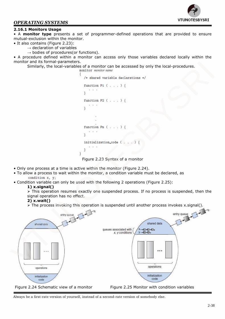
OPERATING SYSTEMS
2-38
2.16.1 Monitors Usage
• A monitor type presents a set of programmer-defined operations that are provided to ensure
mutual-exclusion within the monitor.
• It also contains (Figure 2.23): → declaration of variables
→ bodies of procedures(or functions).
• A procedure defined within a monitor can access only those variables declared locally within the
monitor and its formal-parameters.
Similarly, the local-variables of a monitor can be accessed by only the local-procedures.
Figure 2.23 Syntax of a monitor
• Only one process at a time is active within the monitor (Figure 2.24).
• To allow a process to wait within the monitor, a condition variable must be declared, as
• Condition variable can only be used with the following 2 operations (Figure 2.25):
1) x.signal() This operation resumes exactly one suspended process. If no process is suspended, then the
signal operation has no effect.
2) x.wait() The process invoking this operation is suspended until another process invokes x.signal().
Figure 2.24 Schematic view of a monitor Figure 2.25 Monitor with condition variables
VTUNOTESBYSRI
Always be a first-rate version of yourself, instead of a second-rate version of somebody else.
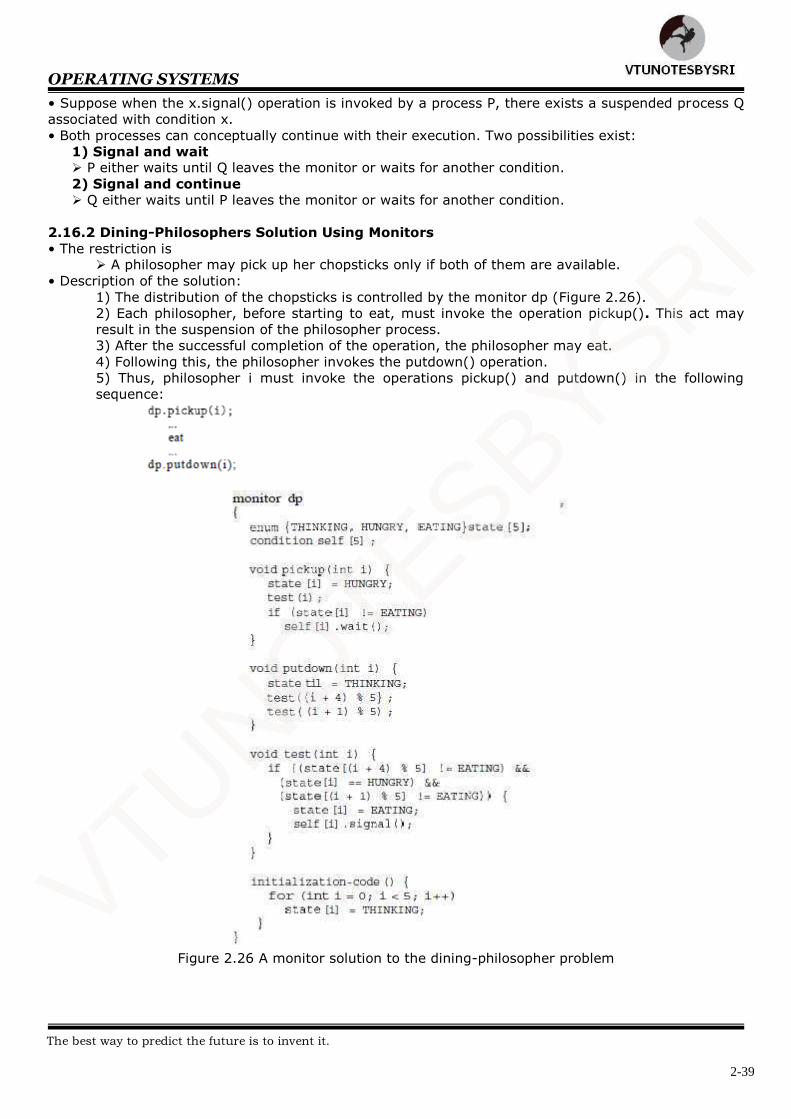
OPERATING SYSTEMS
2-39
• Suppose when the x.signal() operation is invoked by a process P, there exists a suspended process Q
associated with condition x.
• Both processes can conceptually continue with their execution. Two possibilities exist:
1) Signal and wait P either waits until Q leaves the monitor or waits for another condition.
2) Signal and continue
Q either waits until P leaves the monitor or waits for another condition.
2.16.2 Dining-Philosophers Solution Using Monitors
• The restriction is A philosopher may pick up her chopsticks only if both of them are available.
• Description of the solution:
1) The distribution of the chopsticks is controlled by the monitor dp (Figure 2.26).
2) Each philosopher, before starting to eat, must invoke the operation pickup(). This act may
result in the suspension of the philosopher process.
3) After the successful completion of the operation, the philosopher may eat.
4) Following this, the philosopher invokes the putdown() operation.
5) Thus, philosopher i must invoke the operations pickup() and putdown() in the following
sequence:
Figure 2.26 A monitor solution to the dining-philosopher problem
VTUNOTESBYSRI
The best way to predict the future is to invent it.
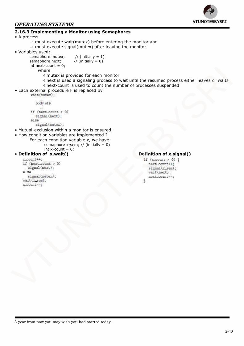
OPERATING SYSTEMS
2-40
2.16.3 Implementing a Monitor using Semaphores
• A process
→ must execute wait(mutex) before entering the monitor and
→ must execute signal(mutex) after leaving the monitor.
• Variables used: semaphore mutex; // (initially = 1) semaphore next; // (initially = 0) int next-count = 0;
where
¤ mutex is provided for each monitor.
¤ next is used a signaling process to wait until the resumed process either leaves or waits
¤ next-count is used to count the number of processes suspended
• Each external procedure F is replaced by
• Mutual-exclusion within a monitor is ensured.
• How condition variables are implemented ?
For each condition variable x, we have: semaphore x-sem; // (initially = 0)
int x-count = 0;
• Definition of x.wait() Definition of x.signal()
VTUNOTESBYSRI
A year from now you may wish you had started today.
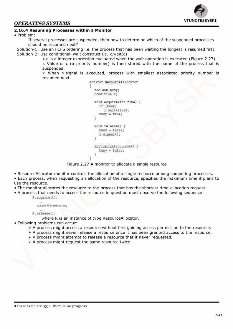
OPERATING SYSTEMS
2-41
2.16.4 Resuming Processes within a Monitor
• Problem:
If several processes are suspended, then how to determine which of the suspended processes
should be resumed next?
Solution-1: Use an FCFS ordering i.e. the process that has been waiting the longest is resumed first.
Solution-2: Use conditional–wait construct i.e. x.wait(c)
¤ c is a integer expression evaluated when the wait operation is executed (Figure 2.27).
¤ Value of c (a priority number) is then stored with the name of the process that is
suspended.
¤ When x.signal is executed, process with smallest associated priority number is
resumed next.
Figure 2.27 A monitor to allocate a single resource
• ResourceAllocator monitor controls the allocation of a single resource among competing processes.
• Each process, when requesting an allocation of the resource, specifies the maximum time it plans to
use the resource.
• The monitor allocates the resource to the process that has the shortest time-allocation request.
• A process that needs to access the resource in question must observe the following sequence:
where R is an instance of type ResourceAllocator.
• Following problems can occur: A process might access a resource without first gaining access permission to the resource.
A process might never release a resource once it has been granted access to the resource.
A process might attempt to release a resource that it never requested.
A process might request the same resource twice.
VTUNOTESBYSRI
If there is no struggle, there is no progress.
OPERATING SYSTEMS
3-1
MODULE 3: DEADLOCKS
MEMORY MANAGEMENT
3.1 Deadlocks
3.2 System Model
3.3 Deadlock Characterization
3.3.1 Necessary Conditions
3.3.2 Resource Allocation Graph
3.4 Methods for Handling Deadlocks
3.5 Deadlock Prevention
3.5.1 Mutual Exclusion
3.5.2 Hold and Wait
3.5.3 No Preemption
3.5.4 Circular Wait
3.6 Deadlock Avoidance
3.6.1 Safe State
3.6.2 Resource Allocation Graph Algorithm
3.6.3 Banker's Algorithm
3.6.3.1 Safety Algorithm
3.6.3.2 Resource Request Algorithm
3.6 3.3 An Illustrative Example
3.7 Deadlock Detection
3.7.1 Single Instance of Each Resource Type
3.7.2 Several Instances of a Resource Type
3.7.3 Detection Algorithm Usage
3.8 Recovery from Deadlock
3.8.1 Process Termination
3.8.2 Resource Preemption
3.9 Main Memory
3.9.1 Basic Hardware
3.9.2 Address Binding
3.9.3 Logical versus Physical Address Space
3.9.4 Dynamic Loading
3.9.5 Dynamic Linking and Shared Libraries
3.10 Swapping
3.11 Contiguous Memory Allocation
3.11.1 Memory Mapping & Protection
3.11.2 Memory Allocation
3.11.3 Fragmentation
3.12 Segmentation
3.13 Paging
3.13.1 Basic Method
3.13.2 Hardware Support for Paging
3.13.3 Protection
3.13.4 Shared Pages
3.14 Structure of the Page Table
3.14.1 Hierarchical Paging
3.14.2 Hashed Page Tables
3.14.3 Inverted Page Tables
3.15 Segmentation
3.15.1 Basic Method
3.15.2 Hardware Support
VTUNOTESBYSRI
Do what you love and the money will follow.

OPERATING SYSTEMS
3-2
MODULE 3: DEADLOCKS
3.1 Deadlocks
• Deadlock is a situation where a set of processes are blocked because each process is
→ holding a resource and
→ waiting for another resource held by some other process.
• Real life example:
When 2 trains are coming toward each other on same track and there is only one track, none of
the trains can move once they are in front of each other.
• Similar situation occurs in operating systems when there are two or more processes hold some
resources and wait for resources held by other(s).
• Here is an example of a situation where deadlock can occur (Figure 3.1).
Figure 3.1 Deadlock Situation
3.2 System Model
• A system consist of finite number of resources. (For ex: memory, printers, CPUs).
• These resources are distributed among number of processes.
• A process must → request a resource before using it and
→ release the resource after using it.
• The process can request any number of resources to carry out a given task.
• The total number of resource requested must not exceed the total number of resources available.
• In normal operation, a process must perform following tasks in sequence:
1) Request If the request cannot be granted immediately (for ex: the resource is being used by
another process), then the requesting-process must wait for acquiring the resource.
For example: open( ), malloc( ), new( ), and request( )
2) Use The process uses the resource.
For example: prints to the printer or reads from the file.
3) Release The process releases the resource.
So that, the resource becomes available for other processes.
For example: close( ), free( ), delete( ), and release( ).
• A set of processes is deadlocked when every process in the set is waiting for a resource that is
currently allocated to another process in the set.
• Deadlock may involve different types of resources.
• As shown in figure 3.2,
Both processes P1 & P2 need resources to continue
execution.
P1 requires additional resource R1 and is in
possession of resource R2.
P2 requires additional resource R2 and is in
possession of R1.
• Thus, neither process can continue.
• Multithread programs are good candidates for deadlock because
Figure 3.2 they compete for shared resources.
VTUNOTESBYSRI
The purpose of our lives is to be happy.
OPERATING SYSTEMS
3-3
3.3 Deadlock Characterization
• In a deadlock, processes never finish executing, and system resources are tied up, preventing other
jobs from starting.
3.3.1 Necessary Conditions
• There are four conditions that are necessary to achieve deadlock:
1) Mutual Exclusion At least one resource must be held in a non-sharable mode.
If any other process requests this resource, then the requesting-process must wait for the
resource to be released.
2) Hold and Wait A process must be simultaneously
→ holding at least one resource and
→ waiting to acquire additional resources held by the other process.
3) No Preemption
Once a process is holding a resource ( i.e. once its request has been granted ), then that
resource cannot be taken away from that process until the process voluntarily releases it.
4) Circular Wait
A set of processes { P0, P1, P2, . . ., PN } must exist such that
P0 is waiting for a resource that is held by P1
P1 is waiting for a resource that is held by P2, and so on
VTUNOTESBYSRI
You do not need to be a success to be happy; you need to be happy to be truly successful.
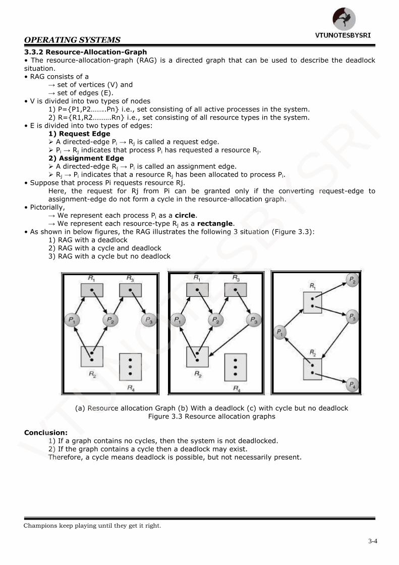
OPERATING SYSTEMS
3-4
3.3.2 Resource-Allocation-Graph
• The resource-allocation-graph (RAG) is a directed graph that can be used to describe the deadlock
situation.
• RAG consists of a → set of vertices (V) and
→ set of edges (E).
• V is divided into two types of nodes
1) P={P1,P2……..Pn} i.e., set consisting of all active processes in the system.
2) R={R1,R2……….Rn} i.e., set consisting of all resource types in the system.
• E is divided into two types of edges:
1) Request Edge A directed-edge Pi → Rj is called a request edge.
Pi → Rj indicates that process Pi has requested a resource Rj.
2) Assignment Edge
A directed-edge Rj → Pi is called an assignment edge.
Rj → Pi indicates that a resource Rj has been allocated to process Pi.
• Suppose that process Pi requests resource Rj.
Here, the request for Rj from Pi can be granted only if the converting request-edge to
assignment-edge do not form a cycle in the resource-allocation graph.
• Pictorially,
→ We represent each process Pi as a circle.
→ We represent each resource-type Rj as a rectangle.
• As shown in below figures, the RAG illustrates the following 3 situation (Figure 3.3):
1) RAG with a deadlock
2) RAG with a cycle and deadlock
3) RAG with a cycle but no deadlock
(a) Resource allocation Graph (b) With a deadlock (c) with cycle but no deadlock
Figure 3.3 Resource allocation graphs
Conclusion:
1) If a graph contains no cycles, then the system is not deadlocked.
2) If the graph contains a cycle then a deadlock may exist.
Therefore, a cycle means deadlock is possible, but not necessarily present.
VTUNOTESBYSRI
Champions keep playing until they get it right.
OPERATING SYSTEMS
3-5
3.4 Methods for Handling Deadlocks
• There are three ways of handling deadlocks:
1) Deadlock prevention or avoidance - Do not allow the system to get into a deadlocked state.
2) Deadlock detection and recovery - Abort a process or preempt some resources when
deadlocks are detected.
3) Ignore the problem all together - If deadlocks only occur once a year or so, it may be better
to simply let them happen and reboot the system.
• In order to avoid deadlocks, the system must have additional information about all processes.
• In particular, the system must know what resources a process will or may request in the future.
• Deadlock detection is fairly straightforward, but deadlock recovery requires either aborting processes
or preempting resources.
• If deadlocks are neither prevented nor detected, then when a deadlock occurs the system will
gradually slow down.
3.5 Deadlock-Prevention
• Deadlocks can be eliminated by preventing at least one of the four required conditions:
1) Mutual exclusion
2) Hold-and-wait
3) No preemption
4) Circular-wait.
3.5.1 Mutual Exclusion
• This condition must hold for non-sharable resources.
• For example:
A printer cannot be simultaneously shared by several processes.
• On the other hand, shared resources do not lead to deadlocks.
• For example:
Simultaneous access can be granted for read-only file.
• A process never waits for accessing a sharable resource.
• In general, we cannot prevent deadlocks by denying the mutual-exclusion condition because some
resources are non-sharable by default.
3.5.2 Hold and Wait
• To prevent this condition:
The processes must be prevented from holding one or more resources while simultaneously
waiting for one or more other resources.
• There are several solutions to this problem.
• For example:
Consider a process that → copies the data from a tape drive to the disk
→ sorts the file and
→ then prints the results to a printer.
Protocol-1 Each process must be allocated with all of its resources before it begins execution.
All the resources (tape drive, disk files and printer) are allocated to the process at the
beginning.
Protocol-2
A process must request a resource only when the process has none.
Initially, the process is allocated with tape drive and disk file.
The process performs the required operation and releases both tape drive and disk file.
Then, the process is again allocated with disk file and the printer
Again, the process performs the required operation & releases both disk file and the printer.
• Disadvantages of above 2 methods:
1) Resource utilization may be low, since resources may be allocated but unused for a long
period.
2) Starvation is possible.
VTUNOTESBYSRI
Nothing important was ever achieved without someone taking a chance.
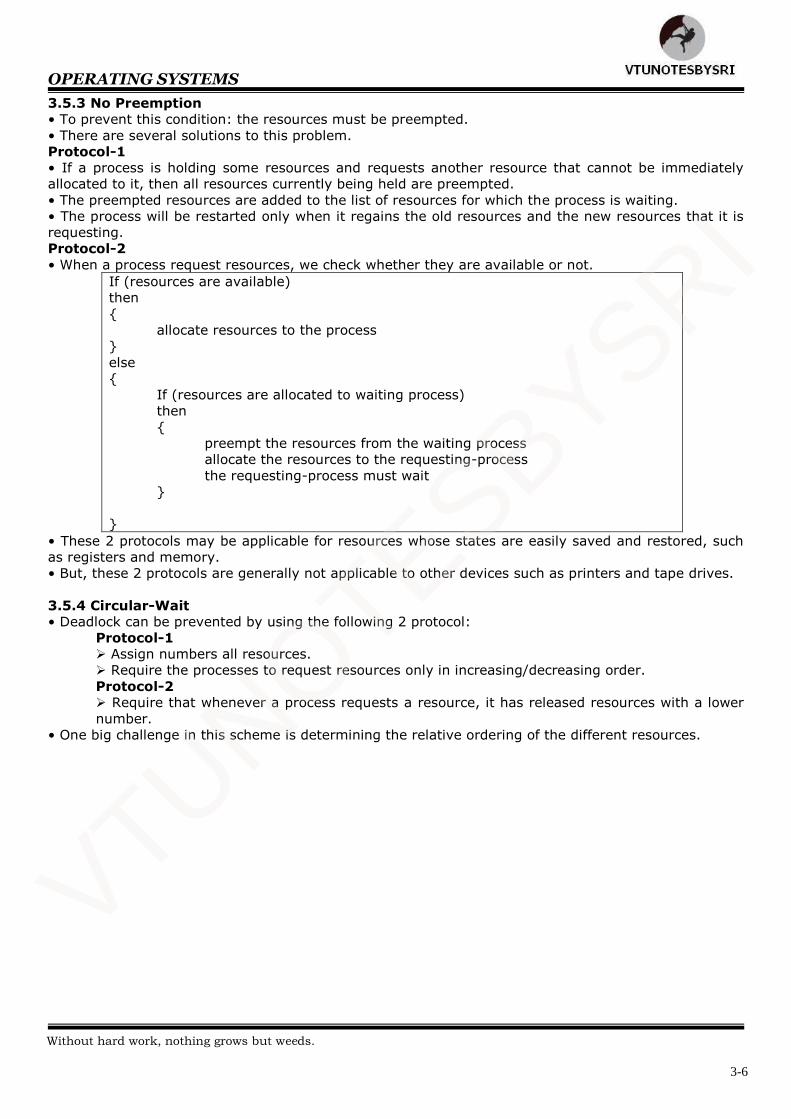
OPERATING SYSTEMS
3-6
3.5.3 No Preemption
• To prevent this condition: the resources must be preempted.
• There are several solutions to this problem.
Protocol-1
• If a process is holding some resources and requests another resource that cannot be immediately
allocated to it, then all resources currently being held are preempted.
• The preempted resources are added to the list of resources for which the process is waiting.
• The process will be restarted only when it regains the old resources and the new resources that it is
requesting.
Protocol-2
• When a process request resources, we check whether they are available or not.
If (resources are available)
then
{
allocate resources to the process
}
else
{
If (resources are allocated to waiting process)
then
{
preempt the resources from the waiting process
allocate the resources to the requesting-process
the requesting-process must wait
}
}
• These 2 protocols may be applicable for resources whose states are easily saved and restored, such
as registers and memory.
• But, these 2 protocols are generally not applicable to other devices such as printers and tape drives.
3.5.4 Circular-Wait
• Deadlock can be prevented by using the following 2 protocol:
Protocol-1
Assign numbers all resources.
Require the processes to request resources only in increasing/decreasing order.
Protocol-2
Require that whenever a process requests a resource, it has released resources with a lower
number.
• One big challenge in this scheme is determining the relative ordering of the different resources.
VTUNOTESBYSRI
Without hard work, nothing grows but weeds.
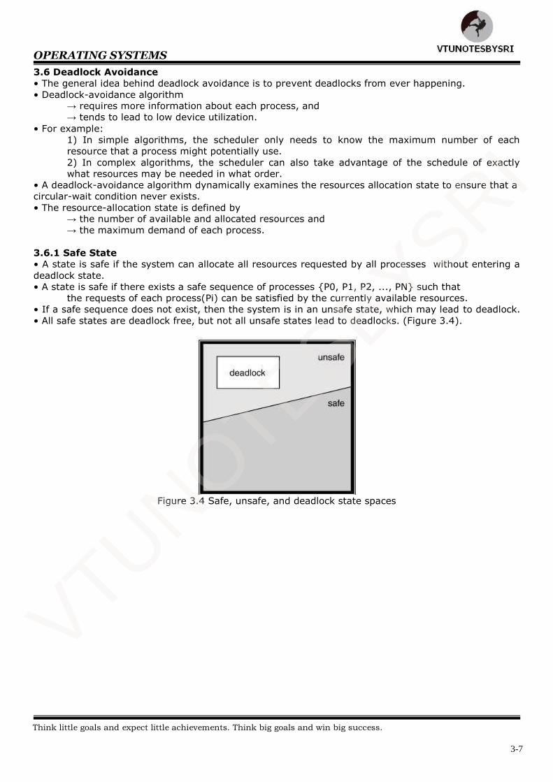
OPERATING SYSTEMS
3-7
3.6 Deadlock Avoidance
• The general idea behind deadlock avoidance is to prevent deadlocks from ever happening.
• Deadlock-avoidance algorithm → requires more information about each process, and
→ tends to lead to low device utilization.
• For example:
1) In simple algorithms, the scheduler only needs to know the maximum number of each
resource that a process might potentially use.
2) In complex algorithms, the scheduler can also take advantage of the schedule of exactly
what resources may be needed in what order.
• A deadlock-avoidance algorithm dynamically examines the resources allocation state to ensure that a
circular-wait condition never exists.
• The resource-allocation state is defined by → the number of available and allocated resources and
→ the maximum demand of each process.
3.6.1 Safe State
• A state is safe if the system can allocate all resources requested by all processes without entering a
deadlock state.
• A state is safe if there exists a safe sequence of processes {P0, P1, P2, ..., PN} such that
the requests of each process(Pi) can be satisfied by the currently available resources.
• If a safe sequence does not exist, then the system is in an unsafe state, which may lead to deadlock.
• All safe states are deadlock free, but not all unsafe states lead to deadlocks. (Figure 3.4).
Figure 3.4 Safe, unsafe, and deadlock state spaces
VTUNOTESBYSRI
Think little goals and expect little achievements. Think big goals and win big success.
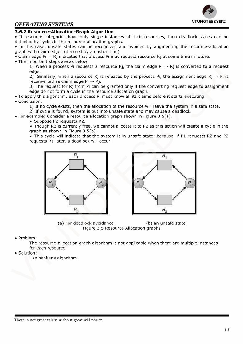
OPERATING SYSTEMS
3-8
3.6.2 Resource-Allocation-Graph Algorithm
• If resource categories have only single instances of their resources, then deadlock states can be
detected by cycles in the resource-allocation graphs.
• In this case, unsafe states can be recognized and avoided by augmenting the resource-allocation
graph with claim edges (denoted by a dashed line). • Claim edge Pi → Rj indicated that process Pi may request resource Rj at some time in future.
• The important steps are as below: 1) When a process Pi requests a resource Rj, the claim edge Pi → Rj is converted to a request
edge. 2) Similarly, when a resource Rj is released by the process Pi, the assignment edge Rj → Pi is
reconverted as claim edge Pi → Rj.
3) The request for Rj from Pi can be granted only if the converting request edge to assignment
edge do not form a cycle in the resource allocation graph.
• To apply this algorithm, each process Pi must know all its claims before it starts executing.
• Conclusion:
1) If no cycle exists, then the allocation of the resource will leave the system in a safe state.
2) If cycle is found, system is put into unsafe state and may cause a deadlock.
• For example: Consider a resource allocation graph shown in Figure 3.5(a).
Suppose P2 requests R2.
Though R2 is currently free, we cannot allocate it to P2 as this action will create a cycle in the
graph as shown in Figure 3.5(b).
This cycle will indicate that the system is in unsafe state: because, if P1 requests R2 and P2
requests R1 later, a deadlock will occur.
(a) For deadlock avoidance (b) an unsafe state
Figure 3.5 Resource Allocation graphs
• Problem:
The resource-allocation graph algorithm is not applicable when there are multiple instances
for each resource.
• Solution:
Use banker's algorithm.
VTUNOTESBYSRI
There is not great talent without great will power.
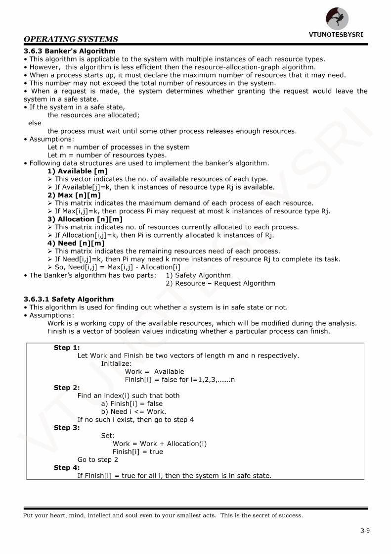
OPERATING SYSTEMS
3-9
3.6.3 Banker's Algorithm
• This algorithm is applicable to the system with multiple instances of each resource types.
• However, this algorithm is less efficient then the resource-allocation-graph algorithm.
• When a process starts up, it must declare the maximum number of resources that it may need.
• This number may not exceed the total number of resources in the system.
• When a request is made, the system determines whether granting the request would leave the
system in a safe state.
• If the system in a safe state,
the resources are allocated;
else
the process must wait until some other process releases enough resources.
• Assumptions:
Let n = number of processes in the system
Let m = number of resources types.
• Following data structures are used to implement the banker’s algorithm.
1) Available [m] This vector indicates the no. of available resources of each type.
If Available[j]=k, then k instances of resource type Rj is available.
2) Max [n][m] This matrix indicates the maximum demand of each process of each resource.
If Max[i,j]=k, then process Pi may request at most k instances of resource type Rj.
3) Allocation [n][m] This matrix indicates no. of resources currently allocated to each process.
If Allocation[i,j]=k, then Pi is currently allocated k instances of Rj.
4) Need [n][m] This matrix indicates the remaining resources need of each process.
If Need[i,j]=k, then Pi may need k more instances of resource Rj to complete its task.
So, Need[i,j] = Max[i,j] - Allocation[i]
• The Banker’s algorithm has two parts: 1) Safety Algorithm
2) Resource – Request Algorithm
3.6.3.1 Safety Algorithm
• This algorithm is used for finding out whether a system is in safe state or not.
• Assumptions:
Work is a working copy of the available resources, which will be modified during the analysis.
Finish is a vector of boolean values indicating whether a particular process can finish.
Step 1:
Let Work and Finish be two vectors of length m and n respectively.
Initialize:
Work = Available
Finish[i] = false for i=1,2,3,…….n
Step 2:
Find an index(i) such that both
a) Finish[i] = false
b) Need i <= Work.
If no such i exist, then go to step 4
Step 3:
Set:
Work = Work + Allocation(i)
Finish[i] = true
Go to step 2
Step 4:
If Finish[i] = true for all i, then the system is in safe state.
VTUNOTESBYSRI
Put your heart, mind, intellect and soul even to your smallest acts. This is the secret of success.
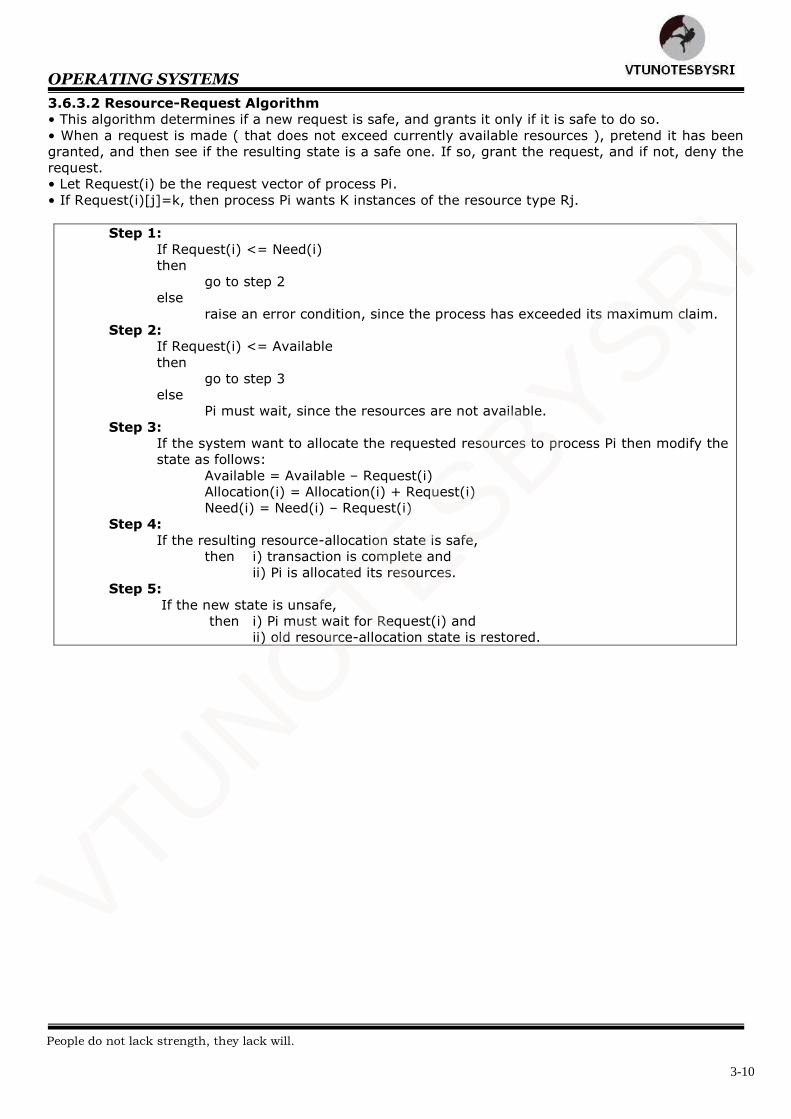
OPERATING SYSTEMS
3-10
3.6.3.2 Resource-Request Algorithm
• This algorithm determines if a new request is safe, and grants it only if it is safe to do so.
• When a request is made ( that does not exceed currently available resources ), pretend it has been
granted, and then see if the resulting state is a safe one. If so, grant the request, and if not, deny the
request.
• Let Request(i) be the request vector of process Pi.
• If Request(i)[j]=k, then process Pi wants K instances of the resource type Rj.
Step 1:
If Request(i) <= Need(i)
then
go to step 2
else
raise an error condition, since the process has exceeded its maximum claim.
Step 2:
If Request(i) <= Available
then
go to step 3
else
Pi must wait, since the resources are not available.
Step 3:
If the system want to allocate the requested resources to process Pi then modify the
state as follows:
Available = Available – Request(i)
Allocation(i) = Allocation(i) + Request(i)
Need(i) = Need(i) – Request(i)
Step 4:
If the resulting resource-allocation state is safe,
then i) transaction is complete and
ii) Pi is allocated its resources.
Step 5:
If the new state is unsafe,
then i) Pi must wait for Request(i) and
ii) old resource-allocation state is restored.
VTUNOTESBYSRI
People do not lack strength, they lack will.
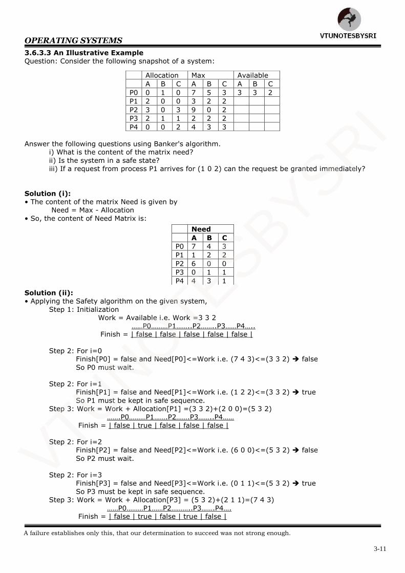
OPERATING SYSTEMS
3-11
3.6.3.3 An Illustrative Example
Question: Consider the following snapshot of a system:
Answer the following questions using Banker's algorithm.
i) What is the content of the matrix need?
ii) Is the system in a safe state?
iii) If a request from process P1 arrives for (1 0 2) can the request be granted immediately?
Solution (i):
• The content of the matrix Need is given by
Need = Max - Allocation
• So, the content of Need Matrix is:
Solution (ii):
• Applying the Safety algorithm on the given system,
Step 1: Initialization
Work = Available i.e. Work =3 3 2
……P0………P1……..P2……..P3……P4…..
Finish = | false | false | false | false | false |
Step 2: For i=0 Finish[P0] = false and Need[P0]<=Work i.e. (7 4 3)<=(3 3 2) false
So P0 must wait.
Step 2: For i=1 Finish[P1] = false and Need[P1]<=Work i.e. (1 2 2)<=(3 3 2) true
So P1 must be kept in safe sequence.
Step 3: Work = Work + Allocation[P1] =(3 3 2)+(2 0 0)=(5 3 2)
…….P0………P1…….P2…….P3……..P4……
Finish = | false | true | false | false | false |
Step 2: For i=2 Finish[P2] = false and Need[P2]<=Work i.e. (6 0 0)<=(5 3 2) false
So P2 must wait.
Step 2: For i=3
Finish[P3] = false and Need[P3]<=Work i.e. (0 1 1)<=(5 3 2) true
So P3 must be kept in safe sequence.
Step 3: Work = Work + Allocation[P3] = (5 3 2)+(2 1 1)=(7 4 3)
……P0………P1……P2………..P3…….P4….
Finish = | false | true | false | true | false |
Allocation Max Available
A B C A B C A B C
P0 0 1 0 7 5 3 3 3 2
P1 2 0 0 3 2 2
P2 3 0 3 9 0 2
P3 2 1 1 2 2 2
P4 0 0 2 4 3 3
Need
A B C
P0 7 4 3
P1 1 2 2
P2 6 0 0
P3 0 1 1
P4 4 3 1
VTUNOTESBYSRI
A failure establishes only this, that our determination to succeed was not strong enough.
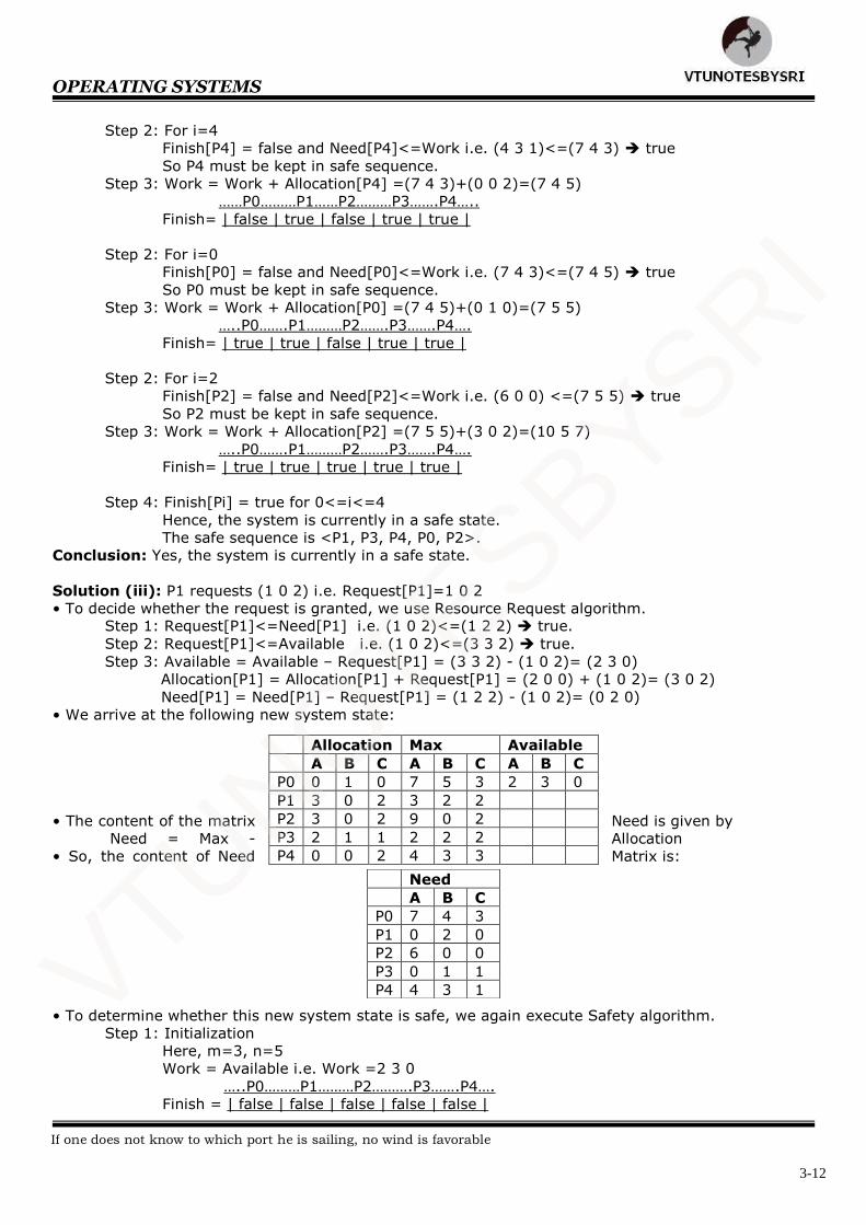
OPERATING SYSTEMS
3-12
Step 2: For i=4
Finish[P4] = false and Need[P4]<=Work i.e. (4 3 1)<=(7 4 3) true
So P4 must be kept in safe sequence.
Step 3: Work = Work + Allocation[P4] =(7 4 3)+(0 0 2)=(7 4 5)
……P0………P1……P2………P3…….P4…..
Finish= | false | true | false | true | true |
Step 2: For i=0
Finish[P0] = false and Need[P0]<=Work i.e. (7 4 3)<=(7 4 5) true
So P0 must be kept in safe sequence.
Step 3: Work = Work + Allocation[P0] =(7 4 5)+(0 1 0)=(7 5 5)
…..P0…….P1………P2…….P3…….P4….
Finish= | true | true | false | true | true |
Step 2: For i=2
Finish[P2] = false and Need[P2]<=Work i.e. (6 0 0) <=(7 5 5) true
So P2 must be kept in safe sequence.
Step 3: Work = Work + Allocation[P2] =(7 5 5)+(3 0 2)=(10 5 7)
…..P0…….P1………P2…….P3…….P4….
Finish= | true | true | true | true | true |
Step 4: Finish[Pi] = true for 0<=i<=4
Hence, the system is currently in a safe state.
The safe sequence is <P1, P3, P4, P0, P2>.
Conclusion: Yes, the system is currently in a safe state.
Solution (iii): P1 requests (1 0 2) i.e. Request[P1]=1 0 2
• To decide whether the request is granted, we use Resource Request algorithm. Step 1: Request[P1]<=Need[P1] i.e. (1 0 2)<=(1 2 2) true.
Step 2: Request[P1]<=Available i.e. (1 0 2)<=(3 3 2) true.
Step 3: Available = Available – Request[P1] = (3 3 2) - (1 0 2)= (2 3 0)
Allocation[P1] = Allocation[P1] + Request[P1] = (2 0 0) + (1 0 2)= (3 0 2)
Need[P1] = Need[P1] – Request[P1] = (1 2 2) - (1 0 2)= (0 2 0)
• We arrive at the following new system state:
• The content of the matrix Need is given by
Need = Max - Allocation
• So, the content of Need Matrix is:
• To determine whether this new system state is safe, we again execute Safety algorithm.
Step 1: Initialization
Here, m=3, n=5
Work = Available i.e. Work =2 3 0
…..P0………P1………P2……….P3…….P4….
Finish = | false | false | false | false | false |
Allocation Max Available
A B C A B C A B C
P0 0 1 0 7 5 3 2 3 0
P1 3 0 2 3 2 2
P2 3 0 2 9 0 2
P3 2 1 1 2 2 2
P4 0 0 2 4 3 3
Need
A B C
P0 7 4 3
P1 0 2 0
P2 6 0 0
P3 0 1 1
P4 4 3 1 VTUNOTESBYSRI
If one does not know to which port he is sailing, no wind is favorable
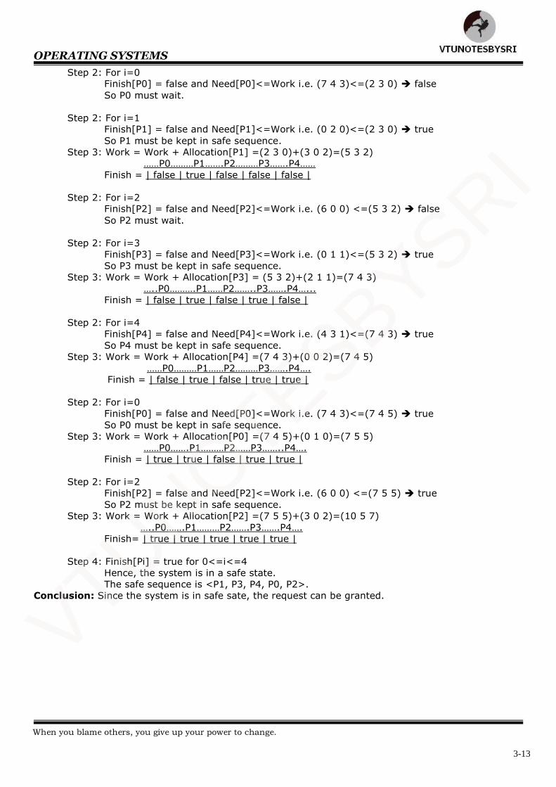
OPERATING SYSTEMS
3-13
Step 2: For i=0 Finish[P0] = false and Need[P0]<=Work i.e. (7 4 3)<=(2 3 0) false
So P0 must wait.
Step 2: For i=1 Finish[P1] = false and Need[P1]<=Work i.e. (0 2 0)<=(2 3 0) true
So P1 must be kept in safe sequence.
Step 3: Work = Work + Allocation[P1] =(2 3 0)+(3 0 2)=(5 3 2)
……P0………P1…….P2………P3…….P4……
Finish = | false | true | false | false | false |
Step 2: For i=2 Finish[P2] = false and Need[P2]<=Work i.e. (6 0 0) <=(5 3 2) false
So P2 must wait.
Step 2: For i=3
Finish[P3] = false and Need[P3]<=Work i.e. (0 1 1)<=(5 3 2) true
So P3 must be kept in safe sequence.
Step 3: Work = Work + Allocation[P3] = (5 3 2)+(2 1 1)=(7 4 3)
…..P0……….P1……P2……..P3…….P4…...
Finish = | false | true | false | true | false |
Step 2: For i=4
Finish[P4] = false and Need[P4]<=Work i.e. (4 3 1)<=(7 4 3) true
So P4 must be kept in safe sequence.
Step 3: Work = Work + Allocation[P4] =(7 4 3)+(0 0 2)=(7 4 5)
……P0………P1……P2………P3…….P4….
Finish = | false | true | false | true | true |
Step 2: For i=0
Finish[P0] = false and Need[P0]<=Work i.e. (7 4 3)<=(7 4 5) true
So P0 must be kept in safe sequence.
Step 3: Work = Work + Allocation[P0] =(7 4 5)+(0 1 0)=(7 5 5)
……P0…….P1………P2……P3……..P4….
Finish = | true | true | false | true | true |
Step 2: For i=2
Finish[P2] = false and Need[P2]<=Work i.e. (6 0 0) <=(7 5 5) true
So P2 must be kept in safe sequence.
Step 3: Work = Work + Allocation[P2] =(7 5 5)+(3 0 2)=(10 5 7)
…..P0…….P1………P2…….P3…….P4….
Finish= | true | true | true | true | true |
Step 4: Finish[Pi] = true for 0<=i<=4
Hence, the system is in a safe state.
The safe sequence is <P1, P3, P4, P0, P2>.
Conclusion: Since the system is in safe sate, the request can be granted.
VTUNOTESBYSRI
When you blame others, you give up your power to change.
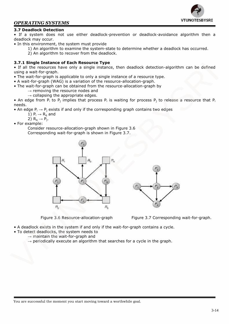
OPERATING SYSTEMS
3-14
3.7 Deadlock Detection
• If a system does not use either deadlock-prevention or deadlock-avoidance algorithm then a
deadlock may occur.
• In this environment, the system must provide
1) An algorithm to examine the system-state to determine whether a deadlock has occurred.
2) An algorithm to recover from the deadlock.
3.7.1 Single Instance of Each Resource Type
• If all the resources have only a single instance, then deadlock detection-algorithm can be defined
using a wait-for-graph.
• The wait-for-graph is applicable to only a single instance of a resource type.
• A wait-for-graph (WAG) is a variation of the resource-allocation-graph.
• The wait-for-graph can be obtained from the resource-allocation-graph by
→ removing the resource nodes and
→ collapsing the appropriate edges.
• An edge from Pi to Pj implies that process Pi is waiting for process Pj to release a resource that Pi
needs. • An edge Pi → Pj exists if and only if the corresponding graph contains two edges
1) Pi → Rq and
2) Rq → Pj.
• For example:
Consider resource-allocation-graph shown in Figure 3.6
Corresponding wait-for-graph is shown in Figure 3.7.
Figure 3.6 Resource-allocation-graph Figure 3.7 Corresponding wait-for-graph.
• A deadlock exists in the system if and only if the wait-for-graph contains a cycle.
• To detect deadlocks, the system needs to → maintain the wait-for-graph and
→ periodically execute an algorithm that searches for a cycle in the graph.
VTUNOTESBYSRI
You are successful the moment you start moving toward a worthwhile goal.
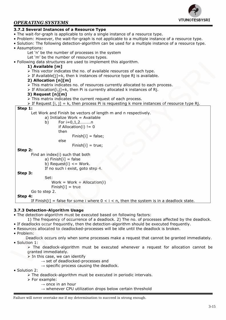
OPERATING SYSTEMS
3-15
3.7.2 Several Instances of a Resource Type
• The wait-for-graph is applicable to only a single instance of a resource type.
• Problem: However, the wait-for-graph is not applicable to a multiple instance of a resource type.
• Solution: The following detection-algorithm can be used for a multiple instance of a resource type.
• Assumptions:
Let ‘n’ be the number of processes in the system
Let ‘m’ be the number of resources types.
• Following data structures are used to implement this algorithm.
1) Available [m] This vector indicates the no. of available resources of each type.
If Available[j]=k, then k instances of resource type Rj is available.
2) Allocation [n][m] This matrix indicates no. of resources currently allocated to each process.
If Allocation[i,j]=k, then Pi is currently allocated k instances of Rj.
3) Request [n][m] This matrix indicates the current request of each process.
If Request [i, j] = k, then process Pi is requesting k more instances of resource type Rj.
Step 1:
Let Work and Finish be vectors of length m and n respectively.
a) Initialize Work = Available
b) For i=0,1,2……….n
if Allocation(i) != 0
then
Finish[i] = false;
else
Finish[i] = true;
Step 2:
Find an index(i) such that both
a) Finish[i] = false
b) Request(i) <= Work.
If no such i exist, goto step 4.
Step 3:
Set:
Work = Work + Allocation(i)
Finish[i] = true
Go to step 2.
Step 4:
If Finish[i] = false for some i where 0 < i < n, then the system is in a deadlock state.
3.7.3 Detection-Algorithm Usage
• The detection-algorithm must be executed based on following factors:
1) The frequency of occurrence of a deadlock. 2) The no. of processes affected by the deadlock.
• If deadlocks occur frequently, then the detection-algorithm should be executed frequently.
• Resources allocated to deadlocked-processes will be idle until the deadlock is broken.
• Problem:
Deadlock occurs only when some processes make a request that cannot be granted immediately.
• Solution 1: The deadlock-algorithm must be executed whenever a request for allocation cannot be
granted immediately.
In this case, we can identify
→ set of deadlocked-processes and
→ specific process causing the deadlock.
• Solution 2: The deadlock-algorithm must be executed in periodic intervals.
For example:
→ once in an hour
→ whenever CPU utilization drops below certain threshold
VTUNOTESBYSRI
Failure will never overtake me if my determination to succeed is strong enough.
OPERATING SYSTEMS
3-16
3.8 Recovery from deadlock
• Three approaches to recovery from deadlock:
1) Inform the system-operator for manual intervention.
2) Terminate one or more deadlocked-processes.
3) Preempt(or Block) some resources.
3.8.1 Process Termination
• Two methods to remove deadlocks:
1) Terminate all deadlocked-processes. This method will definitely break the deadlock-cycle.
However, this method incurs great expense. This is because
→ Deadlocked-processes might have computed for a long time.
→ Results of these partial computations must be discarded.
→ Probably, the results must be re-computed later.
2) Terminate one process at a time until the deadlock-cycle is eliminated. This method incurs large overhead. This is because
after each process is aborted,
deadlock-algorithm must be executed to determine if any other process is still deadlocked
• For process termination, following factors need to be considered:
1) The priority of process.
2) The time taken by the process for computation & the required time for complete execution.
3) The no. of resources used by the process.
4) The no. of extra resources required by the process for complete execution.
5) The no. of processes that need to be terminated for deadlock-free execution.
6) The process is interactive or batch.
3.8.2 Resource Preemption
• Some resources are taken from one or more deadlocked-processes.
• These resources are given to other processes until the deadlock-cycle is broken.
• Three issues need to be considered:
1) Selecting a victim Which resources/processes are to be pre-empted (or blocked)?
The order of pre-emption must be determined to minimize cost.
Cost factors includes
1. The time taken by deadlocked-process for computation.
2. The no. of resources used by deadlocked-process.
2) Rollback If a resource is taken from a process, the process cannot continue its normal execution.
In this case, the process must be rolled-back to break the deadlock.
This method requires the system to keep more info. about the state of all running processes.
3) Starvation
Problem: In a system where victim-selection is based on cost-factors, the same process may
be always picked as a victim. As a result, this process never completes its designated task.
Solution: Ensure a process is picked as a victim only a (small) finite number of times.
VTUNOTESBYSRI
Failure? I never encountered it. All I ever met were temporary setbacks.
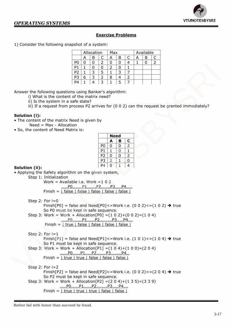
OPERATING SYSTEMS
3-17
Exercise Problems
1) Consider the following snapshot of a system:
Answer the following questions using Banker's algorithm:
i) What is the content of the matrix need?
ii) Is the system in a safe state?
iii) If a request from process P2 arrives for (0 0 2) can the request be granted immediately?
Solution (i):
• The content of the matrix Need is given by
Need = Max - Allocation
• So, the content of Need Matrix is:
Solution (ii):
• Applying the Safety algorithm on the given system,
Step 1: Initialization
Work = Available i.e. Work =1 0 2
……P0………P1……..P2……..P3……P4…..
Finish = | false | false | false | false | false |
Step 2: For i=0 Finish[P0] = false and Need[P0]<=Work i.e. (0 0 2)<=(1 0 2) true
So P0 must be kept in safe sequence.
Step 3: Work = Work + Allocation[P0] =(1 0 2)+(0 0 2)=(1 0 4)
……P0………P1…….P2………..P3……P4….
Finish = | true | false | false | false | false |
Step 2: For i=1 Finish[P1] = false and Need[P1]<=Work i.e. (1 0 1)<=(1 0 4) true
So P1 must be kept in safe sequence.
Step 3: Work = Work + Allocation[P1] =(1 0 4)+(1 0 0)=(2 0 4)
…….P0…….P1……P2………P3……...P4…
Finish = | true | true | false | false | false |
Step 2: For i=2 Finish[P2] = false and Need[P2]<=Work i.e. (0 0 2)<=(2 0 4) true
So P2 must be kept in safe sequence.
Step 3: Work = Work + Allocation[P2] =(2 0 4)+(1 3 5)=(3 3 9)
……P0…….P1…….P2……….P3……P4….
Finish = | true | true | true | false | false |
Allocation Max Available
A B C A B C A B C
P0 0 0 2 0 0 4 1 0 2
P1 1 0 0 2 0 1
P2 1 3 5 1 3 7
P3 6 3 2 8 4 2
P4 1 4 3 1 5 7
Need
A B C
P0 0 0 2
P1 1 0 1
P2 0 0 2
P3 2 1 0
P4 0 1 4
VTUNOTESBYSRI
Rather fail with honor than succeed by fraud.
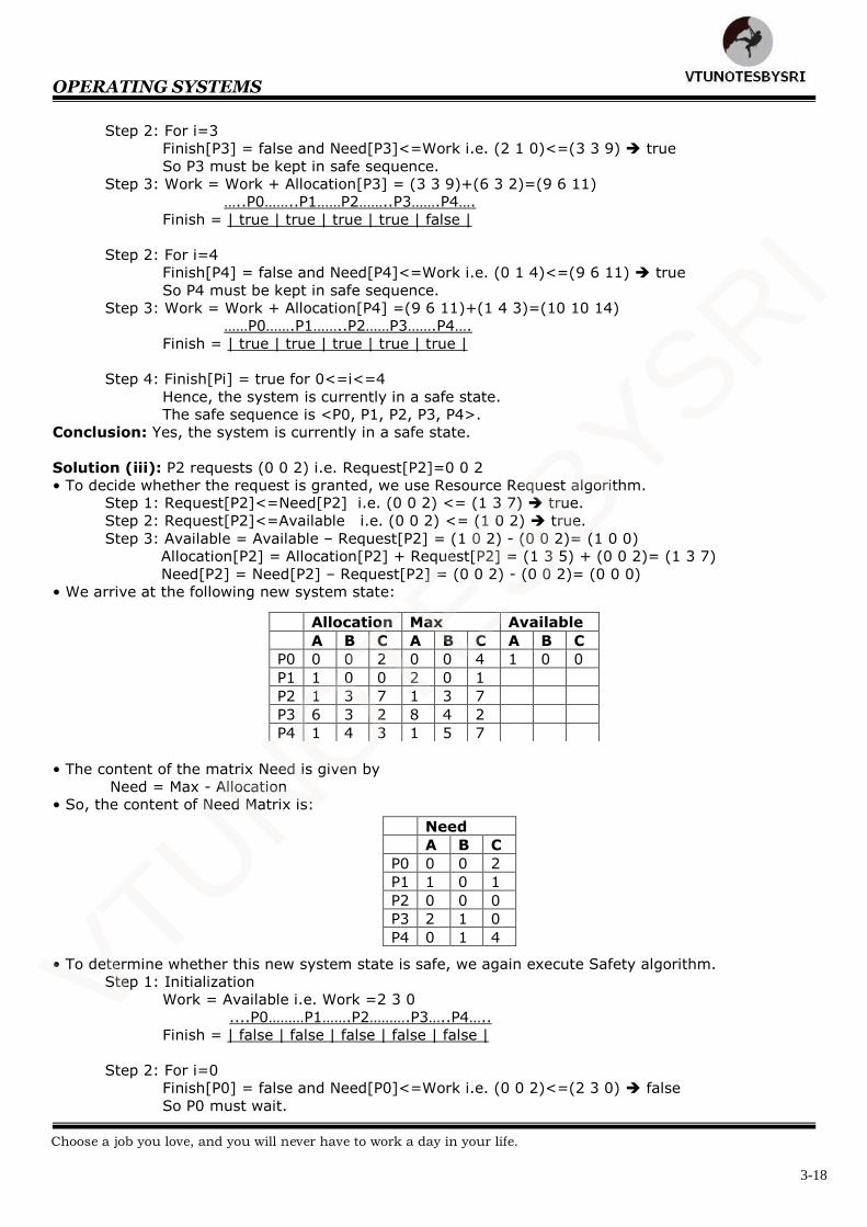
OPERATING SYSTEMS
3-18
Step 2: For i=3
Finish[P3] = false and Need[P3]<=Work i.e. (2 1 0)<=(3 3 9) true
So P3 must be kept in safe sequence.
Step 3: Work = Work + Allocation[P3] = (3 3 9)+(6 3 2)=(9 6 11)
…..P0……..P1……P2……..P3…….P4….
Finish = | true | true | true | true | false |
Step 2: For i=4
Finish[P4] = false and Need[P4]<=Work i.e. (0 1 4)<=(9 6 11) true
So P4 must be kept in safe sequence.
Step 3: Work = Work + Allocation[P4] =(9 6 11)+(1 4 3)=(10 10 14)
……P0…….P1……..P2……P3…….P4….
Finish = | true | true | true | true | true |
Step 4: Finish[Pi] = true for 0<=i<=4
Hence, the system is currently in a safe state.
The safe sequence is <P0, P1, P2, P3, P4>.
Conclusion: Yes, the system is currently in a safe state.
Solution (iii): P2 requests (0 0 2) i.e. Request[P2]=0 0 2
• To decide whether the request is granted, we use Resource Request algorithm. Step 1: Request[P2]<=Need[P2] i.e. (0 0 2) <= (1 3 7) true.
Step 2: Request[P2]<=Available i.e. (0 0 2) <= (1 0 2) true.
Step 3: Available = Available – Request[P2] = (1 0 2) - (0 0 2)= (1 0 0)
Allocation[P2] = Allocation[P2] + Request[P2] = (1 3 5) + (0 0 2)= (1 3 7)
Need[P2] = Need[P2] – Request[P2] = (0 0 2) - (0 0 2)= (0 0 0)
• We arrive at the following new system state:
• The content of the matrix Need is given by
Need = Max - Allocation
• So, the content of Need Matrix is:
• To determine whether this new system state is safe, we again execute Safety algorithm.
Step 1: Initialization
Work = Available i.e. Work =2 3 0
....P0………P1…….P2……….P3…..P4…..
Finish = | false | false | false | false | false |
Step 2: For i=0
Finish[P0] = false and Need[P0]<=Work i.e. (0 0 2)<=(2 3 0) false
So P0 must wait.
Allocation Max Available
A B C A B C A B C
P0 0 0 2 0 0 4 1 0 0
P1 1 0 0 2 0 1
P2 1 3 7 1 3 7
P3 6 3 2 8 4 2
P4 1 4 3 1 5 7
Need
A B C
P0 0 0 2
P1 1 0 1
P2 0 0 0
P3 2 1 0
P4 0 1 4
VTUNOTESBYSRI
Choose a job you love, and you will never have to work a day in your life.
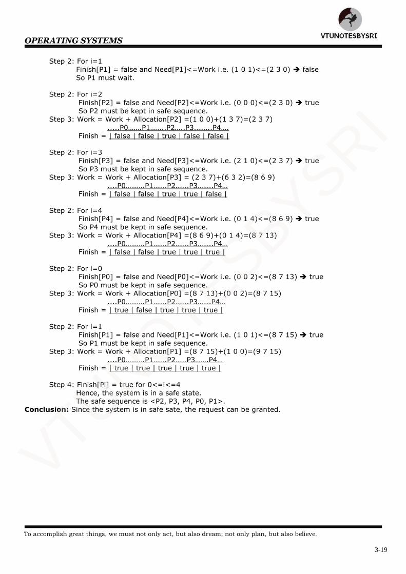
OPERATING SYSTEMS
3-19
Step 2: For i=1
Finish[P1] = false and Need[P1]<=Work i.e. (1 0 1)<=(2 3 0) false
So P1 must wait.
Step 2: For i=2
Finish[P2] = false and Need[P2]<=Work i.e. (0 0 0)<=(2 3 0) true
So P2 must be kept in safe sequence.
Step 3: Work = Work + Allocation[P2] =(1 0 0)+(1 3 7)=(2 3 7)
.....P0…….P1……..P2…..P3.……..P4….
Finish = | false | false | true | false | false |
Step 2: For i=3
Finish[P3] = false and Need[P3]<=Work i.e. (2 1 0)<=(2 3 7) true
So P3 must be kept in safe sequence.
Step 3: Work = Work + Allocation[P3] = (2 3 7)+(6 3 2)=(8 6 9)
....P0……….P1…….P2…….P3……..P4…
Finish = | false | false | true | true | false |
Step 2: For i=4 Finish[P4] = false and Need[P4]<=Work i.e. (0 1 4)<=(8 6 9) true
So P4 must be kept in safe sequence.
Step 3: Work = Work + Allocation[P4] =(8 6 9)+(0 1 4)=(8 7 13)
....P0……….P1…….P2…….P3……..P4…
Finish = | false | false | true | true | true |
Step 2: For i=0 Finish[P0] = false and Need[P0]<=Work i.e. (0 0 2)<=(8 7 13) true
So P0 must be kept in safe sequence.
Step 3: Work = Work + Allocation[P0] =(8 7 13)+(0 0 2)=(8 7 15)
....P0……….P1…….P2…….P3…….P4…
Finish = | true | false | true | true | true |
Step 2: For i=1 Finish[P1] = false and Need[P1]<=Work i.e. (1 0 1)<=(8 7 15) true
So P1 must be kept in safe sequence.
Step 3: Work = Work + Allocation[P1] =(8 7 15)+(1 0 0)=(9 7 15)
....P0……….P1…….P2……P3…….P4…
Finish = | true | true | true | true | true |
Step 4: Finish[Pi] = true for 0<=i<=4
Hence, the system is in a safe state.
The safe sequence is <P2, P3, P4, P0, P1>.
Conclusion: Since the system is in safe sate, the request can be granted.
VTUNOTESBYSRI
To accomplish great things, we must not only act, but also dream; not only plan, but also believe.
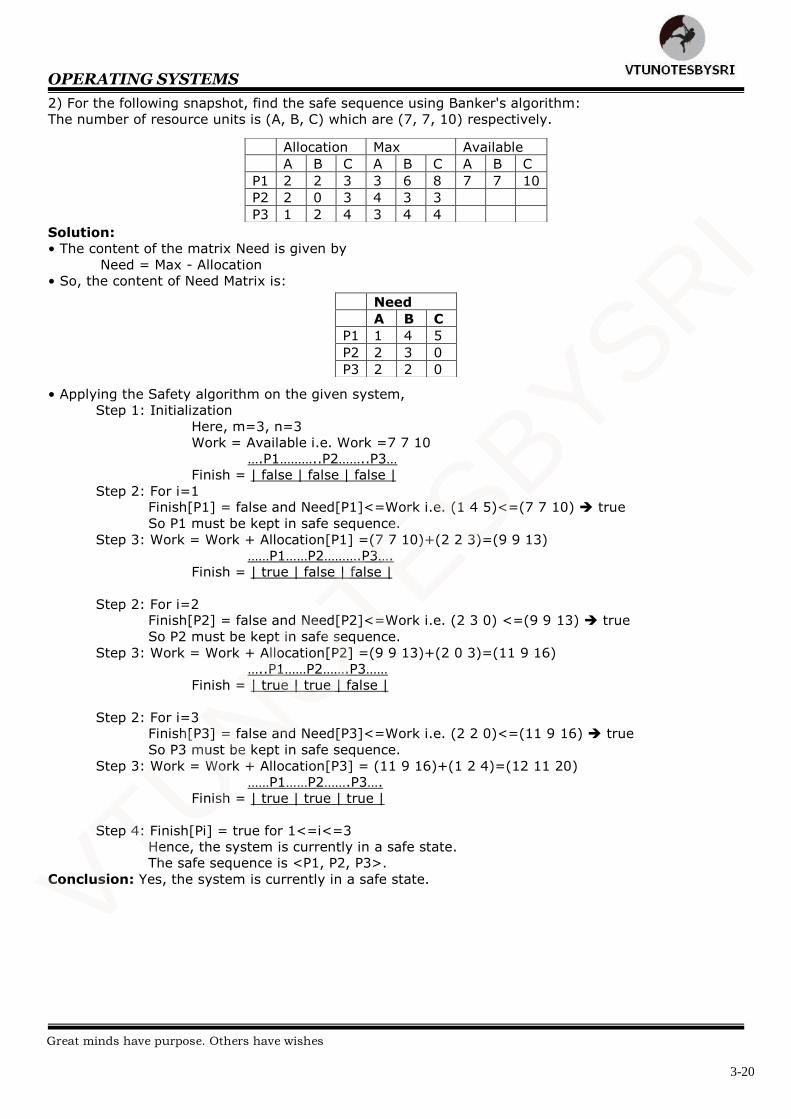
OPERATING SYSTEMS
3-20
2) For the following snapshot, find the safe sequence using Banker's algorithm:
The number of resource units is (A, B, C) which are (7, 7, 10) respectively.
Solution:
• The content of the matrix Need is given by
Need = Max - Allocation
• So, the content of Need Matrix is:
• Applying the Safety algorithm on the given system,
Step 1: Initialization
Here, m=3, n=3
Work = Available i.e. Work =7 7 10
….P1………..P2……..P3…
Finish = | false | false | false |
Step 2: For i=1 Finish[P1] = false and Need[P1]<=Work i.e. (1 4 5)<=(7 7 10) true
So P1 must be kept in safe sequence.
Step 3: Work = Work + Allocation[P1] =(7 7 10)+(2 2 3)=(9 9 13)
……P1……P2……….P3….
Finish = | true | false | false |
Step 2: For i=2 Finish[P2] = false and Need[P2]<=Work i.e. (2 3 0) <=(9 9 13) true
So P2 must be kept in safe sequence.
Step 3: Work = Work + Allocation[P2] =(9 9 13)+(2 0 3)=(11 9 16)
…..P1……P2…….P3……
Finish = | true | true | false |
Step 2: For i=3 Finish[P3] = false and Need[P3]<=Work i.e. (2 2 0)<=(11 9 16) true
So P3 must be kept in safe sequence.
Step 3: Work = Work + Allocation[P3] = (11 9 16)+(1 2 4)=(12 11 20)
……P1……P2…….P3….
Finish = | true | true | true |
Step 4: Finish[Pi] = true for 1<=i<=3
Hence, the system is currently in a safe state.
The safe sequence is <P1, P2, P3>.
Conclusion: Yes, the system is currently in a safe state.
Allocation Max Available
A B C A B C A B C
P1 2 2 3 3 6 8 7 7 10
P2 2 0 3 4 3 3
P3 1 2 4 3 4 4
Need
A B C
P1 1 4 5
P2 2 3 0
P3 2 2 0
VTUNOTESBYSRI
Great minds have purpose. Others have wishes
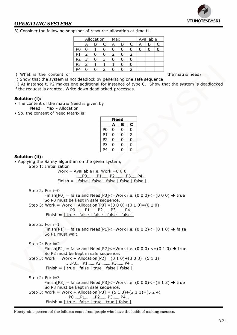
OPERATING SYSTEMS
3-21
3) Consider the following snapshot of resource-allocation at time t1.
i) What is the content of the matrix need?
ii) Show that the system is not deadlock by generating one safe sequence
iii) At instance t, P2 makes one additional for instance of type C. Show that the system is deadlocked
if the request is granted. Write down deadlocked-processes.
Solution (i):
• The content of the matrix Need is given by
Need = Max - Allocation
• So, the content of Need Matrix is:
Solution (ii):
• Applying the Safety algorithm on the given system,
Step 1: Initialization
Work = Available i.e. Work =0 0 0
……P0………P1…….P2……….P3……P4…
Finish = | false | false | false | false | false |
Step 2: For i=0 Finish[P0] = false and Need[P0]<=Work i.e. (0 0 0)<=(0 0 0) true
So P0 must be kept in safe sequence.
Step 3: Work = Work + Allocation[P0] =(0 0 0)+(0 1 0)=(0 1 0)
…..P0………P1…….P2…….P3……..P4…
Finish = | true | false | false | false | false |
Step 2: For i=1 Finish[P1] = false and Need[P1]<=Work i.e. (0 0 2)<=(0 1 0) false
So P1 must wait.
Step 2: For i=2
Finish[P2] = false and Need[P2]<=Work i.e. (0 0 0) <=(0 1 0) true
So P2 must be kept in safe sequence.
Step 3: Work = Work + Allocation[P2] =(0 1 0)+(3 0 3)=(5 1 3)
....P0……P1…….P2……….P3…….P4…
Finish = | true | false | true | false | false |
Step 2: For i=3
Finish[P3] = false and Need[P3]<=Work i.e. (0 0 0)<=(5 1 3) true
So P3 must be kept in safe sequence.
Step 3: Work = Work + Allocation[P3] = (5 1 3)+(2 1 1)=(5 2 4)
…P0……P1………P2…….P3…….P4…
Finish = | true | false | true | true | false |
Allocation Max Available
A B C A B C A B C
P0 0 1 0 0 0 0 0 0 0
P1 2 0 0 2 0 2
P2 3 0 3 0 0 0
P3 2 1 1 1 0 0
P4 0 0 2 0 0 2
Need
A B C
P0 0 0 0
P1 0 0 2
P2 0 0 0
P3 0 0 0
P4 0 0 0
VTUNOTESBYSRI
Ninety-nine percent of the failures come from people who have the habit of making excuses.
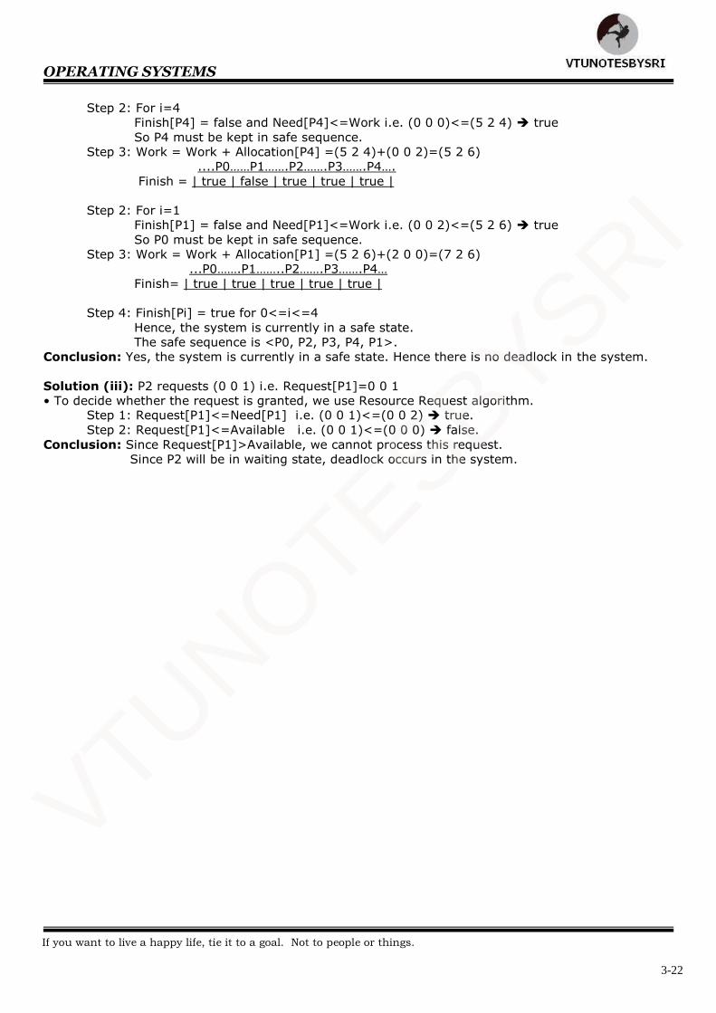
OPERATING SYSTEMS
3-22
Step 2: For i=4
Finish[P4] = false and Need[P4]<=Work i.e. (0 0 0)<=(5 2 4) true
So P4 must be kept in safe sequence.
Step 3: Work = Work + Allocation[P4] =(5 2 4)+(0 0 2)=(5 2 6)
....P0……P1…….P2…….P3…….P4….
Finish = | true | false | true | true | true |
Step 2: For i=1
Finish[P1] = false and Need[P1]<=Work i.e. (0 0 2)<=(5 2 6) true
So P0 must be kept in safe sequence.
Step 3: Work = Work + Allocation[P1] =(5 2 6)+(2 0 0)=(7 2 6)
...P0…….P1……..P2…….P3…….P4…
Finish= | true | true | true | true | true |
Step 4: Finish[Pi] = true for 0<=i<=4
Hence, the system is currently in a safe state.
The safe sequence is <P0, P2, P3, P4, P1>.
Conclusion: Yes, the system is currently in a safe state. Hence there is no deadlock in the system.
Solution (iii): P2 requests (0 0 1) i.e. Request[P1]=0 0 1
• To decide whether the request is granted, we use Resource Request algorithm. Step 1: Request[P1]<=Need[P1] i.e. (0 0 1)<=(0 0 2) true.
Step 2: Request[P1]<=Available i.e. (0 0 1)<=(0 0 0) false.
Conclusion: Since Request[P1]>Available, we cannot process this request.
Since P2 will be in waiting state, deadlock occurs in the system.
VTUNOTESBYSRI
If you want to live a happy life, tie it to a goal. Not to people or things.
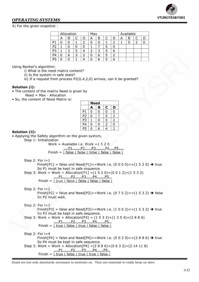
OPERATING SYSTEMS
3-23
4) For the given snapshot :
Using Banker's algorithm:
i) What is the need matrix content?
ii) Is the system in safe state?
iii) If a request from process P2(0,4,2,0) arrives, can it be granted?
Solution (i):
• The content of the matrix Need is given by
Need = Max - Allocation
• So, the content of Need Matrix is:
Solution (ii):
• Applying the Safety algorithm on the given system,
Step 1: Initialization
Work = Available i.e. Work =1 5 2 0
....P1………P2…….P3……….P4…..P5…..
Finish = | false | false | false | false | false |
Step 2: For i=1 Finish[P1] = false and Need[P1]<=Work i.e. (0 0 0 0)<=(1 5 2 0) true
So P1 must be kept in safe sequence.
Step 3: Work = Work + Allocation[P1] =(1 5 2 0)+(0 0 1 2)=(1 5 3 2)
....P1………P2…….P3…….P4……..P5…
Finish = | true | false | false | false | false |
Step 2: For i=2 Finish[P2] = false and Need[P2]<=Work i.e. (0 7 5 2)<=(1 5 3 2) false
So P2 must wait.
Step 2: For i=3
Finish[P3] = false and Need[P3]<=Work i.e. (1 0 0 2)<=(1 5 3 2) true
So P3 must be kept in safe sequence.
Step 3: Work = Work + Allocation[P3] = (1 5 3 2)+(1 3 5 4)=(2 8 8 6)
....P1………P2…….P3…….P4……..P5…
Finish = | true | false | true | false | false |
Step 2: For i=4
Finish[P4] = false and Need[P4]<=Work i.e. (0 0 2 0)<=(2 8 8 6) true
So P4 must be kept in safe sequence.
Step 3: Work = Work + Allocation[P4] =(2 8 8 6)+(0 6 3 2)=(2 14 11 8)
....P1………P2…….P3…….P4…….P5…
Finish = | true | false | true | true | false |
Allocation Max Available
A B C D A B C D A B C D
P1 0 0 1 2 0 0 1 2 1 5 2 0
P2 1 0 0 0 1 7 5 0
P3 1 3 5 4 2 3 5 6
P4 0 6 3 2 0 6 5 2
P5 0 0 1 4 0 6 5 6
Need
A B C D
P1 0 0 0 0
P2 0 7 5 2
P3 1 0 0 2
P4 0 0 2 0
P5 0 6 4 2
VTUNOTESBYSRI
Goals are not only absolutely necessary to motivate us. They are essential to really keep us alive.
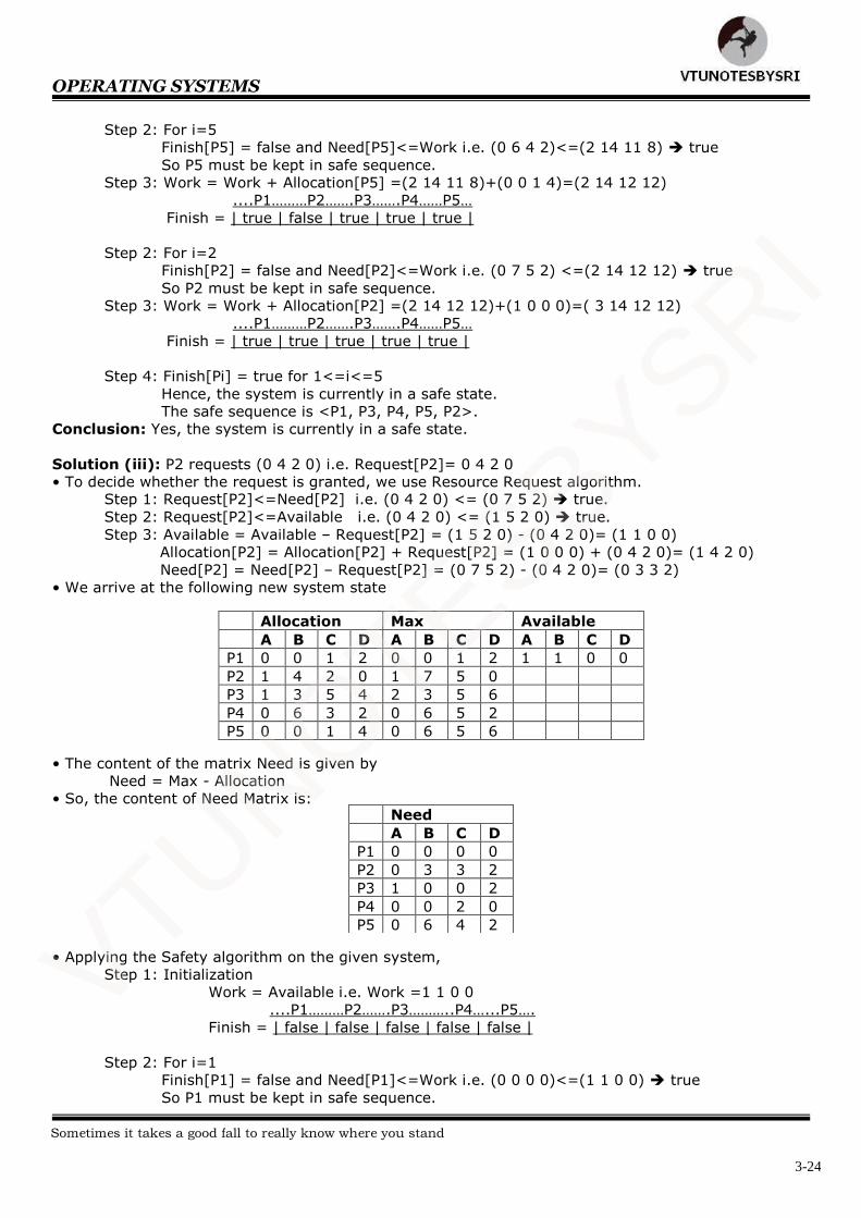
OPERATING SYSTEMS
3-24
Step 2: For i=5
Finish[P5] = false and Need[P5]<=Work i.e. (0 6 4 2)<=(2 14 11 8) true
So P5 must be kept in safe sequence.
Step 3: Work = Work + Allocation[P5] =(2 14 11 8)+(0 0 1 4)=(2 14 12 12)
....P1………P2…….P3…….P4……P5…
Finish = | true | false | true | true | true |
Step 2: For i=2
Finish[P2] = false and Need[P2]<=Work i.e. (0 7 5 2) <=(2 14 12 12) true
So P2 must be kept in safe sequence.
Step 3: Work = Work + Allocation[P2] =(2 14 12 12)+(1 0 0 0)=( 3 14 12 12)
....P1………P2…….P3…….P4……P5…
Finish = | true | true | true | true | true |
Step 4: Finish[Pi] = true for 1<=i<=5
Hence, the system is currently in a safe state.
The safe sequence is <P1, P3, P4, P5, P2>.
Conclusion: Yes, the system is currently in a safe state.
Solution (iii): P2 requests (0 4 2 0) i.e. Request[P2]= 0 4 2 0
• To decide whether the request is granted, we use Resource Request algorithm. Step 1: Request[P2]<=Need[P2] i.e. (0 4 2 0) <= (0 7 5 2) true.
Step 2: Request[P2]<=Available i.e. (0 4 2 0) <= (1 5 2 0) true.
Step 3: Available = Available – Request[P2] = (1 5 2 0) - (0 4 2 0)= (1 1 0 0)
Allocation[P2] = Allocation[P2] + Request[P2] = (1 0 0 0) + (0 4 2 0)= (1 4 2 0)
Need[P2] = Need[P2] – Request[P2] = (0 7 5 2) - (0 4 2 0)= (0 3 3 2)
• We arrive at the following new system state
• The content of the matrix Need is given by
Need = Max - Allocation
• So, the content of Need Matrix is:
• Applying the Safety algorithm on the given system,
Step 1: Initialization
Work = Available i.e. Work =1 1 0 0
....P1………P2…….P3………..P4…...P5….
Finish = | false | false | false | false | false |
Step 2: For i=1
Finish[P1] = false and Need[P1]<=Work i.e. (0 0 0 0)<=(1 1 0 0) true
So P1 must be kept in safe sequence.
Allocation Max Available
A B C D A B C D A B C D
P1 0 0 1 2 0 0 1 2 1 1 0 0
P2 1 4 2 0 1 7 5 0
P3 1 3 5 4 2 3 5 6
P4 0 6 3 2 0 6 5 2
P5 0 0 1 4 0 6 5 6
Need
A B C D
P1 0 0 0 0
P2 0 3 3 2
P3 1 0 0 2
P4 0 0 2 0
P5 0 6 4 2
VTUNOTESBYSRI
Sometimes it takes a good fall to really know where you stand
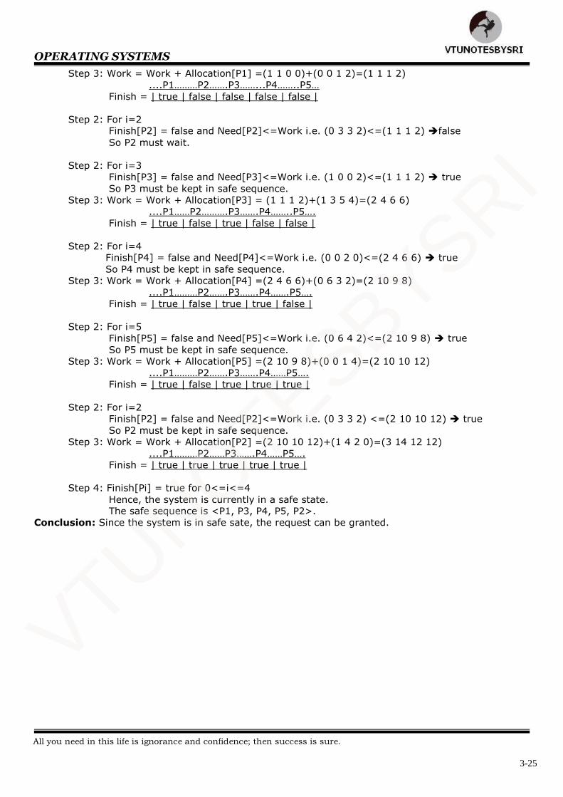
OPERATING SYSTEMS
3-25
Step 3: Work = Work + Allocation[P1] =(1 1 0 0)+(0 0 1 2)=(1 1 1 2)
....P1………P2…….P3……...P4……..P5…
Finish = | true | false | false | false | false |
Step 2: For i=2 Finish[P2] = false and Need[P2]<=Work i.e. (0 3 3 2)<=(1 1 1 2) false
So P2 must wait.
Step 2: For i=3
Finish[P3] = false and Need[P3]<=Work i.e. (1 0 0 2)<=(1 1 1 2) true
So P3 must be kept in safe sequence.
Step 3: Work = Work + Allocation[P3] = (1 1 1 2)+(1 3 5 4)=(2 4 6 6)
....P1……P2……….P3…….P4……..P5….
Finish = | true | false | true | false | false |
Step 2: For i=4
Finish[P4] = false and Need[P4]<=Work i.e. (0 0 2 0)<=(2 4 6 6) true
So P4 must be kept in safe sequence.
Step 3: Work = Work + Allocation[P4] =(2 4 6 6)+(0 6 3 2)=(2 10 9 8)
....P1………P2…….P3…….P4…….P5….
Finish = | true | false | true | true | false |
Step 2: For i=5
Finish[P5] = false and Need[P5]<=Work i.e. (0 6 4 2)<=(2 10 9 8) true
So P5 must be kept in safe sequence.
Step 3: Work = Work + Allocation[P5] =(2 10 9 8)+(0 0 1 4)=(2 10 10 12)
....P1………P2…….P3…….P4……P5….
Finish = | true | false | true | true | true |
Step 2: For i=2
Finish[P2] = false and Need[P2]<=Work i.e. (0 3 3 2) <=(2 10 10 12) true
So P2 must be kept in safe sequence.
Step 3: Work = Work + Allocation[P2] =(2 10 10 12)+(1 4 2 0)=(3 14 12 12)
....P1………P2……P3…….P4……P5….
Finish = | true | true | true | true | true |
Step 4: Finish[Pi] = true for 0<=i<=4
Hence, the system is currently in a safe state.
The safe sequence is <P1, P3, P4, P5, P2>.
Conclusion: Since the system is in safe sate, the request can be granted.
VTUNOTESBYSRI
All you need in this life is ignorance and confidence; then success is sure.
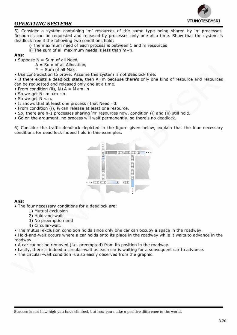
OPERATING SYSTEMS
3-26
5) Consider a system containing ‘m’ resources of the same type being shared by ‘n’ processes.
Resources can be requested and released by processes only one at a time. Show that the system is
deadlock free if the following two conditions hold:
i) The maximum need of each process is between 1 and m resources
ii) The sum of all maximum needs is less than m+n.
Ans:
• Suppose N = Sum of all Needi
A = Sum of all Allocationi
M = Sum of all Maxi.
• Use contradiction to prove: Assume this system is not deadlock free.
• If there exists a deadlock state, then A=m because there's only one kind of resource and resources
can be requested and released only one at a time.
• From condition (ii), N+A = M<m+n
• So we get N+m <m +n.
• So we get N < n.
• It shows that at least one process i that Needi=0.
• From condition (i), Pi can release at least one resource.
• So, there are n-1 processes sharing ‘m’ resources now, condition (i) and (ii) still hold.
• Go on the argument, no process will wait permanently, so there's no deadlock.
6) Consider the traffic deadlock depicted in the figure given below, explain that the four necessary
conditions for dead lock indeed hold in this examples.
Ans:
• The four necessary conditions for a deadlock are:
1) Mutual exclusion
2) Hold-and-wait
3) No preemption and
4) Circular-wait.
• The mutual exclusion condition holds since only one car can occupy a space in the roadway.
• Hold-and-wait occurs where a car holds onto its place in the roadway while it waits to advance in the
roadway.
• A car cannot be removed (i.e. preempted) from its position in the roadway.
• Lastly, there is indeed a circular-wait as each car is waiting for a subsequent car to advance.
• The circular-wait condition is also easily observed from the graphic.
VTUNOTESBYSRI
Success is not how high you have climbed, but how you make a positive difference to the world.
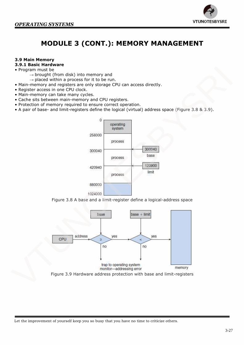
OPERATING SYSTEMS
3-27
MODULE 3 (CONT.): MEMORY MANAGEMENT
3.9 Main Memory
3.9.1 Basic Hardware
• Program must be → brought (from disk) into memory and
→ placed within a process for it to be run.
• Main-memory and registers are only storage CPU can access directly.
• Register access in one CPU clock.
• Main-memory can take many cycles.
• Cache sits between main-memory and CPU registers.
• Protection of memory required to ensure correct operation.
• A pair of base- and limit-registers define the logical (virtual) address space (Figure 3.8 & 3.9).
Figure 3.8 A base and a limit-register define a logical-address space
Figure 3.9 Hardware address protection with base and limit-registers
VTUNOTESBYSRI
Let the improvement of yourself keep you so busy that you have no time to criticize others.
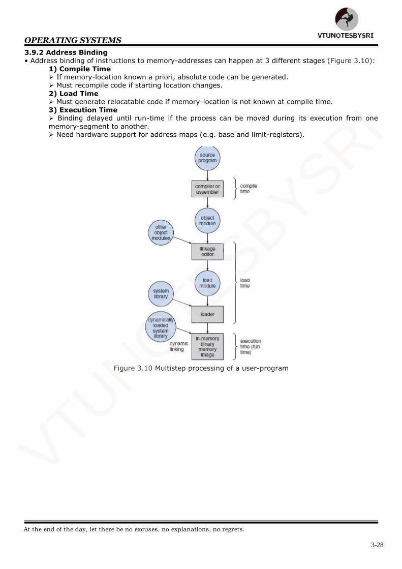
OPERATING SYSTEMS
3-28
3.9.2 Address Binding
• Address binding of instructions to memory-addresses can happen at 3 different stages (Figure 3.10):
1) Compile Time If memory-location known a priori, absolute code can be generated.
Must recompile code if starting location changes.
2) Load Time Must generate relocatable code if memory-location is not known at compile time.
3) Execution Time Binding delayed until run-time if the process can be moved during its execution from one
memory-segment to another. Need hardware support for address maps (e.g. base and limit-registers).
Figure 3.10 Multistep processing of a user-program
VTUNOTESBYSRI
At the end of the day, let there be no excuses, no explanations, no regrets.
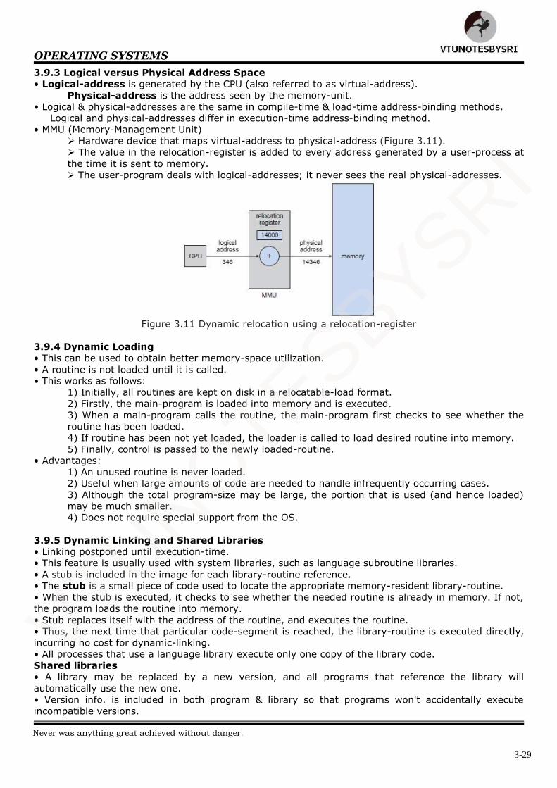
OPERATING SYSTEMS
3-29
3.9.3 Logical versus Physical Address Space
• Logical-address is generated by the CPU (also referred to as virtual-address).
Physical-address is the address seen by the memory-unit.
• Logical & physical-addresses are the same in compile-time & load-time address-binding methods.
Logical and physical-addresses differ in execution-time address-binding method.
• MMU (Memory-Management Unit)
Hardware device that maps virtual-address to physical-address (Figure 3.11).
The value in the relocation-register is added to every address generated by a user-process at
the time it is sent to memory.
The user-program deals with logical-addresses; it never sees the real physical-addresses.
Figure 3.11 Dynamic relocation using a relocation-register
3.9.4 Dynamic Loading
• This can be used to obtain better memory-space utilization.
• A routine is not loaded until it is called.
• This works as follows:
1) Initially, all routines are kept on disk in a relocatable-load format.
2) Firstly, the main-program is loaded into memory and is executed.
3) When a main-program calls the routine, the main-program first checks to see whether the
routine has been loaded.
4) If routine has been not yet loaded, the loader is called to load desired routine into memory.
5) Finally, control is passed to the newly loaded-routine.
• Advantages:
1) An unused routine is never loaded.
2) Useful when large amounts of code are needed to handle infrequently occurring cases.
3) Although the total program-size may be large, the portion that is used (and hence loaded)
may be much smaller.
4) Does not require special support from the OS.
3.9.5 Dynamic Linking and Shared Libraries
• Linking postponed until execution-time.
• This feature is usually used with system libraries, such as language subroutine libraries.
• A stub is included in the image for each library-routine reference.
• The stub is a small piece of code used to locate the appropriate memory-resident library-routine.
• When the stub is executed, it checks to see whether the needed routine is already in memory. If not,
the program loads the routine into memory.
• Stub replaces itself with the address of the routine, and executes the routine.
• Thus, the next time that particular code-segment is reached, the library-routine is executed directly,
incurring no cost for dynamic-linking.
• All processes that use a language library execute only one copy of the library code.
Shared libraries
• A library may be replaced by a new version, and all programs that reference the library will
automatically use the new one.
• Version info. is included in both program & library so that programs won't accidentally execute
incompatible versions.
VTUNOTESBYSRI
Never was anything great achieved without danger.
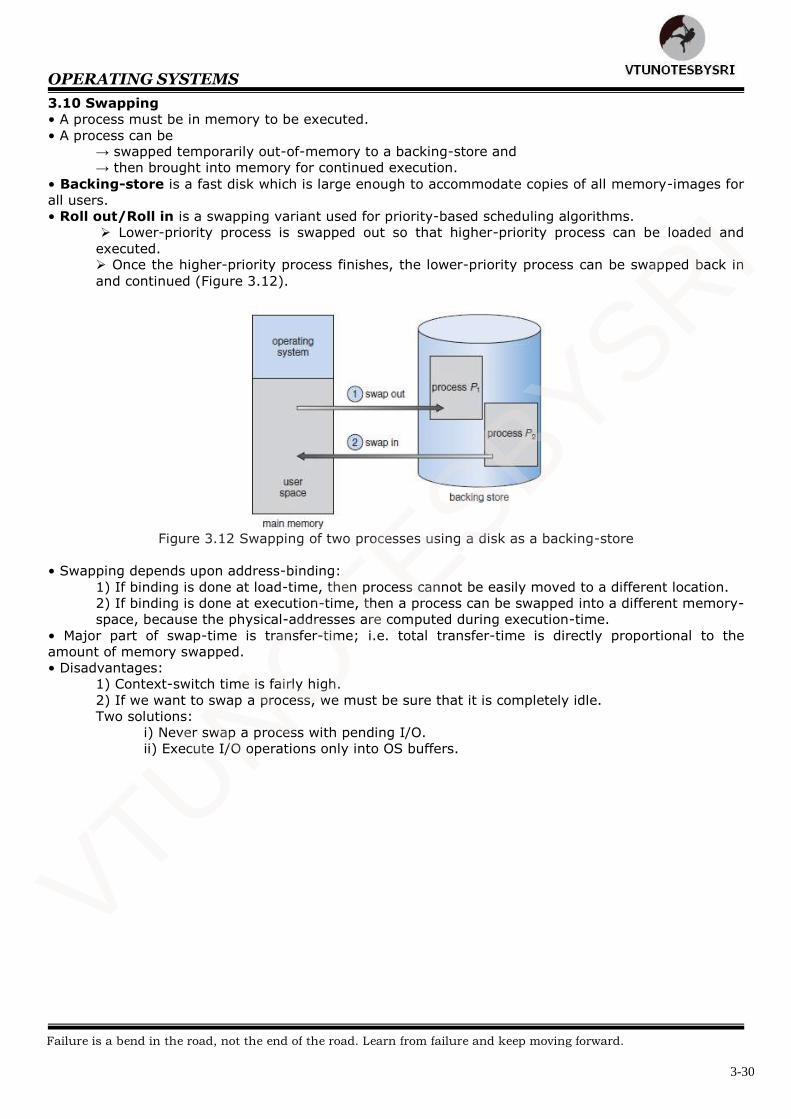
OPERATING SYSTEMS
3-30
3.10 Swapping
• A process must be in memory to be executed.
• A process can be → swapped temporarily out-of-memory to a backing-store and
→ then brought into memory for continued execution.
• Backing-store is a fast disk which is large enough to accommodate copies of all memory-images for
all users.
• Roll out/Roll in is a swapping variant used for priority-based scheduling algorithms.
Lower-priority process is swapped out so that higher-priority process can be loaded and
executed. Once the higher-priority process finishes, the lower-priority process can be swapped back in
and continued (Figure 3.12).
Figure 3.12 Swapping of two processes using a disk as a backing-store
• Swapping depends upon address-binding:
1) If binding is done at load-time, then process cannot be easily moved to a different location.
2) If binding is done at execution-time, then a process can be swapped into a different memory-
space, because the physical-addresses are computed during execution-time.
• Major part of swap-time is transfer-time; i.e. total transfer-time is directly proportional to the
amount of memory swapped.
• Disadvantages:
1) Context-switch time is fairly high.
2) If we want to swap a process, we must be sure that it is completely idle.
Two solutions:
i) Never swap a process with pending I/O.
ii) Execute I/O operations only into OS buffers.
VTUNOTESBYSRI
Failure is a bend in the road, not the end of the road. Learn from failure and keep moving forward.
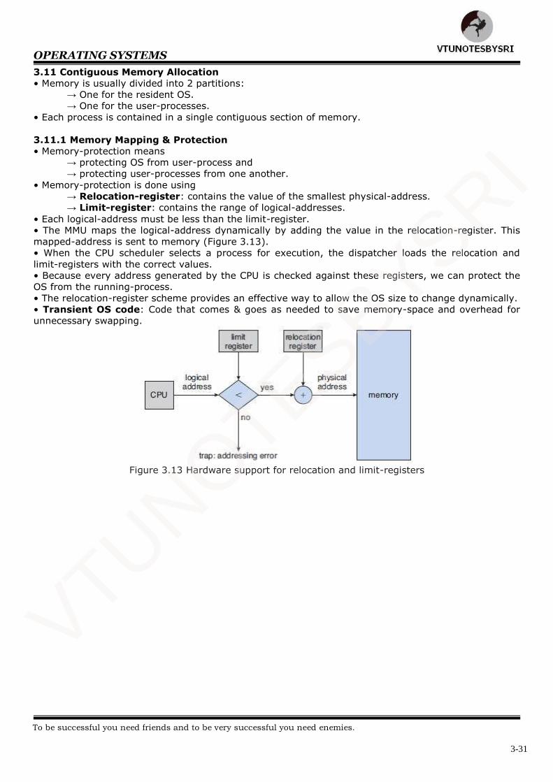
OPERATING SYSTEMS
3-31
3.11 Contiguous Memory Allocation
• Memory is usually divided into 2 partitions:
→ One for the resident OS.
→ One for the user-processes.
• Each process is contained in a single contiguous section of memory.
3.11.1 Memory Mapping & Protection
• Memory-protection means
→ protecting OS from user-process and
→ protecting user-processes from one another.
• Memory-protection is done using
→ Relocation-register: contains the value of the smallest physical-address.
→ Limit-register: contains the range of logical-addresses.
• Each logical-address must be less than the limit-register.
• The MMU maps the logical-address dynamically by adding the value in the relocation-register. This
mapped-address is sent to memory (Figure 3.13).
• When the CPU scheduler selects a process for execution, the dispatcher loads the relocation and
limit-registers with the correct values.
• Because every address generated by the CPU is checked against these registers, we can protect the
OS from the running-process.
• The relocation-register scheme provides an effective way to allow the OS size to change dynamically.
• Transient OS code: Code that comes & goes as needed to save memory-space and overhead for
unnecessary swapping.
Figure 3.13 Hardware support for relocation and limit-registers
VTUNOTESBYSRI
To be successful you need friends and to be very successful you need enemies.
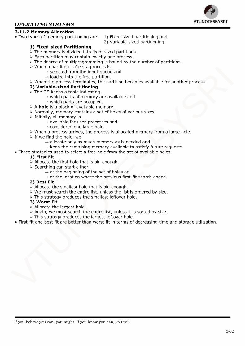
OPERATING SYSTEMS
3-32
3.11.2 Memory Allocation
• Two types of memory partitioning are: 1) Fixed-sized partitioning and
2) Variable-sized partitioning
1) Fixed-sized Partitioning The memory is divided into fixed-sized partitions.
Each partition may contain exactly one process.
The degree of multiprogramming is bound by the number of partitions.
When a partition is free, a process is
→ selected from the input queue and
→ loaded into the free partition.
When the process terminates, the partition becomes available for another process.
2) Variable-sized Partitioning The OS keeps a table indicating
→ which parts of memory are available and
→ which parts are occupied.
A hole is a block of available memory.
Normally, memory contains a set of holes of various sizes.
Initially, all memory is
→ available for user-processes and
→ considered one large hole.
When a process arrives, the process is allocated memory from a large hole.
If we find the hole, we
→ allocate only as much memory as is needed and
→ keep the remaining memory available to satisfy future requests.
• Three strategies used to select a free hole from the set of available holes.
1) First Fit Allocate the first hole that is big enough.
Searching can start either
→ at the beginning of the set of holes or
→ at the location where the previous first-fit search ended.
2) Best Fit Allocate the smallest hole that is big enough.
We must search the entire list, unless the list is ordered by size.
This strategy produces the smallest leftover hole.
3) Worst Fit
Allocate the largest hole.
Again, we must search the entire list, unless it is sorted by size.
This strategy produces the largest leftover hole.
• First-fit and best fit are better than worst fit in terms of decreasing time and storage utilization.
VTUNOTESBYSRI
If you believe you can, you might. If you know you can, you will.
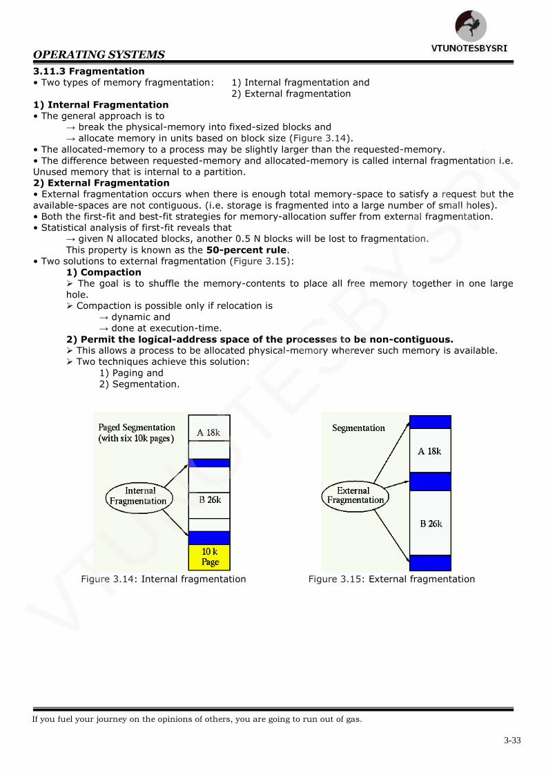
OPERATING SYSTEMS
3-33
3.11.3 Fragmentation
• Two types of memory fragmentation: 1) Internal fragmentation and
2) External fragmentation
1) Internal Fragmentation
• The general approach is to → break the physical-memory into fixed-sized blocks and
→ allocate memory in units based on block size (Figure 3.14).
• The allocated-memory to a process may be slightly larger than the requested-memory.
• The difference between requested-memory and allocated-memory is called internal fragmentation i.e.
Unused memory that is internal to a partition.
2) External Fragmentation
• External fragmentation occurs when there is enough total memory-space to satisfy a request but the
available-spaces are not contiguous. (i.e. storage is fragmented into a large number of small holes).
• Both the first-fit and best-fit strategies for memory-allocation suffer from external fragmentation.
• Statistical analysis of first-fit reveals that → given N allocated blocks, another 0.5 N blocks will be lost to fragmentation.
This property is known as the 50-percent rule.
• Two solutions to external fragmentation (Figure 3.15):
1) Compaction
The goal is to shuffle the memory-contents to place all free memory together in one large
hole. Compaction is possible only if relocation is
→ dynamic and
→ done at execution-time.
2) Permit the logical-address space of the processes to be non-contiguous. This allows a process to be allocated physical-memory wherever such memory is available.
Two techniques achieve this solution:
1) Paging and
2) Segmentation.
Figure 3.14: Internal fragmentation Figure 3.15: External fragmentation
VTUNOTESBYSRI
If you fuel your journey on the opinions of others, you are going to run out of gas.
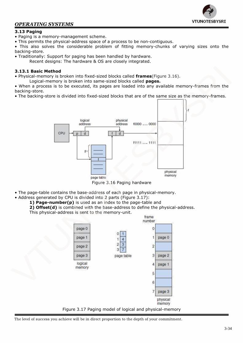
OPERATING SYSTEMS
3-34
3.13 Paging
• Paging is a memory-management scheme.
• This permits the physical-address space of a process to be non-contiguous.
• This also solves the considerable problem of fitting memory-chunks of varying sizes onto the
backing-store.
• Traditionally: Support for paging has been handled by hardware.
Recent designs: The hardware & OS are closely integrated.
3.13.1 Basic Method
• Physical-memory is broken into fixed-sized blocks called frames(Figure 3.16).
Logical-memory is broken into same-sized blocks called pages.
• When a process is to be executed, its pages are loaded into any available memory-frames from the
backing-store.
• The backing-store is divided into fixed-sized blocks that are of the same size as the memory-frames.
Figure 3.16 Paging hardware
• The page-table contains the base-address of each page in physical-memory.
• Address generated by CPU is divided into 2 parts (Figure 3.17):
1) Page-number(p) is used as an index to the page-table and
2) Offset(d) is combined with the base-address to define the physical-address.
This physical-address is sent to the memory-unit.
Figure 3.17 Paging model of logical and physical-memory
VTUNOTESBYSRI
The level of success you achieve will be in direct proportion to the depth of your commitment.
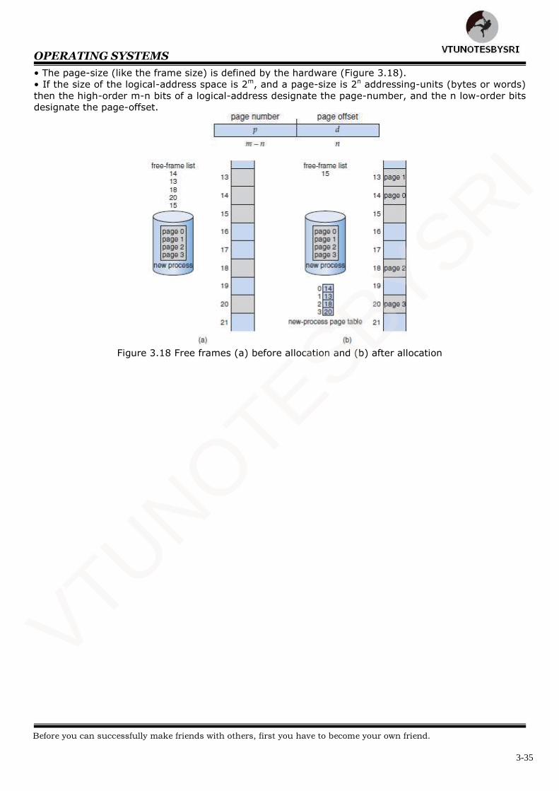
OPERATING SYSTEMS
3-35
• The page-size (like the frame size) is defined by the hardware (Figure 3.18).
• If the size of the logical-address space is 2m, and a page-size is 2n addressing-units (bytes or words)
then the high-order m-n bits of a logical-address designate the page-number, and the n low-order bits
designate the page-offset.
Figure 3.18 Free frames (a) before allocation and (b) after allocation
VTUNOTESBYSRI
Before you can successfully make friends with others, first you have to become your own friend.
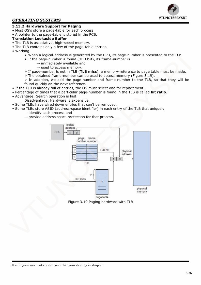
OPERATING SYSTEMS
3-36
3.13.2 Hardware Support for Paging
• Most OS's store a page-table for each process.
• A pointer to the page-table is stored in the PCB.
Translation Lookaside Buffer
• The TLB is associative, high-speed memory.
• The TLB contains only a few of the page-table entries.
• Working: When a logical-address is generated by the CPU, its page-number is presented to the TLB.
If the page-number is found (TLB hit), its frame-number is
→ immediately available and
→ used to access memory.
If page-number is not in TLB (TLB miss), a memory-reference to page table must be made.
The obtained frame-number can be used to access memory (Figure 3.19).
In addition, we add the page-number and frame-number to the TLB, so that they will be
found quickly on the next reference.
• If the TLB is already full of entries, the OS must select one for replacement.
• Percentage of times that a particular page-number is found in the TLB is called hit ratio.
• Advantage: Search operation is fast.
Disadvantage: Hardware is expensive.
• Some TLBs have wired down entries that can't be removed.
• Some TLBs store ASID (address-space identifier) in each entry of the TLB that uniquely
→ identify each process and
→ provide address space protection for that process.
Figure 3.19 Paging hardware with TLB
VTUNOTESBYSRI
It is in your moments of decision that your destiny is shaped.
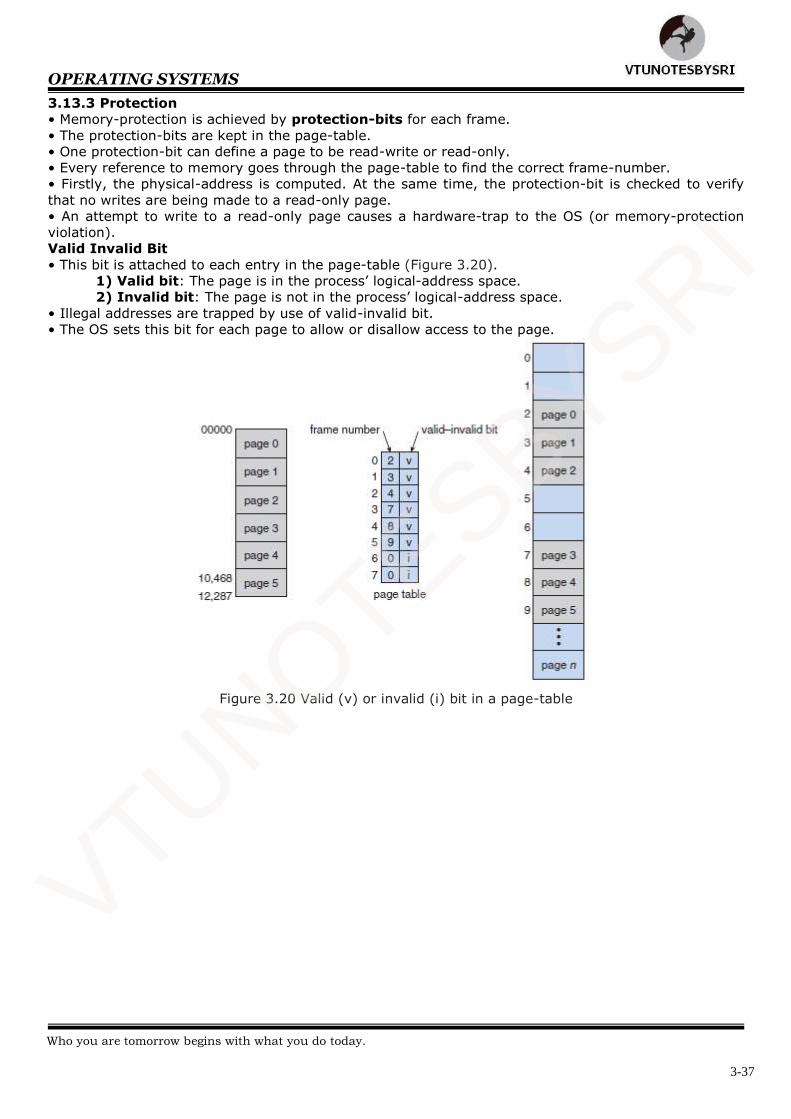
OPERATING SYSTEMS
3-37
3.13.3 Protection
• Memory-protection is achieved by protection-bits for each frame.
• The protection-bits are kept in the page-table.
• One protection-bit can define a page to be read-write or read-only.
• Every reference to memory goes through the page-table to find the correct frame-number.
• Firstly, the physical-address is computed. At the same time, the protection-bit is checked to verify
that no writes are being made to a read-only page.
• An attempt to write to a read-only page causes a hardware-trap to the OS (or memory-protection
violation).
Valid Invalid Bit
• This bit is attached to each entry in the page-table (Figure 3.20).
1) Valid bit: The page is in the process’ logical-address space.
2) Invalid bit: The page is not in the process’ logical-address space.
• Illegal addresses are trapped by use of valid-invalid bit.
• The OS sets this bit for each page to allow or disallow access to the page.
Figure 3.20 Valid (v) or invalid (i) bit in a page-table
VTUNOTESBYSRI
Who you are tomorrow begins with what you do today.
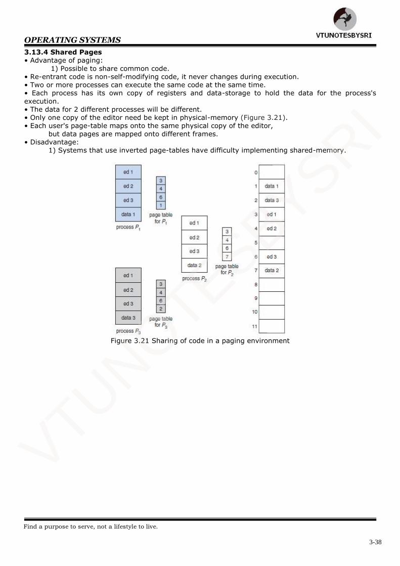
OPERATING SYSTEMS
3-38
3.13.4 Shared Pages
• Advantage of paging:
1) Possible to share common code.
• Re-entrant code is non-self-modifying code, it never changes during execution.
• Two or more processes can execute the same code at the same time.
• Each process has its own copy of registers and data-storage to hold the data for the process's
execution.
• The data for 2 different processes will be different.
• Only one copy of the editor need be kept in physical-memory (Figure 3.21).
• Each user's page-table maps onto the same physical copy of the editor,
but data pages are mapped onto different frames.
• Disadvantage:
1) Systems that use inverted page-tables have difficulty implementing shared-memory.
Figure 3.21 Sharing of code in a paging environment
VTUNOTESBYSRI
Find a purpose to serve, not a lifestyle to live.
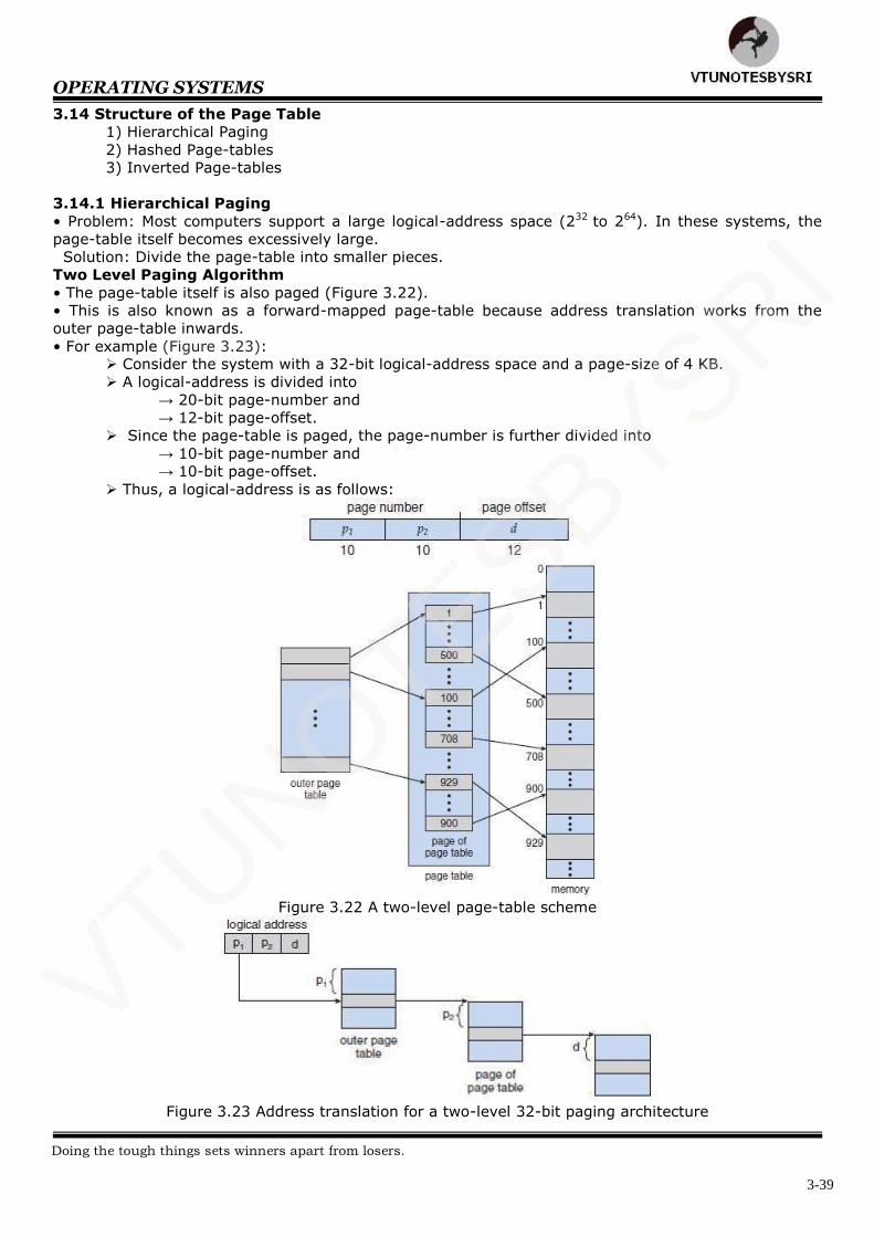
OPERATING SYSTEMS
3-39
3.14 Structure of the Page Table
1) Hierarchical Paging
2) Hashed Page-tables
3) Inverted Page-tables
3.14.1 Hierarchical Paging
• Problem: Most computers support a large logical-address space (232 to 264). In these systems, the
page-table itself becomes excessively large.
Solution: Divide the page-table into smaller pieces.
Two Level Paging Algorithm
• The page-table itself is also paged (Figure 3.22).
• This is also known as a forward-mapped page-table because address translation works from the
outer page-table inwards.
• For example (Figure 3.23): Consider the system with a 32-bit logical-address space and a page-size of 4 KB.
A logical-address is divided into
→ 20-bit page-number and
→ 12-bit page-offset.
Since the page-table is paged, the page-number is further divided into
→ 10-bit page-number and
→ 10-bit page-offset.
Thus, a logical-address is as follows:
Figure 3.22 A two-level page-table scheme
Figure 3.23 Address translation for a two-level 32-bit paging architecture
VTUNOTESBYSRI
Doing the tough things sets winners apart from losers.
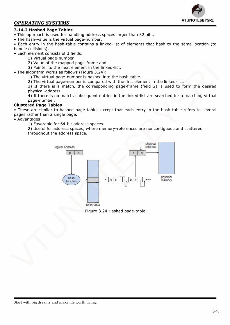
OPERATING SYSTEMS
3-40
3.14.2 Hashed Page Tables
• This approach is used for handling address spaces larger than 32 bits.
• The hash-value is the virtual page-number.
• Each entry in the hash-table contains a linked-list of elements that hash to the same location (to
handle collisions).
• Each element consists of 3 fields:
1) Virtual page-number
2) Value of the mapped page-frame and
3) Pointer to the next element in the linked-list.
• The algorithm works as follows (Figure 3.24):
1) The virtual page-number is hashed into the hash-table.
2) The virtual page-number is compared with the first element in the linked-list.
3) If there is a match, the corresponding page-frame (field 2) is used to form the desired
physical-address.
4) If there is no match, subsequent entries in the linked-list are searched for a matching virtual
page-number.
Clustered Page Tables
• These are similar to hashed page-tables except that each entry in the hash-table refers to several
pages rather than a single page.
• Advantages:
1) Favorable for 64-bit address spaces.
2) Useful for address spaces, where memory-references are noncontiguous and scattered
throughout the address space.
Figure 3.24 Hashed page-table
VTUNOTESBYSRI
Start with big dreams and make life worth living.
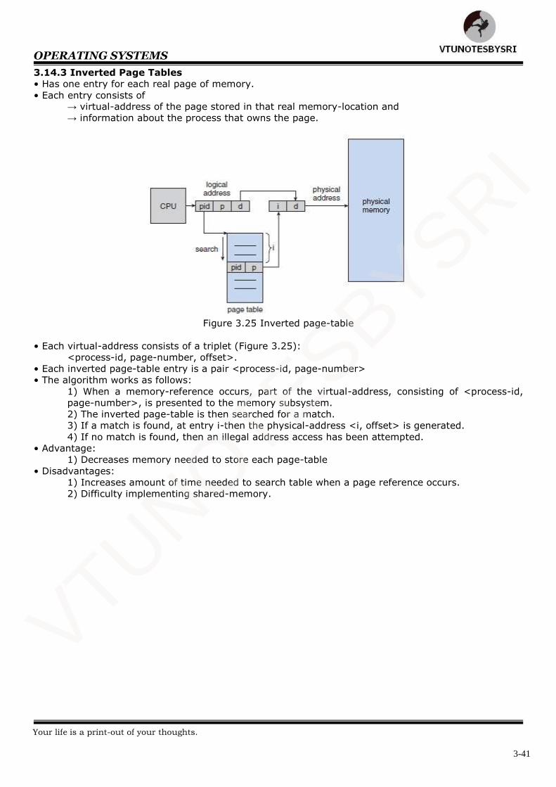
OPERATING SYSTEMS
3-41
3.14.3 Inverted Page Tables
• Has one entry for each real page of memory.
• Each entry consists of → virtual-address of the page stored in that real memory-location and
→ information about the process that owns the page.
Figure 3.25 Inverted page-table
• Each virtual-address consists of a triplet (Figure 3.25):
<process-id, page-number, offset>.
• Each inverted page-table entry is a pair <process-id, page-number>
• The algorithm works as follows:
1) When a memory-reference occurs, part of the virtual-address, consisting of <process-id,
page-number>, is presented to the memory subsystem.
2) The inverted page-table is then searched for a match.
3) If a match is found, at entry i-then the physical-address <i, offset> is generated.
4) If no match is found, then an illegal address access has been attempted.
• Advantage:
1) Decreases memory needed to store each page-table
• Disadvantages:
1) Increases amount of time needed to search table when a page reference occurs.
2) Difficulty implementing shared-memory.
VTUNOTESBYSRI
Your life is a print-out of your thoughts.
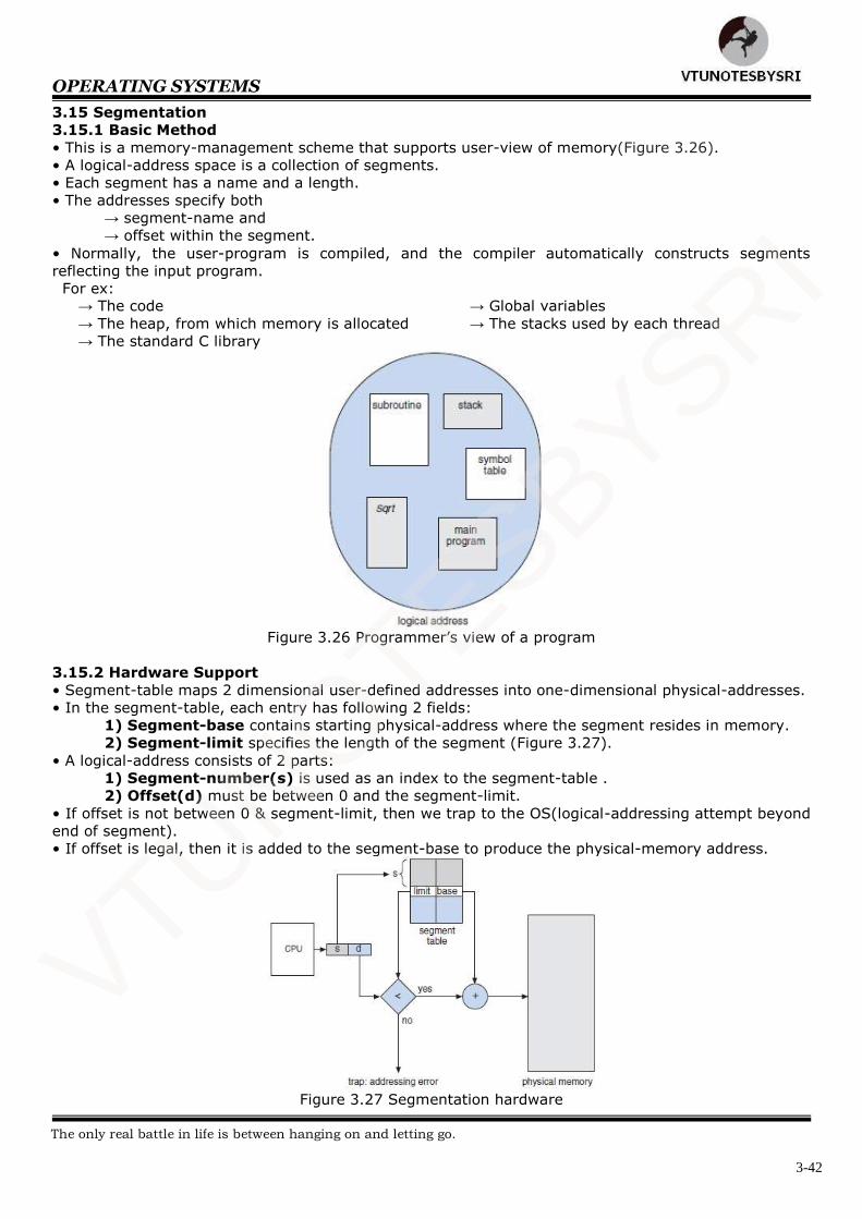
OPERATING SYSTEMS
3-42
3.15 Segmentation
3.15.1 Basic Method
• This is a memory-management scheme that supports user-view of memory(Figure 3.26).
• A logical-address space is a collection of segments.
• Each segment has a name and a length.
• The addresses specify both
→ segment-name and
→ offset within the segment.
• Normally, the user-program is compiled, and the compiler automatically constructs segments
reflecting the input program.
For ex: → The code → Global variables
→ The heap, from which memory is allocated → The stacks used by each thread
→ The standard C library
Figure 3.26 Programmer’s view of a program
3.15.2 Hardware Support
• Segment-table maps 2 dimensional user-defined addresses into one-dimensional physical-addresses.
• In the segment-table, each entry has following 2 fields:
1) Segment-base contains starting physical-address where the segment resides in memory.
2) Segment-limit specifies the length of the segment (Figure 3.27).
• A logical-address consists of 2 parts:
1) Segment-number(s) is used as an index to the segment-table .
2) Offset(d) must be between 0 and the segment-limit.
• If offset is not between 0 & segment-limit, then we trap to the OS(logical-addressing attempt beyond
end of segment).
• If offset is legal, then it is added to the segment-base to produce the physical-memory address.
Figure 3.27 Segmentation hardware
VTUNOTESBYSRI
The only real battle in life is between hanging on and letting go.
OPERATING SYSTEMS
4-1
MODULE 4: VIRTUAL MEMORY
FILE-SYSTEM INTERFACE
FILE-SYSTEM IMPLEMENTATION
4.1 Virtual Memory
4.2 Demand Paging
4.2.1 Basic Concepts
4.2.2 Performance
4.3 Copy-on-Write
4.4 Page Replacement
4.4.1 Need for Page Replacement
4.4.2 Basic Page Replacement
4.4.3 FIFO Page Replacement
4.4.4 Optimal Page Replacement
4.4.5 LRU Page Replacement
4.4.6 LRU-Approximation Page Replacement
4.4.6.1 Additional-Reference-Bits Algorithm
4.4.6.2 Second-Chance Algorithm
4.4.6.3 Enhanced Second-Chance Algorithm
4.4.7 Counting-Based Page Replacement
4.5 Allocation of Frames
4.5.1 Minimum Number of Frames
4.5.2 Allocation Algorithms
4.5.3 Global versus Local Allocation
4.6 Thrashing
4.6.1 Cause of Thrashing
4.7 File Concept
4.7.1 File Attributes
4.7.2 File Operations
4.7.3 File Types
4.7.4 File Structure
4.7.5 Internal File Structure
4.8 Access Methods
4.8.1 Sequential Access
4.8.2 Direct Access (Relative Access)
4.8.3 Other Access Methods
4.9 Directory and Disk Structure
4.9.1 Storage Structure
4.9.2 Directory Overview
4.9.3 Single Level Directory
4.9.4 Two Level Directory
4.9.5 Tree Structured Directories
4.9.6 Acyclic Graph Directories
4.9.7 General Graph Directory
4.10 File-System Mounting
4.11 File Sharing
4.11.1 Multiple Users
4.11.2 Remote File Systems
4.11.2.1 Client Server Model
4.11.2.2 Distributed Information Systems
4.11.2.3 Failure Modes
4.11.3 Consistency Semantics
VTUNOTESBYSRI
The backbone of success is...hard work, determination, good planning, and perserverence.
OPERATING SYSTEMS
4-2
4.12 Protection
4.12.1 Types of Access
4.12.2 Access Control
4.12.3 Other Protection Approaches
4.13 File-System Structure
4.13.1 Layered File System
4.14 File-System Implementation
4.14.1 Overview
4.14.2 Partitions & Mounting
4.14.3 Virtual File Systems
4.15 Directory Implementation
4.15.1 Linear List
4.15.2 Hash Table
4.16 Allocation Methods
4.16.1 Contiguous Allocation
4.16.2 Linked Allocation
4.16.3 Indexed Allocation
4.16.4 Performance
4.17 Free-Space Management
VTUNOTESBYSRI
To do more for the world than the world does for you - that is success.
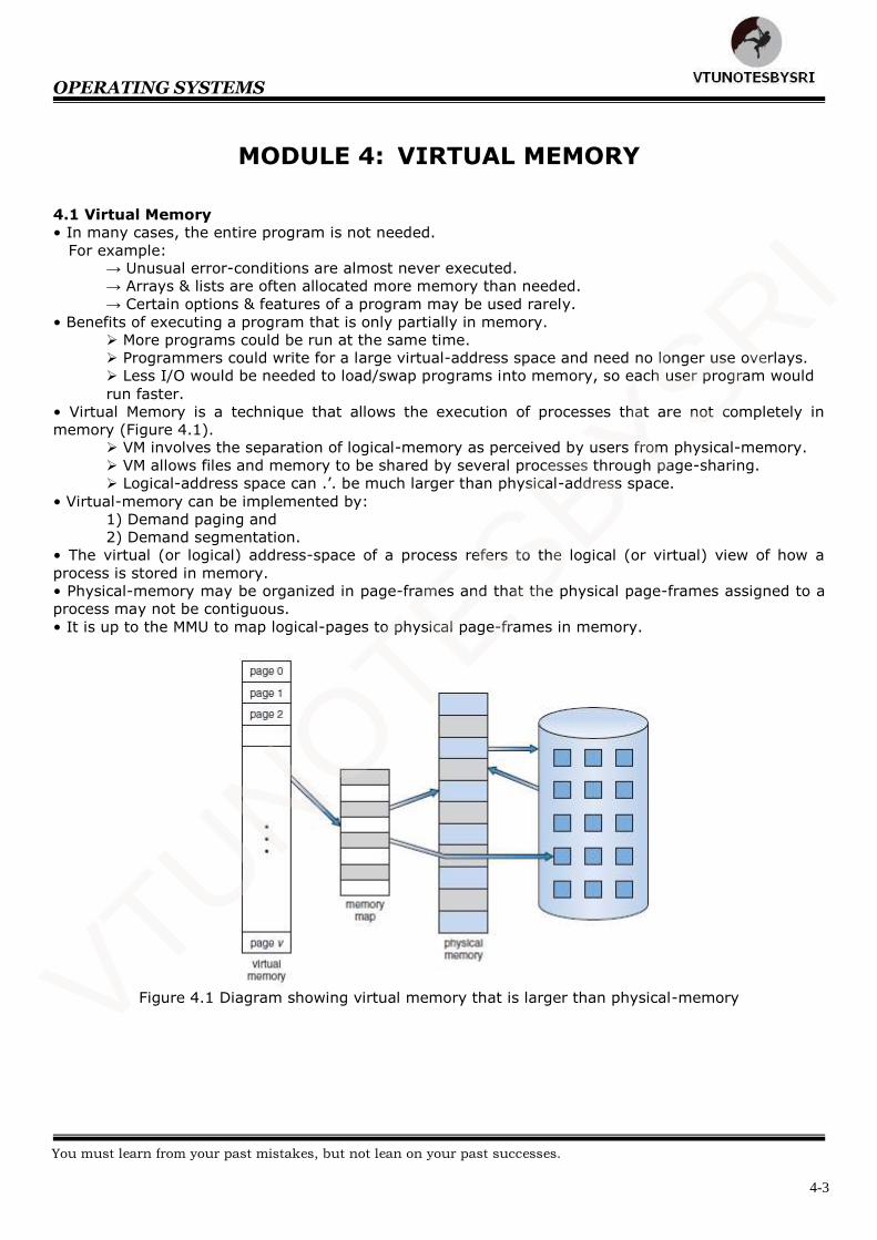
OPERATING SYSTEMS
4-3
MODULE 4: VIRTUAL MEMORY
4.1 Virtual Memory
• In many cases, the entire program is not needed.
For example: → Unusual error-conditions are almost never executed.
→ Arrays & lists are often allocated more memory than needed.
→ Certain options & features of a program may be used rarely.
• Benefits of executing a program that is only partially in memory.
More programs could be run at the same time.
Programmers could write for a large virtual-address space and need no longer use overlays.
Less I/O would be needed to load/swap programs into memory, so each user program would
run faster.
• Virtual Memory is a technique that allows the execution of processes that are not completely in
memory (Figure 4.1). VM involves the separation of logical-memory as perceived by users from physical-memory.
VM allows files and memory to be shared by several processes through page-sharing.
Logical-address space can .‟. be much larger than physical-address space.
• Virtual-memory can be implemented by:
1) Demand paging and
2) Demand segmentation.
• The virtual (or logical) address-space of a process refers to the logical (or virtual) view of how a
process is stored in memory.
• Physical-memory may be organized in page-frames and that the physical page-frames assigned to a
process may not be contiguous.
• It is up to the MMU to map logical-pages to physical page-frames in memory.
Figure 4.1 Diagram showing virtual memory that is larger than physical-memory
VTUNOTESBYSRI
You must learn from your past mistakes, but not lean on your past successes.
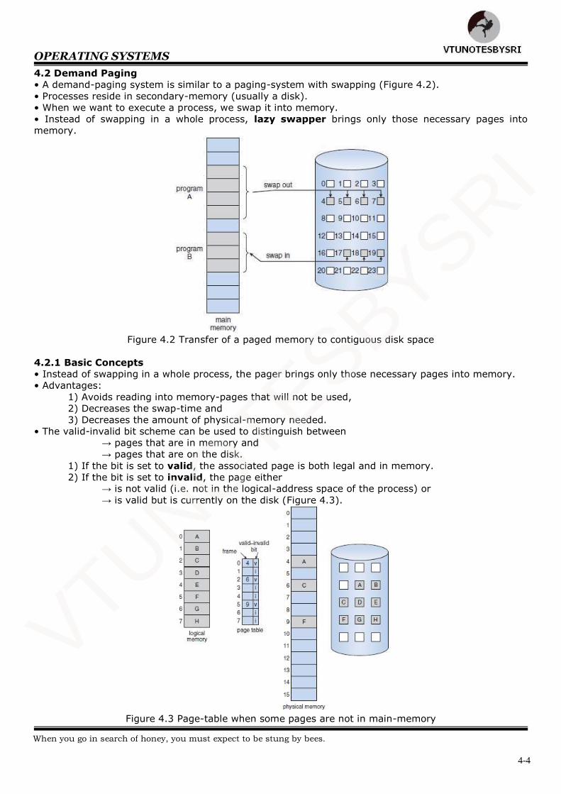
OPERATING SYSTEMS
4-4
4.2 Demand Paging
• A demand-paging system is similar to a paging-system with swapping (Figure 4.2).
• Processes reside in secondary-memory (usually a disk).
• When we want to execute a process, we swap it into memory.
• Instead of swapping in a whole process, lazy swapper brings only those necessary pages into
memory.
Figure 4.2 Transfer of a paged memory to contiguous disk space
4.2.1 Basic Concepts
• Instead of swapping in a whole process, the pager brings only those necessary pages into memory.
• Advantages:
1) Avoids reading into memory-pages that will not be used,
2) Decreases the swap-time and
3) Decreases the amount of physical-memory needed.
• The valid-invalid bit scheme can be used to distinguish between
→ pages that are in memory and
→ pages that are on the disk.
1) If the bit is set to valid, the associated page is both legal and in memory.
2) If the bit is set to invalid, the page either → is not valid (i.e. not in the logical-address space of the process) or
→ is valid but is currently on the disk (Figure 4.3).
Figure 4.3 Page-table when some pages are not in main-memory
VTUNOTESBYSRI
When you go in search of honey, you must expect to be stung by bees.
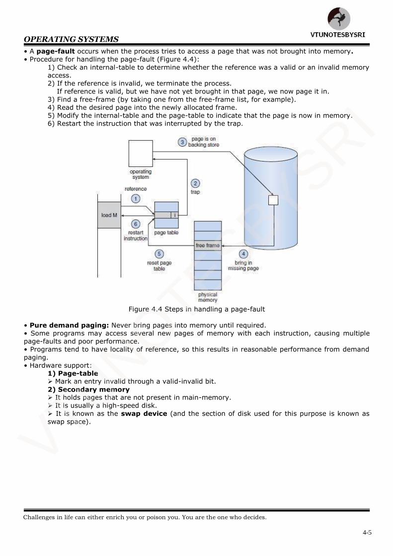
OPERATING SYSTEMS
4-5
• A page-fault occurs when the process tries to access a page that was not brought into memory.
• Procedure for handling the page-fault (Figure 4.4):
1) Check an internal-table to determine whether the reference was a valid or an invalid memory
access.
2) If the reference is invalid, we terminate the process.
If reference is valid, but we have not yet brought in that page, we now page it in.
3) Find a free-frame (by taking one from the free-frame list, for example).
4) Read the desired page into the newly allocated frame.
5) Modify the internal-table and the page-table to indicate that the page is now in memory.
6) Restart the instruction that was interrupted by the trap.
Figure 4.4 Steps in handling a page-fault
• Pure demand paging: Never bring pages into memory until required.
• Some programs may access several new pages of memory with each instruction, causing multiple
page-faults and poor performance.
• Programs tend to have locality of reference, so this results in reasonable performance from demand
paging.
• Hardware support:
1) Page-table Mark an entry invalid through a valid-invalid bit.
2) Secondary memory It holds pages that are not present in main-memory.
It is usually a high-speed disk.
It is known as the swap device (and the section of disk used for this purpose is known as
swap space).
VTUNOTESBYSRI
Challenges in life can either enrich you or poison you. You are the one who decides.
OPERATING SYSTEMS
4-6
4.2.2 Performance
• Demand paging can significantly affect the performance of a computer-system.
• Let p be the probability of a page-fault (0≤p ≤1).
if p = 0, no page-faults.
if p = 1, every reference is a fault.
• effective access time(EAT)=[(1 - p) *memory access]+ [p *page-fault time]
• A page-fault causes the following events to occur:
1) Trap to the OS.
2) Save the user-registers and process-state.
3) Determine that the interrupt was a page-fault. '
4) Check that the page-reference was legal and determine the location of the page on the disk.
5) Issue a read from the disk to a free frame:
a. Wait in a queue for this device until the read request is serviced.
b. Wait for the device seek time.
c. Begin the transfer of the page to a free frame.
6) While waiting, allocate the CPU to some other user.
7) Receive an interrupt from the disk I/O subsystem (I/O completed).
8) Save the registers and process-state for the other user (if step 6 is executed).
9) Determine that the interrupt was from the disk.
10) Correct the page-table and other tables to show that the desired page is now in memory.
11) Wait for the CPU to be allocated to this process again.
12) Restore the user-registers, process-state, and new page-table, and then resume the
interrupted instruction.
4.3 Copy-on-Write
• This technique allows the parent and child processes initially to share the same pages.
• If either process writes to a shared-page, a copy of the shared-page is created.
• For example:
Assume that the child process attempts to modify a page containing portions of the stack,
with the pages set to be copy-on-write. OS will then create a copy of this page, mapping it to the address space of the child process.
Child process will then modify its copied page & not the page belonging to the parent process.
VTUNOTESBYSRI
FOCUS = Follow On Course Until Successful.
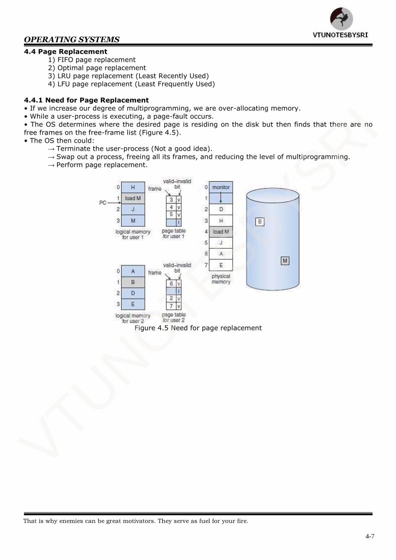
OPERATING SYSTEMS
4-7
4.4 Page Replacement
1) FIFO page replacement
2) Optimal page replacement
3) LRU page replacement (Least Recently Used)
4) LFU page replacement (Least Frequently Used)
4.4.1 Need for Page Replacement
• If we increase our degree of multiprogramming, we are over-allocating memory.
• While a user-process is executing, a page-fault occurs.
• The OS determines where the desired page is residing on the disk but then finds that there are no
free frames on the free-frame list (Figure 4.5).
• The OS then could: → Terminate the user-process (Not a good idea).
→ Swap out a process, freeing all its frames, and reducing the level of multiprogramming.
→ Perform page replacement.
Figure 4.5 Need for page replacement
VTUNOTESBYSRI
That is why enemies can be great motivators. They serve as fuel for your fire.
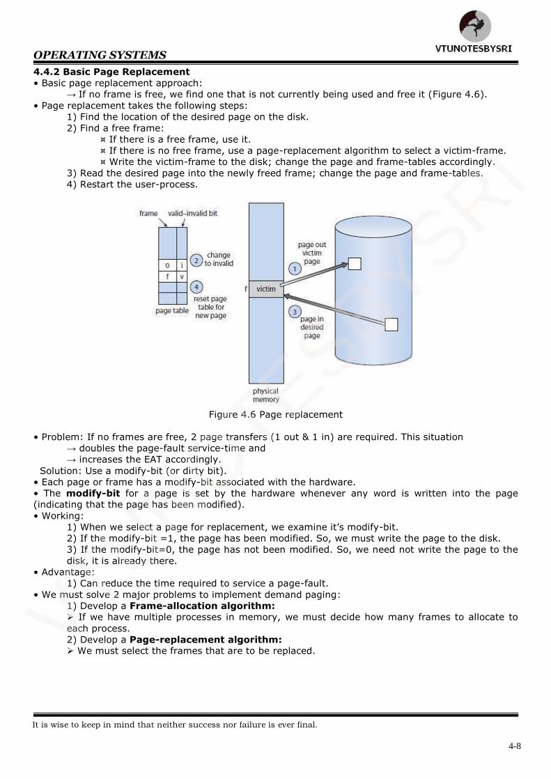
OPERATING SYSTEMS
4-8
4.4.2 Basic Page Replacement
• Basic page replacement approach:
→ If no frame is free, we find one that is not currently being used and free it (Figure 4.6).
• Page replacement takes the following steps:
1) Find the location of the desired page on the disk.
2) Find a free frame:
¤ If there is a free frame, use it.
¤ If there is no free frame, use a page-replacement algorithm to select a victim-frame.
¤ Write the victim-frame to the disk; change the page and frame-tables accordingly.
3) Read the desired page into the newly freed frame; change the page and frame-tables.
4) Restart the user-process.
Figure 4.6 Page replacement
• Problem: If no frames are free, 2 page transfers (1 out & 1 in) are required. This situation
→ doubles the page-fault service-time and
→ increases the EAT accordingly.
Solution: Use a modify-bit (or dirty bit).
• Each page or frame has a modify-bit associated with the hardware.
• The modify-bit for a page is set by the hardware whenever any word is written into the page
(indicating that the page has been modified).
• Working:
1) When we select a page for replacement, we examine it‟s modify-bit.
2) If the modify-bit =1, the page has been modified. So, we must write the page to the disk.
3) If the modify-bit=0, the page has not been modified. So, we need not write the page to the
disk, it is already there.
• Advantage:
1) Can reduce the time required to service a page-fault.
• We must solve 2 major problems to implement demand paging:
1) Develop a Frame-allocation algorithm: If we have multiple processes in memory, we must decide how many frames to allocate to
each process.
2) Develop a Page-replacement algorithm: We must select the frames that are to be replaced.
VTUNOTESBYSRI
It is wise to keep in mind that neither success nor failure is ever final.
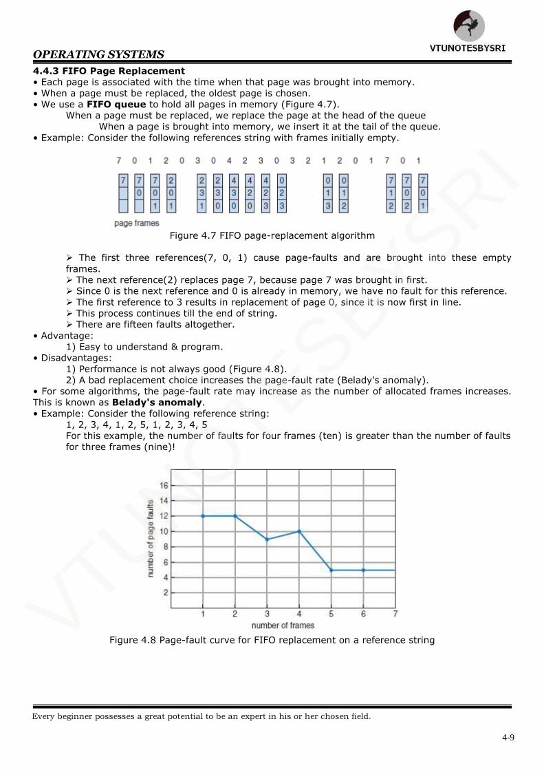
OPERATING SYSTEMS
4-9
4.4.3 FIFO Page Replacement
• Each page is associated with the time when that page was brought into memory.
• When a page must be replaced, the oldest page is chosen.
• We use a FIFO queue to hold all pages in memory (Figure 4.7).
When a page must be replaced, we replace the page at the head of the queue
When a page is brought into memory, we insert it at the tail of the queue.
• Example: Consider the following references string with frames initially empty.
Figure 4.7 FIFO page-replacement algorithm
The first three references(7, 0, 1) cause page-faults and are brought into these empty
frames. The next reference(2) replaces page 7, because page 7 was brought in first.
Since 0 is the next reference and 0 is already in memory, we have no fault for this reference.
The first reference to 3 results in replacement of page 0, since it is now first in line.
This process continues till the end of string.
There are fifteen faults altogether.
• Advantage:
1) Easy to understand & program.
• Disadvantages:
1) Performance is not always good (Figure 4.8).
2) A bad replacement choice increases the page-fault rate (Belady's anomaly).
• For some algorithms, the page-fault rate may increase as the number of allocated frames increases.
This is known as Belady's anomaly.
• Example: Consider the following reference string:
1, 2, 3, 4, 1, 2, 5, 1, 2, 3, 4, 5
For this example, the number of faults for four frames (ten) is greater than the number of faults
for three frames (nine)!
Figure 4.8 Page-fault curve for FIFO replacement on a reference string
VTUNOTESBYSRI
Every beginner possesses a great potential to be an expert in his or her chosen field.
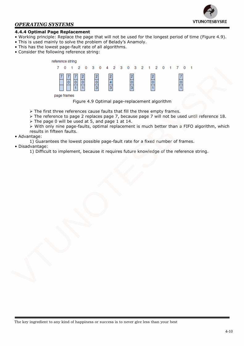
OPERATING SYSTEMS
4-10
4.4.4 Optimal Page Replacement
• Working principle: Replace the page that will not be used for the longest period of time (Figure 4.9).
• This is used mainly to solve the problem of Belady‟s Anamoly.
• This has the lowest page-fault rate of all algorithms.
• Consider the following reference string:
Figure 4.9 Optimal page-replacement algorithm
The first three references cause faults that fill the three empty frames.
The reference to page 2 replaces page 7, because page 7 will not be used until reference 18.
The page 0 will be used at 5, and page 1 at 14.
With only nine page-faults, optimal replacement is much better than a FIFO algorithm, which
results in fifteen faults.
• Advantage:
1) Guarantees the lowest possible page-fault rate for a fixed number of frames.
• Disadvantage:
1) Difficult to implement, because it requires future knowledge of the reference string.
VTUNOTESBYSRI
The key ingredient to any kind of happiness or success is to never give less than your best
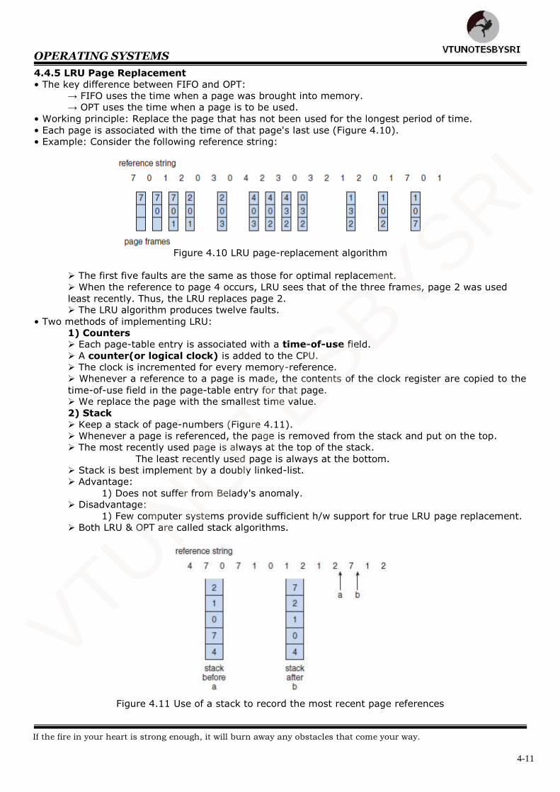
OPERATING SYSTEMS
4-11
4.4.5 LRU Page Replacement
• The key difference between FIFO and OPT:
→ FIFO uses the time when a page was brought into memory.
→ OPT uses the time when a page is to be used.
• Working principle: Replace the page that has not been used for the longest period of time.
• Each page is associated with the time of that page's last use (Figure 4.10).
• Example: Consider the following reference string:
Figure 4.10 LRU page-replacement algorithm
The first five faults are the same as those for optimal replacement.
When the reference to page 4 occurs, LRU sees that of the three frames, page 2 was used
least recently. Thus, the LRU replaces page 2. The LRU algorithm produces twelve faults.
• Two methods of implementing LRU:
1) Counters Each page-table entry is associated with a time-of-use field.
A counter(or logical clock) is added to the CPU.
The clock is incremented for every memory-reference.
Whenever a reference to a page is made, the contents of the clock register are copied to the
time-of-use field in the page-table entry for that page. We replace the page with the smallest time value.
2) Stack
Keep a stack of page-numbers (Figure 4.11).
Whenever a page is referenced, the page is removed from the stack and put on the top.
The most recently used page is always at the top of the stack.
The least recently used page is always at the bottom. Stack is best implement by a doubly linked-list.
Advantage:
1) Does not suffer from Belady's anomaly. Disadvantage:
1) Few computer systems provide sufficient h/w support for true LRU page replacement.
Both LRU & OPT are called stack algorithms.
Figure 4.11 Use of a stack to record the most recent page references
VTUNOTESBYSRI
If the fire in your heart is strong enough, it will burn away any obstacles that come your way.
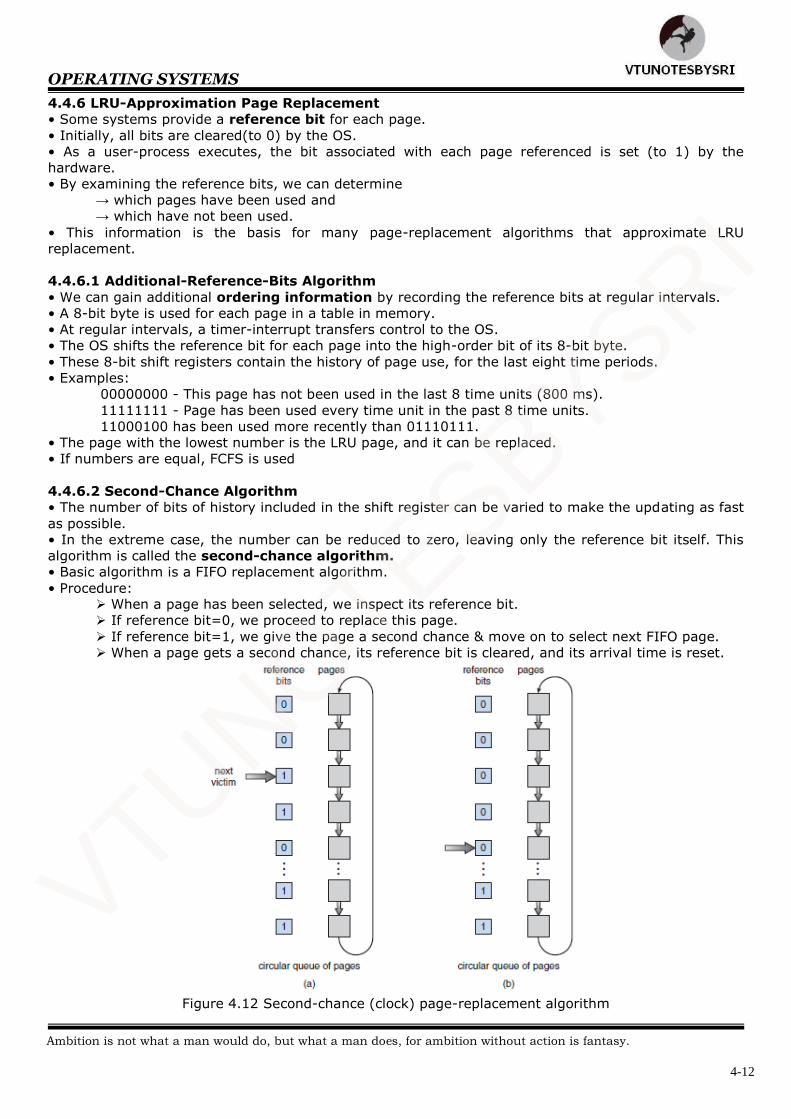
OPERATING SYSTEMS
4-12
4.4.6 LRU-Approximation Page Replacement
• Some systems provide a reference bit for each page.
• Initially, all bits are cleared(to 0) by the OS.
• As a user-process executes, the bit associated with each page referenced is set (to 1) by the
hardware.
• By examining the reference bits, we can determine
→ which pages have been used and
→ which have not been used.
• This information is the basis for many page-replacement algorithms that approximate LRU
replacement.
4.4.6.1 Additional-Reference-Bits Algorithm
• We can gain additional ordering information by recording the reference bits at regular intervals.
• A 8-bit byte is used for each page in a table in memory.
• At regular intervals, a timer-interrupt transfers control to the OS.
• The OS shifts the reference bit for each page into the high-order bit of its 8-bit byte.
• These 8-bit shift registers contain the history of page use, for the last eight time periods.
• Examples:
00000000 - This page has not been used in the last 8 time units (800 ms).
11111111 - Page has been used every time unit in the past 8 time units.
11000100 has been used more recently than 01110111.
• The page with the lowest number is the LRU page, and it can be replaced.
• If numbers are equal, FCFS is used
4.4.6.2 Second-Chance Algorithm
• The number of bits of history included in the shift register can be varied to make the updating as fast
as possible.
• In the extreme case, the number can be reduced to zero, leaving only the reference bit itself. This
algorithm is called the second-chance algorithm.
• Basic algorithm is a FIFO replacement algorithm.
• Procedure: When a page has been selected, we inspect its reference bit.
If reference bit=0, we proceed to replace this page.
If reference bit=1, we give the page a second chance & move on to select next FIFO page.
When a page gets a second chance, its reference bit is cleared, and its arrival time is reset.
Figure 4.12 Second-chance (clock) page-replacement algorithm
VTUNOTESBYSRI
Ambition is not what a man would do, but what a man does, for ambition without action is fantasy.
OPERATING SYSTEMS
4-13
• A circular queue can be used to implement the second-chance algorithm (Figure 4.12). A pointer (that is, a hand on the clock) indicates which page is to be replaced next.
When a frame is needed, the pointer advances until it finds a page with a 0 reference bit.
As it advances, it clears the reference bits.
Once a victim page is found, the page is replaced, and the new page is inserted in the circular
queue in that position.
4.4.6.3 Enhanced Second-Chance Algorithm
• We can enhance the second-chance algorithm by considering
1) Reference bit and
2) modify-bit.
• We have following 4 possible classes:
1) (0, 0) neither recently used nor modified -best page to replace.
2) (0, 1) not recently used hut modified-not quite as good, because the page will need to be
written out before replacement.
3) (1, 0) recently used but clean-probably will be used again soon.
4) (1, 1) recently used and modified -probably will be used again soon, and the page will be
need to be written out to disk before it can be replaced.
• Each page is in one of these four classes.
• When page replacement is called for, we examine the class to which that page belongs.
• We replace the first page encountered in the lowest nonempty class.
4.4.7 Counting-Based Page Replacement
1) LFU page-replacement algorithm Working principle: The page with the smallest count will be replaced.
The reason for this selection is that an actively used page should have a large reference
count. Problem:
When a page is used heavily during initial phase of a process but then is never used again.
Since it was used heavily, it has a large count and remains in memory even though it is no
longer needed.
Solution:
Shift the counts right by 1 bit at regular intervals, forming an exponentially decaying
average usage count.
2) MFU (Most Frequently Used) page-replacement algorithm Working principle: The page with the smallest count was probably just brought in and has
yet to be used.
VTUNOTESBYSRI
Doubts in your mind are a much greater roadblock to success than obstacles on the journey.
OPERATING SYSTEMS
4-14
4.5 Allocation of Frames
4.5.1 Minimum Number of Frames
• We must also allocate at least a minimum number of frames. One reason for this is performance.
• As the number of frames allocated to each process decreases, the page-fault rate increases, slowing
process execution.
• In addition, when a page-fault occurs before an executing instruction is complete, the instruction
must be restarted.
• The minimum number of frames is defined by the computer architecture.
4.5.2 Allocation Algorithms
1) Equal Allocation We split m frames among n processes is to give everyone an equal share, m/n frames.
(For ex: if there are 93 frames and five processes, each process will get 18 frames. The three
leftover frames can be used as a free-frame buffer pool).
2) Proportional Allocation We can allocate available memory to each process according to its size.
• In both 1 & 2, the allocation may vary according to the multiprogramming level.
• If the multiprogramming level is increased, each process will lose some frames to provide the
memory needed for the new process.
• Conversely, if the multiprogramming level decreases, the frames that were allocated to the departed
process can be spread over the remaining processes.
4.5.3 Global versus Local Allocation
Global Replacement Local Replacement
Allows a process to a replacement frame
from the set of all frames.
Each process selects from only its own set of
allocated frames.
A process may happen to select only frames
allocated to other processes, thus increasing
the number of frames allocated to it.
Number of frames allocated to a process
does not change.
Disadvantage:
A process cannot control its own page-fault
rate.
Disadvantage:
Might prevent a process by not making
available to it other less used pages of
memory.
Advantage:
Results in greater system throughput.
VTUNOTESBYSRI
A life fueled by passions is like riding on the back of a dragon.
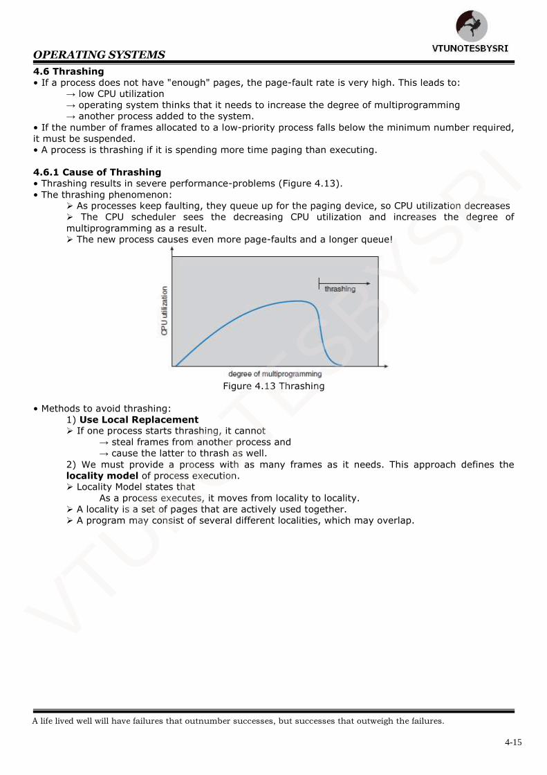
OPERATING SYSTEMS
4-15
4.6 Thrashing
• If a process does not have "enough" pages, the page-fault rate is very high. This leads to:
→ low CPU utilization
→ operating system thinks that it needs to increase the degree of multiprogramming
→ another process added to the system.
• If the number of frames allocated to a low-priority process falls below the minimum number required,
it must be suspended.
• A process is thrashing if it is spending more time paging than executing.
4.6.1 Cause of Thrashing
• Thrashing results in severe performance-problems (Figure 4.13).
• The thrashing phenomenon: As processes keep faulting, they queue up for the paging device, so CPU utilization decreases
The CPU scheduler sees the decreasing CPU utilization and increases the degree of
multiprogramming as a result. The new process causes even more page-faults and a longer queue!
Figure 4.13 Thrashing
• Methods to avoid thrashing:
1) Use Local Replacement If one process starts thrashing, it cannot
→ steal frames from another process and
→ cause the latter to thrash as well.
2) We must provide a process with as many frames as it needs. This approach defines the
locality model of process execution. Locality Model states that
As a process executes, it moves from locality to locality.
A locality is a set of pages that are actively used together.
A program may consist of several different localities, which may overlap.
VTUNOTESBYSRI
A life lived well will have failures that outnumber successes, but successes that outweigh the failures.
OPERATING SYSTEMS
4-16
EXERCISE PROBLEMS
1) Consider following page reference string:
7 0 1 2 0 3 0 4 2 3 0 3 2 1 2 0 1 7 0 1
For a memory with 3 frames, how many page faults would occur for
(i) LRU algorithm
(ii) FIFO algorithm and
(iii) Optimal page replacement algorithm?
Which is the most efficient among them?
Solution:
(i) LRU with 3 frames:
Frames 7 0 1 2 0 3 0 4 2 3 0 3 2 1 2 0 1 7 0 1
1 7 7 7 2 2 2 2 4 4 4 0 0 0 1 1 1 1 1 1 1
2 0 0 0 0 0 0 0 0 3 3 3 3 3 3 0 0 0 0 0
3 1 1 1 3 3 3 2 2 2 2 2 2 2 2 2 7 7 7
No. of Page faults √ √ √ √ √ √ √ √ √ √ √ √
No of page faults=12
(ii) FIFO with 3 frames:
Frames 7 0 1 2 0 3 0 4 2 3 0 3 2 1 2 0 1 7 0 1
1 7 0 1 2 2 3 0 4 2 3 0 0 0 1 2 2 2 7 0 1
2 7 0 1 1 2 3 0 4 2 3 3 3 0 1 1 1 2 7 0
3 7 0 0 1 2 3 0 4 2 2 2 3 0 0 0 1 2 7
No. of Page faults √ √ √ √ √ √ √ √ √ √ √ √ √ √ √
No of page faults=15
(iii) Optimal with 3 frames:
Frames 7 0 1 2 0 3 0 4 2 3 0 3 2 1 2 0 1 7 0 1
1 7 7 7 2 2 2 2 2 2 2 2 2 2 2 2 2 2 7 7 7
2 0 0 0 0 0 0 4 4 4 0 0 0 0 0 0 0 0 0 0
3 1 1 1 3 3 3 3 3 3 3 3 1 1 1 1 1 1 1
No. of Page faults √ √ √ √ √ √ √ √ √
No of page faults=9
Conclusion: The optimal page replacement algorithm is most efficient among three algorithms, as it
has lowest page faults i.e. 9.
VTUNOTESBYSRI
Even if you are on the right track, but just sit there, you will still get run over.
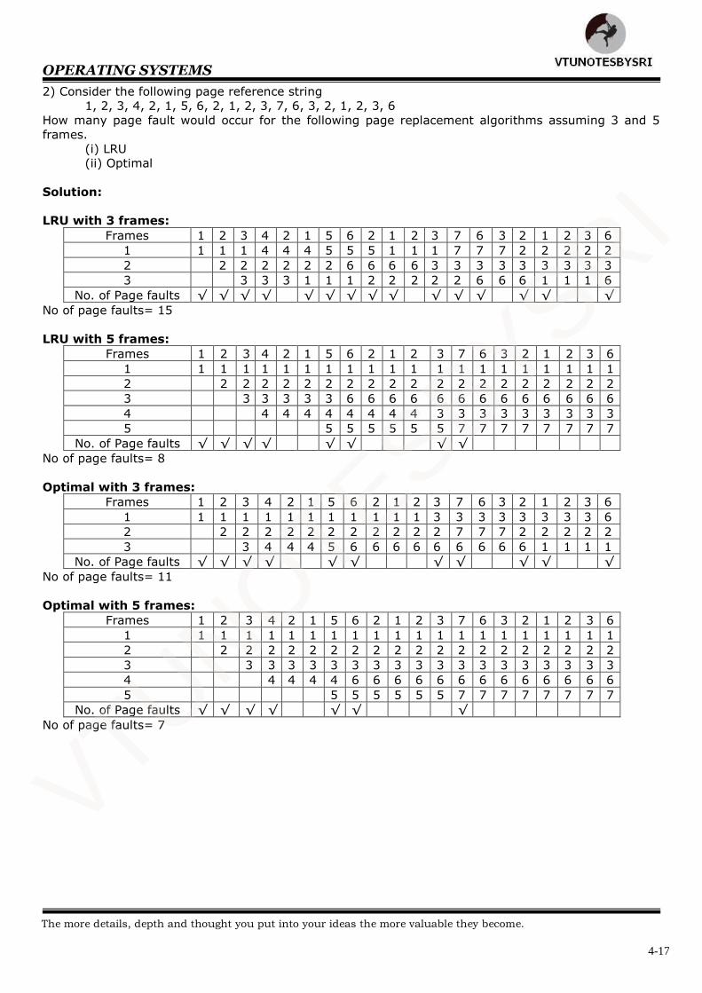
OPERATING SYSTEMS
4-17
2) Consider the following page reference string
1, 2, 3, 4, 2, 1, 5, 6, 2, 1, 2, 3, 7, 6, 3, 2, 1, 2, 3, 6
How many page fault would occur for the following page replacement algorithms assuming 3 and 5
frames.
(i) LRU
(ii) Optimal
Solution:
LRU with 3 frames:
Frames 1 2 3 4 2 1 5 6 2 1 2 3 7 6 3 2 1 2 3 6
1 1 1 1 4 4 4 5 5 5 1 1 1 7 7 7 2 2 2 2 2
2 2 2 2 2 2 2 6 6 6 6 3 3 3 3 3 3 3 3 3
3 3 3 3 1 1 1 2 2 2 2 2 6 6 6 1 1 1 6
No. of Page faults √ √ √ √ √ √ √ √ √ √ √ √ √ √ √
No of page faults= 15
LRU with 5 frames:
Frames 1 2 3 4 2 1 5 6 2 1 2 3 7 6 3 2 1 2 3 6
1 1 1 1 1 1 1 1 1 1 1 1 1 1 1 1 1 1 1 1 1
2 2 2 2 2 2 2 2 2 2 2 2 2 2 2 2 2 2 2 2
3 3 3 3 3 3 6 6 6 6 6 6 6 6 6 6 6 6 6
4 4 4 4 4 4 4 4 4 3 3 3 3 3 3 3 3 3
5 5 5 5 5 5 5 7 7 7 7 7 7 7 7
No. of Page faults √ √ √ √ √ √ √ √
No of page faults= 8
Optimal with 3 frames:
Frames 1 2 3 4 2 1 5 6 2 1 2 3 7 6 3 2 1 2 3 6
1 1 1 1 1 1 1 1 1 1 1 1 3 3 3 3 3 3 3 3 6
2 2 2 2 2 2 2 2 2 2 2 2 7 7 7 2 2 2 2 2
3 3 4 4 4 5 6 6 6 6 6 6 6 6 6 1 1 1 1
No. of Page faults √ √ √ √ √ √ √ √ √ √ √
No of page faults= 11
Optimal with 5 frames:
Frames 1 2 3 4 2 1 5 6 2 1 2 3 7 6 3 2 1 2 3 6
1 1 1 1 1 1 1 1 1 1 1 1 1 1 1 1 1 1 1 1 1
2 2 2 2 2 2 2 2 2 2 2 2 2 2 2 2 2 2 2 2
3 3 3 3 3 3 3 3 3 3 3 3 3 3 3 3 3 3 3
4 4 4 4 4 6 6 6 6 6 6 6 6 6 6 6 6 6
5 5 5 5 5 5 5 7 7 7 7 7 7 7 7
No. of Page faults √ √ √ √ √ √ √
No of page faults= 7
VTUNOTESBYSRI
The more details, depth and thought you put into your ideas the more valuable they become.
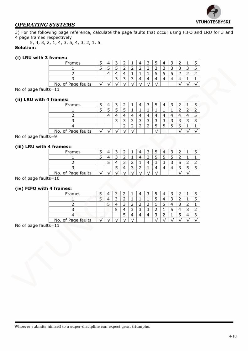
OPERATING SYSTEMS
4-18
3) For the following page reference, calculate the page faults that occur using FIFO and LRU for 3 and
4 page frames respectively
5, 4, 3, 2, 1, 4, 3, 5, 4, 3, 2, 1, 5.
Solution:
(i) LRU with 3 frames:
Frames 5 4 3 2 1 4 3 5 4 3 2 1 5
1 5 5 5 2 2 2 3 3 3 3 3 3 5
2 4 4 4 1 1 1 5 5 5 2 2 2
3 3 3 3 4 4 4 4 4 4 1 1
No. of Page faults √ √ √ √ √ √ √ √ √ √ √
No of page faults=11
(ii) LRU with 4 frames:
Frames 5 4 3 2 1 4 3 5 4 3 2 1 5
1 5 5 5 5 1 1 1 1 1 1 2 2 2
2 4 4 4 4 4 4 4 4 4 4 4 5
3 3 3 3 3 3 3 3 3 3 3 3
4 2 2 2 2 5 5 5 5 1 1
No. of Page faults √ √ √ √ √ √ √ √ √
No of page faults=9
(iii) LRU with 4 frames::
Frames 5 4 3 2 1 4 3 5 4 3 2 1 5
1 5 4 3 2 1 4 3 5 5 5 2 1 1
2 5 4 3 2 1 4 3 3 3 5 2 2
3 5 4 3 2 1 4 4 4 3 5 5
No. of Page faults √ √ √ √ √ √ √ √ √ √
No of page faults=10
(iv) FIFO with 4 frames:
Frames 5 4 3 2 1 4 3 5 4 3 2 1 5
1 5 4 3 2 1 1 1 5 4 3 2 1 5
2 5 4 3 2 2 2 1 5 4 3 2 1
3 5 4 3 3 3 2 1 5 4 3 2
4 5 4 4 4 3 2 1 5 4 3
No. of Page faults √ √ √ √ √ √ √ √ √ √ √
No of page faults=11
VTUNOTESBYSRI
Whoever submits himself to a super-discipline can expect great triumphs.
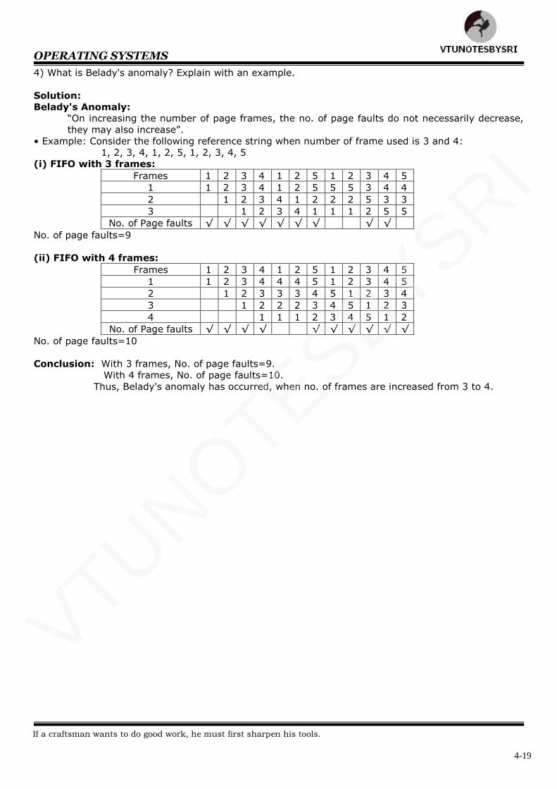
OPERATING SYSTEMS
4-19
4) What is Belady's anomaly? Explain with an example.
Solution:
Belady's Anomaly:
“On increasing the number of page frames, the no. of page faults do not necessarily decrease,
they may also increase”.
• Example: Consider the following reference string when number of frame used is 3 and 4:
1, 2, 3, 4, 1, 2, 5, 1, 2, 3, 4, 5
(i) FIFO with 3 frames:
Frames 1 2 3 4 1 2 5 1 2 3 4 5
1 1 2 3 4 1 2 5 5 5 3 4 4
2 1 2 3 4 1 2 2 2 5 3 3
3 1 2 3 4 1 1 1 2 5 5
No. of Page faults √ √ √ √ √ √ √ √ √
No. of page faults=9
(ii) FIFO with 4 frames:
Frames 1 2 3 4 1 2 5 1 2 3 4 5
1 1 2 3 4 4 4 5 1 2 3 4 5
2 1 2 3 3 3 4 5 1 2 3 4
3 1 2 2 2 3 4 5 1 2 3
4 1 1 1 2 3 4 5 1 2
No. of Page faults √ √ √ √ √ √ √ √ √ √
No. of page faults=10
Conclusion: With 3 frames, No. of page faults=9.
With 4 frames, No. of page faults=10.
Thus, Belady's anomaly has occurred, when no. of frames are increased from 3 to 4.
VTUNOTESBYSRI
If a craftsman wants to do good work, he must first sharpen his tools.
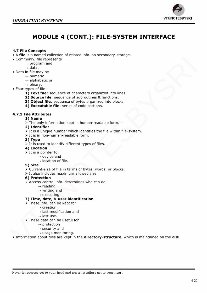
OPERATING SYSTEMS
4-20
MODULE 4 (CONT.): FILE-SYSTEM INTERFACE
4.7 File Concepts
• A file is a named collection of related info. on secondary-storage.
• Commonly, file represents → program and
→ data.
• Data in file may be → numeric
→ alphabetic or
→ binary.
• Four types of file:
1) Text file: sequence of characters organized into lines.
2) Source file: sequence of subroutines & functions.
3) Object file: sequence of bytes organized into blocks.
4) Executable file: series of code sections.
4.7.1 File Attributes
1) Name
The only information kept in human-readable form.
2) Identifier It is a unique number which identifies the file within file-system.
It is in non-human-readable form.
3) Type It is used to identify different types of files.
4) Location It is a pointer to
→ device and
→ location of file.
5) Size Current-size of file in terms of bytes, words, or blocks.
It also includes maximum allowed size.
6) Protection Access-control info. determines who can do
→ reading
→ writing and
→ executing.
7) Time, date, & user identification These info. can be kept for
→ creation
→ last modification and
→ last use.
These data can be useful for
→ protection
→ security and
→ usage monitoring.
• Information about files are kept in the directory-structure, which is maintained on the disk.
VTUNOTESBYSRI
Never let success get to your head and never let failure get to your heart.
OPERATING SYSTEMS
4-21
4.7.2 File Operations
1) Creating a file
Two steps are:
i) Find the space in the file-system for the file.
ii) An entry for the new file is made in the directory.
2) Writing a file
Make a system-call specifying both
→ file-name and
→ info. to be written to the file.
The system searches the directory to find the file's location. (The system keeps a write-
pointer(wp) to the location in the file where the next write is to take place).
The write-pointer must be updated whenever a write-operation occurs.
3) Reading a file Make a system-call specifying both
→ file-name and
→ location of the next block of the file in the memory.
The system searches the directory to find the file's location. (The system keeps a read-
pointer(rp) to the location in the file where the next read is to take place). The read-pointer must be updated whenever a read-operation occurs.
Same pointer (rp & wp) is used for both read- & write-operations. This results in
→ saving space and
→ reducing system-complexity.
4) Repositioning within a file Two steps are:
i) Search the directory for the appropriate entry.
ii) Set the current-file-position to a given value. This file-operation is also known as file seek.
5) Deleting a file
Two steps are:
i) Search the directory for the named-file.
ii) Release all file-space and erase the directory-entry.
6) Truncating a file
The contents of a file are erased but its attributes remain unchanged.
Only file-length attribute is set to zero.
(Most of the above file-operations involve searching the directory for the entry associated with the file.
To avoid this constant searching, many systems require that an „open‟ system-call be used before that
file is first used).
• The OS keeps a small table which contains info. about all open files (called open-file table).
• If a file-operation is requested, then → file is specified via an index into open-file table
→ so no searching is required.
• If the file is no longer actively used, then → process closes the file and
→ OS removes its entry in the open-file table.
• Two levels of internal tables:
1) Per-process Table Tracks all files that a process had opened.
Includes access-rights to
→ file and
→ accounting info.
Each entry in the table in turn points to a system-wide table
2) System-wide Table
Contains process-independent info. such as
→ file-location on the disk
→ file-size and
→ access-dates.
VTUNOTESBYSRI
Take action! An inch of movement will bring you closer to your goals than a mile of intention.
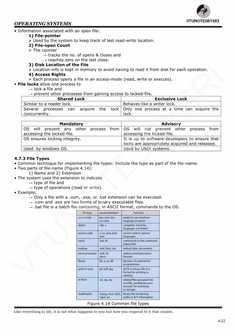
OPERATING SYSTEMS
4-22
• Information associated with an open file:
1) File-pointer
Used by the system to keep track of last read-write location.
2) File-open Count The counter
→ tracks the no. of opens & closes and
→ reaches zero on the last close.
3) Disk Location of the File
Location-info is kept in memory to avoid having to read it from disk for each operation.
4) Access Rights Each process opens a file in an access-mode (read, write or execute).
• File locks allow one process to → lock a file and
→ prevent other processes from gaining access to locked-file.
Shared Lock Exclusive Lock
Similar to a reader lock. Behaves like a writer lock.
Several processes can acquire the lock
concurrently.
Only one process at a time can acquire the
lock.
Mandatory Advisory
OS will prevent any other process from
accessing the locked-file.
OS will not prevent other process from
accessing the locked-file.
OS ensures locking integrity. It is up to software-developers to ensure that
locks are appropriately acquired and released.
Used by windows OS. Used by UNIX systems.
4.7.3 File Types
• Common technique for implementing file-types: Include the type as part of the file-name.
• Two parts of file-name (Figure 4.14):
1) Name and 2) Extension
• The system uses the extension to indicate → type of file and
→ type of operations (read or write).
• Example: → Only a file with a .com, .exe, or .bat extension can be executed.
→ .com and .exe are two forms of binary executable files.
→ .bat file is a batch file containing, in ASCII format, commands to the OS.
Figure 4.14 Common file types
VTUNOTESBYSRI
Like everything in life, it is not what happens to you but how you respond to it that counts.
OPERATING SYSTEMS
4-23
4.7.4 File Structure
• File types can be used to indicate the internal structure of the file.
• Disadvantage of supporting multiple file structures: Large size.
• All OSs must support at least one structure: an executable file
• In Mac OS, file contains 2 parts:
1) Resource fork: contains info. of interest to the user.
2) Data fork: contains program-code or data.
• Too few structures make programming inconvenient.
• Too many structures make programmer confusion.
4.7.5 Internal File Structure
• Locating an offset within a file can be complicated for the OS.
• Disk-systems typically have a well-defined block-size.
• All disk I/0 is performed in units of one block (physical record), and all blocks are the same size.
• Problem: It is unlikely that physical-record size will exactly match length of desired logical-record.
Solution: Packing a number of logical-records into physical-blocks.
• Following things determine how many logical-records are in each physical-block:
→ logical-record size
→ physical-block size and
→ packing technique.
• The packing can be done either by → user's application program or
→ OS.
• Disadvantage of packing: → All file-systems suffer from internal fragmentation (the larger the block size, the greater the
internal fragmentation).
VTUNOTESBYSRI
It is never about who is right or wrong, it is about what is best.
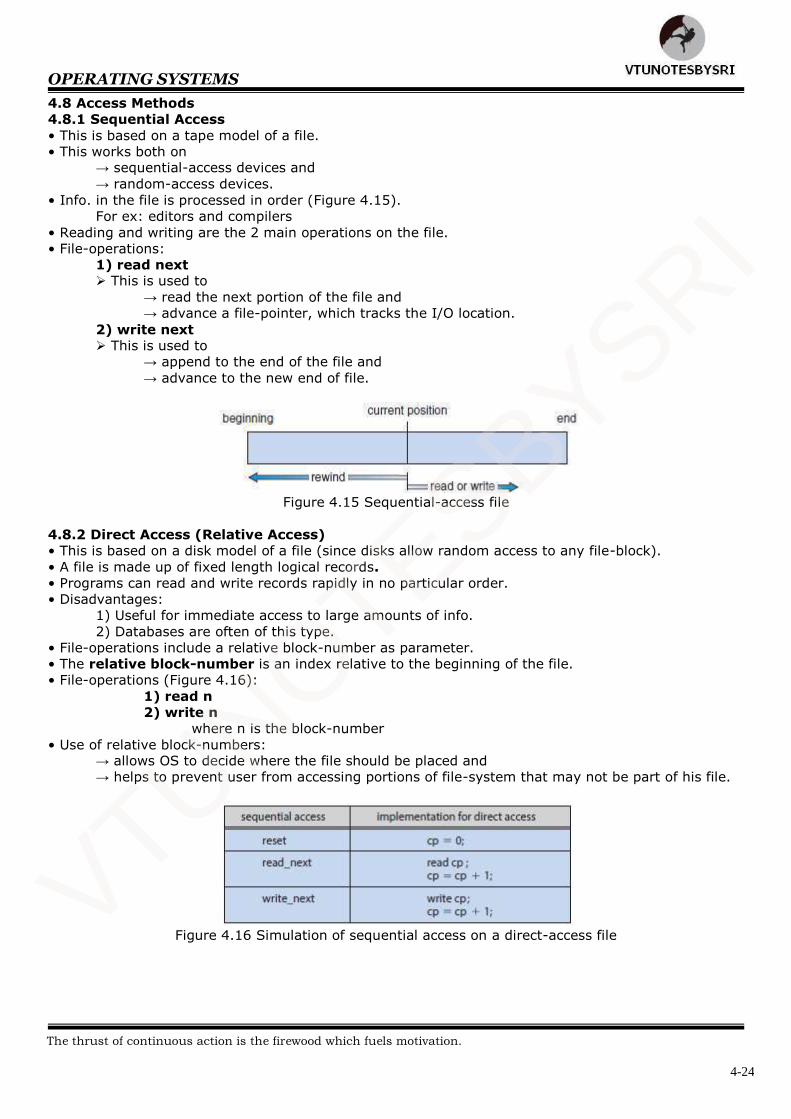
OPERATING SYSTEMS
4-24
4.8 Access Methods
4.8.1 Sequential Access
• This is based on a tape model of a file.
• This works both on → sequential-access devices and
→ random-access devices.
• Info. in the file is processed in order (Figure 4.15).
For ex: editors and compilers
• Reading and writing are the 2 main operations on the file.
• File-operations:
1) read next This is used to
→ read the next portion of the file and
→ advance a file-pointer, which tracks the I/O location.
2) write next This is used to
→ append to the end of the file and
→ advance to the new end of file.
Figure 4.15 Sequential-access file
4.8.2 Direct Access (Relative Access)
• This is based on a disk model of a file (since disks allow random access to any file-block).
• A file is made up of fixed length logical records.
• Programs can read and write records rapidly in no particular order.
• Disadvantages:
1) Useful for immediate access to large amounts of info.
2) Databases are often of this type.
• File-operations include a relative block-number as parameter.
• The relative block-number is an index relative to the beginning of the file.
• File-operations (Figure 4.16):
1) read n
2) write n
where n is the block-number
• Use of relative block-numbers: → allows OS to decide where the file should be placed and
→ helps to prevent user from accessing portions of file-system that may not be part of his file.
Figure 4.16 Simulation of sequential access on a direct-access file
VTUNOTESBYSRI
The thrust of continuous action is the firewood which fuels motivation.
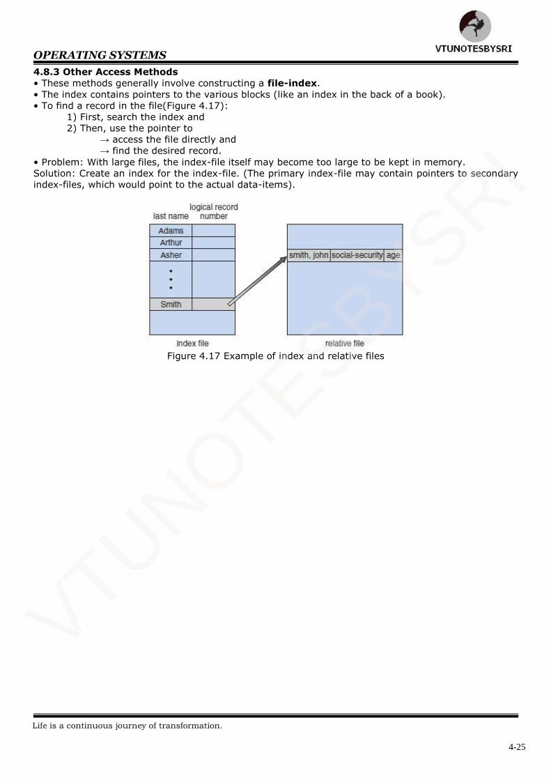
OPERATING SYSTEMS
4-25
4.8.3 Other Access Methods
• These methods generally involve constructing a file-index.
• The index contains pointers to the various blocks (like an index in the back of a book).
• To find a record in the file(Figure 4.17):
1) First, search the index and
2) Then, use the pointer to
→ access the file directly and
→ find the desired record.
• Problem: With large files, the index-file itself may become too large to be kept in memory.
Solution: Create an index for the index-file. (The primary index-file may contain pointers to secondary
index-files, which would point to the actual data-items).
Figure 4.17 Example of index and relative files
VTUNOTESBYSRI
Life is a continuous journey of transformation.
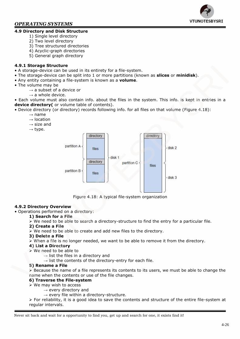
OPERATING SYSTEMS
4-26
4.9 Directory and Disk Structure
1) Single level directory
2) Two level directory
3) Tree structured directories
4) Acyclic-graph directories
5) General graph directory
4.9.1 Storage Structure
• A storage-device can be used in its entirety for a file-system.
• The storage-device can be split into 1 or more partitions (known as slices or minidisk).
• Any entity containing a file-system is known as a volume.
• The volume may be → a subset of a device or
→ a whole device.
• Each volume must also contain info. about the files in the system. This info. is kept in entries in a
device directory( or volume table of contents).
• Device directory (or directory) records following info. for all files on that volume (Figure 4.18): → name
→ location
→ size and
→ type.
Figure 4.18: A typical file-system organization
4.9.2 Directory Overview
• Operations performed on a directory:
1) Search for a File We need to be able to search a directory-structure to find the entry for a particular file.
2) Create a File We need to be able to create and add new files to the directory.
3) Delete a File When a file is no longer needed, we want to be able to remove it from the directory.
4) List a Directory
We need to be able to
→ list the files in a directory and
→ list the contents of the directory-entry for each file.
5) Rename a File Because the name of a file represents its contents to its users, we must be able to change the
name when the contents or use of the file changes.
6) Traverse the File-system We may wish to access
→ every directory and
→ every file within a directory-structure.
For reliability, it is a good idea to save the contents and structure of the entire file-system at
regular intervals.
VTUNOTESBYSRI
Never sit back and wait for a opportunity to find you, get up and search for one, it exists find it!
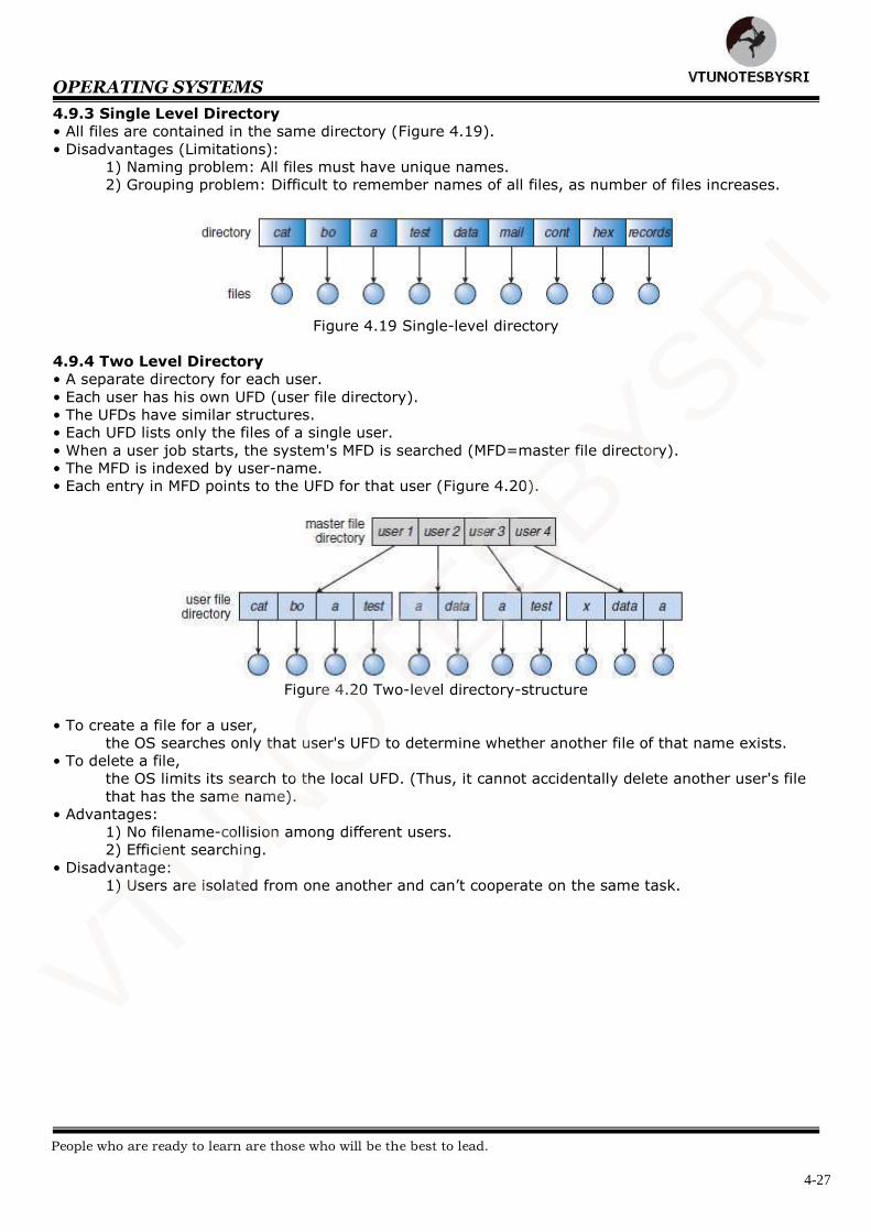
OPERATING SYSTEMS
4-27
4.9.3 Single Level Directory
• All files are contained in the same directory (Figure 4.19).
• Disadvantages (Limitations):
1) Naming problem: All files must have unique names.
2) Grouping problem: Difficult to remember names of all files, as number of files increases.
Figure 4.19 Single-level directory
4.9.4 Two Level Directory
• A separate directory for each user.
• Each user has his own UFD (user file directory).
• The UFDs have similar structures.
• Each UFD lists only the files of a single user.
• When a user job starts, the system's MFD is searched (MFD=master file directory).
• The MFD is indexed by user-name.
• Each entry in MFD points to the UFD for that user (Figure 4.20).
Figure 4.20 Two-level directory-structure
• To create a file for a user,
the OS searches only that user's UFD to determine whether another file of that name exists.
• To delete a file,
the OS limits its search to the local UFD. (Thus, it cannot accidentally delete another user's file
that has the same name).
• Advantages:
1) No filename-collision among different users.
2) Efficient searching.
• Disadvantage:
1) Users are isolated from one another and can‟t cooperate on the same task.
VTUNOTESBYSRI
People who are ready to learn are those who will be the best to lead.
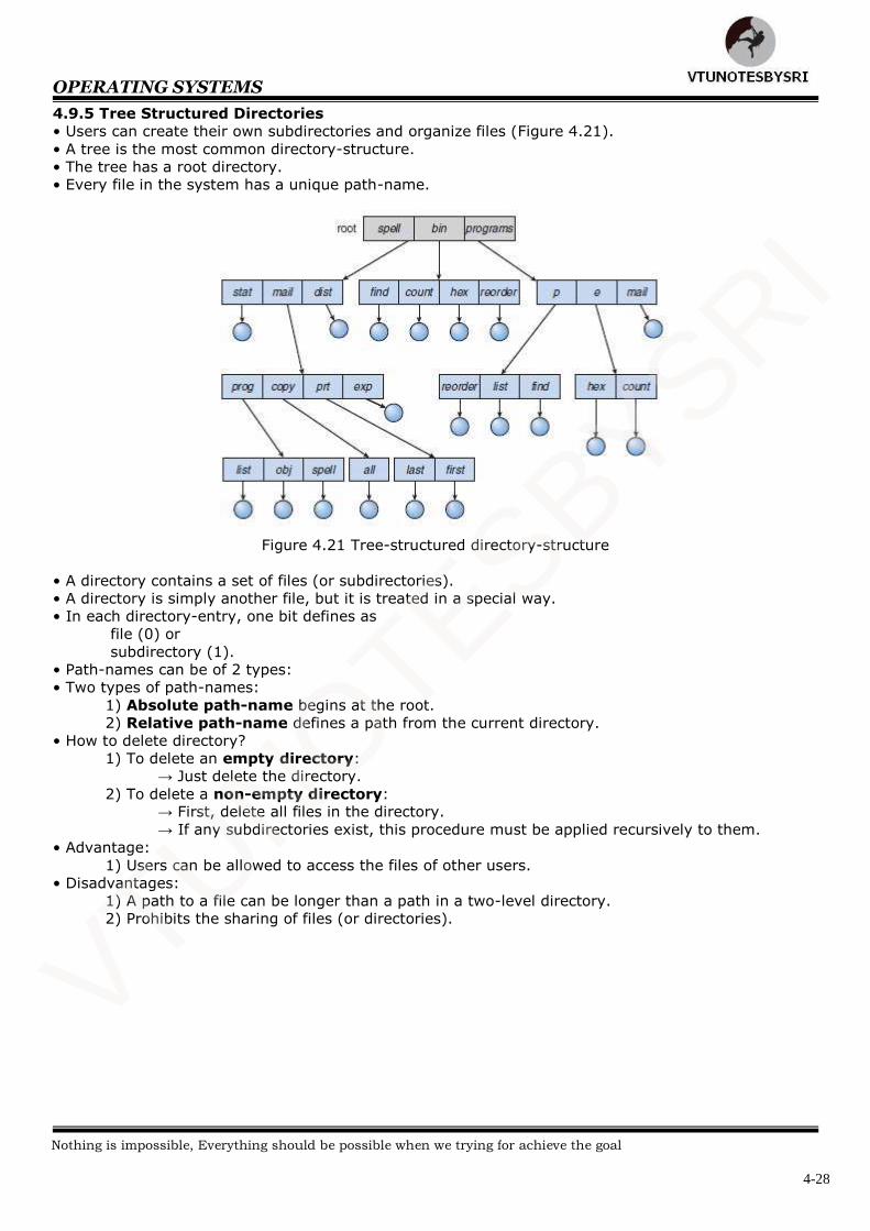
OPERATING SYSTEMS
4-28
4.9.5 Tree Structured Directories
• Users can create their own subdirectories and organize files (Figure 4.21).
• A tree is the most common directory-structure.
• The tree has a root directory.
• Every file in the system has a unique path-name.
Figure 4.21 Tree-structured directory-structure
• A directory contains a set of files (or subdirectories).
• A directory is simply another file, but it is treated in a special way.
• In each directory-entry, one bit defines as
file (0) or
subdirectory (1).
• Path-names can be of 2 types:
• Two types of path-names:
1) Absolute path-name begins at the root.
2) Relative path-name defines a path from the current directory.
• How to delete directory?
1) To delete an empty directory:
→ Just delete the directory.
2) To delete a non-empty directory: → First, delete all files in the directory.
→ If any subdirectories exist, this procedure must be applied recursively to them.
• Advantage:
1) Users can be allowed to access the files of other users.
• Disadvantages:
1) A path to a file can be longer than a path in a two-level directory.
2) Prohibits the sharing of files (or directories).
VTUNOTESBYSRI
Nothing is impossible, Everything should be possible when we trying for achieve the goal
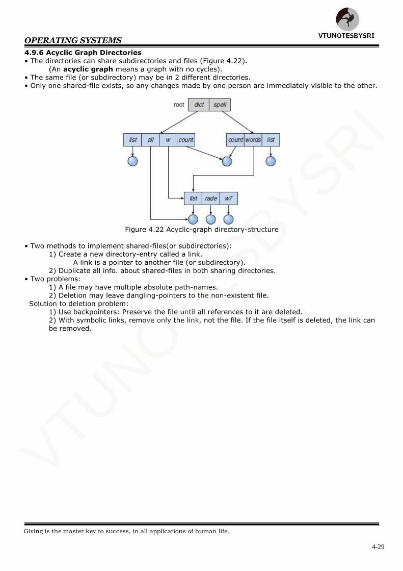
OPERATING SYSTEMS
4-29
4.9.6 Acyclic Graph Directories
• The directories can share subdirectories and files (Figure 4.22).
(An acyclic graph means a graph with no cycles).
• The same file (or subdirectory) may be in 2 different directories.
• Only one shared-file exists, so any changes made by one person are immediately visible to the other.
Figure 4.22 Acyclic-graph directory-structure
• Two methods to implement shared-files(or subdirectories):
1) Create a new directory-entry called a link.
A link is a pointer to another file (or subdirectory).
2) Duplicate all info. about shared-files in both sharing directories.
• Two problems:
1) A file may have multiple absolute path-names.
2) Deletion may leave dangling-pointers to the non-existent file.
Solution to deletion problem:
1) Use backpointers: Preserve the file until all references to it are deleted.
2) With symbolic links, remove only the link, not the file. If the file itself is deleted, the link can
be removed.
VTUNOTESBYSRI
Giving is the master key to success, in all applications of human life.
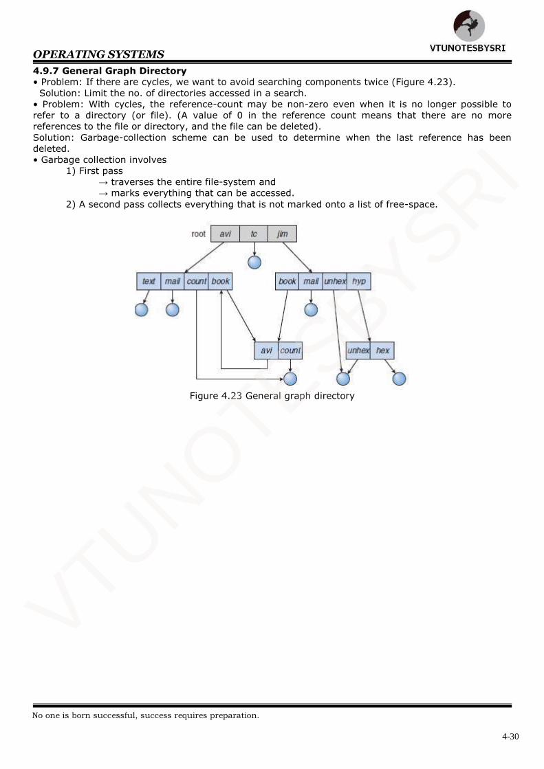
OPERATING SYSTEMS
4-30
4.9.7 General Graph Directory
• Problem: If there are cycles, we want to avoid searching components twice (Figure 4.23).
Solution: Limit the no. of directories accessed in a search.
• Problem: With cycles, the reference-count may be non-zero even when it is no longer possible to
refer to a directory (or file). (A value of 0 in the reference count means that there are no more
references to the file or directory, and the file can be deleted).
Solution: Garbage-collection scheme can be used to determine when the last reference has been
deleted.
• Garbage collection involves
1) First pass
→ traverses the entire file-system and
→ marks everything that can be accessed.
2) A second pass collects everything that is not marked onto a list of free-space.
Figure 4.23 General graph directory
VTUNOTESBYSRI
No one is born successful, success requires preparation.
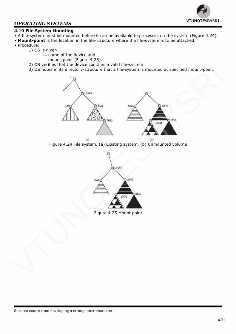
OPERATING SYSTEMS
4-31
4.10 File System Mounting
• A file-system must be mounted before it can be available to processes on the system (Figure 4.24).
• Mount-point is the location in the file-structure where the file-system is to be attached.
• Procedure:
1) OS is given → name of the device and
→ mount-point (Figure 4.25).
2) OS verifies that the device contains a valid file-system.
3) OS notes in its directory-structure that a file-system is mounted at specified mount-point.
Figure 4.24 File system. (a) Existing system. (b) Unmounted volume
Figure 4.25 Mount point
VTUNOTESBYSRI
Success comes from developing a strong inner character.
OPERATING SYSTEMS
4-32
4.11 File Sharing
• Sharing of files on multi-user systems is desirable.
• Sharing may be done through a protection scheme.
• On distributed systems, files may be shared across a network.
• Network File-system (NFS) is a common distributed file-sharing method.
4.11.1 Multiple Users
• File-sharing can be done in 2 ways:
1) The system can allow a user to access the files of other users by default or
2) The system may require that a user specifically grant access.
• To implement file-sharing, the system must maintain more file- & directory-attributes than on a
single-user system.
• Most systems use concepts of file owner and group.
1) Owner The user who
→ may change attributes & grant access and
→ has the most control over the file (or directory).
Most systems implement owner attributes by managing a list of user-names and user IDs
2) Group
The group attribute defines a subset of users who can share access to the file.
Group functionality can be implemented as a system-wide list of group-names and group IDs.
• Exactly which operations can be executed by group-members and other users is definable by the
file's owner.
• The owner and group IDs of a file → are stored with the other file-attributes.
→ can be used to allow/deny requested operations.
4.11.2 Remote File Systems
• Allows a computer to mount 1 or more file-systems from 1 or more remote-machines.
• Three methods:
1) Manually via programs like FTP.
2) Automatically DFS (Distributed file-system): remote directories are visible from a local
machine.
3) Semi-automatically via www (World Wide Web): A browser is needed to gain access to
the remote files, and separate operations (a wrapper for ftp) are used to transfer files.
• ftp is used for both anonymous and authenticated access.
• Anonymous access allows a user to transfer files without having an account on the remote system.
4.11.2.1 Client Server Model
• Allows clients to mount remote file-systems from servers.
• The machine containing the files is called the server.
The machine seeking access to the files is called the client.
• A server can serve multiple clients, and
A client can use multiple servers.
• The server specifies which resources (files) are available to which clients.
• A client can be specified by a network-name such as an IP address.
• Disadvantage:
1) Client identification is more difficult.
• In UNIX and its NFS (network file-system), authentication takes place via the client networking info.,
by default.
• Once the remote file-system is mounted, file-operation requests are sent to the server via the DFS
protocol.
4.11.2.2 Distributed Information Systems
• Provides unified access to the info. needed for remote computing.
• The DNS (domain name system) provides hostname-to-networkaddress translations.
• Other distributed info. systems provide username/password space for a distributed facility.
VTUNOTESBYSRI
Your failures contain key to your success and your destination.
OPERATING SYSTEMS
4-33
4.11.2.3 Failure Modes
• Local file-systems can fail for a variety of reasons such as
→ failure of disk (containing the file-system)
→ corruption of directory-structure &
→ cable failure.
• Remote file-systems have more failure modes because of the complexity of network-systems.
• The network can be interrupted between 2 hosts. Such interruptions can result from → hardware failure
→ poor hardware configuration or
→ networking implementation issues.
• DFS protocols allow delaying of file-system operations to remote-hosts, with the hope that the
remote-host will become available again.
• To implement failure-recovery, some kind of state info. may be maintained on both the client and the
server.
4.11.3 Consistency Semantics
• These represent an important criterion of evaluating file-systems that supports file-sharing.
• These specify how multiple users of a system are to access a shared-file simultaneously.
• In particular, they specify when modifications of data by one user will be observed by other users.
• These semantics are typically implemented as code with the file-system.
• These are directly related to the process-synchronization algorithms.
• A successful implementation of complex sharing semantics can be found in the Andrew file-system
(AFS).
UNIX Semantics
UNIX file-system (UFS) uses the following consistency semantics:
1) Writes to an open-file by a user are visible immediately to other users who have this
file opened.
2) One mode of sharing allows users to share the pointer of current location into a file.
Thus, the advancing of the pointer by one user affects all sharing users. A file is associated with a single physical image that is accessed as an exclusive resource.
Contention for the single image causes delays in user processes.
Session Semantics The AFS uses the following consistency semantics:
1) Writes to an open file by a user are not visible immediately to other users that have
the same file open.
2) Once a file is closed, the changes made to it are visible only in sessions starting later.
Already open instances of the file do not reflect these changes.
A file may be associated temporarily with several (possibly different) images at the same
time. Consequently, multiple users are allowed to perform both read and write accesses
concurrently on their images of the file, without delay. Almost no constraints are enforced on scheduling accesses.
Immutable Shared Files Semantics Once a file is declared as shared by its creator, it cannot be modified.
An immutable file has 2 key properties:
1) File-name may not be reused and
2) File-contents may not be altered.
Thus, the name of an immutable file signifies that the contents of the file are fixed.
The implementation of these semantics in a distributed system is simple, because the sharing
is disciplined
VTUNOTESBYSRI
All great and successful people stayed alone with themselves to develop their gift.
OPERATING SYSTEMS
4-34
4.12 Protection
• When info. is stored in a computer system, we want to keep it safe from physical damage (reliability)
and improper access (protection).
• Reliability is generally provided by duplicate copies of files.
• For a small single-user system, we might provide protection by physically removing the floppy disks
and locking them in a desk drawer.
• File owner/creator should be able to control: → what can be done
→ by whom.
4.12.1 Types of Access
• Systems that do not permit access to the files of other users do not need protection. This is too
extreme, so controlled-access is needed.
• Following operations may be controlled:
1) Read Read from the file.
2) Write Write or rewrite the file.
3) Execute
Load the file into memory and execute it.
4) Append Write new info. at the end of the file.
5) Delete Delete the file and tree its space for possible reuse.
6) List
List the name and attributes of the file.
VTUNOTESBYSRI
Gather all your effort to achieve a single goal and you will be bound to succeed
OPERATING SYSTEMS
4-35
4.12.2 Access Control
• Common approach to protection problem: make access dependent on identity of user.
• Files can be associated with an ACL (access-control list) which specifies → username and
→ types of access for each user.
• Problems:
1) Constructing a list can be tedious.
2) Directory-entry now needs to be of variable-size, resulting in more complicated space
management.
Solution: These problems can be resolved by combining ACLs with an „owner, group, universe‟ access-
control scheme
• To reduce the length of the ACL, many systems recognize 3 classifications of users:
1) Owner The user who created the file is the owner.
2) Group
A set of users who are sharing the file and need similar access is a group.
3) Universe All other users in the system constitute the universe.
• Samples:
E.g. rwx bits indicate which users have permission to read/write/execute
A Sample UNIX directory listing:
4.12.3 Other Protection Approaches
• A password can be associated with each file.
• Disadvantages:
1) The no. of passwords you need to remember may become large.
2) If only one password is used for all the files, then all files are accessible if it is discovered.
3) Commonly, only one password is associated with all of the user‟s files, so protection is all-or-
nothing.
• In a multilevel directory-structure, we need to provide a mechanism for directory protection.
• The directory operations that must be protected are different from the File-operations:
1) Control creation & deletion of files in a directory.
2) Control whether a user can determine the existence of a file in a directory.
VTUNOTESBYSRI
You will be successful if you are focused on your work.
OPERATING SYSTEMS
4-36
MODULE 4 (CONT.): FILE-SYSTEM IMPLEMENTATION
4.13 File System Structure
• Disks provide the bulk of secondary-storage on which a file-system is maintained.
• The disk is a suitable medium for storing multiple files. This is because
1) A disk can be rewritten in place. It is possible to
→ read a block from the disk
→ modify the block and
→ write the block into the disk.
2) A disk can access directly any block of information. It is possible to access any file either sequentially or randomly.
Switching from one file to another requires only moving the read-write heads and waiting for
the disk to rotate.
• To improve I/O efficiency, I/O transfers between memory and disk are performed in units of blocks. Each block has one or more sectors.
Depending on the disk drive, sector-size varies from 32 bytes to 4096 bytes.
The usual size is 512 bytes.
• File-systems provide efficient and convenient access to the disk by allowing data to be stored,
located, and retrieved easily
• Design problems of file-systems:
1) Defining how the file-system should look to the user.
2) Creating algorithms & data-structures to map the logical file-system onto the physical
secondary-storage devices.
• The file-system itself is generally composed of many different levels.
Every level in design uses features of lower levels to create new features for use by higher levels.
4.13.1 Layered File System
• Levels of the file-system(Figure 4.26):
1) I/O Control (Lowest level) Consists of device-drivers & interrupt handlers to transfer info. between main-memory & disk.
A device-driver can be thought of as a translator.
Its input consists of high-level commands.
Its output consists of low-level instructions.
2) Basic File-system Needed only to issue basic commands to the appropriate device-driver to read & write blocks
on the disk.
3) File-organization Module Knows about files and their logical & physical blocks.
Translates logical-block address to physical-block address.
4) Logical File-system Manages metadata information. i.e. Metadata includes all of the file-system structure except
the actual data. Manages the directory-structure.
Maintains file-structure via FCB (File Control Blocks). i.e. FCB contains info. about the file,
including → ownership
→ permissions and
→ location of the file.
• Advantages of layered structure:
1) Duplication of code is minimized.
2) I/O control can be used by multiple file-systems.
VTUNOTESBYSRI
Karma is the balance sheet of life which debits and credit all your deeds.
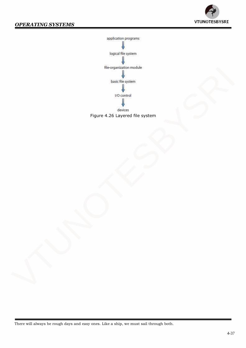
OPERATING SYSTEMS
4-37
Figure 4.26 Layered file system
VTUNOTESBYSRI
There will always be rough days and easy ones. Like a ship, we must sail through both.
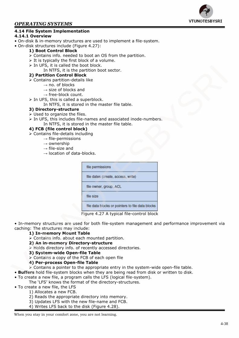
OPERATING SYSTEMS
4-38
4.14 File System Implementation
4.14.1 Overview
• On-disk & in-memory structures are used to implement a file-system.
• On-disk structures include (Figure 4.27):
1) Boot Control Block Contains info. needed to boot an OS from the partition.
It is typically the first block of a volume.
In UFS, it is called the boot block.
In NTFS, it is the partition boot sector.
2) Partition Control Block Contains partition-details like
→ no. of blocks
→ size of blocks and
→ free-block count.
In UFS, this is called a superblock.
In NTFS, it is stored in the master file table.
3) Directory-structure
Used to organize the files.
In UFS, this includes file-names and associated inode-numbers.
In NTFS, it is stored in the master file table.
4) FCB (file control block) Contains file-details including
→ file-permissions
→ ownership
→ file-size and
→ location of data-blocks.
Figure 4.27 A typical file-control block
• In-memory structures are used for both file-system management and performance improvement via
caching: The structures may include:
1) In-memory Mount Table
Contains info. about each mounted partition.
2) An in-memory Directory-structure Holds directory info. of recently accessed directories.
3) System-wide Open-file Table Contains a copy of the FCB of each open file
4) Per-process Open-file Table
Contains a pointer to the appropriate entry in the system-wide open-file table.
• Buffers hold file-system blocks when they are being read from disk or written to disk.
• To create a new file, a program calls the LFS (logical file-system).
The „LFS‟ knows the format of the directory-structures.
• To create a new file, the LFS
1) Allocates a new FCB.
2) Reads the appropriate directory into memory.
3) Updates LFS with the new file-name and FCB.
4) Writes LFS back to the disk (Figure 4.28).
VTUNOTESBYSRI
When you stay in your comfort zone, you are not learning.
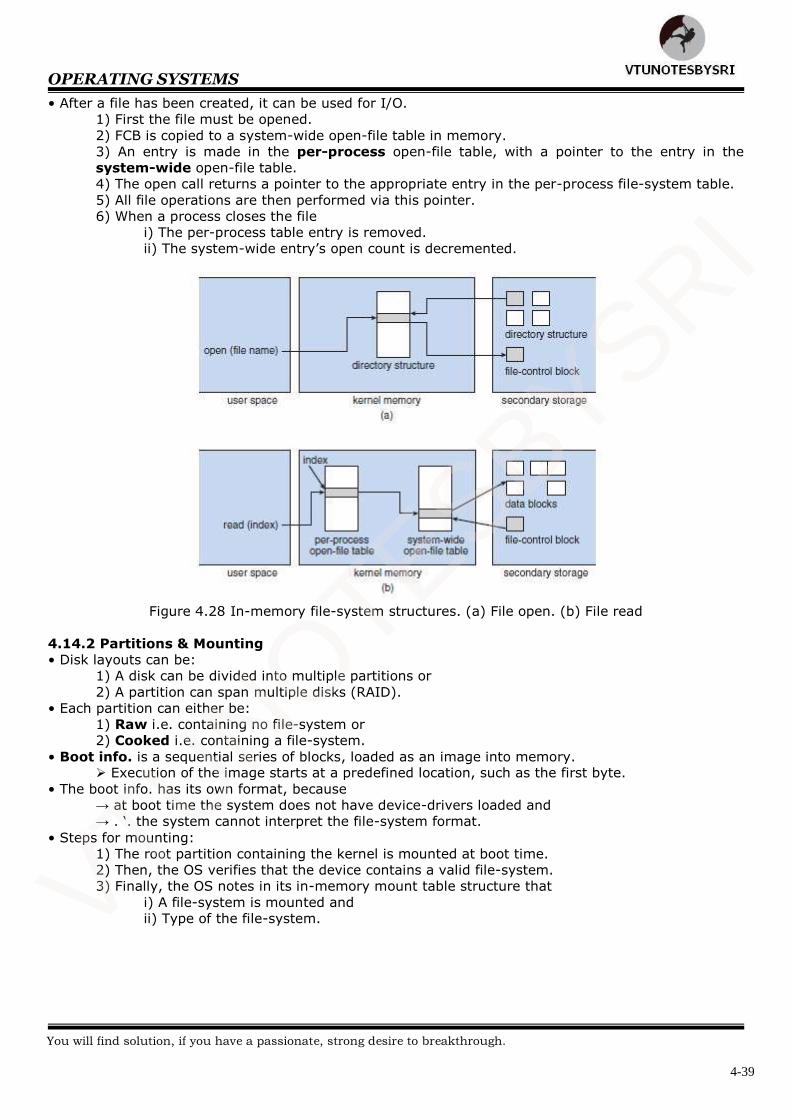
OPERATING SYSTEMS
4-39
• After a file has been created, it can be used for I/O.
1) First the file must be opened.
2) FCB is copied to a system-wide open-file table in memory.
3) An entry is made in the per-process open-file table, with a pointer to the entry in the
system-wide open-file table.
4) The open call returns a pointer to the appropriate entry in the per-process file-system table.
5) All file operations are then performed via this pointer.
6) When a process closes the file
i) The per-process table entry is removed.
ii) The system-wide entry‟s open count is decremented.
Figure 4.28 In-memory file-system structures. (a) File open. (b) File read
4.14.2 Partitions & Mounting
• Disk layouts can be:
1) A disk can be divided into multiple partitions or
2) A partition can span multiple disks (RAID).
• Each partition can either be:
1) Raw i.e. containing no file-system or
2) Cooked i.e. containing a file-system.
• Boot info. is a sequential series of blocks, loaded as an image into memory. Execution of the image starts at a predefined location, such as the first byte.
• The boot info. has its own format, because
→ at boot time the system does not have device-drivers loaded and
→ . „. the system cannot interpret the file-system format.
• Steps for mounting:
1) The root partition containing the kernel is mounted at boot time.
2) Then, the OS verifies that the device contains a valid file-system.
3) Finally, the OS notes in its in-memory mount table structure that
i) A file-system is mounted and
ii) Type of the file-system.
VTUNOTESBYSRI
You will find solution, if you have a passionate, strong desire to breakthrough.
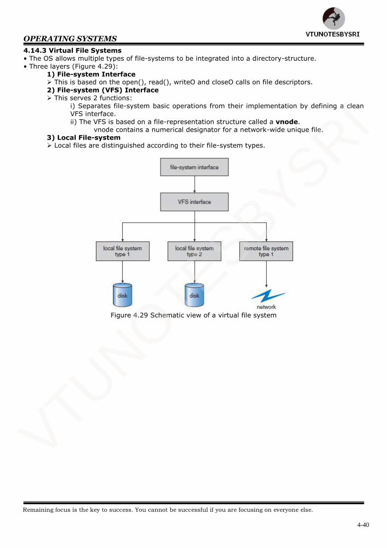
OPERATING SYSTEMS
4-40
4.14.3 Virtual File Systems
• The OS allows multiple types of file-systems to be integrated into a directory-structure.
• Three layers (Figure 4.29):
1) File-system Interface This is based on the open(), read(), writeO and closeO calls on file descriptors.
2) File-system (VFS) Interface
This serves 2 functions:
i) Separates file-system basic operations from their implementation by defining a clean
VFS interface.
ii) The VFS is based on a file-representation structure called a vnode.
vnode contains a numerical designator for a network-wide unique file.
3) Local File-system Local files are distinguished according to their file-system types.
Figure 4.29 Schematic view of a virtual file system
VTUNOTESBYSRI
Remaining focus is the key to success. You cannot be successful if you are focusing on everyone else.
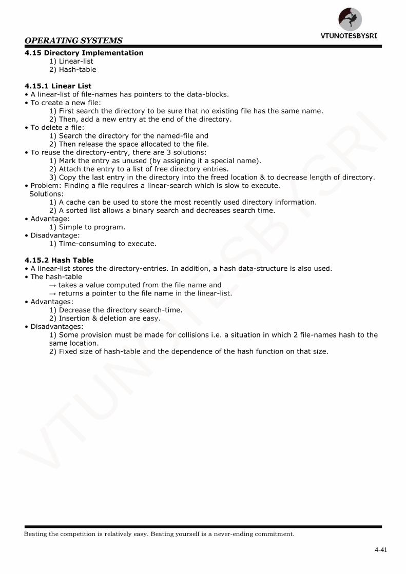
OPERATING SYSTEMS
4-41
4.15 Directory Implementation
1) Linear-list
2) Hash-table
4.15.1 Linear List
• A linear-list of file-names has pointers to the data-blocks.
• To create a new file:
1) First search the directory to be sure that no existing file has the same name.
2) Then, add a new entry at the end of the directory.
• To delete a file:
1) Search the directory for the named-file and
2) Then release the space allocated to the file.
• To reuse the directory-entry, there are 3 solutions:
1) Mark the entry as unused (by assigning it a special name).
2) Attach the entry to a list of free directory entries.
3) Copy the last entry in the directory into the freed location & to decrease length of directory.
• Problem: Finding a file requires a linear-search which is slow to execute.
Solutions:
1) A cache can be used to store the most recently used directory information.
2) A sorted list allows a binary search and decreases search time.
• Advantage:
1) Simple to program.
• Disadvantage:
1) Time-consuming to execute.
4.15.2 Hash Table
• A linear-list stores the directory-entries. In addition, a hash data-structure is also used.
• The hash-table
→ takes a value computed from the file name and
→ returns a pointer to the file name in the linear-list.
• Advantages:
1) Decrease the directory search-time.
2) Insertion & deletion are easy.
• Disadvantages:
1) Some provision must be made for collisions i.e. a situation in which 2 file-names hash to the
same location.
2) Fixed size of hash-table and the dependence of the hash function on that size.
VTUNOTESBYSRI
Beating the competition is relatively easy. Beating yourself is a never-ending commitment.
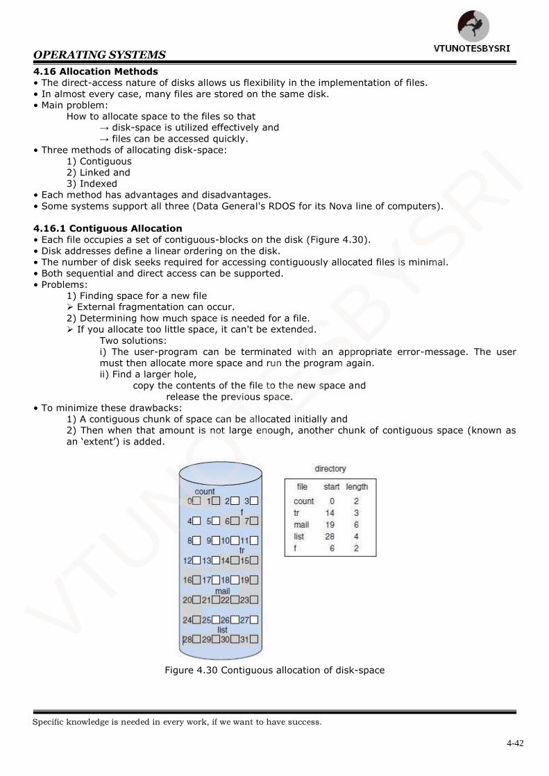
OPERATING SYSTEMS
4-42
4.16 Allocation Methods
• The direct-access nature of disks allows us flexibility in the implementation of files.
• In almost every case, many files are stored on the same disk.
• Main problem:
How to allocate space to the files so that → disk-space is utilized effectively and
→ files can be accessed quickly.
• Three methods of allocating disk-space:
1) Contiguous
2) Linked and
3) Indexed
• Each method has advantages and disadvantages.
• Some systems support all three (Data General's RDOS for its Nova line of computers).
4.16.1 Contiguous Allocation
• Each file occupies a set of contiguous-blocks on the disk (Figure 4.30).
• Disk addresses define a linear ordering on the disk.
• The number of disk seeks required for accessing contiguously allocated files is minimal.
• Both sequential and direct access can be supported.
• Problems:
1) Finding space for a new file External fragmentation can occur.
2) Determining how much space is needed for a file. If you allocate too little space, it can't be extended.
Two solutions:
i) The user-program can be terminated with an appropriate error-message. The user
must then allocate more space and run the program again.
ii) Find a larger hole,
copy the contents of the file to the new space and
release the previous space.
• To minimize these drawbacks:
1) A contiguous chunk of space can be allocated initially and
2) Then when that amount is not large enough, another chunk of contiguous space (known as
an „extent‟) is added.
Figure 4.30 Contiguous allocation of disk-space
VTUNOTESBYSRI
Specific knowledge is needed in every work, if we want to have success.
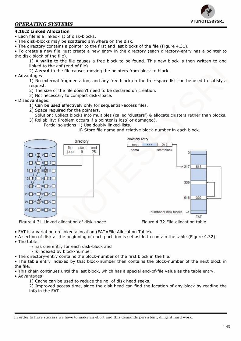
OPERATING SYSTEMS
4-43
4.16.2 Linked Allocation
• Each file is a linked-list of disk-blocks.
• The disk-blocks may be scattered anywhere on the disk.
• The directory contains a pointer to the first and last blocks of the file (Figure 4.31).
• To create a new file, just create a new entry in the directory (each directory-entry has a pointer to
the disk-block of the file).
1) A write to the file causes a free block to be found. This new block is then written to and
linked to the eof (end of file).
2) A read to the file causes moving the pointers from block to block.
• Advantages:
1) No external fragmentation, and any free block on the free-space list can be used to satisfy a
request.
2) The size of the file doesn't need to be declared on creation.
3) Not necessary to compact disk-space.
• Disadvantages:
1) Can be used effectively only for sequential-access files.
2) Space required for the pointers.
Solution: Collect blocks into multiples (called „clusters‟) & allocate clusters rather than blocks.
3) Reliability: Problem occurs if a pointer is lost( or damaged).
Partial solutions: i) Use doubly linked-lists.
ii) Store file name and relative block-number in each block.
Figure 4.31 Linked allocation of disk-space Figure 4.32 File-allocation table
• FAT is a variation on linked allocation (FAT=File Allocation Table).
• A section of disk at the beginning of each partition is set aside to contain the table (Figure 4.32).
• The table → has one entry for each disk-block and
→ is indexed by block-number.
• The directory-entry contains the block-number of the first block in the file.
• The table entry indexed by that block-number then contains the block-number of the next block in
the file.
• This chain continues until the last block, which has a special end-of-file value as the table entry.
• Advantages:
1) Cache can be used to reduce the no. of disk head seeks.
2) Improved access time, since the disk head can find the location of any block by reading the
info in the FAT.
VTUNOTESBYSRI
In order to have success we have to make an effort and this demands persistent, diligent hard work.
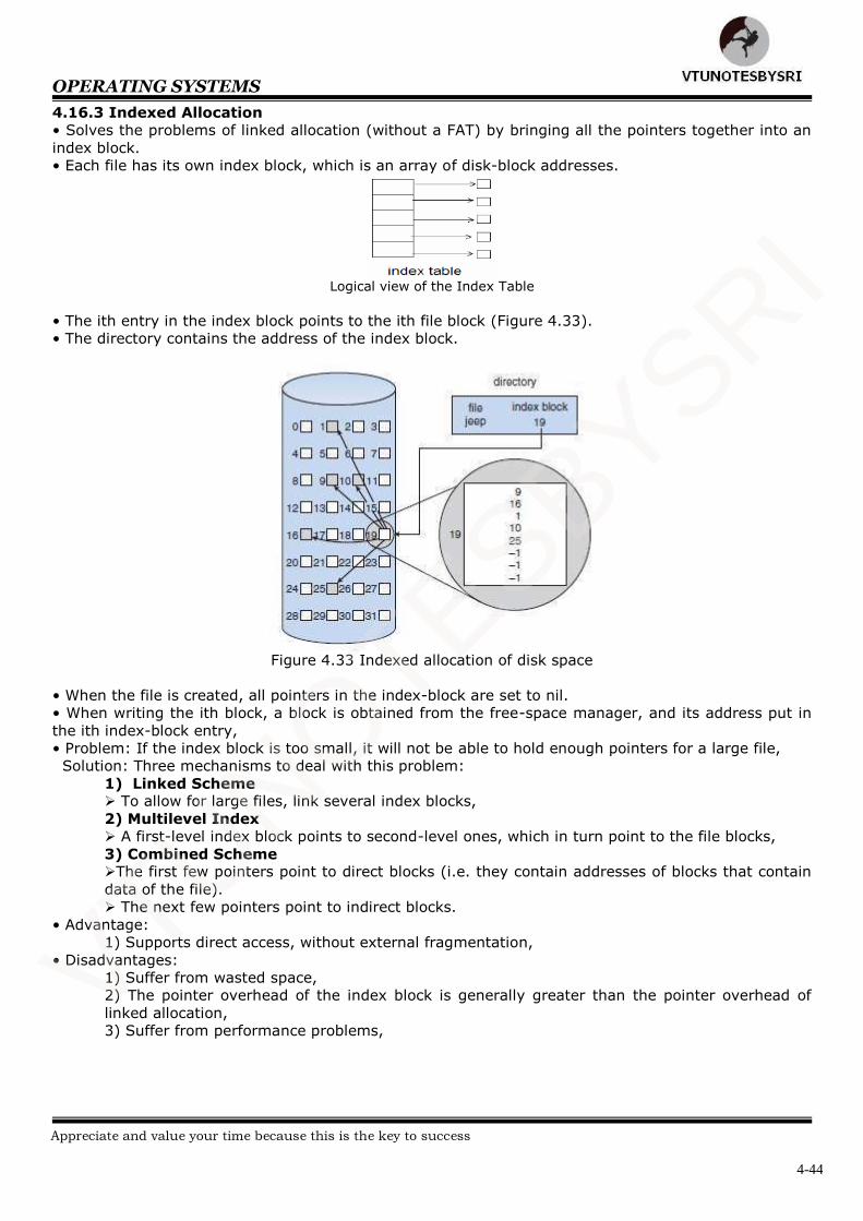
OPERATING SYSTEMS
4-44
4.16.3 Indexed Allocation
• Solves the problems of linked allocation (without a FAT) by bringing all the pointers together into an
index block.
• Each file has its own index block, which is an array of disk-block addresses.
Logical view of the Index Table
• The ith entry in the index block points to the ith file block (Figure 4.33).
• The directory contains the address of the index block.
Figure 4.33 Indexed allocation of disk space
• When the file is created, all pointers in the index-block are set to nil.
• When writing the ith block, a block is obtained from the free-space manager, and its address put in
the ith index-block entry,
• Problem: If the index block is too small, it will not be able to hold enough pointers for a large file,
Solution: Three mechanisms to deal with this problem:
1) Linked Scheme To allow for large files, link several index blocks,
2) Multilevel Index
A first-level index block points to second-level ones, which in turn point to the file blocks,
3) Combined Scheme The first few pointers point to direct blocks (i.e. they contain addresses of blocks that contain
data of the file).
The next few pointers point to indirect blocks.
• Advantage:
1) Supports direct access, without external fragmentation,
• Disadvantages:
1) Suffer from wasted space,
2) The pointer overhead of the index block is generally greater than the pointer overhead of
linked allocation,
3) Suffer from performance problems,
VTUNOTESBYSRI
Appreciate and value your time because this is the key to success
OPERATING SYSTEMS
4-45
4.16.4 Performance
Contiguous Allocation
1Adv)Requires only one access to get a disk-block
2Adv) We can calculate immediately the disk address of the next block and read it directly
3Adv) Good for direct access
Linked Allocation
1Adv) Good for sequential access
1Dis) Not be used for an application requiring direct access
Indexed Allocation
1Adv) If the index block is already in memory, then the access can be made directly
1Dis) keeping the index block in memory requires considerable space (Adv → Advantage Dis → Disadvantage)
VTUNOTESBYSRI
Nobody is going to hand you success. You have to hand yourself to success.
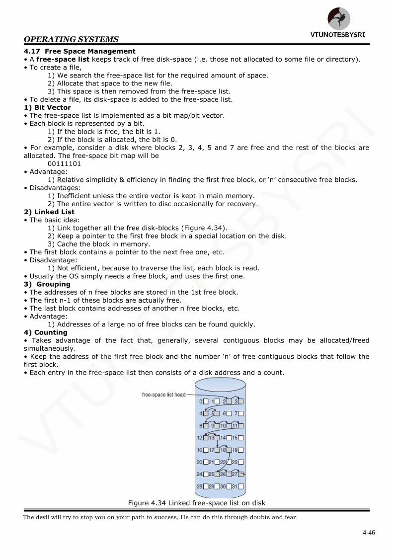
OPERATING SYSTEMS
4-46
4.17 Free Space Management
• A free-space list keeps track of free disk-space (i.e. those not allocated to some file or directory).
• To create a file,
1) We search the free-space list for the required amount of space.
2) Allocate that space to the new file.
3) This space is then removed from the free-space list.
• To delete a file, its disk-space is added to the free-space list.
1) Bit Vector
• The free-space list is implemented as a bit map/bit vector.
• Each block is represented by a bit.
1) If the block is free, the bit is 1.
2) If the block is allocated, the bit is 0.
• For example, consider a disk where blocks 2, 3, 4, 5 and 7 are free and the rest of the blocks are
allocated. The free-space bit map will be
00111101
• Advantage:
1) Relative simplicity & efficiency in finding the first free block, or „n‟ consecutive free blocks.
• Disadvantages:
1) Inefficient unless the entire vector is kept in main memory.
2) The entire vector is written to disc occasionally for recovery.
2) Linked List
• The basic idea:
1) Link together all the free disk-blocks (Figure 4.34).
2) Keep a pointer to the first free block in a special location on the disk.
3) Cache the block in memory.
• The first block contains a pointer to the next free one, etc.
• Disadvantage:
1) Not efficient, because to traverse the list, each block is read.
• Usually the OS simply needs a free block, and uses the first one.
3) Grouping
• The addresses of n free blocks are stored in the 1st free block.
• The first n-1 of these blocks are actually free.
• The last block contains addresses of another n free blocks, etc.
• Advantage:
1) Addresses of a large no of free blocks can be found quickly.
4) Counting
• Takes advantage of the fact that, generally, several contiguous blocks may be allocated/freed
simultaneously.
• Keep the address of the first free block and the number „n‟ of free contiguous blocks that follow the
first block.
• Each entry in the free-space list then consists of a disk address and a count.
Figure 4.34 Linked free-space list on disk
VTUNOTESBYSRI
The devil will try to stop you on your path to success, He can do this through doubts and fear.
OPERATING SYSTEMS
5-1
MODULE 5: MASS-STORAGE STRUCTURE
PROTECTION
THE LINUX SYSTEM
5.1 Mass Storage Structures
5.1.1 Hard-Disks
5.1.2 Solid-State Disks
5.1.3 Magnetic Tapes
5.2 Disk Structure
5.3 Disk Attachment
5.3.1 Host-Attached Storage
5.3.2 Network-Attached Storage
5.3.3 Storage-Area Network
5.4 Disk Scheduling
5.4.1 FCFS Scheduling
5.4.2 SSTF Scheduling
5.4.3 SCAN Scheduling
5.4.4 C-SCAN Scheduling
5.4.5 LOOK Scheduling
5.4.6 Selection of a Disk-Scheduling Algorithm
5.5 Disk Management
5.5.1 Disk Formatting
5.5.2 Boot Block
5.5.3 Bad Blocks
5.6 Swap Space Management
5.6.1 Swap-Space Use
5.6.2 Swap-Space Location
5.6.3 Swap-Space Management: An Example
5.7 Protection vs. Security
5.8 Goals of Protection
5.9 Principles of Protection
5.10 Domain of Protection
5.10.1 Domain Structure
5.10.2 An Example: UNIX
5.10.3 An Example: MULTICS
5.11 Access Matrix
5.12 Implementation of the Access Matrix
5.12.1 Global Table
5.12.2 Access Lists for Objects
5.12.3 Capability Lists for Domains
5.12.4 A Lock–Key Mechanism
5.12.5 Comparison
5.13 Access Control
5.14 Revocation of Access Rights
5.15 Linux History
5.15.1 Linux Kernel
5.15.2 Linux System
5.15.3 Linux Distributions
5.15.4 Linux Licensing
5.16 Design Principles
5.16.1 Components of a Linux System
VTUNOTESBYSRI
Even small positive shifts in thinking, create huge results if you are consistent in your efforts.
OPERATING SYSTEMS
5-2
5.17 Kernel Modules
5.17.1 Module Management
5.17.2 Driver Registration
5.17.3 Conflict Resolution
5.18 Process Management
5.18.1 fork() and exec() Process Model
5.18.1.1 Process Identity
5.18.1.2 Process Environment
5.18.1.3 Process Context
5.18.2 Processes and Threads
5.19 Scheduling
5.19.1 Process Scheduling
5.19.2 Real Time Scheduling
5.19.3 Kernel Synchronization
5.19.4 Symmetric Multiprocessing
5.20 Memory Management
5.20.1 Management of Physical Memory
5.20.2 Virtual Memory
5.20.2.1 Virtual Memory Regions
5.20.2.2 Lifetime of a Virtual Address Space
5.20.2.3 Swapping and Paging
5.20.2.4 Kernel Virtual Memory
5.20.3 Execution and Loading of User Programs
5.20.3.1 Mapping of Programs into Memory
5.20.3.2 Static and Dynamic Linking
5.21 File Systems
5.21.1 Virtual File System
5.21.2 Linux ext3 File System
5.21.3 Journaling
5.21.4 Linux Process File System
5.22 Input and Output
5.22.1 Block Devices
5.22.2 Character Devices
5.23 Inter Process Communication
5.23.1 Synchronization and Signals
5.23.2 Passing of Data among Processes
VTUNOTESBYSRI
The idea you implement is more important than the ideas you collect.
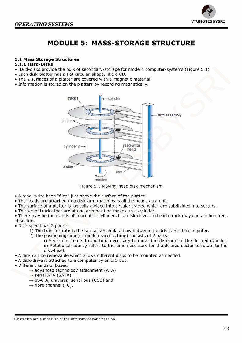
OPERATING SYSTEMS
5-3
MODULE 5: MASS-STORAGE STRUCTURE
5.1 Mass Storage Structures
5.1.1 Hard-Disks
• Hard-disks provide the bulk of secondary-storage for modern computer-systems (Figure 5.1).
• Each disk-platter has a flat circular-shape, like a CD.
• The 2 surfaces of a platter are covered with a magnetic material.
• Information is stored on the platters by recording magnetically.
Figure 5.1 Moving-head disk mechanism
• A read–write head ―flies‖ just above the surface of the platter.
• The heads are attached to a disk-arm that moves all the heads as a unit.
• The surface of a platter is logically divided into circular tracks, which are subdivided into sectors.
• The set of tracks that are at one arm position makes up a cylinder.
• There may be thousands of concentric-cylinders in a disk-drive, and each track may contain hundreds
of sectors.
• Disk-speed has 2 parts:
1) The transfer-rate is the rate at which data flow between the drive and the computer.
2) The positioning-time(or random-access time) consists of 2 parts:
i) Seek-time refers to the time necessary to move the disk-arm to the desired cylinder.
ii) Rotational-latency refers to the time necessary for the desired sector to rotate to the
disk-head.
• A disk can be removable which allows different disks to be mounted as needed.
• A disk-drive is attached to a computer by an I/O bus.
• Different kinds of buses:
→ advanced technology attachment (ATA)
→ serial ATA (SATA)
→ eSATA, universal serial bus (USB) and
→ fibre channel (FC).
VTUNOTESBYSRI
Obstacles are a measure of the intensity of your passion.
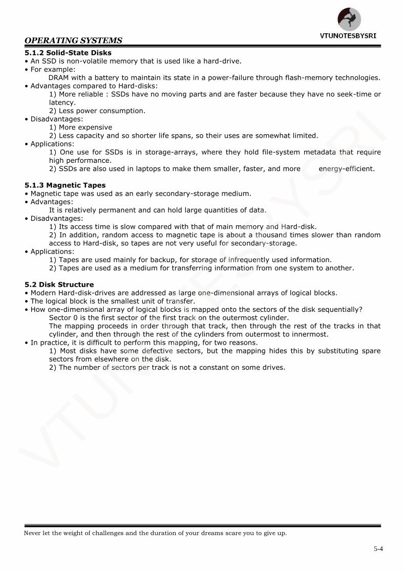
OPERATING SYSTEMS
5-4
5.1.2 Solid-State Disks
• An SSD is non-volatile memory that is used like a hard-drive.
• For example:
DRAM with a battery to maintain its state in a power-failure through flash-memory technologies.
• Advantages compared to Hard-disks:
1) More reliable : SSDs have no moving parts and are faster because they have no seek-time or
latency.
2) Less power consumption.
• Disadvantages:
1) More expensive
2) Less capacity and so shorter life spans, so their uses are somewhat limited.
• Applications:
1) One use for SSDs is in storage-arrays, where they hold file-system metadata that require
high performance.
2) SSDs are also used in laptops to make them smaller, faster, and more energy-efficient.
5.1.3 Magnetic Tapes
• Magnetic tape was used as an early secondary-storage medium.
• Advantages:
It is relatively permanent and can hold large quantities of data.
• Disadvantages:
1) Its access time is slow compared with that of main memory and Hard-disk.
2) In addition, random access to magnetic tape is about a thousand times slower than random
access to Hard-disk, so tapes are not very useful for secondary-storage.
• Applications:
1) Tapes are used mainly for backup, for storage of infrequently used information.
2) Tapes are used as a medium for transferring information from one system to another.
5.2 Disk Structure
• Modern Hard-disk-drives are addressed as large one-dimensional arrays of logical blocks.
• The logical block is the smallest unit of transfer.
• How one-dimensional array of logical blocks is mapped onto the sectors of the disk sequentially?
Sector 0 is the first sector of the first track on the outermost cylinder.
The mapping proceeds in order through that track, then through the rest of the tracks in that
cylinder, and then through the rest of the cylinders from outermost to innermost.
• In practice, it is difficult to perform this mapping, for two reasons.
1) Most disks have some defective sectors, but the mapping hides this by substituting spare
sectors from elsewhere on the disk.
2) The number of sectors per track is not a constant on some drives.
VTUNOTESBYSRI
Never let the weight of challenges and the duration of your dreams scare you to give up.
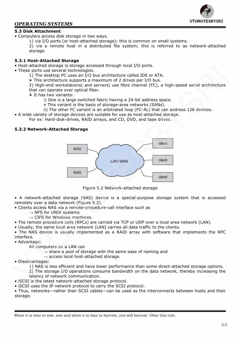
OPERATING SYSTEMS
5-5
5.3 Disk Attachment
• Computers access disk storage in two ways.
1) via I/O ports (or host-attached storage); this is common on small systems.
2) via a remote host in a distributed file system; this is referred to as network-attached
storage.
5.3.1 Host-Attached Storage
• Host-attached storage is storage accessed through local I/O ports.
• These ports use several technologies.
1) The desktop PC uses an I/O bus architecture called IDE or ATA.
This architecture supports a maximum of 2 drives per I/O bus.
2) High-end workstations( and servers) use fibre channel (FC), a high-speed serial architecture
that can operate over optical fiber.
It has two variants:
i) One is a large switched fabric having a 24-bit address space.
¤ This variant is the basis of storage-area networks (SANs).
ii) The other FC variant is an arbitrated loop (FC-AL) that can address 126 devices.
• A wide variety of storage devices are suitable for use as host-attached storage.
For ex: Hard-disk-drives, RAID arrays, and CD, DVD, and tape drives.
5.3.2 Network-Attached Storage
Figure 5.2 Network-attached storage
• A network-attached storage (NAS) device is a special-purpose storage system that is accessed
remotely over a data network (Figure 5.2).
• Clients access NAS via a remote-procedure-call interface such as → NFS for UNIX systems
→ CIFS for Windows machines.
• The remote procedure calls (RPCs) are carried via TCP or UDP over a local area network (LAN).
• Usually, the same local area network (LAN) carries all data traffic to the clients.
• The NAS device is usually implemented as a RAID array with software that implements the RPC
interface.
• Advantage:
All computers on a LAN can
→ share a pool of storage with the same ease of naming and
→ access local host-attached storage.
• Disadvantages:
1) NAS is less efficient and have lower performance than some direct-attached storage options.
2) The storage I/O operations consume bandwidth on the data network, thereby increasing the
latency of network communication.
• iSCSI is the latest network-attached storage protocol.
• iSCSI uses the IP network protocol to carry the SCSI protocol.
• Thus, networks—rather than SCSI cables—can be used as the interconnects between hosts and their
storage.
VTUNOTESBYSRI
When it is time to sow, sow and when it is time to harvest, you will harvest. Obey this rule.
OPERATING SYSTEMS
5-6
5.3.3 Storage-Area Network
• A storage-area network (SAN) is a private network connecting servers and storage units (Figure 5.3).
• The power of a SAN lies in its flexibility.
1) Multiple hosts and multiple storage-arrays can attach to the same SAN.
2) Storage can be dynamically allocated to hosts.
3) A SAN switch allows or prohibits access between the hosts and the storage.
4) SANs make it possible for clusters of servers to share the same storage and for storage
arrays to include multiple direct host connections.
5) SANs typically have more ports than storage-arrays.
• FC is the most common SAN interconnect.
• Another SAN interconnect is InfiniBand — a special-purpose bus architecture that provides hardware
and software support for high-speed interconnection networks for servers and storage units.
Figure 5.3 Storage-area network
VTUNOTESBYSRI
Dare to stretch hard and make it a point to do the hard thing others are afraid to try.
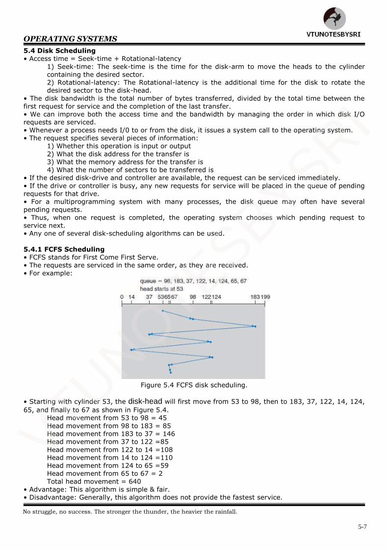
OPERATING SYSTEMS
5-7
5.4 Disk Scheduling
• Access time = Seek-time + Rotational-latency
1) Seek-time: The seek-time is the time for the disk-arm to move the heads to the cylinder
containing the desired sector.
2) Rotational-latency: The Rotational-latency is the additional time for the disk to rotate the
desired sector to the disk-head.
• The disk bandwidth is the total number of bytes transferred, divided by the total time between the
first request for service and the completion of the last transfer.
• We can improve both the access time and the bandwidth by managing the order in which disk I/O
requests are serviced.
• Whenever a process needs I/0 to or from the disk, it issues a system call to the operating system.
• The request specifies several pieces of information:
1) Whether this operation is input or output
2) What the disk address for the transfer is
3) What the memory address for the transfer is
4) What the number of sectors to be transferred is
• If the desired disk-drive and controller are available, the request can be serviced immediately.
• If the drive or controller is busy, any new requests for service will be placed in the queue of pending
requests for that drive.
• For a multiprogramming system with many processes, the disk queue may often have several
pending requests.
• Thus, when one request is completed, the operating system chooses which pending request to
service next.
• Any one of several disk-scheduling algorithms can be used.
5.4.1 FCFS Scheduling
• FCFS stands for First Come First Serve.
• The requests are serviced in the same order, as they are received.
• For example:
Figure 5.4 FCFS disk scheduling.
• Starting with cylinder 53, the disk-head will first move from 53 to 98, then to 183, 37, 122, 14, 124,
65, and finally to 67 as shown in Figure 5.4.
Head movement from 53 to 98 = 45
Head movement from 98 to 183 = 85
Head movement from 183 to 37 = 146
Head movement from 37 to 122 =85
Head movement from 122 to 14 =108
Head movement from 14 to 124 =110
Head movement from 124 to 65 =59
Head movement from 65 to 67 = 2
Total head movement = 640
• Advantage: This algorithm is simple & fair.
• Disadvantage: Generally, this algorithm does not provide the fastest service.
VTUNOTESBYSRI
No struggle, no success. The stronger the thunder, the heavier the rainfall.
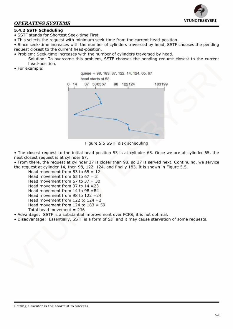
OPERATING SYSTEMS
5-8
5.4.2 SSTF Scheduling
• SSTF stands for Shortest Seek-time First.
• This selects the request with minimum seek-time from the current head-position.
• Since seek-time increases with the number of cylinders traversed by head, SSTF chooses the pending
request closest to the current head-position.
• Problem: Seek-time increases with the number of cylinders traversed by head.
Solution: To overcome this problem, SSTF chooses the pending request closest to the current
head-position.
• For example:
Figure 5.5 SSTF disk scheduling
• The closest request to the initial head position 53 is at cylinder 65. Once we are at cylinder 65, the
next closest request is at cylinder 67.
• From there, the request at cylinder 37 is closer than 98, so 37 is served next. Continuing, we service
the request at cylinder 14, then 98, 122, 124, and finally 183. It is shown in Figure 5.5.
Head movement from 53 to 65 = 12
Head movement from 65 to 67 = 2
Head movement from 67 to 37 = 30
Head movement from 37 to 14 =23
Head movement from 14 to 98 =84
Head movement from 98 to 122 =24
Head movement from 122 to 124 =2
Head movement from 124 to 183 = 59
Total head movement = 236
• Advantage: SSTF is a substantial improvement over FCFS, it is not optimal.
• Disadvantage: Essentially, SSTF is a form of SJF and it may cause starvation of some requests.
VTUNOTESBYSRI
Getting a mentor is the shortcut to success.
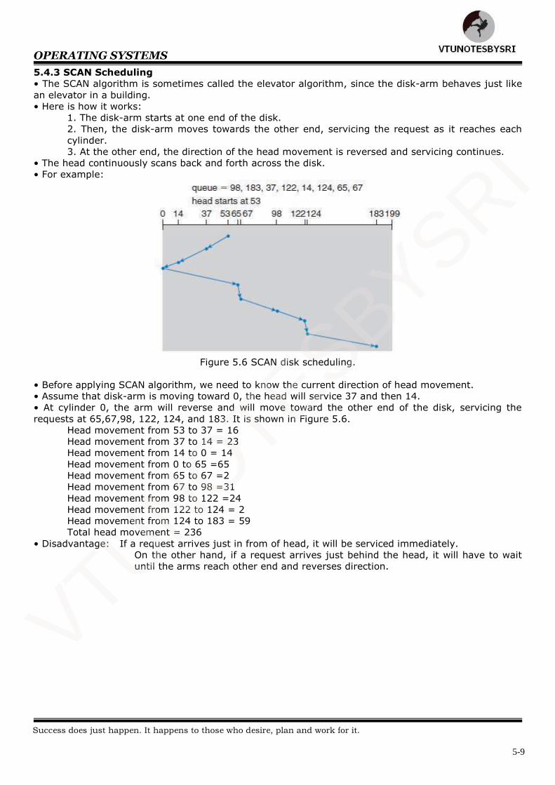
OPERATING SYSTEMS
5-9
5.4.3 SCAN Scheduling
• The SCAN algorithm is sometimes called the elevator algorithm, since the disk-arm behaves just like
an elevator in a building.
• Here is how it works:
1. The disk-arm starts at one end of the disk.
2. Then, the disk-arm moves towards the other end, servicing the request as it reaches each
cylinder.
3. At the other end, the direction of the head movement is reversed and servicing continues.
• The head continuously scans back and forth across the disk.
• For example:
Figure 5.6 SCAN disk scheduling.
• Before applying SCAN algorithm, we need to know the current direction of head movement.
• Assume that disk-arm is moving toward 0, the head will service 37 and then 14. • At cylinder 0, the arm will reverse and will move toward the other end of the disk, servicing the
requests at 65,67,98, 122, 124, and 183. It is shown in Figure 5.6.
Head movement from 53 to 37 = 16
Head movement from 37 to 14 = 23
Head movement from 14 to 0 = 14
Head movement from 0 to 65 =65
Head movement from 65 to 67 =2
Head movement from 67 to 98 =31
Head movement from 98 to 122 =24
Head movement from 122 to 124 = 2
Head movement from 124 to 183 = 59
Total head movement = 236
• Disadvantage: If a request arrives just in from of head, it will be serviced immediately.
On the other hand, if a request arrives just behind the head, it will have to wait
until the arms reach other end and reverses direction.
VTUNOTESBYSRI
Success does just happen. It happens to those who desire, plan and work for it.
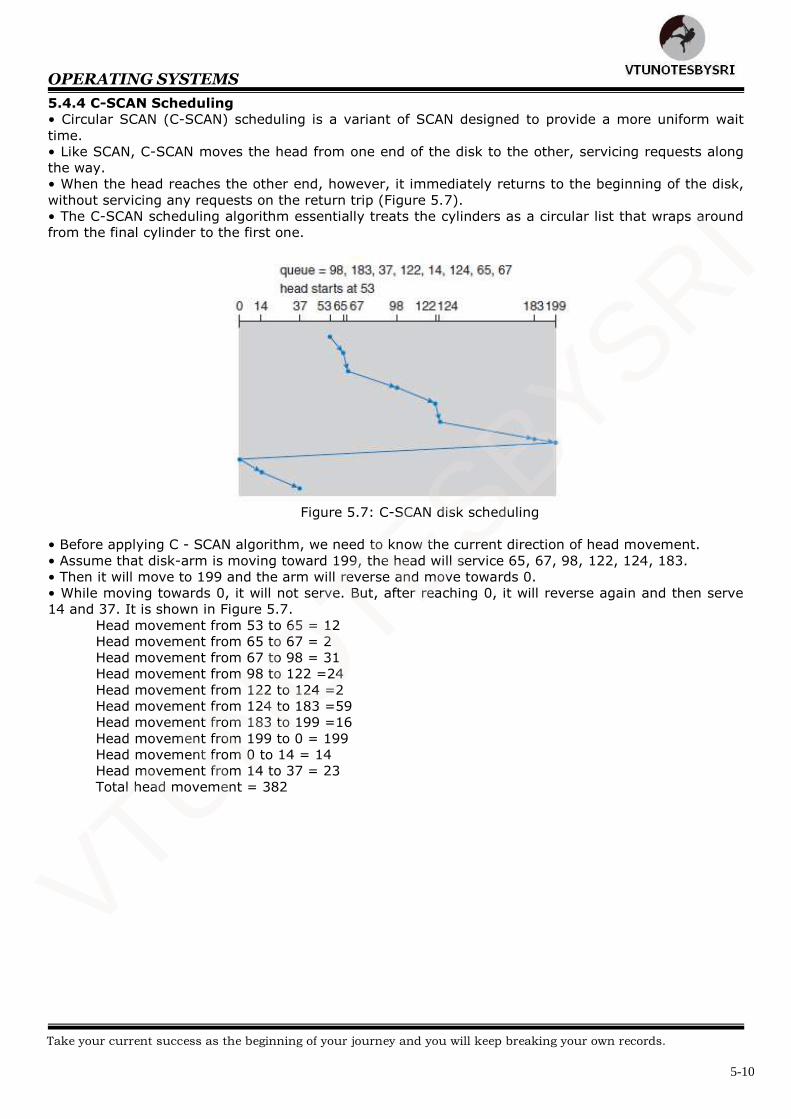
OPERATING SYSTEMS
5-10
5.4.4 C-SCAN Scheduling
• Circular SCAN (C-SCAN) scheduling is a variant of SCAN designed to provide a more uniform wait
time.
• Like SCAN, C-SCAN moves the head from one end of the disk to the other, servicing requests along
the way.
• When the head reaches the other end, however, it immediately returns to the beginning of the disk,
without servicing any requests on the return trip (Figure 5.7).
• The C-SCAN scheduling algorithm essentially treats the cylinders as a circular list that wraps around
from the final cylinder to the first one.
Figure 5.7: C-SCAN disk scheduling
• Before applying C - SCAN algorithm, we need to know the current direction of head movement.
• Assume that disk-arm is moving toward 199, the head will service 65, 67, 98, 122, 124, 183.
• Then it will move to 199 and the arm will reverse and move towards 0.
• While moving towards 0, it will not serve. But, after reaching 0, it will reverse again and then serve
14 and 37. It is shown in Figure 5.7.
Head movement from 53 to 65 = 12
Head movement from 65 to 67 = 2
Head movement from 67 to 98 = 31
Head movement from 98 to 122 =24
Head movement from 122 to 124 =2
Head movement from 124 to 183 =59
Head movement from 183 to 199 =16
Head movement from 199 to 0 = 199
Head movement from 0 to 14 = 14
Head movement from 14 to 37 = 23
Total head movement = 382
VTUNOTESBYSRI
Take your current success as the beginning of your journey and you will keep breaking your own records.
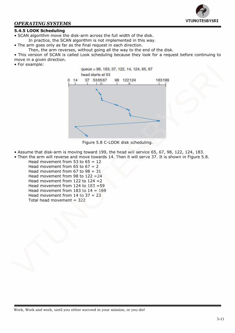
OPERATING SYSTEMS
5-11
5.4.5 LOOK Scheduling
• SCAN algorithm move the disk-arm across the full width of the disk.
In practice, the SCAN algorithm is not implemented in this way.
• The arm goes only as far as the final request in each direction.
Then, the arm reverses, without going all the way to the end of the disk.
• This version of SCAN is called Look scheduling because they look for a request before continuing to
move in a given direction.
• For example:
Figure 5.8 C-LOOK disk scheduling.
• Assume that disk-arm is moving toward 199, the head will service 65, 67, 98, 122, 124, 183.
• Then the arm will reverse and move towards 14. Then it will serve 37. It is shown in Figure 5.8.
Head movement from 53 to 65 = 12
Head movement from 65 to 67 = 2
Head movement from 67 to 98 = 31
Head movement from 98 to 122 =24
Head movement from 122 to 124 =2
Head movement from 124 to 183 =59
Head movement from 183 to 14 = 169
Head movement from 14 to 37 = 23
Total head movement = 322
VTUNOTESBYSRI
Work, Work and work, until you either succeed in your mission, or you die!
OPERATING SYSTEMS
5-12
5.5 Disk Management
• The operating system is responsible for several other aspects of disk management.
• For example:
1) disk initialization
2) booting from disk
3) bad-block recovery.
5.5.1 Disk Formatting
• Usually, a new Hard-disk is a blank slate: it is just a platter of a magnetic recording material.
• Before a disk can store data, it must be divided into sectors that the disk controller can read and
write. This process is called low-level formatting, or physical formatting.
• Low-level formatting fills the disk with a special data structure for each sector.
• The data structure for a sector typically consists of
→ a header
→ a data area (usually 512 bytes in size), and
→ a trailer.
• The header and trailer contain information used by the disk controller, such as → sector number and
→ error-correcting code (ECC).
• Before a disk can store data, the operating system still needs to record its own data structures on the
disk.
• It does so in two steps.
1) Partition the disk into one or more groups of cylinders. The operating system can treat each partition as a separate disk.
For example:
one partition can hold a copy of the operating system’s executable code,
another partition can hold user files.
2) Logical formatting, or creation of a file system.
The operating system stores the initial file-system data structures onto the disk.
These data structures may include maps of free and allocated space and an initial empty
directory.
• To increase efficiency, most file systems group blocks together into larger chunks, frequently called
clusters.
1) Disk I/O is done via blocks,
2) File system I/O is done via clusters.
5.5.2 Boot Block
• For a computer to start running, it must have a bootstrap program to run.
• Bootstrap program → initializes CPU registers, device controllers and the contents of main memory and
→ then starts the operating system.
• For most computers, the bootstrap is stored in read-only memory (ROM).
• Main Problem: To change the bootstrap code, the ROM hardware chips has to be changed.
• To solve this problem, most systems store a tiny bootstrap loader program in the boot-ROM.
• Job of boot-ROM: Bring in a full bootstrap program from disk.
• The full bootstrap program can be changed easily: ―A new version is simply written onto the disk‖.
• The full bootstrap program is stored in the ―boot blocks‖ at a fixed location on the disk.
• A disk that has a boot partition is called a boot disk or system disk.
• In the boot-ROM, the code → instructs the disk-controller to read the boot blocks into memory and
→ then starts executing that code.
VTUNOTESBYSRI
Great leaders inspire greatness in others.
OPERATING SYSTEMS
5-13
5.5.3 Bad Blocks
• Because disks have moving parts and small tolerances, they are prone to failure.
• Sometimes, → The disk needs to be replaced.
→ The disk-contents need to be restored from backup media to the new disk.
→ One or more sectors may become defective.
• From the manufacturer, most disks have bad-blocks.
• How to handle bad-blocks?
On simple disks, bad-blocks are handled manually.
One strategy is to scan the disk to find bad-blocks while the disk is being formatted.
Any bad-blocks that are discovered are flagged as unusable. Thus, the file system does not
allocate them. If blocks go bad during normal operation, a special program (such as Linux bad-blocks
command) must be run manually
→ to search for the bad-blocks and
→ to lock the bad-blocks.
Usually, data that resided on the bad-blocks are lost.
• A typical bad-sector transaction might be as follows:
1) The operating system tries to read logical block 87.
2) The controller calculates the ECC and finds that the sector is bad. It reports this finding to
the operating system.
3) The next time the system is rebooted, a special command is run to tell the controller to
replace the bad sector with a spare.
4) After that, whenever the system requests logical block 87, the request is translated into the
replacement sector’s address by the controller.
VTUNOTESBYSRI
Greatness means setting out to make some difference somewhere to someone in someplace.
OPERATING SYSTEMS
5-14
5.6 Swap Space Management
• Swap-space management is a low-level task of the operating system.
• Virtual memory uses disk space as an extension of main memory.
• Main goal of swap space: to provide the best throughput for the virtual memory system.
• Here, we discuss about 1) Swap space use 2) Swap space location.
5.6.1 Swap-Space Use
• Swap space can be used in 2 ways.
1) Swapping-Systems may use swap space to hold an entire process image, including the code
and data segments.
2) Paging-systems may simply store pages that have been pushed out of main memory.
• The amount of swap space needed on a system can therefore vary from a few megabytes of disk
space to gigabytes, depending on
→ amount of physical memory,
→ amount of virtual memory it is backing, and
→ way in which the virtual memory is used.
5.6.2 Swap-Space Location
• A swap space can reside in one of two places:
1) The swap space can be a large file within the file system. Here, normal file-system routines can be used to create it, name it, and allocate
its space.
Advantage: This approach easy to implement,
Disadvantage: This approach is inefficient. This is because
i) Navigating the directory structure and the disk structures takes time and
extra disk accesses.
ii) External fragmentation can greatly increase swapping times by forcing
multiple seeks during reading or writing of a process image.
2) The swap space can be in a separate raw (disk) partition. No file system or directory structure is placed in the swap space.
Rather, a separate swap-space storage manager is used to allocate and
de-allocate the blocks from the raw partition.
This manager uses algorithms optimized for speed rather than for storage efficiency,
because swap space is accessed much more frequently than file system.
VTUNOTESBYSRI
When your intuition is strong, follow it.
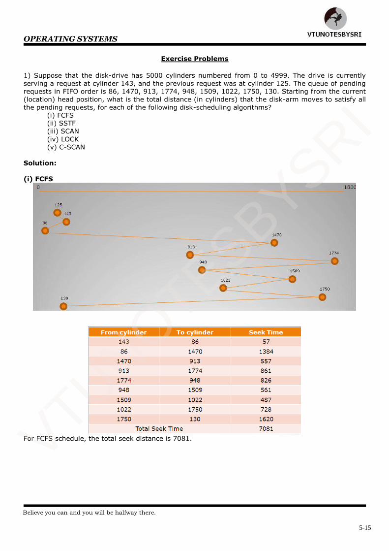
OPERATING SYSTEMS
5-15
Exercise Problems
1) Suppose that the disk-drive has 5000 cylinders numbered from 0 to 4999. The drive is currently
serving a request at cylinder 143, and the previous request was at cylinder 125. The queue of pending
requests in FIFO order is 86, 1470, 913, 1774, 948, 1509, 1022, 1750, 130. Starting from the current
(location) head position, what is the total distance (in cylinders) that the disk-arm moves to satisfy all
the pending requests, for each of the following disk-scheduling algorithms?
(i) FCFS
(ii) SSTF
(iii) SCAN
(iv) LOCK
(v) C-SCAN
Solution:
(i) FCFS
For FCFS schedule, the total seek distance is 7081.
VTUNOTESBYSRI
Believe you can and you will be halfway there.
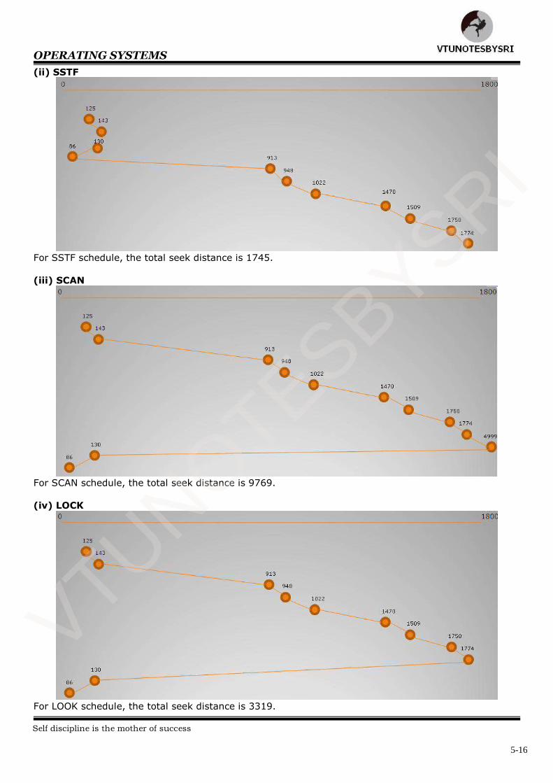
OPERATING SYSTEMS
5-16
(ii) SSTF
For SSTF schedule, the total seek distance is 1745.
(iii) SCAN
For SCAN schedule, the total seek distance is 9769.
(iv) LOCK
For LOOK schedule, the total seek distance is 3319.
VTUNOTESBYSRI
Self discipline is the mother of success
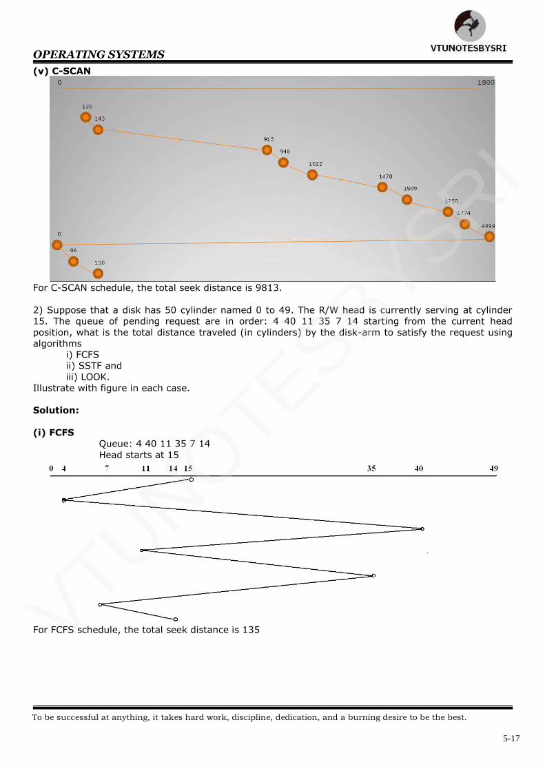
OPERATING SYSTEMS
5-17
(v) C-SCAN
For C-SCAN schedule, the total seek distance is 9813.
2) Suppose that a disk has 50 cylinder named 0 to 49. The R/W head is currently serving at cylinder
15. The queue of pending request are in order: 4 40 11 35 7 14 starting from the current head
position, what is the total distance traveled (in cylinders) by the disk-arm to satisfy the request using
algorithms
i) FCFS
ii) SSTF and
iii) LOOK.
Illustrate with figure in each case.
Solution:
(i) FCFS
Queue: 4 40 11 35 7 14
Head starts at 15
For FCFS schedule, the total seek distance is 135
VTUNOTESBYSRI
To be successful at anything, it takes hard work, discipline, dedication, and a burning desire to be the best.
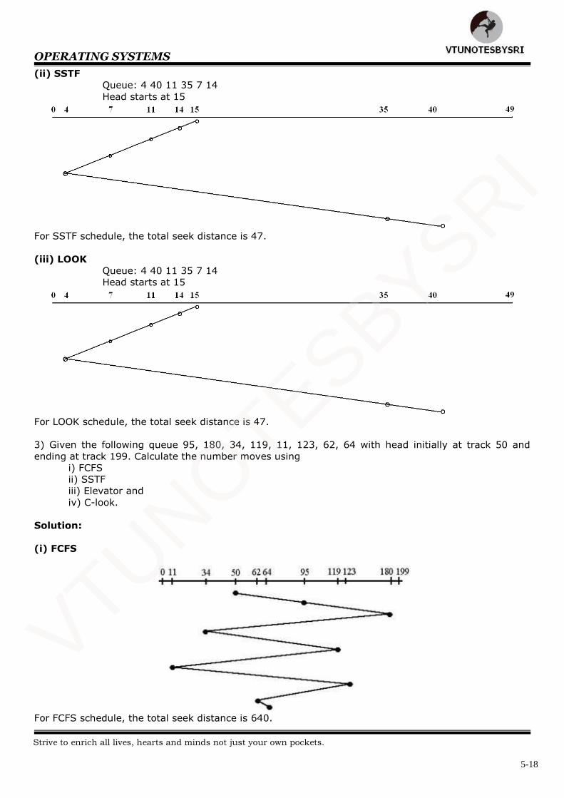
OPERATING SYSTEMS
5-18
(ii) SSTF
Queue: 4 40 11 35 7 14
Head starts at 15
For SSTF schedule, the total seek distance is 47.
(iii) LOOK
Queue: 4 40 11 35 7 14
Head starts at 15
For LOOK schedule, the total seek distance is 47.
3) Given the following queue 95, 180, 34, 119, 11, 123, 62, 64 with head initially at track 50 and
ending at track 199. Calculate the number moves using
i) FCFS
ii) SSTF
iii) Elevator and
iv) C-look.
Solution:
(i) FCFS
For FCFS schedule, the total seek distance is 640.
VTUNOTESBYSRI
Strive to enrich all lives, hearts and minds not just your own pockets.
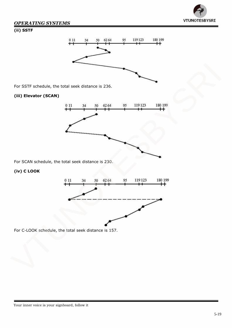
OPERATING SYSTEMS
5-19
(ii) SSTF
For SSTF schedule, the total seek distance is 236.
(iii) Elevator (SCAN)
For SCAN schedule, the total seek distance is 230.
(iv) C LOOK
For C-LOOK schedule, the total seek distance is 157.
VTUNOTESBYSRI
Your inner voice is your signboard, follow it
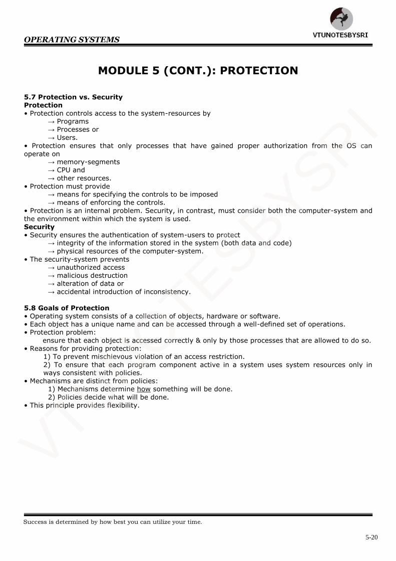
OPERATING SYSTEMS
5-20
MODULE 5 (CONT.): PROTECTION
5.7 Protection vs. Security
Protection
• Protection controls access to the system-resources by → Programs
→ Processes or
→ Users.
• Protection ensures that only processes that have gained proper authorization from the OS can
operate on → memory-segments
→ CPU and
→ other resources.
• Protection must provide → means for specifying the controls to be imposed
→ means of enforcing the controls.
• Protection is an internal problem. Security, in contrast, must consider both the computer-system and
the environment within which the system is used.
Security
• Security ensures the authentication of system-users to protect → integrity of the information stored in the system (both data and code)
→ physical resources of the computer-system.
• The security-system prevents
→ unauthorized access
→ malicious destruction
→ alteration of data or
→ accidental introduction of inconsistency.
5.8 Goals of Protection
• Operating system consists of a collection of objects, hardware or software.
• Each object has a unique name and can be accessed through a well-defined set of operations.
• Protection problem:
ensure that each object is accessed correctly & only by those processes that are allowed to do so.
• Reasons for providing protection:
1) To prevent mischievous violation of an access restriction.
2) To ensure that each program component active in a system uses system resources only in
ways consistent with policies.
• Mechanisms are distinct from policies:
1) Mechanisms determine how something will be done.
2) Policies decide what will be done.
• This principle provides flexibility.
VTUNOTESBYSRI
Success is determined by how best you can utilize your time.
OPERATING SYSTEMS
5-21
5.9 Principles of Protection
• A key principle for protection is the principle of least privilege.
• Principle of Least Privilege:
―Programs, users, and even systems are given just enough privileges to perform their tasks‖.
• The principle of least privilege can help produce a more secure computing environment.
• An operating system which follows the principle of least privilege implements its features, programs,
system-calls, and data structures.
• Thus, failure of a component results in minimum damage.
• An operating system also provides system-calls and services that allow applications to be written with
fine-grained access controls.
• Access Control provides mechanisms → to enable privileges when they are needed.
→ to disable privileges when they are not needed.
• Audit-trails for all privileged function-access can be created.
• Audit-trail can be used to trace all protection/security activities on the system.
• The audit-trail can be used by
→ Programmer
→ System administrator or
→ Law-enforcement officer.
• Managing users with the principle of least privilege requires creating a separate account for each
user, with just the privileges that the user needs.
• Computers implemented in a computing facility under the principle of least privilege can be limited to → running specific services
→ accessing specific remote hosts via specific services
→ accessing during specific times.
• Typically, these restrictions are implemented through enabling or disabling each service and through
using Access Control Lists.
VTUNOTESBYSRI
YOU ARE HERE FOR A CAUSE. YOU REACH TO YOUR ULTIMATE DESTINY BY LIVING THAT CAUSE.
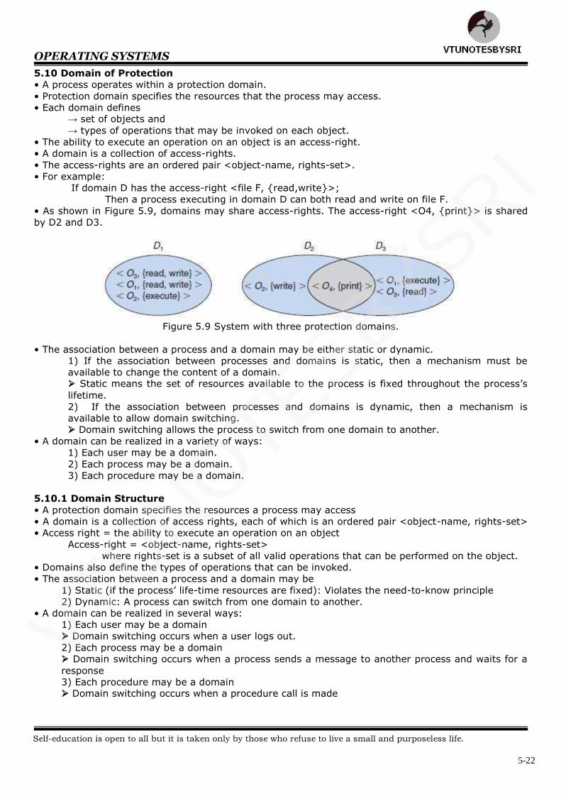
OPERATING SYSTEMS
5-22
5.10 Domain of Protection
• A process operates within a protection domain.
• Protection domain specifies the resources that the process may access.
• Each domain defines → set of objects and
→ types of operations that may be invoked on each object.
• The ability to execute an operation on an object is an access-right.
• A domain is a collection of access-rights.
• The access-rights are an ordered pair <object-name, rights-set>.
• For example:
If domain D has the access-right <file F, {read,write}>;
Then a process executing in domain D can both read and write on file F.
• As shown in Figure 5.9, domains may share access-rights. The access-right <O4, {print}> is shared
by D2 and D3.
Figure 5.9 System with three protection domains.
• The association between a process and a domain may be either static or dynamic.
1) If the association between processes and domains is static, then a mechanism must be
available to change the content of a domain. Static means the set of resources available to the process is fixed throughout the process’s
lifetime.
2) If the association between processes and domains is dynamic, then a mechanism is
available to allow domain switching.
Domain switching allows the process to switch from one domain to another.
• A domain can be realized in a variety of ways:
1) Each user may be a domain.
2) Each process may be a domain.
3) Each procedure may be a domain.
5.10.1 Domain Structure
• A protection domain specifies the resources a process may access
• A domain is a collection of access rights, each of which is an ordered pair <object-name, rights-set>
• Access right = the ability to execute an operation on an object
Access-right = <object-name, rights-set>
where rights-set is a subset of all valid operations that can be performed on the object.
• Domains also define the types of operations that can be invoked.
• The association between a process and a domain may be
1) Static (if the process’ life-time resources are fixed): Violates the need-to-know principle
2) Dynamic: A process can switch from one domain to another.
• A domain can be realized in several ways:
1) Each user may be a domain
Domain switching occurs when a user logs out.
2) Each process may be a domain Domain switching occurs when a process sends a message to another process and waits for a
response
3) Each procedure may be a domain Domain switching occurs when a procedure call is made
VTUNOTESBYSRI
Self-education is open to all but it is taken only by those who refuse to live a small and purposeless life.
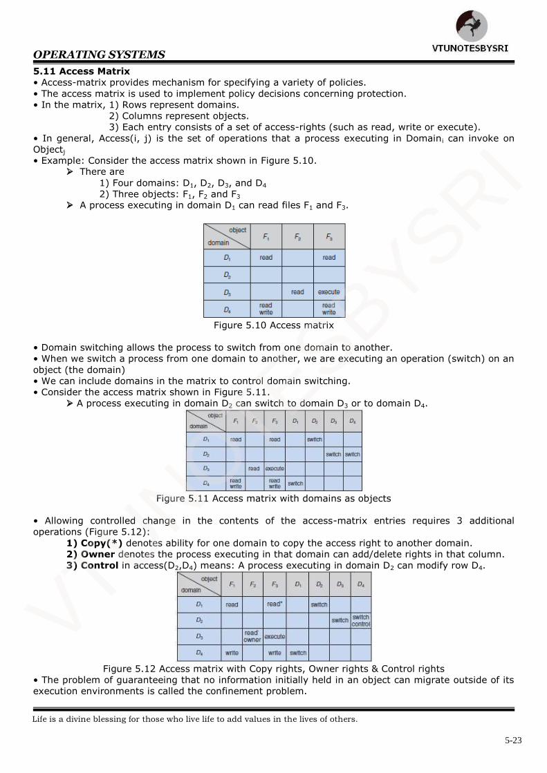
OPERATING SYSTEMS
5-23
5.11 Access Matrix
• Access-matrix provides mechanism for specifying a variety of policies.
• The access matrix is used to implement policy decisions concerning protection.
• In the matrix, 1) Rows represent domains.
2) Columns represent objects.
3) Each entry consists of a set of access-rights (such as read, write or execute).
• In general, Access(i, j) is the set of operations that a process executing in Domaini can invoke on
Objectj
• Example: Consider the access matrix shown in Figure 5.10. There are
1) Four domains: D1, D2, D3, and D4
2) Three objects: F1, F2 and F3 A process executing in domain D1 can read files F1 and F3.
Figure 5.10 Access matrix
• Domain switching allows the process to switch from one domain to another.
• When we switch a process from one domain to another, we are executing an operation (switch) on an
object (the domain)
• We can include domains in the matrix to control domain switching.
• Consider the access matrix shown in Figure 5.11.
A process executing in domain D2 can switch to domain D3 or to domain D4.
Figure 5.11 Access matrix with domains as objects
• Allowing controlled change in the contents of the access-matrix entries requires 3 additional
operations (Figure 5.12):
1) Copy(*) denotes ability for one domain to copy the access right to another domain.
2) Owner denotes the process executing in that domain can add/delete rights in that column.
3) Control in access(D2,D4) means: A process executing in domain D2 can modify row D4.
Figure 5.12 Access matrix with Copy rights, Owner rights & Control rights
• The problem of guaranteeing that no information initially held in an object can migrate outside of its
execution environments is called the confinement problem.
VTUNOTESBYSRI
Life is a divine blessing for those who live life to add values in the lives of others.
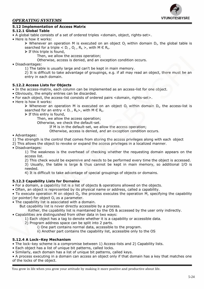
OPERATING SYSTEMS
5-24
5.12 Implementation of Access Matrix
5.12.1 Global Table
• A global table consists of a set of ordered triples <domain, object, rights-set>.
• Here is how it works: Whenever an operation M is executed on an object Oj within domain Di, the global table is
searched for a triple < Di , Oj , Rk >, with M Є Rk.
If this triple is found,
Then, we allow the access operation;
Otherwise, access is denied, and an exception condition occurs.
• Disadvantages:
1) The table is usually large and can't be kept in main memory.
2) It is difficult to take advantage of groupings, e.g. if all may read an object, there must be an
entry in each domain.
5.12.2 Access Lists for Objects
• In the access-matrix, each column can be implemented as an access-list for one object.
• Obviously, the empty entries can be discarded.
• For each object, the access-list consists of ordered pairs <domain, rights-set>.
• Here is how it works: Whenever an operation M is executed on an object Oj within domain Di, the access-list is
searched for an entry < Di , Rk>, with M Є Rk. If this entry is found,
Then, we allow the access operation;
Otherwise, we check the default-set.
If M is in the default-set, we allow the access operation;
Otherwise, access is denied, and an exception condition occurs.
• Advantages:
1) The strength is the control that comes from storing the access privileges along with each object
2) This allows the object to revoke or expand the access privileges in a localized manner.
• Disadvantages:
1) The weakness is the overhead of checking whether the requesting domain appears on the
access list.
2) This check would be expensive and needs to be performed every time the object is accessed.
3) Usually, the table is large & thus cannot be kept in main memory, so additional I/O is
needed.
4) It is difficult to take advantage of special groupings of objects or domains.
5.12.3 Capability Lists for Domains
• For a domain, a capability list is a list of objects & operations allowed on the objects.
• Often, an object is represented by its physical name or address, called a capability.
• To execute operation M on object Oj, the process executes the operation M, specifying the capability
(or pointer) for object Oj as a parameter.
• The capability list is associated with a domain.
But capability list is never directly accessible by a process.
Rather, the capability list is maintained by the OS & accessed by the user only indirectly.
• Capabilities are distinguished from other data in two ways:
1) Each object has a tag to denote whether it is a capability or accessible data.
2) Program address space can be split into 2 parts.
i) One part contains normal data, accessible to the program.
ii) Another part contains the capability list, accessible only to the OS
5.12.4 A Lock–Key Mechanism
• The lock–key scheme is a compromise between 1) Access-lists and 2) Capability lists.
• Each object has a list of unique bit patterns, called locks.
• Similarly, each domain has a list of unique bit patterns, called keys.
• A process executing in a domain can access an object only if that domain has a key that matches one
of the locks of the object.
VTUNOTESBYSRI
You grow in life when you grow your attitude by making it more positive and productive about life.
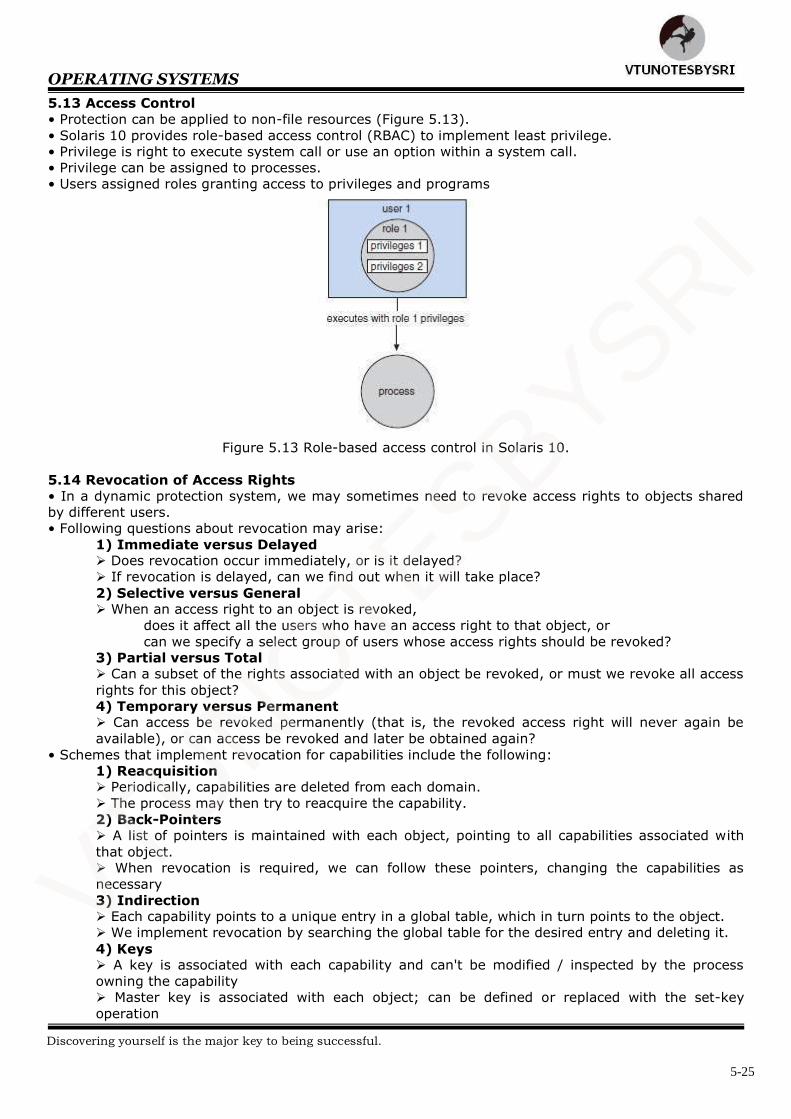
OPERATING SYSTEMS
5-25
5.13 Access Control
• Protection can be applied to non-file resources (Figure 5.13).
• Solaris 10 provides role-based access control (RBAC) to implement least privilege.
• Privilege is right to execute system call or use an option within a system call.
• Privilege can be assigned to processes.
• Users assigned roles granting access to privileges and programs
Figure 5.13 Role-based access control in Solaris 10.
5.14 Revocation of Access Rights
• In a dynamic protection system, we may sometimes need to revoke access rights to objects shared
by different users.
• Following questions about revocation may arise:
1) Immediate versus Delayed Does revocation occur immediately, or is it delayed?
If revocation is delayed, can we find out when it will take place?
2) Selective versus General When an access right to an object is revoked,
does it affect all the users who have an access right to that object, or
can we specify a select group of users whose access rights should be revoked?
3) Partial versus Total Can a subset of the rights associated with an object be revoked, or must we revoke all access
rights for this object?
4) Temporary versus Permanent Can access be revoked permanently (that is, the revoked access right will never again be
available), or can access be revoked and later be obtained again?
• Schemes that implement revocation for capabilities include the following:
1) Reacquisition Periodically, capabilities are deleted from each domain.
The process may then try to reacquire the capability.
2) Back-Pointers A list of pointers is maintained with each object, pointing to all capabilities associated with
that object. When revocation is required, we can follow these pointers, changing the capabilities as
necessary
3) Indirection Each capability points to a unique entry in a global table, which in turn points to the object.
We implement revocation by searching the global table for the desired entry and deleting it.
4) Keys A key is associated with each capability and can't be modified / inspected by the process
owning the capability
Master key is associated with each object; can be defined or replaced with the set-key
operation
VTUNOTESBYSRI
Discovering yourself is the major key to being successful.
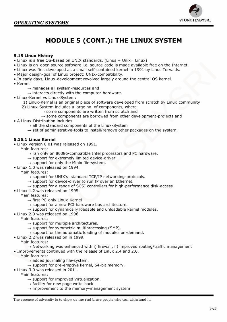
OPERATING SYSTEMS
5-26
MODULE 5 (CONT.): THE LINUX SYSTEM
5.15 Linux History
• Linux is a free OS-based on UNIX standards. (Linus + Unix= Linux)
• Linux is an open source software i.e. source-code is made available free on the Internet.
• Linux was first developed as a small self-contained kernel in 1991 by Linus Torvalds.
• Major design-goal of Linux project: UNIX-compatibility.
• In early days, Linux-development revolved largely around the central OS kernel.
• Kernel → manages all system-resources and
→ interacts directly with the computer-hardware.
• Linux-Kernel vs Linux-System:
1) Linux-Kernel is an original piece of software developed from scratch by Linux community
2) Linux-System includes a large no. of components, where → some components are written from scratch and → some components are borrowed from other development-projects and
• A Linux-Distribution includes → all the standard components of the Linux-System
→ set of administrative-tools to install/remove other packages on the system.
5.15.1 Linux Kernel
• Linux version 0.01 was released on 1991.
Main features: → ran only on 80386-compatible Intel processors and PC hardware.
→ support for extremely limited device-driver.
→ support for only the Minix file-system.
• Linux 1.0 was released on 1994.
Main features: → support for UNIX’s standard TCP/IP networking-protocols.
→ support for device-driver to run IP over an Ethernet.
→ support for a range of SCSI controllers for high-performance disk-access
• Linux 1.2 was released on 1995.
Main features:
→ first PC-only Linux-Kernel
→ support for a new PCI hardware bus architecture.
→ support for dynamically loadable and unloadable kernel modules.
• Linux 2.0 was released on 1996.
Main features:
→ support for multiple architectures.
→ support for symmetric multiprocessing (SMP).
→ support for the automatic loading of modules on-demand.
• Linux 2.2 was released on in 1999.
Main features: → Networking was enhanced with i) firewall, ii) improved routing/traffic management
• Improvements continued with the release of Linux 2.4 and 2.6.
Main features: → added journaling file-system.
→ support for pre-emptive kernel, 64-bit memory.
• Linux 3.0 was released in 2011.
Main features: → support for improved virtualization.
→ facility for new page write-back
→ improvement to the memory-management system
VTUNOTESBYSRI
The essence of adversity is to show us the real brave people who can withstand it.
OPERATING SYSTEMS
5-27
5.15.2 Linux-System
• Linux uses many tools developed as part of
→ Berkeley’s BSD OS
→ MIT’s X Window-System and
→ Free Software Foundation’s GNU project.
• Main system-libraries are created by GNU project.
• Linux networking-administration tools are derived from 4.3BSD code.
• Linux-System is maintained by a many developers collaborating over the Internet.
• A small groups or individuals are responsible for maintaining the integrity of specific components.
• Linux community is responsible for maintaining the File-system Hierarchy Standard.
• This standard ensures compatibility across the various system-components.
5.15.3 Linux-Distributions
• Linux-Distributions include → system-installation and management utilities
→ ready-to-install packages of common UNIX tools (ex: text-processing, web browser).
• The first distributions managed these packages by simply providing a means of unpacking all the files
into the appropriate places.
• Early distributions included SLS and Slackware.
• RedHat and Debian are popular distributions from commercial and non-commercial sources,
respectively. • RPM Package file format permits compatibility among the various Linux-Distributions.
5.15.4 Linux Licensing
• The Linux-Kernel is distributed under the GNU General Public License (GPL).
• Linux is not public-domain software.
• Public domain implies that the authors have waived copyright rights in the software.
• Linux is free software i.e. the people can copy it, modify it, use it.
• Anyone creating their own derivative of Linux, may not make the derived product proprietary.
• Software released under the GPL may not be redistributed as a binary-only product.
VTUNOTESBYSRI
In times of failure you are alone. But success brings many friends.
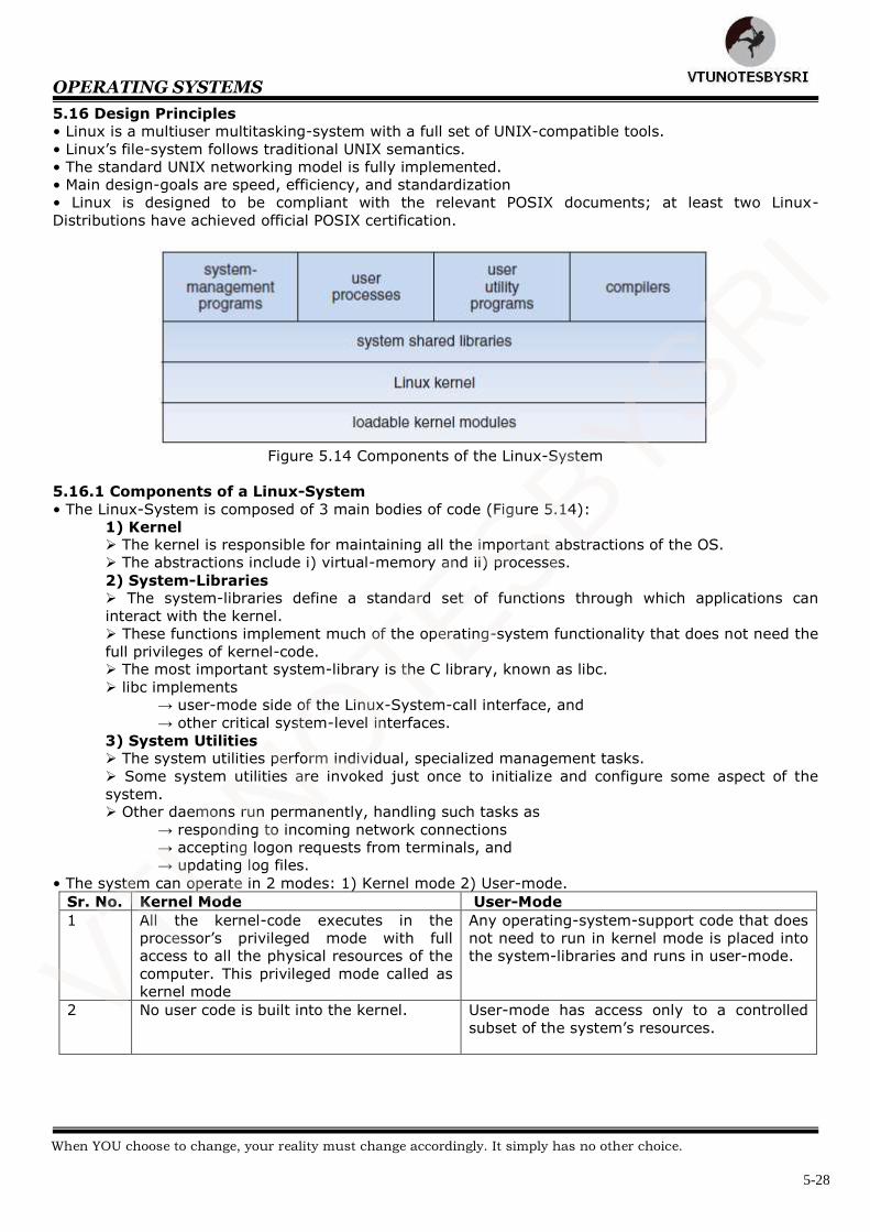
OPERATING SYSTEMS
5-28
5.16 Design Principles
• Linux is a multiuser multitasking-system with a full set of UNIX-compatible tools.
• Linux’s file-system follows traditional UNIX semantics.
• The standard UNIX networking model is fully implemented.
• Main design-goals are speed, efficiency, and standardization
• Linux is designed to be compliant with the relevant POSIX documents; at least two Linux-
Distributions have achieved official POSIX certification.
Figure 5.14 Components of the Linux-System
5.16.1 Components of a Linux-System
• The Linux-System is composed of 3 main bodies of code (Figure 5.14):
1) Kernel The kernel is responsible for maintaining all the important abstractions of the OS.
The abstractions include i) virtual-memory and ii) processes.
2) System-Libraries The system-libraries define a standard set of functions through which applications can
interact with the kernel.
These functions implement much of the operating-system functionality that does not need the
full privileges of kernel-code. The most important system-library is the C library, known as libc.
libc implements
→ user-mode side of the Linux-System-call interface, and
→ other critical system-level interfaces.
3) System Utilities The system utilities perform individual, specialized management tasks.
Some system utilities are invoked just once to initialize and configure some aspect of the
system. Other daemons run permanently, handling such tasks as
→ responding to incoming network connections
→ accepting logon requests from terminals, and
→ updating log files.
• The system can operate in 2 modes: 1) Kernel mode 2) User-mode.
Sr. No. Kernel Mode User-Mode
1 All the kernel-code executes in the
processor’s privileged mode with full
access to all the physical resources of the
computer. This privileged mode called as
kernel mode
Any operating-system-support code that does
not need to run in kernel mode is placed into
the system-libraries and runs in user-mode.
2 No user code is built into the kernel. User-mode has access only to a controlled
subset of the system’s resources.
VTUNOTESBYSRI
When YOU choose to change, your reality must change accordingly. It simply has no other choice.
OPERATING SYSTEMS
5-29
5.17 Kernel Modules
• A kernel module can implement a device-driver, a file-system, or a networking protocol.
• The kernel’s module interface allows third parties to write and distribute, on their own terms, device-
drivers or file-systems that could not be distributed under the GPL.
• Kernel modules allow a Linux-System to be set up with a standard minimal kernel, without any extra
device-drivers built in.
• The module support has 3 components:
1) Module Management
2) Driver Registration
3) Conflict Resolution
5.17.1 Module Management
• Allows modules to be loaded into memory.
• Allows modules to communicate with the rest of the kernel.
• Module loading is split into 2 separate sections:
1) The management of sections of module code in kernel-memory.
2) The handling of symbols that modules are allowed to reference.
• Linux maintains an internal symbol table in the kernel.
• This symbol table → does not contain the full set of symbols defined in the kernel.
→ contains a set of symbol that must be explicitly exported.
• The set of exported symbols constitutes a well-defined interface by which a module can interact with
the kernel.
• The loading of the module is performed in two stages.
1) Module Loader Utility asks the kernel to reserve a continuous area of virtual kernel
memory for the module.
The kernel returns the address of the memory allocated.
The loader utility can use this address to relocate the module’s machine code to the correct
loading address.
2) Module Requestor manages loading requested, but currently unloaded, modules. It also regularly queries the kernel to see whether a dynamically loaded module is still in use.
It will unload the module when it is no longer actively needed.
5.17.2 Driver Registration
• Allows modules to tell the rest of the kernel that a new driver has become available.
• The kernel
→ maintains dynamic tables of all known drivers and
→ provides a set of routines to allow drivers to be added to or removed from these tables at
any time.
• The kernel calls a module’s startup routine when that module is loaded.
The kernel calls the module’s cleanup routine before that module is unloaded.
• Registration tables include the following items:
1) Device-Drivers These drivers include character devices (such as printers, terminals, and mice), block devices
(including all disk drives), and network interface devices.
2) File-systems The file-system implements Linux’s virtual file-system-calling routines.
3) Network Protocols A module may implement an entire networking protocol, such as TCP or simply a new set of
packet-filtering rules for a network firewall.
4) Binary Format This format specifies a way of recognizing, loading, and executing a new type of executable
file.
VTUNOTESBYSRI
Success comes in direct proportion to the number of people you help
OPERATING SYSTEMS
5-30
5.17.3 Conflict Resolution
• Allows different device-drivers to
→ reserve hardware resources and
→ protect the resources from accidental use by another driver.
• Its aims are as follows:
1) To prevent modules from clashing over access to hardware resources.
2) To prevent autoprobes from interfering with existing device-drivers.
3) To resolve conflicts among multiple drivers trying to access the same hardware.
VTUNOTESBYSRI
Understand that success is not an accident, but a planned event.
OPERATING SYSTEMS
5-31
5.18 Process management
5.18.1 The fork() and exec() Process Model
• UNIX process management separates the creation of processes and the running of a new program
into two distinct operations.
• A new process is created by the fork() system-call. A new program is run after a call to exec().
• Process properties fall into 3 groups: 1) Process identity 2) Environment and 3) Context.
5.18.1.1 Process Identity
• A process identity consists mainly of the following items:
1) Process ID (PID)
• Each process has a unique identifier.
• The PID is used to specify the process to the OS when an application makes a system-call to signal,
modify, or wait for the process.
2) Credentials
• Each process must have an associated user ID and one or more group IDs that determine the rights
of a process to access system-resources and files.
3) Personality
• Each process has an associated personality identifier that can slightly modify the semantics of certain
system-calls.
• Personalities are primarily used by emulation libraries to request that system-calls be compatible with
certain varieties of UNIX.
4) Namespace
• Each process is associated with a specific view of the file-system hierarchy, called its namespace.
• Most processes share a common namespace & thus operate on a shared file-system hierarchy.
• However, processes and their children can have different namespaces.
5.18.1.2 Process Environment
• Process’s environment is inherited from its parent & is composed of 2 null-terminated vectors:
1) Argument vector simply lists the command-line arguments used to invoke the running program.
2) Environment vector is a list of ―NAME=VALUE‖ pairs that associates named environment variables
with arbitrary textual values.
5.18.1.3 Process Context
• Process context is the state of the running program at any one time; it changes constantly.
• Process context includes the following parts:
1) Scheduling Context
• Scheduling context refers to the info. scheduler needs to suspend & restart the process.
• This information includes saved copies of all the process’s registers.
• The scheduling context also includes information about → scheduling priority and
→ any outstanding signals waiting to be delivered to the process.
2) Accounting
• The kernel maintains accounting information about → resources currently being consumed by each process and
→ total resources consumed by the process in its entire lifetime.
3) File Table
• The file table is an array of pointers to kernel file structures representing open files.
• When making file-I/O system-calls, processes refer to files by a file descriptor(fd) that the kernel
uses to index into this table.
4) File-System Context
• File-system context includes the process’s root directory, current working directory, and namespace.
5) Signal-Handler Table
• The signal-handler table defines the action to take in response to a specific signal.
• Valid actions include ignoring the signal, terminating the process, and invoking a routine in the
process’s address-space.
6) Virtual-Memory Context
• Virtual-memory context describes the full contents of a process’s private address-space.
VTUNOTESBYSRI
There is always another way, make sure you look in all directions before deciding to give up.
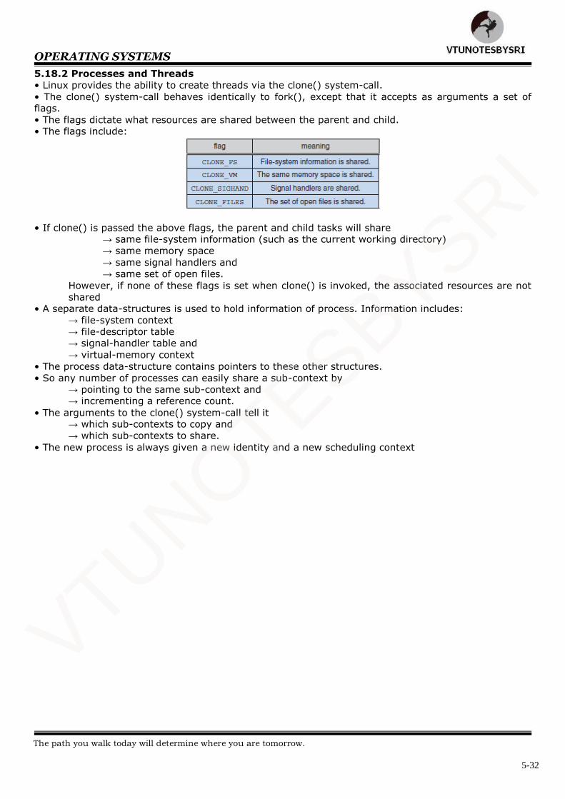
OPERATING SYSTEMS
5-32
5.18.2 Processes and Threads
• Linux provides the ability to create threads via the clone() system-call.
• The clone() system-call behaves identically to fork(), except that it accepts as arguments a set of
flags.
• The flags dictate what resources are shared between the parent and child.
• The flags include:
• If clone() is passed the above flags, the parent and child tasks will share → same file-system information (such as the current working directory)
→ same memory space
→ same signal handlers and
→ same set of open files.
However, if none of these flags is set when clone() is invoked, the associated resources are not
shared
• A separate data-structures is used to hold information of process. Information includes:
→ file-system context
→ file-descriptor table
→ signal-handler table and
→ virtual-memory context
• The process data-structure contains pointers to these other structures.
• So any number of processes can easily share a sub-context by → pointing to the same sub-context and
→ incrementing a reference count.
• The arguments to the clone() system-call tell it → which sub-contexts to copy and
→ which sub-contexts to share.
• The new process is always given a new identity and a new scheduling context
VTUNOTESBYSRI
The path you walk today will determine where you are tomorrow.
OPERATING SYSTEMS
5-33
5.19 Scheduling
• Scheduling is a process of allocating CPU-time to different tasks within an OS.
• Like all UNIX systems, Linux supports preemptive multitasking.
• In such a system, the process-scheduler decides which process runs and when.
5.19.1 Process Scheduling
• Linux uses 2 scheduling-algorithms:
1) A time-sharing algorithm for fair preemptive-scheduling between multiple processes.
2) A real-time algorithm where absolute priorities are more important than fairness.
• A scheduling-class defines which algorithm to apply
• The scheduler is a preemptive, priority-based algorithm with 2 separate priority ranges:
1) Real-time range from 0 to 99 and
2) Nice-value ranging from −20 to 19.
• Smaller nice-values indicate higher priorities.
• Thus, by increasing the nice-value, the priority is decreased and being ―nice‖ to the rest of the
system.
• Linux implements fair scheduling.
• All processes are allotted a proportion of the processor’s time.
5.19.2 Real-Time Scheduling
• Linux implements the two real-time scheduling-classes:
1) FCFS (First-Come, First Served) and
2) Round-robin.
• In both cases, each process has a priority in addition to its scheduling-class.
• The scheduler always runs the process with the highest priority.
• Among processes of equal priority, the scheduler runs the process that has longest waiting-time.
• Difference between FCFS and round-robin scheduling:
1) In FCFS, processes continue to run until they either exit or block.
2) In round-robin, process will be preempted after a while and moved to the end of the
scheduling-queue. Thus, processes of equal priority will automatically time-share among
themselves.
VTUNOTESBYSRI
Focus on the win and you lose the battle, focus on the battle and you win.
OPERATING SYSTEMS
5-34
5.19.3 Kernel Synchronization
• Two ways of requesting for kernel-mode execution:
1) A running program may request an OS service, either → explicitly via a system-call or
→ implicitly when a page-fault occurs
2) A device-driver may deliver a hardware-interrupt.
The interrupt causes the CPU to start executing a kernel-defined handler.
• Two methods to protect critical-sections: 1) spinlocks and 2) semaphores.
1) Spinlocks are used in the kernel only when the lock is held for short-durations.
i) On SMP machines, spinlocks are the main locking mechanism used.
ii) On single-processor machines, spinlocks are not used, instead kernel pre-emption are
enabled and disabled.
2) Semaphores are used in the kernel only when a lock must be held for longer periods. The second protection technique applies to critical-sections that occur in ISR (interrupt
service routine). The basic tool is the processor’s interrupt-control hardware.
By disabling interrupts during a critical-section, the kernel guarantees that it can proceed
without the risk of concurrent-access to shared data-structures.
• Kernel uses a synchronization architecture that allows long critical-sections to run for their entire
duration without interruption.
• ISRs are separated into a top half and a bottom half (Figure 5.15):
1) The top half is a normal ISR, and runs with recursive interrupts disabled.
2) The bottom half is run, with all interrupts enabled, by a miniature-scheduler that ensures
that bottom halves never interrupt themselves.
• This architecture is completed by a mechanism for disabling selected bottom halves while executing
normal, foreground kernel-code.
• Each level may be interrupted by code running at a higher level, but will never be interrupted by
code running at the same or a lower level.
• User-processes can always be preempted by another process when a time-sharing scheduling
interrupt occurs.
Figure 5.15 Interrupt protection levels
5.19.4 Symmetric Multiprocessing (SMP)
• Linux 2.0 kernel was the first stable Linux-Kernel to support SMP hardware,
• Separate processes can execute in parallel on separate processors.
• In Linux 2.2, a single kernel spinlock (called BKL for ―big kernel lock‖) was created to allow multiple
processes to be active in the kernel concurrently.
• However, the BKL provided a very coarse level of locking granularity. This resulted in poor scalability.
• Linux 3.0 provided additional SMP enhancements such as → ever-finer locking
→ processor affinity and
→ load-balancing.
VTUNOTESBYSRI
Individuals who keep growing in knowledge are the ones who succeed.
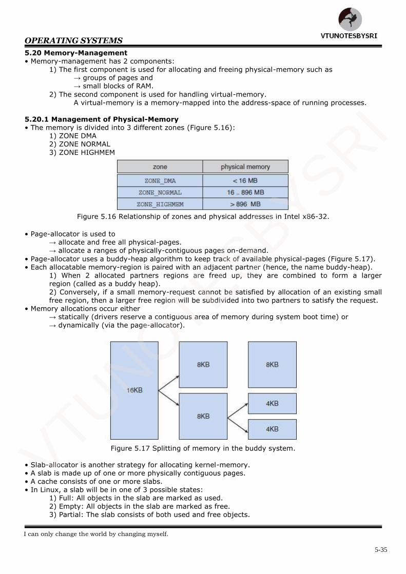
OPERATING SYSTEMS
5-35
5.20 Memory-Management
• Memory-management has 2 components:
1) The first component is used for allocating and freeing physical-memory such as → groups of pages and
→ small blocks of RAM.
2) The second component is used for handling virtual-memory.
A virtual-memory is a memory-mapped into the address-space of running processes.
5.20.1 Management of Physical-Memory
• The memory is divided into 3 different zones (Figure 5.16):
1) ZONE DMA
2) ZONE NORMAL
3) ZONE HIGHMEM
Figure 5.16 Relationship of zones and physical addresses in Intel x86-32.
• Page-allocator is used to
→ allocate and free all physical-pages.
→ allocate a ranges of physically-contiguous pages on-demand.
• Page-allocator uses a buddy-heap algorithm to keep track of available physical-pages (Figure 5.17).
• Each allocatable memory-region is paired with an adjacent partner (hence, the name buddy-heap).
1) When 2 allocated partners regions are freed up, they are combined to form a larger
region (called as a buddy heap).
2) Conversely, if a small memory-request cannot be satisfied by allocation of an existing small
free region, then a larger free region will be subdivided into two partners to satisfy the request.
• Memory allocations occur either → statically (drivers reserve a contiguous area of memory during system boot time) or
→ dynamically (via the page-allocator).
Figure 5.17 Splitting of memory in the buddy system.
• Slab-allocator is another strategy for allocating kernel-memory.
• A slab is made up of one or more physically contiguous pages.
• A cache consists of one or more slabs.
• In Linux, a slab will be in one of 3 possible states:
1) Full: All objects in the slab are marked as used.
2) Empty: All objects in the slab are marked as free.
3) Partial: The slab consists of both used and free objects.
VTUNOTESBYSRI
I can only change the world by changing myself.
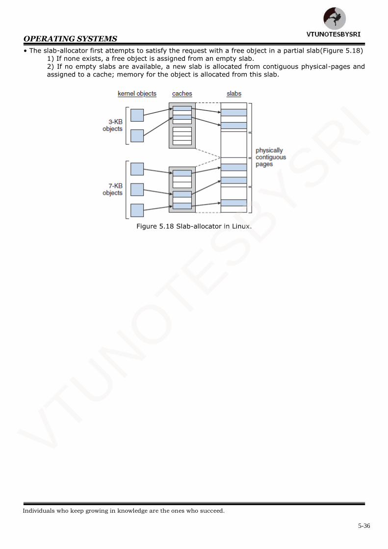
OPERATING SYSTEMS
5-36
• The slab-allocator first attempts to satisfy the request with a free object in a partial slab(Figure 5.18)
1) If none exists, a free object is assigned from an empty slab.
2) If no empty slabs are available, a new slab is allocated from contiguous physical-pages and
assigned to a cache; memory for the object is allocated from this slab.
Figure 5.18 Slab-allocator in Linux.
VTUNOTESBYSRI
Individuals who keep growing in knowledge are the ones who succeed.
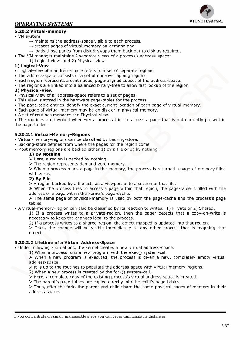
OPERATING SYSTEMS
5-37
5.20.2 Virtual-memory
• VM system
→ maintains the address-space visible to each process.
→ creates pages of virtual-memory on-demand and
→ loads those pages from disk & swaps them back out to disk as required.
• The VM manager maintains 2 separate views of a process’s address-space:
1) Logical-view and 2) Physical-view
1) Logical-Vew
• Logical-view of a address-space refers to a set of separate regions.
• The address-space consists of a set of non-overlapping regions.
• Each region represents a continuous, page-aligned subset of the address-space.
• The regions are linked into a balanced binary-tree to allow fast lookup of the region.
2) Physical-View
• Physical-view of a address-space refers to a set of pages.
• This view is stored in the hardware page-tables for the process.
• The page-table entries identify the exact current location of each page of virtual-memory.
• Each page of virtual-memory may be on disk or in physical-memory.
• A set of routines manages the Physical-view.
• The routines are invoked whenever a process tries to access a page that is not currently present in
the page-tables.
5.20.2.1 Virtual-Memory-Regions
• Virtual-memory-regions can be classified by backing-store.
• Backing-store defines from where the pages for the region come.
• Most memory-regions are backed either 1) by a file or 2) by nothing.
1) By Nothing
Here, a region is backed by nothing.
The region represents demand-zero memory.
When a process reads a page in the memory, the process is returned a page-of-memory filled
with zeros.
2) By File A region backed by a file acts as a viewport onto a section of that file.
When the process tries to access a page within that region, the page-table is filled with the
address of a page within the kernel’s page-cache. The same page of physical-memory is used by both the page-cache and the process’s page
tables.
• A virtual-memory-region can also be classified by its reaction to writes. 1) Private or 2) Shared.
1) If a process writes to a private-region, then the pager detects that a copy-on-write is
necessary to keep the changes local to the process.
2) If a process writes to a shared-region, the object mapped is updated into that region. Thus, the change will be visible immediately to any other process that is mapping that
object.
5.20.2.2 Lifetime of a Virtual Address-Space
• Under following 2 situations, the kernel creates a new virtual address-space:
1) When a process runs a new program with the exec() system-call. When a new program is executed, the process is given a new, completely empty virtual
address-space. It is up to the routines to populate the address-space with virtual-memory-regions.
2) When a new process is created by the fork() system-call. Here, a complete copy of the existing process’s virtual address-space is created.
The parent’s page-tables are copied directly into the child’s page-tables.
Thus, after the fork, the parent and child share the same physical-pages of memory in their
address-spaces.
VTUNOTESBYSRI
If you concentrate on small, manageable steps you can cross unimaginable distances.
OPERATING SYSTEMS
5-38
5.20.2.3 Swapping and Paging
• A VM system relocates pages of memory from physical-memory out to disk when that memory is
needed.
• Paging refers to movement of individual pages of virtual-memory between physical-memory & disk.
• Paging-system is divided into 2 sections:
1) Policy algorithm decides
→ which pages to write out to disk and
→ when to write those pages.
2) Paging mechanism → carries out the transfer and
→ pages data back into physical-memory when they are needed again.
• Linux’s pageout policy uses a modified version of the standard clock algorithm.
• A multiple pass clock is used, and every page has an age that is adjusted on each pass of the clock.
• The age is a measure of the page’s youthfulness, or how much activity the page has seen recently.
• Frequently accessed pages will attain a higher age value, but the age of infrequently accessed pages will drop toward zero with each pass. (LFU → least frequently used)
• This age valuing allows the pager to select pages to page out based on a LFU policy.
• The paging mechanism supports paging both to
1) dedicated swap devices and partitions and
2) normal files
• Blocks are allocated from the swap devices according to a bitmap of used blocks, which is maintained
in physical-memory at all times.
• The allocator uses a next-fit algorithm to try to write out pages to continuous runs of disk blocks for
improved performance.
5.20.2.4 Kernel Virtual-Memory
• Linux reserves a constant, architecture-dependent region of the virtual address-space of every
process for its own internal use.
• The page-table entries that map to these kernel pages are marked as protected.
• Thus, the pages are not visible or modifiable when the processor is running in user-mode.
• The kernel virtual-memory area contains two regions.
1) A static area contains page-table references to every available physical-page of memory in
the system. Thus, a simple translation from physical to virtual addresses occurs when kernel-code is run.
The core of the kernel, along with all pages allocated by the normal page-allocator, resides in
this region.
2) The remainder of the reserved section of address-space is not reserved for any specific
purpose.
Page-table entries in this address range can be modified by the kernel to point to any other
areas of memory.
5.20.3 Execution and Loading of User Programs
• Linux → maintains a table of possible loader-functions
→ gives loader-function the opportunity to try loading the given file when an exec() system-call
is made.
• The registration of multiple loader routines allows Linux to support both the ELF and a.out binary
formats.
• ELF has a number of advantages over a.out:
1) Flexibility and extendability.
2) New sections can be added to ELF w/o causing the loader routines to become confused.
VTUNOTESBYSRI
The experiences you get from failures early in life, will carry you for the rest of your life.
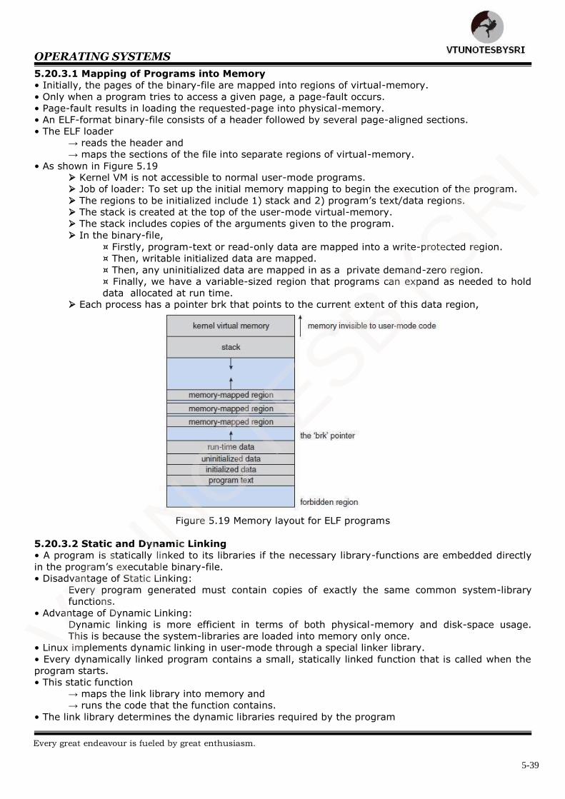
OPERATING SYSTEMS
5-39
5.20.3.1 Mapping of Programs into Memory
• Initially, the pages of the binary-file are mapped into regions of virtual-memory.
• Only when a program tries to access a given page, a page-fault occurs.
• Page-fault results in loading the requested-page into physical-memory.
• An ELF-format binary-file consists of a header followed by several page-aligned sections.
• The ELF loader
→ reads the header and
→ maps the sections of the file into separate regions of virtual-memory.
• As shown in Figure 5.19 Kernel VM is not accessible to normal user-mode programs.
Job of loader: To set up the initial memory mapping to begin the execution of the program.
The regions to be initialized include 1) stack and 2) program’s text/data regions.
The stack is created at the top of the user-mode virtual-memory.
The stack includes copies of the arguments given to the program.
In the binary-file,
¤ Firstly, program-text or read-only data are mapped into a write-protected region.
¤ Then, writable initialized data are mapped.
¤ Then, any uninitialized data are mapped in as a private demand-zero region.
¤ Finally, we have a variable-sized region that programs can expand as needed to hold
data allocated at run time. Each process has a pointer brk that points to the current extent of this data region,
Figure 5.19 Memory layout for ELF programs
5.20.3.2 Static and Dynamic Linking
• A program is statically linked to its libraries if the necessary library-functions are embedded directly
in the program’s executable binary-file.
• Disadvantage of Static Linking:
Every program generated must contain copies of exactly the same common system-library
functions.
• Advantage of Dynamic Linking:
Dynamic linking is more efficient in terms of both physical-memory and disk-space usage.
This is because the system-libraries are loaded into memory only once.
• Linux implements dynamic linking in user-mode through a special linker library.
• Every dynamically linked program contains a small, statically linked function that is called when the
program starts.
• This static function
→ maps the link library into memory and
→ runs the code that the function contains.
• The link library determines the dynamic libraries required by the program
VTUNOTESBYSRI
Every great endeavour is fueled by great enthusiasm.
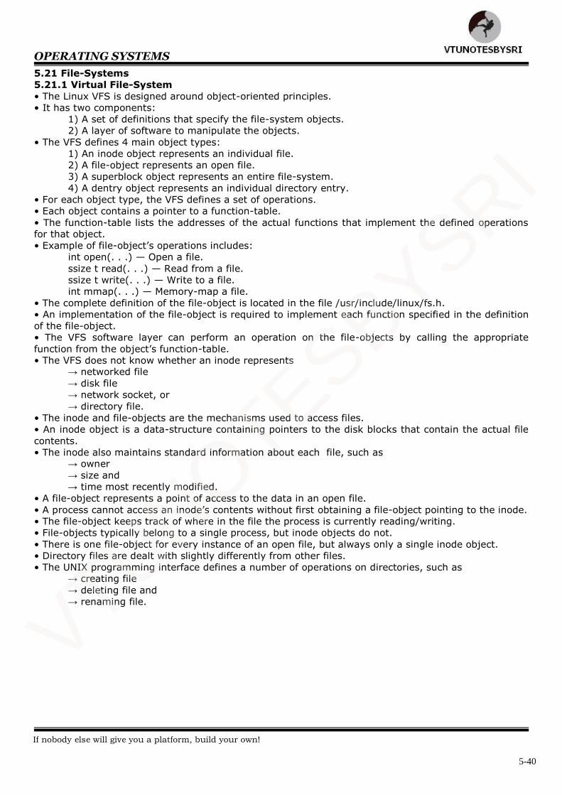
OPERATING SYSTEMS
5-40
5.21 File-Systems
5.21.1 Virtual File-System
• The Linux VFS is designed around object-oriented principles.
• It has two components:
1) A set of definitions that specify the file-system objects.
2) A layer of software to manipulate the objects.
• The VFS defines 4 main object types:
1) An inode object represents an individual file.
2) A file-object represents an open file.
3) A superblock object represents an entire file-system.
4) A dentry object represents an individual directory entry.
• For each object type, the VFS defines a set of operations.
• Each object contains a pointer to a function-table.
• The function-table lists the addresses of the actual functions that implement the defined operations
for that object.
• Example of file-object’s operations includes:
int open(. . .) — Open a file.
ssize t read(. . .) — Read from a file.
ssize t write(. . .) — Write to a file.
int mmap(. . .) — Memory-map a file.
• The complete definition of the file-object is located in the file /usr/include/linux/fs.h.
• An implementation of the file-object is required to implement each function specified in the definition
of the file-object.
• The VFS software layer can perform an operation on the file-objects by calling the appropriate
function from the object’s function-table.
• The VFS does not know whether an inode represents → networked file
→ disk file
→ network socket, or
→ directory file.
• The inode and file-objects are the mechanisms used to access files.
• An inode object is a data-structure containing pointers to the disk blocks that contain the actual file
contents.
• The inode also maintains standard information about each file, such as → owner
→ size and
→ time most recently modified.
• A file-object represents a point of access to the data in an open file.
• A process cannot access an inode’s contents without first obtaining a file-object pointing to the inode.
• The file-object keeps track of where in the file the process is currently reading/writing.
• File-objects typically belong to a single process, but inode objects do not.
• There is one file-object for every instance of an open file, but always only a single inode object.
• Directory files are dealt with slightly differently from other files.
• The UNIX programming interface defines a number of operations on directories, such as → creating file
→ deleting file and
→ renaming file.
VTUNOTESBYSRI
If nobody else will give you a platform, build your own!
OPERATING SYSTEMS
5-41
5.21.2 Linux ext3 File-system
• Similar to BSD FFS, ext3 File-system locates the data blocks belonging to a specific file.
• The main differences between ext3 and FFS lie in their disk-allocation policies. 1) In FFS, the disk is allocated to files in blocks of 8 KB. (FFS → Fast File-system)
The 8KB-blocks are further subdivided into fragments of 1 KB for storage of small files.
2) In ext3, fragments are not used. Allocations are performed in smaller units.
Supported block sizes are 1, 2, 4, and 8 KB.
• ext3 uses allocation policies designed to place logically adjacent blocks of a file into physically
adjacent blocks on disk.
• Thus, ext3 can submit an I/O request for several disk blocks as a single operation.
• The allocation-policy works as follows (Figure 5.20):
An ext3 file-system is divided into multiple segments. These are called block-groups.
When allocating a file, ext3 first selects the block-group for that file.
Within a block-group, ext3 keeps the allocations physically contiguous to reduce
fragmentation. ext3 maintains a bitmap of all free blocks in a block-group.
i) When allocating the first blocks for a new file, ext3 starts searching for a free block
from the beginning of the block-group.
ii) When extending a file, ext3 continues the search from the block most recently
allocated to the file. The search is performed in 2 stages:
1) First, ext3 searches for an entire free byte in the bitmap; if it fails to
find one, it looks for any free bit.
¤ The search for free bytes aims to allocate disk-space in chunks of at
least 8 blocks.
2) After a free block is found, the search is extended backward until an allocated
block is encountered.
¤ The backward extension prevents ext3 from leaving a hole.
The preallocated blocks are returned to the free-space bitmap when the file is closed.
Figure 5.20 ext3 block-allocation policies.
VTUNOTESBYSRI
A road often travelled has heavy traffic and you take more time to reach the destination.
OPERATING SYSTEMS
5-42
5.21.3 Journaling
• ext3 file-system supports a popular feature called journaling.
• Here, modifications to the file-system are written sequentially to a journal.
• A set of operations that performs a specific task is a transaction.
• Once a transaction is written to the journal, it is considered to be committed.
• The journal entries relating to the transaction are replayed across the actual file-system structures.
• When an entire committed transaction is completed, it is removed from the journal.
• If the system crashes, some transactions may remain in the journal.
• If those transactions were never completed, then they must be completed once the system recovers.
• The only problem occurs when a transaction has been aborted i.e. it was not committed before the
system crashed.
• Any changes from those transactions that were applied to the file-system must be undone, again
preserving the consistency of the file-system.
5.21.4 Linux Process File-system (proc File-system)
• The proc file-system does not store data, rather, its contents are computed on demand according to
user file I/O requests.
• The /proc file-system must implement two things: a directory structure and the file contents within.
• proc must define a unique and persistent inode number for each directory and the associated files.
• proc uses this inode number to identify what operation is required when a user tries to
→ read from a particular file inode or
→ perform a lookup in a particular directory inode
• When data are read from these files, proc will collect the appropriate information, format it into
textual form, and place it into the requesting process’s read buffer.
• The kernel can allocate new /proc inode mappings dynamically, maintaining a bitmap of allocated
inode numbers.
• The kernel also maintains a tree data-structure of registered global /proc file-system entries.
• Each entry contains → file’s inode number
→ file name and
→ access permissions
→ special functions used to generate the file’s contents.
• Drivers can register and deregister entries in this tree at any time, and a special section of the tree is
reserved for kernel variables.
VTUNOTESBYSRI
If your beliefs are not useful to you, or they are not bringing you peace and abundance, update them!
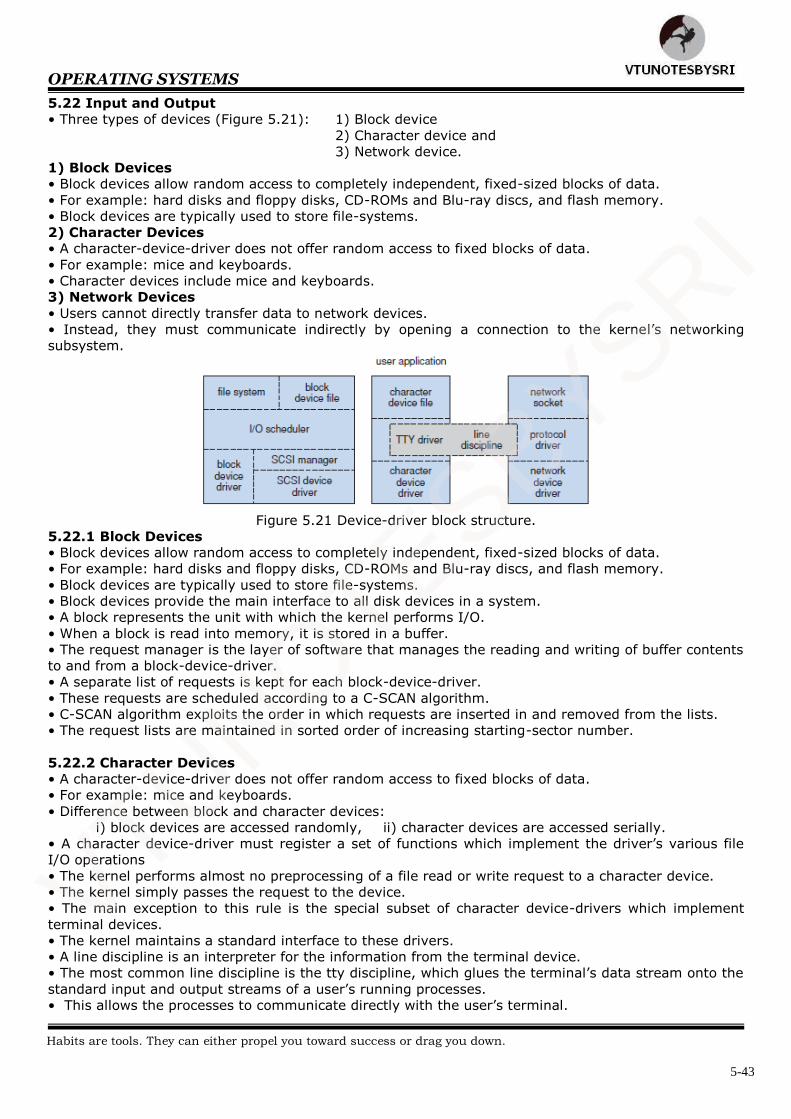
OPERATING SYSTEMS
5-43
5.22 Input and Output
• Three types of devices (Figure 5.21): 1) Block device
2) Character device and
3) Network device.
1) Block Devices
• Block devices allow random access to completely independent, fixed-sized blocks of data.
• For example: hard disks and floppy disks, CD-ROMs and Blu-ray discs, and flash memory.
• Block devices are typically used to store file-systems.
2) Character Devices
• A character-device-driver does not offer random access to fixed blocks of data.
• For example: mice and keyboards.
• Character devices include mice and keyboards.
3) Network Devices
• Users cannot directly transfer data to network devices.
• Instead, they must communicate indirectly by opening a connection to the kernel’s networking
subsystem.
Figure 5.21 Device-driver block structure.
5.22.1 Block Devices
• Block devices allow random access to completely independent, fixed-sized blocks of data.
• For example: hard disks and floppy disks, CD-ROMs and Blu-ray discs, and flash memory.
• Block devices are typically used to store file-systems.
• Block devices provide the main interface to all disk devices in a system.
• A block represents the unit with which the kernel performs I/O.
• When a block is read into memory, it is stored in a buffer.
• The request manager is the layer of software that manages the reading and writing of buffer contents
to and from a block-device-driver.
• A separate list of requests is kept for each block-device-driver.
• These requests are scheduled according to a C-SCAN algorithm.
• C-SCAN algorithm exploits the order in which requests are inserted in and removed from the lists.
• The request lists are maintained in sorted order of increasing starting-sector number.
5.22.2 Character Devices
• A character-device-driver does not offer random access to fixed blocks of data.
• For example: mice and keyboards.
• Difference between block and character devices:
i) block devices are accessed randomly, ii) character devices are accessed serially.
• A character device-driver must register a set of functions which implement the driver’s various file
I/O operations
• The kernel performs almost no preprocessing of a file read or write request to a character device.
• The kernel simply passes the request to the device.
• The main exception to this rule is the special subset of character device-drivers which implement
terminal devices.
• The kernel maintains a standard interface to these drivers.
• A line discipline is an interpreter for the information from the terminal device.
• The most common line discipline is the tty discipline, which glues the terminal’s data stream onto the
standard input and output streams of a user’s running processes.
• This allows the processes to communicate directly with the user’s terminal.
VTUNOTESBYSRI
Habits are tools. They can either propel you toward success or drag you down.
OPERATING SYSTEMS
5-44
5.23 Inter-Process Communication
• In some situations, one process needs to communicate with another process.
• Three methods for IPC:
1) Synchronization and Signals
2) Message Passing Data between Processes
3) Shared Memory Object
5.23.1 Synchronization and Signals
• Linux informs processes that an event has occurred via signals.
• Signals can be sent from any process to any other process.
• There are a limited number of signals, and they cannot carry information.
• Only the fact that a signal has occurred is available to a process.
• The kernel also generates signals internally.
• The Linux-Kernel does not use signals to communicate with processes running in kernel mode.
Rather, communication within the kernel is accomplished via scheduling states and wait_queue
structures.
• Whenever a process wants to wait for some event to complete, the process
→ places itself on a wait queue associated with that event and
→ tells the scheduler that it is no longer eligible for execution.
• Once the event has completed, every process on the wait queue will be awoken.
• This procedure allows multiple processes to wait for a single event.
5.23.2 Passing of Data among Processes
• The standard UNIX pipe mechanism allows a child process to inherit a communication channel from
its parent.
• Data written to one end of the pipe can be read at the other.
• Shared memory offers an extremely fast way to communicate large or small amounts of data.
• Any data written by one process to a shared memory-region can be read immediately by any other
process.
• Main disadvantage of shared memory:
1) It offers no synchronization.
2) A process cannot → ask the OS whether a piece of shared memory has been written or
→ suspend execution until the data is written.
5.23.3 Shared Memory Object
• The shared-memory object acts as a backing-store for shared-memory-regions, just as a file can act
as a backing-store for a memory-mapped memory-region.
• Shared-memory mappings direct page-faults to map in pages from a persistent shared memory
object.
• Also, shared memory objects remember their contents even if no processes are currently mapping
them into virtual-memory.
VTUNOTESBYSRI
Being prepared prevents us from getting tripped up by unexpected glitches and surprises.
Related Documents


