Welcome message from author
This document is posted to help you gain knowledge. Please leave a comment to let me know what you think about it! Share it to your friends and learn new things together.
Transcript

OPERATINGSYSTEMCONCEPTSNINTH EDITION

OPERATINGSYSTEMCONCEPTSABRAHAM SILBERSCHATZYale University
PETER BAER GALVINPluribus Networks
GREG GAGNEWestminster College
NINTH EDITION

!Vice!President!and!Executive!Publisher! ! ! Don!Fowley!Executive!Editor! ! ! ! ! Beth!Lang!Golub!Editorial!Assistant! ! ! ! ! Katherine!Willis!Executive!Marketing!Manager!! ! ! Christopher!Ruel!Senior!Production!Editor! ! ! ! Ken!Santor!Cover!and!title!page!illustrations! ! ! Susan!Cyr!Cover!Designer! ! ! ! ! Madelyn!Lesure!Text!Designer!! ! ! ! ! Judy!Allan!!!!!!This!book!was!set!in!Palatino!by!the!author!using!LaTeX!and!printed!and!bound!by!Courier"Kendallville.!The!cover!was!printed!by!Courier.!!!Copyright!©!2013,!2012,!2008!John!Wiley!&!Sons,!Inc.!!All!rights!reserved.!
!No!part!of!this!publication!may!be!reproduced,!stored!in!a!retrieval!system!or!transmitted!in!any!form!or!by!any!means,!electronic,!mechanical,!photocopying,!recording,!scanning!or!otherwise,!except!as!permitted!under!Sections!107!or!108!of!the!1976!United!States!Copyright!Act,!without!either!the!prior!written!permission!of!the!Publisher,!or!authorization!through!payment!of!the!appropriate!per"copy!fee!to!the!Copyright!Clearance!Center,!Inc.!222!Rosewood!Drive,!Danvers,!MA!01923,!(978)750"8400,!fax!(978)750"4470.!Requests!to!the!Publisher!for!permission!should!be!addressed!to!the!Permissions!Department,!John!Wiley!&!Sons,!Inc.,!111!River!Street,!Hoboken,!NJ!07030!(201)748"6011,!fax!(201)748"6008,!E"Mail:[email protected].!!!!Evaluation!copies!are!provided!to!qualified!academics!and!professionals!for!review!purposes!only,!for!use!in!their!courses!during!the!next!academic!year.!!These!copies!are!licensed!and!may!not!be!sold!or!transferred!to!a!third!party.!!Upon!completion!of!the!review!period,!please!return!the!evaluation!copy!to!Wiley.!!Return!instructions!and!a!free"of"charge!return!shipping!label!are!available!at!www.wiley.com/go/evalreturn.!Outside!of!the!United!States,!please!contact!your!local!representative.!!Founded!in!1807,!John!Wiley!&!Sons,!Inc.!has!been!a!valued!source!of!knowledge!and!understanding!for!more!than!200!years,!helping!people!around!the!world!meet!their!needs!and!fulfill!their!aspirations.!Our!company!is!built!on!a!foundation!of!principles!that!include!responsibility!to!the!communities!we!serve!and!where!we!live!and!work.!In!2008,!we!launched!a!Corporate!Citizenship!Initiative,!a!global!effort!to!address!the!environmental,!social,!economic,!and!ethical!challenges!we!face!in!our!business.!Among!the!issues!we!are!addressing!are!carbon!impact,!paper!specifications!and!procurement,!ethical!conduct!within!our!business!and!among!our!vendors,!and!community!and!charitable!support.!For!more!information,!please!visit!our!website:!www.wiley.com/go/citizenship.!!!!!!ISBN:!!978"1"118"06333"0!ISBN!BRV:!!978"1"118"12938"8!!Printed!in!the!United!States!of!America!!10!!!9!!!8!!!7!!!6!!!5!!!4!!!3!!!2!!!1!
To my children, Lemor, Sivan, and Aaronand my Nicolette
Avi Silberschatz
To Brendan and Ellen,and Barbara, Anne and Harold, and Walter and Rebecca
Peter Baer Galvin
To my Mom and Dad,Greg Gagne

Preface
Operating systems are an essential part of any computer system. Similarly,a course on operating systems is an essential part of any computer scienceeducation. This field is undergoing rapid change, as computers are nowprevalent in virtually every arena of day-to-day life—from embedded devicesin automobiles through the most sophisticated planning tools for governmentsand multinational firms. Yet the fundamental concepts remain fairly clear, andit is on these that we base this book.
We wrote this book as a text for an introductory course in operating systemsat the junior or senior undergraduate level or at the first-year graduate level. Wehope that practitioners will also find it useful. It provides a clear description ofthe concepts that underlie operating systems. As prerequisites, we assume thatthe reader is familiar with basic data structures, computer organization, anda high-level language, such as C or Java. The hardware topics required for anunderstanding of operating systems are covered in Chapter 1. In that chapter,we also include an overview of the fundamental data structures that areprevalent in most operating systems. For code examples, we use predominantlyC, with some Java, but the reader can still understand the algorithms withouta thorough knowledge of these languages.
Concepts are presented using intuitive descriptions. Important theoreticalresults are covered, but formal proofs are largely omitted. The bibliographicalnotes at the end of each chapter contain pointers to research papers in whichresults were first presented and proved, as well as references to recent materialfor further reading. In place of proofs, figures and examples are used to suggestwhy we should expect the result in question to be true.
The fundamental concepts and algorithms covered in the book are oftenbased on those used in both commercial and open-source operating systems.Our aim is to present these concepts and algorithms in a general setting thatis not tied to one particular operating system. However, we present a largenumber of examples that pertain to the most popular and the most innovativeoperating systems, including Linux, Microsoft Windows, Apple Mac OS X, andSolaris. We also include examples of both Android and iOS, currently the twodominant mobile operating systems.
The organization of the text reflects our many years of teaching courses onoperating systems, as well as curriculum guidelines published by the IEEE
vii
viii Preface
Computing Society and the Association for Computing Machinery (ACM).Consideration was also given to the feedback provided by the reviewers ofthe text, along with the many comments and suggestions we received fromreaders of our previous editions and from our current and former students.
Content of This Book
The text is organized in eight major parts:
• Overview. Chapters 1 and 2 explain what operating systems are, whatthey do, and how they are designed and constructed. These chaptersdiscuss what the common features of an operating system are and what anoperating system does for the user. We include coverage of both traditionalPC and server operating systems, as well as operating systems for mobiledevices. The presentation is motivational and explanatory in nature. Wehave avoided a discussion of how things are done internally in thesechapters. Therefore, they are suitable for individual readers or for studentsin lower-level classes who want to learn what an operating system iswithout getting into the details of the internal algorithms.
• Process management. Chapters 3 through 7 describe the process conceptand concurrency as the heart of modern operating systems. A processis the unit of work in a system. Such a system consists of a collectionof concurrently executing processes, some of which are operating-systemprocesses (those that execute system code) and the rest of which are userprocesses (those that execute user code). These chapters cover methods forprocess scheduling, interprocess communication, process synchronization,and deadlock handling. Also included is a discussion of threads, as wellas an examination of issues related to multicore systems and parallelprogramming.
• Memory management. Chapters 8 and 9 deal with the management ofmain memory during the execution of a process. To improve both theutilization of the CPU and the speed of its response to its users, thecomputer must keep several processes in memory. There are many differentmemory-management schemes, reflecting various approaches to memorymanagement, and the effectiveness of a particular algorithm depends onthe situation.
• Storage management. Chapters 10 through 13 describe how mass storage,the file system, and I/O are handled in a modern computer system. Thefile system provides the mechanism for on-line storage of and accessto both data and programs. We describe the classic internal algorithmsand structures of storage management and provide a firm practicalunderstanding of the algorithms used—their properties, advantages, anddisadvantages. Since the I/O devices that attach to a computer vary widely,the operating system needs to provide a wide range of functionality toapplications to allow them to control all aspects of these devices. Wediscuss system I/O in depth, including I/O system design, interfaces, andinternal system structures and functions. In many ways, I/O devices arethe slowest major components of the computer. Because they represent a
Preface ix
performance bottleneck, we also examine performance issues associatedwith I/O devices.
• Protection and security. Chapters 14 and 15 discuss the mechanismsnecessary for the protection and security of computer systems. Theprocesses in an operating system must be protected from one another’sactivities, and to provide such protection, we must ensure that onlyprocesses that have gained proper authorization from the operating systemcan operate on the files, memory, CPU, and other resources of the system.Protection is a mechanism for controlling the access of programs, processes,or users to computer-system resources. This mechanism must provide ameans of specifying the controls to be imposed, as well as a means ofenforcement. Security protects the integrity of the information stored inthe system (both data and code), as well as the physical resources of thesystem, from unauthorized access, malicious destruction or alteration, andaccidental introduction of inconsistency.
• Advanced topics. Chapters 16 and 17 discuss virtual machines anddistributed systems. Chapter 16 is a new chapter that provides an overviewof virtual machines and their relationship to contemporary operatingsystems. Included is an overview of the hardware and software techniquesthat make virtualization possible. Chapter 17 condenses and updates thethree chapters on distributed computing from the previous edition. Thischange is meant to make it easier for instructors to cover the material inthe limited time available during a semester and for students to gain anunderstanding of the core ideas of distributed computing more quickly.
• Case studies. Chapters 18 and 19 in the text, along with Appendices A andB (which are available on (http://www.os-book.com), present detailedcase studies of real operating systems, including Linux, Windows 7,FreeBSD, and Mach. Coverage of both Linux and Windows 7 are presentedthroughout this text; however, the case studies provide much more detail.It is especially interesting to compare and contrast the design of these twovery different systems. Chapter 20 briefly describes a few other influentialoperating systems.
The Ninth Edition
As we wrote this Ninth Edition of Operating System Concepts, we were guidedby the recent growth in three fundamental areas that affect operating systems:
1. Multicore systems
2. Mobile computing
3. Virtualization
To emphasize these topics, we have integrated relevant coverage throughoutthis new edition—and, in the case of virtualization, have written an entirelynew chapter. Additionally, we have rewritten material in almost every chapterby bringing older material up to date and removing material that is no longerinteresting or relevant.
x Preface
We have also made substantial organizational changes. For example, wehave eliminated the chapter on real-time systems and instead have integratedappropriate coverage of these systems throughout the text. We have reorderedthe chapters on storage management and have moved up the presentationof process synchronization so that it appears before process scheduling. Mostof these organizational changes are based on our experiences while teachingcourses on operating systems.
Below, we provide a brief outline of the major changes to the variouschapters:• Chapter 1, Introduction, includes updated coverage of multiprocessor
and multicore systems, as well as a new section on kernel data structures.Additionally, the coverage of computing environments now includesmobile systems and cloud computing. We also have incorporated anoverview of real-time systems.
• Chapter 2, Operating-System Structures, provides new coverage of userinterfaces for mobile devices, including discussions of iOS and Android,and expanded coverage of Mac OS X as a type of hybrid system.
• Chapter 3, Processes, now includes coverage of multitasking in mobileoperating systems, support for the multiprocess model in Google’s Chromeweb browser, and zombie and orphan processes in UNIX.
• Chapter 4, Threads, supplies expanded coverage of parallelism andAmdahl’s law. It also provides a new section on implicit threading,including OpenMP and Apple’s Grand Central Dispatch.
• Chapter 5, Process Synchronization (previously Chapter 6), adds a newsection on mutex locks as well as coverage of synchronization usingOpenMP, as well as functional languages.
• Chapter 6, CPU Scheduling (previously Chapter 5), contains new coverageof the Linux CFS scheduler and Windows user-mode scheduling. Coverageof real-time scheduling algorithms has also been integrated into thischapter.
• Chapter 7, Deadlocks, has no major changes.
• Chapter 8, Main Memory, includes new coverage of swapping on mobilesystems and Intel 32- and 64-bit architectures. A new section discussesARM architecture.
• Chapter 9, Virtual Memory, updates kernel memory management toinclude the Linux SLUB and SLOB memory allocators.
• Chapter 10, Mass-Storage Structure (previously Chapter 12), adds cover-age of solid-state disks.
• Chapter 11, File-System Interface (previously Chapter 10), is updatedwith information about current technologies.
• Chapter 12, File-System Implementation (previously Chapter 11), isupdated with coverage of current technologies.
• Chapter 13, I/O, updates technologies and performance numbers, expandscoverage of synchronous/asynchronous and blocking/nonblocking I/O,and adds a section on vectored I/O.
Preface xi
• Chapter 14, Protection, has no major changes.
• Chapter 15, Security, has a revised cryptography section with modernnotation and an improved explanation of various encryption methods andtheir uses. The chapter also includes new coverage of Windows 7 security.
• Chapter 16, Virtual Machines, is a new chapter that provides an overviewof virtualization and how it relates to contemporary operating systems.
• Chapter 17, Distributed Systems, is a new chapter that combines andupdates a selection of materials from previous Chapters 16, 17, and 18.
• Chapter 18, The Linux System (previously Chapter 21), has been updatedto cover the Linux 3.2 kernel.
• Chapter 19, Windows 7, is a new chapter presenting a case study ofWindows 7.
• Chapter 20, Influential Operating Systems (previously Chapter 23), hasno major changes.
Programming Environments
This book uses examples of many real-world operating systems to illustratefundamental operating-system concepts. Particular attention is paid to Linuxand Microsoft Windows, but we also refer to various versions of UNIX(including Solaris, BSD, and Mac OS X).
The text also provides several example programs written in C andJava. These programs are intended to run in the following programmingenvironments:
• POSIX. POSIX (which stands for Portable Operating System Interface) repre-sents a set of standards implemented primarily for UNIX-based operatingsystems. Although Windows systems can also run certain POSIX programs,our coverage of POSIX focuses on UNIX and Linux systems. POSIX-compliantsystems must implement the POSIX core standard (POSIX.1); Linux, Solaris,and Mac OS X are examples of POSIX-compliant systems. POSIX alsodefines several extensions to the standards, including real-time extensions(POSIX1.b) and an extension for a threads library (POSIX1.c, better knownas Pthreads). We provide several programming examples written in Cillustrating the POSIX base API, as well as Pthreads and the extensions forreal-time programming. These example programs were tested on Linux 2.6and 3.2 systems, Mac OS X 10.7, and Solaris 10 using the gcc 4.0 compiler.
• Java. Java is a widely used programming language with a rich API andbuilt-in language support for thread creation and management. Javaprograms run on any operating system supporting a Java virtual machine(or JVM). We illustrate various operating-system and networking conceptswith Java programs tested using the Java 1.6 JVM.
• Windows systems. The primary programming environment for Windowssystems is the Windows API, which provides a comprehensive set of func-tions for managing processes, threads, memory, and peripheral devices.We supply several C programs illustrating the use of this API. Programswere tested on systems running Windows XP and Windows 7.
xii Preface
We have chosen these three programming environments because webelieve that they best represent the two most popular operating-system models—Windows and UNIX/Linux—along with the widely used Java environment.Most programming examples are written in C, and we expect readers to becomfortable with this language. Readers familiar with both the C and Javalanguages should easily understand most programs provided in this text.
In some instances—such as thread creation—we illustrate a specificconcept using all three programming environments, allowing the readerto contrast the three different libraries as they address the same task. Inother situations, we may use just one of the APIs to demonstrate a concept.For example, we illustrate shared memory using just the POSIX API; socketprogramming in TCP/IP is highlighted using the Java API.
Linux Virtual Machine
To help students gain a better understanding of the Linux system, weprovide a Linux virtual machine, including the Linux source code,that is available for download from the the website supporting thistext (http://www.os-book.com). This virtual machine also includes agcc development environment with compilers and editors. Most of theprogramming assignments in the book can be completed on this virtualmachine, with the exception of assignments that require Java or the WindowsAPI.
We also provide three programming assignments that modify the Linuxkernel through kernel modules:
1. Adding a basic kernel module to the Linux kernel.
2. Adding a kernel module that uses various kernel data structures.
3. Adding a kernel module that iterates over tasks in a running Linuxsystem.
Over time it is our intention to add additional kernel module assignments onthe supporting website.
Supporting Website
When you visit the website supporting this text at http://www.os-book.com,you can download the following resources:
• Linux virtual machine
• C and Java source code
• Sample syllabi
• Set of Powerpoint slides
• Set of figures and illustrations
• FreeBSD and Mach case studies
Preface xiii
• Solutions to practice exercises
• Study guide for students
• Errata
Notes to Instructors
On the website for this text, we provide several sample syllabi that suggestvarious approaches for using the text in both introductory and advancedcourses. As a general rule, we encourage instructors to progress sequentiallythrough the chapters, as this strategy provides the most thorough study ofoperating systems. However, by using the sample syllabi, an instructor canselect a different ordering of chapters (or subsections of chapters).
In this edition, we have added over sixty new written exercises and overtwenty new programming problems and projects. Most of the new program-ming assignments involve processes, threads, process synchronization, andmemory management. Some involve adding kernel modules to the Linuxsystem which requires using either the Linux virtual machine that accompaniesthis text or another suitable Linux distribution.
Solutions to written exercises and programming assignments are availableto instructors who have adopted this text for their operating-system class. Toobtain these restricted supplements, contact your local John Wiley & Sonssales representative. You can find your Wiley representative by going tohttp://www.wiley.com/college and clicking “Who’s my rep?”
Notes to Students
We encourage you to take advantage of the practice exercises that appear atthe end of each chapter. Solutions to the practice exercises are available fordownload from the supporting website http://www.os-book.com. We alsoencourage you to read through the study guide, which was prepared by one ofour students. Finally, for students who are unfamiliar with UNIX and Linuxsystems, we recommend that you download and install the Linux virtualmachine that we include on the supporting website. Not only will this provideyou with a new computing experience, but the open-source nature of Linuxwill allow you to easily examine the inner details of this popular operatingsystem.
We wish you the very best of luck in your study of operating systems.
Contacting Us
We have endeavored to eliminate typos, bugs, and the like from the text. But,as in new releases of software, bugs almost surely remain. An up-to-date erratalist is accessible from the book’s website. We would be grateful if you wouldnotify us of any errors or omissions in the book that are not on the current listof errata.
We would be glad to receive suggestions on improvements to the book.We also welcome any contributions to the book website that could be of
xiv Preface
use to other readers, such as programming exercises, project suggestions,on-line labs and tutorials, and teaching tips. E-mail should be addressed [email protected].
Acknowledgments
This book is derived from the previous editions, the first three of whichwere coauthored by James Peterson. Others who helped us with previouseditions include Hamid Arabnia, Rida Bazzi, Randy Bentson, David Black,Joseph Boykin, Jeff Brumfield, Gael Buckley, Roy Campbell, P. C. Capon, JohnCarpenter, Gil Carrick, Thomas Casavant, Bart Childs, Ajoy Kumar Datta,Joe Deck, Sudarshan K. Dhall, Thomas Doeppner, Caleb Drake, M. RacsitEskicioğlu, Hans Flack, Robert Fowler, G. Scott Graham, Richard Guy, MaxHailperin, Rebecca Hartman, Wayne Hathaway, Christopher Haynes, DonHeller, Bruce Hillyer, Mark Holliday, Dean Hougen, Michael Huang, AhmedKamel, Morty Kewstel, Richard Kieburtz, Carol Kroll, Morty Kwestel, ThomasLeBlanc, John Leggett, Jerrold Leichter, Ted Leung, Gary Lippman, CarolynMiller, Michael Molloy, Euripides Montagne, Yoichi Muraoka, Jim M. Ng,Banu Özden, Ed Posnak, Boris Putanec, Charles Qualline, John Quarterman,Mike Reiter, Gustavo Rodriguez-Rivera, Carolyn J. C. Schauble, Thomas P.Skinner, Yannis Smaragdakis, Jesse St. Laurent, John Stankovic, Adam Stauffer,Steven Stepanek, John Sterling, Hal Stern, Louis Stevens, Pete Thomas, DavidUmbaugh, Steve Vinoski, Tommy Wagner, Larry L. Wear, John Werth, JamesM. Westall, J. S. Weston, and Yang Xiang
Robert Love updated both Chapter 18 and the Linux coverage throughoutthe text, as well as answering many of our Android-related questions. Chapter19 was written by Dave Probert and was derived from Chapter 22 of the EighthEdition of Operating System Concepts. Jonathan Katz contributed to Chapter15. Richard West provided input into Chapter 16. Salahuddin Khan updatedSection 15.9 to provide new coverage of Windows 7 security.
Parts of Chapter 17 were derived from a paper by Levy and Silberschatz[1990]. Chapter 18 was derived from an unpublished manuscript by StephenTweedie. Cliff Martin helped with updating the UNIX appendix to coverFreeBSD. Some of the exercises and accompanying solutions were supplied byArvind Krishnamurthy. Andrew DeNicola prepared the student study guidethat is available on our website. Some of the the slides were prepeared byMarilyn Turnamian.
Mike Shapiro, Bryan Cantrill, and Jim Mauro answered several Solaris-related questions, and Bryan Cantrill from Sun Microsystems helped with theZFS coverage. Josh Dees and Rob Reynolds contributed coverage of Microsoft’sNET. The project for POSIX message queues was contributed by John Trono ofSaint Michael’s College in Colchester, Vermont.
Judi Paige helped with generating figures and presentation of slides.Thomas Gagne prepared new artwork for this edition. Owen Galvin helpedcopy-edit Chapter 16. Mark Wogahn has made sure that the software to producethis book (LATEX and fonts) works properly. Ranjan Kumar Meher rewrote someof the LATEX software used in the production of this new text.
Preface xv
Our Executive Editor, Beth Lang Golub, provided expert guidance as weprepared this edition. She was assisted by Katherine Willis, who managedmany details of the project smoothly. The Senior Production Editor, Ken Santor,was instrumental in handling all the production details.
The cover illustrator was Susan Cyr, and the cover designer was MadelynLesure. Beverly Peavler copy-edited the manuscript. The freelance proofreaderwas Katrina Avery; the freelance indexer was WordCo, Inc.
Abraham Silberschatz, New Haven, CT, 2012Peter Baer Galvin, Boston, MA, 2012Greg Gagne, Salt Lake City, UT, 2012

Contents
PART ONE OVERVIEW
Chapter 1 Introduction1.1 What Operating Systems Do 41.2 Computer-System Organization 71.3 Computer-System Architecture 121.4 Operating-System Structure 191.5 Operating-System Operations 211.6 Process Management 241.7 Memory Management 251.8 Storage Management 26
1.9 Protection and Security 301.10 Kernel Data Structures 311.11 Computing Environments 351.12 Open-Source Operating Systems 431.13 Summary 47
Exercises 49Bibliographical Notes 52
Chapter 2 Operating-System Structures2.1 Operating-System Services 552.2 User and Operating-System
Interface 582.3 System Calls 622.4 Types of System Calls 662.5 System Programs 742.6 Operating-System Design and
Implementation 75
2.7 Operating-System Structure 782.8 Operating-System Debugging 862.9 Operating-System Generation 91
2.10 System Boot 922.11 Summary 93
Exercises 94Bibliographical Notes 101
PART TWO PROCESS MANAGEMENT
Chapter 3 Processes3.1 Process Concept 1053.2 Process Scheduling 1103.3 Operations on Processes 1153.4 Interprocess Communication 1223.5 Examples of IPC Systems 130
3.6 Communication in Client–Server Systems 136
3.7 Summary 147Exercises 149Bibliographical Notes 161
xvii
xviii Contents
Chapter 4 Threads4.1 Overview 1634.2 Multicore Programming 1664.3 Multithreading Models 1694.4 Thread Libraries 1714.5 Implicit Threading 177
4.6 Threading Issues 1834.7 Operating-System Examples 1884.8 Summary 191
Exercises 191Bibliographical Notes 199
Chapter 5 Process Synchronization5.1 Background 2035.2 The Critical-Section Problem 2065.3 Peterson’s Solution 2075.4 Synchronization Hardware 2095.5 Mutex Locks 2125.6 Semaphores 2135.7 Classic Problems of
Synchronization 219
5.8 Monitors 2235.9 Synchronization Examples 232
5.10 Alternative Approaches 2385.11 Summary 242
Exercises 242Bibliographical Notes 258
Chapter 6 CPU Scheduling6.1 Basic Concepts 2616.2 Scheduling Criteria 2656.3 Scheduling Algorithms 2666.4 Thread Scheduling 2776.5 Multiple-Processor Scheduling 2786.6 Real-Time CPU Scheduling 283
6.7 Operating-System Examples 2906.8 Algorithm Evaluation 3006.9 Summary 304
Exercises 305Bibliographical Notes 311
Chapter 7 Deadlocks7.1 System Model 3157.2 Deadlock Characterization 3177.3 Methods for Handling Deadlocks 3227.4 Deadlock Prevention 3237.5 Deadlock Avoidance 327
7.6 Deadlock Detection 3337.7 Recovery from Deadlock 3377.8 Summary 339
Exercises 339Bibliographical Notes 346
PART THREE MEMORY MANAGEMENT
Chapter 8 Main Memory8.1 Background 3518.2 Swapping 3588.3 Contiguous Memory Allocation 3608.4 Segmentation 3648.5 Paging 3668.6 Structure of the Page Table 378
8.7 Example: Intel 32 and 64-bitArchitectures 383
8.8 Example: ARM Architecture 3888.9 Summary 389
Exercises 390Bibliographical Notes 394
Contents xix
Chapter 9 Virtual Memory9.1 Background 3979.2 Demand Paging 4019.3 Copy-on-Write 4089.4 Page Replacement 4099.5 Allocation of Frames 4219.6 Thrashing 4259.7 Memory-Mapped Files 430
9.8 Allocating Kernel Memory 4369.9 Other Considerations 439
9.10 Operating-System Examples 4459.11 Summary 448
Exercises 449Bibliographical Notes 461
PART FOUR STORAGE MANAGEMENT
Chapter 10 Mass-Storage Structure10.1 Overview of Mass-Storage
Structure 46710.2 Disk Structure 47010.3 Disk Attachment 47110.4 Disk Scheduling 47210.5 Disk Management 478
10.6 Swap-Space Management 48210.7 RAID Structure 48410.8 Stable-Storage Implementation 49410.9 Summary 496
Exercises 497Bibliographical Notes 501
Chapter 11 File-System Interface11.1 File Concept 50311.2 Access Methods 51311.3 Directory and Disk Structure 51511.4 File-System Mounting 52611.5 File Sharing 528
11.6 Protection 53311.7 Summary 538
Exercises 539Bibliographical Notes 541
Chapter 12 File-System Implementation12.1 File-System Structure 54312.2 File-System Implementation 54612.3 Directory Implementation 55212.4 Allocation Methods 55312.5 Free-Space Management 56112.6 Efficiency and Performance 564
12.7 Recovery 56812.8 NFS 57112.9 Example: The WAFL File System 577
12.10 Summary 580Exercises 581Bibliographical Notes 585
Chapter 13 I/O Systems13.1 Overview 58713.2 I/O Hardware 58813.3 Application I/O Interface 59713.4 Kernel I/O Subsystem 60413.5 Transforming I/O Requests to
Hardware Operations 611
13.6 STREAMS 61313.7 Performance 61513.8 Summary 618
Exercises 619Bibliographical Notes 621
xx Contents
PART FIVE PROTECTION AND SECURITY
Chapter 14 Protection14.1 Goals of Protection 62514.2 Principles of Protection 62614.3 Domain of Protection 62714.4 Access Matrix 63214.5 Implementation of the Access
Matrix 63614.6 Access Control 639
14.7 Revocation of Access Rights 64014.8 Capability-Based Systems 64114.9 Language-Based Protection 644
14.10 Summary 649Exercises 650Bibliographical Notes 652
Chapter 15 Security15.1 The Security Problem 65715.2 Program Threats 66115.3 System and Network Threats 66915.4 Cryptography as a Security Tool 67415.5 User Authentication 68515.6 Implementing Security Defenses 68915.7 Firewalling to Protect Systems and
Networks 696
15.8 Computer-SecurityClassifications 698
15.9 An Example: Windows 7 69915.10 Summary 701
Exercises 702Bibliographical Notes 704
PART SIX ADVANCED TOPICS
Chapter 16 Virtual Machines16.1 Overview 71116.2 History 71316.3 Benefits and Features 71416.4 Building Blocks 71716.5 Types of Virtual Machines and Their
Implementations 721
16.6 Virtualization and Operating-SystemComponents 728
16.7 Examples 73516.8 Summary 737
Exercises 738Bibliographical Notes 739
Chapter 17 Distributed Systems17.1 Advantages of Distributed
Systems 74117.2 Types of Network-
based Operating Systems 74317.3 Network Structure 74717.4 Communication Structure 75117.5 Communication Protocols 756
17.6 An Example: TCP/IP 76017.7 Robustness 76217.8 Design Issues 76417.9 Distributed File Systems 765
17.10 Summary 773Exercises 774Bibliographical Notes 777
Contents xxi
PART SEVEN CASE STUDIES
Chapter 18 The Linux System18.1 Linux History 78118.2 Design Principles 78618.3 Kernel Modules 78918.4 Process Management 79218.5 Scheduling 79518.6 Memory Management 80018.7 File Systems 809
18.8 Input and Output 81518.9 Interprocess Communication 818
18.10 Network Structure 81918.11 Security 82118.12 Summary 824
Exercises 824Bibliographical Notes 826
Chapter 19 Windows 719.1 History 82919.2 Design Principles 83119.3 System Components 83819.4 Terminal Services and Fast User
Switching 86219.5 File System 863
19.6 Networking 86919.7 Programmer Interface 87419.8 Summary 883
Exercises 883Bibliographical Notes 885
Chapter 20 Influential Operating Systems20.1 Feature Migration 88720.2 Early Systems 88820.3 Atlas 89520.4 XDS-940 89620.5 THE 89720.6 RC 4000 89720.7 CTSS 89820.8 MULTICS 89920.9 IBM OS/360 899
20.10 TOPS-20 90120.11 CP/M and MS/DOS 90120.12 Macintosh Operating System and
Windows 90220.13 Mach 90220.14 Other Systems 904
Exercises 904Bibliographical Notes 904
PART EIGHT APPENDICES
Appendix A BSD UNIXA.1 UNIX History A1A.2 Design Principles A6A.3 Programmer Interface A8A.4 User Interface A15A.5 Process Management A18A.6 Memory Management A22
A.7 File System A24A.8 I/O System A32A.9 Interprocess Communication A36
A.10 Summary A40Exercises A41Bibliographical Notes A42
xxii Contents
Appendix B The Mach SystemB.1 History of the Mach System B1B.2 Design Principles B3B.3 System Components B4B.4 Process Management B7B.5 Interprocess Communication B13
B.6 Memory Management B18B.7 Programmer Interface B23B.8 Summary B24
Exercises B25Bibliographical Notes B26
Part One
OverviewAn operating system acts as an intermediary between the user of acomputer and the computer hardware. The purpose of an operatingsystem is to provide an environment in which a user can executeprograms in a convenient and efficient manner.
An operating system is software that manages the computer hard-ware. The hardware must provide appropriate mechanisms to ensure thecorrect operation of the computer system and to prevent user programsfrom interfering with the proper operation of the system.
Internally, operating systems vary greatly in their makeup, since theyare organized along many different lines. The design of a new operatingsystem is a major task. It is important that the goals of the system be welldefined before the design begins. These goals form the basis for choicesamong various algorithms and strategies.
Because an operating system is large and complex, it must be createdpiece by piece. Each of these pieces should be a well-delineated portionof the system, with carefully defined inputs, outputs, and functions.

1C H A P T E R
Introduction
An operating system is a program that manages a computer’s hardware. Italso provides a basis for application programs and acts as an intermediarybetween the computer user and the computer hardware. An amazing aspect ofoperating systems is how they vary in accomplishing these tasks. Mainframeoperating systems are designed primarily to optimize utilization of hardware.Personal computer (PC) operating systems support complex games, businessapplications, and everything in between. Operating systems for mobile com-puters provide an environment in which a user can easily interface with thecomputer to execute programs. Thus, some operating systems are designed tobe convenient, others to be efficient, and others to be some combination of thetwo.
Before we can explore the details of computer system operation, we need toknow something about system structure. We thus discuss the basic functionsof system startup, I/O, and storage early in this chapter. We also describethe basic computer architecture that makes it possible to write a functionaloperating system.
Because an operating system is large and complex, it must be createdpiece by piece. Each of these pieces should be a well-delineated portion of thesystem, with carefully defined inputs, outputs, and functions. In this chapter,we provide a general overview of the major components of a contemporarycomputer system as well as the functions provided by the operating system.Additionally, we cover several other topics to help set the stage for theremainder of this text: data structures used in operating systems, computingenvironments, and open-source operating systems.
CHAPTER OBJECTIVES
• To describe the basic organization of computer systems.• To provide a grand tour of the major components of operating systems.• To give an overview of the many types of computing environments.• To explore several open-source operating systems.
3
4 Chapter 1 Introduction
user1
user2
user3
computer hardware
operating system
system and application programs
compiler assembler text editor databasesystem
usern…
…
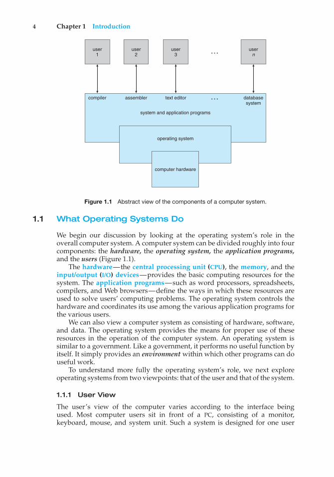
Figure 1.1 Abstract view of the components of a computer system.
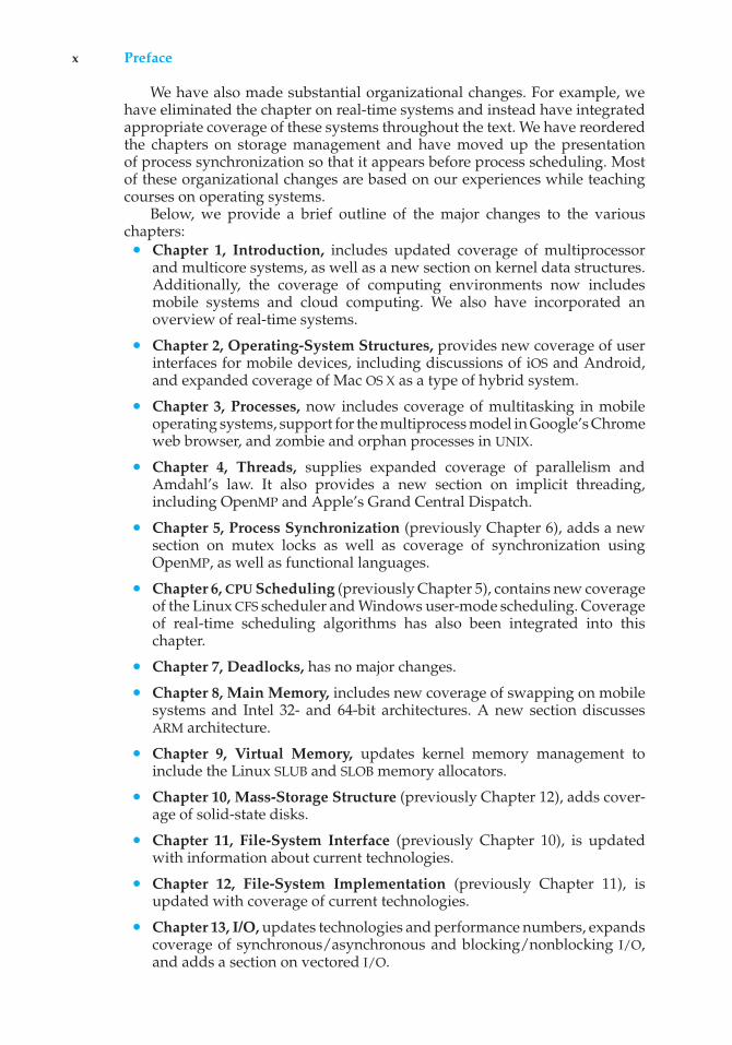
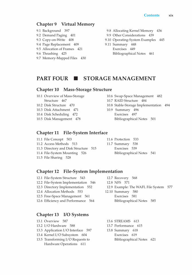
1.1 What Operating Systems Do
We begin our discussion by looking at the operating system’s role in theoverall computer system. A computer system can be divided roughly into fourcomponents: the hardware, the operating system, the application programs,and the users (Figure 1.1).
The hardware—the central processing unit (CPU), the memory, and theinput/output (I/O) devices—provides the basic computing resources for thesystem. The application programs—such as word processors, spreadsheets,compilers, and Web browsers—define the ways in which these resources areused to solve users’ computing problems. The operating system controls thehardware and coordinates its use among the various application programs forthe various users.
We can also view a computer system as consisting of hardware, software,and data. The operating system provides the means for proper use of theseresources in the operation of the computer system. An operating system issimilar to a government. Like a government, it performs no useful function byitself. It simply provides an environment within which other programs can douseful work.
To understand more fully the operating system’s role, we next exploreoperating systems from two viewpoints: that of the user and that of the system.
1.1.1 User View
The user’s view of the computer varies according to the interface beingused. Most computer users sit in front of a PC, consisting of a monitor,keyboard, mouse, and system unit. Such a system is designed for one user
1.1 What Operating Systems Do 5
to monopolize its resources. The goal is to maximize the work (or play) thatthe user is performing. In this case, the operating system is designed mostlyfor ease of use, with some attention paid to performance and none paidto resource utilization—how various hardware and software resources areshared. Performance is, of course, important to the user; but such systemsare optimized for the single-user experience rather than the requirements ofmultiple users.
In other cases, a user sits at a terminal connected to a mainframe or aminicomputer. Other users are accessing the same computer through otherterminals. These users share resources and may exchange information. Theoperating system in such cases is designed to maximize resource utilization—to assure that all available CPU time, memory, and I/O are used efficiently andthat no individual user takes more than her fair share.
In still other cases, users sit at workstations connected to networks ofother workstations and servers. These users have dedicated resources attheir disposal, but they also share resources such as networking and servers,including file, compute, and print servers. Therefore, their operating system isdesigned to compromise between individual usability and resource utilization.
Recently, many varieties of mobile computers, such as smartphones andtablets, have come into fashion. Most mobile computers are standalone units forindividual users. Quite often, they are connected to networks through cellularor other wireless technologies. Increasingly, these mobile devices are replacingdesktop and laptop computers for people who are primarily interested inusing computers for e-mail and web browsing. The user interface for mobilecomputers generally features a touch screen, where the user interacts with thesystem by pressing and swiping fingers across the screen rather than using aphysical keyboard and mouse.
Some computers have little or no user view. For example, embeddedcomputers in home devices and automobiles may have numeric keypads andmay turn indicator lights on or off to show status, but they and their operatingsystems are designed primarily to run without user intervention.
1.1.2 System View
From the computer’s point of view, the operating system is the programmost intimately involved with the hardware. In this context, we can viewan operating system as a resource allocator. A computer system has manyresources that may be required to solve a problem: CPU time, memory space,file-storage space, I/O devices, and so on. The operating system acts as themanager of these resources. Facing numerous and possibly conflicting requestsfor resources, the operating system must decide how to allocate them to specificprograms and users so that it can operate the computer system efficiently andfairly. As we have seen, resource allocation is especially important where manyusers access the same mainframe or minicomputer.
A slightly different view of an operating system emphasizes the need tocontrol the various I/O devices and user programs. An operating system is acontrol program. A control program manages the execution of user programsto prevent errors and improper use of the computer. It is especially concernedwith the operation and control of I/O devices.
6 Chapter 1 Introduction
1.1.3 Defining Operating Systems
By now, you can probably see that the term operating system covers many rolesand functions. That is the case, at least in part, because of the myriad designsand uses of computers. Computers are present within toasters, cars, ships,spacecraft, homes, and businesses. They are the basis for game machines, musicplayers, cable TV tuners, and industrial control systems. Although computershave a relatively short history, they have evolved rapidly. Computing startedas an experiment to determine what could be done and quickly moved tofixed-purpose systems for military uses, such as code breaking and trajectoryplotting, and governmental uses, such as census calculation. Those earlycomputers evolved into general-purpose, multifunction mainframes, andthat’s when operating systems were born. In the 1960s, Moore’s Law predictedthat the number of transistors on an integrated circuit would double everyeighteen months, and that prediction has held true. Computers gained infunctionality and shrunk in size, leading to a vast number of uses and a vastnumber and variety of operating systems. (See Chapter 20 for more details onthe history of operating systems.)
How, then, can we define what an operating system is? In general, we haveno completely adequate definition of an operating system. Operating systemsexist because they offer a reasonable way to solve the problem of creating ausable computing system. The fundamental goal of computer systems is toexecute user programs and to make solving user problems easier. Computerhardware is constructed toward this goal. Since bare hardware alone is notparticularly easy to use, application programs are developed. These programsrequire certain common operations, such as those controlling the I/O devices.The common functions of controlling and allocating resources are then broughttogether into one piece of software: the operating system.
In addition, we have no universally accepted definition of what is part of theoperating system. A simple viewpoint is that it includes everything a vendorships when you order “the operating system.” The features included, however,vary greatly across systems. Some systems take up less than a megabyte ofspace and lack even a full-screen editor, whereas others require gigabytes ofspace and are based entirely on graphical windowing systems. A more commondefinition, and the one that we usually follow, is that the operating systemis the one program running at all times on the computer—usually calledthe kernel. (Along with the kernel, there are two other types of programs:system programs, which are associated with the operating system but are notnecessarily part of the kernel, and application programs, which include allprograms not associated with the operation of the system.)
The matter of what constitutes an operating system became increasinglyimportant as personal computers became more widespread and operatingsystems grew increasingly sophisticated. In 1998, the United States Departmentof Justice filed suit against Microsoft, in essence claiming that Microsoftincluded too much functionality in its operating systems and thus preventedapplication vendors from competing. (For example, a Web browser was anintegral part of the operating systems.) As a result, Microsoft was found guiltyof using its operating-system monopoly to limit competition.
Today, however, if we look at operating systems for mobile devices, wesee that once again the number of features constituting the operating system
1.2 Computer-System Organization 7
is increasing. Mobile operating systems often include not only a core kernelbut also middleware—a set of software frameworks that provide additionalservices to application developers. For example, each of the two most promi-nent mobile operating systems—Apple’s iOS and Google’s Android—featuresa core kernel along with middleware that supports databases, multimedia, andgraphics (to name a only few).
1.2 Computer-System Organization
Before we can explore the details of how computer systems operate, we needgeneral knowledge of the structure of a computer system. In this section,we look at several parts of this structure. The section is mostly concernedwith computer-system organization, so you can skim or skip it if you alreadyunderstand the concepts.
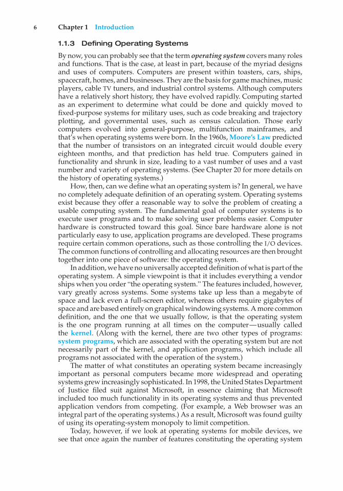
1.2.1 Computer-System Operation
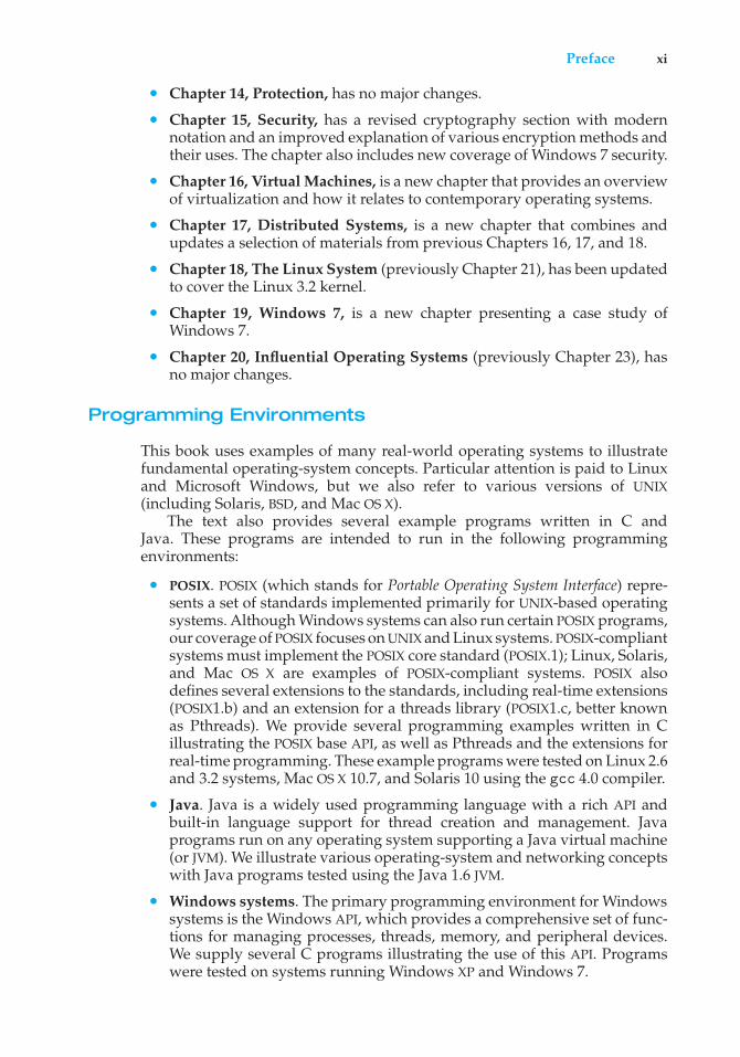
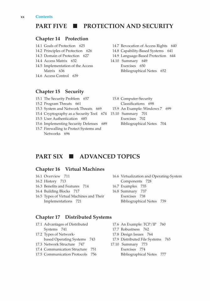
A modern general-purpose computer system consists of one or more CPUsand a number of device controllers connected through a common bus thatprovides access to shared memory (Figure 1.2). Each device controller is incharge of a specific type of device (for example, disk drives, audio devices,or video displays). The CPU and the device controllers can execute in parallel,competing for memory cycles. To ensure orderly access to the shared memory,a memory controller synchronizes access to the memory.
For a computer to start running—for instance, when it is powered up orrebooted—it needs to have an initial program to run. This initial program,or bootstrap program, tends to be simple. Typically, it is stored withinthe computer hardware in read-only memory (ROM) or electrically erasableprogrammable read-only memory (EEPROM), known by the general termfirmware. It initializes all aspects of the system, from CPU registers to devicecontrollers to memory contents. The bootstrap program must know how to loadthe operating system and how to start executing that system. To accomplish
USB controller
keyboard printermouse monitordisks
graphicsadapter
diskcontroller
memory
CPU
on-line
Figure 1.2 A modern computer system.
8 Chapter 1 Introduction
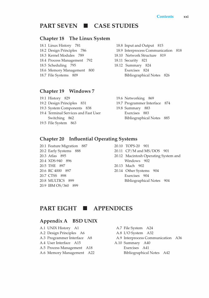
userprocessexecuting
CPU
I/O interruptprocessing
I/Orequest
transferdone
I/Orequest
transferdone
I/Odevice
idle
transferring
Figure 1.3 Interrupt timeline for a single process doing output.
this goal, the bootstrap program must locate the operating-system kernel andload it into memory.
Once the kernel is loaded and executing, it can start providing services tothe system and its users. Some services are provided outside of the kernel, bysystem programs that are loaded into memory at boot time to become systemprocesses, or system daemons that run the entire time the kernel is running.On UNIX, the first system process is “init,” and it starts many other daemons.Once this phase is complete, the system is fully booted, and the system waitsfor some event to occur.
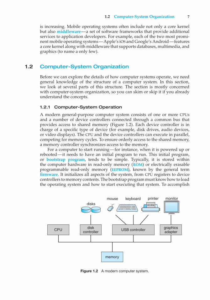
The occurrence of an event is usually signaled by an interrupt from eitherthe hardware or the software. Hardware may trigger an interrupt at any timeby sending a signal to the CPU, usually by way of the system bus. Softwaremay trigger an interrupt by executing a special operation called a system call(also called a monitor call).
When the CPU is interrupted, it stops what it is doing and immediatelytransfers execution to a fixed location. The fixed location usually containsthe starting address where the service routine for the interrupt is located.The interrupt service routine executes; on completion, the CPU resumes theinterrupted computation. A timeline of this operation is shown in Figure 1.3.
Interrupts are an important part of a computer architecture. Each computerdesign has its own interrupt mechanism, but several functions are common.The interrupt must transfer control to the appropriate interrupt service routine.The straightforward method for handling this transfer would be to invokea generic routine to examine the interrupt information. The routine, in turn,would call the interrupt-specific handler. However, interrupts must be handledquickly. Since only a predefined number of interrupts is possible, a table ofpointers to interrupt routines can be used instead to provide the necessaryspeed. The interrupt routine is called indirectly through the table, with nointermediate routine needed. Generally, the table of pointers is stored in lowmemory (the first hundred or so locations). These locations hold the addressesof the interrupt service routines for the various devices. This array, or interruptvector, of addresses is then indexed by a unique device number, given withthe interrupt request, to provide the address of the interrupt service routine for
1.2 Computer-System Organization 9
STORAGE DEFINITIONS AND NOTATION
The basic unit of computer storage is the bit. A bit can contain one of twovalues, 0 and 1. All other storage in a computer is based on collections of bits.Given enough bits, it is amazing how many things a computer can represent:numbers, letters, images, movies, sounds, documents, and programs, to namea few. A byte is 8 bits, and on most computers it is the smallest convenientchunk of storage. For example, most computers don’t have an instruction tomove a bit but do have one to move a byte. A less common term is word,which is a given computer architecture’s native unit of data. A word is madeup of one or more bytes. For example, a computer that has 64-bit registers and64-bit memory addressing typically has 64-bit (8-byte) words. A computerexecutes many operations in its native word size rather than a byte at a time.
Computer storage, along with most computer throughput, is generallymeasured and manipulated in bytes and collections of bytes. A kilobyte, orKB, is 1,024 bytes; a megabyte, or MB, is 1,0242 bytes; a gigabyte, or GB, is1,0243 bytes; a terabyte, or TB, is 1,0244 bytes; and a petabyte, or PB, is 1,0245
bytes. Computer manufacturers often round off these numbers and say thata megabyte is 1 million bytes and a gigabyte is 1 billion bytes. Networkingmeasurements are an exception to this general rule; they are given in bits(because networks move data a bit at a time).
the interrupting device. Operating systems as different as Windows and UNIXdispatch interrupts in this manner.
The interrupt architecture must also save the address of the interruptedinstruction. Many old designs simply stored the interrupt address in afixed location or in a location indexed by the device number. More recentarchitectures store the return address on the system stack. If the interruptroutine needs to modify the processor state—for instance, by modifyingregister values—it must explicitly save the current state and then restore thatstate before returning. After the interrupt is serviced, the saved return addressis loaded into the program counter, and the interrupted computation resumesas though the interrupt had not occurred.
1.2.2 Storage Structure
The CPU can load instructions only from memory, so any programs to run mustbe stored there. General-purpose computers run most of their programs fromrewritable memory, called main memory (also called random-access memory,or RAM). Main memory commonly is implemented in a semiconductortechnology called dynamic random-access memory (DRAM).
Computers use other forms of memory as well. We have already mentionedread-only memory, ROM) and electrically erasable programmable read-onlymemory, EEPROM). Because ROM cannot be changed, only static programs, suchas the bootstrap program described earlier, are stored there. The immutabilityof ROM is of use in game cartridges. EEPROM can be changed but cannotbe changed frequently and so contains mostly static programs. For example,smartphones have EEPROM to store their factory-installed programs.
10 Chapter 1 Introduction
All forms of memory provide an array of bytes. Each byte has itsown address. Interaction is achieved through a sequence of load or storeinstructions to specific memory addresses. The load instruction moves a byteor word from main memory to an internal register within the CPU, whereas thestore instruction moves the content of a register to main memory. Aside fromexplicit loads and stores, the CPU automatically loads instructions from mainmemory for execution.
A typical instruction–execution cycle, as executed on a system with a vonNeumann architecture, first fetches an instruction from memory and storesthat instruction in the instruction register. The instruction is then decodedand may cause operands to be fetched from memory and stored in someinternal register. After the instruction on the operands has been executed, theresult may be stored back in memory. Notice that the memory unit sees onlya stream of memory addresses. It does not know how they are generated (bythe instruction counter, indexing, indirection, literal addresses, or some othermeans) or what they are for (instructions or data). Accordingly, we can ignorehow a memory address is generated by a program. We are interested only inthe sequence of memory addresses generated by the running program.
Ideally, we want the programs and data to reside in main memorypermanently. This arrangement usually is not possible for the following tworeasons:
1. Main memory is usually too small to store all needed programs and datapermanently.
2. Main memory is a volatile storage device that loses its contents whenpower is turned off or otherwise lost.
Thus, most computer systems provide secondary storage as an extension ofmain memory. The main requirement for secondary storage is that it be able tohold large quantities of data permanently.
The most common secondary-storage device is a magnetic disk, whichprovides storage for both programs and data. Most programs (system andapplication) are stored on a disk until they are loaded into memory. Manyprograms then use the disk as both the source and the destination of theirprocessing. Hence, the proper management of disk storage is of centralimportance to a computer system, as we discuss in Chapter 10.
In a larger sense, however, the storage structure that we have described—consisting of registers, main memory, and magnetic disks—is only one of manypossible storage systems. Others include cache memory, CD-ROM, magnetictapes, and so on. Each storage system provides the basic functions of storinga datum and holding that datum until it is retrieved at a later time. The maindifferences among the various storage systems lie in speed, cost, size, andvolatility.
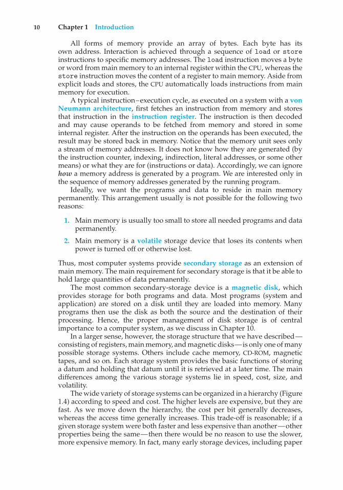
The wide variety of storage systems can be organized in a hierarchy (Figure1.4) according to speed and cost. The higher levels are expensive, but they arefast. As we move down the hierarchy, the cost per bit generally decreases,whereas the access time generally increases. This trade-off is reasonable; if agiven storage system were both faster and less expensive than another—otherproperties being the same—then there would be no reason to use the slower,more expensive memory. In fact, many early storage devices, including paper
1.2 Computer-System Organization 11
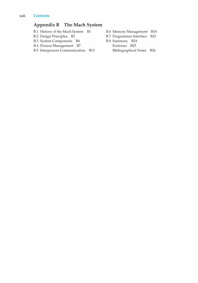
registers
cache
main memory
solid-state disk
magnetic disk
optical disk
magnetic tapes
Figure 1.4 Storage-device hierarchy.
tape and core memories, are relegated to museums now that magnetic tape andsemiconductor memory have become faster and cheaper. The top four levelsof memory in Figure 1.4 may be constructed using semiconductor memory.
In addition to differing in speed and cost, the various storage systems areeither volatile or nonvolatile. As mentioned earlier, volatile storage loses itscontents when the power to the device is removed. In the absence of expensivebattery and generator backup systems, data must be written to nonvolatilestorage for safekeeping. In the hierarchy shown in Figure 1.4, the storagesystems above the solid-state disk are volatile, whereas those including thesolid-state disk and below are nonvolatile.
Solid-state disks have several variants but in general are faster thanmagnetic disks and are nonvolatile. One type of solid-state disk stores data in alarge DRAM array during normal operation but also contains a hidden magnetichard disk and a battery for backup power. If external power is interrupted, thissolid-state disk’s controller copies the data from RAM to the magnetic disk.When external power is restored, the controller copies the data back into RAM.Another form of solid-state disk is flash memory, which is popular in camerasand personal digital assistants (PDAs), in robots, and increasingly for storageon general-purpose computers. Flash memory is slower than DRAM but needsno power to retain its contents. Another form of nonvolatile storage is NVRAM,which is DRAM with battery backup power. This memory can be as fast asDRAM and (as long as the battery lasts) is nonvolatile.
The design of a complete memory system must balance all the factors justdiscussed: it must use only as much expensive memory as necessary whileproviding as much inexpensive, nonvolatile memory as possible. Caches can
12 Chapter 1 Introduction
be installed to improve performance where a large disparity in access time ortransfer rate exists between two components.
1.2.3 I/O Structure
Storage is only one of many types of I/O devices within a computer. A largeportion of operating system code is dedicated to managing I/O, both becauseof its importance to the reliability and performance of a system and because ofthe varying nature of the devices. Next, we provide an overview of I/O.
A general-purpose computer system consists of CPUs and multiple devicecontrollers that are connected through a common bus. Each device controlleris in charge of a specific type of device. Depending on the controller, morethan one device may be attached. For instance, seven or more devices can beattached to the small computer-systems interface (SCSI) controller. A devicecontroller maintains some local buffer storage and a set of special-purposeregisters. The device controller is responsible for moving the data betweenthe peripheral devices that it controls and its local buffer storage. Typically,operating systems have a device driver for each device controller. This devicedriver understands the device controller and provides the rest of the operatingsystem with a uniform interface to the device.
To start an I/O operation, the device driver loads the appropriate registerswithin the device controller. The device controller, in turn, examines thecontents of these registers to determine what action to take (such as “reada character from the keyboard”). The controller starts the transfer of data fromthe device to its local buffer. Once the transfer of data is complete, the devicecontroller informs the device driver via an interrupt that it has finished itsoperation. The device driver then returns control to the operating system,possibly returning the data or a pointer to the data if the operation was a read.For other operations, the device driver returns status information.
This form of interrupt-driven I/O is fine for moving small amounts of databut can produce high overhead when used for bulk data movement such as diskI/O. To solve this problem, direct memory access (DMA) is used. After settingup buffers, pointers, and counters for the I/O device, the device controllertransfers an entire block of data directly to or from its own buffer storage tomemory, with no intervention by the CPU. Only one interrupt is generated perblock, to tell the device driver that the operation has completed, rather thanthe one interrupt per byte generated for low-speed devices. While the devicecontroller is performing these operations, the CPU is available to accomplishother work.
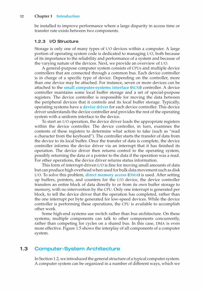
Some high-end systems use switch rather than bus architecture. On thesesystems, multiple components can talk to other components concurrently,rather than competing for cycles on a shared bus. In this case, DMA is evenmore effective. Figure 1.5 shows the interplay of all components of a computersystem.
1.3 Computer-System Architecture
In Section 1.2, we introduced the general structure of a typical computer system.A computer system can be organized in a number of different ways, which we
1.3 Computer-System Architecture 13
thread of executioninstructions
anddata
instruction executioncycle
data movement
DMA
memory
interrupt
cache
data
I/O request
CPU (*N)
device(*M)
Figure 1.5 How a modern computer system works.
can categorize roughly according to the number of general-purpose processorsused.
1.3.1 Single-Processor Systems
Until recently, most computer systems used a single processor. On a single-processor system, there is one main CPU capable of executing a general-purposeinstruction set, including instructions from user processes. Almost all single-processor systems have other special-purpose processors as well. They maycome in the form of device-specific processors, such as disk, keyboard, andgraphics controllers; or, on mainframes, they may come in the form of moregeneral-purpose processors, such as I/O processors that move data rapidlyamong the components of the system.
All of these special-purpose processors run a limited instruction set anddo not run user processes. Sometimes, they are managed by the operatingsystem, in that the operating system sends them information about their nexttask and monitors their status. For example, a disk-controller microprocessorreceives a sequence of requests from the main CPU and implements its own diskqueue and scheduling algorithm. This arrangement relieves the main CPU ofthe overhead of disk scheduling. PCs contain a microprocessor in the keyboardto convert the keystrokes into codes to be sent to the CPU. In other systemsor circumstances, special-purpose processors are low-level components builtinto the hardware. The operating system cannot communicate with theseprocessors; they do their jobs autonomously. The use of special-purposemicroprocessors is common and does not turn a single-processor system into
14 Chapter 1 Introduction
a multiprocessor. If there is only one general-purpose CPU, then the system isa single-processor system.
1.3.2 Multiprocessor Systems
Within the past several years, multiprocessor systems (also known as parallelsystems or multicore systems) have begun to dominate the landscape ofcomputing. Such systems have two or more processors in close communication,sharing the computer bus and sometimes the clock, memory, and peripheraldevices. Multiprocessor systems first appeared prominently appeared inservers and have since migrated to desktop and laptop systems. Recently,multiple processors have appeared on mobile devices such as smartphonesand tablet computers.
Multiprocessor systems have three main advantages:
1. Increased throughput. By increasing the number of processors, we expectto get more work done in less time. The speed-up ratio with N processorsis not N, however; rather, it is less than N. When multiple processorscooperate on a task, a certain amount of overhead is incurred in keepingall the parts working correctly. This overhead, plus contention for sharedresources, lowers the expected gain from additional processors. Similarly,N programmers working closely together do not produce N times theamount of work a single programmer would produce.
2. Economy of scale. Multiprocessor systems can cost less than equivalentmultiple single-processor systems, because they can share peripherals,mass storage, and power supplies. If several programs operate on thesame set of data, it is cheaper to store those data on one disk and to haveall the processors share them than to have many computers with localdisks and many copies of the data.
3. Increased reliability. If functions can be distributed properly amongseveral processors, then the failure of one processor will not halt thesystem, only slow it down. If we have ten processors and one fails, theneach of the remaining nine processors can pick up a share of the work ofthe failed processor. Thus, the entire system runs only 10 percent slower,rather than failing altogether.
Increased reliability of a computer system is crucial in many applications.The ability to continue providing service proportional to the level of survivinghardware is called graceful degradation. Some systems go beyond gracefuldegradation and are called fault tolerant, because they can suffer a failure ofany single component and still continue operation. Fault tolerance requiresa mechanism to allow the failure to be detected, diagnosed, and, if possible,corrected. The HP NonStop (formerly Tandem) system uses both hardware andsoftware duplication to ensure continued operation despite faults. The systemconsists of multiple pairs of CPUs, working in lockstep. Both processors in thepair execute each instruction and compare the results. If the results differ, thenone CPU of the pair is at fault, and both are halted. The process that was beingexecuted is then moved to another pair of CPUs, and the instruction that failed
1.3 Computer-System Architecture 15
is restarted. This solution is expensive, since it involves special hardware andconsiderable hardware duplication.
The multiple-processor systems in use today are of two types. Somesystems use asymmetric multiprocessing, in which each processor is assigneda specific task. A boss processor controls the system; the other processors eitherlook to the boss for instruction or have predefined tasks. This scheme definesa boss–worker relationship. The boss processor schedules and allocates workto the worker processors.
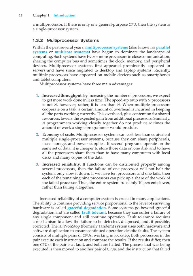
The most common systems use symmetric multiprocessing (SMP), inwhich each processor performs all tasks within the operating system. SMPmeans that all processors are peers; no boss–worker relationship existsbetween processors. Figure 1.6 illustrates a typical SMP architecture. Noticethat each processor has its own set of registers, as well as a private—or local—cache. However, all processors share physical memory. An example of anSMP system is AIX, a commercial version of UNIX designed by IBM. An AIXsystem can be configured to employ dozens of processors. The benefit of thismodel is that many processes can run simultaneously—N processes can runif there are N CPUs—without causing performance to deteriorate significantly.However, we must carefully control I/O to ensure that the data reach theappropriate processor. Also, since the CPUs are separate, one may be sittingidle while another is overloaded, resulting in inefficiencies. These inefficienciescan be avoided if the processors share certain data structures. A multiprocessorsystem of this form will allow processes and resources—such as memory—to be shared dynamically among the various processors and can lower thevariance among the processors. Such a system must be written carefully, aswe shall see in Chapter 5. Virtually all modern operating systems—includingWindows, Mac OS X, and Linux—now provide support for SMP.
The difference between symmetric and asymmetric multiprocessing mayresult from either hardware or software. Special hardware can differentiate themultiple processors, or the software can be written to allow only one boss andmultiple workers. For instance, Sun Microsystems’ operating system SunOSVersion 4 provided asymmetric multiprocessing, whereas Version 5 (Solaris) issymmetric on the same hardware.
Multiprocessing adds CPUs to increase computing power. If the CPU has anintegrated memory controller, then adding CPUs can also increase the amount
CPU0
registers
cache
CPU1
registers
cache
CPU2
registers
cache
memory
Figure 1.6 Symmetric multiprocessing architecture.
16 Chapter 1 Introduction
of memory addressable in the system. Either way, multiprocessing can causea system to change its memory access model from uniform memory access(UMA) to non-uniform memory access (NUMA). UMA is defined as the situationin which access to any RAM from any CPU takes the same amount of time. WithNUMA, some parts of memory may take longer to access than other parts,creating a performance penalty. Operating systems can minimize the NUMApenalty through resource management, as discussed in Section 9.5.4.
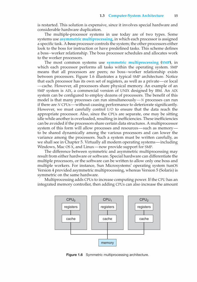
A recent trend in CPU design is to include multiple computing coreson a single chip. Such multiprocessor systems are termed multicore. Theycan be more efficient than multiple chips with single cores because on-chipcommunication is faster than between-chip communication. In addition, onechip with multiple cores uses significantly less power than multiple single-corechips.
It is important to note that while multicore systems are multiprocessorsystems, not all multiprocessor systems are multicore, as we shall see in Section1.3.3. In our coverage of multiprocessor systems throughout this text, unlesswe state otherwise, we generally use the more contemporary term multicore,which excludes some multiprocessor systems.
In Figure 1.7, we show a dual-core design with two cores on the samechip. In this design, each core has its own register set as well as its own localcache. Other designs might use a shared cache or a combination of local andshared caches. Aside from architectural considerations, such as cache, memory,and bus contention, these multicore CPUs appear to the operating system asN standard processors. This characteristic puts pressure on operating systemdesigners—and application programmers—to make use of those processingcores.
Finally, blade servers are a relatively recent development in which multipleprocessor boards, I/O boards, and networking boards are placed in the samechassis. The difference between these and traditional multiprocessor systemsis that each blade-processor board boots independently and runs its ownoperating system. Some blade-server boards are multiprocessor as well, whichblurs the lines between types of computers. In essence, these servers consist ofmultiple independent multiprocessor systems.
CPU core0
registers
cache
CPU core1
registers
cache
memory
Figure 1.7 A dual-core design with two cores placed on the same chip.
1.3 Computer-System Architecture 17
1.3.3 Clustered Systems
Another type of multiprocessor system is a clustered system, which gatherstogether multiple CPUs. Clustered systems differ from the multiprocessorsystems described in Section 1.3.2 in that they are composed of two or moreindividual systems—or nodes—joined together. Such systems are consideredloosely coupled. Each node may be a single processor system or a multicoresystem. We should note that the definition of clustered is not concrete; manycommercial packages wrestle to define a clustered system and why one formis better than another. The generally accepted definition is that clusteredcomputers share storage and are closely linked via a local-area network LAN(as described in Chapter 17) or a faster interconnect, such as InfiniBand.
Clustering is usually used to provide high-availability service—that is,service will continue even if one or more systems in the cluster fail. Generally,we obtain high availability by adding a level of redundancy in the system.A layer of cluster software runs on the cluster nodes. Each node can monitorone or more of the others (over the LAN). If the monitored machine fails,the monitoring machine can take ownership of its storage and restart theapplications that were running on the failed machine. The users and clients ofthe applications see only a brief interruption of service.
Clustering can be structured asymmetrically or symmetrically. In asym-metric clustering, one machine is in hot-standby mode while the other isrunning the applications. The hot-standby host machine does nothing butmonitor the active server. If that server fails, the hot-standby host becomesthe active server. In symmetric clustering, two or more hosts are runningapplications and are monitoring each other. This structure is obviously moreefficient, as it uses all of the available hardware. However it does require thatmore than one application be available to run.
Since a cluster consists of several computer systems connected via anetwork, clusters can also be used to provide high-performance computingenvironments. Such systems can supply significantly greater computationalpower than single-processor or even SMP systems because they can run anapplication concurrently on all computers in the cluster. The application musthave been written specifically to take advantage of the cluster, however. Thisinvolves a technique known as parallelization, which divides a program intoseparate components that run in parallel on individual computers in the cluster.Typically, these applications are designed so that once each computing node inthe cluster has solved its portion of the problem, the results from all the nodesare combined into a final solution.
Other forms of clusters include parallel clusters and clustering over awide-area network (WAN) (as described in Chapter 17). Parallel clusters allowmultiple hosts to access the same data on shared storage. Because mostoperating systems lack support for simultaneous data access by multiple hosts,parallel clusters usually require the use of special versions of software andspecial releases of applications. For example, Oracle Real Application Clusteris a version of Oracle’s database that has been designed to run on a parallelcluster. Each machine runs Oracle, and a layer of software tracks access to theshared disk. Each machine has full access to all data in the database. To providethis shared access, the system must also supply access control and locking to
18 Chapter 1 Introduction
BEOWULF CLUSTERS
Beowulf clusters are designed to solve high-performance computing tasks.A Beowulf cluster consists of commodity hardware—such as personalcomputers—connected via a simple local-area network. No single specificsoftware package is required to construct a cluster. Rather, the nodes use aset of open-source software libraries to communicate with one another. Thus,there are a variety of approaches to constructing a Beowulf cluster. Typically,though, Beowulf computing nodes run the Linux operating system. SinceBeowulf clusters require no special hardware and operate using open-sourcesoftware that is available free, they offer a low-cost strategy for buildinga high-performance computing cluster. In fact, some Beowulf clusters builtfrom discarded personal computers are using hundreds of nodes to solvecomputationally expensive scientific computing problems.
ensure that no conflicting operations occur. This function, commonly knownas a distributed lock manager (DLM), is included in some cluster technology.
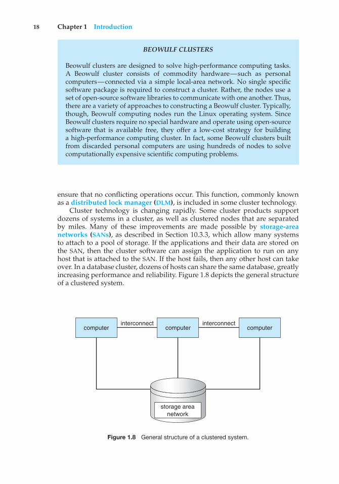
Cluster technology is changing rapidly. Some cluster products supportdozens of systems in a cluster, as well as clustered nodes that are separatedby miles. Many of these improvements are made possible by storage-areanetworks (SANs), as described in Section 10.3.3, which allow many systemsto attach to a pool of storage. If the applications and their data are stored onthe SAN, then the cluster software can assign the application to run on anyhost that is attached to the SAN. If the host fails, then any other host can takeover. In a database cluster, dozens of hosts can share the same database, greatlyincreasing performance and reliability. Figure 1.8 depicts the general structureof a clustered system.
computerinterconnect
computerinterconnect
computer
storage areanetwork
Figure 1.8 General structure of a clustered system.
1.4 Operating-System Structure 19
job 1
0
Max
operating system
job 2
job 3
job 4
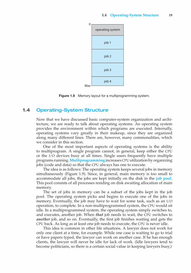
Figure 1.9 Memory layout for a multiprogramming system.
1.4 Operating-System Structure
Now that we have discussed basic computer-system organization and archi-tecture, we are ready to talk about operating systems. An operating systemprovides the environment within which programs are executed. Internally,operating systems vary greatly in their makeup, since they are organizedalong many different lines. There are, however, many commonalities, whichwe consider in this section.
One of the most important aspects of operating systems is the abilityto multiprogram. A single program cannot, in general, keep either the CPUor the I/O devices busy at all times. Single users frequently have multipleprograms running. Multiprogramming increases CPU utilization by organizingjobs (code and data) so that the CPU always has one to execute.
The idea is as follows: The operating system keeps several jobs in memorysimultaneously (Figure 1.9). Since, in general, main memory is too small toaccommodate all jobs, the jobs are kept initially on the disk in the job pool.This pool consists of all processes residing on disk awaiting allocation of mainmemory.
The set of jobs in memory can be a subset of the jobs kept in the jobpool. The operating system picks and begins to execute one of the jobs inmemory. Eventually, the job may have to wait for some task, such as an I/Ooperation, to complete. In a non-multiprogrammed system, the CPU would sitidle. In a multiprogrammed system, the operating system simply switches to,and executes, another job. When that job needs to wait, the CPU switches toanother job, and so on. Eventually, the first job finishes waiting and gets theCPU back. As long as at least one job needs to execute, the CPU is never idle.
This idea is common in other life situations. A lawyer does not work foronly one client at a time, for example. While one case is waiting to go to trialor have papers typed, the lawyer can work on another case. If he has enoughclients, the lawyer will never be idle for lack of work. (Idle lawyers tend tobecome politicians, so there is a certain social value in keeping lawyers busy.)
20 Chapter 1 Introduction
Multiprogrammed systems provide an environment in which the varioussystem resources (for example, CPU, memory, and peripheral devices) areutilized effectively, but they do not provide for user interaction with thecomputer system. Time sharing (or multitasking) is a logical extension ofmultiprogramming. In time-sharing systems, the CPU executes multiple jobsby switching among them, but the switches occur so frequently that the userscan interact with each program while it is running.
Time sharing requires an interactive computer system, which providesdirect communication between the user and the system. The user givesinstructions to the operating system or to a program directly, using a inputdevice such as a keyboard, mouse, touch pad, or touch screen, and waits forimmediate results on an output device. Accordingly, the response time shouldbe short—typically less than one second.
A time-shared operating system allows many users to share the computersimultaneously. Since each action or command in a time-shared system tendsto be short, only a little CPU time is needed for each user. As the system switchesrapidly from one user to the next, each user is given the impression that theentire computer system is dedicated to his use, even though it is being sharedamong many users.
A time-shared operating system uses CPU scheduling and multiprogram-ming to provide each user with a small portion of a time-shared computer.Each user has at least one separate program in memory. A program loaded intomemory and executing is called a process. When a process executes, it typicallyexecutes for only a short time before it either finishes or needs to perform I/O.I/O may be interactive; that is, output goes to a display for the user, and inputcomes from a user keyboard, mouse, or other device. Since interactive I/Otypically runs at “people speeds,” it may take a long time to complete. Input,for example, may be bounded by the user’s typing speed; seven characters persecond is fast for people but incredibly slow for computers. Rather than letthe CPU sit idle as this interactive input takes place, the operating system willrapidly switch the CPU to the program of some other user.
Time sharing and multiprogramming require that several jobs be keptsimultaneously in memory. If several jobs are ready to be brought into memory,and if there is not enough room for all of them, then the system must chooseamong them. Making this decision involves job scheduling, which we discussin Chapter 6. When the operating system selects a job from the job pool, it loadsthat job into memory for execution. Having several programs in memory atthe same time requires some form of memory management, which we cover inChapters 8 and 9. In addition, if several jobs are ready to run at the same time,the system must choose which job will run first. Making this decision is CPUscheduling, which is also discussed in Chapter 6. Finally, running multiplejobs concurrently requires that their ability to affect one another be limited inall phases of the operating system, including process scheduling, disk storage,and memory management. We discuss these considerations throughout thetext.
In a time-sharing system, the operating system must ensure reasonableresponse time. This goal is sometimes accomplished through swapping,whereby processes are swapped in and out of main memory to the disk. A morecommon method for ensuring reasonable response time is virtual memory, atechnique that allows the execution of a process that is not completely in
1.5 Operating-System Operations 21
memory (Chapter 9). The main advantage of the virtual-memory scheme is thatit enables users to run programs that are larger than actual physical memory.Further, it abstracts main memory into a large, uniform array of storage,separating logical memory as viewed by the user from physical memory.This arrangement frees programmers from concern over memory-storagelimitations.
A time-sharing system must also provide a file system (Chapters 11 and12). The file system resides on a collection of disks; hence, disk managementmust be provided (Chapter 10). In addition, a time-sharing system providesa mechanism for protecting resources from inappropriate use (Chapter 14).To ensure orderly execution, the system must provide mechanisms for jobsynchronization and communication (Chapter 5), and it may ensure that jobsdo not get stuck in a deadlock, forever waiting for one another (Chapter 7).
1.5 Operating-System Operations
As mentioned earlier, modern operating systems are interrupt driven. If thereare no processes to execute, no I/O devices to service, and no users to whomto respond, an operating system will sit quietly, waiting for something tohappen. Events are almost always signaled by the occurrence of an interruptor a trap. A trap (or an exception) is a software-generated interrupt causedeither by an error (for example, division by zero or invalid memory access)or by a specific request from a user program that an operating-system servicebe performed. The interrupt-driven nature of an operating system definesthat system’s general structure. For each type of interrupt, separate segmentsof code in the operating system determine what action should be taken. Aninterrupt service routine is provided to deal with the interrupt.
Since the operating system and the users share the hardware and softwareresources of the computer system, we need to make sure that an error in auser program could cause problems only for the one program running. Withsharing, many processes could be adversely affected by a bug in one program.For example, if a process gets stuck in an infinite loop, this loop could preventthe correct operation of many other processes. More subtle errors can occurin a multiprogramming system, where one erroneous program might modifyanother program, the data of another program, or even the operating systemitself.
Without protection against these sorts of errors, either the computer mustexecute only one process at a time or all output must be suspect. A properlydesigned operating system must ensure that an incorrect (or malicious)program cannot cause other programs to execute incorrectly.
1.5.1 Dual-Mode and Multimode Operation
In order to ensure the proper execution of the operating system, we must beable to distinguish between the execution of operating-system code and user-defined code. The approach taken by most computer systems is to providehardware support that allows us to differentiate among various modes ofexecution.
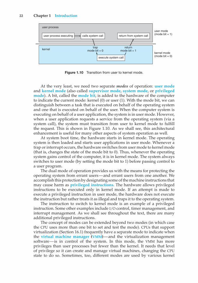
22 Chapter 1 Introduction
user process executing
user process
kernel
calls system call return from system call
user mode(mode bit = 1)
trapmode bit = 0
returnmode bit = 1
kernel mode(mode bit = 0)execute system call
Figure 1.10 Transition from user to kernel mode.
At the very least, we need two separate modes of operation: user modeand kernel mode (also called supervisor mode, system mode, or privilegedmode). A bit, called the mode bit, is added to the hardware of the computerto indicate the current mode: kernel (0) or user (1). With the mode bit, we candistinguish between a task that is executed on behalf of the operating systemand one that is executed on behalf of the user. When the computer system isexecuting on behalf of a user application, the system is in user mode. However,when a user application requests a service from the operating system (via asystem call), the system must transition from user to kernel mode to fulfillthe request. This is shown in Figure 1.10. As we shall see, this architecturalenhancement is useful for many other aspects of system operation as well.
At system boot time, the hardware starts in kernel mode. The operatingsystem is then loaded and starts user applications in user mode. Whenever atrap or interrupt occurs, the hardware switches from user mode to kernel mode(that is, changes the state of the mode bit to 0). Thus, whenever the operatingsystem gains control of the computer, it is in kernel mode. The system alwaysswitches to user mode (by setting the mode bit to 1) before passing control toa user program.
The dual mode of operation provides us with the means for protecting theoperating system from errant users—and errant users from one another. Weaccomplish this protection by designating some of the machine instructions thatmay cause harm as privileged instructions. The hardware allows privilegedinstructions to be executed only in kernel mode. If an attempt is made toexecute a privileged instruction in user mode, the hardware does not executethe instruction but rather treats it as illegal and traps it to the operating system.
The instruction to switch to kernel mode is an example of a privilegedinstruction. Some other examples include I/O control, timer management, andinterrupt management. As we shall see throughout the text, there are manyadditional privileged instructions.
The concept of modes can be extended beyond two modes (in which casethe CPU uses more than one bit to set and test the mode). CPUs that supportvirtualization (Section 16.1) frequently have a separate mode to indicate whenthe virtual machine manager (VMM)—and the virtualization managementsoftware—is in control of the system. In this mode, the VMM has moreprivileges than user processes but fewer than the kernel. It needs that levelof privilege so it can create and manage virtual machines, changing the CPUstate to do so. Sometimes, too, different modes are used by various kernel
1.5 Operating-System Operations 23
components. We should note that, as an alternative to modes, the CPU designermay use other methods to differentiate operational privileges. The Intel 64family of CPUs supports four privilege levels, for example, and supportsvirtualization but does not have a separate mode for virtualization.
We can now see the life cycle of instruction execution in a computer system.Initial control resides in the operating system, where instructions are executedin kernel mode. When control is given to a user application, the mode is set touser mode. Eventually, control is switched back to the operating system via aninterrupt, a trap, or a system call.
System calls provide the means for a user program to ask the operatingsystem to perform tasks reserved for the operating system on the userprogram’s behalf. A system call is invoked in a variety of ways, dependingon the functionality provided by the underlying processor. In all forms, it is themethod used by a process to request action by the operating system. A systemcall usually takes the form of a trap to a specific location in the interrupt vector.This trap can be executed by a generic trap instruction, although some systems(such as MIPS) have a specific syscall instruction to invoke a system call.
When a system call is executed, it is typically treated by the hardwareas a software interrupt. Control passes through the interrupt vector to aservice routine in the operating system, and the mode bit is set to kernelmode. The system-call service routine is a part of the operating system. Thekernel examines the interrupting instruction to determine what system callhas occurred; a parameter indicates what type of service the user program isrequesting. Additional information needed for the request may be passed inregisters, on the stack, or in memory (with pointers to the memory locationspassed in registers). The kernel verifies that the parameters are correct andlegal, executes the request, and returns control to the instruction following thesystem call. We describe system calls more fully in Section 2.3.
The lack of a hardware-supported dual mode can cause serious shortcom-ings in an operating system. For instance, MS-DOS was written for the Intel8088 architecture, which has no mode bit and therefore no dual mode. A userprogram running awry can wipe out the operating system by writing over itwith data; and multiple programs are able to write to a device at the sametime, with potentially disastrous results. Modern versions of the Intel CPUdo provide dual-mode operation. Accordingly, most contemporary operatingsystems—such as Microsoft Windows 7, as well as Unix and Linux—takeadvantage of this dual-mode feature and provide greater protection for theoperating system.
Once hardware protection is in place, it detects errors that violate modes.These errors are normally handled by the operating system. If a user programfails in some way—such as by making an attempt either to execute an illegalinstruction or to access memory that is not in the user’s address space—thenthe hardware traps to the operating system. The trap transfers control throughthe interrupt vector to the operating system, just as an interrupt does. Whena program error occurs, the operating system must terminate the programabnormally. This situation is handled by the same code as a user-requestedabnormal termination. An appropriate error message is given, and the memoryof the program may be dumped. The memory dump is usually written to afile so that the user or programmer can examine it and perhaps correct it andrestart the program.
24 Chapter 1 Introduction
1.5.2 Timer
We must ensure that the operating system maintains control over the CPU.We cannot allow a user program to get stuck in an infinite loop or to failto call system services and never return control to the operating system. Toaccomplish this goal, we can use a timer. A timer can be set to interruptthe computer after a specified period. The period may be fixed (for example,1/60 second) or variable (for example, from 1 millisecond to 1 second). Avariable timer is generally implemented by a fixed-rate clock and a counter.The operating system sets the counter. Every time the clock ticks, the counteris decremented. When the counter reaches 0, an interrupt occurs. For instance,a 10-bit counter with a 1-millisecond clock allows interrupts at intervals from1 millisecond to 1,024 milliseconds, in steps of 1 millisecond.
Before turning over control to the user, the operating system ensuresthat the timer is set to interrupt. If the timer interrupts, control transfersautomatically to the operating system, which may treat the interrupt as a fatalerror or may give the program more time. Clearly, instructions that modify thecontent of the timer are privileged.
We can use the timer to prevent a user program from running too long.A simple technique is to initialize a counter with the amount of time that aprogram is allowed to run. A program with a 7-minute time limit, for example,would have its counter initialized to 420. Every second, the timer interrupts,and the counter is decremented by 1. As long as the counter is positive, controlis returned to the user program. When the counter becomes negative, theoperating system terminates the program for exceeding the assigned timelimit.
1.6 Process Management
A program does nothing unless its instructions are executed by a CPU. Aprogram in execution, as mentioned, is a process. A time-shared user programsuch as a compiler is a process. A word-processing program being run by anindividual user on a PC is a process. A system task, such as sending outputto a printer, can also be a process (or at least part of one). For now, you canconsider a process to be a job or a time-shared program, but later you will learnthat the concept is more general. As we shall see in Chapter 3, it is possibleto provide system calls that allow processes to create subprocesses to executeconcurrently.
A process needs certain resources—including CPU time, memory, files,and I/O devices—to accomplish its task. These resources are either given tothe process when it is created or allocated to it while it is running. In additionto the various physical and logical resources that a process obtains when it iscreated, various initialization data (input) may be passed along. For example,consider a process whose function is to display the status of a file on the screenof a terminal. The process will be given the name of the file as an input and willexecute the appropriate instructions and system calls to obtain and displaythe desired information on the terminal. When the process terminates, theoperating system will reclaim any reusable resources.
We emphasize that a program by itself is not a process. A program is apassive entity, like the contents of a file stored on disk, whereas a process
1.7 Memory Management 25
is an active entity. A single-threaded process has one program counterspecifying the next instruction to execute. (Threads are covered in Chapter4.) The execution of such a process must be sequential. The CPU executes oneinstruction of the process after another, until the process completes. Further,at any time, one instruction at most is executed on behalf of the process. Thus,although two processes may be associated with the same program, they arenevertheless considered two separate execution sequences. A multithreadedprocess has multiple program counters, each pointing to the next instructionto execute for a given thread.
A process is the unit of work in a system. A system consists of a collectionof processes, some of which are operating-system processes (those that executesystem code) and the rest of which are user processes (those that executeuser code). All these processes can potentially execute concurrently—bymultiplexing on a single CPU, for example.
The operating system is responsible for the following activities in connec-tion with process management:
• Scheduling processes and threads on the CPUs
• Creating and deleting both user and system processes
• Suspending and resuming processes
• Providing mechanisms for process synchronization
• Providing mechanisms for process communication
We discuss process-management techniques in Chapters 3 through 5.
1.7 Memory Management
As we discussed in Section 1.2.2, the main memory is central to the operationof a modern computer system. Main memory is a large array of bytes, rangingin size from hundreds of thousands to billions. Each byte has its own address.Main memory is a repository of quickly accessible data shared by the CPU andI/O devices. The central processor reads instructions from main memory duringthe instruction-fetch cycle and both reads and writes data from main memoryduring the data-fetch cycle (on a von Neumann architecture). As noted earlier,the main memory is generally the only large storage device that the CPU is ableto address and access directly. For example, for the CPU to process data fromdisk, those data must first be transferred to main memory by CPU-generatedI/O calls. In the same way, instructions must be in memory for the CPU toexecute them.
For a program to be executed, it must be mapped to absolute addresses andloaded into memory. As the program executes, it accesses program instructionsand data from memory by generating these absolute addresses. Eventually,the program terminates, its memory space is declared available, and the nextprogram can be loaded and executed.
To improve both the utilization of the CPU and the speed of the computer’sresponse to its users, general-purpose computers must keep several programsin memory, creating a need for memory management. Many different memory-
26 Chapter 1 Introduction
management schemes are used. These schemes reflect various approaches, andthe effectiveness of any given algorithm depends on the situation. In selecting amemory-management scheme for a specific system, we must take into accountmany factors—especially the hardware design of the system. Each algorithmrequires its own hardware support.
The operating system is responsible for the following activities in connec-tion with memory management:
• Keeping track of which parts of memory are currently being used and whois using them
• Deciding which processes (or parts of processes) and data to move intoand out of memory
• Allocating and deallocating memory space as needed
Memory-management techniques are discussed in Chapters 8 and 9.
1.8 Storage Management
To make the computer system convenient for users, the operating systemprovides a uniform, logical view of information storage. The operating systemabstracts from the physical properties of its storage devices to define a logicalstorage unit, the file. The operating system maps files onto physical media andaccesses these files via the storage devices.
1.8.1 File-System Management
File management is one of the most visible components of an operating system.Computers can store information on several different types of physical media.Magnetic disk, optical disk, and magnetic tape are the most common. Eachof these media has its own characteristics and physical organization. Eachmedium is controlled by a device, such as a disk drive or tape drive, thatalso has its own unique characteristics. These properties include access speed,capacity, data-transfer rate, and access method (sequential or random).
A file is a collection of related information defined by its creator. Commonly,files represent programs (both source and object forms) and data. Data files maybe numeric, alphabetic, alphanumeric, or binary. Files may be free-form (forexample, text files), or they may be formatted rigidly (for example, fixed fields).Clearly, the concept of a file is an extremely general one.
The operating system implements the abstract concept of a file by managingmass-storage media, such as tapes and disks, and the devices that control them.In addition, files are normally organized into directories to make them easierto use. Finally, when multiple users have access to files, it may be desirableto control which user may access a file and how that user may access it (forexample, read, write, append).
The operating system is responsible for the following activities in connec-tion with file management:
• Creating and deleting files
1.8 Storage Management 27
• Creating and deleting directories to organize files
• Supporting primitives for manipulating files and directories
• Mapping files onto secondary storage
• Backing up files on stable (nonvolatile) storage media
File-management techniques are discussed in Chapters 11 and 12.
1.8.2 Mass-Storage Management
As we have already seen, because main memory is too small to accommodateall data and programs, and because the data that it holds are lost when poweris lost, the computer system must provide secondary storage to back up mainmemory. Most modern computer systems use disks as the principal on-linestorage medium for both programs and data. Most programs—includingcompilers, assemblers, word processors, editors, and formatters—are storedon a disk until loaded into memory. They then use the disk as both the sourceand destination of their processing. Hence, the proper management of diskstorage is of central importance to a computer system. The operating system isresponsible for the following activities in connection with disk management:
• Free-space management
• Storage allocation
• Disk scheduling
Because secondary storage is used frequently, it must be used efficiently. Theentire speed of operation of a computer may hinge on the speeds of the disksubsystem and the algorithms that manipulate that subsystem.
There are, however, many uses for storage that is slower and lower incost (and sometimes of higher capacity) than secondary storage. Backups ofdisk data, storage of seldom-used data, and long-term archival storage aresome examples. Magnetic tape drives and their tapes and CD and DVD drivesand platters are typical tertiary storage devices. The media (tapes and opticalplatters) vary between WORM (write-once, read-many-times) and RW (read–write) formats.
Tertiary storage is not crucial to system performance, but it still mustbe managed. Some operating systems take on this task, while others leavetertiary-storage management to application programs. Some of the functionsthat operating systems can provide include mounting and unmounting mediain devices, allocating and freeing the devices for exclusive use by processes,and migrating data from secondary to tertiary storage.
Techniques for secondary and tertiary storage management are discussedin Chapter 10.
1.8.3 Caching
Caching is an important principle of computer systems. Here’s how it works.Information is normally kept in some storage system (such as main memory).As it is used, it is copied into a faster storage system—the cache—on a
28 Chapter 1 Introduction
temporary basis. When we need a particular piece of information, we firstcheck whether it is in the cache. If it is, we use the information directly fromthe cache. If it is not, we use the information from the source, putting a copyin the cache under the assumption that we will need it again soon.
In addition, internal programmable registers, such as index registers,provide a high-speed cache for main memory. The programmer (or compiler)implements the register-allocation and register-replacement algorithms todecide which information to keep in registers and which to keep in mainmemory.
Other caches are implemented totally in hardware. For instance, mostsystems have an instruction cache to hold the instructions expected to beexecuted next. Without this cache, the CPU would have to wait several cycleswhile an instruction was fetched from main memory. For similar reasons, mostsystems have one or more high-speed data caches in the memory hierarchy.We are not concerned with these hardware-only caches in this text, since theyare outside the control of the operating system.
Because caches have limited size, cache management is an importantdesign problem. Careful selection of the cache size and of a replacement policycan result in greatly increased performance. Figure 1.11 compares storageperformance in large workstations and small servers. Various replacementalgorithms for software-controlled caches are discussed in Chapter 9.
Main memory can be viewed as a fast cache for secondary storage, sincedata in secondary storage must be copied into main memory for use anddata must be in main memory before being moved to secondary storage forsafekeeping. The file-system data, which resides permanently on secondarystorage, may appear on several levels in the storage hierarchy. At the highestlevel, the operating system may maintain a cache of file-system data in mainmemory. In addition, solid-state disks may be used for high-speed storage thatis accessed through the file-system interface. The bulk of secondary storageis on magnetic disks. The magnetic-disk storage, in turn, is often backed uponto magnetic tapes or removable disks to protect against data loss in caseof a hard-disk failure. Some systems automatically archive old file data fromsecondary storage to tertiary storage, such as tape jukeboxes, to lower thestorage cost (see Chapter 10).
Level
Name
Typical size
Implementationtechnology
Access time (ns)
Bandwidth (MB/sec)
Managed by
Backed by
1
registers
< 1 KB
custom memorywith multipleports CMOS
0.25 - 0.5
20,000 - 100,000
compiler
cache
2
cache
< 16MB
on-chip oroff-chipCMOS SRAM
0.5 - 25
5,000 - 10,000
hardware
main memory
3
main memory
< 64GB
CMOS SRAM
80 - 250
1,000 - 5,000
operating system
disk
4
solid state disk
< 1 TB
flash memory
25,000 - 50,000
500
operating system
disk
5
magnetic disk
< 10 TB
magnetic disk
5,000,000
20 - 150
operating system
disk or tape
Figure 1.11 Performance of various levels of storage.
1.8 Storage Management 29
A A Amagneticdisk
mainmemory
hardwareregistercache
Figure 1.12 Migration of integer A from disk to register.
The movement of information between levels of a storage hierarchy maybe either explicit or implicit, depending on the hardware design and thecontrolling operating-system software. For instance, data transfer from cacheto CPU and registers is usually a hardware function, with no operating-systemintervention. In contrast, transfer of data from disk to memory is usuallycontrolled by the operating system.
In a hierarchical storage structure, the same data may appear in differentlevels of the storage system. For example, suppose that an integer A that is tobe incremented by 1 is located in file B, and file B resides on magnetic disk.The increment operation proceeds by first issuing an I/O operation to copy thedisk block on which A resides to main memory. This operation is followed bycopying A to the cache and to an internal register. Thus, the copy of A appearsin several places: on the magnetic disk, in main memory, in the cache, and in aninternal register (see Figure 1.12). Once the increment takes place in the internalregister, the value of A differs in the various storage systems. The value of Abecomes the same only after the new value of A is written from the internalregister back to the magnetic disk.
In a computing environment where only one process executes at a time,this arrangement poses no difficulties, since an access to integer A will alwaysbe to the copy at the highest level of the hierarchy. However, in a multitaskingenvironment, where the CPU is switched back and forth among variousprocesses, extreme care must be taken to ensure that, if several processes wishto access A, then each of these processes will obtain the most recently updatedvalue of A.
The situation becomes more complicated in a multiprocessor environmentwhere, in addition to maintaining internal registers, each of the CPUs alsocontains a local cache (Figure 1.6). In such an environment, a copy of A mayexist simultaneously in several caches. Since the various CPUs can all executein parallel, we must make sure that an update to the value of A in one cacheis immediately reflected in all other caches where A resides. This situation iscalled cache coherency, and it is usually a hardware issue (handled below theoperating-system level).
In a distributed environment, the situation becomes even more complex.In this environment, several copies (or replicas) of the same file can be kept ondifferent computers. Since the various replicas may be accessed and updatedconcurrently, some distributed systems ensure that, when a replica is updatedin one place, all other replicas are brought up to date as soon as possible. Thereare various ways to achieve this guarantee, as we discuss in Chapter 17.
1.8.4 I/O Systems
One of the purposes of an operating system is to hide the peculiarities of specifichardware devices from the user. For example, in UNIX, the peculiarities of I/O
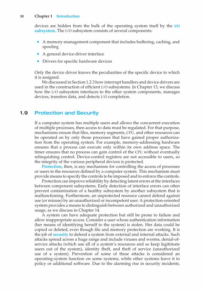
30 Chapter 1 Introduction
devices are hidden from the bulk of the operating system itself by the I/Osubsystem. The I/O subsystem consists of several components:
• A memory-management component that includes buffering, caching, andspooling
• A general device-driver interface
• Drivers for specific hardware devices
Only the device driver knows the peculiarities of the specific device to whichit is assigned.
We discussed in Section 1.2.3 how interrupt handlers and device drivers areused in the construction of efficient I/O subsystems. In Chapter 13, we discusshow the I/O subsystem interfaces to the other system components, managesdevices, transfers data, and detects I/O completion.
1.9 Protection and Security
If a computer system has multiple users and allows the concurrent executionof multiple processes, then access to data must be regulated. For that purpose,mechanisms ensure that files, memory segments, CPU, and other resources canbe operated on by only those processes that have gained proper authoriza-tion from the operating system. For example, memory-addressing hardwareensures that a process can execute only within its own address space. Thetimer ensures that no process can gain control of the CPU without eventuallyrelinquishing control. Device-control registers are not accessible to users, sothe integrity of the various peripheral devices is protected.
Protection, then, is any mechanism for controlling the access of processesor users to the resources defined by a computer system. This mechanism mustprovide means to specify the controls to be imposed and to enforce the controls.
Protection can improve reliability by detecting latent errors at the interfacesbetween component subsystems. Early detection of interface errors can oftenprevent contamination of a healthy subsystem by another subsystem that ismalfunctioning. Furthermore, an unprotected resource cannot defend againstuse (or misuse) by an unauthorized or incompetent user. A protection-orientedsystem provides a means to distinguish between authorized and unauthorizedusage, as we discuss in Chapter 14.
A system can have adequate protection but still be prone to failure andallow inappropriate access. Consider a user whose authentication information(her means of identifying herself to the system) is stolen. Her data could becopied or deleted, even though file and memory protection are working. It isthe job of security to defend a system from external and internal attacks. Suchattacks spread across a huge range and include viruses and worms, denial-of-service attacks (which use all of a system’s resources and so keep legitimateusers out of the system), identity theft, and theft of service (unauthorizeduse of a system). Prevention of some of these attacks is considered anoperating-system function on some systems, while other systems leave it topolicy or additional software. Due to the alarming rise in security incidents,
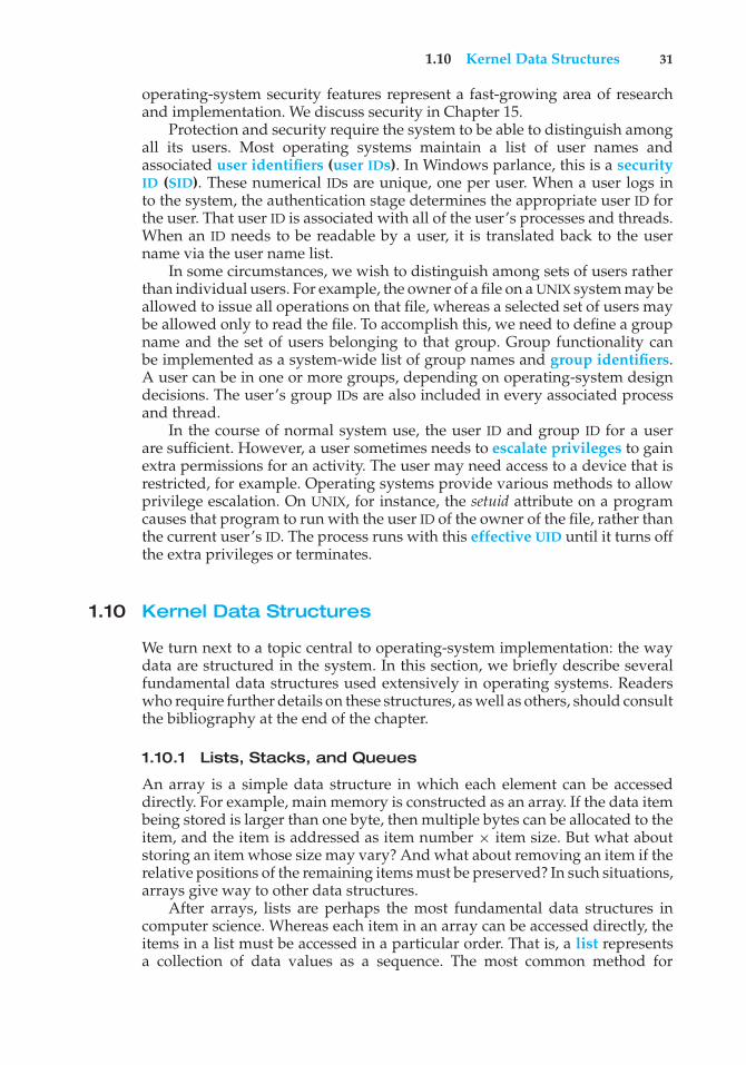
1.10 Kernel Data Structures 31
operating-system security features represent a fast-growing area of researchand implementation. We discuss security in Chapter 15.
Protection and security require the system to be able to distinguish amongall its users. Most operating systems maintain a list of user names andassociated user identifiers (user IDs). In Windows parlance, this is a securityID (SID). These numerical IDs are unique, one per user. When a user logs into the system, the authentication stage determines the appropriate user ID forthe user. That user ID is associated with all of the user’s processes and threads.When an ID needs to be readable by a user, it is translated back to the username via the user name list.
In some circumstances, we wish to distinguish among sets of users ratherthan individual users. For example, the owner of a file on a UNIX system may beallowed to issue all operations on that file, whereas a selected set of users maybe allowed only to read the file. To accomplish this, we need to define a groupname and the set of users belonging to that group. Group functionality canbe implemented as a system-wide list of group names and group identifiers.A user can be in one or more groups, depending on operating-system designdecisions. The user’s group IDs are also included in every associated processand thread.
In the course of normal system use, the user ID and group ID for a userare sufficient. However, a user sometimes needs to escalate privileges to gainextra permissions for an activity. The user may need access to a device that isrestricted, for example. Operating systems provide various methods to allowprivilege escalation. On UNIX, for instance, the setuid attribute on a programcauses that program to run with the user ID of the owner of the file, rather thanthe current user’s ID. The process runs with this effective UID until it turns offthe extra privileges or terminates.
1.10 Kernel Data Structures
We turn next to a topic central to operating-system implementation: the waydata are structured in the system. In this section, we briefly describe severalfundamental data structures used extensively in operating systems. Readerswho require further details on these structures, as well as others, should consultthe bibliography at the end of the chapter.
1.10.1 Lists, Stacks, and Queues
An array is a simple data structure in which each element can be accesseddirectly. For example, main memory is constructed as an array. If the data itembeing stored is larger than one byte, then multiple bytes can be allocated to theitem, and the item is addressed as item number × item size. But what aboutstoring an item whose size may vary? And what about removing an item if therelative positions of the remaining items must be preserved? In such situations,arrays give way to other data structures.
After arrays, lists are perhaps the most fundamental data structures incomputer science. Whereas each item in an array can be accessed directly, theitems in a list must be accessed in a particular order. That is, a list representsa collection of data values as a sequence. The most common method for
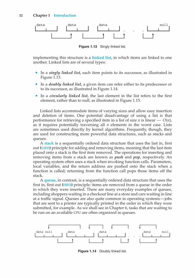
32 Chapter 1 Introduction
data data data null
• ••
Figure 1.13 Singly linked list.
implementing this structure is a linked list, in which items are linked to oneanother. Linked lists are of several types:
• In a singly linked list, each item points to its successor, as illustrated inFigure 1.13.
• In a doubly linked list, a given item can refer either to its predecessor orto its successor, as illustrated in Figure 1.14.
• In a circularly linked list, the last element in the list refers to the firstelement, rather than to null, as illustrated in Figure 1.15.
Linked lists accommodate items of varying sizes and allow easy insertionand deletion of items. One potential disadvantage of using a list is thatperformance for retrieving a specified item in a list of size n is linear — O(n),as it requires potentially traversing all n elements in the worst case. Listsare sometimes used directly by kernel algorithms. Frequently, though, theyare used for constructing more powerful data structures, such as stacks andqueues.
A stack is a sequentially ordered data structure that uses the last in, firstout (LIFO) principle for adding and removing items, meaning that the last itemplaced onto a stack is the first item removed. The operations for inserting andremoving items from a stack are known as push and pop, respectively. Anoperating system often uses a stack when invoking function calls. Parameters,local variables, and the return address are pushed onto the stack when afunction is called; returning from the function call pops those items off thestack.
A queue, in contrast, is a sequentially ordered data structure that uses thefirst in, first out (FIFO) principle: items are removed from a queue in the orderin which they were inserted. There are many everyday examples of queues,including shoppers waiting in a checkout line at a store and cars waiting in lineat a traffic signal. Queues are also quite common in operating systems—jobsthat are sent to a printer are typically printed in the order in which they weresubmitted, for example. As we shall see in Chapter 6, tasks that are waiting tobe run on an available CPU are often organized in queues.
data null nulldata data data
• ••
Figure 1.14 Doubly linked list.
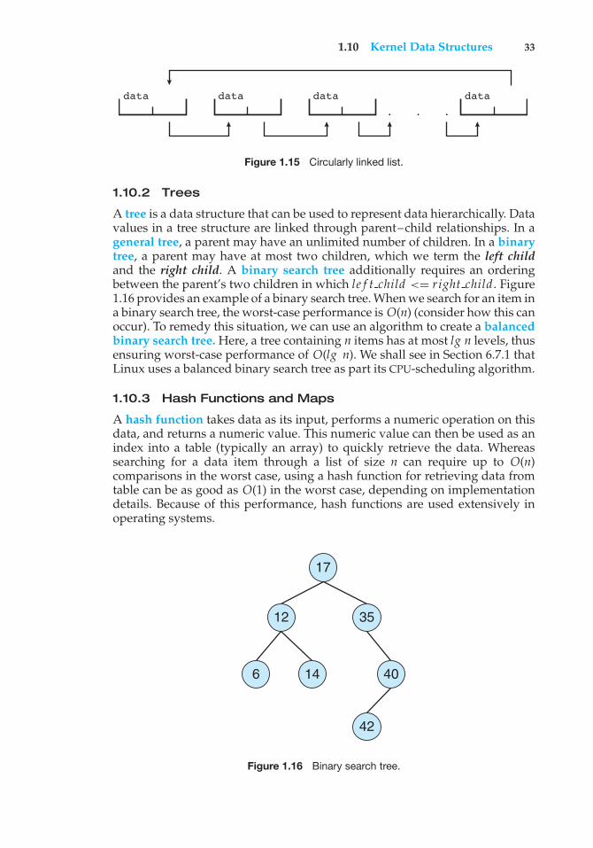
1.10 Kernel Data Structures 33
data data data data
• ••
Figure 1.15 Circularly linked list.
1.10.2 Trees
A tree is a data structure that can be used to represent data hierarchically. Datavalues in a tree structure are linked through parent–child relationships. In ageneral tree, a parent may have an unlimited number of children. In a binarytree, a parent may have at most two children, which we term the left childand the right child. A binary search tree additionally requires an orderingbetween the parent’s two children in which le f t child <= right child. Figure1.16 provides an example of a binary search tree. When we search for an item ina binary search tree, the worst-case performance is O(n) (consider how this canoccur). To remedy this situation, we can use an algorithm to create a balancedbinary search tree. Here, a tree containing n items has at most lg n levels, thusensuring worst-case performance of O(lg n). We shall see in Section 6.7.1 thatLinux uses a balanced binary search tree as part its CPU-scheduling algorithm.
1.10.3 Hash Functions and Maps
A hash function takes data as its input, performs a numeric operation on thisdata, and returns a numeric value. This numeric value can then be used as anindex into a table (typically an array) to quickly retrieve the data. Whereassearching for a data item through a list of size n can require up to O(n)comparisons in the worst case, using a hash function for retrieving data fromtable can be as good as O(1) in the worst case, depending on implementationdetails. Because of this performance, hash functions are used extensively inoperating systems.
17
35
40
42
12
146
Figure 1.16 Binary search tree.
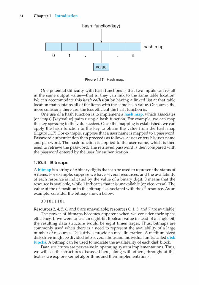
34 Chapter 1 Introduction
0 1 . . n
value
hash map
hash_function(key)
Figure 1.17 Hash map.
One potential difficulty with hash functions is that two inputs can resultin the same output value—that is, they can link to the same table location.We can accommodate this hash collision by having a linked list at that tablelocation that contains all of the items with the same hash value. Of course, themore collisions there are, the less efficient the hash function is.
One use of a hash function is to implement a hash map, which associates(or maps) [key:value] pairs using a hash function. For example, we can mapthe key operating to the value system. Once the mapping is established, we canapply the hash function to the key to obtain the value from the hash map(Figure 1.17). For example, suppose that a user name is mapped to a password.Password authentication then proceeds as follows: a user enters his user nameand password. The hash function is applied to the user name, which is thenused to retrieve the password. The retrieved password is then compared withthe password entered by the user for authentication.
1.10.4 Bitmaps
A bitmap is a string of n binary digits that can be used to represent the status ofn items. For example, suppose we have several resources, and the availabilityof each resource is indicated by the value of a binary digit: 0 means that theresource is available, while 1 indicates that it is unavailable (or vice-versa). Thevalue of the i th position in the bitmap is associated with the i th resource. As anexample, consider the bitmap shown below:
0 0 1 0 1 1 1 0 1
Resources 2, 4, 5, 6, and 8 are unavailable; resources 0, 1, 3, and 7 are available.The power of bitmaps becomes apparent when we consider their space
efficiency. If we were to use an eight-bit Boolean value instead of a single bit,the resulting data structure would be eight times larger. Thus, bitmaps arecommonly used when there is a need to represent the availability of a largenumber of resources. Disk drives provide a nice illustration. A medium-sizeddisk drive might be divided into several thousand individual units, called diskblocks. A bitmap can be used to indicate the availability of each disk block.
Data structures are pervasive in operating system implementations. Thus,we will see the structures discussed here, along with others, throughout thistext as we explore kernel algorithms and their implementations.
1.11 Computing Environments 35
LINUX KERNEL DATA STRUCTURES
The data structures used in the Linux kernel are available in the kernel sourcecode. The include file <linux/list.h> provides details of the linked-listdata structure used throughout the kernel. A queue in Linux is known asa kfifo, and its implementation can be found in the kfifo.c file in thekernel directory of the source code. Linux also provides a balanced binarysearch tree implementation using red-black trees. Details can be found in theinclude file <linux/rbtree.h>.
1.11 Computing Environments
So far, we have briefly described several aspects of computer systems and theoperating systems that manage them. We turn now to a discussion of howoperating systems are used in a variety of computing environments.
1.11.1 Traditional Computing
As computing has matured, the lines separating many of the traditional com-puting environments have blurred. Consider the “typical office environment.”Just a few years ago, this environment consisted of PCs connected to a network,with servers providing file and print services. Remote access was awkward,and portability was achieved by use of laptop computers. Terminals attachedto mainframes were prevalent at many companies as well, with even fewerremote access and portability options.
The current trend is toward providing more ways to access these computingenvironments. Web technologies and increasing WAN bandwidth are stretchingthe boundaries of traditional computing. Companies establish portals, whichprovide Web accessibility to their internal servers. Network computers (orthin clients)—which are essentially terminals that understand web-basedcomputing—are used in place of traditional workstations where more securityor easier maintenance is desired. Mobile computers can synchronize with PCsto allow very portable use of company information. Mobile computers can alsoconnect to wireless networks and cellular data networks to use the company’sWeb portal (as well as the myriad other Web resources).
At home, most users once had a single computer with a slow modemconnection to the office, the Internet, or both. Today, network-connectionspeeds once available only at great cost are relatively inexpensive in manyplaces, giving home users more access to more data. These fast data connectionsare allowing home computers to serve up Web pages and to run networks thatinclude printers, client PCs, and servers. Many homes use firewalls to protecttheir networks from security breaches.
In the latter half of the 20th century, computing resources were relativelyscarce. (Before that, they were nonexistent!) For a period of time, systemswere either batch or interactive. Batch systems processed jobs in bulk, withpredetermined input from files or other data sources. Interactive systemswaited for input from users. To optimize the use of the computing resources,multiple users shared time on these systems. Time-sharing systems used a
36 Chapter 1 Introduction
timer and scheduling algorithms to cycle processes rapidly through the CPU,giving each user a share of the resources.
Today, traditional time-sharing systems are uncommon. The same schedul-ing technique is still in use on desktop computers, laptops, servers, and evenmobile computers, but frequently all the processes are owned by the sameuser (or a single user and the operating system). User processes, and systemprocesses that provide services to the user, are managed so that each frequentlygets a slice of computer time. Consider the windows created while a useris working on a PC, for example, and the fact that they may be performingdifferent tasks at the same time. Even a web browser can be composed ofmultiple processes, one for each website currently being visited, with timesharing applied to each web browser process.
1.11.2 Mobile Computing
Mobile computing refers to computing on handheld smartphones and tabletcomputers. These devices share the distinguishing physical features of beingportable and lightweight. Historically, compared with desktop and laptopcomputers, mobile systems gave up screen size, memory capacity, and overallfunctionality in return for handheld mobile access to services such as e-mailand web browsing. Over the past few years, however, features on mobiledevices have become so rich that the distinction in functionality between, say,a consumer laptop and a tablet computer may be difficult to discern. In fact,we might argue that the features of a contemporary mobile device allow it toprovide functionality that is either unavailable or impractical on a desktop orlaptop computer.
Today, mobile systems are used not only for e-mail and web browsing butalso for playing music and video, reading digital books, taking photos, andrecording high-definition video. Accordingly, tremendous growth continuesin the wide range of applications that run on such devices. Many developersare now designing applications that take advantage of the unique features ofmobile devices, such as global positioning system (GPS) chips, accelerometers,and gyroscopes. An embedded GPS chip allows a mobile device to use satellitesto determine its precise location on earth. That functionality is especially usefulin designing applications that provide navigation—for example, telling userswhich way to walk or drive or perhaps directing them to nearby services, suchas restaurants. An accelerometer allows a mobile device to detect its orientationwith respect to the ground and to detect certain other forces, such as tiltingand shaking. In several computer games that employ accelerometers, playersinterface with the system not by using a mouse or a keyboard but rather bytilting, rotating, and shaking the mobile device! Perhaps more a practical useof these features is found in augmented-reality applications, which overlayinformation on a display of the current environment. It is difficult to imaginehow equivalent applications could be developed on traditional laptop ordesktop computer systems.
To provide access to on-line services, mobile devices typically use eitherIEEE standard 802.11 wireless or cellular data networks. The memory capacityand processing speed of mobile devices, however, are more limited than thoseof PCs. Whereas a smartphone or tablet may have 64 GB in storage, it is notuncommon to find 1 TB in storage on a desktop computer. Similarly, because
1.11 Computing Environments 37
power consumption is such a concern, mobile devices often use processors thatare smaller, are slower, and offer fewer processing cores than processors foundon traditional desktop and laptop computers.
Two operating systems currently dominate mobile computing: Apple iOSand Google Android. iOS was designed to run on Apple iPhone and iPadmobile devices. Android powers smartphones and tablet computers availablefrom many manufacturers. We examine these two mobile operating systems infurther detail in Chapter 2.
1.11.3 Distributed Systems
A distributed system is a collection of physically separate, possibly heteroge-neous, computer systems that are networked to provide users with access tothe various resources that the system maintains. Access to a shared resourceincreases computation speed, functionality, data availability, and reliability.Some operating systems generalize network access as a form of file access, withthe details of networking contained in the network interface’s device driver.Others make users specifically invoke network functions. Generally, systemscontain a mix of the two modes—for example FTP and NFS. The protocolsthat create a distributed system can greatly affect that system’s utility andpopularity.
A network, in the simplest terms, is a communication path betweentwo or more systems. Distributed systems depend on networking for theirfunctionality. Networks vary by the protocols used, the distances betweennodes, and the transport media. TCP/IP is the most common network protocol,and it provides the fundamental architecture of the Internet. Most operatingsystems support TCP/IP, including all general-purpose ones. Some systemssupport proprietary protocols to suit their needs. To an operating system, anetwork protocol simply needs an interface device—a network adapter, forexample—with a device driver to manage it, as well as software to handledata. These concepts are discussed throughout this book.
Networks are characterized based on the distances between their nodes.A local-area network (LAN) connects computers within a room, a building,or a campus. A wide-area network (WAN) usually links buildings, cities, orcountries. A global company may have a WAN to connect its offices worldwide,for example. These networks may run one protocol or several protocols. Thecontinuing advent of new technologies brings about new forms of networks.For example, a metropolitan-area network (MAN) could link buildings withina city. BlueTooth and 802.11 devices use wireless technology to communicateover a distance of several feet, in essence creating a personal-area network(PAN) between a phone and a headset or a smartphone and a desktop computer.
The media to carry networks are equally varied. They include copper wires,fiber strands, and wireless transmissions between satellites, microwave dishes,and radios. When computing devices are connected to cellular phones, theycreate a network. Even very short-range infrared communication can be usedfor networking. At a rudimentary level, whenever computers communicate,they use or create a network. These networks also vary in their performanceand reliability.
Some operating systems have taken the concept of networks and dis-tributed systems further than the notion of providing network connectivity.
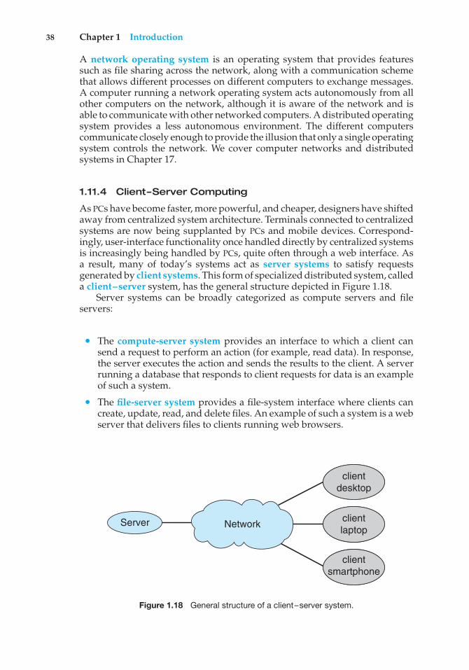
38 Chapter 1 Introduction
A network operating system is an operating system that provides featuressuch as file sharing across the network, along with a communication schemethat allows different processes on different computers to exchange messages.A computer running a network operating system acts autonomously from allother computers on the network, although it is aware of the network and isable to communicate with other networked computers. A distributed operatingsystem provides a less autonomous environment. The different computerscommunicate closely enough to provide the illusion that only a single operatingsystem controls the network. We cover computer networks and distributedsystems in Chapter 17.
1.11.4 Client–Server Computing
As PCs have become faster, more powerful, and cheaper, designers have shiftedaway from centralized system architecture. Terminals connected to centralizedsystems are now being supplanted by PCs and mobile devices. Correspond-ingly, user-interface functionality once handled directly by centralized systemsis increasingly being handled by PCs, quite often through a web interface. Asa result, many of today’s systems act as server systems to satisfy requestsgenerated by client systems. This form of specialized distributed system, calleda client–server system, has the general structure depicted in Figure 1.18.
Server systems can be broadly categorized as compute servers and fileservers:
• The compute-server system provides an interface to which a client cansend a request to perform an action (for example, read data). In response,the server executes the action and sends the results to the client. A serverrunning a database that responds to client requests for data is an exampleof such a system.
• The file-server system provides a file-system interface where clients cancreate, update, read, and delete files. An example of such a system is a webserver that delivers files to clients running web browsers.
Server Network
clientdesktop
clientlaptop
clientsmartphone
Figure 1.18 General structure of a client–server system.
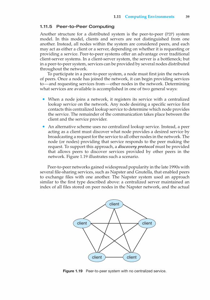
1.11 Computing Environments 39
1.11.5 Peer-to-Peer Computing
Another structure for a distributed system is the peer-to-peer (P2P) systemmodel. In this model, clients and servers are not distinguished from oneanother. Instead, all nodes within the system are considered peers, and eachmay act as either a client or a server, depending on whether it is requesting orproviding a service. Peer-to-peer systems offer an advantage over traditionalclient-server systems. In a client-server system, the server is a bottleneck; butin a peer-to-peer system, services can be provided by several nodes distributedthroughout the network.
To participate in a peer-to-peer system, a node must first join the networkof peers. Once a node has joined the network, it can begin providing servicesto—and requesting services from—other nodes in the network. Determiningwhat services are available is accomplished in one of two general ways:
• When a node joins a network, it registers its service with a centralizedlookup service on the network. Any node desiring a specific service firstcontacts this centralized lookup service to determine which node providesthe service. The remainder of the communication takes place between theclient and the service provider.
• An alternative scheme uses no centralized lookup service. Instead, a peeracting as a client must discover what node provides a desired service bybroadcasting a request for the service to all other nodes in the network. Thenode (or nodes) providing that service responds to the peer making therequest. To support this approach, a discovery protocol must be providedthat allows peers to discover services provided by other peers in thenetwork. Figure 1.19 illustrates such a scenario.
Peer-to-peer networks gained widespread popularity in the late 1990s withseveral file-sharing services, such as Napster and Gnutella, that enabled peersto exchange files with one another. The Napster system used an approachsimilar to the first type described above: a centralized server maintained anindex of all files stored on peer nodes in the Napster network, and the actual
client
clientclient
client client
Figure 1.19 Peer-to-peer system with no centralized service.
40 Chapter 1 Introduction
exchange of files took place between the peer nodes. The Gnutella system useda technique similar to the second type: a client broadcasted file requests toother nodes in the system, and nodes that could service the request respondeddirectly to the client. The future of exchanging files remains uncertain becausepeer-to-peer networks can be used to exchange copyrighted materials (music,for example) anonymously, and there are laws governing the distribution ofcopyrighted material. Notably, Napster ran into legal trouble for copyrightinfringement and its services were shut down in 2001.
Skype is another example of peer-to-peer computing. It allows clients tomake voice calls and video calls and to send text messages over the Internetusing a technology known as voice over IP (VoIP). Skype uses a hybrid peer-to-peer approach. It includes a centralized login server, but it also incorporatesdecentralized peers and allows two peers to communicate.
1.11.6 Virtualization
Virtualization is a technology that allows operating systems to run as appli-cations within other operating systems. At first blush, there seems to belittle reason for such functionality. But the virtualization industry is vast andgrowing, which is a testament to its utility and importance.
Broadly speaking, virtualization is one member of a class of softwarethat also includes emulation. Emulation is used when the source CPU typeis different from the target CPU type. For example, when Apple switched fromthe IBM Power CPU to the Intel x86 CPU for its desktop and laptop computers,it included an emulation facility called “Rosetta,” which allowed applicationscompiled for the IBM CPU to run on the Intel CPU. That same concept can beextended to allow an entire operating system written for one platform to runon another. Emulation comes at a heavy price, however. Every machine-levelinstruction that runs natively on the source system must be translated to theequivalent function on the target system, frequently resulting in several targetinstructions. If the source and target CPUs have similar performance levels, theemulated code can run much slower than the native code.
A common example of emulation occurs when a computer language isnot compiled to native code but instead is either executed in its high-levelform or translated to an intermediate form. This is known as interpretation.Some languages, such as BASIC, can be either compiled or interpreted. Java, incontrast, is always interpreted. Interpretation is a form of emulation in that thehigh-level language code is translated to native CPU instructions, emulatingnot another CPU but a theoretical virtual machine on which that language couldrun natively. Thus, we can run Java programs on “Java virtual machines,” buttechnically those virtual machines are Java emulators.
With virtualization, in contrast, an operating system that is natively com-piled for a particular CPU architecture runs within another operating systemalso native to that CPU. Virtualization first came about on IBM mainframesas a method for multiple users to run tasks concurrently. Running multiplevirtual machines allowed (and still allows) many users to run tasks on a systemdesigned for a single user. Later, in response to problems with running multipleMicrosoft Windows XP applications on the Intel x86 CPU, VMware created anew virtualization technology in the form of an application that ran on XP.That application ran one or more guest copies of Windows or other native
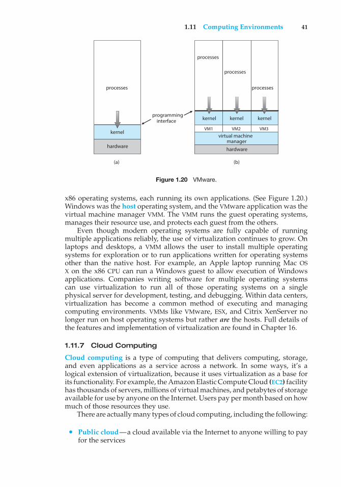
1.11 Computing Environments 41
(a)
processes
hardware
kernel
(b)
programminginterface
processes
processes
processes
kernelkernel kernel
VM2VM1 VM3
managerhardware
virtual machine
Figure 1.20 VMware.
x86 operating systems, each running its own applications. (See Figure 1.20.)Windows was the host operating system, and the VMware application was thevirtual machine manager VMM. The VMM runs the guest operating systems,manages their resource use, and protects each guest from the others.
Even though modern operating systems are fully capable of runningmultiple applications reliably, the use of virtualization continues to grow. Onlaptops and desktops, a VMM allows the user to install multiple operatingsystems for exploration or to run applications written for operating systemsother than the native host. For example, an Apple laptop running Mac OSX on the x86 CPU can run a Windows guest to allow execution of Windowsapplications. Companies writing software for multiple operating systemscan use virtualization to run all of those operating systems on a singlephysical server for development, testing, and debugging. Within data centers,virtualization has become a common method of executing and managingcomputing environments. VMMs like VMware, ESX, and Citrix XenServer nolonger run on host operating systems but rather are the hosts. Full details ofthe features and implementation of virtualization are found in Chapter 16.
1.11.7 Cloud Computing
Cloud computing is a type of computing that delivers computing, storage,and even applications as a service across a network. In some ways, it’s alogical extension of virtualization, because it uses virtualization as a base forits functionality. For example, the Amazon Elastic Compute Cloud (EC2) facilityhas thousands of servers, millions of virtual machines, and petabytes of storageavailable for use by anyone on the Internet. Users pay per month based on howmuch of those resources they use.
There are actually many types of cloud computing, including the following:
• Public cloud—a cloud available via the Internet to anyone willing to payfor the services
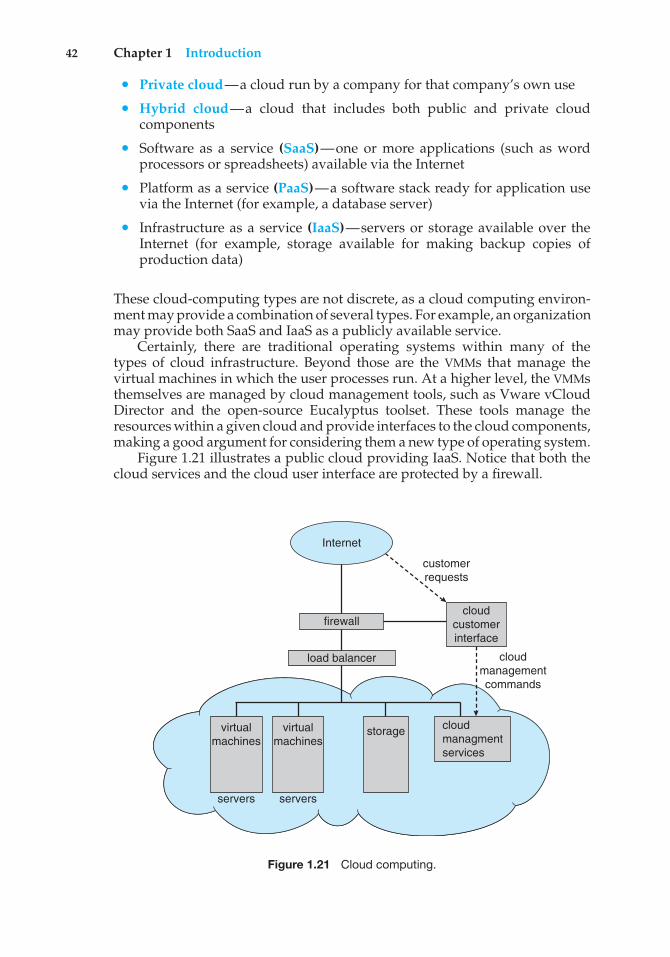
42 Chapter 1 Introduction
• Private cloud—a cloud run by a company for that company’s own use
• Hybrid cloud—a cloud that includes both public and private cloudcomponents
• Software as a service (SaaS)—one or more applications (such as wordprocessors or spreadsheets) available via the Internet
• Platform as a service (PaaS)—a software stack ready for application usevia the Internet (for example, a database server)
• Infrastructure as a service (IaaS)—servers or storage available over theInternet (for example, storage available for making backup copies ofproduction data)
These cloud-computing types are not discrete, as a cloud computing environ-ment may provide a combination of several types. For example, an organizationmay provide both SaaS and IaaS as a publicly available service.
Certainly, there are traditional operating systems within many of thetypes of cloud infrastructure. Beyond those are the VMMs that manage thevirtual machines in which the user processes run. At a higher level, the VMMsthemselves are managed by cloud management tools, such as Vware vCloudDirector and the open-source Eucalyptus toolset. These tools manage theresources within a given cloud and provide interfaces to the cloud components,making a good argument for considering them a new type of operating system.
Figure 1.21 illustrates a public cloud providing IaaS. Notice that both thecloud services and the cloud user interface are protected by a firewall.
firewallcloud
customerinterface
load balancer
virtualmachines
virtualmachines
servers servers
storage
Internet
customerrequests
cloudmanagementcommands
cloudmanagmentservices
Figure 1.21 Cloud computing.
1.12 Open-Source Operating Systems 43
1.11.8 Real-Time Embedded Systems
Embedded computers are the most prevalent form of computers in existence.These devices are found everywhere, from car engines and manufacturingrobots to DVDs and microwave ovens. They tend to have very specific tasks.The systems they run on are usually primitive, and so the operating systemsprovide limited features. Usually, they have little or no user interface, preferringto spend their time monitoring and managing hardware devices, such asautomobile engines and robotic arms.
These embedded systems vary considerably. Some are general-purposecomputers, running standard operating systems—such as Linux—withspecial-purpose applications to implement the functionality. Others are hard-ware devices with a special-purpose embedded operating system providingjust the functionality desired. Yet others are hardware devices with application-specific integrated circuits (ASICs) that perform their tasks without an operat-ing system.
The use of embedded systems continues to expand. The power of thesedevices, both as standalone units and as elements of networks and the web,is sure to increase as well. Even now, entire houses can be computerized, sothat a central computer—either a general-purpose computer or an embeddedsystem—can control heating and lighting, alarm systems, and even coffeemakers. Web access can enable a home owner to tell the house to heat upbefore she arrives home. Someday, the refrigerator can notify the grocery storewhen it notices the milk is gone.
Embedded systems almost always run real-time operating systems. Areal-time system is used when rigid time requirements have been placed onthe operation of a processor or the flow of data; thus, it is often used as acontrol device in a dedicated application. Sensors bring data to the computer.The computer must analyze the data and possibly adjust controls to modifythe sensor inputs. Systems that control scientific experiments, medical imagingsystems, industrial control systems, and certain display systems are real-time systems. Some automobile-engine fuel-injection systems, home-appliancecontrollers, and weapon systems are also real-time systems.
A real-time system has well-defined, fixed time constraints. Processingmust be done within the defined constraints, or the system will fail. Forinstance, it would not do for a robot arm to be instructed to halt after it hadsmashed into the car it was building. A real-time system functions correctlyonly if it returns the correct result within its time constraints. Contrast thissystem with a time-sharing system, where it is desirable (but not mandatory)to respond quickly, or a batch system, which may have no time constraints atall.
In Chapter 6, we consider the scheduling facility needed to implementreal-time functionality in an operating system. In Chapter 9, we describe thedesign of memory management for real-time computing. Finally, in Chapters18 and 19, we describe the real-time components of the Linux and Windows 7operating systems.
1.12 Open-Source Operating Systems
We noted at the beginning of this chapter that the study of operating systemshas been made easier by the availability of a vast number of open-source
44 Chapter 1 Introduction
releases. Open-source operating systems are those available in source-codeformat rather than as compiled binary code. Linux is the most famous open-source operating system, while Microsoft Windows is a well-known exampleof the opposite closed-source approach. Apple’s Mac OS X and iOS operatingsystems comprise a hybrid approach. They contain an open-source kernelnamed Darwin yet include proprietary, closed-source components as well.
Starting with the source code allows the programmer to produce binarycode that can be executed on a system. Doing the opposite—reverse engi-neering the source code from the binaries—is quite a lot of work, and usefulitems such as comments are never recovered. Learning operating systems byexamining the source code has other benefits as well. With the source codein hand, a student can modify the operating system and then compile andrun the code to try out those changes, which is an excellent learning tool.This text includes projects that involve modifying operating-system sourcecode, while also describing algorithms at a high level to be sure all importantoperating-system topics are covered. Throughout the text, we provide pointersto examples of open-source code for deeper study.
There are many benefits to open-source operating systems, including acommunity of interested (and usually unpaid) programmers who contributeto the code by helping to debug it, analyze it, provide support, and suggestchanges. Arguably, open-source code is more secure than closed-source codebecause many more eyes are viewing the code. Certainly, open-source code hasbugs, but open-source advocates argue that bugs tend to be found and fixedfaster owing to the number of people using and viewing the code. Companiesthat earn revenue from selling their programs often hesitate to open-sourcetheir code, but Red Hat and a myriad of other companies are doing just thatand showing that commercial companies benefit, rather than suffer, when theyopen-source their code. Revenue can be generated through support contractsand the sale of hardware on which the software runs, for example.
1.12.1 History
In the early days of modern computing (that is, the 1950s), a great deal ofsoftware was available in open-source format. The original hackers (computerenthusiasts) at MIT’s Tech Model Railroad Club left their programs in drawersfor others to work on. “Homebrew” user groups exchanged code during theirmeetings. Later, company-specific user groups, such as Digital EquipmentCorporation’s DEC, accepted contributions of source-code programs, collectedthem onto tapes, and distributed the tapes to interested members.
Computer and software companies eventually sought to limit the use oftheir software to authorized computers and paying customers. Releasing onlythe binary files compiled from the source code, rather than the source codeitself, helped them to achieve this goal, as well as protecting their code and theirideas from their competitors. Another issue involved copyrighted material.Operating systems and other programs can limit the ability to play back moviesand music or display electronic books to authorized computers. Such copyprotection or digital rights management (DRM) would not be effective if thesource code that implemented these limits were published. Laws in manycountries, including the U.S. Digital Millennium Copyright Act (DMCA), makeit illegal to reverse-engineer DRM code or otherwise try to circumvent copyprotection.
1.12 Open-Source Operating Systems 45
To counter the move to limit software use and redistribution, RichardStallman in 1983 started the GNU project to create a free, open-source, UNIX-compatible operating system. In 1985, he published the GNU Manifesto, whichargues that all software should be free and open-sourced. He also formedthe Free Software Foundation (FSF) with the goal of encouraging the freeexchange of software source code and the free use of that software. Rather thancopyright its software, the FSF “copylefts” the software to encourage sharingand improvement. The GNU General Public License (GPL) codifies copyleftingand is a common license under which free software is released. Fundamentally,GPL requires that the source code be distributed with any binaries and that anychanges made to the source code be released under the same GPL license.
1.12.2 Linux
As an example of an open-source operating system, consider GNU/Linux.The GNU project produced many UNIX-compatible tools, including compilers,editors, and utilities, but never released a kernel. In 1991, a student inFinland, Linus Torvalds, released a rudimentary UNIX-like kernel using theGNU compilers and tools and invited contributions worldwide. The advent ofthe Internet meant that anyone interested could download the source code,modify it, and submit changes to Torvalds. Releasing updates once a weekallowed this so-called Linux operating system to grow rapidly, enhanced byseveral thousand programmers.
The resulting GNU/Linux operating system has spawned hundreds ofunique distributions, or custom builds, of the system. Major distributionsinclude RedHat, SUSE, Fedora, Debian, Slackware, and Ubuntu. Distributionsvary in function, utility, installed applications, hardware support, user inter-face, and purpose. For example, RedHat Enterprise Linux is geared to largecommercial use. PCLinuxOS is a LiveCD—an operating system that can bebooted and run from a CD-ROM without being installed on a system’s harddisk. One variant of PCLinuxOS—called “PCLinuxOS Supergamer DVD”—is aLiveDVD that includes graphics drivers and games. A gamer can run it onany compatible system simply by booting from the DVD. When the gamer isfinished, a reboot of the system resets it to its installed operating system.
You can run Linux on a Windows system using the following simple, freeapproach:
1. Download the free “VMware Player” tool from
http://www.vmware.com/download/player/
and install it on your system.
2. Choose a Linux version from among the hundreds of “appliances,” orvirtual machine images, available from VMware at
http://www.vmware.com/appliances/
These images are preinstalled with operating systems and applicationsand include many flavors of Linux.
46 Chapter 1 Introduction
3. Boot the virtual machine within VMware Player.
With this text, we provide a virtual machine image of Linux running the Debianrelease. This image contains the Linux source code as well as tools for softwaredevelopment. We cover examples involving that Linux image throughout thistext, as well as in a detailed case study in Chapter 18.
1.12.3 BSD UNIX
BSD UNIX has a longer and more complicated history than Linux. It started in1978 as a derivative of AT&T’s UNIX. Releases from the University of Californiaat Berkeley (UCB) came in source and binary form, but they were not open-source because a license from AT&T was required. BSD UNIX’s development wasslowed by a lawsuit by AT&T, but eventually a fully functional, open-sourceversion, 4.4BSD-lite, was released in 1994.
Just as with Linux, there are many distributions of BSD UNIX, includingFreeBSD, NetBSD, OpenBSD, and DragonflyBSD. To explore the source codeof FreeBSD, simply download the virtual machine image of the version ofinterest and boot it within VMware, as described above for Linux. The sourcecode comes with the distribution and is stored in /usr/src/. The kernelsource code is in /usr/src/sys. For example, to examine the virtual memoryimplementation code in the FreeBSD kernel, see the files in /usr/src/sys/vm.
Darwin, the core kernel component of Mac OS X, is based on BSDUNIX and is open-sourced as well. That source code is available fromhttp://www.opensource.apple.com/. Every Mac OS X release has its open-source components posted at that site. The name of the package that containsthe kernel begins with “xnu.” Apple also provides extensive developer tools,documentation, and support at http://connect.apple.com. For more informa-tion, see Appendix A.
1.12.4 Solaris
Solaris is the commercial UNIX-based operating system of Sun Microsystems.Originally, Sun’s SunOS operating system was based on BSD UNIX. Sun movedto AT&T’s System V UNIX as its base in 1991. In 2005, Sun open-sourced mostof the Solaris code as the OpenSolaris project. The purchase of Sun by Oraclein 2009, however, left the state of this project unclear. The source code as itwas in 2005 is still available via a source code browser and for download athttp://src.opensolaris.org/source.
Several groups interested in using OpenSolaris have started from that baseand expanded its features. Their working set is Project Illumos, which hasexpanded from the OpenSolaris base to include more features and to be thebasis for several products. Illumos is available at http://wiki.illumos.org.
1.12.5 Open-Source Systems as Learning Tools
The free software movement is driving legions of programmers to createthousands of open-source projects, including operating systems. Sites likehttp://freshmeat.net/ and http://distrowatch.com/ provide portals to manyof these projects. As we stated earlier, open-source projects enable students touse source code as a learning tool. They can modify programs and test them,
1.13 Summary 47
help find and fix bugs, and otherwise explore mature, full-featured operatingsystems, compilers, tools, user interfaces, and other types of programs. Theavailability of source code for historic projects, such as Multics, can helpstudents to understand those projects and to build knowledge that will help inthe implementation of new projects.
GNU/Linux and BSD UNIX are all open-source operating systems, but eachhas its own goals, utility, licensing, and purpose. Sometimes, licenses are notmutually exclusive and cross-pollination occurs, allowing rapid improvementsin operating-system projects. For example, several major components ofOpenSolaris have been ported to BSD UNIX. The advantages of free softwareand open sourcing are likely to increase the number and quality of open-sourceprojects, leading to an increase in the number of individuals and companiesthat use these projects.
1.13 Summary
An operating system is software that manages the computer hardware, as wellas providing an environment for application programs to run. Perhaps themost visible aspect of an operating system is the interface to the computersystem it provides to the human user.
For a computer to do its job of executing programs, the programs must be inmain memory. Main memory is the only large storage area that the processorcan access directly. It is an array of bytes, ranging in size from millions tobillions. Each byte in memory has its own address. The main memory is usuallya volatile storage device that loses its contents when power is turned off orlost. Most computer systems provide secondary storage as an extension ofmain memory. Secondary storage provides a form of nonvolatile storage thatis capable of holding large quantities of data permanently. The most commonsecondary-storage device is a magnetic disk, which provides storage of bothprograms and data.
The wide variety of storage systems in a computer system can be organizedin a hierarchy according to speed and cost. The higher levels are expensive,but they are fast. As we move down the hierarchy, the cost per bit generallydecreases, whereas the access time generally increases.
There are several different strategies for designing a computer system.Single-processor systems have only one processor, while multiprocessorsystems contain two or more processors that share physical memory andperipheral devices. The most common multiprocessor design is symmetricmultiprocessing (or SMP), where all processors are considered peers and runindependently of one another. Clustered systems are a specialized form ofmultiprocessor systems and consist of multiple computer systems connectedby a local-area network.
To best utilize the CPU, modern operating systems employ multiprogram-ming, which allows several jobs to be in memory at the same time, thus ensuringthat the CPU always has a job to execute. Time-sharing systems are an exten-sion of multiprogramming wherein CPU scheduling algorithms rapidly switchbetween jobs, thus providing the illusion that each job is running concurrently.
The operating system must ensure correct operation of the computersystem. To prevent user programs from interfering with the proper operation of
48 Chapter 1 Introduction
THE STUDY OF OPERATING SYSTEMS
There has never been a more interesting time to study operating systems, andit has never been easier. The open-source movement has overtaken operatingsystems, causing many of them to be made available in both source and binary(executable) format. The list of operating systems available in both formatsincludes Linux, BSD UNIX, Solaris, and part of Mac OS X. The availabilityof source code allows us to study operating systems from the inside out.Questions that we could once answer only by looking at documentation orthe behavior of an operating system we can now answer by examining thecode itself.
Operating systems that are no longer commercially viable have beenopen-sourced as well, enabling us to study how systems operated in atime of fewer CPU, memory, and storage resources. An extensive butincomplete list of open-source operating-system projects is available fromhttp://dmoz.org/Computers/Software/Operating Systems/Open Source/.
In addition, the rise of virtualization as a mainstream (and frequently free)computer function makes it possible to run many operating systems on top ofone core system. For example, VMware ( http://www.vmware.com) providesa free “player” for Windows on which hundreds of free “virtual appliances”can run. Virtualbox ( http://www.virtualbox.com) provides a free, open-source virtual machine manager on many operating systems. Using suchtools, students can try out hundreds of operating systems without dedicatedhardware.
In some cases, simulators of specific hardware are also available, allowingthe operating system to run on “native” hardware, all within the confinesof a modern computer and modern operating system. For example, aDECSYSTEM-20 simulator running on Mac OS X can boot TOPS-20, load thesource tapes, and modify and compile a new TOPS-20 kernel. An interestedstudent can search the Internet to find the original papers that describe theoperating system, as well as the original manuals.
The advent of open-source operating systems has also made it easier tomake the move from student to operating-system developer. With someknowledge, some effort, and an Internet connection, a student can even createa new operating-system distribution. Just a few years ago, it was difficult orimpossible to get access to source code. Now, such access is limited only byhow much interest, time, and disk space a student has.
the system, the hardware has two modes: user mode and kernel mode. Variousinstructions (such as I/O instructions and halt instructions) are privileged andcan be executed only in kernel mode. The memory in which the operatingsystem resides must also be protected from modification by the user. A timerprevents infinite loops. These facilities (dual mode, privileged instructions,memory protection, and timer interrupt) are basic building blocks used byoperating systems to achieve correct operation.
A process (or job) is the fundamental unit of work in an operating system.Process management includes creating and deleting processes and providingmechanisms for processes to communicate and synchronize with each other.
Practice Exercises 49
An operating system manages memory by keeping track of what parts ofmemory are being used and by whom. The operating system is also responsiblefor dynamically allocating and freeing memory space. Storage space is alsomanaged by the operating system; this includes providing file systems forrepresenting files and directories and managing space on mass-storage devices.
Operating systems must also be concerned with protecting and securing theoperating system and users. Protection measures control the access of processesor users to the resources made available by the computer system. Securitymeasures are responsible for defending a computer system from external orinternal attacks.
Several data structures that are fundamental to computer science are widelyused in operating systems, including lists, stacks, queues, trees, hash functions,maps, and bitmaps.
Computing takes place in a variety of environments. Traditional computinginvolves desktop and laptop PCs, usually connected to a computer network.Mobile computing refers to computing on handheld smartphones and tabletcomputers, which offer several unique features. Distributed systems allowusers to share resources on geographically dispersed hosts connected viaa computer network. Services may be provided through either the client–server model or the peer-to-peer model. Virtualization involves abstractinga computer’s hardware into several different execution environments. Cloudcomputing uses a distributed system to abstract services into a “cloud,” whereusers may access the services from remote locations. Real-time operatingsystems are designed for embedded environments, such as consumer devices,automobiles, and robotics.
The free software movement has created thousands of open-source projects,including operating systems. Because of these projects, students are able to usesource code as a learning tool. They can modify programs and test them,help find and fix bugs, and otherwise explore mature, full-featured operatingsystems, compilers, tools, user interfaces, and other types of programs.
GNU/Linux and BSD UNIX are open-source operating systems. The advan-tages of free software and open sourcing are likely to increase the numberand quality of open-source projects, leading to an increase in the number ofindividuals and companies that use these projects.
Practice Exercises
1.1 What are the three main purposes of an operating system?
1.2 We have stressed the need for an operating system to make efficient useof the computing hardware. When is it appropriate for the operatingsystem to forsake this principle and to “waste” resources? Why is sucha system not really wasteful?
1.3 What is the main difficulty that a programmer must overcome in writingan operating system for a real-time environment?
1.4 Keeping in mind the various definitions of operating system, considerwhether the operating system should include applications such as webbrowsers and mail programs. Argue both that it should and that it shouldnot, and support your answers.
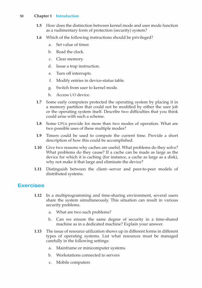
50 Chapter 1 Introduction
1.5 How does the distinction between kernel mode and user mode functionas a rudimentary form of protection (security) system?
1.6 Which of the following instructions should be privileged?
a. Set value of timer.
b. Read the clock.
c. Clear memory.
d. Issue a trap instruction.
e. Turn off interrupts.
f. Modify entries in device-status table.
g. Switch from user to kernel mode.
h. Access I/O device.
1.7 Some early computers protected the operating system by placing it ina memory partition that could not be modified by either the user jobor the operating system itself. Describe two difficulties that you thinkcould arise with such a scheme.
1.8 Some CPUs provide for more than two modes of operation. What aretwo possible uses of these multiple modes?
1.9 Timers could be used to compute the current time. Provide a shortdescription of how this could be accomplished.
1.10 Give two reasons why caches are useful. What problems do they solve?What problems do they cause? If a cache can be made as large as thedevice for which it is caching (for instance, a cache as large as a disk),why not make it that large and eliminate the device?
1.11 Distinguish between the client–server and peer-to-peer models ofdistributed systems.
Exercises
1.12 In a multiprogramming and time-sharing environment, several usersshare the system simultaneously. This situation can result in varioussecurity problems.
a. What are two such problems?
b. Can we ensure the same degree of security in a time-sharedmachine as in a dedicated machine? Explain your answer.
1.13 The issue of resource utilization shows up in different forms in differenttypes of operating systems. List what resources must be managedcarefully in the following settings:
a. Mainframe or minicomputer systems
b. Workstations connected to servers
c. Mobile computers
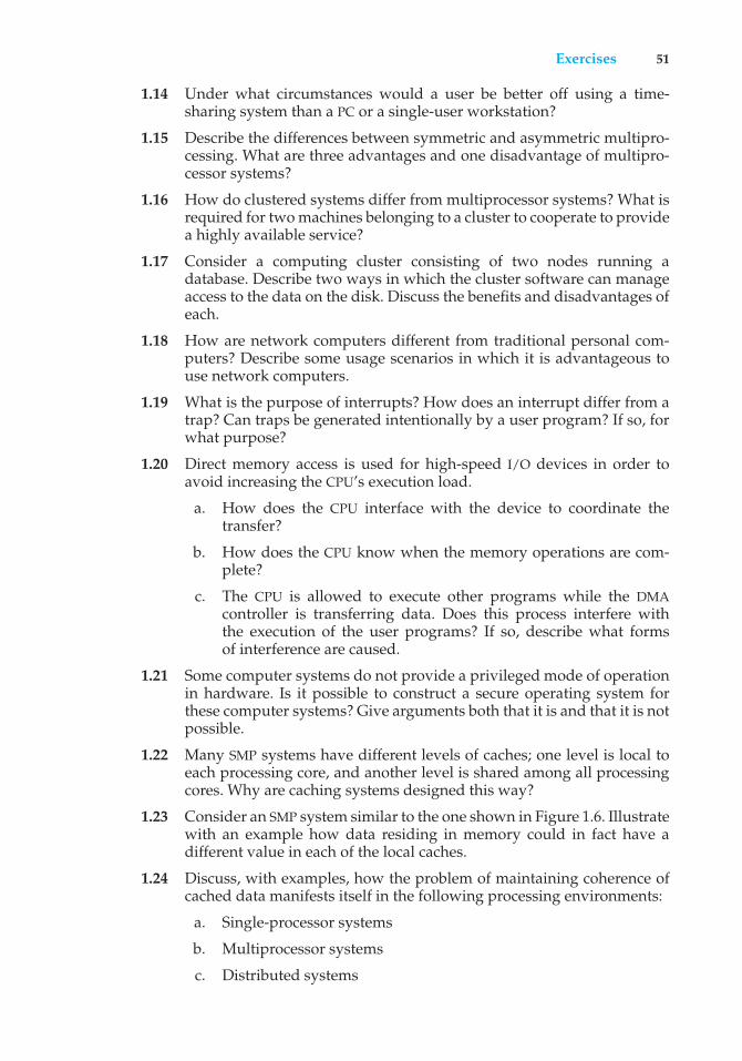
Exercises 51
1.14 Under what circumstances would a user be better off using a time-sharing system than a PC or a single-user workstation?
1.15 Describe the differences between symmetric and asymmetric multipro-cessing. What are three advantages and one disadvantage of multipro-cessor systems?
1.16 How do clustered systems differ from multiprocessor systems? What isrequired for two machines belonging to a cluster to cooperate to providea highly available service?
1.17 Consider a computing cluster consisting of two nodes running adatabase. Describe two ways in which the cluster software can manageaccess to the data on the disk. Discuss the benefits and disadvantages ofeach.
1.18 How are network computers different from traditional personal com-puters? Describe some usage scenarios in which it is advantageous touse network computers.
1.19 What is the purpose of interrupts? How does an interrupt differ from atrap? Can traps be generated intentionally by a user program? If so, forwhat purpose?
1.20 Direct memory access is used for high-speed I/O devices in order toavoid increasing the CPU’s execution load.
a. How does the CPU interface with the device to coordinate thetransfer?
b. How does the CPU know when the memory operations are com-plete?
c. The CPU is allowed to execute other programs while the DMAcontroller is transferring data. Does this process interfere withthe execution of the user programs? If so, describe what formsof interference are caused.
1.21 Some computer systems do not provide a privileged mode of operationin hardware. Is it possible to construct a secure operating system forthese computer systems? Give arguments both that it is and that it is notpossible.
1.22 Many SMP systems have different levels of caches; one level is local toeach processing core, and another level is shared among all processingcores. Why are caching systems designed this way?
1.23 Consider an SMP system similar to the one shown in Figure 1.6. Illustratewith an example how data residing in memory could in fact have adifferent value in each of the local caches.
1.24 Discuss, with examples, how the problem of maintaining coherence ofcached data manifests itself in the following processing environments:
a. Single-processor systems
b. Multiprocessor systems
c. Distributed systems
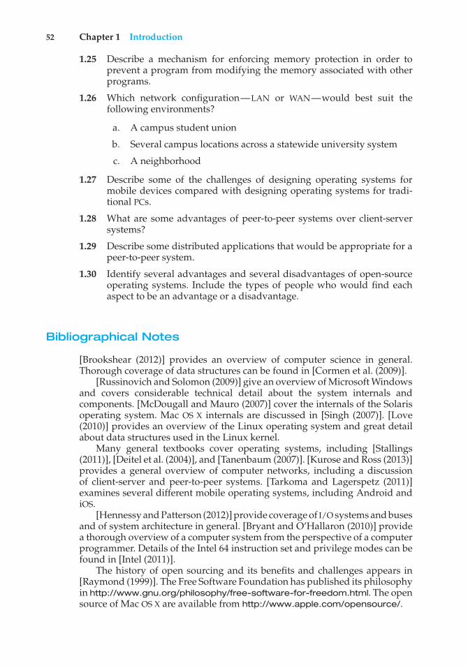
52 Chapter 1 Introduction
1.25 Describe a mechanism for enforcing memory protection in order toprevent a program from modifying the memory associated with otherprograms.
1.26 Which network configuration—LAN or WAN—would best suit thefollowing environments?
a. A campus student union
b. Several campus locations across a statewide university system
c. A neighborhood
1.27 Describe some of the challenges of designing operating systems formobile devices compared with designing operating systems for tradi-tional PCs.
1.28 What are some advantages of peer-to-peer systems over client-serversystems?
1.29 Describe some distributed applications that would be appropriate for apeer-to-peer system.
1.30 Identify several advantages and several disadvantages of open-sourceoperating systems. Include the types of people who would find eachaspect to be an advantage or a disadvantage.
Bibliographical Notes
[Brookshear (2012)] provides an overview of computer science in general.Thorough coverage of data structures can be found in [Cormen et al. (2009)].
[Russinovich and Solomon (2009)] give an overview of Microsoft Windowsand covers considerable technical detail about the system internals andcomponents. [McDougall and Mauro (2007)] cover the internals of the Solarisoperating system. Mac OS X internals are discussed in [Singh (2007)]. [Love(2010)] provides an overview of the Linux operating system and great detailabout data structures used in the Linux kernel.
Many general textbooks cover operating systems, including [Stallings(2011)], [Deitel et al. (2004)], and [Tanenbaum (2007)]. [Kurose and Ross (2013)]provides a general overview of computer networks, including a discussionof client-server and peer-to-peer systems. [Tarkoma and Lagerspetz (2011)]examines several different mobile operating systems, including Android andiOS.
[Hennessy and Patterson (2012)] provide coverage of I/O systems and busesand of system architecture in general. [Bryant and O’Hallaron (2010)] providea thorough overview of a computer system from the perspective of a computerprogrammer. Details of the Intel 64 instruction set and privilege modes can befound in [Intel (2011)].
The history of open sourcing and its benefits and challenges appears in[Raymond (1999)]. The Free Software Foundation has published its philosophyin http://www.gnu.org/philosophy/free-software-for-freedom.html. The opensource of Mac OS X are available from http://www.apple.com/opensource/.
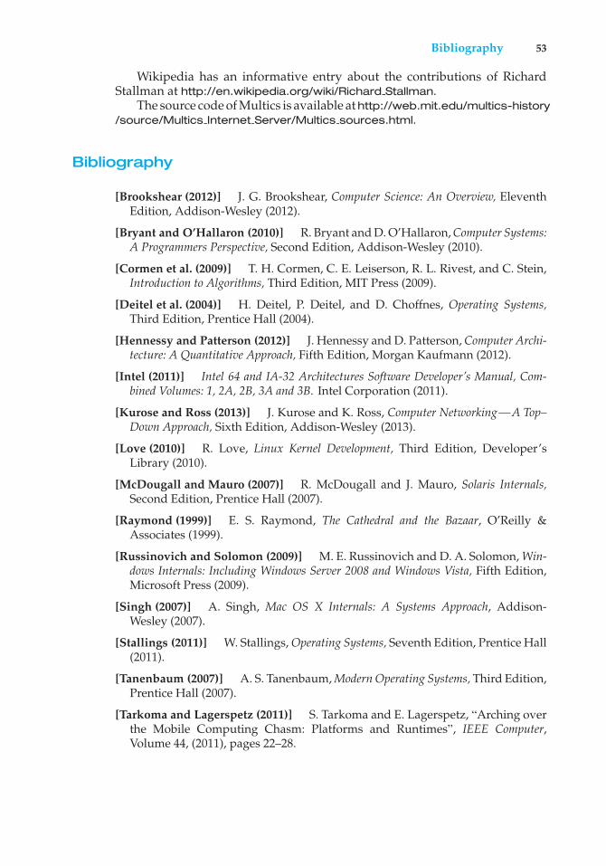
Bibliography 53
Wikipedia has an informative entry about the contributions of RichardStallman at http://en.wikipedia.org/wiki/Richard Stallman.
The source code of Multics is available at http://web.mit.edu/multics-history/source/Multics Internet Server/Multics sources.html.
Bibliography
[Brookshear (2012)] J. G. Brookshear, Computer Science: An Overview, EleventhEdition, Addison-Wesley (2012).
[Bryant and O’Hallaron (2010)] R. Bryant and D. O’Hallaron, Computer Systems:A Programmers Perspective, Second Edition, Addison-Wesley (2010).
[Cormen et al. (2009)] T. H. Cormen, C. E. Leiserson, R. L. Rivest, and C. Stein,Introduction to Algorithms, Third Edition, MIT Press (2009).
[Deitel et al. (2004)] H. Deitel, P. Deitel, and D. Choffnes, Operating Systems,Third Edition, Prentice Hall (2004).
[Hennessy and Patterson (2012)] J. Hennessy and D. Patterson, Computer Archi-tecture: A Quantitative Approach, Fifth Edition, Morgan Kaufmann (2012).
[Intel (2011)] Intel 64 and IA-32 Architectures Software Developer’s Manual, Com-bined Volumes: 1, 2A, 2B, 3A and 3B. Intel Corporation (2011).
[Kurose and Ross (2013)] J. Kurose and K. Ross, Computer Networking—A Top–Down Approach, Sixth Edition, Addison-Wesley (2013).
[Love (2010)] R. Love, Linux Kernel Development, Third Edition, Developer’sLibrary (2010).
[McDougall and Mauro (2007)] R. McDougall and J. Mauro, Solaris Internals,Second Edition, Prentice Hall (2007).
[Raymond (1999)] E. S. Raymond, The Cathedral and the Bazaar, O’Reilly &Associates (1999).
[Russinovich and Solomon (2009)] M. E. Russinovich and D. A. Solomon, Win-dows Internals: Including Windows Server 2008 and Windows Vista, Fifth Edition,Microsoft Press (2009).
[Singh (2007)] A. Singh, Mac OS X Internals: A Systems Approach, Addison-Wesley (2007).
[Stallings (2011)] W. Stallings, Operating Systems, Seventh Edition, Prentice Hall(2011).
[Tanenbaum (2007)] A. S. Tanenbaum, Modern Operating Systems, Third Edition,Prentice Hall (2007).
[Tarkoma and Lagerspetz (2011)] S. Tarkoma and E. Lagerspetz, “Arching overthe Mobile Computing Chasm: Platforms and Runtimes”, IEEE Computer,Volume 44, (2011), pages 22–28.

2C H A P T E ROperating -SystemStructures
An operating system provides the environment within which programs areexecuted. Internally, operating systems vary greatly in their makeup, sincethey are organized along many different lines. The design of a new operatingsystem is a major task. It is important that the goals of the system be welldefined before the design begins. These goals form the basis for choices amongvarious algorithms and strategies.
We can view an operating system from several vantage points. One viewfocuses on the services that the system provides; another, on the interface thatit makes available to users and programmers; a third, on its components andtheir interconnections. In this chapter, we explore all three aspects of operatingsystems, showing the viewpoints of users, programmers, and operating systemdesigners. We consider what services an operating system provides, how theyare provided, how they are debugged, and what the various methodologiesare for designing such systems. Finally, we describe how operating systemsare created and how a computer starts its operating system.
CHAPTER OBJECTIVES
• To describe the services an operating system provides to users, processes,and other systems.
• To discuss the various ways of structuring an operating system.• To explain how operating systems are installed and customized and how
they boot.
2.1 Operating-System Services
An operating system provides an environment for the execution of programs.It provides certain services to programs and to the users of those programs.The specific services provided, of course, differ from one operating system toanother, but we can identify common classes. These operating system servicesare provided for the convenience of the programmer, to make the programming
55
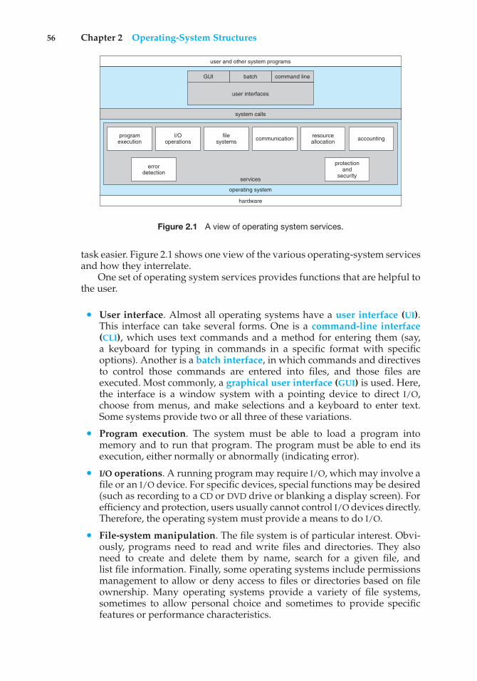
56 Chapter 2 Operating-System Structures
user and other system programs
services
operating system
hardware
system calls
GUI batch
user interfaces
command line
programexecution
I/Ooperations
filesystems communication resource
allocation accounting
protectionand
security
errordetection
Figure 2.1 A view of operating system services.
task easier. Figure 2.1 shows one view of the various operating-system servicesand how they interrelate.
One set of operating system services provides functions that are helpful tothe user.
• User interface. Almost all operating systems have a user interface (UI).This interface can take several forms. One is a command-line interface(CLI), which uses text commands and a method for entering them (say,a keyboard for typing in commands in a specific format with specificoptions). Another is a batch interface, in which commands and directivesto control those commands are entered into files, and those files areexecuted. Most commonly, a graphical user interface (GUI) is used. Here,the interface is a window system with a pointing device to direct I/O,choose from menus, and make selections and a keyboard to enter text.Some systems provide two or all three of these variations.
• Program execution. The system must be able to load a program intomemory and to run that program. The program must be able to end itsexecution, either normally or abnormally (indicating error).
• I/O operations. A running program may require I/O, which may involve afile or an I/O device. For specific devices, special functions may be desired(such as recording to a CD or DVD drive or blanking a display screen). Forefficiency and protection, users usually cannot control I/O devices directly.Therefore, the operating system must provide a means to do I/O.
• File-system manipulation. The file system is of particular interest. Obvi-ously, programs need to read and write files and directories. They alsoneed to create and delete them by name, search for a given file, andlist file information. Finally, some operating systems include permissionsmanagement to allow or deny access to files or directories based on fileownership. Many operating systems provide a variety of file systems,sometimes to allow personal choice and sometimes to provide specificfeatures or performance characteristics.
2.1 Operating-System Services 57
• Communications. There are many circumstances in which one processneeds to exchange information with another process. Such communicationmay occur between processes that are executing on the same computer orbetween processes that are executing on different computer systems tiedtogether by a computer network. Communications may be implementedvia shared memory, in which two or more processes read and write toa shared section of memory, or message passing, in which packets ofinformation in predefined formats are moved between processes by theoperating system.
• Error detection. The operating system needs to be detecting and correctingerrors constantly. Errors may occur in the CPU and memory hardware (suchas a memory error or a power failure), in I/O devices (such as a parity erroron disk, a connection failure on a network, or lack of paper in the printer),and in the user program (such as an arithmetic overflow, an attempt toaccess an illegal memory location, or a too-great use of CPU time). Foreach type of error, the operating system should take the appropriate actionto ensure correct and consistent computing. Sometimes, it has no choicebut to halt the system. At other times, it might terminate an error-causingprocess or return an error code to a process for the process to detect andpossibly correct.
Another set of operating system functions exists not for helping the userbut rather for ensuring the efficient operation of the system itself. Systems withmultiple users can gain efficiency by sharing the computer resources amongthe users.
• Resource allocation. When there are multiple users or multiple jobsrunning at the same time, resources must be allocated to each of them. Theoperating system manages many different types of resources. Some (suchas CPU cycles, main memory, and file storage) may have special allocationcode, whereas others (such as I/O devices) may have much more generalrequest and release code. For instance, in determining how best to usethe CPU, operating systems have CPU-scheduling routines that take intoaccount the speed of the CPU, the jobs that must be executed, the number ofregisters available, and other factors. There may also be routines to allocateprinters, USB storage drives, and other peripheral devices.
• Accounting. We want to keep track of which users use how much andwhat kinds of computer resources. This record keeping may be used foraccounting (so that users can be billed) or simply for accumulating usagestatistics. Usage statistics may be a valuable tool for researchers who wishto reconfigure the system to improve computing services.
• Protection and security. The owners of information stored in a multiuser ornetworked computer system may want to control use of that information.When several separate processes execute concurrently, it should not bepossible for one process to interfere with the others or with the operatingsystem itself. Protection involves ensuring that all access to systemresources is controlled. Security of the system from outsiders is alsoimportant. Such security starts with requiring each user to authenticate
58 Chapter 2 Operating-System Structures
himself or herself to the system, usually by means of a password, to gainaccess to system resources. It extends to defending external I/O devices,including network adapters, from invalid access attempts and to recordingall such connections for detection of break-ins. If a system is to be protectedand secure, precautions must be instituted throughout it. A chain is onlyas strong as its weakest link.
2.2 User and Operating-System Interface
We mentioned earlier that there are several ways for users to interface withthe operating system. Here, we discuss two fundamental approaches. Oneprovides a command-line interface, or command interpreter, that allows usersto directly enter commands to be performed by the operating system. Theother allows users to interface with the operating system via a graphical userinterface, or GUI.
2.2.1 Command Interpreters
Some operating systems include the command interpreter in the kernel. Others,such as Windows and UNIX, treat the command interpreter as a special programthat is running when a job is initiated or when a user first logs on (on interactivesystems). On systems with multiple command interpreters to choose from, theinterpreters are known as shells. For example, on UNIX and Linux systems, auser may choose among several different shells, including the Bourne shell, Cshell, Bourne-Again shell, Korn shell, and others. Third-party shells and freeuser-written shells are also available. Most shells provide similar functionality,and a user’s choice of which shell to use is generally based on personalpreference. Figure 2.2 shows the Bourne shell command interpreter being usedon Solaris 10.
The main function of the command interpreter is to get and execute the nextuser-specified command. Many of the commands given at this level manipulatefiles: create, delete, list, print, copy, execute, and so on. The MS-DOS and UNIXshells operate in this way. These commands can be implemented in two generalways.
In one approach, the command interpreter itself contains the code toexecute the command. For example, a command to delete a file may causethe command interpreter to jump to a section of its code that sets up theparameters and makes the appropriate system call. In this case, the number ofcommands that can be given determines the size of the command interpreter,since each command requires its own implementing code.
An alternative approach—used by UNIX, among other operating systems—implements most commands through system programs. In this case, thecommand interpreter does not understand the command in any way; it merelyuses the command to identify a file to be loaded into memory and executed.Thus, the UNIX command to delete a file
rm file.txt
would search for a file called rm, load the file into memory, and execute it withthe parameter file.txt. The function associated with the rm command would
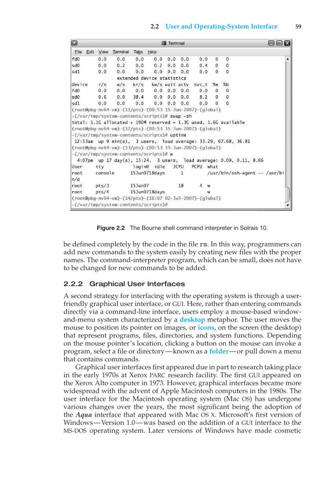
2.2 User and Operating-System Interface 59
Figure 2.2 The Bourne shell command interpreter in Solrais 10.
be defined completely by the code in the file rm. In this way, programmers canadd new commands to the system easily by creating new files with the propernames. The command-interpreter program, which can be small, does not haveto be changed for new commands to be added.
2.2.2 Graphical User Interfaces
A second strategy for interfacing with the operating system is through a user-friendly graphical user interface, or GUI. Here, rather than entering commandsdirectly via a command-line interface, users employ a mouse-based window-and-menu system characterized by a desktop metaphor. The user moves themouse to position its pointer on images, or icons, on the screen (the desktop)that represent programs, files, directories, and system functions. Dependingon the mouse pointer’s location, clicking a button on the mouse can invoke aprogram, select a file or directory—known as a folder—or pull down a menuthat contains commands.
Graphical user interfaces first appeared due in part to research taking placein the early 1970s at Xerox PARC research facility. The first GUI appeared onthe Xerox Alto computer in 1973. However, graphical interfaces became morewidespread with the advent of Apple Macintosh computers in the 1980s. Theuser interface for the Macintosh operating system (Mac OS) has undergonevarious changes over the years, the most significant being the adoption ofthe Aqua interface that appeared with Mac OS X. Microsoft’s first version ofWindows—Version 1.0—was based on the addition of a GUI interface to theMS-DOS operating system. Later versions of Windows have made cosmetic
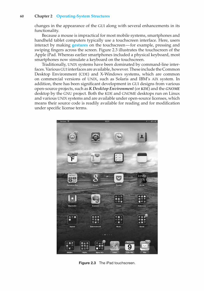
60 Chapter 2 Operating-System Structures
changes in the appearance of the GUI along with several enhancements in itsfunctionality.
Because a mouse is impractical for most mobile systems, smartphones andhandheld tablet computers typically use a touchscreen interface. Here, usersinteract by making gestures on the touchscreen—for example, pressing andswiping fingers across the screen. Figure 2.3 illustrates the touchscreen of theApple iPad. Whereas earlier smartphones included a physical keyboard, mostsmartphones now simulate a keyboard on the touchscreen.
Traditionally, UNIX systems have been dominated by command-line inter-faces. Various GUI interfaces are available, however. These include the CommonDesktop Environment (CDE) and X-Windows systems, which are commonon commercial versions of UNIX, such as Solaris and IBM’s AIX system. Inaddition, there has been significant development in GUI designs from variousopen-source projects, such as K Desktop Environment (or KDE) and the GNOMEdesktop by the GNU project. Both the KDE and GNOME desktops run on Linuxand various UNIX systems and are available under open-source licenses, whichmeans their source code is readily available for reading and for modificationunder specific license terms.
Figure 2.3 The iPad touchscreen.
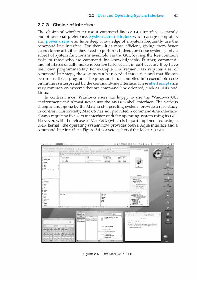
2.2 User and Operating-System Interface 61
2.2.3 Choice of Interface
The choice of whether to use a command-line or GUI interface is mostlyone of personal preference. System administrators who manage computersand power users who have deep knowledge of a system frequently use thecommand-line interface. For them, it is more efficient, giving them fasteraccess to the activities they need to perform. Indeed, on some systems, only asubset of system functions is available via the GUI, leaving the less commontasks to those who are command-line knowledgeable. Further, command-line interfaces usually make repetitive tasks easier, in part because they havetheir own programmability. For example, if a frequent task requires a set ofcommand-line steps, those steps can be recorded into a file, and that file canbe run just like a program. The program is not compiled into executable codebut rather is interpreted by the command-line interface. These shell scripts arevery common on systems that are command-line oriented, such as UNIX andLinux.
In contrast, most Windows users are happy to use the Windows GUIenvironment and almost never use the MS-DOS shell interface. The variouschanges undergone by the Macintosh operating systems provide a nice studyin contrast. Historically, Mac OS has not provided a command-line interface,always requiring its users to interface with the operating system using its GUI.However, with the release of Mac OS X (which is in part implemented using aUNIX kernel), the operating system now provides both a Aqua interface and acommand-line interface. Figure 2.4 is a screenshot of the Mac OS X GUI.
Figure 2.4 The Mac OS X GUI.
62 Chapter 2 Operating-System Structures
The user interface can vary from system to system and even from userto user within a system. It typically is substantially removed from the actualsystem structure. The design of a useful and friendly user interface is thereforenot a direct function of the operating system. In this book, we concentrate onthe fundamental problems of providing adequate service to user programs.From the point of view of the operating system, we do not distinguish betweenuser programs and system programs.
2.3 System Calls
System calls provide an interface to the services made available by an operatingsystem. These calls are generally available as routines written in C andC++, although certain low-level tasks (for example, tasks where hardwaremust be accessed directly) may have to be written using assembly-languageinstructions.
Before we discuss how an operating system makes system calls available,let’s first use an example to illustrate how system calls are used: writing asimple program to read data from one file and copy them to another file. Thefirst input that the program will need is the names of the two files: the input fileand the output file. These names can be specified in many ways, depending onthe operating-system design. One approach is for the program to ask the userfor the names. In an interactive system, this approach will require a sequence ofsystem calls, first to write a prompting message on the screen and then to readfrom the keyboard the characters that define the two files. On mouse-based andicon-based systems, a menu of file names is usually displayed in a window.The user can then use the mouse to select the source name, and a windowcan be opened for the destination name to be specified. This sequence requiresmany I/O system calls.
Once the two file names have been obtained, the program must open theinput file and create the output file. Each of these operations requires anothersystem call. Possible error conditions for each operation can require additionalsystem calls. When the program tries to open the input file, for example, it mayfind that there is no file of that name or that the file is protected against access.In these cases, the program should print a message on the console (anothersequence of system calls) and then terminate abnormally (another system call).If the input file exists, then we must create a new output file. We may find thatthere is already an output file with the same name. This situation may causethe program to abort (a system call), or we may delete the existing file (anothersystem call) and create a new one (yet another system call). Another option,in an interactive system, is to ask the user (via a sequence of system calls tooutput the prompting message and to read the response from the terminal)whether to replace the existing file or to abort the program.
When both files are set up, we enter a loop that reads from the input file(a system call) and writes to the output file (another system call). Each readand write must return status information regarding various possible errorconditions. On input, the program may find that the end of the file has beenreached or that there was a hardware failure in the read (such as a parity error).The write operation may encounter various errors, depending on the outputdevice (for example, no more disk space).
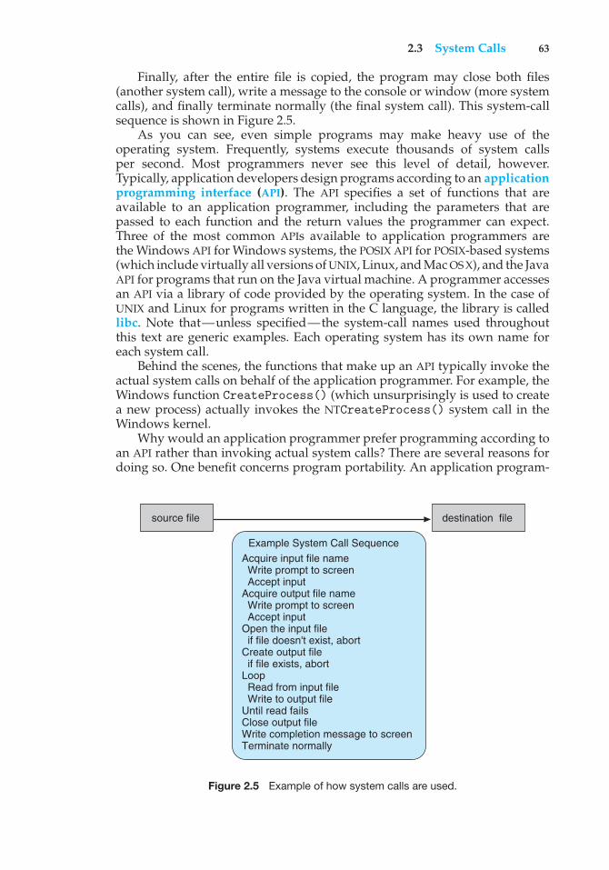
2.3 System Calls 63
Finally, after the entire file is copied, the program may close both files(another system call), write a message to the console or window (more systemcalls), and finally terminate normally (the final system call). This system-callsequence is shown in Figure 2.5.
As you can see, even simple programs may make heavy use of theoperating system. Frequently, systems execute thousands of system callsper second. Most programmers never see this level of detail, however.Typically, application developers design programs according to an applicationprogramming interface (API). The API specifies a set of functions that areavailable to an application programmer, including the parameters that arepassed to each function and the return values the programmer can expect.Three of the most common APIs available to application programmers arethe Windows API for Windows systems, the POSIX API for POSIX-based systems(which include virtually all versions of UNIX, Linux, and Mac OS X), and the JavaAPI for programs that run on the Java virtual machine. A programmer accessesan API via a library of code provided by the operating system. In the case ofUNIX and Linux for programs written in the C language, the library is calledlibc. Note that—unless specified—the system-call names used throughoutthis text are generic examples. Each operating system has its own name foreach system call.
Behind the scenes, the functions that make up an API typically invoke theactual system calls on behalf of the application programmer. For example, theWindows function CreateProcess() (which unsurprisingly is used to createa new process) actually invokes the NTCreateProcess() system call in theWindows kernel.
Why would an application programmer prefer programming according toan API rather than invoking actual system calls? There are several reasons fordoing so. One benefit concerns program portability. An application program-
source file destination file
Example System Call SequenceAcquire input file name Write prompt to screen Accept inputAcquire output file name Write prompt to screen Accept input Open the input file if file doesn't exist, abort Create output file if file exists, abort Loop Read from input file Write to output file Until read fails Close output fileWrite completion message to screen Terminate normally
Figure 2.5 Example of how system calls are used.
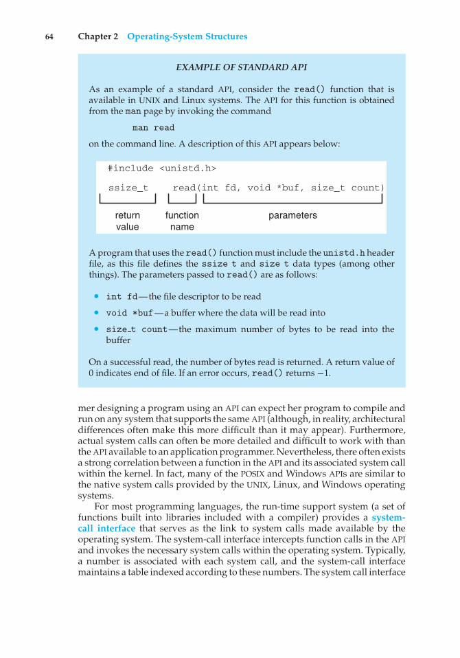
64 Chapter 2 Operating-System Structures
EXAMPLE OF STANDARD API
As an example of a standard API, consider the read() function that isavailable in UNIX and Linux systems. The API for this function is obtainedfrom the man page by invoking the command
man read
on the command line. A description of this API appears below:
#include <unistd.h>
ssize_t read(int fd, void *buf, size_t count)
returnvalue
functionname
parameters
A program that uses the read() function must include the unistd.h headerfile, as this file defines the ssize t and size t data types (among otherthings). The parameters passed to read() are as follows:
• int fd—the file descriptor to be read
• void *buf—a buffer where the data will be read into
• size t count—the maximum number of bytes to be read into thebuffer
On a successful read, the number of bytes read is returned. A return value of0 indicates end of file. If an error occurs, read() returns −1.
mer designing a program using an API can expect her program to compile andrun on any system that supports the same API (although, in reality, architecturaldifferences often make this more difficult than it may appear). Furthermore,actual system calls can often be more detailed and difficult to work with thanthe API available to an application programmer. Nevertheless, there often existsa strong correlation between a function in the API and its associated system callwithin the kernel. In fact, many of the POSIX and Windows APIs are similar tothe native system calls provided by the UNIX, Linux, and Windows operatingsystems.
For most programming languages, the run-time support system (a set offunctions built into libraries included with a compiler) provides a system-call interface that serves as the link to system calls made available by theoperating system. The system-call interface intercepts function calls in the APIand invokes the necessary system calls within the operating system. Typically,a number is associated with each system call, and the system-call interfacemaintains a table indexed according to these numbers. The system call interface
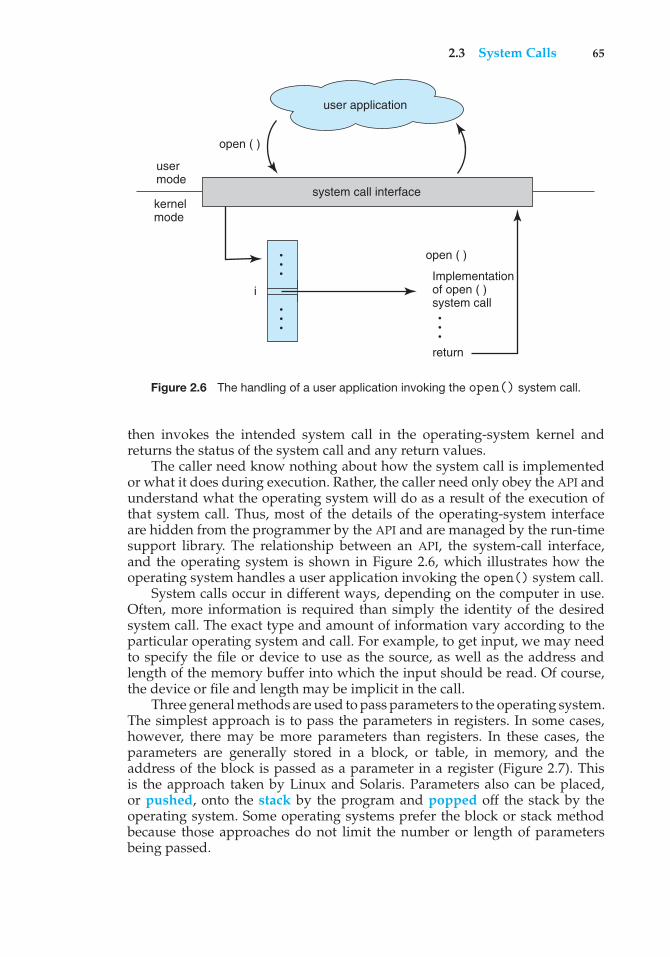
2.3 System Calls 65
Implementationof open ( )system call
open ( )
user mode
return
user application
system call interfacekernelmode
i
open ( )
Figure 2.6 The handling of a user application invoking the open() system call.
then invokes the intended system call in the operating-system kernel andreturns the status of the system call and any return values.
The caller need know nothing about how the system call is implementedor what it does during execution. Rather, the caller need only obey the API andunderstand what the operating system will do as a result of the execution ofthat system call. Thus, most of the details of the operating-system interfaceare hidden from the programmer by the API and are managed by the run-timesupport library. The relationship between an API, the system-call interface,and the operating system is shown in Figure 2.6, which illustrates how theoperating system handles a user application invoking the open() system call.
System calls occur in different ways, depending on the computer in use.Often, more information is required than simply the identity of the desiredsystem call. The exact type and amount of information vary according to theparticular operating system and call. For example, to get input, we may needto specify the file or device to use as the source, as well as the address andlength of the memory buffer into which the input should be read. Of course,the device or file and length may be implicit in the call.
Three general methods are used to pass parameters to the operating system.The simplest approach is to pass the parameters in registers. In some cases,however, there may be more parameters than registers. In these cases, theparameters are generally stored in a block, or table, in memory, and theaddress of the block is passed as a parameter in a register (Figure 2.7). Thisis the approach taken by Linux and Solaris. Parameters also can be placed,or pushed, onto the stack by the program and popped off the stack by theoperating system. Some operating systems prefer the block or stack methodbecause those approaches do not limit the number or length of parametersbeing passed.
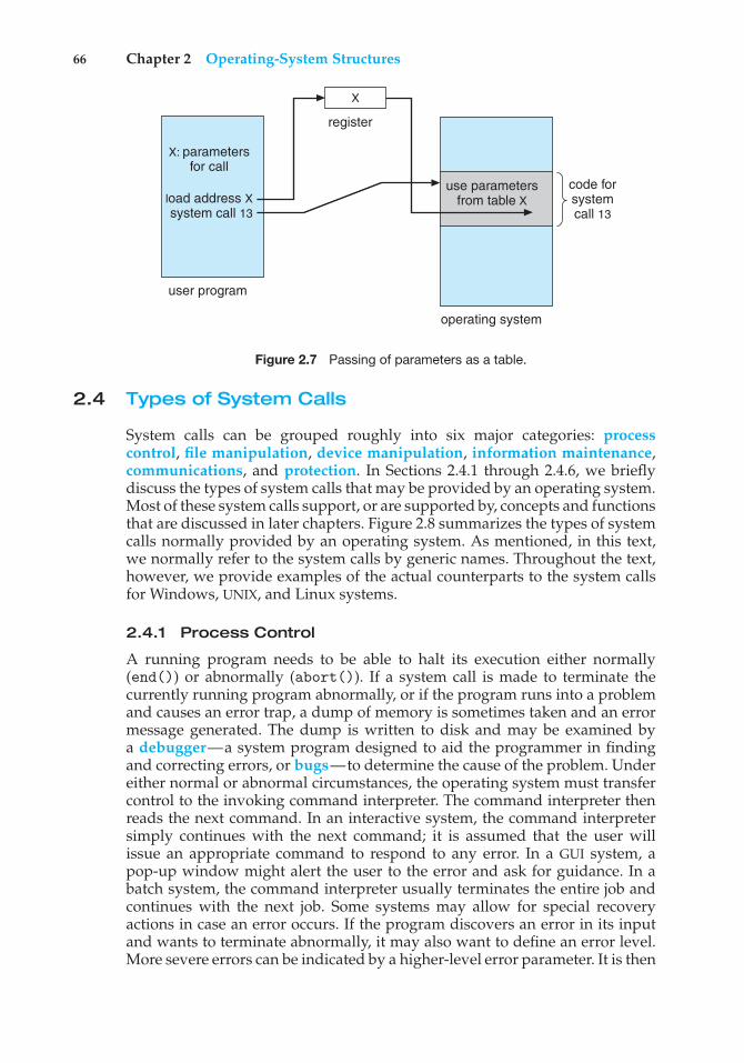
66 Chapter 2 Operating-System Structures
code for system call 13
operating system
user program
use parametersfrom table X
register
X
X: parametersfor call
load address Xsystem call 13
Figure 2.7 Passing of parameters as a table.
2.4 Types of System Calls
System calls can be grouped roughly into six major categories: processcontrol, file manipulation, device manipulation, information maintenance,communications, and protection. In Sections 2.4.1 through 2.4.6, we brieflydiscuss the types of system calls that may be provided by an operating system.Most of these system calls support, or are supported by, concepts and functionsthat are discussed in later chapters. Figure 2.8 summarizes the types of systemcalls normally provided by an operating system. As mentioned, in this text,we normally refer to the system calls by generic names. Throughout the text,however, we provide examples of the actual counterparts to the system callsfor Windows, UNIX, and Linux systems.
2.4.1 Process Control
A running program needs to be able to halt its execution either normally(end()) or abnormally (abort()). If a system call is made to terminate thecurrently running program abnormally, or if the program runs into a problemand causes an error trap, a dump of memory is sometimes taken and an errormessage generated. The dump is written to disk and may be examined bya debugger—a system program designed to aid the programmer in findingand correcting errors, or bugs—to determine the cause of the problem. Undereither normal or abnormal circumstances, the operating system must transfercontrol to the invoking command interpreter. The command interpreter thenreads the next command. In an interactive system, the command interpretersimply continues with the next command; it is assumed that the user willissue an appropriate command to respond to any error. In a GUI system, apop-up window might alert the user to the error and ask for guidance. In abatch system, the command interpreter usually terminates the entire job andcontinues with the next job. Some systems may allow for special recoveryactions in case an error occurs. If the program discovers an error in its inputand wants to terminate abnormally, it may also want to define an error level.More severe errors can be indicated by a higher-level error parameter. It is then
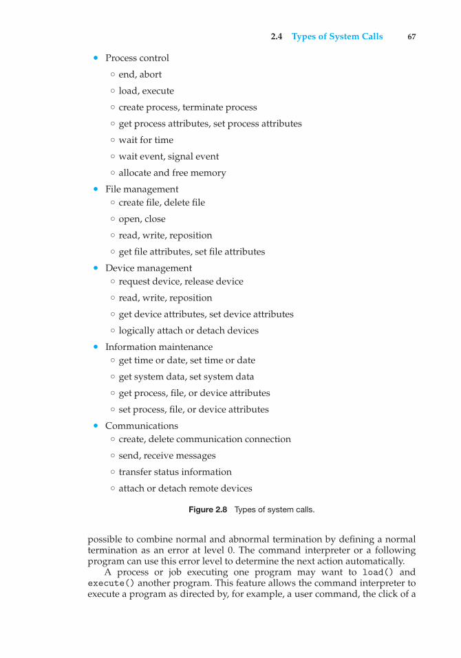
2.4 Types of System Calls 67
• Process control
◦ end, abort
◦ load, execute
◦ create process, terminate process
◦ get process attributes, set process attributes
◦ wait for time
◦ wait event, signal event
◦ allocate and free memory
• File management◦ create file, delete file
◦ open, close
◦ read, write, reposition
◦ get file attributes, set file attributes
• Device management◦ request device, release device
◦ read, write, reposition
◦ get device attributes, set device attributes
◦ logically attach or detach devices
• Information maintenance◦ get time or date, set time or date
◦ get system data, set system data
◦ get process, file, or device attributes
◦ set process, file, or device attributes
• Communications◦ create, delete communication connection
◦ send, receive messages
◦ transfer status information
◦ attach or detach remote devices
Figure 2.8 Types of system calls.
possible to combine normal and abnormal termination by defining a normaltermination as an error at level 0. The command interpreter or a followingprogram can use this error level to determine the next action automatically.
A process or job executing one program may want to load() andexecute() another program. This feature allows the command interpreter toexecute a program as directed by, for example, a user command, the click of a
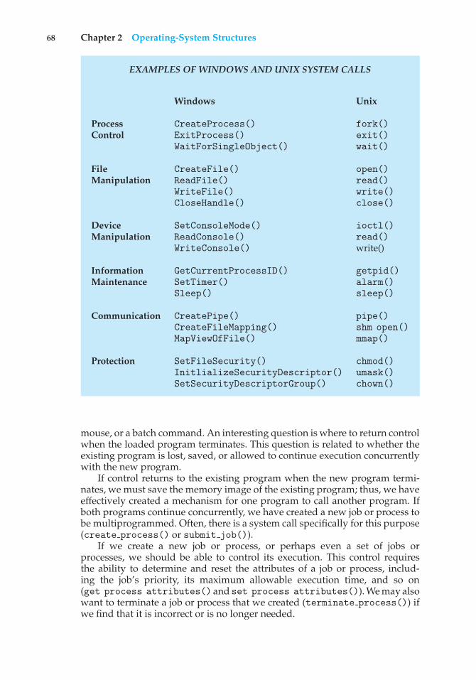
68 Chapter 2 Operating-System Structures
EXAMPLES OF WINDOWS AND UNIX SYSTEM CALLS
Windows Unix
Process CreateProcess() fork()Control ExitProcess() exit()
WaitForSingleObject() wait()
File CreateFile() open()Manipulation ReadFile() read()
WriteFile() write()CloseHandle() close()
Device SetConsoleMode() ioctl()Manipulation ReadConsole() read()
WriteConsole() write()
Information GetCurrentProcessID() getpid()Maintenance SetTimer() alarm()
Sleep() sleep()
Communication CreatePipe() pipe()CreateFileMapping() shm open()MapViewOfFile() mmap()
Protection SetFileSecurity() chmod()InitlializeSecurityDescriptor() umask()SetSecurityDescriptorGroup() chown()
mouse, or a batch command. An interesting question is where to return controlwhen the loaded program terminates. This question is related to whether theexisting program is lost, saved, or allowed to continue execution concurrentlywith the new program.
If control returns to the existing program when the new program termi-nates, we must save the memory image of the existing program; thus, we haveeffectively created a mechanism for one program to call another program. Ifboth programs continue concurrently, we have created a new job or process tobe multiprogrammed. Often, there is a system call specifically for this purpose(create process() or submit job()).
If we create a new job or process, or perhaps even a set of jobs orprocesses, we should be able to control its execution. This control requiresthe ability to determine and reset the attributes of a job or process, includ-ing the job’s priority, its maximum allowable execution time, and so on(get process attributes() andset process attributes()). We may alsowant to terminate a job or process that we created (terminate process()) ifwe find that it is incorrect or is no longer needed.
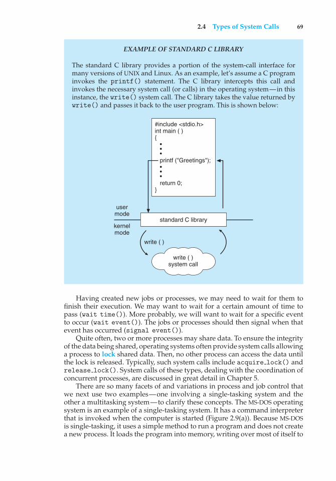
2.4 Types of System Calls 69
EXAMPLE OF STANDARD C LIBRARY
The standard C library provides a portion of the system-call interface formany versions of UNIX and Linux. As an example, let’s assume a C programinvokes the printf() statement. The C library intercepts this call andinvokes the necessary system call (or calls) in the operating system—in thisinstance, the write() system call. The C library takes the value returned bywrite() and passes it back to the user program. This is shown below:
write ( )system call
usermode
kernelmode
#include <stdio.h>int main ( ){ • • • printf ("Greetings"); • • • return 0;}
standard C library
write ( )
Having created new jobs or processes, we may need to wait for them tofinish their execution. We may want to wait for a certain amount of time topass (wait time()). More probably, we will want to wait for a specific eventto occur (wait event()). The jobs or processes should then signal when thatevent has occurred (signal event()).
Quite often, two or more processes may share data. To ensure the integrityof the data being shared, operating systems often provide system calls allowinga process to lock shared data. Then, no other process can access the data untilthe lock is released. Typically, such system calls include acquire lock() andrelease lock(). System calls of these types, dealing with the coordination ofconcurrent processes, are discussed in great detail in Chapter 5.
There are so many facets of and variations in process and job control thatwe next use two examples—one involving a single-tasking system and theother a multitasking system—to clarify these concepts. The MS-DOS operatingsystem is an example of a single-tasking system. It has a command interpreterthat is invoked when the computer is started (Figure 2.9(a)). Because MS-DOSis single-tasking, it uses a simple method to run a program and does not createa new process. It loads the program into memory, writing over most of itself to
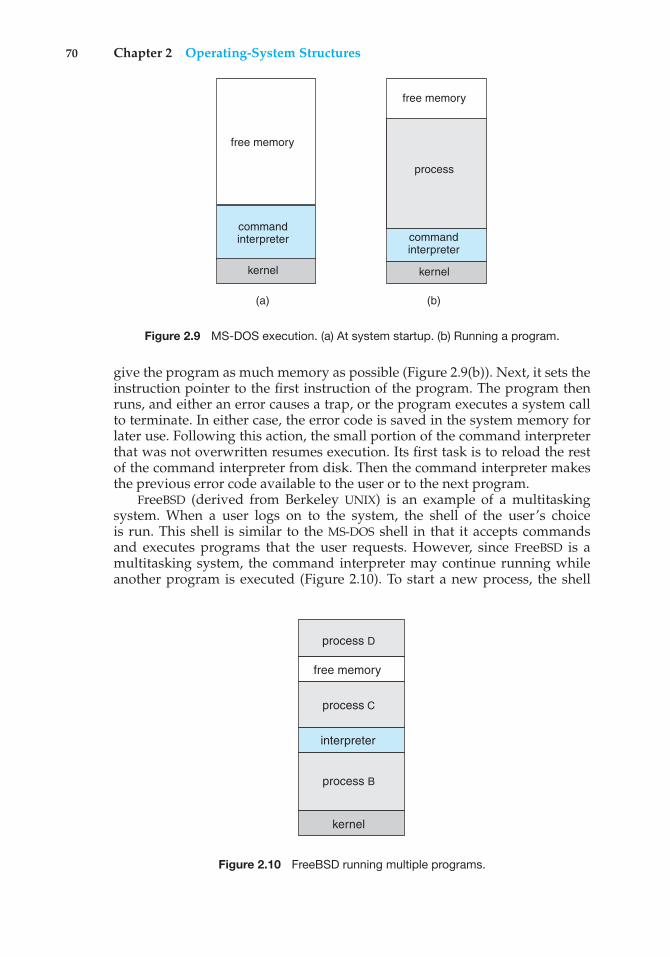
70 Chapter 2 Operating-System Structures
(a) (b)
free memory
command interpreter
kernel
process
free memory
command interpreter
kernel
Figure 2.9 MS-DOS execution. (a) At system startup. (b) Running a program.
give the program as much memory as possible (Figure 2.9(b)). Next, it sets theinstruction pointer to the first instruction of the program. The program thenruns, and either an error causes a trap, or the program executes a system callto terminate. In either case, the error code is saved in the system memory forlater use. Following this action, the small portion of the command interpreterthat was not overwritten resumes execution. Its first task is to reload the restof the command interpreter from disk. Then the command interpreter makesthe previous error code available to the user or to the next program.
FreeBSD (derived from Berkeley UNIX) is an example of a multitaskingsystem. When a user logs on to the system, the shell of the user’s choiceis run. This shell is similar to the MS-DOS shell in that it accepts commandsand executes programs that the user requests. However, since FreeBSD is amultitasking system, the command interpreter may continue running whileanother program is executed (Figure 2.10). To start a new process, the shell
free memory
interpreter
kernel
process D
process C
process B
Figure 2.10 FreeBSD running multiple programs.
2.4 Types of System Calls 71
executes a fork() system call. Then, the selected program is loaded intomemory via an exec() system call, and the program is executed. Dependingon the way the command was issued, the shell then either waits for the processto finish or runs the process “in the background.” In the latter case, the shellimmediately requests another command. When a process is running in thebackground, it cannot receive input directly from the keyboard, because theshell is using this resource. I/O is therefore done through files or through a GUIinterface. Meanwhile, the user is free to ask the shell to run other programs, tomonitor the progress of the running process, to change that program’s priority,and so on. When the process is done, it executes an exit() system call toterminate, returning to the invoking process a status code of 0 or a nonzeroerror code. This status or error code is then available to the shell or otherprograms. Processes are discussed in Chapter 3 with a program example usingthe fork() and exec() system calls.
2.4.2 File Management
The file system is discussed in more detail in Chapters 11 and 12. We can,however, identify several common system calls dealing with files.
We first need to be able to create() and delete() files. Either system callrequires the name of the file and perhaps some of the file’s attributes. Oncethe file is created, we need to open() it and to use it. We may also read(),write(), or reposition() (rewind or skip to the end of the file, for example).Finally, we need to close() the file, indicating that we are no longer using it.
We may need these same sets of operations for directories if we have adirectory structure for organizing files in the file system. In addition, for eitherfiles or directories, we need to be able to determine the values of variousattributes and perhaps to reset them if necessary. File attributes include the filename, file type, protection codes, accounting information, and so on. At leasttwo system calls, get file attributes() and set file attributes(), arerequired for this function. Some operating systems provide many more calls,such as calls for file move() and copy(). Others might provide an API thatperforms those operations using code and other system calls, and others mightprovide system programs to perform those tasks. If the system programs arecallable by other programs, then each can be considered an API by other systemprograms.
2.4.3 Device Management
A process may need several resources to execute—main memory, disk drives,access to files, and so on. If the resources are available, they can be granted,and control can be returned to the user process. Otherwise, the process willhave to wait until sufficient resources are available.
The various resources controlled by the operating system can be thoughtof as devices. Some of these devices are physical devices (for example, diskdrives), while others can be thought of as abstract or virtual devices (forexample, files). A system with multiple users may require us to first request()a device, to ensure exclusive use of it. After we are finished with the device, werelease() it. These functions are similar to the open() and close() systemcalls for files. Other operating systems allow unmanaged access to devices.
72 Chapter 2 Operating-System Structures
The hazard then is the potential for device contention and perhaps deadlock,which are described in Chapter 7.
Once the device has been requested (and allocated to us), we can read(),write(), and (possibly) reposition() the device, just as we can with files. Infact, the similarity between I/O devices and files is so great that many operatingsystems, including UNIX, merge the two into a combined file–device structure.In this case, a set of system calls is used on both files and devices. Sometimes,I/O devices are identified by special file names, directory placement, or fileattributes.
The user interface can also make files and devices appear to be similar, eventhough the underlying system calls are dissimilar. This is another example ofthe many design decisions that go into building an operating system and userinterface.
2.4.4 Information Maintenance
Many system calls exist simply for the purpose of transferring informationbetween the user program and the operating system. For example, mostsystems have a system call to return the current time() and date(). Othersystem calls may return information about the system, such as the number ofcurrent users, the version number of the operating system, the amount of freememory or disk space, and so on.
Another set of system calls is helpful in debugging a program. Manysystems provide system calls to dump() memory. This provision is useful fordebugging. A program trace lists each system call as it is executed. Evenmicroprocessors provide a CPU mode known as single step, in which a trapis executed by the CPU after every instruction. The trap is usually caught by adebugger.
Many operating systems provide a time profile of a program to indicatethe amount of time that the program executes at a particular location or setof locations. A time profile requires either a tracing facility or regular timerinterrupts. At every occurrence of the timer interrupt, the value of the programcounter is recorded. With sufficiently frequent timer interrupts, a statisticalpicture of the time spent on various parts of the program can be obtained.
In addition, the operating system keeps information about all its processes,and system calls are used to access this information. Generally, calls arealso used to reset the process information (get process attributes() andset process attributes()). In Section 3.1.3, we discuss what information isnormally kept.
2.4.5 Communication
There are two common models of interprocess communication: the message-passing model and the shared-memory model. In the message-passing model,the communicating processes exchange messages with one another to transferinformation. Messages can be exchanged between the processes either directlyor indirectly through a common mailbox. Before communication can takeplace, a connection must be opened. The name of the other communicatormust be known, be it another process on the same system or a process onanother computer connected by a communications network. Each computer ina network has a host name by which it is commonly known. A host also has a
2.4 Types of System Calls 73
network identifier, such as an IP address. Similarly, each process has a processname, and this name is translated into an identifier by which the operatingsystem can refer to the process. The get hostid() and get processid()system calls do this translation. The identifiers are then passed to the general-purpose open() and close() calls provided by the file system or to specificopen connection()andclose connection() system calls, depending on thesystem’s model of communication. The recipient process usually must give itspermission for communication to take place with an accept connection()call. Most processes that will be receiving connections are special-purposedaemons, which are system programs provided for that purpose. They executea wait for connection() call and are awakened when a connection is made.The source of the communication, known as the client, and the receivingdaemon, known as a server, then exchange messages by usingread message()and write message() system calls. The close connection() call terminatesthe communication.
In the shared-memory model, processes use shared memory create()and shared memory attach() system calls to create and gain access to regionsof memory owned by other processes. Recall that, normally, the operatingsystem tries to prevent one process from accessing another process’s memory.Shared memory requires that two or more processes agree to remove thisrestriction. They can then exchange information by reading and writing datain the shared areas. The form of the data is determined by the processes and isnot under the operating system’s control. The processes are also responsible forensuring that they are not writing to the same location simultaneously. Suchmechanisms are discussed in Chapter 5. In Chapter 4, we look at a variation ofthe process scheme—threads—in which memory is shared by default.
Both of the models just discussed are common in operating systems,and most systems implement both. Message passing is useful for exchangingsmaller amounts of data, because no conflicts need be avoided. It is also easier toimplement than is shared memory for intercomputer communication. Sharedmemory allows maximum speed and convenience of communication, since itcan be done at memory transfer speeds when it takes place within a computer.Problems exist, however, in the areas of protection and synchronizationbetween the processes sharing memory.
2.4.6 Protection
Protection provides a mechanism for controlling access to the resourcesprovided by a computer system. Historically, protection was a concern only onmultiprogrammed computer systems with several users. However, with theadvent of networking and the Internet, all computer systems, from servers tomobile handheld devices, must be concerned with protection.
Typically, system calls providing protection include set permission()and get permission(), which manipulate the permission settings ofresources such as files and disks. The allow user() and deny user() systemcalls specify whether particular users can—or cannot—be allowed access tocertain resources.
We cover protection in Chapter 14 and the much larger issue of security inChapter 15.
74 Chapter 2 Operating-System Structures
2.5 System Programs
Another aspect of a modern system is its collection of system programs. RecallFigure 1.1, which depicted the logical computer hierarchy. At the lowest level ishardware. Next is the operating system, then the system programs, and finallythe application programs. System programs, also known as system utilities,provide a convenient environment for program development and execution.Some of them are simply user interfaces to system calls. Others are considerablymore complex. They can be divided into these categories:
• File management. These programs create, delete, copy, rename, print,dump, list, and generally manipulate files and directories.
• Status information. Some programs simply ask the system for the date,time, amount of available memory or disk space, number of users, orsimilar status information. Others are more complex, providing detailedperformance, logging, and debugging information. Typically, these pro-grams format and print the output to the terminal or other output devicesor files or display it in a window of the GUI. Some systems also support aregistry, which is used to store and retrieve configuration information.
• File modification. Several text editors may be available to create andmodify the content of files stored on disk or other storage devices. Theremay also be special commands to search contents of files or performtransformations of the text.
• Programming-language support. Compilers, assemblers, debuggers, andinterpreters for common programming languages (such as C, C++, Java,and PERL) are often provided with the operating system or available as aseparate download.
• Program loading and execution. Once a program is assembled or com-piled, it must be loaded into memory to be executed. The system mayprovide absolute loaders, relocatable loaders, linkage editors, and overlayloaders. Debugging systems for either higher-level languages or machinelanguage are needed as well.
• Communications. These programs provide the mechanism for creatingvirtual connections among processes, users, and computer systems. Theyallow users to send messages to one another’s screens, to browse Webpages, to send e-mail messages, to log in remotely, or to transfer files fromone machine to another.
• Background services. All general-purpose systems have methods forlaunching certain system-program processes at boot time. Some of theseprocesses terminate after completing their tasks, while others continueto run until the system is halted. Constantly running system-programprocesses are known as services, subsystems, or daemons. One example isthe network daemon discussed in Section 2.4.5. In that example, a systemneeded a service to listen for network connections in order to connectthose requests to the correct processes. Other examples include processschedulers that start processes according to a specified schedule, systemerror monitoring services, and print servers. Typical systems have dozens
2.6 Operating-System Design and Implementation 75
of daemons. In addition, operating systems that run important activitiesin user context rather than in kernel context may use daemons to run theseactivities.
Along with system programs, most operating systems are supplied withprograms that are useful in solving common problems or performing commonoperations. Such application programs include Web browsers, word proces-sors and text formatters, spreadsheets, database systems, compilers, plottingand statistical-analysis packages, and games.
The view of the operating system seen by most users is defined by theapplication and system programs, rather than by the actual system calls.Consider a user’s PC. When a user’s computer is running the Mac OS Xoperating system, the user might see the GUI, featuring a mouse-and-windowsinterface. Alternatively, or even in one of the windows, the user might have acommand-line UNIX shell. Both use the same set of system calls, but the systemcalls look different and act in different ways. Further confusing the user view,consider the user dual-booting from Mac OS X into Windows. Now the sameuser on the same hardware has two entirely different interfaces and two sets ofapplications using the same physical resources. On the same hardware, then,a user can be exposed to multiple user interfaces sequentially or concurrently.
2.6 Operating-System Design and Implementation
In this section, we discuss problems we face in designing and implementing anoperating system. There are, of course, no complete solutions to such problems,but there are approaches that have proved successful.
2.6.1 Design Goals
The first problem in designing a system is to define goals and specifications.At the highest level, the design of the system will be affected by the choice ofhardware and the type of system: batch, time sharing, single user, multiuser,distributed, real time, or general purpose.
Beyond this highest design level, the requirements may be much harderto specify. The requirements can, however, be divided into two basic groups:user goals and system goals.
Users want certain obvious properties in a system. The system should beconvenient to use, easy to learn and to use, reliable, safe, and fast. Of course,these specifications are not particularly useful in the system design, since thereis no general agreement on how to achieve them.
A similar set of requirements can be defined by those people who mustdesign, create, maintain, and operate the system. The system should be easy todesign, implement, and maintain; and it should be flexible, reliable, error free,and efficient. Again, these requirements are vague and may be interpreted invarious ways.
There is, in short, no unique solution to the problem of defining therequirements for an operating system. The wide range of systems in existenceshows that different requirements can result in a large variety of solutions fordifferent environments. For example, the requirements for VxWorks, a real-
76 Chapter 2 Operating-System Structures
time operating system for embedded systems, must have been substantiallydifferent from those for MVS, a large multiuser, multiaccess operating systemfor IBM mainframes.
Specifying and designing an operating system is a highly creative task.Although no textbook can tell you how to do it, general principles havebeen developed in the field of software engineering, and we turn now toa discussion of some of these principles.
2.6.2 Mechanisms and Policies
One important principle is the separation of policy from mechanism. Mecha-nisms determine how to do something; policies determine what will be done.For example, the timer construct (see Section 1.5.2) is a mechanism for ensuringCPU protection, but deciding how long the timer is to be set for a particularuser is a policy decision.
The separation of policy and mechanism is important for flexibility. Policiesare likely to change across places or over time. In the worst case, each changein policy would require a change in the underlying mechanism. A generalmechanism insensitive to changes in policy would be more desirable. A changein policy would then require redefinition of only certain parameters of thesystem. For instance, consider a mechanism for giving priority to certain typesof programs over others. If the mechanism is properly separated from policy,it can be used either to support a policy decision that I/O-intensive programsshould have priority over CPU-intensive ones or to support the opposite policy.
Microkernel-based operating systems (Section 2.7.3) take the separation ofmechanism and policy to one extreme by implementing a basic set of primitivebuilding blocks. These blocks are almost policy free, allowing more advancedmechanisms and policies to be added via user-created kernel modules or userprograms themselves. As an example, consider the history of UNIX. At first,it had a time-sharing scheduler. In the latest version of Solaris, schedulingis controlled by loadable tables. Depending on the table currently loaded,the system can be time sharing, batch processing, real time, fair share, orany combination. Making the scheduling mechanism general purpose allowsvast policy changes to be made with a single load-new-table command. Atthe other extreme is a system such as Windows, in which both mechanismand policy are encoded in the system to enforce a global look and feel. Allapplications have similar interfaces, because the interface itself is built intothe kernel and system libraries. The Mac OS X operating system has similarfunctionality.
Policy decisions are important for all resource allocation. Whenever it isnecessary to decide whether or not to allocate a resource, a policy decision mustbe made. Whenever the question is how rather than what, it is a mechanismthat must be determined.
2.6.3 Implementation
Once an operating system is designed, it must be implemented. Becauseoperating systems are collections of many programs, written by many peopleover a long period of time, it is difficult to make general statements about howthey are implemented.
2.6 Operating-System Design and Implementation 77
Early operating systems were written in assembly language. Now, althoughsome operating systems are still written in assembly language, most are writtenin a higher-level language such as C or an even higher-level language such asC++. Actually, an operating system can be written in more than one language.The lowest levels of the kernel might be assembly language. Higher-levelroutines might be in C, and system programs might be in C or C++, ininterpreted scripting languages like PERL or Python, or in shell scripts. Infact, a given Linux distribution probably includes programs written in all ofthose languages.
The first system that was not written in assembly language was probablythe Master Control Program (MCP) for Burroughs computers. MCP was writtenin a variant of ALGOL. MULTICS, developed at MIT, was written mainly inthe system programming language PL/1. The Linux and Windows operatingsystem kernels are written mostly in C, although there are some small sectionsof assembly code for device drivers and for saving and restoring the state ofregisters.
The advantages of using a higher-level language, or at least a systems-implementation language, for implementing operating systems are the sameas those gained when the language is used for application programs: the codecan be written faster, is more compact, and is easier to understand and debug.In addition, improvements in compiler technology will improve the generatedcode for the entire operating system by simple recompilation. Finally, anoperating system is far easier to port—to move to some other hardware—if it is written in a higher-level language. For example, MS-DOS was written inIntel 8088 assembly language. Consequently, it runs natively only on the IntelX86 family of CPUs. (Note that although MS-DOS runs natively only on IntelX86, emulators of the X86 instruction set allow the operating system to run onother CPUs—but more slowly, and with higher resource use. As we mentionedin Chapter 1, emulators are programs that duplicate the functionality of onesystem on another system.) The Linux operating system, in contrast, is writtenmostly in C and is available natively on a number of different CPUs, includingIntel X86, Oracle SPARC, and IBMPowerPC.
The only possible disadvantages of implementing an operating system in ahigher-level language are reduced speed and increased storage requirements.This, however, is no longer a major issue in today’s systems. Although anexpert assembly-language programmer can produce efficient small routines,for large programs a modern compiler can perform complex analysis and applysophisticated optimizations that produce excellent code. Modern processorshave deep pipelining and multiple functional units that can handle the detailsof complex dependencies much more easily than can the human mind.
As is true in other systems, major performance improvements in oper-ating systems are more likely to be the result of better data structures andalgorithms than of excellent assembly-language code. In addition, althoughoperating systems are large, only a small amount of the code is critical to highperformance; the interrupt handler, I/O manager, memory manager, and CPUscheduler are probably the most critical routines. After the system is writtenand is working correctly, bottleneck routines can be identified and can bereplaced with assembly-language equivalents.
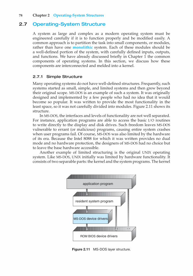
78 Chapter 2 Operating-System Structures
2.7 Operating-System Structure
A system as large and complex as a modern operating system must beengineered carefully if it is to function properly and be modified easily. Acommon approach is to partition the task into small components, or modules,rather than have one monolithic system. Each of these modules should bea well-defined portion of the system, with carefully defined inputs, outputs,and functions. We have already discussed briefly in Chapter 1 the commoncomponents of operating systems. In this section, we discuss how thesecomponents are interconnected and melded into a kernel.
2.7.1 Simple Structure
Many operating systems do not have well-defined structures. Frequently, suchsystems started as small, simple, and limited systems and then grew beyondtheir original scope. MS-DOS is an example of such a system. It was originallydesigned and implemented by a few people who had no idea that it wouldbecome so popular. It was written to provide the most functionality in theleast space, so it was not carefully divided into modules. Figure 2.11 shows itsstructure.
In MS-DOS, the interfaces and levels of functionality are not well separated.For instance, application programs are able to access the basic I/O routinesto write directly to the display and disk drives. Such freedom leaves MS-DOSvulnerable to errant (or malicious) programs, causing entire system crasheswhen user programs fail. Of course, MS-DOS was also limited by the hardwareof its era. Because the Intel 8088 for which it was written provides no dualmode and no hardware protection, the designers of MS-DOS had no choice butto leave the base hardware accessible.
Another example of limited structuring is the original UNIX operatingsystem. Like MS-DOS, UNIX initially was limited by hardware functionality. Itconsists of two separable parts: the kernel and the system programs. The kernel
ROM BIOS device drivers
application program
MS-DOS device drivers
resident system program
Figure 2.11 MS-DOS layer structure.
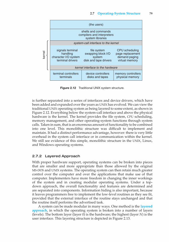
2.7 Operating-System Structure 79
kern
el
(the users)
shells and commandscompilers and interpreters
system libraries
system-call interface to the kernel
signals terminalhandling
character I/O systemterminal drivers
file systemswapping block I/O
systemdisk and tape drivers
CPU schedulingpage replacementdemand pagingvirtual memory
kernel interface to the hardware
terminal controllersterminals
device controllersdisks and tapes
memory controllersphysical memory
Figure 2.12 Traditional UNIX system structure.
is further separated into a series of interfaces and device drivers, which havebeen added and expanded over the years as UNIX has evolved. We can view thetraditional UNIX operating system as being layered to some extent, as shown inFigure 2.12. Everything below the system-call interface and above the physicalhardware is the kernel. The kernel provides the file system, CPU scheduling,memory management, and other operating-system functions through systemcalls. Taken in sum, that is an enormous amount of functionality to be combinedinto one level. This monolithic structure was difficult to implement andmaintain. It had a distinct performance advantage, however: there is very littleoverhead in the system call interface or in communication within the kernel.We still see evidence of this simple, monolithic structure in the UNIX, Linux,and Windows operating systems.
2.7.2 Layered Approach
With proper hardware support, operating systems can be broken into piecesthat are smaller and more appropriate than those allowed by the originalMS-DOS and UNIX systems. The operating system can then retain much greatercontrol over the computer and over the applications that make use of thatcomputer. Implementers have more freedom in changing the inner workingsof the system and in creating modular operating systems. Under a top-down approach, the overall functionality and features are determined andare separated into components. Information hiding is also important, becauseit leaves programmers free to implement the low-level routines as they see fit,provided that the external interface of the routine stays unchanged and thatthe routine itself performs the advertised task.
A system can be made modular in many ways. One method is the layeredapproach, in which the operating system is broken into a number of layers(levels). The bottom layer (layer 0) is the hardware; the highest (layer N) is theuser interface. This layering structure is depicted in Figure 2.13.
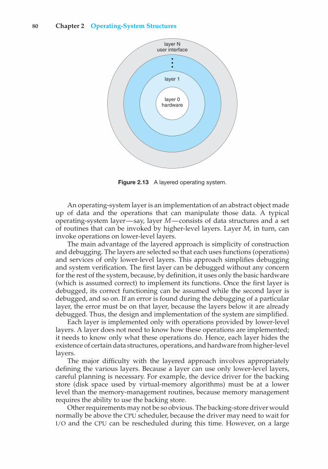
80 Chapter 2 Operating-System Structures
layer Nuser interface
•••
layer 1
layer 0hardware
Figure 2.13 A layered operating system.
An operating-system layer is an implementation of an abstract object madeup of data and the operations that can manipulate those data. A typicaloperating-system layer—say, layer M—consists of data structures and a setof routines that can be invoked by higher-level layers. Layer M, in turn, caninvoke operations on lower-level layers.
The main advantage of the layered approach is simplicity of constructionand debugging. The layers are selected so that each uses functions (operations)and services of only lower-level layers. This approach simplifies debuggingand system verification. The first layer can be debugged without any concernfor the rest of the system, because, by definition, it uses only the basic hardware(which is assumed correct) to implement its functions. Once the first layer isdebugged, its correct functioning can be assumed while the second layer isdebugged, and so on. If an error is found during the debugging of a particularlayer, the error must be on that layer, because the layers below it are alreadydebugged. Thus, the design and implementation of the system are simplified.
Each layer is implemented only with operations provided by lower-levellayers. A layer does not need to know how these operations are implemented;it needs to know only what these operations do. Hence, each layer hides theexistence of certain data structures, operations, and hardware from higher-levellayers.
The major difficulty with the layered approach involves appropriatelydefining the various layers. Because a layer can use only lower-level layers,careful planning is necessary. For example, the device driver for the backingstore (disk space used by virtual-memory algorithms) must be at a lowerlevel than the memory-management routines, because memory managementrequires the ability to use the backing store.
Other requirements may not be so obvious. The backing-store driver wouldnormally be above the CPU scheduler, because the driver may need to wait forI/O and the CPU can be rescheduled during this time. However, on a large
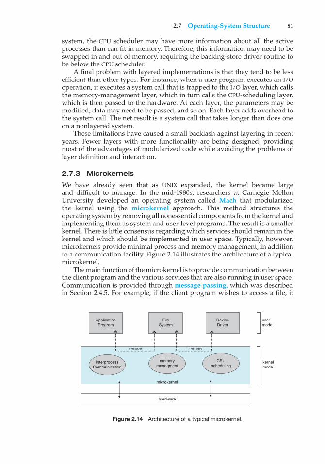
2.7 Operating-System Structure 81
system, the CPU scheduler may have more information about all the activeprocesses than can fit in memory. Therefore, this information may need to beswapped in and out of memory, requiring the backing-store driver routine tobe below the CPU scheduler.
A final problem with layered implementations is that they tend to be lessefficient than other types. For instance, when a user program executes an I/Ooperation, it executes a system call that is trapped to the I/O layer, which callsthe memory-management layer, which in turn calls the CPU-scheduling layer,which is then passed to the hardware. At each layer, the parameters may bemodified, data may need to be passed, and so on. Each layer adds overhead tothe system call. The net result is a system call that takes longer than does oneon a nonlayered system.
These limitations have caused a small backlash against layering in recentyears. Fewer layers with more functionality are being designed, providingmost of the advantages of modularized code while avoiding the problems oflayer definition and interaction.
2.7.3 Microkernels
We have already seen that as UNIX expanded, the kernel became largeand difficult to manage. In the mid-1980s, researchers at Carnegie MellonUniversity developed an operating system called Mach that modularizedthe kernel using the microkernel approach. This method structures theoperating system by removing all nonessential components from the kernel andimplementing them as system and user-level programs. The result is a smallerkernel. There is little consensus regarding which services should remain in thekernel and which should be implemented in user space. Typically, however,microkernels provide minimal process and memory management, in additionto a communication facility. Figure 2.14 illustrates the architecture of a typicalmicrokernel.
The main function of the microkernel is to provide communication betweenthe client program and the various services that are also running in user space.Communication is provided through message passing, which was describedin Section 2.4.5. For example, if the client program wishes to access a file, it
ApplicationProgram
FileSystem
DeviceDriver
InterprocessCommunication
memorymanagment
CPUscheduling
messagesmessages
microkernel
hardware
usermode
kernelmode
Figure 2.14 Architecture of a typical microkernel.
82 Chapter 2 Operating-System Structures
must interact with the file server. The client program and service never interactdirectly. Rather, they communicate indirectly by exchanging messages with themicrokernel.
One benefit of the microkernel approach is that it makes extendingthe operating system easier. All new services are added to user space andconsequently do not require modification of the kernel. When the kernel doeshave to be modified, the changes tend to be fewer, because the microkernel isa smaller kernel. The resulting operating system is easier to port from onehardware design to another. The microkernel also provides more securityand reliability, since most services are running as user—rather than kernel—processes. If a service fails, the rest of the operating system remains untouched.
Some contemporary operating systems have used the microkernelapproach. Tru64 UNIX (formerly Digital UNIX) provides a UNIX interface to theuser, but it is implemented with a Mach kernel. The Mach kernel maps UNIXsystem calls into messages to the appropriate user-level services. The Mac OS Xkernel (also known as Darwin) is also partly based on the Mach microkernel.
Another example is QNX, a real-time operating system for embeddedsystems. The QNX Neutrino microkernel provides services for message passingand process scheduling. It also handles low-level network communicationand hardware interrupts. All other services in QNX are provided by standardprocesses that run outside the kernel in user mode.
Unfortunately, the performance of microkernels can suffer due to increasedsystem-function overhead. Consider the history of Windows NT. The firstrelease had a layered microkernel organization. This version’s performancewas low compared with that of Windows 95. Windows NT 4.0 partiallycorrected the performance problem by moving layers from user space tokernel space and integrating them more closely. By the time Windows XPwas designed, Windows architecture had become more monolithic thanmicrokernel.
2.7.4 Modules
Perhaps the best current methodology for operating-system design involvesusing loadable kernel modules. Here, the kernel has a set of core componentsand links in additional services via modules, either at boot time or during runtime. This type of design is common in modern implementations of UNIX, suchas Solaris, Linux, and Mac OS X, as well as Windows.
The idea of the design is for the kernel to provide core services whileother services are implemented dynamically, as the kernel is running. Linkingservices dynamically is preferable to adding new features directly to the kernel,which would require recompiling the kernel every time a change was made.Thus, for example, we might build CPU scheduling and memory managementalgorithms directly into the kernel and then add support for different filesystems by way of loadable modules.
The overall result resembles a layered system in that each kernel sectionhas defined, protected interfaces; but it is more flexible than a layered system,because any module can call any other module. The approach is also similar tothe microkernel approach in that the primary module has only core functionsand knowledge of how to load and communicate with other modules; but it
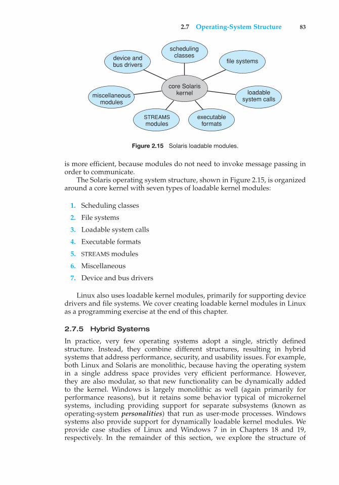
2.7 Operating-System Structure 83
core Solariskernel
file systems
loadablesystem calls
executableformats
STREAMSmodules
miscellaneousmodules
device andbus drivers
schedulingclasses
Figure 2.15 Solaris loadable modules.
is more efficient, because modules do not need to invoke message passing inorder to communicate.
The Solaris operating system structure, shown in Figure 2.15, is organizedaround a core kernel with seven types of loadable kernel modules:
1. Scheduling classes
2. File systems
3. Loadable system calls
4. Executable formats
5. STREAMS modules
6. Miscellaneous
7. Device and bus drivers
Linux also uses loadable kernel modules, primarily for supporting devicedrivers and file systems. We cover creating loadable kernel modules in Linuxas a programming exercise at the end of this chapter.
2.7.5 Hybrid Systems
In practice, very few operating systems adopt a single, strictly definedstructure. Instead, they combine different structures, resulting in hybridsystems that address performance, security, and usability issues. For example,both Linux and Solaris are monolithic, because having the operating systemin a single address space provides very efficient performance. However,they are also modular, so that new functionality can be dynamically addedto the kernel. Windows is largely monolithic as well (again primarily forperformance reasons), but it retains some behavior typical of microkernelsystems, including providing support for separate subsystems (known asoperating-system personalities) that run as user-mode processes. Windowssystems also provide support for dynamically loadable kernel modules. Weprovide case studies of Linux and Windows 7 in in Chapters 18 and 19,respectively. In the remainder of this section, we explore the structure of
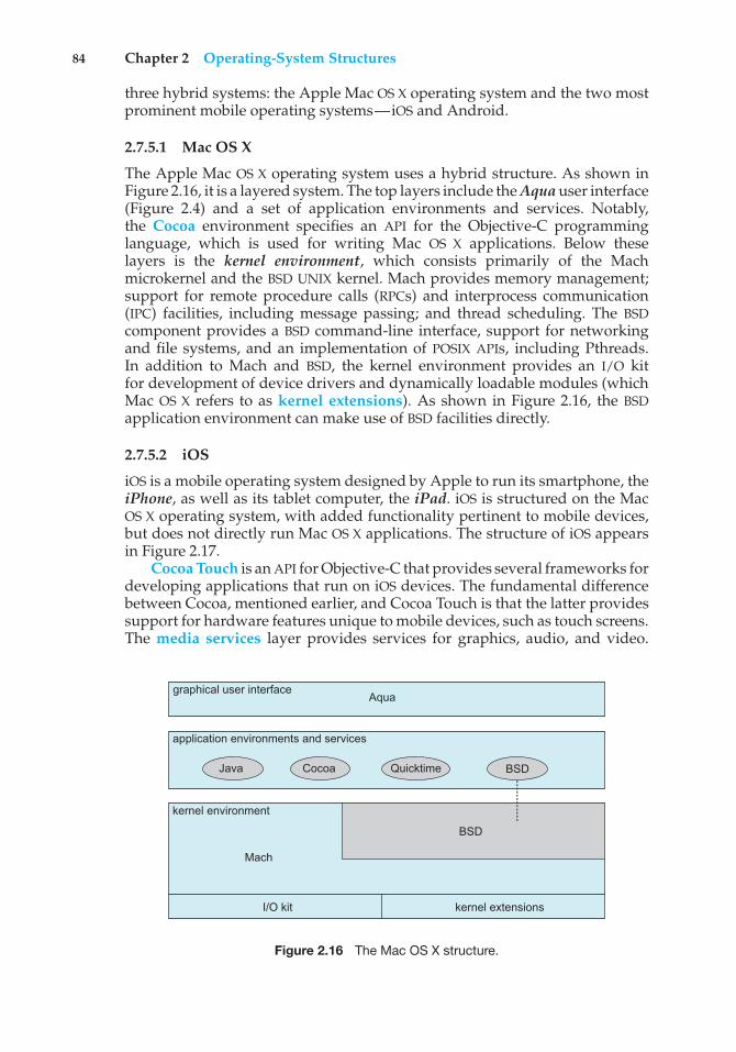
84 Chapter 2 Operating-System Structures
three hybrid systems: the Apple Mac OS X operating system and the two mostprominent mobile operating systems—iOS and Android.
2.7.5.1 Mac OS X
The Apple Mac OS X operating system uses a hybrid structure. As shown inFigure 2.16, it is a layered system. The top layers include the Aqua user interface(Figure 2.4) and a set of application environments and services. Notably,the Cocoa environment specifies an API for the Objective-C programminglanguage, which is used for writing Mac OS X applications. Below theselayers is the kernel environment, which consists primarily of the Machmicrokernel and the BSD UNIX kernel. Mach provides memory management;support for remote procedure calls (RPCs) and interprocess communication(IPC) facilities, including message passing; and thread scheduling. The BSDcomponent provides a BSD command-line interface, support for networkingand file systems, and an implementation of POSIX APIs, including Pthreads.In addition to Mach and BSD, the kernel environment provides an I/O kitfor development of device drivers and dynamically loadable modules (whichMac OS X refers to as kernel extensions). As shown in Figure 2.16, the BSDapplication environment can make use of BSD facilities directly.
2.7.5.2 iOS
iOS is a mobile operating system designed by Apple to run its smartphone, theiPhone, as well as its tablet computer, the iPad. iOS is structured on the MacOS X operating system, with added functionality pertinent to mobile devices,but does not directly run Mac OS X applications. The structure of iOS appearsin Figure 2.17.
Cocoa Touch is an API for Objective-C that provides several frameworks fordeveloping applications that run on iOS devices. The fundamental differencebetween Cocoa, mentioned earlier, and Cocoa Touch is that the latter providessupport for hardware features unique to mobile devices, such as touch screens.The media services layer provides services for graphics, audio, and video.
graphical user interface Aqua
application environments and services
kernel environment
Java Cocoa Quicktime BSD
Mach
I/O kit kernel extensions
BSD
Figure 2.16 The Mac OS X structure.
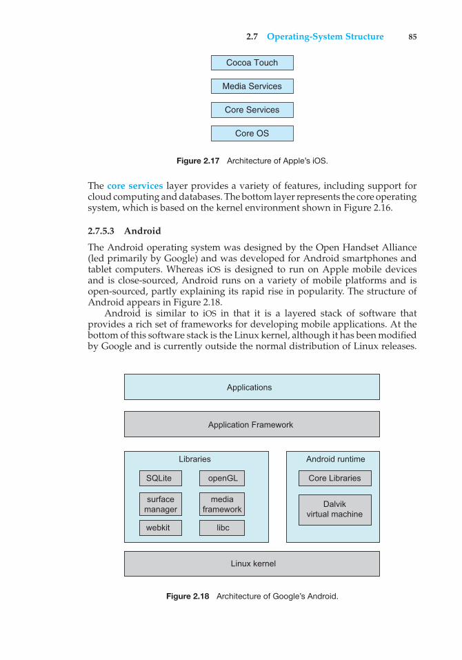
2.7 Operating-System Structure 85
Cocoa Touch
Media Services
Core Services
Core OS
Figure 2.17 Architecture of Apple’s iOS.
The core services layer provides a variety of features, including support forcloud computing and databases. The bottom layer represents the core operatingsystem, which is based on the kernel environment shown in Figure 2.16.
2.7.5.3 Android
The Android operating system was designed by the Open Handset Alliance(led primarily by Google) and was developed for Android smartphones andtablet computers. Whereas iOS is designed to run on Apple mobile devicesand is close-sourced, Android runs on a variety of mobile platforms and isopen-sourced, partly explaining its rapid rise in popularity. The structure ofAndroid appears in Figure 2.18.
Android is similar to iOS in that it is a layered stack of software thatprovides a rich set of frameworks for developing mobile applications. At thebottom of this software stack is the Linux kernel, although it has been modifiedby Google and is currently outside the normal distribution of Linux releases.
Applications
Application Framework
Android runtime
Core Libraries
Dalvikvirtual machine
Libraries
Linux kernel
SQLite openGL
surfacemanager
webkit libc
mediaframework
Figure 2.18 Architecture of Google’s Android.
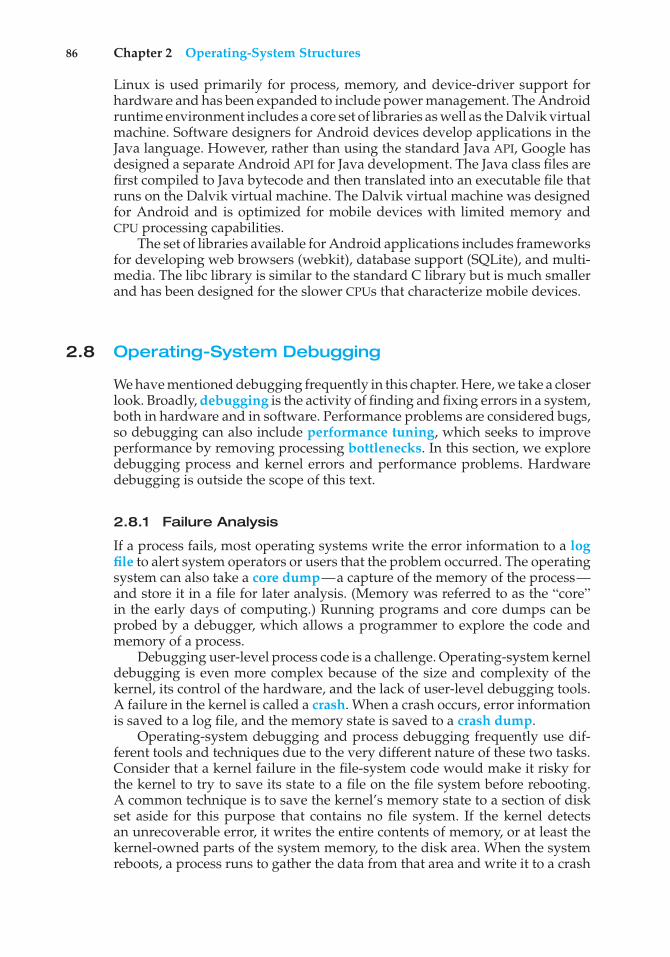
86 Chapter 2 Operating-System Structures
Linux is used primarily for process, memory, and device-driver support forhardware and has been expanded to include power management. The Androidruntime environment includes a core set of libraries as well as the Dalvik virtualmachine. Software designers for Android devices develop applications in theJava language. However, rather than using the standard Java API, Google hasdesigned a separate Android API for Java development. The Java class files arefirst compiled to Java bytecode and then translated into an executable file thatruns on the Dalvik virtual machine. The Dalvik virtual machine was designedfor Android and is optimized for mobile devices with limited memory andCPU processing capabilities.
The set of libraries available for Android applications includes frameworksfor developing web browsers (webkit), database support (SQLite), and multi-media. The libc library is similar to the standard C library but is much smallerand has been designed for the slower CPUs that characterize mobile devices.
2.8 Operating-System Debugging
We have mentioned debugging frequently in this chapter. Here, we take a closerlook. Broadly, debugging is the activity of finding and fixing errors in a system,both in hardware and in software. Performance problems are considered bugs,so debugging can also include performance tuning, which seeks to improveperformance by removing processing bottlenecks. In this section, we exploredebugging process and kernel errors and performance problems. Hardwaredebugging is outside the scope of this text.
2.8.1 Failure Analysis
If a process fails, most operating systems write the error information to a logfile to alert system operators or users that the problem occurred. The operatingsystem can also take a core dump—a capture of the memory of the process—and store it in a file for later analysis. (Memory was referred to as the “core”in the early days of computing.) Running programs and core dumps can beprobed by a debugger, which allows a programmer to explore the code andmemory of a process.
Debugging user-level process code is a challenge. Operating-system kerneldebugging is even more complex because of the size and complexity of thekernel, its control of the hardware, and the lack of user-level debugging tools.A failure in the kernel is called a crash. When a crash occurs, error informationis saved to a log file, and the memory state is saved to a crash dump.
Operating-system debugging and process debugging frequently use dif-ferent tools and techniques due to the very different nature of these two tasks.Consider that a kernel failure in the file-system code would make it risky forthe kernel to try to save its state to a file on the file system before rebooting.A common technique is to save the kernel’s memory state to a section of diskset aside for this purpose that contains no file system. If the kernel detectsan unrecoverable error, it writes the entire contents of memory, or at least thekernel-owned parts of the system memory, to the disk area. When the systemreboots, a process runs to gather the data from that area and write it to a crash
2.8 Operating-System Debugging 87
Kernighan’s Law
“Debugging is twice as hard as writing the code in the first place. Therefore,if you write the code as cleverly as possible, you are, by definition, not smartenough to debug it.”
dump file within a file system for analysis. Obviously, such strategies wouldbe unnecessary for debugging ordinary user-level processes.
2.8.2 Performance Tuning
We mentioned earlier that performance tuning seeks to improve performanceby removing processing bottlenecks. To identify bottlenecks, we must be ableto monitor system performance. Thus, the operating system must have somemeans of computing and displaying measures of system behavior. In a numberof systems, the operating system does this by producing trace listings of systembehavior. All interesting events are logged with their time and importantparameters and are written to a file. Later, an analysis program can processthe log file to determine system performance and to identify bottlenecks andinefficiencies. These same traces can be run as input for a simulation of asuggested improved system. Traces also can help people to find errors inoperating-system behavior.
Another approach to performance tuning uses single-purpose, interactivetools that allow users and administrators to question the state of various systemcomponents to look for bottlenecks. One such tool employs the UNIX commandtop to display the resources used on the system, as well as a sorted list ofthe “top” resource-using processes. Other tools display the state of disk I/O,memory allocation, and network traffic.
The Windows Task Manager is a similar tool for Windows systems. Thetask manager includes information for current applications as well as processes,CPU and memory usage, and networking statistics. A screen shot of the taskmanager appears in Figure 2.19.
Making operating systems easier to understand, debug, and tune as theyrun is an active area of research and implementation. A new generation ofkernel-enabled performance analysis tools has made significant improvementsin how this goal can be achieved. Next, we discuss a leading example of sucha tool: the Solaris 10 DTrace dynamic tracing facility.
2.8.3 DTrace
DTrace is a facility that dynamically adds probes to a running system, bothin user processes and in the kernel. These probes can be queried via the Dprogramming language to determine an astonishing amount about the kernel,the system state, and process activities. For example, Figure 2.20 follows anapplication as it executes a system call (ioctl()) and shows the functionalcalls within the kernel as they execute to perform the system call. Lines endingwith “U” are executed in user mode, and lines ending in “K” in kernel mode.
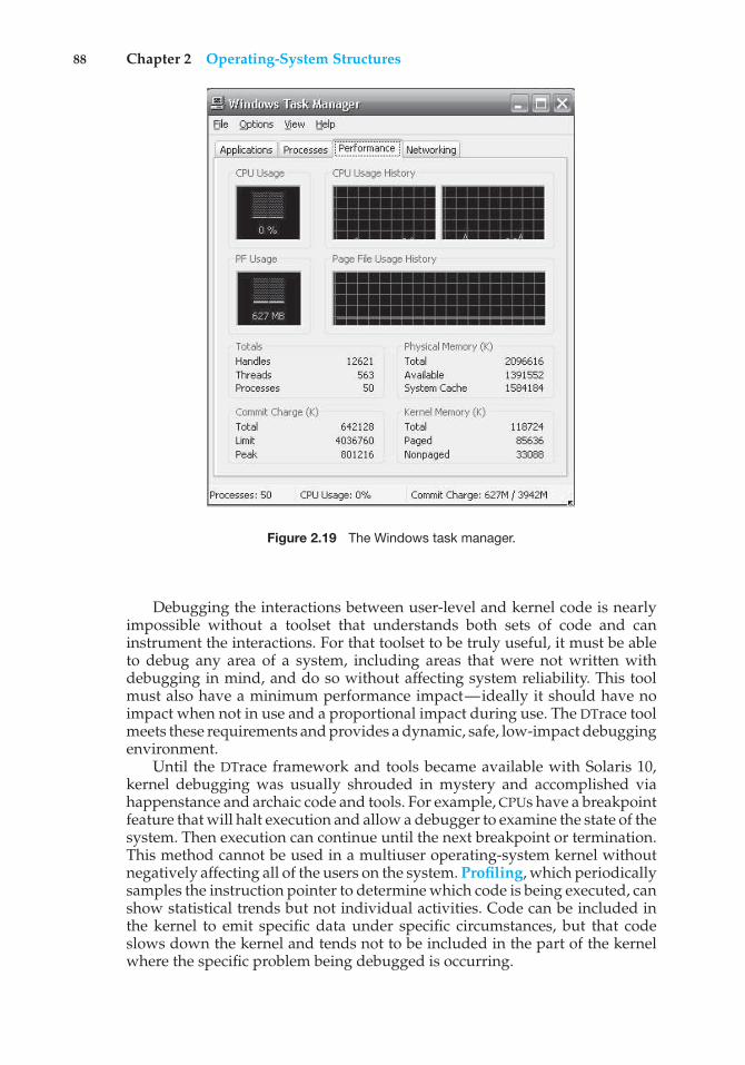
88 Chapter 2 Operating-System Structures
Figure 2.19 The Windows task manager.
Debugging the interactions between user-level and kernel code is nearlyimpossible without a toolset that understands both sets of code and caninstrument the interactions. For that toolset to be truly useful, it must be ableto debug any area of a system, including areas that were not written withdebugging in mind, and do so without affecting system reliability. This toolmust also have a minimum performance impact—ideally it should have noimpact when not in use and a proportional impact during use. The DTrace toolmeets these requirements and provides a dynamic, safe, low-impact debuggingenvironment.
Until the DTrace framework and tools became available with Solaris 10,kernel debugging was usually shrouded in mystery and accomplished viahappenstance and archaic code and tools. For example, CPUs have a breakpointfeature that will halt execution and allow a debugger to examine the state of thesystem. Then execution can continue until the next breakpoint or termination.This method cannot be used in a multiuser operating-system kernel withoutnegatively affecting all of the users on the system. Profiling, which periodicallysamples the instruction pointer to determine which code is being executed, canshow statistical trends but not individual activities. Code can be included inthe kernel to emit specific data under specific circumstances, but that codeslows down the kernel and tends not to be included in the part of the kernelwhere the specific problem being debugged is occurring.
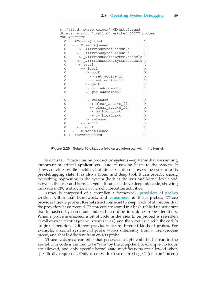
2.8 Operating-System Debugging 89
# ./all.d ‘pgrep xclock‘ XEventsQueueddtrace: script ’./all.d’ matched 52377 probesCPU FUNCTION 0 –> XEventsQueued U 0 –> _XEventsQueued U 0 –> _X11TransBytesReadable U 0 <– _X11TransBytesReadable U 0 –> _X11TransSocketBytesReadable U 0 <– _X11TransSocketBytesreadable U 0 –> ioctl U 0 –> ioctl K 0 –> getf K 0 –> set_active_fd K 0 <– set_active_fd K 0 <– getf K 0 –> get_udatamodel K 0 <– get_udatamodel K... 0 –> releasef K 0 –> clear_active_fd K 0 <– clear_active_fd K 0 –> cv_broadcast K 0 <– cv_broadcast K 0 <– releasef K 0 <– ioctl K 0 <– ioctl U 0 <– _XEventsQueued U 0 <– XEventsQueued U
Figure 2.20 Solaris 10 dtrace follows a system call within the kernel.
In contrast, DTrace runs on production systems—systems that are runningimportant or critical applications—and causes no harm to the system. Itslows activities while enabled, but after execution it resets the system to itspre-debugging state. It is also a broad and deep tool. It can broadly debugeverything happening in the system (both at the user and kernel levels andbetween the user and kernel layers). It can also delve deep into code, showingindividual CPU instructions or kernel subroutine activities.
DTrace is composed of a compiler, a framework, providers of probeswritten within that framework, and consumers of those probes. DTraceproviders create probes. Kernel structures exist to keep track of all probes thatthe providers have created. The probes are stored in a hash-table data structurethat is hashed by name and indexed according to unique probe identifiers.When a probe is enabled, a bit of code in the area to be probed is rewrittento call dtrace probe(probe identifier) and then continue with the code’soriginal operation. Different providers create different kinds of probes. Forexample, a kernel system-call probe works differently from a user-processprobe, and that is different from an I/O probe.
DTrace features a compiler that generates a byte code that is run in thekernel. This code is assured to be “safe” by the compiler. For example, no loopsare allowed, and only specific kernel state modifications are allowed whenspecifically requested. Only users with DTrace “privileges” (or “root” users)
90 Chapter 2 Operating-System Structures
are allowed to use DTrace, as it can retrieve private kernel data (and modifydata if requested). The generated code runs in the kernel and enables probes.It also enables consumers in user mode and enables communications betweenthe two.
A DTrace consumer is code that is interested in a probe and its results.A consumer requests that the provider create one or more probes. When aprobe fires, it emits data that are managed by the kernel. Within the kernel,actions called enabling control blocks, or ECBs, are performed when probesfire. One probe can cause multiple ECBs to execute if more than one consumeris interested in that probe. Each ECB contains a predicate (“if statement”) thatcan filter out that ECB. Otherwise, the list of actions in the ECB is executed. Themost common action is to capture some bit of data, such as a variable’s value atthat point of the probe execution. By gathering such data, a complete picture ofa user or kernel action can be built. Further, probes firing from both user spaceand the kernel can show how a user-level action caused kernel-level reactions.Such data are invaluable for performance monitoring and code optimization.
Once the probe consumer terminates, its ECBs are removed. If there are noECBs consuming a probe, the probe is removed. That involves rewriting thecode to remove the dtrace probe() call and put back the original code. Thus,before a probe is created and after it is destroyed, the system is exactly thesame, as if no probing occurred.
DTrace takes care to assure that probes do not use too much memory orCPU capacity, which could harm the running system. The buffers used to holdthe probe results are monitored for exceeding default and maximum limits.CPU time for probe execution is monitored as well. If limits are exceeded, theconsumer is terminated, along with the offending probes. Buffers are allocatedper CPU to avoid contention and data loss.
An example of D code and its output shows some of its utility. The followingprogram shows the DTrace code to enable scheduler probes and record theamount of CPU time of each process running with user ID 101 while thoseprobes are enabled (that is, while the program runs):
sched:::on-cpuuid == 101{
self->ts = timestamp;}
sched:::off-cpuself->ts{
@time[execname] = sum(timestamp - self->ts);self->ts = 0;
}
The output of the program, showing the processes and how much time (innanoseconds) they spend running on the CPUs, is shown in Figure 2.21.
Because DTrace is part of the open-source OpenSolaris version of the Solaris10 operating system, it has been added to other operating systems when those
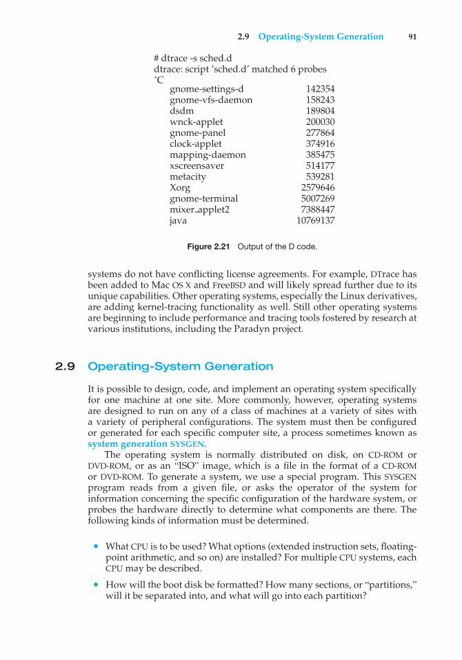
2.9 Operating-System Generation 91
# dtrace -s sched.ddtrace: script ’sched.d’ matched 6 probesˆC
gnome-settings-d 142354gnome-vfs-daemon 158243dsdm 189804wnck-applet 200030gnome-panel 277864clock-applet 374916mapping-daemon 385475xscreensaver 514177metacity 539281Xorg 2579646gnome-terminal 5007269mixer applet2 7388447java 10769137
Figure 2.21 Output of the D code.
systems do not have conflicting license agreements. For example, DTrace hasbeen added to Mac OS X and FreeBSD and will likely spread further due to itsunique capabilities. Other operating systems, especially the Linux derivatives,are adding kernel-tracing functionality as well. Still other operating systemsare beginning to include performance and tracing tools fostered by research atvarious institutions, including the Paradyn project.
2.9 Operating-System Generation
It is possible to design, code, and implement an operating system specificallyfor one machine at one site. More commonly, however, operating systemsare designed to run on any of a class of machines at a variety of sites witha variety of peripheral configurations. The system must then be configuredor generated for each specific computer site, a process sometimes known assystem generation SYSGEN.
The operating system is normally distributed on disk, on CD-ROM orDVD-ROM, or as an “ISO” image, which is a file in the format of a CD-ROMor DVD-ROM. To generate a system, we use a special program. This SYSGENprogram reads from a given file, or asks the operator of the system forinformation concerning the specific configuration of the hardware system, orprobes the hardware directly to determine what components are there. Thefollowing kinds of information must be determined.
• What CPU is to be used? What options (extended instruction sets, floating-point arithmetic, and so on) are installed? For multiple CPU systems, eachCPU may be described.
• How will the boot disk be formatted? How many sections, or “partitions,”will it be separated into, and what will go into each partition?
92 Chapter 2 Operating-System Structures
• How much memory is available? Some systems will determine this valuethemselves by referencing memory location after memory location until an“illegal address” fault is generated. This procedure defines the final legaladdress and hence the amount of available memory.
• What devices are available? The system will need to know how to addresseach device (the device number), the device interrupt number, the device’stype and model, and any special device characteristics.
• What operating-system options are desired, or what parameter values areto be used? These options or values might include how many buffers ofwhich sizes should be used, what type of CPU-scheduling algorithm isdesired, what the maximum number of processes to be supported is, andso on.
Once this information is determined, it can be used in several ways. At oneextreme, a system administrator can use it to modify a copy of the source code ofthe operating system. The operating system then is completely compiled. Datadeclarations, initializations, and constants, along with conditional compilation,produce an output-object version of the operating system that is tailored to thesystem described.
At a slightly less tailored level, the system description can lead to thecreation of tables and the selection of modules from a precompiled library.These modules are linked together to form the generated operating system.Selection allows the library to contain the device drivers for all supported I/Odevices, but only those needed are linked into the operating system. Becausethe system is not recompiled, system generation is faster, but the resultingsystem may be overly general.
At the other extreme, it is possible to construct a system that is completelytable driven. All the code is always part of the system, and selection occurs atexecution time, rather than at compile or link time. System generation involvessimply creating the appropriate tables to describe the system.
The major differences among these approaches are the size and generalityof the generated system and the ease of modifying it as the hardwareconfiguration changes. Consider the cost of modifying the system to support anewly acquired graphics terminal or another disk drive. Balanced against thatcost, of course, is the frequency (or infrequency) of such changes.
2.10 System Boot
After an operating system is generated, it must be made available for use bythe hardware. But how does the hardware know where the kernel is or how toload that kernel? The procedure of starting a computer by loading the kernelis known as booting the system. On most computer systems, a small piece ofcode known as the bootstrap program or bootstrap loader locates the kernel,loads it into main memory, and starts its execution. Some computer systems,such as PCs, use a two-step process in which a simple bootstrap loader fetchesa more complex boot program from disk, which in turn loads the kernel.
When a CPU receives a reset event—for instance, when it is powered upor rebooted—the instruction register is loaded with a predefined memory
2.11 Summary 93
location, and execution starts there. At that location is the initial bootstrapprogram. This program is in the form of read-only memory (ROM), becausethe RAM is in an unknown state at system startup. ROM is convenient becauseit needs no initialization and cannot easily be infected by a computer virus.
The bootstrap program can perform a variety of tasks. Usually, one taskis to run diagnostics to determine the state of the machine. If the diagnosticspass, the program can continue with the booting steps. It can also initialize allaspects of the system, from CPU registers to device controllers and the contentsof main memory. Sooner or later, it starts the operating system.
Some systems—such as cellular phones, tablets, and game consoles—storethe entire operating system in ROM. Storing the operating system in ROM issuitable for small operating systems, simple supporting hardware, and ruggedoperation. A problem with this approach is that changing the bootstrap coderequires changing the ROM hardware chips. Some systems resolve this problemby using erasable programmable read-only memory (EPROM), which is read-only except when explicitly given a command to become writable. All formsof ROM are also known as firmware, since their characteristics fall somewherebetween those of hardware and those of software. A problem with firmwarein general is that executing code there is slower than executing code in RAM.Some systems store the operating system in firmware and copy it to RAM forfast execution. A final issue with firmware is that it is relatively expensive, sousually only small amounts are available.
For large operating systems (including most general-purpose operatingsystems like Windows, Mac OS X, and UNIX) or for systems that changefrequently, the bootstrap loader is stored in firmware, and the operating systemis on disk. In this case, the bootstrap runs diagnostics and has a bit of codethat can read a single block at a fixed location (say block zero) from disk intomemory and execute the code from that boot block. The program stored in theboot block may be sophisticated enough to load the entire operating systeminto memory and begin its execution. More typically, it is simple code (as it fitsin a single disk block) and knows only the address on disk and length of theremainder of the bootstrap program. GRUB is an example of an open-sourcebootstrap program for Linux systems. All of the disk-bound bootstrap, and theoperating system itself, can be easily changed by writing new versions to disk.A disk that has a boot partition (more on that in Section 10.5.1) is called a bootdisk or system disk.
Now that the full bootstrap program has been loaded, it can traverse thefile system to find the operating system kernel, load it into memory, and startits execution. It is only at this point that the system is said to be running.
2.11 Summary
Operating systems provide a number of services. At the lowest level, systemcalls allow a running program to make requests from the operating systemdirectly. At a higher level, the command interpreter or shell provides amechanism for a user to issue a request without writing a program. Commandsmay come from files during batch-mode execution or directly from a terminalor desktop GUI when in an interactive or time-shared mode. System programsare provided to satisfy many common user requests.
94 Chapter 2 Operating-System Structures
The types of requests vary according to level. The system-call level mustprovide the basic functions, such as process control and file and devicemanipulation. Higher-level requests, satisfied by the command interpreter orsystem programs, are translated into a sequence of system calls. System servicescan be classified into several categories: program control, status requests, andI/O requests. Program errors can be considered implicit requests for service.
The design of a new operating system is a major task. It is important thatthe goals of the system be well defined before the design begins. The type ofsystem desired is the foundation for choices among various algorithms andstrategies that will be needed.
Throughout the entire design cycle, we must be careful to separate policydecisions from implementation details (mechanisms). This separation allowsmaximum flexibility if policy decisions are to be changed later.
Once an operating system is designed, it must be implemented. Oper-ating systems today are almost always written in a systems-implementationlanguage or in a higher-level language. This feature improves their implemen-tation, maintenance, and portability.
A system as large and complex as a modern operating system mustbe engineered carefully. Modularity is important. Designing a system as asequence of layers or using a microkernel is considered a good technique. Manyoperating systems now support dynamically loaded modules, which allowadding functionality to an operating system while it is executing. Generally,operating systems adopt a hybrid approach that combines several differenttypes of structures.
Debugging process and kernel failures can be accomplished through theuse of debuggers and other tools that analyze core dumps. Tools such as DTraceanalyze production systems to find bottlenecks and understand other systembehavior.
To create an operating system for a particular machine configuration, wemust perform system generation. For the computer system to begin running,the CPU must initialize and start executing the bootstrap program in firmware.The bootstrap can execute the operating system directly if the operating systemis also in the firmware, or it can complete a sequence in which it loadsprogressively smarter programs from firmware and disk until the operatingsystem itself is loaded into memory and executed.
Practice Exercises
2.1 What is the purpose of system calls?
2.2 What are the five major activities of an operating system with regard toprocess management?
2.3 What are the three major activities of an operating system with regardto memory management?
2.4 What are the three major activities of an operating system with regardto secondary-storage management?
2.5 What is the purpose of the command interpreter? Why is it usuallyseparate from the kernel?
Exercises 95
2.6 What system calls have to be executed by a command interpreter or shellin order to start a new process?
2.7 What is the purpose of system programs?
2.8 What is the main advantage of the layered approach to system design?What are the disadvantages of the layered approach?
2.9 List five services provided by an operating system, and explain how eachcreates convenience for users. In which cases would it be impossible foruser-level programs to provide these services? Explain your answer.
2.10 Why do some systems store the operating system in firmware, whileothers store it on disk?
2.11 How could a system be designed to allow a choice of operating systemsfrom which to boot? What would the bootstrap program need to do?
Exercises
2.12 The services and functions provided by an operating system can bedivided into two main categories. Briefly describe the two categories,and discuss how they differ.
2.13 Describe three general methods for passing parameters to the operatingsystem.
2.14 Describe how you could obtain a statistical profile of the amount of timespent by a program executing different sections of its code. Discuss theimportance of obtaining such a statistical profile.
2.15 What are the five major activities of an operating system with regard tofile management?
2.16 What are the advantages and disadvantages of using the same system-call interface for manipulating both files and devices?
2.17 Would it be possible for the user to develop a new command interpreterusing the system-call interface provided by the operating system?
2.18 What are the two models of interprocess communication? What are thestrengths and weaknesses of the two approaches?
2.19 Why is the separation of mechanism and policy desirable?
2.20 It is sometimes difficult to achieve a layered approach if two componentsof the operating system are dependent on each other. Identify a scenarioin which it is unclear how to layer two system components that requiretight coupling of their functionalities.
2.21 What is the main advantage of the microkernel approach to systemdesign? How do user programs and system services interact in amicrokernel architecture? What are the disadvantages of using themicrokernel approach?
2.22 What are the advantages of using loadable kernel modules?
96 Chapter 2 Operating-System Structures
2.23 How are iOS and Android similar? How are they different?
2.24 Explain why Java programs running on Android systems do not use thestandard Java API and virtual machine.
2.25 The experimental Synthesis operating system has an assembler incor-porated in the kernel. To optimize system-call performance, the kernelassembles routines within kernel space to minimize the path that thesystem call must take through the kernel. This approach is the antithesisof the layered approach, in which the path through the kernel is extendedto make building the operating system easier. Discuss the pros and consof the Synthesis approach to kernel design and system-performanceoptimization.
Programming Problems
2.26 In Section 2.3, we described a program that copies the contents of one fileto a destination file. This program works by first prompting the user forthe name of the source and destination files. Write this program usingeither the Windows or POSIX API. Be sure to include all necessary errorchecking, including ensuring that the source file exists.
Once you have correctly designed and tested the program, if youused a system that supports it, run the program using a utility that tracessystem calls. Linux systems provide the strace utility, and Solaris andMac OS X systems use the dtrace command. As Windows systems donot provide such features, you will have to trace through the Windowsversion of this program using a debugger.
Programming Projects
Linux Kernel ModulesIn this project, you will learn how to create a kernel module and load it into theLinux kernel. The project can be completed using the Linux virtual machinethat is available with this text. Although you may use an editor to write theseC programs, you will have to use the terminal application to compile theprograms, and you will have to enter commands on the command line tomanage the modules in the kernel.
As you’ll discover, the advantage of developing kernel modules is that itis a relatively easy method of interacting with the kernel, thus allowing you towrite programs that directly invoke kernel functions. It is important for youto keep in mind that you are indeed writing kernel code that directly interactswith the kernel. That normally means that any errors in the code could crashthe system! However, since you will be using a virtual machine, any failureswill at worst only require rebooting the system.
Part I—Creating Kernel Modules
The first part of this project involves following a series of steps for creating andinserting a module into the Linux kernel.
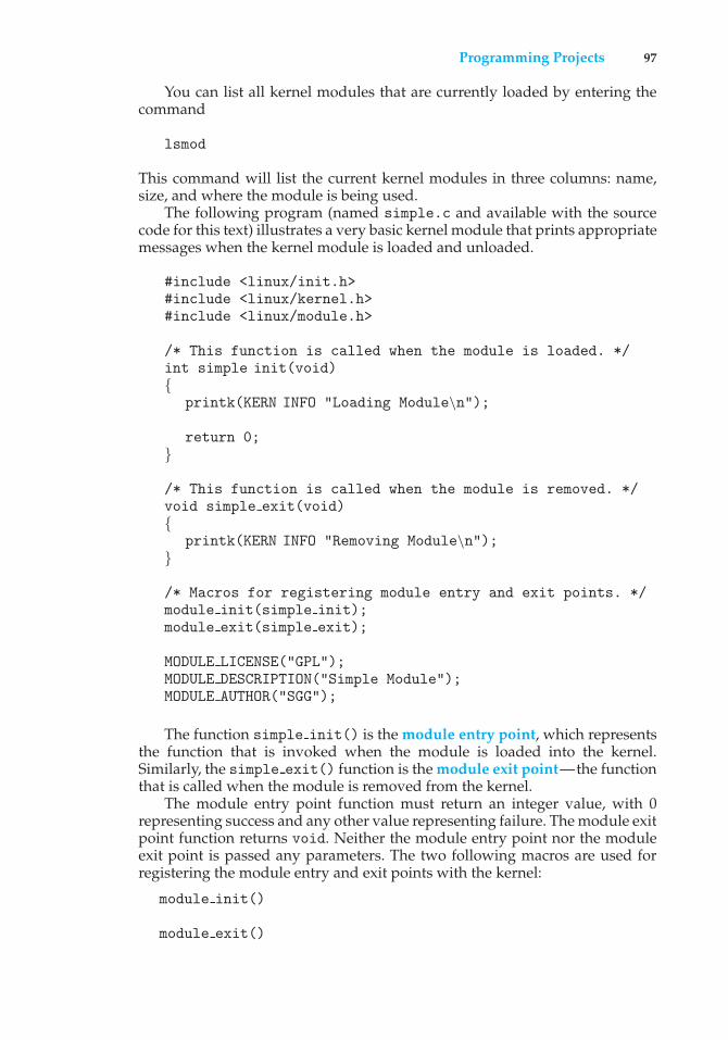
Programming Projects 97
You can list all kernel modules that are currently loaded by entering thecommand
lsmod
This command will list the current kernel modules in three columns: name,size, and where the module is being used.
The following program (named simple.c and available with the sourcecode for this text) illustrates a very basic kernel module that prints appropriatemessages when the kernel module is loaded and unloaded.
#include <linux/init.h>#include <linux/kernel.h>#include <linux/module.h>
/* This function is called when the module is loaded. */int simple init(void){
printk(KERN INFO "Loading Module\n");
return 0;}
/* This function is called when the module is removed. */void simple exit(void){
printk(KERN INFO "Removing Module\n");}
/* Macros for registering module entry and exit points. */module init(simple init);module exit(simple exit);
MODULE LICENSE("GPL");MODULE DESCRIPTION("Simple Module");MODULE AUTHOR("SGG");
The function simple init() is the module entry point, which representsthe function that is invoked when the module is loaded into the kernel.Similarly, the simple exit() function is the module exit point—the functionthat is called when the module is removed from the kernel.
The module entry point function must return an integer value, with 0representing success and any other value representing failure. The module exitpoint function returns void. Neither the module entry point nor the moduleexit point is passed any parameters. The two following macros are used forregistering the module entry and exit points with the kernel:
module init()
module exit()
98 Chapter 2 Operating-System Structures
Notice how both the module entry and exit point functions make callsto the printk() function. printk() is the kernel equivalent of printf(),yet its output is sent to a kernel log buffer whose contents can be read bythe dmesg command. One difference between printf() and printk() is thatprintk() allows us to specify a priority flag whose values are given in the<linux/printk.h> include file. In this instance, the priority is KERN INFO,which is defined as an informational message.
The final lines—MODULE LICENSE(), MODULE DESCRIPTION(), and MOD-ULE AUTHOR()—represent details regarding the software license, descriptionof the module, and author. For our purposes, we do not depend on thisinformation, but we include it because it is standard practice in developingkernel modules.
This kernel module simple.c is compiled using the Makefile accom-panying the source code with this project. To compile the module, enter thefollowing on the command line:
make
The compilation produces several files. The file simple.ko represents thecompiled kernel module. The following step illustrates inserting this moduleinto the Linux kernel.
Loading and Removing Kernel Modules
Kernel modules are loaded using theinsmod command, which is run as follows:
sudo insmod simple.ko
To check whether the module has loaded, enter the lsmod command and searchfor the module simple. Recall that the module entry point is invoked whenthe module is inserted into the kernel. To check the contents of this message inthe kernel log buffer, enter the command
dmesg
You should see the message "Loading Module."Removing the kernel module involves invoking the rmmod command
(notice that the .ko suffix is unnecessary):
sudo rmmod simple
Be sure to check with the dmesg command to ensure the module has beenremoved.
Because the kernel log buffer can fill up quickly, it often makes sense toclear the buffer periodically. This can be accomplished as follows:
sudo dmesg -c
Programming Projects 99
Part I Assignment
Proceed through the steps described above to create the kernel module and toload and unload the module. Be sure to check the contents of the kernel logbuffer using dmesg to ensure you have properly followed the steps.
Part II—Kernel Data Structures
The second part of this project involves modifying the kernel module so thatit uses the kernel linked-list data structure.
In Section 1.10, we covered various data structures that are common inoperating systems. The Linux kernel provides several of these structures. Here,we explore using the circular, doubly linked list that is available to kerneldevelopers. Much of what we discuss is available in the Linux source code—in this instance, the include file <linux/list.h>—and we recommend thatyou examine this file as you proceed through the following steps.
Initially, you must define a struct containing the elements that are to beinserted in the linked list. The following C struct defines birthdays:
struct birthday {int day;int month;int year;struct list head list;
}
Notice the member struct list head list. The list head structure isdefined in the include file <linux/types.h>. Its intention is to embed thelinked list within the nodes that comprise the list. This list head structure isquite simple—it merely holds two members, next and prev, that point to thenext and previous entries in the list. By embedding the linked list within thestructure, Linux makes it possible to manage the data structure with a series ofmacro functions.
Inserting Elements into the Linked List
We can declare a list head object, which we use as a reference to the head ofthe list by using the LIST HEAD() macro
static LIST HEAD(birthday list);
This macro defines and initializes the variable birthday list, which is of typestruct list head.
100 Chapter 2 Operating-System Structures
We create and initialize instances of struct birthday as follows:
struct birthday *person;
person = kmalloc(sizeof(*person), GFP KERNEL);person->day = 2;person->month= 8;person->year = 1995;INIT LIST HEAD(&person->list);
The kmalloc() function is the kernel equivalent of the user-level malloc()function for allocating memory, except that kernel memory is being allocated.(The GFP KERNEL flag indicates routine kernel memory allocation.) The macroINIT LIST HEAD() initializes the list member in struct birthday. We canthen add this instance to the end of the linked list using the list add tail()macro:
list add tail(&person->list, &birthday list);
Traversing the Linked List
Traversing the list involves using the list for each entry() Macro, whichaccepts three parameters:
• A pointer to the structure being iterated over
• A pointer to the head of the list being iterated over
• The name of the variable containing the list head structure
The following code illustrates this macro:
struct birthday *ptr;
list for each entry(ptr, &birthday list, list) {/* on each iteration ptr points *//* to the next birthday struct */
}
Removing Elements from the Linked List
Removing elements from the list involves using the list del() macro, whichis passed a pointer to struct list head
list del(struct list head *element)
This removes element from the list while maintaining the structure of theremainder of the list.
Perhaps the simplest approach for removing all elements from alinked list is to remove each element as you traverse the list. The macrolist for each entry safe() behaves much like list for each entry()
Bibliographical Notes 101
except that it is passed an additional argument that maintains the value of thenext pointer of the item being deleted. (This is necessary for preserving thestructure of the list.) The following code example illustrates this macro:
struct birthday *ptr, *next
list for each entry safe(ptr,next,&birthday list,list) {/* on each iteration ptr points *//* to the next birthday struct */list del(&ptr->list);kfree(ptr);
}
Notice that after deleting each element, we return memory that was previouslyallocated with kmalloc() back to the kernel with the call to kfree(). Carefulmemory management—which includes releasing memory to prevent memoryleaks—is crucial when developing kernel-level code.
Part II Assignment
In the module entry point, create a linked list containing fivestruct birthdayelements. Traverse the linked list and output its contents to the kernel log buffer.Invoke the dmesg command to ensure the list is properly constructed once thekernel module has been loaded.
In the module exit point, delete the elements from the linked list and returnthe free memory back to the kernel. Again, invoke the dmesg command to checkthat the list has been removed once the kernel module has been unloaded.
Bibliographical Notes
[Dijkstra (1968)] advocated the layered approach to operating-system design.[Brinch-Hansen (1970)] was an early proponent of constructing an operatingsystem as a kernel (or nucleus) on which more complete systems could bebuilt. [Tarkoma and Lagerspetz (2011)] provide an overview of various mobileoperating systems, including Android and iOS.
MS-DOS, Version 3.1, is described in [Microsoft (1986)]. Windows NTand Windows 2000 are described by [Solomon (1998)] and [Solomon andRussinovich (2000)]. Windows XP internals are described in [Russinovichand Solomon (2009)]. [Hart (2005)] covers Windows systems programmingin detail. BSD UNIX is described in [McKusick et al. (1996)]. [Love (2010)] and[Mauerer (2008)] thoroughly discuss the Linux kernel. In particular, [Love(2010)] covers Linux kernel modules as well as kernel data structures. SeveralUNIX systems—including Mach—are treated in detail in [Vahalia (1996)]. MacOS X is presented at http://www.apple.com/macosx and in [Singh (2007)].Solaris is fully described in [McDougall and Mauro (2007)].
DTrace is discussed in [Gregg and Mauro (2011)]. The DTrace source codeis available at http://src.opensolaris.org/source/.
102 Chapter 2 Operating-System Structures
Bibliography
[Brinch-Hansen (1970)] P. Brinch-Hansen, “The Nucleus of a Multiprogram-ming System”, Communications of the ACM, Volume 13, Number 4 (1970), pages238–241 and 250.
[Dijkstra (1968)] E. W. Dijkstra, “The Structure of the THE MultiprogrammingSystem”, Communications of the ACM, Volume 11, Number 5 (1968), pages341–346.
[Gregg and Mauro (2011)] B. Gregg and J. Mauro, DTrace—Dynamic Tracing inOracle Solaris, Mac OS X, and FreeBSD, Prentice Hall (2011).
[Hart (2005)] J. M. Hart, Windows System Programming, Third Edition, Addison-Wesley (2005).
[Love (2010)] R. Love, Linux Kernel Development, Third Edition, Developer’sLibrary (2010).
[Mauerer (2008)] W. Mauerer, Professional Linux Kernel Architecture, John Wileyand Sons (2008).
[McDougall and Mauro (2007)] R. McDougall and J. Mauro, Solaris Internals,Second Edition, Prentice Hall (2007).
[McKusick et al. (1996)] M. K. McKusick, K. Bostic, and M. J. Karels, The Designand Implementation of the 4.4 BSD UNIX Operating System, John Wiley and Sons(1996).
[Microsoft (1986)] Microsoft MS-DOS User’s Reference and Microsoft MS-DOSProgrammer’s Reference. Microsoft Press (1986).
[Russinovich and Solomon (2009)] M. E. Russinovich and D. A. Solomon, Win-dows Internals: Including Windows Server 2008 and Windows Vista, Fifth Edition,Microsoft Press (2009).
[Singh (2007)] A. Singh, Mac OS X Internals: A Systems Approach, Addison-Wesley (2007).
[Solomon (1998)] D. A. Solomon, Inside Windows NT, Second Edition, MicrosoftPress (1998).
[Solomon and Russinovich (2000)] D. A. Solomon and M. E. Russinovich, InsideMicrosoft Windows 2000, Third Edition, Microsoft Press (2000).
[Tarkoma and Lagerspetz (2011)] S. Tarkoma and E. Lagerspetz, “Arching overthe Mobile Computing Chasm: Platforms and Runtimes”, IEEE Computer,Volume 44, (2011), pages 22–28.
[Vahalia (1996)] U. Vahalia, Unix Internals: The New Frontiers, Prentice Hall(1996).
Part Two
ProcessManagement
A process can be thought of as a program in execution. A process willneed certain resources—such as CPU time, memory, files, and I/O devices—to accomplish its task. These resources are allocated to the processeither when it is created or while it is executing.
A process is the unit of work in most systems. Systems consist ofa collection of processes: operating-system processes execute systemcode, and user processes execute user code. All these processes mayexecute concurrently.
Although traditionally a process contained only a single thread ofcontrol as it ran, most modern operating systems now support processesthat have multiple threads.
The operating system is responsible for several important aspects ofprocess and thread management: the creation and deletion of both userand system processes; the scheduling of processes; and the provision ofmechanisms for synchronization, communication, and deadlock handlingfor processes.

3C H A P T E R
Processes
Early computers allowed only one program to be executed at a time. Thisprogram had complete control of the system and had access to all the system’sresources. In contrast, contemporary computer systems allow multiple pro-grams to be loaded into memory and executed concurrently. This evolutionrequired firmer control and more compartmentalization of the various pro-grams; and these needs resulted in the notion of a process, which is a programin execution. A process is the unit of work in a modern time-sharing system.
The more complex the operating system is, the more it is expected to do onbehalf of its users. Although its main concern is the execution of user programs,it also needs to take care of various system tasks that are better left outside thekernel itself. A system therefore consists of a collection of processes: operating-system processes executing system code and user processes executing usercode. Potentially, all these processes can execute concurrently, with the CPU (orCPUs) multiplexed among them. By switching the CPU between processes, theoperating system can make the computer more productive. In this chapter, youwill read about what processes are and how they work.
CHAPTER OBJECTIVES
• To introduce the notion of a process—a program in execution, which formsthe basis of all computation.
• To describe the various features of processes, including scheduling,creation, and termination.
• To explore interprocess communication using shared memory and mes-sage passing.
• To describe communication in client–server systems.
3.1 Process Concept
A question that arises in discussing operating systems involves what to callall the CPU activities. A batch system executes jobs, whereas a time-shared
105
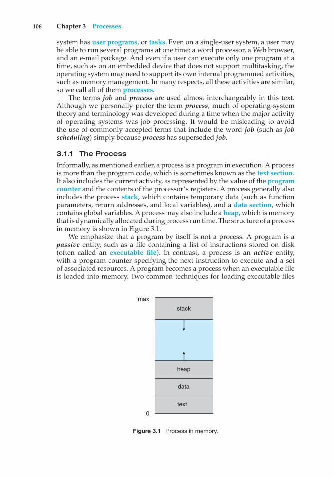
106 Chapter 3 Processes
system has user programs, or tasks. Even on a single-user system, a user maybe able to run several programs at one time: a word processor, a Web browser,and an e-mail package. And even if a user can execute only one program at atime, such as on an embedded device that does not support multitasking, theoperating system may need to support its own internal programmed activities,such as memory management. In many respects, all these activities are similar,so we call all of them processes.
The terms job and process are used almost interchangeably in this text.Although we personally prefer the term process, much of operating-systemtheory and terminology was developed during a time when the major activityof operating systems was job processing. It would be misleading to avoidthe use of commonly accepted terms that include the word job (such as jobscheduling) simply because process has superseded job.
3.1.1 The Process
Informally, as mentioned earlier, a process is a program in execution. A processis more than the program code, which is sometimes known as the text section.It also includes the current activity, as represented by the value of the programcounter and the contents of the processor’s registers. A process generally alsoincludes the process stack, which contains temporary data (such as functionparameters, return addresses, and local variables), and a data section, whichcontains global variables. A process may also include a heap, which is memorythat is dynamically allocated during process run time. The structure of a processin memory is shown in Figure 3.1.
We emphasize that a program by itself is not a process. A program is apassive entity, such as a file containing a list of instructions stored on disk(often called an executable file). In contrast, a process is an active entity,with a program counter specifying the next instruction to execute and a setof associated resources. A program becomes a process when an executable fileis loaded into memory. Two common techniques for loading executable files
text
0
max
data
heap
stack
Figure 3.1 Process in memory.
3.1 Process Concept 107
are double-clicking an icon representing the executable file and entering thename of the executable file on the command line (as in prog.exe or a.out).
Although two processes may be associated with the same program, theyare nevertheless considered two separate execution sequences. For instance,several users may be running different copies of the mail program, or the sameuser may invoke many copies of the web browser program. Each of these is aseparate process; and although the text sections are equivalent, the data, heap,and stack sections vary. It is also common to have a process that spawns manyprocesses as it runs. We discuss such matters in Section 3.4.
Note that a process itself can be an execution environment for othercode. The Java programming environment provides a good example. In mostcircumstances, an executable Java program is executed within the Java virtualmachine (JVM). The JVM executes as a process that interprets the loaded Javacode and takes actions (via native machine instructions) on behalf of that code.For example, to run the compiled Java program Program.class, we wouldenter
java Program
The command java runs the JVM as an ordinary process, which in turnsexecutes the Java program Program in the virtual machine. The concept is thesame as simulation, except that the code, instead of being written for a differentinstruction set, is written in the Java language.
3.1.2 Process State
As a process executes, it changes state. The state of a process is defined in partby the current activity of that process. A process may be in one of the followingstates:
• New. The process is being created.
• Running. Instructions are being executed.
• Waiting. The process is waiting for some event to occur (such as an I/Ocompletion or reception of a signal).
• Ready. The process is waiting to be assigned to a processor.
• Terminated. The process has finished execution.
These names are arbitrary, and they vary across operating systems. The statesthat they represent are found on all systems, however. Certain operatingsystems also more finely delineate process states. It is important to realizethat only one process can be running on any processor at any instant. Manyprocesses may be ready and waiting, however. The state diagram correspondingto these states is presented in Figure 3.2.
3.1.3 Process Control Block
Each process is represented in the operating system by a process control block(PCB)—also called a task control block. A PCB is shown in Figure 3.3. It containsmany pieces of information associated with a specific process, including these:
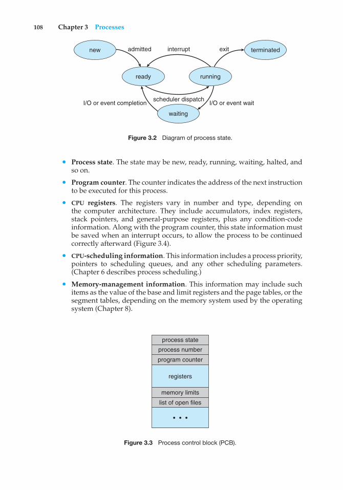
108 Chapter 3 Processes
new terminated
runningready
admitted interrupt
scheduler dispatchI/O or event completion I/O or event wait
exit
waiting
Figure 3.2 Diagram of process state.
• Process state. The state may be new, ready, running, waiting, halted, andso on.
• Program counter. The counter indicates the address of the next instructionto be executed for this process.
• CPU registers. The registers vary in number and type, depending onthe computer architecture. They include accumulators, index registers,stack pointers, and general-purpose registers, plus any condition-codeinformation. Along with the program counter, this state information mustbe saved when an interrupt occurs, to allow the process to be continuedcorrectly afterward (Figure 3.4).
• CPU-scheduling information. This information includes a process priority,pointers to scheduling queues, and any other scheduling parameters.(Chapter 6 describes process scheduling.)
• Memory-management information. This information may include suchitems as the value of the base and limit registers and the page tables, or thesegment tables, depending on the memory system used by the operatingsystem (Chapter 8).
process state
process number
program counter
memory limits
list of open files
registers
• • •
Figure 3.3 Process control block (PCB).
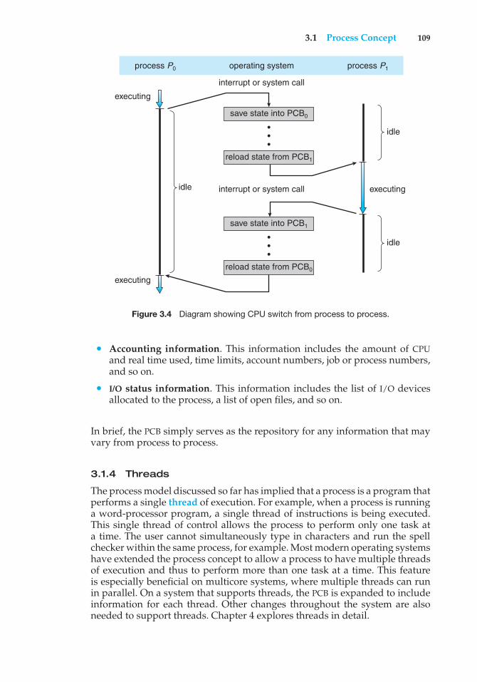
3.1 Process Concept 109
process P0 process P1
save state into PCB0
save state into PCB1
reload state from PCB1
reload state from PCB0
operating system
idle
idle
executingidle
executing
executing
interrupt or system call
interrupt or system call
•••
•••
Figure 3.4 Diagram showing CPU switch from process to process.
• Accounting information. This information includes the amount of CPUand real time used, time limits, account numbers, job or process numbers,and so on.
• I/O status information. This information includes the list of I/O devicesallocated to the process, a list of open files, and so on.
In brief, the PCB simply serves as the repository for any information that mayvary from process to process.
3.1.4 Threads
The process model discussed so far has implied that a process is a program thatperforms a single thread of execution. For example, when a process is runninga word-processor program, a single thread of instructions is being executed.This single thread of control allows the process to perform only one task ata time. The user cannot simultaneously type in characters and run the spellchecker within the same process, for example. Most modern operating systemshave extended the process concept to allow a process to have multiple threadsof execution and thus to perform more than one task at a time. This featureis especially beneficial on multicore systems, where multiple threads can runin parallel. On a system that supports threads, the PCB is expanded to includeinformation for each thread. Other changes throughout the system are alsoneeded to support threads. Chapter 4 explores threads in detail.
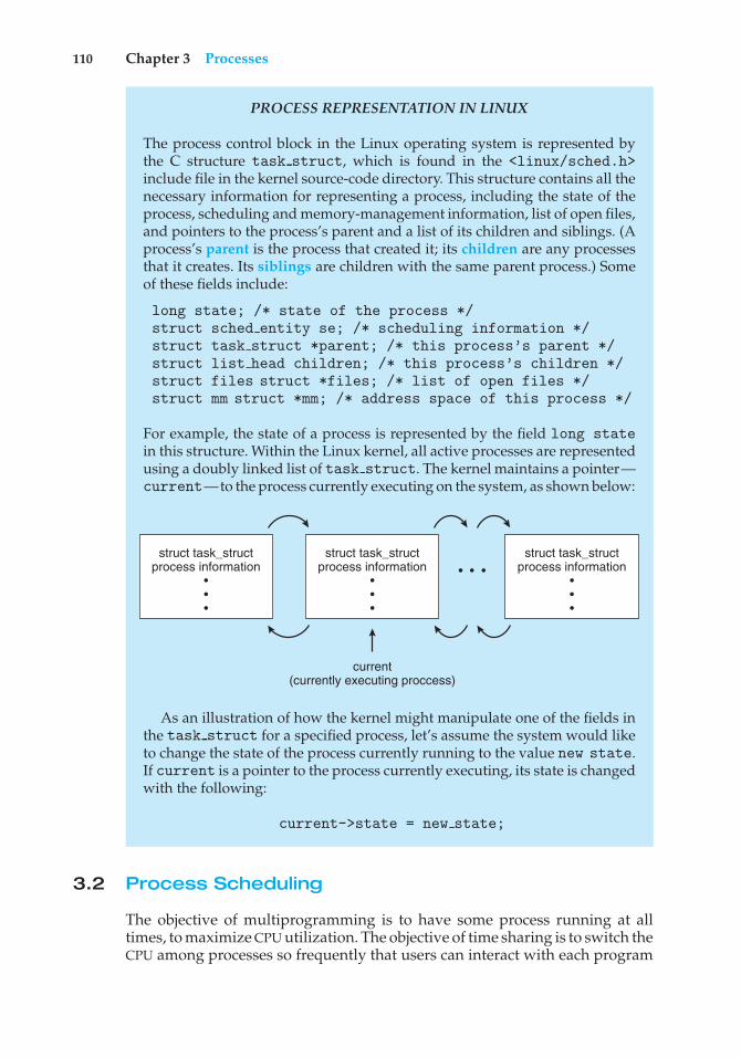
110 Chapter 3 Processes
PROCESS REPRESENTATION IN LINUX
The process control block in the Linux operating system is represented bythe C structure task struct, which is found in the <linux/sched.h>include file in the kernel source-code directory. This structure contains all thenecessary information for representing a process, including the state of theprocess, scheduling and memory-management information, list of open files,and pointers to the process’s parent and a list of its children and siblings. (Aprocess’s parent is the process that created it; its children are any processesthat it creates. Its siblings are children with the same parent process.) Someof these fields include:
long state; /* state of the process */struct sched entity se; /* scheduling information */struct task struct *parent; /* this process’s parent */struct list head children; /* this process’s children */struct files struct *files; /* list of open files */struct mm struct *mm; /* address space of this process */
For example, the state of a process is represented by the field long statein this structure. Within the Linux kernel, all active processes are representedusing a doubly linked list of task struct. The kernel maintains a pointer—current—to the process currently executing on the system, as shown below:
struct task_structprocess information
• • •
struct task_structprocess information
•••
current(currently executing proccess)
struct task_structprocess information
•••
• • •
As an illustration of how the kernel might manipulate one of the fields inthe task struct for a specified process, let’s assume the system would liketo change the state of the process currently running to the value new state.If current is a pointer to the process currently executing, its state is changedwith the following:
current->state = new state;
3.2 Process Scheduling
The objective of multiprogramming is to have some process running at alltimes, to maximize CPU utilization. The objective of time sharing is to switch theCPU among processes so frequently that users can interact with each program
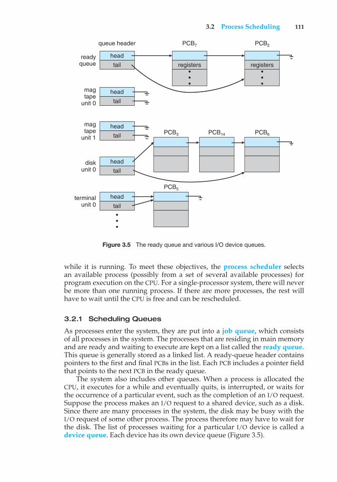
3.2 Process Scheduling 111
queue header PCB7
PCB3
PCB5
PCB14 PCB6
PCB2
head
head
head
head
head
readyqueue
disk unit 0
terminal unit 0
magtape
unit 0
magtape
unit 1
tail registers registers
tail
tail
tail
tail•••
•••
•••
Figure 3.5 The ready queue and various I/O device queues.
while it is running. To meet these objectives, the process scheduler selectsan available process (possibly from a set of several available processes) forprogram execution on the CPU. For a single-processor system, there will neverbe more than one running process. If there are more processes, the rest willhave to wait until the CPU is free and can be rescheduled.
3.2.1 Scheduling Queues
As processes enter the system, they are put into a job queue, which consistsof all processes in the system. The processes that are residing in main memoryand are ready and waiting to execute are kept on a list called the ready queue.This queue is generally stored as a linked list. A ready-queue header containspointers to the first and final PCBs in the list. Each PCB includes a pointer fieldthat points to the next PCB in the ready queue.
The system also includes other queues. When a process is allocated theCPU, it executes for a while and eventually quits, is interrupted, or waits forthe occurrence of a particular event, such as the completion of an I/O request.Suppose the process makes an I/O request to a shared device, such as a disk.Since there are many processes in the system, the disk may be busy with theI/O request of some other process. The process therefore may have to wait forthe disk. The list of processes waiting for a particular I/O device is called adevice queue. Each device has its own device queue (Figure 3.5).
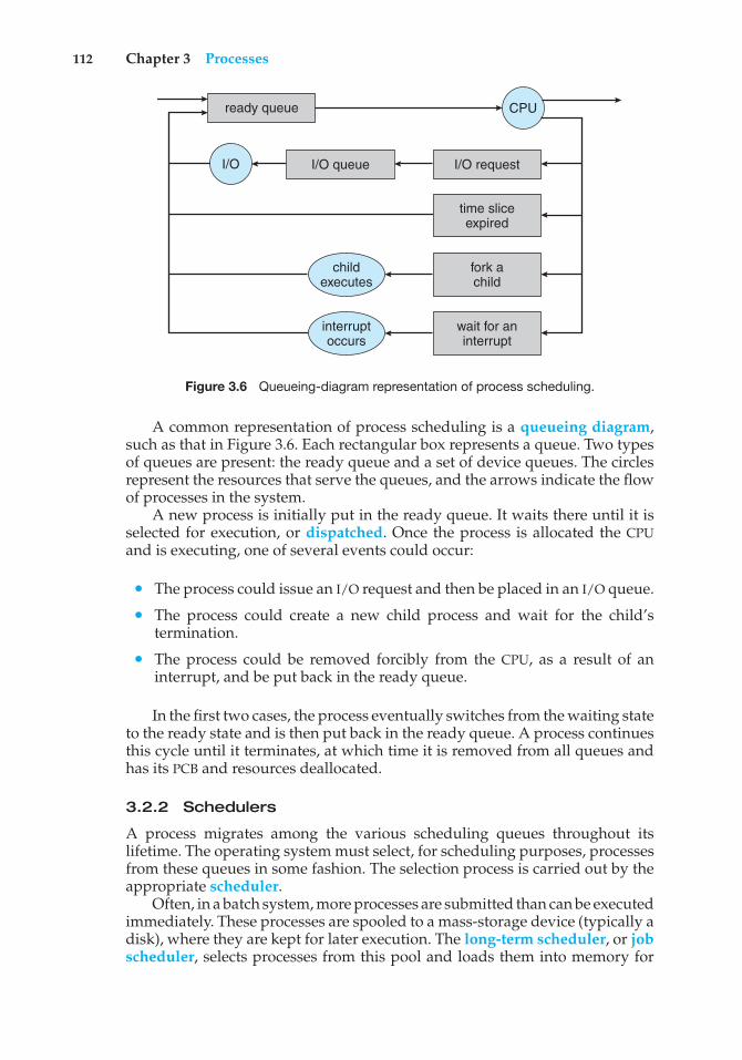
112 Chapter 3 Processes
ready queue CPU
I/O I/O queue I/O request
time sliceexpired
fork achild
wait for aninterrupt
interruptoccurs
childexecutes
Figure 3.6 Queueing-diagram representation of process scheduling.
A common representation of process scheduling is a queueing diagram,such as that in Figure 3.6. Each rectangular box represents a queue. Two typesof queues are present: the ready queue and a set of device queues. The circlesrepresent the resources that serve the queues, and the arrows indicate the flowof processes in the system.
A new process is initially put in the ready queue. It waits there until it isselected for execution, or dispatched. Once the process is allocated the CPUand is executing, one of several events could occur:
• The process could issue an I/O request and then be placed in an I/O queue.
• The process could create a new child process and wait for the child’stermination.
• The process could be removed forcibly from the CPU, as a result of aninterrupt, and be put back in the ready queue.
In the first two cases, the process eventually switches from the waiting stateto the ready state and is then put back in the ready queue. A process continuesthis cycle until it terminates, at which time it is removed from all queues andhas its PCB and resources deallocated.
3.2.2 Schedulers
A process migrates among the various scheduling queues throughout itslifetime. The operating system must select, for scheduling purposes, processesfrom these queues in some fashion. The selection process is carried out by theappropriate scheduler.
Often, in a batch system, more processes are submitted than can be executedimmediately. These processes are spooled to a mass-storage device (typically adisk), where they are kept for later execution. The long-term scheduler, or jobscheduler, selects processes from this pool and loads them into memory for
3.2 Process Scheduling 113
execution. The short-term scheduler, or CPU scheduler, selects from amongthe processes that are ready to execute and allocates the CPU to one of them.
The primary distinction between these two schedulers lies in frequencyof execution. The short-term scheduler must select a new process for the CPUfrequently. A process may execute for only a few milliseconds before waitingfor an I/O request. Often, the short-term scheduler executes at least once every100 milliseconds. Because of the short time between executions, the short-termscheduler must be fast. If it takes 10 milliseconds to decide to execute a processfor 100 milliseconds, then 10/(100 + 10) = 9 percent of the CPU is being used(wasted) simply for scheduling the work.
The long-term scheduler executes much less frequently; minutes may sep-arate the creation of one new process and the next. The long-term schedulercontrols the degree of multiprogramming (the number of processes in mem-ory). If the degree of multiprogramming is stable, then the average rate ofprocess creation must be equal to the average departure rate of processesleaving the system. Thus, the long-term scheduler may need to be invokedonly when a process leaves the system. Because of the longer interval betweenexecutions, the long-term scheduler can afford to take more time to decidewhich process should be selected for execution.
It is important that the long-term scheduler make a careful selection. Ingeneral, most processes can be described as either I/O bound or CPU bound.An I/O-bound process is one that spends more of its time doing I/O thanit spends doing computations. A CPU-bound process, in contrast, generatesI/O requests infrequently, using more of its time doing computations. It isimportant that the long-term scheduler select a good process mix of I/O-boundand CPU-bound processes. If all processes are I/O bound, the ready queue willalmost always be empty, and the short-term scheduler will have little to do.If all processes are CPU bound, the I/O waiting queue will almost always beempty, devices will go unused, and again the system will be unbalanced. Thesystem with the best performance will thus have a combination of CPU-boundand I/O-bound processes.
On some systems, the long-term scheduler may be absent or minimal.For example, time-sharing systems such as UNIX and Microsoft Windowssystems often have no long-term scheduler but simply put every new process inmemory for the short-term scheduler. The stability of these systems dependseither on a physical limitation (such as the number of available terminals)or on the self-adjusting nature of human users. If performance declines tounacceptable levels on a multiuser system, some users will simply quit.
Some operating systems, such as time-sharing systems, may introduce anadditional, intermediate level of scheduling. This medium-term scheduler isdiagrammed in Figure 3.7. The key idea behind a medium-term scheduler isthat sometimes it can be advantageous to remove a process from memory(and from active contention for the CPU) and thus reduce the degree ofmultiprogramming. Later, the process can be reintroduced into memory, and itsexecution can be continued where it left off. This scheme is called swapping.The process is swapped out, and is later swapped in, by the medium-termscheduler. Swapping may be necessary to improve the process mix or becausea change in memory requirements has overcommitted available memory,requiring memory to be freed up. Swapping is discussed in Chapter 8.
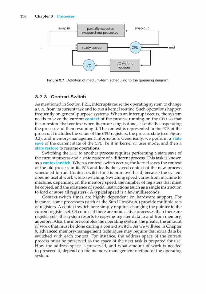
114 Chapter 3 Processes
swap in swap out
endCPU
I/O I/O waitingqueues
ready queue
partially executedswapped-out processes
Figure 3.7 Addition of medium-term scheduling to the queueing diagram.
3.2.3 Context Switch
As mentioned in Section 1.2.1, interrupts cause the operating system to changea CPU from its current task and to run a kernel routine. Such operations happenfrequently on general-purpose systems. When an interrupt occurs, the systemneeds to save the current context of the process running on the CPU so thatit can restore that context when its processing is done, essentially suspendingthe process and then resuming it. The context is represented in the PCB of theprocess. It includes the value of the CPU registers, the process state (see Figure3.2), and memory-management information. Generically, we perform a statesave of the current state of the CPU, be it in kernel or user mode, and then astate restore to resume operations.
Switching the CPU to another process requires performing a state save ofthe current process and a state restore of a different process. This task is knownas a context switch. When a context switch occurs, the kernel saves the contextof the old process in its PCB and loads the saved context of the new processscheduled to run. Context-switch time is pure overhead, because the systemdoes no useful work while switching. Switching speed varies from machine tomachine, depending on the memory speed, the number of registers that mustbe copied, and the existence of special instructions (such as a single instructionto load or store all registers). A typical speed is a few milliseconds.
Context-switch times are highly dependent on hardware support. Forinstance, some processors (such as the Sun UltraSPARC) provide multiple setsof registers. A context switch here simply requires changing the pointer to thecurrent register set. Of course, if there are more active processes than there areregister sets, the system resorts to copying register data to and from memory,as before. Also, the more complex the operating system, the greater the amountof work that must be done during a context switch. As we will see in Chapter8, advanced memory-management techniques may require that extra data beswitched with each context. For instance, the address space of the currentprocess must be preserved as the space of the next task is prepared for use.How the address space is preserved, and what amount of work is neededto preserve it, depend on the memory-management method of the operatingsystem.
3.3 Operations on Processes 115
MULTITASKING IN MOBILE SYSTEMS
Because of the constraints imposed on mobile devices, early versions of iOSdid not provide user-application multitasking; only one application runs inthe foreground and all other user applications are suspended. Operating-system tasks were multitasked because they were written by Apple and wellbehaved. However, beginning with iOS 4, Apple now provides a limitedform of multitasking for user applications, thus allowing a single foregroundapplication to run concurrently with multiple background applications. (Ona mobile device, the foreground application is the application currentlyopen and appearing on the display. The background application remainsin memory, but does not occupy the display screen.) The iOS 4 programmingAPI provides support for multitasking, thus allowing a process to run inthe background without being suspended. However, it is limited and onlyavailable for a limited number of application types, including applications
• running a single, finite-length task (such as completing a download ofcontent from a network);
• receiving notifications of an event occurring (such as a new emailmessage);
• with long-running background tasks (such as an audio player.)
Apple probably limits multitasking due to battery life and memory useconcerns. The CPU certainly has the features to support multitasking, butApple chooses to not take advantage of some of them in order to bettermanage resource use.
Android does not place such constraints on the types of applications thatcan run in the background. If an application requires processing while inthe background, the application must use a service, a separate applicationcomponent that runs on behalf of the background process. Consider astreaming audio application: if the application moves to the background, theservice continues to send audio files to the audio device driver on behalf ofthe background application. In fact, the service will continue to run even if thebackground application is suspended. Services do not have a user interfaceand have a small memory footprint, thus providing an efficient technique formultitasking in a mobile environment.
3.3 Operations on Processes
The processes in most systems can execute concurrently, and they maybe created and deleted dynamically. Thus, these systems must provide amechanism for process creation and termination. In this section, we explorethe mechanisms involved in creating processes and illustrate process creationon UNIX and Windows systems.
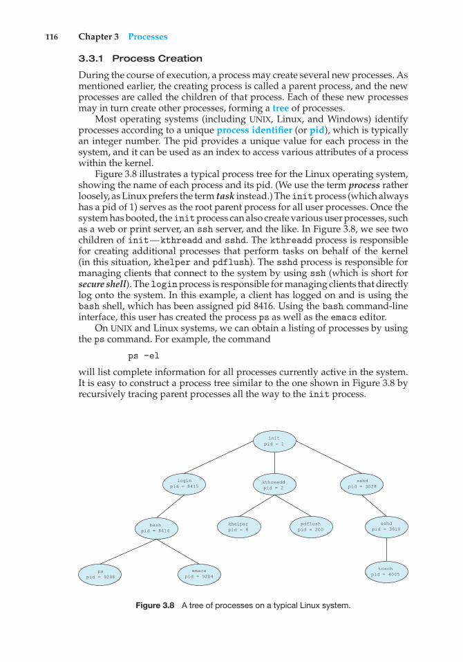
116 Chapter 3 Processes
3.3.1 Process Creation
During the course of execution, a process may create several new processes. Asmentioned earlier, the creating process is called a parent process, and the newprocesses are called the children of that process. Each of these new processesmay in turn create other processes, forming a tree of processes.
Most operating systems (including UNIX, Linux, and Windows) identifyprocesses according to a unique process identifier (or pid), which is typicallyan integer number. The pid provides a unique value for each process in thesystem, and it can be used as an index to access various attributes of a processwithin the kernel.
Figure 3.8 illustrates a typical process tree for the Linux operating system,showing the name of each process and its pid. (We use the term process ratherloosely, as Linux prefers the term task instead.) Theinitprocess (which alwayshas a pid of 1) serves as the root parent process for all user processes. Once thesystem has booted, theinitprocess can also create various user processes, suchas a web or print server, an ssh server, and the like. In Figure 3.8, we see twochildren of init—kthreadd and sshd. The kthreadd process is responsiblefor creating additional processes that perform tasks on behalf of the kernel(in this situation, khelper and pdflush). The sshd process is responsible formanaging clients that connect to the system by using ssh (which is short forsecure shell). Theloginprocess is responsible for managing clients that directlylog onto the system. In this example, a client has logged on and is using thebash shell, which has been assigned pid 8416. Using the bash command-lineinterface, this user has created the process ps as well as the emacs editor.
On UNIX and Linux systems, we can obtain a listing of processes by usingthe ps command. For example, the command
ps -el
will list complete information for all processes currently active in the system.It is easy to construct a process tree similar to the one shown in Figure 3.8 byrecursively tracing parent processes all the way to the init process.
initpid = 1
sshdpid = 3028
loginpid = 8415 kthreadd
pid = 2
sshdpid = 3610
pdflushpid = 200
khelperpid = 6
tcschpid = 4005emacs
pid = 9204
bashpid = 8416
pspid = 9298
Figure 3.8 A tree of processes on a typical Linux system.
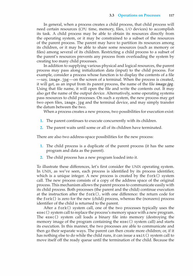
3.3 Operations on Processes 117
In general, when a process creates a child process, that child process willneed certain resources (CPU time, memory, files, I/O devices) to accomplishits task. A child process may be able to obtain its resources directly fromthe operating system, or it may be constrained to a subset of the resourcesof the parent process. The parent may have to partition its resources amongits children, or it may be able to share some resources (such as memory orfiles) among several of its children. Restricting a child process to a subset ofthe parent’s resources prevents any process from overloading the system bycreating too many child processes.
In addition to supplying various physical and logical resources, the parentprocess may pass along initialization data (input) to the child process. Forexample, consider a process whose function is to display the contents of a file—say, image.jpg—on the screen of a terminal. When the process is created,it will get, as an input from its parent process, the name of the file image.jpg.Using that file name, it will open the file and write the contents out. It mayalso get the name of the output device. Alternatively, some operating systemspass resources to child processes. On such a system, the new process may gettwo open files, image.jpg and the terminal device, and may simply transferthe datum between the two.
When a process creates a new process, two possibilities for execution exist:
1. The parent continues to execute concurrently with its children.
2. The parent waits until some or all of its children have terminated.
There are also two address-space possibilities for the new process:
1. The child process is a duplicate of the parent process (it has the sameprogram and data as the parent).
2. The child process has a new program loaded into it.
To illustrate these differences, let’s first consider the UNIX operating system.In UNIX, as we’ve seen, each process is identified by its process identifier,which is a unique integer. A new process is created by the fork() systemcall. The new process consists of a copy of the address space of the originalprocess. This mechanism allows the parent process to communicate easily withits child process. Both processes (the parent and the child) continue executionat the instruction after the fork(), with one difference: the return code forthe fork() is zero for the new (child) process, whereas the (nonzero) processidentifier of the child is returned to the parent.
After a fork() system call, one of the two processes typically uses theexec() system call to replace the process’s memory space with a new program.The exec() system call loads a binary file into memory (destroying thememory image of the program containing the exec() system call) and startsits execution. In this manner, the two processes are able to communicate andthen go their separate ways. The parent can then create more children; or, if ithas nothing else to do while the child runs, it can issue a wait() system call tomove itself off the ready queue until the termination of the child. Because the
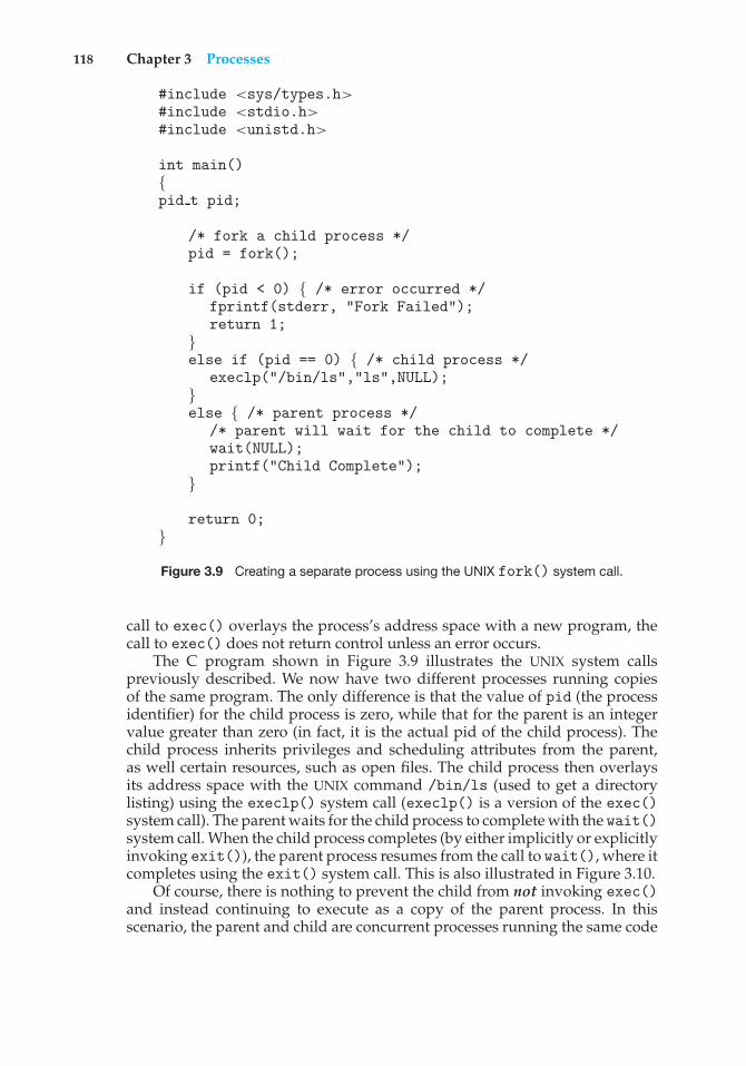
118 Chapter 3 Processes
#include <sys/types.h>#include <stdio.h>#include <unistd.h>
int main(){pid t pid;
/* fork a child process */pid = fork();
if (pid < 0) { /* error occurred */fprintf(stderr, "Fork Failed");return 1;
}else if (pid == 0) { /* child process */
execlp("/bin/ls","ls",NULL);}else { /* parent process */
/* parent will wait for the child to complete */wait(NULL);printf("Child Complete");
}
return 0;}
Figure 3.9 Creating a separate process using the UNIX fork() system call.
call to exec() overlays the process’s address space with a new program, thecall to exec() does not return control unless an error occurs.
The C program shown in Figure 3.9 illustrates the UNIX system callspreviously described. We now have two different processes running copiesof the same program. The only difference is that the value of pid (the processidentifier) for the child process is zero, while that for the parent is an integervalue greater than zero (in fact, it is the actual pid of the child process). Thechild process inherits privileges and scheduling attributes from the parent,as well certain resources, such as open files. The child process then overlaysits address space with the UNIX command /bin/ls (used to get a directorylisting) using the execlp() system call (execlp() is a version of the exec()system call). The parent waits for the child process to complete with the wait()system call. When the child process completes (by either implicitly or explicitlyinvoking exit()), the parent process resumes from the call to wait(), where itcompletes using the exit() system call. This is also illustrated in Figure 3.10.
Of course, there is nothing to prevent the child from not invoking exec()and instead continuing to execute as a copy of the parent process. In thisscenario, the parent and child are concurrent processes running the same code
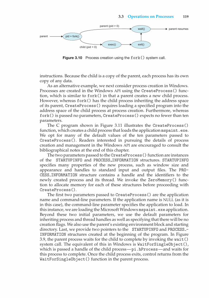
3.3 Operations on Processes 119
pid = fork()
exec()
parent
parent (pid > 0)
child (pid = 0)
wait()
exit()
parent resumes
Figure 3.10 Process creation using the fork() system call.
instructions. Because the child is a copy of the parent, each process has its owncopy of any data.
As an alternative example, we next consider process creation in Windows.Processes are created in the Windows API using the CreateProcess() func-tion, which is similar to fork() in that a parent creates a new child process.However, whereas fork() has the child process inheriting the address spaceof its parent, CreateProcess() requires loading a specified program into theaddress space of the child process at process creation. Furthermore, whereasfork() is passed no parameters, CreateProcess() expects no fewer than tenparameters.
The C program shown in Figure 3.11 illustrates the CreateProcess()function, which creates a child process that loads the application mspaint.exe.We opt for many of the default values of the ten parameters passed toCreateProcess(). Readers interested in pursuing the details of processcreation and management in the Windows API are encouraged to consult thebibliographical notes at the end of this chapter.
The two parameters passed to the CreateProcess() function are instancesof the STARTUPINFO and PROCESS INFORMATION structures. STARTUPINFOspecifies many properties of the new process, such as window size andappearance and handles to standard input and output files. The PRO-CESS INFORMATION structure contains a handle and the identifiers to thenewly created process and its thread. We invoke the ZeroMemory() func-tion to allocate memory for each of these structures before proceeding withCreateProcess().
The first two parameters passed to CreateProcess() are the applicationname and command-line parameters. If the application name is NULL (as it isin this case), the command-line parameter specifies the application to load. Inthis instance, we are loading the Microsoft Windows mspaint.exe application.Beyond these two initial parameters, we use the default parameters forinheriting process and thread handles as well as specifying that there will be nocreation flags. We also use the parent’s existing environment block and startingdirectory. Last, we provide two pointers to the STARTUPINFO and PROCESS -INFORMATION structures created at the beginning of the program. In Figure3.9, the parent process waits for the child to complete by invoking the wait()system call. The equivalent of this in Windows is WaitForSingleObject(),which is passed a handle of the child process—pi.hProcess—and waits forthis process to complete. Once the child process exits, control returns from theWaitForSingleObject() function in the parent process.
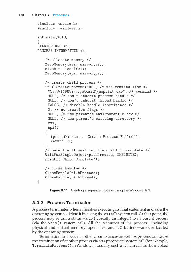
120 Chapter 3 Processes
#include <stdio.h>#include <windows.h>
int main(VOID){STARTUPINFO si;PROCESS INFORMATION pi;
/* allocate memory */ZeroMemory(&si, sizeof(si));si.cb = sizeof(si);ZeroMemory(&pi, sizeof(pi));
/* create child process */if (!CreateProcess(NULL, /* use command line */"C:\\WINDOWS\\system32\\mspaint.exe", /* command */NULL, /* don’t inherit process handle */NULL, /* don’t inherit thread handle */FALSE, /* disable handle inheritance */0, /* no creation flags */NULL, /* use parent’s environment block */NULL, /* use parent’s existing directory */&si,&pi))
{fprintf(stderr, "Create Process Failed");return -1;
}/* parent will wait for the child to complete */WaitForSingleObject(pi.hProcess, INFINITE);printf("Child Complete");
/* close handles */CloseHandle(pi.hProcess);CloseHandle(pi.hThread);
}
Figure 3.11 Creating a separate process using the Windows API.
3.3.2 Process Termination
A process terminates when it finishes executing its final statement and asks theoperating system to delete it by using the exit() system call. At that point, theprocess may return a status value (typically an integer) to its parent process(via the wait() system call). All the resources of the process—includingphysical and virtual memory, open files, and I/O buffers—are deallocatedby the operating system.
Termination can occur in other circumstances as well. A process can causethe termination of another process via an appropriate system call (for example,TerminateProcess() in Windows). Usually, such a system call can be invoked
3.3 Operations on Processes 121
only by the parent of the process that is to be terminated. Otherwise, users couldarbitrarily kill each other’s jobs. Note that a parent needs to know the identitiesof its children if it is to terminate them. Thus, when one process creates a newprocess, the identity of the newly created process is passed to the parent.
A parent may terminate the execution of one of its children for a variety ofreasons, such as these:
• The child has exceeded its usage of some of the resources that it has beenallocated. (To determine whether this has occurred, the parent must havea mechanism to inspect the state of its children.)
• The task assigned to the child is no longer required.
• The parent is exiting, and the operating system does not allow a child tocontinue if its parent terminates.
Some systems do not allow a child to exist if its parent has terminated. Insuch systems, if a process terminates (either normally or abnormally), thenall its children must also be terminated. This phenomenon, referred to ascascading termination, is normally initiated by the operating system.
To illustrate process execution and termination, consider that, in Linuxand UNIX systems, we can terminate a process by using the exit() systemcall, providing an exit status as a parameter:
/* exit with status 1 */exit(1);
In fact, under normal termination, exit() may be called either directly (asshown above) or indirectly (by a return statement in main()).
A parent process may wait for the termination of a child process by usingthe wait() system call. The wait() system call is passed a parameter thatallows the parent to obtain the exit status of the child. This system call alsoreturns the process identifier of the terminated child so that the parent can tellwhich of its children has terminated:
pid t pid;int status;
pid = wait(&status);
When a process terminates, its resources are deallocated by the operatingsystem. However, its entry in the process table must remain there until theparent calls wait(), because the process table contains the process’s exit status.A process that has terminated, but whose parent has not yet called wait(), isknown as a zombie process. All processes transition to this state when theyterminate, but generally they exist as zombies only briefly. Once the parentcalls wait(), the process identifier of the zombie process and its entry in theprocess table are released.
Now consider what would happen if a parent did not invoke wait() andinstead terminated, thereby leaving its child processes as orphans. Linux andUNIX address this scenario by assigning the init process as the new parent to
122 Chapter 3 Processes
orphan processes. (Recall from Figure 3.8 that the init process is the root of theprocess hierarchy in UNIX and Linux systems.) The init process periodicallyinvokes wait(), thereby allowing the exit status of any orphaned process to becollected and releasing the orphan’s process identifier and process-table entry.
3.4 Interprocess Communication
Processes executing concurrently in the operating system may be eitherindependent processes or cooperating processes. A process is independentif it cannot affect or be affected by the other processes executing in the system.Any process that does not share data with any other process is independent. Aprocess is cooperating if it can affect or be affected by the other processesexecuting in the system. Clearly, any process that shares data with otherprocesses is a cooperating process.
There are several reasons for providing an environment that allows processcooperation:
• Information sharing. Since several users may be interested in the samepiece of information (for instance, a shared file), we must provide anenvironment to allow concurrent access to such information.
• Computation speedup. If we want a particular task to run faster, we mustbreak it into subtasks, each of which will be executing in parallel with theothers. Notice that such a speedup can be achieved only if the computerhas multiple processing cores.
• Modularity. We may want to construct the system in a modular fashion,dividing the system functions into separate processes or threads, as wediscussed in Chapter 2.
• Convenience. Even an individual user may work on many tasks at thesame time. For instance, a user may be editing, listening to music, andcompiling in parallel.
Cooperating processes require an interprocess communication (IPC) mech-anism that will allow them to exchange data and information. There are twofundamental models of interprocess communication: shared memory and mes-sage passing. In the shared-memory model, a region of memory that is sharedby cooperating processes is established. Processes can then exchange informa-tion by reading and writing data to the shared region. In the message-passingmodel, communication takes place by means of messages exchanged betweenthe cooperating processes. The two communications models are contrasted inFigure 3.12.
Both of the models just mentioned are common in operating systems,and many systems implement both. Message passing is useful for exchangingsmaller amounts of data, because no conflicts need be avoided. Messagepassing is also easier to implement in a distributed system than shared memory.(Although there are systems that provide distributed shared memory, we do notconsider them in this text.) Shared memory can be faster than message passing,since message-passing systems are typically implemented using system calls
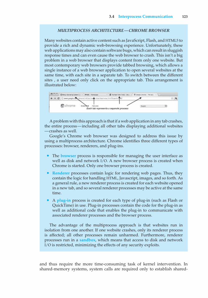
3.4 Interprocess Communication 123
MULTIPROCESS ARCHITECTURE—CHROME BROWSER
Many websites contain active content such as JavaScript, Flash, and HTML5 toprovide a rich and dynamic web-browsing experience. Unfortunately, theseweb applications may also contain software bugs, which can result in sluggishresponse times and can even cause the web browser to crash. This isn’t a bigproblem in a web browser that displays content from only one website. Butmost contemporary web browsers provide tabbed browsing, which allows asingle instance of a web browser application to open several websites at thesame time, with each site in a separate tab. To switch between the differentsites , a user need only click on the appropriate tab. This arrangement isillustrated below:
A problem with this approach is that if a web application in any tab crashes,the entire process—including all other tabs displaying additional websites—crashes as well.
Google’s Chrome web browser was designed to address this issue byusing a multiprocess architecture. Chrome identifies three different types ofprocesses: browser, renderers, and plug-ins.
• The browser process is responsible for managing the user interface aswell as disk and network I/O. A new browser process is created whenChrome is started. Only one browser process is created.
• Renderer processes contain logic for rendering web pages. Thus, theycontain the logic for handling HTML, Javascript, images, and so forth. Asa general rule, a new renderer process is created for each website openedin a new tab, and so several renderer processes may be active at the sametime.
• A plug-in process is created for each type of plug-in (such as Flash orQuickTime) in use. Plug-in processes contain the code for the plug-in aswell as additional code that enables the plug-in to communicate withassociated renderer processes and the browser process.
The advantage of the multiprocess approach is that websites run inisolation from one another. If one website crashes, only its renderer processis affected; all other processes remain unharmed. Furthermore, rendererprocesses run in a sandbox, which means that access to disk and networkI/O is restricted, minimizing the effects of any security exploits.
and thus require the more time-consuming task of kernel intervention. Inshared-memory systems, system calls are required only to establish shared-
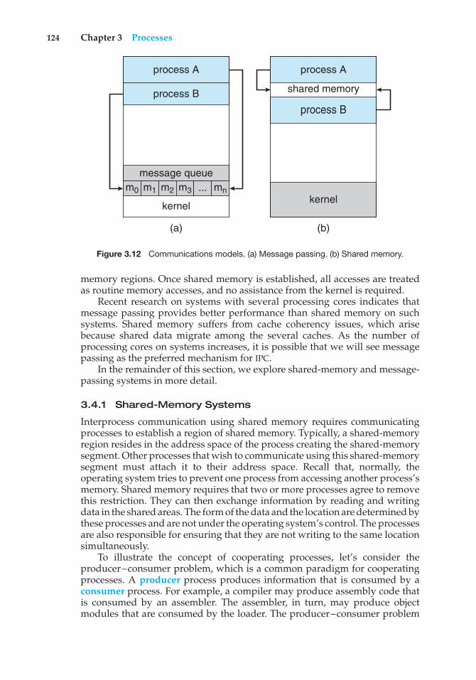
124 Chapter 3 Processes
process A
message queue
kernel
(a) (b)
process A
shared memory
kernel
process B
m0 m1 m2 ...m3 mn
process B
Figure 3.12 Communications models. (a) Message passing. (b) Shared memory.
memory regions. Once shared memory is established, all accesses are treatedas routine memory accesses, and no assistance from the kernel is required.
Recent research on systems with several processing cores indicates thatmessage passing provides better performance than shared memory on suchsystems. Shared memory suffers from cache coherency issues, which arisebecause shared data migrate among the several caches. As the number ofprocessing cores on systems increases, it is possible that we will see messagepassing as the preferred mechanism for IPC.
In the remainder of this section, we explore shared-memory and message-passing systems in more detail.
3.4.1 Shared-Memory Systems
Interprocess communication using shared memory requires communicatingprocesses to establish a region of shared memory. Typically, a shared-memoryregion resides in the address space of the process creating the shared-memorysegment. Other processes that wish to communicate using this shared-memorysegment must attach it to their address space. Recall that, normally, theoperating system tries to prevent one process from accessing another process’smemory. Shared memory requires that two or more processes agree to removethis restriction. They can then exchange information by reading and writingdata in the shared areas. The form of the data and the location are determined bythese processes and are not under the operating system’s control. The processesare also responsible for ensuring that they are not writing to the same locationsimultaneously.
To illustrate the concept of cooperating processes, let’s consider theproducer–consumer problem, which is a common paradigm for cooperatingprocesses. A producer process produces information that is consumed by aconsumer process. For example, a compiler may produce assembly code thatis consumed by an assembler. The assembler, in turn, may produce objectmodules that are consumed by the loader. The producer–consumer problem
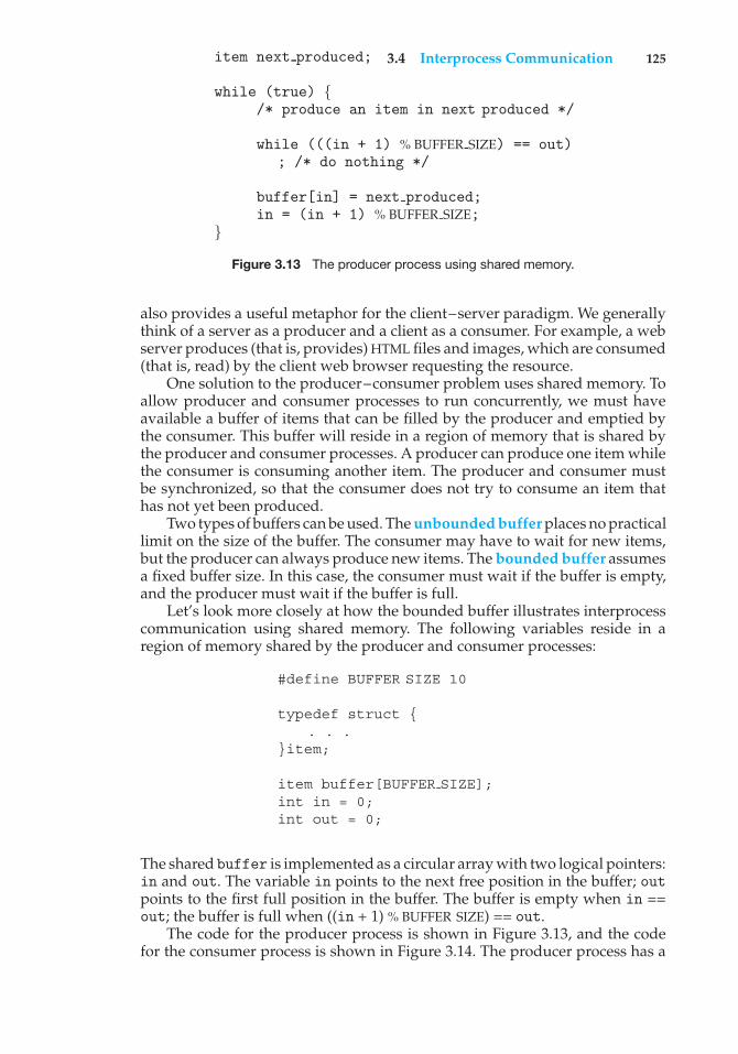
3.4 Interprocess Communication 125item next produced;
while (true) {/* produce an item in next produced */
while (((in + 1) % BUFFER SIZE) == out); /* do nothing */
buffer[in] = next produced;in = (in + 1) % BUFFER SIZE;
}
Figure 3.13 The producer process using shared memory.
also provides a useful metaphor for the client–server paradigm. We generallythink of a server as a producer and a client as a consumer. For example, a webserver produces (that is, provides) HTML files and images, which are consumed(that is, read) by the client web browser requesting the resource.
One solution to the producer–consumer problem uses shared memory. Toallow producer and consumer processes to run concurrently, we must haveavailable a buffer of items that can be filled by the producer and emptied bythe consumer. This buffer will reside in a region of memory that is shared bythe producer and consumer processes. A producer can produce one item whilethe consumer is consuming another item. The producer and consumer mustbe synchronized, so that the consumer does not try to consume an item thathas not yet been produced.
Two types of buffers can be used. The unbounded buffer places no practicallimit on the size of the buffer. The consumer may have to wait for new items,but the producer can always produce new items. The bounded buffer assumesa fixed buffer size. In this case, the consumer must wait if the buffer is empty,and the producer must wait if the buffer is full.
Let’s look more closely at how the bounded buffer illustrates interprocesscommunication using shared memory. The following variables reside in aregion of memory shared by the producer and consumer processes:
#define BUFFER SIZE 10
typedef struct {. . .
}item;
item buffer[BUFFER SIZE];int in = 0;int out = 0;
The shared buffer is implemented as a circular array with two logical pointers:in and out. The variable in points to the next free position in the buffer; outpoints to the first full position in the buffer. The buffer is empty when in ==out; the buffer is full when ((in + 1) % BUFFER SIZE) == out.
The code for the producer process is shown in Figure 3.13, and the codefor the consumer process is shown in Figure 3.14. The producer process has a
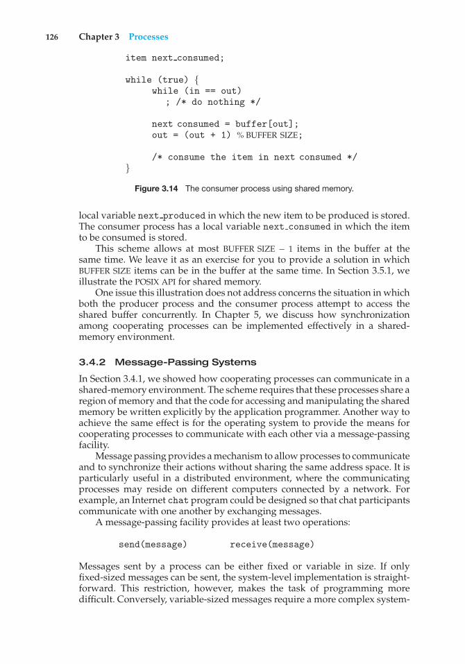
126 Chapter 3 Processes
item next consumed;
while (true) {while (in == out)
; /* do nothing */
next consumed = buffer[out];out = (out + 1) % BUFFER SIZE;
/* consume the item in next consumed */}
Figure 3.14 The consumer process using shared memory.
local variable next produced in which the new item to be produced is stored.The consumer process has a local variable next consumed in which the itemto be consumed is stored.
This scheme allows at most BUFFER SIZE − 1 items in the buffer at thesame time. We leave it as an exercise for you to provide a solution in whichBUFFER SIZE items can be in the buffer at the same time. In Section 3.5.1, weillustrate the POSIX API for shared memory.
One issue this illustration does not address concerns the situation in whichboth the producer process and the consumer process attempt to access theshared buffer concurrently. In Chapter 5, we discuss how synchronizationamong cooperating processes can be implemented effectively in a shared-memory environment.
3.4.2 Message-Passing Systems
In Section 3.4.1, we showed how cooperating processes can communicate in ashared-memory environment. The scheme requires that these processes share aregion of memory and that the code for accessing and manipulating the sharedmemory be written explicitly by the application programmer. Another way toachieve the same effect is for the operating system to provide the means forcooperating processes to communicate with each other via a message-passingfacility.
Message passing provides a mechanism to allow processes to communicateand to synchronize their actions without sharing the same address space. It isparticularly useful in a distributed environment, where the communicatingprocesses may reside on different computers connected by a network. Forexample, an Internet chat program could be designed so that chat participantscommunicate with one another by exchanging messages.
A message-passing facility provides at least two operations:
send(message) receive(message)
Messages sent by a process can be either fixed or variable in size. If onlyfixed-sized messages can be sent, the system-level implementation is straight-forward. This restriction, however, makes the task of programming moredifficult. Conversely, variable-sized messages require a more complex system-
3.4 Interprocess Communication 127
level implementation, but the programming task becomes simpler. This is acommon kind of tradeoff seen throughout operating-system design.
If processes P and Q want to communicate, they must send messages to andreceive messages from each other: a communication link must exist betweenthem. This link can be implemented in a variety of ways. We are concerned herenot with the link’s physical implementation (such as shared memory, hardwarebus, or network, which are covered in Chapter 17) but rather with its logicalimplementation. Here are several methods for logically implementing a linkand the send()/receive() operations:
• Direct or indirect communication
• Synchronous or asynchronous communication
• Automatic or explicit buffering
We look at issues related to each of these features next.
3.4.2.1 Naming
Processes that want to communicate must have a way to refer to each other.They can use either direct or indirect communication.
Under direct communication, each process that wants to communicatemust explicitly name the recipient or sender of the communication. In thisscheme, the send() and receive() primitives are defined as:
• send(P, message)—Send a message to process P.
• receive(Q, message)—Receive a message from process Q.
A communication link in this scheme has the following properties:
• A link is established automatically between every pair of processes thatwant to communicate. The processes need to know only each other’sidentity to communicate.
• A link is associated with exactly two processes.
• Between each pair of processes, there exists exactly one link.
This scheme exhibits symmetry in addressing; that is, both the senderprocess and the receiver process must name the other to communicate. Avariant of this scheme employs asymmetry in addressing. Here, only the sendernames the recipient; the recipient is not required to name the sender. In thisscheme, the send() and receive() primitives are defined as follows:
• send(P, message)—Send a message to process P.
• receive(id, message)—Receive a message from any process. Thevariable id is set to the name of the process with which communicationhas taken place.
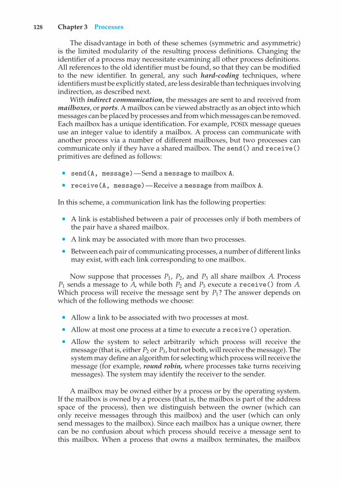
128 Chapter 3 Processes
The disadvantage in both of these schemes (symmetric and asymmetric)is the limited modularity of the resulting process definitions. Changing theidentifier of a process may necessitate examining all other process definitions.All references to the old identifier must be found, so that they can be modifiedto the new identifier. In general, any such hard-coding techniques, whereidentifiers must be explicitly stated, are less desirable than techniques involvingindirection, as described next.
With indirect communication, the messages are sent to and received frommailboxes, or ports. A mailbox can be viewed abstractly as an object into whichmessages can be placed by processes and from which messages can be removed.Each mailbox has a unique identification. For example, POSIX message queuesuse an integer value to identify a mailbox. A process can communicate withanother process via a number of different mailboxes, but two processes cancommunicate only if they have a shared mailbox. The send() and receive()primitives are defined as follows:
• send(A, message)—Send a message to mailbox A.
• receive(A, message)—Receive a message from mailbox A.
In this scheme, a communication link has the following properties:
• A link is established between a pair of processes only if both members ofthe pair have a shared mailbox.
• A link may be associated with more than two processes.
• Between each pair of communicating processes, a number of different linksmay exist, with each link corresponding to one mailbox.
Now suppose that processes P1, P2, and P3 all share mailbox A. ProcessP1 sends a message to A, while both P2 and P3 execute a receive() from A.Which process will receive the message sent by P1? The answer depends onwhich of the following methods we choose:
• Allow a link to be associated with two processes at most.
• Allow at most one process at a time to execute a receive() operation.
• Allow the system to select arbitrarily which process will receive themessage (that is, either P2 or P3, but not both, will receive the message). Thesystem may define an algorithm for selecting which process will receive themessage (for example, round robin, where processes take turns receivingmessages). The system may identify the receiver to the sender.
A mailbox may be owned either by a process or by the operating system.If the mailbox is owned by a process (that is, the mailbox is part of the addressspace of the process), then we distinguish between the owner (which canonly receive messages through this mailbox) and the user (which can onlysend messages to the mailbox). Since each mailbox has a unique owner, therecan be no confusion about which process should receive a message sent tothis mailbox. When a process that owns a mailbox terminates, the mailbox
3.4 Interprocess Communication 129
disappears. Any process that subsequently sends a message to this mailboxmust be notified that the mailbox no longer exists.
In contrast, a mailbox that is owned by the operating system has anexistence of its own. It is independent and is not attached to any particularprocess. The operating system then must provide a mechanism that allows aprocess to do the following:
• Create a new mailbox.
• Send and receive messages through the mailbox.
• Delete a mailbox.
The process that creates a new mailbox is that mailbox’s owner by default.Initially, the owner is the only process that can receive messages through thismailbox. However, the ownership and receiving privilege may be passed toother processes through appropriate system calls. Of course, this provisioncould result in multiple receivers for each mailbox.
3.4.2.2 Synchronization
Communication between processes takes place through calls to send() andreceive() primitives. There are different design options for implementingeach primitive. Message passing may be either blocking or nonblocking—also known as synchronous and asynchronous. (Throughout this text, youwill encounter the concepts of synchronous and asynchronous behavior inrelation to various operating-system algorithms.)
• Blocking send. The sending process is blocked until the message isreceived by the receiving process or by the mailbox.
• Nonblocking send. The sending process sends the message and resumesoperation.
• Blocking receive. The receiver blocks until a message is available.
• Nonblocking receive. The receiver retrieves either a valid message or anull.
Different combinations of send() and receive() are possible. When bothsend() and receive() are blocking, we have a rendezvous between thesender and the receiver. The solution to the producer–consumer problembecomes trivial when we use blocking send() and receive() statements.The producer merely invokes the blocking send() call and waits until themessage is delivered to either the receiver or the mailbox. Likewise, when theconsumer invokes receive(), it blocks until a message is available. This isillustrated in Figures 3.15 and 3.16.
3.4.2.3 Buffering
Whether communication is direct or indirect, messages exchanged by commu-nicating processes reside in a temporary queue. Basically, such queues can beimplemented in three ways:
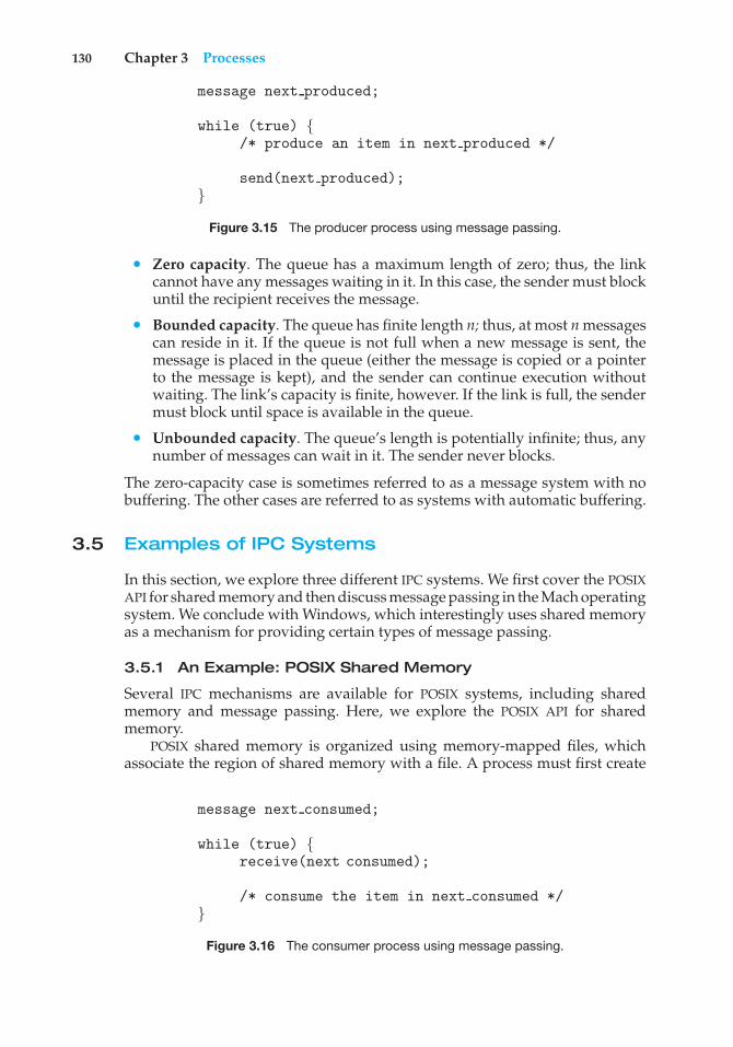
130 Chapter 3 Processes
message next produced;
while (true) {/* produce an item in next produced */
send(next produced);}
Figure 3.15 The producer process using message passing.
• Zero capacity. The queue has a maximum length of zero; thus, the linkcannot have any messages waiting in it. In this case, the sender must blockuntil the recipient receives the message.
• Bounded capacity. The queue has finite length n; thus, at most n messagescan reside in it. If the queue is not full when a new message is sent, themessage is placed in the queue (either the message is copied or a pointerto the message is kept), and the sender can continue execution withoutwaiting. The link’s capacity is finite, however. If the link is full, the sendermust block until space is available in the queue.
• Unbounded capacity. The queue’s length is potentially infinite; thus, anynumber of messages can wait in it. The sender never blocks.
The zero-capacity case is sometimes referred to as a message system with nobuffering. The other cases are referred to as systems with automatic buffering.
3.5 Examples of IPC Systems
In this section, we explore three different IPC systems. We first cover the POSIXAPI for shared memory and then discuss message passing in the Mach operatingsystem. We conclude with Windows, which interestingly uses shared memoryas a mechanism for providing certain types of message passing.
3.5.1 An Example: POSIX Shared Memory
Several IPC mechanisms are available for POSIX systems, including sharedmemory and message passing. Here, we explore the POSIX API for sharedmemory.
POSIX shared memory is organized using memory-mapped files, whichassociate the region of shared memory with a file. A process must first create
message next consumed;
while (true) {receive(next consumed);
/* consume the item in next consumed */}
Figure 3.16 The consumer process using message passing.
3.5 Examples of IPC Systems 131
a shared-memory object using the shm open() system call, as follows:
shm fd = shm open(name, O CREAT | O RDRW, 0666);
The first parameter specifies the name of the shared-memory object. Processesthat wish to access this shared memory must refer to the object by this name.The subsequent parameters specify that the shared-memory object is to becreated if it does not yet exist (O CREAT) and that the object is open for readingand writing (O RDRW). The last parameter establishes the directory permissionsof the shared-memory object. A successful call toshm open() returns an integerfile descriptor for the shared-memory object.
Once the object is established, the ftruncate() function is used toconfigure the size of the object in bytes. The call
ftruncate(shm fd, 4096);
sets the size of the object to 4,096 bytes.Finally, the mmap() function establishes a memory-mapped file containing
the shared-memory object. It also returns a pointer to the memory-mapped filethat is used for accessing the shared-memory object.
The programs shown in Figure 3.17 and 3.18 use the producer–consumermodel in implementing shared memory. The producer establishes a shared-memory object and writes to shared memory, and the consumer reads fromshared memory.
The producer, shown in Figure 3.17, creates a shared-memory object namedOS and writes the infamous string "Hello World!" to shared memory. Theprogram memory-maps a shared-memory object of the specified size andallows writing to the object. (Obviously, only writing is necessary for theproducer.) The flag MAP SHARED specifies that changes to the shared-memoryobject will be visible to all processes sharing the object. Notice that we write tothe shared-memory object by calling the sprintf() function and writing theformatted string to the pointer ptr. After each write, we must increment thepointer by the number of bytes written.
The consumer process, shown in Figure 3.18, reads and outputs the contentsof the shared memory. The consumer also invokes the shm unlink() function,which removes the shared-memory segment after the consumer has accessedit. We provide further exercises using the POSIX shared-memory API in theprogramming exercises at the end of this chapter. Additionally, we providemore detailed coverage of memory mapping in Section 9.7.
3.5.2 An Example: Mach
As an example of message passing, we next consider the Mach operatingsystem. You may recall that we introduced Mach in Chapter 2 as part of the MacOS X operating system. The Mach kernel supports the creation and destructionof multiple tasks, which are similar to processes but have multiple threadsof control and fewer associated resources. Most communication in Mach—including all intertask information—is carried out by messages. Messages aresent to and received from mailboxes, called ports in Mach.
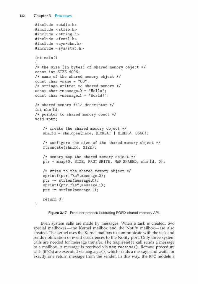
132 Chapter 3 Processes
#include <stdio.h>#include <stlib.h>#include <string.h>#include <fcntl.h>#include <sys/shm.h>#include <sys/stat.h>
int main(){/* the size (in bytes) of shared memory object */const int SIZE 4096;/* name of the shared memory object */const char *name = "OS";/* strings written to shared memory */const char *message 0 = "Hello";const char *message 1 = "World!";
/* shared memory file descriptor */int shm fd;/* pointer to shared memory obect */void *ptr;
/* create the shared memory object */shm fd = shm open(name, O CREAT | O RDRW, 0666);
/* configure the size of the shared memory object */ftruncate(shm fd, SIZE);
/* memory map the shared memory object */ptr = mmap(0, SIZE, PROT WRITE, MAP SHARED, shm fd, 0);
/* write to the shared memory object */sprintf(ptr,"%s",message 0);ptr += strlen(message 0);sprintf(ptr,"%s",message 1);ptr += strlen(message 1);
return 0;}
Figure 3.17 Producer process illustrating POSIX shared-memory API.
Even system calls are made by messages. When a task is created, twospecial mailboxes—the Kernel mailbox and the Notify mailbox—are alsocreated. The kernel uses the Kernel mailbox to communicate with the task andsends notification of event occurrences to the Notify port. Only three systemcalls are needed for message transfer. The msg send() call sends a messageto a mailbox. A message is received via msg receive(). Remote procedurecalls (RPCs) are executed via msg rpc(), which sends a message and waits forexactly one return message from the sender. In this way, the RPC models a
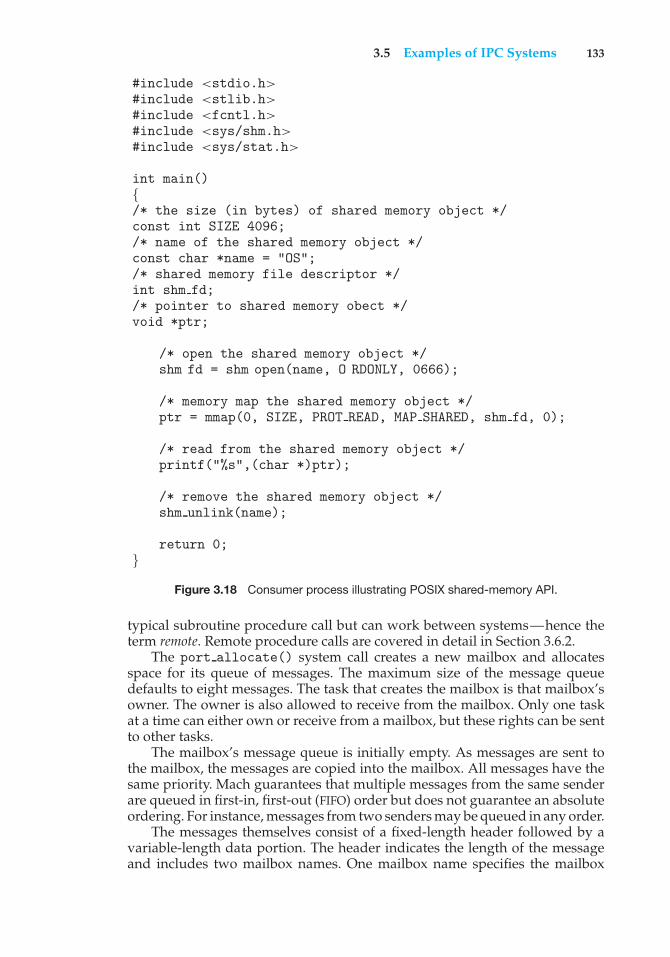
3.5 Examples of IPC Systems 133
#include <stdio.h>#include <stlib.h>#include <fcntl.h>#include <sys/shm.h>#include <sys/stat.h>
int main(){/* the size (in bytes) of shared memory object */const int SIZE 4096;/* name of the shared memory object */const char *name = "OS";/* shared memory file descriptor */int shm fd;/* pointer to shared memory obect */void *ptr;
/* open the shared memory object */shm fd = shm open(name, O RDONLY, 0666);
/* memory map the shared memory object */ptr = mmap(0, SIZE, PROT READ, MAP SHARED, shm fd, 0);
/* read from the shared memory object */printf("%s",(char *)ptr);
/* remove the shared memory object */shm unlink(name);
return 0;}
Figure 3.18 Consumer process illustrating POSIX shared-memory API.
typical subroutine procedure call but can work between systems—hence theterm remote. Remote procedure calls are covered in detail in Section 3.6.2.
The port allocate() system call creates a new mailbox and allocatesspace for its queue of messages. The maximum size of the message queuedefaults to eight messages. The task that creates the mailbox is that mailbox’sowner. The owner is also allowed to receive from the mailbox. Only one taskat a time can either own or receive from a mailbox, but these rights can be sentto other tasks.
The mailbox’s message queue is initially empty. As messages are sent tothe mailbox, the messages are copied into the mailbox. All messages have thesame priority. Mach guarantees that multiple messages from the same senderare queued in first-in, first-out (FIFO) order but does not guarantee an absoluteordering. For instance, messages from two senders may be queued in any order.
The messages themselves consist of a fixed-length header followed by avariable-length data portion. The header indicates the length of the messageand includes two mailbox names. One mailbox name specifies the mailbox
134 Chapter 3 Processes
to which the message is being sent. Commonly, the sending thread expects areply, so the mailbox name of the sender is passed on to the receiving task,which can use it as a “return address.”
The variable part of a message is a list of typed data items. Each entryin the list has a type, size, and value. The type of the objects specified in themessage is important, since objects defined by the operating system—such asownership or receive access rights, task states, and memory segments—maybe sent in messages.
The send and receive operations themselves are flexible. For instance, whena message is sent to a mailbox, the mailbox may be full. If the mailbox is notfull, the message is copied to the mailbox, and the sending thread continues. Ifthe mailbox is full, the sending thread has four options:
1. Wait indefinitely until there is room in the mailbox.
2. Wait at most n milliseconds.
3. Do not wait at all but rather return immediately.
4. Temporarily cache a message. Here, a message is given to the operatingsystem to keep, even though the mailbox to which that message is beingsent is full. When the message can be put in the mailbox, a message is sentback to the sender. Only one message to a full mailbox can be pending atany time for a given sending thread.
The final option is meant for server tasks, such as a line-printer driver. Afterfinishing a request, such tasks may need to send a one-time reply to the taskthat requested service, but they must also continue with other service requests,even if the reply mailbox for a client is full.
The receive operation must specify the mailbox or mailbox set from which amessage is to be received. A mailbox set is a collection of mailboxes, as declaredby the task, which can be grouped together and treated as one mailbox for thepurposes of the task. Threads in a task can receive only from a mailbox ormailbox set for which the task has receive access. A port status() systemcall returns the number of messages in a given mailbox. The receive operationattempts to receive from (1) any mailbox in a mailbox set or (2) a specific(named) mailbox. If no message is waiting to be received, the receiving threadcan either wait at most n milliseconds or not wait at all.
The Mach system was especially designed for distributed systems, whichwe discuss in Chapter 17, but Mach was shown to be suitable for systemswith fewer processing cores, as evidenced by its inclusion in the Mac OS Xsystem. The major problem with message systems has generally been poorperformance caused by double copying of messages: the message is copiedfirst from the sender to the mailbox and then from the mailbox to the receiver.The Mach message system attempts to avoid double-copy operations by usingvirtual-memory-management techniques (Chapter 9). Essentially, Mach mapsthe address space containing the sender’s message into the receiver’s addressspace. The message itself is never actually copied. This message-managementtechnique provides a large performance boost but works for only intrasystemmessages. The Mach operating system is discussed in more detail in the onlineAppendix B.
3.5 Examples of IPC Systems 135
3.5.3 An Example: Windows
The Windows operating system is an example of modern design that employsmodularity to increase functionality and decrease the time needed to imple-ment new features. Windows provides support for multiple operating envi-ronments, or subsystems. Application programs communicate with thesesubsystems via a message-passing mechanism. Thus, application programscan be considered clients of a subsystem server.
The message-passing facility in Windows is called the advanced localprocedure call (ALPC) facility. It is used for communication between twoprocesses on the same machine. It is similar to the standard remote procedurecall (RPC) mechanism that is widely used, but it is optimized for and specificto Windows. (Remote procedure calls are covered in detail in Section 3.6.2.)Like Mach, Windows uses a port object to establish and maintain a connectionbetween two processes. Windows uses two types of ports: connection portsand communication ports.
Server processes publish connection-port objects that are visible to allprocesses. When a client wants services from a subsystem, it opens a handle tothe server’s connection-port object and sends a connection request to that port.The server then creates a channel and returns a handle to the client. The channelconsists of a pair of private communication ports: one for client—servermessages, the other for server—client messages. Additionally, communicationchannels support a callback mechanism that allows the client and server toaccept requests when they would normally be expecting a reply.
When an ALPC channel is created, one of three message-passing techniquesis chosen:
1. For small messages (up to 256 bytes), the port’s message queue is usedas intermediate storage, and the messages are copied from one process tothe other.
2. Larger messages must be passed through a section object, which is aregion of shared memory associated with the channel.
3. When the amount of data is too large to fit into a section object, an API isavailable that allows server processes to read and write directly into theaddress space of a client.
The client has to decide when it sets up the channel whether it will needto send a large message. If the client determines that it does want to sendlarge messages, it asks for a section object to be created. Similarly, if the serverdecides that replies will be large, it creates a section object. So that the sectionobject can be used, a small message is sent that contains a pointer and sizeinformation about the section object. This method is more complicated thanthe first method listed above, but it avoids data copying. The structure ofadvanced local procedure calls in Windows is shown in Figure 3.19.
It is important to note that the ALPC facility in Windows is not part of theWindows API and hence is not visible to the application programmer. Rather,applications using the Windows API invoke standard remote procedure calls.When the RPC is being invoked on a process on the same system, the RPC ishandled indirectly through an ALPC. procedure call. Additionally, many kernelservices use ALPC to communicate with client processes.
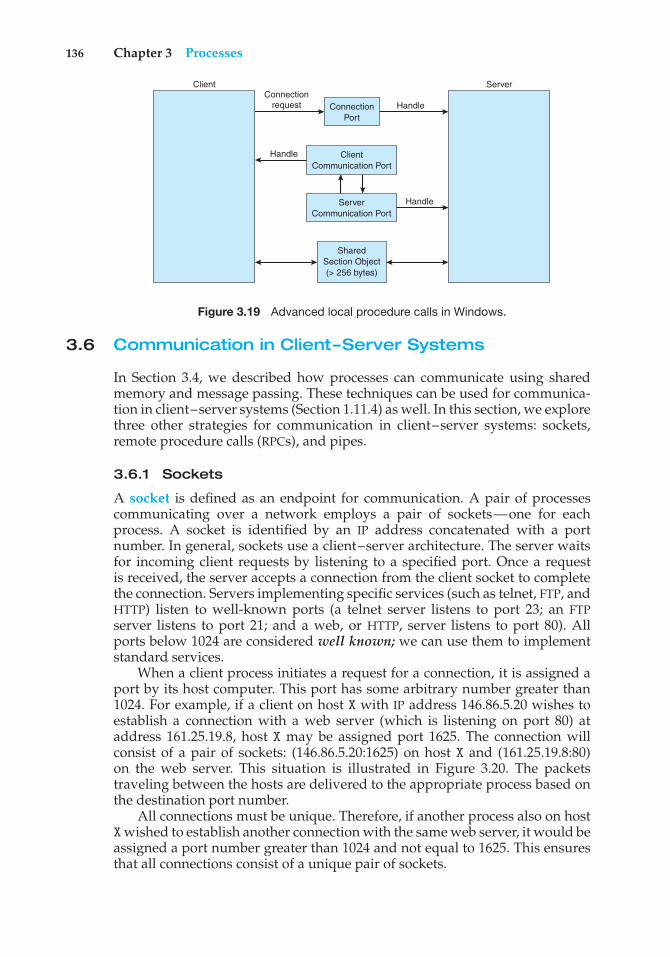
136 Chapter 3 Processes
ConnectionPort
Connectionrequest Handle
Handle
Handle
ClientCommunication Port
ServerCommunication Port
SharedSection Object(> 256 bytes)
ServerClient
Figure 3.19 Advanced local procedure calls in Windows.
3.6 Communication in Client–Server Systems
In Section 3.4, we described how processes can communicate using sharedmemory and message passing. These techniques can be used for communica-tion in client–server systems (Section 1.11.4) as well. In this section, we explorethree other strategies for communication in client–server systems: sockets,remote procedure calls (RPCs), and pipes.
3.6.1 Sockets
A socket is defined as an endpoint for communication. A pair of processescommunicating over a network employs a pair of sockets—one for eachprocess. A socket is identified by an IP address concatenated with a portnumber. In general, sockets use a client–server architecture. The server waitsfor incoming client requests by listening to a specified port. Once a requestis received, the server accepts a connection from the client socket to completethe connection. Servers implementing specific services (such as telnet, FTP, andHTTP) listen to well-known ports (a telnet server listens to port 23; an FTPserver listens to port 21; and a web, or HTTP, server listens to port 80). Allports below 1024 are considered well known; we can use them to implementstandard services.
When a client process initiates a request for a connection, it is assigned aport by its host computer. This port has some arbitrary number greater than1024. For example, if a client on host X with IP address 146.86.5.20 wishes toestablish a connection with a web server (which is listening on port 80) ataddress 161.25.19.8, host X may be assigned port 1625. The connection willconsist of a pair of sockets: (146.86.5.20:1625) on host X and (161.25.19.8:80)on the web server. This situation is illustrated in Figure 3.20. The packetstraveling between the hosts are delivered to the appropriate process based onthe destination port number.
All connections must be unique. Therefore, if another process also on hostXwished to establish another connection with the same web server, it would beassigned a port number greater than 1024 and not equal to 1625. This ensuresthat all connections consist of a unique pair of sockets.
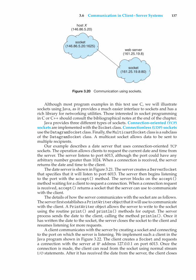
3.6 Communication in Client–Server Systems 137
socket(146.86.5.20:1625)
host X(146.86.5.20)
socket(161.25.19.8:80)
web server(161.25.19.8)
Figure 3.20 Communication using sockets.
Although most program examples in this text use C, we will illustratesockets using Java, as it provides a much easier interface to sockets and has arich library for networking utilities. Those interested in socket programmingin C or C++ should consult the bibliographical notes at the end of the chapter.
Java provides three different types of sockets. Connection-oriented (TCP)sockets are implemented with the Socket class. Connectionless (UDP) socketsuse theDatagramSocket class. Finally, theMulticastSocket class is a subclassof the DatagramSocket class. A multicast socket allows data to be sent tomultiple recipients.
Our example describes a date server that uses connection-oriented TCPsockets. The operation allows clients to request the current date and time fromthe server. The server listens to port 6013, although the port could have anyarbitrary number greater than 1024. When a connection is received, the serverreturns the date and time to the client.
The date server is shown in Figure 3.21. The server creates a ServerSocketthat specifies that it will listen to port 6013. The server then begins listeningto the port with the accept() method. The server blocks on the accept()method waiting for a client to request a connection. When a connection requestis received, accept() returns a socket that the server can use to communicatewith the client.
The details of how the server communicates with the socket are as follows.The server first establishes aPrintWriterobject that it will use to communicatewith the client. A PrintWriter object allows the server to write to the socketusing the routine print() and println() methods for output. The serverprocess sends the date to the client, calling the method println(). Once ithas written the date to the socket, the server closes the socket to the client andresumes listening for more requests.
A client communicates with the server by creating a socket and connectingto the port on which the server is listening. We implement such a client in theJava program shown in Figure 3.22. The client creates a Socket and requestsa connection with the server at IP address 127.0.0.1 on port 6013. Once theconnection is made, the client can read from the socket using normal streamI/O statements. After it has received the date from the server, the client closes
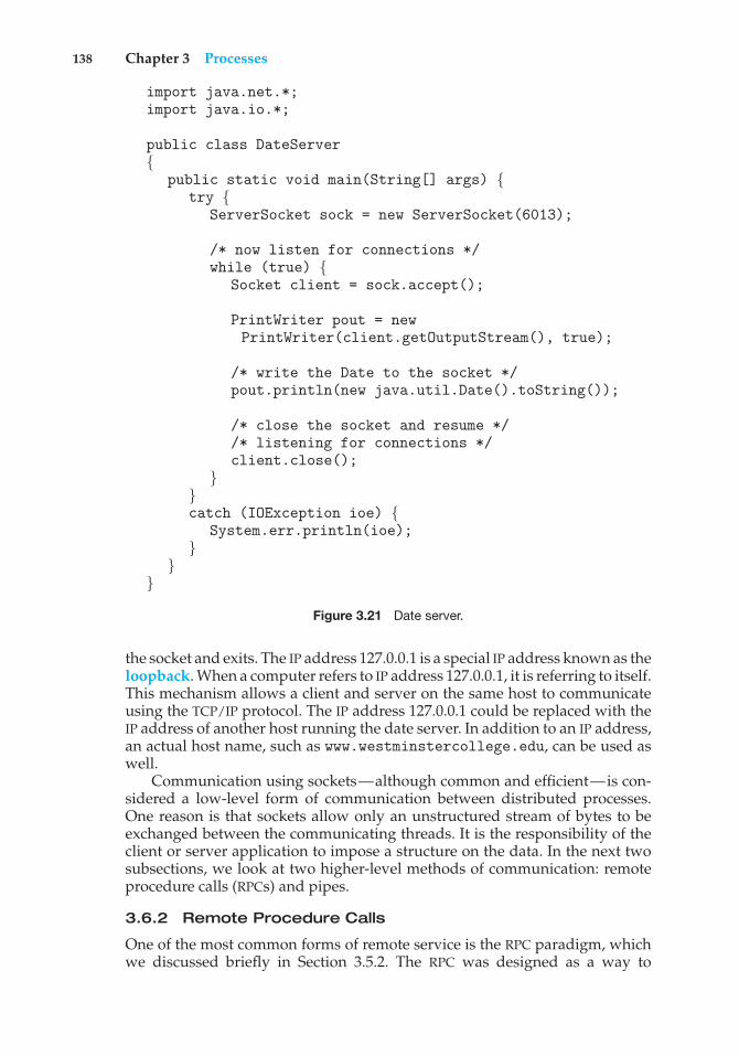
138 Chapter 3 Processes
import java.net.*;import java.io.*;
public class DateServer{
public static void main(String[] args) {try {
ServerSocket sock = new ServerSocket(6013);
/* now listen for connections */while (true) {
Socket client = sock.accept();
PrintWriter pout = newPrintWriter(client.getOutputStream(), true);
/* write the Date to the socket */pout.println(new java.util.Date().toString());
/* close the socket and resume *//* listening for connections */client.close();
}}catch (IOException ioe) {
System.err.println(ioe);}
}}
Figure 3.21 Date server.
the socket and exits. The IP address 127.0.0.1 is a special IP address known as theloopback. When a computer refers to IP address 127.0.0.1, it is referring to itself.This mechanism allows a client and server on the same host to communicateusing the TCP/IP protocol. The IP address 127.0.0.1 could be replaced with theIP address of another host running the date server. In addition to an IP address,an actual host name, such as www.westminstercollege.edu, can be used aswell.
Communication using sockets—although common and efficient—is con-sidered a low-level form of communication between distributed processes.One reason is that sockets allow only an unstructured stream of bytes to beexchanged between the communicating threads. It is the responsibility of theclient or server application to impose a structure on the data. In the next twosubsections, we look at two higher-level methods of communication: remoteprocedure calls (RPCs) and pipes.
3.6.2 Remote Procedure Calls
One of the most common forms of remote service is the RPC paradigm, whichwe discussed briefly in Section 3.5.2. The RPC was designed as a way to
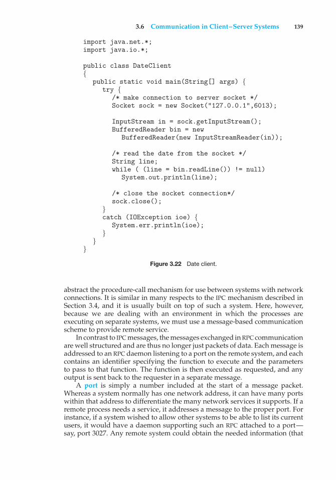
3.6 Communication in Client–Server Systems 139
import java.net.*;import java.io.*;
public class DateClient{
public static void main(String[] args) {try {
/* make connection to server socket */Socket sock = new Socket("127.0.0.1",6013);
InputStream in = sock.getInputStream();BufferedReader bin = new
BufferedReader(new InputStreamReader(in));
/* read the date from the socket */String line;while ( (line = bin.readLine()) != null)
System.out.println(line);
/* close the socket connection*/sock.close();
}catch (IOException ioe) {
System.err.println(ioe);}
}}
Figure 3.22 Date client.
abstract the procedure-call mechanism for use between systems with networkconnections. It is similar in many respects to the IPC mechanism described inSection 3.4, and it is usually built on top of such a system. Here, however,because we are dealing with an environment in which the processes areexecuting on separate systems, we must use a message-based communicationscheme to provide remote service.
In contrast to IPC messages, the messages exchanged in RPC communicationare well structured and are thus no longer just packets of data. Each message isaddressed to an RPC daemon listening to a port on the remote system, and eachcontains an identifier specifying the function to execute and the parametersto pass to that function. The function is then executed as requested, and anyoutput is sent back to the requester in a separate message.
A port is simply a number included at the start of a message packet.Whereas a system normally has one network address, it can have many portswithin that address to differentiate the many network services it supports. If aremote process needs a service, it addresses a message to the proper port. Forinstance, if a system wished to allow other systems to be able to list its currentusers, it would have a daemon supporting such an RPC attached to a port—say, port 3027. Any remote system could obtain the needed information (that
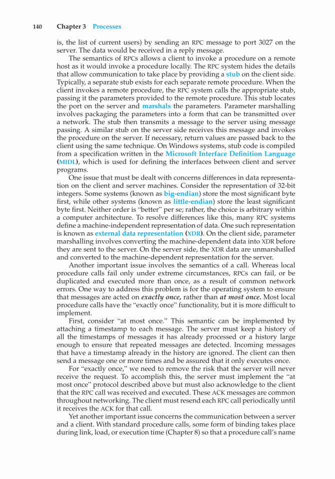
140 Chapter 3 Processes
is, the list of current users) by sending an RPC message to port 3027 on theserver. The data would be received in a reply message.
The semantics of RPCs allows a client to invoke a procedure on a remotehost as it would invoke a procedure locally. The RPC system hides the detailsthat allow communication to take place by providing a stub on the client side.Typically, a separate stub exists for each separate remote procedure. When theclient invokes a remote procedure, the RPC system calls the appropriate stub,passing it the parameters provided to the remote procedure. This stub locatesthe port on the server and marshals the parameters. Parameter marshallinginvolves packaging the parameters into a form that can be transmitted overa network. The stub then transmits a message to the server using messagepassing. A similar stub on the server side receives this message and invokesthe procedure on the server. If necessary, return values are passed back to theclient using the same technique. On Windows systems, stub code is compiledfrom a specification written in the Microsoft Interface Definition Language(MIDL), which is used for defining the interfaces between client and serverprograms.
One issue that must be dealt with concerns differences in data representa-tion on the client and server machines. Consider the representation of 32-bitintegers. Some systems (known as big-endian) store the most significant bytefirst, while other systems (known as little-endian) store the least significantbyte first. Neither order is “better” per se; rather, the choice is arbitrary withina computer architecture. To resolve differences like this, many RPC systemsdefine a machine-independent representation of data. One such representationis known as external data representation (XDR). On the client side, parametermarshalling involves converting the machine-dependent data into XDR beforethey are sent to the server. On the server side, the XDR data are unmarshalledand converted to the machine-dependent representation for the server.
Another important issue involves the semantics of a call. Whereas localprocedure calls fail only under extreme circumstances, RPCs can fail, or beduplicated and executed more than once, as a result of common networkerrors. One way to address this problem is for the operating system to ensurethat messages are acted on exactly once, rather than at most once. Most localprocedure calls have the “exactly once” functionality, but it is more difficult toimplement.
First, consider “at most once.” This semantic can be implemented byattaching a timestamp to each message. The server must keep a history ofall the timestamps of messages it has already processed or a history largeenough to ensure that repeated messages are detected. Incoming messagesthat have a timestamp already in the history are ignored. The client can thensend a message one or more times and be assured that it only executes once.
For “exactly once,” we need to remove the risk that the server will neverreceive the request. To accomplish this, the server must implement the “atmost once” protocol described above but must also acknowledge to the clientthat the RPC call was received and executed. These ACK messages are commonthroughout networking. The client must resend each RPC call periodically untilit receives the ACK for that call.
Yet another important issue concerns the communication between a serverand a client. With standard procedure calls, some form of binding takes placeduring link, load, or execution time (Chapter 8) so that a procedure call’s name
3.6 Communication in Client–Server Systems 141
client
user calls kernelto send RPCmessage toprocedure X
matchmakerreceivesmessage, looksup answer
matchmakerreplies to clientwith port P
daemonlistening toport P receivesmessage
daemonprocessesrequest andprocesses sendoutput
kernel sendsmessage tomatchmaker tofind port number
From: clientTo: server
Port: matchmakerRe: addressfor RPC X
From: clientTo: server
Port: port P<contents>
From: RPCPort: P
To: clientPort: kernel<output>
From: serverTo: client
Port: kernelRe: RPC X
Port: P
kernel placesport P in userRPC message
kernel sendsRPC
kernel receivesreply, passesit to user
messages server
Figure 3.23 Execution of a remote procedure call (RPC).
is replaced by the memory address of the procedure call. The RPC schemerequires a similar binding of the client and the server port, but how does a clientknow the port numbers on the server? Neither system has full informationabout the other, because they do not share memory.
Two approaches are common. First, the binding information may bepredetermined, in the form of fixed port addresses. At compile time, an RPCcall has a fixed port number associated with it. Once a program is compiled,the server cannot change the port number of the requested service. Second,binding can be done dynamically by a rendezvous mechanism. Typically, anoperating system provides a rendezvous (also called a matchmaker) daemonon a fixed RPC port. A client then sends a message containing the name ofthe RPC to the rendezvous daemon requesting the port address of the RPC itneeds to execute. The port number is returned, and the RPC calls can be sentto that port until the process terminates (or the server crashes). This methodrequires the extra overhead of the initial request but is more flexible than thefirst approach. Figure 3.23 shows a sample interaction.
The RPC scheme is useful in implementing a distributed file system(Chapter 17). Such a system can be implemented as a set of RPC daemons
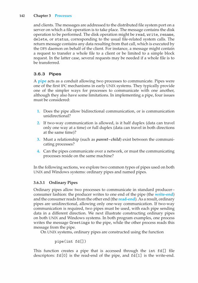
142 Chapter 3 Processes
and clients. The messages are addressed to the distributed file system port on aserver on which a file operation is to take place. The message contains the diskoperation to be performed. The disk operation might be read, write, rename,delete, or status, corresponding to the usual file-related system calls. Thereturn message contains any data resulting from that call, which is executed bythe DFS daemon on behalf of the client. For instance, a message might containa request to transfer a whole file to a client or be limited to a simple blockrequest. In the latter case, several requests may be needed if a whole file is tobe transferred.
3.6.3 Pipes
A pipe acts as a conduit allowing two processes to communicate. Pipes wereone of the first IPC mechanisms in early UNIX systems. They typically provideone of the simpler ways for processes to communicate with one another,although they also have some limitations. In implementing a pipe, four issuesmust be considered:
1. Does the pipe allow bidirectional communication, or is communicationunidirectional?
2. If two-way communication is allowed, is it half duplex (data can travelonly one way at a time) or full duplex (data can travel in both directionsat the same time)?
3. Must a relationship (such as parent–child) exist between the communi-cating processes?
4. Can the pipes communicate over a network, or must the communicatingprocesses reside on the same machine?
In the following sections, we explore two common types of pipes used on bothUNIX and Windows systems: ordinary pipes and named pipes.
3.6.3.1 Ordinary Pipes
Ordinary pipes allow two processes to communicate in standard producer–consumer fashion: the producer writes to one end of the pipe (the write-end)and the consumer reads from the other end (the read-end). As a result, ordinarypipes are unidirectional, allowing only one-way communication. If two-waycommunication is required, two pipes must be used, with each pipe sendingdata in a different direction. We next illustrate constructing ordinary pipeson both UNIX and Windows systems. In both program examples, one processwrites the message Greetings to the pipe, while the other process reads thismessage from the pipe.
On UNIX systems, ordinary pipes are constructed using the function
pipe(int fd[])
This function creates a pipe that is accessed through the int fd[] filedescriptors: fd[0] is the read-end of the pipe, and fd[1] is the write-end.
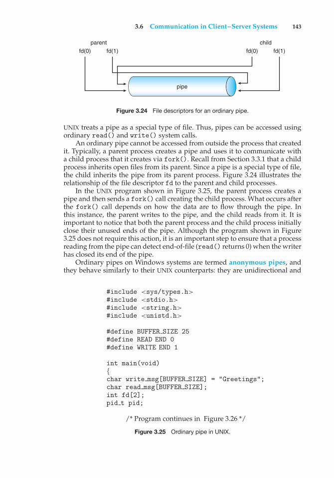
3.6 Communication in Client–Server Systems 143
parentfd(0) fd(1)
childfd(0) fd(1)
pipe
Figure 3.24 File descriptors for an ordinary pipe.
UNIX treats a pipe as a special type of file. Thus, pipes can be accessed usingordinary read() and write() system calls.
An ordinary pipe cannot be accessed from outside the process that createdit. Typically, a parent process creates a pipe and uses it to communicate witha child process that it creates via fork(). Recall from Section 3.3.1 that a childprocess inherits open files from its parent. Since a pipe is a special type of file,the child inherits the pipe from its parent process. Figure 3.24 illustrates therelationship of the file descriptor fd to the parent and child processes.
In the UNIX program shown in Figure 3.25, the parent process creates apipe and then sends a fork() call creating the child process. What occurs afterthe fork() call depends on how the data are to flow through the pipe. Inthis instance, the parent writes to the pipe, and the child reads from it. It isimportant to notice that both the parent process and the child process initiallyclose their unused ends of the pipe. Although the program shown in Figure3.25 does not require this action, it is an important step to ensure that a processreading from the pipe can detect end-of-file (read() returns 0) when the writerhas closed its end of the pipe.
Ordinary pipes on Windows systems are termed anonymous pipes, andthey behave similarly to their UNIX counterparts: they are unidirectional and
#include <sys/types.h>#include <stdio.h>#include <string.h>#include <unistd.h>
#define BUFFER SIZE 25#define READ END 0#define WRITE END 1
int main(void){char write msg[BUFFER SIZE] = "Greetings";char read msg[BUFFER SIZE];int fd[2];pid t pid;
/* Program continues in Figure 3.26 */
Figure 3.25 Ordinary pipe in UNIX.
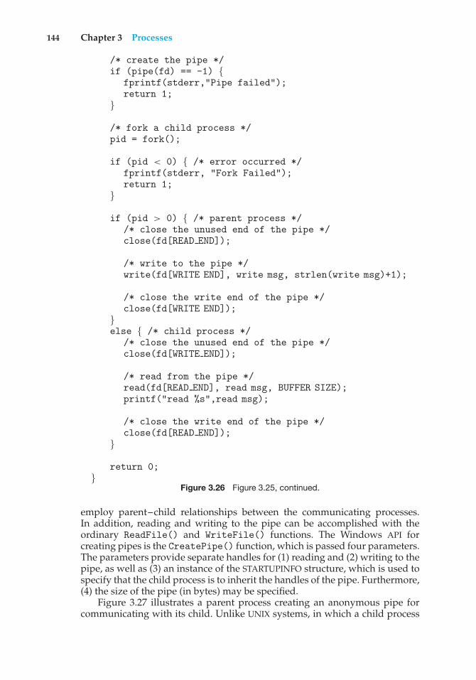
144 Chapter 3 Processes
/* create the pipe */if (pipe(fd) == -1) {
fprintf(stderr,"Pipe failed");return 1;
}
/* fork a child process */pid = fork();
if (pid < 0) { /* error occurred */fprintf(stderr, "Fork Failed");return 1;
}
if (pid > 0) { /* parent process *//* close the unused end of the pipe */close(fd[READ END]);
/* write to the pipe */write(fd[WRITE END], write msg, strlen(write msg)+1);
/* close the write end of the pipe */close(fd[WRITE END]);
}else { /* child process */
/* close the unused end of the pipe */close(fd[WRITE END]);
/* read from the pipe */read(fd[READ END], read msg, BUFFER SIZE);printf("read %s",read msg);
/* close the write end of the pipe */close(fd[READ END]);
}
return 0;}
Figure 3.26 Figure 3.25, continued.
employ parent–child relationships between the communicating processes.In addition, reading and writing to the pipe can be accomplished with theordinary ReadFile() and WriteFile() functions. The Windows API forcreating pipes is the CreatePipe() function, which is passed four parameters.The parameters provide separate handles for (1) reading and (2) writing to thepipe, as well as (3) an instance of the STARTUPINFO structure, which is used tospecify that the child process is to inherit the handles of the pipe. Furthermore,(4) the size of the pipe (in bytes) may be specified.
Figure 3.27 illustrates a parent process creating an anonymous pipe forcommunicating with its child. Unlike UNIX systems, in which a child process
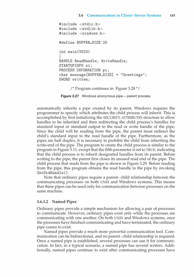
3.6 Communication in Client–Server Systems 145
#include <stdio.h>#include <stdlib.h>#include <windows.h>
#define BUFFER SIZE 25
int main(VOID){HANDLE ReadHandle, WriteHandle;STARTUPINFO si;PROCESS INFORMATION pi;char message[BUFFER SIZE] = "Greetings";DWORD written;
/* Program continues in Figure 3.28 */
Figure 3.27 Windows anonymous pipe—parent process.
automatically inherits a pipe created by its parent, Windows requires theprogrammer to specify which attributes the child process will inherit. This isaccomplished by first initializing the SECURITY ATTRIBUTES structure to allowhandles to be inherited and then redirecting the child process’s handles forstandard input or standard output to the read or write handle of the pipe.Since the child will be reading from the pipe, the parent must redirect thechild’s standard input to the read handle of the pipe. Furthermore, as thepipes are half duplex, it is necessary to prohibit the child from inheriting thewrite-end of the pipe. The program to create the child process is similar to theprogram in Figure 3.11, except that the fifth parameter is set to TRUE, indicatingthat the child process is to inherit designated handles from its parent. Beforewriting to the pipe, the parent first closes its unused read end of the pipe. Thechild process that reads from the pipe is shown in Figure 3.29. Before readingfrom the pipe, this program obtains the read handle to the pipe by invokingGetStdHandle().
Note that ordinary pipes require a parent–child relationship between thecommunicating processes on both UNIX and Windows systems. This meansthat these pipes can be used only for communication between processes on thesame machine.
3.6.3.2 Named Pipes
Ordinary pipes provide a simple mechanism for allowing a pair of processesto communicate. However, ordinary pipes exist only while the processes arecommunicating with one another. On both UNIX and Windows systems, oncethe processes have finished communicating and have terminated, the ordinarypipe ceases to exist.
Named pipes provide a much more powerful communication tool. Com-munication can be bidirectional, and no parent–child relationship is required.Once a named pipe is established, several processes can use it for communi-cation. In fact, in a typical scenario, a named pipe has several writers. Addi-tionally, named pipes continue to exist after communicating processes have
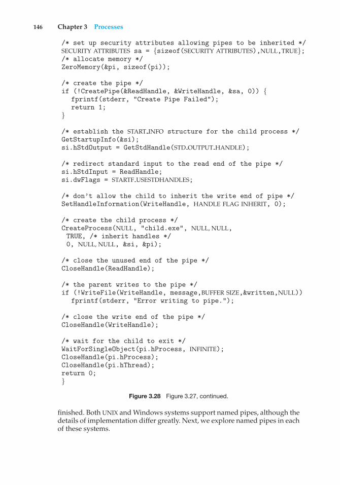
146 Chapter 3 Processes
/* set up security attributes allowing pipes to be inherited */SECURITY ATTRIBUTES sa = {sizeof(SECURITY ATTRIBUTES),NULL,TRUE};/* allocate memory */ZeroMemory(&pi, sizeof(pi));
/* create the pipe */if (!CreatePipe(&ReadHandle, &WriteHandle, &sa, 0)) {
fprintf(stderr, "Create Pipe Failed");return 1;
}
/* establish the START INFO structure for the child process */GetStartupInfo(&si);si.hStdOutput = GetStdHandle(STD OUTPUT HANDLE);
/* redirect standard input to the read end of the pipe */si.hStdInput = ReadHandle;si.dwFlags = STARTF USESTDHANDLES;
/* don’t allow the child to inherit the write end of pipe */SetHandleInformation(WriteHandle, HANDLE FLAG INHERIT, 0);
/* create the child process */CreateProcess(NULL, "child.exe", NULL, NULL,TRUE, /* inherit handles */0, NULL, NULL, &si, &pi);
/* close the unused end of the pipe */CloseHandle(ReadHandle);
/* the parent writes to the pipe */if (!WriteFile(WriteHandle, message,BUFFER SIZE,&written,NULL))
fprintf(stderr, "Error writing to pipe.");
/* close the write end of the pipe */CloseHandle(WriteHandle);
/* wait for the child to exit */WaitForSingleObject(pi.hProcess, INFINITE);CloseHandle(pi.hProcess);CloseHandle(pi.hThread);return 0;}
Figure 3.28 Figure 3.27, continued.
finished. Both UNIX and Windows systems support named pipes, although thedetails of implementation differ greatly. Next, we explore named pipes in eachof these systems.
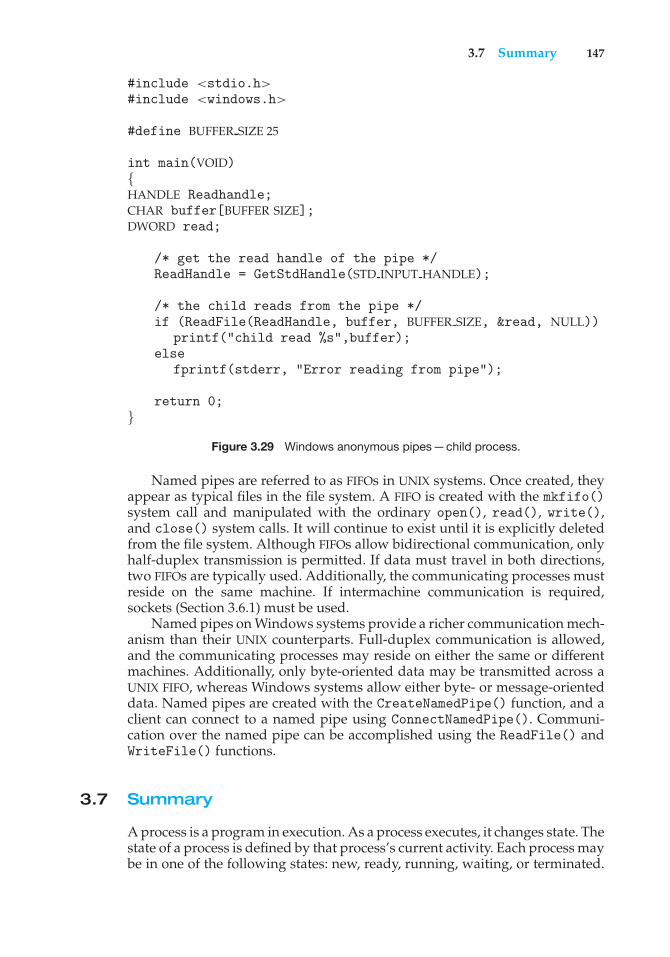
3.7 Summary 147
#include <stdio.h>#include <windows.h>
#define BUFFER SIZE 25
int main(VOID){HANDLE Readhandle;CHAR buffer[BUFFER SIZE];DWORD read;
/* get the read handle of the pipe */ReadHandle = GetStdHandle(STD INPUT HANDLE);
/* the child reads from the pipe */if (ReadFile(ReadHandle, buffer, BUFFER SIZE, &read, NULL))
printf("child read %s",buffer);else
fprintf(stderr, "Error reading from pipe");
return 0;}
Figure 3.29 Windows anonymous pipes—child process.
Named pipes are referred to as FIFOs in UNIX systems. Once created, theyappear as typical files in the file system. A FIFO is created with the mkfifo()system call and manipulated with the ordinary open(), read(), write(),and close() system calls. It will continue to exist until it is explicitly deletedfrom the file system. Although FIFOs allow bidirectional communication, onlyhalf-duplex transmission is permitted. If data must travel in both directions,two FIFOs are typically used. Additionally, the communicating processes mustreside on the same machine. If intermachine communication is required,sockets (Section 3.6.1) must be used.
Named pipes on Windows systems provide a richer communication mech-anism than their UNIX counterparts. Full-duplex communication is allowed,and the communicating processes may reside on either the same or differentmachines. Additionally, only byte-oriented data may be transmitted across aUNIX FIFO, whereas Windows systems allow either byte- or message-orienteddata. Named pipes are created with the CreateNamedPipe() function, and aclient can connect to a named pipe using ConnectNamedPipe(). Communi-cation over the named pipe can be accomplished using the ReadFile() andWriteFile() functions.
3.7 Summary
A process is a program in execution. As a process executes, it changes state. Thestate of a process is defined by that process’s current activity. Each process maybe in one of the following states: new, ready, running, waiting, or terminated.
148 Chapter 3 Processes
PIPES IN PRACTICE
Pipes are used quite often in the UNIX command-line environment forsituations in which the output of one command serves as input to another. Forexample, the UNIX ls command produces a directory listing. For especiallylong directory listings, the output may scroll through several screens. Thecommand more manages output by displaying only one screen of output ata time; the user must press the space bar to move from one screen to the next.Setting up a pipe between the ls and more commands (which are running asindividual processes) allows the output of ls to be delivered as the input tomore, enabling the user to display a large directory listing a screen at a time.A pipe can be constructed on the command line using the | character. Thecomplete command is
ls | more
In this scenario, the ls command serves as the producer, and its output isconsumed by the more command.
Windows systems provide a more command for the DOS shell withfunctionality similar to that of its UNIX counterpart. The DOS shell also usesthe | character for establishing a pipe. The only difference is that to geta directory listing, DOS uses the dir command rather than ls, as shownbelow:
dir | more
Each process is represented in the operating system by its own process controlblock (PCB).
A process, when it is not executing, is placed in some waiting queue. Thereare two major classes of queues in an operating system: I/O request queuesand the ready queue. The ready queue contains all the processes that are readyto execute and are waiting for the CPU. Each process is represented by a PCB.
The operating system must select processes from various schedulingqueues. Long-term (job) scheduling is the selection of processes that will beallowed to contend for the CPU. Normally, long-term scheduling is heavilyinfluenced by resource-allocation considerations, especially memory manage-ment. Short-term (CPU) scheduling is the selection of one process from theready queue.
Operating systems must provide a mechanism for parent processes tocreate new child processes. The parent may wait for its children to terminatebefore proceeding, or the parent and children may execute concurrently. Thereare several reasons for allowing concurrent execution: information sharing,computation speedup, modularity, and convenience.
The processes executing in the operating system may be either independentprocesses or cooperating processes. Cooperating processes require an interpro-cess communication mechanism to communicate with each other. Principally,communication is achieved through two schemes: shared memory and mes-sage passing. The shared-memory method requires communicating processes
Practice Exercises 149
#include <sys/types.h>#include <stdio.h>#include <unistd.h>
int value = 5;
int main(){pid t pid;
pid = fork();
if (pid == 0) { /* child process */value += 15;return 0;
}else if (pid > 0) { /* parent process */
wait(NULL);printf("PARENT: value = %d",value); /* LINE A */return 0;
}}
Figure 3.30 What output will be at Line A?
to share some variables. The processes are expected to exchange informationthrough the use of these shared variables. In a shared-memory system, theresponsibility for providing communication rests with the application pro-grammers; the operating system needs to provide only the shared memory.The message-passing method allows the processes to exchange messages.The responsibility for providing communication may rest with the operatingsystem itself. These two schemes are not mutually exclusive and can be usedsimultaneously within a single operating system.
Communication in client–server systems may use (1) sockets, (2) remoteprocedure calls (RPCs), or (3) pipes. A socket is defined as an endpoint forcommunication. A connection between a pair of applications consists of a pairof sockets, one at each end of the communication channel. RPCs are anotherform of distributed communication. An RPC occurs when a process (or thread)calls a procedure on a remote application. Pipes provide a relatively simpleways for processes to communicate with one another. Ordinary pipes allowcommunication between parent and child processes, while named pipes permitunrelated processes to communicate.
Practice Exercises
3.1 Using the program shown in Figure 3.30, explain what the output willbe at LINE A.
3.2 Including the initial parent process, how many processes are created bythe program shown in Figure 3.31?
150 Chapter 3 Processes
#include <stdio.h>#include <unistd.h>
int main(){
/* fork a child process */fork();
/* fork another child process */fork();
/* and fork another */fork();
return 0;}
Figure 3.31 How many processes are created?
3.3 Original versions of Apple’s mobile iOS operating system provided nomeans of concurrent processing. Discuss three major complications thatconcurrent processing adds to an operating system.
3.4 The Sun UltraSPARC processor has multiple register sets. Describe whathappens when a context switch occurs if the new context is alreadyloaded into one of the register sets. What happens if the new context isin memory rather than in a register set and all the register sets are inuse?
3.5 When a process creates a new process using the fork() operation, whichof the following states is shared between the parent process and the childprocess?
a. Stack
b. Heap
c. Shared memory segments
3.6 Consider the “exactly once”semantic with respect to the RPC mechanism.Does the algorithm for implementing this semantic execute correctlyeven if the ACK message sent back to the client is lost due to a networkproblem? Describe the sequence of messages, and discuss whether“exactly once” is still preserved.
3.7 Assume that a distributed system is susceptible to server failure. Whatmechanisms would be required to guarantee the “exactly once” semanticfor execution of RPCs?
Exercises
3.8 Describe the differences among short-term, medium-term, and long-term scheduling.
Exercises 151
#include <stdio.h>#include <unistd.h>
int main(){
int i;
for (i = 0; i < 4; i++)fork();
return 0;}
Figure 3.32 How many processes are created?
3.9 Describe the actions taken by a kernel to context-switch betweenprocesses.
3.10 Construct a process tree similar to Figure 3.8. To obtain process infor-mation for the UNIX or Linux system, use the command ps -ael.
#include <sys/types.h>#include <stdio.h>#include <unistd.h>
int main(){pid t pid;
/* fork a child process */pid = fork();
if (pid < 0) { /* error occurred */fprintf(stderr, "Fork Failed");return 1;
}else if (pid == 0) { /* child process */
execlp("/bin/ls","ls",NULL);printf("LINE J");
}else { /* parent process */
/* parent will wait for the child to complete */wait(NULL);printf("Child Complete");
}
return 0;}
Figure 3.33 When will LINE J be reached?
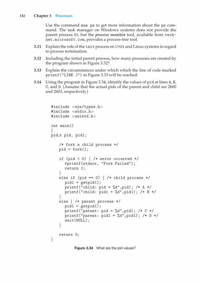
152 Chapter 3 Processes
Use the command man ps to get more information about the ps com-mand. The task manager on Windows systems does not provide theparent process ID, but the process monitor tool, available from tech-net.microsoft.com, provides a process-tree tool.
3.11 Explain the role of the initprocess on UNIX and Linux systems in regardto process termination.
3.12 Including the initial parent process, how many processes are created bythe program shown in Figure 3.32?
3.13 Explain the circumstances under which which the line of code markedprintf("LINE J") in Figure 3.33 will be reached.
3.14 Using the program in Figure 3.34, identify the values of pid at lines A, B,C, and D. (Assume that the actual pids of the parent and child are 2600and 2603, respectively.)
#include <sys/types.h>#include <stdio.h>#include <unistd.h>
int main(){pid t pid, pid1;
/* fork a child process */pid = fork();
if (pid < 0) { /* error occurred */fprintf(stderr, "Fork Failed");return 1;
}else if (pid == 0) { /* child process */
pid1 = getpid();printf("child: pid = %d",pid); /* A */printf("child: pid1 = %d",pid1); /* B */
}else { /* parent process */
pid1 = getpid();printf("parent: pid = %d",pid); /* C */printf("parent: pid1 = %d",pid1); /* D */wait(NULL);
}
return 0;}
Figure 3.34 What are the pid values?
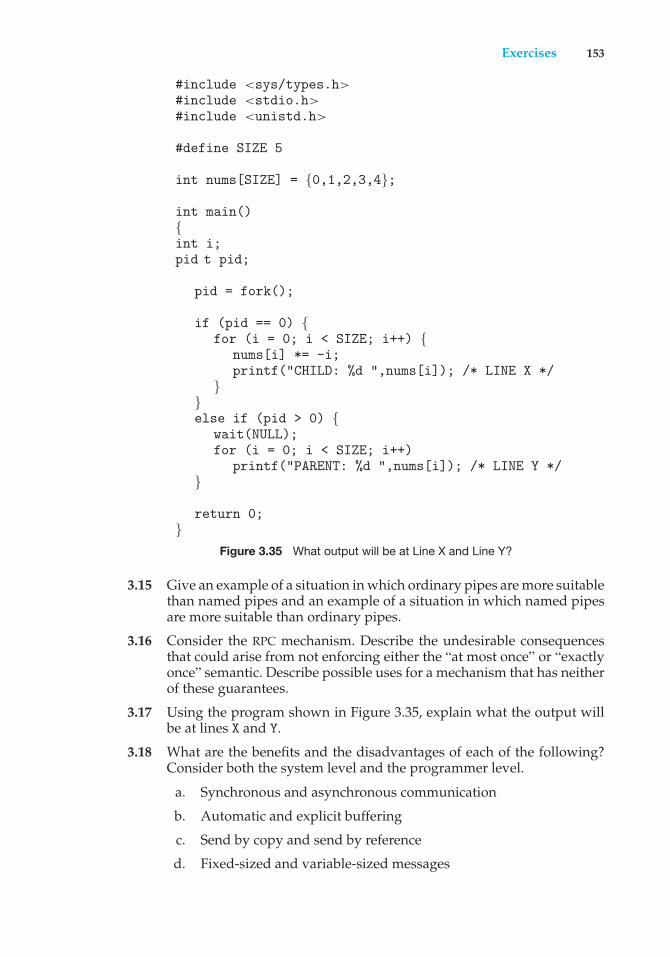
Exercises 153
#include <sys/types.h>#include <stdio.h>#include <unistd.h>
#define SIZE 5
int nums[SIZE] = {0,1,2,3,4};
int main(){int i;pid t pid;
pid = fork();
if (pid == 0) {for (i = 0; i < SIZE; i++) {
nums[i] *= -i;printf("CHILD: %d ",nums[i]); /* LINE X */
}}else if (pid > 0) {
wait(NULL);for (i = 0; i < SIZE; i++)
printf("PARENT: %d ",nums[i]); /* LINE Y */}
return 0;}
Figure 3.35 What output will be at Line X and Line Y?
3.15 Give an example of a situation in which ordinary pipes are more suitablethan named pipes and an example of a situation in which named pipesare more suitable than ordinary pipes.
3.16 Consider the RPC mechanism. Describe the undesirable consequencesthat could arise from not enforcing either the “at most once” or “exactlyonce” semantic. Describe possible uses for a mechanism that has neitherof these guarantees.
3.17 Using the program shown in Figure 3.35, explain what the output willbe at lines X and Y.
3.18 What are the benefits and the disadvantages of each of the following?Consider both the system level and the programmer level.
a. Synchronous and asynchronous communication
b. Automatic and explicit buffering
c. Send by copy and send by reference
d. Fixed-sized and variable-sized messages
154 Chapter 3 Processes
Programming Problems
3.19 Using either a UNIX or a Linux system, write a C program that forksa child process that ultimately becomes a zombie process. This zombieprocess must remain in the system for at least 10 seconds. Process statescan be obtained from the command
ps -l
The process states are shown below the S column; processes with a stateof Z are zombies. The process identifier (pid) of the child process is listedin the PID column, and that of the parent is listed in the PPID column.
Perhaps the easiest way to determine that the child process is indeeda zombie is to run the program that you have written in the background(using the &) and then run the command ps -l to determine whetherthe child is a zombie process. Because you do not want too many zombieprocesses existing in the system, you will need to remove the one thatyou have created. The easiest way to do that is to terminate the parentprocess using the kill command. For example, if the process id of theparent is 4884, you would enter
kill -9 4884
3.20 An operating system’s pid manager is responsible for managing processidentifiers. When a process is first created, it is assigned a unique pidby the pid manager. The pid is returned to the pid manager when theprocess completes execution, and the manager may later reassign thispid. Process identifiers are discussed more fully in Section 3.3.1. Whatis most important here is to recognize that process identifiers must beunique; no two active processes can have the same pid.Use the following constants to identify the range of possible pid values:
#define MIN PID 300#define MAX PID 5000
You may use any data structure of your choice to represent the avail-ability of process identifiers. One strategy is to adopt what Linux hasdone and use a bitmap in which a value of 0 at position i indicates thata process id of value i is available and a value of 1 indicates that theprocess id is currently in use.
Implement the following API for obtaining and releasing a pid:
• int allocate map(void)—Creates and initializes a data structurefor representing pids; returns—1 if unsuccessful, 1 if successful
• int allocate pid(void)—Allocates and returns a pid; returns—1 if unable to allocate a pid (all pids are in use)
• void release pid(int pid)—Releases a pid
This programming problem will be modified later on in Chpaters 4 and5.
Programming Problems 155
3.21 The Collatz conjecture concerns what happens when we take anypositive integer n and apply the following algorithm:
n =!
n/2, if n is even3× n + 1, if n is odd
The conjecture states that when this algorithm is continually applied,all positive integers will eventually reach 1. For example, if n = 35, thesequence is
35, 106, 53, 160, 80, 40, 20, 10, 5, 16, 8, 4, 2, 1
Write a C program using the fork() system call that generates thissequence in the child process. The starting number will be providedfrom the command line. For example, if 8 is passed as a parameter onthe command line, the child process will output 8, 4, 2, 1. Because theparent and child processes have their own copies of the data, it will benecessary for the child to output the sequence. Have the parent invokethe wait() call to wait for the child process to complete before exitingthe program. Perform necessary error checking to ensure that a positiveinteger is passed on the command line.
3.22 In Exercise 3.21, the child process must output the sequence of numbersgenerated from the algorithm specified by the Collatz conjecture becausethe parent and child have their own copies of the data. Anotherapproach to designing this program is to establish a shared-memoryobject between the parent and child processes. This technique allows thechild to write the contents of the sequence to the shared-memory object.The parent can then output the sequence when the child completes.Because the memory is shared, any changes the child makes will bereflected in the parent process as well.
This program will be structured using POSIX shared memory asdescribed in Section 3.5.1. The parent process will progress through thefollowing steps:
a. Establish the shared-memory object (shm open(), ftruncate(),and mmap()).
b. Create the child process and wait for it to terminate.
c. Output the contents of shared memory.
d. Remove the shared-memory object.
One area of concern with cooperating processes involves synchro-nization issues. In this exercise, the parent and child processes must becoordinated so that the parent does not output the sequence until thechild finishes execution. These two processes will be synchronized usingthe wait() system call: the parent process will invoke wait(), whichwill suspend it until the child process exits.
3.23 Section 3.6.1 describes port numbers below 1024 as being well known—that is, they provide standard services. Port 17 is known as the quote-of-
156 Chapter 3 Processes
the-day service. When a client connects to port 17 on a server, the serverresponds with a quote for that day.
Modify the date server shown in Figure 3.21 so that it delivers a quoteof the day rather than the current date. The quotes should be printableASCII characters and should contain fewer than 512 characters, althoughmultiple lines are allowed. Since port 17 is well known and thereforeunavailable, have your server listen to port 6017. The date client shownin Figure 3.22 can be used to read the quotes returned by your server.
3.24 A haiku is a three-line poem in which the first line contains five syllables,the second line contains seven syllables, and the third line contains fivesyllables. Write a haiku server that listens to port 5575. When a clientconnects to this port, the server responds with a haiku. The date clientshown in Figure 3.22 can be used to read the quotes returned by yourhaiku server.
3.25 An echo server echoes back whatever it receives from a client. Forexample, if a client sends the server the string Hello there!, the serverwill respond with Hello there!
Write an echo server using the Java networking API described inSection 3.6.1. This server will wait for a client connection using theaccept() method. When a client connection is received, the server willloop, performing the following steps:
• Read data from the socket into a buffer.
• Write the contents of the buffer back to the client.
The server will break out of the loop only when it has determined thatthe client has closed the connection.
The date server shown in Figure 3.21 uses thejava.io.BufferedReader class. BufferedReader extends thejava.io.Reader class, which is used for reading character streams.However, the echo server cannot guarantee that it will readcharacters from clients; it may receive binary data as well. Theclass java.io.InputStream deals with data at the byte level ratherthan the character level. Thus, your echo server must use an objectthat extends java.io.InputStream. The read() method in thejava.io.InputStream class returns −1 when the client has closed itsend of the socket connection.
3.26 Design a program using ordinary pipes in which one process sends astring message to a second process, and the second process reversesthe case of each character in the message and sends it back to the firstprocess. For example, if the first process sends the messageHi There, thesecond process will return hI tHERE. This will require using two pipes,one for sending the original message from the first to the second processand the other for sending the modified message from the second to thefirst process. You can write this program using either UNIX or Windowspipes.
3.27 Design a file-copying program named filecopy using ordinary pipes.This program will be passed two parameters: the name of the file to be
Programming Projects 157
copied and the name of the copied file. The program will then createan ordinary pipe and write the contents of the file to be copied to thepipe. The child process will read this file from the pipe and write it tothe destination file. For example, if we invoke the program as follows:
filecopy input.txt copy.txt
the file input.txt will be written to the pipe. The child process willread the contents of this file and write it to the destination file copy.txt.You may write this program using either UNIX or Windows pipes.
Programming Projects
Project 1—UNIX Shell and History FeatureThis project consists of designing a C program to serve as a shell interfacethat accepts user commands and then executes each command in a separateprocess. This project can be completed on any Linux, UNIX, or Mac OS X system.
A shell interface gives the user a prompt, after which the next commandis entered. The example below illustrates the prompt osh> and the user’snext command: cat prog.c. (This command displays the file prog.c on theterminal using the UNIX cat command.)
osh> cat prog.c
One technique for implementing a shell interface is to have the parent processfirst read what the user enters on the command line (in this case, catprog.c), and then create a separate child process that performs the command.Unless otherwise specified, the parent process waits for the child to exitbefore continuing. This is similar in functionality to the new process creationillustrated in Figure 3.10. However, UNIX shells typically also allow the childprocess to run in the background, or concurrently. To accomplish this, we addan ampersand (&) at the end of the command. Thus, if we rewrite the abovecommand as
osh> cat prog.c &
the parent and child processes will run concurrently.The separate child process is created using the fork() system call, and the
user’s command is executed using one of the system calls in the exec() family(as described in Section 3.3.1).
A C program that provides the general operations of a command-line shellis supplied in Figure 3.36. The main() function presents the prompt osh->and outlines the steps to be taken after input from the user has been read. Themain() function continually loops as long as should run equals 1; when theuser enters exit at the prompt, your program will set should run to 0 andterminate.
This project is organized into two parts: (1) creating the child process andexecuting the command in the child, and (2) modifying the shell to allow ahistory feature.
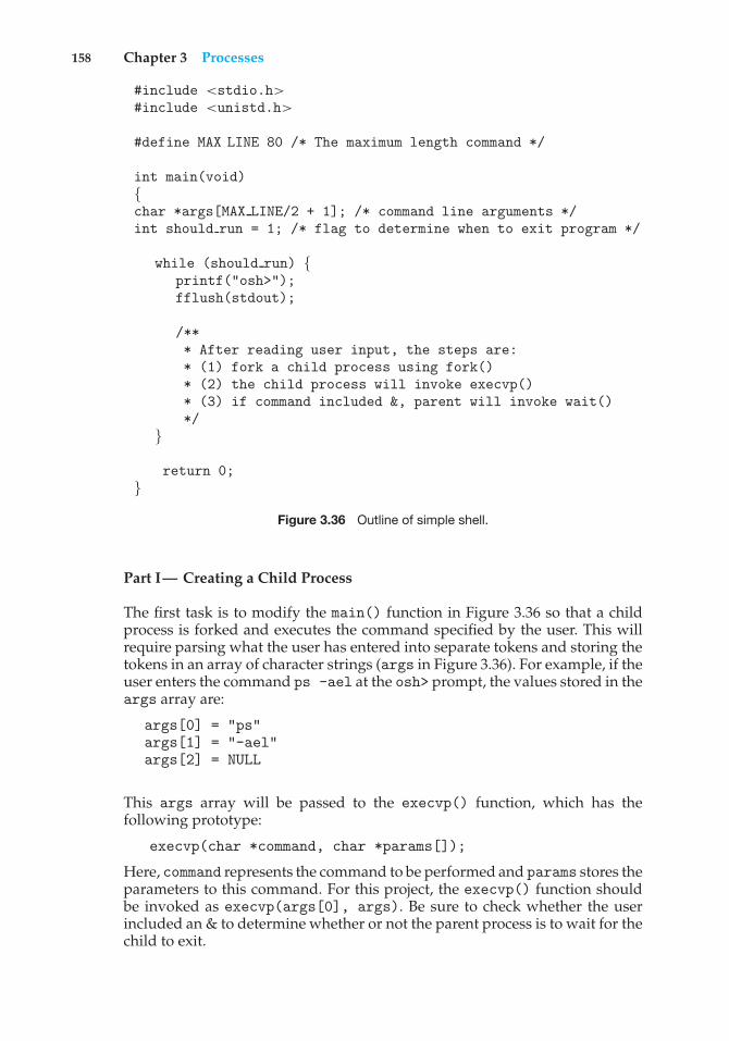
158 Chapter 3 Processes
#include <stdio.h>#include <unistd.h>
#define MAX LINE 80 /* The maximum length command */
int main(void){char *args[MAX LINE/2 + 1]; /* command line arguments */int should run = 1; /* flag to determine when to exit program */
while (should run) {printf("osh>");fflush(stdout);
/*** After reading user input, the steps are:* (1) fork a child process using fork()* (2) the child process will invoke execvp()* (3) if command included &, parent will invoke wait()*/
}
return 0;}
Figure 3.36 Outline of simple shell.
Part I— Creating a Child Process
The first task is to modify the main() function in Figure 3.36 so that a childprocess is forked and executes the command specified by the user. This willrequire parsing what the user has entered into separate tokens and storing thetokens in an array of character strings (args in Figure 3.36). For example, if theuser enters the command ps -ael at the osh> prompt, the values stored in theargs array are:
args[0] = "ps"args[1] = "-ael"args[2] = NULL
This args array will be passed to the execvp() function, which has thefollowing prototype:
execvp(char *command, char *params[]);
Here, command represents the command to be performed and params stores theparameters to this command. For this project, the execvp() function shouldbe invoked as execvp(args[0], args). Be sure to check whether the userincluded an & to determine whether or not the parent process is to wait for thechild to exit.
Programming Projects 159
Part II—Creating a History Feature
The next task is to modify the shell interface program so that it providesa history feature that allows the user to access the most recently enteredcommands. The user will be able to access up to 10 commands by using thefeature. The commands will be consecutively numbered starting at 1, andthe numbering will continue past 10. For example, if the user has entered 35commands, the 10 most recent commands will be numbered 26 to 35.
The user will be able to list the command history by entering the command
history
at the osh> prompt. As an example, assume that the history consists of thecommands (from most to least recent):
ps, ls -l, top, cal, who, date
The command history will output:
6 ps5 ls -l4 top3 cal2 who1 date
Your program should support two techniques for retrieving commandsfrom the command history:
1. When the user enters !!, the most recent command in the history isexecuted.
2. When the user enters a single ! followed by an integer N, the Nth
command in the history is executed.
Continuing our example from above, if the user enters !!, the ps commandwill be performed; if the user enters !3, the command cal will be executed.Any command executed in this fashion should be echoed on the user’s screen.The command should also be placed in the history buffer as the next command.
The program should also manage basic error handling. If there areno commands in the history, entering !! should result in a message “Nocommands in history.” If there is no command corresponding to the numberentered with the single !, the program should output "No such command inhistory."
Project 2—Linux Kernel Module for Listing TasksIn this project, you will write a kernel module that lists all current tasks in aLinux system. Be sure to review the programming project in Chapter 2, whichdeals with creating Linux kernel modules, before you begin this project. Theproject can be completed using the Linux virtual machine provided with thistext.
160 Chapter 3 Processes
Part I—Iterating over Tasks Linearly
As illustrated in Section 3.1, the PCB in Linux is represented by the structuretask struct, which is found in the <linux/sched.h> include file. In Linux,the for each process() macro easily allows iteration over all current tasksin the system:
#include <linux/sched.h>
struct task struct *task;
for each process(task) {/* on each iteration task points to the next task */
}
The various fields in task struct can then be displayed as the program loopsthrough the for each process() macro.
Part I Assignment
Design a kernel module that iterates through all tasks in the system using thefor each process() macro. In particular, output the task name (known asexecutable name), state, and process id of each task. (You will probably haveto read through the task struct structure in <linux/sched.h> to obtain thenames of these fields.) Write this code in the module entry point so that itscontents will appear in the kernel log buffer, which can be viewed using thedmesg command. To verify that your code is working correctly, compare thecontents of the kernel log buffer with the output of the following command,which lists all tasks in the system:
ps -el
The two values should be very similar. Because tasks are dynamic, however, itis possible that a few tasks may appear in one listing but not the other.
Part II—Iterating over Tasks with a Depth-First Search Tree
The second portion of this project involves iterating over all tasks in the systemusing a depth-first search (DFS) tree. (As an example: the DFS iteration of theprocesses in Figure 3.8 is 1, 8415, 8416, 9298, 9204, 2, 6, 200, 3028, 3610, 4005.)
Linux maintains its process tree as a series of lists. Examining thetask struct in <linux/sched.h>, we see two struct list head objects:
children
and
sibling
Bibliographical Notes 161
These objects are pointers to a list of the task’s children, as well as its sib-lings. Linux also maintains references to the init task (struct task structinit task). Using this information as well as macro operations on lists, wecan iterate over the children of init as follows:
struct task struct *task;struct list head *list;
list for each(list, &init task->children) {task = list entry(list, struct task struct, sibling);/* task points to the next child in the list */
}
The list for each() macro is passed two parameters, both of type structlist head:
• A pointer to the head of the list to be traversed
• A pointer to the head node of the list to be traversed
At each iteration of list for each(), the first parameter is set to the liststructure of the next child. We then use this value to obtain each structure inthe list using the list entry() macro.
Part II Assignment
Beginning from the init task, design a kernel module that iterates over all tasksin the system using a DFS tree. Just as in the first part of this project, outputthe name, state, and pid of each task. Perform this iteration in the kernel entrymodule so that its output appears in the kernel log buffer.
If you output all tasks in the system, you may see many more tasks thanappear with the ps -ael command. This is because some threads appear aschildren but do not show up as ordinary processes. Therefore, to check theoutput of the DFS tree, use the command
ps -eLf
This command lists all tasks—including threads—in the system. To verifythat you have indeed performed an appropriate DFS iteration, you will have toexamine the relationships among the various tasks output by the ps command.
Bibliographical Notes
Process creation, management, and IPC in UNIX and Windows systems,respectively, are discussed in [Robbins and Robbins (2003)] and [Russinovichand Solomon (2009)]. [Love (2010)] covers support for processes in the Linuxkernel, and [Hart (2005)] covers Windows systems programming in detail.Coverage of the multiprocess model used in Google’s Chrome can be found athttp://blog.chromium.org/2008/09/multi-process-architecture.html.
162 Chapter 3 Processes
Message passing for multicore systems is discussed in [Holland andSeltzer (2011)]. [Baumann et al. (2009)] describe performance issues in shared-memory and message-passing systems. [Vahalia (1996)] describes interprocesscommunication in the Mach system.
The implementation of RPCs is discussed by [Birrell and Nelson (1984)].[Staunstrup (1982)] discusses procedure calls versus message-passing com-munication. [Harold (2005)] provides coverage of socket programming inJava.
[Hart (2005)] and [Robbins and Robbins (2003)] cover pipes in Windowsand UNIX systems, respectively.
Bibliography
[Baumann et al. (2009)] A. Baumann, P. Barham, P.-E. Dagand, T. Harris,R. Isaacs, P. Simon, T. Roscoe, A. Schüpbach, and A. Singhania, “The multikernel:a new OS architecture for scalable multicore systems” (2009), pages 29–44.
[Birrell and Nelson (1984)] A. D. Birrell and B. J. Nelson, “ImplementingRemote Procedure Calls”, ACM Transactions on Computer Systems, Volume 2,Number 1 (1984), pages 39–59.
[Harold (2005)] E. R. Harold, Java Network Programming, Third Edition, O’Reilly& Associates (2005).
[Hart (2005)] J. M. Hart, Windows System Programming, Third Edition, Addison-Wesley (2005).
[Holland and Seltzer (2011)] D. Holland and M. Seltzer, “Multicore OSes: look-ing forward from 1991, er, 2011”, Proceedings of the 13th USENIX conference onHot topics in operating systems (2011), pages 33–33.
[Love (2010)] R. Love, Linux Kernel Development, Third Edition, Developer’sLibrary (2010).
[Robbins and Robbins (2003)] K. Robbins and S. Robbins, Unix Systems Pro-gramming: Communication, Concurrency and Threads, Second Edition, PrenticeHall (2003).
[Russinovich and Solomon (2009)] M. E. Russinovich and D. A. Solomon, Win-dows Internals: Including Windows Server 2008 and Windows Vista, Fifth Edition,Microsoft Press (2009).
[Staunstrup (1982)] J. Staunstrup, “Message Passing Communication VersusProcedure Call Communication”, Software—Practice and Experience, Volume 12,Number 3 (1982), pages 223–234.
[Vahalia (1996)] U. Vahalia, Unix Internals: The New Frontiers, Prentice Hall(1996).
4C H A P T E R
Threads
The process model introduced in Chapter 3 assumed that a process wasan executing program with a single thread of control. Virtually all modernoperating systems, however, provide features enabling a process to containmultiple threads of control. In this chapter, we introduce many conceptsassociated with multithreaded computer systems, including a discussion ofthe APIs for the Pthreads, Windows, and Java thread libraries. We look at anumber of issues related to multithreaded programming and its effect on thedesign of operating systems. Finally, we explore how the Windows and Linuxoperating systems support threads at the kernel level.
CHAPTER OBJECTIVES
• To introduce the notion of a thread—a fundamental unit of CPU utilizationthat forms the basis of multithreaded computer systems.
• To discuss the APIs for the Pthreads, Windows, and Java thread libraries.• To explore several strategies that provide implicit threading.• To examine issues related to multithreaded programming.• To cover operating system support for threads in Windows and Linux.
4.1 Overview
A thread is a basic unit of CPU utilization; it comprises a thread ID, a programcounter, a register set, and a stack. It shares with other threads belongingto the same process its code section, data section, and other operating-systemresources, such as open files and signals. A traditional (or heavyweight) processhas a single thread of control. If a process has multiple threads of control, itcan perform more than one task at a time. Figure 4.1 illustrates the differencebetween a traditional single-threaded process and a multithreaded process.
4.1.1 Motivation
Most software applications that run on modern computers are multithreaded.An application typically is implemented as a separate process with several
163
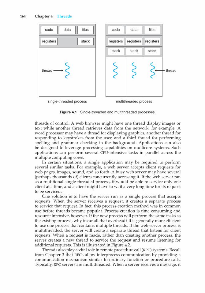
164 Chapter 4 Threads
registers
code data files
stack registers registers registers
code data files
stackstackstack
thread thread
single-threaded process multithreaded process
Figure 4.1 Single-threaded and multithreaded processes.
threads of control. A web browser might have one thread display images ortext while another thread retrieves data from the network, for example. Aword processor may have a thread for displaying graphics, another thread forresponding to keystrokes from the user, and a third thread for performingspelling and grammar checking in the background. Applications can alsobe designed to leverage processing capabilities on multicore systems. Suchapplications can perform several CPU-intensive tasks in parallel across themultiple computing cores.
In certain situations, a single application may be required to performseveral similar tasks. For example, a web server accepts client requests forweb pages, images, sound, and so forth. A busy web server may have several(perhaps thousands of) clients concurrently accessing it. If the web server ranas a traditional single-threaded process, it would be able to service only oneclient at a time, and a client might have to wait a very long time for its requestto be serviced.
One solution is to have the server run as a single process that acceptsrequests. When the server receives a request, it creates a separate processto service that request. In fact, this process-creation method was in commonuse before threads became popular. Process creation is time consuming andresource intensive, however. If the new process will perform the same tasks asthe existing process, why incur all that overhead? It is generally more efficientto use one process that contains multiple threads. If the web-server process ismultithreaded, the server will create a separate thread that listens for clientrequests. When a request is made, rather than creating another process, theserver creates a new thread to service the request and resume listening foradditional requests. This is illustrated in Figure 4.2.
Threads also play a vital role in remote procedure call (RPC) systems. Recallfrom Chapter 3 that RPCs allow interprocess communication by providing acommunication mechanism similar to ordinary function or procedure calls.Typically, RPC servers are multithreaded. When a server receives a message, it
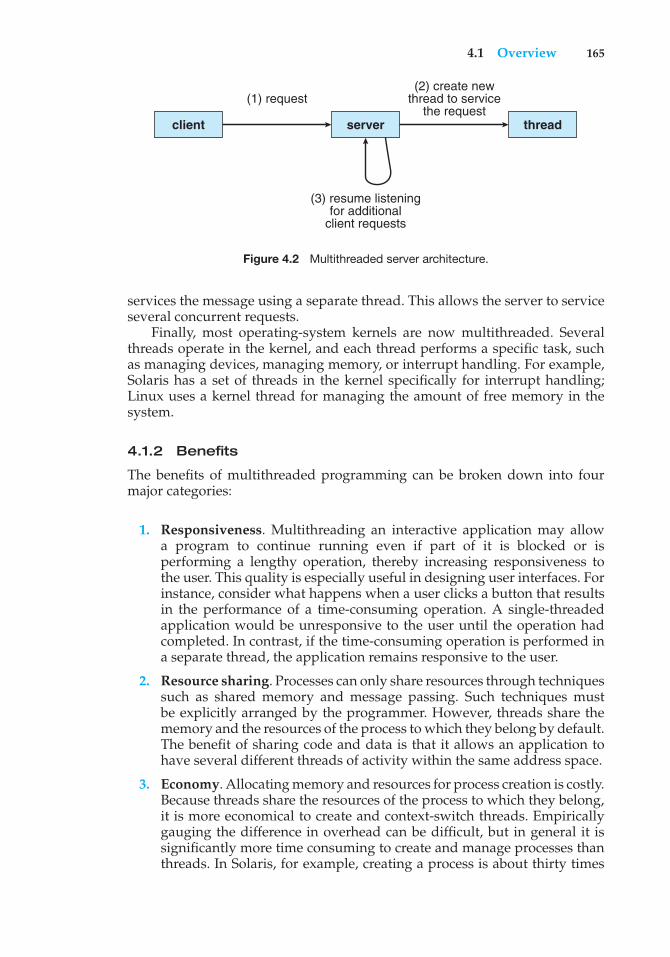
4.1 Overview 165
client
(1) request(2) create new
thread to servicethe request
(3) resume listeningfor additional
client requests
server thread
Figure 4.2 Multithreaded server architecture.
services the message using a separate thread. This allows the server to serviceseveral concurrent requests.
Finally, most operating-system kernels are now multithreaded. Severalthreads operate in the kernel, and each thread performs a specific task, suchas managing devices, managing memory, or interrupt handling. For example,Solaris has a set of threads in the kernel specifically for interrupt handling;Linux uses a kernel thread for managing the amount of free memory in thesystem.
4.1.2 Benefits
The benefits of multithreaded programming can be broken down into fourmajor categories:
1. Responsiveness. Multithreading an interactive application may allowa program to continue running even if part of it is blocked or isperforming a lengthy operation, thereby increasing responsiveness tothe user. This quality is especially useful in designing user interfaces. Forinstance, consider what happens when a user clicks a button that resultsin the performance of a time-consuming operation. A single-threadedapplication would be unresponsive to the user until the operation hadcompleted. In contrast, if the time-consuming operation is performed ina separate thread, the application remains responsive to the user.
2. Resource sharing. Processes can only share resources through techniquessuch as shared memory and message passing. Such techniques mustbe explicitly arranged by the programmer. However, threads share thememory and the resources of the process to which they belong by default.The benefit of sharing code and data is that it allows an application tohave several different threads of activity within the same address space.
3. Economy. Allocating memory and resources for process creation is costly.Because threads share the resources of the process to which they belong,it is more economical to create and context-switch threads. Empiricallygauging the difference in overhead can be difficult, but in general it issignificantly more time consuming to create and manage processes thanthreads. In Solaris, for example, creating a process is about thirty times
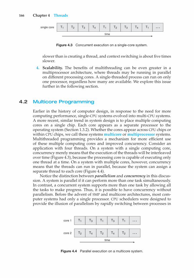
166 Chapter 4 Threads
T1 T2 T3 T4 T1 T2 T3 T4 T1single core
time
…
Figure 4.3 Concurrent execution on a single-core system.
slower than is creating a thread, and context switching is about five timesslower.
4. Scalability. The benefits of multithreading can be even greater in amultiprocessor architecture, where threads may be running in parallelon different processing cores. A single-threaded process can run on onlyone processor, regardless how many are available. We explore this issuefurther in the following section.
4.2 Multicore Programming
Earlier in the history of computer design, in response to the need for morecomputing performance, single-CPU systems evolved into multi-CPU systems.A more recent, similar trend in system design is to place multiple computingcores on a single chip. Each core appears as a separate processor to theoperating system (Section 1.3.2). Whether the cores appear across CPU chips orwithin CPU chips, we call these systems multicore or multiprocessor systems.Multithreaded programming provides a mechanism for more efficient useof these multiple computing cores and improved concurrency. Consider anapplication with four threads. On a system with a single computing core,concurrency merely means that the execution of the threads will be interleavedover time (Figure 4.3), because the processing core is capable of executing onlyone thread at a time. On a system with multiple cores, however, concurrencymeans that the threads can run in parallel, because the system can assign aseparate thread to each core (Figure 4.4).
Notice the distinction between parallelism and concurrency in this discus-sion. A system is parallel if it can perform more than one task simultaneously.In contrast, a concurrent system supports more than one task by allowing allthe tasks to make progress. Thus, it is possible to have concurrency withoutparallelism. Before the advent of SMP and multicore architectures, most com-puter systems had only a single processor. CPU schedulers were designed toprovide the illusion of parallelism by rapidly switching between processes in
T1 T3 T1 T3 T1core 1
T2 T4 T2 T4 T2core 2
time
…
…
Figure 4.4 Parallel execution on a multicore system.
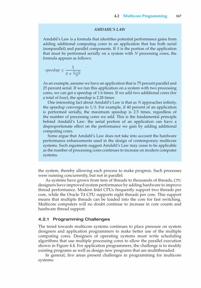
4.2 Multicore Programming 167
AMDAHL’S LAW
Amdahl’s Law is a formula that identifies potential performance gains fromadding additional computing cores to an application that has both serial(nonparallel) and parallel components. If S is the portion of the applicationthat must be performed serially on a system with N processing cores, theformula appears as follows:
speedup ≤ 1
S + (1−S)N
As an example, assume we have an application that is 75 percent parallel and25 percent serial. If we run this application on a system with two processingcores, we can get a speedup of 1.6 times. If we add two additional cores (fora total of four), the speedup is 2.28 times.
One interesting fact about Amdahl’s Law is that as N approaches infinity,the speedup converges to 1/S. For example, if 40 percent of an applicationis performed serially, the maximum speedup is 2.5 times, regardless ofthe number of processing cores we add. This is the fundamental principlebehind Amdahl’s Law: the serial portion of an application can have adisproportionate effect on the performance we gain by adding additionalcomputing cores.
Some argue that Amdahl’s Law does not take into account the hardwareperformance enhancements used in the design of contemporary multicoresystems. Such arguments suggest Amdahl’s Law may cease to be applicableas the number of processing cores continues to increase on modern computersystems.
the system, thereby allowing each process to make progress. Such processeswere running concurrently, but not in parallel.
As systems have grown from tens of threads to thousands of threads, CPUdesigners have improved system performance by adding hardware to improvethread performance. Modern Intel CPUs frequently support two threads percore, while the Oracle T4 CPU supports eight threads per core. This supportmeans that multiple threads can be loaded into the core for fast switching.Multicore computers will no doubt continue to increase in core counts andhardware thread support.
4.2.1 Programming Challenges
The trend towards multicore systems continues to place pressure on systemdesigners and application programmers to make better use of the multiplecomputing cores. Designers of operating systems must write schedulingalgorithms that use multiple processing cores to allow the parallel executionshown in Figure 4.4. For application programmers, the challenge is to modifyexisting programs as well as design new programs that are multithreaded.
In general, five areas present challenges in programming for multicoresystems:
168 Chapter 4 Threads
1. Identifying tasks. This involves examining applications to find areasthat can be divided into separate, concurrent tasks. Ideally, tasks areindependent of one another and thus can run in parallel on individualcores.
2. Balance. While identifying tasks that can run in parallel, programmersmust also ensure that the tasks perform equal work of equal value. Insome instances, a certain task may not contribute as much value to theoverall process as other tasks. Using a separate execution core to run thattask may not be worth the cost.
3. Data splitting. Just as applications are divided into separate tasks, thedata accessed and manipulated by the tasks must be divided to run onseparate cores.
4. Data dependency. The data accessed by the tasks must be examined fordependencies between two or more tasks. When one task depends ondata from another, programmers must ensure that the execution of thetasks is synchronized to accommodate the data dependency. We examinesuch strategies in Chapter 5.
5. Testing and debugging. When a program is running in parallel onmultiple cores, many different execution paths are possible. Testing anddebugging such concurrent programs is inherently more difficult thantesting and debugging single-threaded applications.
Because of these challenges, many software developers argue that the advent ofmulticore systems will require an entirely new approach to designing softwaresystems in the future. (Similarly, many computer science educators believe thatsoftware development must be taught with increased emphasis on parallelprogramming.)
4.2.2 Types of Parallelism
In general, there are two types of parallelism: data parallelism and taskparallelism. Data parallelism focuses on distributing subsets of the same dataacross multiple computing cores and performing the same operation on eachcore. Consider, for example, summing the contents of an array of size N. On asingle-core system, one thread would simply sum the elements [0] . . . [N− 1].On a dual-core system, however, thread A, running on core 0, could sum theelements [0] . . . [N/2 − 1] while thread B, running on core 1, could sum theelements [N/2] . . . [N − 1]. The two threads would be running in parallel onseparate computing cores.
Task parallelism involves distributing not data but tasks (threads) acrossmultiple computing cores. Each thread is performing a unique operation.Different threads may be operating on the same data, or they may be operatingon different data. Consider again our example above. In contrast to thatsituation, an example of task parallelism might involve two threads, eachperforming a unique statistical operation on the array of elements. The threadsagain are operating in parallel on separate computing cores, but each isperforming a unique operation.
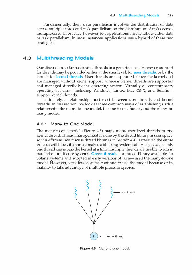
4.3 Multithreading Models 169
Fundamentally, then, data parallelism involves the distribution of dataacross multiple cores and task parallelism on the distribution of tasks acrossmultiple cores. In practice, however, few applications strictly follow either dataor task parallelism. In most instances, applications use a hybrid of these twostrategies.
4.3 Multithreading Models
Our discussion so far has treated threads in a generic sense. However, supportfor threads may be provided either at the user level, for user threads, or by thekernel, for kernel threads. User threads are supported above the kernel andare managed without kernel support, whereas kernel threads are supportedand managed directly by the operating system. Virtually all contemporaryoperating systems—including Windows, Linux, Mac OS X, and Solaris—support kernel threads.
Ultimately, a relationship must exist between user threads and kernelthreads. In this section, we look at three common ways of establishing such arelationship: the many-to-one model, the one-to-one model, and the many-to-many model.
4.3.1 Many-to-One Model
The many-to-one model (Figure 4.5) maps many user-level threads to onekernel thread. Thread management is done by the thread library in user space,so it is efficient (we discuss thread libraries in Section 4.4). However, the entireprocess will block if a thread makes a blocking system call. Also, because onlyone thread can access the kernel at a time, multiple threads are unable to run inparallel on multicore systems. Green threads—a thread library available forSolaris systems and adopted in early versions of Java—used the many-to-onemodel. However, very few systems continue to use the model because of itsinability to take advantage of multiple processing cores.
user thread
kernel threadk
Figure 4.5 Many-to-one model.
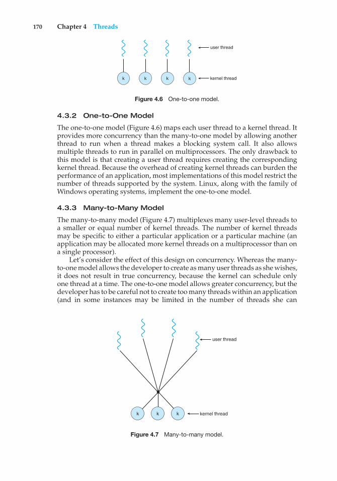
170 Chapter 4 Threads
user thread
kernel threadkkkk
Figure 4.6 One-to-one model.
4.3.2 One-to-One Model
The one-to-one model (Figure 4.6) maps each user thread to a kernel thread. Itprovides more concurrency than the many-to-one model by allowing anotherthread to run when a thread makes a blocking system call. It also allowsmultiple threads to run in parallel on multiprocessors. The only drawback tothis model is that creating a user thread requires creating the correspondingkernel thread. Because the overhead of creating kernel threads can burden theperformance of an application, most implementations of this model restrict thenumber of threads supported by the system. Linux, along with the family ofWindows operating systems, implement the one-to-one model.
4.3.3 Many-to-Many Model
The many-to-many model (Figure 4.7) multiplexes many user-level threads toa smaller or equal number of kernel threads. The number of kernel threadsmay be specific to either a particular application or a particular machine (anapplication may be allocated more kernel threads on a multiprocessor than ona single processor).
Let’s consider the effect of this design on concurrency. Whereas the many-to-one model allows the developer to create as many user threads as she wishes,it does not result in true concurrency, because the kernel can schedule onlyone thread at a time. The one-to-one model allows greater concurrency, but thedeveloper has to be careful not to create too many threads within an application(and in some instances may be limited in the number of threads she can
user thread
kernel threadkkk
Figure 4.7 Many-to-many model.
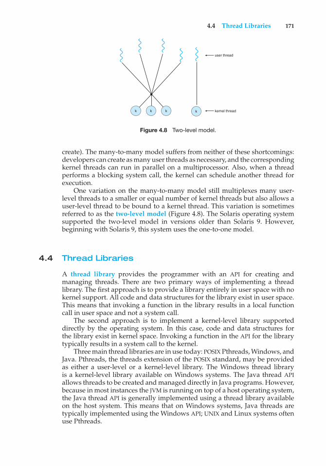
4.4 Thread Libraries 171
user thread
kernel threadkkk k
Figure 4.8 Two-level model.
create). The many-to-many model suffers from neither of these shortcomings:developers can create as many user threads as necessary, and the correspondingkernel threads can run in parallel on a multiprocessor. Also, when a threadperforms a blocking system call, the kernel can schedule another thread forexecution.
One variation on the many-to-many model still multiplexes many user-level threads to a smaller or equal number of kernel threads but also allows auser-level thread to be bound to a kernel thread. This variation is sometimesreferred to as the two-level model (Figure 4.8). The Solaris operating systemsupported the two-level model in versions older than Solaris 9. However,beginning with Solaris 9, this system uses the one-to-one model.
4.4 Thread Libraries
A thread library provides the programmer with an API for creating andmanaging threads. There are two primary ways of implementing a threadlibrary. The first approach is to provide a library entirely in user space with nokernel support. All code and data structures for the library exist in user space.This means that invoking a function in the library results in a local functioncall in user space and not a system call.
The second approach is to implement a kernel-level library supporteddirectly by the operating system. In this case, code and data structures forthe library exist in kernel space. Invoking a function in the API for the librarytypically results in a system call to the kernel.
Three main thread libraries are in use today: POSIX Pthreads, Windows, andJava. Pthreads, the threads extension of the POSIX standard, may be providedas either a user-level or a kernel-level library. The Windows thread libraryis a kernel-level library available on Windows systems. The Java thread APIallows threads to be created and managed directly in Java programs. However,because in most instances the JVM is running on top of a host operating system,the Java thread API is generally implemented using a thread library availableon the host system. This means that on Windows systems, Java threads aretypically implemented using the Windows API; UNIX and Linux systems oftenuse Pthreads.
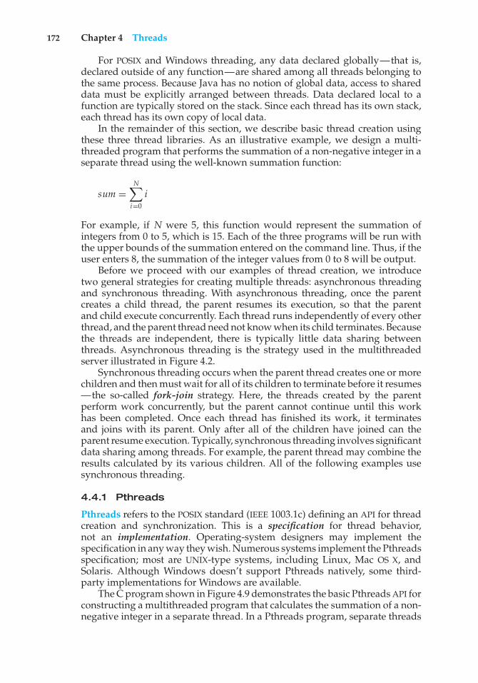
172 Chapter 4 Threads
For POSIX and Windows threading, any data declared globally—that is,declared outside of any function—are shared among all threads belonging tothe same process. Because Java has no notion of global data, access to shareddata must be explicitly arranged between threads. Data declared local to afunction are typically stored on the stack. Since each thread has its own stack,each thread has its own copy of local data.
In the remainder of this section, we describe basic thread creation usingthese three thread libraries. As an illustrative example, we design a multi-threaded program that performs the summation of a non-negative integer in aseparate thread using the well-known summation function:
sum =N"
i=0i
For example, if N were 5, this function would represent the summation ofintegers from 0 to 5, which is 15. Each of the three programs will be run withthe upper bounds of the summation entered on the command line. Thus, if theuser enters 8, the summation of the integer values from 0 to 8 will be output.
Before we proceed with our examples of thread creation, we introducetwo general strategies for creating multiple threads: asynchronous threadingand synchronous threading. With asynchronous threading, once the parentcreates a child thread, the parent resumes its execution, so that the parentand child execute concurrently. Each thread runs independently of every otherthread, and the parent thread need not know when its child terminates. Becausethe threads are independent, there is typically little data sharing betweenthreads. Asynchronous threading is the strategy used in the multithreadedserver illustrated in Figure 4.2.
Synchronous threading occurs when the parent thread creates one or morechildren and then must wait for all of its children to terminate before it resumes—the so-called fork-join strategy. Here, the threads created by the parentperform work concurrently, but the parent cannot continue until this workhas been completed. Once each thread has finished its work, it terminatesand joins with its parent. Only after all of the children have joined can theparent resume execution. Typically, synchronous threading involves significantdata sharing among threads. For example, the parent thread may combine theresults calculated by its various children. All of the following examples usesynchronous threading.
4.4.1 Pthreads
Pthreads refers to the POSIX standard (IEEE 1003.1c) defining an API for threadcreation and synchronization. This is a specification for thread behavior,not an implementation. Operating-system designers may implement thespecification in any way they wish. Numerous systems implement the Pthreadsspecification; most are UNIX-type systems, including Linux, Mac OS X, andSolaris. Although Windows doesn’t support Pthreads natively, some third-party implementations for Windows are available.
The C program shown in Figure 4.9 demonstrates the basic Pthreads API forconstructing a multithreaded program that calculates the summation of a non-negative integer in a separate thread. In a Pthreads program, separate threads
4.4 Thread Libraries 173
#include <pthread.h>#include <stdio.h>
int sum; /* this data is shared by the thread(s) */void *runner(void *param); /* threads call this function */
int main(int argc, char *argv[]){
pthread t tid; /* the thread identifier */pthread attr t attr; /* set of thread attributes */
if (argc != 2) {fprintf(stderr,"usage: a.out <integer value>\n");return -1;
}if (atoi(argv[1]) < 0) {
fprintf(stderr,"%d must be >= 0\n",atoi(argv[1]));return -1;
}
/* get the default attributes */pthread attr init(&attr);/* create the thread */pthread create(&tid,&attr,runner,argv[1]);/* wait for the thread to exit */pthread join(tid,NULL);
printf("sum = %d\n",sum);}
/* The thread will begin control in this function */void *runner(void *param){
int i, upper = atoi(param);sum = 0;
for (i = 1; i <= upper; i++)sum += i;
pthread exit(0);}
Figure 4.9 Multithreaded C program using the Pthreads API.
begin execution in a specified function. In Figure 4.9, this is the runner()function. When this program begins, a single thread of control begins inmain(). After some initialization, main() creates a second thread that beginscontrol in the runner() function. Both threads share the global data sum.
Let’s look more closely at this program. All Pthreads programs mustinclude the pthread.h header file. The statement pthread t tid declares
174 Chapter 4 Threads
#define NUM THREADS 10
/* an array of threads to be joined upon */pthread t workers[NUM THREADS];
for (int i = 0; i < NUM THREADS; i++)pthread join(workers[i], NULL);
Figure 4.10 Pthread code for joining ten threads.
the identifier for the thread we will create. Each thread has a set of attributes,including stack size and scheduling information. The pthread attr t attrdeclaration represents the attributes for the thread. We set the attributes in thefunction call pthread attr init(&attr). Because we did not explicitly setany attributes, we use the default attributes provided. (In Chapter 6, we discusssome of the scheduling attributes provided by the Pthreads API.) A separatethread is created with the pthread create() function call. In addition topassing the thread identifier and the attributes for the thread, we also pass thename of the function where the new thread will begin execution—in this case,the runner() function. Last, we pass the integer parameter that was providedon the command line, argv[1].
At this point, the program has two threads: the initial (or parent) threadin main() and the summation (or child) thread performing the summationoperation in the runner() function. This program follows the fork-join strategydescribed earlier: after creating the summation thread, the parent threadwill wait for it to terminate by calling the pthread join() function. Thesummation thread will terminate when it calls the function pthread exit().Once the summation thread has returned, the parent thread will output thevalue of the shared data sum.
This example program creates only a single thread. With the growingdominance of multicore systems, writing programs containing several threadshas become increasingly common. A simple method for waiting on severalthreads using the pthread join() function is to enclose the operation withina simple for loop. For example, you can join on ten threads using the Pthreadcode shown in Figure 4.10.
4.4.2 Windows Threads
The technique for creating threads using the Windows thread library is similarto the Pthreads technique in several ways. We illustrate the Windows threadAPI in the C program shown in Figure 4.11. Notice that we must include thewindows.h header file when using the Windows API.
Just as in the Pthreads version shown in Figure 4.9, data shared by theseparate threads—in this case, Sum—are declared globally (the DWORD datatype is an unsigned 32-bit integer). We also define the Summation() functionthat is to be performed in a separate thread. This function is passed a pointerto a void, which Windows defines as LPVOID. The thread performing thisfunction sets the global data Sum to the value of the summation from 0 to theparameter passed to Summation().
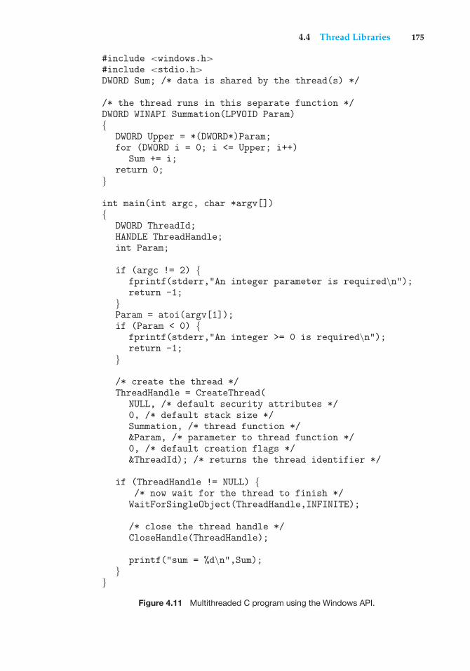
4.4 Thread Libraries 175
#include <windows.h>#include <stdio.h>DWORD Sum; /* data is shared by the thread(s) */
/* the thread runs in this separate function */DWORD WINAPI Summation(LPVOID Param){
DWORD Upper = *(DWORD*)Param;for (DWORD i = 0; i <= Upper; i++)
Sum += i;return 0;
}
int main(int argc, char *argv[]){
DWORD ThreadId;HANDLE ThreadHandle;int Param;
if (argc != 2) {fprintf(stderr,"An integer parameter is required\n");return -1;
}Param = atoi(argv[1]);if (Param < 0) {
fprintf(stderr,"An integer >= 0 is required\n");return -1;
}
/* create the thread */ThreadHandle = CreateThread(
NULL, /* default security attributes */0, /* default stack size */Summation, /* thread function */&Param, /* parameter to thread function */0, /* default creation flags */&ThreadId); /* returns the thread identifier */
if (ThreadHandle != NULL) {/* now wait for the thread to finish */
WaitForSingleObject(ThreadHandle,INFINITE);
/* close the thread handle */CloseHandle(ThreadHandle);
printf("sum = %d\n",Sum);}
}
Figure 4.11 Multithreaded C program using the Windows API.
176 Chapter 4 Threads
Threads are created in the Windows API using the CreateThread()function, and—just as in Pthreads—a set of attributes for the thread is passedto this function. These attributes include security information, the size of thestack, and a flag that can be set to indicate if the thread is to start in a suspendedstate. In this program, we use the default values for these attributes. (Thedefault values do not initially set the thread to a suspended state and insteadmake it eligible to be run by the CPU scheduler.) Once the summation threadis created, the parent must wait for it to complete before outputting the valueof Sum, as the value is set by the summation thread. Recall that the Pthreadprogram (Figure 4.9) had the parent thread wait for the summation threadusing the pthread join() statement. We perform the equivalent of this in theWindows API using the WaitForSingleObject() function, which causes thecreating thread to block until the summation thread has exited.
In situations that require waiting for multiple threads to complete, theWaitForMultipleObjects() function is used. This function is passed fourparameters:
1. The number of objects to wait for
2. A pointer to the array of objects
3. A flag indicating whether all objects have been signaled
4. A timeout duration (or INFINITE)
For example, if THandles is an array of thread HANDLE objects of size N, theparent thread can wait for all its child threads to complete with this statement:
WaitForMultipleObjects(N, THandles, TRUE, INFINITE);
4.4.3 Java Threads
Threads are the fundamental model of program execution in a Java program,and the Java language and its API provide a rich set of features for the creationand management of threads. All Java programs comprise at least a single threadof control—even a simple Java program consisting of only a main() methodruns as a single thread in the JVM. Java threads are available on any system thatprovides a JVM including Windows, Linux, and Mac OS X. The Java thread APIis available for Android applications as well.
There are two techniques for creating threads in a Java program. Oneapproach is to create a new class that is derived from the Thread class andto override its run() method. An alternative—and more commonly used—technique is to define a class that implements the Runnable interface. TheRunnable interface is defined as follows:
public interface Runnable{
public abstract void run();}
When a class implements Runnable, it must define a run() method. The codeimplementing the run() method is what runs as a separate thread.
4.5 Implicit Threading 177
Figure 4.12 shows the Java version of a multithreaded program thatdetermines the summation of a non-negative integer. The Summation classimplements the Runnable interface. Thread creation is performed by creatingan object instance of the Thread class and passing the constructor a Runnableobject.
Creating a Thread object does not specifically create the new thread; rather,the start() method creates the new thread. Calling the start() method forthe new object does two things:
1. It allocates memory and initializes a new thread in the JVM.
2. It calls the run()method, making the thread eligible to be run by the JVM.(Note again that we never call the run() method directly. Rather, we callthe start() method, and it calls the run() method on our behalf.)
When the summation program runs, the JVM creates two threads. The firstis the parent thread, which starts execution in the main() method. The secondthread is created when the start() method on the Thread object is invoked.This child thread begins execution in the run()method of the Summation class.After outputting the value of the summation, this thread terminates when itexits from its run() method.
Data sharing between threads occurs easily in Windows and Pthreads, sinceshared data are simply declared globally. As a pure object-oriented language,Java has no such notion of global data. If two or more threads are to sharedata in a Java program, the sharing occurs by passing references to the sharedobject to the appropriate threads. In the Java program shown in Figure 4.12,the main thread and the summation thread share the object instance of the Sumclass. This shared object is referenced through the appropriate getSum() andsetSum() methods. (You might wonder why we don’t use an Integer objectrather than designing a new sum class. The reason is that the Integer class isimmutable—that is, once its value is set, it cannot change.)
Recall that the parent threads in the Pthreads and Windows librariesuse pthread join() and WaitForSingleObject() (respectively) to waitfor the summation threads to finish before proceeding. The join() methodin Java provides similar functionality. (Notice that join() can throw anInterruptedException, which we choose to ignore.) If the parent must waitfor several threads to finish, the join() method can be enclosed in a for loopsimilar to that shown for Pthreads in Figure 4.10.
4.5 Implicit Threading
With the continued growth of multicore processing, applications containinghundreds—or even thousands—of threads are looming on the horizon.Designing such applications is not a trivial undertaking: programmers mustaddress not only the challenges outlined in Section 4.2 but additional difficultiesas well. These difficulties, which relate to program correctness, are covered inChapters 5 and 7.
One way to address these difficulties and better support the design ofmultithreaded applications is to transfer the creation and management of
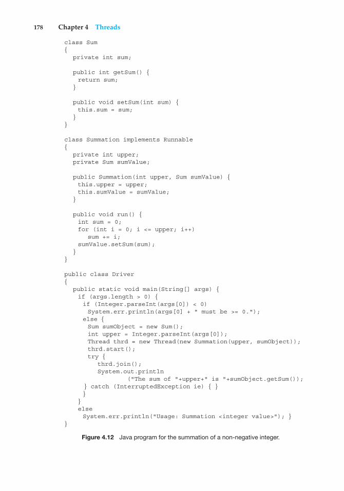
178 Chapter 4 Threads
class Sum{
private int sum;
public int getSum() {return sum;
}
public void setSum(int sum) {this.sum = sum;
}}
class Summation implements Runnable{
private int upper;private Sum sumValue;
public Summation(int upper, Sum sumValue) {this.upper = upper;this.sumValue = sumValue;
}
public void run() {int sum = 0;for (int i = 0; i <= upper; i++)
sum += i;sumValue.setSum(sum);
}}
public class Driver{
public static void main(String[] args) {if (args.length > 0) {if (Integer.parseInt(args[0]) < 0)System.err.println(args[0] + " must be >= 0.");
else {Sum sumObject = new Sum();int upper = Integer.parseInt(args[0]);Thread thrd = new Thread(new Summation(upper, sumObject));thrd.start();try {
thrd.join();System.out.println
("The sum of "+upper+" is "+sumObject.getSum());} catch (InterruptedException ie) { }}
}elseSystem.err.println("Usage: Summation <integer value>"); }
}
Figure 4.12 Java program for the summation of a non-negative integer.
4.5 Implicit Threading 179
THE JVM AND THE HOST OPERATING SYSTEM
The JVM is typically implemented on top of a host operating system (seeFigure 16.10). This setup allows the JVM to hide the implementation detailsof the underlying operating system and to provide a consistent, abstractenvironment that allows Java programs to operate on any platform thatsupports a JVM. The specification for the JVM does not indicate how Javathreads are to be mapped to the underlying operating system, instead leavingthat decision to the particular implementation of the JVM. For example, theWindows XP operating system uses the one-to-one model; therefore, eachJava thread for a JVM running on such a system maps to a kernel thread. Onoperating systems that use the many-to-many model (such as Tru64 UNIX), aJava thread is mapped according to the many-to-many model. Solaris initiallyimplemented the JVM using the many-to-one model (the green threads library,mentioned earlier). Later releases of the JVM were implemented using themany-to-many model. Beginning with Solaris 9, Java threads were mappedusing the one-to-one model. In addition, there may be a relationship betweenthe Java thread library and the thread library on the host operating system.For example, implementations of a JVM for the Windows family of operatingsystems might use the Windows API when creating Java threads; Linux,Solaris, and Mac OS X systems might use the Pthreads API.
threading from application developers to compilers and run-time libraries.This strategy, termed implicit threading, is a popular trend today. In thissection, we explore three alternative approaches for designing multithreadedprograms that can take advantage of multicore processors through implicitthreading.
4.5.1 Thread Pools
In Section 4.1, we described a multithreaded web server. In this situation,whenever the server receives a request, it creates a separate thread to servicethe request. Whereas creating a separate thread is certainly superior to creatinga separate process, a multithreaded server nonetheless has potential problems.The first issue concerns the amount of time required to create the thread,together with the fact that the thread will be discarded once it has completedits work. The second issue is more troublesome. If we allow all concurrentrequests to be serviced in a new thread, we have not placed a bound on thenumber of threads concurrently active in the system. Unlimited threads couldexhaust system resources, such as CPU time or memory. One solution to thisproblem is to use a thread pool.
The general idea behind a thread pool is to create a number of threads atprocess startup and place them into a pool, where they sit and wait for work.When a server receives a request, it awakens a thread from this pool—if oneis available—and passes it the request for service. Once the thread completesits service, it returns to the pool and awaits more work. If the pool contains noavailable thread, the server waits until one becomes free.
180 Chapter 4 Threads
Thread pools offer these benefits:
1. Servicing a request with an existing thread is faster than waiting to createa thread.
2. A thread pool limits the number of threads that exist at any one point.This is particularly important on systems that cannot support a largenumber of concurrent threads.
3. Separating the task to be performed from the mechanics of creating thetask allows us to use different strategies for running the task. For example,the task could be scheduled to execute after a time delay or to executeperiodically.
The number of threads in the pool can be set heuristically based on factorssuch as the number of CPUs in the system, the amount of physical memory,and the expected number of concurrent client requests. More sophisticatedthread-pool architectures can dynamically adjust the number of threads in thepool according to usage patterns. Such architectures provide the further benefitof having a smaller pool—thereby consuming less memory—when the loadon the system is low. We discuss one such architecture, Apple’s Grand CentralDispatch, later in this section.
The Windows API provides several functions related to thread pools. Usingthe thread pool API is similar to creating a thread with the Thread Create()function, as described in Section 4.4.2. Here, a function that is to run as aseparate thread is defined. Such a function may appear as follows:
DWORD WINAPI PoolFunction(AVOID Param) {/** this function runs as a separate thread.*/
}
A pointer to PoolFunction() is passed to one of the functions in the threadpool API, and a thread from the pool executes this function. One such memberin the thread pool API is the QueueUserWorkItem() function, which is passedthree parameters:
• LPTHREAD START ROUTINE Function—a pointer to the function that is torun as a separate thread
• PVOID Param—the parameter passed to Function
• ULONG Flags—flags indicating how the thread pool is to create andmanage execution of the thread
An example of invoking a function is the following:
QueueUserWorkItem(&PoolFunction, NULL, 0);
This causes a thread from the thread pool to invoke PoolFunction() on behalfof the programmer. In this instance, we pass no parameters to PoolFunc-
4.5 Implicit Threading 181
tion(). Because we specify 0 as a flag, we provide the thread pool with nospecial instructions for thread creation.
Other members in the Windows thread pool API include utilities that invokefunctions at periodic intervals or when an asynchronous I/O request completes.The java.util.concurrent package in the Java API provides a thread-poolutility as well.
4.5.2 OpenMP
OpenMP is a set of compiler directives as well as an API for programs writtenin C, C++, or FORTRAN that provides support for parallel programming inshared-memory environments. OpenMP identifies parallel regions as blocksof code that may run in parallel. Application developers insert compilerdirectives into their code at parallel regions, and these directives instruct theOpenMP run-time library to execute the region in parallel. The following Cprogram illustrates a compiler directive above the parallel region containingthe printf() statement:
#include <omp.h>#include <stdio.h>
int main(int argc, char *argv[]){
/* sequential code */
#pragma omp parallel{
printf("I am a parallel region.");}
/* sequential code */
return 0;}
When OpenMP encounters the directive
#pragma omp parallel
it creates as many threads are there are processing cores in the system. Thus, fora dual-core system, two threads are created, for a quad-core system, four arecreated; and so forth. All the threads then simultaneously execute the parallelregion. As each thread exits the parallel region, it is terminated.
OpenMP provides several additional directives for running code regionsin parallel, including parallelizing loops. For example, assume we have twoarrays a and b of size N. We wish to sum their contents and place the resultsin array c. We can have this task run in parallel by using the following codesegment, which contains the compiler directive for parallelizing for loops:
182 Chapter 4 Threads
#pragma omp parallel forfor (i = 0; i < N; i++) {
c[i] = a[i] + b[i];}
OpenMP divides the work contained in the for loop among the threads it hascreated in response to the directive
#pragma omp parallel for
In addition to providing directives for parallelization, OpenMP allows devel-opers to choose among several levels of parallelism. For example, they can setthe number of threads manually. It also allows developers to identify whetherdata are shared between threads or are private to a thread. OpenMP is availableon several open-source and commercial compilers for Linux, Windows, andMac OS X systems. We encourage readers interested in learning more aboutOpenMP to consult the bibliography at the end of the chapter.
4.5.3 Grand Central Dispatch
Grand Central Dispatch (GCD)—a technology for Apple’s Mac OS X and iOSoperating systems—is a combination of extensions to the C language, an API,and a run-time library that allows application developers to identify sectionsof code to run in parallel. Like OpenMP, GCD manages most of the details ofthreading.
GCD identifies extensions to the C and C++ languages known as blocks. Ablock is simply a self-contained unit of work. It is specified by a caret ˆ insertedin front of a pair of braces { }. A simple example of a block is shown below:
ˆ{ printf("I am a block"); }
GCD schedules blocks for run-time execution by placing them on a dispatchqueue. When it removes a block from a queue, it assigns the block to anavailable thread from the thread pool it manages. GCD identifies two types ofdispatch queues: serial and concurrent.
Blocks placed on a serial queue are removed in FIFO order. Once a block hasbeen removed from the queue, it must complete execution before another blockis removed. Each process has its own serial queue (known as its main queue).Developers can create additional serial queues that are local to particularprocesses. Serial queues are useful for ensuring the sequential execution ofseveral tasks.
Blocks placed on a concurrent queue are also removed in FIFO order, butseveral blocks may be removed at a time, thus allowing multiple blocks toexecute in parallel. There are three system-wide concurrent dispatch queues,and they are distinguished according to priority: low, default, and high.Priorities represent an approximation of the relative importance of blocks.Quite simply, blocks with a higher priority should be placed on the high-priority dispatch queue.
The following code segment illustrates obtaining the default-priorityconcurrent queue and submitting a block to the queue using thedispatch async() function:
4.6 Threading Issues 183
dispatch queue t queue = dispatch get global queue(DISPATCH QUEUE PRIORITY DEFAULT, 0);
dispatch async(queue, ˆ{ printf("I am a block."); });
Internally, GCD’s thread pool is composed of POSIX threads. GCD activelymanages the pool, allowing the number of threads to grow and shrinkaccording to application demand and system capacity.
4.5.4 Other Approaches
Thread pools, OpenMP, and Grand Central Dispatch are just a few of manyemerging technologies for managing multithreaded applications. Other com-mercial approaches include parallel and concurrent libraries, such as Intel’sThreading Building Blocks (TBB) and several products from Microsoft. The Javalanguage and API have seen significant movement toward supporting concur-rent programming as well. A notable example is the java.util.concurrentpackage, which supports implicit thread creation and management.
4.6 Threading Issues
In this section, we discuss some of the issues to consider in designingmultithreaded programs.
4.6.1 The fork() and exec() System Calls
In Chapter 3, we described how the fork() system call is used to create aseparate, duplicate process. The semantics of the fork() and exec() systemcalls change in a multithreaded program.
If one thread in a program calls fork(), does the new process duplicateall threads, or is the new process single-threaded? Some UNIX systems havechosen to have two versions of fork(), one that duplicates all threads andanother that duplicates only the thread that invoked the fork() system call.
The exec() system call typically works in the same way as describedin Chapter 3. That is, if a thread invokes the exec() system call, the programspecified in the parameter to exec()will replace the entire process—includingall threads.
Which of the two versions of fork() to use depends on the application.If exec() is called immediately after forking, then duplicating all threads isunnecessary, as the program specified in the parameters to exec() will replacethe process. In this instance, duplicating only the calling thread is appropriate.If, however, the separate process does not callexec() after forking, the separateprocess should duplicate all threads.
4.6.2 Signal Handling
A signal is used in UNIX systems to notify a process that a particular event hasoccurred. A signal may be received either synchronously or asynchronously,
184 Chapter 4 Threads
depending on the source of and the reason for the event being signaled. Allsignals, whether synchronous or asynchronous, follow the same pattern:
1. A signal is generated by the occurrence of a particular event.
2. The signal is delivered to a process.
3. Once delivered, the signal must be handled.
Examples of synchronous signal include illegal memory access and divi-sion by 0. If a running program performs either of these actions, a signalis generated. Synchronous signals are delivered to the same process thatperformed the operation that caused the signal (that is the reason they areconsidered synchronous).
When a signal is generated by an event external to a running process, thatprocess receives the signal asynchronously. Examples of such signals includeterminating a process with specific keystrokes (such as <control><C>) andhaving a timer expire. Typically, an asynchronous signal is sent to anotherprocess.
A signal may be handled by one of two possible handlers:
1. A default signal handler
2. A user-defined signal handler
Every signal has a default signal handler that the kernel runs whenhandling that signal. This default action can be overridden by a user-definedsignal handler that is called to handle the signal. Signals are handled indifferent ways. Some signals (such as changing the size of a window) aresimply ignored; others (such as an illegal memory access) are handled byterminating the program.
Handling signals in single-threaded programs is straightforward: signalsare always delivered to a process. However, delivering signals is morecomplicated in multithreaded programs, where a process may have severalthreads. Where, then, should a signal be delivered?
In general, the following options exist:
1. Deliver the signal to the thread to which the signal applies.
2. Deliver the signal to every thread in the process.
3. Deliver the signal to certain threads in the process.
4. Assign a specific thread to receive all signals for the process.
The method for delivering a signal depends on the type of signal generated.For example, synchronous signals need to be delivered to the thread causingthe signal and not to other threads in the process. However, the situation withasynchronous signals is not as clear. Some asynchronous signals—such as asignal that terminates a process (<control><C>, for example)—should besent to all threads.
4.6 Threading Issues 185
The standard UNIX function for delivering a signal is
kill(pid t pid, int signal)
This function specifies the process (pid) to which a particular signal (signal) isto be delivered. Most multithreaded versions of UNIX allow a thread to specifywhich signals it will accept and which it will block. Therefore, in some cases,an asynchronous signal may be delivered only to those threads that are notblocking it. However, because signals need to be handled only once, a signal istypically delivered only to the first thread found that is not blocking it. POSIXPthreads provides the following function, which allows a signal to be deliveredto a specified thread (tid):
pthread kill(pthread t tid, int signal)
Although Windows does not explicitly provide support for signals, itallows us to emulate them using asynchronous procedure calls (APCs). TheAPC facility enables a user thread to specify a function that is to be calledwhen the user thread receives notification of a particular event. As indicatedby its name, an APC is roughly equivalent to an asynchronous signal in UNIX.However, whereas UNIX must contend with how to deal with signals in amultithreaded environment, the APC facility is more straightforward, since anAPC is delivered to a particular thread rather than a process.
4.6.3 Thread Cancellation
Thread cancellation involves terminating a thread before it has completed. Forexample, if multiple threads are concurrently searching through a database andone thread returns the result, the remaining threads might be canceled. Anothersituation might occur when a user presses a button on a web browser that stopsa web page from loading any further. Often, a web page loads using severalthreads—each image is loaded in a separate thread. When a user presses thestop button on the browser, all threads loading the page are canceled.
A thread that is to be canceled is often referred to as the target thread.Cancellation of a target thread may occur in two different scenarios:
1. Asynchronous cancellation. One thread immediately terminates thetarget thread.
2. Deferred cancellation. The target thread periodically checks whether itshould terminate, allowing it an opportunity to terminate itself in anorderly fashion.
The difficulty with cancellation occurs in situations where resources havebeen allocated to a canceled thread or where a thread is canceled while inthe midst of updating data it is sharing with other threads. This becomesespecially troublesome with asynchronous cancellation. Often, the operatingsystem will reclaim system resources from a canceled thread but will notreclaim all resources. Therefore, canceling a thread asynchronously may notfree a necessary system-wide resource.
186 Chapter 4 Threads
With deferred cancellation, in contrast, one thread indicates that a targetthread is to be canceled, but cancellation occurs only after the target thread haschecked a flag to determine whether or not it should be canceled. The threadcan perform this check at a point at which it can be canceled safely.
In Pthreads, thread cancellation is initiated using the pthread cancel()function. The identifier of the target thread is passed as a parameter tothe function. The following code illustrates creating—and then canceling—a thread:
pthread t tid;
/* create the thread */pthread create(&tid, 0, worker, NULL);
. . .
/* cancel the thread */pthread cancel(tid);
Invoking pthread cancel()indicates only a request to cancel the targetthread, however; actual cancellation depends on how the target thread is setup to handle the request. Pthreads supports three cancellation modes. Eachmode is defined as a state and a type, as illustrated in the table below. A threadmay set its cancellation state and type using an API.
Mode State Type
Off Disabled –Deferred Enabled Deferred
Asynchronous Enabled Asynchronous
As the table illustrates, Pthreads allows threads to disable or enablecancellation. Obviously, a thread cannot be canceled if cancellation is disabled.However, cancellation requests remain pending, so the thread can later enablecancellation and respond to the request.
The default cancellation type is deferred cancellation. Here, cancellationoccurs only when a thread reaches a cancellation point. One technique forestablishing a cancellation point is to invoke the pthread testcancel()function. If a cancellation request is found to be pending, a function knownas a cleanup handler is invoked. This function allows any resources a threadmay have acquired to be released before the thread is terminated.
The following code illustrates how a thread may respond to a cancellationrequest using deferred cancellation:
while (1) {/* do some work for awhile *//* . . . */
/* check if there is a cancellation request */pthread testcancel();
}
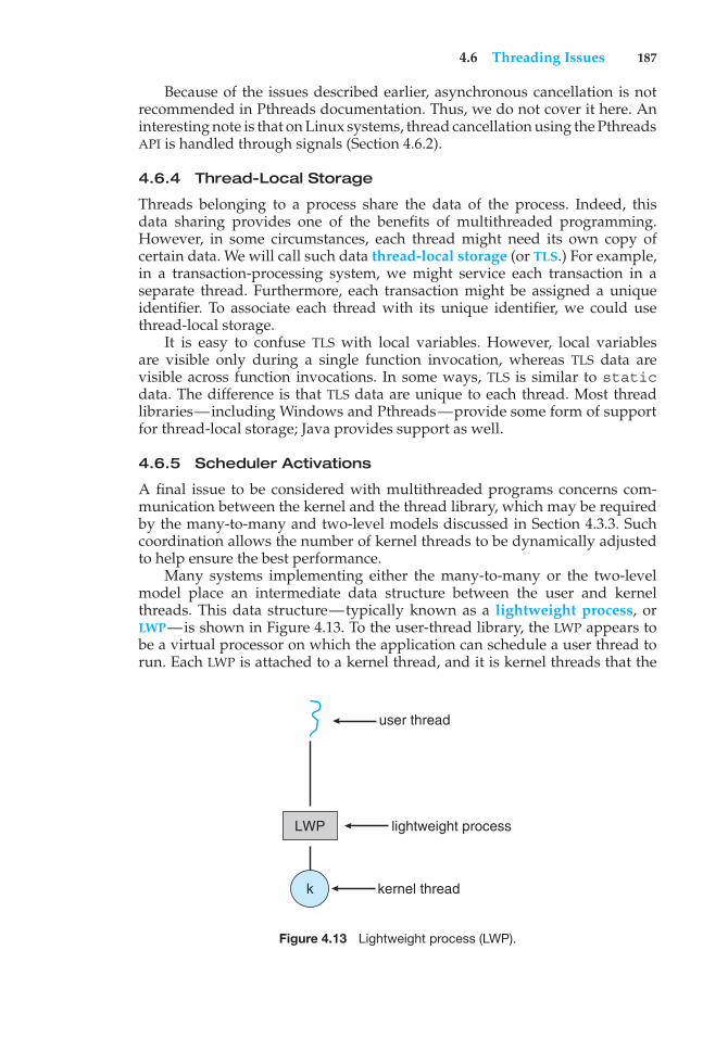
4.6 Threading Issues 187
Because of the issues described earlier, asynchronous cancellation is notrecommended in Pthreads documentation. Thus, we do not cover it here. Aninteresting note is that on Linux systems, thread cancellation using the PthreadsAPI is handled through signals (Section 4.6.2).
4.6.4 Thread-Local Storage
Threads belonging to a process share the data of the process. Indeed, thisdata sharing provides one of the benefits of multithreaded programming.However, in some circumstances, each thread might need its own copy ofcertain data. We will call such data thread-local storage (or TLS.) For example,in a transaction-processing system, we might service each transaction in aseparate thread. Furthermore, each transaction might be assigned a uniqueidentifier. To associate each thread with its unique identifier, we could usethread-local storage.
It is easy to confuse TLS with local variables. However, local variablesare visible only during a single function invocation, whereas TLS data arevisible across function invocations. In some ways, TLS is similar to staticdata. The difference is that TLS data are unique to each thread. Most threadlibraries—including Windows and Pthreads—provide some form of supportfor thread-local storage; Java provides support as well.
4.6.5 Scheduler Activations
A final issue to be considered with multithreaded programs concerns com-munication between the kernel and the thread library, which may be requiredby the many-to-many and two-level models discussed in Section 4.3.3. Suchcoordination allows the number of kernel threads to be dynamically adjustedto help ensure the best performance.
Many systems implementing either the many-to-many or the two-levelmodel place an intermediate data structure between the user and kernelthreads. This data structure—typically known as a lightweight process, orLWP—is shown in Figure 4.13. To the user-thread library, the LWP appears tobe a virtual processor on which the application can schedule a user thread torun. Each LWP is attached to a kernel thread, and it is kernel threads that the
LWP
user thread
kernel threadk
lightweight process
Figure 4.13 Lightweight process (LWP).
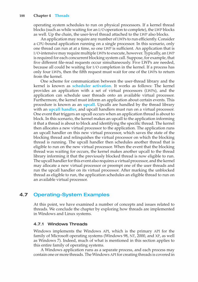
188 Chapter 4 Threads
operating system schedules to run on physical processors. If a kernel threadblocks (such as while waiting for an I/O operation to complete), the LWP blocksas well. Up the chain, the user-level thread attached to the LWP also blocks.
An application may require any number of LWPs to run efficiently. Considera CPU-bound application running on a single processor. In this scenario, onlyone thread can run at at a time, so one LWP is sufficient. An application that isI/O-intensive may require multiple LWPs to execute, however. Typically, an LWPis required for each concurrent blocking system call. Suppose, for example, thatfive different file-read requests occur simultaneously. Five LWPs are needed,because all could be waiting for I/O completion in the kernel. If a process hasonly four LWPs, then the fifth request must wait for one of the LWPs to returnfrom the kernel.
One scheme for communication between the user-thread library and thekernel is known as scheduler activation. It works as follows: The kernelprovides an application with a set of virtual processors (LWPs), and theapplication can schedule user threads onto an available virtual processor.Furthermore, the kernel must inform an application about certain events. Thisprocedure is known as an upcall. Upcalls are handled by the thread librarywith an upcall handler, and upcall handlers must run on a virtual processor.One event that triggers an upcall occurs when an application thread is about toblock. In this scenario, the kernel makes an upcall to the application informingit that a thread is about to block and identifying the specific thread. The kernelthen allocates a new virtual processor to the application. The application runsan upcall handler on this new virtual processor, which saves the state of theblocking thread and relinquishes the virtual processor on which the blockingthread is running. The upcall handler then schedules another thread that iseligible to run on the new virtual processor. When the event that the blockingthread was waiting for occurs, the kernel makes another upcall to the threadlibrary informing it that the previously blocked thread is now eligible to run.The upcall handler for this event also requires a virtual processor, and the kernelmay allocate a new virtual processor or preempt one of the user threads andrun the upcall handler on its virtual processor. After marking the unblockedthread as eligible to run, the application schedules an eligible thread to run onan available virtual processor.
4.7 Operating-System Examples
At this point, we have examined a number of concepts and issues related tothreads. We conclude the chapter by exploring how threads are implementedin Windows and Linux systems.
4.7.1 Windows Threads
Windows implements the Windows API, which is the primary API for thefamily of Microsoft operating systems (Windows 98, NT, 2000, and XP, as wellas Windows 7). Indeed, much of what is mentioned in this section applies tothis entire family of operating systems.
A Windows application runs as a separate process, and each process maycontain one or more threads. The Windows API for creating threads is covered in
4.7 Operating-System Examples 189
Section 4.4.2. Additionally, Windows uses the one-to-one mapping describedin Section 4.3.2, where each user-level thread maps to an associated kernelthread.
The general components of a thread include:
• A thread ID uniquely identifying the thread
• A register set representing the status of the processor
• A user stack, employed when the thread is running in user mode, and akernel stack, employed when the thread is running in kernel mode
• A private storage area used by various run-time libraries and dynamic linklibraries (DLLs)
The register set, stacks, and private storage area are known as the context ofthe thread.
The primary data structures of a thread include:
• ETHREAD—executive thread block
• KTHREAD—kernel thread block
• TEB—thread environment block
The key components of the ETHREAD include a pointer to the processto which the thread belongs and the address of the routine in which thethread starts control. The ETHREAD also contains a pointer to the correspondingKTHREAD.
The KTHREAD includes scheduling and synchronization information forthe thread. In addition, the KTHREAD includes the kernel stack (used when thethread is running in kernel mode) and a pointer to the TEB.
The ETHREAD and the KTHREAD exist entirely in kernel space; this meansthat only the kernel can access them. The TEB is a user-space data structurethat is accessed when the thread is running in user mode. Among other fields,the TEB contains the thread identifier, a user-mode stack, and an array forthread-local storage. The structure of a Windows thread is illustrated in Figure4.14.
4.7.2 Linux Threads
Linux provides the fork() system call with the traditional functionality ofduplicating a process, as described in Chapter 3. Linux also provides the abilityto create threads using the clone() system call. However, Linux does notdistinguish between processes and threads. In fact, Linux uses the term task—rather than process or thread— when referring to a flow of control within aprogram.
When clone() is invoked, it is passed a set of flags that determine howmuch sharing is to take place between the parent and child tasks. Some of theseflags are listed in Figure 4.15. For example, suppose that clone() is passedthe flags CLONE FS, CLONE VM, CLONE SIGHAND, and CLONE FILES. The parentand child tasks will then share the same file-system information (such as thecurrent working directory), the same memory space, the same signal handlers,
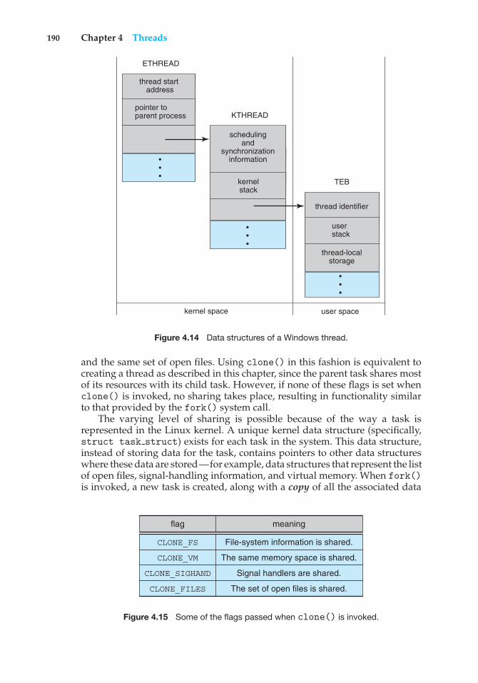
190 Chapter 4 Threads
user spacekernel space
pointer to parent process
thread start address
ETHREAD
KTHREAD
• • •
kernel stack
scheduling and
synchronizationinformation
• • •
user stack
thread-local storage
thread identifier
TEB
• • •
Figure 4.14 Data structures of a Windows thread.
and the same set of open files. Using clone() in this fashion is equivalent tocreating a thread as described in this chapter, since the parent task shares mostof its resources with its child task. However, if none of these flags is set whenclone() is invoked, no sharing takes place, resulting in functionality similarto that provided by the fork() system call.
The varying level of sharing is possible because of the way a task isrepresented in the Linux kernel. A unique kernel data structure (specifically,struct task struct) exists for each task in the system. This data structure,instead of storing data for the task, contains pointers to other data structureswhere these data are stored—for example, data structures that represent the listof open files, signal-handling information, and virtual memory. When fork()is invoked, a new task is created, along with a copy of all the associated data
flag meaning
CLONE_FS
CLONE_VM
CLONE_SIGHAND
CLONE_FILES
File-system information is shared.
The same memory space is shared.
Signal handlers are shared.
The set of open files is shared.
Figure 4.15 Some of the flags passed when clone() is invoked.
Practice Exercises 191
structures of the parent process. A new task is also created when the clone()system call is made. However, rather than copying all data structures, the newtask points to the data structures of the parent task, depending on the set offlags passed to clone().
4.8 Summary
A thread is a flow of control within a process. A multithreaded process containsseveral different flows of control within the same address space. The benefits ofmultithreading include increased responsiveness to the user, resource sharingwithin the process, economy, and scalability factors, such as more efficient useof multiple processing cores.
User-level threads are threads that are visible to the programmer and areunknown to the kernel. The operating-system kernel supports and manageskernel-level threads. In general, user-level threads are faster to create andmanage than are kernel threads, because no intervention from the kernel isrequired.
Three different types of models relate user and kernel threads. The many-to-one model maps many user threads to a single kernel thread. The one-to-onemodel maps each user thread to a corresponding kernel thread. The many-to-many model multiplexes many user threads to a smaller or equal number ofkernel threads.
Most modern operating systems provide kernel support for threads. Theseinclude Windows, Mac OS X, Linux, and Solaris.
Thread libraries provide the application programmer with an API forcreating and managing threads. Three primary thread libraries are in commonuse: POSIX Pthreads, Windows threads, and Java threads.
In addition to explicitly creating threads using the API provided by alibrary, we can use implicit threading, in which the creation and managementof threading is transferred to compilers and run-time libraries. Strategies forimplicit threading include thread pools, OpenMP, and Grand Central Dispatch.
Multithreaded programs introduce many challenges for programmers,including the semantics of the fork() and exec() system calls. Otherissues include signal handling, thread cancellation, thread-local storage, andscheduler activations.
Practice Exercises
4.1 Provide two programming examples in which multithreading providesbetter performance than a single-threaded solution.
4.2 What are two differences between user-level threads and kernel-levelthreads? Under what circumstances is one type better than the other?
4.3 Describe the actions taken by a kernel to context-switch between kernel-level threads.
4.4 What resources are used when a thread is created? How do they differfrom those used when a process is created?
192 Chapter 4 Threads
4.5 Assume that an operating system maps user-level threads to the kernelusing the many-to-many model and that the mapping is done throughLWPs. Furthermore, the system allows developers to create real-timethreads for use in real-time systems. Is it necessary to bind a real-timethread to an LWP? Explain.
Exercises
4.6 Provide two programming examples in which multithreading does notprovide better performance than a single-threaded solution.
4.7 Under what circumstances does a multithreaded solution using multi-ple kernel threads provide better performance than a single-threadedsolution on a single-processor system?
4.8 Which of the following components of program state are shared acrossthreads in a multithreaded process?
a. Register values
b. Heap memory
c. Global variables
d. Stack memory
4.9 Can a multithreaded solution using multiple user-level threads achievebetter performance on a multiprocessor system than on a single-processor system? Explain.
4.10 In Chapter 3, we discussed Google’s Chrome browser and its practiceof opening each new website in a separate process. Would the samebenefits have been achieved if instead Chrome had been designed toopen each new website in a separate thread? Explain.
4.11 Is it possible to have concurrency but not parallelism? Explain.
4.12 Using Amdahl’s Law, calculate the speedup gain of an application thathas a 60 percent parallel component for (a) two processing cores and (b)four processing cores.
4.13 Determine if the following problems exhibit task or data parallelism:
• The multithreaded statistical program described in Exercise 4.21
• The multithreaded Sudoku validator described in Project 1 in thischapter
• The multithreaded sorting program described in Project 2 in thischapter
• The multithreaded web server described in Section 4.1
4.14 A system with two dual-core processors has four processors availablefor scheduling. A CPU-intensive application is running on this system.All input is performed at program start-up, when a single file mustbe opened. Similarly, all output is performed just before the program
Exercises 193
terminates, when the program results must be written to a singlefile. Between startup and termination, the program is entirely CPU-bound. Your task is to improve the performance of this applicationby multithreading it. The application runs on a system that uses theone-to-one threading model (each user thread maps to a kernel thread).
• How many threads will you create to perform the input and output?Explain.
• How many threads will you create for the CPU-intensive portion ofthe application? Explain.
4.15 Consider the following code segment:
pid t pid;
pid = fork();if (pid == 0) { /* child process */
fork();thread create( . . .);
}fork();
a. How many unique processes are created?
b. How many unique threads are created?
4.16 As described in Section 4.7.2, Linux does not distinguish betweenprocesses and threads. Instead, Linux treats both in the same way,allowing a task to be more akin to a process or a thread depending on theset of flags passed to the clone() system call. However, other operatingsystems, such as Windows, treat processes and threads differently.Typically, such systems use a notation in which the data structure fora process contains pointers to the separate threads belonging to theprocess. Contrast these two approaches for modeling processes andthreads within the kernel.
4.17 The program shown in Figure 4.16 uses the Pthreads API. What wouldbe the output from the program at LINE C and LINE P?
4.18 Consider a multicore system and a multithreaded program writtenusing the many-to-many threading model. Let the number of user-levelthreads in the program be greater than the number of processing coresin the system. Discuss the performance implications of the followingscenarios.
a. The number of kernel threads allocated to the program is less thanthe number of processing cores.
b. The number of kernel threads allocated to the program is equal tothe number of processing cores.
c. The number of kernel threads allocated to the program is greaterthan the number of processing cores but less than the number ofuser-level threads.
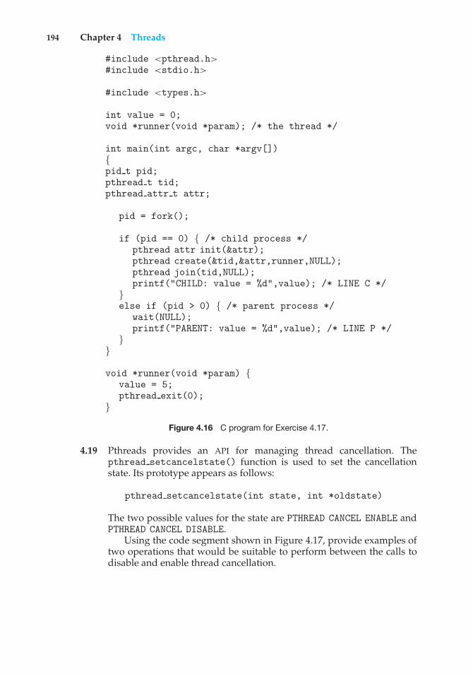
194 Chapter 4 Threads
#include <pthread.h>#include <stdio.h>
#include <types.h>
int value = 0;void *runner(void *param); /* the thread */
int main(int argc, char *argv[]){pid t pid;pthread t tid;pthread attr t attr;
pid = fork();
if (pid == 0) { /* child process */pthread attr init(&attr);pthread create(&tid,&attr,runner,NULL);pthread join(tid,NULL);printf("CHILD: value = %d",value); /* LINE C */
}else if (pid > 0) { /* parent process */
wait(NULL);printf("PARENT: value = %d",value); /* LINE P */
}}
void *runner(void *param) {value = 5;pthread exit(0);
}
Figure 4.16 C program for Exercise 4.17.
4.19 Pthreads provides an API for managing thread cancellation. Thepthread setcancelstate() function is used to set the cancellationstate. Its prototype appears as follows:
pthread setcancelstate(int state, int *oldstate)
The two possible values for the state are PTHREAD CANCEL ENABLE andPTHREAD CANCEL DISABLE.
Using the code segment shown in Figure 4.17, provide examples oftwo operations that would be suitable to perform between the calls todisable and enable thread cancellation.
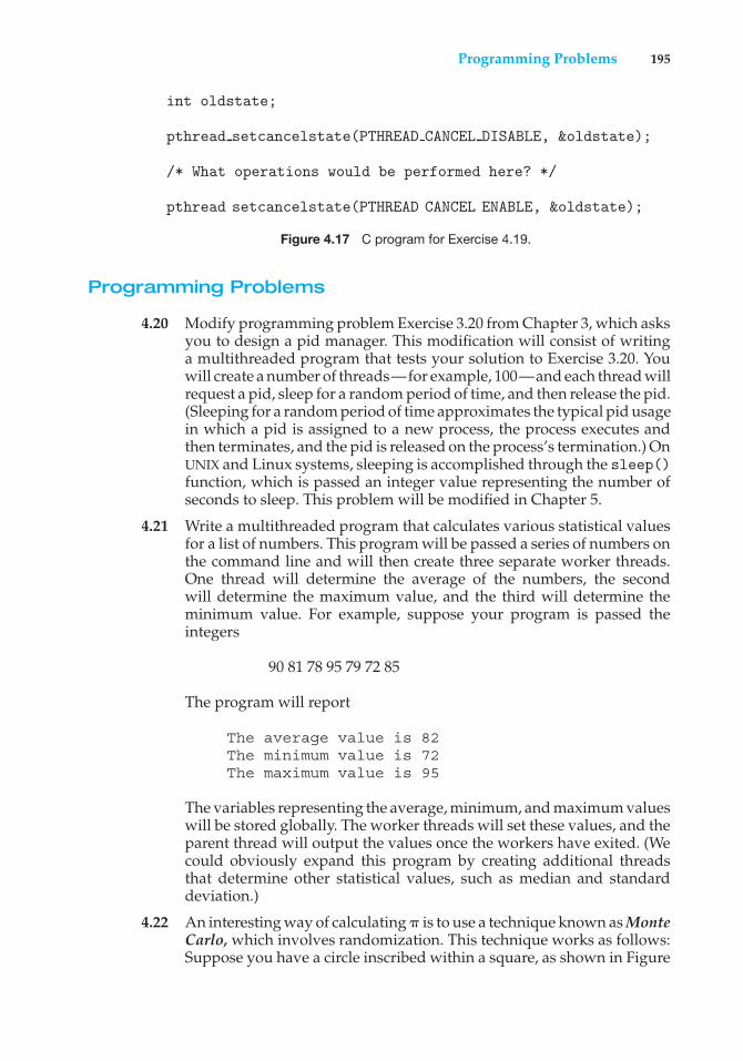
Programming Problems 195
int oldstate;
pthread setcancelstate(PTHREAD CANCEL DISABLE, &oldstate);
/* What operations would be performed here? */
pthread setcancelstate(PTHREAD CANCEL ENABLE, &oldstate);
Figure 4.17 C program for Exercise 4.19.
Programming Problems
4.20 Modify programming problem Exercise 3.20 from Chapter 3, which asksyou to design a pid manager. This modification will consist of writinga multithreaded program that tests your solution to Exercise 3.20. Youwill create a number of threads—for example, 100—and each thread willrequest a pid, sleep for a random period of time, and then release the pid.(Sleeping for a random period of time approximates the typical pid usagein which a pid is assigned to a new process, the process executes andthen terminates, and the pid is released on the process’s termination.) OnUNIX and Linux systems, sleeping is accomplished through the sleep()function, which is passed an integer value representing the number ofseconds to sleep. This problem will be modified in Chapter 5.
4.21 Write a multithreaded program that calculates various statistical valuesfor a list of numbers. This program will be passed a series of numbers onthe command line and will then create three separate worker threads.One thread will determine the average of the numbers, the secondwill determine the maximum value, and the third will determine theminimum value. For example, suppose your program is passed theintegers
90 81 78 95 79 72 85
The program will report
The average value is 82The minimum value is 72The maximum value is 95
The variables representing the average, minimum, and maximum valueswill be stored globally. The worker threads will set these values, and theparent thread will output the values once the workers have exited. (Wecould obviously expand this program by creating additional threadsthat determine other statistical values, such as median and standarddeviation.)
4.22 An interesting way of calculating ! is to use a technique known as MonteCarlo, which involves randomization. This technique works as follows:Suppose you have a circle inscribed within a square, as shown in Figure
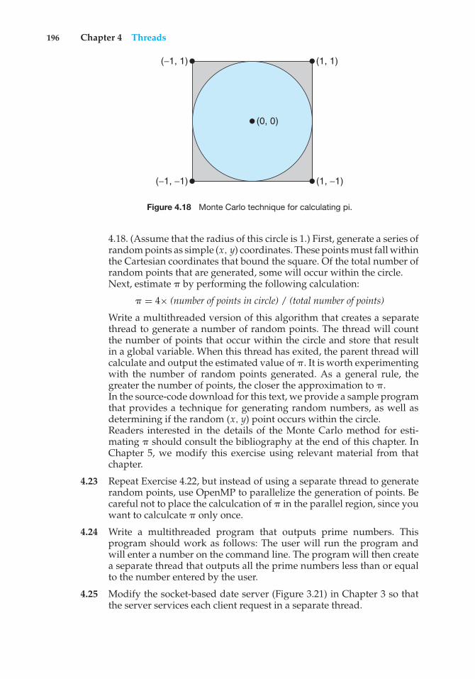
196 Chapter 4 Threads
(−1, 1)
(−1, −1)
(1, 1)
(1, −1)
(0, 0)
Figure 4.18 Monte Carlo technique for calculating pi.
4.18. (Assume that the radius of this circle is 1.) First, generate a series ofrandom points as simple (x, y) coordinates. These points must fall withinthe Cartesian coordinates that bound the square. Of the total number ofrandom points that are generated, some will occur within the circle.Next, estimate ! by performing the following calculation:
! = 4× (number of points in circle) / (total number of points)
Write a multithreaded version of this algorithm that creates a separatethread to generate a number of random points. The thread will countthe number of points that occur within the circle and store that resultin a global variable. When this thread has exited, the parent thread willcalculate and output the estimated value of !. It is worth experimentingwith the number of random points generated. As a general rule, thegreater the number of points, the closer the approximation to !.In the source-code download for this text, we provide a sample programthat provides a technique for generating random numbers, as well asdetermining if the random (x, y) point occurs within the circle.Readers interested in the details of the Monte Carlo method for esti-mating ! should consult the bibliography at the end of this chapter. InChapter 5, we modify this exercise using relevant material from thatchapter.
4.23 Repeat Exercise 4.22, but instead of using a separate thread to generaterandom points, use OpenMP to parallelize the generation of points. Becareful not to place the calculcation of ! in the parallel region, since youwant to calculcate ! only once.
4.24 Write a multithreaded program that outputs prime numbers. Thisprogram should work as follows: The user will run the program andwill enter a number on the command line. The program will then createa separate thread that outputs all the prime numbers less than or equalto the number entered by the user.
4.25 Modify the socket-based date server (Figure 3.21) in Chapter 3 so thatthe server services each client request in a separate thread.
Programming Projects 197
4.26 The Fibonacci sequence is the series of numbers 0, 1, 1, 2, 3, 5, 8, ....Formally, it can be expressed as:
f ib0 = 0f ib1 = 1f ibn = f ibn−1 + f ibn−2
Write a multithreaded program that generates the Fibonacci sequence.This program should work as follows: On the command line, the userwill enter the number of Fibonacci numbers that the program is togenerate. The program will then create a separate thread that willgenerate the Fibonacci numbers, placing the sequence in data that canbe shared by the threads (an array is probably the most convenientdata structure). When the thread finishes execution, the parent threadwill output the sequence generated by the child thread. Because theparent thread cannot begin outputting the Fibonacci sequence until thechild thread finishes, the parent thread will have to wait for the childthread to finish. Use the techniques described in Section 4.4 to meet thisrequirement.
4.27 Exercise 3.25 in Chapter 3 involves designing an echo server using theJava threading API. This server is single-threaded, meaning that theserver cannot respond to concurrent echo clients until the current clientexits. Modify the solution to Exercise 3.25 so that the echo server serviceseach client in a separate request.
Programming Projects
Project 1—Sudoku Solution Validator
A Sudoku puzzle uses a 9 × 9 grid in which each column and row, as well aseach of the nine 3 × 3 subgrids, must contain all of the digits 1 · · · 9. Figure4.19 presents an example of a valid Sudoku puzzle. This project consists ofdesigning a multithreaded application that determines whether the solution toa Sudoku puzzle is valid.
There are several different ways of multithreading this application. Onesuggested strategy is to create threads that check the following criteria:
• A thread to check that each column contains the digits 1 through 9
• A thread to check that each row contains the digits 1 through 9
• Nine threads to check that each of the 3× 3 subgrids contains the digits 1through 9
This would result in a total of eleven separate threads for validating aSudoku puzzle. However, you are welcome to create even more threads forthis project. For example, rather than creating one thread that checks all nine
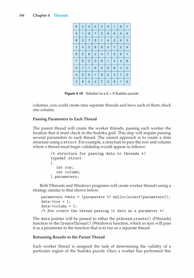
198 Chapter 4 Threads
6 2 4 5 3 9 1 8 7
5 1 9 7 2 8 6 3 4
8 3 7 6 1 4 2 9 5
1 4 3 8 6 5 7 2 9
9 5 8 2 4 7 3 6 1
7 6 2 3 9 1 4 5 8
3 7 1 9 5 6 8 4 2
4 9 6 1 8 2 5 7 3
2 8 5 4 7 3 9 1 6
Figure 4.19 Solution to a 9× 9 Sudoku puzzle.
columns, you could create nine separate threads and have each of them checkone column.
Passing Parameters to Each Thread
The parent thread will create the worker threads, passing each worker thelocation that it must check in the Sudoku grid. This step will require passingseveral parameters to each thread. The easiest approach is to create a datastructure using a struct. For example, a structure to pass the row and columnwhere a thread must begin validating would appear as follows:
/* structure for passing data to threads */typedef struct{
int row;int column;
} parameters;
Both Pthreads and Windows programs will create worker threads using astrategy similar to that shown below:
parameters *data = (parameters *) malloc(sizeof(parameters));data->row = 1;data->column = 1;/* Now create the thread passing it data as a parameter */
The data pointer will be passed to either the pthread create() (Pthreads)function or the CreateThread() (Windows) function, which in turn will passit as a parameter to the function that is to run as a separate thread.
Returning Results to the Parent Thread
Each worker thread is assigned the task of determining the validity of aparticular region of the Sudoku puzzle. Once a worker has performed this
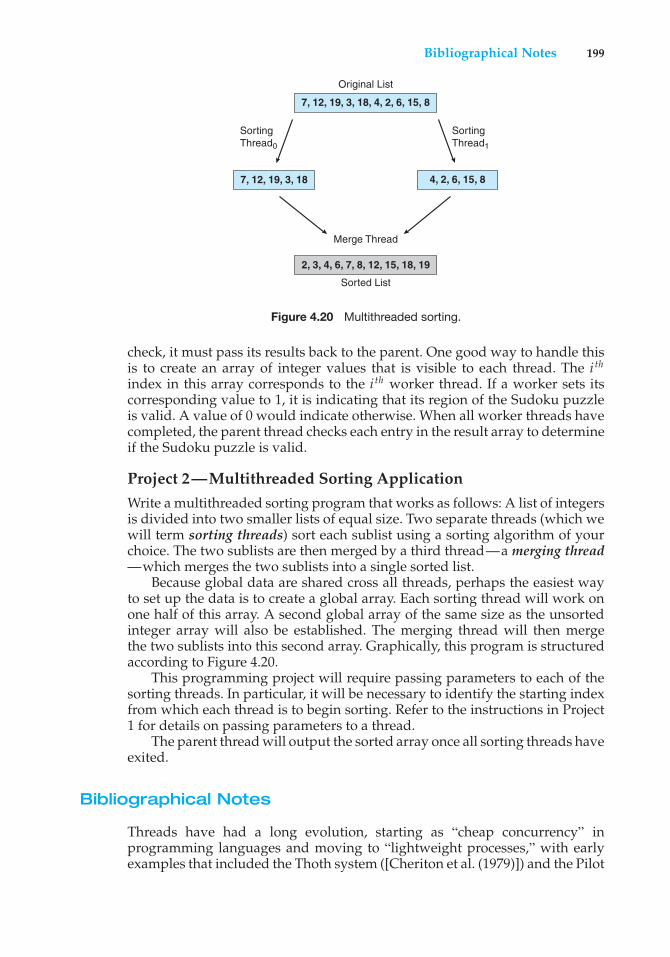
Bibliographical Notes 199
7, 12, 19, 3, 18
7, 12, 19, 3, 18, 4, 2, 6, 15, 8
Original List
2, 3, 4, 6, 7, 8, 12, 15, 18, 19
Merge Thread
Sorted List
SortingThread0
SortingThread1
4, 2, 6, 15, 8
Figure 4.20 Multithreaded sorting.
check, it must pass its results back to the parent. One good way to handle thisis to create an array of integer values that is visible to each thread. The i th
index in this array corresponds to the i th worker thread. If a worker sets itscorresponding value to 1, it is indicating that its region of the Sudoku puzzleis valid. A value of 0 would indicate otherwise. When all worker threads havecompleted, the parent thread checks each entry in the result array to determineif the Sudoku puzzle is valid.
Project 2—Multithreaded Sorting ApplicationWrite a multithreaded sorting program that works as follows: A list of integersis divided into two smaller lists of equal size. Two separate threads (which wewill term sorting threads) sort each sublist using a sorting algorithm of yourchoice. The two sublists are then merged by a third thread—a merging thread—which merges the two sublists into a single sorted list.
Because global data are shared cross all threads, perhaps the easiest wayto set up the data is to create a global array. Each sorting thread will work onone half of this array. A second global array of the same size as the unsortedinteger array will also be established. The merging thread will then mergethe two sublists into this second array. Graphically, this program is structuredaccording to Figure 4.20.
This programming project will require passing parameters to each of thesorting threads. In particular, it will be necessary to identify the starting indexfrom which each thread is to begin sorting. Refer to the instructions in Project1 for details on passing parameters to a thread.
The parent thread will output the sorted array once all sorting threads haveexited.
Bibliographical Notes
Threads have had a long evolution, starting as “cheap concurrency” inprogramming languages and moving to “lightweight processes,” with earlyexamples that included the Thoth system ([Cheriton et al. (1979)]) and the Pilot
200 Chapter 4 Threads
system ([Redell et al. (1980)]). [Binding (1985)] described moving threads intothe UNIX kernel. Mach ([Accetta et al. (1986)], [Tevanian et al. (1987)]), and V([Cheriton (1988)]) made extensive use of threads, and eventually almost allmajor operating systems implemented them in some form or another.
[Vahalia (1996)] covers threading in several versions of UNIX. [McDougalland Mauro (2007)] describes developments in threading the Solaris kernel.[Russinovich and Solomon (2009)] discuss threading in the Windows operatingsystem family. [Mauerer (2008)] and [Love (2010)] explain how Linux handlesthreading, and [Singh (2007)] covers threads in Mac OS X.
Information on Pthreads programming is given in [Lewis and Berg(1998)] and [Butenhof (1997)]. [Oaks and Wong (1999)] and [Lewis andBerg (2000)] discuss multithreading in Java. [Goetz et al. (2006)] present adetailed discussion of concurrent programming in Java. [Hart (2005)] describesmultithreading using Windows. Details on using OpenMP can be found athttp://openmp.org.
An analysis of an optimal thread-pool size can be found in [Ling et al.(2000)]. Scheduler activations were first presented in [Anderson et al. (1991)],and [Williams (2002)] discusses scheduler activations in the NetBSD system.
[Breshears (2009)] and [Pacheco (2011)] cover parallel programming indetail. [Hill and Marty (2008)] examine Amdahl’s Law with respect to multicoresystems. The Monte Carlo technique for estimating ! is further discussed inhttp://math.fullerton.edu/mathews/n2003/montecarlopimod.html.
Bibliography
[Accetta et al. (1986)] M. Accetta, R. Baron, W. Bolosky, D. B. Golub, R. Rashid,A. Tevanian, and M. Young, “Mach: A New Kernel Foundation for UNIXDevelopment”, Proceedings of the Summer USENIX Conference (1986), pages93–112.
[Anderson et al. (1991)] T. E. Anderson, B. N. Bershad, E. D. Lazowska, andH. M. Levy, “Scheduler Activations: Effective Kernel Support for the User-LevelManagement of Parallelism”, Proceedings of the ACM Symposium on OperatingSystems Principles (1991), pages 95–109.
[Binding (1985)] C. Binding, “Cheap Concurrency in C”, SIGPLAN Notices,Volume 20, Number 9 (1985), pages 21–27.
[Breshears (2009)] C. Breshears, The Art of Concurrency, O’Reilly & Associates(2009).
[Butenhof (1997)] D. Butenhof, Programming with POSIX Threads, Addison-Wesley (1997).
[Cheriton (1988)] D. Cheriton, “The V Distributed System”, Communications ofthe ACM, Volume 31, Number 3 (1988), pages 314–333.
[Cheriton et al. (1979)] D. R. Cheriton, M. A. Malcolm, L. S. Melen, and G. R.Sager, “Thoth, a Portable Real-Time Operating System”, Communications of theACM, Volume 22, Number 2 (1979), pages 105–115.
Bibliography 201
[Goetz et al. (2006)] B. Goetz, T. Peirls, J. Bloch, J. Bowbeer, D. Holmes, andD. Lea, Java Concurrency in Practice, Addison-Wesley (2006).
[Hart (2005)] J. M. Hart, Windows System Programming, Third Edition, Addison-Wesley (2005).
[Hill and Marty (2008)] M. Hill and M. Marty, “Amdahl’s Law in the MulticoreEra”, IEEE Computer, Volume 41, Number 7 (2008), pages 33–38.
[Lewis and Berg (1998)] B. Lewis and D. Berg, Multithreaded Programming withPthreads, Sun Microsystems Press (1998).
[Lewis and Berg (2000)] B. Lewis and D. Berg, Multithreaded Programming withJava Technology, Sun Microsystems Press (2000).
[Ling et al. (2000)] Y. Ling, T. Mullen, and X. Lin, “Analysis of Optimal ThreadPool Size”, Operating System Review, Volume 34, Number 2 (2000), pages 42–55.
[Love (2010)] R. Love, Linux Kernel Development, Third Edition, Developer’sLibrary (2010).
[Mauerer (2008)] W. Mauerer, Professional Linux Kernel Architecture, John Wileyand Sons (2008).
[McDougall and Mauro (2007)] R. McDougall and J. Mauro, Solaris Internals,Second Edition, Prentice Hall (2007).
[Oaks and Wong (1999)] S. Oaks and H. Wong, Java Threads, Second Edition,O’Reilly & Associates (1999).
[Pacheco (2011)] P. S. Pacheco, An Introduction to Parallel Programming, MorganKaufmann (2011).
[Redell et al. (1980)] D. D. Redell, Y. K. Dalal, T. R. Horsley, H. C. Lauer, W. C.Lynch, P. R. McJones, H. G. Murray, and S. P. Purcell, “Pilot: An Operating Systemfor a Personal Computer”, Communications of the ACM, Volume 23, Number 2(1980), pages 81–92.
[Russinovich and Solomon (2009)] M. E. Russinovich and D. A. Solomon, Win-dows Internals: Including Windows Server 2008 and Windows Vista, Fifth Edition,Microsoft Press (2009).
[Singh (2007)] A. Singh, Mac OS X Internals: A Systems Approach, Addison-Wesley (2007).
[Tevanian et al. (1987)] A. Tevanian, Jr., R. F. Rashid, D. B. Golub, D. L. Black,E. Cooper, and M. W. Young, “Mach Threads and the Unix Kernel: The Battlefor Control”, Proceedings of the Summer USENIX Conference (1987).
[Vahalia (1996)] U. Vahalia, Unix Internals: The New Frontiers, Prentice Hall(1996).
[Williams (2002)] N. Williams, “An Implementation of Scheduler Activationson the NetBSD Operating System”, 2002 USENIX Annual Technical Conference,FREENIX Track (2002).

5C H A P T E R
ProcessSynchronization
A cooperating process is one that can affect or be affected by other processesexecuting in the system. Cooperating processes can either directly share alogical address space (that is, both code and data) or be allowed to share dataonly through files or messages. The former case is achieved through the use ofthreads, discussed in Chapter 4. Concurrent access to shared data may result indata inconsistency, however. In this chapter, we discuss various mechanismsto ensure the orderly execution of cooperating processes that share a logicaladdress space, so that data consistency is maintained.
CHAPTER OBJECTIVES
• To introduce the critical-section problem, whose solutions can be used toensure the consistency of shared data.
• To present both software and hardware solutions of the critical-sectionproblem.
• To examine several classical process-synchronization problems.• To explore several tools that are used to solve process synchronization
problems.
5.1 Background
We’ve already seen that processes can execute concurrently or in parallel.Section 3.2.2 introduced the role of process scheduling and described howthe CPU scheduler switches rapidly between processes to provide concurrentexecution. This means that one process may only partially complete executionbefore another process is scheduled. In fact, a process may be interrupted atany point in its instruction stream, and the processing core may be assignedto execute instructions of another process. Additionally, Section 4.2 introducedparallel execution, in which two instruction streams (representing differentprocesses) execute simultaneously on separate processing cores. In this chapter,
203
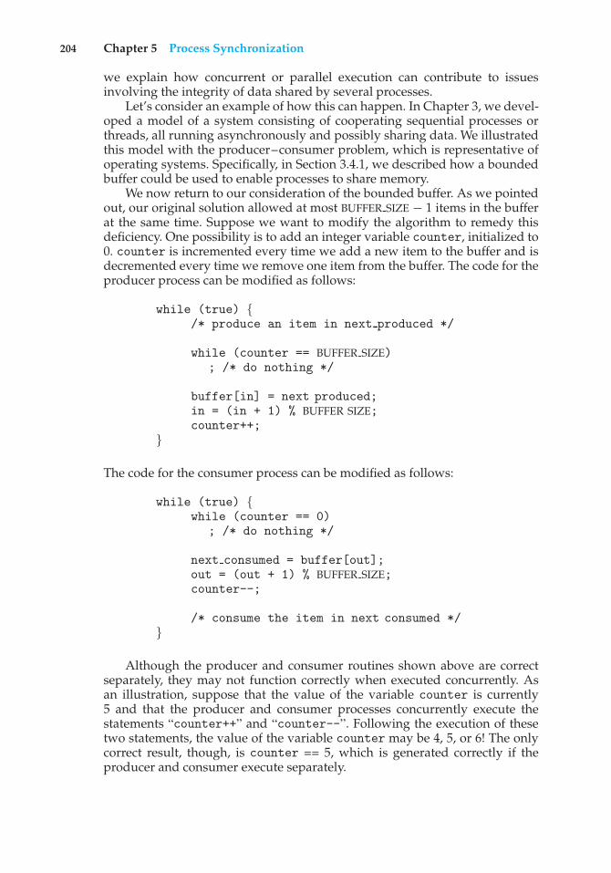
204 Chapter 5 Process Synchronization
we explain how concurrent or parallel execution can contribute to issuesinvolving the integrity of data shared by several processes.
Let’s consider an example of how this can happen. In Chapter 3, we devel-oped a model of a system consisting of cooperating sequential processes orthreads, all running asynchronously and possibly sharing data. We illustratedthis model with the producer–consumer problem, which is representative ofoperating systems. Specifically, in Section 3.4.1, we described how a boundedbuffer could be used to enable processes to share memory.
We now return to our consideration of the bounded buffer. As we pointedout, our original solution allowed at most BUFFER SIZE − 1 items in the bufferat the same time. Suppose we want to modify the algorithm to remedy thisdeficiency. One possibility is to add an integer variable counter, initialized to0. counter is incremented every time we add a new item to the buffer and isdecremented every time we remove one item from the buffer. The code for theproducer process can be modified as follows:
while (true) {/* produce an item in next produced */
while (counter == BUFFER SIZE); /* do nothing */
buffer[in] = next produced;in = (in + 1) % BUFFER SIZE;counter++;
}
The code for the consumer process can be modified as follows:
while (true) {while (counter == 0)
; /* do nothing */
next consumed = buffer[out];out = (out + 1) % BUFFER SIZE;counter--;
/* consume the item in next consumed */}
Although the producer and consumer routines shown above are correctseparately, they may not function correctly when executed concurrently. Asan illustration, suppose that the value of the variable counter is currently5 and that the producer and consumer processes concurrently execute thestatements “counter++” and “counter--”. Following the execution of thesetwo statements, the value of the variable counter may be 4, 5, or 6! The onlycorrect result, though, is counter == 5, which is generated correctly if theproducer and consumer execute separately.
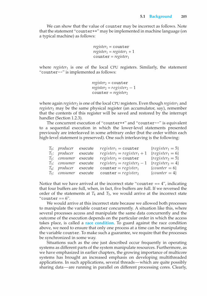
5.1 Background 205
We can show that the value of counter may be incorrect as follows. Notethat the statement “counter++” may be implemented in machine language (ona typical machine) as follows:
register1 = counterregister1 = register1 + 1counter = register1
where register1 is one of the local CPU registers. Similarly, the statement“counter--” is implemented as follows:
register2 = counterregister2 = register2 − 1counter = register2
where again register2 is one of the local CPU registers. Even though register1 andregister2 may be the same physical register (an accumulator, say), rememberthat the contents of this register will be saved and restored by the interrupthandler (Section 1.2.3).
The concurrent execution of “counter++” and “counter--” is equivalentto a sequential execution in which the lower-level statements presentedpreviously are interleaved in some arbitrary order (but the order within eachhigh-level statement is preserved). One such interleaving is the following:
T0: producer execute register1 = counter {register1 = 5}T1: producer execute register1 = register1 + 1 {register1 = 6}T2: consumer execute register2 = counter {register2 = 5}T3: consumer execute register2 = register2 − 1 {register2 = 4}T4: producer execute counter = register1 {counter = 6}T5: consumer execute counter = register2 {counter = 4}
Notice that we have arrived at the incorrect state “counter == 4”, indicatingthat four buffers are full, when, in fact, five buffers are full. If we reversed theorder of the statements at T4 and T5, we would arrive at the incorrect state“counter == 6”.
We would arrive at this incorrect state because we allowed both processesto manipulate the variable counter concurrently. A situation like this, whereseveral processes access and manipulate the same data concurrently and theoutcome of the execution depends on the particular order in which the accesstakes place, is called a race condition. To guard against the race conditionabove, we need to ensure that only one process at a time can be manipulatingthe variable counter. To make such a guarantee, we require that the processesbe synchronized in some way.
Situations such as the one just described occur frequently in operatingsystems as different parts of the system manipulate resources. Furthermore, aswe have emphasized in earlier chapters, the growing importance of multicoresystems has brought an increased emphasis on developing multithreadedapplications. In such applications, several threads—which are quite possiblysharing data—are running in parallel on different processing cores. Clearly,
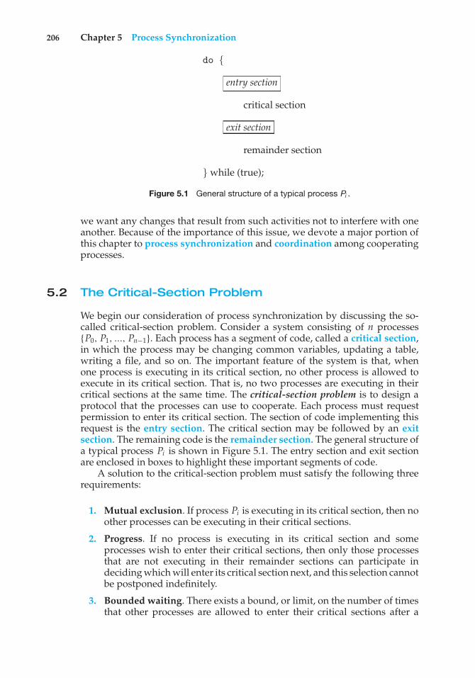
206 Chapter 5 Process Synchronization
do {
entry section
critical section
exit section
remainder section
} while (true);
Figure 5.1 General structure of a typical process Pi .
we want any changes that result from such activities not to interfere with oneanother. Because of the importance of this issue, we devote a major portion ofthis chapter to process synchronization and coordination among cooperatingprocesses.
5.2 The Critical-Section Problem
We begin our consideration of process synchronization by discussing the so-called critical-section problem. Consider a system consisting of n processes{P0, P1, ..., Pn−1}. Each process has a segment of code, called a critical section,in which the process may be changing common variables, updating a table,writing a file, and so on. The important feature of the system is that, whenone process is executing in its critical section, no other process is allowed toexecute in its critical section. That is, no two processes are executing in theircritical sections at the same time. The critical-section problem is to design aprotocol that the processes can use to cooperate. Each process must requestpermission to enter its critical section. The section of code implementing thisrequest is the entry section. The critical section may be followed by an exitsection. The remaining code is the remainder section. The general structure ofa typical process Pi is shown in Figure 5.1. The entry section and exit sectionare enclosed in boxes to highlight these important segments of code.
A solution to the critical-section problem must satisfy the following threerequirements:
1. Mutual exclusion. If process Pi is executing in its critical section, then noother processes can be executing in their critical sections.
2. Progress. If no process is executing in its critical section and someprocesses wish to enter their critical sections, then only those processesthat are not executing in their remainder sections can participate indeciding which will enter its critical section next, and this selection cannotbe postponed indefinitely.
3. Bounded waiting. There exists a bound, or limit, on the number of timesthat other processes are allowed to enter their critical sections after a
5.3 Peterson’s Solution 207
process has made a request to enter its critical section and before thatrequest is granted.
We assume that each process is executing at a nonzero speed. However, we canmake no assumption concerning the relative speed of the n processes.
At a given point in time, many kernel-mode processes may be active inthe operating system. As a result, the code implementing an operating system(kernel code) is subject to several possible race conditions. Consider as anexample a kernel data structure that maintains a list of all open files in thesystem. This list must be modified when a new file is opened or closed (addingthe file to the list or removing it from the list). If two processes were to open filessimultaneously, the separate updates to this list could result in a race condition.Other kernel data structures that are prone to possible race conditions includestructures for maintaining memory allocation, for maintaining process lists,and for interrupt handling. It is up to kernel developers to ensure that theoperating system is free from such race conditions.
Two general approaches are used to handle critical sections in operatingsystems: preemptive kernels and nonpreemptive kernels. A preemptivekernel allows a process to be preempted while it is running in kernel mode. Anonpreemptive kernel does not allow a process running in kernel mode to bepreempted; a kernel-mode process will run until it exits kernel mode, blocks,or voluntarily yields control of the CPU.
Obviously, a nonpreemptive kernel is essentially free from race conditionson kernel data structures, as only one process is active in the kernel at a time.We cannot say the same about preemptive kernels, so they must be carefullydesigned to ensure that shared kernel data are free from race conditions.Preemptive kernels are especially difficult to design for SMP architectures,since in these environments it is possible for two kernel-mode processes to runsimultaneously on different processors.
Why, then, would anyone favor a preemptive kernel over a nonpreemptiveone? A preemptive kernel may be more responsive, since there is less risk that akernel-mode process will run for an arbitrarily long period before relinquishingthe processor to waiting processes. (Of course, this risk can also be minimizedby designing kernel code that does not behave in this way.) Furthermore, apreemptive kernel is more suitable for real-time programming, as it will allowa real-time process to preempt a process currently running in the kernel. Laterin this chapter, we explore how various operating systems manage preemptionwithin the kernel.
5.3 Peterson’s Solution
Next, we illustrate a classic software-based solution to the critical-sectionproblem known as Peterson’s solution. Because of the way modern computerarchitectures perform basic machine-language instructions, such as load andstore, there are no guarantees that Peterson’s solution will work correctly onsuch architectures. However, we present the solution because it provides a goodalgorithmic description of solving the critical-section problem and illustratessome of the complexities involved in designing software that addresses therequirements of mutual exclusion, progress, and bounded waiting.

208 Chapter 5 Process Synchronization
do {
flag[i] = true;turn = j;while (flag[j] && turn == j);
critical section
flag[i] = false;
remainder section
} while (true);
Figure 5.2 The structure of process Pi in Peterson’s solution.
Peterson’s solution is restricted to two processes that alternate executionbetween their critical sections and remainder sections. The processes arenumbered P0 and P1. For convenience, when presenting Pi , we use Pj todenote the other process; that is, j equals 1 − i.
Peterson’s solution requires the two processes to share two data items:
int turn;boolean flag[2];
The variable turn indicates whose turn it is to enter its critical section. That is,if turn == i, then process Pi is allowed to execute in its critical section. Theflag array is used to indicate if a process is ready to enter its critical section.For example, if flag[i] is true, this value indicates that Pi is ready to enterits critical section. With an explanation of these data structures complete, weare now ready to describe the algorithm shown in Figure 5.2.
To enter the critical section, process Pi first sets flag[i] to be true andthen sets turn to the value j, thereby asserting that if the other process wishesto enter the critical section, it can do so. If both processes try to enter at the sametime, turnwill be set to bothi and j at roughly the same time. Only one of theseassignments will last; the other will occur but will be overwritten immediately.The eventual value of turn determines which of the two processes is allowedto enter its critical section first.
We now prove that this solution is correct. We need to show that:
1. Mutual exclusion is preserved.
2. The progress requirement is satisfied.
3. The bounded-waiting requirement is met.
To prove property 1, we note that each Pi enters its critical section onlyif either flag[j] == false or turn == i. Also note that, if both processescan be executing in their critical sections at the same time, then flag[0] ==flag[1] == true. These two observations imply that P0 and P1 could not havesuccessfully executed their while statements at about the same time, since the
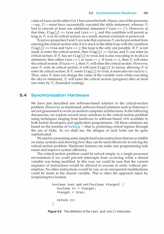
5.4 Synchronization Hardware 209
value of turn can be either 0 or 1 but cannot be both. Hence, one of the processes—say, Pj —must have successfully executed the while statement, whereas Pihad to execute at least one additional statement (“turn == j”). However, atthat time, flag[j] == true and turn == j, and this condition will persist aslong as Pj is in its critical section; as a result, mutual exclusion is preserved.
To prove properties 2 and 3, we note that a process Pi can be prevented fromentering the critical section only if it is stuck in the while loop with the conditionflag[j] == true and turn == j; this loop is the only one possible. If Pj is notready to enter the critical section, then flag[j] == false, and Pi can enter itscritical section. If Pj has set flag[j] to true and is also executing in its whilestatement, then either turn == i or turn == j. If turn == i, then Pi will enterthe critical section. If turn == j, then Pj will enter the critical section. However,once Pj exits its critical section, it will reset flag[j] to false, allowing Pi toenter its critical section. If Pj resets flag[j] to true, it must also set turn to i.Thus, since Pi does not change the value of the variable turn while executingthe while statement, Pi will enter the critical section (progress) after at mostone entry by Pj (bounded waiting).
5.4 Synchronization Hardware
We have just described one software-based solution to the critical-sectionproblem. However, as mentioned, software-based solutions such as Peterson’sare not guaranteed to work on modern computer architectures. In the followingdiscussions, we explore several more solutions to the critical-section problemusing techniques ranging from hardware to software-based APIs available toboth kernel developers and application programmers. All these solutions arebased on the premise of locking —that is, protecting critical regions throughthe use of locks. As we shall see, the designs of such locks can be quitesophisticated.
We start by presenting some simple hardware instructions that are availableon many systems and showing how they can be used effectively in solving thecritical-section problem. Hardware features can make any programming taskeasier and improve system efficiency.
The critical-section problem could be solved simply in a single-processorenvironment if we could prevent interrupts from occurring while a sharedvariable was being modified. In this way, we could be sure that the currentsequence of instructions would be allowed to execute in order without pre-emption. No other instructions would be run, so no unexpected modificationscould be made to the shared variable. This is often the approach taken bynonpreemptive kernels.
boolean test and set(boolean *target) {boolean rv = *target;*target = true;
return rv;}
Figure 5.3 The definition of the test and set() instruction.
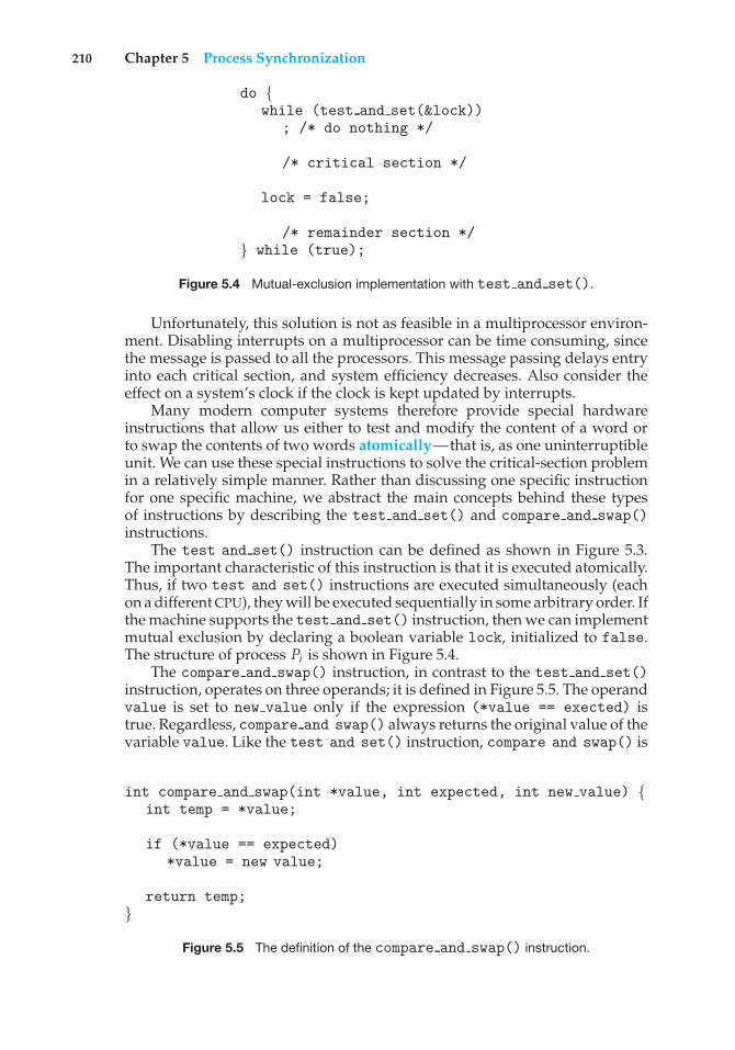
210 Chapter 5 Process Synchronization
do {while (test and set(&lock))
; /* do nothing */
/* critical section */
lock = false;
/* remainder section */} while (true);
Figure 5.4 Mutual-exclusion implementation with test and set().
Unfortunately, this solution is not as feasible in a multiprocessor environ-ment. Disabling interrupts on a multiprocessor can be time consuming, sincethe message is passed to all the processors. This message passing delays entryinto each critical section, and system efficiency decreases. Also consider theeffect on a system’s clock if the clock is kept updated by interrupts.
Many modern computer systems therefore provide special hardwareinstructions that allow us either to test and modify the content of a word orto swap the contents of two words atomically—that is, as one uninterruptibleunit. We can use these special instructions to solve the critical-section problemin a relatively simple manner. Rather than discussing one specific instructionfor one specific machine, we abstract the main concepts behind these typesof instructions by describing the test and set() and compare and swap()instructions.
The test and set() instruction can be defined as shown in Figure 5.3.The important characteristic of this instruction is that it is executed atomically.Thus, if two test and set() instructions are executed simultaneously (eachon a different CPU), they will be executed sequentially in some arbitrary order. Ifthe machine supports the test and set() instruction, then we can implementmutual exclusion by declaring a boolean variable lock, initialized to false.The structure of process Pi is shown in Figure 5.4.
The compare and swap() instruction, in contrast to the test and set()instruction, operates on three operands; it is defined in Figure 5.5. The operandvalue is set to new value only if the expression (*value == exected) istrue. Regardless, compare and swap() always returns the original value of thevariable value. Like the test and set() instruction, compare and swap() is
int compare and swap(int *value, int expected, int new value) {int temp = *value;
if (*value == expected)*value = new value;
return temp;}
Figure 5.5 The definition of the compare and swap() instruction.
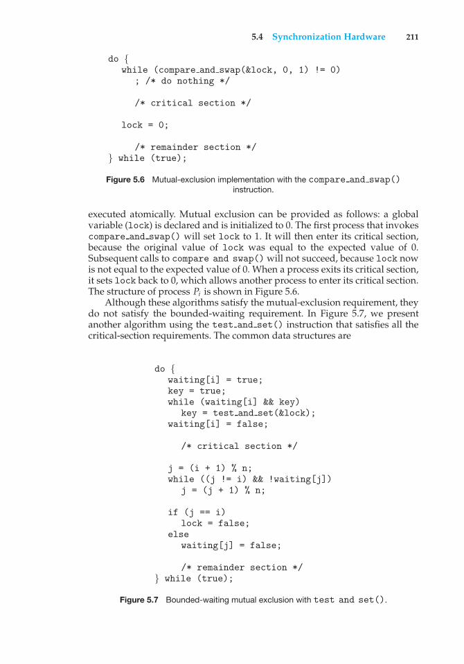
5.4 Synchronization Hardware 211
do {while (compare and swap(&lock, 0, 1) != 0)
; /* do nothing */
/* critical section */
lock = 0;
/* remainder section */} while (true);
Figure 5.6 Mutual-exclusion implementation with the compare and swap()instruction.
executed atomically. Mutual exclusion can be provided as follows: a globalvariable (lock) is declared and is initialized to 0. The first process that invokescompare and swap() will set lock to 1. It will then enter its critical section,because the original value of lock was equal to the expected value of 0.Subsequent calls to compare and swap() will not succeed, because lock nowis not equal to the expected value of 0. When a process exits its critical section,it sets lock back to 0, which allows another process to enter its critical section.The structure of process Pi is shown in Figure 5.6.
Although these algorithms satisfy the mutual-exclusion requirement, theydo not satisfy the bounded-waiting requirement. In Figure 5.7, we presentanother algorithm using the test and set() instruction that satisfies all thecritical-section requirements. The common data structures are
do {waiting[i] = true;key = true;while (waiting[i] && key)
key = test and set(&lock);waiting[i] = false;
/* critical section */
j = (i + 1) % n;while ((j != i) && !waiting[j])
j = (j + 1) % n;
if (j == i)lock = false;
elsewaiting[j] = false;
/* remainder section */} while (true);
Figure 5.7 Bounded-waiting mutual exclusion with test and set().
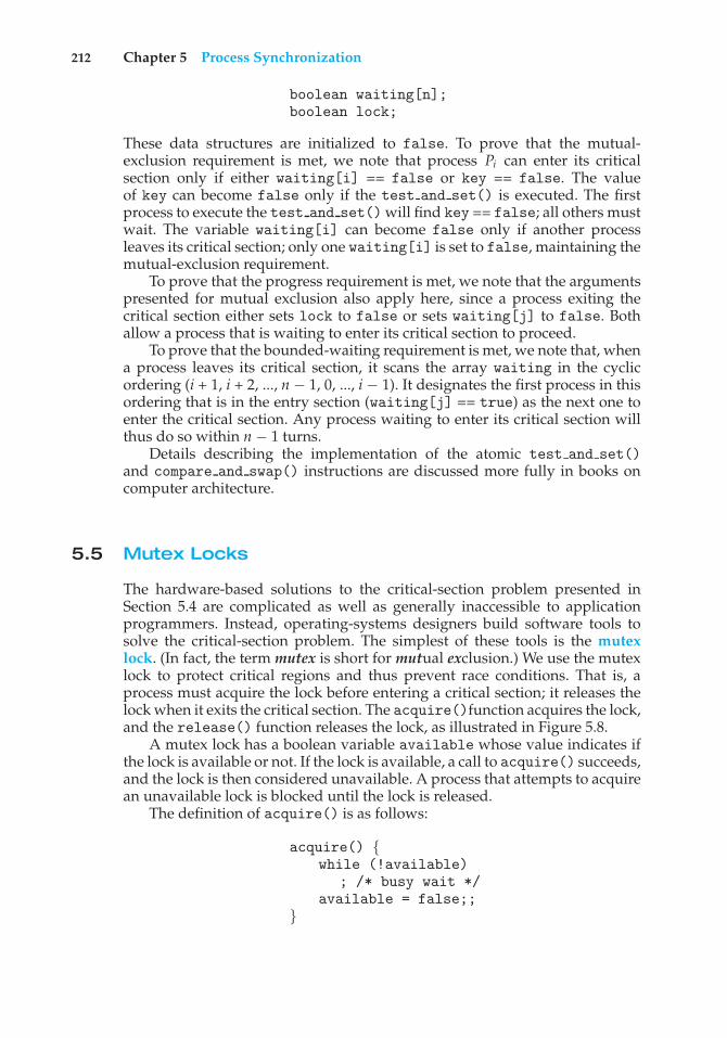
212 Chapter 5 Process Synchronization
boolean waiting[n];boolean lock;
These data structures are initialized to false. To prove that the mutual-exclusion requirement is met, we note that process Pi can enter its criticalsection only if either waiting[i] == false or key == false. The valueof key can become false only if the test and set() is executed. The firstprocess to execute the test and set() will find key == false; all others mustwait. The variable waiting[i] can become false only if another processleaves its critical section; only one waiting[i] is set to false, maintaining themutual-exclusion requirement.
To prove that the progress requirement is met, we note that the argumentspresented for mutual exclusion also apply here, since a process exiting thecritical section either sets lock to false or sets waiting[j] to false. Bothallow a process that is waiting to enter its critical section to proceed.
To prove that the bounded-waiting requirement is met, we note that, whena process leaves its critical section, it scans the array waiting in the cyclicordering (i + 1, i + 2, ..., n − 1, 0, ..., i − 1). It designates the first process in thisordering that is in the entry section (waiting[j] == true) as the next one toenter the critical section. Any process waiting to enter its critical section willthus do so within n − 1 turns.
Details describing the implementation of the atomic test and set()and compare and swap() instructions are discussed more fully in books oncomputer architecture.
5.5 Mutex Locks
The hardware-based solutions to the critical-section problem presented inSection 5.4 are complicated as well as generally inaccessible to applicationprogrammers. Instead, operating-systems designers build software tools tosolve the critical-section problem. The simplest of these tools is the mutexlock. (In fact, the term mutex is short for mutual exclusion.) We use the mutexlock to protect critical regions and thus prevent race conditions. That is, aprocess must acquire the lock before entering a critical section; it releases thelock when it exits the critical section. The acquire()function acquires the lock,and the release() function releases the lock, as illustrated in Figure 5.8.
A mutex lock has a boolean variable available whose value indicates ifthe lock is available or not. If the lock is available, a call to acquire() succeeds,and the lock is then considered unavailable. A process that attempts to acquirean unavailable lock is blocked until the lock is released.
The definition of acquire() is as follows:
acquire() {while (!available)
; /* busy wait */available = false;;
}
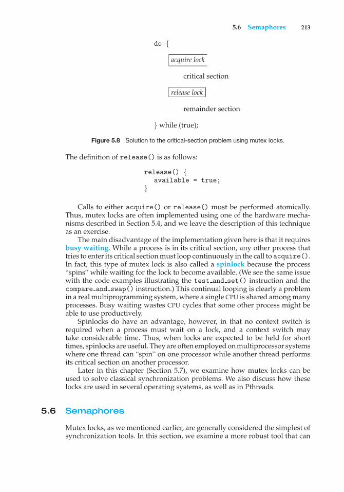
5.6 Semaphores 213
do {
acquire lock
critical section
release lock
remainder section
} while (true);
Figure 5.8 Solution to the critical-section problem using mutex locks.
The definition of release() is as follows:
release() {available = true;
}
Calls to either acquire() or release() must be performed atomically.Thus, mutex locks are often implemented using one of the hardware mecha-nisms described in Section 5.4, and we leave the description of this techniqueas an exercise.
The main disadvantage of the implementation given here is that it requiresbusy waiting. While a process is in its critical section, any other process thattries to enter its critical section must loop continuously in the call to acquire().In fact, this type of mutex lock is also called a spinlock because the process“spins” while waiting for the lock to become available. (We see the same issuewith the code examples illustrating the test and set() instruction and thecompare and swap() instruction.) This continual looping is clearly a problemin a real multiprogramming system, where a single CPU is shared among manyprocesses. Busy waiting wastes CPU cycles that some other process might beable to use productively.
Spinlocks do have an advantage, however, in that no context switch isrequired when a process must wait on a lock, and a context switch maytake considerable time. Thus, when locks are expected to be held for shorttimes, spinlocks are useful. They are often employed on multiprocessor systemswhere one thread can “spin” on one processor while another thread performsits critical section on another processor.
Later in this chapter (Section 5.7), we examine how mutex locks can beused to solve classical synchronization problems. We also discuss how theselocks are used in several operating systems, as well as in Pthreads.
5.6 Semaphores
Mutex locks, as we mentioned earlier, are generally considered the simplest ofsynchronization tools. In this section, we examine a more robust tool that can
214 Chapter 5 Process Synchronization
behave similarly to a mutex lock but can also provide more sophisticated waysfor processes to synchronize their activities.
A semaphore S is an integer variable that, apart from initialization, isaccessed only through two standard atomic operations: wait() and signal().The wait() operation was originally termed P (from the Dutch proberen, “totest”); signal() was originally called V (from verhogen, “to increment”). Thedefinition of wait() is as follows:
wait(S) {while (S <= 0)
; // busy waitS--;
}
The definition of signal() is as follows:
signal(S) {S++;
}
All modifications to the integer value of the semaphore in the wait() andsignal() operations must be executed indivisibly. That is, when one processmodifies the semaphore value, no other process can simultaneously modifythat same semaphore value. In addition, in the case of wait(S), the testing ofthe integer value of S (S ≤ 0), as well as its possible modification (S--), mustbe executed without interruption. We shall see how these operations can beimplemented in Section 5.6.2. First, let’s see how semaphores can be used.
5.6.1 Semaphore Usage
Operating systems often distinguish between counting and binary semaphores.The value of a counting semaphore can range over an unrestricted domain.The value of a binary semaphore can range only between 0 and 1. Thus, binarysemaphores behave similarly to mutex locks. In fact, on systems that do notprovide mutex locks, binary semaphores can be used instead for providingmutual exclusion.
Counting semaphores can be used to control access to a given resourceconsisting of a finite number of instances. The semaphore is initialized to thenumber of resources available. Each process that wishes to use a resourceperforms a wait() operation on the semaphore (thereby decrementing thecount). When a process releases a resource, it performs a signal() operation(incrementing the count). When the count for the semaphore goes to 0, allresources are being used. After that, processes that wish to use a resource willblock until the count becomes greater than 0.
We can also use semaphores to solve various synchronization problems.For example, consider two concurrently running processes: P1 with a statementS1 and P2 with a statement S2. Suppose we require that S2 be executed onlyafter S1 has completed. We can implement this scheme readily by letting P1and P2 share a common semaphore synch, initialized to 0. In process P1, weinsert the statements
5.6 Semaphores 215
S1;signal(synch);
In process P2, we insert the statements
wait(synch);S2;
Because synch is initialized to 0, P2 will execute S2 only after P1 has invokedsignal(synch), which is after statement S1 has been executed.
5.6.2 Semaphore Implementation
Recall that the implementation of mutex locks discussed in Section 5.5 suffersfrom busy waiting. The definitions of the wait() and signal() semaphoreoperations just described present the same problem. To overcome the needfor busy waiting, we can modify the definition of the wait() and signal()operations as follows: When a process executes the wait() operation and findsthat the semaphore value is not positive, it must wait. However, rather thanengaging in busy waiting, the process can block itself. The block operationplaces a process into a waiting queue associated with the semaphore, and thestate of the process is switched to the waiting state. Then control is transferredto the CPU scheduler, which selects another process to execute.
A process that is blocked, waiting on a semaphore S, should be restartedwhen some other process executes a signal() operation. The process isrestarted by a wakeup() operation, which changes the process from the waitingstate to the ready state. The process is then placed in the ready queue. (TheCPU may or may not be switched from the running process to the newly readyprocess, depending on the CPU-scheduling algorithm.)
To implement semaphores under this definition, we define a semaphore asfollows:
typedef struct {int value;struct process *list;
} semaphore;
Each semaphore has an integer value and a list of processes list. Whena process must wait on a semaphore, it is added to the list of processes. Asignal() operation removes one process from the list of waiting processesand awakens that process.
Now, the wait() semaphore operation can be defined as
wait(semaphore *S) {S->value--;if (S->value < 0) {
add this process to S->list;block();
}}
216 Chapter 5 Process Synchronization
and the signal() semaphore operation can be defined as
signal(semaphore *S) {S->value++;if (S->value <= 0) {
remove a process P from S->list;wakeup(P);
}}
The block() operation suspends the process that invokes it. The wakeup(P)operation resumes the execution of a blocked process P. These two operationsare provided by the operating system as basic system calls.
Note that in this implementation, semaphore values may be negative,whereas semaphore values are never negative under the classical definition ofsemaphores with busy waiting. If a semaphore value is negative, its magnitudeis the number of processes waiting on that semaphore. This fact results fromswitching the order of the decrement and the test in the implementation of thewait() operation.
The list of waiting processes can be easily implemented by a link field ineach process control block (PCB). Each semaphore contains an integer value anda pointer to a list of PCBs. One way to add and remove processes from the listso as to ensure bounded waiting is to use a FIFO queue, where the semaphorecontains both head and tail pointers to the queue. In general, however, the listcan use any queueing strategy. Correct usage of semaphores does not dependon a particular queueing strategy for the semaphore lists.
It is critical that semaphore operations be executed atomically. We mustguarantee that no two processes can execute wait() and signal() operationson the same semaphore at the same time. This is a critical-section problem;and in a single-processor environment, we can solve it by simply inhibitinginterrupts during the time the wait() and signal() operations are executing.This scheme works in a single-processor environment because, once interruptsare inhibited, instructions from different processes cannot be interleaved. Onlythe currently running process executes until interrupts are reenabled and thescheduler can regain control.
In a multiprocessor environment, interrupts must be disabled on every pro-cessor. Otherwise, instructions from different processes (running on differentprocessors) may be interleaved in some arbitrary way. Disabling interrupts onevery processor can be a difficult task and furthermore can seriously diminishperformance. Therefore, SMP systems must provide alternative locking tech-niques—such as compare and swap() or spinlocks—to ensure that wait()and signal() are performed atomically.
It is important to admit that we have not completely eliminated busywaiting with this definition of the wait() and signal() operations. Rather,we have moved busy waiting from the entry section to the critical sectionsof application programs. Furthermore, we have limited busy waiting to thecritical sections of the wait() and signal() operations, and these sections areshort (if properly coded, they should be no more than about ten instructions).Thus, the critical section is almost never occupied, and busy waiting occurs
5.6 Semaphores 217
rarely, and then for only a short time. An entirely different situation existswith application programs whose critical sections may be long (minutes oreven hours) or may almost always be occupied. In such cases, busy waiting isextremely inefficient.
5.6.3 Deadlocks and Starvation
The implementation of a semaphore with a waiting queue may result in asituation where two or more processes are waiting indefinitely for an eventthat can be caused only by one of the waiting processes. The event in questionis the execution of a signal() operation. When such a state is reached, theseprocesses are said to be deadlocked.
To illustrate this, consider a system consisting of two processes, P0 and P1,each accessing two semaphores, S and Q, set to the value 1:
P0 P1
wait(S); wait(Q);wait(Q); wait(S);
. .
. .
. .signal(S); signal(Q);signal(Q); signal(S);
Suppose that P0 executes wait(S) and then P1 executes wait(Q). When P0executes wait(Q), it must wait until P1 executes signal(Q). Similarly, whenP1 executes wait(S), it must wait until P0 executes signal(S). Since thesesignal() operations cannot be executed, P0 and P1 are deadlocked.
We say that a set of processes is in a deadlocked state when every processin the set is waiting for an event that can be caused only by another processin the set. The events with which we are mainly concerned here are resourceacquisition and release. Other types of events may result in deadlocks, as weshow in Chapter 7. In that chapter, we describe various mechanisms for dealingwith the deadlock problem.
Another problem related to deadlocks is indefinite blocking or starvation,a situation in which processes wait indefinitely within the semaphore. Indefi-nite blocking may occur if we remove processes from the list associated with asemaphore in LIFO (last-in, first-out) order.
5.6.4 Priority Inversion
A scheduling challenge arises when a higher-priority process needs to reador modify kernel data that are currently being accessed by a lower-priorityprocess—or a chain of lower-priority processes. Since kernel data are typicallyprotected with a lock, the higher-priority process will have to wait for alower-priority one to finish with the resource. The situation becomes morecomplicated if the lower-priority process is preempted in favor of anotherprocess with a higher priority.
As an example, assume we have three processes— L, M, and H —whosepriorities follow the order L < M < H. Assume that process H requires
218 Chapter 5 Process Synchronization
PRIORITY INVERSION AND THE MARS PATHFINDER
Priority inversion can be more than a scheduling inconvenience. On systemswith tight time constraints—such as real-time systems—priority inversioncan cause a process to take longer than it should to accomplish a task. Whenthat happens, other failures can cascade, resulting in system failure.
Consider the Mars Pathfinder, a NASA space probe that landed a robot, theSojourner rover, on Mars in 1997 to conduct experiments. Shortly after theSojourner began operating, it started to experience frequent computer resets.Each reset reinitialized all hardware and software, including communica-tions. If the problem had not been solved, the Sojourner would have failed inits mission.
The problem was caused by the fact that one high-priority task, “bc dist,”was taking longer than expected to complete its work. This task was beingforced to wait for a shared resource that was held by the lower-priority“ASI/MET” task, which in turn was preempted by multiple medium-prioritytasks. The “bc dist” task would stall waiting for the shared resource, andultimately the “bc sched” task would discover the problem and perform thereset. The Sojourner was suffering from a typical case of priority inversion.
The operating system on the Sojourner was the VxWorks real-time operat-ing system, which had a global variable to enable priority inheritance on allsemaphores. After testing, the variable was set on the Sojourner (on Mars!),and the problem was solved.
A full description of the problem, its detection, and its solu-tion was written by the software team lead and is available athttp://research.microsoft.com/en-us/um/people/mbj/mars pathfinder/authoritative account.html.
resource R, which is currently being accessed by process L . Ordinarily, processH would wait for L to finish using resource R. However, now suppose thatprocess M becomes runnable, thereby preempting process L. Indirectly, aprocess with a lower priority—process M—has affected how long processH must wait for L to relinquish resource R.
This problem is known as priority inversion. It occurs only in systems withmore than two priorities, so one solution is to have only two priorities. That isinsufficient for most general-purpose operating systems, however. Typicallythese systems solve the problem by implementing a priority-inheritanceprotocol. According to this protocol, all processes that are accessing resourcesneeded by a higher-priority process inherit the higher priority until they arefinished with the resources in question. When they are finished, their prioritiesrevert to their original values. In the example above, a priority-inheritanceprotocol would allow process L to temporarily inherit the priority of processH, thereby preventing process M from preempting its execution. When processL had finished using resource R, it would relinquish its inherited priority fromH and assume its original priority. Because resource R would now be available,process H —not M—would run next.
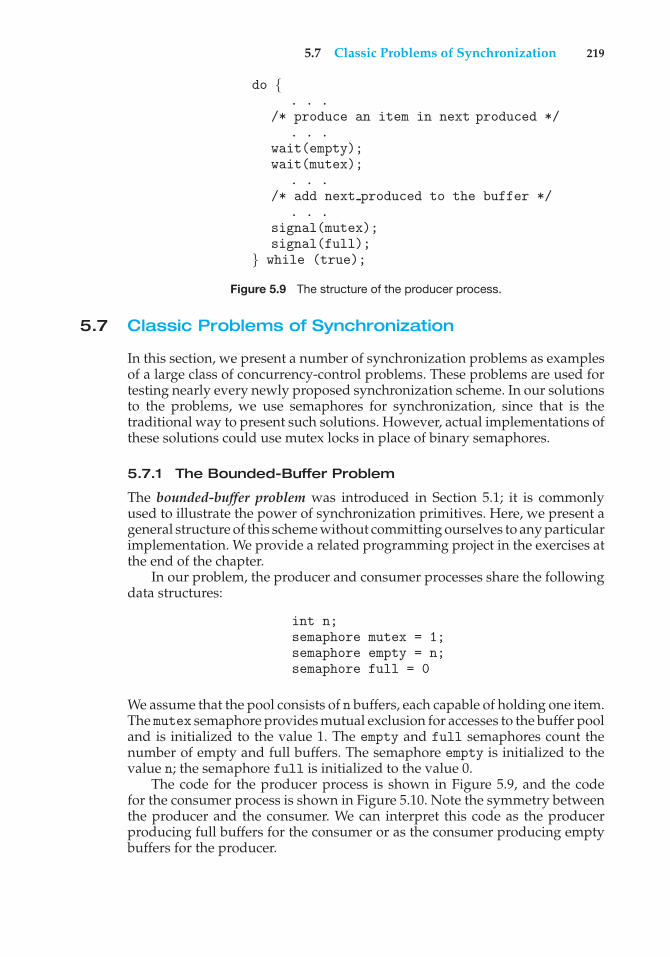
5.7 Classic Problems of Synchronization 219
do {. . .
/* produce an item in next produced */. . .
wait(empty);wait(mutex);
. . ./* add next produced to the buffer */
. . .signal(mutex);signal(full);
} while (true);
Figure 5.9 The structure of the producer process.
5.7 Classic Problems of Synchronization
In this section, we present a number of synchronization problems as examplesof a large class of concurrency-control problems. These problems are used fortesting nearly every newly proposed synchronization scheme. In our solutionsto the problems, we use semaphores for synchronization, since that is thetraditional way to present such solutions. However, actual implementations ofthese solutions could use mutex locks in place of binary semaphores.
5.7.1 The Bounded-Buffer Problem
The bounded-buffer problem was introduced in Section 5.1; it is commonlyused to illustrate the power of synchronization primitives. Here, we present ageneral structure of this scheme without committing ourselves to any particularimplementation. We provide a related programming project in the exercises atthe end of the chapter.
In our problem, the producer and consumer processes share the followingdata structures:
int n;semaphore mutex = 1;semaphore empty = n;semaphore full = 0
We assume that the pool consists of n buffers, each capable of holding one item.The mutex semaphore provides mutual exclusion for accesses to the buffer pooland is initialized to the value 1. The empty and full semaphores count thenumber of empty and full buffers. The semaphore empty is initialized to thevalue n; the semaphore full is initialized to the value 0.
The code for the producer process is shown in Figure 5.9, and the codefor the consumer process is shown in Figure 5.10. Note the symmetry betweenthe producer and the consumer. We can interpret this code as the producerproducing full buffers for the consumer or as the consumer producing emptybuffers for the producer.
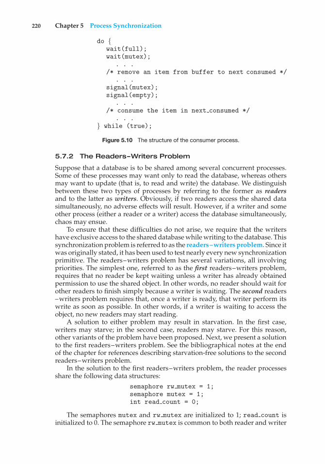
220 Chapter 5 Process Synchronization
do {wait(full);wait(mutex);
. . ./* remove an item from buffer to next consumed */
. . .signal(mutex);signal(empty);
. . ./* consume the item in next consumed */
. . .} while (true);
Figure 5.10 The structure of the consumer process.
5.7.2 The Readers–Writers Problem
Suppose that a database is to be shared among several concurrent processes.Some of these processes may want only to read the database, whereas othersmay want to update (that is, to read and write) the database. We distinguishbetween these two types of processes by referring to the former as readersand to the latter as writers. Obviously, if two readers access the shared datasimultaneously, no adverse effects will result. However, if a writer and someother process (either a reader or a writer) access the database simultaneously,chaos may ensue.
To ensure that these difficulties do not arise, we require that the writershave exclusive access to the shared database while writing to the database. Thissynchronization problem is referred to as the readers–writers problem. Since itwas originally stated, it has been used to test nearly every new synchronizationprimitive. The readers–writers problem has several variations, all involvingpriorities. The simplest one, referred to as the first readers–writers problem,requires that no reader be kept waiting unless a writer has already obtainedpermission to use the shared object. In other words, no reader should wait forother readers to finish simply because a writer is waiting. The second readers–writers problem requires that, once a writer is ready, that writer perform itswrite as soon as possible. In other words, if a writer is waiting to access theobject, no new readers may start reading.
A solution to either problem may result in starvation. In the first case,writers may starve; in the second case, readers may starve. For this reason,other variants of the problem have been proposed. Next, we present a solutionto the first readers–writers problem. See the bibliographical notes at the endof the chapter for references describing starvation-free solutions to the secondreaders–writers problem.
In the solution to the first readers–writers problem, the reader processesshare the following data structures:
semaphore rw mutex = 1;semaphore mutex = 1;int read count = 0;
The semaphores mutex and rw mutex are initialized to 1; read count isinitialized to 0. The semaphore rw mutex is common to both reader and writer
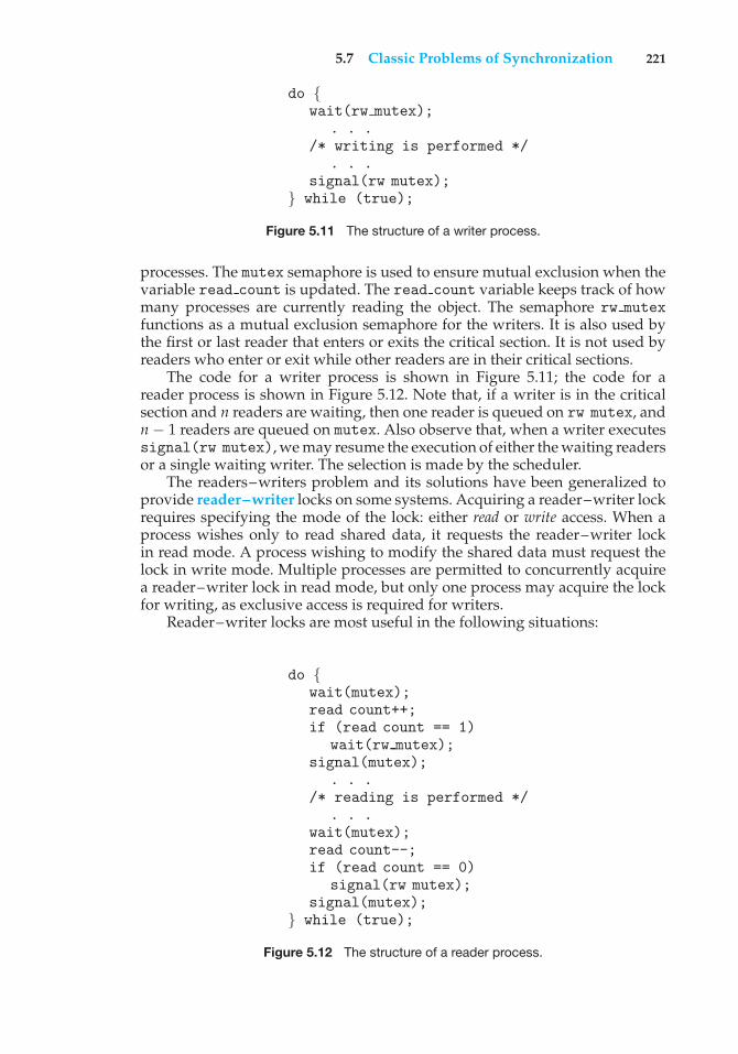
5.7 Classic Problems of Synchronization 221
do {wait(rw mutex);
. . ./* writing is performed */
. . .signal(rw mutex);
} while (true);
Figure 5.11 The structure of a writer process.
processes. The mutex semaphore is used to ensure mutual exclusion when thevariable read count is updated. The read count variable keeps track of howmany processes are currently reading the object. The semaphore rw mutexfunctions as a mutual exclusion semaphore for the writers. It is also used bythe first or last reader that enters or exits the critical section. It is not used byreaders who enter or exit while other readers are in their critical sections.
The code for a writer process is shown in Figure 5.11; the code for areader process is shown in Figure 5.12. Note that, if a writer is in the criticalsection and n readers are waiting, then one reader is queued on rw mutex, andn − 1 readers are queued on mutex. Also observe that, when a writer executessignal(rw mutex), we may resume the execution of either the waiting readersor a single waiting writer. The selection is made by the scheduler.
The readers–writers problem and its solutions have been generalized toprovide reader–writer locks on some systems. Acquiring a reader–writer lockrequires specifying the mode of the lock: either read or write access. When aprocess wishes only to read shared data, it requests the reader–writer lockin read mode. A process wishing to modify the shared data must request thelock in write mode. Multiple processes are permitted to concurrently acquirea reader–writer lock in read mode, but only one process may acquire the lockfor writing, as exclusive access is required for writers.
Reader–writer locks are most useful in the following situations:
do {wait(mutex);read count++;if (read count == 1)
wait(rw mutex);signal(mutex);
. . ./* reading is performed */
. . .wait(mutex);read count--;if (read count == 0)
signal(rw mutex);signal(mutex);
} while (true);
Figure 5.12 The structure of a reader process.
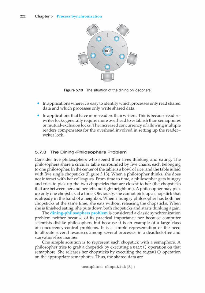
222 Chapter 5 Process Synchronization
RICE
Figure 5.13 The situation of the dining philosophers.
• In applications where it is easy to identify which processes only read shareddata and which processes only write shared data.
• In applications that have more readers than writers. This is because reader–writer locks generally require more overhead to establish than semaphoresor mutual-exclusion locks. The increased concurrency of allowing multiplereaders compensates for the overhead involved in setting up the reader–writer lock.
5.7.3 The Dining-Philosophers Problem
Consider five philosophers who spend their lives thinking and eating. Thephilosophers share a circular table surrounded by five chairs, each belongingto one philosopher. In the center of the table is a bowl of rice, and the table is laidwith five single chopsticks (Figure 5.13). When a philosopher thinks, she doesnot interact with her colleagues. From time to time, a philosopher gets hungryand tries to pick up the two chopsticks that are closest to her (the chopsticksthat are between her and her left and right neighbors). A philosopher may pickup only one chopstick at a time. Obviously, she cannot pick up a chopstick thatis already in the hand of a neighbor. When a hungry philosopher has both herchopsticks at the same time, she eats without releasing the chopsticks. Whenshe is finished eating, she puts down both chopsticks and starts thinking again.
The dining-philosophers problem is considered a classic synchronizationproblem neither because of its practical importance nor because computerscientists dislike philosophers but because it is an example of a large classof concurrency-control problems. It is a simple representation of the needto allocate several resources among several processes in a deadlock-free andstarvation-free manner.
One simple solution is to represent each chopstick with a semaphore. Aphilosopher tries to grab a chopstick by executing a wait() operation on thatsemaphore. She releases her chopsticks by executing the signal() operationon the appropriate semaphores. Thus, the shared data are
semaphore chopstick[5];
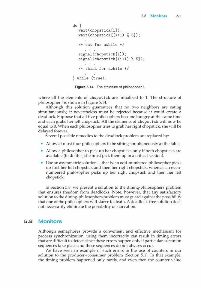
5.8 Monitors 223
do {wait(chopstick[i]);wait(chopstick[(i+1) % 5]);
. . ./* eat for awhile */
. . .signal(chopstick[i]);signal(chopstick[(i+1) % 5]);
. . ./* think for awhile */
. . .} while (true);
Figure 5.14 The structure of philosopher i.
where all the elements of chopstick are initialized to 1. The structure ofphilosopher i is shown in Figure 5.14.
Although this solution guarantees that no two neighbors are eatingsimultaneously, it nevertheless must be rejected because it could create adeadlock. Suppose that all five philosophers become hungry at the same timeand each grabs her left chopstick. All the elements of chopstick will now beequal to 0. When each philosopher tries to grab her right chopstick, she will bedelayed forever.
Several possible remedies to the deadlock problem are replaced by:
• Allow at most four philosophers to be sitting simultaneously at the table.
• Allow a philosopher to pick up her chopsticks only if both chopsticks areavailable (to do this, she must pick them up in a critical section).
• Use an asymmetric solution—that is, an odd-numbered philosopher picksup first her left chopstick and then her right chopstick, whereas an even-numbered philosopher picks up her right chopstick and then her leftchopstick.
In Section 5.8, we present a solution to the dining-philosophers problemthat ensures freedom from deadlocks. Note, however, that any satisfactorysolution to the dining-philosophers problem must guard against the possibilitythat one of the philosophers will starve to death. A deadlock-free solution doesnot necessarily eliminate the possibility of starvation.
5.8 Monitors
Although semaphores provide a convenient and effective mechanism forprocess synchronization, using them incorrectly can result in timing errorsthat are difficult to detect, since these errors happen only if particular executionsequences take place and these sequences do not always occur.
We have seen an example of such errors in the use of counters in oursolution to the producer–consumer problem (Section 5.1). In that example,the timing problem happened only rarely, and even then the counter value
224 Chapter 5 Process Synchronization
appeared to be reasonable—off by only 1. Nevertheless, the solution isobviously not an acceptable one. It is for this reason that semaphores wereintroduced in the first place.
Unfortunately, such timing errors can still occur when semaphores areused. To illustrate how, we review the semaphore solution to the critical-sectionproblem. All processes share a semaphore variable mutex, which is initializedto 1. Each process must executewait(mutex)before entering the critical sectionand signal(mutex) afterward. If this sequence is not observed, two processesmay be in their critical sections simultaneously. Next, we examine the variousdifficulties that may result. Note that these difficulties will arise even if asingle process is not well behaved. This situation may be caused by an honestprogramming error or an uncooperative programmer.
• Suppose that a process interchanges the order in which the wait() andsignal() operations on the semaphore mutex are executed, resulting inthe following execution:
signal(mutex);...
critical section...
wait(mutex);
In this situation, several processes may be executing in their critical sectionssimultaneously, violating the mutual-exclusion requirement. This errormay be discovered only if several processes are simultaneously activein their critical sections. Note that this situation may not always bereproducible.
• Suppose that a process replaces signal(mutex) with wait(mutex). Thatis, it executes
wait(mutex);...
critical section...
wait(mutex);
In this case, a deadlock will occur.
• Suppose that a process omits the wait(mutex), or the signal(mutex), orboth. In this case, either mutual exclusion is violated or a deadlock willoccur.
These examples illustrate that various types of errors can be generated easilywhen programmers use semaphores incorrectly to solve the critical-sectionproblem. Similar problems may arise in the other synchronization modelsdiscussed in Section 5.7.
To deal with such errors, researchers have developed high-level languageconstructs. In this section, we describe one fundamental high-level synchro-nization construct—the monitor type.
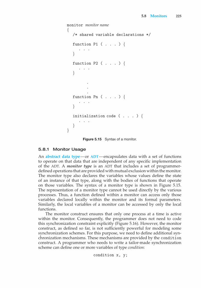
5.8 Monitors 225
monitor monitor name{
/* shared variable declarations */
function P1 ( . . . ) {. . .
}
function P2 ( . . . ) {. . .
}
.
.
.function Pn ( . . . ) {
. . .}
initialization code ( . . . ) {. . .
}}
Figure 5.15 Syntax of a monitor.
5.8.1 Monitor Usage
An abstract data type—or ADT—encapsulates data with a set of functionsto operate on that data that are independent of any specific implementationof the ADT. A monitor type is an ADT that includes a set of programmer-defined operations that are provided with mutual exclusion within the monitor.The monitor type also declares the variables whose values define the stateof an instance of that type, along with the bodies of functions that operateon those variables. The syntax of a monitor type is shown in Figure 5.15.The representation of a monitor type cannot be used directly by the variousprocesses. Thus, a function defined within a monitor can access only thosevariables declared locally within the monitor and its formal parameters.Similarly, the local variables of a monitor can be accessed by only the localfunctions.
The monitor construct ensures that only one process at a time is activewithin the monitor. Consequently, the programmer does not need to codethis synchronization constraint explicitly (Figure 5.16). However, the monitorconstruct, as defined so far, is not sufficiently powerful for modeling somesynchronization schemes. For this purpose, we need to define additional syn-chronization mechanisms. These mechanisms are provided by the conditionconstruct. A programmer who needs to write a tailor-made synchronizationscheme can define one or more variables of type condition:
condition x, y;
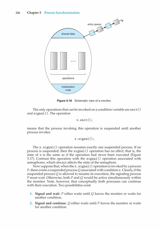
226 Chapter 5 Process Synchronization
entry queue
shared data
operations
initializationcode
. . .
Figure 5.16 Schematic view of a monitor.
The only operations that can be invoked on a condition variable are wait()and signal(). The operation
x.wait();
means that the process invoking this operation is suspended until anotherprocess invokes
x.signal();
The x.signal() operation resumes exactly one suspended process. If noprocess is suspended, then the signal() operation has no effect; that is, thestate of x is the same as if the operation had never been executed (Figure5.17). Contrast this operation with the signal() operation associated withsemaphores, which always affects the state of the semaphore.
Now suppose that, when the x.signal() operation is invoked by a processP, there exists a suspended process Q associated with condition x. Clearly, if thesuspended process Q is allowed to resume its execution, the signaling processP must wait. Otherwise, both P and Q would be active simultaneously withinthe monitor. Note, however, that conceptually both processes can continuewith their execution. Two possibilities exist:
1. Signal and wait. P either waits until Q leaves the monitor or waits foranother condition.
2. Signal and continue. Q either waits until P leaves the monitor or waitsfor another condition.
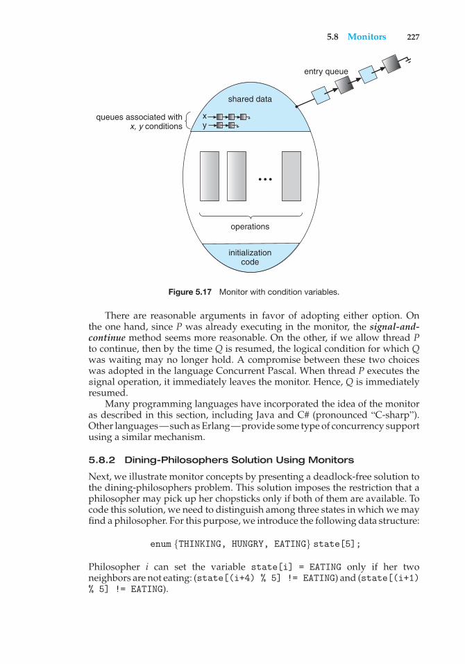
5.8 Monitors 227
operations
queues associated withx, y conditions
entry queue
shared data
x y
initializationcode
• • •
Figure 5.17 Monitor with condition variables.
There are reasonable arguments in favor of adopting either option. Onthe one hand, since P was already executing in the monitor, the signal-and-continue method seems more reasonable. On the other, if we allow thread Pto continue, then by the time Q is resumed, the logical condition for which Qwas waiting may no longer hold. A compromise between these two choiceswas adopted in the language Concurrent Pascal. When thread P executes thesignal operation, it immediately leaves the monitor. Hence, Q is immediatelyresumed.
Many programming languages have incorporated the idea of the monitoras described in this section, including Java and C# (pronounced “C-sharp”).Other languages—such as Erlang—provide some type of concurrency supportusing a similar mechanism.
5.8.2 Dining-Philosophers Solution Using Monitors
Next, we illustrate monitor concepts by presenting a deadlock-free solution tothe dining-philosophers problem. This solution imposes the restriction that aphilosopher may pick up her chopsticks only if both of them are available. Tocode this solution, we need to distinguish among three states in which we mayfind a philosopher. For this purpose, we introduce the following data structure:
enum {THINKING, HUNGRY, EATING} state[5];
Philosopher i can set the variable state[i] = EATING only if her twoneighbors are not eating: (state[(i+4) % 5] != EATING) and (state[(i+1)% 5] != EATING).
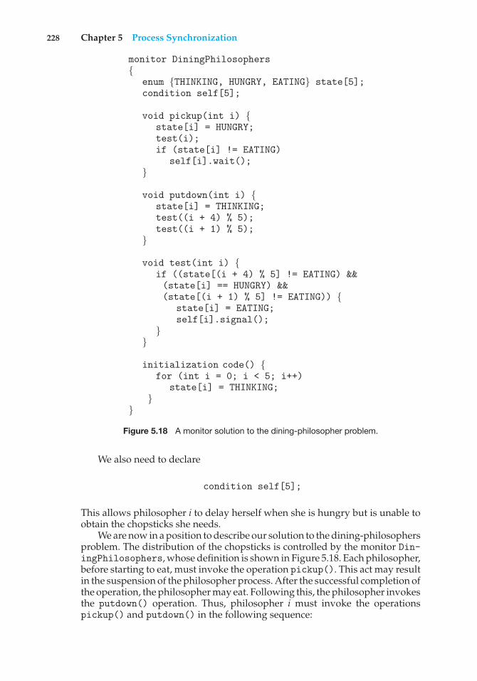
228 Chapter 5 Process Synchronization
monitor DiningPhilosophers{
enum {THINKING, HUNGRY, EATING} state[5];condition self[5];
void pickup(int i) {state[i] = HUNGRY;test(i);if (state[i] != EATING)
self[i].wait();}
void putdown(int i) {state[i] = THINKING;test((i + 4) % 5);test((i + 1) % 5);
}
void test(int i) {if ((state[(i + 4) % 5] != EATING) &&(state[i] == HUNGRY) &&(state[(i + 1) % 5] != EATING)) {
state[i] = EATING;self[i].signal();
}}
initialization code() {for (int i = 0; i < 5; i++)
state[i] = THINKING;}
}
Figure 5.18 A monitor solution to the dining-philosopher problem.
We also need to declare
condition self[5];
This allows philosopher i to delay herself when she is hungry but is unable toobtain the chopsticks she needs.
We are now in a position to describe our solution to the dining-philosophersproblem. The distribution of the chopsticks is controlled by the monitor Din-ingPhilosophers, whose definition is shown in Figure 5.18. Each philosopher,before starting to eat, must invoke the operation pickup(). This act may resultin the suspension of the philosopher process. After the successful completion ofthe operation, the philosopher may eat. Following this, the philosopher invokesthe putdown() operation. Thus, philosopher i must invoke the operationspickup() and putdown() in the following sequence:
5.8 Monitors 229
DiningPhilosophers.pickup(i);...eat...
DiningPhilosophers.putdown(i);
It is easy to show that this solution ensures that no two neighbors are eatingsimultaneously and that no deadlocks will occur. We note, however, that it ispossible for a philosopher to starve to death. We do not present a solution tothis problem but rather leave it as an exercise for you.
5.8.3 Implementing a Monitor Using Semaphores
We now consider a possible implementation of the monitor mechanism usingsemaphores. For each monitor, a semaphore mutex (initialized to 1) is provided.A process must execute wait(mutex) before entering the monitor and mustexecute signal(mutex) after leaving the monitor.
Since a signaling process must wait until the resumed process either leavesor waits, an additional semaphore, next, is introduced, initialized to 0. Thesignaling processes can use next to suspend themselves. An integer variablenext count is also provided to count the number of processes suspended onnext. Thus, each external function F is replaced by
wait(mutex);...
body of F...
if (next count > 0)signal(next);
elsesignal(mutex);
Mutual exclusion within a monitor is ensured.We can now describe how condition variables are implemented as well.
For each condition x, we introduce a semaphore x sem and an integervariable x count, both initialized to 0. The operation x.wait() can now beimplemented as
x count++;if (next count > 0)
signal(next);else
signal(mutex);wait(x sem);x count--;
The operation x.signal() can be implemented as
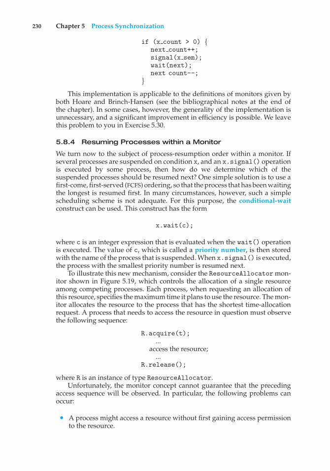
230 Chapter 5 Process Synchronization
if (x count > 0) {next count++;signal(x sem);wait(next);next count--;
}
This implementation is applicable to the definitions of monitors given byboth Hoare and Brinch-Hansen (see the bibliographical notes at the end ofthe chapter). In some cases, however, the generality of the implementation isunnecessary, and a significant improvement in efficiency is possible. We leavethis problem to you in Exercise 5.30.
5.8.4 Resuming Processes within a Monitor
We turn now to the subject of process-resumption order within a monitor. Ifseveral processes are suspended on condition x, and an x.signal() operationis executed by some process, then how do we determine which of thesuspended processes should be resumed next? One simple solution is to use afirst-come, first-served (FCFS) ordering, so that the process that has been waitingthe longest is resumed first. In many circumstances, however, such a simplescheduling scheme is not adequate. For this purpose, the conditional-waitconstruct can be used. This construct has the form
x.wait(c);
where c is an integer expression that is evaluated when the wait() operationis executed. The value of c, which is called a priority number, is then storedwith the name of the process that is suspended. When x.signal() is executed,the process with the smallest priority number is resumed next.
To illustrate this new mechanism, consider the ResourceAllocator mon-itor shown in Figure 5.19, which controls the allocation of a single resourceamong competing processes. Each process, when requesting an allocation ofthis resource, specifies the maximum time it plans to use the resource. The mon-itor allocates the resource to the process that has the shortest time-allocationrequest. A process that needs to access the resource in question must observethe following sequence:
R.acquire(t);...
access the resource;...
R.release();
where R is an instance of type ResourceAllocator.Unfortunately, the monitor concept cannot guarantee that the preceding
access sequence will be observed. In particular, the following problems canoccur:
• A process might access a resource without first gaining access permissionto the resource.
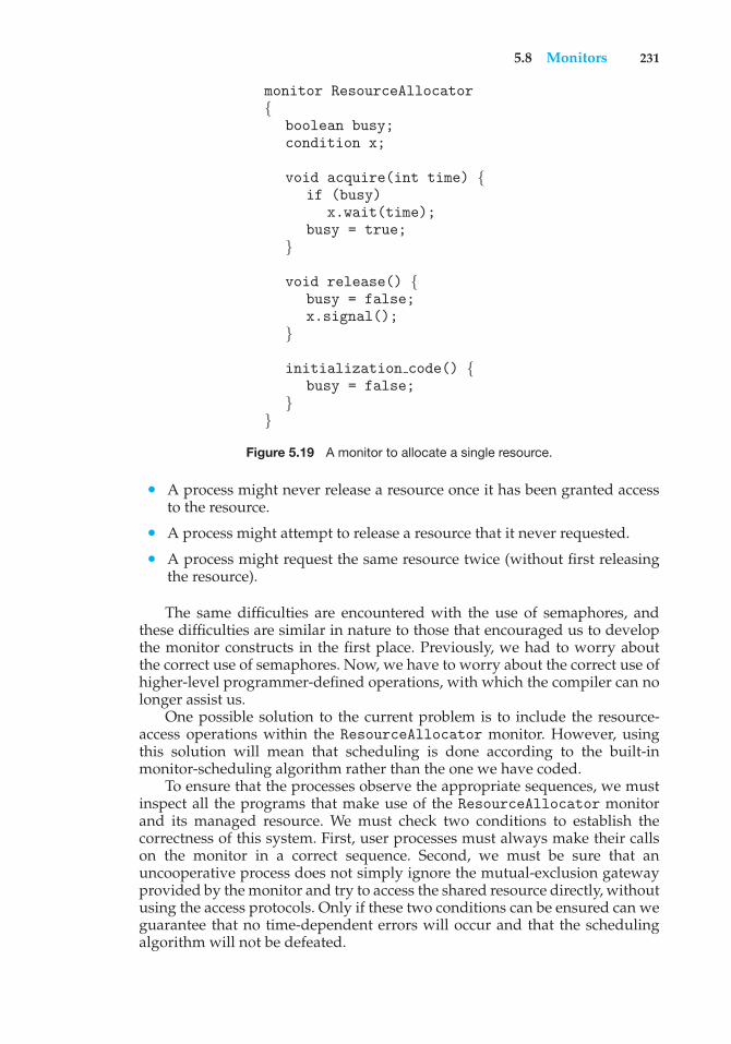
5.8 Monitors 231
monitor ResourceAllocator{
boolean busy;condition x;
void acquire(int time) {if (busy)
x.wait(time);busy = true;
}
void release() {busy = false;x.signal();
}
initialization code() {busy = false;
}}
Figure 5.19 A monitor to allocate a single resource.
• A process might never release a resource once it has been granted accessto the resource.
• A process might attempt to release a resource that it never requested.
• A process might request the same resource twice (without first releasingthe resource).
The same difficulties are encountered with the use of semaphores, andthese difficulties are similar in nature to those that encouraged us to developthe monitor constructs in the first place. Previously, we had to worry aboutthe correct use of semaphores. Now, we have to worry about the correct use ofhigher-level programmer-defined operations, with which the compiler can nolonger assist us.
One possible solution to the current problem is to include the resource-access operations within the ResourceAllocator monitor. However, usingthis solution will mean that scheduling is done according to the built-inmonitor-scheduling algorithm rather than the one we have coded.
To ensure that the processes observe the appropriate sequences, we mustinspect all the programs that make use of the ResourceAllocator monitorand its managed resource. We must check two conditions to establish thecorrectness of this system. First, user processes must always make their callson the monitor in a correct sequence. Second, we must be sure that anuncooperative process does not simply ignore the mutual-exclusion gatewayprovided by the monitor and try to access the shared resource directly, withoutusing the access protocols. Only if these two conditions can be ensured can weguarantee that no time-dependent errors will occur and that the schedulingalgorithm will not be defeated.
232 Chapter 5 Process Synchronization
JAVA MONITORS
Java provides a monitor-like concurrency mechanism for thread synchro-nization. Every object in Java has associated with it a single lock. When amethod is declared to be synchronized, calling the method requires owningthe lock for the object. We declare a synchronized method by placing thesynchronized keyword in the method definition. The following definessafeMethod() as synchronized, for example:
public class SimpleClass {. . .public synchronized void safeMethod() {. . ./* Implementation of safeMethod() */. . .
}}
Next, we create an object instance of SimpleClass, such as the following:
SimpleClass sc = new SimpleClass();
Invoking sc.safeMethod() method requires owning the lock on the objectinstance sc. If the lock is already owned by another thread, the thread callingthe synchronizedmethod blocks and is placed in the entry set for the object’slock. The entry set represents the set of threads waiting for the lock to becomeavailable. If the lock is available when a synchronized method is called,the calling thread becomes the owner of the object’s lock and can enter themethod. The lock is released when the thread exits the method. A thread fromthe entry set is then selected as the new owner of the lock.
Java also provides wait() and notify() methods, which are similar infunction to the wait() and signal() statements for a monitor. The JavaAPI provides support for semaphores, condition variables, and mutex locks(among other concurrency mechanisms) in the java.util.concurrentpackage.
Although this inspection may be possible for a small, static system, it isnot reasonable for a large system or a dynamic system. This access-controlproblem can be solved only through the use of the additional mechanisms thatare described in Chapter 14.
5.9 Synchronization Examples
We next describe the synchronization mechanisms provided by the Windows,Linux, and Solaris operating systems, as well as the Pthreads API. We havechosen these three operating systems because they provide good examples ofdifferent approaches to synchronizing the kernel, and we have included the
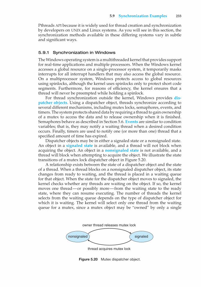
5.9 Synchronization Examples 233
Pthreads API because it is widely used for thread creation and synchronizationby developers on UNIX and Linux systems. As you will see in this section, thesynchronization methods available in these differing systems vary in subtleand significant ways.
5.9.1 Synchronization in Windows
The Windows operating system is a multithreaded kernel that provides supportfor real-time applications and multiple processors. When the Windows kernelaccesses a global resource on a single-processor system, it temporarily masksinterrupts for all interrupt handlers that may also access the global resource.On a multiprocessor system, Windows protects access to global resourcesusing spinlocks, although the kernel uses spinlocks only to protect short codesegments. Furthermore, for reasons of efficiency, the kernel ensures that athread will never be preempted while holding a spinlock.
For thread synchronization outside the kernel, Windows provides dis-patcher objects. Using a dispatcher object, threads synchronize according toseveral different mechanisms, including mutex locks, semaphores, events, andtimers. The system protects shared data by requiring a thread to gain ownershipof a mutex to access the data and to release ownership when it is finished.Semaphores behave as described in Section 5.6. Events are similar to conditionvariables; that is, they may notify a waiting thread when a desired conditionoccurs. Finally, timers are used to notify one (or more than one) thread that aspecified amount of time has expired.
Dispatcher objects may be in either a signaled state or a nonsignaled state.An object in a signaled state is available, and a thread will not block whenacquiring the object. An object in a nonsignaled state is not available, and athread will block when attempting to acquire the object. We illustrate the statetransitions of a mutex lock dispatcher object in Figure 5.20.
A relationship exists between the state of a dispatcher object and the stateof a thread. When a thread blocks on a nonsignaled dispatcher object, its statechanges from ready to waiting, and the thread is placed in a waiting queuefor that object. When the state for the dispatcher object moves to signaled, thekernel checks whether any threads are waiting on the object. If so, the kernelmoves one thread—or possibly more—from the waiting state to the readystate, where they can resume executing. The number of threads the kernelselects from the waiting queue depends on the type of dispatcher object forwhich it is waiting. The kernel will select only one thread from the waitingqueue for a mutex, since a mutex object may be “owned” by only a single
nonsignaled signaled
owner thread releases mutex lock
thread acquires mutex lock
Figure 5.20 Mutex dispatcher object.
234 Chapter 5 Process Synchronization
thread. For an event object, the kernel will select all threads that are waitingfor the event.
We can use a mutex lock as an illustration of dispatcher objects andthread states. If a thread tries to acquire a mutex dispatcher object that is in anonsignaled state, that thread will be suspended and placed in a waiting queuefor the mutex object. When the mutex moves to the signaled state (becauseanother thread has released the lock on the mutex), the thread waiting at thefront of the queue will be moved from the waiting state to the ready state andwill acquire the mutex lock.
A critical-section object is a user-mode mutex that can often be acquiredand released without kernel intervention. On a multiprocessor system, acritical-section object first uses a spinlock while waiting for the other thread torelease the object. If it spins too long, the acquiring thread will then allocate akernel mutex and yield its CPU. Critical-section objects are particularly efficientbecause the kernel mutex is allocated only when there is contention for theobject. In practice, there is very little contention, so the savings are significant.
We provide a programming project at the end of this chapter that usesmutex locks and semaphores in the Windows API.
5.9.2 Synchronization in Linux
Prior to Version 2.6, Linux was a nonpreemptive kernel, meaning that a processrunning in kernel mode could not be preempted—even if a higher-priorityprocess became available to run. Now, however, the Linux kernel is fullypreemptive, so a task can be preempted when it is running in the kernel.
Linux provides several different mechanisms for synchronization in thekernel. As most computer architectures provide instructions for atomic ver-sions of simple math operations, the simplest synchronization technique withinthe Linux kernel is an atomic integer, which is represented using the opaquedata type atomic t. As the name implies, all math operations using atomicintegers are performed without interruption. The following code illustratesdeclaring an atomic integer counter and then performing various atomicoperations:
atomic t counter;int value;
atomic set(&counter,5); /* counter = 5 */atomic add(10, &counter); /* counter = counter + 10 */atomic sub(4, &counter); /* counter = counter - 4 */atomic inc(&counter); /* counter = counter + 1 */value = atomic read(&counter); /* value = 12 */
Atomic integers are particularly efficient in situations where an integer variable—such as a counter—needs to be updated, since atomic operations do notrequire the overhead of locking mechanisms. However, their usage is limitedto these sorts of scenarios. In situations where there are several variablescontributing to a possible race condition, more sophisticated locking toolsmust be used.
Mutex locks are available in Linux for protecting critical sections within thekernel. Here, a task must invoke the mutex lock() function prior to entering
5.9 Synchronization Examples 235
a critical section and the mutex unlock() function after exiting the criticalsection. If the mutex lock is unavailable, a task calling mutex lock() is put intoa sleep state and is awakened when the lock’s owner invokes mutex unlock().
Linux also provides spinlocks and semaphores (as well as reader–writerversions of these two locks) for locking in the kernel. On SMP machines, thefundamental locking mechanism is a spinlock, and the kernel is designedso that the spinlock is held only for short durations. On single-processormachines, such as embedded systems with only a single processing core,spinlocks are inappropriate for use and are replaced by enabling and disablingkernel preemption. That is, on single-processor systems, rather than holding aspinlock, the kernel disables kernel preemption; and rather than releasing thespinlock, it enables kernel preemption. This is summarized below:
single processor multiple processors
Acquire spin lock.
Release spin lock.
Disable kernel preemption.
Enable kernel preemption.
Linux uses an interesting approach to disable and enable kernel preemp-tion. It provides two simple system calls—preempt disable() and pre-empt enable()—for disabling and enabling kernel preemption. The kernelis not preemptible, however, if a task running in the kernel is holding a lock.To enforce this rule, each task in the system has a thread-info structurecontaining a counter, preempt count, to indicate the number of locks beingheld by the task. When a lock is acquired, preempt count is incremented. Itis decremented when a lock is released. If the value of preempt count forthe task currently running in the kernel is greater than 0, it is not safe topreempt the kernel, as this task currently holds a lock. If the count is 0, thekernel can safely be interrupted (assuming there are no outstanding calls topreempt disable()).
Spinlocks—along with enabling and disabling kernel preemption—areused in the kernel only when a lock (or disabling kernel preemption) is heldfor a short duration. When a lock must be held for a longer period, semaphoresor mutex locks are appropriate for use.
5.9.3 Synchronization in Solaris
To control access to critical sections, Solaris provides adaptive mutex locks,condition variables, semaphores, reader–writer locks, and turnstiles. Solarisimplements semaphores and condition variables essentially as they are pre-sented in Sections 5.6 and 5.7 In this section, we describe adaptive mutex locks,reader–writer locks, and turnstiles.
An adaptive mutex protects access to every critical data item. On amultiprocessor system, an adaptive mutex starts as a standard semaphoreimplemented as a spinlock. If the data are locked and therefore already in use,the adaptive mutex does one of two things. If the lock is held by a thread thatis currently running on another CPU, the thread spins while waiting for thelock to become available, because the thread holding the lock is likely to finishsoon. If the thread holding the lock is not currently in run state, the thread
236 Chapter 5 Process Synchronization
blocks, going to sleep until it is awakened by the release of the lock. It is putto sleep so that it will not spin while waiting, since the lock will not be freedvery soon. A lock held by a sleeping thread is likely to be in this category. Ona single-processor system, the thread holding the lock is never running if thelock is being tested by another thread, because only one thread can run at atime. Therefore, on this type of system, threads always sleep rather than spinif they encounter a lock.
Solaris uses the adaptive-mutex method to protect only data that areaccessed by short code segments. That is, a mutex is used if a lock will beheld for less than a few hundred instructions. If the code segment is longerthan that, the spin-waiting method is exceedingly inefficient. For these longercode segments, condition variables and semaphores are used. If the desiredlock is already held, the thread issues a wait and sleeps. When a thread freesthe lock, it issues a signal to the next sleeping thread in the queue. The extracost of putting a thread to sleep and waking it, and of the associated contextswitches, is less than the cost of wasting several hundred instructions waitingin a spinlock.
Reader–writer locks are used to protect data that are accessed frequentlybut are usually accessed in a read-only manner. In these circumstances,reader–writer locks are more efficient than semaphores, because multiplethreads can read data concurrently, whereas semaphores always serialize accessto the data. Reader–writer locks are relatively expensive to implement, so againthey are used only on long sections of code.
Solaris uses turnstiles to order the list of threads waiting to acquire eitheran adaptive mutex or a reader–writer lock. A turnstile is a queue structurecontaining threads blocked on a lock. For example, if one thread currentlyowns the lock for a synchronized object, all other threads trying to acquire thelock will block and enter the turnstile for that lock. When the lock is released,the kernel selects a thread from the turnstile as the next owner of the lock.Each synchronized object with at least one thread blocked on the object’s lockrequires a separate turnstile. However, rather than associating a turnstile witheach synchronized object, Solaris gives each kernel thread its own turnstile.Because a thread can be blocked only on one object at a time, this is moreefficient than having a turnstile for each object.
The turnstile for the first thread to block on a synchronized object becomesthe turnstile for the object itself. Threads subsequently blocking on the lock willbe added to this turnstile. When the initial thread ultimately releases the lock,it gains a new turnstile from a list of free turnstiles maintained by the kernel. Toprevent a priority inversion, turnstiles are organized according to a priority-inheritance protocol. This means that if a lower-priority thread currently holdsa lock on which a higher-priority thread is blocked, the thread with the lowerpriority will temporarily inherit the priority of the higher-priority thread. Uponreleasing the lock, the thread will revert to its original priority.
Note that the locking mechanisms used by the kernel are implementedfor user-level threads as well, so the same types of locks are available insideand outside the kernel. A crucial implementation difference is the priority-inheritance protocol. Kernel-locking routines adhere to the kernel priority-inheritance methods used by the scheduler, as described in Section 5.6.4.User-level thread-locking mechanisms do not provide this functionality.
5.9 Synchronization Examples 237
To optimize Solaris performance, developers have refined and fine-tunedthe locking methods. Because locks are used frequently and typically are usedfor crucial kernel functions, tuning their implementation and use can producegreat performance gains.
5.9.4 Pthreads Synchronization
Although the locking mechanisms used in Solaris are available to user-levelthreads as well as kernel threads, basically the synchronization methodsdiscussed thus far pertain to synchronization within the kernel. In contrast,the Pthreads API is available for programmers at the user level and is not partof any particular kernel. This API provides mutex locks, condition variables,and read–write locks for thread synchronization.
Mutex locks represent the fundamental synchronization technique usedwith Pthreads. A mutex lock is used to protect critical sections of code—thatis, a thread acquires the lock before entering a critical section and releases itupon exiting the critical section. Pthreads uses the pthread mutex t data typefor mutex locks. A mutex is created with the pthread mutex init() function.The first parameter is a pointer to the mutex. By passing NULL as a secondparameter, we initialize the mutex to its default attributes. This is illustratedbelow:
#include <pthread.h>
pthread mutex t mutex;
/* create the mutex lock */pthread mutex init(&mutex,NULL);
The mutex is acquired and released with the pthread mutex lock()and pthread mutex unlock() functions. If the mutex lock is unavailablewhen pthread mutex lock() is invoked, the calling thread is blocked untilthe owner invokes pthread mutex unlock(). The following code illustratesprotecting a critical section with mutex locks:
/* acquire the mutex lock */pthread mutex lock(&mutex);
/* critical section */
/* release the mutex lock */pthread mutex unlock(&mutex);
All mutex functions return a value of 0 with correct operation; if an erroroccurs, these functions return a nonzero error code. Condition variables andread–write locks behave similarly to the way they are described in Sections 5.8and 5.7.2, respectively.
Many systems that implement Pthreads also provide semaphores, althoughsemaphores are not part of the Pthreads standard and instead belong to thePOSIX SEM extension. POSIX specifies two types of semaphores—named and
238 Chapter 5 Process Synchronization
unnamed. The fundamental distinction between the two is that a namedsemaphore has an actual name in the file system and can be shared bymultiple unrelated processes. Unnamed semaphores can be used only bythreads belonging to the same process. In this section, we describe unnamedsemaphores.
The code below illustrates the sem init() function for creating andinitializing an unnamed semaphore:
#include <semaphore.h>sem t sem;
/* Create the semaphore and initialize it to 1 */sem init(&sem, 0, 1);
The sem init() function is passed three parameters:
1. A pointer to the semaphore
2. A flag indicating the level of sharing
3. The semaphore’s initial value
In this example, by passing the flag 0, we are indicating that this semaphore canbe shared only by threads belonging to the process that created the semaphore.A nonzero value would allow other processes to access the semaphore as well.In addition, we initialize the semaphore to the value 1.
In Section 5.6, we described the classical wait() and signal() semaphoreoperations. Pthreads names these operations sem wait() and sem post(),respectively. The following code sample illustrates protecting a critical sectionusing the semaphore created above:
/* acquire the semaphore */sem wait(&sem);
/* critical section */
/* release the semaphore */sem post(&sem);
Just like mutex locks, all semaphore functions return 0 when successful, andnonzero when an error condition occurs.
There are other extensions to the Pthreads API — including spinlocks —but it is important to note that not all extensions are considered portable fromone implementation to another. We provide several programming problemsand projects at the end of this chapter that use Pthreads mutex locks andcondition variables as well as POSIX semaphores.
5.10 Alternative Approaches
With the emergence of multicore systems has come increased pressure todevelop multithreaded applications that take advantage of multiple processing
5.10 Alternative Approaches 239
cores. However, multithreaded applications present an increased risk of raceconditions and deadlocks. Traditionally, techniques such as mutex locks,semaphores, and monitors have been used to address these issues, but as thenumber of processing cores increases, it becomes increasingly difficult to designmultithreaded applications that are free from race conditions and deadlocks.
In this section, we explore various features provided in both program-ming languages and hardware that support designing thread-safe concurrentapplications.
5.10.1 Transactional Memory
Quite often in computer science, ideas from one area of study can be usedto solve problems in other areas. The concept of transactional memoryoriginated in database theory, for example, yet it provides a strategy for processsynchronization. A memory transaction is a sequence of memory read–writeoperations that are atomic. If all operations in a transaction are completed, thememory transaction is committed. Otherwise, the operations must be abortedand rolled back. The benefits of transactional memory can be obtained throughfeatures added to a programming language.
Consider an example. Suppose we have a functionupdate() that modifiesshared data. Traditionally, this function would be written using mutex locks(or semaphores) such as the following:
void update (){
acquire();
/* modify shared data */
release();}
However, using synchronization mechanisms such as mutex locks andsemaphores involves many potential problems, including deadlock. Addition-ally, as the number of threads increases, traditional locking scales less well,because the level of contention among threads for lock ownership becomesvery high.
As an alternative to traditional locking methods, new features that takeadvantage of transactional memory can be added to a programming language.In our example, suppose we add the construct atomic{S}, which ensuresthat the operations in S execute as a transaction. This allows us to rewrite theupdate() function as follows:
void update (){
atomic {/* modify shared data */
}}
The advantage of using such a mechanism rather than locks is thatthe transactional memory system—not the developer—is responsible for
240 Chapter 5 Process Synchronization
guaranteeing atomicity. Additionally, because no locks are involved, deadlockis not possible. Furthermore, a transactional memory system can identify whichstatements in atomic blocks can be executed concurrently, such as concurrentread access to a shared variable. It is, of course, possible for a programmerto identify these situations and use reader–writer locks, but the task becomesincreasingly difficult as the number of threads within an application grows.
Transactional memory can be implemented in either software or hardware.Software transactional memory (STM), as the name suggests, implementstransactional memory exclusively in software—no special hardware is needed.STM works by inserting instrumentation code inside transaction blocks. Thecode is inserted by a compiler and manages each transaction by examiningwhere statements may run concurrently and where specific low-level lockingis required. Hardware transactional memory (HTM) uses hardware cachehierarchies and cache coherency protocols to manage and resolve conflictsinvolving shared data residing in separate processors’ caches. HTM requires nospecial code instrumentation and thus has less overhead than STM. However,HTM does require that existing cache hierarchies and cache coherency protocolsbe modified to support transactional memory.
Transactional memory has existed for several years without widespreadimplementation. However, the growth of multicore systems and the associ-ated emphasis on concurrent and parallel programming have prompted asignificant amount of research in this area on the part of both academics andcommercial software and hardware vendors.
5.10.2 OpenMP
In Section 4.5.2, we provided an overview of OpenMP and its support of parallelprogramming in a shared-memory environment. Recall that OpenMP includesa set of compiler directives and an API. Any code following the compilerdirective #pragma omp parallel is identified as a parallel region and isperformed by a number of threads equal to the number of processing coresin the system. The advantage of OpenMP (and similar tools) is that threadcreation and management are handled by the OpenMP library and are not theresponsibility of application developers.
Along with its #pragma omp parallel compiler directive, OpenMP pro-vides the compiler directive #pragma omp critical, which specifies the coderegion following the directive as a critical section in which only one thread maybe active at a time. In this way, OpenMP provides support for ensuring thatthreads do not generate race conditions.
As an example of the use of the critical-section compiler directive, firstassume that the shared variable counter can be modified in the update()function as follows:
void update(int value){
counter += value;}
If the update() function can be part of—or invoked from—a parallel region,a race condition is possible on the variable counter.
5.10 Alternative Approaches 241
The critical-section compiler directive can be used to remedy this racecondition and is coded as follows:
void update(int value){
#pragma omp critical{
counter += value;}
}
The critical-section compiler directive behaves much like a binary semaphoreor mutex lock, ensuring that only one thread at a time is active in the criticalsection. If a thread attempts to enter a critical section when another thread iscurrently active in that section (that is, owns the section), the calling thread isblocked until the owner thread exits. If multiple critical sections must be used,each critical section can be assigned a separate name, and a rule can specifythat no more than one thread may be active in a critical section of the samename simultaneously.
An advantage of using the critical-section compiler directive in OpenMPis that it is generally considered easier to use than standard mutex locks.However, a disadvantage is that application developers must still identifypossible race conditions and adequately protect shared data using the compilerdirective. Additionally, because the critical-section compiler directive behavesmuch like a mutex lock, deadlock is still possible when two or more criticalsections are identified.
5.10.3 Functional Programming Languages
Most well-known programming languages—such as C, C++, Java, and C#—are known as imperative (or procedural) languages. Imperative languages areused for implementing algorithms that are state-based. In these languages, theflow of the algorithm is crucial to its correct operation, and state is representedwith variables and other data structures. Of course, program state is mutable,as variables may be assigned different values over time.
With the current emphasis on concurrent and parallel programming formulticore systems, there has been greater focus on functional programminglanguages, which follow a programming paradigm much different fromthat offered by imperative languages. The fundamental difference betweenimperative and functional languages is that functional languages do notmaintain state. That is, once a variable has been defined and assigned a value, itsvalue is immutable—it cannot change. Because functional languages disallowmutable state, they need not be concerned with issues such as race conditionsand deadlocks. Essentially, most of the problems addressed in this chapter arenonexistent in functional languages.
Several functional languages are presently in use, and we briefly mentiontwo of them here: Erlang and Scala. The Erlang language has gained significantattention because of its support for concurrency and the ease with which itcan be used to develop applications that run on parallel systems. Scala is afunctional language that is also object-oriented. In fact, much of the syntax ofScala is similar to the popular object-oriented languages Java and C#. Readers
242 Chapter 5 Process Synchronization
interested in Erlang and Scala, and in further details about functional languagesin general, are encouraged to consult the bibliography at the end of this chapterfor additional references.
5.11 Summary
Given a collection of cooperating sequential processes that share data, mutualexclusion must be provided to ensure that a critical section of code is used byonly one process or thread at a time. Typically, computer hardware providesseveral operations that ensure mutual exclusion. However, such hardware-based solutions are too complicated for most developers to use. Mutex locksand semaphores overcome this obstacle. Both tools can be used to solve varioussynchronization problems and can be implemented efficiently, especially ifhardware support for atomic operations is available.
Various synchronization problems (such as the bounded-buffer problem,the readers–writers problem, and the dining-philosophers problem) are impor-tant mainly because they are examples of a large class of concurrency-controlproblems. These problems are used to test nearly every newly proposedsynchronization scheme.
The operating system must provide the means to guard against timingerrors, and several language constructs have been proposed to deal withthese problems. Monitors provide a synchronization mechanism for sharingabstract data types. A condition variable provides a method by which a monitorfunction can block its execution until it is signaled to continue.
Operating systems also provide support for synchronization. For example,Windows, Linux, and Solaris provide mechanisms such as semaphores, mutexlocks, spinlocks, and condition variables to control access to shared data. ThePthreads API provides support for mutex locks and semaphores, as well ascondition variables.
Several alternative approaches focus on synchronization for multicoresystems. One approach uses transactional memory, which may address syn-chronization issues using either software or hardware techniques. Anotherapproach uses the compiler extensions offered by OpenMP. Finally, func-tional programming languages address synchronization issues by disallowingmutability.
Practice Exercises
5.1 In Section 5.4, we mentioned that disabling interrupts frequently canaffect the system’s clock. Explain why this can occur and how sucheffects can be minimized.
5.2 Explain why Windows, Linux, and Solaris implement multiple lockingmechanisms. Describe the circumstances under which they use spin-locks, mutex locks, semaphores, adaptive mutex locks, and conditionvariables. In each case, explain why the mechanism is needed.
Exercises 243
5.3 What is the meaning of the term busy waiting? What other kinds ofwaiting are there in an operating system? Can busy waiting be avoidedaltogether? Explain your answer.
5.4 Explain why spinlocks are not appropriate for single-processor systemsyet are often used in multiprocessor systems.
5.5 Show that, if the wait() and signal() semaphore operations are notexecuted atomically, then mutual exclusion may be violated.
5.6 Illustrate how a binary semaphore can be used to implement mutualexclusion among n processes.
Exercises
5.7 Race conditions are possible in many computer systems. Consider abanking system that maintains an account balance with two functions:deposit(amount) and withdraw(amount). These two functions arepassed the amount that is to be deposited or withdrawn from the bankaccount balance. Assume that a husband and wife share a bank account.Concurrently, the husband calls the withdraw() function and the wifecalls deposit(). Describe how a race condition is possible and whatmight be done to prevent the race condition from occurring.
5.8 The first known correct software solution to the critical-section problemfor two processes was developed by Dekker. The two processes, P0 andP1, share the following variables:
boolean flag[2]; /* initially false */int turn;
The structure of process Pi (i == 0 or 1) is shown in Figure 5.21. Theother process is Pj (j == 1 or 0). Prove that the algorithm satisfies allthree requirements for the critical-section problem.
5.9 The first known correct software solution to the critical-section problemfor n processes with a lower bound on waiting of n − 1 turns waspresented by Eisenberg and McGuire. The processes share the followingvariables:
enum pstate {idle, want in, in cs};pstate flag[n];int turn;
All the elements of flag are initially idle. The initial value of turn isimmaterial (between 0 and n-1). The structure of process Pi is shown inFigure 5.22. Prove that the algorithm satisfies all three requirements forthe critical-section problem.
5.10 Explain why implementing synchronization primitives by disablinginterrupts is not appropriate in a single-processor system if the syn-chronization primitives are to be used in user-level programs.
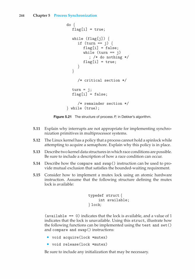
244 Chapter 5 Process Synchronization
do {flag[i] = true;
while (flag[j]) {if (turn == j) {
flag[i] = false;while (turn == j)
; /* do nothing */flag[i] = true;
}}
/* critical section */
turn = j;flag[i] = false;
/* remainder section */} while (true);
Figure 5.21 The structure of process Pi in Dekker’s algorithm.
5.11 Explain why interrupts are not appropriate for implementing synchro-nization primitives in multiprocessor systems.
5.12 The Linux kernel has a policy that a process cannot hold a spinlock whileattempting to acquire a semaphore. Explain why this policy is in place.
5.13 Describe two kernel data structures in which race conditions are possible.Be sure to include a description of how a race condition can occur.
5.14 Describe how the compare and swap() instruction can be used to pro-vide mutual exclusion that satisfies the bounded-waiting requirement.
5.15 Consider how to implement a mutex lock using an atomic hardwareinstruction. Assume that the following structure defining the mutexlock is available:
typedef struct {int available;
} lock;
(available == 0) indicates that the lock is available, and a value of 1indicates that the lock is unavailable. Using this struct, illustrate howthe following functions can be implemented using the test and set()and compare and swap() instructions:
• void acquire(lock *mutex)
• void release(lock *mutex)
Be sure to include any initialization that may be necessary.
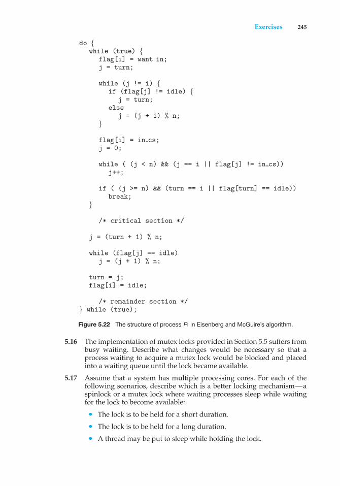
Exercises 245
do {while (true) {
flag[i] = want in;j = turn;
while (j != i) {if (flag[j] != idle) {
j = turn;else
j = (j + 1) % n;}
flag[i] = in cs;j = 0;
while ( (j < n) && (j == i || flag[j] != in cs))j++;
if ( (j >= n) && (turn == i || flag[turn] == idle))break;
}
/* critical section */
j = (turn + 1) % n;
while (flag[j] == idle)j = (j + 1) % n;
turn = j;flag[i] = idle;
/* remainder section */} while (true);
Figure 5.22 The structure of process Pi in Eisenberg and McGuire’s algorithm.
5.16 The implementation of mutex locks provided in Section 5.5 suffers frombusy waiting. Describe what changes would be necessary so that aprocess waiting to acquire a mutex lock would be blocked and placedinto a waiting queue until the lock became available.
5.17 Assume that a system has multiple processing cores. For each of thefollowing scenarios, describe which is a better locking mechanism—aspinlock or a mutex lock where waiting processes sleep while waitingfor the lock to become available:
• The lock is to be held for a short duration.
• The lock is to be held for a long duration.
• A thread may be put to sleep while holding the lock.
246 Chapter 5 Process Synchronization
#define MAX PROCESSES 255int number of processes = 0;
/* the implementation of fork() calls this function */int allocate process() {int new pid;
if (number of processes == MAX PROCESSES)return -1;
else {/* allocate necessary process resources */++number of processes;
return new pid;}
}
/* the implementation of exit() calls this function */void release process() {
/* release process resources */--number of processes;
}
Figure 5.23 Allocating and releasing processes.
5.18 Assume that a context switch takes T time. Suggest an upper bound(in terms of T) for holding a spinlock. If the spinlock is held for anylonger, a mutex lock (where waiting threads are put to sleep) is a betteralternative.
5.19 A multithreaded web server wishes to keep track of the numberof requests it services (known as hits). Consider the two followingstrategies to prevent a race condition on the variable hits. The firststrategy is to use a basic mutex lock when updating hits:
int hits;mutex lock hit lock;
hit lock.acquire();hits++;hit lock.release();
A second strategy is to use an atomic integer:
atomic t hits;atomic inc(&hits);
Explain which of these two strategies is more efficient.
5.20 Consider the code example for allocating and releasing processes shownin Figure 5.23.
Exercises 247
a. Identify the race condition(s).
b. Assume you have a mutex lock named mutex with the operationsacquire() and release(). Indicate where the locking needs tobe placed to prevent the race condition(s).
c. Could we replace the integer variable
int number of processes = 0
with the atomic integer
atomic t number of processes = 0
to prevent the race condition(s)?
5.21 Servers can be designed to limit the number of open connections. Forexample, a server may wish to have only N socket connections at anypoint in time. As soon as N connections are made, the server willnot accept another incoming connection until an existing connectionis released. Explain how semaphores can be used by a server to limit thenumber of concurrent connections.
5.22 Windows Vista provides a lightweight synchronization tool called slimreader–writer locks. Whereas most implementations of reader–writerlocks favor either readers or writers, or perhaps order waiting threadsusing a FIFO policy, slim reader–writer locks favor neither readers norwriters, nor are waiting threads ordered in a FIFO queue. Explain thebenefits of providing such a synchronization tool.
5.23 Show how to implement the wait() and signal() semaphore oper-ations in multiprocessor environments using the test and set()instruction. The solution should exhibit minimal busy waiting.
5.24 Exercise 4.26 requires the parent thread to wait for the child thread tofinish its execution before printing out the computed values. If we let theparent thread access the Fibonacci numbers as soon as they have beencomputed by the child thread—rather than waiting for the child threadto terminate—what changes would be necessary to the solution for thisexercise? Implement your modified solution.
5.25 Demonstrate that monitors and semaphores are equivalent insofaras they can be used to implement solutions to the same types ofsynchronization problems.
5.26 Design an algorithm for a bounded-buffer monitor in which the buffers(portions) are embedded within the monitor itself.
5.27 The strict mutual exclusion within a monitor makes the bounded-buffermonitor of Exercise 5.26 mainly suitable for small portions.
a. Explain why this is true.
b. Design a new scheme that is suitable for larger portions.
5.28 Discuss the tradeoff between fairness and throughput of operationsin the readers–writers problem. Propose a method for solving thereaders–writers problem without causing starvation.
248 Chapter 5 Process Synchronization
5.29 How does the signal() operation associated with monitors differ fromthe corresponding operation defined for semaphores?
5.30 Suppose the signal() statement can appear only as the last statementin a monitor function. Suggest how the implementation described inSection 5.8 can be simplified in this situation.
5.31 Consider a system consisting of processes P1, P2, ..., Pn, each of which hasa unique priority number. Write a monitor that allocates three identicalprinters to these processes, using the priority numbers for deciding theorder of allocation.
5.32 A file is to be shared among different processes, each of which hasa unique number. The file can be accessed simultaneously by severalprocesses, subject to the following constraint: the sum of all uniquenumbers associated with all the processes currently accessing the filemust be less than n. Write a monitor to coordinate access to the file.
5.33 When a signal is performed on a condition inside a monitor, the signalingprocess can either continue its execution or transfer control to the processthat is signaled. How would the solution to the preceding exercise differwith these two different ways in which signaling can be performed?
5.34 Suppose we replace the wait() and signal() operations of moni-tors with a single construct await(B), where B is a general Booleanexpression that causes the process executing it to wait until B becomestrue.
a. Write a monitor using this scheme to implement the readers–writers problem.
b. Explain why, in general, this construct cannot be implementedefficiently.
c. What restrictions need to be put on the await statement so that itcan be implemented efficiently? (Hint: Restrict the generality of B;see [Kessels (1977)].)
5.35 Design an algorithm for a monitor that implements an alarm clock thatenables a calling program to delay itself for a specified number of timeunits (ticks). You may assume the existence of a real hardware clock thatinvokes a function tick() in your monitor at regular intervals.
Programming Problems
5.36 Programming Exercise 3.20 required you to design a PID manager thatallocated a unique process identifier to each process. Exercise 4.20required you to modify your solution to Exercise 3.20 by writing aprogram that created a number of threads that requested and releasedprocess identifiers. Now modify your solution to Exercise 4.20 byensuring that the data structure used to represent the availability ofprocess identifiers is safe from race conditions. Use Pthreads mutexlocks, described in Section 5.9.4.
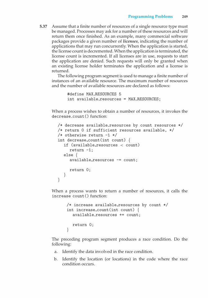
Programming Problems 249
5.37 Assume that a finite number of resources of a single resource type mustbe managed. Processes may ask for a number of these resources and willreturn them once finished. As an example, many commercial softwarepackages provide a given number of licenses, indicating the number ofapplications that may run concurrently. When the application is started,the license count is decremented. When the application is terminated, thelicense count is incremented. If all licenses are in use, requests to startthe application are denied. Such requests will only be granted whenan existing license holder terminates the application and a license isreturned.
The following program segment is used to manage a finite number ofinstances of an available resource. The maximum number of resourcesand the number of available resources are declared as follows:
#define MAX RESOURCES 5int available resources = MAX RESOURCES;
When a process wishes to obtain a number of resources, it invokes thedecrease count() function:
/* decrease available resources by count resources *//* return 0 if sufficient resources available, *//* otherwise return -1 */int decrease count(int count) {
if (available resources < count)return -1;
else {available resources -= count;
return 0;}
}
When a process wants to return a number of resources, it calls theincrease count() function:
/* increase available resources by count */int increase count(int count) {
available resources += count;
return 0;}
The preceding program segment produces a race condition. Do thefollowing:
a. Identify the data involved in the race condition.
b. Identify the location (or locations) in the code where the racecondition occurs.
250 Chapter 5 Process Synchronization
c. Using a semaphore or mutex lock, fix the race condition. It ispermissible to modify the decrease count() function so that thecalling process is blocked until sufficient resources are available.
5.38 The decrease count() function in the previous exercise currentlyreturns 0 if sufficient resources are available and −1 otherwise. Thisleads to awkward programming for a process that wishes to obtain anumber of resources:
while (decrease count(count) == -1);
Rewrite the resource-manager code segment using a monitor andcondition variables so that the decrease count() function suspendsthe process until sufficient resources are available. This will allow aprocess to invoke decrease count() by simply calling
decrease count(count);
The process will return from this function call only when sufficientresources are available.
5.39 Exercise 4.22 asked you to design a multithreaded program that esti-mated ! using the Monte Carlo technique. In that exercise, you wereasked to create a single thread that generated random points, storingthe result in a global variable. Once that thread exited, the parent threadperformed the calcuation that estimated the value of !. Modify thatprogram so that you create several threads, each of which generatesrandom points and determines if the points fall within the circle. Eachthread will have to update the global count of all points that fall withinthe circle. Protect against race conditions on updates to the shared globalvariable by using mutex locks.
5.40 Exercise 4.23 asked you to design a program using OpenMP thatestimated ! using the Monte Carlo technique. Examine your solution tothat program looking for any possible race conditions. If you identify arace condition, protect against it using the strategy outlined in Section5.10.2.
5.41 A barrier is a tool for synchronizing the activity of a number of threads.When a thread reaches a barrier point, it cannot proceed until all otherthreads have reached this point as well. When the last thread reachesthe barrier point, all threads are released and can resume concurrentexecution.Assume that the barrier is initialized to N—the number of threads thatmust wait at the barrier point:
init(N);
Each thread then performs some work until it reaches the barrier point:
Programming Projects 251
/* do some work for awhile */
barrier point();
/* do some work for awhile */
Using synchronization tools described in this chapter, construct a barrierthat implements the following API:
• int init(int n)—Initializes the barrier to the specified size.
• int barrier point(void)—Identifies the barrier point. Allthreads are released from the barrier when the last thread reachesthis point.
The return value of each function is used to identify error conditions.Each function will return 0 under normal operation and will return−1 if an error occurs. A testing harness is provided in the source codedownload to test your implementation of the barrier.
Programming Projects
Project 1—The Sleeping Teaching Assistant
A university computer science department has a teaching assistant (TA) whohelps undergraduate students with their programming assignments duringregular office hours. The TA’s office is rather small and has room for only onedesk with a chair and computer. There are three chairs in the hallway outsidethe office where students can sit and wait if the TA is currently helping anotherstudent. When there are no students who need help during office hours, theTA sits at the desk and takes a nap. If a student arrives during office hoursand finds the TA sleeping, the student must awaken the TA to ask for help. If astudent arrives and finds the TA currently helping another student, the studentsits on one of the chairs in the hallway and waits. If no chairs are available, thestudent will come back at a later time.
Using POSIX threads, mutex locks, and semaphores, implement a solutionthat coordinates the activities of the TA and the students. Details for thisassignment are provided below.
The Students and the TA
Using Pthreads (Section 4.4.1), begin by creating n students. Each will run as aseparate thread. The TA will run as a separate thread as well. Student threadswill alternate between programming for a period of time and seeking helpfrom the TA. If the TA is available, they will obtain help. Otherwise, they willeither sit in a chair in the hallway or, if no chairs are available, will resumeprogramming and will seek help at a later time. If a student arrives and noticesthat the TA is sleeping, the student must notify the TA using a semaphore. Whenthe TA finishes helping a student, the TA must check to see if there are studentswaiting for help in the hallway. If so, the TA must help each of these studentsin turn. If no students are present, the TA may return to napping.
252 Chapter 5 Process Synchronization
Perhaps the best option for simulating students programming—as well asthe TA providing help to a student—is to have the appropriate threads sleepfor a random period of time.
POSIX Synchronization
Coverage of POSIX mutex locks and semaphores is provided in Section 5.9.4.Consult that section for details.
Project 2—The Dining Philosophers Problem
In Section 5.7.3, we provide an outline of a solution to the dining-philosophersproblem using monitors. This problem will require implementing a solutionusing Pthreads mutex locks and condition variables.
The Philosophers
Begin by creating five philosophers, each identified by a number 0 . . 4. Eachphilosopher will run as a separate thread. Thread creation using Pthreads iscovered in Section 4.4.1. Philosophers alternate between thinking and eating.To simulate both activities, have the thread sleep for a random period betweenone and three seconds. When a philosopher wishes to eat, she invokes thefunction
pickup forks(int philosopher number)
where philosopher number identifies the number of the philosopher wishingto eat. When a philosopher finishes eating, she invokes
return forks(int philosopher number)
Pthreads Condition Variables
Condition variables in Pthreads behave similarly to those described in Section5.8. However, in that section, condition variables are used within the contextof a monitor, which provides a locking mechanism to ensure data integrity.Since Pthreads is typically used in C programs—and since C does not havea monitor— we accomplish locking by associating a condition variable witha mutex lock. Pthreads mutex locks are covered in Section 5.9.4. We coverPthreads condition variables here.
Condition variables in Pthreads use the pthread cond t data type andare initialized using the pthread cond init() function. The following codecreates and initializes a condition variable as well as its associated mutex lock:
pthread mutex t mutex;pthread cond t cond var;
pthread mutex init(&mutex,NULL);pthread cond init(&cond var,NULL);
Programming Projects 253
The pthread cond wait() function is used for waiting on a conditionvariable. The following code illustrates how a thread can wait for the conditiona == b to become true using a Pthread condition variable:
pthread mutex lock(&mutex);while (a != b)
pthread cond wait(&mutex, &cond var);
pthread mutex unlock(&mutex);
The mutex lock associated with the condition variable must be lockedbefore the pthread cond wait() function is called, since it is used to protectthe data in the conditional clause from a possible race condition. Once thislock is acquired, the thread can check the condition. If the condition is not true,the thread then invokes pthread cond wait(), passing the mutex lock andthe condition variable as parameters. Calling pthread cond wait() releasesthe mutex lock, thereby allowing another thread to access the shared data andpossibly update its value so that the condition clause evaluates to true. (Toprotect against program errors, it is important to place the conditional clausewithin a loop so that the condition is rechecked after being signaled.)
A thread that modifies the shared data can invoke thepthread cond signal() function, thereby signaling one thread waitingon the condition variable. This is illustrated below:
pthread mutex lock(&mutex);a = b;pthread cond signal(&cond var);pthread mutex unlock(&mutex);
It is important to note that the call to pthread cond signal() does notrelease the mutex lock. It is the subsequent call to pthread mutex unlock()that releases the mutex. Once the mutex lock is released, the signaled threadbecomes the owner of the mutex lock and returns control from the call topthread cond wait().
Project 3—Producer–Consumer Problem
In Section 5.7.1, we presented a semaphore-based solution to the producer–consumer problem using a bounded buffer. In this project, you will design aprogramming solution to the bounded-buffer problem using the producer andconsumer processes shown in Figures 5.9 and 5.10. The solution presented inSection 5.7.1 uses three semaphores: empty and full, which count the numberof empty and full slots in the buffer, and mutex, which is a binary (or mutual-exclusion) semaphore that protects the actual insertion or removal of itemsin the buffer. For this project, you will use standard counting semaphores forempty and full and a mutex lock, rather than a binary semaphore, to representmutex. The producer and consumer—running as separate threads—will moveitems to and from a buffer that is synchronized with the empty,full, andmutexstructures. You can solve this problem using either Pthreads or the WindowsAPI.
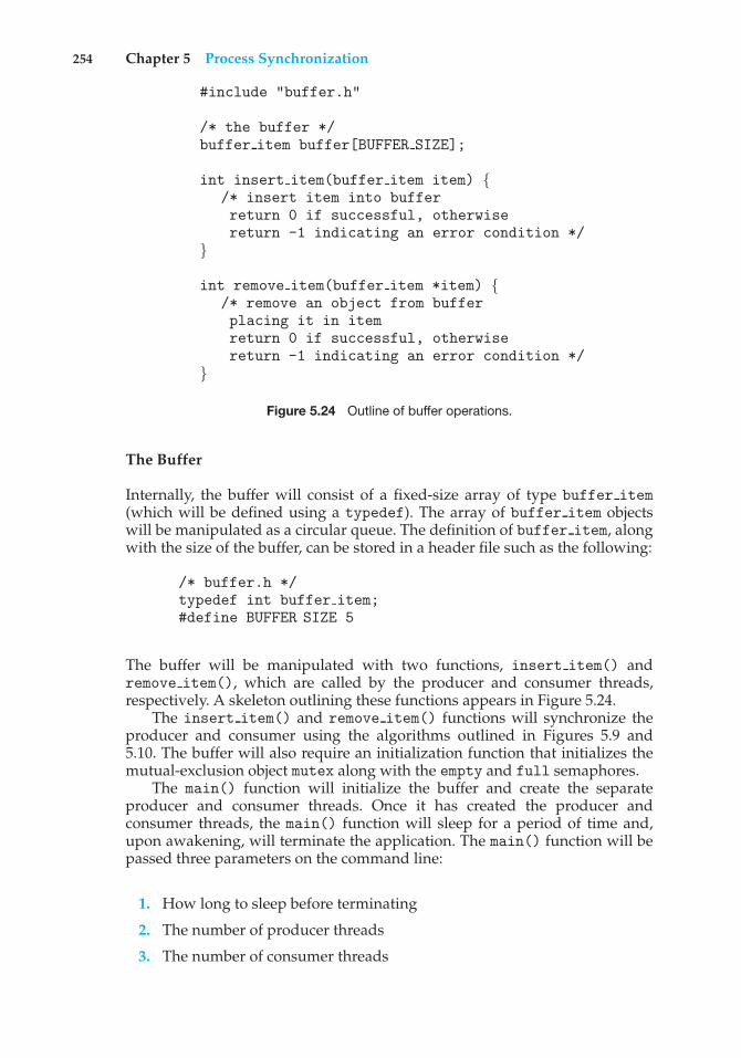
254 Chapter 5 Process Synchronization
#include "buffer.h"
/* the buffer */buffer item buffer[BUFFER SIZE];
int insert item(buffer item item) {/* insert item into bufferreturn 0 if successful, otherwisereturn -1 indicating an error condition */
}
int remove item(buffer item *item) {/* remove an object from bufferplacing it in itemreturn 0 if successful, otherwisereturn -1 indicating an error condition */
}
Figure 5.24 Outline of buffer operations.
The Buffer
Internally, the buffer will consist of a fixed-size array of type buffer item(which will be defined using a typedef). The array of buffer item objectswill be manipulated as a circular queue. The definition of buffer item, alongwith the size of the buffer, can be stored in a header file such as the following:
/* buffer.h */typedef int buffer item;#define BUFFER SIZE 5
The buffer will be manipulated with two functions, insert item() andremove item(), which are called by the producer and consumer threads,respectively. A skeleton outlining these functions appears in Figure 5.24.
The insert item() and remove item() functions will synchronize theproducer and consumer using the algorithms outlined in Figures 5.9 and5.10. The buffer will also require an initialization function that initializes themutual-exclusion object mutex along with the empty and full semaphores.
The main() function will initialize the buffer and create the separateproducer and consumer threads. Once it has created the producer andconsumer threads, the main() function will sleep for a period of time and,upon awakening, will terminate the application. The main() function will bepassed three parameters on the command line:
1. How long to sleep before terminating
2. The number of producer threads
3. The number of consumer threads
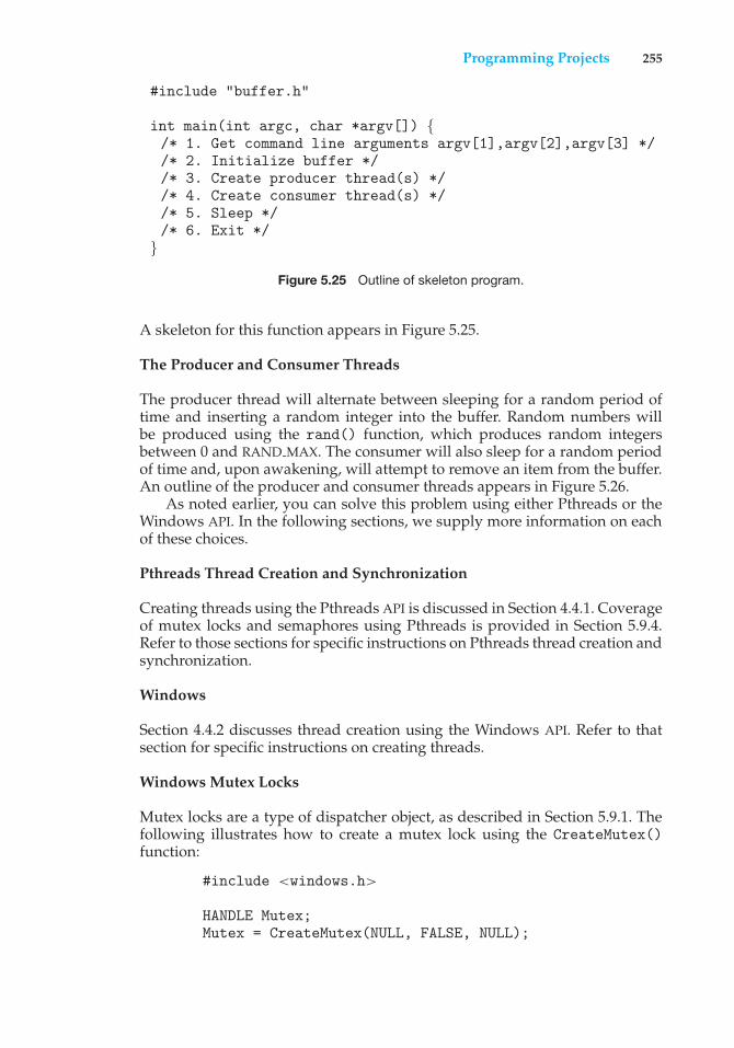
Programming Projects 255
#include "buffer.h"
int main(int argc, char *argv[]) {/* 1. Get command line arguments argv[1],argv[2],argv[3] *//* 2. Initialize buffer *//* 3. Create producer thread(s) *//* 4. Create consumer thread(s) *//* 5. Sleep *//* 6. Exit */
}
Figure 5.25 Outline of skeleton program.
A skeleton for this function appears in Figure 5.25.
The Producer and Consumer Threads
The producer thread will alternate between sleeping for a random period oftime and inserting a random integer into the buffer. Random numbers willbe produced using the rand() function, which produces random integersbetween 0 and RAND MAX. The consumer will also sleep for a random periodof time and, upon awakening, will attempt to remove an item from the buffer.An outline of the producer and consumer threads appears in Figure 5.26.
As noted earlier, you can solve this problem using either Pthreads or theWindows API. In the following sections, we supply more information on eachof these choices.
Pthreads Thread Creation and Synchronization
Creating threads using the Pthreads API is discussed in Section 4.4.1. Coverageof mutex locks and semaphores using Pthreads is provided in Section 5.9.4.Refer to those sections for specific instructions on Pthreads thread creation andsynchronization.
Windows
Section 4.4.2 discusses thread creation using the Windows API. Refer to thatsection for specific instructions on creating threads.
Windows Mutex Locks
Mutex locks are a type of dispatcher object, as described in Section 5.9.1. Thefollowing illustrates how to create a mutex lock using the CreateMutex()function:
#include <windows.h>
HANDLE Mutex;Mutex = CreateMutex(NULL, FALSE, NULL);
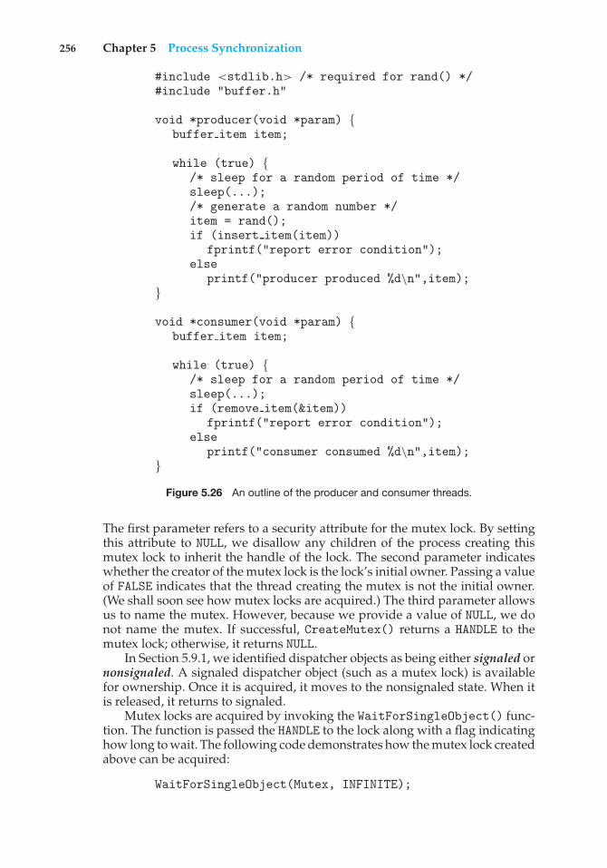
256 Chapter 5 Process Synchronization
#include <stdlib.h> /* required for rand() */#include "buffer.h"
void *producer(void *param) {buffer item item;
while (true) {/* sleep for a random period of time */sleep(...);/* generate a random number */item = rand();if (insert item(item))
fprintf("report error condition");else
printf("producer produced %d\n",item);}
void *consumer(void *param) {buffer item item;
while (true) {/* sleep for a random period of time */sleep(...);if (remove item(&item))
fprintf("report error condition");else
printf("consumer consumed %d\n",item);}
Figure 5.26 An outline of the producer and consumer threads.
The first parameter refers to a security attribute for the mutex lock. By settingthis attribute to NULL, we disallow any children of the process creating thismutex lock to inherit the handle of the lock. The second parameter indicateswhether the creator of the mutex lock is the lock’s initial owner. Passing a valueof FALSE indicates that the thread creating the mutex is not the initial owner.(We shall soon see how mutex locks are acquired.) The third parameter allowsus to name the mutex. However, because we provide a value of NULL, we donot name the mutex. If successful, CreateMutex() returns a HANDLE to themutex lock; otherwise, it returns NULL.
In Section 5.9.1, we identified dispatcher objects as being either signaled ornonsignaled. A signaled dispatcher object (such as a mutex lock) is availablefor ownership. Once it is acquired, it moves to the nonsignaled state. When itis released, it returns to signaled.
Mutex locks are acquired by invoking the WaitForSingleObject() func-tion. The function is passed the HANDLE to the lock along with a flag indicatinghow long to wait. The following code demonstrates how the mutex lock createdabove can be acquired:
WaitForSingleObject(Mutex, INFINITE);
Programming Projects 257
The parameter value INFINITE indicates that we will wait an infinite amountof time for the lock to become available. Other values could be used that wouldallow the calling thread to time out if the lock did not become available withina specified time. If the lock is in a signaled state, WaitForSingleObject()returns immediately, and the lock becomes nonsignaled. A lock is released(moves to the signaled state) by invoking ReleaseMutex()—for example, asfollows:
ReleaseMutex(Mutex);
Windows Semaphores
Semaphores in the Windows API are dispatcher objects and thus use the samesignaling mechanism as mutex locks. Semaphores are created as follows:
#include <windows.h>
HANDLE Sem;Sem = CreateSemaphore(NULL, 1, 5, NULL);
The first and last parameters identify a security attribute and a name for thesemaphore, similar to what we described for mutex locks. The second and thirdparameters indicate the initial value and maximum value of the semaphore. Inthis instance, the initial value of the semaphore is 1, and its maximum valueis 5. If successful, CreateSemaphore() returns a HANDLE to the mutex lock;otherwise, it returns NULL.
Semaphores are acquired with the same WaitForSingleObject() func-tion as mutex locks. We acquire the semaphore Sem created in this example byusing the following statement:
WaitForSingleObject(Semaphore, INFINITE);
If the value of the semaphore is > 0, the semaphore is in the signaled stateand thus is acquired by the calling thread. Otherwise, the calling thread blocksindefinitely—as we are specifying INFINITE—until the semaphore returns tothe signaled state.
The equivalent of the signal() operation for Windows semaphores is theReleaseSemaphore() function. This function is passed three parameters:
1. The HANDLE of the semaphore
2. How much to increase the value of the semaphore
3. A pointer to the previous value of the semaphore
We can use the following statement to increase Sem by 1:
ReleaseSemaphore(Sem, 1, NULL);
Both ReleaseSemaphore() and ReleaseMutex() return a nonzero value ifsuccessful and 0 otherwise.
258 Chapter 5 Process Synchronization
Bibliographical Notes
The mutual-exclusion problem was first discussed in a classic paper by[Dijkstra (1965)]. Dekker’s algorithm (Exercise 5.8)—the first correct softwaresolution to the two-process mutual-exclusion problem—was developed by theDutch mathematician T. Dekker. This algorithm also was discussed by [Dijkstra(1965)]. A simpler solution to the two-process mutual-exclusion problem hassince been presented by [Peterson (1981)] (Figure 5.2). The semaphore conceptwas suggested by [Dijkstra (1965)].
The classic process-coordination problems that we have described areparadigms for a large class of concurrency-control problems. The bounded-buffer problem and the dining-philosophers problem were suggested in[Dijkstra (1965)] and [Dijkstra (1971)]. The readers–writers problem wassuggested by [Courtois et al. (1971)].
The critical-region concept was suggested by [Hoare (1972)] andby [Brinch-Hansen (1972)]. The monitor concept was developed by[Brinch-Hansen (1973)]. [Hoare (1974)] gave a complete description ofthe monitor.
Some details of the locking mechanisms used in Solaris were presentedin [Mauro and McDougall (2007)]. As noted earlier, the locking mechanismsused by the kernel are implemented for user-level threads as well, so the sametypes of locks are available inside and outside the kernel. Details of Windows2000 synchronization can be found in [Solomon and Russinovich (2000)]. [Love(2010)] describes synchronization in the Linux kernel.
Information on Pthreads programming can be found in [Lewis and Berg(1998)] and [Butenhof (1997)]. [Hart (2005)] describes thread synchronizationusing Windows. [Goetz et al. (2006)] present a detailed discussion of concur-rent programming in Java as well as the java.util.concurrent package.[Breshears (2009)] and [Pacheco (2011)] provide detailed coverage of synchro-nization issues in relation to parallel programming. [Lu et al. (2008)] provide astudy of concurrency bugs in real-world applications.
[Adl-Tabatabai et al. (2007)] discuss transactional memory. Details on usingOpenMP can be found at http://openmp.org. Functional programming usingErlang and Scala is covered in [Armstrong (2007)] and [Odersky et al. ()]respectively.
Bibliography
[Adl-Tabatabai et al. (2007)] A.-R. Adl-Tabatabai, C. Kozyrakis, and B. Saha,“Unlocking Concurrency”, Queue, Volume 4, Number 10 (2007), pages 24–33.
[Armstrong (2007)] J. Armstrong, Programming Erlang Software for a ConcurrentWorld, The Pragmatic Bookshelf (2007).
[Breshears (2009)] C. Breshears, The Art of Concurrency, O’Reilly & Associates(2009).
[Brinch-Hansen (1972)] P. Brinch-Hansen, “Structured Multiprogramming”,Communications of the ACM, Volume 15, Number 7 (1972), pages 574–578.
Bibliography 259
[Brinch-Hansen (1973)] P. Brinch-Hansen, Operating System Principles, PrenticeHall (1973).
[Butenhof (1997)] D. Butenhof, Programming with POSIX Threads, Addison-Wesley (1997).
[Courtois et al. (1971)] P. J. Courtois, F. Heymans, and D. L. Parnas, “ConcurrentControl with ‘Readers’ and ‘Writers’”, Communications of the ACM, Volume 14,Number 10 (1971), pages 667–668.
[Dijkstra (1965)] E. W. Dijkstra, “Cooperating Sequential Processes”, Technicalreport, Technological University, Eindhoven, the Netherlands (1965).
[Dijkstra (1971)] E. W. Dijkstra, “Hierarchical Ordering of Sequential Processes”,Acta Informatica, Volume 1, Number 2 (1971), pages 115–138.
[Goetz et al. (2006)] B. Goetz, T. Peirls, J. Bloch, J. Bowbeer, D. Holmes, andD. Lea, Java Concurrency in Practice, Addison-Wesley (2006).
[Hart (2005)] J. M. Hart, Windows System Programming, Third Edition, Addison-Wesley (2005).
[Hoare (1972)] C. A. R. Hoare, “Towards a Theory of Parallel Programming”, in[Hoare and Perrott 1972] (1972), pages 61–71.
[Hoare (1974)] C. A. R. Hoare, “Monitors: An Operating System StructuringConcept”, Communications of the ACM, Volume 17, Number 10 (1974), pages549–557.
[Kessels (1977)] J. L. W. Kessels, “An Alternative to Event Queues for Synchro-nization in Monitors”, Communications of the ACM, Volume 20, Number 7 (1977),pages 500–503.
[Lewis and Berg (1998)] B. Lewis and D. Berg, Multithreaded Programming withPthreads, Sun Microsystems Press (1998).
[Love (2010)] R. Love, Linux Kernel Development, Third Edition, Developer’sLibrary (2010).
[Lu et al. (2008)] S. Lu, S. Park, E. Seo, and Y. Zhou, “Learning from mistakes: acomprehensive study on real world concurrency bug characteristics”, SIGPLANNotices, Volume 43, Number 3 (2008), pages 329–339.
[Mauro and McDougall (2007)] J. Mauro and R. McDougall, Solaris Internals:Core Kernel Architecture, Prentice Hall (2007).
[Odersky et al. ()] M. Odersky, V. Cremet, I. Dragos, G. Dubochet, B. Emir,S. Mcdirmid, S. Micheloud, N. Mihaylov, M. Schinz, E. Stenman, L. Spoon,and M. Zenger.
[Pacheco (2011)] P. S. Pacheco, An Introduction to Parallel Programming, MorganKaufmann (2011).
[Peterson (1981)] G. L. Peterson, “Myths About the Mutual Exclusion Problem”,Information Processing Letters, Volume 12, Number 3 (1981).
[Solomon and Russinovich (2000)] D. A. Solomon and M. E. Russinovich, InsideMicrosoft Windows 2000, Third Edition, Microsoft Press (2000).

6C H A P T E R
CPUScheduling
CPU scheduling is the basis of multiprogrammed operating systems. Byswitching the CPU among processes, the operating system can make thecomputer more productive. In this chapter, we introduce basic CPU-schedulingconcepts and present several CPU-scheduling algorithms. We also consider theproblem of selecting an algorithm for a particular system.
In Chapter 4, we introduced threads to the process model. On operatingsystems that support them, it is kernel-level threads—not processes—thatare in fact being scheduled by the operating system. However, the terms"process scheduling" and "thread scheduling" are often used interchangeably.In this chapter, we use process scheduling when discussing general schedulingconcepts and thread scheduling to refer to thread-specific ideas.
CHAPTER OBJECTIVES
• To introduce CPU scheduling, which is the basis for multiprogrammedoperating systems.
• To describe various CPU-scheduling algorithms.• To discuss evaluation criteria for selecting a CPU-scheduling algorithm for
a particular system.• To examine the scheduling algorithms of several operating systems.
6.1 Basic Concepts
In a single-processor system, only one process can run at a time. Othersmust wait until the CPU is free and can be rescheduled. The objective ofmultiprogramming is to have some process running at all times, to maximizeCPU utilization. The idea is relatively simple. A process is executed untilit must wait, typically for the completion of some I/O request. In a simplecomputer system, the CPU then just sits idle. All this waiting time is wasted;no useful work is accomplished. With multiprogramming, we try to use thistime productively. Several processes are kept in memory at one time. When
261
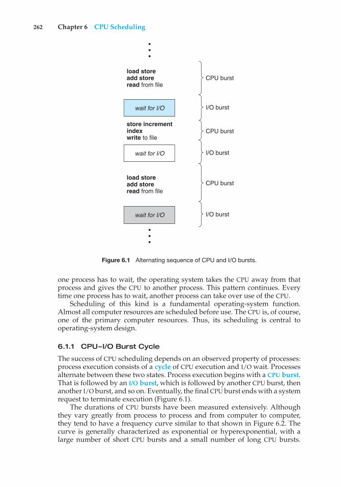
262 Chapter 6 CPU Scheduling
CPU burstload storeadd storeread from file
store incrementindexwrite to file
load storeadd storeread from file
wait for I/O
wait for I/O
wait for I/O
I/O burst
I/O burst
I/O burst
CPU burst
CPU burst
•••
•••
Figure 6.1 Alternating sequence of CPU and I/O bursts.
one process has to wait, the operating system takes the CPU away from thatprocess and gives the CPU to another process. This pattern continues. Everytime one process has to wait, another process can take over use of the CPU.
Scheduling of this kind is a fundamental operating-system function.Almost all computer resources are scheduled before use. The CPU is, of course,one of the primary computer resources. Thus, its scheduling is central tooperating-system design.
6.1.1 CPU–I/O Burst Cycle
The success of CPU scheduling depends on an observed property of processes:process execution consists of a cycle of CPU execution and I/O wait. Processesalternate between these two states. Process execution begins with a CPU burst.That is followed by an I/O burst, which is followed by another CPU burst, thenanother I/O burst, and so on. Eventually, the final CPU burst ends with a systemrequest to terminate execution (Figure 6.1).
The durations of CPU bursts have been measured extensively. Althoughthey vary greatly from process to process and from computer to computer,they tend to have a frequency curve similar to that shown in Figure 6.2. Thecurve is generally characterized as exponential or hyperexponential, with alarge number of short CPU bursts and a small number of long CPU bursts.
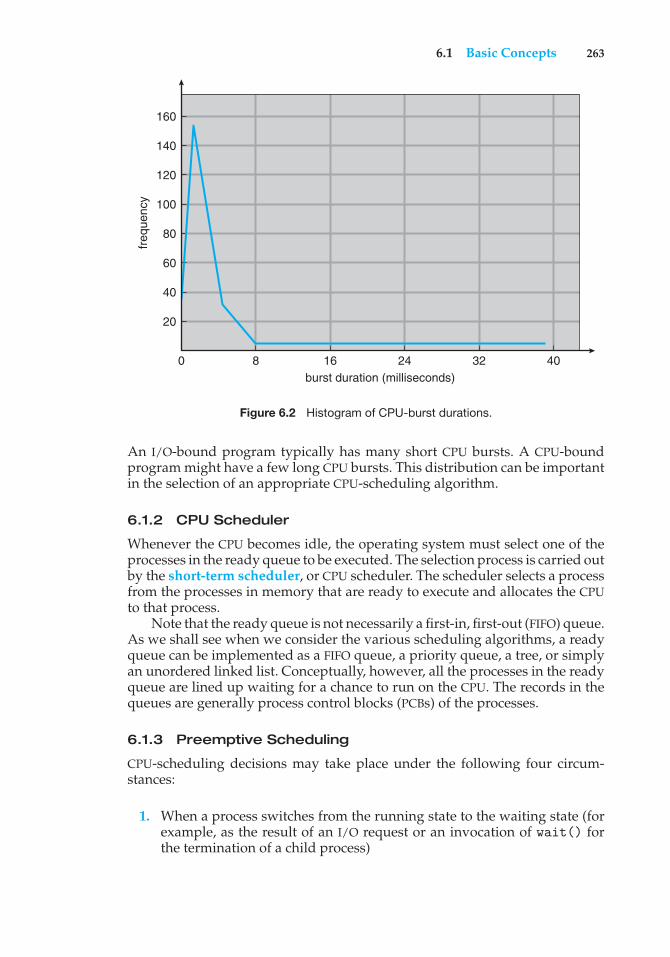
6.1 Basic Concepts 263
freq
uenc
y
160
140
120
100
80
60
40
20
0 8 16 24 32 40burst duration (milliseconds)
Figure 6.2 Histogram of CPU-burst durations.
An I/O-bound program typically has many short CPU bursts. A CPU-boundprogram might have a few long CPU bursts. This distribution can be importantin the selection of an appropriate CPU-scheduling algorithm.
6.1.2 CPU Scheduler
Whenever the CPU becomes idle, the operating system must select one of theprocesses in the ready queue to be executed. The selection process is carried outby the short-term scheduler, or CPU scheduler. The scheduler selects a processfrom the processes in memory that are ready to execute and allocates the CPUto that process.
Note that the ready queue is not necessarily a first-in, first-out (FIFO) queue.As we shall see when we consider the various scheduling algorithms, a readyqueue can be implemented as a FIFO queue, a priority queue, a tree, or simplyan unordered linked list. Conceptually, however, all the processes in the readyqueue are lined up waiting for a chance to run on the CPU. The records in thequeues are generally process control blocks (PCBs) of the processes.
6.1.3 Preemptive Scheduling
CPU-scheduling decisions may take place under the following four circum-stances:
1. When a process switches from the running state to the waiting state (forexample, as the result of an I/O request or an invocation of wait() forthe termination of a child process)
264 Chapter 6 CPU Scheduling
2. When a process switches from the running state to the ready state (forexample, when an interrupt occurs)
3. When a process switches from the waiting state to the ready state (forexample, at completion of I/O)
4. When a process terminates
For situations 1 and 4, there is no choice in terms of scheduling. A new process(if one exists in the ready queue) must be selected for execution. There is achoice, however, for situations 2 and 3.
When scheduling takes place only under circumstances 1 and 4, we saythat the scheduling scheme is nonpreemptive or cooperative. Otherwise,it is preemptive. Under nonpreemptive scheduling, once the CPU has beenallocated to a process, the process keeps the CPU until it releases the CPU eitherby terminating or by switching to the waiting state. This scheduling methodwas used by Microsoft Windows 3.x. Windows 95 introduced preemptivescheduling, and all subsequent versions of Windows operating systems haveused preemptive scheduling. The Mac OS X operating system for the Macintoshalso uses preemptive scheduling; previous versions of the Macintosh operatingsystem relied on cooperative scheduling. Cooperative scheduling is the onlymethod that can be used on certain hardware platforms, because it does notrequire the special hardware (for example, a timer) needed for preemptivescheduling.
Unfortunately, preemptive scheduling can result in race conditions whendata are shared among several processes. Consider the case of two processesthat share data. While one process is updating the data, it is preempted so thatthe second process can run. The second process then tries to read the data,which are in an inconsistent state. This issue was explored in detail in Chapter5.
Preemption also affects the design of the operating-system kernel. Duringthe processing of a system call, the kernel may be busy with an activity on behalfof a process. Such activities may involve changing important kernel data (forinstance, I/O queues). What happens if the process is preempted in the middleof these changes and the kernel (or the device driver) needs to read or modifythe same structure? Chaos ensues. Certain operating systems, including mostversions of UNIX, deal with this problem by waiting either for a system callto complete or for an I/O block to take place before doing a context switch.This scheme ensures that the kernel structure is simple, since the kernel willnot preempt a process while the kernel data structures are in an inconsistentstate. Unfortunately, this kernel-execution model is a poor one for supportingreal-time computing where tasks must complete execution within a given timeframe. In Section 6.6, we explore scheduling demands of real-time systems.
Because interrupts can, by definition, occur at any time, and becausethey cannot always be ignored by the kernel, the sections of code affectedby interrupts must be guarded from simultaneous use. The operating systemneeds to accept interrupts at almost all times. Otherwise, input might be lost oroutput overwritten. So that these sections of code are not accessed concurrentlyby several processes, they disable interrupts at entry and reenable interruptsat exit. It is important to note that sections of code that disable interrupts donot occur very often and typically contain few instructions.
6.2 Scheduling Criteria 265
6.1.4 Dispatcher
Another component involved in the CPU-scheduling function is the dispatcher.The dispatcher is the module that gives control of the CPU to the process selectedby the short-term scheduler. This function involves the following:
• Switching context
• Switching to user mode
• Jumping to the proper location in the user program to restart that program
The dispatcher should be as fast as possible, since it is invoked during everyprocess switch. The time it takes for the dispatcher to stop one process andstart another running is known as the dispatch latency.
6.2 Scheduling Criteria
Different CPU-scheduling algorithms have different properties, and the choiceof a particular algorithm may favor one class of processes over another. Inchoosing which algorithm to use in a particular situation, we must considerthe properties of the various algorithms.
Many criteria have been suggested for comparing CPU-scheduling algo-rithms. Which characteristics are used for comparison can make a substantialdifference in which algorithm is judged to be best. The criteria include thefollowing:
• CPU utilization. We want to keep the CPU as busy as possible. Concep-tually, CPU utilization can range from 0 to 100 percent. In a real system, itshould range from 40 percent (for a lightly loaded system) to 90 percent(for a heavily loaded system).
• Throughput. If the CPU is busy executing processes, then work is beingdone. One measure of work is the number of processes that are completedper time unit, called throughput. For long processes, this rate may be oneprocess per hour; for short transactions, it may be ten processes per second.
• Turnaround time. From the point of view of a particular process, theimportant criterion is how long it takes to execute that process. The intervalfrom the time of submission of a process to the time of completion is theturnaround time. Turnaround time is the sum of the periods spent waitingto get into memory, waiting in the ready queue, executing on the CPU, anddoing I/O.
• Waiting time. The CPU-scheduling algorithm does not affect the amountof time during which a process executes or does I/O. It affects only theamount of time that a process spends waiting in the ready queue. Waitingtime is the sum of the periods spent waiting in the ready queue.
• Response time. In an interactive system, turnaround time may not bethe best criterion. Often, a process can produce some output fairly earlyand can continue computing new results while previous results are being
266 Chapter 6 CPU Scheduling
output to the user. Thus, another measure is the time from the submissionof a request until the first response is produced. This measure, calledresponse time, is the time it takes to start responding, not the time it takesto output the response. The turnaround time is generally limited by thespeed of the output device.
It is desirable to maximize CPU utilization and throughput and to minimizeturnaround time, waiting time, and response time. In most cases, we optimizethe average measure. However, under some circumstances, we prefer tooptimize the minimum or maximum values rather than the average. Forexample, to guarantee that all users get good service, we may want to minimizethe maximum response time.
Investigators have suggested that, for interactive systems (such as desktopsystems), it is more important to minimize the variance in the response timethan to minimize the average response time. A system with reasonable andpredictable response time may be considered more desirable than a systemthat is faster on the average but is highly variable. However, little work hasbeen done on CPU-scheduling algorithms that minimize variance.
As we discuss various CPU-scheduling algorithms in the following section,we illustrate their operation. An accurate illustration should involve manyprocesses, each a sequence of several hundred CPU bursts and I/O bursts.For simplicity, though, we consider only one CPU burst (in milliseconds) perprocess in our examples. Our measure of comparison is the average waitingtime. More elaborate evaluation mechanisms are discussed in Section 6.8.
6.3 Scheduling Algorithms
CPU scheduling deals with the problem of deciding which of the processes in theready queue is to be allocated the CPU. There are many different CPU-schedulingalgorithms. In this section, we describe several of them.
6.3.1 First-Come, First-Served Scheduling
By far the simplest CPU-scheduling algorithm is the first-come, first-served(FCFS) scheduling algorithm. With this scheme, the process that requests theCPU first is allocated the CPU first. The implementation of the FCFS policy iseasily managed with a FIFO queue. When a process enters the ready queue, itsPCB is linked onto the tail of the queue. When the CPU is free, it is allocated tothe process at the head of the queue. The running process is then removed fromthe queue. The code for FCFS scheduling is simple to write and understand.
On the negative side, the average waiting time under the FCFS policy isoften quite long. Consider the following set of processes that arrive at time 0,with the length of the CPU burst given in milliseconds:
Process Burst Time
P1 24P2 3P3 3
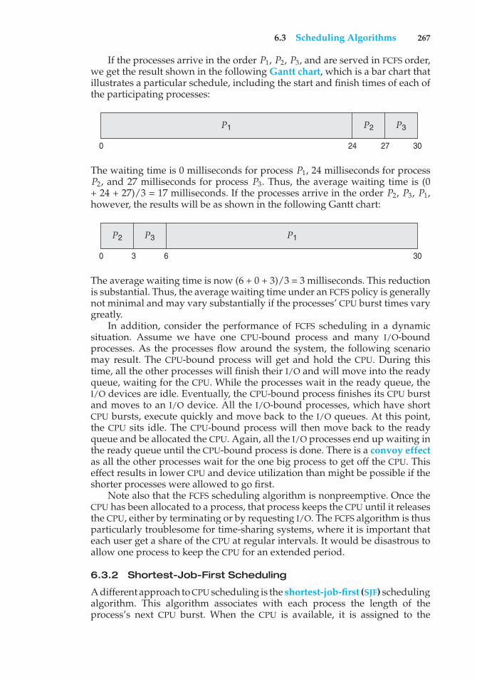
6.3 Scheduling Algorithms 267
If the processes arrive in the order P1, P2, P3, and are served in FCFS order,we get the result shown in the following Gantt chart, which is a bar chart thatillustrates a particular schedule, including the start and finish times of each ofthe participating processes:
P1 P2 P3
3027240
The waiting time is 0 milliseconds for process P1, 24 milliseconds for processP2, and 27 milliseconds for process P3. Thus, the average waiting time is (0+ 24 + 27)/3 = 17 milliseconds. If the processes arrive in the order P2, P3, P1,however, the results will be as shown in the following Gantt chart:
P1P2 P3
300 3 6
The average waiting time is now (6 + 0 + 3)/3 = 3 milliseconds. This reductionis substantial. Thus, the average waiting time under an FCFS policy is generallynot minimal and may vary substantially if the processes’ CPU burst times varygreatly.
In addition, consider the performance of FCFS scheduling in a dynamicsituation. Assume we have one CPU-bound process and many I/O-boundprocesses. As the processes flow around the system, the following scenariomay result. The CPU-bound process will get and hold the CPU. During thistime, all the other processes will finish their I/O and will move into the readyqueue, waiting for the CPU. While the processes wait in the ready queue, theI/O devices are idle. Eventually, the CPU-bound process finishes its CPU burstand moves to an I/O device. All the I/O-bound processes, which have shortCPU bursts, execute quickly and move back to the I/O queues. At this point,the CPU sits idle. The CPU-bound process will then move back to the readyqueue and be allocated the CPU. Again, all the I/O processes end up waiting inthe ready queue until the CPU-bound process is done. There is a convoy effectas all the other processes wait for the one big process to get off the CPU. Thiseffect results in lower CPU and device utilization than might be possible if theshorter processes were allowed to go first.
Note also that the FCFS scheduling algorithm is nonpreemptive. Once theCPU has been allocated to a process, that process keeps the CPU until it releasesthe CPU, either by terminating or by requesting I/O. The FCFS algorithm is thusparticularly troublesome for time-sharing systems, where it is important thateach user get a share of the CPU at regular intervals. It would be disastrous toallow one process to keep the CPU for an extended period.
6.3.2 Shortest-Job-First Scheduling
A different approach to CPU scheduling is the shortest-job-first (SJF) schedulingalgorithm. This algorithm associates with each process the length of theprocess’s next CPU burst. When the CPU is available, it is assigned to the
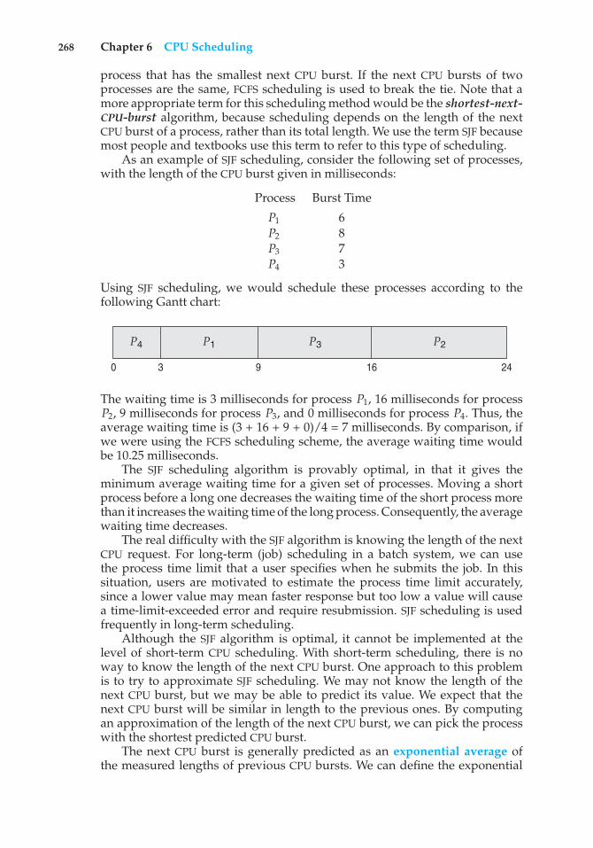
268 Chapter 6 CPU Scheduling
process that has the smallest next CPU burst. If the next CPU bursts of twoprocesses are the same, FCFS scheduling is used to break the tie. Note that amore appropriate term for this scheduling method would be the shortest-next-CPU-burst algorithm, because scheduling depends on the length of the nextCPU burst of a process, rather than its total length. We use the term SJF becausemost people and textbooks use this term to refer to this type of scheduling.
As an example of SJF scheduling, consider the following set of processes,with the length of the CPU burst given in milliseconds:
Process Burst Time
P1 6P2 8P3 7P4 3
Using SJF scheduling, we would schedule these processes according to thefollowing Gantt chart:
P3 P2P4 P1
241690 3
The waiting time is 3 milliseconds for process P1, 16 milliseconds for processP2, 9 milliseconds for process P3, and 0 milliseconds for process P4. Thus, theaverage waiting time is (3 + 16 + 9 + 0)/4 = 7 milliseconds. By comparison, ifwe were using the FCFS scheduling scheme, the average waiting time wouldbe 10.25 milliseconds.
The SJF scheduling algorithm is provably optimal, in that it gives theminimum average waiting time for a given set of processes. Moving a shortprocess before a long one decreases the waiting time of the short process morethan it increases the waiting time of the long process. Consequently, the averagewaiting time decreases.
The real difficulty with the SJF algorithm is knowing the length of the nextCPU request. For long-term (job) scheduling in a batch system, we can usethe process time limit that a user specifies when he submits the job. In thissituation, users are motivated to estimate the process time limit accurately,since a lower value may mean faster response but too low a value will causea time-limit-exceeded error and require resubmission. SJF scheduling is usedfrequently in long-term scheduling.
Although the SJF algorithm is optimal, it cannot be implemented at thelevel of short-term CPU scheduling. With short-term scheduling, there is noway to know the length of the next CPU burst. One approach to this problemis to try to approximate SJF scheduling. We may not know the length of thenext CPU burst, but we may be able to predict its value. We expect that thenext CPU burst will be similar in length to the previous ones. By computingan approximation of the length of the next CPU burst, we can pick the processwith the shortest predicted CPU burst.
The next CPU burst is generally predicted as an exponential average ofthe measured lengths of previous CPU bursts. We can define the exponential
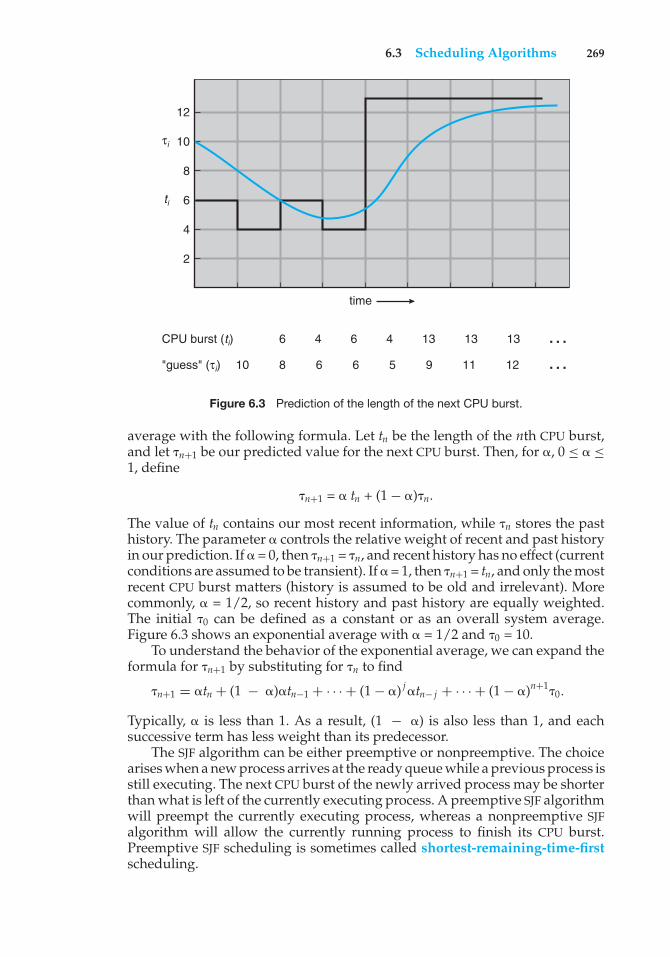
6.3 Scheduling Algorithms 269
6 4 6 4 13 13 13 …810 6 6 5 9 11 12 …
CPU burst (ti)
"guess" (τi)
ti
τi
2
time
4
6
8
10
12
Figure 6.3 Prediction of the length of the next CPU burst.
average with the following formula. Let tn be the length of the nth CPU burst,and let "n+1 be our predicted value for the next CPU burst. Then, for #, 0 ≤ # ≤1, define
"n+1 = # tn + (1− #)"n.
The value of tn contains our most recent information, while "n stores the pasthistory. The parameter # controls the relative weight of recent and past historyin our prediction. If # = 0, then "n+1 = "n, and recent history has no effect (currentconditions are assumed to be transient). If # = 1, then "n+1 = tn, and only the mostrecent CPU burst matters (history is assumed to be old and irrelevant). Morecommonly, # = 1/2, so recent history and past history are equally weighted.The initial "0 can be defined as a constant or as an overall system average.Figure 6.3 shows an exponential average with # = 1/2 and "0 = 10.
To understand the behavior of the exponential average, we can expand theformula for "n+1 by substituting for "n to find
"n+1 = #tn + (1 − #)#tn−1 + · · · + (1− #) j #tn− j + · · · + (1− #)n+1"0.
Typically, # is less than 1. As a result, (1 − #) is also less than 1, and eachsuccessive term has less weight than its predecessor.
The SJF algorithm can be either preemptive or nonpreemptive. The choicearises when a new process arrives at the ready queue while a previous process isstill executing. The next CPU burst of the newly arrived process may be shorterthan what is left of the currently executing process. A preemptive SJF algorithmwill preempt the currently executing process, whereas a nonpreemptive SJFalgorithm will allow the currently running process to finish its CPU burst.Preemptive SJF scheduling is sometimes called shortest-remaining-time-firstscheduling.
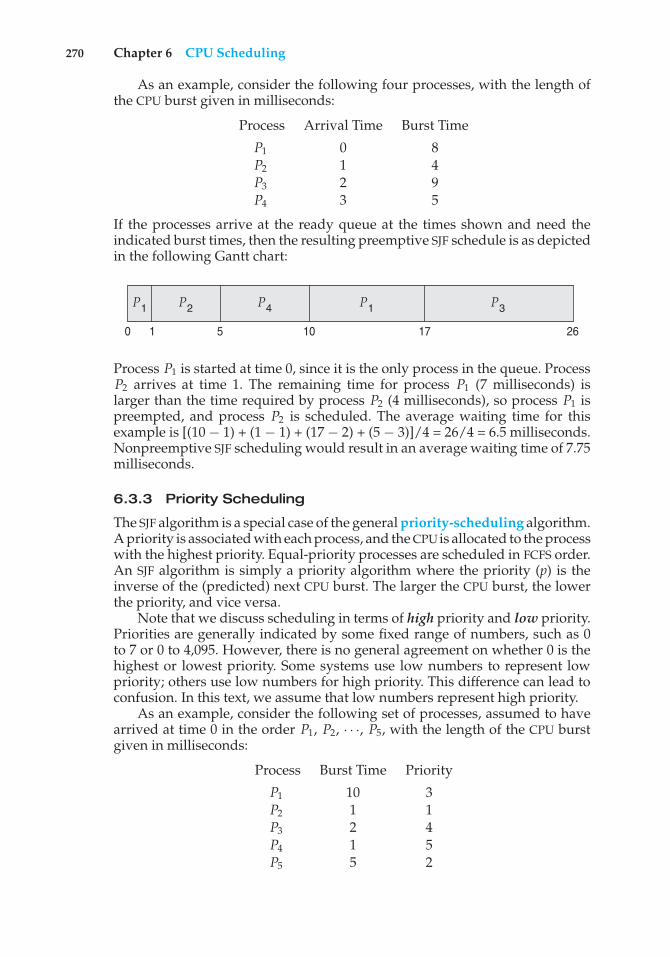
270 Chapter 6 CPU Scheduling
As an example, consider the following four processes, with the length ofthe CPU burst given in milliseconds:
Process Arrival Time Burst Time
P1 0 8P2 1 4P3 2 9P4 3 5
If the processes arrive at the ready queue at the times shown and need theindicated burst times, then the resulting preemptive SJF schedule is as depictedin the following Gantt chart:
P1 P3P1 P2 P4
2617100 1 5
Process P1 is started at time 0, since it is the only process in the queue. ProcessP2 arrives at time 1. The remaining time for process P1 (7 milliseconds) islarger than the time required by process P2 (4 milliseconds), so process P1 ispreempted, and process P2 is scheduled. The average waiting time for thisexample is [(10 − 1) + (1 − 1) + (17 − 2) + (5 − 3)]/4 = 26/4 = 6.5 milliseconds.Nonpreemptive SJF scheduling would result in an average waiting time of 7.75milliseconds.
6.3.3 Priority Scheduling
The SJF algorithm is a special case of the general priority-scheduling algorithm.A priority is associated with each process, and the CPU is allocated to the processwith the highest priority. Equal-priority processes are scheduled in FCFS order.An SJF algorithm is simply a priority algorithm where the priority (p) is theinverse of the (predicted) next CPU burst. The larger the CPU burst, the lowerthe priority, and vice versa.
Note that we discuss scheduling in terms of high priority and low priority.Priorities are generally indicated by some fixed range of numbers, such as 0to 7 or 0 to 4,095. However, there is no general agreement on whether 0 is thehighest or lowest priority. Some systems use low numbers to represent lowpriority; others use low numbers for high priority. This difference can lead toconfusion. In this text, we assume that low numbers represent high priority.
As an example, consider the following set of processes, assumed to havearrived at time 0 in the order P1, P2, · · ·, P5, with the length of the CPU burstgiven in milliseconds:
Process Burst Time Priority
P1 10 3P2 1 1P3 2 4P4 1 5P5 5 2
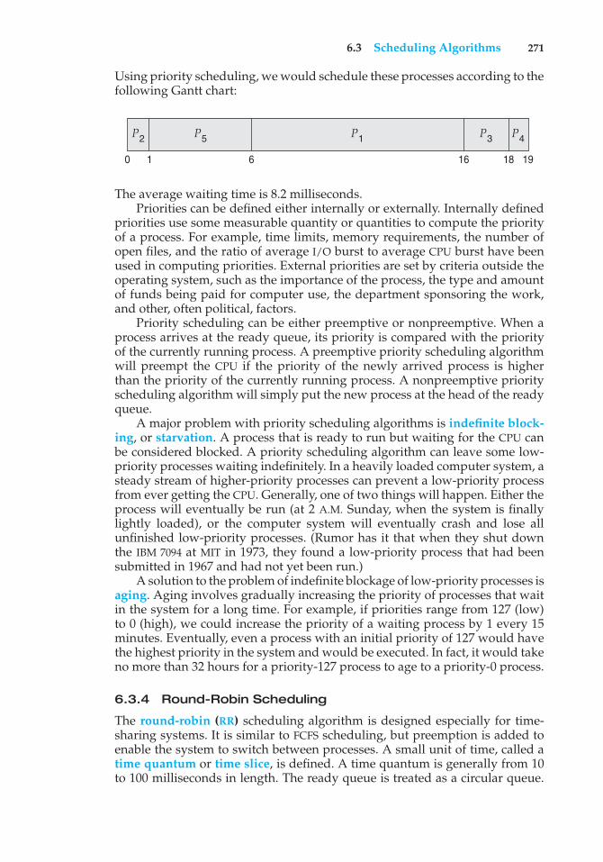
6.3 Scheduling Algorithms 271
Using priority scheduling, we would schedule these processes according to thefollowing Gantt chart:
P1 P4P3P2 P5
19181660 1
The average waiting time is 8.2 milliseconds.Priorities can be defined either internally or externally. Internally defined
priorities use some measurable quantity or quantities to compute the priorityof a process. For example, time limits, memory requirements, the number ofopen files, and the ratio of average I/O burst to average CPU burst have beenused in computing priorities. External priorities are set by criteria outside theoperating system, such as the importance of the process, the type and amountof funds being paid for computer use, the department sponsoring the work,and other, often political, factors.
Priority scheduling can be either preemptive or nonpreemptive. When aprocess arrives at the ready queue, its priority is compared with the priorityof the currently running process. A preemptive priority scheduling algorithmwill preempt the CPU if the priority of the newly arrived process is higherthan the priority of the currently running process. A nonpreemptive priorityscheduling algorithm will simply put the new process at the head of the readyqueue.
A major problem with priority scheduling algorithms is indefinite block-ing, or starvation. A process that is ready to run but waiting for the CPU canbe considered blocked. A priority scheduling algorithm can leave some low-priority processes waiting indefinitely. In a heavily loaded computer system, asteady stream of higher-priority processes can prevent a low-priority processfrom ever getting the CPU. Generally, one of two things will happen. Either theprocess will eventually be run (at 2 A.M. Sunday, when the system is finallylightly loaded), or the computer system will eventually crash and lose allunfinished low-priority processes. (Rumor has it that when they shut downthe IBM 7094 at MIT in 1973, they found a low-priority process that had beensubmitted in 1967 and had not yet been run.)
A solution to the problem of indefinite blockage of low-priority processes isaging. Aging involves gradually increasing the priority of processes that waitin the system for a long time. For example, if priorities range from 127 (low)to 0 (high), we could increase the priority of a waiting process by 1 every 15minutes. Eventually, even a process with an initial priority of 127 would havethe highest priority in the system and would be executed. In fact, it would takeno more than 32 hours for a priority-127 process to age to a priority-0 process.
6.3.4 Round-Robin Scheduling
The round-robin (RR) scheduling algorithm is designed especially for time-sharing systems. It is similar to FCFS scheduling, but preemption is added toenable the system to switch between processes. A small unit of time, called atime quantum or time slice, is defined. A time quantum is generally from 10to 100 milliseconds in length. The ready queue is treated as a circular queue.
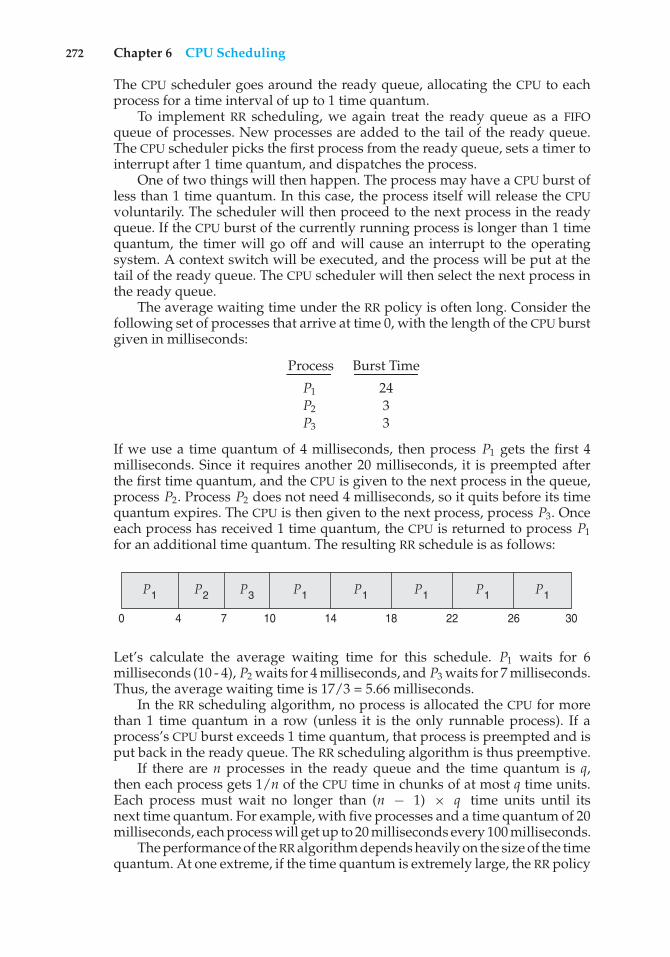
272 Chapter 6 CPU Scheduling
The CPU scheduler goes around the ready queue, allocating the CPU to eachprocess for a time interval of up to 1 time quantum.
To implement RR scheduling, we again treat the ready queue as a FIFOqueue of processes. New processes are added to the tail of the ready queue.The CPU scheduler picks the first process from the ready queue, sets a timer tointerrupt after 1 time quantum, and dispatches the process.
One of two things will then happen. The process may have a CPU burst ofless than 1 time quantum. In this case, the process itself will release the CPUvoluntarily. The scheduler will then proceed to the next process in the readyqueue. If the CPU burst of the currently running process is longer than 1 timequantum, the timer will go off and will cause an interrupt to the operatingsystem. A context switch will be executed, and the process will be put at thetail of the ready queue. The CPU scheduler will then select the next process inthe ready queue.
The average waiting time under the RR policy is often long. Consider thefollowing set of processes that arrive at time 0, with the length of the CPU burstgiven in milliseconds:
Process Burst Time
P1 24P2 3P3 3
If we use a time quantum of 4 milliseconds, then process P1 gets the first 4milliseconds. Since it requires another 20 milliseconds, it is preempted afterthe first time quantum, and the CPU is given to the next process in the queue,process P2. Process P2 does not need 4 milliseconds, so it quits before its timequantum expires. The CPU is then given to the next process, process P3. Onceeach process has received 1 time quantum, the CPU is returned to process P1for an additional time quantum. The resulting RR schedule is as follows:
P1P1 P1P1P1P1 P2
301814 26221070 4
P3
Let’s calculate the average waiting time for this schedule. P1 waits for 6milliseconds (10 - 4), P2 waits for 4 milliseconds, and P3 waits for 7 milliseconds.Thus, the average waiting time is 17/3 = 5.66 milliseconds.
In the RR scheduling algorithm, no process is allocated the CPU for morethan 1 time quantum in a row (unless it is the only runnable process). If aprocess’s CPU burst exceeds 1 time quantum, that process is preempted and isput back in the ready queue. The RR scheduling algorithm is thus preemptive.
If there are n processes in the ready queue and the time quantum is q,then each process gets 1/n of the CPU time in chunks of at most q time units.Each process must wait no longer than (n − 1) × q time units until itsnext time quantum. For example, with five processes and a time quantum of 20milliseconds, each process will get up to 20 milliseconds every 100 milliseconds.
The performance of the RR algorithm depends heavily on the size of the timequantum. At one extreme, if the time quantum is extremely large, the RR policy
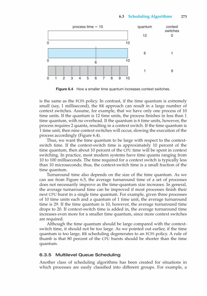
6.3 Scheduling Algorithms 273
process time $ 10 quantum contextswitches
12 0
6 1
1 9
0 10
0 10
0 1 2 3 4 5 6 7 8 9 10
6
Figure 6.4 How a smaller time quantum increases context switches.
is the same as the FCFS policy. In contrast, if the time quantum is extremelysmall (say, 1 millisecond), the RR approach can result in a large number ofcontext switches. Assume, for example, that we have only one process of 10time units. If the quantum is 12 time units, the process finishes in less than 1time quantum, with no overhead. If the quantum is 6 time units, however, theprocess requires 2 quanta, resulting in a context switch. If the time quantum is1 time unit, then nine context switches will occur, slowing the execution of theprocess accordingly (Figure 6.4).
Thus, we want the time quantum to be large with respect to the context-switch time. If the context-switch time is approximately 10 percent of thetime quantum, then about 10 percent of the CPU time will be spent in contextswitching. In practice, most modern systems have time quanta ranging from10 to 100 milliseconds. The time required for a context switch is typically lessthan 10 microseconds; thus, the context-switch time is a small fraction of thetime quantum.
Turnaround time also depends on the size of the time quantum. As wecan see from Figure 6.5, the average turnaround time of a set of processesdoes not necessarily improve as the time-quantum size increases. In general,the average turnaround time can be improved if most processes finish theirnext CPU burst in a single time quantum. For example, given three processesof 10 time units each and a quantum of 1 time unit, the average turnaroundtime is 29. If the time quantum is 10, however, the average turnaround timedrops to 20. If context-switch time is added in, the average turnaround timeincreases even more for a smaller time quantum, since more context switchesare required.
Although the time quantum should be large compared with the context-switch time, it should not be too large. As we pointed out earlier, if the timequantum is too large, RR scheduling degenerates to an FCFS policy. A rule ofthumb is that 80 percent of the CPU bursts should be shorter than the timequantum.
6.3.5 Multilevel Queue Scheduling
Another class of scheduling algorithms has been created for situations inwhich processes are easily classified into different groups. For example, a
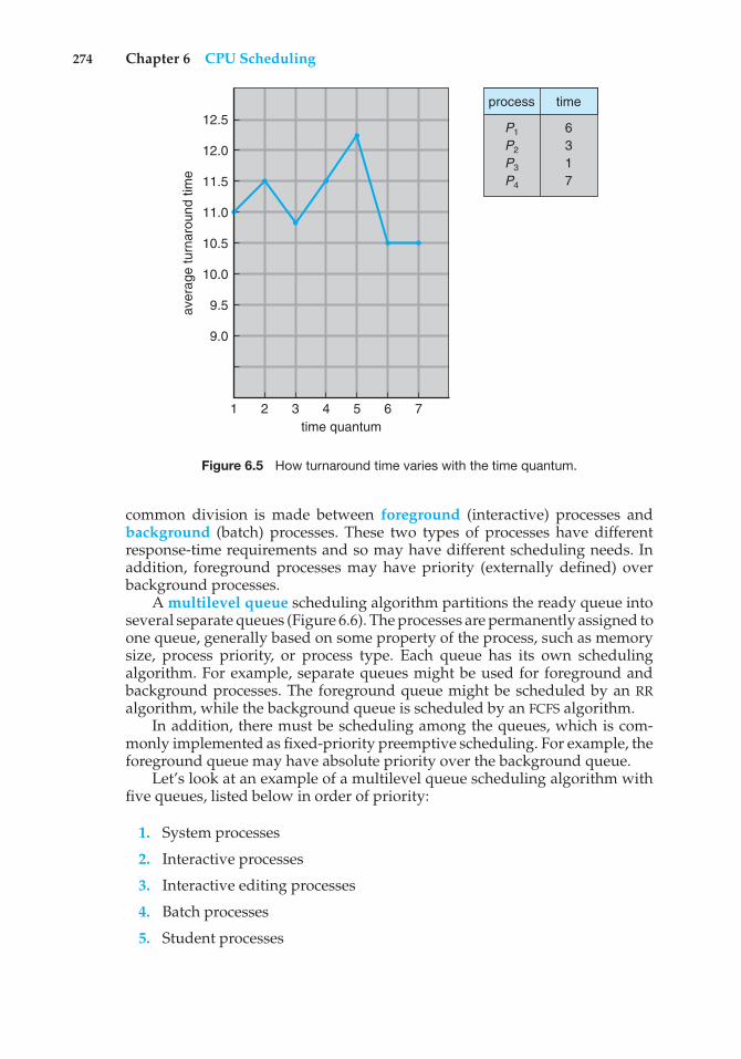
274 Chapter 6 CPU Scheduling
aver
age
turn
arou
nd ti
me
1
12.5
12.0
11.5
11.0
10.5
10.0
9.5
9.0
2 3 4time quantum
5 6 7
P1
P2
P3
P4
6 3 1 7
process time
Figure 6.5 How turnaround time varies with the time quantum.
common division is made between foreground (interactive) processes andbackground (batch) processes. These two types of processes have differentresponse-time requirements and so may have different scheduling needs. Inaddition, foreground processes may have priority (externally defined) overbackground processes.
A multilevel queue scheduling algorithm partitions the ready queue intoseveral separate queues (Figure 6.6). The processes are permanently assigned toone queue, generally based on some property of the process, such as memorysize, process priority, or process type. Each queue has its own schedulingalgorithm. For example, separate queues might be used for foreground andbackground processes. The foreground queue might be scheduled by an RRalgorithm, while the background queue is scheduled by an FCFS algorithm.
In addition, there must be scheduling among the queues, which is com-monly implemented as fixed-priority preemptive scheduling. For example, theforeground queue may have absolute priority over the background queue.
Let’s look at an example of a multilevel queue scheduling algorithm withfive queues, listed below in order of priority:
1. System processes
2. Interactive processes
3. Interactive editing processes
4. Batch processes
5. Student processes
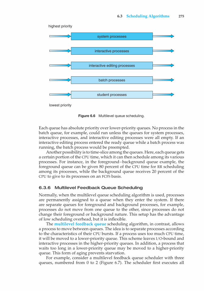
6.3 Scheduling Algorithms 275
system processes
highest priority
lowest priority
interactive processes
interactive editing processes
batch processes
student processes
Figure 6.6 Multilevel queue scheduling.
Each queue has absolute priority over lower-priority queues. No process in thebatch queue, for example, could run unless the queues for system processes,interactive processes, and interactive editing processes were all empty. If aninteractive editing process entered the ready queue while a batch process wasrunning, the batch process would be preempted.
Another possibility is to time-slice among the queues. Here, each queue getsa certain portion of the CPU time, which it can then schedule among its variousprocesses. For instance, in the foreground–background queue example, theforeground queue can be given 80 percent of the CPU time for RR schedulingamong its processes, while the background queue receives 20 percent of theCPU to give to its processes on an FCFS basis.
6.3.6 Multilevel Feedback Queue Scheduling
Normally, when the multilevel queue scheduling algorithm is used, processesare permanently assigned to a queue when they enter the system. If thereare separate queues for foreground and background processes, for example,processes do not move from one queue to the other, since processes do notchange their foreground or background nature. This setup has the advantageof low scheduling overhead, but it is inflexible.
The multilevel feedback queue scheduling algorithm, in contrast, allowsa process to move between queues. The idea is to separate processes accordingto the characteristics of their CPU bursts. If a process uses too much CPU time,it will be moved to a lower-priority queue. This scheme leaves I/O-bound andinteractive processes in the higher-priority queues. In addition, a process thatwaits too long in a lower-priority queue may be moved to a higher-priorityqueue. This form of aging prevents starvation.
For example, consider a multilevel feedback queue scheduler with threequeues, numbered from 0 to 2 (Figure 6.7). The scheduler first executes all
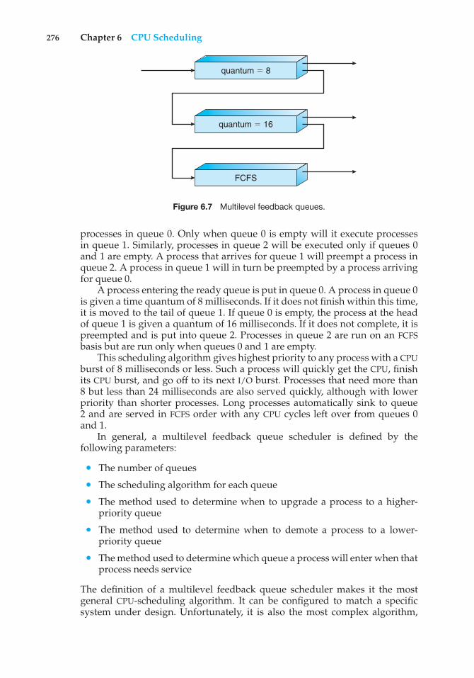
276 Chapter 6 CPU Scheduling
quantum $ 8
quantum $ 16
FCFS
Figure 6.7 Multilevel feedback queues.
processes in queue 0. Only when queue 0 is empty will it execute processesin queue 1. Similarly, processes in queue 2 will be executed only if queues 0and 1 are empty. A process that arrives for queue 1 will preempt a process inqueue 2. A process in queue 1 will in turn be preempted by a process arrivingfor queue 0.
A process entering the ready queue is put in queue 0. A process in queue 0is given a time quantum of 8 milliseconds. If it does not finish within this time,it is moved to the tail of queue 1. If queue 0 is empty, the process at the headof queue 1 is given a quantum of 16 milliseconds. If it does not complete, it ispreempted and is put into queue 2. Processes in queue 2 are run on an FCFSbasis but are run only when queues 0 and 1 are empty.
This scheduling algorithm gives highest priority to any process with a CPUburst of 8 milliseconds or less. Such a process will quickly get the CPU, finishits CPU burst, and go off to its next I/O burst. Processes that need more than8 but less than 24 milliseconds are also served quickly, although with lowerpriority than shorter processes. Long processes automatically sink to queue2 and are served in FCFS order with any CPU cycles left over from queues 0and 1.
In general, a multilevel feedback queue scheduler is defined by thefollowing parameters:
• The number of queues
• The scheduling algorithm for each queue
• The method used to determine when to upgrade a process to a higher-priority queue
• The method used to determine when to demote a process to a lower-priority queue
• The method used to determine which queue a process will enter when thatprocess needs service
The definition of a multilevel feedback queue scheduler makes it the mostgeneral CPU-scheduling algorithm. It can be configured to match a specificsystem under design. Unfortunately, it is also the most complex algorithm,
6.4 Thread Scheduling 277
since defining the best scheduler requires some means by which to selectvalues for all the parameters.
6.4 Thread Scheduling
In Chapter 4, we introduced threads to the process model, distinguishingbetween user-level and kernel-level threads. On operating systems that supportthem, it is kernel-level threads—not processes—that are being scheduled bythe operating system. User-level threads are managed by a thread library,and the kernel is unaware of them. To run on a CPU, user-level threadsmust ultimately be mapped to an associated kernel-level thread, althoughthis mapping may be indirect and may use a lightweight process (LWP). In thissection, we explore scheduling issues involving user-level and kernel-levelthreads and offer specific examples of scheduling for Pthreads.
6.4.1 Contention Scope
One distinction between user-level and kernel-level threads lies in how theyare scheduled. On systems implementing the many-to-one (Section 4.3.1) andmany-to-many (Section 4.3.3) models, the thread library schedules user-levelthreads to run on an available LWP. This scheme is known as process-contention scope (PCS), since competition for the CPU takes place amongthreads belonging to the same process. (When we say the thread libraryschedules user threads onto available LWPs, we do not mean that the threadsare actually running on a CPU. That would require the operating system toschedule the kernel thread onto a physical CPU.) To decide which kernel-levelthread to schedule onto a CPU, the kernel uses system-contention scope (SCS).Competition for the CPU with SCS scheduling takes place among all threadsin the system. Systems using the one-to-one model (Section 4.3.2), such asWindows, Linux, and Solaris, schedule threads using only SCS.
Typically, PCS is done according to priority—the scheduler selects therunnable thread with the highest priority to run. User-level thread prioritiesare set by the programmer and are not adjusted by the thread library, althoughsome thread libraries may allow the programmer to change the priority ofa thread. It is important to note that PCS will typically preempt the threadcurrently running in favor of a higher-priority thread; however, there is noguarantee of time slicing (Section 6.3.4) among threads of equal priority.
6.4.2 Pthread Scheduling
We provided a sample POSIX Pthread program in Section 4.4.1, along with anintroduction to thread creation with Pthreads. Now, we highlight the POSIXPthread API that allows specifying PCS or SCS during thread creation. Pthreadsidentifies the following contention scope values:
• PTHREAD SCOPE PROCESS schedules threads using PCS scheduling.
• PTHREAD SCOPE SYSTEM schedules threads using SCS scheduling.
278 Chapter 6 CPU Scheduling
On systems implementing the many-to-many model, thePTHREAD SCOPE PROCESS policy schedules user-level threads onto availableLWPs. The number of LWPs is maintained by the thread library, perhaps usingscheduler activations (Section 4.6.5). The PTHREAD SCOPE SYSTEM schedulingpolicy will create and bind an LWP for each user-level thread on many-to-manysystems, effectively mapping threads using the one-to-one policy.
The Pthread IPC provides two functions for getting—and setting—thecontention scope policy:
• pthread attr setscope(pthread attr t *attr, int scope)
• pthread attr getscope(pthread attr t *attr, int *scope)
The first parameter for both functions contains a pointer to the attribute set forthe thread. The second parameter for the pthread attr setscope() functionis passed either the PTHREAD SCOPE SYSTEM or the PTHREAD SCOPE PROCESSvalue, indicating how the contention scope is to be set. In the case ofpthread attr getscope(), this second parameter contains a pointer to anint value that is set to the current value of the contention scope. If an erroroccurs, each of these functions returns a nonzero value.
In Figure 6.8, we illustrate a Pthread scheduling API. The pro-gram first determines the existing contention scope and sets it toPTHREAD SCOPE SYSTEM. It then creates five separate threads that willrun using the SCS scheduling policy. Note that on some systems, only certaincontention scope values are allowed. For example, Linux and Mac OS Xsystems allow only PTHREAD SCOPE SYSTEM.
6.5 Multiple-Processor Scheduling
Our discussion thus far has focused on the problems of scheduling the CPU ina system with a single processor. If multiple CPUs are available, load sharingbecomes possible—but scheduling problems become correspondingly morecomplex. Many possibilities have been tried; and as we saw with single-processor CPU scheduling, there is no one best solution.
Here, we discuss several concerns in multiprocessor scheduling. Weconcentrate on systems in which the processors are identical—homogeneous—in terms of their functionality. We can then use any available processor torun any process in the queue. Note, however, that even with homogeneousmultiprocessors, there are sometimes limitations on scheduling. Consider asystem with an I/O device attached to a private bus of one processor. Processesthat wish to use that device must be scheduled to run on that processor.
6.5.1 Approaches to Multiple-Processor Scheduling
One approach to CPU scheduling in a multiprocessor system has all schedulingdecisions, I/O processing, and other system activities handled by a singleprocessor—the master server. The other processors execute only user code.This asymmetric multiprocessing is simple because only one processoraccesses the system data structures, reducing the need for data sharing.
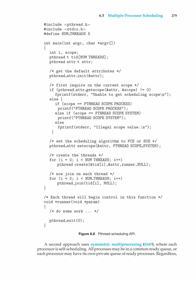
6.5 Multiple-Processor Scheduling 279
#include <pthread.h>#include <stdio.h>#define NUM THREADS 5
int main(int argc, char *argv[]){
int i, scope;pthread t tid[NUM THREADS];pthread attr t attr;
/* get the default attributes */pthread attr init(&attr);
/* first inquire on the current scope */if (pthread attr getscope(&attr, &scope) != 0)
fprintf(stderr, "Unable to get scheduling scope\n");else {
if (scope == PTHREAD SCOPE PROCESS)printf("PTHREAD SCOPE PROCESS");
else if (scope == PTHREAD SCOPE SYSTEM)printf("PTHREAD SCOPE SYSTEM");
elsefprintf(stderr, "Illegal scope value.\n");
}
/* set the scheduling algorithm to PCS or SCS */pthread attr setscope(&attr, PTHREAD SCOPE SYSTEM);
/* create the threads */for (i = 0; i < NUM THREADS; i++)
pthread create(&tid[i],&attr,runner,NULL);
/* now join on each thread */for (i = 0; i < NUM THREADS; i++)
pthread join(tid[i], NULL);}
/* Each thread will begin control in this function */void *runner(void *param){
/* do some work ... */
pthread exit(0);}
Figure 6.8 Pthread scheduling API.
A second approach uses symmetric multiprocessing (SMP), where eachprocessor is self-scheduling. All processes may be in a common ready queue, oreach processor may have its own private queue of ready processes. Regardless,
280 Chapter 6 CPU Scheduling
scheduling proceeds by having the scheduler for each processor examine theready queue and select a process to execute. As we saw in Chapter 5, if we havemultiple processors trying to access and update a common data structure, thescheduler must be programmed carefully. We must ensure that two separateprocessors do not choose to schedule the same process and that processes arenot lost from the queue. Virtually all modern operating systems support SMP,including Windows, Linux, and Mac OS X. In the remainder of this section, wediscuss issues concerning SMP systems.
6.5.2 Processor Affinity
Consider what happens to cache memory when a process has been running ona specific processor. The data most recently accessed by the process populatethe cache for the processor. As a result, successive memory accesses by theprocess are often satisfied in cache memory. Now consider what happensif the process migrates to another processor. The contents of cache memorymust be invalidated for the first processor, and the cache for the secondprocessor must be repopulated. Because of the high cost of invalidating andrepopulating caches, most SMP systems try to avoid migration of processesfrom one processor to another and instead attempt to keep a process runningon the same processor. This is known as processor affinity—that is, a processhas an affinity for the processor on which it is currently running.
Processor affinity takes several forms. When an operating system has apolicy of attempting to keep a process running on the same processor—butnot guaranteeing that it will do so—we have a situation known as soft affinity.Here, the operating system will attempt to keep a process on a single processor,but it is possible for a process to migrate between processors. In contrast, somesystems provide system calls that support hard affinity, thereby allowing aprocess to specify a subset of processors on which it may run. Many systemsprovide both soft and hard affinity. For example, Linux implements soft affinity,but it also provides the sched setaffinity() system call, which supportshard affinity.
The main-memory architecture of a system can affect processor affinityissues. Figure 6.9 illustrates an architecture featuring non-uniform memoryaccess (NUMA), in which a CPU has faster access to some parts of main memorythan to other parts. Typically, this occurs in systems containing combined CPUand memory boards. The CPUs on a board can access the memory on thatboard faster than they can access memory on other boards in the system.If the operating system’s CPU scheduler and memory-placement algorithmswork together, then a process that is assigned affinity to a particular CPUcan be allocated memory on the board where that CPU resides. This examplealso shows that operating systems are frequently not as cleanly defined andimplemented as described in operating-system textbooks. Rather, the “solidlines” between sections of an operating system are frequently only “dottedlines,” with algorithms creating connections in ways aimed at optimizingperformance and reliability.
6.5.3 Load Balancing
On SMP systems, it is important to keep the workload balanced among allprocessors to fully utilize the benefits of having more than one processor.
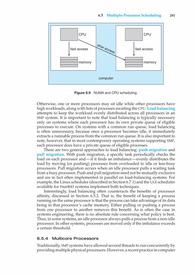
6.5 Multiple-Processor Scheduling 281
CPU
fast access
memory
CPU
fast accessslow access
memory
computer
Figure 6.9 NUMA and CPU scheduling.
Otherwise, one or more processors may sit idle while other processors havehigh workloads, along with lists of processes awaiting the CPU. Load balancingattempts to keep the workload evenly distributed across all processors in anSMP system. It is important to note that load balancing is typically necessaryonly on systems where each processor has its own private queue of eligibleprocesses to execute. On systems with a common run queue, load balancingis often unnecessary, because once a processor becomes idle, it immediatelyextracts a runnable process from the common run queue. It is also important tonote, however, that in most contemporary operating systems supporting SMP,each processor does have a private queue of eligible processes.
There are two general approaches to load balancing: push migration andpull migration. With push migration, a specific task periodically checks theload on each processor and—if it finds an imbalance—evenly distributes theload by moving (or pushing) processes from overloaded to idle or less-busyprocessors. Pull migration occurs when an idle processor pulls a waiting taskfrom a busy processor. Push and pull migration need not be mutually exclusiveand are in fact often implemented in parallel on load-balancing systems. Forexample, the Linux scheduler (described in Section 6.7.1) and the ULE scheduleravailable for FreeBSD systems implement both techniques.
Interestingly, load balancing often counteracts the benefits of processoraffinity, discussed in Section 6.5.2. That is, the benefit of keeping a processrunning on the same processor is that the process can take advantage of its databeing in that processor’s cache memory. Either pulling or pushing a processfrom one processor to another removes this benefit. As is often the case insystems engineering, there is no absolute rule concerning what policy is best.Thus, in some systems, an idle processor always pulls a process from a non-idleprocessor. In other systems, processes are moved only if the imbalance exceedsa certain threshold.
6.5.4 Multicore Processors
Traditionally, SMP systems have allowed several threads to run concurrently byproviding multiple physical processors. However, a recent practice in computer
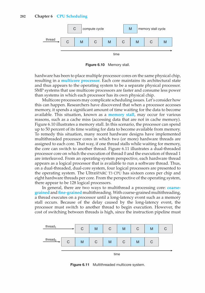
282 Chapter 6 CPU Scheduling
time
compute cycle memory stall cycle
threadC
C
M C M C M
M
C M
Figure 6.10 Memory stall.
hardware has been to place multiple processor cores on the same physical chip,resulting in a multicore processor. Each core maintains its architectural stateand thus appears to the operating system to be a separate physical processor.SMP systems that use multicore processors are faster and consume less powerthan systems in which each processor has its own physical chip.
Multicore processors may complicate scheduling issues. Let’s consider howthis can happen. Researchers have discovered that when a processor accessesmemory, it spends a significant amount of time waiting for the data to becomeavailable. This situation, known as a memory stall, may occur for variousreasons, such as a cache miss (accessing data that are not in cache memory).Figure 6.10 illustrates a memory stall. In this scenario, the processor can spendup to 50 percent of its time waiting for data to become available from memory.To remedy this situation, many recent hardware designs have implementedmultithreaded processor cores in which two (or more) hardware threads areassigned to each core. That way, if one thread stalls while waiting for memory,the core can switch to another thread. Figure 6.11 illustrates a dual-threadedprocessor core on which the execution of thread 0 and the execution of thread 1are interleaved. From an operating-system perspective, each hardware threadappears as a logical processor that is available to run a software thread. Thus,on a dual-threaded, dual-core system, four logical processors are presented tothe operating system. The UltraSPARC T3 CPU has sixteen cores per chip andeight hardware threads per core. From the perspective of the operating system,there appear to be 128 logical processors.
In general, there are two ways to multithread a processing core: coarse-grained and fine-grained multithreading. With coarse-grained multithreading,a thread executes on a processor until a long-latency event such as a memorystall occurs. Because of the delay caused by the long-latency event, theprocessor must switch to another thread to begin execution. However, thecost of switching between threads is high, since the instruction pipeline must
time
thread0
thread1
C M C M C M C
C M C M C M C
Figure 6.11 Multithreaded multicore system.
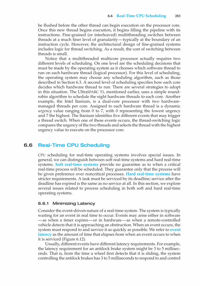
6.6 Real-Time CPU Scheduling 283
be flushed before the other thread can begin execution on the processor core.Once this new thread begins execution, it begins filling the pipeline with itsinstructions. Fine-grained (or interleaved) multithreading switches betweenthreads at a much finer level of granularity—typically at the boundary of aninstruction cycle. However, the architectural design of fine-grained systemsincludes logic for thread switching. As a result, the cost of switching betweenthreads is small.
Notice that a multithreaded multicore processor actually requires twodifferent levels of scheduling. On one level are the scheduling decisions thatmust be made by the operating system as it chooses which software thread torun on each hardware thread (logical processor). For this level of scheduling,the operating system may choose any scheduling algorithm, such as thosedescribed in Section 6.3. A second level of scheduling specifies how each coredecides which hardware thread to run. There are several strategies to adoptin this situation. The UltraSPARC T3, mentioned earlier, uses a simple round-robin algorithm to schedule the eight hardware threads to each core. Anotherexample, the Intel Itanium, is a dual-core processor with two hardware-managed threads per core. Assigned to each hardware thread is a dynamicurgency value ranging from 0 to 7, with 0 representing the lowest urgencyand 7 the highest. The Itanium identifies five different events that may triggera thread switch. When one of these events occurs, the thread-switching logiccompares the urgency of the two threads and selects the thread with the highesturgency value to execute on the processor core.
6.6 Real-Time CPU Scheduling
CPU scheduling for real-time operating systems involves special issues. Ingeneral, we can distinguish between soft real-time systems and hard real-timesystems. Soft real-time systems provide no guarantee as to when a criticalreal-time process will be scheduled. They guarantee only that the process willbe given preference over noncritical processes. Hard real-time systems havestricter requirements. A task must be serviced by its deadline; service after thedeadline has expired is the same as no service at all. In this section, we exploreseveral issues related to process scheduling in both soft and hard real-timeoperating systems.
6.6.1 Minimizing Latency
Consider the event-driven nature of a real-time system. The system is typicallywaiting for an event in real time to occur. Events may arise either in software—as when a timer expires—or in hardware—as when a remote-controlledvehicle detects that it is approaching an obstruction. When an event occurs, thesystem must respond to and service it as quickly as possible. We refer to eventlatency as the amount of time that elapses from when an event occurs to whenit is serviced (Figure 6.12).
Usually, different events have different latency requirements. For example,the latency requirement for an antilock brake system might be 3 to 5 millisec-onds. That is, from the time a wheel first detects that it is sliding, the systemcontrolling the antilock brakes has 3 to 5 milliseconds to respond to and control
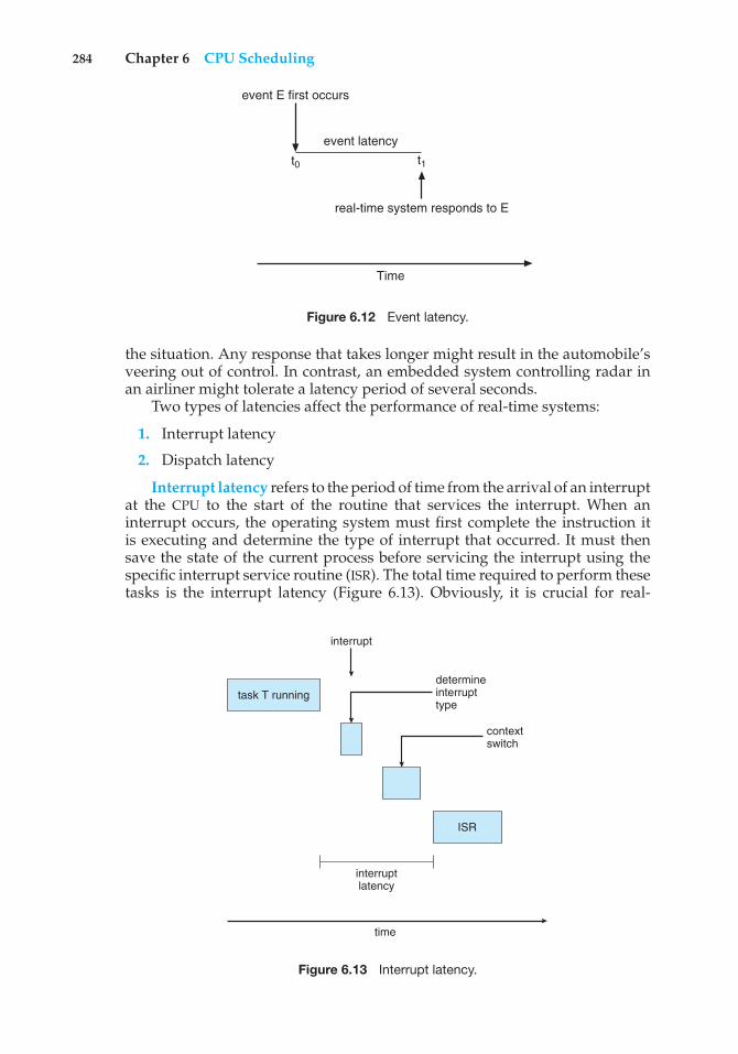
284 Chapter 6 CPU Scheduling
t1t0
event latency
event E first occurs
real-time system responds to E
Time
Figure 6.12 Event latency.
the situation. Any response that takes longer might result in the automobile’sveering out of control. In contrast, an embedded system controlling radar inan airliner might tolerate a latency period of several seconds.
Two types of latencies affect the performance of real-time systems:
1. Interrupt latency
2. Dispatch latency
Interrupt latency refers to the period of time from the arrival of an interruptat the CPU to the start of the routine that services the interrupt. When aninterrupt occurs, the operating system must first complete the instruction itis executing and determine the type of interrupt that occurred. It must thensave the state of the current process before servicing the interrupt using thespecific interrupt service routine (ISR). The total time required to perform thesetasks is the interrupt latency (Figure 6.13). Obviously, it is crucial for real-
task T running
ISR
determineinterrupttype
interrupt
interruptlatency
contextswitch
time
Figure 6.13 Interrupt latency.
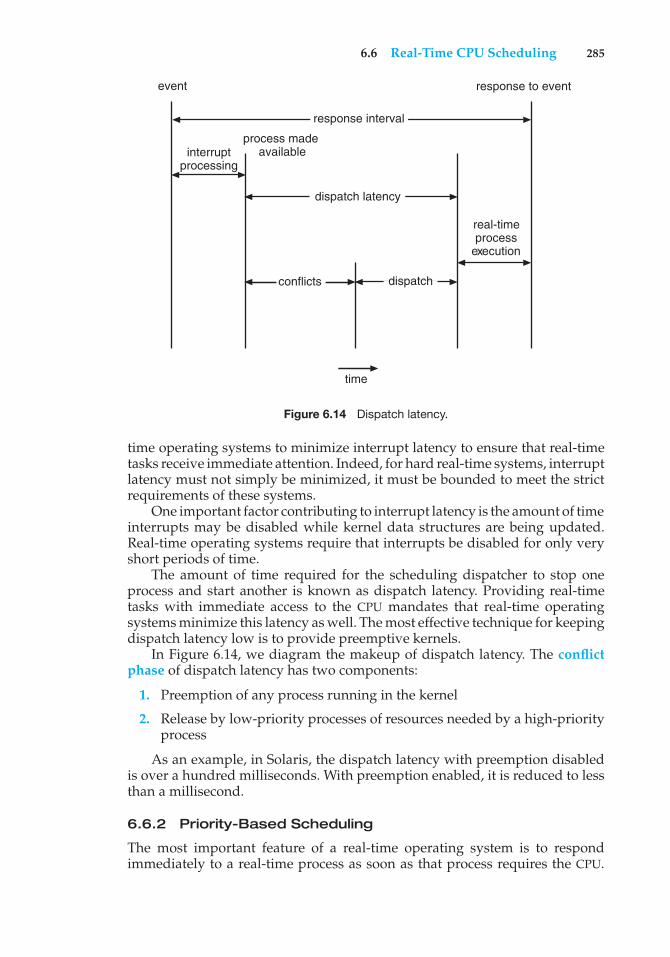
6.6 Real-Time CPU Scheduling 285
response to event
real-time process
execution
event
conflicts
time
dispatch
response interval
dispatch latency
process made availableinterrupt
processing
Figure 6.14 Dispatch latency.
time operating systems to minimize interrupt latency to ensure that real-timetasks receive immediate attention. Indeed, for hard real-time systems, interruptlatency must not simply be minimized, it must be bounded to meet the strictrequirements of these systems.
One important factor contributing to interrupt latency is the amount of timeinterrupts may be disabled while kernel data structures are being updated.Real-time operating systems require that interrupts be disabled for only veryshort periods of time.
The amount of time required for the scheduling dispatcher to stop oneprocess and start another is known as dispatch latency. Providing real-timetasks with immediate access to the CPU mandates that real-time operatingsystems minimize this latency as well. The most effective technique for keepingdispatch latency low is to provide preemptive kernels.
In Figure 6.14, we diagram the makeup of dispatch latency. The conflictphase of dispatch latency has two components:
1. Preemption of any process running in the kernel
2. Release by low-priority processes of resources needed by a high-priorityprocess
As an example, in Solaris, the dispatch latency with preemption disabledis over a hundred milliseconds. With preemption enabled, it is reduced to lessthan a millisecond.
6.6.2 Priority-Based Scheduling
The most important feature of a real-time operating system is to respondimmediately to a real-time process as soon as that process requires the CPU.
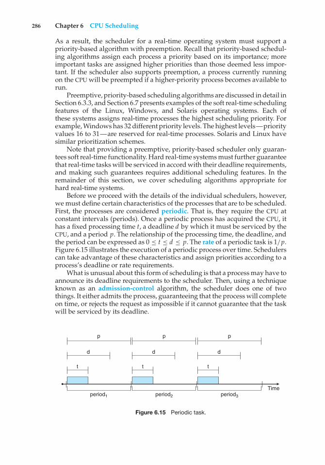
286 Chapter 6 CPU Scheduling
As a result, the scheduler for a real-time operating system must support apriority-based algorithm with preemption. Recall that priority-based schedul-ing algorithms assign each process a priority based on its importance; moreimportant tasks are assigned higher priorities than those deemed less impor-tant. If the scheduler also supports preemption, a process currently runningon the CPU will be preempted if a higher-priority process becomes available torun.
Preemptive, priority-based scheduling algorithms are discussed in detail inSection 6.3.3, and Section 6.7 presents examples of the soft real-time schedulingfeatures of the Linux, Windows, and Solaris operating systems. Each ofthese systems assigns real-time processes the highest scheduling priority. Forexample, Windows has 32 different priority levels. The highest levels—priorityvalues 16 to 31—are reserved for real-time processes. Solaris and Linux havesimilar prioritization schemes.
Note that providing a preemptive, priority-based scheduler only guaran-tees soft real-time functionality. Hard real-time systems must further guaranteethat real-time tasks will be serviced in accord with their deadline requirements,and making such guarantees requires additional scheduling features. In theremainder of this section, we cover scheduling algorithms appropriate forhard real-time systems.
Before we proceed with the details of the individual schedulers, however,we must define certain characteristics of the processes that are to be scheduled.First, the processes are considered periodic. That is, they require the CPU atconstant intervals (periods). Once a periodic process has acquired the CPU, ithas a fixed processing time t, a deadline d by which it must be serviced by theCPU, and a period p. The relationship of the processing time, the deadline, andthe period can be expressed as 0 ≤ t ≤ d ≤ p. The rate of a periodic task is 1/p.Figure 6.15 illustrates the execution of a periodic process over time. Schedulerscan take advantage of these characteristics and assign priorities according to aprocess’s deadline or rate requirements.
What is unusual about this form of scheduling is that a process may have toannounce its deadline requirements to the scheduler. Then, using a techniqueknown as an admission-control algorithm, the scheduler does one of twothings. It either admits the process, guaranteeing that the process will completeon time, or rejects the request as impossible if it cannot guarantee that the taskwill be serviced by its deadline.
period1 period2 period3
Time
p p p
ddd
t tt
Figure 6.15 Periodic task.
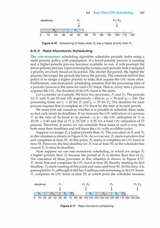
6.6 Real-Time CPU Scheduling 287
0 10 20 30 40 50 60 70 80 12090 100 110
P1
P1
P1, P2
P2
deadlines
Figure 6.16 Scheduling of tasks when P2 has a higher priority than P1.
6.6.3 Rate-Monotonic Scheduling
The rate-monotonic scheduling algorithm schedules periodic tasks using astatic priority policy with preemption. If a lower-priority process is runningand a higher-priority process becomes available to run, it will preempt thelower-priority process. Upon entering the system, each periodic task is assigneda priority inversely based on its period. The shorter the period, the higher thepriority; the longer the period, the lower the priority. The rationale behind thispolicy is to assign a higher priority to tasks that require the CPU more often.Furthermore, rate-monotonic scheduling assumes that the processing time ofa periodic process is the same for each CPU burst. That is, every time a processacquires the CPU, the duration of its CPU burst is the same.
Let’s consider an example. We have two processes, P1 and P2. The periodsfor P1 and P2 are 50 and 100, respectively—that is, p1 = 50 and p2 = 100. Theprocessing times are t1 = 20 for P1 and t2 = 35 for P2. The deadline for eachprocess requires that it complete its CPU burst by the start of its next period.
We must first ask ourselves whether it is possible to schedule these tasksso that each meets its deadlines. If we measure the CPU utilization of a processPi as the ratio of its burst to its period—ti/pi —the CPU utilization of P1 is20/50 = 0.40 and that of P2 is 35/100 = 0.35, for a total CPU utilization of 75percent. Therefore, it seems we can schedule these tasks in such a way thatboth meet their deadlines and still leave the CPU with available cycles.
Suppose we assign P2 a higher priority than P1. The execution of P1 and P2in this situation is shown in Figure 6.16. As we can see, P2 starts execution firstand completes at time 35. At this point, P1 starts; it completes its CPU burst attime 55. However, the first deadline for P1 was at time 50, so the scheduler hascaused P1 to miss its deadline.
Now suppose we use rate-monotonic scheduling, in which we assign P1a higher priority than P2 because the period of P1 is shorter than that of P2.The execution of these processes in this situation is shown in Figure 6.17.P1 starts first and completes its CPU burst at time 20, thereby meeting its firstdeadline. P2 starts running at this point and runs until time 50. At this time, it ispreempted by P1, although it still has 5 milliseconds remaining in its CPU burst.P1 completes its CPU burst at time 70, at which point the scheduler resumes
0 10 20 30 40 50 60 70 80 120 130 140 150 160 170 180 190 20090 100 110
P1
P1
P1, P2
P1 P2
deadlines P1, P2P1
P2 P1 P2 P1 P2
Figure 6.17 Rate-monotonic scheduling.
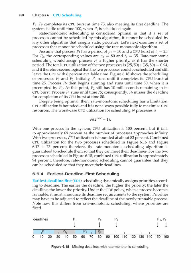
288 Chapter 6 CPU Scheduling
P2. P2 completes its CPU burst at time 75, also meeting its first deadline. Thesystem is idle until time 100, when P1 is scheduled again.
Rate-monotonic scheduling is considered optimal in that if a set ofprocesses cannot be scheduled by this algorithm, it cannot be scheduled byany other algorithm that assigns static priorities. Let’s next examine a set ofprocesses that cannot be scheduled using the rate-monotonic algorithm.
Assume that process P1 has a period of p1 = 50 and a CPU burst of t1 = 25.For P2, the corresponding values are p2 = 80 and t2 = 35. Rate-monotonicscheduling would assign process P1 a higher priority, as it has the shorterperiod. The total CPU utilization of the two processes is (25/50)+(35/80) = 0.94,and it therefore seems logical that the two processes could be scheduled and stillleave the CPU with 6 percent available time. Figure 6.18 shows the schedulingof processes P1 and P2. Initially, P1 runs until it completes its CPU burst attime 25. Process P2 then begins running and runs until time 50, when it ispreempted by P1. At this point, P2 still has 10 milliseconds remaining in itsCPU burst. Process P1 runs until time 75; consequently, P2 misses the deadlinefor completion of its CPU burst at time 80.
Despite being optimal, then, rate-monotonic scheduling has a limitation:CPU utilization is bounded, and it is not always possible fully to maximize CPUresources. The worst-case CPU utilization for scheduling N processes is
N(21/N − 1).
With one process in the system, CPU utilization is 100 percent, but it fallsto approximately 69 percent as the number of processes approaches infinity.With two processes, CPU utilization is bounded at about 83 percent. CombinedCPU utilization for the two processes scheduled in Figure 6.16 and Figure6.17 is 75 percent; therefore, the rate-monotonic scheduling algorithm isguaranteed to schedule them so that they can meet their deadlines. For the twoprocesses scheduled in Figure 6.18, combined CPU utilization is approximately94 percent; therefore, rate-monotonic scheduling cannot guarantee that theycan be scheduled so that they meet their deadlines.
6.6.4 Earliest-Deadline-First Scheduling
Earliest-deadline-first (EDF) scheduling dynamically assigns priorities accord-ing to deadline. The earlier the deadline, the higher the priority; the later thedeadline, the lower the priority. Under the EDF policy, when a process becomesrunnable, it must announce its deadline requirements to the system. Prioritiesmay have to be adjusted to reflect the deadline of the newly runnable process.Note how this differs from rate-monotonic scheduling, where priorities arefixed.
0 10 20 30 40 50 60 70 80 120 130 140 150 16090 100 110
P1
P1
P2
P1 P2
deadlines P1
P2
P1, P2
Figure 6.18 Missing deadlines with rate-monotonic scheduling.
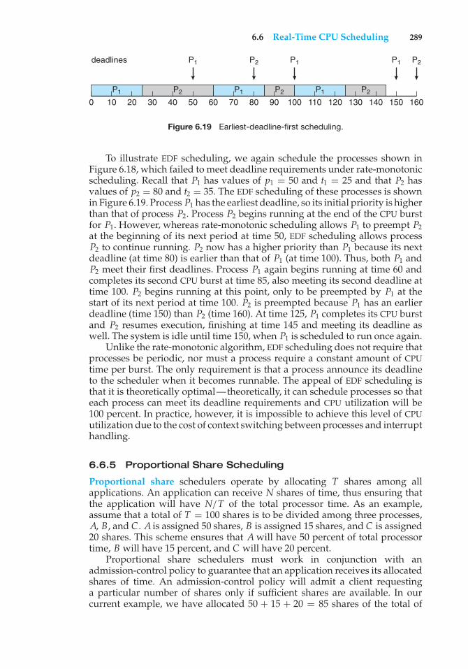
6.6 Real-Time CPU Scheduling 289
0 10 20 30 40 50 60 70 80 120 130 140 150 16090 100 110
P1
P1 P1
P2
P1 P2
deadlines P2P1P1
P2 P2
Figure 6.19 Earliest-deadline-first scheduling.
To illustrate EDF scheduling, we again schedule the processes shown inFigure 6.18, which failed to meet deadline requirements under rate-monotonicscheduling. Recall that P1 has values of p1 = 50 and t1 = 25 and that P2 hasvalues of p2 = 80 and t2 = 35. The EDF scheduling of these processes is shownin Figure 6.19. Process P1 has the earliest deadline, so its initial priority is higherthan that of process P2. Process P2 begins running at the end of the CPU burstfor P1. However, whereas rate-monotonic scheduling allows P1 to preempt P2at the beginning of its next period at time 50, EDF scheduling allows processP2 to continue running. P2 now has a higher priority than P1 because its nextdeadline (at time 80) is earlier than that of P1 (at time 100). Thus, both P1 andP2 meet their first deadlines. Process P1 again begins running at time 60 andcompletes its second CPU burst at time 85, also meeting its second deadline attime 100. P2 begins running at this point, only to be preempted by P1 at thestart of its next period at time 100. P2 is preempted because P1 has an earlierdeadline (time 150) than P2 (time 160). At time 125, P1 completes its CPU burstand P2 resumes execution, finishing at time 145 and meeting its deadline aswell. The system is idle until time 150, when P1 is scheduled to run once again.
Unlike the rate-monotonic algorithm, EDF scheduling does not require thatprocesses be periodic, nor must a process require a constant amount of CPUtime per burst. The only requirement is that a process announce its deadlineto the scheduler when it becomes runnable. The appeal of EDF scheduling isthat it is theoretically optimal—theoretically, it can schedule processes so thateach process can meet its deadline requirements and CPU utilization will be100 percent. In practice, however, it is impossible to achieve this level of CPUutilization due to the cost of context switching between processes and interrupthandling.
6.6.5 Proportional Share Scheduling
Proportional share schedulers operate by allocating T shares among allapplications. An application can receive N shares of time, thus ensuring thatthe application will have N/T of the total processor time. As an example,assume that a total of T = 100 shares is to be divided among three processes,A, B, and C . A is assigned 50 shares, B is assigned 15 shares, and C is assigned20 shares. This scheme ensures that A will have 50 percent of total processortime, B will have 15 percent, and C will have 20 percent.
Proportional share schedulers must work in conjunction with anadmission-control policy to guarantee that an application receives its allocatedshares of time. An admission-control policy will admit a client requestinga particular number of shares only if sufficient shares are available. In ourcurrent example, we have allocated 50 + 15 + 20 = 85 shares of the total of
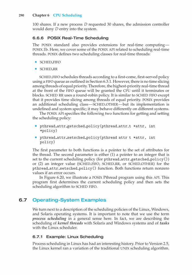
290 Chapter 6 CPU Scheduling
100 shares. If a new process D requested 30 shares, the admission controllerwould deny D entry into the system.
6.6.6 POSIX Real-Time Scheduling
The POSIX standard also provides extensions for real-time computing—POSIX.1b. Here, we cover some of the POSIX API related to scheduling real-timethreads. POSIX defines two scheduling classes for real-time threads:
• SCHED FIFO
• SCHED RR
SCHED FIFO schedules threads according to a first-come, first-served policyusing a FIFO queue as outlined in Section 6.3.1. However, there is no time slicingamong threads of equal priority. Therefore, the highest-priority real-time threadat the front of the FIFO queue will be granted the CPU until it terminates orblocks. SCHED RR uses a round-robin policy. It is similar to SCHED FIFO exceptthat it provides time slicing among threads of equal priority. POSIX providesan additional scheduling class—SCHED OTHER—but its implementation isundefined and system specific; it may behave differently on different systems.
The POSIX API specifies the following two functions for getting and settingthe scheduling policy:
• pthread attr getsched policy(pthread attr t *attr, int*policy)
• pthread attr setsched policy(pthread attr t *attr, intpolicy)
The first parameter to both functions is a pointer to the set of attributes forthe thread. The second parameter is either (1) a pointer to an integer that isset to the current scheduling policy (for pthread attr getsched policy())or (2) an integer value (SCHED FIFO, SCHED RR, or SCHED OTHER) for thepthread attr setsched policy() function. Both functions return nonzerovalues if an error occurs.
In Figure 6.20, we illustrate a POSIX Pthread program using this API. Thisprogram first determines the current scheduling policy and then sets thescheduling algorithm to SCHED FIFO.
6.7 Operating-System Examples
We turn next to a description of the scheduling policies of the Linux, Windows,and Solaris operating systems. It is important to note that we use the termprocess scheduling in a general sense here. In fact, we are describing thescheduling of kernel threads with Solaris and Windows systems and of taskswith the Linux scheduler.
6.7.1 Example: Linux Scheduling
Process scheduling in Linux has had an interesting history. Prior to Version 2.5,the Linux kernel ran a variation of the traditional UNIX scheduling algorithm.
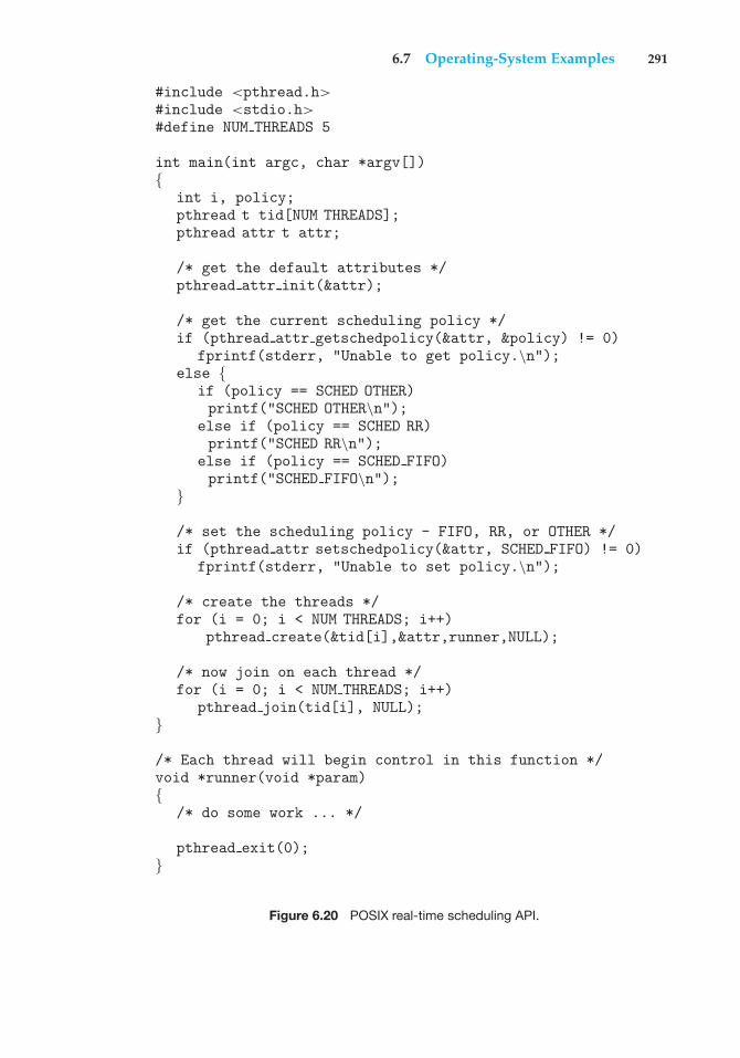
6.7 Operating-System Examples 291
#include <pthread.h>#include <stdio.h>#define NUM THREADS 5
int main(int argc, char *argv[]){
int i, policy;pthread t tid[NUM THREADS];pthread attr t attr;
/* get the default attributes */pthread attr init(&attr);
/* get the current scheduling policy */if (pthread attr getschedpolicy(&attr, &policy) != 0)
fprintf(stderr, "Unable to get policy.\n");else {
if (policy == SCHED OTHER)printf("SCHED OTHER\n");
else if (policy == SCHED RR)printf("SCHED RR\n");
else if (policy == SCHED FIFO)printf("SCHED FIFO\n");
}
/* set the scheduling policy - FIFO, RR, or OTHER */if (pthread attr setschedpolicy(&attr, SCHED FIFO) != 0)
fprintf(stderr, "Unable to set policy.\n");
/* create the threads */for (i = 0; i < NUM THREADS; i++)
pthread create(&tid[i],&attr,runner,NULL);
/* now join on each thread */for (i = 0; i < NUM THREADS; i++)
pthread join(tid[i], NULL);}
/* Each thread will begin control in this function */void *runner(void *param){
/* do some work ... */
pthread exit(0);}
Figure 6.20 POSIX real-time scheduling API.
292 Chapter 6 CPU Scheduling
However, as this algorithm was not designed with SMP systems in mind, itdid not adequately support systems with multiple processors. In addition, itresulted in poor performance for systems with a large number of runnableprocesses. With Version 2.5 of the kernel, the scheduler was overhauled toinclude a scheduling algorithm—known as O(1)—that ran in constant timeregardless of the number of tasks in the system. The O(1) scheduler alsoprovided increased support for SMP systems, including processor affinity andload balancing between processors. However, in practice, although the O(1)scheduler delivered excellent performance on SMP systems, it led to poorresponse times for the interactive processes that are common on many desktopcomputer systems. During development of the 2.6 kernel, the scheduler wasagain revised; and in release 2.6.23 of the kernel, the Completely Fair Scheduler(CFS) became the default Linux scheduling algorithm.
Scheduling in the Linux system is based on scheduling classes. Each class isassigned a specific priority. By using different scheduling classes, the kernel canaccommodate different scheduling algorithms based on the needs of the systemand its processes. The scheduling criteria for a Linux server, for example, maybe different from those for a mobile device running Linux. To decide whichtask to run next, the scheduler selects the highest-priority task belonging tothe highest-priority scheduling class. Standard Linux kernels implement twoscheduling classes: (1) a default scheduling class using the CFS schedulingalgorithm and (2) a real-time scheduling class. We discuss each of these classeshere. New scheduling classes can, of course, be added.
Rather than using strict rules that associate a relative priority value withthe length of a time quantum, the CFS scheduler assigns a proportion of CPUprocessing time to each task. This proportion is calculated based on the nicevalue assigned to each task. Nice values range from −20 to +19, where anumerically lower nice value indicates a higher relative priority. Tasks withlower nice values receive a higher proportion of CPU processing time thantasks with higher nice values. The default nice value is 0. (The term nice comesfrom the idea that if a task increases its nice value from, say, 0 to +10, it is beingnice to other tasks in the system by lowering its relative priority.) CFS doesn’tuse discrete values of time slices and instead identifies a targeted latency,which is an interval of time during which every runnable task should run atleast once. Proportions of CPU time are allocated from the value of targetedlatency. In addition to having default and minimum values, targeted latencycan increase if the number of active tasks in the system grows beyond a certainthreshold.
The CFS scheduler doesn’t directly assign priorities. Rather, it records howlong each task has run by maintaining the virtual run time of each task usingthe per-task variable vruntime. The virtual run time is associated with a decayfactor based on the priority of a task: lower-priority tasks have higher ratesof decay than higher-priority tasks. For tasks at normal priority (nice valuesof 0), virtual run time is identical to actual physical run time. Thus, if a taskwith default priority runs for 200 milliseconds, its vruntime will also be 200milliseconds. However, if a lower-priority task runs for 200 milliseconds, itsvruntime will be higher than 200 milliseconds. Similarly, if a higher-prioritytask runs for 200 milliseconds, its vruntime will be less than 200 milliseconds.To decide which task to run next, the scheduler simply selects the task that hasthe smallest vruntime value. In addition, a higher-priority task that becomesavailable to run can preempt a lower-priority task.
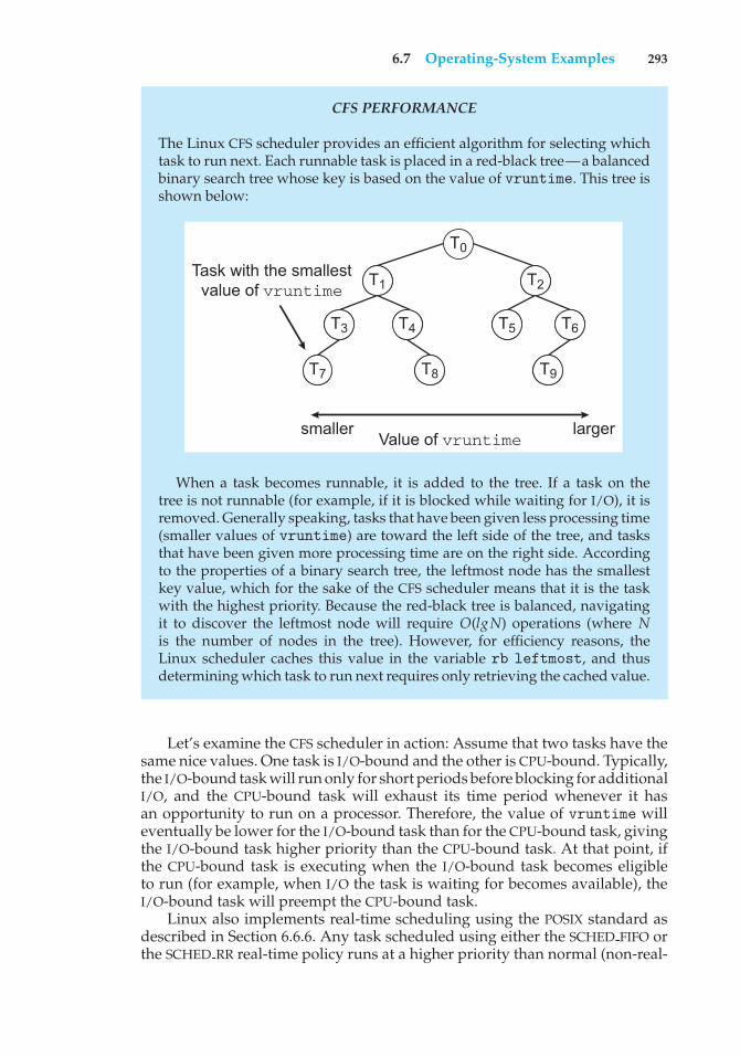
6.7 Operating-System Examples 293
CFS PERFORMANCE
The Linux CFS scheduler provides an efficient algorithm for selecting whichtask to run next. Each runnable task is placed in a red-black tree—a balancedbinary search tree whose key is based on the value of vruntime. This tree isshown below:
T0
T2
T3 T5 T6
T1
T4
T9T7 T8
smaller larger
Task with the smallestvalue of vruntime
Value of vruntime
When a task becomes runnable, it is added to the tree. If a task on thetree is not runnable (for example, if it is blocked while waiting for I/O), it isremoved. Generally speaking, tasks that have been given less processing time(smaller values of vruntime) are toward the left side of the tree, and tasksthat have been given more processing time are on the right side. Accordingto the properties of a binary search tree, the leftmost node has the smallestkey value, which for the sake of the CFS scheduler means that it is the taskwith the highest priority. Because the red-black tree is balanced, navigatingit to discover the leftmost node will require O(lgN) operations (where Nis the number of nodes in the tree). However, for efficiency reasons, theLinux scheduler caches this value in the variable rb leftmost, and thusdetermining which task to run next requires only retrieving the cached value.
Let’s examine the CFS scheduler in action: Assume that two tasks have thesame nice values. One task is I/O-bound and the other is CPU-bound. Typically,the I/O-bound task will run only for short periods before blocking for additionalI/O, and the CPU-bound task will exhaust its time period whenever it hasan opportunity to run on a processor. Therefore, the value of vruntime willeventually be lower for the I/O-bound task than for the CPU-bound task, givingthe I/O-bound task higher priority than the CPU-bound task. At that point, ifthe CPU-bound task is executing when the I/O-bound task becomes eligibleto run (for example, when I/O the task is waiting for becomes available), theI/O-bound task will preempt the CPU-bound task.
Linux also implements real-time scheduling using the POSIX standard asdescribed in Section 6.6.6. Any task scheduled using either the SCHED FIFO orthe SCHED RR real-time policy runs at a higher priority than normal (non-real-
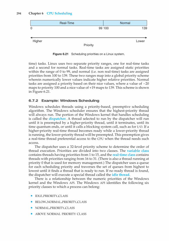
294 Chapter 6 CPU Scheduling
0 100 13999
Real-Time Normal
PriorityHigher Lower
Figure 6.21 Scheduling priorities on a Linux system.
time) tasks. Linux uses two separate priority ranges, one for real-time tasksand a second for normal tasks. Real-time tasks are assigned static prioritieswithin the range of 0 to 99, and normal (i.e. non real-time) tasks are assignedpriorities from 100 to 139. These two ranges map into a global priority schemewherein numerically lower values indicate higher relative priorities. Normaltasks are assigned a priority based on their nice values, where a value of –20maps to priority 100 and a nice value of +19 maps to 139. This scheme is shownin Figure 6.21.
6.7.2 Example: Windows Scheduling
Windows schedules threads using a priority-based, preemptive schedulingalgorithm. The Windows scheduler ensures that the highest-priority threadwill always run. The portion of the Windows kernel that handles schedulingis called the dispatcher. A thread selected to run by the dispatcher will rununtil it is preempted by a higher-priority thread, until it terminates, until itstime quantum ends, or until it calls a blocking system call, such as for I/O. If ahigher-priority real-time thread becomes ready while a lower-priority threadis running, the lower-priority thread will be preempted. This preemption givesa real-time thread preferential access to the CPU when the thread needs suchaccess.
The dispatcher uses a 32-level priority scheme to determine the order ofthread execution. Priorities are divided into two classes. The variable classcontains threads having priorities from 1 to 15, and the real-time class containsthreads with priorities ranging from 16 to 31. (There is also a thread running atpriority 0 that is used for memory management.) The dispatcher uses a queuefor each scheduling priority and traverses the set of queues from highest tolowest until it finds a thread that is ready to run. If no ready thread is found,the dispatcher will execute a special thread called the idle thread.
There is a relationship between the numeric priorities of the Windowskernel and the Windows API. The Windows API identifies the following sixpriority classes to which a process can belong:
• IDLE PRIORITY CLASS
• BELOW NORMAL PRIORITY CLASS
• NORMAL PRIORITY CLASS
• ABOVE NORMAL PRIORITY CLASS
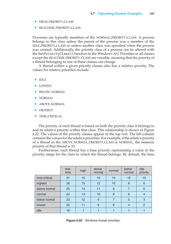
6.7 Operating-System Examples 295
• HIGH PRIORITY CLASS
• REALTIME PRIORITY CLASS
Processes are typically members of the NORMAL PRIORITY CLASS. A processbelongs to this class unless the parent of the process was a member of theIDLE PRIORITY CLASS or unless another class was specified when the processwas created. Additionally, the priority class of a process can be altered withthe SetPriorityClass() function in the Windows API. Priorities in all classesexcept the REALTIME PRIORITY CLASS are variable, meaning that the priority ofa thread belonging to one of these classes can change.
A thread within a given priority classes also has a relative priority. Thevalues for relative priorities include:
• IDLE
• LOWEST
• BELOW NORMAL
• NORMAL
• ABOVE NORMAL
• HIGHEST
• TIME CRITICAL
The priority of each thread is based on both the priority class it belongs toand its relative priority within that class. This relationship is shown in Figure6.22. The values of the priority classes appear in the top row. The left columncontains the values for the relative priorities. For example, if the relative priorityof a thread in the ABOVE NORMAL PRIORITY CLASS is NORMAL, the numericpriority of that thread is 10.
Furthermore, each thread has a base priority representing a value in thepriority range for the class to which the thread belongs. By default, the base
high abovenormal normal below
normalidlepriority
time-critical
real-time
31
26
25
24
23
22
16
15
15
14
13
12
11
1
15
12
11
10
9
8
1
15
10
9
8
7
6
1
15
8
7
6
5
4
1
15
6
5
4
3
2
1
highest
above normal
normal
lowest
idle
below normal
Figure 6.22 Windows thread priorities.
296 Chapter 6 CPU Scheduling
priority is the value of the NORMAL relative priority for that class. The basepriorities for each priority class are as follows:
• REALTIME PRIORITY CLASS—24
• HIGH PRIORITY CLASS—13
• ABOVE NORMAL PRIORITY CLASS—10
• NORMAL PRIORITY CLASS—8
• BELOW NORMAL PRIORITY CLASS—6
• IDLE PRIORITY CLASS—4
The initial priority of a thread is typically the base priority of the processthe thread belongs to, although the SetThreadPriority() function in theWindows API can also be used to modify a thread’s the base priority.
When a thread’s time quantum runs out, that thread is interrupted. If thethread is in the variable-priority class, its priority is lowered. The priority isnever lowered below the base priority, however. Lowering the priority tendsto limit the CPU consumption of compute-bound threads. When a variable-priority thread is released from a wait operation, the dispatcher boosts thepriority. The amount of the boost depends on what the thread was waiting for.For example, a thread waiting for keyboard I/O would get a large increase,whereas a thread waiting for a disk operation would get a moderate one.This strategy tends to give good response times to interactive threads thatare using the mouse and windows. It also enables I/O-bound threads to keepthe I/O devices busy while permitting compute-bound threads to use spareCPU cycles in the background. This strategy is used by several time-sharingoperating systems, including UNIX. In addition, the window with which theuser is currently interacting receives a priority boost to enhance its responsetime.
When a user is running an interactive program, the system needs to provideespecially good performance. For this reason, Windows has a special schedul-ing rule for processes in the NORMAL PRIORITY CLASS. Windows distinguishesbetween the foreground process that is currently selected on the screen andthe background processes that are not currently selected. When a processmoves into the foreground, Windows increases the scheduling quantum bysome factor—typically by 3. This increase gives the foreground process threetimes longer to run before a time-sharing preemption occurs.
Windows 7 introduced user-mode scheduling (UMS), which allows appli-cations to create and manage threads independently of the kernel. Thus,an application can create and schedule multiple threads without involvingthe Windows kernel scheduler. For applications that create a large numberof threads, scheduling threads in user mode is much more efficient thankernel-mode thread scheduling, as no kernel intervention is necessary.
Earlier versions of Windows provided a similar feature known as fibers,which allowed several user-mode threads (fibers) to be mapped to a singlekernel thread. However, fibers were of limited practical use. A fiber wasunable to make calls to the Windows API because all fibers had to share thethread environment block (TEB) of the thread on which they were running. This
6.7 Operating-System Examples 297
presented a problem if a Windows API function placed state information intothe TEB for one fiber, only to have the information overwritten by a differentfiber. UMS overcomes this obstacle by providing each user-mode thread withits own thread context.
In addition, unlike fibers, UMS is not intended to be used directly bythe programmer. The details of writing user-mode schedulers can be verychallenging, and UMS does not include such a scheduler. Rather, the schedulerscome from programming language libraries that build on top of UMS. Forexample, Microsoft provides Concurrency Runtime (ConcRT), a concurrentprogramming framework for C++ that is designed for task-based parallelism(Section 4.2) on multicore processors. ConcRT provides a user-mode schedulertogether with facilities for decomposing programs into tasks, which can thenbe scheduled on the available processing cores. Further details on UMS can befound in Section 19.7.3.7.
6.7.3 Example: Solaris Scheduling
Solaris uses priority-based thread scheduling. Each thread belongs to one ofsix classes:
1. Time sharing (TS)
2. Interactive (IA)
3. Real time (RT)
4. System (SYS)
5. Fair share (FSS)
6. Fixed priority (FP)
Within each class there are different priorities and different scheduling algo-rithms.
The default scheduling class for a process is time sharing. The schedulingpolicy for the time-sharing class dynamically alters priorities and assigns timeslices of different lengths using a multilevel feedback queue. By default, thereis an inverse relationship between priorities and time slices. The higher thepriority, the smaller the time slice; and the lower the priority, the larger thetime slice. Interactive processes typically have a higher priority; CPU-boundprocesses, a lower priority. This scheduling policy gives good response timefor interactive processes and good throughput for CPU-bound processes. Theinteractive class uses the same scheduling policy as the time-sharing class, butit gives windowing applications—such as those created by the KDE or GNOMEwindow managers—a higher priority for better performance.
Figure 6.23 shows the dispatch table for scheduling time-sharing andinteractive threads. These two scheduling classes include 60 priority levels,but for brevity, we display only a handful. The dispatch table shown in Figure6.23 contains the following fields:
• Priority. The class-dependent priority for the time-sharing and interactiveclasses. A higher number indicates a higher priority.
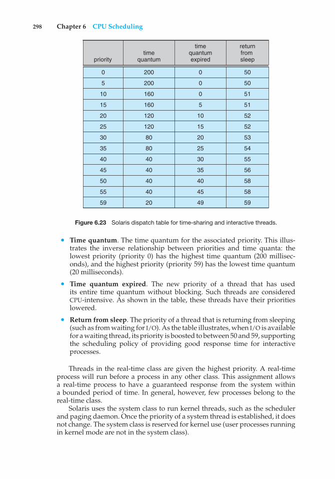
298 Chapter 6 CPU Scheduling
timequantumpriority
returnfrom sleep
timequantumexpired
0
5
10
15
20
25
30
35
40
45
50
55
59
200
200
160
160
120
120
80
80
40
40
40
40
20
0
0
0
5
10
15
20
25
30
35
40
45
49
50
50
51
51
52
52
53
54
55
56
58
58
59
Figure 6.23 Solaris dispatch table for time-sharing and interactive threads.
• Time quantum. The time quantum for the associated priority. This illus-trates the inverse relationship between priorities and time quanta: thelowest priority (priority 0) has the highest time quantum (200 millisec-onds), and the highest priority (priority 59) has the lowest time quantum(20 milliseconds).
• Time quantum expired. The new priority of a thread that has usedits entire time quantum without blocking. Such threads are consideredCPU-intensive. As shown in the table, these threads have their prioritieslowered.
• Return from sleep. The priority of a thread that is returning from sleeping(such as from waiting for I/O). As the table illustrates, when I/O is availablefor a waiting thread, its priority is boosted to between 50 and 59, supportingthe scheduling policy of providing good response time for interactiveprocesses.
Threads in the real-time class are given the highest priority. A real-timeprocess will run before a process in any other class. This assignment allowsa real-time process to have a guaranteed response from the system withina bounded period of time. In general, however, few processes belong to thereal-time class.
Solaris uses the system class to run kernel threads, such as the schedulerand paging daemon. Once the priority of a system thread is established, it doesnot change. The system class is reserved for kernel use (user processes runningin kernel mode are not in the system class).
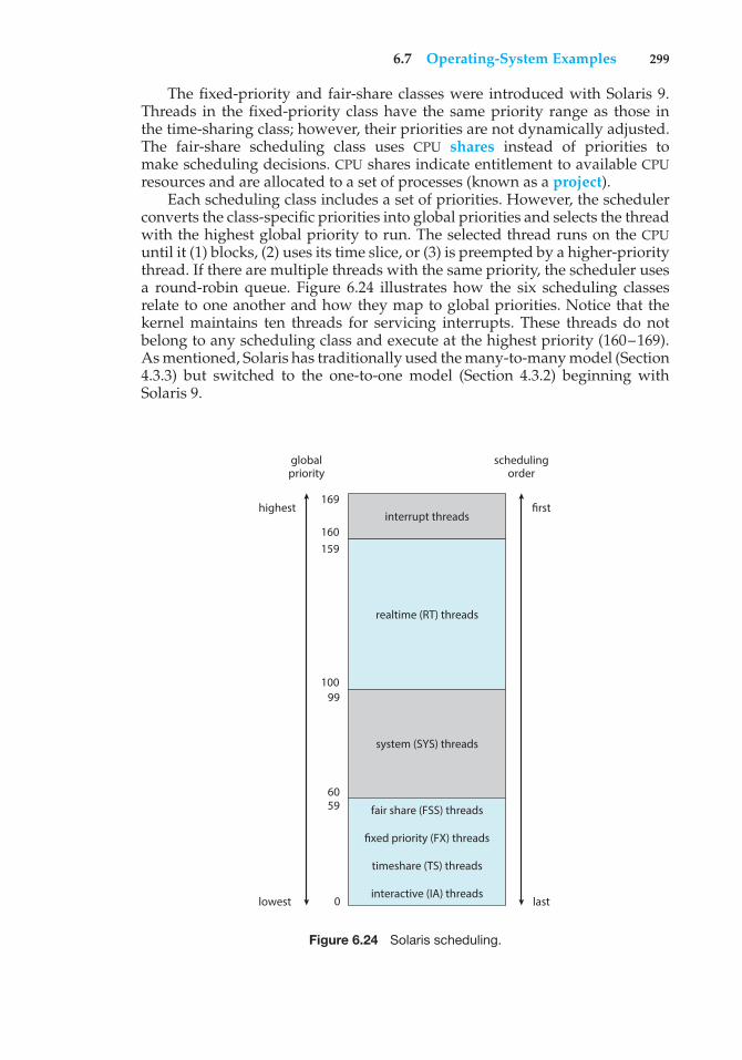
6.7 Operating-System Examples 299
The fixed-priority and fair-share classes were introduced with Solaris 9.Threads in the fixed-priority class have the same priority range as those inthe time-sharing class; however, their priorities are not dynamically adjusted.The fair-share scheduling class uses CPU shares instead of priorities tomake scheduling decisions. CPU shares indicate entitlement to available CPUresources and are allocated to a set of processes (known as a project).
Each scheduling class includes a set of priorities. However, the schedulerconverts the class-specific priorities into global priorities and selects the threadwith the highest global priority to run. The selected thread runs on the CPUuntil it (1) blocks, (2) uses its time slice, or (3) is preempted by a higher-prioritythread. If there are multiple threads with the same priority, the scheduler usesa round-robin queue. Figure 6.24 illustrates how the six scheduling classesrelate to one another and how they map to global priorities. Notice that thekernel maintains ten threads for servicing interrupts. These threads do notbelong to any scheduling class and execute at the highest priority (160–169).As mentioned, Solaris has traditionally used the many-to-many model (Section4.3.3) but switched to the one-to-one model (Section 4.3.2) beginning withSolaris 9.
interrupt threads169
highest
lowest
first
schedulingorder
globalpriority
last
160159
100
6059
0
99
realtime (RT) threads
system (SYS) threads
fair share (FSS) threads
fixed priority (FX) threads
timeshare (TS) threads
interactive (IA) threads
Figure 6.24 Solaris scheduling.
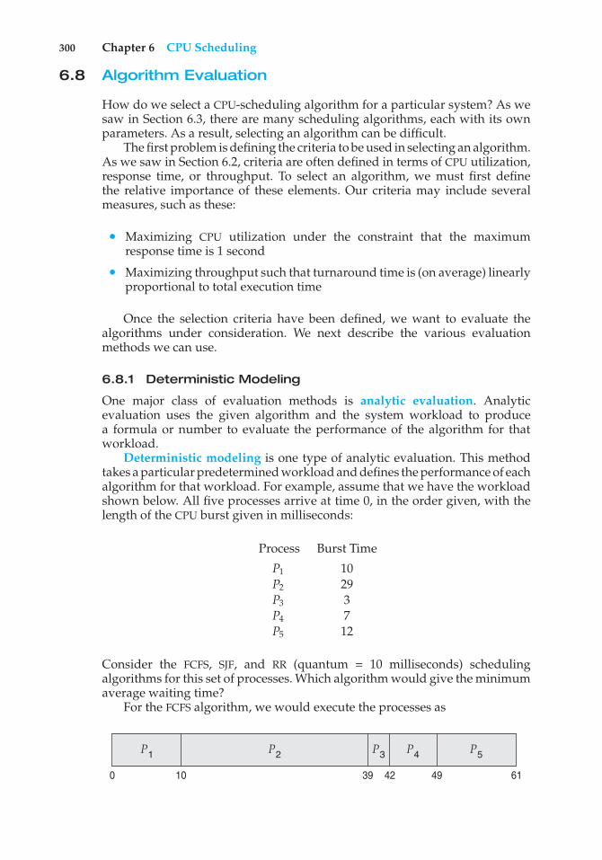
300 Chapter 6 CPU Scheduling
6.8 Algorithm Evaluation
How do we select a CPU-scheduling algorithm for a particular system? As wesaw in Section 6.3, there are many scheduling algorithms, each with its ownparameters. As a result, selecting an algorithm can be difficult.
The first problem is defining the criteria to be used in selecting an algorithm.As we saw in Section 6.2, criteria are often defined in terms of CPU utilization,response time, or throughput. To select an algorithm, we must first definethe relative importance of these elements. Our criteria may include severalmeasures, such as these:
• Maximizing CPU utilization under the constraint that the maximumresponse time is 1 second
• Maximizing throughput such that turnaround time is (on average) linearlyproportional to total execution time
Once the selection criteria have been defined, we want to evaluate thealgorithms under consideration. We next describe the various evaluationmethods we can use.
6.8.1 Deterministic Modeling
One major class of evaluation methods is analytic evaluation. Analyticevaluation uses the given algorithm and the system workload to producea formula or number to evaluate the performance of the algorithm for thatworkload.
Deterministic modeling is one type of analytic evaluation. This methodtakes a particular predetermined workload and defines the performance of eachalgorithm for that workload. For example, assume that we have the workloadshown below. All five processes arrive at time 0, in the order given, with thelength of the CPU burst given in milliseconds:
Process Burst Time
P1 10P2 29P3 3P4 7P5 12
Consider the FCFS, SJF, and RR (quantum = 10 milliseconds) schedulingalgorithms for this set of processes. Which algorithm would give the minimumaverage waiting time?
For the FCFS algorithm, we would execute the processes as
P2 P5P3 P4P1
6139 49420 10
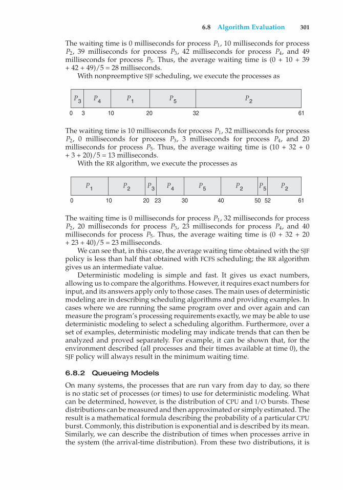
6.8 Algorithm Evaluation 301
The waiting time is 0 milliseconds for process P1, 10 milliseconds for processP2, 39 milliseconds for process P3, 42 milliseconds for process P4, and 49milliseconds for process P5. Thus, the average waiting time is (0 + 10 + 39+ 42 + 49)/5 = 28 milliseconds.
With nonpreemptive SJF scheduling, we execute the processes as
P5 P2P3 P4
613220100 3
P1
The waiting time is 10 milliseconds for process P1, 32 milliseconds for processP2, 0 milliseconds for process P3, 3 milliseconds for process P4, and 20milliseconds for process P5. Thus, the average waiting time is (10 + 32 + 0+ 3 + 20)/5 = 13 milliseconds.
With the RR algorithm, we execute the processes as
P5 P5 P2P2 P2P3 P4
6130 40 50 5220 23100
P1
The waiting time is 0 milliseconds for process P1, 32 milliseconds for processP2, 20 milliseconds for process P3, 23 milliseconds for process P4, and 40milliseconds for process P5. Thus, the average waiting time is (0 + 32 + 20+ 23 + 40)/5 = 23 milliseconds.
We can see that, in this case, the average waiting time obtained with the SJFpolicy is less than half that obtained with FCFS scheduling; the RR algorithmgives us an intermediate value.
Deterministic modeling is simple and fast. It gives us exact numbers,allowing us to compare the algorithms. However, it requires exact numbers forinput, and its answers apply only to those cases. The main uses of deterministicmodeling are in describing scheduling algorithms and providing examples. Incases where we are running the same program over and over again and canmeasure the program’s processing requirements exactly, we may be able to usedeterministic modeling to select a scheduling algorithm. Furthermore, over aset of examples, deterministic modeling may indicate trends that can then beanalyzed and proved separately. For example, it can be shown that, for theenvironment described (all processes and their times available at time 0), theSJF policy will always result in the minimum waiting time.
6.8.2 Queueing Models
On many systems, the processes that are run vary from day to day, so thereis no static set of processes (or times) to use for deterministic modeling. Whatcan be determined, however, is the distribution of CPU and I/O bursts. Thesedistributions can be measured and then approximated or simply estimated. Theresult is a mathematical formula describing the probability of a particular CPUburst. Commonly, this distribution is exponential and is described by its mean.Similarly, we can describe the distribution of times when processes arrive inthe system (the arrival-time distribution). From these two distributions, it is
302 Chapter 6 CPU Scheduling
possible to compute the average throughput, utilization, waiting time, and soon for most algorithms.
The computer system is described as a network of servers. Each server hasa queue of waiting processes. The CPU is a server with its ready queue, as isthe I/O system with its device queues. Knowing arrival rates and service rates,we can compute utilization, average queue length, average wait time, and soon. This area of study is called queueing-network analysis.
As an example, let n be the average queue length (excluding the processbeing serviced), let W be the average waiting time in the queue, and let % bethe average arrival rate for new processes in the queue (such as three processesper second). We expect that during the time W that a process waits, % × Wnew processes will arrive in the queue. If the system is in a steady state, thenthe number of processes leaving the queue must be equal to the number ofprocesses that arrive. Thus,
n = % ×W.
This equation, known as Little’s formula, is particularly useful because it isvalid for any scheduling algorithm and arrival distribution.
We can use Little’s formula to compute one of the three variables if weknow the other two. For example, if we know that 7 processes arrive everysecond (on average) and that there are normally 14 processes in the queue,then we can compute the average waiting time per process as 2 seconds.
Queueing analysis can be useful in comparing scheduling algorithms,but it also has limitations. At the moment, the classes of algorithms anddistributions that can be handled are fairly limited. The mathematics ofcomplicated algorithms and distributions can be difficult to work with. Thus,arrival and service distributions are often defined in mathematically tractable—but unrealistic—ways. It is also generally necessary to make a number ofindependent assumptions, which may not be accurate. As a result of thesedifficulties, queueing models are often only approximations of real systems,and the accuracy of the computed results may be questionable.
6.8.3 Simulations
To get a more accurate evaluation of scheduling algorithms, we can usesimulations. Running simulations involves programming a model of thecomputer system. Software data structures represent the major componentsof the system. The simulator has a variable representing a clock. As thisvariable’s value is increased, the simulator modifies the system state to reflectthe activities of the devices, the processes, and the scheduler. As the simulationexecutes, statistics that indicate algorithm performance are gathered andprinted.
The data to drive the simulation can be generated in several ways. Themost common method uses a random-number generator that is programmed togenerate processes, CPU burst times, arrivals, departures, and so on, accordingto probability distributions. The distributions can be defined mathematically(uniform, exponential, Poisson) or empirically. If a distribution is to be definedempirically, measurements of the actual system under study are taken. Theresults define the distribution of events in the real system; this distribution canthen be used to drive the simulation.
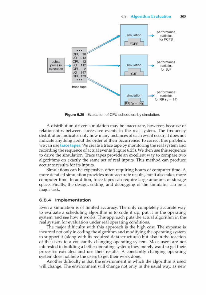
6.8 Algorithm Evaluation 303
actualprocess
execution
performancestatisticsfor FCFS
simulation
FCFS
performancestatisticsfor SJF
performancestatistics
for RR (q $ 14)
trace tape
simulation
SJF
simulation
RR (q $ 14)
• • •CPU 10I/O 213 CPU 12 I/O 112 CPU 2 I/O 147 CPU 173
• • •
Figure 6.25 Evaluation of CPU schedulers by simulation.
A distribution-driven simulation may be inaccurate, however, because ofrelationships between successive events in the real system. The frequencydistribution indicates only how many instances of each event occur; it does notindicate anything about the order of their occurrence. To correct this problem,we can use trace tapes. We create a trace tape by monitoring the real system andrecording the sequence of actual events (Figure 6.25). We then use this sequenceto drive the simulation. Trace tapes provide an excellent way to compare twoalgorithms on exactly the same set of real inputs. This method can produceaccurate results for its inputs.
Simulations can be expensive, often requiring hours of computer time. Amore detailed simulation provides more accurate results, but it also takes morecomputer time. In addition, trace tapes can require large amounts of storagespace. Finally, the design, coding, and debugging of the simulator can be amajor task.
6.8.4 Implementation
Even a simulation is of limited accuracy. The only completely accurate wayto evaluate a scheduling algorithm is to code it up, put it in the operatingsystem, and see how it works. This approach puts the actual algorithm in thereal system for evaluation under real operating conditions.
The major difficulty with this approach is the high cost. The expense isincurred not only in coding the algorithm and modifying the operating systemto support it (along with its required data structures) but also in the reactionof the users to a constantly changing operating system. Most users are notinterested in building a better operating system; they merely want to get theirprocesses executed and use their results. A constantly changing operatingsystem does not help the users to get their work done.
Another difficulty is that the environment in which the algorithm is usedwill change. The environment will change not only in the usual way, as new
304 Chapter 6 CPU Scheduling
programs are written and the types of problems change, but also as a resultof the performance of the scheduler. If short processes are given priority, thenusers may break larger processes into sets of smaller processes. If interactiveprocesses are given priority over noninteractive processes, then users mayswitch to interactive use.
For example, researchers designed one system that classified interactiveand noninteractive processes automatically by looking at the amount ofterminal I/O. If a process did not input or output to the terminal in a 1-secondinterval, the process was classified as noninteractive and was moved to alower-priority queue. In response to this policy, one programmer modified hisprograms to write an arbitrary character to the terminal at regular intervals ofless than 1 second. The system gave his programs a high priority, even thoughthe terminal output was completely meaningless.
The most flexible scheduling algorithms are those that can be alteredby the system managers or by the users so that they can be tuned fora specific application or set of applications. A workstation that performshigh-end graphical applications, for instance, may have scheduling needsdifferent from those of a Web server or file server. Some operating systems—particularly several versions of UNIX—allow the system manager to fine-tunethe scheduling parameters for a particular system configuration. For example,Solaris provides the dispadmin command to allow the system administratorto modify the parameters of the scheduling classes described in Section 6.7.3.
Another approach is to use APIs that can modify the priority of a processor thread. The Java, POSIX, and Windows API provide such functions. Thedownfall of this approach is that performance-tuning a system or applicationmost often does not result in improved performance in more general situations.
6.9 Summary
CPU scheduling is the task of selecting a waiting process from the ready queueand allocating the CPU to it. The CPU is allocated to the selected process by thedispatcher.
First-come, first-served (FCFS) scheduling is the simplest scheduling algo-rithm, but it can cause short processes to wait for very long processes. Shortest-job-first (SJF) scheduling is provably optimal, providing the shortest averagewaiting time. Implementing SJF scheduling is difficult, however, because pre-dicting the length of the next CPU burst is difficult. The SJF algorithm is a specialcase of the general priority scheduling algorithm, which simply allocates theCPU to the highest-priority process. Both priority and SJF scheduling may sufferfrom starvation. Aging is a technique to prevent starvation.
Round-robin (RR) scheduling is more appropriate for a time-shared (inter-active) system. RR scheduling allocates the CPU to the first process in the readyqueue for q time units, where q is the time quantum. After q time units, ifthe process has not relinquished the CPU, it is preempted, and the process isput at the tail of the ready queue. The major problem is the selection of thetime quantum. If the quantum is too large, RR scheduling degenerates to FCFSscheduling. If the quantum is too small, scheduling overhead in the form ofcontext-switch time becomes excessive.
Practice Exercises 305
The FCFS algorithm is nonpreemptive; the RR algorithm is preemptive. TheSJF and priority algorithms may be either preemptive or nonpreemptive.
Multilevel queue algorithms allow different algorithms to be used fordifferent classes of processes. The most common model includes a foregroundinteractive queue that uses RR scheduling and a background batch queue thatuses FCFS scheduling. Multilevel feedback queues allow processes to movefrom one queue to another.
Many contemporary computer systems support multiple processors andallow each processor to schedule itself independently. Typically, each processormaintains its own private queue of processes (or threads), all of which areavailable to run. Additional issues related to multiprocessor scheduling includeprocessor affinity, load balancing, and multicore processing.
A real-time computer system requires that results arrive within a deadlineperiod; results arriving after the deadline has passed are useless. Hard real-timesystems must guarantee that real-time tasks are serviced within their deadlineperiods. Soft real-time systems are less restrictive, assigning real-time taskshigher scheduling priority than other tasks.
Real-time scheduling algorithms include rate-monotonic and earliest-deadline-first scheduling. Rate-monotonic scheduling assigns tasks thatrequire the CPU more often a higher priority than tasks that require theCPU less often. Earliest-deadline-first scheduling assigns priority accordingto upcoming deadlines—the earlier the deadline, the higher the priority.Proportional share scheduling divides up processor time into shares andassigning each process a number of shares, thus guaranteeing each processa proportional share of CPU time. The POSIX Pthread API provides variousfeatures for scheduling real-time threads as well.
Operating systems supporting threads at the kernel level must schedulethreads—not processes—for execution. This is the case with Solaris andWindows. Both of these systems schedule threads using preemptive, priority-based scheduling algorithms, including support for real-time threads. TheLinux process scheduler uses a priority-based algorithm with real-time supportas well. The scheduling algorithms for these three operating systems typicallyfavor interactive over CPU-bound processes.
The wide variety of scheduling algorithms demands that we have methodsto select among algorithms. Analytic methods use mathematical analysis todetermine the performance of an algorithm. Simulation methods determineperformance by imitating the scheduling algorithm on a “representative”sample of processes and computing the resulting performance. However,simulation can at best provide an approximation of actual system performance.The only reliable technique for evaluating a scheduling algorithm is toimplement the algorithm on an actual system and monitor its performancein a “real-world” environment.
Practice Exercises
6.1 A CPU-scheduling algorithm determines an order for the executionof its scheduled processes. Given n processes to be scheduled on oneprocessor, how many different schedules are possible? Give a formulain terms of n.
306 Chapter 6 CPU Scheduling
6.2 Explain the difference between preemptive and nonpreemptive schedul-ing.
6.3 Suppose that the following processes arrive for execution at the timesindicated. Each process will run for the amount of time listed. Inanswering the questions, use nonpreemptive scheduling, and base alldecisions on the information you have at the time the decision must bemade.
Process Arrival Time Burst Time
P1 0.0 8P2 0.4 4P3 1.0 1
a. What is the average turnaround time for these processes with theFCFS scheduling algorithm?
b. What is the average turnaround time for these processes with theSJF scheduling algorithm?
c. The SJF algorithm is supposed to improve performance, but noticethat we chose to run process P1 at time 0 because we did not knowthat two shorter processes would arrive soon. Compute what theaverage turnaround time will be if the CPU is left idle for the first1 unit and then SJF scheduling is used. Remember that processesP1 and P2 are waiting during this idle time, so their waiting timemay increase. This algorithm could be called future-knowledgescheduling.
6.4 What advantage is there in having different time-quantum sizes atdifferent levels of a multilevel queueing system?
6.5 Many CPU-scheduling algorithms are parameterized. For example, theRR algorithm requires a parameter to indicate the time slice. Multilevelfeedback queues require parameters to define the number of queues, thescheduling algorithm for each queue, the criteria used to move processesbetween queues, and so on.
These algorithms are thus really sets of algorithms (for example, theset of RR algorithms for all time slices, and so on). One set of algorithmsmay include another (for example, the FCFS algorithm is the RR algorithmwith an infinite time quantum). What (if any) relation holds between thefollowing pairs of algorithm sets?
a. Priority and SJF
b. Multilevel feedback queues and FCFS
c. Priority and FCFS
d. RR and SJF
6.6 Suppose that a scheduling algorithm (at the level of short-term CPUscheduling) favors those processes that have used the least processor
Exercises 307
time in the recent past. Why will this algorithm favor I/O-boundprograms and yet not permanently starve CPU-bound programs?
6.7 Distinguish between PCS and SCS scheduling.
6.8 Assume that an operating system maps user-level threads to the kernelusing the many-to-many model and that the mapping is done throughthe use of LWPs. Furthermore, the system allows program developers tocreate real-time threads. Is it necessary to bind a real-time thread to anLWP?
6.9 The traditional UNIX scheduler enforces an inverse relationship betweenpriority numbers and priorities: the higher the number, the lower thepriority. The scheduler recalculates process priorities once per secondusing the following function:
Priority = (recent CPU usage / 2) + basewhere base = 60 and recent CPU usage refers to a value indicating howoften a process has used the CPU since priorities were last recalculated.
Assume that recent CPU usage is 40 for process P1, 18 for process P2,and 10 for process P3. What will be the new priorities for these threeprocesses when priorities are recalculated? Based on this information,does the traditional UNIX scheduler raise or lower the relative priorityof a CPU-bound process?
Exercises
6.10 Why is it important for the scheduler to distinguish I/O-bound programsfrom CPU-bound programs?
6.11 Discuss how the following pairs of scheduling criteria conflict in certainsettings.
a. CPU utilization and response time
b. Average turnaround time and maximum waiting time
c. I/O device utilization and CPU utilization
6.12 One technique for implementing lottery scheduling works by assigningprocesses lottery tickets, which are used for allocating CPU time. When-ever a scheduling decision has to be made, a lottery ticket is chosenat random, and the process holding that ticket gets the CPU. The BTVoperating system implements lottery scheduling by holding a lottery50 times each second, with each lottery winner getting 20 millisecondsof CPU time (20 milliseconds × 50 = 1 second). Describe how the BTVscheduler can ensure that higher-priority threads receive more attentionfrom the CPU than lower-priority threads.
6.13 In Chapter 5, we discussed possible race conditions on various kerneldata structures. Most scheduling algorithms maintain a run queue,which lists processes eligible to run on a processor. On multicore systems,there are two general options: (1) each processing core has its own run
308 Chapter 6 CPU Scheduling
queue, or (2) a single run queue is shared by all processing cores. Whatare the advantages and disadvantages of each of these approaches?
6.14 Consider the exponential average formula used to predict the length ofthe next CPU burst. What are the implications of assigning the followingvalues to the parameters used by the algorithm?
a. # = 0 and "0 = 100 milliseconds
b. # = 0.99 and "0 = 10 milliseconds
6.15 A variation of the round-robin scheduler is the regressive round-robinscheduler. This scheduler assigns each process a time quantum and apriority. The initial value of a time quantum is 50 milliseconds. However,every time a process has been allocated the CPU and uses its entire timequantum (does not block for I/O), 10 milliseconds is added to its timequantum, and its priority level is boosted. (The time quantum for aprocess can be increased to a maximum of 100 milliseconds.) When aprocess blocks before using its entire time quantum, its time quantum isreduced by 5 milliseconds, but its priority remains the same. What typeof process (CPU-bound or I/O-bound) does the regressive round-robinscheduler favor? Explain.
6.16 Consider the following set of processes, with the length of the CPU burstgiven in milliseconds:
Process Burst Time Priority
P1 2 2P2 1 1P3 8 4P4 4 2P5 5 3
The processes are assumed to have arrived in the order P1, P2, P3, P4, P5,all at time 0.
a. Draw four Gantt charts that illustrate the execution of theseprocesses using the following scheduling algorithms: FCFS, SJF,nonpreemptive priority (a larger priority number implies a higherpriority), and RR (quantum = 2).
b. What is the turnaround time of each process for each of thescheduling algorithms in part a?
c. What is the waiting time of each process for each of these schedul-ing algorithms?
d. Which of the algorithms results in the minimum average waitingtime (over all processes)?
6.17 The following processes are being scheduled using a preemptive, round-robin scheduling algorithm. Each process is assigned a numericalpriority, with a higher number indicating a higher relative priority.In addition to the processes listed below, the system also has an idle
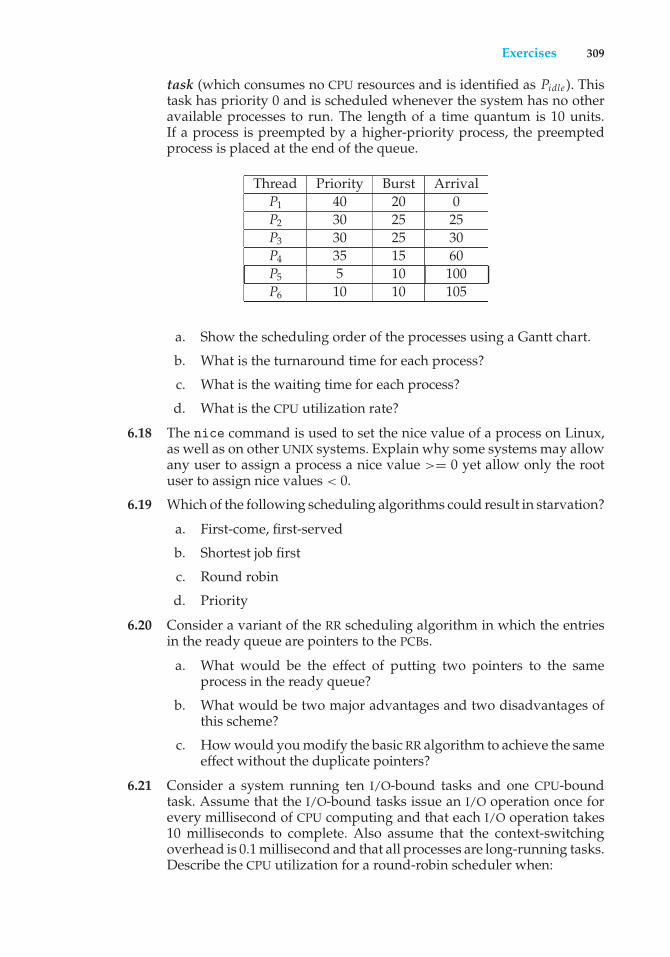
Exercises 309
task (which consumes no CPU resources and is identified as Pidle ). Thistask has priority 0 and is scheduled whenever the system has no otheravailable processes to run. The length of a time quantum is 10 units.If a process is preempted by a higher-priority process, the preemptedprocess is placed at the end of the queue.
Thread Priority Burst ArrivalP1 40 20 0P2 30 25 25P3 30 25 30P4 35 15 60P5 5 10 100P6 10 10 105
a. Show the scheduling order of the processes using a Gantt chart.
b. What is the turnaround time for each process?
c. What is the waiting time for each process?
d. What is the CPU utilization rate?
6.18 The nice command is used to set the nice value of a process on Linux,as well as on other UNIX systems. Explain why some systems may allowany user to assign a process a nice value >= 0 yet allow only the rootuser to assign nice values < 0.
6.19 Which of the following scheduling algorithms could result in starvation?
a. First-come, first-served
b. Shortest job first
c. Round robin
d. Priority
6.20 Consider a variant of the RR scheduling algorithm in which the entriesin the ready queue are pointers to the PCBs.
a. What would be the effect of putting two pointers to the sameprocess in the ready queue?
b. What would be two major advantages and two disadvantages ofthis scheme?
c. How would you modify the basic RR algorithm to achieve the sameeffect without the duplicate pointers?
6.21 Consider a system running ten I/O-bound tasks and one CPU-boundtask. Assume that the I/O-bound tasks issue an I/O operation once forevery millisecond of CPU computing and that each I/O operation takes10 milliseconds to complete. Also assume that the context-switchingoverhead is 0.1 millisecond and that all processes are long-running tasks.Describe the CPU utilization for a round-robin scheduler when:

310 Chapter 6 CPU Scheduling
a. The time quantum is 1 millisecond
b. The time quantum is 10 milliseconds
6.22 Consider a system implementing multilevel queue scheduling. Whatstrategy can a computer user employ to maximize the amount of CPUtime allocated to the user’s process?
6.23 Consider a preemptive priority scheduling algorithm based on dynami-cally changing priorities. Larger priority numbers imply higher priority.When a process is waiting for the CPU (in the ready queue, but notrunning), its priority changes at a rate #. When it is running, its prioritychanges at a rate &. All processes are given a priority of 0 when theyenter the ready queue. The parameters # and & can be set to give manydifferent scheduling algorithms.
a. What is the algorithm that results from & > # > 0?
b. What is the algorithm that results from # < & < 0?
6.24 Explain the differences in how much the following scheduling algo-rithms discriminate in favor of short processes:
a. FCFS
b. RR
c. Multilevel feedback queues
6.25 Using the Windows scheduling algorithm, determine the numericpriority of each of the following threads.
a. A thread in the REALTIME PRIORITY CLASS with a relative priorityof NORMAL
b. A thread in the ABOVE NORMAL PRIORITY CLASS with a relativepriority of HIGHEST
c. A thread in the BELOW NORMAL PRIORITY CLASS with a relativepriority of ABOVE NORMAL
6.26 Assuming that no threads belong to the REALTIME PRIORITY CLASS andthat none may be assigned a TIME CRITICAL priority, what combinationof priority class and priority corresponds to the highest possible relativepriority in Windows scheduling?
6.27 Consider the scheduling algorithm in the Solaris operating system fortime-sharing threads.
a. What is the time quantum (in milliseconds) for a thread withpriority 15? With priority 40?
b. Assume that a thread with priority 50 has used its entire timequantum without blocking. What new priority will the schedulerassign this thread?
c. Assume that a thread with priority 20 blocks for I/O before its timequantum has expired. What new priority will the scheduler assignthis thread?
Bibliographical Notes 311
6.28 Assume that two tasks A and B are running on a Linux system. The nicevalues of Aand B are−5 and +5, respectively. Using the CFS scheduler asa guide, describe how the respective values of vruntime vary betweenthe two processes given each of the following scenarios:
• Both A and B are CPU-bound.
• A is I/O-bound, and B is CPU-bound.
• A is CPU-bound, and B is I/O-bound.
6.29 Discuss ways in which the priority inversion problem could beaddressed in a real-time system. Also discuss whether the solutionscould be implemented within the context of a proportional share sched-uler.
6.30 Under what circumstances is rate-monotonic scheduling inferior toearliest-deadline-first scheduling in meeting the deadlines associatedwith processes?
6.31 Consider two processes, P1 and P2, where p1 = 50, t1 = 25, p2 = 75, andt2 = 30.
a. Can these two processes be scheduled using rate-monotonicscheduling? Illustrate your answer using a Gantt chart such asthe ones in Figure 6.16–Figure 6.19.
b. Illustrate the scheduling of these two processes using earliest-deadline-first (EDF) scheduling.
6.32 Explain why interrupt and dispatch latency times must be bounded ina hard real-time system.
Bibliographical Notes
Feedback queues were originally implemented on the CTSS system described in[Corbato et al. (1962)]. This feedback queue scheduling system was analyzed by[Schrage (1967)]. The preemptive priority scheduling algorithm of Exercise 6.23was suggested by [Kleinrock (1975)]. The scheduling algorithms for hard real-time systems, such as rate monotonic scheduling and earliest-deadline-firstscheduling, are presented in [Liu and Layland (1973)].
[Anderson et al. (1989)], [Lewis and Berg (1998)], and [Philbin et al. (1996)]discuss thread scheduling. Multicore scheduling is examined in [McNairy andBhatia (2005)] and [Kongetira et al. (2005)].
[Fisher (1981)], [Hall et al. (1996)], and [Lowney et al. (1993)] describescheduling techniques that take into account information regarding processexecution times from previous runs.
Fair-share schedulers are covered by [Henry (1984)], [Woodside (1986)],and [Kay and Lauder (1988)].
Scheduling policies used in the UNIX V operating system are describedby [Bach (1987)]; those for UNIX FreeBSD 5.2 are presented by [McKusick andNeville-Neil (2005)]; and those for the Mach operating system are discussedby [Black (1990)]. [Love (2010)] and [Mauerer (2008)] cover scheduling in
312 Chapter 6 CPU Scheduling
Linux. [Faggioli et al. (2009)] discuss adding an EDF scheduler to the Linuxkernel. Details of the ULE scheduler can be found in [Roberson (2003)]. Solarisscheduling is described by [Mauro and McDougall (2007)]. [Russinovich andSolomon (2009)] discusses scheduling in Windows internals. [Butenhof (1997)]and [Lewis and Berg (1998)] describe scheduling in Pthreads systems. [Siddhaet al. (2007)] discuss scheduling challenges on multicore systems.
Bibliography
[Anderson et al. (1989)] T. E. Anderson, E. D. Lazowska, and H. M. Levy,“The Performance Implications of Thread Management Alternatives forShared-Memory Multiprocessors”, IEEE Transactions on Computers, Volume 38,Number 12 (1989), pages 1631–1644.
[Bach (1987)] M. J. Bach, The Design of the UNIX Operating System, Prentice Hall(1987).
[Black (1990)] D. L. Black, “Scheduling Support for Concurrency and Parallelismin the Mach Operating System”, IEEE Computer, Volume 23, Number 5 (1990),pages 35–43.
[Butenhof (1997)] D. Butenhof, Programming with POSIX Threads, Addison-Wesley (1997).
[Corbato et al. (1962)] F. J. Corbato, M. Merwin-Daggett, and R. C. Daley, “AnExperimental Time-Sharing System”, Proceedings of the AFIPS Fall Joint ComputerConference (1962), pages 335–344.
[Faggioli et al. (2009)] D. Faggioli, F. Checconi, M. Trimarchi, and C. Scordino,“An EDF scheduling class for the Linux kernel”, Proceedings of the 11th Real-TimeLinux Workshop (2009).
[Fisher (1981)] J. A. Fisher, “Trace Scheduling: A Technique for Global MicrocodeCompaction”, IEEE Transactions on Computers, Volume 30, Number 7 (1981),pages 478–490.
[Hall et al. (1996)] L. Hall, D. Shmoys, and J. Wein, “Scheduling To MinimizeAverage Completion Time: Off-line and On-line Algorithms”, SODA: ACM-SIAM Symposium on Discrete Algorithms (1996).
[Henry (1984)] G. Henry, “The Fair Share Scheduler”, AT&T Bell LaboratoriesTechnical Journal (1984).
[Kay and Lauder (1988)] J. Kay and P. Lauder, “A Fair Share Scheduler”, Com-munications of the ACM, Volume 31, Number 1 (1988), pages 44–55.
[Kleinrock (1975)] L. Kleinrock, Queueing Systems, Volume II: Computer Applica-tions, Wiley-Interscience (1975).
[Kongetira et al. (2005)] P. Kongetira, K. Aingaran, and K. Olukotun, “Niagara:A 32-Way Multithreaded SPARC Processor”, IEEE Micro Magazine, Volume 25,Number 2 (2005), pages 21–29.
Bibliography 313
[Lewis and Berg (1998)] B. Lewis and D. Berg, Multithreaded Programming withPthreads, Sun Microsystems Press (1998).
[Liu and Layland (1973)] C. L. Liu and J. W. Layland, “Scheduling Algorithmsfor Multiprogramming in a Hard Real-Time Environment”, Communications ofthe ACM, Volume 20, Number 1 (1973), pages 46–61.
[Love (2010)] R. Love, Linux Kernel Development, Third Edition, Developer’sLibrary (2010).
[Lowney et al. (1993)] P. G. Lowney, S. M. Freudenberger, T. J. Karzes, W. D.Lichtenstein, R. P. Nix, J. S. O’Donnell, and J. C. Ruttenberg, “The MultiflowTrace Scheduling Compiler”, Journal of Supercomputing, Volume 7, Number 1-2(1993), pages 51–142.
[Mauerer (2008)] W. Mauerer, Professional Linux Kernel Architecture, John Wileyand Sons (2008).
[Mauro and McDougall (2007)] J. Mauro and R. McDougall, Solaris Internals:Core Kernel Architecture, Prentice Hall (2007).
[McKusick and Neville-Neil (2005)] M. K. McKusick and G. V. Neville-Neil,The Design and Implementation of the FreeBSD UNIX Operating System, AddisonWesley (2005).
[McNairy and Bhatia (2005)] C. McNairy and R. Bhatia, “Montecito: A Dual–Core, Dual-Threaded Itanium Processor”, IEEE Micro Magazine, Volume 25,Number 2 (2005), pages 10–20.
[Philbin et al. (1996)] J. Philbin, J. Edler, O. J. Anshus, C. C. Douglas, and K. Li,“Thread Scheduling for Cache Locality”, Architectural Support for ProgrammingLanguages and Operating Systems (1996), pages 60–71.
[Roberson (2003)] J. Roberson, “ULE: A Modern Scheduler For FreeBSD”,Proceedings of the USENIX BSDCon Conference (2003), pages 17–28.
[Russinovich and Solomon (2009)] M. E. Russinovich and D. A. Solomon, Win-dows Internals: Including Windows Server 2008 and Windows Vista, Fifth Edition,Microsoft Press (2009).
[Schrage (1967)] L. E. Schrage, “The Queue M/G/I with Feedback to LowerPriority Queues”, Management Science, Volume 13, (1967), pages 466–474.
[Siddha et al. (2007)] S. Siddha, V. Pallipadi, and A. Mallick, “Process Schedul-ing Challenges in the Era of Multi-Core Processors”, Intel Technology Journal,Volume 11, Number 4 (2007).
[Woodside (1986)] C. Woodside, “Controllability of Computer PerformanceTradeoffs Obtained Using Controlled-Share Queue Schedulers”, IEEE Transac-tions on Software Engineering, Volume SE-12, Number 10 (1986), pages 1041–1048.

7C H A P T E R
Deadlocks
In a multiprogramming environment, several processes may compete for afinite number of resources. A process requests resources; if the resources arenot available at that time, the process enters a waiting state. Sometimes, awaiting process is never again able to change state, because the resources ithas requested are held by other waiting processes. This situation is calleda deadlock. We discussed this issue briefly in Chapter 5 in connection withsemaphores.
Perhaps the best illustration of a deadlock can be drawn from a law passedby the Kansas legislature early in the 20th century. It said, in part: “When twotrains approach each other at a crossing, both shall come to a full stop andneither shall start up again until the other has gone.”
In this chapter, we describe methods that an operating system can useto prevent or deal with deadlocks. Although some applications can identifyprograms that may deadlock, operating systems typically do not providedeadlock-prevention facilities, and it remains the responsibility of program-mers to ensure that they design deadlock-free programs. Deadlock problemscan only become more common, given current trends, including larger num-bers of processes, multithreaded programs, many more resources within asystem, and an emphasis on long-lived file and database servers rather thanbatch systems.
CHAPTER OBJECTIVES
• To develop a description of deadlocks, which prevent sets of concurrentprocesses from completing their tasks.
• To present a number of different methods for preventing or avoidingdeadlocks in a computer system.
7.1 System Model
A system consists of a finite number of resources to be distributed among anumber of competing processes. The resources may be partitioned into several
315
316 Chapter 7 Deadlocks
types (or classes), each consisting of some number of identical instances. CPUcycles, files, and I/O devices (such as printers and DVD drives) are examples ofresource types. If a system has two CPUs, then the resource type CPU has twoinstances. Similarly, the resource type printer may have five instances.
If a process requests an instance of a resource type, the allocation of anyinstance of the type should satisfy the request. If it does not, then the instancesare not identical, and the resource type classes have not been defined properly.For example, a system may have two printers. These two printers may bedefined to be in the same resource class if no one cares which printer printswhich output. However, if one printer is on the ninth floor and the other isin the basement, then people on the ninth floor may not see both printersas equivalent, and separate resource classes may need to be defined for eachprinter.
Chapter 5 discussed various synchronization tools, such as mutex locksand semaphores. These tools are also considered system resources, and theyare a common source of deadlock. However, a lock is typically associated withprotecting a specific data structure—that is, one lock may be used to protectaccess to a queue, another to protect access to a linked list, and so forth. For thatreason, each lock is typically assigned its own resource class, and definition isnot a problem.
A process must request a resource before using it and must release theresource after using it. A process may request as many resources as it requiresto carry out its designated task. Obviously, the number of resources requestedmay not exceed the total number of resources available in the system. In otherwords, a process cannot request three printers if the system has only two.
Under the normal mode of operation, a process may utilize a resource inonly the following sequence:
1. Request. The process requests the resource. If the request cannot begranted immediately (for example, if the resource is being used by anotherprocess), then the requesting process must wait until it can acquire theresource.
2. Use. The process can operate on the resource (for example, if the resourceis a printer, the process can print on the printer).
3. Release. The process releases the resource.
The request and release of resources may be system calls, as explained inChapter 2. Examples are the request() and release() device, open() andclose() file, and allocate() and free() memory system calls. Similarly,as we saw in Chapter 5, the request and release of semaphores can beaccomplished through the wait() and signal() operations on semaphoresor through acquire() and release() of a mutex lock. For each use of akernel-managed resource by a process or thread, the operating system checksto make sure that the process has requested and has been allocated the resource.A system table records whether each resource is free or allocated. For eachresource that is allocated, the table also records the process to which it isallocated. If a process requests a resource that is currently allocated to anotherprocess, it can be added to a queue of processes waiting for this resource.
A set of processes is in a deadlocked state when every process in the set iswaiting for an event that can be caused only by another process in the set. The
7.2 Deadlock Characterization 317
events with which we are mainly concerned here are resource acquisition andrelease. The resources may be either physical resources (for example, printers,tape drives, memory space, and CPU cycles) or logical resources (for example,semaphores, mutex locks, and files). However, other types of events may resultin deadlocks (for example, the IPC facilities discussed in Chapter 3).
To illustrate a deadlocked state, consider a system with three CD RW drives.Suppose each of three processes holds one of these CD RW drives. If each processnow requests another drive, the three processes will be in a deadlocked state.Each is waiting for the event “CD RW is released,” which can be caused onlyby one of the other waiting processes. This example illustrates a deadlockinvolving the same resource type.
Deadlocks may also involve different resource types. For example, considera system with one printer and one DVD drive. Suppose that process Pi is holdingthe DVD and process Pj is holding the printer. If Pi requests the printer and Pjrequests the DVD drive, a deadlock occurs.
Developers of multithreaded applications must remain aware of thepossibility of deadlocks. The locking tools presented in Chapter 5 are designedto avoid race conditions. However, in using these tools, developers must paycareful attention to how locks are acquired and released. Otherwise, deadlockcan occur, as illustrated in the dining-philosophers problem in Section 5.7.3.
7.2 Deadlock Characterization
In a deadlock, processes never finish executing, and system resources are tiedup, preventing other jobs from starting. Before we discuss the various methodsfor dealing with the deadlock problem, we look more closely at features thatcharacterize deadlocks.
DEADLOCK WITH MUTEX LOCKS
Let’s see how deadlock can occur in a multithreaded Pthread programusing mutex locks. The pthread mutex init() function initializesan unlocked mutex. Mutex locks are acquired and released usingpthread mutex lock() and pthread mutex unlock(), respec-tively. If a thread attempts to acquire a locked mutex, the call topthread mutex lock() blocks the thread until the owner of the mutexlock invokes pthread mutex unlock().
Two mutex locks are created in the following code example:
/* Create and initialize the mutex locks */pthread mutex t first mutex;pthread mutex t second mutex;
pthread mutex init(&first mutex,NULL);pthread mutex init(&second mutex,NULL);
Next, two threads—thread one and thread two—are created, and boththese threads have access to both mutex locks. thread one and thread two
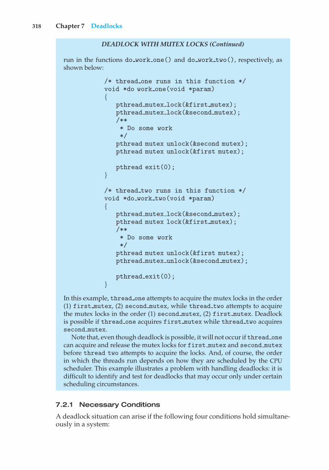
318 Chapter 7 Deadlocks
DEADLOCK WITH MUTEX LOCKS (Continued)
run in the functions do work one() and do work two(), respectively, asshown below:
/* thread one runs in this function */void *do work one(void *param){
pthread mutex lock(&first mutex);pthread mutex lock(&second mutex);/*** Do some work*/
pthread mutex unlock(&second mutex);pthread mutex unlock(&first mutex);
pthread exit(0);}
/* thread two runs in this function */void *do work two(void *param){
pthread mutex lock(&second mutex);pthread mutex lock(&first mutex);/*** Do some work*/
pthread mutex unlock(&first mutex);pthread mutex unlock(&second mutex);
pthread exit(0);}
In this example, thread one attempts to acquire the mutex locks in the order(1) first mutex, (2) second mutex, while thread two attempts to acquirethe mutex locks in the order (1) second mutex, (2) first mutex. Deadlockis possible if thread one acquires first mutex while thread two acquiressecond mutex.
Note that, even though deadlock is possible, it will not occur if thread onecan acquire and release the mutex locks for first mutex and second mutexbefore thread two attempts to acquire the locks. And, of course, the orderin which the threads run depends on how they are scheduled by the CPUscheduler. This example illustrates a problem with handling deadlocks: it isdifficult to identify and test for deadlocks that may occur only under certainscheduling circumstances.
7.2.1 Necessary Conditions
A deadlock situation can arise if the following four conditions hold simultane-ously in a system:
7.2 Deadlock Characterization 319
1. Mutual exclusion. At least one resource must be held in a nonsharablemode; that is, only one process at a time can use the resource. If anotherprocess requests that resource, the requesting process must be delayeduntil the resource has been released.
2. Hold and wait. A process must be holding at least one resource andwaiting to acquire additional resources that are currently being held byother processes.
3. No preemption. Resources cannot be preempted; that is, a resource canbe released only voluntarily by the process holding it, after that processhas completed its task.
4. Circular wait. A set {P0, P1, ..., Pn} of waiting processes must exist suchthat P0 is waiting for a resource held by P1, P1 is waiting for a resourceheld by P2, ..., Pn−1 is waiting for a resource held by Pn, and Pn is waitingfor a resource held by P0.
We emphasize that all four conditions must hold for a deadlock tooccur. The circular-wait condition implies the hold-and-wait condition, so thefour conditions are not completely independent. We shall see in Section 7.4,however, that it is useful to consider each condition separately.
7.2.2 Resource-Allocation Graph
Deadlocks can be described more precisely in terms of a directed graph calleda system resource-allocation graph. This graph consists of a set of vertices Vand a set of edges E. The set of vertices V is partitioned into two different typesof nodes: P = {P1, P2, ..., Pn}, the set consisting of all the active processes in thesystem, and R = {R1, R2, ..., Rm}, the set consisting of all resource types in thesystem.
A directed edge from process Pi to resource type Rj is denoted by Pi → Rj ;it signifies that process Pi has requested an instance of resource type Rj andis currently waiting for that resource. A directed edge from resource type Rjto process Pi is denoted by Rj → Pi ; it signifies that an instance of resourcetype Rj has been allocated to process Pi . A directed edge Pi → Rj is called arequest edge; a directed edge Rj → Pi is called an assignment edge.
Pictorially, we represent each process Pi as a circle and each resource typeRj as a rectangle. Since resource type Rj may have more than one instance, werepresent each such instance as a dot within the rectangle. Note that a requestedge points to only the rectangle Rj , whereas an assignment edge must alsodesignate one of the dots in the rectangle.
When process Pi requests an instance of resource type Rj , a request edgeis inserted in the resource-allocation graph. When this request can be fulfilled,the request edge is instantaneously transformed to an assignment edge. Whenthe process no longer needs access to the resource, it releases the resource. Asa result, the assignment edge is deleted.
The resource-allocation graph shown in Figure 7.1 depicts the followingsituation.
• The sets P, R, and E:
◦ P = {P1, P2, P3}
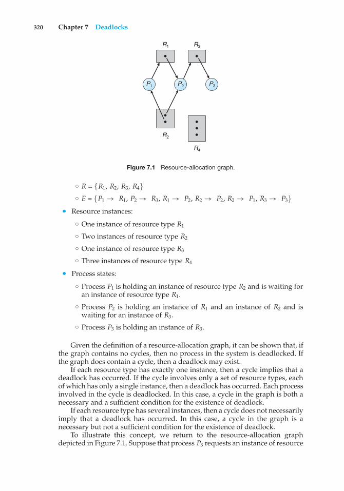
320 Chapter 7 Deadlocks
R1 R3
R2
R4
P3P2P1
Figure 7.1 Resource-allocation graph.
◦ R = {R1, R2, R3, R4}◦ E = {P1 → R1, P2 → R3, R1 → P2, R2 → P2, R2 → P1, R3 → P3}
• Resource instances:
◦ One instance of resource type R1
◦ Two instances of resource type R2
◦ One instance of resource type R3
◦ Three instances of resource type R4
• Process states:
◦ Process P1 is holding an instance of resource type R2 and is waiting foran instance of resource type R1.
◦ Process P2 is holding an instance of R1 and an instance of R2 and iswaiting for an instance of R3.
◦ Process P3 is holding an instance of R3.
Given the definition of a resource-allocation graph, it can be shown that, ifthe graph contains no cycles, then no process in the system is deadlocked. Ifthe graph does contain a cycle, then a deadlock may exist.
If each resource type has exactly one instance, then a cycle implies that adeadlock has occurred. If the cycle involves only a set of resource types, eachof which has only a single instance, then a deadlock has occurred. Each processinvolved in the cycle is deadlocked. In this case, a cycle in the graph is both anecessary and a sufficient condition for the existence of deadlock.
If each resource type has several instances, then a cycle does not necessarilyimply that a deadlock has occurred. In this case, a cycle in the graph is anecessary but not a sufficient condition for the existence of deadlock.
To illustrate this concept, we return to the resource-allocation graphdepicted in Figure 7.1. Suppose that process P3 requests an instance of resource
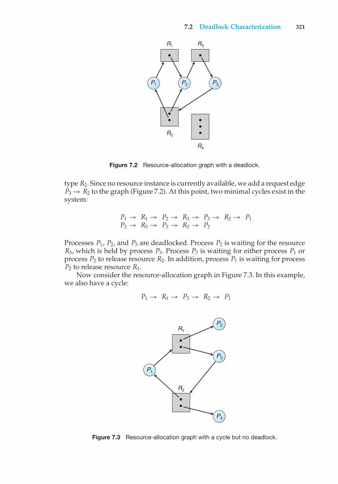
7.2 Deadlock Characterization 321
R1 R3
R2
R4
P3P2P1
Figure 7.2 Resource-allocation graph with a deadlock.
type R2. Since no resource instance is currently available, we add a request edgeP3 → R2 to the graph (Figure 7.2). At this point, two minimal cycles exist in thesystem:
P1 → R1 → P2 → R3 → P3 → R2 → P1P2 → R3 → P3 → R2 → P2
Processes P1, P2, and P3 are deadlocked. Process P2 is waiting for the resourceR3, which is held by process P3. Process P3 is waiting for either process P1 orprocess P2 to release resource R2. In addition, process P1 is waiting for processP2 to release resource R1.
Now consider the resource-allocation graph in Figure 7.3. In this example,we also have a cycle:
P1 → R1 → P3 → R2 → P1
R2
R1
P3
P4
P2
P1
Figure 7.3 Resource-allocation graph with a cycle but no deadlock.
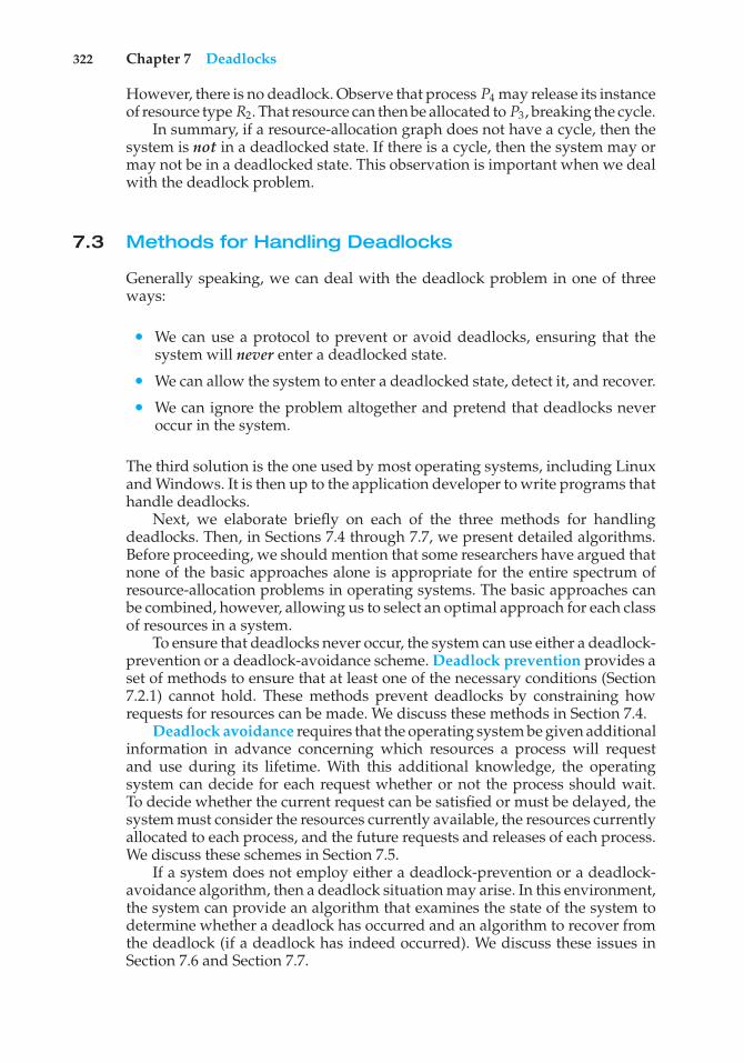
322 Chapter 7 Deadlocks
However, there is no deadlock. Observe that process P4 may release its instanceof resource type R2. That resource can then be allocated to P3, breaking the cycle.
In summary, if a resource-allocation graph does not have a cycle, then thesystem is not in a deadlocked state. If there is a cycle, then the system may ormay not be in a deadlocked state. This observation is important when we dealwith the deadlock problem.
7.3 Methods for Handling Deadlocks
Generally speaking, we can deal with the deadlock problem in one of threeways:
• We can use a protocol to prevent or avoid deadlocks, ensuring that thesystem will never enter a deadlocked state.
• We can allow the system to enter a deadlocked state, detect it, and recover.
• We can ignore the problem altogether and pretend that deadlocks neveroccur in the system.
The third solution is the one used by most operating systems, including Linuxand Windows. It is then up to the application developer to write programs thathandle deadlocks.
Next, we elaborate briefly on each of the three methods for handlingdeadlocks. Then, in Sections 7.4 through 7.7, we present detailed algorithms.Before proceeding, we should mention that some researchers have argued thatnone of the basic approaches alone is appropriate for the entire spectrum ofresource-allocation problems in operating systems. The basic approaches canbe combined, however, allowing us to select an optimal approach for each classof resources in a system.
To ensure that deadlocks never occur, the system can use either a deadlock-prevention or a deadlock-avoidance scheme. Deadlock prevention provides aset of methods to ensure that at least one of the necessary conditions (Section7.2.1) cannot hold. These methods prevent deadlocks by constraining howrequests for resources can be made. We discuss these methods in Section 7.4.
Deadlock avoidance requires that the operating system be given additionalinformation in advance concerning which resources a process will requestand use during its lifetime. With this additional knowledge, the operatingsystem can decide for each request whether or not the process should wait.To decide whether the current request can be satisfied or must be delayed, thesystem must consider the resources currently available, the resources currentlyallocated to each process, and the future requests and releases of each process.We discuss these schemes in Section 7.5.
If a system does not employ either a deadlock-prevention or a deadlock-avoidance algorithm, then a deadlock situation may arise. In this environment,the system can provide an algorithm that examines the state of the system todetermine whether a deadlock has occurred and an algorithm to recover fromthe deadlock (if a deadlock has indeed occurred). We discuss these issues inSection 7.6 and Section 7.7.
7.4 Deadlock Prevention 323
In the absence of algorithms to detect and recover from deadlocks, we mayarrive at a situation in which the system is in a deadlocked state yet has noway of recognizing what has happened. In this case, the undetected deadlockwill cause the system’s performance to deteriorate, because resources are beingheld by processes that cannot run and because more and more processes, asthey make requests for resources, will enter a deadlocked state. Eventually, thesystem will stop functioning and will need to be restarted manually.
Although this method may not seem to be a viable approach to the deadlockproblem, it is nevertheless used in most operating systems, as mentionedearlier. Expense is one important consideration. Ignoring the possibility ofdeadlocks is cheaper than the other approaches. Since in many systems,deadlocks occur infrequently (say, once per year), the extra expense of theother methods may not seem worthwhile. In addition, methods used to recoverfrom other conditions may be put to use to recover from deadlock. In somecircumstances, a system is in a frozen state but not in a deadlocked state.We see this situation, for example, with a real-time process running at thehighest priority (or any process running on a nonpreemptive scheduler) andnever returning control to the operating system. The system must have manualrecovery methods for such conditions and may simply use those techniquesfor deadlock recovery.
7.4 Deadlock Prevention
As we noted in Section 7.2.1, for a deadlock to occur, each of the four necessaryconditions must hold. By ensuring that at least one of these conditions cannothold, we can prevent the occurrence of a deadlock. We elaborate on thisapproach by examining each of the four necessary conditions separately.
7.4.1 Mutual Exclusion
The mutual exclusion condition must hold. That is, at least one resource must benonsharable. Sharable resources, in contrast, do not require mutually exclusiveaccess and thus cannot be involved in a deadlock. Read-only files are a goodexample of a sharable resource. If several processes attempt to open a read-onlyfile at the same time, they can be granted simultaneous access to the file. Aprocess never needs to wait for a sharable resource. In general, however, wecannot prevent deadlocks by denying the mutual-exclusion condition, becausesome resources are intrinsically nonsharable. For example, a mutex lock cannotbe simultaneously shared by several processes.
7.4.2 Hold and Wait
To ensure that the hold-and-wait condition never occurs in the system, we mustguarantee that, whenever a process requests a resource, it does not hold anyother resources. One protocol that we can use requires each process to requestand be allocated all its resources before it begins execution. We can implementthis provision by requiring that system calls requesting resources for a processprecede all other system calls.
324 Chapter 7 Deadlocks
An alternative protocol allows a process to request resources only whenit has none. A process may request some resources and use them. Before itcan request any additional resources, it must release all the resources that it iscurrently allocated.
To illustrate the difference between these two protocols, we consider aprocess that copies data from a DVD drive to a file on disk, sorts the file, andthen prints the results to a printer. If all resources must be requested at thebeginning of the process, then the process must initially request the DVD drive,disk file, and printer. It will hold the printer for its entire execution, even thoughit needs the printer only at the end.
The second method allows the process to request initially only the DVDdrive and disk file. It copies from the DVD drive to the disk and then releasesboth the DVD drive and the disk file. The process must then request the diskfile and the printer. After copying the disk file to the printer, it releases thesetwo resources and terminates.
Both these protocols have two main disadvantages. First, resource utiliza-tion may be low, since resources may be allocated but unused for a long period.In the example given, for instance, we can release the DVD drive and disk file,and then request the disk file and printer, only if we can be sure that our datawill remain on the disk file. Otherwise, we must request all resources at thebeginning for both protocols.
Second, starvation is possible. A process that needs several popularresources may have to wait indefinitely, because at least one of the resourcesthat it needs is always allocated to some other process.
7.4.3 No Preemption
The third necessary condition for deadlocks is that there be no preemptionof resources that have already been allocated. To ensure that this conditiondoes not hold, we can use the following protocol. If a process is holdingsome resources and requests another resource that cannot be immediatelyallocated to it (that is, the process must wait), then all resources the process iscurrently holding are preempted. In other words, these resources are implicitlyreleased. The preempted resources are added to the list of resources for whichthe process is waiting. The process will be restarted only when it can regain itsold resources, as well as the new ones that it is requesting.
Alternatively, if a process requests some resources, we first check whetherthey are available. If they are, we allocate them. If they are not, we checkwhether they are allocated to some other process that is waiting for additionalresources. If so, we preempt the desired resources from the waiting process andallocate them to the requesting process. If the resources are neither availablenor held by a waiting process, the requesting process must wait. While it iswaiting, some of its resources may be preempted, but only if another processrequests them. A process can be restarted only when it is allocated the newresources it is requesting and recovers any resources that were preemptedwhile it was waiting.
This protocol is often applied to resources whose state can be easily savedand restored later, such as CPU registers and memory space. It cannot generallybe applied to such resources as mutex locks and semaphores.
7.4 Deadlock Prevention 325
7.4.4 Circular Wait
The fourth and final condition for deadlocks is the circular-wait condition. Oneway to ensure that this condition never holds is to impose a total ordering ofall resource types and to require that each process requests resources in anincreasing order of enumeration.
To illustrate, we let R = {R1, R2, ..., Rm} be the set of resource types. Weassign to each resource type a unique integer number, which allows us tocompare two resources and to determine whether one precedes another in ourordering. Formally, we define a one-to-one function F: R → N, where N is theset of natural numbers. For example, if the set of resource types R includestape drives, disk drives, and printers, then the function F might be defined asfollows:
F (tape drive) = 1F (disk drive) = 5F (printer) = 12
We can now consider the following protocol to prevent deadlocks: Eachprocess can request resources only in an increasing order of enumeration. Thatis, a process can initially request any number of instances of a resource type—say, Ri . After that, the process can request instances of resource type Rj ifand only if F(Rj ) > F(Ri ). For example, using the function defined previously,a process that wants to use the tape drive and printer at the same time mustfirst request the tape drive and then request the printer. Alternatively, we canrequire that a process requesting an instance of resource type Rj must havereleased any resources Ri such that F(Ri ) ≥ F(Rj ). Note also that if severalinstances of the same resource type are needed, a single request for all of themmust be issued.
If these two protocols are used, then the circular-wait condition cannothold. We can demonstrate this fact by assuming that a circular wait exists(proof by contradiction). Let the set of processes involved in the circular wait be{P0, P1, ..., Pn}, where Pi is waiting for a resource Ri , which is held by processPi+1. (Modulo arithmetic is used on the indexes, so that Pn is waiting fora resource Rn held by P0.) Then, since process Pi+1 is holding resource Riwhile requesting resource Ri+1, we must have F(Ri ) < F(Ri+1) for all i. Butthis condition means that F(R0) < F(R1) < ... < F(Rn) < F (R0). By transitivity,F(R0) < F(R0), which is impossible. Therefore, there can be no circular wait.
We can accomplish this scheme in an application program by developingan ordering among all synchronization objects in the system. All requests forsynchronization objects must be made in increasing order. For example, if thelock ordering in the Pthread program shown in Figure 7.4 was
F (first mutex) = 1F (second mutex) = 5
then thread two could not request the locks out of order.Keep in mind that developing an ordering, or hierarchy, does not in itself
prevent deadlock. It is up to application developers to write programs thatfollow the ordering. Also note that the function F should be defined accordingto the normal order of usage of the resources in a system. For example, because
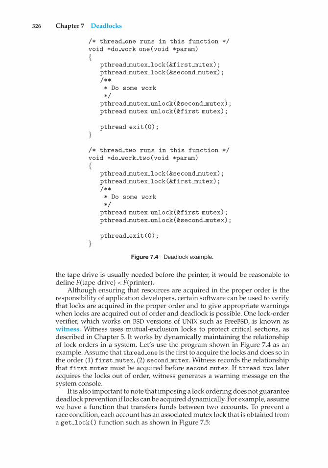
326 Chapter 7 Deadlocks
/* thread one runs in this function */void *do work one(void *param){
pthread mutex lock(&first mutex);pthread mutex lock(&second mutex);/*** Do some work*/
pthread mutex unlock(&second mutex);pthread mutex unlock(&first mutex);
pthread exit(0);}
/* thread two runs in this function */void *do work two(void *param){
pthread mutex lock(&second mutex);pthread mutex lock(&first mutex);/*** Do some work*/
pthread mutex unlock(&first mutex);pthread mutex unlock(&second mutex);
pthread exit(0);}
Figure 7.4 Deadlock example.
the tape drive is usually needed before the printer, it would be reasonable todefine F(tape drive) < F(printer).
Although ensuring that resources are acquired in the proper order is theresponsibility of application developers, certain software can be used to verifythat locks are acquired in the proper order and to give appropriate warningswhen locks are acquired out of order and deadlock is possible. One lock-orderverifier, which works on BSD versions of UNIX such as FreeBSD, is known aswitness. Witness uses mutual-exclusion locks to protect critical sections, asdescribed in Chapter 5. It works by dynamically maintaining the relationshipof lock orders in a system. Let’s use the program shown in Figure 7.4 as anexample. Assume that thread one is the first to acquire the locks and does so inthe order (1) first mutex, (2) second mutex. Witness records the relationshipthat first mutex must be acquired before second mutex. If thread two lateracquires the locks out of order, witness generates a warning message on thesystem console.
It is also important to note that imposing a lock ordering does not guaranteedeadlock prevention if locks can be acquired dynamically. For example, assumewe have a function that transfers funds between two accounts. To prevent arace condition, each account has an associated mutex lock that is obtained froma get lock() function such as shown in Figure 7.5:
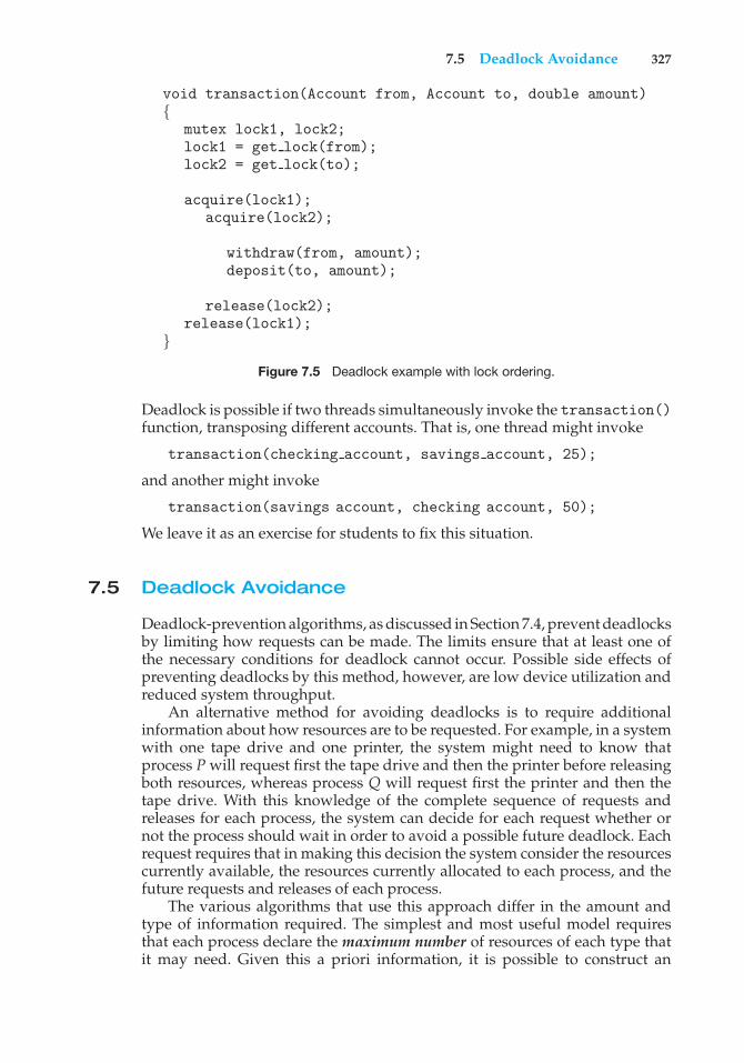
7.5 Deadlock Avoidance 327
void transaction(Account from, Account to, double amount){
mutex lock1, lock2;lock1 = get lock(from);lock2 = get lock(to);
acquire(lock1);acquire(lock2);
withdraw(from, amount);deposit(to, amount);
release(lock2);release(lock1);
}
Figure 7.5 Deadlock example with lock ordering.
Deadlock is possible if two threads simultaneously invoke the transaction()function, transposing different accounts. That is, one thread might invoke
transaction(checking account, savings account, 25);
and another might invoke
transaction(savings account, checking account, 50);
We leave it as an exercise for students to fix this situation.
7.5 Deadlock Avoidance
Deadlock-prevention algorithms, as discussed in Section 7.4, prevent deadlocksby limiting how requests can be made. The limits ensure that at least one ofthe necessary conditions for deadlock cannot occur. Possible side effects ofpreventing deadlocks by this method, however, are low device utilization andreduced system throughput.
An alternative method for avoiding deadlocks is to require additionalinformation about how resources are to be requested. For example, in a systemwith one tape drive and one printer, the system might need to know thatprocess P will request first the tape drive and then the printer before releasingboth resources, whereas process Q will request first the printer and then thetape drive. With this knowledge of the complete sequence of requests andreleases for each process, the system can decide for each request whether ornot the process should wait in order to avoid a possible future deadlock. Eachrequest requires that in making this decision the system consider the resourcescurrently available, the resources currently allocated to each process, and thefuture requests and releases of each process.
The various algorithms that use this approach differ in the amount andtype of information required. The simplest and most useful model requiresthat each process declare the maximum number of resources of each type thatit may need. Given this a priori information, it is possible to construct an
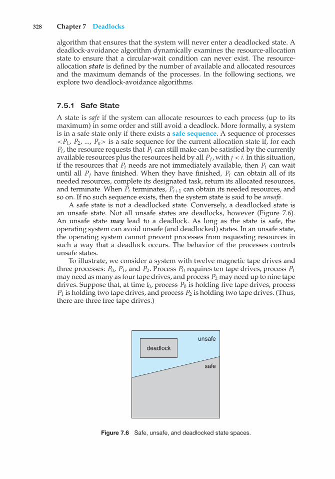
328 Chapter 7 Deadlocks
algorithm that ensures that the system will never enter a deadlocked state. Adeadlock-avoidance algorithm dynamically examines the resource-allocationstate to ensure that a circular-wait condition can never exist. The resource-allocation state is defined by the number of available and allocated resourcesand the maximum demands of the processes. In the following sections, weexplore two deadlock-avoidance algorithms.
7.5.1 Safe State
A state is safe if the system can allocate resources to each process (up to itsmaximum) in some order and still avoid a deadlock. More formally, a systemis in a safe state only if there exists a safe sequence. A sequence of processes<P1, P2, ..., Pn> is a safe sequence for the current allocation state if, for eachPi , the resource requests that Pi can still make can be satisfied by the currentlyavailable resources plus the resources held by all Pj , with j < i. In this situation,if the resources that Pi needs are not immediately available, then Pi can waituntil all Pj have finished. When they have finished, Pi can obtain all of itsneeded resources, complete its designated task, return its allocated resources,and terminate. When Pi terminates, Pi+1 can obtain its needed resources, andso on. If no such sequence exists, then the system state is said to be unsafe.
A safe state is not a deadlocked state. Conversely, a deadlocked state isan unsafe state. Not all unsafe states are deadlocks, however (Figure 7.6).An unsafe state may lead to a deadlock. As long as the state is safe, theoperating system can avoid unsafe (and deadlocked) states. In an unsafe state,the operating system cannot prevent processes from requesting resources insuch a way that a deadlock occurs. The behavior of the processes controlsunsafe states.
To illustrate, we consider a system with twelve magnetic tape drives andthree processes: P0, P1, and P2. Process P0 requires ten tape drives, process P1may need as many as four tape drives, and process P2 may need up to nine tapedrives. Suppose that, at time t0, process P0 is holding five tape drives, processP1 is holding two tape drives, and process P2 is holding two tape drives. (Thus,there are three free tape drives.)
deadlock
unsafe
safe
Figure 7.6 Safe, unsafe, and deadlocked state spaces.
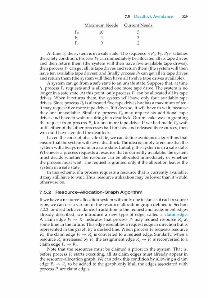
7.5 Deadlock Avoidance 329
Maximum Needs Current Needs
P0 10 5P1 4 2P2 9 2
At time t0, the system is in a safe state. The sequence <P1, P0, P2> satisfiesthe safety condition. Process P1 can immediately be allocated all its tape drivesand then return them (the system will then have five available tape drives);then process P0 can get all its tape drives and return them (the system will thenhave ten available tape drives); and finally process P2 can get all its tape drivesand return them (the system will then have all twelve tape drives available).
A system can go from a safe state to an unsafe state. Suppose that, at timet1, process P2 requests and is allocated one more tape drive. The system is nolonger in a safe state. At this point, only process P1 can be allocated all its tapedrives. When it returns them, the system will have only four available tapedrives. Since process P0 is allocated five tape drives but has a maximum of ten,it may request five more tape drives. If it does so, it will have to wait, becausethey are unavailable. Similarly, process P2 may request six additional tapedrives and have to wait, resulting in a deadlock. Our mistake was in grantingthe request from process P2 for one more tape drive. If we had made P2 waituntil either of the other processes had finished and released its resources, thenwe could have avoided the deadlock.
Given the concept of a safe state, we can define avoidance algorithms thatensure that the system will never deadlock. The idea is simply to ensure that thesystem will always remain in a safe state. Initially, the system is in a safe state.Whenever a process requests a resource that is currently available, the systemmust decide whether the resource can be allocated immediately or whetherthe process must wait. The request is granted only if the allocation leaves thesystem in a safe state.
In this scheme, if a process requests a resource that is currently available,it may still have to wait. Thus, resource utilization may be lower than it wouldotherwise be.
7.5.2 Resource-Allocation-Graph Algorithm
If we have a resource-allocation system with only one instance of each resourcetype, we can use a variant of the resource-allocation graph defined in Section7.2.2 for deadlock avoidance. In addition to the request and assignment edgesalready described, we introduce a new type of edge, called a claim edge.A claim edge Pi → Rj indicates that process Pi may request resource Rj atsome time in the future. This edge resembles a request edge in direction but isrepresented in the graph by a dashed line. When process Pi requests resourceRj , the claim edge Pi → Rj is converted to a request edge. Similarly, when aresource Rj is released by Pi , the assignment edge Rj → Pi is reconverted to aclaim edge Pi → Rj .
Note that the resources must be claimed a priori in the system. That is,before process Pi starts executing, all its claim edges must already appear inthe resource-allocation graph. We can relax this condition by allowing a claimedge Pi → Rj to be added to the graph only if all the edges associated withprocess Pi are claim edges.
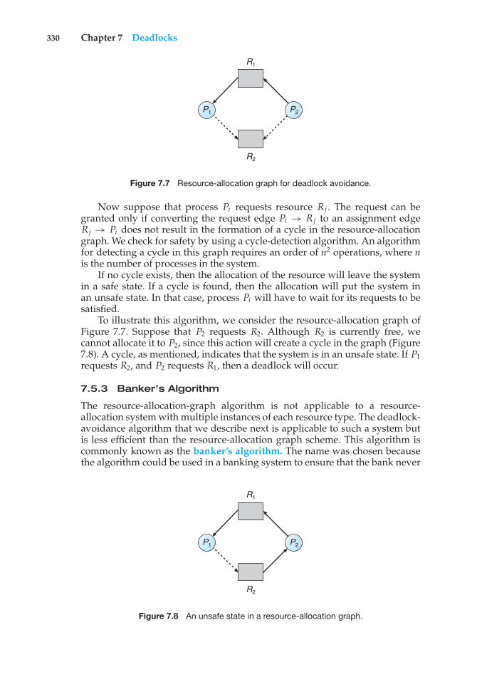
330 Chapter 7 Deadlocks
R1
R2
P2P1
Figure 7.7 Resource-allocation graph for deadlock avoidance.
Now suppose that process Pi requests resource Rj . The request can begranted only if converting the request edge Pi → Rj to an assignment edgeRj → Pi does not result in the formation of a cycle in the resource-allocationgraph. We check for safety by using a cycle-detection algorithm. An algorithmfor detecting a cycle in this graph requires an order of n2 operations, where nis the number of processes in the system.
If no cycle exists, then the allocation of the resource will leave the systemin a safe state. If a cycle is found, then the allocation will put the system inan unsafe state. In that case, process Pi will have to wait for its requests to besatisfied.
To illustrate this algorithm, we consider the resource-allocation graph ofFigure 7.7. Suppose that P2 requests R2. Although R2 is currently free, wecannot allocate it to P2, since this action will create a cycle in the graph (Figure7.8). A cycle, as mentioned, indicates that the system is in an unsafe state. If P1requests R2, and P2 requests R1, then a deadlock will occur.
7.5.3 Banker’s Algorithm
The resource-allocation-graph algorithm is not applicable to a resource-allocation system with multiple instances of each resource type. The deadlock-avoidance algorithm that we describe next is applicable to such a system butis less efficient than the resource-allocation graph scheme. This algorithm iscommonly known as the banker’s algorithm. The name was chosen becausethe algorithm could be used in a banking system to ensure that the bank never
R1
R2
P2P1
Figure 7.8 An unsafe state in a resource-allocation graph.
7.5 Deadlock Avoidance 331
allocated its available cash in such a way that it could no longer satisfy theneeds of all its customers.
When a new process enters the system, it must declare the maximumnumber of instances of each resource type that it may need. This number maynot exceed the total number of resources in the system. When a user requestsa set of resources, the system must determine whether the allocation of theseresources will leave the system in a safe state. If it will, the resources areallocated; otherwise, the process must wait until some other process releasesenough resources.
Several data structures must be maintained to implement the banker’salgorithm. These data structures encode the state of the resource-allocationsystem. We need the following data structures, where n is the number ofprocesses in the system and m is the number of resource types:
• Available. A vector of length m indicates the number of available resourcesof each type. If Available[j] equals k, then k instances of resource type Rjare available.
• Max. An n × m matrix defines the maximum demand of each process.If Max[i][j] equals k, then process Pi may request at most k instances ofresource type Rj .
• Allocation. An n× m matrix defines the number of resources of each typecurrently allocated to each process. If Allocation[i][j] equals k, then processPi is currently allocated k instances of resource type Rj .
• Need. An n × m matrix indicates the remaining resource need of eachprocess. If Need[i][j] equals k, then process Pi may need k more instancesof resource type Rj to complete its task. Note that Need[i][j] equals Max[i][j]− Allocation[i][j].
These data structures vary over time in both size and value.To simplify the presentation of the banker’s algorithm, we next establish
some notation. Let X and Y be vectors of length n. We say that X ≤ Y if andonly if X[i] ≤ Y[i] for all i = 1, 2, ..., n. For example, if X = (1,7,3,2) and Y =(0,3,2,1), then Y ≤ X. In addition, Y < X if Y ≤ X and Y ̸= X.
We can treat each row in the matrices Allocation and Need as vectorsand refer to them as Allocationi and Needi . The vector Allocationi specifiesthe resources currently allocated to process Pi ; the vector Needi specifies theadditional resources that process Pi may still request to complete its task.
7.5.3.1 Safety Algorithm
We can now present the algorithm for finding out whether or not a system isin a safe state. This algorithm can be described as follows:
1. Let Work and Finish be vectors of length m and n, respectively. InitializeWork = Available and Finish[i] = false for i = 0, 1, ..., n − 1.
2. Find an index i such that both
a. Finish[i] == false
b. Needi ≤Work
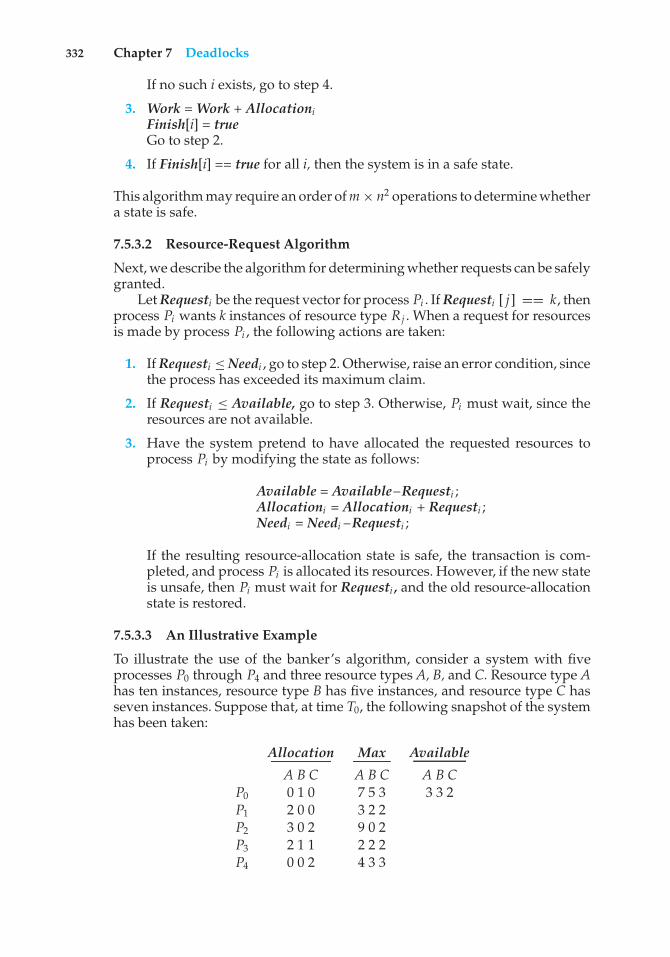
332 Chapter 7 Deadlocks
If no such i exists, go to step 4.
3. Work = Work + AllocationiFinish[i] = trueGo to step 2.
4. If Finish[i] == true for all i, then the system is in a safe state.
This algorithm may require an order of m× n2 operations to determine whethera state is safe.
7.5.3.2 Resource-Request Algorithm
Next, we describe the algorithm for determining whether requests can be safelygranted.
Let Requesti be the request vector for process Pi . If Requesti [ j] == k, thenprocess Pi wants k instances of resource type Rj . When a request for resourcesis made by process Pi , the following actions are taken:
1. If Requesti ≤Needi , go to step 2. Otherwise, raise an error condition, sincethe process has exceeded its maximum claim.
2. If Requesti ≤ Available, go to step 3. Otherwise, Pi must wait, since theresources are not available.
3. Have the system pretend to have allocated the requested resources toprocess Pi by modifying the state as follows:
Available = Available–Requesti ;Allocationi = Allocationi + Requesti ;Needi = Needi –Requesti ;
If the resulting resource-allocation state is safe, the transaction is com-pleted, and process Pi is allocated its resources. However, if the new stateis unsafe, then Pi must wait for Requesti , and the old resource-allocationstate is restored.
7.5.3.3 An Illustrative Example
To illustrate the use of the banker’s algorithm, consider a system with fiveprocesses P0 through P4 and three resource types A, B, and C. Resource type Ahas ten instances, resource type B has five instances, and resource type C hasseven instances. Suppose that, at time T0, the following snapshot of the systemhas been taken:
Allocation Max Available
A B C A B C A B CP0 0 1 0 7 5 3 3 3 2P1 2 0 0 3 2 2P2 3 0 2 9 0 2P3 2 1 1 2 2 2P4 0 0 2 4 3 3
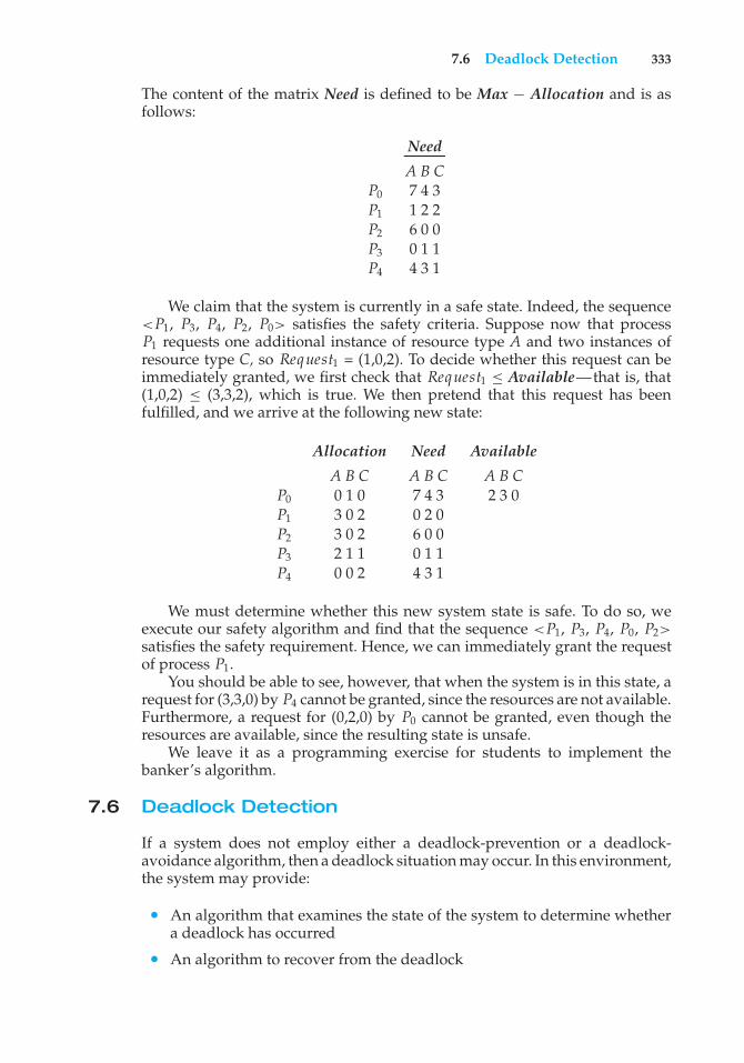
7.6 Deadlock Detection 333
The content of the matrix Need is defined to be Max − Allocation and is asfollows:
Need
A B CP0 7 4 3P1 1 2 2P2 6 0 0P3 0 1 1P4 4 3 1
We claim that the system is currently in a safe state. Indeed, the sequence<P1, P3, P4, P2, P0> satisfies the safety criteria. Suppose now that processP1 requests one additional instance of resource type A and two instances ofresource type C, so Request1 = (1,0,2). To decide whether this request can beimmediately granted, we first check that Request1 ≤ Available—that is, that(1,0,2) ≤ (3,3,2), which is true. We then pretend that this request has beenfulfilled, and we arrive at the following new state:
Allocation Need Available
A B C A B C A B CP0 0 1 0 7 4 3 2 3 0P1 3 0 2 0 2 0P2 3 0 2 6 0 0P3 2 1 1 0 1 1P4 0 0 2 4 3 1
We must determine whether this new system state is safe. To do so, weexecute our safety algorithm and find that the sequence <P1, P3, P4, P0, P2>satisfies the safety requirement. Hence, we can immediately grant the requestof process P1.
You should be able to see, however, that when the system is in this state, arequest for (3,3,0) by P4 cannot be granted, since the resources are not available.Furthermore, a request for (0,2,0) by P0 cannot be granted, even though theresources are available, since the resulting state is unsafe.
We leave it as a programming exercise for students to implement thebanker’s algorithm.
7.6 Deadlock Detection
If a system does not employ either a deadlock-prevention or a deadlock-avoidance algorithm, then a deadlock situation may occur. In this environment,the system may provide:
• An algorithm that examines the state of the system to determine whethera deadlock has occurred
• An algorithm to recover from the deadlock
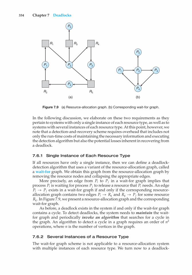
334 Chapter 7 Deadlocks
P3
P5
P4
P2P1
R2
R1 R3 R4
R5
P3
P5
P4
P2P1
(b)(a)
Figure 7.9 (a) Resource-allocation graph. (b) Corresponding wait-for graph.
In the following discussion, we elaborate on these two requirements as theypertain to systems with only a single instance of each resource type, as well as tosystems with several instances of each resource type. At this point, however, wenote that a detection-and-recovery scheme requires overhead that includes notonly the run-time costs of maintaining the necessary information and executingthe detection algorithm but also the potential losses inherent in recovering froma deadlock.
7.6.1 Single Instance of Each Resource Type
If all resources have only a single instance, then we can define a deadlock-detection algorithm that uses a variant of the resource-allocation graph, calleda wait-for graph. We obtain this graph from the resource-allocation graph byremoving the resource nodes and collapsing the appropriate edges.
More precisely, an edge from Pi to Pj in a wait-for graph implies thatprocess Pi is waiting for process Pj to release a resource that Pi needs. An edgePi → Pj exists in a wait-for graph if and only if the corresponding resource-allocation graph contains two edges Pi → Rq and Rq → Pj for some resourceRq . In Figure 7.9, we present a resource-allocation graph and the correspondingwait-for graph.
As before, a deadlock exists in the system if and only if the wait-for graphcontains a cycle. To detect deadlocks, the system needs to maintain the wait-for graph and periodically invoke an algorithm that searches for a cycle inthe graph. An algorithm to detect a cycle in a graph requires an order of n2
operations, where n is the number of vertices in the graph.
7.6.2 Several Instances of a Resource Type
The wait-for graph scheme is not applicable to a resource-allocation systemwith multiple instances of each resource type. We turn now to a deadlock-
7.6 Deadlock Detection 335
detection algorithm that is applicable to such a system. The algorithm employsseveral time-varying data structures that are similar to those used in thebanker’s algorithm (Section 7.5.3):
• Available. A vector of length m indicates the number of available resourcesof each type.
• Allocation. An n× m matrix defines the number of resources of each typecurrently allocated to each process.
• Request. An n × m matrix indicates the current request of each process.If Request[i][j] equals k, then process Pi is requesting k more instances ofresource type Rj .
The≤ relation between two vectors is defined as in Section 7.5.3. To simplifynotation, we again treat the rows in the matrices Allocation and Request asvectors; we refer to them as Allocationi and Requesti . The detection algorithmdescribed here simply investigates every possible allocation sequence for theprocesses that remain to be completed. Compare this algorithm with thebanker’s algorithm of Section 7.5.3.
1. Let Work and Finish be vectors of length m and n, respectively. InitializeWork = Available. For i = 0, 1, ..., n–1, if Allocationi ̸= 0, then Finish[i] =false. Otherwise, Finish[i] = true.
2. Find an index i such that both
a. Finish[i] == false
b. Requesti ≤Work
If no such i exists, go to step 4.
3. Work = Work + AllocationiFinish[i] = trueGo to step 2.
4. If Finish[i] == false for some i, 0≤ i < n, then the system is in a deadlockedstate. Moreover, if Finish[i] == false, then process Pi is deadlocked.
This algorithm requires an order of m × n2 operations to detect whether thesystem is in a deadlocked state.
You may wonder why we reclaim the resources of process Pi (in step 3) assoon as we determine that Requesti ≤ Work (in step 2b). We know that Pi iscurrently not involved in a deadlock (since Requesti ≤ Work). Thus, we takean optimistic attitude and assume that Pi will require no more resources tocomplete its task; it will thus soon return all currently allocated resources tothe system. If our assumption is incorrect, a deadlock may occur later. Thatdeadlock will be detected the next time the deadlock-detection algorithm isinvoked.
To illustrate this algorithm, we consider a system with five processes P0through P4 and three resource types A, B, and C. Resource type A has seveninstances, resource type B has two instances, and resource type C has six
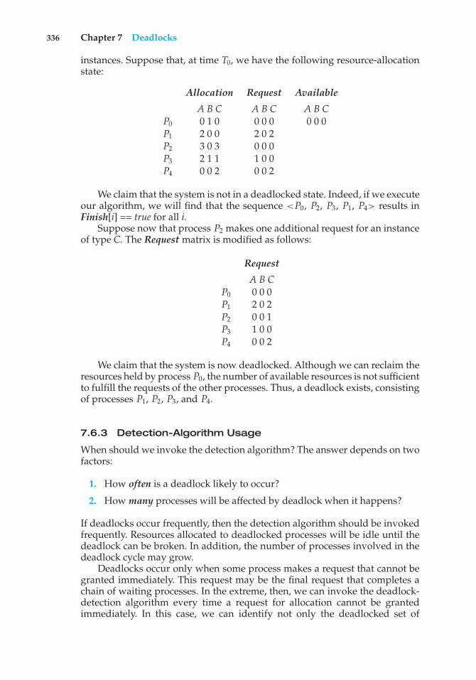
336 Chapter 7 Deadlocks
instances. Suppose that, at time T0, we have the following resource-allocationstate:
Allocation Request Available
A B C A B C A B CP0 0 1 0 0 0 0 0 0 0P1 2 0 0 2 0 2P2 3 0 3 0 0 0P3 2 1 1 1 0 0P4 0 0 2 0 0 2
We claim that the system is not in a deadlocked state. Indeed, if we executeour algorithm, we will find that the sequence <P0, P2, P3, P1, P4> results inFinish[i] == true for all i.
Suppose now that process P2 makes one additional request for an instanceof type C. The Request matrix is modified as follows:
Request
A B CP0 0 0 0P1 2 0 2P2 0 0 1P3 1 0 0P4 0 0 2
We claim that the system is now deadlocked. Although we can reclaim theresources held by process P0, the number of available resources is not sufficientto fulfill the requests of the other processes. Thus, a deadlock exists, consistingof processes P1, P2, P3, and P4.
7.6.3 Detection-Algorithm Usage
When should we invoke the detection algorithm? The answer depends on twofactors:
1. How often is a deadlock likely to occur?
2. How many processes will be affected by deadlock when it happens?
If deadlocks occur frequently, then the detection algorithm should be invokedfrequently. Resources allocated to deadlocked processes will be idle until thedeadlock can be broken. In addition, the number of processes involved in thedeadlock cycle may grow.
Deadlocks occur only when some process makes a request that cannot begranted immediately. This request may be the final request that completes achain of waiting processes. In the extreme, then, we can invoke the deadlock-detection algorithm every time a request for allocation cannot be grantedimmediately. In this case, we can identify not only the deadlocked set of
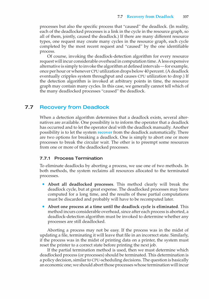
7.7 Recovery from Deadlock 337
processes but also the specific process that “caused” the deadlock. (In reality,each of the deadlocked processes is a link in the cycle in the resource graph, soall of them, jointly, caused the deadlock.) If there are many different resourcetypes, one request may create many cycles in the resource graph, each cyclecompleted by the most recent request and “caused” by the one identifiableprocess.
Of course, invoking the deadlock-detection algorithm for every resourcerequest will incur considerable overhead in computation time. A less expensivealternative is simply to invoke the algorithm at defined intervals—for example,once per hour or whenever CPU utilization drops below 40 percent. (A deadlockeventually cripples system throughput and causes CPU utilization to drop.) Ifthe detection algorithm is invoked at arbitrary points in time, the resourcegraph may contain many cycles. In this case, we generally cannot tell which ofthe many deadlocked processes “caused” the deadlock.
7.7 Recovery from Deadlock
When a detection algorithm determines that a deadlock exists, several alter-natives are available. One possibility is to inform the operator that a deadlockhas occurred and to let the operator deal with the deadlock manually. Anotherpossibility is to let the system recover from the deadlock automatically. Thereare two options for breaking a deadlock. One is simply to abort one or moreprocesses to break the circular wait. The other is to preempt some resourcesfrom one or more of the deadlocked processes.
7.7.1 Process Termination
To eliminate deadlocks by aborting a process, we use one of two methods. Inboth methods, the system reclaims all resources allocated to the terminatedprocesses.
• Abort all deadlocked processes. This method clearly will break thedeadlock cycle, but at great expense. The deadlocked processes may havecomputed for a long time, and the results of these partial computationsmust be discarded and probably will have to be recomputed later.
• Abort one process at a time until the deadlock cycle is eliminated. Thismethod incurs considerable overhead, since after each process is aborted, adeadlock-detection algorithm must be invoked to determine whether anyprocesses are still deadlocked.
Aborting a process may not be easy. If the process was in the midst ofupdating a file, terminating it will leave that file in an incorrect state. Similarly,if the process was in the midst of printing data on a printer, the system mustreset the printer to a correct state before printing the next job.
If the partial termination method is used, then we must determine whichdeadlocked process (or processes) should be terminated. This determination isa policy decision, similar to CPU-scheduling decisions. The question is basicallyan economic one; we should abort those processes whose termination will incur
338 Chapter 7 Deadlocks
the minimum cost. Unfortunately, the term minimum cost is not a precise one.Many factors may affect which process is chosen, including:
1. What the priority of the process is
2. How long the process has computed and how much longer the processwill compute before completing its designated task
3. How many and what types of resources the process has used (for example,whether the resources are simple to preempt)
4. How many more resources the process needs in order to complete
5. How many processes will need to be terminated
6. Whether the process is interactive or batch
7.7.2 Resource Preemption
To eliminate deadlocks using resource preemption, we successively preemptsome resources from processes and give these resources to other processes untilthe deadlock cycle is broken.
If preemption is required to deal with deadlocks, then three issues need tobe addressed:
1. Selecting a victim. Which resources and which processes are to bepreempted? As in process termination, we must determine the order ofpreemption to minimize cost. Cost factors may include such parametersas the number of resources a deadlocked process is holding and theamount of time the process has thus far consumed.
2. Rollback. If we preempt a resource from a process, what should be donewith that process? Clearly, it cannot continue with its normal execution; itis missing some needed resource. We must roll back the process to somesafe state and restart it from that state.
Since, in general, it is difficult to determine what a safe state is, thesimplest solution is a total rollback: abort the process and then restartit. Although it is more effective to roll back the process only as far asnecessary to break the deadlock, this method requires the system to keepmore information about the state of all running processes.
3. Starvation. How do we ensure that starvation will not occur? That is,how can we guarantee that resources will not always be preempted fromthe same process?
In a system where victim selection is based primarily on cost factors,it may happen that the same process is always picked as a victim. Asa result, this process never completes its designated task, a starvationsituation any practical system must address. Clearly, we must ensurethat a process can be picked as a victim only a (small) finite number oftimes. The most common solution is to include the number of rollbacksin the cost factor.
Practice Exercises 339
7.8 Summary
A deadlocked state occurs when two or more processes are waiting indefinitelyfor an event that can be caused only by one of the waiting processes. There arethree principal methods for dealing with deadlocks:
• Use some protocol to prevent or avoid deadlocks, ensuring that the systemwill never enter a deadlocked state.
• Allow the system to enter a deadlocked state, detect it, and then recover.
• Ignore the problem altogether and pretend that deadlocks never occur inthe system.
The third solution is the one used by most operating systems, including Linuxand Windows.
A deadlock can occur only if four necessary conditions hold simultaneouslyin the system: mutual exclusion, hold and wait, no preemption, and circularwait. To prevent deadlocks, we can ensure that at least one of the necessaryconditions never holds.
A method for avoiding deadlocks, rather than preventing them, requiresthat the operating system have a priori information about how each processwill utilize system resources. The banker’s algorithm, for example, requiresa priori information about the maximum number of each resource class thateach process may request. Using this information, we can define a deadlock-avoidance algorithm.
If a system does not employ a protocol to ensure that deadlocks will neveroccur, then a detection-and-recovery scheme may be employed. A deadlock-detection algorithm must be invoked to determine whether a deadlockhas occurred. If a deadlock is detected, the system must recover either byterminating some of the deadlocked processes or by preempting resourcesfrom some of the deadlocked processes.
Where preemption is used to deal with deadlocks, three issues must beaddressed: selecting a victim, rollback, and starvation. In a system that selectsvictims for rollback primarily on the basis of cost factors, starvation may occur,and the selected process can never complete its designated task.
Researchers have argued that none of the basic approaches alone is appro-priate for the entire spectrum of resource-allocation problems in operatingsystems. The basic approaches can be combined, however, allowing us to selectan optimal approach for each class of resources in a system.
Practice Exercises
7.1 List three examples of deadlocks that are not related to a computer-system environment.
7.2 Suppose that a system is in an unsafe state. Show that it is possible forthe processes to complete their execution without entering a deadlockedstate.
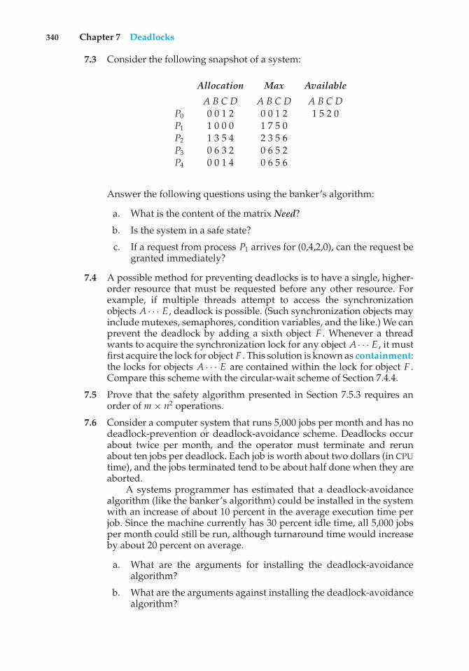
340 Chapter 7 Deadlocks
7.3 Consider the following snapshot of a system:
Allocation Max Available
A B C D A B C D A B C DP0 0 0 1 2 0 0 1 2 1 5 2 0P1 1 0 0 0 1 7 5 0P2 1 3 5 4 2 3 5 6P3 0 6 3 2 0 6 5 2P4 0 0 1 4 0 6 5 6
Answer the following questions using the banker’s algorithm:
a. What is the content of the matrix Need?
b. Is the system in a safe state?
c. If a request from process P1 arrives for (0,4,2,0), can the request begranted immediately?
7.4 A possible method for preventing deadlocks is to have a single, higher-order resource that must be requested before any other resource. Forexample, if multiple threads attempt to access the synchronizationobjects A · · · E , deadlock is possible. (Such synchronization objects mayinclude mutexes, semaphores, condition variables, and the like.) We canprevent the deadlock by adding a sixth object F . Whenever a threadwants to acquire the synchronization lock for any object A · · · E , it mustfirst acquire the lock for object F . This solution is known as containment:the locks for objects A · · · E are contained within the lock for object F .Compare this scheme with the circular-wait scheme of Section 7.4.4.
7.5 Prove that the safety algorithm presented in Section 7.5.3 requires anorder of m × n2 operations.
7.6 Consider a computer system that runs 5,000 jobs per month and has nodeadlock-prevention or deadlock-avoidance scheme. Deadlocks occurabout twice per month, and the operator must terminate and rerunabout ten jobs per deadlock. Each job is worth about two dollars (in CPUtime), and the jobs terminated tend to be about half done when they areaborted.
A systems programmer has estimated that a deadlock-avoidancealgorithm (like the banker’s algorithm) could be installed in the systemwith an increase of about 10 percent in the average execution time perjob. Since the machine currently has 30 percent idle time, all 5,000 jobsper month could still be run, although turnaround time would increaseby about 20 percent on average.
a. What are the arguments for installing the deadlock-avoidancealgorithm?
b. What are the arguments against installing the deadlock-avoidancealgorithm?
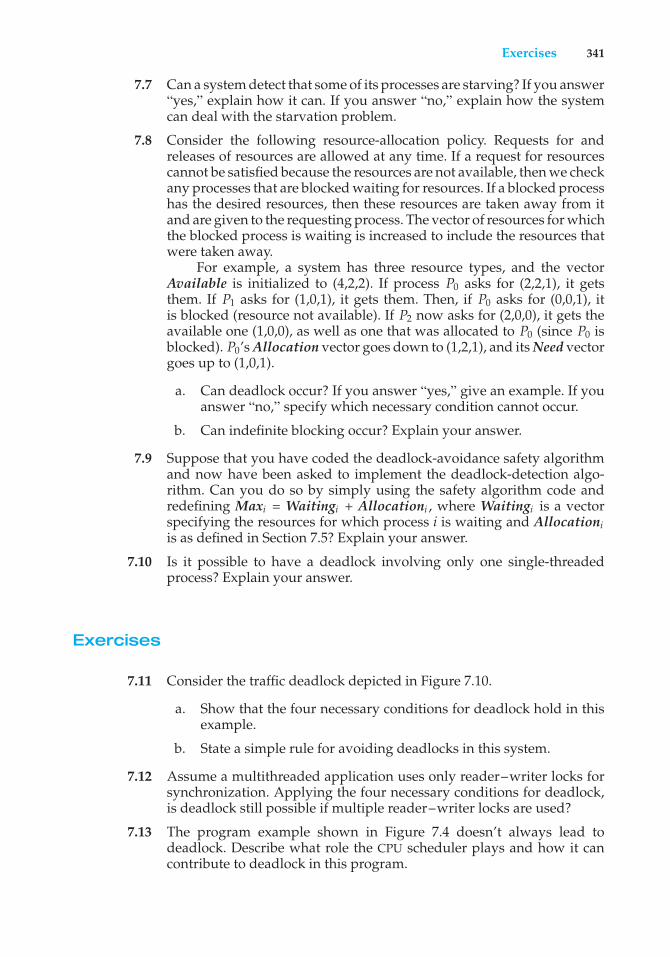
Exercises 341
7.7 Can a system detect that some of its processes are starving? If you answer“yes,” explain how it can. If you answer “no,” explain how the systemcan deal with the starvation problem.
7.8 Consider the following resource-allocation policy. Requests for andreleases of resources are allowed at any time. If a request for resourcescannot be satisfied because the resources are not available, then we checkany processes that are blocked waiting for resources. If a blocked processhas the desired resources, then these resources are taken away from itand are given to the requesting process. The vector of resources for whichthe blocked process is waiting is increased to include the resources thatwere taken away.
For example, a system has three resource types, and the vectorAvailable is initialized to (4,2,2). If process P0 asks for (2,2,1), it getsthem. If P1 asks for (1,0,1), it gets them. Then, if P0 asks for (0,0,1), itis blocked (resource not available). If P2 now asks for (2,0,0), it gets theavailable one (1,0,0), as well as one that was allocated to P0 (since P0 isblocked). P0’s Allocation vector goes down to (1,2,1), and its Need vectorgoes up to (1,0,1).
a. Can deadlock occur? If you answer “yes,” give an example. If youanswer “no,” specify which necessary condition cannot occur.
b. Can indefinite blocking occur? Explain your answer.
7.9 Suppose that you have coded the deadlock-avoidance safety algorithmand now have been asked to implement the deadlock-detection algo-rithm. Can you do so by simply using the safety algorithm code andredefining Maxi = Waitingi + Allocationi , where Waitingi is a vectorspecifying the resources for which process i is waiting and Allocationiis as defined in Section 7.5? Explain your answer.
7.10 Is it possible to have a deadlock involving only one single-threadedprocess? Explain your answer.
Exercises
7.11 Consider the traffic deadlock depicted in Figure 7.10.
a. Show that the four necessary conditions for deadlock hold in thisexample.
b. State a simple rule for avoiding deadlocks in this system.
7.12 Assume a multithreaded application uses only reader–writer locks forsynchronization. Applying the four necessary conditions for deadlock,is deadlock still possible if multiple reader–writer locks are used?
7.13 The program example shown in Figure 7.4 doesn’t always lead todeadlock. Describe what role the CPU scheduler plays and how it cancontribute to deadlock in this program.
342 Chapter 7 Deadlocks
•••
•••
• • •
• • •
Figure 7.10 Traffic deadlock for Exercise 7.11.
7.14 In Section 7.4.4, we describe a situation in which we prevent deadlockby ensuring that all locks are acquired in a certain order. However,we also point out that deadlock is possible in this situation if twothreads simultaneously invoke the transaction() function. Fix thetransaction() function to prevent deadlocks.
7.15 Compare the circular-wait scheme with the various deadlock-avoidanceschemes (like the banker’s algorithm) with respect to the followingissues:
a. Runtime overheads
b. System throughput
7.16 In a real computer system, neither the resources available nor thedemands of processes for resources are consistent over long periods(months). Resources break or are replaced, new processes come and go,and new resources are bought and added to the system. If deadlock iscontrolled by the banker’s algorithm, which of the following changescan be made safely (without introducing the possibility of deadlock),and under what circumstances?
a. Increase Available (new resources added).
b. Decrease Available (resource permanently removed from system).
c. Increase Max for one process (the process needs or wants moreresources than allowed).
d. Decrease Max for one process (the process decides it does not needthat many resources).
Exercises 343
e. Increase the number of processes.
f. Decrease the number of processes.
7.17 Consider a system consisting of four resources of the same type that areshared by three processes, each of which needs at most two resources.Show that the system is deadlock free.
7.18 Consider a system consisting of m resources of the same type beingshared by n processes. A process can request or release only one resourceat a time. Show that the system is deadlock free if the following twoconditions hold:
a. The maximum need of each process is between one resource andm resources.
b. The sum of all maximum needs is less than m + n.
7.19 Consider the version of the dining-philosophers problem in which thechopsticks are placed at the center of the table and any two of themcan be used by a philosopher. Assume that requests for chopsticks aremade one at a time. Describe a simple rule for determining whether aparticular request can be satisfied without causing deadlock given thecurrent allocation of chopsticks to philosophers.
7.20 Consider again the setting in the preceding question. Assume now thateach philosopher requires three chopsticks to eat. Resource requests arestill issued one at a time. Describe some simple rules for determiningwhether a particular request can be satisfied without causing deadlockgiven the current allocation of chopsticks to philosophers.
7.21 We can obtain the banker’s algorithm for a single resource type fromthe general banker’s algorithm simply by reducing the dimensionalityof the various arrays by 1. Show through an example that we cannotimplement the multiple-resource-type banker’s scheme by applying thesingle-resource-type scheme to each resource type individually.
7.22 Consider the following snapshot of a system:
Allocation Max
A B C D A B C DP0 3 0 1 4 5 1 1 7P1 2 2 1 0 3 2 1 1P2 3 1 2 1 3 3 2 1P3 0 5 1 0 4 6 1 2P4 4 2 1 2 6 3 2 5
Using the banker’s algorithm, determine whether or not each of thefollowing states is unsafe. If the state is safe, illustrate the order in whichthe processes may complete. Otherwise, illustrate why the state is unsafe.
a. Available = (0, 3, 0, 1)
b. Available = (1, 0, 0, 2)
344 Chapter 7 Deadlocks
7.23 Consider the following snapshot of a system:
Allocation Max Available
A B C D A B C D A B C DP0 2 0 0 1 4 2 1 2 3 3 2 1P1 3 1 2 1 5 2 5 2P2 2 1 0 3 2 3 1 6P3 1 3 1 2 1 4 2 4P4 1 4 3 2 3 6 6 5
Answer the following questions using the banker’s algorithm:
a. Illustrate that the system is in a safe state by demonstrating anorder in which the processes may complete.
b. If a request from process P1 arrives for (1, 1, 0, 0), can the requestbe granted immediately?
c. If a request from process P4 arrives for (0, 0, 2, 0), can the requestbe granted immediately?
7.24 What is the optimistic assumption made in the deadlock-detectionalgorithm? How can this assumption be violated?
7.25 A single-lane bridge connects the two Vermont villages of NorthTunbridge and South Tunbridge. Farmers in the two villages use thisbridge to deliver their produce to the neighboring town. The bridgecan become deadlocked if a northbound and a southbound farmer geton the bridge at the same time. (Vermont farmers are stubborn and areunable to back up.) Using semaphores and/or mutex locks, design analgorithm in pseudocode that prevents deadlock. Initially, do not beconcerned about starvation (the situation in which northbound farmersprevent southbound farmers from using the bridge, or vice versa).
7.26 Modify your solution to Exercise 7.25 so that it is starvation-free.
Programming Problems
7.27 Implement your solution to Exercise 7.25 using POSIX synchronization.In particular, represent northbound and southbound farmers as separatethreads. Once a farmer is on the bridge, the associated thread will sleepfor a random period of time, representing traveling across the bridge.Design your program so that you can create several threads representingthe northbound and southbound farmers.
Programming Projects 345
Programming Projects
Banker’s Algorithm
For this project, you will write a multithreaded program that implements thebanker’s algorithm discussed in Section 7.5.3. Several customers request andrelease resources from the bank. The banker will grant a request only if it leavesthe system in a safe state. A request that leaves the system in an unsafe statewill be denied. This programming assignment combines three separate topics:(1) multithreading, (2) preventing race conditions, and (3) deadlock avoidance.
The Banker
The banker will consider requests from n customers for m resources types. asoutlined in Section 7.5.3. The banker will keep track of the resources using thefollowing data structures:
/* these may be any values >= 0 */#define NUMBER OF CUSTOMERS 5#define NUMBER OF RESOURCES 3
/* the available amount of each resource */int available[NUMBER OF RESOURCES];
/*the maximum demand of each customer */int maximum[NUMBER OF CUSTOMERS][NUMBER OF RESOURCES];
/* the amount currently allocated to each customer */int allocation[NUMBER OF CUSTOMERS][NUMBER OF RESOURCES];
/* the remaining need of each customer */int need[NUMBER OF CUSTOMERS][NUMBER OF RESOURCES];
The Customers
Create n customer threads that request and release resources from the bank.The customers will continually loop, requesting and then releasing randomnumbers of resources. The customers’ requests for resources will be boundedby their respective values in the need array. The banker will grant a request ifit satisfies the safety algorithm outlined in Section 7.5.3.1. If a request does notleave the system in a safe state, the banker will deny it. Function prototypesfor requesting and releasing resources are as follows:
int request resources(int customer num, int request[]);
int release resources(int customer num, int release[]);
These two functions should return 0 if successful (the request has beengranted) and –1 if unsuccessful. Multiple threads (customers) will concurrently
346 Chapter 7 Deadlocks
access shared data through these two functions. Therefore, access must becontrolled through mutex locks to prevent race conditions. Both the Pthreadsand Windows APIs provide mutex locks. The use of Pthreads mutex locks iscovered in Section 5.9.4; mutex locks for Windows systems are described in theproject entitled “Producer–Consumer Problem” at the end of Chapter 5.
Implementation
You should invoke your program by passing the number of resources of eachtype on the command line. For example, if there were three resource types,with ten instances of the first type, five of the second type, and seven of thethird type, you would invoke your program follows:
./a.out 10 5 7
The available array would be initialized to these values. You may initializethemaximum array (which holds the maximum demand of each customer) usingany method you find convenient.
Bibliographical Notes
Most research involving deadlock was conducted many years ago. [Dijkstra(1965)] was one of the first and most influential contributors in the deadlockarea. [Holt (1972)] was the first person to formalize the notion of deadlocks interms of an allocation-graph model similar to the one presented in this chapter.Starvation was also covered by [Holt (1972)]. [Hyman (1985)] provided thedeadlock example from the Kansas legislature. A study of deadlock handlingis provided in [Levine (2003)].
The various prevention algorithms were suggested by [Havender (1968)],who devised the resource-ordering scheme for the IBM OS/360 system. Thebanker’s algorithm for avoiding deadlocks was developed for a single resourcetype by [Dijkstra (1965)] and was extended to multiple resource types by[Habermann (1969)].
The deadlock-detection algorithm for multiple instances of a resource type,which is described in Section 7.6.2, was presented by [Coffman et al. (1971)].
[Bach (1987)] describes how many of the algorithms in the traditionalUNIX kernel handle deadlock. Solutions to deadlock problems in networks arediscussed in works such as [Culler et al. (1998)] and [Rodeheffer and Schroeder(1991)].
The witness lock-order verifier is presented in [Baldwin (2002)].
Bibliography
[Bach (1987)] M. J. Bach, The Design of the UNIX Operating System, Prentice Hall(1987).
[Baldwin (2002)] J. Baldwin, “Locking in the Multithreaded FreeBSD Kernel”,USENIX BSD (2002).

Bibliography 347
[Coffman et al. (1971)] E. G. Coffman, M. J. Elphick, and A. Shoshani, “SystemDeadlocks”, Computing Surveys, Volume 3, Number 2 (1971), pages 67–78.
[Culler et al. (1998)] D. E. Culler, J. P. Singh, and A. Gupta, Parallel ComputerArchitecture: A Hardware/Software Approach, Morgan Kaufmann Publishers Inc.(1998).
[Dijkstra (1965)] E. W. Dijkstra, “Cooperating Sequential Processes”, Technicalreport, Technological University, Eindhoven, the Netherlands (1965).
[Habermann (1969)] A. N. Habermann, “Prevention of System Deadlocks”,Communications of the ACM, Volume 12, Number 7 (1969), pages 373–377, 385.
[Havender (1968)] J. W. Havender, “Avoiding Deadlock in Multitasking Sys-tems”, IBM Systems Journal, Volume 7, Number 2 (1968), pages 74–84.
[Holt (1972)] R. C. Holt, “Some Deadlock Properties of Computer Systems”,Computing Surveys, Volume 4, Number 3 (1972), pages 179–196.
[Hyman (1985)] D. Hyman, The Columbus Chicken Statute and More BoneheadLegislation, S. Greene Press (1985).
[Levine (2003)] G. Levine, “Defining Deadlock”, Operating Systems Review, Vol-ume 37, Number 1 (2003).
[Rodeheffer and Schroeder (1991)] T. L. Rodeheffer and M. D. Schroeder,“Automatic Reconfiguration in Autonet”, Proceedings of the ACM Symposiumon Operating Systems Principles (1991), pages 183–97.

Part Three
MemoryManagement
The main purpose of a computer system is to execute programs. Theseprograms, together with the data they access, must be at least partiallyin main memory during execution.
To improve both the utilization of the CPU and the speed of itsresponse to users, a general-purpose computer must keep several pro-cesses in memory. Many memory-management schemes exist, reflect-ing various approaches, and the effectiveness of each algorithm dependson the situation. Selection of a memory-management scheme for a sys-tem depends on many factors, especially on the hardware design of thesystem. Most algorithms require hardware support.

8C H A P T E R
Main Memory
In Chapter 6, we showed how the CPU can be shared by a set of processes. Asa result of CPU scheduling, we can improve both the utilization of the CPU andthe speed of the computer’s response to its users. To realize this increase inperformance, however, we must keep several processes in memory—that is,we must share memory.
In this chapter, we discuss various ways to manage memory. The memory-management algorithms vary from a primitive bare-machine approach topaging and segmentation strategies. Each approach has its own advantagesand disadvantages. Selection of a memory-management method for a specificsystem depends on many factors, especially on the hardware design of thesystem. As we shall see, many algorithms require hardware support, leadingmany systems to have closely integrated hardware and operating-systemmemory management.
CHAPTER OBJECTIVES
• To provide a detailed description of various ways of organizing memoryhardware.
• To explore various techniques of allocating memory to processes.• To discuss in detail how paging works in contemporary computer systems.
8.1 Background
As we saw in Chapter 1, memory is central to the operation of a moderncomputer system. Memory consists of a large array of bytes, each with its ownaddress. The CPU fetches instructions from memory according to the value ofthe program counter. These instructions may cause additional loading fromand storing to specific memory addresses.
A typical instruction-execution cycle, for example, first fetches an instruc-tion from memory. The instruction is then decoded and may cause operandsto be fetched from memory. After the instruction has been executed on theoperands, results may be stored back in memory. The memory unit sees only
351
352 Chapter 8 Main Memory
a stream of memory addresses; it does not know how they are generated (bythe instruction counter, indexing, indirection, literal addresses, and so on) orwhat they are for (instructions or data). Accordingly, we can ignore how aprogram generates a memory address. We are interested only in the sequenceof memory addresses generated by the running program.
We begin our discussion by covering several issues that are pertinentto managing memory: basic hardware, the binding of symbolic memoryaddresses to actual physical addresses, and the distinction between logicaland physical addresses. We conclude the section with a discussion of dynamiclinking and shared libraries.
8.1.1 Basic Hardware
Main memory and the registers built into the processor itself are the onlygeneral-purpose storage that the CPU can access directly. There are machineinstructions that take memory addresses as arguments, but none that take diskaddresses. Therefore, any instructions in execution, and any data being usedby the instructions, must be in one of these direct-access storage devices. If thedata are not in memory, they must be moved there before the CPU can operateon them.
Registers that are built into the CPU are generally accessible within onecycle of the CPU clock. Most CPUs can decode instructions and perform simpleoperations on register contents at the rate of one or more operations perclock tick. The same cannot be said of main memory, which is accessed viaa transaction on the memory bus. Completing a memory access may takemany cycles of the CPU clock. In such cases, the processor normally needs tostall, since it does not have the data required to complete the instruction that itis executing. This situation is intolerable because of the frequency of memoryaccesses. The remedy is to add fast memory between the CPUand main memory,typically on the CPU chip for fast access. Such a cache was described in Section1.8.3. To manage a cache built into the CPU, the hardware automatically speedsup memory access without any operating-system control.
Not only are we concerned with the relative speed of accessing physicalmemory, but we also must ensure correct operation. For proper systemoperation we must protect the operating system from access by user processes.On multiuser systems, we must additionally protect user processes fromone another. This protection must be provided by the hardware because theoperating system doesn’t usually intervene between the CPU and its memoryaccesses (because of the resulting performance penalty). Hardware implementsthis production in several different ways, as we show throughout the chapter.Here, we outline one possible implementation.
We first need to make sure that each process has a separate memory space.Separate per-process memory space protects the processes from each other andis fundamental to having multiple processes loaded in memory for concurrentexecution. To separate memory spaces, we need the ability to determine therange of legal addresses that the process may access and to ensure that theprocess can access only these legal addresses. We can provide this protectionby using two registers, usually a base and a limit, as illustrated in Figure 8.1.The base register holds the smallest legal physical memory address; the limitregister specifies the size of the range. For example, if the base register holds
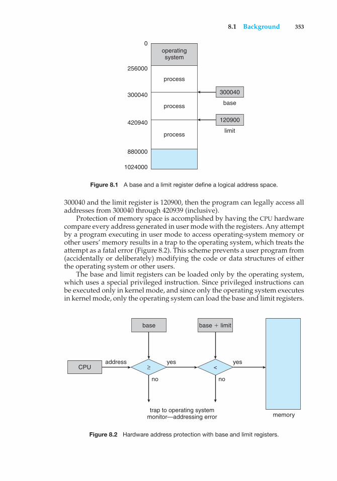
8.1 Background 353
operatingsystem
0
256000
300040 300040
base
120900
limit420940
880000
1024000
process
process
process
Figure 8.1 A base and a limit register define a logical address space.
300040 and the limit register is 120900, then the program can legally access alladdresses from 300040 through 420939 (inclusive).
Protection of memory space is accomplished by having the CPU hardwarecompare every address generated in user mode with the registers. Any attemptby a program executing in user mode to access operating-system memory orother users’ memory results in a trap to the operating system, which treats theattempt as a fatal error (Figure 8.2). This scheme prevents a user program from(accidentally or deliberately) modifying the code or data structures of eitherthe operating system or other users.
The base and limit registers can be loaded only by the operating system,which uses a special privileged instruction. Since privileged instructions canbe executed only in kernel mode, and since only the operating system executesin kernel mode, only the operating system can load the base and limit registers.
base
memorytrap to operating system
monitor—addressing error
address yesyes
nono
CPU
base ' limit
≥ <
Figure 8.2 Hardware address protection with base and limit registers.
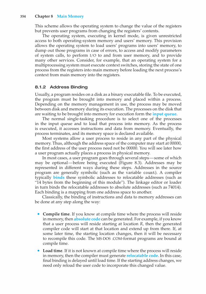
354 Chapter 8 Main Memory
This scheme allows the operating system to change the value of the registersbut prevents user programs from changing the registers’ contents.
The operating system, executing in kernel mode, is given unrestrictedaccess to both operating-system memory and users’ memory. This provisionallows the operating system to load users’ programs into users’ memory, todump out those programs in case of errors, to access and modify parametersof system calls, to perform I/O to and from user memory, and to providemany other services. Consider, for example, that an operating system for amultiprocessing system must execute context switches, storing the state of oneprocess from the registers into main memory before loading the next process’scontext from main memory into the registers.
8.1.2 Address Binding
Usually, a program resides on a disk as a binary executable file. To be executed,the program must be brought into memory and placed within a process.Depending on the memory management in use, the process may be movedbetween disk and memory during its execution. The processes on the disk thatare waiting to be brought into memory for execution form the input queue.
The normal single-tasking procedure is to select one of the processesin the input queue and to load that process into memory. As the processis executed, it accesses instructions and data from memory. Eventually, theprocess terminates, and its memory space is declared available.
Most systems allow a user process to reside in any part of the physicalmemory. Thus, although the address space of the computer may start at 00000,the first address of the user process need not be 00000. You will see later howa user program actually places a process in physical memory.
In most cases, a user program goes through several steps—some of whichmay be optional—before being executed (Figure 8.3). Addresses may berepresented in different ways during these steps. Addresses in the sourceprogram are generally symbolic (such as the variable count). A compilertypically binds these symbolic addresses to relocatable addresses (such as“14 bytes from the beginning of this module”). The linkage editor or loaderin turn binds the relocatable addresses to absolute addresses (such as 74014).Each binding is a mapping from one address space to another.
Classically, the binding of instructions and data to memory addresses canbe done at any step along the way:
• Compile time. If you know at compile time where the process will residein memory, then absolute code can be generated. For example, if you knowthat a user process will reside starting at location R, then the generatedcompiler code will start at that location and extend up from there. If, atsome later time, the starting location changes, then it will be necessaryto recompile this code. The MS-DOS .COM-format programs are bound atcompile time.
• Load time. If it is not known at compile time where the process will residein memory, then the compiler must generate relocatable code. In this case,final binding is delayed until load time. If the starting address changes, weneed only reload the user code to incorporate this changed value.
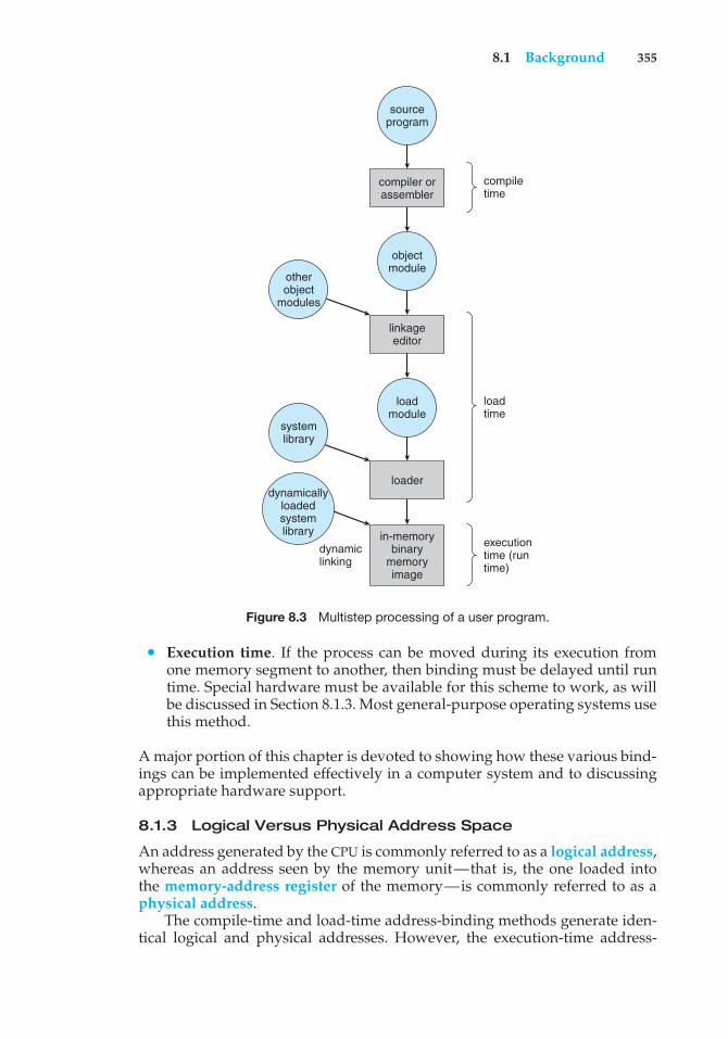
8.1 Background 355
dynamiclinking
sourceprogram
objectmodule
linkageeditor
loadmodule
loader
in-memorybinary
memoryimage
otherobject
modules
compiletime
loadtime
executiontime (runtime)
compiler orassembler
systemlibrary
dynamicallyloadedsystemlibrary
Figure 8.3 Multistep processing of a user program.
• Execution time. If the process can be moved during its execution fromone memory segment to another, then binding must be delayed until runtime. Special hardware must be available for this scheme to work, as willbe discussed in Section 8.1.3. Most general-purpose operating systems usethis method.
A major portion of this chapter is devoted to showing how these various bind-ings can be implemented effectively in a computer system and to discussingappropriate hardware support.
8.1.3 Logical Versus Physical Address Space
An address generated by the CPU is commonly referred to as a logical address,whereas an address seen by the memory unit—that is, the one loaded intothe memory-address register of the memory—is commonly referred to as aphysical address.
The compile-time and load-time address-binding methods generate iden-tical logical and physical addresses. However, the execution-time address-
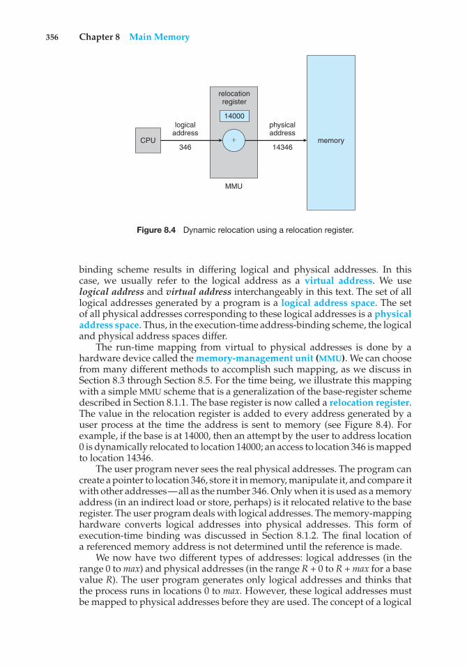
356 Chapter 8 Main Memory
'
MMU
CPU memory14346
14000
relocationregister
346
logicaladdress
physicaladdress
Figure 8.4 Dynamic relocation using a relocation register.
binding scheme results in differing logical and physical addresses. In thiscase, we usually refer to the logical address as a virtual address. We uselogical address and virtual address interchangeably in this text. The set of alllogical addresses generated by a program is a logical address space. The setof all physical addresses corresponding to these logical addresses is a physicaladdress space. Thus, in the execution-time address-binding scheme, the logicaland physical address spaces differ.
The run-time mapping from virtual to physical addresses is done by ahardware device called the memory-management unit (MMU). We can choosefrom many different methods to accomplish such mapping, as we discuss inSection 8.3 through Section 8.5. For the time being, we illustrate this mappingwith a simple MMU scheme that is a generalization of the base-register schemedescribed in Section 8.1.1. The base register is now called a relocation register.The value in the relocation register is added to every address generated by auser process at the time the address is sent to memory (see Figure 8.4). Forexample, if the base is at 14000, then an attempt by the user to address location0 is dynamically relocated to location 14000; an access to location 346 is mappedto location 14346.
The user program never sees the real physical addresses. The program cancreate a pointer to location 346, store it in memory, manipulate it, and compare itwith other addresses—all as the number 346. Only when it is used as a memoryaddress (in an indirect load or store, perhaps) is it relocated relative to the baseregister. The user program deals with logical addresses. The memory-mappinghardware converts logical addresses into physical addresses. This form ofexecution-time binding was discussed in Section 8.1.2. The final location ofa referenced memory address is not determined until the reference is made.
We now have two different types of addresses: logical addresses (in therange 0 to max) and physical addresses (in the range R + 0 to R + max for a basevalue R). The user program generates only logical addresses and thinks thatthe process runs in locations 0 to max. However, these logical addresses mustbe mapped to physical addresses before they are used. The concept of a logical
8.1 Background 357
address space that is bound to a separate physical address space is central toproper memory management.
8.1.4 Dynamic Loading
In our discussion so far, it has been necessary for the entire program and alldata of a process to be in physical memory for the process to execute. The sizeof a process has thus been limited to the size of physical memory. To obtainbetter memory-space utilization, we can use dynamic loading. With dynamicloading, a routine is not loaded until it is called. All routines are kept on diskin a relocatable load format. The main program is loaded into memory andis executed. When a routine needs to call another routine, the calling routinefirst checks to see whether the other routine has been loaded. If it has not, therelocatable linking loader is called to load the desired routine into memory andto update the program’s address tables to reflect this change. Then control ispassed to the newly loaded routine.
The advantage of dynamic loading is that a routine is loaded only when itis needed. This method is particularly useful when large amounts of code areneeded to handle infrequently occurring cases, such as error routines. In thiscase, although the total program size may be large, the portion that is used(and hence loaded) may be much smaller.
Dynamic loading does not require special support from the operatingsystem. It is the responsibility of the users to design their programs to takeadvantage of such a method. Operating systems may help the programmer,however, by providing library routines to implement dynamic loading.
8.1.5 Dynamic Linking and Shared Libraries
Dynamically linked libraries are system libraries that are linked to userprograms when the programs are run (refer back to Figure 8.3). Some operatingsystems support only static linking, in which system libraries are treatedlike any other object module and are combined by the loader into the binaryprogram image. Dynamic linking, in contrast, is similar to dynamic loading.Here, though, linking, rather than loading, is postponed until execution time.This feature is usually used with system libraries, such as language subroutinelibraries. Without this facility, each program on a system must include a copyof its language library (or at least the routines referenced by the program) in theexecutable image. This requirement wastes both disk space and main memory.
With dynamic linking, a stub is included in the image for each library-routine reference. The stub is a small piece of code that indicates how to locatethe appropriate memory-resident library routine or how to load the library ifthe routine is not already present. When the stub is executed, it checks to seewhether the needed routine is already in memory. If it is not, the program loadsthe routine into memory. Either way, the stub replaces itself with the addressof the routine and executes the routine. Thus, the next time that particularcode segment is reached, the library routine is executed directly, incurring nocost for dynamic linking. Under this scheme, all processes that use a languagelibrary execute only one copy of the library code.
This feature can be extended to library updates (such as bug fixes). A librarymay be replaced by a new version, and all programs that reference the librarywill automatically use the new version. Without dynamic linking, all such
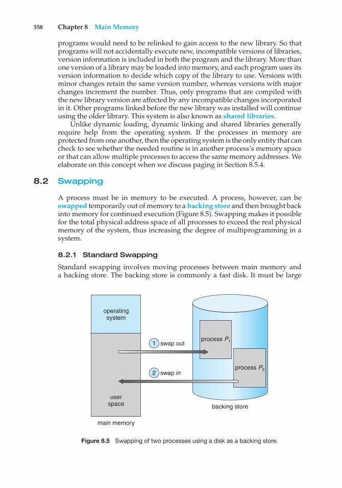
358 Chapter 8 Main Memory
programs would need to be relinked to gain access to the new library. So thatprograms will not accidentally execute new, incompatible versions of libraries,version information is included in both the program and the library. More thanone version of a library may be loaded into memory, and each program uses itsversion information to decide which copy of the library to use. Versions withminor changes retain the same version number, whereas versions with majorchanges increment the number. Thus, only programs that are compiled withthe new library version are affected by any incompatible changes incorporatedin it. Other programs linked before the new library was installed will continueusing the older library. This system is also known as shared libraries.
Unlike dynamic loading, dynamic linking and shared libraries generallyrequire help from the operating system. If the processes in memory areprotected from one another, then the operating system is the only entity that cancheck to see whether the needed routine is in another process’s memory spaceor that can allow multiple processes to access the same memory addresses. Weelaborate on this concept when we discuss paging in Section 8.5.4.
8.2 Swapping
A process must be in memory to be executed. A process, however, can beswapped temporarily out of memory to a backing store and then brought backinto memory for continued execution (Figure 8.5). Swapping makes it possiblefor the total physical address space of all processes to exceed the real physicalmemory of the system, thus increasing the degree of multiprogramming in asystem.
8.2.1 Standard Swapping
Standard swapping involves moving processes between main memory anda backing store. The backing store is commonly a fast disk. It must be large
operatingsystem
swap out
swap in
userspace
main memory
backing store
process P2
process P11
2
Figure 8.5 Swapping of two processes using a disk as a backing store.
8.2 Swapping 359
enough to accommodate copies of all memory images for all users, and it mustprovide direct access to these memory images. The system maintains a readyqueue consisting of all processes whose memory images are on the backingstore or in memory and are ready to run. Whenever the CPU scheduler decidesto execute a process, it calls the dispatcher. The dispatcher checks to see whetherthe next process in the queue is in memory. If it is not, and if there is no freememory region, the dispatcher swaps out a process currently in memory andswaps in the desired process. It then reloads registers and transfers control tothe selected process.
The context-switch time in such a swapping system is fairly high. To get anidea of the context-switch time, let’s assume that the user process is 100 MB insize and the backing store is a standard hard disk with a transfer rate of 50 MBper second. The actual transfer of the 100-MB process to or from main memorytakes
100 MB/50 MB per second = 2 seconds
The swap time is 200 milliseconds. Since we must swap both out and in, thetotal swap time is about 4,000 milliseconds. (Here, we are ignoring other diskperformance aspects, which we cover in Chapter 10.)
Notice that the major part of the swap time is transfer time. The totaltransfer time is directly proportional to the amount of memory swapped.If we have a computer system with 4 GB of main memory and a residentoperating system taking 1 GB, the maximum size of the user process is 3GB. However, many user processes may be much smaller than this—say, 100MB. A 100-MB process could be swapped out in 2 seconds, compared withthe 60 seconds required for swapping 3 GB. Clearly, it would be useful toknow exactly how much memory a user process is using, not simply howmuch it might be using. Then we would need to swap only what is actuallyused, reducing swap time. For this method to be effective, the user mustkeep the system informed of any changes in memory requirements. Thus,a process with dynamic memory requirements will need to issue system calls(request memory() and release memory()) to inform the operating systemof its changing memory needs.
Swapping is constrained by other factors as well. If we want to swapa process, we must be sure that it is completely idle. Of particular concernis any pending I/O. A process may be waiting for an I/O operation whenwe want to swap that process to free up memory. However, if the I/O isasynchronously accessing the user memory for I/O buffers, then the processcannot be swapped. Assume that the I/O operation is queued because thedevice is busy. If we were to swap out process P1 and swap in process P2, theI/O operation might then attempt to use memory that now belongs to processP2. There are two main solutions to this problem: never swap a process withpending I/O, or execute I/O operations only into operating-system buffers.Transfers between operating-system buffers and process memory then occuronly when the process is swapped in. Note that this double buffering itselfadds overhead. We now need to copy the data again, from kernel memory touser memory, before the user process can access it.
Standard swapping is not used in modern operating systems. It requires toomuch swapping time and provides too little execution time to be a reasonable
360 Chapter 8 Main Memory
memory-management solution. Modified versions of swapping, however, arefound on many systems, including UNIX, Linux, and Windows. In one commonvariation, swapping is normally disabled but will start if the amount of freememory (unused memory available for the operating system or processes touse) falls below a threshold amount. Swapping is halted when the amountof free memory increases. Another variation involves swapping portions ofprocesses—rather than entire processes—to decrease swap time. Typically,these modified forms of swapping work in conjunction with virtual memory,which we cover in Chapter 9.
8.2.2 Swapping on Mobile Systems
Although most operating systems for PCs and servers support some modifiedversion of swapping, mobile systems typically do not support swapping in anyform. Mobile devices generally use flash memory rather than more spacioushard disks as their persistent storage. The resulting space constraint is onereason why mobile operating-system designers avoid swapping. Other reasonsinclude the limited number of writes that flash memory can tolerate before itbecomes unreliable and the poor throughput between main memory and flashmemory in these devices.
Instead of using swapping, when free memory falls below a certainthreshold, Apple’s iOS asks applications to voluntarily relinquish allocatedmemory. Read-only data (such as code) are removed from the system and laterreloaded from flash memory if necessary. Data that have been modified (suchas the stack) are never removed. However, any applications that fail to free upsufficient memory may be terminated by the operating system.
Android does not support swapping and adopts a strategy similar to thatused by iOS. It may terminate a process if insufficient free memory is available.However, before terminating a process, Android writes its application state toflash memory so that it can be quickly restarted.
Because of these restrictions, developers for mobile systems must carefullyallocate and release memory to ensure that their applications do not use toomuch memory or suffer from memory leaks. Note that both iOS and Androidsupport paging, so they do have memory-management abilities. We discusspaging later in this chapter.
8.3 Contiguous Memory Allocation
The main memory must accommodate both the operating system and thevarious user processes. We therefore need to allocate main memory in the mostefficient way possible. This section explains one early method, contiguousmemory allocation.
The memory is usually divided into two partitions: one for the residentoperating system and one for the user processes. We can place the operatingsystem in either low memory or high memory. The major factor affecting thisdecision is the location of the interrupt vector. Since the interrupt vector isoften in low memory, programmers usually place the operating system in lowmemory as well. Thus, in this text, we discuss only the situation in which
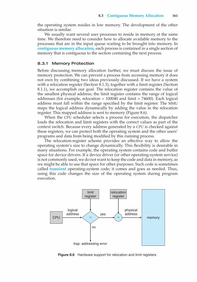
8.3 Contiguous Memory Allocation 361
the operating system resides in low memory. The development of the othersituation is similar.
We usually want several user processes to reside in memory at the sametime. We therefore need to consider how to allocate available memory to theprocesses that are in the input queue waiting to be brought into memory. Incontiguous memory allocation, each process is contained in a single section ofmemory that is contiguous to the section containing the next process.
8.3.1 Memory Protection
Before discussing memory allocation further, we must discuss the issue ofmemory protection. We can prevent a process from accessing memory it doesnot own by combining two ideas previously discussed. If we have a systemwith a relocation register (Section 8.1.3), together with a limit register (Section8.1.1), we accomplish our goal. The relocation register contains the value ofthe smallest physical address; the limit register contains the range of logicaladdresses (for example, relocation = 100040 and limit = 74600). Each logicaladdress must fall within the range specified by the limit register. The MMUmaps the logical address dynamically by adding the value in the relocationregister. This mapped address is sent to memory (Figure 8.6).
When the CPU scheduler selects a process for execution, the dispatcherloads the relocation and limit registers with the correct values as part of thecontext switch. Because every address generated by a CPU is checked againstthese registers, we can protect both the operating system and the other users’programs and data from being modified by this running process.
The relocation-register scheme provides an effective way to allow theoperating system’s size to change dynamically. This flexibility is desirable inmany situations. For example, the operating system contains code and bufferspace for device drivers. If a device driver (or other operating-system service)is not commonly used, we do not want to keep the code and data in memory, aswe might be able to use that space for other purposes. Such code is sometimescalled transient operating-system code; it comes and goes as needed. Thus,using this code changes the size of the operating system during programexecution.
CPU memory
logicaladdress
trap: addressing error
no
yesphysicaladdress
relocationregister
'(
limitregister
Figure 8.6 Hardware support for relocation and limit registers.
362 Chapter 8 Main Memory
8.3.2 Memory Allocation
Now we are ready to turn to memory allocation. One of the simplestmethods for allocating memory is to divide memory into several fixed-sizedpartitions. Each partition may contain exactly one process. Thus, the degreeof multiprogramming is bound by the number of partitions. In this multiple-partition method, when a partition is free, a process is selected from the inputqueue and is loaded into the free partition. When the process terminates, thepartition becomes available for another process. This method was originallyused by the IBM OS/360 operating system (called MFT)but is no longer in use.The method described next is a generalization of the fixed-partition scheme(called MVT); it is used primarily in batch environments. Many of the ideaspresented here are also applicable to a time-sharing environment in whichpure segmentation is used for memory management (Section 8.4).
In the variable-partition scheme, the operating system keeps a tableindicating which parts of memory are available and which are occupied.Initially, all memory is available for user processes and is considered onelarge block of available memory, a hole. Eventually, as you will see, memorycontains a set of holes of various sizes.
As processes enter the system, they are put into an input queue. Theoperating system takes into account the memory requirements of each processand the amount of available memory space in determining which processes areallocated memory. When a process is allocated space, it is loaded into memory,and it can then compete for CPU time. When a process terminates, it releases itsmemory, which the operating system may then fill with another process fromthe input queue.
At any given time, then, we have a list of available block sizes and aninput queue. The operating system can order the input queue according toa scheduling algorithm. Memory is allocated to processes until, finally, thememory requirements of the next process cannot be satisfied—that is, noavailable block of memory (or hole) is large enough to hold that process. Theoperating system can then wait until a large enough block is available, or it canskip down the input queue to see whether the smaller memory requirementsof some other process can be met.
In general, as mentioned, the memory blocks available comprise a set ofholes of various sizes scattered throughout memory. When a process arrivesand needs memory, the system searches the set for a hole that is large enoughfor this process. If the hole is too large, it is split into two parts. One part isallocated to the arriving process; the other is returned to the set of holes. Whena process terminates, it releases its block of memory, which is then placed backin the set of holes. If the new hole is adjacent to other holes, these adjacent holesare merged to form one larger hole. At this point, the system may need to checkwhether there are processes waiting for memory and whether this newly freedand recombined memory could satisfy the demands of any of these waitingprocesses.
This procedure is a particular instance of the general dynamic storage-allocation problem, which concerns how to satisfy a request of size n from alist of free holes. There are many solutions to this problem. The first-fit, best-fit,and worst-fit strategies are the ones most commonly used to select a free holefrom the set of available holes.
8.3 Contiguous Memory Allocation 363
• First fit. Allocate the first hole that is big enough. Searching can start eitherat the beginning of the set of holes or at the location where the previousfirst-fit search ended. We can stop searching as soon as we find a free holethat is large enough.
• Best fit. Allocate the smallest hole that is big enough. We must search theentire list, unless the list is ordered by size. This strategy produces thesmallest leftover hole.
• Worst fit. Allocate the largest hole. Again, we must search the entire list,unless it is sorted by size. This strategy produces the largest leftover hole,which may be more useful than the smaller leftover hole from a best-fitapproach.
Simulations have shown that both first fit and best fit are better than worstfit in terms of decreasing time and storage utilization. Neither first fit nor bestfit is clearly better than the other in terms of storage utilization, but first fit isgenerally faster.
8.3.3 Fragmentation
Both the first-fit and best-fit strategies for memory allocation suffer fromexternal fragmentation. As processes are loaded and removed from memory,the free memory space is broken into little pieces. External fragmentation existswhen there is enough total memory space to satisfy a request but the availablespaces are not contiguous: storage is fragmented into a large number of smallholes. This fragmentation problem can be severe. In the worst case, we couldhave a block of free (or wasted) memory between every two processes. If allthese small pieces of memory were in one big free block instead, we might beable to run several more processes.
Whether we are using the first-fit or best-fit strategy can affect the amountof fragmentation. (First fit is better for some systems, whereas best fit is betterfor others.) Another factor is which end of a free block is allocated. (Which isthe leftover piece—the one on the top or the one on the bottom?) No matterwhich algorithm is used, however, external fragmentation will be a problem.
Depending on the total amount of memory storage and the average processsize, external fragmentation may be a minor or a major problem. Statisticalanalysis of first fit, for instance, reveals that, even with some optimization,given N allocated blocks, another 0.5 N blocks will be lost to fragmentation.That is, one-third of memory may be unusable! This property is known as the50-percent rule.
Memory fragmentation can be internal as well as external. Consider amultiple-partition allocation scheme with a hole of 18,464 bytes. Suppose thatthe next process requests 18,462 bytes. If we allocate exactly the requested block,we are left with a hole of 2 bytes. The overhead to keep track of this hole will besubstantially larger than the hole itself. The general approach to avoiding thisproblem is to break the physical memory into fixed-sized blocks and allocatememory in units based on block size. With this approach, the memory allocatedto a process may be slightly larger than the requested memory. The differencebetween these two numbers is internal fragmentation—unused memory thatis internal to a partition.
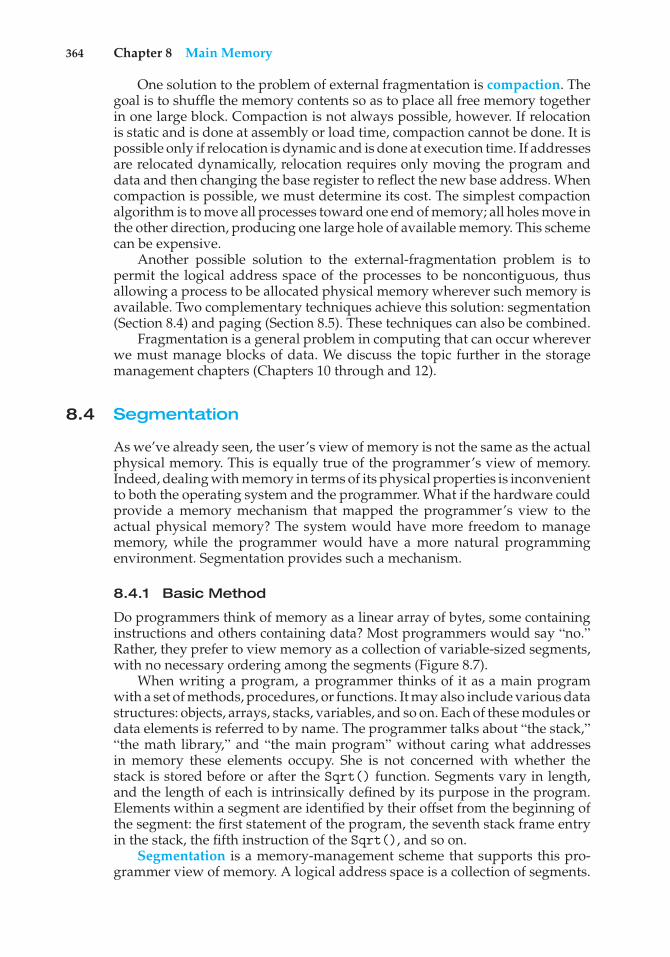
364 Chapter 8 Main Memory
One solution to the problem of external fragmentation is compaction. Thegoal is to shuffle the memory contents so as to place all free memory togetherin one large block. Compaction is not always possible, however. If relocationis static and is done at assembly or load time, compaction cannot be done. It ispossible only if relocation is dynamic and is done at execution time. If addressesare relocated dynamically, relocation requires only moving the program anddata and then changing the base register to reflect the new base address. Whencompaction is possible, we must determine its cost. The simplest compactionalgorithm is to move all processes toward one end of memory; all holes move inthe other direction, producing one large hole of available memory. This schemecan be expensive.
Another possible solution to the external-fragmentation problem is topermit the logical address space of the processes to be noncontiguous, thusallowing a process to be allocated physical memory wherever such memory isavailable. Two complementary techniques achieve this solution: segmentation(Section 8.4) and paging (Section 8.5). These techniques can also be combined.
Fragmentation is a general problem in computing that can occur whereverwe must manage blocks of data. We discuss the topic further in the storagemanagement chapters (Chapters 10 through and 12).
8.4 Segmentation
As we’ve already seen, the user’s view of memory is not the same as the actualphysical memory. This is equally true of the programmer’s view of memory.Indeed, dealing with memory in terms of its physical properties is inconvenientto both the operating system and the programmer. What if the hardware couldprovide a memory mechanism that mapped the programmer’s view to theactual physical memory? The system would have more freedom to managememory, while the programmer would have a more natural programmingenvironment. Segmentation provides such a mechanism.
8.4.1 Basic Method
Do programmers think of memory as a linear array of bytes, some containinginstructions and others containing data? Most programmers would say “no.”Rather, they prefer to view memory as a collection of variable-sized segments,with no necessary ordering among the segments (Figure 8.7).
When writing a program, a programmer thinks of it as a main programwith a set of methods, procedures, or functions. It may also include various datastructures: objects, arrays, stacks, variables, and so on. Each of these modules ordata elements is referred to by name. The programmer talks about “the stack,”“the math library,” and “the main program” without caring what addressesin memory these elements occupy. She is not concerned with whether thestack is stored before or after the Sqrt() function. Segments vary in length,and the length of each is intrinsically defined by its purpose in the program.Elements within a segment are identified by their offset from the beginning ofthe segment: the first statement of the program, the seventh stack frame entryin the stack, the fifth instruction of the Sqrt(), and so on.
Segmentation is a memory-management scheme that supports this pro-grammer view of memory. A logical address space is a collection of segments.
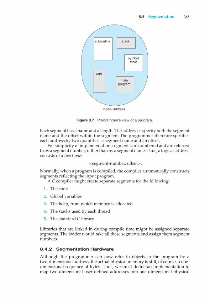
8.4 Segmentation 365
logical address
subroutine stack
symbol table
main program
Sqrt
Figure 8.7 Programmer’s view of a program.
Each segment has a name and a length. The addresses specify both the segmentname and the offset within the segment. The programmer therefore specifieseach address by two quantities: a segment name and an offset.
For simplicity of implementation, segments are numbered and are referredto by a segment number, rather than by a segment name. Thus, a logical addressconsists of a two tuple:
<segment-number, offset>.
Normally, when a program is compiled, the compiler automatically constructssegments reflecting the input program.
A C compiler might create separate segments for the following:
1. The code
2. Global variables
3. The heap, from which memory is allocated
4. The stacks used by each thread
5. The standard C library
Libraries that are linked in during compile time might be assigned separatesegments. The loader would take all these segments and assign them segmentnumbers.
8.4.2 Segmentation Hardware
Although the programmer can now refer to objects in the program by atwo-dimensional address, the actual physical memory is still, of course, a one-dimensional sequence of bytes. Thus, we must define an implementation tomap two-dimensional user-defined addresses into one-dimensional physical
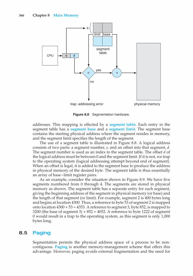
366 Chapter 8 Main Memory
CPU
physical memory
s d
< +
trap: addressing error
no
yes
segment table
limit base
s
Figure 8.8 Segmentation hardware.
addresses. This mapping is effected by a segment table. Each entry in thesegment table has a segment base and a segment limit. The segment basecontains the starting physical address where the segment resides in memory,and the segment limit specifies the length of the segment.
The use of a segment table is illustrated in Figure 8.8. A logical addressconsists of two parts: a segment number, s, and an offset into that segment, d.The segment number is used as an index to the segment table. The offset d ofthe logical address must be between 0 and the segment limit. If it is not, we trapto the operating system (logical addressing attempt beyond end of segment).When an offset is legal, it is added to the segment base to produce the addressin physical memory of the desired byte. The segment table is thus essentiallyan array of base–limit register pairs.
As an example, consider the situation shown in Figure 8.9. We have fivesegments numbered from 0 through 4. The segments are stored in physicalmemory as shown. The segment table has a separate entry for each segment,giving the beginning address of the segment in physical memory (or base) andthe length of that segment (or limit). For example, segment 2 is 400 bytes longand begins at location 4300. Thus, a reference to byte 53 of segment 2 is mappedonto location 4300 + 53 = 4353. A reference to segment 3, byte 852, is mapped to3200 (the base of segment 3) + 852 = 4052. A reference to byte 1222 of segment0 would result in a trap to the operating system, as this segment is only 1,000bytes long.
8.5 Paging
Segmentation permits the physical address space of a process to be non-contiguous. Paging is another memory-management scheme that offers thisadvantage. However, paging avoids external fragmentation and the need for
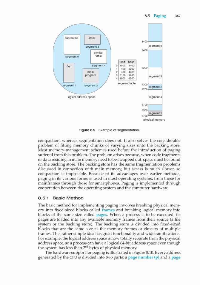
8.5 Paging 367
logical address space
subroutine stack
symbol table
main program
Sqrt
1400
physical memory
2400
3200
segment 24300
4700
5700
6300
6700
segment table
limit0 1 2 3 4
1000 400 400
1100 1000
base1400 6300 4300 3200 4700
segment 0
segment 3
segment 4
segment 2segment 1
segment 0
segment 3
segment 4
segment 1
Figure 8.9 Example of segmentation.
compaction, whereas segmentation does not. It also solves the considerableproblem of fitting memory chunks of varying sizes onto the backing store.Most memory-management schemes used before the introduction of pagingsuffered from this problem. The problem arises because, when code fragmentsor data residing in main memory need to be swapped out, space must be foundon the backing store. The backing store has the same fragmentation problemsdiscussed in connection with main memory, but access is much slower, socompaction is impossible. Because of its advantages over earlier methods,paging in its various forms is used in most operating systems, from those formainframes through those for smartphones. Paging is implemented throughcooperation between the operating system and the computer hardware.
8.5.1 Basic Method
The basic method for implementing paging involves breaking physical mem-ory into fixed-sized blocks called frames and breaking logical memory intoblocks of the same size called pages. When a process is to be executed, itspages are loaded into any available memory frames from their source (a filesystem or the backing store). The backing store is divided into fixed-sizedblocks that are the same size as the memory frames or clusters of multipleframes. This rather simple idea has great functionality and wide ramifications.For example, the logical address space is now totally separate from the physicaladdress space, so a process can have a logical 64-bit address space even thoughthe system has less than 264 bytes of physical memory.
The hardware support for paging is illustrated in Figure 8.10. Every addressgenerated by the CPU is divided into two parts: a page number (p) and a page
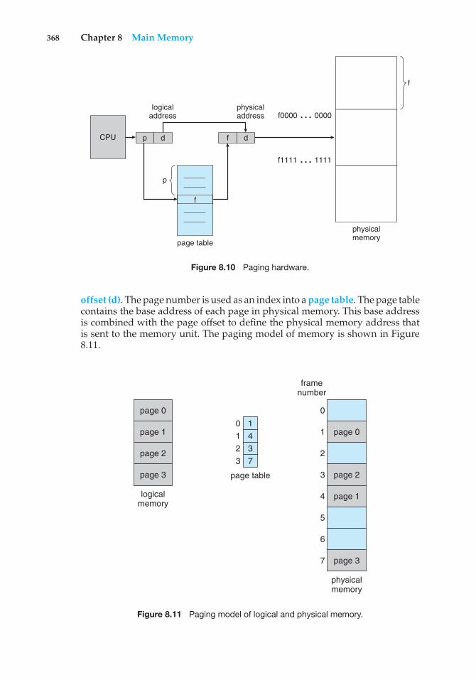
368 Chapter 8 Main Memory
physicalmemory
f
logicaladdress
page table
physicaladdress
CPU p
p
f
d df
f0000 … 0000
f1111 … 1111
Figure 8.10 Paging hardware.
offset (d). The page number is used as an index into a page table. The page tablecontains the base address of each page in physical memory. This base addressis combined with the page offset to define the physical memory address thatis sent to the memory unit. The paging model of memory is shown in Figure8.11.
page 0
page 1
page 2
page 3
logicalmemory
page 1
page 3
page 0
page 2
physicalmemory
page table
framenumber
1437
0123
0
1
2
3
4
5
6
7
Figure 8.11 Paging model of logical and physical memory.
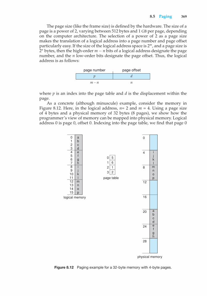
8.5 Paging 369
The page size (like the frame size) is defined by the hardware. The size of apage is a power of 2, varying between 512 bytes and 1 GB per page, dependingon the computer architecture. The selection of a power of 2 as a page sizemakes the translation of a logical address into a page number and page offsetparticularly easy. If the size of the logical address space is 2m, and a page size is2n bytes, then the high-order m− n bits of a logical address designate the pagenumber, and the n low-order bits designate the page offset. Thus, the logicaladdress is as follows:
p d
page number page offset
m – n n
where p is an index into the page table and d is the displacement within thepage.
As a concrete (although minuscule) example, consider the memory inFigure 8.12. Here, in the logical address, n= 2 and m = 4. Using a page sizeof 4 bytes and a physical memory of 32 bytes (8 pages), we show how theprogrammer’s view of memory can be mapped into physical memory. Logicaladdress 0 is page 0, offset 0. Indexing into the page table, we find that page 0
logical memory
physical memory
page table
ijkl
mnop
abcdefgh
abcdefghijkl
mnop
0123456789101112131415
0
0
4
8
12
16
20
24
28
123
5612
Figure 8.12 Paging example for a 32-byte memory with 4-byte pages.
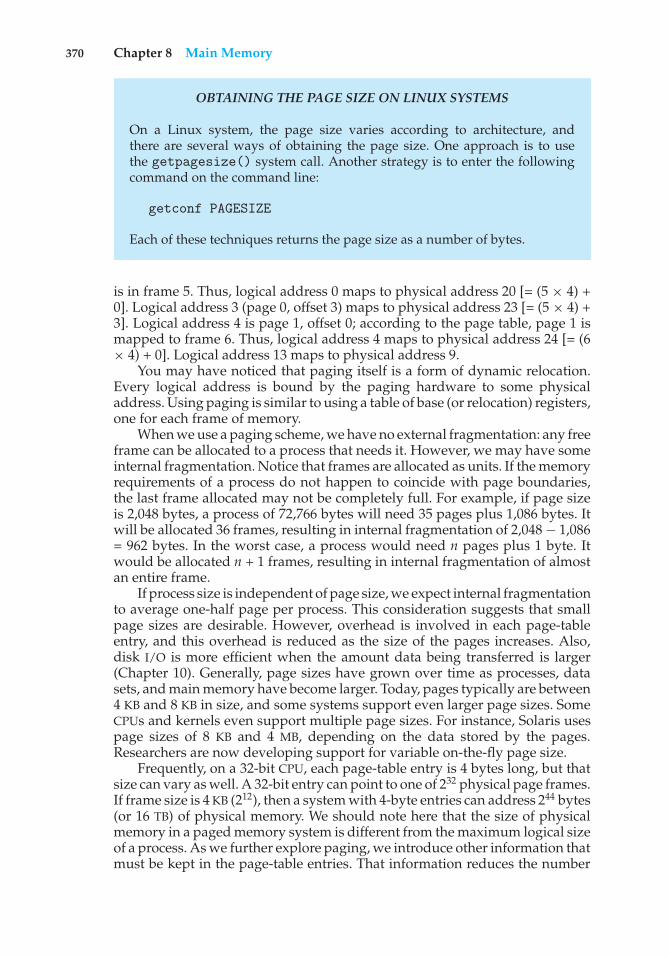
370 Chapter 8 Main Memory
OBTAINING THE PAGE SIZE ON LINUX SYSTEMS
On a Linux system, the page size varies according to architecture, andthere are several ways of obtaining the page size. One approach is to usethe getpagesize() system call. Another strategy is to enter the followingcommand on the command line:
getconf PAGESIZE
Each of these techniques returns the page size as a number of bytes.
is in frame 5. Thus, logical address 0 maps to physical address 20 [= (5 × 4) +0]. Logical address 3 (page 0, offset 3) maps to physical address 23 [= (5 × 4) +3]. Logical address 4 is page 1, offset 0; according to the page table, page 1 ismapped to frame 6. Thus, logical address 4 maps to physical address 24 [= (6× 4) + 0]. Logical address 13 maps to physical address 9.
You may have noticed that paging itself is a form of dynamic relocation.Every logical address is bound by the paging hardware to some physicaladdress. Using paging is similar to using a table of base (or relocation) registers,one for each frame of memory.
When we use a paging scheme, we have no external fragmentation: any freeframe can be allocated to a process that needs it. However, we may have someinternal fragmentation. Notice that frames are allocated as units. If the memoryrequirements of a process do not happen to coincide with page boundaries,the last frame allocated may not be completely full. For example, if page sizeis 2,048 bytes, a process of 72,766 bytes will need 35 pages plus 1,086 bytes. Itwill be allocated 36 frames, resulting in internal fragmentation of 2,048− 1,086= 962 bytes. In the worst case, a process would need n pages plus 1 byte. Itwould be allocated n + 1 frames, resulting in internal fragmentation of almostan entire frame.
If process size is independent of page size, we expect internal fragmentationto average one-half page per process. This consideration suggests that smallpage sizes are desirable. However, overhead is involved in each page-tableentry, and this overhead is reduced as the size of the pages increases. Also,disk I/O is more efficient when the amount data being transferred is larger(Chapter 10). Generally, page sizes have grown over time as processes, datasets, and main memory have become larger. Today, pages typically are between4 KB and 8 KB in size, and some systems support even larger page sizes. SomeCPUs and kernels even support multiple page sizes. For instance, Solaris usespage sizes of 8 KB and 4 MB, depending on the data stored by the pages.Researchers are now developing support for variable on-the-fly page size.
Frequently, on a 32-bit CPU, each page-table entry is 4 bytes long, but thatsize can vary as well. A 32-bit entry can point to one of 232 physical page frames.If frame size is 4 KB (212), then a system with 4-byte entries can address 244 bytes(or 16 TB) of physical memory. We should note here that the size of physicalmemory in a paged memory system is different from the maximum logical sizeof a process. As we further explore paging, we introduce other information thatmust be kept in the page-table entries. That information reduces the number
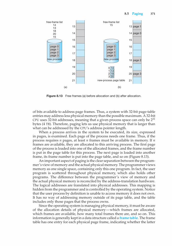
8.5 Paging 371
(a)
free-frame list1413182015
13
14
15
16
17
18
19
20
21
page 0 page 1 page 2 page 3
new process
(b)
free-frame list15 13 page 1
page 0
page 2
page 3
14
15
16
17
18
19
20
21
page 0 page 1 page 2 page 3
new process
new-process page table
140123
131820
Figure 8.13 Free frames (a) before allocation and (b) after allocation.
of bits available to address page frames. Thus, a system with 32-bit page-tableentries may address less physical memory than the possible maximum. A 32-bitCPU uses 32-bit addresses, meaning that a given process space can only be 232
bytes (4 TB). Therefore, paging lets us use physical memory that is larger thanwhat can be addressed by the CPU’s address pointer length.
When a process arrives in the system to be executed, its size, expressedin pages, is examined. Each page of the process needs one frame. Thus, if theprocess requires n pages, at least n frames must be available in memory. If nframes are available, they are allocated to this arriving process. The first pageof the process is loaded into one of the allocated frames, and the frame numberis put in the page table for this process. The next page is loaded into anotherframe, its frame number is put into the page table, and so on (Figure 8.13).
An important aspect of paging is the clear separation between the program-mer’s view of memory and the actual physical memory. The programmer viewsmemory as one single space, containing only this one program. In fact, the userprogram is scattered throughout physical memory, which also holds otherprograms. The difference between the programmer’s view of memory andthe actual physical memory is reconciled by the address-translation hardware.The logical addresses are translated into physical addresses. This mapping ishidden from the programmer and is controlled by the operating system. Noticethat the user process by definition is unable to access memory it does not own.It has no way of addressing memory outside of its page table, and the tableincludes only those pages that the process owns.
Since the operating system is managing physical memory, it must be awareof the allocation details of physical memory—which frames are allocated,which frames are available, how many total frames there are, and so on. Thisinformation is generally kept in a data structure called a frame table. The frametable has one entry for each physical page frame, indicating whether the latter
372 Chapter 8 Main Memory
is free or allocated and, if it is allocated, to which page of which process orprocesses.
In addition, the operating system must be aware that user processes operatein user space, and all logical addresses must be mapped to produce physicaladdresses. If a user makes a system call (to do I/O, for example) and providesan address as a parameter (a buffer, for instance), that address must be mappedto produce the correct physical address. The operating system maintains a copyof the page table for each process, just as it maintains a copy of the instructioncounter and register contents. This copy is used to translate logical addresses tophysical addresses whenever the operating system must map a logical addressto a physical address manually. It is also used by the CPU dispatcher to definethe hardware page table when a process is to be allocated the CPU. Pagingtherefore increases the context-switch time.
8.5.2 Hardware Support
Each operating system has its own methods for storing page tables. Someallocate a page table for each process. A pointer to the page table is stored withthe other register values (like the instruction counter) in the process controlblock. When the dispatcher is told to start a process, it must reload the userregisters and define the correct hardware page-table values from the stored userpage table. Other operating systems provide one or at most a few page tables,which decreases the overhead involved when processes are context-switched.
The hardware implementation of the page table can be done in severalways. In the simplest case, the page table is implemented as a set of dedicatedregisters. These registers should be built with very high-speed logic to make thepaging-address translation efficient. Every access to memory must go throughthe paging map, so efficiency is a major consideration. The CPU dispatcherreloads these registers, just as it reloads the other registers. Instructions to loador modify the page-table registers are, of course, privileged, so that only theoperating system can change the memory map. The DEC PDP-11 is an exampleof such an architecture. The address consists of 16 bits, and the page size is 8KB. The page table thus consists of eight entries that are kept in fast registers.
The use of registers for the page table is satisfactory if the page table isreasonably small (for example, 256 entries). Most contemporary computers,however, allow the page table to be very large (for example, 1 million entries).For these machines, the use of fast registers to implement the page table isnot feasible. Rather, the page table is kept in main memory, and a page-tablebase register (PTBR) points to the page table. Changing page tables requireschanging only this one register, substantially reducing context-switch time.
The problem with this approach is the time required to access a usermemory location. If we want to access location i, we must first index intothe page table, using the value in the PTBR offset by the page number for i. Thistask requires a memory access. It provides us with the frame number, whichis combined with the page offset to produce the actual address. We can thenaccess the desired place in memory. With this scheme, two memory accessesare needed to access a byte (one for the page-table entry, one for the byte). Thus,memory access is slowed by a factor of 2. This delay would be intolerable undermost circumstances. We might as well resort to swapping!
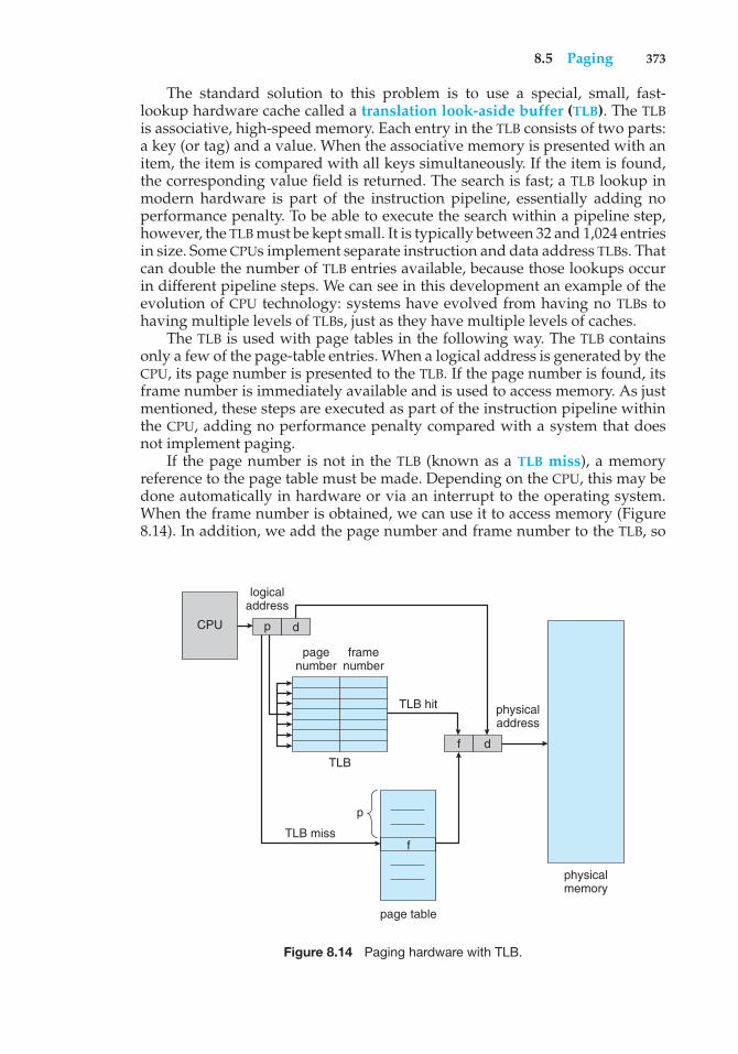
8.5 Paging 373
The standard solution to this problem is to use a special, small, fast-lookup hardware cache called a translation look-aside buffer (TLB). The TLBis associative, high-speed memory. Each entry in the TLB consists of two parts:a key (or tag) and a value. When the associative memory is presented with anitem, the item is compared with all keys simultaneously. If the item is found,the corresponding value field is returned. The search is fast; a TLB lookup inmodern hardware is part of the instruction pipeline, essentially adding noperformance penalty. To be able to execute the search within a pipeline step,however, the TLB must be kept small. It is typically between 32 and 1,024 entriesin size. Some CPUs implement separate instruction and data address TLBs. Thatcan double the number of TLB entries available, because those lookups occurin different pipeline steps. We can see in this development an example of theevolution of CPU technology: systems have evolved from having no TLBs tohaving multiple levels of TLBs, just as they have multiple levels of caches.
The TLB is used with page tables in the following way. The TLB containsonly a few of the page-table entries. When a logical address is generated by theCPU, its page number is presented to the TLB. If the page number is found, itsframe number is immediately available and is used to access memory. As justmentioned, these steps are executed as part of the instruction pipeline withinthe CPU, adding no performance penalty compared with a system that doesnot implement paging.
If the page number is not in the TLB (known as a TLB miss), a memoryreference to the page table must be made. Depending on the CPU, this may bedone automatically in hardware or via an interrupt to the operating system.When the frame number is obtained, we can use it to access memory (Figure8.14). In addition, we add the page number and frame number to the TLB, so
page table
f
CPU
logicaladdress
p d
f d
physicaladdress
physicalmemory
p
TLB miss
pagenumber
framenumber
TLB hit
TLB
Figure 8.14 Paging hardware with TLB.
374 Chapter 8 Main Memory
that they will be found quickly on the next reference. If the TLB is already fullof entries, an existing entry must be selected for replacement. Replacementpolicies range from least recently used (LRU) through round-robin to random.Some CPUs allow the operating system to participate in LRU entry replacement,while others handle the matter themselves. Furthermore, some TLBs allowcertain entries to be wired down, meaning that they cannot be removed fromthe TLB. Typically, TLB entries for key kernel code are wired down.
Some TLBs store address-space identifiers (ASIDs) in each TLB entry. AnASID uniquely identifies each process and is used to provide address-spaceprotection for that process. When the TLB attempts to resolve virtual pagenumbers, it ensures that the ASID for the currently running process matches theASID associated with the virtual page. If the ASIDs do not match, the attempt istreated as a TLB miss. In addition to providing address-space protection, an ASIDallows the TLB to contain entries for several different processes simultaneously.If the TLB does not support separate ASIDs, then every time a new page tableis selected (for instance, with each context switch), the TLB must be flushed(or erased) to ensure that the next executing process does not use the wrongtranslation information. Otherwise, the TLB could include old entries thatcontain valid virtual addresses but have incorrect or invalid physical addressesleft over from the previous process.
The percentage of times that the page number of interest is found in theTLB is called the hit ratio. An 80-percent hit ratio, for example, means thatwe find the desired page number in the TLB 80 percent of the time. If it takes100 nanoseconds to access memory, then a mapped-memory access takes 100nanoseconds when the page number is in the TLB. If we fail to find the pagenumber in the TLB then we must first access memory for the page table andframe number (100 nanoseconds) and then access the desired byte in memory(100 nanoseconds), for a total of 200 nanoseconds. (We are assuming that apage-table lookup takes only one memory access, but it can take more, as weshall see.) To find the effective memory-access time, we weight the case by itsprobability:
effective access time = 0.80 × 100 + 0.20 × 200= 120 nanoseconds
In this example, we suffer a 20-percent slowdown in average memory-accesstime (from 100 to 120 nanoseconds).
For a 99-percent hit ratio, which is much more realistic, we have
effective access time = 0.99 × 100 + 0.01 × 200= 101 nanoseconds
This increased hit rate produces only a 1 percent slowdown in access time.As we noted earlier, CPUs today may provide multiple levels of TLBs.
Calculating memory access times in modern CPUs is therefore much morecomplicated than shown in the example above. For instance, the Intel Corei7 CPU has a 128-entry L1 instruction TLB and a 64-entry L1 data TLB. In thecase of a miss at L1, it takes the CPU six cycles to check for the entry in the L2512-entry TLB. A miss in L2 means that the CPU must either walk through the
8.5 Paging 375
page-table entries in memory to find the associated frame address, which cantake hundreds of cycles, or interrupt to the operating system to have it do thework.
A complete performance analysis of paging overhead in such a systemwould require miss-rate information about each TLB tier. We can see from thegeneral information above, however, that hardware features can have a signif-icant effect on memory performance and that operating-system improvements(such as paging) can result in and, in turn, be affected by hardware changes(such as TLBs). We will further explore the impact of the hit ratio on the TLB inChapter 9.
TLBs are a hardware feature and therefore would seem to be of little concernto operating systems and their designers. But the designer needs to understandthe function and features of TLBs, which vary by hardware platform. Foroptimal operation, an operating-system design for a given platform mustimplement paging according to the platform’s TLB design. Likewise, a change inthe TLB design (for example, between generations of Intel CPUs) may necessitatea change in the paging implementation of the operating systems that use it.
8.5.3 Protection
Memory protection in a paged environment is accomplished by protection bitsassociated with each frame. Normally, these bits are kept in the page table.
One bit can define a page to be read–write or read-only. Every referenceto memory goes through the page table to find the correct frame number. Atthe same time that the physical address is being computed, the protection bitscan be checked to verify that no writes are being made to a read-only page. Anattempt to write to a read-only page causes a hardware trap to the operatingsystem (or memory-protection violation).
We can easily expand this approach to provide a finer level of protection.We can create hardware to provide read-only, read–write, or execute-onlyprotection; or, by providing separate protection bits for each kind of access, wecan allow any combination of these accesses. Illegal attempts will be trappedto the operating system.
One additional bit is generally attached to each entry in the page table: avalid–invalid bit. When this bit is set to valid, the associated page is in theprocess’s logical address space and is thus a legal (or valid) page. When thebit is set toinvalid, the page is not in the process’s logical address space. Illegaladdresses are trapped by use of the valid–invalid bit. The operating systemsets this bit for each page to allow or disallow access to the page.
Suppose, for example, that in a system with a 14-bit address space (0 to16383), we have a program that should use only addresses 0 to 10468. Givena page size of 2 KB, we have the situation shown in Figure 8.15. Addresses inpages 0, 1, 2, 3, 4, and 5 are mapped normally through the page table. Anyattempt to generate an address in pages 6 or 7, however, will find that thevalid–invalid bit is set to invalid, and the computer will trap to the operatingsystem (invalid page reference).
Notice that this scheme has created a problem. Because the programextends only to address 10468, any reference beyond that address is illegal.However, references to page 5 are classified as valid, so accesses to addressesup to 12287 are valid. Only the addresses from 12288 to 16383 are invalid. This
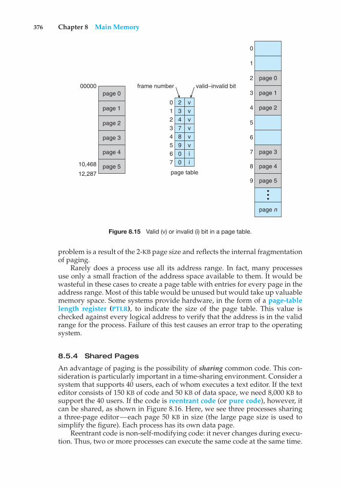
376 Chapter 8 Main Memory
page 0
page 0
page 1
page 2
page 3
page 4
page 5
page n
•••
00000
0
1
2
3
4
5
6
7
8
9
frame number
01234567
23478900
vvvvvvii
page table
valid–invalid bit
10,468
12,287
page 1
page 2
page 3
page 4
page 5
Figure 8.15 Valid (v) or invalid (i) bit in a page table.
problem is a result of the 2-KB page size and reflects the internal fragmentationof paging.
Rarely does a process use all its address range. In fact, many processesuse only a small fraction of the address space available to them. It would bewasteful in these cases to create a page table with entries for every page in theaddress range. Most of this table would be unused but would take up valuablememory space. Some systems provide hardware, in the form of a page-tablelength register (PTLR), to indicate the size of the page table. This value ischecked against every logical address to verify that the address is in the validrange for the process. Failure of this test causes an error trap to the operatingsystem.
8.5.4 Shared Pages
An advantage of paging is the possibility of sharing common code. This con-sideration is particularly important in a time-sharing environment. Consider asystem that supports 40 users, each of whom executes a text editor. If the texteditor consists of 150 KB of code and 50 KB of data space, we need 8,000 KB tosupport the 40 users. If the code is reentrant code (or pure code), however, itcan be shared, as shown in Figure 8.16. Here, we see three processes sharinga three-page editor—each page 50 KB in size (the large page size is used tosimplify the figure). Each process has its own data page.
Reentrant code is non-self-modifying code: it never changes during execu-tion. Thus, two or more processes can execute the same code at the same time.
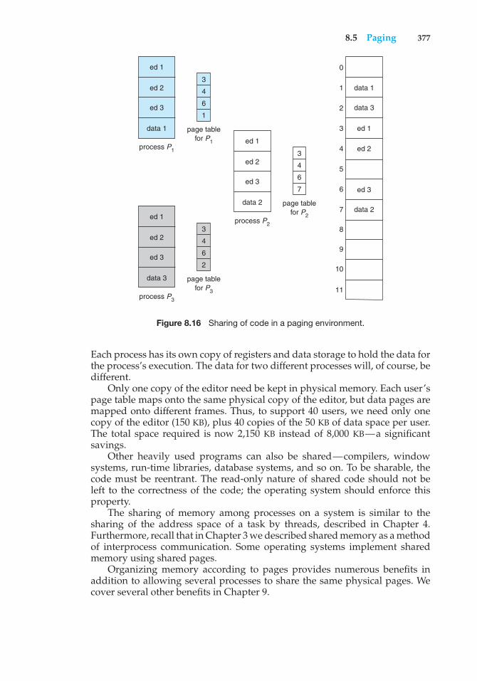
8.5 Paging 377
7
6
5
ed 24
ed 13
2
data 11
0
3
4
6
1
page tablefor P1
process P1
data 1
ed 2
ed 3
ed 1
3
4
6
2
page tablefor P3
process P3
data 3
ed 2
ed 3
ed 1
3
4
6
7
page tablefor P2
process P2
data 2
ed 2
ed 3
ed 1
8
9
10
11
data 3
2data
ed 3
Figure 8.16 Sharing of code in a paging environment.
Each process has its own copy of registers and data storage to hold the data forthe process’s execution. The data for two different processes will, of course, bedifferent.
Only one copy of the editor need be kept in physical memory. Each user’spage table maps onto the same physical copy of the editor, but data pages aremapped onto different frames. Thus, to support 40 users, we need only onecopy of the editor (150 KB), plus 40 copies of the 50 KB of data space per user.The total space required is now 2,150 KB instead of 8,000 KB—a significantsavings.
Other heavily used programs can also be shared—compilers, windowsystems, run-time libraries, database systems, and so on. To be sharable, thecode must be reentrant. The read-only nature of shared code should not beleft to the correctness of the code; the operating system should enforce thisproperty.
The sharing of memory among processes on a system is similar to thesharing of the address space of a task by threads, described in Chapter 4.Furthermore, recall that in Chapter 3 we described shared memory as a methodof interprocess communication. Some operating systems implement sharedmemory using shared pages.
Organizing memory according to pages provides numerous benefits inaddition to allowing several processes to share the same physical pages. Wecover several other benefits in Chapter 9.
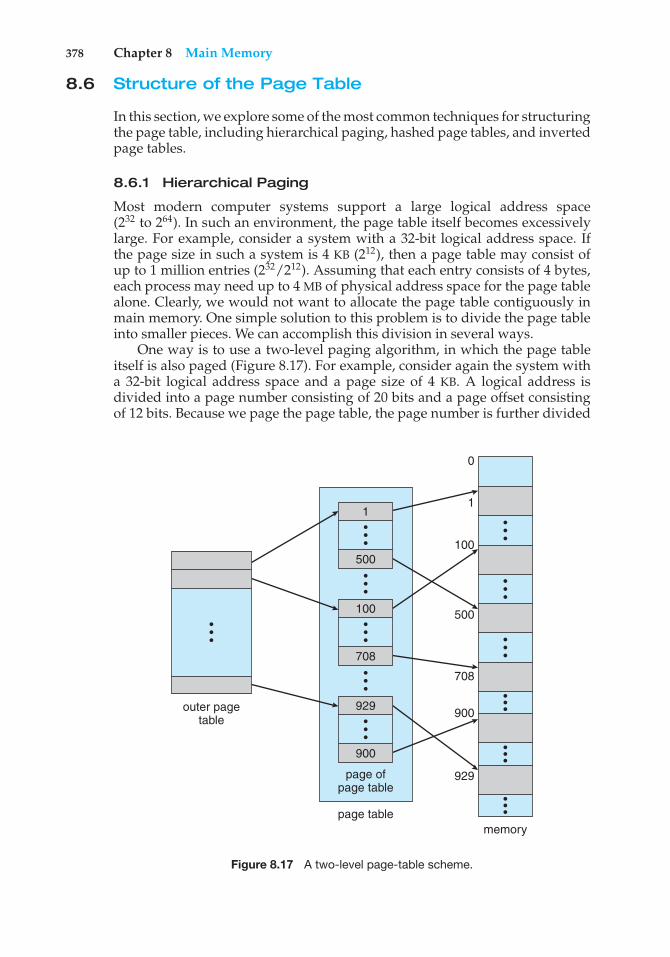
378 Chapter 8 Main Memory
8.6 Structure of the Page Table
In this section, we explore some of the most common techniques for structuringthe page table, including hierarchical paging, hashed page tables, and invertedpage tables.
8.6.1 Hierarchical Paging
Most modern computer systems support a large logical address space(232 to 264). In such an environment, the page table itself becomes excessivelylarge. For example, consider a system with a 32-bit logical address space. Ifthe page size in such a system is 4 KB (212), then a page table may consist ofup to 1 million entries (232/212). Assuming that each entry consists of 4 bytes,each process may need up to 4 MB of physical address space for the page tablealone. Clearly, we would not want to allocate the page table contiguously inmain memory. One simple solution to this problem is to divide the page tableinto smaller pieces. We can accomplish this division in several ways.
One way is to use a two-level paging algorithm, in which the page tableitself is also paged (Figure 8.17). For example, consider again the system witha 32-bit logical address space and a page size of 4 KB. A logical address isdivided into a page number consisting of 20 bits and a page offset consistingof 12 bits. Because we page the page table, the page number is further divided
•••
•••
outer pagetable
page ofpage table
page tablememory
929
900
929
900
708
500
100
1
0
•••
100
708
•••
•••
•••
•••
•••
•••
•••
•••
•••
1
500
Figure 8.17 A two-level page-table scheme.
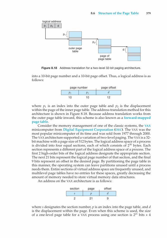
8.6 Structure of the Page Table 379
logical address
outer pagetable
p1 p2
p1
page ofpage table
p2
d
d
Figure 8.18 Address translation for a two-level 32-bit paging architecture.
into a 10-bit page number and a 10-bit page offset. Thus, a logical address is asfollows:
p1 p2 d
page number page offset
10 10 12
where p1 is an index into the outer page table and p2 is the displacementwithin the page of the inner page table. The address-translation method for thisarchitecture is shown in Figure 8.18. Because address translation works fromthe outer page table inward, this scheme is also known as a forward-mappedpage table.
Consider the memory management of one of the classic systems, the VAXminicomputer from Digital Equipment Corporation (DEC). The VAX was themost popular minicomputer of its time and was sold from 1977 through 2000.The VAX architecture supported a variation of two-level paging. The VAX is a 32-bit machine with a page size of 512 bytes. The logical address space of a processis divided into four equal sections, each of which consists of 230 bytes. Eachsection represents a different part of the logical address space of a process. Thefirst 2 high-order bits of the logical address designate the appropriate section.The next 21 bits represent the logical page number of that section, and the final9 bits represent an offset in the desired page. By partitioning the page table inthis manner, the operating system can leave partitions unused until a processneeds them. Entire sections of virtual address space are frequently unused, andmultilevel page tables have no entries for these spaces, greatly decreasing theamount of memory needed to store virtual memory data structures.
An address on the VAX architecture is as follows:
s p d
section page offset
2 21 9
where s designates the section number, p is an index into the page table, and dis the displacement within the page. Even when this scheme is used, the sizeof a one-level page table for a VAX process using one section is 221 bits ∗ 4
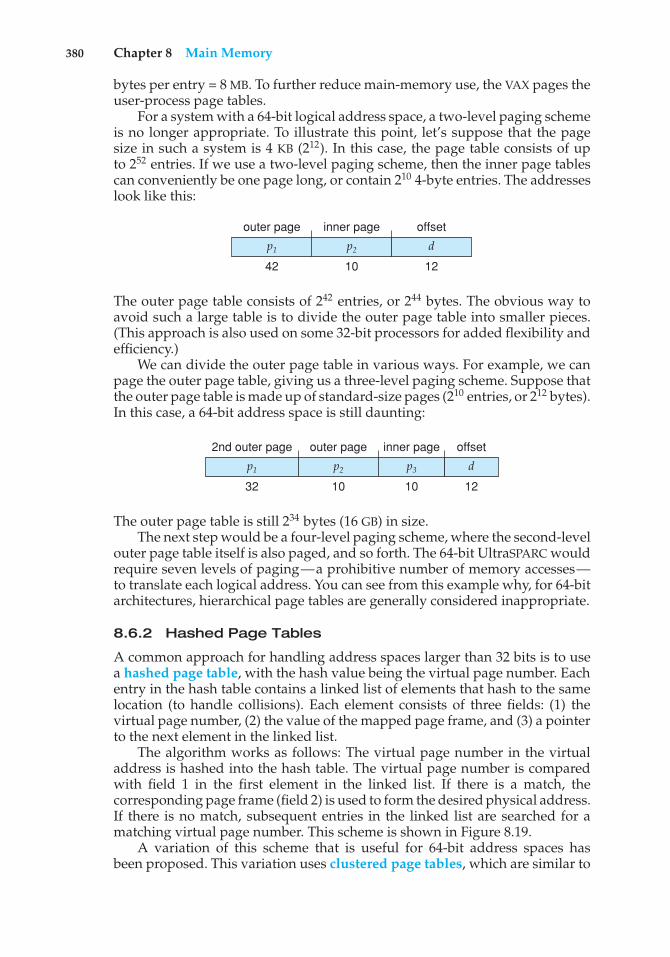
380 Chapter 8 Main Memory
bytes per entry = 8 MB. To further reduce main-memory use, the VAX pages theuser-process page tables.
For a system with a 64-bit logical address space, a two-level paging schemeis no longer appropriate. To illustrate this point, let’s suppose that the pagesize in such a system is 4 KB (212). In this case, the page table consists of upto 252 entries. If we use a two-level paging scheme, then the inner page tablescan conveniently be one page long, or contain 210 4-byte entries. The addresseslook like this:
p1 p2 d
outer page inner page offset
42 10 12
The outer page table consists of 242 entries, or 244 bytes. The obvious way toavoid such a large table is to divide the outer page table into smaller pieces.(This approach is also used on some 32-bit processors for added flexibility andefficiency.)
We can divide the outer page table in various ways. For example, we canpage the outer page table, giving us a three-level paging scheme. Suppose thatthe outer page table is made up of standard-size pages (210 entries, or 212 bytes).In this case, a 64-bit address space is still daunting:
p1 p2 p3
2nd outer page outer page inner page
32 10 10
d
offset
12
The outer page table is still 234 bytes (16 GB) in size.The next step would be a four-level paging scheme, where the second-level
outer page table itself is also paged, and so forth. The 64-bit UltraSPARC wouldrequire seven levels of paging—a prohibitive number of memory accesses—to translate each logical address. You can see from this example why, for 64-bitarchitectures, hierarchical page tables are generally considered inappropriate.
8.6.2 Hashed Page Tables
A common approach for handling address spaces larger than 32 bits is to usea hashed page table, with the hash value being the virtual page number. Eachentry in the hash table contains a linked list of elements that hash to the samelocation (to handle collisions). Each element consists of three fields: (1) thevirtual page number, (2) the value of the mapped page frame, and (3) a pointerto the next element in the linked list.
The algorithm works as follows: The virtual page number in the virtualaddress is hashed into the hash table. The virtual page number is comparedwith field 1 in the first element in the linked list. If there is a match, thecorresponding page frame (field 2) is used to form the desired physical address.If there is no match, subsequent entries in the linked list are searched for amatching virtual page number. This scheme is shown in Figure 8.19.
A variation of this scheme that is useful for 64-bit address spaces hasbeen proposed. This variation uses clustered page tables, which are similar to
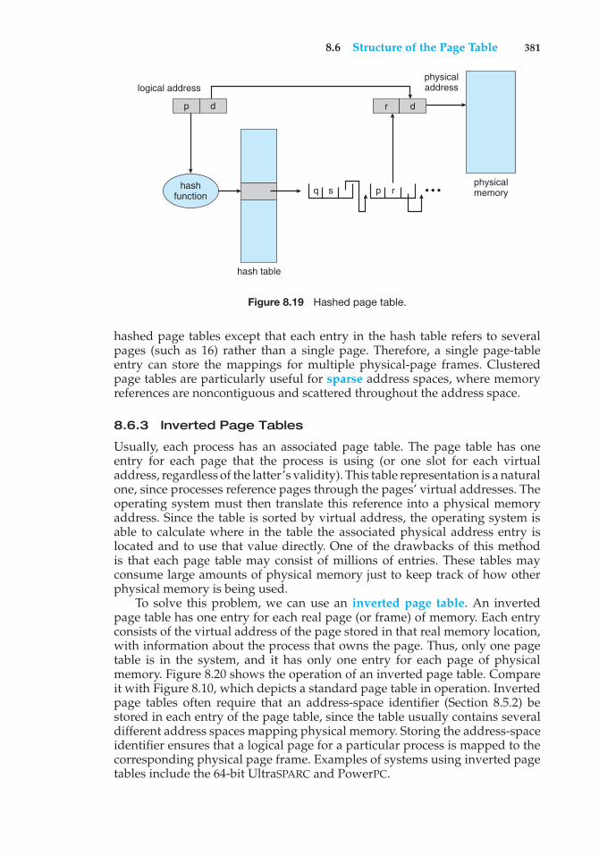
8.6 Structure of the Page Table 381
hash table
q s
logical addressphysicaladdress
physicalmemory
p d r d
p rhashfunction • • •
Figure 8.19 Hashed page table.
hashed page tables except that each entry in the hash table refers to severalpages (such as 16) rather than a single page. Therefore, a single page-tableentry can store the mappings for multiple physical-page frames. Clusteredpage tables are particularly useful for sparse address spaces, where memoryreferences are noncontiguous and scattered throughout the address space.
8.6.3 Inverted Page Tables
Usually, each process has an associated page table. The page table has oneentry for each page that the process is using (or one slot for each virtualaddress, regardless of the latter’s validity). This table representation is a naturalone, since processes reference pages through the pages’ virtual addresses. Theoperating system must then translate this reference into a physical memoryaddress. Since the table is sorted by virtual address, the operating system isable to calculate where in the table the associated physical address entry islocated and to use that value directly. One of the drawbacks of this methodis that each page table may consist of millions of entries. These tables mayconsume large amounts of physical memory just to keep track of how otherphysical memory is being used.
To solve this problem, we can use an inverted page table. An invertedpage table has one entry for each real page (or frame) of memory. Each entryconsists of the virtual address of the page stored in that real memory location,with information about the process that owns the page. Thus, only one pagetable is in the system, and it has only one entry for each page of physicalmemory. Figure 8.20 shows the operation of an inverted page table. Compareit with Figure 8.10, which depicts a standard page table in operation. Invertedpage tables often require that an address-space identifier (Section 8.5.2) bestored in each entry of the page table, since the table usually contains severaldifferent address spaces mapping physical memory. Storing the address-spaceidentifier ensures that a logical page for a particular process is mapped to thecorresponding physical page frame. Examples of systems using inverted pagetables include the 64-bit UltraSPARC and PowerPC.
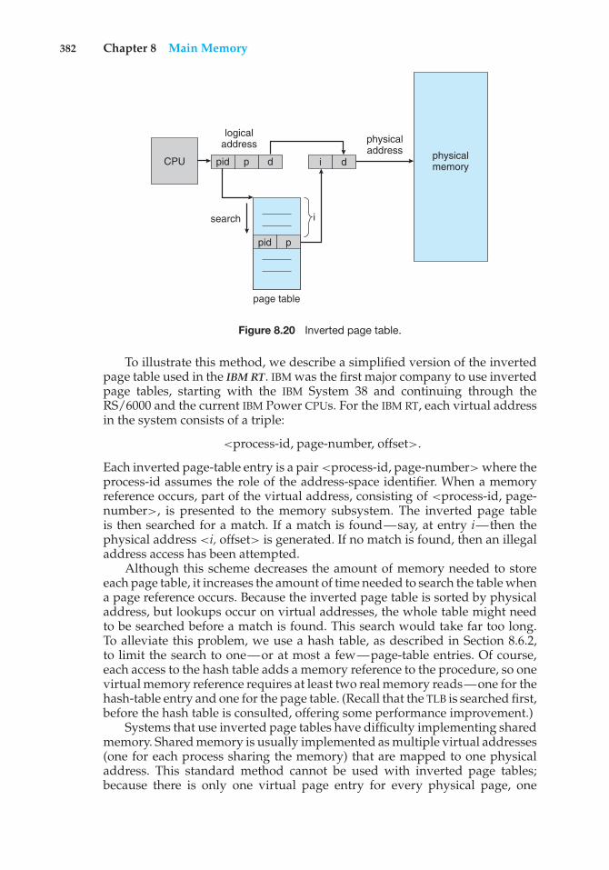
382 Chapter 8 Main Memory
page table
CPU
logicaladdress physical
address physicalmemory
i
pid p
pid
search
p
d i d
Figure 8.20 Inverted page table.
To illustrate this method, we describe a simplified version of the invertedpage table used in the IBM RT. IBM was the first major company to use invertedpage tables, starting with the IBM System 38 and continuing through theRS/6000 and the current IBM Power CPUs. For the IBM RT, each virtual addressin the system consists of a triple:
<process-id, page-number, offset>.
Each inverted page-table entry is a pair <process-id, page-number> where theprocess-id assumes the role of the address-space identifier. When a memoryreference occurs, part of the virtual address, consisting of <process-id, page-number>, is presented to the memory subsystem. The inverted page tableis then searched for a match. If a match is found—say, at entry i—then thephysical address <i, offset> is generated. If no match is found, then an illegaladdress access has been attempted.
Although this scheme decreases the amount of memory needed to storeeach page table, it increases the amount of time needed to search the table whena page reference occurs. Because the inverted page table is sorted by physicaladdress, but lookups occur on virtual addresses, the whole table might needto be searched before a match is found. This search would take far too long.To alleviate this problem, we use a hash table, as described in Section 8.6.2,to limit the search to one—or at most a few—page-table entries. Of course,each access to the hash table adds a memory reference to the procedure, so onevirtual memory reference requires at least two real memory reads—one for thehash-table entry and one for the page table. (Recall that the TLB is searched first,before the hash table is consulted, offering some performance improvement.)
Systems that use inverted page tables have difficulty implementing sharedmemory. Shared memory is usually implemented as multiple virtual addresses(one for each process sharing the memory) that are mapped to one physicaladdress. This standard method cannot be used with inverted page tables;because there is only one virtual page entry for every physical page, one
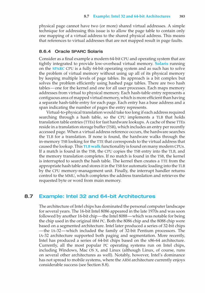
8.7 Example: Intel 32 and 64-bit Architectures 383
physical page cannot have two (or more) shared virtual addresses. A simpletechnique for addressing this issue is to allow the page table to contain onlyone mapping of a virtual address to the shared physical address. This meansthat references to virtual addresses that are not mapped result in page faults.
8.6.4 Oracle SPARC Solaris
Consider as a final example a modern 64-bit CPU and operating system that aretightly integrated to provide low-overhead virtual memory. Solaris runningon the SPARC CPU is a fully 64-bit operating system and as such has to solvethe problem of virtual memory without using up all of its physical memoryby keeping multiple levels of page tables. Its approach is a bit complex butsolves the problem efficiently using hashed page tables. There are two hashtables—one for the kernel and one for all user processes. Each maps memoryaddresses from virtual to physical memory. Each hash-table entry represents acontiguous area of mapped virtual memory, which is more efficient than havinga separate hash-table entry for each page. Each entry has a base address and aspan indicating the number of pages the entry represents.
Virtual-to-physical translation would take too long if each address requiredsearching through a hash table, so the CPU implements a TLB that holdstranslation table entries (TTEs) for fast hardware lookups. A cache of these TTEsreside in a translation storage buffer (TSB), which includes an entry per recentlyaccessed page. When a virtual address reference occurs, the hardware searchesthe TLB for a translation. If none is found, the hardware walks through thein-memory TSB looking for the TTE that corresponds to the virtual address thatcaused the lookup. This TLB walk functionality is found on many modern CPUs.If a match is found in the TSB, the CPU copies the TSB entry into the TLB, andthe memory translation completes. If no match is found in the TSB, the kernelis interrupted to search the hash table. The kernel then creates a TTE from theappropriate hash table and stores it in the TSB for automatic loading into the TLBby the CPU memory-management unit. Finally, the interrupt handler returnscontrol to the MMU, which completes the address translation and retrieves therequested byte or word from main memory.
8.7 Example: Intel 32 and 64-bit Architectures
The architecture of Intel chips has dominated the personal computer landscapefor several years. The 16-bit Intel 8086 appeared in the late 1970s and was soonfollowed by another 16-bit chip—the Intel 8088—which was notable for beingthe chip used in the original IBM PC. Both the 8086 chip and the 8088 chip werebased on a segmented architecture. Intel later produced a series of 32-bit chips—the IA-32—which included the family of 32-bit Pentium processors. TheIA-32 architecture supported both paging and segmentation. More recently,Intel has produced a series of 64-bit chips based on the x86-64 architecture.Currently, all the most popular PC operating systems run on Intel chips,including Windows, Mac OS X, and Linux (although Linux, of course, runson several other architectures as well). Notably, however, Intel’s dominancehas not spread to mobile systems, where the ARM architecture currently enjoysconsiderable success (see Section 8.8).
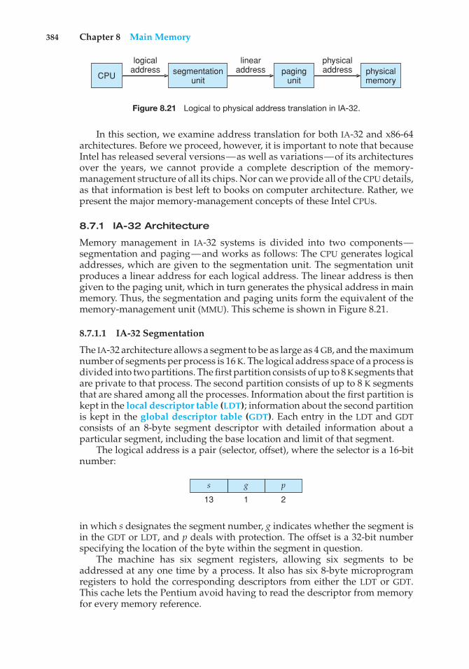
384 Chapter 8 Main Memory
CPU
logicaladdress segmentation
unit
linearaddress paging
unit
physicaladdress physical
memory
Figure 8.21 Logical to physical address translation in IA-32.
In this section, we examine address translation for both IA-32 and x86-64architectures. Before we proceed, however, it is important to note that becauseIntel has released several versions—as well as variations—of its architecturesover the years, we cannot provide a complete description of the memory-management structure of all its chips. Nor can we provide all of the CPU details,as that information is best left to books on computer architecture. Rather, wepresent the major memory-management concepts of these Intel CPUs.
8.7.1 IA-32 Architecture
Memory management in IA-32 systems is divided into two components—segmentation and paging—and works as follows: The CPU generates logicaladdresses, which are given to the segmentation unit. The segmentation unitproduces a linear address for each logical address. The linear address is thengiven to the paging unit, which in turn generates the physical address in mainmemory. Thus, the segmentation and paging units form the equivalent of thememory-management unit (MMU). This scheme is shown in Figure 8.21.
8.7.1.1 IA-32 Segmentation
The IA-32 architecture allows a segment to be as large as 4 GB, and the maximumnumber of segments per process is 16 K. The logical address space of a process isdivided into two partitions. The first partition consists of up to 8 Ksegments thatare private to that process. The second partition consists of up to 8 K segmentsthat are shared among all the processes. Information about the first partition iskept in the local descriptor table (LDT); information about the second partitionis kept in the global descriptor table (GDT). Each entry in the LDT and GDTconsists of an 8-byte segment descriptor with detailed information about aparticular segment, including the base location and limit of that segment.
The logical address is a pair (selector, offset), where the selector is a 16-bitnumber:
p
2
g
1
s
13
in which s designates the segment number, g indicates whether the segment isin the GDT or LDT, and p deals with protection. The offset is a 32-bit numberspecifying the location of the byte within the segment in question.
The machine has six segment registers, allowing six segments to beaddressed at any one time by a process. It also has six 8-byte microprogramregisters to hold the corresponding descriptors from either the LDT or GDT.This cache lets the Pentium avoid having to read the descriptor from memoryfor every memory reference.
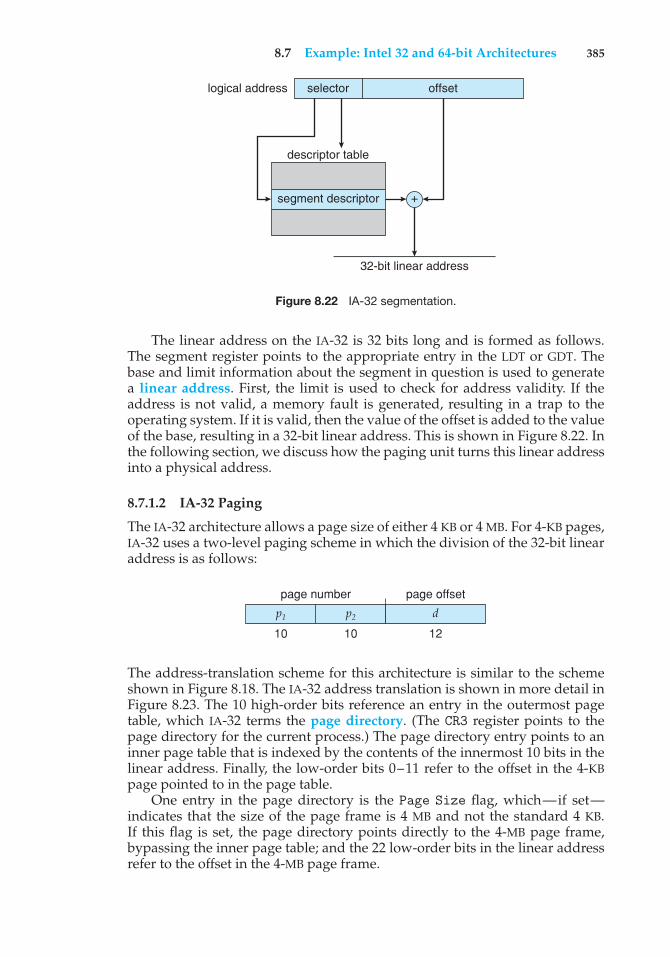
8.7 Example: Intel 32 and 64-bit Architectures 385
logical address selector
descriptor table
segment descriptor +
32-bit linear address
offset
Figure 8.22 IA-32 segmentation.
The linear address on the IA-32 is 32 bits long and is formed as follows.The segment register points to the appropriate entry in the LDT or GDT. Thebase and limit information about the segment in question is used to generatea linear address. First, the limit is used to check for address validity. If theaddress is not valid, a memory fault is generated, resulting in a trap to theoperating system. If it is valid, then the value of the offset is added to the valueof the base, resulting in a 32-bit linear address. This is shown in Figure 8.22. Inthe following section, we discuss how the paging unit turns this linear addressinto a physical address.
8.7.1.2 IA-32 Paging
The IA-32 architecture allows a page size of either 4 KB or 4 MB. For 4-KB pages,IA-32 uses a two-level paging scheme in which the division of the 32-bit linearaddress is as follows:
p1 p2 d
page number page offset
10 10 12
The address-translation scheme for this architecture is similar to the schemeshown in Figure 8.18. The IA-32 address translation is shown in more detail inFigure 8.23. The 10 high-order bits reference an entry in the outermost pagetable, which IA-32 terms the page directory. (The CR3 register points to thepage directory for the current process.) The page directory entry points to aninner page table that is indexed by the contents of the innermost 10 bits in thelinear address. Finally, the low-order bits 0–11 refer to the offset in the 4-KBpage pointed to in the page table.
One entry in the page directory is the Page Size flag, which—if set—indicates that the size of the page frame is 4 MB and not the standard 4 KB.If this flag is set, the page directory points directly to the 4-MB page frame,bypassing the inner page table; and the 22 low-order bits in the linear addressrefer to the offset in the 4-MB page frame.
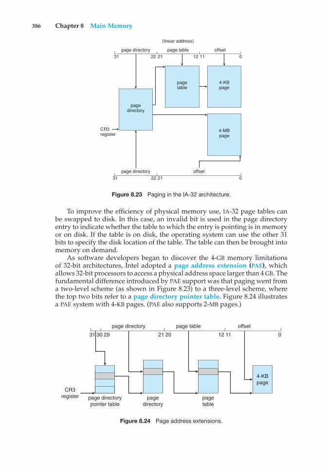
386 Chapter 8 Main Memory
page directory
page directory
CR3register
pagedirectory
pagetable
4-KBpage
4-MBpage
page table
offset
offset
(linear address)
31 22 21 12 11 0
2131 22 0
Figure 8.23 Paging in the IA-32 architecture.
To improve the efficiency of physical memory use, IA-32 page tables canbe swapped to disk. In this case, an invalid bit is used in the page directoryentry to indicate whether the table to which the entry is pointing is in memoryor on disk. If the table is on disk, the operating system can use the other 31bits to specify the disk location of the table. The table can then be brought intomemory on demand.
As software developers began to discover the 4-GB memory limitationsof 32-bit architectures, Intel adopted a page address extension (PAE), whichallows 32-bit processors to access a physical address space larger than 4 GB. Thefundamental difference introduced by PAE support was that paging went froma two-level scheme (as shown in Figure 8.23) to a three-level scheme, wherethe top two bits refer to a page directory pointer table. Figure 8.24 illustratesa PAE system with 4-KB pages. (PAE also supports 2-MB pages.)
31 30 29 21 20 12 11 0
page table offsetpage directory
4-KBpage
pagetable
page directorypointer table
CR3register page
directory
Figure 8.24 Page address extensions.
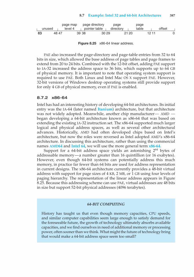
8.7 Example: Intel 32 and 64-bit Architectures 387
unusedpage map
level 4page directorypointer table
pagedirectory
pagetable offset
6363 4748 39 38 30 29 21 20 12 11 0
Figure 8.25 x86-64 linear address.
PAE also increased the page-directory and page-table entries from 32 to 64bits in size, which allowed the base address of page tables and page frames toextend from 20 to 24 bits. Combined with the 12-bit offset, adding PAE supportto IA-32 increased the address space to 36 bits, which supports up to 64 GBof physical memory. It is important to note that operating system support isrequired to use PAE. Both Linux and Intel Mac OS X support PAE. However,32-bit versions of Windows desktop operating systems still provide supportfor only 4 GB of physical memory, even if PAE is enabled.
8.7.2 x86-64
Intel has had an interesting history of developing 64-bit architectures. Its initialentry was the IA-64 (later named Itanium) architecture, but that architecturewas not widely adopted. Meanwhile, another chip manufacturer— AMD —began developing a 64-bit architecture known as x86-64 that was based onextending the existing IA-32 instruction set. The x86-64 supported much largerlogical and physical address spaces, as well as several other architecturaladvances. Historically, AMD had often developed chips based on Intel’sarchitecture, but now the roles were reversed as Intel adopted AMD’s x86-64architecture. In discussing this architecture, rather than using the commercialnames AMD64 and Intel 64, we will use the more general term x86-64.
Support for a 64-bit address space yields an astonishing 264 bytes ofaddressable memory—a number greater than 16 quintillion (or 16 exabytes).However, even though 64-bit systems can potentially address this muchmemory, in practice far fewer than 64 bits are used for address representationin current designs. The x86-64 architecture currently provides a 48-bit virtualaddress with support for page sizes of 4 KB, 2 MB, or 1 GB using four levels ofpaging hierarchy. The representation of the linear address appears in Figure8.25. Because this addressing scheme can use PAE, virtual addresses are 48 bitsin size but support 52-bit physical addresses (4096 terabytes).
64-BIT COMPUTING
History has taught us that even though memory capacities, CPU speeds,and similar computer capabilities seem large enough to satisfy demand forthe foreseeable future, the growth of technology ultimately absorbs availablecapacities, and we find ourselves in need of additional memory or processingpower, often sooner than we think. What might the future of technology bringthat would make a 64-bit address space seem too small?
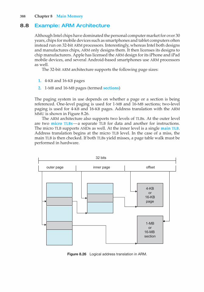
388 Chapter 8 Main Memory
8.8 Example: ARM Architecture
Although Intel chips have dominated the personal computer market for over 30years, chips for mobile devices such as smartphones and tablet computers ofteninstead run on 32-bit ARM processors. Interestingly, whereas Intel both designsand manufactures chips, ARM only designs them. It then licenses its designs tochip manufacturers. Apple has licensed the ARM design for its iPhone and iPadmobile devices, and several Android-based smartphones use ARM processorsas well.
The 32-bit ARM architecture supports the following page sizes:
1. 4-KB and 16-KB pages
2. 1-MB and 16-MB pages (termed sections)
The paging system in use depends on whether a page or a section is beingreferenced. One-level paging is used for 1-MB and 16-MB sections; two-levelpaging is used for 4-KB and 16-KB pages. Address translation with the ARMMMU is shown in Figure 8.26.
The ARM architecture also supports two levels of TLBs. At the outer levelare two micro TLBs—a separate TLB for data and another for instructions.The micro TLB supports ASIDs as well. At the inner level is a single main TLB.Address translation begins at the micro TLB level. In the case of a miss, themain TLB is then checked. If both TLBs yield misses, a page table walk must beperformed in hardware.
outer page inner page offset
4-KBor
16-KBpage
1-MBor
16-MB section
32 bits
Figure 8.26 Logical address translation in ARM.
8.9 Summary 389
8.9 Summary
Memory-management algorithms for multiprogrammed operating systemsrange from the simple single-user system approach to segmentation andpaging. The most important determinant of the method used in a particularsystem is the hardware provided. Every memory address generated by theCPU must be checked for legality and possibly mapped to a physical address.The checking cannot be implemented (efficiently) in software. Hence, we areconstrained by the hardware available.
The various memory-management algorithms (contiguous allocation, pag-ing, segmentation, and combinations of paging and segmentation) differ inmany aspects. In comparing different memory-management strategies, we usethe following considerations:
• Hardware support. A simple base register or a base–limit register pair issufficient for the single- and multiple-partition schemes, whereas pagingand segmentation need mapping tables to define the address map.
• Performance. As the memory-management algorithm becomes morecomplex, the time required to map a logical address to a physical addressincreases. For the simple systems, we need only compare or add to thelogical address—operations that are fast. Paging and segmentation can beas fast if the mapping table is implemented in fast registers. If the table isin memory, however, user memory accesses can be degraded substantially.A TLB can reduce the performance degradation to an acceptable level.
• Fragmentation. A multiprogrammed system will generally perform moreefficiently if it has a higher level of multiprogramming. For a givenset of processes, we can increase the multiprogramming level only bypacking more processes into memory. To accomplish this task, we mustreduce memory waste, or fragmentation. Systems with fixed-sized allo-cation units, such as the single-partition scheme and paging, suffer frominternal fragmentation. Systems with variable-sized allocation units, suchas the multiple-partition scheme and segmentation, suffer from externalfragmentation.
• Relocation. One solution to the external-fragmentation problem is com-paction. Compaction involves shifting a program in memory in such away that the program does not notice the change. This considerationrequires that logical addresses be relocated dynamically, at execution time.If addresses are relocated only at load time, we cannot compact storage.
• Swapping. Swapping can be added to any algorithm. At intervals deter-mined by the operating system, usually dictated by CPU-scheduling poli-cies, processes are copied from main memory to a backing store and laterare copied back to main memory. This scheme allows more processes tobe run than can be fit into memory at one time. In general, PC operatingsystems support paging, and operating systems for mobile devices do not.
• Sharing. Another means of increasing the multiprogramming level is toshare code and data among different processes. Sharing generally requiresthat either paging or segmentation be used to provide small packets of
390 Chapter 8 Main Memory
information (pages or segments) that can be shared. Sharing is a meansof running many processes with a limited amount of memory, but sharedprograms and data must be designed carefully.
• Protection. If paging or segmentation is provided, different sections of auser program can be declared execute-only, read-only, or read–write. Thisrestriction is necessary with shared code or data and is generally usefulin any case to provide simple run-time checks for common programmingerrors.
Practice Exercises
8.1 Name two differences between logical and physical addresses.
8.2 Consider a system in which a program can be separated into twoparts: code and data. The CPU knows whether it wants an instruction(instruction fetch) or data (data fetch or store). Therefore, two base–limit register pairs are provided: one for instructions and one for data.The instruction base–limit register pair is automatically read-only, soprograms can be shared among different users. Discuss the advantagesand disadvantages of this scheme.
8.3 Why are page sizes always powers of 2?
8.4 Consider a logical address space of 64 pages of 1,024 words each, mappedonto a physical memory of 32 frames.
a. How many bits are there in the logical address?
b. How many bits are there in the physical address?
8.5 What is the effect of allowing two entries in a page table to point to thesame page frame in memory? Explain how this effect could be used todecrease the amount of time needed to copy a large amount of memoryfrom one place to another. What effect would updating some byte on theone page have on the other page?
8.6 Describe a mechanism by which one segment could belong to the addressspace of two different processes.
8.7 Sharing segments among processes without requiring that they have thesame segment number is possible in a dynamically linked segmentationsystem.
a. Define a system that allows static linking and sharing of segmentswithout requiring that the segment numbers be the same.
b. Describe a paging scheme that allows pages to be shared withoutrequiring that the page numbers be the same.
8.8 In the IBM/370, memory protection is provided through the use of keys.A key is a 4-bit quantity. Each 2-K block of memory has a key (thestorage key) associated with it. The CPU also has a key (the protectionkey) associated with it. A store operation is allowed only if both keys
Exercises 391
are equal or if either is 0. Which of the following memory-managementschemes could be used successfully with this hardware?
a. Bare machine
b. Single-user system
c. Multiprogramming with a fixed number of processes
d. Multiprogramming with a variable number of processes
e. Paging
f. Segmentation
Exercises
8.9 Explain the difference between internal and external fragmentation.
8.10 Consider the following process for generating binaries. A compiler isused to generate the object code for individual modules, and a linkageeditor is used to combine multiple object modules into a single programbinary. How does the linkage editor change the binding of instructionsand data to memory addresses? What information needs to be passedfrom the compiler to the linkage editor to facilitate the memory-bindingtasks of the linkage editor?
8.11 Given six memory partitions of 300 KB, 600 KB, 350 KB, 200 KB, 750 KB,and 125 KB (in order), how would the first-fit, best-fit, and worst-fitalgorithms place processes of size 115 KB, 500 KB, 358 KB, 200 KB, and375 KB (in order)? Rank the algorithms in terms of how efficiently theyuse memory.
8.12 Most systems allow a program to allocate more memory to its addressspace during execution. Allocation of data in the heap segments ofprograms is an example of such allocated memory. What is requiredto support dynamic memory allocation in the following schemes?
a. Contiguous memory allocation
b. Pure segmentation
c. Pure paging
8.13 Compare the memory organization schemes of contiguous memoryallocation, pure segmentation, and pure paging with respect to thefollowing issues:
a. External fragmentation
b. Internal fragmentation
c. Ability to share code across processes
8.14 On a system with paging, a process cannot access memory that it doesnot own. Why? How could the operating system allow access to othermemory? Why should it or should it not?
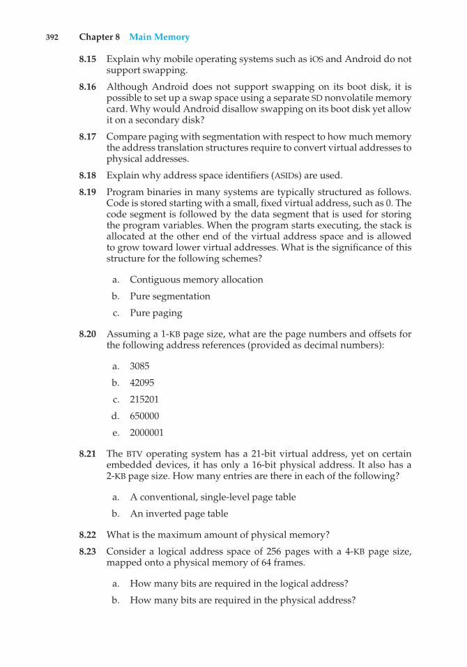
392 Chapter 8 Main Memory
8.15 Explain why mobile operating systems such as iOS and Android do notsupport swapping.
8.16 Although Android does not support swapping on its boot disk, it ispossible to set up a swap space using a separate SD nonvolatile memorycard. Why would Android disallow swapping on its boot disk yet allowit on a secondary disk?
8.17 Compare paging with segmentation with respect to how much memorythe address translation structures require to convert virtual addresses tophysical addresses.
8.18 Explain why address space identifiers (ASIDs) are used.
8.19 Program binaries in many systems are typically structured as follows.Code is stored starting with a small, fixed virtual address, such as 0. Thecode segment is followed by the data segment that is used for storingthe program variables. When the program starts executing, the stack isallocated at the other end of the virtual address space and is allowedto grow toward lower virtual addresses. What is the significance of thisstructure for the following schemes?
a. Contiguous memory allocation
b. Pure segmentation
c. Pure paging
8.20 Assuming a 1-KB page size, what are the page numbers and offsets forthe following address references (provided as decimal numbers):
a. 3085
b. 42095
c. 215201
d. 650000
e. 2000001
8.21 The BTV operating system has a 21-bit virtual address, yet on certainembedded devices, it has only a 16-bit physical address. It also has a2-KB page size. How many entries are there in each of the following?
a. A conventional, single-level page table
b. An inverted page table
8.22 What is the maximum amount of physical memory?
8.23 Consider a logical address space of 256 pages with a 4-KB page size,mapped onto a physical memory of 64 frames.
a. How many bits are required in the logical address?
b. How many bits are required in the physical address?
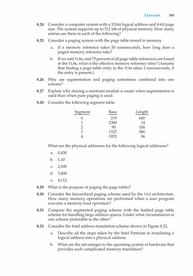
Exercises 393
8.24 Consider a computer system with a 32-bit logical address and 4-KB pagesize. The system supports up to 512 MB of physical memory. How manyentries are there in each of the following?
8.25 Consider a paging system with the page table stored in memory.
a. If a memory reference takes 50 nanoseconds, how long does apaged memory reference take?
b. If we add TLBs, and 75 percent of all page-table references are foundin the TLBs, what is the effective memory reference time? (Assumethat finding a page-table entry in the TLBs takes 2 nanoseconds, ifthe entry is present.)
8.26 Why are segmentation and paging sometimes combined into onescheme?
8.27 Explain why sharing a reentrant module is easier when segmentation isused than when pure paging is used.
8.28 Consider the following segment table:
Segment Base Length0 219 6001 2300 142 90 1003 1327 5804 1952 96
What are the physical addresses for the following logical addresses?
a. 0,430
b. 1,10
c. 2,500
d. 3,400
e. 4,112
8.29 What is the purpose of paging the page tables?
8.30 Consider the hierarchical paging scheme used by the VAX architecture.How many memory operations are performed when a user programexecutes a memory-load operation?
8.31 Compare the segmented paging scheme with the hashed page tablescheme for handling large address spaces. Under what circumstances isone scheme preferable to the other?
8.32 Consider the Intel address-translation scheme shown in Figure 8.22.
a. Describe all the steps taken by the Intel Pentium in translating alogical address into a physical address.
b. What are the advantages to the operating system of hardware thatprovides such complicated memory translation?
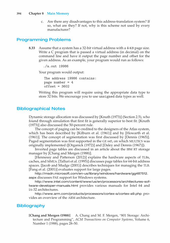
394 Chapter 8 Main Memory
c. Are there any disadvantages to this address-translation system? Ifso, what are they? If not, why is this scheme not used by everymanufacturer?
Programming Problems
8.33 Assume that a system has a 32-bit virtual address with a 4-KB page size.Write a C program that is passed a virtual address (in decimal) on thecommand line and have it output the page number and offset for thegiven address. As an example, your program would run as follows:
./a.out 19986
Your program would output:
The address 19986 contains:page number = 4offset = 3602
Writing this program will require using the appropriate data type tostore 32 bits. We encourage you to use unsigned data types as well.
Bibliographical Notes
Dynamic storage allocation was discussed by [Knuth (1973)] (Section 2.5), whofound through simulation that first fit is generally superior to best fit. [Knuth(1973)] also discussed the 50-percent rule.
The concept of paging can be credited to the designers of the Atlas system,which has been described by [Kilburn et al. (1961)] and by [Howarth et al.(1961)]. The concept of segmentation was first discussed by [Dennis (1965)].Paged segmentation was first supported in the GE 645, on which MULTICS wasoriginally implemented ([Organick (1972)] and [Daley and Dennis (1967)]).
Inverted page tables are discussed in an article about the IBM RT storagemanager by [Chang and Mergen (1988)].
[Hennessy and Patterson (2012)] explains the hardware aspects of TLBs,caches, and MMUs. [Talluri et al. (1995)] discusses page tables for 64-bit addressspaces. [Jacob and Mudge (2001)] describes techniques for managing the TLB.[Fang et al. (2001)] evaluates support for large pages.
http://msdn.microsoft.com/en-us/library/windows/hardware/gg487512.aspx discusses PAE support for Windows systems.
http://www.intel.com/content/www/us/en/processors/architectures-sof-tware-developer-manuals.html provides various manuals for Intel 64 andIA-32 architectures.
http://www.arm.com/products/processors/cortex-a/cortex-a9.php pro-vides an overview of the ARM architecture.
Bibliography
[Chang and Mergen (1988)] A. Chang and M. F. Mergen, “801 Storage: Archi-tecture and Programming”, ACM Transactions on Computer Systems, Volume 6,Number 1 (1988), pages 28–50.
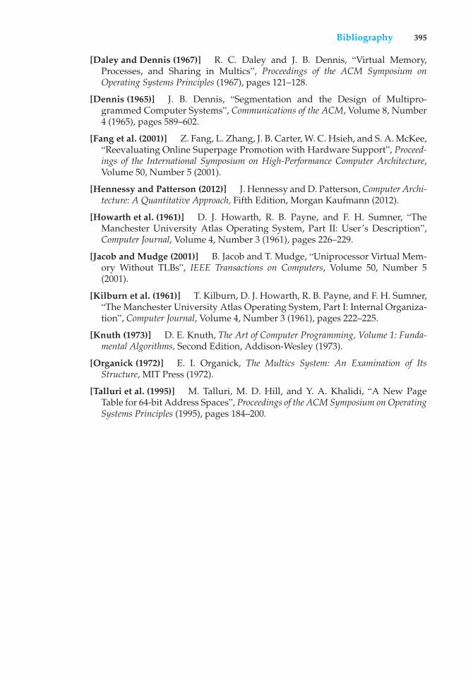
Bibliography 395
[Daley and Dennis (1967)] R. C. Daley and J. B. Dennis, “Virtual Memory,Processes, and Sharing in Multics”, Proceedings of the ACM Symposium onOperating Systems Principles (1967), pages 121–128.
[Dennis (1965)] J. B. Dennis, “Segmentation and the Design of Multipro-grammed Computer Systems”, Communications of the ACM, Volume 8, Number4 (1965), pages 589–602.
[Fang et al. (2001)] Z. Fang, L. Zhang, J. B. Carter, W. C. Hsieh, and S. A. McKee,“Reevaluating Online Superpage Promotion with Hardware Support”, Proceed-ings of the International Symposium on High-Performance Computer Architecture,Volume 50, Number 5 (2001).
[Hennessy and Patterson (2012)] J. Hennessy and D. Patterson, Computer Archi-tecture: A Quantitative Approach, Fifth Edition, Morgan Kaufmann (2012).
[Howarth et al. (1961)] D. J. Howarth, R. B. Payne, and F. H. Sumner, “TheManchester University Atlas Operating System, Part II: User’s Description”,Computer Journal, Volume 4, Number 3 (1961), pages 226–229.
[Jacob and Mudge (2001)] B. Jacob and T. Mudge, “Uniprocessor Virtual Mem-ory Without TLBs”, IEEE Transactions on Computers, Volume 50, Number 5(2001).
[Kilburn et al. (1961)] T. Kilburn, D. J. Howarth, R. B. Payne, and F. H. Sumner,“The Manchester University Atlas Operating System, Part I: Internal Organiza-tion”, Computer Journal, Volume 4, Number 3 (1961), pages 222–225.
[Knuth (1973)] D. E. Knuth, The Art of Computer Programming, Volume 1: Funda-mental Algorithms, Second Edition, Addison-Wesley (1973).
[Organick (1972)] E. I. Organick, The Multics System: An Examination of ItsStructure, MIT Press (1972).
[Talluri et al. (1995)] M. Talluri, M. D. Hill, and Y. A. Khalidi, “A New PageTable for 64-bit Address Spaces”, Proceedings of the ACM Symposium on OperatingSystems Principles (1995), pages 184–200.

9C H A P T E R
VirtualMemory
In Chapter 8, we discussed various memory-management strategies used incomputer systems. All these strategies have the same goal: to keep manyprocesses in memory simultaneously to allow multiprogramming. However,they tend to require that an entire process be in memory before it can execute.
Virtual memory is a technique that allows the execution of processesthat are not completely in memory. One major advantage of this scheme isthat programs can be larger than physical memory. Further, virtual memoryabstracts main memory into an extremely large, uniform array of storage,separating logical memory as viewed by the user from physical memory.This technique frees programmers from the concerns of memory-storagelimitations. Virtual memory also allows processes to share files easily andto implement shared memory. In addition, it provides an efficient mechanismfor process creation. Virtual memory is not easy to implement, however, andmay substantially decrease performance if it is used carelessly. In this chapter,we discuss virtual memory in the form of demand paging and examine itscomplexity and cost.
CHAPTER OBJECTIVES
• To describe the benefits of a virtual memory system.• To explain the concepts of demand paging, page-replacement algorithms,
and allocation of page frames.• To discuss the principles of the working-set model.• To examine the relationship between shared memory and memory-mapped
files.• To explore how kernel memory is managed.
9.1 Background
The memory-management algorithms outlined in Chapter 8 are necessarybecause of one basic requirement: The instructions being executed must be
397
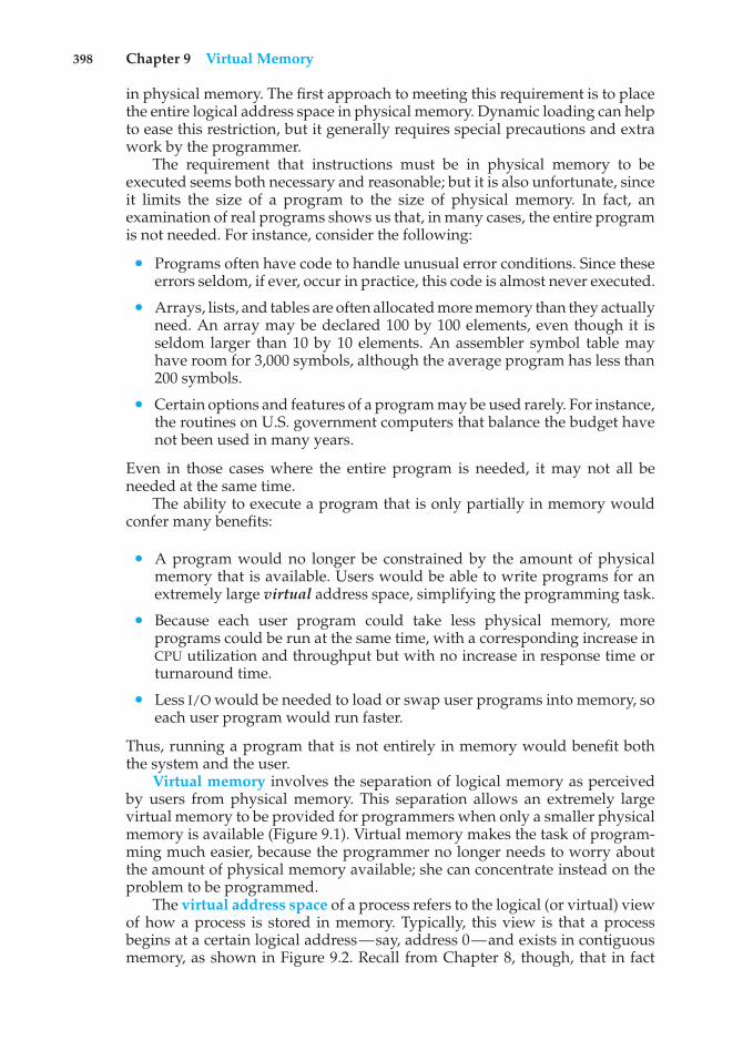
398 Chapter 9 Virtual Memory
in physical memory. The first approach to meeting this requirement is to placethe entire logical address space in physical memory. Dynamic loading can helpto ease this restriction, but it generally requires special precautions and extrawork by the programmer.
The requirement that instructions must be in physical memory to beexecuted seems both necessary and reasonable; but it is also unfortunate, sinceit limits the size of a program to the size of physical memory. In fact, anexamination of real programs shows us that, in many cases, the entire programis not needed. For instance, consider the following:
• Programs often have code to handle unusual error conditions. Since theseerrors seldom, if ever, occur in practice, this code is almost never executed.
• Arrays, lists, and tables are often allocated more memory than they actuallyneed. An array may be declared 100 by 100 elements, even though it isseldom larger than 10 by 10 elements. An assembler symbol table mayhave room for 3,000 symbols, although the average program has less than200 symbols.
• Certain options and features of a program may be used rarely. For instance,the routines on U.S. government computers that balance the budget havenot been used in many years.
Even in those cases where the entire program is needed, it may not all beneeded at the same time.
The ability to execute a program that is only partially in memory wouldconfer many benefits:
• A program would no longer be constrained by the amount of physicalmemory that is available. Users would be able to write programs for anextremely large virtual address space, simplifying the programming task.
• Because each user program could take less physical memory, moreprograms could be run at the same time, with a corresponding increase inCPU utilization and throughput but with no increase in response time orturnaround time.
• Less I/O would be needed to load or swap user programs into memory, soeach user program would run faster.
Thus, running a program that is not entirely in memory would benefit boththe system and the user.
Virtual memory involves the separation of logical memory as perceivedby users from physical memory. This separation allows an extremely largevirtual memory to be provided for programmers when only a smaller physicalmemory is available (Figure 9.1). Virtual memory makes the task of program-ming much easier, because the programmer no longer needs to worry aboutthe amount of physical memory available; she can concentrate instead on theproblem to be programmed.
The virtual address space of a process refers to the logical (or virtual) viewof how a process is stored in memory. Typically, this view is that a processbegins at a certain logical address—say, address 0—and exists in contiguousmemory, as shown in Figure 9.2. Recall from Chapter 8, though, that in fact
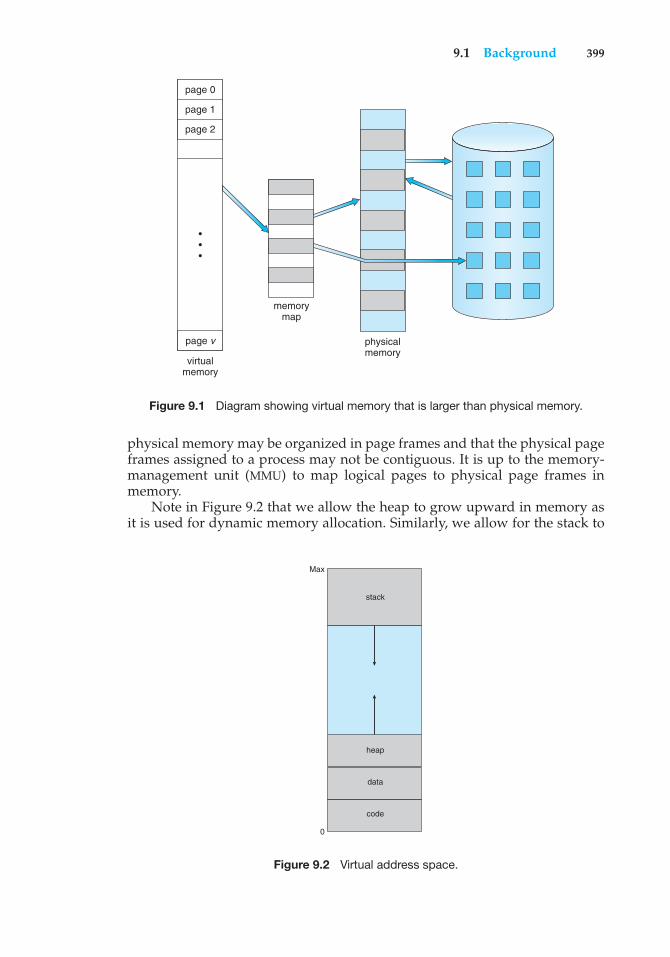
9.1 Background 399
virtualmemory
memorymap
physicalmemory
•••
page 0
page 1
page 2
page v
Figure 9.1 Diagram showing virtual memory that is larger than physical memory.
physical memory may be organized in page frames and that the physical pageframes assigned to a process may not be contiguous. It is up to the memory-management unit (MMU) to map logical pages to physical page frames inmemory.
Note in Figure 9.2 that we allow the heap to grow upward in memory asit is used for dynamic memory allocation. Similarly, we allow for the stack to
code
0
Max
data
heap
stack
Figure 9.2 Virtual address space.
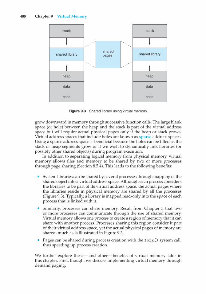
400 Chapter 9 Virtual Memory
shared library
stack
shared pages
code
data
heap
code
data
heap
shared library
stack
Figure 9.3 Shared library using virtual memory.
grow downward in memory through successive function calls. The large blankspace (or hole) between the heap and the stack is part of the virtual addressspace but will require actual physical pages only if the heap or stack grows.Virtual address spaces that include holes are known as sparse address spaces.Using a sparse address space is beneficial because the holes can be filled as thestack or heap segments grow or if we wish to dynamically link libraries (orpossibly other shared objects) during program execution.
In addition to separating logical memory from physical memory, virtualmemory allows files and memory to be shared by two or more processesthrough page sharing (Section 8.5.4). This leads to the following benefits:
• System libraries can be shared by several processes through mapping of theshared object into a virtual address space. Although each process considersthe libraries to be part of its virtual address space, the actual pages wherethe libraries reside in physical memory are shared by all the processes(Figure 9.3). Typically, a library is mapped read-only into the space of eachprocess that is linked with it.
• Similarly, processes can share memory. Recall from Chapter 3 that twoor more processes can communicate through the use of shared memory.Virtual memory allows one process to create a region of memory that it canshare with another process. Processes sharing this region consider it partof their virtual address space, yet the actual physical pages of memory areshared, much as is illustrated in Figure 9.3.
• Pages can be shared during process creation with the fork() system call,thus speeding up process creation.
We further explore these—and other—benefits of virtual memory later inthis chapter. First, though, we discuss implementing virtual memory throughdemand paging.
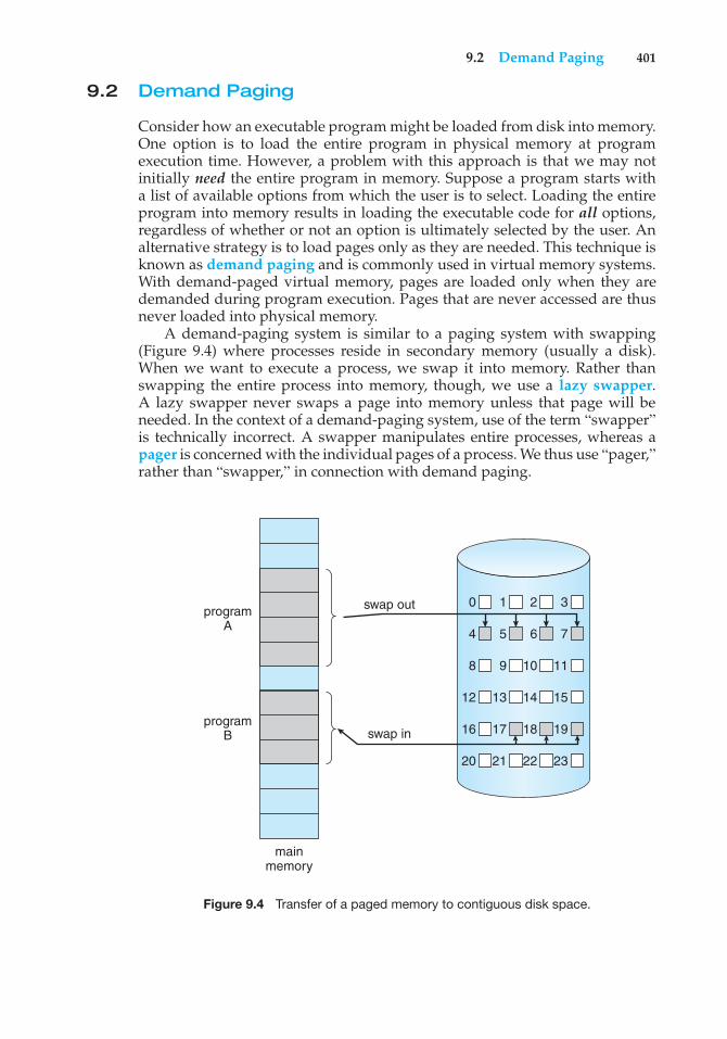
9.2 Demand Paging 401
9.2 Demand Paging
Consider how an executable program might be loaded from disk into memory.One option is to load the entire program in physical memory at programexecution time. However, a problem with this approach is that we may notinitially need the entire program in memory. Suppose a program starts witha list of available options from which the user is to select. Loading the entireprogram into memory results in loading the executable code for all options,regardless of whether or not an option is ultimately selected by the user. Analternative strategy is to load pages only as they are needed. This technique isknown as demand paging and is commonly used in virtual memory systems.With demand-paged virtual memory, pages are loaded only when they aredemanded during program execution. Pages that are never accessed are thusnever loaded into physical memory.
A demand-paging system is similar to a paging system with swapping(Figure 9.4) where processes reside in secondary memory (usually a disk).When we want to execute a process, we swap it into memory. Rather thanswapping the entire process into memory, though, we use a lazy swapper.A lazy swapper never swaps a page into memory unless that page will beneeded. In the context of a demand-paging system, use of the term “swapper”is technically incorrect. A swapper manipulates entire processes, whereas apager is concerned with the individual pages of a process. We thus use “pager,”rather than “swapper,” in connection with demand paging.
programA
swap out 0 1 2 3
4 5 6 7
8 9 10 11
12 13 14 15
16 17 18 19
20 21 22 23
swap inprogram
B
mainmemory
Figure 9.4 Transfer of a paged memory to contiguous disk space.
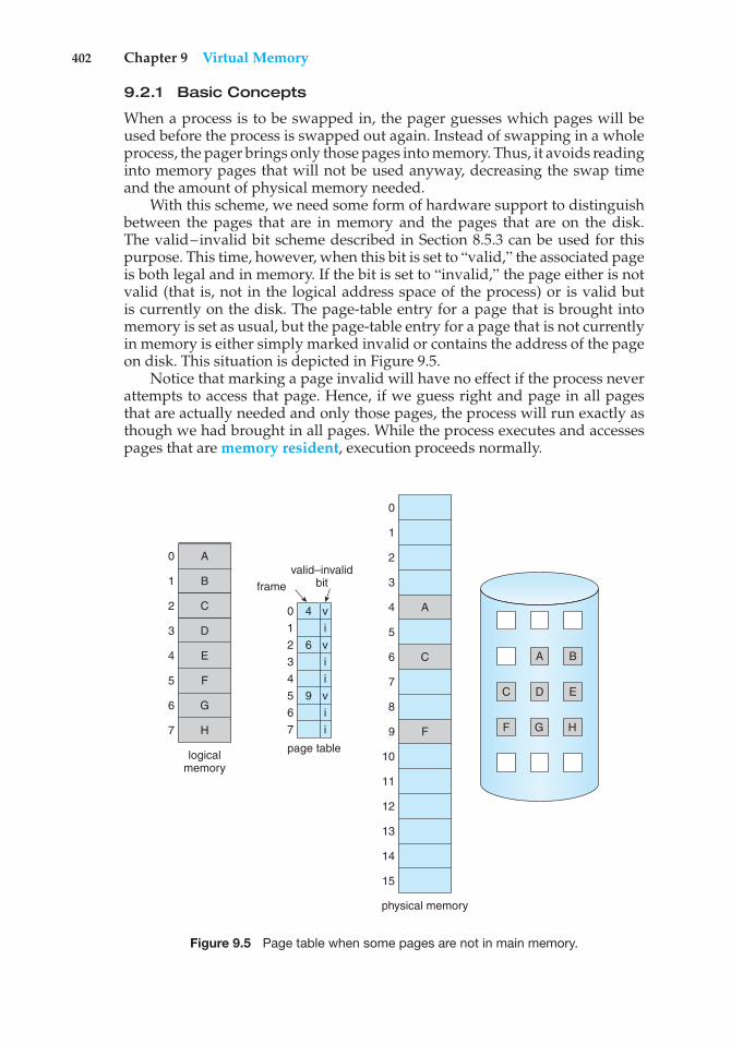
402 Chapter 9 Virtual Memory
9.2.1 Basic Concepts
When a process is to be swapped in, the pager guesses which pages will beused before the process is swapped out again. Instead of swapping in a wholeprocess, the pager brings only those pages into memory. Thus, it avoids readinginto memory pages that will not be used anyway, decreasing the swap timeand the amount of physical memory needed.
With this scheme, we need some form of hardware support to distinguishbetween the pages that are in memory and the pages that are on the disk.The valid–invalid bit scheme described in Section 8.5.3 can be used for thispurpose. This time, however, when this bit is set to “valid,” the associated pageis both legal and in memory. If the bit is set to “invalid,” the page either is notvalid (that is, not in the logical address space of the process) or is valid butis currently on the disk. The page-table entry for a page that is brought intomemory is set as usual, but the page-table entry for a page that is not currentlyin memory is either simply marked invalid or contains the address of the pageon disk. This situation is depicted in Figure 9.5.
Notice that marking a page invalid will have no effect if the process neverattempts to access that page. Hence, if we guess right and page in all pagesthat are actually needed and only those pages, the process will run exactly asthough we had brought in all pages. While the process executes and accessespages that are memory resident, execution proceeds normally.
B
D
D EF
H
logicalmemory
valid–invalidbitframe
page table
10 4
62345 967
1
0
2
3
4
5
6
7
iv
viivii
physical memory
A
A BC
C
F G HF
1
0
2
3
4
5
6
7
9
8
10
11
12
13
14
15
A
C
E
G
Figure 9.5 Page table when some pages are not in main memory.
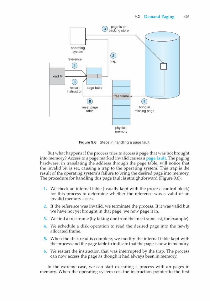
9.2 Demand Paging 403
load M
reference trap
i
page is onbacking store
operatingsystem
restartinstruction
reset pagetable
page table
physicalmemory
bring inmissing page
free frame
1
2
3
6
5 4
Figure 9.6 Steps in handling a page fault.
But what happens if the process tries to access a page that was not broughtinto memory? Access to a page marked invalid causes a page fault. The paginghardware, in translating the address through the page table, will notice thatthe invalid bit is set, causing a trap to the operating system. This trap is theresult of the operating system’s failure to bring the desired page into memory.The procedure for handling this page fault is straightforward (Figure 9.6):
1. We check an internal table (usually kept with the process control block)for this process to determine whether the reference was a valid or aninvalid memory access.
2. If the reference was invalid, we terminate the process. If it was valid butwe have not yet brought in that page, we now page it in.
3. We find a free frame (by taking one from the free-frame list, for example).
4. We schedule a disk operation to read the desired page into the newlyallocated frame.
5. When the disk read is complete, we modify the internal table kept withthe process and the page table to indicate that the page is now in memory.
6. We restart the instruction that was interrupted by the trap. The processcan now access the page as though it had always been in memory.
In the extreme case, we can start executing a process with no pages inmemory. When the operating system sets the instruction pointer to the first
404 Chapter 9 Virtual Memory
instruction of the process, which is on a non-memory-resident page, the processimmediately faults for the page. After this page is brought into memory, theprocess continues to execute, faulting as necessary until every page that itneeds is in memory. At that point, it can execute with no more faults. Thisscheme is pure demand paging: never bring a page into memory until it isrequired.
Theoretically, some programs could access several new pages of memorywith each instruction execution (one page for the instruction and many fordata), possibly causing multiple page faults per instruction. This situationwould result in unacceptable system performance. Fortunately, analysis ofrunning processes shows that this behavior is exceedingly unlikely. Programstend to have locality of reference, described in Section 9.6.1, which results inreasonable performance from demand paging.
The hardware to support demand paging is the same as the hardware forpaging and swapping:
• Page table. This table has the ability to mark an entry invalid through avalid–invalid bit or a special value of protection bits.
• Secondary memory. This memory holds those pages that are not presentin main memory. The secondary memory is usually a high-speed disk. It isknown as the swap device, and the section of disk used for this purpose isknown as swap space. Swap-space allocation is discussed in Chapter 10.
A crucial requirement for demand paging is the ability to restart anyinstruction after a page fault. Because we save the state (registers, conditioncode, instruction counter) of the interrupted process when the page faultoccurs, we must be able to restart the process in exactly the same place andstate, except that the desired page is now in memory and is accessible. In mostcases, this requirement is easy to meet. A page fault may occur at any memoryreference. If the page fault occurs on the instruction fetch, we can restart byfetching the instruction again. If a page fault occurs while we are fetching anoperand, we must fetch and decode the instruction again and then fetch theoperand.
As a worst-case example, consider a three-address instruction such as ADDthe content of A to B, placing the result in C. These are the steps to execute thisinstruction:
1. Fetch and decode the instruction (ADD).
2. Fetch A.
3. Fetch B.
4. Add A and B.
5. Store the sum in C.
If we fault when we try to store in C (because C is in a page not currentlyin memory), we will have to get the desired page, bring it in, correct thepage table, and restart the instruction. The restart will require fetching theinstruction again, decoding it again, fetching the two operands again, andthen adding again. However, there is not much repeated work (less than one
9.2 Demand Paging 405
complete instruction), and the repetition is necessary only when a page faultoccurs.
The major difficulty arises when one instruction may modify severaldifferent locations. For example, consider the IBM System 360/370 MVC (movecharacter) instruction, which can move up to 256 bytes from one location toanother (possibly overlapping) location. If either block (source or destination)straddles a page boundary, a page fault might occur after the move is partiallydone. In addition, if the source and destination blocks overlap, the sourceblock may have been modified, in which case we cannot simply restart theinstruction.
This problem can be solved in two different ways. In one solution, themicrocode computes and attempts to access both ends of both blocks. If a pagefault is going to occur, it will happen at this step, before anything is modified.The move can then take place; we know that no page fault can occur, since allthe relevant pages are in memory. The other solution uses temporary registersto hold the values of overwritten locations. If there is a page fault, all the oldvalues are written back into memory before the trap occurs. This action restoresmemory to its state before the instruction was started, so that the instructioncan be repeated.
This is by no means the only architectural problem resulting from addingpaging to an existing architecture to allow demand paging, but it illustratessome of the difficulties involved. Paging is added between the CPU and thememory in a computer system. It should be entirely transparent to the userprocess. Thus, people often assume that paging can be added to any system.Although this assumption is true for a non-demand-paging environment,where a page fault represents a fatal error, it is not true where a page faultmeans only that an additional page must be brought into memory and theprocess restarted.
9.2.2 Performance of Demand Paging
Demand paging can significantly affect the performance of a computer system.To see why, let’s compute the effective access time for a demand-pagedmemory. For most computer systems, the memory-access time, denoted ma,ranges from 10 to 200 nanoseconds. As long as we have no page faults, theeffective access time is equal to the memory access time. If, however, a pagefault occurs, we must first read the relevant page from disk and then access thedesired word.
Let p be the probability of a page fault (0 ≤ p ≤ 1). We would expect p tobe close to zero—that is, we would expect to have only a few page faults. Theeffective access time is then
effective access time = (1 − p) × ma + p × page fault time.
To compute the effective access time, we must know how much time isneeded to service a page fault. A page fault causes the following sequence tooccur:
1. Trap to the operating system.
2. Save the user registers and process state.
406 Chapter 9 Virtual Memory
3. Determine that the interrupt was a page fault.
4. Check that the page reference was legal and determine the location of thepage on the disk.
5. Issue a read from the disk to a free frame:
a. Wait in a queue for this device until the read request is serviced.
b. Wait for the device seek and/or latency time.
c. Begin the transfer of the page to a free frame.
6. While waiting, allocate the CPU to some other user (CPU scheduling,optional).
7. Receive an interrupt from the disk I/O subsystem (I/O completed).
8. Save the registers and process state for the other user (if step 6 is executed).
9. Determine that the interrupt was from the disk.
10. Correct the page table and other tables to show that the desired page isnow in memory.
11. Wait for the CPU to be allocated to this process again.
12. Restore the user registers, process state, and new page table, and thenresume the interrupted instruction.
Not all of these steps are necessary in every case. For example, we are assumingthat, in step 6, the CPU is allocated to another process while the I/O occurs.This arrangement allows multiprogramming to maintain CPU utilization butrequires additional time to resume the page-fault service routine when the I/Otransfer is complete.
In any case, we are faced with three major components of the page-faultservice time:
1. Service the page-fault interrupt.
2. Read in the page.
3. Restart the process.
The first and third tasks can be reduced, with careful coding, to severalhundred instructions. These tasks may take from 1 to 100 microseconds each.The page-switch time, however, will probably be close to 8 milliseconds.(A typical hard disk has an average latency of 3 milliseconds, a seek of5 milliseconds, and a transfer time of 0.05 milliseconds. Thus, the totalpaging time is about 8 milliseconds, including hardware and software time.)Remember also that we are looking at only the device-service time. If a queueof processes is waiting for the device, we have to add device-queueing time aswe wait for the paging device to be free to service our request, increasing evenmore the time to swap.
9.2 Demand Paging 407
With an average page-fault service time of 8 milliseconds and a memory-access time of 200 nanoseconds, the effective access time in nanosecondsis
effective access time = (1 − p) × (200) + p (8 milliseconds)= (1 − p) × 200 + p × 8,000,000= 200 + 7,999,800 × p.
We see, then, that the effective access time is directly proportional to thepage-fault rate. If one access out of 1,000 causes a page fault, the effective accesstime is 8.2 microseconds. The computer will be slowed down by a factor of 40because of demand paging! If we want performance degradation to be lessthan 10 percent, we need to keep the probability of page faults at the followinglevel:
220 > 200 + 7,999,800 × p,20 > 7,999,800 × p,p < 0.0000025.
That is, to keep the slowdown due to paging at a reasonable level, we canallow fewer than one memory access out of 399,990 to page-fault. In sum,it is important to keep the page-fault rate low in a demand-paging system.Otherwise, the effective access time increases, slowing process executiondramatically.
An additional aspect of demand paging is the handling and overall useof swap space. Disk I/O to swap space is generally faster than that to the filesystem. It is a faster file system because swap space is allocated in much largerblocks, and file lookups and indirect allocation methods are not used (Chapter10). The system can therefore gain better paging throughput by copying anentire file image into the swap space at process startup and then performingdemand paging from the swap space. Another option is to demand pagesfrom the file system initially but to write the pages to swap space as they arereplaced. This approach will ensure that only needed pages are read from thefile system but that all subsequent paging is done from swap space.
Some systems attempt to limit the amount of swap space used throughdemand paging of binary files. Demand pages for such files are brought directlyfrom the file system. However, when page replacement is called for, theseframes can simply be overwritten (because they are never modified), and thepages can be read in from the file system again if needed. Using this approach,the file system itself serves as the backing store. However, swap space must stillbe used for pages not associated with a file (known as anonymous memory);these pages include the stack and heap for a process. This method appears tobe a good compromise and is used in several systems, including Solaris andBSD UNIX.
Mobile operating systems typically do not support swapping. Instead,these systems demand-page from the file system and reclaim read-only pages(such as code) from applications if memory becomes constrained. Such datacan be demand-paged from the file system if it is later needed. Under iOS,anonymous memory pages are never reclaimed from an application unless theapplication is terminated or explicitly releases the memory.
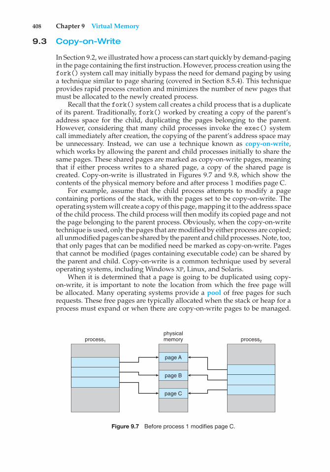
408 Chapter 9 Virtual Memory
9.3 Copy-on-Write
In Section 9.2, we illustrated how a process can start quickly by demand-pagingin the page containing the first instruction. However, process creation using thefork() system call may initially bypass the need for demand paging by usinga technique similar to page sharing (covered in Section 8.5.4). This techniqueprovides rapid process creation and minimizes the number of new pages thatmust be allocated to the newly created process.
Recall that the fork() system call creates a child process that is a duplicateof its parent. Traditionally, fork() worked by creating a copy of the parent’saddress space for the child, duplicating the pages belonging to the parent.However, considering that many child processes invoke the exec() systemcall immediately after creation, the copying of the parent’s address space maybe unnecessary. Instead, we can use a technique known as copy-on-write,which works by allowing the parent and child processes initially to share thesame pages. These shared pages are marked as copy-on-write pages, meaningthat if either process writes to a shared page, a copy of the shared page iscreated. Copy-on-write is illustrated in Figures 9.7 and 9.8, which show thecontents of the physical memory before and after process 1 modifies page C.
For example, assume that the child process attempts to modify a pagecontaining portions of the stack, with the pages set to be copy-on-write. Theoperating system will create a copy of this page, mapping it to the address spaceof the child process. The child process will then modify its copied page and notthe page belonging to the parent process. Obviously, when the copy-on-writetechnique is used, only the pages that are modified by either process are copied;all unmodified pages can be shared by the parent and child processes. Note, too,that only pages that can be modified need be marked as copy-on-write. Pagesthat cannot be modified (pages containing executable code) can be shared bythe parent and child. Copy-on-write is a common technique used by severaloperating systems, including Windows XP, Linux, and Solaris.
When it is determined that a page is going to be duplicated using copy-on-write, it is important to note the location from which the free page willbe allocated. Many operating systems provide a pool of free pages for suchrequests. These free pages are typically allocated when the stack or heap for aprocess must expand or when there are copy-on-write pages to be managed.
process1
physicalmemory
page A
page B
page C
process2
Figure 9.7 Before process 1 modifies page C.
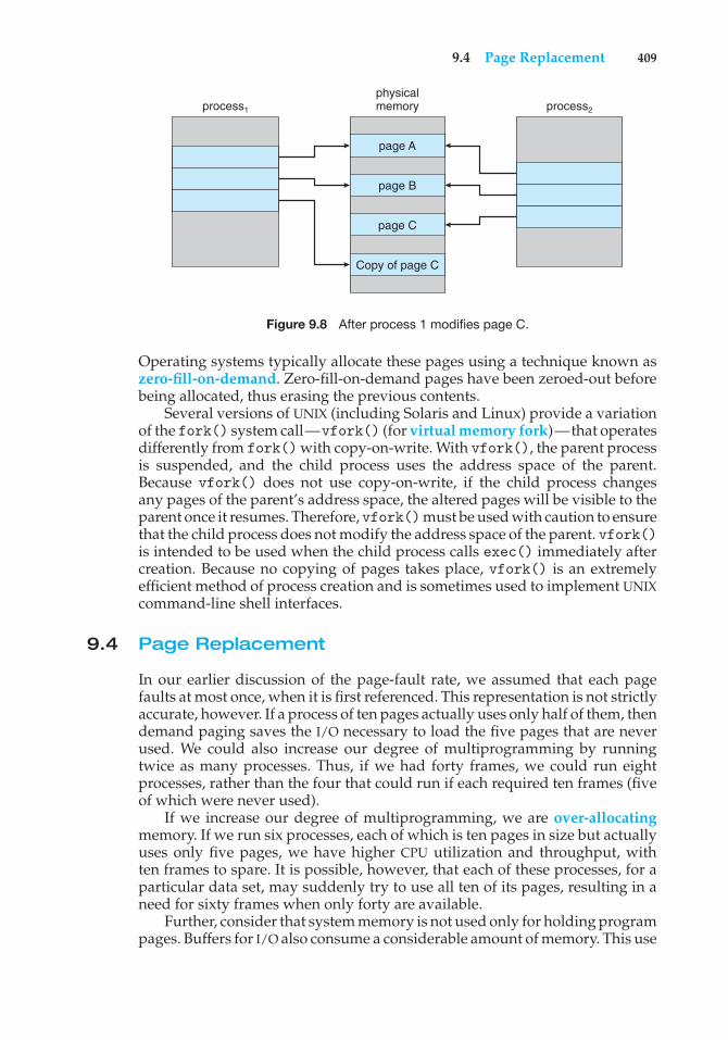
9.4 Page Replacement 409
process1
physicalmemory
page A
page B
page C
Copy of page C
process2
Figure 9.8 After process 1 modifies page C.
Operating systems typically allocate these pages using a technique known aszero-fill-on-demand. Zero-fill-on-demand pages have been zeroed-out beforebeing allocated, thus erasing the previous contents.
Several versions of UNIX (including Solaris and Linux) provide a variationof the fork() system call—vfork() (for virtual memory fork)—that operatesdifferently from fork() with copy-on-write. With vfork(), the parent processis suspended, and the child process uses the address space of the parent.Because vfork() does not use copy-on-write, if the child process changesany pages of the parent’s address space, the altered pages will be visible to theparent once it resumes. Therefore,vfork()must be used with caution to ensurethat the child process does not modify the address space of the parent. vfork()is intended to be used when the child process calls exec() immediately aftercreation. Because no copying of pages takes place, vfork() is an extremelyefficient method of process creation and is sometimes used to implement UNIXcommand-line shell interfaces.
9.4 Page Replacement
In our earlier discussion of the page-fault rate, we assumed that each pagefaults at most once, when it is first referenced. This representation is not strictlyaccurate, however. If a process of ten pages actually uses only half of them, thendemand paging saves the I/O necessary to load the five pages that are neverused. We could also increase our degree of multiprogramming by runningtwice as many processes. Thus, if we had forty frames, we could run eightprocesses, rather than the four that could run if each required ten frames (fiveof which were never used).
If we increase our degree of multiprogramming, we are over-allocatingmemory. If we run six processes, each of which is ten pages in size but actuallyuses only five pages, we have higher CPU utilization and throughput, withten frames to spare. It is possible, however, that each of these processes, for aparticular data set, may suddenly try to use all ten of its pages, resulting in aneed for sixty frames when only forty are available.
Further, consider that system memory is not used only for holding programpages. Buffers for I/O also consume a considerable amount of memory. This use
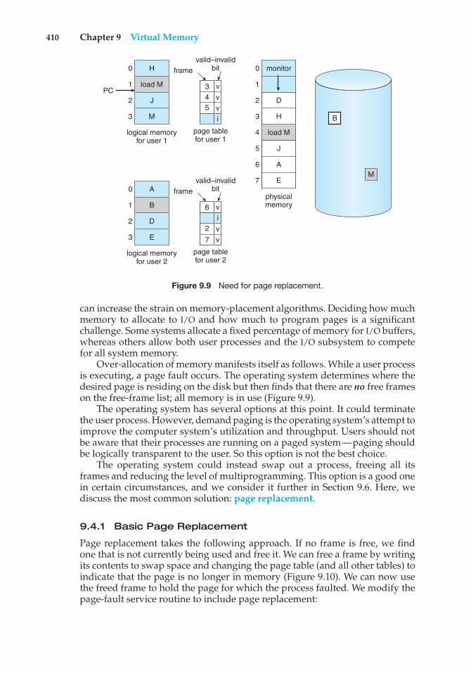
410 Chapter 9 Virtual Memory
monitor
load M
physicalmemory
1
0
2
3
4
5
6
7
H
load M
J
M
logical memoryfor user 1
0
PC1
2
3 B
M
valid–invalidbitframe
page tablefor user 1
i
A
B
D
E
logical memoryfor user 2
0
1
2
3
valid–invalidbitframe
page tablefor user 2
i
43
5
vvv
7
2 vv
6 v
D
H
J
A
E
Figure 9.9 Need for page replacement.
can increase the strain on memory-placement algorithms. Deciding how muchmemory to allocate to I/O and how much to program pages is a significantchallenge. Some systems allocate a fixed percentage of memory for I/O buffers,whereas others allow both user processes and the I/O subsystem to competefor all system memory.
Over-allocation of memory manifests itself as follows. While a user processis executing, a page fault occurs. The operating system determines where thedesired page is residing on the disk but then finds that there are no free frameson the free-frame list; all memory is in use (Figure 9.9).
The operating system has several options at this point. It could terminatethe user process. However, demand paging is the operating system’s attempt toimprove the computer system’s utilization and throughput. Users should notbe aware that their processes are running on a paged system—paging shouldbe logically transparent to the user. So this option is not the best choice.
The operating system could instead swap out a process, freeing all itsframes and reducing the level of multiprogramming. This option is a good onein certain circumstances, and we consider it further in Section 9.6. Here, wediscuss the most common solution: page replacement.
9.4.1 Basic Page Replacement
Page replacement takes the following approach. If no frame is free, we findone that is not currently being used and free it. We can free a frame by writingits contents to swap space and changing the page table (and all other tables) toindicate that the page is no longer in memory (Figure 9.10). We can now usethe freed frame to hold the page for which the process faulted. We modify thepage-fault service routine to include page replacement:
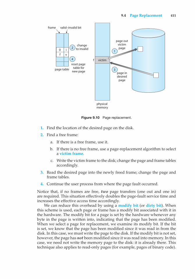
9.4 Page Replacement 411
valid–invalid bitframe
f
page table
victim
changeto invalid
page outvictimpage
page indesired
page
reset pagetable for
new page
physicalmemory
2
4
1
3
f0 i
v
Figure 9.10 Page replacement.
1. Find the location of the desired page on the disk.
2. Find a free frame:
a. If there is a free frame, use it.
b. If there is no free frame, use a page-replacement algorithm to selecta victim frame.
c. Write the victim frame to the disk; change the page and frame tablesaccordingly.
3. Read the desired page into the newly freed frame; change the page andframe tables.
4. Continue the user process from where the page fault occurred.
Notice that, if no frames are free, two page transfers (one out and one in)are required. This situation effectively doubles the page-fault service time andincreases the effective access time accordingly.
We can reduce this overhead by using a modify bit (or dirty bit). Whenthis scheme is used, each page or frame has a modify bit associated with it inthe hardware. The modify bit for a page is set by the hardware whenever anybyte in the page is written into, indicating that the page has been modified.When we select a page for replacement, we examine its modify bit. If the bitis set, we know that the page has been modified since it was read in from thedisk. In this case, we must write the page to the disk. If the modify bit is not set,however, the page has not been modified since it was read into memory. In thiscase, we need not write the memory page to the disk: it is already there. Thistechnique also applies to read-only pages (for example, pages of binary code).
412 Chapter 9 Virtual Memory
Such pages cannot be modified; thus, they may be discarded when desired.This scheme can significantly reduce the time required to service a page fault,since it reduces I/O time by one-half if the page has not been modified.
Page replacement is basic to demand paging. It completes the separationbetween logical memory and physical memory. With this mechanism, anenormous virtual memory can be provided for programmers on a smallerphysical memory. With no demand paging, user addresses are mapped intophysical addresses, and the two sets of addresses can be different. All thepages of a process still must be in physical memory, however. With demandpaging, the size of the logical address space is no longer constrained by physicalmemory. If we have a user process of twenty pages, we can execute it in tenframes simply by using demand paging and using a replacement algorithm tofind a free frame whenever necessary. If a page that has been modified is to bereplaced, its contents are copied to the disk. A later reference to that page willcause a page fault. At that time, the page will be brought back into memory,perhaps replacing some other page in the process.
We must solve two major problems to implement demand paging: we mustdevelop a frame-allocation algorithm and a page-replacement algorithm.That is, if we have multiple processes in memory, we must decide how manyframes to allocate to each process; and when page replacement is required,we must select the frames that are to be replaced. Designing appropriatealgorithms to solve these problems is an important task, because disk I/Ois so expensive. Even slight improvements in demand-paging methods yieldlarge gains in system performance.
There are many different page-replacement algorithms. Every operatingsystem probably has its own replacement scheme. How do we select aparticular replacement algorithm? In general, we want the one with the lowestpage-fault rate.
We evaluate an algorithm by running it on a particular string of memoryreferences and computing the number of page faults. The string of memoryreferences is called a reference string. We can generate reference stringsartificially (by using a random-number generator, for example), or we can tracea given system and record the address of each memory reference. The latterchoice produces a large number of data (on the order of 1 million addressesper second). To reduce the number of data, we use two facts.
First, for a given page size (and the page size is generally fixed by thehardware or system), we need to consider only the page number, rather thanthe entire address. Second, if we have a reference to a page p, then any referencesto page p that immediately follow will never cause a page fault. Page p willbe in memory after the first reference, so the immediately following referenceswill not fault.
For example, if we trace a particular process, we might record the followingaddress sequence:
0100, 0432, 0101, 0612, 0102, 0103, 0104, 0101, 0611, 0102, 0103,0104, 0101, 0610, 0102, 0103, 0104, 0101, 0609, 0102, 0105
At 100 bytes per page, this sequence is reduced to the following referencestring:
1, 4, 1, 6, 1, 6, 1, 6, 1, 6, 1
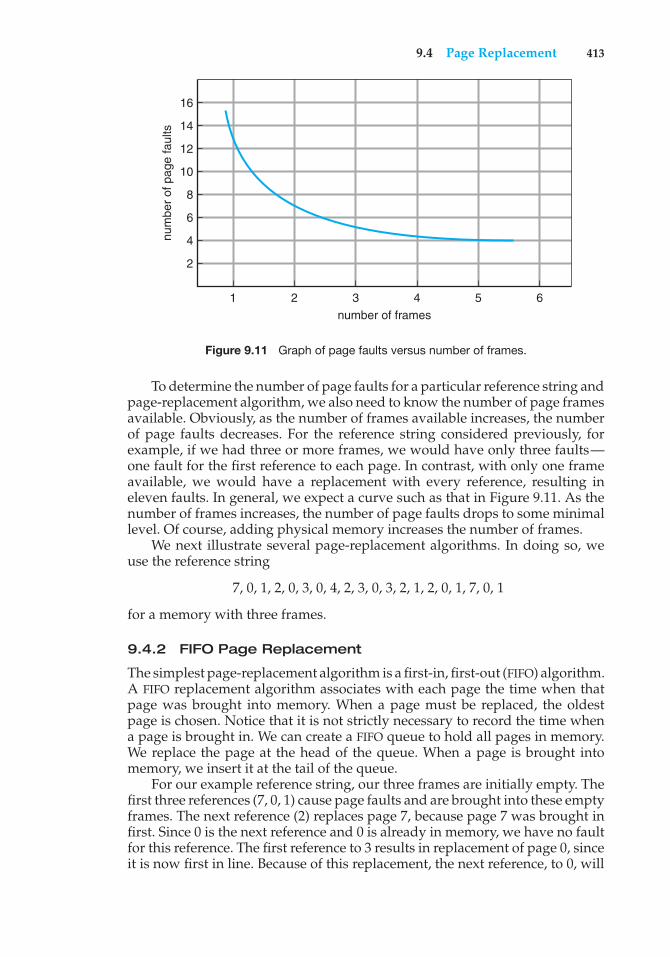
9.4 Page Replacement 413
num
ber
of p
age
faul
ts
16
14
12
10
8
6
4
2
1 2 3number of frames
4 5 6
Figure 9.11 Graph of page faults versus number of frames.
To determine the number of page faults for a particular reference string andpage-replacement algorithm, we also need to know the number of page framesavailable. Obviously, as the number of frames available increases, the numberof page faults decreases. For the reference string considered previously, forexample, if we had three or more frames, we would have only three faults—one fault for the first reference to each page. In contrast, with only one frameavailable, we would have a replacement with every reference, resulting ineleven faults. In general, we expect a curve such as that in Figure 9.11. As thenumber of frames increases, the number of page faults drops to some minimallevel. Of course, adding physical memory increases the number of frames.
We next illustrate several page-replacement algorithms. In doing so, weuse the reference string
7, 0, 1, 2, 0, 3, 0, 4, 2, 3, 0, 3, 2, 1, 2, 0, 1, 7, 0, 1
for a memory with three frames.
9.4.2 FIFO Page Replacement
The simplest page-replacement algorithm is a first-in, first-out (FIFO) algorithm.A FIFO replacement algorithm associates with each page the time when thatpage was brought into memory. When a page must be replaced, the oldestpage is chosen. Notice that it is not strictly necessary to record the time whena page is brought in. We can create a FIFO queue to hold all pages in memory.We replace the page at the head of the queue. When a page is brought intomemory, we insert it at the tail of the queue.
For our example reference string, our three frames are initially empty. Thefirst three references (7, 0, 1) cause page faults and are brought into these emptyframes. The next reference (2) replaces page 7, because page 7 was brought infirst. Since 0 is the next reference and 0 is already in memory, we have no faultfor this reference. The first reference to 3 results in replacement of page 0, sinceit is now first in line. Because of this replacement, the next reference, to 0, will
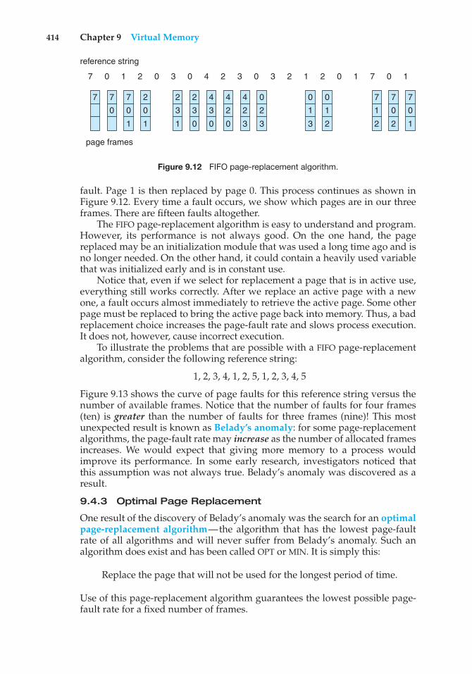
414 Chapter 9 Virtual Memory
7 7
0
7
0
1
page frames
reference string
2
0
1
2
3
1
2
3
0
4
3
0
4
2
0
4
2
3
0
2
3
7
1
2
7
0
2
7
0
1
0
1
3
0
7 0 1 2 0 3 0 4 2 3 0 7 11 02 1 20 3
1
2
Figure 9.12 FIFO page-replacement algorithm.
fault. Page 1 is then replaced by page 0. This process continues as shown inFigure 9.12. Every time a fault occurs, we show which pages are in our threeframes. There are fifteen faults altogether.
The FIFO page-replacement algorithm is easy to understand and program.However, its performance is not always good. On the one hand, the pagereplaced may be an initialization module that was used a long time ago and isno longer needed. On the other hand, it could contain a heavily used variablethat was initialized early and is in constant use.
Notice that, even if we select for replacement a page that is in active use,everything still works correctly. After we replace an active page with a newone, a fault occurs almost immediately to retrieve the active page. Some otherpage must be replaced to bring the active page back into memory. Thus, a badreplacement choice increases the page-fault rate and slows process execution.It does not, however, cause incorrect execution.
To illustrate the problems that are possible with a FIFO page-replacementalgorithm, consider the following reference string:
1, 2, 3, 4, 1, 2, 5, 1, 2, 3, 4, 5
Figure 9.13 shows the curve of page faults for this reference string versus thenumber of available frames. Notice that the number of faults for four frames(ten) is greater than the number of faults for three frames (nine)! This mostunexpected result is known as Belady’s anomaly: for some page-replacementalgorithms, the page-fault rate may increase as the number of allocated framesincreases. We would expect that giving more memory to a process wouldimprove its performance. In some early research, investigators noticed thatthis assumption was not always true. Belady’s anomaly was discovered as aresult.
9.4.3 Optimal Page Replacement
One result of the discovery of Belady’s anomaly was the search for an optimalpage-replacement algorithm—the algorithm that has the lowest page-faultrate of all algorithms and will never suffer from Belady’s anomaly. Such analgorithm does exist and has been called OPT or MIN. It is simply this:
Replace the page that will not be used for the longest period of time.
Use of this page-replacement algorithm guarantees the lowest possible page-fault rate for a fixed number of frames.
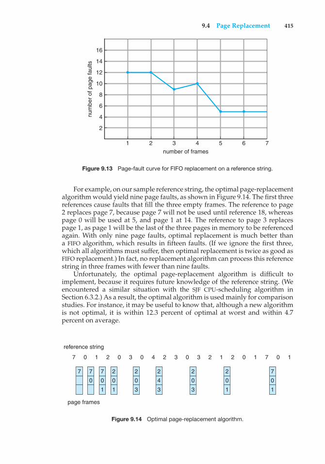
9.4 Page Replacement 415
num
ber
of p
age
faul
ts
16
14
12
10
8
6
4
2
1 2 3number of frames
4 5 6 7
Figure 9.13 Page-fault curve for FIFO replacement on a reference string.
For example, on our sample reference string, the optimal page-replacementalgorithm would yield nine page faults, as shown in Figure 9.14. The first threereferences cause faults that fill the three empty frames. The reference to page2 replaces page 7, because page 7 will not be used until reference 18, whereaspage 0 will be used at 5, and page 1 at 14. The reference to page 3 replacespage 1, as page 1 will be the last of the three pages in memory to be referencedagain. With only nine page faults, optimal replacement is much better thana FIFO algorithm, which results in fifteen faults. (If we ignore the first three,which all algorithms must suffer, then optimal replacement is twice as good asFIFO replacement.) In fact, no replacement algorithm can process this referencestring in three frames with fewer than nine faults.
Unfortunately, the optimal page-replacement algorithm is difficult toimplement, because it requires future knowledge of the reference string. (Weencountered a similar situation with the SJF CPU-scheduling algorithm inSection 6.3.2.) As a result, the optimal algorithm is used mainly for comparisonstudies. For instance, it may be useful to know that, although a new algorithmis not optimal, it is within 12.3 percent of optimal at worst and within 4.7percent on average.
page frames
reference string
7 7
0
7
0
1
2
0
1
2
0
3
2
4
3
2
0
3
7
0
1
2
0
1
7 0 1 2 0 3 0 4 2 3 0 7 11 02 1 20 3
Figure 9.14 Optimal page-replacement algorithm.
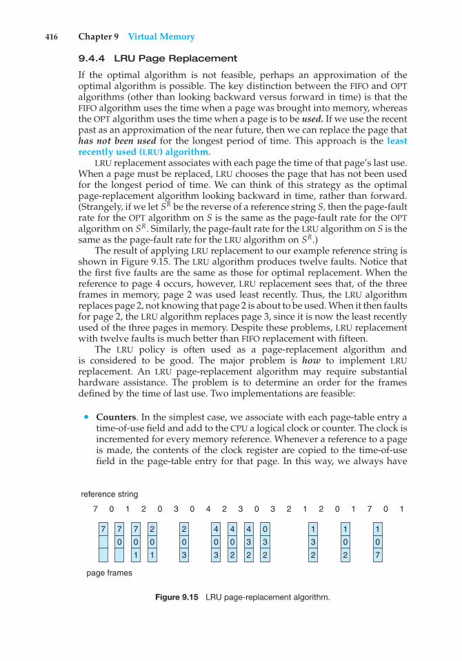
416 Chapter 9 Virtual Memory
9.4.4 LRU Page Replacement
If the optimal algorithm is not feasible, perhaps an approximation of theoptimal algorithm is possible. The key distinction between the FIFO and OPTalgorithms (other than looking backward versus forward in time) is that theFIFO algorithm uses the time when a page was brought into memory, whereasthe OPT algorithm uses the time when a page is to be used. If we use the recentpast as an approximation of the near future, then we can replace the page thathas not been used for the longest period of time. This approach is the leastrecently used (LRU) algorithm.
LRU replacement associates with each page the time of that page’s last use.When a page must be replaced, LRU chooses the page that has not been usedfor the longest period of time. We can think of this strategy as the optimalpage-replacement algorithm looking backward in time, rather than forward.(Strangely, if we let SR be the reverse of a reference string S, then the page-faultrate for the OPT algorithm on S is the same as the page-fault rate for the OPTalgorithm on SR. Similarly, the page-fault rate for the LRU algorithm on S is thesame as the page-fault rate for the LRU algorithm on SR.)
The result of applying LRU replacement to our example reference string isshown in Figure 9.15. The LRU algorithm produces twelve faults. Notice thatthe first five faults are the same as those for optimal replacement. When thereference to page 4 occurs, however, LRU replacement sees that, of the threeframes in memory, page 2 was used least recently. Thus, the LRU algorithmreplaces page 2, not knowing that page 2 is about to be used. When it then faultsfor page 2, the LRU algorithm replaces page 3, since it is now the least recentlyused of the three pages in memory. Despite these problems, LRU replacementwith twelve faults is much better than FIFO replacement with fifteen.
The LRU policy is often used as a page-replacement algorithm andis considered to be good. The major problem is how to implement LRUreplacement. An LRU page-replacement algorithm may require substantialhardware assistance. The problem is to determine an order for the framesdefined by the time of last use. Two implementations are feasible:
• Counters. In the simplest case, we associate with each page-table entry atime-of-use field and add to the CPU a logical clock or counter. The clock isincremented for every memory reference. Whenever a reference to a pageis made, the contents of the clock register are copied to the time-of-usefield in the page-table entry for that page. In this way, we always have
page frames
reference string
7 7
0
7
0
1
2
0
1
2
0
3
4
0
3
4
0
2
4
3
2
0
3
2
1
3
2
1
0
2
1
0
7
7 0 1 2 0 3 0 4 2 3 0 7 11 02 1 20 3
Figure 9.15 LRU page-replacement algorithm.
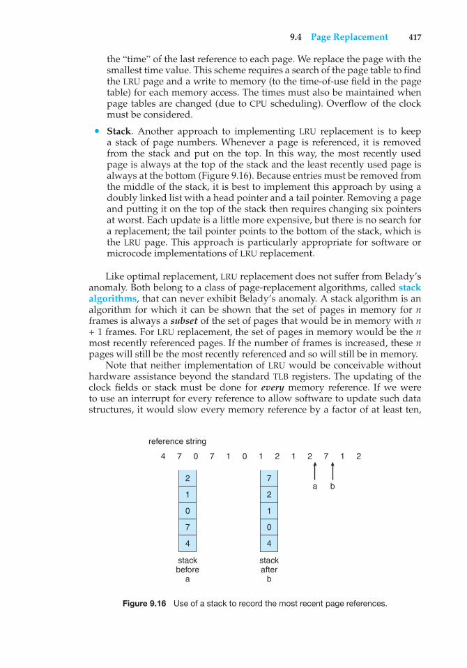
9.4 Page Replacement 417
the “time” of the last reference to each page. We replace the page with thesmallest time value. This scheme requires a search of the page table to findthe LRU page and a write to memory (to the time-of-use field in the pagetable) for each memory access. The times must also be maintained whenpage tables are changed (due to CPU scheduling). Overflow of the clockmust be considered.
• Stack. Another approach to implementing LRU replacement is to keepa stack of page numbers. Whenever a page is referenced, it is removedfrom the stack and put on the top. In this way, the most recently usedpage is always at the top of the stack and the least recently used page isalways at the bottom (Figure 9.16). Because entries must be removed fromthe middle of the stack, it is best to implement this approach by using adoubly linked list with a head pointer and a tail pointer. Removing a pageand putting it on the top of the stack then requires changing six pointersat worst. Each update is a little more expensive, but there is no search fora replacement; the tail pointer points to the bottom of the stack, which isthe LRU page. This approach is particularly appropriate for software ormicrocode implementations of LRU replacement.
Like optimal replacement, LRU replacement does not suffer from Belady’sanomaly. Both belong to a class of page-replacement algorithms, called stackalgorithms, that can never exhibit Belady’s anomaly. A stack algorithm is analgorithm for which it can be shown that the set of pages in memory for nframes is always a subset of the set of pages that would be in memory with n+ 1 frames. For LRU replacement, the set of pages in memory would be the nmost recently referenced pages. If the number of frames is increased, these npages will still be the most recently referenced and so will still be in memory.
Note that neither implementation of LRU would be conceivable withouthardware assistance beyond the standard TLB registers. The updating of theclock fields or stack must be done for every memory reference. If we wereto use an interrupt for every reference to allow software to update such datastructures, it would slow every memory reference by a factor of at least ten,
2
1
0
4
7
stackbefore
a
7
2
1
4
0
stackafter
b
reference string
4 7 0 7 1 0 1 2 1 2 27
a b
1
Figure 9.16 Use of a stack to record the most recent page references.
418 Chapter 9 Virtual Memory
hence slowing every user process by a factor of ten. Few systems could toleratethat level of overhead for memory management.
9.4.5 LRU-Approximation Page Replacement
Few computer systems provide sufficient hardware support for true LRU pagereplacement. In fact, some systems provide no hardware support, and otherpage-replacement algorithms (such as a FIFO algorithm) must be used. Manysystems provide some help, however, in the form of a reference bit. Thereference bit for a page is set by the hardware whenever that page is referenced(either a read or a write to any byte in the page). Reference bits are associatedwith each entry in the page table.
Initially, all bits are cleared (to 0) by the operating system. As a user processexecutes, the bit associated with each page referenced is set (to 1) by thehardware. After some time, we can determine which pages have been used andwhich have not been used by examining the reference bits, although we do notknow the order of use. This information is the basis for many page-replacementalgorithms that approximate LRU replacement.
9.4.5.1 Additional-Reference-Bits Algorithm
We can gain additional ordering information by recording the reference bits atregular intervals. We can keep an 8-bit byte for each page in a table in memory.At regular intervals (say, every 100 milliseconds), a timer interrupt transferscontrol to the operating system. The operating system shifts the reference bitfor each page into the high-order bit of its 8-bit byte, shifting the other bits rightby 1 bit and discarding the low-order bit. These 8-bit shift registers contain thehistory of page use for the last eight time periods. If the shift register contains00000000, for example, then the page has not been used for eight time periods.A page that is used at least once in each period has a shift register value of11111111. A page with a history register value of 11000100 has been used morerecently than one with a value of 01110111. If we interpret these 8-bit bytesas unsigned integers, the page with the lowest number is the LRU page, andit can be replaced. Notice that the numbers are not guaranteed to be unique,however. We can either replace (swap out) all pages with the smallest value oruse the FIFO method to choose among them.
The number of bits of history included in the shift register can be varied,of course, and is selected (depending on the hardware available) to makethe updating as fast as possible. In the extreme case, the number can bereduced to zero, leaving only the reference bit itself. This algorithm is calledthe second-chance page-replacement algorithm.
9.4.5.2 Second-Chance Algorithm
The basic algorithm of second-chance replacement is a FIFO replacementalgorithm. When a page has been selected, however, we inspect its referencebit. If the value is 0, we proceed to replace this page; but if the reference bitis set to 1, we give the page a second chance and move on to select the nextFIFO page. When a page gets a second chance, its reference bit is cleared, andits arrival time is reset to the current time. Thus, a page that is given a secondchance will not be replaced until all other pages have been replaced (or given
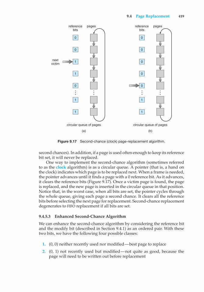
9.4 Page Replacement 419
circular queue of pages
(a)
nextvictim
0
referencebits
pages
0
1
1
0
1
1
……
circular queue of pages
(b)
0
referencebits
pages
0
0
0
0
1
1
……Figure 9.17 Second-chance (clock) page-replacement algorithm.
second chances). In addition, if a page is used often enough to keep its referencebit set, it will never be replaced.
One way to implement the second-chance algorithm (sometimes referredto as the clock algorithm) is as a circular queue. A pointer (that is, a hand onthe clock) indicates which page is to be replaced next. When a frame is needed,the pointer advances until it finds a page with a 0 reference bit. As it advances,it clears the reference bits (Figure 9.17). Once a victim page is found, the pageis replaced, and the new page is inserted in the circular queue in that position.Notice that, in the worst case, when all bits are set, the pointer cycles throughthe whole queue, giving each page a second chance. It clears all the referencebits before selecting the next page for replacement. Second-chance replacementdegenerates to FIFO replacement if all bits are set.
9.4.5.3 Enhanced Second-Chance Algorithm
We can enhance the second-chance algorithm by considering the reference bitand the modify bit (described in Section 9.4.1) as an ordered pair. With thesetwo bits, we have the following four possible classes:
1. (0, 0) neither recently used nor modified—best page to replace
2. (0, 1) not recently used but modified—not quite as good, because thepage will need to be written out before replacement
420 Chapter 9 Virtual Memory
3. (1, 0) recently used but clean—probably will be used again soon
4. (1, 1) recently used and modified—probably will be used again soon, andthe page will be need to be written out to disk before it can be replaced
Each page is in one of these four classes. When page replacement is called for,we use the same scheme as in the clock algorithm; but instead of examiningwhether the page to which we are pointing has the reference bit set to 1,we examine the class to which that page belongs. We replace the first pageencountered in the lowest nonempty class. Notice that we may have to scanthe circular queue several times before we find a page to be replaced.
The major difference between this algorithm and the simpler clock algo-rithm is that here we give preference to those pages that have been modifiedin order to reduce the number of I/Os required.
9.4.6 Counting-Based Page Replacement
There are many other algorithms that can be used for page replacement. Forexample, we can keep a counter of the number of references that have beenmade to each page and develop the following two schemes.
• The least frequently used (LFU) page-replacement algorithm requires thatthe page with the smallest count be replaced. The reason for this selection isthat an actively used page should have a large reference count. A problemarises, however, when a page is used heavily during the initial phase ofa process but then is never used again. Since it was used heavily, it has alarge count and remains in memory even though it is no longer needed.One solution is to shift the counts right by 1 bit at regular intervals, formingan exponentially decaying average usage count.
• The most frequently used (MFU) page-replacement algorithm is basedon the argument that the page with the smallest count was probably justbrought in and has yet to be used.
As you might expect, neither MFU nor LFU replacement is common. Theimplementation of these algorithms is expensive, and they do not approximateOPT replacement well.
9.4.7 Page-Buffering Algorithms
Other procedures are often used in addition to a specific page-replacementalgorithm. For example, systems commonly keep a pool of free frames. Whena page fault occurs, a victim frame is chosen as before. However, the desiredpage is read into a free frame from the pool before the victim is written out. Thisprocedure allows the process to restart as soon as possible, without waitingfor the victim page to be written out. When the victim is later written out, itsframe is added to the free-frame pool.
An expansion of this idea is to maintain a list of modified pages. Wheneverthe paging device is idle, a modified page is selected and is written to the disk.Its modify bit is then reset. This scheme increases the probability that a pagewill be clean when it is selected for replacement and will not need to be writtenout.
9.5 Allocation of Frames 421
Another modification is to keep a pool of free frames but to rememberwhich page was in each frame. Since the frame contents are not modified whena frame is written to the disk, the old page can be reused directly from thefree-frame pool if it is needed before that frame is reused. No I/O is needed inthis case. When a page fault occurs, we first check whether the desired page isin the free-frame pool. If it is not, we must select a free frame and read into it.
This technique is used in the VAX/VMS system along with a FIFO replace-ment algorithm. When the FIFO replacement algorithm mistakenly replaces apage that is still in active use, that page is quickly retrieved from the free-framepool, and no I/O is necessary. The free-frame buffer provides protection againstthe relatively poor, but simple, FIFO replacement algorithm. This method isnecessary because the early versions of VAX did not implement the referencebit correctly.
Some versions of the UNIX system use this method in conjunction withthe second-chance algorithm. It can be a useful augmentation to any page-replacement algorithm, to reduce the penalty incurred if the wrong victimpage is selected.
9.4.8 Applications and Page Replacement
In certain cases, applications accessing data through the operating system’svirtual memory perform worse than if the operating system provided nobuffering at all. A typical example is a database, which provides its ownmemory management and I/O buffering. Applications like this understandtheir memory use and disk use better than does an operating system that isimplementing algorithms for general-purpose use. If the operating system isbuffering I/O and the application is doing so as well, however, then twice thememory is being used for a set of I/O.
In another example, data warehouses frequently perform massive sequen-tial disk reads, followed by computations and writes. The LRU algorithm wouldbe removing old pages and preserving new ones, while the application wouldmore likely be reading older pages than newer ones (as it starts its sequentialreads again). Here, MFU would actually be more efficient than LRU.
Because of such problems, some operating systems give special programsthe ability to use a disk partition as a large sequential array of logical blocks,without any file-system data structures. This array is sometimes called the rawdisk, and I/O to this array is termed raw I/O. Raw I/O bypasses all the file-system services, such as file I/O demand paging, file locking, prefetching, spaceallocation, file names, and directories. Note that although certain applicationsare more efficient when implementing their own special-purpose storageservices on a raw partition, most applications perform better when they usethe regular file-system services.
9.5 Allocation of Frames
We turn next to the issue of allocation. How do we allocate the fixed amountof free memory among the various processes? If we have 93 free frames andtwo processes, how many frames does each process get?
The simplest case is the single-user system. Consider a single-user systemwith 128 KB of memory composed of pages 1 KB in size. This system has 128
422 Chapter 9 Virtual Memory
frames. The operating system may take 35 KB, leaving 93 frames for the userprocess. Under pure demand paging, all 93 frames would initially be put onthe free-frame list. When a user process started execution, it would generate asequence of page faults. The first 93 page faults would all get free frames fromthe free-frame list. When the free-frame list was exhausted, a page-replacementalgorithm would be used to select one of the 93 in-memory pages to be replacedwith the 94th, and so on. When the process terminated, the 93 frames wouldonce again be placed on the free-frame list.
There are many variations on this simple strategy. We can require that theoperating system allocate all its buffer and table space from the free-frame list.When this space is not in use by the operating system, it can be used to supportuser paging. We can try to keep three free frames reserved on the free-frame listat all times. Thus, when a page fault occurs, there is a free frame available topage into. While the page swap is taking place, a replacement can be selected,which is then written to the disk as the user process continues to execute.Other variants are also possible, but the basic strategy is clear: the user processis allocated any free frame.
9.5.1 Minimum Number of Frames
Our strategies for the allocation of frames are constrained in various ways. Wecannot, for example, allocate more than the total number of available frames(unless there is page sharing). We must also allocate at least a minimum numberof frames. Here, we look more closely at the latter requirement.
One reason for allocating at least a minimum number of frames involvesperformance. Obviously, as the number of frames allocated to each processdecreases, the page-fault rate increases, slowing process execution. In addition,remember that, when a page fault occurs before an executing instructionis complete, the instruction must be restarted. Consequently, we must haveenough frames to hold all the different pages that any single instruction canreference.
For example, consider a machine in which all memory-reference instruc-tions may reference only one memory address. In this case, we need at least oneframe for the instruction and one frame for the memory reference. In addition,if one-level indirect addressing is allowed (for example, a load instruction onpage 16 can refer to an address on page 0, which is an indirect reference to page23), then paging requires at least three frames per process. Think about whatmight happen if a process had only two frames.
The minimum number of frames is defined by the computer architecture.For example, the move instruction for the PDP-11 includes more than one wordfor some addressing modes, and thus the instruction itself may straddle twopages. In addition, each of its two operands may be indirect references, for atotal of six frames. Another example is the IBM 370 MVC instruction. Since theinstruction is from storage location to storage location, it takes 6 bytes and canstraddle two pages. The block of characters to move and the area to which itis to be moved can each also straddle two pages. This situation would requiresix frames. The worst case occurs when the MVC instruction is the operand ofan EXECUTE instruction that straddles a page boundary; in this case, we needeight frames.
9.5 Allocation of Frames 423
The worst-case scenario occurs in computer architectures that allowmultiple levels of indirection (for example, each 16-bit word could containa 15-bit address plus a 1-bit indirect indicator). Theoretically, a simple loadinstruction could reference an indirect address that could reference an indirectaddress (on another page) that could also reference an indirect address (on yetanother page), and so on, until every page in virtual memory had been touched.Thus, in the worst case, the entire virtual memory must be in physical memory.To overcome this difficulty, we must place a limit on the levels of indirection (forexample, limit an instruction to at most 16 levels of indirection). When the firstindirection occurs, a counter is set to 16; the counter is then decremented foreach successive indirection for this instruction. If the counter is decremented to0, a trap occurs (excessive indirection). This limitation reduces the maximumnumber of memory references per instruction to 17, requiring the same numberof frames.
Whereas the minimum number of frames per process is defined by thearchitecture, the maximum number is defined by the amount of availablephysical memory. In between, we are still left with significant choice in frameallocation.
9.5.2 Allocation Algorithms
The easiest way to split m frames among n processes is to give everyone anequal share, m/n frames (ignoring frames needed by the operating systemfor the moment). For instance, if there are 93 frames and five processes, eachprocess will get 18 frames. The three leftover frames can be used as a free-framebuffer pool. This scheme is called equal allocation.
An alternative is to recognize that various processes will need differingamounts of memory. Consider a system with a 1-KB frame size. If a smallstudent process of 10 KB and an interactive database of 127 KB are the onlytwo processes running in a system with 62 free frames, it does not make muchsense to give each process 31 frames. The student process does not need morethan 10 frames, so the other 21 are, strictly speaking, wasted.
To solve this problem, we can use proportional allocation, in which weallocate available memory to each process according to its size. Let the size ofthe virtual memory for process pi be si , and define
S =#
si .
Then, if the total number of available frames is m, we allocate ai frames toprocess pi , where ai is approximately
ai = si /S× m.
Of course, we must adjust each ai to be an integer that is greater than theminimum number of frames required by the instruction set, with a sum notexceeding m.
With proportional allocation, we would split 62 frames between twoprocesses, one of 10 pages and one of 127 pages, by allocating 4 frames and 57frames, respectively, since
10/137 × 62 ≈ 4, and127/137 × 62 ≈ 57.
424 Chapter 9 Virtual Memory
In this way, both processes share the available frames according to their“needs,” rather than equally.
In both equal and proportional allocation, of course, the allocation mayvary according to the multiprogramming level. If the multiprogramming levelis increased, each process will lose some frames to provide the memory neededfor the new process. Conversely, if the multiprogramming level decreases, theframes that were allocated to the departed process can be spread over theremaining processes.
Notice that, with either equal or proportional allocation, a high-priorityprocess is treated the same as a low-priority process. By its definition, however,we may want to give the high-priority process more memory to speed itsexecution, to the detriment of low-priority processes. One solution is to usea proportional allocation scheme wherein the ratio of frames depends not onthe relative sizes of processes but rather on the priorities of processes or on acombination of size and priority.
9.5.3 Global versus Local Allocation
Another important factor in the way frames are allocated to the variousprocesses is page replacement. With multiple processes competing for frames,we can classify page-replacement algorithms into two broad categories: globalreplacement and local replacement. Global replacement allows a process toselect a replacement frame from the set of all frames, even if that frame iscurrently allocated to some other process; that is, one process can take a framefrom another. Local replacement requires that each process select from only itsown set of allocated frames.
For example, consider an allocation scheme wherein we allow high-priorityprocesses to select frames from low-priority processes for replacement. Aprocess can select a replacement from among its own frames or the framesof any lower-priority process. This approach allows a high-priority process toincrease its frame allocation at the expense of a low-priority process. With alocal replacement strategy, the number of frames allocated to a process does notchange. With global replacement, a process may happen to select only framesallocated to other processes, thus increasing the number of frames allocated toit (assuming that other processes do not choose its frames for replacement).
One problem with a global replacement algorithm is that a process cannotcontrol its own page-fault rate. The set of pages in memory for a processdepends not only on the paging behavior of that process but also on the pagingbehavior of other processes. Therefore, the same process may perform quitedifferently (for example, taking 0.5 seconds for one execution and 10.3 secondsfor the next execution) because of totally external circumstances. Such is notthe case with a local replacement algorithm. Under local replacement, theset of pages in memory for a process is affected by the paging behavior ofonly that process. Local replacement might hinder a process, however, bynot making available to it other, less used pages of memory. Thus, globalreplacement generally results in greater system throughput and is thereforethe more commonly used method.
9.5.4 Non-Uniform Memory Access
Thus far in our coverage of virtual memory, we have assumed that all mainmemory is created equal—or at least that it is accessed equally. On many
9.6 Thrashing 425
computer systems, that is not the case. Often, in systems with multiple CPUs(Section 1.3.2), a given CPU can access some sections of main memory fasterthan it can access others. These performance differences are caused by howCPUs and memory are interconnected in the system. Frequently, such a systemis made up of several system boards, each containing multiple CPUs and somememory. The system boards are interconnected in various ways, ranging fromsystem buses to high-speed network connections like InfiniBand. As you mightexpect, the CPUs on a particular board can access the memory on that board withless delay than they can access memory on other boards in the system. Systemsin which memory access times vary significantly are known collectively asnon-uniform memory access (NUMA) systems, and without exception, theyare slower than systems in which memory and CPUs are located on the samemotherboard.
Managing which page frames are stored at which locations can significantlyaffect performance in NUMA systems. If we treat memory as uniform in sucha system, CPUs may wait significantly longer for memory access than if wemodify memory allocation algorithms to take NUMA into account. Similarchanges must be made to the scheduling system. The goal of these changes isto have memory frames allocated “as close as possible” to the CPU on whichthe process is running. The definition of “close” is “with minimum latency,”which typically means on the same system board as the CPU.
The algorithmic changes consist of having the scheduler track the last CPUon which each process ran. If the scheduler tries to schedule each process ontoits previous CPU, and the memory-management system tries to allocate framesfor the process close to the CPU on which it is being scheduled, then improvedcache hits and decreased memory access times will result.
The picture is more complicated once threads are added. For example, aprocess with many running threads may end up with those threads scheduledon many different system boards. How is the memory to be allocated in thiscase? Solaris solves the problem by creating lgroups (for “latency groups”) inthe kernel. Each lgroup gathers together close CPUs and memory. In fact, thereis a hierarchy of lgroups based on the amount of latency between the groups.Solaris tries to schedule all threads of a process and allocate all memory of aprocess within an lgroup. If that is not possible, it picks nearby lgroups for therest of the resources needed. This practice minimizes overall memory latencyand maximizes CPU cache hit rates.
9.6 Thrashing
If the number of frames allocated to a low-priority process falls below theminimum number required by the computer architecture, we must suspendthat process’s execution. We should then page out its remaining pages, freeingall its allocated frames. This provision introduces a swap-in, swap-out level ofintermediate CPU scheduling.
In fact, look at any process that does not have “enough” frames. If theprocess does not have the number of frames it needs to support pages inactive use, it will quickly page-fault. At this point, it must replace some page.However, since all its pages are in active use, it must replace a page that willbe needed again right away. Consequently, it quickly faults again, and again,and again, replacing pages that it must bring back in immediately.
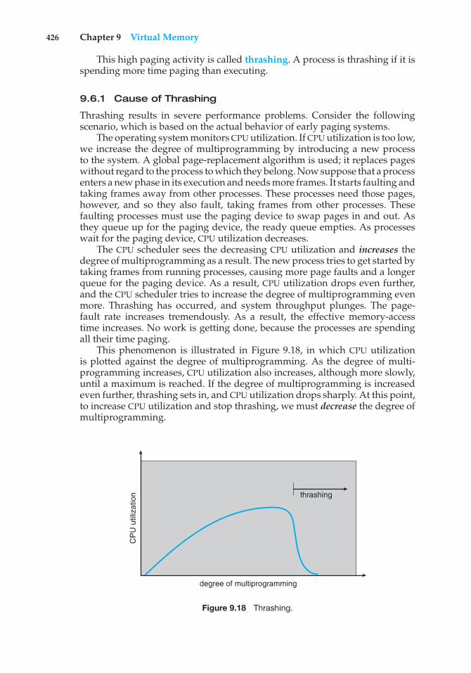
426 Chapter 9 Virtual Memory
This high paging activity is called thrashing. A process is thrashing if it isspending more time paging than executing.
9.6.1 Cause of Thrashing
Thrashing results in severe performance problems. Consider the followingscenario, which is based on the actual behavior of early paging systems.
The operating system monitors CPU utilization. If CPU utilization is too low,we increase the degree of multiprogramming by introducing a new processto the system. A global page-replacement algorithm is used; it replaces pageswithout regard to the process to which they belong. Now suppose that a processenters a new phase in its execution and needs more frames. It starts faulting andtaking frames away from other processes. These processes need those pages,however, and so they also fault, taking frames from other processes. Thesefaulting processes must use the paging device to swap pages in and out. Asthey queue up for the paging device, the ready queue empties. As processeswait for the paging device, CPU utilization decreases.
The CPU scheduler sees the decreasing CPU utilization and increases thedegree of multiprogramming as a result. The new process tries to get started bytaking frames from running processes, causing more page faults and a longerqueue for the paging device. As a result, CPU utilization drops even further,and the CPU scheduler tries to increase the degree of multiprogramming evenmore. Thrashing has occurred, and system throughput plunges. The page-fault rate increases tremendously. As a result, the effective memory-accesstime increases. No work is getting done, because the processes are spendingall their time paging.
This phenomenon is illustrated in Figure 9.18, in which CPU utilizationis plotted against the degree of multiprogramming. As the degree of multi-programming increases, CPU utilization also increases, although more slowly,until a maximum is reached. If the degree of multiprogramming is increasedeven further, thrashing sets in, and CPU utilization drops sharply. At this point,to increase CPU utilization and stop thrashing, we must decrease the degree ofmultiprogramming.
thrashing
degree of multiprogramming
CP
U u
tiliz
atio
n
Figure 9.18 Thrashing.
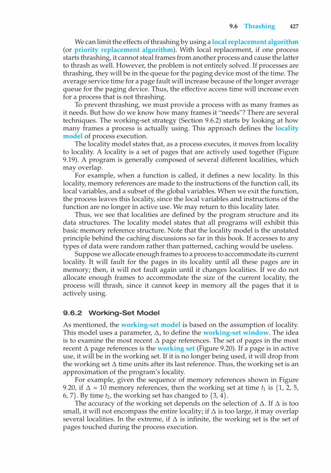
9.6 Thrashing 427
We can limit the effects of thrashing by using a local replacement algorithm(or priority replacement algorithm). With local replacement, if one processstarts thrashing, it cannot steal frames from another process and cause the latterto thrash as well. However, the problem is not entirely solved. If processes arethrashing, they will be in the queue for the paging device most of the time. Theaverage service time for a page fault will increase because of the longer averagequeue for the paging device. Thus, the effective access time will increase evenfor a process that is not thrashing.
To prevent thrashing, we must provide a process with as many frames asit needs. But how do we know how many frames it “needs”? There are severaltechniques. The working-set strategy (Section 9.6.2) starts by looking at howmany frames a process is actually using. This approach defines the localitymodel of process execution.
The locality model states that, as a process executes, it moves from localityto locality. A locality is a set of pages that are actively used together (Figure9.19). A program is generally composed of several different localities, whichmay overlap.
For example, when a function is called, it defines a new locality. In thislocality, memory references are made to the instructions of the function call, itslocal variables, and a subset of the global variables. When we exit the function,the process leaves this locality, since the local variables and instructions of thefunction are no longer in active use. We may return to this locality later.
Thus, we see that localities are defined by the program structure and itsdata structures. The locality model states that all programs will exhibit thisbasic memory reference structure. Note that the locality model is the unstatedprinciple behind the caching discussions so far in this book. If accesses to anytypes of data were random rather than patterned, caching would be useless.
Suppose we allocate enough frames to a process to accommodate its currentlocality. It will fault for the pages in its locality until all these pages are inmemory; then, it will not fault again until it changes localities. If we do notallocate enough frames to accommodate the size of the current locality, theprocess will thrash, since it cannot keep in memory all the pages that it isactively using.
9.6.2 Working-Set Model
As mentioned, the working-set model is based on the assumption of locality.This model uses a parameter, !, to define the working-set window. The ideais to examine the most recent ! page references. The set of pages in the mostrecent ! page references is the working set (Figure 9.20). If a page is in activeuse, it will be in the working set. If it is no longer being used, it will drop fromthe working set ! time units after its last reference. Thus, the working set is anapproximation of the program’s locality.
For example, given the sequence of memory references shown in Figure9.20, if ! = 10 memory references, then the working set at time t1 is {1, 2, 5,6, 7}. By time t2, the working set has changed to {3, 4}.
The accuracy of the working set depends on the selection of !. If ! is toosmall, it will not encompass the entire locality; if ! is too large, it may overlapseveral localities. In the extreme, if ! is infinite, the working set is the set ofpages touched during the process execution.
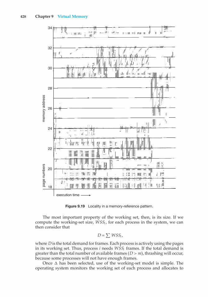
428 Chapter 9 Virtual Memory
18
20
22
24
26
28
30
32
34
page
num
bers
mem
ory
addr
ess
execution time
Figure 9.19 Locality in a memory-reference pattern.
The most important property of the working set, then, is its size. If wecompute the working-set size, WSSi , for each process in the system, we canthen consider that
D =#
WSSi ,
where D is the total demand for frames. Each process is actively using the pagesin its working set. Thus, process i needs WSSi frames. If the total demand isgreater than the total number of available frames (D > m), thrashing will occur,because some processes will not have enough frames.
Once ! has been selected, use of the working-set model is simple. Theoperating system monitors the working set of each process and allocates to
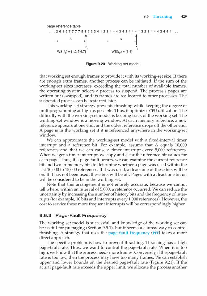
9.6 Thrashing 429
page reference table. . . 2 6 1 5 7 7 7 7 5 1 6 2 3 4 1 2 3 4 4 4 3 4 3 4 4 4 1 3 2 3 4 4 4 3 4 4 4 . . .
∆
t1WS(t1) = {1,2,5,6,7}
∆
t2WS(t2) = {3,4}
Figure 9.20 Working-set model.
that working set enough frames to provide it with its working-set size. If thereare enough extra frames, another process can be initiated. If the sum of theworking-set sizes increases, exceeding the total number of available frames,the operating system selects a process to suspend. The process’s pages arewritten out (swapped), and its frames are reallocated to other processes. Thesuspended process can be restarted later.
This working-set strategy prevents thrashing while keeping the degree ofmultiprogramming as high as possible. Thus, it optimizes CPU utilization. Thedifficulty with the working-set model is keeping track of the working set. Theworking-set window is a moving window. At each memory reference, a newreference appears at one end, and the oldest reference drops off the other end.A page is in the working set if it is referenced anywhere in the working-setwindow.
We can approximate the working-set model with a fixed-interval timerinterrupt and a reference bit. For example, assume that ! equals 10,000references and that we can cause a timer interrupt every 5,000 references.When we get a timer interrupt, we copy and clear the reference-bit values foreach page. Thus, if a page fault occurs, we can examine the current referencebit and two in-memory bits to determine whether a page was used within thelast 10,000 to 15,000 references. If it was used, at least one of these bits will beon. If it has not been used, these bits will be off. Pages with at least one bit onwill be considered to be in the working set.
Note that this arrangement is not entirely accurate, because we cannottell where, within an interval of 5,000, a reference occurred. We can reduce theuncertainty by increasing the number of history bits and the frequency of inter-rupts (for example, 10 bits and interrupts every 1,000 references). However, thecost to service these more frequent interrupts will be correspondingly higher.
9.6.3 Page-Fault Frequency
The working-set model is successful, and knowledge of the working set canbe useful for prepaging (Section 9.9.1), but it seems a clumsy way to controlthrashing. A strategy that uses the page-fault frequency (PFF) takes a moredirect approach.
The specific problem is how to prevent thrashing. Thrashing has a highpage-fault rate. Thus, we want to control the page-fault rate. When it is toohigh, we know that the process needs more frames. Conversely, if the page-faultrate is too low, then the process may have too many frames. We can establishupper and lower bounds on the desired page-fault rate (Figure 9.21). If theactual page-fault rate exceeds the upper limit, we allocate the process another
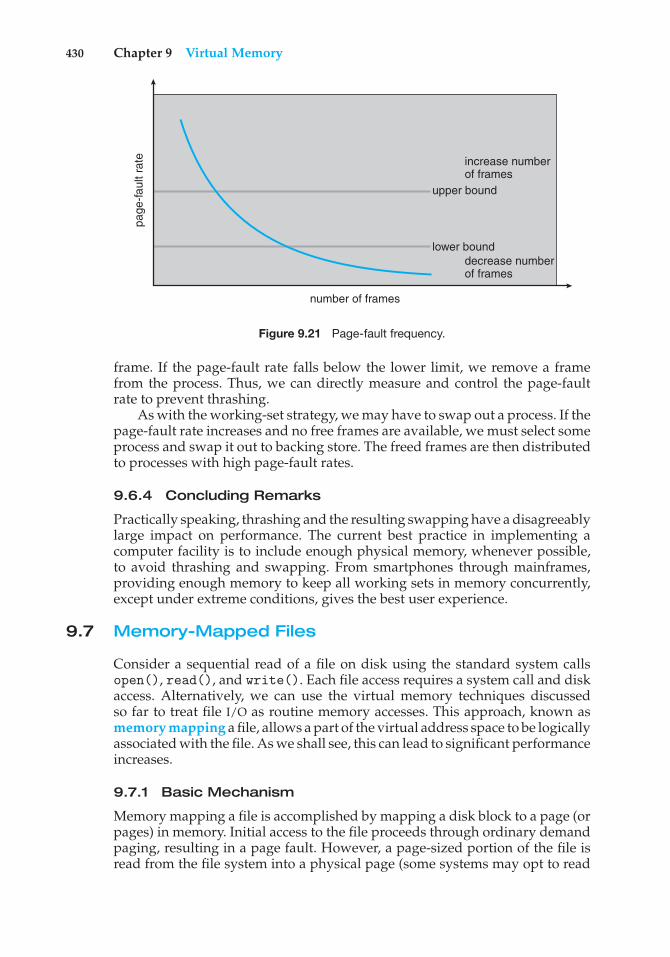
430 Chapter 9 Virtual Memory
number of frames
increase numberof frames
upper bound
lower bounddecrease numberof frames
page
-faul
t rat
e
Figure 9.21 Page-fault frequency.
frame. If the page-fault rate falls below the lower limit, we remove a framefrom the process. Thus, we can directly measure and control the page-faultrate to prevent thrashing.
As with the working-set strategy, we may have to swap out a process. If thepage-fault rate increases and no free frames are available, we must select someprocess and swap it out to backing store. The freed frames are then distributedto processes with high page-fault rates.
9.6.4 Concluding Remarks
Practically speaking, thrashing and the resulting swapping have a disagreeablylarge impact on performance. The current best practice in implementing acomputer facility is to include enough physical memory, whenever possible,to avoid thrashing and swapping. From smartphones through mainframes,providing enough memory to keep all working sets in memory concurrently,except under extreme conditions, gives the best user experience.
9.7 Memory-Mapped Files
Consider a sequential read of a file on disk using the standard system callsopen(), read(), and write(). Each file access requires a system call and diskaccess. Alternatively, we can use the virtual memory techniques discussedso far to treat file I/O as routine memory accesses. This approach, known asmemory mapping a file, allows a part of the virtual address space to be logicallyassociated with the file. As we shall see, this can lead to significant performanceincreases.
9.7.1 Basic Mechanism
Memory mapping a file is accomplished by mapping a disk block to a page (orpages) in memory. Initial access to the file proceeds through ordinary demandpaging, resulting in a page fault. However, a page-sized portion of the file isread from the file system into a physical page (some systems may opt to read
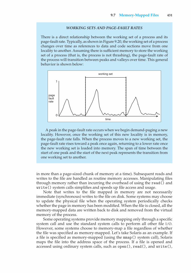
9.7 Memory-Mapped Files 431
WORKING SETS AND PAGE-FAULT RATES
There is a direct relationship between the working set of a process and itspage-fault rate. Typically, as shown in Figure 9.20, the working set of a processchanges over time as references to data and code sections move from onelocality to another. Assuming there is sufficient memory to store the workingset of a process (that is, the process is not thrashing), the page-fault rate ofthe process will transition between peaks and valleys over time. This generalbehavior is shown below:
1
0time
working set
page fault rate
A peak in the page-fault rate occurs when we begin demand-paging a newlocality. However, once the working set of this new locality is in memory,the page-fault rate falls. When the process moves to a new working set, thepage-fault rate rises toward a peak once again, returning to a lower rate oncethe new working set is loaded into memory. The span of time between thestart of one peak and the start of the next peak represents the transition fromone working set to another.
in more than a page-sized chunk of memory at a time). Subsequent reads andwrites to the file are handled as routine memory accesses. Manipulating filesthrough memory rather than incurring the overhead of using the read() andwrite() system calls simplifies and speeds up file access and usage.
Note that writes to the file mapped in memory are not necessarilyimmediate (synchronous) writes to the file on disk. Some systems may chooseto update the physical file when the operating system periodically checkswhether the page in memory has been modified. When the file is closed, all thememory-mapped data are written back to disk and removed from the virtualmemory of the process.
Some operating systems provide memory mapping only through a specificsystem call and use the standard system calls to perform all other file I/O.However, some systems choose to memory-map a file regardless of whetherthe file was specified as memory-mapped. Let’s take Solaris as an example. Ifa file is specified as memory-mapped (using the mmap() system call), Solarismaps the file into the address space of the process. If a file is opened andaccessed using ordinary system calls, such as open(), read(), and write(),
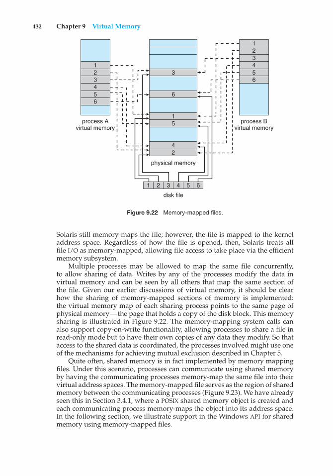
432 Chapter 9 Virtual Memory
process Avirtual memory
1
1
1 2 3 4 5 6
23
3
45
5
42
66
123456
process Bvirtual memory
physical memory
disk file
Figure 9.22 Memory-mapped files.
Solaris still memory-maps the file; however, the file is mapped to the kerneladdress space. Regardless of how the file is opened, then, Solaris treats allfile I/O as memory-mapped, allowing file access to take place via the efficientmemory subsystem.
Multiple processes may be allowed to map the same file concurrently,to allow sharing of data. Writes by any of the processes modify the data invirtual memory and can be seen by all others that map the same section ofthe file. Given our earlier discussions of virtual memory, it should be clearhow the sharing of memory-mapped sections of memory is implemented:the virtual memory map of each sharing process points to the same page ofphysical memory—the page that holds a copy of the disk block. This memorysharing is illustrated in Figure 9.22. The memory-mapping system calls canalso support copy-on-write functionality, allowing processes to share a file inread-only mode but to have their own copies of any data they modify. So thataccess to the shared data is coordinated, the processes involved might use oneof the mechanisms for achieving mutual exclusion described in Chapter 5.
Quite often, shared memory is in fact implemented by memory mappingfiles. Under this scenario, processes can communicate using shared memoryby having the communicating processes memory-map the same file into theirvirtual address spaces. The memory-mapped file serves as the region of sharedmemory between the communicating processes (Figure 9.23). We have alreadyseen this in Section 3.4.1, where a POSIX shared memory object is created andeach communicating process memory-maps the object into its address space.In the following section, we illustrate support in the Windows API for sharedmemory using memory-mapped files.
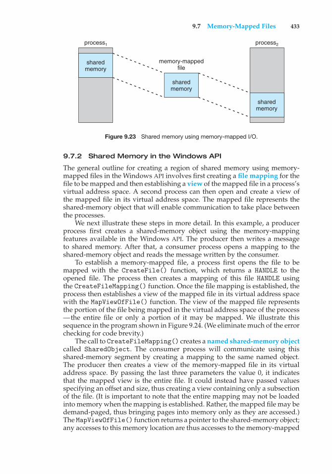
9.7 Memory-Mapped Files 433
process1
memory-mappedfile
sharedmemory
sharedmemory
sharedmemory
process2
Figure 9.23 Shared memory using memory-mapped I/O.
9.7.2 Shared Memory in the Windows API
The general outline for creating a region of shared memory using memory-mapped files in the Windows API involves first creating a file mapping for thefile to be mapped and then establishing a view of the mapped file in a process’svirtual address space. A second process can then open and create a view ofthe mapped file in its virtual address space. The mapped file represents theshared-memory object that will enable communication to take place betweenthe processes.
We next illustrate these steps in more detail. In this example, a producerprocess first creates a shared-memory object using the memory-mappingfeatures available in the Windows API. The producer then writes a messageto shared memory. After that, a consumer process opens a mapping to theshared-memory object and reads the message written by the consumer.
To establish a memory-mapped file, a process first opens the file to bemapped with the CreateFile() function, which returns a HANDLE to theopened file. The process then creates a mapping of this file HANDLE usingthe CreateFileMapping() function. Once the file mapping is established, theprocess then establishes a view of the mapped file in its virtual address spacewith the MapViewOfFile() function. The view of the mapped file representsthe portion of the file being mapped in the virtual address space of the process—the entire file or only a portion of it may be mapped. We illustrate thissequence in the program shown in Figure 9.24. (We eliminate much of the errorchecking for code brevity.)
The call to CreateFileMapping() creates a named shared-memory objectcalled SharedObject. The consumer process will communicate using thisshared-memory segment by creating a mapping to the same named object.The producer then creates a view of the memory-mapped file in its virtualaddress space. By passing the last three parameters the value 0, it indicatesthat the mapped view is the entire file. It could instead have passed valuesspecifying an offset and size, thus creating a view containing only a subsectionof the file. (It is important to note that the entire mapping may not be loadedinto memory when the mapping is established. Rather, the mapped file may bedemand-paged, thus bringing pages into memory only as they are accessed.)The MapViewOfFile() function returns a pointer to the shared-memory object;any accesses to this memory location are thus accesses to the memory-mapped
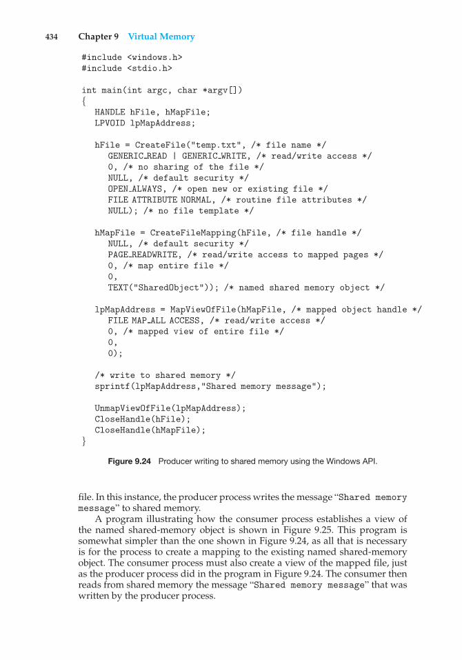
434 Chapter 9 Virtual Memory
#include <windows.h>#include <stdio.h>
int main(int argc, char *argv[]){
HANDLE hFile, hMapFile;LPVOID lpMapAddress;
hFile = CreateFile("temp.txt", /* file name */GENERIC READ | GENERIC WRITE, /* read/write access */0, /* no sharing of the file */NULL, /* default security */OPEN ALWAYS, /* open new or existing file */FILE ATTRIBUTE NORMAL, /* routine file attributes */NULL); /* no file template */
hMapFile = CreateFileMapping(hFile, /* file handle */NULL, /* default security */PAGE READWRITE, /* read/write access to mapped pages */0, /* map entire file */0,TEXT("SharedObject")); /* named shared memory object */
lpMapAddress = MapViewOfFile(hMapFile, /* mapped object handle */FILE MAP ALL ACCESS, /* read/write access */0, /* mapped view of entire file */0,0);
/* write to shared memory */sprintf(lpMapAddress,"Shared memory message");
UnmapViewOfFile(lpMapAddress);CloseHandle(hFile);CloseHandle(hMapFile);
}
Figure 9.24 Producer writing to shared memory using the Windows API.
file. In this instance, the producer process writes the message “Shared memorymessage” to shared memory.
A program illustrating how the consumer process establishes a view ofthe named shared-memory object is shown in Figure 9.25. This program issomewhat simpler than the one shown in Figure 9.24, as all that is necessaryis for the process to create a mapping to the existing named shared-memoryobject. The consumer process must also create a view of the mapped file, justas the producer process did in the program in Figure 9.24. The consumer thenreads from shared memory the message “Shared memory message” that waswritten by the producer process.
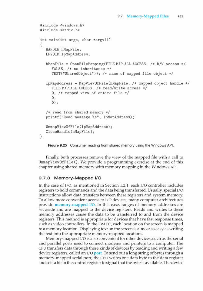
9.7 Memory-Mapped Files 435
#include <windows.h>#include <stdio.h>
int main(int argc, char *argv[]){
HANDLE hMapFile;LPVOID lpMapAddress;
hMapFile = OpenFileMapping(FILE MAP ALL ACCESS, /* R/W access */FALSE, /* no inheritance */TEXT("SharedObject")); /* name of mapped file object */
lpMapAddress = MapViewOfFile(hMapFile, /* mapped object handle */FILE MAP ALL ACCESS, /* read/write access */0, /* mapped view of entire file */0,0);
/* read from shared memory */printf("Read message %s", lpMapAddress);
UnmapViewOfFile(lpMapAddress);CloseHandle(hMapFile);
}
Figure 9.25 Consumer reading from shared memory using the Windows API.
Finally, both processes remove the view of the mapped file with a call toUnmapViewOfFile(). We provide a programming exercise at the end of thischapter using shared memory with memory mapping in the Windows API.
9.7.3 Memory-Mapped I/O
In the case of I/O, as mentioned in Section 1.2.1, each I/O controller includesregisters to hold commands and the data being transferred. Usually, special I/Oinstructions allow data transfers between these registers and system memory.To allow more convenient access to I/O devices, many computer architecturesprovide memory-mapped I/O. In this case, ranges of memory addresses areset aside and are mapped to the device registers. Reads and writes to thesememory addresses cause the data to be transferred to and from the deviceregisters. This method is appropriate for devices that have fast response times,such as video controllers. In the IBM PC, each location on the screen is mappedto a memory location. Displaying text on the screen is almost as easy as writingthe text into the appropriate memory-mapped locations.
Memory-mapped I/O is also convenient for other devices, such as the serialand parallel ports used to connect modems and printers to a computer. TheCPU transfers data through these kinds of devices by reading and writing a fewdevice registers, called an I/O port. To send out a long string of bytes through amemory-mapped serial port, the CPU writes one data byte to the data registerand sets a bit in the control register to signal that the byte is available. The device
436 Chapter 9 Virtual Memory
takes the data byte and then clears the bit in the control register to signal thatit is ready for the next byte. Then the CPU can transfer the next byte. If theCPU uses polling to watch the control bit, constantly looping to see whetherthe device is ready, this method of operation is called programmed I/O (PIO).If the CPU does not poll the control bit, but instead receives an interrupt whenthe device is ready for the next byte, the data transfer is said to be interruptdriven.
9.8 Allocating Kernel Memory
When a process running in user mode requests additional memory, pagesare allocated from the list of free page frames maintained by the kernel.This list is typically populated using a page-replacement algorithm such asthose discussed in Section 9.4 and most likely contains free pages scatteredthroughout physical memory, as explained earlier. Remember, too, that if auser process requests a single byte of memory, internal fragmentation willresult, as the process will be granted an entire page frame.
Kernel memory is often allocated from a free-memory pool different fromthe list used to satisfy ordinary user-mode processes. There are two primaryreasons for this:
1. The kernel requests memory for data structures of varying sizes, some ofwhich are less than a page in size. As a result, the kernel must use memoryconservatively and attempt to minimize waste due to fragmentation. Thisis especially important because many operating systems do not subjectkernel code or data to the paging system.
2. Pages allocated to user-mode processes do not necessarily have to be incontiguous physical memory. However, certain hardware devices interactdirectly with physical memory—without the benefit of a virtual memoryinterface—and consequently may require memory residing in physicallycontiguous pages.
In the following sections, we examine two strategies for managing free memorythat is assigned to kernel processes: the “buddy system” and slab allocation.
9.8.1 Buddy System
The buddy system allocates memory from a fixed-size segment consisting ofphysically contiguous pages. Memory is allocated from this segment using apower-of-2 allocator, which satisfies requests in units sized as a power of 2(4 KB, 8 KB, 16 KB, and so forth). A request in units not appropriately sized isrounded up to the next highest power of 2. For example, a request for 11 KB issatisfied with a 16-KB segment.
Let’s consider a simple example. Assume the size of a memory segmentis initially 256 KB and the kernel requests 21 KB of memory. The segment isinitially divided into two buddies—which we will call AL and AR —each 128KB in size. One of these buddies is further divided into two 64-KB buddies—BL and BR. However, the next-highest power of 2 from 21 KB is 32 KB so eitherBL or BR is again divided into two 32-KB buddies, CL and CR. One of these
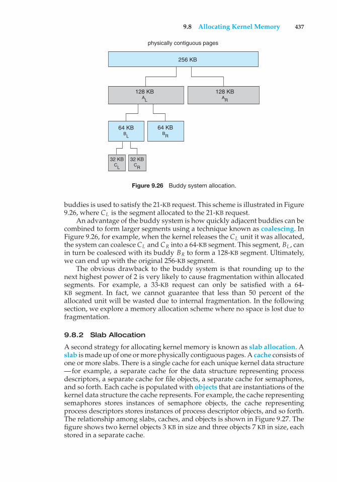
9.8 Allocating Kernel Memory 437
physically contiguous pages
256 KB
128 KB AL
64 KB BR
64 KB BL
32 KB CL
32 KB CR
128 KB AR
Figure 9.26 Buddy system allocation.
buddies is used to satisfy the 21-KB request. This scheme is illustrated in Figure9.26, where CL is the segment allocated to the 21-KB request.
An advantage of the buddy system is how quickly adjacent buddies can becombined to form larger segments using a technique known as coalescing. InFigure 9.26, for example, when the kernel releases the CL unit it was allocated,the system can coalesce CL and CR into a 64-KB segment. This segment, BL , canin turn be coalesced with its buddy BR to form a 128-KB segment. Ultimately,we can end up with the original 256-KB segment.
The obvious drawback to the buddy system is that rounding up to thenext highest power of 2 is very likely to cause fragmentation within allocatedsegments. For example, a 33-KB request can only be satisfied with a 64-KB segment. In fact, we cannot guarantee that less than 50 percent of theallocated unit will be wasted due to internal fragmentation. In the followingsection, we explore a memory allocation scheme where no space is lost due tofragmentation.
9.8.2 Slab Allocation
A second strategy for allocating kernel memory is known as slab allocation. Aslab is made up of one or more physically contiguous pages. A cache consists ofone or more slabs. There is a single cache for each unique kernel data structure—for example, a separate cache for the data structure representing processdescriptors, a separate cache for file objects, a separate cache for semaphores,and so forth. Each cache is populated with objects that are instantiations of thekernel data structure the cache represents. For example, the cache representingsemaphores stores instances of semaphore objects, the cache representingprocess descriptors stores instances of process descriptor objects, and so forth.The relationship among slabs, caches, and objects is shown in Figure 9.27. Thefigure shows two kernel objects 3 KB in size and three objects 7 KB in size, eachstored in a separate cache.
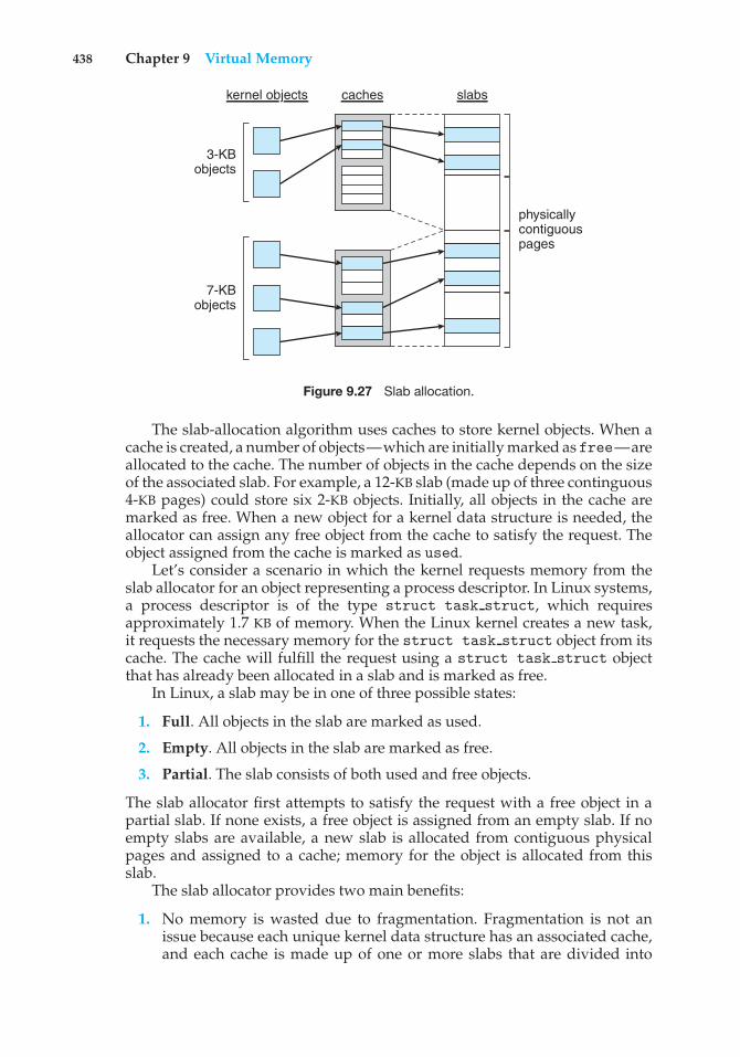
438 Chapter 9 Virtual Memory
3-KBobjects
7-KBobjects
kernel objects caches slabs
physicallycontiguouspages
Figure 9.27 Slab allocation.
The slab-allocation algorithm uses caches to store kernel objects. When acache is created, a number of objects—which are initially marked as free—areallocated to the cache. The number of objects in the cache depends on the sizeof the associated slab. For example, a 12-KB slab (made up of three continguous4-KB pages) could store six 2-KB objects. Initially, all objects in the cache aremarked as free. When a new object for a kernel data structure is needed, theallocator can assign any free object from the cache to satisfy the request. Theobject assigned from the cache is marked as used.
Let’s consider a scenario in which the kernel requests memory from theslab allocator for an object representing a process descriptor. In Linux systems,a process descriptor is of the type struct task struct, which requiresapproximately 1.7 KB of memory. When the Linux kernel creates a new task,it requests the necessary memory for the struct task struct object from itscache. The cache will fulfill the request using a struct task struct objectthat has already been allocated in a slab and is marked as free.
In Linux, a slab may be in one of three possible states:
1. Full. All objects in the slab are marked as used.
2. Empty. All objects in the slab are marked as free.
3. Partial. The slab consists of both used and free objects.
The slab allocator first attempts to satisfy the request with a free object in apartial slab. If none exists, a free object is assigned from an empty slab. If noempty slabs are available, a new slab is allocated from contiguous physicalpages and assigned to a cache; memory for the object is allocated from thisslab.
The slab allocator provides two main benefits:
1. No memory is wasted due to fragmentation. Fragmentation is not anissue because each unique kernel data structure has an associated cache,and each cache is made up of one or more slabs that are divided into
9.9 Other Considerations 439
chunks the size of the objects being represented. Thus, when the kernelrequests memory for an object, the slab allocator returns the exact amountof memory required to represent the object.
2. Memory requests can be satisfied quickly. The slab allocation schemeis thus particularly effective for managing memory when objects arefrequently allocated and deallocated, as is often the case with requestsfrom the kernel. The act of allocating—and releasing—memory can bea time-consuming process. However, objects are created in advance andthus can be quickly allocated from the cache. Furthermore, when thekernel has finished with an object and releases it, it is marked as free andreturned to its cache, thus making it immediately available for subsequentrequests from the kernel.
The slab allocator first appeared in the Solaris 2.4 kernel. Because of itsgeneral-purpose nature, this allocator is now also used for certain user-modememory requests in Solaris. Linux originally used the buddy system; however,beginning with Version 2.2, the Linux kernel adopted the slab allocator.
Recent distributions of Linux now include two other kernel memory allo-cators—the SLOB and SLUB allocators. (Linux refers to its slab implementationas SLAB.)
The SLOB allocator is designed for systems with a limited amount ofmemory, such as embedded systems. SLOB (which stands for Simple List ofBlocks) works by maintaining three lists of objects: small (for objects less than256 bytes), medium (for objects less than 1,024 bytes), and large (for objectsless than 1,024 bytes). Memory requests are allocated from an object on anappropriately sized list using a first-fit policy.
Beginning with Version 2.6.24, the SLUB allocator replaced SLAB as thedefault allocator for the Linux kernel. SLUB addresses performance issueswith slab allocation by reducing much of the overhead required by theSLAB allocator. One change is to move the metadata that is stored witheach slab under SLAB allocation to the page structure the Linux kerneluses for each page. Additionally, SLUB removes the per-CPU queues that theSLAB allocator maintains for objects in each cache. For systems with a largenumber of processors, the amount of memory allocated to these queues wasnot insignificant. Thus, SLUB provides better performance as the number ofprocessors on a system increases.
9.9 Other Considerations
The major decisions that we make for a paging system are the selections ofa replacement algorithm and an allocation policy, which we discussed earlierin this chapter. There are many other considerations as well, and we discussseveral of them here.
9.9.1 Prepaging
An obvious property of pure demand paging is the large number of page faultsthat occur when a process is started. This situation results from trying to get theinitial locality into memory. The same situation may arise at other times. For
440 Chapter 9 Virtual Memory
instance, when a swapped-out process is restarted, all its pages are on the disk,and each must be brought in by its own page fault. Prepaging is an attempt toprevent this high level of initial paging. The strategy is to bring into memory atone time all the pages that will be needed. Some operating systems—notablySolaris—prepage the page frames for small files.
In a system using the working-set model, for example, we could keep witheach process a list of the pages in its working set. If we must suspend a process(due to an I/O wait or a lack of free frames), we remember the working set forthat process. When the process is to be resumed (because I/O has finished orenough free frames have become available), we automatically bring back intomemory its entire working set before restarting the process.
Prepaging may offer an advantage in some cases. The question is simplywhether the cost of using prepaging is less than the cost of servicing thecorresponding page faults. It may well be the case that many of the pagesbrought back into memory by prepaging will not be used.
Assume that s pages are prepaged and a fraction # of these s pages isactually used (0 ≤ # ≤ 1). The question is whether the cost of the s * # savedpage faults is greater or less than the cost of prepaging s * (1 − #) unnecessarypages. If # is close to 0, prepaging loses; if # is close to 1, prepaging wins.
9.9.2 Page Size
The designers of an operating system for an existing machine seldom havea choice concerning the page size. However, when new machines are beingdesigned, a decision regarding the best page size must be made. As you mightexpect, there is no single best page size. Rather, there is a set of factors thatsupport various sizes. Page sizes are invariably powers of 2, generally rangingfrom 4,096 (212) to 4,194,304 (222) bytes.
How do we select a page size? One concern is the size of the page table. Fora given virtual memory space, decreasing the page size increases the numberof pages and hence the size of the page table. For a virtual memory of 4 MB(222), for example, there would be 4,096 pages of 1,024 bytes but only 512 pagesof 8,192 bytes. Because each active process must have its own copy of the pagetable, a large page size is desirable.
Memory is better utilized with smaller pages, however. If a process isallocated memory starting at location 00000 and continuing until it has as muchas it needs, it probably will not end exactly on a page boundary. Thus, a partof the final page must be allocated (because pages are the units of allocation)but will be unused (creating internal fragmentation). Assuming independenceof process size and page size, we can expect that, on the average, half of thefinal page of each process will be wasted. This loss is only 256 bytes for a pageof 512 bytes but is 4,096 bytes for a page of 8,192 bytes. To minimize internalfragmentation, then, we need a small page size.
Another problem is the time required to read or write a page. I/O time iscomposed of seek, latency, and transfer times. Transfer time is proportional tothe amount transferred (that is, the page size)—a fact that would seem to arguefor a small page size. However, as we shall see in Section 10.1.1, latency andseek time normally dwarf transfer time. At a transfer rate of 2 MB per second,it takes only 0.2 milliseconds to transfer 512 bytes. Latency time, though, isperhaps 8 milliseconds, and seek time 20 milliseconds. Of the total I/O time
9.9 Other Considerations 441
(28.2 milliseconds), therefore, only 1 percent is attributable to the actual transfer.Doubling the page size increases I/O time to only 28.4 milliseconds. It takes 28.4milliseconds to read a single page of 1,024 bytes but 56.4 milliseconds to readthe same amount as two pages of 512 bytes each. Thus, a desire to minimizeI/O time argues for a larger page size.
With a smaller page size, though, total I/O should be reduced, since localitywill be improved. A smaller page size allows each page to match programlocality more accurately. For example, consider a process 200 KB in size, ofwhich only half (100 KB) is actually used in an execution. If we have only onelarge page, we must bring in the entire page, a total of 200 KB transferred andallocated. If instead we had pages of only 1 byte, then we could bring in onlythe 100 KB that are actually used, resulting in only 100 KB transferred andallocated. With a smaller page size, then, we have better resolution, allowingus to isolate only the memory that is actually needed. With a larger page size,we must allocate and transfer not only what is needed but also anything elsethat happens to be in the page, whether it is needed or not. Thus, a smallerpage size should result in less I/O and less total allocated memory.
But did you notice that with a page size of 1 byte, we would have a pagefault for each byte? A process of 200 KB that used only half of that memorywould generate only one page fault with a page size of 200 KB but 102,400 pagefaults with a page size of 1 byte. Each page fault generates the large amountof overhead needed for processing the interrupt, saving registers, replacing apage, queueing for the paging device, and updating tables. To minimize thenumber of page faults, we need to have a large page size.
Other factors must be considered as well (such as the relationship betweenpage size and sector size on the paging device). The problem has no bestanswer. As we have seen, some factors (internal fragmentation, locality) arguefor a small page size, whereas others (table size, I/O time) argue for a largepage size. Nevertheless, the historical trend is toward larger page sizes, evenfor mobile systems. Indeed, the first edition of Operating System Concepts (1983)used 4,096 bytes as the upper bound on page sizes, and this value was the mostcommon page size in 1990. Modern systems may now use much larger pagesizes, as we will see in the following section.
9.9.3 TLB Reach
In Chapter 8, we introduced the hit ratio of the TLB. Recall that the hit ratiofor the TLB refers to the percentage of virtual address translations that areresolved in the TLB rather than the page table. Clearly, the hit ratio is relatedto the number of entries in the TLB, and the way to increase the hit ratio isby increasing the number of entries in the TLB. This, however, does not comecheaply, as the associative memory used to construct the TLB is both expensiveand power hungry.
Related to the hit ratio is a similar metric: the TLB reach. The TLB reach refersto the amount of memory accessible from the TLB and is simply the numberof entries multiplied by the page size. Ideally, the working set for a process isstored in the TLB. If it is not, the process will spend a considerable amount oftime resolving memory references in the page table rather than the TLB. If wedouble the number of entries in the TLB, we double the TLB reach. However,
442 Chapter 9 Virtual Memory
for some memory-intensive applications, this may still prove insufficient forstoring the working set.
Another approach for increasing the TLB reach is to either increase thesize of the page or provide multiple page sizes. If we increase the page size—say, from 8 KB to 32 KB—we quadruple the TLB reach. However, this maylead to an increase in fragmentation for some applications that do not requiresuch a large page size. Alternatively, an operating system may provide severaldifferent page sizes. For example, the UltraSPARC supports page sizes of 8 KB,64 KB, 512 KB, and 4 MB. Of these available pages sizes, Solaris uses both 8-KBand 4-MB page sizes. And with a 64-entry TLB, the TLB reach for Solaris rangesfrom 512 KB with 8-KB pages to 256 MB with 4-MB pages. For the majority ofapplications, the 8-KB page size is sufficient, although Solaris maps the first 4 MBof kernel code and data with two 4-MB pages. Solaris also allows applications—such as databases—to take advantage of the large 4-MB page size.
Providing support for multiple page sizes requires the operating system—not hardware—to manage the TLB. For example, one of the fields in a TLBentry must indicate the size of the page frame corresponding to the TLB entry.Managing the TLB in software and not hardware comes at a cost in performance.However, the increased hit ratio and TLB reach offset the performance costs.Indeed, recent trends indicate a move toward software-managed TLBs andoperating-system support for multiple page sizes.
9.9.4 Inverted Page Tables
Section 8.6.3 introduced the concept of the inverted page table. The purposeof this form of page management is to reduce the amount of physical memoryneeded to track virtual-to-physical address translations. We accomplish thissavings by creating a table that has one entry per page of physical memory,indexed by the pair <process-id, page-number>.
Because they keep information about which virtual memory page is storedin each physical frame, inverted page tables reduce the amount of physicalmemory needed to store this information. However, the inverted page tableno longer contains complete information about the logical address space of aprocess, and that information is required if a referenced page is not currentlyin memory. Demand paging requires this information to process page faults.For the information to be available, an external page table (one per process)must be kept. Each such table looks like the traditional per-process page tableand contains information on where each virtual page is located.
But do external page tables negate the utility of inverted page tables? Sincethese tables are referenced only when a page fault occurs, they do not need tobe available quickly. Instead, they are themselves paged in and out of memoryas necessary. Unfortunately, a page fault may now cause the virtual memorymanager to generate another page fault as it pages in the external page table itneeds to locate the virtual page on the backing store. This special case requirescareful handling in the kernel and a delay in the page-lookup processing.
9.9.5 Program Structure
Demand paging is designed to be transparent to the user program. In manycases, the user is completely unaware of the paged nature of memory. In other
9.9 Other Considerations 443
cases, however, system performance can be improved if the user (or compiler)has an awareness of the underlying demand paging.
Let’s look at a contrived but informative example. Assume that pages are128 words in size. Consider a C program whose function is to initialize to 0each element of a 128-by-128 array. The following code is typical:
int i, j;int[128][128] data;
for (j = 0; j < 128; j++)for (i = 0; i < 128; i++)
data[i][j] = 0;
Notice that the array is stored row major; that is, the array is storeddata[0][0], data[0][1], · · ·, data[0][127], data[1][0], data[1][1], · · ·,data[127][127]. For pages of 128 words, each row takes one page. Thus,the preceding code zeros one word in each page, then another word in eachpage, and so on. If the operating system allocates fewer than 128 frames to theentire program, then its execution will result in 128× 128 = 16,384 page faults.In contrast, suppose we change the code to
int i, j;int[128][128] data;
for (i = 0; i < 128; i++)for (j = 0; j < 128; j++)
data[i][j] = 0;
This code zeros all the words on one page before starting the next page,reducing the number of page faults to 128.
Careful selection of data structures and programming structures canincrease locality and hence lower the page-fault rate and the number of pages inthe working set. For example, a stack has good locality, since access is alwaysmade to the top. A hash table, in contrast, is designed to scatter references,producing bad locality. Of course, locality of reference is just one measure ofthe efficiency of the use of a data structure. Other heavily weighted factorsinclude search speed, total number of memory references, and total number ofpages touched.
At a later stage, the compiler and loader can have a significant effect onpaging. Separating code and data and generating reentrant code means thatcode pages can be read-only and hence will never be modified. Clean pagesdo not have to be paged out to be replaced. The loader can avoid placingroutines across page boundaries, keeping each routine completely in one page.Routines that call each other many times can be packed into the same page.This packaging is a variant of the bin-packing problem of operations research:try to pack the variable-sized load segments into the fixed-sized pages so thatinterpage references are minimized. Such an approach is particularly usefulfor large page sizes.
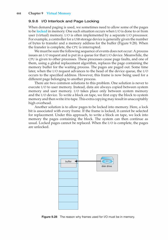
444 Chapter 9 Virtual Memory
9.9.6 I/O Interlock and Page Locking
When demand paging is used, we sometimes need to allow some of the pagesto be locked in memory. One such situation occurs when I/O is done to or fromuser (virtual) memory. I/O is often implemented by a separate I/O processor.For example, a controller for a USB storage device is generally given the numberof bytes to transfer and a memory address for the buffer (Figure 9.28). Whenthe transfer is complete, the CPU is interrupted.
We must be sure the following sequence of events does not occur: A processissues an I/O request and is put in a queue for that I/O device. Meanwhile, theCPU is given to other processes. These processes cause page faults, and one ofthem, using a global replacement algorithm, replaces the page containing thememory buffer for the waiting process. The pages are paged out. Some timelater, when the I/O request advances to the head of the device queue, the I/Ooccurs to the specified address. However, this frame is now being used for adifferent page belonging to another process.
There are two common solutions to this problem. One solution is never toexecute I/O to user memory. Instead, data are always copied between systemmemory and user memory. I/O takes place only between system memoryand the I/O device. To write a block on tape, we first copy the block to systemmemory and then write it to tape. This extra copying may result in unacceptablyhigh overhead.
Another solution is to allow pages to be locked into memory. Here, a lockbit is associated with every frame. If the frame is locked, it cannot be selectedfor replacement. Under this approach, to write a block on tape, we lock intomemory the pages containing the block. The system can then continue asusual. Locked pages cannot be replaced. When the I/O is complete, the pagesare unlocked.
buffer
disk drive
Figure 9.28 The reason why frames used for I/O must be in memory.
9.10 Operating-System Examples 445
Lock bits are used in various situations. Frequently, some or all of theoperating-system kernel is locked into memory. Many operating systemscannot tolerate a page fault caused by the kernel or by a specific kernel module,including the one performing memory management. User processes may alsoneed to lock pages into memory. A database process may want to managea chunk of memory, for example, moving blocks between disk and memoryitself because it has the best knowledge of how it is going to use its data. Suchpinning of pages in memory is fairly common, and most operating systemshave a system call allowing an application to request that a region of its logicaladdress space be pinned. Note that this feature could be abused and couldcause stress on the memory-management algorithms. Therefore, an applicationfrequently requires special privileges to make such a request.
Another use for a lock bit involves normal page replacement. Considerthe following sequence of events: A low-priority process faults. Selecting areplacement frame, the paging system reads the necessary page into memory.Ready to continue, the low-priority process enters the ready queue and waitsfor the CPU. Since it is a low-priority process, it may not be selected by theCPU scheduler for a time. While the low-priority process waits, a high-priorityprocess faults. Looking for a replacement, the paging system sees a page thatis in memory but has not been referenced or modified: it is the page that thelow-priority process just brought in. This page looks like a perfect replacement:it is clean and will not need to be written out, and it apparently has not beenused for a long time.
Whether the high-priority process should be able to replace the low-priorityprocess is a policy decision. After all, we are simply delaying the low-priorityprocess for the benefit of the high-priority process. However, we are wastingthe effort spent to bring in the page for the low-priority process. If we decideto prevent replacement of a newly brought-in page until it can be used at leastonce, then we can use the lock bit to implement this mechanism. When a pageis selected for replacement, its lock bit is turned on. It remains on until thefaulting process is again dispatched.
Using a lock bit can be dangerous: the lock bit may get turned on butnever turned off. Should this situation occur (because of a bug in the operatingsystem, for example), the locked frame becomes unusable. On a single-usersystem, the overuse of locking would hurt only the user doing the locking.Multiuser systems must be less trusting of users. For instance, Solaris allowslocking “hints,” but it is free to disregard these hints if the free-frame poolbecomes too small or if an individual process requests that too many pages belocked in memory.
9.10 Operating-System Examples
In this section, we describe how Windows and Solaris implement virtualmemory.
9.10.1 Windows
Windows implements virtual memory using demand paging with clustering.Clustering handles page faults by bringing in not only the faulting page but also
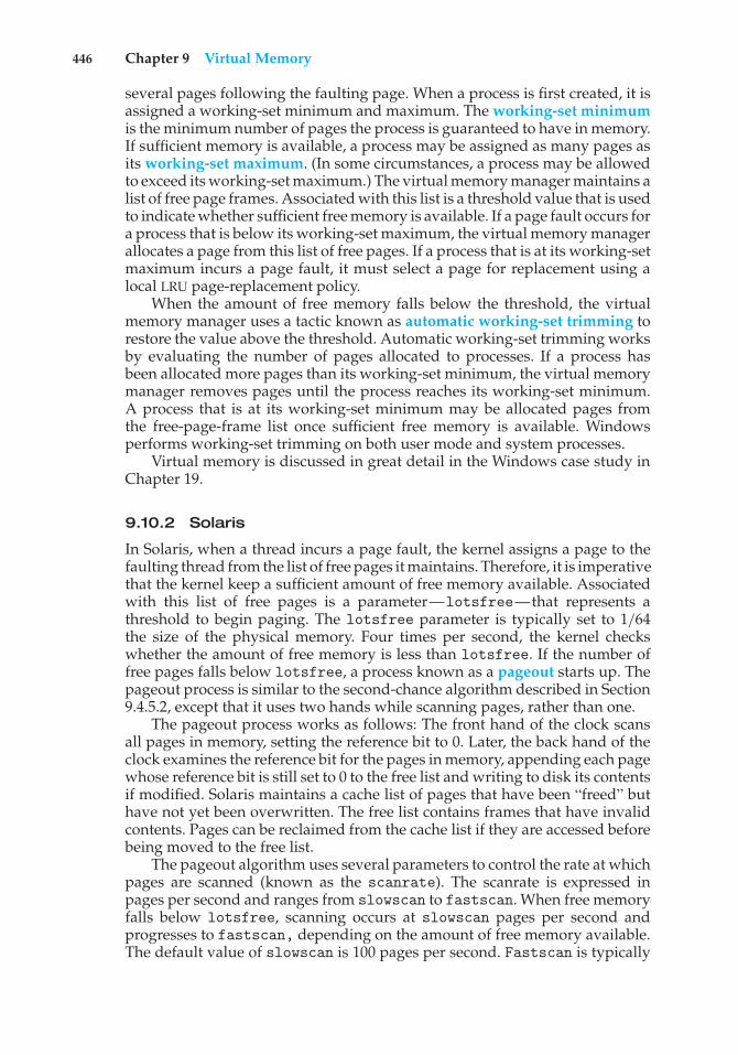
446 Chapter 9 Virtual Memory
several pages following the faulting page. When a process is first created, it isassigned a working-set minimum and maximum. The working-set minimumis the minimum number of pages the process is guaranteed to have in memory.If sufficient memory is available, a process may be assigned as many pages asits working-set maximum. (In some circumstances, a process may be allowedto exceed its working-set maximum.) The virtual memory manager maintains alist of free page frames. Associated with this list is a threshold value that is usedto indicate whether sufficient free memory is available. If a page fault occurs fora process that is below its working-set maximum, the virtual memory managerallocates a page from this list of free pages. If a process that is at its working-setmaximum incurs a page fault, it must select a page for replacement using alocal LRU page-replacement policy.
When the amount of free memory falls below the threshold, the virtualmemory manager uses a tactic known as automatic working-set trimming torestore the value above the threshold. Automatic working-set trimming worksby evaluating the number of pages allocated to processes. If a process hasbeen allocated more pages than its working-set minimum, the virtual memorymanager removes pages until the process reaches its working-set minimum.A process that is at its working-set minimum may be allocated pages fromthe free-page-frame list once sufficient free memory is available. Windowsperforms working-set trimming on both user mode and system processes.
Virtual memory is discussed in great detail in the Windows case study inChapter 19.
9.10.2 Solaris
In Solaris, when a thread incurs a page fault, the kernel assigns a page to thefaulting thread from the list of free pages it maintains. Therefore, it is imperativethat the kernel keep a sufficient amount of free memory available. Associatedwith this list of free pages is a parameter—lotsfree—that represents athreshold to begin paging. The lotsfree parameter is typically set to 1/64the size of the physical memory. Four times per second, the kernel checkswhether the amount of free memory is less than lotsfree. If the number offree pages falls below lotsfree, a process known as a pageout starts up. Thepageout process is similar to the second-chance algorithm described in Section9.4.5.2, except that it uses two hands while scanning pages, rather than one.
The pageout process works as follows: The front hand of the clock scansall pages in memory, setting the reference bit to 0. Later, the back hand of theclock examines the reference bit for the pages in memory, appending each pagewhose reference bit is still set to 0 to the free list and writing to disk its contentsif modified. Solaris maintains a cache list of pages that have been “freed” buthave not yet been overwritten. The free list contains frames that have invalidcontents. Pages can be reclaimed from the cache list if they are accessed beforebeing moved to the free list.
The pageout algorithm uses several parameters to control the rate at whichpages are scanned (known as the scanrate). The scanrate is expressed inpages per second and ranges from slowscan to fastscan. When free memoryfalls below lotsfree, scanning occurs at slowscan pages per second andprogresses to fastscan, depending on the amount of free memory available.The default value of slowscan is 100 pages per second. Fastscan is typically
9.10 Operating-System Examples 447
set to the value (total physical pages)/2 pages per second, with a maximum of8,192 pages per second. This is shown in Figure 9.29 (with fastscan set to themaximum).
The distance (in pages) between the hands of the clock is determinedby a system parameter, handspread. The amount of time between the fronthand’s clearing a bit and the back hand’s investigating its value depends onthe scanrate and the handspread. If scanrate is 100 pages per second andhandspread is 1,024 pages, 10 seconds can pass between the time a bit is set bythe front hand and the time it is checked by the back hand. However, becauseof the demands placed on the memory system, a scanrate of several thousandis not uncommon. This means that the amount of time between clearing andinvestigating a bit is often a few seconds.
As mentioned above, the pageout process checks memory four times persecond. However, if free memory falls below the value ofdesfree (Figure 9.29),pageout will run a hundred times per second with the intention of keeping atleast desfree free memory available. If the pageout process is unable to keepthe amount of free memory at desfree for a 30-second average, the kernelbegins swapping processes, thereby freeing all pages allocated to swappedprocesses. In general, the kernel looks for processes that have been idle forlong periods of time. If the system is unable to maintain the amount of freememory at minfree, the pageout process is called for every request for a newpage.
Recent releases of the Solaris kernel have provided enhancements ofthe paging algorithm. One such enhancement involves recognizing pagesfrom shared libraries. Pages belonging to libraries that are being shared byseveral processes—even if they are eligible to be claimed by the scanner—are skipped during the page-scanning process. Another enhancement concerns
minfree
scan
rat
e
100 slowscan
8192 fastscan
desfreeamount of free memory
lotsfree
Figure 9.29 Solaris page scanner.
448 Chapter 9 Virtual Memory
distinguishing pages that have been allocated to processes from pages allocatedto regular files. This is known as priority paging and is covered in Section 12.6.2.
9.11 Summary
It is desirable to be able to execute a process whose logical address space islarger than the available physical address space. Virtual memory is a techniquethat enables us to map a large logical address space onto a smaller physicalmemory. Virtual memory allows us to run extremely large processes and toraise the degree of multiprogramming, increasing CPU utilization. Further, itfrees application programmers from worrying about memory availability. Inaddition, with virtual memory, several processes can share system librariesand memory. With virtual memory, we can also use an efficient type of processcreation known as copy-on-write, wherein parent and child processes shareactual pages of memory.
Virtual memory is commonly implemented by demand paging. Puredemand paging never brings in a page until that page is referenced. The firstreference causes a page fault to the operating system. The operating-systemkernel consults an internal table to determine where the page is located on thebacking store. It then finds a free frame and reads the page in from the backingstore. The page table is updated to reflect this change, and the instruction thatcaused the page fault is restarted. This approach allows a process to run eventhough its entire memory image is not in main memory at once. As long as thepage-fault rate is reasonably low, performance is acceptable.
We can use demand paging to reduce the number of frames allocated toa process. This arrangement can increase the degree of multiprogramming(allowing more processes to be available for execution at one time) and—intheory, at least—the CPU utilization of the system. It also allows processesto be run even though their memory requirements exceed the total availablephysical memory. Such processes run in virtual memory.
If total memory requirements exceed the capacity of physical memory,then it may be necessary to replace pages from memory to free frames fornew pages. Various page-replacement algorithms are used. FIFO page replace-ment is easy to program but suffers from Belady’s anomaly. Optimal pagereplacement requires future knowledge. LRU replacement is an approxima-tion of optimal page replacement, but even it may be difficult to implement.Most page-replacement algorithms, such as the second-chance algorithm, areapproximations of LRU replacement.
In addition to a page-replacement algorithm, a frame-allocation policyis needed. Allocation can be fixed, suggesting local page replacement, ordynamic, suggesting global replacement. The working-set model assumes thatprocesses execute in localities. The working set is the set of pages in the currentlocality. Accordingly, each process should be allocated enough frames for itscurrent working set. If a process does not have enough memory for its workingset, it will thrash. Providing enough frames to each process to avoid thrashingmay require process swapping and scheduling.
Most operating systems provide features for memory mapping files, thusallowing file I/O to be treated as routine memory access. The Win32 APIimplements shared memory through memory mapping of files.
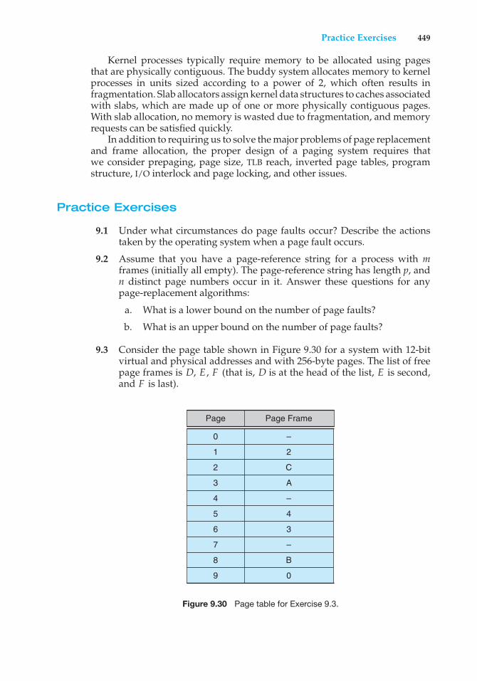
Practice Exercises 449
Kernel processes typically require memory to be allocated using pagesthat are physically contiguous. The buddy system allocates memory to kernelprocesses in units sized according to a power of 2, which often results infragmentation. Slab allocators assign kernel data structures to caches associatedwith slabs, which are made up of one or more physically contiguous pages.With slab allocation, no memory is wasted due to fragmentation, and memoryrequests can be satisfied quickly.
In addition to requiring us to solve the major problems of page replacementand frame allocation, the proper design of a paging system requires thatwe consider prepaging, page size, TLB reach, inverted page tables, programstructure, I/O interlock and page locking, and other issues.
Practice Exercises
9.1 Under what circumstances do page faults occur? Describe the actionstaken by the operating system when a page fault occurs.
9.2 Assume that you have a page-reference string for a process with mframes (initially all empty). The page-reference string has length p, andn distinct page numbers occur in it. Answer these questions for anypage-replacement algorithms:
a. What is a lower bound on the number of page faults?
b. What is an upper bound on the number of page faults?
9.3 Consider the page table shown in Figure 9.30 for a system with 12-bitvirtual and physical addresses and with 256-byte pages. The list of freepage frames is D, E , F (that is, D is at the head of the list, E is second,and F is last).
Page Page Frame
0
1
2
3
4
5
–
2
C
A
–
4
6 3
7 –
8 B
9 0
Figure 9.30 Page table for Exercise 9.3.
450 Chapter 9 Virtual Memory
Convert the following virtual addresses to their equivalent physicaladdresses in hexadecimal. All numbers are given in hexadecimal. (Adash for a page frame indicates that the page is not in memory.)
• 9EF
• 111
• 700
• 0FF
9.4 Consider the following page-replacement algorithms. Rank these algo-rithms on a five-point scale from “bad” to “perfect” according to theirpage-fault rate. Separate those algorithms that suffer from Belady’sanomaly from those that do not.
a. LRU replacement
b. FIFO replacement
c. Optimal replacement
d. Second-chance replacement
9.5 Discuss the hardware support required to support demand paging.
9.6 An operating system supports a paged virtual memory. The centralprocessor has a cycle time of 1 microsecond. It costs an additional 1microsecond to access a page other than the current one. Pages have 1,000words, and the paging device is a drum that rotates at 3,000 revolutionsper minute and transfers 1 million words per second. The followingstatistical measurements were obtained from the system:
• One percent of all instructions executed accessed a page other thanthe current page.
• Of the instructions that accessed another page, 80 percent accesseda page already in memory.
• When a new page was required, the replaced page was modified 50percent of the time.
Calculate the effective instruction time on this system, assuming that thesystem is running one process only and that the processor is idle duringdrum transfers.
9.7 Consider the two-dimensional array A:
int A[][] = new int[100][100];
where A[0][0] is at location 200 in a paged memory system with pagesof size 200. A small process that manipulates the matrix resides in page0 (locations 0 to 199). Thus, every instruction fetch will be from page 0.
For three page frames, how many page faults are generated by thefollowing array-initialization loops? Use LRU replacement, and assume
Practice Exercises 451
that page frame 1 contains the process and the other two are initiallyempty.
a. for (int j = 0; j < 100; j++)for (int i = 0; i < 100; i++)
A[i][j] = 0;
b. for (int i = 0; i < 100; i++)for (int j = 0; j < 100; j++)
A[i][j] = 0;
9.8 Consider the following page reference string:
1, 2, 3, 4, 2, 1, 5, 6, 2, 1, 2, 3, 7, 6, 3, 2, 1, 2, 3, 6.
How many page faults would occur for the following replacementalgorithms, assuming one, two, three, four, five, six, and seven frames?Remember that all frames are initially empty, so your first unique pageswill cost one fault each.
• LRU replacement
• FIFO replacement
• Optimal replacement
9.9 Suppose that you want to use a paging algorithm that requires a referencebit (such as second-chance replacement or working-set model), butthe hardware does not provide one. Sketch how you could simulate areference bit even if one were not provided by the hardware, or explainwhy it is not possible to do so. If it is possible, calculate what the costwould be.
9.10 You have devised a new page-replacement algorithm that you think maybe optimal. In some contorted test cases, Belady’s anomaly occurs. Is thenew algorithm optimal? Explain your answer.
9.11 Segmentation is similar to paging but uses variable-sized “pages.” Definetwo segment-replacement algorithms, one based on the FIFO page-replacement scheme and the other on the LRU page-replacement scheme.Remember that since segments are not the same size, the segment thatis chosen for replacement may be too small to leave enough consecutivelocations for the needed segment. Consider strategies for systems wheresegments cannot be relocated and strategies for systems where they can.
9.12 Consider a demand-paged computer system where the degree of mul-tiprogramming is currently fixed at four. The system was recentlymeasured to determine utilization of the CPU and the paging disk. Threealternative results are shown below. For each case, what is happening?Can the degree of multiprogramming be increased to increase the CPUutilization? Is the paging helping?
a. CPU utilization 13 percent; disk utilization 97 percent
b. CPU utilization 87 percent; disk utilization 3 percent
c. CPU utilization 13 percent; disk utilization 3 percent
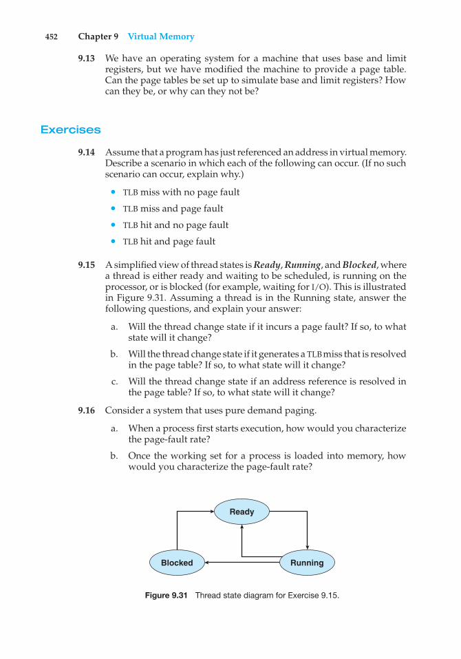
452 Chapter 9 Virtual Memory
9.13 We have an operating system for a machine that uses base and limitregisters, but we have modified the machine to provide a page table.Can the page tables be set up to simulate base and limit registers? Howcan they be, or why can they not be?
Exercises
9.14 Assume that a program has just referenced an address in virtual memory.Describe a scenario in which each of the following can occur. (If no suchscenario can occur, explain why.)
• TLB miss with no page fault
• TLB miss and page fault
• TLB hit and no page fault
• TLB hit and page fault
9.15 A simplified view of thread states is Ready, Running, and Blocked, wherea thread is either ready and waiting to be scheduled, is running on theprocessor, or is blocked (for example, waiting for I/O). This is illustratedin Figure 9.31. Assuming a thread is in the Running state, answer thefollowing questions, and explain your answer:
a. Will the thread change state if it incurs a page fault? If so, to whatstate will it change?
b. Will the thread change state if it generates a TLB miss that is resolvedin the page table? If so, to what state will it change?
c. Will the thread change state if an address reference is resolved inthe page table? If so, to what state will it change?
9.16 Consider a system that uses pure demand paging.
a. When a process first starts execution, how would you characterizethe page-fault rate?
b. Once the working set for a process is loaded into memory, howwould you characterize the page-fault rate?
Ready
Blocked Running
Figure 9.31 Thread state diagram for Exercise 9.15.
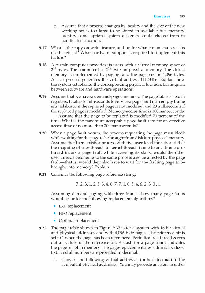
Exercises 453
c. Assume that a process changes its locality and the size of the newworking set is too large to be stored in available free memory.Identify some options system designers could choose from tohandle this situation.
9.17 What is the copy-on-write feature, and under what circumstances is itsuse beneficial? What hardware support is required to implement thisfeature?
9.18 A certain computer provides its users with a virtual memory space of232 bytes. The computer has 222 bytes of physical memory. The virtualmemory is implemented by paging, and the page size is 4,096 bytes.A user process generates the virtual address 11123456. Explain howthe system establishes the corresponding physical location. Distinguishbetween software and hardware operations.
9.19 Assume that we have a demand-paged memory. The page table is held inregisters. It takes 8 milliseconds to service a page fault if an empty frameis available or if the replaced page is not modified and 20 milliseconds ifthe replaced page is modified. Memory-access time is 100 nanoseconds.
Assume that the page to be replaced is modified 70 percent of thetime. What is the maximum acceptable page-fault rate for an effectiveaccess time of no more than 200 nanoseconds?
9.20 When a page fault occurs, the process requesting the page must blockwhile waiting for the page to be brought from disk into physical memory.Assume that there exists a process with five user-level threads and thatthe mapping of user threads to kernel threads is one to one. If one userthread incurs a page fault while accessing its stack, would the otheruser threads belonging to the same process also be affected by the pagefault—that is, would they also have to wait for the faulting page to bebrought into memory? Explain.
9.21 Consider the following page reference string:
7, 2, 3, 1, 2, 5, 3, 4, 6, 7, 7, 1, 0, 5, 4, 6, 2, 3, 0 , 1.
Assuming demand paging with three frames, how many page faultswould occur for the following replacement algorithms?
• LRU replacement
• FIFO replacement
• Optimal replacement
9.22 The page table shown in Figure 9.32 is for a system with 16-bit virtualand physical addresses and with 4,096-byte pages. The reference bit isset to 1 when the page has been referenced. Periodically, a thread zeroesout all values of the reference bit. A dash for a page frame indicatesthe page is not in memory. The page-replacement algorithm is localizedLRU, and all numbers are provided in decimal.
a. Convert the following virtual addresses (in hexadecimal) to theequivalent physical addresses. You may provide answers in either
454 Chapter 9 Virtual Memory
Page Page Frame Reference Bit
0 9 01 1 02 14 03 10 04 – 05 13 06 8 07 15 08 – 09 0 0
10 5 011 4 012 – 013 – 014 3 015 2 0
Figure 9.32 Page table for Exercise 9.22.
hexadecimal or decimal. Also set the reference bit for the appro-priate entry in the page table.
• 0xE12C
• 0x3A9D
• 0xA9D9
• 0x7001
• 0xACA1
b. Using the above addresses as a guide, provide an example of alogical address (in hexadecimal) that results in a page fault.
c. From what set of page frames will the LRU page-replacementalgorithm choose in resolving a page fault?
9.23 Assume that you are monitoring the rate at which the pointer in theclock algorithm moves. (The pointer indicates the candidate page forreplacement.) What can you say about the system if you notice thefollowing behavior:
a. Pointer is moving fast.
b. Pointer is moving slow.
9.24 Discuss situations in which the least frequently used (LFU) page-replacement algorithm generates fewer page faults than the least recentlyused (LRU) page-replacement algorithm. Also discuss under what cir-cumstances the opposite holds.
9.25 Discuss situations in which the most frequently used (MFU) page-replacement algorithm generates fewer page faults than the least recentlyused (LRU) page-replacement algorithm. Also discuss under what cir-cumstances the opposite holds.
Exercises 455
9.26 The VAX/VMS system uses a FIFO replacement algorithm for residentpages and a free-frame pool of recently used pages. Assume that thefree-frame pool is managed using the LRU replacement policy. Answerthe following questions:
a. If a page fault occurs and the page does not exist in the free-framepool, how is free space generated for the newly requested page?
b. If a page fault occurs and the page exists in the free-frame pool,how is the resident page set and the free-frame pool managed tomake space for the requested page?
c. What does the system degenerate to if the number of resident pagesis set to one?
d. What does the system degenerate to if the number of pages in thefree-frame pool is zero?
9.27 Consider a demand-paging system with the following time-measuredutilizations:
CPU utilization 20%Paging disk 97.7%Other I/O devices 5%
For each of the following, indicate whether it will (or is likely to) improveCPU utilization. Explain your answers.
a. Install a faster CPU.
b. Install a bigger paging disk.
c. Increase the degree of multiprogramming.
d. Decrease the degree of multiprogramming.
e. Install more main memory.
f. Install a faster hard disk or multiple controllers with multiple harddisks.
g. Add prepaging to the page-fetch algorithms.
h. Increase the page size.
9.28 Suppose that a machine provides instructions that can access memorylocations using the one-level indirect addressing scheme. What sequenceof page faults is incurred when all of the pages of a program arecurrently nonresident and the first instruction of the program is anindirect memory-load operation? What happens when the operatingsystem is using a per-process frame allocation technique and only twopages are allocated to this process?
9.29 Suppose that your replacement policy (in a paged system) is to examineeach page regularly and to discard that page if it has not been used sincethe last examination. What would you gain and what would you loseby using this policy rather than LRU or second-chance replacement?
456 Chapter 9 Virtual Memory
9.30 A page-replacement algorithm should minimize the number of pagefaults. We can achieve this minimization by distributing heavily usedpages evenly over all of memory, rather than having them compete fora small number of page frames. We can associate with each page framea counter of the number of pages associated with that frame. Then,to replace a page, we can search for the page frame with the smallestcounter.
a. Define a page-replacement algorithm using this basic idea. Specif-ically address these problems:
i. What is the initial value of the counters?ii. When are counters increased?
iii. When are counters decreased?iv. How is the page to be replaced selected?
b. How many page faults occur for your algorithm for the followingreference string with four page frames?
1, 2, 3, 4, 5, 3, 4, 1, 6, 7, 8, 7, 8, 9, 7, 8, 9, 5, 4, 5, 4, 2.
c. What is the minimum number of page faults for an optimal page-replacement strategy for the reference string in part b with fourpage frames?
9.31 Consider a demand-paging system with a paging disk that has anaverage access and transfer time of 20 milliseconds. Addresses aretranslated through a page table in main memory, with an access time of 1microsecond per memory access. Thus, each memory reference throughthe page table takes two accesses. To improve this time, we have addedan associative memory that reduces access time to one memory referenceif the page-table entry is in the associative memory.
Assume that 80 percent of the accesses are in the associative memoryand that, of those remaining, 10 percent (or 2 percent of the total) causepage faults. What is the effective memory access time?
9.32 What is the cause of thrashing? How does the system detect thrashing?Once it detects thrashing, what can the system do to eliminate thisproblem?
9.33 Is it possible for a process to have two working sets, one representingdata and another representing code? Explain.
9.34 Consider the parameter ! used to define the working-set window in theworking-set model. When ! is set to a small value, what is the effecton the page-fault frequency and the number of active (nonsuspended)processes currently executing in the system? What is the effect when !is set to a very high value?
9.35 In a 1,024-KB segment, memory is allocated using the buddy system.Using Figure 9.26 as a guide, draw a tree illustrating how the followingmemory requests are allocated:
• Request 6-KB
Programming Problems 457
• Request 250 bytes
• Request 900 bytes
• Request 1,500 bytes
• Request 7-KB
Next, modify the tree for the following releases of memory. Performcoalescing whenever possible:
• Release 250 bytes
• Release 900 bytes
• Release 1,500 bytes
9.36 A system provides support for user-level and kernel-level threads. Themapping in this system is one to one (there is a corresponding kernelthread for each user thread). Does a multithreaded process consist of (a)a working set for the entire process or (b) a working set for each thread?Explain
9.37 The slab-allocation algorithm uses a separate cache for each differentobject type. Assuming there is one cache per object type, explain whythis scheme doesn’t scale well with multiple CPUs. What could be doneto address this scalability issue?
9.38 Consider a system that allocates pages of different sizes to its processes.What are the advantages of such a paging scheme? What modificationsto the virtual memory system provide this functionality?
Programming Problems
9.39 Write a program that implements the FIFO, LRU, and optimal page-replacement algorithms presented in this chapter. First, generate arandom page-reference string where page numbers range from 0 to 9.Apply the random page-reference string to each algorithm, and recordthe number of page faults incurred by each algorithm. Implement thereplacement algorithms so that the number of page frames can vary from1 to 7. Assume that demand paging is used.
9.40 Repeat Exercise 3.22, this time using Windows shared memory. In partic-ular, using the producer—consumer strategy, design two programs thatcommunicate with shared memory using the Windows API as outlinedin Section 9.7.2. The producer will generate the numbers specified inthe Collatz conjecture and write them to a shared memory object. Theconsumer will then read and output the sequence of numbers fromshared memory.
In this instance, the producer will be passed an integer parameteron the command line specifying how many numbers to produce (forexample, providing 5 on the command line means the producer processwill generate the first five numbers).
458 Chapter 9 Virtual Memory
Programming Projects
Designing a Virtual Memory ManagerThis project consists of writing a program that translates logical to physicaladdresses for a virtual address space of size 216 = 65,536 bytes. Your programwill read from a file containing logical addresses and, using a TLB as well asa page table, will translate each logical address to its corresponding physicaladdress and output the value of the byte stored at the translated physicaladdress. The goal behind this project is to simulate the steps involved intranslating logical to physical addresses.
Specifics
Your program will read a file containing several 32-bit integer numbers thatrepresent logical addresses. However, you need only be concerned with 16-bitaddresses, so you must mask the rightmost 16 bits of each logical address.These 16 bits are divided into (1) an 8-bit page number and (2) 8-bit page offset.Hence, the addresses are structured as shown in Figure 9.33.
Other specifics include the following:
• 28 entries in the page table
• Page size of 28 bytes
• 16 entries in the TLB
• Frame size of 28 bytes
• 256 frames
• Physical memory of 65,536 bytes (256 frames × 256-byte frame size)
Additionally, your program need only be concerned with reading logicaladdresses and translating them to their corresponding physical addresses. Youdo not need to support writing to the logical address space.
Address Translation
Your program will translate logical to physical addresses using a TLB and pagetable as outlined in Section 8.5. First, the page number is extracted from thelogical address, and the TLB is consulted. In the case of a TLB-hit, the framenumber is obtained from the TLB. In the case of a TLB-miss, the page tablemust be consulted. In the latter case, either the frame number is obtained
offset
078151631
page number
Figure 9.33 Address structure.
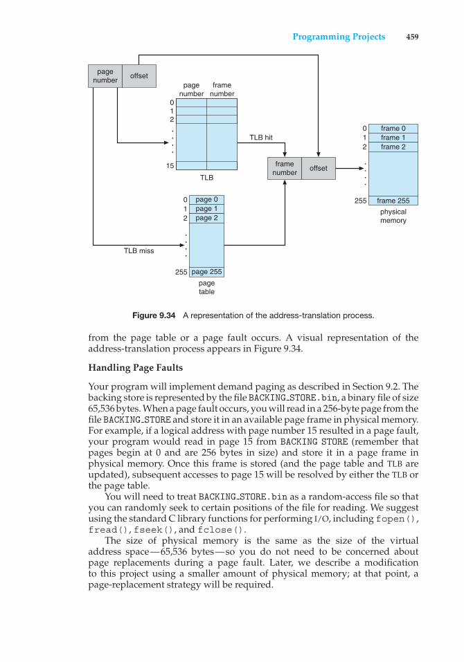
Programming Projects 459
pagenumber
012
15
012
255
TLB
pagetable
TLB hit
TLB miss
page 0
page 255
page 1page 2
framenumber
.
.
.
.
.
.
.
.
012
255physicalmemory
frame 0
frame 255
frame 1frame 2
.
.
.
.
pagenumber offset
framenumber offset
Figure 9.34 A representation of the address-translation process.
from the page table or a page fault occurs. A visual representation of theaddress-translation process appears in Figure 9.34.
Handling Page Faults
Your program will implement demand paging as described in Section 9.2. Thebacking store is represented by the file BACKING STORE.bin, a binary file of size65,536 bytes. When a page fault occurs, you will read in a 256-byte page from thefile BACKING STORE and store it in an available page frame in physical memory.For example, if a logical address with page number 15 resulted in a page fault,your program would read in page 15 from BACKING STORE (remember thatpages begin at 0 and are 256 bytes in size) and store it in a page frame inphysical memory. Once this frame is stored (and the page table and TLB areupdated), subsequent accesses to page 15 will be resolved by either the TLB orthe page table.
You will need to treat BACKING STORE.bin as a random-access file so thatyou can randomly seek to certain positions of the file for reading. We suggestusing the standard C library functions for performing I/O, including fopen(),fread(), fseek(), and fclose().
The size of physical memory is the same as the size of the virtualaddress space—65,536 bytes—so you do not need to be concerned aboutpage replacements during a page fault. Later, we describe a modificationto this project using a smaller amount of physical memory; at that point, apage-replacement strategy will be required.
460 Chapter 9 Virtual Memory
Test File
We provide the file addresses.txt, which contains integer values represent-ing logical addresses ranging from 0 − 65535 (the size of the virtual addressspace). Your program will open this file, read each logical address and translateit to its corresponding physical address, and output the value of the signed byteat the physical address.
How to Begin
First, write a simple program that extracts the page number and offset (basedon Figure 9.33) from the following integer numbers:
1, 256, 32768, 32769, 128, 65534, 33153
Perhaps the easiest way to do this is by using the operators for bit-maskingand bit-shifting. Once you can correctly establish the page number and offsetfrom an integer number, you are ready to begin.
Initially, we suggest that you bypass the TLB and use only a page table. Youcan integrate the TLB once your page table is working properly. Remember,address translation can work without a TLB; the TLB just makes it faster. Whenyou are ready to implement the TLB, recall that it has only 16 entries, so youwill need to use a replacement strategy when you update a full TLB. You mayuse either a FIFO or an LRU policy for updating your TLB.
How to Run Your Program
Your program should run as follows:
./a.out addresses.txt
Your program will read in the file addresses.txt, which contains 1,000 logicaladdresses ranging from 0 to 65535. Your program is to translate each logicaladdress to a physical address and determine the contents of the signed bytestored at the correct physical address. (Recall that in the C language, the chardata type occupies a byte of storage, so we suggest using char values.)
Your program is to output the following values:
1. The logical address being translated (the integer value being read fromaddresses.txt).
2. The corresponding physical address (what your program translates thelogical address to).
3. The signed byte value stored at the translated physical address.
We also provide the file correct.txt, which contains the correct outputvalues for the file addresses.txt. You should use this file to determine if yourprogram is correctly translating logical to physical addresses.
Statistics
After completion, your program is to report the following statistics:
Bibliographical Notes 461
1. Page-fault rate—The percentage of address references that resulted inpage faults.
2. TLB hit rate—The percentage of address references that were resolved inthe TLB.
Since the logical addresses in addresses.txt were generated randomlyand do not reflect any memory access locality, do not expect to have a high TLBhit rate.
Modifications
This project assumes that physical memory is the same size as the virtualaddress space. In practice, physical memory is typically much smaller than avirtual address space. A suggested modification is to use a smaller physicaladdress space. We recommend using 128 page frames rather than 256. Thischange will require modifying your program so that it keeps track of free pageframes as well as implementing a page-replacement policy using either FIFOor LRU (Section 9.4).
Bibliographical Notes
Demand paging was first used in the Atlas system, implemented on theManchester University MUSE computer around 1960 ([Kilburn et al. (1961)]).Another early demand-paging system was MULTICS, implemented on the GE645 system ([Organick (1972)]). Virtual memory was added to Unix in 1979[Babaoglu and Joy (1981)]
[Belady et al. (1969)] were the first researchers to observe that the FIFOreplacement strategy may produce the anomaly that bears Belady’s name.[Mattson et al. (1970)] demonstrated that stack algorithms are not subject toBelady’s anomaly.
The optimal replacement algorithm was presented by [Belady (1966)]and was proved to be optimal by [Mattson et al. (1970)]. Belady’s optimalalgorithm is for a fixed allocation; [Prieve and Fabry (1976)] presented anoptimal algorithm for situations in which the allocation can vary.
The enhanced clock algorithm was discussed by [Carr and Hennessy(1981)].
The working-set model was developed by [Denning (1968)]. Discussionsconcerning the working-set model were presented by [Denning (1980)].
The scheme for monitoring the page-fault rate was developed by [Wulf(1969)], who successfully applied this technique to the Burroughs B5500computer system.
Buddy system memory allocators were described in [Knowlton (1965)],[Peterson and Norman (1977)], and [Purdom, Jr. and Stigler (1970)]. [Bonwick(1994)] discussed the slab allocator, and [Bonwick and Adams (2001)] extendedthe discussion to multiple processors. Other memory-fitting algorithms can befound in [Stephenson (1983)], [Bays (1977)], and [Brent (1989)]. A survey ofmemory-allocation strategies can be found in [Wilson et al. (1995)].
[Solomon and Russinovich (2000)] and [Russinovich and Solomon (2005)]described how Windows implements virtual memory. [McDougall and Mauro
462 Chapter 9 Virtual Memory
(2007)] discussed virtual memory in Solaris. Virtual memory techniques inLinux and FreeBSD were described by [Love (2010)] and [McKusick andNeville-Neil (2005)], respectively. [Ganapathy and Schimmel (1998)] and[Navarro et al. (2002)] discussed operating system support for multiple pagesizes.
Bibliography
[Babaoglu and Joy (1981)] O. Babaoglu and W. Joy, “Converting a Swap-BasedSystem to Do Paging in an Architecture Lacking Page-Reference Bits”, Pro-ceedings of the ACM Symposium on Operating Systems Principles (1981), pages78–86.
[Bays (1977)] C. Bays, “A Comparison of Next-Fit, First-Fit and Best-Fit”, Com-munications of the ACM, Volume 20, Number 3 (1977), pages 191–192.
[Belady (1966)] L. A. Belady, “A Study of Replacement Algorithms for a Virtu-al-Storage Computer”, IBM Systems Journal, Volume 5, Number 2 (1966), pages78–101.
[Belady et al. (1969)] L. A. Belady, R. A. Nelson, and G. S. Shedler, “An Anomalyin Space-Time Characteristics of Certain Programs Running in a PagingMachine”, Communications of the ACM, Volume 12, Number 6 (1969), pages349–353.
[Bonwick (1994)] J. Bonwick, “The Slab Allocator: An Object-Caching KernelMemory Allocator”, USENIX Summer (1994), pages 87–98.
[Bonwick and Adams (2001)] J. Bonwick and J. Adams, “Magazines and Vmem:Extending the Slab Allocator to Many CPUs and Arbitrary Resources”, Proceed-ings of the 2001 USENIX Annual Technical Conference (2001).
[Brent (1989)] R. Brent, “Efficient Implementation of the First-Fit Strategy forDynamic Storage Allocation”, ACM Transactions on Programming Languages andSystems, Volume 11, Number 3 (1989), pages 388–403.
[Carr and Hennessy (1981)] W. R. Carr and J. L. Hennessy, “WSClock—ASimple and Effective Algorithm for Virtual Memory Management”, Proceedingsof the ACM Symposium on Operating Systems Principles (1981), pages 87–95.
[Denning (1968)] P. J. Denning, “The Working Set Model for Program Behavior”,Communications of the ACM, Volume 11, Number 5 (1968), pages 323–333.
[Denning (1980)] P. J. Denning, “Working Sets Past and Present”, IEEE Transac-tions on Software Engineering, Volume SE-6, Number 1 (1980), pages 64–84.
[Ganapathy and Schimmel (1998)] N. Ganapathy and C. Schimmel, “GeneralPurpose Operating System Support for Multiple Page Sizes”, Proceedings of theUSENIX Technical Conference (1998).
[Kilburn et al. (1961)] T. Kilburn, D. J. Howarth, R. B. Payne, and F. H. Sumner,“The Manchester University Atlas Operating System, Part I: Internal Organiza-tion”, Computer Journal, Volume 4, Number 3 (1961), pages 222–225.
Bibliography 463
[Knowlton (1965)] K. C. Knowlton, “A Fast Storage Allocator”, Communicationsof the ACM, Volume 8, Number 10 (1965), pages 623–624.
[Love (2010)] R. Love, Linux Kernel Development, Third Edition, Developer’sLibrary (2010).
[Mattson et al. (1970)] R. L. Mattson, J. Gecsei, D. R. Slutz, and I. L. Traiger,“Evaluation Techniques for Storage Hierarchies”, IBM Systems Journal, Volume9, Number 2 (1970), pages 78–117.
[McDougall and Mauro (2007)] R. McDougall and J. Mauro, Solaris Internals,Second Edition, Prentice Hall (2007).
[McKusick and Neville-Neil (2005)] M. K. McKusick and G. V. Neville-Neil,The Design and Implementation of the FreeBSD UNIX Operating System, AddisonWesley (2005).
[Navarro et al. (2002)] J. Navarro, S. Lyer, P. Druschel, and A. Cox, “Practical,Transparent Operating System Support for Superpages”, Proceedings of theUSENIX Symposium on Operating Systems Design and Implementation (2002).
[Organick (1972)] E. I. Organick, The Multics System: An Examination of ItsStructure, MIT Press (1972).
[Peterson and Norman (1977)] J. L. Peterson and T. A. Norman, “Buddy Sys-tems”, Communications of the ACM, Volume 20, Number 6 (1977), pages 421–431.
[Prieve and Fabry (1976)] B. G. Prieve and R. S. Fabry, “VMIN—An OptimalVariable Space Page-Replacement Algorithm”, Communications of the ACM,Volume 19, Number 5 (1976), pages 295–297.
[Purdom, Jr. and Stigler (1970)] P. W. Purdom, Jr. and S. M. Stigler, “StatisticalProperties of the Buddy System”, J. ACM, Volume 17, Number 4 (1970), pages683–697.
[Russinovich and Solomon (2005)] M. E. Russinovich and D. A. Solomon,Microsoft Windows Internals, Fourth Edition, Microsoft Press (2005).
[Solomon and Russinovich (2000)] D. A. Solomon and M. E. Russinovich, InsideMicrosoft Windows 2000, Third Edition, Microsoft Press (2000).
[Stephenson (1983)] C. J. Stephenson, “Fast Fits: A New Method for DynamicStorage Allocation”, Proceedings of the Ninth Symposium on Operating SystemsPrinciples (1983), pages 30–32.
[Wilson et al. (1995)] P. R. Wilson, M. S. Johnstone, M. Neely, and D. Boles,“Dynamic Storage Allocation: A Survey and Critical Review”, Proceedings of theInternational Workshop on Memory Management (1995), pages 1–116.
[Wulf (1969)] W. A. Wulf, “Performance Monitors for Multiprogramming Sys-tems”, Proceedings of the ACM Symposium on Operating Systems Principles (1969),pages 175–181.

Part Four
StorageManagement
Since main memory is usually too small to accommodate all the data andprograms permanently, the computer system must provide secondarystorage to back up main memory. Modern computer systems use disksas the primary on-line storage medium for information (both programsand data). The file system provides the mechanism for on-line storageof and access to both data and programs residing on the disks. A fileis a collection of related information defined by its creator. The files aremapped by the operating system onto physical devices. Files are normallyorganized into directories for ease of use.
The devices that attach to a computer vary in many aspects. Somedevices transfer a character or a block of characters at a time. Somecan be accessed only sequentially, others randomly. Some transferdata synchronously, others asynchronously. Some are dedicated, someshared. They can be read-only or read–write. They vary greatly in speed.In many ways, they are also the slowest major component of thecomputer.
Because of all this device variation, the operating system needs toprovide a wide range of functionality to applications, to allow them tocontrol all aspects of the devices. One key goal of an operating system’sI/O subsystem is to provide the simplest interface possible to the rest ofthe system. Because devices are a performance bottleneck, another keyis to optimize I/O for maximum concurrency.

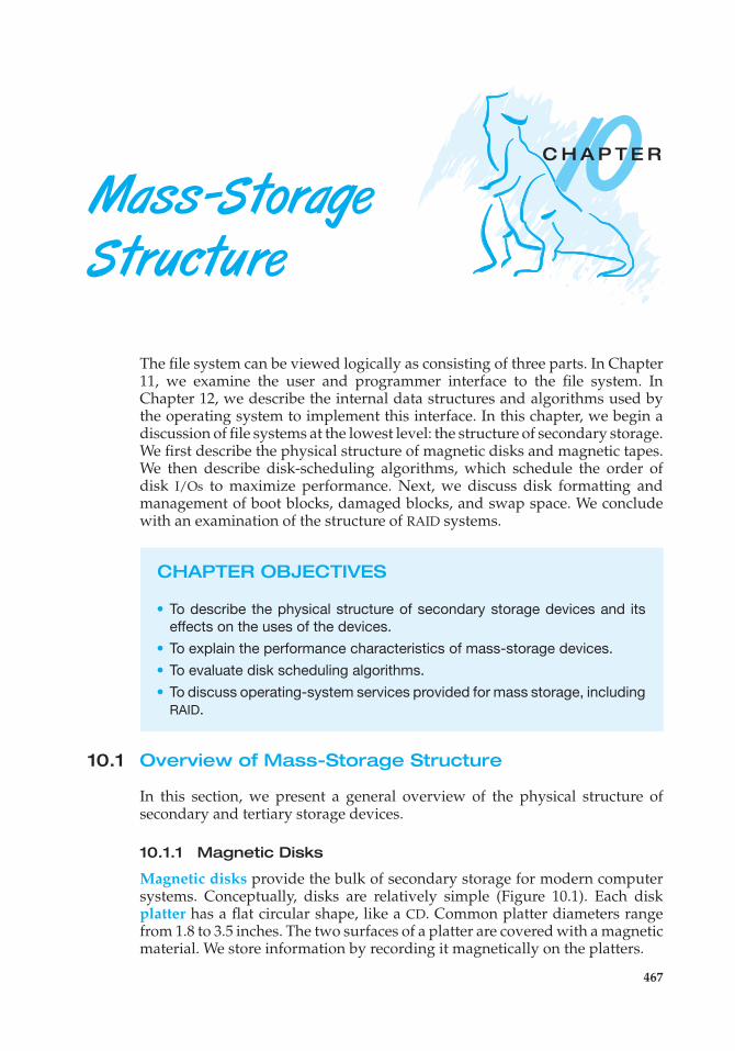
10C H A P T E R
Mass -StorageStructure
The file system can be viewed logically as consisting of three parts. In Chapter11, we examine the user and programmer interface to the file system. InChapter 12, we describe the internal data structures and algorithms used bythe operating system to implement this interface. In this chapter, we begin adiscussion of file systems at the lowest level: the structure of secondary storage.We first describe the physical structure of magnetic disks and magnetic tapes.We then describe disk-scheduling algorithms, which schedule the order ofdisk I/Os to maximize performance. Next, we discuss disk formatting andmanagement of boot blocks, damaged blocks, and swap space. We concludewith an examination of the structure of RAID systems.
CHAPTER OBJECTIVES
• To describe the physical structure of secondary storage devices and itseffects on the uses of the devices.
• To explain the performance characteristics of mass-storage devices.• To evaluate disk scheduling algorithms.• To discuss operating-system services provided for mass storage, including
RAID.
10.1 Overview of Mass-Storage Structure
In this section, we present a general overview of the physical structure ofsecondary and tertiary storage devices.
10.1.1 Magnetic Disks
Magnetic disks provide the bulk of secondary storage for modern computersystems. Conceptually, disks are relatively simple (Figure 10.1). Each diskplatter has a flat circular shape, like a CD. Common platter diameters rangefrom 1.8 to 3.5 inches. The two surfaces of a platter are covered with a magneticmaterial. We store information by recording it magnetically on the platters.
467
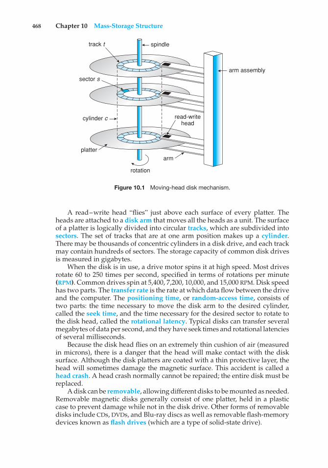
468 Chapter 10 Mass-Storage Structure
track t
sector s
spindle
cylinder c
platterarm
read-writehead
arm assembly
rotation
Figure 10.1 Moving-head disk mechanism.
A read–write head “flies” just above each surface of every platter. Theheads are attached to a disk arm that moves all the heads as a unit. The surfaceof a platter is logically divided into circular tracks, which are subdivided intosectors. The set of tracks that are at one arm position makes up a cylinder.There may be thousands of concentric cylinders in a disk drive, and each trackmay contain hundreds of sectors. The storage capacity of common disk drivesis measured in gigabytes.
When the disk is in use, a drive motor spins it at high speed. Most drivesrotate 60 to 250 times per second, specified in terms of rotations per minute(RPM). Common drives spin at 5,400, 7,200, 10,000, and 15,000 RPM. Disk speedhas two parts. The transfer rate is the rate at which data flow between the driveand the computer. The positioning time, or random-access time, consists oftwo parts: the time necessary to move the disk arm to the desired cylinder,called the seek time, and the time necessary for the desired sector to rotate tothe disk head, called the rotational latency. Typical disks can transfer severalmegabytes of data per second, and they have seek times and rotational latenciesof several milliseconds.
Because the disk head flies on an extremely thin cushion of air (measuredin microns), there is a danger that the head will make contact with the disksurface. Although the disk platters are coated with a thin protective layer, thehead will sometimes damage the magnetic surface. This accident is called ahead crash. A head crash normally cannot be repaired; the entire disk must bereplaced.
A disk can be removable, allowing different disks to be mounted as needed.Removable magnetic disks generally consist of one platter, held in a plasticcase to prevent damage while not in the disk drive. Other forms of removabledisks include CDs, DVDs, and Blu-ray discs as well as removable flash-memorydevices known as flash drives (which are a type of solid-state drive).
10.1 Overview of Mass-Storage Structure 469
A disk drive is attached to a computer by a set of wires called an I/Obus. Several kinds of buses are available, including advanced technologyattachment (ATA), serial ATA (SATA), eSATA, universal serial bus (USB), andfibre channel (FC). The data transfers on a bus are carried out by specialelectronic processors called controllers. The host controller is the controller atthe computer end of the bus. A disk controller is built into each disk drive. Toperform a disk I/O operation, the computer places a command into the hostcontroller, typically using memory-mapped I/O ports, as described in Section9.7.3. The host controller then sends the command via messages to the diskcontroller, and the disk controller operates the disk-drive hardware to carryout the command. Disk controllers usually have a built-in cache. Data transferat the disk drive happens between the cache and the disk surface, and datatransfer to the host, at fast electronic speeds, occurs between the cache and thehost controller.
10.1.2 Solid-State Disks
Sometimes old technologies are used in new ways as economics change orthe technologies evolve. An example is the growing importance of solid-statedisks, or SSDs. Simply described, an SSD is nonvolatile memory that is used likea hard drive. There are many variations of this technology, from DRAM with abattery to allow it to maintain its state in a power failure through flash-memorytechnologies like single-level cell (SLC) and multilevel cell (MLC) chips.
SSDs have the same characteristics as traditional hard disks but can be morereliable because they have no moving parts and faster because they have noseek time or latency. In addition, they consume less power. However, they aremore expensive per megabyte than traditional hard disks, have less capacitythan the larger hard disks, and may have shorter life spans than hard disks,so their uses are somewhat limited. One use for SSDs is in storage arrays,where they hold file-system metadata that require high performance. SSDs arealso used in some laptop computers to make them smaller, faster, and moreenergy-efficient.
Because SSDs can be much faster than magnetic disk drives, standard businterfaces can cause a major limit on throughput. Some SSDs are designed toconnect directly to the system bus (PCI, for example). SSDs are changing othertraditional aspects of computer design as well. Some systems use them asa direct replacement for disk drives, while others use them as a new cachetier, moving data between magnetic disks, SSDs, and memory to optimizeperformance.
In the remainder of this chapter, some sections pertain to SSDs, whileothers do not. For example, because SSDs have no disk head, disk-schedulingalgorithms largely do not apply. Throughput and formatting, however, doapply.
10.1.3 Magnetic Tapes
Magnetic tape was used as an early secondary-storage medium. Although itis relatively permanent and can hold large quantities of data, its access timeis slow compared with that of main memory and magnetic disk. In addition,random access to magnetic tape is about a thousand times slower than randomaccess to magnetic disk, so tapes are not very useful for secondary storage.
470 Chapter 10 Mass-Storage Structure
DISK TRANSFER RATES
As with many aspects of computing, published performance numbers fordisks are not the same as real-world performance numbers. Stated transferrates are always lower than effective transfer rates, for example. The transferrate may be the rate at which bits can be read from the magnetic media bythe disk head, but that is different from the rate at which blocks are deliveredto the operating system.
Tapes are used mainly for backup, for storage of infrequently used information,and as a medium for transferring information from one system to another.
A tape is kept in a spool and is wound or rewound past a read–write head.Moving to the correct spot on a tape can take minutes, but once positioned, tapedrives can write data at speeds comparable to disk drives. Tape capacities varygreatly, depending on the particular kind of tape drive, with current capacitiesexceeding several terabytes. Some tapes have built-in compression that canmore than double the effective storage. Tapes and their drivers are usuallycategorized by width, including 4, 8, and 19 millimeters and 1/4 and 1/2 inch.Some are named according to technology, such as LTO-5 and SDLT.
10.2 Disk Structure
Modern magnetic disk drives are addressed as large one-dimensional arrays oflogical blocks, where the logical block is the smallest unit of transfer. The sizeof a logical block is usually 512 bytes, although some disks can be low-levelformatted to have a different logical block size, such as 1,024 bytes. This optionis described in Section 10.5.1. The one-dimensional array of logical blocks ismapped onto the sectors of the disk sequentially. Sector 0 is the first sectorof the first track on the outermost cylinder. The mapping proceeds in orderthrough that track, then through the rest of the tracks in that cylinder, and thenthrough the rest of the cylinders from outermost to innermost.
By using this mapping, we can—at least in theory—convert a logical blocknumber into an old-style disk address that consists of a cylinder number, a tracknumber within that cylinder, and a sector number within that track. In practice,it is difficult to perform this translation, for two reasons. First, most disks havesome defective sectors, but the mapping hides this by substituting spare sectorsfrom elsewhere on the disk. Second, the number of sectors per track is not aconstant on some drives.
Let’s look more closely at the second reason. On media that use constantlinear velocity (CLV), the density of bits per track is uniform. The farther atrack is from the center of the disk, the greater its length, so the more sectors itcan hold. As we move from outer zones to inner zones, the number of sectorsper track decreases. Tracks in the outermost zone typically hold 40 percentmore sectors than do tracks in the innermost zone. The drive increases itsrotation speed as the head moves from the outer to the inner tracks to keepthe same rate of data moving under the head. This method is used in CD-ROM
10.3 Disk Attachment 471
and DVD-ROM drives. Alternatively, the disk rotation speed can stay constant;in this case, the density of bits decreases from inner tracks to outer tracks tokeep the data rate constant. This method is used in hard disks and is known asconstant angular velocity (CAV).
The number of sectors per track has been increasing as disk technologyimproves, and the outer zone of a disk usually has several hundred sectors pertrack. Similarly, the number of cylinders per disk has been increasing; largedisks have tens of thousands of cylinders.
10.3 Disk Attachment
Computers access disk storage in two ways. One way is via I/O ports (orhost-attached storage); this is common on small systems. The other way is viaa remote host in a distributed file system; this is referred to as network-attachedstorage.
10.3.1 Host-Attached Storage
Host-attached storage is storage accessed through local I/O ports. These portsuse several technologies. The typical desktop PC uses an I/O bus architecturecalled IDE or ATA. This architecture supports a maximum of two drives per I/Obus. A newer, similar protocol that has simplified cabling is SATA.
High-end workstations and servers generally use more sophisticated I/Oarchitectures such as fibre channel (FC), a high-speed serial architecture thatcan operate over optical fiber or over a four-conductor copper cable. It hastwo variants. One is a large switched fabric having a 24-bit address space. Thisvariant is expected to dominate in the future and is the basis of storage-areanetworks (SANs), discussed in Section 10.3.3. Because of the large address spaceand the switched nature of the communication, multiple hosts and storagedevices can attach to the fabric, allowing great flexibility in I/O communication.The other FC variant is an arbitrated loop (FC-AL) that can address 126 devices(drives and controllers).
A wide variety of storage devices are suitable for use as host-attachedstorage. Among these are hard disk drives, RAID arrays, and CD, DVD, andtape drives. The I/O commands that initiate data transfers to a host-attachedstorage device are reads and writes of logical data blocks directed to specificallyidentified storage units (such as bus ID or target logical unit).
10.3.2 Network-Attached Storage
A network-attached storage (NAS) device is a special-purpose storage systemthat is accessed remotely over a data network (Figure 10.2). Clients accessnetwork-attached storage via a remote-procedure-call interface such as NFSfor UNIX systems or CIFS for Windows machines. The remote procedure calls(RPCs) are carried via TCP or UDP over an IP network—usually the same local-area network (LAN) that carries all data traffic to the clients. Thus, it may beeasiest to think of NAS as simply another storage-access protocol. The network-attached storage unit is usually implemented as a RAID array with softwarethat implements the RPC interface.
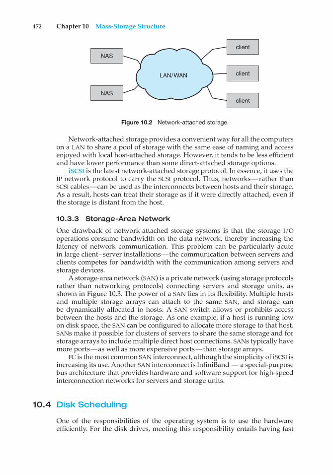
472 Chapter 10 Mass-Storage Structure
NASclient
NASclient
clientLAN/WAN
Figure 10.2 Network-attached storage.
Network-attached storage provides a convenient way for all the computerson a LAN to share a pool of storage with the same ease of naming and accessenjoyed with local host-attached storage. However, it tends to be less efficientand have lower performance than some direct-attached storage options.
iSCSI is the latest network-attached storage protocol. In essence, it uses theIP network protocol to carry the SCSI protocol. Thus, networks—rather thanSCSI cables—can be used as the interconnects between hosts and their storage.As a result, hosts can treat their storage as if it were directly attached, even ifthe storage is distant from the host.
10.3.3 Storage-Area Network
One drawback of network-attached storage systems is that the storage I/Ooperations consume bandwidth on the data network, thereby increasing thelatency of network communication. This problem can be particularly acutein large client–server installations—the communication between servers andclients competes for bandwidth with the communication among servers andstorage devices.
A storage-area network (SAN) is a private network (using storage protocolsrather than networking protocols) connecting servers and storage units, asshown in Figure 10.3. The power of a SAN lies in its flexibility. Multiple hostsand multiple storage arrays can attach to the same SAN, and storage canbe dynamically allocated to hosts. A SAN switch allows or prohibits accessbetween the hosts and the storage. As one example, if a host is running lowon disk space, the SAN can be configured to allocate more storage to that host.SANs make it possible for clusters of servers to share the same storage and forstorage arrays to include multiple direct host connections. SANs typically havemore ports—as well as more expensive ports—than storage arrays.
FC is the most common SAN interconnect, although the simplicity of iSCSI isincreasing its use. Another SAN interconnect is InfiniBand — a special-purposebus architecture that provides hardware and software support for high-speedinterconnection networks for servers and storage units.
10.4 Disk Scheduling
One of the responsibilities of the operating system is to use the hardwareefficiently. For the disk drives, meeting this responsibility entails having fast
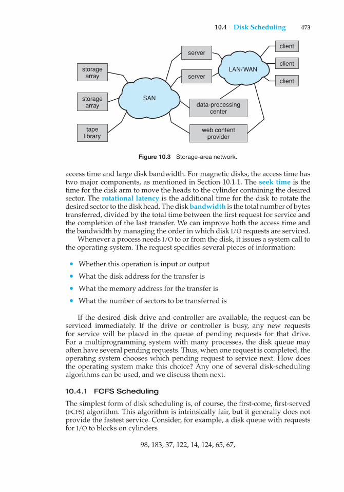
10.4 Disk Scheduling 473
LAN/WAN
storagearray
storagearray
data-processingcenter
web contentprovider
serverclient
client
clientserver
tapelibrary
SAN
Figure 10.3 Storage-area network.
access time and large disk bandwidth. For magnetic disks, the access time hastwo major components, as mentioned in Section 10.1.1. The seek time is thetime for the disk arm to move the heads to the cylinder containing the desiredsector. The rotational latency is the additional time for the disk to rotate thedesired sector to the disk head. The disk bandwidth is the total number of bytestransferred, divided by the total time between the first request for service andthe completion of the last transfer. We can improve both the access time andthe bandwidth by managing the order in which disk I/O requests are serviced.
Whenever a process needs I/O to or from the disk, it issues a system call tothe operating system. The request specifies several pieces of information:
• Whether this operation is input or output
• What the disk address for the transfer is
• What the memory address for the transfer is
• What the number of sectors to be transferred is
If the desired disk drive and controller are available, the request can beserviced immediately. If the drive or controller is busy, any new requestsfor service will be placed in the queue of pending requests for that drive.For a multiprogramming system with many processes, the disk queue mayoften have several pending requests. Thus, when one request is completed, theoperating system chooses which pending request to service next. How doesthe operating system make this choice? Any one of several disk-schedulingalgorithms can be used, and we discuss them next.
10.4.1 FCFS Scheduling
The simplest form of disk scheduling is, of course, the first-come, first-served(FCFS) algorithm. This algorithm is intrinsically fair, but it generally does notprovide the fastest service. Consider, for example, a disk queue with requestsfor I/O to blocks on cylinders
98, 183, 37, 122, 14, 124, 65, 67,
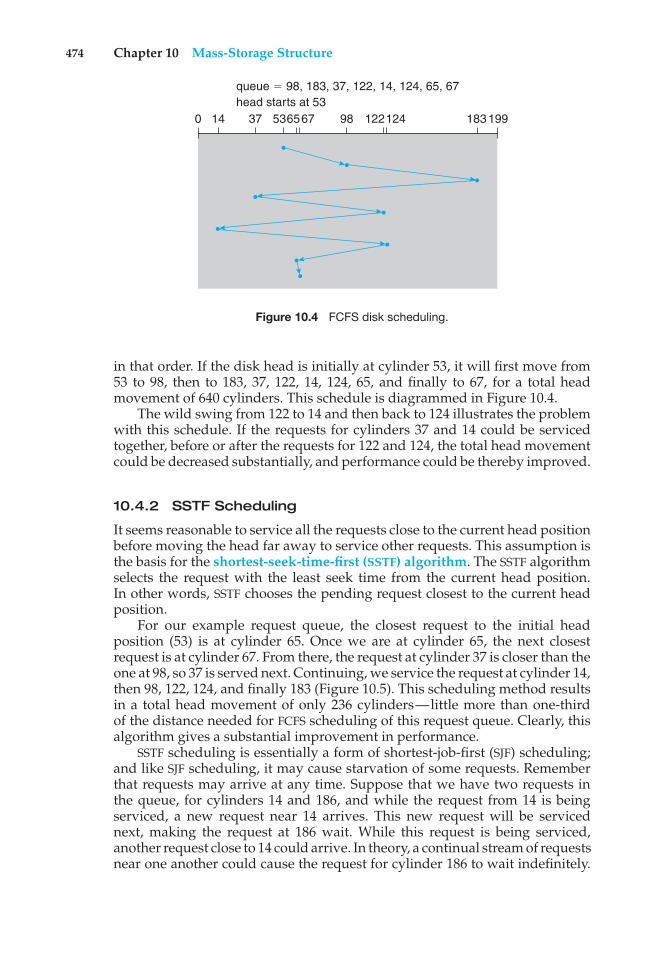
474 Chapter 10 Mass-Storage Structure
0 14 37 536567 98 122124 183199
queue $ 98, 183, 37, 122, 14, 124, 65, 67head starts at 53
Figure 10.4 FCFS disk scheduling.
in that order. If the disk head is initially at cylinder 53, it will first move from53 to 98, then to 183, 37, 122, 14, 124, 65, and finally to 67, for a total headmovement of 640 cylinders. This schedule is diagrammed in Figure 10.4.
The wild swing from 122 to 14 and then back to 124 illustrates the problemwith this schedule. If the requests for cylinders 37 and 14 could be servicedtogether, before or after the requests for 122 and 124, the total head movementcould be decreased substantially, and performance could be thereby improved.
10.4.2 SSTF Scheduling
It seems reasonable to service all the requests close to the current head positionbefore moving the head far away to service other requests. This assumption isthe basis for the shortest-seek-time-first (SSTF) algorithm. The SSTF algorithmselects the request with the least seek time from the current head position.In other words, SSTF chooses the pending request closest to the current headposition.
For our example request queue, the closest request to the initial headposition (53) is at cylinder 65. Once we are at cylinder 65, the next closestrequest is at cylinder 67. From there, the request at cylinder 37 is closer than theone at 98, so 37 is served next. Continuing, we service the request at cylinder 14,then 98, 122, 124, and finally 183 (Figure 10.5). This scheduling method resultsin a total head movement of only 236 cylinders—little more than one-thirdof the distance needed for FCFS scheduling of this request queue. Clearly, thisalgorithm gives a substantial improvement in performance.
SSTF scheduling is essentially a form of shortest-job-first (SJF) scheduling;and like SJF scheduling, it may cause starvation of some requests. Rememberthat requests may arrive at any time. Suppose that we have two requests inthe queue, for cylinders 14 and 186, and while the request from 14 is beingserviced, a new request near 14 arrives. This new request will be servicednext, making the request at 186 wait. While this request is being serviced,another request close to 14 could arrive. In theory, a continual stream of requestsnear one another could cause the request for cylinder 186 to wait indefinitely.
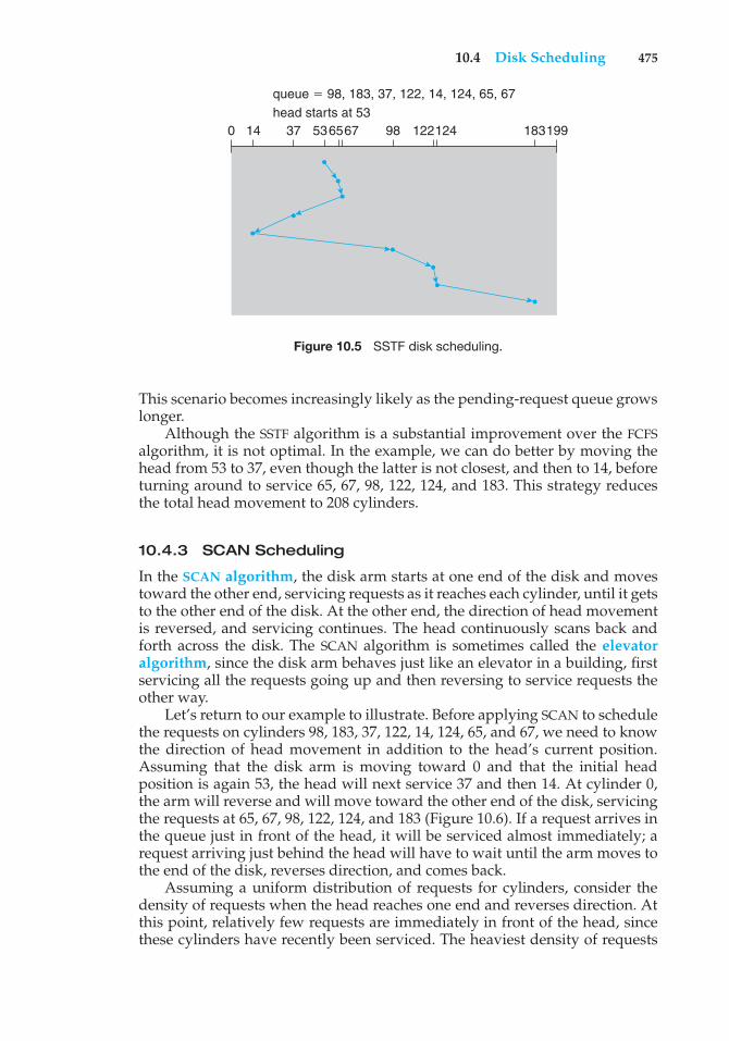
10.4 Disk Scheduling 475
0 14 37 536567 98 122124 183199
queue $ 98, 183, 37, 122, 14, 124, 65, 67head starts at 53
Figure 10.5 SSTF disk scheduling.
This scenario becomes increasingly likely as the pending-request queue growslonger.
Although the SSTF algorithm is a substantial improvement over the FCFSalgorithm, it is not optimal. In the example, we can do better by moving thehead from 53 to 37, even though the latter is not closest, and then to 14, beforeturning around to service 65, 67, 98, 122, 124, and 183. This strategy reducesthe total head movement to 208 cylinders.
10.4.3 SCAN Scheduling
In the SCAN algorithm, the disk arm starts at one end of the disk and movestoward the other end, servicing requests as it reaches each cylinder, until it getsto the other end of the disk. At the other end, the direction of head movementis reversed, and servicing continues. The head continuously scans back andforth across the disk. The SCAN algorithm is sometimes called the elevatoralgorithm, since the disk arm behaves just like an elevator in a building, firstservicing all the requests going up and then reversing to service requests theother way.
Let’s return to our example to illustrate. Before applying SCAN to schedulethe requests on cylinders 98, 183, 37, 122, 14, 124, 65, and 67, we need to knowthe direction of head movement in addition to the head’s current position.Assuming that the disk arm is moving toward 0 and that the initial headposition is again 53, the head will next service 37 and then 14. At cylinder 0,the arm will reverse and will move toward the other end of the disk, servicingthe requests at 65, 67, 98, 122, 124, and 183 (Figure 10.6). If a request arrives inthe queue just in front of the head, it will be serviced almost immediately; arequest arriving just behind the head will have to wait until the arm moves tothe end of the disk, reverses direction, and comes back.
Assuming a uniform distribution of requests for cylinders, consider thedensity of requests when the head reaches one end and reverses direction. Atthis point, relatively few requests are immediately in front of the head, sincethese cylinders have recently been serviced. The heaviest density of requests
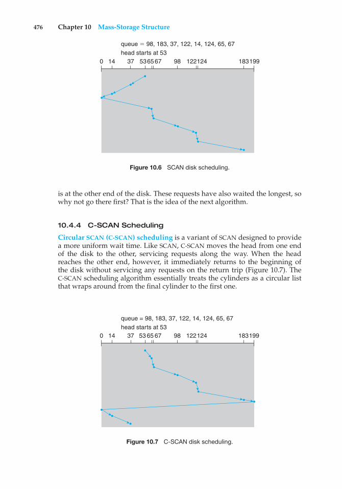
476 Chapter 10 Mass-Storage Structure
0 14 37 536567 98 122124 183199
queue $ 98, 183, 37, 122, 14, 124, 65, 67head starts at 53
Figure 10.6 SCAN disk scheduling.
is at the other end of the disk. These requests have also waited the longest, sowhy not go there first? That is the idea of the next algorithm.
10.4.4 C-SCAN Scheduling
Circular SCAN (C-SCAN) scheduling is a variant of SCAN designed to providea more uniform wait time. Like SCAN, C-SCAN moves the head from one endof the disk to the other, servicing requests along the way. When the headreaches the other end, however, it immediately returns to the beginning ofthe disk without servicing any requests on the return trip (Figure 10.7). TheC-SCAN scheduling algorithm essentially treats the cylinders as a circular listthat wraps around from the final cylinder to the first one.
0 14 37 53 65 67 98 122124 183199
queue = 98, 183, 37, 122, 14, 124, 65, 67head starts at 53
Figure 10.7 C-SCAN disk scheduling.
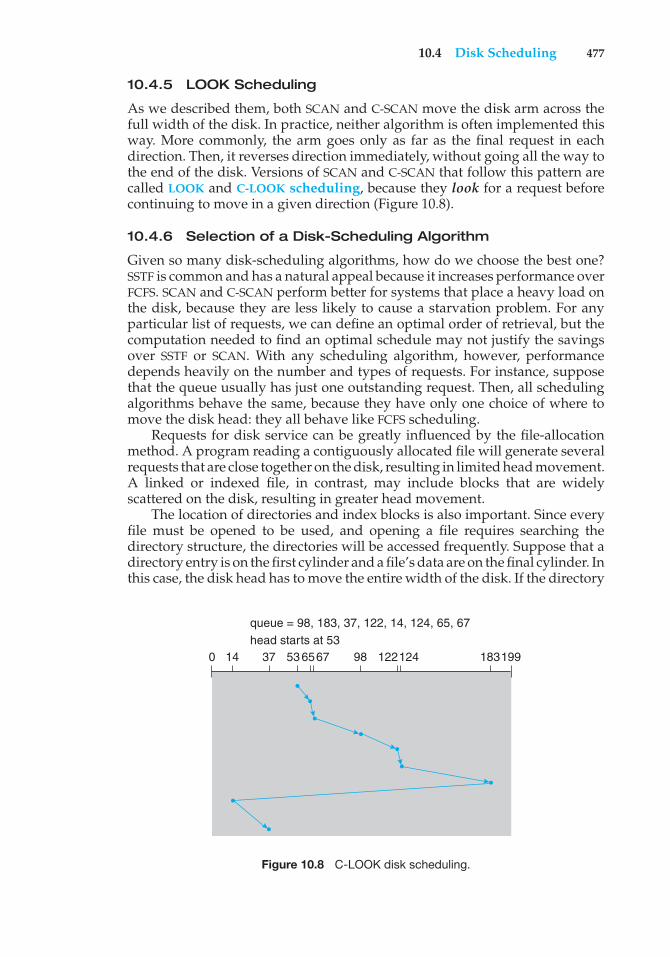
10.4 Disk Scheduling 477
10.4.5 LOOK Scheduling
As we described them, both SCAN and C-SCAN move the disk arm across thefull width of the disk. In practice, neither algorithm is often implemented thisway. More commonly, the arm goes only as far as the final request in eachdirection. Then, it reverses direction immediately, without going all the way tothe end of the disk. Versions of SCAN and C-SCAN that follow this pattern arecalled LOOK and C-LOOK scheduling, because they look for a request beforecontinuing to move in a given direction (Figure 10.8).
10.4.6 Selection of a Disk-Scheduling Algorithm
Given so many disk-scheduling algorithms, how do we choose the best one?SSTF is common and has a natural appeal because it increases performance overFCFS. SCAN and C-SCAN perform better for systems that place a heavy load onthe disk, because they are less likely to cause a starvation problem. For anyparticular list of requests, we can define an optimal order of retrieval, but thecomputation needed to find an optimal schedule may not justify the savingsover SSTF or SCAN. With any scheduling algorithm, however, performancedepends heavily on the number and types of requests. For instance, supposethat the queue usually has just one outstanding request. Then, all schedulingalgorithms behave the same, because they have only one choice of where tomove the disk head: they all behave like FCFS scheduling.
Requests for disk service can be greatly influenced by the file-allocationmethod. A program reading a contiguously allocated file will generate severalrequests that are close together on the disk, resulting in limited head movement.A linked or indexed file, in contrast, may include blocks that are widelyscattered on the disk, resulting in greater head movement.
The location of directories and index blocks is also important. Since everyfile must be opened to be used, and opening a file requires searching thedirectory structure, the directories will be accessed frequently. Suppose that adirectory entry is on the first cylinder and a file’s data are on the final cylinder. Inthis case, the disk head has to move the entire width of the disk. If the directory
0 14 37 536567 98 122124 183199
queue = 98, 183, 37, 122, 14, 124, 65, 67head starts at 53
Figure 10.8 C-LOOK disk scheduling.
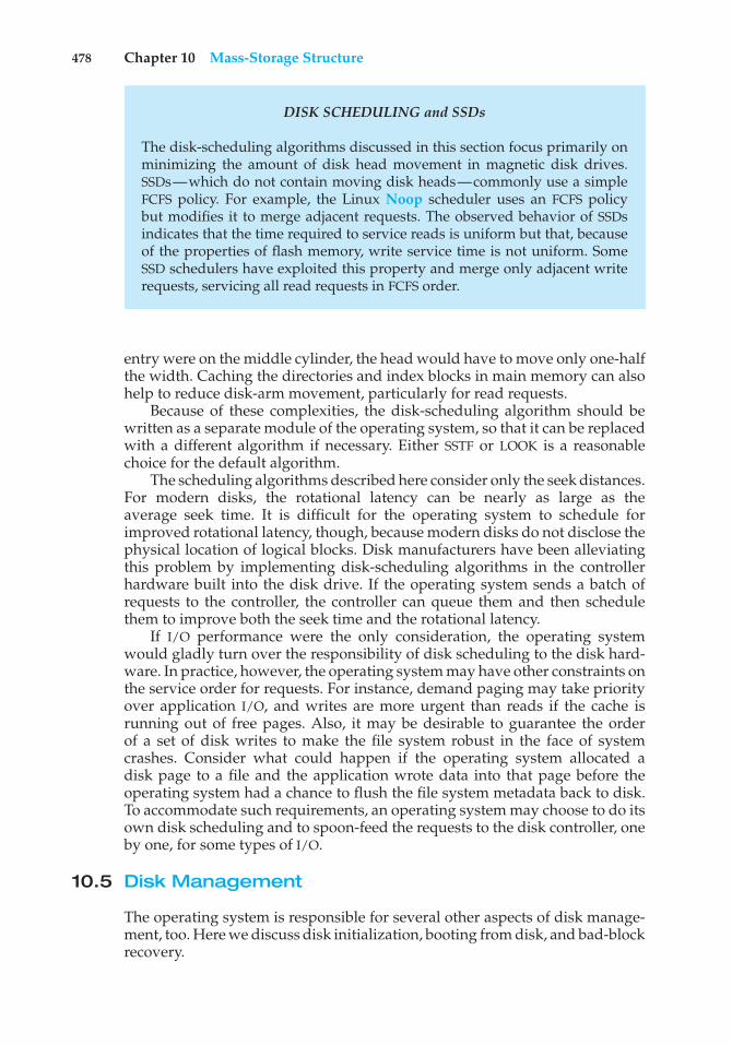
478 Chapter 10 Mass-Storage Structure
DISK SCHEDULING and SSDs
The disk-scheduling algorithms discussed in this section focus primarily onminimizing the amount of disk head movement in magnetic disk drives.SSDs—which do not contain moving disk heads—commonly use a simpleFCFS policy. For example, the Linux Noop scheduler uses an FCFS policybut modifies it to merge adjacent requests. The observed behavior of SSDsindicates that the time required to service reads is uniform but that, becauseof the properties of flash memory, write service time is not uniform. SomeSSD schedulers have exploited this property and merge only adjacent writerequests, servicing all read requests in FCFS order.
entry were on the middle cylinder, the head would have to move only one-halfthe width. Caching the directories and index blocks in main memory can alsohelp to reduce disk-arm movement, particularly for read requests.
Because of these complexities, the disk-scheduling algorithm should bewritten as a separate module of the operating system, so that it can be replacedwith a different algorithm if necessary. Either SSTF or LOOK is a reasonablechoice for the default algorithm.
The scheduling algorithms described here consider only the seek distances.For modern disks, the rotational latency can be nearly as large as theaverage seek time. It is difficult for the operating system to schedule forimproved rotational latency, though, because modern disks do not disclose thephysical location of logical blocks. Disk manufacturers have been alleviatingthis problem by implementing disk-scheduling algorithms in the controllerhardware built into the disk drive. If the operating system sends a batch ofrequests to the controller, the controller can queue them and then schedulethem to improve both the seek time and the rotational latency.
If I/O performance were the only consideration, the operating systemwould gladly turn over the responsibility of disk scheduling to the disk hard-ware. In practice, however, the operating system may have other constraints onthe service order for requests. For instance, demand paging may take priorityover application I/O, and writes are more urgent than reads if the cache isrunning out of free pages. Also, it may be desirable to guarantee the orderof a set of disk writes to make the file system robust in the face of systemcrashes. Consider what could happen if the operating system allocated adisk page to a file and the application wrote data into that page before theoperating system had a chance to flush the file system metadata back to disk.To accommodate such requirements, an operating system may choose to do itsown disk scheduling and to spoon-feed the requests to the disk controller, oneby one, for some types of I/O.
10.5 Disk Management
The operating system is responsible for several other aspects of disk manage-ment, too. Here we discuss disk initialization, booting from disk, and bad-blockrecovery.
10.5 Disk Management 479
10.5.1 Disk Formatting
A new magnetic disk is a blank slate: it is just a platter of a magnetic recordingmaterial. Before a disk can store data, it must be divided into sectors that thedisk controller can read and write. This process is called low-level formatting,or physical formatting. Low-level formatting fills the disk with a special datastructure for each sector. The data structure for a sector typically consists of aheader, a data area (usually 512 bytes in size), and a trailer. The header andtrailer contain information used by the disk controller, such as a sector numberand an error-correcting code (ECC). When the controller writes a sector of dataduring normal I/O, the ECC is updated with a value calculated from all the bytesin the data area. When the sector is read, the ECC is recalculated and comparedwith the stored value. If the stored and calculated numbers are different, thismismatch indicates that the data area of the sector has become corrupted andthat the disk sector may be bad (Section 10.5.3). The ECC is an error-correctingcode because it contains enough information, if only a few bits of data havebeen corrupted, to enable the controller to identify which bits have changedand calculate what their correct values should be. It then reports a recoverablesoft error. The controller automatically does the ECC processing whenever asector is read or written.
Most hard disks are low-level-formatted at the factory as a part of themanufacturing process. This formatting enables the manufacturer to test thedisk and to initialize the mapping from logical block numbers to defect-freesectors on the disk. For many hard disks, when the disk controller is instructedto low-level-format the disk, it can also be told how many bytes of data spaceto leave between the header and trailer of all sectors. It is usually possible tochoose among a few sizes, such as 256, 512, and 1,024 bytes. Formatting a diskwith a larger sector size means that fewer sectors can fit on each track; but italso means that fewer headers and trailers are written on each track and morespace is available for user data. Some operating systems can handle only asector size of 512 bytes.
Before it can use a disk to hold files, the operating system still needs torecord its own data structures on the disk. It does so in two steps. The first stepis to partition the disk into one or more groups of cylinders. The operatingsystem can treat each partition as though it were a separate disk. For instance,one partition can hold a copy of the operating system’s executable code, whileanother holds user files. The second step is logical formatting, or creation of afile system. In this step, the operating system stores the initial file-system datastructures onto the disk. These data structures may include maps of free andallocated space and an initial empty directory.
To increase efficiency, most file systems group blocks together into largerchunks, frequently called clusters. Disk I/O is done via blocks, but file systemI/O is done via clusters, effectively assuring that I/O has more sequential-accessand fewer random-access characteristics.
Some operating systems give special programs the ability to use a diskpartition as a large sequential array of logical blocks, without any file-systemdata structures. This array is sometimes called the raw disk, and I/O to thisarray is termed raw I/O. For example, some database systems prefer rawI/O because it enables them to control the exact disk location where eachdatabase record is stored. Raw I/O bypasses all the file-system services, such
480 Chapter 10 Mass-Storage Structure
as the buffer cache, file locking, prefetching, space allocation, file names, anddirectories. We can make certain applications more efficient by allowing themto implement their own special-purpose storage services on a raw partition,but most applications perform better when they use the regular file-systemservices.
10.5.2 Boot Block
For a computer to start running—for instance, when it is powered up orrebooted—it must have an initial program to run. This initial bootstrapprogram tends to be simple. It initializes all aspects of the system, from CPUregisters to device controllers and the contents of main memory, and thenstarts the operating system. To do its job, the bootstrap program finds theoperating-system kernel on disk, loads that kernel into memory, and jumps toan initial address to begin the operating-system execution.
For most computers, the bootstrap is stored in read-only memory (ROM).This location is convenient, because ROM needs no initialization and is at a fixedlocation that the processor can start executing when powered up or reset. And,since ROM is read only, it cannot be infected by a computer virus. The problem isthat changing this bootstrap code requires changing the ROM hardware chips.For this reason, most systems store a tiny bootstrap loader program in the bootROM whose only job is to bring in a full bootstrap program from disk. The fullbootstrap program can be changed easily: a new version is simply written ontothe disk. The full bootstrap program is stored in the “boot blocks” at a fixedlocation on the disk. A disk that has a boot partition is called a boot disk orsystem disk.
The code in the boot ROM instructs the disk controller to read the bootblocks into memory (no device drivers are loaded at this point) and then startsexecuting that code. The full bootstrap program is more sophisticated than thebootstrap loader in the boot ROM. It is able to load the entire operating systemfrom a non-fixed location on disk and to start the operating system running.Even so, the full bootstrap code may be small.
Let’s consider as an example the boot process in Windows. First, note thatWindows allows a hard disk to be divided into partitions, and one partition—identified as the boot partition—contains the operating system and devicedrivers. The Windows system places its boot code in the first sector on the harddisk, which it terms the master boot record, or MBR. Booting begins by runningcode that is resident in the system’s ROM memory. This code directs the systemto read the boot code from the MBR. In addition to containing boot code, theMBR contains a table listing the partitions for the hard disk and a flag indicatingwhich partition the system is to be booted from, as illustrated in Figure 10.9.Once the system identifies the boot partition, it reads the first sector from thatpartition (which is called the boot sector) and continues with the remainder ofthe boot process, which includes loading the various subsystems and systemservices.
10.5.3 Bad Blocks
Because disks have moving parts and small tolerances (recall that the diskhead flies just above the disk surface), they are prone to failure. Sometimes thefailure is complete; in this case, the disk needs to be replaced and its contents
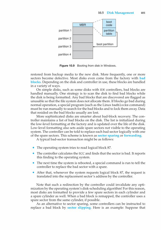
10.5 Disk Management 481
MBR
partition 1
partition 2
partition 3
partition 4
bootcode
partitiontable
boot partition
Figure 10.9 Booting from disk in Windows.
restored from backup media to the new disk. More frequently, one or moresectors become defective. Most disks even come from the factory with badblocks. Depending on the disk and controller in use, these blocks are handledin a variety of ways.
On simple disks, such as some disks with IDE controllers, bad blocks arehandled manually. One strategy is to scan the disk to find bad blocks whilethe disk is being formatted. Any bad blocks that are discovered are flagged asunusable so that the file system does not allocate them. If blocks go bad duringnormal operation, a special program (such as the Linux badblocks command)must be run manually to search for the bad blocks and to lock them away. Datathat resided on the bad blocks usually are lost.
More sophisticated disks are smarter about bad-block recovery. The con-troller maintains a list of bad blocks on the disk. The list is initialized duringthe low-level formatting at the factory and is updated over the life of the disk.Low-level formatting also sets aside spare sectors not visible to the operatingsystem. The controller can be told to replace each bad sector logically with oneof the spare sectors. This scheme is known as sector sparing or forwarding.
A typical bad-sector transaction might be as follows:
• The operating system tries to read logical block 87.
• The controller calculates the ECC and finds that the sector is bad. It reportsthis finding to the operating system.
• The next time the system is rebooted, a special command is run to tell thecontroller to replace the bad sector with a spare.
• After that, whenever the system requests logical block 87, the request istranslated into the replacement sector’s address by the controller.
Note that such a redirection by the controller could invalidate any opti-mization by the operating system’s disk-scheduling algorithm! For this reason,most disks are formatted to provide a few spare sectors in each cylinder anda spare cylinder as well. When a bad block is remapped, the controller uses aspare sector from the same cylinder, if possible.
As an alternative to sector sparing, some controllers can be instructed toreplace a bad block by sector slipping. Here is an example: Suppose that
482 Chapter 10 Mass-Storage Structure
logical block 17 becomes defective and the first available spare follows sector202. Sector slipping then remaps all the sectors from 17 to 202, moving themall down one spot. That is, sector 202 is copied into the spare, then sector 201into 202, then 200 into 201, and so on, until sector 18 is copied into sector 19.Slipping the sectors in this way frees up the space of sector 18 so that sector 17can be mapped to it.
The replacement of a bad block generally is not totally automatic, becausethe data in the bad block are usually lost. Soft errors may trigger a process inwhich a copy of the block data is made and the block is spared or slipped.An unrecoverable hard error, however, results in lost data. Whatever file wasusing that block must be repaired (for instance, by restoration from a backuptape), and that requires manual intervention.
10.6 Swap-Space Management
Swapping was first presented in Section 8.2, where we discussed movingentire processes between disk and main memory. Swapping in that settingoccurs when the amount of physical memory reaches a critically low point andprocesses are moved from memory to swap space to free available memory.In practice, very few modern operating systems implement swapping inthis fashion. Rather, systems now combine swapping with virtual memorytechniques (Chapter 9) and swap pages, not necessarily entire processes. In fact,some systems now use the terms “swapping” and “paging” interchangeably,reflecting the merging of these two concepts.
Swap-space management is another low-level task of the operatingsystem. Virtual memory uses disk space as an extension of main memory.Since disk access is much slower than memory access, using swap spacesignificantly decreases system performance. The main goal for the design andimplementation of swap space is to provide the best throughput for the virtualmemory system. In this section, we discuss how swap space is used, whereswap space is located on disk, and how swap space is managed.
10.6.1 Swap-Space Use
Swap space is used in various ways by different operating systems, dependingon the memory-management algorithms in use. For instance, systems thatimplement swapping may use swap space to hold an entire process image,including the code and data segments. Paging systems may simply store pagesthat have been pushed out of main memory. The amount of swap space neededon a system can therefore vary from a few megabytes of disk space to gigabytes,depending on the amount of physical memory, the amount of virtual memoryit is backing, and the way in which the virtual memory is used.
Note that it may be safer to overestimate than to underestimate the amountof swap space required, because if a system runs out of swap space it may beforced to abort processes or may crash entirely. Overestimation wastes diskspace that could otherwise be used for files, but it does no other harm. Somesystems recommend the amount to be set aside for swap space. Solaris, forexample, suggests setting swap space equal to the amount by which virtualmemory exceeds pageable physical memory. In the past, Linux has suggested
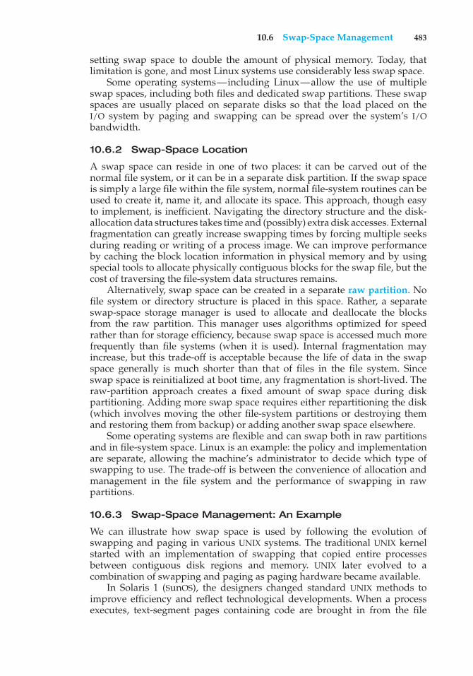
10.6 Swap-Space Management 483
setting swap space to double the amount of physical memory. Today, thatlimitation is gone, and most Linux systems use considerably less swap space.
Some operating systems—including Linux—allow the use of multipleswap spaces, including both files and dedicated swap partitions. These swapspaces are usually placed on separate disks so that the load placed on theI/O system by paging and swapping can be spread over the system’s I/Obandwidth.
10.6.2 Swap-Space Location
A swap space can reside in one of two places: it can be carved out of thenormal file system, or it can be in a separate disk partition. If the swap spaceis simply a large file within the file system, normal file-system routines can beused to create it, name it, and allocate its space. This approach, though easyto implement, is inefficient. Navigating the directory structure and the disk-allocation data structures takes time and (possibly) extra disk accesses. Externalfragmentation can greatly increase swapping times by forcing multiple seeksduring reading or writing of a process image. We can improve performanceby caching the block location information in physical memory and by usingspecial tools to allocate physically contiguous blocks for the swap file, but thecost of traversing the file-system data structures remains.
Alternatively, swap space can be created in a separate raw partition. Nofile system or directory structure is placed in this space. Rather, a separateswap-space storage manager is used to allocate and deallocate the blocksfrom the raw partition. This manager uses algorithms optimized for speedrather than for storage efficiency, because swap space is accessed much morefrequently than file systems (when it is used). Internal fragmentation mayincrease, but this trade-off is acceptable because the life of data in the swapspace generally is much shorter than that of files in the file system. Sinceswap space is reinitialized at boot time, any fragmentation is short-lived. Theraw-partition approach creates a fixed amount of swap space during diskpartitioning. Adding more swap space requires either repartitioning the disk(which involves moving the other file-system partitions or destroying themand restoring them from backup) or adding another swap space elsewhere.
Some operating systems are flexible and can swap both in raw partitionsand in file-system space. Linux is an example: the policy and implementationare separate, allowing the machine’s administrator to decide which type ofswapping to use. The trade-off is between the convenience of allocation andmanagement in the file system and the performance of swapping in rawpartitions.
10.6.3 Swap-Space Management: An Example
We can illustrate how swap space is used by following the evolution ofswapping and paging in various UNIX systems. The traditional UNIX kernelstarted with an implementation of swapping that copied entire processesbetween contiguous disk regions and memory. UNIX later evolved to acombination of swapping and paging as paging hardware became available.
In Solaris 1 (SunOS), the designers changed standard UNIX methods toimprove efficiency and reflect technological developments. When a processexecutes, text-segment pages containing code are brought in from the file
484 Chapter 10 Mass-Storage Structure
swap areapageslot
swap partitionor swap file
swap map 1 0 3 0 1
Figure 10.10 The data structures for swapping on Linux systems.
system, accessed in main memory, and thrown away if selected for pageout. Itis more efficient to reread a page from the file system than to write it to swapspace and then reread it from there. Swap space is only used as a backing storefor pages of anonymous memory, which includes memory allocated for thestack, heap, and uninitialized data of a process.
More changes were made in later versions of Solaris. The biggest changeis that Solaris now allocates swap space only when a page is forced out ofphysical memory, rather than when the virtual memory page is first created.This scheme gives better performance on modern computers, which have morephysical memory than older systems and tend to page less.
Linux is similar to Solaris in that swap space is used only for anonymousmemory—that is, memory not backed by any file. Linux allows one or moreswap areas to be established. A swap area may be in either a swap file on aregular file system or a dedicated swap partition. Each swap area consists of aseries of 4-KB page slots, which are used to hold swapped pages. Associatedwith each swap area is a swap map—an array of integer counters, eachcorresponding to a page slot in the swap area. If the value of a counter is 0,the corresponding page slot is available. Values greater than 0 indicate that thepage slot is occupied by a swapped page. The value of the counter indicates thenumber of mappings to the swapped page. For example, a value of 3 indicatesthat the swapped page is mapped to three different processes (which can occurif the swapped page is storing a region of memory shared by three processes).The data structures for swapping on Linux systems are shown in Figure 10.10.
10.7 RAID Structure
Disk drives have continued to get smaller and cheaper, so it is now econom-ically feasible to attach many disks to a computer system. Having a largenumber of disks in a system presents opportunities for improving the rateat which data can be read or written, if the disks are operated in parallel.Furthermore, this setup offers the potential for improving the reliability of datastorage, because redundant information can be stored on multiple disks. Thus,failure of one disk does not lead to loss of data. A variety of disk-organizationtechniques, collectively called redundant arrays of independent disks (RAID),are commonly used to address the performance and reliability issues.
In the past, RAIDs composed of small, cheap disks were viewed as acost-effective alternative to large, expensive disks. Today, RAIDs are used for
10.7 RAID Structure 485
STRUCTURING RAID
RAID storage can be structured in a variety of ways. For example, a systemcan have disks directly attached to its buses. In this case, the operatingsystem or system software can implement RAID functionality. Alternatively,an intelligent host controller can control multiple attached disks and canimplement RAID on those disks in hardware. Finally, a storage array, or RAIDarray, can be used. A RAID array is a standalone unit with its own controller,cache (usually), and disks. It is attached to the host via one or more standardcontrollers (for example, FC). This common setup allows an operating systemor software without RAID functionality to have RAID-protected disks. It iseven used on systems that do have RAID software layers because of itssimplicity and flexibility.
their higher reliability and higher data-transfer rate, rather than for economicreasons. Hence, the I in RAID, which once stood for “inexpensive,” now standsfor “independent.”
10.7.1 Improvement of Reliability via Redundancy
Let’s first consider the reliability of RAIDs. The chance that some disk out ofa set of N disks will fail is much higher than the chance that a specific singledisk will fail. Suppose that the mean time to failure of a single disk is 100,000hours. Then the mean time to failure of some disk in an array of 100 diskswill be 100,000/100 = 1,000 hours, or 41.66 days, which is not long at all! If westore only one copy of the data, then each disk failure will result in loss of asignificant amount of data—and such a high rate of data loss is unacceptable.
The solution to the problem of reliability is to introduce redundancy; westore extra information that is not normally needed but that can be used in theevent of failure of a disk to rebuild the lost information. Thus, even if a diskfails, data are not lost.
The simplest (but most expensive) approach to introducing redundancy isto duplicate every disk. This technique is called mirroring. With mirroring, alogical disk consists of two physical disks, and every write is carried out onboth disks. The result is called a mirrored volume. If one of the disks in thevolume fails, the data can be read from the other. Data will be lost only if thesecond disk fails before the first failed disk is replaced.
The mean time to failure of a mirrored volume—where failure is the loss ofdata—depends on two factors. One is the mean time to failure of the individualdisks. The other is the mean time to repair, which is the time it takes (onaverage) to replace a failed disk and to restore the data on it. Suppose that thefailures of the two disks are independent; that is, the failure of one disk is notconnected to the failure of the other. Then, if the mean time to failure of a singledisk is 100,000 hours and the mean time to repair is 10 hours, the mean timeto data loss of a mirrored disk system is 100, 0002/(2 ∗ 10) = 500 ∗ 106 hours,or 57,000 years!
486 Chapter 10 Mass-Storage Structure
You should be aware that we cannot really assume that disk failures willbe independent. Power failures and natural disasters, such as earthquakes,fires, and floods, may result in damage to both disks at the same time.Also, manufacturing defects in a batch of disks can cause correlated failures.As disks age, the probability of failure grows, increasing the chance that asecond disk will fail while the first is being repaired. In spite of all theseconsiderations, however, mirrored-disk systems offer much higher reliabilitythan do single-disk systems.
Power failures are a particular source of concern, since they occur far morefrequently than do natural disasters. Even with mirroring of disks, if writes arein progress to the same block in both disks, and power fails before both blocksare fully written, the two blocks can be in an inconsistent state. One solutionto this problem is to write one copy first, then the next. Another is to add asolid-state nonvolatile RAM (NVRAM) cache to the RAID array. This write-backcache is protected from data loss during power failures, so the write can beconsidered complete at that point, assuming the NVRAM has some kind of errorprotection and correction, such as ECC or mirroring.
10.7.2 Improvement in Performance via Parallelism
Now let’s consider how parallel access to multiple disks improves perfor-mance. With disk mirroring, the rate at which read requests can be handled isdoubled, since read requests can be sent to either disk (as long as both disksin a pair are functional, as is almost always the case). The transfer rate of eachread is the same as in a single-disk system, but the number of reads per unittime has doubled.
With multiple disks, we can improve the transfer rate as well (or instead)by striping data across the disks. In its simplest form, data striping consistsof splitting the bits of each byte across multiple disks; such striping is calledbit-level striping. For example, if we have an array of eight disks, we writebit i of each byte to disk i. The array of eight disks can be treated as a singledisk with sectors that are eight times the normal size and, more important, thathave eight times the access rate. Every disk participates in every access (reador write); so the number of accesses that can be processed per second is aboutthe same as on a single disk, but each access can read eight times as many datain the same time as on a single disk.
Bit-level striping can be generalized to include a number of disks that eitheris a multiple of 8 or divides 8. For example, if we use an array of four disks,bits i and 4 + i of each byte go to disk i. Further, striping need not occur atthe bit level. In block-level striping, for instance, blocks of a file are stripedacross multiple disks; with n disks, block i of a file goes to disk (i mod n) + 1.Other levels of striping, such as bytes of a sector or sectors of a block, also arepossible. Block-level striping is the most common.
Parallelism in a disk system, as achieved through striping, has two maingoals:
1. Increase the throughput of multiple small accesses (that is, page accesses)by load balancing.
2. Reduce the response time of large accesses.
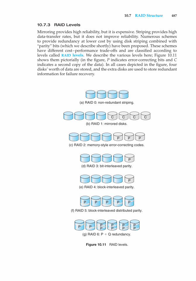
10.7 RAID Structure 487
10.7.3 RAID Levels
Mirroring provides high reliability, but it is expensive. Striping provides highdata-transfer rates, but it does not improve reliability. Numerous schemesto provide redundancy at lower cost by using disk striping combined with“parity” bits (which we describe shortly) have been proposed. These schemeshave different cost–performance trade-offs and are classified according tolevels called RAID levels. We describe the various levels here; Figure 10.11shows them pictorially (in the figure, P indicates error-correcting bits and Cindicates a second copy of the data). In all cases depicted in the figure, fourdisks’ worth of data are stored, and the extra disks are used to store redundantinformation for failure recovery.
(a) RAID 0: non-redundant striping.
(b) RAID 1: mirrored disks.
C C C C
(c) RAID 2: memory-style error-correcting codes.
(d) RAID 3: bit-interleaved parity.
(e) RAID 4: block-interleaved parity.
(f) RAID 5: block-interleaved distributed parity.
P P
P
P
P P P
(g) RAID 6: P ' Q redundancy.
PP P
PPPP P
PPP
PP
Figure 10.11 RAID levels.
488 Chapter 10 Mass-Storage Structure
• RAID level 0. RAID level 0 refers to disk arrays with striping at the level ofblocks but without any redundancy (such as mirroring or parity bits), asshown in Figure 10.11(a).
• RAID level 1. RAID level 1 refers to disk mirroring. Figure 10.11(b) showsa mirrored organization.
• RAID level 2. RAID level 2 is also known as memory-style error-correcting-code (ECC) organization. Memory systems have long detected certainerrors by using parity bits. Each byte in a memory system may have aparity bit associated with it that records whether the number of bits in thebyte set to 1 is even (parity = 0) or odd (parity = 1). If one of the bits in thebyte is damaged (either a 1 becomes a 0, or a 0 becomes a 1), the parity ofthe byte changes and thus does not match the stored parity. Similarly, if thestored parity bit is damaged, it does not match the computed parity. Thus,all single-bit errors are detected by the memory system. Error-correctingschemes store two or more extra bits and can reconstruct the data if a singlebit is damaged.
The idea of ECC can be used directly in disk arrays via striping ofbytes across disks. For example, the first bit of each byte can be stored indisk 1, the second bit in disk 2, and so on until the eighth bit is stored indisk 8; the error-correction bits are stored in further disks. This schemeis shown in Figure 10.11(c), where the disks labeled P store the error-correction bits. If one of the disks fails, the remaining bits of the byte andthe associated error-correction bits can be read from other disks and usedto reconstruct the damaged data. Note that RAID level 2 requires only threedisks’ overhead for four disks of data, unlike RAID level 1, which requiresfour disks’ overhead.
• RAID level 3. RAID level 3, or bit-interleaved parity organization, improveson level 2 by taking into account the fact that, unlike memory systems, diskcontrollers can detect whether a sector has been read correctly, so a singleparity bit can be used for error correction as well as for detection. The ideais as follows: If one of the sectors is damaged, we know exactly whichsector it is, and we can figure out whether any bit in the sector is a 1 ora 0 by computing the parity of the corresponding bits from sectors in theother disks. If the parity of the remaining bits is equal to the stored parity,the missing bit is 0; otherwise, it is 1. RAID level 3 is as good as level 2 but isless expensive in the number of extra disks required (it has only a one-diskoverhead), so level 2 is not used in practice. Level 3 is shown pictorially inFigure 10.11(d).
RAID level 3 has two advantages over level 1. First, the storage over-head is reduced because only one parity disk is needed for several regulardisks, whereas one mirror disk is needed for every disk in level 1. Second,since reads and writes of a byte are spread out over multiple disks withN-way striping of data, the transfer rate for reading or writing a singleblock is N times as fast as with RAID level 1. On the negative side, RAIDlevel 3 supports fewer I/Os per second, since every disk has to participatein every I/O request.
A further performance problem with RAID 3—and with all parity-based RAID levels—is the expense of computing and writing the parity.
10.7 RAID Structure 489
This overhead results in significantly slower writes than with non-parityRAID arrays. To moderate this performance penalty, many RAID storagearrays include a hardware controller with dedicated parity hardware. Thiscontroller offloads the parity computation from the CPU to the array. Thearray has an NVRAM cache as well, to store the blocks while the parity iscomputed and to buffer the writes from the controller to the spindles. Thiscombination can make parity RAID almost as fast as non-parity. In fact, acaching array doing parity RAID can outperform a non-caching non-parityRAID.
• RAID level 4. RAID level 4, or block-interleaved parity organization, usesblock-level striping, as in RAID 0, and in addition keeps a parity block ona separate disk for corresponding blocks from N other disks. This schemeis diagrammed in Figure 10.11(e). If one of the disks fails, the parity blockcan be used with the corresponding blocks from the other disks to restorethe blocks of the failed disk.
A block read accesses only one disk, allowing other requests to beprocessed by the other disks. Thus, the data-transfer rate for each accessis slower, but multiple read accesses can proceed in parallel, leading to ahigher overall I/O rate. The transfer rates for large reads are high, since allthe disks can be read in parallel. Large writes also have high transfer rates,since the data and parity can be written in parallel.
Small independent writes cannot be performed in parallel. An operating-system write of data smaller than a block requires that the block be read,modified with the new data, and written back. The parity block has to beupdated as well. This is known as the read-modify-write cycle. Thus, asingle write requires four disk accesses: two to read the two old blocks andtwo to write the two new blocks.
WAFL (which we cover in Chapter 12) uses RAID level 4 because this RAIDlevel allows disks to be added to a RAID set seamlessly. If the added disksare initialized with blocks containing only zeros, then the parity value doesnot change, and the RAID set is still correct.
• RAID level 5. RAID level 5, or block-interleaved distributed parity, differsfrom level 4 in that it spreads data and parity among all N+1 disks, ratherthan storing data in N disks and parity in one disk. For each block, one ofthe disks stores the parity and the others store data. For example, with anarray of five disks, the parity for the nth block is stored in disk (n mod 5)+1.The nth blocks of the other four disks store actual data for that block. Thissetup is shown in Figure 10.11(f), where the Ps are distributed across allthe disks. A parity block cannot store parity for blocks in the same disk,because a disk failure would result in loss of data as well as of parity, andhence the loss would not be recoverable. By spreading the parity acrossall the disks in the set, RAID 5 avoids potential overuse of a single paritydisk, which can occur with RAID 4. RAID 5 is the most common parity RAIDsystem.
• RAID level 6. RAID level 6, also called the P + Q redundancy scheme, ismuch like RAID level 5 but stores extra redundant information to guardagainst multiple disk failures. Instead of parity, error-correcting codes suchas the Reed–Solomon codes are used. In the scheme shown in Figure
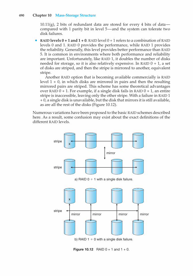
490 Chapter 10 Mass-Storage Structure
10.11(g), 2 bits of redundant data are stored for every 4 bits of data—compared with 1 parity bit in level 5—and the system can tolerate twodisk failures.
• RAID levels 0 + 1 and 1 + 0. RAID level 0 + 1 refers to a combination of RAIDlevels 0 and 1. RAID 0 provides the performance, while RAID 1 providesthe reliability. Generally, this level provides better performance than RAID5. It is common in environments where both performance and reliabilityare important. Unfortunately, like RAID 1, it doubles the number of disksneeded for storage, so it is also relatively expensive. In RAID 0 + 1, a setof disks are striped, and then the stripe is mirrored to another, equivalentstripe.
Another RAID option that is becoming available commercially is RAIDlevel 1 + 0, in which disks are mirrored in pairs and then the resultingmirrored pairs are striped. This scheme has some theoretical advantagesover RAID 0 + 1. For example, if a single disk fails in RAID 0 + 1, an entirestripe is inaccessible, leaving only the other stripe. With a failure in RAID 1+ 0, a single disk is unavailable, but the disk that mirrors it is still available,as are all the rest of the disks (Figure 10.12).
Numerous variations have been proposed to the basic RAID schemes describedhere. As a result, some confusion may exist about the exact definitions of thedifferent RAID levels.
x
x
mirror
a) RAID 0 ' 1 with a single disk failure.
stripe
stripe
mirror
b) RAID 1 ' 0 with a single disk failure.
stripemirror mirror mirror
Figure 10.12 RAID 0 + 1 and 1 + 0.
10.7 RAID Structure 491
The implementation of RAID is another area of variation. Consider thefollowing layers at which RAID can be implemented.
• Volume-management software can implement RAID within the kernel orat the system software layer. In this case, the storage hardware can provideminimal features and still be part of a full RAID solution. Parity RAID isfairly slow when implemented in software, so typically RAID 0, 1, or 0 + 1is used.
• RAID can be implemented in the host bus-adapter (HBA) hardware. Onlythe disks directly connected to the HBA can be part of a given RAID set.This solution is low in cost but not very flexible.
• RAID can be implemented in the hardware of the storage array. The storagearray can create RAID sets of various levels and can even slice these setsinto smaller volumes, which are then presented to the operating system.The operating system need only implement the file system on each of thevolumes. Arrays can have multiple connections available or can be part ofa SAN, allowing multiple hosts to take advantage of the array’s features.
• RAID can be implemented in the SAN interconnect layer by disk virtualiza-tion devices. In this case, a device sits between the hosts and the storage.It accepts commands from the servers and manages access to the storage.It could provide mirroring, for example, by writing each block to twoseparate storage devices.
Other features, such as snapshots and replication, can be implementedat each of these levels as well. A snapshot is a view of the file systembefore the last update took place. (Snapshots are covered more fully inChapter 12.) Replication involves the automatic duplication of writes betweenseparate sites for redundancy and disaster recovery. Replication can besynchronous or asynchronous. In synchronous replication, each block must bewritten locally and remotely before the write is considered complete, whereasin asynchronous replication, the writes are grouped together and writtenperiodically. Asynchronous replication can result in data loss if the primarysite fails, but it is faster and has no distance limitations.
The implementation of these features differs depending on the layer atwhich RAID is implemented. For example, if RAID is implemented in software,then each host may need to carry out and manage its own replication. Ifreplication is implemented in the storage array or in the SAN interconnect,however, then whatever the host operating system or its features, the host’sdata can be replicated.
One other aspect of most RAID implementations is a hot spare disk or disks.A hot spare is not used for data but is configured to be used as a replacement incase of disk failure. For instance, a hot spare can be used to rebuild a mirroredpair should one of the disks in the pair fail. In this way, the RAID level can bereestablished automatically, without waiting for the failed disk to be replaced.Allocating more than one hot spare allows more than one failure to be repairedwithout human intervention.
492 Chapter 10 Mass-Storage Structure
10.7.4 Selecting a RAID Level
Given the many choices they have, how do system designers choose a RAIDlevel? One consideration is rebuild performance. If a disk fails, the time neededto rebuild its data can be significant. This may be an important factor if acontinuous supply of data is required, as it is in high-performance or interactivedatabase systems. Furthermore, rebuild performance influences the mean timeto failure.
Rebuild performance varies with the RAID level used. Rebuilding is easiestfor RAID level 1, since data can be copied from another disk. For the otherlevels, we need to access all the other disks in the array to rebuild data in afailed disk. Rebuild times can be hours for RAID 5 rebuilds of large disk sets.
RAID level 0 is used in high-performance applications where data loss isnot critical. RAID level 1 is popular for applications that require high reliabilitywith fast recovery. RAID 0 + 1 and 1 + 0 are used where both performance andreliability are important—for example, for small databases. Due to RAID 1’shigh space overhead, RAID 5 is often preferred for storing large volumes ofdata. Level 6 is not supported currently by many RAID implementations, but itshould offer better reliability than level 5.
RAID system designers and administrators of storage have to make severalother decisions as well. For example, how many disks should be in a givenRAID set? How many bits should be protected by each parity bit? If more disksare in an array, data-transfer rates are higher, but the system is more expensive.If more bits are protected by a parity bit, the space overhead due to parity bitsis lower, but the chance that a second disk will fail before the first failed disk isrepaired is greater, and that will result in data loss.
10.7.5 Extensions
The concepts of RAID have been generalized to other storage devices, includingarrays of tapes, and even to the broadcast of data over wireless systems. Whenapplied to arrays of tapes, RAID structures are able to recover data even if oneof the tapes in an array is damaged. When applied to broadcast of data, a blockof data is split into short units and is broadcast along with a parity unit. If oneof the units is not received for any reason, it can be reconstructed from theother units. Commonly, tape-drive robots containing multiple tape drives willstripe data across all the drives to increase throughput and decrease backuptime.
10.7.6 Problems with RAID
Unfortunately, RAID does not always assure that data are available for theoperating system and its users. A pointer to a file could be wrong, for example,or pointers within the file structure could be wrong. Incomplete writes, if notproperly recovered, could result in corrupt data. Some other process couldaccidentally write over a file system’s structures, too. RAID protects againstphysical media errors, but not other hardware and software errors. As large asis the landscape of software and hardware bugs, that is how numerous are thepotential perils for data on a system.
The Solaris ZFS file system takes an innovative approach to solving theseproblems through the use of checksums—a technique used to verify the
10.7 RAID Structure 493
THE InServ STORAGE ARRAY
Innovation, in an effort to provide better, faster, and less expensive solutions,frequently blurs the lines that separated previous technologies. Consider theInServ storage array from 3Par. Unlike most other storage arrays, InServdoes not require that a set of disks be configured at a specific RAID level.Rather, each disk is broken into 256-MB “chunklets.” RAID is then applied atthe chunklet level. A disk can thus participate in multiple and various RAIDlevels as its chunklets are used for multiple volumes.
InServ also provides snapshots similar to those created by the WAFL filesystem. The format of InServ snapshots can be read–write as well as read-only, allowing multiple hosts to mount copies of a given file system withoutneeding their own copies of the entire file system. Any changes a host makesin its own copy are copy-on-write and so are not reflected in the other copies.
A further innovation is utility storage. Some file systems do not expandor shrink. On these systems, the original size is the only size, and any changerequires copying data. An administrator can configure InServ to provide ahost with a large amount of logical storage that initially occupies only a smallamount of physical storage. As the host starts using the storage, unused disksare allocated to the host, up to the original logical level. The host thus canbelieve that it has a large fixed storage space, create its file systems there, andso on. Disks can be added or removed from the file system by InServ withoutthe file system’s noticing the change. This feature can reduce the number ofdrives needed by hosts, or at least delay the purchase of disks until they arereally needed.
integrity of data. ZFS maintains internal checksums of all blocks, includingdata and metadata. These checksums are not kept with the block that is beingchecksummed. Rather, they are stored with the pointer to that block. (See Figure10.13.) Consider an inode — a data structure for storing file system metadata— with pointers to its data. Within the inode is the checksum of each blockof data. If there is a problem with the data, the checksum will be incorrect,and the file system will know about it. If the data are mirrored, and there is ablock with a correct checksum and one with an incorrect checksum, ZFS willautomatically update the bad block with the good one. Similarly, the directoryentry that points to the inode has a checksum for the inode. Any problemin the inode is detected when the directory is accessed. This checksummingtakes places throughout all ZFS structures, providing a much higher level ofconsistency, error detection, and error correction than is found in RAID disk setsor standard file systems. The extra overhead that is created by the checksumcalculation and extra block read-modify-write cycles is not noticeable becausethe overall performance of ZFS is very fast.
Another issue with most RAID implementations is lack of flexibility.Consider a storage array with twenty disks divided into four sets of five disks.Each set of five disks is a RAID level 5 set. As a result, there are four separatevolumes, each holding a file system. But what if one file system is too large to fiton a five-disk RAID level 5 set? And what if another file system needs very littlespace? If such factors are known ahead of time, then the disks and volumes
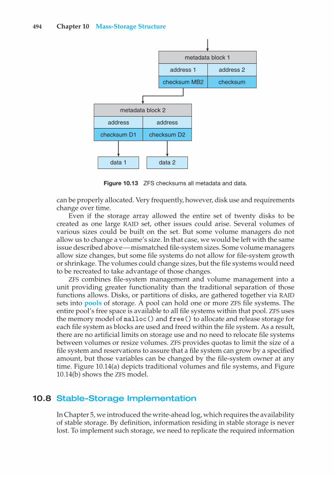
494 Chapter 10 Mass-Storage Structure
metadata block 1
address 1
checksum MB2 checksum
address 2
metadata block 2
address
checksum D1 checksum D2
data 1 data 2
address
Figure 10.13 ZFS checksums all metadata and data.
can be properly allocated. Very frequently, however, disk use and requirementschange over time.
Even if the storage array allowed the entire set of twenty disks to becreated as one large RAID set, other issues could arise. Several volumes ofvarious sizes could be built on the set. But some volume managers do notallow us to change a volume’s size. In that case, we would be left with the sameissue described above—mismatched file-system sizes. Some volume managersallow size changes, but some file systems do not allow for file-system growthor shrinkage. The volumes could change sizes, but the file systems would needto be recreated to take advantage of those changes.
ZFS combines file-system management and volume management into aunit providing greater functionality than the traditional separation of thosefunctions allows. Disks, or partitions of disks, are gathered together via RAIDsets into pools of storage. A pool can hold one or more ZFS file systems. Theentire pool’s free space is available to all file systems within that pool. ZFS usesthe memory model of malloc() and free() to allocate and release storage foreach file system as blocks are used and freed within the file system. As a result,there are no artificial limits on storage use and no need to relocate file systemsbetween volumes or resize volumes. ZFS provides quotas to limit the size of afile system and reservations to assure that a file system can grow by a specifiedamount, but those variables can be changed by the file-system owner at anytime. Figure 10.14(a) depicts traditional volumes and file systems, and Figure10.14(b) shows the ZFS model.
10.8 Stable-Storage Implementation
In Chapter 5, we introduced the write-ahead log, which requires the availabilityof stable storage. By definition, information residing in stable storage is neverlost. To implement such storage, we need to replicate the required information
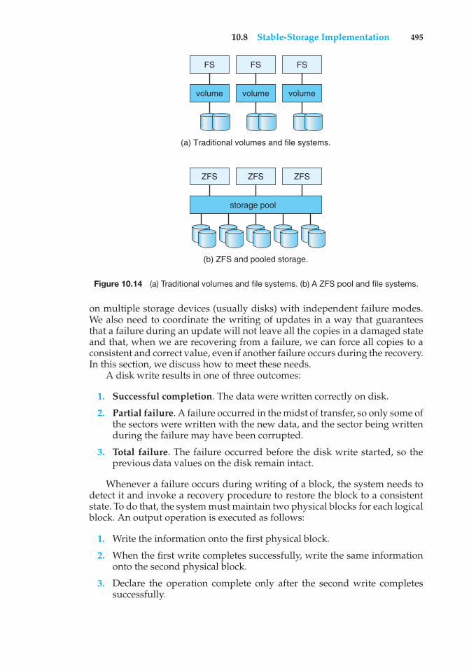
10.8 Stable-Storage Implementation 495
FS
volume
ZFS ZFS
storage pool
ZFS
volume volume
FS FS
(a) Traditional volumes and file systems.
(b) ZFS and pooled storage.
Figure 10.14 (a) Traditional volumes and file systems. (b) A ZFS pool and file systems.
on multiple storage devices (usually disks) with independent failure modes.We also need to coordinate the writing of updates in a way that guaranteesthat a failure during an update will not leave all the copies in a damaged stateand that, when we are recovering from a failure, we can force all copies to aconsistent and correct value, even if another failure occurs during the recovery.In this section, we discuss how to meet these needs.
A disk write results in one of three outcomes:
1. Successful completion. The data were written correctly on disk.
2. Partial failure. A failure occurred in the midst of transfer, so only some ofthe sectors were written with the new data, and the sector being writtenduring the failure may have been corrupted.
3. Total failure. The failure occurred before the disk write started, so theprevious data values on the disk remain intact.
Whenever a failure occurs during writing of a block, the system needs todetect it and invoke a recovery procedure to restore the block to a consistentstate. To do that, the system must maintain two physical blocks for each logicalblock. An output operation is executed as follows:
1. Write the information onto the first physical block.
2. When the first write completes successfully, write the same informationonto the second physical block.
3. Declare the operation complete only after the second write completessuccessfully.
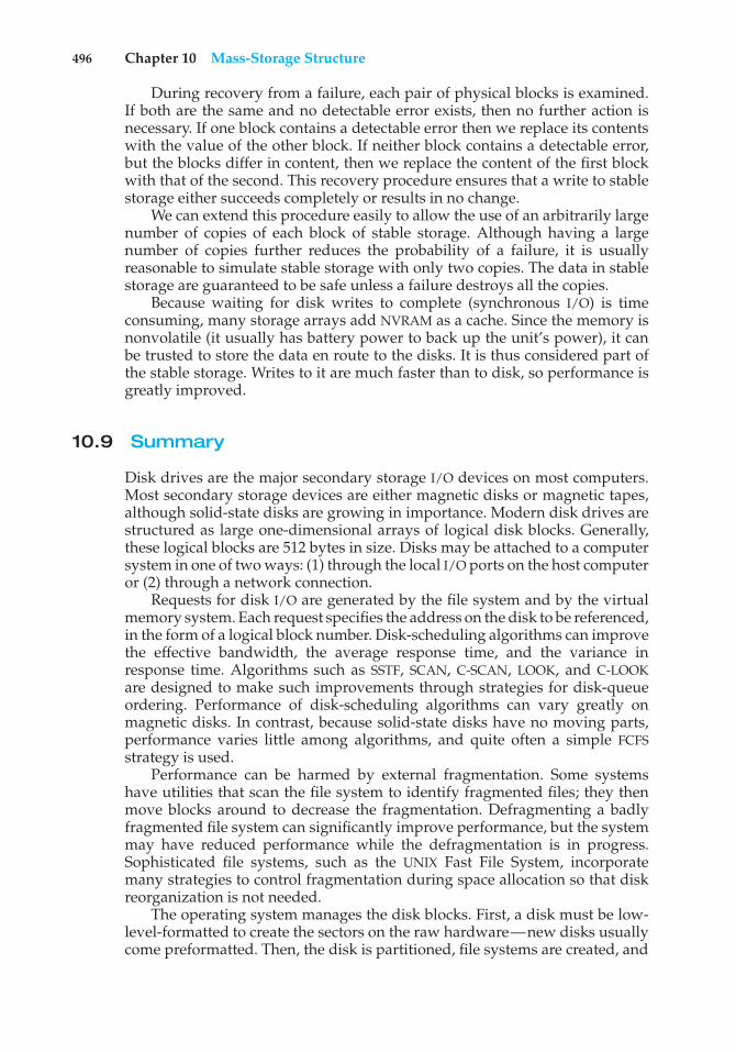
496 Chapter 10 Mass-Storage Structure
During recovery from a failure, each pair of physical blocks is examined.If both are the same and no detectable error exists, then no further action isnecessary. If one block contains a detectable error then we replace its contentswith the value of the other block. If neither block contains a detectable error,but the blocks differ in content, then we replace the content of the first blockwith that of the second. This recovery procedure ensures that a write to stablestorage either succeeds completely or results in no change.
We can extend this procedure easily to allow the use of an arbitrarily largenumber of copies of each block of stable storage. Although having a largenumber of copies further reduces the probability of a failure, it is usuallyreasonable to simulate stable storage with only two copies. The data in stablestorage are guaranteed to be safe unless a failure destroys all the copies.
Because waiting for disk writes to complete (synchronous I/O) is timeconsuming, many storage arrays add NVRAM as a cache. Since the memory isnonvolatile (it usually has battery power to back up the unit’s power), it canbe trusted to store the data en route to the disks. It is thus considered part ofthe stable storage. Writes to it are much faster than to disk, so performance isgreatly improved.
10.9 Summary
Disk drives are the major secondary storage I/O devices on most computers.Most secondary storage devices are either magnetic disks or magnetic tapes,although solid-state disks are growing in importance. Modern disk drives arestructured as large one-dimensional arrays of logical disk blocks. Generally,these logical blocks are 512 bytes in size. Disks may be attached to a computersystem in one of two ways: (1) through the local I/O ports on the host computeror (2) through a network connection.
Requests for disk I/O are generated by the file system and by the virtualmemory system. Each request specifies the address on the disk to be referenced,in the form of a logical block number. Disk-scheduling algorithms can improvethe effective bandwidth, the average response time, and the variance inresponse time. Algorithms such as SSTF, SCAN, C-SCAN, LOOK, and C-LOOKare designed to make such improvements through strategies for disk-queueordering. Performance of disk-scheduling algorithms can vary greatly onmagnetic disks. In contrast, because solid-state disks have no moving parts,performance varies little among algorithms, and quite often a simple FCFSstrategy is used.
Performance can be harmed by external fragmentation. Some systemshave utilities that scan the file system to identify fragmented files; they thenmove blocks around to decrease the fragmentation. Defragmenting a badlyfragmented file system can significantly improve performance, but the systemmay have reduced performance while the defragmentation is in progress.Sophisticated file systems, such as the UNIX Fast File System, incorporatemany strategies to control fragmentation during space allocation so that diskreorganization is not needed.
The operating system manages the disk blocks. First, a disk must be low-level-formatted to create the sectors on the raw hardware—new disks usuallycome preformatted. Then, the disk is partitioned, file systems are created, and
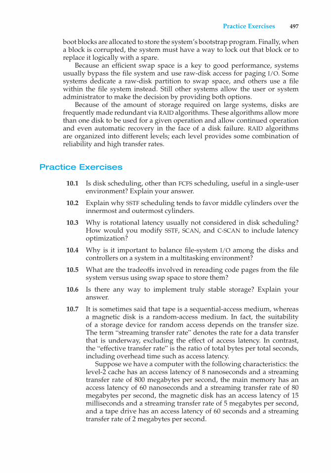
Practice Exercises 497
boot blocks are allocated to store the system’s bootstrap program. Finally, whena block is corrupted, the system must have a way to lock out that block or toreplace it logically with a spare.
Because an efficient swap space is a key to good performance, systemsusually bypass the file system and use raw-disk access for paging I/O. Somesystems dedicate a raw-disk partition to swap space, and others use a filewithin the file system instead. Still other systems allow the user or systemadministrator to make the decision by providing both options.
Because of the amount of storage required on large systems, disks arefrequently made redundant via RAID algorithms. These algorithms allow morethan one disk to be used for a given operation and allow continued operationand even automatic recovery in the face of a disk failure. RAID algorithmsare organized into different levels; each level provides some combination ofreliability and high transfer rates.
Practice Exercises
10.1 Is disk scheduling, other than FCFS scheduling, useful in a single-userenvironment? Explain your answer.
10.2 Explain why SSTF scheduling tends to favor middle cylinders over theinnermost and outermost cylinders.
10.3 Why is rotational latency usually not considered in disk scheduling?How would you modify SSTF, SCAN, and C-SCAN to include latencyoptimization?
10.4 Why is it important to balance file-system I/O among the disks andcontrollers on a system in a multitasking environment?
10.5 What are the tradeoffs involved in rereading code pages from the filesystem versus using swap space to store them?
10.6 Is there any way to implement truly stable storage? Explain youranswer.
10.7 It is sometimes said that tape is a sequential-access medium, whereasa magnetic disk is a random-access medium. In fact, the suitabilityof a storage device for random access depends on the transfer size.The term “streaming transfer rate” denotes the rate for a data transferthat is underway, excluding the effect of access latency. In contrast,the “effective transfer rate” is the ratio of total bytes per total seconds,including overhead time such as access latency.
Suppose we have a computer with the following characteristics: thelevel-2 cache has an access latency of 8 nanoseconds and a streamingtransfer rate of 800 megabytes per second, the main memory has anaccess latency of 60 nanoseconds and a streaming transfer rate of 80megabytes per second, the magnetic disk has an access latency of 15milliseconds and a streaming transfer rate of 5 megabytes per second,and a tape drive has an access latency of 60 seconds and a streamingtransfer rate of 2 megabytes per second.
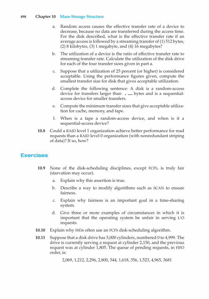
498 Chapter 10 Mass-Storage Structure
a. Random access causes the effective transfer rate of a device todecrease, because no data are transferred during the access time.For the disk described, what is the effective transfer rate if anaverage access is followed by a streaming transfer of (1) 512 bytes,(2) 8 kilobytes, (3) 1 megabyte, and (4) 16 megabytes?
b. The utilization of a device is the ratio of effective transfer rate tostreaming transfer rate. Calculate the utilization of the disk drivefor each of the four transfer sizes given in part a.
c. Suppose that a utilization of 25 percent (or higher) is consideredacceptable. Using the performance figures given, compute thesmallest transfer size for disk that gives acceptable utilization.
d. Complete the following sentence: A disk is a random-accessdevice for transfers larger than bytes and is a sequential-access device for smaller transfers.
e. Compute the minimum transfer sizes that give acceptable utiliza-tion for cache, memory, and tape.
f. When is a tape a random-access device, and when is it asequential-access device?
10.8 Could a RAID level 1 organization achieve better performance for readrequests than a RAID level 0 organization (with nonredundant stripingof data)? If so, how?
Exercises
10.9 None of the disk-scheduling disciplines, except FCFS, is truly fair(starvation may occur).
a. Explain why this assertion is true.
b. Describe a way to modify algorithms such as SCAN to ensurefairness.
c. Explain why fairness is an important goal in a time-sharingsystem.
d. Give three or more examples of circumstances in which it isimportant that the operating system be unfair in serving I/Orequests.
10.10 Explain why SSDs often use an FCFS disk-scheduling algorithm.
10.11 Suppose that a disk drive has 5,000 cylinders, numbered 0 to 4,999. Thedrive is currently serving a request at cylinder 2,150, and the previousrequest was at cylinder 1,805. The queue of pending requests, in FIFOorder, is:
2,069, 1,212, 2,296, 2,800, 544, 1,618, 356, 1,523, 4,965, 3681
Exercises 499
Starting from the current head position, what is the total distance (incylinders) that the disk arm moves to satisfy all the pending requestsfor each of the following disk-scheduling algorithms?
a. FCFS
b. SSTF
c. SCAN
d. LOOK
e. C-SCAN
f. C-LOOK
10.12 Elementary physics states that when an object is subjected to a constantacceleration a, the relationship between distance d and time t is givenby d = 1
2 at2. Suppose that, during a seek, the disk in Exercise 10.11accelerates the disk arm at a constant rate for the first half of the seek,then decelerates the disk arm at the same rate for the second half of theseek. Assume that the disk can perform a seek to an adjacent cylinderin 1 millisecond and a full-stroke seek over all 5,000 cylinders in 18milliseconds.
a. The distance of a seek is the number of cylinders over which thehead moves. Explain why the seek time is proportional to thesquare root of the seek distance.
b. Write an equation for the seek time as a function of the seekdistance. This equation should be of the form t = x + y
√L , where
t is the time in milliseconds and L is the seek distance in cylinders.
c. Calculate the total seek time for each of the schedules in Exercise10.11. Determine which schedule is the fastest (has the smallesttotal seek time).
d. The percentage speedup is the time saved divided by the originaltime. What is the percentage speedup of the fastest schedule overFCFS?
10.13 Suppose that the disk in Exercise 10.12 rotates at 7,200 RPM.
a. What is the average rotational latency of this disk drive?
b. What seek distance can be covered in the time that you found forpart a?
10.14 Describe some advantages and disadvantages of using SSDs as acaching tier and as a disk-drive replacement compared with using onlymagnetic disks.
10.15 Compare the performance of C-SCAN and SCAN scheduling, assuminga uniform distribution of requests. Consider the average response time(the time between the arrival of a request and the completion of thatrequest’s service), the variation in response time, and the effective
500 Chapter 10 Mass-Storage Structure
bandwidth. How does performance depend on the relative sizes ofseek time and rotational latency?
10.16 Requests are not usually uniformly distributed. For example, we canexpect a cylinder containing the file-system metadata to be accessedmore frequently than a cylinder containing only files. Suppose youknow that 50 percent of the requests are for a small, fixed number ofcylinders.
a. Would any of the scheduling algorithms discussed in this chapterbe particularly good for this case? Explain your answer.
b. Propose a disk-scheduling algorithm that gives even better per-formance by taking advantage of this “hot spot” on the disk.
10.17 Consider a RAID level 5 organization comprising five disks, with theparity for sets of four blocks on four disks stored on the fifth disk. Howmany blocks are accessed in order to perform the following?
a. A write of one block of data
b. A write of seven continuous blocks of data
10.18 Compare the throughput achieved by a RAID level 5 organization withthat achieved by a RAID level 1 organization for the following:
a. Read operations on single blocks
b. Read operations on multiple contiguous blocks
10.19 Compare the performance of write operations achieved by a RAID level5 organization with that achieved by a RAID level 1 organization.
10.20 Assume that you have a mixed configuration comprising disks orga-nized as RAID level 1 and RAID level 5 disks. Assume that the systemhas flexibility in deciding which disk organization to use for storing aparticular file. Which files should be stored in the RAID level 1 disksand which in the RAID level 5 disks in order to optimize performance?
10.21 The reliability of a hard-disk drive is typically described in terms ofa quantity called mean time between failures (MTBF). Although thisquantity is called a “time,” the MTBF actually is measured in drive-hoursper failure.
a. If a system contains 1,000 disk drives, each of which has a 750,000-hour MTBF, which of the following best describes how often adrive failure will occur in that disk farm: once per thousand years,once per century, once per decade, once per year, once per month,once per week, once per day, once per hour, once per minute, oronce per second?
b. Mortality statistics indicate that, on the average, a U.S. residenthas about 1 chance in 1,000 of dying between the ages of 20 and 21.Deduce the MTBF hours for 20-year-olds. Convert this figure fromhours to years. What does this MTBF tell you about the expectedlifetime of a 20-year-old?
Bibliographical Notes 501
c. The manufacturer guarantees a 1-million-hour MTBF for a certainmodel of disk drive. What can you conclude about the number ofyears for which one of these drives is under warranty?
10.22 Discuss the relative advantages and disadvantages of sector sparingand sector slipping.
10.23 Discuss the reasons why the operating system might require accurateinformation on how blocks are stored on a disk. How could the oper-ating system improve file-system performance with this knowledge?
Programming Problems
10.24 Write a program that implements the following disk-scheduling algo-rithms:
a. FCFS
b. SSTF
c. SCAN
d. C-SCAN
e. LOOK
f. C-LOOK
Your program will service a disk with 5,000 cylinders numbered 0 to4,999. The program will generate a random series of 1,000 cylinderrequests and service them according to each of the algorithms listedabove. The program will be passed the initial position of the disk head(as a parameter on the command line) and report the total amount ofhead movement required by each algorithm.
Bibliographical Notes
[Services (2012)] provides an overview of data storage in a variety of moderncomputing environments. [Teorey and Pinkerton (1972)] present an earlycomparative analysis of disk-scheduling algorithms using simulations thatmodel a disk for which seek time is linear in the number of cylinders crossed.Scheduling optimizations that exploit disk idle times are discussed in [Lumbet al. (2000)]. [Kim et al. (2009)] discusses disk-scheduling algorithms for SSDs.
Discussions of redundant arrays of independent disks (RAIDs) are pre-sented by [Patterson et al. (1988)].
[Russinovich and Solomon (2009)], [McDougall and Mauro (2007)], and[Love (2010)] discuss file system details in Windows, Solaris, and Linux,respectively.
The I/O size and randomness of the workload influence disk performanceconsiderably. [Ousterhout et al. (1985)] and [Ruemmler and Wilkes (1993)]report numerous interesting workload characteristics—for example, most filesare small, most newly created files are deleted soon thereafter, most files that
502 Chapter 10 Mass-Storage Structure
are opened for reading are read sequentially in their entirety, and most seeksare short.
The concept of a storage hierarchy has been studied for more than fortyyears. For instance, a 1970 paper by [Mattson et al. (1970)] describes amathematical approach to predicting the performance of a storage hierarchy.
Bibliography
[Kim et al. (2009)] J. Kim, Y. Oh, E. Kim, J. C. D. Lee, and S. Noh, “Disk schedulersfor solid state drivers” (2009), pages 295–304.
[Love (2010)] R. Love, Linux Kernel Development, Third Edition, Developer’sLibrary (2010).
[Lumb et al. (2000)] C. Lumb, J. Schindler, G. R. Ganger, D. F. Nagle, andE. Riedel, “Towards Higher Disk Head Utilization: Extracting Free BandwidthFrom Busy Disk Drives”, Symposium on Operating Systems Design and Implemen-tation (2000).
[Mattson et al. (1970)] R. L. Mattson, J. Gecsei, D. R. Slutz, and I. L. Traiger,“Evaluation Techniques for Storage Hierarchies”, IBM Systems Journal, Volume9, Number 2 (1970), pages 78–117.
[McDougall and Mauro (2007)] R. McDougall and J. Mauro, Solaris Internals,Second Edition, Prentice Hall (2007).
[Ousterhout et al. (1985)] J. K. Ousterhout, H. D. Costa, D. Harrison, J. A. Kunze,M. Kupfer, and J. G. Thompson, “A Trace-Driven Analysis of the UNIX 4.2 BSDFile System”, Proceedings of the ACM Symposium on Operating Systems Principles(1985), pages 15–24.
[Patterson et al. (1988)] D. A. Patterson, G. Gibson, and R. H. Katz, “A Casefor Redundant Arrays of Inexpensive Disks (RAID)”, Proceedings of the ACMSIGMOD International Conference on the Management of Data (1988), pages 109–116.
[Ruemmler and Wilkes (1993)] C. Ruemmler and J. Wilkes, “Unix Disk AccessPatterns”, Proceedings of the Winter USENIX Conference (1993), pages 405–420.
[Russinovich and Solomon (2009)] M. E. Russinovich and D. A. Solomon, Win-dows Internals: Including Windows Server 2008 and Windows Vista, Fifth Edition,Microsoft Press (2009).
[Services (2012)] E. E. Services, Information Storage and Management: Storing,Managing, and Protecting Digital Information in Classic, Virtualized, and CloudEnvironments, Wiley (2012).
[Teorey and Pinkerton (1972)] T. J. Teorey and T. B. Pinkerton, “A ComparativeAnalysis of Disk Scheduling Policies”, Communications of the ACM, Volume 15,Number 3 (1972), pages 177–184.
11C H A P T E R
File -SystemInterface
For most users, the file system is the most visible aspect of an operatingsystem. It provides the mechanism for on-line storage of and access to bothdata and programs of the operating system and all the users of the computersystem. The file system consists of two distinct parts: a collection of files, eachstoring related data, and a directory structure, which organizes and providesinformation about all the files in the system. File systems live on devices,which we described in the preceding chapter and will continue to discuss inthe following one. In this chapter, we consider the various aspects of files andthe major directory structures. We also discuss the semantics of sharing filesamong multiple processes, users, and computers. Finally, we discuss ways tohandle file protection, necessary when we have multiple users and we want tocontrol who may access files and how files may be accessed.
CHAPTER OBJECTIVES
• To explain the function of file systems.• To describe the interfaces to file systems.• To discuss file-system design tradeoffs, including access methods, file
sharing, file locking, and directory structures.• To explore file-system protection.
11.1 File Concept
Computers can store information on various storage media, such as magneticdisks, magnetic tapes, and optical disks. So that the computer system willbe convenient to use, the operating system provides a uniform logical viewof stored information. The operating system abstracts from the physicalproperties of its storage devices to define a logical storage unit, the file. Files aremapped by the operating system onto physical devices. These storage devicesare usually nonvolatile, so the contents are persistent between system reboots.
503
504 Chapter 11 File-System Interface
A file is a named collection of related information that is recorded onsecondary storage. From a user’s perspective, a file is the smallest allotmentof logical secondary storage; that is, data cannot be written to secondarystorage unless they are within a file. Commonly, files represent programs (bothsource and object forms) and data. Data files may be numeric, alphabetic,alphanumeric, or binary. Files may be free form, such as text files, or may beformatted rigidly. In general, a file is a sequence of bits, bytes, lines, or records,the meaning of which is defined by the file’s creator and user. The concept ofa file is thus extremely general.
The information in a file is defined by its creator. Many different types ofinformation may be stored in a file—source or executable programs, numeric ortext data, photos, music, video, and so on. A file has a certain defined structure,which depends on its type. A text file is a sequence of characters organizedinto lines (and possibly pages). A source file is a sequence of functions, each ofwhich is further organized as declarations followed by executable statements.An executable file is a series of code sections that the loader can bring intomemory and execute.
11.1.1 File Attributes
A file is named, for the convenience of its human users, and is referred to byits name. A name is usually a string of characters, such as example.c. Somesystems differentiate between uppercase and lowercase characters in names,whereas other systems do not. When a file is named, it becomes independentof the process, the user, and even the system that created it. For instance, oneuser might create the file example.c, and another user might edit that file byspecifying its name. The file’s owner might write the file to a USB disk, send itas an e-mail attachment, or copy it across a network, and it could still be calledexample.c on the destination system.
A file’s attributes vary from one operating system to another but typicallyconsist of these:
• Name. The symbolic file name is the only information kept in human-readable form.
• Identifier. This unique tag, usually a number, identifies the file within thefile system; it is the non-human-readable name for the file.
• Type. This information is needed for systems that support different typesof files.
• Location. This information is a pointer to a device and to the location ofthe file on that device.
• Size. The current size of the file (in bytes, words, or blocks) and possiblythe maximum allowed size are included in this attribute.
• Protection. Access-control information determines who can do reading,writing, executing, and so on.
• Time, date, and user identification. This information may be kept forcreation, last modification, and last use. These data can be useful forprotection, security, and usage monitoring.
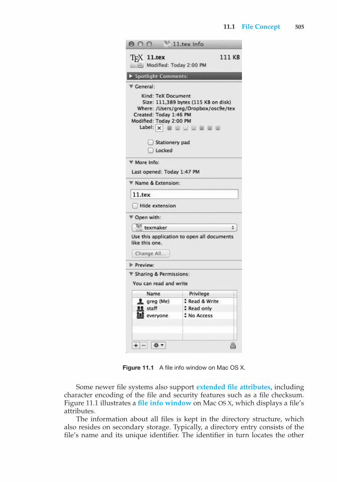
11.1 File Concept 505
Figure 11.1 A file info window on Mac OS X.
Some newer file systems also support extended file attributes, includingcharacter encoding of the file and security features such as a file checksum.Figure 11.1 illustrates a file info window on Mac OS X, which displays a file’sattributes.
The information about all files is kept in the directory structure, whichalso resides on secondary storage. Typically, a directory entry consists of thefile’s name and its unique identifier. The identifier in turn locates the other
506 Chapter 11 File-System Interface
file attributes. It may take more than a kilobyte to record this information foreach file. In a system with many files, the size of the directory itself may bemegabytes. Because directories, like files, must be nonvolatile, they must bestored on the device and brought into memory piecemeal, as needed.
11.1.2 File Operations
A file is an abstract data type. To define a file properly, we need to consider theoperations that can be performed on files. The operating system can providesystem calls to create, write, read, reposition, delete, and truncate files. Let’sexamine what the operating system must do to perform each of these six basicfile operations. It should then be easy to see how other similar operations, suchas renaming a file, can be implemented.
• Creating a file. Two steps are necessary to create a file. First, space in thefile system must be found for the file. We discuss how to allocate space forthe file in Chapter 12. Second, an entry for the new file must be made inthe directory.
• Writing a file. To write a file, we make a system call specifying both thename of the file and the information to be written to the file. Given thename of the file, the system searches the directory to find the file’s location.The system must keep a write pointer to the location in the file where thenext write is to take place. The write pointer must be updated whenever awrite occurs.
• Reading a file. To read from a file, we use a system call that specifies thename of the file and where (in memory) the next block of the file shouldbe put. Again, the directory is searched for the associated entry, and thesystem needs to keep a read pointer to the location in the file where thenext read is to take place. Once the read has taken place, the read pointeris updated. Because a process is usually either reading from or writing toa file, the current operation location can be kept as a per-process current-file-position pointer. Both the read and write operations use this samepointer, saving space and reducing system complexity.
• Repositioning within a file. The directory is searched for the appropriateentry, and the current-file-position pointer is repositioned to a given value.Repositioning within a file need not involve any actual I/O. This fileoperation is also known as a file seek.
• Deleting a file. To delete a file, we search the directory for the named file.Having found the associated directory entry, we release all file space, sothat it can be reused by other files, and erase the directory entry.
• Truncating a file. The user may want to erase the contents of a file butkeep its attributes. Rather than forcing the user to delete the file and thenrecreate it, this function allows all attributes to remain unchanged—exceptfor file length—but lets the file be reset to length zero and its file spacereleased.
These six basic operations comprise the minimal set of required fileoperations. Other common operations include appending new information
11.1 File Concept 507
to the end of an existing file and renaming an existing file. These primitiveoperations can then be combined to perform other file operations. For instance,we can create a copy of a file—or copy the file to another I/O device, such asa printer or a display—by creating a new file and then reading from the oldand writing to the new. We also want to have operations that allow a user toget and set the various attributes of a file. For example, we may want to haveoperations that allow a user to determine the status of a file, such as the file’slength, and to set file attributes, such as the file’s owner.
Most of the file operations mentioned involve searching the directory forthe entry associated with the named file. To avoid this constant searching,many systems require that an open() system call be made before a file is firstused. The operating system keeps a table, called the open-file table, containinginformation about all open files. When a file operation is requested, the file isspecified via an index into this table, so no searching is required. When the fileis no longer being actively used, it is closed by the process, and the operatingsystem removes its entry from the open-file table. create() and delete() aresystem calls that work with closed rather than open files.
Some systems implicitly open a file when the first reference to it is made.The file is automatically closed when the job or program that opened thefile terminates. Most systems, however, require that the programmer open afile explicitly with the open() system call before that file can be used. Theopen() operation takes a file name and searches the directory, copying thedirectory entry into the open-file table. The open() call can also accept access-mode information—create, read-only, read–write, append-only, and so on.This mode is checked against the file’s permissions. If the request mode isallowed, the file is opened for the process. The open() system call typicallyreturns a pointer to the entry in the open-file table. This pointer, not the actualfile name, is used in all I/O operations, avoiding any further searching andsimplifying the system-call interface.
The implementation of the open() and close() operations is morecomplicated in an environment where several processes may open the filesimultaneously. This may occur in a system where several different applicationsopen the same file at the same time. Typically, the operating system uses twolevels of internal tables: a per-process table and a system-wide table. The per-process table tracks all files that a process has open. Stored in this table isinformation regarding the process’s use of the file. For instance, the currentfile pointer for each file is found here. Access rights to the file and accountinginformation can also be included.
Each entry in the per-process table in turn points to a system-wide open-filetable. The system-wide table contains process-independent information, suchas the location of the file on disk, access dates, and file size. Once a file hasbeen opened by one process, the system-wide table includes an entry for thefile. When another process executes an open() call, a new entry is simplyadded to the process’s open-file table pointing to the appropriate entry inthe system-wide table. Typically, the open-file table also has an open countassociated with each file to indicate how many processes have the file open.Each close() decreases this open count, and when the open count reacheszero, the file is no longer in use, and the file’s entry is removed from theopen-file table.
508 Chapter 11 File-System Interface
In summary, several pieces of information are associated with an open file.
• File pointer. On systems that do not include a file offset as part of theread() and write() system calls, the system must track the last read–write location as a current-file-position pointer. This pointer is unique toeach process operating on the file and therefore must be kept separate fromthe on-disk file attributes.
• File-open count. As files are closed, the operating system must reuse itsopen-file table entries, or it could run out of space in the table. Multipleprocesses may have opened a file, and the system must wait for the lastfile to close before removing the open-file table entry. The file-open counttracks the number of opens and closes and reaches zero on the last close.The system can then remove the entry.
• Disk location of the file. Most file operations require the system to modifydata within the file. The information needed to locate the file on disk iskept in memory so that the system does not have to read it from disk foreach operation.
• Access rights. Each process opens a file in an access mode. This informationis stored on the per-process table so the operating system can allow or denysubsequent I/O requests.
Some operating systems provide facilities for locking an open file (orsections of a file). File locks allow one process to lock a file and prevent otherprocesses from gaining access to it. File locks are useful for files that are sharedby several processes—for example, a system log file that can be accessed andmodified by a number of processes in the system.
File locks provide functionality similar to reader–writer locks, covered inSection 5.7.2. A shared lock is akin to a reader lock in that several processescan acquire the lock concurrently. An exclusive lock behaves like a writer lock;only one process at a time can acquire such a lock. It is important to notethat not all operating systems provide both types of locks: some systems onlyprovide exclusive file locking.
FILE LOCKING IN JAVA
In the Java API, acquiring a lock requires first obtaining the FileChannelfor the file to be locked. The lock() method of the FileChannel is used toacquire the lock. The API of the lock() method is
FileLock lock(long begin, long end, boolean shared)where begin and end are the beginning and ending positions of the regionbeing locked. Setting shared to true is for shared locks; setting sharedto false acquires the lock exclusively. The lock is released by invoking therelease() of the FileLock returned by the lock() operation.
The program in Figure 11.2 illustrates file locking in Java. This programacquires two locks on the file file.txt. The first half of the file is acquiredas an exclusive lock; the lock for the second half is a shared lock.
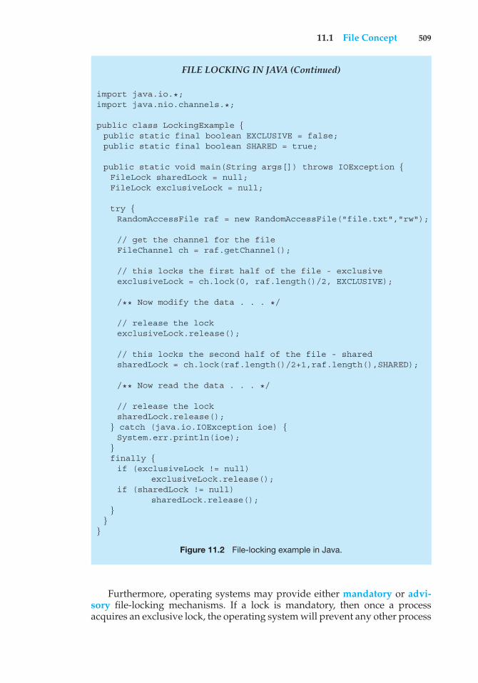
11.1 File Concept 509
FILE LOCKING IN JAVA (Continued)
import java.io.*;import java.nio.channels.*;
public class LockingExample {public static final boolean EXCLUSIVE = false;public static final boolean SHARED = true;
public static void main(String args[]) throws IOException {FileLock sharedLock = null;FileLock exclusiveLock = null;
try {RandomAccessFile raf = new RandomAccessFile("file.txt","rw");
// get the channel for the fileFileChannel ch = raf.getChannel();
// this locks the first half of the file - exclusiveexclusiveLock = ch.lock(0, raf.length()/2, EXCLUSIVE);
/** Now modify the data . . . */
// release the lockexclusiveLock.release();
// this locks the second half of the file - sharedsharedLock = ch.lock(raf.length()/2+1,raf.length(),SHARED);
/** Now read the data . . . */
// release the locksharedLock.release();
} catch (java.io.IOException ioe) {System.err.println(ioe);
}finally {if (exclusiveLock != null)
exclusiveLock.release();if (sharedLock != null)
sharedLock.release();}
}}
Figure 11.2 File-locking example in Java.
Furthermore, operating systems may provide either mandatory or advi-sory file-locking mechanisms. If a lock is mandatory, then once a processacquires an exclusive lock, the operating system will prevent any other process
510 Chapter 11 File-System Interface
from accessing the locked file. For example, assume a process acquires anexclusive lock on the file system.log. If we attempt to open system.logfrom another process—for example, a text editor—the operating system willprevent access until the exclusive lock is released. This occurs even if the texteditor is not written explicitly to acquire the lock. Alternatively, if the lockis advisory, then the operating system will not prevent the text editor fromacquiring access to system.log. Rather, the text editor must be written so thatit manually acquires the lock before accessing the file. In other words, if thelocking scheme is mandatory, the operating system ensures locking integrity.For advisory locking, it is up to software developers to ensure that locks areappropriately acquired and released. As a general rule, Windows operatingsystems adopt mandatory locking, and UNIX systems employ advisory locks.
The use of file locks requires the same precautions as ordinary processsynchronization. For example, programmers developing on systems withmandatory locking must be careful to hold exclusive file locks only whilethey are accessing the file. Otherwise, they will prevent other processes fromaccessing the file as well. Furthermore, some measures must be taken to ensurethat two or more processes do not become involved in a deadlock while tryingto acquire file locks.
11.1.3 File Types
When we design a file system—indeed, an entire operating system—wealways consider whether the operating system should recognize and supportfile types. If an operating system recognizes the type of a file, it can then operateon the file in reasonable ways. For example, a common mistake occurs when auser tries to output the binary-object form of a program. This attempt normallyproduces garbage; however, the attempt can succeed if the operating systemhas been told that the file is a binary-object program.
A common technique for implementing file types is to include the typeas part of the file name. The name is split into two parts—a name and anextension, usually separated by a period (Figure 11.3). In this way, the userand the operating system can tell from the name alone what the type of a fileis. Most operating systems allow users to specify a file name as a sequenceof characters followed by a period and terminated by an extension madeup of additional characters. Examples include resume.docx, server.c, andReaderThread.cpp.
The system uses the extension to indicate the type of the file and the typeof operations that can be done on that file. Only a file with a .com, .exe, or .shextension can be executed, for instance. The .com and .exe files are two formsof binary executable files, whereas the .sh file is a shell script containing, inASCII format, commands to the operating system. Application programs alsouse extensions to indicate file types in which they are interested. For example,Java compilers expect source files to have a .java extension, and the MicrosoftWord word processor expects its files to end with a .doc or .docx extension.These extensions are not always required, so a user may specify a file withoutthe extension (to save typing), and the application will look for a file withthe given name and the extension it expects. Because these extensions arenot supported by the operating system, they can be considered “hints” to theapplications that operate on them.
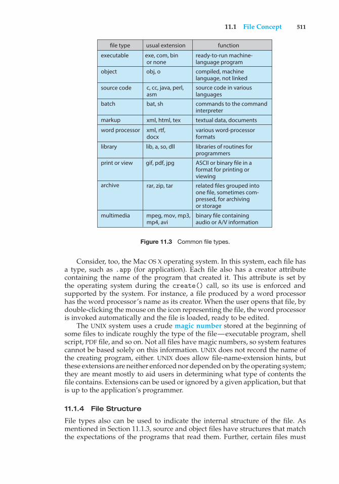
11.1 File Concept 511
file type usual extension function
ready-to-run machine-language program
executable exe, com, binor none
compiled, machinelanguage, not linked
object obj, o
binary file containingaudio or A/V information
multimedia mpeg, mov, mp3,mp4, avi
related files grouped intoone file, sometimes com-pressed, for archivingor storage
archive rar, zip, tar
ASCII or binary file in aformat for printing orviewing
print or view gif, pdf, jpg
libraries of routines forprogrammers
library lib, a, so, dll
various word-processorformats
word processordocx
commands to the commandinterpreter
batch bat, sh
textual data, documentsmarkup xml, html, tex
source code in variouslanguages
source code c, cc, java, perl,asm
xml, rtf,
Figure 11.3 Common file types.
Consider, too, the Mac OS X operating system. In this system, each file hasa type, such as .app (for application). Each file also has a creator attributecontaining the name of the program that created it. This attribute is set bythe operating system during the create() call, so its use is enforced andsupported by the system. For instance, a file produced by a word processorhas the word processor’s name as its creator. When the user opens that file, bydouble-clicking the mouse on the icon representing the file, the word processoris invoked automatically and the file is loaded, ready to be edited.
The UNIX system uses a crude magic number stored at the beginning ofsome files to indicate roughly the type of the file—executable program, shellscript, PDF file, and so on. Not all files have magic numbers, so system featurescannot be based solely on this information. UNIX does not record the name ofthe creating program, either. UNIX does allow file-name-extension hints, butthese extensions are neither enforced nor depended on by the operating system;they are meant mostly to aid users in determining what type of contents thefile contains. Extensions can be used or ignored by a given application, but thatis up to the application’s programmer.
11.1.4 File Structure
File types also can be used to indicate the internal structure of the file. Asmentioned in Section 11.1.3, source and object files have structures that matchthe expectations of the programs that read them. Further, certain files must
512 Chapter 11 File-System Interface
conform to a required structure that is understood by the operating system. Forexample, the operating system requires that an executable file have a specificstructure so that it can determine where in memory to load the file and whatthe location of the first instruction is. Some operating systems extend this ideainto a set of system-supported file structures, with sets of special operationsfor manipulating files with those structures.
This point brings us to one of the disadvantages of having the operatingsystem support multiple file structures: the resulting size of the operatingsystem is cumbersome. If the operating system defines five different filestructures, it needs to contain the code to support these file structures.In addition, it may be necessary to define every file as one of the filetypes supported by the operating system. When new applications requireinformation structured in ways not supported by the operating system, severeproblems may result.
For example, assume that a system supports two types of files: text files(composed of ASCII characters separated by a carriage return and line feed)and executable binary files. Now, if we (as users) want to define an encryptedfile to protect the contents from being read by unauthorized people, we mayfind neither file type to be appropriate. The encrypted file is not ASCII text linesbut rather is (apparently) random bits. Although it may appear to be a binaryfile, it is not executable. As a result, we may have to circumvent or misuse theoperating system’s file-type mechanism or abandon our encryption scheme.
Some operating systems impose (and support) a minimal number of filestructures. This approach has been adopted in UNIX, Windows, and others.UNIX considers each file to be a sequence of 8-bit bytes; no interpretation ofthese bits is made by the operating system. This scheme provides maximumflexibility but little support. Each application program must include its owncode to interpret an input file as to the appropriate structure. However, alloperating systems must support at least one structure—that of an executablefile—so that the system is able to load and run programs.
11.1.5 Internal File Structure
Internally, locating an offset within a file can be complicated for the operatingsystem. Disk systems typically have a well-defined block size determined bythe size of a sector. All disk I/O is performed in units of one block (physicalrecord), and all blocks are the same size. It is unlikely that the physical recordsize will exactly match the length of the desired logical record. Logical recordsmay even vary in length. Packing a number of logical records into physicalblocks is a common solution to this problem.
For example, the UNIX operating system defines all files to be simplystreams of bytes. Each byte is individually addressable by its offset from thebeginning (or end) of the file. In this case, the logical record size is 1 byte. Thefile system automatically packs and unpacks bytes into physical disk blocks—say, 512 bytes per block—as necessary.
The logical record size, physical block size, and packing technique deter-mine how many logical records are in each physical block. The packing can bedone either by the user’s application program or by the operating system. Ineither case, the file may be considered a sequence of blocks. All the basic I/O
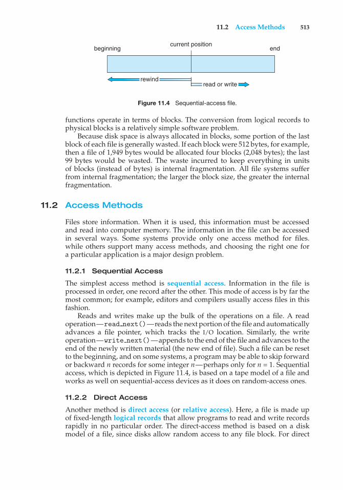
11.2 Access Methods 513
beginning endcurrent position
rewindread or write
Figure 11.4 Sequential-access file.
functions operate in terms of blocks. The conversion from logical records tophysical blocks is a relatively simple software problem.
Because disk space is always allocated in blocks, some portion of the lastblock of each file is generally wasted. If each block were 512 bytes, for example,then a file of 1,949 bytes would be allocated four blocks (2,048 bytes); the last99 bytes would be wasted. The waste incurred to keep everything in unitsof blocks (instead of bytes) is internal fragmentation. All file systems sufferfrom internal fragmentation; the larger the block size, the greater the internalfragmentation.
11.2 Access Methods
Files store information. When it is used, this information must be accessedand read into computer memory. The information in the file can be accessedin several ways. Some systems provide only one access method for files.while others support many access methods, and choosing the right one fora particular application is a major design problem.
11.2.1 Sequential Access
The simplest access method is sequential access. Information in the file isprocessed in order, one record after the other. This mode of access is by far themost common; for example, editors and compilers usually access files in thisfashion.
Reads and writes make up the bulk of the operations on a file. A readoperation—read next()—reads the next portion of the file and automaticallyadvances a file pointer, which tracks the I/O location. Similarly, the writeoperation—write next()—appends to the end of the file and advances to theend of the newly written material (the new end of file). Such a file can be resetto the beginning, and on some systems, a program may be able to skip forwardor backward n records for some integer n—perhaps only for n = 1. Sequentialaccess, which is depicted in Figure 11.4, is based on a tape model of a file andworks as well on sequential-access devices as it does on random-access ones.
11.2.2 Direct Access
Another method is direct access (or relative access). Here, a file is made upof fixed-length logical records that allow programs to read and write recordsrapidly in no particular order. The direct-access method is based on a diskmodel of a file, since disks allow random access to any file block. For direct
514 Chapter 11 File-System Interface
access, the file is viewed as a numbered sequence of blocks or records. Thus,we may read block 14, then read block 53, and then write block 7. There are norestrictions on the order of reading or writing for a direct-access file.
Direct-access files are of great use for immediate access to large amountsof information. Databases are often of this type. When a query concerning aparticular subject arrives, we compute which block contains the answer andthen read that block directly to provide the desired information.
As a simple example, on an airline-reservation system, we might store allthe information about a particular flight (for example, flight 713) in the blockidentified by the flight number. Thus, the number of available seats for flight713 is stored in block 713 of the reservation file. To store information about alarger set, such as people, we might compute a hash function on the people’snames or search a small in-memory index to determine a block to read andsearch.
For the direct-access method, the file operations must be modified toinclude the block number as a parameter. Thus, we have read(n), wheren is the block number, rather than read next(), and write(n) ratherthan write next(). An alternative approach is to retain read next() andwrite next(), as with sequential access, and to add an operation posi-tion file(n) where n is the block number. Then, to effect a read(n), wewould position file(n) and then read next().
The block number provided by the user to the operating system is normallya relative block number. A relative block number is an index relative to thebeginning of the file. Thus, the first relative block of the file is 0, the next is1, and so on, even though the absolute disk address may be 14703 for thefirst block and 3192 for the second. The use of relative block numbers allowsthe operating system to decide where the file should be placed (called theallocation problem, as we discuss in Chapter 12) and helps to prevent the userfrom accessing portions of the file system that may not be part of her file. Somesystems start their relative block numbers at 0; others start at 1.
How, then, does the system satisfy a request for record N in a file? Assumingwe have a logical record length L, the request for record N is turned into anI/O request for L bytes starting at location L ∗ (N) within the file (assuming thefirst record is N = 0). Since logical records are of a fixed size, it is also easy toread, write, or delete a record.
Not all operating systems support both sequential and direct access forfiles. Some systems allow only sequential file access; others allow only directaccess. Some systems require that a file be defined as sequential or direct whenit is created. Such a file can be accessed only in a manner consistent with itsdeclaration. We can easily simulate sequential access on a direct-access file bysimply keeping a variable cp that defines our current position, as shown inFigure 11.5. Simulating a direct-access file on a sequential-access file, however,is extremely inefficient and clumsy.
11.2.3 Other Access Methods
Other access methods can be built on top of a direct-access method. Thesemethods generally involve the construction of an index for the file. The index,like an index in the back of a book, contains pointers to the various blocks. To
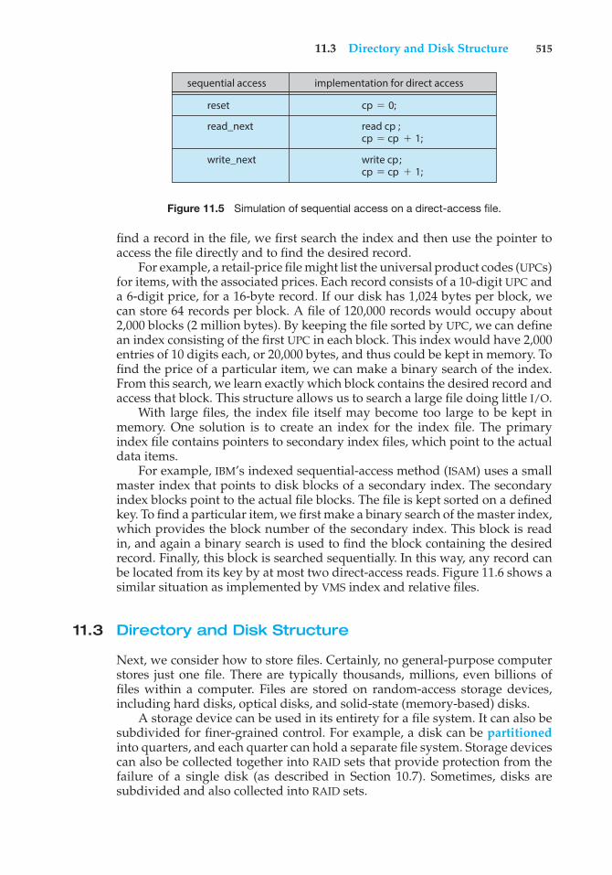
11.3 Directory and Disk Structure 515
sequential access
reset
read_next
write_next
cp 0;
read cp ;cp cp 1;
write cp ;cp cp 1;
implementation for direct access
Figure 11.5 Simulation of sequential access on a direct-access file.
find a record in the file, we first search the index and then use the pointer toaccess the file directly and to find the desired record.
For example, a retail-price file might list the universal product codes (UPCs)for items, with the associated prices. Each record consists of a 10-digit UPC anda 6-digit price, for a 16-byte record. If our disk has 1,024 bytes per block, wecan store 64 records per block. A file of 120,000 records would occupy about2,000 blocks (2 million bytes). By keeping the file sorted by UPC, we can definean index consisting of the first UPC in each block. This index would have 2,000entries of 10 digits each, or 20,000 bytes, and thus could be kept in memory. Tofind the price of a particular item, we can make a binary search of the index.From this search, we learn exactly which block contains the desired record andaccess that block. This structure allows us to search a large file doing little I/O.
With large files, the index file itself may become too large to be kept inmemory. One solution is to create an index for the index file. The primaryindex file contains pointers to secondary index files, which point to the actualdata items.
For example, IBM’s indexed sequential-access method (ISAM) uses a smallmaster index that points to disk blocks of a secondary index. The secondaryindex blocks point to the actual file blocks. The file is kept sorted on a definedkey. To find a particular item, we first make a binary search of the master index,which provides the block number of the secondary index. This block is readin, and again a binary search is used to find the block containing the desiredrecord. Finally, this block is searched sequentially. In this way, any record canbe located from its key by at most two direct-access reads. Figure 11.6 shows asimilar situation as implemented by VMS index and relative files.
11.3 Directory and Disk Structure
Next, we consider how to store files. Certainly, no general-purpose computerstores just one file. There are typically thousands, millions, even billions offiles within a computer. Files are stored on random-access storage devices,including hard disks, optical disks, and solid-state (memory-based) disks.
A storage device can be used in its entirety for a file system. It can also besubdivided for finer-grained control. For example, a disk can be partitionedinto quarters, and each quarter can hold a separate file system. Storage devicescan also be collected together into RAID sets that provide protection from thefailure of a single disk (as described in Section 10.7). Sometimes, disks aresubdivided and also collected into RAID sets.
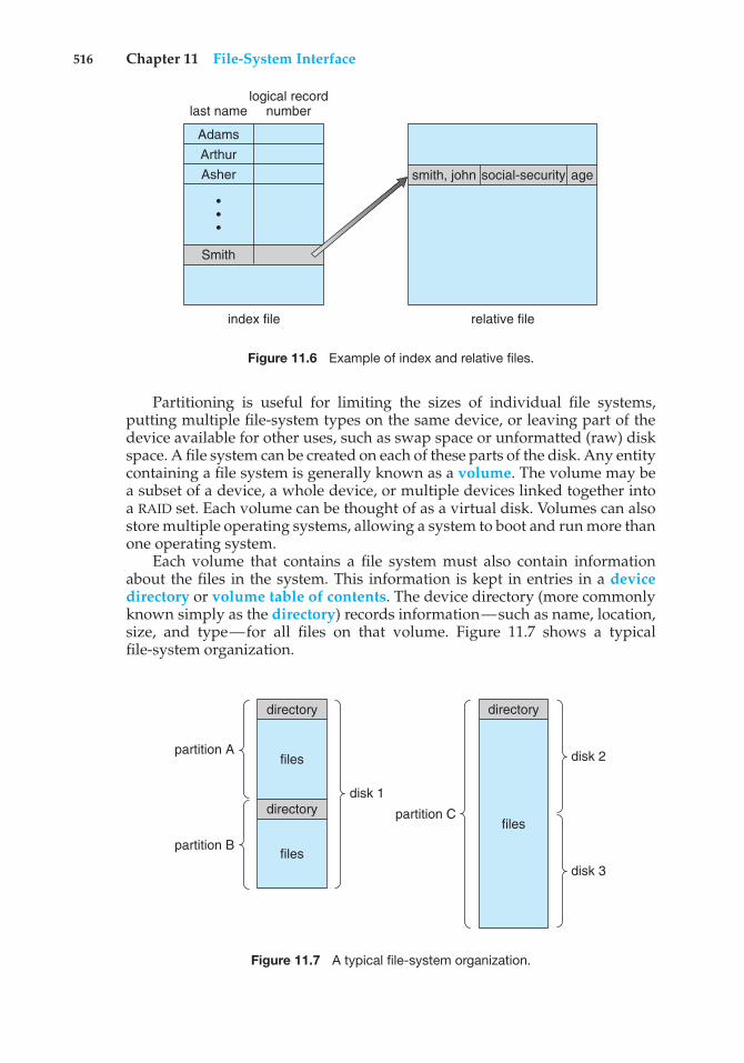
516 Chapter 11 File-System Interface
index file relative file
Smith
last name
smith, john social-security age
logical recordnumber
AdamsArthurAsher
•••
Figure 11.6 Example of index and relative files.
Partitioning is useful for limiting the sizes of individual file systems,putting multiple file-system types on the same device, or leaving part of thedevice available for other uses, such as swap space or unformatted (raw) diskspace. A file system can be created on each of these parts of the disk. Any entitycontaining a file system is generally known as a volume. The volume may bea subset of a device, a whole device, or multiple devices linked together intoa RAID set. Each volume can be thought of as a virtual disk. Volumes can alsostore multiple operating systems, allowing a system to boot and run more thanone operating system.
Each volume that contains a file system must also contain informationabout the files in the system. This information is kept in entries in a devicedirectory or volume table of contents. The device directory (more commonlyknown simply as the directory) records information—such as name, location,size, and type—for all files on that volume. Figure 11.7 shows a typicalfile-system organization.
directory directory
directory
filespartition A
partition B
partition C
files
disk 1
disk 2
disk 3
files
Figure 11.7 A typical file-system organization.
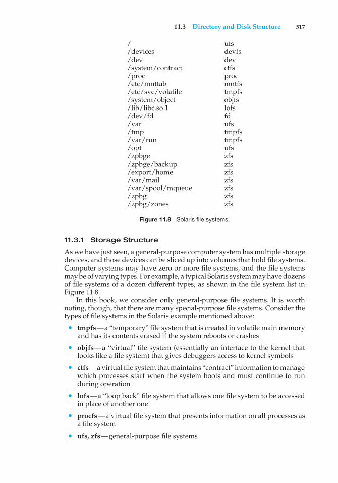
11.3 Directory and Disk Structure 517
/ ufs/devices devfs/dev dev/system/contract ctfs/proc proc/etc/mnttab mntfs/etc/svc/volatile tmpfs/system/object objfs/lib/libc.so.1 lofs/dev/fd fd/var ufs/tmp tmpfs/var/run tmpfs/opt ufs/zpbge zfs/zpbge/backup zfs/export/home zfs/var/mail zfs/var/spool/mqueue zfs/zpbg zfs/zpbg/zones zfs
Figure 11.8 Solaris file systems.
11.3.1 Storage Structure
As we have just seen, a general-purpose computer system has multiple storagedevices, and those devices can be sliced up into volumes that hold file systems.Computer systems may have zero or more file systems, and the file systemsmay be of varying types. For example, a typical Solaris system may have dozensof file systems of a dozen different types, as shown in the file system list inFigure 11.8.
In this book, we consider only general-purpose file systems. It is worthnoting, though, that there are many special-purpose file systems. Consider thetypes of file systems in the Solaris example mentioned above:
• tmpfs—a “temporary” file system that is created in volatile main memoryand has its contents erased if the system reboots or crashes
• objfs—a “virtual” file system (essentially an interface to the kernel thatlooks like a file system) that gives debuggers access to kernel symbols
• ctfs—a virtual file system that maintains “contract” information to managewhich processes start when the system boots and must continue to runduring operation
• lofs—a “loop back” file system that allows one file system to be accessedin place of another one
• procfs—a virtual file system that presents information on all processes asa file system
• ufs, zfs—general-purpose file systems
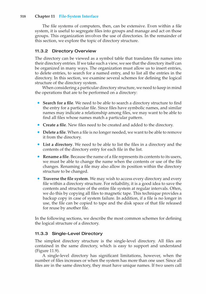
518 Chapter 11 File-System Interface
The file systems of computers, then, can be extensive. Even within a filesystem, it is useful to segregate files into groups and manage and act on thosegroups. This organization involves the use of directories. In the remainder ofthis section, we explore the topic of directory structure.
11.3.2 Directory Overview
The directory can be viewed as a symbol table that translates file names intotheir directory entries. If we take such a view, we see that the directory itself canbe organized in many ways. The organization must allow us to insert entries,to delete entries, to search for a named entry, and to list all the entries in thedirectory. In this section, we examine several schemes for defining the logicalstructure of the directory system.
When considering a particular directory structure, we need to keep in mindthe operations that are to be performed on a directory:
• Search for a file. We need to be able to search a directory structure to findthe entry for a particular file. Since files have symbolic names, and similarnames may indicate a relationship among files, we may want to be able tofind all files whose names match a particular pattern.
• Create a file. New files need to be created and added to the directory.
• Delete a file. When a file is no longer needed, we want to be able to removeit from the directory.
• List a directory. We need to be able to list the files in a directory and thecontents of the directory entry for each file in the list.
• Rename a file. Because the name of a file represents its contents to its users,we must be able to change the name when the contents or use of the filechanges. Renaming a file may also allow its position within the directorystructure to be changed.
• Traverse the file system. We may wish to access every directory and everyfile within a directory structure. For reliability, it is a good idea to save thecontents and structure of the entire file system at regular intervals. Often,we do this by copying all files to magnetic tape. This technique provides abackup copy in case of system failure. In addition, if a file is no longer inuse, the file can be copied to tape and the disk space of that file releasedfor reuse by another file.
In the following sections, we describe the most common schemes for definingthe logical structure of a directory.
11.3.3 Single-Level Directory
The simplest directory structure is the single-level directory. All files arecontained in the same directory, which is easy to support and understand(Figure 11.9).
A single-level directory has significant limitations, however, when thenumber of files increases or when the system has more than one user. Since allfiles are in the same directory, they must have unique names. If two users call
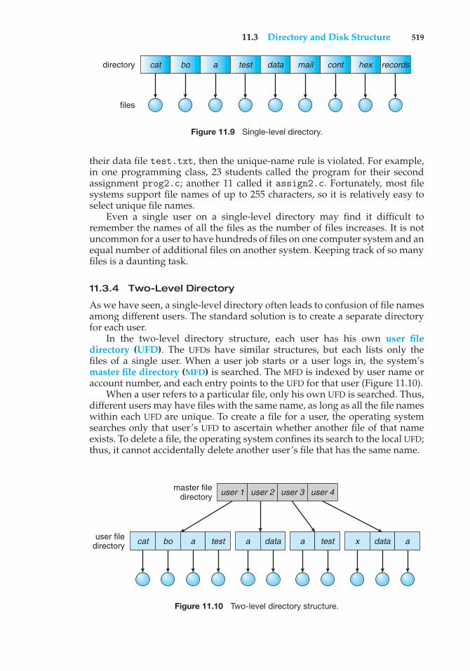
11.3 Directory and Disk Structure 519
cat
files
directory bo a test data mail cont hex records
Figure 11.9 Single-level directory.
their data file test.txt, then the unique-name rule is violated. For example,in one programming class, 23 students called the program for their secondassignment prog2.c; another 11 called it assign2.c. Fortunately, most filesystems support file names of up to 255 characters, so it is relatively easy toselect unique file names.
Even a single user on a single-level directory may find it difficult toremember the names of all the files as the number of files increases. It is notuncommon for a user to have hundreds of files on one computer system and anequal number of additional files on another system. Keeping track of so manyfiles is a daunting task.
11.3.4 Two-Level Directory
As we have seen, a single-level directory often leads to confusion of file namesamong different users. The standard solution is to create a separate directoryfor each user.
In the two-level directory structure, each user has his own user filedirectory (UFD). The UFDs have similar structures, but each lists only thefiles of a single user. When a user job starts or a user logs in, the system’smaster file directory (MFD) is searched. The MFD is indexed by user name oraccount number, and each entry points to the UFD for that user (Figure 11.10).
When a user refers to a particular file, only his own UFD is searched. Thus,different users may have files with the same name, as long as all the file nameswithin each UFD are unique. To create a file for a user, the operating systemsearches only that user’s UFD to ascertain whether another file of that nameexists. To delete a file, the operating system confines its search to the local UFD;thus, it cannot accidentally delete another user’s file that has the same name.
cat bo a test x data aa
user 1 user 2 user 3 user 4
data a testuser filedirectory
master filedirectory
Figure 11.10 Two-level directory structure.
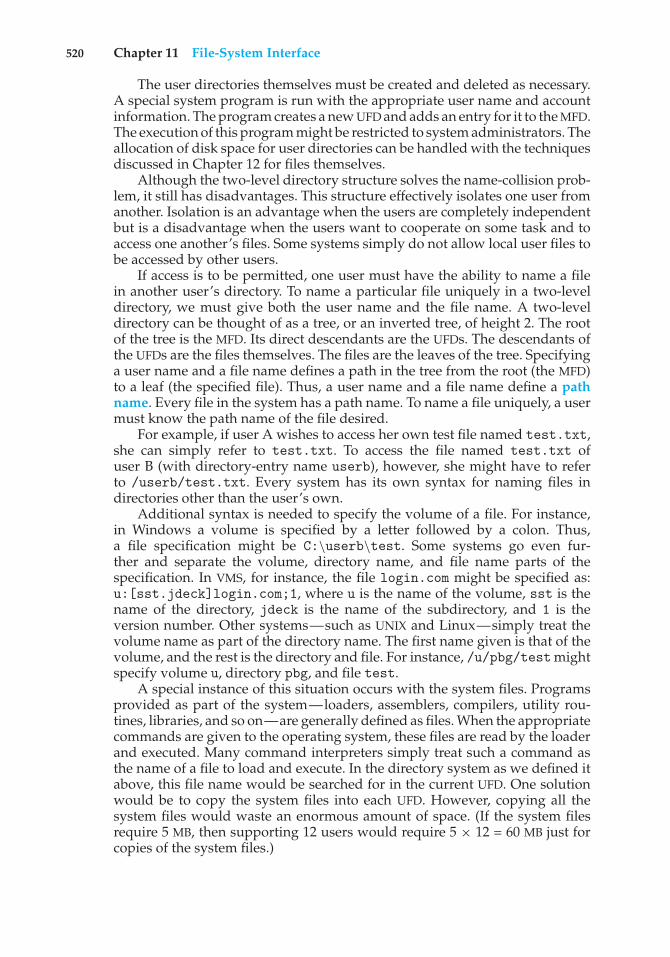
520 Chapter 11 File-System Interface
The user directories themselves must be created and deleted as necessary.A special system program is run with the appropriate user name and accountinformation. The program creates a new UFD and adds an entry for it to the MFD.The execution of this program might be restricted to system administrators. Theallocation of disk space for user directories can be handled with the techniquesdiscussed in Chapter 12 for files themselves.
Although the two-level directory structure solves the name-collision prob-lem, it still has disadvantages. This structure effectively isolates one user fromanother. Isolation is an advantage when the users are completely independentbut is a disadvantage when the users want to cooperate on some task and toaccess one another’s files. Some systems simply do not allow local user files tobe accessed by other users.
If access is to be permitted, one user must have the ability to name a filein another user’s directory. To name a particular file uniquely in a two-leveldirectory, we must give both the user name and the file name. A two-leveldirectory can be thought of as a tree, or an inverted tree, of height 2. The rootof the tree is the MFD. Its direct descendants are the UFDs. The descendants ofthe UFDs are the files themselves. The files are the leaves of the tree. Specifyinga user name and a file name defines a path in the tree from the root (the MFD)to a leaf (the specified file). Thus, a user name and a file name define a pathname. Every file in the system has a path name. To name a file uniquely, a usermust know the path name of the file desired.
For example, if user A wishes to access her own test file named test.txt,she can simply refer to test.txt. To access the file named test.txt ofuser B (with directory-entry name userb), however, she might have to referto /userb/test.txt. Every system has its own syntax for naming files indirectories other than the user’s own.
Additional syntax is needed to specify the volume of a file. For instance,in Windows a volume is specified by a letter followed by a colon. Thus,a file specification might be C:\userb\test. Some systems go even fur-ther and separate the volume, directory name, and file name parts of thespecification. In VMS, for instance, the file login.com might be specified as:u:[sst.jdeck]login.com;1, where u is the name of the volume, sst is thename of the directory, jdeck is the name of the subdirectory, and 1 is theversion number. Other systems—such as UNIX and Linux—simply treat thevolume name as part of the directory name. The first name given is that of thevolume, and the rest is the directory and file. For instance, /u/pbg/testmightspecify volume u, directory pbg, and file test.
A special instance of this situation occurs with the system files. Programsprovided as part of the system—loaders, assemblers, compilers, utility rou-tines, libraries, and so on—are generally defined as files. When the appropriatecommands are given to the operating system, these files are read by the loaderand executed. Many command interpreters simply treat such a command asthe name of a file to load and execute. In the directory system as we defined itabove, this file name would be searched for in the current UFD. One solutionwould be to copy the system files into each UFD. However, copying all thesystem files would waste an enormous amount of space. (If the system filesrequire 5 MB, then supporting 12 users would require 5 × 12 = 60 MB just forcopies of the system files.)
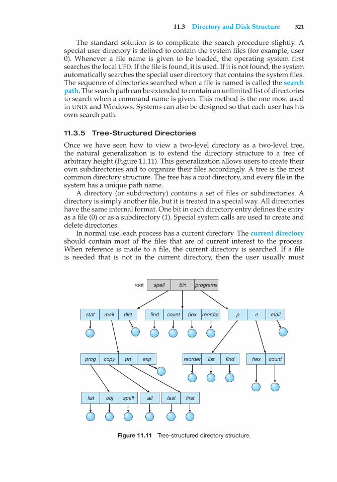
11.3 Directory and Disk Structure 521
The standard solution is to complicate the search procedure slightly. Aspecial user directory is defined to contain the system files (for example, user0). Whenever a file name is given to be loaded, the operating system firstsearches the local UFD. If the file is found, it is used. If it is not found, the systemautomatically searches the special user directory that contains the system files.The sequence of directories searched when a file is named is called the searchpath. The search path can be extended to contain an unlimited list of directoriesto search when a command name is given. This method is the one most usedin UNIX and Windows. Systems can also be designed so that each user has hisown search path.
11.3.5 Tree-Structured Directories
Once we have seen how to view a two-level directory as a two-level tree,the natural generalization is to extend the directory structure to a tree ofarbitrary height (Figure 11.11). This generalization allows users to create theirown subdirectories and to organize their files accordingly. A tree is the mostcommon directory structure. The tree has a root directory, and every file in thesystem has a unique path name.
A directory (or subdirectory) contains a set of files or subdirectories. Adirectory is simply another file, but it is treated in a special way. All directorieshave the same internal format. One bit in each directory entry defines the entryas a file (0) or as a subdirectory (1). Special system calls are used to create anddelete directories.
In normal use, each process has a current directory. The current directoryshould contain most of the files that are of current interest to the process.When reference is made to a file, the current directory is searched. If a fileis needed that is not in the current directory, then the user usually must
list obj spell
find count hex reorderstat mail dist
root spell bin programs
p e mail
reorder list findprog copy prt exp
last first
hex count
all
Figure 11.11 Tree-structured directory structure.
522 Chapter 11 File-System Interface
either specify a path name or change the current directory to be the directoryholding that file. To change directories, a system call is provided that takes adirectory name as a parameter and uses it to redefine the current directory.Thus, the user can change her current directory whenever she wants. From onechange directory() system call to the next, all open() system calls searchthe current directory for the specified file. Note that the search path may ormay not contain a special entry that stands for “the current directory.”
The initial current directory of a user’s login shell is designated whenthe user job starts or the user logs in. The operating system searches theaccounting file (or some other predefined location) to find an entry for thisuser (for accounting purposes). In the accounting file is a pointer to (or thename of) the user’s initial directory. This pointer is copied to a local variablefor this user that specifies the user’s initial current directory. From that shell,other processes can be spawned. The current directory of any subprocess isusually the current directory of the parent when it was spawned.
Path names can be of two types: absolute and relative. An absolute pathname begins at the root and follows a path down to the specified file, givingthe directory names on the path. A relative path name defines a path from thecurrent directory. For example, in the tree-structured file system of Figure11.11, if the current directory is root/spell/mail, then the relative pathname prt/first refers to the same file as does the absolute path nameroot/spell/mail/prt/first.
Allowing a user to define her own subdirectories permits her to imposea structure on her files. This structure might result in separate directories forfiles associated with different topics (for example, a subdirectory was createdto hold the text of this book) or different forms of information (for example,the directory programs may contain source programs; the directory bin maystore all the binaries).
An interesting policy decision in a tree-structured directory concerns howto handle the deletion of a directory. If a directory is empty, its entry in thedirectory that contains it can simply be deleted. However, suppose the directoryto be deleted is not empty but contains several files or subdirectories. One oftwo approaches can be taken. Some systems will not delete a directory unlessit is empty. Thus, to delete a directory, the user must first delete all the filesin that directory. If any subdirectories exist, this procedure must be appliedrecursively to them, so that they can be deleted also. This approach can resultin a substantial amount of work. An alternative approach, such as that takenby the UNIX rm command, is to provide an option: when a request is madeto delete a directory, all that directory’s files and subdirectories are also to bedeleted. Either approach is fairly easy to implement; the choice is one of policy.The latter policy is more convenient, but it is also more dangerous, because anentire directory structure can be removed with one command. If that commandis issued in error, a large number of files and directories will need to be restored(assuming a backup exists).
With a tree-structured directory system, users can be allowed to access, inaddition to their files, the files of other users. For example, user B can access afile of user A by specifying its path names. User B can specify either an absoluteor a relative path name. Alternatively, user B can change her current directoryto be user A’s directory and access the file by its file names.
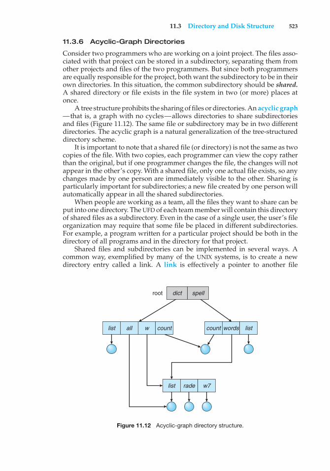
11.3 Directory and Disk Structure 523
11.3.6 Acyclic-Graph Directories
Consider two programmers who are working on a joint project. The files asso-ciated with that project can be stored in a subdirectory, separating them fromother projects and files of the two programmers. But since both programmersare equally responsible for the project, both want the subdirectory to be in theirown directories. In this situation, the common subdirectory should be shared.A shared directory or file exists in the file system in two (or more) places atonce.
A tree structure prohibits the sharing of files or directories. An acyclic graph—that is, a graph with no cycles—allows directories to share subdirectoriesand files (Figure 11.12). The same file or subdirectory may be in two differentdirectories. The acyclic graph is a natural generalization of the tree-structureddirectory scheme.
It is important to note that a shared file (or directory) is not the same as twocopies of the file. With two copies, each programmer can view the copy ratherthan the original, but if one programmer changes the file, the changes will notappear in the other’s copy. With a shared file, only one actual file exists, so anychanges made by one person are immediately visible to the other. Sharing isparticularly important for subdirectories; a new file created by one person willautomatically appear in all the shared subdirectories.
When people are working as a team, all the files they want to share can beput into one directory. The UFD of each team member will contain this directoryof shared files as a subdirectory. Even in the case of a single user, the user’s fileorganization may require that some file be placed in different subdirectories.For example, a program written for a particular project should be both in thedirectory of all programs and in the directory for that project.
Shared files and subdirectories can be implemented in several ways. Acommon way, exemplified by many of the UNIX systems, is to create a newdirectory entry called a link. A link is effectively a pointer to another file
list all w count words list
list rade w7
count
root dict spell
Figure 11.12 Acyclic-graph directory structure.
524 Chapter 11 File-System Interface
or subdirectory. For example, a link may be implemented as an absolute or arelative path name. When a reference to a file is made, we search the directory. Ifthe directory entry is marked as a link, then the name of the real file is includedin the link information. We resolve the link by using that path name to locatethe real file. Links are easily identified by their format in the directory entry(or by having a special type on systems that support types) and are effectivelyindirect pointers. The operating system ignores these links when traversingdirectory trees to preserve the acyclic structure of the system.
Another common approach to implementing shared files is simply toduplicate all information about them in both sharing directories. Thus, bothentries are identical and equal. Consider the difference between this approachand the creation of a link. The link is clearly different from the original directoryentry; thus, the two are not equal. Duplicate directory entries, however, makethe original and the copy indistinguishable. A major problem with duplicatedirectory entries is maintaining consistency when a file is modified.
An acyclic-graph directory structure is more flexible than a simple treestructure, but it is also more complex. Several problems must be consideredcarefully. A file may now have multiple absolute path names. Consequently,distinct file names may refer to the same file. This situation is similar to thealiasing problem for programming languages. If we are trying to traverse theentire file system—to find a file, to accumulate statistics on all files, or to copyall files to backup storage—this problem becomes significant, since we do notwant to traverse shared structures more than once.
Another problem involves deletion. When can the space allocated to ashared file be deallocated and reused? One possibility is to remove the filewhenever anyone deletes it, but this action may leave dangling pointers to thenow-nonexistent file. Worse, if the remaining file pointers contain actual diskaddresses, and the space is subsequently reused for other files, these danglingpointers may point into the middle of other files.
In a system where sharing is implemented by symbolic links, this situationis somewhat easier to handle. The deletion of a link need not affect the originalfile; only the link is removed. If the file entry itself is deleted, the space forthe file is deallocated, leaving the links dangling. We can search for these linksand remove them as well, but unless a list of the associated links is kept witheach file, this search can be expensive. Alternatively, we can leave the linksuntil an attempt is made to use them. At that time, we can determine that thefile of the name given by the link does not exist and can fail to resolve thelink name; the access is treated just as with any other illegal file name. (In thiscase, the system designer should consider carefully what to do when a file isdeleted and another file of the same name is created, before a symbolic link tothe original file is used.) In the case of UNIX, symbolic links are left when a fileis deleted, and it is up to the user to realize that the original file is gone or hasbeen replaced. Microsoft Windows uses the same approach.
Another approach to deletion is to preserve the file until all references toit are deleted. To implement this approach, we must have some mechanismfor determining that the last reference to the file has been deleted. We couldkeep a list of all references to a file (directory entries or symbolic links). Whena link or a copy of the directory entry is established, a new entry is added tothe file-reference list. When a link or directory entry is deleted, we remove itsentry on the list. The file is deleted when its file-reference list is empty.
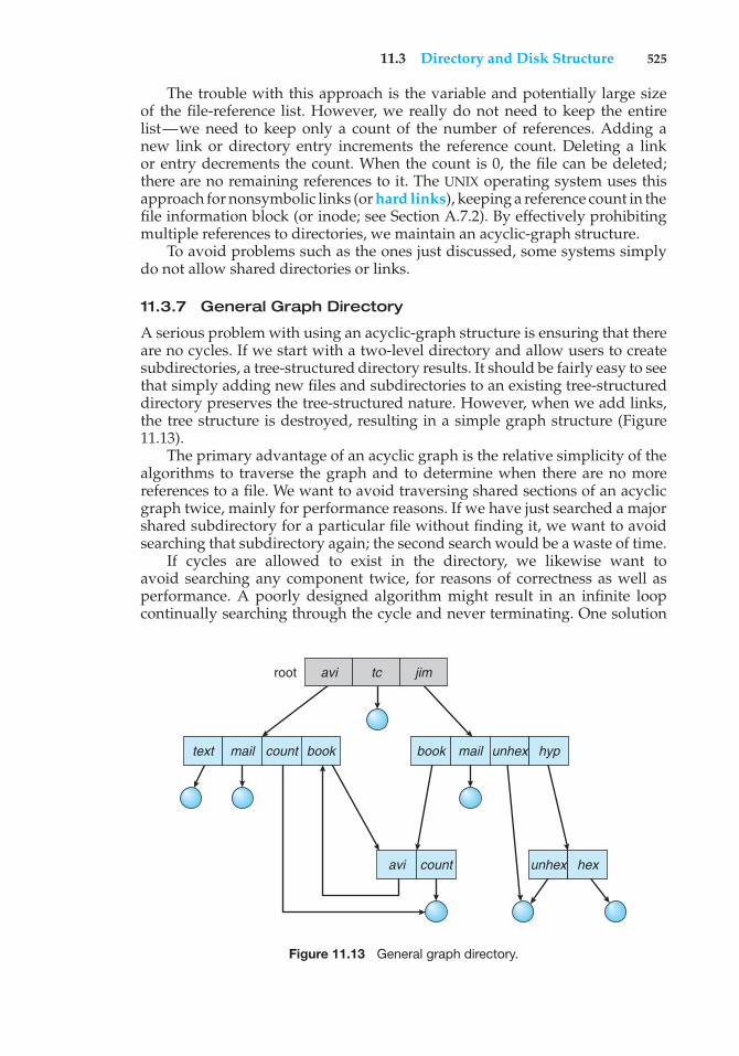
11.3 Directory and Disk Structure 525
The trouble with this approach is the variable and potentially large sizeof the file-reference list. However, we really do not need to keep the entirelist—we need to keep only a count of the number of references. Adding anew link or directory entry increments the reference count. Deleting a linkor entry decrements the count. When the count is 0, the file can be deleted;there are no remaining references to it. The UNIX operating system uses thisapproach for nonsymbolic links (or hard links), keeping a reference count in thefile information block (or inode; see Section A.7.2). By effectively prohibitingmultiple references to directories, we maintain an acyclic-graph structure.
To avoid problems such as the ones just discussed, some systems simplydo not allow shared directories or links.
11.3.7 General Graph Directory
A serious problem with using an acyclic-graph structure is ensuring that thereare no cycles. If we start with a two-level directory and allow users to createsubdirectories, a tree-structured directory results. It should be fairly easy to seethat simply adding new files and subdirectories to an existing tree-structureddirectory preserves the tree-structured nature. However, when we add links,the tree structure is destroyed, resulting in a simple graph structure (Figure11.13).
The primary advantage of an acyclic graph is the relative simplicity of thealgorithms to traverse the graph and to determine when there are no morereferences to a file. We want to avoid traversing shared sections of an acyclicgraph twice, mainly for performance reasons. If we have just searched a majorshared subdirectory for a particular file without finding it, we want to avoidsearching that subdirectory again; the second search would be a waste of time.
If cycles are allowed to exist in the directory, we likewise want toavoid searching any component twice, for reasons of correctness as well asperformance. A poorly designed algorithm might result in an infinite loopcontinually searching through the cycle and never terminating. One solution
text mail
avi count unhex hex
count book book mail unhex hyp
root avi tc jim
Figure 11.13 General graph directory.
526 Chapter 11 File-System Interface
is to limit arbitrarily the number of directories that will be accessed during asearch.
A similar problem exists when we are trying to determine when a filecan be deleted. With acyclic-graph directory structures, a value of 0 in thereference count means that there are no more references to the file or directory,and the file can be deleted. However, when cycles exist, the reference countmay not be 0 even when it is no longer possible to refer to a directory or file.This anomaly results from the possibility of self-referencing (or a cycle) in thedirectory structure. In this case, we generally need to use a garbage collectionscheme to determine when the last reference has been deleted and the diskspace can be reallocated. Garbage collection involves traversing the entire filesystem, marking everything that can be accessed. Then, a second pass collectseverything that is not marked onto a list of free space. (A similar markingprocedure can be used to ensure that a traversal or search will cover everythingin the file system once and only once.) Garbage collection for a disk-based filesystem, however, is extremely time consuming and is thus seldom attempted.
Garbage collection is necessary only because of possible cycles in the graph.Thus, an acyclic-graph structure is much easier to work with. The difficultyis to avoid cycles as new links are added to the structure. How do we knowwhen a new link will complete a cycle? There are algorithms to detect cyclesin graphs; however, they are computationally expensive, especially when thegraph is on disk storage. A simpler algorithm in the special case of directoriesand links is to bypass links during directory traversal. Cycles are avoided, andno extra overhead is incurred.
11.4 File-System Mounting
Just as a file must be opened before it is used, a file system must be mountedbefore it can be available to processes on the system. More specifically, thedirectory structure may be built out of multiple volumes, which must bemounted to make them available within the file-system name space.
The mount procedure is straightforward. The operating system is given thename of the device and the mount point—the location within the file structurewhere the file system is to be attached. Some operating systems require that afile system type be provided, while others inspect the structures of the deviceand determine the type of file system. Typically, a mount point is an emptydirectory. For instance, on a UNIX system, a file system containing a user’s homedirectories might be mounted as /home; then, to access the directory structurewithin that file system, we could precede the directory names with /home, asin /home/jane. Mounting that file system under /users would result in thepath name /users/jane, which we could use to reach the same directory.
Next, the operating system verifies that the device contains a valid filesystem. It does so by asking the device driver to read the device directoryand verifying that the directory has the expected format. Finally, the operatingsystem notes in its directory structure that a file system is mounted at thespecified mount point. This scheme enables the operating system to traverseits directory structure, switching among file systems, and even file systems ofvarying types, as appropriate.
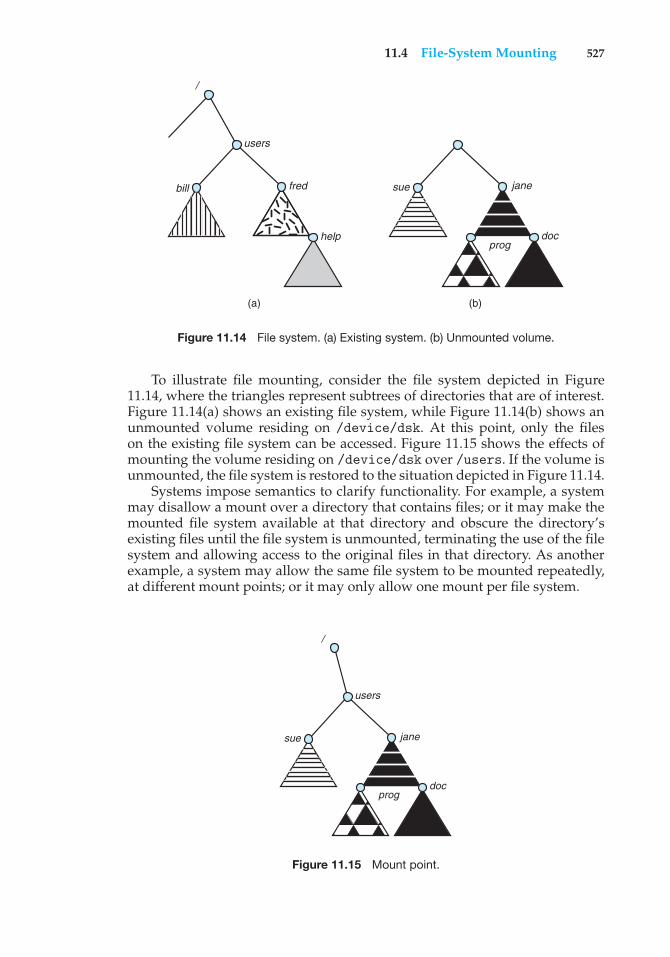
11.4 File-System Mounting 527
users
/
bill fred
help
sue jane
progdoc
(a) (b)
Figure 11.14 File system. (a) Existing system. (b) Unmounted volume.
To illustrate file mounting, consider the file system depicted in Figure11.14, where the triangles represent subtrees of directories that are of interest.Figure 11.14(a) shows an existing file system, while Figure 11.14(b) shows anunmounted volume residing on /device/dsk. At this point, only the fileson the existing file system can be accessed. Figure 11.15 shows the effects ofmounting the volume residing on /device/dsk over /users. If the volume isunmounted, the file system is restored to the situation depicted in Figure 11.14.
Systems impose semantics to clarify functionality. For example, a systemmay disallow a mount over a directory that contains files; or it may make themounted file system available at that directory and obscure the directory’sexisting files until the file system is unmounted, terminating the use of the filesystem and allowing access to the original files in that directory. As anotherexample, a system may allow the same file system to be mounted repeatedly,at different mount points; or it may only allow one mount per file system.
/
users
sue jane
progdoc
Figure 11.15 Mount point.
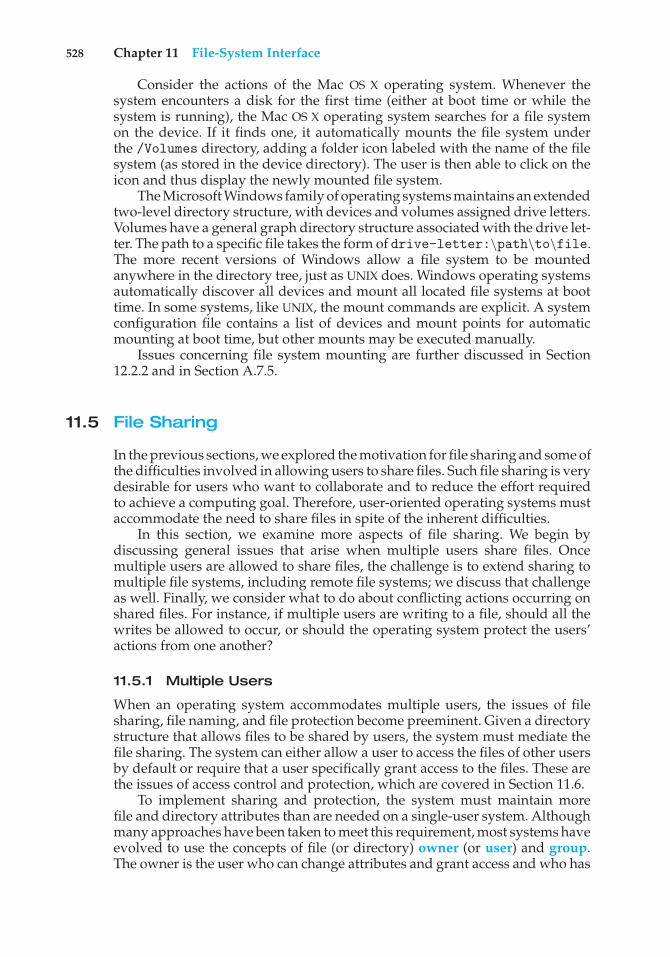
528 Chapter 11 File-System Interface
Consider the actions of the Mac OS X operating system. Whenever thesystem encounters a disk for the first time (either at boot time or while thesystem is running), the Mac OS X operating system searches for a file systemon the device. If it finds one, it automatically mounts the file system underthe /Volumes directory, adding a folder icon labeled with the name of the filesystem (as stored in the device directory). The user is then able to click on theicon and thus display the newly mounted file system.
The Microsoft Windows family of operating systems maintains an extendedtwo-level directory structure, with devices and volumes assigned drive letters.Volumes have a general graph directory structure associated with the drive let-ter. The path to a specific file takes the form of drive-letter:\path\to\file.The more recent versions of Windows allow a file system to be mountedanywhere in the directory tree, just as UNIX does. Windows operating systemsautomatically discover all devices and mount all located file systems at boottime. In some systems, like UNIX, the mount commands are explicit. A systemconfiguration file contains a list of devices and mount points for automaticmounting at boot time, but other mounts may be executed manually.
Issues concerning file system mounting are further discussed in Section12.2.2 and in Section A.7.5.
11.5 File Sharing
In the previous sections, we explored the motivation for file sharing and some ofthe difficulties involved in allowing users to share files. Such file sharing is verydesirable for users who want to collaborate and to reduce the effort requiredto achieve a computing goal. Therefore, user-oriented operating systems mustaccommodate the need to share files in spite of the inherent difficulties.
In this section, we examine more aspects of file sharing. We begin bydiscussing general issues that arise when multiple users share files. Oncemultiple users are allowed to share files, the challenge is to extend sharing tomultiple file systems, including remote file systems; we discuss that challengeas well. Finally, we consider what to do about conflicting actions occurring onshared files. For instance, if multiple users are writing to a file, should all thewrites be allowed to occur, or should the operating system protect the users’actions from one another?
11.5.1 Multiple Users
When an operating system accommodates multiple users, the issues of filesharing, file naming, and file protection become preeminent. Given a directorystructure that allows files to be shared by users, the system must mediate thefile sharing. The system can either allow a user to access the files of other usersby default or require that a user specifically grant access to the files. These arethe issues of access control and protection, which are covered in Section 11.6.
To implement sharing and protection, the system must maintain morefile and directory attributes than are needed on a single-user system. Althoughmany approaches have been taken to meet this requirement, most systems haveevolved to use the concepts of file (or directory) owner (or user) and group.The owner is the user who can change attributes and grant access and who has
11.5 File Sharing 529
the most control over the file. The group attribute defines a subset of users whocan share access to the file. For example, the owner of a file on a UNIX systemcan issue all operations on a file, while members of the file’s group can executeone subset of those operations, and all other users can execute another subsetof operations. Exactly which operations can be executed by group membersand other users is definable by the file’s owner. More details on permissionattributes are included in the next section.
The owner and group IDs of a given file (or directory) are stored with theother file attributes. When a user requests an operation on a file, the user ID canbe compared with the owner attribute to determine if the requesting user is theowner of the file. Likewise, the group IDs can be compared. The result indicateswhich permissions are applicable. The system then applies those permissionsto the requested operation and allows or denies it.
Many systems have multiple local file systems, including volumes of asingle disk or multiple volumes on multiple attached disks. In these cases,the ID checking and permission matching are straightforward, once the filesystems are mounted.
11.5.2 Remote File Systems
With the advent of networks (Chapter 17), communication among remotecomputers became possible. Networking allows the sharing of resources spreadacross a campus or even around the world. One obvious resource to share isdata in the form of files.
Through the evolution of network and file technology, remote file-sharingmethods have changed. The first implemented method involves manuallytransferring files between machines via programs like ftp. The second majormethod uses a distributed file system (DFS) in which remote directories arevisible from a local machine. In some ways, the third method, the World WideWeb, is a reversion to the first. A browser is needed to gain access to theremote files, and separate operations (essentially a wrapper for ftp) are usedto transfer files. Increasingly, cloud computing (Section 1.11.7) is being usedfor file sharing as well.
ftp is used for both anonymous and authenticated access. Anonymousaccess allows a user to transfer files without having an account on the remotesystem. The World Wide Web uses anonymous file exchange almost exclusively.DFS involves a much tighter integration between the machine that is accessingthe remote files and the machine providing the files. This integration addscomplexity, as we describe in this section.
11.5.2.1 The Client–Server Model
Remote file systems allow a computer to mount one or more file systems fromone or more remote machines. In this case, the machine containing the filesis the server, and the machine seeking access to the files is the client. Theclient–server relationship is common with networked machines. Generally,the server declares that a resource is available to clients and specifies exactlywhich resource (in this case, which files) and exactly which clients. A servercan serve multiple clients, and a client can use multiple servers, depending onthe implementation details of a given client–server facility.
530 Chapter 11 File-System Interface
The server usually specifies the available files on a volume or directorylevel. Client identification is more difficult. A client can be specified bya network name or other identifier, such as an IP address, but these canbe spoofed, or imitated. As a result of spoofing, an unauthorized clientcould be allowed access to the server. More secure solutions include secureauthentication of the client via encrypted keys. Unfortunately, with securitycome many challenges, including ensuring compatibility of the client andserver (they must use the same encryption algorithms) and security of keyexchanges (intercepted keys could again allow unauthorized access). Becauseof the difficulty of solving these problems, unsecure authentication methodsare most commonly used.
In the case of UNIX and its network file system (NFS), authentication takesplace via the client networking information, by default. In this scheme, theuser’s IDs on the client and server must match. If they do not, the server willbe unable to determine access rights to files. Consider the example of a userwho has an ID of 1000 on the client and 2000 on the server. A request fromthe client to the server for a specific file will not be handled appropriately, asthe server will determine if user 1000 has access to the file rather than basingthe determination on the real user ID of 2000. Access is thus granted or deniedbased on incorrect authentication information. The server must trust the clientto present the correct user ID. Note that the NFS protocols allow many-to-manyrelationships. That is, many servers can provide files to many clients. In fact,a given machine can be both a server to some NFS clients and a client of otherNFS servers.
Once the remote file system is mounted, file operation requests are senton behalf of the user across the network to the server via the DFS protocol.Typically, a file-open request is sent along with the ID of the requesting user.The server then applies the standard access checks to determine if the user hascredentials to access the file in the mode requested. The request is either allowedor denied. If it is allowed, a file handle is returned to the client application,and the application then can perform read, write, and other operations on thefile. The client closes the file when access is completed. The operating systemmay apply semantics similar to those for a local file-system mount or may usedifferent semantics.
11.5.2.2 Distributed Information Systems
To make client–server systems easier to manage, distributed informationsystems, also known as distributed naming services, provide unified accessto the information needed for remote computing. The domain name system(DNS) provides host-name-to-network-address translations for the entire Inter-net. Before DNS became widespread, files containing the same informationwere sent via e-mail or ftp between all networked hosts. Obviously, thismethodology was not scalable! DNS is further discussed in Section 17.4.1.
Other distributed information systems provide user name/password/userID/group ID space for a distributed facility. UNIX systems have employed awide variety of distributed information methods. Sun Microsystems (nowpart of Oracle Corporation) introduced yellow pages (since renamed networkinformation service, or NIS), and most of the industry adopted its use. Itcentralizes storage of user names, host names, printer information, and the like.
11.5 File Sharing 531
Unfortunately, it uses unsecure authentication methods, including sendinguser passwords unencrypted (in clear text) and identifying hosts by IP address.Sun’s NIS+ was a much more secure replacement for NIS but was much morecomplicated and was not widely adopted.
In the case of Microsoft’s common Internet file system (CIFS), networkinformation is used in conjunction with user authentication (user name andpassword) to create a network login that the server uses to decide whetherto allow or deny access to a requested file system. For this authentication tobe valid, the user names must match from machine to machine (as with NFS).Microsoft uses active directory as a distributed naming structure to provide asingle name space for users. Once established, the distributed naming facilityis used by all clients and servers to authenticate users.
The industry is moving toward use of the lightweight directory-accessprotocol (LDAP) as a secure distributed naming mechanism. In fact, activedirectory is based on LDAP. Oracle Solaris and most other major operatingsystems include LDAP and allow it to be employed for user authentication aswell as system-wide retrieval of information, such as availability of printers.Conceivably, one distributed LDAP directory could be used by an organizationto store all user and resource information for all the organization’s computers.The result would be secure single sign-on for users, who would entertheir authentication information once for access to all computers within theorganization. It would also ease system-administration efforts by combining,in one location, information that is currently scattered in various files on eachsystem or in different distributed information services.
11.5.2.3 Failure Modes
Local file systems can fail for a variety of reasons, including failure of thedisk containing the file system, corruption of the directory structure or otherdisk-management information (collectively called metadata), disk-controllerfailure, cable failure, and host-adapter failure. User or system-administratorfailure can also cause files to be lost or entire directories or volumes to bedeleted. Many of these failures will cause a host to crash and an error conditionto be displayed, and human intervention will be required to repair the damage.
Remote file systems have even more failure modes. Because of thecomplexity of network systems and the required interactions between remotemachines, many more problems can interfere with the proper operation ofremote file systems. In the case of networks, the network can be interruptedbetween two hosts. Such interruptions can result from hardware failure, poorhardware configuration, or networking implementation issues. Although somenetworks have built-in resiliency, including multiple paths between hosts,many do not. Any single failure can thus interrupt the flow of DFS commands.
Consider a client in the midst of using a remote file system. It has files openfrom the remote host; among other activities, it may be performing directorylookups to open files, reading or writing data to files, and closing files. Nowconsider a partitioning of the network, a crash of the server, or even a scheduledshutdown of the server. Suddenly, the remote file system is no longer reachable.This scenario is rather common, so it would not be appropriate for the clientsystem to act as it would if a local file system were lost. Rather, the system caneither terminate all operations to the lost server or delay operations until the
532 Chapter 11 File-System Interface
server is again reachable. These failure semantics are defined and implementedas part of the remote-file-system protocol. Termination of all operations canresult in users’ losing data—and patience. Thus, most DFS protocols eitherenforce or allow delaying of file-system operations to remote hosts, with thehope that the remote host will become available again.
To implement this kind of recovery from failure, some kind of stateinformation may be maintained on both the client and the server. If both serverand client maintain knowledge of their current activities and open files, thenthey can seamlessly recover from a failure. In the situation where the servercrashes but must recognize that it has remotely mounted exported file systemsand opened files, NFS takes a simple approach, implementing a stateless DFS.In essence, it assumes that a client request for a file read or write would nothave occurred unless the file system had been remotely mounted and the filehad been previously open. The NFS protocol carries all the information neededto locate the appropriate file and perform the requested operation. Similarly,it does not track which clients have the exported volumes mounted, againassuming that if a request comes in, it must be legitimate. While this statelessapproach makes NFS resilient and rather easy to implement, it also makes itunsecure. For example, forged read or write requests could be allowed by anNFS server. These issues are addressed in the industry standard NFS Version4, in which NFS is made stateful to improve its security, performance, andfunctionality.
11.5.3 Consistency Semantics
Consistency semantics represent an important criterion for evaluating anyfile system that supports file sharing. These semantics specify how multipleusers of a system are to access a shared file simultaneously. In particular, theyspecify when modifications of data by one user will be observable by otherusers. These semantics are typically implemented as code with the file system.
Consistency semantics are directly related to the process synchronizationalgorithms of Chapter 5. However, the complex algorithms of that chapter tendnot to be implemented in the case of file I/O because of the great latencies andslow transfer rates of disks and networks. For example, performing an atomictransaction to a remote disk could involve several network communications,several disk reads and writes, or both. Systems that attempt such a full set offunctionalities tend to perform poorly. A successful implementation of complexsharing semantics can be found in the Andrew file system.
For the following discussion, we assume that a series of file accesses (thatis, reads and writes) attempted by a user to the same file is always enclosedbetween the open() and close() operations. The series of accesses betweenthe open() and close() operations makes up a file session. To illustrate theconcept, we sketch several prominent examples of consistency semantics.
11.5.3.1 UNIX Semantics
The UNIX file system (Chapter 17) uses the following consistency semantics:
• Writes to an open file by a user are visible immediately to other users whohave this file open.
11.6 Protection 533
• One mode of sharing allows users to share the pointer of current locationinto the file. Thus, the advancing of the pointer by one user affects allsharing users. Here, a file has a single image that interleaves all accesses,regardless of their origin.
In the UNIX semantics, a file is associated with a single physical image thatis accessed as an exclusive resource. Contention for this single image causesdelays in user processes.
11.5.3.2 Session Semantics
The Andrew file system (OpenAFS) uses the following consistency semantics:
• Writes to an open file by a user are not visible immediately to other usersthat have the same file open.
• Once a file is closed, the changes made to it are visible only in sessionsstarting later. Already open instances of the file do not reflect these changes.
According to these semantics, a file may be associated temporarily with several(possibly different) images at the same time. Consequently, multiple users areallowed to perform both read and write accesses concurrently on their imagesof the file, without delay. Almost no constraints are enforced on schedulingaccesses.
11.5.3.3 Immutable-Shared-Files Semantics
A unique approach is that of immutable shared files. Once a file is declaredas shared by its creator, it cannot be modified. An immutable file has two keyproperties: its name may not be reused, and its contents may not be altered.Thus, the name of an immutable file signifies that the contents of the file arefixed. The implementation of these semantics in a distributed system (Chapter17) is simple, because the sharing is disciplined (read-only).
11.6 Protection
When information is stored in a computer system, we want to keep it safefrom physical damage (the issue of reliability) and improper access (the issueof protection).
Reliability is generally provided by duplicate copies of files. Many comput-ers have systems programs that automatically (or through computer-operatorintervention) copy disk files to tape at regular intervals (once per day or weekor month) to maintain a copy should a file system be accidentally destroyed.File systems can be damaged by hardware problems (such as errors in readingor writing), power surges or failures, head crashes, dirt, temperature extremes,and vandalism. Files may be deleted accidentally. Bugs in the file-system soft-ware can also cause file contents to be lost. Reliability is covered in more detailin Chapter 10.
534 Chapter 11 File-System Interface
Protection can be provided in many ways. For a single-user laptop system,we might provide protection by locking the computer in a desk drawer or filecabinet. In a larger multiuser system, however, other mechanisms are needed.
11.6.1 Types of Access
The need to protect files is a direct result of the ability to access files. Systemsthat do not permit access to the files of other users do not need protection. Thus,we could provide complete protection by prohibiting access. Alternatively, wecould provide free access with no protection. Both approaches are too extremefor general use. What is needed is controlled access.
Protection mechanisms provide controlled access by limiting the types offile access that can be made. Access is permitted or denied depending onseveral factors, one of which is the type of access requested. Several differenttypes of operations may be controlled:
• Read. Read from the file.
• Write. Write or rewrite the file.
• Execute. Load the file into memory and execute it.
• Append. Write new information at the end of the file.
• Delete. Delete the file and free its space for possible reuse.
• List. List the name and attributes of the file.
Other operations, such as renaming, copying, and editing the file, may alsobe controlled. For many systems, however, these higher-level functions maybe implemented by a system program that makes lower-level system calls.Protection is provided at only the lower level. For instance, copying a file maybe implemented simply by a sequence of read requests. In this case, a user withread access can also cause the file to be copied, printed, and so on.
Many protection mechanisms have been proposed. Each has advantagesand disadvantages and must be appropriate for its intended application. Asmall computer system that is used by only a few members of a research group,for example, may not need the same types of protection as a large corporatecomputer that is used for research, finance, and personnel operations. Wediscuss some approaches to protection in the following sections and present amore complete treatment in Chapter 14.
11.6.2 Access Control
The most common approach to the protection problem is to make accessdependent on the identity of the user. Different users may need different typesof access to a file or directory. The most general scheme to implement identity-dependent access is to associate with each file and directory an access-controllist (ACL) specifying user names and the types of access allowed for each user.When a user requests access to a particular file, the operating system checksthe access list associated with that file. If that user is listed for the requestedaccess, the access is allowed. Otherwise, a protection violation occurs, and theuser job is denied access to the file.
11.6 Protection 535
This approach has the advantage of enabling complex access methodolo-gies. The main problem with access lists is their length. If we want to alloweveryone to read a file, we must list all users with read access. This techniquehas two undesirable consequences:
• Constructing such a list may be a tedious and unrewarding task, especiallyif we do not know in advance the list of users in the system.
• The directory entry, previously of fixed size, now must be of variable size,resulting in more complicated space management.
These problems can be resolved by use of a condensed version of the accesslist.
To condense the length of the access-control list, many systems recognizethree classifications of users in connection with each file:
• Owner. The user who created the file is the owner.
• Group. A set of users who are sharing the file and need similar access is agroup, or work group.
• Universe. All other users in the system constitute the universe.
The most common recent approach is to combine access-control lists withthe more general (and easier to implement) owner, group, and universe access-control scheme just described. For example, Solaris uses the three categoriesof access by default but allows access-control lists to be added to specific filesand directories when more fine-grained access control is desired.
To illustrate, consider a person, Sara, who is writing a new book. She hashired three graduate students (Jim, Dawn, and Jill) to help with the project. Thetext of the book is kept in a file named book.tex. The protection associatedwith this file is as follows:
• Sara should be able to invoke all operations on the file.
• Jim, Dawn, and Jill should be able only to read and write the file; theyshould not be allowed to delete the file.
• All other users should be able to read, but not write, the file. (Sara isinterested in letting as many people as possible read the text so that shecan obtain feedback.)
To achieve such protection, we must create a new group—say, text—with members Jim, Dawn, and Jill. The name of the group, text, must thenbe associated with the file book.tex, and the access rights must be set inaccordance with the policy we have outlined.
Now consider a visitor to whom Sara would like to grant temporary accessto Chapter 1. The visitor cannot be added to the text group because that wouldgive him access to all chapters. Because a file can be in only one group, Saracannot add another group to Chapter 1. With the addition of access-control-listfunctionality, though, the visitor can be added to the access control list ofChapter 1.
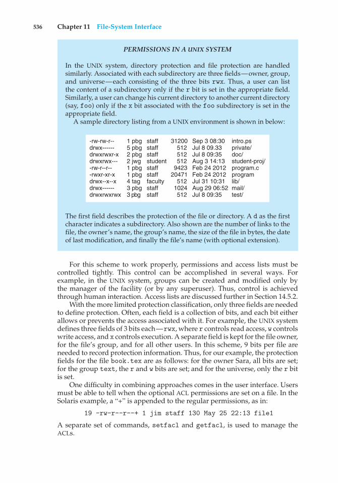
536 Chapter 11 File-System Interface
PERMISSIONS IN A UNIX SYSTEM
In the UNIX system, directory protection and file protection are handledsimilarly. Associated with each subdirectory are three fields—owner, group,and universe—each consisting of the three bits rwx. Thus, a user can listthe content of a subdirectory only if the r bit is set in the appropriate field.Similarly, a user can change his current directory to another current directory(say, foo) only if the x bit associated with the foo subdirectory is set in theappropriate field.
A sample directory listing from a UNIX environment is shown in below:
-rw-rw-r--drwx------drwxrwxr-xdrwxrwx----rw-r--r---rwxr-xr-xdrwx--x--xdrwx------drwxrwxrwx
1 pbg5 pbg2 pbg 2 jwg 1 pbg 1 pbg 4 tag 3 pbg 3 pbg
staffstaffstaffstudentstaffstafffacultystaffstaff
intro.psprivate/doc/student-proj/program.cprogramlib/mail/test/
Sep 3 08:30Jul 8 09.33Jul 8 09:35Aug 3 14:13Feb 24 2012Feb 24 2012Jul 31 10:31Aug 29 06:52Jul 8 09:35
31200512512512
942320471
512 1024 512
The first field describes the protection of the file or directory. A d as the firstcharacter indicates a subdirectory. Also shown are the number of links to thefile, the owner’s name, the group’s name, the size of the file in bytes, the dateof last modification, and finally the file’s name (with optional extension).
For this scheme to work properly, permissions and access lists must becontrolled tightly. This control can be accomplished in several ways. Forexample, in the UNIX system, groups can be created and modified only bythe manager of the facility (or by any superuser). Thus, control is achievedthrough human interaction. Access lists are discussed further in Section 14.5.2.
With the more limited protection classification, only three fields are neededto define protection. Often, each field is a collection of bits, and each bit eitherallows or prevents the access associated with it. For example, the UNIX systemdefines three fields of 3 bits each—rwx, where r controls read access, w controlswrite access, and x controls execution. A separate field is kept for the file owner,for the file’s group, and for all other users. In this scheme, 9 bits per file areneeded to record protection information. Thus, for our example, the protectionfields for the file book.tex are as follows: for the owner Sara, all bits are set;for the group text, the r and w bits are set; and for the universe, only the r bitis set.
One difficulty in combining approaches comes in the user interface. Usersmust be able to tell when the optional ACL permissions are set on a file. In theSolaris example, a “+” is appended to the regular permissions, as in:
19 -rw-r--r--+ 1 jim staff 130 May 25 22:13 file1
A separate set of commands, setfacl and getfacl, is used to manage theACLs.
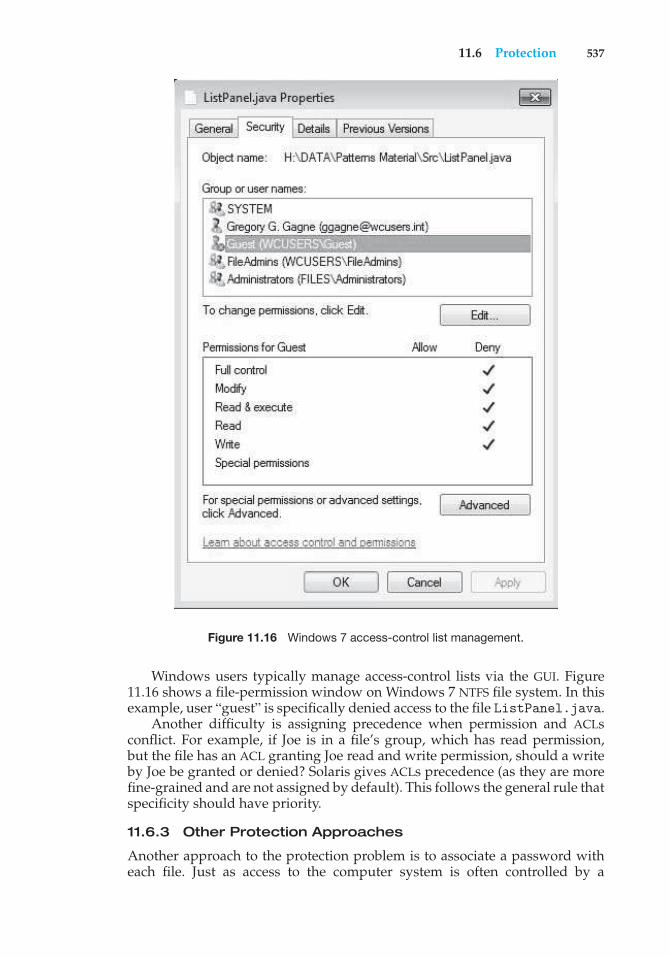
11.6 Protection 537
Figure 11.16 Windows 7 access-control list management.
Windows users typically manage access-control lists via the GUI. Figure11.16 shows a file-permission window on Windows 7 NTFS file system. In thisexample, user “guest” is specifically denied access to the file ListPanel.java.
Another difficulty is assigning precedence when permission and ACLsconflict. For example, if Joe is in a file’s group, which has read permission,but the file has an ACL granting Joe read and write permission, should a writeby Joe be granted or denied? Solaris gives ACLs precedence (as they are morefine-grained and are not assigned by default). This follows the general rule thatspecificity should have priority.
11.6.3 Other Protection Approaches
Another approach to the protection problem is to associate a password witheach file. Just as access to the computer system is often controlled by a
538 Chapter 11 File-System Interface
password, access to each file can be controlled in the same way. If the passwordsare chosen randomly and changed often, this scheme may be effective inlimiting access to a file. The use of passwords has a few disadvantages,however. First, the number of passwords that a user needs to remember maybecome large, making the scheme impractical. Second, if only one password isused for all the files, then once it is discovered, all files are accessible; protectionis on an all-or-none basis. Some systems allow a user to associate a passwordwith a subdirectory, rather than with an individual file, to address this problem.
In a multilevel directory structure, we need to protect not only individualfiles but also collections of files in subdirectories; that is, we need to providea mechanism for directory protection. The directory operations that must beprotected are somewhat different from the file operations. We want to controlthe creation and deletion of files in a directory. In addition, we probably wantto control whether a user can determine the existence of a file in a directory.Sometimes, knowledge of the existence and name of a file is significant in itself.Thus, listing the contents of a directory must be a protected operation. Similarly,if a path name refers to a file in a directory, the user must be allowed access toboth the directory and the file. In systems where files may have numerous pathnames (such as acyclic and general graphs), a given user may have differentaccess rights to a particular file, depending on the path name used.
11.7 Summary
A file is an abstract data type defined and implemented by the operatingsystem. It is a sequence of logical records. A logical record may be a byte, a line(of fixed or variable length), or a more complex data item. The operating systemmay specifically support various record types or may leave that support to theapplication program.
The major task for the operating system is to map the logical file conceptonto physical storage devices such as magnetic disk or tape. Since the physicalrecord size of the device may not be the same as the logical record size, it maybe necessary to order logical records into physical records. Again, this task maybe supported by the operating system or left for the application program.
Each device in a file system keeps a volume table of contents or a devicedirectory listing the location of the files on the device. In addition, it is usefulto create directories to allow files to be organized. A single-level directoryin a multiuser system causes naming problems, since each file must have aunique name. A two-level directory solves this problem by creating a separatedirectory for each user’s files. The directory lists the files by name and includesthe file’s location on the disk, length, type, owner, time of creation, time of lastuse, and so on.
The natural generalization of a two-level directory is a tree-structureddirectory. A tree-structured directory allows a user to create subdirectoriesto organize files. Acyclic-graph directory structures enable users to sharesubdirectories and files but complicate searching and deletion. A general graphstructure allows complete flexibility in the sharing of files and directories butsometimes requires garbage collection to recover unused disk space.
Disks are segmented into one or more volumes, each containing a filesystem or left “raw.” File systems may be mounted into the system’s naming
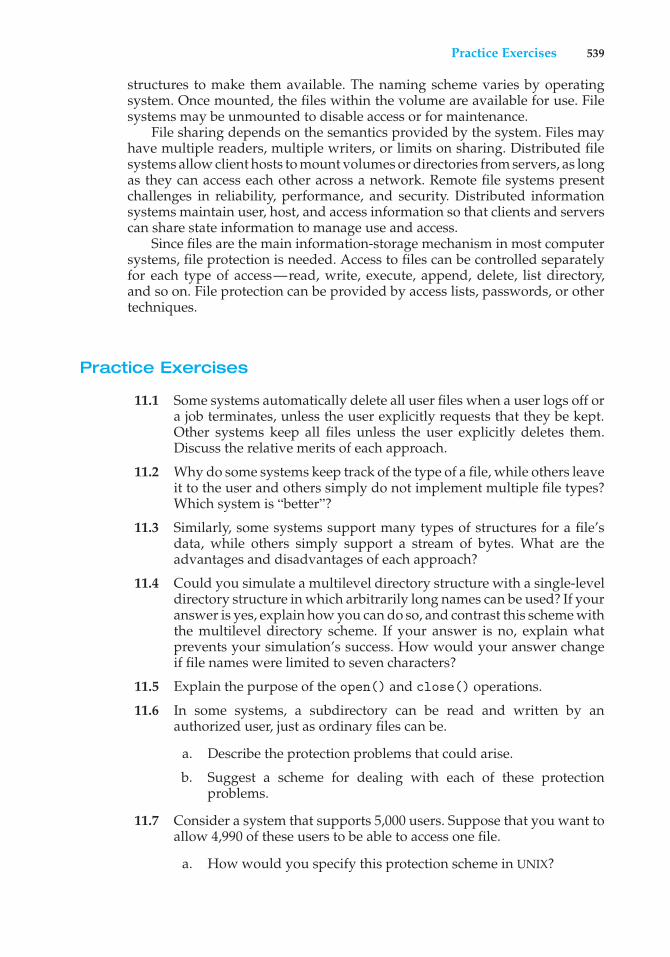
Practice Exercises 539
structures to make them available. The naming scheme varies by operatingsystem. Once mounted, the files within the volume are available for use. Filesystems may be unmounted to disable access or for maintenance.
File sharing depends on the semantics provided by the system. Files mayhave multiple readers, multiple writers, or limits on sharing. Distributed filesystems allow client hosts to mount volumes or directories from servers, as longas they can access each other across a network. Remote file systems presentchallenges in reliability, performance, and security. Distributed informationsystems maintain user, host, and access information so that clients and serverscan share state information to manage use and access.
Since files are the main information-storage mechanism in most computersystems, file protection is needed. Access to files can be controlled separatelyfor each type of access—read, write, execute, append, delete, list directory,and so on. File protection can be provided by access lists, passwords, or othertechniques.
Practice Exercises
11.1 Some systems automatically delete all user files when a user logs off ora job terminates, unless the user explicitly requests that they be kept.Other systems keep all files unless the user explicitly deletes them.Discuss the relative merits of each approach.
11.2 Why do some systems keep track of the type of a file, while others leaveit to the user and others simply do not implement multiple file types?Which system is “better”?
11.3 Similarly, some systems support many types of structures for a file’sdata, while others simply support a stream of bytes. What are theadvantages and disadvantages of each approach?
11.4 Could you simulate a multilevel directory structure with a single-leveldirectory structure in which arbitrarily long names can be used? If youranswer is yes, explain how you can do so, and contrast this scheme withthe multilevel directory scheme. If your answer is no, explain whatprevents your simulation’s success. How would your answer changeif file names were limited to seven characters?
11.5 Explain the purpose of the open() and close() operations.
11.6 In some systems, a subdirectory can be read and written by anauthorized user, just as ordinary files can be.
a. Describe the protection problems that could arise.
b. Suggest a scheme for dealing with each of these protectionproblems.
11.7 Consider a system that supports 5,000 users. Suppose that you want toallow 4,990 of these users to be able to access one file.
a. How would you specify this protection scheme in UNIX?
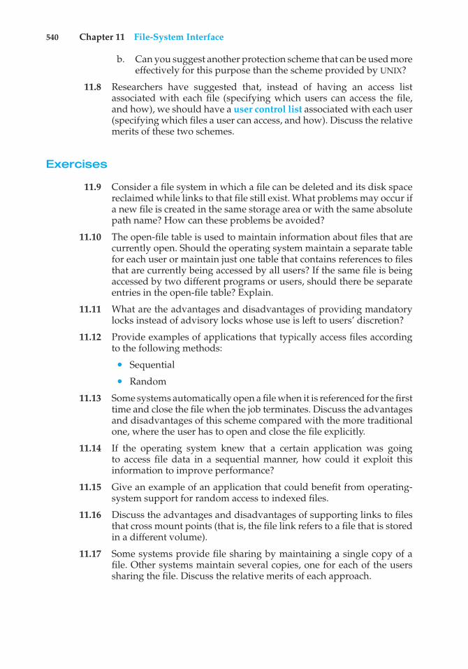
540 Chapter 11 File-System Interface
b. Can you suggest another protection scheme that can be used moreeffectively for this purpose than the scheme provided by UNIX?
11.8 Researchers have suggested that, instead of having an access listassociated with each file (specifying which users can access the file,and how), we should have a user control list associated with each user(specifying which files a user can access, and how). Discuss the relativemerits of these two schemes.
Exercises
11.9 Consider a file system in which a file can be deleted and its disk spacereclaimed while links to that file still exist. What problems may occur ifa new file is created in the same storage area or with the same absolutepath name? How can these problems be avoided?
11.10 The open-file table is used to maintain information about files that arecurrently open. Should the operating system maintain a separate tablefor each user or maintain just one table that contains references to filesthat are currently being accessed by all users? If the same file is beingaccessed by two different programs or users, should there be separateentries in the open-file table? Explain.
11.11 What are the advantages and disadvantages of providing mandatorylocks instead of advisory locks whose use is left to users’ discretion?
11.12 Provide examples of applications that typically access files accordingto the following methods:
• Sequential
• Random
11.13 Some systems automatically open a file when it is referenced for the firsttime and close the file when the job terminates. Discuss the advantagesand disadvantages of this scheme compared with the more traditionalone, where the user has to open and close the file explicitly.
11.14 If the operating system knew that a certain application was goingto access file data in a sequential manner, how could it exploit thisinformation to improve performance?
11.15 Give an example of an application that could benefit from operating-system support for random access to indexed files.
11.16 Discuss the advantages and disadvantages of supporting links to filesthat cross mount points (that is, the file link refers to a file that is storedin a different volume).
11.17 Some systems provide file sharing by maintaining a single copy of afile. Other systems maintain several copies, one for each of the userssharing the file. Discuss the relative merits of each approach.
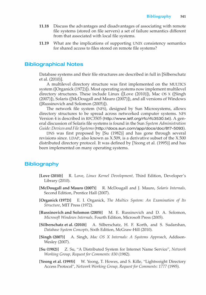
Bibliography 541
11.18 Discuss the advantages and disadvantages of associating with remotefile systems (stored on file servers) a set of failure semantics differentfrom that associated with local file systems.
11.19 What are the implications of supporting UNIX consistency semanticsfor shared access to files stored on remote file systems?
Bibliographical Notes
Database systems and their file structures are described in full in [Silberschatzet al. (2010)].
A multilevel directory structure was first implemented on the MULTICSsystem ([Organick (1972)]). Most operating systems now implement multileveldirectory structures. These include Linux ([Love (2010)]), Mac OS X ([Singh(2007)]), Solaris ([McDougall and Mauro (2007)]), and all versions of Windows([Russinovich and Solomon (2005)]).
The network file system (NFS), designed by Sun Microsystems, allowsdirectory structures to be spread across networked computer systems. NFSVersion 4 is described in RFC3505 (http://www.ietf.org/rfc/rfc3530.txt). A gen-eral discussion of Solaris file systems is found in the Sun System AdministrationGuide: Devices and File Systems (http://docs.sun.com/app/docs/doc/817-5093).
DNS was first proposed by [Su (1982)] and has gone through severalrevisions since. LDAP, also known as X.509, is a derivative subset of the X.500distributed directory protocol. It was defined by [Yeong et al. (1995)] and hasbeen implemented on many operating systems.
Bibliography
[Love (2010)] R. Love, Linux Kernel Development, Third Edition, Developer’sLibrary (2010).
[McDougall and Mauro (2007)] R. McDougall and J. Mauro, Solaris Internals,Second Edition, Prentice Hall (2007).
[Organick (1972)] E. I. Organick, The Multics System: An Examination of ItsStructure, MIT Press (1972).
[Russinovich and Solomon (2005)] M. E. Russinovich and D. A. Solomon,Microsoft Windows Internals, Fourth Edition, Microsoft Press (2005).
[Silberschatz et al. (2010)] A. Silberschatz, H. F. Korth, and S. Sudarshan,Database System Concepts, Sixth Edition, McGraw-Hill (2010).
[Singh (2007)] A. Singh, Mac OS X Internals: A Systems Approach, Addison-Wesley (2007).
[Su (1982)] Z. Su, “A Distributed System for Internet Name Service”, NetworkWorking Group, Request for Comments: 830 (1982).
[Yeong et al. (1995)] W. Yeong, T. Howes, and S. Kille, “Lightweight DirectoryAccess Protocol”, Network Working Group, Request for Comments: 1777 (1995).

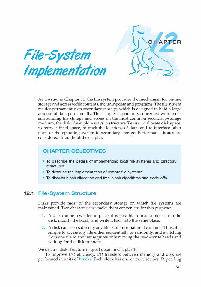
12C H A P T E R
File -SystemImplementation
As we saw in Chapter 11, the file system provides the mechanism for on-linestorage and access to file contents, including data and programs. The file systemresides permanently on secondary storage, which is designed to hold a largeamount of data permanently. This chapter is primarily concerned with issuessurrounding file storage and access on the most common secondary-storagemedium, the disk. We explore ways to structure file use, to allocate disk space,to recover freed space, to track the locations of data, and to interface otherparts of the operating system to secondary storage. Performance issues areconsidered throughout the chapter.
CHAPTER OBJECTIVES
• To describe the details of implementing local file systems and directorystructures.
• To describe the implementation of remote file systems.• To discuss block allocation and free-block algorithms and trade-offs.
12.1 File-System Structure
Disks provide most of the secondary storage on which file systems aremaintained. Two characteristics make them convenient for this purpose:
1. A disk can be rewritten in place; it is possible to read a block from thedisk, modify the block, and write it back into the same place.
2. A disk can access directly any block of information it contains. Thus, it issimple to access any file either sequentially or randomly, and switchingfrom one file to another requires only moving the read–write heads andwaiting for the disk to rotate.
We discuss disk structure in great detail in Chapter 10.To improve I/O efficiency, I/O transfers between memory and disk are
performed in units of blocks. Each block has one or more sectors. Depending
543
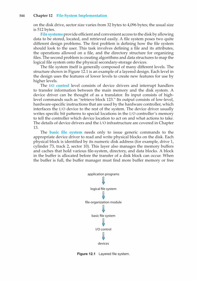
544 Chapter 12 File-System Implementation
on the disk drive, sector size varies from 32 bytes to 4,096 bytes; the usual sizeis 512 bytes.
File systems provide efficient and convenient access to the disk by allowingdata to be stored, located, and retrieved easily. A file system poses two quitedifferent design problems. The first problem is defining how the file systemshould look to the user. This task involves defining a file and its attributes,the operations allowed on a file, and the directory structure for organizingfiles. The second problem is creating algorithms and data structures to map thelogical file system onto the physical secondary-storage devices.
The file system itself is generally composed of many different levels. Thestructure shown in Figure 12.1 is an example of a layered design. Each level inthe design uses the features of lower levels to create new features for use byhigher levels.
The I/O control level consists of device drivers and interrupt handlersto transfer information between the main memory and the disk system. Adevice driver can be thought of as a translator. Its input consists of high-level commands such as “retrieve block 123.” Its output consists of low-level,hardware-specific instructions that are used by the hardware controller, whichinterfaces the I/O device to the rest of the system. The device driver usuallywrites specific bit patterns to special locations in the I/O controller’s memoryto tell the controller which device location to act on and what actions to take.The details of device drivers and the I/O infrastructure are covered in Chapter13.
The basic file system needs only to issue generic commands to theappropriate device driver to read and write physical blocks on the disk. Eachphysical block is identified by its numeric disk address (for example, drive 1,cylinder 73, track 2, sector 10). This layer also manages the memory buffersand caches that hold various file-system, directory, and data blocks. A blockin the buffer is allocated before the transfer of a disk block can occur. Whenthe buffer is full, the buffer manager must find more buffer memory or free
application programs
file-organization module
basic file system
I/O control
devices
logical file system
Figure 12.1 Layered file system.
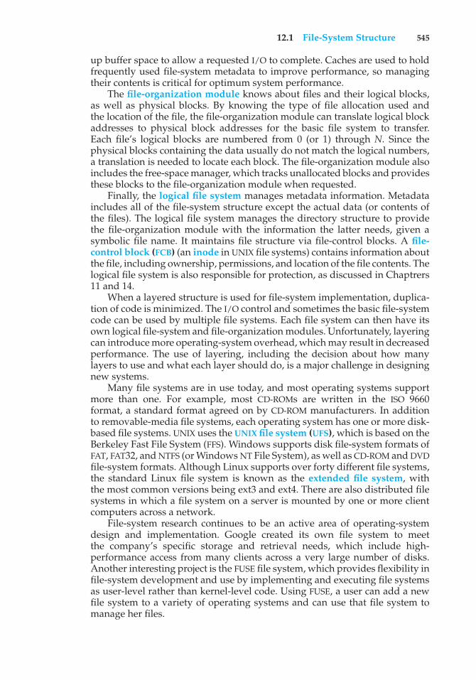
12.1 File-System Structure 545
up buffer space to allow a requested I/O to complete. Caches are used to holdfrequently used file-system metadata to improve performance, so managingtheir contents is critical for optimum system performance.
The file-organization module knows about files and their logical blocks,as well as physical blocks. By knowing the type of file allocation used andthe location of the file, the file-organization module can translate logical blockaddresses to physical block addresses for the basic file system to transfer.Each file’s logical blocks are numbered from 0 (or 1) through N. Since thephysical blocks containing the data usually do not match the logical numbers,a translation is needed to locate each block. The file-organization module alsoincludes the free-space manager, which tracks unallocated blocks and providesthese blocks to the file-organization module when requested.
Finally, the logical file system manages metadata information. Metadataincludes all of the file-system structure except the actual data (or contents ofthe files). The logical file system manages the directory structure to providethe file-organization module with the information the latter needs, given asymbolic file name. It maintains file structure via file-control blocks. A file-control block (FCB) (an inode in UNIX file systems) contains information aboutthe file, including ownership, permissions, and location of the file contents. Thelogical file system is also responsible for protection, as discussed in Chaptrers11 and 14.
When a layered structure is used for file-system implementation, duplica-tion of code is minimized. The I/O control and sometimes the basic file-systemcode can be used by multiple file systems. Each file system can then have itsown logical file-system and file-organization modules. Unfortunately, layeringcan introduce more operating-system overhead, which may result in decreasedperformance. The use of layering, including the decision about how manylayers to use and what each layer should do, is a major challenge in designingnew systems.
Many file systems are in use today, and most operating systems supportmore than one. For example, most CD-ROMs are written in the ISO 9660format, a standard format agreed on by CD-ROM manufacturers. In additionto removable-media file systems, each operating system has one or more disk-based file systems. UNIX uses the UNIX file system (UFS), which is based on theBerkeley Fast File System (FFS). Windows supports disk file-system formats ofFAT, FAT32, and NTFS (or Windows NT File System), as well as CD-ROM and DVDfile-system formats. Although Linux supports over forty different file systems,the standard Linux file system is known as the extended file system, withthe most common versions being ext3 and ext4. There are also distributed filesystems in which a file system on a server is mounted by one or more clientcomputers across a network.
File-system research continues to be an active area of operating-systemdesign and implementation. Google created its own file system to meetthe company’s specific storage and retrieval needs, which include high-performance access from many clients across a very large number of disks.Another interesting project is the FUSE file system, which provides flexibility infile-system development and use by implementing and executing file systemsas user-level rather than kernel-level code. Using FUSE, a user can add a newfile system to a variety of operating systems and can use that file system tomanage her files.
546 Chapter 12 File-System Implementation
12.2 File-System Implementation
As was described in Section 11.1.2, operating systems implement open()and close() systems calls for processes to request access to file contents.In this section, we delve into the structures and operations used to implementfile-system operations.
12.2.1 Overview
Several on-disk and in-memory structures are used to implement a file system.These structures vary depending on the operating system and the file system,but some general principles apply.
On disk, the file system may contain information about how to boot anoperating system stored there, the total number of blocks, the number andlocation of free blocks, the directory structure, and individual files. Many ofthese structures are detailed throughout the remainder of this chapter. Here,we describe them briefly:
• A boot control block (per volume) can contain information needed by thesystem to boot an operating system from that volume. If the disk does notcontain an operating system, this block can be empty. It is typically thefirst block of a volume. In UFS, it is called the boot block. In NTFS, it is thepartition boot sector.
• A volume control block (per volume) contains volume (or partition)details, such as the number of blocks in the partition, the size of the blocks,a free-block count and free-block pointers, and a free-FCB count and FCBpointers. In UFS, this is called a superblock. In NTFS, it is stored in themaster file table.
• A directory structure (per file system) is used to organize the files. In UFS,this includes file names and associated inode numbers. In NTFS, it is storedin the master file table.
• A per-file FCB contains many details about the file. It has a uniqueidentifier number to allow association with a directory entry. In NTFS,this information is actually stored within the master file table, which usesa relational database structure, with a row per file.
The in-memory information is used for both file-system management andperformance improvement via caching. The data are loaded at mount time,updated during file-system operations, and discarded at dismount. Severaltypes of structures may be included.
• An in-memory mount table contains information about each mountedvolume.
• An in-memory directory-structure cache holds the directory informationof recently accessed directories. (For directories at which volumes aremounted, it can contain a pointer to the volume table.)
• The system-wide open-file table contains a copy of the FCB of each openfile, as well as other information.
12.2 File-System Implementation 547
file permissions
file dates (create, access, write)
file owner, group, ACL
file size
file data blocks or pointers to file data blocks
Figure 12.2 A typical file-control block.
• The per-process open-file table contains a pointer to the appropriate entryin the system-wide open-file table, as well as other information.
• Buffers hold file-system blocks when they are being read from disk orwritten to disk.
To create a new file, an application program calls the logical file system.The logical file system knows the format of the directory structures. To create anew file, it allocates a new FCB. (Alternatively, if the file-system implementationcreates all FCBs at file-system creation time, an FCB is allocated from the setof free FCBs.) The system then reads the appropriate directory into memory,updates it with the new file name and FCB, and writes it back to the disk. Atypical FCB is shown in Figure 12.2.
Some operating systems, including UNIX, treat a directory exactly the sameas a file—one with a “type” field indicating that it is a directory. Other operatingsystems, including Windows, implement separate system calls for files anddirectories and treat directories as entities separate from files. Whatever thelarger structural issues, the logical file system can call the file-organizationmodule to map the directory I/O into disk-block numbers, which are passedon to the basic file system and I/O control system.
Now that a file has been created, it can be used for I/O. First, though, itmust be opened. The open() call passes a file name to the logical file system.The open() system call first searches the system-wide open-file table to seeif the file is already in use by another process. If it is, a per-process open-filetable entry is created pointing to the existing system-wide open-file table. Thisalgorithm can save substantial overhead. If the file is not already open, thedirectory structure is searched for the given file name. Parts of the directorystructure are usually cached in memory to speed directory operations. Oncethe file is found, the FCB is copied into a system-wide open-file table in memory.This table not only stores the FCB but also tracks the number of processes thathave the file open.
Next, an entry is made in the per-process open-file table, with a pointerto the entry in the system-wide open-file table and some other fields. Theseother fields may include a pointer to the current location in the file (for the nextread() or write() operation) and the access mode in which the file is open.The open() call returns a pointer to the appropriate entry in the per-process
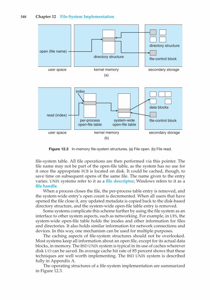
548 Chapter 12 File-System Implementation
directory structure
directory structureopen (file name)
kernel memoryuser space
index
(a)
file-control block
secondary storage
data blocks
per-processopen-file table
system-wideopen-file table
read (index)
kernel memoryuser space(b)
file-control block
secondary storage
Figure 12.3 In-memory file-system structures. (a) File open. (b) File read.
file-system table. All file operations are then performed via this pointer. Thefile name may not be part of the open-file table, as the system has no use forit once the appropriate FCB is located on disk. It could be cached, though, tosave time on subsequent opens of the same file. The name given to the entryvaries. UNIX systems refer to it as a file descriptor; Windows refers to it as afile handle.
When a process closes the file, the per-process table entry is removed, andthe system-wide entry’s open count is decremented. When all users that haveopened the file close it, any updated metadata is copied back to the disk-baseddirectory structure, and the system-wide open-file table entry is removed.
Some systems complicate this scheme further by using the file system as aninterface to other system aspects, such as networking. For example, in UFS, thesystem-wide open-file table holds the inodes and other information for filesand directories. It also holds similar information for network connections anddevices. In this way, one mechanism can be used for multiple purposes.
The caching aspects of file-system structures should not be overlooked.Most systems keep all information about an open file, except for its actual datablocks, in memory. The BSD UNIX system is typical in its use of caches whereverdisk I/O can be saved. Its average cache hit rate of 85 percent shows that thesetechniques are well worth implementing. The BSD UNIX system is describedfully in Appendix A.
The operating structures of a file-system implementation are summarizedin Figure 12.3.
12.2 File-System Implementation 549
12.2.2 Partitions and Mounting
The layout of a disk can have many variations, depending on the operatingsystem. A disk can be sliced into multiple partitions, or a volume can spanmultiple partitions on multiple disks. The former layout is discussed here,while the latter, which is more appropriately considered a form of RAID, iscovered in Section 10.7.
Each partition can be either “raw,” containing no file system, or “cooked,”containing a file system. Raw disk is used where no file system is appropriate.UNIX swap space can use a raw partition, for example, since it uses its ownformat on disk and does not use a file system. Likewise, some databases use rawdisk and format the data to suit their needs. Raw disk can also hold informationneeded by disk RAID systems, such as bit maps indicating which blocks aremirrored and which have changed and need to be mirrored. Similarly, rawdisk can contain a miniature database holding RAID configuration information,such as which disks are members of each RAID set. Raw disk use is discussedin Section 10.5.1.
Boot information can be stored in a separate partition, as described inSection 10.5.2. Again, it has its own format, because at boot time the systemdoes not have the file-system code loaded and therefore cannot interpret thefile-system format. Rather, boot information is usually a sequential series ofblocks, loaded as an image into memory. Execution of the image starts at apredefined location, such as the first byte. This boot loader in turn knowsenough about the file-system structure to be able to find and load the kerneland start it executing. It can contain more than the instructions for how to boota specific operating system. For instance, many systems can be dual-booted,allowing us to install multiple operating systems on a single system. How doesthe system know which one to boot? A boot loader that understands multiplefile systems and multiple operating systems can occupy the boot space. Onceloaded, it can boot one of the operating systems available on the disk. The diskcan have multiple partitions, each containing a different type of file system anda different operating system.
The root partition, which contains the operating-system kernel and some-times other system files, is mounted at boot time. Other volumes can beautomatically mounted at boot or manually mounted later, depending onthe operating system. As part of a successful mount operation, the operatingsystem verifies that the device contains a valid file system. It does so by askingthe device driver to read the device directory and verifying that the directoryhas the expected format. If the format is invalid, the partition must haveits consistency checked and possibly corrected, either with or without userintervention. Finally, the operating system notes in its in-memory mount tablethat a file system is mounted, along with the type of the file system. The detailsof this function depend on the operating system.
Microsoft Windows–based systems mount each volume in a separate namespace, denoted by a letter and a colon. To record that a file system is mountedat F:, for example, the operating system places a pointer to the file system ina field of the device structure corresponding to F:. When a process specifiesthe driver letter, the operating system finds the appropriate file-system pointerand traverses the directory structures on that device to find the specified file
550 Chapter 12 File-System Implementation
or directory. Later versions of Windows can mount a file system at any pointwithin the existing directory structure.
On UNIX, file systems can be mounted at any directory. Mounting isimplemented by setting a flag in the in-memory copy of the inode for thatdirectory. The flag indicates that the directory is a mount point. A field thenpoints to an entry in the mount table, indicating which device is mounted there.The mount table entry contains a pointer to the superblock of the file system onthat device. This scheme enables the operating system to traverse its directorystructure, switching seamlessly among file systems of varying types.
12.2.3 Virtual File Systems
The previous section makes it clear that modern operating systems mustconcurrently support multiple types of file systems. But how does an operatingsystem allow multiple types of file systems to be integrated into a directorystructure? And how can users seamlessly move between file-system typesas they navigate the file-system space? We now discuss some of theseimplementation details.
An obvious but suboptimal method of implementing multiple types of filesystems is to write directory and file routines for each type. Instead, however,most operating systems, including UNIX, use object-oriented techniques tosimplify, organize, and modularize the implementation. The use of thesemethods allows very dissimilar file-system types to be implemented withinthe same structure, including network file systems, such as NFS. Users canaccess files contained within multiple file systems on the local disk or even onfile systems available across the network.
Data structures and procedures are used to isolate the basic system-call functionality from the implementation details. Thus, the file-systemimplementation consists of three major layers, as depicted schematically inFigure 12.4. The first layer is the file-system interface, based on the open(),read(), write(), and close() calls and on file descriptors.
The second layer is called the virtual file system (VFS) layer. The VFS layerserves two important functions:
1. It separates file-system-generic operations from their implementationby defining a clean VFS interface. Several implementations for the VFSinterface may coexist on the same machine, allowing transparent accessto different types of file systems mounted locally.
2. It provides a mechanism for uniquely representing a file throughout anetwork. The VFS is based on a file-representation structure, called avnode, that contains a numerical designator for a network-wide uniquefile. (UNIX inodes are unique within only a single file system.) Thisnetwork-wide uniqueness is required for support of network file systems.The kernel maintains one vnode structure for each active node (file ordirectory).
Thus, the VFS distinguishes local files from remote ones, and local files arefurther distinguished according to their file-system types.
The VFS activates file-system-specific operations to handle local requestsaccording to their file-system types and calls the NFS protocol procedures for
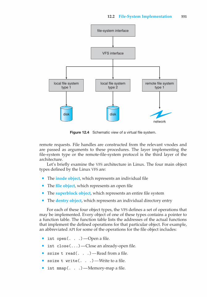
12.2 File-System Implementation 551
local file systemtype 1
disk
local file systemtype 2
disk
remote file systemtype 1
network
file-system interface
VFS interface
Figure 12.4 Schematic view of a virtual file system.
remote requests. File handles are constructed from the relevant vnodes andare passed as arguments to these procedures. The layer implementing thefile-system type or the remote-file-system protocol is the third layer of thearchitecture.
Let’s briefly examine the VFS architecture in Linux. The four main objecttypes defined by the Linux VFS are:
• The inode object, which represents an individual file
• The file object, which represents an open file
• The superblock object, which represents an entire file system
• The dentry object, which represents an individual directory entry
For each of these four object types, the VFS defines a set of operations thatmay be implemented. Every object of one of these types contains a pointer toa function table. The function table lists the addresses of the actual functionsthat implement the defined operations for that particular object. For example,an abbreviated API for some of the operations for the file object includes:
• int open(. . .)—Open a file.
• int close(...)—Close an already-open file.
• ssize t read(. . .)—Read from a file.
• ssize t write(. . .)—Write to a file.
• int mmap(. . .)—Memory-map a file.
552 Chapter 12 File-System Implementation
An implementation of the file object for a specific file type is required to imple-ment each function specified in the definition of the file object. (The completedefinition of the file object is specified in the struct file operations, whichis located in the file /usr/include/linux/fs.h.)
Thus, the VFS software layer can perform an operation on one of theseobjects by calling the appropriate function from the object’s function table,without having to know in advance exactly what kind of object it is dealingwith. The VFS does not know, or care, whether an inode represents a disk file,a directory file, or a remote file. The appropriate function for that file’s read()operation will always be at the same place in its function table, and the VFSsoftware layer will call that function without caring how the data are actuallyread.
12.3 Directory Implementation
The selection of directory-allocation and directory-management algorithmssignificantly affects the efficiency, performance, and reliability of the filesystem. In this section, we discuss the trade-offs involved in choosing oneof these algorithms.
12.3.1 Linear List
The simplest method of implementing a directory is to use a linear list of filenames with pointers to the data blocks. This method is simple to programbut time-consuming to execute. To create a new file, we must first search thedirectory to be sure that no existing file has the same name. Then, we add anew entry at the end of the directory. To delete a file, we search the directory forthe named file and then release the space allocated to it. To reuse the directoryentry, we can do one of several things. We can mark the entry as unused (byassigning it a special name, such as an all-blank name, or by including a used–unused bit in each entry), or we can attach it to a list of free directory entries. Athird alternative is to copy the last entry in the directory into the freed locationand to decrease the length of the directory. A linked list can also be used todecrease the time required to delete a file.
The real disadvantage of a linear list of directory entries is that finding afile requires a linear search. Directory information is used frequently, and userswill notice if access to it is slow. In fact, many operating systems implement asoftware cache to store the most recently used directory information. A cachehit avoids the need to constantly reread the information from disk. A sortedlist allows a binary search and decreases the average search time. However, therequirement that the list be kept sorted may complicate creating and deletingfiles, since we may have to move substantial amounts of directory informationto maintain a sorted directory. A more sophisticated tree data structure, suchas a balanced tree, might help here. An advantage of the sorted list is that asorted directory listing can be produced without a separate sort step.
12.3.2 Hash Table
Another data structure used for a file directory is a hash table. Here, a linearlist stores the directory entries, but a hash data structure is also used. The hashtable takes a value computed from the file name and returns a pointer to the file
12.4 Allocation Methods 553
name in the linear list. Therefore, it can greatly decrease the directory searchtime. Insertion and deletion are also fairly straightforward, although someprovision must be made for collisions—situations in which two file nameshash to the same location.
The major difficulties with a hash table are its generally fixed size and thedependence of the hash function on that size. For example, assume that wemake a linear-probing hash table that holds 64 entries. The hash functionconverts file names into integers from 0 to 63 (for instance, by using theremainder of a division by 64). If we later try to create a 65th file, we mustenlarge the directory hash table—say, to 128 entries. As a result, we needa new hash function that must map file names to the range 0 to 127, and wemust reorganize the existing directory entries to reflect their new hash-functionvalues.
Alternatively, we can use a chained-overflow hash table. Each hash entrycan be a linked list instead of an individual value, and we can resolve collisionsby adding the new entry to the linked list. Lookups may be somewhat slowed,because searching for a name might require stepping through a linked list ofcolliding table entries. Still, this method is likely to be much faster than a linearsearch through the entire directory.
12.4 Allocation Methods
The direct-access nature of disks gives us flexibility in the implementation offiles. In almost every case, many files are stored on the same disk. The mainproblem is how to allocate space to these files so that disk space is utilizedeffectively and files can be accessed quickly. Three major methods of allocatingdisk space are in wide use: contiguous, linked, and indexed. Each method hasadvantages and disadvantages. Although some systems support all three, it ismore common for a system to use one method for all files within a file-systemtype.
12.4.1 Contiguous Allocation
Contiguous allocation requires that each file occupy a set of contiguous blockson the disk. Disk addresses define a linear ordering on the disk. With thisordering, assuming that only one job is accessing the disk, accessing block b +1 after block b normally requires no head movement. When head movementis needed (from the last sector of one cylinder to the first sector of the nextcylinder), the head need only move from one track to the next. Thus, thenumber of disk seeks required for accessing contiguously allocated files isminimal, as is seek time when a seek is finally needed.
Contiguous allocation of a file is defined by the disk address and length (inblock units) of the first block. If the file is n blocks long and starts at locationb, then it occupies blocks b, b + 1, b + 2, ..., b + n − 1. The directory entry foreach file indicates the address of the starting block and the length of the areaallocated for this file (Figure 12.5).
Accessing a file that has been allocated contiguously is easy. For sequentialaccess, the file system remembers the disk address of the last block referencedand, when necessary, reads the next block. For direct access to block i of a
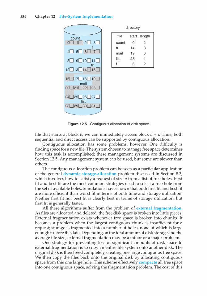
554 Chapter 12 File-System Implementation
directory
0 1 2 3
4 5 6 7
8 9 10 11
12 13 14 15
16 17 18 19
20 21 22 23
24 25 26 27
28 29 30 31
count
f
tr
list
start
0 14 19 28 6
length
2 3 6 4 2
file
count tr mail list f
Figure 12.5 Contiguous allocation of disk space.
file that starts at block b, we can immediately access block b + i. Thus, bothsequential and direct access can be supported by contiguous allocation.
Contiguous allocation has some problems, however. One difficulty isfinding space for a new file. The system chosen to manage free space determineshow this task is accomplished; these management systems are discussed inSection 12.5. Any management system can be used, but some are slower thanothers.
The contiguous-allocation problem can be seen as a particular applicationof the general dynamic storage-allocation problem discussed in Section 8.3,which involves how to satisfy a request of size n from a list of free holes. Firstfit and best fit are the most common strategies used to select a free hole fromthe set of available holes. Simulations have shown that both first fit and best fitare more efficient than worst fit in terms of both time and storage utilization.Neither first fit nor best fit is clearly best in terms of storage utilization, butfirst fit is generally faster.
All these algorithms suffer from the problem of external fragmentation.As files are allocated and deleted, the free disk space is broken into little pieces.External fragmentation exists whenever free space is broken into chunks. Itbecomes a problem when the largest contiguous chunk is insufficient for arequest; storage is fragmented into a number of holes, none of which is largeenough to store the data. Depending on the total amount of disk storage and theaverage file size, external fragmentation may be a minor or a major problem.
One strategy for preventing loss of significant amounts of disk space toexternal fragmentation is to copy an entire file system onto another disk. Theoriginal disk is then freed completely, creating one large contiguous free space.We then copy the files back onto the original disk by allocating contiguousspace from this one large hole. This scheme effectively compacts all free spaceinto one contiguous space, solving the fragmentation problem. The cost of this
12.4 Allocation Methods 555
compaction is time, however, and the cost can be particularly high for largehard disks. Compacting these disks may take hours and may be necessary ona weekly basis. Some systems require that this function be done off-line, withthe file system unmounted. During this down time, normal system operationgenerally cannot be permitted, so such compaction is avoided at all costs onproduction machines. Most modern systems that need defragmentation canperform it on-line during normal system operations, but the performancepenalty can be substantial.
Another problem with contiguous allocation is determining how muchspace is needed for a file. When the file is created, the total amount of spaceit will need must be found and allocated. How does the creator (program orperson) know the size of the file to be created? In some cases, this determinationmay be fairly simple (copying an existing file, for example). In general,however, the size of an output file may be difficult to estimate.
If we allocate too little space to a file, we may find that the file cannotbe extended. Especially with a best-fit allocation strategy, the space on bothsides of the file may be in use. Hence, we cannot make the file larger in place.Two possibilities then exist. First, the user program can be terminated, withan appropriate error message. The user must then allocate more space andrun the program again. These repeated runs may be costly. To prevent them,the user will normally overestimate the amount of space needed, resultingin considerable wasted space. The other possibility is to find a larger hole,copy the contents of the file to the new space, and release the previous space.This series of actions can be repeated as long as space exists, although it canbe time consuming. The user need never be informed explicitly about whatis happening, however; the system continues despite the problem, althoughmore and more slowly.
Even if the total amount of space needed for a file is known in advance,preallocation may be inefficient. A file that will grow slowly over a long period(months or years) must be allocated enough space for its final size, even thoughmuch of that space will be unused for a long time. The file therefore has a largeamount of internal fragmentation.
To minimize these drawbacks, some operating systems use a modifiedcontiguous-allocation scheme. Here, a contiguous chunk of space is allocatedinitially. Then, if that amount proves not to be large enough, another chunk ofcontiguous space, known as an extent, is added. The location of a file’s blocksis then recorded as a location and a block count, plus a link to the first blockof the next extent. On some systems, the owner of the file can set the extentsize, but this setting results in inefficiencies if the owner is incorrect. Internalfragmentation can still be a problem if the extents are too large, and externalfragmentation can become a problem as extents of varying sizes are allocatedand deallocated. The commercial Veritas file system uses extents to optimizeperformance. Veritas is a high-performance replacement for the standard UNIXUFS.
12.4.2 Linked Allocation
Linked allocation solves all problems of contiguous allocation. With linkedallocation, each file is a linked list of disk blocks; the disk blocks may bescattered anywhere on the disk. The directory contains a pointer to the first
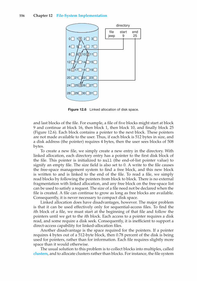
556 Chapter 12 File-System Implementation
0 1 2 3
4 5 7
8 9 10 11
12 13 14
16 17 18 19
20 21 22 23
24 25 26 27
28 29 30 31
15
6
filejeep
start9
directory
end25
1
1
-1
2
Figure 12.6 Linked allocation of disk space.
and last blocks of the file. For example, a file of five blocks might start at block9 and continue at block 16, then block 1, then block 10, and finally block 25(Figure 12.6). Each block contains a pointer to the next block. These pointersare not made available to the user. Thus, if each block is 512 bytes in size, anda disk address (the pointer) requires 4 bytes, then the user sees blocks of 508bytes.
To create a new file, we simply create a new entry in the directory. Withlinked allocation, each directory entry has a pointer to the first disk block ofthe file. This pointer is initialized to null (the end-of-list pointer value) tosignify an empty file. The size field is also set to 0. A write to the file causesthe free-space management system to find a free block, and this new blockis written to and is linked to the end of the file. To read a file, we simplyread blocks by following the pointers from block to block. There is no externalfragmentation with linked allocation, and any free block on the free-space listcan be used to satisfy a request. The size of a file need not be declared when thefile is created. A file can continue to grow as long as free blocks are available.Consequently, it is never necessary to compact disk space.
Linked allocation does have disadvantages, however. The major problemis that it can be used effectively only for sequential-access files. To find theith block of a file, we must start at the beginning of that file and follow thepointers until we get to the ith block. Each access to a pointer requires a diskread, and some require a disk seek. Consequently, it is inefficient to support adirect-access capability for linked-allocation files.
Another disadvantage is the space required for the pointers. If a pointerrequires 4 bytes out of a 512-byte block, then 0.78 percent of the disk is beingused for pointers, rather than for information. Each file requires slightly morespace than it would otherwise.
The usual solution to this problem is to collect blocks into multiples, calledclusters, and to allocate clusters rather than blocks. For instance, the file system
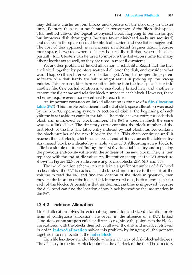
12.4 Allocation Methods 557
may define a cluster as four blocks and operate on the disk only in clusterunits. Pointers then use a much smaller percentage of the file’s disk space.This method allows the logical-to-physical block mapping to remain simplebut improves disk throughput (because fewer disk-head seeks are required)and decreases the space needed for block allocation and free-list management.The cost of this approach is an increase in internal fragmentation, becausemore space is wasted when a cluster is partially full than when a block ispartially full. Clusters can be used to improve the disk-access time for manyother algorithms as well, so they are used in most file systems.
Yet another problem of linked allocation is reliability. Recall that the filesare linked together by pointers scattered all over the disk, and consider whatwould happen if a pointer were lost or damaged. A bug in the operating-systemsoftware or a disk hardware failure might result in picking up the wrongpointer. This error could in turn result in linking into the free-space list or intoanother file. One partial solution is to use doubly linked lists, and another isto store the file name and relative block number in each block. However, theseschemes require even more overhead for each file.
An important variation on linked allocation is the use of a file-allocationtable (FAT). This simple but efficient method of disk-space allocation was usedby the MS-DOS operating system. A section of disk at the beginning of eachvolume is set aside to contain the table. The table has one entry for each diskblock and is indexed by block number. The FAT is used in much the sameway as a linked list. The directory entry contains the block number of thefirst block of the file. The table entry indexed by that block number containsthe block number of the next block in the file. This chain continues until itreaches the last block, which has a special end-of-file value as the table entry.An unused block is indicated by a table value of 0. Allocating a new block toa file is a simple matter of finding the first 0-valued table entry and replacingthe previous end-of-file value with the address of the new block. The 0 is thenreplaced with the end-of-file value. An illustrative example is the FAT structureshown in Figure 12.7 for a file consisting of disk blocks 217, 618, and 339.
The FAT allocation scheme can result in a significant number of disk headseeks, unless the FAT is cached. The disk head must move to the start of thevolume to read the FAT and find the location of the block in question, thenmove to the location of the block itself. In the worst case, both moves occur foreach of the blocks. A benefit is that random-access time is improved, becausethe disk head can find the location of any block by reading the information inthe FAT.
12.4.3 Indexed Allocation
Linked allocation solves the external-fragmentation and size-declaration prob-lems of contiguous allocation. However, in the absence of a FAT, linkedallocation cannot support efficient direct access, since the pointers to the blocksare scattered with the blocks themselves all over the disk and must be retrievedin order. Indexed allocation solves this problem by bringing all the pointerstogether into one location: the index block.
Each file has its own index block, which is an array of disk-block addresses.The i th entry in the index block points to the i th block of the file. The directory
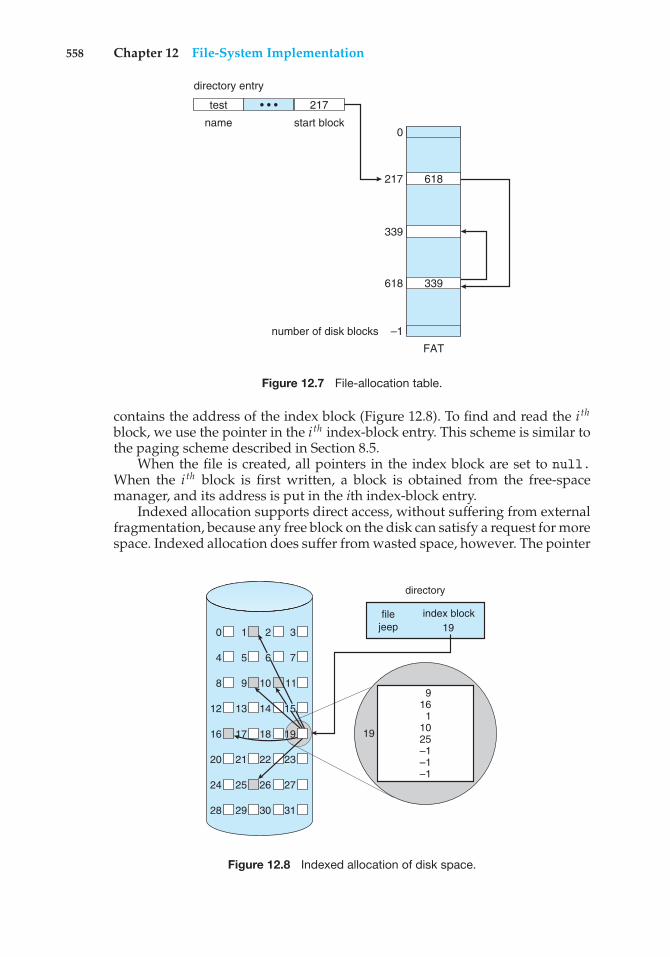
558 Chapter 12 File-System Implementation
• • •
directory entry
test 217
start blockname0
217 618
339
618 339
number of disk blocks –1
FAT
Figure 12.7 File-allocation table.
contains the address of the index block (Figure 12.8). To find and read the i th
block, we use the pointer in the i th index-block entry. This scheme is similar tothe paging scheme described in Section 8.5.
When the file is created, all pointers in the index block are set to null.When the i th block is first written, a block is obtained from the free-spacemanager, and its address is put in the ith index-block entry.
Indexed allocation supports direct access, without suffering from externalfragmentation, because any free block on the disk can satisfy a request for morespace. Indexed allocation does suffer from wasted space, however. The pointer
directory
0 1 2 3
4 5 7
8 9 10 11
12 13 14
16 17 18 19
20 21 22 23
24 25 26 27
28 29 30 31
15
6
9 161
10 25 –1 –1–1
filejeep
index block19
19
Figure 12.8 Indexed allocation of disk space.
12.4 Allocation Methods 559
overhead of the index block is generally greater than the pointer overhead oflinked allocation. Consider a common case in which we have a file of only oneor two blocks. With linked allocation, we lose the space of only one pointer perblock. With indexed allocation, an entire index block must be allocated, evenif only one or two pointers will be non-null.
This point raises the question of how large the index block should be. Everyfile must have an index block, so we want the index block to be as small aspossible. If the index block is too small, however, it will not be able to holdenough pointers for a large file, and a mechanism will have to be available todeal with this issue. Mechanisms for this purpose include the following:
• Linked scheme. An index block is normally one disk block. Thus, it canbe read and written directly by itself. To allow for large files, we can linktogether several index blocks. For example, an index block might contain asmall header giving the name of the file and a set of the first 100 disk-blockaddresses. The next address (the last word in the index block) is null (fora small file) or is a pointer to another index block (for a large file).
• Multilevel index. A variant of linked representation uses a first-level indexblock to point to a set of second-level index blocks, which in turn point tothe file blocks. To access a block, the operating system uses the first-levelindex to find a second-level index block and then uses that block to find thedesired data block. This approach could be continued to a third or fourthlevel, depending on the desired maximum file size. With 4,096-byte blocks,we could store 1,024 four-byte pointers in an index block. Two levels ofindexes allow 1,048,576 data blocks and a file size of up to 4 GB.
• Combined scheme. Another alternative, used in UNIX-based file systems,is to keep the first, say, 15 pointers of the index block in the file’s inode.The first 12 of these pointers point to direct blocks; that is, they containaddresses of blocks that contain data of the file. Thus, the data for smallfiles (of no more than 12 blocks) do not need a separate index block. If theblock size is 4 KB, then up to 48 KB of data can be accessed directly. The nextthree pointers point to indirect blocks. The first points to a single indirectblock, which is an index block containing not data but the addresses ofblocks that do contain data. The second points to a double indirect block,which contains the address of a block that contains the addresses of blocksthat contain pointers to the actual data blocks. The last pointer containsthe address of a triple indirect block. (A UNIX inode is shown in Figure12.9.)
Under this method, the number of blocks that can be allocated to a fileexceeds the amount of space addressable by the 4-byte file pointers usedby many operating systems. A 32-bit file pointer reaches only 232 bytes,or 4 GB. Many UNIX and Linux implementations now support 64-bit filepointers, which allows files and file systems to be several exbibytes in size.The ZFS file system supports 128-bit file pointers.
Indexed-allocation schemes suffer from some of the same performanceproblems as does linked allocation. Specifically, the index blocks can be cachedin memory, but the data blocks may be spread all over a volume.
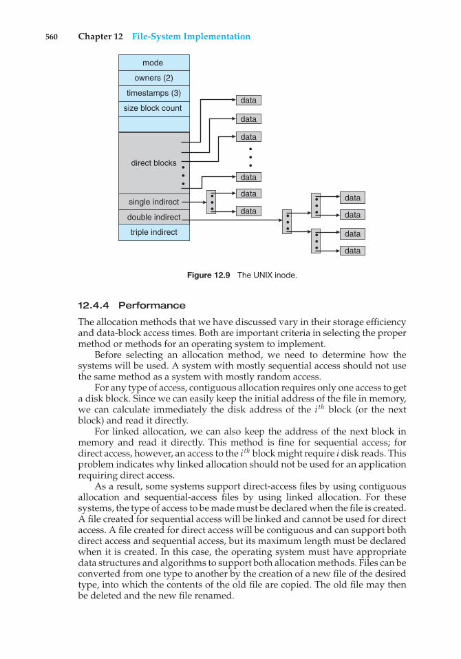
560 Chapter 12 File-System Implementation
direct blocks
data
data
data
data
data
data
data
data
data
data
• • ••
• •
• • •
• • •
• • •
• • •
mode
owners (2)
timestamps (3)
size block count
single indirect
double indirect
triple indirect
Figure 12.9 The UNIX inode.
12.4.4 Performance
The allocation methods that we have discussed vary in their storage efficiencyand data-block access times. Both are important criteria in selecting the propermethod or methods for an operating system to implement.
Before selecting an allocation method, we need to determine how thesystems will be used. A system with mostly sequential access should not usethe same method as a system with mostly random access.
For any type of access, contiguous allocation requires only one access to geta disk block. Since we can easily keep the initial address of the file in memory,we can calculate immediately the disk address of the i th block (or the nextblock) and read it directly.
For linked allocation, we can also keep the address of the next block inmemory and read it directly. This method is fine for sequential access; fordirect access, however, an access to the i th block might require i disk reads. Thisproblem indicates why linked allocation should not be used for an applicationrequiring direct access.
As a result, some systems support direct-access files by using contiguousallocation and sequential-access files by using linked allocation. For thesesystems, the type of access to be made must be declared when the file is created.A file created for sequential access will be linked and cannot be used for directaccess. A file created for direct access will be contiguous and can support bothdirect access and sequential access, but its maximum length must be declaredwhen it is created. In this case, the operating system must have appropriatedata structures and algorithms to support both allocation methods. Files can beconverted from one type to another by the creation of a new file of the desiredtype, into which the contents of the old file are copied. The old file may thenbe deleted and the new file renamed.
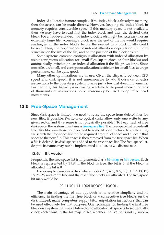
12.5 Free-Space Management 561
Indexed allocation is more complex. If the index block is already in memory,then the access can be made directly. However, keeping the index block inmemory requires considerable space. If this memory space is not available,then we may have to read first the index block and then the desired datablock. For a two-level index, two index-block reads might be necessary. For anextremely large file, accessing a block near the end of the file would requirereading in all the index blocks before the needed data block finally couldbe read. Thus, the performance of indexed allocation depends on the indexstructure, on the size of the file, and on the position of the block desired.
Some systems combine contiguous allocation with indexed allocation byusing contiguous allocation for small files (up to three or four blocks) andautomatically switching to an indexed allocation if the file grows large. Sincemost files are small, and contiguous allocation is efficient for small files, averageperformance can be quite good.
Many other optimizations are in use. Given the disparity between CPUspeed and disk speed, it is not unreasonable to add thousands of extrainstructions to the operating system to save just a few disk-head movements.Furthermore, this disparity is increasing over time, to the point where hundredsof thousands of instructions could reasonably be used to optimize headmovements.
12.5 Free-Space Management
Since disk space is limited, we need to reuse the space from deleted files fornew files, if possible. (Write-once optical disks allow only one write to anygiven sector, and thus reuse is not physically possible.) To keep track of freedisk space, the system maintains a free-space list. The free-space list records allfree disk blocks—those not allocated to some file or directory. To create a file,we search the free-space list for the required amount of space and allocate thatspace to the new file. This space is then removed from the free-space list. Whena file is deleted, its disk space is added to the free-space list. The free-space list,despite its name, may not be implemented as a list, as we discuss next.
12.5.1 Bit Vector
Frequently, the free-space list is implemented as a bit map or bit vector. Eachblock is represented by 1 bit. If the block is free, the bit is 1; if the block isallocated, the bit is 0.
For example, consider a disk where blocks 2, 3, 4, 5, 8, 9, 10, 11, 12, 13, 17,18, 25, 26, and 27 are free and the rest of the blocks are allocated. The free-spacebit map would be
001111001111110001100000011100000 ...
The main advantage of this approach is its relative simplicity and itsefficiency in finding the first free block or n consecutive free blocks on thedisk. Indeed, many computers supply bit-manipulation instructions that canbe used effectively for that purpose. One technique for finding the first freeblock on a system that uses a bit-vector to allocate disk space is to sequentiallycheck each word in the bit map to see whether that value is not 0, since a
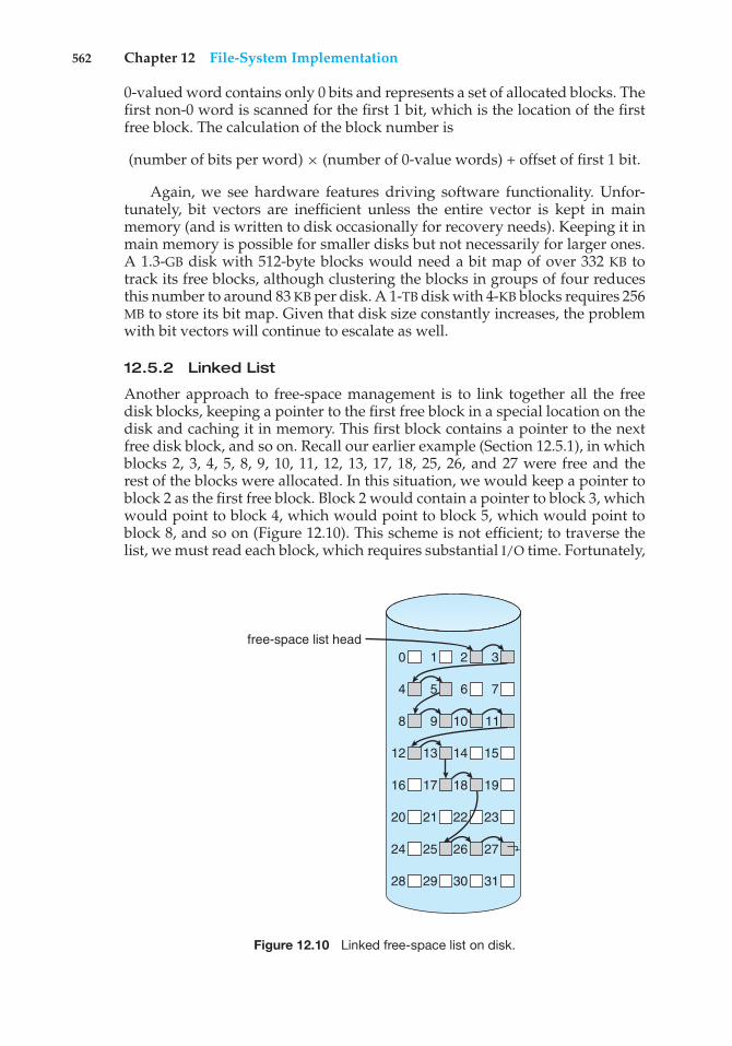
562 Chapter 12 File-System Implementation
0-valued word contains only 0 bits and represents a set of allocated blocks. Thefirst non-0 word is scanned for the first 1 bit, which is the location of the firstfree block. The calculation of the block number is
(number of bits per word) × (number of 0-value words) + offset of first 1 bit.
Again, we see hardware features driving software functionality. Unfor-tunately, bit vectors are inefficient unless the entire vector is kept in mainmemory (and is written to disk occasionally for recovery needs). Keeping it inmain memory is possible for smaller disks but not necessarily for larger ones.A 1.3-GB disk with 512-byte blocks would need a bit map of over 332 KB totrack its free blocks, although clustering the blocks in groups of four reducesthis number to around 83 KB per disk. A 1-TB disk with 4-KB blocks requires 256MB to store its bit map. Given that disk size constantly increases, the problemwith bit vectors will continue to escalate as well.
12.5.2 Linked List
Another approach to free-space management is to link together all the freedisk blocks, keeping a pointer to the first free block in a special location on thedisk and caching it in memory. This first block contains a pointer to the nextfree disk block, and so on. Recall our earlier example (Section 12.5.1), in whichblocks 2, 3, 4, 5, 8, 9, 10, 11, 12, 13, 17, 18, 25, 26, and 27 were free and therest of the blocks were allocated. In this situation, we would keep a pointer toblock 2 as the first free block. Block 2 would contain a pointer to block 3, whichwould point to block 4, which would point to block 5, which would point toblock 8, and so on (Figure 12.10). This scheme is not efficient; to traverse thelist, we must read each block, which requires substantial I/O time. Fortunately,
0 1 2 3
4 5 7
8 9 10 11
12 13 14
16 17 18 19
20 21 22 23
24 25 26 27
28 29 30 31
15
6
free-space list head
Figure 12.10 Linked free-space list on disk.
12.5 Free-Space Management 563
however, traversing the free list is not a frequent action. Usually, the operatingsystem simply needs a free block so that it can allocate that block to a file, sothe first block in the free list is used. The FAT method incorporates free-blockaccounting into the allocation data structure. No separate method is needed.
12.5.3 Grouping
A modification of the free-list approach stores the addresses of n free blocksin the first free block. The first n−1 of these blocks are actually free. The lastblock contains the addresses of another n free blocks, and so on. The addressesof a large number of free blocks can now be found quickly, unlike the situationwhen the standard linked-list approach is used.
12.5.4 Counting
Another approach takes advantage of the fact that, generally, several contigu-ous blocks may be allocated or freed simultaneously, particularly when spaceis allocated with the contiguous-allocation algorithm or through clustering.Thus, rather than keeping a list of n free disk addresses, we can keep theaddress of the first free block and the number (n) of free contiguous blocks thatfollow the first block. Each entry in the free-space list then consists of a diskaddress and a count. Although each entry requires more space than would asimple disk address, the overall list is shorter, as long as the count is generallygreater than 1. Note that this method of tracking free space is similar to theextent method of allocating blocks. These entries can be stored in a balancedtree, rather than a linked list, for efficient lookup, insertion, and deletion.
12.5.5 Space Maps
Oracle’s ZFS file system (found in Solaris and other operating systems) wasdesigned to encompass huge numbers of files, directories, and even file systems(in ZFS, we can create file-system hierarchies). On these scales, metadata I/O canhave a large performance impact. Consider, for example, that if the free-spacelist is implemented as a bit map, bit maps must be modified both when blocksare allocated and when they are freed. Freeing 1 GB of data on a 1-TB disk couldcause thousands of blocks of bit maps to be updated, because those data blockscould be scattered over the entire disk. Clearly, the data structures for such asystem could be large and inefficient.
In its management of free space, ZFS uses a combination of techniques tocontrol the size of data structures and minimize the I/O needed to managethose structures. First, ZFS creates metaslabs to divide the space on the deviceinto chunks of manageable size. A given volume may contain hundreds ofmetaslabs. Each metaslab has an associated space map. ZFS uses the countingalgorithm to store information about free blocks. Rather than write countingstructures to disk, it uses log-structured file-system techniques to record them.The space map is a log of all block activity (allocating and freeing), in timeorder, in counting format. When ZFS decides to allocate or free space from ametaslab, it loads the associated space map into memory in a balanced-treestructure (for very efficient operation), indexed by offset, and replays the loginto that structure. The in-memory space map is then an accurate representationof the allocated and free space in the metaslab. ZFS also condenses the map as
564 Chapter 12 File-System Implementation
much as possible by combining contiguous free blocks into a single entry.Finally, the free-space list is updated on disk as part of the transaction-orientedoperations of ZFS. During the collection and sorting phase, block requests canstill occur, and ZFS satisfies these requests from the log. In essence, the log plusthe balanced tree is the free list.
12.6 Efficiency and Performance
Now that we have discussed various block-allocation and directory-management options, we can further consider their effect on performanceand efficient disk use. Disks tend to represent a major bottleneck in systemperformance, since they are the slowest main computer component. In thissection, we discuss a variety of techniques used to improve the efficiency andperformance of secondary storage.
12.6.1 Efficiency
The efficient use of disk space depends heavily on the disk-allocation anddirectory algorithms in use. For instance, UNIX inodes are preallocated ona volume. Even an empty disk has a percentage of its space lost to inodes.However, by preallocating the inodes and spreading them across the volume,we improve the file system’s performance. This improved performance resultsfrom the UNIX allocation and free-space algorithms, which try to keep a file’sdata blocks near that file’s inode block to reduce seek time.
As another example, let’s reconsider the clustering scheme discussed inSection 12.4, which improves file-seek and file-transfer performance at the costof internal fragmentation. To reduce this fragmentation, BSD UNIX varies thecluster size as a file grows. Large clusters are used where they can be filled, andsmall clusters are used for small files and the last cluster of a file. This systemis described in Appendix A.
The types of data normally kept in a file’s directory (or inode) entry alsorequire consideration. Commonly, a “last write date” is recorded to supplyinformation to the user and to determine whether the file needs to be backedup. Some systems also keep a “last access date,” so that a user can determinewhen the file was last read. The result of keeping this information is that,whenever the file is read, a field in the directory structure must be writtento. That means the block must be read into memory, a section changed, andthe block written back out to disk, because operations on disks occur only inblock (or cluster) chunks. So any time a file is opened for reading, its directoryentry must be read and written as well. This requirement can be inefficient forfrequently accessed files, so we must weigh its benefit against its performancecost when designing a file system. Generally, every data item associated witha file needs to be considered for its effect on efficiency and performance.
Consider, for instance, how efficiency is affected by the size of the pointersused to access data. Most systems use either 32-bit or 64-bit pointers throughoutthe operating system. Using 32-bit pointers limits the size of a file to 232, or 4GB. Using 64-bit pointers allows very large file sizes, but 64-bit pointers require

12.6 Efficiency and Performance 565
more space to store. As a result, the allocation and free-space-managementmethods (linked lists, indexes, and so on) use more disk space.
One of the difficulties in choosing a pointer size—or, indeed, any fixedallocation size within an operating system—is planning for the effects ofchanging technology. Consider that the IBM PC XT had a 10-MB hard driveand an MS-DOS file system that could support only 32 MB. (Each FAT entrywas 12 bits, pointing to an 8-KB cluster.) As disk capacities increased, largerdisks had to be split into 32-MB partitions, because the file system could nottrack blocks beyond 32 MB. As hard disks with capacities of over 100 MB becamecommon, the disk data structures and algorithms in MS-DOS had to be modifiedto allow larger file systems. (Each FAT entry was expanded to 16 bits and laterto 32 bits.) The initial file-system decisions were made for efficiency reasons;however, with the advent of MS-DOS Version 4, millions of computer users wereinconvenienced when they had to switch to the new, larger file system. Solaris’ZFS file system uses 128-bit pointers, which theoretically should never needto be extended. (The minimum mass of a device capable of storing 2128 bytesusing atomic-level storage would be about 272 trillion kilograms.)
As another example, consider the evolution of the Solaris operating system.Originally, many data structures were of fixed length, allocated at systemstartup. These structures included the process table and the open-file table.When the process table became full, no more processes could be created. Whenthe file table became full, no more files could be opened. The system would failto provide services to users. Table sizes could be increased only by recompilingthe kernel and rebooting the system. With later releases of Solaris, almost allkernel structures were allocated dynamically, eliminating these artificial limitson system performance. Of course, the algorithms that manipulate these tablesare more complicated, and the operating system is a little slower because itmust dynamically allocate and deallocate table entries; but that price is theusual one for more general functionality.
12.6.2 Performance
Even after the basic file-system algorithms have been selected, we can stillimprove performance in several ways. As will be discussed in Chapter 13,most disk controllers include local memory to form an on-board cache that islarge enough to store entire tracks at a time. Once a seek is performed, thetrack is read into the disk cache starting at the sector under the disk head(reducing latency time). The disk controller then transfers any sector requeststo the operating system. Once blocks make it from the disk controller into mainmemory, the operating system may cache the blocks there.
Some systems maintain a separate section of main memory for a buffercache, where blocks are kept under the assumption that they will be usedagain shortly. Other systems cache file data using a page cache. The pagecache uses virtual memory techniques to cache file data as pages rather thanas file-system-oriented blocks. Caching file data using virtual addresses is farmore efficient than caching through physical disk blocks, as accesses interfacewith virtual memory rather than the file system. Several systems—includingSolaris, Linux, and Windows —use page caching to cache both process pagesand file data. This is known as unified virtual memory.
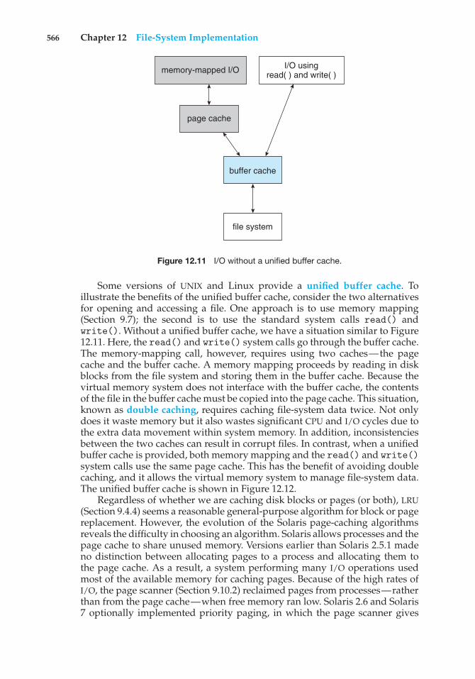
566 Chapter 12 File-System Implementation
memory-mapped I/O I/O usingread( ) and write( )
page cache
buffer cache
file system
Figure 12.11 I/O without a unified buffer cache.
Some versions of UNIX and Linux provide a unified buffer cache. Toillustrate the benefits of the unified buffer cache, consider the two alternativesfor opening and accessing a file. One approach is to use memory mapping(Section 9.7); the second is to use the standard system calls read() andwrite(). Without a unified buffer cache, we have a situation similar to Figure12.11. Here, the read() and write() system calls go through the buffer cache.The memory-mapping call, however, requires using two caches—the pagecache and the buffer cache. A memory mapping proceeds by reading in diskblocks from the file system and storing them in the buffer cache. Because thevirtual memory system does not interface with the buffer cache, the contentsof the file in the buffer cache must be copied into the page cache. This situation,known as double caching, requires caching file-system data twice. Not onlydoes it waste memory but it also wastes significant CPU and I/O cycles due tothe extra data movement within system memory. In addition, inconsistenciesbetween the two caches can result in corrupt files. In contrast, when a unifiedbuffer cache is provided, both memory mapping and the read() and write()system calls use the same page cache. This has the benefit of avoiding doublecaching, and it allows the virtual memory system to manage file-system data.The unified buffer cache is shown in Figure 12.12.
Regardless of whether we are caching disk blocks or pages (or both), LRU(Section 9.4.4) seems a reasonable general-purpose algorithm for block or pagereplacement. However, the evolution of the Solaris page-caching algorithmsreveals the difficulty in choosing an algorithm. Solaris allows processes and thepage cache to share unused memory. Versions earlier than Solaris 2.5.1 madeno distinction between allocating pages to a process and allocating them tothe page cache. As a result, a system performing many I/O operations usedmost of the available memory for caching pages. Because of the high rates ofI/O, the page scanner (Section 9.10.2) reclaimed pages from processes—ratherthan from the page cache—when free memory ran low. Solaris 2.6 and Solaris7 optionally implemented priority paging, in which the page scanner gives
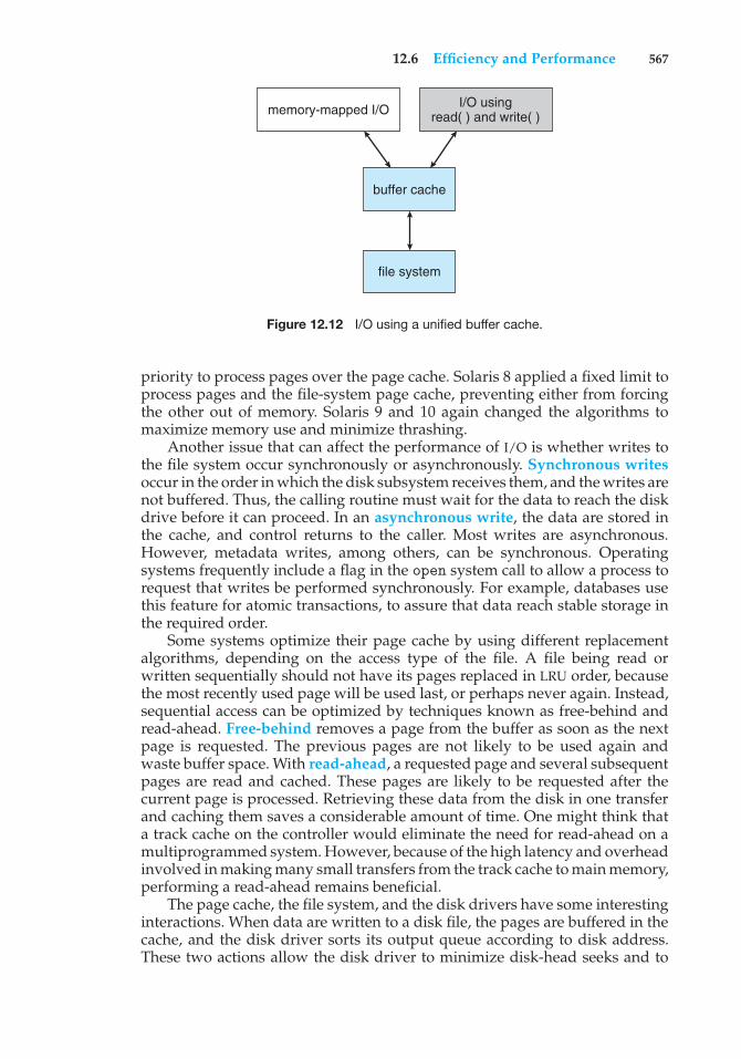
12.6 Efficiency and Performance 567
memory-mapped I/O I/O usingread( ) and write( )
buffer cache
file system
Figure 12.12 I/O using a unified buffer cache.
priority to process pages over the page cache. Solaris 8 applied a fixed limit toprocess pages and the file-system page cache, preventing either from forcingthe other out of memory. Solaris 9 and 10 again changed the algorithms tomaximize memory use and minimize thrashing.
Another issue that can affect the performance of I/O is whether writes tothe file system occur synchronously or asynchronously. Synchronous writesoccur in the order in which the disk subsystem receives them, and the writes arenot buffered. Thus, the calling routine must wait for the data to reach the diskdrive before it can proceed. In an asynchronous write, the data are stored inthe cache, and control returns to the caller. Most writes are asynchronous.However, metadata writes, among others, can be synchronous. Operatingsystems frequently include a flag in the open system call to allow a process torequest that writes be performed synchronously. For example, databases usethis feature for atomic transactions, to assure that data reach stable storage inthe required order.
Some systems optimize their page cache by using different replacementalgorithms, depending on the access type of the file. A file being read orwritten sequentially should not have its pages replaced in LRU order, becausethe most recently used page will be used last, or perhaps never again. Instead,sequential access can be optimized by techniques known as free-behind andread-ahead. Free-behind removes a page from the buffer as soon as the nextpage is requested. The previous pages are not likely to be used again andwaste buffer space. With read-ahead, a requested page and several subsequentpages are read and cached. These pages are likely to be requested after thecurrent page is processed. Retrieving these data from the disk in one transferand caching them saves a considerable amount of time. One might think thata track cache on the controller would eliminate the need for read-ahead on amultiprogrammed system. However, because of the high latency and overheadinvolved in making many small transfers from the track cache to main memory,performing a read-ahead remains beneficial.
The page cache, the file system, and the disk drivers have some interestinginteractions. When data are written to a disk file, the pages are buffered in thecache, and the disk driver sorts its output queue according to disk address.These two actions allow the disk driver to minimize disk-head seeks and to
568 Chapter 12 File-System Implementation
write data at times optimized for disk rotation. Unless synchronous writes arerequired, a process writing to disk simply writes into the cache, and the systemasynchronously writes the data to disk when convenient. The user process seesvery fast writes. When data are read from a disk file, the block I/O system doessome read-ahead; however, writes are much more nearly asynchronous thanare reads. Thus, output to the disk through the file system is often faster thanis input for large transfers, counter to intuition.
12.7 Recovery
Files and directories are kept both in main memory and on disk, and care mustbe taken to ensure that a system failure does not result in loss of data or in datainconsistency. We deal with these issues in this section. We also consider howa system can recover from such a failure.
A system crash can cause inconsistencies among on-disk file-system datastructures, such as directory structures, free-block pointers, and free FCBpointers. Many file systems apply changes to these structures in place. Atypical operation, such as creating a file, can involve many structural changeswithin the file system on the disk. Directory structures are modified, FCBs areallocated, data blocks are allocated, and the free counts for all of these blocksare decreased. These changes can be interrupted by a crash, and inconsistenciesamong the structures can result. For example, the free FCB count might indicatethat an FCB had been allocated, but the directory structure might not point tothe FCB. Compounding this problem is the caching that operating systems doto optimize I/O performance. Some changes may go directly to disk, whileothers may be cached. If the cached changes do not reach disk before a crashoccurs, more corruption is possible.
In addition to crashes, bugs in file-system implementation, disk controllers,and even user applications can corrupt a file system. File systems have varyingmethods to deal with corruption, depending on the file-system data structuresand algorithms. We deal with these issues next.
12.7.1 Consistency Checking
Whatever the cause of corruption, a file system must first detect the problemsand then correct them. For detection, a scan of all the metadata on each filesystem can confirm or deny the consistency of the system. Unfortunately, thisscan can take minutes or hours and should occur every time the system boots.Alternatively, a file system can record its state within the file-system metadata.At the start of any metadata change, a status bit is set to indicate that themetadata is in flux. If all updates to the metadata complete successfully, the filesystem can clear that bit. If, however, the status bit remains set, a consistencychecker is run.
The consistency checker—a systems program such as fsck in UNIX—compares the data in the directory structure with the data blocks on diskand tries to fix any inconsistencies it finds. The allocation and free-space-management algorithms dictate what types of problems the checker can findand how successful it will be in fixing them. For instance, if linked allocation isused and there is a link from any block to its next block, then the entire file can be
12.7 Recovery 569
reconstructed from the data blocks, and the directory structure can be recreated.In contrast, the loss of a directory entry on an indexed allocation system canbe disastrous, because the data blocks have no knowledge of one another. Forthis reason, UNIX caches directory entries for reads; but any write that resultsin space allocation, or other metadata changes, is done synchronously, beforethe corresponding data blocks are written. Of course, problems can still occurif a synchronous write is interrupted by a crash.
12.7.2 Log-Structured File Systems
Computer scientists often find that algorithms and technologies originallyused in one area are equally useful in other areas. Such is the case with thedatabase log-based recovery algorithms. These logging algorithms have beenapplied successfully to the problem of consistency checking. The resultingimplementations are known as log-based transaction-oriented (or journaling)file systems.
Note that with the consistency-checking approach discussed in the pre-ceding section, we essentially allow structures to break and repair them onrecovery. However, there are several problems with this approach. One is thatthe inconsistency may be irreparable. The consistency check may not be able torecover the structures, resulting in loss of files and even entire directories.Consistency checking can require human intervention to resolve conflicts,and that is inconvenient if no human is available. The system can remainunavailable until the human tells it how to proceed. Consistency checking alsotakes system and clock time. To check terabytes of data, hours of clock timemay be required.
The solution to this problem is to apply log-based recovery techniques tofile-system metadata updates. Both NTFS and the Veritas file system use thismethod, and it is included in recent versions of UFS on Solaris. In fact, it isbecoming common on many operating systems.
Fundamentally, all metadata changes are written sequentially to a log.Each set of operations for performing a specific task is a transaction. Oncethe changes are written to this log, they are considered to be committed,and the system call can return to the user process, allowing it to continueexecution. Meanwhile, these log entries are replayed across the actual file-system structures. As the changes are made, a pointer is updated to indicatewhich actions have completed and which are still incomplete. When an entirecommitted transaction is completed, it is removed from the log file, which isactually a circular buffer. A circular buffer writes to the end of its space andthen continues at the beginning, overwriting older values as it goes. We wouldnot want the buffer to write over data that had not yet been saved, so thatscenario is avoided. The log may be in a separate section of the file system oreven on a separate disk spindle. It is more efficient, but more complex, to haveit under separate read and write heads, thereby decreasing head contentionand seek times.
If the system crashes, the log file will contain zero or more transactions.Any transactions it contains were not completed to the file system, even thoughthey were committed by the operating system, so they must now be completed.The transactions can be executed from the pointer until the work is complete
570 Chapter 12 File-System Implementation
so that the file-system structures remain consistent. The only problem occurswhen a transaction was aborted—that is, was not committed before the systemcrashed. Any changes from such a transaction that were applied to the filesystem must be undone, again preserving the consistency of the file system.This recovery is all that is needed after a crash, eliminating any problems withconsistency checking.
A side benefit of using logging on disk metadata updates is that thoseupdates proceed much faster than when they are applied directly to the on-disk data structures. The reason is found in the performance advantage ofsequential I/O over random I/O. The costly synchronous random metadatawrites are turned into much less costly synchronous sequential writes to thelog-structured file system’s logging area. Those changes, in turn, are replayedasynchronously via random writes to the appropriate structures. The overallresult is a significant gain in performance of metadata-oriented operations,such as file creation and deletion.
12.7.3 Other Solutions
Another alternative to consistency checking is employed by Network Appli-ance’s WAFL file system and the Solaris ZFS file system. These systems neveroverwrite blocks with new data. Rather, a transaction writes all data and meta-data changes to new blocks. When the transaction is complete, the metadatastructures that pointed to the old versions of these blocks are updated to pointto the new blocks. The file system can then remove the old pointers and the oldblocks and make them available for reuse. If the old pointers and blocks arekept, a snapshot is created; the snapshot is a view of the file system before thelast update took place. This solution should require no consistency checking ifthe pointer update is done atomically. WAFL does have a consistency checker,however, so some failure scenarios can still cause metadata corruption. (SeeSection 12.9 for details of the WAFL file system.)
ZFS takes an even more innovative approach to disk consistency. It neveroverwrites blocks, just like WAFL. However, ZFS goes further and provideschecksumming of all metadata and data blocks. This solution (when combinedwith RAID) assures that data are always correct. ZFS therefore has no consistencychecker. (More details on ZFS are found in Section 10.7.6.)
12.7.4 Backup and Restore
Magnetic disks sometimes fail, and care must be taken to ensure that the datalost in such a failure are not lost forever. To this end, system programs can beused to back up data from disk to another storage device, such as a magnetictape or other hard disk. Recovery from the loss of an individual file, or of anentire disk, may then be a matter of restoring the data from backup.
To minimize the copying needed, we can use information from each file’sdirectory entry. For instance, if the backup program knows when the lastbackup of a file was done, and the file’s last write date in the directory indicatesthat the file has not changed since that date, then the file does not need to becopied again. A typical backup schedule may then be as follows:
• Day 1. Copy to a backup medium all files from the disk. This is called afull backup.
12.8 NFS 571
• Day 2. Copy to another medium all files changed since day 1. This is anincremental backup.
• Day 3. Copy to another medium all files changed since day 2.
.
.
.
• Day N. Copy to another medium all files changed since day N− 1. Thengo back to day 1.
The new cycle can have its backup written over the previous set or onto anew set of backup media.
Using this method, we can restore an entire disk by starting restores withthe full backup and continuing through each of the incremental backups. Ofcourse, the larger the value of N, the greater the number of media that must beread for a complete restore. An added advantage of this backup cycle is thatwe can restore any file accidentally deleted during the cycle by retrieving thedeleted file from the backup of the previous day.
The length of the cycle is a compromise between the amount of backupmedium needed and the number of days covered by a restore. To decrease thenumber of tapes that must be read to do a restore, an option is to perform afull backup and then each day back up all files that have changed since thefull backup. In this way, a restore can be done via the most recent incrementalbackup and the full backup, with no other incremental backups needed. Thetrade-off is that more files will be modified each day, so each successiveincremental backup involves more files and more backup media.
A user may notice that a particular file is missing or corrupted long afterthe damage was done. For this reason, we usually plan to take a full backupfrom time to time that will be saved “forever.” It is a good idea to store thesepermanent backups far away from the regular backups to protect againsthazard, such as a fire that destroys the computer and all the backups too.And if the backup cycle reuses media, we must take care not to reuse themedia too many times—if the media wear out, it might not be possible torestore any data from the backups.
12.8 NFS
Network file systems are commonplace. They are typically integrated withthe overall directory structure and interface of the client system. NFS is a goodexample of a widely used, well implemented client–server network file system.Here, we use it as an example to explore the implementation details of networkfile systems.
NFS is both an implementation and a specification of a software system foraccessing remote files across LANs (or even WANs). NFS is part of ONC+, whichmost UNIX vendors and some PC operating systems support. The implementa-tion described here is part of the Solaris operating system, which is a modifiedversion of UNIX SVR4. It uses either the TCP or UDP/IP protocol (depending on
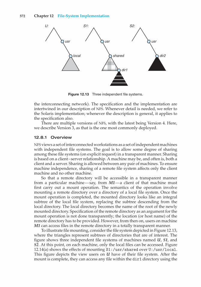
572 Chapter 12 File-System Implementation
local
usr
shared
dir1
usr
U: S1: S2:
dir2
usr
Figure 12.13 Three independent file systems.
the interconnecting network). The specification and the implementation areintertwined in our description of NFS. Whenever detail is needed, we refer tothe Solaris implementation; whenever the description is general, it applies tothe specification also.
There are multiple versions of NFS, with the latest being Version 4. Here,we describe Version 3, as that is the one most commonly deployed.
12.8.1 Overview
NFS views a set of interconnected workstations as a set of independent machineswith independent file systems. The goal is to allow some degree of sharingamong these file systems (on explicit request) in a transparent manner. Sharingis based on a client–server relationship. A machine may be, and often is, both aclient and a server. Sharing is allowed between any pair of machines. To ensuremachine independence, sharing of a remote file system affects only the clientmachine and no other machine.
So that a remote directory will be accessible in a transparent mannerfrom a particular machine—say, from M1—a client of that machine mustfirst carry out a mount operation. The semantics of the operation involvemounting a remote directory over a directory of a local file system. Once themount operation is completed, the mounted directory looks like an integralsubtree of the local file system, replacing the subtree descending from thelocal directory. The local directory becomes the name of the root of the newlymounted directory. Specification of the remote directory as an argument for themount operation is not done transparently; the location (or host name) of theremote directory has to be provided. However, from then on, users on machineM1 can access files in the remote directory in a totally transparent manner.
To illustrate file mounting, consider the file system depicted in Figure 12.13,where the triangles represent subtrees of directories that are of interest. Thefigure shows three independent file systems of machines named U, S1, andS2. At this point, on each machine, only the local files can be accessed. Figure12.14(a) shows the effects of mounting S1:/usr/shared over U:/usr/local.This figure depicts the view users on U have of their file system. After themount is complete, they can access any file within the dir1 directory using the
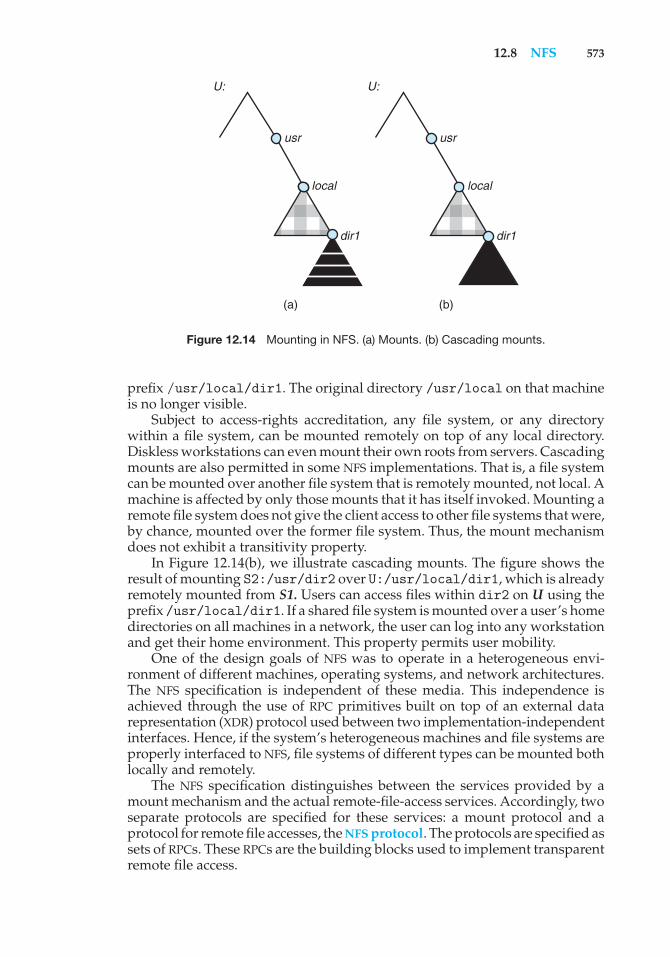
12.8 NFS 573
local
dir1 dir1
usr
U: U:
(a) (b)
local
usr
Figure 12.14 Mounting in NFS. (a) Mounts. (b) Cascading mounts.
prefix /usr/local/dir1. The original directory /usr/local on that machineis no longer visible.
Subject to access-rights accreditation, any file system, or any directorywithin a file system, can be mounted remotely on top of any local directory.Diskless workstations can even mount their own roots from servers. Cascadingmounts are also permitted in some NFS implementations. That is, a file systemcan be mounted over another file system that is remotely mounted, not local. Amachine is affected by only those mounts that it has itself invoked. Mounting aremote file system does not give the client access to other file systems that were,by chance, mounted over the former file system. Thus, the mount mechanismdoes not exhibit a transitivity property.
In Figure 12.14(b), we illustrate cascading mounts. The figure shows theresult of mounting S2:/usr/dir2 over U:/usr/local/dir1, which is alreadyremotely mounted from S1. Users can access files within dir2 on U using theprefix /usr/local/dir1. If a shared file system is mounted over a user’s homedirectories on all machines in a network, the user can log into any workstationand get their home environment. This property permits user mobility.
One of the design goals of NFS was to operate in a heterogeneous envi-ronment of different machines, operating systems, and network architectures.The NFS specification is independent of these media. This independence isachieved through the use of RPC primitives built on top of an external datarepresentation (XDR) protocol used between two implementation-independentinterfaces. Hence, if the system’s heterogeneous machines and file systems areproperly interfaced to NFS, file systems of different types can be mounted bothlocally and remotely.
The NFS specification distinguishes between the services provided by amount mechanism and the actual remote-file-access services. Accordingly, twoseparate protocols are specified for these services: a mount protocol and aprotocol for remote file accesses, the NFS protocol. The protocols are specified assets of RPCs. These RPCs are the building blocks used to implement transparentremote file access.
574 Chapter 12 File-System Implementation
12.8.2 The Mount Protocol
The mount protocol establishes the initial logical connection between a serverand a client. In Solaris, each machine has a server process, outside the kernel,performing the protocol functions.
A mount operation includes the name of the remote directory to bemounted and the name of the server machine storing it. The mount requestis mapped to the corresponding RPC and is forwarded to the mount serverrunning on the specific server machine. The server maintains an export listthat specifies local file systems that it exports for mounting, along with namesof machines that are permitted to mount them. (In Solaris, this list is the/etc/dfs/dfstab, which can be edited only by a superuser.) The specificationcan also include access rights, such as read only. To simplify the maintenanceof export lists and mount tables, a distributed naming scheme can be used tohold this information and make it available to appropriate clients.
Recall that any directory within an exported file system can be mountedremotely by an accredited machine. A component unit is such a directory. Whenthe server receives a mount request that conforms to its export list, it returns tothe client a file handle that serves as the key for further accesses to files withinthe mounted file system. The file handle contains all the information that theserver needs to distinguish an individual file it stores. In UNIX terms, the filehandle consists of a file-system identifier and an inode number to identify theexact mounted directory within the exported file system.
The server also maintains a list of the client machines and the correspondingcurrently mounted directories. This list is used mainly for administrativepurposes—for instance, for notifying all clients that the server is going down.Only through addition and deletion of entries in this list can the server statebe affected by the mount protocol.
Usually, a system has a static mounting preconfiguration that is establishedat boot time (/etc/vfstab in Solaris); however, this layout can be modified. Inaddition to the actual mount procedure, the mount protocol includes severalother procedures, such as unmount and return export list.
12.8.3 The NFS Protocol
The NFS protocol provides a set of RPCs for remote file operations. Theprocedures support the following operations:
• Searching for a file within a directory
• Reading a set of directory entries
• Manipulating links and directories
• Accessing file attributes
• Reading and writing files
These procedures can be invoked only after a file handle for the remotelymounted directory has been established.
The omission of open and close operations is intentional. A prominentfeature of NFS servers is that they are stateless. Servers do not maintaininformation about their clients from one access to another. No parallels to
12.8 NFS 575
UNIX’s open-files table or file structures exist on the server side. Consequently,each request has to provide a full set of arguments, including a unique fileidentifier and an absolute offset inside the file for the appropriate operations.The resulting design is robust; no special measures need be taken to recovera server after a crash. File operations must be idempotent for this purpose,that is, the same operation performed multiple times has the same effect asif it were only performed once. To achieve idempotence, every NFS requesthas a sequence number, allowing the server to determine if a request has beenduplicated or if any are missing.
Maintaining the list of clients that we mentioned seems to violate thestatelessness of the server. However, this list is not essential for the correctoperation of the client or the server, and hence it does not need to be restoredafter a server crash. Consequently, it may include inconsistent data and istreated as only a hint.
A further implication of the stateless-server philosophy and a result of thesynchrony of an RPC is that modified data (including indirection and statusblocks) must be committed to the server’s disk before results are returned tothe client. That is, a client can cache write blocks, but when it flushes them to theserver, it assumes that they have reached the server’s disks. The server mustwrite all NFS data synchronously. Thus, a server crash and recovery will beinvisible to a client; all blocks that the server is managing for the client will beintact. The resulting performance penalty can be large, because the advantagesof caching are lost. Performance can be increased by using storage with its ownnonvolatile cache (usually battery-backed-up memory). The disk controlleracknowledges the disk write when the write is stored in the nonvolatile cache.In essence, the host sees a very fast synchronous write. These blocks remainintact even after a system crash and are written from this stable storage to diskperiodically.
A single NFS write procedure call is guaranteed to be atomic and is notintermixed with other write calls to the same file. The NFS protocol, however,does not provide concurrency-control mechanisms. A write() system call maybe broken down into several RPC writes, because each NFS write or read callcan contain up to 8 KB of data and UDP packets are limited to 1,500 bytes. As aresult, two users writing to the same remote file may get their data intermixed.The claim is that, because lock management is inherently stateful, a serviceoutside the NFS should provide locking (and Solaris does). Users are advisedto coordinate access to shared files using mechanisms outside the scope of NFS.
NFS is integrated into the operating system via a VFS. As an illustrationof the architecture, let’s trace how an operation on an already-open remotefile is handled (follow the example in Figure 12.15). The client initiates theoperation with a regular system call. The operating-system layer maps thiscall to a VFS operation on the appropriate vnode. The VFS layer identifies thefile as a remote one and invokes the appropriate NFS procedure. An RPC callis made to the NFS service layer at the remote server. This call is reinjected tothe VFS layer on the remote system, which finds that it is local and invokesthe appropriate file-system operation. This path is retraced to return the result.An advantage of this architecture is that the client and the server are identical;thus, a machine may be a client, or a server, or both. The actual service on eachserver is performed by kernel threads.
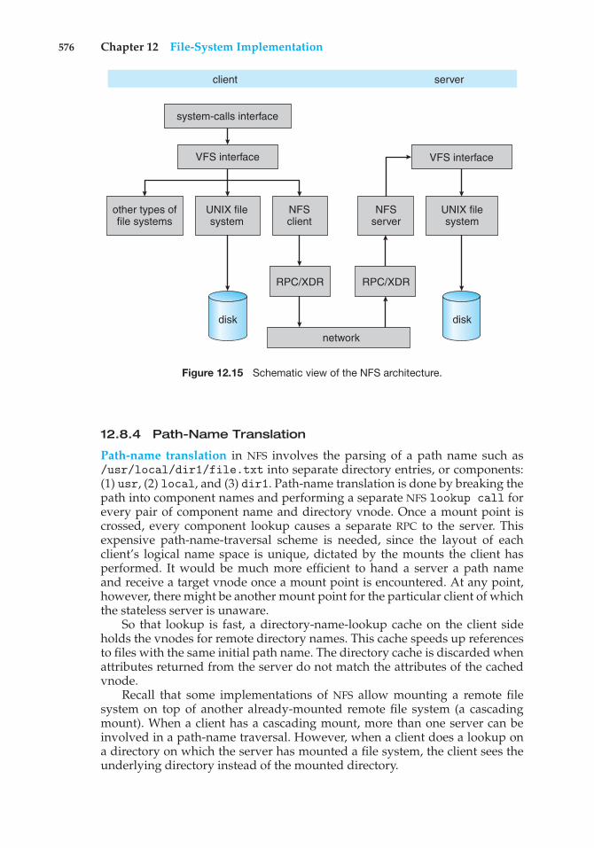
576 Chapter 12 File-System Implementation
disk disk
system-calls interface
client server
other types offile systems
UNIX filesystem
UNIX filesystem
NFSclient
RPC/XDR
network
RPC/XDR
NFSserver
VFS interface VFS interface
Figure 12.15 Schematic view of the NFS architecture.
12.8.4 Path-Name Translation
Path-name translation in NFS involves the parsing of a path name such as/usr/local/dir1/file.txt into separate directory entries, or components:(1) usr, (2) local, and (3) dir1. Path-name translation is done by breaking thepath into component names and performing a separate NFS lookup call forevery pair of component name and directory vnode. Once a mount point iscrossed, every component lookup causes a separate RPC to the server. Thisexpensive path-name-traversal scheme is needed, since the layout of eachclient’s logical name space is unique, dictated by the mounts the client hasperformed. It would be much more efficient to hand a server a path nameand receive a target vnode once a mount point is encountered. At any point,however, there might be another mount point for the particular client of whichthe stateless server is unaware.
So that lookup is fast, a directory-name-lookup cache on the client sideholds the vnodes for remote directory names. This cache speeds up referencesto files with the same initial path name. The directory cache is discarded whenattributes returned from the server do not match the attributes of the cachedvnode.
Recall that some implementations of NFS allow mounting a remote filesystem on top of another already-mounted remote file system (a cascadingmount). When a client has a cascading mount, more than one server can beinvolved in a path-name traversal. However, when a client does a lookup ona directory on which the server has mounted a file system, the client sees theunderlying directory instead of the mounted directory.
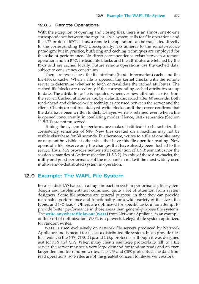
12.9 Example: The WAFL File System 577
12.8.5 Remote Operations
With the exception of opening and closing files, there is an almost one-to-onecorrespondence between the regular UNIX system calls for file operations andthe NFS protocol RPCs. Thus, a remote file operation can be translated directlyto the corresponding RPC. Conceptually, NFS adheres to the remote-serviceparadigm; but in practice, buffering and caching techniques are employed forthe sake of performance. No direct correspondence exists between a remoteoperation and an RPC. Instead, file blocks and file attributes are fetched by theRPCs and are cached locally. Future remote operations use the cached data,subject to consistency constraints.
There are two caches: the file-attribute (inode-information) cache and thefile-blocks cache. When a file is opened, the kernel checks with the remoteserver to determine whether to fetch or revalidate the cached attributes. Thecached file blocks are used only if the corresponding cached attributes are upto date. The attribute cache is updated whenever new attributes arrive fromthe server. Cached attributes are, by default, discarded after 60 seconds. Bothread-ahead and delayed-write techniques are used between the server and theclient. Clients do not free delayed-write blocks until the server confirms thatthe data have been written to disk. Delayed-write is retained even when a fileis opened concurrently, in conflicting modes. Hence, UNIX semantics (Section11.5.3.1) are not preserved.
Tuning the system for performance makes it difficult to characterize theconsistency semantics of NFS. New files created on a machine may not bevisible elsewhere for 30 seconds. Furthermore, writes to a file at one site mayor may not be visible at other sites that have this file open for reading. Newopens of a file observe only the changes that have already been flushed to theserver. Thus, NFS provides neither strict emulation of UNIX semantics nor thesession semantics of Andrew (Section 11.5.3.2). In spite of these drawbacks, theutility and good performance of the mechanism make it the most widely usedmulti-vendor-distributed system in operation.
12.9 Example: The WAFL File System
Because disk I/O has such a huge impact on system performance, file-systemdesign and implementation command quite a lot of attention from systemdesigners. Some file systems are general purpose, in that they can providereasonable performance and functionality for a wide variety of file sizes, filetypes, and I/O loads. Others are optimized for specific tasks in an attempt toprovide better performance in those areas than general-purpose file systems.The write-anywhere file layout (WAFL) from Network Appliance is an exampleof this sort of optimization. WAFL is a powerful, elegant file system optimizedfor random writes.
WAFL is used exclusively on network file servers produced by NetworkAppliance and is meant for use as a distributed file system. It can provide filesto clients via the NFS, CIFS, ftp, and http protocols, although it was designedjust for NFS and CIFS. When many clients use these protocols to talk to a fileserver, the server may see a very large demand for random reads and an evenlarger demand for random writes. The NFS and CIFS protocols cache data fromread operations, so writes are of the greatest concern to file-server creators.
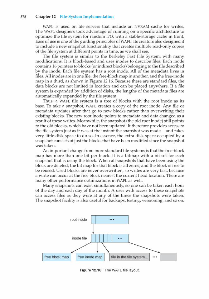
578 Chapter 12 File-System Implementation
WAFL is used on file servers that include an NVRAM cache for writes.The WAFL designers took advantage of running on a specific architecture tooptimize the file system for random I/O, with a stable-storage cache in front.Ease of use is one of the guiding principles of WAFL. Its creators also designed itto include a new snapshot functionality that creates multiple read-only copiesof the file system at different points in time, as we shall see.
The file system is similar to the Berkeley Fast File System, with manymodifications. It is block-based and uses inodes to describe files. Each inodecontains 16 pointers to blocks (or indirect blocks) belonging to the file describedby the inode. Each file system has a root inode. All of the metadata lives infiles. All inodes are in one file, the free-block map in another, and the free-inodemap in a third, as shown in Figure 12.16. Because these are standard files, thedata blocks are not limited in location and can be placed anywhere. If a filesystem is expanded by addition of disks, the lengths of the metadata files areautomatically expanded by the file system.
Thus, a WAFL file system is a tree of blocks with the root inode as itsbase. To take a snapshot, WAFL creates a copy of the root inode. Any file ormetadata updates after that go to new blocks rather than overwriting theirexisting blocks. The new root inode points to metadata and data changed as aresult of these writes. Meanwhile, the snapshot (the old root inode) still pointsto the old blocks, which have not been updated. It therefore provides access tothe file system just as it was at the instant the snapshot was made—and takesvery little disk space to do so. In essence, the extra disk space occupied by asnapshot consists of just the blocks that have been modified since the snapshotwas taken.
An important change from more standard file systems is that the free-blockmap has more than one bit per block. It is a bitmap with a bit set for eachsnapshot that is using the block. When all snapshots that have been using theblock are deleted, the bit map for that block is all zeros, and the block is free tobe reused. Used blocks are never overwritten, so writes are very fast, becausea write can occur at the free block nearest the current head location. There aremany other performance optimizations in WAFL as well.
Many snapshots can exist simultaneously, so one can be taken each hourof the day and each day of the month. A user with access to these snapshotscan access files as they were at any of the times the snapshots were taken.The snapshot facility is also useful for backups, testing, versioning, and so on.
free block map free inode map file in the file system...
root inode
inode file
•••
•••
•••
Figure 12.16 The WAFL file layout.
12.9 Example: The WAFL File System 579
block A B C D E
root inode
(a) Before a snapshot.
block A B C D E
root inode
(b) After a snapshot, before any blocks change.
new snapshot
block A B C D D´E
root inode
(c) After block D has changed to D´.
new snapshot
Figure 12.17 Snapshots in WAFL.
WAFL’s snapshot facility is very efficient in that it does not even require thatcopy-on-write copies of each data block be taken before the block is modified.Other file systems provide snapshots, but frequently with less efficiency. WAFLsnapshots are depicted in Figure 12.17.
Newer versions of WAFL actually allow read–write snapshots, known asclones. Clones are also efficient, using the same techniques as shapshots. Inthis case, a read-only snapshot captures the state of the file system, and a clonerefers back to that read-only snapshot. Any writes to the clone are stored innew blocks, and the clone’s pointers are updated to refer to the new blocks.The original snapshot is unmodified, still giving a view into the file system asit was before the clone was updated. Clones can also be promoted to replacethe original file system; this involves throwing out all of the old pointers andany associated old blocks. Clones are useful for testing and upgrades, as theoriginal version is left untouched and the clone deleted when the test is doneor if the upgrade fails.
Another feature that naturally results from the WAFL file system implemen-tation is replication, the duplication and synchronization of a set of data over anetwork to another system. First, a snapshot of a WAFL file system is duplicatedto another system. When another snapshot is taken on the source system, itis relatively easy to update the remote system just by sending over all blockscontained in the new snapshot. These blocks are the ones that have changed
580 Chapter 12 File-System Implementation
between the times the two snapshots were taken. The remote system adds theseblocks to the file system and updates its pointers, and the new system then is aduplicate of the source system as of the time of the second snapshot. Repeatingthis process maintains the remote system as a nearly up-to-date copy of the firstsystem. Such replication is used for disaster recovery. Should the first systembe destroyed, most of its data are available for use on the remote system.
Finally, we should note that the ZFS file system supports similarly efficientsnapshots, clones, and replication.
12.10Summary
The file system resides permanently on secondary storage, which is designed tohold a large amount of data permanently. The most common secondary-storagemedium is the disk.
Physical disks may be segmented into partitions to control media useand to allow multiple, possibly varying, file systems on a single spindle.These file systems are mounted onto a logical file system architecture to makethem available for use. File systems are often implemented in a layered ormodular structure. The lower levels deal with the physical properties of storagedevices. Upper levels deal with symbolic file names and logical properties offiles. Intermediate levels map the logical file concepts into physical deviceproperties.
Any file-system type can have different structures and algorithms. A VFSlayer allows the upper layers to deal with each file-system type uniformly. Evenremote file systems can be integrated into the system’s directory structure andacted on by standard system calls via the VFS interface.
The various files can be allocated space on the disk in three ways: throughcontiguous, linked, or indexed allocation. Contiguous allocation can sufferfrom external fragmentation. Direct access is very inefficient with linkedallocation. Indexed allocation may require substantial overhead for its indexblock. These algorithms can be optimized in many ways. Contiguous spacecan be enlarged through extents to increase flexibility and to decrease externalfragmentation. Indexed allocation can be done in clusters of multiple blocksto increase throughput and to reduce the number of index entries needed.Indexing in large clusters is similar to contiguous allocation with extents.
Free-space allocation methods also influence the efficiency of disk-spaceuse, the performance of the file system, and the reliability of secondary storage.The methods used include bit vectors and linked lists. Optimizations includegrouping, counting, and the FAT, which places the linked list in one contiguousarea.
Directory-management routines must consider efficiency, performance,and reliability. A hash table is a commonly used method, as it is fast andefficient. Unfortunately, damage to the table or a system crash can resultin inconsistency between the directory information and the disk’s contents.A consistency checker can be used to repair the damage. Operating-systembackup tools allow disk data to be copied to tape, enabling the user to recoverfrom data or even disk loss due to hardware failure, operating system bug, oruser error.
Practice Exercises 581
Network file systems, such as NFS, use client–server methodology toallow users to access files and directories from remote machines as if theywere on local file systems. System calls on the client are translated intonetwork protocols and retranslated into file-system operations on the server.Networking and multiple-client access create challenges in the areas of dataconsistency and performance.
Due to the fundamental role that file systems play in system operation,their performance and reliability are crucial. Techniques such as log structuresand caching help improve performance, while log structures and RAID improvereliability. The WAFL file system is an example of optimization of performanceto match a specific I/O load.
Practice Exercises
12.1 Consider a file currently consisting of 100 blocks. Assume that the file-control block (and the index block, in the case of indexed allocation)is already in memory. Calculate how many disk I/O operations arerequired for contiguous, linked, and indexed (single-level) allocationstrategies, if, for one block, the following conditions hold. In thecontiguous-allocation case, assume that there is no room to grow atthe beginning but there is room to grow at the end. Also assume thatthe block information to be added is stored in memory.
a. The block is added at the beginning.
b. The block is added in the middle.
c. The block is added at the end.
d. The block is removed from the beginning.
e. The block is removed from the middle.
f. The block is removed from the end.
12.2 What problems could occur if a system allowed a file system to bemounted simultaneously at more than one location?
12.3 Why must the bit map for file allocation be kept on mass storage, ratherthan in main memory?
12.4 Consider a system that supports the strategies of contiguous, linked,and indexed allocation. What criteria should be used in deciding whichstrategy is best utilized for a particular file?
12.5 One problem with contiguous allocation is that the user must preallo-cate enough space for each file. If the file grows to be larger than thespace allocated for it, special actions must be taken. One solution to thisproblem is to define a file structure consisting of an initial contiguousarea (of a specified size). If this area is filled, the operating systemautomatically defines an overflow area that is linked to the initialcontiguous area. If the overflow area is filled, another overflow areais allocated. Compare this implementation of a file with the standardcontiguous and linked implementations.
582 Chapter 12 File-System Implementation
12.6 How do caches help improve performance? Why do systems not usemore or larger caches if they are so useful?
12.7 Why is it advantageous to the user for an operating system to dynami-cally allocate its internal tables? What are the penalties to the operatingsystem for doing so?
12.8 Explain how the VFS layer allows an operating system to supportmultiple types of file systems easily.
Exercises
12.9 Consider a file system that uses a modifed contiguous-allocationscheme with support for extents. A file is a collection of extents, witheach extent corresponding to a contiguous set of blocks. A key issue insuch systems is the degree of variability in the size of the extents. Whatare the advantages and disadvantages of the following schemes?
a. All extents are of the same size, and the size is predetermined.
b. Extents can be of any size and are allocated dynamically.
c. Extents can be of a few fixed sizes, and these sizes are predeter-mined.
12.10 Contrast the performance of the three techniques for allocating diskblocks (contiguous, linked, and indexed) for both sequential andrandom file access.
12.11 What are the advantages of the variant of linked allocation that uses aFAT to chain together the blocks of a file?
12.12 Consider a system where free space is kept in a free-space list.
a. Suppose that the pointer to the free-space list is lost. Can thesystem reconstruct the free-space list? Explain your answer.
b. Consider a file system similar to the one used by UNIX withindexed allocation. How many disk I/O operations might berequired to read the contents of a small local file at /a/b/c?Assume that none of the disk blocks is currently being cached.
c. Suggest a scheme to ensure that the pointer is never lost as a resultof memory failure.
12.13 Some file systems allow disk storage to be allocated at different levelsof granularity. For instance, a file system could allocate 4 KB of diskspace as a single 4-KB block or as eight 512-byte blocks. How couldwe take advantage of this flexibility to improve performance? Whatmodifications would have to be made to the free-space managementscheme in order to support this feature?
12.14 Discuss how performance optimizations for file systems might resultin difficulties in maintaining the consistency of the systems in the eventof computer crashes.
Programming Problems 583
12.15 Consider a file system on a disk that has both logical and physicalblock sizes of 512 bytes. Assume that the information about eachfile is already in memory. For each of the three allocation strategies(contiguous, linked, and indexed), answer these questions:
a. How is the logical-to-physical address mapping accomplishedin this system? (For the indexed allocation, assume that a file isalways less than 512 blocks long.)
b. If we are currently at logical block 10 (the last block accessed wasblock 10) and want to access logical block 4, how many physicalblocks must be read from the disk?
12.16 Consider a file system that uses inodes to represent files. Disk blocksare 8 KB in size, and a pointer to a disk block requires 4 bytes. This filesystem has 12 direct disk blocks, as well as single, double, and tripleindirect disk blocks. What is the maximum size of a file that can bestored in this file system?
12.17 Fragmentation on a storage device can be eliminated by recompactionof the information. Typical disk devices do not have relocation or baseregisters (such as those used when memory is to be compacted), sohow can we relocate files? Give three reasons why recompacting andrelocation of files are often avoided.
12.18 Assume that in a particular augmentation of a remote-file-accessprotocol, each client maintains a name cache that caches translationsfrom file names to corresponding file handles. What issues should wetake into account in implementing the name cache?
12.19 Explain why logging metadata updates ensures recovery of a filesystem after a file-system crash.
12.20 Consider the following backup scheme:
• Day 1. Copy to a backup medium all files from the disk.
• Day 2. Copy to another medium all files changed since day 1.
• Day 3. Copy to another medium all files changed since day 1.
This differs from the schedule given in Section 12.7.4 by having allsubsequent backups copy all files modified since the first full backup.What are the benefits of this system over the one in Section 12.7.4?What are the drawbacks? Are restore operations made easier or moredifficult? Explain your answer.
Programming Problems
The following exercise examines the relationship between files andinodes on a UNIX or Linux system. On these systems, files are repre-sented with inodes. That is, an inode is a file (and vice versa). You cancomplete this exercise on the Linux virtual machine that is providedwith this text. You can also complete the exercise on any Linux, UNIX, or
584 Chapter 12 File-System Implementation
Mac OS X system, but it will require creating two simple text files namedfile1.txt and file3.txt whose contents are unique sentences.
12.21 In the source code available with this text, open file1.txt andexamine its contents. Next, obtain the inode number of this file withthe command
ls -li file1.txt
This will produce output similar to the following:
16980 -rw-r--r-- 2 os os 22 Sep 14 16:13 file1.txt
where the inode number is boldfaced. (The inode number of file1.txtis likely to be different on your system.)
The UNIX ln command creates a link between a source and target file.This command works as follows:
ln [-s] <source file> <target file>
UNIX provides two types of links: (1) hard links and (2) soft links.A hard link creates a separate target file that has the same inode as thesource file. Enter the following command to create a hard link betweenfile1.txt and file2.txt:
ln file1.txt file2.txt
What are the inode values of file1.txt and file2.txt? Are theythe same or different? Do the two files have the same—or different—contents?
Next, edit file2.txt and change its contents. After you have doneso, examine the contents of file1.txt. Are the contents of file1.txtand file2.txt the same or different?
Next, enter the following command which removes file1.txt:
rm file1.txt
Does file2.txt still exist as well?Now examine the man pages for both the rm and unlink commands.
Afterwards, remove file2.txt by entering the command
strace rm file2.txt
The strace command traces the execution of system calls as thecommand rm file2.txt is run. What system call is used for removingfile2.txt?
A soft link (or symbolic link) creates a new file that “points” to thename of the file it is linking to. In the source code available with this text,create a soft link to file3.txt by entering the following command:
ln -s file3.txt file4.txt
After you have done so, obtain the inode numbers of file3.txt andfile4.txt using the command
ls -li file*.txt
Bibliography 585
Are the inodes the same, or is each unique? Next, edit the contentsof file4.txt. Have the contents of file3.txt been altered as well?Last, delete file3.txt. After you have done so, explain what happenswhen you attempt to edit file4.txt.
Bibliographical Notes
The MS-DOS FAT system is explained in [Norton and Wilton (1988)]. Theinternals of the BSD UNIX system are covered in full in [McKusick andNeville-Neil (2005)]. Details concerning file systems for Linux can be found in[Love (2010)]. The Google file system is described in [Ghemawat et al. (2003)].FUSE can be found at http://fuse.sourceforge.net.
Log-structured file organizations for enhancing both performance andconsistency are discussed in [Rosenblum and Ousterhout (1991)], [Seltzeret al. (1993)], and [Seltzer et al. (1995)]. Algorithms such as balancedtrees (and much more) are covered by [Knuth (1998)] and [Cormen et al.(2009)]. [Silvers (2000)] discusses implementing the page cache in theNetBSD operating system. The ZFS source code for space maps can be found athttp://src.opensolaris.org/source/xref/onnv/onnv-gate/usr/src/uts/common/fs/zfs/space map.c.
The network file system (NFS) is discussed in [Callaghan (2000)]. NFS Ver-sion 4 is a standard described at http://www.ietf.org/rfc/rfc3530.txt. [Ouster-hout (1991)] discusses the role of distributed state in networked file systems.Log-structured designs for networked file systems are proposed in [Hartmanand Ousterhout (1995)] and [Thekkath et al. (1997)]. NFS and the UNIX filesystem (UFS) are described in [Vahalia (1996)] and [Mauro and McDougall(2007)]. The NTFS file system is explained in [Solomon (1998)]. The Ext3 filesystem used in Linux is described in [Mauerer (2008)] and the WAFL filesystem is covered in [Hitz et al. (1995)]. ZFS documentation can be foundat http://www.opensolaris.org/os/community/ZFS/docs.
Bibliography
[Callaghan (2000)] B. Callaghan, NFS Illustrated, Addison-Wesley (2000).
[Cormen et al. (2009)] T. H. Cormen, C. E. Leiserson, R. L. Rivest, and C. Stein,Introduction to Algorithms, Third Edition, MIT Press (2009).
[Ghemawat et al. (2003)] S. Ghemawat, H. Gobioff, and S.-T. Leung, “TheGoogle File System”, Proceedings of the ACM Symposium on Operating SystemsPrinciples (2003).
[Hartman and Ousterhout (1995)] J. H. Hartman and J. K. Ousterhout, “TheZebra Striped Network File System”, ACM Transactions on Computer Systems,Volume 13, Number 3 (1995), pages 274–310.
[Hitz et al. (1995)] D. Hitz, J. Lau, and M. Malcolm, “File System Design for anNFS File Server Appliance”, Technical report, NetApp (1995).

586 Chapter 12 File-System Implementation
[Knuth (1998)] D. E. Knuth, The Art of Computer Programming, Volume 3: Sortingand Searching, Second Edition, Addison-Wesley (1998).
[Love (2010)] R. Love, Linux Kernel Development, Third Edition, Developer’sLibrary (2010).
[Mauerer (2008)] W. Mauerer, Professional Linux Kernel Architecture, John Wileyand Sons (2008).
[Mauro and McDougall (2007)] J. Mauro and R. McDougall, Solaris Internals:Core Kernel Architecture, Prentice Hall (2007).
[McKusick and Neville-Neil (2005)] M. K. McKusick and G. V. Neville-Neil,The Design and Implementation of the FreeBSD UNIX Operating System, AddisonWesley (2005).
[Norton and Wilton (1988)] P. Norton and R. Wilton, The New Peter NortonProgrammer’s Guide to the IBM PC & PS/2, Microsoft Press (1988).
[Ousterhout (1991)] J. Ousterhout. “The Role of Distributed State”. In CMUComputer Science: a 25th Anniversary Commemorative, R. F. Rashid, Ed., Addison-Wesley (1991).
[Rosenblum and Ousterhout (1991)] M. Rosenblum and J. K. Ousterhout, “TheDesign and Implementation of a Log-Structured File System”, Proceedings of theACM Symposium on Operating Systems Principles (1991), pages 1–15.
[Seltzer et al. (1993)] M. I. Seltzer, K. Bostic, M. K. McKusick, and C. Staelin, “AnImplementation of a Log-Structured File System for UNIX”, USENIX Winter(1993), pages 307–326.
[Seltzer et al. (1995)] M. I. Seltzer, K. A. Smith, H. Balakrishnan, J. Chang,S. McMains, and V. N. Padmanabhan, “File System Logging Versus Clustering:A Performance Comparison”, USENIX Winter (1995), pages 249–264.
[Silvers (2000)] C. Silvers, “UBC: An Efficient Unified I/O and Memory CachingSubsystem for NetBSD”, USENIX Annual Technical Conference—FREENIX Track(2000).
[Solomon (1998)] D. A. Solomon, Inside Windows NT, Second Edition, MicrosoftPress (1998).
[Thekkath et al. (1997)] C. A. Thekkath, T. Mann, and E. K. Lee, “Frangipani:A Scalable Distributed File System”, Symposium on Operating Systems Principles(1997), pages 224–237.
[Vahalia (1996)] U. Vahalia, Unix Internals: The New Frontiers, Prentice Hall(1996).
13C H A P T E R
I/O Systems
The two main jobs of a computer are I/O and processing. In many cases, themain job is I/O, and the processing is merely incidental. For instance, whenwe browse a web page or edit a file, our immediate interest is to read or entersome information, not to compute an answer.
The role of the operating system in computer I/O is to manage andcontrol I/O operations and I/O devices. Although related topics appear inother chapters, here we bring together the pieces to paint a complete pictureof I/O. First, we describe the basics of I/O hardware, because the nature of thehardware interface places constraints on the internal facilities of the operatingsystem. Next, we discuss the I/O services provided by the operating systemand the embodiment of these services in the application I/O interface. Then,we explain how the operating system bridges the gap between the hardwareinterface and the application interface. We also discuss the UNIX System VSTREAMS mechanism, which enables an application to assemble pipelines ofdriver code dynamically. Finally, we discuss the performance aspects of I/Oand the principles of operating-system design that improve I/O performance.
CHAPTER OBJECTIVES
• To explore the structure of an operating system’s I/O subsystem.• To discuss the principles and complexities of I/O hardware.• To explain the performance aspects of I/O hardware and software.
13.1 Overview
The control of devices connected to the computer is a major concern ofoperating-system designers. Because I/O devices vary so widely in theirfunction and speed (consider a mouse, a hard disk, and a tape robot), variedmethods are needed to control them. These methods form the I/O subsystemof the kernel, which separates the rest of the kernel from the complexities ofmanaging I/O devices.
587
588 Chapter 13 I/O Systems
I/O-device technology exhibits two conflicting trends. On the one hand, wesee increasing standardization of software and hardware interfaces. This trendhelps us to incorporate improved device generations into existing computersand operating systems. On the other hand, we see an increasingly broad varietyof I/O devices. Some new devices are so unlike previous devices that it is achallenge to incorporate them into our computers and operating systems. Thischallenge is met by a combination of hardware and software techniques. Thebasic I/O hardware elements, such as ports, buses, and device controllers,accommodate a wide variety of I/O devices. To encapsulate the details andoddities of different devices, the kernel of an operating system is structuredto use device-driver modules. The device drivers present a uniform device-access interface to the I/O subsystem, much as system calls provide a standardinterface between the application and the operating system.
13.2 I/O Hardware
Computers operate a great many kinds of devices. Most fit into the generalcategories of storage devices (disks, tapes), transmission devices (network con-nections, Bluetooth), and human-interface devices (screen, keyboard, mouse,audio in and out). Other devices are more specialized, such as those involved inthe steering of a jet. In these aircraft, a human gives input to the flight computervia a joystick and foot pedals, and the computer sends output commands thatcause motors to move rudders and flaps and fuels to the engines. Despitethe incredible variety of I/O devices, though, we need only a few concepts tounderstand how the devices are attached and how the software can control thehardware.
A device communicates with a computer system by sending signals overa cable or even through the air. The device communicates with the machinevia a connection point, or port—for example, a serial port. If devices share acommon set of wires, the connection is called a bus. A bus is a set of wires anda rigidly defined protocol that specifies a set of messages that can be sent onthe wires. In terms of the electronics, the messages are conveyed by patternsof electrical voltages applied to the wires with defined timings. When deviceA has a cable that plugs into device B, and device B has a cable that plugs intodevice C, and device C plugs into a port on the computer, this arrangement iscalled a daisy chain. A daisy chain usually operates as a bus.
Buses are used widely in computer architecture and vary in their signalingmethods, speed, throughput, and connection methods. A typical PC busstructure appears in Figure 13.1. In the figure, a PCI bus (the common PCsystem bus) connects the processor–memory subsystem to fast devices, andan expansion bus connects relatively slow devices, such as the keyboard andserial and USB ports. In the upper-right portion of the figure, four disks areconnected together on a Small Computer System Interface (SCSI) bus pluggedinto a SCSI controller. Other common buses used to interconnect main parts ofa computer include PCI Express (PCIe), with throughput of up to 16 GB persecond, and HyperTransport, with throughput of up to 25 GB per second.
A controller is a collection of electronics that can operate a port, a bus,or a device. A serial-port controller is a simple device controller. It is a singlechip (or portion of a chip) in the computer that controls the signals on the
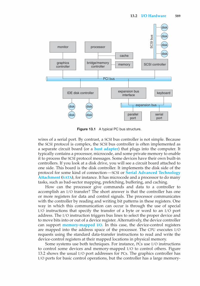
13.2 I/O Hardware 589
expansion bus
PCI bus
disk
disk
disk
disk
disk
disk
disk
disk
SCSI controller
SC
SI b
us
cache
memory
processor
bridge/memorycontroller
monitor
IDE disk controller expansion businterface
graphicscontroller
keyboard
parallelport
serialport
Figure 13.1 A typical PC bus structure.
wires of a serial port. By contrast, a SCSI bus controller is not simple. Becausethe SCSI protocol is complex, the SCSI bus controller is often implemented asa separate circuit board (or a host adapter) that plugs into the computer. Ittypically contains a processor, microcode, and some private memory to enableit to process the SCSI protocol messages. Some devices have their own built-incontrollers. If you look at a disk drive, you will see a circuit board attached toone side. This board is the disk controller. It implements the disk side of theprotocol for some kind of connection—SCSI or Serial Advanced TechnologyAttachment (SATA), for instance. It has microcode and a processor to do manytasks, such as bad-sector mapping, prefetching, buffering, and caching.
How can the processor give commands and data to a controller toaccomplish an I/O transfer? The short answer is that the controller has oneor more registers for data and control signals. The processor communicateswith the controller by reading and writing bit patterns in these registers. Oneway in which this communication can occur is through the use of specialI/O instructions that specify the transfer of a byte or word to an I/O portaddress. The I/O instruction triggers bus lines to select the proper device andto move bits into or out of a device register. Alternatively, the device controllercan support memory-mapped I/O. In this case, the device-control registersare mapped into the address space of the processor. The CPU executes I/Orequests using the standard data-transfer instructions to read and write thedevice-control registers at their mapped locations in physical memory.
Some systems use both techniques. For instance, PCs use I/O instructionsto control some devices and memory-mapped I/O to control others. Figure13.2 shows the usual I/O port addresses for PCs. The graphics controller hasI/O ports for basic control operations, but the controller has a large memory-
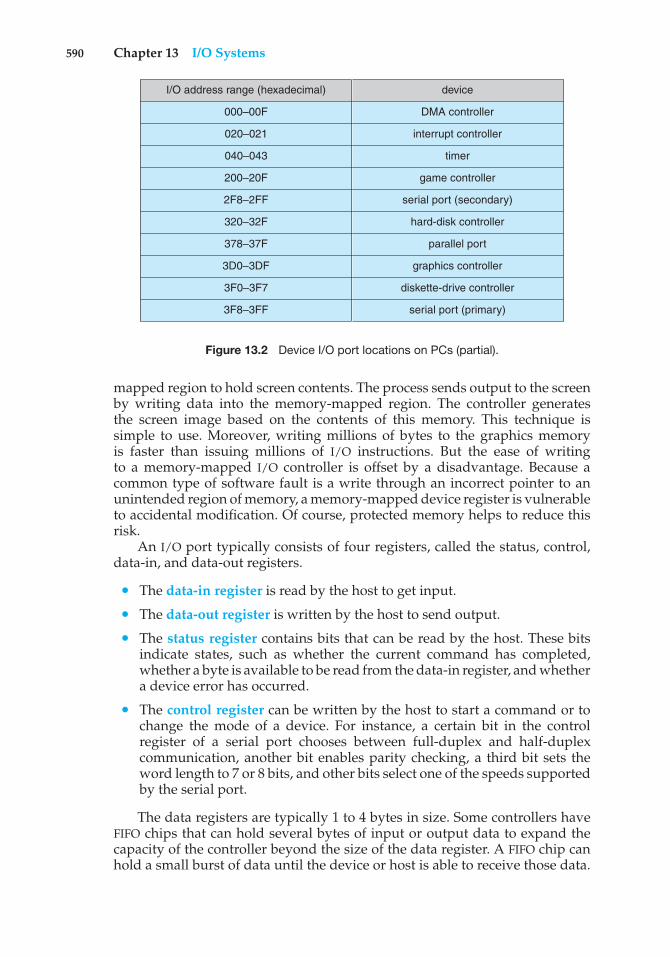
590 Chapter 13 I/O Systems
I/O address range (hexadecimal)
000–00F
020–021
040–043
200–20F
2F8–2FF
320–32F
378–37F
3D0–3DF
3F0–3F7
3F8–3FF
device
DMA controller
interrupt controller
timer
game controller
serial port (secondary)
hard-disk controller
parallel port
graphics controller
diskette-drive controller
serial port (primary)
Figure 13.2 Device I/O port locations on PCs (partial).
mapped region to hold screen contents. The process sends output to the screenby writing data into the memory-mapped region. The controller generatesthe screen image based on the contents of this memory. This technique issimple to use. Moreover, writing millions of bytes to the graphics memoryis faster than issuing millions of I/O instructions. But the ease of writingto a memory-mapped I/O controller is offset by a disadvantage. Because acommon type of software fault is a write through an incorrect pointer to anunintended region of memory, a memory-mapped device register is vulnerableto accidental modification. Of course, protected memory helps to reduce thisrisk.
An I/O port typically consists of four registers, called the status, control,data-in, and data-out registers.
• The data-in register is read by the host to get input.
• The data-out register is written by the host to send output.
• The status register contains bits that can be read by the host. These bitsindicate states, such as whether the current command has completed,whether a byte is available to be read from the data-in register, and whethera device error has occurred.
• The control register can be written by the host to start a command or tochange the mode of a device. For instance, a certain bit in the controlregister of a serial port chooses between full-duplex and half-duplexcommunication, another bit enables parity checking, a third bit sets theword length to 7 or 8 bits, and other bits select one of the speeds supportedby the serial port.
The data registers are typically 1 to 4 bytes in size. Some controllers haveFIFO chips that can hold several bytes of input or output data to expand thecapacity of the controller beyond the size of the data register. A FIFO chip canhold a small burst of data until the device or host is able to receive those data.
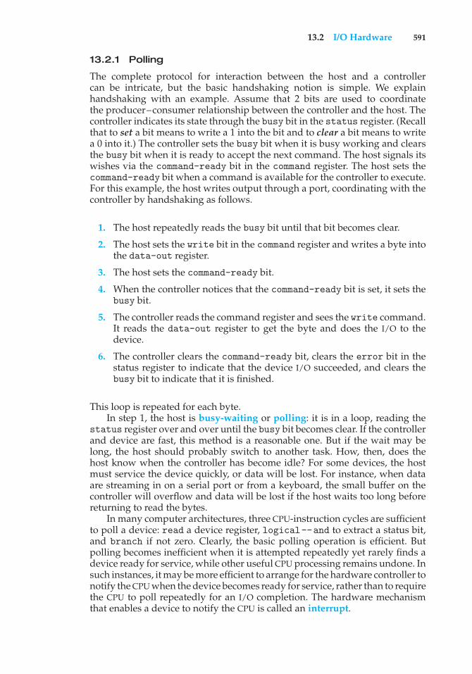
13.2 I/O Hardware 591
13.2.1 Polling
The complete protocol for interaction between the host and a controllercan be intricate, but the basic handshaking notion is simple. We explainhandshaking with an example. Assume that 2 bits are used to coordinatethe producer–consumer relationship between the controller and the host. Thecontroller indicates its state through the busy bit in the status register. (Recallthat to set a bit means to write a 1 into the bit and to clear a bit means to writea 0 into it.) The controller sets the busy bit when it is busy working and clearsthe busy bit when it is ready to accept the next command. The host signals itswishes via the command-ready bit in the command register. The host sets thecommand-ready bit when a command is available for the controller to execute.For this example, the host writes output through a port, coordinating with thecontroller by handshaking as follows.
1. The host repeatedly reads the busy bit until that bit becomes clear.
2. The host sets the write bit in the command register and writes a byte intothe data-out register.
3. The host sets the command-ready bit.
4. When the controller notices that the command-ready bit is set, it sets thebusy bit.
5. The controller reads the command register and sees the write command.It reads the data-out register to get the byte and does the I/O to thedevice.
6. The controller clears the command-ready bit, clears the error bit in thestatus register to indicate that the device I/O succeeded, and clears thebusy bit to indicate that it is finished.
This loop is repeated for each byte.In step 1, the host is busy-waiting or polling: it is in a loop, reading the
status register over and over until the busy bit becomes clear. If the controllerand device are fast, this method is a reasonable one. But if the wait may belong, the host should probably switch to another task. How, then, does thehost know when the controller has become idle? For some devices, the hostmust service the device quickly, or data will be lost. For instance, when dataare streaming in on a serial port or from a keyboard, the small buffer on thecontroller will overflow and data will be lost if the host waits too long beforereturning to read the bytes.
In many computer architectures, three CPU-instruction cycles are sufficientto poll a device: read a device register, logical--and to extract a status bit,and branch if not zero. Clearly, the basic polling operation is efficient. Butpolling becomes inefficient when it is attempted repeatedly yet rarely finds adevice ready for service, while other useful CPU processing remains undone. Insuch instances, it may be more efficient to arrange for the hardware controller tonotify the CPU when the device becomes ready for service, rather than to requirethe CPU to poll repeatedly for an I/O completion. The hardware mechanismthat enables a device to notify the CPU is called an interrupt.
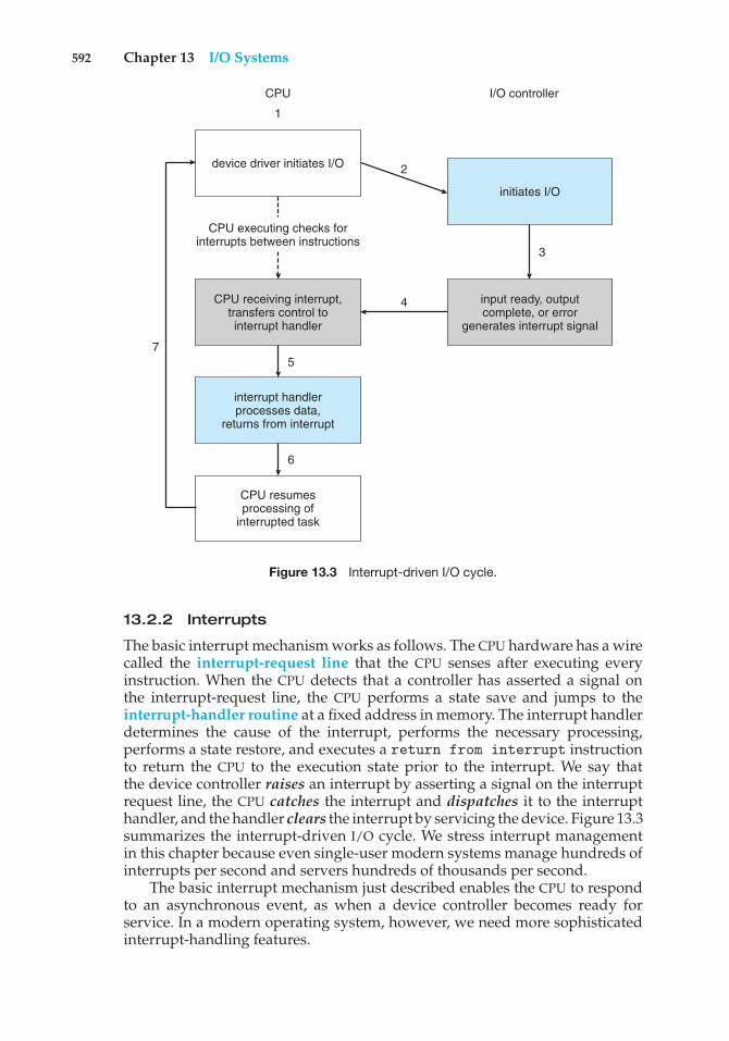
592 Chapter 13 I/O Systems
device driver initiates I/O
CPU receiving interrupt,transfers control tointerrupt handler
CPU resumesprocessing of
interrupted task
CPU
1
I/O controller
CPU executing checks forinterrupts between instructions
5
interrupt handlerprocesses data,
returns from interrupt
initiates I/O
3
2
4
7
input ready, outputcomplete, or error
generates interrupt signal
6
Figure 13.3 Interrupt-driven I/O cycle.
13.2.2 Interrupts
The basic interrupt mechanism works as follows. The CPU hardware has a wirecalled the interrupt-request line that the CPU senses after executing everyinstruction. When the CPU detects that a controller has asserted a signal onthe interrupt-request line, the CPU performs a state save and jumps to theinterrupt-handler routine at a fixed address in memory. The interrupt handlerdetermines the cause of the interrupt, performs the necessary processing,performs a state restore, and executes a return from interrupt instructionto return the CPU to the execution state prior to the interrupt. We say thatthe device controller raises an interrupt by asserting a signal on the interruptrequest line, the CPU catches the interrupt and dispatches it to the interrupthandler, and the handler clears the interrupt by servicing the device. Figure 13.3summarizes the interrupt-driven I/O cycle. We stress interrupt managementin this chapter because even single-user modern systems manage hundreds ofinterrupts per second and servers hundreds of thousands per second.
The basic interrupt mechanism just described enables the CPU to respondto an asynchronous event, as when a device controller becomes ready forservice. In a modern operating system, however, we need more sophisticatedinterrupt-handling features.
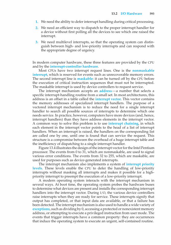
13.2 I/O Hardware 593
1. We need the ability to defer interrupt handling during critical processing.
2. We need an efficient way to dispatch to the proper interrupt handler fora device without first polling all the devices to see which one raised theinterrupt.
3. We need multilevel interrupts, so that the operating system can distin-guish between high- and low-priority interrupts and can respond withthe appropriate degree of urgency.
In modern computer hardware, these three features are provided by the CPUand by the interrupt-controller hardware.
Most CPUs have two interrupt request lines. One is the nonmaskableinterrupt, which is reserved for events such as unrecoverable memory errors.The second interrupt line is maskable: it can be turned off by the CPU beforethe execution of critical instruction sequences that must not be interrupted.The maskable interrupt is used by device controllers to request service.
The interrupt mechanism accepts an address—a number that selects aspecific interrupt-handling routine from a small set. In most architectures, thisaddress is an offset in a table called the interrupt vector. This vector containsthe memory addresses of specialized interrupt handlers. The purpose of avectored interrupt mechanism is to reduce the need for a single interrupthandler to search all possible sources of interrupts to determine which oneneeds service. In practice, however, computers have more devices (and, hence,interrupt handlers) than they have address elements in the interrupt vector.A common way to solve this problem is to use interrupt chaining, in whicheach element in the interrupt vector points to the head of a list of interrupthandlers. When an interrupt is raised, the handlers on the corresponding listare called one by one, until one is found that can service the request. Thisstructure is a compromise between the overhead of a huge interrupt table andthe inefficiency of dispatching to a single interrupt handler.
Figure 13.4 illustrates the design of the interrupt vector for the Intel Pentiumprocessor. The events from 0 to 31, which are nonmaskable, are used to signalvarious error conditions. The events from 32 to 255, which are maskable, areused for purposes such as device-generated interrupts.
The interrupt mechanism also implements a system of interrupt prioritylevels. These levels enable the CPU to defer the handling of low-priorityinterrupts without masking all interrupts and makes it possible for a high-priority interrupt to preempt the execution of a low-priority interrupt.
A modern operating system interacts with the interrupt mechanism inseveral ways. At boot time, the operating system probes the hardware busesto determine what devices are present and installs the corresponding interrupthandlers into the interrupt vector. During I/O, the various device controllersraise interrupts when they are ready for service. These interrupts signify thatoutput has completed, or that input data are available, or that a failure hasbeen detected. The interrupt mechanism is also used to handle a wide variety ofexceptions, such as dividing by 0, accessing a protected or nonexistent memoryaddress, or attempting to execute a privileged instruction from user mode. Theevents that trigger interrupts have a common property: they are occurrencesthat induce the operating system to execute an urgent, self-contained routine.
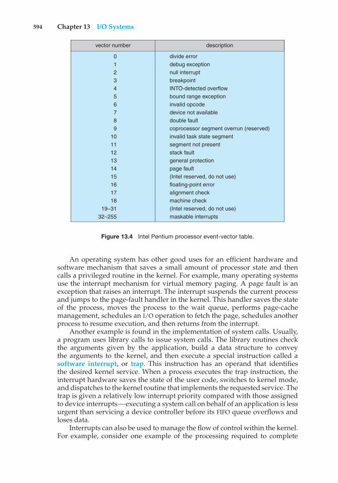
594 Chapter 13 I/O Systems
descriptionvector number
0123456789
101112131415161718
19–3132–255
divide errordebug exceptionnull interruptbreakpointINTO-detected overflowbound range exceptioninvalid opcodedevice not availabledouble faultcoprocessor segment overrun (reserved)invalid task state segmentsegment not presentstack faultgeneral protectionpage fault(Intel reserved, do not use)floating-point erroralignment checkmachine check(Intel reserved, do not use)maskable interrupts
Figure 13.4 Intel Pentium processor event-vector table.
An operating system has other good uses for an efficient hardware andsoftware mechanism that saves a small amount of processor state and thencalls a privileged routine in the kernel. For example, many operating systemsuse the interrupt mechanism for virtual memory paging. A page fault is anexception that raises an interrupt. The interrupt suspends the current processand jumps to the page-fault handler in the kernel. This handler saves the stateof the process, moves the process to the wait queue, performs page-cachemanagement, schedules an I/O operation to fetch the page, schedules anotherprocess to resume execution, and then returns from the interrupt.
Another example is found in the implementation of system calls. Usually,a program uses library calls to issue system calls. The library routines checkthe arguments given by the application, build a data structure to conveythe arguments to the kernel, and then execute a special instruction called asoftware interrupt, or trap. This instruction has an operand that identifiesthe desired kernel service. When a process executes the trap instruction, theinterrupt hardware saves the state of the user code, switches to kernel mode,and dispatches to the kernel routine that implements the requested service. Thetrap is given a relatively low interrupt priority compared with those assignedto device interrupts—executing a system call on behalf of an application is lessurgent than servicing a device controller before its FIFO queue overflows andloses data.
Interrupts can also be used to manage the flow of control within the kernel.For example, consider one example of the processing required to complete
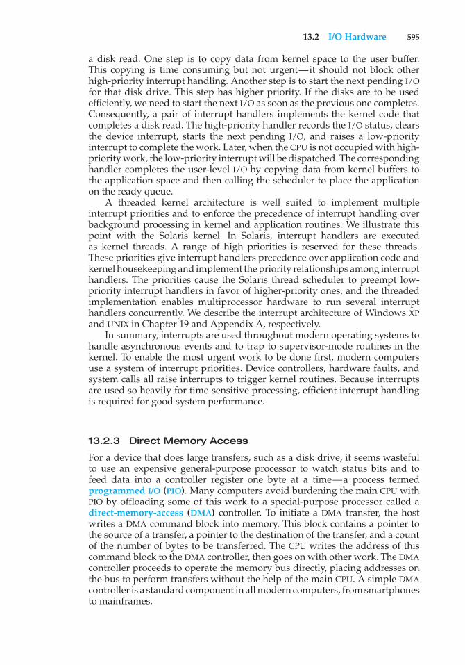
13.2 I/O Hardware 595
a disk read. One step is to copy data from kernel space to the user buffer.This copying is time consuming but not urgent—it should not block otherhigh-priority interrupt handling. Another step is to start the next pending I/Ofor that disk drive. This step has higher priority. If the disks are to be usedefficiently, we need to start the next I/O as soon as the previous one completes.Consequently, a pair of interrupt handlers implements the kernel code thatcompletes a disk read. The high-priority handler records the I/O status, clearsthe device interrupt, starts the next pending I/O, and raises a low-priorityinterrupt to complete the work. Later, when the CPU is not occupied with high-priority work, the low-priority interrupt will be dispatched. The correspondinghandler completes the user-level I/O by copying data from kernel buffers tothe application space and then calling the scheduler to place the applicationon the ready queue.
A threaded kernel architecture is well suited to implement multipleinterrupt priorities and to enforce the precedence of interrupt handling overbackground processing in kernel and application routines. We illustrate thispoint with the Solaris kernel. In Solaris, interrupt handlers are executedas kernel threads. A range of high priorities is reserved for these threads.These priorities give interrupt handlers precedence over application code andkernel housekeeping and implement the priority relationships among interrupthandlers. The priorities cause the Solaris thread scheduler to preempt low-priority interrupt handlers in favor of higher-priority ones, and the threadedimplementation enables multiprocessor hardware to run several interrupthandlers concurrently. We describe the interrupt architecture of Windows XPand UNIX in Chapter 19 and Appendix A, respectively.
In summary, interrupts are used throughout modern operating systems tohandle asynchronous events and to trap to supervisor-mode routines in thekernel. To enable the most urgent work to be done first, modern computersuse a system of interrupt priorities. Device controllers, hardware faults, andsystem calls all raise interrupts to trigger kernel routines. Because interruptsare used so heavily for time-sensitive processing, efficient interrupt handlingis required for good system performance.
13.2.3 Direct Memory Access
For a device that does large transfers, such as a disk drive, it seems wastefulto use an expensive general-purpose processor to watch status bits and tofeed data into a controller register one byte at a time—a process termedprogrammed I/O (PIO). Many computers avoid burdening the main CPU withPIO by offloading some of this work to a special-purpose processor called adirect-memory-access (DMA) controller. To initiate a DMA transfer, the hostwrites a DMA command block into memory. This block contains a pointer tothe source of a transfer, a pointer to the destination of the transfer, and a countof the number of bytes to be transferred. The CPU writes the address of thiscommand block to the DMA controller, then goes on with other work. The DMAcontroller proceeds to operate the memory bus directly, placing addresses onthe bus to perform transfers without the help of the main CPU. A simple DMAcontroller is a standard component in all modern computers, from smartphonesto mainframes.
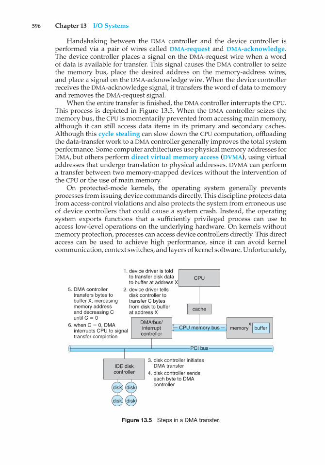
596 Chapter 13 I/O Systems
Handshaking between the DMA controller and the device controller isperformed via a pair of wires called DMA-request and DMA-acknowledge.The device controller places a signal on the DMA-request wire when a wordof data is available for transfer. This signal causes the DMA controller to seizethe memory bus, place the desired address on the memory-address wires,and place a signal on the DMA-acknowledge wire. When the device controllerreceives the DMA-acknowledge signal, it transfers the word of data to memoryand removes the DMA-request signal.
When the entire transfer is finished, the DMA controller interrupts the CPU.This process is depicted in Figure 13.5. When the DMA controller seizes thememory bus, the CPU is momentarily prevented from accessing main memory,although it can still access data items in its primary and secondary caches.Although this cycle stealing can slow down the CPU computation, offloadingthe data-transfer work to a DMA controller generally improves the total systemperformance. Some computer architectures use physical memory addresses forDMA, but others perform direct virtual memory access (DVMA), using virtualaddresses that undergo translation to physical addresses. DVMA can performa transfer between two memory-mapped devices without the intervention ofthe CPU or the use of main memory.
On protected-mode kernels, the operating system generally preventsprocesses from issuing device commands directly. This discipline protects datafrom access-control violations and also protects the system from erroneous useof device controllers that could cause a system crash. Instead, the operatingsystem exports functions that a sufficiently privileged process can use toaccess low-level operations on the underlying hardware. On kernels withoutmemory protection, processes can access device controllers directly. This directaccess can be used to achieve high performance, since it can avoid kernelcommunication, context switches, and layers of kernel software. Unfortunately,
IDE diskcontroller
xDMA/bus/interruptcontroller
bufferx
memoryCPU memory bus
PCI bus
cache
CPU
5. DMA controller transfers bytes to buffer X, increasing memory address and decreasing C until C $ 0
1. device driver is told to transfer disk data to buffer at address X 2. device driver tells disk controller to transfer C bytes from disk to buffer at address X
6. when C $ 0, DMA interrupts CPU to signal transfer completion
3. disk controller initiates DMA transfer4. disk controller sends each byte to DMA controllerdisk
disk
disk
disk
Figure 13.5 Steps in a DMA transfer.
13.3 Application I/O Interface 597
it interferes with system security and stability. The trend in general-purposeoperating systems is to protect memory and devices so that the system can tryto guard against erroneous or malicious applications.
13.2.4 I/O Hardware Summary
Although the hardware aspects of I/O are complex when considered at thelevel of detail of electronics-hardware design, the concepts that we havejust described are sufficient to enable us to understand many I/O featuresof operating systems. Let’s review the main concepts:
• A bus
• A controller
• An I/O port and its registers
• The handshaking relationship between the host and a device controller
• The execution of this handshaking in a polling loop or via interrupts
• The offloading of this work to a DMA controller for large transfers
We gave a basic example of the handshaking that takes place between adevice controller and the host earlier in this section. In reality, the wide varietyof available devices poses a problem for operating-system implementers. Eachkind of device has its own set of capabilities, control-bit definitions, andprotocols for interacting with the host—and they are all different. How canthe operating system be designed so that we can attach new devices to thecomputer without rewriting the operating system? And when the devicesvary so widely, how can the operating system give a convenient, uniform I/Ointerface to applications? We address those questions next.
13.3 Application I/O Interface
In this section, we discuss structuring techniques and interfaces for theoperating system that enable I/O devices to be treated in a standard, uniformway. We explain, for instance, how an application can open a file on a diskwithout knowing what kind of disk it is and how new disks and other devicescan be added to a computer without disruption of the operating system.
Like other complex software-engineering problems, the approach hereinvolves abstraction, encapsulation, and software layering. Specifically, wecan abstract away the detailed differences in I/O devices by identifying a fewgeneral kinds. Each general kind is accessed through a standardized set offunctions—an interface. The differences are encapsulated in kernel modulescalled device drivers that internally are custom-tailored to specific devicesbut that export one of the standard interfaces. Figure 13.6 illustrates how theI/O-related portions of the kernel are structured in software layers.
The purpose of the device-driver layer is to hide the differences amongdevice controllers from the I/O subsystem of the kernel, much as the I/Osystem calls encapsulate the behavior of devices in a few generic classesthat hide hardware differences from applications. Making the I/O subsystem
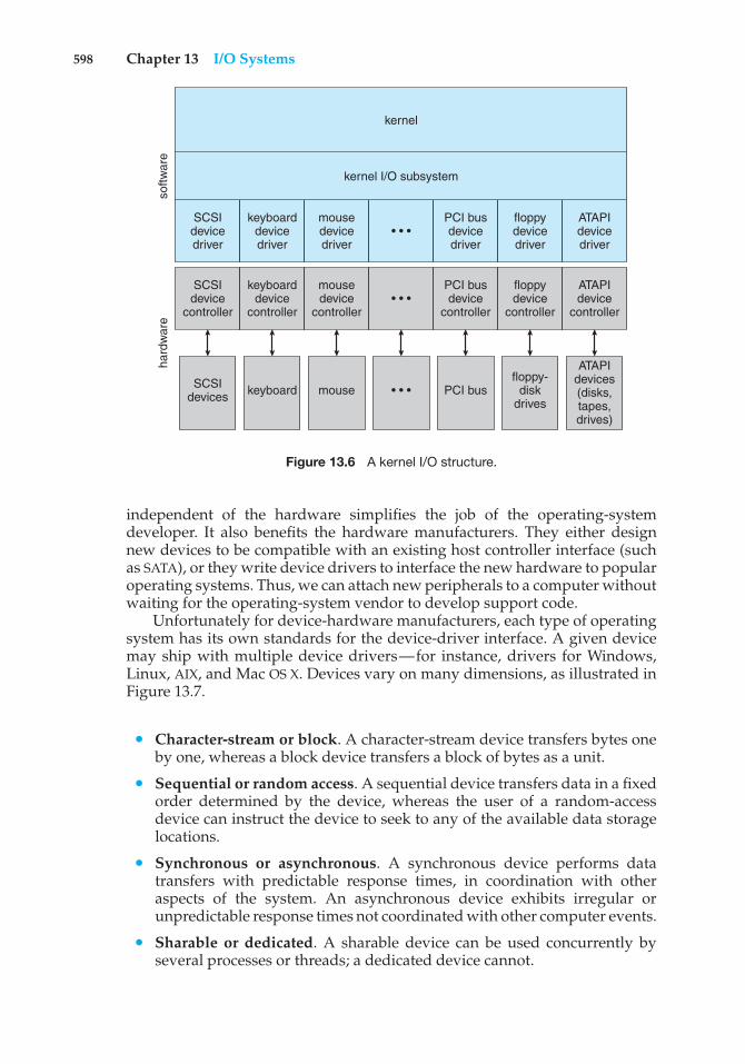
598 Chapter 13 I/O Systems
kernel
hard
war
eso
ftwar
e
SCSIdevicedriver
keyboarddevicedriver
mousedevicedriver
• • •
• • •
• • •
PCI busdevicedriver
floppydevicedriver
ATAPIdevicedriver
SCSIdevice
controller
keyboarddevice
controller
mousedevice
controller
PCI busdevice
controller
floppydevice
controller
ATAPIdevice
controller
SCSIdevices keyboard mouse PCI bus
floppy-disk
drives
ATAPIdevices(disks,tapes,drives)
kernel I/O subsystem
Figure 13.6 A kernel I/O structure.
independent of the hardware simplifies the job of the operating-systemdeveloper. It also benefits the hardware manufacturers. They either designnew devices to be compatible with an existing host controller interface (suchas SATA), or they write device drivers to interface the new hardware to popularoperating systems. Thus, we can attach new peripherals to a computer withoutwaiting for the operating-system vendor to develop support code.
Unfortunately for device-hardware manufacturers, each type of operatingsystem has its own standards for the device-driver interface. A given devicemay ship with multiple device drivers—for instance, drivers for Windows,Linux, AIX, and Mac OS X. Devices vary on many dimensions, as illustrated inFigure 13.7.
• Character-stream or block. A character-stream device transfers bytes oneby one, whereas a block device transfers a block of bytes as a unit.
• Sequential or random access. A sequential device transfers data in a fixedorder determined by the device, whereas the user of a random-accessdevice can instruct the device to seek to any of the available data storagelocations.
• Synchronous or asynchronous. A synchronous device performs datatransfers with predictable response times, in coordination with otheraspects of the system. An asynchronous device exhibits irregular orunpredictable response times not coordinated with other computer events.
• Sharable or dedicated. A sharable device can be used concurrently byseveral processes or threads; a dedicated device cannot.
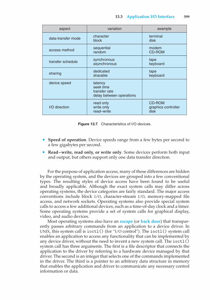
13.3 Application I/O Interface 599
aspect variation example
terminaldisk
modemCD-ROM
tapekeyboard
tapekeyboard
CD-ROMgraphics controllerdisk
data-transfer mode
access method
transfer schedule
sharing
I/O direction
characterblock
sequentialrandom
synchronousasynchronous
dedicatedsharable
read onlywrite onlyread–write
latencyseek timetransfer ratedelay between operations
device speed
Figure 13.7 Characteristics of I/O devices.
• Speed of operation. Device speeds range from a few bytes per second toa few gigabytes per second.
• Read–write, read only, or write only. Some devices perform both inputand output, but others support only one data transfer direction.
For the purpose of application access, many of these differences are hiddenby the operating system, and the devices are grouped into a few conventionaltypes. The resulting styles of device access have been found to be usefuland broadly applicable. Although the exact system calls may differ acrossoperating systems, the device categories are fairly standard. The major accessconventions include block I/O, character-stream I/O, memory-mapped fileaccess, and network sockets. Operating systems also provide special systemcalls to access a few additional devices, such as a time-of-day clock and a timer.Some operating systems provide a set of system calls for graphical display,video, and audio devices.
Most operating systems also have an escape (or back door) that transpar-ently passes arbitrary commands from an application to a device driver. InUNIX, this system call is ioctl() (for “I/O control”). The ioctl() system callenables an application to access any functionality that can be implemented byany device driver, without the need to invent a new system call. The ioctl()system call has three arguments. The first is a file descriptor that connects theapplication to the driver by referring to a hardware device managed by thatdriver. The second is an integer that selects one of the commands implementedin the driver. The third is a pointer to an arbitrary data structure in memorythat enables the application and driver to communicate any necessary controlinformation or data.
600 Chapter 13 I/O Systems
13.3.1 Block and Character Devices
The block-device interface captures all the aspects necessary for accessing diskdrives and other block-oriented devices. The device is expected to understandcommands such as read() and write(). If it is a random-access device,it is also expected to have a seek() command to specify which block totransfer next. Applications normally access such a device through a file-systeminterface. We can see that read(), write(), and seek() capture the essentialbehaviors of block-storage devices, so that applications are insulated from thelow-level differences among those devices.
The operating system itself, as well as special applications such as database-management systems, may prefer to access a block device as a simple lineararray of blocks. This mode of access is sometimes called raw I/O. If theapplication performs its own buffering, then using a file system would causeextra, unneeded buffering. Likewise, if an application provides its own lockingof file blocks or regions, then any operating-system locking services would beredundant at the least and contradictory at the worst. To avoid these conflicts,raw-device access passes control of the device directly to the application, lettingthe operating system step out of the way. Unfortunately, no operating-systemservices are then performed on this device. A compromise that is becomingcommon is for the operating system to allow a mode of operation on a file thatdisables buffering and locking. In the UNIX world, this is called direct I/O.
Memory-mapped file access can be layered on top of block-device drivers.Rather than offering read and write operations, a memory-mapped interfaceprovides access to disk storage via an array of bytes in main memory. Thesystem call that maps a file into memory returns the virtual memory addressthat contains a copy of the file. The actual data transfers are performed onlywhen needed to satisfy access to the memory image. Because the transfersare handled by the same mechanism as that used for demand-paged virtualmemory access, memory-mapped I/O is efficient. Memory mapping is alsoconvenient for programmers—access to a memory-mapped file is as simpleas reading from and writing to memory. Operating systems that offer virtualmemory commonly use the mapping interface for kernel services. For instance,to execute a program, the operating system maps the executable into memoryand then transfers control to the entry address of the executable. The mappinginterface is also commonly used for kernel access to swap space on disk.
A keyboard is an example of a device that is accessed through a character-stream interface. The basic system calls in this interface enable an applicationto get() or put() one character. On top of this interface, libraries can bebuilt that offer line-at-a-time access, with buffering and editing services (forexample, when a user types a backspace, the preceding character is removedfrom the input stream). This style of access is convenient for input devices suchas keyboards, mice, and modems that produce data for input “spontaneously”—that is, at times that cannot necessarily be predicted by the application. Thisaccess style is also good for output devices such as printers and audio boards,which naturally fit the concept of a linear stream of bytes.
13.3.2 Network Devices
Because the performance and addressing characteristics of network I/O differsignificantly from those of disk I/O, most operating systems provide a network
13.3 Application I/O Interface 601
I/O interface that is different from theread()–write()–seek() interface usedfor disks. One interface available in many operating systems, including UNIXand Windows, is the network socket interface.
Think of a wall socket for electricity: any electrical appliance can be pluggedin. By analogy, the system calls in the socket interface enable an applicationto create a socket, to connect a local socket to a remote address (which plugsthis application into a socket created by another application), to listen forany remote application to plug into the local socket, and to send and receivepackets over the connection. To support the implementation of servers, thesocket interface also provides a function called select() that manages a setof sockets. A call to select() returns information about which sockets have apacket waiting to be received and which sockets have room to accept a packetto be sent. The use of select() eliminates the polling and busy waiting thatwould otherwise be necessary for network I/O. These functions encapsulate theessential behaviors of networks, greatly facilitating the creation of distributedapplications that can use any underlying network hardware and protocol stack.
Many other approaches to interprocess communication and networkcommunication have been implemented. For instance, Windows provides oneinterface to the network interface card and a second interface to the networkprotocols. In UNIX, which has a long history as a proving ground for networktechnology, we find half-duplex pipes, full-duplex FIFOs, full-duplex STREAMS,message queues, and sockets. Information on UNIX networking is given inSection A.9.
13.3.3 Clocks and Timers
Most computers have hardware clocks and timers that provide three basicfunctions:
• Give the current time.
• Give the elapsed time.
• Set a timer to trigger operation X at time T.
These functions are used heavily by the operating system, as well as by time-sensitive applications. Unfortunately, the system calls that implement thesefunctions are not standardized across operating systems.
The hardware to measure elapsed time and to trigger operations is calleda programmable interval timer. It can be set to wait a certain amount of timeand then generate an interrupt, and it can be set to do this once or to repeat theprocess to generate periodic interrupts. The scheduler uses this mechanism togenerate an interrupt that will preempt a process at the end of its time slice.The disk I/O subsystem uses it to invoke the periodic flushing of dirty cachebuffers to disk, and the network subsystem uses it to cancel operations that areproceeding too slowly because of network congestion or failures. The operatingsystem may also provide an interface for user processes to use timers. Theoperating system can support more timer requests than the number of timerhardware channels by simulating virtual clocks. To do so, the kernel (or thetimer device driver) maintains a list of interrupts wanted by its own routinesand by user requests, sorted in earliest-time-first order. It sets the timer for the
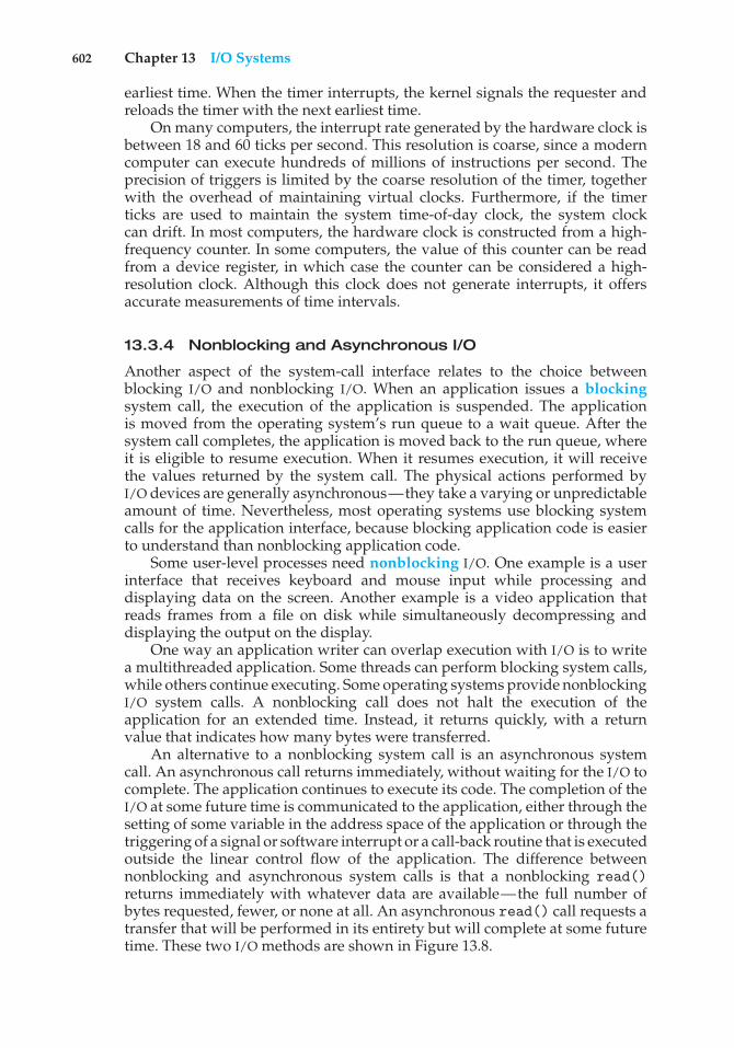
602 Chapter 13 I/O Systems
earliest time. When the timer interrupts, the kernel signals the requester andreloads the timer with the next earliest time.
On many computers, the interrupt rate generated by the hardware clock isbetween 18 and 60 ticks per second. This resolution is coarse, since a moderncomputer can execute hundreds of millions of instructions per second. Theprecision of triggers is limited by the coarse resolution of the timer, togetherwith the overhead of maintaining virtual clocks. Furthermore, if the timerticks are used to maintain the system time-of-day clock, the system clockcan drift. In most computers, the hardware clock is constructed from a high-frequency counter. In some computers, the value of this counter can be readfrom a device register, in which case the counter can be considered a high-resolution clock. Although this clock does not generate interrupts, it offersaccurate measurements of time intervals.
13.3.4 Nonblocking and Asynchronous I/O
Another aspect of the system-call interface relates to the choice betweenblocking I/O and nonblocking I/O. When an application issues a blockingsystem call, the execution of the application is suspended. The applicationis moved from the operating system’s run queue to a wait queue. After thesystem call completes, the application is moved back to the run queue, whereit is eligible to resume execution. When it resumes execution, it will receivethe values returned by the system call. The physical actions performed byI/O devices are generally asynchronous—they take a varying or unpredictableamount of time. Nevertheless, most operating systems use blocking systemcalls for the application interface, because blocking application code is easierto understand than nonblocking application code.
Some user-level processes need nonblocking I/O. One example is a userinterface that receives keyboard and mouse input while processing anddisplaying data on the screen. Another example is a video application thatreads frames from a file on disk while simultaneously decompressing anddisplaying the output on the display.
One way an application writer can overlap execution with I/O is to writea multithreaded application. Some threads can perform blocking system calls,while others continue executing. Some operating systems provide nonblockingI/O system calls. A nonblocking call does not halt the execution of theapplication for an extended time. Instead, it returns quickly, with a returnvalue that indicates how many bytes were transferred.
An alternative to a nonblocking system call is an asynchronous systemcall. An asynchronous call returns immediately, without waiting for the I/O tocomplete. The application continues to execute its code. The completion of theI/O at some future time is communicated to the application, either through thesetting of some variable in the address space of the application or through thetriggering of a signal or software interrupt or a call-back routine that is executedoutside the linear control flow of the application. The difference betweennonblocking and asynchronous system calls is that a nonblocking read()returns immediately with whatever data are available—the full number ofbytes requested, fewer, or none at all. An asynchronous read() call requests atransfer that will be performed in its entirety but will complete at some futuretime. These two I/O methods are shown in Figure 13.8.
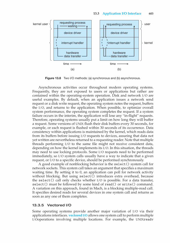
13.3 Application I/O Interface 603
requesting processwaiting
hardwaredata transfer
hardwaredata transfer
device driver device driver
interrupt handler
requesting processkernel user
(a) (b)
time time
user
kernelinterrupt handler
Figure 13.8 Two I/O methods: (a) synchronous and (b) asynchronous.
Asynchronous activities occur throughout modern operating systems.Frequently, they are not exposed to users or applications but rather arecontained within the operating-system operation. Disk and network I/O areuseful examples. By default, when an application issues a network sendrequest or a disk write request, the operating system notes the request, buffersthe I/O, and returns to the application. When possible, to optimize overallsystem performance, the operating system completes the request. If a systemfailure occurs in the interim, the application will lose any “in-flight” requests.Therefore, operating systems usually put a limit on how long they will buffera request. Some versions of UNIX flush their disk buffers every 30 seconds, forexample, or each request is flushed within 30 seconds of its occurrence. Dataconsistency within applications is maintained by the kernel, which reads datafrom its buffers before issuing I/O requests to devices, assuring that data notyet written are nevertheless returned to a requesting reader. Note that multiplethreads performing I/O to the same file might not receive consistent data,depending on how the kernel implements its I/O. In this situation, the threadsmay need to use locking protocols. Some I/O requests need to be performedimmediately, so I/O system calls usually have a way to indicate that a givenrequest, or I/O to a specific device, should be performed synchronously.
A good example of nonblocking behavior is the select() system call fornetwork sockets. This system call takes an argument that specifies a maximumwaiting time. By setting it to 0, an application can poll for network activitywithout blocking. But using select() introduces extra overhead, becausethe select() call only checks whether I/O is possible. For a data transfer,select() must be followed by some kind of read() or write() command.A variation on this approach, found in Mach, is a blocking multiple-read call.It specifies desired reads for several devices in one system call and returns assoon as any one of them completes.
13.3.5 Vectored I/O
Some operating systems provide another major variation of I/O via theirapplications interfaces. vectored I/O allows one system call to perform multipleI/Ooperations involving multiple locations. For example, the UNIXreadv
604 Chapter 13 I/O Systems
system call accepts a vector of multiple buffers and either reads from a source tothat vector or writes from that vector to a destination. The same transfer couldbe caused by several individual invocations of system calls, but this scatter–gather method is useful for a variety of reasons.
Multiple separate buffers can have their contents transferred via onesystem call, avoiding context-switching and system-call overhead. Withoutvectored I/O, the data might first need to be transferred to a larger buffer inthe right order and then transmitted, which is inefficient. In addition, someversions of scatter–gather provide atomicity, assuring that all the I/O is donewithout interruption (and avoiding corruption of data if other threads are alsoperforming I/Oinvolving those buffers). When possible, programmers makeuse of scatter–gather I/O features to increase throughput and decrease systemoverhead.
13.4 Kernel I/O Subsystem
Kernels provide many services related to I/O. Several services—scheduling,buffering, caching, spooling, device reservation, and error handling—areprovided by the kernel’s I/O subsystem and build on the hardware and device-driver infrastructure. The I/O subsystem is also responsible for protecting itselffrom errant processes and malicious users.
13.4.1 I/O Scheduling
To schedule a set of I/O requests means to determine a good order in which toexecute them. The order in which applications issue system calls rarely is thebest choice. Scheduling can improve overall system performance, can sharedevice access fairly among processes, and can reduce the average waiting timefor I/O to complete. Here is a simple example to illustrate. Suppose that a diskarm is near the beginning of a disk and that three applications issue blockingread calls to that disk. Application 1 requests a block near the end of the disk,application 2 requests one near the beginning, and application 3 requests onein the middle of the disk. The operating system can reduce the distance that thedisk arm travels by serving the applications in the order 2, 3, 1. Rearrangingthe order of service in this way is the essence of I/O scheduling.
Operating-system developers implement scheduling by maintaining a waitqueue of requests for each device. When an application issues a blocking I/Osystem call, the request is placed on the queue for that device. The I/Oschedulerrearranges the order of the queue to improve the overall system efficiencyand the average response time experienced by applications. The operatingsystem may also try to be fair, so that no one application receives especiallypoor service, or it may give priority service for delay-sensitive requests. Forinstance, requests from the virtual memory subsystem may take priority overapplication requests. Several scheduling algorithms for disk I/O are detailedin Section 10.4.
When a kernel supports asynchronous I/O, it must be able to keep trackof many I/O requests at the same time. For this purpose, the operating systemmight attach the wait queue to a device-status table. The kernel manages thistable, which contains an entry for each I/O device, as shown in Figure 13.9.
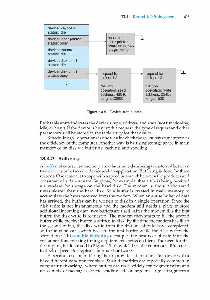
13.4 Kernel I/O Subsystem 605
device: keyboardstatus: idle
device: laser printerstatus: busy
device: mousestatus: idle
device: disk unit 1status: idle
device: disk unit 2 status: busy
...
request forlaser printeraddress: 38546length: 1372
request fordisk unit 2
file: xxxoperation: readaddress: 43046length: 20000
request fordisk unit 2
file: yyyoperation: writeaddress: 03458length: 500
Figure 13.9 Device-status table.
Each table entry indicates the device’s type, address, and state (not functioning,idle, or busy). If the device is busy with a request, the type of request and otherparameters will be stored in the table entry for that device.
Scheduling I/O operations is one way in which the I/O subsystem improvesthe efficiency of the computer. Another way is by using storage space in mainmemory or on disk via buffering, caching, and spooling.
13.4.2 Buffering
A buffer, of course, is a memory area that stores data being transferred betweentwo devices or between a device and an application. Buffering is done for threereasons. One reason is to cope with a speed mismatch between the producer andconsumer of a data stream. Suppose, for example, that a file is being receivedvia modem for storage on the hard disk. The modem is about a thousandtimes slower than the hard disk. So a buffer is created in main memory toaccumulate the bytes received from the modem. When an entire buffer of datahas arrived, the buffer can be written to disk in a single operation. Since thedisk write is not instantaneous and the modem still needs a place to storeadditional incoming data, two buffers are used. After the modem fills the firstbuffer, the disk write is requested. The modem then starts to fill the secondbuffer while the first buffer is written to disk. By the time the modem has filledthe second buffer, the disk write from the first one should have completed,so the modem can switch back to the first buffer while the disk writes thesecond one. This double buffering decouples the producer of data from theconsumer, thus relaxing timing requirements between them. The need for thisdecoupling is illustrated in Figure 13.10, which lists the enormous differencesin device speeds for typical computer hardware.
A second use of buffering is to provide adaptations for devices thathave different data-transfer sizes. Such disparities are especially common incomputer networking, where buffers are used widely for fragmentation andreassembly of messages. At the sending side, a large message is fragmented
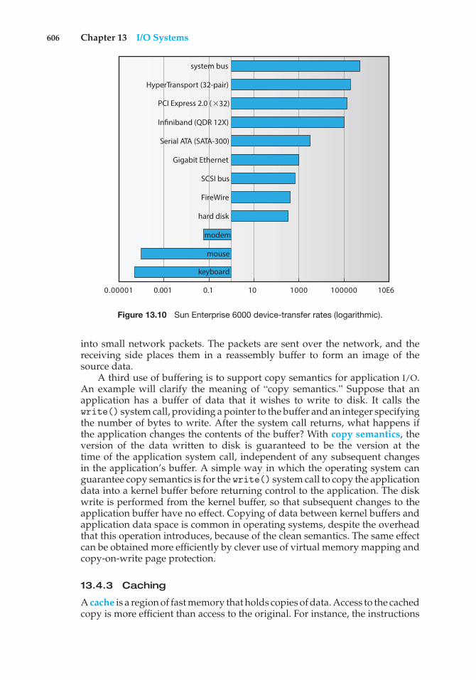
606 Chapter 13 I/O Systems
0.1 100.001 10E6000001000110000.0
modem
mouse
keyboard
hard disk
FireWire
SCSI bus
Gigabit Ethernet
Serial ATA (SATA-300)
Infiniband (QDR 12X)
PCI Express 2.0 ( 32)
HyperTransport (32-pair)
system bus
Figure 13.10 Sun Enterprise 6000 device-transfer rates (logarithmic).
into small network packets. The packets are sent over the network, and thereceiving side places them in a reassembly buffer to form an image of thesource data.
A third use of buffering is to support copy semantics for application I/O.An example will clarify the meaning of “copy semantics.” Suppose that anapplication has a buffer of data that it wishes to write to disk. It calls thewrite() system call, providing a pointer to the buffer and an integer specifyingthe number of bytes to write. After the system call returns, what happens ifthe application changes the contents of the buffer? With copy semantics, theversion of the data written to disk is guaranteed to be the version at thetime of the application system call, independent of any subsequent changesin the application’s buffer. A simple way in which the operating system canguarantee copy semantics is for the write() system call to copy the applicationdata into a kernel buffer before returning control to the application. The diskwrite is performed from the kernel buffer, so that subsequent changes to theapplication buffer have no effect. Copying of data between kernel buffers andapplication data space is common in operating systems, despite the overheadthat this operation introduces, because of the clean semantics. The same effectcan be obtained more efficiently by clever use of virtual memory mapping andcopy-on-write page protection.
13.4.3 Caching
A cache is a region of fast memory that holds copies of data. Access to the cachedcopy is more efficient than access to the original. For instance, the instructions
13.4 Kernel I/O Subsystem 607
of the currently running process are stored on disk, cached in physical memory,and copied again in the CPU’s secondary and primary caches. The differencebetween a buffer and a cache is that a buffer may hold the only existing copyof a data item, whereas a cache, by definition, holds a copy on faster storage ofan item that resides elsewhere.
Caching and buffering are distinct functions, but sometimes a regionof memory can be used for both purposes. For instance, to preserve copysemantics and to enable efficient scheduling of disk I/O, the operating systemuses buffers in main memory to hold disk data. These buffers are also used asa cache, to improve the I/O efficiency for files that are shared by applicationsor that are being written and reread rapidly. When the kernel receives a fileI/O request, the kernel first accesses the buffer cache to see whether that regionof the file is already available in main memory. If it is, a physical disk I/Ocan be avoided or deferred. Also, disk writes are accumulated in the buffercache for several seconds, so that large transfers are gathered to allow efficientwrite schedules. This strategy of delaying writes to improve I/O efficiency isdiscussed, in the context of remote file access, in Section 17.9.2.
13.4.4 Spooling and Device Reservation
A spool is a buffer that holds output for a device, such as a printer, that cannotaccept interleaved data streams. Although a printer can serve only one jobat a time, several applications may wish to print their output concurrently,without having their output mixed together. The operating system solves thisproblem by intercepting all output to the printer. Each application’s outputis spooled to a separate disk file. When an application finishes printing, thespooling system queues the corresponding spool file for output to the printer.The spooling system copies the queued spool files to the printer one at a time. Insome operating systems, spooling is managed by a system daemon process. Inothers, it is handled by an in-kernel thread. In either case, the operating systemprovides a control interface that enables users and system administrators todisplay the queue, remove unwanted jobs before those jobs print, suspendprinting while the printer is serviced, and so on.
Some devices, such as tape drives and printers, cannot usefully multiplexthe I/O requests of multiple concurrent applications. Spooling is one wayoperating systems can coordinate concurrent output. Another way to deal withconcurrent device access is to provide explicit facilities for coordination. Someoperating systems (including VMS) provide support for exclusive device accessby enabling a process to allocate an idle device and to deallocate that devicewhen it is no longer needed. Other operating systems enforce a limit of oneopen file handle to such a device. Many operating systems provide functionsthat enable processes to coordinate exclusive access among themselves. Forinstance, Windows provides system calls to wait until a device object becomesavailable. It also has a parameter to theOpenFile() system call that declares thetypes of access to be permitted to other concurrent threads. On these systems,it is up to the applications to avoid deadlock.
13.4.5 Error Handling
An operating system that uses protected memory can guard against manykinds of hardware and application errors, so that a complete system failure is
608 Chapter 13 I/O Systems
not the usual result of each minor mechanical malfunction. Devices and I/Otransfers can fail in many ways, either for transient reasons, as when a networkbecomes overloaded, or for “permanent” reasons, as when a disk controllerbecomes defective. Operating systems can often compensate effectively fortransient failures. For instance, a disk read() failure results in a read() retry,and a network send() error results in a resend(), if the protocol so specifies.Unfortunately, if an important component experiences a permanent failure, theoperating system is unlikely to recover.
As a general rule, an I/O system call will return one bit of informationabout the status of the call, signifying either success or failure. In the UNIXoperating system, an additional integer variable named errno is used toreturn an error code—one of about a hundred values—indicating the generalnature of the failure (for example, argument out of range, bad pointer, orfile not open). By contrast, some hardware can provide highly detailed errorinformation, although many current operating systems are not designed toconvey this information to the application. For instance, a failure of a SCSIdevice is reported by the SCSI protocol in three levels of detail: a sense key thatidentifies the general nature of the failure, such as a hardware error or an illegalrequest; an additional sense code that states the category of failure, such as abad command parameter or a self-test failure; and an additional sense-codequalifier that gives even more detail, such as which command parameter wasin error or which hardware subsystem failed its self-test. Further, many SCSIdevices maintain internal pages of error-log information that can be requestedby the host—but seldom are.
13.4.6 I/O Protection
Errors are closely related to the issue of protection. A user process mayaccidentally or purposely attempt to disrupt the normal operation of a systemby attempting to issue illegal I/O instructions. We can use various mechanismsto ensure that such disruptions cannot take place in the system.
To prevent users from performing illegal I/O, we define all I/O instructionsto be privileged instructions. Thus, users cannot issue I/O instructions directly;they must do it through the operating system. To do I/O, a user programexecutes a system call to request that the operating system perform I/O on itsbehalf (Figure 13.11). The operating system, executing in monitor mode, checksthat the request is valid and, if it is, does the I/O requested. The operatingsystem then returns to the user.
In addition, any memory-mapped and I/O port memory locations mustbe protected from user access by the memory-protection system. Note that akernel cannot simply deny all user access. Most graphics games and videoediting and playback software need direct access to memory-mapped graphicscontroller memory to speed the performance of the graphics, for example. Thekernel might in this case provide a locking mechanism to allow a section ofgraphics memory (representing a window on screen) to be allocated to oneprocess at a time.
13.4.7 Kernel Data Structures
The kernel needs to keep state information about the use of I/O components.It does so through a variety of in-kernel data structures, such as the open-file
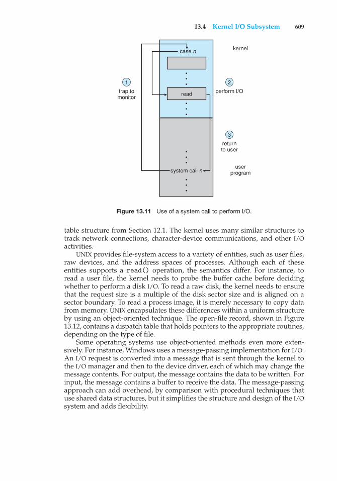
13.4 Kernel I/O Subsystem 609
kernel
2
perform I/O
case n
system call n
read
3
returnto user
1
trap tomonitor
userprogram
• • •
• • •
• • •
• • •
Figure 13.11 Use of a system call to perform I/O.
table structure from Section 12.1. The kernel uses many similar structures totrack network connections, character-device communications, and other I/Oactivities.
UNIX provides file-system access to a variety of entities, such as user files,raw devices, and the address spaces of processes. Although each of theseentities supports a read() operation, the semantics differ. For instance, toread a user file, the kernel needs to probe the buffer cache before decidingwhether to perform a disk I/O. To read a raw disk, the kernel needs to ensurethat the request size is a multiple of the disk sector size and is aligned on asector boundary. To read a process image, it is merely necessary to copy datafrom memory. UNIX encapsulates these differences within a uniform structureby using an object-oriented technique. The open-file record, shown in Figure13.12, contains a dispatch table that holds pointers to the appropriate routines,depending on the type of file.
Some operating systems use object-oriented methods even more exten-sively. For instance, Windows uses a message-passing implementation for I/O.An I/O request is converted into a message that is sent through the kernel tothe I/O manager and then to the device driver, each of which may change themessage contents. For output, the message contains the data to be written. Forinput, the message contains a buffer to receive the data. The message-passingapproach can add overhead, by comparison with procedural techniques thatuse shared data structures, but it simplifies the structure and design of the I/Osystem and adds flexibility.
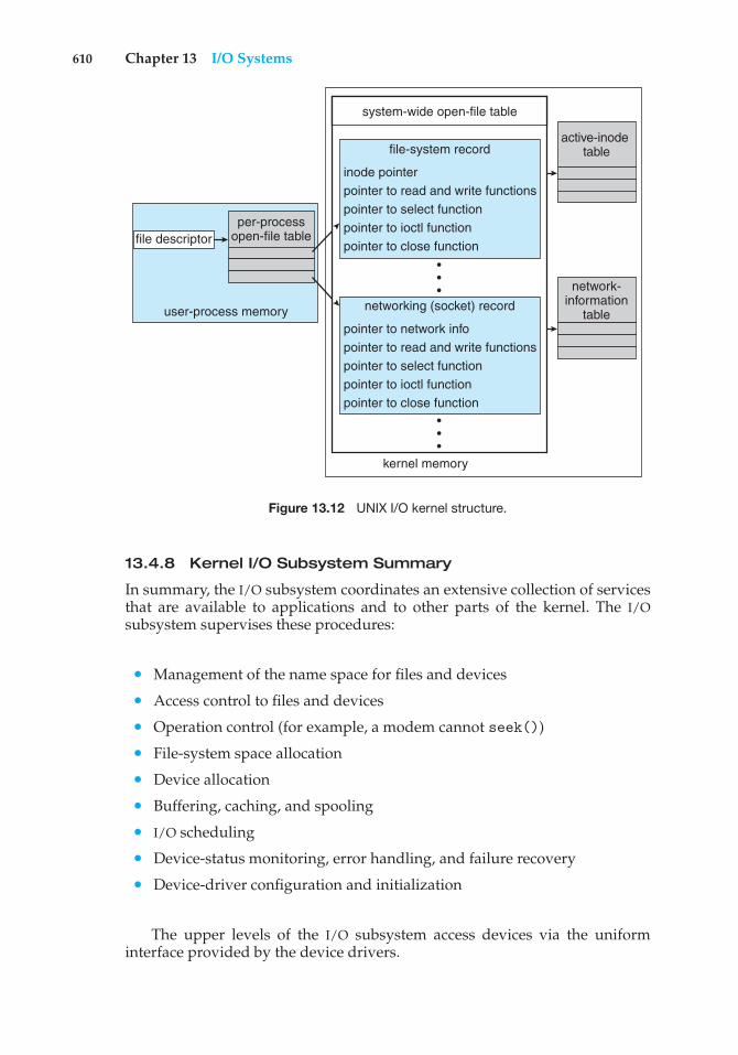
610 Chapter 13 I/O Systems
active-inode table
network-information
table
per-processopen-file table
user-process memory
system-wide open-file table
kernel memory
•••
•••
file-system record
inode pointerpointer to read and write functionspointer to select functionpointer to ioctl functionpointer to close function
networking (socket) record
pointer to network infopointer to read and write functionspointer to select functionpointer to ioctl functionpointer to close function
file descriptor
Figure 13.12 UNIX I/O kernel structure.
13.4.8 Kernel I/O Subsystem Summary
In summary, the I/O subsystem coordinates an extensive collection of servicesthat are available to applications and to other parts of the kernel. The I/Osubsystem supervises these procedures:
• Management of the name space for files and devices
• Access control to files and devices
• Operation control (for example, a modem cannot seek())
• File-system space allocation
• Device allocation
• Buffering, caching, and spooling
• I/O scheduling
• Device-status monitoring, error handling, and failure recovery
• Device-driver configuration and initialization
The upper levels of the I/O subsystem access devices via the uniforminterface provided by the device drivers.
13.5 Transforming I/O Requests to Hardware Operations 611
13.5 Transforming I/O Requests to Hardware Operations
Earlier, we described the handshaking between a device driver and a devicecontroller, but we did not explain how the operating system connects anapplication request to a set of network wires or to a specific disk sector.Consider, for example, reading a file from disk. The application refers to thedata by a file name. Within a disk, the file system maps from the file namethrough the file-system directories to obtain the space allocation of the file. Forinstance, in MS-DOS, the name maps to a number that indicates an entry in thefile-access table, and that table entry tells which disk blocks are allocated tothe file. In UNIX, the name maps to an inode number, and the correspondinginode contains the space-allocation information. But how is the connectionmade from the file name to the disk controller (the hardware port address orthe memory-mapped controller registers)?
One method is that used by MS-DOS, a relatively simple operating system.The first part of an MS-DOS file name, preceding the colon, is a string thatidentifies a specific hardware device. For example, C: is the first part of everyfile name on the primary hard disk. The fact that C: represents the primary harddisk is built into the operating system; C: is mapped to a specific port addressthrough a device table. Because of the colon separator, the device name spaceis separate from the file-system name space. This separation makes it easyfor the operating system to associate extra functionality with each device. Forinstance, it is easy to invoke spooling on any files written to the printer.
If, instead, the device name space is incorporated in the regular file-systemname space, as it is in UNIX, the normal file-system name services are providedautomatically. If the file system provides ownership and access control to allfile names, then devices have owners and access control. Since files are storedon devices, such an interface provides access to the I/O system at two levels.Names can be used to access the devices themselves or to access the files storedon the devices.
UNIX represents device names in the regular file-system name space. Unlikean MS-DOS file name, which has a colon separator, a UNIX path name has noclear separation of the device portion. In fact, no part of the path name is thename of a device. UNIX has a mount table that associates prefixes of path nameswith specific device names. To resolve a path name, UNIX looks up the name inthe mount table to find the longest matching prefix; the corresponding entryin the mount table gives the device name. This device name also has the formof a name in the file-system name space. When UNIX looks up this name in thefile-system directory structures, it finds not an inode number but a <major,minor> device number. The major device number identifies a device driverthat should be called to handle I/O to this device. The minor device numberis passed to the device driver to index into a device table. The correspondingdevice-table entry gives the port address or the memory-mapped address ofthe device controller.
Modern operating systems gain significant flexibility from the multiplestages of lookup tables in the path between a request and a physical devicecontroller. The mechanisms that pass requests between applications anddrivers are general. Thus, we can introduce new devices and drivers into acomputer without recompiling the kernel. In fact, some operating systemshave the ability to load device drivers on demand. At boot time, the system
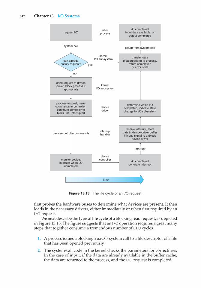
612 Chapter 13 I/O Systems
send request to devicedriver, block process if
appropriate
monitor device,interrupt when I/O
completed
process request, issuecommands to controller,configure controller toblock until interrupted
request I/O
system call
no
yes
I/O completed,input data available, or
output completed
userprocess
kernelI/O subsystem
kernelI/O subsystem
devicedriver
devicecontroller
time
interrupthandler
transfer data(if appropriate) to process,
return completionor error code
determine which I/Ocompleted, indicate statechange to I/O subsystem
receive interrupt, storedata in device-driver bufferif input, signal to unblock
device driver
I/O completed,generate interrupt
return from system call
interrupt
device-controller commands
can alreadysatisfy request?
Figure 13.13 The life cycle of an I/O request.
first probes the hardware buses to determine what devices are present. It thenloads in the necessary drivers, either immediately or when first required by anI/O request.
We next describe the typical life cycle of a blocking read request, as depictedin Figure 13.13. The figure suggests that an I/O operation requires a great manysteps that together consume a tremendous number of CPU cycles.
1. A process issues a blocking read() system call to a file descriptor of a filethat has been opened previously.
2. The system-call code in the kernel checks the parameters for correctness.In the case of input, if the data are already available in the buffer cache,the data are returned to the process, and the I/O request is completed.
13.6 STREAMS 613
3. Otherwise, a physical I/O must be performed. The process is removedfrom the run queue and is placed on the wait queue for the device, andthe I/O request is scheduled. Eventually, the I/O subsystem sends therequest to the device driver. Depending on the operating system, therequest is sent via a subroutine call or an in-kernel message.
4. The device driver allocates kernel buffer space to receive the data andschedules the I/O. Eventually, the driver sends commands to the devicecontroller by writing into the device-control registers.
5. The device controller operates the device hardware to perform the datatransfer.
6. The driver may poll for status and data, or it may have set up a DMAtransfer into kernel memory. We assume that the transfer is managedby a DMA controller, which generates an interrupt when the transfercompletes.
7. The correct interrupt handler receives the interrupt via the interrupt-vector table, stores any necessary data, signals the device driver, andreturns from the interrupt.
8. The device driver receives the signal, determines which I/O request hascompleted, determines the request’s status, and signals the kernel I/Osubsystem that the request has been completed.
9. The kernel transfers data or return codes to the address space of therequesting process and moves the process from the wait queue back tothe ready queue.
10. Moving the process to the ready queue unblocks the process. When thescheduler assigns the process to the CPU, the process resumes executionat the completion of the system call.
13.6 STREAMS
UNIX System V has an interesting mechanism, called STREAMS, that enablesan application to assemble pipelines of driver code dynamically. A stream isa full-duplex connection between a device driver and a user-level process. Itconsists of a stream head that interfaces with the user process, a driver endthat controls the device, and zero or more stream modules between the streamhead and the driver end. Each of these components contains a pair of queues—a read queue and a write queue. Message passing is used to transfer databetween queues. The STREAMS structure is shown in Figure 13.14.
Modules provide the functionality of STREAMS processing; they are pushedonto a stream by use of the ioctl() system call. For example, a process canopen a serial-port device via a stream and can push on a module to handleinput editing. Because messages are exchanged between queues in adjacentmodules, a queue in one module may overflow an adjacent queue. To preventthis from occurring, a queue may support flow control. Without flow control,a queue accepts all messages and immediately sends them on to the queuein the adjacent module without buffering them. A queue that supports flow
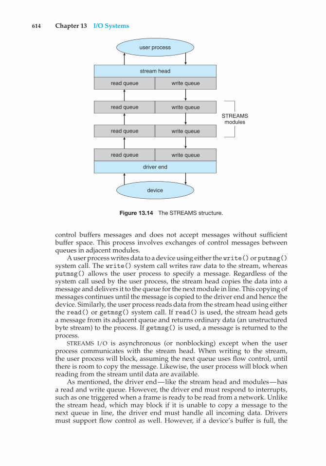
614 Chapter 13 I/O Systems
user process
device
stream head
driver end
read queue write queue
STREAMSmodules
read queue
read queue
read queue
write queue
write queue
write queue
Figure 13.14 The STREAMS structure.
control buffers messages and does not accept messages without sufficientbuffer space. This process involves exchanges of control messages betweenqueues in adjacent modules.
A user process writes data to a device using either the write()orputmsg()system call. The write() system call writes raw data to the stream, whereasputmsg() allows the user process to specify a message. Regardless of thesystem call used by the user process, the stream head copies the data into amessage and delivers it to the queue for the next module in line. This copying ofmessages continues until the message is copied to the driver end and hence thedevice. Similarly, the user process reads data from the stream head using eitherthe read() or getmsg() system call. If read() is used, the stream head getsa message from its adjacent queue and returns ordinary data (an unstructuredbyte stream) to the process. If getmsg() is used, a message is returned to theprocess.
STREAMS I/O is asynchronous (or nonblocking) except when the userprocess communicates with the stream head. When writing to the stream,the user process will block, assuming the next queue uses flow control, untilthere is room to copy the message. Likewise, the user process will block whenreading from the stream until data are available.
As mentioned, the driver end—like the stream head and modules—hasa read and write queue. However, the driver end must respond to interrupts,such as one triggered when a frame is ready to be read from a network. Unlikethe stream head, which may block if it is unable to copy a message to thenext queue in line, the driver end must handle all incoming data. Driversmust support flow control as well. However, if a device’s buffer is full, the
13.7 Performance 615
device typically resorts to dropping incoming messages. Consider a networkcard whose input buffer is full. The network card must simply drop furthermessages until there is enough buffer space to store incoming messages.
The benefit of using STREAMS is that it provides a framework for amodular and incremental approach to writing device drivers and networkprotocols. Modules may be used by different streams and hence by differentdevices. For example, a networking module may be used by both an Ethernetnetwork card and a 802.11 wireless network card. Furthermore, rather thantreating character-device I/O as an unstructured byte stream, STREAMS allowssupport for message boundaries and control information when communicatingbetween modules. Most UNIX variants support STREAMS, and it is the preferredmethod for writing protocols and device drivers. For example, System V UNIXand Solaris implement the socket mechanism using STREAMS.
13.7 Performance
I/O is a major factor in system performance. It places heavy demands on the CPUto execute device-driver code and to schedule processes fairly and efficientlyas they block and unblock. The resulting context switches stress the CPU and itshardware caches. I/O also exposes any inefficiencies in the interrupt-handlingmechanisms in the kernel. In addition, I/O loads down the memory bus duringdata copies between controllers and physical memory and again during copiesbetween kernel buffers and application data space. Coping gracefully with allthese demands is one of the major concerns of a computer architect.
Although modern computers can handle many thousands of interrupts persecond, interrupt handling is a relatively expensive task. Each interrupt causesthe system to perform a state change, to execute the interrupt handler, and thento restore state. Programmed I/O can be more efficient than interrupt-drivenI/O, if the number of cycles spent in busy waiting is not excessive. An I/Ocompletion typically unblocks a process, leading to the full overhead of acontext switch.
Network traffic can also cause a high context-switch rate. Consider, forinstance, a remote login from one machine to another. Each character typedon the local machine must be transported to the remote machine. On the localmachine, the character is typed; a keyboard interrupt is generated; and thecharacter is passed through the interrupt handler to the device driver, to thekernel, and then to the user process. The user process issues a network I/Osystem call to send the character to the remote machine. The character thenflows into the local kernel, through the network layers that construct a networkpacket, and into the network device driver. The network device driver transfersthe packet to the network controller, which sends the character and generatesan interrupt. The interrupt is passed back up through the kernel to cause thenetwork I/O system call to complete.
Now, the remote system’s network hardware receives the packet, and aninterrupt is generated. The character is unpacked from the network protocolsand is given to the appropriate network daemon. The network daemonidentifies which remote login session is involved and passes the packet tothe appropriate subdaemon for that session. Throughout this flow, there are
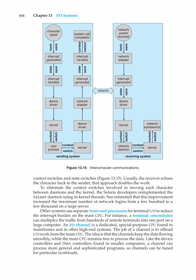
616 Chapter 13 I/O Systems
network
kerneluserprocess
kernel
devicedriver
interrupthandled
devicedriver
networkadapter
interruptgenerated
interrupthandled
interruptgenerated
system callcompletes
sending system
stat
e
save
stat
e
save
stat
e
save
cont
ext
switc
h
cont
ext
switc
h
hard
-
war
e
hard
-
war
e
receiving system
charactertyped
context
switch
context
switch
cont
ext
switc
h
cont
ext
switc
h
kernelnetworkdaemon
networksubdaemon
kernel
devicedriver
interruptgenerated
networkadapter
networkpacket
received
Figure 13.15 Intercomputer communications.
context switches and state switches (Figure 13.15). Usually, the receiver echoesthe character back to the sender; that approach doubles the work.
To eliminate the context switches involved in moving each characterbetween daemons and the kernel, the Solaris developers reimplemented thetelnet daemon using in-kernel threads. Sun estimated that this improvementincreased the maximum number of network logins from a few hundred to afew thousand on a large server.
Other systems use separate front-end processors for terminal I/O to reducethe interrupt burden on the main CPU. For instance, a terminal concentratorcan multiplex the traffic from hundreds of remote terminals into one port on alarge computer. An I/O channel is a dedicated, special-purpose CPU found inmainframes and in other high-end systems. The job of a channel is to offloadI/O work from the main CPU. The idea is that the channels keep the data flowingsmoothly, while the main CPU remains free to process the data. Like the devicecontrollers and DMA controllers found in smaller computers, a channel canprocess more general and sophisticated programs, so channels can be tunedfor particular workloads.
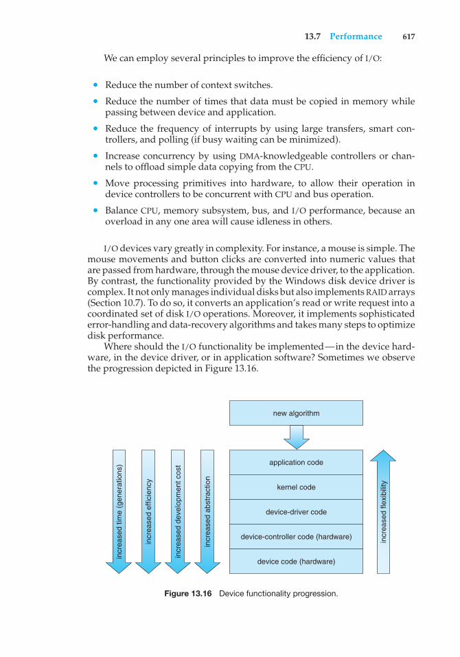
13.7 Performance 617
We can employ several principles to improve the efficiency of I/O:
• Reduce the number of context switches.
• Reduce the number of times that data must be copied in memory whilepassing between device and application.
• Reduce the frequency of interrupts by using large transfers, smart con-trollers, and polling (if busy waiting can be minimized).
• Increase concurrency by using DMA-knowledgeable controllers or chan-nels to offload simple data copying from the CPU.
• Move processing primitives into hardware, to allow their operation indevice controllers to be concurrent with CPU and bus operation.
• Balance CPU, memory subsystem, bus, and I/O performance, because anoverload in any one area will cause idleness in others.
I/O devices vary greatly in complexity. For instance, a mouse is simple. Themouse movements and button clicks are converted into numeric values thatare passed from hardware, through the mouse device driver, to the application.By contrast, the functionality provided by the Windows disk device driver iscomplex. It not only manages individual disks but also implements RAID arrays(Section 10.7). To do so, it converts an application’s read or write request into acoordinated set of disk I/O operations. Moreover, it implements sophisticatederror-handling and data-recovery algorithms and takes many steps to optimizedisk performance.
Where should the I/O functionality be implemented—in the device hard-ware, in the device driver, or in application software? Sometimes we observethe progression depicted in Figure 13.16.
application code
kernel code
device-driver code
device-controller code (hardware)
device code (hardware)
new algorithm
incr
ease
d fle
xibi
lity
incr
ease
d ab
stra
ctio
n
incr
ease
d de
velo
pmen
t cos
t
incr
ease
d ef
ficie
ncy
incr
ease
d tim
e (g
ener
atio
ns)
Figure 13.16 Device functionality progression.
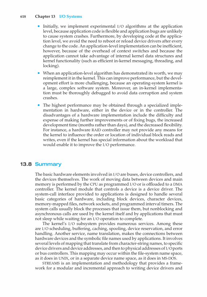
618 Chapter 13 I/O Systems
• Initially, we implement experimental I/O algorithms at the applicationlevel, because application code is flexible and application bugs are unlikelyto cause system crashes. Furthermore, by developing code at the applica-tion level, we avoid the need to reboot or reload device drivers after everychange to the code. An application-level implementation can be inefficient,however, because of the overhead of context switches and because theapplication cannot take advantage of internal kernel data structures andkernel functionality (such as efficient in-kernel messaging, threading, andlocking).
• When an application-level algorithm has demonstrated its worth, we mayreimplement it in the kernel. This can improve performance, but the devel-opment effort is more challenging, because an operating-system kernel isa large, complex software system. Moreover, an in-kernel implementa-tion must be thoroughly debugged to avoid data corruption and systemcrashes.
• The highest performance may be obtained through a specialized imple-mentation in hardware, either in the device or in the controller. Thedisadvantages of a hardware implementation include the difficulty andexpense of making further improvements or of fixing bugs, the increaseddevelopment time (months rather than days), and the decreased flexibility.For instance, a hardware RAID controller may not provide any means forthe kernel to influence the order or location of individual block reads andwrites, even if the kernel has special information about the workload thatwould enable it to improve the I/O performance.
13.8 Summary
The basic hardware elements involved in I/O are buses, device controllers, andthe devices themselves. The work of moving data between devices and mainmemory is performed by the CPU as programmed I/O or is offloaded to a DMAcontroller. The kernel module that controls a device is a device driver. Thesystem-call interface provided to applications is designed to handle severalbasic categories of hardware, including block devices, character devices,memory-mapped files, network sockets, and programmed interval timers. Thesystem calls usually block the processes that issue them, but nonblocking andasynchronous calls are used by the kernel itself and by applications that mustnot sleep while waiting for an I/O operation to complete.
The kernel’s I/O subsystem provides numerous services. Among theseare I/O scheduling, buffering, caching, spooling, device reservation, and errorhandling. Another service, name translation, makes the connections betweenhardware devices and the symbolic file names used by applications. It involvesseveral levels of mapping that translate from character-string names, to specificdevice drivers and device addresses, and then to physical addresses of I/Oportsor bus controllers. This mapping may occur within the file-system name space,as it does in UNIX, or in a separate device name space, as it does in MS-DOS.
STREAMS is an implementation and methodology that provides a frame-work for a modular and incremental approach to writing device drivers and
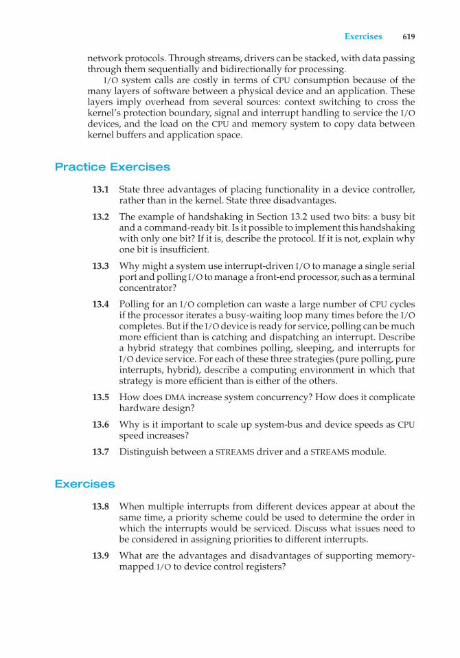
Exercises 619
network protocols. Through streams, drivers can be stacked, with data passingthrough them sequentially and bidirectionally for processing.
I/O system calls are costly in terms of CPU consumption because of themany layers of software between a physical device and an application. Theselayers imply overhead from several sources: context switching to cross thekernel’s protection boundary, signal and interrupt handling to service the I/Odevices, and the load on the CPU and memory system to copy data betweenkernel buffers and application space.
Practice Exercises
13.1 State three advantages of placing functionality in a device controller,rather than in the kernel. State three disadvantages.
13.2 The example of handshaking in Section 13.2 used two bits: a busy bitand a command-ready bit. Is it possible to implement this handshakingwith only one bit? If it is, describe the protocol. If it is not, explain whyone bit is insufficient.
13.3 Why might a system use interrupt-driven I/O to manage a single serialport and polling I/O to manage a front-end processor, such as a terminalconcentrator?
13.4 Polling for an I/O completion can waste a large number of CPU cyclesif the processor iterates a busy-waiting loop many times before the I/Ocompletes. But if the I/O device is ready for service, polling can be muchmore efficient than is catching and dispatching an interrupt. Describea hybrid strategy that combines polling, sleeping, and interrupts forI/O device service. For each of these three strategies (pure polling, pureinterrupts, hybrid), describe a computing environment in which thatstrategy is more efficient than is either of the others.
13.5 How does DMA increase system concurrency? How does it complicatehardware design?
13.6 Why is it important to scale up system-bus and device speeds as CPUspeed increases?
13.7 Distinguish between a STREAMS driver and a STREAMS module.
Exercises
13.8 When multiple interrupts from different devices appear at about thesame time, a priority scheme could be used to determine the order inwhich the interrupts would be serviced. Discuss what issues need tobe considered in assigning priorities to different interrupts.
13.9 What are the advantages and disadvantages of supporting memory-mapped I/O to device control registers?
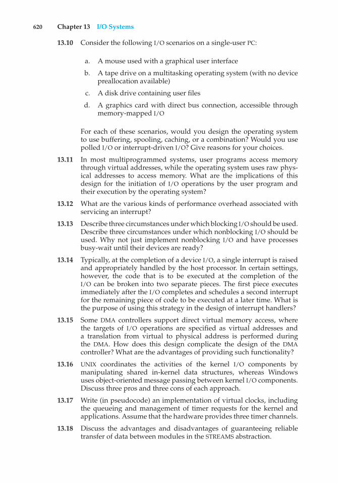
620 Chapter 13 I/O Systems
13.10 Consider the following I/O scenarios on a single-user PC:
a. A mouse used with a graphical user interface
b. A tape drive on a multitasking operating system (with no devicepreallocation available)
c. A disk drive containing user files
d. A graphics card with direct bus connection, accessible throughmemory-mapped I/O
For each of these scenarios, would you design the operating systemto use buffering, spooling, caching, or a combination? Would you usepolled I/O or interrupt-driven I/O? Give reasons for your choices.
13.11 In most multiprogrammed systems, user programs access memorythrough virtual addresses, while the operating system uses raw phys-ical addresses to access memory. What are the implications of thisdesign for the initiation of I/O operations by the user program andtheir execution by the operating system?
13.12 What are the various kinds of performance overhead associated withservicing an interrupt?
13.13 Describe three circumstances under which blocking I/O should be used.Describe three circumstances under which nonblocking I/O should beused. Why not just implement nonblocking I/O and have processesbusy-wait until their devices are ready?
13.14 Typically, at the completion of a device I/O, a single interrupt is raisedand appropriately handled by the host processor. In certain settings,however, the code that is to be executed at the completion of theI/O can be broken into two separate pieces. The first piece executesimmediately after the I/O completes and schedules a second interruptfor the remaining piece of code to be executed at a later time. What isthe purpose of using this strategy in the design of interrupt handlers?
13.15 Some DMA controllers support direct virtual memory access, wherethe targets of I/O operations are specified as virtual addresses anda translation from virtual to physical address is performed duringthe DMA. How does this design complicate the design of the DMAcontroller? What are the advantages of providing such functionality?
13.16 UNIX coordinates the activities of the kernel I/O components bymanipulating shared in-kernel data structures, whereas Windowsuses object-oriented message passing between kernel I/O components.Discuss three pros and three cons of each approach.
13.17 Write (in pseudocode) an implementation of virtual clocks, includingthe queueing and management of timer requests for the kernel andapplications. Assume that the hardware provides three timer channels.
13.18 Discuss the advantages and disadvantages of guaranteeing reliabletransfer of data between modules in the STREAMS abstraction.
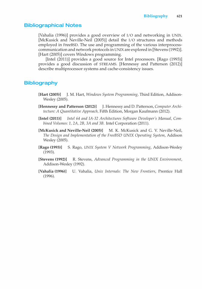
Bibliography 621
Bibliographical Notes
[Vahalia (1996)] provides a good overview of I/O and networking in UNIX.[McKusick and Neville-Neil (2005)] detail the I/O structures and methodsemployed in FreeBSD. The use and programming of the various interprocess-communication and network protocols in UNIX are explored in [Stevens (1992)].[Hart (2005)] covers Windows programming.
[Intel (2011)] provides a good source for Intel processors. [Rago (1993)]provides a good discussion of STREAMS. [Hennessy and Patterson (2012)]describe multiprocessor systems and cache-consistency issues.
Bibliography
[Hart (2005)] J. M. Hart, Windows System Programming, Third Edition, Addison-Wesley (2005).
[Hennessy and Patterson (2012)] J. Hennessy and D. Patterson, Computer Archi-tecture: A Quantitative Approach, Fifth Edition, Morgan Kaufmann (2012).
[Intel (2011)] Intel 64 and IA-32 Architectures Software Developer’s Manual, Com-bined Volumes: 1, 2A, 2B, 3A and 3B. Intel Corporation (2011).
[McKusick and Neville-Neil (2005)] M. K. McKusick and G. V. Neville-Neil,The Design and Implementation of the FreeBSD UNIX Operating System, AddisonWesley (2005).
[Rago (1993)] S. Rago, UNIX System V Network Programming, Addison-Wesley(1993).
[Stevens (1992)] R. Stevens, Advanced Programming in the UNIX Environment,Addison-Wesley (1992).
[Vahalia (1996)] U. Vahalia, Unix Internals: The New Frontiers, Prentice Hall(1996).

Part Five
Protection andSecurity
Protection mechanisms control access to a system by limiting the typesof file access permitted to users. In addition, protection must ensurethat only processes that have gained proper authorization from theoperating system can operate on memory segments, the CPU, and otherresources.
Protection is provided by a mechanism that controls the access ofprograms, processes, or users to the resources defined by a computersystem. This mechanism must provide a means for specifying the controlsto be imposed, together with a means of enforcing them.
Security ensures the authentication of system users to protect theintegrity of the information stored in the system (both data and code),as well as the physical resources of the computer system. The securitysystem prevents unauthorized access, malicious destruction or alterationof data, and accidental introduction of inconsistency.

14C H A P T E R
Protection
The processes in an operating system must be protected from one another’sactivities. To provide such protection, we can use various mechanisms to ensurethat only processes that have gained proper authorization from the operatingsystem can operate on the files, memory segments, CPU, and other resourcesof a system.
Protection refers to a mechanism for controlling the access of programs,processes, or users to the resources defined by a computer system. Thismechanism must provide a means for specifying the controls to be imposed,together with a means of enforcement. We distinguish between protection andsecurity, which is a measure of confidence that the integrity of a system andits data will be preserved. In this chapter, we focus on protection. Securityassurance is a much broader topic, and we address it in Chapter 15.
CHAPTER OBJECTIVES
• To discuss the goals and principles of protection in a modern computersystem.
• To explain how protection domains, combined with an access matrix, areused to specify the resources a process may access.
• To examine capability- and language-based protection systems.
14.1 Goals of Protection
As computer systems have become more sophisticated and pervasive in theirapplications, the need to protect their integrity has also grown. Protection wasoriginally conceived as an adjunct to multiprogramming operating systems,so that untrustworthy users might safely share a common logical name space,such as a directory of files, or share a common physical name space, such asmemory. Modern protection concepts have evolved to increase the reliabilityof any complex system that makes use of shared resources.
We need to provide protection for several reasons. The most obvious is theneed to prevent the mischievous, intentional violation of an access restriction
625
626 Chapter 14 Protection
by a user. Of more general importance, however, is the need to ensure thateach program component active in a system uses system resources only inways consistent with stated policies. This requirement is an absolute one for areliable system.
Protection can improve reliability by detecting latent errors at the interfacesbetween component subsystems. Early detection of interface errors can oftenprevent contamination of a healthy subsystem by a malfunctioning subsystem.Also, an unprotected resource cannot defend against use (or misuse) by anunauthorized or incompetent user. A protection-oriented system providesmeans to distinguish between authorized and unauthorized usage.
The role of protection in a computer system is to provide a mechanism forthe enforcement of the policies governing resource use. These policies can beestablished in a variety of ways. Some are fixed in the design of the system,while others are formulated by the management of a system. Still others aredefined by the individual users to protect their own files and programs. Aprotection system must have the flexibility to enforce a variety of policies.
Policies for resource use may vary by application, and they may changeover time. For these reasons, protection is no longer the concern solely ofthe designer of an operating system. The application programmer needs touse protection mechanisms as well, to guard resources created and supportedby an application subsystem against misuse. In this chapter, we describe theprotection mechanisms the operating system should provide, but applicationdesigners can use them as well in designing their own protection software.
Note that mechanisms are distinct from policies. Mechanisms determinehow something will be done; policies decide what will be done. The separationof policy and mechanism is important for flexibility. Policies are likely tochange from place to place or time to time. In the worst case, every changein policy would require a change in the underlying mechanism. Using generalmechanisms enables us to avoid such a situation.
14.2 Principles of Protection
Frequently, a guiding principle can be used throughout a project, such asthe design of an operating system. Following this principle simplifies designdecisions and keeps the system consistent and easy to understand. A key,time-tested guiding principle for protection is the principle of least privilege. Itdictates that programs, users, and even systems be given just enough privilegesto perform their tasks.
Consider the analogy of a security guard with a passkey. If this key allowsthe guard into just the public areas that she guards, then misuse of the keywill result in minimal damage. If, however, the passkey allows access to allareas, then damage from its being lost, stolen, misused, copied, or otherwisecompromised will be much greater.
An operating system following the principle of least privilege implementsits features, programs, system calls, and data structures so that failure orcompromise of a component does the minimum damage and allows theminimum damage to be done. The overflow of a buffer in a system daemonmight cause the daemon process to fail, for example, but should not allow theexecution of code from the daemon process’s stack that would enable a remote
14.3 Domain of Protection 627
user to gain maximum privileges and access to the entire system (as happenstoo often today).
Such an operating system also provides system calls and services thatallow applications to be written with fine-grained access controls. It providesmechanisms to enable privileges when they are needed and to disable themwhen they are not needed. Also beneficial is the creation of audit trails forall privileged function access. The audit trail allows the programmer, systemadministrator, or law-enforcement officer to trace all protection and securityactivities on the system.
Managing users with the principle of least privilege entails creating aseparate account for each user, with just the privileges that the user needs. Anoperator who needs to mount tapes and back up files on the system has accessto just those commands and files needed to accomplish the job. Some systemsimplement role-based access control (RBAC) to provide this functionality.
Computers implemented in a computing facility under the principle of leastprivilege can be limited to running specific services, accessing specific remotehosts via specific services, and doing so during specific times. Typically, theserestrictions are implemented through enabling or disabling each service andthrough using access control lists, as described in Sections Section 11.6.2 andSection 14.6.
The principle of least privilege can help produce a more secure computingenvironment. Unfortunately, it frequently does not. For example, Windows2000 has a complex protection scheme at its core and yet has many securityholes. By comparison, Solaris is considered relatively secure, even though itis a variant of UNIX, which historically was designed with little protectionin mind. One reason for the difference may be that Windows 2000 has morelines of code and more services than Solaris and thus has more to secure andprotect. Another reason could be that the protection scheme in Windows 2000is incomplete or protects the wrong aspects of the operating system, leavingother areas vulnerable.
14.3 Domain of Protection
A computer system is a collection of processes and objects. By objects, we meanboth hardware objects (such as the CPU, memory segments, printers, disks, andtape drives) and software objects (such as files, programs, and semaphores).Each object has a unique name that differentiates it from all other objects in thesystem, and each can be accessed only through well-defined and meaningfuloperations. Objects are essentially abstract data types.
The operations that are possible may depend on the object. For example,on a CPU, we can only execute. Memory segments can be read and written,whereas a CD-ROM or DVD-ROM can only be read. Tape drives can be read,written, and rewound. Data files can be created, opened, read, written, closed,and deleted; program files can be read, written, executed, and deleted.
A process should be allowed to access only those resources for which ithas authorization. Furthermore, at any time, a process should be able to accessonly those resources that it currently requires to complete its task. This secondrequirement, commonly referred to as the need-to-know principle, is usefulin limiting the amount of damage a faulty process can cause in the system.
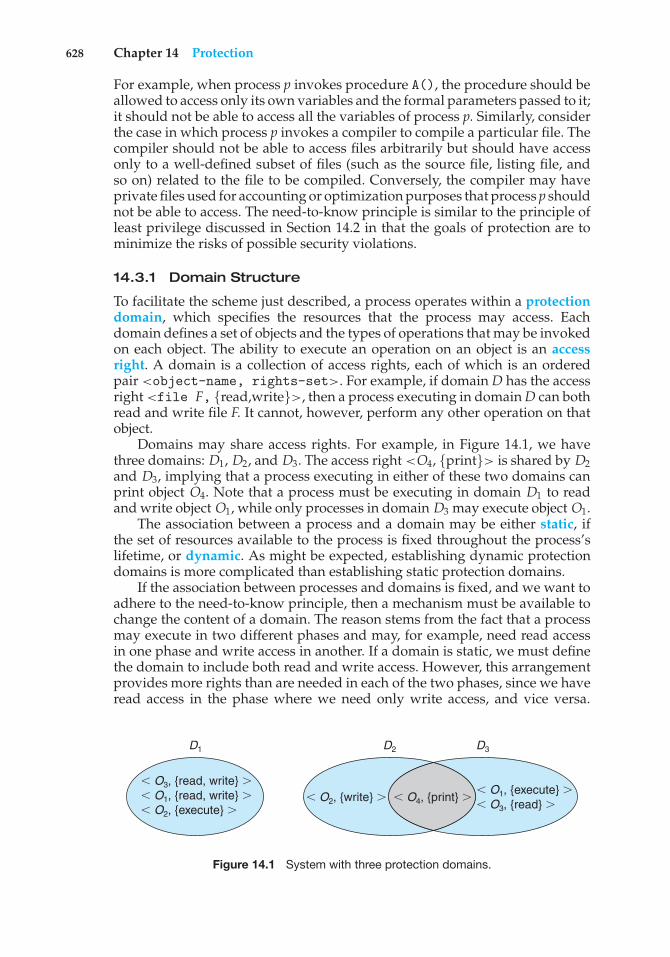
628 Chapter 14 Protection
For example, when process p invokes procedure A(), the procedure should beallowed to access only its own variables and the formal parameters passed to it;it should not be able to access all the variables of process p. Similarly, considerthe case in which process p invokes a compiler to compile a particular file. Thecompiler should not be able to access files arbitrarily but should have accessonly to a well-defined subset of files (such as the source file, listing file, andso on) related to the file to be compiled. Conversely, the compiler may haveprivate files used for accounting or optimization purposes that process p shouldnot be able to access. The need-to-know principle is similar to the principle ofleast privilege discussed in Section 14.2 in that the goals of protection are tominimize the risks of possible security violations.
14.3.1 Domain Structure
To facilitate the scheme just described, a process operates within a protectiondomain, which specifies the resources that the process may access. Eachdomain defines a set of objects and the types of operations that may be invokedon each object. The ability to execute an operation on an object is an accessright. A domain is a collection of access rights, each of which is an orderedpair <object-name, rights-set>. For example, if domain D has the accessright <file F, {read,write}>, then a process executing in domain D can bothread and write file F. It cannot, however, perform any other operation on thatobject.
Domains may share access rights. For example, in Figure 14.1, we havethree domains: D1, D2, and D3. The access right <O4, {print}> is shared by D2and D3, implying that a process executing in either of these two domains canprint object O4. Note that a process must be executing in domain D1 to readand write object O1, while only processes in domain D3 may execute object O1.
The association between a process and a domain may be either static, ifthe set of resources available to the process is fixed throughout the process’slifetime, or dynamic. As might be expected, establishing dynamic protectiondomains is more complicated than establishing static protection domains.
If the association between processes and domains is fixed, and we want toadhere to the need-to-know principle, then a mechanism must be available tochange the content of a domain. The reason stems from the fact that a processmay execute in two different phases and may, for example, need read accessin one phase and write access in another. If a domain is static, we must definethe domain to include both read and write access. However, this arrangementprovides more rights than are needed in each of the two phases, since we haveread access in the phase where we need only write access, and vice versa.
D1
( O3, {read, write} )( O1, {read, write} )( O2, {execute} )
( O1, {execute} )( O3, {read} )
( O2, {write} ) ( O4, {print} )
D2 D3
Figure 14.1 System with three protection domains.

14.3 Domain of Protection 629
Thus, the need-to-know principle is violated. We must allow the contents ofa domain to be modified so that the domain always reflects the minimumnecessary access rights.
If the association is dynamic, a mechanism is available to allow domainswitching, enabling the process to switch from one domain to another. We mayalso want to allow the content of a domain to be changed. If we cannot changethe content of a domain, we can provide the same effect by creating a newdomain with the changed content and switching to that new domain when wewant to change the domain content.
A domain can be realized in a variety of ways:
• Each user may be a domain. In this case, the set of objects that can beaccessed depends on the identity of the user. Domain switching occurswhen the user is changed—generally when one user logs out and anotheruser logs in.
• Each process may be a domain. In this case, the set of objects that can beaccessed depends on the identity of the process. Domain switching occurswhen one process sends a message to another process and then waits fora response.
• Each procedure may be a domain. In this case, the set of objects that can beaccessed corresponds to the local variables defined within the procedure.Domain switching occurs when a procedure call is made.
We discuss domain switching in greater detail in Section 14.4.Consider the standard dual-mode (monitor–user mode) model of
operating-system execution. When a process executes in monitor mode, itcan execute privileged instructions and thus gain complete control of thecomputer system. In contrast, when a process executes in user mode, it caninvoke only nonprivileged instructions. Consequently, it can execute onlywithin its predefined memory space. These two modes protect the operatingsystem (executing in monitor domain) from the user processes (executingin user domain). In a multiprogrammed operating system, two protectiondomains are insufficient, since users also want to be protected from oneanother. Therefore, a more elaborate scheme is needed. We illustrate such ascheme by examining two influential operating systems—UNIX and MULTICS—to see how they implement these concepts.
14.3.2 An Example: UNIX
In the UNIX operating system, a domain is associated with the user. Switchingthe domain corresponds to changing the user identification temporarily.This change is accomplished through the file system as follows. An owneridentification and a domain bit (known as the setuid bit) are associated witheach file. When the setuid bit is on, and a user executes that file, the userID isset to that of the owner of the file. When the bit is off, however, the userIDdoes not change. For example, when a user A (that is, a user with userID =A) starts executing a file owned by B, whose associated domain bit is off, theuserID of the process is set to A. When the setuid bit is on, the userID is set to
630 Chapter 14 Protection
that of the owner of the file: B. When the process exits, this temporary userIDchange ends.
Other methods are used to change domains in operating systems in whichuserIDs are used for domain definition, because almost all systems needto provide such a mechanism. This mechanism is used when an otherwiseprivileged facility needs to be made available to the general user population.For instance, it might be desirable to allow users to access a network withoutletting them write their own networking programs. In such a case, on a UNIXsystem, the setuid bit on a networking program would be set, causing theuserID to change when the program was run. The userID would change tothat of a user with network access privilege (such as root, the most powerfuluserID). One problem with this method is that if a user manages to create a filewith userID root and with its setuid bit on, that user can become root anddo anything and everything on the system. The setuid mechanism is discussedfurther in Appendix A.
An alternative to this method used in some other operating systems isto place privileged programs in a special directory. The operating system isdesigned to change the userID of any program run from this directory, eitherto the equivalent of root or to the userID of the owner of the directory. Thiseliminates one security problem, which occurs when intruders create programsto manipulate the setuid feature and hide the programs in the system for lateruse (using obscure file or directory names). This method is less flexible thanthat used in UNIX, however.
Even more restrictive, and thus more protective, are systems that simplydo not allow a change of userID. In these instances, special techniques mustbe used to allow users access to privileged facilities. For instance, a daemonprocess may be started at boot time and run as a special userID. Users thenrun a separate program, which sends requests to this process whenever theyneed to use the facility. This method is used by the TOPS-20 operating system.
In any of these systems, great care must be taken in writing privilegedprograms. Any oversight can result in a total lack of protection on the system.Generally, these programs are the first to be attacked by people trying tobreak into a system. Unfortunately, the attackers are frequently successful.For example, security has been breached on many UNIX systems because of thesetuid feature. We discuss security in Chapter 15.
14.3.3 An Example: MULTICS
In the MULTICS system, the protection domains are organized hierarchicallyinto a ring structure. Each ring corresponds to a single domain (Figure 14.2).The rings are numbered from 0 to 7. Let Di and Dj be any two domain rings.If j < i, then Di is a subset of Dj . That is, a process executing in domain Djhas more privileges than does a process executing in domain Di . A processexecuting in domain D0 has the most privileges. If only two rings exist, thisscheme is equivalent to the monitor–user mode of execution, where monitormode corresponds to D0 and user mode corresponds to D1.
MULTICS has a segmented address space; each segment is a file, and eachsegment is associated with one of the rings. A segment description includes anentry that identifies the ring number. In addition, it includes three access bits
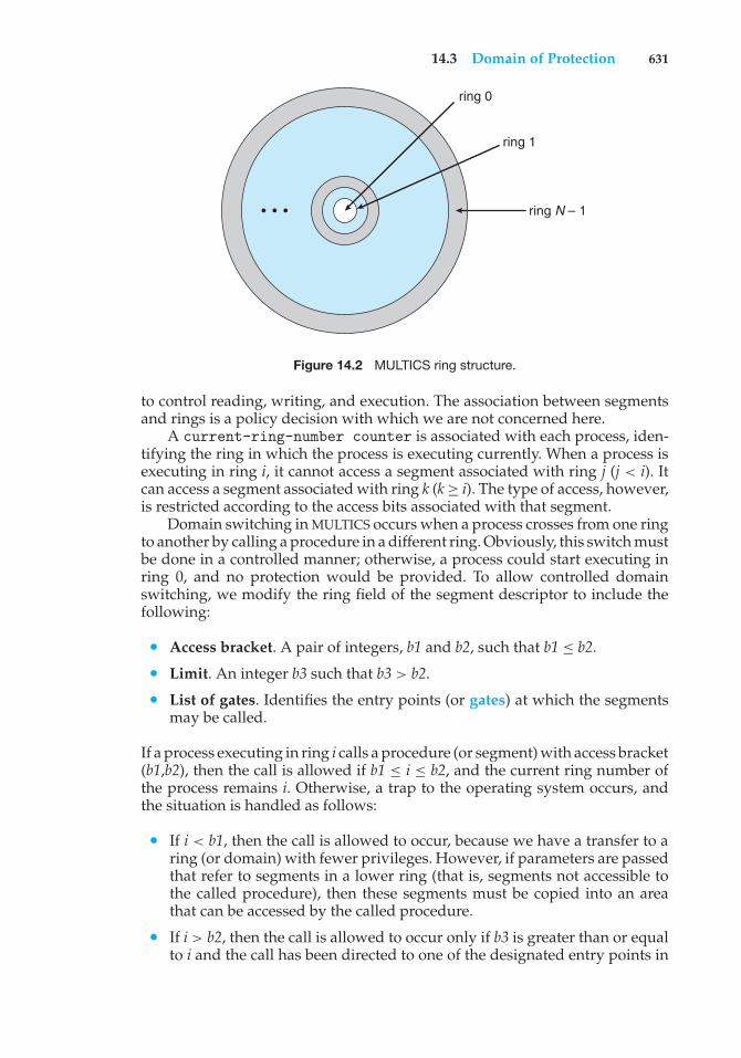
14.3 Domain of Protection 631
ring 0
ring 1
ring N – 1• • •
Figure 14.2 MULTICS ring structure.
to control reading, writing, and execution. The association between segmentsand rings is a policy decision with which we are not concerned here.
A current-ring-number counter is associated with each process, iden-tifying the ring in which the process is executing currently. When a process isexecuting in ring i, it cannot access a segment associated with ring j (j < i). Itcan access a segment associated with ring k (k≥ i). The type of access, however,is restricted according to the access bits associated with that segment.
Domain switching in MULTICS occurs when a process crosses from one ringto another by calling a procedure in a different ring. Obviously, this switch mustbe done in a controlled manner; otherwise, a process could start executing inring 0, and no protection would be provided. To allow controlled domainswitching, we modify the ring field of the segment descriptor to include thefollowing:
• Access bracket. A pair of integers, b1 and b2, such that b1 ≤ b2.
• Limit. An integer b3 such that b3 > b2.
• List of gates. Identifies the entry points (or gates) at which the segmentsmay be called.
If a process executing in ring i calls a procedure (or segment) with access bracket(b1,b2), then the call is allowed if b1 ≤ i ≤ b2, and the current ring number ofthe process remains i. Otherwise, a trap to the operating system occurs, andthe situation is handled as follows:
• If i < b1, then the call is allowed to occur, because we have a transfer to aring (or domain) with fewer privileges. However, if parameters are passedthat refer to segments in a lower ring (that is, segments not accessible tothe called procedure), then these segments must be copied into an areathat can be accessed by the called procedure.
• If i > b2, then the call is allowed to occur only if b3 is greater than or equalto i and the call has been directed to one of the designated entry points in
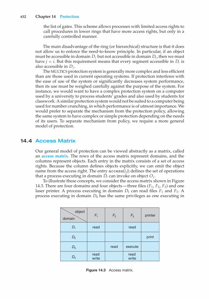
632 Chapter 14 Protection
the list of gates. This scheme allows processes with limited access rights tocall procedures in lower rings that have more access rights, but only in acarefully controlled manner.
The main disadvantage of the ring (or hierarchical) structure is that it doesnot allow us to enforce the need-to-know principle. In particular, if an objectmust be accessible in domain Dj but not accessible in domain Di , then we musthave j < i. But this requirement means that every segment accessible in Di isalso accessible in Dj .
The MULTICS protection system is generally more complex and less efficientthan are those used in current operating systems. If protection interferes withthe ease of use of the system or significantly decreases system performance,then its use must be weighed carefully against the purpose of the system. Forinstance, we would want to have a complex protection system on a computerused by a university to process students’ grades and also used by students forclasswork. A similar protection system would not be suited to a computer beingused for number crunching, in which performance is of utmost importance. Wewould prefer to separate the mechanism from the protection policy, allowingthe same system to have complex or simple protection depending on the needsof its users. To separate mechanism from policy, we require a more generalmodel of protection.
14.4 Access Matrix
Our general model of protection can be viewed abstractly as a matrix, calledan access matrix. The rows of the access matrix represent domains, and thecolumns represent objects. Each entry in the matrix consists of a set of accessrights. Because the column defines objects explicitly, we can omit the objectname from the access right. The entry access(i,j) defines the set of operationsthat a process executing in domain Di can invoke on object Oj .
To illustrate these concepts, we consider the access matrix shown in Figure14.3. There are four domains and four objects—three files (F1, F2, F3) and onelaser printer. A process executing in domain D1 can read files F1 and F3. Aprocess executing in domain D4 has the same privileges as one executing in
objectprinter
read
read execute
readwrite
readwrite
read
F1
D1
D2
D3
D4
F2 F3domain
Figure 14.3 Access matrix.
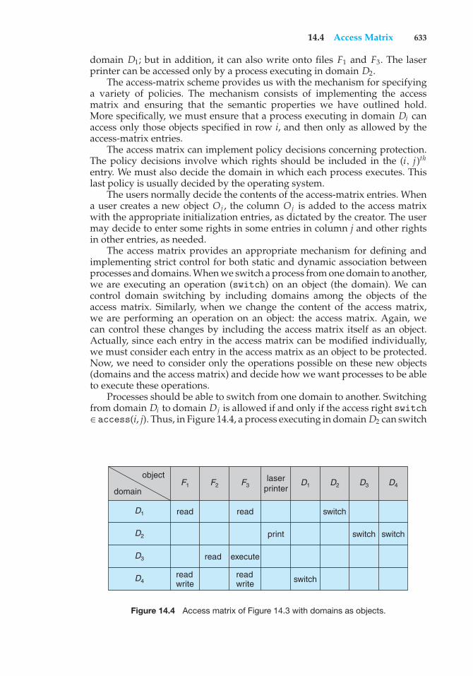
14.4 Access Matrix 633
domain D1; but in addition, it can also write onto files F1 and F3. The laserprinter can be accessed only by a process executing in domain D2.
The access-matrix scheme provides us with the mechanism for specifyinga variety of policies. The mechanism consists of implementing the accessmatrix and ensuring that the semantic properties we have outlined hold.More specifically, we must ensure that a process executing in domain Di canaccess only those objects specified in row i, and then only as allowed by theaccess-matrix entries.
The access matrix can implement policy decisions concerning protection.The policy decisions involve which rights should be included in the (i, j)th
entry. We must also decide the domain in which each process executes. Thislast policy is usually decided by the operating system.
The users normally decide the contents of the access-matrix entries. Whena user creates a new object Oj , the column Oj is added to the access matrixwith the appropriate initialization entries, as dictated by the creator. The usermay decide to enter some rights in some entries in column j and other rightsin other entries, as needed.
The access matrix provides an appropriate mechanism for defining andimplementing strict control for both static and dynamic association betweenprocesses and domains. When we switch a process from one domain to another,we are executing an operation (switch) on an object (the domain). We cancontrol domain switching by including domains among the objects of theaccess matrix. Similarly, when we change the content of the access matrix,we are performing an operation on an object: the access matrix. Again, wecan control these changes by including the access matrix itself as an object.Actually, since each entry in the access matrix can be modified individually,we must consider each entry in the access matrix as an object to be protected.Now, we need to consider only the operations possible on these new objects(domains and the access matrix) and decide how we want processes to be ableto execute these operations.
Processes should be able to switch from one domain to another. Switchingfrom domain Di to domain Dj is allowed if and only if the access right switch∈ access(i, j). Thus, in Figure 14.4, a process executing in domain D2 can switch
laserprinter
read
read execute
readwrite
readwrite
read
switch
switch
switch switch
F1
D1
D1
D2
D2
D3
D3
D4
D4F2 F3
object
domain
Figure 14.4 Access matrix of Figure 14.3 with domains as objects.
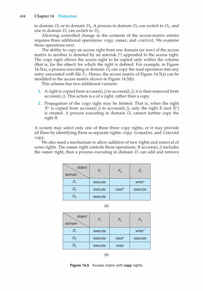
634 Chapter 14 Protection
to domain D3 or to domain D4. A process in domain D4 can switch to D1, andone in domain D1 can switch to D2.
Allowing controlled change in the contents of the access-matrix entriesrequires three additional operations: copy, owner, and control. We examinethese operations next.
The ability to copy an access right from one domain (or row) of the accessmatrix to another is denoted by an asterisk (*) appended to the access right.The copy right allows the access right to be copied only within the column(that is, for the object) for which the right is defined. For example, in Figure14.5(a), a process executing in domain D2 can copy the read operation into anyentry associated with file F2. Hence, the access matrix of Figure 14.5(a) can bemodified to the access matrix shown in Figure 14.5(b).
This scheme has two additional variants:
1. A right is copied from access(i, j) to access(k, j); it is then removed fromaccess(i, j). This action is a of a right, rather than a copy.
2. Propagation of the copy right may be limited. That is, when the rightR∗ is copied from access(i, j) to access(k, j), only the right R (not R∗)is created. A process executing in domain Dk cannot further copy theright R.
A system may select only one of these three copy rights, or it may provideall three by identifying them as separate rights: copy, transfer, and limitedcopy.
We also need a mechanism to allow addition of new rights and removal ofsome rights. The owner right controls these operations. If access(i, j) includesthe owner right, then a process executing in domain Di can add and remove
object
read*
write*execute
execute execute
execute
F1
D1
D2
D3
F2 F3domain
(a)
object
read*
write*execute
execute execute
execute read
F1
D1
D2
D3
F2 F3domain
(b)
Figure 14.5 Access matrix with copy rights.
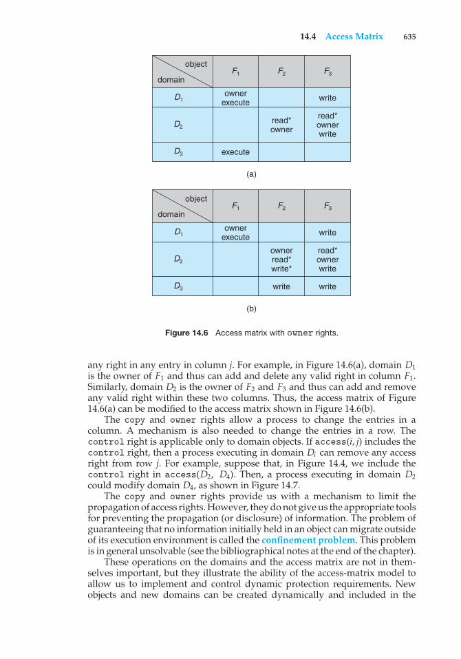
14.4 Access Matrix 635
object
read*owner
writeownerexecute
read*ownerwrite
execute
F1
D1
D2
D3
F2 F3domain
(a)
object
ownerread*write*
writeownerexecute
read*ownerwrite
F1
D1
D2
D3
F2 F3domain
(b)
writewrite
Figure 14.6 Access matrix with owner rights.
any right in any entry in column j. For example, in Figure 14.6(a), domain D1is the owner of F1 and thus can add and delete any valid right in column F1.Similarly, domain D2 is the owner of F2 and F3 and thus can add and removeany valid right within these two columns. Thus, the access matrix of Figure14.6(a) can be modified to the access matrix shown in Figure 14.6(b).
The copy and owner rights allow a process to change the entries in acolumn. A mechanism is also needed to change the entries in a row. Thecontrol right is applicable only to domain objects. If access(i, j) includes thecontrol right, then a process executing in domain Di can remove any accessright from row j. For example, suppose that, in Figure 14.4, we include thecontrol right in access(D2, D4). Then, a process executing in domain D2could modify domain D4, as shown in Figure 14.7.
The copy and owner rights provide us with a mechanism to limit thepropagation of access rights. However, they do not give us the appropriate toolsfor preventing the propagation (or disclosure) of information. The problem ofguaranteeing that no information initially held in an object can migrate outsideof its execution environment is called the confinement problem. This problemis in general unsolvable (see the bibliographical notes at the end of the chapter).
These operations on the domains and the access matrix are not in them-selves important, but they illustrate the ability of the access-matrix model toallow us to implement and control dynamic protection requirements. Newobjects and new domains can be created dynamically and included in the
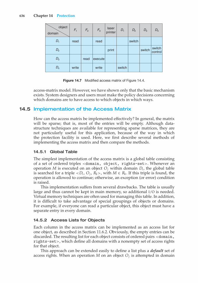
636 Chapter 14 Protection
laserprinter
read
read execute
write write
read
switch
switch
switch switchcontrol
F1
D1
D1
D2
D2
D3
D3
D4
D4F2 F3
object
domain
Figure 14.7 Modified access matrix of Figure 14.4.
access-matrix model. However, we have shown only that the basic mechanismexists. System designers and users must make the policy decisions concerningwhich domains are to have access to which objects in which ways.
14.5 Implementation of the Access Matrix
How can the access matrix be implemented effectively? In general, the matrixwill be sparse; that is, most of the entries will be empty. Although data-structure techniques are available for representing sparse matrices, they arenot particularly useful for this application, because of the way in whichthe protection facility is used. Here, we first describe several methods ofimplementing the access matrix and then compare the methods.
14.5.1 Global Table
The simplest implementation of the access matrix is a global table consistingof a set of ordered triples <domain, object, rights-set>. Whenever anoperation M is executed on an object Oj within domain Di , the global tableis searched for a triple <Di , Oj , Rk>, with M ∈ Rk . If this triple is found, theoperation is allowed to continue; otherwise, an exception (or error) conditionis raised.
This implementation suffers from several drawbacks. The table is usuallylarge and thus cannot be kept in main memory, so additional I/O is needed.Virtual memory techniques are often used for managing this table. In addition,it is difficult to take advantage of special groupings of objects or domains.For example, if everyone can read a particular object, this object must have aseparate entry in every domain.
14.5.2 Access Lists for Objects
Each column in the access matrix can be implemented as an access list forone object, as described in Section 11.6.2. Obviously, the empty entries can bediscarded. The resulting list for each object consists of ordered pairs <domain,rights-set>, which define all domains with a nonempty set of access rightsfor that object.
This approach can be extended easily to define a list plus a default set ofaccess rights. When an operation M on an object Oj is attempted in domain
14.5 Implementation of the Access Matrix 637
Di , we search the access list for object Oj , looking for an entry <Di , Rk> withM ∈ Rk . If the entry is found, we allow the operation; if it is not, we check thedefault set. If M is in the default set, we allow the access. Otherwise, access isdenied, and an exception condition occurs. For efficiency, we may check thedefault set first and then search the access list.
14.5.3 Capability Lists for Domains
Rather than associating the columns of the access matrix with the objects asaccess lists, we can associate each row with its domain. A capability list fora domain is a list of objects together with the operations allowed on thoseobjects. An object is often represented by its physical name or address, calleda capability. To execute operation M on object Oj , the process executes theoperation M, specifying the capability (or pointer) for object Oj as a parameter.Simple possession of the capability means that access is allowed.
The capability list is associated with a domain, but it is never directlyaccessible to a process executing in that domain. Rather, the capability listis itself a protected object, maintained by the operating system and accessedby the user only indirectly. Capability-based protection relies on the fact thatthe capabilities are never allowed to migrate into any address space directlyaccessible by a user process (where they could be modified). If all capabilitiesare secure, the object they protect is also secure against unauthorized access.
Capabilities were originally proposed as a kind of secure pointer, tomeet the need for resource protection that was foreseen as multiprogrammedcomputer systems came of age. The idea of an inherently protected pointerprovides a foundation for protection that can be extended up to the applicationlevel.
To provide inherent protection, we must distinguish capabilities from otherkinds of objects, and they must be interpreted by an abstract machine on whichhigher-level programs run. Capabilities are usually distinguished from otherdata in one of two ways:
• Each object has a tag to denote whether it is a capability or accessibledata. The tags themselves must not be directly accessible by an applicationprogram. Hardware or firmware support may be used to enforce thisrestriction. Although only one bit is necessary to distinguish betweencapabilities and other objects, more bits are often used. This extensionallows all objects to be tagged with their types by the hardware. Thus,the hardware can distinguish integers, floating-point numbers, pointers,Booleans, characters, instructions, capabilities, and uninitialized values bytheir tags.
• Alternatively, the address space associated with a program can be split intotwo parts. One part is accessible to the program and contains the program’snormal data and instructions. The other part, containing the capability list,is accessible only by the operating system. A segmented memory space(Section 8.4) is useful to support this approach.
Several capability-based protection systems have been developed; we describethem briefly in Section 14.8. The Mach operating system also uses a version ofcapability-based protection; it is described in Appendix B.
638 Chapter 14 Protection
14.5.4 A Lock–Key Mechanism
The lock–key scheme is a compromise between access lists and capabilitylists. Each object has a list of unique bit patterns, called locks. Similarly, eachdomain has a list of unique bit patterns, called keys. A process executing in adomain can access an object only if that domain has a key that matches one ofthe locks of the object.
As with capability lists, the list of keys for a domain must be managedby the operating system on behalf of the domain. Users are not allowed toexamine or modify the list of keys (or locks) directly.
14.5.5 Comparison
As you might expect, choosing a technique for implementing an access matrixinvolves various trade-offs. Using a global table is simple; however, the tablecan be quite large and often cannot take advantage of special groupings ofobjects or domains. Access lists correspond directly to the needs of users.When a user creates an object, he can specify which domains can access theobject, as well as what operations are allowed. However, because access-rightinformation for a particular domain is not localized, determining the set ofaccess rights for each domain is difficult. In addition, every access to the objectmust be checked, requiring a search of the access list. In a large system withlong access lists, this search can be time consuming.
Capability lists do not correspond directly to the needs of users, but they areuseful for localizing information for a given process. The process attemptingaccess must present a capability for that access. Then, the protection systemneeds only to verify that the capability is valid. Revocation of capabilities,however, may be inefficient (Section 14.7).
The lock–key mechanism, as mentioned, is a compromise between accesslists and capability lists. The mechanism can be both effective and flexible,depending on the length of the keys. The keys can be passed freely fromdomain to domain. In addition, access privileges can be effectively revoked bythe simple technique of changing some of the locks associated with the object(Section 14.7).
Most systems use a combination of access lists and capabilities. When aprocess first tries to access an object, the access list is searched. If access isdenied, an exception condition occurs. Otherwise, a capability is created andattached to the process. Additional references use the capability to demonstrateswiftly that access is allowed. After the last access, the capability is destroyed.This strategy is used in the MULTICS system and in the CAL system.
As an example of how such a strategy works, consider a file system inwhich each file has an associated access list. When a process opens a file, thedirectory structure is searched to find the file, access permission is checked, andbuffers are allocated. All this information is recorded in a new entry in a filetable associated with the process. The operation returns an index into this tablefor the newly opened file. All operations on the file are made by specificationof the index into the file table. The entry in the file table then points to the fileand its buffers. When the file is closed, the file-table entry is deleted. Since thefile table is maintained by the operating system, the user cannot accidentallycorrupt it. Thus, the user can access only those files that have been opened.
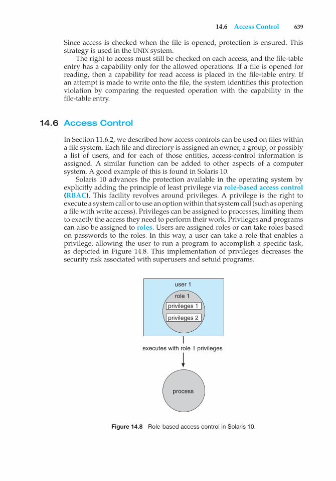
14.6 Access Control 639
Since access is checked when the file is opened, protection is ensured. Thisstrategy is used in the UNIX system.
The right to access must still be checked on each access, and the file-tableentry has a capability only for the allowed operations. If a file is opened forreading, then a capability for read access is placed in the file-table entry. Ifan attempt is made to write onto the file, the system identifies this protectionviolation by comparing the requested operation with the capability in thefile-table entry.
14.6 Access Control
In Section 11.6.2, we described how access controls can be used on files withina file system. Each file and directory is assigned an owner, a group, or possiblya list of users, and for each of those entities, access-control information isassigned. A similar function can be added to other aspects of a computersystem. A good example of this is found in Solaris 10.
Solaris 10 advances the protection available in the operating system byexplicitly adding the principle of least privilege via role-based access control(RBAC). This facility revolves around privileges. A privilege is the right toexecute a system call or to use an option within that system call (such as openinga file with write access). Privileges can be assigned to processes, limiting themto exactly the access they need to perform their work. Privileges and programscan also be assigned to roles. Users are assigned roles or can take roles basedon passwords to the roles. In this way, a user can take a role that enables aprivilege, allowing the user to run a program to accomplish a specific task,as depicted in Figure 14.8. This implementation of privileges decreases thesecurity risk associated with superusers and setuid programs.
user 1
role 1
privileges 1
executes with role 1 privileges
privileges 2
process
Figure 14.8 Role-based access control in Solaris 10.
640 Chapter 14 Protection
Notice that this facility is similar to the access matrix described in Section14.4. This relationship is further explored in the exercises at the end of thechapter.
14.7 Revocation of Access Rights
In a dynamic protection system, we may sometimes need to revoke accessrights to objects shared by different users. Various questions about revocationmay arise:
• Immediate versus delayed. Does revocation occur immediately, or is itdelayed? If revocation is delayed, can we find out when it will take place?
• Selective versus general. When an access right to an object is revoked,does it affect all the users who have an access right to that object, or canwe specify a select group of users whose access rights should be revoked?
• Partial versus total. Can a subset of the rights associated with an object berevoked, or must we revoke all access rights for this object?
• Temporary versus permanent. Can access be revoked permanently (thatis, the revoked access right will never again be available), or can access berevoked and later be obtained again?
With an access-list scheme, revocation is easy. The access list is searched forany access rights to be revoked, and they are deleted from the list. Revocationis immediate and can be general or selective, total or partial, and permanentor temporary.
Capabilities, however, present a much more difficult revocation problem,as mentioned earlier. Since the capabilities are distributed throughout thesystem, we must find them before we can revoke them. Schemes that implementrevocation for capabilities include the following:
• Reacquisition. Periodically, capabilities are deleted from each domain. Ifa process wants to use a capability, it may find that that capability has beendeleted. The process may then try to reacquire the capability. If access hasbeen revoked, the process will not be able to reacquire the capability.
• Back-pointers. A list of pointers is maintained with each object, pointingto all capabilities associated with that object. When revocation is required,we can follow these pointers, changing the capabilities as necessary. Thisscheme was adopted in the MULTICS system. It is quite general, but itsimplementation is costly.
• Indirection. The capabilities point indirectly, not directly, to the objects.Each capability points to a unique entry in a global table, which in turnpoints to the object. We implement revocation by searching the global tablefor the desired entry and deleting it. Then, when an access is attempted,the capability is found to point to an illegal table entry. Table entries canbe reused for other capabilities without difficulty, since both the capabilityand the table entry contain the unique name of the object. The object for a
14.8 Capability-Based Systems 641
capability and its table entry must match. This scheme was adopted in theCAL system. It does not allow selective revocation.
• Keys. A key is a unique bit pattern that can be associated with a capability.This key is defined when the capability is created, and it can be neithermodified nor inspected by the process that owns the capability. A masterkey is associated with each object; it can be defined or replaced withthe set-key operation. When a capability is created, the current valueof the master key is associated with the capability. When the capabilityis exercised, its key is compared with the master key. If the keys match,the operation is allowed to continue; otherwise, an exception conditionis raised. Revocation replaces the master key with a new value via theset-key operation, invalidating all previous capabilities for this object.
This scheme does not allow selective revocation, since only one masterkey is associated with each object. If we associate a list of keys with eachobject, then selective revocation can be implemented. Finally, we can groupall keys into one global table of keys. A capability is valid only if itskey matches some key in the global table. We implement revocation byremoving the matching key from the table. With this scheme, a key can beassociated with several objects, and several keys can be associated witheach object, providing maximum flexibility.
In key-based schemes, the operations of defining keys, inserting theminto lists, and deleting them from lists should not be available to all users.In particular, it would be reasonable to allow only the owner of an objectto set the keys for that object. This choice, however, is a policy decisionthat the protection system can implement but should not define.
14.8 Capability-Based Systems
In this section, we survey two capability-based protection systems. Thesesystems differ in their complexity and in the types of policies that can beimplemented on them. Neither system is widely used, but both provideinteresting proving grounds for protection theories.
14.8.1 An Example: Hydra
Hydra is a capability-based protection system that provides considerableflexibility. The system implements a fixed set of possible access rights, includingsuch basic forms of access as the right to read, write, or execute a memorysegment. In addition, a user (of the protection system) can declare other rights.The interpretation of user-defined rights is performed solely by the user’sprogram, but the system provides access protection for the use of these rights,as well as for the use of system-defined rights. These facilities constitute asignificant development in protection technology.
Operations on objects are defined procedurally. The procedures thatimplement such operations are themselves a form of object, and they areaccessed indirectly by capabilities. The names of user-defined procedures mustbe identified to the protection system if it is to deal with objects of the user-defined type. When the definition of an object is made known to Hydra, thenames of operations on the type become auxiliary rights. Auxiliary rights
642 Chapter 14 Protection
can be described in a capability for an instance of the type. For a process toperform an operation on a typed object, the capability it holds for that objectmust contain the name of the operation being invoked among its auxiliaryrights. This restriction enables discrimination of access rights to be made on aninstance-by-instance and process-by-process basis.
Hydra also provides rights amplification. This scheme allows a procedureto be certified as trustworthy to act on a formal parameter of a specified typeon behalf of any process that holds a right to execute the procedure. The rightsheld by a trustworthy procedure are independent of, and may exceed, therights held by the calling process. However, such a procedure must not beregarded as universally trustworthy (the procedure is not allowed to act onother types, for instance), and the trustworthiness must not be extended to anyother procedures or program segments that might be executed by a process.
Amplification allows implementation procedures access to the representa-tion variables of an abstract data type. If a process holds a capability to a typedobject A, for instance, this capability may include an auxiliary right to invokesome operation P but does not include any of the so-called kernel rights, suchas read, write, or execute, on the segment that represents A. Such a capabilitygives a process a means of indirect access (through the operation P) to therepresentation of A, but only for specific purposes.
When a process invokes the operation P on an object A, however, thecapability for access to A may be amplified as control passes to the code bodyof P. This amplification may be necessary to allow P the right to access thestorage segment representing A so as to implement the operation that P defineson the abstract data type. The code body of P may be allowed to read or towrite to the segment of A directly, even though the calling process cannot.On return from P, the capability for A is restored to its original, unamplifiedstate. This case is a typical one in which the rights held by a process for accessto a protected segment must change dynamically, depending on the task tobe performed. The dynamic adjustment of rights is performed to guaranteeconsistency of a programmer-defined abstraction. Amplification of rights canbe stated explicitly in the declaration of an abstract type to the Hydra operatingsystem.
When a user passes an object as an argument to a procedure, we may needto ensure that the procedure cannot modify the object. We can implement thisrestriction readily by passing an access right that does not have the modification(write) right. However, if amplification may occur, the right to modify maybe reinstated. Thus, the user-protection requirement can be circumvented.In general, of course, a user may trust that a procedure performs its taskcorrectly. This assumption is not always correct, however, because of hardwareor software errors. Hydra solves this problem by restricting amplifications.
The procedure-call mechanism of Hydra was designed as a direct solutionto the problem of mutually suspicious subsystems. This problem is definedas follows. Suppose that a program can be invoked as a service by a numberof different users (for example, a sort routine, a compiler, a game). Whenusers invoke this service program, they take the risk that the program willmalfunction and will either damage the given data or retain some access right tothe data to be used (without authority) later. Similarly, the service program mayhave some private files (for accounting purposes, for example) that should not
14.8 Capability-Based Systems 643
be accessed directly by the calling user program. Hydra provides mechanismsfor directly dealing with this problem.
A Hydra subsystem is built on top of its protection kernel and may requireprotection of its own components. A subsystem interacts with the kernelthrough calls on a set of kernel-defined primitives that define access rights toresources defined by the subsystem. The subsystem designer can define policiesfor use of these resources by user processes, but the policies are enforced byuse of the standard access protection provided by the capability system.
Programmers can make direct use of the protection system after acquaint-ing themselves with its features in the appropriate reference manual. Hydraprovides a large library of system-defined procedures that can be called byuser programs. Programmers can explicitly incorporate calls on these systemprocedures into their program code or can use a program translator that hasbeen interfaced to Hydra.
14.8.2 An Example: Cambridge CAP System
A different approach to capability-based protection has been taken in thedesign of the Cambridge CAP system. CAP’s capability system is simpler andsuperficially less powerful than that of Hydra. However, closer examinationshows that it, too, can be used to provide secure protection of user-definedobjects. CAP has two kinds of capabilities. The ordinary kind is called adata capability. It can be used to provide access to objects, but the onlyrights provided are the standard read, write, and execute of the individualstorage segments associated with the object. Data capabilities are interpretedby microcode in the CAP machine.
The second kind of capability is the so-called software capability, whichis protected, but not interpreted, by the CAP microcode. It is interpretedby a protected (that is, privileged) procedure, which may be written by anapplication programmer as part of a subsystem. A particular kind of rightsamplification is associated with a protected procedure. When executing thecode body of such a procedure, a process temporarily acquires the right toread or write the contents of a software capability itself. This specific kindof rights amplification corresponds to an implementation of the seal andunseal primitives on capabilities. Of course, this privilege is still subject totype verification to ensure that only software capabilities for a specified abstracttype are passed to any such procedure. Universal trust is not placed in any codeother than the CAP machine’s microcode. (See the bibliographical notes at theend of the chapter for references.)
The interpretation of a software capability is left completely to the sub-system, through the protected procedures it contains. This scheme allows avariety of protection policies to be implemented. Although programmers candefine their own protected procedures (any of which might be incorrect), thesecurity of the overall system cannot be compromised. The basic protectionsystem will not allow an unverified, user-defined, protected procedure accessto any storage segments (or capabilities) that do not belong to the protectionenvironment in which it resides. The most serious consequence of an insecureprotected procedure is a protection breakdown of the subsystem for which thatprocedure has responsibility.
644 Chapter 14 Protection
The designers of the CAP system have noted that the use of softwarecapabilities allowed them to realize considerable economies in formulatingand implementing protection policies commensurate with the requirements ofabstract resources. However, subsystem designers who want to make use ofthis facility cannot simply study a reference manual, as is the case with Hydra.Instead, they must learn the principles and techniques of protection, since thesystem provides them with no library of procedures.
14.9 Language-Based Protection
To the degree that protection is provided in existing computer systems, it isusually achieved through an operating-system kernel, which acts as a securityagent to inspect and validate each attempt to access a protected resource. Sincecomprehensive access validation may be a source of considerable overhead,either we must give it hardware support to reduce the cost of each validation,or we must allow the system designer to compromise the goals of protection.Satisfying all these goals is difficult if the flexibility to implement protectionpolicies is restricted by the support mechanisms provided or if protectionenvironments are made larger than necessary to secure greater operationalefficiency.
As operating systems have become more complex, and particularly as theyhave attempted to provide higher-level user interfaces, the goals of protectionhave become much more refined. The designers of protection systems havedrawn heavily on ideas that originated in programming languages andespecially on the concepts of abstract data types and objects. Protection systemsare now concerned not only with the identity of a resource to which access isattempted but also with the functional nature of that access. In the newestprotection systems, concern for the function to be invoked extends beyonda set of system-defined functions, such as standard file-access methods, toinclude functions that may be user-defined as well.
Policies for resource use may also vary, depending on the application, andthey may be subject to change over time. For these reasons, protection can nolonger be considered a matter of concern only to the designer of an operatingsystem. It should also be available as a tool for use by the application designer,so that resources of an application subsystem can be guarded against tamperingor the influence of an error.
14.9.1 Compiler-Based Enforcement
At this point, programming languages enter the picture. Specifying the desiredcontrol of access to a shared resource in a system is making a declarativestatement about the resource. This kind of statement can be integrated into alanguage by an extension of its typing facility. When protection is declaredalong with data typing, the designer of each subsystem can specify itsrequirements for protection, as well as its need for use of other resources in asystem. Such a specification should be given directly as a program is composed,and in the language in which the program itself is stated. This approach hasseveral significant advantages:
14.9 Language-Based Protection 645
1. Protection needs are simply declared, rather than programmed as asequence of calls on procedures of an operating system.
2. Protection requirements can be stated independently of the facilitiesprovided by a particular operating system.
3. The means for enforcement need not be provided by the designer of asubsystem.
4. A declarative notation is natural because access privileges are closelyrelated to the linguistic concept of data type.
A variety of techniques can be provided by a programming-languageimplementation to enforce protection, but any of these must depend on somedegree of support from an underlying machine and its operating system. Forexample, suppose a language is used to generate code to run on the CambridgeCAP system. On this system, every storage reference made on the underlyinghardware occurs indirectly through a capability. This restriction prevents anyprocess from accessing a resource outside of its protection environment atany time. However, a program may impose arbitrary restrictions on howa resource can be used during execution of a particular code segment.We can implement such restrictions most readily by using the softwarecapabilities provided by CAP. A language implementation might providestandard protected procedures to interpret software capabilities that wouldrealize the protection policies that could be specified in the language. Thisscheme puts policy specification at the disposal of the programmers, whilefreeing them from implementing its enforcement.
Even if a system does not provide a protection kernel as powerful as thoseof Hydra or CAP, mechanisms are still available for implementing protectionspecifications given in a programming language. The principal distinction isthat the security of this protection will not be as great as that supported bya protection kernel, because the mechanism must rely on more assumptionsabout the operational state of the system. A compiler can separate referencesfor which it can certify that no protection violation could occur from thosefor which a violation might be possible, and it can treat them differently. Thesecurity provided by this form of protection rests on the assumption that thecode generated by the compiler will not be modified prior to or during itsexecution.
What, then, are the relative merits of enforcement based solely on a kernel,as opposed to enforcement provided largely by a compiler?
• Security. Enforcement by a kernel provides a greater degree of securityof the protection system itself than does the generation of protection-checking code by a compiler. In a compiler-supported scheme, securityrests on correctness of the translator, on some underlying mechanism ofstorage management that protects the segments from which compiledcode is executed, and, ultimately, on the security of files from which aprogram is loaded. Some of these considerations also apply to a software-supported protection kernel, but to a lesser degree, since the kernel mayreside in fixed physical storage segments and may be loaded only froma designated file. With a tagged-capability system, in which all address
646 Chapter 14 Protection
computation is performed either by hardware or by a fixed microprogram,even greater security is possible. Hardware-supported protection is alsorelatively immune to protection violations that might occur as a result ofeither hardware or system software malfunction.
• Flexibility. There are limits to the flexibility of a protection kernel inimplementing a user-defined policy, although it may supply adequatefacilities for the system to provide enforcement of its own policies.With a programming language, protection policy can be declared andenforcement provided as needed by an implementation. If a languagedoes not provide sufficient flexibility, it can be extended or replacedwith less disturbance than would be caused by the modification of anoperating-system kernel.
• Efficiency. The greatest efficiency is obtained when enforcement of protec-tion is supported directly by hardware (or microcode). Insofar as softwaresupport is required, language-based enforcement has the advantage thatstatic access enforcement can be verified off-line at compile time. Also,since an intelligent compiler can tailor the enforcement mechanism tomeet the specified need, the fixed overhead of kernel calls can often beavoided.
In summary, the specification of protection in a programming languageallows the high-level description of policies for the allocation and use ofresources. A language implementation can provide software for protectionenforcement when automatic hardware-supported checking is unavailable. Inaddition, it can interpret protection specifications to generate calls on whateverprotection system is provided by the hardware and the operating system.
One way of making protection available to the application program isthrough the use of a software capability that could be used as an objectof computation. Inherent in this concept is the idea that certain programcomponents might have the privilege of creating or examining these softwarecapabilities. A capability-creating program would be able to execute a primitiveoperation that would seal a data structure, rendering the latter’s contentsinaccessible to any program components that did not hold either the seal orthe unseal privilege. Such components might copy the data structure or passits address to other program components, but they could not gain access toits contents. The reason for introducing such software capabilities is to bring aprotection mechanism into the programming language. The only problem withthe concept as proposed is that the use of the seal and unseal operations takesa procedural approach to specifying protection. A nonprocedural or declarativenotation seems a preferable way to make protection available to the applicationprogrammer.
What is needed is a safe, dynamic access-control mechanism for distribut-ing capabilities to system resources among user processes. To contribute to theoverall reliability of a system, the access-control mechanism should be safeto use. To be useful in practice, it should also be reasonably efficient. Thisrequirement has led to the development of a number of language constructsthat allow the programmer to declare various restrictions on the use of a specificmanaged resource. (See the bibliographical notes for appropriate references.)These constructs provide mechanisms for three functions:
14.9 Language-Based Protection 647
1. Distributing capabilities safely and efficiently among customer processes.In particular, mechanisms ensure that a user process will use the managedresource only if it was granted a capability to that resource.
2. Specifying the type of operations that a particular process may invoke onan allocated resource (for example, a reader of a file should be allowedonly to read the file, whereas a writer should be able both to read andto write). It should not be necessary to grant the same set of rights toevery user process, and it should be impossible for a process to enlargeits set of access rights, except with the authorization of the access-controlmechanism.
3. Specifying the order in which a particular process may invoke the variousoperations of a resource (for example, a file must be opened before it canbe read). It should be possible to give two processes different restrictionson the order in which they can invoke the operations of the allocatedresource.
The incorporation of protection concepts into programming languages, asa practical tool for system design, is in its infancy. Protection will likely becomea matter of greater concern to the designers of new systems with distributedarchitectures and increasingly stringent requirements on data security. Thenthe importance of suitable language notations in which to express protectionrequirements will be recognized more widely.
14.9.2 Protection in Java
Because Java was designed to run in a distributed environment, the Javavirtual machine—or JVM—has many built-in protection mechanisms. Javaprograms are composed of classes, each of which is a collection of data fieldsand functions (called methods) that operate on those fields. The JVM loads aclass in response to a request to create instances (or objects) of that class. One ofthe most novel and useful features of Java is its support for dynamically loadinguntrusted classes over a network and for executing mutually distrusting classeswithin the same JVM.
Because of these capabilities, protection is a paramount concern. Classesrunning in the same JVM may be from different sources and may not be equallytrusted. As a result, enforcing protection at the granularity of the JVM processis insufficient. Intuitively, whether a request to open a file should be allowedwill generally depend on which class has requested the open. The operatingsystem lacks this knowledge.
Thus, such protection decisions are handled within the JVM. When theJVM loads a class, it assigns the class to a protection domain that givesthe permissions of that class. The protection domain to which the class isassigned depends on the URL from which the class was loaded and any digitalsignatures on the class file. (Digital signatures are covered in Section 15.4.1.3.)A configurable policy file determines the permissions granted to the domain(and its classes). For example, classes loaded from a trusted server might beplaced in a protection domain that allows them to access files in the user’shome directory, whereas classes loaded from an untrusted server might haveno file access permissions at all.
648 Chapter 14 Protection
It can be complicated for the JVM to determine what class is responsible for arequest to access a protected resource. Accesses are often performed indirectly,through system libraries or other classes. For example, consider a class thatis not allowed to open network connections. It could call a system library torequest the load of the contents of a URL. The JVM must decide whether or notto open a network connection for this request. But which class should be usedto determine if the connection should be allowed, the application or the systemlibrary?
The philosophy adopted in Java is to require the library class to explicitlypermit a network connection. More generally, in order to access a protectedresource, some method in the calling sequence that resulted in the request mustexplicitly assert the privilege to access the resource. By doing so, this methodtakes responsibility for the request. Presumably, it will also perform whateverchecks are necessary to ensure the safety of the request. Of course, not everymethod is allowed to assert a privilege; a method can assert a privilege only ifits class is in a protection domain that is itself allowed to exercise the privilege.
This implementation approach is called stack inspection. Every threadin the JVM has an associated stack of its ongoing method invocations. Whena caller may not be trusted, a method executes an access request within adoPrivileged block to perform the access to a protected resource directly orindirectly. doPrivileged() is a static method in the AccessController classthat is passed a class with a run() method to invoke. When the doPrivilegedblock is entered, the stack frame for this method is annotated to indicate thisfact. Then, the contents of the block are executed. When an access to a protectedresource is subsequently requested, either by this method or a method itcalls, a call to checkPermissions() is used to invoke stack inspection todetermine if the request should be allowed. The inspection examines stackframes on the calling thread’s stack, starting from the most recently addedframe and working toward the oldest. If a stack frame is first found that has thedoPrivileged() annotation, then checkPermissions() returns immediatelyand silently, allowing the access. If a stack frame is first found for whichaccess is disallowed based on the protection domain of the method’s class,then checkPermissions() throws an AccessControlException. If the stackinspection exhausts the stack without finding either type of frame, thenwhether access is allowed depends on the implementation (for example, someimplementations of the JVM may allow access, while other implementationsmay not).
Stack inspection is illustrated in Figure 14.9. Here, the gui() method ofa class in the untrusted applet protection domain performs two operations,first a get() and then an open(). The former is an invocation of theget() method of a class in the URL loader protection domain, which ispermitted to open() sessions to sites in the lucent.com domain, in particulara proxy server proxy.lucent.com for retrieving URLs. For this reason, theuntrusted applet’s get() invocation will succeed: the checkPermissions()call in the networking library encounters the stack frame of the get()method, which performed its open() in a doPrivileged block. However,the untrusted applet’s open() invocation will result in an exception, becausethe checkPermissions() call finds no doPrivileged annotation beforeencountering the stack frame of the gui() method.
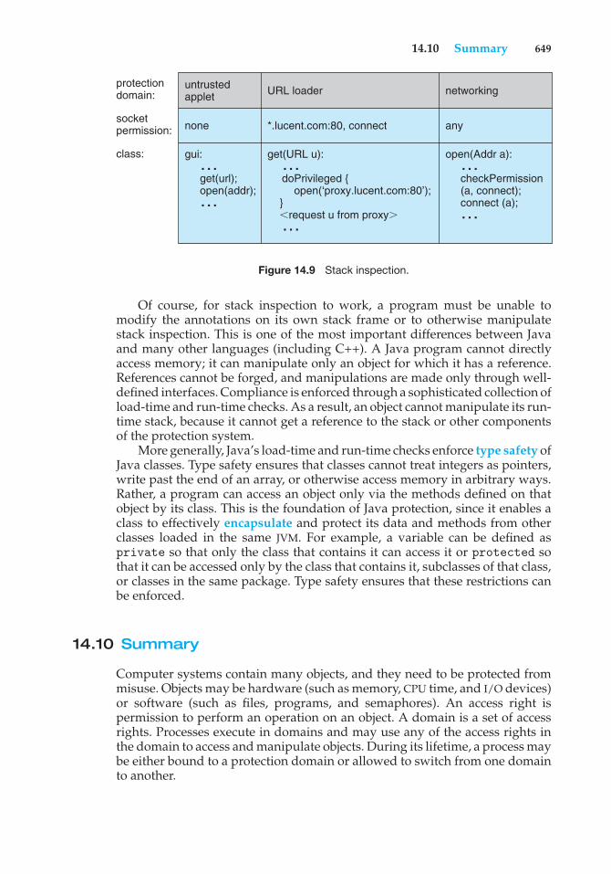
14.10 Summary 649
untrustedapplet
protectiondomain:
socketpermission:
class:
none
gui: … get(url); open(addr); …
networking
any
open(Addr a): … checkPermission (a, connect); connect (a); …
get(URL u): … doPrivileged { open(‘proxy.lucent.com:80’); } (request u from proxy) …
*.lucent.com:80, connect
URL loader
Figure 14.9 Stack inspection.
Of course, for stack inspection to work, a program must be unable tomodify the annotations on its own stack frame or to otherwise manipulatestack inspection. This is one of the most important differences between Javaand many other languages (including C++). A Java program cannot directlyaccess memory; it can manipulate only an object for which it has a reference.References cannot be forged, and manipulations are made only through well-defined interfaces. Compliance is enforced through a sophisticated collection ofload-time and run-time checks. As a result, an object cannot manipulate its run-time stack, because it cannot get a reference to the stack or other componentsof the protection system.
More generally, Java’s load-time and run-time checks enforce type safety ofJava classes. Type safety ensures that classes cannot treat integers as pointers,write past the end of an array, or otherwise access memory in arbitrary ways.Rather, a program can access an object only via the methods defined on thatobject by its class. This is the foundation of Java protection, since it enables aclass to effectively encapsulate and protect its data and methods from otherclasses loaded in the same JVM. For example, a variable can be defined asprivate so that only the class that contains it can access it or protected sothat it can be accessed only by the class that contains it, subclasses of that class,or classes in the same package. Type safety ensures that these restrictions canbe enforced.
14.10 Summary
Computer systems contain many objects, and they need to be protected frommisuse. Objects may be hardware (such as memory, CPU time, and I/O devices)or software (such as files, programs, and semaphores). An access right ispermission to perform an operation on an object. A domain is a set of accessrights. Processes execute in domains and may use any of the access rights inthe domain to access and manipulate objects. During its lifetime, a process maybe either bound to a protection domain or allowed to switch from one domainto another.
650 Chapter 14 Protection
The access matrix is a general model of protection that provides amechanism for protection without imposing a particular protection policy onthe system or its users. The separation of policy and mechanism is an importantdesign property.
The access matrix is sparse. It is normally implemented either as access listsassociated with each object or as capability lists associated with each domain.We can include dynamic protection in the access-matrix model by consideringdomains and the access matrix itself as objects. Revocation of access rights in adynamic protection model is typically easier to implement with an access-listscheme than with a capability list.
Real systems are much more limited than the general model and tend toprovide protection only for files. UNIX is representative, providing read, write,and execution protection separately for the owner, group, and general publicfor each file. MULTICS uses a ring structure in addition to file access. Hydra, theCambridge CAP system, and Mach are capability systems that extend protectionto user-defined software objects. Solaris 10 implements the principle of leastprivilege via role-based access control, a form of the access matrix.
Language-based protection provides finer-grained arbitration of requestsand privileges than the operating system is able to provide. For example, asingle Java JVM can run several threads, each in a different protection class. Itenforces the resource requests through sophisticated stack inspection and viathe type safety of the language.
Practice Exercises
14.1 What are the main differences between capability lists and access lists?
14.2 A Burroughs B7000/B6000 MCP file can be tagged as sensitive data.When such a file is deleted, its storage area is overwritten by somerandom bits. For what purpose would such a scheme be useful?
14.3 In a ring-protection system, level 0 has the greatest access to objects,and level n (where n > 0) has fewer access rights. The access rights ofa program at a particular level in the ring structure are considered aset of capabilities. What is the relationship between the capabilities ofa domain at level j and a domain at level i to an object (for j > i)?
14.4 The RC 4000 system, among others, has defined a tree of processes(called a process tree) such that all the descendants of a process canbe given resources (objects) and access rights by their ancestors only.Thus, a descendant can never have the ability to do anything that itsancestors cannot do. The root of the tree is the operating system, whichhas the ability to do anything. Assume that the set of access rights isrepresented by an access matrix, A. A(x,y) defines the access rights ofprocess x to object y. If x is a descendant of z, what is the relationshipbetween A(x,y) and A(z,y) for an arbitrary object y?
14.5 What protection problems may arise if a shared stack is used forparameter passing?
Exercises 651
14.6 Consider a computing environment where a unique number is associ-ated with each process and each object in the system. Suppose that weallow a process with number n to access an object with number m onlyif n > m. What type of protection structure do we have?
14.7 Consider a computing environment where a process is given theprivilege of accessing an object only n times. Suggest a scheme forimplementing this policy.
14.8 If all the access rights to an object are deleted, the object can no longerbe accessed. At this point, the object should also be deleted, and thespace it occupies should be returned to the system. Suggest an efficientimplementation of this scheme.
14.9 Why is it difficult to protect a system in which users are allowed to dotheir own I/O?
14.10 Capability lists are usually kept within the address space of the user.How does the system ensure that the user cannot modify the contentsof the list?
Exercises
14.11 Consider the ring-protection scheme in MULTICS. If we were to imple-ment the system calls of a typical operating system and store them in asegment associated with ring 0, what should be the values stored in thering field of the segment descriptor? What happens during a systemcall when a process executing in a higher-numbered ring invokes aprocedure in ring 0?
14.12 The access-control matrix can be used to determine whether a processcan switch from, say, domain A to domain B and enjoy the accessprivileges of domain B. Is this approach equivalent to including theaccess privileges of domain B in those of domain A?
14.13 Consider a computer system in which computer games can be playedby students only between 10 P.M. and 6 A.M., by faculty membersbetween 5 P.M. and 8 A.M., and by the computer center staff at alltimes. Suggest a scheme for implementing this policy efficiently.
14.14 What hardware features does a computer system need for efficientcapability manipulation? Can these features be used for memoryprotection?
14.15 Discuss the strengths and weaknesses of implementing an access matrixusing access lists that are associated with objects.
14.16 Discuss the strengths and weaknesses of implementing an access matrixusing capabilities that are associated with domains.
14.17 Explain why a capability-based system such as Hydra provides greaterflexibility than the ring-protection scheme in enforcing protectionpolicies.
652 Chapter 14 Protection
14.18 Discuss the need for rights amplification in Hydra. How does thispractice compare with the cross-ring calls in a ring-protection scheme?
14.19 What is the need-to-know principle? Why is it important for a protec-tion system to adhere to this principle?
14.20 Discuss which of the following systems allow module designers toenforce the need-to-know principle.
a. The MULTICS ring-protection scheme
b. Hydra’s capabilities
c. JVM’s stack-inspection scheme
14.21 Describe how the Java protection model would be compromised if aJava program were allowed to directly alter the annotations of its stackframe.
14.22 How are the access-matrix facility and the role-based access-controlfacility similar? How do they differ?
14.23 How does the principle of least privilege aid in the creation of protectionsystems?
14.24 How can systems that implement the principle of least privilege stillhave protection failures that lead to security violations?
Bibliographical Notes
The access-matrix model of protection between domains and objects wasdeveloped by [Lampson (1969)] and [Lampson (1971)]. [Popek (1974)] and[Saltzer and Schroeder (1975)] provided excellent surveys on the subjectof protection. [Harrison et al. (1976)] used a formal version of the access-matrix model to enable them to prove properties of a protection systemmathematically.
The concept of a capability evolved from Iliffe’s and Jodeit’s codewords,which were implemented in the Rice University computer ([Iliffe and Jodeit(1962)]). The term capability was introduced by [Dennis and Horn (1966)].
The Hydra system was described by [Wulf et al. (1981)]. The CAP systemwas described by [Needham and Walker (1977)]. [Organick (1972)] discussedthe MULTICS ring-protection system.
Revocation was discussed by [Redell and Fabry (1974)], [Cohen andJefferson (1975)], and [Ekanadham and Bernstein (1979)]. The principle ofseparation of policy and mechanism was advocated by the designer ofHydra ([Levin et al. (1975)]). The confinement problem was first discussedby [Lampson (1973)] and was further examined by [Lipner (1975)].
The use of higher-level languages for specifying access control was sug-gested first by [Morris (1973)], who proposed the use of the seal andunsealoperations discussed in Section 14.9. [Kieburtz and Silberschatz (1978)],[Kieburtz and Silberschatz (1983)], and [McGraw and Andrews (1979)] pro-posed various language constructs for dealing with general dynamic-resource-management schemes. [Jones and Liskov (1978)] considered how a static access-
Bibliography 653
control scheme can be incorporated in a programming language that supportsabstract data types. The use of minimal operating-system support to enforceprotection was advocated by the Exokernel Project ([Ganger et al. (2002)],[Kaashoek et al. (1997)]). Extensibility of system code through language-basedprotection mechanisms was discussed in [Bershad et al. (1995)]. Other tech-niques for enforcing protection include sandboxing ([Goldberg et al. (1996)])and software fault isolation ([Wahbe et al. (1993)]). The issues of lowering theoverhead associated with protection costs and enabling user-level access tonetworking devices were discussed in [McCanne and Jacobson (1993)] and[Basu et al. (1995)].
More detailed analyses of stack inspection, including comparisons withother approaches to Java security, can be found in [Wallach et al. (1997)] and[Gong et al. (1997)].
Bibliography
[Basu et al. (1995)] A. Basu, V. Buch, W. Vogels, and T. von Eicken, “U-Net:A User-Level Network Interface for Parallel and Distributed Computing”,Proceedings of the ACM Symposium on Operating Systems Principles (1995).
[Bershad et al. (1995)] B. N. Bershad, S. Savage, P. Pardyak, E. G. Sirer,M. Fiuczynski, D. Becker, S. Eggers, and C. Chambers, “Extensibility, Safety andPerformance in the SPIN Operating System”, Proceedings of the ACM Symposiumon Operating Systems Principles (1995), pages 267–284.
[Cohen and Jefferson (1975)] E. S. Cohen and D. Jefferson, “Protection in theHydra Operating System”, Proceedings of the ACM Symposium on OperatingSystems Principles (1975), pages 141–160.
[Dennis and Horn (1966)] J. B. Dennis and E. C. V. Horn, “Programming Seman-tics for Multiprogrammed Computations”, Communications of the ACM, Volume9, Number 3 (1966), pages 143–155.
[Ekanadham and Bernstein (1979)] K. Ekanadham and A. J. Bernstein, “Con-ditional Capabilities”, IEEE Transactions on Software Engineering, Volume SE-5,Number 5 (1979), pages 458–464.
[Ganger et al. (2002)] G. R. Ganger, D. R. Engler, M. F. Kaashoek, H. M. Briceno,R. Hunt, and T. Pinckney, “Fast and Flexible Application-Level Networking onExokernel Systems”, ACM Transactions on Computer Systems, Volume 20, Number1 (2002), pages 49–83.
[Goldberg et al. (1996)] I. Goldberg, D. Wagner, R. Thomas, and E. A. Brewer,“A Secure Environment for Untrusted Helper Applications”, Proceedings of the6th Usenix Security Symposium (1996).
[Gong et al. (1997)] L. Gong, M. Mueller, H. Prafullchandra, and R. Schemers,“Going Beyond the Sandbox: An Overview of the New Security Architecture inthe Java Development Kit 1.2”, Proceedings of the USENIX Symposium on InternetTechnologies and Systems (1997).
654 Chapter 14 Protection
[Harrison et al. (1976)] M. A. Harrison, W. L. Ruzzo, and J. D. Ullman, “Protec-tion in Operating Systems”, Communications of the ACM, Volume 19, Number 8(1976), pages 461–471.
[Iliffe and Jodeit (1962)] J. K. Iliffe and J. G. Jodeit, “A Dynamic Storage Alloca-tion System”, Computer Journal, Volume 5, Number 3 (1962), pages 200–209.
[Jones and Liskov (1978)] A. K. Jones and B. H. Liskov, “A Language Extensionfor Expressing Constraints on Data Access”, Communications of the ACM, Volume21, Number 5 (1978), pages 358–367.
[Kaashoek et al. (1997)] M. F. Kaashoek, D. R. Engler, G. R. Ganger, H. M.Briceno, R. Hunt, D. Mazieres, T. Pinckney, R. Grimm, J. Jannotti, and K. Macken-zie, “Application Performance and Flexibility on Exokernel Systems”, Pro-ceedings of the ACM Symposium on Operating Systems Principles (1997), pages52–65.
[Kieburtz and Silberschatz (1978)] R. B. Kieburtz and A. Silberschatz, “Capabil-ity Managers”, IEEE Transactions on Software Engineering, Volume SE-4, Number6 (1978), pages 467–477.
[Kieburtz and Silberschatz (1983)] R. B. Kieburtz and A. Silberschatz, “AccessRight Expressions”, ACM Transactions on Programming Languages and Systems,Volume 5, Number 1 (1983), pages 78–96.
[Lampson (1969)] B. W. Lampson, “Dynamic Protection Structures”, Proceedingsof the AFIPS Fall Joint Computer Conference (1969), pages 27–38.
[Lampson (1971)] B. W. Lampson, “Protection”, Proceedings of the Fifth AnnualPrinceton Conference on Information Systems Science (1971), pages 437–443.
[Lampson (1973)] B. W. Lampson, “A Note on the Confinement Problem”,Communications of the ACM, Volume 10, Number 16 (1973), pages 613–615.
[Levin et al. (1975)] R. Levin, E. S. Cohen, W. M. Corwin, F. J. Pollack, andW. A. Wulf, “Policy/Mechanism Separation in Hydra”, Proceedings of the ACMSymposium on Operating Systems Principles (1975), pages 132–140.
[Lipner (1975)] S. Lipner, “A Comment on the Confinement Problem”, OperatingSystem Review, Volume 9, Number 5 (1975), pages 192–196.
[McCanne and Jacobson (1993)] S. McCanne and V. Jacobson, “The BSD PacketFilter: A New Architecture for User-level Packet Capture”, USENIX Winter(1993), pages 259–270.
[McGraw and Andrews (1979)] J. R. McGraw and G. R. Andrews, “AccessControl in Parallel Programs”, IEEE Transactions on Software Engineering, VolumeSE-5, Number 1 (1979), pages 1–9.
[Morris (1973)] J. H. Morris, “Protection in Programming Languages”, Commu-nications of the ACM, Volume 16, Number 1 (1973), pages 15–21.
[Needham and Walker (1977)] R. M. Needham and R. D. H. Walker, “TheCambridge CAP Computer and Its Protection System”, Proceedings of the SixthSymposium on Operating System Principles (1977), pages 1–10.
Bibliography 655
[Organick (1972)] E. I. Organick, The Multics System: An Examination of ItsStructure, MIT Press (1972).
[Popek (1974)] G. J. Popek, “Protection Structures”, Computer, Volume 7, Num-ber 6 (1974), pages 22–33.
[Redell and Fabry (1974)] D. D. Redell and R. S. Fabry, “Selective Revocationof Capabilities”, Proceedings of the IRIA International Workshop on Protection inOperating Systems (1974), pages 197–210.
[Saltzer and Schroeder (1975)] J. H. Saltzer and M. D. Schroeder, “The Protec-tion of Information in Computer Systems”, Proceedings of the IEEE (1975), pages1278–1308.
[Wahbe et al. (1993)] R. Wahbe, S. Lucco, T. E. Anderson, and S. L. Graham,“Efficient Software-Based Fault Isolation”, ACM SIGOPS Operating SystemsReview, Volume 27, Number 5 (1993), pages 203–216.
[Wallach et al. (1997)] D. S. Wallach, D. Balfanz, D. Dean, and E. W. Felten,“Extensible Security Architectures for Java”, Proceedings of the ACM Symposiumon Operating Systems Principles (1997), pages 116–128.
[Wulf et al. (1981)] W. A. Wulf, R. Levin, and S. P. Harbison, Hydra/C.mmp: AnExperimental Computer System, McGraw-Hill (1981).

15C H A P T E R
Security
Protection, as we discussed in Chapter 14, is strictly an internal problem: Howdo we provide controlled access to programs and data stored in a computersystem? Security, on the other hand, requires not only an adequate protectionsystem but also consideration of the external environment within which thesystem operates. A protection system is ineffective if user authentication iscompromised or a program is run by an unauthorized user.
Computer resources must be guarded against unauthorized access, mali-cious destruction or alteration, and accidental introduction of inconsistency.These resources include information stored in the system (both data and code),as well as the CPU, memory, disks, tapes, and networking that are the com-puter. In this chapter, we start by examining ways in which resources maybe accidentally or purposely misused. We then explore a key security enabler—cryptography. Finally, we look at mechanisms to guard against or detectattacks.
CHAPTER OBJECTIVES
• To discuss security threats and attacks.• To explain the fundamentals of encryption, authentication, and hashing.• To examine the uses of cryptography in computing.• To describe various countermeasures to security attacks.
15.1 The Security Problem
In many applications, ensuring the security of the computer system is worthconsiderable effort. Large commercial systems containing payroll or otherfinancial data are inviting targets to thieves. Systems that contain data pertain-ing to corporate operations may be of interest to unscrupulous competitors.Furthermore, loss of such data, whether by accident or fraud, can seriouslyimpair the ability of the corporation to function.
In Chapter 14, we discussed mechanisms that the operating system canprovide (with appropriate aid from the hardware) that allow users to protect
657
658 Chapter 15 Security
their resources, including programs and data. These mechanisms work wellonly as long as the users conform to the intended use of and access to theseresources. We say that a system is secure if its resources are used and accessedas intended under all circumstances. Unfortunately, total security cannot beachieved. Nonetheless, we must have mechanisms to make security breachesa rare occurrence, rather than the norm.
Security violations (or misuse) of the system can be categorized as inten-tional (malicious) or accidental. It is easier to protect against accidental misusethan against malicious misuse. For the most part, protection mechanisms arethe core of protection from accidents. The following list includes several formsof accidental and malicious security violations. We should note that in our dis-cussion of security, we use the terms intruder and cracker for those attemptingto breach security. In addition, a threat is the potential for a security violation,such as the discovery of a vulnerability, whereas an attack is the attempt tobreak security.
• Breach of confidentiality. This type of violation involves unauthorizedreading of data (or theft of information). Typically, a breach of confiden-tiality is the goal of an intruder. Capturing secret data from a system ora data stream, such as credit-card information or identity information foridentity theft, can result directly in money for the intruder.
• Breach of integrity. This violation involves unauthorized modificationof data. Such attacks can, for example, result in passing of liability toan innocent party or modification of the source code of an importantcommercial application.
• Breach of availability. This violation involves unauthorized destruction ofdata. Some crackers would rather wreak havoc and gain status or braggingrights than gain financially. Website defacement is a common example ofthis type of security breach.
• Theft of service. This violation involves unauthorized use of resources.For example, an intruder (or intrusion program) may install a daemon ona system that acts as a file server.
• Denial of service. This violation involves preventing legitimate use ofthe system. Denial-of-service (DOS) attacks are sometimes accidental. Theoriginal Internet worm turned into a DOS attack when a bug failed to delayits rapid spread. We discuss DOS attacks further in Section 15.3.3.
Attackers use several standard methods in their attempts to breachsecurity. The most common is masquerading, in which one participant ina communication pretends to be someone else (another host or anotherperson). By masquerading, attackers breach authentication, the correctnessof identification; they can then gain access that they would not normally beallowed or escalate their privileges—obtain privileges to which they would notnormally be entitled. Another common attack is to replay a captured exchangeof data. A replay attack consists of the malicious or fraudulent repeat of avalid data transmission. Sometimes the replay comprises the entire attack—for example, in a repeat of a request to transfer money. But frequently it isdone along with message modification, again to escalate privileges. Consider
15.1 The Security Problem 659
communication
communication
communicationcommunication
sender receiver
attacker
sender receiver
attacker
sender receiver
attacker
Masquerading
Man-in-the-middle
Normal
Figure 15.1 Standard security attacks.
the damage that could be done if a request for authentication had a legitimateuser’s information replaced with an unauthorized user’s. Yet another kind ofattack is the man-in-the-middle attack, in which an attacker sits in the dataflow of a communication, masquerading as the sender to the receiver, andvice versa. In a network communication, a man-in-the-middle attack may bepreceded by a session hijacking, in which an active communication session isintercepted. Several attack methods are depicted in Figure 15.1.
As we have already suggested, absolute protection of the system frommalicious abuse is not possible, but the cost to the perpetrator can be madesufficiently high to deter most intruders. In some cases, such as a denial-of-service attack, it is preferable to prevent the attack but sufficient to detect theattack so that countermeasures can be taken.
To protect a system, we must take security measures at four levels:
1. Physical. The site or sites containing the computer systems must bephysically secured against armed or surreptitious entry by intruders.Both the machine rooms and the terminals or workstations that haveaccess to the machines must be secured.
660 Chapter 15 Security
2. Human. Authorization must be done carefully to assure that onlyappropriate users have access to the system. Even authorized users,however, may be “encouraged” to let others use their access (in exchangefor a bribe, for example). They may also be tricked into allowingaccess via social engineering. One type of social-engineering attackis phishing. Here, a legitimate-looking e-mail or web page misleadsa user into entering confidential information. Another technique isdumpster diving, a general term for attempting to gather information inorder to gain unauthorized access to the computer (by looking throughtrash, finding phone books, or finding notes containing passwords, forexample). These security problems are management and personnel issues,not problems pertaining to operating systems.
3. Operating system. The system must protect itself from accidental orpurposeful security breaches. A runaway process could constitute anaccidental denial-of-service attack. A query to a service could reveal pass-words. A stack overflow could allow the launching of an unauthorizedprocess. The list of possible breaches is almost endless.
4. Network. Much computer data in modern systems travels over privateleased lines, shared lines like the Internet, wireless connections, or dial-uplines. Intercepting these data could be just as harmful as breaking into acomputer, and interruption of communications could constitute a remotedenial-of-service attack, diminishing users’ use of and trust in the system.
Security at the first two levels must be maintained if operating-systemsecurity is to be ensured. A weakness at a high level of security (physical orhuman) allows circumvention of strict low-level (operating-system) securitymeasures. Thus, the old adage that a chain is only as strong as its weakest linkis especially true of system security. All of these aspects must be addressed forsecurity to be maintained.
Furthermore, the system must provide protection (Chapter 14) to allow theimplementation of security features. Without the ability to authorize usersand processes, to control their access, and to log their activities, it wouldbe impossible for an operating system to implement security measures orto run securely. Hardware protection features are needed to support an overallprotection scheme. For example, a system without memory protection cannotbe secure. New hardware features are allowing systems to be made moresecure, as we shall discuss.
Unfortunately, little in security is straightforward. As intruders exploitsecurity vulnerabilities, security countermeasures are created and deployed.This causes intruders to become more sophisticated in their attacks. Forexample, recent security incidents include the use of spyware to providea conduit for spam through innocent systems (we discuss this practice inSection 15.2). This cat-and-mouse game is likely to continue, with more securitytools needed to block the escalating intruder techniques and activities.
In the remainder of this chapter, we address security at the network andoperating-system levels. Security at the physical and human levels, althoughimportant, is for the most part beyond the scope of this text. Security within theoperating system and between operating systems is implemented in several
15.2 Program Threats 661
ways, ranging from passwords for authentication through guarding againstviruses to detecting intrusions. We start with an exploration of security threats.
15.2 Program Threats
Processes, along with the kernel, are the only means of accomplishing workon a computer. Therefore, writing a program that creates a breach of security,or causing a normal process to change its behavior and create a breach, is acommon goal of crackers. In fact, even most nonprogram security events haveas their goal causing a program threat. For example, while it is useful to log into a system without authorization, it is quite a lot more useful to leave behinda back-door daemon that provides information or allows easy access even ifthe original exploit is blocked. In this section, we describe common methodsby which programs cause security breaches. Note that there is considerablevariation in the naming conventions for security holes and that we use themost common or descriptive terms.
15.2.1 Trojan Horse
Many systems have mechanisms for allowing programs written by users tobe executed by other users. If these programs are executed in a domain thatprovides the access rights of the executing user, the other users may misusethese rights. A text-editor program, for example, may include code to searchthe file to be edited for certain keywords. If any are found, the entire filemay be copied to a special area accessible to the creator of the text editor.A code segment that misuses its environment is called a Trojan horse. Longsearch paths, such as are common on UNIX systems, exacerbate the Trojan-horse problem. The search path lists the set of directories to search when anambiguous program name is given. The path is searched for a file of thatname, and the file is executed. All the directories in such a search path mustbe secure, or a Trojan horse could be slipped into the user’s path and executedaccidentally.
For instance, consider the use of the “.” character in a search path. The “.”tells the shell to include the current directory in the search. Thus, if a user has“.” in her search path, has set her current directory to a friend’s directory, andenters the name of a normal system command, the command may be executedfrom the friend’s directory. The program will run within the user’s domain,allowing the program to do anything that the user is allowed to do, includingdeleting the user’s files, for instance.
A variation of the Trojan horse is a program that emulates a login program.An unsuspecting user starts to log in at a terminal and notices that he hasapparently mistyped his password. He tries again and is successful. Whathas happened is that his authentication key and password have been stolenby the login emulator, which was left running on the terminal by the thief.The emulator stored away the password, printed out a login error message,and exited; the user was then provided with a genuine login prompt. Thistype of attack can be defeated by having the operating system print a usagemessage at the end of an interactive session or by a nontrappable key sequence,
662 Chapter 15 Security
such as the control-alt-delete combination used by all modern Windowsoperating systems.
Another variation on the Trojan horse is spyware. Spyware sometimesaccompanies a program that the user has chosen to install. Most frequently, itcomes along with freeware or shareware programs, but sometimes it is includedwith commercial software. The goal of spyware is to download ads to displayon the user’s system, create pop-up browser windows when certain sites arevisited, or capture information from the user’s system and return it to a centralsite. This latter practice is an example of a general category of attacks known ascovert channels, in which surreptitious communication occurs. For example,the installation of an innocuous-seeming program on a Windows system couldresult in the loading of a spyware daemon. The spyware could contact a centralsite, be given a message and a list of recipient addresses, and deliver a spammessage to those users from the Windows machine. This process continuesuntil the user discovers the spyware. Frequently, the spyware is not discovered.In 2010, it was estimated that 90 percent of spam was being delivered by thismethod. This theft of service is not even considered a crime in most countries!
Spyware is a micro example of a macro problem: violation of the principleof least privilege. Under most circumstances, a user of an operating systemdoes not need to install network daemons. Such daemons are installed viatwo mistakes. First, a user may run with more privileges than necessary (forexample, as the administrator), allowing programs that she runs to have moreaccess to the system than is necessary. This is a case of human error—a commonsecurity weakness. Second, an operating system may allow by default moreprivileges than a normal user needs. This is a case of poor operating-systemdesign decisions. An operating system (and, indeed, software in general)should allow fine-grained control of access and security, but it must also be easyto manage and understand. Inconvenient or inadequate security measures arebound to be circumvented, causing an overall weakening of the security theywere designed to implement.
15.2.2 Trap Door
The designer of a program or system might leave a hole in the software that onlyshe is capable of using. This type of security breach (or trap door) was shown inthe movie War Games. For instance, the code might check for a specific user ID orpassword, and it might circumvent normal security procedures. Programmershave been arrested for embezzling from banks by including rounding errorsin their code and having the occasional half-cent credited to their accounts.This account crediting can add up to a large amount of money, considering thenumber of transactions that a large bank executes.
A clever trap door could be included in a compiler. The compiler couldgenerate standard object code as well as a trap door, regardless of the sourcecode being compiled. This activity is particularly nefarious, since a search ofthe source code of the program will not reveal any problems. Only the sourcecode of the compiler would contain the information.
Trap doors pose a difficult problem because, to detect them, we have toanalyze all the source code for all components of a system. Given that softwaresystems may consist of millions of lines of code, this analysis is not donefrequently, and frequently it is not done at all!
15.2 Program Threats 663
15.2.3 Logic Bomb
Consider a program that initiates a security incident only under certaincircumstances. It would be hard to detect because under normal operations,there would be no security hole. However, when a predefined set of parameterswas met, the security hole would be created. This scenario is known as a logicbomb. A programmer, for example, might write code to detect whether hewas still employed; if that check failed, a daemon could be spawned to allowremote access, or code could be launched to cause damage to the site.
15.2.4 Stack and Buffer Overflow
The stack- or buffer-overflow attack is the most common way for an attackeroutside the system, on a network or dial-up connection, to gain unauthorizedaccess to the target system. An authorized user of the system may also use thisexploit for privilege escalation.
Essentially, the attack exploits a bug in a program. The bug can be a simplecase of poor programming, in which the programmer neglected to code boundschecking on an input field. In this case, the attacker sends more data than theprogram was expecting. By using trial and error, or by examining the sourcecode of the attacked program if it is available, the attacker determines thevulnerability and writes a program to do the following:
1. Overflow an input field, command-line argument, or input buffer—forexample, on a network daemon—until it writes into the stack.
2. Overwrite the current return address on the stack with the address of theexploit code loaded in step 3.
3. Write a simple set of code for the next space in the stack that includesthe commands that the attacker wishes to execute—for instance, spawna shell.
The result of this attack program’s execution will be a root shell or otherprivileged command execution.
For instance, if a web-page form expects a user name to be entered into afield, the attacker could send the user name, plus extra characters to overflowthe buffer and reach the stack, plus a new return address to load onto the stack,plus the code the attacker wants to run. When the buffer-reading subroutinereturns from execution, the return address is the exploit code, and the code isrun.
Let’s look at a buffer-overflow exploit in more detail. Consider the simpleC program shown in Figure 15.2. This program creates a character array ofsize BUFFER SIZE and copies the contents of the parameter provided on thecommand line—argv[1]. As long as the size of this parameter is less thanBUFFER SIZE (we need one byte to store the null terminator), this programworks properly. But consider what happens if the parameter provided on thecommand line is longer than BUFFER SIZE. In this scenario, the strcpy()function will begin copying from argv[1] until it encounters a null terminator(\0) or until the program crashes. Thus, this program suffers from a potentialbuffer-overflow problem in which copied data overflow the buffer array.
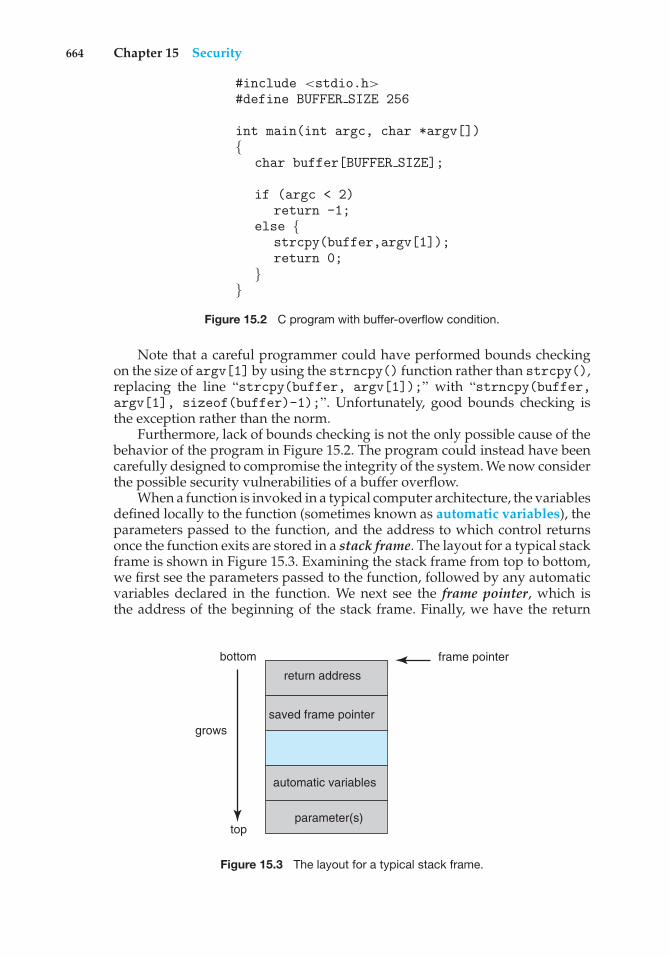
664 Chapter 15 Security
#include <stdio.h>#define BUFFER SIZE 256
int main(int argc, char *argv[]){
char buffer[BUFFER SIZE];
if (argc < 2)return -1;
else {strcpy(buffer,argv[1]);return 0;
}}
Figure 15.2 C program with buffer-overflow condition.
Note that a careful programmer could have performed bounds checkingon the size of argv[1] by using the strncpy() function rather than strcpy(),replacing the line “strcpy(buffer, argv[1]);” with “strncpy(buffer,argv[1], sizeof(buffer)-1);”. Unfortunately, good bounds checking isthe exception rather than the norm.
Furthermore, lack of bounds checking is not the only possible cause of thebehavior of the program in Figure 15.2. The program could instead have beencarefully designed to compromise the integrity of the system. We now considerthe possible security vulnerabilities of a buffer overflow.
When a function is invoked in a typical computer architecture, the variablesdefined locally to the function (sometimes known as automatic variables), theparameters passed to the function, and the address to which control returnsonce the function exits are stored in a stack frame. The layout for a typical stackframe is shown in Figure 15.3. Examining the stack frame from top to bottom,we first see the parameters passed to the function, followed by any automaticvariables declared in the function. We next see the frame pointer, which isthe address of the beginning of the stack frame. Finally, we have the return
parameter(s)
bottom
grows
top
automatic variables
saved frame pointer
frame pointer
return address
Figure 15.3 The layout for a typical stack frame.
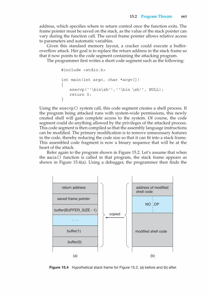
15.2 Program Threats 665
address, which specifies where to return control once the function exits. Theframe pointer must be saved on the stack, as the value of the stack pointer canvary during the function call. The saved frame pointer allows relative accessto parameters and automatic variables.
Given this standard memory layout, a cracker could execute a buffer-overflow attack. Her goal is to replace the return address in the stack frame sothat it now points to the code segment containing the attacking program.
The programmer first writes a short code segment such as the following:
#include <stdio.h>
int main(int argc, char *argv[]){
execvp(‘‘\bin\sh’’,‘‘\bin \sh’’, NULL);return 0;
}
Using the execvp() system call, this code segment creates a shell process. Ifthe program being attacked runs with system-wide permissions, this newlycreated shell will gain complete access to the system. Of course, the codesegment could do anything allowed by the privileges of the attacked process.This code segment is then compiled so that the assembly language instructionscan be modified. The primary modification is to remove unnecessary featuresin the code, thereby reducing the code size so that it can fit into a stack frame.This assembled code fragment is now a binary sequence that will be at theheart of the attack.
Refer again to the program shown in Figure 15.2. Let’s assume that whenthe main() function is called in that program, the stack frame appears asshown in Figure 15.4(a). Using a debugger, the programmer then finds the
buffer(0)
buffer(1)
buffer(BUFFER_SIZE - 1)
saved frame pointer
copied
return address
modified shell code
NO _OP
address of modified shell code
• ••
• ••
• ••
(a) (b)
Figure 15.4 Hypothetical stack frame for Figure 15.2, (a) before and (b) after.
666 Chapter 15 Security
address of buffer[0] in the stack. That address is the location of the code theattacker wants executed. The binary sequence is appended with the necessaryamount of NO-OP instructions (for NO-OPeration) to fill the stack frame upto the location of the return address, and the location of buffer[0], the newreturn address, is added. The attack is complete when the attacker gives thisconstructed binary sequence as input to the process. The process then copiesthe binary sequence from argv[1] to position buffer[0] in the stack frame.Now, when control returns from main(), instead of returning to the locationspecified by the old value of the return address, we return to the modified shellcode, which runs with the access rights of the attacked process! Figure 15.4(b)contains the modified shell code.
There are many ways to exploit potential buffer-overflow problems. Inthis example, we considered the possibility that the program being attacked—the code shown in Figure 15.2—ran with system-wide permissions. However,the code segment that runs once the value of the return address has beenmodified might perform any type of malicious act, such as deleting files,opening network ports for further exploitation, and so on.
This example buffer-overflow attack reveals that considerable knowledgeand programming skill are needed to recognize exploitable code and thento exploit it. Unfortunately, it does not take great programmers to launchsecurity attacks. Rather, one cracker can determine the bug and then write anexploit. Anyone with rudimentary computer skills and access to the exploit—a so-called script kiddie—can then try to launch the attack at target systems.
The buffer-overflow attack is especially pernicious because it can be runbetween systems and can travel over allowed communication channels. Suchattacks can occur within protocols that are expected to be used to communicatewith the target machine, and they can therefore be hard to detect and prevent.They can even bypass the security added by firewalls (Section 15.7).
One solution to this problem is for the CPU to have a feature that disallowsexecution of code in a stack section of memory. Recent versions of Sun’s SPARCchip include this setting, and recent versions of Solaris enable it. The returnaddress of the overflowed routine can still be modified; but when the returnaddress is within the stack and the code there attempts to execute, an exceptionis generated, and the program is halted with an error.
Recent versions of AMD and Intel x86 chips include the NX feature to preventthis type of attack. The use of the feature is supported in several x86 operatingsystems, including Linux and Windows XP SP2. The hardware implementationinvolves the use of a new bit in the page tables of the CPUs. This bit marks theassociated page as nonexecutable, so that instructions cannot be read from itand executed. As this feature becomes more prevalent, buffer-overflow attacksshould greatly diminish.
15.2.5 Viruses
Another form of program threat is a virus. A virus is a fragment of code embed-ded in a legitimate program. Viruses are self-replicating and are designed to“infect” other programs. They can wreak havoc in a system by modifying ordestroying files and causing system crashes and program malfunctions. Aswith most penetration attacks, viruses are very specific to architectures, oper-ating systems, and applications. Viruses are a particular problem for users of
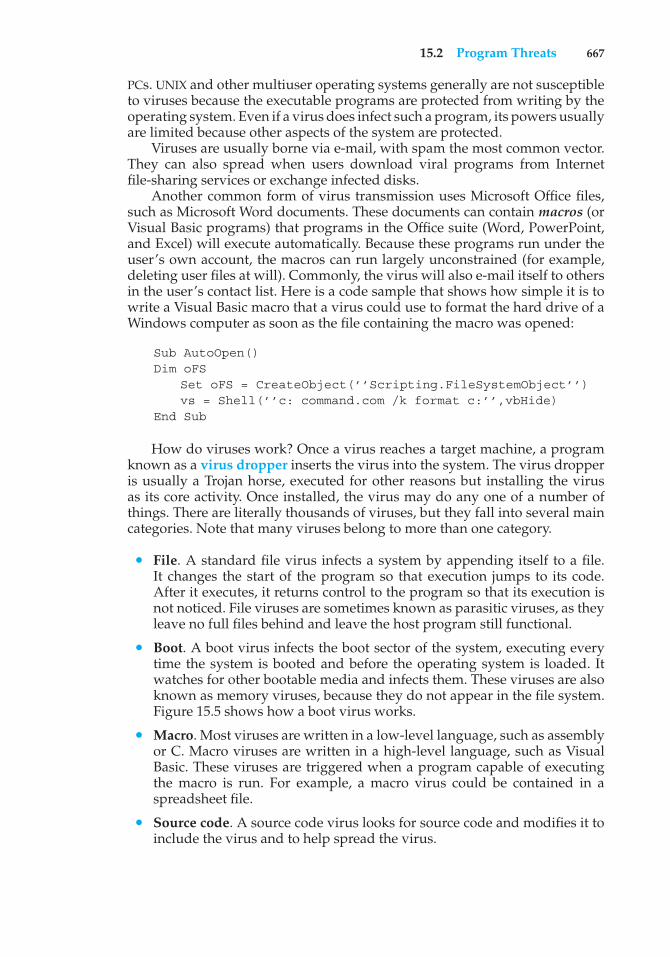
15.2 Program Threats 667
PCs. UNIX and other multiuser operating systems generally are not susceptibleto viruses because the executable programs are protected from writing by theoperating system. Even if a virus does infect such a program, its powers usuallyare limited because other aspects of the system are protected.
Viruses are usually borne via e-mail, with spam the most common vector.They can also spread when users download viral programs from Internetfile-sharing services or exchange infected disks.
Another common form of virus transmission uses Microsoft Office files,such as Microsoft Word documents. These documents can contain macros (orVisual Basic programs) that programs in the Office suite (Word, PowerPoint,and Excel) will execute automatically. Because these programs run under theuser’s own account, the macros can run largely unconstrained (for example,deleting user files at will). Commonly, the virus will also e-mail itself to othersin the user’s contact list. Here is a code sample that shows how simple it is towrite a Visual Basic macro that a virus could use to format the hard drive of aWindows computer as soon as the file containing the macro was opened:
Sub AutoOpen()Dim oFS
Set oFS = CreateObject(’’Scripting.FileSystemObject’’)vs = Shell(’’c: command.com /k format c:’’,vbHide)
End Sub
How do viruses work? Once a virus reaches a target machine, a programknown as a virus dropper inserts the virus into the system. The virus dropperis usually a Trojan horse, executed for other reasons but installing the virusas its core activity. Once installed, the virus may do any one of a number ofthings. There are literally thousands of viruses, but they fall into several maincategories. Note that many viruses belong to more than one category.
• File. A standard file virus infects a system by appending itself to a file.It changes the start of the program so that execution jumps to its code.After it executes, it returns control to the program so that its execution isnot noticed. File viruses are sometimes known as parasitic viruses, as theyleave no full files behind and leave the host program still functional.
• Boot. A boot virus infects the boot sector of the system, executing everytime the system is booted and before the operating system is loaded. Itwatches for other bootable media and infects them. These viruses are alsoknown as memory viruses, because they do not appear in the file system.Figure 15.5 shows how a boot virus works.
• Macro. Most viruses are written in a low-level language, such as assemblyor C. Macro viruses are written in a high-level language, such as VisualBasic. These viruses are triggered when a program capable of executingthe macro is run. For example, a macro virus could be contained in aspreadsheet file.
• Source code. A source code virus looks for source code and modifies it toinclude the virus and to help spread the virus.
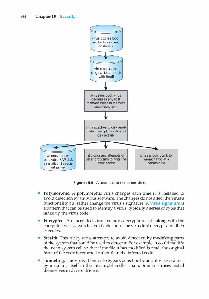
668 Chapter 15 Security
whenever new removable R/W disk is installed, it infects
that as well
it has a logic bomb to wreak havoc at a
certain date
virus replaces original boot block
with itself
at system boot, virus decreases physical
memory, hides in memory above new limit
virus attaches to disk read- write interrupt, monitors all
disk activity
it blocks any attempts of other programs to write the
boot sector
virus copies boot sector to unused
location X
Figure 15.5 A boot-sector computer virus.
• Polymorphic. A polymorphic virus changes each time it is installed toavoid detection by antivirus software. The changes do not affect the virus’sfunctionality but rather change the virus’s signature. A virus signature isa pattern that can be used to identify a virus, typically a series of bytes thatmake up the virus code.
• Encrypted. An encrypted virus includes decryption code along with theencrypted virus, again to avoid detection. The virus first decrypts and thenexecutes.
• Stealth. This tricky virus attempts to avoid detection by modifying partsof the system that could be used to detect it. For example, it could modifythe read system call so that if the file it has modified is read, the originalform of the code is returned rather than the infected code.
• Tunneling. This virus attempts to bypass detection by an antivirus scannerby installing itself in the interrupt-handler chain. Similar viruses installthemselves in device drivers.
15.3 System and Network Threats 669
• Multipartite. A virus of this type is able to infect multiple parts of a system,including boot sectors, memory, and files. This makes it difficult to detectand contain.
• Armored. An armored virus is coded to make it hard for antivirusresearchers to unravel and understand. It can also be compressed to avoiddetection and disinfection. In addition, virus droppers and other full filesthat are part of a virus infestation are frequently hidden via file attributesor unviewable file names.
This vast variety of viruses has continued to grow. For example, in 2004a new and widespread virus was detected. It exploited three separate bugsfor its operation. This virus started by infecting hundreds of Windows servers(including many trusted sites) running Microsoft Internet Information Server(IIS). Any vulnerable Microsoft Explorer web browser visiting those sitesreceived a browser virus with any download. The browser virus installedseveral back-door programs, including a keystroke logger, which recordseverything entered on the keyboard (including passwords and credit-cardnumbers). It also installed a daemon to allow unlimited remote access byan intruder and another that allowed an intruder to route spam through theinfected desktop computer.
Generally, viruses are the most disruptive security attacks, and becausethey are effective, they will continue to be written and to spread. An activesecurity-related debate within the computing community concerns the exis-tence of a monoculture, in which many systems run the same hardware,operating system, and application software. This monoculture supposedlyconsists of Microsoft products. One question is whether such a monocultureeven exists today. Another question is whether, if it does, it increases the threatof and damage caused by viruses and other security intrusions.
15.3 System and Network Threats
Program threats typically use a breakdown in the protection mechanisms of asystem to attack programs. In contrast, system and network threats involve theabuse of services and network connections. System and network threats createa situation in which operating-system resources and user files are misused.Sometimes, a system and network attack is used to launch a program attack,and vice versa.
The more open an operating system is—the more services it has enabledand the more functions it allows—the more likely it is that a bug is availableto exploit. Increasingly, operating systems strive to be secure by default.For example, Solaris 10 moved from a model in which many services (FTP,telnet, and others) were enabled by default when the system was installedto a model in which almost all services are disabled at installation time andmust specifically be enabled by system administrators. Such changes reducethe system’s attack surface—the set of ways in which an attacker can try tobreak into the system.
In the remainder of this section, we discuss some examples of systemand network threats, including worms, port scanning, and denial-of-service
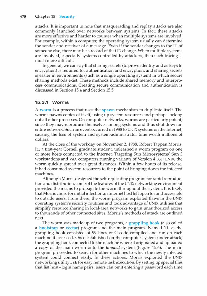
670 Chapter 15 Security
attacks. It is important to note that masquerading and replay attacks are alsocommonly launched over networks between systems. In fact, these attacksare more effective and harder to counter when multiple systems are involved.For example, within a computer, the operating system usually can determinethe sender and receiver of a message. Even if the sender changes to the ID ofsomeone else, there may be a record of that ID change. When multiple systemsare involved, especially systems controlled by attackers, then such tracing ismuch more difficult.
In general, we can say that sharing secrets (to prove identity and as keys toencryption) is required for authentication and encryption, and sharing secretsis easier in environments (such as a single operating system) in which securesharing methods exist. These methods include shared memory and interpro-cess communications. Creating secure communication and authentication isdiscussed in Section 15.4 and Section 15.5.
15.3.1 Worms
A worm is a process that uses the spawn mechanism to duplicate itself. Theworm spawns copies of itself, using up system resources and perhaps lockingout all other processes. On computer networks, worms are particularly potent,since they may reproduce themselves among systems and thus shut down anentire network. Such an event occurred in 1988 to UNIX systems on the Internet,causing the loss of system and system-administrator time worth millions ofdollars.
At the close of the workday on November 2, 1988, Robert Tappan Morris,Jr., a first-year Cornell graduate student, unleashed a worm program on oneor more hosts connected to the Internet. Targeting Sun Microsystems’ Sun 3workstations and VAX computers running variants of Version 4 BSD UNIX, theworm quickly spread over great distances. Within a few hours of its release,it had consumed system resources to the point of bringing down the infectedmachines.
Although Morris designed the self-replicating program for rapid reproduc-tion and distribution, some of the features of the UNIX networking environmentprovided the means to propagate the worm throughout the system. It is likelythat Morris chose for initial infection an Internet host left open for and accessibleto outside users. From there, the worm program exploited flaws in the UNIXoperating system’s security routines and took advantage of UNIX utilities thatsimplify resource sharing in local-area networks to gain unauthorized accessto thousands of other connected sites. Morris’s methods of attack are outlinednext.
The worm was made up of two programs, a grappling hook (also calleda bootstrap or vector) program and the main program. Named l1.c, thegrappling hook consisted of 99 lines of C code compiled and run on eachmachine it accessed. Once established on the computer system under attack,the grappling hook connected to the machine where it originated and uploadeda copy of the main worm onto the hooked system (Figure 15.6). The mainprogram proceeded to search for other machines to which the newly infectedsystem could connect easily. In these actions, Morris exploited the UNIXnetworking utility rsh for easy remote task execution. By setting up special filesthat list host–login name pairs, users can omit entering a password each time
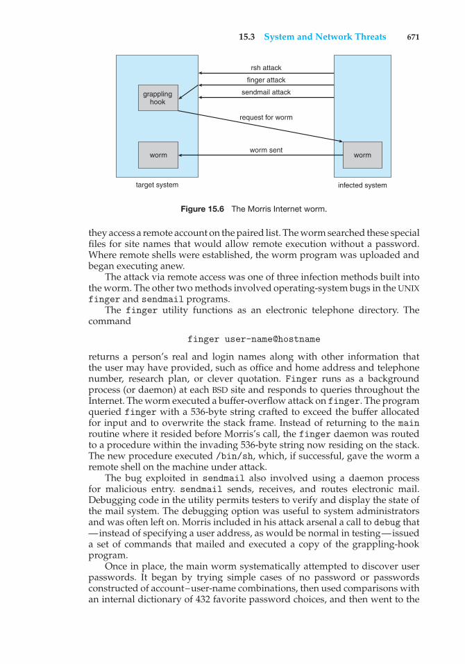
15.3 System and Network Threats 671
grappling hook
worm
target system
worm
infected system
rsh attack
finger attack
sendmail attack
request for worm
worm sent
Figure 15.6 The Morris Internet worm.
they access a remote account on the paired list. The worm searched these specialfiles for site names that would allow remote execution without a password.Where remote shells were established, the worm program was uploaded andbegan executing anew.
The attack via remote access was one of three infection methods built intothe worm. The other two methods involved operating-system bugs in the UNIXfinger and sendmail programs.
The finger utility functions as an electronic telephone directory. Thecommand
finger user-name@hostname
returns a person’s real and login names along with other information thatthe user may have provided, such as office and home address and telephonenumber, research plan, or clever quotation. Finger runs as a backgroundprocess (or daemon) at each BSD site and responds to queries throughout theInternet. The worm executed a buffer-overflow attack on finger. The programqueried finger with a 536-byte string crafted to exceed the buffer allocatedfor input and to overwrite the stack frame. Instead of returning to the mainroutine where it resided before Morris’s call, the finger daemon was routedto a procedure within the invading 536-byte string now residing on the stack.The new procedure executed /bin/sh, which, if successful, gave the worm aremote shell on the machine under attack.
The bug exploited in sendmail also involved using a daemon processfor malicious entry. sendmail sends, receives, and routes electronic mail.Debugging code in the utility permits testers to verify and display the state ofthe mail system. The debugging option was useful to system administratorsand was often left on. Morris included in his attack arsenal a call to debug that—instead of specifying a user address, as would be normal in testing—issueda set of commands that mailed and executed a copy of the grappling-hookprogram.
Once in place, the main worm systematically attempted to discover userpasswords. It began by trying simple cases of no password or passwordsconstructed of account–user-name combinations, then used comparisons withan internal dictionary of 432 favorite password choices, and then went to the
672 Chapter 15 Security
final stage of trying each word in the standard UNIX on-line dictionary as apossible password. This elaborate and efficient three-stage password-crackingalgorithm enabled the worm to gain access to other user accounts on theinfected system. The worm then searched for rsh data files in these newlybroken accounts and used them as described previously to gain access to useraccounts on remote systems.
With each new access, the worm program searched for already activecopies of itself. If it found one, the new copy exited, except in every seventhinstance. Had the worm exited on all duplicate sightings, it might haveremained undetected. Allowing every seventh duplicate to proceed (possiblyto confound efforts to stop its spread by baiting with “fake” worms) created awholesale infestation of Sun and VAX systems on the Internet.
The very features of the UNIX network environment that assisted in theworm’s propagation also helped to stop its advance. Ease of electronic commu-nication, mechanisms to copy source and binary files to remote machines, andaccess to both source code and human expertise allowed cooperative efforts todevelop solutions quickly. By the evening of the next day, November 3, methodsof halting the invading program were circulated to system administrators viathe Internet. Within days, specific software patches for the exploited securityflaws were available.
Why did Morris unleash the worm? The action has been characterizedas both a harmless prank gone awry and a serious criminal offense. Basedon the complexity of the attack, it is unlikely that the worm’s release or thescope of its spread was unintentional. The worm program took elaborate stepsto cover its tracks and to repel efforts to stop its spread. Yet the programcontained no code aimed at damaging or destroying the systems on which itran. The author clearly had the expertise to include such commands; in fact,data structures were present in the bootstrap code that could have been used totransfer Trojan-horse or virus programs. The behavior of the program may leadto interesting observations, but it does not provide a sound basis for inferringmotive. What is not open to speculation, however, is the legal outcome: afederal court convicted Morris and handed down a sentence of three years’probation, 400 hours of community service, and a $10,000 fine. Morris’s legalcosts probably exceeded $100,000.
Security experts continue to evaluate methods to decrease or eliminateworms. A more recent event, though, shows that worms are still a fact oflife on the Internet. It also shows that as the Internet grows, the damagethat even “harmless” worms can do also grows and can be significant. Thisexample occurred during August 2003. The fifth version of the “Sobig” worm,more properly known as “W32.Sobig.F@mm,” was released by persons at thistime unknown. It was the fastest-spreading worm released to date, at its peakinfecting hundreds of thousands of computers and one in seventeen e-mailmessages on the Internet. It clogged e-mail inboxes, slowed networks, andtook a huge number of hours to clean up.
Sobig.F was launched by being uploaded to a pornography newsgroup viaan account created with a stolen credit card. It was disguised as a photo. Thevirus targeted Microsoft Windows systems and used its own SMTP engine toe-mail itself to all the addresses found on an infected system. It used a varietyof subject lines to help avoid detection, including “Thank You!” “Your details,”
15.3 System and Network Threats 673
and “Re: Approved.” It also used a random address on the host as the “From:”address, making it difficult to determine from the message which machine wasthe infected source. Sobig.F included an attachment for the target e-mail readerto click on, again with a variety of names. If this payload was executed, it storeda program called WINPPR32.EXE in the default Windows directory, along witha text file. It also modified the Windows registry.
The code included in the attachment was also programmed to periodicallyattempt to connect to one of twenty servers and download and execute aprogram from them. Fortunately, the servers were disabled before the codecould be downloaded. The content of the program from these servers has notyet been determined. If the code was malevolent, untold damage to a vastnumber of machines could have resulted.
15.3.2 Port Scanning
Port scanning is not an attack but rather a means for a cracker to detecta system’s vulnerabilities to attack. Port scanning typically is automated,involving a tool that attempts to create a TCP/IP connection to a specific portor a range of ports. For example, suppose there is a known vulnerability (orbug) in sendmail. A cracker could launch a port scanner to try to connect, say,to port 25 of a particular system or to a range of systems. If the connectionwas successful, the cracker (or tool) could attempt to communicate with theanswering service to determine if the service was indeed sendmail and, if so,if it was the version with the bug.
Now imagine a tool in which each bug of every service of every operatingsystem was encoded. The tool could attempt to connect to every port of oneor more systems. For every service that answered, it could try to use eachknown bug. Frequently, the bugs are buffer overflows, allowing the creation ofa privileged command shell on the system. From there, of course, the crackercould install Trojan horses, back-door programs, and so on.
There is no such tool, but there are tools that perform subsets of thatfunctionality. For example, nmap (from http://www.insecure.org/nmap/) isa very versatile open-source utility for network exploration and securityauditing. When pointed at a target, it will determine what services are running,including application names and versions. It can identify the host operatingsystem. It can also provide information about defenses, such as what firewallsare defending the target. It does not exploit any known bugs.
Because port scans are detectable (Section 15.6.3), they frequently arelaunched from zombie systems. Such systems are previously compromised,independent systems that are serving their owners while being used for nefar-ious purposes, including denial-of-service attacks and spam relay. Zombiesmake crackers particularly difficult to prosecute because determining thesource of the attack and the person that launched it is challenging. This isone of many reasons for securing “inconsequential” systems, not just systemscontaining “valuable” information or services.
15.3.3 Denial of Service
As mentioned earlier, denial-of-service attacks are aimed not at gaininginformation or stealing resources but rather at disrupting legitimate use ofa system or facility. Most such attacks involve systems that the attacker has
674 Chapter 15 Security
not penetrated. Launching an attack that prevents legitimate use is frequentlyeasier than breaking into a machine or facility.
Denial-of-service attacks are generally network based. They fall into twocategories. Attacks in the first category use so many facility resources that,in essence, no useful work can be done. For example, a website click coulddownload a Java applet that proceeds to use all available CPU time or to popup windows infinitely. The second category involves disrupting the networkof the facility. There have been several successful denial-of-service attacks ofthis kind against major websites. These attacks result from abuse of some of thefundamental functionality of TCP/IP. For instance, if the attacker sends the partof the protocol that says “I want to start a TCP connection,” but never followswith the standard “The connection is now complete,” the result can be partiallystarted TCP sessions. If enough of these sessions are launched, they can eat upall the network resources of the system, disabling any further legitimate TCPconnections. Such attacks, which can last hours or days, have caused partial orfull failure of attempts to use the target facility. The attacks are usually stoppedat the network level until the operating systems can be updated to reduce theirvulnerability.
Generally, it is impossible to prevent denial-of-service attacks. The attacksuse the same mechanisms as normal operation. Even more difficult to preventand resolve are distributed denial-of-service (DDOS) attacks. These attacksare launched from multiple sites at once, toward a common target, typicallyby zombies. DDOS attacks have become more common and are sometimesassociated with blackmail attempts. A site comes under attack, and theattackers offer to halt the attack in exchange for money.
Sometimes a site does not even know it is under attack. It can be difficultto determine whether a system slowdown is an attack or just a surge in systemuse. Consider that a successful advertising campaign that greatly increasestraffic to a site could be considered a DDOS.
There are other interesting aspects of DOS attacks. For example, if anauthentication algorithm locks an account for a period of time after severalincorrect attempts to access the account, then an attacker could cause allauthentication to be blocked by purposely making incorrect attempts to accessall accounts. Similarly, a firewall that automatically blocks certain kinds oftraffic could be induced to block that traffic when it should not. These examplessuggest that programmers and systems managers need to fully understand thealgorithms and technologies they are deploying. Finally, computer scienceclasses are notorious sources of accidental system DOS attacks. Consider thefirst programming exercises in which students learn to create subprocessesor threads. A common bug involves spawning subprocesses infinitely. Thesystem’s free memory and CPU resources don’t stand a chance.
15.4 Cryptography as a Security Tool
There are many defenses against computer attacks, running the gamut frommethodology to technology. The broadest tool available to system designersand users is cryptography. In this section, we discuss cryptography and itsuse in computer security. Note that the cryptography discussed here has beensimplified for educational purposes; readers are cautioned against using any
15.4 Cryptography as a Security Tool 675
of the schemes described here in the real world. Good cryptography librariesare widely available and would make a good basis for production applications.
In an isolated computer, the operating system can reliably determine thesender and recipient of all interprocess communication, since it controls allcommunication channels in the computer. In a network of computers, thesituation is quite different. A networked computer receives bits “from thewire” with no immediate and reliable way of determining what machine orapplication sent those bits. Similarly, the computer sends bits onto the networkwith no way of knowing who might eventually receive them. Additionally,when either sending or receiving, the system has no way of knowing if aneavesdropper listened to the communication.
Commonly, network addresses are used to infer the potential sendersand receivers of network messages. Network packets arrive with a sourceaddress, such as an IP address. And when a computer sends a message, itnames the intended receiver by specifying a destination address. However, forapplications where security matters, we are asking for trouble if we assumethat the source or destination address of a packet reliably determines who sentor received that packet. A rogue computer can send a message with a falsifiedsource address, and numerous computers other than the one specified by thedestination address can (and typically do) receive a packet. For example, all ofthe routers on the way to the destination will receive the packet, too. How, then,is an operating system to decide whether to grant a request when it cannot trustthe named source of the request? And how is it supposed to provide protectionfor a request or data when it cannot determine who will receive the responseor message contents it sends over the network?
It is generally considered infeasible to build a network of any scale inwhich the source and destination addresses of packets can be trusted in thissense. Therefore, the only alternative is somehow to eliminate the need totrust the network. This is the job of cryptography. Abstractly, cryptography isused to constrain the potential senders and/or receivers of a message. Moderncryptography is based on secrets called keys that are selectively distributed tocomputers in a network and used to process messages. Cryptography enables arecipient of a message to verify that the message was created by some computerpossessing a certain key. Similarly, a sender can encode its message so thatonly a computer with a certain key can decode the message. Unlike networkaddresses, however, keys are designed so that it is not computationally feasibleto derive them from the messages they were used to generate or from anyother public information. Thus, they provide a much more trustworthy meansof constraining senders and receivers of messages. Note that cryptography isa field of study unto itself, with large and small complexities and subtleties.Here, we explore the most important aspects of the parts of cryptography thatpertain to operating systems.
15.4.1 Encryption
Because it solves a wide variety of communication security problems, encryp-tion is used frequently in many aspects of modern computing. It is used to sendmessages securely across across a network, as well as to protect database data,files, and even entire disks from having their contents read by unauthorizedentities. An encryption algorithm enables the sender of a message to ensure that
676 Chapter 15 Security
only a computer possessing a certain key can read the message, or ensure thatthe writer of data is the only reader of that data. Encryption of messages is anancient practice, of course, and there have been many encryption algorithms,dating back to ancient times. In this section, we describe important modernencryption principles and algorithms.
An encryption algorithm consists of the following components:
• A set K of keys.
• A set M of messages.
• A set C of ciphertexts.
• An encrypting function E : K → (M→ C). That is, for each k ∈ K , Ek is afunction for generating ciphertexts from messages. Both E and Ek for any kshould be efficiently computable functions. Generally, Ek is a randomizedmapping from messages to ciphertexts.
• A decrypting function D : K → (C → M). That is, for each k ∈ K , Dk is afunction for generating messages from ciphertexts. Both D and Dk for anyk should be efficiently computable functions.
An encryption algorithm must provide this essential property: given aciphertext c ∈ C , a computer can compute m such that Ek(m) = c only ifit possesses k. Thus, a computer holding k can decrypt ciphertexts to theplaintexts used to produce them, but a computer not holding k cannot decryptciphertexts. Since ciphertexts are generally exposed (for example, sent on anetwork), it is important that it be infeasible to derive k from the ciphertexts.
There are two main types of encryption algorithms: symmetric andasymmetric. We discuss both types in the following sections.
15.4.1.1 Symmetric Encryption
In a symmetric encryption algorithm, the same key is used to encrypt and todecrypt. Therefore, the secrecy of k must be protected. Figure 15.7 shows anexample of two users communicating securely via symmetric encryption overan insecure channel. Note that the key exchange can take place directly betweenthe two parties or via a trusted third party (that is, a certificate authority), asdiscussed in Section 15.4.1.4.
For the past several decades, the most commonly used symmetric encryp-tion algorithm in the United States for civilian applications has been thedata-encryption standard (DES) cipher adopted by the National Institute ofStandards and Technology (NIST). DES works by taking a 64-bit value anda 56-bit key and performing a series of transformations that are based onsubstitution and permutation operations. Because DES works on a block of bitsat a time, is known as a block cipher, and its transformations are typical ofblock ciphers. With block ciphers, if the same key is used for encrypting anextended amount of data, it becomes vulnerable to attack.
DES is now considered insecure for many applications because its keys canbe exhaustively searched with moderate computing resources. (Note, though,that it is still frequently used.) Rather than giving up on DES, NIST created amodification called triple DES, in which the DES algorithm is repeated threetimes (two encryptions and one decryption) on the same plaintext using two
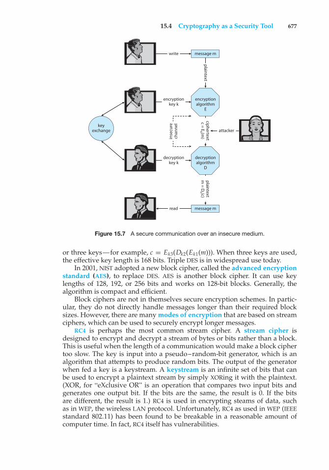
15.4 Cryptography as a Security Tool 677
keyexchange
message m
message m
encryptionalgorithm
E
decryptionalgorithm
D
write
encryptionkey k
decryptionkey k
read
inse
cure
chan
nel
plaintextciphertextc = E
k (m)
plaintextm
= Dk (c)
attacker
Figure 15.7 A secure communication over an insecure medium.
or three keys—for example, c = Ek3(Dk2(Ek1(m))). When three keys are used,the effective key length is 168 bits. Triple DES is in widespread use today.
In 2001, NIST adopted a new block cipher, called the advanced encryptionstandard (AES), to replace DES. AES is another block cipher. It can use keylengths of 128, 192, or 256 bits and works on 128-bit blocks. Generally, thealgorithm is compact and efficient.
Block ciphers are not in themselves secure encryption schemes. In partic-ular, they do not directly handle messages longer than their required blocksizes. However, there are many modes of encryption that are based on streamciphers, which can be used to securely encrypt longer messages.
RC4 is perhaps the most common stream cipher. A stream cipher isdesigned to encrypt and decrypt a stream of bytes or bits rather than a block.This is useful when the length of a communication would make a block ciphertoo slow. The key is input into a pseudo–random-bit generator, which is analgorithm that attempts to produce random bits. The output of the generatorwhen fed a key is a keystream. A keystream is an infinite set of bits that canbe used to encrypt a plaintext stream by simply XORing it with the plaintext.(XOR, for “eXclusive OR” is an operation that compares two input bits andgenerates one output bit. If the bits are the same, the result is 0. If the bitsare different, the result is 1.) RC4 is used in encrypting steams of data, suchas in WEP, the wireless LAN protocol. Unfortunately, RC4 as used in WEP (IEEEstandard 802.11) has been found to be breakable in a reasonable amount ofcomputer time. In fact, RC4 itself has vulnerabilities.
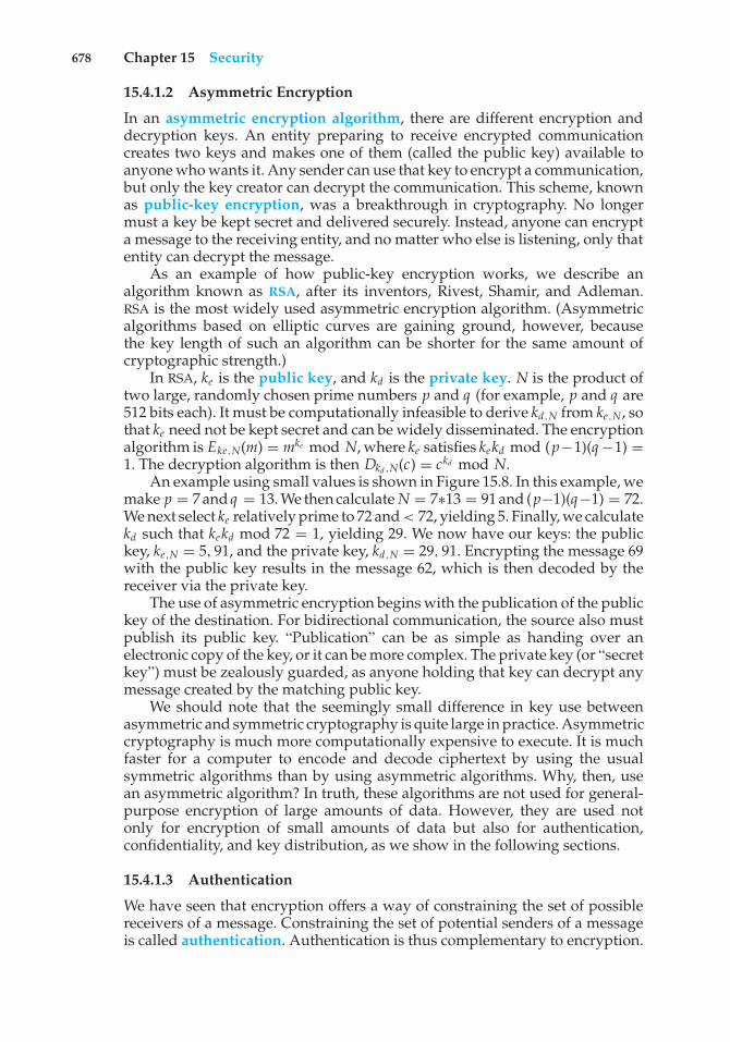
678 Chapter 15 Security
15.4.1.2 Asymmetric Encryption
In an asymmetric encryption algorithm, there are different encryption anddecryption keys. An entity preparing to receive encrypted communicationcreates two keys and makes one of them (called the public key) available toanyone who wants it. Any sender can use that key to encrypt a communication,but only the key creator can decrypt the communication. This scheme, knownas public-key encryption, was a breakthrough in cryptography. No longermust a key be kept secret and delivered securely. Instead, anyone can encrypta message to the receiving entity, and no matter who else is listening, only thatentity can decrypt the message.
As an example of how public-key encryption works, we describe analgorithm known as RSA, after its inventors, Rivest, Shamir, and Adleman.RSA is the most widely used asymmetric encryption algorithm. (Asymmetricalgorithms based on elliptic curves are gaining ground, however, becausethe key length of such an algorithm can be shorter for the same amount ofcryptographic strength.)
In RSA, ke is the public key, and kd is the private key. N is the product oftwo large, randomly chosen prime numbers p and q (for example, p and q are512 bits each). It must be computationally infeasible to derive kd,N from ke,N, sothat ke need not be kept secret and can be widely disseminated. The encryptionalgorithm is Eke,N(m) = mke mod N, where ke satisfies kekd mod (p−1)(q−1) =1. The decryption algorithm is then Dkd ,N(c) = ckd mod N.
An example using small values is shown in Figure 15.8. In this example, wemake p = 7 and q = 13. We then calculate N = 7∗13 = 91 and (p−1)(q−1) = 72.We next select ke relatively prime to 72 and < 72, yielding 5. Finally, we calculatekd such that kekd mod 72 = 1, yielding 29. We now have our keys: the publickey, ke,N = 5, 91, and the private key, kd,N = 29, 91. Encrypting the message 69with the public key results in the message 62, which is then decoded by thereceiver via the private key.
The use of asymmetric encryption begins with the publication of the publickey of the destination. For bidirectional communication, the source also mustpublish its public key. “Publication” can be as simple as handing over anelectronic copy of the key, or it can be more complex. The private key (or “secretkey”) must be zealously guarded, as anyone holding that key can decrypt anymessage created by the matching public key.
We should note that the seemingly small difference in key use betweenasymmetric and symmetric cryptography is quite large in practice. Asymmetriccryptography is much more computationally expensive to execute. It is muchfaster for a computer to encode and decode ciphertext by using the usualsymmetric algorithms than by using asymmetric algorithms. Why, then, usean asymmetric algorithm? In truth, these algorithms are not used for general-purpose encryption of large amounts of data. However, they are used notonly for encryption of small amounts of data but also for authentication,confidentiality, and key distribution, as we show in the following sections.
15.4.1.3 Authentication
We have seen that encryption offers a way of constraining the set of possiblereceivers of a message. Constraining the set of potential senders of a messageis called authentication. Authentication is thus complementary to encryption.
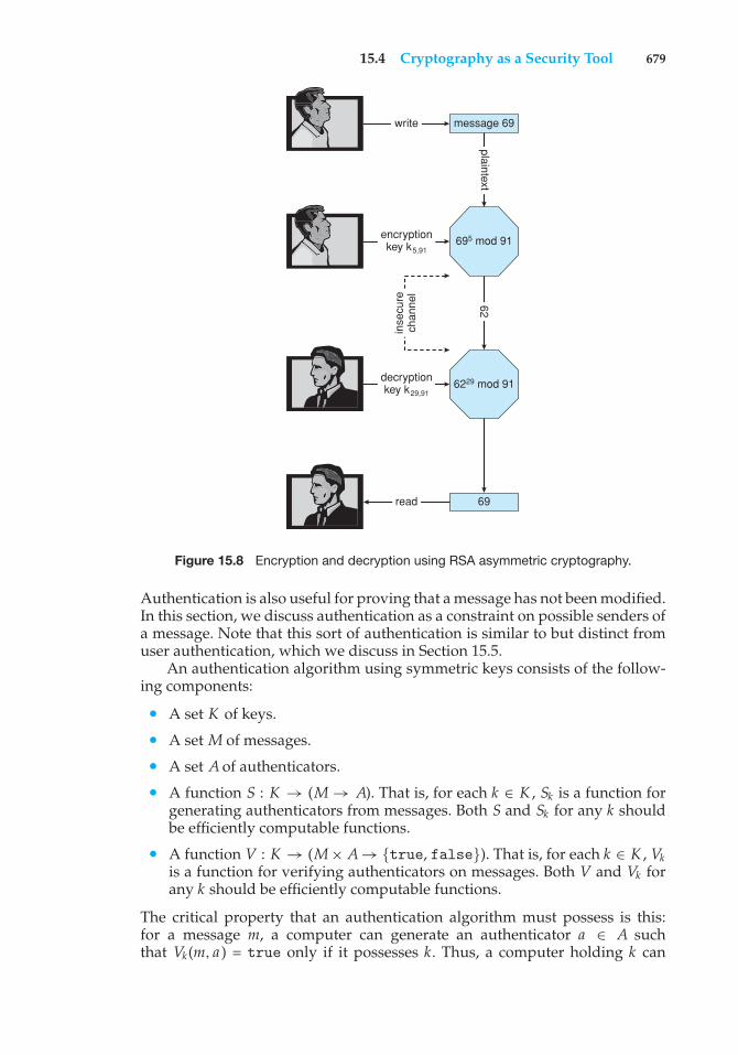
15.4 Cryptography as a Security Tool 679
message 69
69
695 mod 91
6229 mod 91
write
encryptionkey k5,91
decryptionkey k29,91
read
inse
cure
chan
nel
plaintext62
Figure 15.8 Encryption and decryption using RSA asymmetric cryptography.
Authentication is also useful for proving that a message has not been modified.In this section, we discuss authentication as a constraint on possible senders ofa message. Note that this sort of authentication is similar to but distinct fromuser authentication, which we discuss in Section 15.5.
An authentication algorithm using symmetric keys consists of the follow-ing components:
• A set K of keys.
• A set M of messages.
• A set A of authenticators.
• A function S : K → (M → A). That is, for each k ∈ K , Sk is a function forgenerating authenticators from messages. Both S and Sk for any k shouldbe efficiently computable functions.
• A function V : K → (M× A→ {true, false}). That is, for each k ∈ K , Vkis a function for verifying authenticators on messages. Both V and Vk forany k should be efficiently computable functions.
The critical property that an authentication algorithm must possess is this:for a message m, a computer can generate an authenticator a ∈ A suchthat Vk(m, a ) = true only if it possesses k. Thus, a computer holding k can
680 Chapter 15 Security
generate authenticators on messages so that any computer possessing k canverify them. However, a computer not holding k cannot generate authenticatorson messages that can be verified using Vk . Since authenticators are generallyexposed (for example, sent on a network with the messages themselves), itmust not be feasible to derive k from the authenticators. Practically, if Vk(m, a )= true, then we know that m has not been modified, and that the sender ofthe message has k. If we share k with only one entity, then we know that themessage originated from k.
Just as there are two types of encryption algorithms, there are two mainvarieties of authentication algorithms. The first step in understanding thesealgorithms is to explore hash functions. A hash function H(m) creates a small,fixed-sized block of data, known as a message digest or hash value, from amessage m. Hash functions work by taking a message, splitting it into blocks,and processing the blocks to produce an n-bit hash. H must be collision resistant—that is, it must be infeasible to find an m′ ̸= m such that H(m) = H(m′). Now,if H(m) = H(m′), we know that m = m′—that is, we know that the messagehas not been modified. Common message-digest functions include MD5, nowconsidered insecure, which produces a 128-bit hash, and SHA-1, which outputsa 160-bit hash. Message digests are useful for detecting changed messages butare not useful as authenticators. For example, H(m) can be sent along with amessage; but if H is known, then someone could modify m to m′ and recomputeH(m′), and the message modification would not be detected. Therefore, wemust authenticate H(m).
The first main type of authentication algorithm uses symmetric encryp-tion. In a message-authentication code (MAC), a cryptographic checksum isgenerated from the message using a secret key. A MAC provides a way tosecurely authenticate short values. If we use it to authenticate H(m) for an Hthat is collision resistant, then we obtain a way to securely authenticate longmessages by hashing them first. Note that k is needed to compute both Sk andVk , so anyone able to compute one can compute the other.
The second main type of authentication algorithm is a digital-signaturealgorithm, and the authenticators thus produced are called digital signatures.Digital signatures are very useful in that they enable anyone to verify theauthenticity of the message. In a digital-signature algorithm, it is computa-tionally infeasible to derive ks from kv. Thus, kv is the public key, and ks is theprivate key.
Consider as an example the RSA digital-signature algorithm. It is similarto the RSA encryption algorithm, but the key use is reversed. The digitalsignature of a message is derived by computing Sks(m) = H(m)ks mod N.The key ks again is a pair ⟨d, N⟩, where N is the product of two large,randomly chosen prime numbers p and q . The verification algorithm is thenVkv(m, a ) ?=a kv mod N = H(m)), where kv satisfies kvks mod (p − 1)(q − 1) = 1.
Note that encryption and authentication may be used together or sepa-rately. Sometimes, for instance, we want authentication but not confidentiality.For example, a company could provide a software patch and could “sign” thatpatch to prove that it came from the company and that it hasn’t been modified.
Authentication is a component of many aspects of security. For example,digital signatures are the core of nonrepudiation, which supplies proof thatan entity performed an action. A typical example of nonrepudiation involves
15.4 Cryptography as a Security Tool 681
the filling out of electronic forms as an alternative to the signing of papercontracts. Nonrepudiation assures that a person filling out an electronic formcannot deny that he did so.
15.4.1.4 Key Distribution
Certainly, a good part of the battle between cryptographers (those inventingciphers) and cryptanalysts (those trying to break them) involves keys. Withsymmetric algorithms, both parties need the key, and no one else shouldhave it. The delivery of the symmetric key is a huge challenge. Sometimesit is performed out-of-band—say, via a paper document or a conversation.These methods do not scale well, however. Also consider the key-managementchallenge. Suppose a user wanted to communicate with N other users privately.That user would need N keys and, for more security, would need to changethose keys frequently.
These are the very reasons for efforts to create asymmetric key algorithms.Not only can the keys be exchanged in public, but a given user needs onlyone private key, no matter how many other people she wants to communicatewith. There is still the matter of managing a public key for each recipient of thecommunication, but since public keys need not be secured, simple storage canbe used for that key ring.
Unfortunately, even the distribution of public keys requires some care.Consider the man-in-the-middle attack shown in Figure 15.9. Here, the personwho wants to receive an encrypted message sends out his public key, but anattacker also sends her “bad” public key (which matches her private key). Theperson who wants to send the encrypted message knows no better and so usesthe bad key to encrypt the message. The attacker then happily decrypts it.
The problem is one of authentication—what we need is proof of who (orwhat) owns a public key. One way to solve that problem involves the useof digital certificates. A digital certificate is a public key digitally signed by atrusted party. The trusted party receives proof of identification from some entityand certifies that the public key belongs to that entity. But how do we knowwe can trust the certifier? These certificate authorities have their public keysincluded within web browsers (and other consumers of certificates) before theyare distributed. The certificate authorities can then vouch for other authorities(digitally signing the public keys of these other authorities), and so on, creatinga web of trust. The certificates can be distributed in a standard X.509 digitalcertificate format that can be parsed by computer. This scheme is used forsecure web communication, as we discuss in Section 15.4.3.
15.4.2 Implementation of Cryptography
Network protocols are typically organized in layers, like an onion or a parfait,with each layer acting as a client of the one below it. That is, when one protocolgenerates a message to send to its protocol peer on another machine, it handsits message to the protocol below it in the network-protocol stack for deliveryto its peer on that machine. For example, in an IP network, TCP (a transport-layer protocol) acts as a client of IP (a network-layer protocol): TCP packets arepassed down to IP for delivery to the IP peer at the other end of the connection.IP encapsulates the TCP packet in an IP packet, which it similarly passes downto the data-link layer to be transmitted across the network to its peer on the
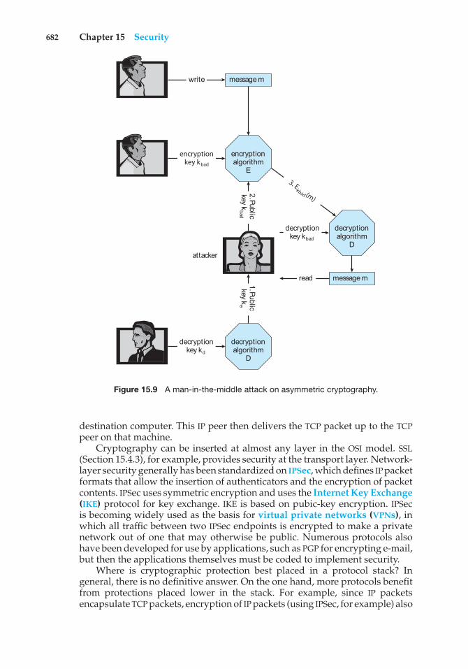
682 Chapter 15 Security
message m
encryptionalgorithm
E
decryptionalgorithm
D
write
3. Ekbad (m)
message mread
encryptionkey kbad
decryptionkey kd
decryptionalgorithm
D
decryptionkey kbad
2. Publickeyk
bad
1. Publickeyk
e
attacker
Figure 15.9 A man-in-the-middle attack on asymmetric cryptography.
destination computer. This IP peer then delivers the TCP packet up to the TCPpeer on that machine.
Cryptography can be inserted at almost any layer in the OSI model. SSL(Section 15.4.3), for example, provides security at the transport layer. Network-layer security generally has been standardized on IPSec, which defines IP packetformats that allow the insertion of authenticators and the encryption of packetcontents. IPSec uses symmetric encryption and uses the Internet Key Exchange(IKE) protocol for key exchange. IKE is based on pubic-key encryption. IPSecis becoming widely used as the basis for virtual private networks (VPNs), inwhich all traffic between two IPSec endpoints is encrypted to make a privatenetwork out of one that may otherwise be public. Numerous protocols alsohave been developed for use by applications, such as PGP for encrypting e-mail,but then the applications themselves must be coded to implement security.
Where is cryptographic protection best placed in a protocol stack? Ingeneral, there is no definitive answer. On the one hand, more protocols benefitfrom protections placed lower in the stack. For example, since IP packetsencapsulate TCP packets, encryption of IP packets (using IPSec, for example) also
15.4 Cryptography as a Security Tool 683
hides the contents of the encapsulated TCP packets. Similarly, authenticatorson IP packets detect the modification of contained TCP header information.
On the other hand, protection at lower layers in the protocol stackmay give insufficient protection to higher-layer protocols. For example, anapplication server that accepts connections encrypted with IPSec might beable to authenticate the client computers from which requests are received.However, to authenticate a user at a client computer, the server may need to usean application-level protocol—the user may be required to type a password.Also consider the problem of e-mail. E-mail delivered via the industry-standardSMTP protocol is stored and forwarded, frequently multiple times, before it isdelivered. Each of these transmissions could go over a secure or an insecurenetwork. For e-mail to be secure, the e-mail message needs to be encrypted sothat its security is independent of the transports that carry it.
15.4.3 An Example: SSL
SSL 3.0 is a cryptographic protocol that enables two computers to communicatesecurely—that is, so that each can limit the sender and receiver of messagesto the other. It is perhaps the most commonly used cryptographic protocolon the Internet today, since it is the standard protocol by which web browserscommunicate securely with web servers. For completeness, we should note thatSSL was designed by Netscape and that it evolved into the industry- standardTLS protocol. In this discussion, we use SSL to mean both SSL and TLS.
SSL is a complex protocol with many options. Here, we present only a singlevariation of it. Even then, we describe it in a very simplified and abstract form,so as to maintain focus on its use of cryptographic primitives. What we areabout to see is a complex dance in which asymmetric cryptography is used sothat a client and a server can establish a secure session key that can be usedfor symmetric encryption of the session between the two—all of this whileavoiding man-in-the-middle and replay attacks. For added cryptographicstrength, the session keys are forgotten once a session is completed. Anothercommunication between the two will require generation of new session keys.
The SSL protocol is initiated by a client c to communicate securely with aserver. Prior to the protocol’s use, the server s is assumed to have obtained acertificate, denoted certs , from certification authority CA. This certificate is astructure containing the following:
• Various attributes (attrs) of the server, such as its unique distinguishedname and its common (DNS) name
• The identity of a asymmetric encryption algorithm E () for the server
• The public key ke of this server
• A validity interval (interval) during which the certificate should be consid-ered valid
• A digital signature a on the above information made by the CA—that is,a = SkC A(⟨ attrs, Eke , interval ⟩)
In addition, prior to the protocol’s use, the client is presumed to haveobtained the public verification algorithm VkC A for CA. In the case of the Web,the user’s browser is shipped from its vendor containing the verification
684 Chapter 15 Security
algorithms and public keys of certain certification authorities. The user canadd or delete these as she chooses.
When c connects to s, it sends a 28-byte random value nc to the server, whichresponds with a random value ns of its own, plus its certificate certs . The clientverifies that VkC A(⟨ attrs, Eke , interval⟩, a) = true and that the current time isin the validity interval interval. If both of these tests are satisfied, the serverhas proved its identity. Then the client generates a random 46-byte premastersecret pms and sends cpms = Eke(pms) to the server. The server recovers pms= Dkd (cpms). Now both the client and the server are in possession of nc , ns ,and pms, and each can compute a shared 48-byte master secret ms = H(nc, ns ,pms). Only the server and client can compute ms, since only they know pms.Moreover, the dependence of ms on nc and ns ensures that ms is a fresh value—that is, a session key that has not been used in a previous communication.At this point, the client and the server both compute the following keys fromthe ms:
• A symmetric encryption key kcryptcs for encrypting messages from the client
to the server
• A symmetric encryption key kcryptsc for encrypting messages from the server
to the client
• A MAC generation key kmaccs for generating authenticators on messages
from the client to the server
• A MAC generation key kmacsc for generating authenticators on messages
from the server to the client
To send a message m to the server, the client sends
c = Ekcryptcs
(⟨m, Skmaccs
(m)⟩).
Upon receiving c, the server recovers
⟨m, a⟩ = Dkcryptcs
(c)
and accepts m if Vkmaccs
(m, a ) = true. Similarly, to send a message m to the client,the server sends
c = Ekcryptsc
(⟨m, Skmacsc
(m)⟩)
and the client recovers
⟨m, a⟩ = Dkcryptsc
(c)
and accepts m if Vkmacsc
(m, a ) = true.This protocol enables the server to limit the recipients of its messages to the
client that generated pms and to limit the senders of the messages it acceptsto that same client. Similarly, the client can limit the recipients of the messagesit sends and the senders of the messages it accepts to the party that knows kd(that is, the party that can decrypt cpms). In many applications, such as webtransactions, the client needs to verify the identity of the party that knows kd .This is one purpose of the certificate certs . In particular, the attrs field containsinformation that the client can use to determine the identity—for example, the
15.5 User Authentication 685
domain name—of the server with which it is communicating. For applicationsin which the server also needs information about the client, SSL supports anoption by which a client can send a certificate to the server.
In addition to its use on the Internet, SSL is being used for a wide varietyof tasks. For example, IPSec VPNs now have a competitor in SSL VPNs. IPSecis good for point-to-point encryption of traffic—say, between two companyoffices. SSL VPNs are more flexible but not as efficient, so they might be usedbetween an individual employee working remotely and the corporate office.
15.5 User Authentication
Our earlier discussion of authentication involves messages and sessions. Butwhat about users? If a system cannot authenticate a user, then authenticatingthat a message came from that user is pointless. Thus, a major security problemfor operating systems is user authentication. The protection system dependson the ability to identify the programs and processes currently executing,which in turn depends on the ability to identify each user of the system.Users normally identify themselves. How do we determine whether a user’sidentity is authentic? Generally, user authentication is based on one or moreof three things: the user’s possession of something (a key or card), the user’sknowledge of something (a user identifier and password), or an attribute ofthe user (fingerprint, retina pattern, or signature).
15.5.1 Passwords
The most common approach to authenticating a user identity is the use ofpasswords. When the user identifies herself by user ID or account name, sheis asked for a password. If the user-supplied password matches the passwordstored in the system, the system assumes that the account is being accessed bythe owner of that account.
Passwords are often used to protect objects in the computer system, inthe absence of more complete protection schemes. They can be considered aspecial case of either keys or capabilities. For instance, a password may beassociated with each resource (such as a file). Whenever a request is made touse the resource, the password must be given. If the password is correct, accessis granted. Different passwords may be associated with different access rights.For example, different passwords may be used for reading files, appendingfiles, and updating files.
In practice, most systems require only one password for a user to gainfull rights. Although more passwords theoretically would be more secure,such systems tend not to be implemented due to the classic trade-off betweensecurity and convenience. If security makes something inconvenient, then thesecurity is frequently bypassed or otherwise circumvented.
15.5.2 Password Vulnerabilities
Passwords are extremely common because they are easy to understand and use.Unfortunately, passwords can often be guessed, accidentally exposed, sniffed(read by an eavesdropper), or illegally transferred from an authorized user toan unauthorized one, as we show next.
686 Chapter 15 Security
There are two common ways to guess a password. One way is for theintruder (either human or program) to know the user or to have informationabout the user. All too frequently, people use obvious information (such as thenames of their cats or spouses) as their passwords. The other way is to use bruteforce, trying enumeration—or all possible combinations of valid passwordcharacters (letters, numbers, and punctuation on some systems)—until thepassword is found. Short passwords are especially vulnerable to this method.For example, a four-character password provides only 10,000 variations. Onaverage, guessing 5,000 times would produce a correct hit. A program thatcould try a password every millisecond would take only about 5 seconds toguess a four-character password. Enumeration is less successful where systemsallow longer passwords that include both uppercase and lowercase letters,along with numbers and all punctuation characters. Of course, users must takeadvantage of the large password space and must not, for example, use onlylowercase letters.
In addition to being guessed, passwords can be exposed as a result ofvisual or electronic monitoring. An intruder can look over the shoulder of auser (shoulder surfing) when the user is logging in and can learn the passwordeasily by watching the keyboard. Alternatively, anyone with access to thenetwork on which a computer resides can seamlessly add a network monitor,allowing him to sniff, or watch, all data being transferred on the network,including user IDs and passwords. Encrypting the data stream containing thepassword solves this problem. Even such a system could have passwordsstolen, however. For example, if a file is used to contain the passwords, itcould be copied for off-system analysis. Or consider a Trojan-horse programinstalled on the system that captures every keystroke before sending it on tothe application.
Exposure is a particularly severe problem if the password is written downwhere it can be read or lost. Some systems force users to select hard-to-remember or long passwords, or to change their password frequently, whichmay cause a user to record the password or to reuse it. As a result, suchsystems provide much less security than systems that allow users to selecteasy passwords!
The final type of password compromise, illegal transfer, is the result ofhuman nature. Most computer installations have a rule that forbids users toshare accounts. This rule is sometimes implemented for accounting reasons butis often aimed at improving security. For instance, suppose one user ID is sharedby several users, and a security breach occurs from that user ID. It is impossibleto know who was using the ID at the time the break occurred or even whetherthe user was an authorized one. With one user per user ID, any user can bequestioned directly about use of the account; in addition, the user might noticesomething different about the account and detect the break-in. Sometimes,users break account-sharing rules to help friends or to circumvent accounting,and this behavior can result in a system’s being accessed by unauthorized users—possibly harmful ones.
Passwords can be either generated by the system or selected by a user.System-generated passwords may be difficult to remember, and thus users maywrite them down. As mentioned, however, user-selected passwords are ofteneasy to guess (the user’s name or favorite car, for example). Some systems willcheck a proposed password for ease of guessing or cracking before accepting
15.5 User Authentication 687
it. Some systems also age passwords, forcing users to change their passwordsat regular intervals (every three months, for instance). This method is notfoolproof either, because users can easily toggle between two passwords. Thesolution, as implemented on some systems, is to record a password history foreach user. For instance, the system could record the last N passwords and notallow their reuse.
Several variants on these simple password schemes can be used. Forexample, the password can be changed more frequently. At the extreme, thepassword is changed from session to session. A new password is selected(either by the system or by the user) at the end of each session, and thatpassword must be used for the next session. In such a case, even if a passwordis used by an unauthorized person, that person can use it only once. Whenthe legitimate user tries to use a now-invalid password at the next session, hediscovers the security violation. Steps can then be taken to repair the breachedsecurity.
15.5.3 Securing Passwords
One problem with all these approaches is the difficulty of keeping the passwordsecret within the computer. How can the system store a password securely yetallow its use for authentication when the user presents her password? The UNIXsystem uses secure hashing to avoid the necessity of keeping its password listsecret. Because the list is hashed rather than encrypted, it is impossible for thesystem to decrypt the stored value and determine the original password.
Here’s how this system works. Each user has a password. The systemcontains a function that is extremely difficult—the designers hope impossible—to invert but is simple to compute. That is, given a value x, it is easy tocompute the hash function value f (x). Given a function value f (x), however,it is impossible to compute x. This function is used to encode all passwords.Only encoded passwords are stored. When a user presents a password, it ishashed and compared against the stored encoded password. Even if the storedencoded password is seen, it cannot be decoded, so the password cannot bedetermined. Thus, the password file does not need to be kept secret.
The flaw in this method is that the system no longer has control over thepasswords. Although the passwords are hashed, anyone with a copy of thepassword file can run fast hash routines against it—hashing each word ina dictionary, for instance, and comparing the results against the passwords.If the user has selected a password that is also a word in the dictionary, thepassword is cracked. On sufficiently fast computers, or even on clusters ofslow computers, such a comparison may take only a few hours. Furthermore,because UNIX systems use a well-known hashing algorithm, a cracker mightkeep a cache of passwords that have been cracked previously. For thesereasons, systems include a “salt,” or recorded random number, in the hashingalgorithm. The salt value is added to the password to ensure that if two plaintextpasswords are the same, they result in different hash values. In addition, thesalt value makes hashing a dictionary ineffective, because each dictionary termwould need to be combined with each salt value for comparison to the storedpasswords. Newer versions of UNIX also store the hashed password entries ina file readable only by the superuser. The programs that compare the hash to
688 Chapter 15 Security
the stored value are run setuid to root, so they can read this file, but otherusers cannot.
Another weakness in the UNIX password methods is that many UNIXsystems treat only the first eight characters as significant. It is thereforeextremely important for users to take advantage of the available passwordspace. Complicating the issue further is the fact that some systems do not allowthe use of dictionary words as passwords. A good technique is to generate yourpassword by using the first letter of each word of an easily remembered phraseusing both upper and lower characters with a number or punctuation markthrown in for good measure. For example, the phrase “My mother’s name isKatherine” might yield the password “Mmn.isK!”. The password is hard tocrack but easy for the user to remember. A more secure system would allowmore characters in its passwords. Indeed, a system might also allow passwordsto include the space character, so that a user could create a passphrase.
15.5.4 One-Time Passwords
To avoid the problems of password sniffing and shoulder surfing, a system canuse a set of paired passwords. When a session begins, the system randomlyselects and presents one part of a password pair; the user must supply theother part. In this system, the user is challenged and must respond with thecorrect answer to that challenge.
This approach can be generalized to the use of an algorithm as a password.Such algorithmic passwords are not susceptible to reuse. That is, a usercan type in a password, and no entity intercepting that password will beable to reuse it. In this scheme, the system and the user share a symmetricpassword. The password pw is never transmitted over a medium that allowsexposure. Rather, the password is used as input to the function, along with achallenge ch presented by the system. The user then computes the functionH(pw, ch). The result of this function is transmitted as the authenticator tothe computer. Because the computer also knows pw and ch, it can performthe same computation. If the results match, the user is authenticated. The nexttime the user needs to be authenticated, another ch is generated, and the samesteps ensue. This time, the authenticator is different. This one-time passwordsystem is one of only a few ways to prevent improper authentication due topassword exposure.
One-time password systems are implemented in various ways. Commer-cial implementations use hardware calculators with a display or a displayand numeric keypad. These calculators generally take the shape of a creditcard, a key-chain dongle, or a USB device. Software running on computersor smartphones provides the user with H(pw, ch); pw can be input by theuser or generated by the calculator in synchronization with the computer.Sometimes, pw is just a personal identification number (PIN). The outputof any of these systems shows the one-time password. A one-time passwordgenerator that requires input by the user involves two-factor authentication.Two different types of components are needed in this case—for example, aone-time password generator that generates the correct response only if the PINis valid. Two-factor authentication offers far better authentication protectionthan single-factor authentication because it requires “something you have” aswell as “something you know.”
15.6 Implementing Security Defenses 689
Another variation on one-time passwords uses a code book, or one-timepad, which is a list of single-use passwords. Each password on the list is usedonce and then is crossed out or erased. The commonly used S/Key systemuses either a software calculator or a code book based on these calculationsas a source of one-time passwords. Of course, the user must protect his codebook, and it is helpful if the code book does not identify the system to whichthe codes are authenticators.
15.5.5 Biometrics
Yet another variation on the use of passwords for authentication involvesthe use of biometric measures. Palm- or hand-readers are commonly used tosecure physical access—for example, access to a data center. These readersmatch stored parameters against what is being read from hand-reader pads.The parameters can include a temperature map, as well as finger length, fingerwidth, and line patterns. These devices are currently too large and expensiveto be used for normal computer authentication.
Fingerprint readers have become accurate and cost-effective and shouldbecome more common in the future. These devices read finger ridge patternsand convert them into a sequence of numbers. Over time, they can store a set ofsequences to adjust for the location of the finger on the reading pad and otherfactors. Software can then scan a finger on the pad and compare its featureswith these stored sequences to determine if they match. Of course, multipleusers can have profiles stored, and the scanner can differentiate among them.A very accurate two-factor authentication scheme can result from requiringa password as well as a user name and fingerprint scan. If this informationis encrypted in transit, the system can be very resistant to spoofing or replayattack.
Multifactor authentication is better still. Consider how strong authentica-tion can be with a USB device that must be plugged into the system, a PIN, anda fingerprint scan. Except for having to place ones finger on a pad and plug theUSB into the system, this authentication method is no less convenient than thatusing normal passwords. Recall, though, that strong authentication by itself isnot sufficient to guarantee the ID of the user. An authenticated session can stillbe hijacked if it is not encrypted.
15.6 Implementing Security Defenses
Just as there are myriad threats to system and network security, there are manysecurity solutions. The solutions range from improved user education, throughtechnology, to writing bug-free software. Most security professionals subscribeto the theory of defense in depth, which states that more layers of defense arebetter than fewer layers. Of course, this theory applies to any kind of security.Consider the security of a house without a door lock, with a door lock, andwith a lock and an alarm. In this section, we look at the major methods, tools,and techniques that can be used to improve resistance to threats.
15.6.1 Security Policy
The first step toward improving the security of any aspect of computing is tohave a security policy. Policies vary widely but generally include a statement
690 Chapter 15 Security
of what is being secured. For example, a policy might state that all outside-accessible applications must have a code review before being deployed, or thatusers should not share their passwords, or that all connection points between acompany and the outside must have port scans run every six months. Withouta policy in place, it is impossible for users and administrators to know whatis permissible, what is required, and what is not allowed. The policy is a roadmap to security, and if a site is trying to move from less secure to more secure,it needs a map to know how to get there.
Once the security policy is in place, the people it affects should know itwell. It should be their guide. The policy should also be a living documentthat is reviewed and updated periodically to ensure that it is still pertinent andstill followed.
15.6.2 Vulnerability Assessment
How can we determine whether a security policy has been correctly imple-mented? The best way is to execute a vulnerability assessment. Such assess-ments can cover broad ground, from social engineering through risk assess-ment to port scans. Risk assessment, for example, attempts to value the assetsof the entity in question (a program, a management team, a system, or afacility) and determine the odds that a security incident will affect the entityand decrease its value. When the odds of suffering a loss and the amount of thepotential loss are known, a value can be placed on trying to secure the entity.
The core activity of most vulnerability assessments is a penetration test,in which the entity is scanned for known vulnerabilities. Because this bookis concerned with operating systems and the software that runs on them, weconcentrate on those aspects of vulnerability assessment.
Vulnerability scans typically are done at times when computer use isrelatively low, to minimize their impact. When appropriate, they are done ontest systems rather than production systems, because they can induce unhappybehavior from the target systems or network devices.
A scan within an individual system can check a variety of aspects of thesystem:
• Short or easy-to-guess passwords
• Unauthorized privileged programs, such as setuid programs
• Unauthorized programs in system directories
• Unexpectedly long-running processes
• Improper directory protections on user and system directories
• Improper protections on system data files, such as the password file, devicedrivers, or the operating-system kernel itself
• Dangerous entries in the program search path (for example, the Trojanhorse discussed in Section 15.2.1)
• Changes to system programs detected with checksum values
• Unexpected or hidden network daemons
Any problems found by a security scan can be either fixed automatically orreported to the managers of the system.
15.6 Implementing Security Defenses 691
Networked computers are much more susceptible to security attacks thanare standalone systems. Rather than attacks from a known set of accesspoints, such as directly connected terminals, we face attacks from an unknownand large set of access points—a potentially severe security problem. To alesser extent, systems connected to telephone lines via modems are also moreexposed.
In fact, the U.S. government considers a system to be only as secure as itsmost far-reaching connection. For instance, a top-secret system may be accessedonly from within a building also considered top-secret. The system loses its top-secret rating if any form of communication can occur outside that environment.Some government facilities take extreme security precautions. The connectorsthat plug a terminal into the secure computer are locked in a safe in the officewhen the terminal is not in use. A person must have proper ID to gain access tothe building and her office, must know a physical lock combination, and mustknow authentication information for the computer itself to gain access to thecomputer—an example of multifactor authentication.
Unfortunately for system administrators and computer-security profes-sionals, it is frequently impossible to lock a machine in a room and disallowall remote access. For instance, the Internet currently connects millions ofcomputers and has become a mission-critical, indispensable resource for manycompanies and individuals. If you consider the Internet a club, then, as in anyclub with millions of members, there are many good members and some badmembers. The bad members have many tools they can use to attempt to gainaccess to the interconnected computers, just as Morris did with his worm.
Vulnerability scans can be applied to networks to address some of theproblems with network security. The scans search a network for ports thatrespond to a request. If services are enabled that should not be, access to themcan be blocked, or they can be disabled. The scans then determine the details ofthe application listening on that port and try to determine if it has any knownvulnerabilities. Testing those vulnerabilities can determine if the system ismisconfigured or lacks needed patches.
Finally, though, consider the use of port scanners in the hands of a crackerrather than someone trying to improve security. These tools could help crackersfind vulnerabilities to attack. (Fortunately, it is possible to detect port scansthrough anomaly detection, as we discuss next.) It is a general challenge tosecurity that the same tools can be used for good and for harm. In fact, somepeople advocate security through obscurity, stating that no tools should bewritten to test security, because such tools can be used to find (and exploit)security holes. Others believe that this approach to security is not a valid one,pointing out, for example, that crackers could write their own tools. It seemsreasonable that security through obscurity be considered one of the layersof security only so long as it is not the only layer. For example, a companycould publish its entire network configuration, but keeping that informationsecret makes it harder for intruders to know what to attack or to determinewhat might be detected. Even here, though, a company assuming that suchinformation will remain a secret has a false sense of security.
15.6.3 Intrusion Detection
Securing systems and facilities is intimately linked to intrusion detection. Intru-sion detection, as its name suggests, strives to detect attempted or successful
692 Chapter 15 Security
intrusions into computer systems and to initiate appropriate responses to theintrusions. Intrusion detection encompasses a wide array of techniques thatvary on a number of axes, including the following:
• The time at which detection occurs. Detection can occur in real time (whilethe intrusion is occurring) or after the fact.
• The types of inputs examined to detect intrusive activity. These mayinclude user-shell commands, process system calls, and network packetheaders or contents. Some forms of intrusion might be detected only bycorrelating information from several such sources.
• The range of response capabilities. Simple forms of response includealerting an administrator to the potential intrusion or somehow haltingthe potentially intrusive activity—for example, killing a process engagedin such activity. In a sophisticated form of response, a system mighttransparently divert an intruder’s activity to a honeypot—a false resourceexposed to the attacker. The resource appears real to the attacker andenables the system to monitor and gain information about the attack.
These degrees of freedom in the design space for detecting intrusions haveyielded a wide range of solutions, known as intrusion-detection systems(IDSs) and intrusion-prevention systems (IDPs). IDS systems raise an alarmwhen an intrusion is detected, while IDP systems act as routers, passing trafficunless an intrusion is detected (at which point that traffic is blocked).
But just what constitutes an intrusion? Defining a suitable specification ofintrusion turns out to be quite difficult, and thus automatic IDSs and IDPs todaytypically settle for one of two less ambitious approaches. In the first, calledsignature-based detection, system input or network traffic is examined forspecific behavior patterns (or signatures) known to indicate attacks. A simpleexample of signature-based detection is scanning network packets for the string/etc/passwd/ targeted for a UNIX system. Another example is virus-detectionsoftware, which scans binaries or network packets for known viruses.
The second approach, typically called anomaly detection, attemptsthrough various techniques to detect anomalous behavior within computersystems. Of course, not all anomalous system activity indicates an intrusion,but the presumption is that intrusions often induce anomalous behavior. Anexample of anomaly detection is monitoring system calls of a daemon processto detect whether the system-call behavior deviates from normal patterns,possibly indicating that a buffer overflow has been exploited in the daemonto corrupt its behavior. Another example is monitoring shell commands todetect anomalous commands for a given user or detecting an anomalous logintime for a user, either of which may indicate that an attacker has succeeded ingaining access to that user’s account.
Signature-based detection and anomaly detection can be viewed as twosides of the same coin. Signature-based detection attempts to characterizedangerous behaviors and to detect when one of these behaviors occurs,whereas anomaly detection attempts to characterize normal (or nondangerous)behaviors and to detect when something other than these behaviors occurs.
These different approaches yield IDSs and IDPs with very different proper-ties, however. In particular, anomaly detection can find previously unknown
15.6 Implementing Security Defenses 693
methods of intrusion (so-called zero-day attacks). Signature-based detection,in contrast, will identify only known attacks that can be codified in a rec-ognizable pattern. Thus, new attacks that were not contemplated when thesignatures were generated will evade signature-based detection. This problemis well known to vendors of virus-detection software, who must release newsignatures with great frequency as new viruses are detected manually.
Anomaly detection is not necessarily superior to signature-based detection,however. Indeed, a significant challenge for systems that attempt anomalydetection is to benchmark “normal” system behavior accurately. If the systemhas already been penetrated when it is benchmarked, then the intrusive activitymay be included in the “normal” benchmark. Even if the system is bench-marked cleanly, without influence from intrusive behavior, the benchmarkmust give a fairly complete picture of normal behavior. Otherwise, the numberof false positives (false alarms) or, worse, false negatives (missed intrusions)will be excessive.
To illustrate the impact of even a marginally high rate of false alarms,consider an installation consisting of a hundred UNIX workstations from whichsecurity-relevant events are recorded for purposes of intrusion detection. Asmall installation such as this could easily generate a million audit records perday. Only one or two might be worthy of an administrator’s investigation. If wesuppose, optimistically, that each actual attack is reflected in ten audit records,we can roughly compute the rate of occurrence of audit records reflecting trulyintrusive activity as follows:
2 intrusionsday · 10 records
intrusion
106 recordsday
= 0.00002.
Interpreting this as a “probability of occurrence of intrusive records,” wedenote it as P(I ); that is, event I is the occurrence of a record reflecting trulyintrusive behavior. Since P(I ) = 0.00002, we also know that P(¬I ) = 1−P(I ) =0.99998. Now we let Adenote the raising of an alarm by an IDS. An accurate IDSshould maximize both P(I |A) and P(¬I |¬A)—that is, the probabilities that analarm indicates an intrusion and that no alarm indicates no intrusion. Focusingon P(I |A) for the moment, we can compute it using Bayes’ theorem:
P(I |A) = P(I ) · P(A|I )P(I ) · P(A|I ) + P(¬I ) · P(A|¬I )
= 0.00002 · P(A|I )0.00002 · P(A|I ) + 0.99998 · P(A|¬I )
Now consider the impact of the false-alarm rate P(A|¬I ) on P(I |A). Evenwith a very good true-alarm rate of P(A|I ) = 0.8, a seemingly good false-alarm rate of P(A|¬I ) = 0.0001 yields P(I |A) ≈ 0.14. That is, fewer than onein every seven alarms indicates a real intrusion! In systems where a securityadministrator investigates each alarm, a high rate of false alarms—called a“Christmas tree effect”—is exceedingly wasteful and will quickly teach theadministrator to ignore alarms.
694 Chapter 15 Security
This example illustrates a general principle for IDSs and IDPs: for usability,they must offer an extremely low false-alarm rate. Achieving a sufficientlylow false-alarm rate is an especially serious challenge for anomaly-detectionsystems, as mentioned, because of the difficulties of adequately benchmarkingnormal system behavior. However, research continues to improve anomaly-detection techniques. Intrusion detection software is evolving to implementsignatures, anomaly algorithms, and other algorithms and to combine theresults to arrive at a more accurate anomaly-detection rate.
15.6.4 Virus Protection
As we have seen, viruses can and do wreak havoc on systems. Protection fromviruses thus is an important security concern. Antivirus programs are oftenused to provide this protection. Some of these programs are effective againstonly particular known viruses. They work by searching all the programs ona system for the specific pattern of instructions known to make up the virus.When they find a known pattern, they remove the instructions, disinfectingthe program. Antivirus programs may have catalogs of thousands of virusesfor which they search.
Both viruses and antivirus software continue to become more sophisticated.Some viruses modify themselves as they infect other software to avoid the basicpattern-match approach of antivirus programs. Antivirus programs in turnnow look for families of patterns rather than a single pattern to identify a virus.In fact, some antivirus programs implement a variety of detection algorithms.They can decompress compressed viruses before checking for a signature.Some also look for process anomalies. A process opening an executable filefor writing is suspicious, for example, unless it is a compiler. Another populartechnique is to run a program in a sandbox, which is a controlled or emulatedsection of the system. The antivirus software analyzes the behavior of the codein the sandbox before letting it run unmonitored. Some antivirus programs alsoput up a complete shield rather than just scanning files within a file system.They search boot sectors, memory, inbound and outbound e-mail, files as theyare downloaded, files on removable devices or media, and so on.
The best protection against computer viruses is prevention, or the practiceof safe computing. Purchasing unopened software from vendors and avoidingfree or pirated copies from public sources or disk exchange offer the safestroute to preventing infection. However, even new copies of legitimate softwareapplications are not immune to virus infection: in a few cases, disgruntledemployees of a software company have infected the master copies of softwareprograms to do economic harm to the company. For macro viruses, one defenseis to exchange Microsoft Word documents in an alternative file format calledrich text format (RTF). Unlike the native Word format, RTF does not include thecapability to attach macros.
Another defense is to avoid opening any e-mail attachments from unknownusers. Unfortunately, history has shown that e-mail vulnerabilities appear asfast as they are fixed. For example, in 2000, the love bug virus became verywidespread by traveling in e-mail messages that pretended to be love notessent by friends of the receivers. Once a receiver opened the attached VisualBasic script, the virus propagated by sending itself to the first addresses in thereceiver’s e-mail contact list. Fortunately, except for clogging e-mail systems
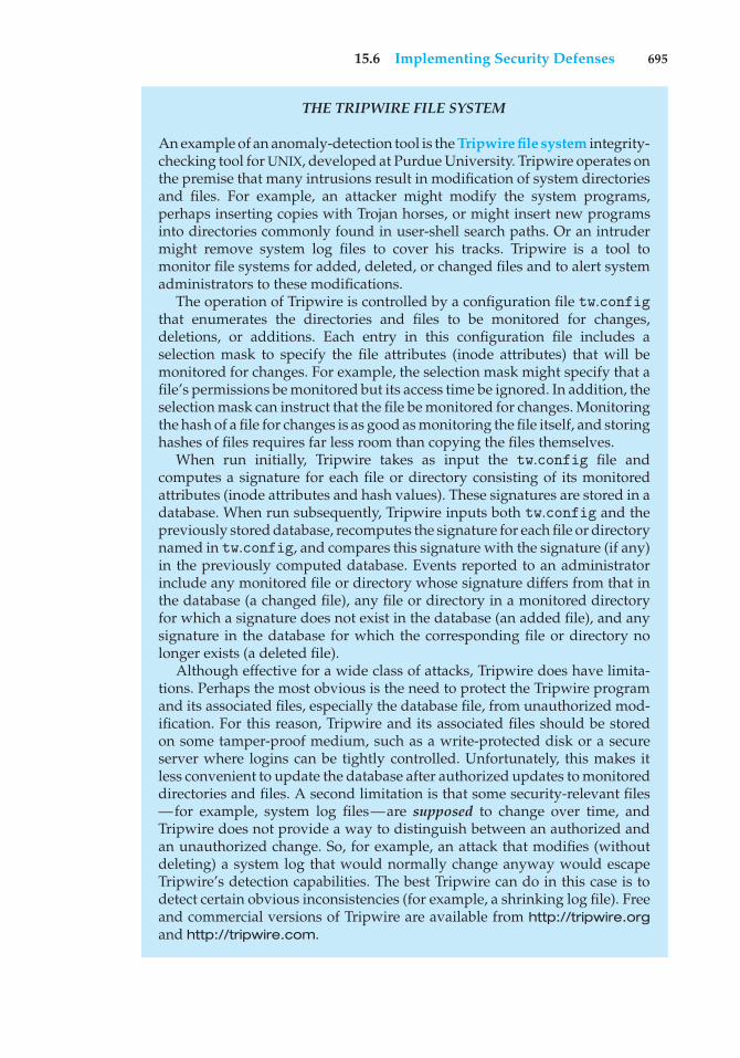
15.6 Implementing Security Defenses 695
THE TRIPWIRE FILE SYSTEM
An example of an anomaly-detection tool is the Tripwire file system integrity-checking tool for UNIX, developed at Purdue University. Tripwire operates onthe premise that many intrusions result in modification of system directoriesand files. For example, an attacker might modify the system programs,perhaps inserting copies with Trojan horses, or might insert new programsinto directories commonly found in user-shell search paths. Or an intrudermight remove system log files to cover his tracks. Tripwire is a tool tomonitor file systems for added, deleted, or changed files and to alert systemadministrators to these modifications.
The operation of Tripwire is controlled by a configuration file tw.configthat enumerates the directories and files to be monitored for changes,deletions, or additions. Each entry in this configuration file includes aselection mask to specify the file attributes (inode attributes) that will bemonitored for changes. For example, the selection mask might specify that afile’s permissions be monitored but its access time be ignored. In addition, theselection mask can instruct that the file be monitored for changes. Monitoringthe hash of a file for changes is as good as monitoring the file itself, and storinghashes of files requires far less room than copying the files themselves.
When run initially, Tripwire takes as input the tw.config file andcomputes a signature for each file or directory consisting of its monitoredattributes (inode attributes and hash values). These signatures are stored in adatabase. When run subsequently, Tripwire inputs both tw.config and thepreviously stored database, recomputes the signature for each file or directorynamed in tw.config, and compares this signature with the signature (if any)in the previously computed database. Events reported to an administratorinclude any monitored file or directory whose signature differs from that inthe database (a changed file), any file or directory in a monitored directoryfor which a signature does not exist in the database (an added file), and anysignature in the database for which the corresponding file or directory nolonger exists (a deleted file).
Although effective for a wide class of attacks, Tripwire does have limita-tions. Perhaps the most obvious is the need to protect the Tripwire programand its associated files, especially the database file, from unauthorized mod-ification. For this reason, Tripwire and its associated files should be storedon some tamper-proof medium, such as a write-protected disk or a secureserver where logins can be tightly controlled. Unfortunately, this makes itless convenient to update the database after authorized updates to monitoreddirectories and files. A second limitation is that some security-relevant files—for example, system log files—are supposed to change over time, andTripwire does not provide a way to distinguish between an authorized andan unauthorized change. So, for example, an attack that modifies (withoutdeleting) a system log that would normally change anyway would escapeTripwire’s detection capabilities. The best Tripwire can do in this case is todetect certain obvious inconsistencies (for example, a shrinking log file). Freeand commercial versions of Tripwire are available from http://tripwire.organd http://tripwire.com.
696 Chapter 15 Security
and users’ inboxes, it was relatively harmless. It did, however, effectivelynegate the defensive strategy of opening attachments only from people knownto the receiver. A more effective defense method is to avoid opening any e-mailattachment that contains executable code. Some companies now enforce thisas policy by removing all incoming attachments to e-mail messages.
Another safeguard, although it does not prevent infection, does permitearly detection. A user must begin by completely reformatting the hard disk,especially the boot sector, which is often targeted for viral attack. Only securesoftware is uploaded, and a signature of each program is taken via a securemessage-digest computation. The resulting file name and associated message-digest list must then be kept free from unauthorized access. Periodically, oreach time a program is run, the operating system recomputes the signature andcompares it with the signature on the original list; any differences serve as awarning of possible infection. This technique can be combined with others. Forexample, a high-overhead antivirus scan, such as a sandbox, can be used; andif a program passes the test, a signature can be created for it. If the signaturesmatch the next time the program is run, it does not need to be virus-scannedagain.
15.6.5 Auditing, Accounting, and Logging
Auditing, accounting, and logging can decrease system performance, but theyare useful in several areas, including security. Logging can be general orspecific. All system-call executions can be logged for analysis of programbehavior (or misbehavior). More typically, suspicious events are logged.Authentication failures and authorization failures can tell us quite a lot aboutbreak-in attempts.
Accounting is another potential tool in a security administrator’s kit. Itcan be used to find performance changes, which in turn can reveal securityproblems. One of the early UNIX computer break-ins was detected by CliffStoll when he was examining accounting logs and spotted an anomaly.
15.7 Firewalling to Protect Systems and Networks
We turn next to the question of how a trusted computer can be connectedsafely to an untrustworthy network. One solution is the use of a firewall toseparate trusted and untrusted systems. A firewall is a computer, appliance,or router that sits between the trusted and the untrusted. A network firewalllimits network access between the two security domains and monitors andlogs all connections. It can also limit connections based on source or destinationaddress, source or destination port, or direction of the connection. For instance,web servers use HTTP to communicate with web browsers. A firewall thereforemay allow only HTTP to pass from all hosts outside the firewall to the webserver within the firewall. The Morris Internet worm used the finger protocolto break into computers, so finger would not be allowed to pass, for example.
In fact, a network firewall can separate a network into multiple domains.A common implementation has the Internet as the untrusted domain; asemitrusted and semisecure network, called the demilitarized zone (DMZ),as another domain; and a company’s computers as a third domain (Figure
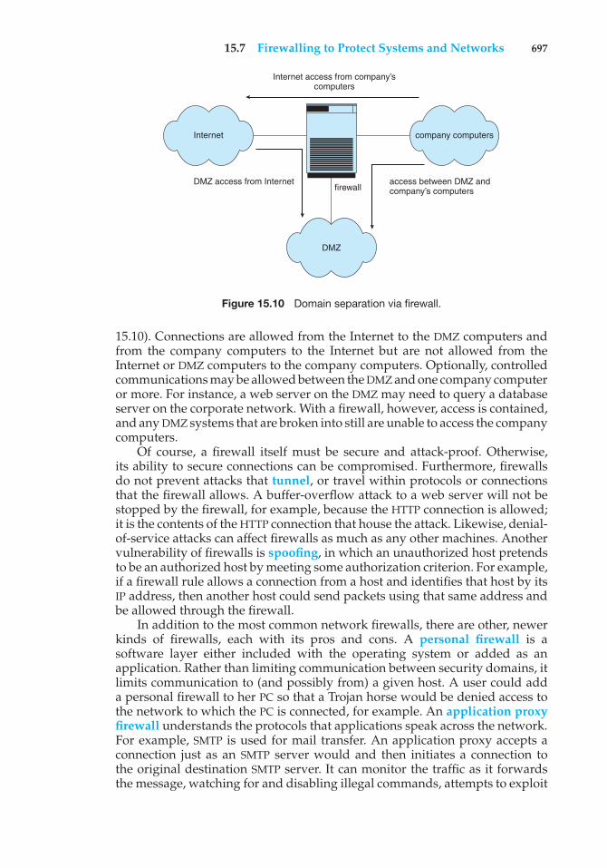
15.7 Firewalling to Protect Systems and Networks 697
Internet access from company’scomputers
company computers
DMZ access from Internetfirewall
DMZ
access between DMZ andcompany’s computers
Internet
Figure 15.10 Domain separation via firewall.
15.10). Connections are allowed from the Internet to the DMZ computers andfrom the company computers to the Internet but are not allowed from theInternet or DMZ computers to the company computers. Optionally, controlledcommunications may be allowed between the DMZ and one company computeror more. For instance, a web server on the DMZ may need to query a databaseserver on the corporate network. With a firewall, however, access is contained,and any DMZ systems that are broken into still are unable to access the companycomputers.
Of course, a firewall itself must be secure and attack-proof. Otherwise,its ability to secure connections can be compromised. Furthermore, firewallsdo not prevent attacks that tunnel, or travel within protocols or connectionsthat the firewall allows. A buffer-overflow attack to a web server will not bestopped by the firewall, for example, because the HTTP connection is allowed;it is the contents of the HTTP connection that house the attack. Likewise, denial-of-service attacks can affect firewalls as much as any other machines. Anothervulnerability of firewalls is spoofing, in which an unauthorized host pretendsto be an authorized host by meeting some authorization criterion. For example,if a firewall rule allows a connection from a host and identifies that host by itsIP address, then another host could send packets using that same address andbe allowed through the firewall.
In addition to the most common network firewalls, there are other, newerkinds of firewalls, each with its pros and cons. A personal firewall is asoftware layer either included with the operating system or added as anapplication. Rather than limiting communication between security domains, itlimits communication to (and possibly from) a given host. A user could adda personal firewall to her PC so that a Trojan horse would be denied access tothe network to which the PC is connected, for example. An application proxyfirewall understands the protocols that applications speak across the network.For example, SMTP is used for mail transfer. An application proxy accepts aconnection just as an SMTP server would and then initiates a connection tothe original destination SMTP server. It can monitor the traffic as it forwardsthe message, watching for and disabling illegal commands, attempts to exploit
698 Chapter 15 Security
bugs, and so on. Some firewalls are designed for one specific protocol. AnXML firewall, for example, has the specific purpose of analyzing XML trafficand blocking disallowed or malformed XML. System-call firewalls sit betweenapplications and the kernel, monitoring system-call execution. For example,in Solaris 10, the “least privilege” feature implements a list of more than fiftysystem calls that processes may or may not be allowed to make. A process thatdoes not need to spawn other processes can have that ability taken away, forinstance.
15.8 Computer-Security Classifications
The U.S. Department of Defense Trusted Computer System Evaluation Criteriaspecify four security classifications in systems: A, B, C, and D. This specificationis widely used to determine the security of a facility and to model securitysolutions, so we explore it here. The lowest-level classification is division D, orminimal protection. Division D includes only one class and is used for systemsthat have failed to meet the requirements of any of the other security classes.For instance, MS-DOS and Windows 3.1 are in division D.
Division C, the next level of security, provides discretionary protection andaccountability of users and their actions through the use of audit capabilities.Division C has two levels: C1 and C2. A C1-class system incorporates someform of controls that allow users to protect private information and tokeep other users from accidentally reading or destroying their data. A C1environment is one in which cooperating users access data at the same levelsof sensitivity. Most versions of UNIX are C1 class.
The total of all protection systems within a computer system (hardware,software, firmware) that correctly enforce a security policy is known as atrusted computer base (TCB). The TCB of a C1 system controls access betweenusers and files by allowing the user to specify and control sharing of objectsby named individuals or defined groups. In addition, the TCB requires that theusers identify themselves before they start any activities that the TCB is expectedto mediate. This identification is accomplished via a protected mechanism orpassword. The TCB protects the authentication data so that they are inaccessibleto unauthorized users.
A C2-class system adds an individual-level access control to the require-ments of a C1 system. For example, access rights of a file can be specifiedto the level of a single individual. In addition, the system administrator canselectively audit the actions of any one or more users based on individualidentity. The TCB also protects itself from modification of its code or datastructures. In addition, no information produced by a prior user is availableto another user who accesses a storage object that has been released back tothe system. Some special, secure versions of UNIX have been certified at the C2level.
Division-B mandatory-protection systems have all the properties of aclass-C2 system. In addition, they attach a sensitivity label to each objectin the system. The B1-class TCB maintains these labels, which are used fordecisions pertaining to mandatory access control. For example, a user at theconfidential level could not access a file at the more sensitive secret level.The TCB also denotes the sensitivity level at the top and bottom of each
15.9 An Example: Windows 7 699
page of any human-readable output. In addition to the normal user-name–password authentication information, the TCB also maintains the clearanceand authorizations of individual users and will support at least two levels ofsecurity. These levels are hierarchical, so that a user may access any objectsthat carry sensitivity labels equal to or lower than his security clearance. Forexample, a secret-level user could access a file at the confidential level in theabsence of other access controls. Processes are also isolated through the use ofdistinct address spaces.
A B2-class system extends the sensitivity labels to each system resource,such as storage objects. Physical devices are assigned minimum and maximumsecurity levels that the system uses to enforce constraints imposed by thephysical environments in which the devices are located. In addition, a B2system supports covert channels and the auditing of events that could lead tothe exploitation of a covert channel.
A B3-class system allows the creation of access-control lists that denoteusers or groups not granted access to a given named object. The TCB alsocontains a mechanism to monitor events that may indicate a violation ofsecurity policy. The mechanism notifies the security administrator and, ifnecessary, terminates the event in the least disruptive manner.
The highest-level classification is division A. Architecturally, a class-A1system is functionally equivalent to a B3 system, but it uses formal designspecifications and verification techniques, granting a high degree of assurancethat the TCB has been implemented correctly. A system beyond class A1 mightbe designed and developed in a trusted facility by trusted personnel.
The use of a TCB merely ensures that the system can enforce aspects of asecurity policy; the TCB does not specify what the policy should be. Typically,a given computing environment develops a security policy for certificationand has the plan accredited by a security agency, such as the NationalComputer Security Center. Certain computing environments may require othercertification, such as that supplied by TEMPEST, which guards against electroniceavesdropping. For example, a TEMPEST-certified system has terminals thatare shielded to prevent electromagnetic fields from escaping. This shieldingensures that equipment outside the room or building where the terminal ishoused cannot detect what information is being displayed by the terminal.
15.9 An Example: Windows 7
Microsoft Windows 7 is a general-purpose operating system designed tosupport a variety of security features and methods. In this section, weexamine features that Windows 7 uses to perform security functions. For moreinformation and background on Windows 7, see Chapter 19.
The Windows 7 security model is based on the notion of user accounts.Windows 7 allows the creation of any number of user accounts, which canbe grouped in any manner. Access to system objects can then be permitted ordenied as desired. Users are identified to the system by a unique security ID.When a user logs on, Windows 7 creates a security access token that includesthe security ID for the user, security IDs for any groups of which the user isa member, and a list of any special privileges that the user has. Examplesof special privileges include backing up files and directories, shutting down
700 Chapter 15 Security
the computer, logging on interactively, and changing the system clock. Everyprocess that Windows 7 runs on behalf of a user will receive a copy of theaccess token. The system uses the security IDs in the access token to permit ordeny access to system objects whenever the user, or a process on behalf of theuser, attempts to access the object. Authentication of a user account is typicallyaccomplished via a user name and password, although the modular design ofWindows 7 allows the development of custom authentication packages. Forexample, a retinal (or eye) scanner might be used to verify that the user is whoshe says she is.
Windows 7 uses the idea of a subject to ensure that programs run by a userdo not get greater access to the system than the user is authorized to have.A subject is used to track and manage permissions for each program that auser runs. It is composed of the user’s access token and the program actingon behalf of the user. Since Windows 7 operates with a client–server model,two classes of subjects are used to control access: simple subjects and serversubjects. An example of a simple subject is the typical application programthat a user executes after she logs on. The simple subject is assigned a securitycontext based on the security access token of the user. A server subject is aprocess implemented as a protected server that uses the security context of theclient when acting on the client’s behalf.
As mentioned in Section 15.7, auditing is a useful security technique.Windows 7 has built-in auditing that allows many common security threats tobe monitored. Examples include failure auditing for login and logoff eventsto detect random password break-ins, success auditing for login and logoffevents to detect login activity at strange hours, success and failure write-accessauditing for executable files to track a virus outbreak, and success and failureauditing for file access to detect access to sensitive files.
Windows added mandatory integrity control, which works by assigning anintegrity label to each securable object and subject. In order for a given subjectto have access to an object, it must have the access requested in the discretionaryaccess-control list, and its integrity label must be equal to or higher than thatof the secured object (for the given operation). The integrity labels in Windows7 are (in ascending order): untrusted, low, medium, high, and system. Inaddition, three access mask bits are permitted for integrity labels: NoReadUp,NoWriteUp, and NoExecuteUp. NoWriteUp is automatically enforced, so alower-integrity subject cannot perform a write operation on a higher-integrityobject. However, unless explictly blocked by the security descriptor, it canperform read or execute operations.
For securable objects without an explicit integrity label, a default labelof medium is assigned. The label for a given subject is assigned duringlogon. For instance, a nonadministrative user will have an integrity labelof medium. In addition to integrity labels, Windows Vista also added UserAccount Control (UAC), which represents an administrative account (not thebuilt-in Administrators account) with two separate tokens. One, for normalusage, has the built-in Administrators group disabled and has an integritylabel of medium. The other, for elevated usage, has the built-in Administratorsgroup enabled and an integrity label of high.
Security attributes of an object in Windows 7 are described by a securitydescriptor. The security descriptor contains the security ID of the owner ofthe object (who can change the access permissions), a group security ID used
15.10 Summary 701
only by the POSIX subsystem, a discretionary access-control list that identifieswhich users or groups are allowed (and which are explicitly denied) access, anda system access-control list that controls which auditing messages the systemwill generate. Optionally, the system access-control list can set the integrity ofthe object and identify which operations to block from lower-integrity subjects:read, write (always enforced), or execute. For example, the security descriptorof the file foo.bar might have owner avi and this discretionary access-controllist:
• avi—all access
• group cs—read–write access
• user cliff—no access
In addition, it might have a system access-control list that tells the system toaudit writes by everyone, along with an integrity label of medium that deniesread, write, and execute to lower-integrity subjects.
An access-control list is composed of access-control entries that containthe security ID of the individual and an access mask that defines all possibleactions on the object, with a value of AccessAllowed or AccessDenied foreach action. Files in Windows 7 may have the following access types: Read-Data, WriteData, AppendData, Execute, ReadExtendedAttribute, Write-ExtendedAttribute, ReadAttributes, and WriteAttributes. We can seehow this allows a fine degree of control over access to objects.
Windows 7 classifies objects as either container objects or noncontainerobjects. Container objects, such as directories, can logically contain otherobjects. By default, when an object is created within a container object, the newobject inherits permissions from the parent object. Similarly, if the user copies afile from one directory to a new directory, the file will inherit the permissions ofthe destination directory. Noncontainer objects inherit no other permissions.Furthermore, if a permission is changed on a directory, the new permissionsdo not automatically apply to existing files and subdirectories; the user mayexplicitly apply them if he so desires.
The system administrator can prohibit printing to a printer on the systemfor all or part of a day and can use the Windows 7 Performance Monitor tohelp her spot approaching problems. In general, Windows 7 does a good job ofproviding features to help ensure a secure computing environment. Many ofthese features are not enabled by default, however, which may be one reasonfor the myriad security breaches on Windows 7 systems. Another reason is thevast number of services Windows 7 starts at system boot time and the numberof applications that typically are installed on a Windows 7 system. For a realmultiuser environment, the system administrator should formulate a securityplan and implement it, using the features that Windows 7 provides and othersecurity tools.
15.10 Summary
Protection is an internal problem. Security, in contrast, must consider boththe computer system and the environment—people, buildings, businesses,valuable objects, and threats—within which the system is used.
702 Chapter 15 Security
The data stored in the computer system must be protected from unautho-rized access, malicious destruction or alteration, and accidental introduction ofinconsistency. It is easier to protect against accidental loss of data consistencythan to protect against malicious access to the data. Absolute protection of theinformation stored in a computer system from malicious abuse is not possible;but the cost to the perpetrator can be made sufficiently high to deter most, ifnot all, attempts to access that information without proper authority.
Several types of attacks can be launched against programs and againstindividual computers or the masses. Stack- and buffer-overflow techniquesallow successful attackers to change their level of system access. Viruses andworms are self-perpetuating, sometimes infecting thousands of computers.Denial-of-service attacks prevent legitimate use of target systems.
Encryption limits the domain of receivers of data, while authenticationlimits the domain of senders. Encryption is used to provide confidentialityof data being stored or transferred. Symmetric encryption requires a sharedkey, while asymmetric encryption provides a public key and a private key.Authentication, when combined with hashing, can prove that data have notbeen changed.
User authentication methods are used to identify legitimate users of asystem. In addition to standard user-name and password protection, severalauthentication methods are used. One-time passwords, for example, changefrom session to session to avoid replay attacks. Two-factor authenticationrequires two forms of authentication, such as a hardware calculator with anactivation PIN. Multifactor authentication uses three or more forms. Thesemethods greatly decrease the chance of authentication forgery.
Methods of preventing or detecting security incidents include intrusion-detection systems, antivirus software, auditing and logging of system events,monitoring of system software changes, system-call monitoring, and firewalls.
Exercises
15.1 Buffer-overflow attacks can be avoided by adopting a better program-ming methodology or by using special hardware support. Discuss thesesolutions.
15.2 A password may become known to other users in a variety of ways. Isthere a simple method for detecting that such an event has occurred?Explain your answer.
15.3 What is the purpose of using a “salt” along with the user-providedpassword? Where should the “salt” be stored, and how should it beused?
15.4 The list of all passwords is kept within the operating system. Thus,if a user manages to read this list, password protection is no longerprovided. Suggest a scheme that will avoid this problem. (Hint: Usedifferent internal and external representations.)
15.5 An experimental addition to UNIX allows a user to connect a watchdogprogram to a file. The watchdog is invoked whenever a program
Bibliographical Notes 703
requests access to the file. The watchdog then either grants or deniesaccess to the file. Discuss two pros and two cons of using watchdogsfor security.
15.6 The UNIX program COPS scans a given system for possible securityholes and alerts the user to possible problems. What are two potentialhazards of using such a system for security? How can these problemsbe limited or eliminated?
15.7 Discuss a means by which managers of systems connected to theInternet could design their systems to limit or eliminate the damagedone by worms. What are the drawbacks of making the change thatyou suggest?
15.8 Argue for or against the judicial sentence handed down against RobertMorris, Jr., for his creation and execution of the Internet worm discussedin Section 15.3.1.
15.9 Make a list of six security concerns for a bank’s computer system. Foreach item on your list, state whether this concern relates to physical,human, or operating-system security.
15.10 What are two advantages of encrypting data stored in the computersystem?
15.11 What commonly used computer programs are prone to man-in-the-middle attacks? Discuss solutions for preventing this form of attack.
15.12 Compare symmetric and asymmetric encryption schemes, and discussthe circumstances under which a distributed system would use one orthe other.
15.13 Why doesn’t Dkd,N(Eke,N(m)) provide authentication of the sender? Towhat uses can such an encryption be put?
15.14 Discuss how the asymmetric encryption algorithm can be used toachieve the following goals.
a. Authentication: the receiver knows that only the sender couldhave generated the message.
b. Secrecy: only the receiver can decrypt the message.
c. Authentication and secrecy: only the receiver can decrypt themessage, and the receiver knows that only the sender could havegenerated the message.
15.15 Consider a system that generates 10 million audit records per day.Assume that, on average, there are 10 attacks per day on this systemand each attack is reflected in 20 records. If the intrusion-detectionsystem has a true-alarm rate of 0.6 and a false-alarm rate of 0.0005,what percentage of alarms generated by the system correspond to realintrusions?
704 Chapter 15 Security
Bibliographical Notes
General discussions concerning security are given by [Denning (1982)],[Pfleeger and Pfleeger (2006)] and [Tanenbaum (2010)]. Computer networkingis discussed in [Kurose and Ross (2013)].
Issues concerning the design and verification of secure systems are dis-cussed by [Rushby (1981)] and by [Silverman (1983)]. A security kernel for amultiprocessor microcomputer is described by [Schell (1983)]. A distributedsecure system is described by [Rushby and Randell (1983)].
[Morris and Thompson (1979)] discuss password security. [Morshedian(1986)] presents methods to fight password pirates. Password authenticationwith insecure communications is considered by [Lamport (1981)]. The issueof password cracking is examined by [Seely (1989)]. Computer break-ins arediscussed by [Lehmann (1987)] and by [Reid (1987)]. Issues related to trustingcomputer programs are discussed in [Thompson (1984)].
Discussions concerning UNIX security are offered by [Grampp and Morris(1984)], [Wood and Kochan (1985)], [Farrow (1986)], [Filipski and Hanko(1986)], [Hecht et al. (1988)], [Kramer (1988)], and [Garfinkel et al. (2003)].[Bershad and Pinkerton (1988)] present the watchdog extension to BSD UNIX.
[Spafford (1989)] presents a detailed technical discussion of the Internetworm. The Spafford article appears with three others in a special section onthe Morris Internet worm in Communications of the ACM (Volume 32, Number6, June 1989).
Security problems associated with the TCP/IP protocol suite are described in[Bellovin (1989)]. The mechanisms commonly used to prevent such attacks arediscussed in [Cheswick et al. (2003)]. Another approach to protecting networksfrom insider attacks is to secure topology or route discovery. [Kent et al.(2000)], [Hu et al. (2002)], [Zapata and Asokan (2002)], and [Hu and Perrig(2004)] present solutions for secure routing. [Savage et al. (2000)] examinethe distributed denial-of-service attack and propose IP trace-back solutions toaddress the problem. [Perlman (1988)] proposes an approach to diagnose faultswhen the network contains malicious routers.
Information about viruses and worms can be found athttp://www.securelist.com, as well as in [Ludwig (1998)] and [Ludwig(2002)]. Another website containing up-to-date security informa-tion is http://www.eeye.com/resources/security-center/research. Apaper on the dangers of a computer monoculture can be found athttp://cryptome.org/cyberinsecurity.htm.
[Diffie and Hellman (1976)] and [Diffie and Hellman (1979)] were thefirst researchers to propose the use of the public-key encryption scheme. Thealgorithm presented in Section 15.4.1 is based on the public-key encryptionscheme; it was developed by [Rivest et al. (1978)]. [C. Kaufman (2002)]and [Stallings (2011)] explore the use of cryptography in computer systems.Discussions concerning protection of digital signatures are offered by [Akl(1983)], [Davies (1983)], [Denning (1983)], and [Denning (1984)]. Completecryptography information is presented in [Schneier (1996)] and [Katz andLindell (2008)].
The RSA algorithm is presented in [Rivest et al. (1978)]. Information aboutNIST’s AES activities can be found at http://www.nist.gov/aes; informationabout other cryptographic standards for the United States can also be found
Bibliography 705
at that site. In 1999, SSL 3.0 was modified slightly and presented in an IETFRequest for Comments (RFC) under the name TLS.
The example in Section 15.6.3 illustrating the impact of false-alarm rateon the effectiveness of IDSs is based on [Axelsson (1999)]. The description ofTripwire in Section 15.6.5 is based on [Kim and Spafford (1993)]. Research intosystem-call-based anomaly detection is described in [Forrest et al. (1996)].
The U.S. government is, of course, concerned about security. The Depart-ment of Defense Trusted Computer System Evaluation Criteria ([DoD(1985)]), known also as the Orange Book, describes a set of security levels andthe features that an operating system must have to qualify for each securityrating. Reading it is a good starting point for understanding security concerns.The Microsoft Windows NT Workstation Resource Kit ([Microsoft (1996)])describes the security model of NT and how to use that model.
Bibliography
[Akl (1983)] S. G. Akl, “Digital Signatures: A Tutorial Survey”, Computer, Volume16, Number 2 (1983), pages 15–24.
[Axelsson (1999)] S. Axelsson, “The Base-Rate Fallacy and Its Implicationsfor Intrusion Detection”, Proceedings of the ACM Conference on Computer andCommunications Security (1999), pages 1–7.
[Bellovin (1989)] S. M. Bellovin, “Security Problems in the TCP/IP ProtocolSuite”, Computer Communications Review, Volume 19:2, (1989), pages 32–48.
[Bershad and Pinkerton (1988)] B. N. Bershad and C. B. Pinkerton, “Watchdogs:Extending the Unix File System”, Proceedings of the Winter USENIX Conference(1988).
[C. Kaufman (2002)] M. S. C. Kaufman, R. Perlman, Network Security: PrivateCommunication in a Public World, Second Edition, Prentice Hall (2002).
[Cheswick et al. (2003)] W. Cheswick, S. Bellovin, and A. Rubin, Firewalls andInternet Security: Repelling the Wily Hacker, Second Edition, Addison-Wesley(2003).
[Davies (1983)] D. W. Davies, “Applying the RSA Digital Signature to ElectronicMail”, Computer, Volume 16, Number 2 (1983), pages 55–62.
[Denning (1982)] D. E. Denning, Cryptography and Data Security, Addison-Wesley (1982).
[Denning (1983)] D. E. Denning, “Protecting Public Keys and Signature Keys”,Computer, Volume 16, Number 2 (1983), pages 27–35.
[Denning (1984)] D. E. Denning, “Digital Signatures with RSA and OtherPublic-Key Cryptosystems”, Communications of the ACM, Volume 27, Number 4(1984), pages 388–392.
[Diffie and Hellman (1976)] W. Diffie and M. E. Hellman, “New Directions inCryptography”, IEEE Transactions on Information Theory, Volume 22, Number 6(1976), pages 644–654.
706 Chapter 15 Security
[Diffie and Hellman (1979)] W. Diffie and M. E. Hellman, “Privacy and Authen-tication”, Proceedings of the IEEE (1979), pages 397–427.
[DoD (1985)] Trusted Computer System Evaluation Criteria. Department ofDefense (1985).
[Farrow (1986)] R. Farrow, “Security Issues and Strategies for Users”, UNIXWorld (April 1986), pages 65–71.
[Filipski and Hanko (1986)] A. Filipski and J. Hanko, “Making UNIX Secure”,Byte (April 1986), pages 113–128.
[Forrest et al. (1996)] S. Forrest, S. A. Hofmeyr, and T. A. Longstaff, “A Senseof Self for UNIX Processes”, Proceedings of the IEEE Symposium on Security andPrivacy (1996), pages 120–128.
[Garfinkel et al. (2003)] S. Garfinkel, G. Spafford, and A. Schwartz, PracticalUNIX & Internet Security, O’Reilly & Associates (2003).
[Grampp and Morris (1984)] F. T. Grampp and R. H. Morris, “UNIX Oper-ating-System Security”, AT&T Bell Laboratories Technical Journal, Volume 63,Number 8 (1984), pages 1649–1672.
[Hecht et al. (1988)] M. S. Hecht, A. Johri, R. Aditham, and T. J. Wei, “ExperienceAdding C2 Security Features to UNIX”, Proceedings of the Summer USENIXConference (1988), pages 133–146.
[Hu and Perrig (2004)] Y.-C. Hu and A. Perrig, “SPV: A Secure Path VectorRouting Scheme for Securing BGP”, Proceedings of ACM SIGCOMM Conferenceon Data Communication (2004).
[Hu et al. (2002)] Y.-C. Hu, A. Perrig, and D. Johnson, “Ariadne: A SecureOn-Demand Routing Protocol for Ad Hoc Networks”, Proceedings of the AnnualInternational Conference on Mobile Computing and Networking (2002).
[Katz and Lindell (2008)] J. Katz and Y. Lindell, Introduction to Modern Cryptog-raphy, Chapman & Hall/CRC Press (2008).
[Kent et al. (2000)] S. Kent, C. Lynn, and K. Seo, “Secure Border GatewayProtocol (Secure-BGP)”, IEEE Journal on Selected Areas in Communications, Volume18, Number 4 (2000), pages 582–592.
[Kim and Spafford (1993)] G. H. Kim and E. H. Spafford, “The Design andImplementation of Tripwire: A File System Integrity Checker”, Technical report,Purdue University (1993).
[Kramer (1988)] S. M. Kramer, “Retaining SUID Programs in a Secure UNIX”,Proceedings of the Summer USENIX Conference (1988), pages 107–118.
[Kurose and Ross (2013)] J. Kurose and K. Ross, Computer Networking—A Top–Down Approach, Sixth Edition, Addison-Wesley (2013).
[Lamport (1981)] L. Lamport, “Password Authentication with Insecure Com-munications”, Communications of the ACM, Volume 24, Number 11 (1981), pages770–772.
[Lehmann (1987)] F. Lehmann, “Computer Break-Ins”, Communications of theACM, Volume 30, Number 7 (1987), pages 584–585.
Bibliography 707
[Ludwig (1998)] M. Ludwig, The Giant Black Book of Computer Viruses, SecondEdition, American Eagle Publications (1998).
[Ludwig (2002)] M. Ludwig, The Little Black Book of Email Viruses, AmericanEagle Publications (2002).
[Microsoft (1996)] Microsoft Windows NT Workstation Resource Kit. MicrosoftPress (1996).
[Morris and Thompson (1979)] R. Morris and K. Thompson, “Password Secu-rity: A Case History”, Communications of the ACM, Volume 22, Number 11 (1979),pages 594–597.
[Morshedian (1986)] D. Morshedian, “How to Fight Password Pirates”, Com-puter, Volume 19, Number 1 (1986).
[Perlman (1988)] R. Perlman, Network Layer Protocols with Byzantine Robustness.PhD thesis, Massachusetts Institute of Technology (1988).
[Pfleeger and Pfleeger (2006)] C. Pfleeger and S. Pfleeger, Security in Computing,Fourth Edition, Prentice Hall (2006).
[Reid (1987)] B. Reid, “Reflections on Some Recent Widespread ComputerBreak-Ins”, Communications of the ACM, Volume 30, Number 2 (1987), pages103–105.
[Rivest et al. (1978)] R. L. Rivest, A. Shamir, and L. Adleman, “On DigitalSignatures and Public Key Cryptosystems”, Communications of the ACM, Volume21, Number 2 (1978), pages 120–126.
[Rushby (1981)] J. M. Rushby, “Design and Verification of Secure Systems”,Proceedings of the ACM Symposium on Operating Systems Principles (1981), pages12–21.
[Rushby and Randell (1983)] J. Rushby and B. Randell, “A Distributed SecureSystem”, Computer, Volume 16, Number 7 (1983), pages 55–67.
[Savage et al. (2000)] S. Savage, D. Wetherall, A. R. Karlin, and T. Anderson,“Practical Network Support for IP Traceback”, Proceedings of ACM SIGCOMMConference on Data Communication (2000), pages 295–306.
[Schell (1983)] R. R. Schell, “A Security Kernel for a Multiprocessor Microcom-puter”, Computer (1983), pages 47–53.
[Schneier (1996)] B. Schneier, Applied Cryptography, Second Edition, John Wileyand Sons (1996).
[Seely (1989)] D. Seely, “Password Cracking: A Game of Wits”, Communicationsof the ACM, Volume 32, Number 6 (1989), pages 700–704.
[Silverman (1983)] J. M. Silverman, “Reflections on the Verification of theSecurity of an Operating System Kernel”, Proceedings of the ACM Symposiumon Operating Systems Principles (1983), pages 143–154.
[Spafford (1989)] E. H. Spafford, “The Internet Worm: Crisis and Aftermath”,Communications of the ACM, Volume 32, Number 6 (1989), pages 678–687.

708 Chapter 15 Security
[Stallings (2011)] W. Stallings, Operating Systems, Seventh Edition, Prentice Hall(2011).
[Tanenbaum (2010)] A. S. Tanenbaum, Computer Networks, Fifth Edition, Pren-tice Hall (2010).
[Thompson (1984)] K. Thompson, “Reflections on Trusting Trust”, Communica-tions of ACM, Volume 27, Number 8 (1984), pages 761–763.
[Wood and Kochan (1985)] P. Wood and S. Kochan, UNIX System Security,Hayden (1985).
[Zapata and Asokan (2002)] M. Zapata and N. Asokan, “Securing Ad HocRouting Protocols”, Proc. 2002 ACM Workshop on Wireless Security (2002), pages1–10.
Part Six
Advanced TopicsVirtualization permeates all aspects of computing. Virtual machines areone instance of this trend. Generally, with a virtual machine, guest oper-ating systems and applications run in an environment that appears tothem to be native hardware. This environment behaves toward them asnative hardware would but also protects, manages, and limits them.
A distributed system is a collection of processors that do not sharememory or a clock. Instead, each processor has its own local memory,and the processors communicate with one another through communica-tion lines such as local-area or wide-area networks. Distributed systemsoffer several benefits: they give users access to more of the resourcesmaintained by the system, speed computation, and improve data avail-ability and reliability.

16C H A P T E R
Virtual Machines
The term virtualization has many meanings, and aspects of virtualizationpermeate all aspects of computing. Virtual machines are one instance ofthis trend. Generally, with a virtual machine, guest operating systems andapplications run in an environment that appears to them to be native hardwareand that behaves toward them as native hardware would but that also protects,manages, and limits them.
This chapter delves into the uses, features, and implementation of virtualmachines. Virtual machines can be implemented in several ways, and thischapter describes these options. One option is to add virtual machine supportto the kernel. Because that implementation method is the most pertinent to thisbook, we explore it most fully. Additionally, hardware features provided bythe CPU and even by I/O devices can support virtual machine implementation,so we discuss how those features are used by the appropriate kernel modules.
CHAPTER OBJECTIVES
• To explore the history and benefits of virtual machines.• To discuss the various virtual machine technologies.• To describe the methods used to implement virtualization.• To show the most common hardware features that support virtualization
and explain how they are used by operating-system modules.
16.1 Overview
The fundamental idea behind a virtual machine is to abstract the hardwareof a single computer (the CPU, memory, disk drives, network interface cards,and so forth) into several different execution environments, thereby creatingthe illusion that each separate environment is running on its own privatecomputer. This concept may seem similar to the layered approach of operatingsystem implementation (see Section 2.7.2), and in some ways it is. In the case ofvirtualization, there is a layer that creates a virtual system on which operatingsystems or applications can run.
711
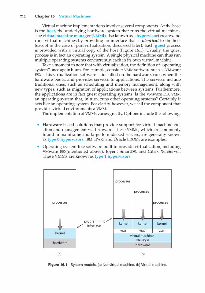
712 Chapter 16 Virtual Machines
Virtual machine implementations involve several components. At the baseis the host, the underlying hardware system that runs the virtual machines.The virtual machine manager (VMM) (also known as a hypervisor) creates andruns virtual machines by providing an interface that is identical to the host(except in the case of paravirtualization, discussed later). Each guest processis provided with a virtual copy of the host (Figure 16.1). Usually, the guestprocess is in fact an operating system. A single physical machine can thus runmultiple operating systems concurrently, each in its own virtual machine.
Take a moment to note that with virtualization, the definition of “operatingsystem” once again blurs. For example, consider VMM software such as VMwareESX. This virtualization software is installed on the hardware, runs when thehardware boots, and provides services to applications. The services includetraditional ones, such as scheduling and memory management, along withnew types, such as migration of applications between systems. Furthermore,the applications are in fact guest operating systems. Is the VMware ESX VMMan operating system that, in turn, runs other operating systems? Certainly itacts like an operating system. For clarity, however, we call the component thatprovides virtual environments a VMM.
The implementation of VMMs varies greatly. Options include the following:
• Hardware-based solutions that provide support for virtual machine cre-ation and management via firmware. These VMMs, which are commonlyfound in mainframe and large to midsized servers, are generally knownas type 0 hypervisors. IBM LPARs and Oracle LDOMs are examples.
• Operating-system-like software built to provide virtualization, includingVMware ESX(mentioned above), Joyent SmartOS, and Citrix XenServer.These VMMs are known as type 1 hypervisors.
(a)
processes
hardware
kernel
(b)
programminginterface
processes
processes
processes
kernelkernel kernel
VM2VM1 VM3
managerhardware
virtual machine
Figure 16.1 System models. (a) Nonvirtual machine. (b) Virtual machine.

16.2 History 713
INDIRECTION
“All problems in computer science can be solved by another level ofindirection”—David Wheeler “. . . except for the problem of too many layersof indirection.”—Kevlin Henney
• General-purpose operating systems that provide standard functions aswell as VMM functions, including Microsoft Windows Server with HyperVand RedHat Linux with the KVM feature. Because such systems have afeature set similar to type 1 hypervisors, they are also known as type 1.
• Applications that run on standard operating systems but provide VMMfeatures to guest operating systems. These applications, which includeVMware Workstation and Fusion, Parallels Desktop, and Oracle Virtual-Box, are type 2 hypervisors.
• Paravirtualization, a technique in which the guest operating system ismodified to work in cooperation with the VMM to optimize performance.
• Programming-environment virtualization, in which VMMs do not virtu-alize real hardware but instead create an optimized virtual system. Thistechnique is used by Oracle Java and Microsoft.Net.
• Emulators that allow applications written for one hardware environmentto run on a very different hardware environment, such as a different typeof CPU.
• Application containment, which is not virtualization at all but ratherprovides virtualization-like features by segregating applications from theoperating system. Oracle Solaris Zones, BSD Jails, and IBM AIX WPARs“contain” applications, making them more secure and manageable.
The variety of virtualization techniques in use today is a testament tothe breadth, depth, and importance of virtualization in modern computing.Virtualization is invaluable for data-center operations, efficient applicationdevelopment, and software testing, among many other uses.
16.2 History
Virtual machines first appeared commercially on IBM mainframes in 1972.Virtualization was provided by the IBM VM operating system. This system hasevolved and is still available. In addition, many of its original concepts arefound in other systems, making it worth exploring.
IBM VM370 divided a mainframe into multiple virtual machines, eachrunning its own operating system. A major difficulty with the VM approachinvolved disk systems. Suppose that the physical machine had three disk drivesbut wanted to support seven virtual machines. Clearly, it could not allocate adisk drive to each virtual machine. The solution was to provide virtual disks—termed minidisks in IBM’s VM operating system. The minidisks are identical
714 Chapter 16 Virtual Machines
to the system’s hard disks in all respects except size. The system implementedeach minidisk by allocating as many tracks on the physical disks as the minidiskneeded.
Once the virtual machines were created, users could run any of theoperating systems or software packages that were available on the underlyingmachine. For the IBM VM system, a user normally ran CMS—a single-userinteractive operating system.
For many years after IBM introduced this technology, virtualizationremained in its domain. Most systems could not support virtualization.However, a formal definition of virtualization helped to establish systemrequirements and a target for functionality. The virtualization requirementsstated that:
1. A VMM provides an environment for programs that is essentially identicalto the original machine.
2. Programs running within that environment show only minor perfor-mance decreases.
3. The VMM is in complete control of system resources.
These requirements of fidelity, performance, and safety still guide virtualiza-tion efforts today.
By the late 1990s, Intel 80x86 CPUs had become common, fast, and richin features. Accordingly, developers launched multiple efforts to implementvirtualization on that platform. Both Xen and VMware created technologies,still used today, to allow guest operating systems to run on the 80x86. Sincethat time, virtualization has expanded to include all common CPUs, manycommercial and open-source tools, and many operating systems. For example,the open-source VirtualBox project (http://www.virtualbox.org) provides aprogram than runs on Intel x86 and AMD64 CPUs and on Windows, Linux,Mac OS X, and Solaris host operating systems. Possible guest operating systemsinclude many versions of Windows, Linux, Solaris, and BSD, including evenMS-DOS and IBM OS/2.
16.3 Benefits and Features
Several advantages make virtualization attractive. Most of them are fundamen-tally related to the ability to share the same hardware yet run several differentexecution environments (that is, different operating systems) concurrently.
One important advantage of virtualization is that the host system isprotected from the virtual machines, just as the virtual machines are protectedfrom each other. A virus inside a guest operating system might damage thatoperating system but is unlikely to affect the host or the other guests. Becauseeach virtual machine is almost completely isolated from all other virtualmachines, there are almost no protection problems.
A potential disadvantage of isolation is that it can prevent sharing ofresources. Two approaches to provide sharing have been implemented. First,it is possible to share a file-system volume and thus to share files. Second,it is possible to define a network of virtual machines, each of which can
16.3 Benefits and Features 715
send information over the virtual communications network. The networkis modeled after physical communication networks but is implemented insoftware. Of course, the VMM is free to allow any number of its guests touse physical resources, such as a physical network connection (with sharingprovided by the VMM), in which case the allowed guests could communicatewith each other via the physical network.
One feature common to most virtualization implementations is the abilityto freeze, or suspend, a running virtual machine. Many operating systemsprovide that basic feature for processes, but VMMs go one step further andallow copies and snapshots to be made of the guest. The copy can be used tocreate a new VM or to move a VM from one machine to another with its currentstate intact. The guest can then resume where it was, as if on its originalmachine, creating a clone. The snapshot records a point in time, and the guestcan be reset to that point if necessary (for example, if a change was madebut is no longer wanted). Often, VMMs allow many snapshots to be taken. Forexample, snapshots might record a guest’s state every day for a month, makingrestoration to any of those snapshot states possible. These abilities are used togood advantage in virtual environments.
A virtual machine system is a perfect vehicle for operating-system researchand development. Normally, changing an operating system is a difficult task.Operating systems are large and complex programs, and a change in onepart may cause obscure bugs to appear in some other part. The power ofthe operating system makes changing it particularly dangerous. Because theoperating system executes in kernel mode, a wrong change in a pointer couldcause an error that would destroy the entire file system. Thus, it is necessaryto test all changes to the operating system carefully.
Furthermore, the operating system runs on and controls the entire machine,meaning that the system must be stopped and taken out of use while changesare made and tested. This period is commonly called system-developmenttime. Since it makes the system unavailable to users, system-developmenttime on shared systems is often scheduled late at night or on weekends, whensystem load is low.
A virtual-machine system can eliminate much of this latter problem.System programmers are given their own virtual machine, and system develop-ment is done on the virtual machine instead of on a physical machine. Normalsystem operation is disrupted only when a completed and tested change isready to be put into production.
Another advantage of virtual machines for developers is that multipleoperating systems can run concurrently on the developer’s workstation. Thisvirtualized workstation allows for rapid porting and testing of programs invarying environments. In addition, multiple versions of a program can run,each in its own isolated operating system, within one system. Similarly, quality-assurance engineers can test their applications in multiple environmentswithout buying, powering, and maintaining a computer for each environment.
A major advantage of virtual machines in production data-center use issystem consolidation, which involves taking two or more separate systemsand running them in virtual machines on one system. Such physical-to-virtualconversions result in resource optimization, since many lightly used systemscan be combined to create one more heavily used system.
716 Chapter 16 Virtual Machines
Consider, too, that management tools that are part of the VMM allow systemadministrators to manage many more systems than they otherwise could.A virtual environment might include 100 physical servers, each running 20virtual servers. Without virtualization, 2,000 servers would require severalsystem administrators. With virtualization and its tools, the same work can bemanaged by one or two administrators. One of the tools that make this possibleis templating, in which one standard virtual machine image, including aninstalled and configured guest operating system and applications, is saved andused as a source for multiple running VMs. Other features include managingthe patching of all guests, backing up and restoring the guests, and monitoringtheir resource use.
Virtualization can improve not only resource utilization but also resourcemanagement. Some VMMs include a live migration feature that moves arunning guest from one physical server to another without interruptingits operation or active network connections. If a server is overloaded, livemigration can thus free resources on the source host while not disrupting theguest. Similarly, when host hardware must be repaired or upgraded, guestscan be migrated to other servers, the evacuated host can be maintained, andthen the guests can be migrated back. This operation occurs without downtimeand without interruption to users.
Think about the possible effects of virtualization on how applications aredeployed. If a system can easily add, remove, and move a virtual machine,then why install applications on that system directly? Instead, the applicationcould be preinstalled on a tuned and customized operating system in a virtualmachine. This method would offer several benefits for application developers.Application management would become easier, less tuning would be required,and technical support of the application would be more straightforward.System administrators would find the environment easier to manage as well.Installation would be simple, and redeploying the application to anothersystem would be much easier than the usual steps of uninstalling andreinstalling. For widespread adoption of this methodology to occur, though, theformat of virtual machines must be standardized so that any virtual machinewill run on any virtualization platform. The “Open Virtual Machine Format” isan attempt to provide such standardization, and it could succeed in unifyingvirtual machine formats.
Virtualization has laid the foundation for many other advances in computerfacility implementation, management, and monitoring. Cloud computing,for example, is made possible by virtualization in which resources such asCPU, memory, and I/O are provided as services to customers using Internettechnologies. By using APIs, a program can tell a cloud computing facility tocreate thousands of VMs, all running a specific guest operating system andapplication, which others can access via the Internet. Many multiuser games,photo-sharing sites, and other web services use this functionality.
In the area of desktop computing, virtualization is enabling desktop andlaptop computer users to connect remotely to virtual machines located inremote data centers and access their applications as if they were local. Thispractice can increase security, because no data are stored on local disks at theuser’s site. The cost of the user’s computing resource may also decrease. Theuser must have networking, CPU, and some memory, but all that these systemcomponents need to do is display an image of the guest as its runs remotely (via
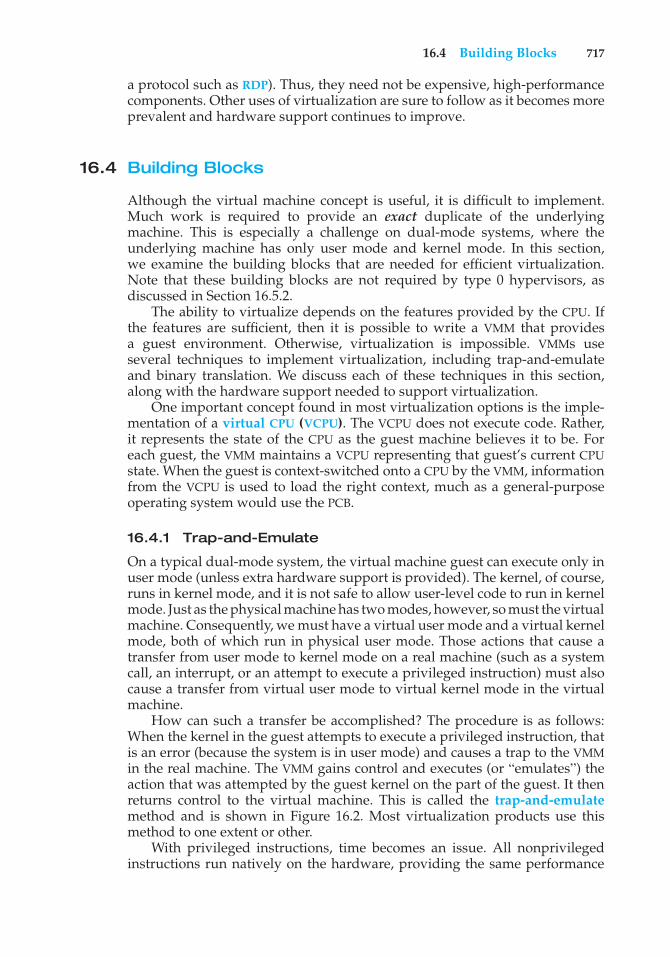
16.4 Building Blocks 717
a protocol such as RDP). Thus, they need not be expensive, high-performancecomponents. Other uses of virtualization are sure to follow as it becomes moreprevalent and hardware support continues to improve.
16.4 Building Blocks
Although the virtual machine concept is useful, it is difficult to implement.Much work is required to provide an exact duplicate of the underlyingmachine. This is especially a challenge on dual-mode systems, where theunderlying machine has only user mode and kernel mode. In this section,we examine the building blocks that are needed for efficient virtualization.Note that these building blocks are not required by type 0 hypervisors, asdiscussed in Section 16.5.2.
The ability to virtualize depends on the features provided by the CPU. Ifthe features are sufficient, then it is possible to write a VMM that providesa guest environment. Otherwise, virtualization is impossible. VMMs useseveral techniques to implement virtualization, including trap-and-emulateand binary translation. We discuss each of these techniques in this section,along with the hardware support needed to support virtualization.
One important concept found in most virtualization options is the imple-mentation of a virtual CPU (VCPU). The VCPU does not execute code. Rather,it represents the state of the CPU as the guest machine believes it to be. Foreach guest, the VMM maintains a VCPU representing that guest’s current CPUstate. When the guest is context-switched onto a CPU by the VMM, informationfrom the VCPU is used to load the right context, much as a general-purposeoperating system would use the PCB.
16.4.1 Trap-and-Emulate
On a typical dual-mode system, the virtual machine guest can execute only inuser mode (unless extra hardware support is provided). The kernel, of course,runs in kernel mode, and it is not safe to allow user-level code to run in kernelmode. Just as the physical machine has two modes, however, so must the virtualmachine. Consequently, we must have a virtual user mode and a virtual kernelmode, both of which run in physical user mode. Those actions that cause atransfer from user mode to kernel mode on a real machine (such as a systemcall, an interrupt, or an attempt to execute a privileged instruction) must alsocause a transfer from virtual user mode to virtual kernel mode in the virtualmachine.
How can such a transfer be accomplished? The procedure is as follows:When the kernel in the guest attempts to execute a privileged instruction, thatis an error (because the system is in user mode) and causes a trap to the VMMin the real machine. The VMM gains control and executes (or “emulates”) theaction that was attempted by the guest kernel on the part of the guest. It thenreturns control to the virtual machine. This is called the trap-and-emulatemethod and is shown in Figure 16.2. Most virtualization products use thismethod to one extent or other.
With privileged instructions, time becomes an issue. All nonprivilegedinstructions run natively on the hardware, providing the same performance
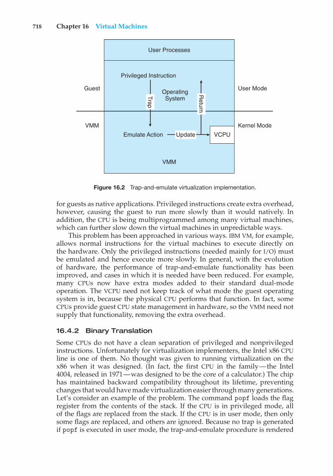
718 Chapter 16 Virtual Machines
Privileged Instruction
OperatingSystem
VCPU
VMM
VMM
Guest
Kernel Mode
User Mode
Emulate ActionR
eturn
Trap
Update
User Processes
Figure 16.2 Trap-and-emulate virtualization implementation.
for guests as native applications. Privileged instructions create extra overhead,however, causing the guest to run more slowly than it would natively. Inaddition, the CPU is being multiprogrammed among many virtual machines,which can further slow down the virtual machines in unpredictable ways.
This problem has been approached in various ways. IBM VM, for example,allows normal instructions for the virtual machines to execute directly onthe hardware. Only the privileged instructions (needed mainly for I/O) mustbe emulated and hence execute more slowly. In general, with the evolutionof hardware, the performance of trap-and-emulate functionality has beenimproved, and cases in which it is needed have been reduced. For example,many CPUs now have extra modes added to their standard dual-modeoperation. The VCPU need not keep track of what mode the guest operatingsystem is in, because the physical CPU performs that function. In fact, someCPUs provide guest CPU state management in hardware, so the VMM need notsupply that functionality, removing the extra overhead.
16.4.2 Binary Translation
Some CPUs do not have a clean separation of privileged and nonprivilegedinstructions. Unfortunately for virtualization implementers, the Intel x86 CPUline is one of them. No thought was given to running virtualization on thex86 when it was designed. (In fact, the first CPU in the family—the Intel4004, released in 1971—was designed to be the core of a calculator.) The chiphas maintained backward compatibility throughout its lifetime, preventingchanges that would have made virtualization easier through many generations.Let’s consider an example of the problem. The command popf loads the flagregister from the contents of the stack. If the CPU is in privileged mode, allof the flags are replaced from the stack. If the CPU is in user mode, then onlysome flags are replaced, and others are ignored. Because no trap is generatedif popf is executed in user mode, the trap-and-emulate procedure is rendered
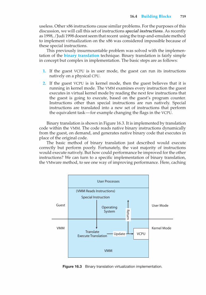
16.4 Building Blocks 719
useless. Other x86 instructions cause similar problems. For the purposes of thisdiscussion, we will call this set of instructions special instructions. As recentlyas 1998, /Judi 1998 doesnt seem that recent using the trap-and-emulate methodto implement virtualization on the x86 was considered impossible because ofthese special instructions.
This previously insurmountable problem was solved with the implemen-tation of the binary translation technique. Binary translation is fairly simplein concept but complex in implementation. The basic steps are as follows:
1. If the guest VCPU is in user mode, the guest can run its instructionsnatively on a physical CPU.
2. If the guest VCPU is in kernel mode, then the guest believes that it isrunning in kernel mode. The VMM examines every instruction the guestexecutes in virtual kernel mode by reading the next few instructions thatthe guest is going to execute, based on the guest’s program counter.Instructions other than special instructions are run natively. Specialinstructions are translated into a new set of instructions that performthe equivalent task—for example changing the flags in the VCPU.
Binary translation is shown in Figure 16.3. It is implemented by translationcode within the VMM. The code reads native binary instructions dynamicallyfrom the guest, on demand, and generates native binary code that executes inplace of the original code.
The basic method of binary translation just described would executecorrectly but perform poorly. Fortunately, the vast majority of instructionswould execute natively. But how could performance be improved for the otherinstructions? We can turn to a specific implementation of binary translation,the VMware method, to see one way of improving performance. Here, caching
User Processes
Special Instruction
(VMM Reads Instructions)
OperatingSystem
VCPU
VMM
VMM
Guest
Kernel Mode
User Mode
TranslateExecute Translation
Return
Update
Figure 16.3 Binary translation virtualization implementation.
720 Chapter 16 Virtual Machines
provides the solution. The replacement code for each instruction that needs tobe translated is cached. All later executions of that instruction run from thetranslation cache and need not be translated again. If the cache is large enough,this method can greatly improve performance.
Let’s consider another issue in virtualization: memory management, specif-ically the page tables. How can the VMM keep page-table state both for gueststhat believe they are managing the page tables and for the VMM itself? Acommon method, used with both trap-and-emulate and binary translation, isto use nested page tables (NPTs). Each guest operating system maintains oneor more page tables to translate from virtual to physical memory. The VMMmaintains NPTs to represent the guest’s page-table state, just as it creates aVCPU to represent the guest’s CPU state. The VMM knows when the guest triesto change its page table, and it makes the equivalent change in the NPT. Whenthe guest is on the CPU, the VMM puts the pointer to the appropriate NPT intothe appropriate CPU register to make that table the active page table. If theguest needs to modify the page table (for example, fulfilling a page fault), thenthat operation must be intercepted by the VMM and appropriate changes madeto the nested and system page tables. Unfortunately, the use of NPTs can causeTLB misses to increase, and many other complexities need to be addressed toachieve reasonable performance.
Although it might seem that the binary translation method creates largeamounts of overhead, it performed well enough to launch a new industryaimed at virtualizing Intel x86-based systems. VMware tested the performanceimpact of binary translation by booting one such system, Windows XP, andimmediately shutting it down while monitoring the elapsed time and thenumber of translations produced by the binary translation method. The resultwas 950,000 translations, taking 3 microseconds each, for a total increaseof 3 seconds (about 5%) over native execution of Windows XP. To achievethat result, developers used many performance improvements that we do notdiscuss here. For more information, consult the bibliographical notes at theend of this chapter.
16.4.3 Hardware Assistance
Without some level of hardware support, virtualization would be impossible.The more hardware support available within a system, the more feature-richand stable the virtual machines can be and the better they can perform. Inthe Intel x86 CPU family, Intel added new virtualization support in successivegenerations (the VT-x instructions) beginning in 2005. Now, binary translationis no longer needed.
In fact, all major general-purpose CPUs are providing extended amountsof hardware support for virtualization. For example,AMD virtualization tech-nology (AMD-V) has appeared in several AMD processors starting in 2006. Itdefines two new modes of operation—host and guest—thus moving from adual-mode to a multimode processor. The VMM can enable host mode, definethe characteristics of each guest virtual machine, and then switch the systemto guest mode, passing control of the system to a guest operating system thatis running in the virtual machine. In guest mode, the virtualized operatingsystem thinks it is running on native hardware and sees whatever devicesare included in the host’s definition of the guest. If the guest tries to access a
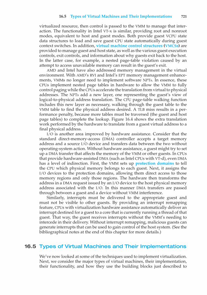
16.5 Types of Virtual Machines and Their Implementations 721
virtualized resource, then control is passed to the VMM to manage that inter-action. The functionality in Intel VT-x is similar, providing root and nonrootmodes, equivalent to host and guest modes. Both provide guest VCPU statedata structures to load and save guest CPU state automatically during guestcontext switches. In addition, virtual machine control structures (VMCSs) areprovided to manage guest and host state, as well as the various guest executioncontrols, exit controls, and information about why guests exit back to the host.In the latter case, for example, a nested page-table violation caused by anattempt to access unavailable memory can result in the guest’s exit.
AMD and Intel have also addressed memory management in the virtualenvironment. With AMD’s RVI and Intel’s EPT memory management enhance-ments, VMMs no longer need to implement software NPTs. In essence, theseCPUs implement nested page tables in hardware to allow the VMM to fullycontrol paging while the CPUs accelerate the translation from virtual to physicaladdresses. The NPTs add a new layer, one representing the guest’s view oflogical-to-physical address translation. The CPU page-table walking functionincludes this new layer as necessary, walking through the guest table to theVMM table to find the physical address desired. A TLB miss results in a per-formance penalty, because more tables must be traversed (the guest and hostpage tables) to complete the lookup. Figure 16.4 shows the extra translationwork performed by the hardware to translate from a guest virtual address to afinal physical address.
I/O is another area improved by hardware assistance. Consider that thestandard direct-memory-access (DMA) controller accepts a target memoryaddress and a source I/O device and transfers data between the two withoutoperating-system action. Without hardware assistance, a guest might try to setup a DMA transfer that affects the memory of the VMM or other guests. In CPUsthat provide hardware-assisted DMA (such as Intel CPUs with VT-d), even DMAhas a level of indirection. First, the VMM sets up protection domains to tellthe CPU which physical memory belongs to each guest. Next, it assigns theI/O devices to the protection domains, allowing them direct access to thosememory regions and only those regions. The hardware then transforms theaddress in a DMA request issued by an I/O device to the host physical memoryaddress associated with the I/O. In this manner DMA transfers are passedthrough between a guest and a device without VMM interference.
Similarly, interrupts must be delivered to the appropriate guest andmust not be visible to other guests. By providing an interrupt remappingfeature, CPUs with virtualization hardware assistance automatically deliver aninterrupt destined for a guest to a core that is currently running a thread of thatguest. That way, the guest receives interrupts without the VMM’s needing tointercede in their delivery. Without interrupt remapping, malicious guests cangenerate interrupts that can be used to gain control of the host system. (See thebibliographical notes at the end of this chapter for more details.)
16.5 Types of Virtual Machines and Their Implementations
We’ve now looked at some of the techniques used to implement virtualization.Next, we consider the major types of virtual machines, their implementation,their functionality, and how they use the building blocks just described to
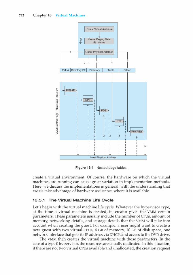
722 Chapter 16 Virtual Machines
VM
M N
este
d P
age
Tab
le D
ata
Str
uctu
re PML4E
PDPTE
PDE
PTE
Phy Addr
Host Physical Address
OffsetTableDirectoryDirectory PtrPML4
Guest Virtual Address
Kernel Paging DataStructures
Guest Physical Address
Gue
st
1
2 3 45
1 1 2 2 3 3 4
54
Figure 16.4 Nested page tables.
create a virtual environment. Of course, the hardware on which the virtualmachines are running can cause great variation in implementation methods.Here, we discuss the implementations in general, with the understanding thatVMMs take advantage of hardware assistance where it is available.
16.5.1 The Virtual Machine Life Cycle
Let’s begin with the virtual machine life cycle. Whatever the hypervisor type,at the time a virtual machine is created, its creator gives the VMM certainparameters. These parameters usually include the number of CPUs, amount ofmemory, networking details, and storage details that the VMM will take intoaccount when creating the guest. For example, a user might want to create anew guest with two virtual CPUs, 4 GB of memory, 10 GB of disk space, onenetwork interface that gets its IP address via DHCP, and access to the DVD drive.
The VMM then creates the virtual machine with those parameters. In thecase of a type 0 hypervisor, the resources are usually dedicated. In this situation,if there are not two virtual CPUs available and unallocated, the creation request
16.5 Types of Virtual Machines and Their Implementations 723
in our example will fail. For other hypervisor types, the resources are dedicatedor virtualized, depending on the type. Certainly, an IPaddress cannot be shared,but the virtual CPUs are usually multiplexed on the physical CPUs as discussedin Section 16.6.1. Similarly, memory management usually involves allocatingmore memory to guests than actually exists in physical memory. This is morecomplicated and is described in Section 16.6.2.
Finally, when the virtual machine is no longer needed, it can be deleted.When this happens, the VMM first frees up any used disk space and thenremoves the configuration associated with the virtual machine, essentiallyforgetting the virtual machine.
These steps are quite simple compared with building, configuring, running,and removing physical machines. Creating a virtual machine from an existingone can be as easy as clicking the “clone” button and providing a new nameand IP address. This ease of creation can lead to virtual machine sprawl, whichoccurs when there are so many virtual machines on a system that their use,history, and state become confusing and difficult to track.
16.5.2 Type 0 Hypervisor
Type 0 hypervisors have existed for many years under many names, including“partitions” and “domains”. They are a hardware feature, and that brings itsown positives and negatives. Operating systems need do nothing special totake advantage of their features. The VMM itself is encoded in the firmwareand loaded at boot time. In turn, it loads the guest images to run in eachpartition. The feature set of a type 0 hypervisor tends to be smaller than thoseof the other types because it is implemented in hardware. For example, a systemmight be split into four virtual systems, each with dedicated CPUs, memory,and I/O devices. Each guest believes that it has dedicated hardware because itdoes, simplifying many implementation details.
I/O presents some difficulty, because it is not easy to dedicate I/O devicesto guests if there are not enough. What if a system has two Ethernet ports andmore than two guests, for example? Either all guests must get their own I/Odevices, or the system must provided I/O device sharing. In these cases, thehypervisor manages shared access or grants all devices to a control partition.In the control partition, a guest operating system provides services (suchas networking) via daemons to other guests, and the hypervisor routes I/Orequests appropriately. Some type 0 hypervisors are even more sophisticatedand can move physical CPUs and memory between running guests. In thesecases, the guests are paravirtualized, aware of the virtualization and assistingin its execution. For example, a guest must watch for signals from the hardwareor VMM that a hardware change has occurred, probe its hardware devices todetect the change, and add or subtract CPUs or memory from its availableresources.
Because type 0 virtualization is very close to raw hardware execution,it should be considered separately from the other methods discussed here.A type 0 hypervisor can run multiple guest operating systems (one in eachhardware partition). All of those guests, because they are running on rawhardware, can in turn be VMMs. Essentially, the guest operating systems ina type 0 hypervisor are native operating systems with a subset of hardwaremade available to them. Because of that, each can have its own guest operating
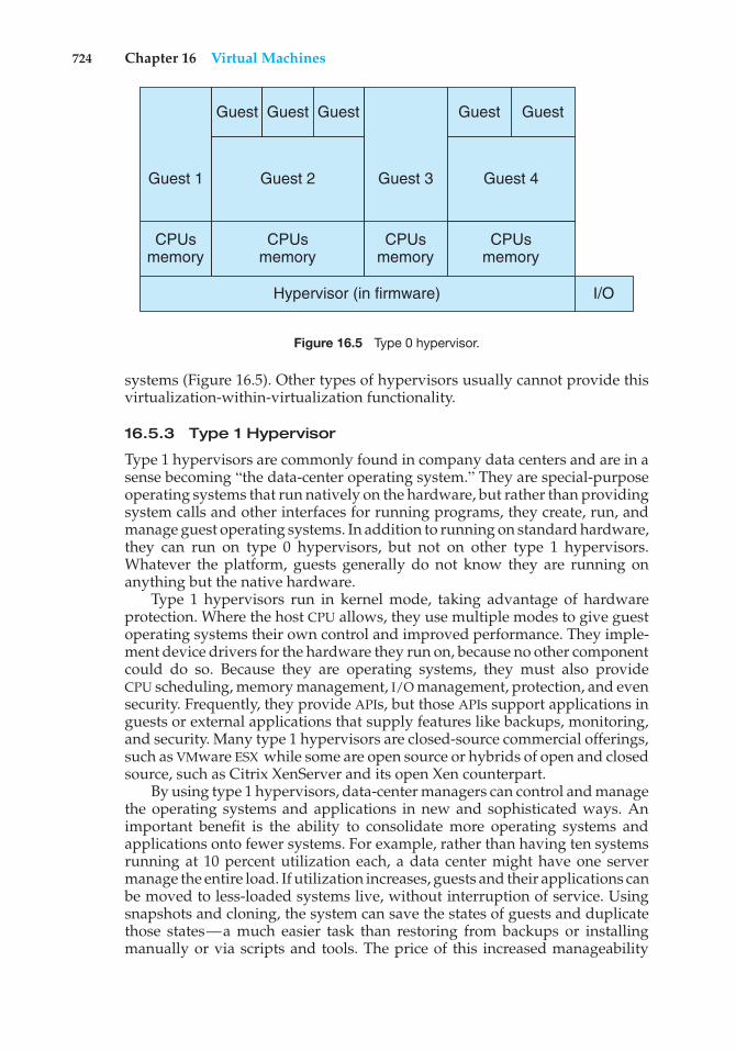
724 Chapter 16 Virtual Machines
Guest 1 Guest 2
CPUsmemory
CPUsmemory
Hypervisor (in firmware) I/O
CPUsmemory
CPUsmemory
Guest 3 Guest 4
Guest Guest Guest Guest Guest
Figure 16.5 Type 0 hypervisor.
systems (Figure 16.5). Other types of hypervisors usually cannot provide thisvirtualization-within-virtualization functionality.
16.5.3 Type 1 Hypervisor
Type 1 hypervisors are commonly found in company data centers and are in asense becoming “the data-center operating system.” They are special-purposeoperating systems that run natively on the hardware, but rather than providingsystem calls and other interfaces for running programs, they create, run, andmanage guest operating systems. In addition to running on standard hardware,they can run on type 0 hypervisors, but not on other type 1 hypervisors.Whatever the platform, guests generally do not know they are running onanything but the native hardware.
Type 1 hypervisors run in kernel mode, taking advantage of hardwareprotection. Where the host CPU allows, they use multiple modes to give guestoperating systems their own control and improved performance. They imple-ment device drivers for the hardware they run on, because no other componentcould do so. Because they are operating systems, they must also provideCPU scheduling, memory management, I/O management, protection, and evensecurity. Frequently, they provide APIs, but those APIs support applications inguests or external applications that supply features like backups, monitoring,and security. Many type 1 hypervisors are closed-source commercial offerings,such as VMware ESX while some are open source or hybrids of open and closedsource, such as Citrix XenServer and its open Xen counterpart.
By using type 1 hypervisors, data-center managers can control and managethe operating systems and applications in new and sophisticated ways. Animportant benefit is the ability to consolidate more operating systems andapplications onto fewer systems. For example, rather than having ten systemsrunning at 10 percent utilization each, a data center might have one servermanage the entire load. If utilization increases, guests and their applications canbe moved to less-loaded systems live, without interruption of service. Usingsnapshots and cloning, the system can save the states of guests and duplicatethose states—a much easier task than restoring from backups or installingmanually or via scripts and tools. The price of this increased manageability
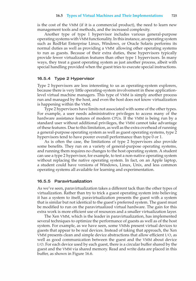
16.5 Types of Virtual Machines and Their Implementations 725
is the cost of the VMM (if it is a commercial product), the need to learn newmanagement tools and methods, and the increased complexity.
Another type of type 1 hypervisor includes various general-purposeoperating systems with VMM functionality. In this instance, an operating systemsuch as RedHat Enterprise Linux, Windows, or Oracle Solaris performs itsnormal duties as well as providing a VMM allowing other operating systemsto run as guests. Because of their extra duties, these hypervisors typicallyprovide fewer virtualization features than other type 1 hypervisors. In manyways, they treat a guest operating system as just another process, albeit withspecial handling provided when the guest tries to execute special instructions.
16.5.4 Type 2 Hypervisor
Type 2 hypervisors are less interesting to us as operating-system explorers,because there is very little operating-system involvement in these application-level virtual machine managers. This type of VMM is simply another processrun and managed by the host, and even the host does not know virtualizationis happening within the VMM.
Type 2 hypervisors have limits not associated with some of the other types.For example, a user needs administrative privileges to access many of thehardware assistance features of modern CPUs. If the VMM is being run by astandard user without additional privileges, the VMM cannot take advantageof these features. Due to this limitation, as well as the extra overhead of runninga general-purpose operating system as well as guest operating systems, type 2hypervisors tend to have poorer overall performance than type 0 or 1.
As is often the case, the limitations of type 2 hypervisors also providesome benefits. They run on a variety of general-purpose operating systems,and running them requires no changes to the host operating system. A studentcan use a type 2 hypervisor, for example, to test a non-native operating systemwithout replacing the native operating system. In fact, on an Apple laptop,a student could have versions of Windows, Linux, Unix, and less commonoperating systems all available for learning and experimentation.
16.5.5 Paravirtualization
As we’ve seen, paravirtualization takes a different tack than the other types ofvirtualization. Rather than try to trick a guest operating system into believingit has a system to itself, paravirtualization presents the guest with a systemthat is similar but not identical to the guest’s preferred system. The guest mustbe modified to run on the paravirtualized virtual hardware. The gain for thisextra work is more efficient use of resources and a smaller virtualization layer.
The Xen VMM, which is the leader in paravirtualization, has implementedseveral techniques to optimize the performance of guests as well as of the hostsystem. For example, as we have seen, some VMMs present virtual devices toguests that appear to be real devices. Instead of taking that approach, the XenVMM presents clean and simple device abstractions that allow efficient I/O, aswell as good communication between the guest and the VMM about deviceI/O. For each device used by each guest, there is a circular buffer shared by theguest and the VMM via shared memory. Read and write data are placed in thisbuffer, as shown in Figure 16.6.
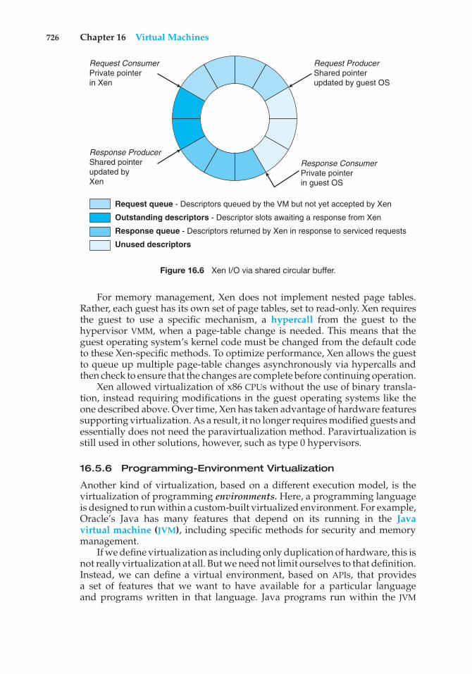
726 Chapter 16 Virtual Machines
Request ProducerShared pointerupdated by guest OS
Request ConsumerPrivate pointerin Xen
Response ProducerShared pointerupdated byXen
Response ConsumerPrivate pointerin guest OS
Request queue - Descriptors queued by the VM but not yet accepted by Xen
Outstanding descriptors - Descriptor slots awaiting a response from Xen
Response queue - Descriptors returned by Xen in response to serviced requests
Unused descriptors
Figure 16.6 Xen I/O via shared circular buffer.
For memory management, Xen does not implement nested page tables.Rather, each guest has its own set of page tables, set to read-only. Xen requiresthe guest to use a specific mechanism, a hypercall from the guest to thehypervisor VMM, when a page-table change is needed. This means that theguest operating system’s kernel code must be changed from the default codeto these Xen-specific methods. To optimize performance, Xen allows the guestto queue up multiple page-table changes asynchronously via hypercalls andthen check to ensure that the changes are complete before continuing operation.
Xen allowed virtualization of x86 CPUs without the use of binary transla-tion, instead requiring modifications in the guest operating systems like theone described above. Over time, Xen has taken advantage of hardware featuressupporting virtualization. As a result, it no longer requires modified guests andessentially does not need the paravirtualization method. Paravirtualization isstill used in other solutions, however, such as type 0 hypervisors.
16.5.6 Programming-Environment Virtualization
Another kind of virtualization, based on a different execution model, is thevirtualization of programming environments. Here, a programming languageis designed to run within a custom-built virtualized environment. For example,Oracle’s Java has many features that depend on its running in the Javavirtual machine (JVM), including specific methods for security and memorymanagement.
If we define virtualization as including only duplication of hardware, this isnot really virtualization at all. But we need not limit ourselves to that definition.Instead, we can define a virtual environment, based on APIs, that providesa set of features that we want to have available for a particular languageand programs written in that language. Java programs run within the JVM
16.5 Types of Virtual Machines and Their Implementations 727
environment, and the JVM is compiled to be a native program on systems onwhich it runs. This arrangement means that Java programs are written onceand then can run on any system (including all of the major operating systems)on which a JVM is available. The same can be said for interpreted languages,which run inside programs that read each instruction and interpret it intonative operations.
16.5.7 Emulation
Virtualization is probably the most common method for running applicationsdesigned for one operating system on a different operating system, but on thesame CPU. This method works relatively efficiently because the applicationswere compiled for the same instruction set as the target system uses.
But what if an application or operating system needs to run on a differentCPU? Here, it is necessary to translate all of the source CPU’s instructions sothat they are turned into the equivalent instructions of the target CPU. Such anenvironment is no longer virtualized but rather is fully emulated.
Emulation is useful when the host system has one system architectureand the guest system was compiled for a different architecture. For example,suppose a company has replaced its outdated computer system with a newsystem but would like to continue to run certain important programs that werecompiled for the old system. The programs could be run in an emulator thattranslates each of the outdated system’s instructions into the native instructionset of the new system. Emulation can increase the life of programs and allowus to explore old architectures without having an actual old machine.
As may be expected, the major challenge of emulation is performance.Instruction-set emulation can run an order of magnitude slower than nativeinstructions, because it may take ten instructions on the new system to read,parse, and simulate an instruction from the old system. Thus, unless the newmachine is ten times faster than the old, the program running on the newmachine will run more slowly than it did on its native hardware. Anotherchallenge for emulator writers is that it is difficult to create a correct emulatorbecause, in essence, this task involves writing an entire CPU in software.
In spite of these challenges, emulation is very popular, particularly ingaming circles. Many popular video games were written for platforms that areno longer in production. Users who want to run those games frequently canfind an emulator of such a platform and then run the game unmodified withinthe emulator. Modern systems are so much faster than old game consoles thateven the Apple iPhone has game emulators and games available to run withinthem.
16.5.8 Application Containment
The goal of virtualization in some instances is to provide a method to segregateapplications, manage their performance and resource use, and create an easyway to start, stop, move, and manage them. In such cases, perhaps full-fledgedvirtualization is not needed. If the applications are all compiled for the sameoperating system, then we do not need complete virtualization to provide thesefeatures. We can instead use application containment.
728 Chapter 16 Virtual Machines
virtual platformdevice management
zone 1
global zone
Solaris kernel
network addresses
zone 2
zone management
user programssystem programsCPU resources
memory resources
user programssystem programs
network addressesdevice accessCPU resources
memory resources
user programssystem programs
network addressesdevice accessCPU resources
memory resources
device device…
Figure 16.7 Solaris 10 with two zones.
Consider one example of application containment. Starting with version10, Oracle Solaris has included containers, or zones, that create a virtual layerbetween the operating system and the applications. In this system, only onekernel is installed, and the hardware is not virtualized. Rather, the operatingsystem and its devices are virtualized, providing processes within a zone withthe impression that they are the only processes on the system. One or morecontainers can be created, and each can have its own applications, networkstacks, network address and ports, user accounts, and so on. CPU and memoryresources can be divided among the zones and the system-wide processes.Each zone in fact can run its own scheduler to optimize the performance of itsapplications on the allotted resources. Figure 16.7 shows a Solaris 10 systemwith two containers and the standard “global” user space.
16.6 Virtualization and Operating-System Components
Thus far, we have explored the building blocks of virtualization and the varioustypes of virtualization. In this section, we take a deeper dive into the operating-system aspects of virtualization, including how the VMM provides coreoperating-system functions like scheduling, I/O, and memory management.Here, we answer questions such as these: How do VMMs schedule CPU usewhen guest operating systems believe they have dedicated CPUs? How canmemory management work when many guests require large amounts ofmemory?
16.6 Virtualization and Operating-System Components 729
16.6.1 CPU Scheduling
A system with virtualization, even a single-CPU system, frequently acts likea multiprocessor system. The virtualization software presents one or morevirtual CPUs to each of the virtual machines running on the system and thenschedules the use of the physical CPUs among the virtual machines.
The significant variations among virtualization technologies make it diffi-cult to summarize the effect of virtualization on scheduling. First, let’s considerthe general case of VMM scheduling. The VMM has a number of physical CPUsavailable and a number of threads to run on those CPUs. The threads can beVMM threads or guest threads. Guests are configured with a certain number ofvirtual CPUs at creation time, and that number can be adjusted throughout thelife of the VM. When there are enough CPUs to allocate the requested number toeach guest, the VMM can treat the CPUs as dedicated and schedule only a givenguest’s threads on that guest’s CPUs. In this situation, the guests act much likenative operating systems running on native CPUs.
Of course, in other situations, there may not be enough CPUs to goaround. The VMM itself needs some CPU cycles for guest management and I/Omanagement and can steal cycles from the guests by scheduling its threadsacross all of the system CPUs, but the impact of this action is relativelyminor. More difficult is the case of overcommitment, in which the guestsare configured for more CPUs than exist in the system. Here, a VMM canuse standard scheduling algorithms to make progress on each thread butcan also add a fairness aspect to those algorithms. For example, if there aresix hardware CPUs and 12 guest-allocated CPUs, the VMM could allocate CPUresources proportionally, giving each guest half of the CPU resources it believesit has. The VMM can still present all 12 virtual CPUs to the guests, but inmapping them onto physical CPUs, the VMM can use its scheduler to sharethem appropriately.
Even given a scheduler that provides fairness, any guest operating-systemscheduling algorithm that assumes a certain amount of progress in a givenamount of time will be negatively affected by virtualization. Consider a time-sharing operating system that tries to allot 100 milliseconds to each time slice togive users a reasonable response time. Within a virtual machine, this operatingsystem is at the mercy of the virtualization system as to what CPU resources itactually receives. A given 100-millisecond time slice may take much more than100 milliseconds of virtual CPU time. Depending on how busy the system is,the time slice may take a second or more, resulting in very poor response timesfor users logged into that virtual machine. The effect on a real-time operatingsystem can be even more serious.
The net effect of such scheduling layering is that individual virtualizedoperating systems receive only a portion of the available CPU cycles, eventhough they believe they are receiving all of the cycles and indeed that theyare scheduling all of those cycles. Commonly, the time-of-day clocks in virtualmachines are incorrect because timers take longer to trigger than they would ondedicated CPUs. Virtualization can thus undo the good scheduling-algorithmefforts of the operating systems within virtual machines.
To correct for this, a VMM will have an application available for each typeof operating system that system administrators install into the guests. This
730 Chapter 16 Virtual Machines
application corrects clock drift and can have other functions such as virtualdevice management.
16.6.2 Memory Management
Efficient memory use in general-purpose operating systems is one of the majorkeys to performance. In virtualized environments, there are more users ofmemory (the guests and their applications, as well as the VMM), leading tomore pressure on memory use. Further adding to this pressure is that VMMstypically overcommit memory, so that the total memory with which guests areconfigured exceeds the amount of memory that physically exists in the system.The extra need for efficient memory use is not lost on the implementers ofVMMs, who take great measures to ensure the optimal use of memory.
For example, VMware ESX uses at least three methods of memory manage-ment. Before memory optimization can occur, the VMM must establish howmuch real memory each guest should use. To do that, the VMM first evaluatesthe maximum memory size of each guest as dictated when it is configured.General-purpose operating systems do not expect the amount of memoryin the system to change, so VMMs must maintain the illusion that the guesthas that amount of memory. Next, the VMM computes a target real memoryallocation for each guest based on the configured memory for that guest andother factors, such as overcommitment and system load. It then uses the threelow-level mechanisms below to reclaim memory from the guests. The overalleffect is to enable guests to behave and perform as if they had the full amountof memory requested although in reality they have less.
1. Recall that a guest believes it controls memory allocation via its page-table management, whereas in reality the VMM maintains a nested pagetable that re-translates the guest page table to the real page table. TheVMM can use this extra level of indirection to optimize the guest’s useof memory without the guest’s knowledge or help. One approach is toprovide double paging, in which the VMM has its own page-replacementalgorithms and pages to backing-store pages that the guest believes arein physical memory. Of course, the VMM has knows less about the guest’smemory access patterns than the guest does, so its paging is less efficient,creating performance problems. VMMs do use this method when othermethods are not available or are not providing enough free memory.However, it is not the preferred approach.
2. A common solution is for the VMM to install in each guest a pseudo–device driver or kernel module that it controls. (A pseudo–device driveruses device-driver interfaces, appearing to the kernel to be a device driver,but does not actually control a device. Rather, it is an easy way to addkernel-mode code without directly modifying the kernel.) This balloonmemory manager communicates with the VMM and is told to allocateor deallocate memory. If told to allocate, it allocates memory and tellsthe operating system to pin the allocated pages into physical memory.Recall that pinning locks a page into physical memory so that it cannot bemoved or paged out. The guest sees memory pressure becauses of thesepinned pages, essentially decreasing the amount of physical memory ithas available to use. The guest then may free up other physical memory
16.6 Virtualization and Operating-System Components 731
to be sure it has a sufficient pool of free memory. Meanwhile, the VMM,knowing that the pages pinned by the balloon process will never beused, removes those physical pages from the guest and allocates themto another guest. At the same time, the guest is using its own memory-management and paging algorithms to manage the available memory,which is the most efficient option. If memory pressure within the entiresystem decreases, the VMM will tell the balloon process within the guestto unpin and free some or all of the memory, allowing the guest morepages for its use.
3. Another common method for reducing memory pressure is for the VMMto determine if the same page has been loaded more than once. If thisis the case, to the VMM reduces the number of copies of the page toone and maps the other users of the page to that one copy. VMware, forexample, randomly samples guest memory and creates a hash for eachpage sampled. That hash value is a “thumbprint” of the page. The hashof every page examined is compared with other hashes already storedin a hash table. If there is a match, the pages are compared byte by byteto see if they really are identical. If they are, one page is freed, and itslogical address is mapped to the other’s physical address. This techniquemight seem at first to be ineffective, but consider that guests run operatingsystems. If multiple guests run the same operating system, then only onecopy of the active operating-system pages need be in memory. Similarly,multiple guests could be running the same set of applications, again alikely source of memory sharing.
16.6.3 I/O
In the area of I/O, hypervisors have some leeway and can be less concernedwith exactly representing the underlying hardware to their guests. Because ofall the variation in I/O devices, operating systems are used to dealing withvarying and flexible I/O mechanisms. For example, operating systems havea device-driver mechanism that provides a uniform interface to the operatingsystem whatever the I/O device. Device-driver interfaces are designed to allowthird-party hardware manufacturers to provide device drivers connecting theirdevices to the operating system. Usually, device drivers can be dynamicallyloaded and unloaded. Virtualization takes advantage of such built-in flexibilityby providing specific virtualized devices to guest operating systems.
As described in Section 16.5, VMMs vary greatly in how they provide I/O totheir guests. I/O devices may be dedicated to guests, for example, or the VMMmay have device drivers onto which it maps guest I/O. The VMM may alsoprovide idealized device drivers to guests, which allows easy provision andmanagement of guest I/O. In this case, the guest sees an easy-to-control device,but in reality that simple device driver communicates to the VMM which sendsthose requests to a more complicated real device through a more complex realdevice driver. I/O in virtual environments is complicated and requires carefulVMM design and implementation.
Consider the case of a hypervisor and hardware combination that allowsdevices to be dedicated to a guest and allows the guest to access those devicesdirectly. Of course, a device dedicated to one guest is not available to anyother guests, but this direct access can still be useful in some circumstances.
732 Chapter 16 Virtual Machines
The reason to allow direct access is to improve I/O performance. The less thehypervisor has to do to enable I/O for its guests, the faster the I/O can occur.With Type 0 hypervisors that provide direct device access, guests can oftenrun at the same speed as native operating systems. When type 0 hypervisorsinstead provide shared devices, performance can suffer by comparison.
With direct device access in type 1 and 2 hypervisors, performance canbe similar to that of native operating systems if certain hardware supportis present. The hardware needs to provide DMA pass-through with facilitieslike VT-d, as well as direct interrupt delivery to specific guests. Given howfrequently interrupts occur, it should be no surprise that the guests on hardwarewithout these features have worse performance than if they were runningnatively.
In addition to direct access, VMMs provide shared access to devices.Consider a disk drive to which multiple guests have access. The VMM mustprovide protection while sharing the device, assuring that a guest can accessonly the blocks specified in the guest’s configuration. In such instances, theVMM must be part of every I/O, checking it for correctness as well as routingthe data to and from the appropriate devices and guests.
In the area of networking, VMMs also have work to do. General-purposeoperating systems typically have one Internet protocol (IP) address, althoughthey sometimes have more than one—for example, to connect to a managementnetwork, backup network, and production network. With virtualization, eachguest needs at least one IP address, because that is the guest’s main modeof communication. Therefore, a server running a VMM may have dozens ofaddresses, and the VMM acts as a virtual switch to route the network packetsto the addressed guest.
The guests can be “directly” connected to the network by an IP address thatis seen by the broader network (this is known as bridging). Alternatively,the VMM can provide a network address translation (NAT) address. TheNAT address is local to the server on which the guest is running, and theVMM provides routing between the broader network and the guest. The VMMalso provides firewalling, moderating connections between guests within thesystem and between guests and external systems.
16.6.4 Storage Management
An important question in determining how virtualization works is this: Ifmultiple operating systems have been installed, what and where is the bootdisk? Clearly, virtualized environments need to approach the area of storagemanagement differently from native operating systems. Even the standardmultiboot method of slicing the root disk into partitions, installing a bootmanager in one partition, and installing each other operating system in anotherpartition is not sufficient, because partitioning has limits that would prevent itfrom working for tens or hundreds of virtual machines.
Once again, the solution to this problem depends on the type of hypervisor.Type 0 hypervisors do tend to allow root disk partitioning, partly because thesesystems tend to run fewer guests than other systems. Alternatively, they mayhave a disk manager as part of the control partition, and that disk managerprovides disk space (including boot disks) to the other partitions.
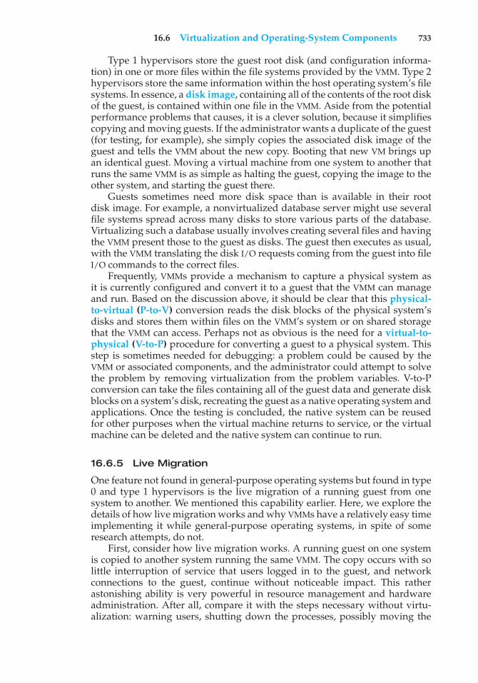
16.6 Virtualization and Operating-System Components 733
Type 1 hypervisors store the guest root disk (and configuration informa-tion) in one or more files within the file systems provided by the VMM. Type 2hypervisors store the same information within the host operating system’s filesystems. In essence, a disk image, containing all of the contents of the root diskof the guest, is contained within one file in the VMM. Aside from the potentialperformance problems that causes, it is a clever solution, because it simplifiescopying and moving guests. If the administrator wants a duplicate of the guest(for testing, for example), she simply copies the associated disk image of theguest and tells the VMM about the new copy. Booting that new VM brings upan identical guest. Moving a virtual machine from one system to another thatruns the same VMM is as simple as halting the guest, copying the image to theother system, and starting the guest there.
Guests sometimes need more disk space than is available in their rootdisk image. For example, a nonvirtualized database server might use severalfile systems spread across many disks to store various parts of the database.Virtualizing such a database usually involves creating several files and havingthe VMM present those to the guest as disks. The guest then executes as usual,with the VMM translating the disk I/O requests coming from the guest into fileI/O commands to the correct files.
Frequently, VMMs provide a mechanism to capture a physical system asit is currently configured and convert it to a guest that the VMM can manageand run. Based on the discussion above, it should be clear that this physical-to-virtual (P-to-V) conversion reads the disk blocks of the physical system’sdisks and stores them within files on the VMM’s system or on shared storagethat the VMM can access. Perhaps not as obvious is the need for a virtual-to-physical (V-to-P) procedure for converting a guest to a physical system. Thisstep is sometimes needed for debugging: a problem could be caused by theVMM or associated components, and the administrator could attempt to solvethe problem by removing virtualization from the problem variables. V-to-Pconversion can take the files containing all of the guest data and generate diskblocks on a system’s disk, recreating the guest as a native operating system andapplications. Once the testing is concluded, the native system can be reusedfor other purposes when the virtual machine returns to service, or the virtualmachine can be deleted and the native system can continue to run.
16.6.5 Live Migration
One feature not found in general-purpose operating systems but found in type0 and type 1 hypervisors is the live migration of a running guest from onesystem to another. We mentioned this capability earlier. Here, we explore thedetails of how live migration works and why VMMs have a relatively easy timeimplementing it while general-purpose operating systems, in spite of someresearch attempts, do not.
First, consider how live migration works. A running guest on one systemis copied to another system running the same VMM. The copy occurs with solittle interruption of service that users logged in to the guest, and networkconnections to the guest, continue without noticeable impact. This ratherastonishing ability is very powerful in resource management and hardwareadministration. After all, compare it with the steps necessary without virtu-alization: warning users, shutting down the processes, possibly moving the
734 Chapter 16 Virtual Machines
binaries, and restarting the processes on the new system, with users onlythen able to use the services again. With live migration, an overloaded systemcan have its load decreased live with no discernible disruption. Similarly, asystem needing hardware or system changes (for example, a firmware upgrade,hardware addition or removal, or hardware repair) can have guests migratedoff, the work done, and guests migrated back without noticeable impact onusers or remote connections.
Live migration is made possible because of the well-defined interfacesbetween guests and VMMs and the limited state the VMM maintains for theguest. The VMM migrates a guest via the following steps:
1. The source VMM establishes a connection with the target VMM andconfirms that it is allowed to send a guest.
2. The target creates a new guest by creating a new VCPU, new nested pagetable, and other state storage.
3. The source sends all read-only memory pages to the target.
4. The source sends all read-write pages to the target, marking them asclean.
5. The source repeats step 4, as during that step some pages were probablymodified by the guest and are now dirty. These pages need to be sentagain and marked again as clean.
6. When the cycle of steps 4 and 5 becomes very short, the source VMMfreezes the guest, sends the VCPU’s final state, sends other state details,sends the final dirty pages, and tells the target to start running theguest. Once the target acknowledges that the guest is running, the sourceterminates the guest.
This sequence is shown in Figure 16.8.We conclude this discussion with a few interesting details and limita-
tions concerning live migration. First, for network connections to continueuninterrupted, the network infrastructure needs to understand that a MAC
Guest Target running
5 – Send Dirty Pages (repeatedly)
4 – Send R/W Pages
3 – Send R/O Pages
1 – Establish0 – RunningGuest Source
VM
M S
ourc
e
7 – TerminateGuest Source
VM
M T
arge
t
2 – CreateGuest Target
6 – RunningGuest Target
Figure 16.8 Live migration of a guest between two servers.
16.7 Examples 735
address—the hardware networking address—can move between systems.Before virtualization, this did not happen, as the MAC address was tied tophysical hardware. With virtualization, the MAC must be movable for exist-ing networking connections to continue without resetting. Modern networkswitches understand this and route traffic wherever the MAC address is, evenaccommodating a move.
A limitation of live migration is that no disk state is transferred. One reasonlive migration is possible is that most of the guest’s state is maintained withinthe guest—for example, open file tables, system-call state, kernel state, and soon. Because disk I/O is so much slower than memory access, and used diskspace is usually much larger than used memory, disks associated with the guestcannot be moved as part of a live migration. Rather, the disk must be remote tothe guest, accessed over the network. In that case, disk access state is maintainedwithin the guest, and network connections are all that matter to the VMM. Thenetwork connections are maintained during the migration, so remote diskaccess continues. Typically, NFS, CIFS, or iSCSI is used to store virtual machineimages and any other storage a guest needs access to. Those network-basedstorage accesses simply continue when the network connections are continuedonce the guest has been migrated.
Live migration enables entirely new ways of managing data centers.For example, virtualization management tools can monitor all the VMMs inan environment and automatically balance resource use by moving guestsbetween the VMMs. They can also optimize the use of electricity and coolingby migrating all guests off selected servers if other servers can handle the loadand powering down the selected servers entirely. If the load increases, thesetools can power up the servers and migrate guests back to them.
16.7 Examples
Despite the advantages of virtual machines, they received little attention fora number of years after they were first developed. Today, however, virtualmachines are coming into fashion as a means of solving system compatibilityproblems. In this section, we explore two popular contemporary virtualmachines: the VMware Workstation and the Java virtual machine. As you willsee, these virtual machines can typically run on top of operating systems ofany of the design types discussed in earlier chapters. Thus, operating-systemdesign methods—simple layers, microkernels, modules, and virtual machines—are not mutually exclusive.
16.7.1 VMware
VMware Workstation is a popular commercial application that abstractsIntel X86 and compatible hardware into isolated virtual machines. VMwareWorkstation is a prime example of a Type 2 hypervisor. It runs as an applicationon a host operating system such as Windows or Linux and allows thishost system to run several different guest operating systems concurrently asindependent virtual machines.
The architecture of such a system is shown in Figure 16.9. In this scenario,Linux is running as the host operating system, and FreeBSD, Windows NT, and
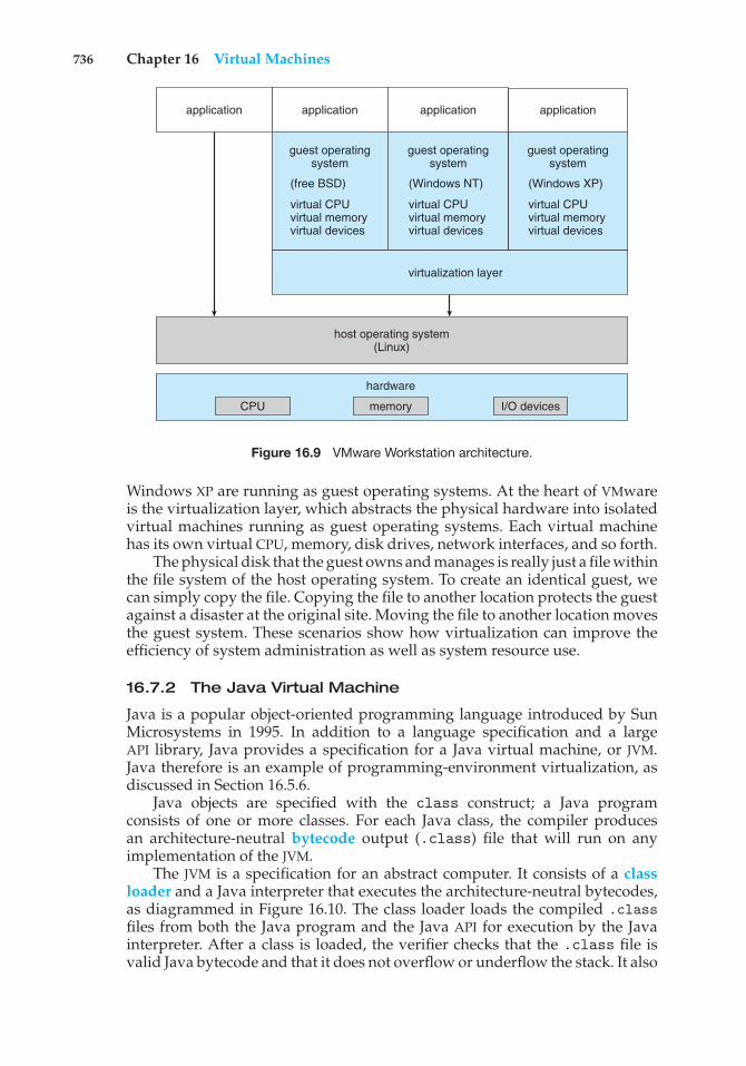
736 Chapter 16 Virtual Machines
virtualization layer
host operating system(Linux)
CPU memory
hardware
I/O devices
application application application application
guest operatingsystem
(free BSD)
virtual CPUvirtual memoryvirtual devices
guest operatingsystem
(Windows NT)
virtual CPUvirtual memoryvirtual devices
guest operatingsystem
(Windows XP)
virtual CPUvirtual memoryvirtual devices
Figure 16.9 VMware Workstation architecture.
Windows XP are running as guest operating systems. At the heart of VMwareis the virtualization layer, which abstracts the physical hardware into isolatedvirtual machines running as guest operating systems. Each virtual machinehas its own virtual CPU, memory, disk drives, network interfaces, and so forth.
The physical disk that the guest owns and manages is really just a file withinthe file system of the host operating system. To create an identical guest, wecan simply copy the file. Copying the file to another location protects the guestagainst a disaster at the original site. Moving the file to another location movesthe guest system. These scenarios show how virtualization can improve theefficiency of system administration as well as system resource use.
16.7.2 The Java Virtual Machine
Java is a popular object-oriented programming language introduced by SunMicrosystems in 1995. In addition to a language specification and a largeAPI library, Java provides a specification for a Java virtual machine, or JVM.Java therefore is an example of programming-environment virtualization, asdiscussed in Section 16.5.6.
Java objects are specified with the class construct; a Java programconsists of one or more classes. For each Java class, the compiler producesan architecture-neutral bytecode output (.class) file that will run on anyimplementation of the JVM.
The JVM is a specification for an abstract computer. It consists of a classloader and a Java interpreter that executes the architecture-neutral bytecodes,as diagrammed in Figure 16.10. The class loader loads the compiled .classfiles from both the Java program and the Java API for execution by the Javainterpreter. After a class is loaded, the verifier checks that the .class file isvalid Java bytecode and that it does not overflow or underflow the stack. It also
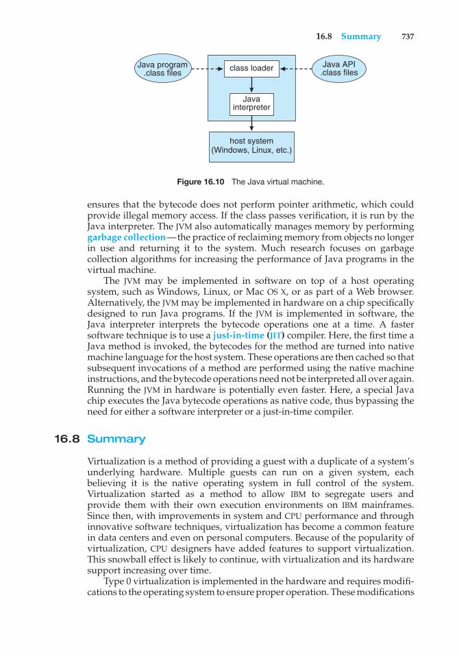
16.8 Summary 737
host system (Windows, Linux, etc.)
class loader
Javainterpreter
Java program.class files
Java API.class files
Figure 16.10 The Java virtual machine.
ensures that the bytecode does not perform pointer arithmetic, which couldprovide illegal memory access. If the class passes verification, it is run by theJava interpreter. The JVM also automatically manages memory by performinggarbage collection—the practice of reclaiming memory from objects no longerin use and returning it to the system. Much research focuses on garbagecollection algorithms for increasing the performance of Java programs in thevirtual machine.
The JVM may be implemented in software on top of a host operatingsystem, such as Windows, Linux, or Mac OS X, or as part of a Web browser.Alternatively, the JVM may be implemented in hardware on a chip specificallydesigned to run Java programs. If the JVM is implemented in software, theJava interpreter interprets the bytecode operations one at a time. A fastersoftware technique is to use a just-in-time (JIT) compiler. Here, the first time aJava method is invoked, the bytecodes for the method are turned into nativemachine language for the host system. These operations are then cached so thatsubsequent invocations of a method are performed using the native machineinstructions, and the bytecode operations need not be interpreted all over again.Running the JVM in hardware is potentially even faster. Here, a special Javachip executes the Java bytecode operations as native code, thus bypassing theneed for either a software interpreter or a just-in-time compiler.
16.8 Summary
Virtualization is a method of providing a guest with a duplicate of a system’sunderlying hardware. Multiple guests can run on a given system, eachbelieving it is the native operating system in full control of the system.Virtualization started as a method to allow IBM to segregate users andprovide them with their own execution environments on IBM mainframes.Since then, with improvements in system and CPU performance and throughinnovative software techniques, virtualization has become a common featurein data centers and even on personal computers. Because of the popularity ofvirtualization, CPU designers have added features to support virtualization.This snowball effect is likely to continue, with virtualization and its hardwaresupport increasing over time.
Type 0 virtualization is implemented in the hardware and requires modifi-cations to the operating system to ensure proper operation. These modifications
738 Chapter 16 Virtual Machines
offer an example of paravirtualization, in which the operating system is notblind to virtualization but instead has features added and algorithms changedto improve virtualization’s features and performance. In Type 1 virtualization,a host virtual machine monitor (VMM) provides the environment and featuresneeded to create, run, and destroy guest virtual machines. Each guest includesall of the software typically associated with a full native system, including theoperating system, device drivers, applications, user accounts, and so on.
Type 2 hypervisors are simply applications that run on other operatingsystems, which do not know that virtualization is taking place. These hypervi-sors do not enjoy hardware or host support so must perform all virtualizationactivities in the context of a process.
Other facilities that are similar to virtualization but do not meet the fulldefinition of replicating hardware exactly are also common. Programming-environment virtualization is part of the design of a programming language.The language specifies a containing application in which programs run, andthis application provides services to the programs. Emulation is used when ahost system has one architecture and the guest was compiled for a differentarchitecture. Every instruction the guest wants to execute must be translatedfrom its instruction set to that of the native hardware. Although this methodinvolves some perform penalty, it is balanced by the usefulness of being ableto run old programs on newer, incompatible hardware or run games designedfor old consoles on modern hardware.
Implementing virtualization is challenging, especially when hardwaresupport is minimal. Some hardware support must exist for virtualization,but the more features provided by the system, the easier virtualization is toimplement and the better the performance of the guests. VMMs take advantageof whatever hardware support is available when optimizing CPU scheduling,memory management, and I/O modules to provide guests with optimumresource use while protecting the VMM from the guests and the guests fromone another.
Exercises
16.1 Describe the three types of traditional virtualization.
16.2 Describe the four virtualization-like execution environments and whythey are not “true” virtualization.
16.3 Describe four benefits of virtualization.
16.4 Why can VMMs not implement trap-and-emulate-based virtualizationon some CPUs? Lacking the ability to trap-and-emulate, what methodcan a VMM use to implement virtualization?
16.5 What hardware assistance for virtualization can be provided by modernCPUs?
16.6 Why is live migration possible in virtual environments but much lesspossible for a native operating system?
Bibliography 739
Bibliographical Notes
The original IBM VM system was described in [Meyer and Seawright (1970)].[Popek and Goldberg (1974)] established the characteristics that help defineVMMs. Methods of implementing virtual machines are discussed in [Agesenet al. (2010)].
Virtualization has been an active research area for many years. Disco wasone of the first attempts to use virtualization to enforce logical isolation andprovide scalability on multicore systems ([Bugnion et al. (1997)]). Based on thatand and other work, Quest-V used virtualization to create an entire distributedoperating system within a multicore system ([Li et al. (2011)]).
Intel x86 hardware virtualization support is described in [Neiger et al.(2006)]. AMD hardware virtualization support is described in a white paper(http://developer.amd.com/assets/NPT-WP-1%201-final-TM.pdf).
KVM is described in [Kivity et al. (2007)]. Xen is described in [Barhamet al. (2003)]. Oracle Solaris containers are similar to BSD jails, as described in[Poul-henning Kamp (2000)].
[Agesen et al. (2010)] discuss the performance of binary translation.Memory management in VMware is described in [Waldspurger (2002)]. Theproblem of I/O overhead in virtualized environments has a proposed solutionin [Gordon et al. (2012)]. Some protection challenges and attacks in virtualenvironments are discussed in [Wojtczuk and Ruthkowska (2011)].
Live process migration research occurred in the 1980s and was first dis-cussed in [Powell and Miller (1983)]. Problems identified in that researchleft migration in a functionally limited state, as described in [Milojicicet al. (2000)]. VMware realized that virtualization could allow functionallive migration and described prototype work in [Chandra et al. (2002)].VMware shipped the vMotion live migration feature as part of VMwarevCenter, as described in VMware VirtualCenter User’s Manual Version 1.0(http://www.vmware.com/pdf/VirtualCenter Users Manual.pdf). The detailsof the implementation of a similar feature in the Xen VMM are found in [Clarket al. (2005)].
Research showing that, without interrupt remapping, malicious guestscan generate interrupts that can be used to gain control of the host system isdiscussed in [Wojtczuk and Ruthkowska (2011)].
Bibliography
[Agesen et al. (2010)] O. Agesen, A. Garthwaite, J. Sheldon, and P. Subrah-manyam, “The Evolution of an x86 Virtual Machine Monitor”, Proceedings ofthe ACM Symposium on Operating Systems Principles (2010), pages 3–18.
[Barham et al. (2003)] P. Barham, B. Dragovic, K. Fraser, S. Hand, T. Harris,A. Ho, R. Neugebauer, I. Pratt, and A. Warfield, “Xen and the Art of Virtu-alization”, Proceedings of the ACM Symposium on Operating Systems Principles(2003), pages 164–177.
740 Chapter 16 Virtual Machines
[Bugnion et al. (1997)] E. Bugnion, S. Devine, and M. Rosenblum, “Disco: Run-ning Commodity Operating Systems on Scalable Multiprocessors”, Proceedingsof the ACM Symposium on Operating Systems Principles (1997), pages 143–156.
[Chandra et al. (2002)] R. Chandra, B. Pfaff, J. Chow, M. Lam, and M. Rosen-blum, “Optimizing the Migration of Virtual Computers” (2002), pages 377–390.
[Clark et al. (2005)] C. Clark, K. Fraser, S. Hand, J. G. Hansen, E. Jul, C. Limpach,I. Pratt, and A. Warfield, “Live Migration of Virtual Machines”, Proceedings ofthe 2nd Conference on Symposium on Networked Systems Design & Implementation(2005), pages 273–286.
[Gordon et al. (2012)] A. Gordon, N. A. N. Har’El, M. Ben-Yehuda, A. Landau,and A. S. andDan Tsafrir, “ELI: Bare-metal Performance for I/O Virtualization”,Proceedings of the International Conference on Architectural Support for ProgrammingLanguages and Operating Systems (2012), pages 411–422.
[Kivity et al. (2007)] A. Kivity, Y. Kamay, D. Laor, U. Lublin, and A. Liguori,“kvm: the Linux Virtual Machine Monitor”, Proceedings of the Linux Symposium(2007).
[Li et al. (2011)] Y. Li, M. Danish, and R. West, “Quest-V: A Virtualized Mul-tikernel for High-Confidence Systems”, Technical report, Boston University(2011).
[Meyer and Seawright (1970)] R. A. Meyer and L. H. Seawright, “A VirtualMachine Time-Sharing System”, IBM Systems Journal, Volume 9, Number 3(1970), pages 199–218.
[Milojicic et al. (2000)] D. S. Milojicic, F. Douglis, Y. Paindaveine, R. Wheeler,and S. Zhou, “Process Migration”, ACM Computing Surveys, Volume 32, Number3 (2000), pages 241–299.
[Neiger et al. (2006)] G. Neiger, A. Santoni, F. Leung, D. Rodgers, and R. Uhlig,“Intel Virtualization Technology: Hardware Support for Efficient OrocessorVirtualization”, Intel Technology Journal, Volume 10, (2006).
[Popek and Goldberg (1974)] G. J. Popek and R. P. Goldberg, “Formal Require-ments for Virtualizable Third Generation Architectures”, Communications of theACM, Volume 17, Number 7 (1974), pages 412–421.
[Poul-henning Kamp (2000)] R. N. M. W. Poul-henning Kamp, “Jails: Confiningthe Omnipotent Root”, Proceedings of the 2nd International System Administrationand Networking Conferenc (2000).
[Powell and Miller (1983)] M. Powell and B. Miller, “Process Migration inDEMOS/MP”, Proceedings of the ACM Symposium on Operating Systems Principles(1983).
[Waldspurger (2002)] C. Waldspurger, “Memory Resource Management inVMware ESX Server”, Operating Systems Review, Volume 36, Number 4 (2002),pages 181–194.
[Wojtczuk and Ruthkowska (2011)] R. Wojtczuk and J. Ruthkowska, “Follow-ing the White Rabbit: Software Attacks Against Intel VT-d Technology”, TheInvisible Things Lab’s blog (2011).
17C H A P T E R
DistributedSystems
A distributed system is a collection of processors that do not share memory ora clock. Instead, each node has its own local memory. The nodes communicatewith one another through various networks, such as high-speed buses and theInternet. In this chapter, we discuss the general structure of distributed systemsand the networks that interconnect them. We also contrast the main differencesin operating-system design between these systems and centralized systems.
CHAPTER OBJECTIVES
• To provide a high-level overview of distributed systems and the networksthat interconnect them.
• To describe the general structure of distributed operating systems.• To explain general communication structure and communication protocols.• To discuss issues concerning the design of distributed systems.
17.1 Advantages of Distributed Systems
A distributed system is a collection of loosely coupled nodes interconnectedby a communication network. From the point of view of a specific node ina distributed system, the rest of the nodes and their respective resources areremote, whereas its own resources are local.
The nodes in a distributed system may vary in size and function. They mayinclude small microprocessors, personal computers, and large general-purposecomputer systems. These processors are referred to by a number of names, suchas processors, sites, machines, and hosts, depending on the context in which theyare mentioned. We mainly use site to indicate the location of a machine and nodeto refer to a specific system at a site. Generally, one node at one site, the server,has a resource that another node at another site, the client (or user), would liketo use. A general structure of a distributed system is shown in Figure 17.1.
There are four major reasons for building distributed systems: resourcesharing, computation speedup, reliability, and communication. In this section,we briefly discuss each of them.
741
742 Chapter 17 Distributed Systems
site C
resources
site B
client
communication
site A
server
network
Figure 17.1 A distributed system.
17.1.1 Resource Sharing
If a number of different sites (with different capabilities) are connected to oneanother, then a user at one site may be able to use the resources available atanother. For example, a user at site A may be using a laser printer located atsite B. Meanwhile, a user at B may access a file that resides at A. In general,resource sharing in a distributed system provides mechanisms for sharingfiles at remote sites, processing information in a distributed database, printingfiles at remote sites, using remote specialized hardware devices (such as asupercomputer), and performing other operations.
17.1.2 Computation Speedup
If a particular computation can be partitioned into subcomputations thatcan run concurrently, then a distributed system allows us to distributethe subcomputations among the various sites. The subcomputations can berun concurrently and thus provide computation speedup. In addition, if aparticular site is currently overloaded with jobs, some of them can be movedto other, lightly loaded sites. This movement of jobs is called load sharing orjob migration. Automated load sharing, in which the distributed operatingsystem automatically moves jobs, is not yet common in commercial systems.
17.1.3 Reliability
If one site fails in a distributed system, the remaining sites can continueoperating, giving the system better reliability. If the system is composed ofmultiple large autonomous installations (that is, general-purpose computers),the failure of one of them should not affect the rest. If, however, the systemis composed of small machines, each of which is responsible for some crucialsystem function (such as the web server or the file system), then a singlefailure may halt the operation of the whole system. In general, with enough
17.2 Types of Network-based Operating Systems 743
redundancy (in both hardware and data), the system can continue operation,even if some of its sites have failed.
The failure of a site must be detected by the system, and appropriate actionmay be needed to recover from the failure. The system must no longer use theservices of that site. In addition, if the function of the failed site can be takenover by another site, the system must ensure that the transfer of function occurscorrectly. Finally, when the failed site recovers or is repaired, mechanisms mustbe available to integrate it back into the system smoothly.
17.1.4 Communication
When several sites are connected to one another by a communication network,users at the various sites have the opportunity to exchange information. Ata low level, messages are passed between systems, much as messages arepassed between processes in the single-computer message system discussedin Section 3.4. Given message passing, all the higher-level functionality foundin standalone systems can be expanded to encompass the distributed system.Such functions include file transfer, login, mail, and remote procedure calls(RPCs).
The advantage of a distributed system is that these functions can becarried out over great distances. Two people at geographically distant sites cancollaborate on a project, for example. By transferring the files of the project,logging in to each other’s remote systems to run programs, and exchangingmail to coordinate the work, users minimize the limitations inherent in long-distance work. We wrote this book by collaborating in such a manner.
The advantages of distributed systems have resulted in an industry-widetrend toward downsizing. Many companies are replacing their mainframeswith networks of workstations or personal computers. Companies get a biggerbang for the buck (that is, better functionality for the cost), more flexibility inlocating resources and expanding facilities, better user interfaces, and easiermaintenance.
17.2 Types of Network-based Operating Systems
In this section, we describe the two general categories of network-orientedoperating systems: network operating systems and distributed operatingsystems. Network operating systems are simpler to implement but generallymore difficult for users to access and utilize than are distributed operatingsystems, which provide more features.
17.2.1 Network Operating Systems
A network operating system provides an environment in which users, whoare aware of the multiplicity of machines, can access remote resources byeither logging in to the appropriate remote machine or transferring data fromthe remote machine to their own machines. Currently, all general-purposeoperating systems, and even embedded operating systems such as Androidand iOS, are network operating systems.
744 Chapter 17 Distributed Systems
17.2.1.1 Remote Login
An important function of a network operating system is to allow users tolog in remotely. The Internet provides the ssh facility for this purpose. Toillustrate, let’s suppose that a user at Westminster College wishes to computeon cs.yale.edu, a computer that is located at Yale University. To do so, theuser must have a valid account on that machine. To log in remotely, the userissues the command
ssh cs.yale.edu
This command results in the formation of an encrypted socket connectionbetween the local machine at Westminster College and the “cs.yale.edu”computer. After this connection has been established, the networking softwarecreates a transparent, bidirectional link so that all characters entered by the userare sent to a process on “cs.yale.edu” and all the output from that process is sentback to the user. The process on the remote machine asks the user for a loginname and a password. Once the correct information has been received, theprocess acts as a proxy for the user, who can compute on the remote machinejust as any local user can.
17.2.1.2 Remote File Transfer
Another major function of a network operating system is to provide amechanism for remote file transfer from one machine to another. In suchan environment, each computer maintains its own local file system. If a user atone site (say, cs.uvm.edu) wants to access a file located on another computer(say, cs.yale.edu), then the file must be copied explicitly from the computerat Yale to the computer at the University of Vermont.
The Internet provides a mechanism for such a transfer with the file transferprotocol (FTP) program and the more private secure file transfer protocol (SFTP)program. Suppose that a user on “cs.uvm.edu” wants to copy a Java programServer.java that resides on “cs.yale.edu.” The user must first invoke the sftpprogram by executing
sftp cs.yale.edu
The program then asks the user for a login name and a password. Oncethe correct information has been received, the user must connect to thesubdirectory where the file Server.java resides and then copy the file byexecuting
get Server.java
In this scheme, the file location is not transparent to the user; users must knowexactly where each file is. Moreover, there is no real file sharing, because a usercan only copy a file from one site to another. Thus, several copies of the samefile may exist, resulting in a waste of space. In addition, if these copies aremodified, the various copies will be inconsistent.
Notice that, in our example, the user at the University of Vermont musthave login permission on “cs.yale.edu.” FTP also provides a way to allow a user
17.2 Types of Network-based Operating Systems 745
who does not have an account on the Yale computer to copy files remotely. Thisremote copying is accomplished through the “anonymous FTP” method, whichworks as follows. The file to be copied (that is, Server.java) must be placedin a special subdirectory (say, ftp) with the protection set to allow the public toread the file. A user who wishes to copy the file uses the ftp command. Whenthe user is asked for the login name, the user supplies the name “anonymous”and an arbitrary password.
Once anonymous login is accomplished, the system must ensure that thispartially authorized user does not access inappropriate files. Generally, theuser is allowed to access only those files that are in the directory tree of user“anonymous.” Any files placed here are accessible to any anonymous users,subject to the usual file-protection scheme used on that machine. Anonymoususers, however, cannot access files outside of this directory tree.
Implementation of the FTP mechanism is similar to ssh implementation.A daemon on the remote site watches for requests to connect to the system’sFTP port. Login authentication is accomplished, and the user is allowed toexecute transfer commands remotely. Unlike the ssh daemon, which executesany command for the user, the FTP daemon responds only to a predefined setof file-related commands. These include the following:
• get—Transfer a file from the remote machine to the local machine.
• put—Transfer from the local machine to the remote machine.
• ls or dir—List files in the current directory on the remote machine.
• cd—Change the current directory on the remote machine.
There are also various commands to change transfer modes (for binary or ASCIIfiles) and to determine connection status.
An important point about ssh and FTP is that they require the user tochange paradigms. FTP requires the user to know a command set entirelydifferent from the normal operating-system commands. With ssh, the usermust know appropriate commands on the remote system. For instance, a useron a Windows machine who connects remotely to a UNIX machine must switchto UNIX commands for the duration of the ssh session. (In networking, asession is a complete round of communication, frequently beginning with alogin to authenticate and ending with a logoff to terminate the communication.)Obviously, users would find it more convenient not to be required to usea different set of commands. Distributed operating systems are designed toaddress this problem.
17.2.2 Distributed Operating Systems
In a distributed operating system, users access remote resources in the sameway they access local resources. Data and process migration from one site toanother is under the control of the distributed operating system.
17.2.2.1 Data Migration
Suppose a user on site A wants to access data (such as a file) that reside at siteB. The system can transfer the data by one of two basic methods. One approach
746 Chapter 17 Distributed Systems
to data migration is to transfer the entire file to site A. From that point on, allaccess to the file is local. When the user no longer needs access to the file, acopy of the file (if it has been modified) is sent back to site B. Even if only amodest change has been made to a large file, all the data must be transferred.This mechanism can be thought of as an automated FTP system. This approachwas used in the Andrew file system, but it was found to be too inefficient.
The other approach is to transfer to site A only those portions of the filethat are actually necessary for the immediate task. If another portion is requiredlater, another transfer will take place. When the user no longer wants to accessthe file, any part of it that has been modified must be sent back to site B.(Note the similarity to demand paging.) The Sun Microsystems network filesystem (NFS) protocol uses this method (Section 12.8), as do newer versionsof Andrew. The Microsoft SMB protocol (also known as Common Internet FileSystem, or CIFS) also allows file sharing over a network. SMB is described inSection 19.6.2.1.
Clearly, if only a small part of a large file is being accessed, the latterapproach is preferable. If significant portions of the file are being accessed,however, it is more efficient to copy the entire file. Whichever method is used,data migration includes more than the mere transfer of data from one site toanother. The system must also perform various data translations if the twosites involved are not directly compatible (for instance, if they use differentcharacter-code representations or represent integers with a different numberor order of bits).
17.2.2.2 Computation Migration
In some circumstances, we may want to transfer the computation, rather thanthe data, across the system; this process is called computation migration. Forexample, consider a job that needs to access various large files that reside atdifferent sites, to obtain a summary of those files. It would be more efficient toaccess the files at the sites where they reside and return the desired results tothe site that initiated the computation. Generally, if the time to transfer the datais longer than the time to execute the remote command, the remote commandshould be used.
Such a computation can be carried out in different ways. Suppose thatprocess P wants to access a file at site A. Access to the file is carried out at siteA and could be initiated by an RPC. An RPC uses network protocols to executea routine on a remote system (Section 3.6.2). Process P invokes a predefinedprocedure at site A. The procedure executes appropriately and then returnsthe results to P.
Alternatively, process P can send a message to site A. The operating systemat site A then creates a new process Q whose function is to carry out thedesignated task. When process Q completes its execution, it sends the neededresult back to P via the message system. In this scheme, process P may executeconcurrently with process Q. In fact, it may have several processes runningconcurrently on several sites.
Either method could be used to access several files residing at various sites.One RPC might result in the invocation of another RPC or even in the transferof messages to another site. Similarly, process Q could, during the course of itsexecution, send a message to another site, which in turn would create anotherprocess. This process might either send a message back to Q or repeat the cycle.
17.3 Network Structure 747
17.2.2.3 Process Migration
A logical extension of computation migration is process migration. When aprocess is submitted for execution, it is not always executed at the site at whichit is initiated. The entire process, or parts of it, may be executed at differentsites. This scheme may be used for several reasons:
• Load balancing. The processes (or subprocesses) may be distributed acrossthe network to even the workload.
• Computation speedup. If a single process can be divided into a numberof subprocesses that can run concurrently on different sites, then the totalprocess turnaround time can be reduced.
• Hardware preference. The process may have characteristics that make itmore suitable for execution on some specialized processor (such as matrixinversion on an array processor) rather than on a microprocessor.
• Software preference. The process may require software that is availableat only a particular site, and either the software cannot be moved, or it isless expensive to move the process.
• Data access. Just as in computation migration, if the data being used in thecomputation are numerous, it may be more efficient to have a process runremotely than to transfer all the data.
We use two complementary techniques to move processes in a computernetwork. In the first, the system can attempt to hide the fact that the process hasmigrated from the client. The client then need not code her program explicitlyto accomplish the migration. This method is usually employed for achievingload balancing and computation speedup among homogeneous systems, asthey do not need user input to help them execute programs remotely.
The other approach is to allow (or require) the user to specify explicitlyhow the process should migrate. This method is usually employed when theprocess must be moved to satisfy a hardware or software preference.
You have probably realized that the World Wide Web has many aspects ofa distributed computing environment. Certainly it provides data migration(between a web server and a web client). It also provides computationmigration. For instance, a web client could trigger a database operation ona web server. Finally, with Java, Javascript, and similar languages, it providesa form of process migration: Java applets and Javascript scripts are sent fromthe server to the client, where they are executed. A network operating systemprovides most of these features, but a distributed operating system makes themseamless and easily accessible. The result is a powerful and easy-to-use facility—one of the reasons for the huge growth of the World Wide Web.
17.3 Network Structure
There are basically two types of networks: local-area networks (LAN) andwide-area networks (WAN). The main difference between the two is the way inwhich they are geographically distributed. Local-area networks are composed
748 Chapter 17 Distributed Systems
of hosts distributed over small areas (such as a single building or a numberof adjacent buildings), whereas wide-area networks are composed of systemsdistributed over a large area (such as the United States). These differences implymajor variations in the speed and reliability of the communications networks,and they are reflected in the distributed operating-system design.
17.3.1 Local-Area Networks
Local-area networks emerged in the early 1970s as a substitute for largemainframe computer systems. For many enterprises, it is more economicalto have a number of small computers, each with its own self-containedapplications, than to have a single large system. Because each small computeris likely to need a full complement of peripheral devices (such as disksand printers), and because some form of data sharing is likely to occur ina single enterprise, it was a natural step to connect these small systems into anetwork.
LANs, as mentioned, are usually designed to cover a small geographicalarea, and they are generally used in an office environment. All the sites insuch systems are close to one another, so the communication links tend to havea higher speed and lower error rate than do their counterparts in wide-areanetworks.
The most common links in a local-area network are twisted-pair and fiber-optic cabling. The most common configuration is the star network. In a starnetwork, the nodes connect to one or more switches, and the switches connect toeach other, enabling any two nodes to communicate. Communication speedsrange from 1 megabit per second for networks such as AppleTalk, infrared,and the Bluetooth local radio network to 40 gigabits per second for the fastestEthernet. Ten megabits per second is the speed of 10BaseT Ethernet. 100BaseTEthernet and 1000BaseT Ethernet provide throughputs of 100 megabits and1 gigabit per second over twisted-pair copper cable. The use of optical-fiber cabling is growing; it provides higher communication rates over longerdistances than are possible with copper.
A typical LAN may consist of a number of different computers (frommainframes to laptops or other mobile devices), various shared peripheraldevices (such as laser printers and storage arrays), and one or more routers(specialized network communication processors) that provide access to othernetworks (Figure 17.2). Ethernet is commonly used to construct LANs. AnEthernet network has no central controller, because it is a multiaccess bus, sonew hosts can be added easily to the network. The Ethernet protocol is definedby the IEEE 802.3 standard.
The wireless spectrum is increasingly used for designing local-area net-works. Wireless (or WiFi) technology allows us to construct a network usingonly a wireless router to transmit signals between hosts. Each host has awireless transmitter and receiver that it uses to participate in the network.A disadvantage of wireless networks concerns their speed. Whereas Ether-net systems often run at 1 gigabit per second, WiFi networks typically runconsiderably slower. There are several IEEE standards for wireless networks.The 802.11g standard can theoretically run at 54 megabits per second, but inpractice, data rates are often less than half that. The recent 802.11n standardprovides theoretically much higher data rates. In actual practice, though, these
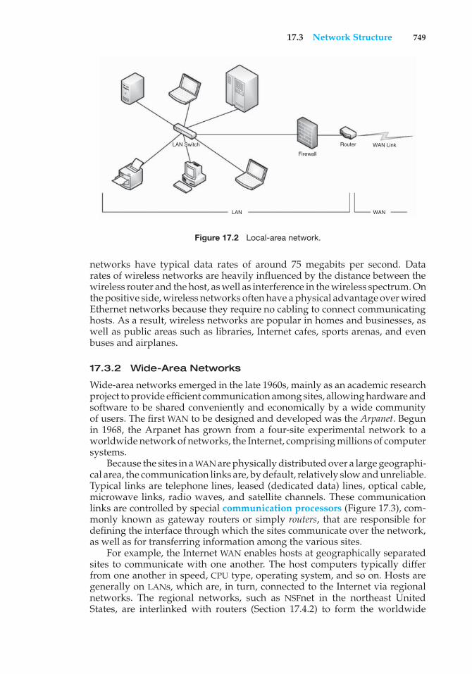
17.3 Network Structure 749
LAN Switch
Firewall
Router WAN Link
LAN WAN
Figure 17.2 Local-area network.
networks have typical data rates of around 75 megabits per second. Datarates of wireless networks are heavily influenced by the distance between thewireless router and the host, as well as interference in the wireless spectrum. Onthe positive side, wireless networks often have a physical advantage over wiredEthernet networks because they require no cabling to connect communicatinghosts. As a result, wireless networks are popular in homes and businesses, aswell as public areas such as libraries, Internet cafes, sports arenas, and evenbuses and airplanes.
17.3.2 Wide-Area Networks
Wide-area networks emerged in the late 1960s, mainly as an academic researchproject to provide efficient communication among sites, allowing hardware andsoftware to be shared conveniently and economically by a wide communityof users. The first WAN to be designed and developed was the Arpanet. Begunin 1968, the Arpanet has grown from a four-site experimental network to aworldwide network of networks, the Internet, comprising millions of computersystems.
Because the sites in a WAN are physically distributed over a large geographi-cal area, the communication links are, by default, relatively slow and unreliable.Typical links are telephone lines, leased (dedicated data) lines, optical cable,microwave links, radio waves, and satellite channels. These communicationlinks are controlled by special communication processors (Figure 17.3), com-monly known as gateway routers or simply routers, that are responsible fordefining the interface through which the sites communicate over the network,as well as for transferring information among the various sites.
For example, the Internet WAN enables hosts at geographically separatedsites to communicate with one another. The host computers typically differfrom one another in speed, CPU type, operating system, and so on. Hosts aregenerally on LANs, which are, in turn, connected to the Internet via regionalnetworks. The regional networks, such as NSFnet in the northeast UnitedStates, are interlinked with routers (Section 17.4.2) to form the worldwide
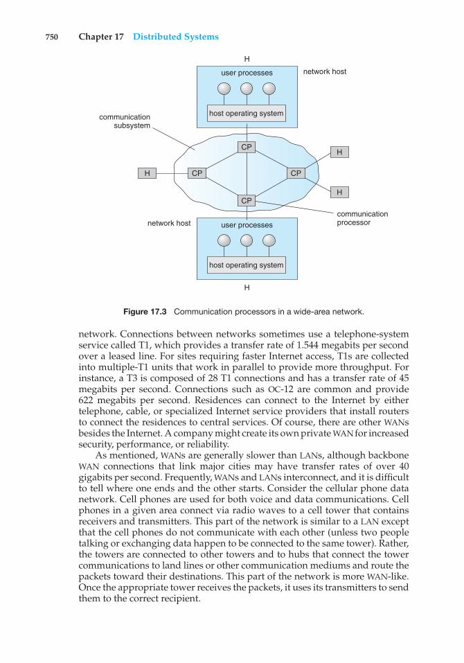
750 Chapter 17 Distributed Systems
communicationprocessor
communicationsubsystem
H
H
H
H
H
user processes
user processes
network host
network host
host operating system
host operating system
CP
CP
CPCP
Figure 17.3 Communication processors in a wide-area network.
network. Connections between networks sometimes use a telephone-systemservice called T1, which provides a transfer rate of 1.544 megabits per secondover a leased line. For sites requiring faster Internet access, T1s are collectedinto multiple-T1 units that work in parallel to provide more throughput. Forinstance, a T3 is composed of 28 T1 connections and has a transfer rate of 45megabits per second. Connections such as OC-12 are common and provide622 megabits per second. Residences can connect to the Internet by eithertelephone, cable, or specialized Internet service providers that install routersto connect the residences to central services. Of course, there are other WANsbesides the Internet. A company might create its own private WAN for increasedsecurity, performance, or reliability.
As mentioned, WANs are generally slower than LANs, although backboneWAN connections that link major cities may have transfer rates of over 40gigabits per second. Frequently, WANs and LANs interconnect, and it is difficultto tell where one ends and the other starts. Consider the cellular phone datanetwork. Cell phones are used for both voice and data communications. Cellphones in a given area connect via radio waves to a cell tower that containsreceivers and transmitters. This part of the network is similar to a LAN exceptthat the cell phones do not communicate with each other (unless two peopletalking or exchanging data happen to be connected to the same tower). Rather,the towers are connected to other towers and to hubs that connect the towercommunications to land lines or other communication mediums and route thepackets toward their destinations. This part of the network is more WAN-like.Once the appropriate tower receives the packets, it uses its transmitters to sendthem to the correct recipient.
17.4 Communication Structure 751
17.4 Communication Structure
Now that we have discussed the physical aspects of networking, we turn tothe internal workings. The designer of a communication network must addressfive basic issues:
• Naming and name resolution. How do two processes locate each other tocommunicate?
• Routing strategies. How are messages sent through the network?
• Packet strategies. Are packets sent individually or as a sequence?
• Connection strategies. How do two processes send a sequence of mes-sages?
In the following sections, we elaborate on each of these issues.
17.4.1 Naming and Name Resolution
The first issue in network communication involves the naming of the systemsin the network. For a process at site A to exchange information with a processat site B, each must be able to specify the other. Within a computer system,each process has a process identifier, and messages may be addressed with theprocess identifier. Because networked systems share no memory, however, ahost within the system initially has no knowledge about the processes on otherhosts.
To solve this problem, processes on remote systems are generally identifiedby the pair <host name, identifier>, where host name is a name unique withinthe network and identifier is a process identifier or other unique number withinthat host. A host name is usually an alphanumeric identifier, rather than anumber, to make it easier for users to specify. For instance, site A might havehosts named homer, marge, bart, and lisa. Bart is certainly easier to rememberthan is 12814831100.
Names are convenient for humans to use, but computers prefer numbers forspeed and simplicity. For this reason, there must be a mechanism to resolve thehost name into a host-id that describes the destination system to the networkinghardware. This mechanism is similar to the name-to-address binding thatoccurs during program compilation, linking, loading, and execution (Chapter8). In the case of host names, two possibilities exist. First, every host may have adata file containing the names and addresses of all the other hosts reachable onthe network (similar to binding at compile time). The problem with this modelis that adding or removing a host from the network requires updating the datafiles on all the hosts. The alternative is to distribute the information amongsystems on the network. The network must then use a protocol to distributeand retrieve the information. This scheme is like execution-time binding. Thefirst method was the one originally used on the Internet. As the Internet grew,however, it became untenable. The second method, the domain-name system(DNS), is the one now in use.
DNS specifies the naming structure of the hosts, as well as name-to-addressresolution. Hosts on the Internet are logically addressed with multipart namesknown as IP addresses. The parts of an IP address progress from the most
752 Chapter 17 Distributed Systems
specific to the most general, with periods separating the fields. For instance,bob.cs.brown.edu refers to host bob in the Department of Computer Science atBrown University within the top-level domain edu. (Other top-level domainsinclude com for commercial sites and org for organizations, as well as a domainfor each country connected to the network, for systems specified by countryrather than organization type.) Generally, the system resolves addresses byexamining the host-name components in reverse order. Each component has aname server—simply a process on a system—that accepts a name and returnsthe address of the name server responsible for that name. As the final step, thename server for the host in question is contacted, and a host-id is returned.For example, a request made by a process on system A to communicate withbob.cs.brown.edu would result in the following steps:
1. The system library or the kernel on system A issues a request to the nameserver for the edu domain, asking for the address of the name server forbrown.edu. The name server for the edu domain must be at a knownaddress, so that it can be queried.
2. The edu name server returns the address of the host on which thebrown.edu name server resides.
3. System A then queries the name server at this address and asks aboutcs.brown.edu.
4. An address is returned. Now, finally, a request to that address forbob.cs.brown.edu returns an Internet address host-id for that host (forexample, 128.148.31.100).
This protocol may seem inefficient, but individual hosts cache the IP addressesthey have already resolved to speed the process. (Of course, the contents ofthese caches must be refreshed over time in case the name server is movedor its address changes.) In fact, the protocol is so important that it has beenoptimized many times and has had many safeguards added. Consider whatwould happen if the primary edu name server crashed. It is possible thatno edu hosts would be able to have their addresses resolved, making themall unreachable! The solution is to use secondary, backup name servers thatduplicate the contents of the primary servers.
Before the domain-name service was introduced, all hosts on the Internetneeded to have copies of a file that contained the names and addresses of eachhost on the network. All changes to this file had to be registered at one site (hostSRI-NIC), and periodically all hosts had to copy the updated file from SRI-NICto be able to contact new systems or find hosts whose addresses had changed.Under the domain-name service, each name-server site is responsible forupdating the host information for that domain. For instance, any host changesat Brown University are the responsibility of the name server for brown.edu andneed not be reported anywhere else. DNS lookups will automatically retrievethe updated information because they will contact brown.edu directly. Domainsmay contain autonomous subdomains to further distribute the responsibilityfor host-name and host-id changes.
Java provides the necessary API to design a program that maps IP names toIP addresses. The program shown in Figure 17.4 is passed an IP name (such as
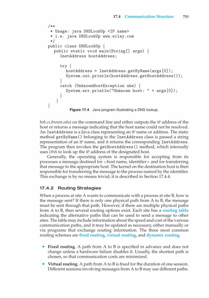
17.4 Communication Structure 753
/*** Usage: java DNSLookUp <IP name>* i.e. java DNSLookUp www.wiley.com*/public class DNSLookUp {
public static void main(String[] args) {InetAddress hostAddress;
try {hostAddress = InetAddress.getByName(args[0]);System.out.println(hostAddress.getHostAddress());
}catch (UnknownHostException uhe) {
System.err.println("Unknown host: " + args[0]);}
}}
Figure 17.4 Java program illustrating a DNS lookup.
bob.cs.brown.edu) on the command line and either outputs the IP address of thehost or returns a message indicating that the host name could not be resolved.An InetAddress is a Java class representing an IP name or address. The staticmethod getByName() belonging to the InetAddress class is passed a stringrepresentation of an IP name, and it returns the corresponding InetAddress.The program then invokes the getHostAddress() method, which internallyuses DNS to look up the IP address of the designated host.
Generally, the operating system is responsible for accepting from itsprocesses a message destined for <host name, identifier> and for transferringthat message to the appropriate host. The kernel on the destination host is thenresponsible for transferring the message to the process named by the identifier.This exchange is by no means trivial; it is described in Section 17.4.4.
17.4.2 Routing Strategies
When a process at site A wants to communicate with a process at site B, how isthe message sent? If there is only one physical path from A to B, the messagemust be sent through that path. However, if there are multiple physical pathsfrom A to B, then several routing options exist. Each site has a routing tableindicating the alternative paths that can be used to send a message to othersites. The table may include information about the speed and cost of the variouscommunication paths, and it may be updated as necessary, either manually orvia programs that exchange routing information. The three most commonrouting schemes are fixed routing, virtual routing, and dynamic routing.
• Fixed routing. A path from A to B is specified in advance and does notchange unless a hardware failure disables it. Usually, the shortest path ischosen, so that communication costs are minimized.
• Virtual routing. A path from A to B is fixed for the duration of one session.Different sessions involving messages from A to B may use different paths.
754 Chapter 17 Distributed Systems
A session could be as short as a file transfer or as long as a remote-loginperiod.
• Dynamic routing. The path used to send a message from site A to siteB is chosen only when the message is sent. Because the decision is madedynamically, separate messages may be assigned different paths. Site Awill make a decision to send the message to site C. C, in turn, will decideto send it to site D, and so on. Eventually, a site will deliver the messageto B. Usually, a site sends a message to another site on whatever link is theleast used at that particular time.
There are tradeoffs among these three schemes. Fixed routing cannot adaptto link failures or load changes. In other words, if a path has been establishedbetween A and B, the messages must be sent along this path, even if the pathis down or is used more heavily than another possible path. We can partiallyremedy this problem by using virtual routing and can avoid it completely byusing dynamic routing. Fixed routing and virtual routing ensure that messagesfrom A to B will be delivered in the order in which they were sent. In dynamicrouting, messages may arrive out of order. We can remedy this problem byappending a sequence number to each message.
Dynamic routing is the most complicated to set up and run; however, it isthe best way to manage routing in complicated environments. UNIX providesboth fixed routing for use on hosts within simple networks and dynamicrouting for complicated network environments. It is also possible to mix thetwo. Within a site, the hosts may just need to know how to reach the system thatconnects the local network to other networks (such as company-wide networksor the Internet). Such a node is known as a gateway. Each individual host hasa static route to the gateway, but the gateway itself uses dynamic routing toreach any host on the rest of the network.
A router is the communications processor within the computer networkresponsible for routing messages. A router can be a host computer with routingsoftware or a special-purpose device. Either way, a router must have at leasttwo network connections, or else it would have nowhere to route messages.A router decides whether any given message needs to be passed from thenetwork on which it is received to any other network connected to the router.It makes this determination by examining the destination Internet addressof the message. The router checks its tables to determine the location of thedestination host, or at least of the network to which it will send the messagetoward the destination host. In the case of static routing, this table is changedonly by manual update (a new file is loaded onto the router). With dynamicrouting, a routing protocol is used between routers to inform them of networkchanges and to allow them to update their routing tables automatically.
Gateways and routers have typically been dedicated hardware devicesthat run code out of firmware. More recently, routing has been managed bysoftware that directs multiple network devices more intelligently than a singlerouter could. The software is device-independent, enabling network devicesfrom multiple vendors to cooperate more easily. For example, the OpenFlowstandard allows developers to introduce new networking efficiencies andfeatures by decoupling data-routing decisions from the underlying networkingdevices.
17.4 Communication Structure 755
17.4.3 Packet Strategies
Messages generally vary in length. To simplify the system design, we com-monly implement communication with fixed-length messages called packets,frames, or datagrams. A communication implemented in one packet can besent to its destination in a connectionless message. A connectionless messagecan be unreliable, in which case the sender has no guarantee that, and cannottell whether, the packet reached its destination. Alternatively, the packet can bereliable. Usually, in this case, an acknowledgement packet is returned from thedestination indicating that the original packet arrived. (Of course, the returnpacket could be lost along the way.) If a message is too long to fit withinone packet, or if the packets need to flow back and forth between the twocommunicators, a connection is established to allow the reliable exchange ofmultiple packets.
17.4.4 Connection Strategies
Once messages are able to reach their destinations, processes can institutecommunications sessions to exchange information. Pairs of processes that wantto communicate over the network can be connected in a number of ways. Thethree most common schemes are circuit switching, message switching, andpacket switching.
• Circuit switching. If two processes want to communicate, a permanentphysical link is established between them. This link is allocated for theduration of the communication session, and no other process can usethat link during this period (even if the two processes are not activelycommunicating for a while). This scheme is similar to that used in thetelephone system. Once a communication line has been opened betweentwo parties (that is, party A calls party B), no one else can use this circuituntil the communication is terminated explicitly (for example, when theparties hang up).
• Message switching. If two processes want to communicate, a temporarylink is established for the duration of one message transfer. Physicallinks are allocated dynamically among correspondents as needed andare allocated for only short periods. Each message is a block of datawith system information—such as the source, the destination, and error-correction codes (ECC)—that allows the communication network to deliverthe message to the destination correctly. This scheme is similar to thepost-office mailing system. Each letter is a message that contains both thedestination address and source (return) address. Many messages (fromdifferent users) can be shipped over the same link.
• Packet switching. One logical message may have to be divided into anumber of packets. Each packet may be sent to its destination separately,and each therefore must include a source and a destination address with itsdata. Furthermore, the various packets may take different paths throughthe network. The packets must be reassembled into messages as theyarrive. Note that it is not harmful for data to be broken into packets,possibly routed separately, and reassembled at the destination. Breaking
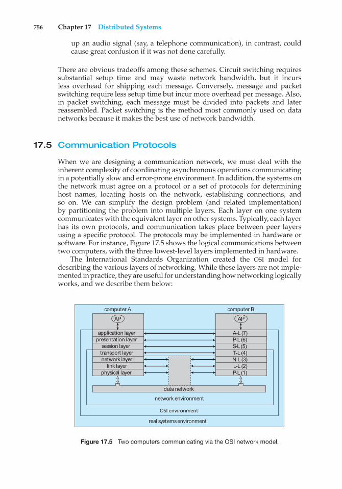
756 Chapter 17 Distributed Systems
up an audio signal (say, a telephone communication), in contrast, couldcause great confusion if it was not done carefully.
There are obvious tradeoffs among these schemes. Circuit switching requiressubstantial setup time and may waste network bandwidth, but it incursless overhead for shipping each message. Conversely, message and packetswitching require less setup time but incur more overhead per message. Also,in packet switching, each message must be divided into packets and laterreassembled. Packet switching is the method most commonly used on datanetworks because it makes the best use of network bandwidth.
17.5 Communication Protocols
When we are designing a communication network, we must deal with theinherent complexity of coordinating asynchronous operations communicatingin a potentially slow and error-prone environment. In addition, the systems onthe network must agree on a protocol or a set of protocols for determininghost names, locating hosts on the network, establishing connections, andso on. We can simplify the design problem (and related implementation)by partitioning the problem into multiple layers. Each layer on one systemcommunicates with the equivalent layer on other systems. Typically, each layerhas its own protocols, and communication takes place between peer layersusing a specific protocol. The protocols may be implemented in hardware orsoftware. For instance, Figure 17.5 shows the logical communications betweentwo computers, with the three lowest-level layers implemented in hardware.
The International Standards Organization created the OSI model fordescribing the various layers of networking. While these layers are not imple-mented in practice, they are useful for understanding how networking logicallyworks, and we describe them below:
real systems environment
OSI environment
network environment
data network
computer A
application layerpresentation layer
session layertransport layernetwork layer
link layerphysical layer
AP
computer B
A-L (7) P-L (6) S-L (5) T-L (4) N-L (3) L-L (2) P-L (1)
AP
Figure 17.5 Two computers communicating via the OSI network model.
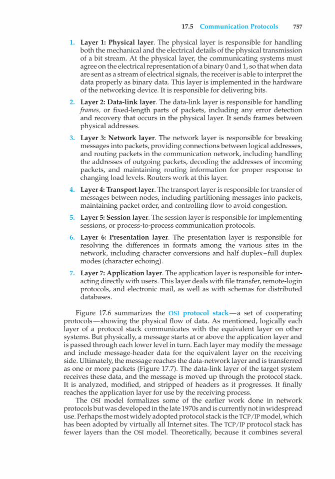
17.5 Communication Protocols 757
1. Layer 1: Physical layer. The physical layer is responsible for handlingboth the mechanical and the electrical details of the physical transmissionof a bit stream. At the physical layer, the communicating systems mustagree on the electrical representation of a binary 0 and 1, so that when dataare sent as a stream of electrical signals, the receiver is able to interpret thedata properly as binary data. This layer is implemented in the hardwareof the networking device. It is responsible for delivering bits.
2. Layer 2: Data-link layer. The data-link layer is responsible for handlingframes, or fixed-length parts of packets, including any error detectionand recovery that occurs in the physical layer. It sends frames betweenphysical addresses.
3. Layer 3: Network layer. The network layer is responsible for breakingmessages into packets, providing connections between logical addresses,and routing packets in the communication network, including handlingthe addresses of outgoing packets, decoding the addresses of incomingpackets, and maintaining routing information for proper response tochanging load levels. Routers work at this layer.
4. Layer 4: Transport layer. The transport layer is responsible for transfer ofmessages between nodes, including partitioning messages into packets,maintaining packet order, and controlling flow to avoid congestion.
5. Layer 5: Session layer. The session layer is responsible for implementingsessions, or process-to-process communication protocols.
6. Layer 6: Presentation layer. The presentation layer is responsible forresolving the differences in formats among the various sites in thenetwork, including character conversions and half duplex–full duplexmodes (character echoing).
7. Layer 7: Application layer. The application layer is responsible for inter-acting directly with users. This layer deals with file transfer, remote-loginprotocols, and electronic mail, as well as with schemas for distributeddatabases.
Figure 17.6 summarizes the OSI protocol stack—a set of cooperatingprotocols—showing the physical flow of data. As mentioned, logically eachlayer of a protocol stack communicates with the equivalent layer on othersystems. But physically, a message starts at or above the application layer andis passed through each lower level in turn. Each layer may modify the messageand include message-header data for the equivalent layer on the receivingside. Ultimately, the message reaches the data-network layer and is transferredas one or more packets (Figure 17.7). The data-link layer of the target systemreceives these data, and the message is moved up through the protocol stack.It is analyzed, modified, and stripped of headers as it progresses. It finallyreaches the application layer for use by the receiving process.
The OSI model formalizes some of the earlier work done in networkprotocols but was developed in the late 1970s and is currently not in widespreaduse. Perhaps the most widely adopted protocol stack is the TCP/IP model, whichhas been adopted by virtually all Internet sites. The TCP/IP protocol stack hasfewer layers than the OSI model. Theoretically, because it combines several
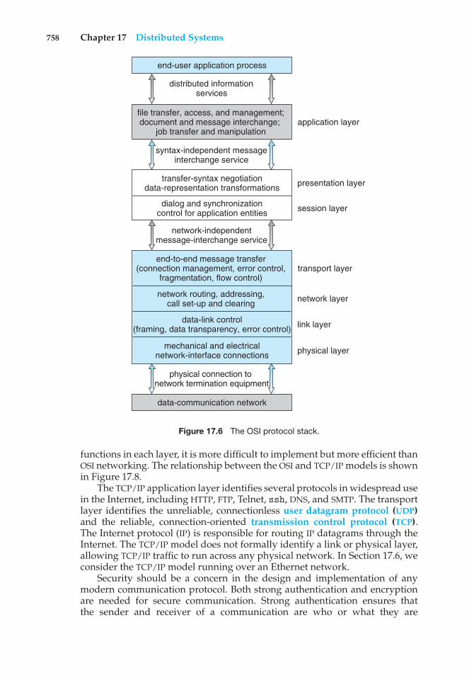
758 Chapter 17 Distributed Systems
data-communication network
end-to-end message transfer(connection management, error control,
fragmentation, flow control)
physical connection to network termination equipment
transport layer
network routing, addressing,call set-up and clearing
transfer-syntax negotiationdata-representation transformations
network-independentmessage-interchange service
presentation layer
file transfer, access, and management; document and message interchange;
job transfer and manipulation
syntax-independent messageinterchange service
end-user application process
distributed information services
application layer
dialog and synchronizationcontrol for application entities session layer
network layer
link layer
physical layer
data-link control(framing, data transparency, error control)
mechanical and electricalnetwork-interface connections
Figure 17.6 The OSI protocol stack.
functions in each layer, it is more difficult to implement but more efficient thanOSI networking. The relationship between the OSI and TCP/IP models is shownin Figure 17.8.
The TCP/IP application layer identifies several protocols in widespread usein the Internet, including HTTP, FTP, Telnet, ssh, DNS, and SMTP. The transportlayer identifies the unreliable, connectionless user datagram protocol (UDP)and the reliable, connection-oriented transmission control protocol (TCP).The Internet protocol (IP) is responsible for routing IP datagrams through theInternet. The TCP/IP model does not formally identify a link or physical layer,allowing TCP/IP traffic to run across any physical network. In Section 17.6, weconsider the TCP/IP model running over an Ethernet network.
Security should be a concern in the design and implementation of anymodern communication protocol. Both strong authentication and encryptionare needed for secure communication. Strong authentication ensures thatthe sender and receiver of a communication are who or what they are
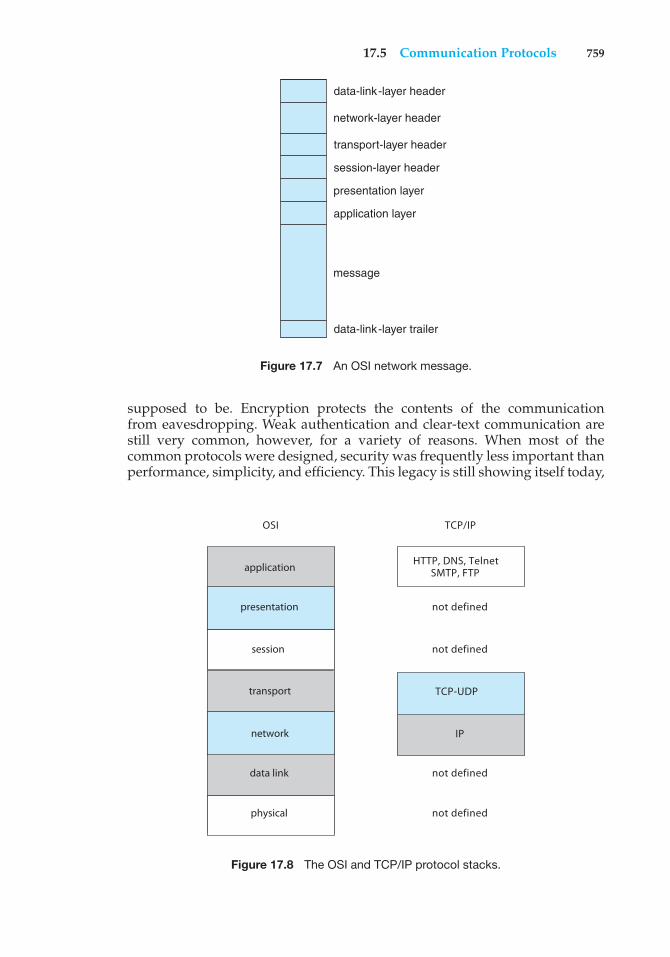
17.5 Communication Protocols 759
data-link-layer header
network-layer header
transport-layer header
session-layer header
presentation layer
application layer
message
data-link-layer trailer
Figure 17.7 An OSI network message.
supposed to be. Encryption protects the contents of the communicationfrom eavesdropping. Weak authentication and clear-text communication arestill very common, however, for a variety of reasons. When most of thecommon protocols were designed, security was frequently less important thanperformance, simplicity, and efficiency. This legacy is still showing itself today,
data link
transport
application HTTP, DNS, TelnetSMTP, FTP
not defined
not defined
not defined
OSI TCP/IP
not defined
IP
TCP-UDP
physical
network
session
presentation
Figure 17.8 The OSI and TCP/IP protocol stacks.
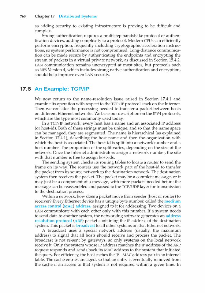
760 Chapter 17 Distributed Systems
as adding security to existing infrastructure is proving to be difficult andcomplex.
Strong authentication requires a multistep handshake protocol or authen-tication devices, adding complexity to a protocol. Modern CPUs can efficientlyperform encryption, frequently including cryptographic acceleration instruc-tions, so system performance is not compromised. Long-distance communica-tion can be made secure by authenticating the endpoints and encrypting thestream of packets in a virtual private network, as discussed in Section 15.4.2.LAN communication remains unencrypted at most sites, but protocols suchas NFS Version 4, which includes strong native authentication and encryption,should help improve even LAN security.
17.6 An Example: TCP/IP
We now return to the name-resolution issue raised in Section 17.4.1 andexamine its operation with respect to the TCP/IP protocol stack on the Internet.Then we consider the processing needed to transfer a packet between hostson different Ethernet networks. We base our description on the IPV4 protocols,which are the type most commonly used today.
In a TCP/IP network, every host has a name and an associated IP address(or host-id). Both of these strings must be unique; and so that the name spacecan be managed, they are segmented. The name is hierarchical (as explainedin Section 17.4.1), describing the host name and then the organization withwhich the host is associated. The host-id is split into a network number and ahost number. The proportion of the split varies, depending on the size of thenetwork. Once the Internet administrators assign a network number, the sitewith that number is free to assign host-ids.
The sending system checks its routing tables to locate a router to send theframe on its way. The routers use the network part of the host-id to transferthe packet from its source network to the destination network. The destinationsystem then receives the packet. The packet may be a complete message, or itmay just be a component of a message, with more packets needed before themessage can be reassembled and passed to the TCP/UDP layer for transmissionto the destination process.
Within a network, how does a packet move from sender (host or router) toreceiver? Every Ethernet device has a unique byte number, called the mediumaccess control (MAC) address, assigned to it for addressing. Two devices on aLAN communicate with each other only with this number. If a system needsto send data to another system, the networking software generates an addressresolution protocol (ARP) packet containing the IP address of the destinationsystem. This packet is broadcast to all other systems on that Ethernet network.
A broadcast uses a special network address (usually, the maximumaddress) to signal that all hosts should receive and process the packet. Thebroadcast is not re-sent by gateways, so only systems on the local networkreceive it. Only the system whose IP address matches the IP address of the ARPrequest responds and sends back its MAC address to the system that initiatedthe query. For efficiency, the host caches the IP– MAC address pair in an internaltable. The cache entries are aged, so that an entry is eventually removed fromthe cache if an access to that system is not required within a given time. In
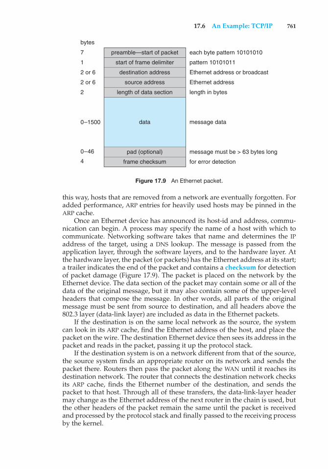
17.6 An Example: TCP/IP 761
preamble—start of packet
start of frame delimiter
destination address
source address
length of data section
pad (optional)
frame checksum
bytes
7
1
2 or 6
2 or 6
2
each byte pattern 10101010
pattern 10101011
Ethernet address or broadcast
Ethernet address
length in bytes
message data
message must be > 63 bytes long
for error detection
0–1500
0–46
4
data
Figure 17.9 An Ethernet packet.
this way, hosts that are removed from a network are eventually forgotten. Foradded performance, ARP entries for heavily used hosts may be pinned in theARP cache.
Once an Ethernet device has announced its host-id and address, commu-nication can begin. A process may specify the name of a host with which tocommunicate. Networking software takes that name and determines the IPaddress of the target, using a DNS lookup. The message is passed from theapplication layer, through the software layers, and to the hardware layer. Atthe hardware layer, the packet (or packets) has the Ethernet address at its start;a trailer indicates the end of the packet and contains a checksum for detectionof packet damage (Figure 17.9). The packet is placed on the network by theEthernet device. The data section of the packet may contain some or all of thedata of the original message, but it may also contain some of the upper-levelheaders that compose the message. In other words, all parts of the originalmessage must be sent from source to destination, and all headers above the802.3 layer (data-link layer) are included as data in the Ethernet packets.
If the destination is on the same local network as the source, the systemcan look in its ARP cache, find the Ethernet address of the host, and place thepacket on the wire. The destination Ethernet device then sees its address in thepacket and reads in the packet, passing it up the protocol stack.
If the destination system is on a network different from that of the source,the source system finds an appropriate router on its network and sends thepacket there. Routers then pass the packet along the WAN until it reaches itsdestination network. The router that connects the destination network checksits ARP cache, finds the Ethernet number of the destination, and sends thepacket to that host. Through all of these transfers, the data-link-layer headermay change as the Ethernet address of the next router in the chain is used, butthe other headers of the packet remain the same until the packet is receivedand processed by the protocol stack and finally passed to the receiving processby the kernel.
762 Chapter 17 Distributed Systems
17.7 Robustness
A distributed system may suffer from various types of hardware failure. Thefailure of a link, the failure of a site, and the loss of a message are the mostcommon types. To ensure that the system is robust, we must detect any of thesefailures, reconfigure the system so that computation can continue, and recoverwhen a site or a link is repaired.
17.7.1 Failure Detection
In an environment with no shared memory, we are generally unable todifferentiate among link failure, site failure, and message loss. We can usuallydetect only that one of these failures has occurred. Once a failure has beendetected, appropriate action must be taken. What action is appropriate dependson the particular application.
To detect link and site failure, we use a heartbeat procedure. Suppose thatsites A and B have a direct physical link between them. At fixed intervals, thesites send each other an I-am-up message. If site A does not receive this messagewithin a predetermined time period, it can assume that site B has failed, thatthe link between A and B has failed, or that the message from B has been lost.At this point, site A has two choices. It can wait for another time period toreceive an I-am-up message from B, or it can send an Are-you-up? message to B.
If time goes by and site A still has not received an I-am-up message, or if siteA has sent an Are-you-up? message and has not received a reply, the procedurecan be repeated. Again, the only conclusion that site A can draw safely is thatsome type of failure has occurred.
Site A can try to differentiate between link failure and site failure by sendingan Are-you-up? message to B by another route (if one exists). If and when Breceives this message, it immediately replies positively. This positive reply tellsA that B is up and that the failure is in the direct link between them. Since wedo not know in advance how long it will take the message to travel from A to Band back, we must use a time-out scheme. At the time A sends the Are-you-up?message, it specifies a time interval during which it is willing to wait for thereply from B. If A receives the reply message within that time interval, then itcan safely conclude that B is up. If not, however (that is, if a time-out occurs),then A may conclude only that one or more of the following situations hasoccurred:
• Site B is down.
• The direct link (if one exists) from A to B is down.
• The alternative path from A to B is down.
• The message has been lost.
Site A cannot, however, determine which of these events has occurred.
17.7.2 Reconfiguration
Suppose that site A has discovered, through the mechanism just described,that a failure has occurred. It must then initiate a procedure that will allow thesystem to reconfigure and to continue its normal mode of operation.
17.7 Robustness 763
• If a direct link from A to B has failed, this information must be broadcast toevery site in the system, so that the various routing tables can be updatedaccordingly.
• If the system believes that a site has failed (because that site can be reachedno longer), then all sites in the system must be notified, so that they willno longer attempt to use the services of the failed site. The failure of a sitethat serves as a central coordinator for some activity (such as deadlockdetection) requires the election of a new coordinator. Similarly, if the failedsite is part of a logical ring, then a new logical ring must be constructed.Note that, if the site has not failed (that is, if it is up but cannot be reached),then we may have the undesirable situation in which two sites serve as thecoordinator. When the network is partitioned, the two coordinators (eachfor its own partition) may initiate conflicting actions. For example, if thecoordinators are responsible for implementing mutual exclusion, we mayhave a situation in which two processes are executing simultaneously intheir critical sections.
17.7.3 Recovery from Failure
When a failed link or site is repaired, it must be integrated into the systemgracefully and smoothly.
• Suppose that a link between A and B has failed. When it is repaired, both Aand B must be notified. We can accomplish this notification by continuouslyrepeating the heartbeat procedure described in Section 17.7.1.
• Suppose that site B has failed. When it recovers, it must notify all othersites that it is up again. Site B then may have to receive information fromthe other sites to update its local tables. For example, it may need routing-table information, a list of sites that are down, undelivered messages, atransaction log of unexecuted transactions, and mail. If the site has notfailed but simply could not be reached, then it still needs this information.
17.7.4 Fault Tolerance
A distributed system must tolerate a certain level of failure and continue tofunction normally when faced with various types of failures. Making a facilityfault tolerant starts at the protocol level, as described above, but continuesthrough all aspects of the system. We use the term fault tolerance in a broadsense. Communication faults, certain machine failures, storage-device crashes,and decays of storage media should all be tolerated to some extent. A fault-tolerant system should continue to function, perhaps in a degraded form, whenfaced with such failures. The degradation can affect performance, functionality,or both. It should be proportional, however, to the failures that caused it. Asystem that grinds to a halt when only one of its components fails is certainlynot fault tolerant.
Unfortunately, fault tolerance can be difficult and expensive to implement.At the network layer, multiple redundant communication paths and networkdevices such as switches and routers are needed to avoid a communicationfailure. A storage failure can cause loss of the operating system, applications,or data. Storage units can include redundant hardware components that
764 Chapter 17 Distributed Systems
automatically take over from each other in case of failure. In addition, RAIDsystems can ensure continued access to the data even in the event of one ormore disk failures (Section 10.7).
A system failure without redundancy can cause an application or an entirefacility to stop operation. The most simple system failure involves a systemrunning only stateless applications. These applications can be restarted withoutcompromising the operation; so as long as the applications can run on morethan one computer (node), operation can continue. Such a facility is commonlyknown as a compute cluster because it centers on computation.
In contrast, datacentric systems involve running applications that accessand modify shared data. As a result, datacentric computing facilities are moredifficult to make fault tolerant. They require failure-monitoring software andspecial infrastructure. For instance, high-availability clusters include two ormore computers and a set of shared disks. Any given application can bestored on the computers or on the shared disk, but the data must be storedon the shared disk. The running application’s node has exclusive access tothe application’s data on disk. The application is monitored by the clustersoftware, and if it fails it is automatically restarted. If it cannot be restarted, orif the entire computer fails, the node’s exclusive access to the application’s datais terminated and is granted to another node in the cluster. The application isrestarted on that new node. The application loses whatever state informationwas in the failed system’s memory but can continue based on whatever stateit last wrote to the shared disk. From a user’s point of view, a service wasinterrupted and then restarted, possibly with some data missing.
Specific applications may improve on this functionality by implementinglock management along with clustering. With lock management, the applica-tion can run on multiple nodes and can use the same data on shared disksconcurrently. Clustered databases frequently implement this functionality. Ifa node fails, transactions can continue on other nodes, and users notice nointerruption of service, as long as the client is able to automatically locate theother nodes in the cluster. Any noncommitted transactions on the failed nodeare lost, but again, client applications can be designed to retry noncommittedtransactions if they detect a failure of their database node.
17.8 Design Issues
Making the multiplicity of processors and storage devices transparent to theusers has been a key challenge to many designers. Ideally, a distributed systemshould look to its users like a conventional, centralized system. The userinterface of a transparent distributed system should not distinguish betweenlocal and remote resources. That is, users should be able to access remoteresources as though these resources were local, and the distributed systemshould be responsible for locating the resources and for arranging for theappropriate interaction.
Another aspect of transparency is user mobility. It would be convenient toallow users to log into any machine in the system rather than forcing them to usea specific machine. A transparent distributed system facilitates user mobilityby bringing over the user’s environment (for example, home directory) towherever he logs in. Protocols like LDAP provide an authentication system for
17.9 Distributed File Systems 765
local, remote, and mobile users. Once the authentication is complete, facilitieslike desktop virtualization allow users to see their desktop sessions at remotefacilities.
Still another issue is scalability—the capability of a system to adapt toincreased service load. Systems have bounded resources and can becomecompletely saturated under increased load. For example, with respect to a filesystem, saturation occurs either when a server’s CPU runs at a high utilizationrate or when disks’ I/O requests overwhelm the I/O subsystem. Scalabilityis a relative property, but it can be measured accurately. A scalable systemreacts more gracefully to increased load than does a nonscalable one. First,its performance degrades more moderately; and second, its resources reach asaturated state later. Even perfect design cannot accommodate an ever-growingload. Adding new resources might solve the problem, but it might generateadditional indirect load on other resources (for example, adding machines toa distributed system can clog the network and increase service loads). Evenworse, expanding the system can call for expensive design modifications. Ascalable system should have the potential to grow without these problems. Ina distributed system, the ability to scale up gracefully is of special importance,since expanding the network by adding new machines or interconnecting twonetworks is commonplace. In short, a scalable design should withstand highservice load, accommodate growth of the user community, and allow simpleintegration of added resources.
Scalability is related to fault tolerance, discussed earlier. A heavily loadedcomponent can become paralyzed and behave like a faulty component. Inaddition, shifting the load from a faulty component to that component’sbackup can saturate the latter. Generally, having spare resources is essentialfor ensuring reliability as well as for handling peak loads gracefully. Thus, themultiple resources in a distributed system represent an inherent advantage,giving the system a greater potential for fault tolerance and scalability.However, inappropriate design can obscure this potential. Fault-tolerance andscalability considerations call for a design demonstrating distribution of controland data.
Facilities like the Hadoop distributed file system were created with thisproblem in mind. Hadoop is based on Google’s MapReduce and GoogleFile System projects that created a facility to track every web page on theInternet. Hadoop is an open-source programming framework that supportsthe processing of large data sets in distributed computing environments.Traditional systems with traditional databases cannot scale to the capacity andperformance needed by “big data” projects (at least not at reasonable prices).Examples of big data projects include mining Twitter for information pertinentto a company and sifting financial data to look for trends in stock pricing.With Hadoop and its related tools, thousands of systems can work together tomanage a distributed database of petabytes of information.
17.9 Distributed File Systems
Although the World Wide Web is the predominant distributed system in usetoday, it is not the only one. Another important and popular use of distributedcomputing is the distributed file system, or DFS. In this section, we discuss
766 Chapter 17 Distributed Systems
distributed file systems. In doing so, we use two running examples—OpenAFS,an open-source distributed file system, and NFS, the most common UNIX-basedDFS. NFS has several versions, and here we refer to NFS Version 3 unlessotherwise noted.
To explain the structure of a DFS, we need to define the terms service,server, and client in the DFS context. A service is a software entity running onone or more machines and providing a particular type of function to clients.A server is the service software running on a single machine. A client isa process that can invoke a service using a set of operations that form itsclient interface. Sometimes a lower-level interface is defined for the actualcross-machine interaction; it is the intermachine interface.
Using this terminology, we say that a file system provides file services toclients. A client interface for a file service is formed by a set of primitive fileoperations, such as create a file, delete a file, read from a file, and write to a file.The primary hardware component that a file server controls is a set of localsecondary-storage devices (usually, magnetic disks) on which files are storedand from which they are retrieved according to the clients’ requests.
A DFS is a file system whose clients, servers, and storage devices aredispersed among the machines of a distributed system. Accordingly, serviceactivity has to be carried out across the network. Instead of a single centralizeddata repository, the system frequently has multiple and independent storagedevices. As you will see, the concrete configuration and implementation of aDFS may vary from system to system. In some configurations, servers run ondedicated machines. In others, a machine can be both a server and a client. A DFScan be implemented as part of a distributed operating system or, alternatively,by a software layer whose task is to manage the communication betweenconventional operating systems and file systems.
The distinctive features of a DFS are the multiplicity and autonomy ofclients and servers in the system. Ideally, though, a DFS should appear to itsclients to be a conventional, centralized file system. That is, the client interfaceof a DFS should not distinguish between local and remote files. It is up to theDFS to locate the files and to arrange for the transport of the data. A transparentDFS—like the transparent distributed systems mentioned earlier—facilitatesuser mobility by bringing a user’s environment (that is, home directory) towherever the user logs in.
The most important performance measure of a DFS is the amount of timeneeded to satisfy service requests. In conventional systems, this time consists ofdisk-access time and a small amount of CPU-processing time. In a DFS, however,a remote access has the additional overhead associated with the distributedstructure. This overhead includes the time to deliver the request to a server, aswell as the time to get the response across the network back to the client. Foreach direction, in addition to the transfer of the information, there is the CPUoverhead of running the communication protocol software. The performanceof a DFS can be viewed as another dimension of the DFS’s transparency. That is,the performance of an ideal DFS would be comparable to that of a conventionalfile system.
The fact that a DFS manages a set of dispersed storage devices is the DFS’skey distinguishing feature. The overall storage space managed by a DFS iscomposed of different and remotely located smaller storage spaces. Usually,these constituent storage spaces correspond to sets of files. A component unit
17.9 Distributed File Systems 767
is the smallest set of files that can be stored on a single machine, independentlyfrom other units. All files belonging to the same component unit must residein the same location.
17.9.1 Naming and Transparency
Naming is a mapping between logical and physical objects. For instance,users deal with logical data objects represented by file names, whereas thesystem manipulates physical blocks of data stored on disk tracks. Usually, auser refers to a file by a textual name. The latter is mapped to a lower-levelnumerical identifier that in turn is mapped to disk blocks. This multilevelmapping provides users with an abstraction of a file that hides the details ofhow and where on the disk the file is stored.
In a transparent DFS, a new dimension is added to the abstraction: that ofhiding where in the network the file is located. In a conventional file system, therange of the naming mapping is an address within a disk. In a DFS, this rangeis expanded to include the specific machine on whose disk the file is stored.Going one step further with the concept of treating files as abstractions leadsto the possibility of file replication. Given a file name, the mapping returns aset of the locations of this file’s replicas. In this abstraction, both the existenceof multiple copies and their locations are hidden.
17.9.1.1 Naming Structures
We need to differentiate two related notions regarding name mappings in aDFS:
1. Location transparency. The name of a file does not reveal any hint of thefile’s physical storage location.
2. Location independence. The name of a file does not need to be changedwhen the file’s physical storage location changes.
Both definitions relate to the level of naming discussed previously, since fileshave different names at different levels (that is, user-level textual names andsystem-level numerical identifiers). A location-independent naming scheme isa dynamic mapping, since it can map the same file name to different locationsat two different times. Therefore, location independence is a stronger propertythan is location transparency.
In practice, most of the current DFSs provide a static, location-transparentmapping for user-level names. Some support file migration—that is, changingthe location of a file automatically, providing location independence. OpenAFSsupports location independence and file mobility, for example. The Hadoopdistributed file system (HDFS)—a special file system written for the Hadoopframework—is a more recent creation. It includes file migration but doesso without following POSIX standards, providing more flexibility in imple-mentation and interface. HDFS keeps track of the location of data but hidesthis information from clients. This dynamic location transparency allows theunderlying mechanism to self-tune. In another example, Amazon’s §3 cloudstorage facility provides blocks of storage on demand via APIs, placing thestorage where it sees fit and moving the data as necessary to meet performance,reliability, and capacity requirements.
768 Chapter 17 Distributed Systems
A few aspects can further differentiate location independence and staticlocation transparency:
• Divorce of data from location, as exhibited by location independence,provides a better abstraction for files. A file name should denote the file’smost significant attributes, which are its contents rather than its location.Location-independent files can be viewed as logical data containers thatare not attached to a specific storage location. If only static locationtransparency is supported, the file name still denotes a specific, althoughhidden, set of physical disk blocks.
• Static location transparency provides users with a convenient way toshare data. Users can share remote files by simply naming the files in alocation-transparent manner, as though the files were local. Dropbox andother cloud-based storage solutions work this way. Location independencepromotes sharing the storage space itself, as well as the data objects. Whenfiles can be mobilized, the overall, system-wide storage space looks likea single virtual resource. A possible benefit is the ability to balance theutilization of storage across the system.
• Location independence separates the naming hierarchy from the storage-devices hierarchy and from the intercomputer structure. By contrast, ifstatic location transparency is used (although names are transparent),we can easily expose the correspondence between component units andmachines. The machines are configured in a pattern similar to the namingstructure. This configuration may restrict the architecture of the systemunnecessarily and conflict with other considerations. A server in charge ofa root directory is an example of a structure that is dictated by the naminghierarchy and contradicts decentralization guidelines.
Once the separation of name and location has been completed, clientscan access files residing on remote server systems. In fact, these clients maybe diskless and rely on servers to provide all files, including the operating-system kernel. Special protocols are needed for the boot sequence, however.Consider the problem of getting the kernel to a diskless workstation. Thediskless workstation has no kernel, so it cannot use the DFS code to retrievethe kernel. Instead, a special boot protocol, stored in read-only memory (ROM)on the client, is invoked. It enables networking and retrieves only one specialfile (the kernel or boot code) from a fixed location. Once the kernel is copiedover the network and loaded, its DFS makes all the other operating-system filesavailable. The advantages of diskless clients are many, including lower cost(because the client machines require no disks) and greater convenience (whenan operating-system upgrade occurs, only the server needs to be modified).The disadvantages are the added complexity of the boot protocols and theperformance loss resulting from the use of a network rather than a local disk.
17.9.1.2 Naming Schemes
There are three main approaches to naming schemes in a DFS. In the simplestapproach, a file is identified by some combination of its host name and localname, which guarantees a unique system-wide name. In Ibis, for instance, a
17.9 Distributed File Systems 769
file is identified uniquely by the name host:local-name, where local-name is aUNIX-like path. The Internet URL system also uses this approach. This namingscheme is neither location transparent nor location independent. The DFS isstructured as a collection of isolated component units, each of which is anentire conventional file system. Component units remain isolated, althoughmeans are provided to refer to remote files. We do not consider this schemeany further here.
The second approach was popularized by Sun’s network file system,NFS. NFS is found in many systems, including UNIX and Linux distributions.NFS provides a means to attach remote directories to local directories, thusgiving the appearance of a coherent directory tree. Early NFS versions allowedonly previously mounted remote directories to be accessed transparently. Theadvent of the automount feature allowed mounts to be done on demandbased on a table of mount points and file-structure names. Components areintegrated to support transparent sharing, but this integration is limited and isnot uniform, because each machine may attach different remote directories toits tree. The resulting structure is versatile.
We can achieve total integration of the component file systems by usingthe third approach. Here, a single global name structure spans all the filesin the system. Ideally, the composed file-system structure is the same as thestructure of a conventional file system. In practice, however, the many specialfiles (for example, UNIX device files and machine-specific binary directories)make this goal difficult to attain. To evaluate naming structures, we lookat their administrative complexity. The most complex and most difficult-to-maintain structure is the NFS structure. Because any remote directory can beattached anywhere onto the local directory tree, the resulting hierarchy canbe highly unstructured. If a server becomes unavailable, some arbitrary set ofdirectories on different machines becomes unavailable. In addition, a separateaccreditation mechanism controls which machine is allowed to attach whichdirectory to its tree. Thus, a user might be able to access a remote directory treeon one client but be denied access on another client.
17.9.1.3 Implementation Techniques
Implementation of transparent naming requires a provision for the mappingof a file name to the associated location. To keep this mapping manageable,we must aggregate sets of files into component units and provide the mappingon a component-unit basis rather than on a single-file basis. This aggregationserves administrative purposes as well. UNIX-like systems use the hierarchicaldirectory tree to provide name-to-location mapping and to aggregate filesrecursively into directories.
To enhance the availability of the crucial mapping information, we canuse replication, local caching, or both. As we noted, location independencemeans that the mapping changes over time. Hence, replicating the mappingmakes a simple yet consistent update of this information impossible. Toovercome this obstacle, we can introduce low-level, location-independentfile identifiers. (OpenAFS uses this approach.) Textual file names are mappedto lower-level file identifiers that indicate to which component unit the filebelongs. These identifiers are still location independent. They can be replicatedand cached freely without being invalidated by migration of component
770 Chapter 17 Distributed Systems
units. The inevitable price is the need for a second level of mapping, whichmaps component units to locations and needs a simple yet consistent updatemechanism. Implementing UNIX-like directory trees using these low-level,location-independent identifiers makes the whole hierarchy invariant undercomponent-unit migration. The only aspect that does change is the component-unit location mapping.
A common way to implement low-level identifiers is to use structurednames. These names are bit strings that usually have two parts. The firstpart identifies the component unit to which the file belongs; the second partidentifies the particular file within the unit. Variants with more parts arepossible. The invariant of structured names, however, is that individual parts ofthe name are unique at all times only within the context of the rest of the parts.We can obtain uniqueness at all times by taking care not to reuse a name that isstill in use, by adding sufficiently more bits (this method is used in OpenAFS), orby using a timestamp as one part of the name (as was done in Apollo Domain).Another way to view this process is that we are taking a location-transparentsystem, such as Ibis, and adding another level of abstraction to produce alocation-independent naming scheme.
17.9.2 Remote File Access
Next, let’s consider a user who requests access to a remote file. The serverstoring the file has been located by the naming scheme, and now the actualdata transfer must take place.
One way to achieve this transfer is through a remote-service mechanism,whereby requests for accesses are delivered to the server, the server machineperforms the accesses, and their results are forwarded back to the user. One ofthe most common ways of implementing remote service is the RPC paradigm,which we discussed in Chapter 3. A direct analogy exists between disk-accessmethods in conventional file systems and the remote-service method in a DFS:using the remote-service method is analogous to performing a disk access foreach access request.
To ensure reasonable performance of a remote-service mechanism, we canuse a form of caching. In conventional file systems, the rationale for caching isto reduce disk I/O (thereby increasing performance), whereas in DFSs, the goalis to reduce both network traffic and disk I/O. In the following discussion, wedescribe the implementation of caching in a DFS and contrast it with the basicremote-service paradigm.
17.9.2.1 Basic Caching Scheme
The concept of caching is simple. If the data needed to satisfy the accessrequest are not already cached, then a copy of those data is brought fromthe server to the client system. Accesses are performed on the cached copy.The idea is to retain recently accessed disk blocks in the cache, so that repeatedaccesses to the same information can be handled locally, without additionalnetwork traffic. A replacement policy (for example, the least-recently-usedalgorithm) keeps the cache size bounded. No direct correspondence existsbetween accesses and traffic to the server. Files are still identified with onemaster copy residing at the server machine, but copies (or parts) of the fileare scattered in different caches. When a cached copy is modified, the changes
17.9 Distributed File Systems 771
need to be reflected on the master copy to preserve the relevant consistencysemantics. The problem of keeping the cached copies consistent with the masterfile is the cache-consistency problem, which we discuss in Section 17.9.2.4. DFScaching could just as easily be called network virtual memory. It acts similarlyto demand-paged virtual memory, except that the backing store usually is aremote server rather than a local disk. NFS allows the swap space to be mountedremotely, so it actually can implement virtual memory over a network, thoughwith a resulting performance penalty.
The granularity of the cached data in a DFS can vary from blocks of a fileto an entire file. Usually, more data are cached than are needed to satisfy asingle access, so that many accesses can be served by the cached data. Thisprocedure is much like disk read-ahead (Section 12.6.2). OpenAFS caches filesin large chunks (64 KB). The other systems discussed here support cachingof individual blocks driven by client demand. Increasing the caching unitincreases the hit ratio, but it also increases the miss penalty, because each missrequires more data to be transferred. It increases the potential for consistencyproblems as well. Selecting the unit of caching involves considering parameterssuch as the network transfer unit and the RPC protocol service unit (if an RPCprotocol is used). The network transfer unit (for Ethernet, a packet) is about1.5 KB, so larger units of cached data need to be disassembled for delivery andreassembled on reception.
Block size and total cache size are obviously of importance for block-caching schemes. In UNIX-like systems, common block sizes are 4 KB and 8KB. For large caches (over 1 MB), large block sizes (over 8 KB) are beneficial. Forsmaller caches, large block sizes are less beneficial because they result in fewerblocks in the cache and a lower hit ratio.
17.9.2.2 Cache Location
Where should the cached data be stored—on disk or in main memory? Diskcaches have one clear advantage over main-memory caches: they are reliable.Modifications to cached data are lost in a crash if the cache is kept in volatilememory. Moreover, if the cached data are kept on disk, they are still there duringrecovery, and there is no need to fetch them again. Main-memory caches haveseveral advantages of their own, however:
• Main-memory caches permit workstations to be diskless.
• Data can be accessed more quickly from a cache in main memory thanfrom one on a disk.
• Technology is moving toward larger and less expensive memory. Theresulting performance speedup is predicted to outweigh the advantagesof disk caches.
• The server caches (used to speed up disk I/O) will be in main memoryregardless of where user caches are located; if we use main-memory cacheson the user machine, too, we can build a single caching mechanism for useby both servers and users.
Many remote-access implementations can be thought of as hybrids ofcaching and remote service. In NFS, for instance, the implementation is based on
772 Chapter 17 Distributed Systems
remote service but is augmented with client- and server-side memory cachingfor performance. Similarly, Sprite’s implementation is based on caching, butunder certain circumstances, a remote-service method is adopted. Thus, toevaluate the two methods, we must evaluate the degree to which either methodis emphasized. The NFS protocol and most implementations do not providedisk caching.
17.9.2.3 Cache-Update Policy
The policy used to write modified data blocks back to the server’s master copyhas a critical effect on the system’s performance and reliability. The simplestpolicy is to write data through to disk as soon as they are placed in any cache.The advantage of a write-through policy is reliability: little information islost when a client system crashes. However, this policy requires each writeaccess to wait until the information is sent to the server, so it causes poor writeperformance. Caching with write-through is equivalent to using remote servicefor write accesses and exploiting caching only for read accesses.
An alternative is the delayed-write policy, also known as write-backcaching, where we delay updates to the master copy. Modifications are writtento the cache and then are written through to the server at a later time. Thispolicy has two advantages over write-through. First, because writes are madeto the cache, write accesses complete much more quickly. Second, data may beoverwritten before they are written back, in which case only the last updateneeds to be written at all. Unfortunately, delayed-write schemes introducereliability problems, since unwritten data are lost whenever a user machinecrashes.
Variations of the delayed-write policy differ in when modified data blocksare flushed to the server. One alternative is to flush a block when it is about tobe ejected from the client’s cache. This option can result in good performance,but some blocks can reside in the client’s cache a long time before they arewritten back to the server. A compromise between this alternative and thewrite-through policy is to scan the cache at regular intervals and to flushblocks that have been modified since the most recent scan, just as UNIX scansits local cache. Sprite uses this policy with a 30-second interval. NFS uses thepolicy for file data, but once a write is issued to the server during a cacheflush, the write must reach the server’s disk before it is considered complete.NFS treats metadata (directory data and file-attribute data) differently. Anymetadata changes are issued synchronously to the server. Thus, file-structureloss and directory-structure corruption are avoided when a client or the servercrashes.
Yet another variation on delayed write is to write data back to the serverwhen the file is closed. This write-on-close policy is used in OpenAFS. In thecase of files that are open for short periods or are modified rarely, this policydoes not significantly reduce network traffic. In addition, the write-on-closepolicy requires the closing process to delay while the file is written through,which reduces the performance advantages of delayed writes. For files that areopen for long periods and are modified frequently, however, the performanceadvantages of this policy over delayed write with more frequent flushing areapparent.
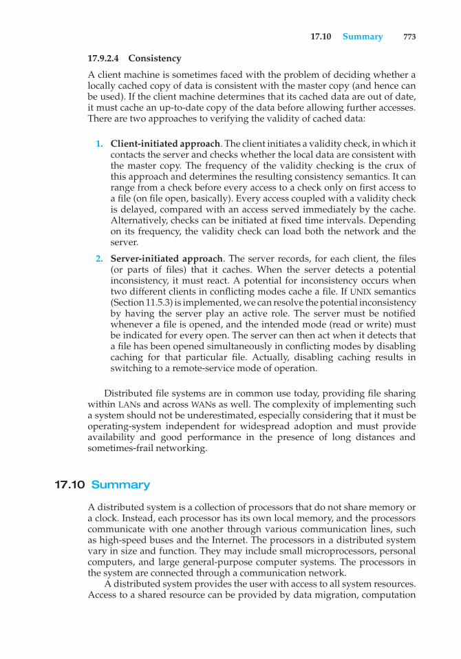
17.10 Summary 773
17.9.2.4 Consistency
A client machine is sometimes faced with the problem of deciding whether alocally cached copy of data is consistent with the master copy (and hence canbe used). If the client machine determines that its cached data are out of date,it must cache an up-to-date copy of the data before allowing further accesses.There are two approaches to verifying the validity of cached data:
1. Client-initiated approach. The client initiates a validity check, in which itcontacts the server and checks whether the local data are consistent withthe master copy. The frequency of the validity checking is the crux ofthis approach and determines the resulting consistency semantics. It canrange from a check before every access to a check only on first access toa file (on file open, basically). Every access coupled with a validity checkis delayed, compared with an access served immediately by the cache.Alternatively, checks can be initiated at fixed time intervals. Dependingon its frequency, the validity check can load both the network and theserver.
2. Server-initiated approach. The server records, for each client, the files(or parts of files) that it caches. When the server detects a potentialinconsistency, it must react. A potential for inconsistency occurs whentwo different clients in conflicting modes cache a file. If UNIX semantics(Section 11.5.3) is implemented, we can resolve the potential inconsistencyby having the server play an active role. The server must be notifiedwhenever a file is opened, and the intended mode (read or write) mustbe indicated for every open. The server can then act when it detects thata file has been opened simultaneously in conflicting modes by disablingcaching for that particular file. Actually, disabling caching results inswitching to a remote-service mode of operation.
Distributed file systems are in common use today, providing file sharingwithin LANs and across WANs as well. The complexity of implementing sucha system should not be underestimated, especially considering that it must beoperating-system independent for widespread adoption and must provideavailability and good performance in the presence of long distances andsometimes-frail networking.
17.10 Summary
A distributed system is a collection of processors that do not share memory ora clock. Instead, each processor has its own local memory, and the processorscommunicate with one another through various communication lines, suchas high-speed buses and the Internet. The processors in a distributed systemvary in size and function. They may include small microprocessors, personalcomputers, and large general-purpose computer systems. The processors inthe system are connected through a communication network.
A distributed system provides the user with access to all system resources.Access to a shared resource can be provided by data migration, computation
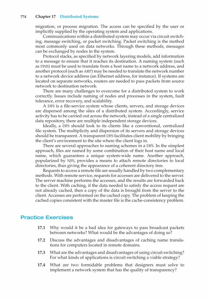
774 Chapter 17 Distributed Systems
migration, or process migration. The access can be specified by the user orimplicitly supplied by the operating system and applications.
Communications within a distributed system may occur via circuit switch-ing, message switching, or packet switching. Packet switching is the methodmost commonly used on data networks. Through these methods, messagescan be exchanged by nodes in the system.
Protocol stacks, as specified by network layering models, add informationto a message to ensure that it reaches its destination. A naming system (suchas DNS) must be used to translate from a host name to a network address, andanother protocol (such as ARP) may be needed to translate the network numberto a network device address (an Ethernet address, for instance). If systems arelocated on separate networks, routers are needed to pass packets from sourcenetwork to destination network.
There are many challenges to overcome for a distributed system to workcorrectly. Issues include naming of nodes and processes in the system, faulttolerance, error recovery, and scalability.
A DFS is a file-service system whose clients, servers, and storage devicesare dispersed among the sites of a distributed system. Accordingly, serviceactivity has to be carried out across the network; instead of a single centralizeddata repository, there are multiple independent storage devices.
Ideally, a DFS should look to its clients like a conventional, centralizedfile system. The multiplicity and dispersion of its servers and storage devicesshould be transparent. A transparent DFS facilitates client mobility by bringingthe client’s environment to the site where the client logs in.
There are several approaches to naming schemes in a DFS. In the simplestapproach, files are named by some combination of their host name and localname, which guarantees a unique system-wide name. Another approach,popularized by NFS, provides a means to attach remote directories to localdirectories, thus giving the appearance of a coherent directory tree.
Requests to access a remote file are usually handled by two complementarymethods. With remote service, requests for accesses are delivered to the server.The server machine performs the accesses, and the results are forwarded backto the client. With caching, if the data needed to satisfy the access request arenot already cached, then a copy of the data is brought from the server to theclient. Accesses are performed on the cached copy. The problem of keeping thecached copies consistent with the master file is the cache-consistency problem.
Practice Exercises
17.1 Why would it be a bad idea for gateways to pass broadcast packetsbetween networks? What would be the advantages of doing so?
17.2 Discuss the advantages and disadvantages of caching name transla-tions for computers located in remote domains.
17.3 What are the advantages and disadvantages of using circuit switching?For what kinds of applications is circuit switching a viable strategy?
17.4 What are two formidable problems that designers must solve toimplement a network system that has the quality of transparency?
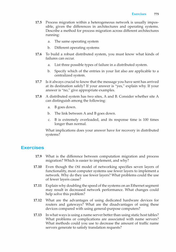
Exercises 775
17.5 Process migration within a heterogeneous network is usually impos-sible, given the differences in architectures and operating systems.Describe a method for process migration across different architecturesrunning:
a. The same operating system
b. Different operating systems
17.6 To build a robust distributed system, you must know what kinds offailures can occur.
a. List three possible types of failure in a distributed system.
b. Specify which of the entries in your list also are applicable to acentralized system.
17.7 Is it always crucial to know that the message you have sent has arrivedat its destination safely? If your answer is “yes,” explain why. If youranswer is “no,” give appropriate examples.
17.8 A distributed system has two sites, A and B. Consider whether site Acan distinguish among the following:
a. B goes down.
b. The link between A and B goes down.
c. B is extremely overloaded, and its response time is 100 timeslonger than normal.
What implications does your answer have for recovery in distributedsystems?
Exercises
17.9 What is the difference between computation migration and processmigration? Which is easier to implement, and why?
17.10 Even though the OSI model of networking specifies seven layers offunctionality, most computer systems use fewer layers to implement anetwork. Why do they use fewer layers? What problems could the useof fewer layers cause?
17.11 Explain why doubling the speed of the systems on an Ethernet segmentmay result in decreased network performance. What changes couldhelp solve this problem?
17.12 What are the advantages of using dedicated hardware devices forrouters and gateways? What are the disadvantages of using thesedevices compared with using general-purpose computers?
17.13 In what ways is using a name server better than using static host tables?What problems or complications are associated with name servers?What methods could you use to decrease the amount of traffic nameservers generate to satisfy translation requests?
776 Chapter 17 Distributed Systems
17.14 Name servers are organized in a hierarchical manner. What is thepurpose of using a hierarchical organization?
17.15 The lower layers of the OSI network model provide datagram service,with no delivery guarantees for messages. A transport-layer protocolsuch as TCP is used to provide reliability. Discuss the advantages anddisadvantages of supporting reliable message delivery at the lowestpossible layer.
17.16 How does using a dynamic routing strategy affect application behav-ior? For what type of applications is it beneficial to use virtual routinginstead of dynamic routing?
17.17 Run the program shown in Figure 17.4 and determine the IP addressesof the following host names:
• www.wiley.com
• www.cs.yale.edu
• www.apple.com
• www.westminstercollege.edu
• www.ietf.org
17.18 The original HTTP protocol used TCP/IP as the underlying networkprotocol. For each page, graphic, or applet, a separate TCP session wasconstructed, used, and torn down. Because of the overhead of buildingand destroying TCP/IP connections, performance problems resultedfrom this implementation method. Would using UDP rather than TCPbe a good alternative? What other changes could you make to improveHTTP performance?
17.19 What are the advantages and the disadvantages of making the com-puter network transparent to the user?
17.20 What are the benefits of a DFS compared with a file system in acentralized system?
17.21 Which of the example DFSs discussed in this chapter would handle alarge, multiclient database application most efficiently? Explain youranswer.
17.22 Discuss whether OpenAFS and NFS provide the following: (a) locationtransparency and (b) location independence.
17.23 Under what circumstances would a client prefer a location-transparent DFS? Under what circumstances would she prefer alocation-independent DFS? Discuss the reasons for these preferences.
17.24 What aspects of a distributed system would you select for a systemrunning on a totally reliable network?
17.25 Consider OpenAFS, which is a stateful distributed file system. Whatactions need to be performed to recover from a server crash in order topreserve the consistency guaranteed by the system?
Bibliography 777
17.26 Compare and contrast the techniques of caching disk blocks locally, ona client system, and remotely, on a server.
17.27 OpenAFS is designed to support a large number of clients. Discuss threetechniques used to make OpenAFS a scalable system.
17.28 What are the benefits of mapping objects into virtual memory, as ApolloDomain does? What are the drawbacks?
17.29 Describe some of the fundamental differences between OpenAFS andNFS (see Chapter 12).
Bibliographical Notes
[Tanenbaum (2010)] and [Kurose and Ross (2013)] provide general overviewsof computer networks. The Internet and its protocols are described in [Comer(1999)] and [Comer (2000)]. Coverage of TCP/IP can be found in [Fall andStevens (2011)] and [Stevens (1995)]. UNIX network programming is describedthoroughly in [Steven et al. ()] and [Stevens (1998)].
Load balancing and load sharing are discussed by [Harchol-Balter andDowney (1997)] and [Vee and Hsu (2000)]. [Harish and Owens (1999)] describeload-balancing DNS servers.
Sun’s network file system (NFS) is described by [Callaghan (2000)] and[Sandberg et al. (1985)]. The OpenAFS system is discussed by [Morris et al.(1986)], [Howard et al. (1988)], and [Satyanarayanan (1990)]. Information aboutOpenAFS is available from http://www.openafs.org. The Andrew file systemis discussed in [Howard et al. (1988)]. The Google MapReduce method isdescribed in http://research.google.com/archive/mapreduce.html.
Bibliography
[Callaghan (2000)] B. Callaghan, NFS Illustrated, Addison-Wesley (2000).
[Comer (1999)] D. Comer, Internetworking with TCP/IP, Volume II, Third Edition,Prentice Hall (1999).
[Comer (2000)] D. Comer, Internetworking with TCP/IP, Volume I, Fourth Edition,Prentice Hall (2000).
[Fall and Stevens (2011)] K. Fall and R. Stevens, TCP/IP Illustrated, Volume 1: TheProtocols, Second Edition, John Wiley and Sons (2011).
[Harchol-Balter and Downey (1997)] M. Harchol-Balter and A. B. Downey,“Exploiting Process Lifetime Distributions for Dynamic Load Balancing”, ACMTransactions on Computer Systems, Volume 15, Number 3 (1997), pages 253–285.
[Harish and Owens (1999)] V. C. Harish and B. Owens, “Dynamic Load Balanc-ing DNS”, Linux Journal, Volume 1999, Number 64 (1999).
[Howard et al. (1988)] J. H. Howard, M. L. Kazar, S. G. Menees, D. A. Nichols,M. Satyanarayanan, and R. N. Sidebotham, “Scale and Performance in a
778 Chapter 17 Distributed Systems
Distributed File System”, ACM Transactions on Computer Systems, Volume 6,Number 1 (1988), pages 55–81.
[Kurose and Ross (2013)] J. Kurose and K. Ross, Computer Networking—A Top–Down Approach, Sixth Edition, Addison-Wesley (2013).
[Morris et al. (1986)] J. H. Morris, M. Satyanarayanan, M. H. Conner, J. H.Howard, D. S. H. Rosenthal, and F. D. Smith, “Andrew: A Distributed PersonalComputing Environment”, Communications of the ACM, Volume 29, Number 3(1986), pages 184–201.
[Sandberg et al. (1985)] R. Sandberg, D. Goldberg, S. Kleiman, D. Walsh, andB. Lyon, “Design and Implementation of the Sun Network Filesystem”, Proceed-ings of the Summer USENIX Conference (1985), pages 119–130.
[Satyanarayanan (1990)] M. Satyanarayanan, “Scalable, Secure and HighlyAvailable Distributed File Access”, Computer, Volume 23, Number 5 (1990), pages9–21.
[Steven et al. ()] R. Steven, B. Fenner, and A. Rudoff, Unix Network Programming,Volume 1: The Sockets Networking API, Third Edition), publisher = wiley, year = 2003.
[Stevens (1995)] R. Stevens, TCP/IP Illustrated, Volume 2: The Implementation,Addison-Wesley (1995).
[Stevens (1998)] W. R. Stevens, UNIX Network Programming—Volume II, PrenticeHall (1998).
[Tanenbaum (2010)] A. S. Tanenbaum, Computer Networks, Fifth Edition, Pren-tice Hall (2010).
[Vee and Hsu (2000)] V. Vee and W. Hsu, “Locality-Preserving Load-BalancingMechanisms for Synchronous Simulations on Shared-Memory Multiproces-sors”, Proceedings of the Fourteenth Workshop on Parallel and Distributed Simulation(2000), pages 131–138.
Part Seven
Case StudiesIn the final part of the book, we integrate the concepts described earlierby examining real operating systems. We cover two such systems indetail—Linux and Windows 7. We chose Linux for several reasons: it ispopular, it is freely available, and it represents a full-featured UNIX system.This gives a student of operating systems an opportunity to read—andmodify—real operating-system source code.
We also cover Windows 7 in detail. This recent operating system fromMicrosoft is gaining popularity not only in the standalone-machine marketbut also in the workgroup–server market. We chose Windows 7 becauseit provides an opportunity to study a modern operating system that hasa design and implementation drastically different from those of UNIX.
In addition, we briefly discuss other highly influential operating sys-tems. Finally, we provide on-line coverage of two more systems: FreeBSDand Mach. The FreeBSD system is another UNIX system. However,whereas Linux combines features from several UNIX systems, FreeBSDis based on the BSD model. FreeBSD source code, like Linux sourcecode, is freely available. Mach is a modern operating system that providescompatibility with BSD UNIX.

18C H A P T E R
The LinuxSystem
Updated by Robert Love
This chapter presents an in-depth examination of the Linux operating system.By examining a complete, real system, we can see how the concepts we havediscussed relate both to one another and to practice.
Linux is a variant of UNIX that has gained popularity over the last severaldecades, powering devices as small as mobile phones and as large as room-filling supercomputers. In this chapter, we look at the history and developmentof Linux and cover the user and programmer interfaces that Linux presents—interfaces that owe a great deal to the UNIX tradition. We also discuss thedesign and implementation of these interfaces. Linux is a rapidly evolvingoperating system. This chapter describes developments through the Linux 3.2kernel, which was released in 2012.
CHAPTER OBJECTIVES
• To explore the history of the UNIX operating system from which Linux isderived and the principles upon which Linux’s design is based.
• To examine the Linux process model and illustrate how Linux schedulesprocesses and provides interprocess communication.
• To look at memory management in Linux.• To explore how Linux implements file systems and manages I/O devices.
18.1 Linux History
Linux looks and feels much like any other UNIX system; indeed, UNIXcompatibility has been a major design goal of the Linux project. However,Linux is much younger than most UNIX systems. Its development began in1991, when a Finnish university student, Linus Torvalds, began developinga small but self-contained kernel for the 80386 processor, the first true 32-bitprocessor in Intel’s range of PC-compatible CPUs.
781
782 Chapter 18 The Linux System
Early in its development, the Linux source code was made available free—both at no cost and with minimal distributional restrictions—on the Internet.As a result, Linux’s history has been one of collaboration by many developersfrom all around the world, corresponding almost exclusively over the Internet.From an initial kernel that partially implemented a small subset of the UNIXsystem services, the Linux system has grown to include all of the functionalityexpected of a modern UNIX system.
In its early days, Linux development revolved largely around the centraloperating-system kernel—the core, privileged executive that manages allsystem resources and interacts directly with the computer hardware. Weneed much more than this kernel, of course, to produce a full operatingsystem. We thus need to make a distinction between the Linux kernel anda complete Linux system. The Linux kernel is an original piece of softwaredeveloped from scratch by the Linux community. The Linux system, as weknow it today, includes a multitude of components, some written from scratch,others borrowed from other development projects, and still others created incollaboration with other teams.
The basic Linux system is a standard environment for applications anduser programming, but it does not enforce any standard means of managingthe available functionality as a whole. As Linux has matured, a need has arisenfor another layer of functionality on top of the Linux system. This need hasbeen met by various Linux distributions. A Linux distribution includes all thestandard components of the Linux system, plus a set of administrative toolsto simplify the initial installation and subsequent upgrading of Linux and tomanage installation and removal of other packages on the system. A moderndistribution also typically includes tools for management of file systems,creation and management of user accounts, administration of networks, Webbrowsers, word processors, and so on.
18.1.1 The Linux Kernel
The first Linux kernel released to the public was version 0.01, dated May 14,1991. It had no networking, ran only on 80386-compatible Intel processorsand PC hardware, and had extremely limited device-driver support. Thevirtual memory subsystem was also fairly basic and included no supportfor memory-mapped files; however, even this early incarnation supportedshared pages with copy-on-write and protected address spaces. The only filesystem supported was the Minix file system, as the first Linux kernels werecross-developed on a Minix platform.
The next milestone, Linux 1.0, was released on March 14, 1994. This releaseculminated three years of rapid development of the Linux kernel. Perhaps thesingle biggest new feature was networking: 1.0 included support for UNIX’sstandard TCP/IP networking protocols, as well as a BSD-compatible socketinterface for networking programming. Device-driver support was added forrunning IP over Ethernet or (via the PPP or SLIP protocols) over serial lines ormodems.
The 1.0 kernel also included a new, much enhanced file system without thelimitations of the original Minix file system, and it supported a range of SCSIcontrollers for high-performance disk access. The developers extended the vir-tual memory subsystem to support paging to swap files and memory mapping
18.1 Linux History 783
of arbitrary files (but only read-only memory mapping was implemented in1.0).
A range of extra hardware support was included in this release. Althoughstill restricted to the Intel PC platform, hardware support had grown to includefloppy-disk and CD-ROM devices, as well as sound cards, a range of mice, andinternational keyboards. Floating-point emulation was provided in the kernelfor 80386 users who had no 80387 math coprocessor. System V UNIX-styleinterprocess communication (IPC), including shared memory, semaphores,and message queues, was implemented.
At this point, development started on the 1.1 kernel stream, but numerousbug-fix patches were released subsequently for 1.0. A pattern was adopted asthe standard numbering convention for Linux kernels. Kernels with an oddminor-version number, such as 1.1 or 2.5, are development kernels; even-numbered minor-version numbers are stable production kernels. Updatesfor the stable kernels are intended only as remedial versions, whereas thedevelopment kernels may include newer and relatively untested functionality.As we will see, this pattern remained in effect until version 3.
In March 1995, the 1.2 kernel was released. This release did not offernearly the same improvement in functionality as the 1.0 release, but it didsupport a much wider variety of hardware, including the new PCI hardwarebus architecture. Developers added another PC-specific feature—support forthe 80386 CPU’s virtual 8086 mode—to allow emulation of the DOS operatingsystem for PC computers. They also updated the IP implementation withsupport for accounting and firewalling. Simple support for dynamicallyloadable and unloadable kernel modules was supplied as well.
The 1.2 kernel was the final PC-only Linux kernel. The source distributionfor Linux 1.2 included partially implemented support for SPARC, Alpha, andMIPS CPUs, but full integration of these other architectures did not begin untilafter the 1.2 stable kernel was released.
The Linux 1.2 release concentrated on wider hardware support and morecomplete implementations of existing functionality. Much new functionalitywas under development at the time, but integration of the new code into themain kernel source code was deferred until after the stable 1.2 kernel wasreleased. As a result, the 1.3 development stream saw a great deal of newfunctionality added to the kernel.
This work was released in June 1996 as Linux version 2.0. This releasewas given a major version-number increment because of two major newcapabilities: support for multiple architectures, including a 64-bit native Alphaport, and symmetric multiprocessing (SMP) support. Additionally, the memory-management code was substantially improved to provide a unified cache forfile-system data independent of the caching of block devices. As a resultof this change, the kernel offered greatly increased file-system and virtual-memory performance. For the first time, file-system caching was extendedto networked file systems, and writable memory-mapped regions were alsosupported. Other major improvements included the addition of internal kernelthreads, a mechanism exposing dependencies between loadable modules,support for the automatic loading of modules on demand, file-system quotas,and POSIX-compatible real-time process-scheduling classes.
784 Chapter 18 The Linux System
Improvements continued with the release of Linux 2.2 in 1999. A port toUltraSPARC systems was added. Networking was enhanced with more flexiblefirewalling, improved routing and traffic management, and support for TCPlarge window and selective acknowledgement. Acorn, Apple, and NT diskscould now be read, and NFS was enhanced with a new kernel-mode NFSdaemon. Signal handling, interrupts, and some I/O were locked at a finerlevel than before to improve symmetric multiprocessor (SMP) performance.
Advances in the 2.4 and 2.6 releases of the kernel included increasedsupport for SMP systems, journaling file systems, and enhancements to thememory-management and block I/O systems. The process scheduler wasmodified in version 2.6, providing an efficient O(1) scheduling algorithm. Inaddition, the 2.6 kernel was preemptive, allowing a process to be preemptedeven while running in kernel mode.
Linux kernel version 3.0 was released in July 2011. The major version bumpfrom 2 to 3 occurred to commemorate the twentieth anniversary of Linux.New features include improved virtualization support, a new page write-backfacility, improvements to the memory-management system, and yet anothernew process scheduler—the Completely Fair Scheduler (CFS). We focus on thisnewest kernel in the remainder of this chapter.
18.1.2 The Linux System
As we noted earlier, the Linux kernel forms the core of the Linux project, butother components make up a complete Linux operating system. Whereas theLinux kernel is composed entirely of code written from scratch specifically forthe Linux project, much of the supporting software that makes up the Linuxsystem is not exclusive to Linux but is common to a number of UNIX-likeoperating systems. In particular, Linux uses many tools developed as partof Berkeley’s BSD operating system, MIT’s X Window System, and the FreeSoftware Foundation’s GNU project.
This sharing of tools has worked in both directions. The main systemlibraries of Linux were originated by the GNU project, but the Linux communitygreatly improved the libraries by addressing omissions, inefficiencies, andbugs. Other components, such as the GNU C compiler (gcc), were already ofsufficiently high quality to be used directly in Linux. The network administra-tion tools under Linux were derived from code first developed for 4.3 BSD, butmore recent BSD derivatives, such as FreeBSD, have borrowed code from Linuxin return. Examples of this sharing include the Intel floating-point-emulationmath library and the PC sound-hardware device drivers.
The Linux system as a whole is maintained by a loose network ofdevelopers collaborating over the Internet, with small groups or individualshaving responsibility for maintaining the integrity of specific components.A small number of public Internet file-transfer-protocol (FTP) archive sitesact as de facto standard repositories for these components. The File SystemHierarchy Standard document is also maintained by the Linux communityas a means of ensuring compatibility across the various system components.This standard specifies the overall layout of a standard Linux file system; itdetermines under which directory names configuration files, libraries, systembinaries, and run-time data files should be stored.
18.1 Linux History 785
18.1.3 Linux Distributions
In theory, anybody can install a Linux system by fetching the latest revisionsof the necessary system components from the FTP sites and compiling them. InLinux’s early days, this is precisely what a Linux user had to do. As Linux hasmatured, however, various individuals and groups have attempted to makethis job less painful by providing standard, precompiled sets of packages foreasy installation.
These collections, or distributions, include much more than just thebasic Linux system. They typically include extra system-installation andmanagement utilities, as well as precompiled and ready-to-install packagesof many of the common UNIX tools, such as news servers, web browsers,text-processing and editing tools, and even games.
The first distributions managed these packages by simply providinga means of unpacking all the files into the appropriate places. One ofthe important contributions of modern distributions, however, is advancedpackage management. Today’s Linux distributions include a package-trackingdatabase that allows packages to be installed, upgraded, or removed painlessly.
The SLS distribution, dating back to the early days of Linux, was the firstcollection of Linux packages that was recognizable as a complete distribution.Although it could be installed as a single entity, SLS lacked the package-management tools now expected of Linux distributions. The Slackwaredistribution represented a great improvement in overall quality, even thoughit also had poor package management. In fact, it is still one of the most widelyinstalled distributions in the Linux community.
Since Slackware’s release, many commercial and noncommercial Linuxdistributions have become available. Red Hat and Debian are particularly pop-ular distributions; the first comes from a commercial Linux support companyand the second from the free-software Linux community. Other commerciallysupported versions of Linux include distributions from Canonical and SuSE,and others too numerous to list here. There are too many Linux distributions incirculation for us to list all of them here. The variety of distributions does notprevent Linux distributions from being compatible, however. The RPM packagefile format is used, or at least understood, by the majority of distributions, andcommercial applications distributed in this format can be installed and run onany distribution that can accept RPM files.
18.1.4 Linux Licensing
The Linux kernel is distributed under version 2.0 of the GNU General PublicLicense (GPL), the terms of which are set out by the Free Software Foundation.Linux is not public-domain software. Public domain implies that the authorshave waived copyright rights in the software, but copyright rights in Linuxcode are still held by the code’s various authors. Linux is free software, however,in the sense that people can copy it, modify it, use it in any manner they want,and give away (or sell) their own copies.
The main implication of Linux’s licensing terms is that nobody using Linux,or creating a derivative of Linux (a legitimate exercise), can distribute thederivative without including the source code. Software released under the GPLcannot be redistributed as a binary-only product. If you release software thatincludes any components covered by the GPL, then, under the GPL, you must
786 Chapter 18 The Linux System
make source code available alongside any binary distributions. (This restrictiondoes not prohibit making—or even selling—binary software distributions, aslong as anybody who receives binaries is also given the opportunity to get theoriginating source code for a reasonable distribution charge.)
18.2 Design Principles
In its overall design, Linux resembles other traditional, nonmicrokernel UNIXimplementations. It is a multiuser, preemptively multitasking system with afull set of UNIX-compatible tools. Linux’s file system adheres to traditional UNIXsemantics, and the standard UNIX networking model is fully implemented. Theinternal details of Linux’s design have been influenced heavily by the historyof this operating system’s development.
Although Linux runs on a wide variety of platforms, it was originallydeveloped exclusively on PC architecture. A great deal of that early devel-opment was carried out by individual enthusiasts rather than by well-fundeddevelopment or research facilities, so from the start Linux attempted to squeezeas much functionality as possible from limited resources. Today, Linux can runhappily on a multiprocessor machine with many gigabytes of main memoryand many terabytes of disk space, but it is still capable of operating usefully inunder 16 MB of RAM.
As PCs became more powerful and as memory and hard disks becamecheaper, the original, minimalist Linux kernels grew to implement moreUNIX functionality. Speed and efficiency are still important design goals, butmuch recent and current work on Linux has concentrated on a third majordesign goal: standardization. One of the prices paid for the diversity of UNIXimplementations currently available is that source code written for one may notnecessarily compile or run correctly on another. Even when the same systemcalls are present on two different UNIX systems, they do not necessarily behavein exactly the same way. The POSIX standards comprise a set of specificationsfor different aspects of operating-system behavior. There are POSIX documentsfor common operating-system functionality and for extensions such as processthreads and real-time operations. Linux is designed to comply with the relevantPOSIX documents, and at least two Linux distributions have achieved officialPOSIX certification.
Because it gives standard interfaces to both the programmer and the user,Linux presents few surprises to anybody familiar with UNIX. We do not detailthese interfaces here. The sections on the programmer interface (Section A.3)and user interface (Section A.4) of BSD apply equally well to Linux. By default,however, the Linux programming interface adheres to SVR4 UNIX semantics,rather than to BSD behavior. A separate set of libraries is available to implementBSD semantics in places where the two behaviors differ significantly.
Many other standards exist in the UNIX world, but full certification ofLinux with respect to these standards is sometimes slowed because certificationis often available only for a fee, and the expense involved in certifying anoperating system’s compliance with most standards is substantial. However,supporting a wide base of applications is important for any operating system,so implementation of standards is a major goal for Linux development, evenif the implementation is not formally certified. In addition to the basic POSIX
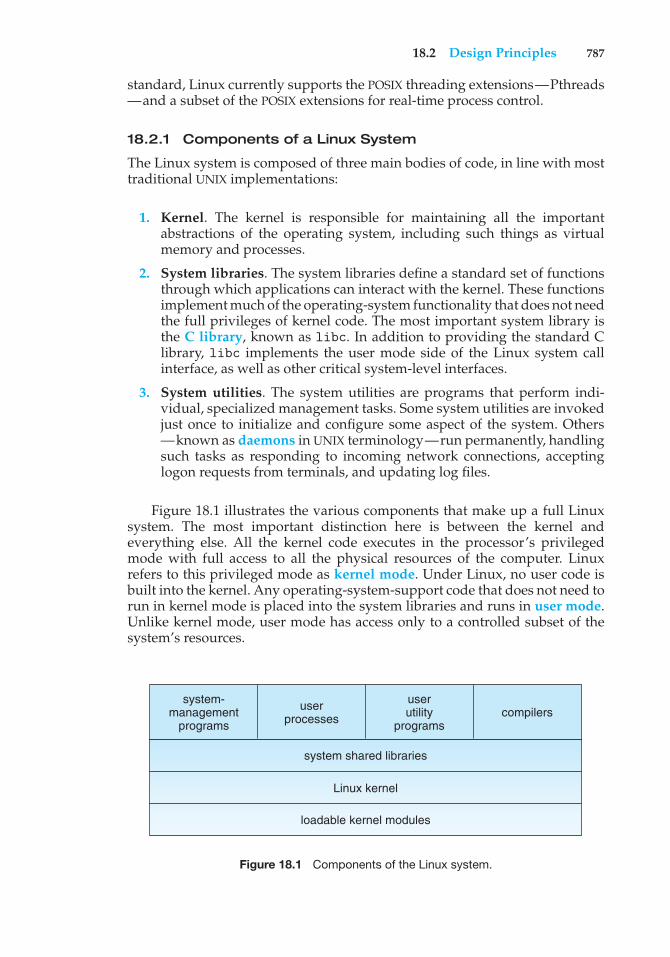
18.2 Design Principles 787
standard, Linux currently supports the POSIX threading extensions—Pthreads—and a subset of the POSIX extensions for real-time process control.
18.2.1 Components of a Linux System
The Linux system is composed of three main bodies of code, in line with mosttraditional UNIX implementations:
1. Kernel. The kernel is responsible for maintaining all the importantabstractions of the operating system, including such things as virtualmemory and processes.
2. System libraries. The system libraries define a standard set of functionsthrough which applications can interact with the kernel. These functionsimplement much of the operating-system functionality that does not needthe full privileges of kernel code. The most important system library isthe C library, known as libc. In addition to providing the standard Clibrary, libc implements the user mode side of the Linux system callinterface, as well as other critical system-level interfaces.
3. System utilities. The system utilities are programs that perform indi-vidual, specialized management tasks. Some system utilities are invokedjust once to initialize and configure some aspect of the system. Others—known as daemons in UNIX terminology—run permanently, handlingsuch tasks as responding to incoming network connections, acceptinglogon requests from terminals, and updating log files.
Figure 18.1 illustrates the various components that make up a full Linuxsystem. The most important distinction here is between the kernel andeverything else. All the kernel code executes in the processor’s privilegedmode with full access to all the physical resources of the computer. Linuxrefers to this privileged mode as kernel mode. Under Linux, no user code isbuilt into the kernel. Any operating-system-support code that does not need torun in kernel mode is placed into the system libraries and runs in user mode.Unlike kernel mode, user mode has access only to a controlled subset of thesystem’s resources.
system shared libraries
Linux kernel
loadable kernel modules
system-management
programs
userprocesses
userutility
programscompilers
Figure 18.1 Components of the Linux system.
788 Chapter 18 The Linux System
Although various modern operating systems have adopted a message-passing architecture for their kernel internals, Linux retains UNIX’s historicalmodel: the kernel is created as a single, monolithic binary. The main reasonis performance. Because all kernel code and data structures are kept in asingle address space, no context switches are necessary when a process calls anoperating-system function or when a hardware interrupt is delivered. More-over, the kernel can pass data and make requests between various subsystemsusing relatively cheap C function invocation and not more complicated inter-process communication (IPC). This single address space contains not only thecore scheduling and virtual memory code but all kernel code, including alldevice drivers, file systems, and networking code.
Even though all the kernel components share this same melting pot, thereis still room for modularity. In the same way that user applications can loadshared libraries at run time to pull in a needed piece of code, so the Linuxkernel can load (and unload) modules dynamically at run time. The kerneldoes not need to know in advance which modules may be loaded—they aretruly independent loadable components.
The Linux kernel forms the core of the Linux operating system. It providesall the functionality necessary to run processes, and it provides system servicesto give arbitrated and protected access to hardware resources. The kernelimplements all the features required to qualify as an operating system. Onits own, however, the operating system provided by the Linux kernel is nota complete UNIX system. It lacks much of the functionality and behavior ofUNIX, and the features that it does provide are not necessarily in the formatin which a UNIX application expects them to appear. The operating-systeminterface visible to running applications is not maintained directly by thekernel. Rather, applications make calls to the system libraries, which in turncall the operating-system services as necessary.
The system libraries provide many types of functionality. At the simplestlevel, they allow applications to make system calls to the Linux kernel. Makinga system call involves transferring control from unprivileged user mode toprivileged kernel mode; the details of this transfer vary from architecture toarchitecture. The libraries take care of collecting the system-call arguments and,if necessary, arranging those arguments in the special form necessary to makethe system call.
The libraries may also provide more complex versions of the basic systemcalls. For example, the C language’s buffered file-handling functions are allimplemented in the system libraries, providing more advanced control of fileI/O than the basic kernel system calls. The libraries also provide routines that donot correspond to system calls at all, such as sorting algorithms, mathematicalfunctions, and string-manipulation routines. All the functions necessary tosupport the running of UNIX or POSIX applications are implemented in thesystem libraries.
The Linux system includes a wide variety of user-mode programs—bothsystem utilities and user utilities. The system utilities include all the programsnecessary to initialize and then administer the system, such as those to setup networking interfaces and to add and remove users from the system.User utilities are also necessary to the basic operation of the system but donot require elevated privileges to run. They include simple file-managementutilities such as those to copy files, create directories, and edit text files. One
18.3 Kernel Modules 789
of the most important user utilities is the shell, the standard command-lineinterface on UNIX systems. Linux supports many shells; the most common isthe bourne-Again shell (bash).
18.3 Kernel Modules
The Linux kernel has the ability to load and unload arbitrary sections of kernelcode on demand. These loadable kernel modules run in privileged kernel modeand as a consequence have full access to all the hardware capabilities of themachine on which they run. In theory, there is no restriction on what a kernelmodule is allowed to do. Among other things, a kernel module can implementa device driver, a file system, or a networking protocol.
Kernel modules are convenient for several reasons. Linux’s source code isfree, so anybody wanting to write kernel code is able to compile a modifiedkernel and to reboot into that new functionality. However, recompiling,relinking, and reloading the entire kernel is a cumbersome cycle to undertakewhen you are developing a new driver. If you use kernel modules, you do nothave to make a new kernel to test a new driver—the driver can be compiledon its own and loaded into the already running kernel. Of course, once a newdriver is written, it can be distributed as a module so that other users canbenefit from it without having to rebuild their kernels.
This latter point has another implication. Because it is covered by theGPL license, the Linux kernel cannot be released with proprietary componentsadded to it unless those new components are also released under the GPL andthe source code for them is made available on demand. The kernel’s moduleinterface allows third parties to write and distribute, on their own terms, devicedrivers or file systems that could not be distributed under the GPL.
Kernel modules allow a Linux system to be set up with a standard minimalkernel, without any extra device drivers built in. Any device drivers that theuser needs can be either loaded explicitly by the system at startup or loadedautomatically by the system on demand and unloaded when not in use. Forexample, a mouse driver can be loaded when a USB mouse is plugged into thesystem and unloaded when the mouse is unplugged.
The module support under Linux has four components:
1. The module-management system allows modules to be loaded intomemory and to communicate with the rest of the kernel.
2. The module loader and unloader, which are user-mode utilities, workwith the module-management system to load a module into memory.
3. The driver-registration system allows modules to tell the rest of thekernel that a new driver has become available.
4. Aconflict-resolution mechanism allows different device drivers toreserve hardware resources and to protect those resources from accidentaluse by another driver.
18.3.1 Module Management
Loading a module requires more than just loading its binary contents intokernel memory. The system must also make sure that any references the
790 Chapter 18 The Linux System
module makes to kernel symbols or entry points are updated to point to thecorrect locations in the kernel’s address space. Linux deals with this referenceupdating by splitting the job of module loading into two separate sections: themanagement of sections of module code in kernel memory and the handlingof symbols that modules are allowed to reference.
Linux maintains an internal symbol table in the kernel. This symbol tabledoes not contain the full set of symbols defined in the kernel during the latter’scompilation; rather, a symbol must be explicitly exported. The set of exportedsymbols constitutes a well-defined interface by which a module can interactwith the kernel.
Although exporting symbols from a kernel function requires an explicitrequest by the programmer, no special effort is needed to import those symbolsinto a module. A module writer just uses the standard external linking of theC language. Any external symbols referenced by the module but not declaredby it are simply marked as unresolved in the final module binary produced bythe compiler. When a module is to be loaded into the kernel, a system utilityfirst scans the module for these unresolved references. All symbols that stillneed to be resolved are looked up in the kernel’s symbol table, and the correctaddresses of those symbols in the currently running kernel are substituted intothe module’s code. Only then is the module passed to the kernel for loading. Ifthe system utility cannot resolve all references in the module by looking themup in the kernel’s symbol table, then the module is rejected.
The loading of the module is performed in two stages. First, the module-loader utility asks the kernel to reserve a continuous area of virtual kernelmemory for the module. The kernel returns the address of the memoryallocated, and the loader utility can use this address to relocate the module’smachine code to the correct loading address. A second system call then passesthe module, plus any symbol table that the new module wants to export, to thekernel. The module itself is now copied verbatim into the previously allocatedspace, and the kernel’s symbol table is updated with the new symbols forpossible use by other modules not yet loaded.
The final module-management component is the module requester. Thekernel defines a communication interface to which a module-managementprogram can connect. With this connection established, the kernel will informthe management process whenever a process requests a device driver, filesystem, or network service that is not currently loaded and will give themanager the opportunity to load that service. The original service request willcomplete once the module is loaded. The manager process regularly queriesthe kernel to see whether a dynamically loaded module is still in use andunloads that module when it is no longer actively needed.
18.3.2 Driver Registration
Once a module is loaded, it remains no more than an isolated region of memoryuntil it lets the rest of the kernel know what new functionality it provides.The kernel maintains dynamic tables of all known drivers and provides aset of routines to allow drivers to be added to or removed from these tablesat any time. The kernel makes sure that it calls a module’s startup routinewhen that module is loaded and calls the module’s cleanup routine before
18.3 Kernel Modules 791
that module is unloaded. These routines are responsible for registering themodule’s functionality.
A module may register many types of functionality; it is not limitedto only one type. For example, a device driver might want to register twoseparate mechanisms for accessing the device. Registration tables include,among others, the following items:
• Device drivers. These drivers include character devices (such as printers,terminals, and mice), block devices (including all disk drives), and networkinterface devices.
• File systems. The file system may be anything that implements Linux’svirtual file system calling routines. It might implement a format for storingfiles on a disk, but it might equally well be a network file system, such asNFS, or a virtual file system whose contents are generated on demand, suchas Linux’s /proc file system.
• Network protocols. A module may implement an entire networkingprotocol, such as TCP or simply a new set of packet-filtering rules fora network firewall.
• Binary format. This format specifies a way of recognizing, loading, andexecuting a new type of executable file.
In addition, a module can register a new set of entries in the sysctl and /proctables, to allow that module to be configured dynamically (Section 18.7.4).
18.3.3 Conflict Resolution
Commercial UNIX implementations are usually sold to run on a vendor’s ownhardware. One advantage of a single-supplier solution is that the softwarevendor has a good idea about what hardware configurations are possible.PC hardware, however, comes in a vast number of configurations, withlarge numbers of possible drivers for devices such as network cards andvideo display adapters. The problem of managing the hardware configurationbecomes more severe when modular device drivers are supported, since thecurrently active set of devices becomes dynamically variable.
Linux provides a central conflict-resolution mechanism to help arbitrateaccess to certain hardware resources. Its aims are as follows:
• To prevent modules from clashing over access to hardware resources
• To prevent autoprobes—device-driver probes that auto-detect deviceconfiguration—from interfering with existing device drivers
• To resolve conflicts among multiple drivers trying to access the samehardware—as, for example, when both the parallel printer driver andthe parallel line IP (PLIP) network driver try to talk to the parallel port
To these ends, the kernel maintains lists of allocated hardware resources.The PC has a limited number of possible I/O ports (addresses in its hardwareI/O address space), interrupt lines, and DMA channels. When any device driverwants to access such a resource, it is expected to reserve the resource with
792 Chapter 18 The Linux System
the kernel database first. This requirement incidentally allows the systemadministrator to determine exactly which resources have been allocated bywhich driver at any given point.
A module is expected to use this mechanism to reserve in advance anyhardware resources that it expects to use. If the reservation is rejected becausethe resource is not present or is already in use, then it is up to the moduleto decide how to proceed. It may fail in its initialization attempt and requestthat it be unloaded if it cannot continue, or it may carry on, using alternativehardware resources.
18.4 Process Management
A process is the basic context in which all user-requested activity is servicedwithin the operating system. To be compatible with other UNIX systems, Linuxmust use a process model similar to those of other versions of UNIX. Linuxoperates differently from UNIX in a few key places, however. In this section,we review the traditional UNIX process model (Section A.3.2) and introduceLinux’s threading model.
18.4.1 The fork() and exec() Process Model
The basic principle of UNIX process management is to separate into two stepstwo operations that are usually combined into one: the creation of a newprocess and the running of a new program. A new process is created by thefork() system call, and a new program is run after a call to exec(). These aretwo distinctly separate functions. We can create a new process with fork()without running a new program—the new subprocess simply continues toexecute exactly the same program, at exactly the same point, that the first(parent) process was running. In the same way, running a new program doesnot require that a new process be created first. Any process may call exec() atany time. A new binary object is loaded into the process’s address space andthe new executable starts executing in the context of the existing process.
This model has the advantage of great simplicity. It is not necessary tospecify every detail of the environment of a new program in the system call thatruns that program. The new program simply runs in its existing environment.If a parent process wishes to modify the environment in which a new programis to be run, it can fork and then, still running the original executable in a childprocess, make any system calls it requires to modify that child process beforefinally executing the new program.
Under UNIX, then, a process encompasses all the information that theoperating system must maintain to track the context of a single execution of asingle program. Under Linux, we can break down this context into a number ofspecific sections. Broadly, process properties fall into three groups: the processidentity, environment, and context.
18.4.1.1 Process Identity
A process identity consists mainly of the following items:
• Process ID (PID). Each process has a unique identifier. The PID is used tospecify the process to the operating system when an application makes a
18.4 Process Management 793
system call to signal, modify, or wait for the process. Additional identifiersassociate the process with a process group (typically, a tree of processesforked by a single user command) and login session.
• Credentials. Each process must have an associated user ID and one or moregroup IDs (user groups are discussed in Section 11.6.2) that determine therights of a process to access system resources and files.
• Personality. Process personalities are not traditionally found on UNIXsystems, but under Linux each process has an associated personalityidentifier that can slightly modify the semantics of certain system calls.Personalities are primarily used by emulation libraries to request thatsystem calls be compatible with certain varieties of UNIX.
• Namespace. Each process is associated with a specific view of the file-system hierarchy, called its namespace. Most processes share a commonnamespace and thus operate on a shared file-system hierarchy. Processesand their children can, however, have different namespaces, each with aunique file-system hierarchy—their own root directory and set of mountedfile systems.
Most of these identifiers are under the limited control of the process itself.The process group and session identifiers can be changed if the processwants to start a new group or session. Its credentials can be changed, subjectto appropriate security checks. However, the primary PID of a process isunchangeable and uniquely identifies that process until termination.
18.4.1.2 Process Environment
A process’s environment is inherited from its parent and is composed of twonull-terminated vectors: the argument vector and the environment vector. Theargument vector simply lists the command-line arguments used to invoke therunning program; it conventionally starts with the name of the program itself.The environment vector is a list of “NAME=VALUE” pairs that associates namedenvironment variables with arbitrary textual values. The environment is notheld in kernel memory but is stored in the process’s own user-mode addressspace as the first datum at the top of the process’s stack.
The argument and environment vectors are not altered when a new processis created. The new child process will inherit the environment of its parent.However, a completely new environment is set up when a new programis invoked. On calling exec(), a process must supply the environment forthe new program. The kernel passes these environment variables to the nextprogram, replacing the process’s current environment. The kernel otherwiseleaves the environment and command-line vectors alone—their interpretationis left entirely to the user-mode libraries and applications.
The passing of environment variables from one process to the next and theinheriting of these variables by the children of a process provide flexible waysto pass information to components of the user-mode system software. Variousimportant environment variables have conventional meanings to related partsof the system software. For example, the TERM variable is set up to name thetype of terminal connected to a user’s login session. Many programs use this
794 Chapter 18 The Linux System
variable to determine how to perform operations on the user’s display, such asmoving the cursor and scrolling a region of text. Programs with multilingualsupport use the LANG variable to determine the language in which to displaysystem messages for programs that include multilingual support.
The environment-variable mechanism custom-tailors the operating systemon a per-process basis. Users can choose their own languages or select theirown editors independently of one another.
18.4.1.3 Process Context
The process identity and environment properties are usually set up when aprocess is created and not changed until that process exits. A process maychoose to change some aspects of its identity if it needs to do so, or it mayalter its environment. In contrast, process context is the state of the runningprogram at any one time; it changes constantly. Process context includes thefollowing parts:
• Scheduling context. The most important part of the process context is itsscheduling context—the information that the scheduler needs to suspendand restart the process. This information includes saved copies of all theprocess’s registers. Floating-point registers are stored separately and arerestored only when needed. Thus, processes that do not use floating-pointarithmetic do not incur the overhead of saving that state. The schedulingcontext also includes information about scheduling priority and about anyoutstanding signals waiting to be delivered to the process. A key part ofthe scheduling context is the process’s kernel stack, a separate area ofkernel memory reserved for use by kernel-mode code. Both system callsand interrupts that occur while the process is executing will use this stack.
• Accounting. The kernel maintains accounting information about theresources currently being consumed by each process and the total resourcesconsumed by the process in its entire lifetime so far.
• File table. The file table is an array of pointers to kernel file structuresrepresenting open files. When making file-I/O system calls, processes referto files by an integer, known as a file descriptor (fd), that the kernel usesto index into this table.
• File-system context. Whereas the file table lists the existing open files, thefile-system context applies to requests to open new files. The file-systemcontext includes the process’s root directory, current working directory,and namespace.
• Signal-handler table. UNIX systems can deliver asynchronous signals toa process in response to various external events. The signal-handler tabledefines the action to take in response to a specific signal. Valid actionsinclude ignoring the signal, terminating the process, and invoking a routinein the process’s address space.
• Virtual memory context. The virtual memory context describes the fullcontents of a process’s private address space; we discuss it in Section 18.6.
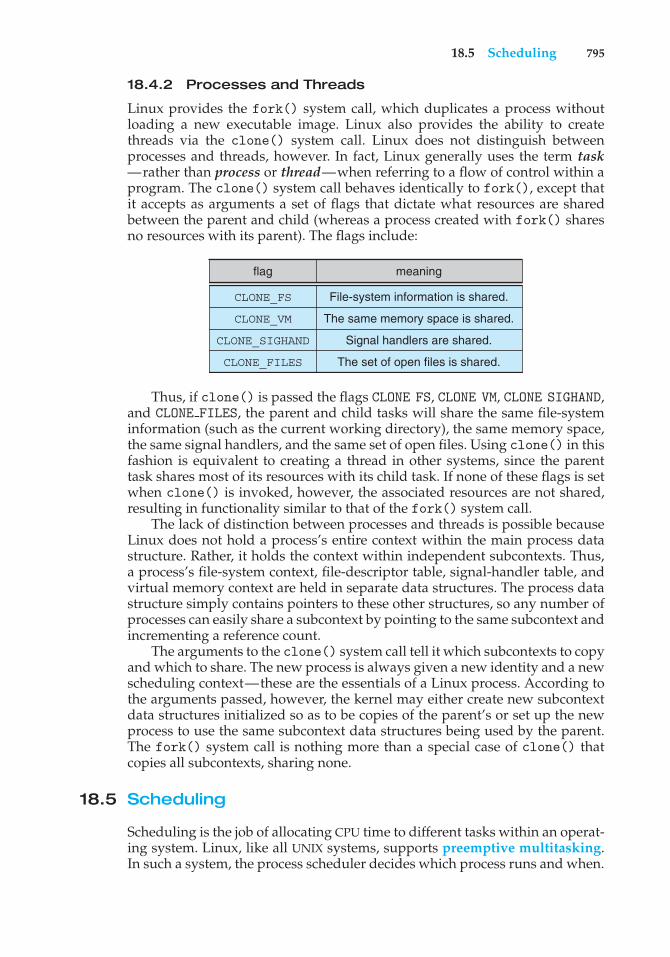
18.5 Scheduling 795
18.4.2 Processes and Threads
Linux provides the fork() system call, which duplicates a process withoutloading a new executable image. Linux also provides the ability to createthreads via the clone() system call. Linux does not distinguish betweenprocesses and threads, however. In fact, Linux generally uses the term task—rather than process or thread—when referring to a flow of control within aprogram. The clone() system call behaves identically to fork(), except thatit accepts as arguments a set of flags that dictate what resources are sharedbetween the parent and child (whereas a process created with fork() sharesno resources with its parent). The flags include:
flag meaning
CLONE_FS
CLONE_VM
CLONE_SIGHAND
CLONE_FILES
File-system information is shared.
The same memory space is shared.
Signal handlers are shared.
The set of open files is shared.
Thus, if clone() is passed the flags CLONE FS, CLONE VM, CLONE SIGHAND,and CLONE FILES, the parent and child tasks will share the same file-systeminformation (such as the current working directory), the same memory space,the same signal handlers, and the same set of open files. Using clone() in thisfashion is equivalent to creating a thread in other systems, since the parenttask shares most of its resources with its child task. If none of these flags is setwhen clone() is invoked, however, the associated resources are not shared,resulting in functionality similar to that of the fork() system call.
The lack of distinction between processes and threads is possible becauseLinux does not hold a process’s entire context within the main process datastructure. Rather, it holds the context within independent subcontexts. Thus,a process’s file-system context, file-descriptor table, signal-handler table, andvirtual memory context are held in separate data structures. The process datastructure simply contains pointers to these other structures, so any number ofprocesses can easily share a subcontext by pointing to the same subcontext andincrementing a reference count.
The arguments to the clone() system call tell it which subcontexts to copyand which to share. The new process is always given a new identity and a newscheduling context—these are the essentials of a Linux process. According tothe arguments passed, however, the kernel may either create new subcontextdata structures initialized so as to be copies of the parent’s or set up the newprocess to use the same subcontext data structures being used by the parent.The fork() system call is nothing more than a special case of clone() thatcopies all subcontexts, sharing none.
18.5 Scheduling
Scheduling is the job of allocating CPU time to different tasks within an operat-ing system. Linux, like all UNIX systems, supports preemptive multitasking.In such a system, the process scheduler decides which process runs and when.
796 Chapter 18 The Linux System
Making these decisions in a way that balances fairness and performance acrossmany different workloads is one of the more complicated challenges in modernoperating systems.
Normally, we think of scheduling as the running and interrupting of userprocesses, but another aspect of scheduling is also important to Linux: therunning of the various kernel tasks. Kernel tasks encompass both tasks that arerequested by a running process and tasks that execute internally on behalf ofthe kernel itself, such as tasks spawned by Linux’s I/O subsystem.
18.5.1 Process Scheduling
Linux has two separate process-scheduling algorithms. One is a time-sharingalgorithm for fair, preemptive scheduling among multiple processes. The otheris designed for real-time tasks, where absolute priorities are more importantthan fairness.
The scheduling algorithm used for routine time-sharing tasks receiveda major overhaul with version 2.6 of the kernel. Earlier versions ran avariation of the traditional UNIX scheduling algorithm. This algorithm doesnot provide adequate support for SMP systems, does not scale well as thenumber of tasks on the system grows, and does not maintain fairness amonginteractive tasks, particularly on systems such as desktops and mobile devices.The process scheduler was first overhauled with version 2.5 of the kernel.Version 2.5 implemented a scheduling algorithm that selects which task torun in constant time—known as O(1)—regardless of the number of tasksor processors in the system. The new scheduler also provided increasedsupport for SMP, including processor affinity and load balancing. Thesechanges, while improving scalability, did not improve interactive performanceor fairness—and, in fact, made these problems worse under certain workloads.Consequently, the process scheduler was overhauled a second time, with Linuxkernel version 2.6. This version ushered in the Completely Fair Scheduler(CFS).
The Linux scheduler is a preemptive, priority-based algorithm with twoseparate priority ranges: a real-time range from 0 to 99 and a nice valueranging from −20 to 19. Smaller nice values indicate higher priorities. Thus,by increasing the nice value, you are decreasing your priority and being “nice”to the rest of the system.
CFS is a significant departure from the traditional UNIX process scheduler.In the latter, the core variables in the scheduling algorithm are priority andtime slice. The time slice is the length of time—the slice of the processor—that a process is afforded. Traditional UNIX systems give processes a fixedtime slice, perhaps with a boost or penalty for high- or low-priority processes,respectively. A process may run for the length of its time slice, and higher-priority processes run before lower-priority processes. It is a simple algorithmthat many non-UNIX systems employ. Such simplicity worked well for earlytime-sharing systems but has proved incapable of delivering good interactiveperformance and fairness on today’s modern desktops and mobile devices.
CFS introduced a new scheduling algorithm called fair scheduling thateliminates time slices in the traditional sense. Instead of time slices, all processesare allotted a proportion of the processor’s time. CFS calculates how long aprocess should run as a function of the total number of runnable processes.
18.5 Scheduling 797
To start, CFS says that if there are N runnable processes, then each shouldbe afforded 1/N of the processor’s time. CFS then adjusts this allotment byweighting each process’s allotment by itsnicevalue. Processes with the defaultnice value have a weight of 1—their priority is unchanged. Processes with asmaller nice value (higher priority) receive a higher weight, while processeswith a larger nice value (lower priority) receive a lower weight. CFS then runseach process for a “time slice” proportional to the process’s weight divided bythe total weight of all runnable processes.
To calculate the actual length of time a process runs, CFS relies on aconfigurable variable called target latency, which is the interval of time duringwhich every runnable task should run at least once. For example, assumethat the target latency is 10 milliseconds. Further assume that we have tworunnable processes of the same priority. Each of these processes has the sameweight and therefore receives the same proportion of the processor’s time. Inthis case, with a target latency of 10 milliseconds, the first process runs for5 milliseconds, then the other process runs for 5 milliseconds, then the firstprocess runs for 5 milliseconds again, and so forth. If we have 10 runnableprocesses, then CFS will run each for a millisecond before repeating.
But what if we had, say, 1, 000 processes? Each process would run for 1microsecond if we followed the procedure just described. Due to switchingcosts, scheduling processes for such short lengths of time is inefficient.CFS consequently relies on a second configurable variable, the minimumgranularity, which is a minimum length of time any process is allotted theprocessor. All processes, regardless of the target latency, will run for at least theminimum granularity. In this manner, CFS ensures that switching costs do notgrow unacceptably large when the number of runnable processes grows toolarge. In doing so, it violates its attempts at fairness. In the usual case, however,the number of runnable processes remains reasonable, and both fairness andswitching costs are maximized.
With the switch to fair scheduling, CFS behaves differently from traditionalUNIX process schedulers in several ways. Most notably, as we have seen, CFSeliminates the concept of a static time slice. Instead, each process receivesa proportion of the processor’s time. How long that allotment is depends onhow many other processes are runnable. This approach solves several problemsin mapping priorities to time slices inherent in preemptive, priority-basedscheduling algorithms. It is possible, of course, to solve these problems in otherways without abandoning the classic UNIX scheduler. CFS, however, solves theproblems with a simple algorithm that performs well on interactive workloadssuch as mobile devices without compromising throughput performance on thelargest of servers.
18.5.2 Real-Time Scheduling
Linux’s real-time scheduling algorithm is significantly simpler than the fairscheduling employed for standard time-sharing processes. Linux implementsthe two real-time scheduling classes required by POSIX.1b: first-come, first-served (FCFS) and round-robin (Section 6.3.1 and Section 6.3.4, respectively). Inboth cases, each process has a priority in addition to its scheduling class. Thescheduler always runs the process with the highest priority. Among processesof equal priority, it runs the process that has been waiting longest. The only
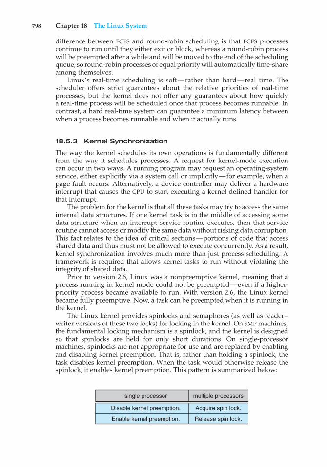
798 Chapter 18 The Linux System
difference between FCFS and round-robin scheduling is that FCFS processescontinue to run until they either exit or block, whereas a round-robin processwill be preempted after a while and will be moved to the end of the schedulingqueue, so round-robin processes of equal priority will automatically time-shareamong themselves.
Linux’s real-time scheduling is soft—rather than hard—real time. Thescheduler offers strict guarantees about the relative priorities of real-timeprocesses, but the kernel does not offer any guarantees about how quicklya real-time process will be scheduled once that process becomes runnable. Incontrast, a hard real-time system can guarantee a minimum latency betweenwhen a process becomes runnable and when it actually runs.
18.5.3 Kernel Synchronization
The way the kernel schedules its own operations is fundamentally differentfrom the way it schedules processes. A request for kernel-mode executioncan occur in two ways. A running program may request an operating-systemservice, either explicitly via a system call or implicitly—for example, when apage fault occurs. Alternatively, a device controller may deliver a hardwareinterrupt that causes the CPU to start executing a kernel-defined handler forthat interrupt.
The problem for the kernel is that all these tasks may try to access the sameinternal data structures. If one kernel task is in the middle of accessing somedata structure when an interrupt service routine executes, then that serviceroutine cannot access or modify the same data without risking data corruption.This fact relates to the idea of critical sections—portions of code that accessshared data and thus must not be allowed to execute concurrently. As a result,kernel synchronization involves much more than just process scheduling. Aframework is required that allows kernel tasks to run without violating theintegrity of shared data.
Prior to version 2.6, Linux was a nonpreemptive kernel, meaning that aprocess running in kernel mode could not be preempted—even if a higher-priority process became available to run. With version 2.6, the Linux kernelbecame fully preemptive. Now, a task can be preempted when it is running inthe kernel.
The Linux kernel provides spinlocks and semaphores (as well as reader–writer versions of these two locks) for locking in the kernel. On SMP machines,the fundamental locking mechanism is a spinlock, and the kernel is designedso that spinlocks are held for only short durations. On single-processormachines, spinlocks are not appropriate for use and are replaced by enablingand disabling kernel preemption. That is, rather than holding a spinlock, thetask disables kernel preemption. When the task would otherwise release thespinlock, it enables kernel preemption. This pattern is summarized below:
single processor multiple processors
Acquire spin lock.
Release spin lock.
Disable kernel preemption.
Enable kernel preemption.
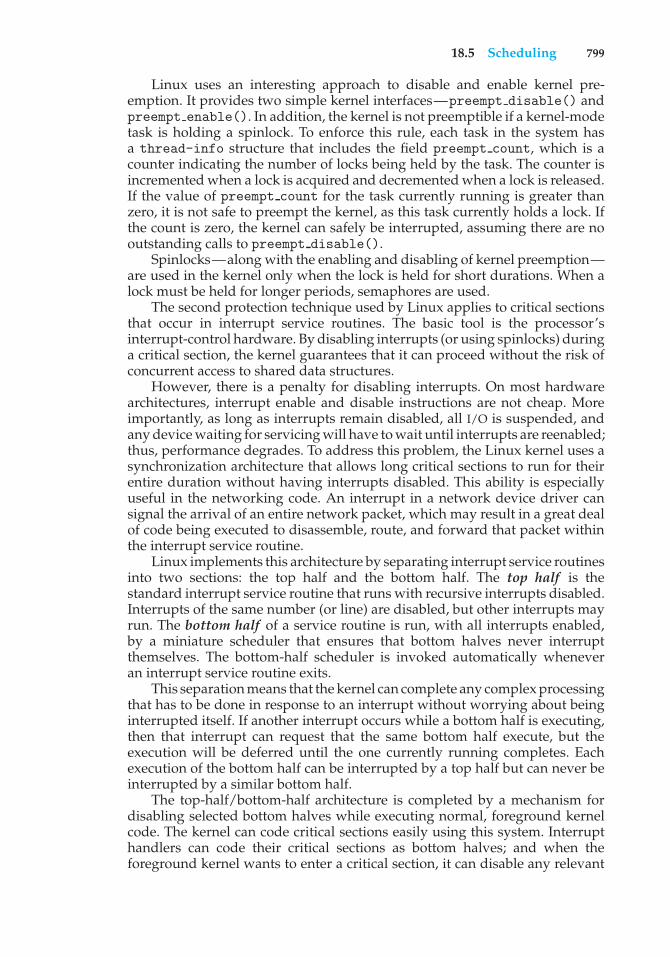
18.5 Scheduling 799
Linux uses an interesting approach to disable and enable kernel pre-emption. It provides two simple kernel interfaces—preempt disable() andpreempt enable(). In addition, the kernel is not preemptible if a kernel-modetask is holding a spinlock. To enforce this rule, each task in the system hasa thread-info structure that includes the field preempt count, which is acounter indicating the number of locks being held by the task. The counter isincremented when a lock is acquired and decremented when a lock is released.If the value of preempt count for the task currently running is greater thanzero, it is not safe to preempt the kernel, as this task currently holds a lock. Ifthe count is zero, the kernel can safely be interrupted, assuming there are nooutstanding calls to preempt disable().
Spinlocks—along with the enabling and disabling of kernel preemption—are used in the kernel only when the lock is held for short durations. When alock must be held for longer periods, semaphores are used.
The second protection technique used by Linux applies to critical sectionsthat occur in interrupt service routines. The basic tool is the processor’sinterrupt-control hardware. By disabling interrupts (or using spinlocks) duringa critical section, the kernel guarantees that it can proceed without the risk ofconcurrent access to shared data structures.
However, there is a penalty for disabling interrupts. On most hardwarearchitectures, interrupt enable and disable instructions are not cheap. Moreimportantly, as long as interrupts remain disabled, all I/O is suspended, andany device waiting for servicing will have to wait until interrupts are reenabled;thus, performance degrades. To address this problem, the Linux kernel uses asynchronization architecture that allows long critical sections to run for theirentire duration without having interrupts disabled. This ability is especiallyuseful in the networking code. An interrupt in a network device driver cansignal the arrival of an entire network packet, which may result in a great dealof code being executed to disassemble, route, and forward that packet withinthe interrupt service routine.
Linux implements this architecture by separating interrupt service routinesinto two sections: the top half and the bottom half. The top half is thestandard interrupt service routine that runs with recursive interrupts disabled.Interrupts of the same number (or line) are disabled, but other interrupts mayrun. The bottom half of a service routine is run, with all interrupts enabled,by a miniature scheduler that ensures that bottom halves never interruptthemselves. The bottom-half scheduler is invoked automatically wheneveran interrupt service routine exits.
This separation means that the kernel can complete any complex processingthat has to be done in response to an interrupt without worrying about beinginterrupted itself. If another interrupt occurs while a bottom half is executing,then that interrupt can request that the same bottom half execute, but theexecution will be deferred until the one currently running completes. Eachexecution of the bottom half can be interrupted by a top half but can never beinterrupted by a similar bottom half.
The top-half/bottom-half architecture is completed by a mechanism fordisabling selected bottom halves while executing normal, foreground kernelcode. The kernel can code critical sections easily using this system. Interrupthandlers can code their critical sections as bottom halves; and when theforeground kernel wants to enter a critical section, it can disable any relevant
800 Chapter 18 The Linux System
top-half interrupt handlers
bottom-half interrupt handlers
kernel-system service routines (preemptible)
user-mode programs (preemptible) incr
easi
ng p
riorit
y
Figure 18.2 Interrupt protection levels.
bottom halves to prevent any other critical sections from interrupting it. Atthe end of the critical section, the kernel can reenable the bottom halves andrun any bottom-half tasks that have been queued by top-half interrupt serviceroutines during the critical section.
Figure 18.2 summarizes the various levels of interrupt protection withinthe kernel. Each level may be interrupted by code running at a higher levelbut will never be interrupted by code running at the same or a lower level.Except for user-mode code, user processes can always be preempted by anotherprocess when a time-sharing scheduling interrupt occurs.
18.5.4 Symmetric Multiprocessing
The Linux 2.0 kernel was the first stable Linux kernel to support symmetricmultiprocessor (SMP) hardware, allowing separate processes to execute inparallel on separate processors. The original implementation of SMP imposedthe restriction that only one processor at a time could be executing kernel code.
In version 2.2 of the kernel, a single kernel spinlock (sometimes termedBKL for “big kernel lock”) was created to allow multiple processes (running ondifferent processors) to be active in the kernel concurrently. However, the BKLprovided a very coarse level of locking granularity, resulting in poor scalabilityto machines with many processors and processes. Later releases of the kernelmade the SMP implementation more scalable by splitting this single kernelspinlock into multiple locks, each of which protects only a small subset of thekernel’s data structures. Such spinlocks are described in Section 18.5.3. The 3.0kernel provides additional SMP enhancements, including ever-finer locking,processor affinity, and load-balancing algorithms.
18.6 Memory Management
Memory management under Linux has two components. The first deals withallocating and freeing physical memory—pages, groups of pages, and smallblocks of RAM. The second handles virtual memory, which is memory-mappedinto the address space of running processes. In this section, we describe thesetwo components and then examine the mechanisms by which the loadablecomponents of a new program are brought into a process’s virtual memory inresponse to an exec() system call.
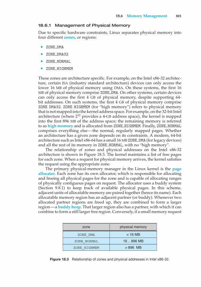
18.6 Memory Management 801
18.6.1 Management of Physical Memory
Due to specific hardware constraints, Linux separates physical memory intofour different zones, or regions:
• ZONE DMA
• ZONE DMA32
• ZONE NORMAL
• ZONE HIGHMEM
These zones are architecture specific. For example, on the Intel x86-32 architec-ture, certain ISA (industry standard architecture) devices can only access thelower 16 MB of physical memory using DMA. On these systems, the first 16MB of physical memory comprise ZONE DMA. On other systems, certain devicescan only access the first 4 GB of physical memory, despite supporting 64-bit addresses. On such systems, the first 4 GB of physical memory compriseZONE DMA32. ZONE HIGHMEM (for “high memory”) refers to physical memorythat is not mapped into the kernel address space. For example, on the 32-bit Intelarchitecture (where 232 provides a 4-GB address space), the kernel is mappedinto the first 896 MB of the address space; the remaining memory is referredto as high memory and is allocated from ZONE HIGHMEM. Finally, ZONE NORMALcomprises everything else—the normal, regularly mapped pages. Whetheran architecture has a given zone depends on its constraints. A modern, 64-bitarchitecture such as Intel x86-64 has a small 16 MB ZONE DMA (for legacy devices)and all the rest of its memory in ZONE NORMAL, with no “high memory”.
The relationship of zones and physical addresses on the Intel x86-32architecture is shown in Figure 18.3. The kernel maintains a list of free pagesfor each zone. When a request for physical memory arrives, the kernel satisfiesthe request using the appropriate zone.
The primary physical-memory manager in the Linux kernel is the pageallocator. Each zone has its own allocator, which is responsible for allocatingand freeing all physical pages for the zone and is capable of allocating rangesof physically contiguous pages on request. The allocator uses a buddy system(Section 9.8.1) to keep track of available physical pages. In this scheme,adjacent units of allocatable memory are paired together (hence its name). Eachallocatable memory region has an adjacent partner (or buddy). Whenever twoallocated partner regions are freed up, they are combined to form a largerregion—a buddy heap. That larger region also has a partner, with which it cancombine to form a still larger free region. Conversely, if a small memory request
zone physical memory
< 16 MB
16 .. 896 MB
> 896 MB
ZONE_DMA
ZONE_NORMAL
ZONE_HIGHMEM
Figure 18.3 Relationship of zones and physical addresses in Intel x86-32.
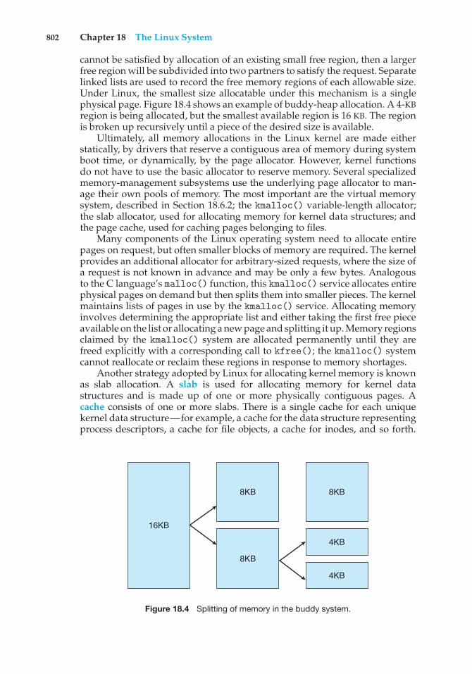
802 Chapter 18 The Linux System
cannot be satisfied by allocation of an existing small free region, then a largerfree region will be subdivided into two partners to satisfy the request. Separatelinked lists are used to record the free memory regions of each allowable size.Under Linux, the smallest size allocatable under this mechanism is a singlephysical page. Figure 18.4 shows an example of buddy-heap allocation. A 4-KBregion is being allocated, but the smallest available region is 16 KB. The regionis broken up recursively until a piece of the desired size is available.
Ultimately, all memory allocations in the Linux kernel are made eitherstatically, by drivers that reserve a contiguous area of memory during systemboot time, or dynamically, by the page allocator. However, kernel functionsdo not have to use the basic allocator to reserve memory. Several specializedmemory-management subsystems use the underlying page allocator to man-age their own pools of memory. The most important are the virtual memorysystem, described in Section 18.6.2; the kmalloc() variable-length allocator;the slab allocator, used for allocating memory for kernel data structures; andthe page cache, used for caching pages belonging to files.
Many components of the Linux operating system need to allocate entirepages on request, but often smaller blocks of memory are required. The kernelprovides an additional allocator for arbitrary-sized requests, where the size ofa request is not known in advance and may be only a few bytes. Analogousto the C language’s malloc() function, this kmalloc() service allocates entirephysical pages on demand but then splits them into smaller pieces. The kernelmaintains lists of pages in use by the kmalloc() service. Allocating memoryinvolves determining the appropriate list and either taking the first free pieceavailable on the list or allocating a new page and splitting it up. Memory regionsclaimed by the kmalloc() system are allocated permanently until they arefreed explicitly with a corresponding call to kfree(); the kmalloc() systemcannot reallocate or reclaim these regions in response to memory shortages.
Another strategy adopted by Linux for allocating kernel memory is knownas slab allocation. A slab is used for allocating memory for kernel datastructures and is made up of one or more physically contiguous pages. Acache consists of one or more slabs. There is a single cache for each uniquekernel data structure—for example, a cache for the data structure representingprocess descriptors, a cache for file objects, a cache for inodes, and so forth.
16KB
8KB
8KB
8KB
4KB
4KB
Figure 18.4 Splitting of memory in the buddy system.
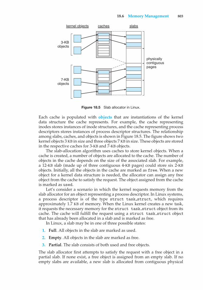
18.6 Memory Management 803
3-KBobjects
7-KBobjects
kernel objects caches slabs
physicallycontiguouspages
Figure 18.5 Slab allocator in Linux.
Each cache is populated with objects that are instantiations of the kerneldata structure the cache represents. For example, the cache representinginodes stores instances of inode structures, and the cache representing processdescriptors stores instances of process descriptor structures. The relationshipamong slabs, caches, and objects is shown in Figure 18.5. The figure shows twokernel objects 3 KB in size and three objects 7 KB in size. These objects are storedin the respective caches for 3-KB and 7-KB objects.
The slab-allocation algorithm uses caches to store kernel objects. When acache is created, a number of objects are allocated to the cache. The number ofobjects in the cache depends on the size of the associated slab. For example,a 12-KB slab (made up of three contiguous 4-KB pages) could store six 2-KBobjects. Initially, all the objects in the cache are marked as free. When a newobject for a kernel data structure is needed, the allocator can assign any freeobject from the cache to satisfy the request. The object assigned from the cacheis marked as used.
Let’s consider a scenario in which the kernel requests memory from theslab allocator for an object representing a process descriptor. In Linux systems,a process descriptor is of the type struct task struct, which requiresapproximately 1.7 KB of memory. When the Linux kernel creates a new task,it requests the necessary memory for the struct task struct object from itscache. The cache will fulfill the request using a struct task struct objectthat has already been allocated in a slab and is marked as free.
In Linux, a slab may be in one of three possible states:
1. Full. All objects in the slab are marked as used.
2. Empty. All objects in the slab are marked as free.
3. Partial. The slab consists of both used and free objects.
The slab allocator first attempts to satisfy the request with a free object in apartial slab. If none exist, a free object is assigned from an empty slab. If noempty slabs are available, a new slab is allocated from contiguous physical
804 Chapter 18 The Linux System
pages and assigned to a cache; memory for the object is allocated from thisslab.
Two other main subsystems in Linux do their own management of physicalpages: the page cache and the virtual memory system. These systems are closelyrelated to each other. The page cache is the kernel’s main cache for files andis the main mechanism through which I/O to block devices (Section 18.8.1)is performed. File systems of all types, including the native Linux disk-basedfile systems and the NFS networked file system, perform their I/O throughthe page cache. The page cache stores entire pages of file contents and is notlimited to block devices. It can also cache networked data. The virtual memorysystem manages the contents of each process’s virtual address space. Thesetwo systems interact closely with each other because reading a page of datainto the page cache requires mapping pages in the page cache using the virtualmemory system. In the following section, we look at the virtual memory systemin greater detail.
18.6.2 Virtual Memory
The Linux virtual memory system is responsible for maintaining the addressspace accessible to each process. It creates pages of virtual memory on demandand manages loading those pages from disk and swapping them back out todisk as required. Under Linux, the virtual memory manager maintains twoseparate views of a process’s address space: as a set of separate regions and asa set of pages.
The first view of an address space is the logical view, describing instructionsthat the virtual memory system has received concerning the layout of theaddress space. In this view, the address space consists of a set of nonoverlappingregions, each region representing a continuous, page-aligned subset of theaddress space. Each region is described internally by a single vm area structstructure that defines the properties of the region, including the process’s read,write, and execute permissions in the region as well as information about anyfiles associated with the region. The regions for each address space are linkedinto a balanced binary tree to allow fast lookup of the region corresponding toany virtual address.
The kernel also maintains a second, physical view of each address space.This view is stored in the hardware page tables for the process. The page-table entries identify the exact current location of each page of virtual memory,whether it is on disk or in physical memory. The physical view is managed by aset of routines, which are invoked from the kernel’s software-interrupt handlerswhenever a process tries to access a page that is not currently present in thepage tables. Each vm area struct in the address-space description contains afield pointing to a table of functions that implement the key page-managementfunctionality for any given virtual memory region. All requests to read or writean unavailable page are eventually dispatched to the appropriate handlerin the function table for the vm area struct, so that the central memory-management routines do not have to know the details of managing eachpossible type of memory region.
18.6 Memory Management 805
18.6.2.1 Virtual Memory Regions
Linux implements several types of virtual memory regions. One propertythat characterizes virtual memory is the backing store for the region, whichdescribes where the pages for the region come from. Most memory regionsare backed either by a file or by nothing. A region backed by nothing is thesimplest type of virtual memory region. Such a region represents demand-zeromemory: when a process tries to read a page in such a region, it is simply givenback a page of memory filled with zeros.
A region backed by a file acts as a viewport onto a section of that file.Whenever the process tries to access a page within that region, the page tableis filled with the address of a page within the kernel’s page cache correspondingto the appropriate offset in the file. The same page of physical memory is usedby both the page cache and the process’s page tables, so any changes made tothe file by the file system are immediately visible to any processes that havemapped that file into their address space. Any number of processes can mapthe same region of the same file, and they will all end up using the same pageof physical memory for the purpose.
A virtual memory region is also defined by its reaction to writes. Themapping of a region into the process’s address space can be either private orshared. If a process writes to a privately mapped region, then the pager detectsthat a copy-on-write is necessary to keep the changes local to the process. Incontrast, writes to a shared region result in updating of the object mapped intothat region, so that the change will be visible immediately to any other processthat is mapping that object.
18.6.2.2 Lifetime of a Virtual Address Space
The kernel creates a new virtual address space in two situations: when a processruns a new program with the exec() system call and when a new process iscreated by the fork() system call. The first case is easy. When a new program isexecuted, the process is given a new, completely empty virtual address space.It is up to the routines for loading the program to populate the address spacewith virtual memory regions.
The second case, creating a new process with fork(), involves creatinga complete copy of the existing process’s virtual address space. The kernelcopies the parent process’s vm area struct descriptors, then creates a new setof page tables for the child. The parent’s page tables are copied directly intothe child’s, and the reference count of each page covered is incremented. Thus,after the fork, the parent and child share the same physical pages of memoryin their address spaces.
A special case occurs when the copying operation reaches a virtual memoryregion that is mapped privately. Any pages to which the parent process haswritten within such a region are private, and subsequent changes to these pagesby either the parent or the child must not update the page in the other process’saddress space. When the page-table entries for such regions are copied, theyare set to be read only and are marked for copy-on-write. As long as neitherprocess modifies these pages, the two processes share the same page of physicalmemory. However, if either process tries to modify a copy-on-write page, thereference count on the page is checked. If the page is still shared, then the
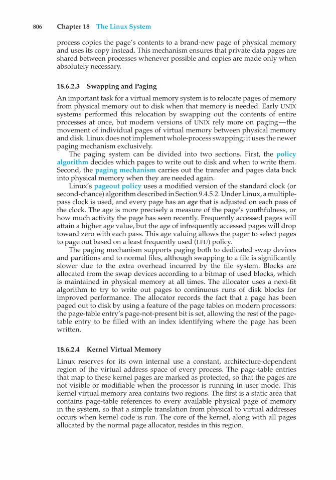
806 Chapter 18 The Linux System
process copies the page’s contents to a brand-new page of physical memoryand uses its copy instead. This mechanism ensures that private data pages areshared between processes whenever possible and copies are made only whenabsolutely necessary.
18.6.2.3 Swapping and Paging
An important task for a virtual memory system is to relocate pages of memoryfrom physical memory out to disk when that memory is needed. Early UNIXsystems performed this relocation by swapping out the contents of entireprocesses at once, but modern versions of UNIX rely more on paging—themovement of individual pages of virtual memory between physical memoryand disk. Linux does not implement whole-process swapping; it uses the newerpaging mechanism exclusively.
The paging system can be divided into two sections. First, the policyalgorithm decides which pages to write out to disk and when to write them.Second, the paging mechanism carries out the transfer and pages data backinto physical memory when they are needed again.
Linux’s pageout policy uses a modified version of the standard clock (orsecond-chance) algorithm described in Section 9.4.5.2. Under Linux, a multiple-pass clock is used, and every page has an age that is adjusted on each pass ofthe clock. The age is more precisely a measure of the page’s youthfulness, orhow much activity the page has seen recently. Frequently accessed pages willattain a higher age value, but the age of infrequently accessed pages will droptoward zero with each pass. This age valuing allows the pager to select pagesto page out based on a least frequently used (LFU) policy.
The paging mechanism supports paging both to dedicated swap devicesand partitions and to normal files, although swapping to a file is significantlyslower due to the extra overhead incurred by the file system. Blocks areallocated from the swap devices according to a bitmap of used blocks, whichis maintained in physical memory at all times. The allocator uses a next-fitalgorithm to try to write out pages to continuous runs of disk blocks forimproved performance. The allocator records the fact that a page has beenpaged out to disk by using a feature of the page tables on modern processors:the page-table entry’s page-not-present bit is set, allowing the rest of the page-table entry to be filled with an index identifying where the page has beenwritten.
18.6.2.4 Kernel Virtual Memory
Linux reserves for its own internal use a constant, architecture-dependentregion of the virtual address space of every process. The page-table entriesthat map to these kernel pages are marked as protected, so that the pages arenot visible or modifiable when the processor is running in user mode. Thiskernel virtual memory area contains two regions. The first is a static area thatcontains page-table references to every available physical page of memoryin the system, so that a simple translation from physical to virtual addressesoccurs when kernel code is run. The core of the kernel, along with all pagesallocated by the normal page allocator, resides in this region.
18.6 Memory Management 807
The remainder of the kernel’s reserved section of address space is notreserved for any specific purpose. Page-table entries in this address rangecan be modified by the kernel to point to any other areas of memory. Thekernel provides a pair of facilities that allow kernel code to use this virtualmemory. The vmalloc() function allocates an arbitrary number of physicalpages of memory that may not be physically contiguous into a single region ofvirtually contiguous kernel memory. The vremap() function maps a sequenceof virtual addresses to point to an area of memory used by a device driver formemory-mapped I/O.
18.6.3 Execution and Loading of User Programs
The Linux kernel’s execution of user programs is triggered by a call tothe exec() system call. This exec() call commands the kernel to run anew program within the current process, completely overwriting the currentexecution context with the initial context of the new program. The first job ofthis system service is to verify that the calling process has permission rights tothe file being executed. Once that matter has been checked, the kernel invokesa loader routine to start running the program. The loader does not necessarilyload the contents of the program file into physical memory, but it does at leastset up the mapping of the program into virtual memory.
There is no single routine in Linux for loading a new program. Instead,Linux maintains a table of possible loader functions, and it gives each suchfunction the opportunity to try loading the given file when an exec() systemcall is made. The initial reason for this loader table was that, between thereleases of the 1.0 and 1.2 kernels, the standard format for Linux’s binary fileswas changed. Older Linux kernels understood the a.out format for binaryfiles—a relatively simple format common on older UNIX systems. NewerLinux systems use the more modern ELF format, now supported by mostcurrent UNIX implementations. ELF has a number of advantages over a.out,including flexibility and extendability. New sections can be added to an ELFbinary (for example, to add extra debugging information) without causingthe loader routines to become confused. By allowing registration of multipleloader routines, Linux can easily support the ELF and a.out binary formats ina single running system.
In Section 18.6.3.1 and Section 18.6.3.2, we concentrate exclusively on theloading and running of ELF-format binaries. The procedure for loading a.outbinaries is simpler but similar in operation.
18.6.3.1 Mapping of Programs into Memory
Under Linux, the binary loader does not load a binary file into physical memory.Rather, the pages of the binary file are mapped into regions of virtual memory.Only when the program tries to access a given page will a page fault result inthe loading of that page into physical memory using demand paging.
It is the responsibility of the kernel’s binary loader to set up the initialmemory mapping. An ELF-format binary file consists of a header followed byseveral page-aligned sections. The ELF loader works by reading the header andmapping the sections of the file into separate regions of virtual memory.
Figure 18.6 shows the typical layout of memory regions set up by the ELFloader. In a reserved region at one end of the address space sits the kernel, in
808 Chapter 18 The Linux System
kernel virtual memory memory invisible to user-mode code
stack
memory-mapped region
memory-mapped region
memory-mapped region
run-time datauninitialized data
initialized dataprogram text
the ‘brk’ pointer
forbidden region
Figure 18.6 Memory layout for ELF programs.
its own privileged region of virtual memory inaccessible to normal user-modeprograms. The rest of virtual memory is available to applications, which can usethe kernel’s memory-mapping functions to create regions that map a portionof a file or that are available for application data.
The loader’s job is to set up the initial memory mapping to allow theexecution of the program to start. The regions that need to be initialized includethe stack and the program’s text and data regions.
The stack is created at the top of the user-mode virtual memory; itgrows downward toward lower-numbered addresses. It includes copies of thearguments and environment variables given to the program in the exec()system call. The other regions are created near the bottom end of virtualmemory. The sections of the binary file that contain program text or read-onlydata are mapped into memory as a write-protected region. Writable initializeddata are mapped next; then any uninitialized data are mapped in as a privatedemand-zero region.
Directly beyond these fixed-sized regions is a variable-sized region thatprograms can expand as needed to hold data allocated at run time. Eachprocess has a pointer, brk, that points to the current extent of this data region,and processes can extend or contract their brk region with a single system call—sbrk().
Once these mappings have been set up, the loader initializes the process’sprogram-counter register with the starting point recorded in the ELF header,and the process can be scheduled.
18.6.3.2 Static and Dynamic Linking
Once the program has been loaded and has started running, all the necessarycontents of the binary file have been loaded into the process’s virtual address
18.7 File Systems 809
space. However, most programs also need to run functions from the systemlibraries, and these library functions must also be loaded. In the simplestcase, the necessary library functions are embedded directly in the program’sexecutable binary file. Such a program is statically linked to its libraries, andstatically linked executables can commence running as soon as they are loaded.
The main disadvantage of static linking is that every program generatedmust contain copies of exactly the same common system library functions. It ismuch more efficient, in terms of both physical memory and disk-space usage,to load the system libraries into memory only once. Dynamic linking allowsthat to happen.
Linux implements dynamic linking in user mode through a special linkerlibrary. Every dynamically linked program contains a small, statically linkedfunction that is called when the program starts. This static function just mapsthe link library into memory and runs the code that the function contains. Thelink library determines the dynamic libraries required by the program and thenames of the variables and functions needed from those libraries by reading theinformation contained in sections of the ELF binary. It then maps the librariesinto the middle of virtual memory and resolves the references to the symbolscontained in those libraries. It does not matter exactly where in memory theseshared libraries are mapped: they are compiled into position-independentcode (PIC), which can run at any address in memory.
18.7 File Systems
Linux retains UNIX’s standard file-system model. In UNIX, a file does not haveto be an object stored on disk or fetched over a network from a remote fileserver. Rather, UNIX files can be anything capable of handling the input oroutput of a stream of data. Device drivers can appear as files, and interprocess-communication channels or network connections also look like files to theuser.
The Linux kernel handles all these types of files by hiding the implemen-tation details of any single file type behind a layer of software, the virtual filesystem (VFS). Here, we first cover the virtual file system and then discuss thestandard Linux file system—ext3.
18.7.1 The Virtual File System
The Linux VFS is designed around object-oriented principles. It has twocomponents: a set of definitions that specify what file-system objects areallowed to look like and a layer of software to manipulate the objects. TheVFS defines four main object types:
• An inode object represents an individual file.
• A file object represents an open file.
• A superblock object represents an entire file system.
• A dentry object represents an individual directory entry.
810 Chapter 18 The Linux System
For each of these four object types, the VFS defines a set of operations.Every object of one of these types contains a pointer to a function table. Thefunction table lists the addresses of the actual functions that implement thedefined operations for that object. For example, an abbreviated API for some ofthe file object’s operations includes:
• int open(. . .) — Open a file.
• ssize t read(. . .) — Read from a file.
• ssize t write(. . .) — Write to a file.
• int mmap(. . .) — Memory-map a file.
The complete definition of the file object is specified in the structfile operations, which is located in the file /usr/include/linux/fs.h.An implementation of the file object (for a specific file type) is required toimplement each function specified in the definition of the file object.
The VFS software layer can perform an operation on one of the file-systemobjects by calling the appropriate function from the object’s function table,without having to know in advance exactly what kind of object it is dealingwith. The VFS does not know, or care, whether an inode represents a networkedfile, a disk file, a network socket, or a directory file. The appropriate functionfor that file’s read() operation will always be at the same place in its functiontable, and the VFS software layer will call that function without caring how thedata are actually read.
The inode and file objects are the mechanisms used to access files. An inodeobject is a data structure containing pointers to the disk blocks that contain theactual file contents, and a file object represents a point of access to the data in anopen file. A process cannot access an inode’s contents without first obtaining afile object pointing to the inode. The file object keeps track of where in the filethe process is currently reading or writing, to keep track of sequential file I/O.It also remembers the permissions (for example, read or write) requested whenthe file was opened and tracks the process’s activity if necessary to performadaptive read-ahead, fetching file data into memory before the process requeststhe data, to improve performance.
File objects typically belong to a single process, but inode objects do not.There is one file object for every instance of an open file, but always only asingle inode object. Even when a file is no longer in use by any process, itsinode object may still be cached by the VFS to improve performance if the fileis used again in the near future. All cached file data are linked onto a list in thefile’s inode object. The inode also maintains standard information about eachfile, such as the owner, size, and time most recently modified.
Directory files are dealt with slightly differently from other files. The UNIXprogramming interface defines a number of operations on directories, such ascreating, deleting, and renaming a file in a directory. The system calls for thesedirectory operations do not require that the user open the files concerned,unlike the case for reading or writing data. The VFS therefore defines thesedirectory operations in the inode object, rather than in the file object.
The superblock object represents a connected set of files that form aself-contained file system. The operating-system kernel maintains a single
18.7 File Systems 811
superblock object for each disk device mounted as a file system and for eachnetworked file system currently connected. The main responsibility of thesuperblock object is to provide access to inodes. The VFS identifies everyinode by a unique file-system/inode number pair, and it finds the inodecorresponding to a particular inode number by asking the superblock object toreturn the inode with that number.
Finally, a dentry object represents a directory entry, which may include thename of a directory in the path name of a file (such as /usr) or the actual file(such as stdio.h). For example, the file /usr/include/stdio.h contains thedirectory entries (1) /, (2) usr, (3) include, and (4) stdio.h. Each of thesevalues is represented by a separate dentry object.
As an example of how dentry objects are used, consider the situ-ation in which a process wishes to open the file with the pathname/usr/include/stdio.husing an editor. Because Linux treats directory namesas files, translating this path requires first obtaining the inode for the root—/. The operating system must then read through this file to obtain the inodefor the file include. It must continue this process until it obtains the inode forthe file stdio.h. Because path-name translation can be a time-consuming task,Linux maintains a cache of dentry objects, which is consulted during path-nametranslation. Obtaining the inode from the dentry cache is considerably fasterthan having to read the on-disk file.
18.7.2 The Linux ext3 File System
The standard on-disk file system used by Linux is called ext3, for historicalreasons. Linux was originally programmed with a Minix-compatible filesystem, to ease exchanging data with the Minix development system, butthat file system was severely restricted by 14-character file-name limits and amaximum file-system size of 64 MB. The Minix file system was superseded bya new file system, which was christened the extended file system (extfs). Alater redesign to improve performance and scalability and to add a few missingfeatures led to the second extended file system (ext2). Further developmentadded journaling capabilities, and the system was renamed the third extendedfile system (ext3). Linux kernel developers are working on augmenting ext3with modern file-system features such as extents. This new file system is calledthe fourth extended file system (ext4). The rest of this section discusses ext3,however, since it remains the most-deployed Linux file system. Most of thediscussion applies equally to ext4.
Linux’s ext3 has much in common with the BSD Fast File System (FFS)(Section A.7.7). It uses a similar mechanism for locating the data blocksbelonging to a specific file, storing data-block pointers in indirect blocksthroughout the file system with up to three levels of indirection. As in FFS,directory files are stored on disk just like normal files, although their contentsare interpreted differently. Each block in a directory file consists of a linked listof entries. In turn, each entry contains the length of the entry, the name of afile, and the inode number of the inode to which that entry refers.
The main differences between ext3 and FFS lie in their disk-allocationpolicies. In FFS, the disk is allocated to files in blocks of 8 KB. These blocksare subdivided into fragments of 1 KB for storage of small files or partiallyfilled blocks at the ends of files. In contrast, ext3 does not use fragments at all
812 Chapter 18 The Linux System
but performs all its allocations in smaller units. The default block size on ext3varies as a function of the total size of the file system. Supported block sizesare 1, 2, 4, and 8 KB.
To maintain high performance, the operating system must try to performI/O operations in large chunks whenever possible by clustering physicallyadjacent I/O requests. Clustering reduces the per-request overhead incurred bydevice drivers, disks, and disk-controller hardware. A block-sized I/O requestsize is too small to maintain good performance, so ext3 uses allocation policiesdesigned to place logically adjacent blocks of a file into physically adjacentblocks on disk, so that it can submit an I/O request for several disk blocks as asingle operation.
The ext3 allocation policy works as follows: As in FFS, an ext3 file system ispartitioned into multiple segments. In ext3, these are called block groups. FFSuses the similar concept of cylinder groups, where each group corresponds toa single cylinder of a physical disk. (Note that modern disk-drive technologypacks sectors onto the disk at different densities, and thus with differentcylinder sizes, depending on how far the disk head is from the center of thedisk. Therefore, fixed-sized cylinder groups do not necessarily correspond tothe disk’s geometry.)
When allocating a file, ext3 must first select the block group for that file.For data blocks, it attempts to allocate the file to the block group to which thefile’s inode has been allocated. For inode allocations, it selects the block groupin which the file’s parent directory resides for nondirectory files. Directoryfiles are not kept together but rather are dispersed throughout the availableblock groups. These policies are designed not only to keep related informationwithin the same block group but also to spread out the disk load among thedisk’s block groups to reduce the fragmentation of any one area of the disk.
Within a block group, ext3 tries to keep allocations physically contiguousif possible, reducing fragmentation if it can. It maintains a bitmap of all freeblocks in a block group. When allocating the first blocks for a new file, itstarts searching for a free block from the beginning of the block group. Whenextending a file, it continues the search from the block most recently allocatedto the file. The search is performed in two stages. First, ext3 searches for anentire free byte in the bitmap; if it fails to find one, it looks for any free bit.The search for free bytes aims to allocate disk space in chunks of at least eightblocks where possible.
Once a free block has been identified, the search is extended backward untilan allocated block is encountered. When a free byte is found in the bitmap,this backward extension prevents ext3 from leaving a hole between the mostrecently allocated block in the previous nonzero byte and the zero byte found.Once the next block to be allocated has been found by either bit or byte search,ext3 extends the allocation forward for up to eight blocks and preallocatesthese extra blocks to the file. This preallocation helps to reduce fragmentationduring interleaved writes to separate files and also reduces the CPU cost ofdisk allocation by allocating multiple blocks simultaneously. The preallocatedblocks are returned to the free-space bitmap when the file is closed.
Figure 18.7 illustrates the allocation policies. Each row represents asequence of set and unset bits in an allocation bitmap, indicating used andfree blocks on disk. In the first case, if we can find any free blocks sufficientlynear the start of the search, then we allocate them no matter how fragmented
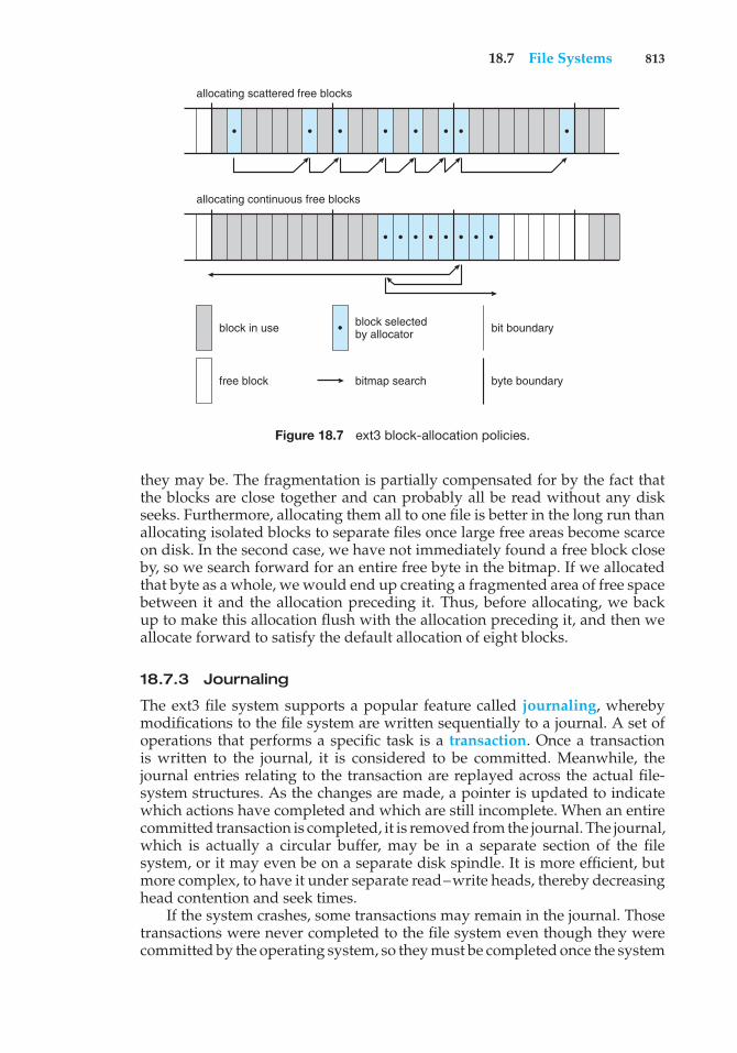
18.7 File Systems 813
allocating scattered free blocks
allocating continuous free blocks
block in use bit boundaryblock selectedby allocator
free block byte boundarybitmap search
Figure 18.7 ext3 block-allocation policies.
they may be. The fragmentation is partially compensated for by the fact thatthe blocks are close together and can probably all be read without any diskseeks. Furthermore, allocating them all to one file is better in the long run thanallocating isolated blocks to separate files once large free areas become scarceon disk. In the second case, we have not immediately found a free block closeby, so we search forward for an entire free byte in the bitmap. If we allocatedthat byte as a whole, we would end up creating a fragmented area of free spacebetween it and the allocation preceding it. Thus, before allocating, we backup to make this allocation flush with the allocation preceding it, and then weallocate forward to satisfy the default allocation of eight blocks.
18.7.3 Journaling
The ext3 file system supports a popular feature called journaling, wherebymodifications to the file system are written sequentially to a journal. A set ofoperations that performs a specific task is a transaction. Once a transactionis written to the journal, it is considered to be committed. Meanwhile, thejournal entries relating to the transaction are replayed across the actual file-system structures. As the changes are made, a pointer is updated to indicatewhich actions have completed and which are still incomplete. When an entirecommitted transaction is completed, it is removed from the journal. The journal,which is actually a circular buffer, may be in a separate section of the filesystem, or it may even be on a separate disk spindle. It is more efficient, butmore complex, to have it under separate read–write heads, thereby decreasinghead contention and seek times.
If the system crashes, some transactions may remain in the journal. Thosetransactions were never completed to the file system even though they werecommitted by the operating system, so they must be completed once the system
814 Chapter 18 The Linux System
recovers. The transactions can be executed from the pointer until the work iscomplete, and the file-system structures remain consistent. The only problemoccurs when a transaction has been aborted—that is, it was not committedbefore the system crashed. Any changes from those transactions that wereapplied to the file system must be undone, again preserving the consistency ofthe file system. This recovery is all that is needed after a crash, eliminating allproblems with consistency checking.
Journaling file systems may perform some operations faster than non-journaling systems, as updates proceed much faster when they are appliedto the in-memory journal rather than directly to the on-disk data structures.The reason for this improvement is found in the performance advantage ofsequential I/O over random I/O. Costly synchronous random writes to the filesystem are turned into much less costly synchronous sequential writes to thefile system’s journal. Those changes, in turn, are replayed asynchronously viarandom writes to the appropriate structures. The overall result is a significantgain in performance of file-system metadata-oriented operations, such as filecreation and deletion. Due to this performance improvement, ext3 can beconfigured to journal only metadata and not file data.
18.7.4 The Linux Process File System
The flexibility of the Linux VFS enables us to implement a file system that doesnot store data persistently at all but rather provides an interface to some otherfunctionality. The Linux process file system, known as the /proc file system,is an example of a file system whose contents are not actually stored anywherebut are computed on demand according to user file I/O requests.
A /proc file system is not unique to Linux. SVR4 UNIX introduced a /procfile system as an efficient interface to the kernel’s process debugging support.Each subdirectory of the file system corresponded not to a directory on anydisk but rather to an active process on the current system. A listing of the filesystem reveals one directory per process, with the directory name being theASCII decimal representation of the process’s unique process identifier (PID).
Linux implements such a /proc file system but extends it greatly byadding a number of extra directories and text files under the file system’s rootdirectory. These new entries correspond to various statistics about the kerneland the associated loaded drivers. The /proc file system provides a way forprograms to access this information as plain text files; the standard UNIX userenvironment provides powerful tools to process such files. For example, inthe past, the traditional UNIX ps command for listing the states of all runningprocesses has been implemented as a privileged process that reads the processstate directly from the kernel’s virtual memory. Under Linux, this commandis implemented as an entirely unprivileged program that simply parses andformats the information from /proc.
The /proc file system must implement two things: a directory structureand the file contents within. Because a UNIX file system is defined as a set of fileand directory inodes identified by their inode numbers, the /proc file systemmust define a unique and persistent inode number for each directory and theassociated files. Once such a mapping exists, the file system can use this inodenumber to identify just what operation is required when a user tries to readfrom a particular file inode or to perform a lookup in a particular directory
18.8 Input and Output 815
inode. When data are read from one of these files, the /proc file system willcollect the appropriate information, format it into textual form, and place itinto the requesting process’s read buffer.
The mapping from inode number to information type splits the inodenumber into two fields. In Linux, a PID is 16 bits in size, but an inode numberis 32 bits. The top 16 bits of the inode number are interpreted as a PID, and theremaining bits define what type of information is being requested about thatprocess.
A PID of zero is not valid, so a zero PID field in the inode number istaken to mean that this inode contains global—rather than process-specific—information. Separate global files exist in /proc to report information such asthe kernel version, free memory, performance statistics, and drivers currentlyrunning.
Not all the inode numbers in this range are reserved. The kernel can allocatenew /proc inode mappings dynamically, maintaining a bitmap of allocatedinode numbers. It also maintains a tree data structure of registered global /procfile-system entries. Each entry contains the file’s inode number, file name, andaccess permissions, along with the special functions used to generate the file’scontents. Drivers can register and deregister entries in this tree at any time,and a special section of the tree—appearing under the /proc/sys directory—is reserved for kernel variables. Files under this tree are managed by a setof common handlers that allow both reading and writing of these variables,so a system administrator can tune the value of kernel parameters simply bywriting out the new desired values in ASCII decimal to the appropriate file.
To allow efficient access to these variables from within applications, the/proc/sys subtree is made available through a special system call, sysctl(),that reads and writes the same variables in binary, rather than in text, withoutthe overhead of the file system. sysctl() is not an extra facility; it simply readsthe /proc dynamic entry tree to identify the variables to which the applicationis referring.
18.8 Input and Output
To the user, the I/O system in Linux looks much like that in any UNIX system.That is, to the extent possible, all device drivers appear as normal files. Userscan open an access channel to a device in the same way they open anyother file—devices can appear as objects within the file system. The systemadministrator can create special files within a file system that contain referencesto a specific device driver, and a user opening such a file will be able to readfrom and write to the device referenced. By using the normal file-protectionsystem, which determines who can access which file, the administrator can setaccess permissions for each device.
Linux splits all devices into three classes: block devices, character devices,and network devices. Figure 18.8 illustrates the overall structure of the device-driver system.
Block devices include all devices that allow random access to completelyindependent, fixed-sized blocks of data, including hard disks and floppy disks,CD-ROMs and Blu-ray discs, and flash memory. Block devices are typically
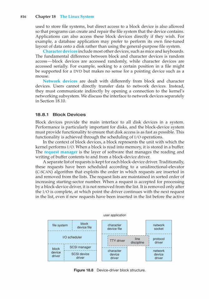
816 Chapter 18 The Linux System
used to store file systems, but direct access to a block device is also allowedso that programs can create and repair the file system that the device contains.Applications can also access these block devices directly if they wish. Forexample, a database application may prefer to perform its own fine-tunedlayout of data onto a disk rather than using the general-purpose file system.
Character devices include most other devices, such as mice and keyboards.The fundamental difference between block and character devices is randomaccess—block devices are accessed randomly, while character devices areaccessed serially. For example, seeking to a certain position in a file mightbe supported for a DVD but makes no sense for a pointing device such as amouse.
Network devices are dealt with differently from block and characterdevices. Users cannot directly transfer data to network devices. Instead,they must communicate indirectly by opening a connection to the kernel’snetworking subsystem. We discuss the interface to network devices separatelyin Section 18.10.
18.8.1 Block Devices
Block devices provide the main interface to all disk devices in a system.Performance is particularly important for disks, and the block-device systemmust provide functionality to ensure that disk access is as fast as possible. Thisfunctionality is achieved through the scheduling of I/O operations.
In the context of block devices, a block represents the unit with which thekernel performs I/O. When a block is read into memory, it is stored in a buffer.The request manager is the layer of software that manages the reading andwriting of buffer contents to and from a block-device driver.
A separate list of requests is kept for each block-device driver. Traditionally,these requests have been scheduled according to a unidirectional-elevator(C-SCAN) algorithm that exploits the order in which requests are inserted inand removed from the lists. The request lists are maintained in sorted order ofincreasing starting-sector number. When a request is accepted for processingby a block-device driver, it is not removed from the list. It is removed only afterthe I/O is complete, at which point the driver continues with the next requestin the list, even if new requests have been inserted in the list before the active
file system blockdevice file
characterdevice file
protocoldriver
linedisciplineTTY driver
I/O scheduler
SCSI manager
SCSI devicedriver
blockdevicedriver
characterdevicedriver
networksocket
networkdevicedriver
user application
Figure 18.8 Device-driver block structure.
18.8 Input and Output 817
request. As new I/O requests are made, the request manager attempts to mergerequests in the lists.
Linux kernel version 2.6 introduced a new I/O scheduling algorithm.Although a simple elevator algorithm remains available, the default I/Oscheduler is now the Completely Fair Queueing (CFQ) scheduler. The CFQ I/Oscheduler is fundamentally different from elevator-based algorithms. Insteadof sorting requests into a list, CFQ maintains a set of lists—by default, onefor each process. Requests originating from a process go in that process’s list.For example, if two processes are issuing I/O requests, CFQ will maintaintwo separate lists of requests, one for each process. The lists are maintainedaccording to the C-SCAN algorithm.
CFQ services the lists differently as well. Where a traditional C-SCANalgorithm is indifferent to a specific process, CFQ services each process’s listround-robin. It pulls a configurable number of requests (by default, four)from each list before moving on to the next. This method results in fairnessat the process level—each process receives an equal fraction of the disk’sbandwidth. The result is beneficial with interactive workloads where I/Olatency is important. In practice, however, CFQ performs well with mostworkloads.
18.8.2 Character Devices
A character-device driver can be almost any device driver that does not offerrandom access to fixed blocks of data. Any character-device drivers registeredto the Linux kernel must also register a set of functions that implement thefile I/O operations that the driver can handle. The kernel performs almost nopreprocessing of a file read or write request to a character device. It simplypasses the request to the device in question and lets the device deal with therequest.
The main exception to this rule is the special subset of character-devicedrivers that implement terminal devices. The kernel maintains a standardinterface to these drivers by means of a set of tty struct structures. Each ofthese structures provides buffering and flow control on the data stream fromthe terminal device and feeds those data to a line discipline.
A line discipline is an interpreter for the information from the terminaldevice. The most common line discipline is the tty discipline, which glues theterminal’s data stream onto the standard input and output streams of a user’srunning processes, allowing those processes to communicate directly with theuser’s terminal. This job is complicated by the fact that several such processesmay be running simultaneously, and the tty line discipline is responsible forattaching and detaching the terminal’s input and output from the variousprocesses connected to it as those processes are suspended or awakened by theuser.
Other line disciplines also are implemented that have nothing to do withI/O to a user process. The PPP and SLIP networking protocols are ways ofencoding a networking connection over a terminal device such as a serialline. These protocols are implemented under Linux as drivers that at one endappear to the terminal system as line disciplines and at the other end appearto the networking system as network-device drivers. After one of these linedisciplines has been enabled on a terminal device, any data appearing on thatterminal will be routed directly to the appropriate network-device driver.
818 Chapter 18 The Linux System
18.9 Interprocess Communication
Linux provides a rich environment for processes to communicate with eachother. Communication may be just a matter of letting another process knowthat some event has occurred, or it may involve transferring data from oneprocess to another.
18.9.1 Synchronization and Signals
The standard Linux mechanism for informing a process that an event hasoccurred is the signal. Signals can be sent from any process to any otherprocess, with restrictions on signals sent to processes owned by another user.However, a limited number of signals are available, and they cannot carryinformation. Only the fact that a signal has occurred is available to a process.Signals are not generated only by processes. The kernel also generates signalsinternally. For example, it can send a signal to a server process when dataarrive on a network channel, to a parent process when a child terminates, or toa waiting process when a timer expires.
Internally, the Linux kernel does not use signals to communicate withprocesses running in kernel mode. If a kernel-mode process is expecting anevent to occur, it will not use signals to receive notification of that event.Rather, communication about incoming asynchronous events within the kerneltakes place through the use of scheduling states and wait queue structures.These mechanisms allow kernel-mode processes to inform one another aboutrelevant events, and they also allow events to be generated by device drivers orby the networking system. Whenever a process wants to wait for some eventto complete, it places itself on a wait queue associated with that event andtells the scheduler that it is no longer eligible for execution. Once the event hascompleted, every process on the wait queue will be awoken. This procedureallows multiple processes to wait for a single event. For example, if severalprocesses are trying to read a file from a disk, then they will all be awakenedonce the data have been read into memory successfully.
Although signals have always been the main mechanism for commu-nicating asynchronous events among processes, Linux also implements thesemaphore mechanism of System V UNIX. A process can wait on a semaphoreas easily as it can wait for a signal, but semaphores have two advantages:large numbers of semaphores can be shared among multiple independent pro-cesses, and operations on multiple semaphores can be performed atomically.Internally, the standard Linux wait queue mechanism synchronizes processesthat are communicating with semaphores.
18.9.2 Passing of Data among Processes
Linux offers several mechanisms for passing data among processes. The stan-dard UNIX pipe mechanism allows a child process to inherit a communicationchannel from its parent; data written to one end of the pipe can be read at theother. Under Linux, pipes appear as just another type of inode to virtual filesystem software, and each pipe has a pair of wait queues to synchronize thereader and writer. UNIX also defines a set of networking facilities that can sendstreams of data to both local and remote processes. Networking is covered inSection 18.10.
18.10 Network Structure 819
Another process communications method, shared memory, offers anextremely fast way to communicate large or small amounts of data. Any datawritten by one process to a shared memory region can be read immediately byany other process that has mapped that region into its address space. The maindisadvantage of shared memory is that, on its own, it offers no synchronization.A process can neither ask the operating system whether a piece of sharedmemory has been written to nor suspend execution until such a write occurs.Shared memory becomes particularly powerful when used in conjunction withanother interprocess-communication mechanism that provides the missingsynchronization.
A shared-memory region in Linux is a persistent object that can be createdor deleted by processes. Such an object is treated as though it were a small,independent address space. The Linux paging algorithms can elect to pageshared-memory pages out to disk, just as they can page out a process’s datapages. The shared-memory object acts as a backing store for shared-memoryregions, just as a file can act as a backing store for a memory-mapped memoryregion. When a file is mapped into a virtual address space region, then anypage faults that occur cause the appropriate page of the file to be mapped intovirtual memory. Similarly, shared-memory mappings direct page faults to mapin pages from a persistent shared-memory object. Also just as for files, shared-memory objects remember their contents even if no processes are currentlymapping them into virtual memory.
18.10 Network Structure
Networking is a key area of functionality for Linux. Not only does Linuxsupport the standard Internet protocols used for most UNIX-to-UNIX com-munications, but it also implements a number of protocols native to other,non-UNIX operating systems. In particular, since Linux was originally imple-mented primarily on PCs, rather than on large workstations or on server-classsystems, it supports many of the protocols typically used on PC networks, suchas AppleTalk and IPX.
Internally, networking in the Linux kernel is implemented by three layersof software:
1. The socket interface
2. Protocol drivers
3. Network-device drivers
User applications perform all networking requests through the socketinterface. This interface is designed to look like the 4.3 BSD socket layer, sothat any programs designed to make use of Berkeley sockets will run on Linuxwithout any source-code changes. This interface is described in Section A.9.1.The BSD socket interface is sufficiently general to represent network addressesfor a wide range of networking protocols. This single interface is used in Linuxto access not just those protocols implemented on standard BSD systems but allthe protocols supported by the system.
820 Chapter 18 The Linux System
The next layer of software is the protocol stack, which is similar inorganization to BSD’s own framework. Whenever any networking data arrive atthis layer, either from an application’s socket or from a network-device driver,the data are expected to have been tagged with an identifier specifying whichnetwork protocol they contain. Protocols can communicate with one anotherif they desire; for example, within the Internet protocol set, separate protocolsmanage routing, error reporting, and reliable retransmission of lost data.
The protocol layer may rewrite packets, create new packets, split orreassemble packets into fragments, or simply discard incoming data. Ulti-mately, once the protocol layer has finished processing a set of packets, itpasses them on, either upward to the socket interface if the data are destinedfor a local connection or downward to a device driver if the data need to betransmitted remotely. The protocol layer decides to which socket or device itwill send the packet.
All communication between the layers of the networking stack is per-formed by passing single skbuff (socket buffer) structures. Each of thesestructures contains a set of pointers into a single continuous area of memory,representing a buffer inside which network packets can be constructed. Thevalid data in a skbuff do not need to start at the beginning of the skbuff’sbuffer, and they do not need to run to the end. The networking code canadd data to or trim data from either end of the packet, as long as the resultstill fits into the skbuff. This capacity is especially important on modernmicroprocessors, where improvements in CPU speed have far outstripped theperformance of main memory. The skbuff architecture allows flexibility inmanipulating packet headers and checksums while avoiding any unnecessarydata copying.
The most important set of protocols in the Linux networking system is theTCP/IP protocol suite. This suite comprises a number of separate protocols.The IP protocol implements routing between different hosts anywhere on thenetwork. On top of the routing protocol are the UDP, TCP, and ICMP protocols.The UDP protocol carries arbitrary individual datagrams between hosts. TheTCP protocol implements reliable connections between hosts with guaranteedin-order delivery of packets and automatic retransmission of lost data. TheICMP protocol carries various error and status messages between hosts.
Each packet (skbuff) arriving at the networking stack’s protocol softwareis expected to be already tagged with an internal identifier indicating theprotocol to which the packet is relevant. Different networking-device driversencode the protocol type in different ways; thus, the protocol for incomingdata must be identified in the device driver. The device driver uses a hash tableof known networking-protocol identifiers to look up the appropriate protocoland passes the packet to that protocol. New protocols can be added to the hashtable as kernel-loadable modules.
Incoming IP packets are delivered to the IP driver. The job of this layeris to perform routing. After deciding where the packet is to be sent, the IPdriver forwards the packet to the appropriate internal protocol driver to bedelivered locally or injects it back into a selected network-device-driver queueto be forwarded to another host. It performs the routing decision using twotables: the persistent forwarding information base (FIB) and a cache of recentrouting decisions. The FIB holds routing-configuration information and canspecify routes based either on a specific destination address or on a wildcard
18.11 Security 821
representing multiple destinations. The FIB is organized as a set of hash tablesindexed by destination address; the tables representing the most specific routesare always searched first. Successful lookups from this table are added tothe route-caching table, which caches routes only by specific destination. Nowildcards are stored in the cache, so lookups can be made quickly. An entry inthe route cache expires after a fixed period with no hits.
At various stages, the IP software passes packets to a separate sectionof code for firewall management—selective filtering of packets accordingto arbitrary criteria, usually for security purposes. The firewall managermaintains a number of separate firewall chains and allows a skbuff to bematched against any chain. Chains are reserved for separate purposes: one isused for forwarded packets, one for packets being input to this host, and onefor data generated at this host. Each chain is held as an ordered list of rules,where a rule specifies one of a number of possible firewall-decision functionsplus some arbitrary data for matching purposes.
Two other functions performed by the IP driver are disassembly andreassembly of large packets. If an outgoing packet is too large to be queued toa device, it is simply split up into smaller fragments, which are all queued tothe driver. At the receiving host, these fragments must be reassembled. The IPdriver maintains an ipfrag object for each fragment awaiting reassembly andan ipq for each datagram being assembled. Incoming fragments are matchedagainst each known ipq. If a match is found, the fragment is added to it;otherwise, a new ipq is created. Once the final fragment has arrived for aipq, a completely new skbuff is constructed to hold the new packet, and thispacket is passed back into the IP driver.
Packets identified by the IP as destined for this host are passed on to oneof the other protocol drivers. The UDP and TCP protocols share a means ofassociating packets with source and destination sockets: each connected pairof sockets is uniquely identified by its source and destination addresses andby the source and destination port numbers. The socket lists are linked tohash tables keyed on these four address and port values for socket lookup onincoming packets. The TCP protocol has to deal with unreliable connections, soit maintains ordered lists of unacknowledged outgoing packets to retransmitafter a timeout and of incoming out-of-order packets to be presented to thesocket when the missing data have arrived.
18.11 Security
Linux’s security model is closely related to typical UNIX security mechanisms.The security concerns can be classified in two groups:
1. Authentication. Making sure that nobody can access the system withoutfirst proving that she has entry rights
2. Access control. Providing a mechanism for checking whether a user hasthe right to access a certain object and preventing access to objects asrequired
822 Chapter 18 The Linux System
18.11.1 Authentication
Authentication in UNIX has typically been performed through the use of apublicly readable password file. A user’s password is combined with a random“salt” value, and the result is encoded with a one-way transformation functionand stored in the password file. The use of the one-way function means thatthe original password cannot be deduced from the password file except bytrial and error. When a user presents a password to the system, the password isrecombined with the salt value stored in the password file and passed throughthe same one-way transformation. If the result matches the contents of thepassword file, then the password is accepted.
Historically, UNIX implementations of this mechanism have had severaldrawbacks. Passwords were often limited to eight characters, and the numberof possible salt values was so low that an attacker could easily combine adictionary of commonly used passwords with every possible salt value andhave a good chance of matching one or more passwords in the passwordfile, gaining unauthorized access to any accounts compromised as a result.Extensions to the password mechanism have been introduced that keep theencrypted password secret in a file that is not publicly readable, that allowlonger passwords, or that use more secure methods of encoding the password.Other authentication mechanisms have been introduced that limit the periodsduring which a user is permitted to connect to the system. Also, mechanismsexist to distribute authentication information to all the related systems in anetwork.
A new security mechanism has been developed by UNIX vendors toaddress authentication problems. The pluggable authentication modules(PAM) system is based on a shared library that can be used by any systemcomponent that needs to authenticate users. An implementation of this systemis available under Linux. PAM allows authentication modules to be loaded ondemand as specified in a system-wide configuration file. If a new authenticationmechanism is added at a later date, it can be added to the configuration file,and all system components will immediately be able to take advantage of it.PAM modules can specify authentication methods, account restrictions, session-setup functions, and password-changing functions (so that, when users changetheir passwords, all the necessary authentication mechanisms can be updatedat once).
18.11.2 Access Control
Access control under UNIX systems, including Linux, is performed through theuse of unique numeric identifiers. A user identifier (UID) identifies a single useror a single set of access rights. A group identifier (GID) is an extra identifierthat can be used to identify rights belonging to more than one user.
Access control is applied to various objects in the system. Every fileavailable in the system is protected by the standard access-control mecha-nism. In addition, other shared objects, such as shared-memory sections andsemaphores, employ the same access system.
Every object in a UNIX system under user and group access control has asingle UID and a single GID associated with it. User processes also have a singleUID, but they may have more than one GID. If a process’s UID matches the UIDof an object, then the process has user rights or owner rights to that object.
18.11 Security 823
If the UIDs do not match but any GID of the process matches the object’s GID,then group rights are conferred; otherwise, the process has world rights to theobject.
Linux performs access control by assigning objects a protection mask thatspecifies which access modes—read, write, or execute—are to be granted toprocesses with owner, group, or world access. Thus, the owner of an objectmight have full read, write, and execute access to a file; other users in a certaingroup might be given read access but denied write access; and everybody elsemight be given no access at all.
The only exception is the privileged root UID. A process with this specialUID is granted automatic access to any object in the system, bypassingnormal access checks. Such processes are also granted permission to performprivileged operations, such as reading any physical memory or openingreserved network sockets. This mechanism allows the kernel to prevent normalusers from accessing these resources: most of the kernel’s key internal resourcesare implicitly owned by the root UID.
Linux implements the standard UNIX setuid mechanism described inSection A.3.2. This mechanism allows a program to run with privileges differentfrom those of the user running the program. For example, the lpr program(which submits a job to a print queue) has access to the system’s print queueseven if the user running that program does not. The UNIX implementation ofsetuid distinguishes between a process’s real and effective UID. The realUID is that of the user running the program; the effective UID is that of the file’sowner.
Under Linux, this mechanism is augmented in two ways. First, Linuximplements the POSIX specification’s saved user-id mechanism, whichallows a process to drop and reacquire its effective UID repeatedly. For securityreasons, a program may want to perform most of its operations in a safe mode,waiving the privileges granted by its setuid status; but it may wish to performselected operations with all its privileges. Standard UNIX implementationsachieve this capacity only by swapping the real and effective UIDs. When thisis done, the previous effective UID is remembered, but the program’s real UIDdoes not always correspond to the UID of the user running the program. SavedUIDs allow a process to set its effective UID to its real UID and then return tothe previous value of its effective UID without having to modify the real UID atany time.
The second enhancement provided by Linux is the addition of a processcharacteristic that grants just a subset of the rights of the effective UID. Thefsuid and fsgid process properties are used when access rights are grantedto files. The appropriate property is set every time the effective UID or GID isset. However, the fsuid and fsgid can be set independently of the effective ids,allowing a process to access files on behalf of another user without taking on theidentity of that other user in any other way. Specifically, server processes canuse this mechanism to serve files to a certain user without becoming vulnerableto being killed or suspended by that user.
Finally, Linux provides a mechanism for flexible passing of rights fromone program to another—a mechanism that has become common in modernversions of UNIX. When a local network socket has been set up between anytwo processes on the system, either of those processes may send to the otherprocess a file descriptor for one of its open files; the other process receives a
824 Chapter 18 The Linux System
duplicate file descriptor for the same file. This mechanism allows a client topass access to a single file selectively to some server process without grantingthat process any other privileges. For example, it is no longer necessary for aprint server to be able to read all the files of a user who submits a new printjob. The print client can simply pass the server file descriptors for any files tobe printed, denying the server access to any of the user’s other files.
18.12 Summary
Linux is a modern, free operating system based on UNIX standards. It has beendesigned to run efficiently and reliably on common PC hardware; it also runs ona variety of other platforms, such as mobile phones. It provides a programminginterface and user interface compatible with standard UNIX systems and canrun a large number of UNIX applications, including an increasing number ofcommercially supported applications.
Linux has not evolved in a vacuum. A complete Linux system includesmany components that were developed independently of Linux. The coreLinux operating-system kernel is entirely original, but it allows much existingfree UNIX software to run, resulting in an entire UNIX-compatible operatingsystem free from proprietary code.
The Linux kernel is implemented as a traditional monolithic kernel forperformance reasons, but it is modular enough in design to allow most driversto be dynamically loaded and unloaded at run time.
Linux is a multiuser system, providing protection between processes andrunning multiple processes according to a time-sharing scheduler. Newlycreated processes can share selective parts of their execution environmentwith their parent processes, allowing multithreaded programming. Interpro-cess communication is supported by both System V mechanisms—messagequeues, semaphores, and shared memory—and BSD’s socket interface. Multi-ple networking protocols can be accessed simultaneously through the socketinterface.
The memory-management system uses page sharing and copy-on-writeto minimize the duplication of data shared by different processes. Pages areloaded on demand when they are first referenced and are paged back out tobacking store according to an LFU algorithm if physical memory needs to bereclaimed.
To the user, the file system appears as a hierarchical directory tree thatobeys UNIX semantics. Internally, Linux uses an abstraction layer to managemultiple file systems. Device-oriented, networked, and virtual file systems aresupported. Device-oriented file systems access disk storage through a pagecache that is unified with the virtual memory system.
Practice Exercises
18.1 Dynamically loadable kernel modules give flexibility when drivers areadded to a system, but do they have disadvantages too? Under whatcircumstances would a kernel be compiled into a single binary file, andwhen would it be better to keep it split into modules? Explain youranswer.
Exercises 825
18.2 Multithreading is a commonly used programming technique. Describethree different ways to implement threads, and compare these threemethods with the Linux clone() mechanism. When might using eachalternative mechanism be better or worse than using clones?
18.3 The Linux kernel does not allow paging out of kernel memory. Whateffect does this restriction have on the kernel’s design? What are twoadvantages and two disadvantages of this design decision?
18.4 Discuss three advantages of dynamic (shared) linkage of librariescompared with static linkage. Describe two cases in which static linkageis preferable.
18.5 Compare the use of networking sockets with the use of shared memoryas a mechanism for communicating data between processes on a singlecomputer. What are the advantages of each method? When might eachbe preferred?
18.6 At one time, UNIX systems used disk-layout optimizations basedon the rotation position of disk data, but modern implementations,including Linux, simply optimize for sequential data access. Why dothey do so? Of what hardware characteristics does sequential accesstake advantage? Why is rotational optimization no longer so useful?
Exercises
18.7 What are the advantages and disadvantages of writing an operatingsystem in a high-level language, such as C?
18.8 In what circumstances is the system-call sequence fork() exec()mostappropriate? When is vfork() preferable?
18.9 What socket type should be used to implement an intercomputerfile-transfer program? What type should be used for a program thatperiodically tests to see whether another computer is up on thenetwork? Explain your answer.
18.10 Linux runs on a variety of hardware platforms. What steps mustLinux developers take to ensure that the system is portable to differentprocessors and memory-management architectures and to minimizethe amount of architecture-specific kernel code?
18.11 What are the advantages and disadvantages of making only some of thesymbols defined inside a kernel accessible to a loadable kernel module?
18.12 What are the primary goals of the conflict-resolution mechanism usedby the Linux kernel for loading kernel modules?
18.13 Discuss how the clone() operation supported by Linux is used tosupport both processes and threads.
18.14 Would you classify Linux threads as user-level threads or as kernel-levelthreads? Support your answer with the appropriate arguments.
18.15 What extra costs are incurred in the creation and scheduling of aprocess, compared with the cost of a cloned thread?
826 Chapter 18 The Linux System
18.16 How does Linux’s Completely Fair Scheduler (CFS) provide improvedfairness over a traditional UNIX process scheduler? When is the fairnessguaranteed?
18.17 What are the two configurable variables of the Completely Fair Sched-uler (CFS)? What are the pros and cons of setting each of them to verysmall and very large values?
18.18 The Linux scheduler implements “soft” real-time scheduling. Whatfeatures necessary for certain real-time programming tasks are missing?How might they be added to the kernel? What are the costs (downsides)of such features?
18.19 Under what circumstances would a user process request an operationthat results in the allocation of a demand-zero memory region?
18.20 What scenarios would cause a page of memory to be mapped into a userprogram’s address space with the copy-on-write attribute enabled?
18.21 In Linux, shared libraries perform many operations central to theoperating system. What is the advantage of keeping this functionalityout of the kernel? Are there any drawbacks? Explain your answer.
18.22 What are the benefits of a journaling file system such as Linux’s ext3?What are the costs? Why does ext3 provide the option to journal onlymetadata?
18.23 The directory structure of a Linux operating system could include filescorresponding to several different file systems, including the Linux/proc file system. How might the need to support different file-systemtypes affect the structure of the Linux kernel?
18.24 In what ways does the Linux setuid feature differ from the setuidfeature SVR4?
18.25 The Linux source code is freely and widely available over the Inter-net and from CD-ROM vendors. What are three implications of thisavailability for the security of the Linux system?
Bibliographical Notes
The Linux system is a product of the Internet; as a result, much of theavailable documentation on Linux is available in some form on the Internet.The following key sites reference most of the useful information available:
• The Linux Cross-Reference Page (LXR) (http://lxr.linux.no) maintains currentlistings of the Linux kernel, browsable via the Web and fully cross-referenced.
• The Kernel Hackers’ Guide provides a helpful overview of the Linux kernelcomponents and internals and is located at http://tldp.org/LDP/tlk/tlk.html.
Bibliography 827
• The Linux Weekly News (LWN) (http://lwn.net) provides weekly Linux-related news, including a very well researched subsection on Linux kernelnews.
Many mailing lists devoted to Linux are also available. The most importantare maintained by a mailing-list manager that can be reached at the e-mailaddress [email protected]. Send e-mail to this address with thesingle line “help” in the mail’s body for information on how to access the listserver and to subscribe to any lists.
Finally, the Linux system itself can be obtained over the Internet. CompleteLinux distributions are available from the home sites of the companiesconcerned, and the Linux community also maintains archives of currentsystem components at several places on the Internet. The most important isftp://ftp.kernel.org/pub/linux.
In addition to investigating Internet resources, you can read about theinternals of the Linux kernel in [Mauerer (2008)] and [Love (2010)].
Bibliography
[Love (2010)] R. Love, Linux Kernel Development, Third Edition, Developer’sLibrary (2010).
[Mauerer (2008)] W. Mauerer, Professional Linux Kernel Architecture, John Wileyand Sons (2008).

19C H A P T E R
Windows 7
Updated by Dave Probert
The Microsoft Windows 7 operating system is a 32-/64-bit preemptive mul-titasking client operating system for microprocessors implementing the IntelIA-32 and AMD64 instruction set architectures (ISAs). Microsoft’s correspondingserver operating system, Windows Server 2008 R2, is based on the same codeas Windows 7 but supports only the 64-bit AMD64 and IA64 (Itanium) ISAs.Windows 7 is the latest in a series of Microsoft operating systems based on itsNT code, which replaced the earlier systems based on Windows 95/98. In thischapter, we discuss the key goals of Windows 7, the layered architecture of thesystem that has made it so easy to use, the file system, the networking features,and the programming interface.
CHAPTER OBJECTIVES
• To explore the principles underlying Windows 7’s design and the specificcomponents of the system.
• To provide a detailed discussion of the Windows 7 file system.• To illustrate the networking protocols supported in Windows 7.• To describe the interface available in Windows 7 to system and application
programmers.• To describe the important algorithms implemented with Windows 7.
19.1 History
In the mid-1980s, Microsoft and IBM cooperated to develop the OS/2 operatingsystem, which was written in assembly language for single-processor Intel80286 systems. In 1988, Microsoft decided to end the joint effort with IBMand develop its own “new technology” (or NT) portable operating system tosupport both the OS/2 and POSIX application-programming interfaces (APIs). In
829
830 Chapter 19 Windows 7
October 1988, Dave Cutler, the architect of the DEC VAX/VMS operating system,was hired and given the charter of building Microsoft’s new operating system.
Originally, the team planned to use the OS/2 API as NT’s native environment,but during development, NT was changed to use a new 32-bit Windows API(called Win32), based on the popular 16-bit API used in Windows 3.0. The firstversions of NT were Windows NT 3.1 and Windows NT 3.1 Advanced Server.(At that time, 16-bit Windows was at Version 3.1.) Windows NT Version 4.0adopted the Windows 95 user interface and incorporated Internet web-serverand web-browser software. In addition, user-interface routines and all graphicscode were moved into the kernel to improve performance, with the side effect ofdecreased system reliability. Although previous versions of NT had been portedto other microprocessor architectures, the Windows 2000 version, releasedin February 2000, supported only Intel (and compatible) processors due tomarketplace factors. Windows 2000 incorporated significant changes. It addedActive Directory (an X.500-based directory service), better networking andlaptop support, support for plug-and-play devices, a distributed file system,and support for more processors and more memory.
In October 2001, Windows XP was released as both an update to theWindows 2000 desktop operating system and a replacement for Windows95/98. In 2002, the server edition of Windows XP became available (calledWindows .Net Server). Windows XP updated the graphical user interface(GUI) with a visual design that took advantage of more recent hardwareadvances and many new ease-of-use features. Numerous features were addedto automatically repair problems in applications and the operating systemitself. As a result of these changes, Windows XP provided better networking anddevice experience (including zero-configuration wireless, instant messaging,streaming media, and digital photography/video), dramatic performanceimprovements for both the desktop and large multiprocessors, and betterreliability and security than earlier Windows operating systems.
The long-awaited update to Windows XP, called Windows Vista, wasreleased in November 2006, but it was not well received. Although Win-dows Vista included many improvements that later showed up in Windows7, these improvements were overshadowed by Windows Vista’s perceivedsluggishness and compatibility problems. Microsoft responded to criticismsof Windows Vista by improving its engineering processes and working moreclosely with the makers of Windows hardware and applications. The result wasWindows 7, which was released in October 2009, along with correspondingserver editions of Windows. Among the significant engineering changes is theincreased use of execution tracing rather than counters or profiling to analyzesystem behavior. Tracing runs constantly in the system, watching hundreds ofscenarios execute. When one of these scenarios fails, or when it succeeds butdoes not perform well, the traces can be analyzed to determine the cause.
Windows 7 uses a client–server architecture (like Mach) to implement twooperating-system personalities, Win32 and POSIX, with user-level processescalled subsystems. (At one time, Windows also supported an OS/2 subsystem,but it was removed in Windows XP due to the demise of OS/2.) The subsystemarchitecture allows enhancements to be made to one operating-system person-ality without affecting the application compatibility of the other. Although thePOSIX subsystem continues to be available for Windows 7, the Win32 API hasbecome very popular, and the POSIX APIs are used by only a few sites. Thesubsystem approach continues to be interesting to study from an operating-
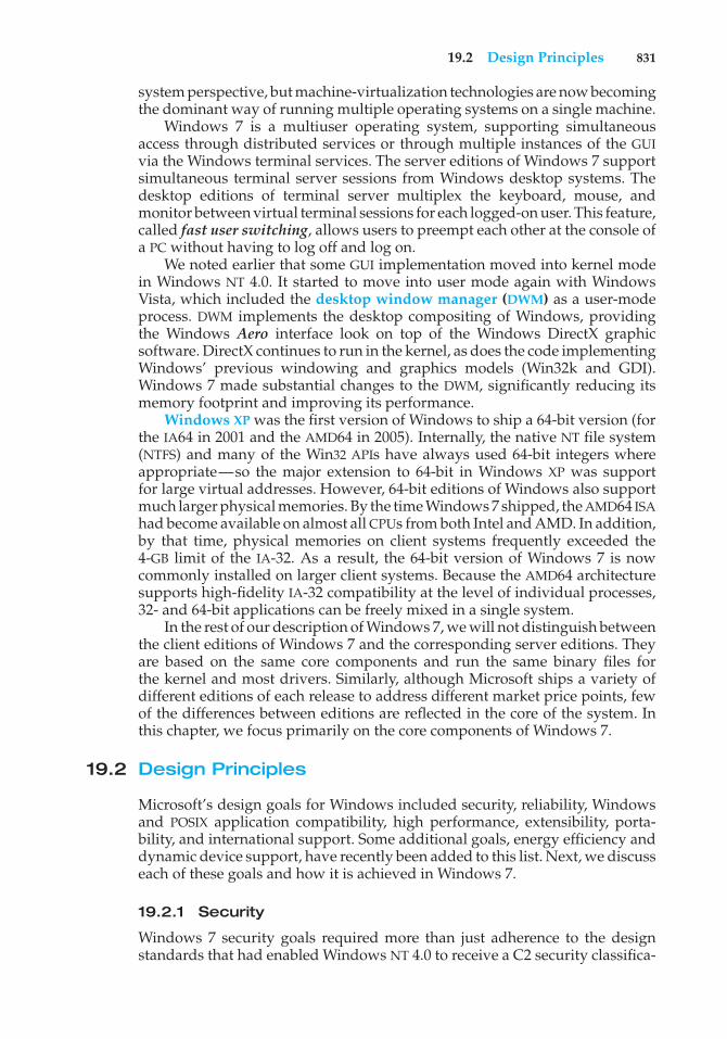
19.2 Design Principles 831
system perspective, but machine-virtualization technologies are now becomingthe dominant way of running multiple operating systems on a single machine.
Windows 7 is a multiuser operating system, supporting simultaneousaccess through distributed services or through multiple instances of the GUIvia the Windows terminal services. The server editions of Windows 7 supportsimultaneous terminal server sessions from Windows desktop systems. Thedesktop editions of terminal server multiplex the keyboard, mouse, andmonitor between virtual terminal sessions for each logged-on user. This feature,called fast user switching, allows users to preempt each other at the console ofa PC without having to log off and log on.
We noted earlier that some GUI implementation moved into kernel modein Windows NT 4.0. It started to move into user mode again with WindowsVista, which included the desktop window manager (DWM) as a user-modeprocess. DWM implements the desktop compositing of Windows, providingthe Windows Aero interface look on top of the Windows DirectX graphicsoftware. DirectX continues to run in the kernel, as does the code implementingWindows’ previous windowing and graphics models (Win32k and GDI).Windows 7 made substantial changes to the DWM, significantly reducing itsmemory footprint and improving its performance.
Windows XP was the first version of Windows to ship a 64-bit version (forthe IA64 in 2001 and the AMD64 in 2005). Internally, the native NT file system(NTFS) and many of the Win32 APIs have always used 64-bit integers whereappropriate—so the major extension to 64-bit in Windows XP was supportfor large virtual addresses. However, 64-bit editions of Windows also supportmuch larger physical memories. By the time Windows 7 shipped, the AMD64 ISAhad become available on almost all CPUs from both Intel and AMD. In addition,by that time, physical memories on client systems frequently exceeded the4-GB limit of the IA-32. As a result, the 64-bit version of Windows 7 is nowcommonly installed on larger client systems. Because the AMD64 architecturesupports high-fidelity IA-32 compatibility at the level of individual processes,32- and 64-bit applications can be freely mixed in a single system.
In the rest of our description of Windows 7, we will not distinguish betweenthe client editions of Windows 7 and the corresponding server editions. Theyare based on the same core components and run the same binary files forthe kernel and most drivers. Similarly, although Microsoft ships a variety ofdifferent editions of each release to address different market price points, fewof the differences between editions are reflected in the core of the system. Inthis chapter, we focus primarily on the core components of Windows 7.
19.2 Design Principles
Microsoft’s design goals for Windows included security, reliability, Windowsand POSIX application compatibility, high performance, extensibility, porta-bility, and international support. Some additional goals, energy efficiency anddynamic device support, have recently been added to this list. Next, we discusseach of these goals and how it is achieved in Windows 7.
19.2.1 Security
Windows 7 security goals required more than just adherence to the designstandards that had enabled Windows NT 4.0 to receive a C2 security classifica-
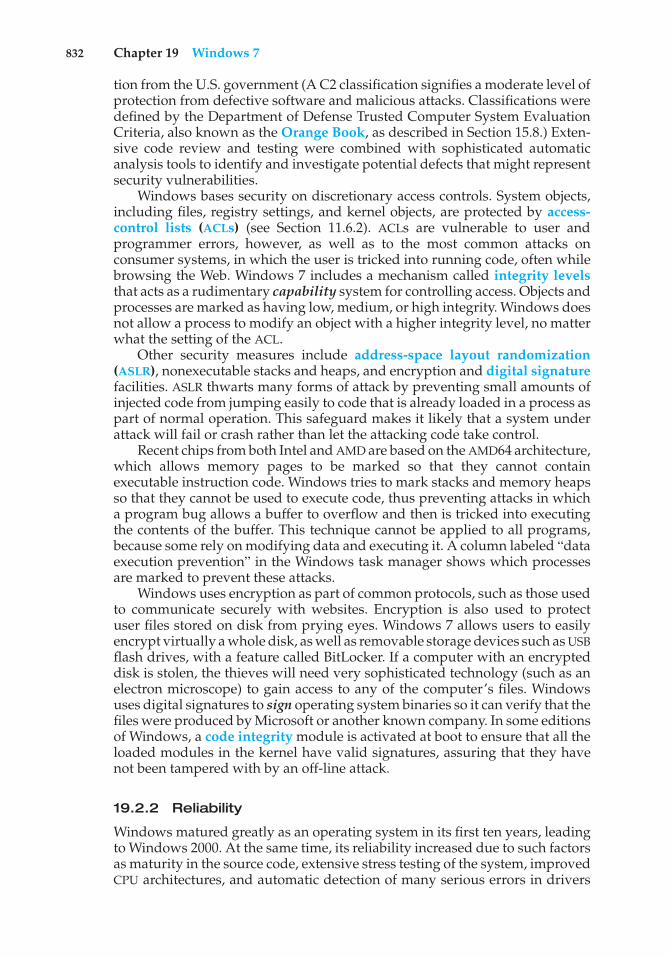
832 Chapter 19 Windows 7
tion from the U.S. government (A C2 classification signifies a moderate level ofprotection from defective software and malicious attacks. Classifications weredefined by the Department of Defense Trusted Computer System EvaluationCriteria, also known as the Orange Book, as described in Section 15.8.) Exten-sive code review and testing were combined with sophisticated automaticanalysis tools to identify and investigate potential defects that might representsecurity vulnerabilities.
Windows bases security on discretionary access controls. System objects,including files, registry settings, and kernel objects, are protected by access-control lists (ACLs) (see Section 11.6.2). ACLs are vulnerable to user andprogrammer errors, however, as well as to the most common attacks onconsumer systems, in which the user is tricked into running code, often whilebrowsing the Web. Windows 7 includes a mechanism called integrity levelsthat acts as a rudimentary capability system for controlling access. Objects andprocesses are marked as having low, medium, or high integrity. Windows doesnot allow a process to modify an object with a higher integrity level, no matterwhat the setting of the ACL.
Other security measures include address-space layout randomization(ASLR), nonexecutable stacks and heaps, and encryption and digital signaturefacilities. ASLR thwarts many forms of attack by preventing small amounts ofinjected code from jumping easily to code that is already loaded in a process aspart of normal operation. This safeguard makes it likely that a system underattack will fail or crash rather than let the attacking code take control.
Recent chips from both Intel and AMD are based on the AMD64 architecture,which allows memory pages to be marked so that they cannot containexecutable instruction code. Windows tries to mark stacks and memory heapsso that they cannot be used to execute code, thus preventing attacks in whicha program bug allows a buffer to overflow and then is tricked into executingthe contents of the buffer. This technique cannot be applied to all programs,because some rely on modifying data and executing it. A column labeled “dataexecution prevention” in the Windows task manager shows which processesare marked to prevent these attacks.
Windows uses encryption as part of common protocols, such as those usedto communicate securely with websites. Encryption is also used to protectuser files stored on disk from prying eyes. Windows 7 allows users to easilyencrypt virtually a whole disk, as well as removable storage devices such as USBflash drives, with a feature called BitLocker. If a computer with an encrypteddisk is stolen, the thieves will need very sophisticated technology (such as anelectron microscope) to gain access to any of the computer’s files. Windowsuses digital signatures to sign operating system binaries so it can verify that thefiles were produced by Microsoft or another known company. In some editionsof Windows, a code integrity module is activated at boot to ensure that all theloaded modules in the kernel have valid signatures, assuring that they havenot been tampered with by an off-line attack.
19.2.2 Reliability
Windows matured greatly as an operating system in its first ten years, leadingto Windows 2000. At the same time, its reliability increased due to such factorsas maturity in the source code, extensive stress testing of the system, improvedCPU architectures, and automatic detection of many serious errors in drivers
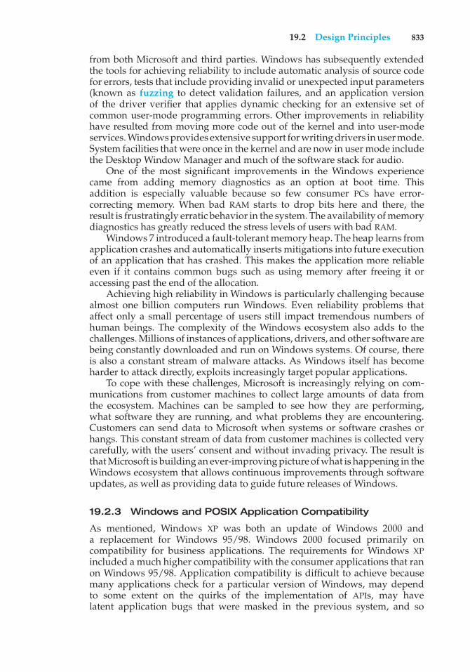
19.2 Design Principles 833
from both Microsoft and third parties. Windows has subsequently extendedthe tools for achieving reliability to include automatic analysis of source codefor errors, tests that include providing invalid or unexpected input parameters(known as fuzzing to detect validation failures, and an application versionof the driver verifier that applies dynamic checking for an extensive set ofcommon user-mode programming errors. Other improvements in reliabilityhave resulted from moving more code out of the kernel and into user-modeservices. Windows provides extensive support for writing drivers in user mode.System facilities that were once in the kernel and are now in user mode includethe Desktop Window Manager and much of the software stack for audio.
One of the most significant improvements in the Windows experiencecame from adding memory diagnostics as an option at boot time. Thisaddition is especially valuable because so few consumer PCs have error-correcting memory. When bad RAM starts to drop bits here and there, theresult is frustratingly erratic behavior in the system. The availability of memorydiagnostics has greatly reduced the stress levels of users with bad RAM.
Windows 7 introduced a fault-tolerant memory heap. The heap learns fromapplication crashes and automatically inserts mitigations into future executionof an application that has crashed. This makes the application more reliableeven if it contains common bugs such as using memory after freeing it oraccessing past the end of the allocation.
Achieving high reliability in Windows is particularly challenging becausealmost one billion computers run Windows. Even reliability problems thataffect only a small percentage of users still impact tremendous numbers ofhuman beings. The complexity of the Windows ecosystem also adds to thechallenges. Millions of instances of applications, drivers, and other software arebeing constantly downloaded and run on Windows systems. Of course, thereis also a constant stream of malware attacks. As Windows itself has becomeharder to attack directly, exploits increasingly target popular applications.
To cope with these challenges, Microsoft is increasingly relying on com-munications from customer machines to collect large amounts of data fromthe ecosystem. Machines can be sampled to see how they are performing,what software they are running, and what problems they are encountering.Customers can send data to Microsoft when systems or software crashes orhangs. This constant stream of data from customer machines is collected verycarefully, with the users’ consent and without invading privacy. The result isthat Microsoft is building an ever-improving picture of what is happening in theWindows ecosystem that allows continuous improvements through softwareupdates, as well as providing data to guide future releases of Windows.
19.2.3 Windows and POSIX Application Compatibility
As mentioned, Windows XP was both an update of Windows 2000 anda replacement for Windows 95/98. Windows 2000 focused primarily oncompatibility for business applications. The requirements for Windows XPincluded a much higher compatibility with the consumer applications that ranon Windows 95/98. Application compatibility is difficult to achieve becausemany applications check for a particular version of Windows, may dependto some extent on the quirks of the implementation of APIs, may havelatent application bugs that were masked in the previous system, and so
834 Chapter 19 Windows 7
forth. Applications may also have been compiled for a different instructionset. Windows 7 implements several strategies to run applications despiteincompatibilities.
Like Windows XP, Windows 7 has a compatibility layer that sits betweenapplications and the Win32 APIs. This layer makes Windows 7 look (almost)bug-for-bug compatible with previous versions of Windows. Windows 7, likeearlier NT releases, maintains support for running many 16-bit applicationsusing a thunking, or conversion, layer that translates 16-bit API calls intoequivalent 32-bit calls. Similarly, the 64-bit version of Windows 7 providesa thunking layer that translates 32-bit API calls into native 64-bit calls.
The Windows subsystem model allows multiple operating-system person-alities to be supported. As noted earlier, although the API most commonlyused with Windows is the Win32 API, some editions of Windows 7 support aPOSIX subsystem. POSIX is a standard specification for UNIX that allows mostavailable UNIX-compatible software to compile and run without modification.
As a final compatibility measure, several editions of Windows 7 providea virtual machine that runs Windows XP inside Windows 7. This allowsapplications to get bug-for-bug compatibility with Windows XP.
19.2.4 High Performance
Windows was designed to provide high performance on desktop systems(which are largely constrained by I/O performance), server systems (wherethe CPU is often the bottleneck), and large multithreaded and multiprocessorenvironments (where locking performance and cache-line management arekeys to scalability). To satisfy performance requirements, NT used a varietyof techniques, such as asynchronous I/O, optimized protocols for networks,kernel-based graphics rendering, and sophisticated caching of file-system data.The memory-management and synchronization algorithms were designedwith an awareness of the performance considerations related to cache linesand multiprocessors.
Windows NT was designed for symmetrical multiprocessing (SMP); ona multiprocessor computer, several threads can run at the same time, evenin the kernel. On each CPU, Windows NT uses priority-based preemptivescheduling of threads. Except while executing in the kernel dispatcher or atinterrupt level, threads in any process running in Windows can be preemptedby higher-priority threads. Thus, the system responds quickly (see Chapter 6).
The subsystems that constitute Windows NT communicate with oneanother efficiently through a local procedure call (LPC) facility that provideshigh-performance message passing. When a thread requests a synchronousservice from another process through an LPC, the servicing thread is markedready, and its priority is temporarily boosted to avoid the scheduling delaysthat would occur if it had to wait for threads already in the queue.
Windows XP further improved performance by reducing the code-pathlength in critical functions, using better algorithms and per-processor datastructures, using memory coloring for non-uniform memory access (NUMA)machines, and implementing more scalable locking protocols, such as queuedspinlocks. The new locking protocols helped reduce system bus cycles andincluded lock-free lists and queues, atomic read–modify–write operations(like interlocked increment), and other advanced synchronization techniques.
19.2 Design Principles 835
By the time Windows 7 was developed, several major changes had cometo computing. Client/server computing had increased in importance, so anadvanced local procedure call (ALPC) facility was introduced to providehigher performance and more reliability than LPC. The number of CPUsand the amount of physical memory available in the largest multiprocessorshad increased substantially, so quite a lot of effort was put into improvingoperating-system scalability.
The implementation of SMP in Windows NT used bitmasks to representcollections of processors and to identify, for example, which set of processors aparticular thread could be scheduled on. These bitmasks were defined as fittingwithin a single word of memory, limiting the number of processors supportedwithin a system to 64. Windows 7 added the concept of processor groups torepresent arbitrary numbers of CPUs, thus accommodating more CPU cores.The number of CPU cores within single systems has continued to increase notonly because of more cores but also because of cores that support more thanone logical thread of execution at a time.
All these additional CPUs created a great deal of contention for the locksused for scheduling CPUs and memory. Windows 7 broke these locks apart. Forexample, before Windows 7, a single lock was used by the Windows schedulerto synchronize access to the queues containing threads waiting for events. InWindows 7, each object has its own lock, allowing the queues to be accessedconcurrently. Also, many execution paths in the scheduler were rewritten to belock-free. This change resulted in good scalability performance for Windowseven on systems with 256 hardware threads.
Other changes are due to the increasing importance of support for parallelcomputing. For years, the computer industry has been dominated by Moore’sLaw, leading to higher densities of transistors that manifest themselves as fasterclock rates for each CPU. Moore’s Law continues to hold true, but limits havebeen reached that prevent CPU clock rates from increasing further. Instead,transistors are being used to build more and more CPUs into each chip. Newprogramming models for achieving parallel execution, such as Microsoft’sConcurrency RunTime (ConcRT) and Intel’s Threading Building Blocks (TBB),are being used to express parallelism in C++ programs. Where Moore’s Lawhas governed computing for forty years, it now seems that Amdahl’s Law,which governs parallel computing, will rule the future.
To support task-based parallelism, Windows 7 provides a new form ofuser-mode scheduling (UMS). UMS allows programs to be decomposed intotasks, and the tasks are then scheduled on the available CPUs by a schedulerthat operates in user mode rather than in the kernel.
The advent of multiple CPUs on the smallest computers is only part ofthe shift taking place to parallel computing. Graphics processing units (GPUs)accelerate the computational algorithms needed for graphics by using SIMDarchitectures to execute a single instruction for multiple data at the sametime. This has given rise to the use of GPUs for general computing, not justgraphics. Operating-system support for software like OpenCL and CUDA isallowing programs to take advantage of the GPUs. Windows supports use ofGPUs through software in its DirectX graphics support. This software, calledDirectCompute, allows programs to specify computational kernels using thesame HLSL (high-level shader language) programming model used to programthe SIMD hardware for graphics shaders. The computational kernels run very
836 Chapter 19 Windows 7
quickly on the GPU and return their results to the main computation runningon the CPU.
19.2.5 Extensibility
Extensibility refers to the capacity of an operating system to keep up withadvances in computing technology. To facilitate change over time, the devel-opers implemented Windows using a layered architecture. The Windowsexecutive runs in kernel mode and provides the basic system services andabstractions that support shared use of the system. On top of the executive,several server subsystems operate in user mode. Among them are environ-mental subsystems that emulate different operating systems. Thus, programswritten for the Win32 APIs and POSIX all run on Windows in the appropriateenvironment. Because of the modular structure, additional environmental sub-systems can be added without affecting the executive. In addition, Windowsuses loadable drivers in the I/O system, so new file systems, new kinds ofI/O devices, and new kinds of networking can be added while the systemis running. Windows uses a client–server model like the Mach operatingsystem and supports distributed processing by remote procedure calls (RPCs)as defined by the Open Software Foundation.
19.2.6 Portability
An operating system is portable if it can be moved from one CPU architectureto another with relatively few changes. Windows was designed to be portable.Like the UNIX operating system, Windows is written primarily in C and C++.The architecture-specific source code is relatively small, and there is verylittle use of assembly code. Porting Windows to a new architecture mostlyaffects the Windows kernel, since the user-mode code in Windows is almostexclusively written to be architecture independent. To port Windows, thekernel’s architecture-specific code must be ported, and sometimes conditionalcompilation is needed in other parts of the kernel because of changes in majordata structures, such as the page-table format. The entire Windows systemmust then be recompiled for the new CPU instruction set.
Operating systems are sensitive not only to CPU architecture but also to CPUsupport chips and hardware boot programs. The CPU and support chips arecollectively known as a chipset. These chipsets and the associated boot codedetermine how interrupts are delivered, describe the physical characteristics ofeach system, and provide interfaces to deeper aspects of the CPU architecture,such as error recovery and power management. It would be burdensome tohave to port Windows to each type of support chip as well as to each CPUarchitecture. Instead, Windows isolates most of the chipset-dependent code ina dynamic link library (DLL), called the hardware-abstraction layer (HAL), thatis loaded with the kernel. The Windows kernel depends on the HAL interfacesrather than on the underlying chipset details. This allows the single set of kerneland driver binaries for a particular CPU to be used with different chipsets simplyby loading a different version of the HAL.
Over the years, Windows has been ported to a number of different CPUarchitectures: Intel IA-32-compatible 32-bit CPUs, AMD64-compatible and IA6464-bit CPUs, the DEC Alpha, and the MIPS and PowerPC CPUs. Most of theseCPU architectures failed in the market. When Windows 7 shipped, only the
19.2 Design Principles 837
IA-32 and AMD64 architectures were supported on client computers, alongwith AMD64 and IA64 on servers.
19.2.7 International Support
Windows was designed for international and multinational use. It providessupport for different locales via the national-language-support (NLS) API.The NLS API provides specialized routines to format dates, time, and moneyin accordance with national customs. String comparisons are specialized toaccount for varying character sets. UNICODE is Windows’s native charactercode. Windows supports ANSI characters by converting them to UNICODEcharacters before manipulating them (8-bit to 16-bit conversion). System textstrings are kept in resource files that can be replaced to localize the systemfor different languages. Multiple locales can be used concurrently, which isimportant to multilingual individuals and businesses.
19.2.8 Energy Efficiency
Increasing energy efficiency for computers causes batteries to last longer forlaptops and netbooks, saves significant operating costs for power and coolingof data centers, and contributes to green initiatives aimed at lowering energyconsumption by businesses and consumers. For some time, Windows hasimplemented several strategies for decreasing energy use. The CPUs are movedto lower power states—for example, by lowering clock frequency—wheneverpossible. In addition, when a computer is not being actively used, Windowsmay put the entire computer into a low-power state (sleep) or may even saveall of memory to disk and shut the computer off (hibernation). When the userreturns, the computer powers up and continues from its previous state, so theuser does not need to reboot and restart applications.
Windows 7 added some new strategies for saving energy. The longer aCPU can stay unused, the more energy can be saved. Because computers are somuch faster than human beings, a lot of energy can be saved just while humansare thinking. The problem is that too many programs are constantly polling tosee what is happening in the system. A swarm of software timers are firing,keeping the CPU from staying idle long enough to save much energy. Windows7 extends CPU idle time by skipping clock ticks, coalescing software timers intosmaller numbers of events, and “parking” entire CPUs when systems are notheavily loaded.
19.2.9 Dynamic Device Support
Early in the history of the PC industry, computer configurations were fairlystatic. Occasionally, new devices might be plugged into the serial, printer, orgame ports on the back of a computer, but that was it. The next steps towarddynamic configuration of PCs were laptop docks and PCMIA cards. A PC couldsuddenly be connected to or disconnected from a whole set of peripherals. Ina contemporary PC, the situation has completely changed. PCs are designedto enable users to plug and unplug a huge host of peripherals all the time;external disks, thumb drives, cameras, and the like are constantly coming andgoing.
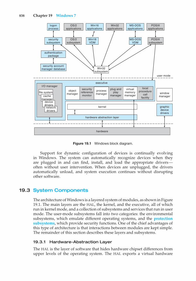
838 Chapter 19 Windows 7
OS/2applications
OS/2subsystem
Win16applications
MS-DOSapplications
Win18VDM
windowmanager
user mode
file system
I/O manager
MS-DOSVDM
Win32subsystem
POSIXsubsystem
logonprocess
securitysubsystem
authenticationpackage
security accountmanager database
Win32applications
POSIXapplications
graphicdevicedrivers
kernel
executive
hardware abstraction layer
hardware
cachemanager
devicedriversnetworkdrivers
objectmanager
securityreferencemonitor
processmanager
plug andplay
manager
virtualmemorymanager
localprocedure
callfacility
Figure 19.1 Windows block diagram.
Support for dynamic configuration of devices is continually evolvingin Windows. The system can automatically recognize devices when theyare plugged in and can find, install, and load the appropriate drivers—often without user intervention. When devices are unplugged, the driversautomatically unload, and system execution continues without disruptingother software.
19.3 System Components
The architecture of Windows is a layered system of modules, as shown in Figure19.1. The main layers are the HAL, the kernel, and the executive, all of whichrun in kernel mode, and a collection of subsystems and services that run in usermode. The user-mode subsystems fall into two categories: the environmentalsubsystems, which emulate different operating systems, and the protectionsubsystems, which provide security functions. One of the chief advantages ofthis type of architecture is that interactions between modules are kept simple.The remainder of this section describes these layers and subsystems.
19.3.1 Hardware-Abstraction Layer
The HAL is the layer of software that hides hardware chipset differences fromupper levels of the operating system. The HAL exports a virtual hardware
19.3 System Components 839
interface that is used by the kernel dispatcher, the executive, and the devicedrivers. Only a single version of each device driver is required for eachCPU architecture, no matter what support chips might be present. Devicedrivers map devices and access them directly, but the chipset-specific detailsof mapping memory, configuring I/O buses, setting up DMA, and coping withmotherboard-specific facilities are all provided by the HAL interfaces.
19.3.2 Kernel
The kernel layer of Windows has four main responsibilities: thread scheduling,low-level processor synchronization, interrupt and exception handling, andswitching between user mode and kernel mode. The kernel is implemented inthe C language, using assembly language only where absolutely necessary tointerface with the lowest level of the hardware architecture.
The kernel is organized according to object-oriented design principles. Anobject type in Windows is a system-defined data type that has a set of attributes(data values) and a set of methods (for example, functions or operations). Anobject is an instance of an object type. The kernel performs its job by using aset of kernel objects whose attributes store the kernel data and whose methodsperform the kernel activities.
19.3.2.1 Kernel Dispatcher
The kernel dispatcher provides the foundation for the executive and thesubsystems. Most of the dispatcher is never paged out of memory, and its exe-cution is never preempted. Its main responsibilities are thread scheduling andcontext switching, implementation of synchronization primitives, timer man-agement, software interrupts (asynchronous and deferred procedure calls), andexception dispatching.
19.3.2.2 Threads and Scheduling
Like many other modern operating systems, Windows uses processes andthreads for executable code. Each process has one or more threads, and eachthread has its own scheduling state, including actual priority, processor affinity,and CPU usage information.
There are six possible thread states: ready, standby, running, waiting,transition, and terminated. Ready indicates that the thread is waiting torun. The highest-priority ready thread is moved to the standby state, whichmeans it is the next thread to run. In a multiprocessor system, each processorkeeps one thread in a standby state. A thread is running when it is executingon a processor. It runs until it is preempted by a higher-priority thread, untilit terminates, until its allotted execution time (quantum) ends, or until it waitson a dispatcher object, such as an event signaling I/O completion. A thread isin the waiting state when it is waiting for a dispatcher object to be signaled.A thread is in the transition state while it waits for resources necessary forexecution; for example, it may be waiting for its kernel stack to be swapped infrom disk. A thread enters the terminated state when it finishes execution.
The dispatcher uses a 32-level priority scheme to determine the order ofthread execution. Priorities are divided into two classes: variable class andreal-time class. The variable class contains threads having priorities from 1 to
840 Chapter 19 Windows 7
15, and the real-time class contains threads with priorities ranging from 16to 31. The dispatcher uses a queue for each scheduling priority and traversesthe set of queues from highest to lowest until it finds a thread that is readyto run. If a thread has a particular processor affinity but that processor is notavailable, the dispatcher skips past it and continues looking for a ready threadthat is willing to run on the available processor. If no ready thread is found,the dispatcher executes a special thread called the idle thread. Priority class 0is reserved for the idle thread.
When a thread’s time quantum runs out, the clock interrupt queues aquantum-end deferred procedure call (DPC) to the processor. Queuing theDPC results in a software interrupt when the processor returns to normalinterrupt priority. The software interrupt causes the dispatcher to reschedulethe processor to execute the next available thread at the preempted thread’spriority level.
The priority of the preempted thread may be modified before it is placedback on the dispatcher queues. If the preempted thread is in the variable-priority class, its priority is lowered. The priority is never lowered below thebase priority. Lowering the thread’s priority tends to limit the CPUconsumptionof compute-bound threads versus I/O-bound threads. When a variable-prioritythread is released from a wait operation, the dispatcher boosts the priority. Theamount of the boost depends on the device for which the thread was waiting.For example, a thread waiting for keyboard I/O would get a large priorityincrease, whereas a thread waiting for a disk operation would get a moderateone. This strategy tends to give good response times to interactive threadsusing a mouse and windows. It also enables I/O-bound threads to keep the I/Odevices busy while permitting compute-bound threads to use spare CPU cyclesin the background. In addition, the thread associated with the user’s active GUIwindow receives a priority boost to enhance its response time.
Scheduling occurs when a thread enters the ready or wait state, whena thread terminates, or when an application changes a thread’s priority orprocessor affinity. If a higher-priority thread becomes ready while a lower-priority thread is running, the lower-priority thread is preempted. Thispreemption gives the higher-priority thread preferential access to the CPU.Windows is not a hard real-time operating system, however, because it doesnot guarantee that a real-time thread will start to execute within a particulartime limit; threads are blocked indefinitely while DPCs and interrupt serviceroutines (ISRs) are running (as further discussed below).
Traditionally, operating-system schedulers used sampling to measure CPUutilization by threads. The system timer would fire periodically, and the timerinterrupt handler would take note of what thread was currently scheduled andwhether it was executing in user or kernel mode when the interrupt occurred.This sampling technique was necessary because either the CPU did not havea high-resolution clock or the clock was too expensive or unreliable to accessfrequently. Although efficient, sampling was inaccurate and led to anomaliessuch as incorporating interrupt servicing time as thread time and dispatchingthreads that had run for only a fraction of the quantum. Starting with WindowsVista, CPU time in Windows has been tracked using the hardware timestampcounter (TSC) included in recent processors. Using the TSC results in moreaccurate accounting of CPU usage, and the scheduler will not preempt threadsbefore they have run for a full quantum.
19.3 System Components 841
19.3.2.3 Implementation of Synchronization Primitives
Key operating-system data structures are managed as objects using commonfacilities for allocation, reference counting, and security. Dispatcher objectscontrol dispatching and synchronization in the system. Examples of theseobjects include the following:
• The event object is used to record an event occurrence and to synchronizethis occurrence with some action. Notification events signal all waitingthreads, and synchronization events signal a single waiting thread.
• The mutant provides kernel-mode or user-mode mutual exclusion associ-ated with the notion of ownership.
• The mutex, available only in kernel mode, provides deadlock-free mutualexclusion.
• The semaphore object acts as a counter or gate to control the number ofthreads that access a resource.
• The thread object is the entity that is scheduled by the kernel dispatcher.It is associated with a process object, which encapsulates a virtual addressspace. The thread object is signaled when the thread exits, and the processobject, when the process exits.
• The timer object is used to keep track of time and to signal timeouts whenoperations take too long and need to be interrupted or when a periodicactivity needs to be scheduled.
Many of the dispatcher objects are accessed from user mode via an openoperation that returns a handle. The user-mode code polls or waits on handlesto synchronize with other threads as well as with the operating system (seeSection 19.7.1).
19.3.2.4 Software Interrupts: Asynchronous and Deferred Procedure Calls
The dispatcher implements two types of software interrupts: asynchronousprocedure calls (APCs) and deferred procedure calls (DPCs, mentioned earlier).An asynchronous procedure call breaks into an executing thread and callsa procedure. APCs are used to begin execution of new threads, suspend orresume existing threads, terminate threads or processes, deliver notificationthat an asynchronous I/O has completed, and extract the contents of the CPUregisters from a running thread. APCs are queued to specific threads and allowthe system to execute both system and user code within a process’s context.User-mode execution of an APC cannot occur at arbitrary times, but only whenthe thread is waiting in the kernel and marked alertable.
DPCsare used to postpone interrupt processing. After handling all urgentdevice-interrupt processing, the ISR schedules the remaining processing byqueuing a DPC. The associated software interrupt will not occur until the CPUis next at a priority lower than the priority of all I/O device interrupts but higherthan the priority at which threads run. Thus, DPCs do not block other deviceISRs. In addition to deferring device-interrupt processing, the dispatcher uses
842 Chapter 19 Windows 7
DPCs to process timer expirations and to preempt thread execution at the endof the scheduling quantum.
Execution of DPCs prevents threads from being scheduled on the currentprocessor and also keeps APCs from signaling the completion of I/O. This isdone so that completion of DPC routines does not take an extended amountof time. As an alternative, the dispatcher maintains a pool of worker threads.ISRs and DPCs may queue work items to the worker threads where they will beexecuted using normal thread scheduling. DPC routines are restricted so thatthey cannot take page faults (be paged out of memory), call system services,or take any other action that might result in an attempt to wait for a dispatcherobject to be signaled. Unlike APCs, DPC routines make no assumptions aboutwhat process context the processor is executing.
19.3.2.5 Exceptions and Interrupts
The kernel dispatcher also provides trap handling for exceptions and interruptsgenerated by hardware or software. Windows defines several architecture-independent exceptions, including:
• Memory-access violation
• Integer overflow
• Floating-point overflow or underflow
• Integer divide by zero
• Floating-point divide by zero
• Illegal instruction
• Data misalignment
• Privileged instruction
• Page-read error
• Access violation
• Paging file quota exceeded
• Debugger breakpoint
• Debugger single step
The trap handlers deal with simple exceptions. Elaborate exception handlingis performed by the kernel’s exception dispatcher. The exception dispatchercreates an exception record containing the reason for the exception and findsan exception handler to deal with it.
When an exception occurs in kernel mode, the exception dispatcher simplycalls a routine to locate the exception handler. If no handler is found, a fatalsystem error occurs, and the user is left with the infamous “blue screen ofdeath” that signifies system failure.
Exception handling is more complex for user-mode processes, becausean environmental subsystem (such as the POSIX system) sets up a debuggerport and an exception port for every process it creates. (For details on ports,
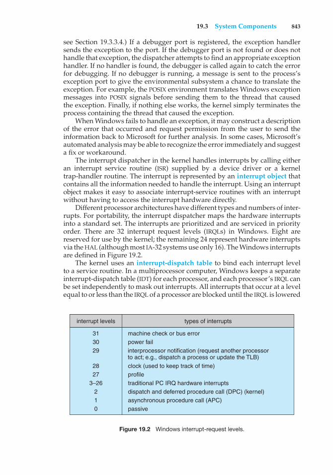
19.3 System Components 843
see Section 19.3.3.4.) If a debugger port is registered, the exception handlersends the exception to the port. If the debugger port is not found or does nothandle that exception, the dispatcher attempts to find an appropriate exceptionhandler. If no handler is found, the debugger is called again to catch the errorfor debugging. If no debugger is running, a message is sent to the process’sexception port to give the environmental subsystem a chance to translate theexception. For example, the POSIX environment translates Windows exceptionmessages into POSIX signals before sending them to the thread that causedthe exception. Finally, if nothing else works, the kernel simply terminates theprocess containing the thread that caused the exception.
When Windows fails to handle an exception, it may construct a descriptionof the error that occurred and request permission from the user to send theinformation back to Microsoft for further analysis. In some cases, Microsoft’sautomated analysis may be able to recognize the error immediately and suggesta fix or workaround.
The interrupt dispatcher in the kernel handles interrupts by calling eitheran interrupt service routine (ISR) supplied by a device driver or a kerneltrap-handler routine. The interrupt is represented by an interrupt object thatcontains all the information needed to handle the interrupt. Using an interruptobject makes it easy to associate interrupt-service routines with an interruptwithout having to access the interrupt hardware directly.
Different processor architectures have different types and numbers of inter-rupts. For portability, the interrupt dispatcher maps the hardware interruptsinto a standard set. The interrupts are prioritized and are serviced in priorityorder. There are 32 interrupt request levels (IRQLs) in Windows. Eight arereserved for use by the kernel; the remaining 24 represent hardware interruptsvia the HAL (although most IA-32 systems use only 16). The Windows interruptsare defined in Figure 19.2.
The kernel uses an interrupt-dispatch table to bind each interrupt levelto a service routine. In a multiprocessor computer, Windows keeps a separateinterrupt-dispatch table (IDT) for each processor, and each processor’s IRQL canbe set independently to mask out interrupts. All interrupts that occur at a levelequal to or less than the IRQL of a processor are blocked until the IRQL is lowered
interrupt levels types of interrupts
31 30 29
machine check or bus errorpower fail
clock (used to keep track of time)profiletraditional PC IRQ hardware interruptsdispatch and deferred procedure call (DPC) (kernel)asynchronous procedure call (APC)passive
28 27
3–26 2 1 0
interprocessor notification (request another processorto act; e.g., dispatch a process or update the TLB)
Figure 19.2 Windows interrupt-request levels.
844 Chapter 19 Windows 7
by a kernel-level thread or by an ISR returning from interrupt processing.Windows takes advantage of this property and uses software interrupts todeliver APCs and DPCs, to perform system functions such as synchronizingthreads with I/O completion, to start thread execution, and to handle timers.
19.3.2.6 Switching between User-Mode and Kernel-Mode Threads
What the programmer thinks of as a thread in traditional Windows is actuallytwo threads: a user-mode thread (UT) and a kernel-mode thread (KT). Each hasits own stack, register values, and execution context. A UT requests a systemservice by executing an instruction that causes a trap to kernel mode. The kernellayer runs a trap handler that switches between the UT and the correspondingKT. When a KT has completed its kernel execution and is ready to switch backto the corresponding UT, the kernel layer is called to make the switch to the UT,which continues its execution in user mode.
Windows 7 modifies the behavior of the kernel layer to support user-mode scheduling of the UTs. User-mode schedulers in Windows 7 supportcooperative scheduling. A UT can explicitly yield to another UT by callingthe user-mode scheduler; it is not necessary to enter the kernel. User-modescheduling is explained in more detail in Section 19.7.3.7.
19.3.3 Executive
The Windows executive provides a set of services that all environmentalsubsystems use. The services are grouped as follows: object manager, virtualmemory manager, process manager, advanced local procedure call facility, I/Omanager, cache manager, security reference monitor, plug-and-play and powermanagers, registry, and booting.
19.3.3.1 Object Manager
For managing kernel-mode entities, Windows uses a generic set of interfacesthat are manipulated by user-mode programs. Windows calls these entitiesobjects, and the executive component that manipulates them is the objectmanager. Examples of objects are semaphores, mutexes, events, processes,and threads; all these are dispatcher objects. Threads can block in the kerneldispatcher waiting for any of these objects to be signaled. The process, thread,and virtual memory APIs use process and thread handles to identify the processor thread to be operated on. Other examples of objects include files, sections,ports, and various internal I/O objects. File objects are used to maintain the openstate of files and devices. Sections are used to map files. Local-communicationendpoints are implemented as port objects.
User-mode code accesses these objects using an opaque value called ahandle, which is returned by many APIs. Each process has a handle tablecontaining entries that track the objects used by the process. The systemprocess, which contains the kernel, has its own handle table, which is protectedfrom user code. The handle tables in Windows are represented by a treestructure, which can expand from holding 1,024 handles to holding over 16million. Kernel-mode code can access an object by using either a handle or areferenced pointer.
19.3 System Components 845
A process gets a handle by creating an object, by opening an existingobject, by receiving a duplicated handle from another process, or by inheritinga handle from the parent process. When a process exits, all its open handlesare implicitly closed. Since the object manager is the only entity that generatesobject handles, it is the natural place to check security. The object managerchecks whether a process has the right to access an object when the processtries to open the object. The object manager also enforces quotas, such as themaximum amount of memory a process may use, by charging a process for thememory occupied by all its referenced objects and refusing to allocate morememory when the accumulated charges exceed the process’s quota.
The object manager keeps track of two counts for each object: the numberof handles for the object and the number of referenced pointers. The handlecount is the number of handles that refer to the object in the handle tablesof all processes, including the system process that contains the kernel. Thereferenced pointer count is incremented whenever a new pointer is neededby the kernel and decremented when the kernel is done with the pointer. Thepurpose of these reference counts is to ensure that an object is not freed whileit is still referenced by either a handle or an internal kernel pointer.
The object manager maintains the Windows internal name space. Incontrast to UNIX, which roots the system name space in the file system,Windows uses an abstract name space and connects the file systems as devices.Whether a Windows object has a name is up to its creator. Processes andthreads are created without names and referenced either by handle or througha separate numerical identifier. Synchronization events usually have names,so that they can be opened by unrelated processes. A name can be eitherpermanent or temporary. A permanent name represents an entity, such as adisk drive, that remains even if no process is accessing it. A temporary nameexists only while a process holds a handle to the object. The object managersupports directories and symbolic links in the name space. As an example,MS-DOS drive letters are implemented using symbolic links; \Global??\C: isa symbolic link to the device object \Device\HarddiskVolume2, representing amounted file-system volume in the \Device directory.
Each object, as mentioned earlier, is an instance of an object type. Theobject type specifies how instances are to be allocated, how the data fields areto be defined, and how the standard set of virtual functions used for all objectsare to be implemented. The standard functions implement operations such asmapping names to objects, closing and deleting, and applying security checks.Functions that are specific to a particular type of object are implemented bysystem services designed to operate on that particular object type, not by themethods specified in the object type.
The parse() function is the most interesting of the standard objectfunctions. It allows the implementation of an object. The file systems, theregistry configuration store, and GUI objects are the most notable users ofparse functions to extend the Windows name space.
Returning to our Windows naming example, device objects used torepresent file-system volumes provide a parse function. This allows a name like\Global??\C:\foo\bar.doc to be interpreted as the file \foo\bar.doc on thevolume represented by the device object HarddiskVolume2. We can illustratehow naming, parse functions, objects, and handles work together by lookingat the steps to open the file in Windows:
846 Chapter 19 Windows 7
1. An application requests that a file named C:\foo\bar.doc be opened.
2. The object manager finds the device object HarddiskVolume2, looks upthe parse procedure IopParseDevice from the object’s type, and invokesit with the file’s name relative to the root of the file system.
3. IopParseDevice() allocates a file object and passes it to the file system,which fills in the details of how to access C:\foo\bar.doc on the volume.
4. When the file system returns, IopParseDevice() allocates an entry forthe file object in the handle table for the current process and returns thehandle to the application.
If the file cannot successfully be opened, IopParseDevice() deletes thefile object it allocated and returns an error indication to the application.
19.3.3.2 Virtual Memory Manager
The executive component that manages the virtual address space, physicalmemory allocation, and paging is the virtual memory (VM) manager. Thedesign of the VM manager assumes that the underlying hardware supportsvirtual-to-physical mapping, a paging mechanism, and transparent cachecoherence on multiprocessor systems, as well as allowing multiple page-tableentries to map to the same physical page frame. The VM manager in Windowsuses a page-based management scheme with page sizes of 4 KB and 2 MB onAMD64 and IA-32-compatible processors and 8 KB on the IA64. Pages of dataallocated to a process that are not in physical memory are either stored in thepaging files on disk or mapped directly to a regular file on a local or remotefile system. A page can also be marked zero-fill-on-demand, which initializesthe page with zeros before it is allocated, thus erasing the previous contents.
On IA-32 processors, each process has a 4-GB virtual address space. Theupper 2 GB are mostly identical for all processes and are used by Windows inkernel mode to access the operating-system code and data structures. For theAMD64 architecture, Windows provides a 8-TB virtual address space for usermode out of the 16 EB supported by existing hardware for each process.
Key areas of the kernel-mode region that are not identical for all processesare the self-map, hyperspace, and session space. The hardware references aprocess’s page table using physical page-frame numbers, and the page tableself-map makes the contents of the process’s page table accessible using virtualaddresses. Hyperspace maps the current process’s working-set informationinto the kernel-mode address space. Session space is used to share an instanceof the Win32 and other session-specific drivers among all the processes inthe same terminal-server (TS) session. Different TS sessions share differentinstances of these drivers, yet they are mapped at the same virtual addresses.The lower, user-mode region of virtual address space is specific to each processand accessible by both user- and kernel-mode threads.
The Windows VM manager uses a two-step process to allocate virtualmemory. The first step reserves one or more pages of virtual addresses inthe process’s virtual address space. The second step commits the allocation byassigning virtual memory space (physical memory or space in the paging files).Windows limits the amount of virtual memory space a process consumes byenforcing a quota on committed memory. A process decommits memory that it
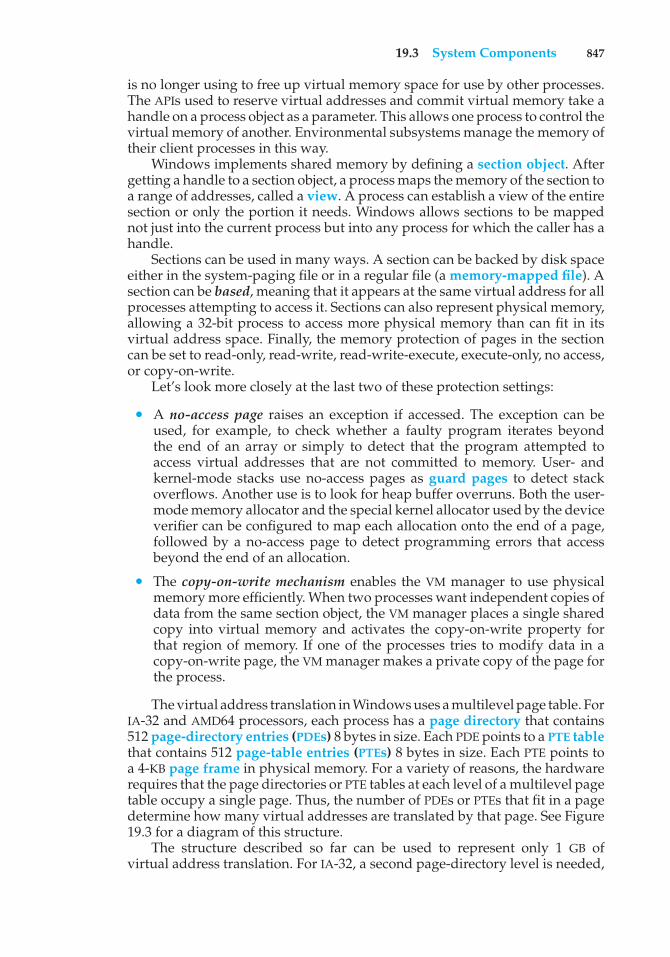
19.3 System Components 847
is no longer using to free up virtual memory space for use by other processes.The APIs used to reserve virtual addresses and commit virtual memory take ahandle on a process object as a parameter. This allows one process to control thevirtual memory of another. Environmental subsystems manage the memory oftheir client processes in this way.
Windows implements shared memory by defining a section object. Aftergetting a handle to a section object, a process maps the memory of the section toa range of addresses, called a view. A process can establish a view of the entiresection or only the portion it needs. Windows allows sections to be mappednot just into the current process but into any process for which the caller has ahandle.
Sections can be used in many ways. A section can be backed by disk spaceeither in the system-paging file or in a regular file (a memory-mapped file). Asection can be based, meaning that it appears at the same virtual address for allprocesses attempting to access it. Sections can also represent physical memory,allowing a 32-bit process to access more physical memory than can fit in itsvirtual address space. Finally, the memory protection of pages in the sectioncan be set to read-only, read-write, read-write-execute, execute-only, no access,or copy-on-write.
Let’s look more closely at the last two of these protection settings:
• A no-access page raises an exception if accessed. The exception can beused, for example, to check whether a faulty program iterates beyondthe end of an array or simply to detect that the program attempted toaccess virtual addresses that are not committed to memory. User- andkernel-mode stacks use no-access pages as guard pages to detect stackoverflows. Another use is to look for heap buffer overruns. Both the user-mode memory allocator and the special kernel allocator used by the deviceverifier can be configured to map each allocation onto the end of a page,followed by a no-access page to detect programming errors that accessbeyond the end of an allocation.
• The copy-on-write mechanism enables the VM manager to use physicalmemory more efficiently. When two processes want independent copies ofdata from the same section object, the VM manager places a single sharedcopy into virtual memory and activates the copy-on-write property forthat region of memory. If one of the processes tries to modify data in acopy-on-write page, the VM manager makes a private copy of the page forthe process.
The virtual address translation in Windows uses a multilevel page table. ForIA-32 and AMD64 processors, each process has a page directory that contains512 page-directory entries (PDEs) 8 bytes in size. Each PDE points to a PTE tablethat contains 512 page-table entries (PTEs) 8 bytes in size. Each PTE points toa 4-KB page frame in physical memory. For a variety of reasons, the hardwarerequires that the page directories or PTE tables at each level of a multilevel pagetable occupy a single page. Thus, the number of PDEs or PTEs that fit in a pagedetermine how many virtual addresses are translated by that page. See Figure19.3 for a diagram of this structure.
The structure described so far can be used to represent only 1 GB ofvirtual address translation. For IA-32, a second page-directory level is needed,
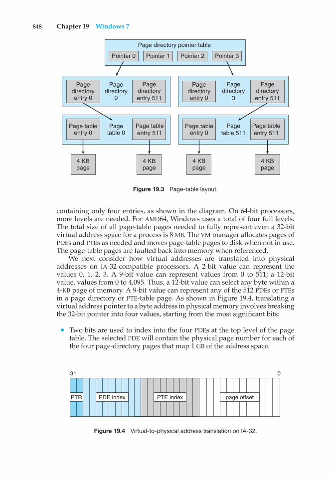
848 Chapter 19 Windows 7
Page tableentry 0
Pagetable 0
Page tableentry 0
4 KBpage
4 KBpage
4 KBpage
4 KBpage
Pagetable 511
Page tableentry 511
Page tableentry 511
Pagedirectoryentry 0
Pagedirectory
0
Pagedirectoryentry 0
Pagedirectory
3
Pagedirectoryentry 511
Pagedirectoryentry 511
Pointer 0 Pointer 1 Pointer 2 Pointer 3
Page directory pointer table
Figure 19.3 Page-table layout.
containing only four entries, as shown in the diagram. On 64-bit processors,more levels are needed. For AMD64, Windows uses a total of four full levels.The total size of all page-table pages needed to fully represent even a 32-bitvirtual address space for a process is 8 MB. The VM manager allocates pages ofPDEs and PTEs as needed and moves page-table pages to disk when not in use.The page-table pages are faulted back into memory when referenced.
We next consider how virtual addresses are translated into physicaladdresses on IA-32-compatible processors. A 2-bit value can represent thevalues 0, 1, 2, 3. A 9-bit value can represent values from 0 to 511; a 12-bitvalue, values from 0 to 4,095. Thus, a 12-bit value can select any byte within a4-KB page of memory. A 9-bit value can represent any of the 512 PDEs or PTEsin a page directory or PTE-table page. As shown in Figure 19.4, translating avirtual address pointer to a byte address in physical memory involves breakingthe 32-bit pointer into four values, starting from the most significant bits:
• Two bits are used to index into the four PDEs at the top level of the pagetable. The selected PDE will contain the physical page number for each ofthe four page-directory pages that map 1 GB of the address space.
PTR PTE indexPDE index page offset
31 0
Figure 19.4 Virtual-to-physical address translation on IA-32.
19.3 System Components 849
• Nine bits are used to select another PDE, this time from a second-level pagedirectory. This PDE will contain the physical page numbers of up to 512PTE-table pages.
• Nine bits are used to select one of 512 PTEs from the selected PTE-tablepage. The selected PTE will contain the physical page number for the bytewe are accessing.
• Twelve bits are used as the byte offset into the page. The physical addressof the byte we are accessing is constructed by appending the lowest 12 bitsof the virtual address to the end of the physical page number we found inthe selected PTE.
The number of bits in a physical address may be different from the numberof bits in a virtual address. In the original IA-32 architecture, the PTE and PDEwere 32-bit structures that had room for only 20 bits of physical page number,so the physical address size and the virtual address size were the same. Suchsystems could address only 4 GB of physical memory. Later, the IA-32 wasextended to the larger 64-bit PTE size used today, and the hardware supported24-bit physical addresses. These systems could support 64 GB and were usedon server systems. Today, all Windows servers are based on either the AMD64or the IA64 and support very, very large physical addresses—more than wecan possibly use. (Of course, once upon a time 4 GB seemed optimistically largefor physical memory.)
To improve performance, the VM manager maps the page-directory andPTE-table pages into the same contiguous region of virtual addresses in everyprocess. This self-map allows the VM manager to use the same pointer to accessthe current PDE or PTE corresponding to a particular virtual address no matterwhat process is running. The self-map for the IA-32 takes a contiguous 8-MBregion of kernel virtual address space; the AMD64 self-map occupies 512 GB.Although the self-map occupies significant address space, it does not requireany additional virtual memory pages. It also allows the page table’s pages tobe automatically paged in and out of physical memory.
In the creation of a self-map, one of the PDEs in the top-level page directoryrefers to the page-directory page itself, forming a “loop” in the page-tabletranslations. The virtual pages are accessed if the loop is not taken, the PTE-tablepages are accessed if the loop is taken once, the lowest-level page-directorypages are accessed if the loop is taken twice, and so forth.
The additional levels of page directories used for 64-bit virtual memory aretranslated in the same way except that the virtual address pointer is broken upinto even more values. For the AMD64, Windows uses four full levels, each ofwhich maps 512 pages, or 9+9+9+9+12 = 48 bits of virtual address.
To avoid the overhead of translating every virtual address by looking upthe PDE and PTE, processors use translation look-aside buffer (TLB) hardware,which contains an associative memory cache for mapping virtual pages toPTEs. The TLB is part of the memory-management unit (MMU) within eachprocessor. The MMU needs to “walk” (navigate the data structures of) the pagetable in memory only when a needed translation is missing from the TLB.
The PDEs and PTEs contain more than just physical page numbers. Theyalso have bits reserved for operating-system use and bits that control how thehardware uses memory, such as whether hardware caching should be used for
850 Chapter 19 Windows 7
each page. In addition, the entries specify what kinds of access are allowed forboth user and kernel modes.
A PDE can also be marked to say that it should function as a PTE ratherthan a PDE. On a IA-32, the first 11 bits of the virtual address pointer select aPDE in the first two levels of translation. If the selected PDE is marked to actas a PTE, then the remaining 21 bits of the pointer are used as the offset ofthe byte. This results in a 2-MB size for the page. Mixing and matching 4-KBand 2-MB page sizes within the page table is easy for the operating system andcan significantly improve the performance of some programs by reducing howoften the MMU needs to reload entries in the TLB, since one PDE mapping 2 MBreplaces 512 PTEs each mapping 4 KB.
Managing physical memory so that 2-MB pages are available when neededis difficult, however, as they may continually be broken up into 4 KB pages,causing external fragmentation of memory. Also, the large pages can resultin very significant internal fragmentation. Because of these problems, it istypically only Windows itself, along with large server applications, that uselarge pages to improve the performance of the TLB. They are better suited to doso because operating-system and server applications start running when thesystem boots, before memory has become fragmented.
Windows manages physical memory by associating each physical pagewith one of seven states: free, zeroed, modified, standby, bad, transition, orvalid.
• A free page is a page that has no particular content.
• A zeroed page is a free page that has been zeroed out and is ready forimmediate use to satisfy zero-on-demand faults.
• A modified page has been written by a process and must be sent to thedisk before it is allocated for another process.
• A standby page is a copy of information already stored on disk. Standbypages may be pages that were not modified, modified pages that havealready been written to the disk, or pages that were prefetched becausethey are expected to be used soon.
• A bad page is unusable because a hardware error has been detected.
• A transition page is on its way in from disk to a page frame allocated inphysical memory.
• A valid page is part of the working set of one or more processes and iscontained within these processes’ page tables.
While valid pages are contained in processes’ page tables, pages in otherstates are kept in separate lists according to state type. The lists are constructedby linking the corresponding entries in the page frame number (PFN) database,which includes an entry for each physical memory page. The PFN entries alsoinclude information such as reference counts, locks, and NUMA information.Note that the PFN database represents pages of physical memory, whereas thePTEs represent pages of virtual memory.
When the valid bit in a PTE is zero, hardware ignores all the other bits, andthe VM manager can define them for its own use. Invalid pages can have anumber of states represented by bits in the PTE. Page-file pages that have never
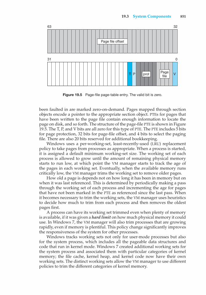
19.3 System Components 851
63
V
32
protT P Pagefile
31 0
Page file offset
Figure 19.5 Page-file page-table entry. The valid bit is zero.
been faulted in are marked zero-on-demand. Pages mapped through sectionobjects encode a pointer to the appropriate section object. PTEs for pages thathave been written to the page file contain enough information to locate thepage on disk, and so forth. The structure of the page-file PTE is shown in Figure19.5. The T, P, and V bits are all zero for this type of PTE. The PTE includes 5 bitsfor page protection, 32 bits for page-file offset, and 4 bits to select the pagingfile. There are also 20 bits reserved for additional bookkeeping.
Windows uses a per-working-set, least-recently-used (LRU) replacementpolicy to take pages from processes as appropriate. When a process is started,it is assigned a default minimum working-set size. The working set of eachprocess is allowed to grow until the amount of remaining physical memorystarts to run low, at which point the VM manager starts to track the age ofthe pages in each working set. Eventually, when the available memory runscritically low, the VM manager trims the working set to remove older pages.
How old a page is depends not on how long it has been in memory but onwhen it was last referenced. This is determined by periodically making a passthrough the working set of each process and incrementing the age for pagesthat have not been marked in the PTE as referenced since the last pass. Whenit becomes necessary to trim the working sets, the VM manager uses heuristicsto decide how much to trim from each process and then removes the oldestpages first.
A process can have its working set trimmed even when plenty of memoryis available, if it was given a hard limit on how much physical memory it coulduse. In Windows 7, the VM manager will also trim processes that are growingrapidly, even if memory is plentiful. This policy change significantly improvesthe responsiveness of the system for other processes.
Windows tracks working sets not only for user-mode processes but alsofor the system process, which includes all the pageable data structures andcode that run in kernel mode. Windows 7 created additional working sets forthe system process and associated them with particular categories of kernelmemory; the file cache, kernel heap, and kernel code now have their ownworking sets. The distinct working sets allow the VM manager to use differentpolicies to trim the different categories of kernel memory.
852 Chapter 19 Windows 7
The VM manager does not fault in only the page immediately needed.Research shows that the memory referencing of a thread tends to have a localityproperty. That is, when a page is used, it is likely that adjacent pages will bereferenced in the near future. (Think of iterating over an array or fetchingsequential instructions that form the executable code for a thread.) Because oflocality, when the VM manager faults in a page, it also faults in a few adjacentpages. This prefetching tends to reduce the total number of page faults andallows reads to be clustered to improve I/O performance.
In addition to managing committed memory, the VM manager manageseach process’s reserved memory, or virtual address space. Each process has anassociated tree that describes the ranges of virtual addresses in use and whatthe uses are. This allows the VM manager to fault in page-table pages as needed.If the PTE for a faulting address is uninitialized, the VM manager searches forthe address in the process’s tree of virtual address descriptors (VADs) anduses this information to fill in the PTE and retrieve the page. In some cases, aPTE-table page itself may not exist; such a page must be transparently allocatedand initialized by the VM manager. In other cases, the page may be shared aspart of a section object, and the VAD will contain a pointer to that section object.The section object contains information on how to find the shared virtual pageso that the PTE can be initialized to point at it directly.
19.3.3.3 Process Manager
The Windows process manager provides services for creating, deleting, andusing processes, threads, and jobs. It has no knowledge about parent–childrelationships or process hierarchies; those refinements are left to the particularenvironmental subsystem that owns the process. The process manager is alsonot involved in the scheduling of processes, other than setting the priorities andaffinities in processes and threads when they are created. Thread schedulingtakes place in the kernel dispatcher.
Each process contains one or more threads. Processes themselves can becollected into larger units called job objects. The use of job objects allowslimits to be placed on CPU usage, working-set size, and processor affinitiesthat control multiple processes at once. Job objects are used to manage largedata-center machines.
An example of process creation in the Win32 environment is as follows:
1. A Win32 application calls CreateProcess().
2. A message is sent to the Win32 subsystem to notify it that the process isbeing created.
3. CreateProcess() in the original process then calls an API in the processmanager of the NT executive to actually create the process.
4. The process manager calls the object manager to create a process objectand returns the object handle to Win32.
5. Win32 calls the process manager again to create a thread for the processand returns handles to the new process and thread.
The Windows APIs for manipulating virtual memory and threads andfor duplicating handles take a process handle, so subsystems can perform
19.3 System Components 853
operations on behalf of a new process without having to execute directly inthe new process’s context. Once a new process is created, the initial threadis created, and an asynchronous procedure call is delivered to the thread toprompt the start of execution at the user-mode image loader. The loader isin ntdll.dll, which is a link library automatically mapped into every newlycreated process. Windows also supports a UNIXfork() style of process creationin order to support the POSIX environmental subsystem. Although the Win32environment calls the process manager directly from the client process, POSIXuses the cross-process nature of the Windows APIs to create the new processfrom within the subsystem process.
The process manager relies on the asynchronous procedure calls (APCs)implemented by the kernel layer. APCs are used to initiate thread execution,suspend and resume threads, access thread registers, terminate threads andprocesses, and support debuggers.
The debugger support in the process manager includes the APIs to suspendand resume threads and to create threads that begin in suspended mode. Thereare also process-manager APIs that get and set a thread’s register context andaccess another process’s virtual memory. Threads can be created in the currentprocess; they can also be injected into another process. The debugger makesuse of thread injection to execute code within a process being debugged.
While running in the executive, a thread can temporarily attach to adifferent process. Thread attach is used by kernel worker threads that need toexecute in the context of the process originating a work request. For example,the VM manager might use thread attach when it needs access to a process’sworking set or page tables, and the I/O manager might use it in updating thestatus variable in a process for asynchronous I/O operations.
The process manager also supports impersonation. Each thread has anassociated security token. When the login process authenticates a user, thesecurity token is attached to the user’s process and inherited by its childprocesses. The token contains the security identity (SID) of the user, the SIDs ofthe groups the user belongs to, the privileges the user has, and the integrity levelof the process. By default, all threads within a process share a common token,representing the user and the application that started the process. However, athread running in a process with a security token belonging to one user can seta thread-specific token belonging to another user to impersonate that user.
The impersonation facility is fundamental to the client–server RPC model,where services must act on behalf of a variety of clients with different securityIDs. The right to impersonate a user is most often delivered as part of an RPCconnection from a client process to a server process. Impersonation allows theserver to access system services as if it were the client in order to access or createobjects and files on behalf of the client. The server process must be trustworthyand must be carefully written to be robust against attacks. Otherwise, one clientcould take over a server process and then impersonate any user who made asubsequent client request.
19.3.3.4 Facilities for Client–Server Computing
The implementation of Windows uses a client–server model throughout. Theenvironmental subsystems are servers that implement particular operating-system personalities. Many other services, such as user authentication, network
854 Chapter 19 Windows 7
facilities, printer spooling, web services, network file systems, and plug-and-play, are also implemented using this model. To reduce the memoryfootprint, multiple services are often collected into a few processes runningthe svchost.exe program. Each service is loaded as a dynamic-link library(DLL), which implements the service by relying on the user-mode thread-poolfacilities to share threads and wait for messages (see Section 19.3.3.3).
The normal implementation paradigm for client–server computing is touse RPCs to communicate requests. The Win32 API supports a standard RPCprotocol, as described in Section 19.6.2.7. RPC uses multiple transports (forexample, named pipes and TCP/IP) and can be used to implement RPCs betweensystems. When an RPC always occurs between a client and server on the localsystem, the advanced local procedure call facility (ALPC) can be used as thetransport. At the lowest level of the system, in the implementation of theenvironmental systems, and for services that must be available in the earlystages of booting, RPC is not available. Instead, native Windows services useALPC directly.
ALPC is a message-passing mechanism. The server process publishes aglobally visible connection-port object. When a client wants services froma subsystem or service, it opens a handle to the server’s connection-portobject and sends a connection request to the port. The server creates achannel and returns a handle to the client. The channel consists of a pair ofprivate communication ports: one for client-to-server messages and the otherfor server-to-client messages. Communication channels support a callbackmechanism, so the client and server can accept requests when they wouldnormally be expecting a reply.
When an ALPC channel is created, one of three message-passing techniquesis chosen.
1. The first technique is suitable for small to medium messages (up to 63KB). In this case, the port’s message queue is used as intermediate storage,and the messages are copied from one process to the other.
2. The second technique is for larger messages. In this case, a shared-memory section object is created for the channel. Messages sent throughthe port’s message queue contain a pointer and size information referringto the section object. This avoids the need to copy large messages. Thesender places data into the shared section, and the receiver views themdirectly.
3. The third technique uses APIs that read and write directly into a process’saddress space. ALPC provides functions and synchronization so that aserver can access the data in a client. This technique is normally used byRPC to achieve higher performance for specific scenarios.
The Win32 window manager uses its own form of message passing, which isindependent of the executive ALPC facilities. When a client asks for a connectionthat uses window-manager messaging, the server sets up three objects: (1) adedicated server thread to handle requests, (2) a 64-KB shared section object,and (3) an event-pair object. An event-pair object is a synchronization objectused by the Win32 subsystem to provide notification when the client thread
19.3 System Components 855
has copied a message to the Win32 server, or vice versa. The section object isused to pass the messages, and the event-pair object provides synchronization.
Window-manager messaging has several advantages:
• The section object eliminates message copying, since it represents a regionof shared memory.
• The event-pair object eliminates the overhead of using the port object topass messages containing pointers and lengths.
• The dedicated server thread eliminates the overhead of determining whichclient thread is calling the server, since there is one server thread per clientthread.
• The kernel gives scheduling preference to these dedicated server threadsto improve performance.
19.3.3.5 I/O Manager
The I/O manager is responsible for managing file systems, device drivers, andnetwork drivers. It keeps track of which device drivers, filter drivers, and filesystems are loaded, and it also manages buffers for I/O requests. It workswith the VM manager to provide memory-mapped file I/O and controls theWindows cache manager, which handles caching for the entire I/O system. TheI/O manager is fundamentally asynchronous, providing synchronous I/O byexplicitly waiting for an I/O operation to complete. The I/O manager providesseveral models of asynchronous I/O completion, including setting of events,updating of a status variable in the calling process, delivery of APCs to initiatingthreads, and use of I/O completion ports, which allow a single thread to processI/O completions from many other threads.
Device drivers are arranged in a list for each device (called a driver orI/O stack). A driver is represented in the system as a driver object. Because asingle driver can operate on multiple devices, the drivers are represented inthe I/O stack by a device object, which contains a link to the driver object.The I/O manager converts the requests it receives into a standard form calledan I/O request packet (IRP). It then forwards the IRP to the first driver in thetargeted I/O stack for processing. After a driver processes the IRP, it calls theI/O manager either to forward the IRP to the next driver in the stack or, if allprocessing is finished, to complete the operation represented by the IRP.
The I/O request may be completed in a context different from the one inwhich it was made. For example, if a driver is performing its part of an I/Ooperation and is forced to block for an extended time, it may queue the IRP toa worker thread to continue processing in the system context. In the originalthread, the driver returns a status indicating that the I/O request is pending sothat the thread can continue executing in parallel with the I/O operation. AnIRP may also be processed in interrupt-service routines and completed in anarbitrary process context. Because some final processing may need to take placein the context that initiated the I/O, the I/O manager uses an APC to do finalI/O-completion processing in the process context of the originating thread.
The I/O stack model is very flexible. As a driver stack is built, variousdrivers have the opportunity to insert themselves into the stack as filter drivers.Filter drivers can examine and potentially modify each I/O operation. Mount
856 Chapter 19 Windows 7
management, partition management, and disk striping and mirroring are allexamples of functionality implemented using filter drivers that execute beneaththe file system in the stack. File-system filter drivers execute above the filesystem and have been used to implement functionalities such as hierarchicalstorage management, single instancing of files for remote boot, and dynamicformat conversion. Third parties also use file-system filter drivers to implementvirus detection.
Device drivers for Windows are written to the Windows Driver Model(WDM) specification. This model lays out all the requirements for device drivers,including how to layer filter drivers, share common code for handling powerand plug-and-play requests, build correct cancellation logic, and so forth.
Because of the richness of the WDM, writing a full WDM device driverfor each new hardware device can involve a great deal of work. Fortunately,the port/miniport model makes it unnecessary to do this. Within a class ofsimilar devices, such as audio drivers, SATA devices, or Ethernet controllers,each instance of a device shares a common driver for that class, called a portdriver. The port driver implements the standard operations for the class andthen calls device-specific routines in the device’s miniport driver to implementdevice-specific functionality. The TCP/IP network stack is implemented inthis way, with the ndis.sys class driver implementing much of the networkdriver functionality and calling out to the network miniport drivers for specifichardware.
Recent versions of Windows, including Windows 7, provide additionalsimplifications for writing device drivers for hardware devices. Kernel-modedrivers can now be written using the Kernel-Mode Driver Framework (KMDF),which provides a simplified programming model for drivers on top of WDM.Another option is the User-Mode Driver Framework (UMDF). Many driversdo not need to operate in kernel mode, and it is easier to develop and deploydrivers in user mode. It also makes the system more reliable, because a failurein a user-mode driver does not cause a kernel-mode crash.
19.3.3.6 Cache Manager
In many operating systems, caching is done by the file system. Instead,Windows provides a centralized caching facility. The cache manager worksclosely with the VM manager to provide cache services for all componentsunder the control of the I/O manager. Caching in Windows is based on filesrather than raw blocks. The size of the cache changes dynamically accordingto how much free memory is available in the system. The cache managermaintains a private working set rather than sharing the system process’sworking set. The cache manager memory-maps files into kernel memory andthen uses special interfaces to the VM manager to fault pages into or trim themfrom this private working set.
The cache is divided into blocks of 256 KB. Each cache block can hold aview (that is, a memory-mapped region) of a file. Each cache block is describedby a virtual address control block (VACB) that stores the virtual address andfile offset for the view, as well as the number of processes using the view. TheVACBs reside in a single array maintained by the cache manager.
When the I/O manager receives a file’s user-level read request, the I/Omanager sends an IRP to the I/O stack for the volume on which the file resides.
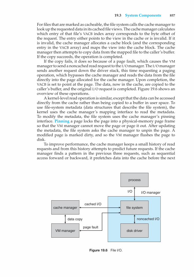
19.3 System Components 857
For files that are marked as cacheable, the file system calls the cache manager tolook up the requested data in its cached file views. The cache manager calculateswhich entry of that file’s VACB index array corresponds to the byte offset ofthe request. The entry either points to the view in the cache or is invalid. If itis invalid, the cache manager allocates a cache block (and the correspondingentry in the VACB array) and maps the view into the cache block. The cachemanager then attempts to copy data from the mapped file to the caller’s buffer.If the copy succeeds, the operation is completed.
If the copy fails, it does so because of a page fault, which causes the VMmanager to send a noncached read request to the I/O manager. The I/O managersends another request down the driver stack, this time requesting a pagingoperation, which bypasses the cache manager and reads the data from the filedirectly into the page allocated for the cache manager. Upon completion, theVACB is set to point at the page. The data, now in the cache, are copied to thecaller’s buffer, and the original I/O request is completed. Figure 19.6 shows anoverview of these operations.
A kernel-level read operation is similar, except that the data can be accesseddirectly from the cache rather than being copied to a buffer in user space. Touse file-system metadata (data structures that describe the file system), thekernel uses the cache manager’s mapping interface to read the metadata.To modify the metadata, the file system uses the cache manager’s pinninginterface. Pinning a page locks the page into a physical-memory page frameso that the VM manager cannot move the page or page it out. After updatingthe metadata, the file system asks the cache manager to unpin the page. Amodified page is marked dirty, and so the VM manager flushes the page todisk.
To improve performance, the cache manager keeps a small history of readrequests and from this history attempts to predict future requests. If the cachemanager finds a pattern in the previous three requests, such as sequentialaccess forward or backward, it prefetches data into the cache before the next
cache manager
VM manager
process
file system
disk driver
noncached I/O
I/O manager
data copy
cached I/O
page fault
I/O
Figure 19.6 File I/O.
858 Chapter 19 Windows 7
request is submitted by the application. In this way, the application may findits data already cached and not need to wait for disk I/O.
The cache manager is also responsible for telling the VM manager to flushthe contents of the cache. The cache manager’s default behavior is write-backcaching: it accumulates writes for 4 to 5 seconds and then wakes up the cache-writer thread. When write-through caching is needed, a process can set a flagwhen opening the file, or the process can call an explicit cache-flush function.
A fast-writing process could potentially fill all the free cache pages beforethe cache-writer thread had a chance to wake up and flush the pages to disk.The cache writer prevents a process from flooding the system in the followingway. When the amount of free cache memory becomes low, the cache managertemporarily blocks processes attempting to write data and wakes the cache-writer thread to flush pages to disk. If the fast-writing process is actually anetwork redirector for a network file system, blocking it for too long couldcause network transfers to time out and be retransmitted. This retransmissionwould waste network bandwidth. To prevent such waste, network redirectorscan instruct the cache manager to limit the backlog of writes in the cache.
Because a network file system needs to move data between a disk and thenetwork interface, the cache manager also provides a DMA interface to movethe data directly. Moving data directly avoids the need to copy data throughan intermediate buffer.
19.3.3.7 Security Reference Monitor
Centralizing management of system entities in the object manager enablesWindows to use a uniform mechanism to perform run-time access validationand audit checks for every user-accessible entity in the system. Whenever aprocess opens a handle to an object, the security reference monitor (SRM)checks the process’s security token and the object’s access-control list to seewhether the process has the necessary access rights.
The SRM is also responsible for manipulating the privileges in securitytokens. Special privileges are required for users to perform backup or restoreoperations on file systems, debug processes, and so forth. Tokens can also bemarked as being restricted in their privileges so that they cannot access objectsthat are available to most users. Restricted tokens are used primarily to limitthe damage that can be done by execution of untrusted code.
The integrity level of the code executing in a process is also representedby a token. Integrity levels are a type of capability mechanism, as mentionedearlier. A process cannot modify an object with an integrity level higher thanthat of the code executing in the process, whatever other permissions havebeen granted. Integrity levels were introduced to make it harder for code thatsuccessfully attacks outward-facing software, like Internet Explorer, to takeover a system.
Another responsibility of the SRM is logging security audit events. TheDepartment of Defense’s Common Criteria (the 2005 successor to the OrangeBook) requires that a secure system have the ability to detect and log allattempts to access system resources so that it can more easily trace attempts atunauthorized access. Because the SRM is responsible for making access checks,it generates most of the audit records in the security-event log.
19.3 System Components 859
19.3.3.8 Plug-and-Play Manager
The operating system uses the plug-and-play (PnP) manager to recognizeand adapt to changes in the hardware configuration. PnP devices use standardprotocols to identify themselves to the system. The PnP manager automaticallyrecognizes installed devices and detects changes in devices as the systemoperates. The manager also keeps track of hardware resources used by adevice, as well as potential resources that could be used, and takes care ofloading the appropriate drivers. This management of hardware resources—primarily interrupts and I/O memory ranges—has the goal of determining ahardware configuration in which all devices are able to operate successfully.
The PnP manager handles dynamic reconfiguration as follows. First, itgets a list of devices from each bus driver (for example, PCI or USB). It loadsthe installed driver (after finding one, if necessary) and sends an add-devicerequest to the appropriate driver for each device. The PnP manager then figuresout the optimal resource assignments and sends a start-device request toeach driver specifying the resource assignments for the device. If a deviceneeds to be reconfigured, the PnP manager sends a query-stop request, whichasks the driver whether the device can be temporarily disabled. If the drivercan disable the device, then all pending operations are completed, and newoperations are prevented from starting. Finally, the PnP manager sends a stoprequest and can then reconfigure the device with a new start-device request.
The PnP manager also supports other requests. For example, query-remove, which operates similarly to query-stop, is employed when a useris getting ready to eject a removable device, such as a USB storage device. Thesurprise-remove request is used when a device fails or, more likely, when auser removes a device without telling the system to stop it first. Finally, theremove request tells the driver to stop using a device permanently.
Many programs in the system are interested in the addition or removalof devices, so the PnP manager supports notifications. Such a notification, forexample, gives GUI file menus the information they need to update their listof disk volumes when a new storage device is attached or removed. Installingdevices often results in adding new services to the svchost.exe processes inthe system. These services frequently set themselves up to run whenever thesystem boots and continue to run even if the original device is never pluggedinto the system. Windows 7 introduced a service-trigger mechanism in theservice control manager (SCM), which manages the system services. With thismechanism, services can register themselves to start only when SCM receives anotification from the PnP manager that the device of interest has been addedto the system.
19.3.3.9 Power Manager
Windows works with the hardware to implement sophisticated strategiesfor energy efficiency, as described in Section 19.2.8. The policies that drivethese strategies are implemented by the power manager. The power managerdetects current system conditions, such as the load on CPUs or I/O devices, andimproves energy efficiency by reducing the performance and responsiveness ofthe system when need is low. The power manager can also put the entire systeminto a very efficient sleep mode and can even write all the contents of memoryto disk and turn off the power to allow the system to go into hibernation.
860 Chapter 19 Windows 7
The primary advantage of sleep is that the system can enter fairly quickly,perhaps just a few seconds after the lid closes on a laptop. The return fromsleep is also fairly quick. The power is turned down low on the CPUs and I/Odevices, but the memory continues to be powered enough that its contents arenot lost.
Hibernation takes considerably longer because the entire contents ofmemory must be transferred to disk before the system is turned off. However,the fact that the system is, in fact, turned off is a significant advantage. Ifthere is a loss of power to the system, as when the battery is swapped on alaptop or a desktop system is unplugged, the saved system data will not belost. Unlike shutdown, hibernation saves the currently running system so auser can resume where she left off, and because hibernation does not requirepower, a system can remain in hibernation indefinitely.
Like the PnP manager, the power manager provides notifications to therest of the system about changes in the power state. Some applications want toknow when the system is about to be shut down so they can start saving theirstates to disk.
19.3.3.10 Registry
Windows keeps much of its configuration information in internal databases,called hives, that are managed by the Windows configuration manager, whichis commonly known as the registry. There are separate hives for systeminformation, default user preferences, software installation, security, and bootoptions. Because the information in the system hive is required to boot thesystem, the registry manager is implemented as a component of the executive.
The registry represents the configuration state in each hive as a hierarchicalnamespace of keys (directories), each of which can contain a set of typed values,such as UNICODE string, ANSI string, integer, or untyped binary data. In theory,new keys and values are created and initialized as new software is installed;then they are modified to reflect changes in the configuration of that software.In practice, the registry is often used as a general-purpose database, as aninterprocess-communication mechanism, and for many other such inventivepurposes.
Restarting applications, or even the system, every time a configurationchange was made would be a nuisance. Instead, programs rely on variouskinds of notifications, such as those provided by the PnP and power managers,to learn about changes in the system configuration. The registry also suppliesnotifications; it allows threads to register to be notified when changes aremade to some part of the registry. The threads can thus detect and adapt toconfiguration changes recorded in the registry itself.
Whenever significant changes are made to the system, such as whenupdates to the operating system or drivers are installed, there is a danger thatthe configuration data may be corrupted (for example, if a working driver isreplaced by a nonworking driver or an application fails to install correctly andleaves partial information in the registry). Windows creates a system restorepoint before making such changes. The restore point contains a copy of thehives before the change and can be used to return to this version of the hivesand thereby get a corrupted system working again.
19.3 System Components 861
To improve the stability of the registry configuration, Windows added atransaction mechanism beginning with Windows Vista that can be used toprevent the registry from being partially updated with a collection of relatedconfiguration changes. Registry transactions can be part of more generaltransactions administered by the kernel transaction manager (KTM), whichcan also include file-system transactions. KTM transactions do not have thefull semantics found in normal database transactions, and they have notsupplanted the system restore facility for recovering from damage to theregistry configuration caused by software installation.
19.3.3.11 Booting
The booting of a Windows PC begins when the hardware powers on andfirmware begins executing from ROM. In older machines, this firmware wasknown as the BIOS, but more modern systems use UEFI (the Unified ExtensibleFirmware Interface), which is faster and more general and makes better use ofthe facilities in contemporary processors. The firmware runs power-on self-test(POST) diagnostics; identifies many of the devices attached to the system andinitializes them to a clean, power-up state; and then builds the descriptionused by the advanced configuration and power interface (ACPI). Next, thefirmware finds the system disk, loads the Windows bootmgr program, andbegins executing it.
In a machine that has been hibernating, the winresume program is loadednext. It restores the running system from disk, and the system continuesexecution at the point it had reached right before hibernating. In a machinethat has been shut down, the bootmgr performs further initialization of thesystem and then loads winload. This program loads hal.dll, the kernel(ntoskrnl.exe), any drivers needed in booting, and the system hive. winloadthen transfers execution to the kernel.
The kernel initializes itself and creates two processes. The system processcontains all the internal kernel worker threads and never executes in user mode.The first user-mode process created is SMSS, for session manager subsystem,which is similar to the INIT (initialization) process in UNIX. SMSS performsfurther initialization of the system, including establishing the paging files,loading more device drivers, and managing the Windows sessions. Eachsession is used to represent a logged-on user, except for session 0, which isused to run system-wide background services, such as LSASS and SERVICES.A session is anchored by an instance of the CSRSS process. Each session otherthan 0 initially runs the WINLOGON process. This process logs on a user andthen launches the EXPLORER process, which implements the Windows GUIexperience. The following list itemizes some of these aspects of booting:
• SMSS completes system initialization and then starts up session 0 and thefirst login session.
• WININIT runs in session 0 to initialize user mode and start LSASS, SERVICES,and the local session manager, LSM.
• LSASS, the security subsystem, implements facilities such as authenticationof users.
862 Chapter 19 Windows 7
• SERVICES contains the service control manager, or SCM, which supervisesall background activities in the system, including user-mode services. Anumber of services will have registered to start when the system boots.Others will be started only on demand or when triggered by an event suchas the arrival of a device.
• CSRSS is the Win32 environmental subsystem process. It is started in everysession—unlike the POSIX subsystem, which is started only on demandwhen a POSIX process is created.
• WINLOGON is run in each Windows session other than session 0 to log ona user.
The system optimizes the boot process by prepaging from files on diskbased on previous boots of the system. Disk access patterns at boot are alsoused to lay out system files on disk to reduce the number of I/O operationsrequired. The processes necessary to start the system are reduced by groupingservices into fewer processes. All of these approaches contribute to a dramaticreduction in system boot time. Of course, system boot time is less importantthan it once was because of the sleep and hibernation capabilities of Windows.
19.4 Terminal Services and Fast User Switching
Windows supports a GUI-based console that interfaces with the user viakeyboard, mouse, and display. Most systems also support audio and video.Audio input is used by Windows voice-recognition software; voice recognitionmakes the system more convenient and increases its accessibility for users withdisabilities. Windows 7 added support for multi-touch hardware, allowingusers to input data by touching the screen and making gestures with one ormore fingers. Eventually, the video-input capability, which is currently usedfor communication applications, is likely to be used for visually interpretinggestures, as Microsoft has demonstrated for its Xbox 360 Kinect product. Otherfuture input experiences may evolve from Microsoft’s surface computer. Mostoften installed at public venues, such as hotels and conference centers, thesurface computer is a table surface with special cameras underneath. It cantrack the actions of multiple users at once and recognize objects that are placedon top.
The PC was, of course, envisioned as a personal computer—an inherentlysingle-user machine. Modern Windows, however, supports the sharing of a PCamong multiple users. Each user that is logged on using the GUI has a sessioncreated to represent the GUI environment he will be using and to contain all theprocesses created to run his applications. Windows allows multiple sessions toexist at the same time on a single machine. However, Windows only supportsa single console, consisting of all the monitors, keyboards, and mice connectedto the PC. Only one session can be connected to the console at a time. From thelogon screen displayed on the console, users can create new sessions or attachto an existing session that was previously created. This allows multiple usersto share a single PC without having to log off and on between users. Microsoftcalls this use of sessions fast user switching.
19.5 File System 863
Users can also create new sessions, or connect to existing sessions, on onePC from a session running on another Windows PC. The terminal server (TS)connects one of the GUI windows in a user’s local session to the new or existingsession, called a remote desktop, on the remote computer. The most commonuse of remote desktops is for users to connect to a session on their work PCfrom their home PC.
Many corporations use corporate terminal-server systems maintained indata centers to run all user sessions that access corporate resources, rather thanallowing users to access those resources from the PCs in each user’s office. Eachserver computer may handle many dozens of remote-desktop sessions. Thisis a form of thin-client computing, in which individual computers rely on aserver for many functions. Relying on data-center terminal servers improvesreliability, manageability, and security of the corporate computing resources.
The TS is also used by Windows to implement remote assistance. A remoteuser can be invited to share a session with the user logged on to the session onthe console. The remote user can watch the user’s actions and even be givencontrol of the desktop to help resolve computing problems.
19.5 File System
The native file system in Windows is NTFS. It is used for all local volumes.However, associated USB thumb drives, flash memory on cameras, and externaldisks may be formatted with the 32-bit FAT file system for portability. FAT isa much older file-system format that is understood by many systems besidesWindows, such as the software running on cameras. A disadvantage is thatthe FAT file system does not restrict file access to authorized users. The onlysolution for securing data with FAT is to run an application to encrypt the databefore storing it on the file system.
In contrast, NTFS uses ACLs to control access to individual files and supportsimplicit encryption of individual files or entire volumes (using WindowsBitLocker feature). NTFS implements many other features as well, includingdata recovery, fault tolerance, very large files and file systems, multiple datastreams, UNICODE names, sparse files, journaling, volume shadow copies, andfile compression.
19.5.1 NTFS Internal Layout
The fundamental entity in NTFS is a volume. A volume is created by theWindows logical disk management utility and is based on a logical diskpartition. A volume may occupy a portion of a disk or an entire disk, or mayspan several disks.
NTFS does not deal with individual sectors of a disk but instead uses clustersas the units of disk allocation. A cluster is a number of disk sectors that is apower of 2. The cluster size is configured when an NTFS file system is formatted.The default cluster size is based on the volume size—4 KB for volumes largerthan 2 GB. Given the size of today’s disks, it may make sense to use cluster sizeslarger than the Windows defaults to achieve better performance, although theseperformance gains will come at the expense of more internal fragmentation.
NTFS uses logical cluster numbers (LCNs) as disk addresses. It assigns themby numbering clusters from the beginning of the disk to the end. Using this
864 Chapter 19 Windows 7
scheme, the system can calculate a physical disk offset (in bytes) by multiplyingthe LCN by the cluster size.
A file in NTFS is not a simple byte stream as it is in UNIX; rather, it is astructured object consisting of typed attributes. Each attribute of a file is anindependent byte stream that can be created, deleted, read, and written. Someattribute types are standard for all files, including the file name (or names, ifthe file has aliases, such as an MS-DOS short name), the creation time, and thesecurity descriptor that specifies the access control list. User data are stored indata attributes.
Most traditional data files have an unnamed data attribute that containsall the file’s data. However, additional data streams can be created withexplicit names. For instance, in Macintosh files stored on a Windows server, theresource fork is a named data stream. The IProp interfaces of the ComponentObject Model (COM) use a named data stream to store properties on ordinaryfiles, including thumbnails of images. In general, attributes may be added asnecessary and are accessed using a file-name:attribute syntax. NTFS returnsonly the size of the unnamed attribute in response to file-query operations,such as when running the dir command.
Every file in NTFS is described by one or more records in an array stored in aspecial file called the master file table (MFT). The size of a record is determinedwhen the file system is created; it ranges from 1 to 4 KB. Small attributesare stored in the MFT record itself and are called resident attributes. Largeattributes, such as the unnamed bulk data, are called nonresident attributesand are stored in one or more contiguous extents on the disk. A pointer toeach extent is stored in the MFT record. For a small file, even the data attributemay fit inside the MFT record. If a file has many attributes—or if it is highlyfragmented, so that many pointers are needed to point to all the fragments—one record in the MFT might not be large enough. In this case, the file isdescribed by a record called the base file record, which contains pointers tooverflow records that hold the additional pointers and attributes.
Each file in an NTFS volume has a unique ID called a file reference. The filereference is a 64-bit quantity that consists of a 48-bit file number and a 16-bitsequence number. The file number is the record number (that is, the array slot)in the MFT that describes the file. The sequence number is incremented everytime an MFT entry is reused. The sequence number enables NTFS to performinternal consistency checks, such as catching a stale reference to a deleted fileafter the MFT entry has been reused for a new file.
19.5.1.1 NTFS B+ Tree
As in UNIX, the NTFS namespace is organized as a hierarchy of directories. Eachdirectory uses a data structure called a B+ tree to store an index of the file namesin that directory. In a B+ tree, the length of every path from the root of the tree toa leaf is the same, and the cost of reorganizing the tree is eliminated. The indexroot of a directory contains the top level of the B+ tree. For a large directory,this top level contains pointers to disk extents that hold the remainder of thetree. Each entry in the directory contains the name and file reference of thefile, as well as a copy of the update timestamp and file size taken from thefile’s resident attributes in the MFT. Copies of this information are stored in thedirectory so that a directory listing can be efficiently generated. Because all thefile names, sizes, and update times are available from the directory itself, thereis no need to gather these attributes from the MFT entries for each of the files.
19.5 File System 865
19.5.1.2 NTFS Metadata
The NTFS volume’s metadata are all stored in files. The first file is the MFT. Thesecond file, which is used during recovery if the MFT is damaged, contains acopy of the first 16 entries of the MFT. The next few files are also special inpurpose. They include the files described below.
• The log file records all metadata updates to the file system.
• The volume file contains the name of the volume, the version of NTFS thatformatted the volume, and a bit that tells whether the volume may havebeen corrupted and needs to be checked for consistency using the chkdskprogram.
• The attribute-definition table indicates which attribute types are used inthe volume and what operations can be performed on each of them.
• The root directory is the top-level directory in the file-system hierarchy.
• The bitmap file indicates which clusters on a volume are allocated to filesand which are free.
• The boot file contains the startup code for Windows and must be locatedat a particular disk address so that it can be found easily by a simple ROMbootstrap loader. The boot file also contains the physical address of theMFT.
• The bad-cluster file keeps track of any bad areas on the volume; NTFS usesthis record for error recovery.
Keeping all the NTFS metadata in actual files has a useful property. Asdiscussed in Section 19.3.3.6, the cache manager caches file data. Since allthe NTFS metadata reside in files, these data can be cached using the samemechanisms used for ordinary data.
19.5.2 Recovery
In many simple file systems, a power failure at the wrong time can damagethe file-system data structures so severely that the entire volume is scrambled.Many UNIX file systems, including UFS but not ZFS, store redundant metadataon the disk, and they recover from crashes by using the fsck program to checkall the file-system data structures and restore them forcibly to a consistentstate. Restoring them often involves deleting damaged files and freeing dataclusters that had been written with user data but not properly recorded in thefile system’s metadata structures. This checking can be a slow process and cancause the loss of significant amounts of data.
NTFS takes a different approach to file-system robustness. In NTFS, all file-system data-structure updates are performed inside transactions. Before a datastructure is altered, the transaction writes a log record that contains redo andundo information. After the data structure has been changed, the transactionwrites a commit record to the log to signify that the transaction succeeded.
After a crash, the system can restore the file-system data structures toa consistent state by processing the log records, first redoing the operationsfor committed transactions and then undoing the operations for transactions
866 Chapter 19 Windows 7
that did not commit successfully before the crash. Periodically (usually every5 seconds), a checkpoint record is written to the log. The system does notneed log records prior to the checkpoint to recover from a crash. They can bediscarded, so the log file does not grow without bounds. The first time aftersystem startup that an NTFS volume is accessed, NTFS automatically performsfile-system recovery.
This scheme does not guarantee that all the user-file contents are correctafter a crash. It ensures only that the file-system data structures (the metadatafiles) are undamaged and reflect some consistent state that existed prior to thecrash. It would be possible to extend the transaction scheme to cover user files,and Microsoft took some steps to do this in Windows Vista.
The log is stored in the third metadata file at the beginning of the volume.It is created with a fixed maximum size when the file system is formatted. Ithas two sections: the logging area, which is a circular queue of log records, andthe restart area, which holds context information, such as the position in thelogging area where NTFS should start reading during a recovery. In fact, therestart area holds two copies of its information, so recovery is still possible ifone copy is damaged during the crash.
The logging functionality is provided by the log-file service. In additionto writing the log records and performing recovery actions, the log-file servicekeeps track of the free space in the log file. If the free space gets too low,the log-file service queues pending transactions, and NTFS halts all new I/Ooperations. After the in-progress operations complete, NTFS calls the cachemanager to flush all data and then resets the log file and performs the queuedtransactions.
19.5.3 Security
The security of an NTFS volume is derived from the Windows object model.Each NTFS file references a security descriptor, which specifies the owner of thefile, and an access-control list, which contains the access permissions grantedor denied to each user or group listed. Early versions of NTFS used a separatesecurity descriptor as an attribute of each file. Beginning with Windows 2000,the security-descriptors attribute points to a shared copy, with a significantsavings in disk and caching space; many, many files have identical securitydescriptors.
In normal operation, NTFS does not enforce permissions on traversal ofdirectories in file path names. However, for compatibility with POSIX, thesechecks can be enabled. Traversal checks are inherently more expensive, sincemodern parsing of file path names uses prefix matching rather than directory-by-directory parsing of path names. Prefix matching is an algorithm that looksup strings in a cache and finds the entry with the longest match—for example,an entry for \foo\bar\dir would be a match for \foo\bar\dir2\dir3\myfile.The prefix-matching cache allows path-name traversal to begin much deeperin the tree, saving many steps. Enforcing traversal checks means that the user’saccess must be checked at each directory level. For instance, a user might lackpermission to traverse \foo\bar, so starting at the access for \foo\bar\dirwould be an error.
19.5 File System 867
19.5.4 Volume Management and Fault Tolerance
FtDisk is the fault-tolerant disk driver for Windows. When installed, itprovides several ways to combine multiple disk drives into one logical volumeso as to improve performance, capacity, or reliability.
19.5.4.1 Volume Sets and RAID Sets
One way to combine multiple disks is to concatenate them logically to form alarge logical volume, as shown in Figure 19.7. In Windows, this logical volume,called a volume set, can consist of up to 32 physical partitions. A volume setthat contains an NTFS volume can be extended without disturbance of the dataalready stored in the file system. The bitmap metadata on the NTFS volume aresimply extended to cover the newly added space. NTFS continues to use thesame LCN mechanism that it uses for a single physical disk, and the FtDiskdriver supplies the mapping from a logical-volume offset to the offset on oneparticular disk.
Another way to combine multiple physical partitions is to interleavetheir blocks in round-robin fashion to form a stripe set. This scheme is alsocalled RAID level 0, or disk striping. (For more on RAID (redundant arrays ofinexpensive disks), see Section 10.7.) FtDisk uses a stripe size of 64 KB. Thefirst 64 KB of the logical volume are stored in the first physical partition, thesecond 64 KB in the second physical partition, and so on, until each partitionhas contributed 64 KB of space. Then, the allocation wraps around to the firstdisk, allocating the second 64-KB block. A stripe set forms one large logicalvolume, but the physical layout can improve the I/O bandwidth, because fora large I/O, all the disks can transfer data in parallel. Windows also supportsRAID level 5, stripe set with parity, and RAID level 1, mirroring.
LCNs 0–128000
LCNs 128001–783361
disk 1 (2.5 GB) disk 2 (2.5 GB)
disk C: (FAT) 2 GB
logical drive D: (NTFS) 3 GB
Figure 19.7 Volume set on two drives.
868 Chapter 19 Windows 7
19.5.4.2 Sector Sparing and Cluster Remapping
To deal with disk sectors that go bad, FtDisk uses a hardware technique calledsector sparing, and NTFS uses a software technique called cluster remapping.Sector sparing is a hardware capability provided by many disk drives. Whena disk drive is formatted, it creates a map from logical block numbers to goodsectors on the disk. It also leaves extra sectors unmapped, as spares. If a sectorfails, FtDisk instructs the disk drive to substitute a spare. Cluster remappingis a software technique performed by the file system. If a disk block goesbad, NTFS substitutes a different, unallocated block by changing any affectedpointers in the MFT. NTFS also makes a note that the bad block should never beallocated to any file.
When a disk block goes bad, the usual outcome is a data loss. But sectorsparing or cluster remapping can be combined with fault-tolerant volumes tomask the failure of a disk block. If a read fails, the system reconstructs themissing data by reading the mirror or by calculating the exclusive or parityin a stripe set with parity. The reconstructed data are stored in a new locationthat is obtained by sector sparing or cluster remapping.
19.5.5 Compression
NTFS can perform data compression on individual files or on all data files ina directory. To compress a file, NTFS divides the file’s data into compressionunits, which are blocks of 16 contiguous clusters. When a compression unitis written, a data-compression algorithm is applied. If the result fits intofewer than 16 clusters, the compressed version is stored. When reading, NTFScan determine whether data have been compressed: if they have been, thelength of the stored compression unit is less than 16 clusters. To improveperformance when reading contiguous compression units, NTFS prefetchesand decompresses ahead of the application requests.
For sparse files or files that contain mostly zeros, NTFS uses anothertechnique to save space. Clusters that contain only zeros because they havenever been written are not actually allocated or stored on disk. Instead, gapsare left in the sequence of virtual-cluster numbers stored in the MFT entry forthe file. When reading a file, if NTFS finds a gap in the virtual-cluster numbers,it just zero-fills that portion of the caller’s buffer. This technique is also usedby UNIX.
19.5.6 Mount Points, Symbolic Links, and Hard Links
Mount points are a form of symbolic link specific to directories on NTFS thatwere introduced in Windows 2000. They provide a mechanism for organizingdisk volumes that is more flexible than the use of global names (like driveletters). A mount point is implemented as a symbolic link with associateddata that contains the true volume name. Ultimately, mount points willsupplant drive letters completely, but there will be a long transition due tothe dependence of many applications on the drive-letter scheme.
Windows Vista introduced support for a more general form of symboliclinks, similar to those found in UNIX. The links can be absolute or relative, canpoint to objects that do not exist, and can point to both files and directories
19.6 Networking 869
even across volumes. NTFS also supports hard links, where a single file has anentry in more than one directory of the same volume.
19.5.7 Change Journal
NTFS keeps a journal describing all changes that have been made to the filesystem. User-mode services can receive notifications of changes to the journaland then identify what files have changed by reading from the journal. Thesearch indexer service uses the change journal to identify files that need to bere-indexed. The file-replication service uses it to identify files that need to bereplicated across the network.
19.5.8 Volume Shadow Copies
Windows implements the capability of bringing a volume to a known stateand then creating a shadow copy that can be used to back up a consistentview of the volume. This technique is known as snapshots in some other filesystems. Making a shadow copy of a volume is a form of copy-on-write, whereblocks modified after the shadow copy is created are stored in their originalform in the copy. To achieve a consistent state for the volume requires thecooperation of applications, since the system cannot know when the data usedby the application are in a stable state from which the application could besafely restarted.
The server version of Windows uses shadow copies to efficiently maintainold versions of files stored on file servers. This allows users to see documentsstored on file servers as they existed at earlier points in time. The user can usethis feature to recover files that were accidentally deleted or simply to look ata previous version of the file, all without pulling out backup media.
19.6 Networking
Windows supports both peer-to-peer and client–server networking. It also hasfacilities for network management. The networking components in Windowsprovide data transport, interprocess communication, file sharing across anetwork, and the ability to send print jobs to remote printers.
19.6.1 Network Interfaces
To describe networking in Windows, we must first mention two of the internalnetworking interfaces: the network device interface specification (NDIS) andthe transport driver interface (TDI). The NDIS interface was developed in 1989by Microsoft and 3Com to separate network adapters from transport protocolsso that either could be changed without affecting the other. NDIS resides atthe interface between the data-link and network layers in the ISO model andenables many protocols to operate over many different network adapters. Interms of the ISO model, the TDI is the interface between the transport layer(layer 4) and the session layer (layer 5). This interface enables any session-layercomponent to use any available transport mechanism. (Similar reasoning ledto the streams mechanism in UNIX.) The TDI supports both connection-basedand connectionless transport and has functions to send any type of data.
870 Chapter 19 Windows 7
19.6.2 Protocols
Windows implements transport protocols as drivers. These drivers can beloaded and unloaded from the system dynamically, although in practice thesystem typically has to be rebooted after a change. Windows comes with severalnetworking protocols. Next, we discuss a number of these protocols.
19.6.2.1 Server-Message Block
The server-message-block (SMB) protocol was first introduced in MS-DOS 3.1.The system uses the protocol to send I/O requests over the network. The SMBprotocol has four message types. Session control messages are commandsthat start and end a redirector connection to a shared resource at the server. Aredirector uses File messages to access files at the server. Printer messagesare used to send data to a remote print queue and to receive status informationfrom the queue, and Message messages are used to communicate with anotherworkstation. A version of the SMB protocol was published as the commonInternet file system (CIFS) and is supported on a number of operating systems.
19.6.2.2 Transmission Control Protocol/Internet Protocol
The transmission control protocol/Internet protocol (TCP/IP) suite that is usedon the Internet has become the de facto standard networking infrastructure.Windows uses TCP/IP to connect to a wide variety of operating systemsand hardware platforms. The Windows TCP/IP package includes the simplenetwork-management protocol (SNM), the dynamic host-configuration proto-col (DHCP), and the older Windows Internet name service (WINS). WindowsVista introduced a new implementation of TCP/IP that supports both IPv4and IPv6 in the same network stack. This new implementation also supportsoffloading of the network stack onto advanced hardware, to achieve very highperformance for servers.
Windows provides a software firewall that limits the TCP ports that canbe used by programs for network communication. Network firewalls arecommonly implemented in routers and are a very important security measure.Having a firewall built into the operating system makes a hardware routerunnecessary, and it also provides more integrated management and easier use.
19.6.2.3 Point-to-Point Tunneling Protocol
The point-to-point tunneling protocol (PPTP) is a protocol provided byWindows to communicate between remote-access server modules runningon Windows server machines and other client systems that are connectedover the Internet. The remote-access servers can encrypt data sent over theconnection, and they support multiprotocol virtual private networks (VPNs)over the Internet.
19.6.2.4 HTTP Protocol
The HTTP protocol is used to get/put information using the World Wide Web.Windows implements HTTP using a kernel-mode driver, so web servers canoperate with a low-overhead connection to the networking stack. HTTP is a
19.6 Networking 871
fairly general protocol, which Windows makes available as a transport optionfor implementing RPC.
19.6.2.5 Web-Distributed Authoring and Versioning Protocol
Web-distributed authoring and versioning (WebDAV) is an HTTP-based protocolfor collaborative authoring across a network. Windows builds a WebDAVredirector into the file system. Being built directly into the file system enablesWebDAV to work with other file-system features, such as encryption. Personalfiles can then be stored securely in a public place. Because WebDAV uses HTTP,which is a get/putprotocol, Windows has to cache the files locally so programscan use read and write operations on parts of the files.
19.6.2.6 Named Pipes
Named pipes are a connection-oriented messaging mechanism. A process canuse named pipes to communicate with other processes on the same machine.Since named pipes are accessed through the file-system interface, the securitymechanisms used for file objects also apply to named pipes. The SMB protocolsupports named pipes, so named pipes can also be used for communicationbetween processes on different systems.
The format of pipe names follows the uniform naming convention(UNC). A UNC name looks like a typical remote file name. The format is\\server name\share name\x\y\z, where server name identifies a serveron the network; share name identifies any resource that is made availableto network users, such as directories, files, named pipes, and printers; and\x\y\z is a normal file path name.
19.6.2.7 Remote Procedure Calls
A remote procedure call (RPC) is a client–server mechanism that enables anapplication on one machine to make a procedure call to code on anothermachine. The client calls a local procedure—a stub routine—that packs itsarguments into a message and sends them across the network to a particularserver process. The client-side stub routine then blocks. Meanwhile, the serverunpacks the message, calls the procedure, packs the return results into amessage, and sends them back to the client stub. The client stub unblocks,receives the message, unpacks the results of the RPC, and returns them to thecaller. This packing of arguments is sometimes called marshaling. The clientstub code and the descriptors necessary to pack and unpack the arguments foran RPC are compiled from a specification written in the Microsoft InterfaceDefinition Language.
The Windows RPC mechanism follows the widely used distributed-computing-environment standard for RPC messages, so programs written touse Windows RPCs are highly portable. The RPC standard is detailed. It hidesmany of the architectural differences among computers, such as the sizesof binary numbers and the order of bytes and bits in computer words, byspecifying standard data formats for RPC messages.
872 Chapter 19 Windows 7
19.6.2.8 Component Object Model
The component object model (COM) is a mechanism for interprocess commu-nication that was developed for Windows. COM objects provide a well-definedinterface to manipulate the data in the object. For instance, COM is the infras-tructure used by Microsoft’s object linking and embedding (OLE) technologyfor inserting spreadsheets into Microsoft Word documents. Many Windowsservices provide COM interfaces. Windows has a distributed extension calledDCOM that can be used over a network utilizing RPC to provide a transparentmethod of developing distributed applications.
19.6.3 Redirectors and Servers
In Windows, an application can use the Windows I/O API to access files from aremote computer as though they were local, provided that the remote computeris running a CIFS server such as those provided by Windows. A redirector is theclient-side object that forwards I/O requests to a remote system, where they aresatisfied by a server. For performance and security, the redirectors and serversrun in kernel mode.
In more detail, access to a remote file occurs as follows:
1. The application calls the I/O manager to request that a file be opened witha file name in the standard UNC format.
2. The I/O manager builds an I/O request packet, as described in Section19.3.3.5.
3. The I/O manager recognizes that the access is for a remote file and calls adriver called a multiple universal-naming-convention provider (MUP).
4. The MUP sends the I/O request packet asynchronously to all registeredredirectors.
5. A redirector that can satisfy the request responds to the MUP. To avoidasking all the redirectors the same question in the future, the MUP uses acache to remember which redirector can handle this file.
6. The redirector sends the network request to the remote system.
7. The remote-system network drivers receive the request and pass it to theserver driver.
8. The server driver hands the request to the proper local file-system driver.
9. The proper device driver is called to access the data.
10. The results are returned to the server driver, which sends the data backto the requesting redirector. The redirector then returns the data to thecalling application via the I/O manager.
A similar process occurs for applications that use the Win32 network API, ratherthan the UNC services, except that a module called a multi-provider router isused instead of a MUP.
For portability, redirectors and servers use the TDI API for networktransport. The requests themselves are expressed in a higher-level protocol,
19.6 Networking 873
which by default is the SMB protocol described in Section 19.6.2. The list ofredirectors is maintained in the system hive of the registry.
19.6.3.1 Distributed File System
UNC names are not always convenient, because multiple file servers may beavailable to serve the same content and UNC names explicitly include the nameof the server. Windows supports a distributed file-system (DFS) protocol thatallows a network administrator to serve up files from multiple servers using asingle distributed name space.
19.6.3.2 Folder Redirection and Client-Side Caching
To improve the PC experience for users who frequently switch among com-puters, Windows allows administrators to give users roaming profiles, whichkeep users’ preferences and other settings on servers. Folder redirection isthen used to automatically store a user’s documents and other files on a server.
This works well until one of the computers is no longer attached to thenetwork, as when a user takes a laptop onto an airplane. To give users off-lineaccess to their redirected files, Windows uses client-side caching (CSC). CSCis also used when the computer is on-line to keep copies of the server fileson the local machine for better performance. The files are pushed up to theserver as they are changed. If the computer becomes disconnected, the files arestill available, and the update of the server is deferred until the next time thecomputer is online.
19.6.4 Domains
Many networked environments have natural groups of users, such as studentsin a computer laboratory at school or employees in one department in abusiness. Frequently, we want all the members of the group to be able toaccess shared resources on their various computers in the group. To managethe global access rights within such groups, Windows uses the concept ofa domain. Previously, these domains had no relationship whatsoever to thedomain-name system (DNS) that maps Internet host names to IP addresses.Now, however, they are closely related.
Specifically, a Windows domain is a group of Windows workstationsand servers that share a common security policy and user database. SinceWindows uses the Kerberos protocol for trust and authentication, a Windowsdomain is the same thing as a Kerberos realm. Windows uses a hierarchicalapproach for establishing trust relationships between related domains. Thetrust relationships are based on DNS and allow transitive trusts that can flow upand down the hierarchy. This approach reduces the number of trusts requiredfor n domains from n ∗ (n − 1) to O(n). The workstations in the domain trustthe domain controller to give correct information about the access rights ofeach user (loaded into the user’s access token by LSASS). All users retain theability to restrict access to their own workstations, however, no matter whatany domain controller may say.
874 Chapter 19 Windows 7
19.6.5 Active Directory
Active Directory is the Windows implementation of lightweight directory-access protocol (LDAP) services. Active Directory stores the topology infor-mation about the domain, keeps the domain-based user and group accountsand passwords, and provides a domain-based store for Windows features thatneed it, such as Windows group policy. Administrators use group policies toestablish uniform standards for desktop preferences and software. For manycorporate information-technology groups, uniformity drastically reduces thecost of computing.
19.7 Programmer Interface
The Win32 API is the fundamental interface to the capabilities of Windows. Thissection describes five main aspects of the Win32 API: access to kernel objects,sharing of objects between processes, process management, interprocess com-munication, and memory management.
19.7.1 Access to Kernel Objects
The Windows kernel provides many services that application programs canuse. Application programs obtain these services by manipulating kernelobjects. A process gains access to a kernel object named XXX by calling theCreateXXX function to open a handle to an instance of XXX. This handle isunique to the process. Depending on which object is being opened, if theCreate() function fails, it may return 0, or it may return a special constantnamed INVALID HANDLE VALUE. A process can close any handle by calling theCloseHandle() function, and the system may delete the object if the count ofhandles referencing the object in all processes drops to zero.
19.7.2 Sharing Objects between Processes
Windows provides three ways to share objects between processes. The firstway is for a child process to inherit a handle to the object. When the parentcalls the CreateXXX function, the parent supplies a SECURITIES ATTRIBUTESstructure with the bInheritHandle field set to TRUE. This field creates aninheritable handle. Next, the child process is created, passing a value of TRUEto the CreateProcess() function’s bInheritHandle argument. Figure 19.8shows a code sample that creates a semaphore handle inherited by a childprocess.
Assuming the child process knows which handles are shared, the parentand child can achieve interprocess communication through the shared objects.In the example in Figure 19.8, the child process gets the value of the handlefrom the first command-line argument and then shares the semaphore withthe parent process.
The second way to share objects is for one process to give the object aname when the object is created and for the second process to open the name.This method has two drawbacks: Windows does not provide a way to checkwhether an object with the chosen name already exists, and the object namespace is global, without regard to the object type. For instance, two applications
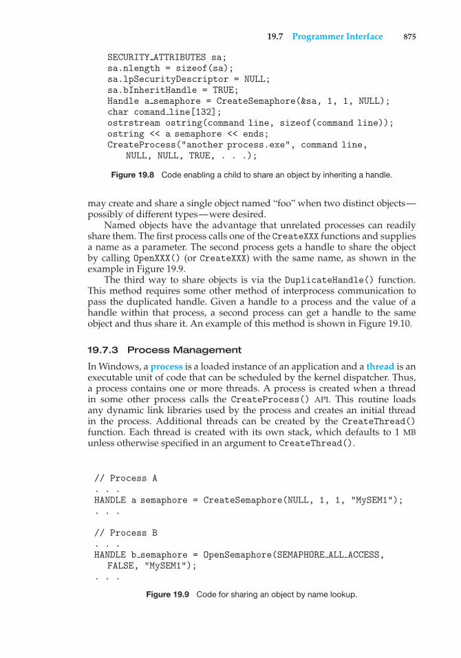
19.7 Programmer Interface 875
SECURITY ATTRIBUTES sa;sa.nlength = sizeof(sa);sa.lpSecurityDescriptor = NULL;sa.bInheritHandle = TRUE;Handle a semaphore = CreateSemaphore(&sa, 1, 1, NULL);char comand line[132];ostrstream ostring(command line, sizeof(command line));ostring << a semaphore << ends;CreateProcess("another process.exe", command line,
NULL, NULL, TRUE, . . .);
Figure 19.8 Code enabling a child to share an object by inheriting a handle.
may create and share a single object named “foo” when two distinct objects—possibly of different types—were desired.
Named objects have the advantage that unrelated processes can readilyshare them. The first process calls one of the CreateXXX functions and suppliesa name as a parameter. The second process gets a handle to share the objectby calling OpenXXX() (or CreateXXX) with the same name, as shown in theexample in Figure 19.9.
The third way to share objects is via the DuplicateHandle() function.This method requires some other method of interprocess communication topass the duplicated handle. Given a handle to a process and the value of ahandle within that process, a second process can get a handle to the sameobject and thus share it. An example of this method is shown in Figure 19.10.
19.7.3 Process Management
In Windows, a process is a loaded instance of an application and a thread is anexecutable unit of code that can be scheduled by the kernel dispatcher. Thus,a process contains one or more threads. A process is created when a threadin some other process calls the CreateProcess() API. This routine loadsany dynamic link libraries used by the process and creates an initial threadin the process. Additional threads can be created by the CreateThread()function. Each thread is created with its own stack, which defaults to 1 MBunless otherwise specified in an argument to CreateThread().
// Process A. . .HANDLE a semaphore = CreateSemaphore(NULL, 1, 1, "MySEM1");. . .
// Process B. . .HANDLE b semaphore = OpenSemaphore(SEMAPHORE ALL ACCESS,
FALSE, "MySEM1");. . .
Figure 19.9 Code for sharing an object by name lookup.
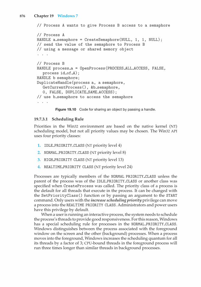
876 Chapter 19 Windows 7
// Process A wants to give Process B access to a semaphore
// Process AHANDLE a semaphore = CreateSemaphore(NULL, 1, 1, NULL);// send the value of the semaphore to Process B// using a message or shared memory object. . .
// Process BHANDLE process a = OpenProcess(PROCESS ALL ACCESS, FALSE,
process id of A);HANDLE b semaphore;DuplicateHandle(process a, a semaphore,
GetCurrentProcess(), &b semaphore,0, FALSE, DUPLICATE SAME ACCESS);
// use b semaphore to access the semaphore. . .
Figure 19.10 Code for sharing an object by passing a handle.
19.7.3.1 Scheduling Rule
Priorities in the Win32 environment are based on the native kernel (NT)scheduling model, but not all priority values may be chosen. The Win32 APIuses four priority classes:
1. IDLE PRIORITY CLASS (NT priority level 4)
2. NORMAL PRIORITY CLASS (NT priority level 8)
3. HIGH PRIORITY CLASS (NT priority level 13)
4. REALTIME PRIORITY CLASS (NT priority level 24)
Processes are typically members of the NORMAL PRIORITY CLASS unless theparent of the process was of the IDLE PRIORITY CLASS or another class wasspecified when CreateProcess was called. The priority class of a process isthe default for all threads that execute in the process. It can be changed withthe SetPriorityClass() function or by passing an argument to the STARTcommand. Only users with the increase scheduling priority privilege can movea process into the REALTIME PRIORITY CLASS. Administrators and power usershave this privilege by default.
When a user is running an interactive process, the system needs to schedulethe process’s threads to provide good responsiveness. For this reason, Windowshas a special scheduling rule for processes in the NORMAL PRIORITY CLASS.Windows distinguishes between the process associated with the foregroundwindow on the screen and the other (background) processes. When a processmoves into the foreground, Windows increases the scheduling quantum for allits threads by a factor of 3; CPU-bound threads in the foreground process willrun three times longer than similar threads in background processes.
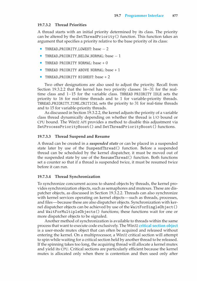
19.7 Programmer Interface 877
19.7.3.2 Thread Priorities
A thread starts with an initial priority determined by its class. The prioritycan be altered by the SetThreadPriority() function. This function takes anargument that specifies a priority relative to the base priority of its class:
• THREAD PRIORITY LOWEST: base − 2
• THREAD PRIORITY BELOW NORMAL: base − 1
• THREAD PRIORITY NORMAL: base + 0
• THREAD PRIORITY ABOVE NORMAL: base + 1
• THREAD PRIORITY HIGHEST: base + 2
Two other designations are also used to adjust the priority. Recall fromSection 19.3.2.2 that the kernel has two priority classes: 16–31 for the real-time class and 1–15 for the variable class. THREAD PRIORITY IDLE sets thepriority to 16 for real-time threads and to 1 for variable-priority threads.THREAD PRIORITY TIME CRITICAL sets the priority to 31 for real-time threadsand to 15 for variable-priority threads.
As discussed in Section 19.3.2.2, the kernel adjusts the priority of a variableclass thread dynamically depending on whether the thread is I/O bound orCPU bound. The Win32 API provides a method to disable this adjustment viaSetProcessPriorityBoost() and SetThreadPriorityBoost() functions.
19.7.3.3 Thread Suspend and Resume
A thread can be created in a suspended state or can be placed in a suspendedstate later by use of the SuspendThread() function. Before a suspendedthread can be scheduled by the kernel dispatcher, it must be moved out ofthe suspended state by use of the ResumeThread() function. Both functionsset a counter so that if a thread is suspended twice, it must be resumed twicebefore it can run.
19.7.3.4 Thread Synchronization
To synchronize concurrent access to shared objects by threads, the kernel pro-vides synchronization objects, such as semaphores and mutexes. These are dis-patcher objects, as discussed in Section 19.3.2.2. Threads can also synchronizewith kernel services operating on kernel objects—such as threads, processes,and files—because these are also dispatcher objects. Synchronization with ker-nel dispatcher objects can be achieved by use of the WaitForSingleObject()and WaitForMultipleObjects() functions; these functions wait for one ormore dispatcher objects to be signaled.
Another method of synchronization is available to threads within the sameprocess that want to execute code exclusively. The Win32 critical section objectis a user-mode mutex object that can often be acquired and released withoutentering the kernel. On a multiprocessor, a Win32 critical section will attemptto spin while waiting for a critical section held by another thread to be released.If the spinning takes too long, the acquiring thread will allocate a kernel mutexand yield its CPU. Critical sections are particularly efficient because the kernelmutex is allocated only when there is contention and then used only after
878 Chapter 19 Windows 7
attempting to spin. Most mutexes in programs are never actually contended,so the savings are significant.
Before using a critical section, some thread in the process must call Ini-tializeCriticalSection(). Each thread that wants to acquire the mutexcalls EnterCriticalSection() and then later calls LeaveCriticalSec-tion() to release the mutex. There is also a TryEnterCriticalSection()function, which attempts to acquire the mutex without blocking.
For programs that want user-mode reader–writer locks rather than amutex, Win32 supports slim reader–writer (SRW) locks. SRW locks have APIssimilar to those for critical sections, such as InitializeSRWLock, AcquireS-RWLockXXX, and ReleaseSRWLockXXX, where XXX is either Exclusive orShared, depending on whether the thread wants write access or just readaccess to the object protected by the lock. The Win32 API also supports conditionvariables, which can be used with either critical sections or SRW locks.
19.7.3.5 Thread Pool
Repeatedly creating and deleting threads can be expensive for applications andservices that perform small amounts of work in each instantiation. The Win32thread pool provides user-mode programs with three services: a queue towhich work requests may be submitted (via the SubmitThreadpoolWork()function), an API that can be used to bind callbacks to waitable handles(RegisterWaitForSingleObject()), and APIs to work with timers (Cre-ateThreadpoolTimer() and WaitForThreadpoolTimerCallbacks()) andto bind callbacks to I/O completion queues (BindIoCompletionCallback()).
The goal of using a thread pool is to increase performance and reducememory footprint. Threads are relatively expensive, and each processor canonly be executing one thread at a time no matter how many threads areavailable. The thread pool attempts to reduce the number of runnable threadsby slightly delaying work requests (reusing each thread for many requests)while providing enough threads to effectively utilize the machine’s CPUs. Thewait and I/O- and timer-callback APIs allow the thread pool to further reducethe number of threads in a process, using far fewer threads than would benecessary if a process were to devote separate threads to servicing each waitablehandle, timer, or completion port.
19.7.3.6 Fibers
A fiber is user-mode code that is scheduled according to a user-definedscheduling algorithm. Fibers are completely a user-mode facility; the kernelis not aware that they exist. The fiber mechanism uses Windows threads asif they were CPUs to execute the fibers. Fibers are cooperatively scheduled,meaning that they are never preempted but must explicitly yield the threadon which they are running. When a fiber yields a thread, another fiber can bescheduled on it by the run-time system (the programming language run-timecode).
The system creates a fiber by calling either ConvertThreadToFiber()or CreateFiber(). The primary difference between these functions is thatCreateFiber() does not begin executing the fiber that was created. To beginexecution, the application must call SwitchToFiber(). The application canterminate a fiber by calling DeleteFiber().
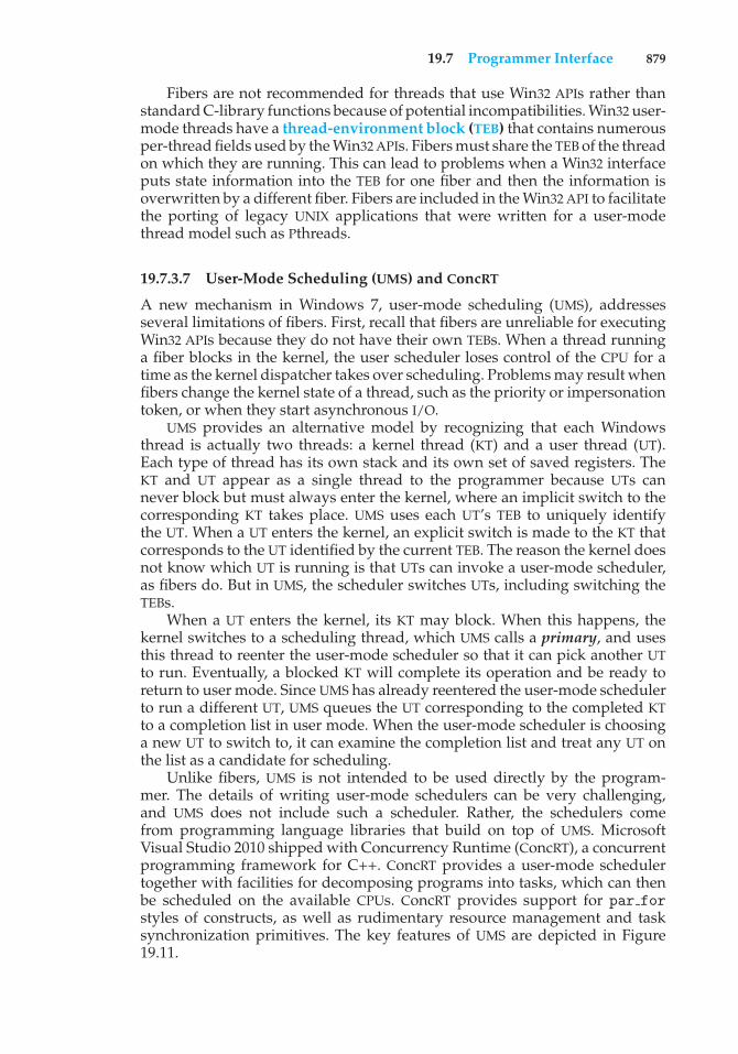
19.7 Programmer Interface 879
Fibers are not recommended for threads that use Win32 APIs rather thanstandard C-library functions because of potential incompatibilities. Win32 user-mode threads have a thread-environment block (TEB) that contains numerousper-thread fields used by the Win32 APIs. Fibers must share the TEB of the threadon which they are running. This can lead to problems when a Win32 interfaceputs state information into the TEB for one fiber and then the information isoverwritten by a different fiber. Fibers are included in the Win32 API to facilitatethe porting of legacy UNIX applications that were written for a user-modethread model such as Pthreads.
19.7.3.7 User-Mode Scheduling (UMS) and ConcRT
A new mechanism in Windows 7, user-mode scheduling (UMS), addressesseveral limitations of fibers. First, recall that fibers are unreliable for executingWin32 APIs because they do not have their own TEBs. When a thread runninga fiber blocks in the kernel, the user scheduler loses control of the CPU for atime as the kernel dispatcher takes over scheduling. Problems may result whenfibers change the kernel state of a thread, such as the priority or impersonationtoken, or when they start asynchronous I/O.
UMS provides an alternative model by recognizing that each Windowsthread is actually two threads: a kernel thread (KT) and a user thread (UT).Each type of thread has its own stack and its own set of saved registers. TheKT and UT appear as a single thread to the programmer because UTs cannever block but must always enter the kernel, where an implicit switch to thecorresponding KT takes place. UMS uses each UT’s TEB to uniquely identifythe UT. When a UT enters the kernel, an explicit switch is made to the KT thatcorresponds to the UT identified by the current TEB. The reason the kernel doesnot know which UT is running is that UTs can invoke a user-mode scheduler,as fibers do. But in UMS, the scheduler switches UTs, including switching theTEBs.
When a UT enters the kernel, its KT may block. When this happens, thekernel switches to a scheduling thread, which UMS calls a primary, and usesthis thread to reenter the user-mode scheduler so that it can pick another UTto run. Eventually, a blocked KT will complete its operation and be ready toreturn to user mode. Since UMS has already reentered the user-mode schedulerto run a different UT, UMS queues the UT corresponding to the completed KTto a completion list in user mode. When the user-mode scheduler is choosinga new UT to switch to, it can examine the completion list and treat any UT onthe list as a candidate for scheduling.
Unlike fibers, UMS is not intended to be used directly by the program-mer. The details of writing user-mode schedulers can be very challenging,and UMS does not include such a scheduler. Rather, the schedulers comefrom programming language libraries that build on top of UMS. MicrosoftVisual Studio 2010 shipped with Concurrency Runtime (ConcRT), a concurrentprogramming framework for C++. ConcRT provides a user-mode schedulertogether with facilities for decomposing programs into tasks, which can thenbe scheduled on the available CPUs. ConcRT provides support for par forstyles of constructs, as well as rudimentary resource management and tasksynchronization primitives. The key features of UMS are depicted in Figure19.11.
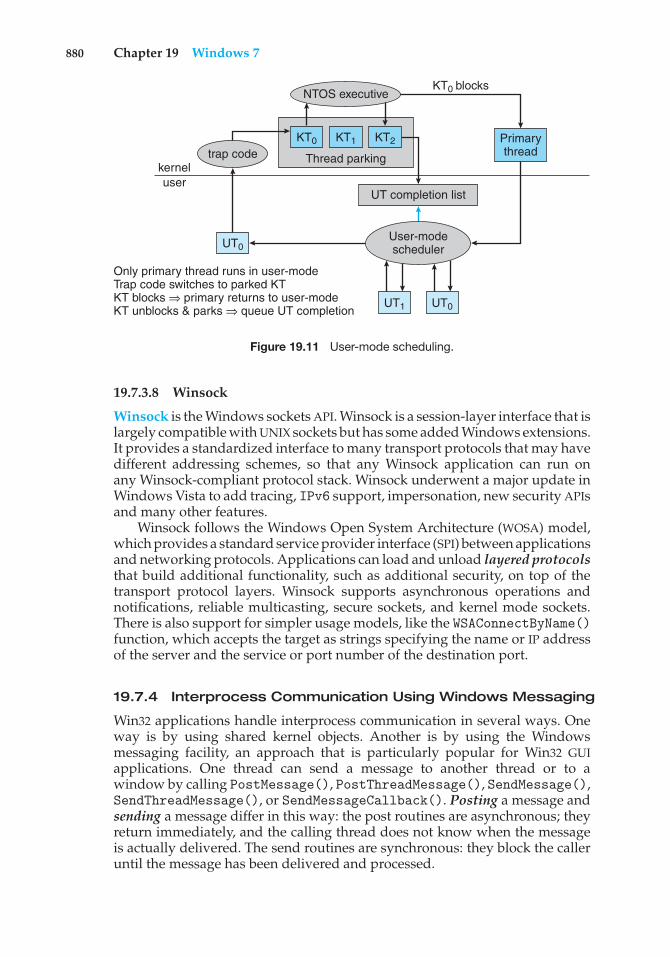
880 Chapter 19 Windows 7
NTOS executive
Only primary thread runs in user-modeTrap code switches to parked KTKT blocks ⇒ primary returns to user-modeKT unblocks & parks ⇒ queue UT completion
Thread parking
UT completion list
kerneluser
User-modescheduler
trap codePrimarythread
KT0
UT0
UT1 UT0
KT1 KT2
KT0 blocks
Figure 19.11 User-mode scheduling.
19.7.3.8 Winsock
Winsock is the Windows sockets API. Winsock is a session-layer interface that islargely compatible with UNIX sockets but has some added Windows extensions.It provides a standardized interface to many transport protocols that may havedifferent addressing schemes, so that any Winsock application can run onany Winsock-compliant protocol stack. Winsock underwent a major update inWindows Vista to add tracing, IPv6 support, impersonation, new security APIsand many other features.
Winsock follows the Windows Open System Architecture (WOSA) model,which provides a standard service provider interface (SPI) between applicationsand networking protocols. Applications can load and unload layered protocolsthat build additional functionality, such as additional security, on top of thetransport protocol layers. Winsock supports asynchronous operations andnotifications, reliable multicasting, secure sockets, and kernel mode sockets.There is also support for simpler usage models, like the WSAConnectByName()function, which accepts the target as strings specifying the name or IP addressof the server and the service or port number of the destination port.
19.7.4 Interprocess Communication Using Windows Messaging
Win32 applications handle interprocess communication in several ways. Oneway is by using shared kernel objects. Another is by using the Windowsmessaging facility, an approach that is particularly popular for Win32 GUIapplications. One thread can send a message to another thread or to awindow by calling PostMessage(), PostThreadMessage(), SendMessage(),SendThreadMessage(), or SendMessageCallback(). Posting a message andsending a message differ in this way: the post routines are asynchronous; theyreturn immediately, and the calling thread does not know when the messageis actually delivered. The send routines are synchronous: they block the calleruntil the message has been delivered and processed.
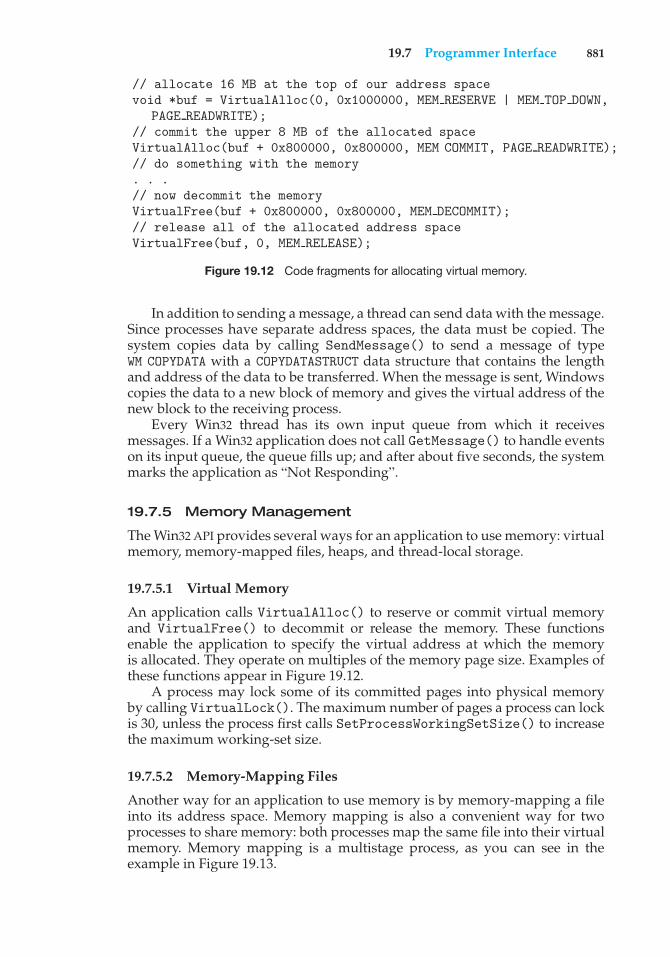
19.7 Programmer Interface 881
// allocate 16 MB at the top of our address spacevoid *buf = VirtualAlloc(0, 0x1000000, MEM RESERVE | MEM TOP DOWN,
PAGE READWRITE);// commit the upper 8 MB of the allocated spaceVirtualAlloc(buf + 0x800000, 0x800000, MEM COMMIT, PAGE READWRITE);// do something with the memory. . .// now decommit the memoryVirtualFree(buf + 0x800000, 0x800000, MEM DECOMMIT);// release all of the allocated address spaceVirtualFree(buf, 0, MEM RELEASE);
Figure 19.12 Code fragments for allocating virtual memory.
In addition to sending a message, a thread can send data with the message.Since processes have separate address spaces, the data must be copied. Thesystem copies data by calling SendMessage() to send a message of typeWM COPYDATA with a COPYDATASTRUCT data structure that contains the lengthand address of the data to be transferred. When the message is sent, Windowscopies the data to a new block of memory and gives the virtual address of thenew block to the receiving process.
Every Win32 thread has its own input queue from which it receivesmessages. If a Win32 application does not call GetMessage() to handle eventson its input queue, the queue fills up; and after about five seconds, the systemmarks the application as “Not Responding”.
19.7.5 Memory Management
The Win32 API provides several ways for an application to use memory: virtualmemory, memory-mapped files, heaps, and thread-local storage.
19.7.5.1 Virtual Memory
An application calls VirtualAlloc() to reserve or commit virtual memoryand VirtualFree() to decommit or release the memory. These functionsenable the application to specify the virtual address at which the memoryis allocated. They operate on multiples of the memory page size. Examples ofthese functions appear in Figure 19.12.
A process may lock some of its committed pages into physical memoryby calling VirtualLock(). The maximum number of pages a process can lockis 30, unless the process first calls SetProcessWorkingSetSize() to increasethe maximum working-set size.
19.7.5.2 Memory-Mapping Files
Another way for an application to use memory is by memory-mapping a fileinto its address space. Memory mapping is also a convenient way for twoprocesses to share memory: both processes map the same file into their virtualmemory. Memory mapping is a multistage process, as you can see in theexample in Figure 19.13.
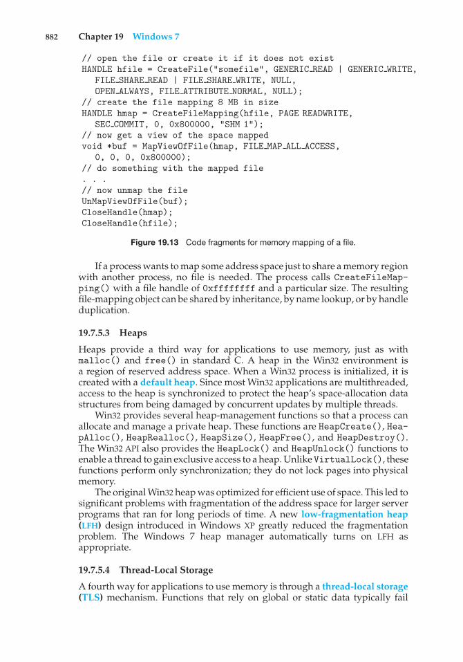
882 Chapter 19 Windows 7
// open the file or create it if it does not existHANDLE hfile = CreateFile("somefile", GENERIC READ | GENERIC WRITE,
FILE SHARE READ | FILE SHARE WRITE, NULL,OPEN ALWAYS, FILE ATTRIBUTE NORMAL, NULL);
// create the file mapping 8 MB in sizeHANDLE hmap = CreateFileMapping(hfile, PAGE READWRITE,
SEC COMMIT, 0, 0x800000, "SHM 1");// now get a view of the space mappedvoid *buf = MapViewOfFile(hmap, FILE MAP ALL ACCESS,
0, 0, 0, 0x800000);// do something with the mapped file. . .// now unmap the fileUnMapViewOfFile(buf);CloseHandle(hmap);CloseHandle(hfile);
Figure 19.13 Code fragments for memory mapping of a file.
If a process wants to map some address space just to share a memory regionwith another process, no file is needed. The process calls CreateFileMap-ping() with a file handle of 0xffffffff and a particular size. The resultingfile-mapping object can be shared by inheritance, by name lookup, or by handleduplication.
19.7.5.3 Heaps
Heaps provide a third way for applications to use memory, just as withmalloc() and free() in standard C. A heap in the Win32 environment isa region of reserved address space. When a Win32 process is initialized, it iscreated with a default heap. Since most Win32 applications are multithreaded,access to the heap is synchronized to protect the heap’s space-allocation datastructures from being damaged by concurrent updates by multiple threads.
Win32 provides several heap-management functions so that a process canallocate and manage a private heap. These functions are HeapCreate(), Hea-pAlloc(), HeapRealloc(), HeapSize(), HeapFree(), and HeapDestroy().The Win32 API also provides the HeapLock() and HeapUnlock() functions toenable a thread to gain exclusive access to a heap. UnlikeVirtualLock(), thesefunctions perform only synchronization; they do not lock pages into physicalmemory.
The original Win32 heap was optimized for efficient use of space. This led tosignificant problems with fragmentation of the address space for larger serverprograms that ran for long periods of time. A new low-fragmentation heap(LFH) design introduced in Windows XP greatly reduced the fragmentationproblem. The Windows 7 heap manager automatically turns on LFH asappropriate.
19.7.5.4 Thread-Local Storage
A fourth way for applications to use memory is through a thread-local storage(TLS) mechanism. Functions that rely on global or static data typically fail
Practice Exercises 883
// reserve a slot for a variableDWORD var index = T1sAlloc();// set it to the value 10T1sSetValue(var index, 10);// get the valueint var T1sGetValue(var index);// release the indexT1sFree(var index);
Figure 19.14 Code for dynamic thread-local storage.
to work properly in a multithreaded environment. For instance, the C run-time function strtok() uses a static variable to keep track of its currentposition while parsing a string. For two concurrent threads to executestrtok()correctly, they need separate current position variables. TLS provides a wayto maintain instances of variables that are global to the function being executedbut not shared with any other thread.
TLS provides both dynamic and static methods of creating thread-localstorage. The dynamic method is illustrated in Figure 19.14. The TLS mechanismallocates global heap storage and attaches it to the thread environment blockthat Windows allocates to every user-mode thread. The TEB is readily accessibleby each thread and is used not just for TLS but for all the per-thread stateinformation in user mode.
To use a thread-local static variable, the application declares the variableas follows to ensure that every thread has its own private copy:
declspec(thread) DWORD cur pos = 0;
19.8 Summary
Microsoft designed Windows to be an extensible, portable operating system—one able to take advantage of new techniques and hardware. Windowssupports multiple operating environments and symmetric multiprocessing,including both 32-bit and 64-bit processors and NUMA computers. The useof kernel objects to provide basic services, along with support for client–server computing, enables Windows to support a wide variety of applica-tion environments. Windows provides virtual memory, integrated caching,and preemptive scheduling. It supports elaborate security mechanisms andincludes internationalization features. Windows runs on a wide variety ofcomputers, so users can choose and upgrade hardware to match their budgetsand performance requirements without needing to alter the applications theyrun.
Practice Exercises
19.1 What type of operating system is Windows? Describe two of its majorfeatures.
19.2 List the design goals of Windows. Describe two in detail.
884 Chapter 19 Windows 7
19.3 Describe the booting process for a Windows system.
19.4 Describe the three main architectural layers of the Windows kernel.
19.5 What is the job of the object manager?
19.6 What types of services does the process manager provide?
19.7 What is a local procedure call?
19.8 What are the responsibilities of the I/O manager?
19.9 What types of networking does Windows support? How does Windowsimplement transport protocols? Describe two networking protocols.
19.10 How is the NTFS namespace organized?
19.11 How does NTFS handle data structures? How does NTFS recover froma system crash? What is guaranteed after a recovery takes place? ‘
19.12 How does Windows allocate user memory?
19.13 Describe some of the ways in which an application can use memoryvia the Win32 API.
Exercises
19.14 Under what circumstances would one use the deferred procedure callsfacility in Windows?
19.15 What is a handle, and how does a process obtain a handle?
19.16 Describe the management scheme of the virtual memory manager. Howdoes the VM manager improve performance?
19.17 Describe a useful application of the no-access page facility provided inWindows.
19.18 Describe the three techniques used for communicating data in a localprocedure call. What settings are most conducive to the application ofthe different message-passing techniques?
19.19 What manages caching in Windows? How is the cache managed?
19.20 How does the NTFS directory structure differ from the directorystructure used in UNIX operating systems?
19.21 What is a process, and how is it managed in Windows?
19.22 What is the fiber abstraction provided by Windows? How does it differfrom the thread abstraction?
19.23 How does user-mode scheduling (UMS) in Windows 7 differ fromfibers? What are some trade-offs between fibers and UMS?
19.24 UMS considers a thread to have two parts, a UT and a KT. How might itbe useful to allow UTs to continue executing in parallel with their KTs?
19.25 What is the performance trade-off of allowing KTs and UTs to executeon different processors?
Bibliography 885
19.26 Why does the self-map occupy large amounts of virtual address spacebut no additional virtual memory?
19.27 How does the self-map make it easy for the VM manager to move thepage-table pages to and from disk? Where are the page-table pageskept on disk?
19.28 When a Windows system hibernates, the system is powered off.Suppose you changed the CPU or the amount of RAM on a hibernatingsystem. Do you think that would work? Why or why not?
19.29 Give an example showing how the use of a suspend count is helpful insuspending and resuming threads in Windows.
Bibliographical Notes
[Russinovich and Solomon (2009)] give an overview of Windows 7 andconsiderable technical detail about system internals and components.
[Brown (2000)] presents details of the security architecture of Windows.The Microsoft Developer Network Library (http://msdn.microsoft.com)
supplies a wealth of information on Windows and other Microsoft products,including documentation of all the published APIs.
[Iseminger (2000)] provides a good reference on the Windows ActiveDirectory. Detailed discussions of writing programs that use the Win32 APIappear in [Richter (1997)]. [Silberschatz et al. (2010)] supply a good discussionof B+ trees.
The source code for a 2005 WRK version of the Windows kernel, togetherwith a collection of slides and other CRK curriculum materials, is available fromwww.microsoft.com/WindowsAcademic for use by universities.
Bibliography
[Brown (2000)] K. Brown, Programming Windows Security, Addison-Wesley(2000).
[Iseminger (2000)] D. Iseminger, Active Directory Services for Microsoft Windows2000. Technical Reference, Microsoft Press (2000).
[Richter (1997)] J. Richter, Advanced Windows, Microsoft Press (1997).
[Russinovich and Solomon (2009)] M. E. Russinovich and D. A. Solomon, Win-dows Internals: Including Windows Server 2008 and Windows Vista, Fifth Edition,Microsoft Press (2009).
[Silberschatz et al. (2010)] A. Silberschatz, H. F. Korth, and S. Sudarshan,Database System Concepts, Sixth Edition, McGraw-Hill (2010).

20C H A P T E RInfluentialOperatingSystems
Now that you understand the fundamental concepts of operating systems (CPUscheduling, memory management, processes, and so on), we are in a positionto examine how these concepts have been applied in several older and highlyinfluential operating systems. Some of them (such as the XDS-940 and the THEsystem) were one-of-a-kind systems; others (such as OS/360) are widely used.The order of presentation highlights the similarities and differences of thesystems; it is not strictly chronological or ordered by importance. The seriousstudent of operating systems should be familiar with all these systems.
In the bibliographical notes at the end of the chapter, we include referencesto further reading about these early systems. The papers, written by thedesigners of the systems, are important both for their technical content andfor their style and flavor.
CHAPTER OBJECTIVES
• To explain how operating-system features migrate over time from largecomputer systems to smaller ones.
• To discuss the features of several historically important operating systems.
20.1 Feature Migration
One reason to study early architectures and operating systems is that a featurethat once ran only on huge systems may eventually make its way into verysmall systems. Indeed, an examination of operating systems for mainframesand microcomputers shows that many features once available only on main-frames have been adopted for microcomputers. The same operating-systemconcepts are thus appropriate for various classes of computers: mainframes,minicomputers, microcomputers, and handhelds. To understand modern oper-ating systems, then, you need to recognize the theme of feature migration andthe long history of many operating-system features, as shown in Figure 20.1.
A good example of feature migration started with the Multiplexed Infor-mation and Computing Services (MULTICS) operating system. MULTICS was
887
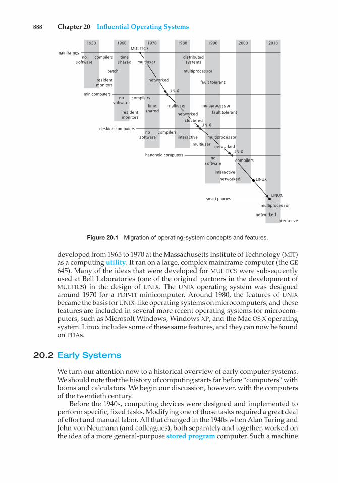
888 Chapter 20 Influential Operating Systems
mainframes
1950
nos oftware
nos oftware
rossecorpitlumhctab
compilers times hared
dis tributeds ys tems
res identmonitors
fault tolerantnetworked
multius er
nos oftware
compilers
nos oftware interactive
compilers
compilers
interactive
networked
times haredres ident
monitorsfault tolerant
multius er
networked
clus tered
multius er
multiproces s or
multiproces s or
1960 1970MULT IC S
1980 1990 2000
minicomputers
desktop computers
handheld computers
UNIX
UNIX
networkedUNIX
smart phones
2010
LINUX
multiproces s or
networkedinteractive
LINUX
Figure 20.1 Migration of operating-system concepts and features.
developed from 1965 to 1970 at the Massachusetts Institute of Technology (MIT)as a computing utility. It ran on a large, complex mainframe computer (the GE645). Many of the ideas that were developed for MULTICS were subsequentlyused at Bell Laboratories (one of the original partners in the development ofMULTICS) in the design of UNIX. The UNIX operating system was designedaround 1970 for a PDP-11 minicomputer. Around 1980, the features of UNIXbecame the basis for UNIX-like operating systems on microcomputers; and thesefeatures are included in several more recent operating systems for microcom-puters, such as Microsoft Windows, Windows XP, and the Mac OS X operatingsystem. Linux includes some of these same features, and they can now be foundon PDAs.
20.2 Early Systems
We turn our attention now to a historical overview of early computer systems.We should note that the history of computing starts far before “computers” withlooms and calculators. We begin our discussion, however, with the computersof the twentieth century.
Before the 1940s, computing devices were designed and implemented toperform specific, fixed tasks. Modifying one of those tasks required a great dealof effort and manual labor. All that changed in the 1940s when Alan Turing andJohn von Neumann (and colleagues), both separately and together, worked onthe idea of a more general-purpose stored program computer. Such a machine
20.2 Early Systems 889
has both a program store and a data store, where the program store providesinstructions about what to do to the data.
This fundamental computer concept quickly generated a number ofgeneral-purpose computers, but much of the history of these machines isblurred by time and the secrecy of their development during World War II. Itis likely that the first working stored-program general-purpose computer wasthe Manchester Mark 1, which ran successfully in 1949. The first commercialcomputer— the Ferranti Mark 1, which went on sale in 1951—was it offspring.
Early computers were physically enormous machines run from consoles.The programmer, who was also the operator of the computer system, wouldwrite a program and then would operate the program directly from theoperator’s console. First, the program would be loaded manually into memoryfrom the front panel switches (one instruction at a time), from paper tape, orfrom punched cards. Then the appropriate buttons would be pushed to set thestarting address and to start the execution of the program. As the program ran,the programmer/operator could monitor its execution by the display lights onthe console. If errors were discovered, the programmer could halt the program,examine the contents of memory and registers, and debug the program directlyfrom the console. Output was printed or was punched onto paper tape or cardsfor later printing.
20.2.1 Dedicated Computer Systems
As time went on, additional software and hardware were developed. Cardreaders, line printers, and magnetic tape became commonplace. Assemblers,loaders, and linkers were designed to ease the programming task. Librariesof common functions were created. Common functions could then be copiedinto a new program without having to be written again, providing softwarereusability.
The routines that performed I/O were especially important. Each new I/Odevice had its own characteristics, requiring careful programming. A specialsubroutine—called a device driver—was written for each I/O device. A devicedriver knows how the buffers, flags, registers, control bits, and status bits fora particular device should be used. Each type of device has its own driver.A simple task, such as reading a character from a paper-tape reader, mightinvolve complex sequences of device-specific operations. Rather than writingthe necessary code every time, the device driver was simply used from thelibrary.
Later, compilers for FORTRAN, COBOL, and other languages appeared,making the programming task much easier but the operation of the computermore complex. To prepare a FORTRAN program for execution, for example,the programmer would first need to load the FORTRAN compiler into thecomputer. The compiler was normally kept on magnetic tape, so the propertape would need to be mounted on a tape drive. The program would be readthrough the card reader and written onto another tape. The FORTRAN compilerproduced assembly-language output, which then had to be assembled. Thisprocedure required mounting another tape with the assembler. The output ofthe assembler would need to be linked to supporting library routines. Finally,the binary object form of the program would be ready to execute. It could beloaded into memory and debugged from the console, as before.
890 Chapter 20 Influential Operating Systems
A significant amount of setup time could be involved in the running of ajob. Each job consisted of many separate steps:
1. Loading the FORTRAN compiler tape
2. Running the compiler
3. Unloading the compiler tape
4. Loading the assembler tape
5. Running the assembler
6. Unloading the assembler tape
7. Loading the object program
8. Running the object program
If an error occurred during any step, the programmer/operator might haveto start over at the beginning. Each job step might involve the loading andunloading of magnetic tapes, paper tapes, and punch cards.
The job setup time was a real problem. While tapes were being mounted orthe programmer was operating the console, the CPU sat idle. Remember that,in the early days, few computers were available, and they were expensive. Acomputer might have cost millions of dollars, not including the operationalcosts of power, cooling, programmers, and so on. Thus, computer time wasextremely valuable, and owners wanted their computers to be used as muchas possible. They needed high utilization to get as much as they could fromtheir investments.
20.2.2 Shared Computer Systems
The solution was twofold. First, a professional computer operator was hired.The programmer no longer operated the machine. As soon as one job wasfinished, the operator could start the next. Since the operator had moreexperience with mounting tapes than a programmer, setup time was reduced.The programmer provided whatever cards or tapes were needed, as well as ashort description of how the job was to be run. Of course, the operator couldnot debug an incorrect program at the console, since the operator would notunderstand the program. Therefore, in the case of program error, a dump ofmemory and registers was taken, and the programmer had to debug from thedump. Dumping the memory and registers allowed the operator to continueimmediately with the next job but left the programmer with the more difficultdebugging problem.
Second, jobs with similar needs were batched together and run through thecomputer as a group to reduce setup time. For instance, suppose the operatorreceived one FORTRAN job, one COBOL job, and another FORTRAN job. If she ranthem in that order, she would have to set up for FORTRAN (load the compilertapes and so on), then set up for COBOL, and then set up for FORTRAN again. Ifshe ran the two FORTRAN programs as a batch, however, she could setup onlyonce for FORTRAN, saving operator time.
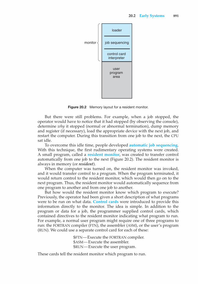
20.2 Early Systems 891
loader
job sequencing
control cardinterpreter
user program
area
monitor
Figure 20.2 Memory layout for a resident monitor.
But there were still problems. For example, when a job stopped, theoperator would have to notice that it had stopped (by observing the console),determine why it stopped (normal or abnormal termination), dump memoryand register (if necessary), load the appropriate device with the next job, andrestart the computer. During this transition from one job to the next, the CPUsat idle.
To overcome this idle time, people developed automatic job sequencing.With this technique, the first rudimentary operating systems were created.A small program, called a resident monitor, was created to transfer controlautomatically from one job to the next (Figure 20.2). The resident monitor isalways in memory (or resident).
When the computer was turned on, the resident monitor was invoked,and it would transfer control to a program. When the program terminated, itwould return control to the resident monitor, which would then go on to thenext program. Thus, the resident monitor would automatically sequence fromone program to another and from one job to another.
But how would the resident monitor know which program to execute?Previously, the operator had been given a short description of what programswere to be run on what data. Control cards were introduced to provide thisinformation directly to the monitor. The idea is simple. In addition to theprogram or data for a job, the programmer supplied control cards, whichcontained directives to the resident monitor indicating what program to run.For example, a normal user program might require one of three programs torun: the FORTRAN compiler (FTN), the assembler (ASM), or the user’s program(RUN). We could use a separate control card for each of these:
$FTN—Execute the FORTRAN compiler.$ASM—Execute the assembler.$RUN—Execute the user program.
These cards tell the resident monitor which program to run.
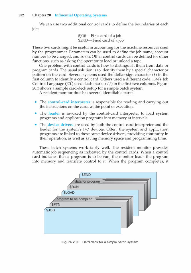
892 Chapter 20 Influential Operating Systems
We can use two additional control cards to define the boundaries of eachjob:
$JOB—First card of a job$END—Final card of a job
These two cards might be useful in accounting for the machine resources usedby the programmer. Parameters can be used to define the job name, accountnumber to be charged, and so on. Other control cards can be defined for otherfunctions, such as asking the operator to load or unload a tape.
One problem with control cards is how to distinguish them from data orprogram cards. The usual solution is to identify them by a special character orpattern on the card. Several systems used the dollar-sign character ($) in thefirst column to identify a control card. Others used a different code. IBM’s JobControl Language (JCL) used slash marks (//) in the first two columns. Figure20.3 shows a sample card-deck setup for a simple batch system.
A resident monitor thus has several identifiable parts:
• The control-card interpreter is responsible for reading and carrying outthe instructions on the cards at the point of execution.
• The loader is invoked by the control-card interpreter to load systemprograms and application programs into memory at intervals.
• The device drivers are used by both the control-card interpreter and theloader for the system’s I/O devices. Often, the system and applicationprograms are linked to these same device drivers, providing continuity intheir operation, as well as saving memory space and programming time.
These batch systems work fairly well. The resident monitor providesautomatic job sequencing as indicated by the control cards. When a controlcard indicates that a program is to be run, the monitor loads the programinto memory and transfers control to it. When the program completes, it
$END
$RUN
data for program
$LOAD
$FTN
$JOB
program to be compiled
Figure 20.3 Card deck for a simple batch system.
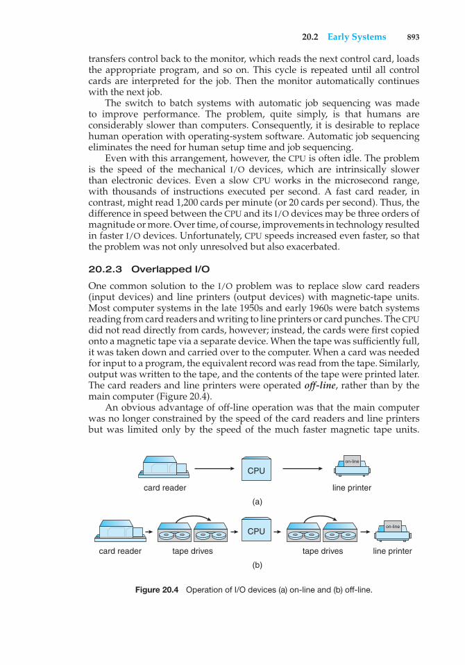
20.2 Early Systems 893
transfers control back to the monitor, which reads the next control card, loadsthe appropriate program, and so on. This cycle is repeated until all controlcards are interpreted for the job. Then the monitor automatically continueswith the next job.
The switch to batch systems with automatic job sequencing was madeto improve performance. The problem, quite simply, is that humans areconsiderably slower than computers. Consequently, it is desirable to replacehuman operation with operating-system software. Automatic job sequencingeliminates the need for human setup time and job sequencing.
Even with this arrangement, however, the CPU is often idle. The problemis the speed of the mechanical I/O devices, which are intrinsically slowerthan electronic devices. Even a slow CPU works in the microsecond range,with thousands of instructions executed per second. A fast card reader, incontrast, might read 1,200 cards per minute (or 20 cards per second). Thus, thedifference in speed between the CPU and its I/O devices may be three orders ofmagnitude or more. Over time, of course, improvements in technology resultedin faster I/O devices. Unfortunately, CPU speeds increased even faster, so thatthe problem was not only unresolved but also exacerbated.
20.2.3 Overlapped I/O
One common solution to the I/O problem was to replace slow card readers(input devices) and line printers (output devices) with magnetic-tape units.Most computer systems in the late 1950s and early 1960s were batch systemsreading from card readers and writing to line printers or card punches. The CPUdid not read directly from cards, however; instead, the cards were first copiedonto a magnetic tape via a separate device. When the tape was sufficiently full,it was taken down and carried over to the computer. When a card was neededfor input to a program, the equivalent record was read from the tape. Similarly,output was written to the tape, and the contents of the tape were printed later.The card readers and line printers were operated off-line, rather than by themain computer (Figure 20.4).
An obvious advantage of off-line operation was that the main computerwas no longer constrained by the speed of the card readers and line printersbut was limited only by the speed of the much faster magnetic tape units.
(b)
(a)
CPU
card reader
card reader
line printer
tape drives tape drives line printer
CPU
on-line
on-line
Figure 20.4 Operation of I/O devices (a) on-line and (b) off-line.
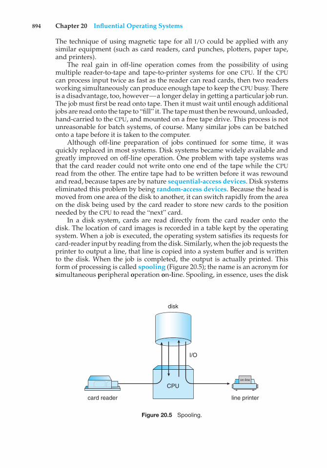
894 Chapter 20 Influential Operating Systems
The technique of using magnetic tape for all I/O could be applied with anysimilar equipment (such as card readers, card punches, plotters, paper tape,and printers).
The real gain in off-line operation comes from the possibility of usingmultiple reader-to-tape and tape-to-printer systems for one CPU. If the CPUcan process input twice as fast as the reader can read cards, then two readersworking simultaneously can produce enough tape to keep the CPU busy. Thereis a disadvantage, too, however—a longer delay in getting a particular job run.The job must first be read onto tape. Then it must wait until enough additionaljobs are read onto the tape to “fill” it. The tape must then be rewound, unloaded,hand-carried to the CPU, and mounted on a free tape drive. This process is notunreasonable for batch systems, of course. Many similar jobs can be batchedonto a tape before it is taken to the computer.
Although off-line preparation of jobs continued for some time, it wasquickly replaced in most systems. Disk systems became widely available andgreatly improved on off-line operation. One problem with tape systems wasthat the card reader could not write onto one end of the tape while the CPUread from the other. The entire tape had to be written before it was rewoundand read, because tapes are by nature sequential-access devices. Disk systemseliminated this problem by being random-access devices. Because the head ismoved from one area of the disk to another, it can switch rapidly from the areaon the disk being used by the card reader to store new cards to the positionneeded by the CPU to read the “next” card.
In a disk system, cards are read directly from the card reader onto thedisk. The location of card images is recorded in a table kept by the operatingsystem. When a job is executed, the operating system satisfies its requests forcard-reader input by reading from the disk. Similarly, when the job requests theprinter to output a line, that line is copied into a system buffer and is writtento the disk. When the job is completed, the output is actually printed. Thisform of processing is called spooling (Figure 20.5); the name is an acronym forsimultaneous peripheral operation on-line. Spooling, in essence, uses the disk
CPU
card reader line printer
disk
I/O
on-line
Figure 20.5 Spooling.
20.3 Atlas 895
as a huge buffer for reading as far ahead as possible on input devices and forstoring output files until the output devices are able to accept them.
Spooling is also used for processing data at remote sites. The CPU sendsthe data via communication paths to a remote printer (or accepts an entireinput job from a remote card reader). The remote processing is done at its ownspeed, with no CPU intervention. The CPU just needs to be notified when theprocessing is completed, so that it can spool the next batch of data.
Spooling overlaps the I/O of one job with the computation of other jobs.Even in a simple system, the spooler may be reading the input of one job whileprinting the output of a different job. During this time, still another job (orother jobs) may be executed, reading its “cards” from disk and “printing” itsoutput lines onto the disk.
Spooling has a direct beneficial effect on the performance of the system.For the cost of some disk space and a few tables, the computation of one joband the I/O of other jobs can take place at the same time. Thus, spooling cankeep both the CPU and the I/O devices working at much higher rates. Spoolingleads naturally to multiprogramming, which is the foundation of all modernoperating systems.
20.3 Atlas
The Atlas operating system was designed at the University of Manchester inEngland in the late 1950s and early 1960s. Many of its basic features that werenovel at the time have become standard parts of modern operating systems.Device drivers were a major part of the system. In addition, system calls wereadded by a set of special instructions called extra codes.
Atlas was a batch operating system with spooling. Spooling allowed thesystem to schedule jobs according to the availability of peripheral devices, suchas magnetic tape units, paper tape readers, paper tape punches, line printers,card readers, and card punches.
The most remarkable feature of Atlas, however, was its memory manage-ment. Core memory was new and expensive at the time. Many computers,like the IBM 650, used a drum for primary memory. The Atlas system used adrum for its main memory, but it had a small amount of core memory that wasused as a cache for the drum. Demand paging was used to transfer informationbetween core memory and the drum automatically.
The Atlas system used a British computer with 48-bit words. Addresseswere 24 bits but were encoded in decimal, which allowed 1 million words tobe addressed. At that time, this was an extremely large address space. Thephysical memory for Atlas was a 98-KB-word drum and 16-KB words of core.Memory was divided into 512-word pages, providing 32 frames in physicalmemory. An associative memory of 32 registers implemented the mappingfrom a virtual address to a physical address.
If a page fault occurred, a page-replacement algorithm was invoked. Onememory frame was always kept empty, so that a drum transfer could startimmediately. The page-replacement algorithm attempted to predict futurememory-accessing behavior based on past behavior. A reference bit for eachframe was set whenever the frame was accessed. The reference bits were read
896 Chapter 20 Influential Operating Systems
into memory every 1,024 instructions, and the last 32 values of these bits wereretained. This history was used to define the time since the most recent reference(t1) and the interval between the last two references (t2). Pages were chosen forreplacement in the following order:
1. Any page with t1 > t2 + 1 is considered to be no longer in use and isreplaced.
2. If t1 ≤ t2 for all pages, then replace the page with the largest value for t2− t1.
The page-replacement algorithm assumes that programs access memory inloops. If the time between the last two references is t2, then another reference isexpected t2 time units later. If a reference does not occur (t1 > t2), it is assumedthat the page is no longer being used, and the page is replaced. If all pagesare still in use, then the page that will not be needed for the longest time isreplaced. The time to the next reference is expected to be t2 − t1.
20.4 XDS-940
The XDS-940 operating system was designed at the University of California atBerkeley in the early 1960’s. Like the Atlas system, it used paging for memorymanagement. Unlike the Atlas system, it was a time-shared system. The pagingwas used only for relocation; it was not used for demand paging. The virtualmemory of any user process was made up of 16-KB words, whereas the physicalmemory was made up of 64-KB words. Each page was made up of 2-KB words.The page table was kept in registers. Since physical memory was larger thanvirtual memory, several user processes could be in memory at the same time.The number of users could be increased by page sharing when the pagescontained read-only reentrant code. Processes were kept on a drum and wereswapped in and out of memory as necessary.
The XDS-940 system was constructed from a modified XDS-930. The mod-ifications were typical of the changes made to a basic computer to allow anoperating system to be written properly. A user-monitor mode was added.Certain instructions, such as I/O and halt, were defined to be privileged. Anattempt to execute a privileged instruction in user mode would trap to theoperating system.
A system-call instruction was added to the user-mode instruction set.This instruction was used to create new resources, such as files, allowing theoperating system to manage the physical resources. Files, for example, wereallocated in 256-word blocks on the drum. A bit map was used to managefree drum blocks. Each file had an index block with pointers to the actual datablocks. Index blocks were chained together.
The XDS-940 system also provided system calls to allow processes to create,start, suspend, and destroy subprocesses. A programmer could construct asystem of processes. Separate processes could share memory for communica-tion and synchronization. Process creation defined a tree structure, where aprocess is the root and its subprocesses are nodes below it in the tree. Each ofthe subprocesses could, in turn, create more subprocesses.
20.6 RC 4000 897
20.5 THE
The THE operating system was designed at the Technische Hogeschool inEindhoven in the Netherlands in the mid-1960’s. It was a batch system runningon a Dutch computer, the EL X8, with 32 KB of 27-bit words. The system wasmainly noted for its clean design, particularly its layer structure, and its use ofa set of concurrent processes employing semaphores for synchronization.
Unlike the processes in the XDS-940 system, the set of processes in theTHE system was static. The operating system itself was designed as a set ofcooperating processes. In addition, five user processes were created that servedas the active agents to compile, execute, and print user programs. When onejob was finished, the process would return to the input queue to select anotherjob.
A priority CPU-scheduling algorithm was used. The priorities were recom-puted every 2 seconds and were inversely proportional to the amount of CPUtime used recently (in the last 8 to 10 seconds). This scheme gave higher priorityto I/O-bound processes and to new processes.
Memory management was limited by the lack of hardware support. How-ever, since the system was limited and user programs could be written only inAlgol, a software paging scheme was used. The Algol compiler automaticallygenerated calls to system routines, which made sure the requested informationwas in memory, swapping if necessary. The backing store was a 512-KB-worddrum. A 512-word page was used, with an LRU page-replacement strategy.
Another major concern of the THE system was deadlock control. Thebanker’s algorithm was used to provide deadlock avoidance.
Closely related to the THE system is the Venus system. The Venus systemwas also a layer-structured design, using semaphores to synchronize processes.The lower levels of the design were implemented in microcode, however,providing a much faster system. Paged-segmented memory was used formemory management. In addition, the system was designed as a time-sharingsystem, rather than a batch system.
20.6 RC 4000
The RC 4000 system, like the THE system, was notable primarily for its designconcepts. It was designed in the late 1960’s for the Danish 4000 computerby Regnecentralen, particularly by Brinch-Hansen. The objective was not todesign a batch system, or a time-sharing system, or any other specific system.Rather, the goal was to create an operating-system nucleus, or kernel, on whicha complete operating system could be built. Thus, the system structure waslayered, and only the lower levels—comprising the kernel—were provided.
The kernel supported a collection of concurrent processes. A round-robinCPU scheduler was used. Although processes could share memory, the primarycommunication and synchronization mechanism was the message systemprovided by the kernel. Processes could communicate with each other byexchanging fixed-sized messages of eight words in length. All messages werestored in buffers from a common buffer pool. When a message buffer was nolonger required, it was returned to the common pool.
898 Chapter 20 Influential Operating Systems
A message queue was associated with each process. It contained all themessages that had been sent to that process but had not yet been received.Messages were removed from the queue in FIFO order. The system supportedfour primitive operations, which were executed atomically:
• send-message (in receiver, in message, out buffer)
• wait-message (out sender, out message, out buffer)
• send-answer (out result, in message, in buffer)
• wait-answer (out result, out message, in buffer)
The last two operations allowed processes to exchange several messages at atime.
These primitives required that a process service its message queue inFIFO order and that it block itself while other processes were handling itsmessages. To remove these restrictions, the developers provided two additionalcommunication primitives that allowed a process to wait for the arrival of thenext message or to answer and service its queue in any order:
• wait-event (in previous-buffer, out next-buffer, out result)
• get-event (out buffer)
I/O devices were also treated as processes. The device drivers were codethat converted the device interrupts and registers into messages. Thus, aprocess would write to a terminal by sending that terminal a message. Thedevice driver would receive the message and output the character to theterminal. An input character would interrupt the system and transfer toa device driver. The device driver would create a message from the inputcharacter and send it to a waiting process.
20.7 CTSS
The Compatible Time-Sharing System (CTSS) was designed at MIT as an experi-mental time-sharing system and first appeared in 1961. It was implemented onan IBM 7090 and eventually supported up to 32 interactive users. The users wereprovided with a set of interactive commands that allowed them to manipulatefiles and to compile and run programs through a terminal.
The 7090 had a 32-KB memory made up of 36-bit words. The monitor used5 KB words, leaving 27 KB for the users. User memory images were swappedbetween memory and a fast drum. CPU scheduling employed a multilevel-feedback-queue algorithm. The time quantum for level i was 2 ∗ i time units.If a program did not finish its CPU burst in one time quantum, it was moveddown to the next level of the queue, giving it twice as much time. The programat the highest level (with the shortest quantum) was run first. The initial levelof a program was determined by its size, so that the time quantum was at leastas long as the swap time.
CTSS was extremely successful and was in use as late as 1972. Althoughit was limited, it succeeded in demonstrating that time sharing was a con-
20.9 IBM OS/360 899
venient and practical mode of computing. One result of CTSS was increaseddevelopment of time-sharing systems. Another result was the development ofMULTICS.
20.8 MULTICS
The MULTICS operating system was designed from 1965 to 1970 at MIT as anatural extension of CTSS. CTSS and other early time-sharing systems were sosuccessful that they created an immediate desire to proceed quickly to biggerand better systems. As larger computers became available, the designers ofCTSS set out to create a time-sharing utility. Computing service would beprovided like electrical power. Large computer systems would be connectedby telephone wires to terminals in offices and homes throughout a city. Theoperating system would be a time-shared system running continuously with avast file system of shared programs and data.
MULTICS was designed by a team from MIT, GE (which later sold itscomputer department to Honeywell), and Bell Laboratories (which droppedout of the project in 1969). The basic GE 635 computer was modified to anew computer system called the GE 645, mainly by the addition of paged-segmentation memory hardware.
In MULTICS, a virtual address was composed of an 18-bit segment numberand a 16-bit word offset. The segments were then paged in 1-KB-word pages.The second-chance page-replacement algorithm was used.
The segmented virtual address space was merged into the file system; eachsegment was a file. Segments were addressed by the name of the file. The filesystem itself was a multilevel tree structure, allowing users to create their ownsubdirectory structures.
Like CTSS, MULTICS used a multilevel feedback queue for CPU scheduling.Protection was accomplished through an access list associated with each fileand a set of protection rings for executing processes. The system, which waswritten almost entirely in PL/1, comprised about 300,000 lines of code. It wasextended to a multiprocessor system, allowing a CPU to be taken out of servicefor maintenance while the system continued running.
20.9 IBM OS/360
The longest line of operating-system development is undoubtedly that of IBMcomputers. The early IBM computers, such as the IBM 7090 and the IBM 7094, areprime examples of the development of common I/O subroutines, followed bydevelopment of a resident monitor, privileged instructions, memory protection,and simple batch processing. These systems were developed separately, oftenat independent sites. As a result, IBM was faced with many different computers,with different languages and different system software.
The IBM/360 —which first appeared in the mid 1960’s — was designed toalter this situation. The IBM/360 ([Mealy et al. (1966)]) was designed as a familyof computers spanning the complete range from small business machines tolarge scientific machines. Only one set of software would be needed for thesesystems, which all used the same operating system: OS/360. This arrangement
900 Chapter 20 Influential Operating Systems
was intended to reduce maintenance problems for IBM and to allow users tomove programs and applications freely from one IBM system to another.
Unfortunately, OS/360 tried to be all things to all people. As a result, itdid none of its tasks especially well. The file system included a type fieldthat defined the type of each file, and different file types were defined forfixed-length and variable-length records and for blocked and unblocked files.Contiguous allocation was used, so the user had to guess the size of each outputfile. The Job Control Language (JCL) added parameters for every possibleoption, making it incomprehensible to the average user.
The memory-management routines were hampered by the architecture.Although a base-register addressing mode was used, the program could accessand modify the base register, so that absolute addresses were generated by theCPU. This arrangement prevented dynamic relocation; the program was boundto physical memory at load time. Two separate versions of the operating systemwere produced: OS/MFT used fixed regions and OS/MVT used variable regions.
The system was written in assembly language by thousands of program-mers, resulting in millions of lines of code. The operating system itself requiredlarge amounts of memory for its code and tables. Operating-system overheadoften consumed one-half of the total CPU cycles. Over the years, new versionswere released to add new features and to fix errors. However, fixing one erroroften caused another in some remote part of the system, so that the number ofknown errors in the system remained fairly constant.
Virtual memory was added to OS/360 with the change to the IBM/370architecture. The underlying hardware provided a segmented-paged virtualmemory. New versions of OS used this hardware in different ways. OS/VS1created one large virtual address space and ran OS/MFT in that virtual memory.Thus, the operating system itself was paged, as well as user programs. OS/VS2Release 1 ran OS/MVT in virtual memory. Finally, OS/VS2 Release 2, which isnow called MVS, provided each user with his own virtual memory.
MVS is still basically a batch operating system. The CTSS system was runon an IBM 7094, but the developers at MIT decided that the address space of the360, IBM’s successor to the 7094, was too small for MULTICS, so they switchedvendors. IBM then decided to create its own time-sharing system, TSS/360. LikeMULTICS, TSS/360 was supposed to be a large, time-shared utility. The basic 360architecture was modified in the model 67 to provide virtual memory. Severalsites purchased the 360/67 in anticipation of TSS/360.
TSS/360 was delayed, however, so other time-sharing systems were devel-oped as temporary systems until TSS/360 was available. A time-sharing option(TSO) was added to OS/360. IBM’s Cambridge Scientific Center developed CMSas a single-user system and CP/67 to provide a virtual machine to run it on.
When TSS/360 was eventually delivered, it was a failure. It was too largeand too slow. As a result, no site would switch from its temporary system toTSS/360. Today, time sharing on IBM systems is largely provided either by TSOunder MVS or by CMS under CP/67 (renamed VM).
Neither TSS/360 nor MULTICS achieved commercial success. What wentwrong? Part of the problem was that these advanced systems were too largeand too complex to be understood. Another problem was the assumptionthat computing power would be available from a large, remote source.
20.11 CP/M and MS/DOS 901
Minicomputers came along and decreased the need for large monolithicsystems. They were followed by workstations and then personal computers,which put computing power closer and closer to the end users.
20.10 TOPS-20
DEC created many influential computer systems during its history. Probablythe most famous operating system associated with DEC is VMS, a popularbusiness-oriented system that is still in use today as OpenVMS, a product ofHewlett-Packard. But perhaps the most influential of DEC’s operating systemswas TOPS-20.
TOPS-20 started life as a research project at Bolt, Beranek, and Newman(BBN) around 1970. BBN took the business-oriented DEC PDP-10 computerrunning TOPS-10, added a hardware memory-paging system to implementvirtual memory, and wrote a new operating system for that computer to takeadvantage of the new hardware features. The result was TENEX, a general-purpose timesharing system. DEC then purchased the rights to TENEX andcreated a new computer with a built-in hardware pager. The resulting systemwas the DECSYSTEM-20 and the TOPS-20 operating system.
TOPS-20 had an advanced command-line interpreter that provided help asneeded to users. That, in combination with the power of the computer andits reasonable price, made the DECSYSTEM-20 the most popular time-sharingsystem of its time. In 1984, DEC stopped work on its line of 36-bit PDP-10computers to concentrate on 32-bit VAX systems running VMS.
20.11 CP/M and MS/DOS
Early hobbyist computers were typically built from kits and ran a singleprogram at a time. The systems evolved into more advanced systems ascomputer components improved. An early “standard” operating system forthese computers of the 1970s was CP/M, short for Control Program/Monitor,written by Gary Kindall of Digital Research, Inc. CP/M ran primarily on thefirst “personal computer” CPU, the 8-bit Intel 8080. CP/M originally supportedonly 64 KB of memory and ran only one program at a time. Of course, it wastext-based, with a command interpreter. The command interpreter resembledthose in other operating systems of the time, such as the TOPS-10 from DEC.
When IBM entered the personal computer business, it decided to have BillGates and company write a new operating system for its 16-bit CPU of choice—the Intel 8086. This operating system, MS-DOS, was similar to CP/M buthad a richer set of built-in commands, again mostly modeled after TOPS-10.MS-DOS became the most popular personal-computer operating system of itstime, starting in 1981 and continuing development until 2000. It supported640 KB of memory, with the ability to address “extended” and “expanded”memory to get somewhat beyond that limit. It lacked fundamental currentoperating-system features, however, especially protected memory.
902 Chapter 20 Influential Operating Systems
20.12 Macintosh Operating System and Windows
With the advent of 16-bit CPUs, operating systems for personal computerscould become more advanced, feature rich, and usable. The Apple Macintoshcomputer was arguably the first computer with a GUI designed for home users.It was certainly the most successful for a while, starting at its launch in 1984.It used a mouse for screen pointing and selecting and came with many utilityprograms that took advantage of the new user interface. Hard-disk drives wererelatively expensive in 1984, so it came only with a 400-KB-capacity floppydrive by default.
The original Mac OS ran only on Apple computers and slowly waseclipsed by Microsoft Windows (starting with Version 1.0 in 1985), whichwas licensed to run on many different computers from a multitude ofcompanies. As microprocessor CPUs evolved to 32-bit chips with advancedfeatures, such as protected memory and context switching, these operatingsystems added features that had previously been found only on mainframesand minicomputers. Over time, personal computers became as powerful asthose systems and more useful for many purposes. Minicomputers diedout, replaced by general and special-purpose “servers.” Although personalcomputers continue to increase in capacity and performance, servers tend tostay ahead of them in amount of memory, disk space, and number and speed ofavailable CPUs. Today, servers typically run in data centers or machine rooms,while personal computers sit on or next to desks and talk to each other andservers across a network.
The desktop rivalry between Apple and Microsoft continues today, withnew versions of Windows and Mac OS trying to outdo each other in features,usability, and application functionality. Other operating systems, such asAmigaOS and OS/2, have appeared over time but have not been long-termcompetitors to the two leading desktop operating systems. Meanwhile, Linuxin its many forms continues to gain in popularity among more technical users—and even with nontechnical users on systems like the One Laptop per Child(OLPC) children’s connected computer network (http://laptop.org/).
20.13 Mach
The Mach operating system traces its ancestry to the Accent operating systemdeveloped at Carnegie Mellon University (CMU). Mach’s communicationsystem and philosophy are derived from Accent, but many other significantportions of the system (for example, the virtual memory system and task andthread management) were developed from scratch.
Work on Mach began in the mid 1980’s and the operating system wasdesigned with the following three critical goals in mind:
1. Emulate 4.3 BSD UNIX so that the executable files from a UNIX system canrun correctly under Mach.
2. Be a modern operating system that supports many memory models, aswell as parallel and distributed computing.
3. Have a kernel that is simpler and easier to modify than 4.3 BSD.
20.13 Mach 903
Mach’s development followed an evolutionary path from BSD UNIX sys-tems. Mach code was initially developed inside the 4.2BSD kernel, with BSDkernel components replaced by Mach components as the Mach componentswere completed. The BSD components were updated to 4.3BSD when thatbecame available. By 1986, the virtual memory and communication subsys-tems were running on the DEC VAX computer family, including multiprocessorversions of the VAX. Versions for the IBM RT/PC and for SUN 3 workstationsfollowed shortly. Then, 1987 saw the completion of the Encore Multimax andSequent Balance multiprocessor versions, including task and thread support,as well as the first official releases of the system, Release 0 and Release 1.
Through Release 2, Mach provided compatibility with the correspondingBSD systems by including much of BSD’s code in the kernel. The new featuresand capabilities of Mach made the kernels in these releases larger than thecorresponding BSD kernels. Mach 3 moved the BSD code outside the kernel,leaving a much smaller microkernel. This system implements only basicMach features in the kernel; all UNIX-specific code has been evicted to runin user-mode servers. Excluding UNIX-specific code from the kernel allowsthe replacement of BSD with another operating system or the simultaneousexecution of multiple operating-system interfaces on top of the microkernel. Inaddition to BSD, user-mode implementations have been developed for DOS, theMacintosh operating system, and OSF/1. This approach has similarities to thevirtual machine concept, but here the virtual machine is defined by software(the Mach kernel interface), rather than by hardware. With Release 3.0, Machbecame available on a wide variety of systems, including single-processor SUN,Intel, IBM, and DEC machines and multiprocessor DEC, Sequent, and Encoresystems.
Mach was propelled to the forefront of industry attention when the OpenSoftware Foundation (OSF) announced in 1989 that it would use Mach 2.5 asthe basis for its new operating system, OSF/1. (Mach 2.5 was also the basis forthe operating system on the NeXT workstation, the brainchild of Steve Jobs ofApple Computer fame.) The initial release of OSF/1 occurred a year later, andthis system competed with UNIX System V, Release 4, the operating systemof choice at that time among UNIX International (UI) members. OSF membersincluded key technological companies such as IBM, DEC, and HP. OSF has sincechanged its direction, and only DEC UNIX is based on the Mach kernel.
Unlike UNIX, which was developed without regard for multiprocessing,Mach incorporates multiprocessing support throughout. This support is alsoexceedingly flexible, ranging from shared-memory systems to systems withno memory shared between processors. Mach uses lightweight processes,in the form of multiple threads of execution within one task (or addressspace), to support multiprocessing and parallel computation. Its extensiveuse of messages as the only communication method ensures that protectionmechanisms are complete and efficient. By integrating messages with thevirtual memory system, Mach also ensures that messages can be handledefficiently. Finally, by having the virtual memory system use messages tocommunicate with the daemons managing the backing store, Mach providesgreat flexibility in the design and implementation of these memory-object-managing tasks. By providing low-level, or primitive, system calls from whichmore complex functions can be built, Mach reduces the size of the kernel
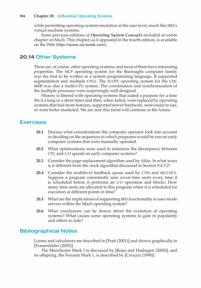
904 Chapter 20 Influential Operating Systems
while permitting operating-system emulation at the user level, much like IBM’svirtual machine systems.
Some previous editions of Operating System Concepts included an entirechapter on Mach. This chapter, as it appeared in the fourth edition, is availableon the Web (http://www.os-book.com).
20.14 Other Systems
There are, of course, other operating systems, and most of them have interestingproperties. The MCP operating system for the Burroughs computer familywas the first to be written in a system programming language. It supportedsegmentation and multiple CPUs. The SCOPE operating system for the CDC6600 was also a multi-CPU system. The coordination and synchronization ofthe multiple processes were surprisingly well designed.
History is littered with operating systems that suited a purpose for a time(be it a long or a short time) and then, when faded, were replaced by operatingsystems that had more features, supported newer hardware, were easier to use,or were better marketed. We are sure this trend will continue in the future.
Exercises
20.1 Discuss what considerations the computer operator took into accountin deciding on the sequences in which programs would be run on earlycomputer systems that were manually operated.
20.2 What optimizations were used to minimize the discrepancy betweenCPU and I/O speeds on early computer systems?
20.3 Consider the page-replacement algorithm used by Atlas. In what waysis it different from the clock algorithm discussed in Section 9.4.5.2?
20.4 Consider the multilevel feedback queue used by CTSS and MULTICS.Suppose a program consistently uses seven time units every time itis scheduled before it performs an I/O operation and blocks. Howmany time units are allocated to this program when it is scheduled forexecution at different points in time?
20.5 What are the implications of supporting BSD functionality in user-modeservers within the Mach operating system?
20.6 What conclusions can be drawn about the evolution of operatingsystems? What causes some operating systems to gain in popularityand others to fade?
Bibliographical Notes
Looms and calculators are described in [Frah (2001)] and shown graphically in[Frauenfelder (2005)].
The Manchester Mark 1 is discussed by [Rojas and Hashagen (2000)], andits offspring, the Ferranti Mark 1, is described by [Ceruzzi (1998)].
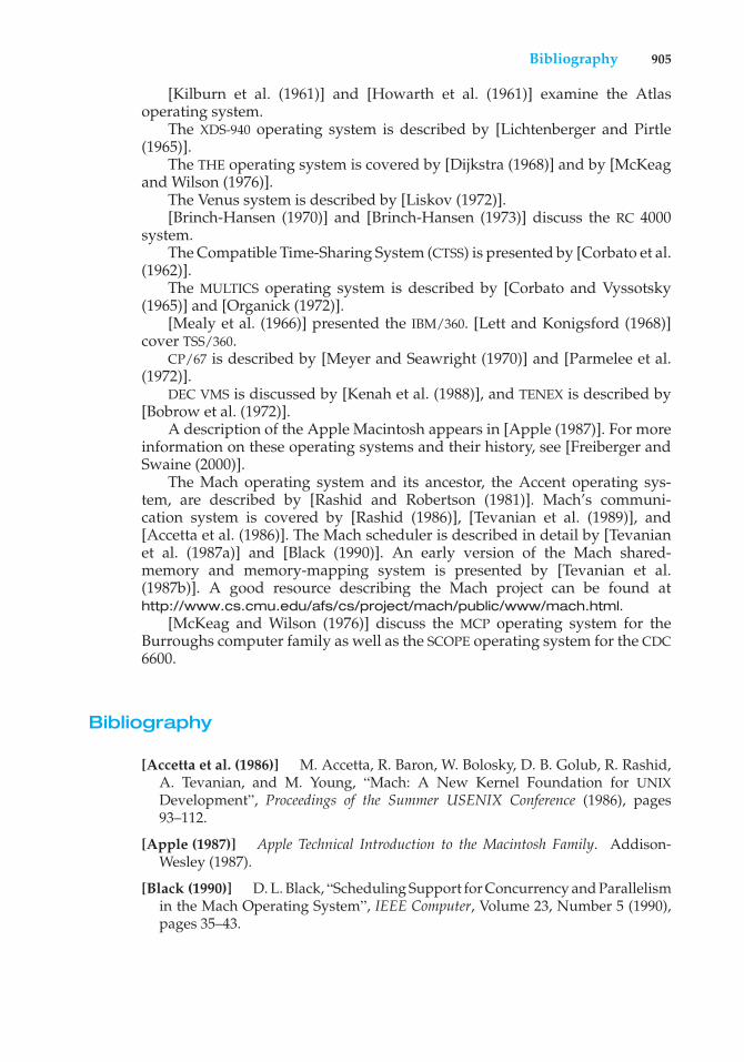
Bibliography 905
[Kilburn et al. (1961)] and [Howarth et al. (1961)] examine the Atlasoperating system.
The XDS-940 operating system is described by [Lichtenberger and Pirtle(1965)].
The THE operating system is covered by [Dijkstra (1968)] and by [McKeagand Wilson (1976)].
The Venus system is described by [Liskov (1972)].[Brinch-Hansen (1970)] and [Brinch-Hansen (1973)] discuss the RC 4000
system.The Compatible Time-Sharing System (CTSS) is presented by [Corbato et al.
(1962)].The MULTICS operating system is described by [Corbato and Vyssotsky
(1965)] and [Organick (1972)].[Mealy et al. (1966)] presented the IBM/360. [Lett and Konigsford (1968)]
cover TSS/360.CP/67 is described by [Meyer and Seawright (1970)] and [Parmelee et al.
(1972)].DEC VMS is discussed by [Kenah et al. (1988)], and TENEX is described by
[Bobrow et al. (1972)].A description of the Apple Macintosh appears in [Apple (1987)]. For more
information on these operating systems and their history, see [Freiberger andSwaine (2000)].
The Mach operating system and its ancestor, the Accent operating sys-tem, are described by [Rashid and Robertson (1981)]. Mach’s communi-cation system is covered by [Rashid (1986)], [Tevanian et al. (1989)], and[Accetta et al. (1986)]. The Mach scheduler is described in detail by [Tevanianet al. (1987a)] and [Black (1990)]. An early version of the Mach shared-memory and memory-mapping system is presented by [Tevanian et al.(1987b)]. A good resource describing the Mach project can be found athttp://www.cs.cmu.edu/afs/cs/project/mach/public/www/mach.html.
[McKeag and Wilson (1976)] discuss the MCP operating system for theBurroughs computer family as well as the SCOPE operating system for the CDC6600.
Bibliography
[Accetta et al. (1986)] M. Accetta, R. Baron, W. Bolosky, D. B. Golub, R. Rashid,A. Tevanian, and M. Young, “Mach: A New Kernel Foundation for UNIXDevelopment”, Proceedings of the Summer USENIX Conference (1986), pages93–112.
[Apple (1987)] Apple Technical Introduction to the Macintosh Family. Addison-Wesley (1987).
[Black (1990)] D. L. Black, “Scheduling Support for Concurrency and Parallelismin the Mach Operating System”, IEEE Computer, Volume 23, Number 5 (1990),pages 35–43.
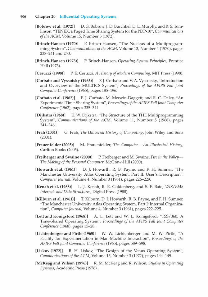
906 Chapter 20 Influential Operating Systems
[Bobrow et al. (1972)] D. G. Bobrow, J. D. Burchfiel, D. L. Murphy, and R. S. Tom-linson, “TENEX, a Paged Time Sharing System for the PDP-10”, Communicationsof the ACM, Volume 15, Number 3 (1972).
[Brinch-Hansen (1970)] P. Brinch-Hansen, “The Nucleus of a Multiprogram-ming System”, Communications of the ACM, Volume 13, Number 4 (1970), pages238–241 and 250.
[Brinch-Hansen (1973)] P. Brinch-Hansen, Operating System Principles, PrenticeHall (1973).
[Ceruzzi (1998)] P. E. Ceruzzi, A History of Modern Computing, MIT Press (1998).
[Corbato and Vyssotsky (1965)] F. J. Corbato and V. A. Vyssotsky, “Introductionand Overview of the MULTICS System”, Proceedings of the AFIPS Fall JointComputer Conference (1965), pages 185–196.
[Corbato et al. (1962)] F. J. Corbato, M. Merwin-Daggett, and R. C. Daley, “AnExperimental Time-Sharing System”, Proceedings of the AFIPS Fall Joint ComputerConference (1962), pages 335–344.
[Dijkstra (1968)] E. W. Dijkstra, “The Structure of the THE MultiprogrammingSystem”, Communications of the ACM, Volume 11, Number 5 (1968), pages341–346.
[Frah (2001)] G. Frah, The Universal History of Computing, John Wiley and Sons(2001).
[Frauenfelder (2005)] M. Frauenfelder, The Computer—An Illustrated History,Carlton Books (2005).
[Freiberger and Swaine (2000)] P. Freiberger and M. Swaine, Fire in the Valley—The Making of the Personal Computer, McGraw-Hill (2000).
[Howarth et al. (1961)] D. J. Howarth, R. B. Payne, and F. H. Sumner, “TheManchester University Atlas Operating System, Part II: User’s Description”,Computer Journal, Volume 4, Number 3 (1961), pages 226–229.
[Kenah et al. (1988)] L. J. Kenah, R. E. Goldenberg, and S. F. Bate, VAX/VMSInternals and Data Structures, Digital Press (1988).
[Kilburn et al. (1961)] T. Kilburn, D. J. Howarth, R. B. Payne, and F. H. Sumner,“The Manchester University Atlas Operating System, Part I: Internal Organiza-tion”, Computer Journal, Volume 4, Number 3 (1961), pages 222–225.
[Lett and Konigsford (1968)] A. L. Lett and W. L. Konigsford, “TSS/360: ATime-Shared Operating System”, Proceedings of the AFIPS Fall Joint ComputerConference (1968), pages 15–28.
[Lichtenberger and Pirtle (1965)] W. W. Lichtenberger and M. W. Pirtle, “AFacility for Experimentation in Man-Machine Interaction”, Proceedings of theAFIPS Fall Joint Computer Conference (1965), pages 589–598.
[Liskov (1972)] B. H. Liskov, “The Design of the Venus Operating System”,Communications of the ACM, Volume 15, Number 3 (1972), pages 144–149.
[McKeag and Wilson (1976)] R. M. McKeag and R. Wilson, Studies in OperatingSystems, Academic Press (1976).
Bibliography 907
[Mealy et al. (1966)] G. H. Mealy, B. I. Witt, and W. A. Clark, “The FunctionalStructure of OS/360”, IBM Systems Journal, Volume 5, Number 1 (1966), pages3–11.
[Meyer and Seawright (1970)] R. A. Meyer and L. H. Seawright, “A VirtualMachine Time-Sharing System”, IBM Systems Journal, Volume 9, Number 3(1970), pages 199–218.
[Organick (1972)] E. I. Organick, The Multics System: An Examination of ItsStructure, MIT Press (1972).
[Parmelee et al. (1972)] R. P. Parmelee, T. I. Peterson, C. C. Tillman, and D. Hat-field, “Virtual Storage and Virtual Machine Concepts”, IBM Systems Journal,Volume 11, Number 2 (1972), pages 99–130.
[Rashid (1986)] R. F. Rashid, “From RIG to Accent to Mach: The Evolution of aNetwork Operating System”, Proceedings of the ACM/IEEE Computer Society, FallJoint Computer Conference (1986), pages 1128–1137.
[Rashid and Robertson (1981)] R. Rashid and G. Robertson, “Accent: A Com-munication-Oriented Network Operating System Kernel”, Proceedings of theACM Symposium on Operating System Principles (1981), pages 64–75.
[Rojas and Hashagen (2000)] R. Rojas and U. Hashagen, The First Computers—History and Architectures, MIT Press (2000).
[Tevanian et al. (1987a)] A. Tevanian, Jr., R. F. Rashid, D. B. Golub, D. L. Black,E. Cooper, and M. W. Young, “Mach Threads and the Unix Kernel: The Battlefor Control”, Proceedings of the Summer USENIX Conference (1987).
[Tevanian et al. (1987b)] A. Tevanian, Jr., R. F. Rashid, M. W. Young, D. B.Golub, M. R. Thompson, W. Bolosky, and R. Sanzi, “A UNIX Interface forShared Memory and Memory Mapped Files Under Mach”, Technical report,Carnegie-Mellon University (1987).
[Tevanian et al. (1989)] A. Tevanian, Jr., and B. Smith, “Mach: The Model forFuture Unix”, Byte (1989).


Credits
• Figure 1.11: From Hennesy and Patterson, Computer Architecture: A Quanti-tative Approach, Third Edition, C⃝ 2002, Morgan Kaufmann Publishers, Figure5.3, p. 394. Reprinted with permission of the publisher.
• Figure 6.24 adapted with permission from Sun Microsystems, Inc.
• Figure 9.18: From IBM Systems Journal, Vol. 10, No. 3, C⃝ 1971, Interna-tional Business Machines Corporation. Reprinted by permission of IBMCorporation.
• Figure 12.9: From Leffler/McKusick/Karels/Quarterman, The Design andImplementation of the 4.3BSD UNIX Operating System, C⃝ 1989 by Addison-Wesley Publishing Co., Inc., Reading, Massachusetts. Figure 7.6, p. 196.Reprinted with permission of the publisher.
• Figure 13.4: From Pentium Processor User’s Manual: Architecture and Pro-gramming Manual, Volume 3, Copyright 1993. Reprinted by permission ofIntel Corporation.
• Figures 17.5, 17.6, and 17.8: From Halsall, Data Communications, ComputerNetworks, and Open Systems, Third Edition, C⃝ 1992, Addison-Wesley Pub-lishing Co., Inc., Reading, Massachusetts. Figure 1.9, p. 14, Figure 1.10, p.15, and Figure 1.11, p. 18. Reprinted with permission of the publisher.
• Figure 6.14: From Khanna/Sebree/Zolnowsky, “Realtime Scheduling inSunOS 5.0,” Proceedings of Winter USENIX, January 1992, San Francisco,California. Derived with permission of the authors.
909

A
access-control lists (ACLs), 832ACLs (access-control lists), 832ACPI (advanced configuration and
power interface), 862address space layout randomization
(ASLR), 832admission-control algorithms, 286advanced configuration and power
interface (ACPI), 862advanced encryption standard
(AES), 677advanced local procedure call
(ALPC), 135, 854ALPC (advanced local procedure
call), 135, 854AMD64 architecture, 387Amdahl’s Law, 167AMD virtualization technology
(AMD-V), 720Android operating system, 85–86API (application program interface),
63–64Apple iPad, 60, 84application containment, 713,
727–728Aqua interface, 59, 84ARM architecture, 388arrays, 31ASIDs (address-space identifiers),
374ASLR (address space layout
randomization), 832assembly language, 77asynchronous threading, 172
augmented-reality applications, 36authentication:
multifactor, 689automatic working-set trimming, 446
B
background processes, 74–75, 115,296
balanced binary search trees, 33binary search trees, 33binary translation, 718–720binary trees, 33bitmaps, 34bourne-Again shell (bash), 789bridging, 732bugs, 66
C
CFQ (Completely Fair Queueing),817
children, 33chipsets, 836Chrome, 123CIFS (common internet file system),
871circularly linked lists, 32client(s):
thin, 35client-server model, 854–855clock algorithm, 418–419clones, 715cloud computing, 41–42, 716Cocoa Touch, 84
911
Index
code integrity module (Windows 7),832
COM (component object model), 873common internet file system (CIFS),
871Completely Fair Queueing (CFQ),
817computational kernels, 835–836computer environments:
cloud computing, 41–42distributed systems, 37–38mobile computing, 36–37real-time embedded systems, 43virtualization, 40–41
computing:mobile, 36–37
concurrency, 166Concurrency Runtime (ConcRT),
297, 880–881condition variables, 879conflict phase (of dispatch latency),
285containers, 728control partitions, 723coupling, symmetric, 17CPU scheduling:
real-time, 283–290earliest-deadline-first scheduling,
288–289and minimizing latency, 283–285POSIX real-time scheduling, 290priority-based scheduling,
285–287proportional share scheduling,
289–290rate-monotonic scheduling,
287–288virtual machines, 729
critical-section problem:and mutex locks, 212–213
D
Dalvik virtual machine, 86data parallelism, 168–169defense in depth, 689desktop window manager (DWM),
831device objects, 855Digital Equipment Corporation
(DEC), 379digital signatures, 832DirectCompute, 835discovery protocols, 39disk(s):
solid-state, 469dispatcher, 294DMA controller, 595doubly linked lists, 32driver objects, 855DWM (desktop window manager),
831dynamic configurations, 837, 838
E
earliest-deadline-first (EDF)scheduling, 288–289
EC2, 41EDF (earliest-deadline-first)
scheduling, 288–289efficiency, 837emulation, 40, 727emulators, 713encryption:
public-key, 678energy efficiency, 837Erlang language, 241–242event latency, 283–284event-pair objects, 855exit() system call, 120, 121
912 Index
ext2 (second extended file system),811
ext3 (third extended file system),811–813
ext4 (fourth extended file system),811
extended file attributes, 505extensibility, 736
F
fast-user switching, 863–864FIFO, 32file info window (Mac OS X), 505file replication, 767file systems:
Windows 7, see Windows 7foreground processes, 115, 296fork-join strategy, 172fourth extended file system (ext4),
811
G
GCD (Grand Central Dispatch),182–183
general trees, 33gestures, 60global positioning system
(GPS), 36GNOME desktop, 60GPS (global positioning system), 36Grand Central Dispatch (GCD),
182–183granularity, minimum, 797graphics shaders, 835guard pages, 847GUIs (graphical user interfaces),
59–62
H
Hadoop, 765Hadoop distributed file system
(HDFS), 767handle tables, 844hands-on computer systems, 20hardware:
virtual machines, 720–721hash collisions, 471hash functions, 33–34hash maps, 471HDFS (Hadoop distributed file
system), 767hibernation, 860–861hybrid cloud, 42hybrid operating systems, 83–86
Android, 85–86iOS, 84–85Mac OS X, 84
hypercalls, 726hypervisors, 712
type 0, 723–724type 1, 724–725type 2, 725
I
IA-32 architecture, 384–387paging in, 385–387segmentation in, 384–385
IA-64 architecture, 387IaaS (infrastructure as a service),
42idle threads, 840IDSs (intrusion-detection systems),
691–694imperative languages, 241impersonation, 853implicit threading, 177–183
Index 913
Grand Central Dispatch (GCD),182–183
OpenMP and, 181–182thread pools and, 179–181
infrastructure as a service (IaaS), 42Intel processors:
IA-32 architecture, 384–387IA-64 architecture, 387
interface(s):choice of, 61–62
Internet Key Exchange (IKE), 682interpretation, 40interpreted languages, 727interrupt latency, 284–285interrupt service routines (ISRs), 840I/O (input/output):
virtual machines, 731–732iOS operating system, 84–85I/O system(s):
application interface:vectored I/O, 603–604
IP (Internet Protocol), 681–683iPad, see Apple iPadISRs (interrupt service routines), 840
J
Java Virtual Machine (JVM), 107,726, 736–737
journaling file systems, 569–570just-in-time (JIT) compilers, 727JVM, see Java Virtual Machine
K
K Desktop Environment (KDE), 60kernel(s):
computational, 835kernel code, 96kernel data structures, 31–34
arrays, 31
bitmaps, 34hash functions and maps, 33–34lists, 31–33queues, 32stacks, 32trees, 31–33
kernel environment, 84Kernel-Mode Driver Framework
(KMDF), 856kernel-mode threads (KT), 844kernel modules:
Linux, 96–101kernel transaction manager (KTM),
862KMDF (Kernel-Mode Driver
Framework), 856KT (kernel-mode threads), 844KTM (kernel transaction manager),
862
L
latency:in real-time systems, 283–285target, 797
left child, 33LFH design, 883–884LIFO, 32Linux:
kernel modules, 96–101Linux system(s):
obtaining page size on, 370lists, 31–32live migration (virtual machines),
716, 733–735lock(s):
mutex, 212–214loosely-coupled systems, 17love bug virus, 694low-fragmentation heap (LFH)
design, 883–884LPCs (local procedure calls), 834
914 Index
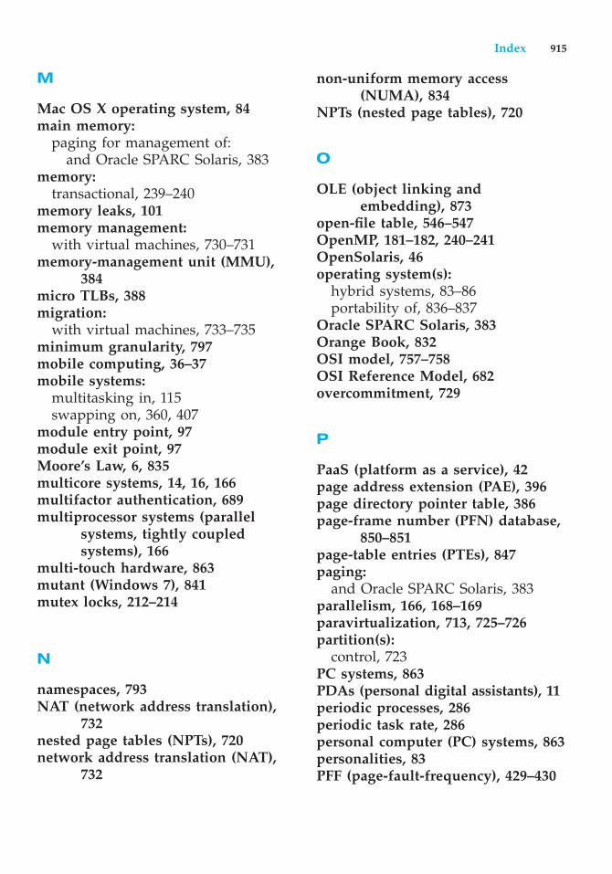
M
Mac OS X operating system, 84main memory:
paging for management of:and Oracle SPARC Solaris, 383
memory:transactional, 239–240
memory leaks, 101memory management:
with virtual machines, 730–731memory-management unit (MMU),
384micro TLBs, 388migration:
with virtual machines, 733–735minimum granularity, 797mobile computing, 36–37mobile systems:
multitasking in, 115swapping on, 360, 407
module entry point, 97module exit point, 97Moore’s Law, 6, 835multicore systems, 14, 16, 166multifactor authentication, 689multiprocessor systems (parallel
systems, tightly coupledsystems), 166
multi-touch hardware, 863mutant (Windows 7), 841mutex locks, 212–214
N
namespaces, 793NAT (network address translation),
732nested page tables (NPTs), 720network address translation (NAT),
732
non-uniform memory access(NUMA), 834
NPTs (nested page tables), 720
O
OLE (object linking andembedding), 873
open-file table, 546–547OpenMP, 181–182, 240–241OpenSolaris, 46operating system(s):
hybrid systems, 83–86portability of, 836–837
Oracle SPARC Solaris, 383Orange Book, 832OSI model, 757–758OSI Reference Model, 682overcommitment, 729
P
PaaS (platform as a service), 42page address extension (PAE), 396page directory pointer table, 386page-frame number (PFN) database,
850–851page-table entries (PTEs), 847paging:
and Oracle SPARC Solaris, 383parallelism, 166, 168–169paravirtualization, 713, 725–726partition(s):
control, 723PC systems, 863PDAs (personal digital assistants), 11periodic processes, 286periodic task rate, 286personal computer (PC) systems, 863personalities, 83PFF (page-fault-frequency), 429–430
Index 915
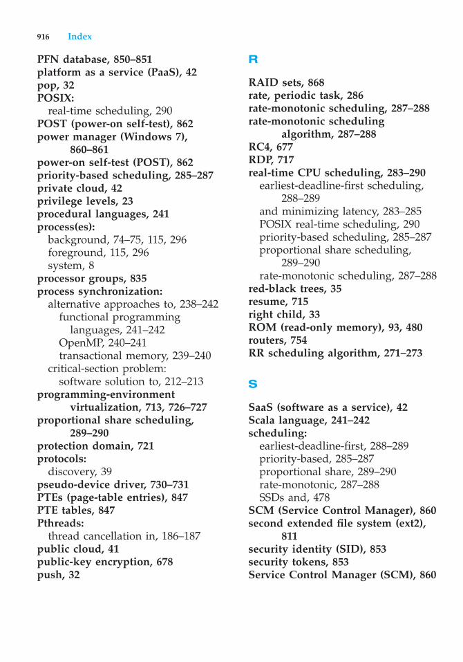
PFN database, 850–851platform as a service (PaaS), 42pop, 32POSIX:
real-time scheduling, 290POST (power-on self-test), 862power manager (Windows 7),
860–861power-on self-test (POST), 862priority-based scheduling, 285–287private cloud, 42privilege levels, 23procedural languages, 241process(es):
background, 74–75, 115, 296foreground, 115, 296system, 8
processor groups, 835process synchronization:
alternative approaches to, 238–242functional programming
languages, 241–242OpenMP, 240–241transactional memory, 239–240
critical-section problem:software solution to, 212–213
programming-environmentvirtualization, 713, 726–727
proportional share scheduling,289–290
protection domain, 721protocols:
discovery, 39pseudo-device driver, 730–731PTEs (page-table entries), 847PTE tables, 847Pthreads:
thread cancellation in, 186–187public cloud, 41public-key encryption, 678push, 32
R
RAID sets, 868rate, periodic task, 286rate-monotonic scheduling, 287–288rate-monotonic scheduling
algorithm, 287–288RC4, 677RDP, 717real-time CPU scheduling, 283–290
earliest-deadline-first scheduling,288–289
and minimizing latency, 283–285POSIX real-time scheduling, 290priority-based scheduling, 285–287proportional share scheduling,
289–290rate-monotonic scheduling, 287–288
red-black trees, 35resume, 715right child, 33ROM (read-only memory), 93, 480routers, 754RR scheduling algorithm, 271–273
S
SaaS (software as a service), 42Scala language, 241–242scheduling:
earliest-deadline-first, 288–289priority-based, 285–287proportional share, 289–290rate-monotonic, 287–288SSDs and, 478
SCM (Service Control Manager), 860second extended file system (ext2),
811security identity (SID), 853security tokens, 853Service Control Manager (SCM), 860
916 Index
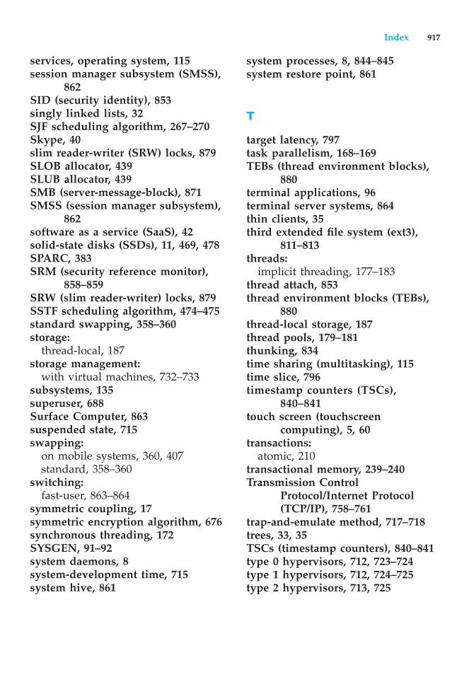
services, operating system, 115session manager subsystem (SMSS),
862SID (security identity), 853singly linked lists, 32SJF scheduling algorithm, 267–270Skype, 40slim reader-writer (SRW) locks, 879SLOB allocator, 439SLUB allocator, 439SMB (server-message-block), 871SMSS (session manager subsystem),
862software as a service (SaaS), 42solid-state disks (SSDs), 11, 469, 478SPARC, 383SRM (security reference monitor),
858–859SRW (slim reader-writer) locks, 879SSTF scheduling algorithm, 474–475standard swapping, 358–360storage:
thread-local, 187storage management:
with virtual machines, 732–733subsystems, 135superuser, 688Surface Computer, 863suspended state, 715swapping:
on mobile systems, 360, 407standard, 358–360
switching:fast-user, 863–864
symmetric coupling, 17symmetric encryption algorithm, 676synchronous threading, 172SYSGEN, 91–92system daemons, 8system-development time, 715system hive, 861
system processes, 8, 844–845system restore point, 861
T
target latency, 797task parallelism, 168–169TEBs (thread environment blocks),
880terminal applications, 96terminal server systems, 864thin clients, 35third extended file system (ext3),
811–813threads:
implicit threading, 177–183thread attach, 853thread environment blocks (TEBs),
880thread-local storage, 187thread pools, 179–181thunking, 834time sharing (multitasking), 115time slice, 796timestamp counters (TSCs),
840–841touch screen (touchscreen
computing), 5, 60transactions:
atomic, 210transactional memory, 239–240Transmission Control
Protocol/Internet Protocol(TCP/IP), 758–761
trap-and-emulate method, 717–718trees, 33, 35TSCs (timestamp counters), 840–841type 0 hypervisors, 712, 723–724type 1 hypervisors, 712, 724–725type 2 hypervisors, 713, 725
Index 917
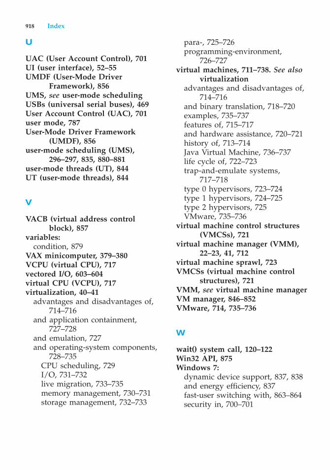
U
UAC (User Account Control), 701UI (user interface), 52–55UMDF (User-Mode Driver
Framework), 856UMS, see user-mode schedulingUSBs (universal serial buses), 469User Account Control (UAC), 701user mode, 787User-Mode Driver Framework
(UMDF), 856user-mode scheduling (UMS),
296–297, 835, 880–881user-mode threads (UT), 844UT (user-mode threads), 844
V
VACB (virtual address controlblock), 857
variables:condition, 879
VAX minicomputer, 379–380VCPU (virtual CPU), 717vectored I/O, 603–604virtual CPU (VCPU), 717virtualization, 40–41
advantages and disadvantages of,714–716
and application containment,727–728
and emulation, 727and operating-system components,
728–735CPU scheduling, 729I/O, 731–732live migration, 733–735memory management, 730–731storage management, 732–733
para-, 725–726programming-environment,
726–727virtual machines, 711–738. See also
virtualizationadvantages and disadvantages of,
714–716and binary translation, 718–720examples, 735–737features of, 715–717and hardware assistance, 720–721history of, 713–714Java Virtual Machine, 736–737life cycle of, 722–723trap-and-emulate systems,
717–718type 0 hypervisors, 723–724type 1 hypervisors, 724–725type 2 hypervisors, 725VMware, 735–736
virtual machine control structures(VMCSs), 721
virtual machine manager (VMM),22–23, 41, 712
virtual machine sprawl, 723VMCSs (virtual machine control
structures), 721VMM, see virtual machine managerVM manager, 846–852VMware, 714, 735–736
W
wait() system call, 120–122Win32 API, 875Windows 7:
dynamic device support, 837, 838and energy efficiency, 837fast-user switching with, 863–864security in, 700–701
918 Index
synchronization in, 833–834,878–879
terminal services, 863–864user-mode scheduling in, 296–297
Windows executive:booting, 862–863power manager, 860–861
Windows group policy, 875Windows Task Manager, 87, 88Windows Vista, 830
security in, 700symbolic links in, 869–870
Windows XP, 830
Winsock, 881Workstation (VMWare), 735–736
X
x86-64 architecture, 387Xen, 714
Z
zones, 728
Index 919

Related Documents