Operating Mechanisms, Disconnect Switches, and Door-Closing Mechanisms Selection Guide Class 9421, 9422, 9423 CONTENTS Description . . . . . . . . . . . . . . . . . . . . . . . . . . . . . . . . . . . . . . . . . . . . . . . . . . . . . Page Class 9421 Door-Mounted Switches and Circuit Breaker Mechanisms VARIO™ Loadbreak Switches . . . . . . . . . . . . . . . . . . . . . . . . . . . . . . . . . . . . . . . . . . 3 IEC-Style Door-Mounted Disconnect Switches . . . . . . . . . . . . . . . . . . . . . . . . . . . . . 6 NEMA-Style Door-Mounted Disconnect Switches . . . . . . . . . . . . . . . . . . . . . . . . . . . 8 Type L Circuit Breaker Mechanisms . . . . . . . . . . . . . . . . . . . . . . . . . . . . . . . . . . . . . 10 Class 9422 Flange-Mounted, Variable-Depth Disconnect Devices Flange-Mounted, Variable-Depth Disconnect Switches . . . . . . . . . . . . . . . . . . . . . . 15 Circuit Breaker Mechanisms . . . . . . . . . . . . . . . . . . . . . . . . . . . . . . . . . . . . . . . . . . . 24 Class 9423 Door-Closing Mechanisms Single- or Multi-door . . . . . . . . . . . . . . . . . . . . . . . . . . . . . . . . . . . . . . . . . . . . . . . . . 34

Welcome message from author
This document is posted to help you gain knowledge. Please leave a comment to let me know what you think about it! Share it to your friends and learn new things together.
Transcript
Operating Mechanisms, Disconnect Switches, and Door-Closing MechanismsSelection Guide
Class 9421, 9422, 9423
CONTENTS
Description . . . . . . . . . . . . . . . . . . . . . . . . . . . . . . . . . . . . . . . . . . . . . . . . . . . . .Page
Class 9421 Door-Mounted Switches and Circuit Breaker MechanismsVARIO™ Loadbreak Switches . . . . . . . . . . . . . . . . . . . . . . . . . . . . . . . . . . . . . . . . . . 3IEC-Style Door-Mounted Disconnect Switches . . . . . . . . . . . . . . . . . . . . . . . . . . . . . 6NEMA-Style Door-Mounted Disconnect Switches . . . . . . . . . . . . . . . . . . . . . . . . . . . 8Type L Circuit Breaker Mechanisms . . . . . . . . . . . . . . . . . . . . . . . . . . . . . . . . . . . . . 10
Class 9422 Flange-Mounted, Variable-Depth Disconnect DevicesFlange-Mounted, Variable-Depth Disconnect Switches . . . . . . . . . . . . . . . . . . . . . . 15Circuit Breaker Mechanisms. . . . . . . . . . . . . . . . . . . . . . . . . . . . . . . . . . . . . . . . . . . 24
Class 9423 Door-Closing MechanismsSingle- or Multi-door . . . . . . . . . . . . . . . . . . . . . . . . . . . . . . . . . . . . . . . . . . . . . . . . . 34
© 1997 Square D All Rights Reserved2
12/97
Note that all Square D switches and circuit breaker mechanisms are lockable in the OFF position, and can be used to comply with OSHA requirements for an Energy Isolation Device.
How to Order
To Order, Specify:Catalog Number
Class Type
1. Class Number2. Type Number— OR —1. Class Number2. Type Number of Switch Body3. Type Number of Shaft Extension4. Type Number of Handle Accessories5. Type Number of Door Interlock Plate6. Type Number of Any Desired Accessories
9421 LN1
Loadbreak Switch
9422R Circuit Breaker Mechanism
NEMA-Style Flange HandleDisconnect Switch
9423 Door-Closing Mechanisms
9421L Circuit Breaker Mechanism
NEMA-Style Rotary HandleDisconnect Switch
IEC-StyleDisconnect Switch
9422 Circuit BreakerCable Operator
Class 9421 Devices
12/97
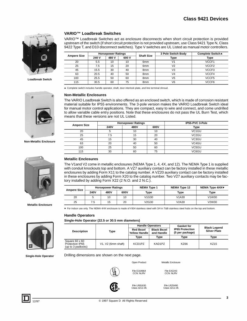
3VARIO™ Loadbreak SwitchesVARIO™ Loadbreak Switches act as enclosure disconnects when short circuit protection is providedupstream of the switch (if short circuit protection is not provided upstream, use Class 9421 Type N, Class9422 Type T, and D10 disconnect switches). Type V switches are UL Listed as manual motor controllers.
q Complete switch includes handle operator, shaft, door interlock plate, and line terminal shroud.
Non-Metallic EnclosuresThe VARIO Loadbreak Switch is also offered as an enclosed switch, which is made of corrosion resistantmaterial suitable for IP55 environments. The 3-pole version makes the VARIO Loadbreak Switch idealfor manual motor control applications. They are compact, easy to wire and connect, and come undrilledto allow variable cable entry positions. Note that these enclosures do not pass the UL Burn Test, whichmeans that these versions are not UL Listed.
Metallic EnclosuresThe V1and V2 come in metallic enclosures (NEMA Type 1, 4, 4X, and 12). The NEMA Type 1 is suppliedwith conduit knockouts top and bottom. A VZ7 auxiliary contact can be factory installed in these metallicenclosures by adding Form X11 to the catalog number. A VZ20 auxiliary contact can be factory installedin these enclosures by adding Form X20 to the catalog number. Two V27 auxiliary contacts may be fac-tory installed by adding Form X22 (2 N.O. and 2 N.C.).
p For indoor use only. The NEMA 4/4X enclosure is made of #304 stainless steel with 3/4 in T&B stainless steel hubs on the top and bottom.
Handle Operators
Drilling dimensions are shown on the next page.
Ampere SizeHorsepower Ratings
Shaft Size3 Pole Switch Body Complete Switchq
240 V 480 V 600 V Type Type20 5.5 10 10 6mm V1 VCCF125 7.5 15 20 6mm V2 VCCF245 15.5 30 40 8mm V3 VCCF363 20.5 40 50 8mm V4 VCCF4
100 25.5 50 60 8mm V5 VCCF5115 30.5 60 75 8mm V6 VCCF6
Ampere SizeHorsepower Ratings IP55-PVC 3-Pole
240V 480V 600V Type20 5 10 10 VC1GU25 7.5 15 20 VC2GU45 15 30 40 VC3GU63 20 40 50 VC4GU
100 25 50 60 VC5GU115 30 60 75 VC6GU
Ampere SizeHorsepower Ratings NEMA Type 1 NEMA Type 12 NEMA Type 4/4Xp
240V 480V 600V Type Type Type
20 5 10 10 V1G30 V1A30 V1W30
25 7.5 15 20 V2G30 V2A30 V2W30
Single-Hole Operator (22.5 or 30.5 mm diameters)
Description Type
Handle Operators Gasket forIP65 Protection(5 per package)
Black LegendSilver PlateRed Bezel
Yellow HandleBlack Bezeland Handle
Type Type Type TypeSquare 60 x 60Protection IP65(up to 3 padlocks)
V1, V2 (6mm shaft) KCD1PZ KAD1PZ KZ66 KZ15
Open Product Metallic Enclosure
File E164864CCN: NLRV
File E42243CCN: NLRV
File LR81630Class 3211-05
File LR25490Class 3211-05
.0.22
Loadbreak Switch
Non-Metallic Enclosure
Metallic Enclosure
Single-Hole Operator
© 1997 Square D All Rights Reserved
Class 9421 Devices
a
b
c
1.89 (48)
2.68
(68
)
1.89
(48
)
0.51 (13) 0.22 (5.5) 0.51 (13)
2.68 (68)in (mm)
Four-Hole Operator(All except KBF3PZ
and KDF3PZ)
Four-Hole Operator(KBF3PZ or KDF3PZ)
Four-Hole 60x60Drilling Dimensions
Four-Hole 90x90Drilling Dimensions
Rear/Panel-Mounting Switch Body
a
b
c
dia. d
.06-.24 (1.5-6)
1.73(44)
in (mm)
0.89(22.5)
0.12 (3.0)
0.5(12.7)
in (mm)
Single-HoleDrilling Dimensions
Main Pole and Auxiliary Contact Module Dimensions
.06-.24 (1.5-6)
a b
1.73(44)
c
in (mm)
Single- and Four-Hole Mounting Dimensions
©4
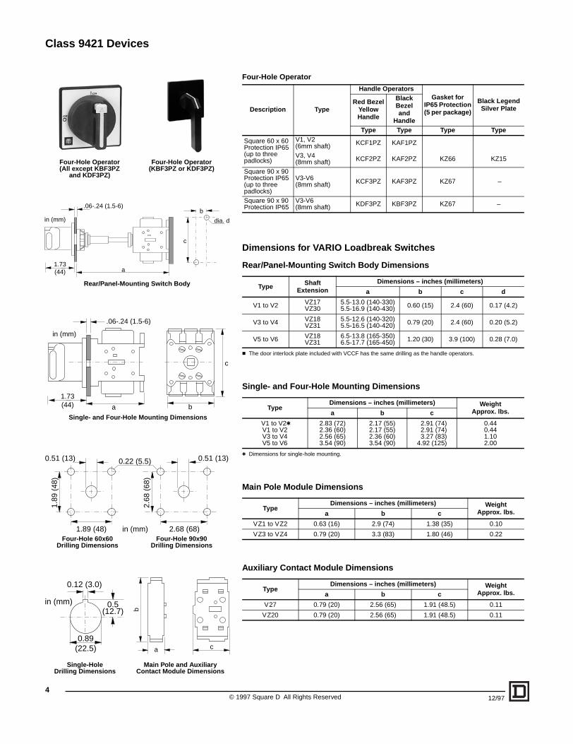
Four-Hole Operator
Dimensions for VARIO Loadbreak Switches
Rear/Panel-Mounting Switch Body Dimensions
c The door interlock plate included with VCCF has the same drilling as the handle operators.
Single- and Four-Hole Mounting Dimensions
t Dimensions for single-hole mounting.
Main Pole Module Dimensions
Auxiliary Contact Module Dimensions
Description Type
Handle OperatorsGasket for
IP65 Protection(5 per package)
Black LegendSilver Plate
Red BezelYellow Handle
Black Bezeland
HandleType Type Type Type
Square 60 x 60Protection IP65(up to three padlocks)
V1, V2(6mm shaft) KCF1PZ KAF1PZ
V3, V4(8mm shaft) KCF2PZ KAF2PZ KZ66 KZ15
Square 90 x 90Protection IP65(up to three padlocks)
V3-V6(8mm shaft) KCF3PZ KAF3PZ KZ67 –
Square 90 x 90Protection IP65
V3-V6 (8mm shaft) KDF3PZ KBF3PZ KZ67 –
Type Shaft Extension
Dimensions – inches (millimeters)
a b c d
V1 to V2 VZ17VZ30
5.5-13.0 (140-330)5.5-16.9 (140-430) 0.60 (15) 2.4 (60) 0.17 (4.2)
V3 to V4 VZ18VZ31
5.5-12.6 (140-320)5.5-16.5 (140-420) 0.79 (20) 2.4 (60) 0.20 (5.2)
V5 to V6 VZ18VZ31
6.5-13.8 (165-350)6.5-17.7 (165-450) 1.20 (30) 3.9 (100) 0.28 (7.0)
TypeDimensions – inches (millimeters) Weight
Approx. lbs.a b c
V1 to V2tV1 to V2V3 to V4V5 to V6
2.83 (72)2.36 (60)2.56 (65)3.54 (90)
2.17 (55)2.17 (55)2.36 (60)3.54 (90)
2.91 (74)2.91 (74)3.27 (83)
4.92 (125)
0.440.441.102.00
TypeDimensions – inches (millimeters) Weight
Approx. lbs.a b c
VZ1 to VZ2 0.63 (16) 2.9 (74) 1.38 (35) 0.10
VZ3 to VZ4 0.79 (20) 3.3 (83) 1.80 (46) 0.22
TypeDimensions – inches (millimeters) Weight
Approx. lbs.a b c
V27 0.79 (20) 2.56 (65) 1.91 (48.5) 0.11
VZ20 0.79 (20) 2.56 (65) 1.91 (48.5) 0.11
1997 Square D All Rights Reserved 12/97
Class 9421 Devices
512/97 © 1997 Square D All Rights Reserved
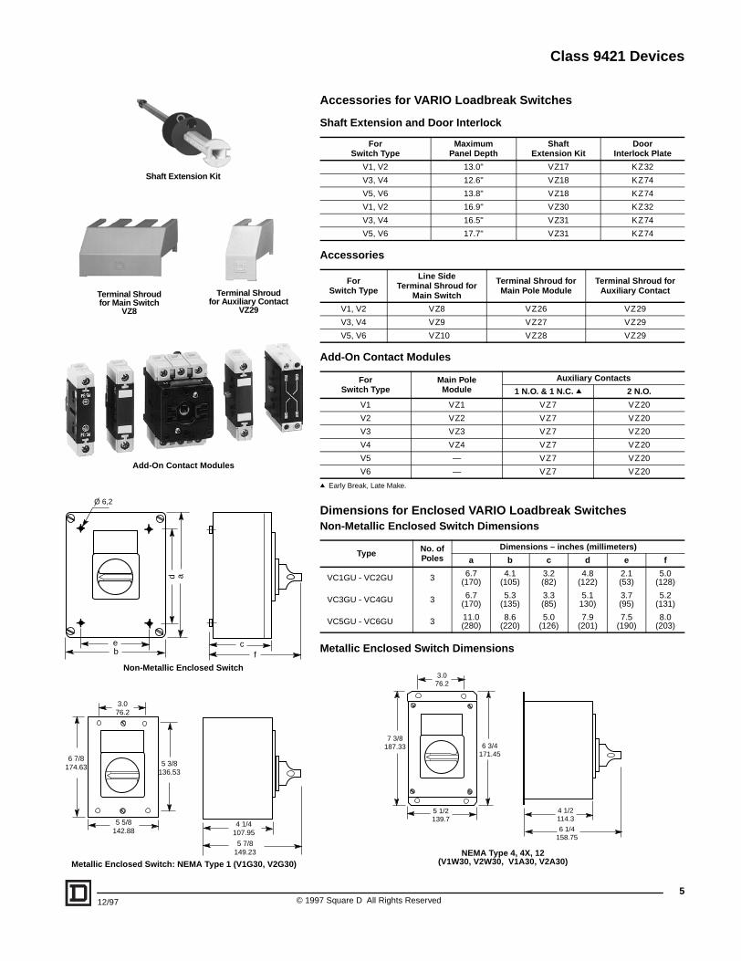
Accessories for VARIO Loadbreak Switches
Shaft Extension and Door Interlock
Accessories
Add-On Contact Modules
q Early Break, Late Make.
Dimensions for Enclosed VARIO Loadbreak SwitchesNon-Metallic Enclosed Switch Dimensions
Metallic Enclosed Switch Dimensions
ForSwitch Type
MaximumPanel Depth
ShaftExtension Kit
DoorInterlock Plate
V1, V2 13.0" VZ17 KZ32
V3, V4 12.6" VZ18 KZ74
V5, V6 13.8" VZ18 KZ74
V1, V2 16.9" VZ30 KZ32
V3, V4 16.5" VZ31 KZ74
V5, V6 17.7" VZ31 KZ74
ForSwitch Type
Line SideTerminal Shroud for
Main Switch
Terminal Shroud for Main Pole Module
Terminal Shroud for Auxiliary Contact
V1, V2 VZ8 VZ26 VZ29
V3, V4 VZ9 VZ27 VZ29
V5, V6 VZ10 VZ28 VZ29
For Switch Type
Main PoleModule
Auxiliary Contacts
1 N.O. & 1 N.C. q 2 N.O.
V1 VZ1 VZ7 VZ20
V2 VZ2 VZ7 VZ20
V3 VZ3 VZ7 VZ20
V4 VZ4 VZ7 VZ20
V5 — VZ7 VZ20
V6 — VZ7 VZ20
Type No. of Poles
Dimensions – inches (millimeters)
a b c d e f
VC1GU - VC2GU 3 6.7(170)
4.1(105)
3.2(82)
4.8(122)
2.1(53)
5.0(128)
VC3GU - VC4GU 3 6.7(170)
5.3(135)
3.3(85)
5.1130)
3.7(95)
5.2(131)
VC5GU - VC6GU 3 11.0 (280)
8.6(220)
5.0(126)
7.9(201)
7.5(190)
8.0(203)
Shaft Extension Kit
Terminal Shroudfor Main Switch
VZ8
Terminal Shroudfor Auxiliary Contact
VZ29
Add-On Contact Modules
O 6,2
eb
d a
cf
Non-Metallic Enclosed Switch3.076.2
6 3/4171.45
7 3/8187.33
5 1/2139.7
4 1/2114.3
6 1/4158.75
NEMA Type 4, 4X, 12(V1W30, V2W30, V1A30, V2A30)
3.076.2
5 3/8136.53
6 7/8174.63
5 5/8142.88
4 1/4107.95
5 7/8149.23
Metallic Enclosed Switch: NEMA Type 1 (V1G30, V2G30)
Class 9421 Devices
© 1997 Square D All Rights Reserved6
12/97
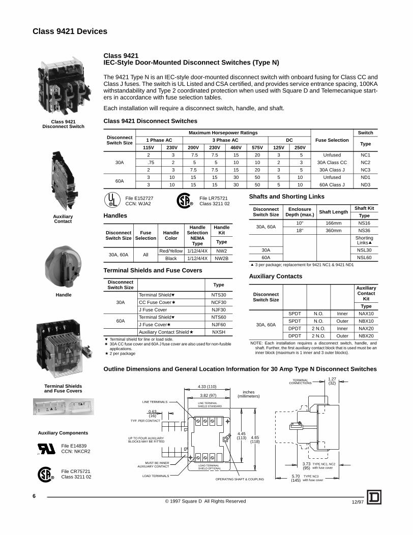
Class 9421 IEC-Style Door-Mounted Disconnect Switches (Type N)
The 9421 Type N is an IEC-style door-mounted disconnect switch with onboard fusing for Class CC andClass J fuses. The switch is UL Listed and CSA certified, and provides service entrance spacing, 100KAwithstandability and Type 2 coordinated protection when used with Square D and Telemecanique start-ers in accordance with fuse selection tables.
Each installation will require a disconnect switch, handle, and shaft.
Class 9421 Disconnect Switches
File E152727 File LR75721CCN: WJA2 Class 3211 02
Handles
Terminal Shields and Fuse Covers
Outline Dimensions and General Location Information for 30 Amp Type N Disconnect Switches
Disconnect Switch Size
Maximum Horsepower Ratings
Fuse Selection
Switch
1 Phase AC 3 Phase AC DCType
115V 230V 200V 230V 460V 575V 125V 250V
30A
2 3 7.5 7.5 15 20 3 5 Unfused NC1
.75 2 5 5 10 10 2 3 30A Class CC NC2
2 3 7.5 7.5 15 20 3 5 30A Class J NC3
60A3 10 15 15 30 50 5 10 Unfused ND1
3 10 15 15 30 50 5 10 60A Class J ND3
Disconnect Switch Size
Fuse Selection
Handle Color
Handle Selection
NEMA Type
Handle Kit
Type
30A, 60A AllRed/Yellow 1/12/4/4X NW2
Black 1/12/4/4X NW2B
Disconnect Switch Size Type
30A
Terminal Shieldp NTS30
CC Fuse Cover t NCF30
J Fuse Cover NJF30
60ATerminal Shieldp NTS60
J Fuse Covert NJF60
Auxiliary Contact Shielda NXSH
p Terminal shield for line or load side.t 30A CC fuse cover and 60A J fuse cover are also used for non-fusible
applications.a 2 per package
TYP. PER CONTACT
TYPE NC3with fuse cover
TYPE NC1, NC2with fuse cover
LOAD TERMINALSOPERATING SHAFT & COUPLING
UP TO FOUR AUXILIARY BLOCKS MAY BE FITTED
LINE TERMINALS
TERMINALCONNECTIONS
LOAD TERMINAL
LINE TERMINAL SHIELD STANDARD
SHIELD OPTIONAL
MUST BE INNERAUXILIARY CONTACT
inches(millimeters)
4.33 (110)
3.82 (97)
4.45(113) 4.65
(118)
0.63(16)
1.27(32)
3.73(95)
5.70(145)
Shafts and Shorting Links
Auxiliary Contacts
Disconnect Switch Size
Enclosure Depth (max.) Shaft Length
Shaft Kit
Type
30A, 60A10" 166mm NS16
18" 360mm NS36
Shorting Linksq
30A NSL30
60A NSL60
q 3 per package; replacement for 9421 NC1 & 9421 ND1
Disconnect Switch Size
Auxiliary Contact
Kit
Type
30A, 60A
SPDT N.O. Inner NAX10
SPDT N.O. Outer NBX10
DPDT 2 N.O. Inner NAX20
DPDT 2 N.O. Outer NBX20
NOTE: Each installation requires a disconnect switch, handle, andshaft. Further, the first auxiliary contact block that is used must be aninner block (maximum is 1 inner and 3 outer blocks).
Class 9421Disconnect Switch
AuxiliaryContact
Handle
Terminal Shieldsand Fuse Covers
Auxiliary Components
File CR75721Class 3211 02
File E14839CCN: NKCR2
Class 9421 Devices
12/97 © 1
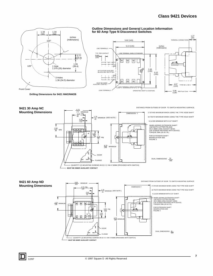
Outline Dimensions and General Location Informationfor 60 Amp Type N Disconnect Switches
5.36(136)
With Fuse Cover
TYPE ND 1, ND 3
LINE TERMINALS
0.63(16)
TYP. PER CONTACT
LOAD TERMINALS OPERATING SHAFT & COUPLING
UP TO FOUR AUXILIARY BLOCKS MAY BE FITTED
TERMINAL CONNECTIONS
LOAD TERMINAL SHIELD OPTIONAL
LINE TERMINAL SHIELD STANDARD
MUST BE INNERAUXILIARY CONTACT
6.10(155)
5.62 (143)
5.14 (131)
4.87(124)
5.06(128)
1.27(32)
inches(millimeters)
1.6241
INMM
DUAL DIMENSIONS
3.2382
1.75
45MINIMUM
9.75248 MINIMUM
FLANGE
DOOR
(SEE NOTE )
G SCREWS #8-32 X 2 / M4 X 50MM (PROVIDED WITH SWITCH)
DIMENSION Y
FOR EXTENSION SHAFTMODIFICATION SEEFIGURE 3
WHEN ADDING EXTENSION SHAFTUSE BOTH COTTER PIN ANDM3 X 8MM LONG SOCKET HEADCAP SCREW PROVIDED WITH DEVICE.TORQUE 2NM (18 LB. IN.)
DISTANCE FROM OUTSIDE OF DOOR TO SWITCH MOUNTING SURFACE.
17.87/445 MAXIMUM WHEN USING THE TYPE NS36 SHAFT
10.75/273 MAXIMUM WHEN USING THE TYPE NS16 SHAFT
6.11/155 MINIMUM WITH CUT SHAFT
mtg
ONTACT
INMM
DUAL DIMENSIONS
1.9750
(SEE NOTE )1.7545
MINIMUM
3.94100
9.75248 MINIMUM
DIMENSION Y
FLANGE
DOOR
G SCREWS #8-32 X 2 / M4 X 50MM (PROVIDED WITH SWITCH)
FOR EXTENSION SHAFTMODIFICATION SEEFIGURE 3
WHEN ADDING EXTENSION SHAFTUSE BOTH COTTER PIN ANDM3 X 8MM LONG SOCKET HEADCAP SCREW PROVIDED WITH DEVICE.TORQUE 2NM (18 LB. IN.)
DISTANCE FROM OUTSIDE OF DOOR TO SWITCH MOUNTING SURFACE.
17.87/445 MAXIMUM WHEN USING THE TYPE NS36 SHAFT
10.75/273 MAXIMUM WHEN USING THE TYPE NS16 SHAFT
6.11/155 MINIMUM WITH CUT SHAFT
mtg
ONTACT
Drilling Dimensions for 9421 NW2/NW2B
0.30
3.5089 MIN.
6.75171 MINIMUM3.3485
7.62
QUANTITY (2) MOUNTIN
mtg
MUST BE INNER AUXILIARY C
9421 30 Amp NC Mounting Dimensions
4.25108
MINIMUM
0.4010
4.72120
8.00203
MINIMUM
QUANTITY (4) MOUNTIN
mtg
MUST BE INNER AUXILIARY C
9421 60 Amp ND Mounting Dimensions
1 Hole1.375 (35) diameter
3 Holes1.36 (34.5) diameter
120°
120°
1.55(39.4)
0.77(19.4)
1.34(34)
1.34(34)
Front Cover
inches(millimeters)
7997 Square D All Rights Reserved
Class 9421 Devices
8
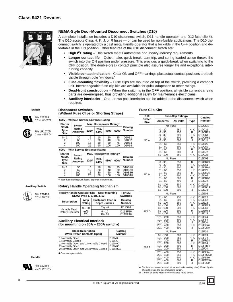
NEMA-Style Door-Mounted Disconnect Switches (D10)A complete installation includes a D10 disconnect switch, D11 handle operator, and D12 fuse clip kit.The D10 accepts Class H, K, J, or R fuses — or can be used for non-fusible applications. The D10 dis-connect switch is operated by a cast metal handle operator that is lockable in the OFF position and de-featable in the ON position. Other features of the D10 disconnect switch are:
• High I2T rating – This switch meets automotive and heavy-industry requirements.• Longer contact life – Quick-make, quick-break, cam-trip, and spring-loaded action throws the
switch into the ON position under pressure. This provides a quick-break when switching to theOFF position. The double-break contact principle also assures longer life and exceptional inter-rupting capacity.
• Visible contact indication – Clear ON and OFF markings plus actual contact positions are bothvisible through pole “windows.”
• Fuse-mounting flexibility – Fuse clips are mounted on top of the switch, providing a compactunit. Interchangeable fuse-clip kits are available for quick adaptation to other ratings.
• Dead-front construction – When the switch is in the OFF position, all visible current-carryingparts are de-energized, thus providing additional safety for maintenance electricians.
• Auxiliary interlocks – One- or two-pole interlocks can be added to the disconnect switch whenrequired.
Disconnect Switches(Without Fuse Clips or Shorting Straps)
j Non-fused rating; with fuses, depends on fuse size.
Rotary Handle Operating Mechanism
Auxiliary Electrical Interlock(for mounting on 30A – 200A switchk)
k One block per switch.
600V – Without Service Entrance Rating
StarterNEMA TypeSize
SwitchRating
Amperes
Max. Horsepower RatingjCatalogNumber120V 200-
240V 480V 600V
0 - 1234
3060
100200
5101525
10203050
204060
100
255075
100
D10S1D10S2D10S3D10S4
600V – With Service Entrance Rating
StarterNEMA TypeSize
SwitchRating
Amperes
Max. Horsepower Rating jCatalogNumber120V 200-
240V 480V 600V
0 - 1234
3060
100200
5101525
10203050
204060
100
255075
100
D10S1HD10S2HD10S3HD10S4H
Rotary Handle Operator Kits – Door MountingNEMA Type 1, 3, 3R, 4, 12
For MC Switches
Description AmpRating
Enclosure InteriorDepth - Inches
CatalogNumber
Variable DepthRotary Operator
30, 60100, 200
55⁄8 - 6 D11SF4
6 - 1010 - 16
D11SF10D11SF16
Block Description(With Switch Contacts Open)
CatalogNumber
1 Normally Open1 Normally Closed1 Normally Open and 1 Normally Closed2 Normally Open2 Normally Open and 2 Normally Closed
D11N0D11NCD11N0CD11N00D11N0C2
Fuse Clip Kits
q Continuous current should not exceed switch rating (size). Fuse clip kitsshould be sized to accommodate inrush.
b Cannot be used with service entrance rated switch.
D10Switch
Size
Fuse-Clip Ratingq CatalogNumberAmperes AC Volts Type
30 A
No Fuse D12CO10 - 300 - 300 - 300 - 300 - 30
250250600600600
H, KR
H, KRJ
D12C21D12CR21D12C61D12CR61D12CJ1
31 - 6031 - 6031 - 6031 - 6061 - 100
250600600600250
H, KH, K
RJ
H, K
D12C22D12C62D12CR62D12CJ2D12C23
60 A
No Fuse D12D020 - 300 - 300 - 3031 - 6031 - 6031 - 6031 - 6031 - 60
250600600250250600600600
RH, K
RH, K
RH, K
RJ
D12DR21D12D61D12DR61D12D22D12DR22D12D62D12DR62D12DJ2
61 - 10061 - 10061 - 100
250600600
H, KH, K
J
D12D23D12D63✫D12DJ3
100 A
No Fuse D12E0331 - 6031 - 6061 - 10061 - 10061 - 10061 - 10061 - 100
250600250250600600600
H, KH, KH, K
RH, K
RJ
D12E22D12E62D12E23D12ER23D12E63D12ER63D12EJ3
101 - 200101 - 200101 - 200201 - 400201 - 400
250600600250600
H, KH, K
JH, K
J
D12F24D12F64D12FJ4D12F25bD12FJ5b
200 A
No Fuse D12F0461 - 100
101 - 200101 - 200101 - 200101 - 200101 - 200
600250250600600600
H, KH, K
RH, K
RJ
D12F63D12F24D12FR24D12F64D12FR64D12FJ4
201 - 400201 - 400201 - 400201 - 400201 - 400
250250600600600
H, KH, KH, K
RJ
D12F25bD12FR25bD12F65bD12FR65bD12FJ5b
Switch
File LR15705Class 4652 04
File E52369CCN: WHTY2
Auxiliary Switch
File E78403CCN: NKCR
Handle
File E52369CCN: WHTY2
© 1997 Square D All Rights Reserved 12/97
Class 9421 Devices
12/97 © 1
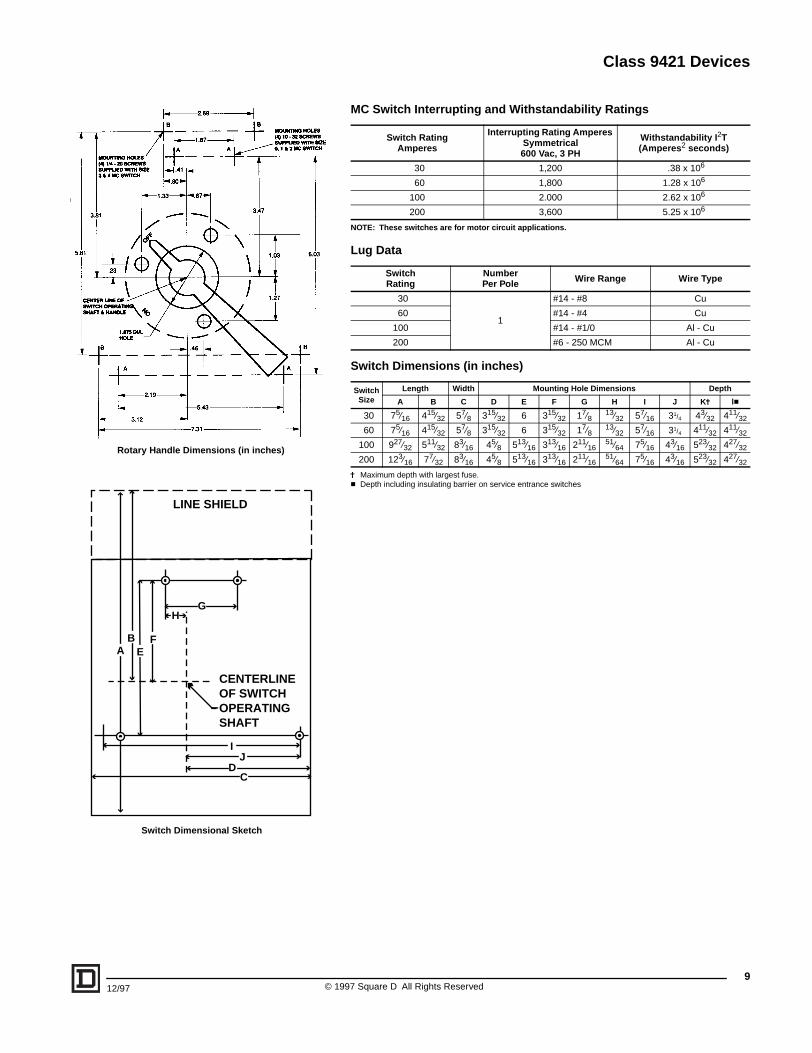
MC Switch Interrupting and Withstandability Ratings
NOTE: These switches are for motor circuit applications.
Lug Data
Switch Dimensions (in inches)
j Maximum depth with largest fuse.c Depth including insulating barrier on service entrance switches
Switch RatingAmperes
Interrupting Rating Amperes Symmetrical600 Vac, 3 PH
Withstandability I2T(Amperes2 seconds)
30 1,200 .38 x 106
60 1,800 1.28 x 10⁶
100 2.000 2.62 x 10⁶
200 3,600 5.25 x 10⁶
SwitchRating
NumberPer Pole Wire Range Wire Type
30
1
#14 - #8 Cu
60 #14 - #4 Cu
100 #14 - #1/0 Al - Cu
200 #6 - 250 MCM Al - Cu
SwitchSize
Length Width Mounting Hole Dimensions Depth
A B C D E F G H I J Kj lc
30 75⁄16 415⁄32 57⁄8 315⁄32 6 315⁄32 17⁄813⁄32 57⁄16 31/4 43⁄32 411⁄32
60 75⁄16 415⁄32 57⁄8 315⁄32 6 315⁄32 17⁄813⁄32 57⁄16 31/4 411⁄32 411⁄32
100 927⁄32 511⁄32 83⁄16 45⁄8 513⁄16 313⁄16 211⁄1651⁄64 75⁄16 43⁄16 523⁄32 427⁄32
200 123⁄16 77⁄32 83⁄16 45⁄8 513⁄16 313⁄16 211⁄1651⁄64 75⁄16 43⁄16 523⁄32 427⁄32
LINE SHIELD
CENTERLINEOF SWITCHOPERATINGSHAFT
IJ
D
AB
EF
H
C
G
Rotary Handle Dimensions (in inches)
Switch Dimensional Sketch
9997 Square D All Rights Reserved
Class 9421 Devices
10
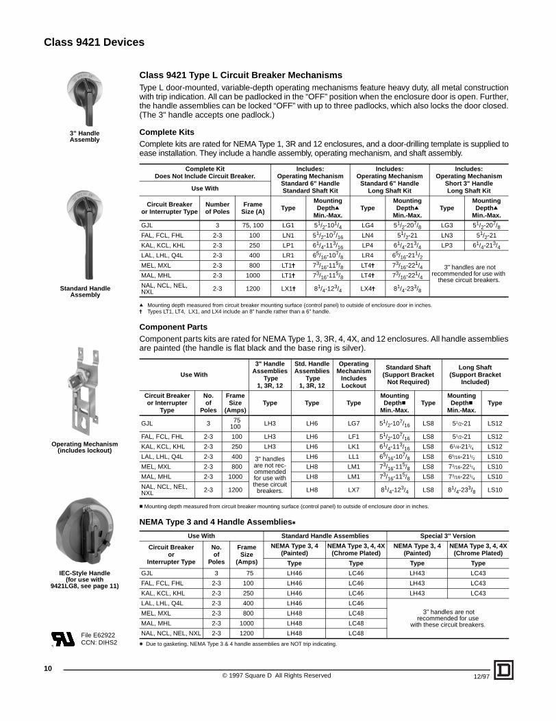
Class 9421 Type L Circuit Breaker MechanismsType L door-mounted, variable-depth operating mechanisms feature heavy duty, all metal constructionwith trip indication. All can be padlocked in the “OFF” position when the enclosure door is open. Further,the handle assemblies can be locked “OFF” with up to three padlocks, which also locks the door closed.(The 3" handle accepts one padlock.)
Complete KitsComplete kits are rated for NEMA Type 1, 3R and 12 enclosures, and a door-drilling template is supplied toease installation. They include a handle assembly, operating mechanism, and shaft assembly.
q Mounting depth measured from circuit breaker mounting surface (control panel) to outside of enclosure door in inches.j Types LT1, LT4, LX1, and LX4 include an 8” handle rather than a 6” handle.
Component PartsComponent parts kits are rated for NEMA Type 1, 3, 3R, 4, 4X, and 12 enclosures. All handle assembliesare painted (the handle is flat black and the base ring is silver).
c Mounting depth measured from circuit breaker mounting surface (control panel) to outside of enclosure door in inches.
NEMA Type 3 and 4 Handle Assembliest
t Due to gasketing, NEMA Type 3 & 4 handle assemblies are NOT trip indicating.
Complete Kit Does Not Include Circuit Breaker.
Includes:Operating Mechanism
Standard 6" HandleStandard Shaft Kit
Includes:Operating Mechanism
Standard 6" HandleLong Shaft Kit
Includes:Operating Mechanism
Short 3" HandleLong Shaft KitUse With
Circuit Breakeror Interrupter Type
Numberof Poles
Frame Size (A) Type
MountingDepthq
Min.-Max.Type
MountingDepthq
Min.-Max.Type
MountingDepthq
Min.-Max.
GJL 3 75, 100 LG1 51/2-101/4 LG4 51/2-207/8 LG3 51/2-207/8FAL, FCL, FHL 2-3 100 LN1 51/2-107/16 LN4 51/2-21 LN3 51/2-21
KAL, KCL, KHL 2-3 250 LP1 61/4-113/16 LP4 61/4-213/4 LP3 61/4-213/4LAL, LHL, Q4L 2-3 400 LR1 65/16-107/8 LR4 65/16-211/2
3" handles are not recommended for use with
these circuit breakers.
MEL, MXL 2-3 800 LT1j 73/16-115/8 LT4j 73/16-221/4MAL, MHL 2-3 1000 LT1j 73/16-115/8 LT4j 73/16-221/4NAL, NCL, NEL, NXL 2-3 1200 LX1j 81/4-123/4 LX4j 81/4-233/8
Use With
3" HandleAssemblies
Type1, 3R, 12
Std. HandleAssemblies
Type1, 3R, 12
OperatingMechanism
Includes Lockout
Standard Shaft(Support Bracket
Not Required)
Long Shaft(Support Bracket
Included)
Circuit Breakeror Interrupter
Type
No.of
Poles
FrameSize
(Amps)Type Type Type
MountingDepthc
Min.-Max.Type
MountingDepthc
Min.-Max.Type
GJL 3 75100 LH3 LH6 LG7 51/2-107/16 LS8 51/2-21 LS12
FAL, FCL, FHL 2-3 100 LH3 LH6 LF1 51/2-107/16 LS8 51/2-21 LS12
KAL, KCL, KHL 2-3 250 LH3 LH6 LK1 61/4-113/16 LS8 61/4-213/4 LS12
LAL, LHL, Q4L 2-3 400 3" handles are not rec-ommended for use with these circuit
breakers.
LH6 LL1 65/16-107/8 LS8 65/16-211/2 LS10
MEL, MXL 2-3 800 LH8 LM1 73/16-115/8 LS8 73/16-221/4 LS10
MAL, MHL 2-3 1000 LH8 LM1 73/16-115/8 LS8 73/16-221/4 LS10
NAL, NCL, NEL, NXL 2-3 1200 LH8 LX7 81/4-123/4 LS8 81/4-233/8 LS10
Use With Standard Handle Assemblies Special 3'' Version
Circuit Breakeror
Interrupter Type
No.of
Poles
FrameSize
(Amps)
NEMA Type 3, 4(Painted)
NEMA Type 3, 4, 4X(Chrome Plated)
NEMA Type 3, 4(Painted)
NEMA Type 3, 4, 4X(Chrome Plated)
Type Type Type Type
GJL 3 75 LH46 LC46 LH43 LC43
FAL, FCL, FHL 2-3 100 LH46 LC46 LH43 LC43
KAL, KCL, KHL 2-3 250 LH46 LC46 LH43 LC43
LAL, LHL, Q4L 2-3 400 LH46 LC46 3" handles are not
recommended for usewith these circuit breakers.
MEL, MXL 2-3 800 LH48 LC48
MAL, MHL 2-3 1000 LH48 LC48
NAL, NCL, NEL, NXL 2-3 1200 LH48 LC48
3” HandleAssembly
Standard HandleAssembly
Operating Mechanism(includes lockout)
IEC-Style Handle(for use with
9421LG8, see page 11)
File E62922CCN: DIHS2
© 1997 Square D All Rights Reserved 12/97
Class 9421 Devices
inmm
1-5/6427.38 27.38
1-3/8
15.8
75
9/327.144
1 x ø
3 x ø
1-5/64
1-1/
431
.75
5/8
35
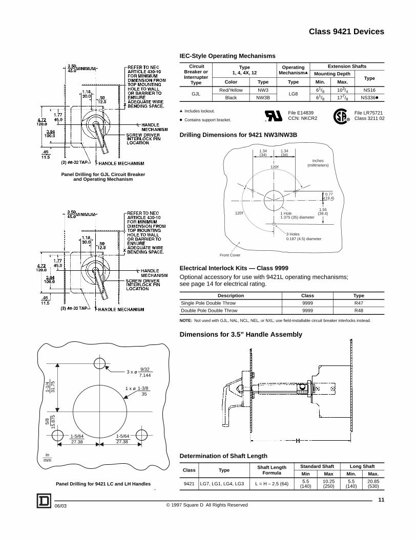
Panel Drilling for GJL Circuit Breakerand Operating Mechanism
Panel Drilling for 9421 LC and LH Handles
12/97 © 106/03
IEC-Style Operating Mechanisms
q Includes lockout.
k Contains support bracket.
Drilling Dimensions for 9421 NW3/NW3B
Electrical Interlock Kits — Class 9999Optional accessory for use with 9421L operating mechanisms; see page 14 for electrical rating.
NOTE: Not used with GJL, NAL, NCL, NEL, or NXL; use field-installable circuit breaker interlocks instead.
Dimensions for 3.5” Handle Assembly
Determination of Shaft Length
Circuit Breaker orInterrupter
Type
Type1, 4, 4X, 12
Operating Mechanismq
Extension Shafts
Mounting DepthType
Color Type Type Min. Max.
GJLRed/Yellow NW3
LG861/8 103/4 NS16
Black NW3B 61/8 177/8 NS336k
Description Class Type
Single Pole Double Throw 9999 R47
Double Pole Double Throw 9999 R48
Class Type Shaft Length Formula
Standard Shaft Long Shaft
Min Max Min. Max.
9421 LG7, LG1, LG4, LG3 L = H – 2.5 (64) 5.5(140)
10.25 (250)
5.5(140)
20.85(530)
1 Hole1.375 (35) diameter
3 Holes0.187 (4.5) diameter
120ϒ
120ϒ
1.55(39.4)
0.77(19.4)
1.34(34)
1.34(34)
Front Cover
inches(millimeters)
File E14839CCN: NKCR2
File LR75721Class 3211 02
11997 Square D All Rights Reserved
Class 9421 Devices
©12
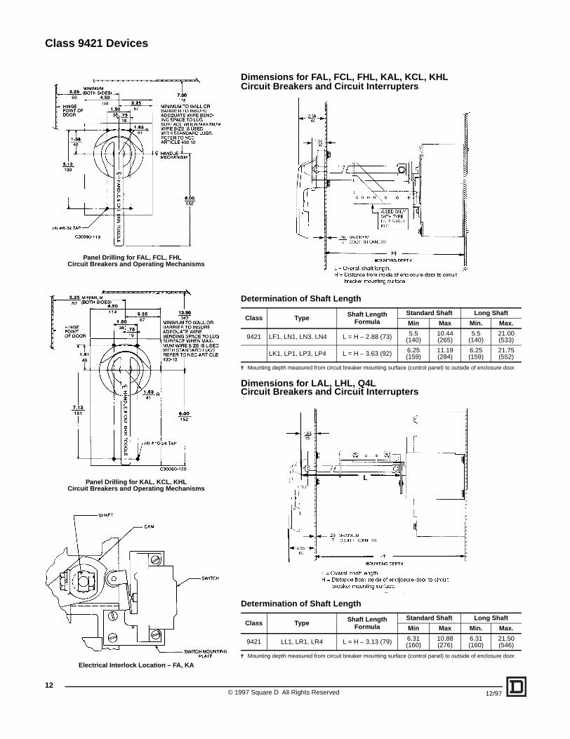
Dimensions for FAL, FCL, FHL, KAL, KCL, KHLCircuit Breakers and Circuit Interrupters
Determination of Shaft Length
j Mounting depth measured from circuit breaker mounting surface (control panel) to outside of enclosure door.
Dimensions for LAL, LHL, Q4LCircuit Breakers and Circuit Interrupters
Determination of Shaft Length
j Mounting depth measured from circuit breaker mounting surface (control panel) to outside of enclosure door.
Class Type Shaft Length Formula
Standard Shaft Long Shaft
Min Max Min. Max.
9421 LF1, LN1, LN3, LN4 L = H – 2.88 (73) 5.5(140)
10.44 (265)
5.5(140)
21.00(533)
LK1, LP1, LP3, LP4 L = H – 3.63 (92) 6.25 (159)
11.19(284)
6.25(159)
21.75(552)
Class Type Shaft Length Formula
Standard Shaft Long Shaft
Min Max Min. Max.
9421 LL1, LR1, LR4 L = H – 3.13 (79) 6.31(160)
10.88 (276)
6.31(160)
21.50(546)
Panel Drilling for FAL, FCL, FHLCircuit Breakers and Operating Mechanisms
Panel Drilling for KAL, KCL, KHL Circuit Breakers and Operating Mechanisms
Electrical Interlock Location – FA, KA
1997 Square D All Rights Reserved 12/97

Class 9421 Devices
12/97 © 1
Panel Drilling for LAL, LHL, Q4L Circuit Breakers and Operating Mechanisms
Panel Drilling for MAL, MEL, MHL, MXL Circuit Breakers and Operating Mechanisms
Circuit Breaker Type
Dimensions – in (mm)A B
MAL, MHL 10.69 (272) 14.00 (356)MEL, MXL 11.47 (291) 14.75 (375)
Electrical Interlock Location for LAL, LHL, Q4LCircuit Breakers and Operating Mechanisms
Dimensions for MAL, MEL, MHL, MXL Circuit Breakers and Circuit Interrupters
Determination of Shaft Length
j Mounting depth measured from circuit breaker mounting surface (control panel) to outside of enclosure door.
Class Type Shaft Length Formula
Standard Shaft Long Shaft
Min Max Min. Max.
9421 LM1, LT1, LT4 L = H – 4.00 (104) 7.18(182)
11.63(295)
7.18(182)
22.25(565)
13997 Square D All Rights Reserved
Class 9421 Devices
©14
9 (229) MINIMUM(BOTH SIDES)
HA
ND
LE M
EC
HA
NIS
M
(4) 1/4-20 TAP
HINGEPOINTOFDOOR
CL
CLC
IRC
UIT
BR
EA
KE
R
12.13(308)
CL
9.5(241)
8.75(222)
7.5(191)
1.66(42)
15.0 (381)3.16(80)
2.5(64)
5.0(127)
R= 1.63(41)
8.0(203)
8.5(216)
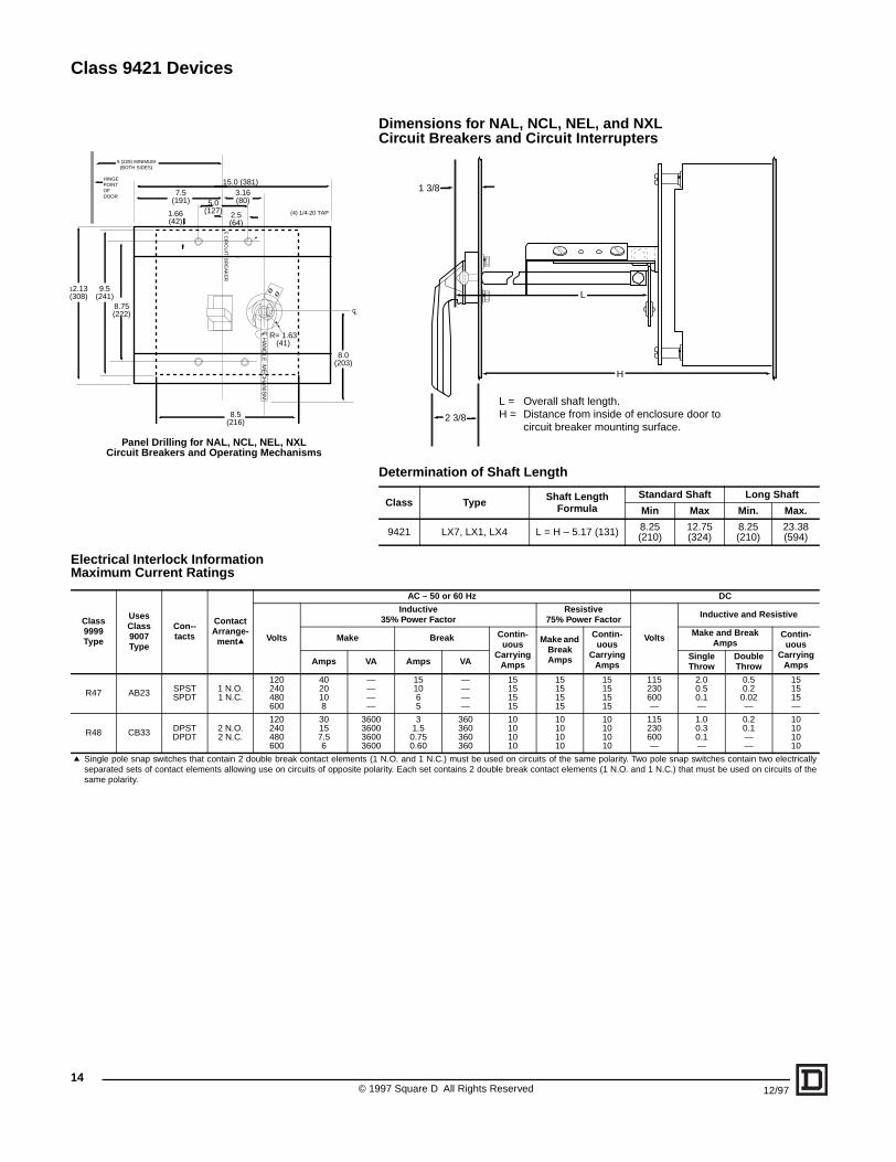
Panel Drilling for NAL, NCL, NEL, NXL Circuit Breakers and Operating Mechanisms
Electrical Interlock InformationMaximum Current Ratings
Class 9999 Type
Uses Class 9007 Type
Con--tacts
Contact Arrange-
mentq Volts Make
Amps V
R47 AB23 SPSTSPDT
1 N.O.1 N.C.
120240480600
4020108
R48 CB33 DPSTDPDT
2 N.O.2 N.C.
120240480600
30157.56
3333
q Single pole snap switches that contain 2 double break contact elementsseparated sets of contact elements allowing use on circuits of opposite psame polarity.
Dimensions for NAL, NCL, NEL, and NXL Circuit Breakers and Circuit Interrupters
Determination of Shaft Length
Class Type Shaft Length Formula
Standard Shaft Long Shaft
Min Max Min. Max.
9421 LX7, LX1, LX4 L = H – 5.17 (131) 8.25(210)
12.75(324)
8.25(210)
23.38(594)
1 3/8
2 3/8
H
L
L = Overall shaft length.H = Distance from inside of enclosure door to
circuit breaker mounting surface.
AC – 50 or 60 Hz DC
Inductive35% Power Factor
Resistive75% Power Factor
Volts
Inductive and Resistive
Break Contin-uous
Carrying Amps
Make and Break Amps
Contin-uous
Carrying Amps
Make and Break Amps
Contin-uous
Carrying AmpsA Amps VA Single
ThrowDouble Throw
————
151065
————
15151515
15151515
15151515
115230600—
2.00.50.1—
0.50.2
0.02—
151515—
600600600600
31.5
0.750.60
360360360360
10101010
10101010
10101010
115230600—
1.00.30.1—
0.20.1——
10101010
(1 N.O. and 1 N.C.) must be used on circuits of the same polarity. Two pole snap switches contain two electricallyolarity. Each set contains 2 double break contact elements (1 N.O. and 1 N.C.) that must be used on circuits of the
1997 Square D All Rights Reserved 12/97
Class 9422 Devices
DisconnectSwitch
Size
VariableDepth
MountingRange
Min.-Max.(inches)
AC
2(2
30A 65/8"–18" 7
60A 65/8"–18" 1
100A 65/8"–18" 2
200-400A
Switch
File LR44199Class 4652 04
File E52639CCN: WHTY2
12/97
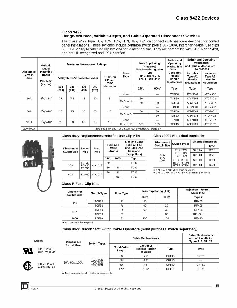
Class 9422Flange-Mounted, Variable-Depth, and Cable-Operated Disconnect SwitchesThe Class 9422 Type TCF, TCN, TDF, TDN, TEF, TEN disconnect switches were designed for controlpanel installations. These switches include common switch profile 30 - 100A, interchangeable fuse clips30 - 60A, ability to add fuse clip kits and cable mechanisms. They are compatible with 9422A and 9423,and are UL recognized and CSA certified.
Class 9422 Replacement/Retrofit Fuse Clip Kits
Class R Fuse Clip Kits
Class 9422 Disconnect Switch Cable Operators (must purchase switch separately)
Maximum Horsepower Ratings
FuseType
Fuse Clip Rating(Amperes)
Non-Interchangeable Type
For Class H, J, Kor R Fuses Only
Switch and Operating
Mechanism Only —
Does Not IncludeHandle
Mechanism
Switch and Operating Mechanism
and Handle Mechanism – Overpacked
Systems Volts (Motor Volts) DC Using2 Poles
250VMaximum
Includes Type A1Handle
Mechanism
Includes Type A2Handle
Mechanism
0800)
240(230)
480(460)
600(575) 250V 600V Type Type Type
.5 7.5 15 20 5
None — TCN30 ATCN301 ATCN302
H, K, J, R30 TCF30 ATCF301 ATCF302
60 30 TCF33 ATCF331 ATCF332
5 15 30 50 10
None — TDN60 ATDN601 ATDN602
H, K, J, R60 30 TDF60 ATDF601 ATDF602
60 TDF63 ATDF631 ATDF632
5 30 60 75 20None — TEN10 ATEN101 ATEN102
H, K, J, R 100 100 TEF10 ATEF101 ATEF102
See 9422 TF and TG Disconnect Switches on page 17
Disconnect Switch Size
Switch Type
Fuse Type
Fuse Clip Rating(Amps)
Line and Load Fuse Clip Kit
(includes load base and
fusepullers)
250V 600V Type
30ATCF30TCN30TCF33
H, K, J, R30 TC30
60 30 TC33
60A TDN60 H, K, J, R60 30 TC33
60 TD63
Disconnect Switch Size Switch Type Fuse Type
Fuse Clip Rating (AIR) Rejection Feature – Class R Kit
250V 600V Typep
30ATCF30 R 30 RFK03
TCF33 R 60 30 RFK06
60ATDF60 R 60 30 RFK06
TDF63 R 60 RFK06H
100A TEF10 R 100 100 RFK10
p No Class Number required.
DisconnectSwitch Size Switch Types
Cable MechanismsqCable Mechanismswith A1 Handle forTypes 1, 3, 3R, 12
Total Cable Length
Length of Flexible Portion
of CableType Type
30A, 60A, 100ATCF, TCNTDF, TDNTEF, TEN
36" 22" CFT30 CFT31
48" 34" CFT40 —
60" 46" CFT50 CFT51
120" 106" CFT10 CFT11
q Must purchase handle mechanism separately.
Class 9999 Electrical Interlocks
t 1 N.C. or 1 N.O. depending on wiring.c 2 N.C., 2 N.O. or 1 N.O., 1 N.C. depending on wiring.
Disconnect Switch Size Switch Types
Electrical Interlock
Type
30A60A100A
TCF, TCNTDF, TDNTEF, TEN
SPDTt TC10
DPDTc TC20
BTCF, BTCNBTDF, BTDNBTEF, BTEN
SPDTt TC11
DPDTc TC21
15© 1997 Square D All Rights Reserved
Class 9422 Devices
16
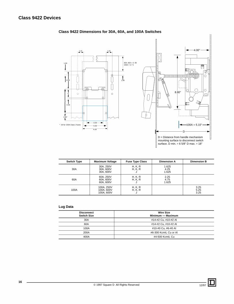
Class 9422 Dimensions for 30A, 60A, and 100A Switches
Lug Data
Switch Type Maximum Voltage Fuse Type Class Dimension A Dimension B
30A30A, 250V30A, 600V30A, 600V
H, K, RH, K, R
J
1.6254.251.625
60A60A, 250V60A, 600V60A, 600V
H, K, RH, K, R
J
2.254.751.625
100A100A, 250V100A, 600V100A, 600V
H, K, RH, K, R
J
3.255.253.25
DisconnectSwitch Size
Wire SizeMinimum — Maximum
30A #14-#2 Cu, #10-#2 Al
60A #14-#2 Cu, #10-#2 Al
100A #10-#0 Cu, #6-#0 Al
200A #6-300 KcmiL Cu or Al
400A #4-500 KcmiL Cu
1.411.41
1.00
30A, 60A = 3 .50100A = 5.7 5
0.30
1.50*
B
A
4.50
1.00
5.50
4.00
6.20
* .30 for 100A Class J fuses
8.80"
4.00"
D
100A = 5.10"
D = Distance from handle mechanismmounting surface to disconnect switchsurface. D min. = 6 5/8" D max. = 18"
© 1997 Square D All Rights Reserved 12/97
Class 9422 Devices
1712/97 © 1997 Square D All Rights Reserved
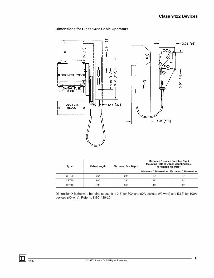
Dimensions for Class 9422 Cable Operators
Dimension X is the wire bending space. It is 2.5" for 30A and 60A devices (#2 wire) and 5.12" for 100A devices (#0 wire). Refer to NEC 430-10.
Type Cable Length Maximum Box Depth
Maximum Distance from Top Right Mounting Hole to Upper Mounting Hole
for Handle Operator
Minimum C Dimension Maximum C Dimension
CFT30 36" 24" 1" 4"
CFT50 60" 36" 16" 24"
CFT10 120" 36" 48" 60"
Class 9422 Devices
18
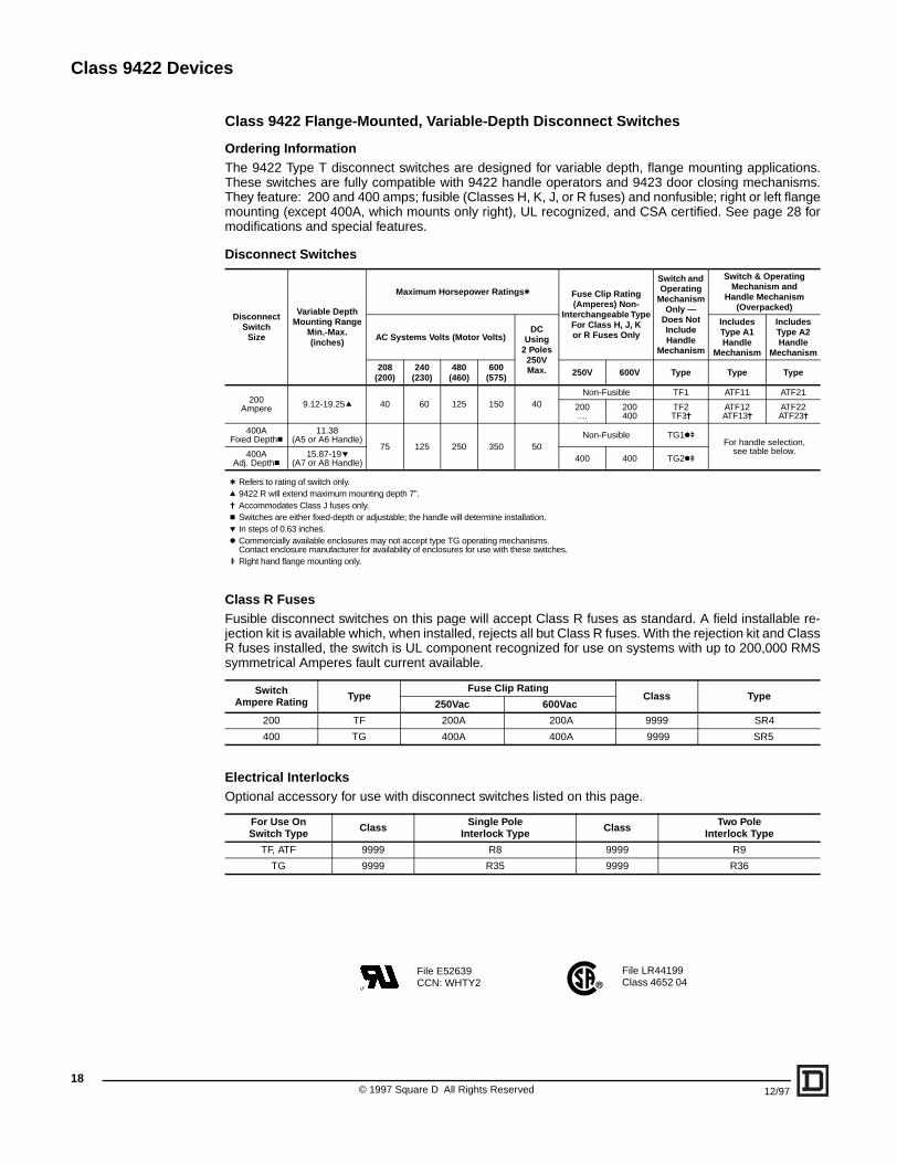
Class 9422 Flange-Mounted, Variable-Depth Disconnect Switches
Ordering InformationThe 9422 Type T disconnect switches are designed for variable depth, flange mounting applications.These switches are fully compatible with 9422 handle operators and 9423 door closing mechanisms.They feature: 200 and 400 amps; fusible (Classes H, K, J, or R fuses) and nonfusible; right or left flangemounting (except 400A, which mounts only right), UL recognized, and CSA certified. See page 28 formodifications and special features.
Disconnect Switches
Class R FusesFusible disconnect switches on this page will accept Class R fuses as standard. A field installable re-jection kit is available which, when installed, rejects all but Class R fuses. With the rejection kit and ClassR fuses installed, the switch is UL component recognized for use on systems with up to 200,000 RMSsymmetrical Amperes fault current available.
Electrical InterlocksOptional accessory for use with disconnect switches listed on this page.
DisconnectSwitch
Size
Variable DepthMounting Range
Min.-Max.(inches)
Maximum Horsepower Ratingst Fuse Clip Rating(Amperes) Non-
Interchangeable TypeFor Class H, J, Kor R Fuses Only
Switch and Operating
Mechanism Only —
Does Not IncludeHandle
Mechanism
Switch & Operating Mechanism and
Handle Mechanism (Overpacked)
AC Systems Volts (Motor Volts)DC
Using2 Poles
250VMax.
Includes Type A1Handle
Mechanism
Includes Type A2Handle
Mechanism
208(200)
240(230)
480(460)
600(575) 250V 600V Type Type Type
200Ampere 9.12-19.25q 40 60 125 150 40
Non-Fusible TF1 ATF11 ATF21
200....
200400
TF2TF3j
ATF12ATF13j
ATF22ATF23j
400AFixed Depthc
11.38(A5 or A6 Handle)
75 125 250 350 50Non-Fusible TG1ku
For handle selection, see table below.400A
Adj. Depthc15.87-19p
(A7 or A8 Handle) 400 400 TG2ku
t Refers to rating of switch only. q 9422 R will extend maximum mounting depth 7".j Accommodates Class J fuses only.c Switches are either fixed-depth or adjustable; the handle will determine installation.p In steps of 0.63 inches.k Commercially available enclosures may not accept type TG operating mechanisms.
Contact enclosure manufacturer for availability of enclosures for use with these switches.u Right hand flange mounting only.
SwitchAmpere Rating Type
Fuse Clip RatingClass Type
250Vac 600Vac
200 TF 200A 200A 9999 SR4
400 TG 400A 400A 9999 SR5
For Use OnSwitch Type Class Single Pole
Interlock Type Class Two PoleInterlock Type
TF, ATF 9999 R8 9999 R9
TG 9999 R35 9999 R36
File LR44199Class 4652 04
File E52639CCN: WHTY2
© 1997 Square D All Rights Reserved 12/97
Class 9422 Devices
12/97 © 1
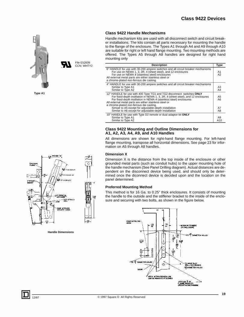
Type A1
Handle Dimensions
File E52639CCN: WHTY2
Class 9422 Handle MechanismsHandle mechanism kits are used with all disconnect switch and circuit break-er installations. The kits contain all parts necessary for mounting the handleto the flange of the enclosure. The Types A1 through A4 and A9 through A10are suitable for right or left hand flange mounting. Two mounting methods areoffered. The Types A5 through A8 handles are designed for right handmounting only
Class 9422 Mounting and Outline Dimensions forA1, A2, A3, A4, A9, and A10 HandlesAll dimensions are shown for right-hand flange mounting. For left-handflange mounting, transpose all horizontal dimensions. See page 23 for infor-mation on A5 through A8 handles.
Dimension XDimension X is the distance from the top inside of the enclosure or othergrounded metal parts (such as conduit hubs) to the upper mounting hole ofthe handle mechanism (See Panel Drilling diagram). Actual distances are de-pendent on the disconnect device being used, and should only be deter-mined once the diconnect device is decided upon and the location on thepanel determined.
Preferred Mounting MethodThis method is for 16 Ga. to 0.25” thick enclosures. It consists of mountingthe handle to the outside and the stiffener bracket to the inside of the enclo-sure and securing with two bolts, as shown in the figure below.
Description Type6” HANDLE for use with 30-200 ampere switches and all circuit breaker mechanisms
For use on NEMA 1, 3, 3R, 4 (sheet steel), and 12 enclosuresFor use on NEMA 4 (stainless steel) enclosures
All external metal parts are either stainless steel or a chrome-plated non-ferrous die casting.
A1A2
4” HANDLE for use with 30-200 ampere switches and all circuit breaker mechanismsSimilar to Type A1Similar to Type A2
A3A4
12” HANDLE for use with 400 Type TG1 and TG2 disconnect switches ONLYFor fixed-depth instllation in NEMA 1, 3, 3R, 4 (sheet steel), and 12 enclosuresFor fixed-depth instllation in NEMA 4 (stainless steel) enclosures
All external metal parts are either stainless steel or a chrome-plated non-ferrous die casting.
Simialr to A5 except for adjustable-depth installationSimilar to A6 except for adjustable-depth installation
A5A6
A7A8
10” HANDLE for use with Type D2 remote or dual adaptor kit ONLY Similar to Type A1Similar to Type A2
A9A10
19997 Square D All Rights Reserved
Class 9422 Devices
©20
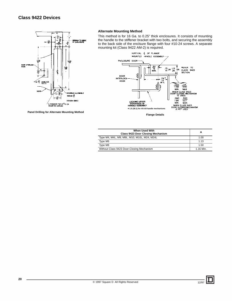
Panel Drilling for Alternate Mounting Method
Alternate Mounting MethodThis method is for 16 Ga. to 0.25” thick enclosures. It consists of mountingthe handle to the stiffener bracket with two bolts, and securing the assemblyto the back side of the enclsure flange with four #10-24 screws. A separatemounting kit (Class 9422 AM-2) is required.
Flange Details
When Used With Class 9423 Door Closing Mechanism A
Type M4, M4L, M9, M9L, M10, M10L, M24, M24L 1.00Type M6 1.13Type M8 1.50Without Class 9423 Door-Closing Mechanism 1.16 Min.
t 1.5 (38.1) for A5-A8 handle mechanisms
1997 Square D All Rights Reserved 12/97
Class 9422 Devices
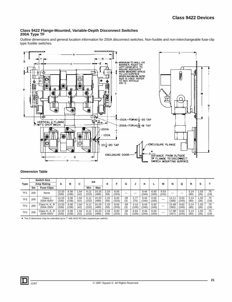
Class 9422 Flange-Mounted, Variable-Depth Disconnect Switches200A Type TFOutline dimensions and general location information for 200A disconnect switches. Non-fusible and non-interchangeable fuse-cliptype fusible switches.
Dimension Table
TypeSwitch Size
A B CDt
E F G J K L M N Q R S TAmp RatingSw Fuse Clips Min Max
TF1 200 None 13.33(339)
9.38(238)
1.64(42)
9.12(232)
19.25(489)
2.33(59)
8.00(203) — — 9.44
(240)6.50(165)
9.53(242) — — 3.14
(80)1.03(26)
.75(19)
TF2 200 Class J200A 600V
13.33(339)
9.38(238)
1.64(42)
9.12(232)
19.25(489)
2.33(59)
8.00(203)
.09(3)
2.77(70)
9.44(240)
6.50(165) — 14.11
(358)9.63(245)
3.14(80)
1.03(26)
.75(19)
TF2 200 Class H, K, R200A 250V
13.33(339)
9.38(238)
1.64(42)
9.12(232)
19.25(489)
2.33(59)
8.00(203)
.09(3)
4.14(105)
9.44(240)
6.50(165) — 15.48
(393)9.63(245)
3.14(80)
1.03(26)
.75(19)
TF2 200 Class H, K, R200A 600V
13.33(339)
9.38(238)
1.64(42)
9.12(232)
19.25(489)
2.33(59)
8.00(203)
.09(3)
6.64(169)
9.44(240)
6.50(165) — 17.98
(457)9.63(245)
3.14(80)
1.03(26)
.75(19)
t The D dimension may be extended up to 7” with 9422 R2 (two required per switch).
2112/97 © 1997 Square D All Rights Reserved
Class 9422 Devices
2
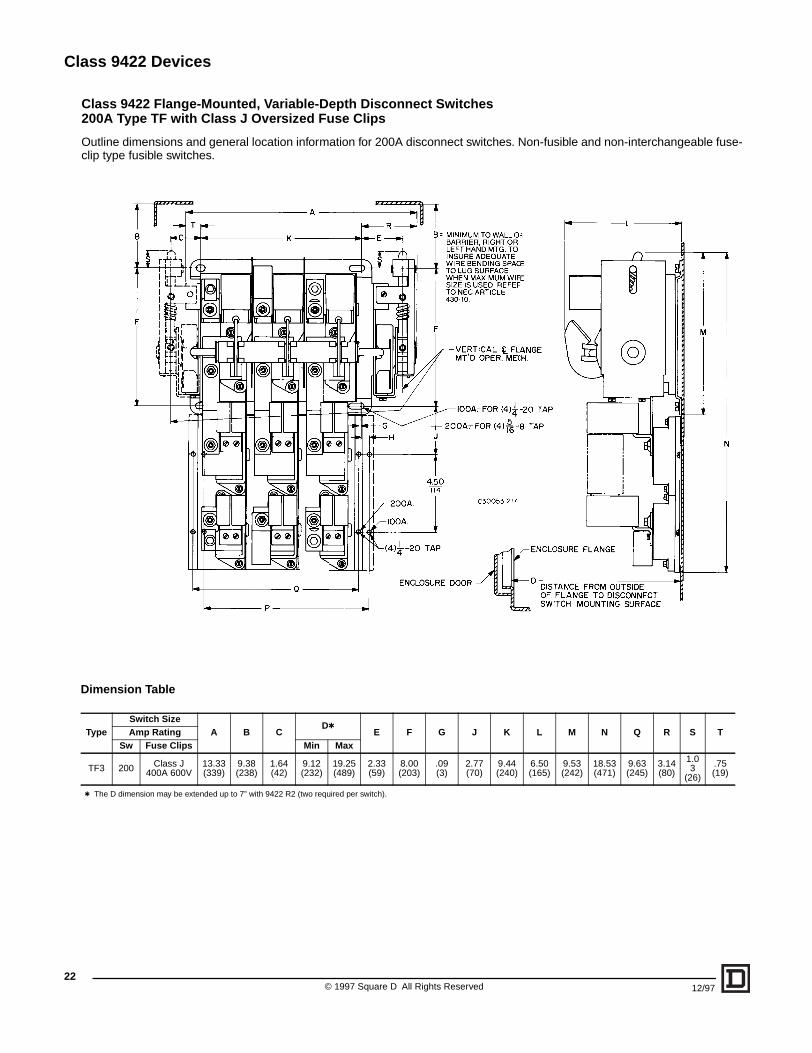
Class 9422 Flange-Mounted, Variable-Depth Disconnect Switches200A Type TF with Class J Oversized Fuse Clips
Outline dimensions and general location information for 200A disconnect switches. Non-fusible and non-interchangeable fuse-clip type fusible switches.
Dimension Table
TypeSwitch Size
A B CDt
E F G J K L M N Q R S TAmp RatingSw Fuse Clips Min Max
TF3 200 Class J400A 600V
13.33(339)
9.38(238)
1.64(42)
9.12(232)
19.25(489)
2.33(59)
8.00(203)
.09(3)
2.77(70)
9.44(240)
6.50(165)
9.53(242)
18.53(471)
9.63(245)
3.14(80)
1.03
(26)
.75(19)
t The D dimension may be extended up to 7” with 9422 R2 (two required per switch).
© 1997 Square D All Rights Reserved2
12/97
Class 9422 Devices
2312/97 © 1997 Square D All Rights Reserved
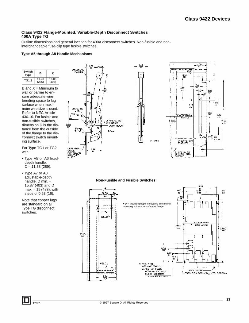
Class 9422 Flange-Mounted, Variable-Depth Disconnect Switches400A Type TGOutline dimensions and general location for 400A disconnect switches. Non-fusible and non-interchangeable fuse-clip type fusible switches.
Type A5 through A8 Handle Mechanisms
Non-Fusible and Fusible Switches
t D = Mounting depth measured from switch mounting suirface to surface of flange
B and X = Minimum to wall or barrier to en-sure adequate wire bending space to lug surface when maxi-mum wire size is used. Refer to NEC Article 430.10. For fusible and non-fusible switches, dimension D is the dis-tance from the outside of the flange to the dis-connect switch mount-ing surface.
For Type TG1 or TG2 with:
• Type A5 or A6 fixed-depth handle, D = 11.38 (289).
• Type A7 or A8 adjustable-depth handle, D min. = 15.87 (403) and D max. = 19 (483), with steps of 0.63 (16).
Note that copper lugs are standard on all Type TG disconnect switches.
Switch Type B X
TG1,2 11.28(286)
16.06(408)

Class 9422 Devices
© 1997 Square D All Rights Reserved24
12/97
Class 9422 Bracket-Mounted Disconnect DevicesClass 9422 Type T disconnect switches listed in the table below are shipped with switch and externalhandle assembled to a bracket, ready for installation into the enclosure. A trim plate is provided witheach kit to eliminate any mounting screws from being accessible from the front and also to provide anattractive installation.These switches can be used with Class 9423 door closing mechanisms.
q Space saving design – Type J fuses mounted on the non-fused bracket.For Lug Data, see page 16; for Electrical Interlocks, see page 26.NOTE: Some enclosures may not accept the listed operating mechanisms; contact the enclosure manufacturer.
Class 9422 Bracket-Mounted Operating Mechanisms for Use With Square D Circuit BreakersCircuit breaker operating mechanisms listed below are shipped with the external operating handle as-sembled to a bracket. Circuit breakers are not included and must be ordered separately. A trim plate isprovided with each kit to eliminate any mounting screws from being accessible from the front and alsoto provide an attractive installation.The operating handle is Type A1. These switches can be used withClass 9423 door closing mechanisms. For Class 9999 electrical interlock kits, see page 26.
NOTE: Some enclosures may not accept the listed operating mechanisms; contact the enclosure manufacturer.
Class 9422 Flexible Cable Mechanisms for Use With Square D Circuit BreakersFor use with Square D circuit breakers and Class 9422A handle operators. Especially designed for tall,deep enclosures where placement flexibility is required.
Disconnect Switch Size
Maximum Horsepower Rating
Fuse TypeFuse Clip Rating
Bracketed Mounted Switch
Mechanism and Handle
AC System Volts (Motor Voltage) 600V
DC208(200)
240(230)
480(480)
600(600)
250V(Amps)
600V(Amps) Type
30A 7.5 7.5 15 20 5
None — — BTCN30
H, K, J, R30 — BTCF30
60 30 BTCF33
Jq 60 30 BTCF32
60A 15 15 30 50 10
None — — BTDN60
H, K, J, R60 30 BTDF60
— 60 BTDF63
Jq — 60 BTDF62
100A 25 30 60 75 20
None — — BTEN10
H, K, J, R 100 100 BTEF10
Jq 100 100 BTEF11
200A 40 60 125 150 40
None — — TFB1
J200 200 TFB2
— 400 TFB3
Use WithOperating Mechanism
Right Hand Flange Mounting
Breaker or Interrupter Type No. of Poles Frame Size (Amps) Type
GJLFAL, FHLKAL, KHL
LAL, LHL, Q4L
32-32-32-3
100100250400
BG1BN1BP1BR1
Circuit Breaker
Type
Number of Poles
Frame Size
Amps
Cable Mechanism Cable Mechanisms with A1 HandleFor Types 1, 3, 3R, 12
Total Length Flexible Length Type Type
GJL 3 100
36" 48"
60"120"
22" 34" 46"106"
CGJ30CGJ40CGJ50CGJ10
CGJ31CGJ41CGJ51CGJ11
FAL, FHL 3 10036"60"
120"
22" 46"106"
CFA30CFA50CFA10
CFA31CFA51CFA11
KAL, KHL 3 25036"60"
120"
22" 46"106"
CKA30CKA50CKA10
CKA31CKA51CKA11
LAL, LHL 3 40036"60"
120"
22" 46"106"
CLA30CLA50CLA10
CLA31CLA51CLA11
File LR44199Class 4652 04
File E52369CCN: WHTY2
Class 9422 Devices
2512/97 © 1997 Square D All Rights Reserved
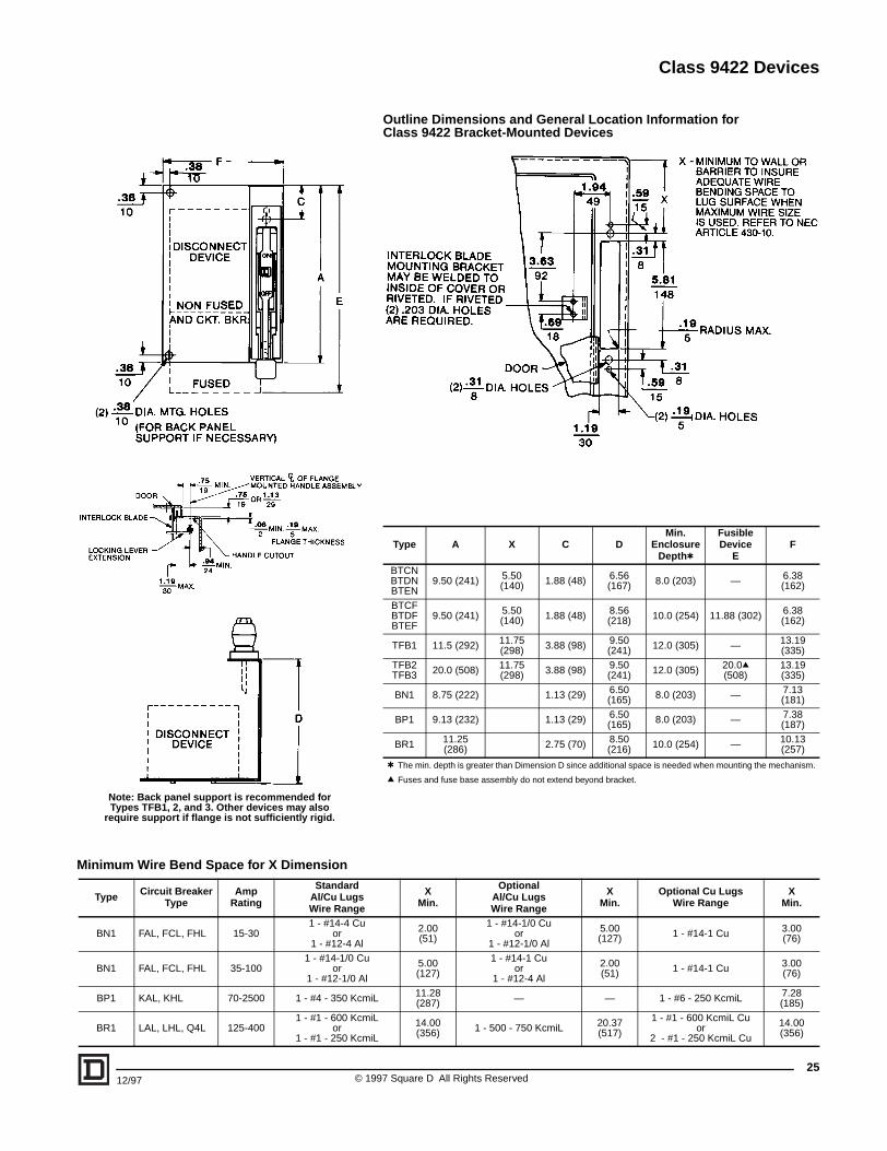
Outline Dimensions and General Location Information forClass 9422 Bracket-Mounted Devices
Type A X C DMin.
Enclosure Deptht
Fusible Device
EF
BTCN BTDN BTEN
9.50 (241) 5.50 (140) 1.88 (48) 6.56
(167) 8.0 (203) — 6.38 (162)
BTCF BTDF BTEF
9.50 (241) 5.50 (140) 1.88 (48) 8.56
(218) 10.0 (254) 11.88 (302) 6.38 (162)
TFB1 11.5 (292) 11.75 (298) 3.88 (98) 9.50
(241) 12.0 (305) — 13.19 (335)
TFB2 TFB3 20.0 (508) 11.75
(298) 3.88 (98) 9.50 (241) 12.0 (305) 20.0q
(508)13.19 (335)
BN1 8.75 (222) 1.13 (29) 6.50 (165) 8.0 (203) — 7.13
(181)
BP1 9.13 (232) 1.13 (29) 6.50 (165) 8.0 (203) — 7.38
(187)
BR1 11.25 (286) 2.75 (70) 8.50
(216) 10.0 (254) — 10.13 (257)
t The min. depth is greater than Dimension D since additional space is needed when mounting the mechanism.
q Fuses and fuse base assembly do not extend beyond bracket.
Type Circuit BreakerType
AmpRating
Standard Al/Cu LugsWire Range
XMin.
Optional Al/Cu LugsWire Range
XMin.
Optional Cu LugsWire Range
XMin.
BN1 FAL, FCL, FHL 15-301 - #14-4 Cu
or1 - #12-4 Al
2.00(51)
1 - #14-1/0 Cuor
1 - #12-1/0 Al
5.00(127) 1 - #14-1 Cu 3.00
(76)
BN1 FAL, FCL, FHL 35-1001 - #14-1/0 Cu
or1 - #12-1/0 Al
5.00(127)
1 - #14-1 Cuor
1 - #12-4 Al
2.00(51) 1 - #14-1 Cu 3.00
(76)
BP1 KAL, KHL 70-2500 1 - #4 - 350 KcmiL 11.28(287) — — 1 - #6 - 250 KcmiL 7.28
(185)
BR1 LAL, LHL, Q4L 125-4001 - #1 - 600 KcmiL
or1 - #1 - 250 KcmiL
14.00(356) 1 - 500 - 750 KcmiL 20.37
(517)
1 - #1 - 600 KcmiL Cuor
2 - #1 - 250 KcmiL Cu
14.00(356)
Note: Back panel support is recommended forTypes TFB1, 2, and 3. Other devices may also
require support if flange is not sufficiently rigid.
Minimum Wire Bend Space for X Dimension
Class 9422 Devices
© 1997 Square D All Rights Reserved26
12/97
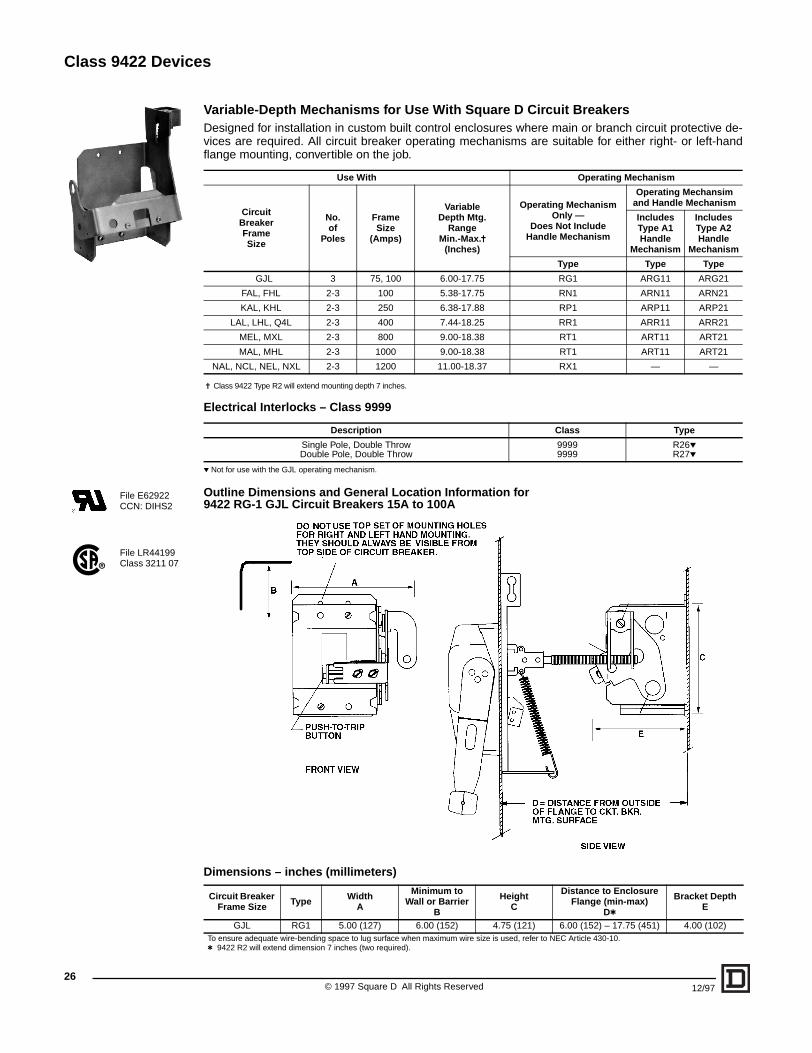
Variable-Depth Mechanisms for Use With Square D Circuit BreakersDesigned for installation in custom built control enclosures where main or branch circuit protective de-vices are required. All circuit breaker operating mechanisms are suitable for either right- or left-handflange mounting, convertible on the job.
j Class 9422 Type R2 will extend mounting depth 7 inches.
Electrical Interlocks – Class 9999
p Not for use with the GJL operating mechanism.
Outline Dimensions and General Location Information for 9422 RG-1 GJL Circuit Breakers 15A to 100A
Dimensions – inches (millimeters)
Use With Operating Mechanism
CircuitBreakerFrameSize
No.of
Poles
FrameSize
(Amps)
VariableDepth Mtg.
RangeMin.-Max.j
(Inches)
Operating Mechanism Only —
Does Not IncludeHandle Mechanism
Operating Mechansimand Handle Mechanism
Includes Type A1Handle
Mechanism
Includes Type A2Handle
Mechanism
Type Type Type
GJL 3 75, 100 6.00-17.75 RG1 ARG11 ARG21
FAL, FHL 2-3 100 5.38-17.75 RN1 ARN11 ARN21
KAL, KHL 2-3 250 6.38-17.88 RP1 ARP11 ARP21
LAL, LHL, Q4L 2-3 400 7.44-18.25 RR1 ARR11 ARR21
MEL, MXL 2-3 800 9.00-18.38 RT1 ART11 ART21
MAL, MHL 2-3 1000 9.00-18.38 RT1 ART11 ART21
NAL, NCL, NEL, NXL 2-3 1200 11.00-18.37 RX1 — —
Description Class Type
Single Pole, Double ThrowDouble Pole, Double Throw
99999999
R26pR27p
Circuit Breaker Frame Size Type Width
A
Minimum to Wall or Barrier
B
HeightC
Distance to Enclosure Flange (min-max)
Dt
Bracket DepthE
GJL RG1 5.00 (127) 6.00 (152) 4.75 (121) 6.00 (152) – 17.75 (451) 4.00 (102)To ensure adequate wire-bending space to lug surface when maximum wire size is used, refer to NEC Article 430-10.t 9422 R2 will extend dimension 7 inches (two required).
File LR44199Class 3211 07
File E62922CCN: DIHS2

Class 9422 Devices
2712/97 © 1997 Square D All Rights Reserved
Outline Dimensions and General Location Information for FAL, FHL, KAL, and KHL Circuit Breakers (100A and 200A Frames)
Dimensions – inches (millimeters)
Circuit Breaker Frame Size
Type A B C Dtmin
Dtmax E Fq G H J K L M N
FAL, FHL RN1 6.75(171)
5.38(137)
2.44(62)
5.51(140)
17.75(451)
2.44(62)
#8-32(4)
5.13(130)
4.26(108)
8.50(216)
1.50(38)
2.19(56)
0.44(11)
3.06(78)
KAL, KHL RP1 7.13(181)
11.69(297)
2.63(67)
6.51(165)
17.88(454)
2.63(67)
#10-24(4)
7.13(181)
4.94(125)
10.13(257)
1.50(38)
2.38(60)
0.44(11)
3.25(83)
To ensure adequate wire-bending space to lug surface when maximum wire size is used, refer to NEC Article 430-10.
t 9422 R2 will extend dimension 7 inches (two required).
q Dimension for panel drilling.

Class 9422 Devices
© 1997 Square D All Rights Reserved28
12/97
Outline Dimensions and General Location Information for LAL, LHL, and Q4L Circuit Breakers (400A Frames)
Dimensions – inches (millimeters)
Circuit Breaker
Frame SizeType A C Dt
minDt
max E F G H J K L M N P Q R
LAL, LHL, Q4L RR1 10.19
(259)3.56(90)
7.44(189)
18.25(464)
3.56(90)
1.38(35)
9.25(235)
6.56(167)
2.31(59)
0.38 (10)Dia. (4)
6.63(168)
6.00(152)
11.00(279)
2.00(51)
4.13(105)
0.88(22)
To ensure adequate wire-bending space to lug surface when maximum wire size is used, refer to NEC Article 430-10.
t 9422 R2 will extend dimension 7 inches (two required).
Class 9422 Devices
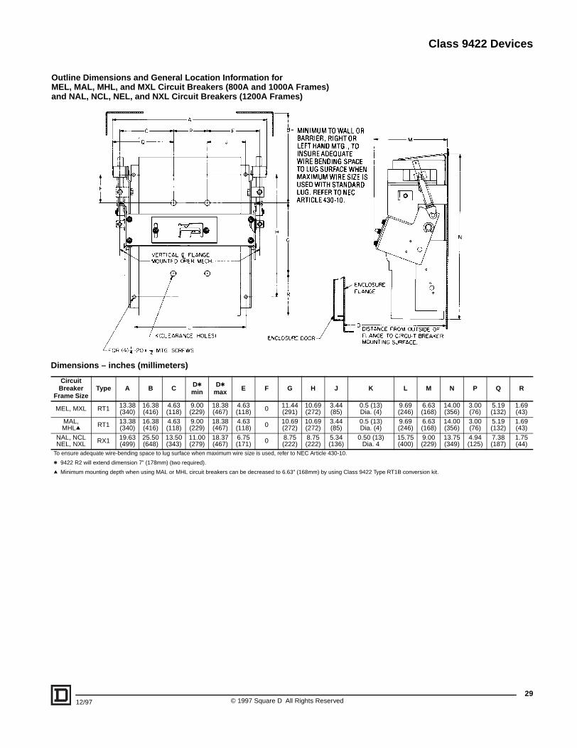
Outline Dimensions and General Location Information for MEL, MAL, MHL, and MXL Circuit Breakers (800A and 1000A Frames)and NAL, NCL, NEL, and NXL Circuit Breakers (1200A Frames)
Dimensions – inches (millimeters)
Circuit Breaker
Frame SizeType A B C Dt
minDt
max E F G H J K L M N P Q R
MEL, MXL RT1 13.38(340)
16.38(416)
4.63(118)
9.00(229)
18.38(467)
4.63(118) 0 11.44
(291)10.69(272)
3.44(85)
0.5 (13)Dia. (4)
9.69(246)
6.63(168)
14.00(356)
3.00(76)
5.19(132)
1.69(43)
MAL, MHLq RT1 13.38
(340)16.38(416)
4.63(118)
9.00(229)
18.38(467)
4.63(118) 0 10.69
(272)10.69(272)
3.44(85)
0.5 (13)Dia. (4)
9.69(246)
6.63(168)
14.00(356)
3.00(76)
5.19(132)
1.69(43)
NAL, NCLNEL, NXL RX1 19.63
(499)25.50(648)
13.50(343)
11.00(279)
18.37(467)
6.75(171) 0 8.75
(222)8.75(222)
5.34(136)
0.50 (13)Dia. 4
15.75(400)
9.00(229)
13.75(349)
4.94(125)
7.38(187)
1.75(44)
To ensure adequate wire-bending space to lug surface when maximum wire size is used, refer to NEC Article 430-10.
t 9422 R2 will extend dimension 7” (178mm) (two required).
q Minimum mounting depth when using MAL or MHL circuit breakers can be decreased to 6.63” (168mm) by using Class 9422 Type RT1B conversion kit.
2912/97 © 1997 Square D All Rights Reserved
Class 9422 Devices
Alternate Mounting Kit
Channel/FlangeSupport Kit
Auxiliary Lock Plate
Remote operation shown(handle mechanism not included in kit)
30
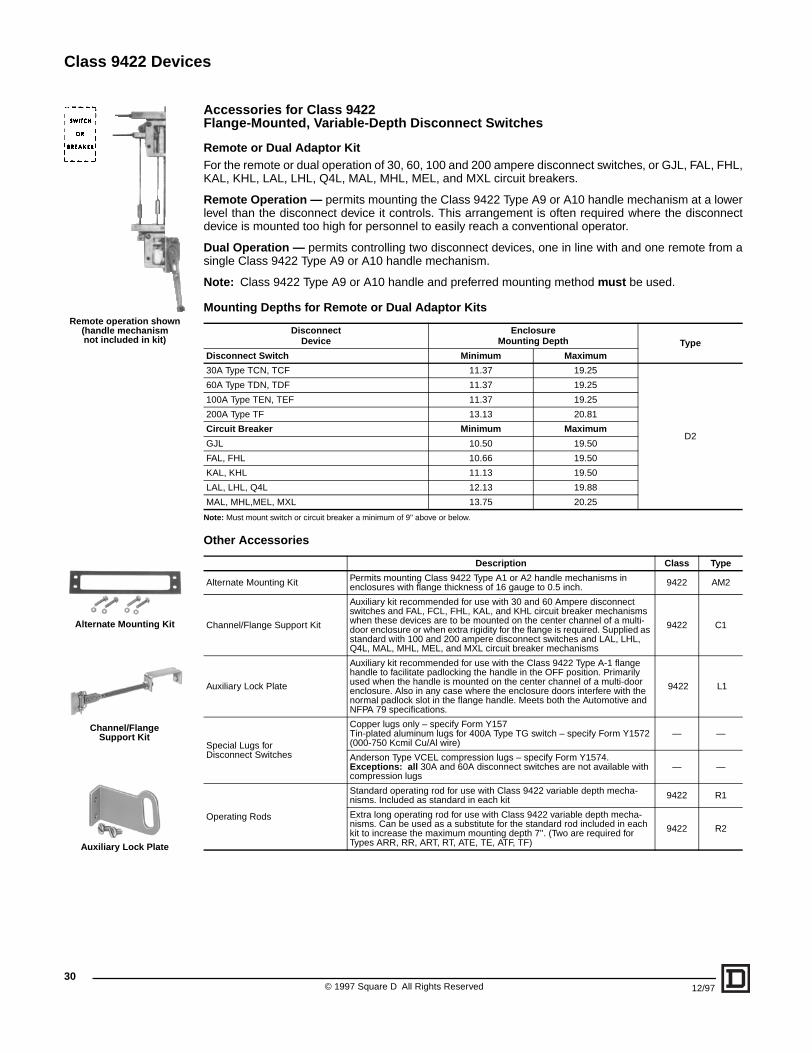
Accessories for Class 9422 Flange-Mounted, Variable-Depth Disconnect Switches
Remote or Dual Adaptor KitFor the remote or dual operation of 30, 60, 100 and 200 ampere disconnect switches, or GJL, FAL, FHL,KAL, KHL, LAL, LHL, Q4L, MAL, MHL, MEL, and MXL circuit breakers.
Remote Operation — permits mounting the Class 9422 Type A9 or A10 handle mechanism at a lowerlevel than the disconnect device it controls. This arrangement is often required where the disconnectdevice is mounted too high for personnel to easily reach a conventional operator.
Dual Operation — permits controlling two disconnect devices, one in line with and one remote from asingle Class 9422 Type A9 or A10 handle mechanism.
Note: Class 9422 Type A9 or A10 handle and preferred mounting method must be used.
Mounting Depths for Remote or Dual Adaptor Kits
Note: Must mount switch or circuit breaker a minimum of 9" above or below.
Other Accessories
DisconnectDevice
EnclosureMounting Depth Type
Disconnect Switch Minimum Maximum
30A Type TCN, TCF 11.37 19.25
D2
60A Type TDN, TDF 11.37 19.25
100A Type TEN, TEF 11.37 19.25
200A Type TF 13.13 20.81
Circuit Breaker Minimum Maximum
GJL 10.50 19.50
FAL, FHL 10.66 19.50
KAL, KHL 11.13 19.50
LAL, LHL, Q4L 12.13 19.88
MAL, MHL,MEL, MXL 13.75 20.25
Description Class Type
Alternate Mounting Kit Permits mounting Class 9422 Type A1 or A2 handle mechanisms in enclosures with flange thickness of 16 gauge to 0.5 inch. 9422 AM2
Channel/Flange Support Kit
Auxiliary kit recommended for use with 30 and 60 Ampere disconnect switches and FAL, FCL, FHL, KAL, and KHL circuit breaker mechanisms when these devices are to be mounted on the center channel of a multi-door enclosure or when extra rigidity for the flange is required. Supplied as standard with 100 and 200 ampere disconnect switches and LAL, LHL, Q4L, MAL, MHL, MEL, and MXL circuit breaker mechanisms
9422 C1
Auxiliary Lock Plate
Auxiliary kit recommended for use with the Class 9422 Type A-1 flange handle to facilitate padlocking the handle in the OFF position. Primarily used when the handle is mounted on the center channel of a multi-door enclosure. Also in any case where the enclosure doors interfere with the normal padlock slot in the flange handle. Meets both the Automotive and NFPA 79 specifications.
9422 L1
Special Lugs forDisconnect Switches
Copper lugs only – specify Form Y157Tin-plated aluminum lugs for 400A Type TG switch – specify Form Y1572 (000-750 Kcmil Cu/Al wire)
— —
Anderson Type VCEL compression lugs – specify Form Y1574. Exceptions: all 30A and 60A disconnect switches are not available with compression lugs
— —
Operating Rods
Standard operating rod for use with Class 9422 variable depth mecha-nisms. Included as standard in each kit 9422 R1
Extra long operating rod for use with Class 9422 variable depth mecha-nisms. Can be used as a substitute for the standard rod included in each kit to increase the maximum mounting depth 7''. (Two are required for Types ARR, RR, ART, RT, ATE, TE, ATF, TF)
9422 R2
© 1997 Square D All Rights Reserved 12/97
Class 9422 Devices
12/97
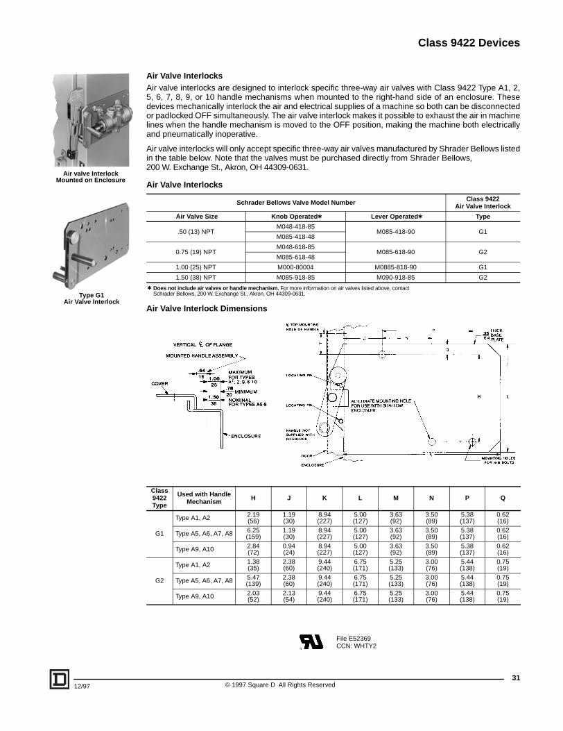
Air Valve InterlocksAir valve interlocks are designed to interlock specific three-way air valves with Class 9422 Type A1, 2,5, 6, 7, 8, 9, or 10 handle mechanisms when mounted to the right-hand side of an enclosure. Thesedevices mechanically interlock the air and electrical supplies of a machine so both can be disconnectedor padlocked OFF simultaneously. The air valve interlock makes it possible to exhaust the air in machinelines when the handle mechanism is moved to the OFF position, making the machine both electricallyand pneumatically inoperative.
Air valve interlocks will only accept specific three-way air valves manufactured by Shrader Bellows listedin the table below. Note that the valves must be purchased directly from Shrader Bellows, 200 W. Exchange St., Akron, OH 44309-0631.
Air Valve Interlocks
t Does not include air valves or handle mechanism. For more information on air valves listed above, contact Schrader Bellows, 200 W. Exchange St., Akron, OH 44309-0631.
Air Valve Interlock Dimensions
Schrader Bellows Valve Model Number Class 9422Air Valve Interlock
Air Valve Size Knob Operatedt Lever Operatedt Type
.50 (13) NPTM048-418-85
M085-418-90 G1M085-418-48
0.75 (19) NPTM048-618-85
M085-618-90 G2M085-618-48
1.00 (25) NPT M000-80004 M0885-818-90 G1
1.50 (38) NPT M085-918-85 M090-918-85 G2
Class 9422 Type
Used with Handle Mechanism H J K L M N P Q
G1
Type A1, A2 2.19(56)
1.19(30)
8.94(227)
5.00(127)
3.63(92)
3.50(89)
5.38(137)
0.62(16)
Type A5, A6, A7, A8 6.25(159)
1.19(30)
8.94(227)
5.00(127)
3.63(92)
3.50(89)
5.38(137)
0.62(16)
Type A9, A10 2.84(72)
0.94(24)
8.94(227)
5.00(127)
3.63(92)
3.50(89)
5.38(137)
0.62(16)
G2
Type A1, A2 1.38(35)
2.38(60)
9.44(240)
6.75(171)
5.25(133)
3.00(76)
5.44(138)
0.75(19)
Type A5, A6, A7, A8 5.47(139)
2.38(60)
9.44(240)
6.75(171)
5.25(133)
3.00(76)
5.44(138)
0.75(19)
Type A9, A10 2.03(52)
2.13(54)
9.44(240)
6.75(171)
5.25(133)
3.00(76)
5.44(138)
0.75(19)
File E52369CCN: WHTY2
Air valve InterlockMounted on Enclosure
Type G1Air Valve Interlock
31© 1997 Square D All Rights Reserved
Class 9422 Devices
© 1997 Square D All Rights Reserved32
12/97
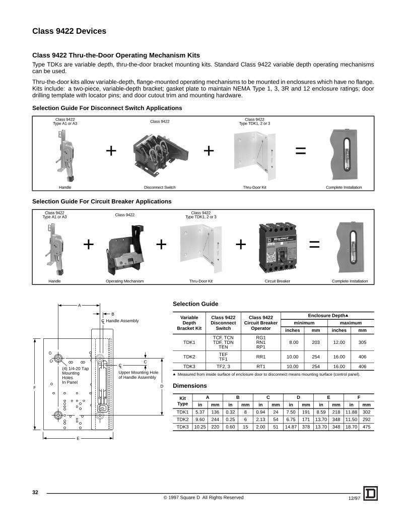
Selection Guide
q Measured from inside surface of enclosure door to disconnect means mounting surface (control panel).
Dimensions
VariableDepth
Bracket Kit
Class 9422Disconnect
Switch
Class 9422Circuit Breaker
Operator
Enclosure Depthq
minimum maximum
inches mm inches mm
TDK1TCF, TCNTDF, TDN
TEN
RG1RN1RP1
8.00 203 12.00 305
TDK2 TEFTF1 RR1 10.00 254 16.00 406
TDK3 TF2, 3 RT1 10.00 254 16.00 406
KitType
A B C D E F
in mm in mm in mm in mm in mm in mm
TDK1 5.37 136 0.32 8 0.94 24 7.50 191 8.59 218 11.88 302
TDK2 9.60 244 0.25 6 2.13 54 6.75 171 13.70 348 11.50 292
TDK3 10.25 220 0.60 15 2.00 51 14.87 378 13.70 348 18.70 475
Class 9422 Thru-the-Door Operating Mechanism KitsType TDKs are variable depth, thru-the-door bracket mounting kits. Standard Class 9422 variable depth operating mechanismscan be used.
Thru-the-door kits allow variable-depth, flange-mounted operating mechanisms to be mounted in enclosures which have no flange.Kits include: a two-piece, variable-depth bracket; gasket plate to maintain NEMA Type 1, 3, 3R and 12 enclosure ratings; doordrilling template with locator pins; and door cutout trim and mounting hardware.
Selection Guide For Disconnect Switch Applications
Selection Guide For Circuit Breaker Applications
Class 9422Type A1 or A3
+
Class 9422
+
Class 9422Type TDK1, 2 or 3
=
Handle Disconnect Switch Thru-Door Kit Complete Installation
Class 9422Type A1 or A3
+
Class 9422
+
Class 9422Type TDK1, 2 or 3
+ =
Handle Operating Mechanism Thru-Door Kit Circuit Breaker Complete Installation
A
B
C
D
E
F
(4) 1/4-20 TapMountingHolesIn Panel
CLUpper Mounting Holeof Handle Assembly
CL Handle Assembly
Class 9422 Devices
3312/97 © 1997 Square D All Rights Reserved
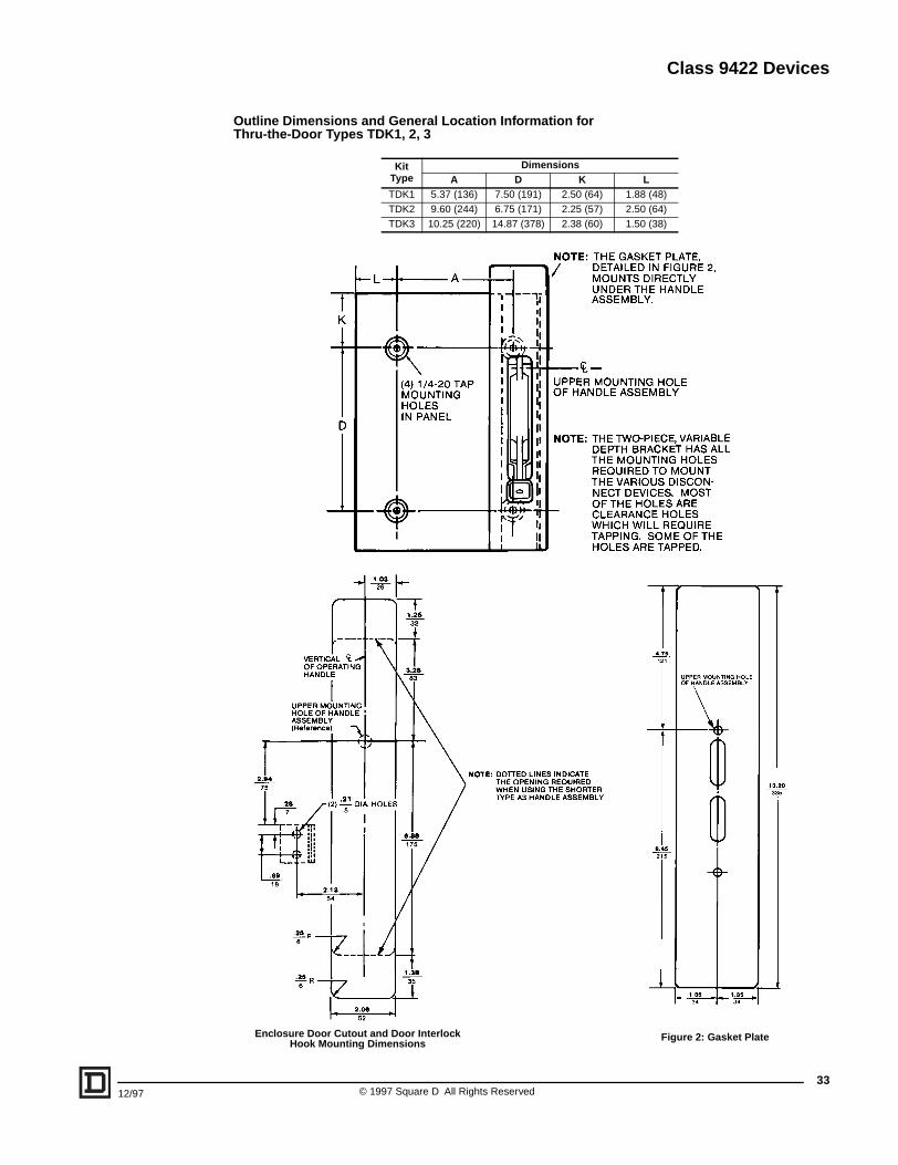
Outline Dimensions and General Location Information forThru-the-Door Types TDK1, 2, 3
Kit Type
DimensionsA D K L
TDK1 5.37 (136) 7.50 (191) 2.50 (64) 1.88 (48)TDK2 9.60 (244) 6.75 (171) 2.25 (57) 2.50 (64)TDK3 10.25 (220) 14.87 (378) 2.38 (60) 1.50 (38)
Figure 2: Gasket PlateEnclosure Door Cutout and Door InterlockHook Mounting Dimensions
Class 9423 Door-Closing Mechanisms
34
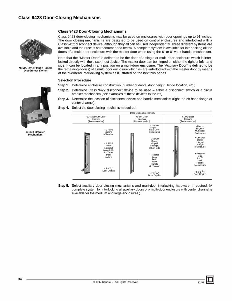
Class 9423 Door-Closing MechanismsClass 9423 door-closing mechanisms may be used on enclosures with door openings up to 91 inches.The door closing mechanisms are designed to be used on control enclosures and interlocked with aClass 9422 disconnect device, although they all can be used independently. Three different systems areavailable and their use is as recommended below. A complete system is available for interlocking all thedoors of a multi-door enclosure with the master door when using the 6" or 8" vault handle mechanism.
Note that the “Master Door” is defined to be the door of a single or multi-door enclosure which is inter-locked directly with the disconnect device. The master door can be hinged on either the right or left handside. It can be located in any position on a multi-door enclosure. The “Auxiliary Door” is defined to bethe remaining door(s) of a multi-door enclosure which is (are) interlocked with the master door by meansof the overhead interlocking system as illustrated on the next two pages.
Selection ProcedureStep 1. Determine enclosure construction (number of doors, door height, hinge location, etc.).
Step 2. Determine Class 9422 disconnect device to be used – either a disconnect switch or a circuitbreaker mechanism (see examples of these devices to the left).
Step 3. Determine the location of disconnect device and handle mechanism (right- or left-hand flange orcenter channel).
Step 4. Select the door closing mechanism required:
Step 5. Select auxiliary door closing mechanisms and multi-door interlocking hardware, if required. (Acomplete system for interlocking all auxiliary doors of a multi-door enclosure with center channel isavailable for the medium and large enclosures.)
Door Closing Mechanism
60" Maximum DoorOpening
(Recommended)
46-60" DoorOpening
(Recommended)
61-91" DoorOpening
(Recommended)
• 2 PointLocking
is Standard
• A ThirdRoller
Latch Kitis Availablefor Three
PointLocking
• For 3/4"Door Depths
• Use onSingle or
Multi-DoorEnclosures
• Use withDoorsHingedon Right
or Left Side
• Referredto asthe 6"Vault
HandleMechansim
• For 3/4"Door Depths
• Use onSingle or
Multi-DoorEnclosures
• Use withDoorsHingedon Right
or Left Side
• Referredto asthe 8"Vault
HandleMechansim
• For 1-1/8"Door Depths
Circuit BreakerMechanism
NEMA-Style Flange HandleDisconnect Switch
© 1997 Square D All Rights Reserved 12/97
Class 9423 Door-Closing Mechanisms
12/97
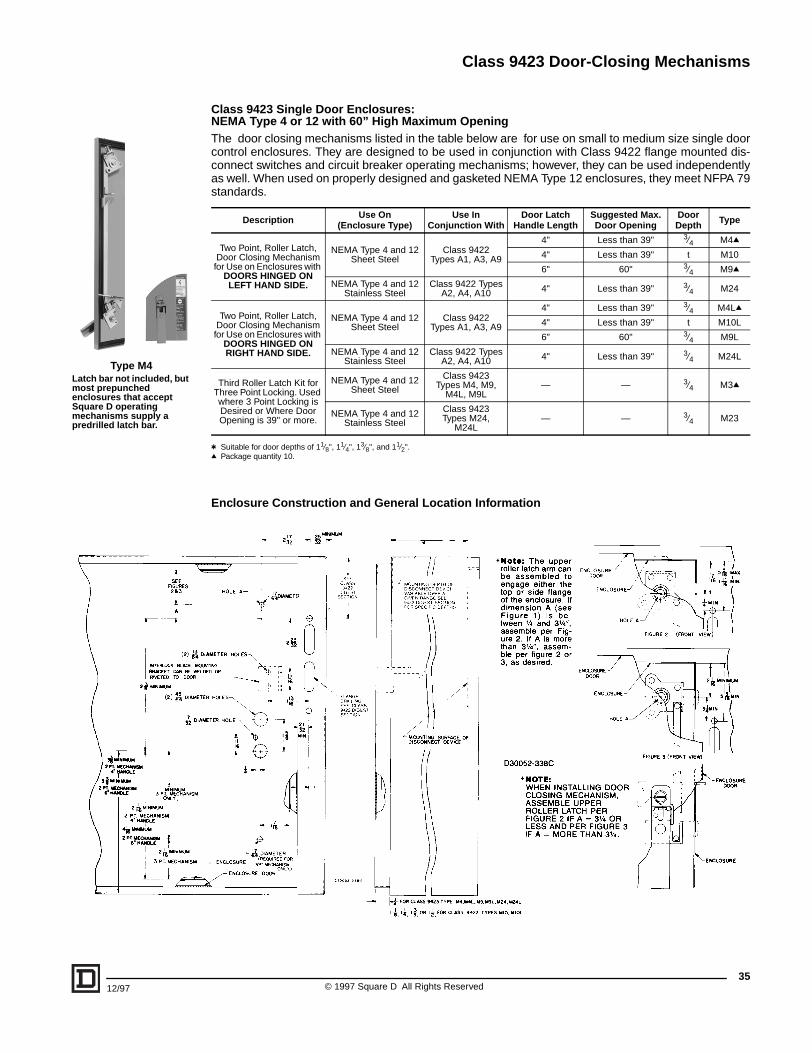
Class 9423 Single Door Enclosures:NEMA Type 4 or 12 with 60” High Maximum OpeningThe door closing mechanisms listed in the table below are for use on small to medium size single doorcontrol enclosures. They are designed to be used in conjunction with Class 9422 flange mounted dis-connect switches and circuit breaker operating mechanisms; however, they can be used independentlyas well. When used on properly designed and gasketed NEMA Type 12 enclosures, they meet NFPA 79standards.
t Suitable for door depths of 11⁄8", 11⁄4", 13⁄8", and 11⁄2".q Package quantity 10.
Enclosure Construction and General Location Information
Description Use On(Enclosure Type)
Use InConjunction With
Door LatchHandle Length
Suggested Max.Door Opening
DoorDepth Type
Two Point, Roller Latch, Door Closing Mechanism for Use on Enclosures with
DOORS HINGED ON LEFT HAND SIDE.
NEMA Type 4 and 12Sheet Steel
Class 9422Types A1, A3, A9
4" Less than 39" 3⁄4 M4q
4" Less than 39" t M10
6" 60" 3⁄4 M9q
NEMA Type 4 and 12Stainless Steel
Class 9422 TypesA2, A4, A10 4" Less than 39" 3⁄4 M24
Two Point, Roller Latch, Door Closing Mechanism for Use on Enclosures with
DOORS HINGED ON RIGHT HAND SIDE.
NEMA Type 4 and 12Sheet Steel
Class 9422Types A1, A3, A9
4" Less than 39" 3⁄4 M4Lq
4" Less than 39" t M10L
6" 60" 3⁄4 M9L
NEMA Type 4 and 12Stainless Steel
Class 9422 TypesA2, A4, A10 4" Less than 39" 3⁄4 M24L
Third Roller Latch Kit for Three Point Locking. Used where 3 Point Locking is Desired or Where Door Opening is 39" or more.
NEMA Type 4 and 12Sheet Steel
Class 9423Types M4, M9,
M4L, M9L— — 3⁄4 M3q
NEMA Type 4 and 12Stainless Steel
Class 9423Types M24,
M24L— — 3⁄4 M23
Type M4Latch bar not included, but most prepunched enclosures that accept Square D operating mechanisms supply a predrilled latch bar.
35© 1997 Square D All Rights Reserved

Class 9423 Door-Closing Mechanisms
© 1997 Square D All Rights Reserved36
12/97
Required Accessories for Auxiliary Doors
TYPE M6 DOOR CLOSING MECHANISM
The Class 9423 Type M6 door closing mechanism is designed to close and seal 0.75” deep doors of single or multi-door NEMA Type 12 enclosures. The Type M6 can be used on doors hinged on either the left or right hand side. Recommended door openings are from 40" – 60". Vault type han-dle length is 6".
TYPE M660 LOCKING BAR KITS
The lock bar kit for the Type M6 door closing mechanism contains two lock bars and is available from stock. The bars can be cut to fit door openings through 60". One lock bar kit is required for each Type M6 ordered.
TYPE M5
The Class 9423 Type M5 mechanical interlock kit is designed to interlock a Class 9422 handle mechanism with the Type M6 door closing mechanism. This kit prevents opening the master door (or single door) with the disconnect handle in the “ON” position, making it mandatory to use a screwdriver to gain entry to the enclosure, regardless of the disconnect handle position.
TYPE M2
One Type M2 kit is required for each auxiliary door. This kit is required to interlock any auxiliary door(s) with the master door.
TYPE M7
The first auxiliary door requires 2 Type M7 kits. Additional auxiliary doors require only 1 Type M7 kit. The 0.25” diameter rod used to interconnect the M7 kits is furnished by the user. If the distance between any two Type M7 kits exceeds 36", an additional Type M7 kit should be installed to pre-vent the rod from buckling.
Viewed from Inside Enclosure
k Interlocking lever extension of the flange mounted handle mechanism.j Actual enclosure opening – not door height.v Screwdriver interlock assembly can be ordered separately. Class 9423
Type CEQ2493.
Note: All mechanisms listed on this page aresuitable for either left or right hand mounting.
1/4" Dia. Rod (Supplied By User)
LockingBar
LockingBar
LockingBar
Auxiliary Door Master Door(Single Door)
LockingBar
DoorjOpening
Type M6 Type M7 Type M2
jj
k
Type M5
Class 9423 Vault Type for Single and Multi-Door Enclosures
Single or Multi-Door Enclosures — NEMA Type 12 with 40" to 60" Door OpeningThe requirements are shown in the table below:
Single-Door Enclosure Multi-Door Enclosure
Without Interlocking With Interlocking Without Interlocking With Interlocking
1 – M6 door closing mechanism
1 – Type M660 locking bar kit
1 – M6 door closing mechanism
1 – Type M660 locking bar kit1 – Type M5 (use with 9422A
handles)
For each door:1 – M6 door closing
mechanism1 – Type M660 locking bar kit
For Master door:1 – M6 door closing
mechanism1 – Type M660 locking bar kit1 – Type M5
(use with 9422A handles)
Each Auxiliary door:1 – M6 door closing
mechanism1 – Type M660 locking bar kitNecessary quantities of Types M2 and M7 for each door (see below)
Class 9423 Door-Closing Mechanisms
12/97 © 1
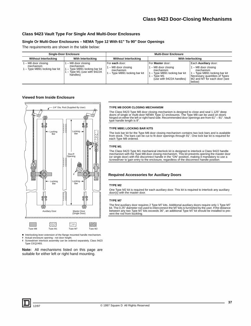
Class 9423 Vault Type For Single And Multi-Door Enclosures
Single Or Multi-Door Enclosures – NEMA Type 12 With 61" To 90" Door OpeningsThe requirements are shown in the table below:
Single-Door Enclosure Multi-Door Enclosure
Without Interlocking With Interlocking Without Interlocking With Interlocking
1 – M8 door closing mechanism
1 – Type M891 locking bar kit
1 – M8 door closing mechanism
1 – Type M891 locking bar kit1 – Type M1 (use with 9422A
handles)
For each door:1 – M8 door closing
mechanism1 – Type M891 locking bar kit
For Master door:1 – M8 door closing
mechanism1 – Type M891 locking bar kit1 – Type M1
(use with 9422A handles)
Each Auxiliary door:1 – M8 door closing
mechanism1 – Type M891 locking bar kitNecessary quantities of Types M2 and M7 for each door (see below)
Required Accessories for Auxiliary Doors
TYPE M8 DOOR CLOSING MECHANISM
The Class 9423 Type M8 door closing mechanism is designed to close and seal 1.125” deep doors of single or multi-door NEMA Type 12 enclosures. The Type M8 can be used on doors hinged on either the left or right hand side. Recommended door openings are from 61" – 91". Vault type handle length is 8".
TYPE M891 LOCKING BAR KITS
The lock bar kit for the Type M8 door closing mechanism contains two lock bars and is available from stock. The bars can be cut to fit door openings through 91". One lock bar kit is required for each Type M8 ordered.
TYPE M1
The Class 9423 Type M1 mechanical interlock kit is designed to interlock a Class 9422 handle mechanism with the Type M8 door closing mechanism. This kit prevents opening the master door (or single door) with the disconnect handle in the “ON” position, making it mandatory to use a screwdriver to gain entry to the enclosure, regardless of the disconnect handle position.
TYPE M2
One Type M2 kit is required for each auxiliary door. This kit is required to interlock any auxiliary door(s) with the master door.
TYPE M7
The first auxiliary door requires 2 Type M7 kits. Additional auxiliary doors require only 1 Type M7 kit. The 0.25” diameter rod used to interconnect the M7 kits is furnished by the user. If the distance between any two Type M7 kits exceeds 36", an additional Type M7 kit should be installed to pre-vent the rod from buckling.
Viewed from Inside Enclosure
k Interlocking lever extension of the flange mounted handle mechanism.j Actual enclosure opening - not door height.u Screwdriver interlock assembly can be ordered separately. Class 9423
Type CEQ2493.
Note: All mechanisms listed on this page aresuitable for either left or right hand mounting.
1/4" Dia. Rod (Supplied By User)
LockingBar
LockingBar
LockingBar
Auxiliary Door Master Door(Single Door)
LockingBar
Door jOpening
Type M8 Type M1 Type M7 Type M2
u
k
37997 Square D All Rights Reserved

Class 9423 Door-Closing Mechanisms
Enclosure with M6, M5, and Class 9422 Handle Mechanism
Enclosure with M8, M1, and Class 9422 Handle Mechanism
©38
Class 9423 Door Closing Mechanisms: Single- and Multi-Door Enclosures
Enclosure Construction and General Location Information for Types M5 and M6 and Types M1 and M8Drilling and location information shown to the left is complete for a single doorenclosure with door hinged on the left side. The top drawing shows a TypeM6, M5, and Class 9422 handle mechanism; the bottom drawing shows aType M8, M1, and Class 9422 handle mechanism.
Transpose all horizontal dimensions for doors hinged on the right side.
See the next page for information on flange and channel construction.
Dimension A
For single-door enclosures and multi-door enclsoures without overheadinterlocking system, minimum is 1" (25mm). For multi-door enclosures withan overhead interlocking system, minimum is 4.5" (114mm). (The overheadinterlocking system consists of the required number of Class 9423 Type M2and M7 kits for interlocking the auxiliary doors with the master door; see pag-es 34 and 35 for further information.)
Dimensions B and C
Type Disconnect Devices If A = 1”,Min B =
If A = 4.5”,Min B = C
With M6, M5, and Class 9422 Handle MechanismTCF, TCN 30A Disconnect Switch 3.44 (88) 2.50 (64) 3.19 (81)TDF, TDN 60A Disconnect Switch 3.44 (88) 2.50 (64) 3.19 (81)TEF, TEN 100A Disconnect Switch 5.25 (134) 2.50 (64) 3.19 (81)TF 200A Disconnect Switch 11.63 (296) 8.13 (207) 3.19 (81)TG 400A Disconnect Switch 15.07 (383) 11.57 (294) 6.75 (172)RG1 GJL Circuit Breaker 4.85 (124) 2.50 (64) 3.19 (81)RN1 FAL, FHL Circuit Breaker 4.85 (124) 2.50 (64) 3.19 (81)RP1 KAL, KHL Circuit Breaker 11.16 (284) 7.66 (195) 3.19 (81)RR2 ILL Circuit Breaker 17.97 (457) 14.47 (368) 3.19 (81)
RT1 MAL, MHL, MEL, MXL CIrcuit Breaker 18.63 (474) 15.13 (385) 3.19 (81)
With M8, M1, and Class 9422 Handle MechanismTCF, TCN 30A Disconnect Switch 2.94 (75) 2.50 (64) 3.19 (81)TDF, TDN 60A Disconnect Switch 2.94 (75) 2.50 (64) 3.19 (81)TEF, TEN 100A Disconnect Switch 4.75 (121) 2.50 (64) 3.19 (81)TF 200A Disconnect Switch 11.13 (283) 8.13 (207) 3.19 (81)TG 400A Disconnect Switch 14.57 (370) 11.57 (294) 5.88 (150)RG1 GJL Circuit Breaker 4.35 (111) 2.50 (64) 3.19 (81)RN1 FAL, FHL Circuit Breaker 4.35 (111) 2.50 (64) 3.19 (81)RP1 KAL, KHL Circuit Breaker 10.66 (271) 7.66 (195) 3.19 (81)RR2 ILL Circuit Breaker 17.47 (444) 14.47 (368) 3.19 (81)
RT1 MAL, MHL, MEL, MXL CIrcuit Breaker 18.13 (461) 15.13 (385) 3.19 (81)
1997 Square D All Rights Reserved 12/97
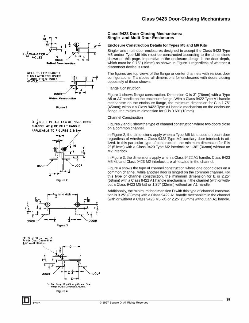
Class 9423 Door-Closing Mechanisms
3912/97 © 1997 Square D All Rights Reserved
Class 9423 Door Closing Mechanisms: Single- and Multi-Door Enclosures
Enclosure Construction Details for Types M5 and M6 KitsSingle- and multi-door enclosures designed to accept the Class 9423 TypeM5 and/or Type M6 kits must be constructed according to the dimensionsshown on this page. Imperative in the enclosure design is the door depth,which must be 0.75" (19mm) as shown in Figure 1 regardless of whether adisconnect device is used.
The figures are top views of the flange or center channels with various doorconfigurations. Transpose all dimensions for enclosures with doors closingoppositely of those shown.
Flange Construction
Figure 1 shows flange construction. Dimension C is 3" (76mm) with a TypeA5 or A7 handle on the enclosure flange. With a Class 9422 Type A1 handlemechanism on the enclosure flange, the minimum dimension for C is 1.75"(45mm); without a Class 9422 Type A1 handle mechanism on the enclosureflange, the minimum dimension for C is 0.69" (18mm).
Channel Construction
Figures 2 and 3 show the type of channel construction where two doors closeon a common channel.
In Figure 2, the dimensions apply when a Type M6 kit is used on each doorregardless of whether a Class 9423 Type M2 auxiliary door interlock is uti-lized. In this particular type of construction, the minimum dimension for E is2" (51mm) with a Class 9423 Type M2 interlock or 1.38" (36mm) without anM2 interlock.
In Figure 3, the dimensions apply when a Class 9422 A1 handle, Class 9423M5 kit, and Class 9423 M2 interlock are all located in the channel.
Figure 4 shows the type of channel construction where one door closes on acommon channel, while another door is hinged on the common channel. Forthis type of channel construction, the minimum dimension for E is 2.25"(58mm) with a Class 9422 A1 handle mechanism in the channel (with or with-out a Class 9423 M5 kit) or 1.25" (32mm) without an A1 handle.
Additionally, the minimum for dimension D with this type of channel construc-tion is 3.25" (83mm) with a Class 9422 A1 handle mechanism in the channel(with or without a Class 9423 M5 kit) or 2.25" (58mm) without an A1 handle.
Figure 1
Figure 4
Figure 2
Figure 3
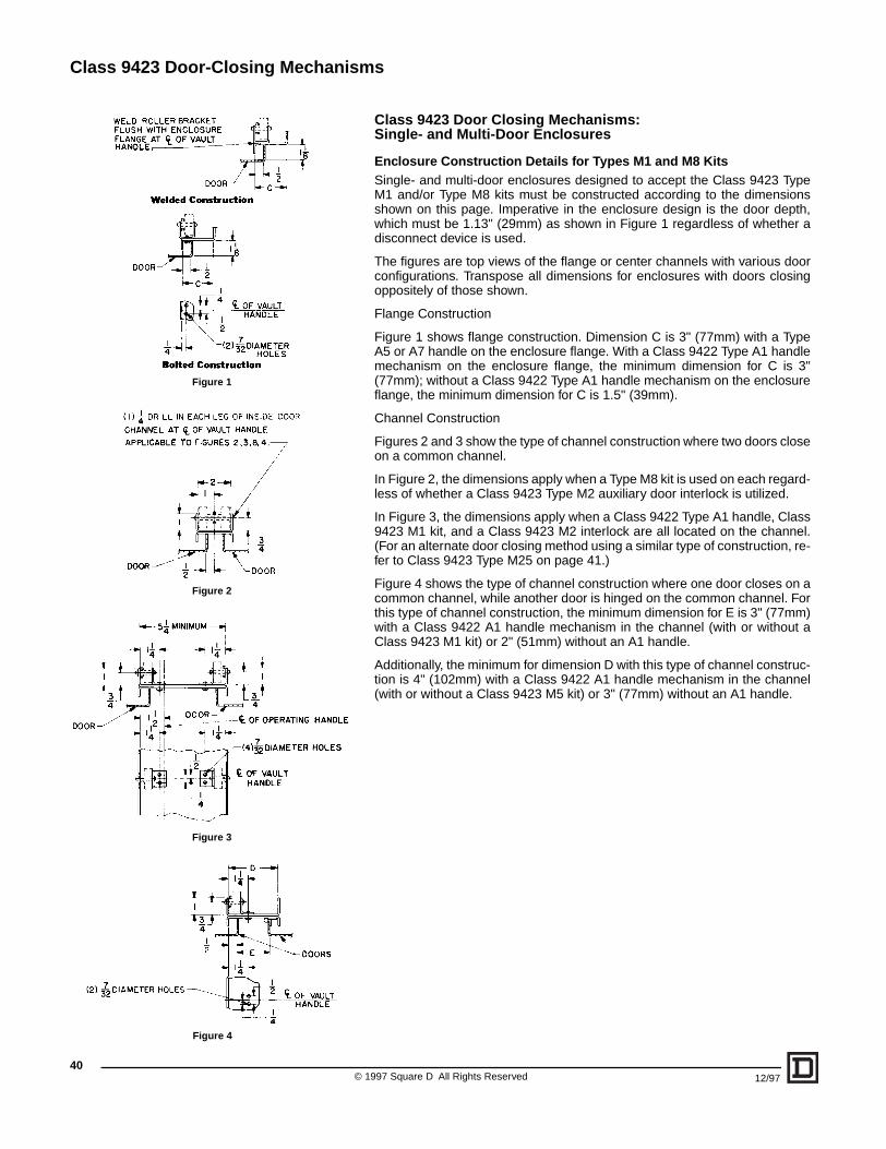
Class 9423 Door-Closing Mechanisms
Figure 1
Figure 4
Figure 2
Figure 3
©40
Class 9423 Door Closing Mechanisms: Single- and Multi-Door Enclosures
Enclosure Construction Details for Types M1 and M8 KitsSingle- and multi-door enclosures designed to accept the Class 9423 TypeM1 and/or Type M8 kits must be constructed according to the dimensionsshown on this page. Imperative in the enclosure design is the door depth,which must be 1.13" (29mm) as shown in Figure 1 regardless of whether adisconnect device is used.
The figures are top views of the flange or center channels with various doorconfigurations. Transpose all dimensions for enclosures with doors closingoppositely of those shown.
Flange Construction
Figure 1 shows flange construction. Dimension C is 3" (77mm) with a TypeA5 or A7 handle on the enclosure flange. With a Class 9422 Type A1 handlemechanism on the enclosure flange, the minimum dimension for C is 3"(77mm); without a Class 9422 Type A1 handle mechanism on the enclosureflange, the minimum dimension for C is 1.5" (39mm).
Channel Construction
Figures 2 and 3 show the type of channel construction where two doors closeon a common channel.
In Figure 2, the dimensions apply when a Type M8 kit is used on each regard-less of whether a Class 9423 Type M2 auxiliary door interlock is utilized.
In Figure 3, the dimensions apply when a Class 9422 Type A1 handle, Class9423 M1 kit, and a Class 9423 M2 interlock are all located on the channel.(For an alternate door closing method using a similar type of construction, re-fer to Class 9423 Type M25 on page 41.)
Figure 4 shows the type of channel construction where one door closes on acommon channel, while another door is hinged on the common channel. Forthis type of channel construction, the minimum dimension for E is 3" (77mm)with a Class 9422 A1 handle mechanism in the channel (with or without aClass 9423 M1 kit) or 2" (51mm) without an A1 handle.
Additionally, the minimum for dimension D with this type of channel construc-tion is 4" (102mm) with a Class 9422 A1 handle mechanism in the channel(with or without a Class 9423 M5 kit) or 3" (77mm) without an A1 handle.
1997 Square D All Rights Reserved 12/97
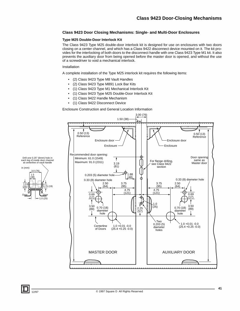
Class 9423 Door-Closing Mechanisms
Drill one 0.25" (6mm) hole ineach leg of inside door channel
at centerline of vault handle
3.0 (76)
1.5(38)
DoorDoor
1.0 (25)
0.75 (19)1.0(25)
in (mm)
12/97
Class 9423 Door Closing Mechanisms: Single- and Multi-Door Enclosures
Type M25 Double-Door Interlock KitThe Class 9423 Type M25 double-door interlock kit is designed for use on enclosures with two doorsclosing on a center channel, and which has a Class 9422 disconnect device mounted on it. The kit pro-vides for the interlocking of both doors to the disconnect handle with one Class 9423 Type M1 kit. It alsoprevents the auxiliary door from being opened before the master door is opened, and without the useof a screwdriver to void a mechanical interlock.
Installation
A complete installation of the Type M25 interlock kit requires the following items:
• (2) Class 9423 Type M8 Vault Handles• (2) Class 9423 Type M891 Lock Bar Kits• (1) Class 9423 Type M1 Mechanical Interlock Kit• (1) Class 9423 Type M25 Double-Door Interlock Kit• (1) Class 9422 Handle Mechanism• (1) Class 9422 Disconnect Device
Enclosure Construction and General Location Information
MASTER DOOR AUXILIARY DOOR
0.69(17)
3.50(89) 0.70 (18)
diameterhole
Centerlineof Doors
2.50(64)
3.75(95)
4.75(121)
2.25(57)
1.0(25)
1.0 +0.01 -0.0(25.4 +0.25 -0.0)
4.75(121)
3.75(95)
0.69(17)
3.50(89)0.70 (18)
diameterhole
2.50(64)
1.0 +0.01 -0.0(25.4 +0.25 -0.0)
Two0.203 (5)diameter
holes
For flange drilling,see Class 9422
section
1.88(48)
3.19(81)
0.203 (5) diameter hole
0.33 (8) diameter hole
Enclosure
Enclosure door
0.50 (13)Reference
Recommended door opening:Minimum: 61.0 (1549)Maximum: 91.0 (2311)
0.50 (13)Reference
Door openingsame as
Master door
Enclosure door
Enclosure
1.50 (38)
3.00 (76)
0.33 (8) diameter hole
41© 1997 Square D All Rights Reserved

Class 9423 Door-Closing Mechanisms
© 1997 Square D All Rights Reserved42
12/97
N O T E S
Class 9423 Door-Closing Mechanisms
4312/97 © 1997 Square D All Rights Reserved
N O T E S

Catalog No. 9420CT9701 12/97 © 1997 Square D All Rights Reserved.
Square D Company8001 Highway 64 EastKnightdale, NC 27545-9023 USA(919) 266-3671
and are registered trademarks of Underwriters Laboratory, Inc.
is a registered trademark of Canadian Standards Assoc.
VARIO™ is a trademark of Telemecanique.
Square D and are registered trademarks of Square D Company.
®
Related Documents